Wire Harness Installation Instructions For Installing:
Part # 30715
1970-1981 Camaro Power Window/Power Door Lock Harness
Perfect Performance Products, LLC Painless Performance Products Division
2501 Ludelle Street Fort Worth, TX 76105-1036
800-423-9696 phone – 817-244-4024 fax Web Site:
E-Mail: www.painlessperformance.com

2
If you have any questions concerning the installation of this harness or having trouble in general, feel free to call Painless Performance Products' tech line at 1-800-423-9696. Calls are answered from 8am to 5pm central time, Monday thru Thursday and 8am-4:30pm Friday, except holidays. We have attempted to provide you with as accurate instructions as possible, and are always concerned about corrections or improvements that can be made. If you have found any errors or omissions, or if you simply have comments or suggestions concerning these instructions, please write us at the address above, send us a fax at (817) 244-4024 or e-mail us at [email protected]. We sincerely appreciate your business. Perfect Performance Products, LLC shall in no event be liable in contract or tort (including negligence) for special, indirect, incidental, or consequential damages, such as but not limited to, loss of property damage, or any other damages, costs or expenses which might be claimed as the result of the use or failure of the goods sold hereby, except only the cost of repair or replacement.
Before any installation takes place disconnect the battery
Preparation
Examine all the parts included with the kit. They are (as seen on the front cover):
• Driver Door Harness • Passenger Door Harness • Main harness, this will have relay bases pre-installed on it
Bag kit containing:
4 relays, 4 self tapping screws, strips of velcro, 2 large 8 pin connectors and terminals position locks, 2 white connectors and 4 larger un-insulated terminals, umbrella zip ties and small 4” zip ties
Prior to any harness or connector installation, you must prep the two supplied door harnesses. This involves inserting the door grommets onto the harness and installing the two large 8 pin connectors from the bag kit. The factory door grommets MUST be re-used
as the factory style door grommet is no longer available.
This grommet each door harness requires will protect the door harness from the three holes the harness passes through to get into the interior of the car. One hole is in the door itself, the next in the body/door jamb (behind the door jamb switch/below the top hinge), the third and smallest hole is on the inner structure panel the kick panel fastens to.
3
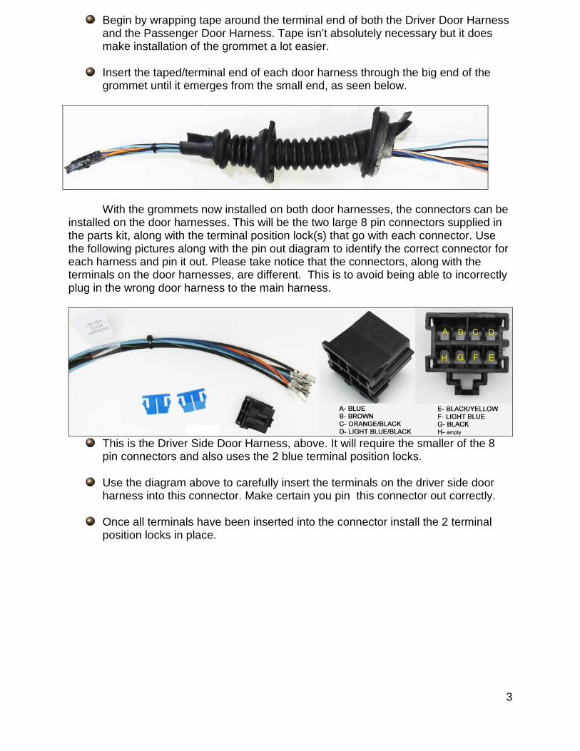
Begin by wrapping tape around the terminal end of both the Driver Door Harness and the Passenger Door Harness. Tape isn’t absolutely necessary but it does make installation of the grommet a lot easier.
Insert the taped/terminal end of each door harness through the big end of the grommet until it emerges from the small end, as seen below.
With the grommets now installed on both door harnesses, the connectors can be
installed on the door harnesses. This will be the two large 8 pin connectors supplied in the parts kit, along with the terminal position lock(s) that go with each connector. Use the following pictures along with the pin out diagram to identify the correct connector for each harness and pin it out. Please take notice that the connectors, along with the terminals on the door harnesses, are different. This is to avoid being able to incorrectly plug in the wrong door harness to the main harness.
This is the Driver Side Door Harness, above. It will require the smaller of the 8
pin connectors and also uses the 2 blue terminal position locks.
Use the diagram above to carefully insert the terminals on the driver side door harness into this connector. Make certain you pin this connector out correctly.
Once all terminals have been inserted into the connector install the 2 terminal position locks in place.

4
This is the Passenger Side Door Harness, above. It will require the larger of the 8 pin connectors and also uses the gray terminal position lock.
Use the diagram above to carefully insert the terminals on the Passenger Side Door Harness into this connector. The driver side and passenger side kick panels, door panels, and driver side
door sill plate must be removed before any installation. The center console will also need to the loosened from all of its mounting points as well, but it may remain in the vehicle.
Door Harness Installation
Installation of the door harnesses will require the window to be in the up position. This will give you access to all of the components and to the harness routing channel.
Installation of the door harnesses will consist of two parts: Door Grommet Installation, and Door Harness Connections
to the components in the door. The following steps will outline these procedures.
Door Grommet Installation
Begin by placing the harness in the door, with the 8 pin connector you just installed towards the front of the car.
Pass the 8 pin connector through the large hole in the door, and then
through the smaller hole in the door jamb area into the interior of the car.
5
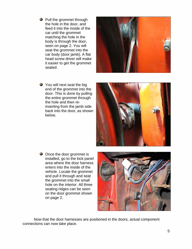
Pull the grommet through
the hole in the door, and feed it into the inside of the car until the grommet matching the hole in the body is through the door, seen on page 2. You will seat the grommet into the car body (door jamb). A flat head screw driver will make it easier to get the grommet seated.
You will next seat the big end of the grommet into the door. This is done by pulling the entire grommet through the hole and then re-inserting from the jamb side back into the door, as shown below.
Once the door grommet is
installed, go to the kick panel area where the door harness enters into the inside of the vehicle. Locate the grommet and pull it through and seat the grommet into the small hole on the interior. All three seating ridges can be seen on the door grommet shown on page 2.
Now that the door harnesses are positioned in the doors, actual component
connections can now take place.
6
Door Harness Connections
Window Motor
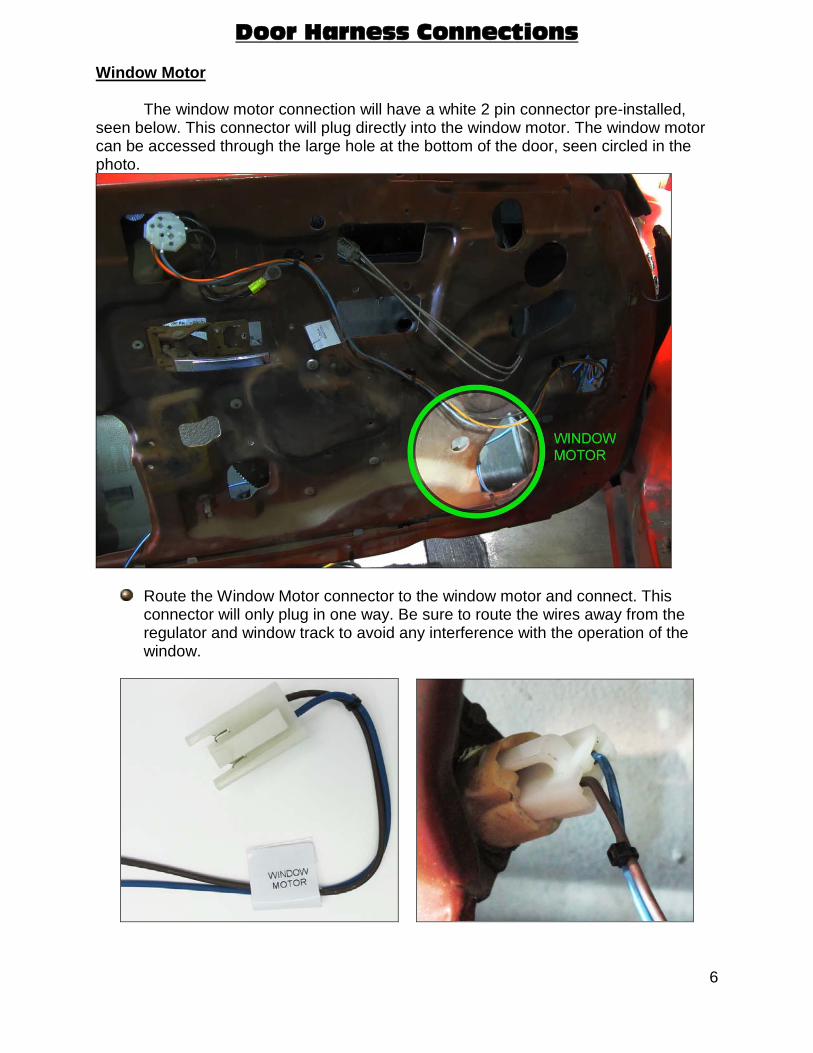
The window motor connection will have a white 2 pin connector pre-installed, seen below. This connector will plug directly into the window motor. The window motor can be accessed through the large hole at the bottom of the door, seen circled in the photo.
Route the Window Motor connector to the window motor and connect. This connector will only plug in one way. Be sure to route the wires away from the regulator and window track to avoid any interference with the operation of the window.
7
Lock Actuator
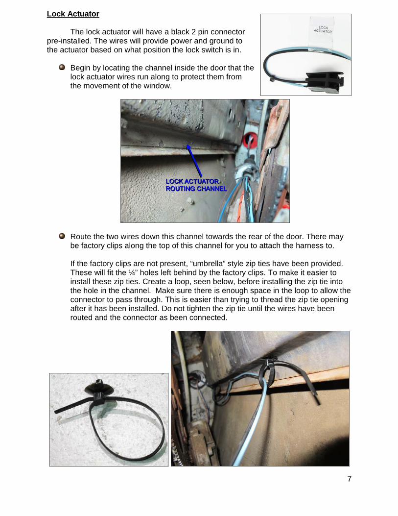
The lock actuator will have a black 2 pin connector pre-installed. The wires will provide power and ground to the actuator based on what position the lock switch is in.
Begin by locating the channel inside the door that the lock actuator wires run along to protect them from the movement of the window.
Route the two wires down this channel towards the rear of the door. There may be factory clips along the top of this channel for you to attach the harness to. If the factory clips are not present, “umbrella” style zip ties have been provided. These will fit the ¼” holes left behind by the factory clips. To make it easier to install these zip ties. Create a loop, seen below, before installing the zip tie into the hole in the channel. Make sure there is enough space in the loop to allow the connector to pass through. This is easier than trying to thread the zip tie opening after it has been installed. Do not tighten the zip tie until the wires have been routed and the connector as been connected.
8
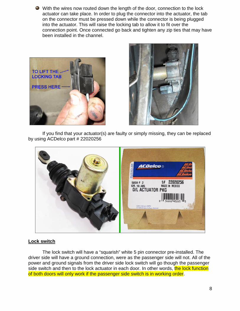
With the wires now routed down the length of the door, connection to the lock actuator can take place. In order to plug the connector into the actuator, the tab on the connector must be pressed down while the connector is being plugged into the actuator. This will raise the locking tab to allow it to fit over the connection point. Once connected go back and tighten any zip ties that may have been installed in the channel.
If you find that your actuator(s) are faulty or simply missing, they can be replaced by using ACDelco part # 22020256
Lock switch
The lock switch will have a “squarish” white 5 pin connector pre-installed. The driver side will have a ground connection, were as the passenger side will not. All of the power and ground signals from the driver side lock switch will go though the passenger side switch and then to the lock actuator in each door. In other words, the lock function of both doors will only work if the passenger side switch is in working order.
9
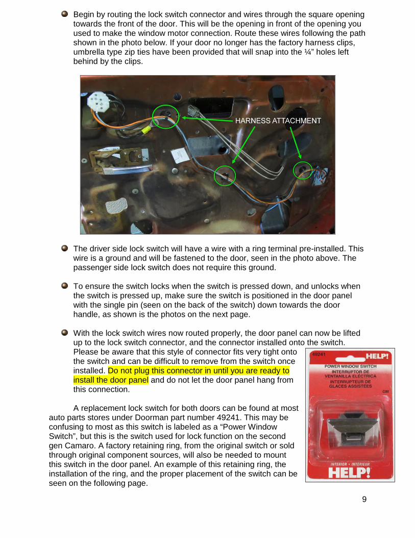
Begin by routing the lock switch connector and wires through the square opening towards the front of the door. This will be the opening in front of the opening you used to make the window motor connection. Route these wires following the path shown in the photo below. If your door no longer has the factory harness clips, umbrella type zip ties have been provided that will snap into the ¼” holes left behind by the clips.
The driver side lock switch will have a wire with a ring terminal pre-installed. This wire is a ground and will be fastened to the door, seen in the photo above. The passenger side lock switch does not require this ground.
To ensure the switch locks when the switch is pressed down, and unlocks when the switch is pressed up, make sure the switch is positioned in the door panel with the single pin (seen on the back of the switch) down towards the door handle, as shown is the photos on the next page.
With the lock switch wires now routed properly, the door panel can now be lifted up to the lock switch connector, and the connector installed onto the switch. Please be aware that this style of connector fits very tight onto the switch and can be difficult to remove from the switch once installed. Do not plug this connector in until you are ready to install the door panel and do not let the door panel hang from this connection.
A replacement lock switch for both doors can be found at most
auto parts stores under Doorman part number 49241. This may be confusing to most as this switch is labeled as a “Power Window Switch”, but this is the switch used for lock function on the second gen Camaro. A factory retaining ring, from the original switch or sold through original component sources, will also be needed to mount this switch in the door panel. An example of this retaining ring, the installation of the ring, and the proper placement of the switch can be seen on the following page.
10
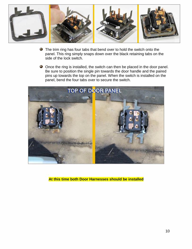
The trim ring has four tabs that bend over to hold the switch onto the panel. This ring simply snaps down over the black retaining tabs on the side of the lock switch.
Once the ring is installed, the switch can then be placed in the door panel. Be sure to position the single pin towards the door handle and the paired pins up towards the top on the panel. When the switch is installed on the panel, bend the four tabs over to secure the switch.
At this time both Door Harnesses should be installed
11
MAIN HARNESS CONNECTION
The main harness provides power connections for the lock switches as well as the window motor relays, the console mounted power window switch, and a connector that will fit each of the connectors you installed onto the door harness.
Door Harness Connectors
Plugging in the door harnesses connectors first will help position the main harness inside the vehicle.
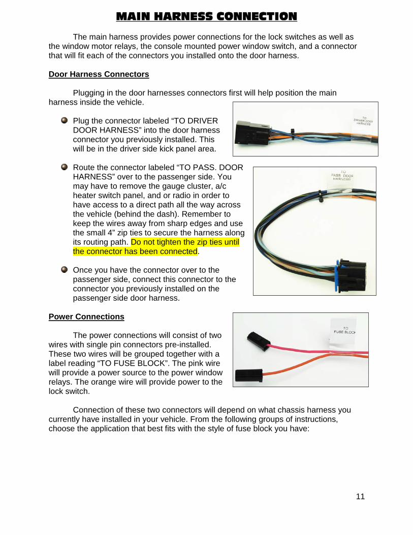
Plug the connector labeled “TO DRIVER DOOR HARNESS” into the door harness connector you previously installed. This will be in the driver side kick panel area.
Route the connector labeled “TO PASS. DOOR HARNESS” over to the passenger side. You may have to remove the gauge cluster, a/c heater switch panel, and or radio in order to have access to a direct path all the way across the vehicle (behind the dash). Remember to keep the wires away from sharp edges and use the small 4” zip ties to secure the harness along its routing path. Do not tighten the zip ties until the connector has been connected.
Once you have the connector over to the
passenger side, connect this connector to the connector you previously installed on the passenger side door harness.
Power Connections
The power connections will consist of two wires with single pin connectors pre-installed. These two wires will be grouped together with a label reading “TO FUSE BLOCK”. The pink wire will provide a power source to the power window relays. The orange wire will provide power to the lock switch.
Connection of these two connectors will depend on what chassis harness you currently have installed in your vehicle. From the following groups of instructions, choose the application that best fits with the style of fuse block you have:

12
18 circuit Painless 2nd Generation Camaro Harness
The two connectors labeled “TO FUSE BLOCK” on this power window/lock harness will plug directly into any one of the three 2nd Gen. specific harnesses Painless offers. These harnesses are 20112, 20113, and 20114.
These chassis harnesses have two connectors labeled
“POWER WINDOW” and “POWER LOCK” pre-installed, seen to the right. The pink/black wire labeled “POWER WINDOW” will connect to the pink wire found on this power window/lock harness. The orange/black wire labeled “POWER LOCK” will connect to the orange wire of this power window/lock harness.
Painless or other aftermarket Universal Harness
Connectors have been provided with this power window/lock harness to allow you to make a plug and play connection without having to hardwire anything directly to the chassis harness.
If you are using an 18 circuit aftermarket universal
harness, chances are there are provisions in the harness for power window and power lock. Most harnesses will provide power widow power and power lock power to both doors; you will only be using one of the power window wires (#911 on a Painless harness) and one of the power lock wires (#910 on a Painless harness).
For those that do not have circuits in the chassis harness predestined for power
window and/or power lock functions, 30 amp switched ignition power and 30 amp battery constant power will need to be sourced.
The orange wire found on this power window/lock harness is intended to connect to a constant battery power source. This will be a power source that has power at all times.
The pink wire found on this power window/lock harness is intended to connect to a switched ignition power source. This will be a power source that only has power when the ignition switch is in the ON position.
Route the wires that will provide these two power sources to the inline connector found on this power window/lock harness.
Strip ¼” of insulation and crimp the supplied terminals onto each wire. These are tough terminals to crimp and a pair of roll over crimpers like Painless part number 70900 is highly recommended.
13
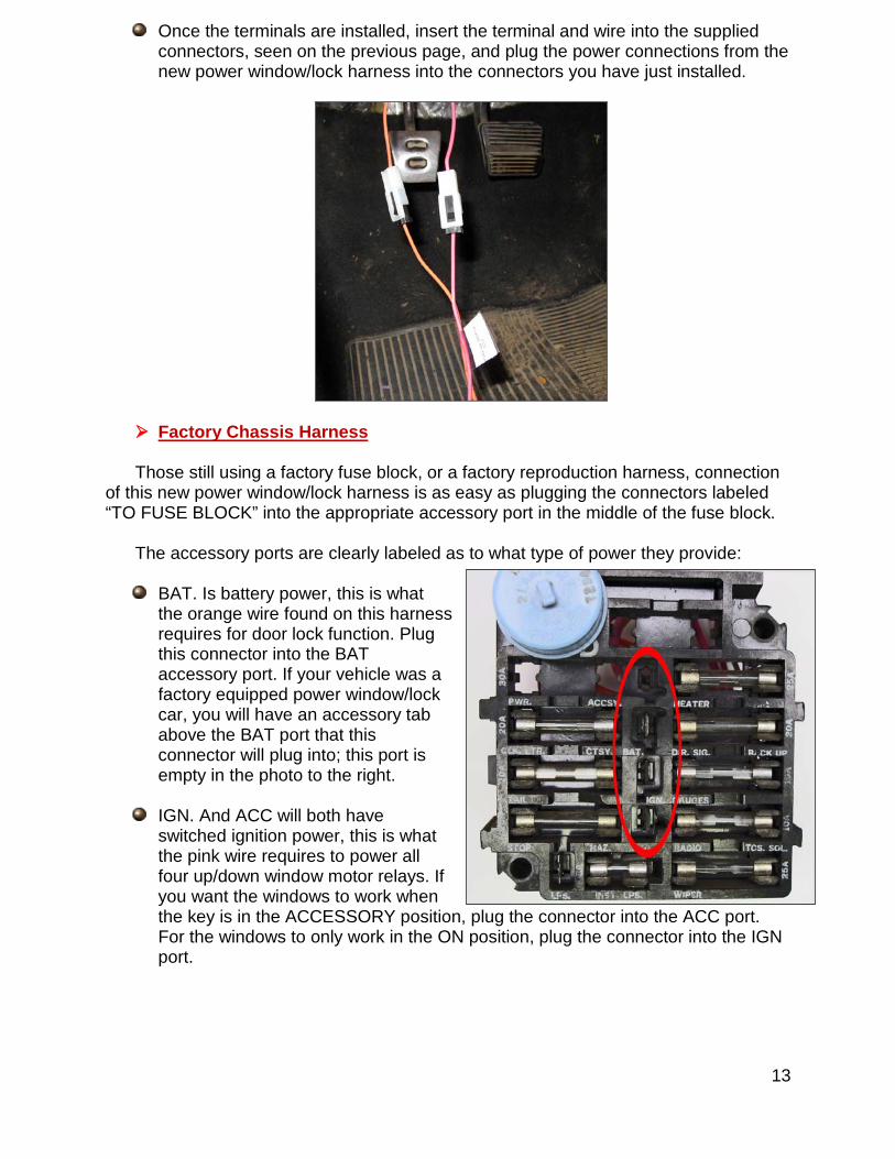
Once the terminals are installed, insert the terminal and wire into the supplied connectors, seen on the previous page, and plug the power connections from the new power window/lock harness into the connectors you have just installed.
Factory Chassis Harness
Those still using a factory fuse block, or a factory reproduction harness, connection of this new power window/lock harness is as easy as plugging the connectors labeled “TO FUSE BLOCK” into the appropriate accessory port in the middle of the fuse block.
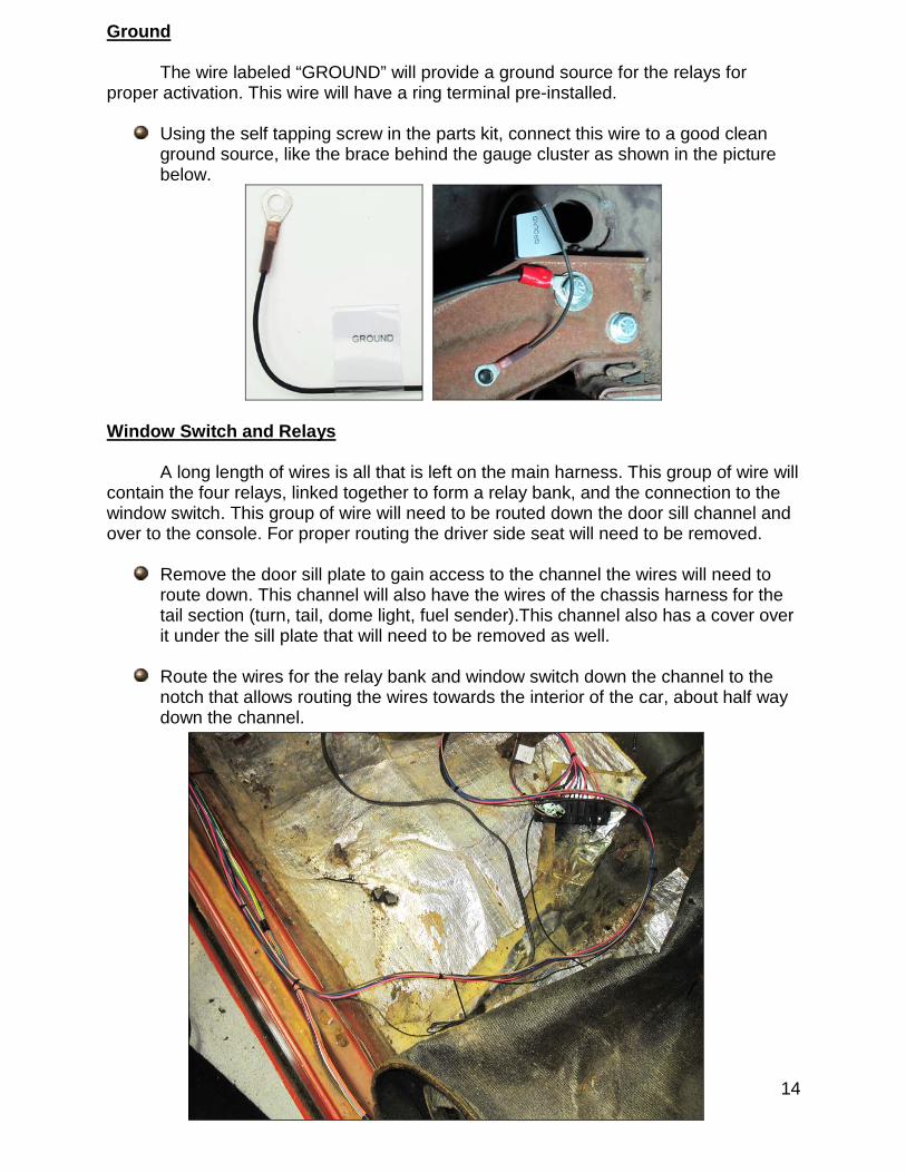
The accessory ports are clearly labeled as to what type of power they provide:
BAT. Is battery power, this is what the orange wire found on this harness requires for door lock function. Plug this connector into the BAT accessory port. If your vehicle was a factory equipped power window/lock car, you will have an accessory tab above the BAT port that this connector will plug into; this port is empty in the photo to the right.
IGN. And ACC will both have switched ignition power, this is what the pink wire requires to power all four up/down window motor relays. If you want the windows to work when the key is in the ACCESSORY position, plug the connector into the ACC port. For the windows to only work in the ON position, plug the connector into the IGN port.
14
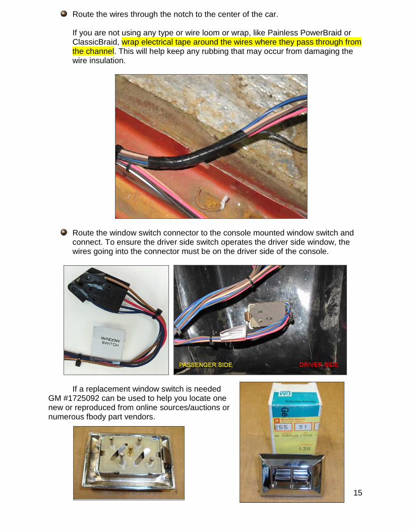
Ground
The wire labeled “GROUND” will provide a ground source for the relays for proper activation. This wire will have a ring terminal pre-installed.
Using the self tapping screw in the parts kit, connect this wire to a good clean ground source, like the brace behind the gauge cluster as shown in the picture below.
Window Switch and Relays
A long length of wires is all that is left on the main harness. This group of wire will contain the four relays, linked together to form a relay bank, and the connection to the window switch. This group of wire will need to be routed down the door sill channel and over to the console. For proper routing the driver side seat will need to be removed.
Remove the door sill plate to gain access to the channel the wires will need to route down. This channel will also have the wires of the chassis harness for the tail section (turn, tail, dome light, fuel sender).This channel also has a cover over it under the sill plate that will need to be removed as well.
Route the wires for the relay bank and window switch down the channel to the notch that allows routing the wires towards the interior of the car, about half way down the channel.
15
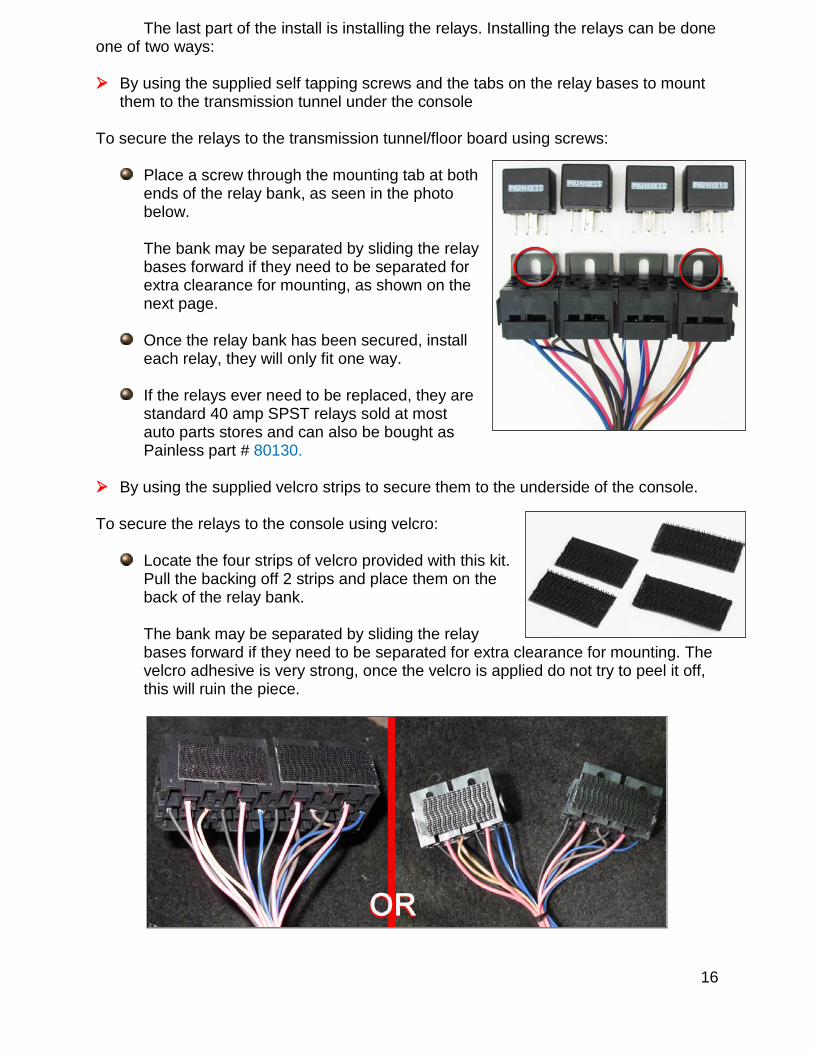
Route the wires through the notch to the center of the car. If you are not using any type or wire loom or wrap, like Painless PowerBraid or ClassicBraid, wrap electrical tape around the wires where they pass through from the channel. This will help keep any rubbing that may occur from damaging the wire insulation.
Route the window switch connector to the console mounted window switch and connect. To ensure the driver side switch operates the driver side window, the wires going into the connector must be on the driver side of the console.
If a replacement window switch is needed GM #1725092 can be used to help you locate one new or reproduced from online sources/auctions or numerous fbody part vendors.
16
The last part of the install is installing the relays. Installing the relays can be done one of two ways:
By using the supplied self tapping screws and the tabs on the relay bases to mount
them to the transmission tunnel under the console To secure the relays to the transmission tunnel/floor board using screws:
Place a screw through the mounting tab at both ends of the relay bank, as seen in the photo below.
The bank may be separated by sliding the relay bases forward if they need to be separated for extra clearance for mounting, as shown on the next page.
Once the relay bank has been secured, install each relay, they will only fit one way.
If the relays ever need to be replaced, they are standard 40 amp SPST relays sold at most auto parts stores and can also be bought as Painless part # 80130.
By using the supplied velcro strips to secure them to the underside of the console.
To secure the relays to the console using velcro:
Locate the four strips of velcro provided with this kit. Pull the backing off 2 strips and place them on the back of the relay bank. The bank may be separated by sliding the relay bases forward if they need to be separated for extra clearance for mounting. The velcro adhesive is very strong, once the velcro is applied do not try to peel it off, this will ruin the piece.
17
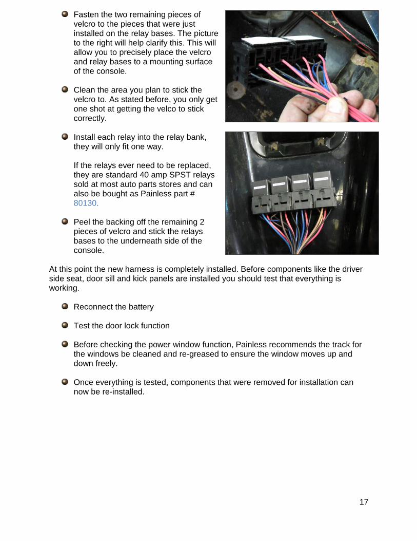
Fasten the two remaining pieces of velcro to the pieces that were just installed on the relay bases. The picture to the right will help clarify this. This will allow you to precisely place the velcro and relay bases to a mounting surface of the console.
Clean the area you plan to stick the
velcro to. As stated before, you only get one shot at getting the velco to stick correctly.
Install each relay into the relay bank, they will only fit one way. If the relays ever need to be replaced, they are standard 40 amp SPST relays sold at most auto parts stores and can also be bought as Painless part # 80130.
Peel the backing off the remaining 2 pieces of velcro and stick the relays bases to the underneath side of the console.
At this point the new harness is completely installed. Before components like the driver side seat, door sill and kick panels are installed you should test that everything is working.
Reconnect the battery
Test the door lock function
Before checking the power window function, Painless recommends the track for the windows be cleaned and re-greased to ensure the window moves up and down freely.
Once everything is tested, components that were removed for installation can now be re-installed.

18
NOTES
Recommended