Embed Size (px)
Citation preview
Central Processing Unit and Pipeline
Course: BCA-2nd Sem Subject: Computer Organization
And Architecture Unit-4
1
CENTRAL PROCESSING UNIT
2
• Introduction
• General Register Organization
• Stack Organization
• Instruction Formats
• Addressing Modes
• Data Transfer and Manipulation
• Program Control
• Reduced Instruction Set Computer (RISC)
MAJOR COMPONENTS OF CPU[1]
3
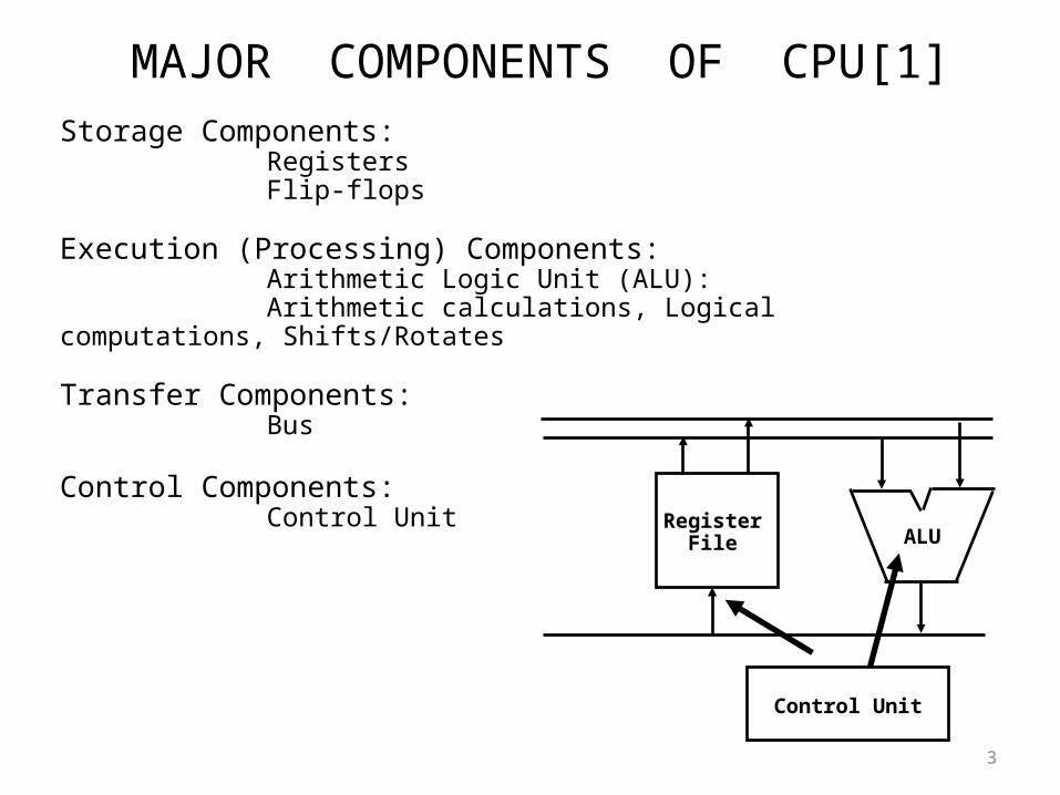
Storage Components: Registers Flip-flops
Execution (Processing) Components: Arithmetic Logic Unit (ALU): Arithmetic calculations, Logical computations, Shifts/Rotates
Transfer Components: Bus
Control Components: Control Unit
RegisterFile ALU
Control Unit
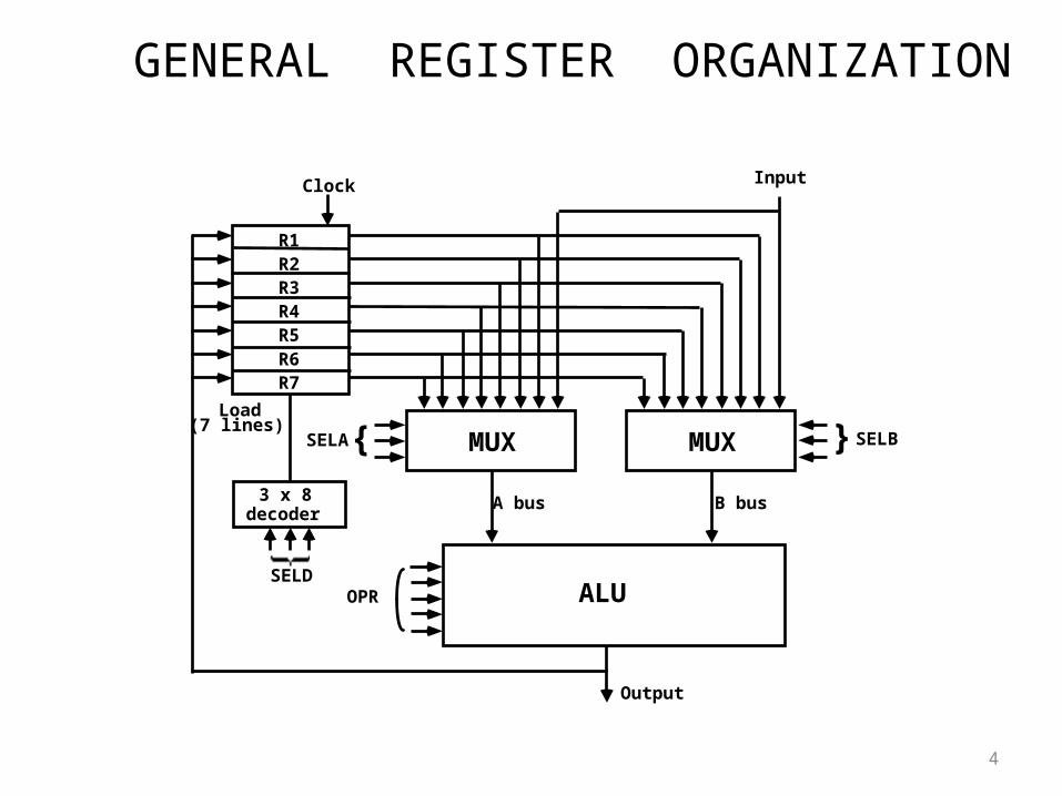
GENERAL REGISTER ORGANIZATION
4
MUXSELA{ MUX } SELB
ALUOPR
R1R2R3R4R5R6R7
Input
3 x 8decoder
SELD
Load(7 lines)
Output
A bus B bus
Clock
OPERATION OF CONTROL UNIT
5
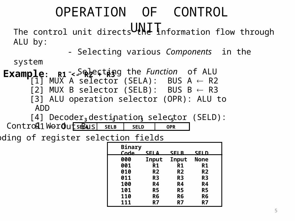
The control unit directs the information flow through ALU by: - Selecting various Components in the system - Selecting the Function of ALU
Example: R1 <- R2 + R3[1] MUX A selector (SELA): BUS A R2[2] MUX B selector (SELB): BUS B R3[3] ALU operation selector (OPR): ALU to ADD[4] Decoder destination selector (SELD): R1 Out Bus
Control Word
Encoding of register selection fieldsBinaryCode SELA SELB SELD000 Input Input None001 R1 R1 R1010 R2 R2 R2011 R3 R3 R3100 R4 R4 R4101 R5 R5 R5110 R6 R6 R6111 R7 R7 R7
SELA SELB SELD OPR
3 3 3 5
ALU CONTROL
6
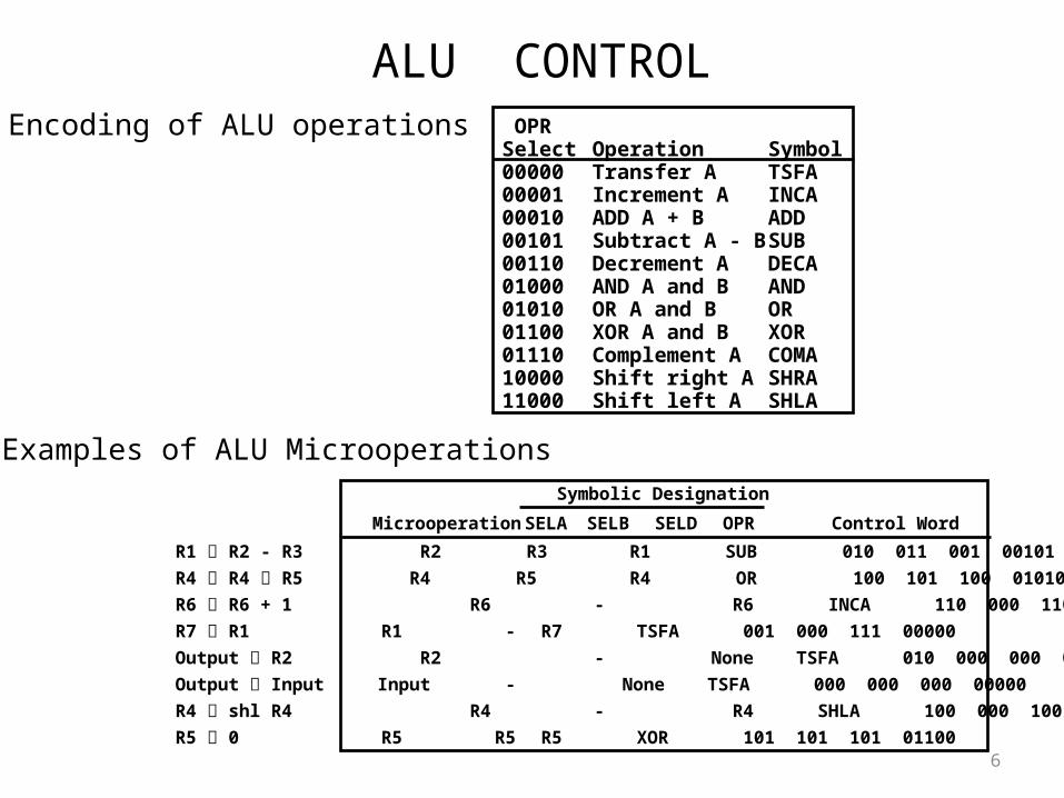
Encoding of ALU operations OPRSelect Operation Symbol00000 Transfer A TSFA00001 Increment A INCA00010 ADD A + B ADD00101 Subtract A - B SUB00110 Decrement A DECA01000 AND A and B AND01010 OR A and B OR01100 XOR A and B XOR01110 Complement A COMA10000 Shift right A SHRA11000 Shift left A SHLA
Examples of ALU Microoperations Symbolic Designation
Microoperation SELA SELB SELD OPR Control Word
R1 R2 - R3 R2 R3 R1 SUB 010 011 001 00101
R4 R4 R5 R4 R5 R4 OR 100 101 100 01010
R6 R6 + 1 R6 - R6 INCA 110 000 110 00001
R7 R1 R1 - R7 TSFA 001 000 111 00000
Output R2 R2 - None TSFA 010 000 000 00000
Output Input Input - None TSFA 000 000 000 00000
R4 shl R4 R4 - R4 SHLA 100 000 100 11000
R5 0 R5 R5 R5 XOR 101 101 101 01100
REGISTER STACK ORGANIZATION[1]
7
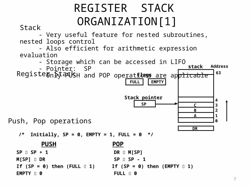
Register Stack
Push, Pop operations
/* Initially, SP = 0, EMPTY = 1, FULL = 0 */
PUSH POPSP SP + 1 DR M[SP]
M[SP] DR SP SP - 1
If (SP = 0) then (FULL 1) If (SP = 0) then (EMPTY 1)
EMPTY 0 FULL 0
Stack - Very useful feature for nested subroutines, nested loops control - Also efficient for arithmetic expression evaluation - Storage which can be accessed in LIFO - Pointer: SP - Only PUSH and POP operations are applicable
ABC
01234
63
Address
FULL EMPTY
SP
DR
Flags
Stack pointer
stack
MEMORY STACK ORGANIZATION
8
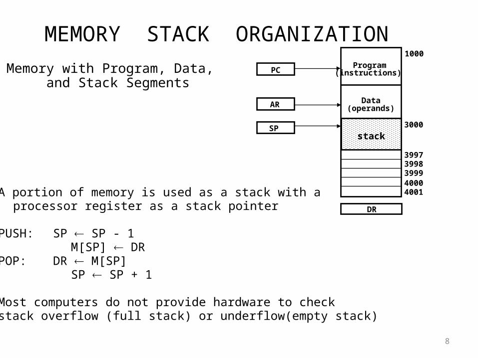
- A portion of memory is used as a stack with a processor register as a stack pointer
- PUSH: SP SP - 1 M[SP] DR
- POP: DR M[SP] SP SP + 1
- Most computers do not provide hardware to check stack overflow (full stack) or underflow(empty stack)
Memory with Program, Data, and Stack Segments
DR
40014000399939983997
3000
Data(operands)
Program(instructions)
1000
PC
AR
SPstack
REVERSE POLISH NOTATION
9
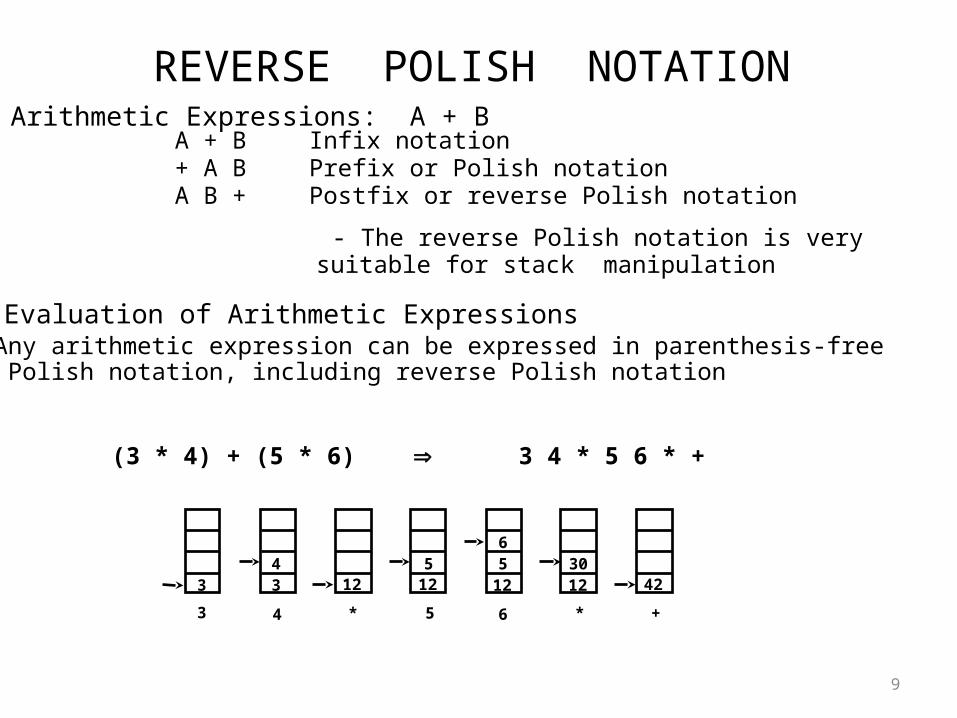
A + B Infix notation+ A B Prefix or Polish notationA B + Postfix or reverse Polish notation
- The reverse Polish notation is very suitable for stack manipulation
Evaluation of Arithmetic Expressions Any arithmetic expression can be expressed in parenthesis-free Polish notation, including reverse Polish notation
(3 * 4) + (5 * 6) 3 4 * 5 6 * +
Arithmetic Expressions: A + B
3 3 12 12 12 12 424 5 5
630
3 4 * 5 6 * +
INSTRUCTION FORMAT
10
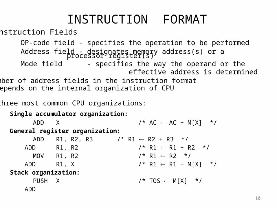
OP-code field - specifies the operation to be performedAddress field - designates memory address(s) or a processor register(s)Mode field - specifies the way the operand or the effective address is determined
The number of address fields in the instruction format depends on the internal organization of CPU
- The three most common CPU organizations:
Single accumulator organization:
ADD X /* AC AC + M[X] */General register organization:
ADD R1, R2, R3 /* R1 R2 + R3 */ ADD R1, R2 /* R1 R1 + R2 */
MOV R1, R2 /* R1 R2 */ ADD R1, X /* R1 R1 + M[X] */Stack organization:
PUSH X /* TOS M[X] */ ADD
Instruction Fields
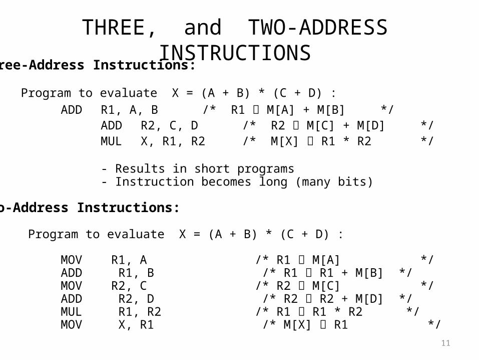
THREE, and TWO-ADDRESS INSTRUCTIONS
11
Three-Address Instructions:
Program to evaluate X = (A + B) * (C + D) :
ADD R1, A, B /* R1 M[A] + M[B] */ ADD R2, C, D /* R2 M[C] + M[D] */ MUL X, R1, R2 /* M[X] R1 * R2 */
- Results in short programs - Instruction becomes long (many bits)
Two-Address Instructions:
Program to evaluate X = (A + B) * (C + D) :
MOV R1, A /* R1 M[A] */ADD R1, B /* R1 R1 + M[B] */MOV R2, C /* R2 M[C] */ADD R2, D /* R2 R2 + M[D] */MUL R1, R2 /* R1 R1 * R2 */MOV X, R1 /* M[X] R1 */
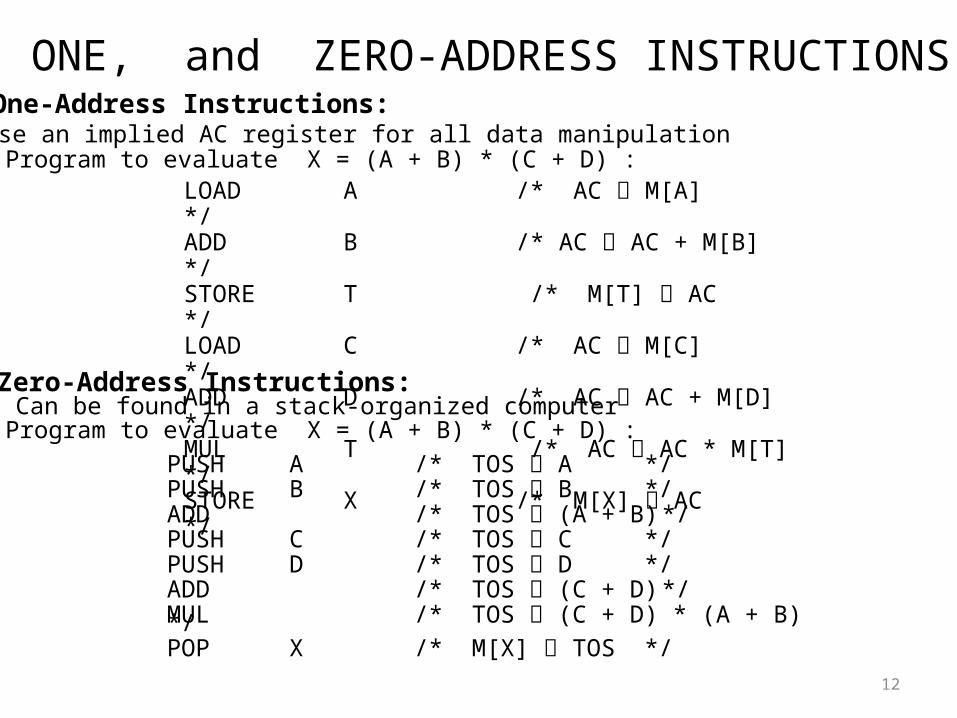
ONE, and ZERO-ADDRESS INSTRUCTIONS
12
One-Address Instructions:- Use an implied AC register for all data manipulation- Program to evaluate X = (A + B) * (C + D) :
LOAD A /* AC M[A] */ADD B /* AC AC + M[B] */STORE T /* M[T] AC */LOAD C /* AC M[C] */ADD D /* AC AC + M[D] */MUL T /* AC AC * M[T] */STORE X /* M[X] AC */
Zero-Address Instructions:- Can be found in a stack-organized computer- Program to evaluate X = (A + B) * (C + D) :
PUSH A /* TOS A */PUSH B /* TOS B */ADD /* TOS (A + B) */PUSH C /* TOS C */PUSH D /* TOS D */ADD /* TOS (C + D) */MUL /* TOS (C + D) * (A + B) */ POP X /* M[X] TOS */
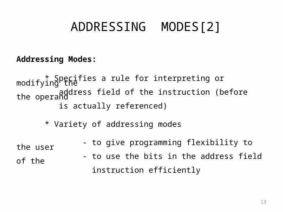
ADDRESSING MODES[2]
13
Addressing Modes:
* Specifies a rule for interpreting or modifying the address field of the instruction (before the operand is actually referenced) * Variety of addressing modes
- to give programming flexibility to the user - to use the bits in the address field of the instruction efficiently
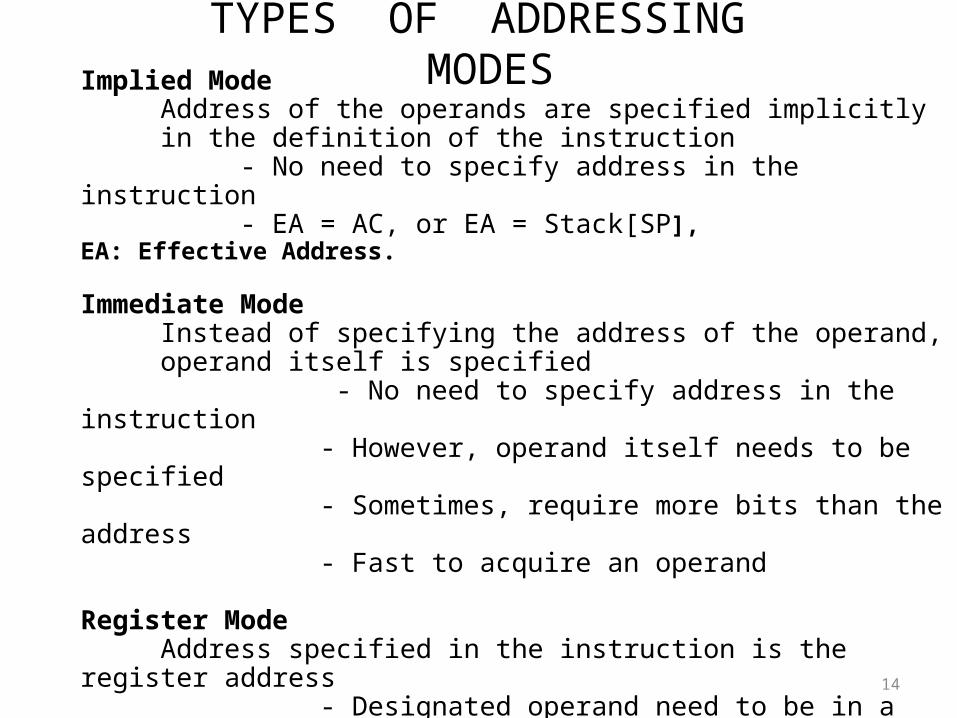
TYPES OF ADDRESSING MODES
14
Implied ModeAddress of the operands are specified implicitly in the definition of the instruction
- No need to specify address in the instruction - EA = AC, or EA = Stack[SP], EA: Effective Address.
Immediate ModeInstead of specifying the address of the operand,
operand itself is specified - No need to specify address in the instruction - However, operand itself needs to be specified - Sometimes, require more bits than the address - Fast to acquire an operand
Register Mode Address specified in the instruction is the register address - Designated operand need to be in a register - Shorter address than the memory address - Saving address field in the instruction - Faster to acquire an operand than the memory addressing - EA = IR(R) (IR(R): Register field of IR)
TYPES OF ADDRESSING MODES
15
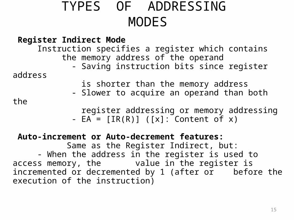
Register Indirect ModeInstruction specifies a register which contains
the memory address of the operand - Saving instruction bits since register address is shorter than the memory address - Slower to acquire an operand than both the register addressing or memory addressing - EA = [IR(R)] ([x]: Content of x)
Auto-increment or Auto-decrement features: Same as the Register Indirect, but:
- When the address in the register is used to access memory, the value in the register is incremented or decremented by 1 (after or before the execution of the instruction)
TYPES OF ADDRESSING MODES
16
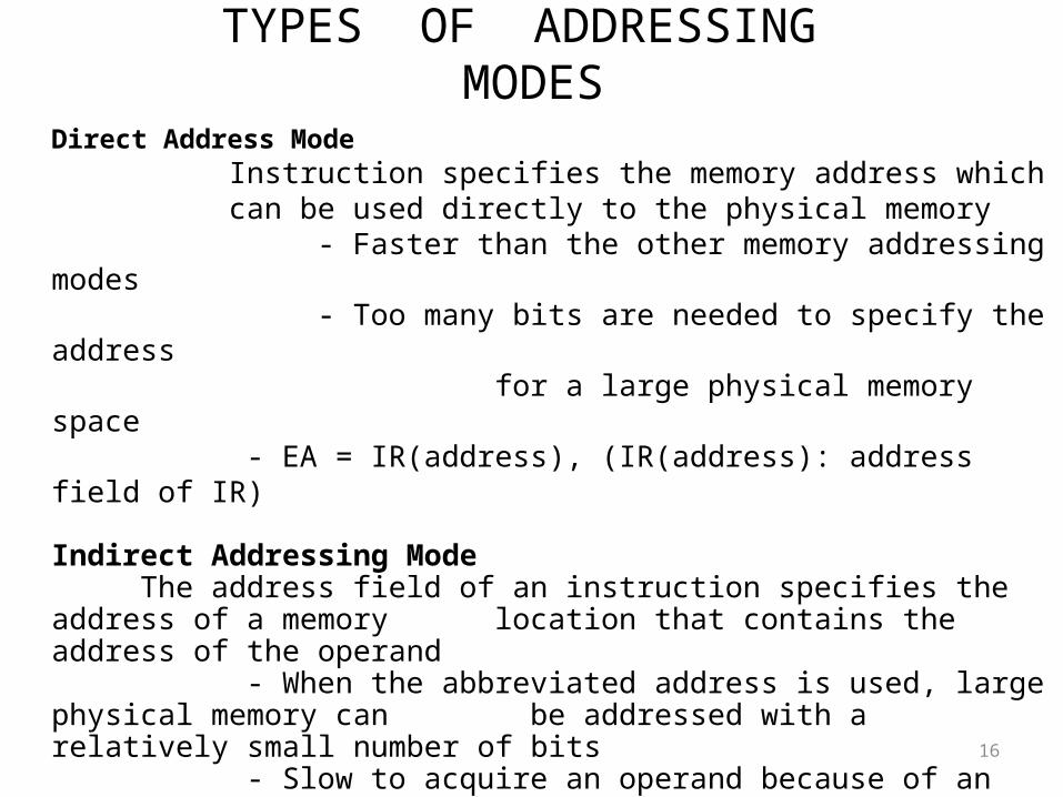
Direct Address Mode Instruction specifies the memory address which can be used directly to the physical memory - Faster than the other memory addressing modes - Too many bits are needed to specify the address for a large physical memory space - EA = IR(address), (IR(address): address field of IR)
Indirect Addressing ModeThe address field of an instruction specifies the address of a memory
location that contains the address of the operand - When the abbreviated address is used, large physical memory can be addressed with a relatively small number of bits - Slow to acquire an operand because of an additional memory access - EA = M[IR(address)]
TYPES OF ADDRESSING MODES
17
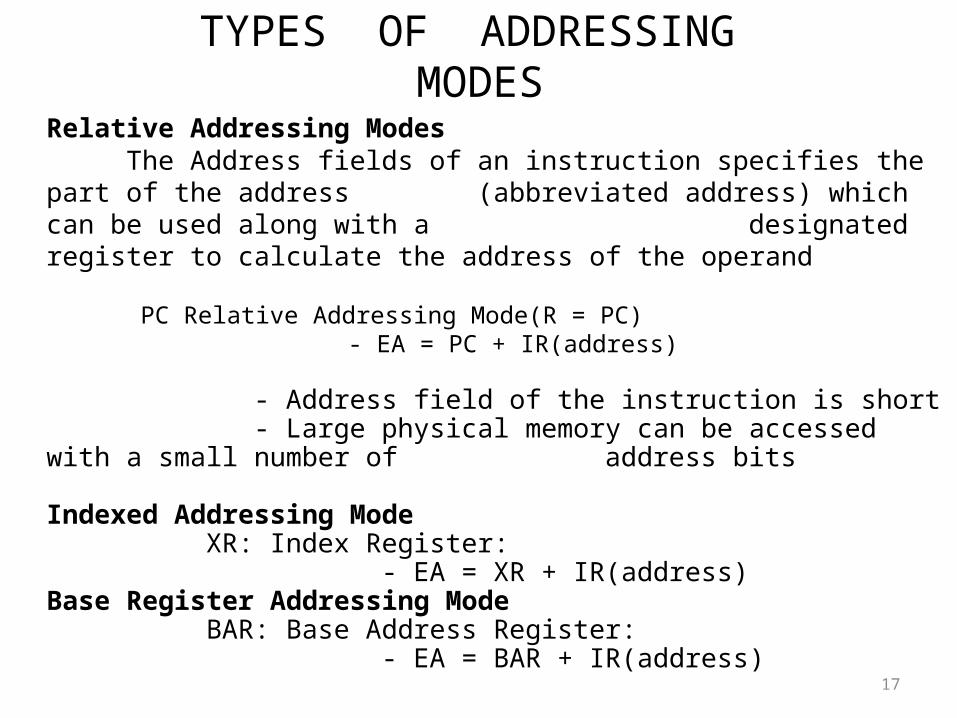
Relative Addressing ModesThe Address fields of an instruction specifies the part of the address
(abbreviated address) which can be used along with a designated register to calculate the address of the operand
PC Relative Addressing Mode(R = PC) - EA = PC + IR(address)
- Address field of the instruction is short - Large physical memory can be accessed with a small number of
address bits
Indexed Addressing Mode XR: Index Register:
- EA = XR + IR(address)Base Register Addressing Mode
BAR: Base Address Register: - EA = BAR + IR(address)
ADDRESSING MODES - EXAMPLES
18
AddressingMode
EffectiveAddress
Contentof AC
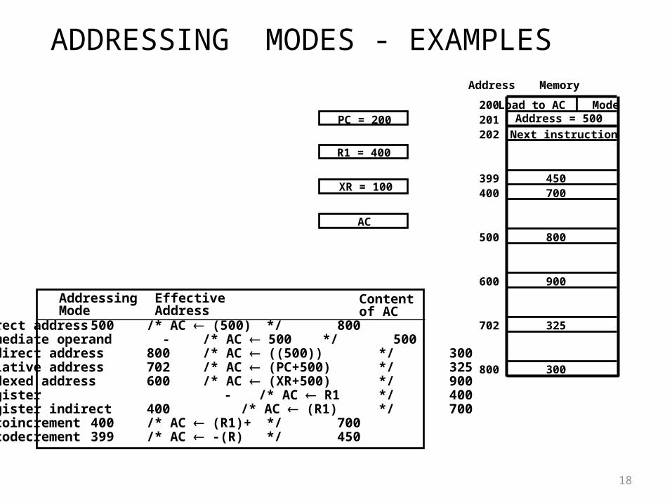
Direct address 500 /* AC (500) */ 800Immediate operand - /* AC 500 */ 500Indirect address 800 /* AC ((500)) */ 300Relative address 702 /* AC (PC+500) */ 325Indexed address 600 /* AC (XR+500) */ 900Register - /* AC R1 */ 400Register indirect 400 /* AC (R1) */ 700Autoincrement 400 /* AC (R1)+ */ 700Autodecrement 399 /* AC -(R) */ 450
Load to AC ModeAddress = 500
Next instruction
200201202
399400
450700
500 800
600 900
702 325
800 300
MemoryAddress
PC = 200
R1 = 400
XR = 100
AC
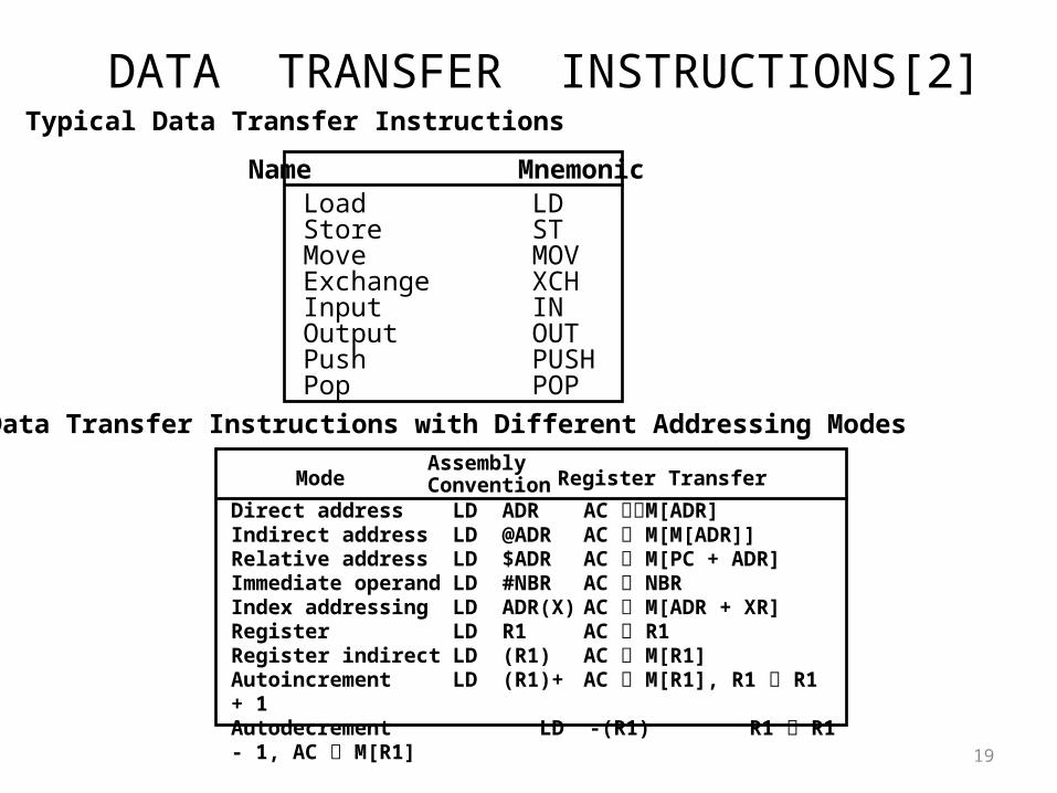
DATA TRANSFER INSTRUCTIONS[2]
19
Load LDStore STMove MOVExchange XCHInput INOutput OUTPush PUSHPop POP
Name Mnemonic
Typical Data Transfer Instructions
Direct address LD ADR AC M[ADR]Indirect address LD @ADR AC M[M[ADR]]Relative address LD $ADR AC M[PC + ADR]Immediate operand LD #NBR AC NBRIndex addressing LD ADR(X) AC M[ADR + XR]Register LD R1 AC R1Register indirect LD (R1) AC M[R1]Autoincrement LD (R1)+ AC M[R1], R1 R1 + 1Autodecrement LD -(R1) R1 R1 - 1, AC M[R1]
ModeAssemblyConvention Register Transfer
Data Transfer Instructions with Different Addressing Modes
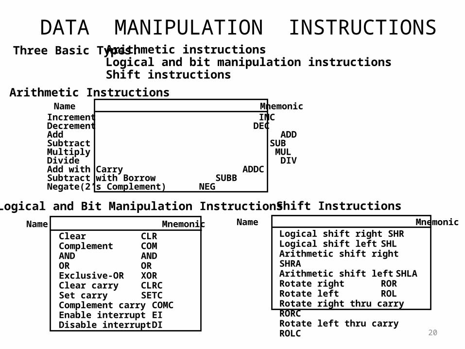
DATA MANIPULATION INSTRUCTIONS
20
Three Basic Types: Arithmetic instructionsLogical and bit manipulation instructionsShift instructions
Arithmetic InstructionsName Mnemonic
Clear CLRComplement COMAND ANDOR ORExclusive-OR XORClear carry CLRCSet carry SETCComplement carry COMCEnable interrupt EIDisable interrupt DI
Name MnemonicLogical shift right SHRLogical shift left SHLArithmetic shift right SHRAArithmetic shift left SHLARotate right RORRotate left ROLRotate right thru carry RORCRotate left thru carry ROLC
Name Mnemonic
Logical and Bit Manipulation Instructions Shift Instructions
Increment INCDecrement DECAdd ADDSubtract SUBMultiply MULDivide DIVAdd with Carry ADDCSubtract with Borrow SUBBNegate(2’s Complement) NEG
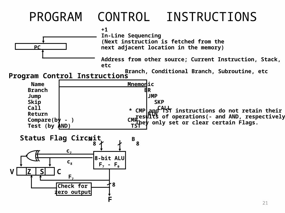
PROGRAM CONTROL INSTRUCTIONS
21
PC
+1In-Line Sequencing(Next instruction is fetched from thenext adjacent location in the memory)
Address from other source; Current Instruction, Stack, etcBranch, Conditional Branch, Subroutine, etc
Program Control Instructions Name Mnemonic
Branch BRJump JMPSkip SKPCall CALLReturn RTNCompare(by - ) CMPTest (by AND) TST
* CMP and TST instructions do not retain their results of operations(- and AND, respectively). They only set or clear certain Flags.
Status Flag Circuit
c7
c8
A B8 8
8-bit ALU
V Z S CF7
F7 - F0
8
F
Check forzero output
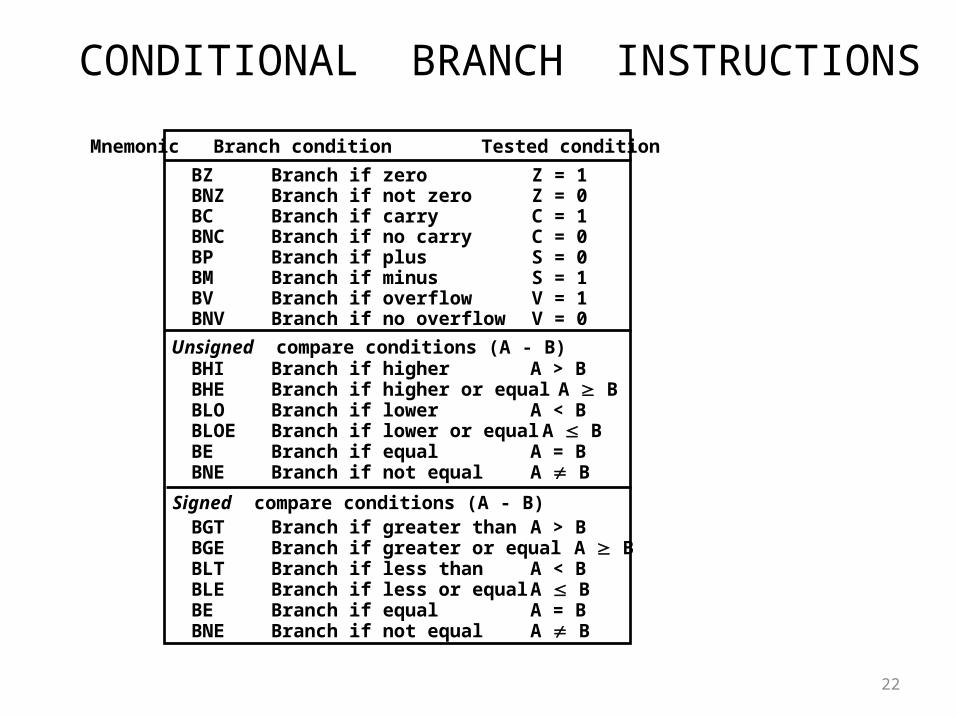
CONDITIONAL BRANCH INSTRUCTIONS
22
BZ Branch if zero Z = 1BNZ Branch if not zero Z = 0BC Branch if carry C = 1BNC Branch if no carry C = 0BP Branch if plus S = 0BM Branch if minus S = 1BV Branch if overflow V = 1BNV Branch if no overflow V = 0
BHI Branch if higher A > BBHE Branch if higher or equal A BBLO Branch if lower A < BBLOE Branch if lower or equal A BBE Branch if equal A = BBNE Branch if not equal A B
BGT Branch if greater than A > BBGE Branch if greater or equal A BBLT Branch if less than A < BBLE Branch if less or equal A BBE Branch if equal A = BBNE Branch if not equal A B
Unsigned compare conditions (A - B)
Signed compare conditions (A - B)
Mnemonic Branch condition Tested condition
SUBROUTINE CALL AND RETURN
23
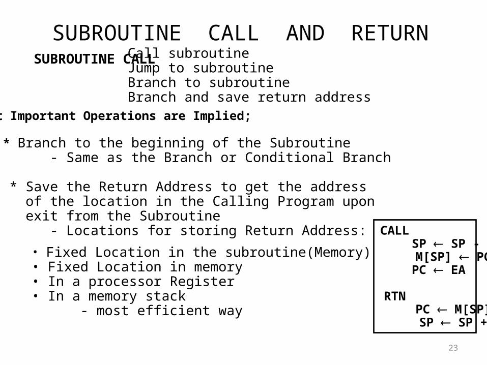
Call subroutineJump to subroutineBranch to subroutineBranch and save return address
• Fixed Location in the subroutine(Memory)• Fixed Location in memory• In a processor Register• In a memory stack - most efficient way
SUBROUTINE CALL
Two Most Important Operations are Implied;
* Branch to the beginning of the Subroutine - Same as the Branch or Conditional Branch
* Save the Return Address to get the address of the location in the Calling Program upon exit from the Subroutine - Locations for storing Return Address: CALL
SP SP - 1 M[SP] PC
PC EA
RTN PC M[SP] SP SP + 1
PROGRAM INTERRUPT[3]
24
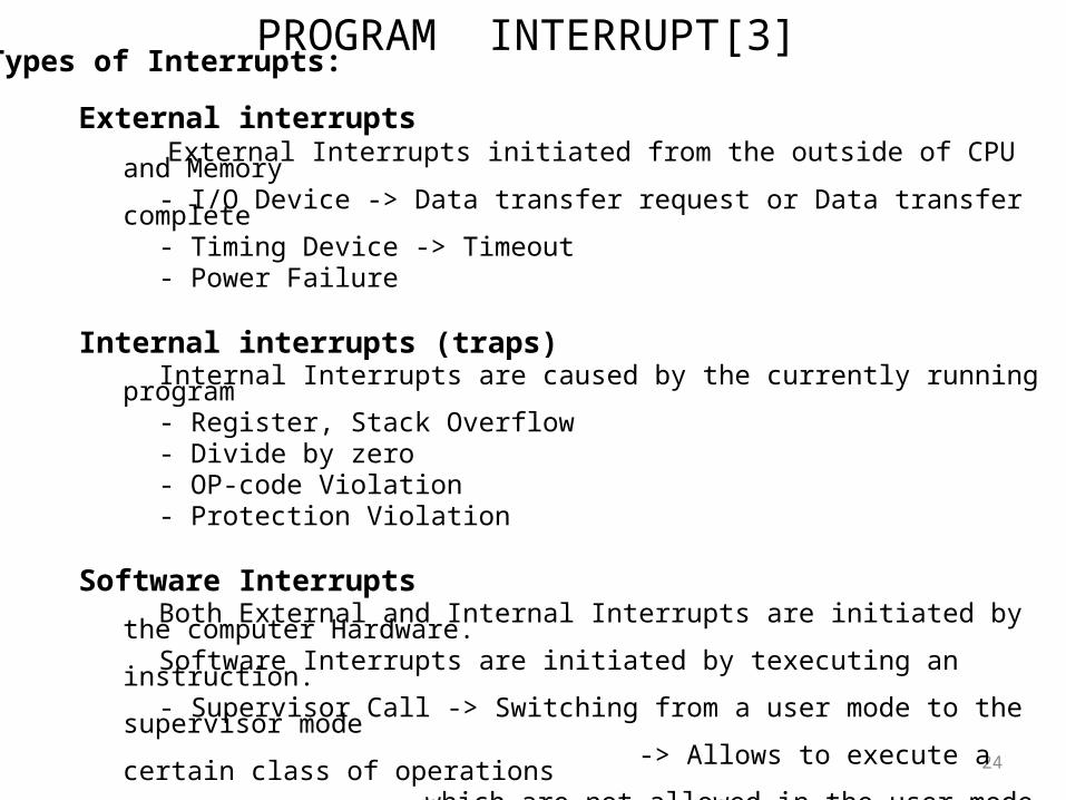
Types of Interrupts:
External interrupts External Interrupts initiated from the outside of CPU and Memory - I/O Device -> Data transfer request or Data transfer complete - Timing Device -> Timeout - Power Failure
Internal interrupts (traps) Internal Interrupts are caused by the currently running program - Register, Stack Overflow - Divide by zero - OP-code Violation - Protection Violation
Software Interrupts Both External and Internal Interrupts are initiated by the computer Hardware. Software Interrupts are initiated by texecuting an instruction. - Supervisor Call -> Switching from a user mode to the supervisor mode -> Allows to execute a certain class of operations
which are not allowed in the user mode
INTERRUPT PROCEDURE
25
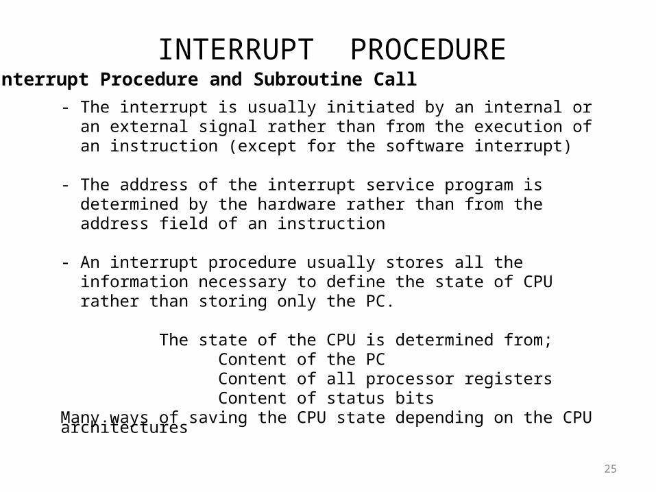
- The interrupt is usually initiated by an internal or an external signal rather than from the execution of an instruction (except for the software interrupt)
- The address of the interrupt service program is determined by the hardware rather than from the address field of an instruction
- An interrupt procedure usually stores all the information necessary to define the state of CPU rather than storing only the PC.
The state of the CPU is determined from; Content of the PC Content of all processor registers Content of status bitsMany ways of saving the CPU state depending on the CPU architectures
Interrupt Procedure and Subroutine Call
RISC: REDUCED INSTRUCTION SET COMPUTERS
26
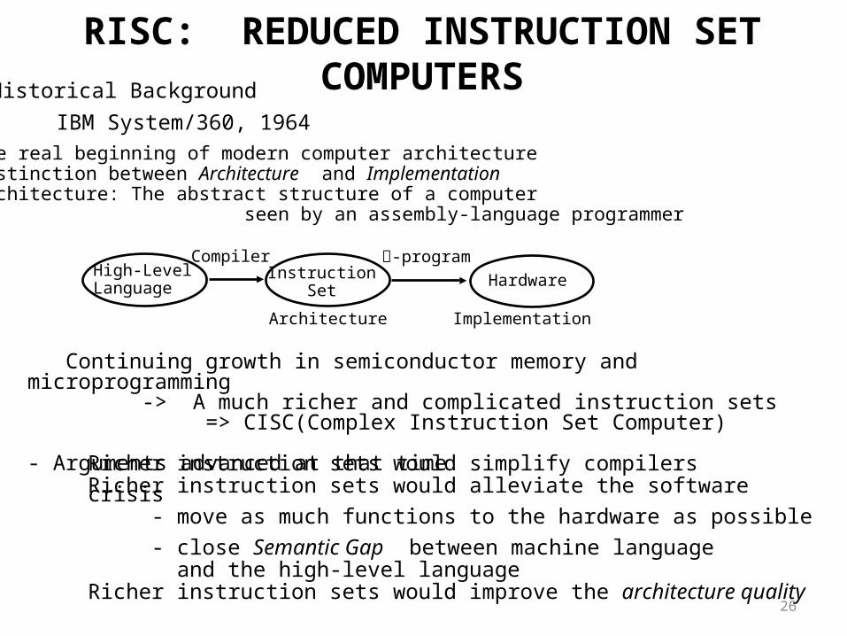
Historical Background
IBM System/360, 1964
- The real beginning of modern computer architecture- Distinction between Architecture and Implementation- Architecture: The abstract structure of a computer seen by an assembly-language programmer
High-LevelLanguage
InstructionSet
Hardware
Compiler -program
Architecture Implementation
Continuing growth in semiconductor memory and microprogramming -> A much richer and complicated instruction sets => CISC(Complex Instruction Set Computer)
- Arguments advanced at that timeRicher instruction sets would simplify compilersRicher instruction sets would alleviate the software crisis - move as much functions to the hardware as possible - close Semantic Gap between machine language and the high-level languageRicher instruction sets would improve the architecture quality
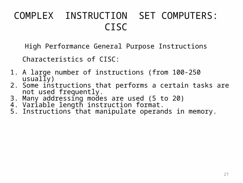
COMPLEX INSTRUCTION SET COMPUTERS: CISC
27
High Performance General Purpose Instructions
Characteristics of CISC:
1. A large number of instructions (from 100-250 usually)2. Some instructions that performs a certain tasks are not used frequently.3. Many addressing modes are used (5 to 20)4. Variable length instruction format.5. Instructions that manipulate operands in memory.
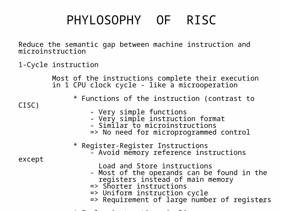
PHYLOSOPHY OF RISC
28
Reduce the semantic gap between machine instruction and microinstruction 1-Cycle instruction
Most of the instructions complete their execution in 1 CPU clock cycle - like a microoperation
* Functions of the instruction (contrast to CISC) - Very simple functions - Very simple instruction format - Similar to microinstructions => No need for microprogrammed control
* Register-Register Instructions - Avoid memory reference instructions except Load and Store instructions - Most of the operands can be found in the registers instead of main memory => Shorter instructions => Uniform instruction cycle => Requirement of large number of registers * Employ instruction pipeline
CHARACTERISTICS OF RISC
29
Common RISC Characteristics
- Operations are register-to-register, with only LOAD and STORE accessing memory
- The operations and addressing modes are reduced
Instruction formats are simple
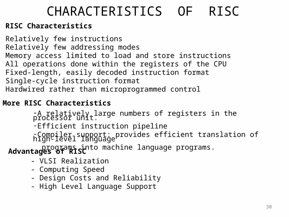
CHARACTERISTICS OF RISC
30
RISC Characteristics
- Relatively few instructions- Relatively few addressing modes- Memory access limited to load and store instructions- All operations done within the registers of the CPU- Fixed-length, easily decoded instruction format- Single-cycle instruction format- Hardwired rather than microprogrammed control
-A relatively large numbers of registers in the processor unit. -Efficient instruction pipeline-Compiler support: provides efficient translation of high-level language programs into machine language programs.
More RISC Characteristics
Advantages of RISC- VLSI Realization- Computing Speed- Design Costs and Reliability- High Level Language Support
Parallel processing[4]
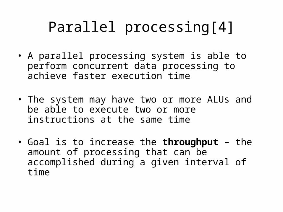
• A parallel processing system is able to perform concurrent data processing to achieve faster execution time
• The system may have two or more ALUs and be able to execute two or more instructions at the same time
• Goal is to increase the throughput – the amount of processing that can be accomplished during a given interval of time
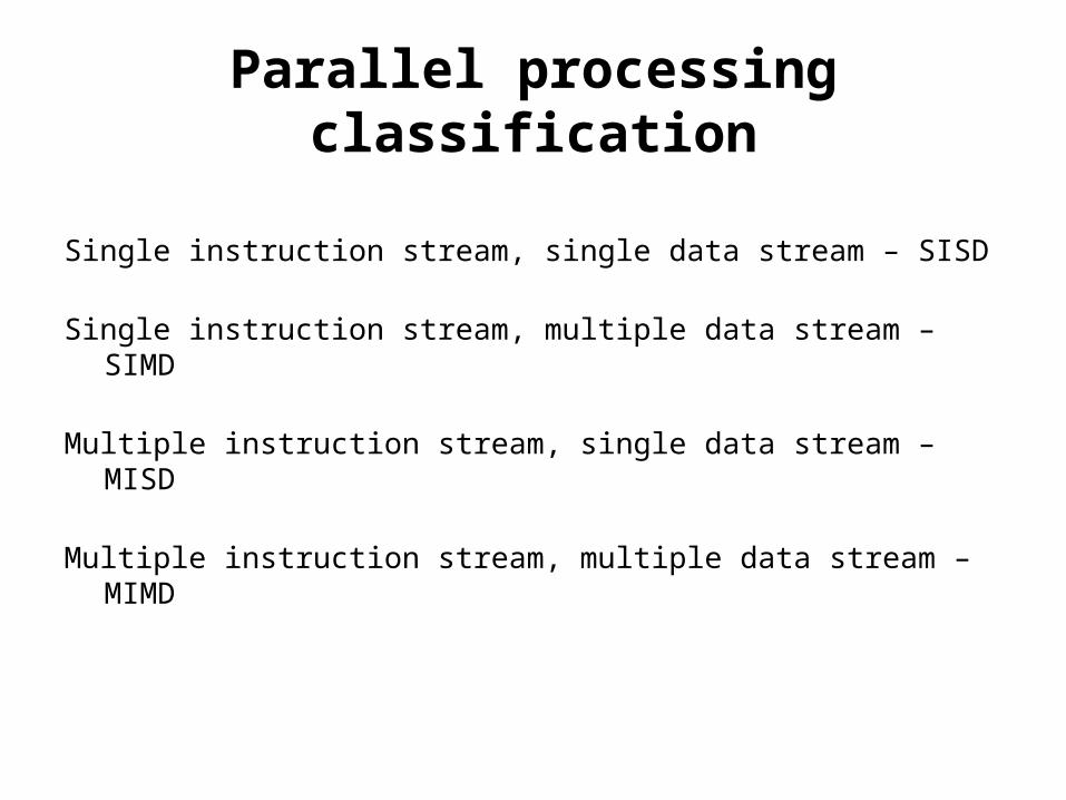
Parallel processing classification
Single instruction stream, single data stream – SISD
Single instruction stream, multiple data stream – SIMD
Multiple instruction stream, single data stream – MISD
Multiple instruction stream, multiple data stream – MIMD
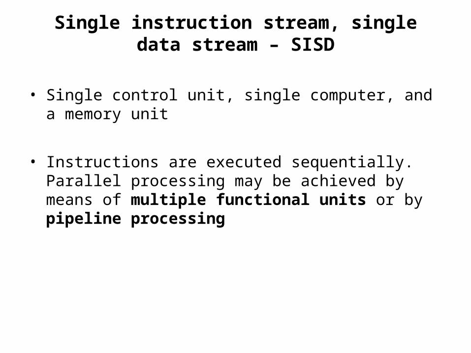
Single instruction stream, single data stream – SISD
• Single control unit, single computer, and a memory unit
• Instructions are executed sequentially. Parallel processing may be achieved by means of multiple functional units or by pipeline processing
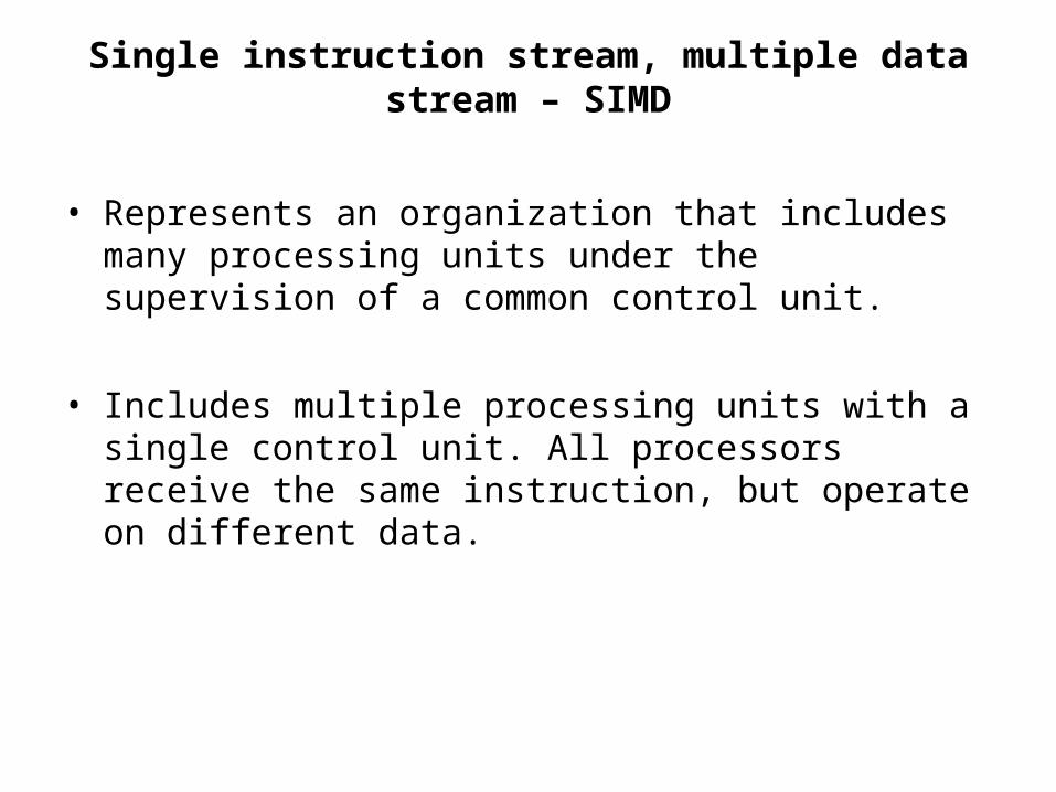
Single instruction stream, multiple data stream – SIMD
• Represents an organization that includes many processing units under the supervision of a common control unit.
• Includes multiple processing units with a single control unit. All processors receive the same instruction, but operate on different data.
Multiple instruction stream, single data stream – MISD
• Theoretical only
• processors receive different instructions, but operate on same data.
Multiple instruction stream, multiple data stream – MIMD
• A computer system capable of processing several programs at the same time.
• Most multiprocessor and multicomputer systems can be classified in this category
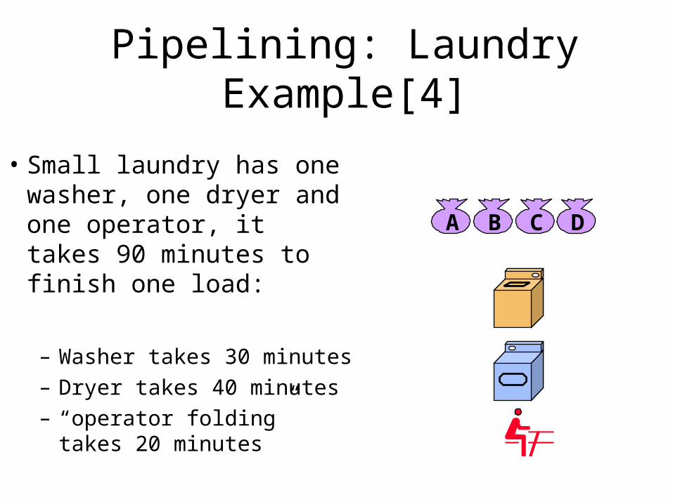
Pipelining: Laundry Example[4]
• Small laundry has one washer, one dryer and one operator, it takes 90 minutes to finish one load:
– Washer takes 30 minutes
– Dryer takes 40 minutes
– “operator folding” takes 20 minutes
A B C D
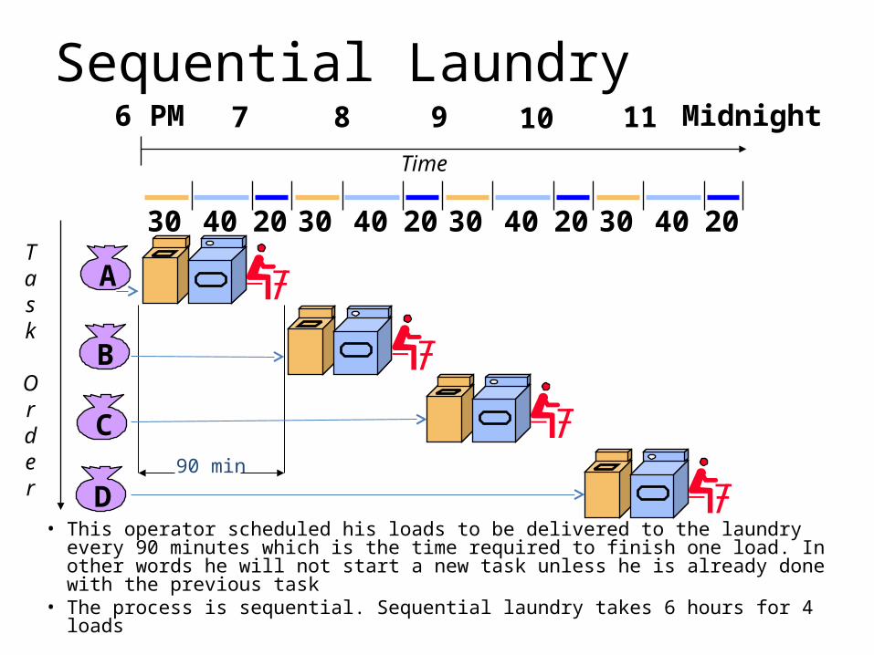
Sequential Laundry
• This operator scheduled his loads to be delivered to the laundry every 90 minutes which is the time required to finish one load. In other words he will not start a new task unless he is already done with the previous task
• The process is sequential. Sequential laundry takes 6 hours for 4 loads
A
B
C
D
30 40 20 30 40 20 30 40 20 30 40 20
6 PM 7 8 9 10 11 Midnight
Task
Order
Time
90 min
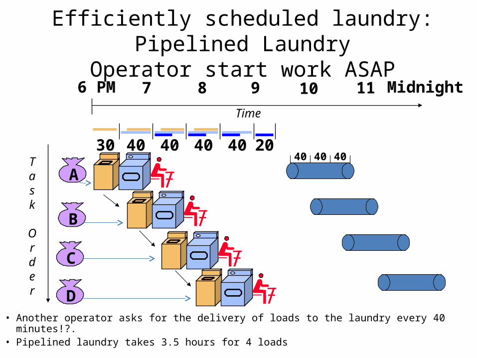
Efficiently scheduled laundry: Pipelined LaundryOperator start work ASAP
• Another operator asks for the delivery of loads to the laundry every 40 minutes!?.• Pipelined laundry takes 3.5 hours for 4 loads
A
B
C
D
6 PM 7 8 9 10 11 Midnight
Task
Order
Time
30 40 40 40 40 2040 40 40
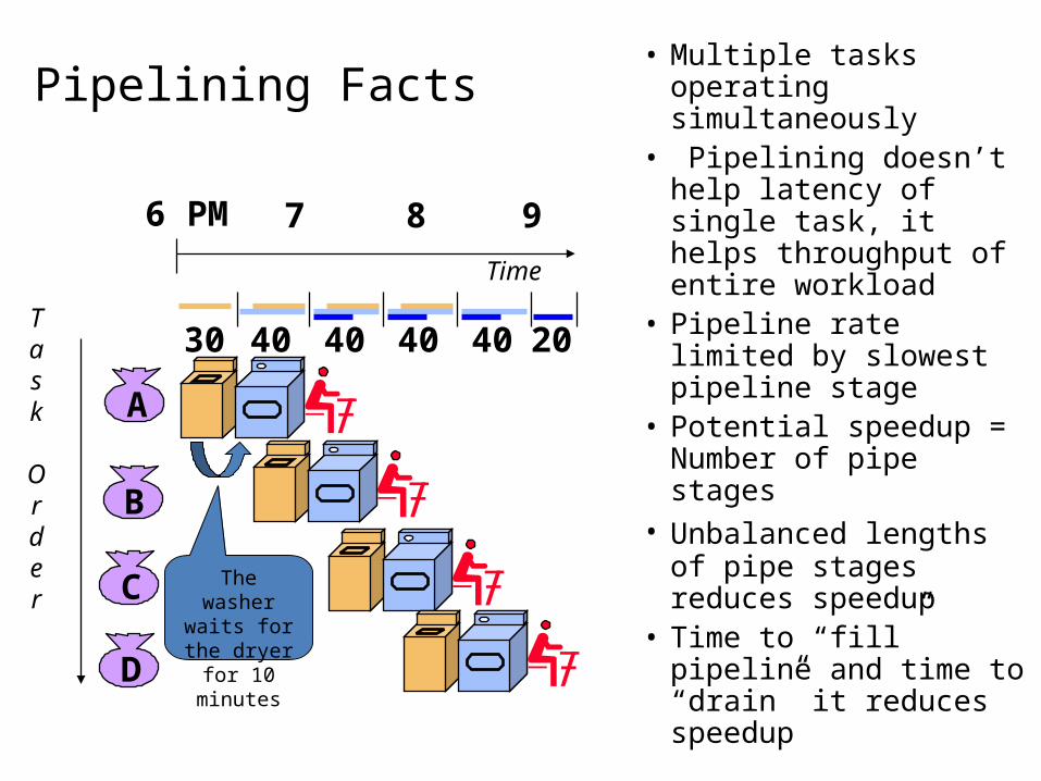
Pipelining Facts• Multiple tasks operating
simultaneously• Pipelining doesn’t help
latency of single task, it helps throughput of entire workload
• Pipeline rate limited by slowest pipeline stage
• Potential speedup = Number of pipe stages
• Unbalanced lengths of pipe stages reduces speedup
• Time to “fill” pipeline and time to “drain” it reduces speedup
A
B
C
D
6 PM 7 8 9
Task
Order
Time
30 40 40 40 40 20
The washer waits for the dryer for 10
minutes
Pipelining
• Decomposes a sequential process into segments.
• Divide the processor into segment processors each one is dedicated to a particular segment.
• Each segment is executed in a dedicated segment-processor operates concurrently with all other segments.
• Information flows through these multiple hardware segments.
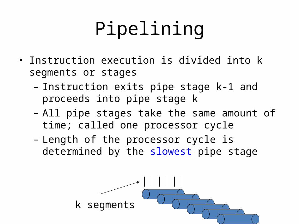
Pipelining
• Instruction execution is divided into k segments or stages
– Instruction exits pipe stage k-1 and proceeds into pipe stage k
– All pipe stages take the same amount of time; called one processor cycle
– Length of the processor cycle is determined by the slowest pipe stage
k segments
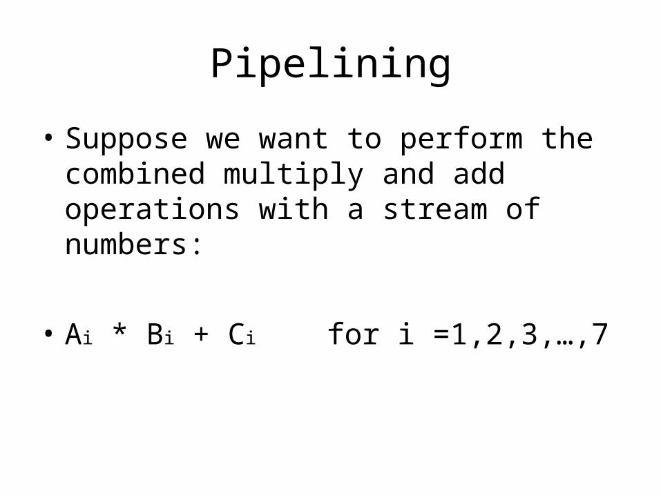
Pipelining
• Suppose we want to perform the combined multiply and add operations with a stream of numbers:
• Ai * Bi + Ci for i =1,2,3,…,7
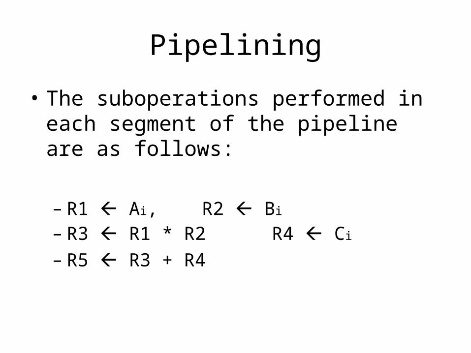
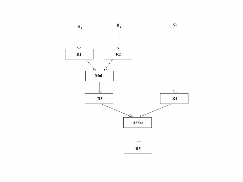
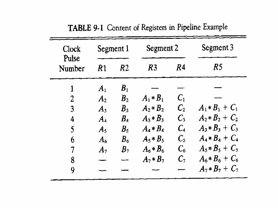
Pipelining
• The suboperations performed in each segment of the pipeline are as follows:
– R1 Ai, R2 Bi
– R3 R1 * R2 R4 Ci
– R5 R3 + R4
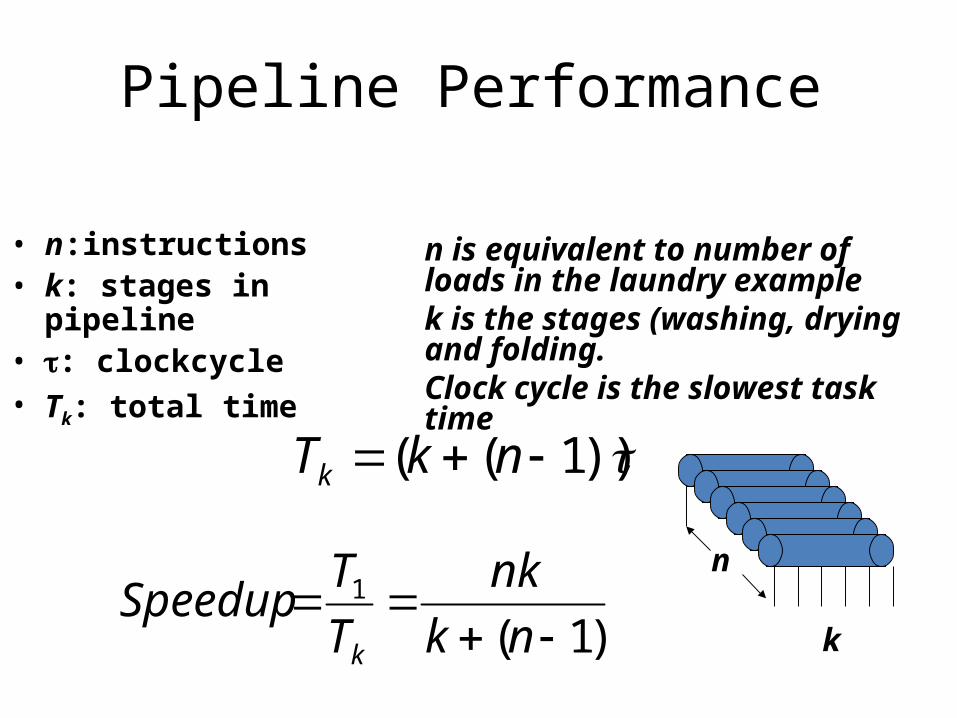
Pipeline Performance
• n:instructions • k: stages in pipeline• : clockcycle• Tk: total time
))1(( nkTk
)1(1
nk
nk
T
TSpeedup
k
n is equivalent to number of loads in the laundry examplek is the stages (washing, drying and folding.Clock cycle is the slowest task time
n
k
SPEEDUP
• • Consider a k-segment pipeline operating on n data sets. (In the above example, k = 3 and n = 4.)
• > It takes k clock cycles to fill the pipeline and get the first result from the output of the pipeline.
• After that the remaining (n - 1) results will come out at each clock cycle.
• > It therefore takes (k + n - 1) clock cycles to complete the task.
SPEEDUP
• If we execute the same task sequentially in a single processing unit, it takes (k * n) clock cycles.
• • The speedup gained by using the pipeline is:
• S = k * n / (k + n - 1 )
SPEEDUP
• S = k * n / (k + n - 1 )
For n >> k (such as 1 million data sets on a 3-stage pipeline),
• S ~ k• So we can gain the speedup which is equal to the
number of functional units for a large data sets. This is because the multiple functional units can work in parallel except for the filling and cleaning-up cycles.
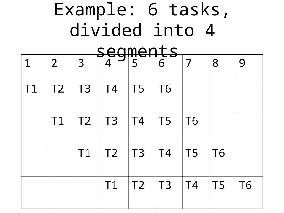
Example: 6 tasks, divided into 4 segments
1 2 3 4 5 6 7 8 9
T1 T2 T3 T4 T5 T6
T1 T2 T3 T4 T5 T6
T1 T2 T3 T4 T5 T6
T1 T2 T3 T4 T5 T6
References
1. Computer Organization and Architecture, Designing for performance by William Stallings, Prentice Hall of India.
2. Modern Computer Architecture, by Morris Mano, Prentice Hall of India.
3. Computer Architecture and Organization by John P. Hayes, McGraw Hill Publishing Company.
4. Computer Organization by V. Carl Hamacher, Zvonko G. Vranesic, Safwat G. Zaky, McGraw Hill Publishing Company.