Embed Size (px)
Citation preview
SCHOOL OF ARCHITECTURE, BUILDING & DESIGN
BACHELOR OF SCIENCE (HONOURS) IN ARCHITECTURE
BUILDING SERVICES (BLD 60903 / ARC 2423)
PROJECT 2:
BUILDING SERVICES IN PUBLIC BUILDINGS
GROUP MEMBERS:
ANDY HENG WEE XIANG 0327152
CHIA CHENG WEI 0322091
KOOI YONG KAI 0323152
LEE XIANG LOON 0322090
LOUIS DE ROZARIO 0327136
ONG EU XUAN 0319050
TUTOR: MR AZIM SULAIMAN
2
TABLE OF CONTENTS
Pages
Table of Contents 2 – 3
1.0 Abstract 4
2.0 Introduction 5
3.0 Findings & Analysis
3.1 Fire Protection System
3.1.1 Introduction 6 – 7
3.1.2 Literature Review 8 – 9
3.1.2.1 Active Fire Protection System
3.1.2.2 Passive Fire Protection System
3.1.3 Research Findings 10 – 42
3.1.3.1 Active Fire Protection System
3.1.3.1.1 Zone Configuration
3.1.3.1.2 Fire Detection
3.1.3.1.3 Portable Fire Extinguishers
3.1.3.1.4 External Fire Hydrant System
3.1.3.1.5 Hose Reel System
3.1.3.2 Passive Fire Protection System
3.1.3.2.1 Separation of Risk Area
3.1.3.2.2 Beam, Column and Separating Wall
3.1.3.2.3 Fire Doors
3.1.3.2.4 Measurement of Travel Distance to Exits
3.1.3.2.5 Exits
3
3.2 Air Conditioning System 43 – 56
3.2.1 Introduction
3.2.2 Literature Review
3.2.3 Research Findings
3.2.3.1 Air Conditioning Outdoor Unit
3.2.3.2 Air Conditioning Indoor Unit
3.3 Mechanical Ventilation System 57 – 67
3.3.1 Introduction
3.3.2 Literature Review
3.3.2.1 Extract System
3.3.2.2 Supply System
3.3.3 Research Findings
3.3.3.1 Return Air Grille
3.3.3.2 Fire Exhaust Fan
3.3.3.3 Supply Air Diffusers
3.4 Mechanical Transportation System 68 – 76
3.4.1 Introduction
3.4.2 Literature Review
3.4.3 Research Findings
3.4.3.1 Method of operation (Direct Acting)
3.4.3.2 Hydraulic Elevator Component
3.4.3.3 Safety System
4.0 Conclusion 77 – 78
5.0 References 79 – 80
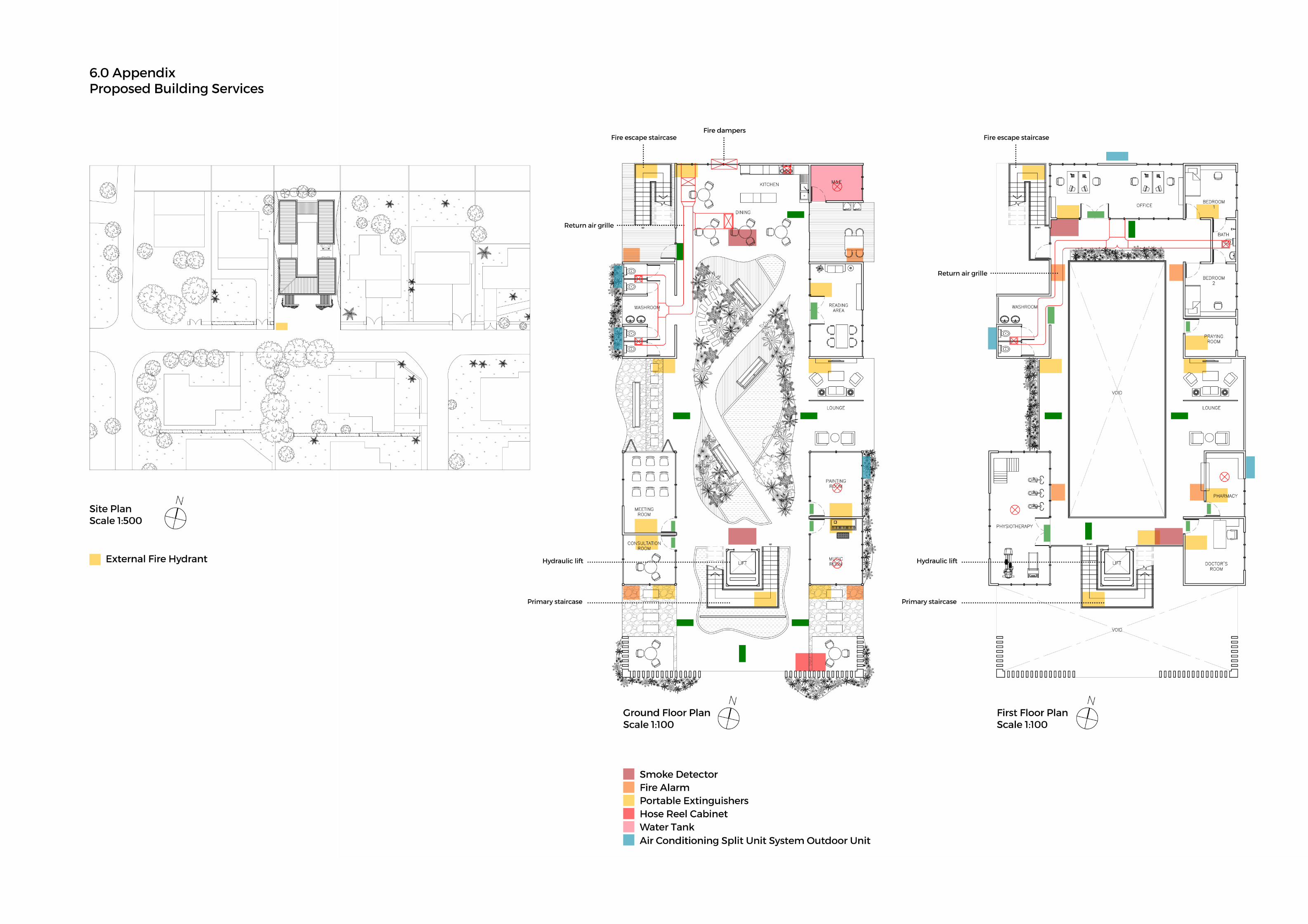
6.0 Appendix 81
4
1.0 ABSTRACT
This report is to analyse and find out the requirement of different building systems required
either based on By-Laws or human requirements onto the proposed building of an Elderly Care
Centre. It helps to understand to provide a better design and environment for the occupants of
the building.
The report is carried out to find out the importance of a fire protective system and its safety for
the users. Air conditioning system and mechanical ventilation system both provide extra
comfort through cool and movement of air, respectively. A mechanical transportation system
is crucial for the elderly to access to upper floors due to certain disabilities.
These four systems include fire protective system, air conditioning system, mechanical
ventilation system and mechanical transportation system will be further discussed and
elaborated further in the report.
5
2.0 INTRODUCTION
The site of the Elderly Care Community Centre in Taman Kanagapuram, Old Klang Road in
Petaling Jaya is a flat rectangular plot of 22 metres wide and 44 metres long in between two
residential bungalows. The idea was to create functional spaces embracing a central courtyard
and freeing the building through multiple open views along the long stretch of corridors. The
centre is built for the seniors in the community to create a dynamic social interaction and foster
good relationship among the staff members of the centre, family, friends, relatives and
neighbouring residents. The centre aims to bring out the positivity to counteract the dull and
slow-paced life seen in the existing nursing homes within a few kilometres radius through
interaction and functional spaces.
The centre provides a medium and platform for the common public to engage and participate
in a wide range of leisure and education programmes, an initiative that is not present in the
other nursing homes. It helps to provide a significant value to the neighbourhood context due
to rapid urbanization surrounding the area.
The Elderly Care Centre requires different building systems to become one whole functional
unit. Each system will play different roles for the safety, comfort and basic requirement for the
building occupants in order to properly function by fulling the requirement of By-Laws and the
elderly themselves.
6
3.0 FINDINGS & ANALYSIS
3.1 Fire Protection System
3.1.1 Introduction
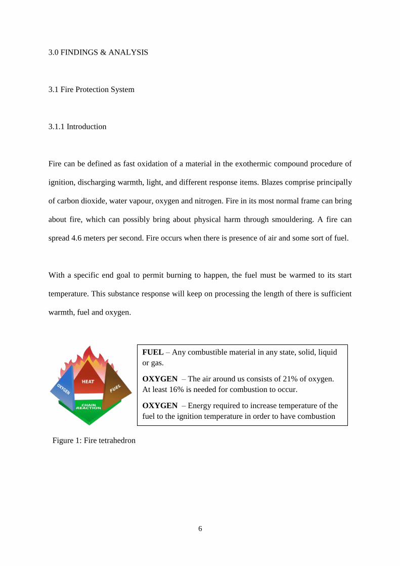
Fire can be defined as fast oxidation of a material in the exothermic compound procedure of
ignition, discharging warmth, light, and different response items. Blazes comprise principally
of carbon dioxide, water vapour, oxygen and nitrogen. Fire in its most normal frame can bring
about fire, which can possibly bring about physical harm through smouldering. A fire can
spread 4.6 meters per second. Fire occurs when there is presence of air and some sort of fuel.
With a specific end goal to permit burning to happen, the fuel must be warmed to its start
temperature. This substance response will keep on processing the length of there is sufficient
warmth, fuel and oxygen.
Figure 1: Fire tetrahedron
FUEL – Any combustible material in any state, solid, liquid
or gas.
OXYGEN – The air around us consists of 21% of oxygen.
At least 16% is needed for combustion to occur.
OXYGEN – Energy required to increase temperature of the
fuel to the ignition temperature in order to have combustion
process.
7
These four elements must be present at the same time for a fire to be produced:
Combustible material or fuel
Exothermic reaction of the fire
Sufficient heat to maintain ignition temperature
Sufficient oxygen to maintain the process of combustion
FUEL + OXYGEN (from the air) = COMBUSTION PRODUCT (CO2 + H2O) + HEAT ENERGY
Cost effective active and passive fire protection system should be intended to join proficient in
new offices and redesign ventures. Aloof and dynamic fire protection systems are compelling
in recognizing, containing, controlling and quenching a fire occasion in the early stage. In each
building, the fire architects are required to guarantee a sensible level of assurance of human
life from flame and the item ignition and additionally to lessen the potential misfortune from
flame.
8
3.1.2 Literature Review
3.1.2.1 Active Fire Protection System
Both the active and passive fire protection systems are basic in guaranteeing the well-being
and security of the users in the building. Active fire protection system is about a procedure or
an approach to caution the tenants or clients, furthermore, the endeavours to control or quench
the fire by utilizing the strategies of applying programmed or physically worked fire
mechanical framework. The techniques that are incorporated into this systems are the fire
discoveries which incorporate smoke/warm discovery, triggers, alerts, pump room and others.
These systems, particularly the fire alert systems, are critical to advise the clients in the building
that departure is vital subsequent to recognizing the smoke or warmth amid the fire. Sprinkle
frameworks which are incorporated into the dynamic fire insurance framework are vital to back
off the rate of flame as the glass of the sprinkles will blast to discharge water when there is
intemperate warmth from the fire. Active fire protection systems are especially helpful in
bigger structures where it is harder to ventilate the focal spaces through common openings, for
example, the windows, so smoke and warmth extraction frameworks are frequently utilized.
3.1.2.2 Passive Fire Protection System
Another system being utilized is the passive fire protection system which is presented in parts
of the building or structure as an obstruction to the fire and back off the rate of fire and smoke
from spreading to different territories or parts of the building. A standout amongst the most
critical elements in detached fire insurance framework is the assurance of escape courses from
the fire and smoke to drag out the escape time by outlining and bringing heatproof trademark
9
into the components of the building. There are two key critical segments in uninvolved fire
assurance framework. The first is the compartmentalization of the spaces with fire-evaluated
assembling parts, for example, the fire-appraised dividers and entryways are mulled over to
counteract the fire spreading from space to space. This is critical in making an oxygen
hindrance and compartmentalize the spaces amid a fire. The fire-evaluated divider not just
speak to an immediate shield which the fire would need to physically blaze through to pass,
additionally, a stifle point for air amid the fire. The second part that is extremely critical is the
way to get out that decides the system and proficiency of escape to outside of the working amid
the occasion of flame and crisis. This includes the use of leave signs, crisis staircase plan and
others.
10
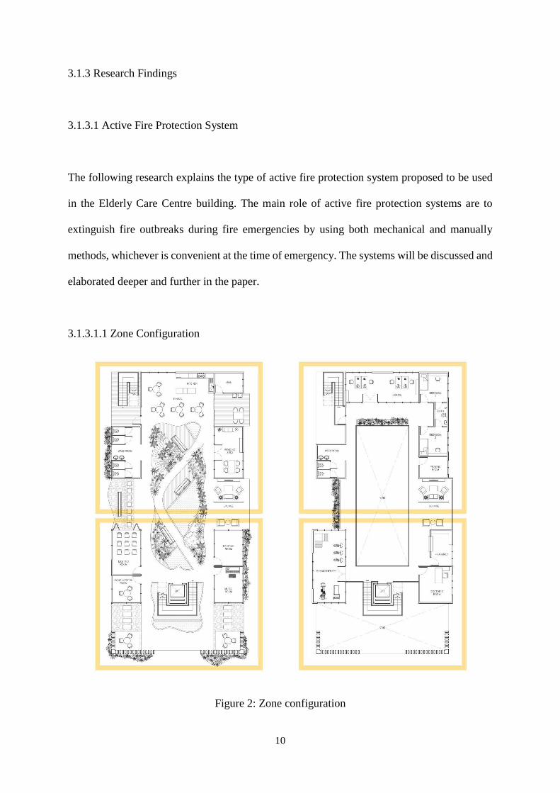
3.1.3 Research Findings
3.1.3.1 Active Fire Protection System
The following research explains the type of active fire protection system proposed to be used
in the Elderly Care Centre building. The main role of active fire protection systems are to
extinguish fire outbreaks during fire emergencies by using both mechanical and manually
methods, whichever is convenient at the time of emergency. The systems will be discussed and
elaborated deeper and further in the paper.
3.1.3.1.1 Zone Configuration
Figure 2: Zone configuration
11
Guide to Fire Protection in Malaysia 13.1.2 (iii)(a): Maximum floor area should not
exceed 200m2.
The total floor area each floor is 400m2. The maximum fire detection floor area should not
exceed 200m2, thus the building is divided into four zones to ensure effective smoke detection.
3.1.3.1.2 Fire Detection
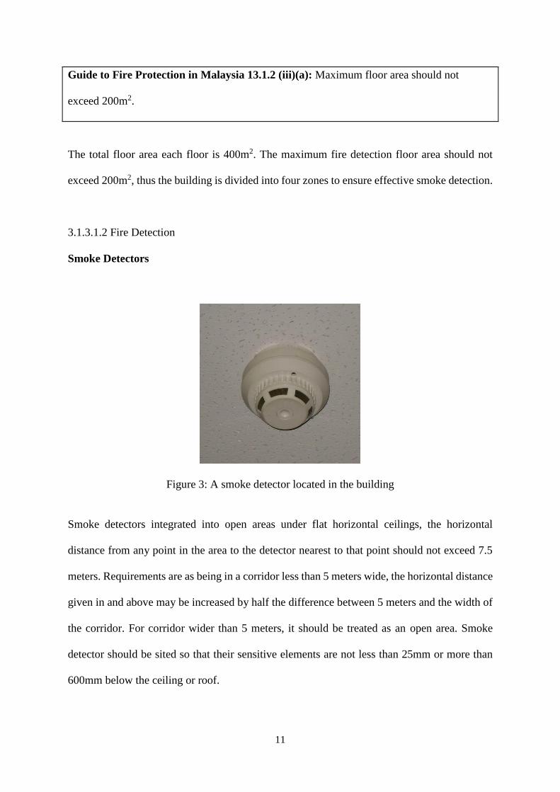
Smoke Detectors
Figure 3: A smoke detector located in the building
Smoke detectors integrated into open areas under flat horizontal ceilings, the horizontal
distance from any point in the area to the detector nearest to that point should not exceed 7.5
meters. Requirements are as being in a corridor less than 5 meters wide, the horizontal distance
given in and above may be increased by half the difference between 5 meters and the width of
the corridor. For corridor wider than 5 meters, it should be treated as an open area. Smoke
detector should be sited so that their sensitive elements are not less than 25mm or more than
600mm below the ceiling or roof.
12
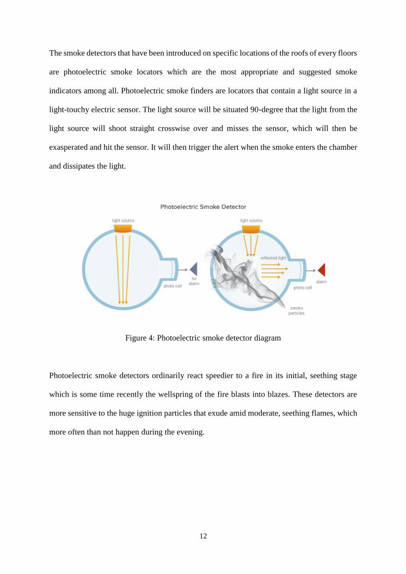
The smoke detectors that have been introduced on specific locations of the roofs of every floors
are photoelectric smoke locators which are the most appropriate and suggested smoke
indicators among all. Photoelectric smoke finders are locators that contain a light source in a
light-touchy electric sensor. The light source will be situated 90-degree that the light from the
light source will shoot straight crosswise over and misses the sensor, which will then be
exasperated and hit the sensor. It will then trigger the alert when the smoke enters the chamber
and dissipates the light.
Figure 4: Photoelectric smoke detector diagram
Photoelectric smoke detectors ordinarily react speedier to a fire in its initial, seething stage
which is some time recently the wellspring of the fire blasts into blazes. These detectors are
more sensitive to the huge ignition particles that exude amid moderate, seething flames, which
more often than not happen during the evening.
13
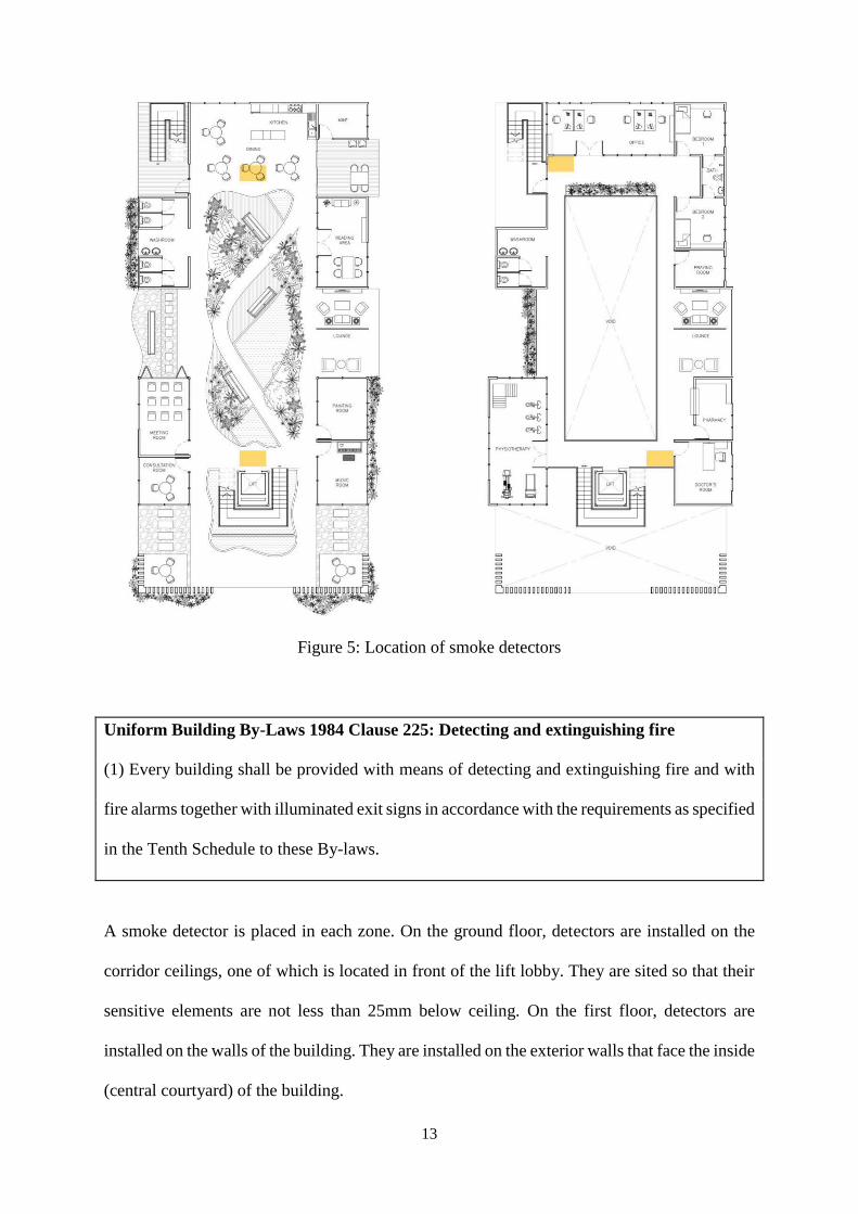
Figure 5: Location of smoke detectors
Uniform Building By-Laws 1984 Clause 225: Detecting and extinguishing fire
(1) Every building shall be provided with means of detecting and extinguishing fire and with
fire alarms together with illuminated exit signs in accordance with the requirements as specified
in the Tenth Schedule to these By-laws.
A smoke detector is placed in each zone. On the ground floor, detectors are installed on the
corridor ceilings, one of which is located in front of the lift lobby. They are sited so that their
sensitive elements are not less than 25mm below ceiling. On the first floor, detectors are
installed on the walls of the building. They are installed on the exterior walls that face the inside
(central courtyard) of the building.
14
Audio Alarm Sounder
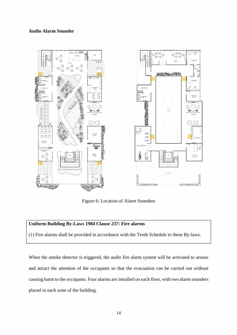
Figure 6: Location of Alarm Sounders
Uniform Building By-Laws 1984 Clause 237: Fire alarms
(1) Fire alarms shall be provided in accordance with the Tenth Schedule to these By-laws.
When the smoke detector is triggered, the audio fire alarm system will be activated to arouse
and attract the attention of the occupants so that the evacuation can be carried out without
causing harm to the occupants. Four alarms are installed on each floor, with two alarm sounders
placed in each zone of the building.
15
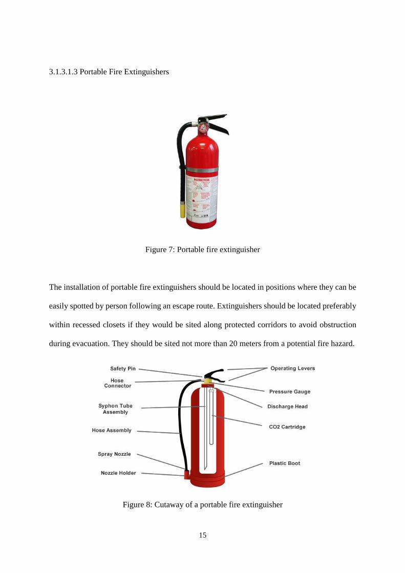
3.1.3.1.3 Portable Fire Extinguishers
Figure 7: Portable fire extinguisher
The installation of portable fire extinguishers should be located in positions where they can be
easily spotted by person following an escape route. Extinguishers should be located preferably
within recessed closets if they would be sited along protected corridors to avoid obstruction
during evacuation. They should be sited not more than 20 meters from a potential fire hazard.
Figure 8: Cutaway of a portable fire extinguisher
16
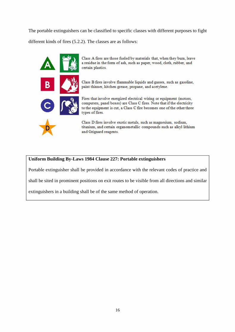
The portable extinguishers can be classified to specific classes with different purposes to fight
different kinds of fires (5.2.2). The classes are as follows:
Uniform Building By-Laws 1984 Clause 227: Portable extinguishers
Portable extinguisher shall be provided in accordance with the relevant codes of practice and
shall be sited in prominent positions on exit routes to be visible from all directions and similar
extinguishers in a building shall be of the same method of operation.
17
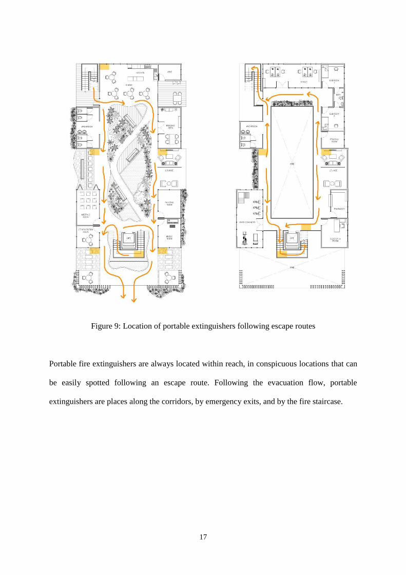
Figure 9: Location of portable extinguishers following escape routes
Portable fire extinguishers are always located within reach, in conspicuous locations that can
be easily spotted following an escape route. Following the evacuation flow, portable
extinguishers are places along the corridors, by emergency exits, and by the fire staircase.
18
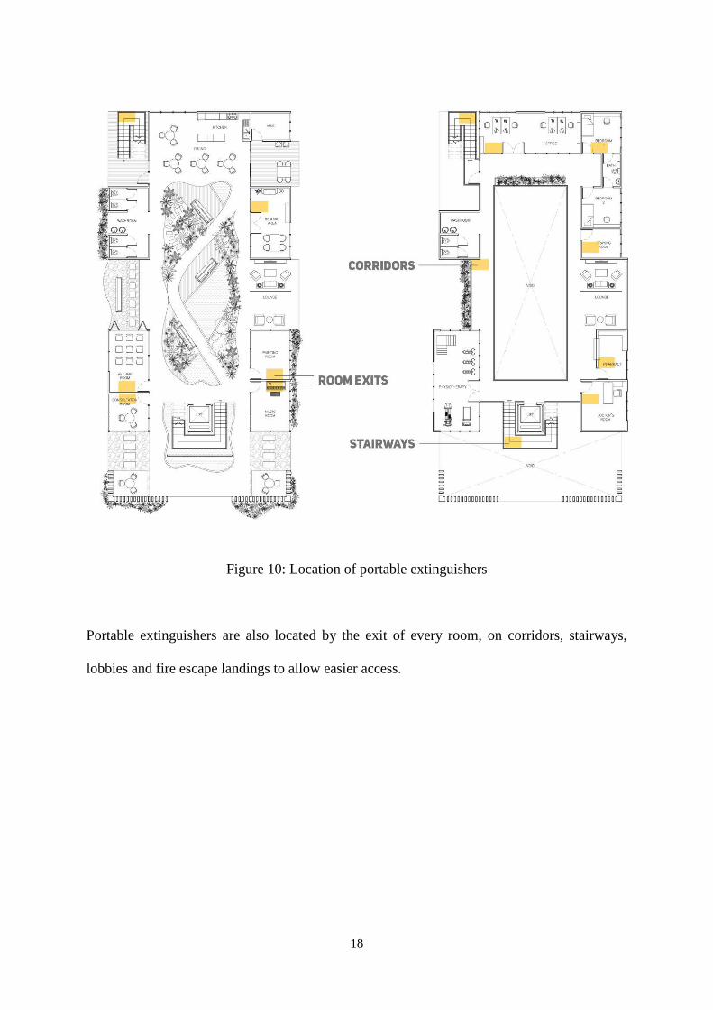
Figure 10: Location of portable extinguishers
Portable extinguishers are also located by the exit of every room, on corridors, stairways,
lobbies and fire escape landings to allow easier access.
19
3.1.3.1.4 External Fire Hydrant System
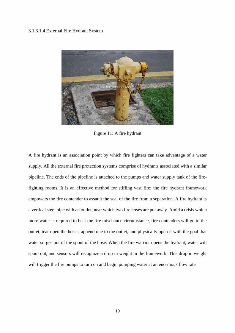
Figure 11: A fire hydrant
A fire hydrant is an association point by which fire fighters can take advantage of a water
supply. All the external fire protection systems comprise of hydrants associated with a similar
pipeline. The ends of the pipeline is attached to the pumps and water supply tank of the fire-
fighting rooms. It is an effective method for stifling vast fire; the fire hydrant framework
empowers the fire contender to assault the seal of the fire from a separation. A fire hydrant is
a vertical steel pipe with an outlet, near which two fire hoses are put away. Amid a crisis which
more water is required to beat the fire mischance circumstance, fire contenders will go to the
outlet, tear open the hoses, append one to the outlet, and physically open it with the goal that
water surges out of the spout of the hose. When the fire warrior opens the hydrant, water will
spout out, and sensors will recognize a drop in weight in the framework. This drop in weight
will trigger the fire pumps to turn on and begin pumping water at an enormous flow rate
20
According to the ‘Guide to Fire Protection in Malaysia’, under Chapter 6: External Fire
Hydrant System, 6.2.2 Hydrant Outlets, pillar hydrants should be located at not more than 30
meters away from the breaching inlet for the building. The hydrant should not be less than 6
meters from the building so as to allow firemen to operate the hydrant safely, away from the
burning building and falling debris. The hydrant mains are usually laid underground. The
piping is usually of cement lined steel pipe.
In 6.2.3 Hydrant Pumps, it is stated that the hydrant pumps draw water from the fire water
storage tank and two sets of pump, one on duty and the other on standby, are provided. The
standby hydrant pump set should be supplied with power from the emergency generator if this
is available. Electrical cabling to supply power to the hydrant pumps should be of fire related
type of cable. The hydrant pump set should be protected from the weather and away from
locations likely to be flooded.
Under 6.2.4 Hydrant Tanks, it is implied that the fire water storage tank should be sized for a
minimum effective capacity of 135,000 litres and should be refilled automatically from a water
supply pipe capable of providing a minimum flow rate of 1,200 l/min. The tank may be of
pressed steel, fiberglass reinforced polyester or concrete. The tank should be compartmented
unless they are of reinforced concrete and water level indicator should be provided to show the
amount of water available.
And lastly, on 6.4.5 Pump Starter Panels and Controls, it stated that the pump starter panel
should be complete with indicator lights. Ventilation slots should be provided with insect
screen to prevent entry of vermin. Hydrant pumps shall start automatically upon actuation of
21
the pressure switches but should only be stopped manually. The pressure switches are normally
installed in the test and drain line on the pump discharge side.
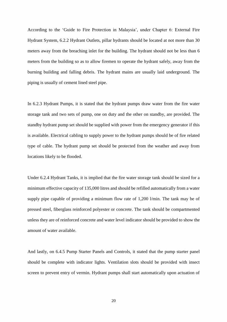
Figure 12: Main parts of a typical fire hydrant
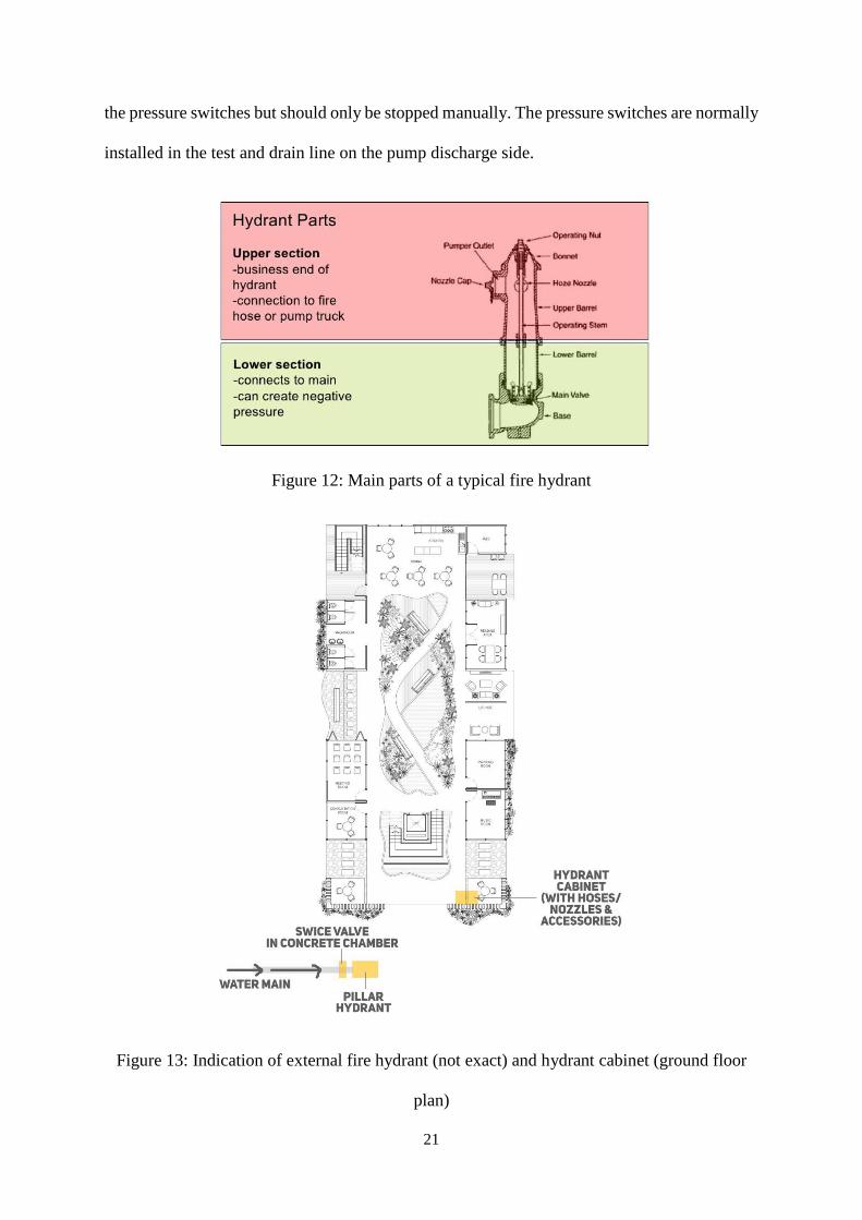
Figure 13: Indication of external fire hydrant (not exact) and hydrant cabinet (ground floor
plan)
22
Uniform Building By-Laws 1984 Clause 225: Detecting and extinguishing fire
(2) Every building shall be served by at least one fire hydrant located not more than 91.5 meters
from the nearest point of fire brigade access.
(3) Depending on the size and location of the building and the provision of access for fire
appliances, additional fire hydrant shall be provided as may be required by the Fire Authority.
In residential lots, external fire hydrant is located by the side of the street, they retrieve water
supply from the public water main. On our site, the fire hydrant was already supplied for in the
neighbourhood.
A hydrant cabinet that stores equipment and accessories such as water hoses and nozzles is
located by the main entrance of the building to allow easier access during outbreaks.
23
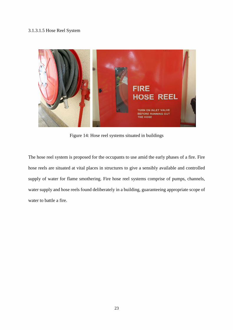
3.1.3.1.5 Hose Reel System
Figure 14: Hose reel systems situated in buildings
The hose reel system is proposed for the occupants to use amid the early phases of a fire. Fire
hose reels are situated at vital places in structures to give a sensibly available and controlled
supply of water for flame smothering. Fire hose reel systems comprise of pumps, channels,
water supply and hose reels found deliberately in a building, guaranteeing appropriate scope of
water to battle a fire.
24
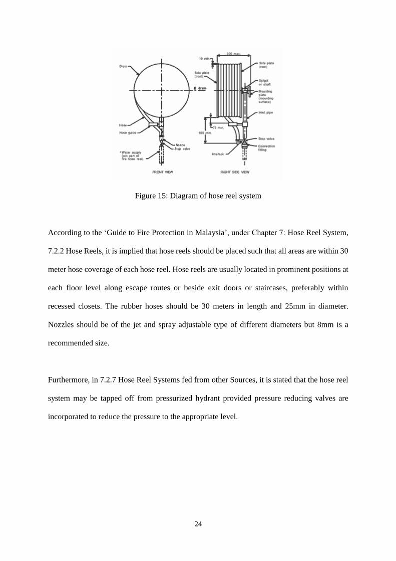
Figure 15: Diagram of hose reel system
According to the ‘Guide to Fire Protection in Malaysia’, under Chapter 7: Hose Reel System,
7.2.2 Hose Reels, it is implied that hose reels should be placed such that all areas are within 30
meter hose coverage of each hose reel. Hose reels are usually located in prominent positions at
each floor level along escape routes or beside exit doors or staircases, preferably within
recessed closets. The rubber hoses should be 30 meters in length and 25mm in diameter.
Nozzles should be of the jet and spray adjustable type of different diameters but 8mm is a
recommended size.
Furthermore, in 7.2.7 Hose Reel Systems fed from other Sources, it is stated that the hose reel
system may be tapped off from pressurized hydrant provided pressure reducing valves are
incorporated to reduce the pressure to the appropriate level.
25
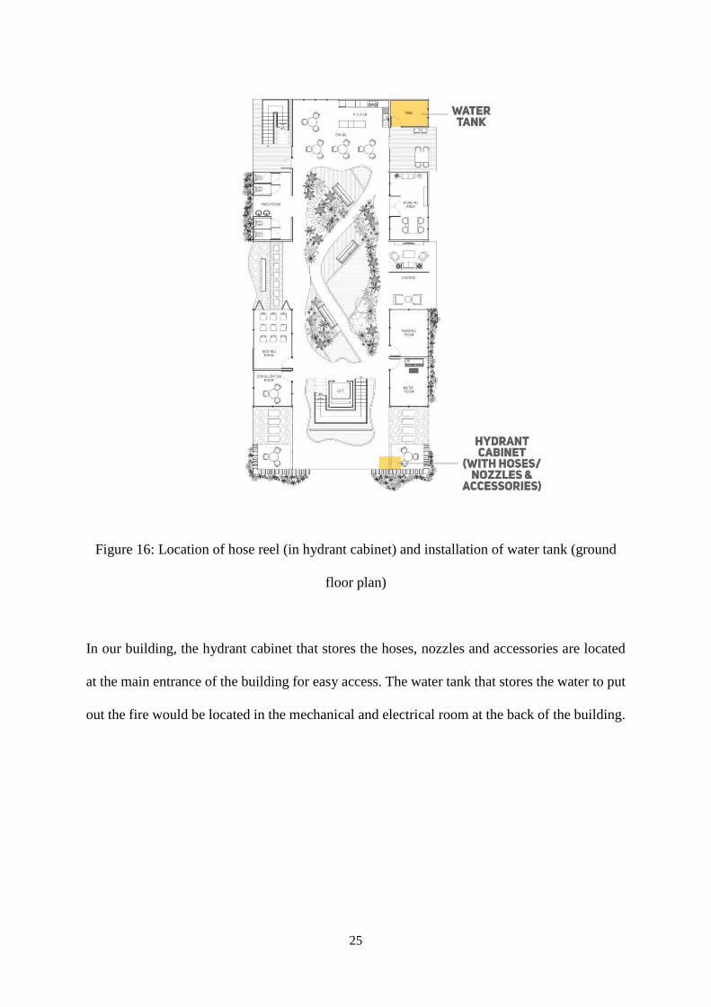
Figure 16: Location of hose reel (in hydrant cabinet) and installation of water tank (ground
floor plan)
In our building, the hydrant cabinet that stores the hoses, nozzles and accessories are located
at the main entrance of the building for easy access. The water tank that stores the water to put
out the fire would be located in the mechanical and electrical room at the back of the building.
26
3.1.3.2 Passive Fire Protection System
The following research explains the types of passive fire system proposed to be used in the
building. The main role of passive fire system is to resist or slow down the spread of fire
outbreaks during fire emergencies by using building or structural systems in the building. The
system will be discussed and elaborated deeper and further in the paper.
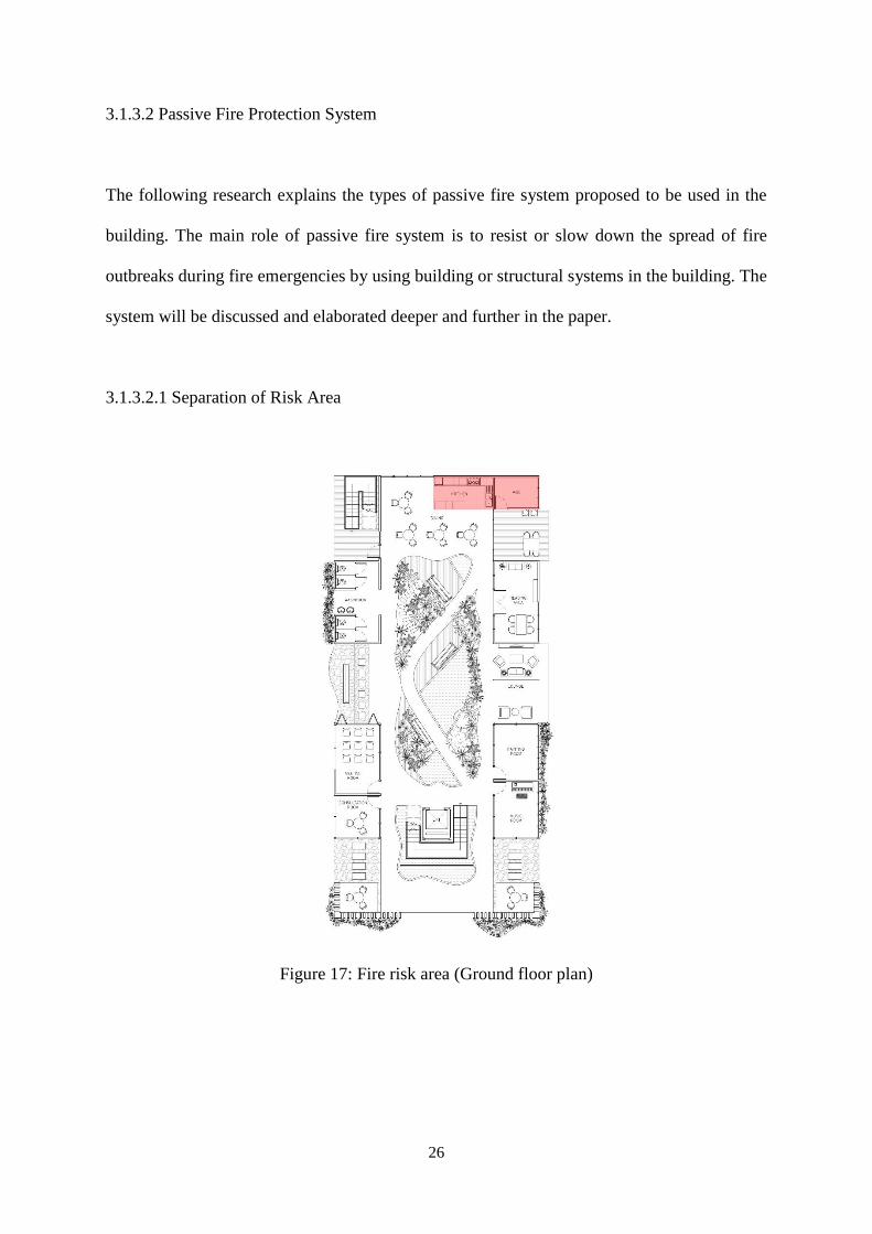
3.1.3.2.1 Separation of Risk Area
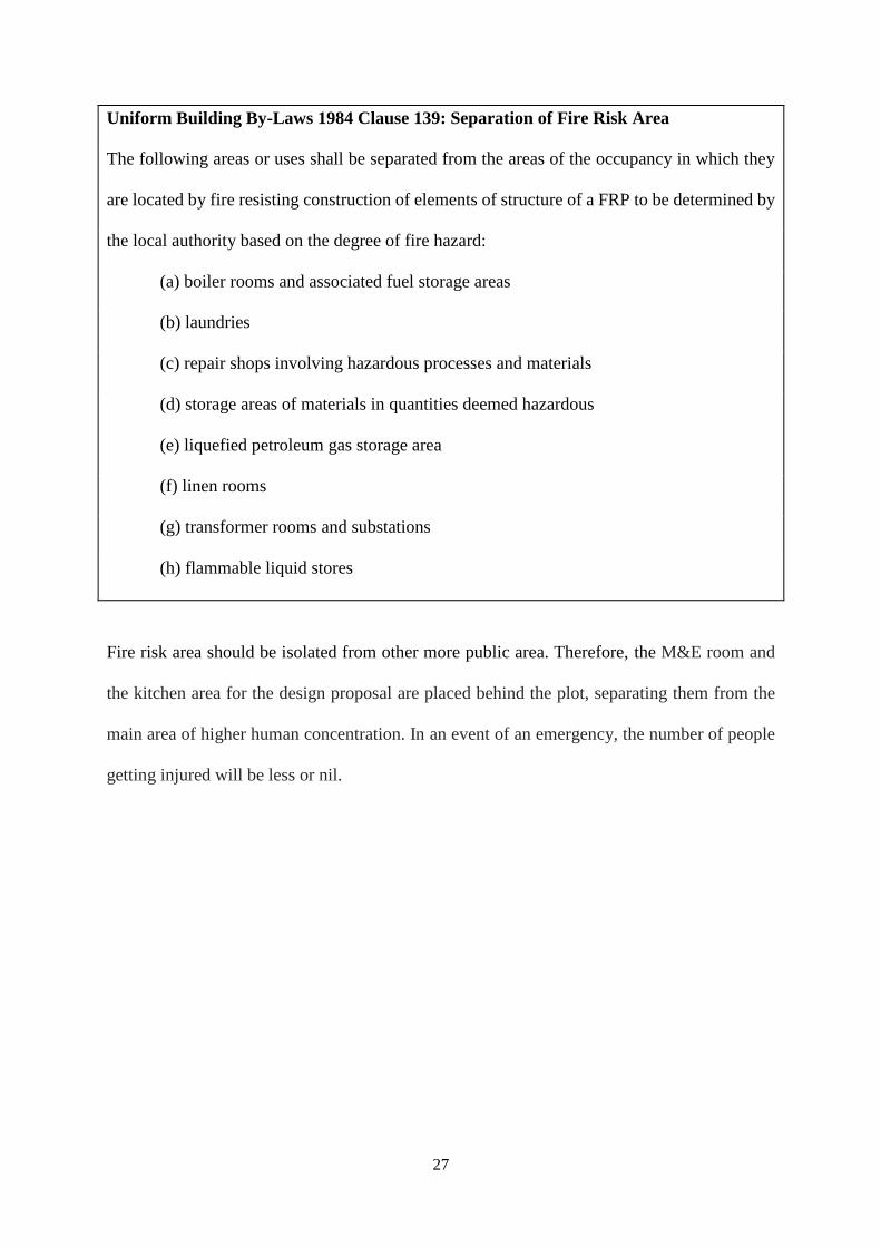
Figure 17: Fire risk area (Ground floor plan)
27
Uniform Building By-Laws 1984 Clause 139: Separation of Fire Risk Area
The following areas or uses shall be separated from the areas of the occupancy in which they
are located by fire resisting construction of elements of structure of a FRP to be determined by
the local authority based on the degree of fire hazard:
(a) boiler rooms and associated fuel storage areas
(b) laundries
(c) repair shops involving hazardous processes and materials
(d) storage areas of materials in quantities deemed hazardous
(e) liquefied petroleum gas storage area
(f) linen rooms
(g) transformer rooms and substations
(h) flammable liquid stores
Fire risk area should be isolated from other more public area. Therefore, the M&E room and
the kitchen area for the design proposal are placed behind the plot, separating them from the
main area of higher human concentration. In an event of an emergency, the number of people
getting injured will be less or nil.
28
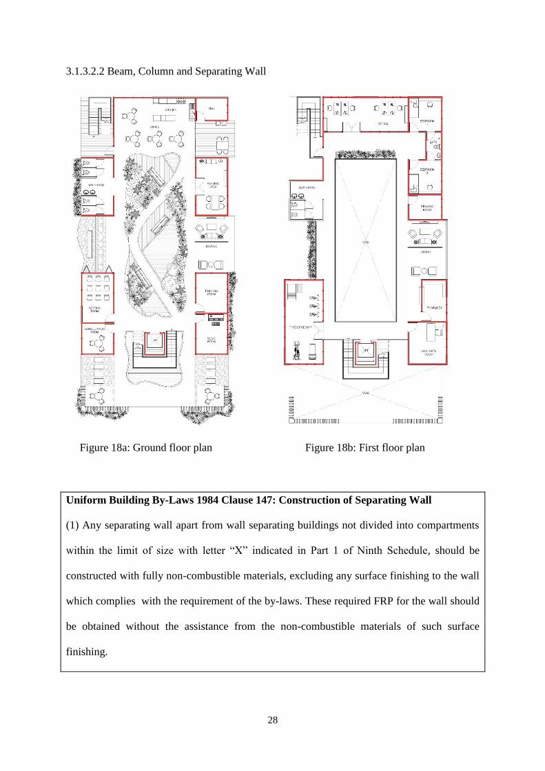
3.1.3.2.2 Beam, Column and Separating Wall
Figure 18a: Ground floor plan Figure 18b: First floor plan
Uniform Building By-Laws 1984 Clause 147: Construction of Separating Wall
(1) Any separating wall apart from wall separating buildings not divided into compartments
within the limit of size with letter “X” indicated in Part 1 of Ninth Schedule, should be
constructed with fully non-combustible materials, excluding any surface finishing to the wall
which complies with the requirement of the by-laws. These required FRP for the wall should
be obtained without the assistance from the non-combustible materials of such surface
finishing.
29
(2) Any beams or column, any structure carrying the load, or separating wall is also required
to be constructed of non-combustible materials which comply the requirement of the paragraph
above (1) in terms of combustibility.
Referring to the Fifth Schedule of Uniform Building By-Laws 1984, our building belongs to
the ‘INSTITUTIONAL’ group as our building, an Elderly Care Centre, is being used as living
accommodation for person suffering from disabilities due to old age or illness. Therefore, in
the Ninth Schedule of Uniform Building By-Laws 1984, the minimum period of fire resistance
under this group for the elements of structure of the ground and upper storey should be at least
one hour.
Therefore, the walls for our building proposal will fulfil the criteria of having FRP of an hour
or more. This is to allow the elderly and other occupants to leave the building during an event
of a fire especially in a room since the building is more to an open clustered design. These
walls will protect the occupants from fire during the period of escape.
Uniform Building By-Laws 1984 Clause 143: Beam or Column
Any beam or column forming part of, and any structure carrying, and external wall which is
required to be constructed of non-combustible materials shall comply with the provisions of
paragraph (3) of by-law 142 as to non-combustibility.
30
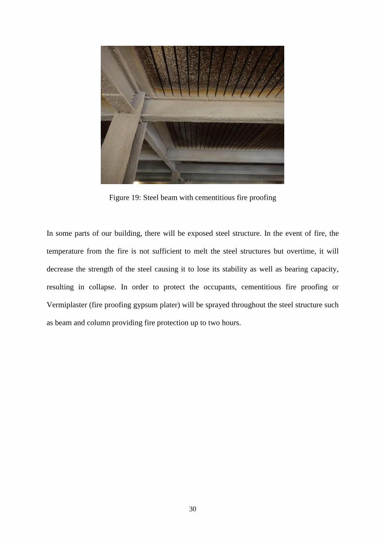
Figure 19: Steel beam with cementitious fire proofing
In some parts of our building, there will be exposed steel structure. In the event of fire, the
temperature from the fire is not sufficient to melt the steel structures but overtime, it will
decrease the strength of the steel causing it to lose its stability as well as bearing capacity,
resulting in collapse. In order to protect the occupants, cementitious fire proofing or
Vermiplaster (fire proofing gypsum plater) will be sprayed throughout the steel structure such
as beam and column providing fire protection up to two hours.
31
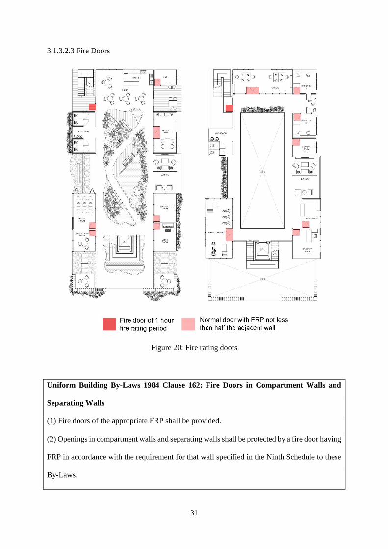
3.1.3.2.3 Fire Doors
Figure 20: Fire rating doors
Uniform Building By-Laws 1984 Clause 162: Fire Doors in Compartment Walls and
Separating Walls
(1) Fire doors of the appropriate FRP shall be provided.
(2) Openings in compartment walls and separating walls shall be protected by a fire door having
FRP in accordance with the requirement for that wall specified in the Ninth Schedule to these
By-Laws.
32
The minimum Fire Rating Period (FRP) of the fire doors in the proposed building will be at
least half an hour. The function of the space determine the fire rating period of the fire doors.
Uniform Building By-Laws 1984 Clause 163: Half Hour and One Hour Doors
Fire doors conforming to the method of construction as stipulated below shall be deemed to
meet the requirement of the specified FRP:
(a) (i) Fire doors having FRP of half hour - a single door of 900mm x 2100m high or
double doors 1800mm x 2100mm high should be constructed of solid hardwood core of not
less than 37mm laminated with adhesives conforming to either BS 745 “Animal Glues”, or
BS1204, “Synthetic resin adhesives (phenolic and aminoplastic) for wood” Part 1, “Gap filling
adhesives”, or BS1444, “Cold setting casein glue for wood”, faced both sides with plywood to
a total thickness of more than 43mm with all edges finished with a solid edge strip full width
of the door. The meeting stiles of double doors shall be rabbeted 12mm deep or may be butted
provided the clearance is kept to a minimum.
(b) (i) Fire doors having FRP of one hour – single door not exceeding 900mm x 2100m
high or double doors not exceeding 1800mm x 2100mm high constructed as for (a) for half
hour fire door but incorporating both faces either externally or beneath the plywood faces a
layer of asbestos insulating board to BS3536 (not asbestos cement) not less than 3mm thick.
33
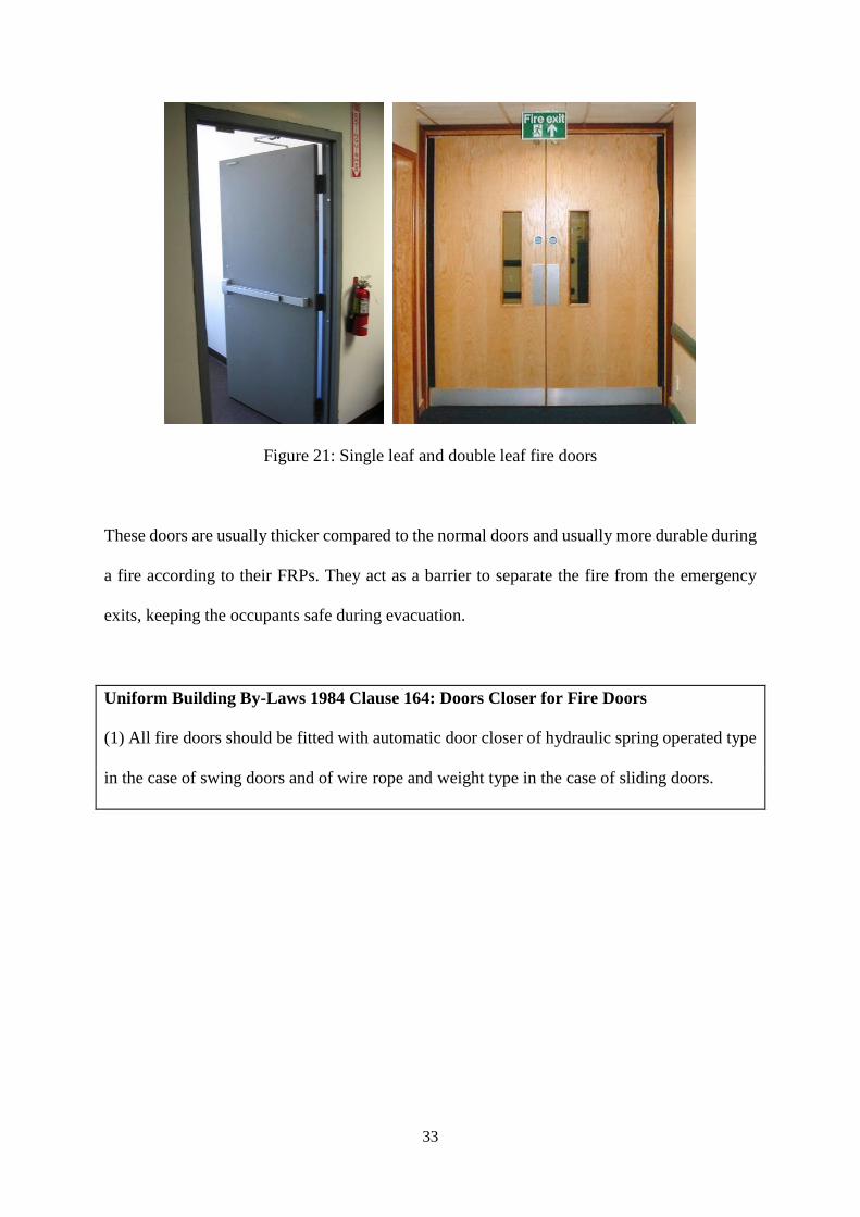
Figure 21: Single leaf and double leaf fire doors
These doors are usually thicker compared to the normal doors and usually more durable during
a fire according to their FRPs. They act as a barrier to separate the fire from the emergency
exits, keeping the occupants safe during evacuation.
Uniform Building By-Laws 1984 Clause 164: Doors Closer for Fire Doors
(1) All fire doors should be fitted with automatic door closer of hydraulic spring operated type
in the case of swing doors and of wire rope and weight type in the case of sliding doors.
34
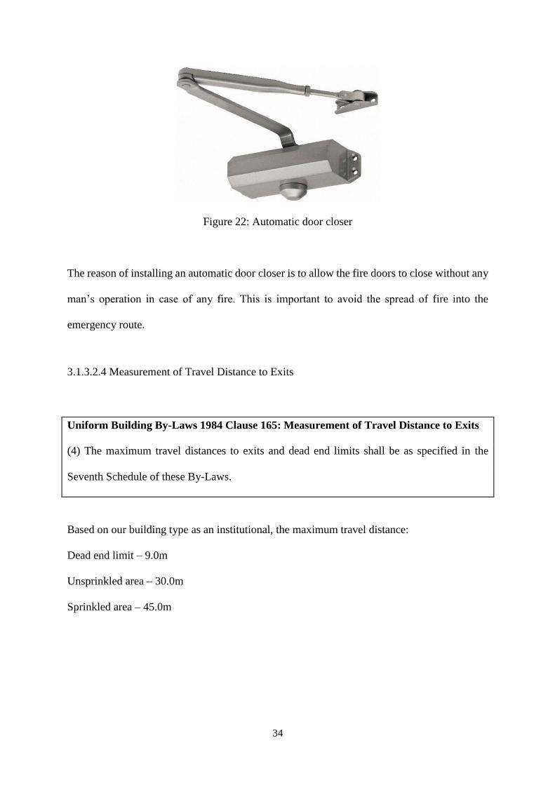
Figure 22: Automatic door closer
The reason of installing an automatic door closer is to allow the fire doors to close without any
man’s operation in case of any fire. This is important to avoid the spread of fire into the
emergency route.
3.1.3.2.4 Measurement of Travel Distance to Exits
Uniform Building By-Laws 1984 Clause 165: Measurement of Travel Distance to Exits
(4) The maximum travel distances to exits and dead end limits shall be as specified in the
Seventh Schedule of these By-Laws.
Based on our building type as an institutional, the maximum travel distance:
Dead end limit – 9.0m
Unsprinkled area – 30.0m
Sprinkled area – 45.0m
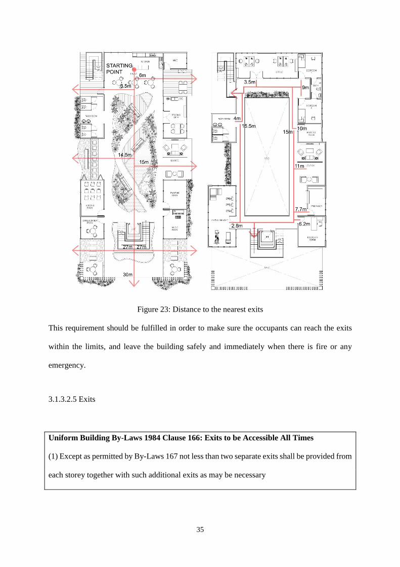
35
Figure 23: Distance to the nearest exits
This requirement should be fulfilled in order to make sure the occupants can reach the exits
within the limits, and leave the building safely and immediately when there is fire or any
emergency.
3.1.3.2.5 Exits
Uniform Building By-Laws 1984 Clause 166: Exits to be Accessible All Times
(1) Except as permitted by By-Laws 167 not less than two separate exits shall be provided from
each storey together with such additional exits as may be necessary
36
(2) This exits shall be sited and the exit access shall be so arranged that the exits are within the
limits of travel distance as specified in the Seventh Schedule to these By-Laws and are readily
accessible at all times.
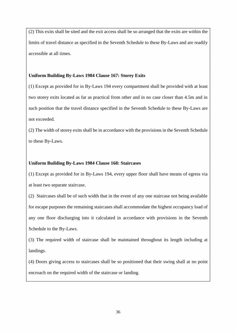
Uniform Building By-Laws 1984 Clause 167: Storey Exits
(1) Except as provided for in By-Laws 194 every compartment shall be provided with at least
two storey exits located as far as practical from other and in no case closer than 4.5m and in
such position that the travel distance specified in the Seventh Schedule to these By-Laws are
not exceeded.
(2) The width of storey exits shall be in accordance with the provisions in the Seventh Schedule
to these By-Laws.
Uniform Building By-Laws 1984 Clause 168: Staircases
(1) Except as provided for in By-Laws 194, every upper floor shall have means of egress via
at least two separate staircase.
(2) Staircases shall be of such width that in the event of any one staircase not being available
for escape purposes the remaining staircases shall accommodate the highest occupancy load of
any one floor discharging into it calculated in accordance with provisions in the Seventh
Schedule to the By-Laws.
(3) The required width of staircase shall be maintained throughout its length including at
landings.
(4) Doors giving access to staircases shall be so positioned that their swing shall at no point
encroach on the required width of the staircase or landing.
37
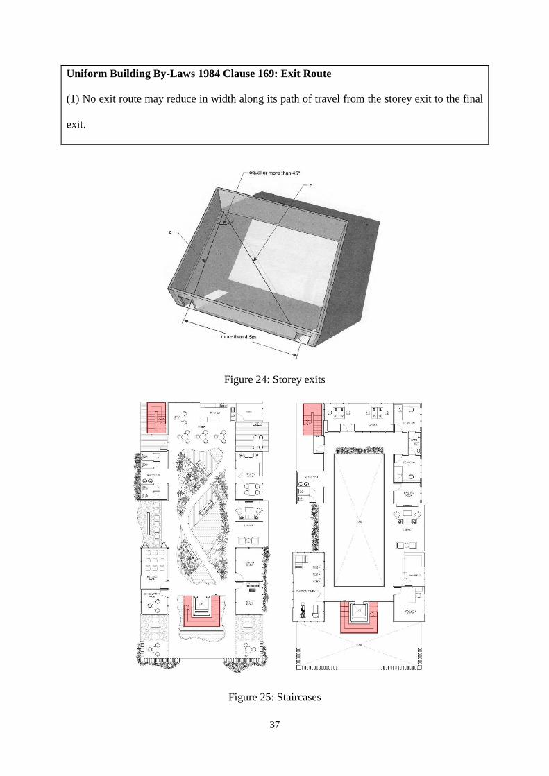
Uniform Building By-Laws 1984 Clause 169: Exit Route
(1) No exit route may reduce in width along its path of travel from the storey exit to the final
exit.
Figure 24: Storey exits
Figure 25: Staircases
38
Separate exits are very important in our building proposal as an elderly care centre. It allows
the elderly to evacuate from the building as soon as possible without the need of travelling long
distances to reach the only available exit. Therefore, two staircases are proposed to ensure the
flow during emergency.
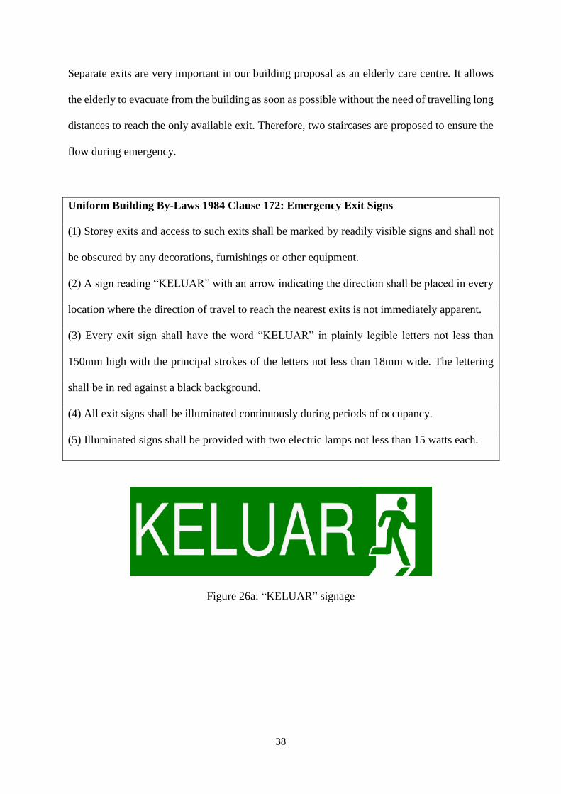
Uniform Building By-Laws 1984 Clause 172: Emergency Exit Signs
(1) Storey exits and access to such exits shall be marked by readily visible signs and shall not
be obscured by any decorations, furnishings or other equipment.
(2) A sign reading “KELUAR” with an arrow indicating the direction shall be placed in every
location where the direction of travel to reach the nearest exits is not immediately apparent.
(3) Every exit sign shall have the word “KELUAR” in plainly legible letters not less than
150mm high with the principal strokes of the letters not less than 18mm wide. The lettering
shall be in red against a black background.
(4) All exit signs shall be illuminated continuously during periods of occupancy.
(5) Illuminated signs shall be provided with two electric lamps not less than 15 watts each.
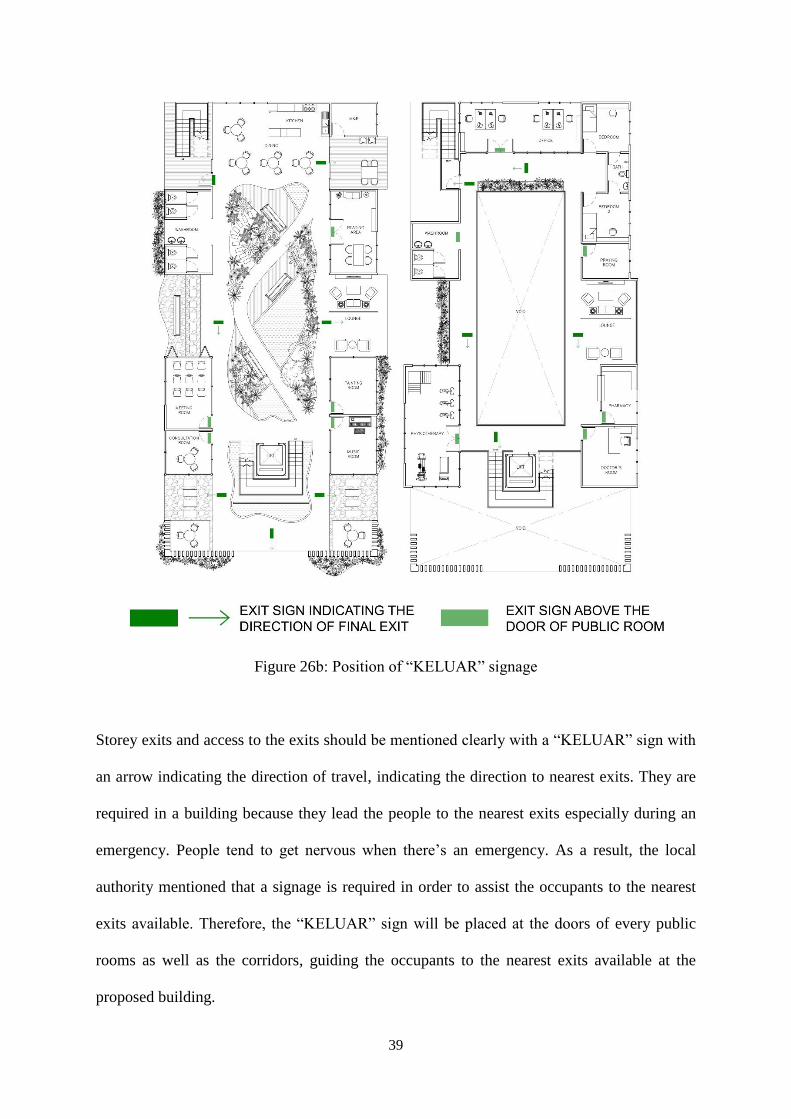
Figure 26a: “KELUAR” signage
39
Figure 26b: Position of “KELUAR” signage
Storey exits and access to the exits should be mentioned clearly with a “KELUAR” sign with
an arrow indicating the direction of travel, indicating the direction to nearest exits. They are
required in a building because they lead the people to the nearest exits especially during an
emergency. People tend to get nervous when there’s an emergency. As a result, the local
authority mentioned that a signage is required in order to assist the occupants to the nearest
exits available. Therefore, the “KELUAR” sign will be placed at the doors of every public
rooms as well as the corridors, guiding the occupants to the nearest exits available at the
proposed building.
40
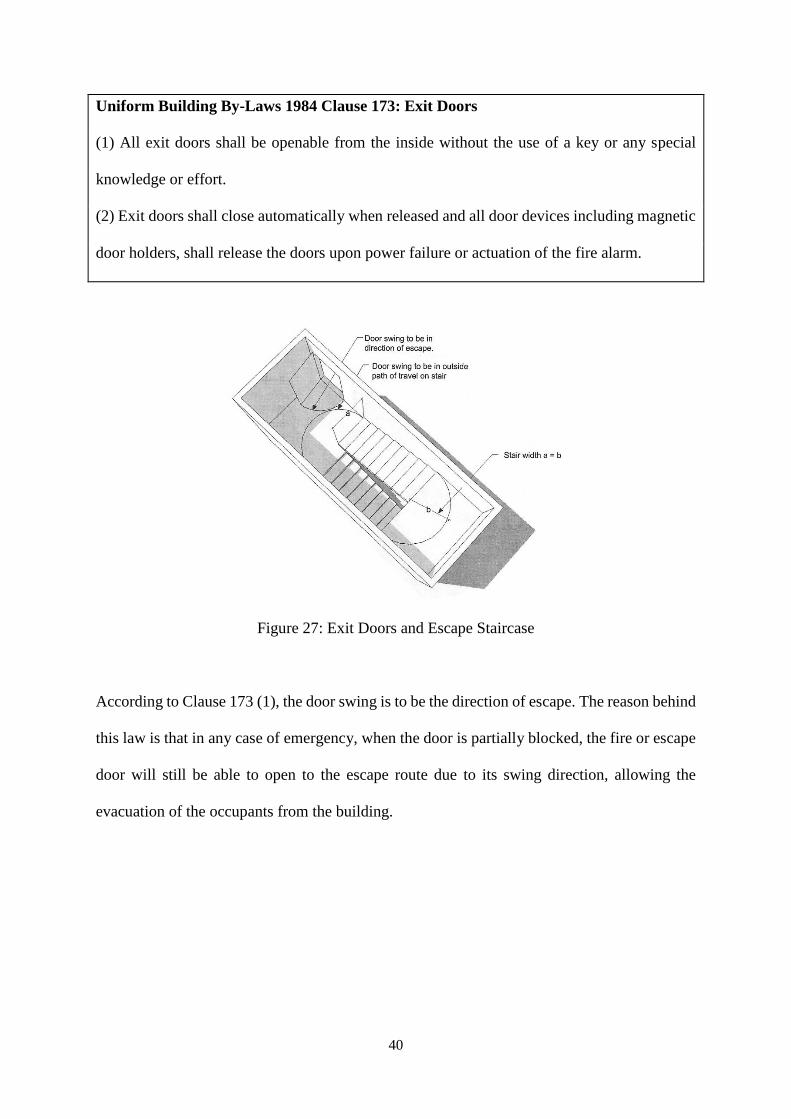
Uniform Building By-Laws 1984 Clause 173: Exit Doors
(1) All exit doors shall be openable from the inside without the use of a key or any special
knowledge or effort.
(2) Exit doors shall close automatically when released and all door devices including magnetic
door holders, shall release the doors upon power failure or actuation of the fire alarm.
Figure 27: Exit Doors and Escape Staircase
According to Clause 173 (1), the door swing is to be the direction of escape. The reason behind
this law is that in any case of emergency, when the door is partially blocked, the fire or escape
door will still be able to open to the escape route due to its swing direction, allowing the
evacuation of the occupants from the building.
41
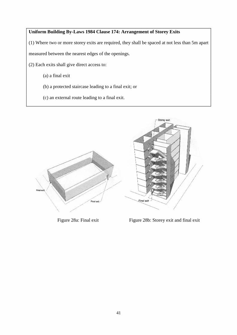
Uniform Building By-Laws 1984 Clause 174: Arrangement of Storey Exits
(1) Where two or more storey exits are required, they shall be spaced at not less than 5m apart
measured between the nearest edges of the openings.
(2) Each exits shall give direct access to:
(a) a final exit
(b) a protected staircase leading to a final exit; or
(c) an external route leading to a final exit.
Figure 28a: Final exit Figure 28b: Storey exit and final exit
42
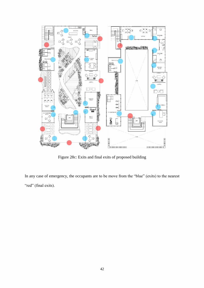
Figure 28c: Exits and final exits of proposed building
In any case of emergency, the occupants are to be move from the “blue” (exits) to the nearest
“red” (final exits).
43
3.2 Air Conditioning System
3.2.1 Introduction
Air conditioning systems are a necessity in Malaysia due to its tropical climate. Commonly
known as air-cond or A/C, air conditioning systems are devices used to provide an acceptable
level of occupancy comfort by controlling temperature, humidity, air distribution and indoor
air quality (IAQ) in order to maintain thermal comfort. Air conditioning systems are a group
of components working together to remove heat from a particular space, such as compressors,
condensers, ductworks and others.
3.2.2 Literature Review
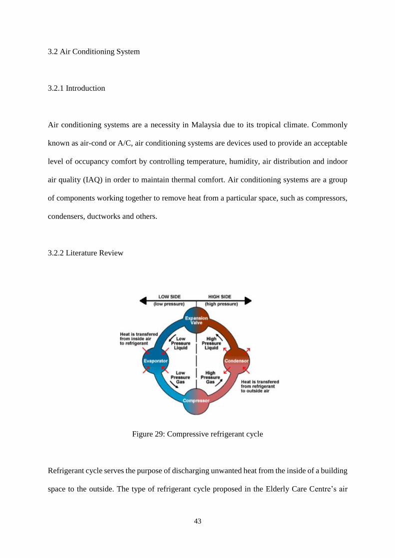
Figure 29: Compressive refrigerant cycle
Refrigerant cycle serves the purpose of discharging unwanted heat from the inside of a building
space to the outside. The type of refrigerant cycle proposed in the Elderly Care Centre’s air
44
conditioning system is a compressive refrigerant cycle, which is a fully enclosed system
consisting four stages: expansion, evaporation, compression and condensation. Within this
enclosed system there is a chemical compound named a refrigerant. The refrigerant will be
liquefied and evaporated repeatedly during the process of it releases, and absorbs heat in the
cycle to help remove heat from the supply air and discharge it to the outside air. Thus, the
refrigerant can be used over and over again.
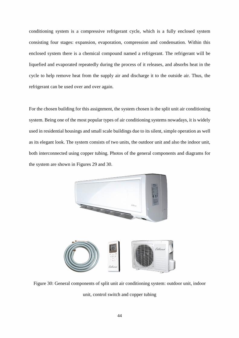
For the chosen building for this assignment, the system chosen is the split unit air conditioning
system. Being one of the most popular types of air conditioning systems nowadays, it is widely
used in residential housings and small scale buildings due to its silent, simple operation as well
as its elegant look. The system consists of two units, the outdoor unit and also the indoor unit,
both interconnected using copper tubing. Photos of the general components and diagrams for
the system are shown in Figures 29 and 30.
Figure 30: General components of split unit air conditioning system: outdoor unit, indoor
unit, control switch and copper tubing
45
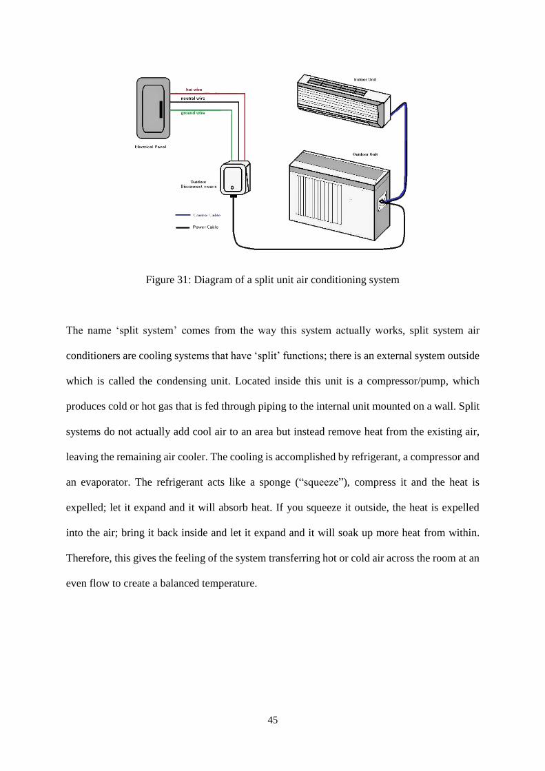
Figure 31: Diagram of a split unit air conditioning system
The name ‘split system’ comes from the way this system actually works, split system air
conditioners are cooling systems that have ‘split’ functions; there is an external system outside
which is called the condensing unit. Located inside this unit is a compressor/pump, which
produces cold or hot gas that is fed through piping to the internal unit mounted on a wall. Split
systems do not actually add cool air to an area but instead remove heat from the existing air,
leaving the remaining air cooler. The cooling is accomplished by refrigerant, a compressor and
an evaporator. The refrigerant acts like a sponge (“squeeze”), compress it and the heat is
expelled; let it expand and it will absorb heat. If you squeeze it outside, the heat is expelled
into the air; bring it back inside and let it expand and it will soak up more heat from within.
Therefore, this gives the feeling of the system transferring hot or cold air across the room at an
even flow to create a balanced temperature.
46
3.2.3 Research Findings
The air conditioning system chosen to be used in the elderly care centre is the split unit system.
This is due to the small scale of the residential building as well as their small spaces inside the
vicinity. Besides that, the wall type indoor unit is chosen instead of a ceiling unit in order to
avoid disruption to the ceiling fans in such a small space.
Split unit air conditioning system consists of two parts, indoor and outdoor units, both having
to be less than 15 meters apart. The outdoor unit is hung or placed on the exterior of the room
of the indoor unit, where there is sufficient air flow around it to remove heat from its
compressor and condenser. The indoor unit is usually hung on the wall of the interior that is to
be cooled.
The outdoor unit removes heat from the refrigerant and also draws in surrounding air, blowing
it over the compressor and condenser, and thus cooling them. Besides that, the condenser is
also covered in aluminium fins so that the heat from the refrigerant can be removed at a much
faster rate. Meanwhile, the indoor unit works by drawing warm room air and passing it over
the filter and evaporator, which leads to the cooling of the air. Connecting these two units are
two copper tubes covered in a layer of insulation, one to supply the refrigerant to the cooling
coil and the other to return it to the compressor.
47
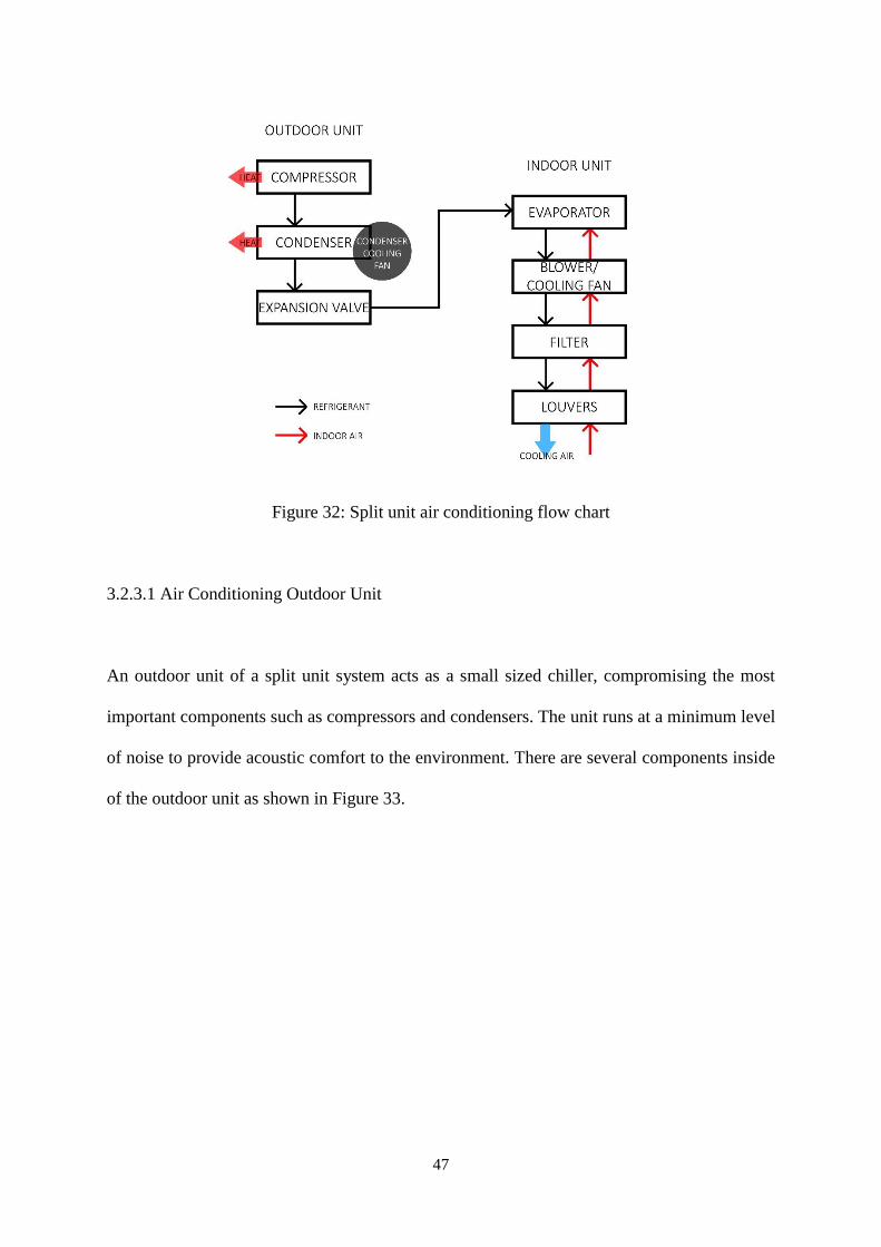
Figure 32: Split unit air conditioning flow chart
3.2.3.1 Air Conditioning Outdoor Unit
An outdoor unit of a split unit system acts as a small sized chiller, compromising the most
important components such as compressors and condensers. The unit runs at a minimum level
of noise to provide acoustic comfort to the environment. There are several components inside
of the outdoor unit as shown in Figure 33.
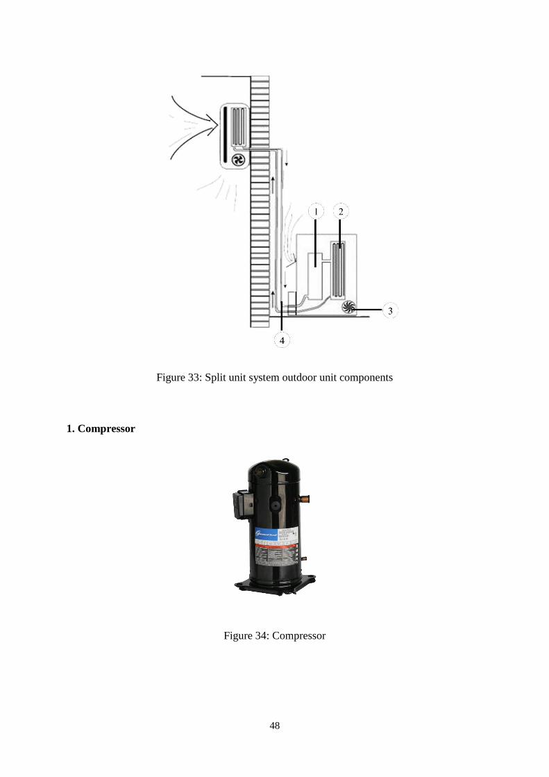
48
Figure 33: Split unit system outdoor unit components
1. Compressor
Figure 34: Compressor
49
External power is supplied to the compressor, which is utilized for compressing refrigerant and
increases its pressure before sending it to the condenser. The size of the compressor varies
depending on the desired air conditioning load. In most domestic split air conditioners,
hermetically sealed type compressor is used. In such compressors, the motor used for driving
the shaft is located inside the sealed unit and it is not visible externally.
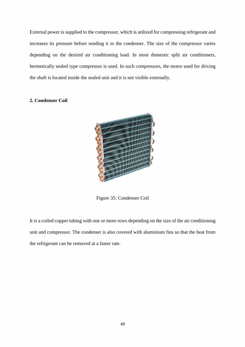
2. Condenser Coil
Figure 35: Condenser Coil
It is a coiled copper tubing with one or more rows depending on the size of the air conditioning
unit and compressor. The condenser is also covered with aluminium fins so that the heat from
the refrigerant can be removed at a faster rate.
50
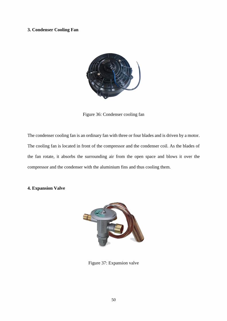
3. Condenser Cooling Fan
Figure 36: Condenser cooling fan
The condenser cooling fan is an ordinary fan with three or four blades and is driven by a motor.
The cooling fan is located in front of the compressor and the condenser coil. As the blades of
the fan rotate, it absorbs the surrounding air from the open space and blows it over the
compressor and the condenser with the aluminium fins and thus cooling them.
4. Expansion Valve
Figure 37: Expansion valve
51
The expansion valve is usually a copper capillary tubing with several rounds of coils. The high
pressure and medium temperature refrigerant leaves the condenser and enters the expansion
valve, where its temperature and pressure drops suddenly.
MS 1525:2007 Code of Practice on Energy Efficiency and Use of Renewable Energy for
Non-residential Buildings Section 8: Air-Conditioning and Mechanical Ventilation
(ACMV) System
8.4.4.2 Outdoor air supply and exhaust systems should be provided with motorised or gravity
dampers or other means of automatic volume shut-off or reduction during period of non-use or
alternate use of the spaces served by the systems.
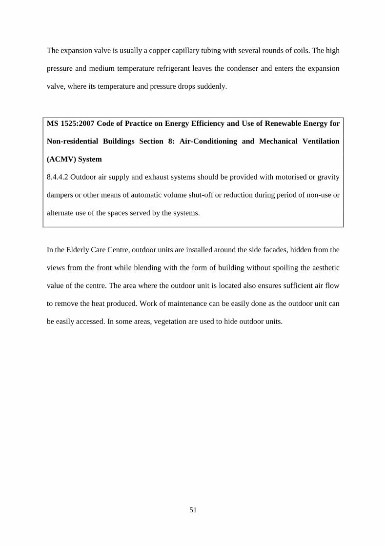
In the Elderly Care Centre, outdoor units are installed around the side facades, hidden from the
views from the front while blending with the form of building without spoiling the aesthetic
value of the centre. The area where the outdoor unit is located also ensures sufficient air flow
to remove the heat produced. Work of maintenance can be easily done as the outdoor unit can
be easily accessed. In some areas, vegetation are used to hide outdoor units.
52
Figure 38: Location of air conditioning outdoor units
53
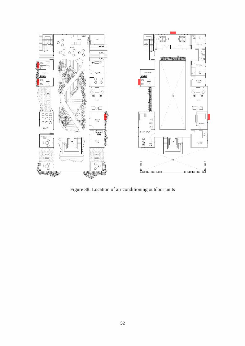
3.2.3.2 Air Conditioning Indoor Unit
Indoor units serve similar purposes as air handling unit (AHU). However, the air is not
distributed to different spaces. The cooled air is directly transferred to the spaces where the
indoor unit is located and the flow of air is controlled by the horizontal louvers. Split unit
indoor units run at an extremely low level of noise. Hence, people have considered it as white
noise which could enhance the sleeping quality or working performance. The type of indoor
unit chosen for this assignment is the wall mounted type. The several components of an indoor
wall mounted unit as shown in Figure 39.
Figure 39: Split unit system indoor unit components
54
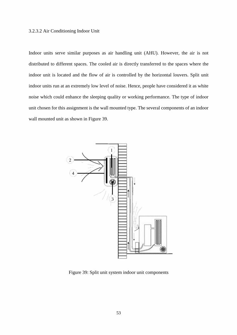
1. Evaporator Coil
Figure 40: Evaporative coil
Acts as a cooling coil is a copper coil made of turns of copper tubing with one or more rows
depending on the capacity of the air conditioning system. The cooling coil is covered with the
aluminium fins so that the maximum amount of heat can be transferred from the coil to the air
inside the room.
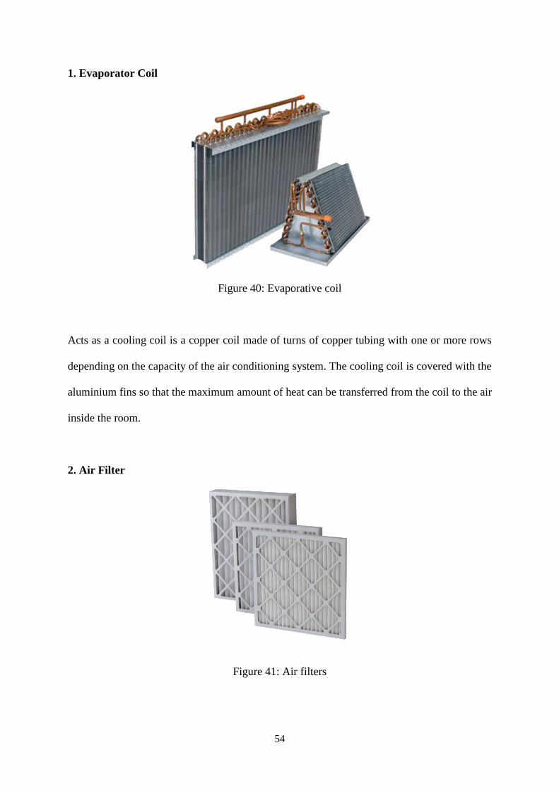
2. Air Filter
Figure 41: Air filters
55
An air filter removes all dirt particles from the room air and helps supplying clean air to the
room. The air filter in the wall mounted type of the indoor unit is placed just before the cooling
coil.
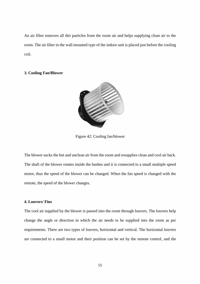
3. Cooling Fan/Blower
Figure 42: Cooling fan/blower
The blower sucks the hot and unclean air from the room and resupplies clean and cool air back.
The shaft of the blower rotates inside the bushes and it is connected to a small multiple speed
motor, thus the speed of the blower can be changed. When the fan speed is changed with the
remote, the speed of the blower changes.
4. Louvers/ Fins
The cool air supplied by the blower is passed into the room through louvers. The louvers help
change the angle or direction in which the air needs to be supplied into the room as per
requirements. There are two types of louvers, horizontal and vertical. The horizontal louvers
are connected to a small motor and their position can be set by the remote control, and the
56
vertical louvers are operated manually and one can easily change their position as per the
requirements.
In the Elderly Care Centre, indoor wall mounted units are placed in areas which require air
conditioning on a rigid concrete wall that can properly withstand its weight. Units are placed
2.4 meters above ground level as specified and also to ensure easy accessibility. Locations are
also carefully considered where air can be distributed as evenly as possible into the interior
spaces.
57
3.3 Mechanical Ventilation System
3.3.1 Introduction
Ventilation is the process of changing air from outside or circulating air within a space.
Ventilation is mainly used to control indoor air quality by removing carbon dioxide, unpleasant
smells, excessive moisture and contaminants to replenish the indoor space with oxygen. It can
also be used to improve the thermal comfort when the introduction of outside air helps to
achieve desired indoor psychometric conditions. Ventilation can be divided into natural
ventilation and mechanical ventilation.
Mechanical ventilation is the system which encourages during the process of changing air
condition and quality in an enclosed space when natural ventilation is not appropriate.
Mechanical ventilation circulates fresh air with the aid of fan and makeup air supply.
Mechanical ventilation incorporates heating, cooling and humidity control. This can be alluded
to as warming ventilation and aerating and cooling (HVAC). Mechanical ventilation is differed
from natural ventilation as it needs electricity to support its system.
Mechanical ventilation is commonly used in Malaysia’s buildings in order to ventilate the
spaces and to provide good indoor air quality condition. Mechanical ventilation system is
considered to be reliable in delivering the designed flow rate, regardless of the impacts of
variable wind and ambient temperature. Filtration system can be installed in the mechanical
ventilation system so that the harmful substances can be filtered before entering the building.
Besides that, natural ventilation has no control on the amount of airflow where mechanical
ventilation is more controllable compared to natural ventilation. The services can be planned
58
on the sources of airflow and the air is filtered before entering the house, which could prevent
the air leaking in to the house from undesirable area like crawl space and causing the increase
the level of air pollution.
3.3.2 Literature Review
When natural ventilation is not effective enough, mechanical ventilation system is responsible
to remove stale air inside the building with fresh air and draw in outside air when the
environment is polluted and high humidity. Exhaust fan is the basic component among the
several components which removes stale air from the building’s interior. There are two types
of mechanical ventilation system which are spot ventilation and energy recovery ventilation
system. Spot ventilation can be categorized into supply system, extract system and combination
system. Combination system is the system which consists of supply and extract system. All
these systems are having similar components which include fans, filters, ductworks, fire
dampers and diffusers.
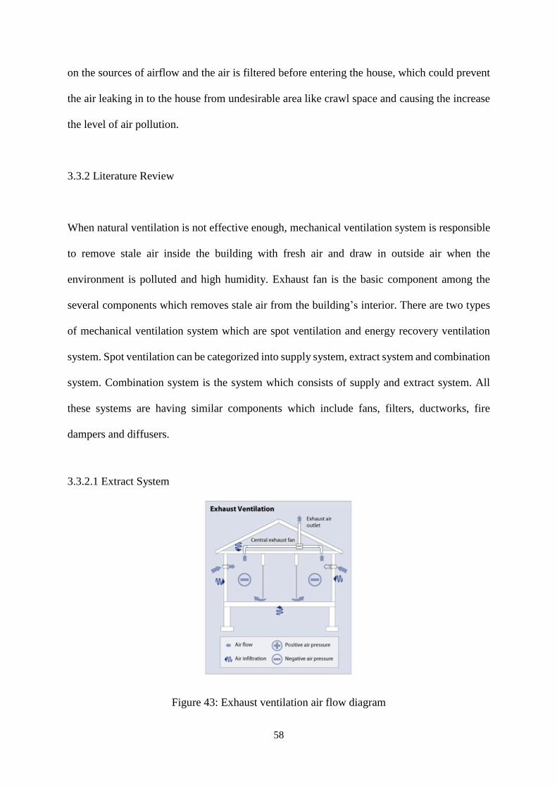
3.3.2.1 Extract System
Figure 43: Exhaust ventilation air flow diagram
59
Exhaust ventilation system is known as fans. It works by depressurizing the interior, creating
negative pressure on its inlet and the system exhausts the air from the interior while make-up
air infiltrates through leaks in the building shell and passive vent. Mechanical extract fans are
installed in the duct connected to the central exhaust point in the building and discharge away
the air from occupying the space owing to its combination with heats, fumes, smoke water
vapour or odour.
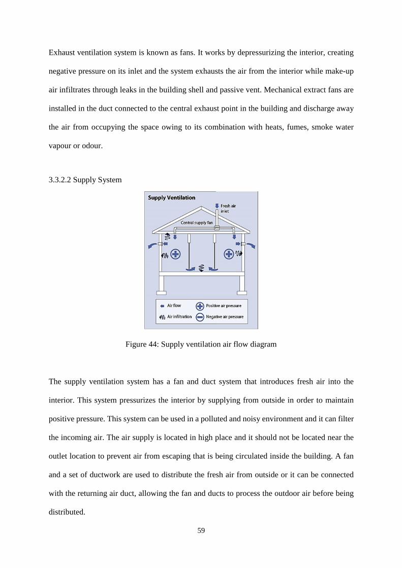
3.3.2.2 Supply System
Figure 44: Supply ventilation air flow diagram
The supply ventilation system has a fan and duct system that introduces fresh air into the
interior. This system pressurizes the interior by supplying from outside in order to maintain
positive pressure. This system can be used in a polluted and noisy environment and it can filter
the incoming air. The air supply is located in high place and it should not be located near the
outlet location to prevent air from escaping that is being circulated inside the building. A fan
and a set of ductwork are used to distribute the fresh air from outside or it can be connected
with the returning air duct, allowing the fan and ducts to process the outdoor air before being
distributed.
60
3.3.3 Research Findings
MS 1525 code 8.4.5 Mechanical Ventilation Control
“Each mechanical ventilation system (supply/exhaust) should be equipped with a readily
accessible switch or other means for shut down or volume reduction when ventilation is not
required. Example of such devices would include timer switch control, thermostat control, duty
cycle programming and CO/CO2 sensor control.”
3.3.3.1 Return Air Grille
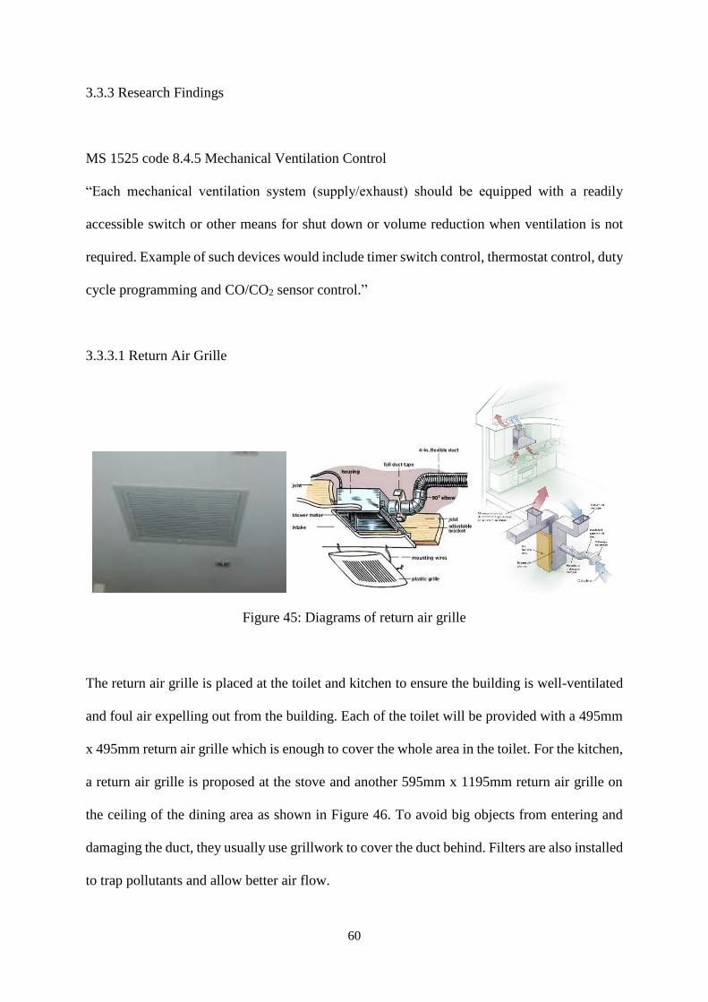
Figure 45: Diagrams of return air grille
The return air grille is placed at the toilet and kitchen to ensure the building is well-ventilated
and foul air expelling out from the building. Each of the toilet will be provided with a 495mm
x 495mm return air grille which is enough to cover the whole area in the toilet. For the kitchen,
a return air grille is proposed at the stove and another 595mm x 1195mm return air grille on
the ceiling of the dining area as shown in Figure 46. To avoid big objects from entering and
damaging the duct, they usually use grillwork to cover the duct behind. Filters are also installed
to trap pollutants and allow better air flow.
61
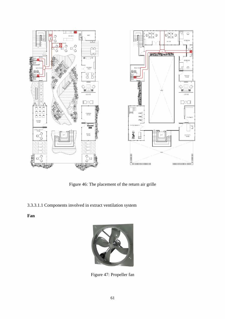
Figure 46: The placement of the return air grille
3.3.3.1.1 Components involved in extract ventilation system
Fan
Figure 47: Propeller fan
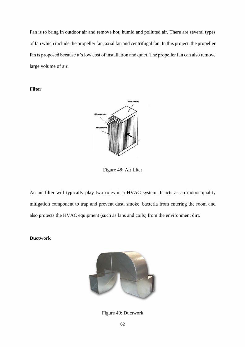
62
Fan is to bring in outdoor air and remove hot, humid and polluted air. There are several types
of fan which include the propeller fan, axial fan and centrifugal fan. In this project, the propeller
fan is proposed because it’s low cost of installation and quiet. The propeller fan can also remove
large volume of air.
Filter
Figure 48: Air filter
An air filter will typically play two roles in a HVAC system. It acts as an indoor quality
mitigation component to trap and prevent dust, smoke, bacteria from entering the room and
also protects the HVAC equipment (such as fans and coils) from the environment dirt.
Ductwork
Figure 49: Ductwork
63
Ductwork is used to channel outside air towards the room or the air from the room towards the
outside. It may be steel, rigid glass fibre, flexible, or cloth. The first three materials are by far
the most common.
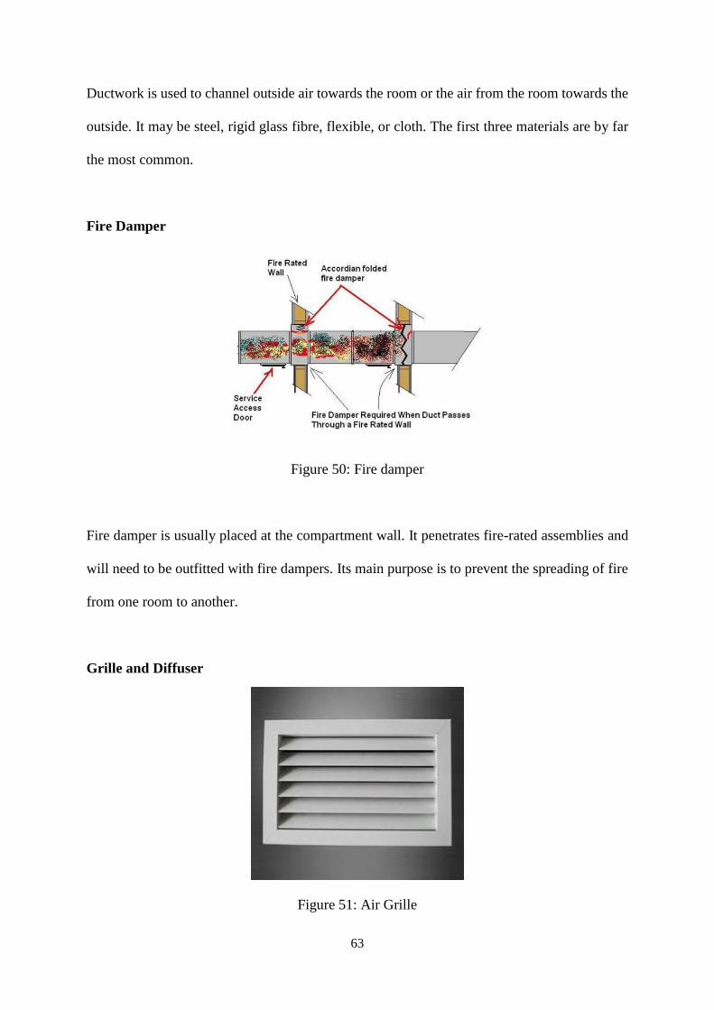
Fire Damper
Figure 50: Fire damper
Fire damper is usually placed at the compartment wall. It penetrates fire-rated assemblies and
will need to be outfitted with fire dampers. Its main purpose is to prevent the spreading of fire
from one room to another.
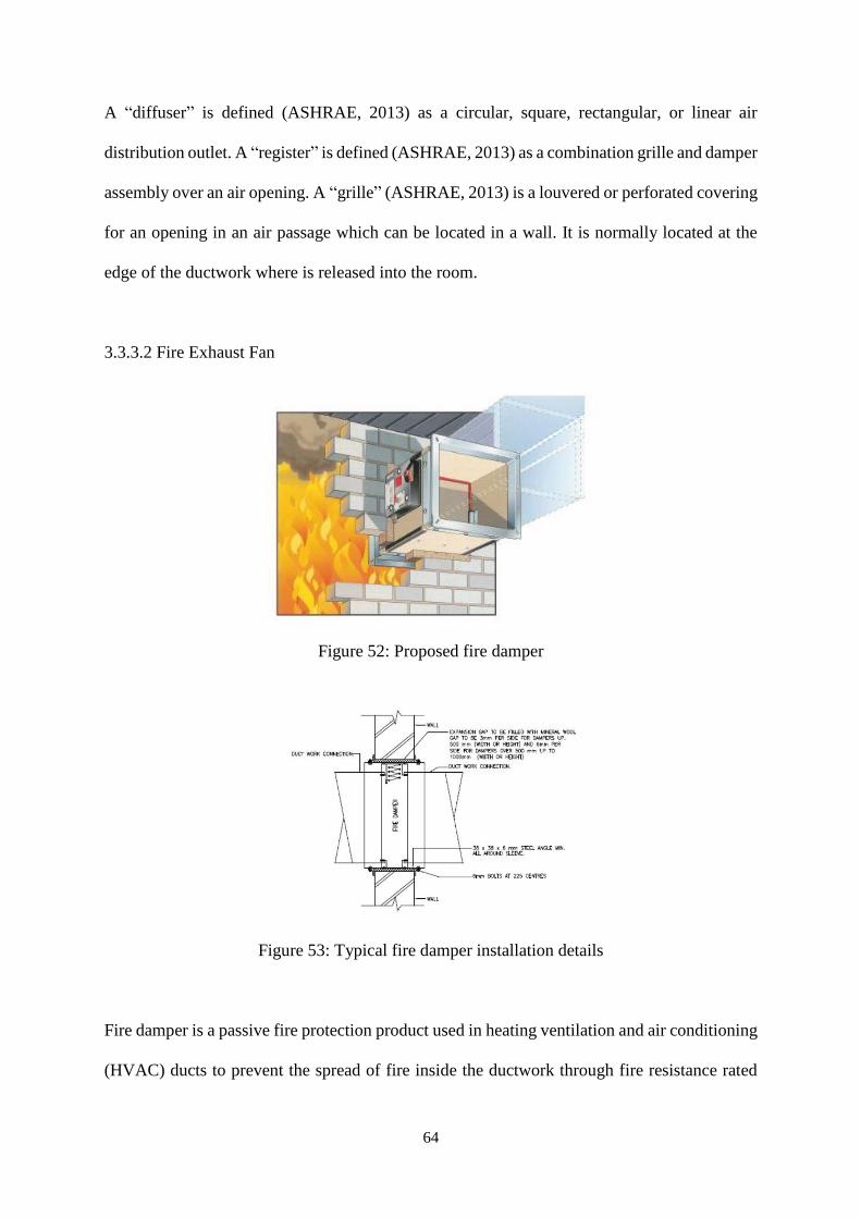
Grille and Diffuser
Figure 51: Air Grille
64
A “diffuser” is defined (ASHRAE, 2013) as a circular, square, rectangular, or linear air
distribution outlet. A “register” is defined (ASHRAE, 2013) as a combination grille and damper
assembly over an air opening. A “grille” (ASHRAE, 2013) is a louvered or perforated covering
for an opening in an air passage which can be located in a wall. It is normally located at the
edge of the ductwork where is released into the room.
3.3.3.2 Fire Exhaust Fan
Figure 52: Proposed fire damper
Figure 53: Typical fire damper installation details
Fire damper is a passive fire protection product used in heating ventilation and air conditioning
(HVAC) ducts to prevent the spread of fire inside the ductwork through fire resistance rated
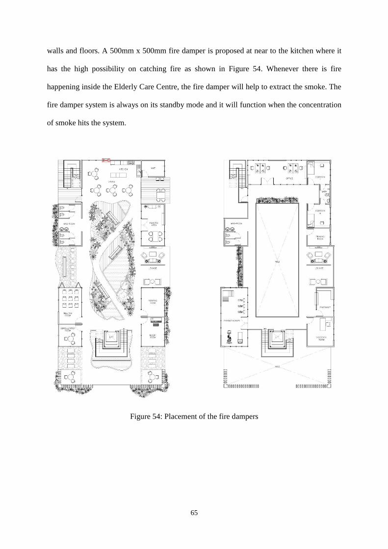
65
walls and floors. A 500mm x 500mm fire damper is proposed at near to the kitchen where it
has the high possibility on catching fire as shown in Figure 54. Whenever there is fire
happening inside the Elderly Care Centre, the fire damper will help to extract the smoke. The
fire damper system is always on its standby mode and it will function when the concentration
of smoke hits the system.
Figure 54: Placement of the fire dampers
66
3.3.3.3 Supply Air Diffusers
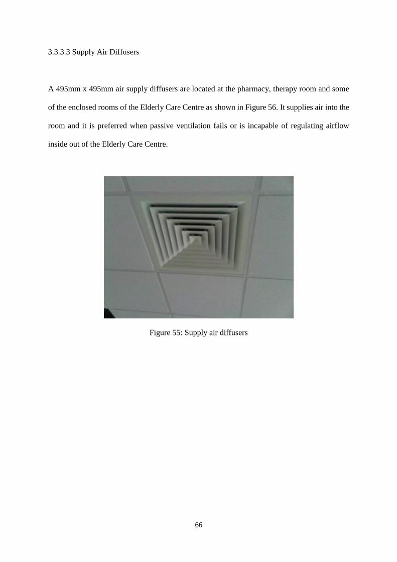
A 495mm x 495mm air supply diffusers are located at the pharmacy, therapy room and some
of the enclosed rooms of the Elderly Care Centre as shown in Figure 56. It supplies air into the
room and it is preferred when passive ventilation fails or is incapable of regulating airflow
inside out of the Elderly Care Centre.
Figure 55: Supply air diffusers
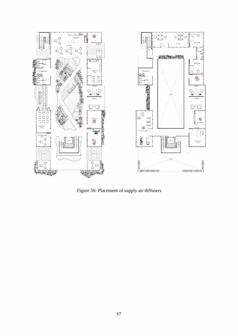
67
Figure 56: Placement of supply air diffusers
68
3.4 Mechanical Transportation System
3.4.1 Introduction
The mechanical transportation is an energy-using services which becomes an integral part of
modern buildings to move people and goods. The need of this such system arises with the
expectations of quality by the final user and with the provision of access for elderly and
disabled people. Others services, fire protection, means of escape and proper maintenance are
of the highest importance when designing this system. The energy consumption may be low,
but a significant amount of electrical power is required for short periods.
3.4.2 Literature Review
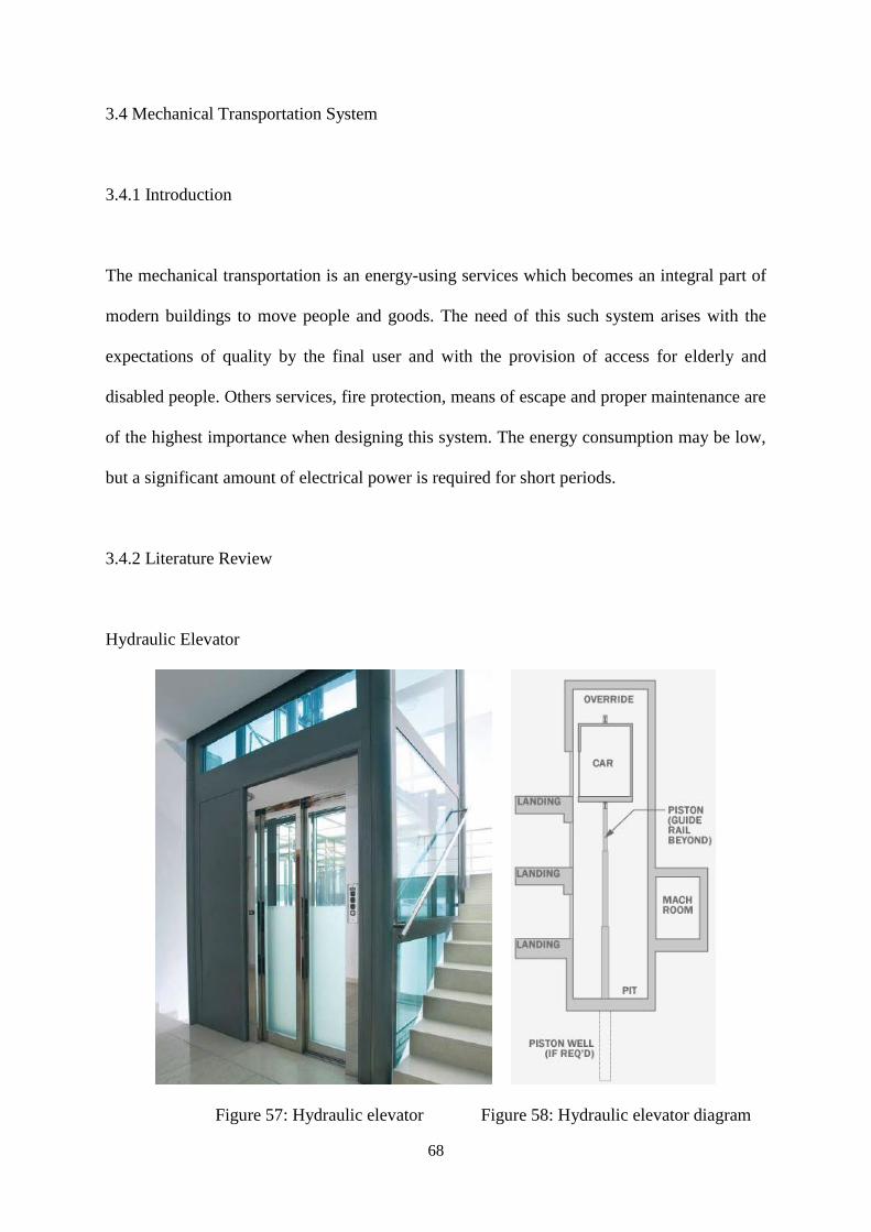
Hydraulic Elevator
Figure 57: Hydraulic elevator Figure 58: Hydraulic elevator diagram
69
Hydraulic elevators are typically used for low-rise buildings of two to eight stories, suitable for
lifting goods, in hospitals and old folks’ homes. They are supported by a piston at the bottom
of the elevators that pushes the elevator up as an electric motor forces oil into the piston. As it
descends, a valve releases the fluid from the piston. Travelling at a maximum speed of 61m
per minute, hydraulically operated lifts have the advantage of very quiet operation and lower
maintenance costs compared to other types of elevators. These elevators also have low
structural cost due to lower imposed load in comparison to electric and traction elevators. A
major drawback of this this type of elevator is that it is a high-heat producing system. Pollution
in ground water may occur if the oil leaks into the ground at the base of the elevator.
70
3.4.3 Research Findings
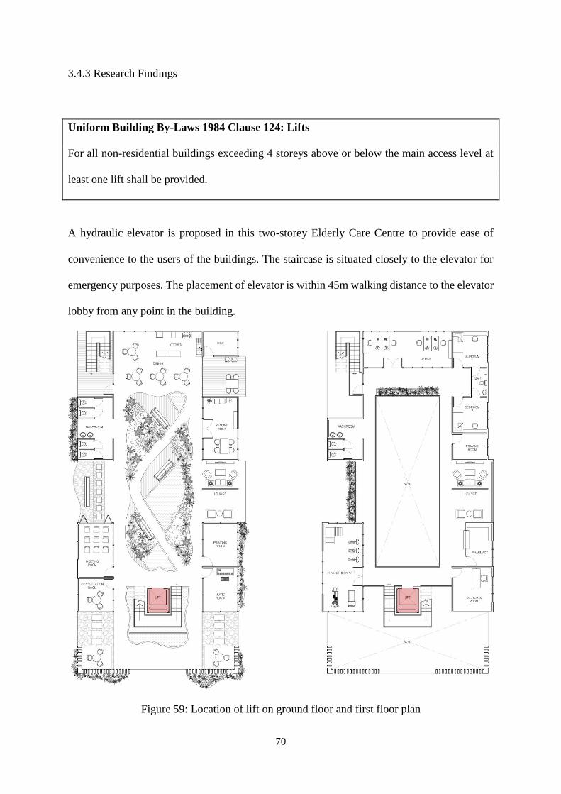
Uniform Building By-Laws 1984 Clause 124: Lifts
For all non-residential buildings exceeding 4 storeys above or below the main access level at
least one lift shall be provided.
A hydraulic elevator is proposed in this two-storey Elderly Care Centre to provide ease of
convenience to the users of the buildings. The staircase is situated closely to the elevator for
emergency purposes. The placement of elevator is within 45m walking distance to the elevator
lobby from any point in the building.
Figure 59: Location of lift on ground floor and first floor plan
71
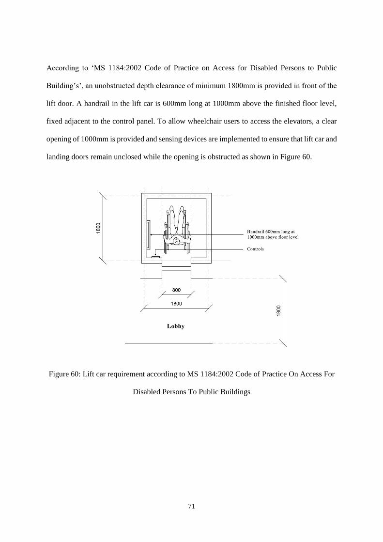
According to ‘MS 1184:2002 Code of Practice on Access for Disabled Persons to Public
Building’s’, an unobstructed depth clearance of minimum 1800mm is provided in front of the
lift door. A handrail in the lift car is 600mm long at 1000mm above the finished floor level,
fixed adjacent to the control panel. To allow wheelchair users to access the elevators, a clear
opening of 1000mm is provided and sensing devices are implemented to ensure that lift car and
landing doors remain unclosed while the opening is obstructed as shown in Figure 60.
Figure 60: Lift car requirement according to MS 1184:2002 Code of Practice On Access For
Disabled Persons To Public Buildings
72
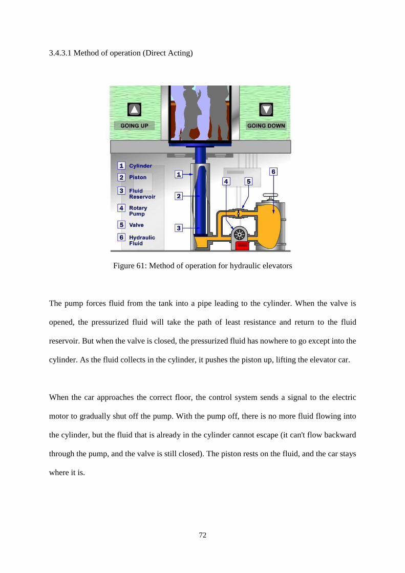
3.4.3.1 Method of operation (Direct Acting)
Figure 61: Method of operation for hydraulic elevators
The pump forces fluid from the tank into a pipe leading to the cylinder. When the valve is
opened, the pressurized fluid will take the path of least resistance and return to the fluid
reservoir. But when the valve is closed, the pressurized fluid has nowhere to go except into the
cylinder. As the fluid collects in the cylinder, it pushes the piston up, lifting the elevator car.
When the car approaches the correct floor, the control system sends a signal to the electric
motor to gradually shut off the pump. With the pump off, there is no more fluid flowing into
the cylinder, but the fluid that is already in the cylinder cannot escape (it can't flow backward
through the pump, and the valve is still closed). The piston rests on the fluid, and the car stays
where it is.
73
To lower the car, the elevator control system sends a signal to the valve. The valve is operated
electrically by a basic solenoid switch (Actuator). When the solenoid opens the valve, the fluid
that has collected in the cylinder can flow out into the fluid reservoir. The weight of the car and
the cargo pushes down on the piston, which drives the fluid into the reservoir. The car gradually
descends. To stop the car at a lower floor, the control system closes the valve again.
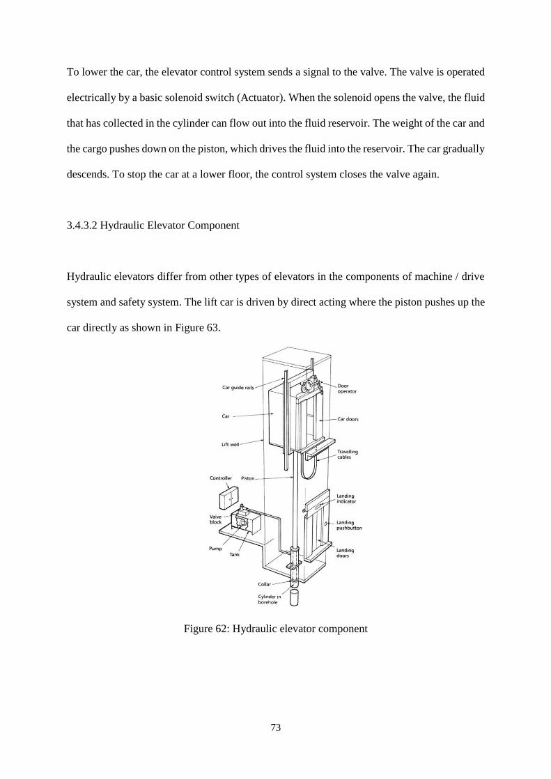
3.4.3.2 Hydraulic Elevator Component
Hydraulic elevators differ from other types of elevators in the components of machine / drive
system and safety system. The lift car is driven by direct acting where the piston pushes up the
car directly as shown in Figure 63.
Figure 62: Hydraulic elevator component
74
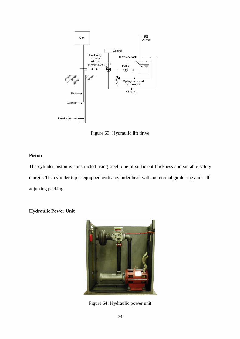
Figure 63: Hydraulic lift drive
Piston
The cylinder piston is constructed using steel pipe of sufficient thickness and suitable safety
margin. The cylinder top is equipped with a cylinder head with an internal guide ring and self-
adjusting packing.
Hydraulic Power Unit
Figure 64: Hydraulic power unit
75
The power unit as shown in Figure 64 is operated with minimum noise and vibration to avoid
distraction to the users in the building. As such, vibration insulators are mounted above the
machine room floor and a silencer unit is fitted in the hydraulic system to reduce the
transmission of pulsations from the pump to the car and the elimination of airborne noise.
3.4.3.3 Safety System
Uniform Building By-Laws 1984
Clause 153: Smoke detectors for lift lobbies –
(1) All lift lobbies shall be provided with smoke detectors.
Clause 154: Emergency mode of operation in the event of mains power failure –
(1) On failure of mains power of lifts shall return in sequence directly to the designated floor,
commencing with the fire lifts, without answering any car or landing calls and park with doors
open.
Clause 155: Fire mode of operation –
(2) If mains power is available all lifts shall return in sequence directly to the designated floor,
commencing with the fire lifts, without answering any car or landing calls, overriding the
emergency stop button inside the car, but not any other emergency or safety devices, and park
with doors open.
(3) The fire lifts shall then be available for use by the fire brigade on operation of the fireman's
switch.
(4) Under this mode of operation, the fire lifts shall only operate in response to car calls but not
to landing calls in a mode of operation in accordance with by-law 154.
76
Hydraulic elevators have seismic valves located in the pit close to the jack that is designed to
withstand pressure in the case where the hydraulic line is broken due to seismic activity. A
buffer-striking member on the underside of the car helps to stop the elevator before the piston
reaches its down limit of travel.
77
4.0 CONCLUSION
Fire must not be taken lightly. In fact, fire is dangerous and hazardous when is not controlled
in the right environment. The active systems are meant to control fires and prevent further
damage caused by it. Active systems are meant to be used in emergencies or when threats of
fire outbreak occurs. These systems are designed to put out fires effectively and in an orderly
manner in most situations. Most importantly situations where there are more than one public
involve. Hence, the importance of active systems should not be taken lightly and to be
understood by the public.
Passive fire system refers to the elements of the buildings that provide fire protection, ensuring
occupants’ safety in the building. This system block or slow down the spread of fire through
the help of fire resistant wall and fire doors, just to name some. Fire doors help to
compartmentalize the building while giving its occupants means of escape. Fire walls as well
as the floors help to separate the building into compartments to stop the spread of fire and
smoke from one to another. The importance of these elements is to provide sufficient time for
people in the building to escape. Not only that, staircases play an important role to provide the
upper floor occupants to leave the building via the nearest staircase to the exit or final exit. Exit
signage is also significant to provide guidance to the occupants on the right way to the final
exit in a limited period of time. In short, passive fire system should always be considered during
the design of the building, minimizing the impact of the fire on the occupants inside the
building at the same time allowing them to leave the building safely in the limited period of
time.
78
A split unit air conditioning system is the most suitable for the Elderly Care Centre as it is a
small residential building. Besides, it also allows flexibility in control, only turning on when it
is to be used, saving electricity and energy. At the same time, the wall mounted type is more
suitable in small interior spaces which have a ceiling fan equipped, so that the A/C unit is not
disrupted by the ceiling fan or lighting.
This Elderly Care Centre has a lot of enclosed spaces causing poor natural airflow. Hence,
mechanical ventilation must be introduced to enhance the efficiency of the ventilation of the
building. Different spaces require ventilation at different hours, so separated accessible
switches to control different air distribution systems are required. Thus, the mechanical
ventilation allows polluted air to be extracted out and cleans air drawn in the spaces efficiently.
A hydraulically operated elevator is proposed in this Elderly Care Centre as it is suitable for
lifting goods and easily operable with lower maintenance cost. The acceleration and travel
experience is also very smooth due to the lack of brake, ropes, pulleys or winding gears.
79
5.0 REFERENCES
Fire Protection System
1. D. (Ed.). (2011). Guide to Fire Protection in Malaysia. Kuala Lumpur, Selangor: The
Institute of Fire Engineers (UK) Malaysia Branch.
2. Fire causes. (n.d.). Retrieved November 23, 2016, from http://www.nfpa.org/news-
and-research/fire-statistics-and-reports/fire-statistics/fire-causes
3. Ionization vs photoelectric. (n.d.). Retrieved November 23, 2016, from
http://www.nfpa.org/public-education/by-topic/smoke-alarms/ionization-vs-
photoelectric
4. The Combustion Process. (n.d.). Retrieved November 23, 2016, from
http://www.auburn.edu/academic/forestry_wildlife/fire/combustion.htm
5. Uniform Building By-Laws 1984. (2013). Petaling Jaya, Selangor: International Law
Book Service.
6. What is a hydrant and why are they so important? (n.d.). Retrieved November 23,
2016, from https://www.fire.nsw.gov.au/home-fire-safety/hydrant-why.html
Air Conditioning System
1. Climate Design. (n.d.) Common Air Conditioning Terms You Should Know | Climate
Design. Retrieved November 13, 2016, from http://www.climatedesign.com/common-
air-conditioning-terms-know/
2. Haresh, K (2009). Parts of Split Air Conditioners: Outdoor Unit. Retrieved November
19, 2016, from http://www.brighthubengineering.com/hvac/45044-parts-of-the-split-
air-condioners-outdoor-unit/
80
3. Malaysian Standard. (2007) Code of practice on energy efficiency and use of
renewable energy for non-residential buildings (1st ed.). Putrajaya.
4. Mitsubishi Electric Cooling and Heating. (n.d.). 5 Advantages of Ductless Cooling
and Heating Systems. Retrieved 10 November 2016, from
http://www.mitsubishicomfort.com/articles/ductless/5-advantages-of-ductless-
cooling-and-heating-systems
5. Zero, B. & Zero, B. (2016). Air Conditioning | Heating & Cooling Experts in Ottawa
ON. Belowzerohvac.ca. Retrieved November 22, 2016, from
http://belowzerohvac.ca/air-conditioners-ottawa/
Mechanical Ventilation System
1. Haines, R. & Wilson, C. (2003). HVAC systems design handbook (1st ed.). New
York: McGraw-Hill.
2. MacIntyre, N. & Branson, R. (2009). Mechanical ventilation (1st ed.). St. Louis, MO:
Saunders Elsevier.
3. Swenson, S. D. (1995). HVAC: Heating, ventilating, and air conditioning.
Homewood, IL: American Technical.
4. Young, A. N. (2000). Building services. London: U.C.L. Bartlett School of
Architecture and Planning.
Mechanical Transportation System
1. Ching, F., & Adams, C. (2001). Building construction illustrated. New York: Wiley.
2. Hall, F., & Greeno, R. (2005). Building services handbook. Oxford: Elsevier
Butterworth-Heinemann.
3. Uniform Building By-Laws 1984. (2013). Petaling Jaya, Selangor: International Law
Book Service.