Embed Size (px)
Citation preview
WWW.VIDYARTHIPLUS.COM
WWW.VIDYARTHIPLUS.COM V+ TEAM
UNIT – 1
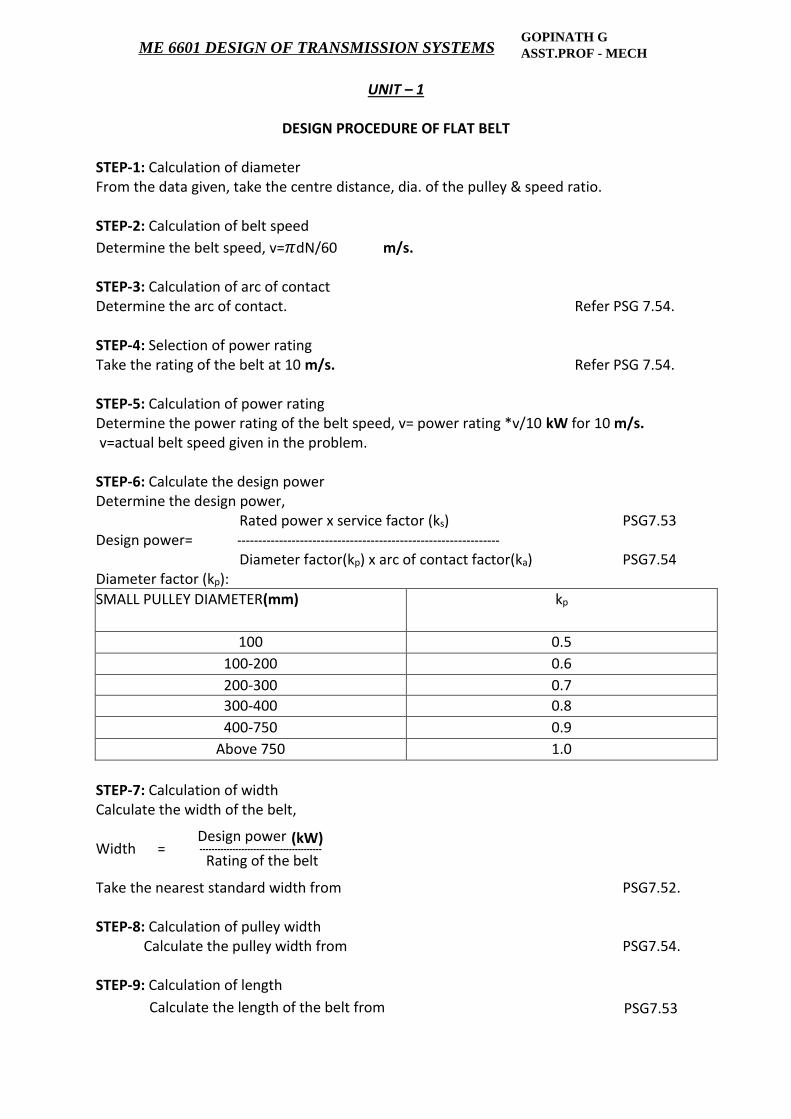
DESIGN PROCEDURE OF FLAT BELT
STEP-1: Calculation of diameter From the data given, take the centre distance, dia. of the pulley & speed ratio. STEP-2: Calculation of belt speed
Determine the belt speed, v=𝜋dN/60 m/s. STEP-3: Calculation of arc of contact Determine the arc of contact. Refer PSG 7.54. STEP-4: Selection of power rating Take the rating of the belt at 10 m/s. Refer PSG 7.54. STEP-5: Calculation of power rating Determine the power rating of the belt speed, v= power rating *v/10 kW for 10 m/s. v=actual belt speed given in the problem. STEP-6: Calculate the design power Determine the design power, Rated power x service factor (ks) PSG7.53 Design power= --------------------------------------------------------------- Diameter factor(kp) x arc of contact factor(ka) PSG7.54 Diameter factor (kp):
SMALL PULLEY DIAMETER(mm) kp
100 0.5
100-200 0.6
200-300 0.7
300-400 0.8
400-750 0.9
Above 750 1.0
STEP-7: Calculation of width Calculate the width of the belt, Design power (kW)
Width = ----------------------------------------- Rating of the belt Take the nearest standard width from PSG7.52. STEP-8: Calculation of pulley width Calculate the pulley width from PSG7.54. STEP-9: Calculation of length
Calculate the length of the belt from PSG7.53
GOPINATH G ASST.PROF - MECHME 6601 DESIGN OF TRANSMISSION SYSTEMS
WWW.VIDYARTHIPLUS.COM
WWW.VIDYARTHIPLUS.COM V+ TEAM
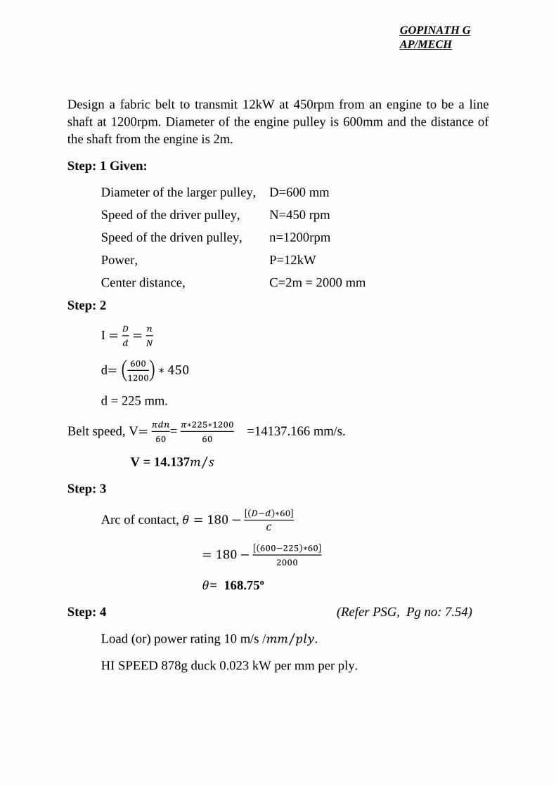
Design a fabric belt to transmit 12kW at 450rpm from an engine to be a line shaft at 1200rpm. Diameter of the engine pulley is 600mm and the distance of the shaft from the engine is 2m.
Step: 1 Given:
Diameter of the larger pulley, D=600 mm
Speed of the driver pulley, N=450 rpm
Speed of the driven pulley, n=1200rpm
Power, P=12kW
Center distance, C=2m = 2000 mm
Step: 2
I =𝐷
𝑑=
𝑛
𝑁
d= (600
1200) ∗ 450
d = 225 mm.
Belt speed, V=𝜋𝑑𝑛
60=
𝜋∗225∗1200
60 =14137.166 mm/s.
V = 14.137𝑚 𝑠⁄
Step: 3
Arc of contact, 𝜃 = 180 −[(𝐷−𝑑)∗60]
𝐶
= 180 −[(600−225)∗60]
2000
𝜃= 168.75o
Step: 4 (Refer PSG, Pg no: 7.54)
Load (or) power rating 10 m/s /𝑚𝑚 𝑝𝑙𝑦⁄ .
HI SPEED 878g duck 0.023 kW per mm per ply.
GOPINATH GAP/MECH
WWW.VIDYARTHIPLUS.COM
WWW.VIDYARTHIPLUS.COM V+ TEAM
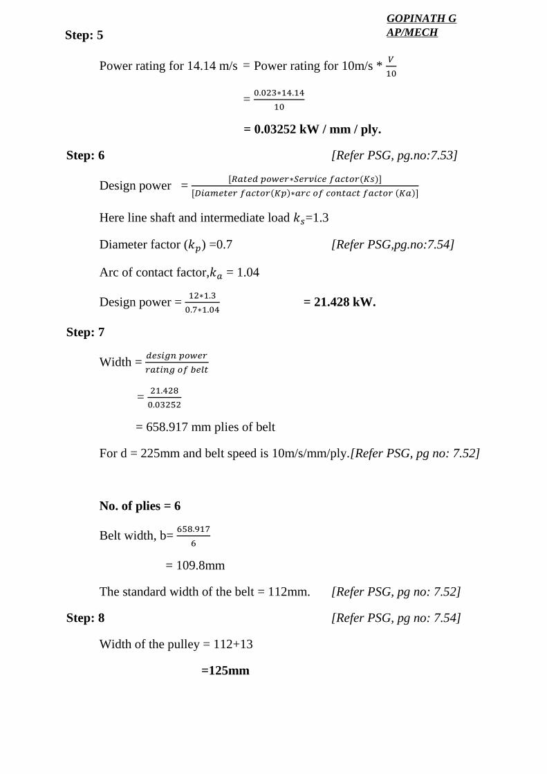
Power rating for 14.14 m/s Power rating for 10m/s * 𝑉
10
= 0.023∗14.14
10
= 0.03252 kW / mm / ply.
Step: 6 [Refer PSG, pg.no:7.53]
Design power = [𝑅𝑎𝑡𝑒𝑑 𝑝𝑜𝑤𝑒𝑟∗𝑆𝑒𝑟𝑣𝑖𝑐𝑒 𝑓𝑎𝑐𝑡𝑜𝑟(𝐾𝑠)]
[𝐷𝑖𝑎𝑚𝑒𝑡𝑒𝑟 𝑓𝑎𝑐𝑡𝑜𝑟(𝐾𝑝)∗𝑎𝑟𝑐 𝑜𝑓 𝑐𝑜𝑛𝑡𝑎𝑐𝑡 𝑓𝑎𝑐𝑡𝑜𝑟 (𝐾𝑎)]
Here line shaft and intermediate load 𝑘𝑠=1.3
Diameter factor (𝑘𝑝) =0.7 [Refer PSG,pg.no:7.54]
Arc of contact factor,𝑘𝑎 = 1.04
Design power = 12∗1.3
0.7∗1.04 = 21.428 kW.
Step: 7
Width = 𝑑𝑒𝑠𝑖𝑔𝑛 𝑝𝑜𝑤𝑒𝑟
𝑟𝑎𝑡𝑖𝑛𝑔 𝑜𝑓 𝑏𝑒𝑙𝑡
= 21.428
0.03252
= 658.917 mm plies of belt
For d = 225mm and belt speed is 10m/s/mm/ply.[Refer PSG, pg no: 7.52]
No. of plies = 6
Belt width, b= 658.917
6
= 109.8mm
The standard width of the belt = 112mm. [Refer PSG, pg no: 7.52]
Step: 8 [Refer PSG, pg no: 7.54]
Width of the pulley = 112+13
=125mm
=
Step: 5GOPINATH GAP/MECH
WWW.VIDYARTHIPLUS.COM
WWW.VIDYARTHIPLUS.COM V+ TEAM
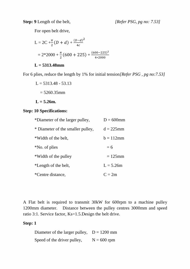
Step: 9 Length of the belt, [Refer PSG, pg no: 7.53]
For open belt drive,
L = 2C +𝜋
2(𝐷 + 𝑑) +
(𝐷−𝑑)
4𝑐
2
= 2*2000 + 𝜋
2(600 + 225) +
(600−225)2
4∗2000
L = 5313.48mm
For 6 plies, reduce the length by 1% for initial tension[Refer PSG , pg no:7.53]
L = 5313.48 - 53.13
= 5260.35mm
L = 5.26m.
Step: 10 Specifications:
*Diameter of the larger pulley, D = 600mm
* Diameter of the smaller pulley, d = 225mm
*Width of the belt, b = 112mm
*No. of plies = 6
*Width of the pulley = 125mm
*Length of the belt, L = 5.26m
*Centre distance, C = 2m
A Flat belt is required to transmit 30kW for 600rpm to a machine pulley 1200mm diameter. Distance between the pulley centres 3000mm and speed ratio 3:1. Service factor, Ks=1.5.Design the belt drive.
Step: 1
Diameter of the larger pulley, D = 1200 mm
Speed of the driver pulley, N = 600 rpm
WWW.VIDYARTHIPLUS.COM
WWW.VIDYARTHIPLUS.COM V+ TEAM
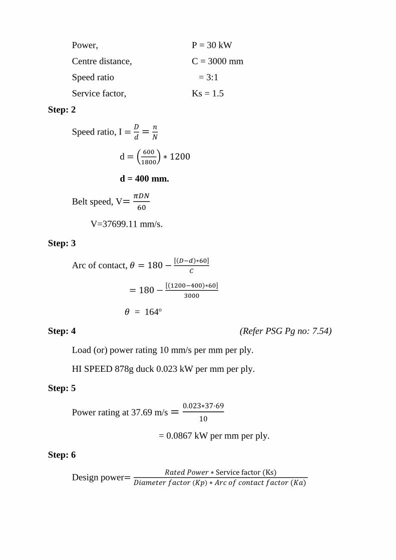
Power, P = 30 kW
Centre distance, C = 3000 mm
Speed ratio = 3:1
Service factor, Ks = 1.5
Step: 2
Speed ratio, I =𝐷
𝑑=
𝑛
𝑁
d = (600
1800) ∗ 1200
d = 400 mm.
Belt speed, V=𝜋𝐷𝑁
60
V=37699.11 mm/s.
Step: 3
Arc of contact, 𝜃 = 180 −[(𝐷−𝑑)∗60]
𝐶
= 180 −[(1200−400)∗60]
3000
𝜃 = 164o
Step: 4 (Refer PSG Pg no: 7.54)
Load (or) power rating 10 mm/s per mm per ply.
HI SPEED 878g duck 0.023 kW per mm per ply.
Step: 5
Power rating at 37.69 m/s =0.023∗37⋅69
10
= 0.0867 kW per mm per ply.
Step: 6
Design power=𝑅𝑎𝑡𝑒𝑑 𝑃𝑜𝑤𝑒𝑟 ∗ Service factor (Ks)
𝐷𝑖𝑎𝑚𝑒𝑡𝑒𝑟 𝑓𝑎𝑐𝑡𝑜𝑟 (𝐾𝑝) ∗ 𝐴𝑟𝑐 𝑜𝑓 𝑐𝑜𝑛𝑡𝑎𝑐𝑡 𝑓𝑎𝑐𝑡𝑜𝑟 (𝐾𝑎)
WWW.VIDYARTHIPLUS.COM
WWW.VIDYARTHIPLUS.COM V+ TEAM
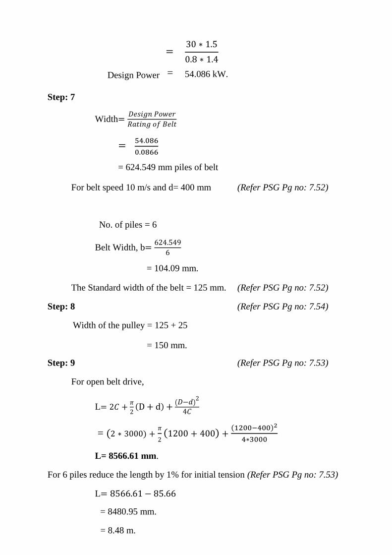
=30 ∗ 1.5
0.8 ∗ 1.4
Design Power = 54.086 kW.
Step: 7
Width=𝐷𝑒𝑠𝑖𝑔𝑛 𝑃𝑜𝑤𝑒𝑟
𝑅𝑎𝑡𝑖𝑛𝑔 𝑜𝑓 𝐵𝑒𝑙𝑡
=54.086
0.0866
= 624.549 mm piles of belt
For belt speed 10 m/s and d= 400 mm (Refer PSG Pg no: 7.52)
No. of piles = 6
Belt Width, b=624.549
6
= 104.09 mm.
The Standard width of the belt = 125 mm. (Refer PSG Pg no: 7.52)
Step: 8 (Refer PSG Pg no: 7.54)
Width of the pulley = 125 + 25
= 150 mm.
Step: 9 (Refer PSG Pg no: 7.53)
For open belt drive,
L= 2𝐶 +𝜋
2(D + d) +
(𝐷−𝑑)2
4𝐶
= (2 ∗ 3000) +𝜋
2(1200 + 400) +
(1200−400)2
4∗3000
L= 8566.61 mm.
For 6 piles reduce the length by 1% for initial tension (Refer PSG Pg no: 7.53)
L= 8566.61 − 85.66
= 8480.95 mm.
= 8.48 m.
WWW.VIDYARTHIPLUS.COM
WWW.VIDYARTHIPLUS.COM V+ TEAM
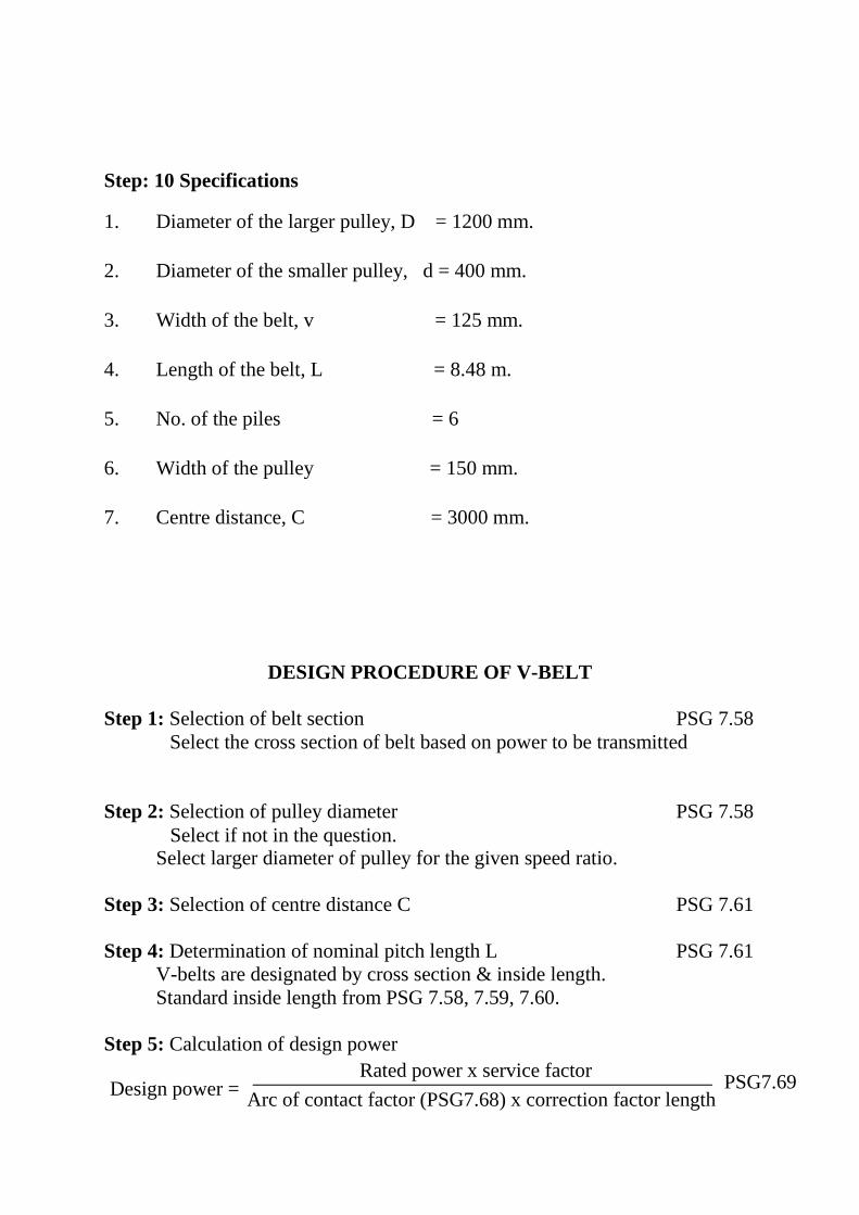
Step: 10 Specifications
1. Diameter of the larger pulley, D = 1200 mm.
2. Diameter of the smaller pulley, d = 400 mm.
3. Width of the belt, v = 125 mm.
4. Length of the belt, L = 8.48 m.
5. No. of the piles = 6
6. Width of the pulley = 150 mm.
7. Centre distance, C = 3000 mm.
DESIGN PROCEDURE OF V-BELT Step 1: Selection of belt section PSG 7.58 Select the cross section of belt based on power to be transmitted Step 2: Selection of pulley diameter PSG 7.58 Select if not in the question.
Select larger diameter of pulley for the given speed ratio. Step 3: Selection of centre distance C PSG 7.61 Step 4: Determination of nominal pitch length L PSG 7.61 V-belts are designated by cross section & inside length. Standard inside length from PSG 7.58, 7.59, 7.60. Step 5: Calculation of design power
Design power =Rated power x service factor
PSG7.69
Arc of contact factor (PSG7.68) x correction factor length
WWW.VIDYARTHIPLUS.COM
WWW.VIDYARTHIPLUS.COM V+ TEAM
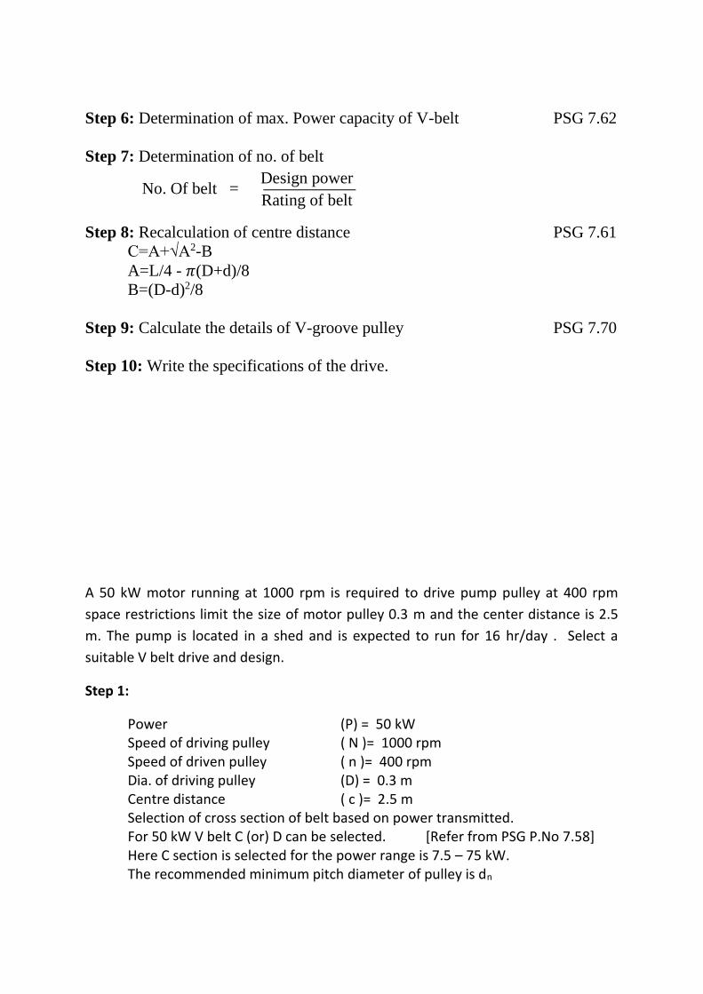
Step 6: Determination of max. Power capacity of V-belt PSG 7.62 Step 7: Determination of no. of belt
No. Of belt = Design power
Rating of belt Step 8: Recalculation of centre distance PSG 7.61
C=A+√A2-B A=L/4 - 𝜋(D+d)/8 B=(D-d)2/8
Step 9: Calculate the details of V-groove pulley PSG 7.70 Step 10: Write the specifications of the drive.
A 50 kW motor running at 1000 rpm is required to drive pump pulley at 400 rpm
space restrictions limit the size of motor pulley 0.3 m and the center distance is 2.5
m. The pump is located in a shed and is expected to run for 16 hr/day . Select a
suitable V belt drive and design.
Step 1:
Power (P) = 50 kW Speed of driving pulley ( N )= 1000 rpm Speed of driven pulley ( n )= 400 rpm Dia. of driving pulley (D) = 0.3 m Centre distance ( c )= 2.5 m Selection of cross section of belt based on power transmitted. For 50 kW V belt C (or) D can be selected. [Refer from PSG P.No 7.58] Here C section is selected for the power range is 7.5 – 75 kW. The recommended minimum pitch diameter of pulley is dn
WWW.VIDYARTHIPLUS.COM
WWW.VIDYARTHIPLUS.COM V+ TEAM
Step 2:
Speed ratio ( i ) = 𝐷
𝑑 =
𝑛
𝑁
i = 400
1000 = 0.4
0.4 = 0.3
𝑑
d = 0.3
0.4 = 0.75 = 750 mm
Step 3:
Select the center distance ( c ) = 2.5 x 1000
= 2500 mm
Step 4:
Nominal pitch length of the belt
Refer PSG Design data book [ P.No 7.61]
L = 2c + 𝜋
2 ( D + d ) +
( 𝐷−𝑑 )2
4𝑐
= 2x2.5 + 𝜋
2 ( 0.75 + 0.3 ) +
( 0.3−0.75 )2
4∗2.5
= 6.67 m
Nearest nominal pitch length [Refer PSG., P.No 7.60]
L = 6.863 m
Nominal pitch length = 6.863 m
Nearest nominal inside length 6807 mm is selected.
Designation of selected V belt is C6807
Step 5:
Design power = Rated power x service factor
Arc of contact factor x Correction factor
Refer PSG Design data book [ P.No 7.69]
Service factor Fa = 1.2 ( medium duty )
WWW.VIDYARTHIPLUS.COM
WWW.VIDYARTHIPLUS.COM V+ TEAM
Arc of contact factor Fd = 180O − 60O ( 0.75−0.3
2.5 )
= 169.2o
Arc of contact factor Fd = 0.97
Correction factor Fc = 1.14 [Refer PSG P.No., 7.60 ]
Design Power = 50 x 1.2
0.97 x 1.14 = 54.26 kW
Step 6:
Load rating of the belt
Refer PSG Design Data book [ P.No 7.62 ] at section c
kW = ( 1.475-0.49 - 42.7
𝑑𝑒 – 2.34 x 10⁻⁴ s2 ) s
de = dp x Fb
= 0.2 x 1.13
Speed ratio = 𝐷
𝑑 =
0.75
0.3 = 2.5
Fb = 1.13
de = 0.200 x 1.13
de = 0.226 m
Speed S = 𝜋𝐷𝑁
60
= π x 0.3 x 1000
60
= 15.71 m/s
kW = ( 1.1473 – 0.63142 – 0.0578 ) 15.71
= 7.196 kW
Step 7:
No. of belt = Design power
rating of the belt
WWW.VIDYARTHIPLUS.COM
WWW.VIDYARTHIPLUS.COM V+ TEAM
= 54.26
7.196
= 7.54 ~ 8
Step 8:
No. of belt = 8
Recalculate the center distance from [PSG P.No 7.61]
C = A + √𝐴2 − 𝐵
A = 𝐿
4 −
𝜋(𝐷+𝑑)
8
= 1.6675 – 0.41233
A = 1.255 m
B = (𝐷−𝑑)2
8
B = 0.0253 m3
C = 2.499 m
Step 9:
Dimension of V groove pulley
Refer PSG Design data book [P.No. 7.70]
Maximum depth (h) = 14.3 mm = 0.0143 m
Center distance groove (e) = 25.5 mm = 0.025m
Pitch width (lb) = 19 mm = 0.019m
Edge of the pulley to first groove center (f) = 17 mm = 0.017 m
Min. distance down to pitch line (b) = 5.7 mm = 0.0057 m
Outer dia. Of smaller pulley = d + 2b
= 0.3 + 2 ( 0.0057)
= 0.7614 m
Core dia. Of the pulley = d – 2h
WWW.VIDYARTHIPLUS.COM
WWW.VIDYARTHIPLUS.COM V+ TEAM
= 0.3 – 2 ( 0.0143)
= 0.2714 m
Width of the pulley = ( No. of belt – 1 ) x e + 2f
= 7 x 0.025 + (2 x 0.017)
= 0.209 m
Step 10:
Specification of V belt drive
Pitch dia. Of smaller pulley dp = 0.200 m
Pitch dia. Of larger pulley Dp = 0.750 m
No. of belt = 8
Selection of B belt used = C6807
Arc of contact = 169.2O
Center distance (c ) = 2.499 m
Specification of pulley
Outer dia. Of smaller pulley = 0.3114 m
Outer dia. Of larger pulley = 0.7614 m
Core dia. Of the pulley = 0.2714 m
Width of the pulley = 0.209 m
DESIGN PROCEDURE OF ROPE DRIVE
STEP-1: Calculation of design load Assume large factor of safety (say 15), If not given. Calculate the DESIGN LOAD: Design load =factor of safety x load to be lifted.
STEP-2: Selection of wire rope diameter Take the design load as the breaking strength. Obtain the rope diameter by referring data book. (PSG. 9.4 to 9.6).
WWW.VIDYARTHIPLUS.COM
WWW.VIDYARTHIPLUS.COM V+ TEAM
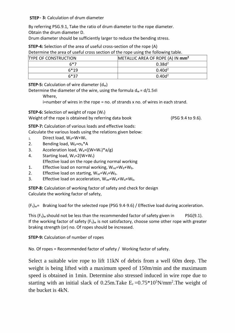
By referring PSG.9.1, Take the ratio of drum diameter to the rope diameter. Obtain the drum diameter D. Drum diameter should be sufficiently larger to reduce the bending stress.
STEP-4: Selection of the area of useful cross-section of the rope (A) Determine the area of useful cross section of the rope using the following table.
TYPE OF CONSTRUCTION METALLIC AREA OF ROPE (A) IN mm2
6*7 0.38d2
6*19 0.40d2
6*37 0.40d2
STEP-5: Calculation of wire diameter (dw) Determine the diameter of the wire, using the formula dw = d/1.5√i
Where, i=number of wires in the rope = no. of strands x no. of wires in each strand.
STEP-6: Selection of weight of rope (Wr) Weight of the rope is obtained by referring data book (PSG 9.4 to 9.6).
STEP-7: Calculation of various loads and effective loads: Calculate the various loads using the relations given below:
1. Direct load, Wd=W+Wr.
2. Bending load, Wb=b*A
3. Acceleration load, Wa=((W+Wr)*a/g) 4. Starting load, Ws=2(W+Wr)
Effective load on the rope during normal working 1. Effective load on normal working, Wne=Wd+Wb. 2. Effective load on starting, Wse=Ws+Wb. 3. Effective load on acceleration, Wae=Wa+Wd+Wb.
STEP-8: Calculation of working factor of safety and check for design Calculate the working factor of safety, (Fs)w= Braking load for the selected rope (PSG 9.4-9.6) / Effective load during acceleration.
This (Fs)w should not be less than the recommended factor of safety given in PSG(9.1). If the working factor of safety (Fs)w is not satisfactory, choose some other rope with greater braking strength (or) no. Of ropes should be increased.
STEP-9: Calculation of number of ropes No. Of ropes = Recommended factor of safety / Working factor of safety.
Select a suitable wire rope to lift 11kN of debris from a well 60m deep. The weight is being lifted with a maximum speed of 150m/min and the maximaum speed is obtained in 1min. Determine also stressed induced in wire rope due to starting with an initial slack of 0.25m.Take Er =0.75*105N/mm2.The weight of the bucket is 4kN.
STEP 3:- Calculation of drum diameter
WWW.VIDYARTHIPLUS.COM
WWW.VIDYARTHIPLUS.COM V+ TEAM
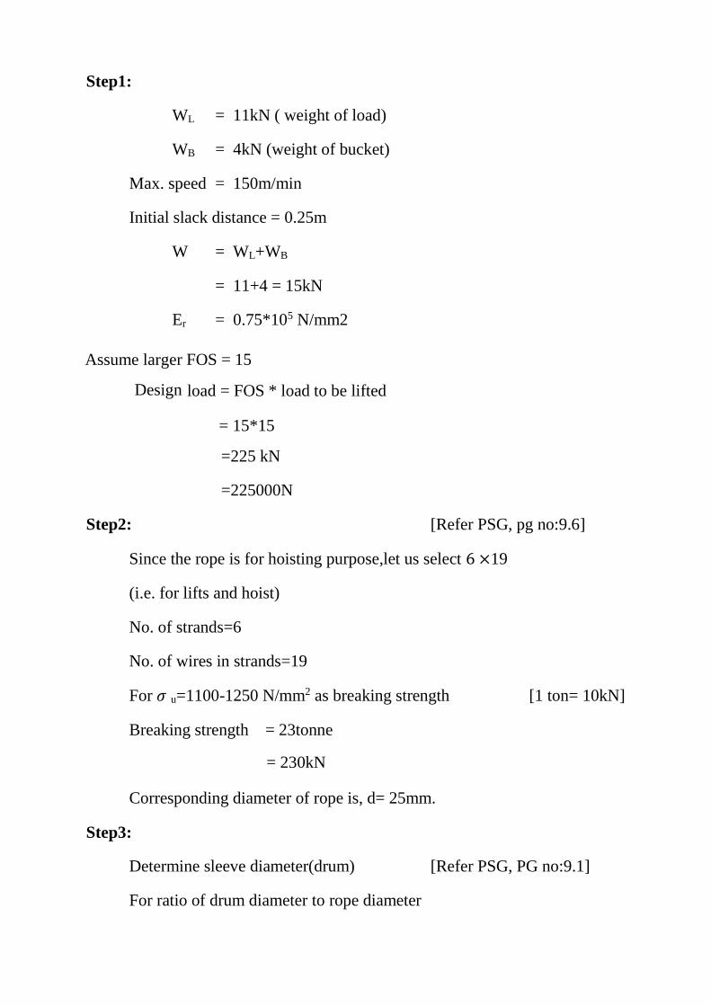
Step1:
WL = 11kN ( weight of load)
WB = 4kN (weight of bucket)
Max. speed = 150m/min
Initial slack distance = 0.25m
W = WL+WB
= 11+4 = 15kN
Er = 0.75*105 N/mm2
Assume larger FOS = 15
Design load = FOS * load to be lifted
= 15*15
=225 kN
=225000N
Step2: [Refer PSG, pg no:9.6]
Since the rope is for hoisting purpose,let us select 6 ×19
(i.e. for lifts and hoist)
No. of strands=6
No. of wires in strands=19
For 𝜎 u=1100-1250 N/mm2 as breaking strength [1 ton= 10kN]
Breaking strength = 23tonne
= 230kN
Corresponding diameter of rope is, d= 25mm.
Step3:
Determine sleeve diameter(drum) [Refer PSG, PG no:9.1]
For ratio of drum diameter to rope diameter
WWW.VIDYARTHIPLUS.COM
WWW.VIDYARTHIPLUS.COM V+ TEAM
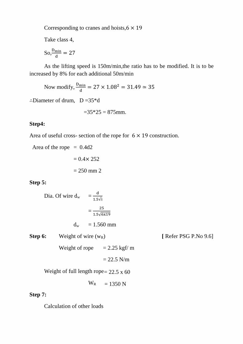
Corresponding to cranes and hoists,6 × 19
Take class 4,
So, Dmin
d= 27
As the lifting speed is 150m/min,the ratio has to be modified. It is to be increased by 8% for each additional 50m/min
Now modify, Dmin
d= 27 × 1.082 = 31.49 ≃ 35
∴Diameter of drum, D =35*d
=35*25 = 875mm.
Step4:
Area of useful cross- section of the rope for 6 × 19 construction.
Area of the rope = 0.4d2
= 0.4× 252
= 250 mm 2
Step 5:
Dia. Of wire dw = d
1.5√i
= 25
1.5√6x19
dw = 1.560 mm
Step 6: Weight of wire (wR) [ Refer PSG P.No 9.6]
Weight of rope = 2.25 kgf/ m
= 22.5 N/m
Weight of full length rope = 22.5 x 60
WR = 1350 N
Step 7:
Calculation of other loads
WWW.VIDYARTHIPLUS.COM
WWW.VIDYARTHIPLUS.COM V+ TEAM
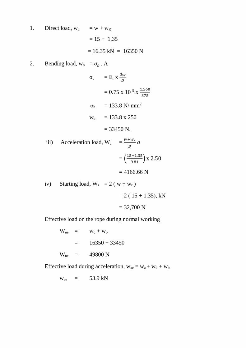
1. Direct load, wd = w + wR
= 15 + 1.35
= 16.35 kN = 16350 N
2. Bending load, wb = 𝜎𝑏 . A
σb = Er x 𝑑𝑊
𝐷
= 0.75 x 10 5 x 1.560
875
σb = 133.8 N/ mm2
wb = 133.8 x 250
= 33450 N.
iii) Acceleration load, Wa = 𝑤+𝑤𝑟
𝑔 a
= (15+1.35
9.81) x 2.50
= 4166.66 N
iv) Starting load, Ws = 2 ( w + wr )
= 2 ( 15 + 1.35), kN
= 32,700 N
Effective load on the rope during normal working
Wne = wd + wb
= 16350 + 33450
Wne = 49800 N
Effective load during acceleration, wae = wa + wd + wb
wae = 53.9 kN
WWW.VIDYARTHIPLUS.COM
WWW.VIDYARTHIPLUS.COM V+ TEAM
Step 8:
(Fs)w = Breaking load
Effective load during acceleration
= 230 x 1000
53.9 = 4.267
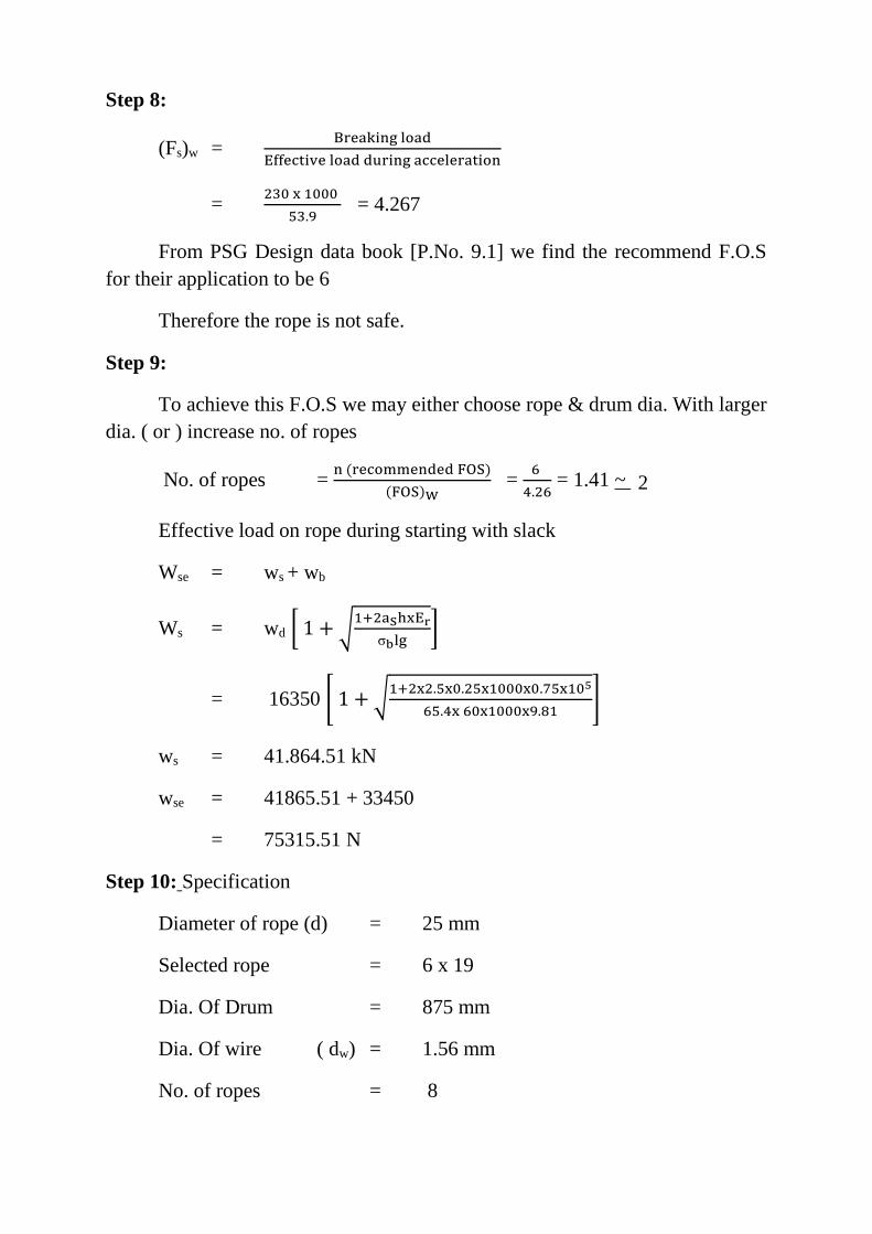
From PSG Design data book [P.No. 9.1] we find the recommend F.O.S for their application to be 6
Therefore the rope is not safe.
Step 9:
To achieve this F.O.S we may either choose rope & drum dia. With larger dia. ( or ) increase no. of ropes
No. of ropes = n (recommended FOS)
(FOS)W =
6
4.26 = 1.41 ~ 2
Effective load on rope during starting with slack
Wse = ws + wb
Ws = wd [ 1 + √1+2aShxEr
σblg]
= 16350 [ 1 + √1+2x2.5x0.25x1000x0.75x105
65.4x 60x1000x9.81]
ws = 41.864.51 kN
wse = 41865.51 + 33450
= 75315.51 N
Step 10: Specification
Diameter of rope (d) = 25 mm
Selected rope = 6 x 19
Dia. Of Drum = 875 mm
Dia. Of wire ( dw) = 1.56 mm
No. of ropes = 8
WWW.VIDYARTHIPLUS.COM
WWW.VIDYARTHIPLUS.COM V+ TEAM
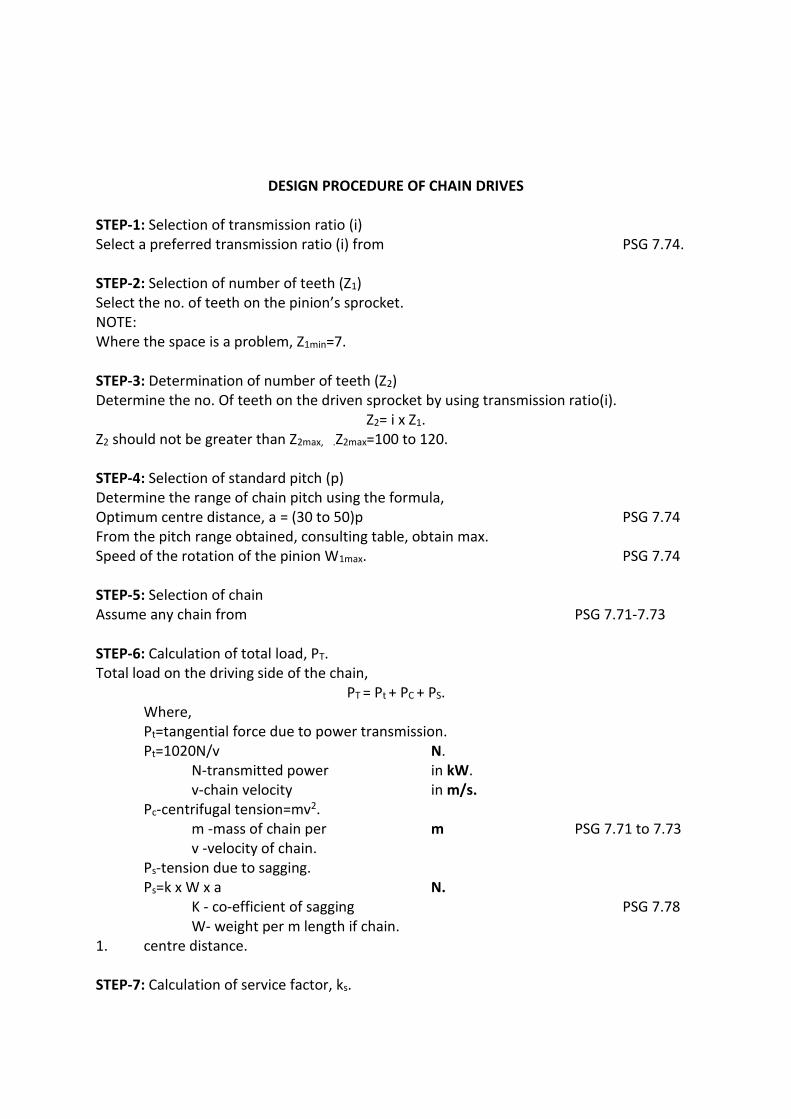
DESIGN PROCEDURE OF CHAIN DRIVES
STEP-1: Selection of transmission ratio (i) Select a preferred transmission ratio (i) from PSG 7.74. STEP-2: Selection of number of teeth (Z1) Select the no. of teeth on the pinion’s sprocket. NOTE: Where the space is a problem, Z1min=7. STEP-3: Determination of number of teeth (Z2) Determine the no. Of teeth on the driven sprocket by using transmission ratio(i).
Z2= i x Z1. Z2 should not be greater than Z2max, .Z2max=100 to 120. STEP-4: Selection of standard pitch (p) Determine the range of chain pitch using the formula, Optimum centre distance, a = (30 to 50)p PSG 7.74 From the pitch range obtained, consulting table, obtain max. Speed of the rotation of the pinion W1max. PSG 7.74 STEP-5: Selection of chain Assume any chain from PSG 7.71-7.73 STEP-6: Calculation of total load, PT. Total load on the driving side of the chain,
PT = Pt + PC + PS. Where, Pt=tangential force due to power transmission. Pt=1020N/v N.
N-transmitted power in kW. v-chain velocity in m/s.
Pc-centrifugal tension=mv2. m -mass of chain per m PSG 7.71 to 7.73 v -velocity of chain.
Ps-tension due to sagging. Ps=k x W x a N.
K - co-efficient of sagging PSG 7.78 W- weight per m length if chain.
1. centre distance. STEP-7: Calculation of service factor, ks.
WWW.VIDYARTHIPLUS.COM
WWW.VIDYARTHIPLUS.COM V+ TEAM
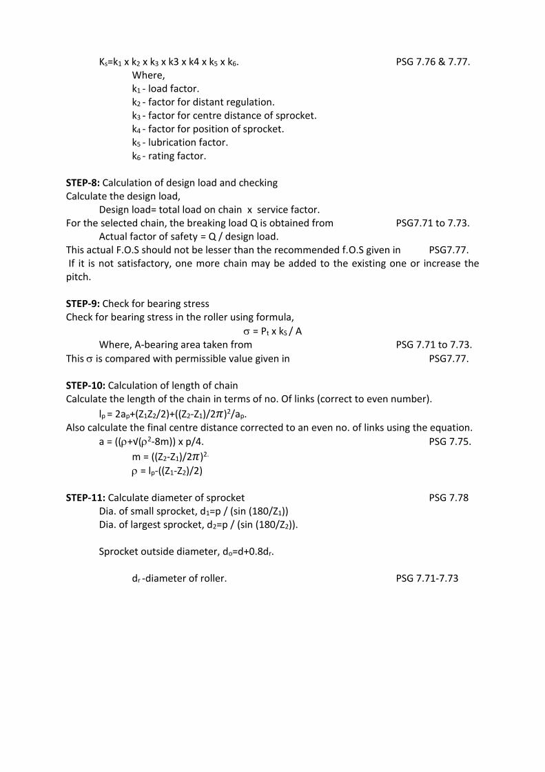
Ks=k1 x k2 x k3 x k3 x k4 x k5 x k6. PSG 7.76 & 7.77. Where, k1 - load factor. k2 - factor for distant regulation. k3 - factor for centre distance of sprocket. k4 - factor for position of sprocket. k5 - lubrication factor. k6 - rating factor.
STEP-8: Calculation of design load and checking Calculate the design load,
Design load= total load on chain x service factor. For the selected chain, the breaking load Q is obtained from PSG7.71 to 7.73.
Actual factor of safety = Q / design load. This actual F.O.S should not be lesser than the recommended f.O.S given in PSG7.77. If it is not satisfactory, one more chain may be added to the existing one or increase the pitch. STEP-9: Check for bearing stress Check for bearing stress in the roller using formula,
= Pt x kS / A Where, A-bearing area taken from PSG 7.71 to 7.73.
This is compared with permissible value given in PSG7.77. STEP-10: Calculation of length of chain Calculate the length of the chain in terms of no. Of links (correct to even number).
lp = 2ap+(Z1Z2/2)+((Z2-Z1)/2𝜋)2/ap. Also calculate the final centre distance corrected to an even no. of links using the equation.
a = ((+√(2-8m)) x p/4. PSG 7.75.
m = ((Z2-Z1)/2𝜋)2.
= lp-((Z1-Z2)/2) STEP-11: Calculate diameter of sprocket PSG 7.78
Dia. of small sprocket, d1=p / (sin (180/Z1)) Dia. of largest sprocket, d2=p / (sin (180/Z2)). Sprocket outside diameter, do=d+0.8dr.
dr -diameter of roller. PSG 7.71-7.73
WWW.VIDYARTHIPLUS.COM
WWW.VIDYARTHIPLUS.COM V+ TEAM
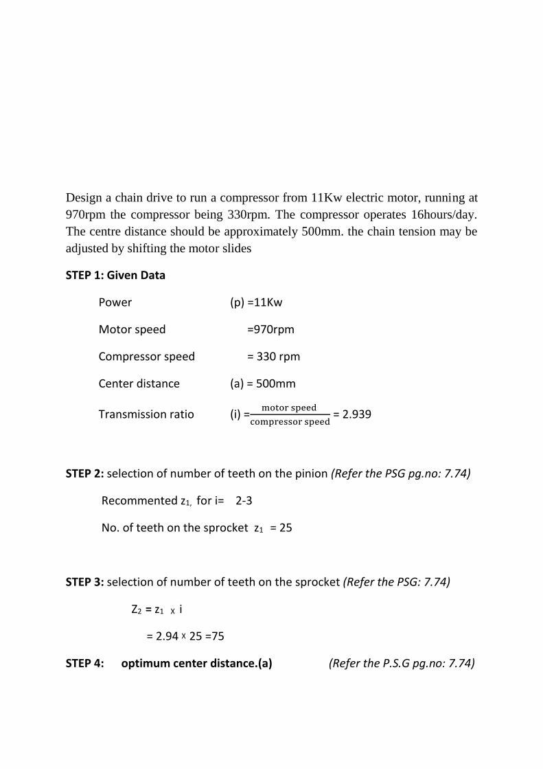
Design a chain drive to run a compressor from 11Kw electric motor, running at 970rpm the compressor being 330rpm. The compressor operates 16hours/day. The centre distance should be approximately 500mm. the chain tension may be adjusted by shifting the motor slides
STEP 1: Given Data
Power (p) =11Kw
Motor speed =970rpm
Compressor speed = 330 rpm
Center distance (a) = 500mm
Transmission ratio (i) =motor speed
compressor speed = 2.939
STEP 2: selection of number of teeth on the pinion (Refer the PSG pg.no: 7.74)
Recommented z1, for i= 2-3
No. of teeth on the sprocket z1 = 25
STEP 3: selection of number of teeth on the sprocket (Refer the PSG: 7.74)
Z2 = z1 X i
= 2.94 X 25 =75
STEP 4: optimum center distance.(a) (Refer the P.S.G pg.no: 7.74)
WWW.VIDYARTHIPLUS.COM
WWW.VIDYARTHIPLUS.COM V+ TEAM
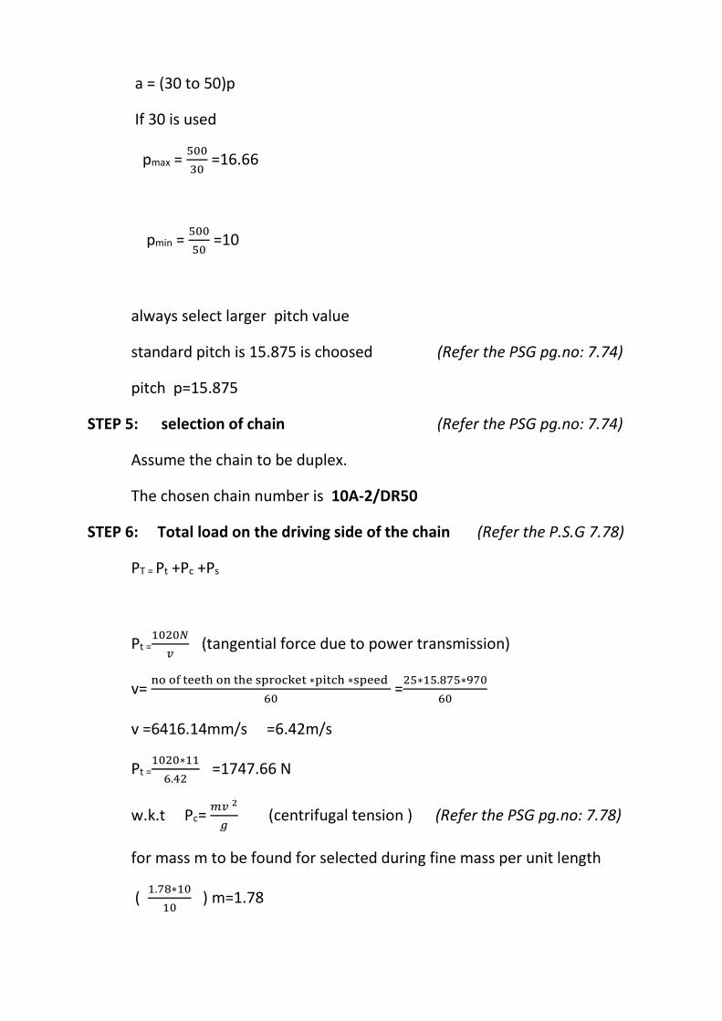
a = (30 to 50)p
If 30 is used
pmax = 500
30 =16.66
pmin = 500
50 =10
always select larger pitch value
standard pitch is 15.875 is choosed (Refer the PSG pg.no: 7.74)
pitch p=15.875
STEP 5: selection of chain (Refer the PSG pg.no: 7.74)
Assume the chain to be duplex.
The chosen chain number is 10A-2/DR50
STEP 6: Total load on the driving side of the chain (Refer the P.S.G 7.78)
PT = Pt +Pc +Ps
Pt =1020𝑁
𝑣 (tangential force due to power transmission)
v= no of teeth on the sprocket ∗pitch ∗speed
60 =
25∗15.875∗970
60
v =6416.14mm/s =6.42m/s
Pt =1020∗11
6.42 =1747.66 N
w.k.t Pc =𝑚𝑣 2
𝑔 (centrifugal tension ) (Refer the PSG pg.no: 7.78)
for mass m to be found for selected during fine mass per unit length
( 1.78∗10
10 ) m=1.78
WWW.VIDYARTHIPLUS.COM
WWW.VIDYARTHIPLUS.COM V+ TEAM
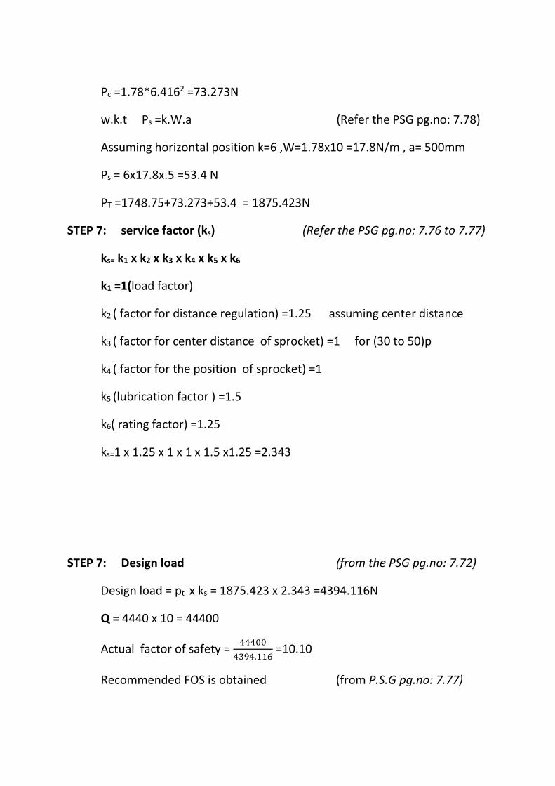
Pc =1.78*6.4162 =73.273N
w.k.t Ps =k.W.a (Refer the PSG pg.no: 7.78)
Assuming horizontal position k=6 ,W=1.78x10 =17.8N/m , a= 500mm
Ps = 6x17.8x.5 =53.4 N
PT =1748.75+73.273+53.4 = 1875.423N
STEP 7: service factor (ks) (Refer the PSG pg.no: 7.76 to 7.77)
ks= k1 x k2 x k3 x k4 x k5 x k6
k1 =1(load factor)
k2 ( factor for distance regulation) =1.25 assuming center distance
k3 ( factor for center distance of sprocket) =1 for (30 to 50)p
k4 ( factor for the position of sprocket) =1
k5 (lubrication factor ) =1.5
k6( rating factor) =1.25
ks=1 x 1.25 x 1 x 1 x 1.5 x1.25 =2.343
STEP 7: Design load (from the PSG pg.no: 7.72)
Design load = pt x ks = 1875.423 x 2.343 =4394.116N
Q = 4440 x 10 = 44400
Actual factor of safety = 44400
4394.116 =10.10
Recommended FOS is obtained (from P.S.G pg.no: 7.77)
WWW.VIDYARTHIPLUS.COM
WWW.VIDYARTHIPLUS.COM V+ TEAM
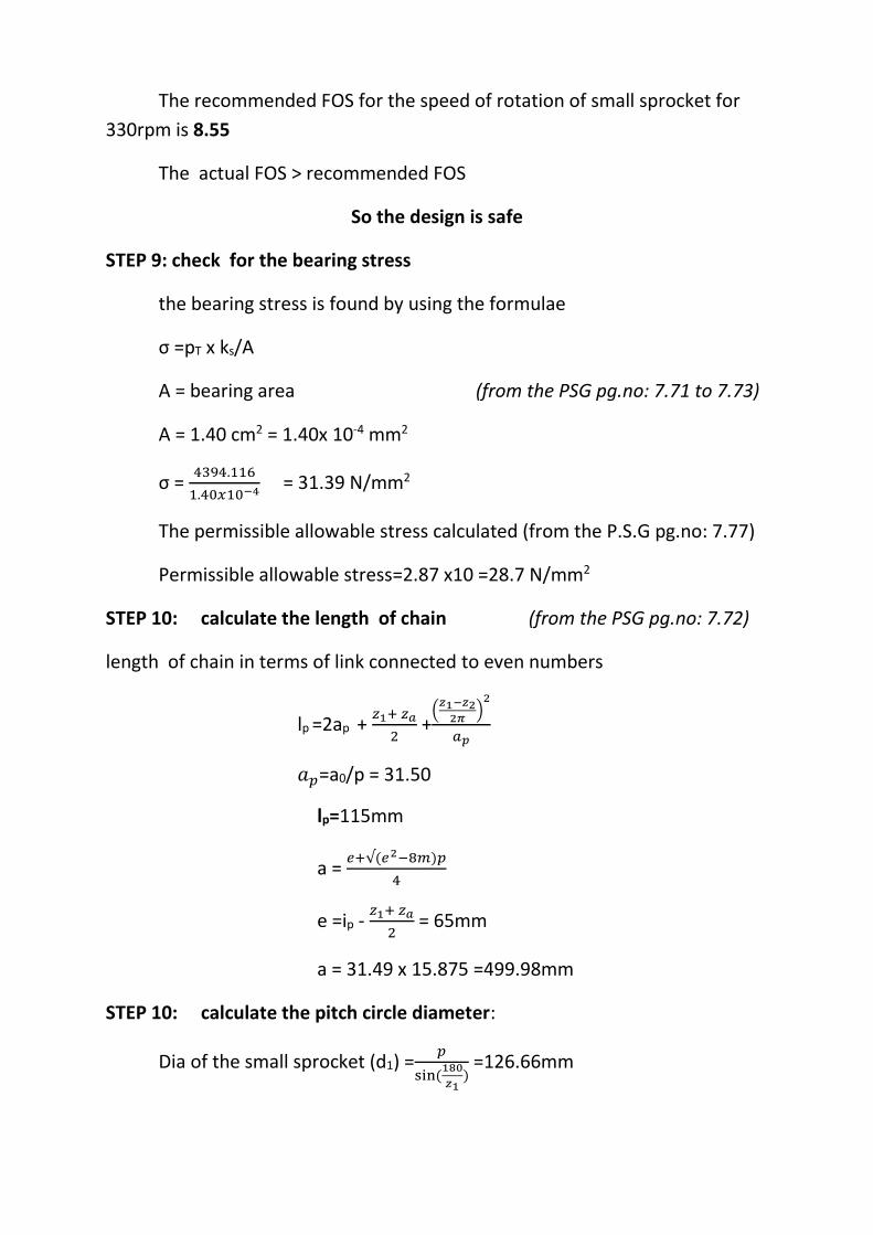
The recommended FOS for the speed of rotation of small sprocket for
330rpm is 8.55
The actual FOS > recommended FOS
So the design is safe
STEP 9: check for the bearing stress
the bearing stress is found by using the formulae
σ =pT x ks/A
A = bearing area (from the PSG pg.no: 7.71 to 7.73)
A = 1.40 cm2 = 1.40x 10⁻⁴ mm2
σ = 4394.116
1.40𝑥10−4 = 31.39 N/mm2
The permissible allowable stress calculated (from the P.S.G pg.no: 7.77)
Permissible allowable stress=2.87 x10 =28.7 N/mm2
STEP 10: calculate the length of chain (from the PSG pg.no: 7.72)
length of chain in terms of link connected to even numbers
lp =2ap + 𝑧1+ 𝑧𝑎
2 +
(𝑧1−𝑧2
2𝜋)
2
𝑎𝑝
𝑎𝑝=a0/p = 31.50
lp=115mm
a = 𝑒+√(𝑒2−8𝑚)𝑝
4
e =ip - 𝑧1+ 𝑧𝑎
2 = 65mm
a = 31.49 x 15.875 =499.98mm
STEP 10: calculate the pitch circle diameter:
Dia of the small sprocket (d1) =𝑝
sin (180
𝑧1) =126.66mm
WWW.VIDYARTHIPLUS.COM
WWW.VIDYARTHIPLUS.COM V+ TEAM
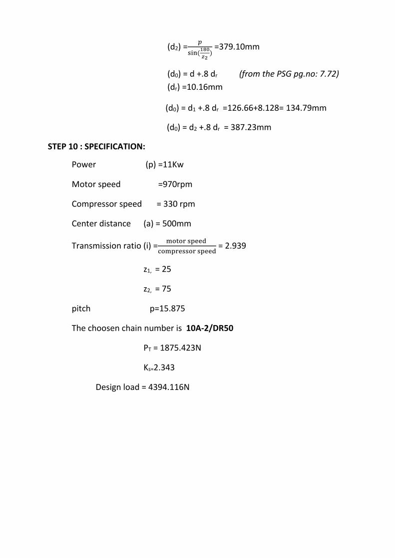
(d2) =𝑝
sin (180
𝑧2) =379.10mm
(d0) = d +.8 dr (from the PSG pg.no: 7.72)
(dr) =10.16mm
(d0) = d1 +.8 dr =126.66+8.128= 134.79mm
(d0) = d2 +.8 dr = 387.23mm
STEP 10 : SPECIFICATION:
Power (p) =11Kw
Motor speed =970rpm
Compressor speed = 330 rpm
Center distance (a) = 500mm
Transmission ratio (i) =motor speed
compressor speed = 2.939
z1, = 25
z2, = 75
pitch p=15.875
The choosen chain number is 10A-2/DR50
PT = 1875.423N
Ks=2.343
Design load = 4394.116N
WWW.VIDYARTHIPLUS.COM
WWW.VIDYARTHIPLUS.COM V+ TEAM
UNIT – 2
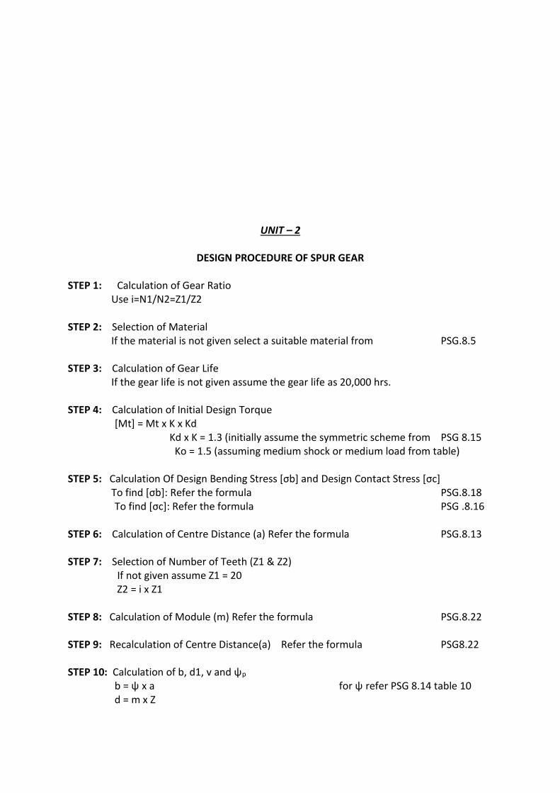
DESIGN PROCEDURE OF SPUR GEAR STEP 1: Calculation of Gear Ratio Use i=N1/N2=Z1/Z2 STEP 2: Selection of Material If the material is not given select a suitable material from PSG.8.5 STEP 3: Calculation of Gear Life If the gear life is not given assume the gear life as 20,000 hrs. STEP 4: Calculation of Initial Design Torque [Mt] = Mt х K х Kd Kd х K = 1.3 (initially assume the symmetric scheme from PSG 8.15 Ko = 1.5 (assuming medium shock or medium load from table) STEP 5: Calculation Of Design Bending Stress [σb] and Design Contact Stress [σc] To find [σb]: Refer the formula PSG.8.18 To find [σc]: Refer the formula PSG .8.16 STEP 6: Calculation of Centre Distance (a) Refer the formula PSG.8.13 STEP 7: Selection of Number of Teeth (Z1 & Z2) If not given assume Z1 = 20 Z2 = i х Z1 STEP 8: Calculation of Module (m) Refer the formula PSG.8.22 STEP 9: Recalculation of Centre Distance(a) Refer the formula PSG8.22 STEP 10: Calculation of b, d1, v and ψp b = ψ х a for ψ refer PSG 8.14 table 10 d = m х Z
WWW.VIDYARTHIPLUS.COM
WWW.VIDYARTHIPLUS.COM V+ TEAM
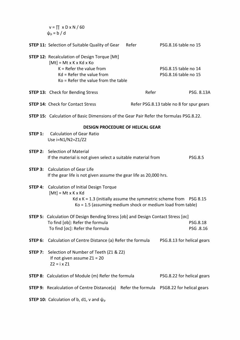
v = ∏ х D х N / 60 ψp = b / d STEP 11: Selection of Suitable Quality of Gear Refer PSG.8.16 table no 15 STEP 12: Recalculation of Design Torque [Mt] [Mt] = Mt х K х Kd х Ko K = Refer the value from PSG.8.15 table no 14 Kd = Refer the value from PSG.8.16 table no 15 Ko = Refer the value from the table STEP 13: Check for Bending Stress Refer PSG. 8.13A STEP 14: Check for Contact Stress Refer PSG.8.13 table no 8 for spur gears STEP 15: Calculation of Basic Dimensions of the Gear Pair Refer the formulas PSG.8.22.
DESIGN PROCEDURE OF HELICAL GEAR
STEP 1: Calculation of Gear Ratio Use i=N1/N2=Z1/Z2 STEP 2: Selection of Material If the material is not given select a suitable material from PSG.8.5 STEP 3: Calculation of Gear Life If the gear life is not given assume the gear life as 20,000 hrs. STEP 4: Calculation of Initial Design Torque [Mt] = Mt х K х Kd Kd х K = 1.3 (initially assume the symmetric scheme from PSG 8.15 Ko = 1.5 (assuming medium shock or medium load from table) STEP 5: Calculation Of Design Bending Stress [σb] and Design Contact Stress [σc] To find [σb]: Refer the formula PSG.8.18 To find [σc]: Refer the formula PSG .8.16 STEP 6: Calculation of Centre Distance (a) Refer the formula PSG.8.13 for helical gears STEP 7: Selection of Number of Teeth (Z1 & Z2) If not given assume Z1 = 20 Z2 = i х Z1 STEP 8: Calculation of Module (m) Refer the formula PSG.8.22 for helical gears STEP 9: Recalculation of Centre Distance(a) Refer the formula PSG8.22 for helical gears STEP 10: Calculation of b, d1, v and ψp
WWW.VIDYARTHIPLUS.COM
WWW.VIDYARTHIPLUS.COM V+ TEAM
b = ψ х a for ψ refer PSG 8.14 table 10 d = m х Z v = ∏ х D х N / 60 ψp = b / d STEP 11: Selection of Suitable Quality of Gear Refer PSG.8.16 table no 15 STEP 12: Recalculation of Design Torque [Mt] [Mt] = Mt х K х Kd х Ko K = Refer the value from PSG.8.15 table no 14 Kd = Refer the value from PSG.8.16 table no 15 Ko = Refer the value from the table STEP 13: Check for Bending Stress Refer PSG. 8.13A for helical gears STEP 14: Check for Contact Stress Refer PSG.8.13 table no 8 for helical gears STEP 15: Calculation of Basic Dimensions of the Gear Pair Refer the formulas PSG.8.22.
UNIT – 3
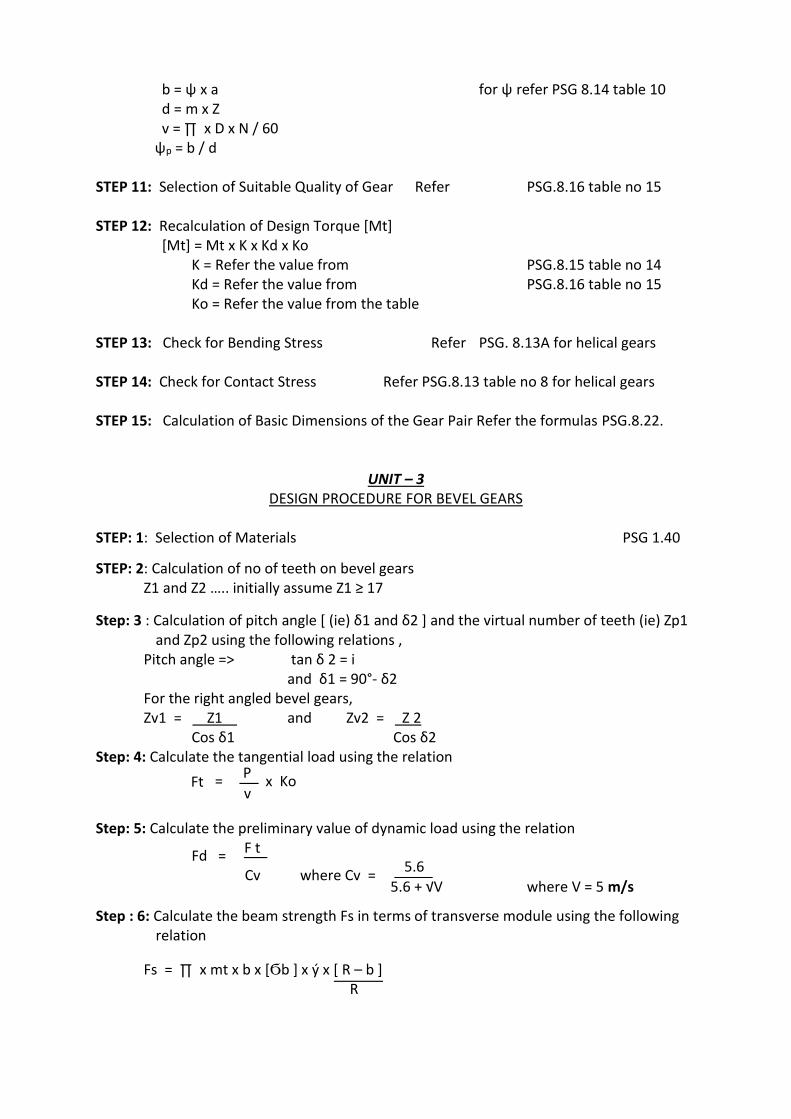
DESIGN PROCEDURE FOR BEVEL GEARS STEP: 1: Selection of Materials PSG 1.40
STEP: 2: Calculation of no of teeth on bevel gears Z1 and Z2 ….. initially assume Z1 ≥ 17
Step: 3 : Calculation of pitch angle [ (ie) δ1 and δ2 ] and the virtual number of teeth (ie) Zp1 and Zp2 using the following relations ,
Pitch angle => tan δ 2 = i and δ1 = 90°- δ2
For the right angled bevel gears, Zv1 = Z1 and Zv2 = Z 2
Cos δ1 Cos δ2 Step: 4: Calculate the tangential load using the relation Ft =
P x Ko v
Step: 5: Calculate the preliminary value of dynamic load using the relation
Fd = F t
Cv where Cv =
5.6 5.6 + √V where V = 5 m/s
Step : 6: Calculate the beam strength Fs in terms of transverse module using the following relation
Fs = ∏ x mt x b x [Ϭb ] x ý x [ R – b ] R
WWW.VIDYARTHIPLUS.COM
WWW.VIDYARTHIPLUS.COM V+ TEAM
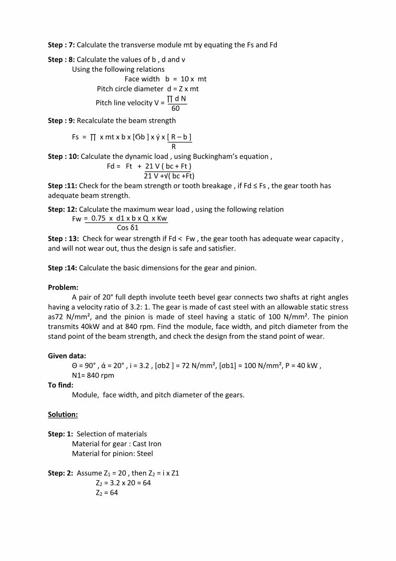
Step : 7: Calculate the transverse module mt by equating the Fs and Fd
Step : 8: Calculate the values of b , d and v Using the following relations Face width b = 10 x mt Pitch circle diameter d = Z x mt
Pitch line velocity V = ∏ d N
60
Step : 9: Recalculate the beam strength
Fs = ∏ x mt x b x [Ϭb ] x ý x [ R – b ] R Step : 10: Calculate the dynamic load , using Buckingham’s equation , Fd = Ft + 21 V ( bc + Ft ) 21 V +√( bc +Ft) Step :11: Check for the beam strength or tooth breakage , if Fd ≤ Fs , the gear tooth has adequate beam strength.
Step: 12: Calculate the maximum wear load , using the following relation Fw = 0.75 x d1 x b x Q x Kw Cos δ1 Step : 13: Check for wear strength if Fd < Fw , the gear tooth has adequate wear capacity , and will not wear out, thus the design is safe and satisfier. Step :14: Calculate the basic dimensions for the gear and pinion. Problem: A pair of 20° full depth involute teeth bevel gear connects two shafts at right angles having a velocity ratio of 3.2: 1. The gear is made of cast steel with an allowable static stress as72 N/mm², and the pinion is made of steel having a static of 100 N/mm². The pinion transmits 40kW and at 840 rpm. Find the module, face width, and pitch diameter from the stand point of the beam strength, and check the design from the stand point of wear. Given data:
Θ = 90° , ά = 20° , i = 3.2 , [σb2 ] = 72 N/mm², [σb1] = 100 N/mm², P = 40 kW , N1= 840 rpm
To find: Module, face width, and pitch diameter of the gears. Solution: Step: 1: Selection of materials Material for gear : Cast Iron Material for pinion: Steel Step: 2: Assume Z1 = 20 , then Z2 = i x Z1 Z2 = 3.2 x 20 = 64 Z2 = 64
WWW.VIDYARTHIPLUS.COM
WWW.VIDYARTHIPLUS.COM V+ TEAM
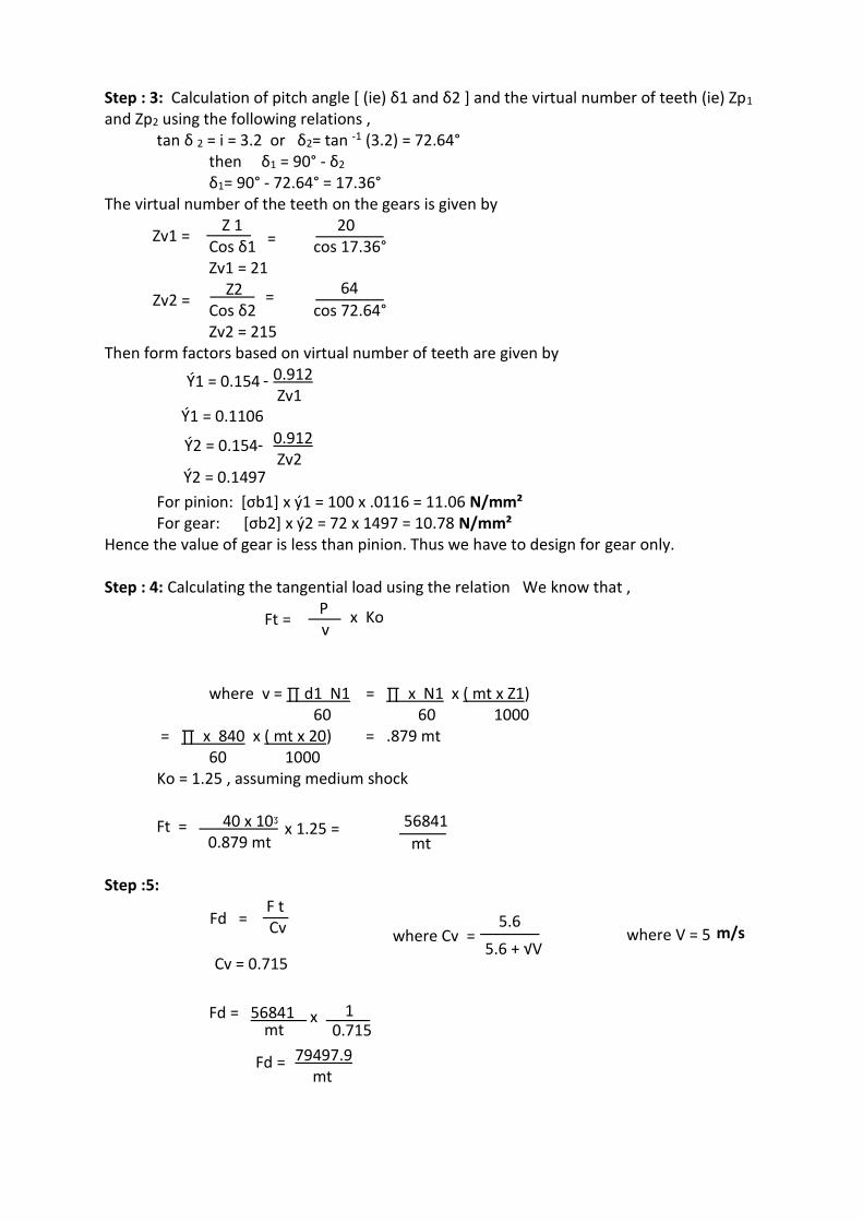
Step : 3: Calculation of pitch angle [ (ie) δ1 and δ2 ] and the virtual number of teeth (ie) Zp1 and Zp2 using the following relations , tan δ 2 = i = 3.2 or δ2= tan -1 (3.2) = 72.64°
then δ1 = 90° - δ2 δ1= 90° - 72.64° = 17.36°
The virtual number of the teeth on the gears is given by
Zv1 = Z 1
= 20
Cos δ1 cos 17.36° Zv1 = 21
Zv2 =
Z2 = 64 Cos δ2 cos 72.64° Zv2 = 215 Then form factors based on virtual number of teeth are given by Ý1 = 0.154 - 0.912 Zv1 Ý1 = 0.1106 Ý2 = 0.154 - 0.912 Zv2 Ý2 = 0.1497
For pinion: [σb1] x ý1 = 100 x .0116 = 11.06 N/mm² For gear: [σb2] x ý2 = 72 x 1497 = 10.78 N/mm²
Hence the value of gear is less than pinion. Thus we have to design for gear only. Step : 4: Calculating the tangential load using the relation We know that ,
Ft = P
x Ko
v
where v = ∏ d1 N1 = ∏ x N1 x ( mt x Z1) 60 60 1000 = ∏ x 840 x ( mt x 20) = .879 mt 60 1000 Ko = 1.25 , assuming medium shock Ft = 40 x 10ᶾ x 1.25 = 56841 0.879 mt mt Step :5:
Fd = F t
Cv where Cv = 5.6
5.6 + √V where V = 5 m/s
Cv = 0.715
Fd = 56841 x 1 mt 0.715 Fd = 79497.9 mt
WWW.VIDYARTHIPLUS.COM
WWW.VIDYARTHIPLUS.COM V+ TEAM
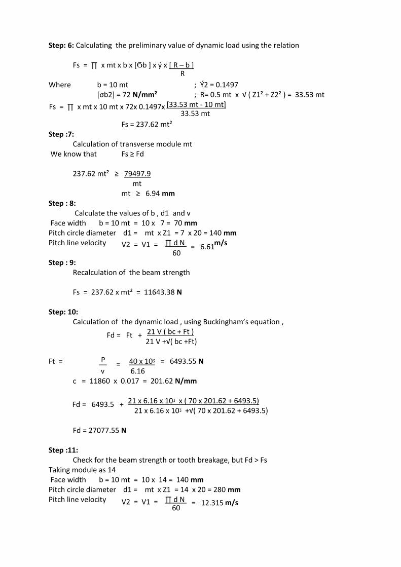
Step: 6: Calculating the preliminary value of dynamic load using the relation Fs = ∏ x mt x b x [Ϭb ] x ý x [ R – b ] R Where b = 10 mt ; Ý2 = 0.1497 [σb2] = 72 N/mm² ; R= 0.5 mt x √ ( Z1² + Z2² ) = 33.53 mt
Fs = ∏ x mt x 10 mt x 72x 0.1497x [33.53 mt - 10 mt] 33.53 mt Fs = 237.62 mt² Step :7: Calculation of transverse module mt We know that Fs ≥ Fd 237.62 mt² ≥ 79497.9 mt mt ≥ 6.94 mm Step : 8: Calculate the values of b , d1 and v Face width b = 10 mt = 10 x 7 = 70 mm Pitch circle diameter d1 = mt x Z1 = 7 x 20 = 140 mm Pitch line velocity V2 = V1 = ∏ d N
= 6.61m/s
60 Step : 9: Recalculation of the beam strength Fs = 237.62 x mt² = 11643.38 N Step: 10: Calculation of the dynamic load , using Buckingham’s equation , Fd = Ft + 21 V ( bc + Ft ) 21 V +√( bc +Ft) Ft = P = 40 x 10ᶾ = 6493.55 N v 6.16 c = 11860 x 0.017 = 201.62 N/mm Fd = 6493.5 + 21 x 6.16 x 10ᶾ x ( 70 x 201.62 + 6493.5) 21 x 6.16 x 10ᶾ +√( 70 x 201.62 + 6493.5) Fd = 27077.55 N Step :11: Check for the beam strength or tooth breakage, but Fd > Fs Taking module as 14 Face width b = 10 mt = 10 x 14 = 140 mm Pitch circle diameter d1 = mt x Z1 = 14 x 20 = 280 mm Pitch line velocity V2 = V1 = ∏ d N = 12.315 m/s
60
WWW.VIDYARTHIPLUS.COM
WWW.VIDYARTHIPLUS.COM V+ TEAM
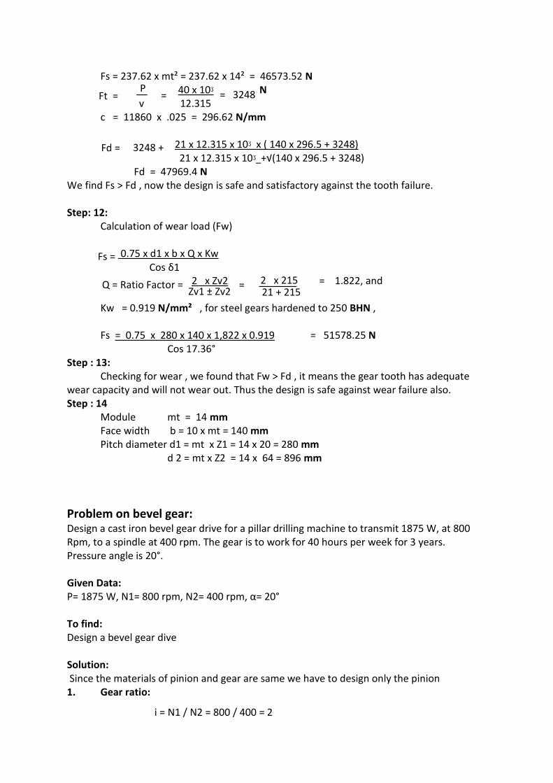
Fs = 237.62 x mt² = 237.62 x 14² = 46573.52 N
Ft = P
= 40 x 10ᶾ = 3248 N
v 12.315 c = 11860 x .025 = 296.62 N/mm Fd = 3248 + 21 x 12.315 x 10ᶾ x ( 140 x 296.5 + 3248) 21 x 12.315 x 10ᶾ +√(140 x 296.5 + 3248) Fd = 47969.4 N We find Fs > Fd , now the design is safe and satisfactory against the tooth failure. Step: 12: Calculation of wear load (Fw) Fs = 0.75 x d1 x b x Q x Kw Cos δ1 Q = Ratio Factor = 2 x Zv2 = 2 x 215 = 1.822, and Zv1 ± Zv2 21 + 215 Kw = 0.919 N/mm² , for steel gears hardened to 250 BHN , Fs = 0.75 x 280 x 140 x 1,822 x 0.919 = 51578.25 N Cos 17.36° Step : 13: Checking for wear , we found that Fw > Fd , it means the gear tooth has adequate wear capacity and will not wear out. Thus the design is safe against wear failure also. Step : 14 Module mt = 14 mm Face width b = 10 x mt = 140 mm Pitch diameter d1 = mt x Z1 = 14 x 20 = 280 mm d 2 = mt x Z2 = 14 x 64 = 896 mm
Problem on bevel gear: Design a cast iron bevel gear drive for a pillar drilling machine to transmit 1875 W, at 800 Rpm, to a spindle at 400 rpm. The gear is to work for 40 hours per week for 3 years. Pressure angle is 20°. Given Data: P= 1875 W, N1= 800 rpm, N2= 400 rpm, α= 20° To find: Design a bevel gear dive Solution: Since the materials of pinion and gear are same we have to design only the pinion 1. Gear ratio:
i = N1 / N2 = 800 / 400 = 2
WWW.VIDYARTHIPLUS.COM
WWW.VIDYARTHIPLUS.COM V+ TEAM
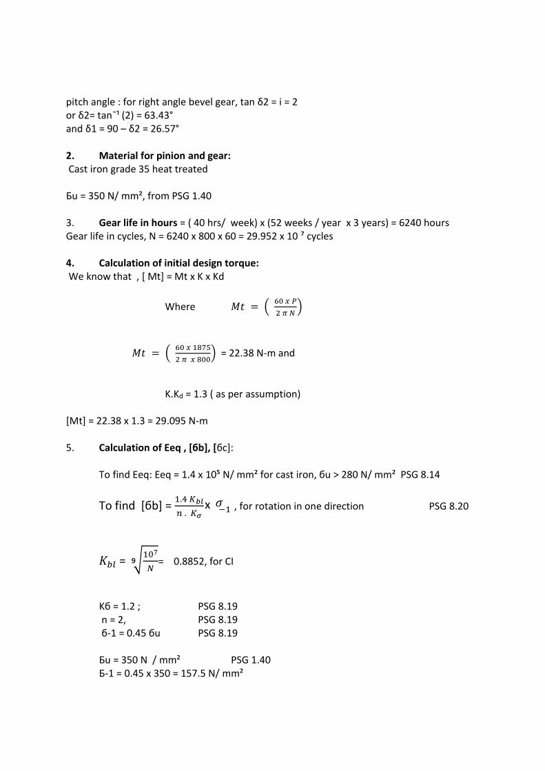
pitch angle : for right angle bevel gear, tan δ2 = i = 2 or δ2= tan¯¹ (2) = 63.43° and δ1 = 90 – δ2 = 26.57° 2. Material for pinion and gear: Cast iron grade 35 heat treated Бu = 350 N/ mm², from PSG 1.40 3. Gear life in hours = ( 40 hrs/ week) x (52 weeks / year x 3 years) = 6240 hours Gear life in cycles, N = 6240 x 800 x 60 = 29.952 x 10 ⁷ cycles 4. Calculation of initial design torque: We know that , [ Mt] = Mt x K x Kd
Where 𝑀𝑡 = ( 60 𝑥 𝑃
2 𝜋 𝑁)
𝑀𝑡 = ( 60 𝑥 1875
2 𝜋 𝑥 800) = 22.38 N-m and
K.Kd = 1.3 ( as per assumption)
[Mt] = 22.38 x 1.3 = 29.095 N-m 5. Calculation of Eeq , [бb], [бc]: To find Eeq: Eeq = 1.4 x 10⁵ N/ mm² for cast iron, бu > 280 N/ mm² PSG 8.14
To find [бb] = 1.4 𝐾𝑏𝑙
𝑛 . 𝐾𝜎
x 𝜎−1 , for rotation in one direction PSG 8.20
𝐾𝑏𝑙 = ⁹√107
𝑁= 0.8852, for CI
Kб = 1.2 ; PSG 8.19
n = 2, PSG 8.19 б-1 = 0.45 бu PSG 8.19
Бu = 350 N / mm² PSG 1.40
Б-1 = 0.45 x 350 = 157.5 N/ mm²
WWW.VIDYARTHIPLUS.COM
WWW.VIDYARTHIPLUS.COM V+ TEAM
Then [бb] = ( 1.4 x 0.8852 x 157.2 / (2x 1.2) ) = 81.33 N/ mm² To find [бc] : [бc] = Cb x HB x Kcl Cb = 2.3 PSG 8.16
Hb = 200 to 260 PSG 8.16
Kcl = ⁶√107
𝑁 =
⁶√ 107
29.952 𝑥 107
= 0.833, for C I
[ бc] = 2.3 x 260 x 0.833 = 498.08 N/ mm² 6. Calculation of cone distance (R):
We know that 𝑅 ≥ 𝜓𝑦 ( √(𝑖2 + 1 )) { ³√[ 0.72
𝜓𝑦 – 0.5[б𝑐]]
2
𝑥 𝐸𝑒𝑞[𝑀𝑡]
𝑖}
𝜓𝑦 = 𝑅
𝑏= 3
R ≥ 50.2 R= 51 mm 7. Assume Z1= 20, Then Z2 = I x Z1= 2 x 20 = 40 Virtual number of teeth Zv₁ = Z₁ / cos δ₁ = 20 / (cos 26.57°) = 23 And Zv₂ = Z₂ / cosδ₂ = 40 / ( cos 63.43) = 90 8. Calculating the transverse module (mt):
𝑀𝑡 = 𝑅
(0.5 √ 𝑍12+ 𝑍22) = 2.28 mm take as 2.5 PSG 8.2
9. Revision of cone distance R: we know that ,
𝑅 = (0.5 𝑀𝑡 √ 𝑍12 + 𝑍22) = 0.5 𝑥 2.5 √( 202 + 402)= 55.9 mm
10. Calculation of b, Mav, d1av, v, and ψy:
WWW.VIDYARTHIPLUS.COM
WWW.VIDYARTHIPLUS.COM V+ TEAM
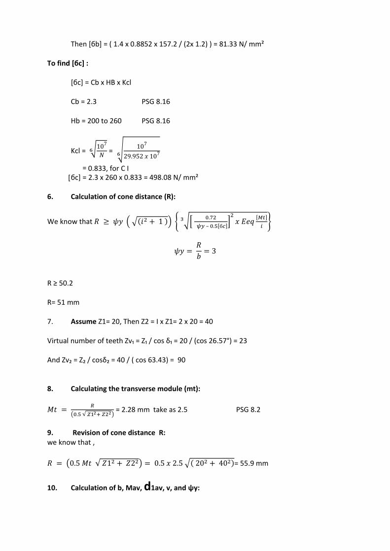
Face width (b) ; b = R / ψy = 55.9 / 3 = 18.63 mm
Average module (mav) : mt – ( b sin δ₁/ Z1) = 2.0863 mm
Average pcd of pinion ( d1 av) = d1av = mav x Z1 = 2.083 x 20 = 41.66 m
Pitch line velocity v : π x d1av x N1
60 = 1.745 m /s
Ψy = b / d1av = 18.63 / 41.66 = 0.477 11. IS quality bevel gear is assumed From PSG 8.3 12. Revision of design torque [Mt]
We know thet [Mt] = Mt x K x Kd K= 1.1 for b / d1av ≤ 1 , PSG 8.15 Kd = 1.35 P SG 8.16
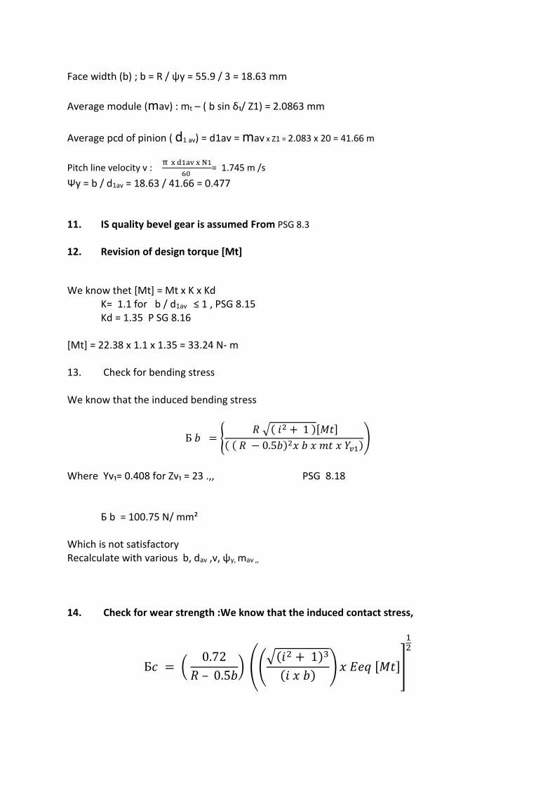
[Mt] = 22.38 x 1.1 x 1.35 = 33.24 N- m 13. Check for bending stress We know that the induced bending stress
Б 𝑏 = { 𝑅 √( 𝑖2 + 1 )[𝑀𝑡]
( ( 𝑅 − 0.5𝑏)2𝑥 𝑏 𝑥 𝑚𝑡 𝑥 𝑌𝑣1))
Where Yv₁= 0.408 for Zv₁ = 23 .,, PSG 8.18 Б b = 100.75 N/ mm² Which is not satisfactory Recalculate with various b, dav ,v, ψy, mav ,,
14. Check for wear strength :We know that the induced contact stress,
Б𝑐 = ( 0.72
𝑅 – 0.5𝑏) ((
√(𝑖2 + 1)3
(𝑖 𝑥 𝑏)) 𝑥 𝐸𝑒𝑞 [𝑀𝑡]]
12
WWW.VIDYARTHIPLUS.COM
WWW.VIDYARTHIPLUS.COM V+ TEAM
= 439.33 N / mm² We find that бc < [бc], thus the design is safety 15. Calculation of basic dimensions of pinion and gear : Transverse module : mt = 3 mm Number of teeth : Z1 = 20, Z2 = 40 Pitch circle diameter : d1= mt x Z1 = 3 x20 = 60 mm and D2 = Mt x Z2 = 3 x 40 = 120 mm Cone distance R = 67.08 mm Face width b = 22.36 mm Pitch angle = δ₁ = 26.57°, and δ₂ = 63.43° Height factor : fo = 1 Clearance : c = 0.2 Virtual number of teeth : Zv₁= 23, and Zv₂= 90
DESIGN PROCEDURE OF WORM GEARS STEP-1: Selection of Material PSG. 8.5
STEP-2: Calculation of Initial Design Torque
[Mt]=Mt x K x Kd. Initially, Assume K x Kd = 1. Mt=60 x p / 2ΠN.
STEP-3: Selection of Z1&Z2.
Select Z1 FOR VARIOUS EFFICIENCIES PSG. 8.46 Z2 = i x Z1. STEP-4: Selection of [σb] & [σc] PSG.8.45
WWW.VIDYARTHIPLUS.COM
WWW.VIDYARTHIPLUS.COM V+ TEAM
STEP-5: Calculation of Centre Distance PSG.8.44 a = [(z/q)|+1] x З√[540/(Z/q) x [σc]]2 x [Mt] / 10 STEP-6: Calculation of Axial Module PSG.8.43 m= 2a / (q+z) STEP-7: Calculation of Revised Centre Distance PSG.8.43 a=0.5m (q+Z2) STEP-8: Calculation of d, v, γ, Vs. d = q x m v = πdn / 60 γ = tan-1 {Z/q} Vs = v/cos γ STEP-9: Recalculation of Design Contact Stress Using Vs. PSG.8.45
STEP-10: Revise K, d, Mt Values.
STEP-11: CHECK FOR BENDING STRESS PSG.8.44 [σb] = 1.9[Mt] / mЗ x q x z x y STEP-12: Check for Wear σc PSG.8.44 STEP-13: Check for Efficiency η=0.95 x tan γ/tan (γ+ρ) ρ=TAN-1(μ) STEP-14: Calculation of Cooling Area Required (1-η) x INPUT POWER = Kt x A (to-ta) STEP-15: Calculation of Basic Dimensions PSG.8.43 PROBLEM ON WORM GEARS A steel worm running at 240 rp , receives 1.5 kw from its shaft. The speed reduction is 10:1, design the drive so as to have an efficiency of 80 %, also determine the cooling area required, if the temperature rise is restricted to 45° C, and take overall heat transfer co efficient as 10 W / m² ° C. Given data: N1= 240 rpm, P= 1.5 kW, I= 10, η desired = 80%, to – ta = 45°C, Kt = 10 W/ m² °C. To find: 1. Design the worm gear drive 2. The cooling area required
WWW.VIDYARTHIPLUS.COM
WWW.VIDYARTHIPLUS.COM V+ TEAM
Solution:
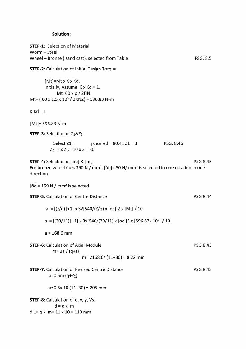
STEP-1: Selection of Material Worm – Steel Wheel – Bronze ( sand cast), selected from Table PSG. 8.5
STEP-2: Calculation of Initial Design Torque
[Mt]=Mt x K x Kd. Initially, Assume K x Kd = 1. Mt=60 x p / 2ΠN. Mt= ( 60 x 1.5 x 10³ / 2πN2) = 596.83 N-m K.Kd = 1 [Mt]= 596.83 N-m
STEP-3: Selection of Z1&Z2.
Select Z1, η desired = 80%,, Z1 = 3 PSG. 8.46 Z2 = i x Z1.= 10 x 3 = 30 STEP-4: Selection of [σb] & [σc] PSG.8.45 For bronze wheel бu < 390 N / mm², [бb]= 50 N/ mm² is selected in one rotation in one direction [бc]= 159 N / mm² is selected
STEP-5: Calculation of Centre Distance PSG.8.44 a = [(z/q)|+1] x З√[540/(Z/q) x [σc]]2 x [Mt] / 10 a = [(30/11)|+1] x З√[540/(30/11) x [σc]]2 x [596.83x 10³] / 10 a = 168.6 mm STEP-6: Calculation of Axial Module PSG.8.43 m= 2a / (q+z) m= 2168.6/ (11+30) = 8.22 mm STEP-7: Calculation of Revised Centre Distance PSG.8.43 a=0.5m (q+Z2) a=0.5x 10 (11+30) = 205 mm STEP-8: Calculation of d, v, γ, Vs. d = q x m d 1= q x m= 11 x 10 = 110 mm
WWW.VIDYARTHIPLUS.COM
WWW.VIDYARTHIPLUS.COM V+ TEAM
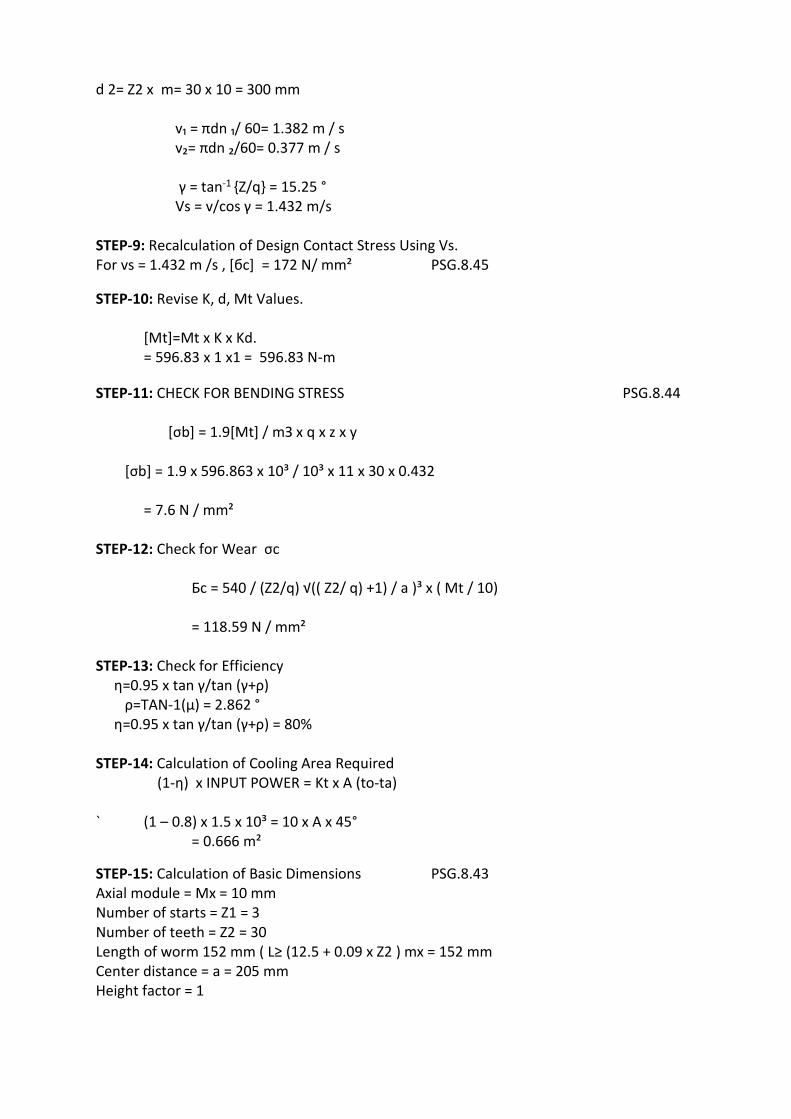
d 2= Z2 x m= 30 x 10 = 300 mm v₁ = πdn ₁/ 60= 1.382 m / s v₂= πdn ₂/60= 0.377 m / s γ = tan-1 {Z/q} = 15.25 ° Vs = v/cos γ = 1.432 m/s STEP-9: Recalculation of Design Contact Stress Using Vs. For vs = 1.432 m /s , [бc] = 172 N/ mm² PSG.8.45
STEP-10: Revise K, d, Mt Values.
[Mt]=Mt x K x Kd. = 596.83 x 1 x1 = 596.83 N-m
STEP-11: CHECK FOR BENDING STRESS PSG.8.44 [σb] = 1.9[Mt] / mЗ x q x z x y [σb] = 1.9 x 596.863 x 10³ / 10³ x 11 x 30 x 0.432 = 7.6 N / mm² STEP-12: Check for Wear σc Бc = 540 / (Z2/q) √(( Z2/ q) +1) / a )³ x ( Mt / 10) = 118.59 N / mm² STEP-13: Check for Efficiency η=0.95 x tan γ/tan (γ+ρ) ρ=TAN-1(μ) = 2.862 ° η=0.95 x tan γ/tan (γ+ρ) = 80% STEP-14: Calculation of Cooling Area Required (1-η) x INPUT POWER = Kt x A (to-ta) ` (1 – 0.8) x 1.5 x 10³ = 10 x A x 45° = 0.666 m²
STEP-15: Calculation of Basic Dimensions PSG.8.43 Axial module = Mx = 10 mm Number of starts = Z1 = 3 Number of teeth = Z2 = 30 Length of worm 152 mm ( L≥ (12.5 + 0.09 x Z2 ) mx = 152 mm Center distance = a = 205 mm Height factor = 1
WWW.VIDYARTHIPLUS.COM
WWW.VIDYARTHIPLUS.COM V+ TEAM
Step 1:
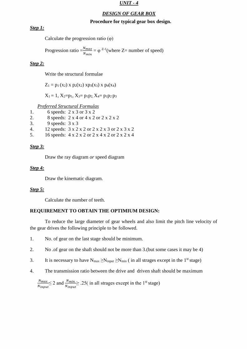
Calculate the progression ratio (φ)
Progression ratio =𝑁𝑚𝑎𝑥
𝑁𝑚𝑖𝑛 = φ Z-1(where Z= number of speed)
Step 2:
Write the structural formulae
Z1 = p1 (x2) x p2(x2) xp3(x3) x p4(x4)
X1 = 1, X2=p1, X3= p1p2, X4= p1p2 p3
Preferred Structural Formulas 1. 6 speeds: 2 x 3 or 3 x 2 2. 8 speeds: 2 x 4 or 4 x 2 or 2 x 2 x 2 3. 9 speeds: 3 x 3 4. 12 speeds: 3 x 2 x 2 or 2 x 2 x 3 or 2 x 3 x 2 5. 16 speeds: 4 x 2 x 2 or 2 x 4 x 2 or 2 x 2 x 4 Step 3:
Draw the ray diagram or speed diagram
Step 4:
Draw the kinematic diagram.
Step 5:
Calculate the number of teeth.
REQUIREMENT TO OBTAIN THE OPTIMIUM DESIGN:
To reduce the large diameter of gear wheels and also limit the pitch line velocity of the gear drives the following principle to be followed.
1. No. of gear on the last stage should be minimum.
2. No .of gear on the shaft should not be more than 3.(but some cases it may be 4)
3. It is necessary to have Nmax ≥Ninput ≥Nmin ( in all strages except in the 1st stage)
4. The transmission ratio between the drive and driven shaft should be maximum
𝑁𝑚𝑎𝑥
𝑁𝑖𝑛𝑝𝑢𝑡≤ 2 and
𝑁𝑚𝑖𝑛
𝑁𝑖𝑛𝑝𝑢𝑡≥ .25( in all strages except in the 1st stage)
WWW.VIDYARTHIPLUS.COM
UNIT - 4
DESIGN OF GEAR BOX
Procedure for typical gear box design.
WWW.VIDYARTHIPLUS.COM
V+ TEAM
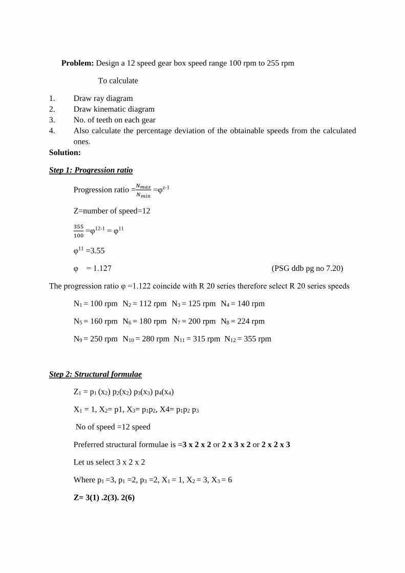
Problem: Design a 12 speed gear box speed range 100 rpm to 255 rpm
To calculate
1. Draw ray diagram 2. Draw kinematic diagram 3. No. of teeth on each gear 4. Also calculate the percentage deviation of the obtainable speeds from the calculated
ones. Solution:
Step 1: Progression ratio
Progression ratio =𝑁𝑚𝑎𝑥
𝑁𝑚𝑖𝑛 =φz-1
Z=number of speed=12
355
100 =φ12-1 = φ11
φ11 =3.55
φ = 1.127 (PSG ddb pg no 7.20)
The progression ratio φ =1.122 coincide with R 20 series therefore select R 20 series speeds
N1 = 100 rpm N2 = 112 rpm N3 = 125 rpm N4 = 140 rpm
N5 = 160 rpm N6 = 180 rpm N7 = 200 rpm N8 = 224 rpm
N9 = 250 rpm N10 = 280 rpm N11 = 315 rpm N12 = 355 rpm
Step 2: Structural formulae
Z1 = p1 (x2) p2(x2) p3(x3) p4(x4)
X1 = 1, X2= p1, X3= p1p2, X4= p1p2 p3
No of speed =12 speed
Preferred structural formulae is =3 x 2 x 2 or 2 x 3 x 2 or 2 x 2 x 3
Let us select 3 x 2 x 2
Where p1 =3, p1 =2, p3 =2, X1 = 1, X2 = 3, X3 = 6
Z= 3(1) .2(3). 2(6)
WWW.VIDYARTHIPLUS.COM
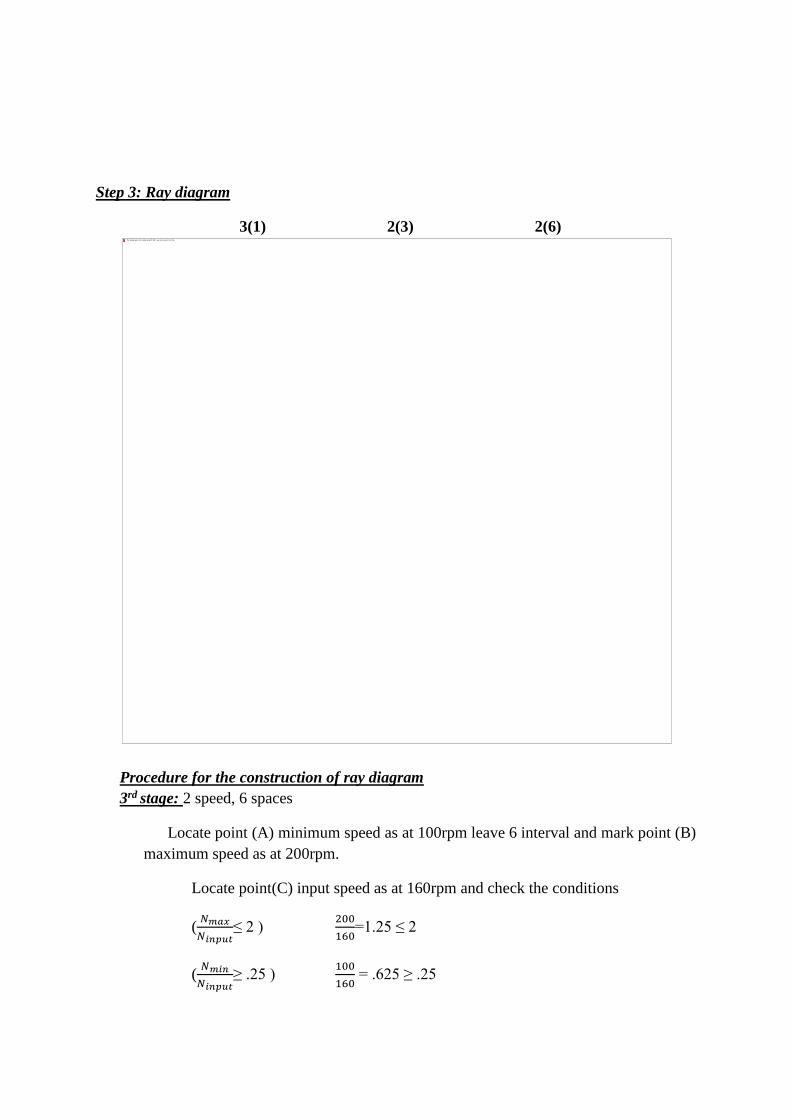
Step 3: Ray diagram
3(1) 2(3) 2(6)
Procedure for the construction of ray diagram 3rd stage: 2 speed, 6 spaces
Locate point (A) minimum speed as at 100rpm leave 6 interval and mark point (B) maximum speed as at 200rpm.
Locate point(C) input speed as at 160rpm and check the conditions
(𝑁𝑚𝑎𝑥
𝑁𝑖𝑛𝑝𝑢𝑡≤ 2 )
200
160=1.25 ≤ 2
(𝑁𝑚𝑖𝑛
𝑁𝑖𝑛𝑝𝑢𝑡≥ .25 )
100
160 = .625 ≥ .25
WWW.VIDYARTHIPLUS.COM
Selected input speed is satisfactory
2rd stage: 2 speed , 3 spaces
Locate point (C) minimum speed as at 160rpm leave 3 interval and mark point (D) maximum speed as at 224rpm.
Locate point (E) input speed as at 200rpm and check the conditions
(𝑁𝑚𝑎𝑥
𝑁𝑖𝑛𝑝𝑢𝑡 ≤ 2 )
224
180=1.24 ≤ 2
(𝑁𝑚𝑖𝑛
𝑁𝑖𝑛𝑝𝑢𝑡 ≥0 .25 )
160
180 = .88≥ .25
Selected input speed is satisfactory
1st stage: There are 3 speeds with 1 space interval.
Therefore mark (F) and (G)
Assume input speed as the engine speed and mark point (H).
(For first stage it is not necessary to satisfy the condition)
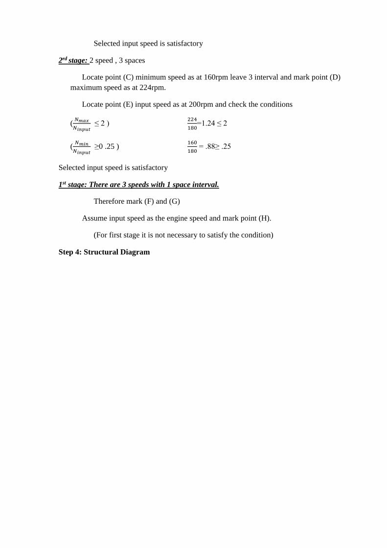
Step 4: Structural Diagram
WWW.VIDYARTHIPLUS.COM
12 possible speeds are:
1. Z9 Z10 Z5 Z6 Z1Z2
2. Z9 Z10 Z5 Z6 Z3Z4
3. Z9 Z10 Z7 Z8 Z1Z2
4. Z9 Z10 Z7 Z8 Z3Z4
5. Z11Z12 Z5Z6 Z1Z2
6. Z11Z12 Z5 Z6 Z3Z4
7. Z11 Z12 Z7Z8 Z1Z2
8. Z11 Z12 Z7Z8 Z3Z4
WWW.VIDYARTHIPLUS.COM
9. Z13 Z14 Z5Z6 Z1Z2
10. Z13 Z14 Z5Z6 Z3Z4
11. Z13 Z14 Z7Z8 Z1Z2
12. Z13 Z14 Z7Z8 Z3Z4
Step 5: Calculation of no. of teeth on each gear.
Third stage:
1st pair :( reducing gear)
𝑠𝑝𝑒𝑒𝑑 𝑜𝑓 𝑡ℎ𝑒 𝑑𝑟𝑖𝑣𝑒𝑛 𝑔𝑒𝑎𝑟
𝑠𝑝𝑒𝑒𝑑 𝑜𝑓 𝑡ℎ𝑒 𝑑𝑟𝑖𝑣𝑒𝑟 𝑔𝑒𝑎𝑟=
𝑁1
𝑁2 =
𝑍2
𝑍1
100
160 =
20
Z1, Z1 = 32 teeth
2nd pair :( increasing speed gear)
𝑠𝑝𝑒𝑒𝑑 𝑜𝑓 𝑡ℎ𝑒 𝑑𝑟𝑖𝑣𝑒𝑛 𝑔𝑒𝑎𝑟
𝑠𝑝𝑒𝑒𝑑 𝑜𝑓 𝑡ℎ𝑒 𝑑𝑟𝑖𝑣𝑒𝑟 𝑔𝑒𝑎𝑟=
𝑁3
𝑁4 =
𝑍4
𝑍3
Z3 +Z4 = Z1 +Z2
Z3 +Z4 = 32
200
160 =
Z4
52−Z4 = 1.25(52 – Z4 ) = Z4
Z4 =29, Z3 =23
Second stage:
1st pair :( reducing gear)
𝑠𝑝𝑒𝑒𝑑 𝑜𝑓 𝑡ℎ𝑒 𝑑𝑟𝑖𝑣𝑒𝑛 𝑔𝑒𝑎𝑟
𝑠𝑝𝑒𝑒𝑑 𝑜𝑓 𝑡ℎ𝑒 𝑑𝑟𝑖𝑣𝑒𝑟 𝑔𝑒𝑎𝑟 =
𝑁5
𝑁6 =
𝑍6
𝑍5
160
180 =
20
Z5, Z5 = 23 teeth
2nd pair :( increasing speed gear)
𝑠𝑝𝑒𝑒𝑑 𝑜𝑓 𝑡ℎ𝑒 𝑑𝑟𝑖𝑣𝑒𝑛 𝑔𝑒𝑎𝑟
𝑠𝑝𝑒𝑒𝑑 𝑜𝑓 𝑡ℎ𝑒 𝑑𝑟𝑖𝑣𝑒𝑟 𝑔𝑒𝑎𝑟=
𝑁7
𝑁8 =
𝑍8
𝑍7
Z6 +Z5 = Z7 +Z8
Z7 +Z8 = 43
224
180 =
Z8
43−Z8 = 1.244(43 – Z8 ) = Z8
Z8 =24, Z7 =19
WWW.VIDYARTHIPLUS.COM
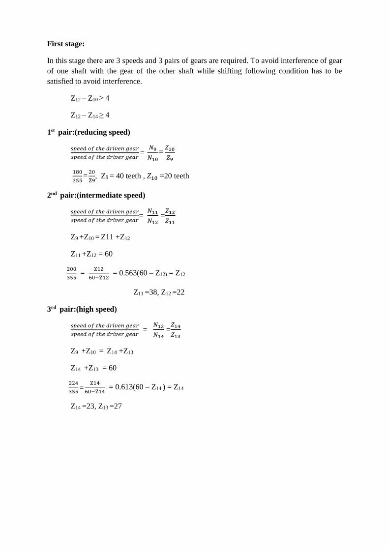
First stage:
In this stage there are 3 speeds and 3 pairs of gears are required. To avoid interference of gear of one shaft with the gear of the other shaft while shifting following condition has to be satisfied to avoid interference.
Z12 – Z10 ≥ 4
Z12 – Z14 ≥ 4
1st pair:(reducing speed)
𝑠𝑝𝑒𝑒𝑑 𝑜𝑓 𝑡ℎ𝑒 𝑑𝑟𝑖𝑣𝑒𝑛 𝑔𝑒𝑎𝑟
𝑠𝑝𝑒𝑒𝑑 𝑜𝑓 𝑡ℎ𝑒 𝑑𝑟𝑖𝑣𝑒𝑟 𝑔𝑒𝑎𝑟=
𝑁9
𝑁10 =
𝑍10
𝑍9
180
355 =
20
Z9, Z9 = 40 teeth , 𝑍10 =20 teeth
2nd pair:(intermediate speed)
𝑠𝑝𝑒𝑒𝑑 𝑜𝑓 𝑡ℎ𝑒 𝑑𝑟𝑖𝑣𝑒𝑛 𝑔𝑒𝑎𝑟
𝑠𝑝𝑒𝑒𝑑 𝑜𝑓 𝑡ℎ𝑒 𝑑𝑟𝑖𝑣𝑒𝑟 𝑔𝑒𝑎𝑟=
𝑁11
𝑁12 =
𝑍12
𝑍11
Z9 +Z10 = Z11 +Z12
Z11 +Z12 = 60
200
355 =
Z12
60−Z12 = 0.563(60 – Z12) = Z12
Z11 =38, Z12 =22
3rd pair:(high speed)
𝑠𝑝𝑒𝑒𝑑 𝑜𝑓 𝑡ℎ𝑒 𝑑𝑟𝑖𝑣𝑒𝑛 𝑔𝑒𝑎𝑟
𝑠𝑝𝑒𝑒𝑑 𝑜𝑓 𝑡ℎ𝑒 𝑑𝑟𝑖𝑣𝑒𝑟 𝑔𝑒𝑎𝑟 =
𝑁13
𝑁14 =
𝑍14
𝑍13
Z9 +Z10 = Z14 +Z13
Z14 +Z13 = 60
224
355 =
Z14
60−Z14 = 0.613(60 – Z14 ) = Z14
Z14 =23, Z13 =27
WWW.VIDYARTHIPLUS.COM
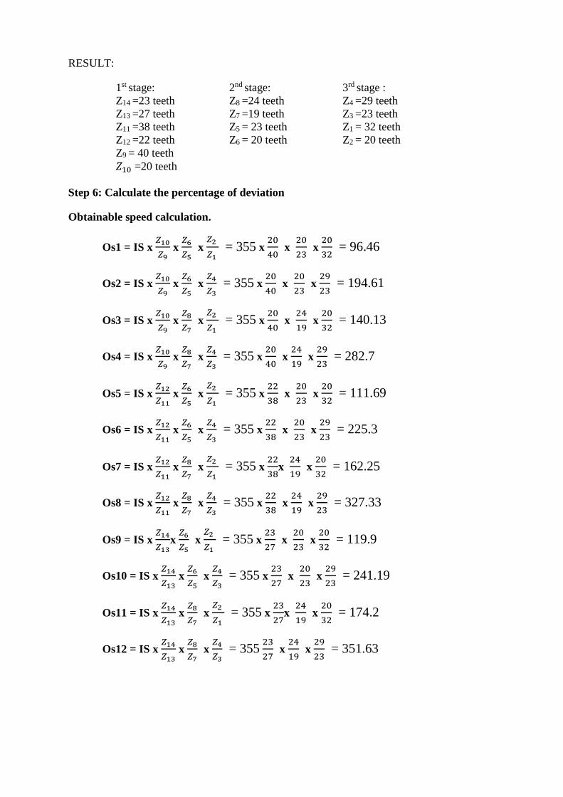
RESULT:
1st stage: 2nd stage: 3rd stage : Z14 =23 teeth Z8 =24 teeth Z4 =29 teeth Z13 =27 teeth Z7 =19 teeth Z3 =23 teeth Z11 =38 teeth Z5 = 23 teeth Z1 = 32 teeth Z12 =22 teeth Z6 = 20 teeth Z2 = 20 teeth Z9 = 40 teeth 𝑍10 =20 teeth
Step 6: Calculate the percentage of deviation
Obtainable speed calculation.
Os1 = IS x 𝑍10
𝑍9 x
𝑍6
𝑍5 x
𝑍2
𝑍1 = 355 x
20
40 x
20
23 x
20
32 = 96.46
Os2 = IS x 𝑍10
𝑍9 x
𝑍6
𝑍5 x
𝑍4
𝑍3 = 355 x
20
40 x
20
23 x
29
23 = 194.61
Os3 = IS x 𝑍10
𝑍9 x
𝑍8
𝑍7 x
𝑍2
𝑍1 = 355 x
20
40 x
24
19 x
20
32 = 140.13
Os4 = IS x 𝑍10
𝑍9 x
𝑍8
𝑍7 x
𝑍4
𝑍3 = 355 x
20
40 x
24
19 x
29
23 = 282.7
Os5 = IS x 𝑍12
𝑍11 x
𝑍6
𝑍5 x
𝑍2
𝑍1 = 355 x
22
38 x
20
23 x
20
32 = 111.69
Os6 = IS x 𝑍12
𝑍11 x
𝑍6
𝑍5 x
𝑍4
𝑍3 = 355 x
22
38 x
20
23 x
29
23 = 225.3
Os7 = IS x 𝑍12
𝑍11 x
𝑍8
𝑍7 x
𝑍2
𝑍1 = 355 x
22
38x
24
19 x
20
32 = 162.25
Os8 = IS x 𝑍12
𝑍11 x
𝑍8
𝑍7 x
𝑍4
𝑍3 = 355 x
22
38 x
24
19 x
29
23 = 327.33
Os9 = IS x 𝑍14
𝑍13x
𝑍6
𝑍5 x
𝑍2
𝑍1 = 355 x
23
27 x
20
23 x
20
32 = 119.9
Os10 = IS x 𝑍14
𝑍13 x
𝑍6
𝑍5 x
𝑍4
𝑍3 = 355 x
23
27 x
20
23 x
29
23 = 241.19
Os11 = IS x 𝑍14
𝑍13 x
𝑍8
𝑍7 x
𝑍2
𝑍1 = 355 x
23
27x
24
19 x
20
32 = 174.2
Os12 = IS x 𝑍14
𝑍13 x
𝑍8
𝑍7 x
𝑍4
𝑍3 = 355
23
27 x
24
19 x
29
23 = 351.63
WWW.VIDYARTHIPLUS.COM
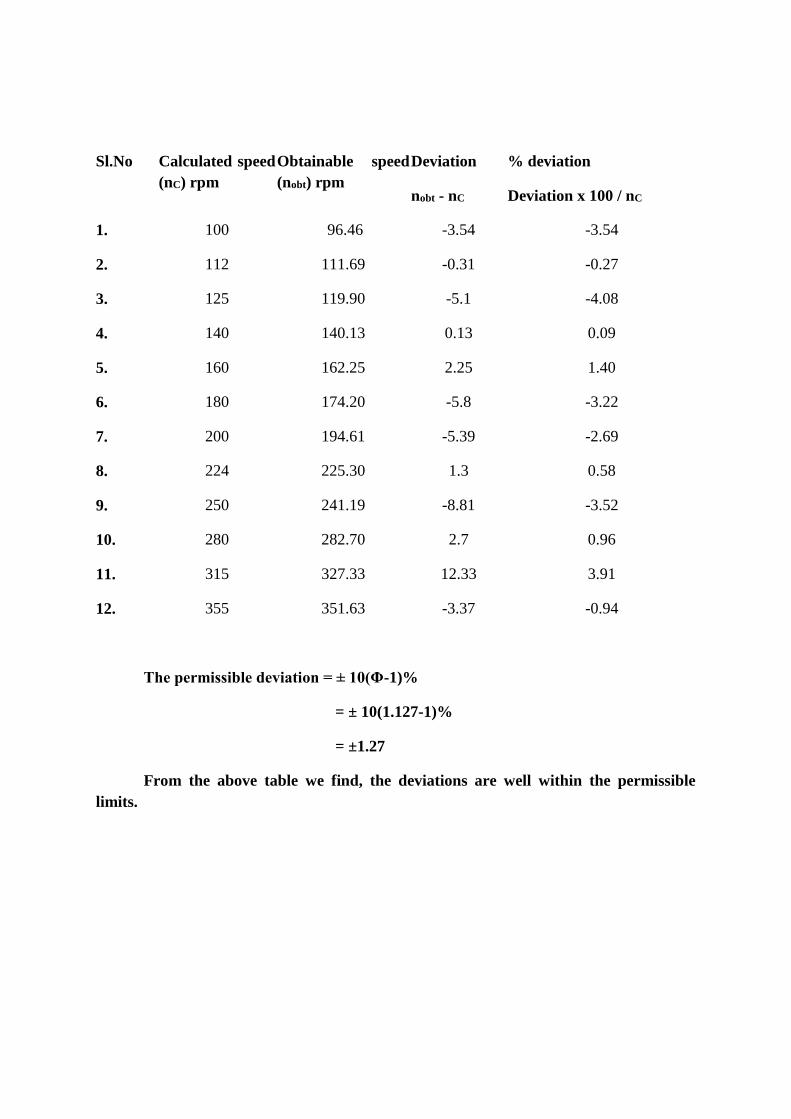
Sl.No Calculated speed (nC) rpm
Obtainable speed (nobt) rpm
Deviation
nobt - nC
% deviation
Deviation x 100 / nC
1. 100 96.46 -3.54 -3.54
2. 112 111.69 -0.31 -0.27
3. 125 119.90 -5.1 -4.08
4. 140 140.13 0.13 0.09
5. 160 162.25 2.25 1.40
6. 180 174.20 -5.8 -3.22
7. 200 194.61 -5.39 -2.69
8. 224 225.30 1.3 0.58
9. 250 241.19 -8.81 -3.52
10. 280 282.70 2.7 0.96
11. 315 327.33 12.33 3.91
12. 355 351.63 -3.37 -0.94
The permissible deviation = ± 10(Φ-1)%
= ± 10(1.127-1)%
= ±1.27
From the above table we find, the deviations are well within the permissible limits.
WW
W.V
IDYA
RTH
IPLU
S.CO
M
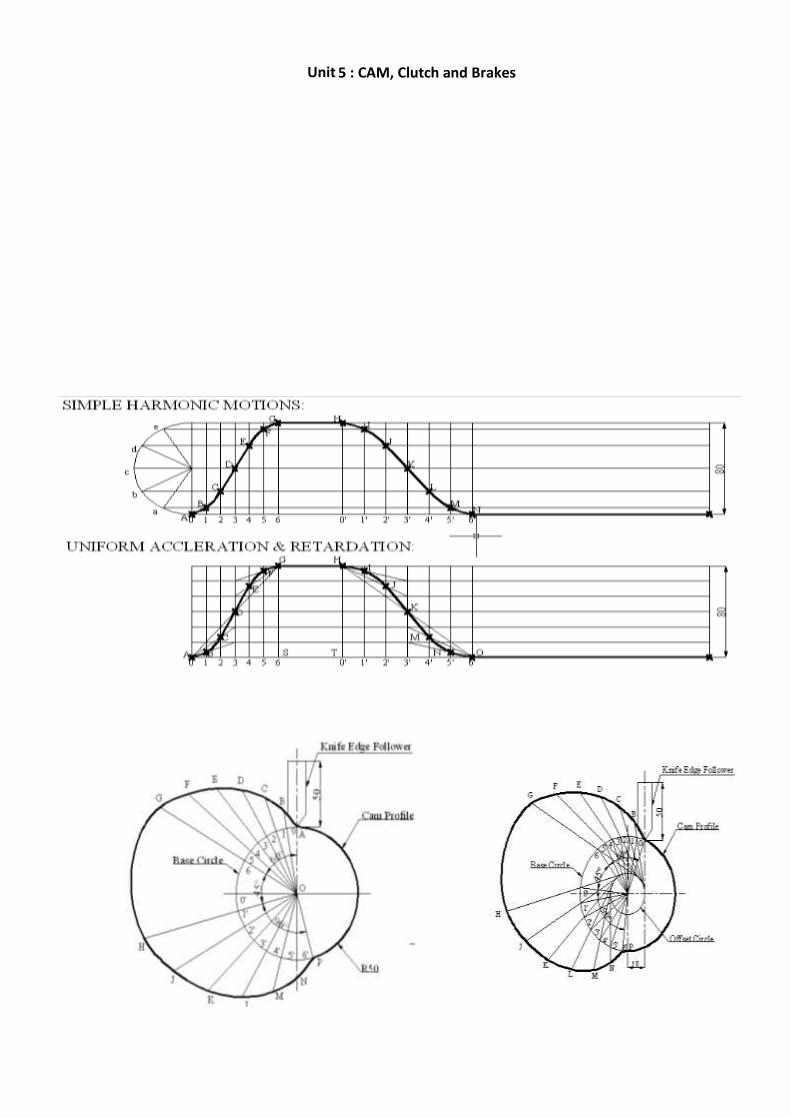
Unit –
5 : CAM, Clutch and Brakes
WWW.VIDYARTHIPLUS.COM
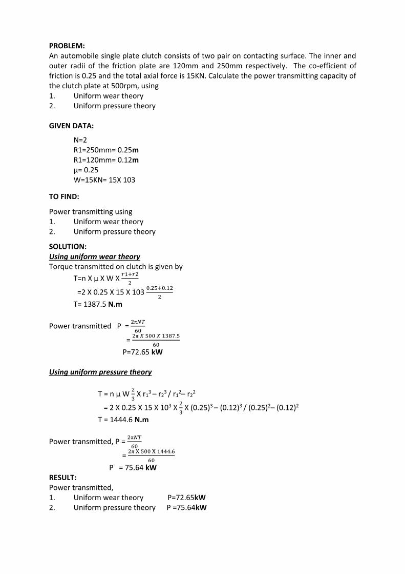
PROBLEM: An automobile single plate clutch consists of two pair on contacting surface. The inner and outer radii of the friction plate are 120mm and 250mm respectively. The co-efficient of friction is 0.25 and the total axial force is 15KN. Calculate the power transmitting capacity of the clutch plate at 500rpm, using 1. Uniform wear theory 2. Uniform pressure theory
GIVEN DATA:
N=2 R1=250mm= 0.25m R1=120mm= 0.12m µ= 0.25 W=15KN= 15X 103
TO FIND:
Power transmitting using 1. Uniform wear theory 2. Uniform pressure theory
SOLUTION: Using uniform wear theory Torque transmitted on clutch is given by
T=n X µ X W X 𝑟1+𝑟2
2
=2 X 0.25 X 15 X 103 0.25+0.12
2
T= 1387.5 N.m
Power transmitted P = 2π𝑁𝑇
60
= 2π 𝑋 500 𝑋 1387.5
60
P=72.65 kW
Using uniform pressure theory
T = n µ W 2
3 X r1
3 – r23 / r1
2– r22
= 2 X 0.25 X 15 X 103 X 2
3 X (0.25)3 – (0.12)3 / (0.25)2– (0.12)2
T = 1444.6 N.m
Power transmitted, P = 2π𝑁𝑇
60
= 2π X 500 X 1444.6
60
P = 75.64 kW RESULT: Power transmitted, 1. Uniform wear theory P=72.65kW 2. Uniform pressure theory P =75.64kW
WWW.VIDYARTHIPLUS.COM
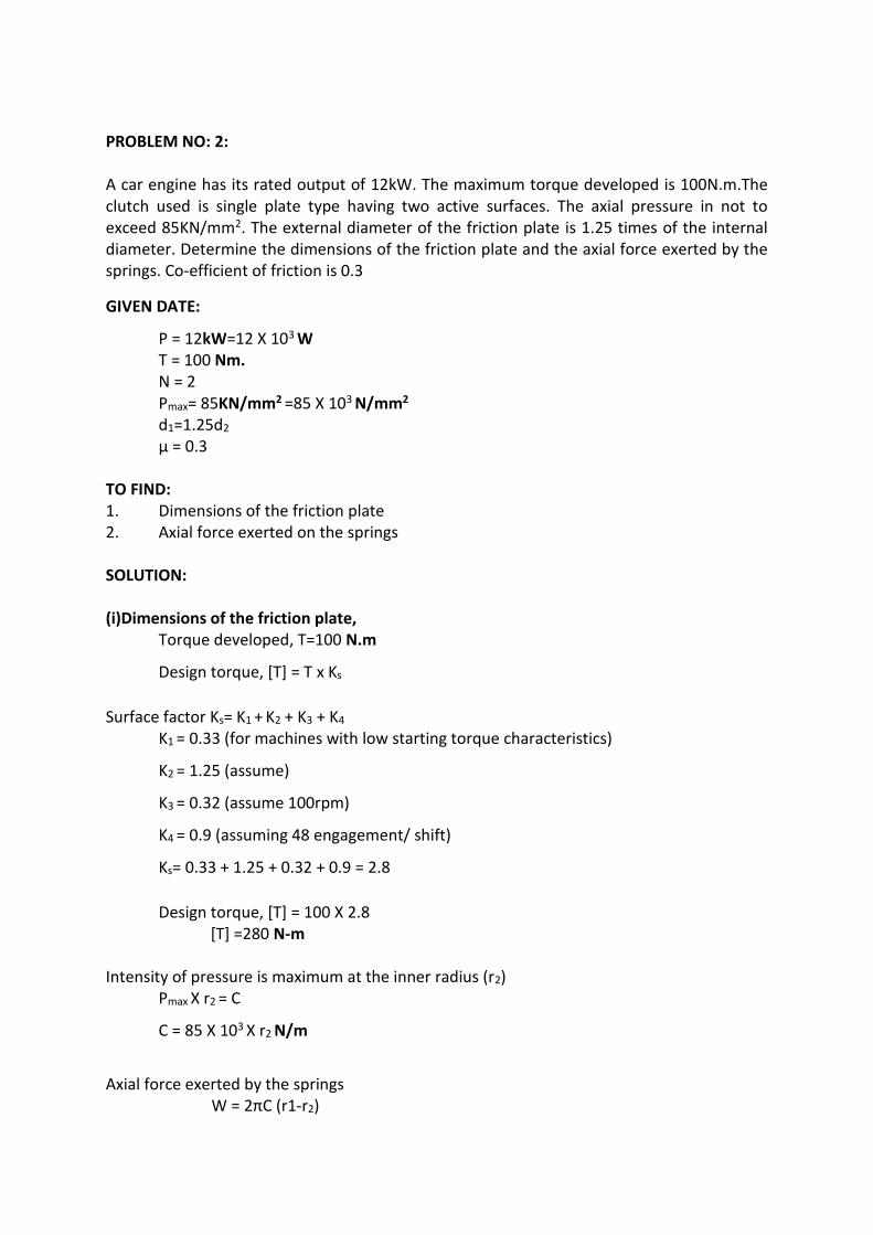
PROBLEM NO: 2: A car engine has its rated output of 12kW. The maximum torque developed is 100N.m.The clutch used is single plate type having two active surfaces. The axial pressure in not to exceed 85KN/mm2. The external diameter of the friction plate is 1.25 times of the internal diameter. Determine the dimensions of the friction plate and the axial force exerted by the springs. Co-efficient of friction is 0.3
GIVEN DATE:
P = 12kW=12 X 103 W
T = 100 Nm. N = 2 Pmax= 85KN/mm2 =85 X 103 N/mm2
d1=1.25d2
µ = 0.3
TO FIND: 1. Dimensions of the friction plate 2. Axial force exerted on the springs SOLUTION: (i)Dimensions of the friction plate,
Torque developed, T=100 N.m
Design torque, [T] = T x Ks
Surface factor Ks= K1 + K2 + K3 + K4
K1 = 0.33 (for machines with low starting torque characteristics)
K2 = 1.25 (assume)
K3 = 0.32 (assume 100rpm)
K4 = 0.9 (assuming 48 engagement/ shift)
Ks= 0.33 + 1.25 + 0.32 + 0.9 = 2.8
Design torque, [T] = 100 X 2.8 [T] =280 N-m
Intensity of pressure is maximum at the inner radius (r2) Pmax X r2 = C
C = 85 X 103 X r2 N/m
Axial force exerted by the springs
W = 2πC (r1-r2)
WWW.VIDYARTHIPLUS.COM
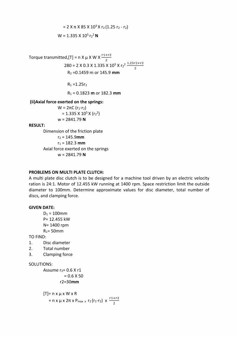
= 2 X π X 85 X 103 X r2 (1.25 r2 - r2)
W = 1.335 X 10⁵ r22 N
Torque transmitted,[T] = n X µ X W X 𝑟1+𝑟2
2
280 = 2 X 0.3 X 1.335 X 105 X r22 1.25𝑟2+𝑟2
2
R2 =0.1459 m or 145.9 mm R1 =1.25r2
R1 = 0.1823 m or 182.3 mm
(ii)Axial force exerted on the springs: W = 2πC (r1-r2)
= 1.335 X 10⁵ X (r22)
w = 2841.79 N RESULT:
Dimension of the friction plate r2 = 145.9mm r1 = 182.3 mm
Axial force exerted on the springs w = 2841.79 N
PROBLEMS ON MULTI PLATE CLUTCH: A multi plate disc clutch is to be designed for a machine tool driven by an electric velocity ration is 24:1. Motor of 12.455 kW running at 1400 rpm. Space restriction limit the outside diameter to 100mm. Determine approximate values for disc diameter, total number of discs, and clamping force. GIVEN DATE:
D1 = 100mm P= 12.455 kW N= 1400 rpm R1= 50mm
TO FIND: 1. Disc diameter 2. Total number 3. Clamping force
SOLUTIONS: Assume r2= 0.6 X r1
= 0.6 X 50 r2=30mm [T]= n x µ x W x R
= n x µ x 2π x Pmax x r2 (r1-r2) x 𝑟1+𝑟2
2
WWW.VIDYARTHIPLUS.COM
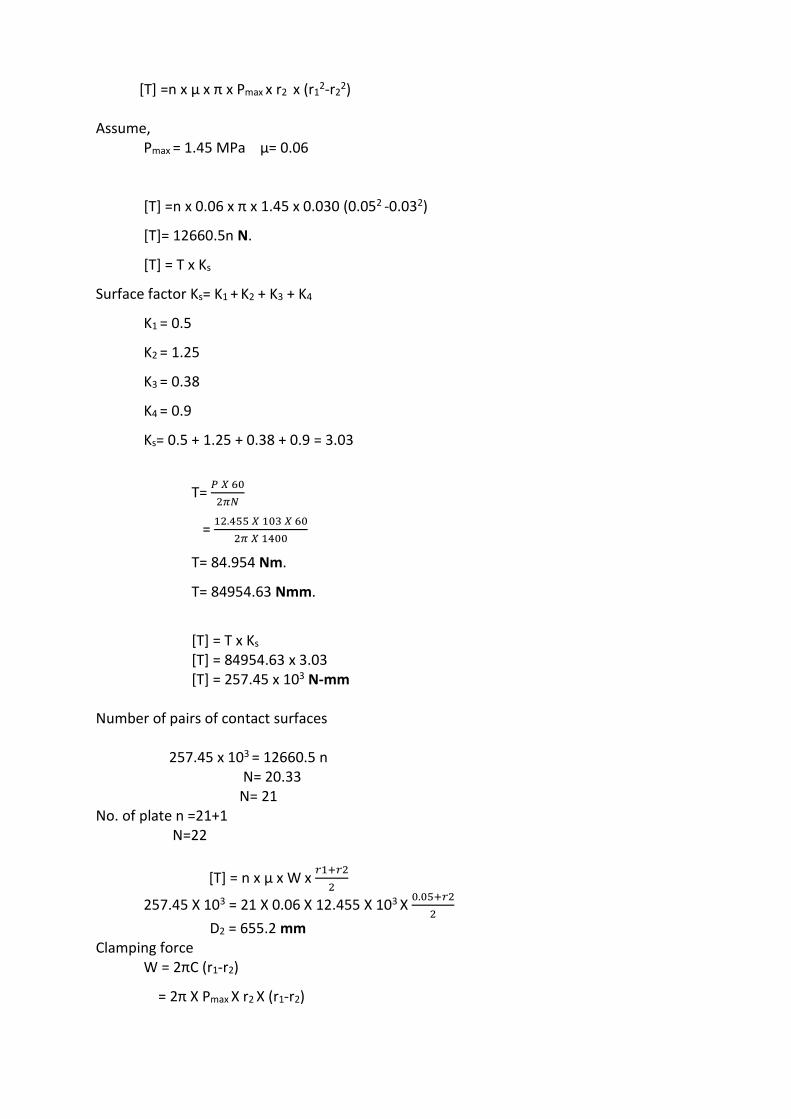
[T] =n x µ x π x Pmax x r2 x (r12-r2
2) Assume,
Pmax = 1.45 MPa µ= 0.06
[T] =n x 0.06 x π x 1.45 x 0.030 (0.052 -0.032)
[T]= 12660.5n N.
[T] = T x Ks
Surface factor Ks= K1 + K2 + K3 + K4
K1 = 0.5
K2 = 1.25
K3 = 0.38
K4 = 0.9
Ks= 0.5 + 1.25 + 0.38 + 0.9 = 3.03
T= 𝑃 𝑋 60
2𝜋𝑁
= 12.455 𝑋 103 𝑋 60
2𝜋 𝑋 1400
T= 84.954 Nm.
T= 84954.63 Nmm.
[T] = T x Ks
[T] = 84954.63 x 3.03 [T] = 257.45 x 10³ N-mm
Number of pairs of contact surfaces
257.45 x 103 = 12660.5 n N= 20.33 N= 21 No. of plate n =21+1 N=22
[T] = n x µ x W x 𝑟1+𝑟2
2
257.45 X 103 = 21 X 0.06 X 12.455 X 103 X 0.05+𝑟2
2
D2 = 655.2 mm Clamping force
W = 2πC (r1-r2)
= 2π X Pmax X r2 X (r1-r2)
WWW.VIDYARTHIPLUS.COM
= 2π X 1.45 X 0.327 X (0.05-0.327)
W =5362.5 N
RESULT: 1. D2 =655.2 mm 2. N=21 3. W=5362.5N CONE CLUTCH: A leather faced conical clutch has cone angle of 30˚. The pressure between the contact surfaces is limited to 0.35N/mm2 and the breadth of the conical surface is not to exceed to 1/3 of the mean radius. Find the dimensions of the contact surfaces to transmit 22kW at 2000 rpm. Also calculate the force required to engage the clutch. Take coefficient of friction is 0.15 GIVEN DATA:
α = 30˚
Pn= 0.35N/mm2
B=r/3
µ= 0.15
P=22kW
N=2000rpm
TO FIND:
1. Dimensions of contact surface (r1, r2)
2. Forces required engaging clutch
SOLUTION:
P = 2π𝑁𝑇
60
22 X 103 = 2π X 2000 X 𝑇
60
T= 105.4 Nm.
Assuming service factor Ks =2.5
Design torque [T} = 105.4 X 2.5
T= 262.60N.m
T =2 x π x µ x Pn x R2 x b
262.60 = 2 x π x 0.15 x 0.35 x R2 x 𝑅
3 x 10³
R=1.336 m
B = 𝑅
3 =
1.336
3
WWW.VIDYARTHIPLUS.COM
B = 0.445m
𝑟1−𝑟2
𝑏 = sinα
r1-r2 = b X sinα = 0.445 x sin (15)
r1-r2 = 0.1151m
Mean radius, R = 𝑟1+𝑟2
2
r1+r2 = 2.672
r1-r2 = 0.1151
r1+r2 = 2.672
2 r1= 2.781
r1 =1.393m
r2 = 1.279m
Force required:
W = 2πC (r1-r2)
= 2π X Pn X r2 X (r1-r2)
= 2π X 0.35 X 1.279 X (1.393-1.279)
W = 3206.44N
RESULT:
R1 = 1.393 mm
R2 = 1.279 mm
W = 3206.44N
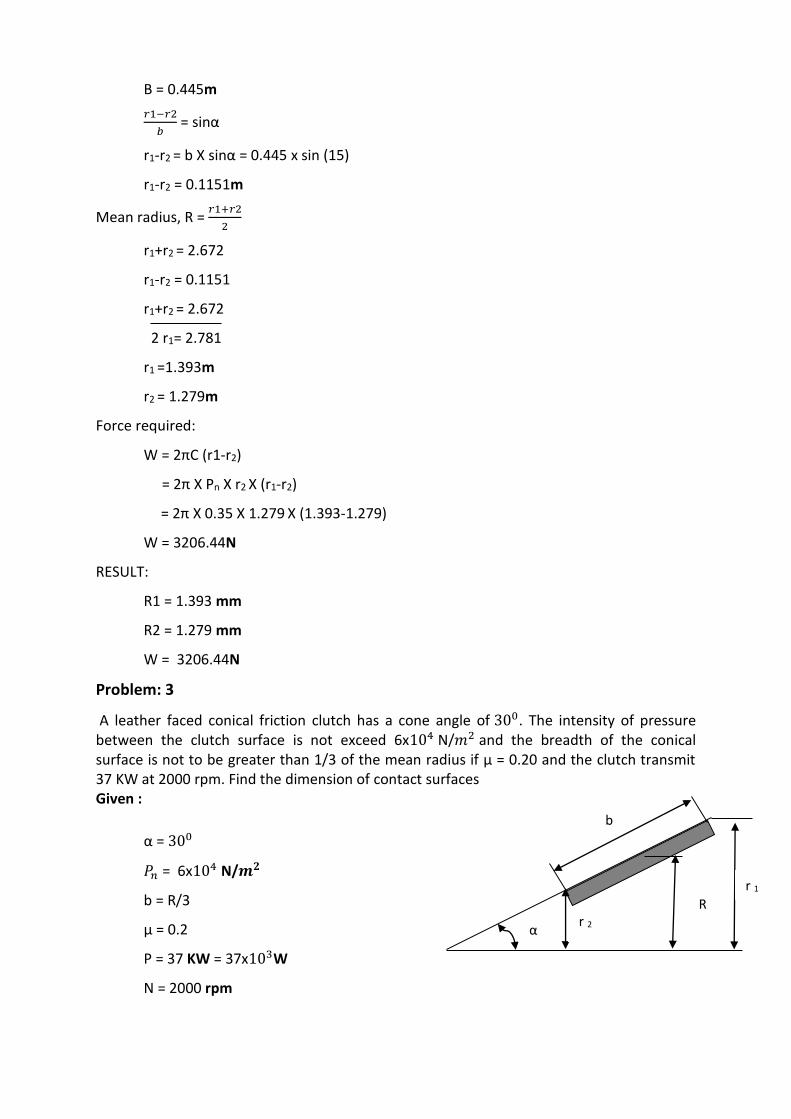
Problem: 3
A leather faced conical friction clutch has a cone angle of 300. The intensity of pressure between the clutch surface is not exceed 6x10⁴ N/𝑚2 and the breadth of the conical surface is not to be greater than 1/3 of the mean radius if µ = 0.20 and the clutch transmit 37 KW at 2000 rpm. Find the dimension of contact surfaces Given :
α = 300
𝑃𝑛 = 6x10⁴ N/𝒎𝟐
b = R/3
µ = 0.2
P = 37 KW = 37x103W
N = 2000 rpm
b
r 1
r 2 R
α
WWW.VIDYARTHIPLUS.COM
To find : Dimensions of contact surfaces : ( 𝑉1𝑎𝑛𝑑 𝑉2 ) Solution :
Power transmitted (P) = 2𝜋𝑁𝑇
60
T = 176.66 Nm Torque transmitted is also given by T = 2πµ 𝑃𝑛𝑅2𝑏
176.66 = 2π x 0.2 x 6 x 104 x 𝑅2(𝑅
3)
=25132.74 𝑅3 R = 0.19155 m (or) 191.55 mm
Face width is given by b = 𝑅
3 =
6.19155
3 = 2.06 m
Result: Face width b = 2.06 m Problem: 4. A cone clutch is to transmit 7.5 KW at 900 rpm. The cone has a face angle of 120 the width of the face is half of the mean radius and the normal pressure between the contact faces is not to exceed 0.09 N/𝑚𝑚2 . Assuming uniform wear and the co-efficient of friction between contact faces as 0.2. Find the main dimensions of the clutch and the axial force required to engage the clutch. Given data: P = 7.5 KW N = 900 rpm α = 120 b = R/2
𝑃𝑛 = 0.09 𝑵/𝒎𝒎𝟐 µ = 0.2 Solution : 1. To find main dimensions of the clutch Given: b = R/2 we know that
𝑟1− 𝑟2
𝑏= sin 𝛼
𝑏 =(𝑟1− 𝑟2)
sin 𝛼
and mean radius R =
𝑟1+ 𝑟2
2
𝑟1− 𝑟2
sin 𝛼 =
𝑟1+ 𝑟2
4 [ ∵ 𝑏 =
𝑅
2 , given ]
𝑟1 − 𝑟2 = sin 120(𝑟1+ 𝑟2)
4
= 0.052 𝑟1 + 0.052 𝑟2 𝑟1 = 1.1096 𝑟2 ------------ (i)
Power P = 2𝜋𝑁𝑇
60
WWW.VIDYARTHIPLUS.COM
7.5 x 103 = 2𝜋900𝑇
60
T = 79.58 Nm For uniform wear, the intensity of pressure is maximum at the inner radius ∴ 𝑃𝑚𝑎𝑥 x 𝑟2 = 𝑐
Torque transmitted T = µ w 𝑐𝑜𝑠𝑒𝑐 𝛼 (𝑟1+ 𝑟2)
2
but W = 2π C (𝑟1 − 𝑟2) = 2π 𝑃𝑚𝑎𝑥 x 𝑟2(𝑟1 − 𝑟2)
then T = µ [2π 𝑃𝑚𝑎𝑥 x 𝑟2(𝑟1 − 𝑟2) ] 𝑐𝑜𝑠𝑒𝑐 𝛼 (𝑟1+ 𝑟2)
2
= µ x π Pmax 𝑐𝑜𝑠𝑒𝑐 𝛼 𝑟2 (𝑟1
2 − 𝑟22)
79.58 = 0.2 x π x 0.09 x 10⁻⁶ x 𝑐𝑜𝑠𝑒𝑐 120 x 𝑟2[ (1.1096𝑟2)2 − 𝑟2
2] 𝑟2 = 0.108 m or 108 mm Then 𝑟1 = 1.1096 𝑟2 = 1.1096 ( 108 ) = 119.8 mm
R = 𝑟1+ 𝑟2
2 =
119.8+108
2= 113.9 𝒎𝒎
Face width, b = 𝑅
2 =
113.9
2= 56.95 𝒎𝒎
ii) To find the axial force required: W = 2πC(𝑟1 − 𝑟2) = 2π 𝑃𝑚𝑎𝑥 x 𝑟2(𝑟1 − 𝑟2) = 2π x 0.09 x 106 x 0.108(0.1198 – 0.108) = 720.65 N
Result:
1. Dimension of the clutch : Face width=56.95mm
2. The axial force required to engage the clutch=720.65 N