Embed Size (px)
Citation preview
ENTITY RELATIONSHIP DIAGRAM (ERD)
Chapter 4
ICT 2073
Prepared By: Siti Hajar Ismail
OBJECTIVES
Define terms related to entity relationship modeling,
including entity, entity instance, attribute,
relationship and cardinality, and primary key.
Describe the entity modeling process.
Discuss how to draw an entity relationship diagram.
Describe how to recognize entities, attributes,
relationships, and cardinalities.
DATABASE MODEL
A database can be modeled as:
a collection of entities,
relationship among entities.
Database systems are often modeled using an Entity
Relationship (ER) diagram as the "blueprint" from
which the actual data is stored
ENTITY RELATIONSHIP DIAGRAM (ERD) ER model allows us to sketch database designs
ERD is a graphical tool for modeling data.
ERD is widely used in database design
ERD is a graphical representation of the logical
structure of a database
ERD is a model that identifies the concepts or
entities that exist in a system and the relationships
between those entities
PURPOSES OF ERD better understanding of the information to be
contained in the database
documentation tool.
to communicate the logical structure of the
database to users
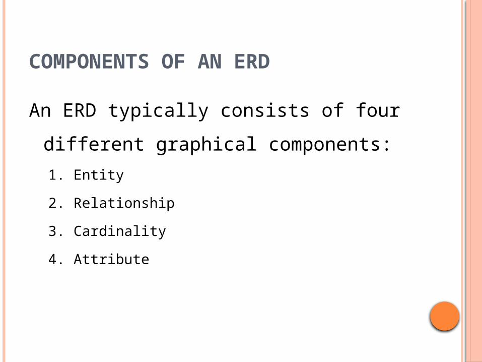
COMPONENTS OF AN ERD
An ERD typically consists of four different
graphical components:
1. Entity
2. Relationship
3. Cardinality
4. Attribute
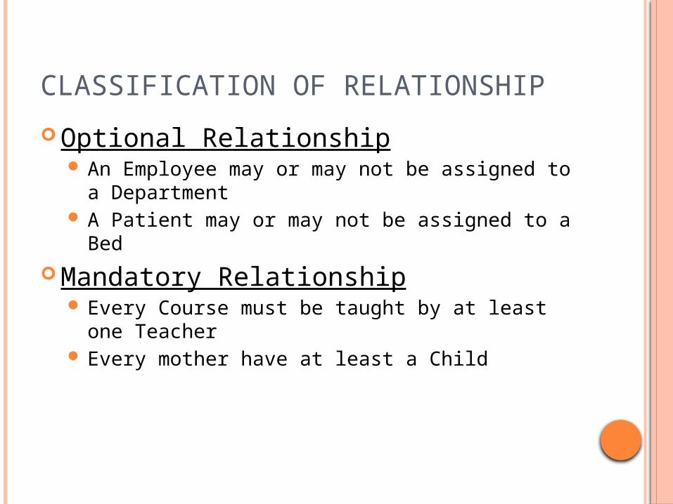
CLASSIFICATION OF RELATIONSHIP
Optional Relationship An Employee may or may not be assigned to a
Department A Patient may or may not be assigned to a Bed
Mandatory Relationship Every Course must be taught by at least one
Teacher Every mother have at least a Child
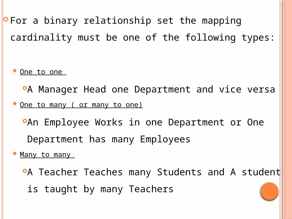
For a binary relationship set the mapping cardinality
must be one of the following types:
One to one
A Manager Head one Department and vice versa One to many ( or many to one)
An Employee Works in one Department or One
Department has many Employees Many to many
A Teacher Teaches many Students and A student
is taught by many Teachers
9
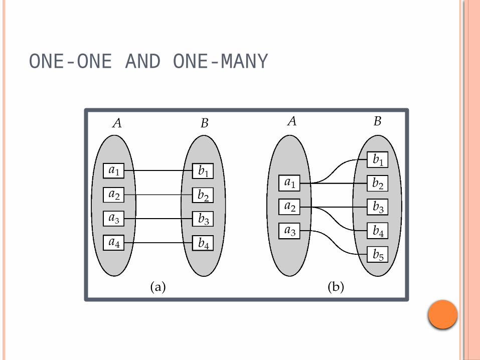
ONE-ONE AND ONE-MANY
10
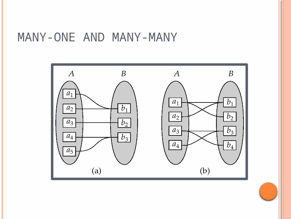
MANY-ONE AND MANY-MANY
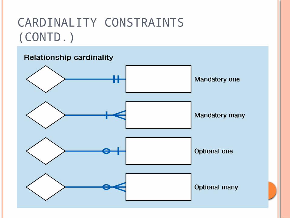
CARDINALITY CONSTRAINTS (CONTD.)
CARDINALITY CONSTRAINTS EXAMPLE
In our model, we wish to indicate that each school may
enroll many students, or may not enroll any students
at all.
We also wish to indicate that each student attends
exactly one school. The following diagram indicates
this optionality and cardinality:
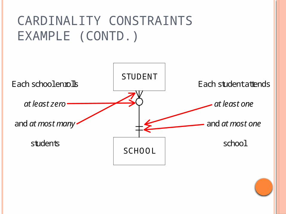
CARDINALITY CONSTRAINTS EXAMPLE (CONTD.)
SCHOOL
STUDENTEach school enrolls
at least zero
and at most many
students
Each student attends
at least one
and at most one
school
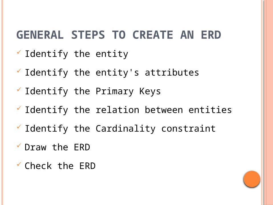
GENERAL STEPS TO CREATE AN ERD Identify the entity
Identify the entity's attributes
Identify the Primary Keys
Identify the relation between entities
Identify the Cardinality constraint
Draw the ERD
Check the ERD
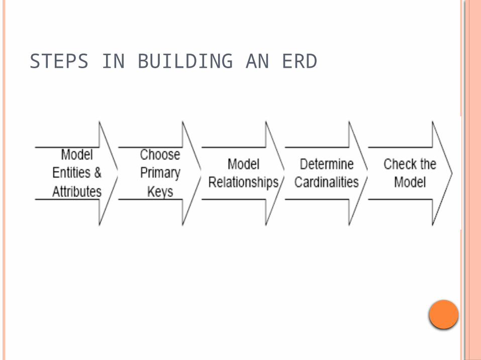
STEPS IN BUILDING AN ERD
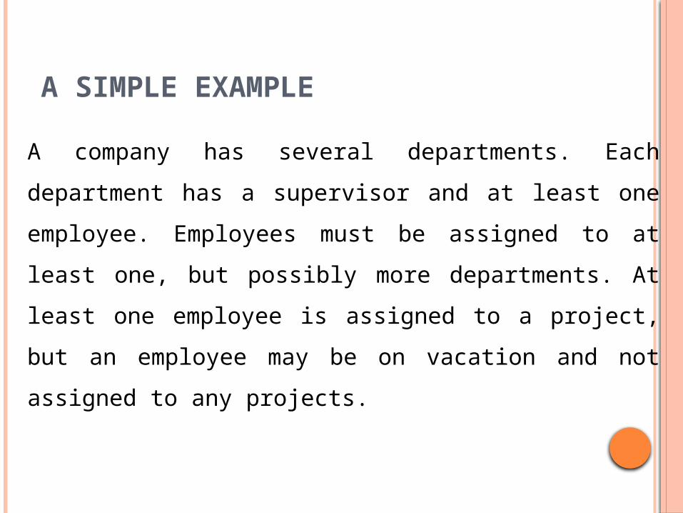
A SIMPLE EXAMPLE
A company has several departments. Each department
has a supervisor and at least one employee.
Employees must be assigned to at least one, but
possibly more departments. At least one employee is
assigned to a project, but an employee may be on
vacation and not assigned to any projects.
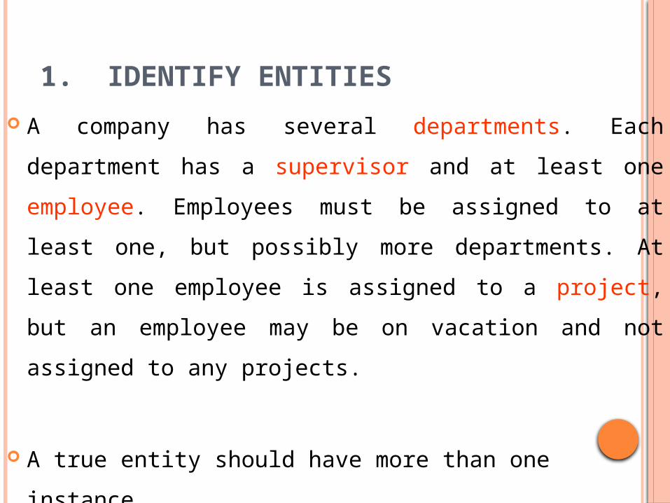
1. IDENTIFY ENTITIES
A company has several departments. Each department
has a supervisor and at least one employee. Employees
must be assigned to at least one, but possibly more
departments. At least one employee is assigned to a
project, but an employee may be on vacation and not
assigned to any projects.
A true entity should have more than one instance
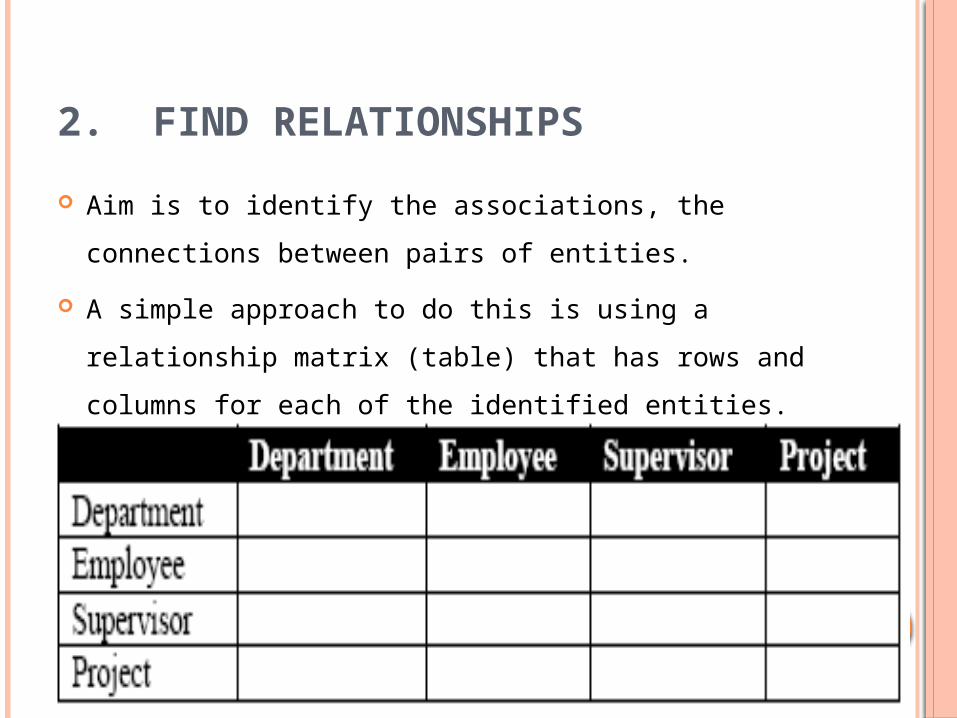
2. FIND RELATIONSHIPS
Aim is to identify the associations, the connections
between pairs of entities.
A simple approach to do this is using a relationship
matrix (table) that has rows and columns for each of the
identified entities.
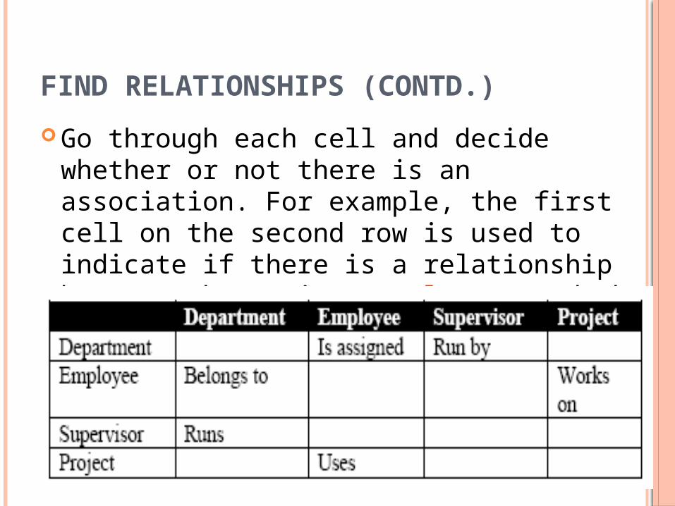
FIND RELATIONSHIPS (CONTD.)
Go through each cell and decide whether or not there is an association. For example, the first cell on the second row is used to indicate if there is a relationship between the entity "Employee" and the entity "Department".
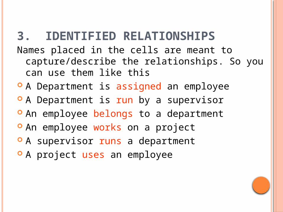
3. IDENTIFIED RELATIONSHIPS Names placed in the cells are meant to
capture/describe the relationships. So you can use them like this
A Department is assigned an employee A Department is run by a supervisor An employee belongs to a department An employee works on a project A supervisor runs a department A project uses an employee
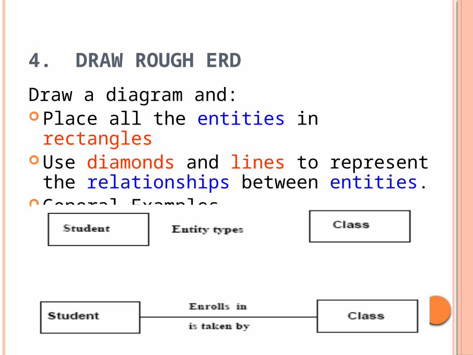
4. DRAW ROUGH ERD
Draw a diagram and: Place all the entities in rectangles Use diamonds and lines to represent the
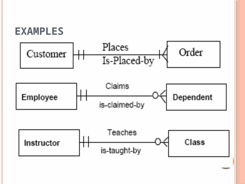
relationships between entities. General Examples
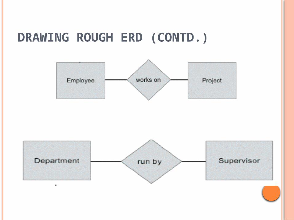
DRAWING ROUGH ERD (CONTD.)
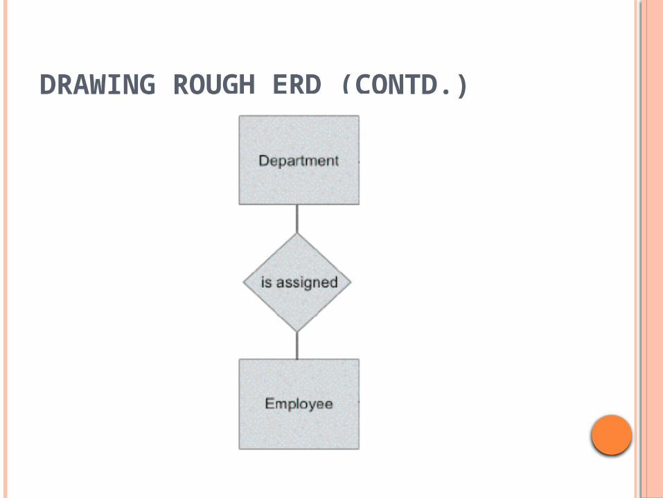
DRAWING ROUGH ERD (CONTD.)
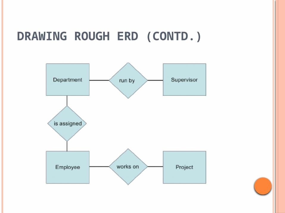
DRAWING ROUGH ERD (CONTD.)
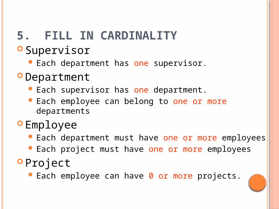
5. FILL IN CARDINALITY Supervisor
Each department has one supervisor.
Department Each supervisor has one department. Each employee can belong to one or more departments
Employee Each department must have one or more employees Each project must have one or more employees
Project Each employee can have 0 or more projects.
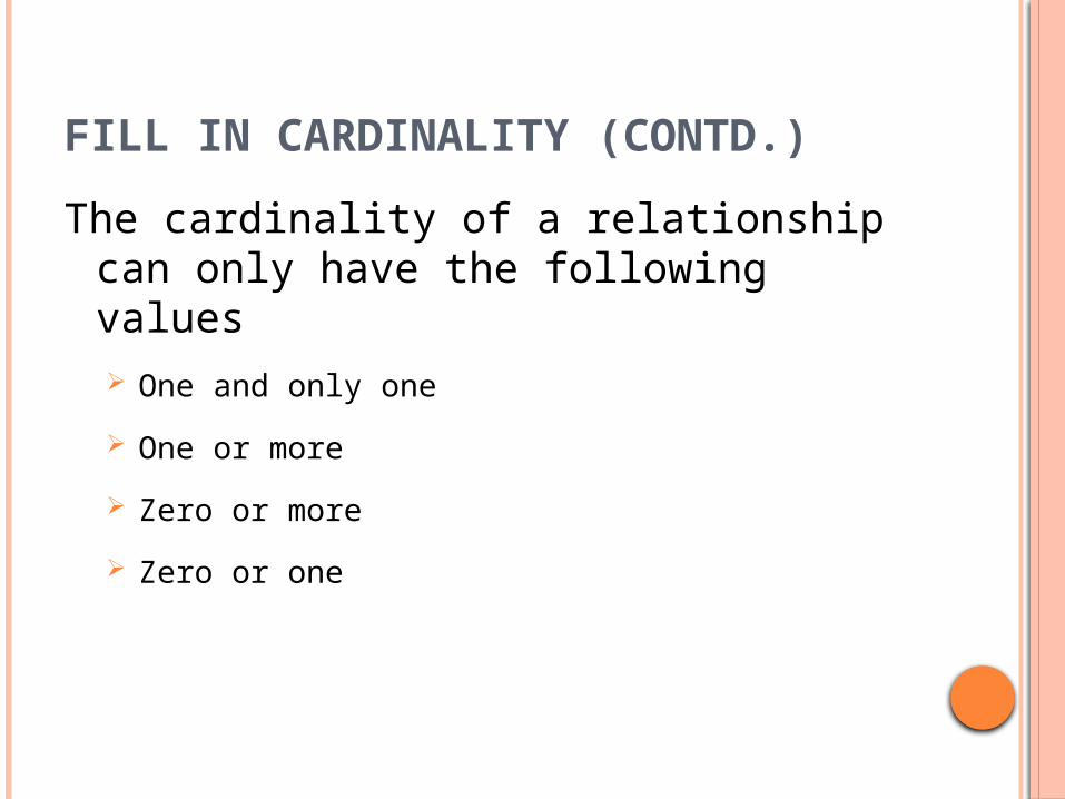
FILL IN CARDINALITY (CONTD.)
The cardinality of a relationship can only have the following values One and only one
One or more
Zero or more
Zero or one
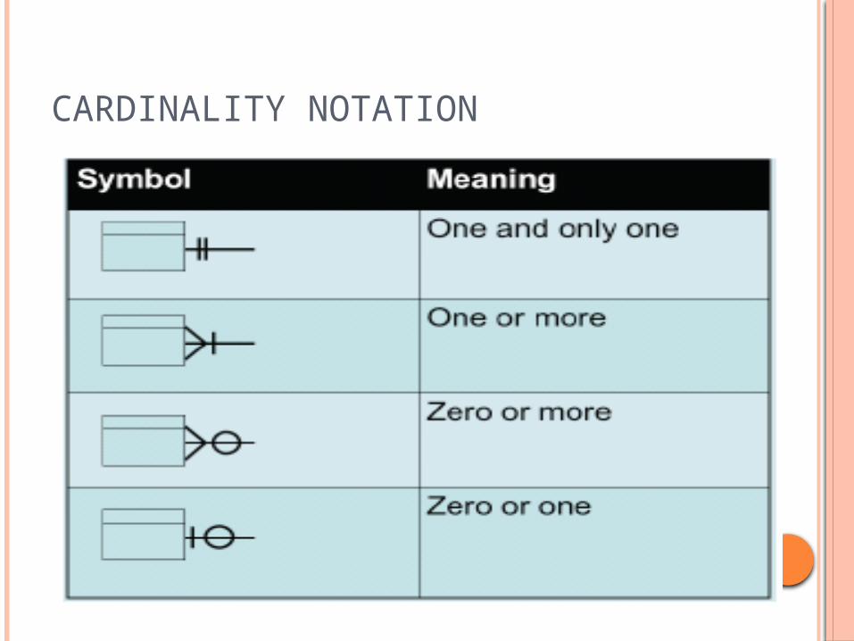
CARDINALITY NOTATION
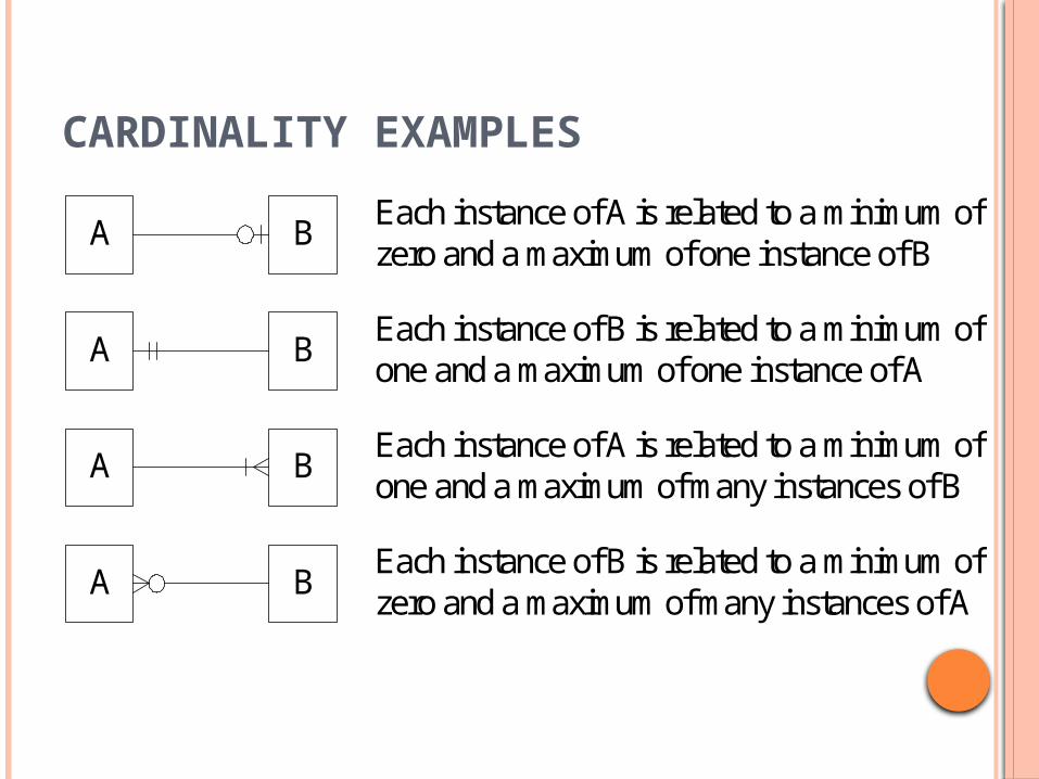
CARDINALITY EXAMPLES
A
A
A
A
B
B
B
B
Each instance of A is related to a minimum ofzero and a maximum of one instance of B
Each instance of B is related to a minimum ofone and a maximum of one instance of A
Each instance of A is related to a minimum ofone and a maximum of many instances of B
Each instance of B is related to a minimum ofzero and a maximum of many instances of A
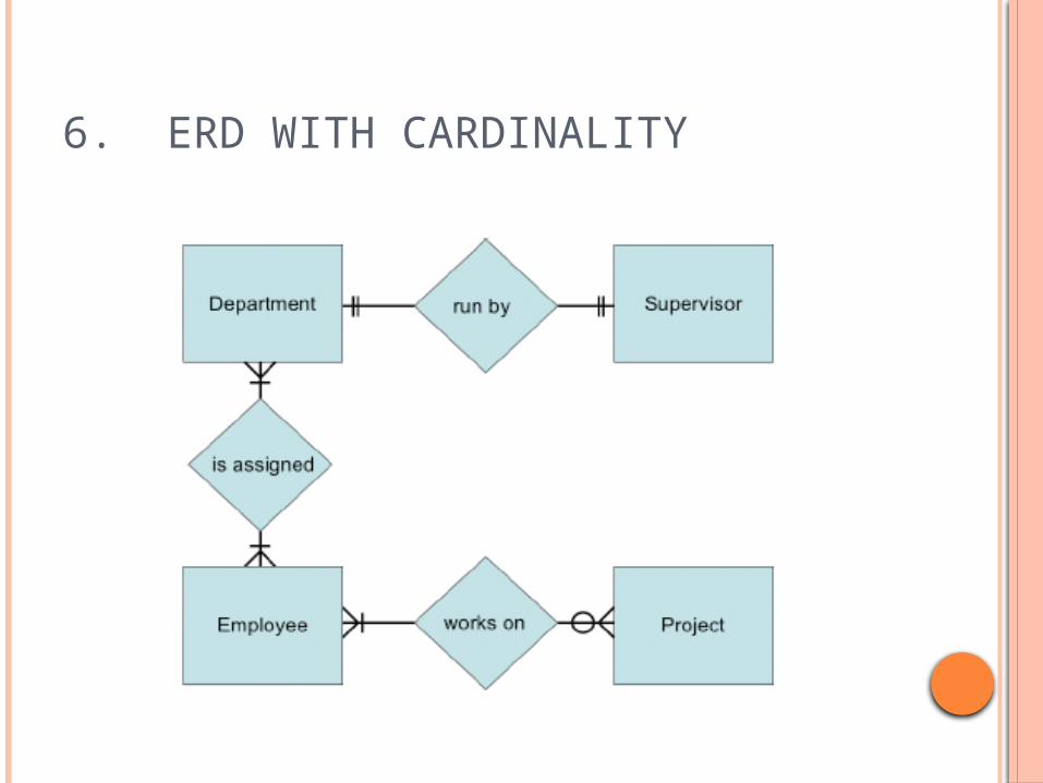
6. ERD WITH CARDINALITY
EXAMPLES
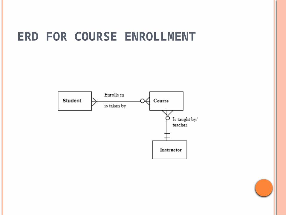
ERD FOR COURSE ENROLLMENT
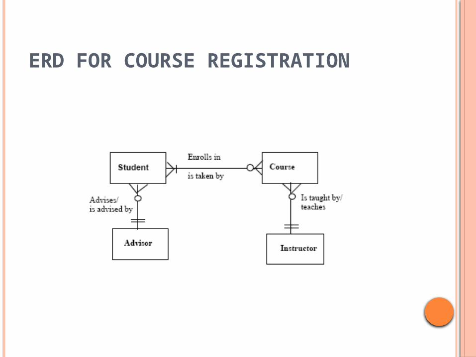
ERD FOR COURSE REGISTRATION
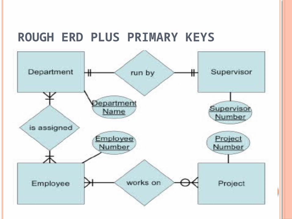
ROUGH ERD PLUS PRIMARY KEYS
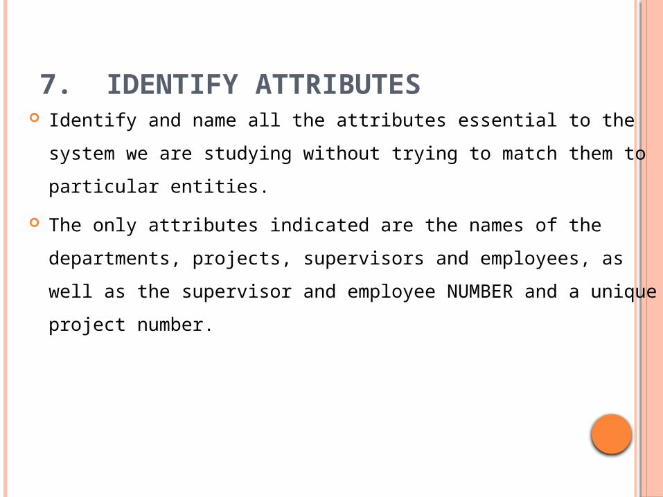
7. IDENTIFY ATTRIBUTES Identify and name all the attributes essential to the system we
are studying without trying to match them to particular entities.
The only attributes indicated are the names of the departments,
projects, supervisors and employees, as well as the supervisor
and employee NUMBER and a unique project number.
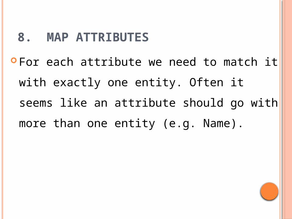
8. MAP ATTRIBUTES
For each attribute we need to match it with
exactly one entity. Often it seems like an
attribute should go with more than one entity
(e.g. Name).
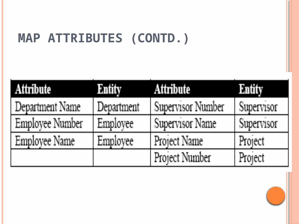
MAP ATTRIBUTES (CONTD.)
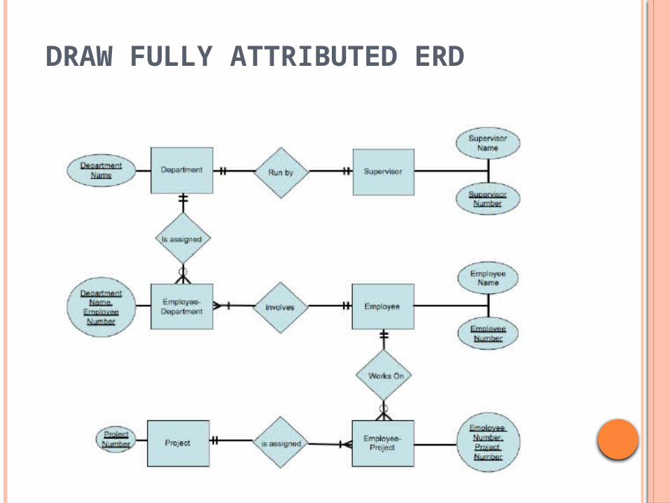
DRAW FULLY ATTRIBUTED ERD
38
WEAK ENTITY SET
Some entity sets in real world naturally depend on some other entity set They can be uniquely identified only if combined
with another entity set Example:
section1, section2, … become unique only if you put them into a context, e.g. csce4350
39
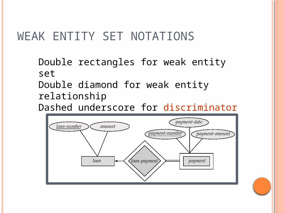
WEAK ENTITY SET NOTATIONS
Double rectangles for weak entity setDouble diamond for weak entity relationshipDashed underscore for discriminator
LEARNING OUTCOME
Define terms related to entity relationship
modeling, including entity, entity instance,
attribute, relationship and cardinality, and
primary key.
Explain the entity modeling process.
Draw an entity relationship diagram.