Embed Size (px)
Citation preview
ECEN 4517 1
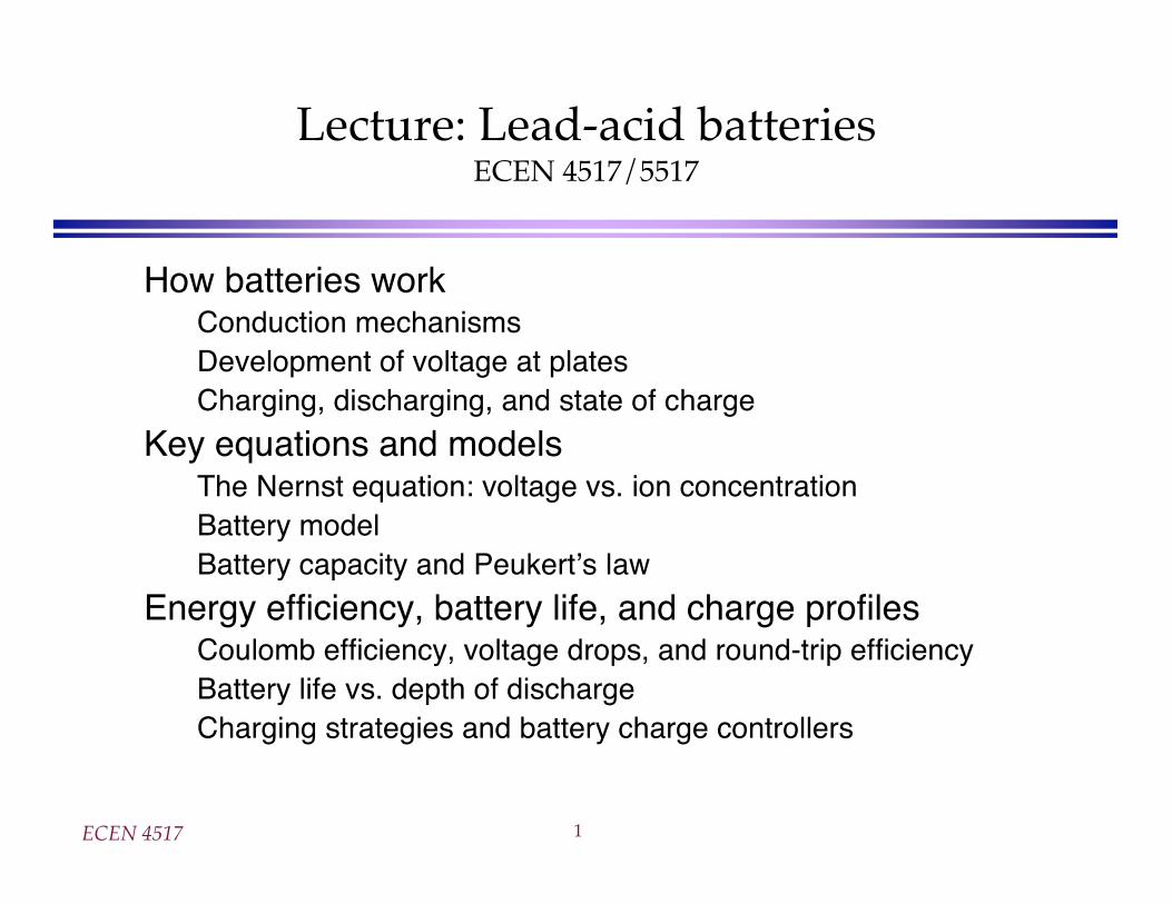
Lecture: Lead-acid batteriesECEN 4517/5517
How batteries workConduction mechanismsDevelopment of voltage at platesCharging, discharging, and state of charge
Key equations and modelsThe Nernst equation: voltage vs. ion concentrationBattery modelBattery capacity and Peukert s law
Energy efficiency, battery life, and charge profilesCoulomb efficiency, voltage drops, and round-trip efficiencyBattery life vs. depth of dischargeCharging strategies and battery charge controllers
ECEN 4517 2
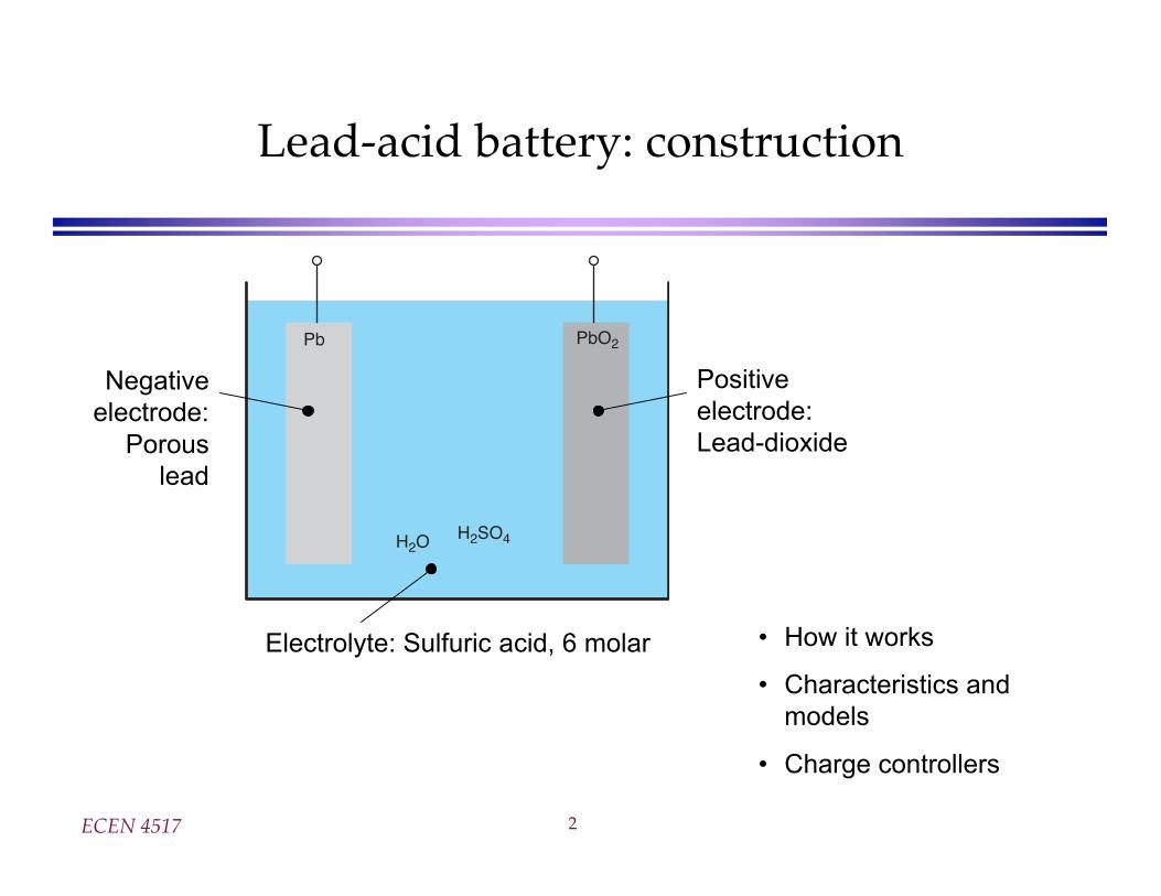
Lead-acid battery: construction
Pb PbO2
H2O H2SO4
Positive
electrode:
Lead-dioxide
Negative
electrode:
Porous
lead
Electrolyte: Sulfuric acid, 6 molar • How it works
• Characteristics and
models
• Charge controllers
ECEN 4517 3
Electrical conduction mechanisms
Pb PbO2
H2O
SO4-2
SO4-2
H+
H+
H+H+
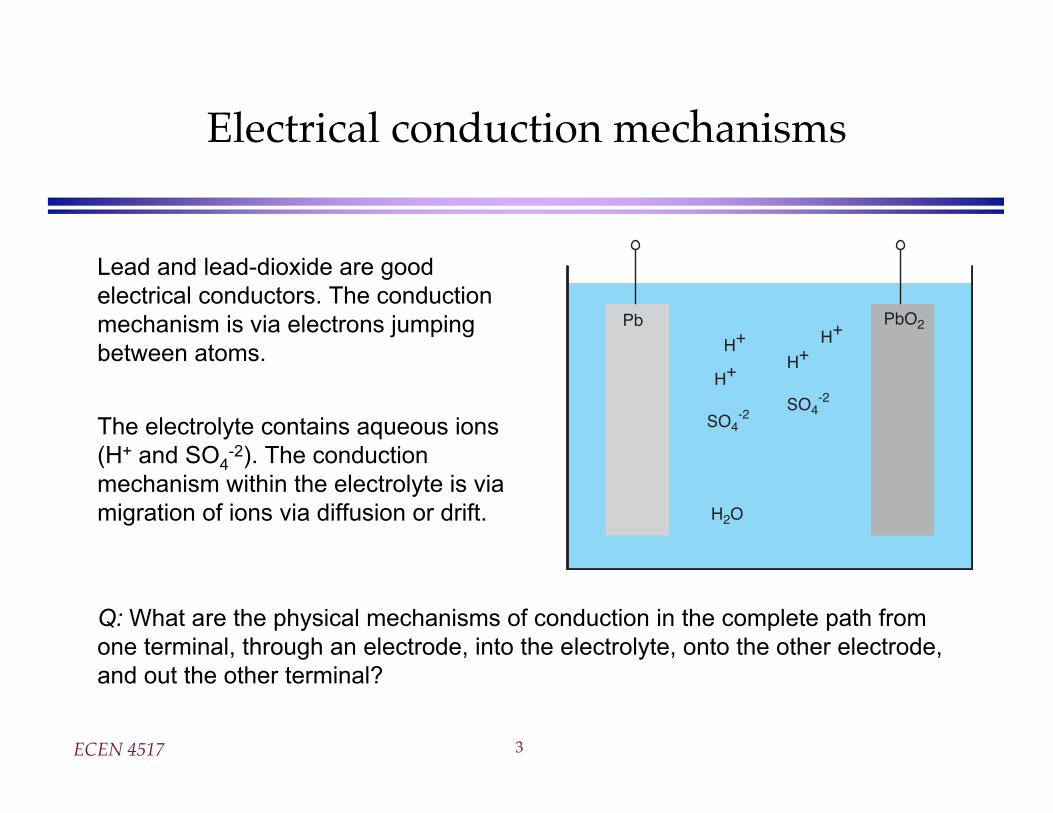
Lead and lead-dioxide are good
electrical conductors. The conduction
mechanism is via electrons jumping
between atoms.
The electrolyte contains aqueous ions
(H+ and SO4-2). The conduction
mechanism within the electrolyte is via
migration of ions via diffusion or drift.
Q: What are the physical mechanisms of conduction in the complete path from
one terminal, through an electrode, into the electrolyte, onto the other electrode,
and out the other terminal?
ECEN 4517 4
Conduction mechanismat the surface of the electrode
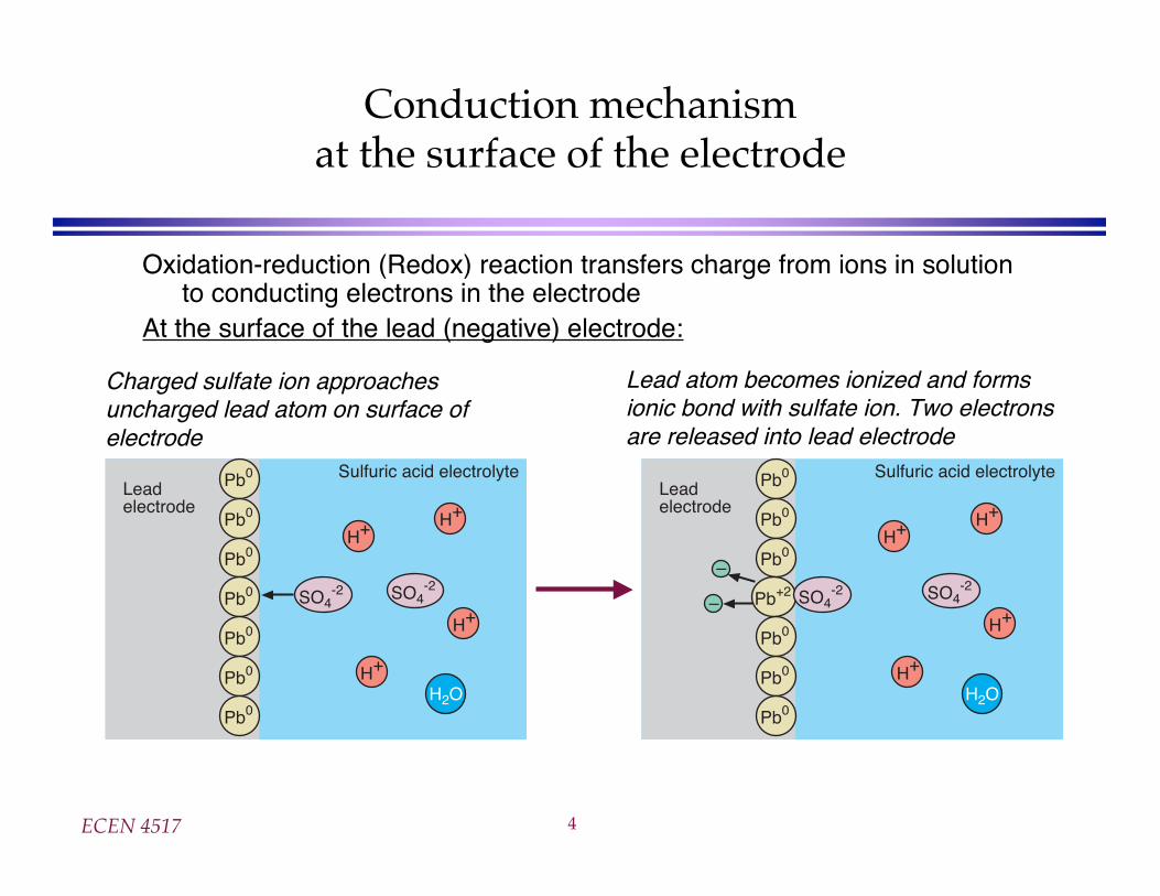
Oxidation-reduction (Redox) reaction transfers charge from ions in solutionto conducting electrons in the electrode
At the surface of the lead (negative) electrode:
Pb0
Pb0
Pb0
Pb0
Pb0
Pb0
Pb0
SO4-2 SO4
-2
H+
H+
H+
H+
H2O
Leadelectrode
Sulfuric acid electrolyte
Charged sulfate ion approachesuncharged lead atom on surface ofelectrode
Pb0
Pb0
Pb0
Pb+2
Pb0
Pb0
Pb0
SO4-2 SO4
-2
H+
H+
H+
H+
H2O
Leadelectrode
Sulfuric acid electrolyte
–
–
Lead atom becomes ionized and formsionic bond with sulfate ion. Two electronsare released into lead electrode
ECEN 4517 5
The chemical reaction (“half reaction”)at the lead electrode
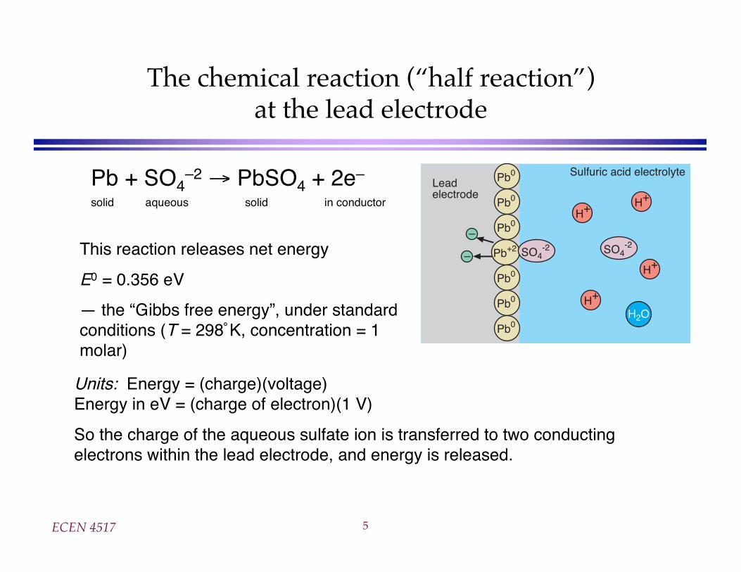
Pb + SO4–2 PbSO4 + 2e–
solid aqueous solid in conductor
Pb0
Pb0
Pb0
Pb+2
Pb0
Pb0
Pb0
SO4-2 SO4
-2
H+
H+
H+
H+
H2O
Leadelectrode
Sulfuric acid electrolyte
–
–This reaction releases net energy
E0 = 0.356 eV
— the “Gibbs free energy”, under standardconditions (T = 298˚K, concentration = 1molar)
Units: Energy = (charge)(voltage)Energy in eV = (charge of electron)(1 V)
So the charge of the aqueous sulfate ion is transferred to two conductingelectrons within the lead electrode, and energy is released.
ECEN 4517 6
Conduction mechanismat the surface of the positive electrode
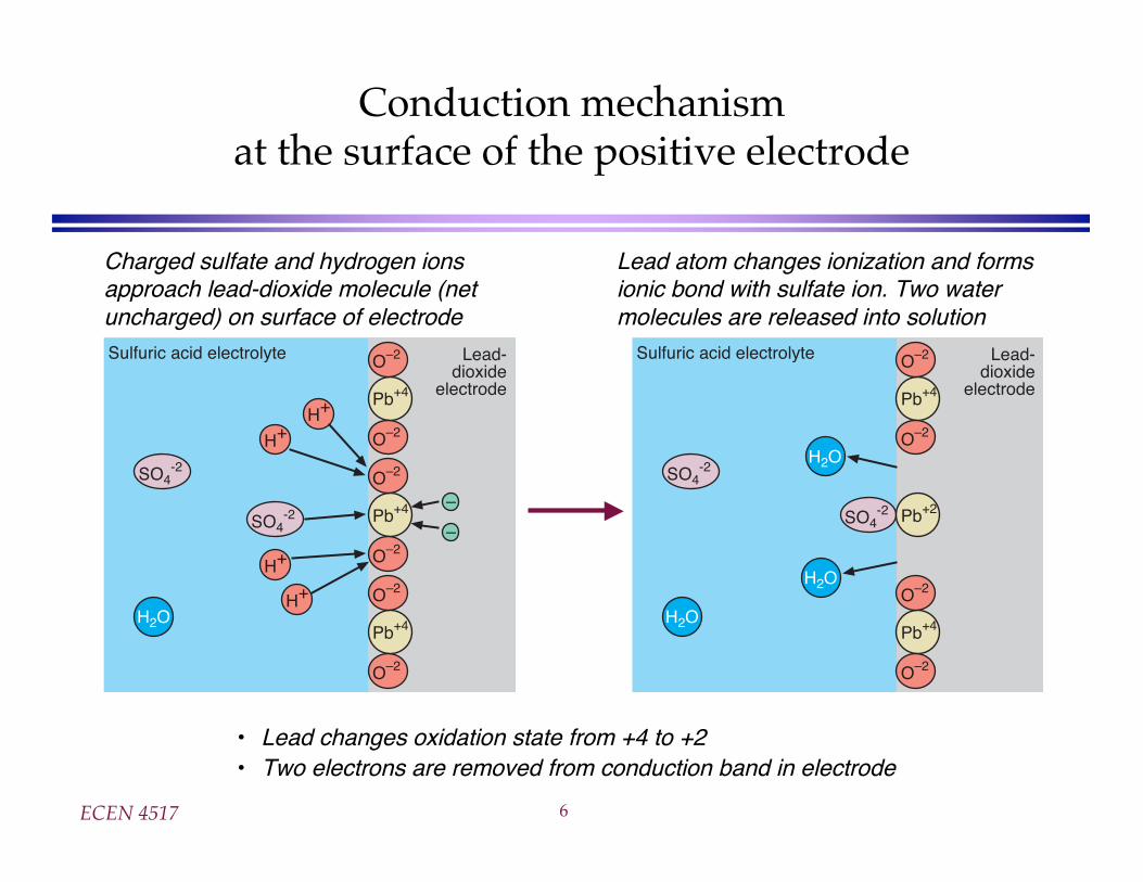
Charged sulfate and hydrogen ionsapproach lead-dioxide molecule (netuncharged) on surface of electrode
Lead atom changes ionization and formsionic bond with sulfate ion. Two watermolecules are released into solution
SO4-2
SO4-2
H+
H+
H+
H+
H2O
Lead-dioxide
electrode
Sulfuric acid electrolyte
Pb+4
O–2
O–2
Pb+4
O–2
O–2
Pb+4
O–2
O–2
–
–
SO4-2
SO4-2
H2O
Lead-dioxide
electrode
Sulfuric acid electrolyte
Pb+2
Pb+4
O–2
O–2
Pb+4
O–2
O–2
H2O
H2O
• Lead changes oxidation state from +4 to +2• Two electrons are removed from conduction band in electrode
ECEN 4517 7
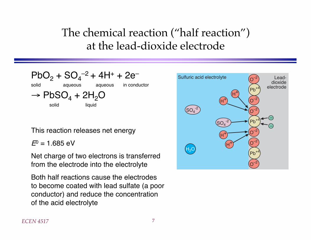
The chemical reaction (“half reaction”)at the lead-dioxide electrode
PbO2 + SO4–2 + 4H+ + 2e–
solid aqueous aqueous in conductor
PbSO4 + 2H2O solid liquid
This reaction releases net energy
E0 = 1.685 eV
Net charge of two electrons is transferredfrom the electrode into the electrolyte
Both half reactions cause the electrodesto become coated with lead sulfate (a poorconductor) and reduce the concentrationof the acid electrolyte
SO4-2
SO4-2
H+
H+
H+
H+
H2O
Lead-dioxide
electrode
Sulfuric acid electrolyte
Pb+4
O–2
O–2
Pb+4
O–2
O–2
Pb+4
O–2
O–2
–
–
ECEN 4517 8
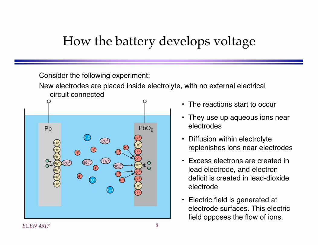
How the battery develops voltage
Consider the following experiment:New electrodes are placed inside electrolyte, with no external electrical
circuit connected
Pb PbO2
SO4-2
H2O
Pb0
Pb0
Pb0
Pb+2
Pb0
Pb0
Pb0
SO4-2 SO4
-2
H+
H+
H+
H+
H2O
SO4-2
SO4-2
H+
H+
H+
H+
H2O
Pb+4
O–2
O–2
Pb+4
O–2
O–2
Pb+4
O–2
O–2
–
––
–
• The reactions start to occur
• They use up aqueous ions nearelectrodes
• Diffusion within electrolytereplenishes ions near electrodes
• Excess electrons are created inlead electrode, and electrondeficit is created in lead-dioxideelectrode
• Electric field is generated atelectrode surfaces. This electricfield opposes the flow of ions.
ECEN 4517 9
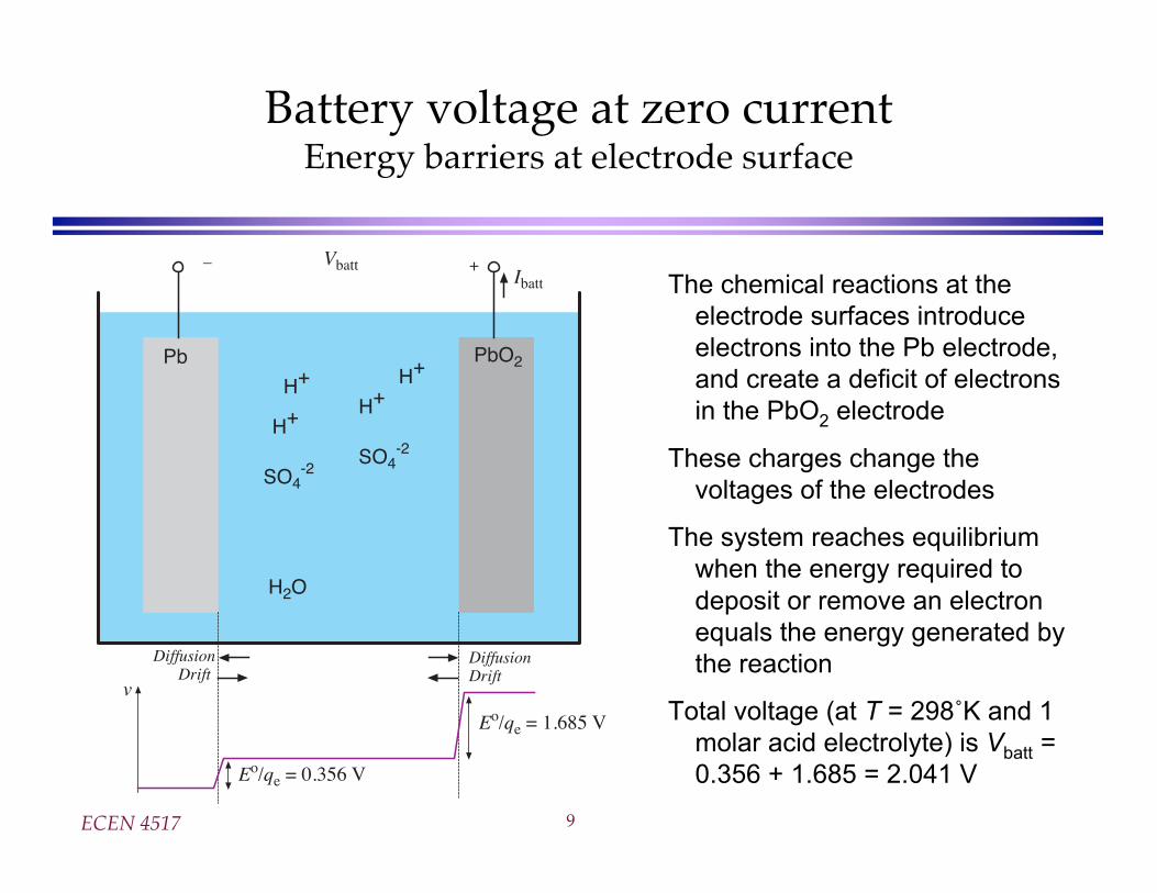
Battery voltage at zero currentEnergy barriers at electrode surface
The chemical reactions at the
electrode surfaces introduce
electrons into the Pb electrode,
and create a deficit of electrons
in the PbO2 electrode
These charges change the
voltages of the electrodes
The system reaches equilibrium
when the energy required to
deposit or remove an electron
equals the energy generated by
the reaction
Total voltage (at T = 298˚K and 1
molar acid electrolyte) is Vbatt =
0.356 + 1.685 = 2.041 V
Pb PbO2
H2O
SO4-2
SO4-2
H+
H+
H+H+
v
Vbatt– +Ibatt
Eo/qe = 0.356 V
Eo/qe = 1.685 V
DiffusionDrift
DiffusionDrift
ECEN 4517 10
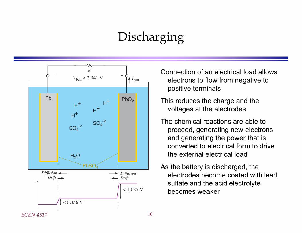
Discharging
Connection of an electrical load allows
electrons to flow from negative to
positive terminals
This reduces the charge and the
voltages at the electrodes
The chemical reactions are able to
proceed, generating new electrons
and generating the power that is
converted to electrical form to drive
the external electrical load
As the battery is discharged, the
electrodes become coated with lead
sulfate and the acid electrolyte
becomes weaker
H2O
SO4-2
SO4-2
H+
H+
H+H+
v
Vbatt < 2.041 V– +
Ibatt
< 0.356 V
< 1.685 V
Pb PbO2
PbSO4
DiffusionDrift
DiffusionDrift
R
ECEN 4517 11
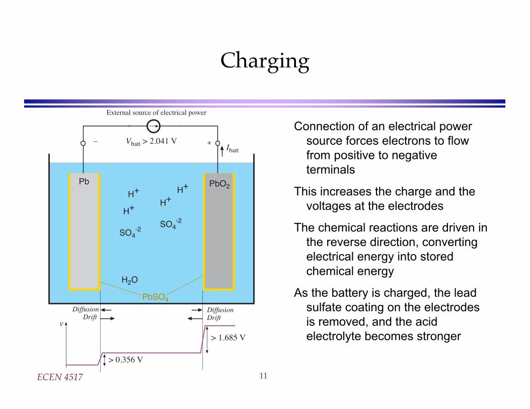
Charging
Connection of an electrical power
source forces electrons to flow
from positive to negative
terminals
This increases the charge and the
voltages at the electrodes
The chemical reactions are driven in
the reverse direction, converting
electrical energy into stored
chemical energy
As the battery is charged, the lead
sulfate coating on the electrodes
is removed, and the acid
electrolyte becomes stronger
H2O
SO4-2
SO4-2
H+
H+
H+H+
v
Vbatt > 2.041 V– +Ibatt
> 0.356 V
> 1.685 V
Pb PbO2
PbSO4
External source of electrical power
DiffusionDrift
DiffusionDrift
ECEN 4517 12
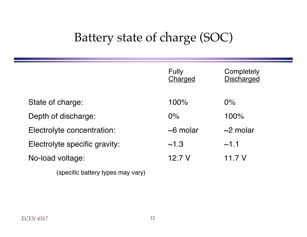
Battery state of charge (SOC)
Fully CompletelyCharged Discharged
State of charge: 100% 0%
Depth of discharge: 0% 100%
Electrolyte concentration: ~6 molar ~2 molar
Electrolyte specific gravity: ~1.3 ~1.1
No-load voltage: 12.7 V 11.7 V
(specific battery types may vary)
ECEN 4517 13
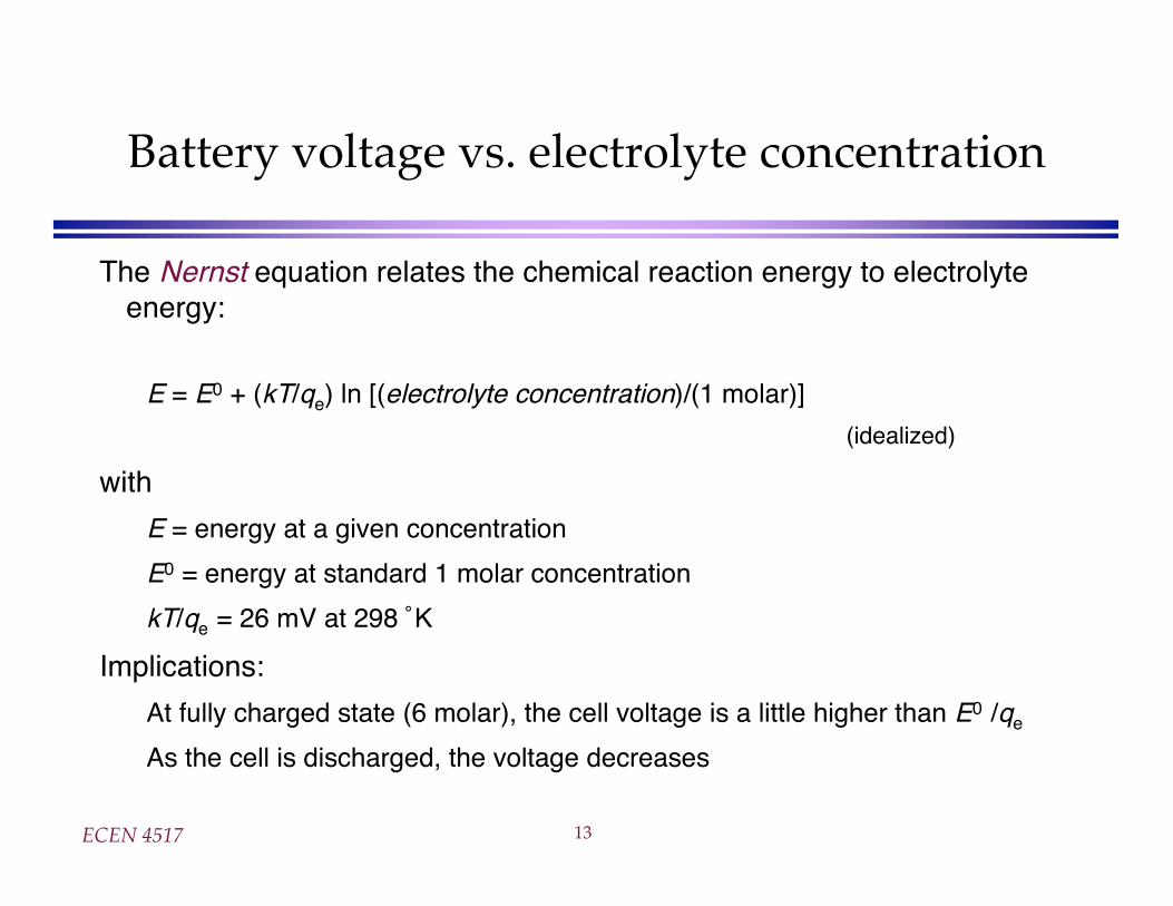
Battery voltage vs. electrolyte concentration
The Nernst equation relates the chemical reaction energy to electrolyteenergy:
E = E0 + (kT/qe) ln [(electrolyte concentration)/(1 molar)]
(idealized)
with
E = energy at a given concentration
E0 = energy at standard 1 molar concentration
kT/qe = 26 mV at 298 ˚K
Implications:
At fully charged state (6 molar), the cell voltage is a little higher than E0 /qe
As the cell is discharged, the voltage decreases
ECEN 4517 14
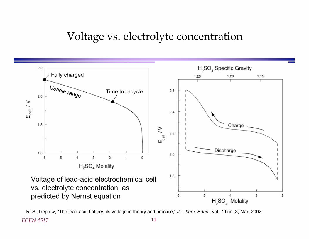
Voltage vs. electrolyte concentration
R. S. Treptow, “The lead-acid battery: its voltage in theory and practice,” J. Chem. Educ., vol. 79 no. 3, Mar. 2002
Voltage of lead-acid electrochemical cell
vs. electrolyte concentration, as
predicted by Nernst equation
Fully charged
Time to recycleUsable range
ECEN 4517 15
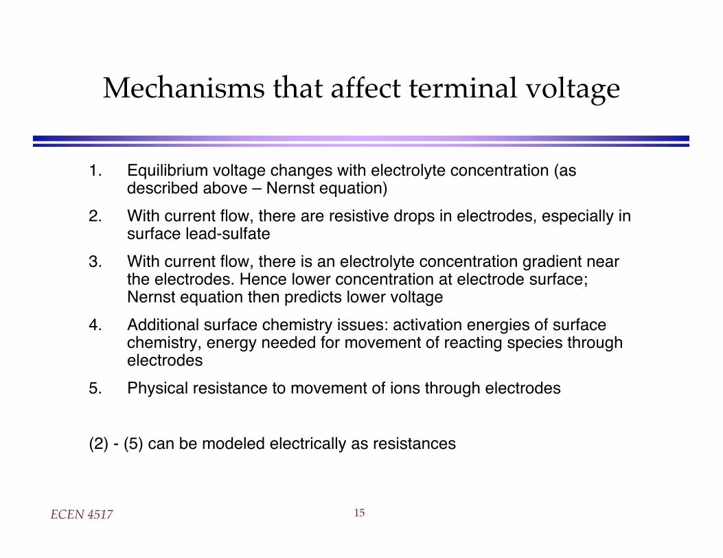
Mechanisms that affect terminal voltage
1. Equilibrium voltage changes with electrolyte concentration (asdescribed above – Nernst equation)
2. With current flow, there are resistive drops in electrodes, especially insurface lead-sulfate
3. With current flow, there is an electrolyte concentration gradient nearthe electrodes. Hence lower concentration at electrode surface;Nernst equation then predicts lower voltage
4. Additional surface chemistry issues: activation energies of surfacechemistry, energy needed for movement of reacting species throughelectrodes
5. Physical resistance to movement of ions through electrodes
(2) - (5) can be modeled electrically as resistances
ECEN 4517 16
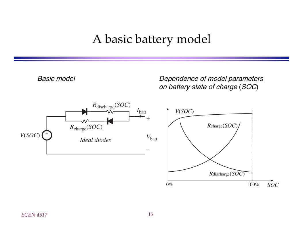
A basic battery model
+–V(SOC)
Ideal diodes
Rcharge(SOC)
Rdischarge(SOC)
+
Vbatt
–
Ibatt
SOC0% 100%
V(SOC)
Rcharge(SOC)
Rdischarge(SOC)
Basic model Dependence of model parameterson battery state of charge (SOC)
ECEN 4517 17
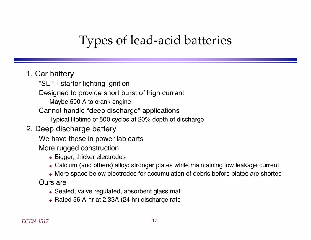
Types of lead-acid batteries
1. Car battery“SLI” - starter lighting ignitionDesigned to provide short burst of high current
Maybe 500 A to crank engine
Cannot handle “deep discharge” applicationsTypical lifetime of 500 cycles at 20% depth of discharge
2. Deep discharge batteryWe have these in power lab cartsMore rugged construction
Bigger, thicker electrodesCalcium (and others) alloy: stronger plates while maintaining low leakage currentMore space below electrodes for accumulation of debris before plates are shorted
Ours areSealed, valve regulated, absorbent glass matRated 56 A-hr at 2.33A (24 hr) discharge rate
ECEN 4517 18
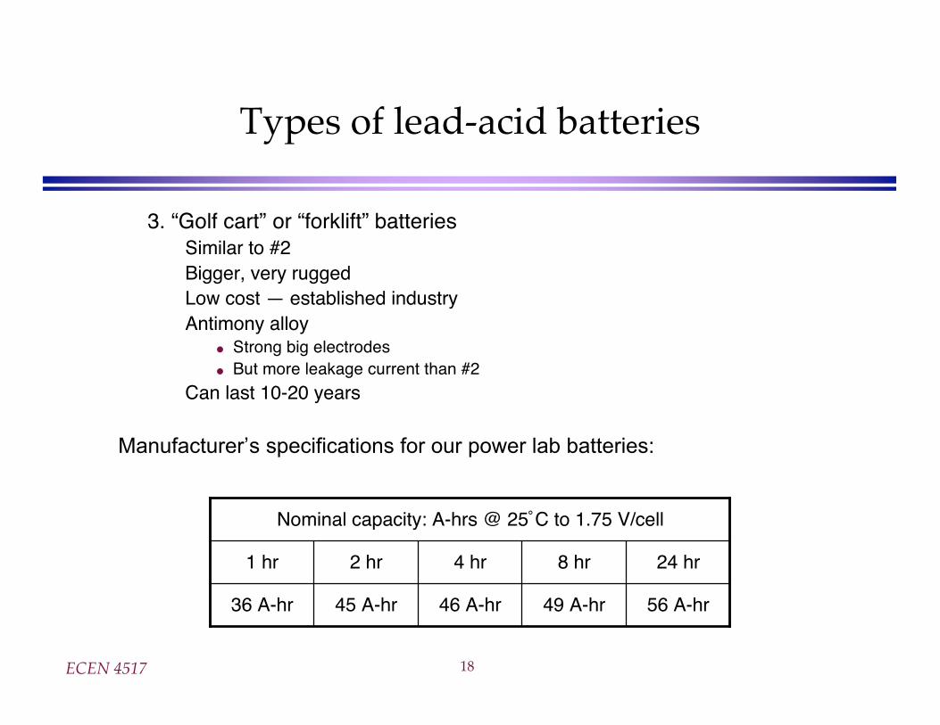
Types of lead-acid batteries
3. “Golf cart” or “forklift” batteriesSimilar to #2Bigger, very ruggedLow cost — established industryAntimony alloy
Strong big electrodesBut more leakage current than #2
Can last 10-20 years
Nominal capacity: A-hrs @ 25˚C to 1.75 V/cell
36 A-hr
1 hr
56 A-hr49 A-hr46 A-hr45 A-hr
24 hr8 hr4 hr2 hr
Manufacturer’s specifications for our power lab batteries:
ECEN 4517 19
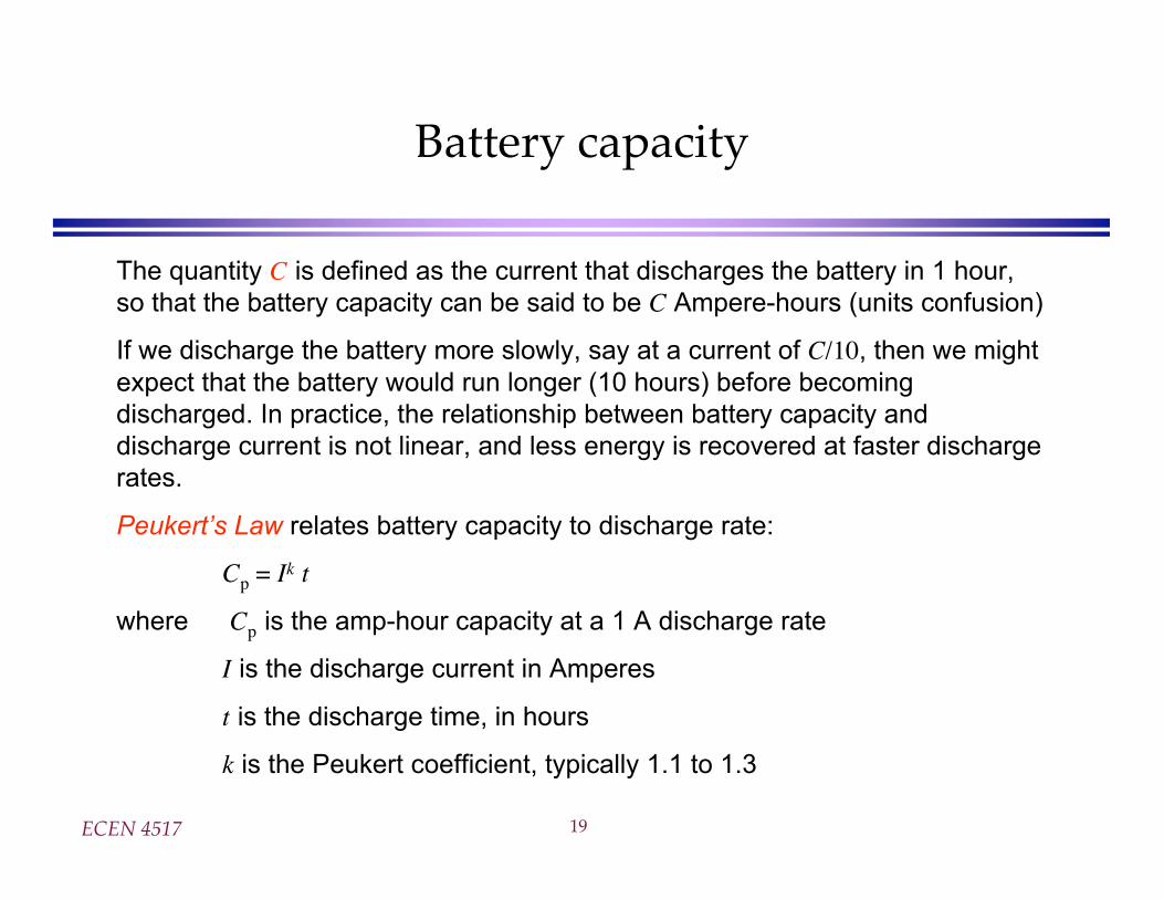
Battery capacity
The quantity C is defined as the current that discharges the battery in 1 hour,
so that the battery capacity can be said to be C Ampere-hours (units confusion)
If we discharge the battery more slowly, say at a current of C/10, then we might
expect that the battery would run longer (10 hours) before becoming
discharged. In practice, the relationship between battery capacity and
discharge current is not linear, and less energy is recovered at faster discharge
rates.
Peukert’s Law relates battery capacity to discharge rate:
Cp = Ik t
where Cp is the amp-hour capacity at a 1 A discharge rate
I is the discharge current in Amperes
t is the discharge time, in hours
k is the Peukert coefficient, typically 1.1 to 1.3
ECEN 4517 20
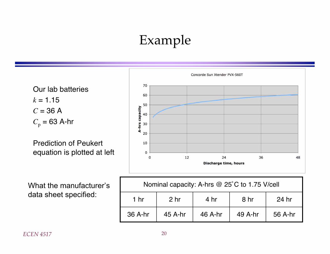
Example
Our lab batteriesk = 1.15C = 36 A
Cp = 63 A-hr
Prediction of Peukertequation is plotted at left
Nominal capacity: A-hrs @ 25˚C to 1.75 V/cell
36 A-hr
1 hr
56 A-hr49 A-hr46 A-hr45 A-hr
24 hr8 hr4 hr2 hr
What the manufacturer’s
data sheet specified:
ECEN 4517 21
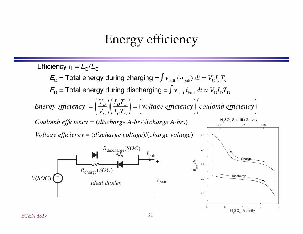
Energy efficiency
Efficiency = ED/EC
EC = Total energy during charging = vbatt (-ibatt) dt VCICTC
ED = Total energy during discharging = vbatt ibatt dt VDIDTD
Energy efficiency =VD
VC
IDTDICTC
= voltage efficiency coulomb efficiency
+–V(SOC)
Ideal diodes
Rcharge(SOC)
Rdischarge(SOC)
+
Vbatt
–
Ibatt
Coulomb efficiency = (discharge A-hrs)/(charge A-hrs)
Voltage efficiency = (discharge voltage)/(charge voltage)
ECEN 4517 22
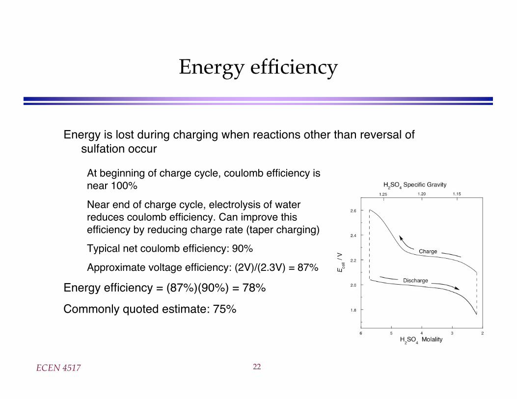
Energy efficiency
Energy is lost during charging when reactions other than reversal ofsulfation occur
At beginning of charge cycle, coulomb efficiency isnear 100%
Near end of charge cycle, electrolysis of waterreduces coulomb efficiency. Can improve thisefficiency by reducing charge rate (taper charging)
Typical net coulomb efficiency: 90%
Approximate voltage efficiency: (2V)/(2.3V) = 87%
Energy efficiency = (87%)(90%) = 78%
Commonly quoted estimate: 75%
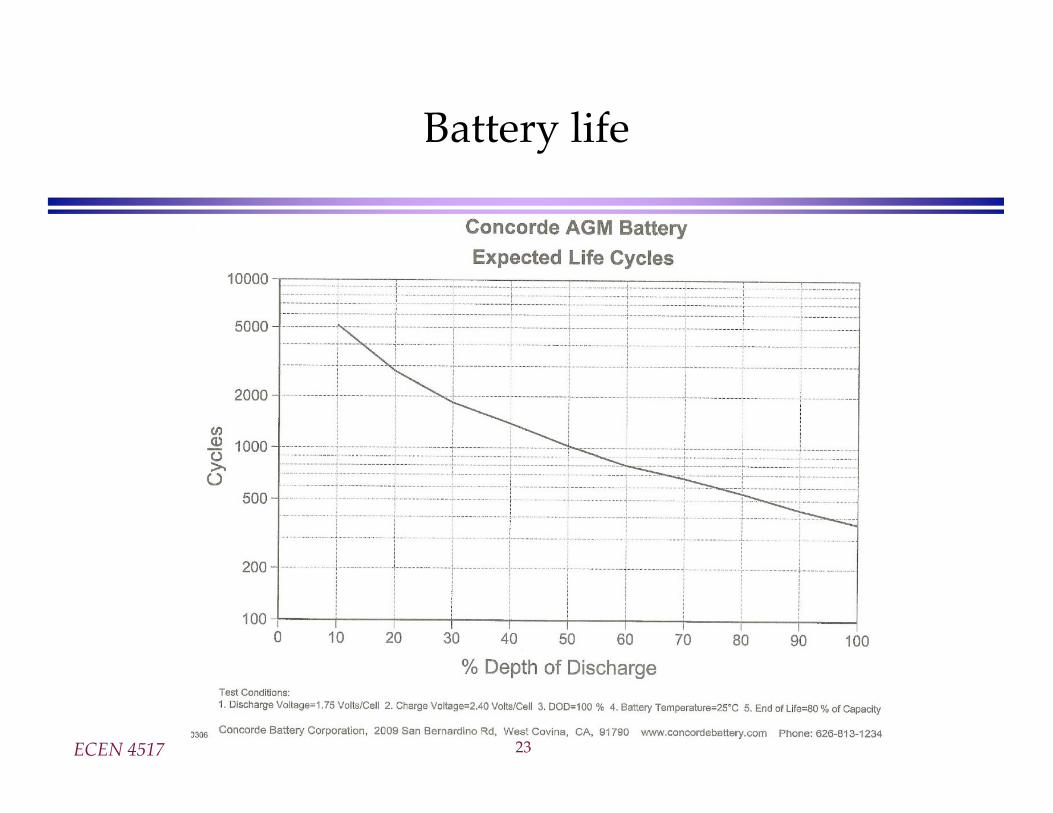
ECEN 4517 23
Battery life
ECEN 4517 24
Charge management
Over-discharge leads to “sulfation” and the battery is ruined. The reaction becomesirreversible when the size of the lead-sulfate formations become too large
Overcharging causes other undesirable reactions to occurElectrolysis of water and generation of hydrogen gas
Electrolysis of other compounds in electrodes and electrolyte, which can generatepoisonous gasses
Bulging and deformation of cases of sealed batteries
Battery charge management to extend life of battery:Limit depth of dischargeWhen charged but not used, employ “float” mode to prevent leakage currents from
discharging battery
Pulsing to break up chunks of lead sulfateTrickle charging to equalize charges of series-connected cells
ECEN 4517 25
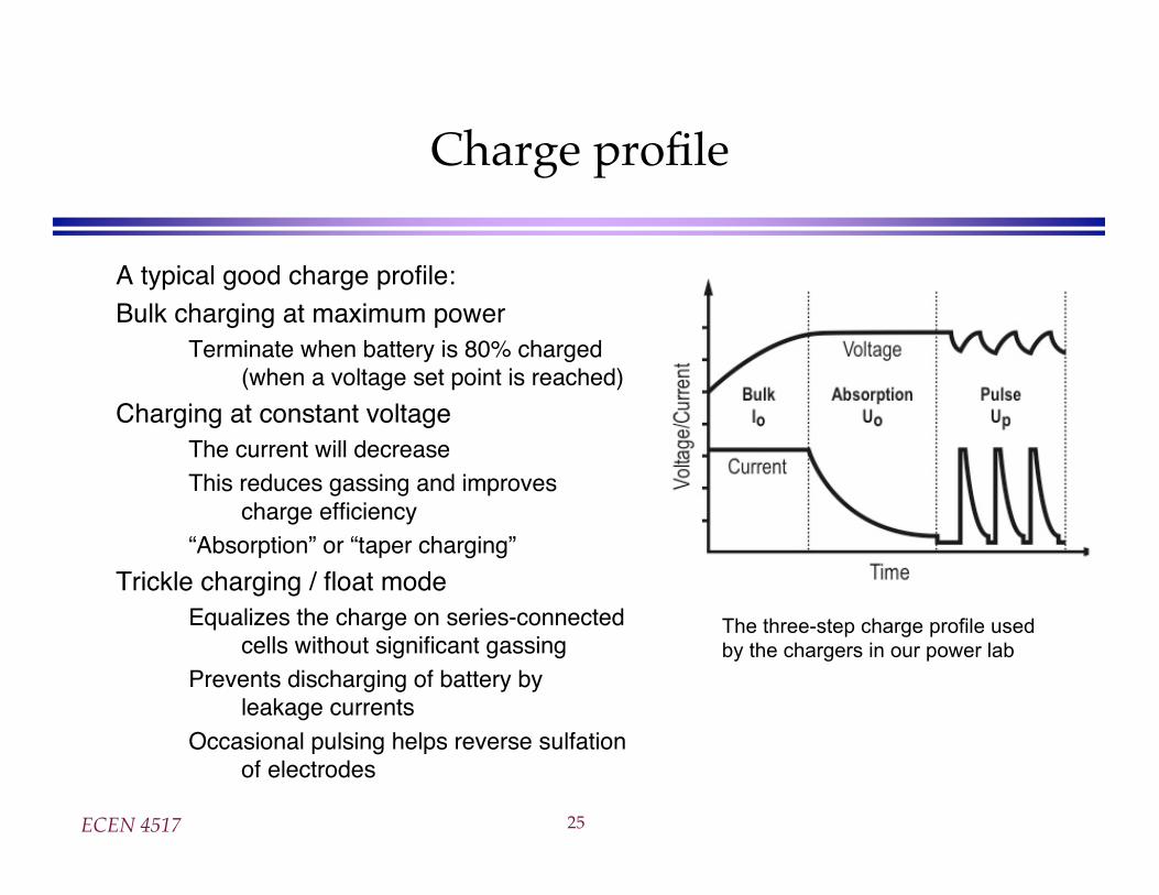
Charge profile
A typical good charge profile:Bulk charging at maximum power
Terminate when battery is 80% charged(when a voltage set point is reached)
Charging at constant voltageThe current will decreaseThis reduces gassing and improves
charge efficiency“Absorption” or “taper charging”
Trickle charging / float modeEqualizes the charge on series-connected
cells without significant gassingPrevents discharging of battery by
leakage currents
Occasional pulsing helps reverse sulfationof electrodes
The three-step charge profile used
by the chargers in our power lab
ECEN 4517 26
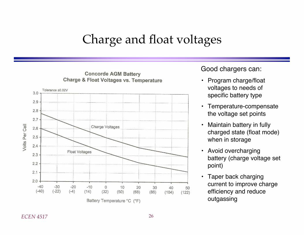
Charge and float voltages
Good chargers can:
• Program charge/floatvoltages to needs ofspecific battery type
• Temperature-compensatethe voltage set points
• Maintain battery in fullycharged state (float mode)when in storage
• Avoid overchargingbattery (charge voltage setpoint)
• Taper back chargingcurrent to improve chargeefficiency and reduceoutgassing
ECEN 4517 27
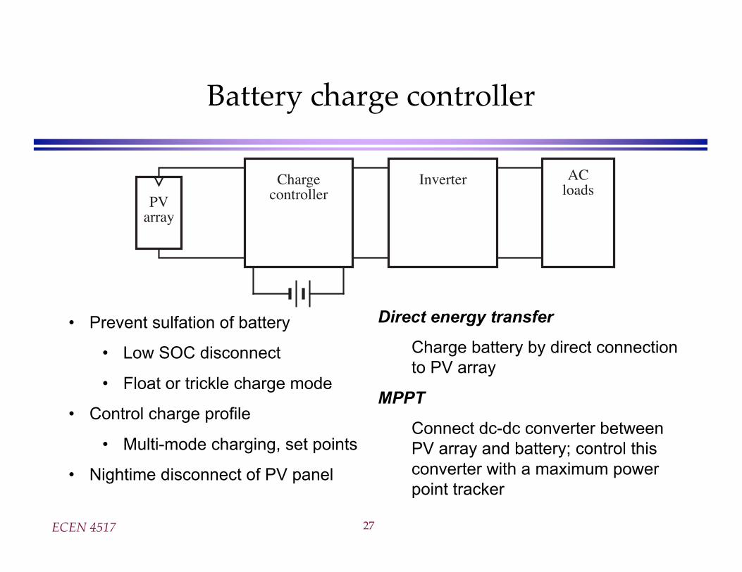
Battery charge controller
PVarray
Chargecontroller
Inverter ACloads
• Prevent sulfation of battery
• Low SOC disconnect
• Float or trickle charge mode
• Control charge profile
• Multi-mode charging, set points
• Nightime disconnect of PV panel
Direct energy transfer
Charge battery by direct connection
to PV array
MPPT
Connect dc-dc converter between
PV array and battery; control this
converter with a maximum power
point tracker