Embed Size (px)
Citation preview
Drafting Sanitary and Plumbing Layout and Details
Content Standard Performance Standard
The learner demonstrates understanding of concepts and underlying principles in drafting sanitary and plumbing layout and details.
The learner independently drafts sanitary and plumbing layout and details following the job requirements.
Quarter IV Time Allotment: 16 hrs.
MODULE 6
Drafting Sanitary and Plumbing Layout and Details
Introduction
This module is designed to familiarize students with the concept of
sanitary disposal of waste and the principle of introducing clean water in to the
residential unit from the source. It will also help the students understand the
intricacy of designing and planning a sanitary plumbing and sewerage layout.
It also familiarizes them with the different abbreviations and symbols used in
drafting of sanitary and plumbing layout, the specification materials used for
the construction and the different kinds of fittings intended for a sound
construction of the layout.
Plumbing drawings are prepared to a very small-scale. Therefore
schematic symbols are used for drawing plumbing lines, fixture and other
components as they actually appear. These symbols are used to show the
type and location of fixtures, valves, joints and other plumbing devices.
Objectives:
At the end of this module, you are expected to:
draft water distribution system; and
draft sanitary and storm drainage
288
At this point, you are heading into meaningful activities and learning encounters. Complete the exercises and answer the suggested worksheets to experience lifelong, practical learning that awaits at the end of this module.
ENJOY YOUR JOURNEY!
Drafting Sanitary and Plumbing Layout and Details
*****
Pre-assessment: Multiple Choice Direction: Choose the letter of the correct answer. Write your answer in the space provided before each number.
_____1. A kind of fitting used to straight section pipes. a. elbows b. coupling c. cross d. tee
_____2. How is hot and cold water distributed from the source to the different parts of the building?a. by pressurizing the source c. by mixing hot and cold water
b. by raising water temperature d. by chemical means_____3. Used to close systems and to connect pipes that have to be disassembled occasionally.
a. unions b. plug valve c. nipples d. reducers
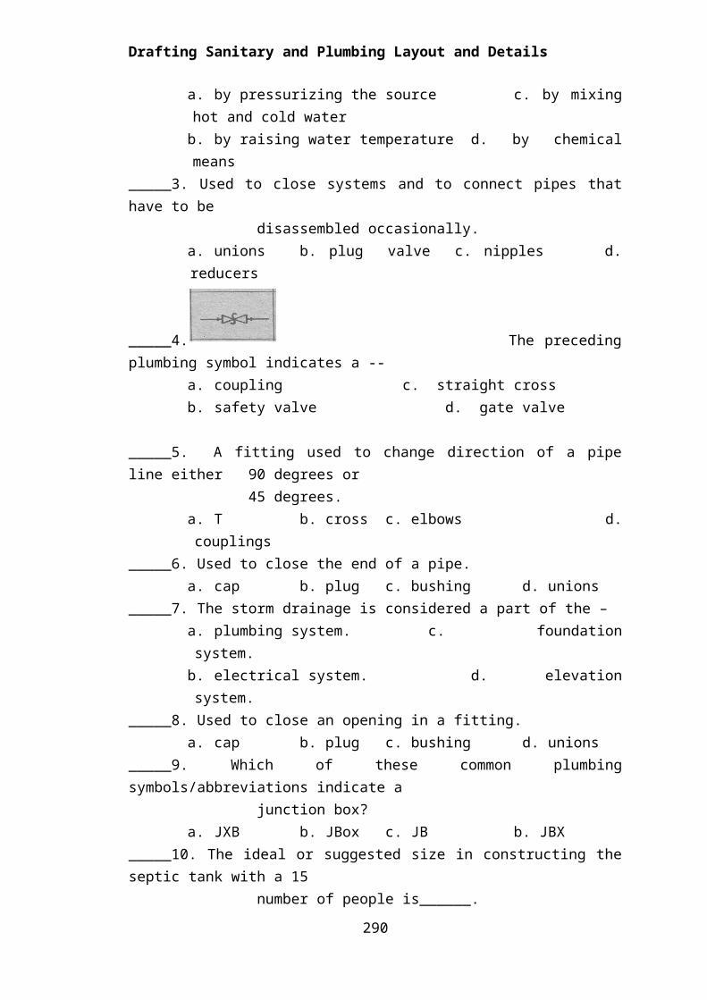
_____4. The preceding plumbing symbol indicates a --a. coupling c. straight crossb. safety valve d. gate valve
_____5. A fitting used to change direction of a pipe line either 90 degrees or 45 degrees.
a. T b. cross c. elbows d. couplings_____6. Used to close the end of a pipe.
a. cap b. plug c. bushing d. unions_____7. The storm drainage is considered a part of the –
a. plumbing system. c. foundation system. b. electrical system. d. elevation system.
_____8. Used to close an opening in a fitting.a. cap b. plug c. bushing d. unions
289
Drafting Sanitary and Plumbing Layout and Details
_____9. Which of these common plumbing symbols/abbreviations indicate a junction box?
a. JXB b. JBox c. JB b. JBX_____10. The ideal or suggested size in constructing the septic tank with a 15 number of people is______.
a. depth- 1:20, W-1:0, L- 2:0 c. depth 1:50 , W- 1:20, L-1:50 b. depth- 1:50, W-1:5, L-150 d. depth 2:50, W-1:50, L -2:50
_____11. Used to reduce the size of an opening.a. bushing b. unions c. cap d. plug
_____12. A network of pipes and fittings that carry off wastes and each plumbing fixture is titled with the appropriate pipe and fitting.
a. Sanitary installation c. Drainage system b. Polyvinyl pipe and fittings d. Sanitary and storm drainage
_____13. Used to close systems and to connect pipes that are to be disassembled occasionally.
a. cap b. plug c. bushing d. unions _____14. A water distribution system shown in an elevation, on plan and on isometric using the different symbols.
a. isometric draft c. isometric water systemb. water system diagram d. schematic drawing
_____15. Which is NOT a type of valve:a. Gate valve c. Check valve b. Globe valve d. Metal valve
Skills Evaluation
Direction: Listed below are some of the most important skills that you must gain in order to draft a quality floor plan. On the right side of the matrix lists the skills expected of you to master. Rate yourself by checking “Not much”, if you are not so familiar yet, “A little” and/or “A lot”, if you are already familiar with the skills. Don’t feel bad if you checked “Not Much” in all of the skills. Keep in mind that this is being administered to determine your pre-entry knowledge of and skills on the lesson to be presented.
Skills in drafting water distribution system Not Much A little A lot
I can draft hot and cold water distribution systems according to Plumbing and Water Codes
I can indicate signs and symbols according to sanitary and plumbing requirements
290
Drafting Sanitary and Plumbing Layout and Details
Learning Goals and Targets:
After reading the introduction and carefully answering the pre assessment instrument, you might have ideas of what you will be dealing with in this module. Now prepare to set your goals and targets for this module by completing the activity below. Write your answer in your notebook.
My goals are:
My targets are:
291
Goal 1
Goal 2
Goal 3
Goal 4
Target 3
Target 2
Target 1
Drafting Sanitary and Plumbing Layout and Details
Lesson 1: Draft Water Distribution Systems
This lesson is designed to familiarize you to draft the proper distribution
of water system (hot and cold water) and the signs and symbols used which
are based on the standard water code of the Philippines.
Operational Definition of Terms:
Aluminum is a lightweight but relatively strong metal often alloyed with
copper
to increase hardness and strength.
Gate Valve is usually chosen for locations where it is left completely open
most
of the time because it offers the least resistance to the flow of water.
Diagrammatic Layout is used for drafting layout in architectural plans.
Nipples are short pieces of pipes threaded on both ends.
Plumbing refers to the water supply and drainage of wastewater sewage.
Plumbing system refers to the supply pipes that carry fresh waste water
under pressure from a public water supply or individual wells to
fixtures.
Reducer is used to connect straight section pipes of different sizes.
Scale Layout is used for drafting large pipes.
Overview
One of man’s essential needs is water. He could live for days without food but not without water. Water appears in its natural state (liquid) or solid (ice) and gas (vapor) or steam. It is 830 times heavier than air but is 133 times lighter in its gaseous state. This can be sourced from: rain water, natural surface water and underground water.
Water is a necessity. It is conveyed from the source to the household through a system of pipes.
Water distribution systems for residential and commercial buildings are conveyed thru pipes, a PVC, Cast Iron or G.I. pipe.
292
KnowKnowKnowKnowKnowKnowKnowKnowKnowKnow
Drafting Sanitary and Plumbing Layout and Details
Hot and cold water is supplied to the buildings by a series of pipes connected from the source under pressure to the building fixtures thru a water line distribution system.
Pipes used for water line distribution systems may be classified as:1. Steel and wrought iron pipe2. Cast iron pipe3. Seamless brass and copper pipe4. Copper tubing5. Special pipes such as PVC (Polyvinyl Chloride), Aluminum and
Stainless Steel pipes, and CPV’C (Chlorinated Polyvinyl Chloride) pipe
Water main refers to the public sewer system along the streets, or laid underground where the service to the house is connected. Water coming from it is under pressure but normally could serve only houses of moderate height. A pump is installed to augment the pressure that forces the water to move inside the pipe.
The size of the service pipe is determined by the demand for water. A maximum demand is one factor, or the maximum water discharge for plumbing fixtures and the probable demand is another, which is the peak demand or peak load.
Connection of Pipes
Pipes are connected by methods dependent upon the material and the demands of service. Steel, brass or bronze pipes are normally threaded and screwed into coupling and fitting. Fittings are used to join adjacent lengths of pipes and to provide changes of direction, and branch connections at any angle and to effect a change in size.
Connections1. Threaded connections 2. Soldered fittings3. Connection by bolded flanges4. Solvent cement weld connections
Common types of fittings1. Screwed fittings2. Welded joints3. Flanged joints4. Solder joints5. Slip fittings (for plastic pipes)
293
Drafting Sanitary and Plumbing Layout and Details
Valves1. Gate valves2. Globe valves3. Check valves4. Pressure reducing valves5. Safety valves
Valves are specified by giving the nominal size, material and ride.
Kinds of Fittings
1. Elbows are used to change direction of a pipeline either 90 degrees
or 45 degrees.
2. Tee connects three pipes.
3. Cross connects four pipes.
4. Couplings are used to connect straight section pipes.
5. Reducers are used to connect straight section pipes of different
sizes.
6. Nipples are short pieces of pipes threaded on both ends and
classified as close nipple and short nipple.
7. Cap is used to close the end of a pipe.
8. Plug is used to close an opening in a fitting.
9. Bushing is used to reduce the size of an opening.
10. Unions are used to close systems and to connect pipes that are to be
disassembled occasionally.
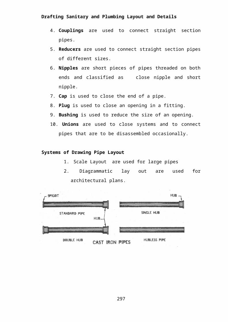
Systems of Drawing Pipe Layout
1. Scale Layout are used for large pipes
2. Diagrammatic lay out are used for architectural plans.
294
Drafting Sanitary and Plumbing Layout and Details
295
Drafting Sanitary and Plumbing Layout and Details
Suggested Activity 1Directions: Read each item carefully. Identify the correct answer and write
it on a separate sheet of paper. __________ 1. It is used to stop or regulate the flow of fluids.__________ 2. It is used to limit the flow of fluids to one direction only.__________ 3. It is used to connect three pipes.__________ 4. It is used to connect straight section pipes of different sizes.__________ 5. They are short pieces of pipes threaded at both ends.__________ 6. They are full sized straightway openings that offer small
resistance to the flow of fluids.__________ 7. It is used to join adjacent length of pipes.__________ 8. It is used to close the end of a pipe.__________ 9. It is used to close an opening or fitting.__________ 10. It is a kind of layout for pipes used in architectural plans.
Group Activity: Identification of pipe fittings and pipe materials
Directions:
Note: The teacher shall distribute pictures of plumbing fixtures and
fittings.
Work in groups of 3 to 5 (depending upon the number of students in the class) and chose a leader.
Identify the different kinds of:o pipes used in plumbing;
o materials used; and
297
ProcessProcessProcessProcessProcessProcessProcessProcess
Drafting Sanitary and Plumbing Layout and Details
o different kinds of pipes fittings and flanges.
Write a description in a piece of paper, each of the above in terms of its characteristics and uses.
Report your outputs to your teacher to assess and/or check your learning of the targeted knowledge and skills.
The plumbing system is important to the designer or draftsman. Although plumbing plans may be omitted on small residential dwellings, they are always included in larger projects for small residences; the plumbing layout is left to the contractor or the owner to decide.
A plumbing system performs two major functions which are:
1. For Water Distribution2. Sewage Disposal
Water distribution systems, whether hot or cold, are distributed by pipes from the source to the house. Amenities as discussed earlier, when tracing the path of the supply of water and fixtures fittings, the architectural designer uses symbols to indicate the distribution system and the different fixtures. The water distribution system is shown in an elevation, on plan and on isometric using the different symbols, hence this is called a schematic drawing.
In drawing the layout, here are the common symbols used for cold water line and sanitary layout.
298
KnowKnowKnowKnowKnowKnowKnowKnow
COMMON PLUMBING SYMBOLS
COMMON PLUMBING SYMBOLS
COMMON PLUMBING SYMBOLS
COMMON PLUMBING SYMBOLS
COMMON PLUMBING SYMBOLS
COMMON PLUMBING SYMBOLS
COMMON PLUMBING SYMBOLS
COMMON PLUMBING SYMBOLS

Drafting Sanitary and Plumbing Layout and Details
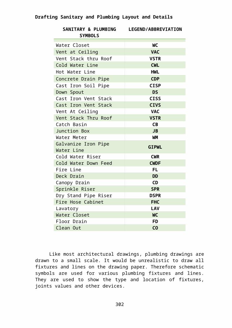
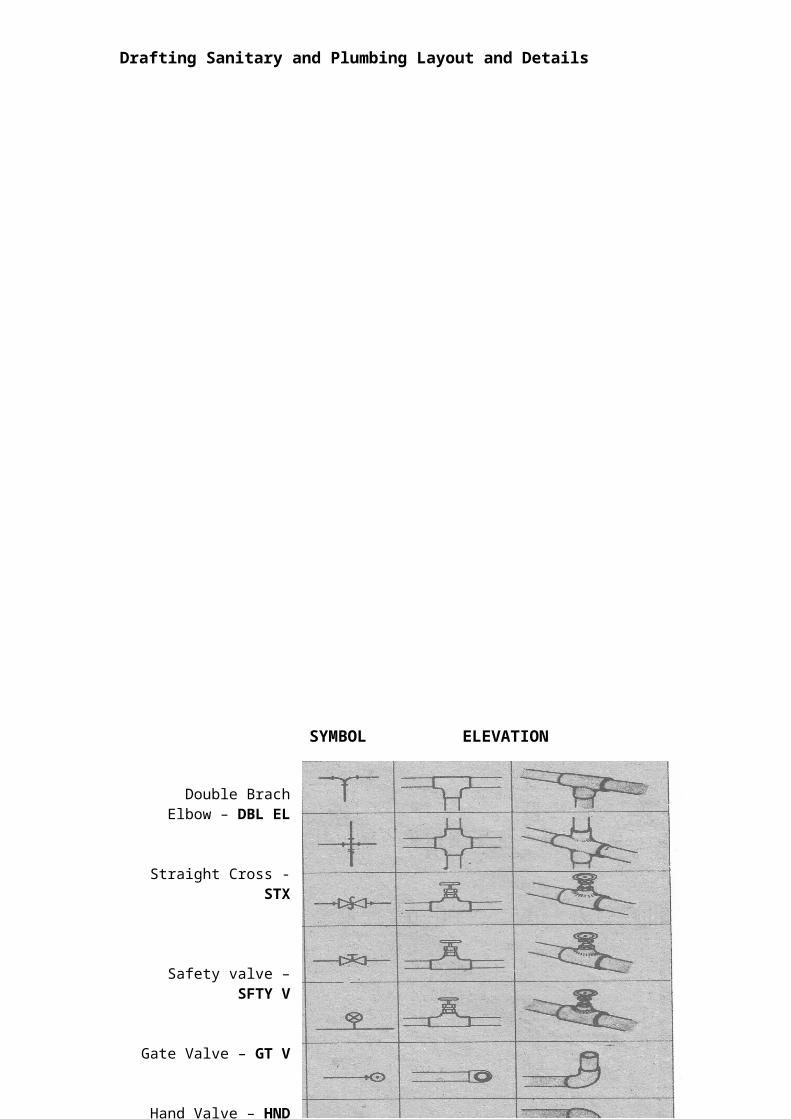
Like most architectural drawings, plumbing drawings are drawn to a small scale. It would be unrealistic to draw all fixtures and lines on the drawing paper. Therefore schematic symbols are used for various plumbing fixtures and lines. They are used to show the type and location of fixtures, joints values and other devices.
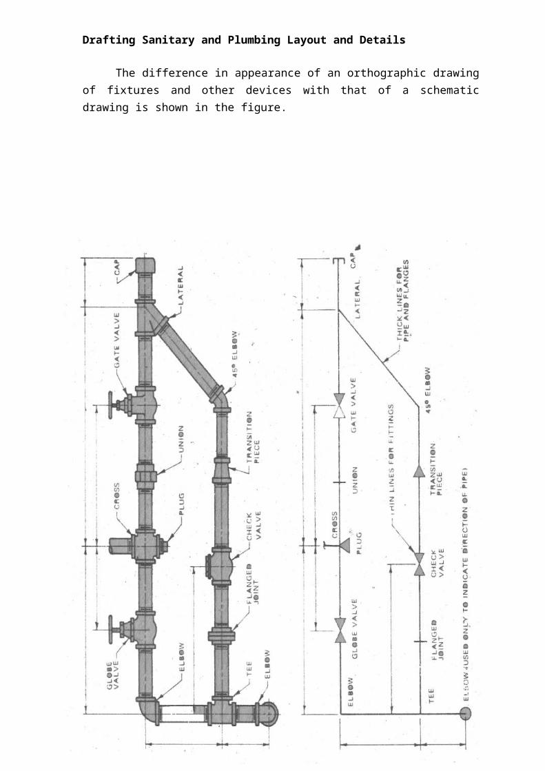
The difference in appearance of an orthographic drawing of fixtures and other devices with that of a schematic drawing is shown in the figure.
299
SANITARY & PLUMBING SYMBOLS
LEGEND/ABBREVIATION
Water Closet WC
Vent at Ceiling VACVent Stack thru Roof VSTRCold Water Line CWLHot Water Line HWL
Concrete Drain Pipe CDPCast Iron Soil Pipe CISPDown Spout DSCast Iron Vent Stack CISSCast Iron Vent Stack CIVSVent At Ceiling VACVent Stack Thru Roof VSTRCatch Basin CBJunction Box JBWater Meter WMGalvanize Iron Pipe Water Line GIPWLCold Water Riser CWRCold Water Down Feed CWDFFire Line FLDeck Drain DDCanopy Drain CDSprinkle Riser SPRDry Stand Pipe Riser DSPRFire Hose Cabinet FHCLavatory LAVWater Closet WCFloor Drain FDClean Out CO

Drafting Sanitary and Plumbing Layout and Details
300
Drafting Sanitary and Plumbing Layout and Details
301

Drafting Sanitary and Plumbing Layout and Details
302
SYMBOL ELEVATION PICTORIAL
Double Brach Elbow – DBL EL
Straight Cross - STX
Safety valve – SFTY V
Gate Valve – GT V
Hand Valve – HND V
Pipe Outlet Up - P
Pipe Outlet Down - P
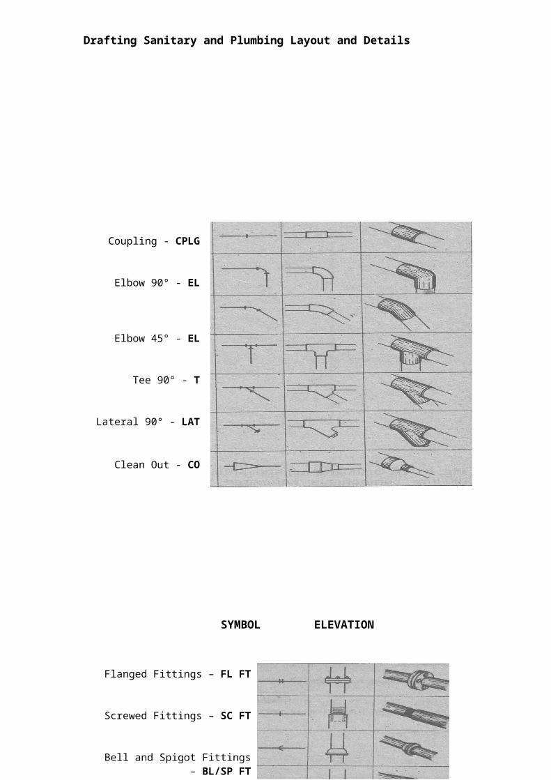
Coupling - CPLG
Elbow 90° - EL
Elbow 45° - EL
Tee 90° - T
Lateral 90° - LAT
Clean Out - CO
Reducer - RED
Drafting Sanitary and Plumbing Layout and Details
303
SYMBOL ELEVATION PICTORIAL
Flanged Fittings – FL FT
Screwed Fittings – SC FT
Bell and Spigot Fittings – BL/SP FT
Welded Fitting – WLD FT
Soldered Fitting – SLD FT
Expansion Joint – EXP JT
Motor Operated Vehicle – MOP V
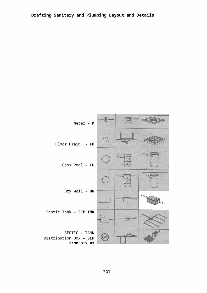
Meter – M
Floor Drain - FD
Cess Pool – CP
Dry Well - DW
Septic Tank – SEP TNK
SEPTIC – TANK Distribution Box – SEP TANK DIS BX
SUMP PIT - SP
Drafting Sanitary and Plumbing Layout and Details
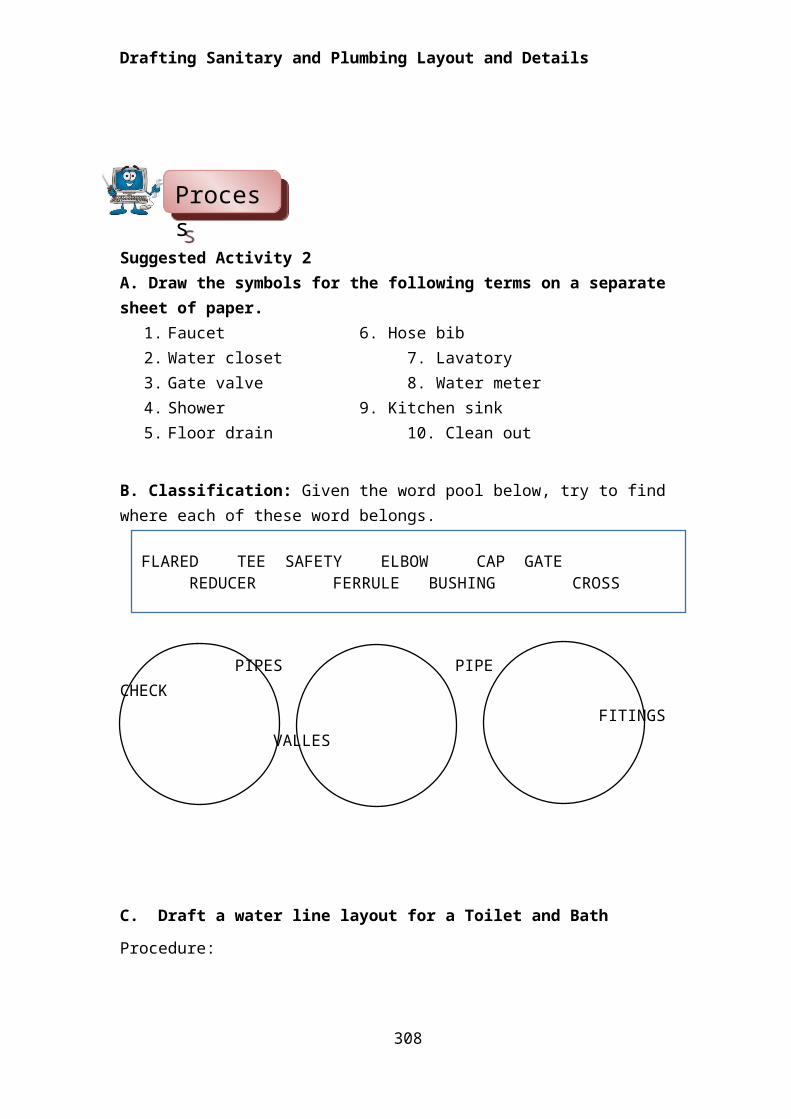
Suggested Activity 2A. Draw the symbols for the following terms on a separate sheet of paper.
1. Faucet 6. Hose bib2. Water closet 7. Lavatory3. Gate valve 8. Water meter4. Shower 9. Kitchen sink5. Floor drain 10. Clean out
B. Classification: Given the word pool below, try to find where each of these word belongs.
PIPES PIPE CHECK FITINGS VALLES
C. Draft a water line layout for a Toilet and Bath
Procedure:1. From the given plan of a T&B, indicate the location of bathroom fixtures by drawing the symbols of each on the place where they think is the best location.
304
ProcessProcessProcessProcessProcessProcessProcessProcess
FLARED TEE SAFETY ELBOW CAP GATEREDUCER FERRULE BUSHING CROSS
Drafting Sanitary and Plumbing Layout and Details
2. In as much as the kitchen is adjacent to the toilet and bath, naturally the source of water supply comes from the same direction. Try to draw the layout of the water supply line to the different fixtures they have identified.
Try to draw the water supply line to indicate the pipe fittings used and the different fixtures and the water flow.
3. After highlighting the pipe fittings used and indicated the water supply
source and its flow, darken the supply line and indicate the pipe and fixture
specifications by writing them beside the fixtures as indicated by the arrow.
Then, write down the legend for identification.
305
Drafting Sanitary and Plumbing Layout and Details
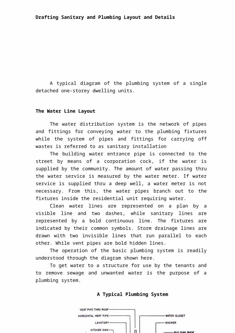
A typical diagram of the plumbing system of a single detached one-storey dwelling units.
The Water Line Layout
The water distribution system is the network of pipes and fittings for conveying water to the plumbing fixtures while the system of pipes and fittings for carrying off wastes is referred to as sanitary installation
The building water entrance pipe is connected to the street by means of a corporation cock, if the water is supplied by the community. The amount of water passing thru the water service is measured by the water meter. If water service is supplied thru a deep well, a water meter is not necessary. From this, the water pipes branch out to the fixtures inside the residential unit requiring water.
Clean water lines are represented on a plan by a visible line and two dashes, while sanitary lines are represented by a bold continuous line. The fixtures are indicated by their common symbols. Storm drainage lines are drawn with two invisible lines that run parallel to each other. While vent pipes are bold hidden lines.
The operation of the basic plumbing system is readily understood through the diagram shown here.
306
Drafting Sanitary and Plumbing Layout and Details
To get water to a structure for use by the tenants and to remove sewage and unwanted water is the purpose of a plumbing system.
307
A Typical Plumbing System
Drafting Sanitary and Plumbing Layout and Details
308
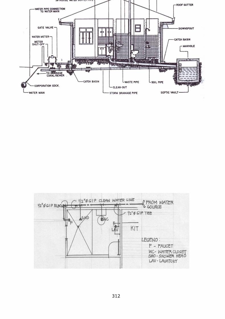
A Sample Plumbing Layout
Drafting Sanitary and Plumbing Layout and Details
309

Drafting Sanitary and Plumbing Layout and Details
310
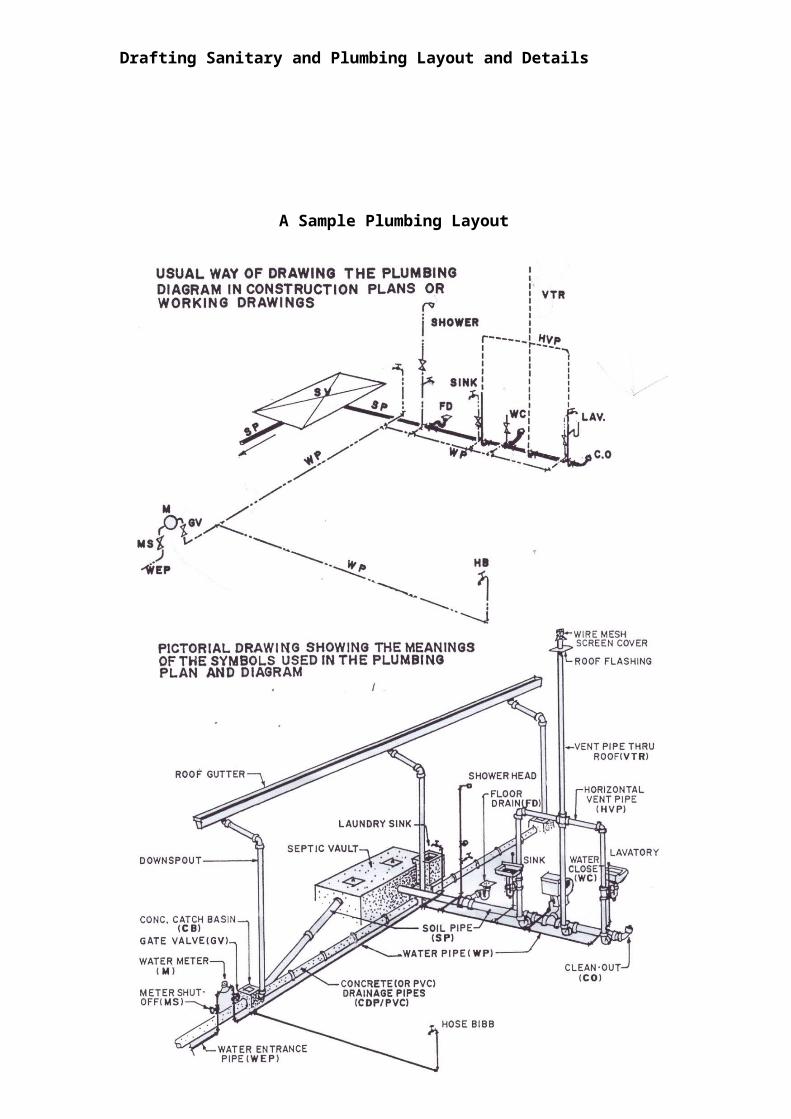
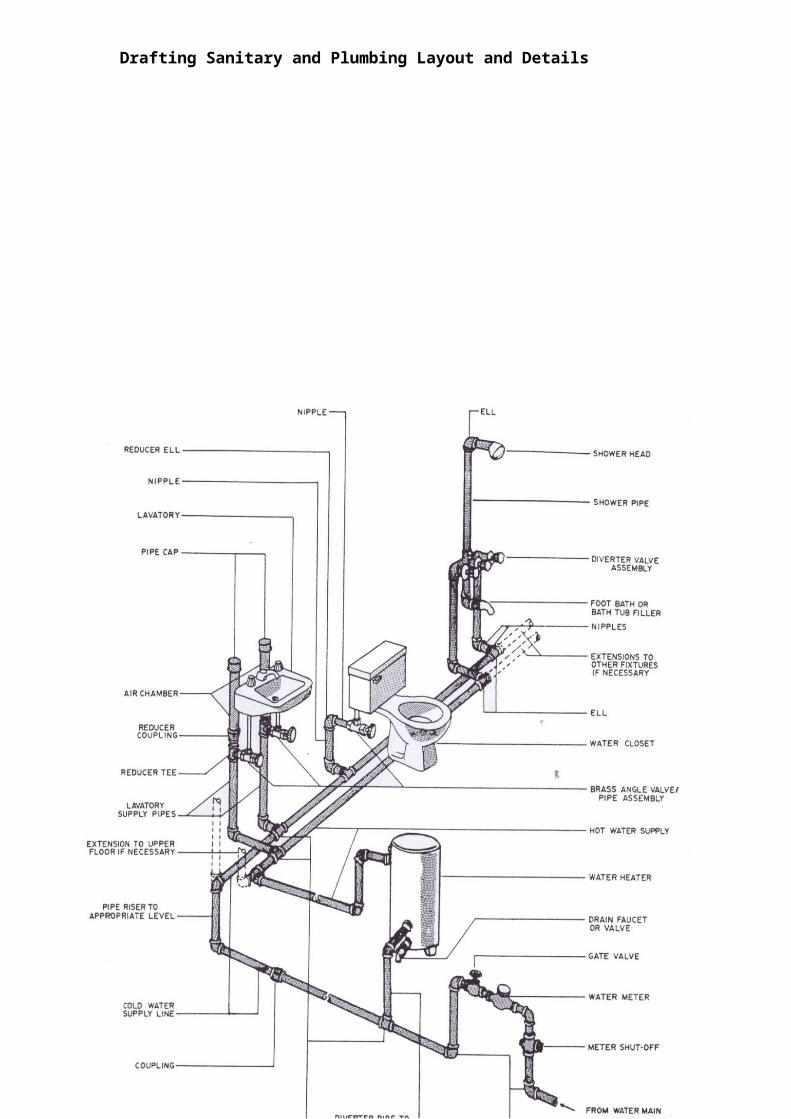
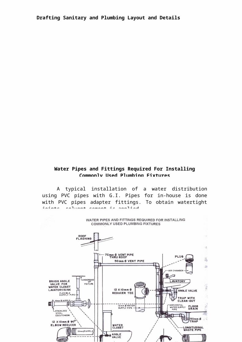
A typical installation of a water distribution using PVC pipes with G.I. Pipes for in-house is done with PVC pipes adapter fittings. To obtain watertight joints, solvent cement is applied.
Water Pipes and Fittings Required For Installing Commonly Used Plumbing Fixtures

Drafting Sanitary and Plumbing Layout and Details
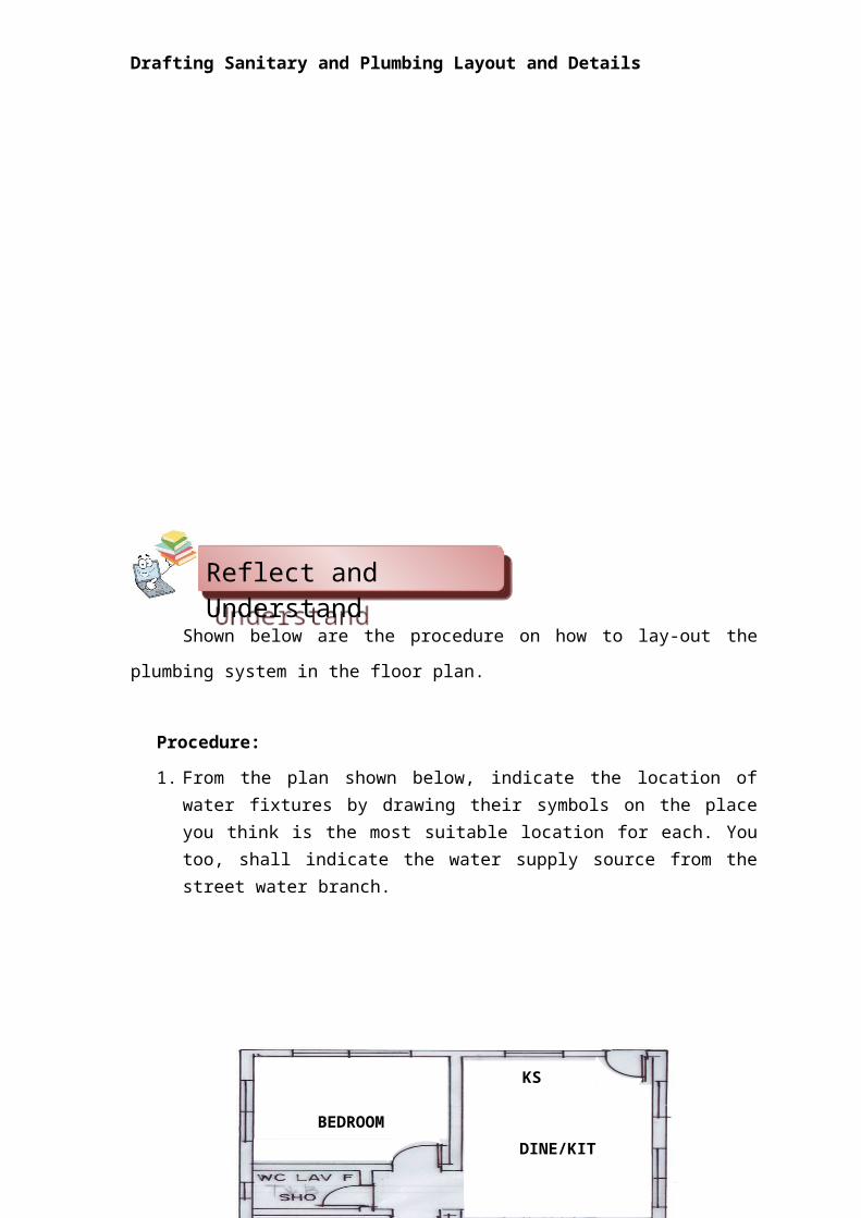
Shown below are the procedure on how to lay-out the plumbing system in
the floor plan.
Procedure:
1. From the plan shown below, indicate the location of water fixtures by drawing their symbols on the place you think is the most suitable location for each. You too, shall indicate the water supply source from the street water branch.
311
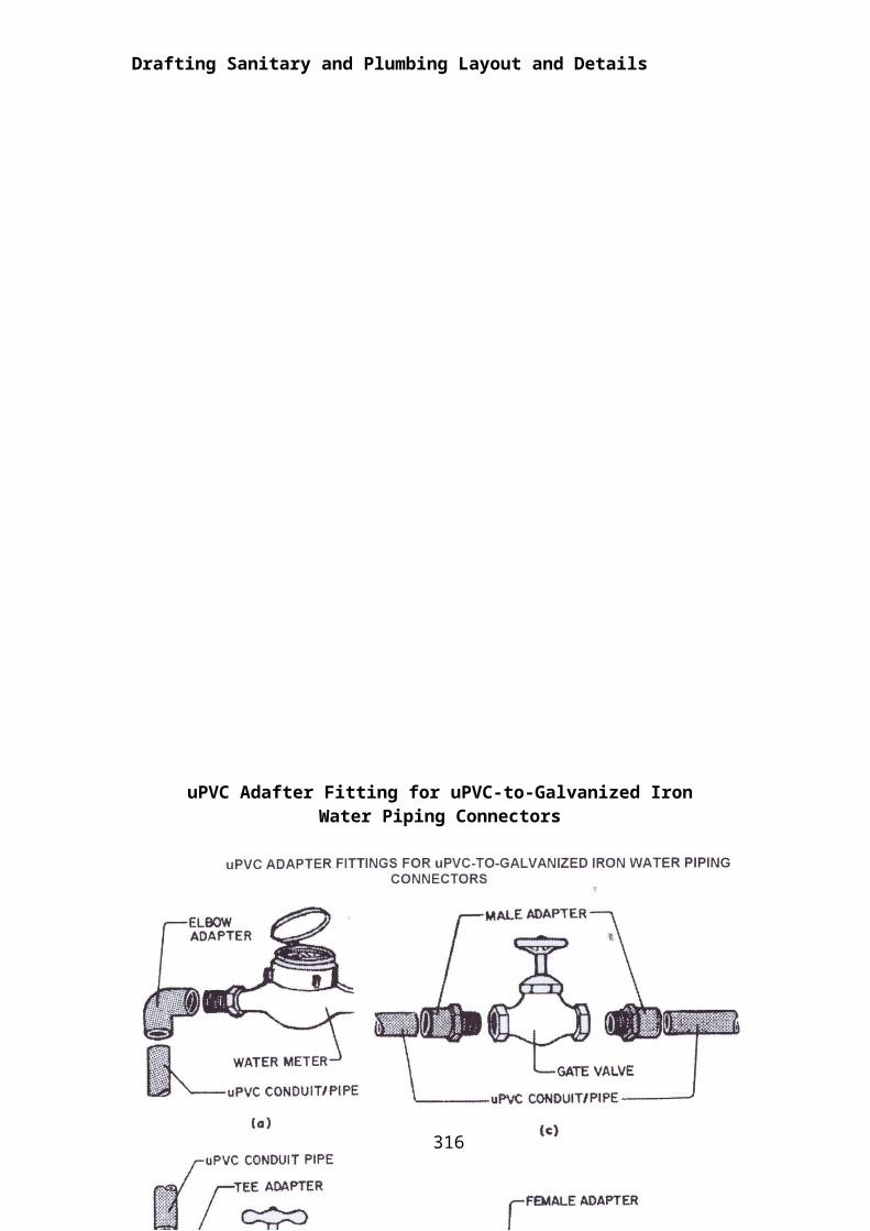
uPVC Adafter Fitting for uPVC-to-Galvanized Iron Water Piping Connectors
Reflect and Reflect and Reflect and Reflect and Reflect and Reflect and Reflect and Reflect and
Drafting Sanitary and Plumbing Layout and Details
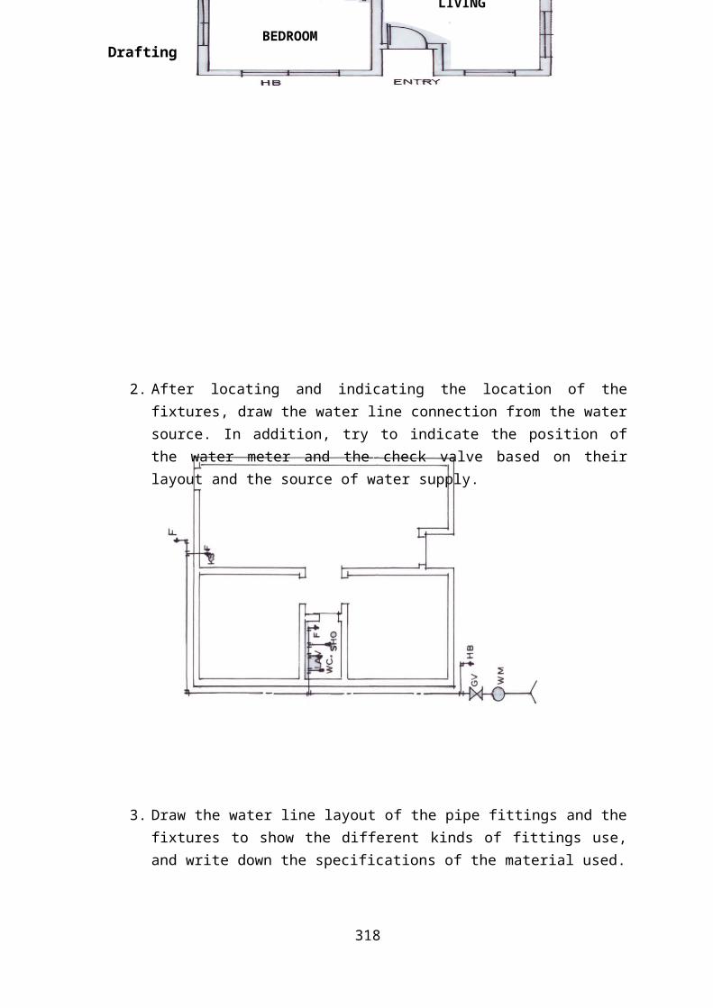
2. After locating and indicating the location of the fixtures, draw the water line connection from the water source. In addition, try to indicate the position of the water meter and the check valve based on their layout and the source of water supply.
3. Draw the water line layout of the pipe fittings and the fixtures to show the different kinds of fittings use, and write down the specifications of the material used.
312
LIVING
KS
DINE/KIT
BEDROOM
BEDROOM
Drafting Sanitary and Plumbing Layout and Details
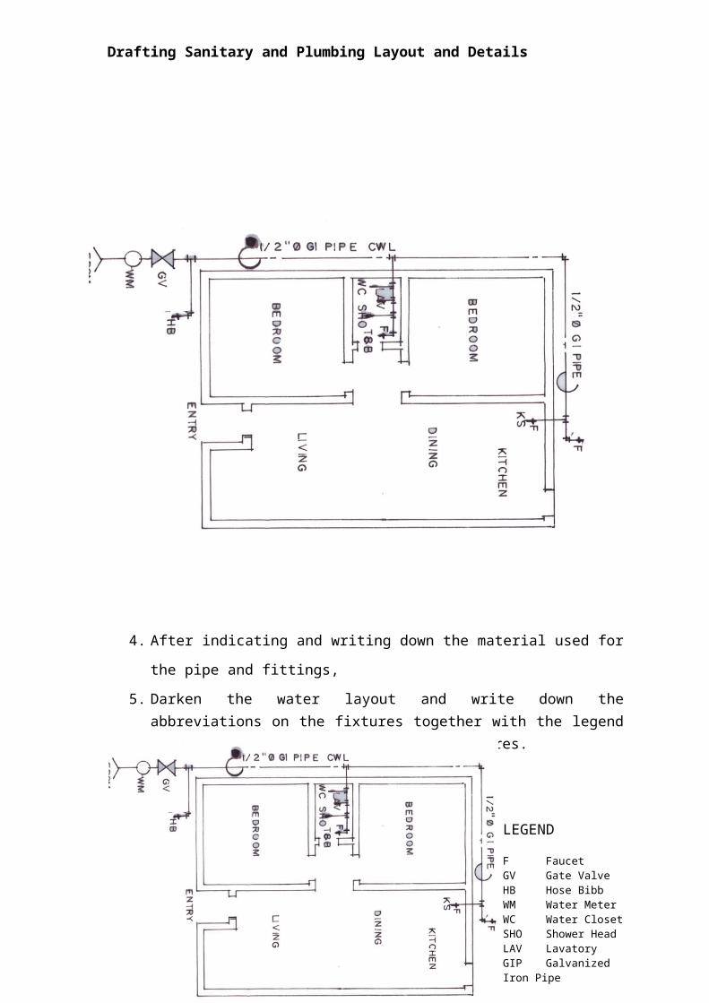
4. After indicating and writing down the material used for the pipe and fittings,
5. Darken the water layout and write down the abbreviations on the fixtures together with the legend to distinguish the different water fixtures.
313
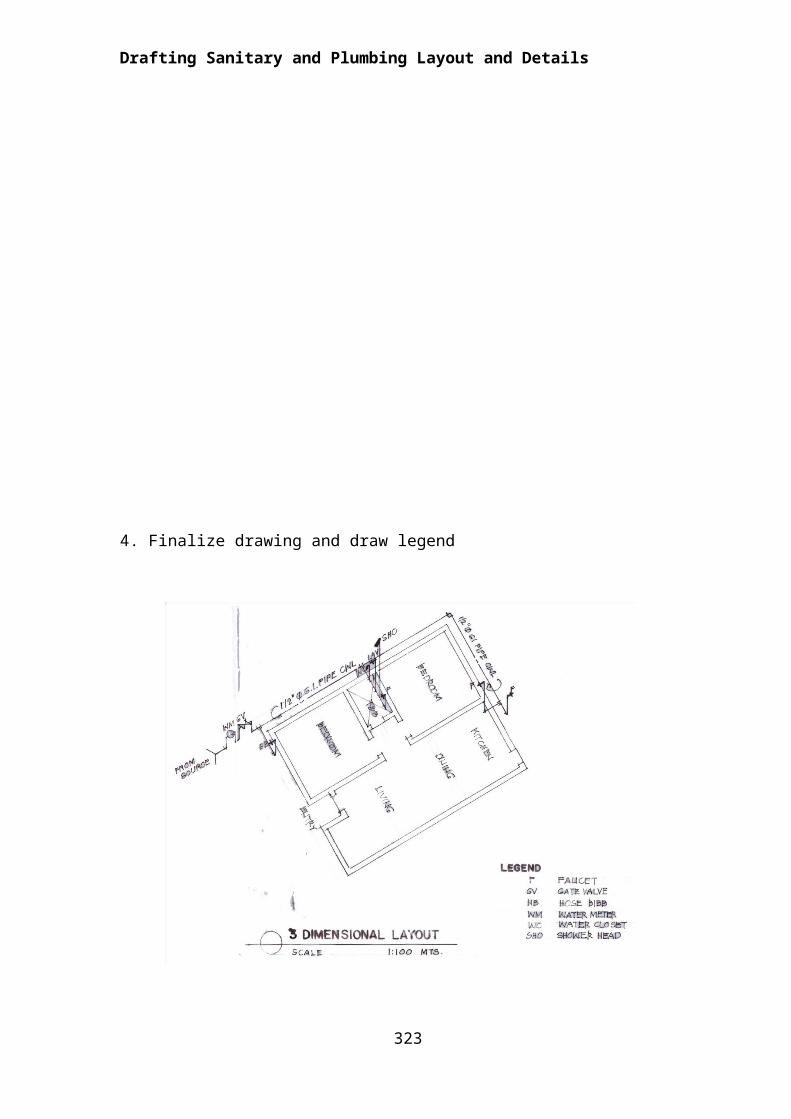
LEGEND
F FaucetGV Gate ValveHB Hose BibbWM Water MeterWC Water ClosetSHO Shower HeadLAV LavatoryGIP Galvanized Iron Pipe
Drafting Sanitary and Plumbing Layout and Details
Directions: From the plan shown below, sketch a clean water line layout.
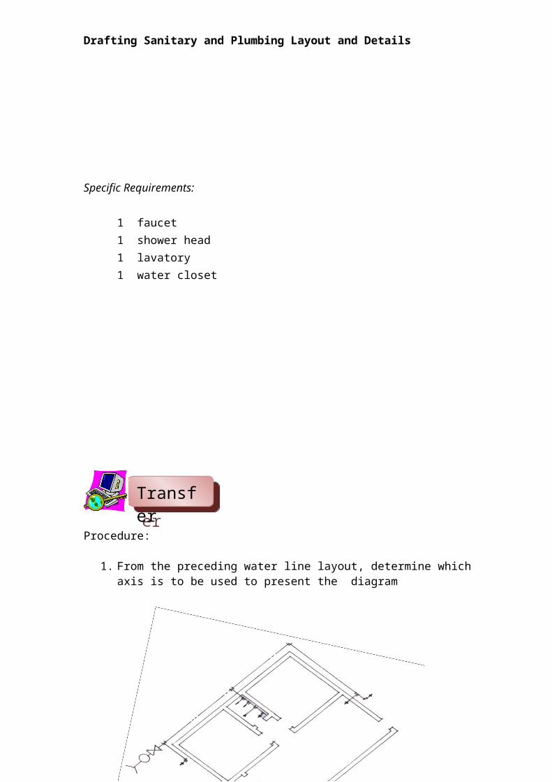
Specific Requirements:
1 faucet1 shower head1 lavatory1 water closet
314
TransferTransferTransferTransferTransferTransferTransferTransfer
Drafting Sanitary and Plumbing Layout and Details
Procedure:
1. From the preceding water line layout, determine which axis is to be used to present the diagram
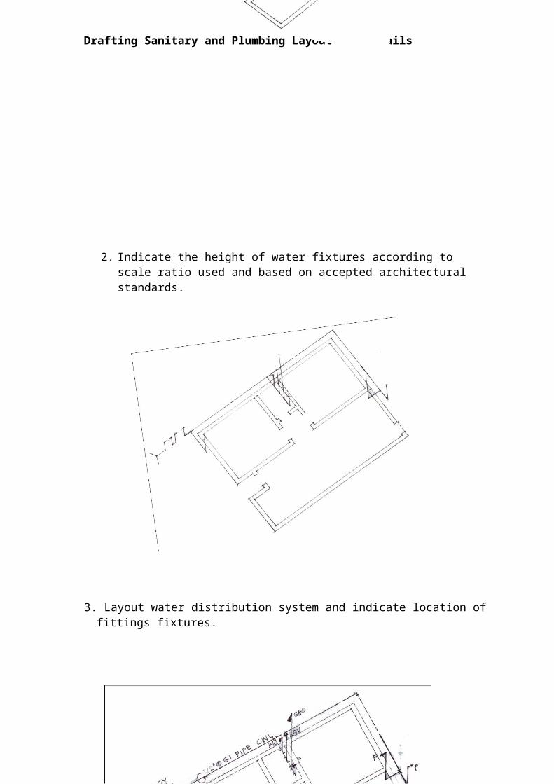
2. Indicate the height of water fixtures according to scale ratio used and based on accepted architectural standards.
315
TransferTransferTransferTransferTransferTransferTransferTransfer
Drafting Sanitary and Plumbing Layout and Details
3. Layout water distribution system and indicate location of fittings fixtures.
4. Finalize drawing and draw legend
316
Drafting Sanitary and Plumbing Layout and Details
Summative Test
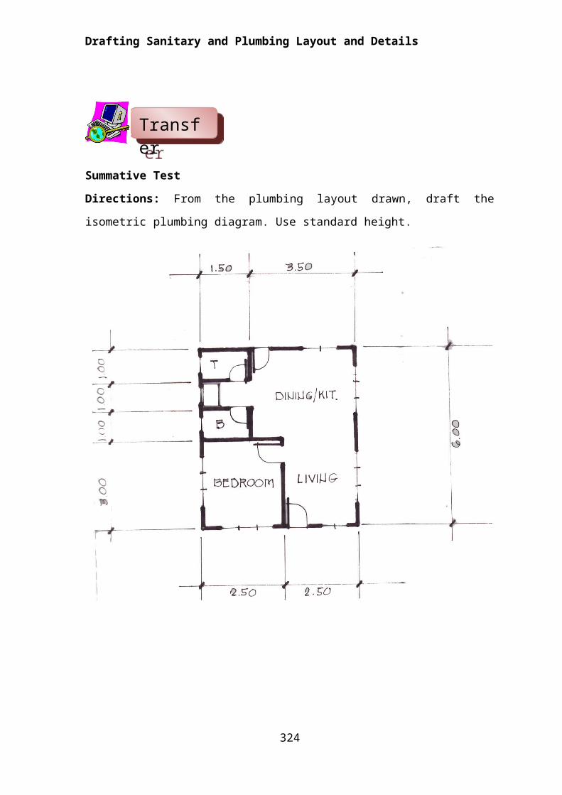
Directions: From the plumbing layout drawn, draft the isometric plumbing
diagram. Use standard height.
317
TransferTransferTransferTransferTransferTransferTransferTransfer
Drafting Sanitary and Plumbing Layout and Details
Lesson 2. Draft Sanitary and Storm Drainage
The sanitary installation is referred to as the network of pipes and fittings that carry off wastes and each plumbing fixture is titled with the appropriate pipe and fitting. The discharges are conveyed to the septic vault.
The storm drainage system, on the other hand, consists of pipes, fittings, catch basins, area drain and is intended for getting rid of water from the building roof and its surrounding and is conveyed to the street sewer. The storm drainage is considered part of the plumbing system.
The pipe used for sanitary and storm drainage most common to homeowners and contractors are the plastic pipe or Polyvinylchloride (PVC) pipes and the concrete pipe for area drain.
Skills Evaluation
Direction: Listed below are some of the most important skills that you must gain in order to draft a quality floor plan. On the right side of the matrix lists the skills expected of you to master. Rate yourself by checking “Not much”, if you are not so familiar yet, “A little” and/or “A lot”, if you are already familiar with the skills. Don’t feel bad if you checked “Not Much” in all of the skills. Keep in mind that this is being administered to determine your pre-entry knowledge of and skills on the lesson to be presented.
Skills in drafting sanitary and storm drainage Not Much A little A lot
I can draw sewerage plan layout according to Plumbing Code
I can draft storm drainage plan according to Plumbing Code
I can draw details and symbols according to sanitary and plumbing requirements
Learning Goals and Targets:
After reading the introduction and carefully answering the instrument, you might have ideas of what you will be dealing with in this module. Now prepare to
318
KnowKnowKnowKnowKnowKnowKnowKnow
Drafting Sanitary and Plumbing Layout and Details
set your goals and targets for this module by completing the activity below. Write your answer in your notebook.
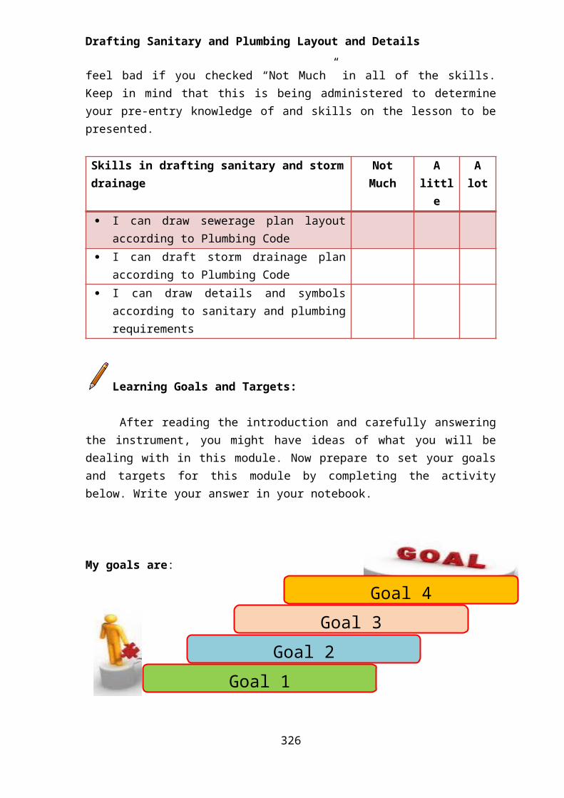
My goals are:
My targets are:
Overview
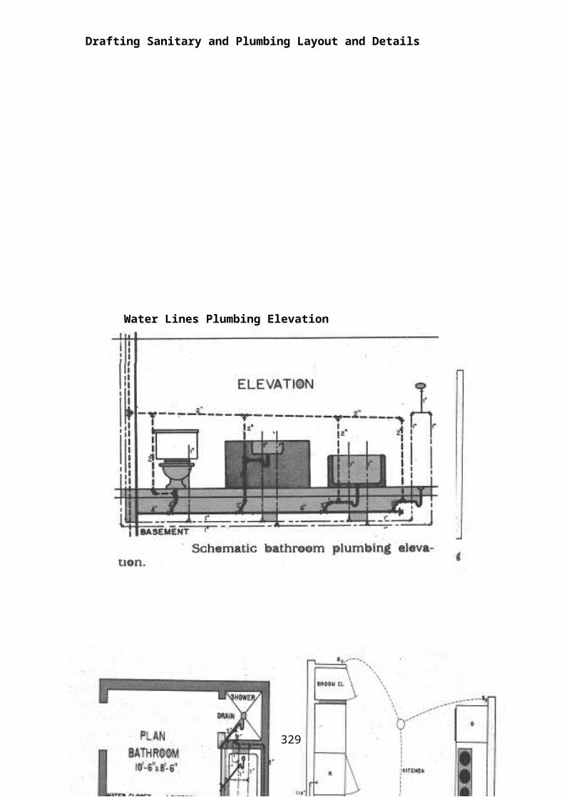
Wastewater is discharged by gravity through the disposal system. All pipes in this system therefore must slant in a downward direction so the weight of the waste will cause it to move down. Because of this gravity flow, waste lines are larger than water lines. The stacks are the vertical lines while the branches are the horizontal lines. Vents are also provided for air circulation and to permit sewer gases to escape thru the roof. This equalizes the air pressure in the drainage system.
The wastewater flows starting at the fixture trap, which is provided to stop gases from entering the building and each fixture has a separate trap or seal to
319
Goal 1
Goal 2
Goal 3
Goal 4
Target 3
Target 2
Target 1
Drafting Sanitary and Plumbing Layout and Details
prevent backflow of sewer gas, through the fixture branches to the main sewer line.
Waste stacks carry only wastewater while solid wastes runs thru the soil lines, which are the largest in the system and are flushed with water after each use.
Piping systems are vital to modern society. Some systems may be complex; others may be simple such as in a residential dwelling unit. But they share some common elements, whether they are steel, plastic, copper pipes or tubing.
Sanitary and storm drainage for residential dwelling are either wrought – iron pipes, Polyvinylchloride (PVC) pipes and for drainage is either concrete pipe or PVC pipe. The more common today is the unplasticized Polyvinylchloride (uPVC) pipe.
Polyvinyl pipe and fittings are available in commercial length of 3.0 meters and also available in schedule 40 and 80. They are usually assembled with slip joint fittings and solvent, both PVC and chlorinated Polyvinylchloride (cPVC) pipes are commonly available in sizes ranging from ½’ to 4” inside diameter.
The Sewage Disposal System
Absence of a good sewage disposal system can result to contamination of water and water-borne diseases. It is important to value a good disposal system.
There are different types of sewage disposal system, from the old to the more scientific ones:
1. Cesspool2. Privy3. Septic Tank4. Public Sewer line
The sanitary system is of two types: the intercepting and the tributary or contributing sewer. The intercepting type is constructed with concrete pipes while the tributary sewer is laid in an open trench and is made of vitrified clay or bricks.
320

Drafting Sanitary and Plumbing Layout and Details
321
Water Lines Plumbing Elevation
Drafting Sanitary and Plumbing Layout and Details
322
Drafting Sanitary and Plumbing Layout and Details
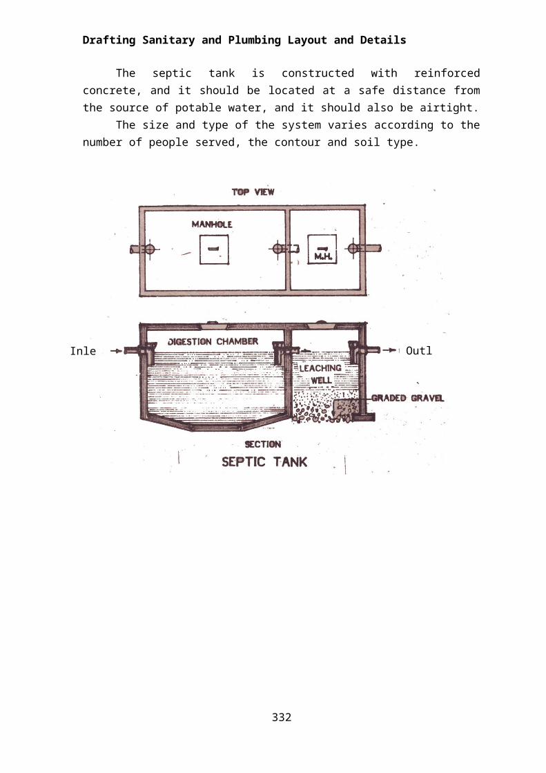
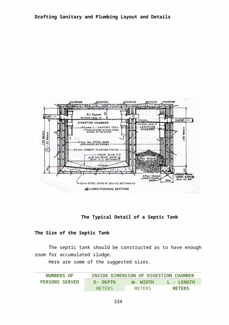
The Septic TankThe septic system converts solid wastes into liquid by bacterial action, the
wastes flow into a septic tank some distance away from the house. The liquid waste flows thru to the sewer line while the sludge remains at the digestion chamber of the tank.
The septic tank is constructed with reinforced concrete, and it should be located at a safe distance from the source of potable water, and it should also be airtight.
The size and type of the system varies according to the number of people served, the contour and soil type.
323
Inlet OutletInlet
Drafting Sanitary and Plumbing Layout and Details
Types of Sanitary Fittings used in plumbing System of Septic Vaults
324
SANITARY FITTING
Drafting Sanitary and Plumbing Layout and Details
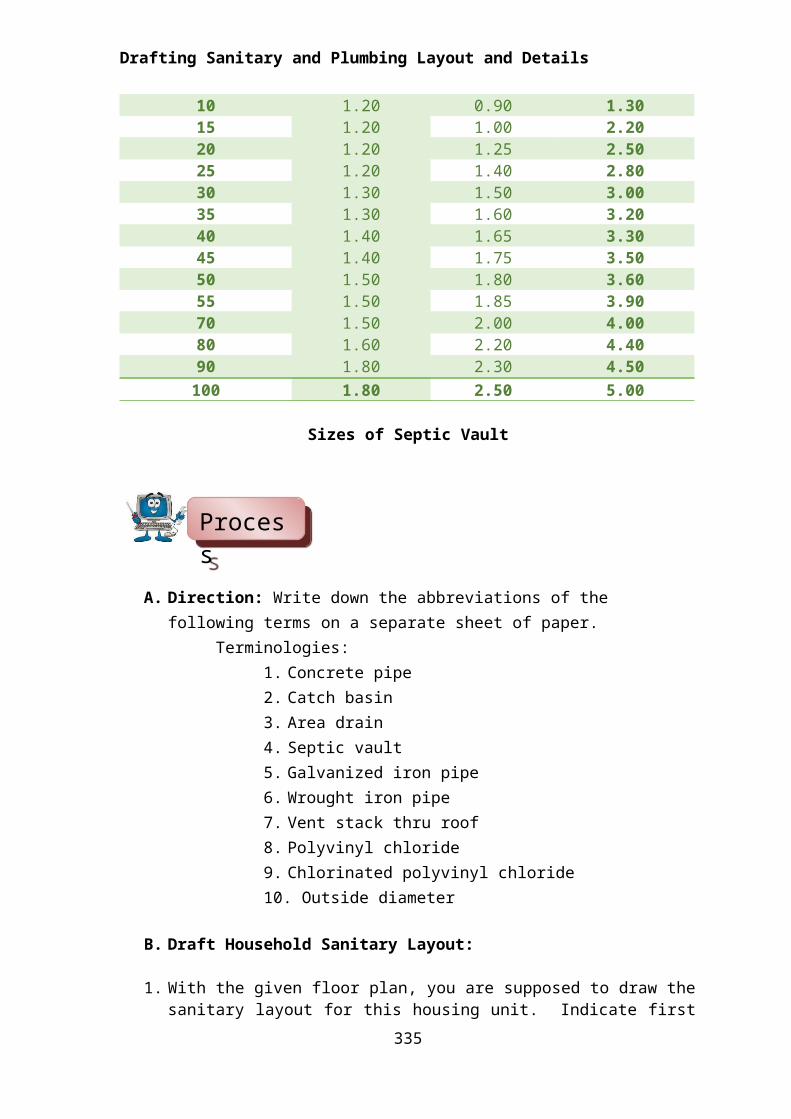
The Size of the Septic Tank
The septic tank should be constructed as to have enough room for accumulated sludge.
Here are some of the suggested sizes.
NUMBERS OF PERSONS SERVED
INSIDE DIMENSION OF DIGESTION CHAMBERD- DEPTH W- WIDTH L - LENGTHMETERS METERS METERS
10 1.20 0.90 1.3015 1.20 1.00 2.2020 1.20 1.25 2.5025 1.20 1.40 2.8030 1.30 1.50 3.0035 1.30 1.60 3.2040 1.40 1.65 3.3045 1.40 1.75 3.5050 1.50 1.80 3.6055 1.50 1.85 3.9070 1.50 2.00 4.00
325
The Typical Detail of a Septic Tank
Drafting Sanitary and Plumbing Layout and Details
80 1.60 2.20 4.4090 1.80 2.30 4.50
100 1.80 2.50 5.00
Sizes of Septic Vault
A. Direction: Write down the abbreviations of the following terms on a separate sheet of paper.
Terminologies:1. Concrete pipe2. Catch basin3. Area drain4. Septic vault5. Galvanized iron pipe6. Wrought iron pipe7. Vent stack thru roof8. Polyvinyl chloride9. Chlorinated polyvinyl chloride10. Outside diameter
B. Draft Household Sanitary Layout:
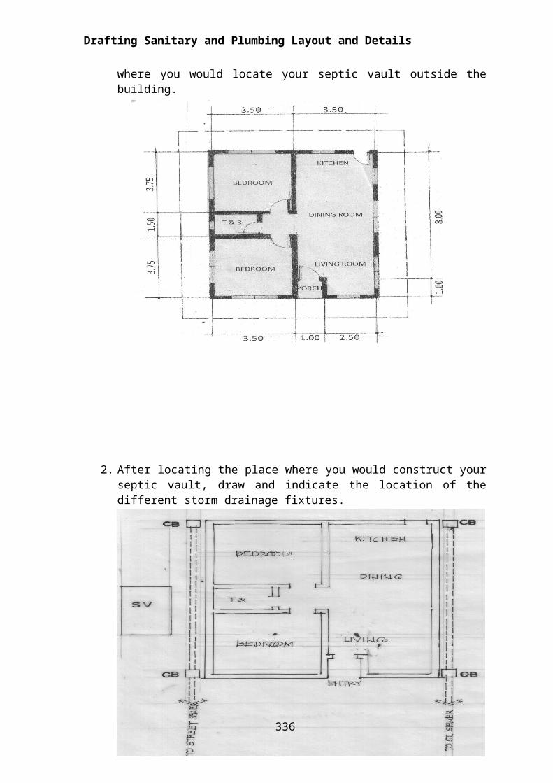
1. With the given floor plan, you are supposed to draw the sanitary layout for this housing unit. Indicate first where you would locate your septic vault outside the building.
326
ProcessProcessProcessProcessProcessProcessProcessProcess
Drafting Sanitary and Plumbing Layout and Details
2. After locating the place where you would construct your septic vault, draw and indicate the location of the different storm drainage fixtures.
3. Indicate the location of the different sanitary fixtures by drawing their symbols on the area where they are best located. Then draw the layout, connecting all these fixtures and to the septic vault with the sewer line connecting to the street sewer.
327
Drafting Sanitary and Plumbing Layout and Details
4. After drawing the layout, indicate the different pipes and fittings used by drawing their symbols on the sewer line layout and write down also the material specification for the fixtures used.
328

Drafting Sanitary and Plumbing Layout and Details
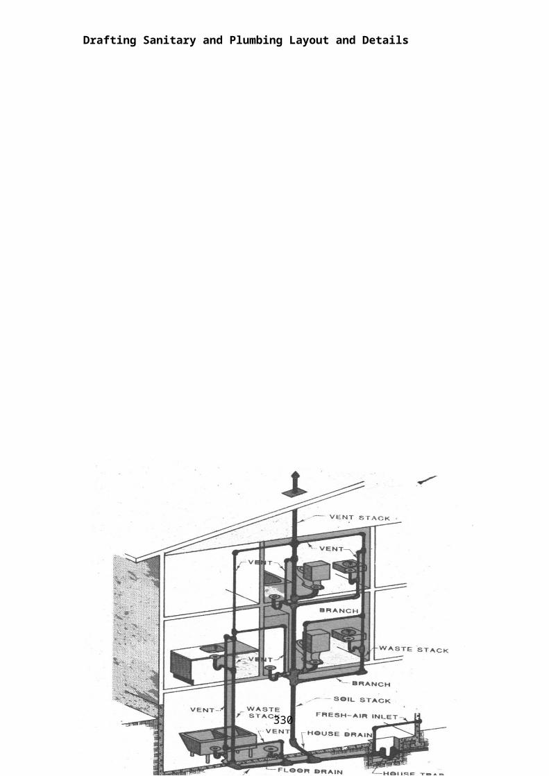
The Drainage System
The drainage system is sometimes referred to as the DWV or the drainage, the waste and the vent system. The construction and installation of this must conform to the provisions of the building and plumbing codes. Some of the general requirements are as follows:
1. Pipes must be fitted and tightly connected to avoid leakage.2. Ventilation must convey gases to the atmosphere.3. Each fixture must be provided with a suitable trap to prevent backflow or
gases.4. The fixture must be re-vented to avoid siphoning of the water seal.5. Drainage pipes should be sloped or graded properly.6. Drainage pipes should be provided with adequate clean out for
maintenance purposes.
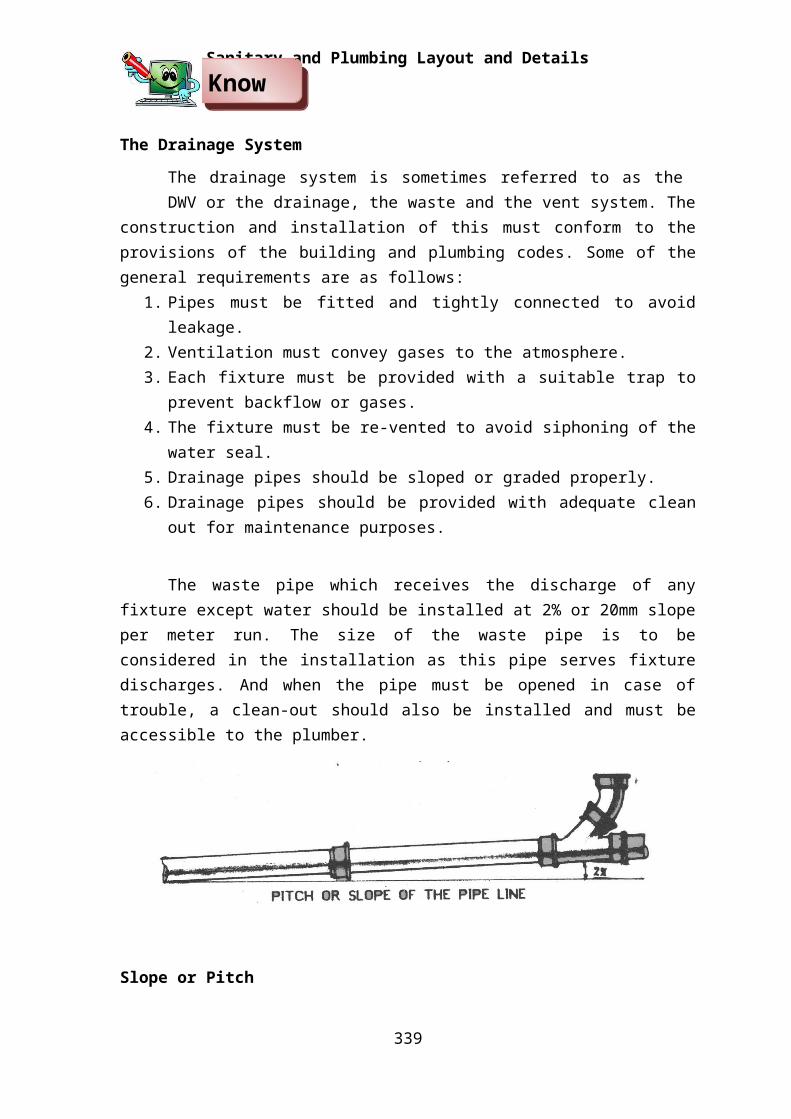
The waste pipe which receives the discharge of any fixture except water should be installed at 2% or 20mm slope per meter run. The size of the waste pipe is to be considered in the installation as this pipe serves fixture discharges. And when the pipe must be opened in case of trouble, a clean-out should also be installed and must be accessible to the plumber.
Slope or Pitch
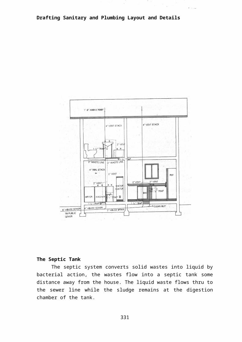
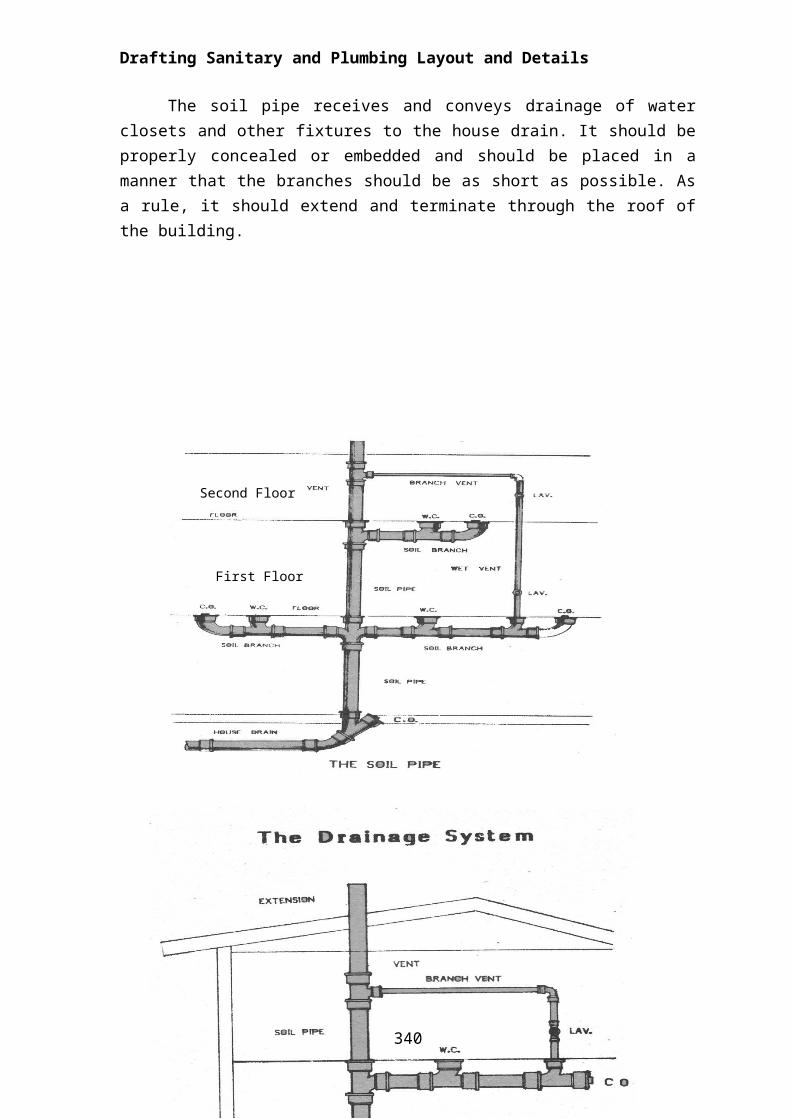
The soil pipe receives and conveys drainage of water closets and other fixtures to the house drain. It should be properly concealed or embedded and should be placed in a manner that the branches should be as short as possible. As a rule, it should extend and terminate through the roof of the building.
329
KnowKnowKnowKnowKnowKnowKnowKnow
Drafting Sanitary and Plumbing Layout and Details
Second Floor
First Floor
The House Drain
The sanitary drain only receives discharges of sanitary and domestic wastes only while the storm drain receives storm, clear water or surface water wastes.
A typical house drain is shown below.
330
Drafting Sanitary and Plumbing Layout and Details
The House Sewer
The portion of the horizontal drainage system starts from the outer surface of the dwelling and terminates at the public sewer. A minimum size of 150mm (6ӯ) is used for residential dwellings.
331
Drafting Sanitary and Plumbing Layout and Details
The Storm Drain
It is the part of the plumbing system which conveys rain or storm water into the street gutter. It is of two types: the inside storm drain and the outside storm drain. Layout of the two is shown in the following illustrations.
332
Drafting Sanitary and Plumbing Layout and Details
A Typical Catch Basin Detail
333
The Catch Basin
The catch basin water discharges from the roof and conveys it to the storm drainage line. It is more or less of the same use as the area drain. It also serves as a manhole for cleaning.
Reflect and Reflect and Reflect and Reflect and Reflect and Reflect and Reflect and Reflect and

Drafting Sanitary and Plumbing Layout and Details
Directions: From the plan shown below, sketch the sewer line from the fixtures
to the street sewer. Label the drawing.
Requirements:1 – Kitchen Sink1 – Water Closet1 – Floor Drain1 – Septic Vault1 – Lavatory
334
TransferTransferTransferTransferTransferTransferTransferTransfer
Drafting Sanitary and Plumbing Layout and Details
Summative Test
Directions: From the layout you drafted. Draw a sanitary and plumbing layout
and details following the job requirement. Use approved standard height of
amenities.
Note: You are provided with a copy of the plan.
Requirements:
1- Kitchen Sink1- Water Closet1- Floor Drain1- Septic Vault
335
I. Enrichment Activity: Draft a septic vault for 5 – 7 persons
Procedure:
1. Refer from the table on recommended sizes of septic vaults. See if the number of persons in the household fits in the data for recommended size of vault.
2. Take down the measurements: width, height and length. Transfer such measurement on your drawing paper.
3. Draw the outline of the septic vault with your pencil using light guidelines only. As you draw the outline, draw also the thickness of the sides of the septic vault, taking into consideration the thickness of CHB used for walls partitions.
4. Indicate also the location of the manhole and the manhole cover. After drawing the outline re-checked your measurements, write down your dimensions and you are ready to draw the reinforcing bars. You may draw your rebars covering the whole area of the vault or you can have a portion of it only.
336
5. Draw the vertical and horizontal bars for the reinforcement of the septic vault. The standard distances and size of the rebars are 12mm Ø for vertical bars and 10mmØ for horizontal bars. For the slabs on top of it would be 10mm Ø spaced at 20cm on both ways of the slab.
6. Draw only the portion you wish to show the detail of the reinforcements. Indicate now the inlet valve, in the digestion chamber its position or location and its size, together with the outlet valve.
7. From the plan you have already drawn, project dimensions downward and draw a longitudinal section of your septic vault. Remember the thickness and measurements of the plan should be the same as your section.
337

8. With the data on its depth you have gathered, layout the depth of the septic vault, including its foundation and footing. Indicate the location of your inlet and outlet valves which should have a distance from the bottom of the slab of about 30 cm. for the air space and the water level.
9. Draw vertical and horizontal bars on the sides and on the footing.10.Review the drawing, its dimensions and measurements. Finalize
the drawing by darkening the lines with a technical pen. Write down the material specifications and construction notes.
338CROSS

II. Drafting Sanitary and Plumbing Layout and Details
Directions: Draft a catch basin detail with the following requirements:
1. Indicate the size of catch basin according to structural and design standard.
2. Draft outlines of both plan and sectional elevation.
3. Draft outlines of pipes and slope of pipes
4. Darken lines or ink drawing .draft dimensions and specifications.
339
Post-Assessment
Answer the post assessment below to determine whether
there is significant increase in your understanding of the lesson on
drafting water distribution, sanitary and storm drainage systems.
The feedback to this post assessment is appended on page ____
Good Luck!
Direction: Choose the letter of the correct answer. Write your answer in the space provided to each number.
_____1. A kind of fitting used to straight section pipes. a. elbows b. coupling c. cross d. tee
_____2. How is hot and cold water distributed from the source to different parts of the building?a. by pressurizing the source c. by mixing hot and cold waterb. by raising water temperature d. by chemical means
_____3. Used to close systems and to connect pipes that have to be disassembled occasionally.
a. unions b. plug valve c. nipples d. reducers
_____4. The preceding plumbing symbol indicates a --a. coupling. c. straight crossb. safety valve. d. gate valve.
_____5. A fitting used to change direction of a pipe line either 90 degrees or 45 degrees.
a. T b. cross c. elbows d. couplings_____6. Used to close the end of a pipe.
a. cap b. plug c. bushing d. unions_____7. The storm drainage is considered a part of the –
a. plumbing system. c. foundation system. b. electrical system. d. elevation system.
340
_____8. Used to close an opening in a fitting.a. cap b. plug c. bushing d. unions
_____9. Which of these common plumbing symbols/abbreviations indicate a junction box?
a. JXB b. JBox c. JB d. JBX_____10. The ideal or suggested size in constructing the septic tank with a 15 number of people is______.
a. depth- 1:20, W-1:0, L- 2:0 c. depth 1:50 , W- 1:20, L-1:50 b. depth- 1:50, W-1:5, L-150 d. depth 2:50, W-1:50, L -2:50
_____11. Used to reduce the size of an opening.a. bushing b. unions c. cap d. plug
_____12. A network of pipes and fittings that carry off wastes and each plumbing fixture is titled with the appropriate pipe and fitting.
a. Sanitary installation c. Drainage system b. Polyvinyl pipe and fittings d. Sanitary and storm drainage
_____13. Used to close systems and to connect pipes that are to be disassembled occasionally.
a. cap b. plug c. bushing d. unions _____14. A water distribution system shown in an elevation, on plan and on isometric using the different symbols is called _________.
a. isometric draft d. isometric water systemb. water system diagram c. schematic drawing
_____15. Which is NOT a type of valve:a. Gate valve c. Check valve b. Globe valve d. Metal valve
341