Embed Size (px)
Citation preview
Drafting Mechanical Layout and Details
Content Standard Performance Standard
The learner demonstrates understanding of concepts and underlying principles in drafting mechanical layout and details.
The learner independently drafts mechanical layout and details following the job requirements.
Quarter IV Time Allotment: 24 hrs.
MODULE 7Drafting Mechanical Layout and Details
Introduction
The objective of architectural design is to create an effective
environmental system. Structural thinking should be introduced at the early
stages in the design process. These will provide buildings and residential
dwellings with mechanical and other environmental subsystems to support
horizontal and vertical movement of men and materials. It also provides
functional heating, ventilating, air conditioning (HVAC) power, water and waste
disposal. In addition, acoustical and lighting needs are often influenced by
structural design.
The requirements for provisions of heating, ventilation, air conditioning,
power, water and waste services can be visualized in the form of a tree diagram.
These services usually originate at a centralized location and trace their way
horizontally and vertically throughout the structure to serve the activity spaces.
The designer should be well versed with heating, ventilating, air
conditioning systems, as well as vertical transportation which include escalators
and elevators.
This module familiarizes you on how to locate the machines, raceways,
wirings, motors, generations and the like in its proper places.
1
At this point, you are heading into meaningful activities and learning encounters. Complete the exercises and answer the suggested worksheets to experience lifelong, practical learning that awaits at the end of this module.
ENJOY YOUR JOURNEY!
Drafting Mechanical Layout and Details
Objectives:
At the end of this module, you are expected to:
draft heating, ventilating, and air conditioning systems layout;
draft mechanical details of conveyor system; and
draft fire protection systems
*****
Pre- assessment:
You will be challenged to dig deeper into your prior knowledge and
previous experiences about drafting mechanical layout details. This phase will
guide you in assessing yourself by answering questions that relate with the
basics of drafting mechanical lay-out and details.
Multiple Choice: Choose the letter of the correct answer. Write your answer in
the space provided to each number.
______1. It is the ability of materials to resist the transfer of heat.
a. Heat resistivity b. Latent heat c. Sensible heat d. Insulation
______2. Which lifts the car usually 3 to 8 in number and placed in parallel,
fastened to the top of the car?
a. hoist way b. elevator machine c. cables d. elevation
_______3. It is the heat energy required to change the state of a substance.
a. Heat resistivity b. Latent heat c. Sensible heat d. Insulation
2
Drafting Mechanical Layout and Details
______ 4. It turns the sheave and thus lifts or lowers the car.
a. hoist way b. elevator machine c. cables d. elevation
______ 5. It is the heat in British thermal unit absorbed by a substance in
changing its temperature without its state.
a. Heat resistivity b. Latent heat c. Sensible heat d. Insulation
______ 6. It is typically referred to as a chiller plant.
a. chilled water system c. heat pump
b. window air conditioner d. cooling only packaged system
_______7. It is a material used to stop the transfer of heat.
a. Heat resistivity b. Latent heat c. Sensible heat d. Insulation
_______8. A window air conditioner typically installed in a window or custom
opening in a wall.
a. chilled water system c. heat pump
b. window air conditioner d. cooling only packaged
system
_______9. It is the shaft or vertical passageway for the travel of the car and its
counterweights.
a. hoist way b. elevator machine c. cables d. elevation
______10. A special valve in the refrigeration piping that allows the refrigeration
cycle to be operated in reverse.
a. chilled water system c. heat pump
b. window air conditioner d. cooling only packaged system
Skills Evaluation
Direction: Listed below are some of the most important skills that you must gain in order to draft a quality floor plan. On the right side of the matrix lists the skills expected of you to master. Rate yourself by checking “Not much”, if you are not so familiar yet, “A little” and/or “A lot”, if you are already familiar with the skills. Don’t feel bad if you checked “Not Much” in all of the skills. Keep in mind that this is being administered to determine your pre-entry knowledge of and skills on the lesson to be presented.
Skills in drafting mechanical layout and details Not Much A little A lot
I can draft heating, ventilating and air-conditioning systems according to Mechanical Code
3
Drafting Mechanical Layout and Details
I can indicate signs and symbols according to mechanical layout and detail requirements
Learning Goals and Targets:
After reading the introduction and carefully answering the pre assessment skills test, you might have ideas of what you will be dealing with in this module. Now prepare to set your goals and targets for this module by completing the activity below. Write your answer in your notebook.
My goals are:
My targets are:
Lesson 1: Draft Heating, Ventilating and Air-Conditioning Systems Layout
Heating, Ventilating, and Air Conditioning (HVAC) equipment perform
heating and/or cooling for residential, commercial or industrial buildings. The
HVAC system may also be responsible for providing fresh outdoor air to dilute
interior airborne contaminants such as odors from occupants, volatile organic
4
KnowKnowKnowKnowKnowKnowKnowKnowKnowKnowKnowKnowKnowKnowKnowKnowKnowKnowKnowKnowKnowKnowKnowKnowKnowKnowKnowKnowKnowKnowKnowKnowKnowKnowKnowKnowKnowKnowKnowKnowKnowKnowKnowKnowKnowKnowKnowKnowKnow
Goal 2
Goal 3
Goal 4
Target 3
Target 2
Target 1
Drafting Mechanical Layout and Details
compounds (VOC’s) emitted from interior furnishings, chemicals used for
cleaning, etc.
Operational Definition of Terms
Adiabatic Saturation is the introduction of water into unsaturated air to
increase its humidity ratio.
Dew Point is the temperature at which an air-water mixture will become
saturated and begin to yield drops of condensed water.
Dry Bulb Temperature is the air-water vapor mixture as measured in the normal
way with a Fahrenheit Thermometer.
Enthalpy is the quantity of British thermal unit per minute in a fluid or gas.
Humidity Ratio is the weight of the actual water vapor in a mixture per pound
of dry air.
Latent Heat is the heat energy required to change the state of a substance.
Relative Humidity is the ratio which indicates the degree of saturation of the
air with water vapor.
Sensible Heat is the heat in British thermal unit absorbed by a substance in
changing its temperature without its state.
Thermal Conductivity is the amount of heat that flows from one face of a
material to another.
Heat Resistivity is the ability of materials to resist the transfer of heat.
Insulation is a material used to stop the transfer of heat.
R Value is a uniform rating of heat resistance that flows through building
materials. The higher the R number, the greater the resistance to heat
flow.
5
Drafting Mechanical Layout and Details
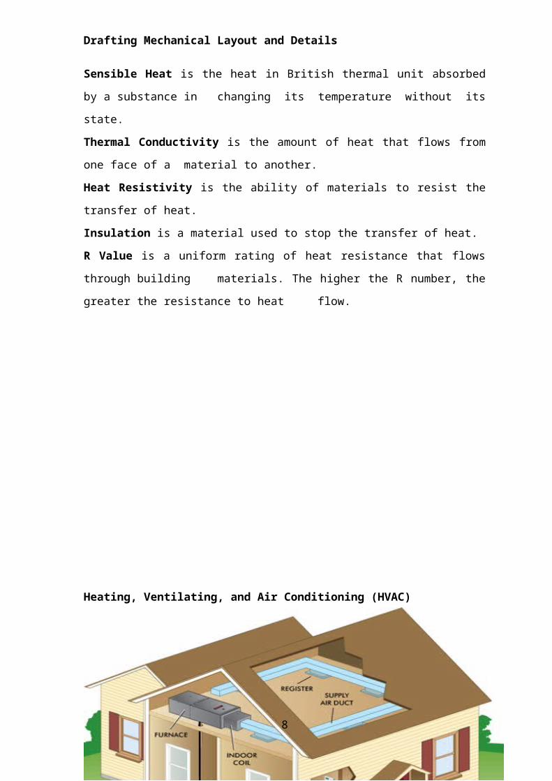
Heating, Ventilating, and Air Conditioning (HVAC)
Air conditioning
Air conditioning may be defined as the simultaneous control of air
temperature, humidity, motion and purity of air in a confined space.
Air Conditioning Systems
Air conditioning which is the process of controlling the physical properties
of air, maybe divided into 2 general classes:
1. Air Conditioning for human comfort
2. Process air conditioning
Comfort air conditioning is a modern method of controlling the temperature
and humidity of air in an enclosed space so that it will give comfort to the majority
of the occupants of the space.
6
Drafting Mechanical Layout and Details
Process air conditioning is concerned with producing an air condition within
an enclosed space that is most favorable to the manufacturing operation being
conducted in that space.
In general, comfort air-conditioning maybe defined as the simultaneous
and automatic control of temperature humidity, and air motion so that the greatest
feeling of comfort is produced for the largest number of people. Air conditioning
consists of cooling the air, dehumidifying it, and placing the air in motion. Cooling
the air requires refrigeration, while dehumidifying the air requires either
refrigeration or chemical treatment.
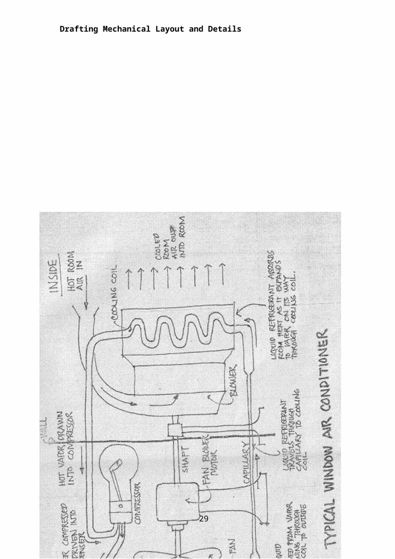
How does an Air Conditioner work?
An air conditioner cools and dehumidifies the air as it passes over a cold
coil surface. The indoor coil is an air-to-liquid heat exchanger with rows of tubes
that pass the liquid through the coil. Finned surfaces connected to these tubes
increase the overall surface area of the cold surface thereby increasing the heat
transfer characteristics between the air passing over the coil and liquid passing
through the coil. The type of liquid used depends on the system selected. Direct-
expansion (DX) equipment uses refrigerant as the liquid medium. Chilled-water
(CW) can also be used as a liquid medium. When the required temperature of a
chilled water system is near the freezing point, freeze protection is added in the
form of glycols or salts. Regardless of the liquid medium used, the liquid is
delivered to the cooling coil at a cold temperature.
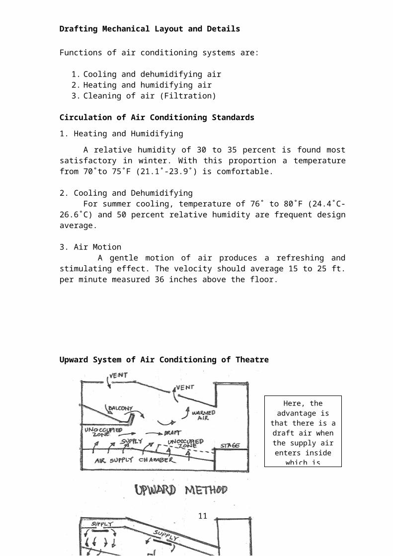
Functions of air conditioning systems are:
1. Cooling and dehumidifying air2. Heating and humidifying air3. Cleaning of air (Filtration)
Circulation of Air Conditioning Standards
1. Heating and Humidifying
A relative humidity of 30 to 35 percent is found most satisfactory in winter. With this proportion a temperature from 70˚to 75˚F (21.1˚-23.9˚) is comfortable.
2. Cooling and DehumidifyingFor summer cooling, temperature of 76˚ to 80˚F (24.4˚C-26.6˚C) and 50
percent relative humidity are frequent design average.
7
Here, the advantage is that there is a
draft air when the supply air enters inside which is
inconvenient to the audience.
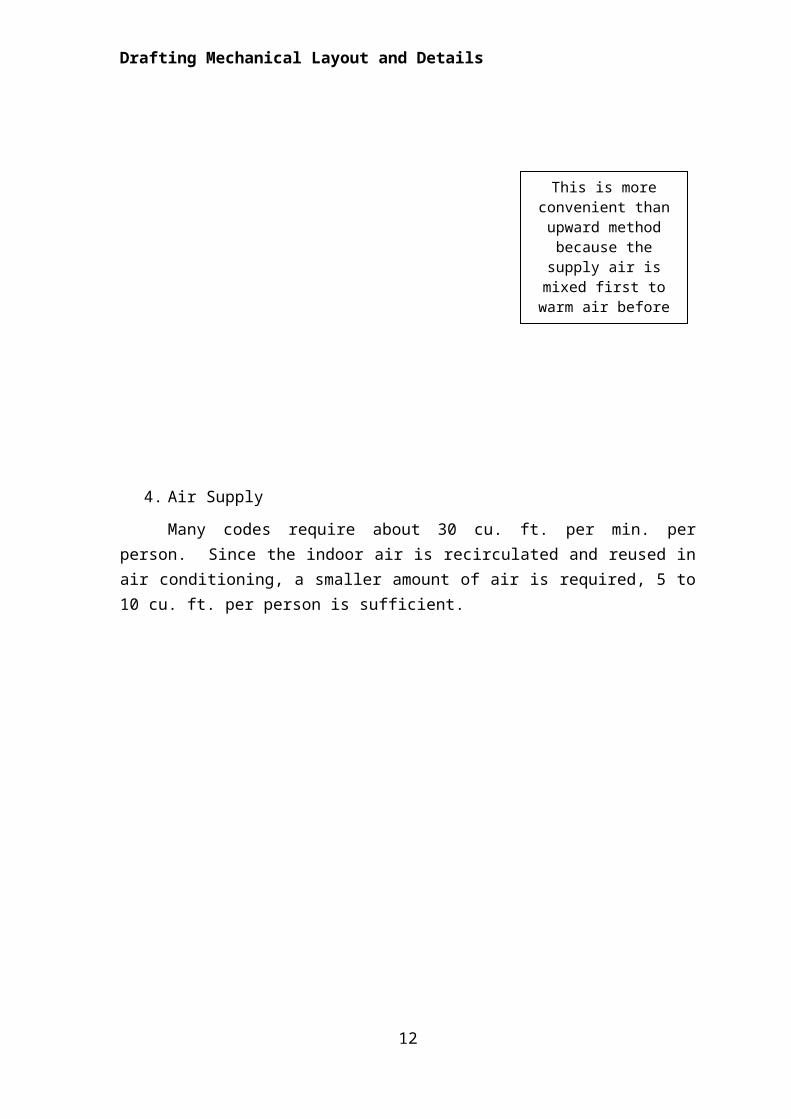
This is more convenient than upward method
because the supply air is mixed first to warm
air before reaching the audience
Drafting Mechanical Layout and Details
3. Air Motion A gentle motion of air produces a refreshing and stimulating effect. The
velocity should average 15 to 25 ft. per minute measured 36 inches above the floor.
Upward System of Air Conditioning of Theatre
4. Air Supply
Many codes require about 30 cu. ft. per min. per person. Since the indoor air is recirculated and reused in air conditioning, a smaller amount of air is required, 5 to 10 cu. ft. per person is sufficient.
8
Drafting Mechanical Layout and Details
9
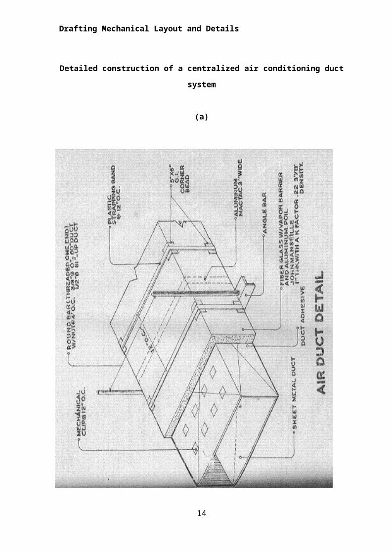
Drafting Mechanical Layout and Details
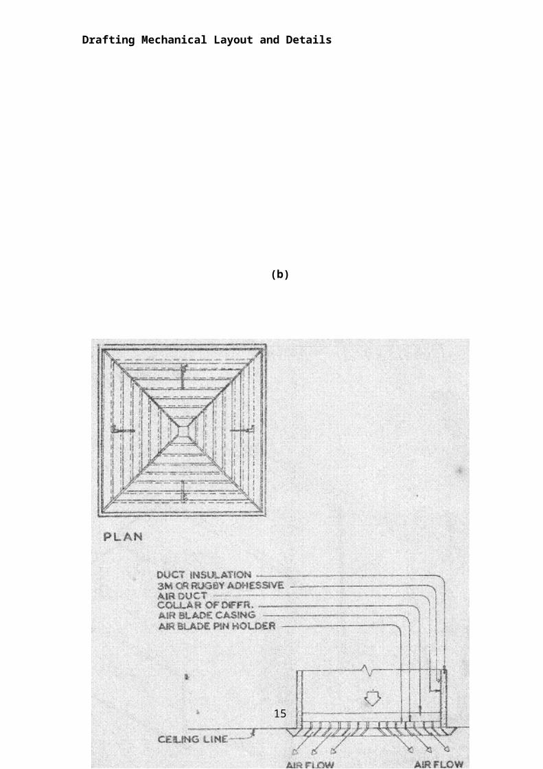
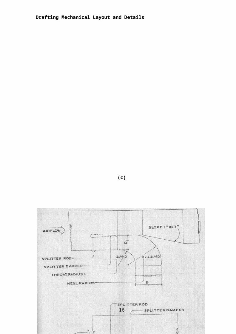
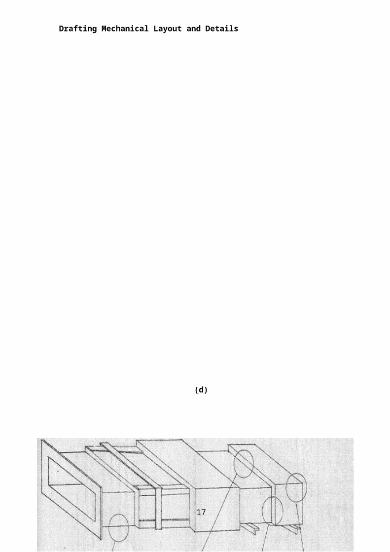
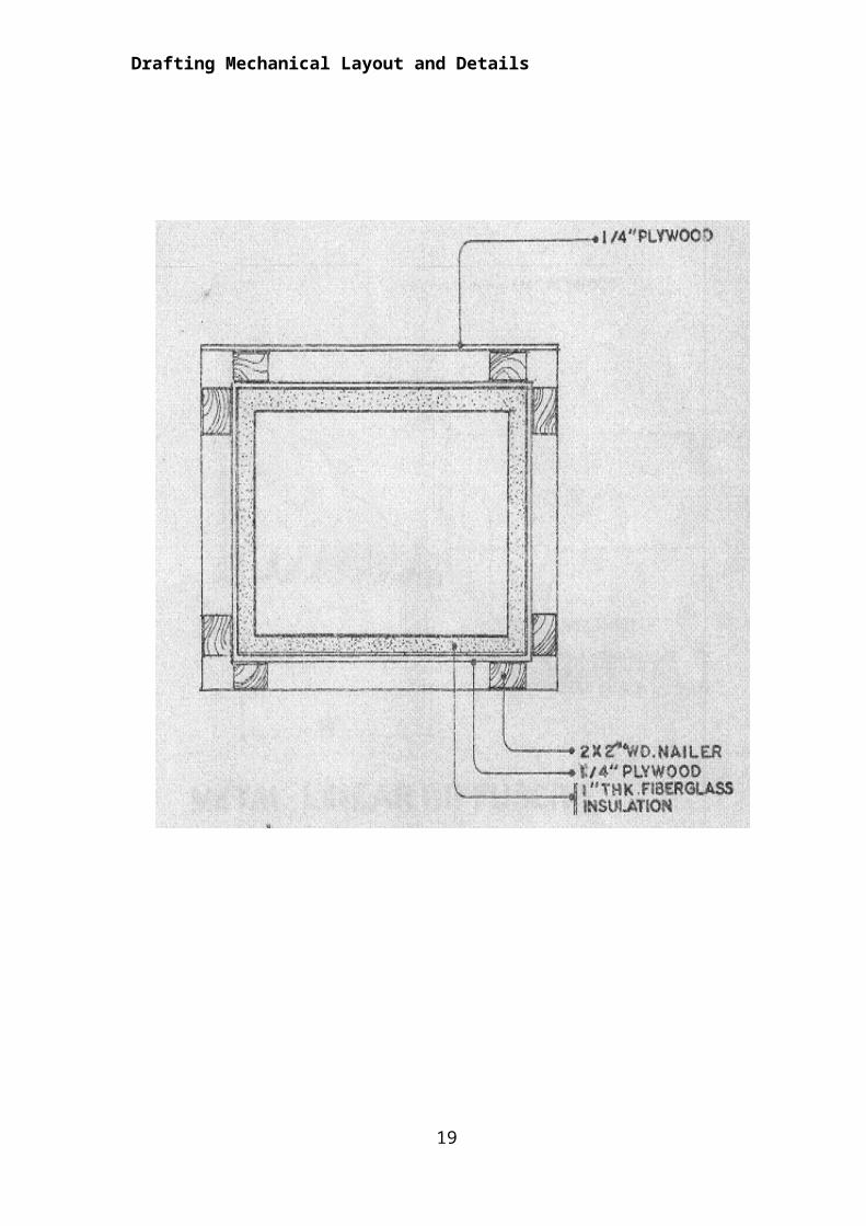
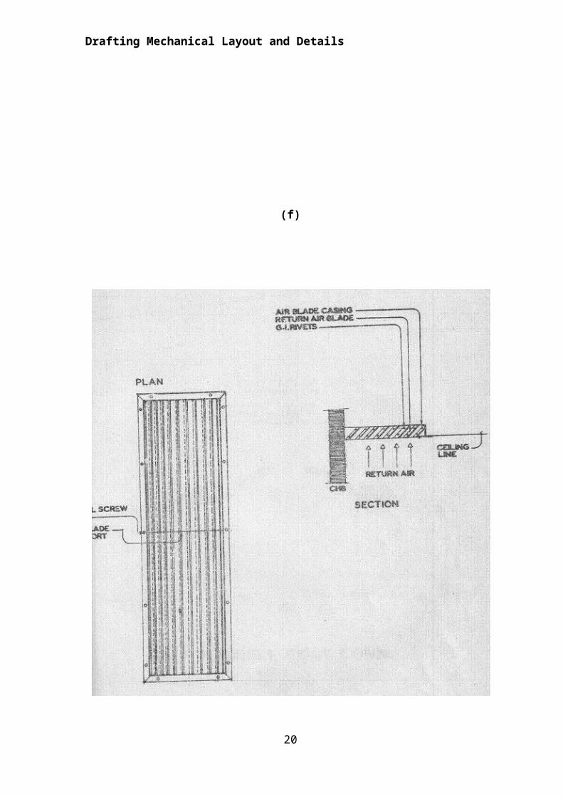
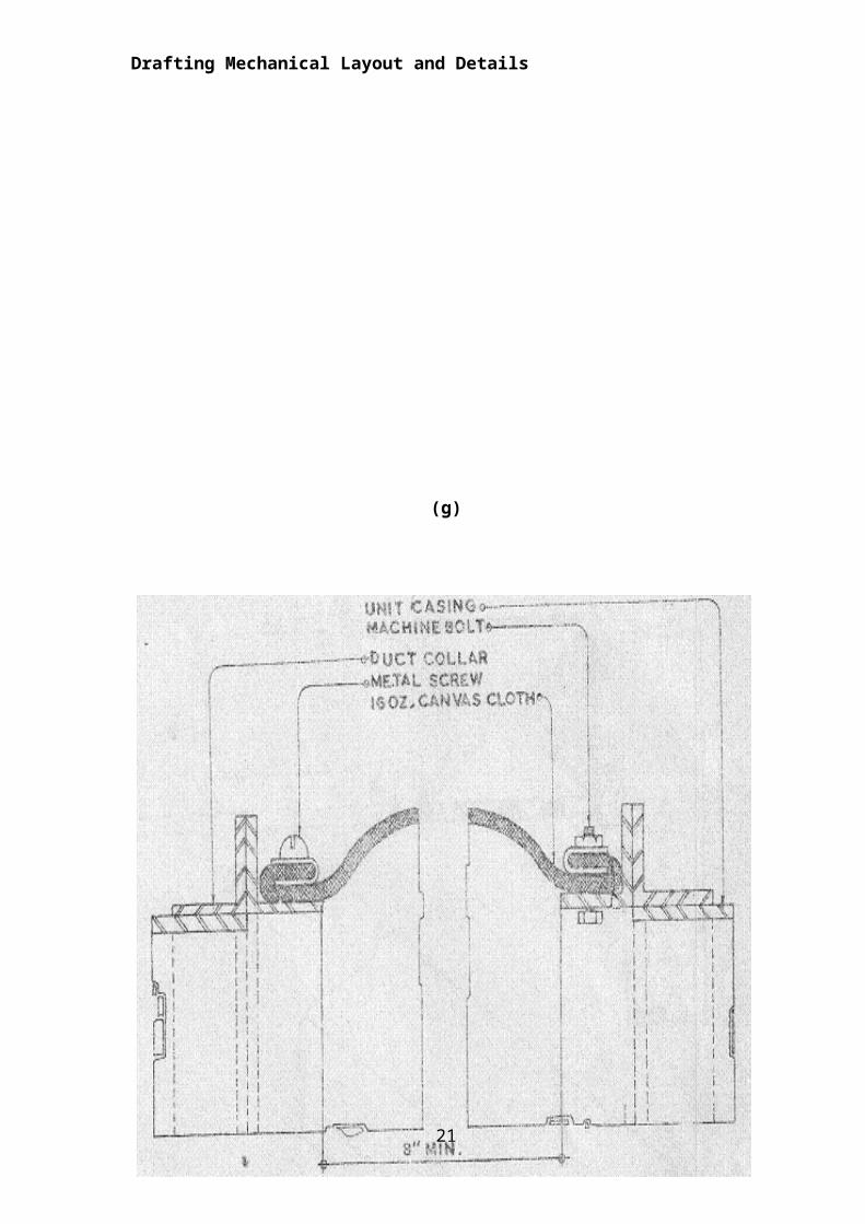
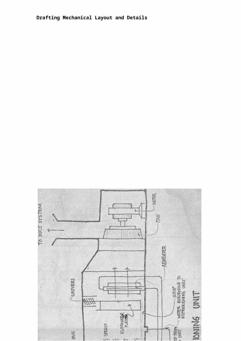
Detailed construction of a centralized air conditioning duct system
(a)
10
Drafting Mechanical Layout and Details
(b)
11
Drafting Mechanical Layout and Details
(c)
12
Drafting Mechanical Layout and Details
(d)
13
Drafting Mechanical Layout and Details
(e)
14
Drafting Mechanical Layout and Details
(f)
15
Drafting Mechanical Layout and Details
(g)
Types of Air Conditioning (AC) systems
Cooling Only Split-System
A split system is a combination of an indoor air handling unit and an
outdoor condensing unit. The indoor air handling unit contains a supply air fan
and an air-to-refrigerant heat exchanger (or cooling coil), and the expansion
16
Drafting Mechanical Layout and Details
device. The outdoor condensing unit consists of a compressor and a condenser
coil. Split-systems are typically found in residential or small commercial buildings.
These systems have the highest Energy Efficiency Rating (EER) of all the
available AC systems. Manufacturers are required to take the EER rating and
provide a Seasonal Energy Efficiency Rating (SEER) for use by consumers.
SEER ratings vary widely and range from 10 to 20. The higher the SEER rating,
the more efficient the AC system operates. If heating is required, an alternate
method of heating the interior of the building must be used, usually in the form of
electric or gas heating.
Cooling Only Packaged System
A cooling only packaged system is a single unit combining all the
components described in the split system. Since the unit is a package, it must be
placed outside the building and indoor air is “ducted” from the building to the
packaged system and back through an air distribution system. These units
typically have SEER rating from 10 to 18. If heating is required, an alternate
method of heating the interior of the building must be used, usually in the form of
electric or gas heating.
Heat Pump
Heat pumps are similar to cooling only systems with one exception. A
special valve in the refrigeration piping allows the refrigeration cycle to be
operated in reverse. It cools the indoor air and ejects heat to the outdoors. A heat
pump can also cool the indoor air, but when the valve is reversed, the indoor air
is heated.
Chilled Water System
In a chilled water system, liquid water is pumped throughout the building to “chilled water coils”. Since the liquid water needs to be at a cold temperature, a “cooling plant” is required. The plant is typically referred to as a chiller plant. Vapor compression equipment in the plant, cools the water to a cold temperature and pump the cold water to air-to-water heat exchangers where needed.
Window Air Conditioners
17
Drafting Mechanical Layout and Details
A window air conditioner is typically installed in a window or custom opening in a wall. The Window AC can only cool small areas and are not intended to provide cooling to multiple rooms or zones. These air conditioners are manufactured as cool only or can provide both cooling and heating.
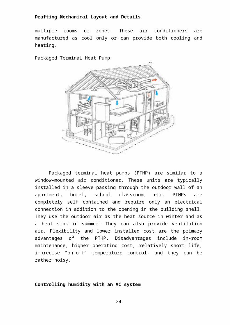
Packaged Terminal Heat Pump
Packaged terminal heat pumps (PTHP) are similar to a window-mounted air conditioner. These units are typically installed in a sleeve passing through the outdoor wall of an apartment, hotel, school classroom, etc. PTHPs are completely self contained and require only an electrical connection in addition to the opening in the building shell. They use the outdoor air as the heat source in winter and as a heat sink in summer. They can also provide ventilation air. Flexibility and lower installed cost are the primary advantages of the PTHP. Disadvantages include in-room maintenance, higher operating cost, relatively short life, imprecise "on-off" temperature control, and they can be rather noisy.
Controlling humidity with an AC system
Humidity is becoming more of a concern to building operators and owners. High indoor humidity leads to mold and mildew growth inside the building. There are several methods of controlling indoor humidity. The simplest (and most expensive) method is to connect a humidistat to an electric heater. When the humidity inside the building rises above the humidistat set point, the heater is
18
Drafting Mechanical Layout and Details
turned on. The additional heat causes the air conditioning system to run longer and remove more moisture.
Comfort requires more than just providing warmth in rainy season or coolness in summer. True comfort means a correct temperature, correct humidity or amount of moisture in the air, and clean, fresh, odorless air.
Directions: On a separate sheet of paper, answer the following questions.
1. What is HVAC? _________________________________________________________________________________________________________________________________________________________________________________________________________________________________________________________________________________________________________________________________________________________
2. How does an AC work? _________________________________________________________________________________________________________________________________________________________________________________________________________________________________________________________________________________________________________________________________________________________
3. What are the Air Conditioning Standards? _________________________________________________________________________________________________________________________________________________________________________________________________________________________________________________________________________________________________________________________________________________________
4. What types of AC systems are available? _________________________________________________________________________________________________________________________________________________________________________________________________________________________________________________________________________________________________________________________________________________________
19
ProcessProcessProcessProcessProcessProcessProcessProcessProcessProcessProcessProcessProcessProcessProcessProcessProcessProcessProcessProcessProcessProcessProcessProcessProcessProcessProcessProcessProcessProcessProcessProcessProcessProcessProcessProcessProcessProcessProcessProcessProcessProcessProcessProcessProcessProcessProcessProcessProcess
Drafting Mechanical Layout and Details
5. How is humidity controlled with an AC system? _________________________________________________________________________________________________________________________________________________________________________________________________________________________________________________________________________________________________________________________________________________________.
Test I. Direction: Fill in the blanks with the correct answers and write it on a separate sheet of paper.
1._______________ is defined as the simultaneous control of air temperature,
humidity, motion and purity of air in a confined space.
2. A relative humidity of ____________ percent is found most satisfactory in
winter.
3. A gentle motion of ______________ produces a refreshing and stimulating
effect.
4. For summer cooling, temperature of _______ (24.4˚C-26.6˚C) and ______
percent relative humidity are frequent design average.
5. The indoor air is recirculated and reused in _______________, a smaller
amount of air is required, 5 to 10 cu. ft. per person is sufficient.
Test II. Direction: Give the entities being asked:
1-2 Kinds of air conditioning system
3-7 Elements of the central system of air-conditioning
8-10 Functions of air conditioning system
20
Drafting Mechanical Layout and Details
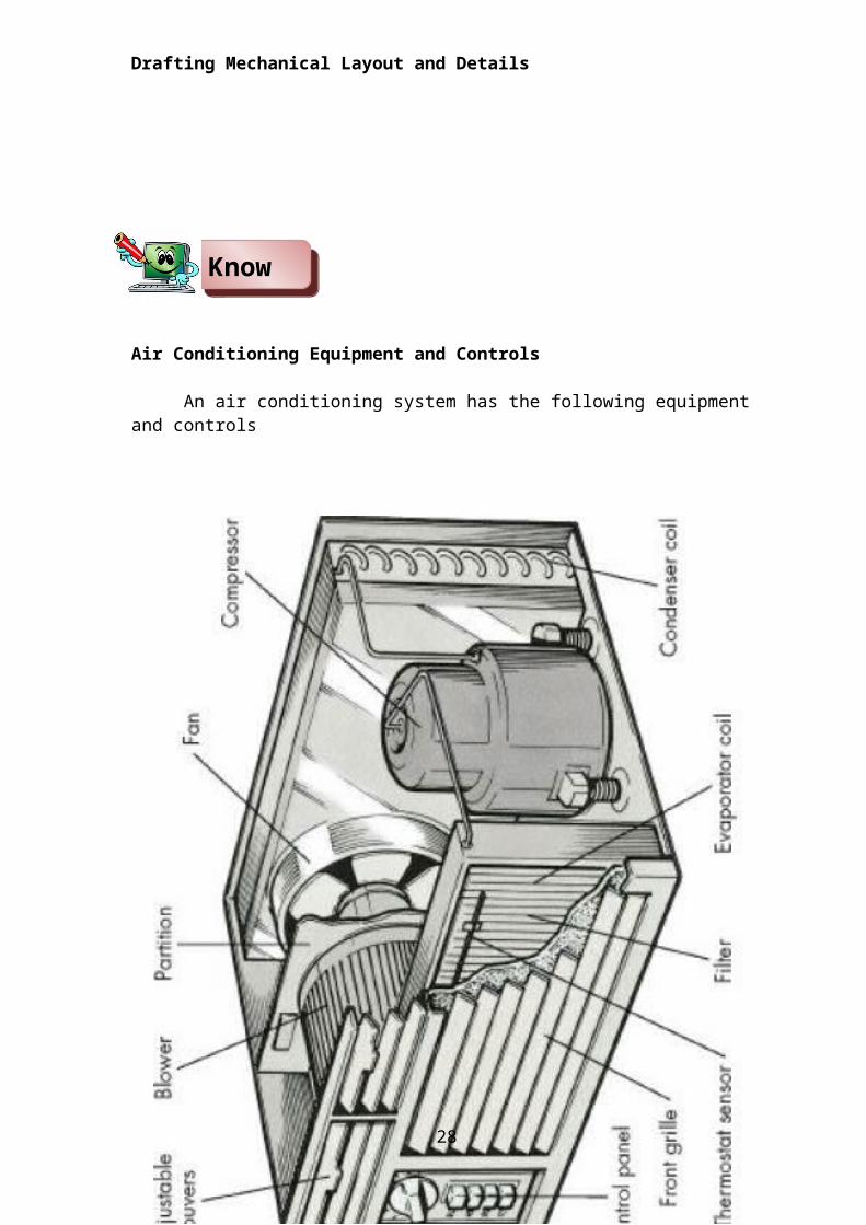
Air Conditioning Equipment and Controls
An air conditioning system has the following equipment and controls
21
KnowKnowKnowKnowKnowKnowKnowKnowKnowKnowKnowKnowKnowKnowKnowKnowKnowKnowKnowKnowKnowKnowKnowKnowKnowKnowKnowKnowKnowKnowKnowKnowKnowKnowKnowKnowKnowKnowKnowKnowKnowKnowKnowKnowKnowKnowKnowKnowKnow
Drafting Mechanical Layout and Details
22
Drafting Mechanical Layout and Details
23
Drafting Mechanical Layout and Details
1. CompressorsCompressors used are of two types:
a. Reciprocating is commonly referred to as piston typeb. Centrifugal refers to two rotary type compressors
For up to 100 tons, reciprocating units are used because centrifugal compressors are not manufactured in these sizes.
2. Condensers Condensers used for liquefying have three general designs:
a. Air cooled condensers Air cooled condensers are seldom used for capacities
above 3 tons of refrigeration unless an adequate water supply is extremely difficult to obtain. The principal disadvantages of this kind are the high power cost and the reduction of capacity on hot days.
The conventional air-cooled condenser consists of the condenser coil, compressor, and condenser fan with motor, crankcase, heater, controls, service valves and filter drier.
b. Water-Cooled condensersWater cooled condensers are of three types:
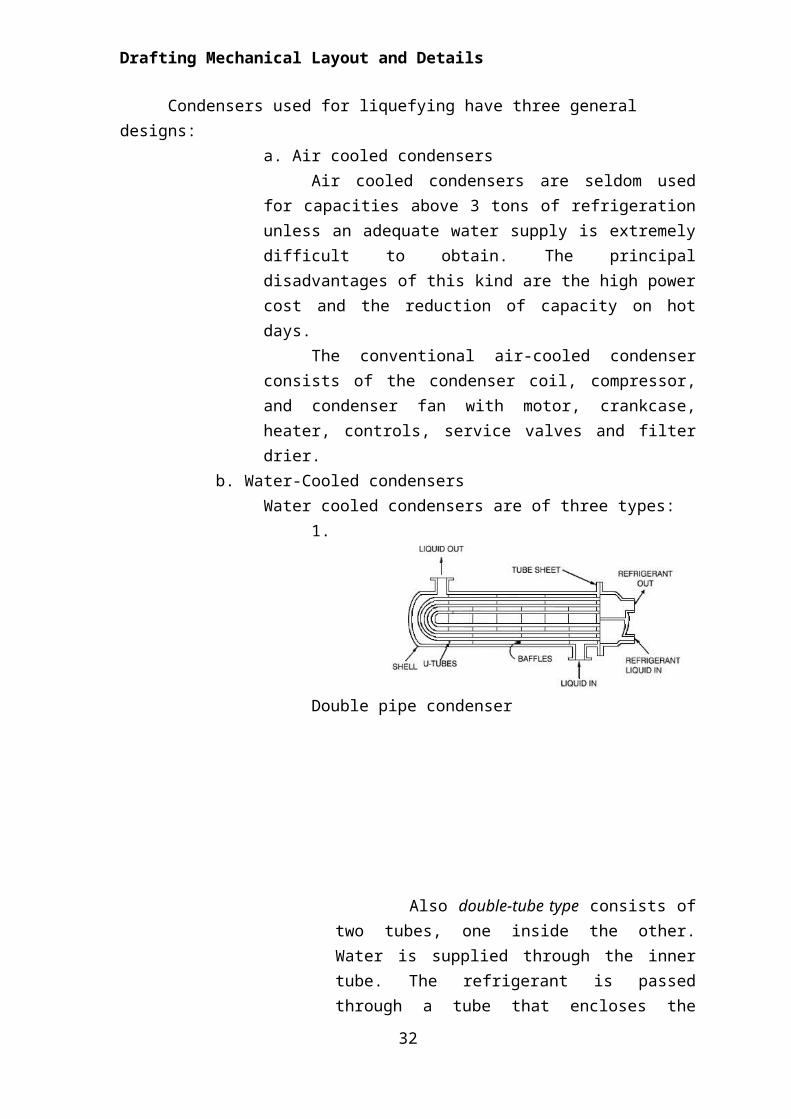
1. Double pipe condenser
Also double-tube type consists of two tubes, one inside the other. Water is supplied through the inner tube. The refrigerant is passed through a tube that encloses the inner tube. Refrigerant flows in the opposite direction than water.
24
Drafting Mechanical Layout and Details
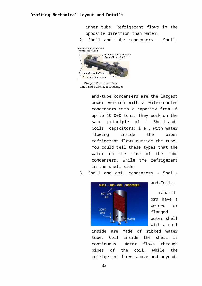
2. Shell and tube condensers – Shell-and-tube
condensers are the largest power version with a water-cooled condensers with a capacity from 10 up to 10 000 tons. They work on the same principle of " Shell-and-Coils, capacitors; i.e., with water flowing inside the pipes refrigerant flows outside the tube. You could tell these types that the water on the side of the tube condensers, while the refrigerant in the shell side
3. Shell and coil condensers - Shell-and-Coils, capacitors have a welded or flanged outer shell with a coil inside are made of ribbed water tube. Coil
inside the shell is continuous. Water flows through pipes of the coil, while the refrigerant flows above and beyond. The outer surface of the heat exchanger tubes and fins are in contact with the refrigerant. This is a vertical Shell-and-the condenser Coil. This can also be done in a horizontal position.
Water cooled condensing units are provided with cooling towers usually located on the roof of the building
c. Evaporative Condensers
25
Drafting Mechanical Layout and Details
This type of condenser makes use of both air and water for cooling and is available in sizes up to 100 tons or more. It is applicable in areas where there is a high cost of water for condenser purposes. However, it uses only 3 to 5 percent of the amount if the condenser is entirely water cooled.
3. Evaporation and CoolersA conventional evaporator of an air-conditioning system includes a
evaporator coil, blowers, motors, control and filter.There are several methods used for cooling in air conditioning:
a. Direct evaporative cooling - (open circuit) is used to lower the temperature of air by using latent heat of evaporation, changing liquid water to water vapor. In this process, the energy in the air does not change. Warm dry air is changed to cool moist air.
b. Indirect evaporative cooling - (closed circuit) is similar to direct evaporative cooling but uses some type of heat exchanger. The cooled moist air never comes in direct contact with the conditioned air.
c. Hybrid - Direct and Indirect cooling has been combined with vapor-compression or absorption air conditioning to increase the overall efficiency and /or to reduce the temperature below the wet-bulb limit.
4. Air cleaning equipmentAir may contain large quantities of dust, cinders, soot, smoke, fumes,
pollen, grit, bacteria and odor. These contaminating elements in the air are removed by filtration and by air washing.Air-conditioning filters are of different types:
a. Dry-filter consists of wire frames or panels, enclosing felt, cotton, batting, cellulose pockets through which the air is screened.
b. Viscous filters consists of a series of metal deflecting plates or screens coated with viscous oil coming in contact with these surfaces. The air flow is abruptly changed in direction and the dust is trapped in the oil film and remains there.
c. Automatic viscous filters. It is a system consisting of two endless vertical filter curtains with a denser front curtain and passes downward through an oil reservoir with the rear curtain catching entrained oil in the air.
d. Electric precipitators. Consists of a positive electric field and negative grounded tubes which serves to remove from the air the fine dusts, mists, unburned particles in smoke and other matters which would pass through the dry and viscous filters.
5. Fans - Fans used in Air-Conditioning are of two tubes:a. Centrifugal Fans (Radial Type of Fan)
26
Drafting Mechanical Layout and Details
The air enters at one side near the axis of the wheel and is discharged radially through the outlet placed at a tangent to the wheel.
b. Propeller Fans (Axial Type of Fan) The air enters at the rear of the fan and emerges at
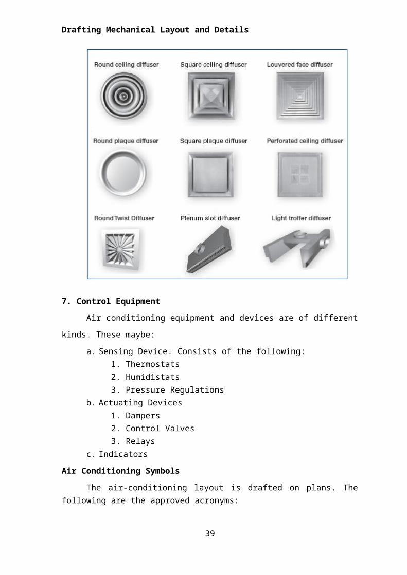
the front in a line parallel to the axis of rotation.6. Air Outlets - An important step in efficient space comfort conditioning is the proper selection of air outlets. This section presents generalized descriptions and characteristics of the types of grilles, registers and diffusers commonly used in commercial air distribution applications today.
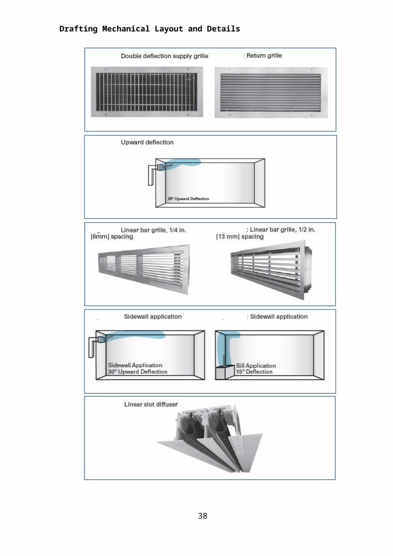
a. Grilles and Registers - The term grille is commonly applied to any air outlet or intake that consists of a square or rectangular face and neck and whose facial appearance is made up of stationary or adjustable louvers which may be used to deflect the air. A register is simply a grille which incorporates an integral damper for air volume control. Supply grilles and registers usually have adjustable louvers and are available in single or double deflection models.
b. Linear Bar Grille - The linear bar grille is normally used where an architectural blend of the grille to its surroundings is required.
c. Linear Slot Diffuser - Linear slot diffusers incorporate adjustable pattern controllers in a multi-slot configuration. Slot sizes are available in ½ in. [13 mm], ¾ in. [19 mm] or 1 in. [25 mm] widths with a choice of one to ten slots. Adjustable pattern controllers allow horizontal left, horizontal right or vertical discharge for maximum flexibility.
d. Round Ceiling Diffuser - Round ceiling diffusers consist of several concentric cones suspended below the ceiling line by an outer cone.
e. Square Ceiling Diffuser - Square ceiling diffusers consist of several concentric square cones and a round neck.
f. Louver Face Diffuser - Louver face diffusers are available with a square or rectangular face composed of a fixed modular core.
g. Round Plaque Diffuser - Round plaque diffusers consist of a plaque mounted inside an outer frame with a round inlet.
h. Square Plaque Diffusers - Square plaque diffusers are comprised of a square plaque situated in a backpan with a round inlet.
i. Perforated Ceiling Diffuser - Perforated ceiling diffusers are available with a square or rectangular face supplied through a round or square neck.
27
Drafting Mechanical Layout and Details
j. Radial/Twist Diffusers - Radial/twist diffusers consist of a circular or square face with multiple air vanes, either fixed or adjustable, and a round neck.
k. Plenum Slot Diffuser - These diffusers consist of a factory fabricated plenum with integral pattern controllers for vertical or horizontal air pattern adjustment.
l. Light Troffer Diffuser - Light troffer diffusers are designed to integrate with commercially available light fixtures in suspended ceiling systems.
28
Drafting Mechanical Layout and Details
7. Control Equipment
Air conditioning equipment and devices are of different kinds. These
maybe:
a. Sensing Device. Consists of the following:1. Thermostats2. Humidistats 3. Pressure Regulations
b. Actuating Devices1. Dampers2. Control Valves3. Relays
29
2. 34
5
7
8910-
11
12
Drafting Mechanical Layout and Details
c. Indicators
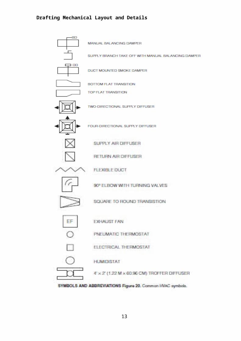
Air Conditioning Symbols
The air-conditioning layout is drafted on plans. The following are the approved acronyms:
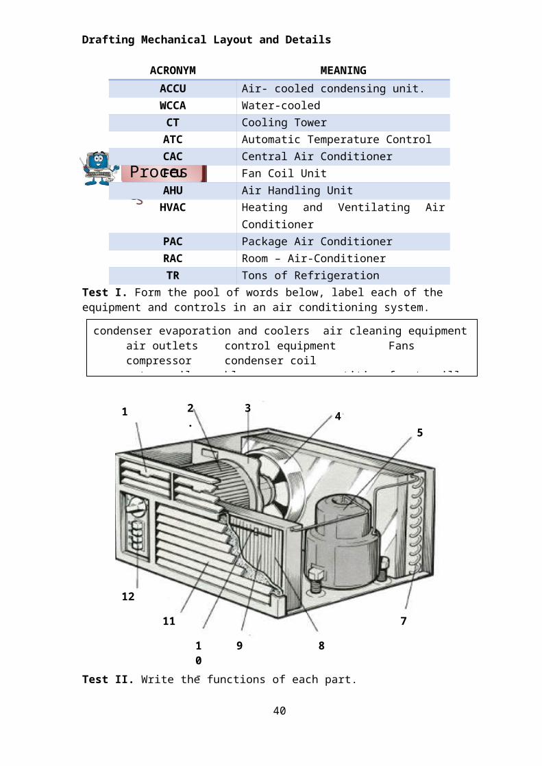
Test I. Form the pool of words below, label each of the equipment and controls in an air conditioning system.
Test II. Write the functions of each part.
1. Compressor2. Condenser
30
1.
ProcessProcessProcessProcessProcessProcessProcessProcessProcessProcessProcessProcessProcessProcessProcessProcessProcessProcessProcessProcessProcessProcessProcessProcessProcessProcessProcessProcessProcessProcessProcessProcessProcessProcessProcessProcessProcessProcessProcessProcessProcessProcessProcessProcessProcessProcessProcessProcessProcess
condenser evaporation and coolers air cleaning equipment air outletscontrol equipment Fans compressor condenser coil
evaporator coil blower partition front grille adjustable louvers thermostat sensor control panel
ACRONYM MEANING
ACCU Air- cooled condensing unit.WCCA Water-cooled
CT Cooling TowerATC Automatic Temperature ControlCAC Central Air ConditionerFCU Fan Coil UnitAHU Air Handling Unit
HVAC Heating and Ventilating Air ConditionerPAC Package Air ConditionerRAC Room – Air-ConditionerTR Tons of Refrigeration
Drafting Mechanical Layout and Details
3. Evaporation and Coolers4. Air cleaning equipment5. Fans6. Air Outlets7. Control Equipment
Test III. Direction: Give the meaning of the following acronyms/symbols. Write the answer on a separate sheet of paper.
1. HVAC - ____________________________________________________________________________________________________________________________________________________
2. FCU - ______________________________________________________________________________________________________________________________________________________
3. CAC - ______________________________________________________________________________________________________________________________________________________
4. CT - ______________________________________________________________________________________________________________________________________________________
5. ACCU - ______________________________________________________________________________________________________________________________________________________
Test II. Enumeration: Enumerate the methods used for cooling in air conditioning and describe each briefly.
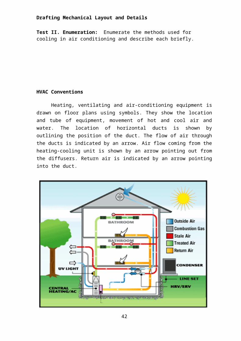
HVAC Conventions
Heating, ventilating and air-conditioning equipment is drawn on floor plans using symbols. They show the location and tube of equipment, movement of hot
31
Drafting Mechanical Layout and Details
and cool air and water. The location of horizontal ducts is shown by outlining the position of the duct. The flow of air through the ducts is indicated by an arrow. Air flow coming from the heating-cooling unit is shown by an arrow pointing out from the diffusers. Return air is indicated by an arrow pointing into the duct.
Climate Control Methods and Heat Transfer
Heat is transferred from a warm to a cool surface by:
1. Radiation is the heat that flows to a cooler surface through space in the same manner light travels.
2. Convection is a warm surface that heats the air, the warm air rises and cool air moves in to take its place causing a convection current
3. Conduction is the heat that moves through a solid material, the denser the material the better it will conduct heat.
Heat loss or gain is the amount of heat that passes through the exterior surface of a building. Thermal conductivity is the amount of heat that flows from one face of a material, through the material, and to the opposite face. It is defined also as the amount of heat transfer through a 1-Sq.Foot area, 1 inch thick with a temperature difference of 1 degree Fahrenheit.
32
Drafting Mechanical Layout and Details
The unit of measurement for heat is Btu (British thermal unit) which is the unit of heat needed to raise the temperature on 1 pound of water 1 degree Fahrenheit.
Resistivity is the ability of materials to resist the transfer of heat while insulation is the material used to stop the transfer of heat, block moisture, stop sound, resist fire and resist insects.
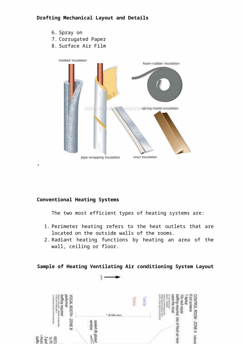
Some kinds of insulating materials are:
1. Flexible Bat2. Flexible Blanket3. Loose Fill Reflective Material4. Rigid Board5. Additives6. Spray on7. Corrugated Paper8. Surface Air Film
‘
Conventional Heating Systems
The two most efficient types of heating systems are:
1. Perimeter heating refers to the heat outlets that are located on the outside walls of the rooms.
2. Radiant heating functions by heating an area of the wall, ceiling or floor.
Sample of Heating Ventilating Air conditioning System Layout
33
Drafting Mechanical Layout and Details
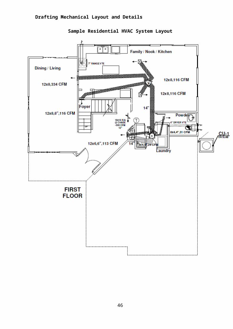
Sample Residential HVAC System Layout
34
Drafting Mechanical Layout and Details
35
Drafting Mechanical Layout and Details
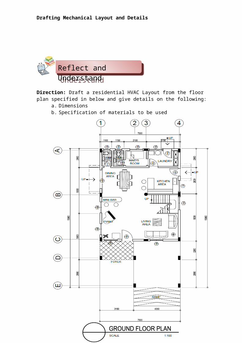
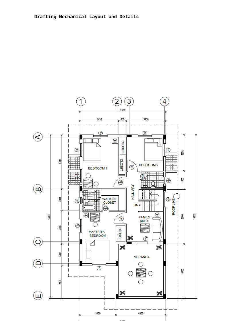
Direction: Draft a residential HVAC Layout from the floor plan specified in below and give details on the following:
a. Dimensionsb. Specification of materials to be used
36
Reflect and Reflect and Reflect and Reflect and Reflect and Reflect and Reflect and Reflect and Reflect and Reflect and Reflect and Reflect and Reflect and Reflect and Reflect and Reflect and Reflect and Reflect and Reflect and Reflect and Reflect and Reflect and Reflect and Reflect and Reflect and Reflect and Reflect and Reflect and Reflect and Reflect and Reflect and Reflect and Reflect and Reflect and Reflect and Reflect and Reflect and Reflect and Reflect and Reflect and Reflect and Reflect and Reflect and Reflect and Reflect and Reflect and Reflect and Reflect and Reflect and
Drafting Mechanical Layout and Details
37TransferTransferTransferTransferTransferTransferTransferTransferTransferTransferTransferTransferTransferTransferTransferTransferTransferTransferTransferTransferTransferTransferTransferTransferTransferTransferTransferTransferTransferTransferTransferTransferTransferTransferTransferTransferTransferTransferTransferTransferTransferTransferTransferTransferTransferTransferTransferTransferTransfer
Drafting Mechanical Layout and Details
I. Direction: Draw a diagrammatic Air conditioning layout based on the specified floor plan on given above. Be sure to include specifications such as:
a. Bill of Materialsb. Time Schedule
II. Multiple Choice: Choose the best answer and write it on a separate sheet of
paper.
1. It is the heating of an area of the wall, ceiling or floor.
a. radiant heating b. perimeter heating c. solar heating
2. It is the heating through outlets located on the outside walls of the rooms.
a. radiant heating b. perimeter heating c. solar heating
3. It is the unit of measurement for heat.
a. BTU b. watts c. kilowatts
4. It is the material used to stop the transfer of heat,
blocks moisture, stops sound, resists fire and insects.
a. conductor b. conduit c. insulation
5. It is the ability of materials to resist the transfer of heat.
a. friction b. resistivity c. insulation
6. The heat that flows to a cooler surface through space in the
same manner light travels.
a. conduction b. convection c. radiation
7. The heat that moves through a solid material, the denser he material, the
better it will conduct heat.
a. conduction b. convection c. radiation
8. Warm surface heats the air on it, as the warmed air rises the cool air
moves
in to take its place.
a. conduction b. convection c. radiation
9. The amount of heat that passes through the exterior surface of
a building.
a. heat loss or heat gain b. Btu c. watts
10. The amount of heat that flows from one face of a material,
through the material, and to the opposite face
38
Drafting Mechanical Layout and Details
a. friction b. resistivity c. thermal conductivity
Lesson 2: Draft Mechanical Details of Conveyor Systems
Assessment Criteria:
1. Elevators, escalators, dumbwaiter and moving ramps systems are drawn
in accordance with the Mechanical Code of the Philippines
2. Drawing details are drawn according to architectural requirements
SKILLS EVALUATION
Direction: Listed below are some of the most important skills that you must gain in order to draft a quality floor plan. On the right side of the matrix lists the skills expected of you to master. Rate yourself by checking “Not much”, if you are not so familiar yet, “A little” and/or “A lot”, if you are already familiar with the skills. Don’t feel bad if you checked “Not Much” in all of the skills. Keep in mind that this is being administered to determine your pre-entry knowledge of and skills on the lesson to be presented.
Skills in drafting mechanical details of conveyor system
Not Much A little A lot
I can layout draw elevator, escalators, dumbwaiter and moving ramp systems according to Mechanical Code
I can draw details of mechanical conveyor system according to mechanical layout and
39
A conveyor system is often the lifeline to a company’s ability to effectively move its product in a timely fashion. The steps that a company can take to ensure that it performs at peak capacity, include regular inspections, close monitoring of motors and reducers, keeping key parts in stock, and proper training of personnel.
Increasing the service life of your conveyor system involves: choosing the right conveyor type, the right system design and paying attention to regular maintenance practices.
A conveyor system that is designed properly will last a long time with proper maintenance. Here are six of the biggest problems to watch for in overhead type conveyor systems including I-beam monorails, enclosed track conveyors and power and free conveyors.
KnowKnowKnowKnowKnowKnowKnowKnowKnowKnowKnowKnowKnowKnowKnowKnowKnowKnowKnowKnowKnowKnowKnowKnowKnowKnowKnowKnowKnowKnowKnowKnowKnowKnowKnowKnowKnowKnowKnowKnowKnowKnowKnowKnowKnowKnowKnowKnowKnow
Drafting Mechanical Layout and Details
details requirements
Learning Goals and Targets:
After reading the introduction and carefully answering the pre assessment instrument, you might have ideas of what you will be dealing with in this module. Now prepare to set your goals and targets for this module by completing the activity below. Write your answer in your notebook.
My goals are:
My targets are:
40
Goal 1
Goal 2
Goal 3
Goal 4
Target 3
Target 2
Target 1
Drafting Mechanical Layout and Details
Escalators, Conveyors, and Elevators
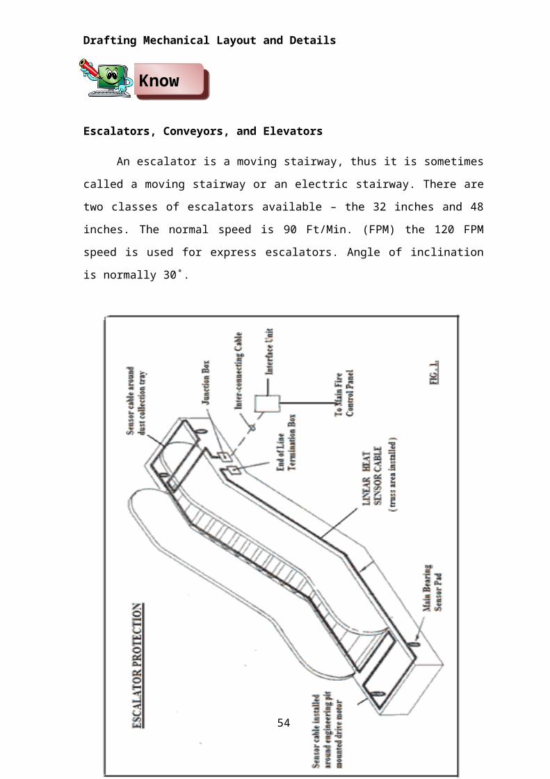
An escalator is a moving stairway, thus it is sometimes called a moving
stairway or an electric stairway. There are two classes of escalators available –
the 32 inches and 48 inches. The normal speed is 90 Ft/Min. (FPM) the 120 FPM
speed is used for express escalators. Angle of inclination is normally 30˚.
Components of an Escalator Installation
42
KnowKnowKnowKnowKnowKnowKnowKnowKnowKnowKnowKnowKnowKnowKnowKnowKnowKnowKnowKnowKnowKnowKnowKnowKnowKnowKnowKnowKnowKnowKnowKnowKnowKnowKnowKnowKnowKnowKnowKnowKnowKnowKnowKnowKnowKnowKnow
Drafting Mechanical Layout and Details
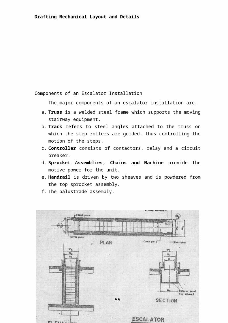
The major components of an escalator installation are:
a. Truss is a welded steel frame which supports the moving stairway equipment.
b. Track refers to steel angles attached to the truss on which the step rollers are guided, thus controlling the motion of the steps.
c. Controller consists of contactors, relay and a circuit breaker.d. Sprocket Assemblies, Chains and Machine provide the motive power
for the unit.e. Handrail is driven by two sheaves and is powdered from the top sprocket
assembly.f. The balustrade assembly.
Arrangements of Escalators
43
Drafting Mechanical Layout and Details
There are generally two types of arrangements employed in an escalators design.
a. Parallel Arrangementb. Crisscross Arrangement
The crisscross arrangement is generally favored because of lower cost,
minimum floor space occupied and lower structural requirement.
Moving Walks and Ramps
Moving walks and ramps are different from moving stairways. While moving stairways(Escalators) have the primary function of moving a large number of people vertically, moving walk or ramp serves a dual function, that is, horizontal transportation only, or a combined function of horizontal and vertical transportation not only of people but also of wheeled vehicles and large parcels.
By definition, a moving walk is one with an inclination not exceeding 5 degrees, where the principal function is horizontal motion and inclined motion is incidental to the horizontal.
A moving ramp is a device with an inclination limited to 15 degrees where vertical motion is as important, or more so, than the horizontal component.
Elevators
An elevator or lift (in British English) is a vertical transport vehicle that efficiently moves people or goods between floors of a building. They are generally powered by electric motors that either drive traction cables and counterweight systems, or pump hydraulic fluid to raise a cylindrical piston.
Lifts began as simple rope or chain hoists. A lift is essentially a platform that is either pulled or pushed up by a mechanical means. A modern day lift consists of a cab (also called a "cage" or "car") mounted on a platform within an enclosed space called a shaft or sometimes a "hoist way". In the past, lift drive mechanisms were powered by steam and water hydraulic pistons. In a "traction" lift, cars are pulled up by means of rolling steel ropes over a deeply grooved pulley, commonly called a sheave in the industry. The weight of the car is balanced with a counterweight. Sometimes two lifts always move synchronously in opposite directions, and they are each other's counterweight. The friction between the ropes and the pulley furnishes the traction which gives this type of lift its name.
44
Drafting Mechanical Layout and Details
Passenger Elevators
Passenger elevators are used to carry passenger traffic in buildings where several peak periods occur each day. Residential elevators may be small enough to only accommodate one person while some are large enough for more than a dozen. Wheelchair, or platform lifts, a specialized type of elevator designed to move a wheelchair 6 ft (1.8 m) or less, often can accommodate just one person in a wheelchair at a time with a load of 1000 lb (455 kg).
The elements of an electrical elevator installation are:
1. Hoistway is the shaft or vertical passageway for the travel of the car and its counterweights.
2. Elevator Car is a cage of light metal supported on a structural frame to the top member of which the cables are fastened. The car is fixed on its vertical travel in the shaft by means of rail shoes on the guide rails.
3. Cables which lift the car usually 3 to 8 in number are placed in parallel, the weight of the car is being equally distributed over the cables which are fastened to the top of the car by cables sockets.
4. Elevator Machine turns the sheave and thus lifts or lowers the car. In most modern installations, the electric driving motor receives its energy from a separate motor- generator set.
5. Machine Room is the place where the elevators machine is housed, usually directly above the elevator shaft or hoistway.
6. Counterweights are rectangular blocks of cast iron stacked in one frame which is supported at the opposite ends of the cables to which the car is fastened.
7. Guide Rails are the vertical tracks that guide the car and its counter weight.
8. Control Equipment is a combination of push buttons contacts, relays, cams and devices which are operated manually or automatically to initiate door opening, starting, acceleration, leveling and stopping of the car.
9. Safety Devices include:a. Main Brake is mounted directly on the shaft of the elevator
machine.b. Safety System is controlled by the speed governor mounted on or
near the elevator machine. c. Electrical Final Limit Switches de-energize the traction motor and
set the main brake if the car over travels.d. Oil or Spring Buffers are always placed in the elevators pit. Their
purpose is not to stop a falling car but to bring it to a partially cushioned stop if it over travels the lower terminal.
45
Drafting Mechanical Layout and Details
Elevators Machines
Two types of elevator machines
a. Gearless Traction Machine
b. Geared Traction Machine.
Systems of Elevator Operation and Supervision
There are three systems of operation involved with elevators. These are:
a. Single Automatic Push Button Control. This is the simplest since it handles only one call at a time, providing for an uninterrupted trip for each call.
b. Collective Control. It is arranged to collect all waiting “up” calls on the trip up and all waiting “Down” calls on the trip down, the control system “store” all calls until they are answered and automatically reverses the direction of travel at the highest and lowest calls.
c. Electronic Group Supervisory Dispatching and Control. Under this system, the entire group or bank of cars in a given group of elevators is in automatic operation at peak periods; and automatically shuts down successively as the number of car passengers become very low and electronic control system performs all commands, thus no operator is needed.
Kinds of Elevators
There are different kinds of elevations as to their purpose these are:
1. Freight Elevators. They are of two types.
a. General Purpose Freight Elevator
b. Light Duty Freight Elevators
c. Sidewalk Elevators
2. Dumbwaiters – they are small freight for the transport of relatively small
articles between levels.
3. Plunger Elevators. These are oil – hydraulic elevators which are raised
and lowered by means of a movable rod rigidly fixed at the bottom of the
car. The system is hydraulic and operates the same as a hydraulic jack
46
Drafting Mechanical Layout and Details
Standard Bed Elevators
47
Drafting Mechanical Layout and Details
Test I. Multiple Choice.
Directions: Choose the letter of the correct answer. Write your answer on a
separate sheet of paper.
1. It is sometimes called a moving stairway or an electric stairway.
a. elevator b. escalator c. conveyor
2. It is used to carry passenger traffic in buildings.
a. elevator b. escalator c. conveyor
3. It is the standard angle of inclination of an elevator.
a. 30˚ b. 60˚ c. 90˚
4. Normal speed of an escalator
a. 90 Ft/Min. (FPM) b. 100 Ft/Min. (FPM) c.80 Ft/Min. (FPM)
5. A vertical transport vehicle that efficiently moves people or goods between
floors of a building.
a. elevator b. escalator c. conveyor
48
ProcessProcessProcessProcessProcessProcessProcessProcessProcessProcessProcessProcessProcessProcessProcessProcessProcessProcessProcessProcessProcessProcessProcessProcessProcessProcessProcessProcessProcessProcessProcessProcessProcessProcessProcessProcessProcessProcessProcessProcessProcess
Drafting Mechanical Layout and Details
Test II. Enumeration.
Write your answer on a separate sheet of paper.
1-3 Systems of Elevator Operation and Supervision
4-5 Types of elevator machines
Direction:
a. Draft the existing illustrated sample plan on:
1. Standard Bed Elevator
2. Elevator Hoist way Roof Detail
3. Elevator Hoist way Corner Detail
4. Elevator Vertical Wall Joint Detail
5. Elevator Hoist way Flashing Detail
5. Section View for Hole less Jack System
Summative Test
I. Practice Activity: Direction: Perform the following:
a. Draft a standard a Sample Bed Elevator as shown below:
b. Create a draftsman portfolio for the following:
1. Standard Bed Elevator
2. Elevator Hoist way Roof Detail
3. Elevator Hoist way Corner Detail
4. Elevator Vertical Wall Joint Detail
5. Elevator Hoist way Flashing Detail
6. Section View for Hole less Jack System
- with suggested improvement on the design and efficiency.
49
Reflect and Reflect and Reflect and Reflect and Reflect and Reflect and Reflect and Reflect and Reflect and Reflect and Reflect and Reflect and Reflect and Reflect and Reflect and Reflect and Reflect and Reflect and Reflect and Reflect and Reflect and Reflect and Reflect and Reflect and Reflect and Reflect and Reflect and Reflect and Reflect and Reflect and Reflect and Reflect and Reflect and Reflect and Reflect and Reflect and Reflect and Reflect and Reflect and Reflect and
TransferTransferTransferTransferTransferTransferTransferTransferTransferTransferTransferTransferTransferTransferTransferTransferTransferTransferTransferTransferTransferTransferTransferTransferTransferTransferTransferTransferTransferTransferTransferTransferTransferTransferTransferTransferTransferTransferTransferTransfer
KnowKnowKnowKnowKnowKnowKnowKnowKnowKnowKnowKnowKnowKnowKnowKnowKnowKnowKnowKnowKnowKnowKnowKnowKnowKnowKnowKnowKnowKnowKnowKnowKnowKnowKnowKnowKnowKnowKnowKnow
Drafting Mechanical Layout and Details
Lesson 3. Draft Fire Protection Systems
An objective conceptual planning is to create an environment in which the user can be as safe as possible. Many of the accidents that frequently occur in homes, schools, offices and elsewhere are due to the facility design and to user errors. Safety considerations applicable to all architectural systems must be considered such as fire protection and alarm system. The provision of fire sprinkler and alarm as embodied in the National Building Code and Fire Code of the Philippines should be implemented.
Skills Evaluation
Direction: Listed below are some of the most important skills that you must gain in order to draft a quality floor plan. On the right side of the matrix lists the skills expected of you to master. Rate yourself by checking “Not much”, if you are not so familiar yet, “A little” and/or “A lot”, if you are already familiar with the skills. Don’t feel bad if you checked “Not Much” in all of the skills. Keep in mind that this is being administered to determine your pre-entry knowledge of and skills on the lesson to be presented.
Skills in drafting fire protection system Not Much A little A lot
I can draw fire sprinkler plan according to Fire Code
I can draw signs and symbols of fire protection systems according to fire protection requirements
Learning Goals and Targets:
After reading the introduction and carefully answering the pre assessment instrument, you might have ideas of what you will be dealing with in this module. Now prepare to set your goals and targets for this module by completing the activity below. Write your answer in your notebook.
My goals are:
50Goal 1
Goal 2
Goal 3
Goal 4
Drafting Mechanical Layout and Details
My targets are:
Requirements for fire safety:
a. There must be at least two means of exit in every residential room (such as a doorway or window).
b. Exit doors must be at least 0.60 m wide.c. Occupied rooms must be accessible.d. All door locking devices must be easily disengaged from the inside by
quick release catches.e. The path of travel from any room to an exit must not be through
another room subject to locking.f. Passages from sleeping rooms to exits must be at least 0.90 wide.g. Stairs must be at least 0.90 m wide.h. Every sleeping room must have at least a window which
can be easily opened from the inside.i. Storm windows, screens, burglar guards must have quick
opening devices.j. Combustion heaters and stoves must not be located to
block escape in case of malfunction.
51
Target 3
Target 2
Target 1
KnowKnowKnowKnowKnowKnowKnowKnowKnowKnowKnowKnowKnowKnowKnowKnowKnowKnowKnowKnowKnowKnowKnowKnowKnowKnowKnowKnowKnowKnowKnowKnowKnowKnowKnowKnowKnowKnowKnowKnow
Drafting Mechanical Layout and Details
Building Classifications
Building code requirements vary as to such factors as type of occupancy,
building contents, type of construction, location and fire extinguishing system.
The code permits “trade offs” between these classifications with the goal of
obtaining public safety as can.
Classification by Occupancy
1. Assembly
2. Educational
3. Institutional
4. Residential
5. Mercantile
6. Offices
7. Industrial
8. Storage
Classification by Content
1. Ordinary Hazard Content
2. Extra Hazard Content
3. Light Hazard Content
Classification by construction type
Type I – Fire resistive construction
Type II – Heavy timber construction
Type III – Non combustible construction
Type IV – Ordinary construction
Type V – Wood frame construction
Classification by location
Buildings constructed in closely packed communities are threat to the general public than buildings located in an open area. Thereof, building codes establish fire limits or fire zones within the limits of a fire zone. All buildings must be designed so that a fire will remain contained.
52
Drafting Mechanical Layout and Details
Fire Extinguishing System
Building codes often require automatic water-sprinkler systems, for they give excellent fire protection in all types of buildings.
A sprinkler system consists of a network of piping placed under the ceiling. It is provided with a number of nozzles called sprinklers when activated, the sprinklers spray water in a hemispherical pattern.
Types of Sprinkler Systems
1. Fixed Temperature System is classified into two kinds:
a. Wet Pipe refers to when water is stored in the piping
b. Dry Pipe refers to when no water is in the pipe
2. Rate-of-Rise Sprinkler System. Detectors open valves upon any abnormal
increase of temperature. It is also classified as:
a. Deluge System is used for extra hazard condition
b. Pre – Action System is used to reduce the possibility of accidental
water damage
Sprinkler Layout
The layout of a sprinkler system is classified into three types:
1. Light hazard is where protection area per sprinkler does not exceed 200
sq.ft.
2. Ordinary hazard is where protection area per sprinkler does not exceed
130 sq. ft.
3. Extra hazard is where protection area per sprinkler does not exceed 90
sq.ft.
Standpipes are vertical water pipes with fire-hose outlets at each floor.
They are located so that any fire can be reached by a stream from not more 75’
of small hose or 100’ of large hose.
53
ProcessProcessProcessProcessProcessProcessProcessProcessProcessProcessProcessProcessProcessProcessProcessProcessProcessProcessProcessProcessProcessProcessProcessProcessProcessProcessProcessProcessProcessProcessProcessProcessProcessProcessProcessProcessProcessProcessProcessProcess
Drafting Mechanical Layout and Details
Test I.Direction: Write A if the statement is correct and write B if is not. Use a
separate sheet of paper.
1. There must be at least two means of exit in every residential room.
2. Exit doors must be at least 0.30 m wide.
3. Passages from sleeping rooms to exits must be at least 0.40 m wide.
4. Every sleeping room must have at least a window which can be easily
opened from the inside.
5. Storm windows, screens, burglar guards must have quick opening
devices.
Test II. Direction: Group each of the words from the pool below to classify
them according to:
Part I. Drafting the fire protection systems.
Direction: Using the only one floor plan floor plan, draft each of the fire protection systems with color coding suggested below:
a. Fire sprinkler system – REDb. Fire standpipes system – GREENc. Diagram connecting fixtures – YELLOW
54
Fire Resistive Industrial
Educational Heavy timber
Ordinary Hazard Residential Offices
Extra Hazard Non-combustible Ordinary
Content
__________
__________
__________
__________
Occupancy
__________
__________
__________
__________
Construction Type
__________
__________
__________
__________
Reflect and Reflect and Reflect and Reflect and Reflect and Reflect and Reflect and Reflect and Reflect and Reflect and Reflect and Reflect and Reflect and Reflect and Reflect and Reflect and Reflect and Reflect and Reflect and Reflect and Reflect and Reflect and Reflect and Reflect and Reflect and Reflect and Reflect and Reflect and Reflect and Reflect and Reflect and Reflect and Reflect and Reflect and Reflect and Reflect and Reflect and Reflect and Reflect and Reflect and
Drafting Mechanical Layout and Details
d. Diagram connecting water source – BLUE
Summative TestI. Drafting Fire Protection Systems
Directions. Locate/indicate the following and draft Fire Protection System based
on the floor plan specified below:
1. Fire sprinklers.
2. Standpipes
3. Finalize the fire sprinkler system by drawing a diagram connecting the
fixtures.
4. Finalize the fire protection system by drawing a diagram connecting the
fixtures from the water source.
55
TransferGoal 1
TransferGoal 1
TransferGoal 1
TransferGoal 1
TransferGoal 1
TransferGoal 1
TransferGoal 1
TransferGoal 1
TransferGoal 1
TransferGoal 1
TransferGoal 1
TransferGoal 1
TransferGoal 1
TransferGoal 1
TransferGoal 1
TransferGoal 1
TransferGoal 1
TransferGoal 1
TransferGoal 1
TransferGoal 1
TransferGoal 1
TransferGoal 1
TransferGoal 1
TransferGoal 1
TransferGoal 1
TransferGoal 1
TransferGoal 1
TransferGoal 1
TransferGoal 1
TransferGoal 1
TransferGoal 1
TransferGoal 1
TransferGoal 1
TransferGoal 1
TransferGoal 1
TransferGoal 1
TransferGoal 1
TransferGoal 1
TransferGoal 1
TransferGoal 1
Drafting Mechanical Layout and Details
56
Drafting Mechanical Layout and Details
Post-Assessment
Answer the post assessment below to determine whether
there is significant increase in your understanding of Drafting
Mechanical Layout and Details. The feedback to this post
assessment is appended on page ____
Good Luck!
Multiple Choice: Choose the letter of the correct answer. Write your answer in
the space provided to each number.
______1. It is the ability of materials to resist the transfer of heat.
a. Heat resistivity b. Latent heat c. Sensible heat d. Insulation
______2. Which lifts the car usually 3 to 8 in number and placed in parallel,
fastened to the top of the car?
a. hoist way b. elevator machine c. cables d. elevation
_______3. It is the heat energy required to change the state of a substance.
57
Drafting Mechanical Layout and Details
a. Heat resistivity b. Latent heat c. Sensible heat d. Insulation
______ 4. It turns the sheave and thus lifts or lowers the car.
a. hoist way b. elevator machine c. cables d. elevation
______ 5. It is the heat in British thermal unit absorbed by a substance in
changing its temperature without its state.
a. Heat resistivity b. Latent heat c. Sensible heat d. Insulation
______ 6. It is typically referred to as a chiller plant.
a. Chilled water system c. Heat pump
b. Window air conditioner d. Cooling only packaged system
_______7. It is a material used to stop the transfer of heat.
a. Heat resistivity b. Latent heat c. Sensible heat d. Insulation
_______8. A window air conditioner typically installed in a window or custom
opening in a wall.
a. Chilled water system c. Heat pump
b. Window air conditioner d. Cooling only packaged system
_______9. It is the shaft or vertical passageway for the travel of the car and its
counterweights.
a. hoist way b. elevator machine c. cables d. elevation
______10. A special valve in the refrigeration piping that allows the refrigeration
cycle to be operated in reverse.
a. Chilled water system c. Heat pump
b. Window air conditioner d. Cooling only packaged system
58
Drafting Mechanical Layout and Details
59