Embed Size (px)
Citation preview
1
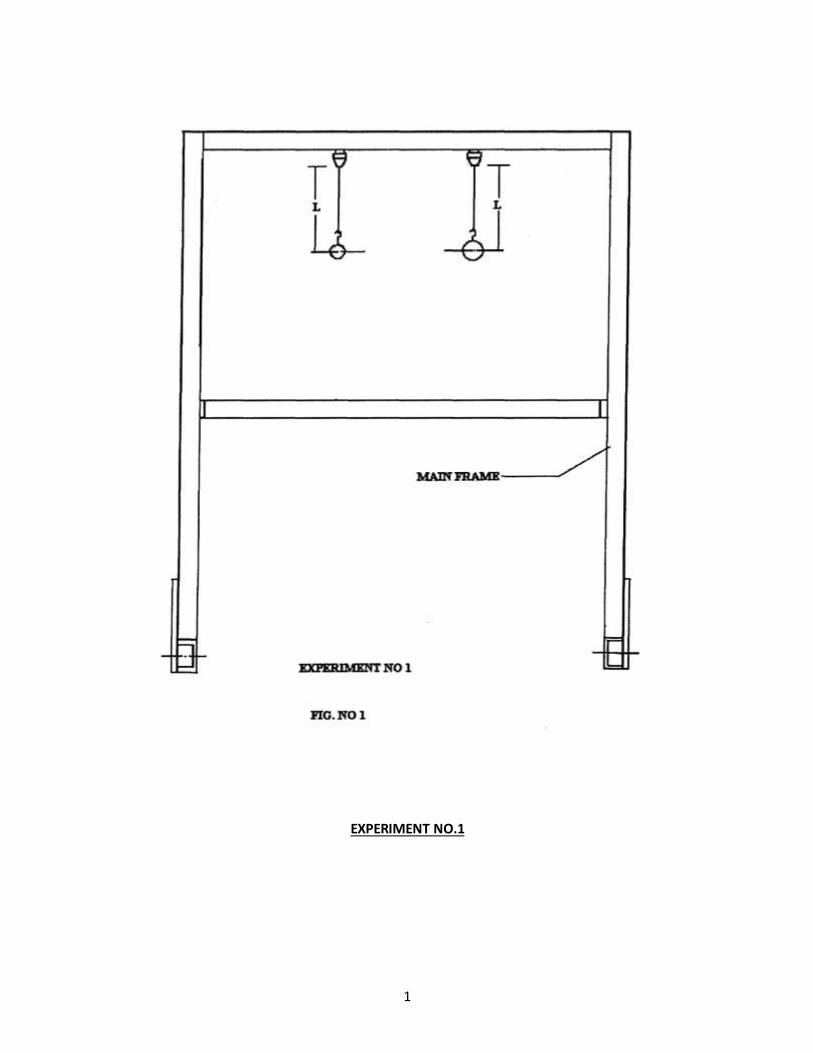
EXPERIMENT NO.1
2
Experiment No 1.
SIMPLE PENDULUM
AIM: To verify the relation.
T = 2π √(𝐥
𝒈)
Where T= Periodic Time in Seconds.
l= Length of Pendulum in cms.
DESCRIPTION OF SET UP :
For conducting the experiment, a bar is supported by nylon thread into the hook. It is
possible to change the length of the pendulum. This makes it possible to study the effect of variation of
length on periodic time.A small ball may be substituted for large ball to illustrate that the period of
oscillation is independent of the mass of ball.
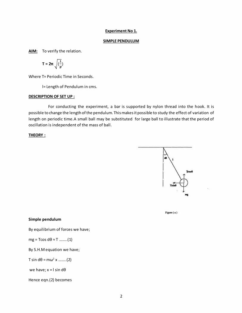
THEORY :
Simple pendulum
By equilibrium of forces we have;
mg = Tcos dθ ≈ T ……..(1)
By S.H.M equation we have;
T sin dθ = mω2 x ……..(2)
we have; x = l sin dθ
Hence eqn.(2) becomes
3
T sin dθ = mω2 l sin dθ
T = mω2 l ……..(3)
From (1) and (3)
mg = mω2 l
ω2 = (g / l) ;ω = √(g/l)
we have ; ω = 2 π / T
Hence,T = 2π √(l
𝑔)
PROCEDURE:
a] Attach each ball to one end of the thread.
b] Allow the ball to oscillate and determine the periodic time T by knowing time ( for say 10 oscillations).
c] Repeat the experiment by changing the length.
d] Complete the observation table given below.
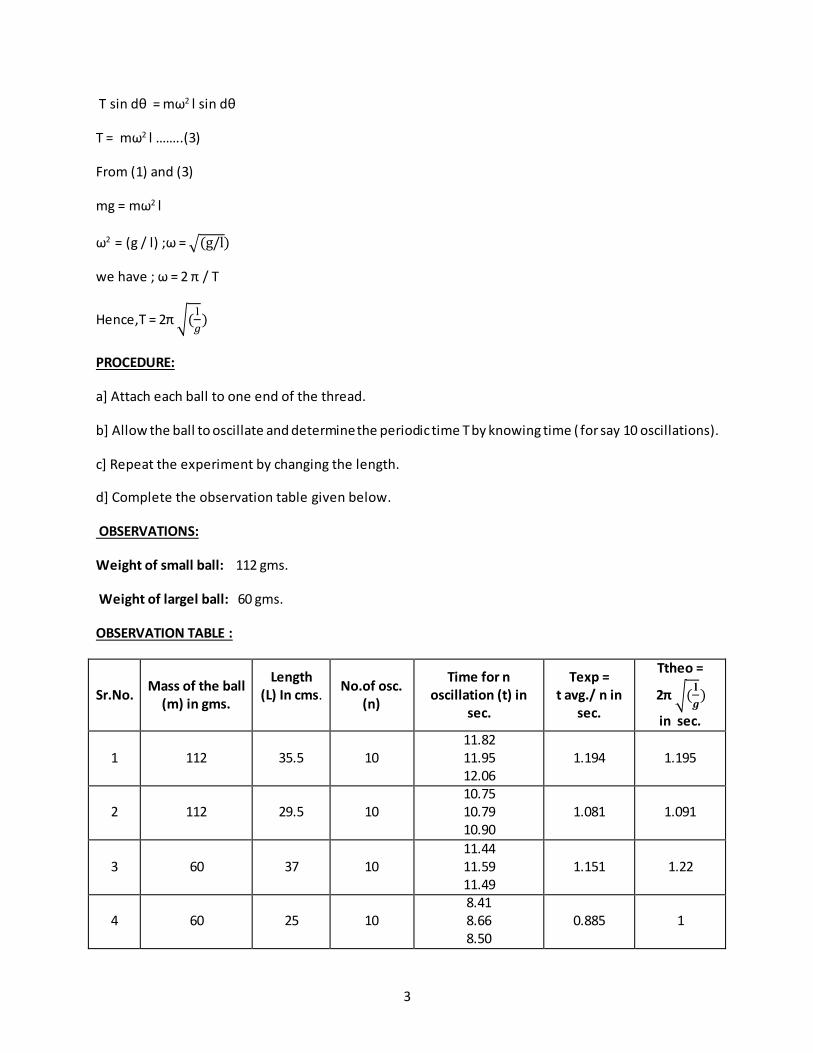
OBSERVATIONS:
Weight of small ball: 112 gms.
Weight of largel ball: 60 gms.
OBSERVATION TABLE :
Sr.No. Mass of the ball
(m) in gms.
Length (L) In cms.
No.of osc. (n)
Time for n oscillation (t) in
sec.
Texp = t avg./ n in
sec.
Ttheo =
2π √(𝐥
𝒈)
in sec.
1 112 35.5 10 11.82 11.95 12.06
1.194 1.195
2 112 29.5 10 10.75 10.79 10.90
1.081 1.091
3 60 37 10 11.44 11.59 11.49
1.151 1.22
4 60 25 10 8.41 8.66 8.50
0.885 1
4
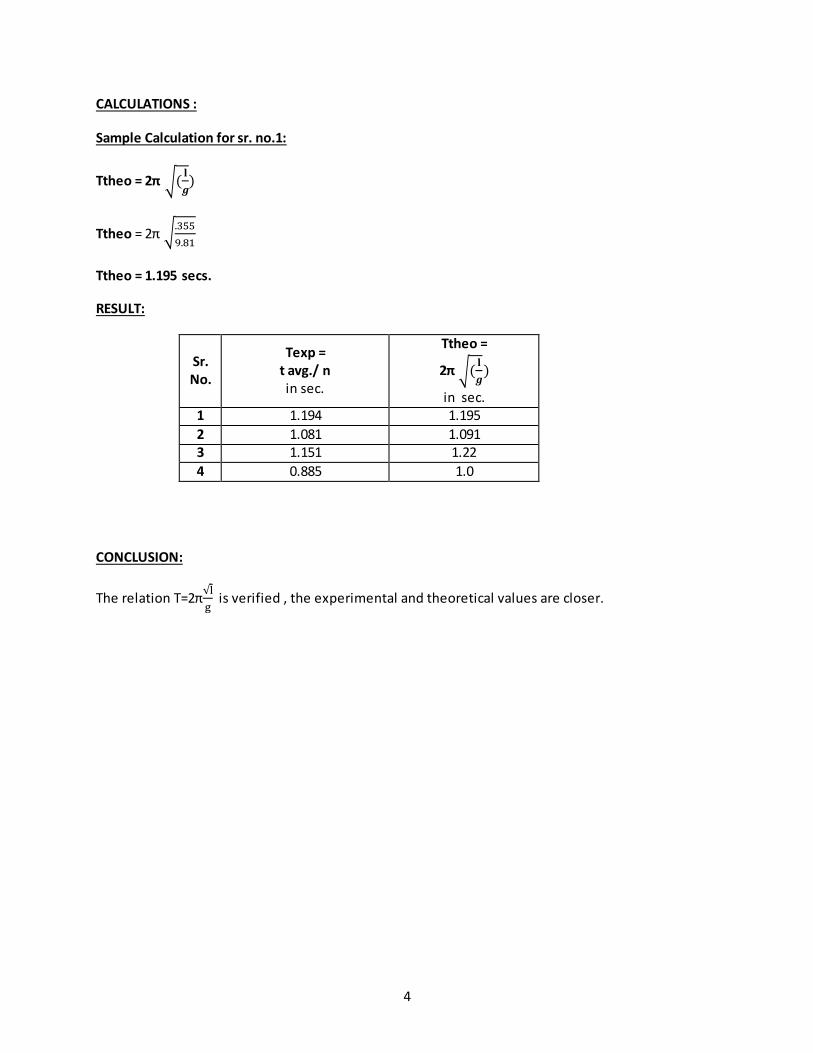
CALCULATIONS :
Sample Calculation for sr. no.1:
Ttheo = 2π √(𝐥
𝒈)
Ttheo = 2π √.355
9.81
Ttheo = 1.195 secs.
RESULT:
Sr. No.
Texp = t avg./ n in sec.
Ttheo =
2π √(𝐥
𝒈)
in sec. 1 1.194 1.195
2 1.081 1.091 3 1.151 1.22
4 0.885 1.0
CONCLUSION:
The relation T=2π√l
g is verified , the experimental and theoretical values are closer.
5
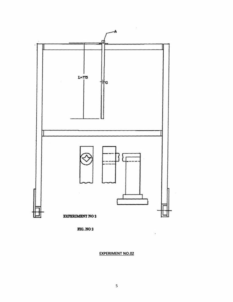
EXPERIMENT NO.02
6
Experiment No 2.
COMPOUND PENDULUM
AIM: To Determine radius of gyration K of given compound pendulum to verify the relation.
T=2π √((𝒌𝟐+𝑶𝑮𝟐) / (g*OG))
Where T= Periodic time in sec.
K=Radius of gyration about C.G in cm.
OG= Distance of CG of rod from support.
L= Length of suspended pendulum in cm.
DISCRIPTION OF SET UP:
The compound pendulum consists of steel bar. The bar is supported in the hole by knife edge.
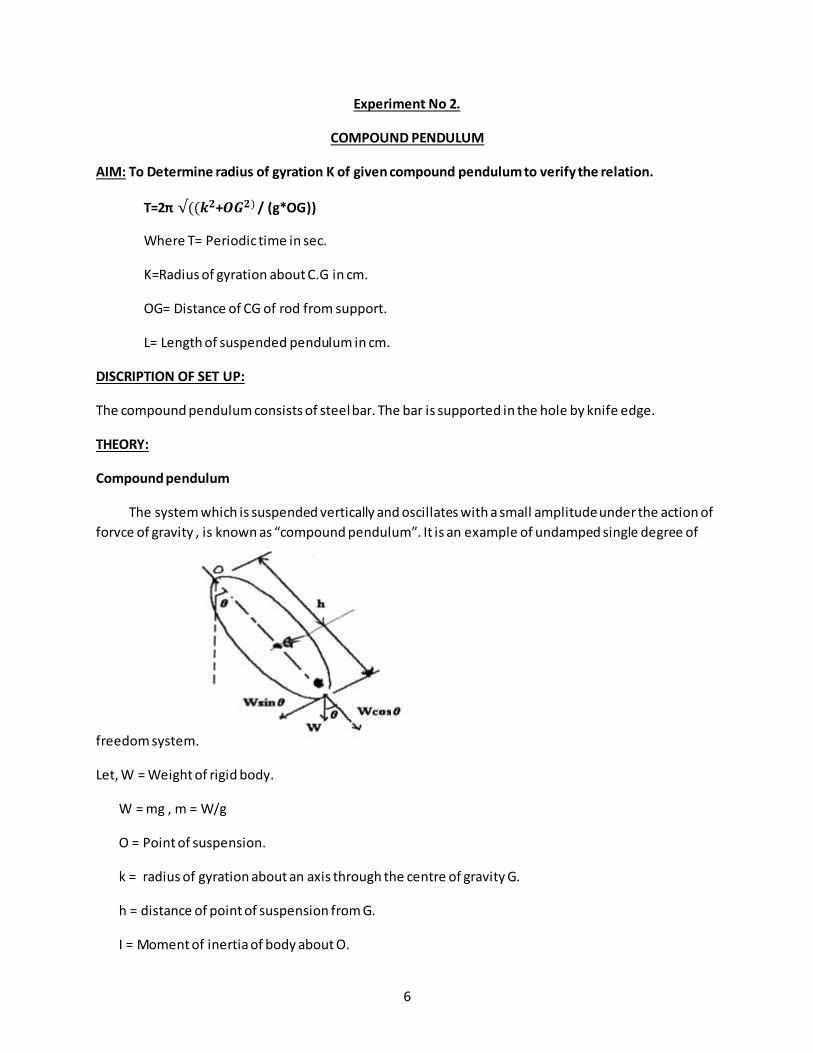
THEORY:
Compound pendulum
The system which is suspended vertically and oscillates with a small amplitude under the action of
forvce of gravity , is known as “compound pendulum”. It is an example of undamped single degree of
freedom system.
Let, W = Weight of rigid body.
W = mg , m = W/g
O = Point of suspension.
k = radius of gyration about an axis through the centre of gravity G.
h = distance of point of suspension from G.
I = Moment of inertia of body about O.
7
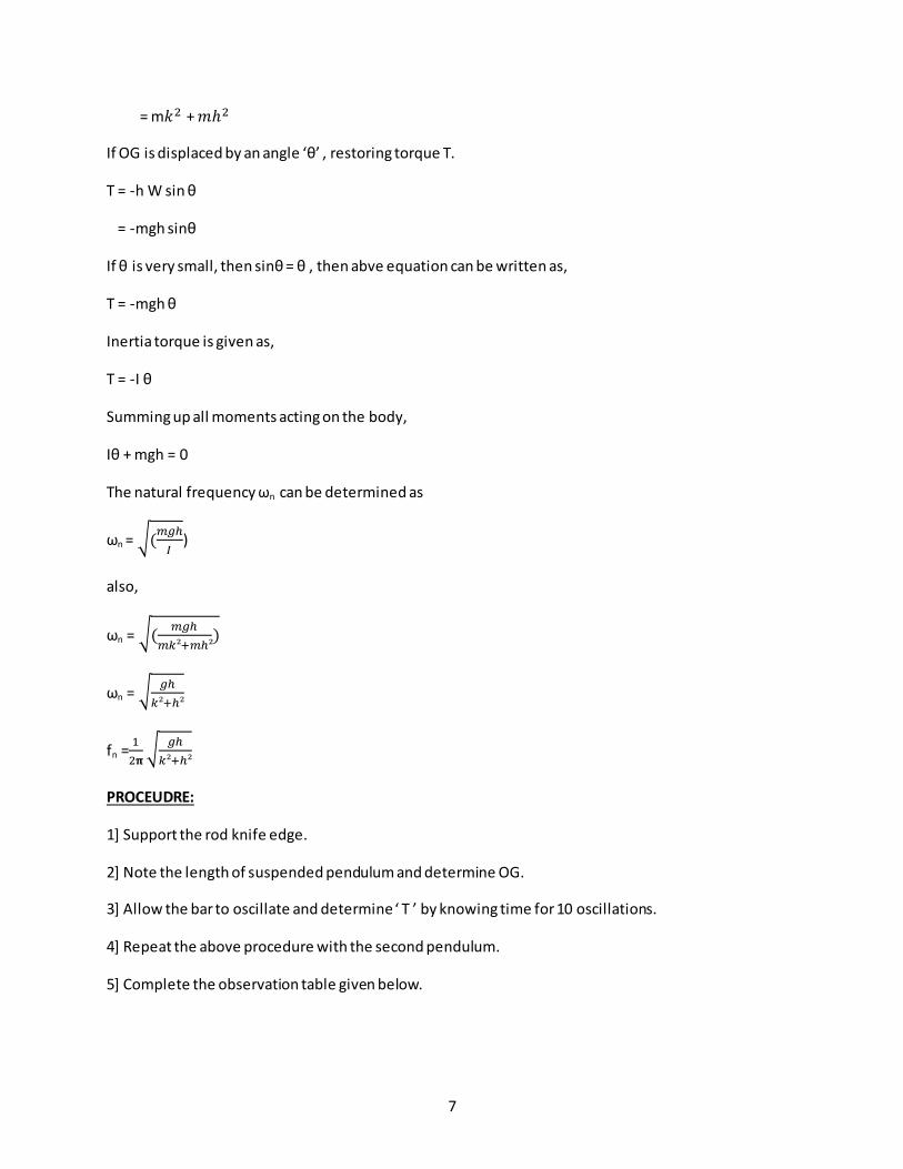
= m𝑘2 + 𝑚ℎ2
If OG is displaced by an angle ‘θ’ , restoring torque T.
T = -h W sin θ
= -mgh sinθ
If θ is very small, then sinθ = θ , then abve equation can be written as,
T = -mgh θ
Inertia torque is given as,
T = -I θ
Summing up all moments acting on the body,
Iθ + mgh = 0
The natural frequency ωn can be determined as
ωn = √(𝑚𝑔ℎ
𝐼)
also,
ωn = √(𝑚𝑔ℎ
𝑚𝑘²+𝑚ℎ²)
ωn = √𝑔ℎ
𝑘²+ℎ²
fn =1
2𝛑 √
𝑔ℎ
𝑘²+ℎ²
PROCEUDRE:
1] Support the rod knife edge.
2] Note the length of suspended pendulum and determine OG.
3] Allow the bar to oscillate and determine ‘ T ’ by knowing time for 10 oscillations.
4] Repeat the above procedure with the second pendulum.
5] Complete the observation table given below.
8
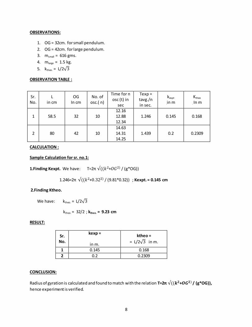
OBSERVATIONS:
1. OG = 32cm. for small pendulum.
2. OG = 42cm. for large pendulum.
3. msmall = 616 gms.
4. mlarge = 1.5 kg.
5. ktheo. = L/2√3
OBSERVATION TABLE :
CALCULATION :
Sample Calculation for sr. no.1:
1.Finding Kexpt. We have: T=2π √((𝑘2+𝑂𝐺2) / (g*OG))
1.246=2π √((𝑘2+0.322) / (9.81*0.32)) ; Kexpt. = 0.145 cm
2.Finding Ktheo.
We have: ktheo. = L/2√3
ktheo. = 32/2 ; ktheo. = 9.23 cm
RESULT:
Sr. No.
kexp =
in m.
ktheo =
= L/2√3 in m.
1 0.145 0.168
2 0.2 0.2309
CONCLUSION:
Radius of gyration is calculated and found to match with the relation T=2π √((𝒌𝟐+𝑶𝑮𝟐) / (g*OG)),
hence experiment is verified.
Sr.No.
L in cm
OG In cm
No. of osc.( n)
Time for n osc (t) in
sec
Texp = tavg./n in sec.
kexpt
.in m Ktheo
. In m
1 58.5 32 10 12.16 12.88 12.34
1.246 0.145 0.168
2 80 42 10 14.63 14.31 14.25
1.439 0.2 0.2309
9
EXPERIMENT NO.3
10
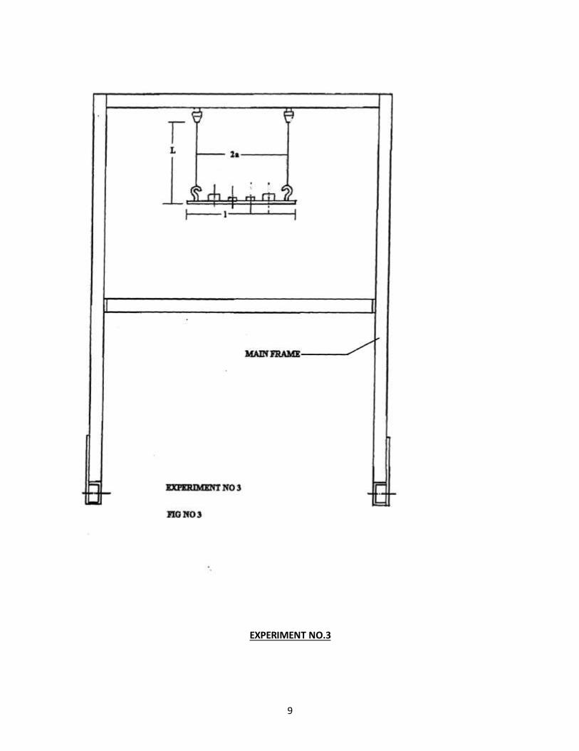
Experiment No 3.
BIFILAR SUSPENSION
AIM:
To determine the radius of gyration of given bar by using bifilar suspension.
DESCRIPTION: OF SET UP:
A uniform rectangular section bar is suspended form the pendulum support frame by two
parallel cords. Top ends of cords are attached to hooks filed at the top. The other ends are secured in the
bifilar bar.It is possible to change the length of cord or decrease its width.
The suspension may also use to determine the radius of gyration of anybody under
investigation the body bolted to the centre. Radius of gyration of the combined bar and body is then
determined.
THEORY:
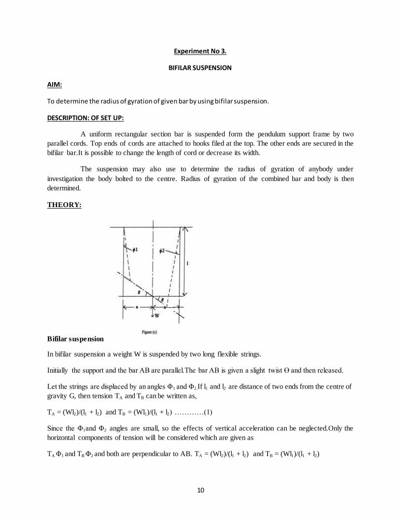
Bifilar suspension
In bifilar suspension a weight W is suspended by two long flexible strings.
Initially the support and the bar AB are parallel.The bar AB is given a slight twist Ɵ and then released.
Let the strings are displaced by an angles Φ1 and Φ2.If l1 and l2 are distance of two ends from the centre of
gravity G, then tension TA and TB can be written as,
TA = (Wl2)/(l1 + l2) and TB = (Wl1)/(l1 + l2) …………(1)
Since the Φ1and Φ2 angles are small, so the effects of vertical acceleration can be neglected.Only the
horizontal components of tension will be considered which are given as
TA Φ1 and TB Φ2 and both are perpendicular to AB. TA = (Wl2)/(l1 + l2) and TB = (Wl1)/(l1 + l2)
11
From the geometry
l1Ɵ = l Φ1 and l2Ɵ = l Φ2
or Φ1 = l1Ɵ / l , Φ2 = l2Ɵ / l ………………(2)
The resisting torque T for the system can be written as
T = TA l1 Φ1 +TB l2 Φ2
=[(Wl2)/(l1 + l2) ]*[(( l1Ɵ) / l)]*l1 + [(Wl1)/(l1 + l2)]*[(( l2Ɵ) / l)]*l2
Substituting TA and TB from (1) and Φ1and Φ2 from (2)
= [(W l2 l1 Ɵ) /(l1 + l2)l]*[( l1 + l2)]
= (W l2 l1 Ɵ)/ l ………..(3)
We know that
T = I α
Where , T = torque
I = Moment of inertia = W k2/ g
α = angular acceleration
k = radius of gyration\
So, α = T/I
= ( (W l2 l1 Ɵ)/ l)/ (W k2/ g)
= (g l2 l1 Ɵ) / l k2……….(4)
We also know that
ω2 = Angular acceleration / Angular Displacement
Where, ω = Angular velocity of AB
ω2 = (g l2 l1 Ɵ) / l k2θ
ω2 = (g l2 l1 ) / l k2
12
Here, l2 = l1= a
ω2 = (g a2 ) / l k
2
ω = (a/k)√(𝑔/𝑙)
We have ω = 2π/T
Hence T = 2π *(k/a)√(𝒍/𝒈) ………(5)
PROCEDURE:
1] Suspend the bar form hook. The suspension length of each cord must be the same.
2] Allow the bar to oscillate about the vertical axis passing through the center & measure the periodic
time‘t’ by knowing time say for 10 oscillations.
3] Repeat expt. by mounting the weight at equal distance form center.
4] Complete the observation table.
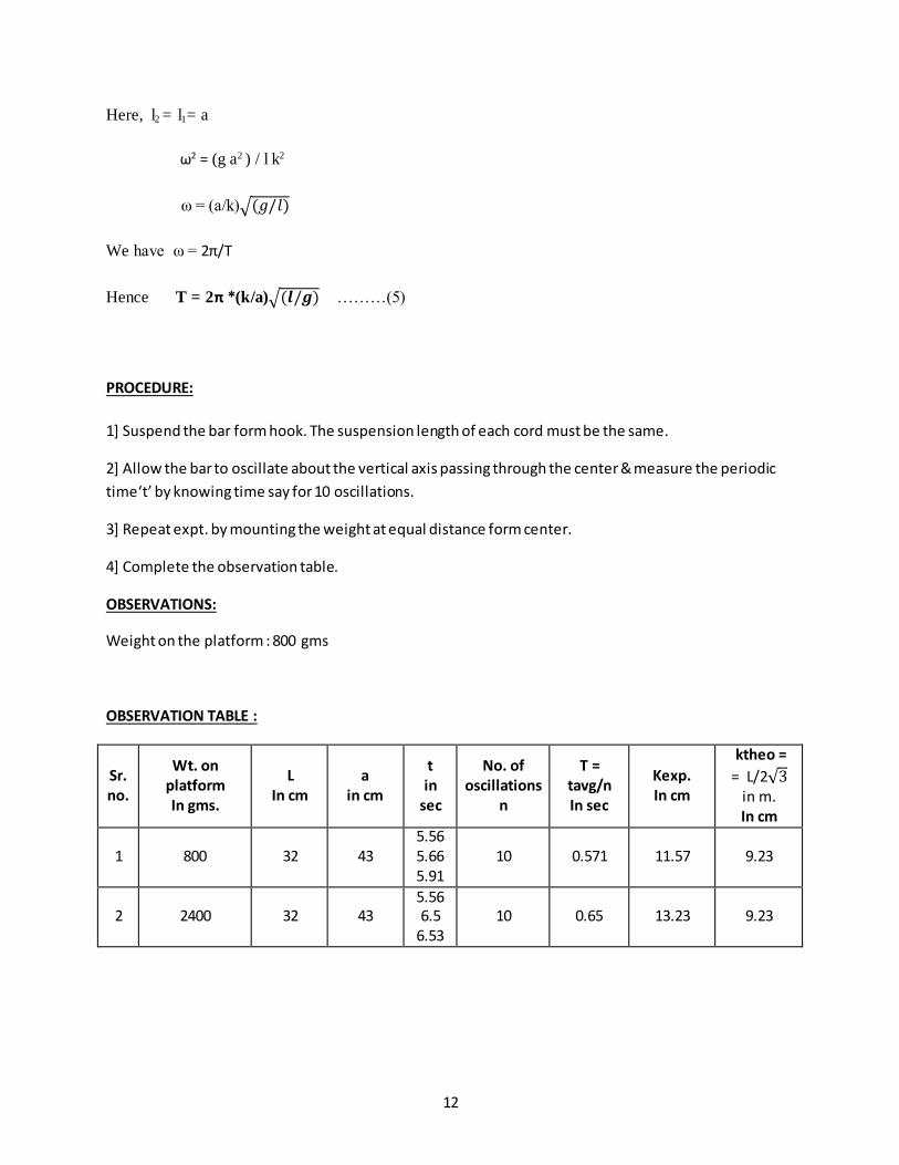
OBSERVATIONS:
Weight on the platform : 800 gms
OBSERVATION TABLE :
Sr. no.
Wt. on platform In gms.
L In cm
a in cm
t in
sec
No. of oscillations
n
T = tavg/n In sec
Kexp. In cm
ktheo =
= L/2√3 in m. In cm
1 800 32 43 5.56 5.66 5.91
10 0.571 11.57 9.23
2 2400 32 43 5.56 6.5
6.53 10 0.65 13.23 9.23
13
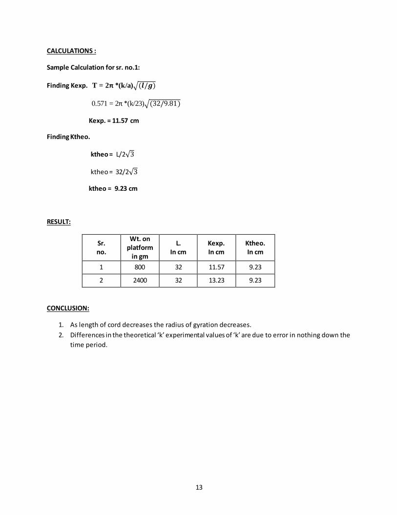
CALCULATIONS :
Sample Calculation for sr. no.1:
Finding Kexp. T = 2π *(k/a)√(𝒍/𝒈)
0.571 = 2π *(k/23)√(32/9.81)
Kexp. = 11.57 cm
Finding Ktheo.
ktheo = L/2√3
ktheo = 32/2√3
ktheo = 9.23 cm
RESULT:
Sr. no.
Wt. on platform
in gm
L. In cm
Kexp. In cm
Ktheo. In cm
1 800 32 11.57 9.23
2 2400 32 13.23 9.23
CONCLUSION:
1. As length of cord decreases the radius of gyration decreases.
2. Differences in the theoretical ‘k’ experimental values of ‘k’ are due to error in nothing down the
time period.
14
EXPERIMENT NO.4
15
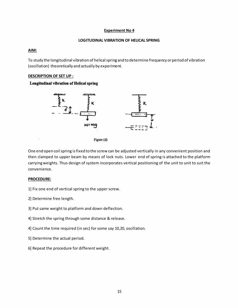
Experiment No 4
LOGITUDINAL VIBRATION OF HELICAL SPRING
AIM:
To study the longitudinal vibration of helical spring and to determine frequency or period of vibration
(oscillation) theoretically and actually by experiment.
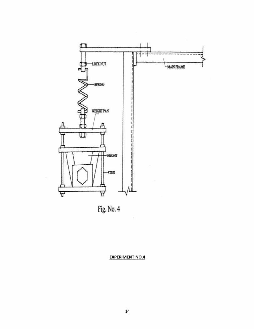
DESCRIPTION OF SET UP :
One end open coil spring is fixed to the screw can be adjusted vertically in any convenient position and
then clamped to upper beam by means of lock nuts. Lower end of spring is attached to the platform
carrying weights. Thus design of system incorporates vertical positioning of the unit to unit to suit the
convenience.
PROCEDURE:
1] Fix one end of vertical spring to the upper screw.
2] Determine free length.
3] Put same weight to platform and down deflection.
4] Stretch the spring through some distance & release.
4] Count the time required (in sec) for some say 10,20, oscillation.
5] Determine the actual period.
6] Repeat the procedure for different weight.

16
OBSERVATIONS:
Weight on the platform : 800 gms
OBSERVATION TABLE 1 :
Spring no. Wt attached (kg) Deflection of spring
In cm (ᵟ) K = W/ᵟ In kg/cm
1 6 1.5 4 2 6 11.5 0.5
OBSERVATION TABLE 2
Spring no. Obs. No. Wt attached
W in Kg
No. of oscillations
n
Time required for n oscillation
sec
Periodic time Texpt =tavg/n in
sec.
Ttheo In sec
1
1 3 10 2.47 2.53 2.32
0.243 0.174
2 6 10 3.37 3.19 3.06
0.3 0.246
2
1 3 10 5.32 5.30
5.285 0.525 0.4916
2 6 10 6.97 7.03 6.88
0.69 0.695
CALCULATIONS:
Sample Calculation for sr. no.1:
1.Finding K
K = W/ᵟ
K = 6/1.5
K = 4 kg/cm
2.Finding Ttheo.;
Ttheo = 2π √𝑤/ km*g
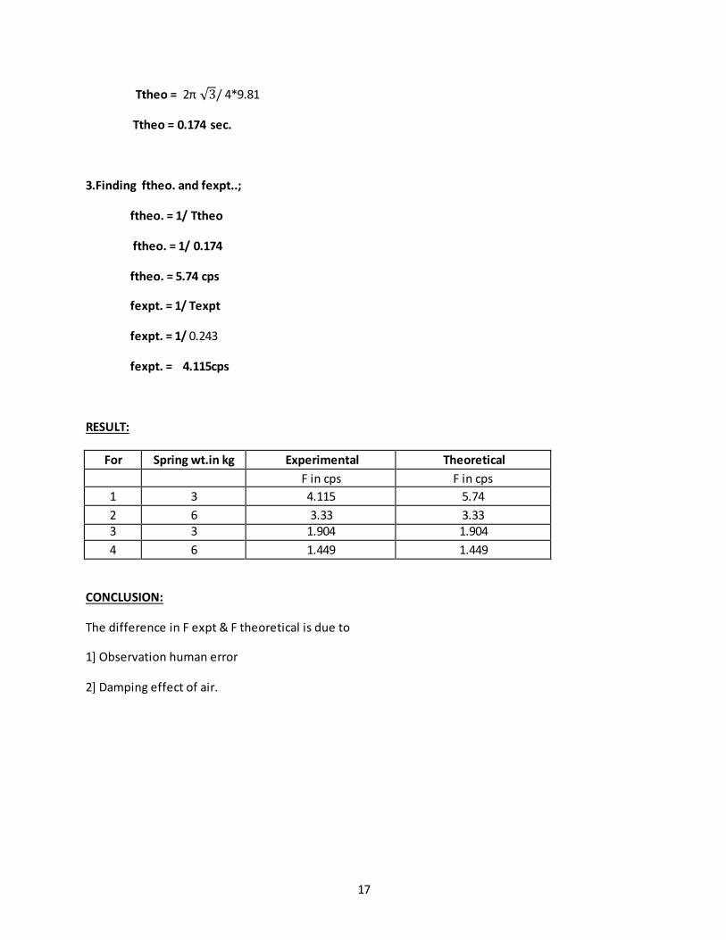
17
Ttheo = 2π √3/ 4*9.81
Ttheo = 0.174 sec.
3.Finding ftheo. and fexpt..;
ftheo. = 1/ Ttheo
ftheo. = 1/ 0.174
ftheo. = 5.74 cps
fexpt. = 1/ Texpt
fexpt. = 1/ 0.243
fexpt. = 4.115cps
RESULT:
For Spring wt.in kg Experimental Theoretical
F in cps F in cps
1 3 4.115 5.74
2 6 3.33 3.33 3 3 1.904 1.904
4 6 1.449 1.449
CONCLUSION:
The difference in F expt & F theoretical is due to
1] Observation human error
2] Damping effect of air.
18
EXPERIMENT NO. 5.
19
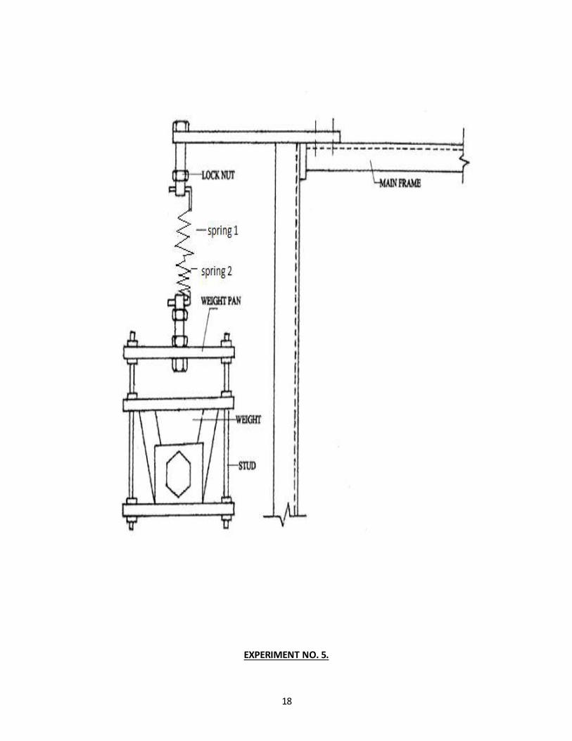
Experiment No 5.
Springs in Series
AIM:
To study the vibration of system having spring in series.
DESCRIPTION OF SET UP:
Fig .shows the general arrangement of experiment setup. It’s consist of fixed support of which there is
hole where spring can be attached through the hook.
THEORY:
Spring in Series:
Let Ke =Equivalent stiffness of system
K1,K2 =Deflection of spring.
The total definition of the system is equal to the sum of deflection of individual springs.
X =X1 + X2 +X3 +----- 1
𝐾𝑒 =
1
𝐾1 +
1
𝐾2 +
1
𝐾3 + ------------
Thus the springs are connected in series the reciprocal of equivalent spring stiffness is equal to the sum
of reciprocal of individual spring stuffiness.
PROCEDURE:
1. first the tension spring is attached is attached to the support with load no attached to it and it’s
length is measure (pitch).
2. Then dead wt is attached to that spring with the help of hook and again length is measured.
3. Same procedure is applied for the spring 2 of different stiffness.
4. Then spring i.e spring 1 and spring 2 connected in series and length is measured then dead wt.
is attached to spring and length is measured.
Observations:
For Spring 1:
Initial pitch = 8mm
Final pitch (with load) = 11mm Load = 1.5kg
Deflection = 3mm
20
For Spring 2:
Initial pitch = 7mm
Final pitch (with load) = 8.5mm Load = 4.872kg
Deflection = 1.5mm
For Springs in series:
Initial length = 24cm
Final length(with load) = 27.8cm Load = 1.5kg
Deflection = 3.8cm
CALCULATIONS:
For Spring 1:
K1 = Load*9.81/defn
K1 = 1.5*9.81/0.003
K1 = 4905 N/m
For Spring 2:
K2 = Load*9.81/defn
K2 = 4.872*9.81/0.0015
K2 = 31862.88 N/m
For Springs in series:
Kexpt = Load*9.81/defn ωnexpt = √Kexpt /m
Kexpt = 1.5*9.81/0.038 ωnexpt = √3872.4 /1.5
Kexpt =3872.4 N/m ωnexpt = 50.8 rad/sec.
1/Ktheo = 1/k1 +1/k2 ωnexpt = √Kexpt /m
Ktheo = 4250.65N /m ωnexpt = 53.28 rad/sec.

21
RESULT:
Kexp =3872.4 N/m , Wexp = 50.81 rad/sec
K th = 4250.66 N/m, W th = 53.28 rad/sec
CONCLUSION:
The theoretical and experimental value of equivalent stiffness were found to almost equal.
22
Experiment No 6.
23
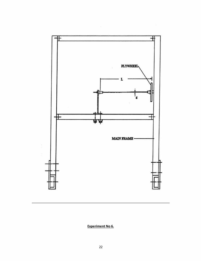
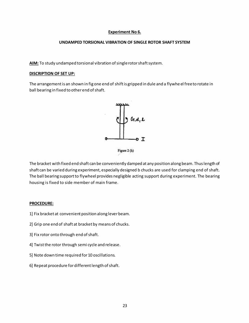
Experiment No 6.
UNDAMPED TORSIONAL VIBRATION OF SINGLE ROTOR SHAFT SYSTEM
AIM: To study undamped torsional vibration of single rotor shaft system.
DISCRIPTION OF SET UP:
The arrangement is an shown in fig one end of shift is gripped in dule and a flywhe el free to rotate in
ball bearing in fixed to other end of shaft.
The bracket with fixed end shaft can be conveniently damped at any position along beam. Thus length of
shaft can be varied during experiment, especially designed b chucks are used for clamping end of shaft.
The ball bearing support to flywheel provides negligible acting support during experiment. The bearing
housing is fixed to side member of main frame.
PROCEDURE:
1] Fix bracket at convenient position along lever beam.
2] Grip one end of shaft at bracket by means of chucks.
3] Fix rotor onto through end of shaft.
4] Twist the rotor through semi cycle and release.
5] Note down time required for 10 oscillations.
6] Repeat procedure for different length of shaft.
24
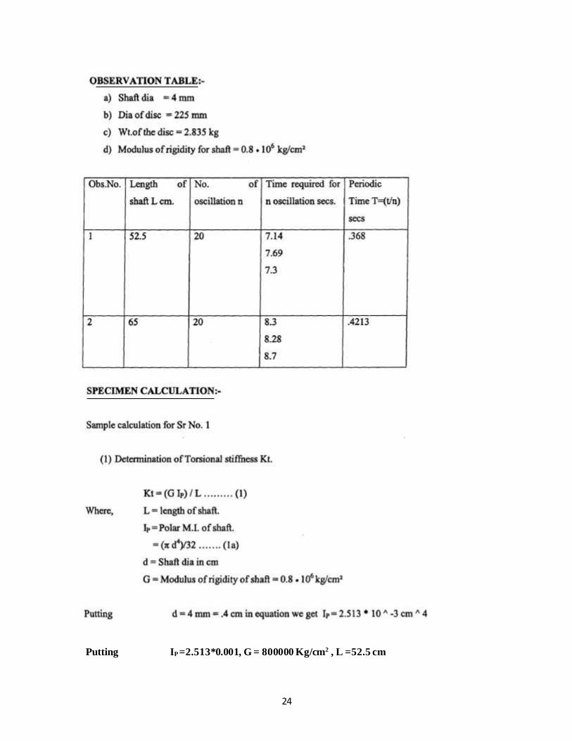
Putting IP =2.513*0.001, G = 800000 Kg/cm2 , L =52.5 cm
25
26
Experiment No 7.
27
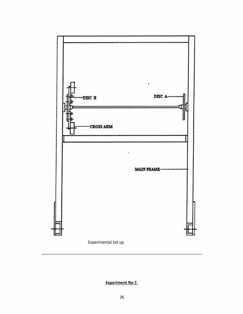
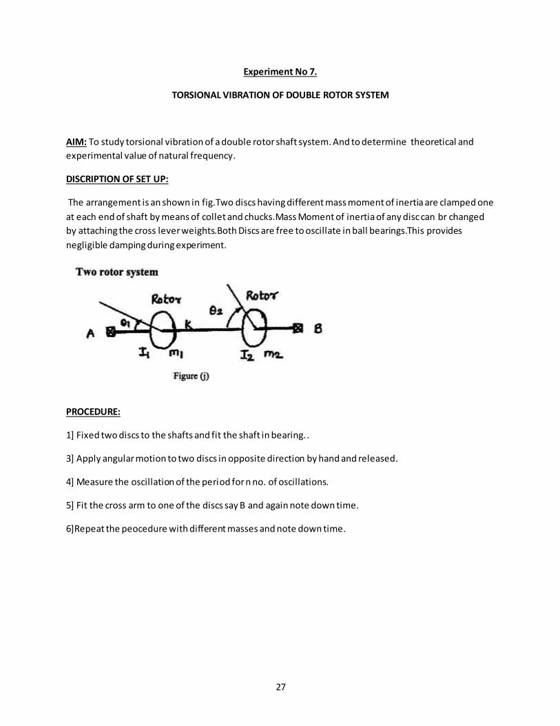
Experiment No 7.
TORSIONAL VIBRATION OF DOUBLE ROTOR SYSTEM
AIM: To study torsional vibration of a double rotor shaft system. And to determine theoretical and
experimental value of natural frequency.
DISCRIPTION OF SET UP:
The arrangement is an shown in fig.Two discs having different mass moment of inertia are clamped one
at each end of shaft by means of collet and chucks.Mass Moment of inertia of any disc can br changed
by attaching the cross lever weights.Both Discs are free to oscillate in ball bearings.This provides
negligible damping during experiment.
PROCEDURE:
1] Fixed two discs to the shafts and fit the shaft in bearing..
3] Apply angular motion to two discs in opposite direction by hand and released.
4] Measure the oscillation of the period for n no. of oscillations.
5] Fit the cross arm to one of the discs say B and again note down time.
6]Repeat the peocedure with different masses and note down time.
28
29

30
CONCLUSION:
Different in practical and theoretical time period due to
1] Human error
2] Damping factor
3] Slip
31
Experiment No .8
32
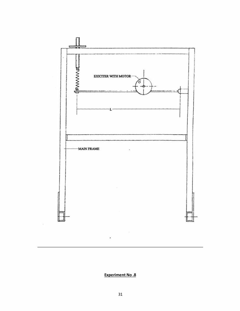
Experiment No .8
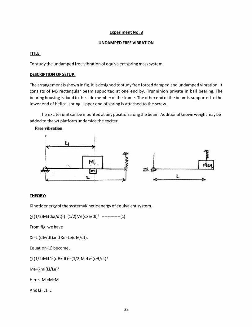
UNDAMPED FREE VIBRATION
TITLE:
To study the undamped free vibration of equivalent spring mass system.
DESCRIPTION OF SETUP:
The arrangement is shown in fig. it is designed to study free forced damped and undamped vibration. It
consists of MS rectangular beam supported at one end by. Trunninion private in ball bearing. The
bearing housing is fixed to the side member of the frame. The other end of the beam is supported to the
lower end of helical spring. Upper end of spring is attached to the screw.
The exciter unit can be mounted at any position along the beam. Additional known weight may be
added to the wt platform underside the exciter.
THEORY:
Kinetic energy of the system=Kinetic energy of equivalent system.
∑((1/2)Mi(dxi/dt)2)=(1/2)Me(dxe/dt)2 -------------(1)
From fig, we have
Xi=Li(dӨ/dt)and Xe=Le(dӨ /dt).
Equation (1) become,
∑((1/2)MiL12(dӨ/dt)2=(1/2)MeLe2(dӨ/dt)2
Me=∑mi(Li/Le)2
Here. Mi=M+M.
And Li=L1=L

33
Meq=(M+M)*(L1/L)2
And now doing similar analysis as in above analysis.
PROCEDURE:
1] Support one end of the beam in the slat of trunion and clamp it by a means of screw.
2] Attach the other end of beam to the lower end of spring.
3] Adjust the screw to which the spring is attached. Such that the beam is horizontally in the above
position.
4] Weight the exciter assembly along with disc &bearing end weight platform.
5] Clamp the assembly at any convenient position.
6] Measure the distance L1 of the assembly from private.
7] Measure the time for any IOsec and find the periodic time and nature frequency.
8] Repeat the experiment by varying L1 and by potting different weight on the platform.
34
CONCLUSION: Undamped vibrations of equivalent spring mass system was studied.
35
Experiment No 09
36
Experiment No 09.
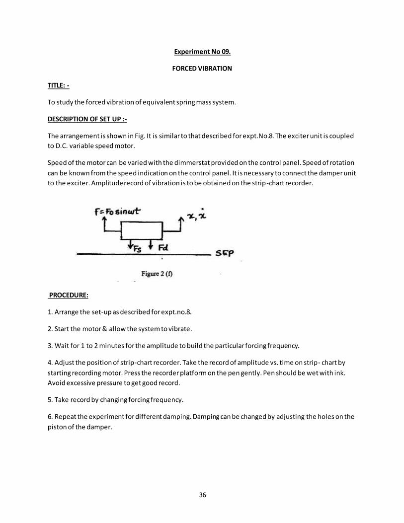
FORCED VIBRATION
TITLE: -
To study the forced vibration of equivalent spring mass system.
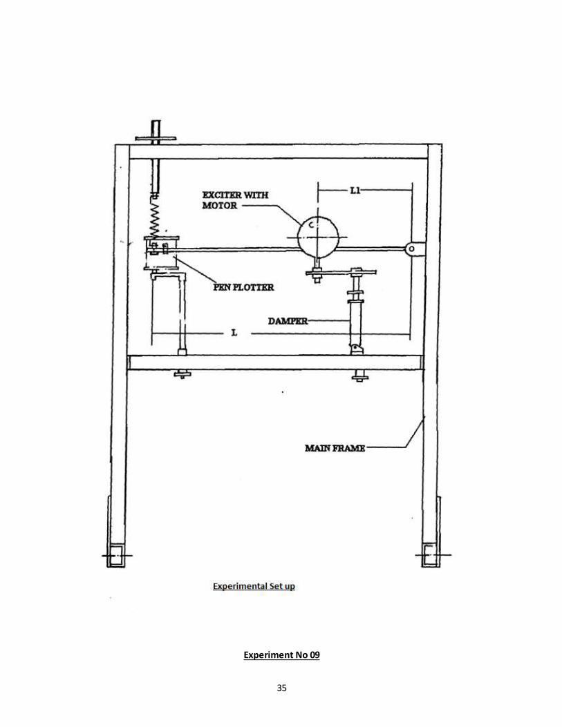
DESCRIPTION OF SET UP :-
The arrangement is shown in Fig. It is similar to that described for expt.No.8. The exciter unit is coupled
to D.C. variable speed motor.
Speed of the motor can be varied with the dimmerstat provided on the control panel. Speed of rotation
can be known from the speed indication on the control panel. It is necessary to connect the damper unit
to the exciter. Amplitude record of vibration is to be obtained on the strip-chart recorder.
PROCEDURE:
1. Arrange the set-up as described for expt.no.8.
2. Start the motor & allow the system to vibrate.
3. Wait for 1 to 2 minutes for the amplitude to build the particular forcing frequency.
4. Adjust the position of strip-chart recorder. Take the record of amplitude vs. time on strip- chart by
starting recording motor. Press the recorder platform on the pen gently. Pen should be wet with ink.
Avoid excessive pressure to get good record.
5. Take record by changing forcing frequency.
6. Repeat the experiment for different damping. Damping can be changed by adjusting the holes on the
piston of the damper.
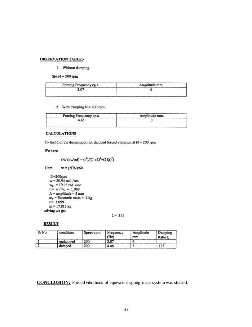
37
CONCLUSION: Forced vibrations of equivalent spring mass system was studied.
38
Experiment No 10.
39
Experiment No 10.
DAMPED TORSIONAL VIBRATION
AIM:
To study damped torsional oscillation and determine damping coefficient.
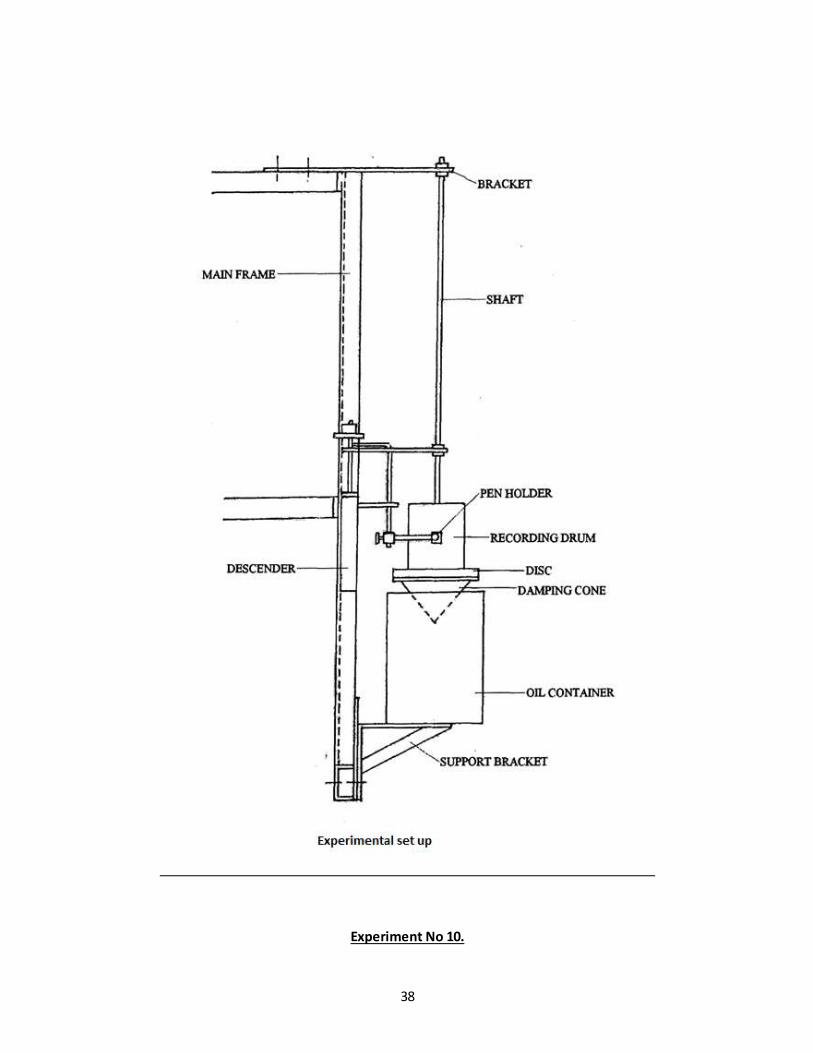
DESCRIPTION OF SET UP:
The fig shows general arrangement for experiment. It consists of long elastic shaft gripped at upper end
by chuck in bracket. The bracket is clamped to upper beam of main frame. A heavy flywheel Clamped to
lower end of shaft suspended from bracket, this drum is immersed in oil which provides damping. Rotor
can be taken up and down for varying depth of immersion of damping drum, depth of immersion can be
read on scale.
PROCEDURE:
1] With no container allow flywheel to oscillate and measure time for 10 Oscillations.
2] Put thin mineral oil in drum and note depth of immersion.
3] Allow flywheel to vibrate.
4] Put sketching pen in bucket.
5] Allow pen to descend see that pen always makes contact with paper and record oscillations.
6] Measure time for some oscillations by means of stop watch.
7] Determine amplitudes of any positions.
OBSERVATION TABLE:
Sr. no.
Damping medium Xn Xn+1
1 Air 1.4 1.3
2 Water 1.15 0.6 3 Oil 1 0.6
40
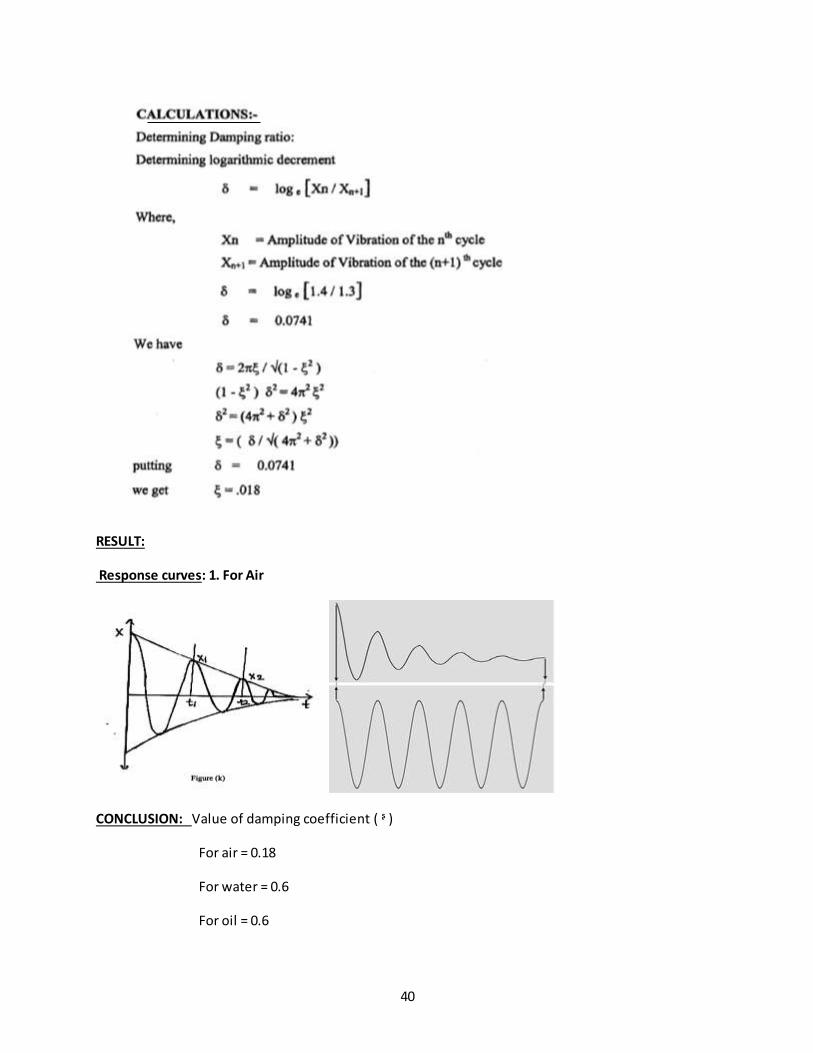
RESULT:
Response curves: 1. For Air
CONCLUSION: Value of damping coefficient ( ᶳ )
For air = 0.18
For water = 0.6
For oil = 0.6
41
Experiment No 11.
42
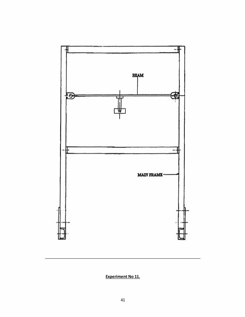
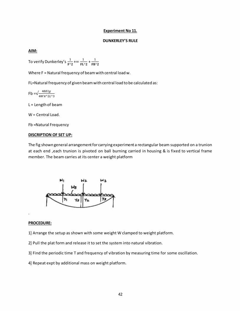
Experiment No 11.
DUNKERLEY’S RULE
AIM:
To verify Dunkerley’s 1
𝐅^𝟐 +=
1
𝐅𝐋^𝟐 +
1
𝐅𝐁^𝟐
Where F = Natural frequency of beam with central load w.
FL=Natural frequency of given beam with central load to be calculated as:
Fb =√48𝐸𝐼𝑔
4𝑊𝜋^2𝐿^3
L = Length of beam
W = Central Load.
Fb =Natural Frequency
DISCRIPTION OF SET UP:
The fig shown general arrangement for carrying experiment a rectangular beam supported on a trunion
at each end ,each trunion is pivoted on ball burning carried in housing & is fixed to vertical frame
member. The beam carries at its center a weight platform
.
PROCEDURE:
1] Arrange the setup as shown with some weight W clamped to weight platform.
2] Pull the plat form and release it to set the system into natural vibration.
3] Find the periodic time T and frequency of vibration by measuring time for some oscillation.
4] Repeat expt by additional mass on weight platform.
43
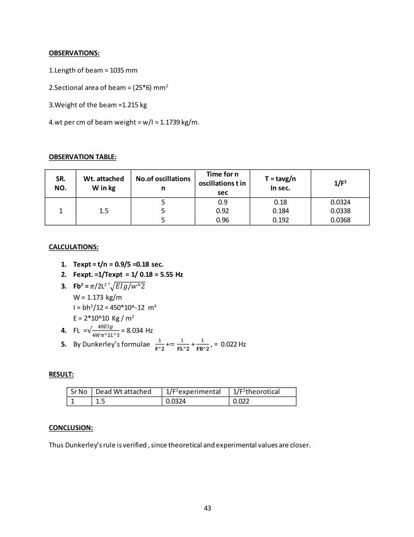
OBSERVATIONS:
1.Length of beam = 1035 mm
2.Sectional area of beam = (25*6) mm2
3.Weight of the beam =1.215 kg
4.wt per cm of beam weight = w/l = 1.1739 kg/m.
OBSERVATION TABLE:
SR. NO.
Wt. attached W in kg
No.of oscillations n
Time for n oscillations t in
sec
T = tavg/n In sec.
1/F2
1 1.5 5 5 5
0.9 0.92 0.96
0.18 0.184 0.192
0.0324 0.0338 0.0368
CALCULATIONS:
1. Texpt = t/n = 0.9/5 =0.18 sec.
2. Fexpt. =1/Texpt = 1/ 0.18 = 5.55 Hz
3. Fb2 = 𝜋/2L2 *√𝐸𝐼𝑔/𝑤^2
W = 1.173 kg/m
I = bh3/12 = 450*10^-12 m4
E = 2*10^10 Kg / m2
4. FL =√48𝐸𝐼𝑔
4𝑊𝜋^2𝐿^3 = 8.034 Hz
5. By Dunkerley’s formulae 1
𝐅^𝟐 +=
1
𝐅𝐋^𝟐 +
1
𝐅𝐁^𝟐 , = 0.022 Hz
RESULT:
Sr No Dead Wt attached 1/F2experimental 1/F2theorotical
1 1.5 0.0324 0.022
CONCLUSION:
Thus Dunkerley’s rule is verified , since theoretical and experimental values are closer.
44
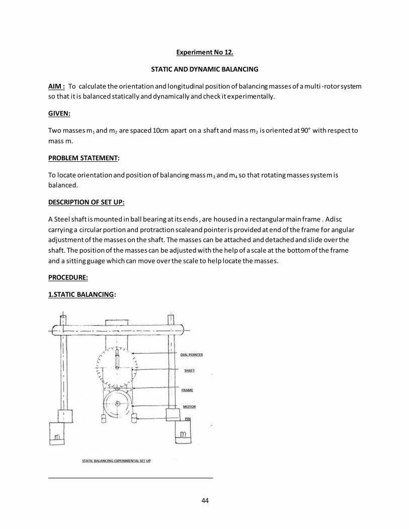
Experiment No 12.
STATIC AND DYNAMIC BALANCING
AIM : To calculate the orientation and longitudinal position of balancing masses of a multi -rotor system
so that it is balanced statically and dynamically and check it experimentally.
GIVEN:
Two masses m1 and m2 are spaced 10cm apart on a shaft and mass m2 is oriented at 90° with respect to
mass m.
PROBLEM STATEMENT:
To locate orientation and position of balancing mass m3 and m4 so that rotating masses system is
balanced.
DESCRIPTION OF SET UP:
A Steel shaft is mounted in ball bearing at its ends , are housed in a rectangular main frame . Adisc
carrying a circular portion and protraction scaleand pointer is provided at end of the frame for angular
adjustment of the masses on the shaft. The masses can be attached and detached and slide over the
shaft. The position of the masses can be adjusted with the help of a scale at the bottom of the frame
and a sitting guage which can move over the scale to help locate the masses.
PROCEDURE:
1.STATIC BALANCING:
45
Remove the drive belt. Unlock the frame from chain to clamp it to the main frame at its top , by means
of nut and bolt arrangement.The value of (m-r) for each block is determined by clamping each block in
turn of shaft.
Here, m = mass of block
r = eccentricity of c.g of block from the axis rotation.
Moment due towt. Of steel bolts = Moment due to wt. of block
FOR STATIC BALANCING, Σmω2r = 0
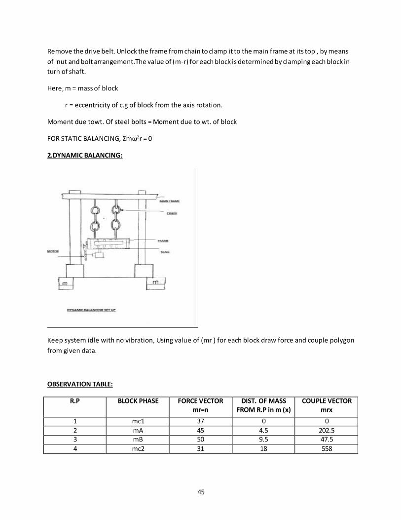
2.DYNAMIC BALANCING:
Keep system idle with no vibration, Using value of (mr ) for each block draw force and couple polygon
from given data.
OBSERVATION TABLE:
R.P BLOCK PHASE FORCE VECTOR mr=n
DIST. OF MASS FROM R.P in m (x)
COUPLE VECTOR mrx
1 mc1 37 0 0
2 mA 45 4.5 202.5 3 mB 50 9.5 47.5
4 mc2 31 18 558
46
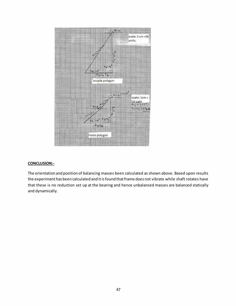
CALCULATIONS:
1.COUPLE POLYGON:
mA.rA.xA= 202.5, ΘA = 0°
mB.rB.xB= 475, ΘB = 90°
From graph,
mc2.rc2.lc2 = 550
mc2.rc2.50 = 550
mc2.rc2 =31
2.FORCE POLYGON:
mA.rA.= 45, ΘA = 0°
mB.rB= 50, ΘB = 90°
From graph,
mc2.rc2. = 31 , Θc2 = 235°
RESULT:
Mass m Angle of orientation w.r.to
x-axis
mr=n = no. of balls POSITION OF MASSES FROM
R.P in m (x)
mc1 0 37 0
mA 90 45 4.5 mB 215 50 9.5
mc2 236 31 18
47
CONCLUSION:-
The orientation and position of balancing masses been calculated as shown above. Based upon results
the experiment has been calculated and it is found that frame does not vibrate while shaft rotates have
that these is no reduction set up at the bearing and hence unbalanced masses are balanced statically
and dynamically.