Embed Size (px)
Citation preview
Part 1: Simplified camera calibration
Shengzhe Li
CVLab, Inha Univ.
2014. 6.
Problem
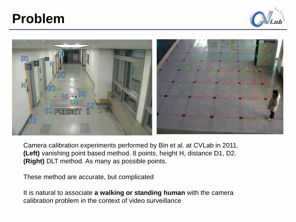
Camera calibration experiments performed by Bin et al. at CVLab in 2011.
(Left) vanishing point based method. 8 points, height H, distance D1, D2.
(Right) DLT method. As many as possible points.
These method are accurate, but complicated
It is natural to associate a walking or standing human with the camera
calibration problem in the context of video surveillance
Calibration by walking human
• Lv, F., Zhao, T., Nevatia, R.: Self-calibration of a camera from video of a walking
human. In: International Conference on Pattern Recognition (ICPR). Volume 1. (2002)
562–567
• Lv, F., Zhao, T., Nevatia, R.: Camera calibration from video of a walking human. IEEE
Trans Pattern Anal Mach Intell 28 (2006) 1513–1518
• Krahnstoever, N., Mendonca, P.R.: Bayesian autocalibration for surveillance. In:
International Conference on Computer Vision (ICCV). (2005)
• Junejo, I., Foroosh, H.: Robust auto-calibration from pedestrians. In: IEEE
International Conference on Video and Signal Based Surveillance (AVSS). (2006)
• Liu, J., Collins, R.T., Liu, Y.: Surveillance camera autocalibration based on pedestrian
height distributions. In: British Machine Vision Conference, Dundee. (2011)
• Liu, J., Collins, R.T., Liu, Y.: Robust autocalibration for a surveillance camera network.
In: IEEE Workshop on Applications of Computer Vision (WACV). (2013) 433–440
Lv et al. 2002, 2006
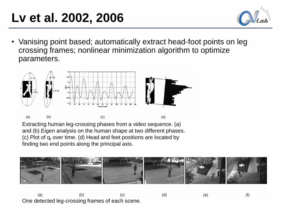
• Vanising point based; automatically extract head-foot points on leg crossing frames; nonlinear minimization algorithm to optimize parameters.
One detected leg-crossing frames of each scene.
Extracting human leg-crossing phases from a video sequence. (a)
and (b) Eigen analysis on the human shape at two different phases.
(c) Plot of qt over time. (d) Head and feet positions are located by
finding two end points along the principal axis.
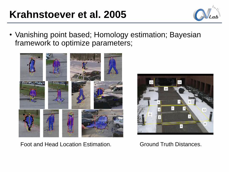
Krahnstoever et al. 2005
• Vanishing point based; Homology estimation; Bayesian framework to optimize parameters;
Foot and Head Location Estimation. Ground Truth Distances.
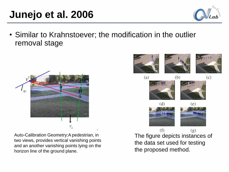
Junejo et al. 2006
• Similar to Krahnstoever; the modification in the outlier removal stage
The figure depicts instances of
the data set used for testing
the proposed method.
Auto-Calibration Geometry:A pedestrian, in
two views, provides vertical vanishing points
and an another vanishing points lying on the
horizon line of the ground plane.
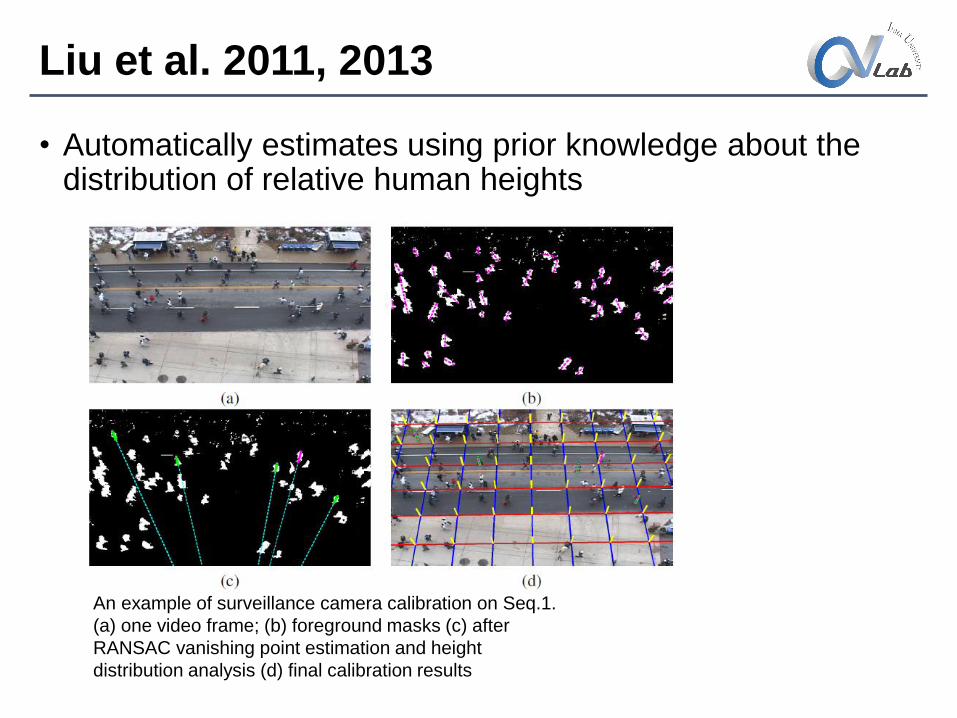
Liu et al. 2011, 2013
• Automatically estimates using prior knowledge about the distribution of relative human heights
An example of surveillance camera calibration on Seq.1.
(a) one video frame; (b) foreground masks (c) after
RANSAC vanishing point estimation and height
distribution analysis (d) final calibration results
Papers on height estimation
• Lee, K.Z.: A simple calibration approach to single view height estimation. In: IEEE
Conference on Computer and Robot Vision (CRV). (2012) 161–166
• Gallagher, A.C., Blose, A.C., Chen, T.: Jointly estimating demographics and height with a
calibrated camera. In: International Conference on Computer Vision (ICCV). (2009) 1187–
1194
• Kispl, I., Jeges, E.: Human height estimation using a calibrated camera. In: IEEE
Conference on Computer Vision and Pattern Recognition (CVPR). (2008)
• DLT or Vanishing points method.
Main idea
• The reason why camera calibration is complicated is that there are too much calibration parameters (five intrinsic and six extrinsic parameters).
• Reducing the number of calibration parameters can simplify the problem.
• Considering that most cameras for video surveillance are installed in high positions with a slightly tilted angle
• It is possible to retain only three calibration parameters in the original camera model, namely the focal length, tilting angle and camera height.
Coordinate system, notations
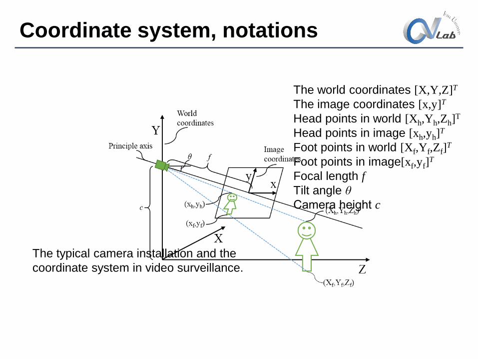
The typical camera installation and the
coordinate system in video surveillance.
The world coordinates [X,Y,Z]T
The image coordinates [x,y]T
Head points in world [Xh,Yh,Zh]T
Head points in image [xh,yh]T
Foot points in world [Xf,Yf,Zf]T
Foot points in image[xf,yf]T
Focal length f
Tilt angle θ
Camera height c
Simplified Calibration
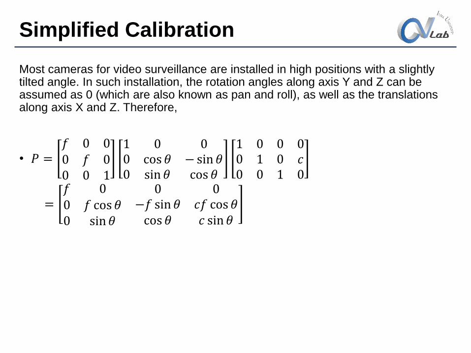
Most cameras for video surveillance are installed in high positions with a slightly tilted angle. In such installation, the rotation angles along axis Y and Z can be assumed as 0 (which are also known as pan and roll), as well as the translations along axis X and Z. Therefore,
• 𝑃 =𝑓 0 00 𝑓 00 0 1
1 0 00 cos 𝜃 − sin 𝜃0 sin 𝜃 cos 𝜃
1 0 00 1 00 0 1
0𝑐0
=𝑓 00 𝑓 cos 𝜃0 sin 𝜃
0 0−𝑓 sin 𝜃 𝑐𝑓 cos 𝜃cos 𝜃 𝑐 sin 𝜃
Simplified Calibration
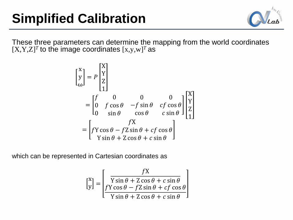
These three parameters can determine the mapping from the world coordinates[X,Y,Z]T to the image coordinates [x,y,w]T as
xyω
= 𝑃
XYZ1
=𝑓 00 𝑓 cos 𝜃0 sin 𝜃
0 0−𝑓 sin 𝜃 𝑐𝑓 cos 𝜃cos 𝜃 𝑐 sin 𝜃
XYZ1
=𝑓X
𝑓Y cos 𝜃 − 𝑓Z sin 𝜃 + 𝑐𝑓 cos 𝜃Y sin 𝜃 + Z cos 𝜃 + 𝑐 sin 𝜃
which can be represented in Cartesian coordinates as
xy =
𝑓X
Y sin 𝜃 + Z cos 𝜃 + 𝑐 sin 𝜃𝑓Y cos 𝜃 − 𝑓Z sin 𝜃 + 𝑐𝑓 cos 𝜃
Y sin 𝜃 + Z cos 𝜃 + 𝑐 sin 𝜃
Simplified Calibration
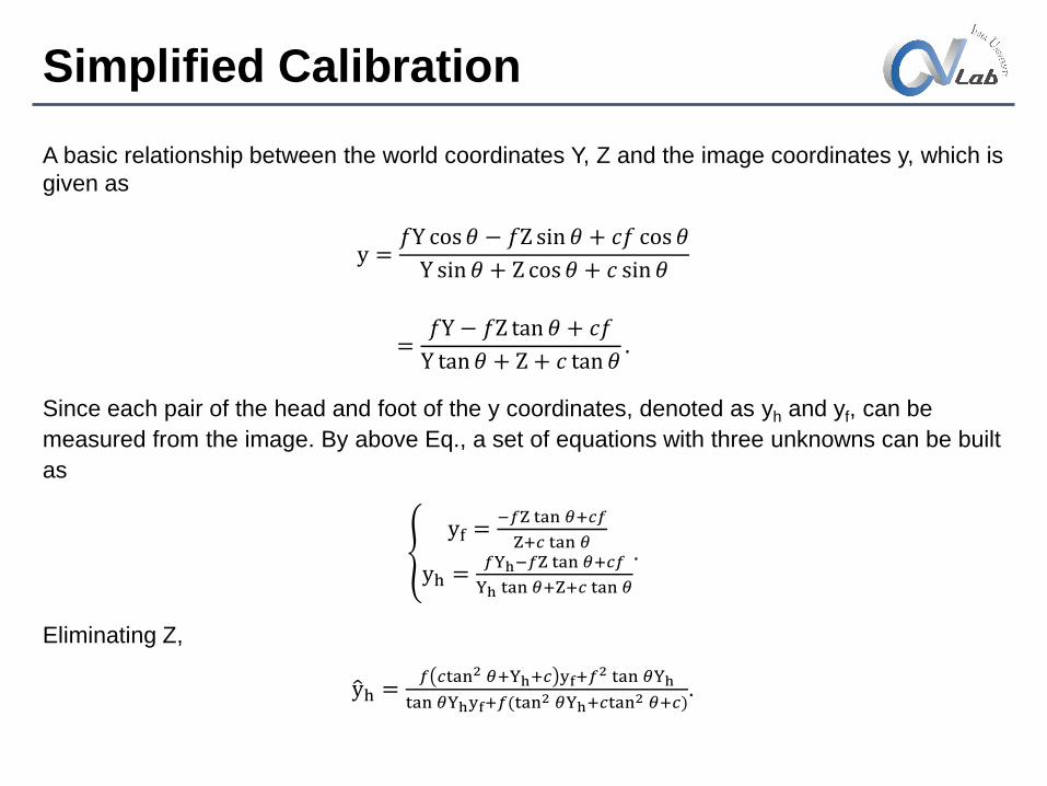
A basic relationship between the world coordinates Y, Z and the image coordinates y, which is
given as
y =𝑓Y cos 𝜃 − 𝑓Z sin 𝜃 + 𝑐𝑓 cos 𝜃
Y sin 𝜃 + Z cos 𝜃 + 𝑐 sin 𝜃
=𝑓Y − 𝑓Z tan 𝜃 + 𝑐𝑓
Y tan 𝜃 + Z + 𝑐 tan 𝜃.
Since each pair of the head and foot of the y coordinates, denoted as yh and yf, can be
measured from the image. By above Eq., a set of equations with three unknowns can be built
as
yf =
−𝑓Z tan 𝜃+𝑐𝑓
Z+𝑐 tan 𝜃
yh =𝑓Yh−𝑓Z tan 𝜃+𝑐𝑓
Yh tan 𝜃+Z+𝑐 tan 𝜃
.
Eliminating Z,
yh =𝑓 𝑐tan2 𝜃+Yh+𝑐 yf+𝑓
2 tan 𝜃Yh
tan 𝜃Yhyf+𝑓(tan2 𝜃Yh+𝑐tan
2 𝜃+𝑐).
Simplified Calibration
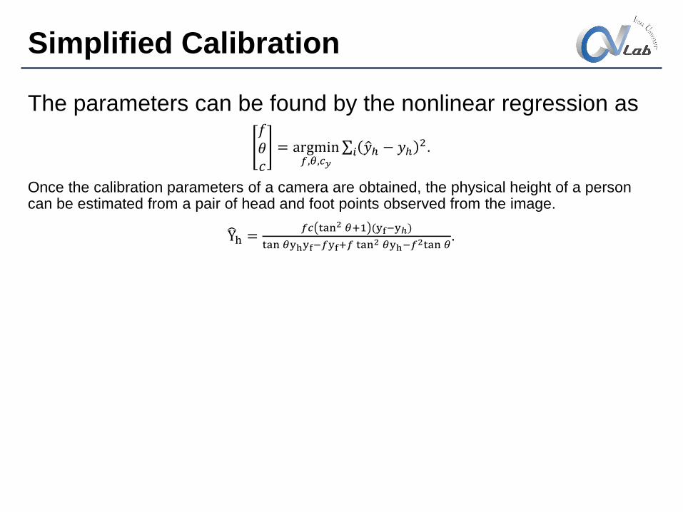
The parameters can be found by the nonlinear regression as𝑓𝜃𝑐
= argmin𝑓,𝜃,𝑐𝑦
𝑖 𝑦ℎ − 𝑦ℎ2.
Once the calibration parameters of a camera are obtained, the physical height of a person can be estimated from a pair of head and foot points observed from the image.
Yh =𝑓𝑐 tan2 𝜃+1 (yf−yℎ)
tan 𝜃yhyf−𝑓yf+𝑓 tan2 𝜃yh−𝑓
2tan 𝜃.
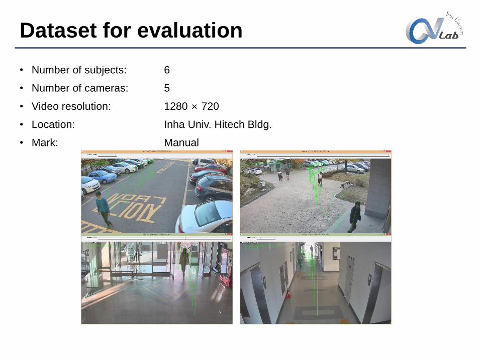
Dataset for evaluation
• Number of subjects: 6
• Number of cameras: 5
• Video resolution: 1280 × 720
• Location: Inha Univ. Hitech Bldg.
• Mark: Manual
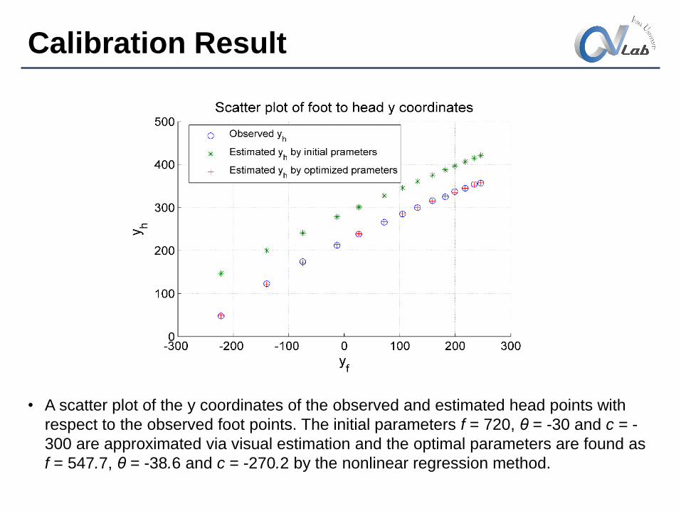
Calibration Result
• A scatter plot of the y coordinates of the observed and estimated head points with
respect to the observed foot points. The initial parameters f = 720, θ = -30 and c = -
300 are approximated via visual estimation and the optimal parameters are found as
f = 547.7, θ = -38.6 and c = -270.2 by the nonlinear regression method.
Height Estimation Results
Test
Train
S1 S2 S3 S4 S5 S6
S1 170(0) 171.7(0.3) 181.7(1.6) 173.7(1.9) 179.8(1.1) 174.8(0.9)
S2 170.2(0.4) 172(0.1) 182(1.7) 173.9(1.7) 180.2(0.8) 175(1)
S3 170.6(1.4) 172.4(1.6) 182(0) 174.1(2.6) 180(2.3) 175.2(1.8)
S4 169.2(1.5) 170.9(1.5) 181.3(3) 173(0) 179.2(1.8) 174.2(1.6)
S5 168.1(1.5) 169.9(1.1) 180(2.3) 171.8(1.3) 178(0) 172.9(0.9)
S6 168.3(1.2) 170(1) 180.1(1.8) 171.9(1.5) 178.1(1.2) 173(0)
True 170 172 182 173 178 173
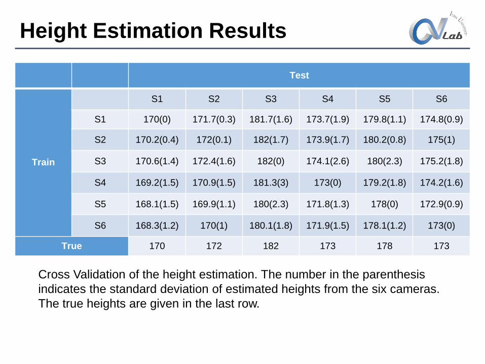
Cross Validation of the height estimation. The number in the parenthesis
indicates the standard deviation of estimated heights from the six cameras.
The true heights are given in the last row.
Height Estimation Results
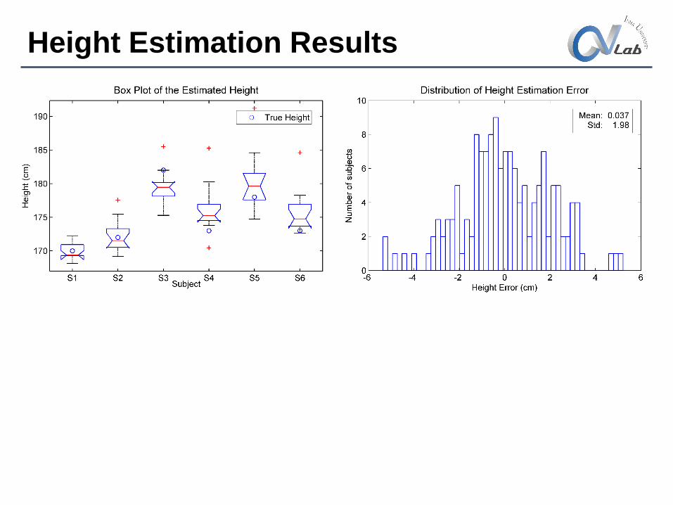
Height estimation results. (left)Box plot of the estimated heights for the six subjects from the camera 1. The circle represents the true height of the corresponding subject. (right)Distribution of the height estimation error from the cross validation. The error is near zero mean and has standard deviation of 1.98cm.
Comparison
Calibration object Method Mean Abs. Error Std. of ErrorMaximum
Error
N. Krahnstoever Walking humanAutomatic;
Vanishing point5.80%
K. Z. Lee Cubix box or lineManual;
Vanishing point5.50%
A. C. Gallager Grid patternManual;
Zhang's method2.67cm 3.28cm
Kispal 3.1cm 5.5cm
Proposed Walking humanManual;
Non-linear regression
1.55cm
(0.8%)
1.98cm
(1.1%)
5.36cm
(3.0%)
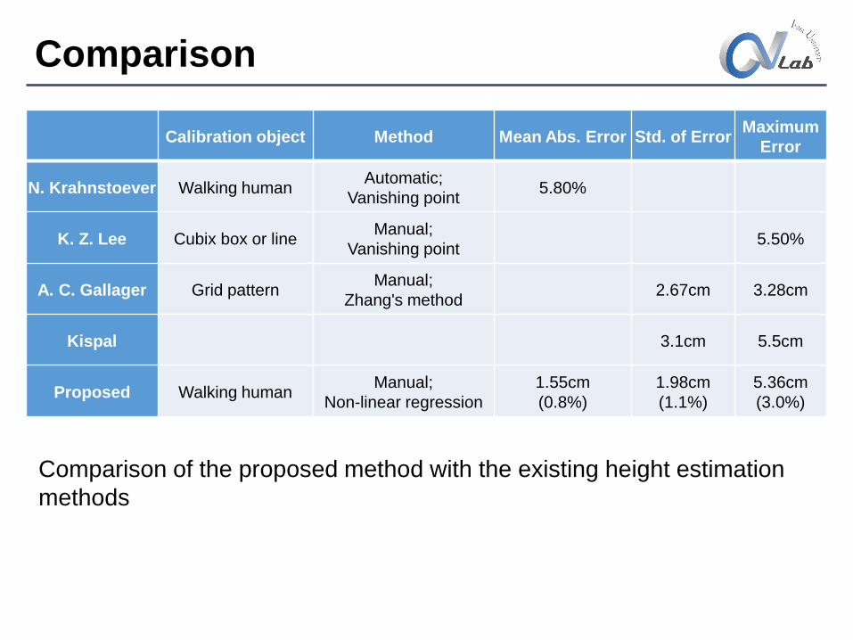
Comparison of the proposed method with the existing height estimation
methods
Conclusion
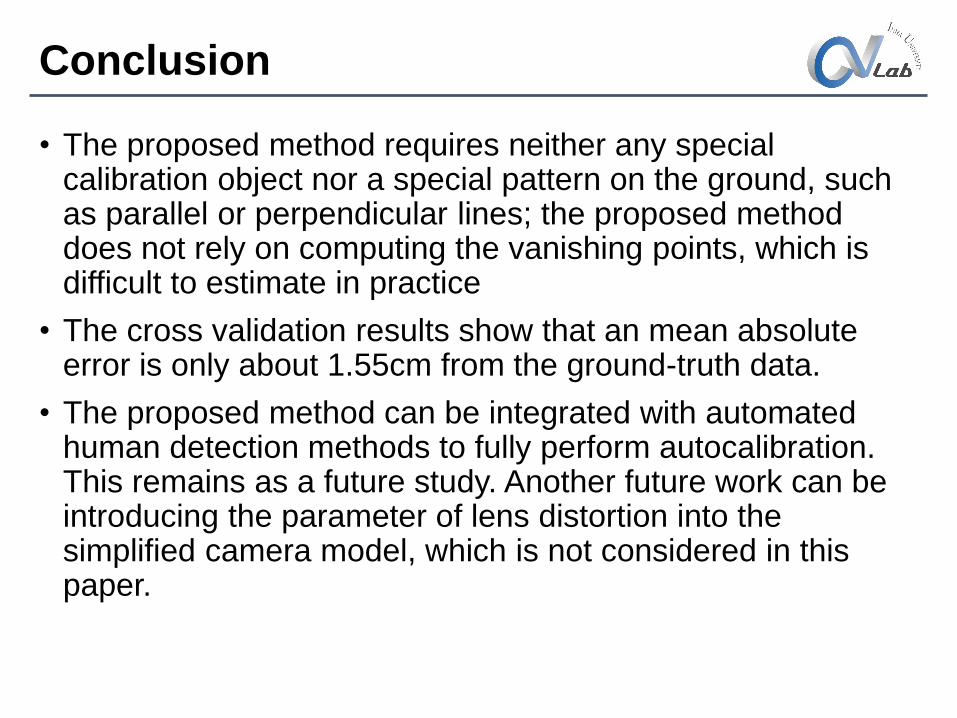
• The proposed method requires neither any special calibration object nor a special pattern on the ground, such as parallel or perpendicular lines; the proposed method does not rely on computing the vanishing points, which is difficult to estimate in practice
• The cross validation results show that an mean absolute error is only about 1.55cm from the ground-truth data.
• The proposed method can be integrated with automated human detection methods to fully perform autocalibration. This remains as a future study. Another future work can be introducing the parameter of lens distortion into the simplified camera model, which is not considered in this paper.
Part 2: Simplified Camera calibration with distortion
correction
Shengzhe Li
CVLab, Inha Univ.
2014. 11.
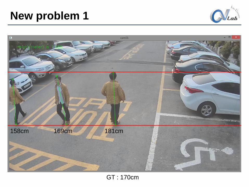
New problem 1
181cm169cm158cm
GT : 170cm
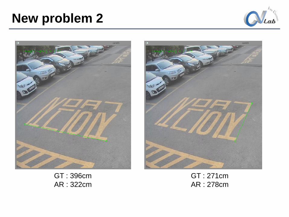
New problem 2
GT : 396cm
AR : 322cm
GT : 271cm
AR : 278cm
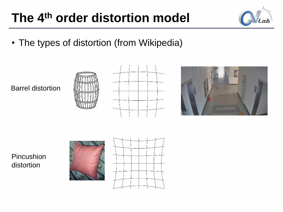
The 4th order distortion model
• The types of distortion (from Wikipedia)
Barrel distortion
Pincushion
distortion
The 4th order distortion model
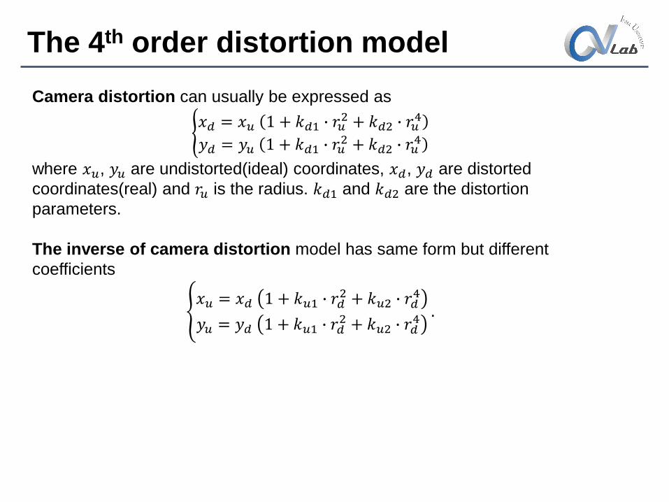
Camera distortion can usually be expressed as
𝑥𝑑 = 𝑥𝑢 1 + 𝑘𝑑1 ∙ 𝑟𝑢
2 + 𝑘𝑑2 ∙ 𝑟𝑢4
𝑦𝑑 = 𝑦𝑢 1 + 𝑘𝑑1 ∙ 𝑟𝑢2 + 𝑘𝑑2 ∙ 𝑟𝑢
4
where 𝑥𝑢, 𝑦𝑢 are undistorted(ideal) coordinates, 𝑥𝑑, 𝑦𝑑 are distorted
coordinates(real) and 𝑟𝑢 is the radius. 𝑘𝑑1 and 𝑘𝑑2 are the distortion
parameters.
The inverse of camera distortion model has same form but different
coefficients
𝑥𝑢 = 𝑥𝑑 1 + 𝑘𝑢1 ∙ 𝑟𝑑
2 + 𝑘𝑢2 ∙ 𝑟𝑑4
𝑦𝑢 = 𝑦𝑑 1 + 𝑘𝑢1 ∙ 𝑟𝑑2 + 𝑘𝑢2 ∙ 𝑟𝑑
4.
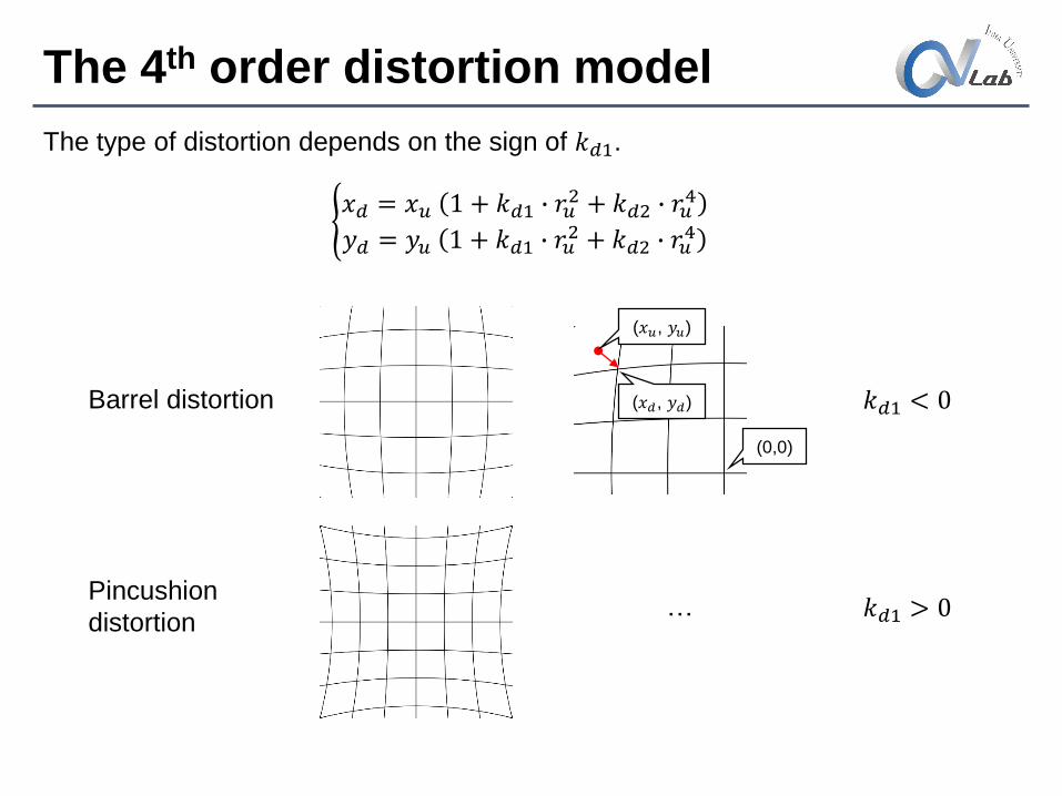
The 4th order distortion model
Barrel distortion
Pincushion
distortion
𝑘𝑑1 < 0
𝑘𝑑1 > 0
(0,0)
(𝑥𝑢, 𝑦𝑢)
(𝑥𝑑, 𝑦𝑑)
…
The type of distortion depends on the sign of 𝑘𝑑1.
𝑥𝑑 = 𝑥𝑢 1 + 𝑘𝑑1 ∙ 𝑟𝑢
2 + 𝑘𝑑2 ∙ 𝑟𝑢4
𝑦𝑑 = 𝑦𝑢 1 + 𝑘𝑑1 ∙ 𝑟𝑢2 + 𝑘𝑑2 ∙ 𝑟𝑢
4
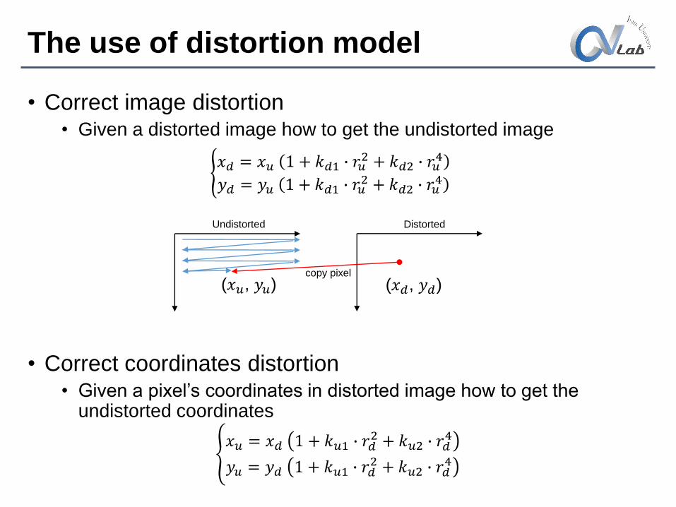
The use of distortion model
• Correct image distortion• Given a distorted image how to get the undistorted image
• Correct coordinates distortion• Given a pixel’s coordinates in distorted image how to get the
undistorted coordinates
𝑥𝑑 = 𝑥𝑢 1 + 𝑘𝑑1 ∙ 𝑟𝑢
2 + 𝑘𝑑2 ∙ 𝑟𝑢4
𝑦𝑑 = 𝑦𝑢 1 + 𝑘𝑑1 ∙ 𝑟𝑢2 + 𝑘𝑑2 ∙ 𝑟𝑢
4
𝑥𝑢 = 𝑥𝑑 1 + 𝑘𝑢1 ∙ 𝑟𝑑
2 + 𝑘𝑢2 ∙ 𝑟𝑑4
𝑦𝑢 = 𝑦𝑑 1 + 𝑘𝑢1 ∙ 𝑟𝑑2 + 𝑘𝑢2 ∙ 𝑟𝑑
4
(𝑥𝑢, 𝑦𝑢) (𝑥𝑑, 𝑦𝑑)
Undistorted Distorted
copy pixel
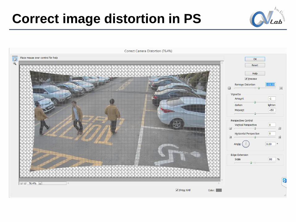
Correct image distortion in PS

Distort
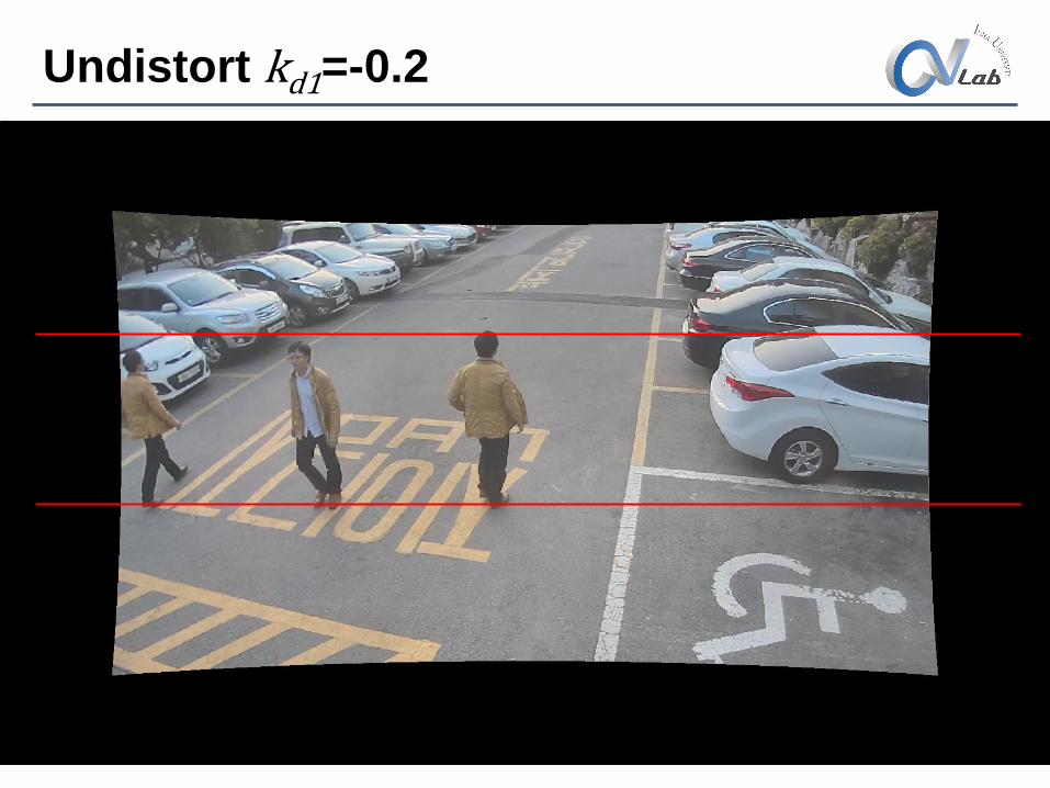
Undistort kd1=-0.2
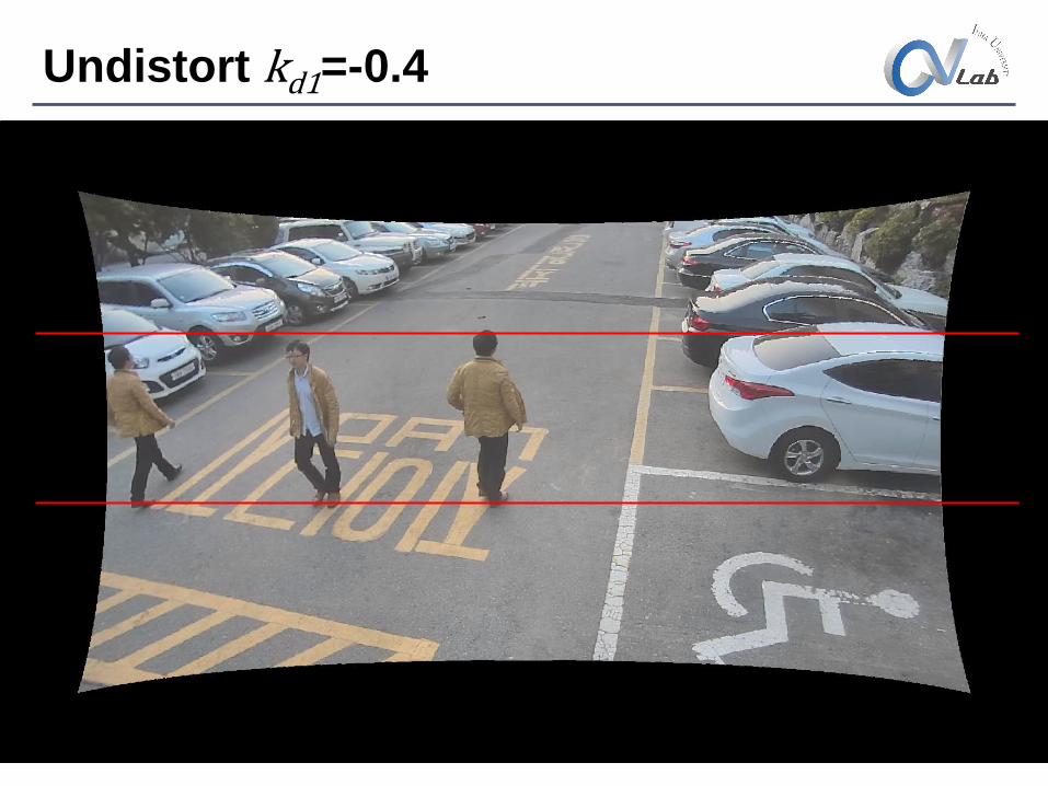
Undistort kd1=-0.4
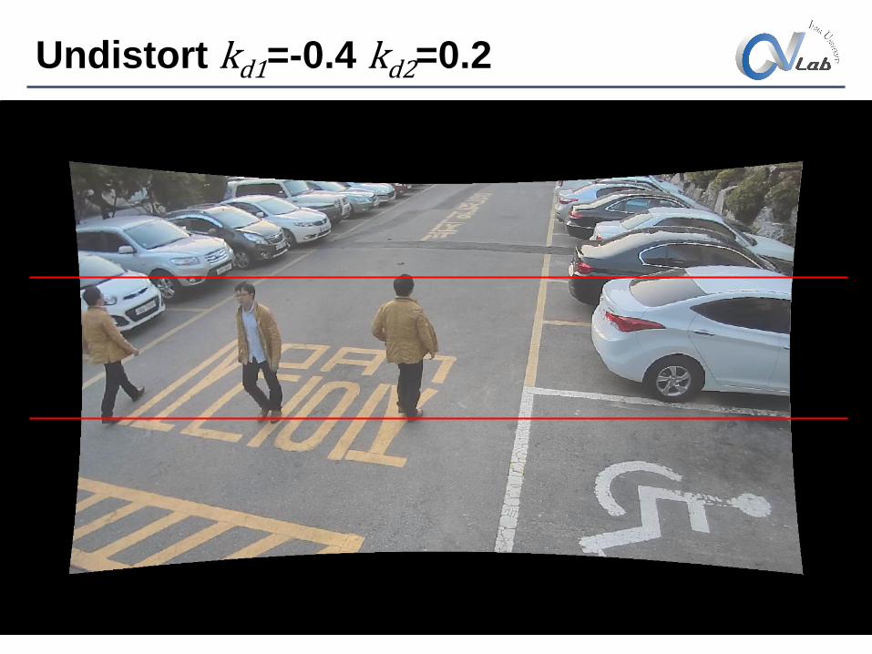
Undistort kd1=-0.4 kd2=0.2
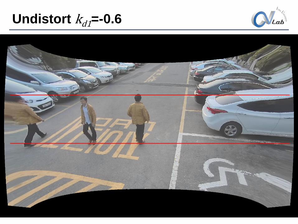
Undistort kd1=-0.6
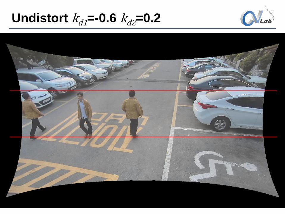
Undistort kd1=-0.6 kd2=0.2
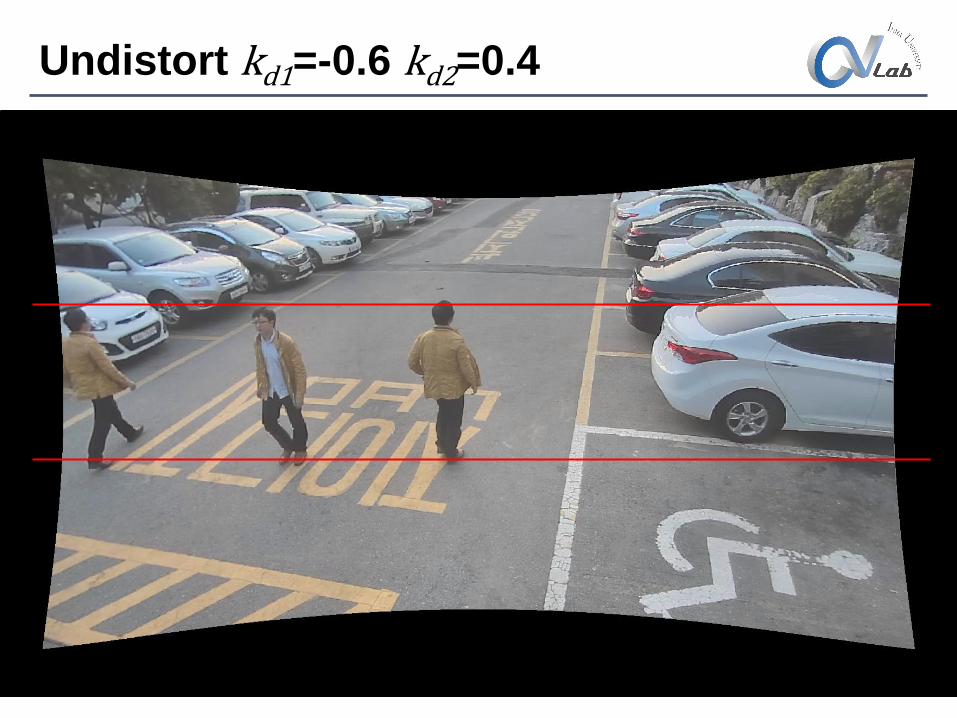
Undistort kd1=-0.6 kd2=0.4
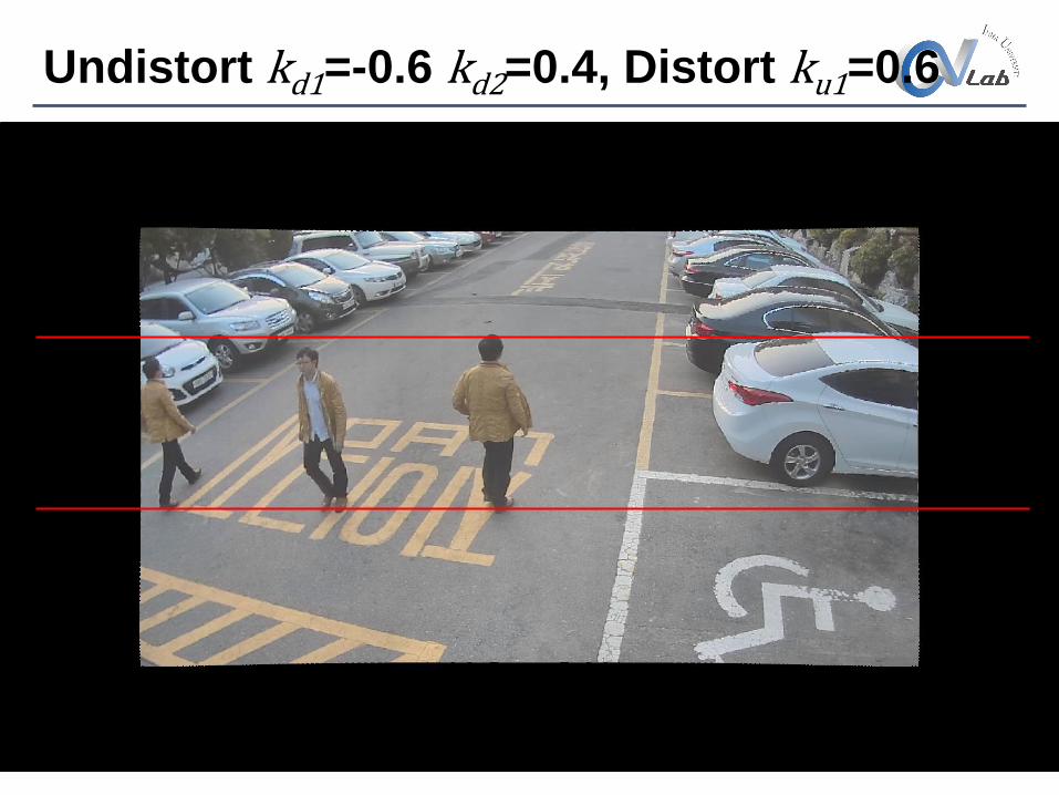
Undistort kd1=-0.6 kd2=0.4, Distort ku1=0.6
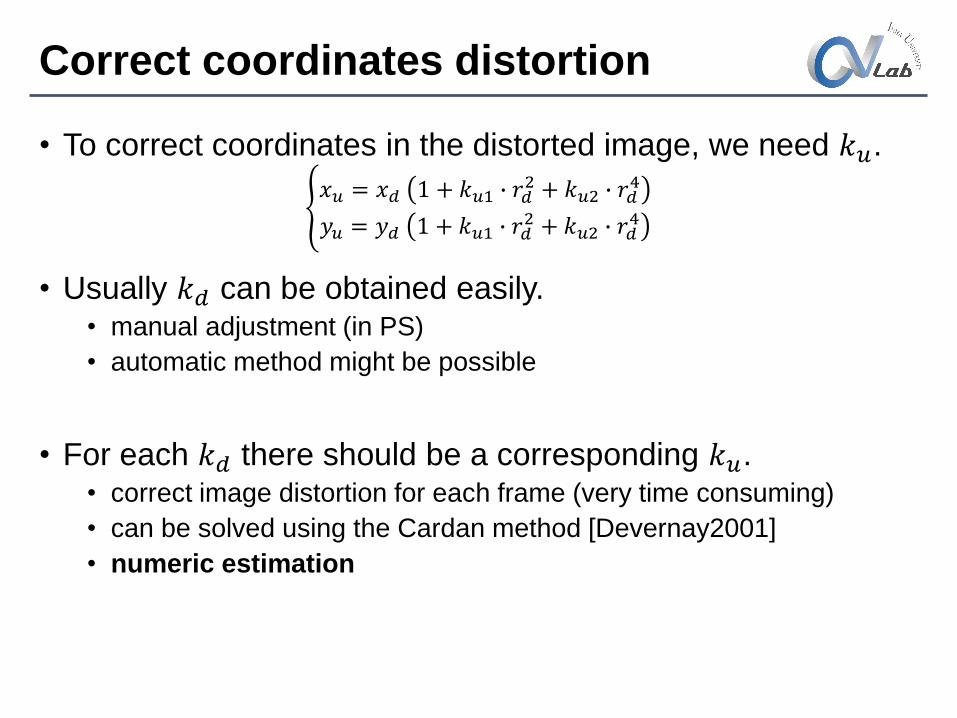
Correct coordinates distortion
• To correct coordinates in the distorted image, we need 𝑘𝑢.
• Usually 𝑘𝑑 can be obtained easily. • manual adjustment (in PS)
• automatic method might be possible
• For each 𝑘𝑑 there should be a corresponding 𝑘𝑢.• correct image distortion for each frame (very time consuming)
• can be solved using the Cardan method [Devernay2001]
• numeric estimation
𝑥𝑢 = 𝑥𝑑 1 + 𝑘𝑢1 ∙ 𝑟𝑑
2 + 𝑘𝑢2 ∙ 𝑟𝑑4
𝑦𝑢 = 𝑦𝑑 1 + 𝑘𝑢1 ∙ 𝑟𝑑2 + 𝑘𝑢2 ∙ 𝑟𝑑
4
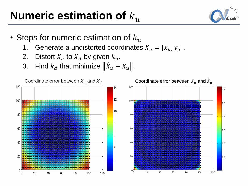
Numeric estimation of 𝑘𝑢
• Steps for numeric estimation of 𝑘𝑢1. Generate a undistorted coordinates 𝑋𝑢 = [𝑥𝑢, 𝑦𝑢].
2. Distort 𝑋𝑢 to 𝑋𝑑 by given 𝑘𝑢.
3. Find 𝑘𝑑 that minimize 𝑋𝑢 − 𝑋𝑢 .
0 20 40 60 80 100 1200
20
40
60
80
100
120
0
0.1
0.2
0.3
0.4
0.5
0.6
0 20 40 60 80 100 1200
20
40
60
80
100
120
2
4
6
8
10
12
14
Coordinate error between 𝑋𝑢 and 𝑋𝑑 Coordinate error between 𝑋𝑢 and 𝑋𝑢
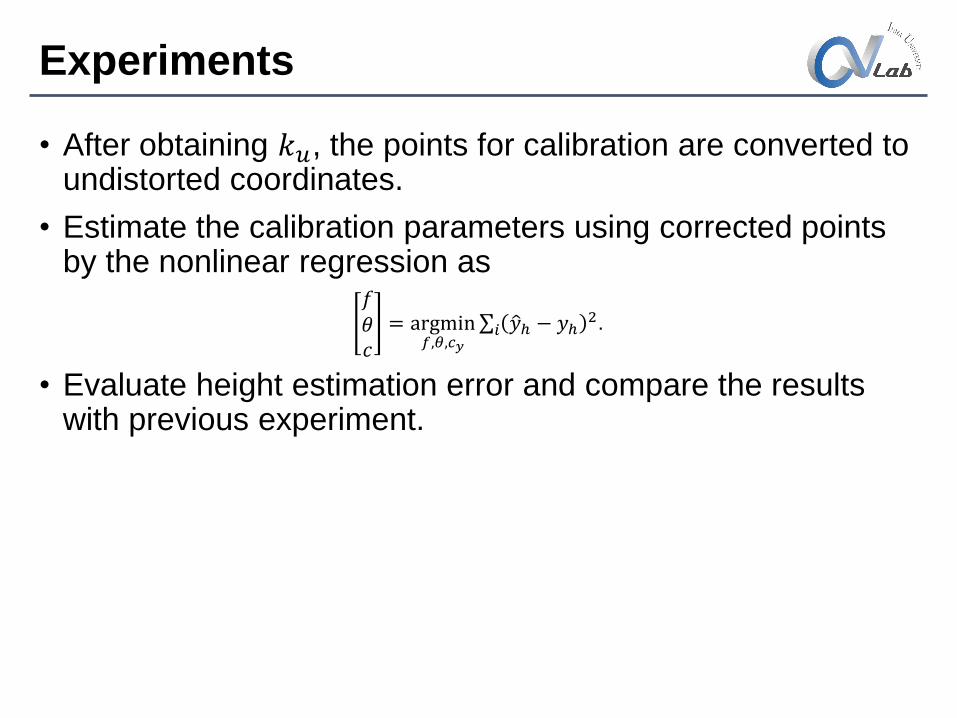
Experiments
• After obtaining 𝑘𝑢, the points for calibration are converted to undistorted coordinates.
• Estimate the calibration parameters using corrected points by the nonlinear regression as
𝑓𝜃𝑐
= argmin𝑓,𝜃,𝑐𝑦
𝑖 𝑦ℎ − 𝑦ℎ2.
• Evaluate height estimation error and compare the results with previous experiment.
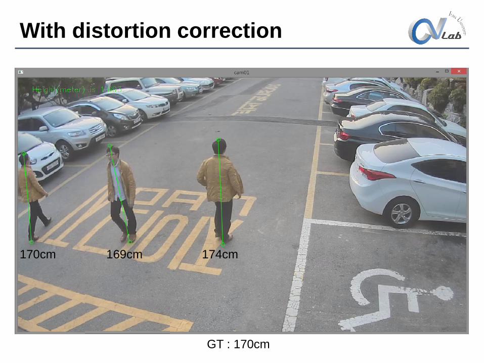
With distortion correction
170cm 169cm 174cm
GT : 170cm
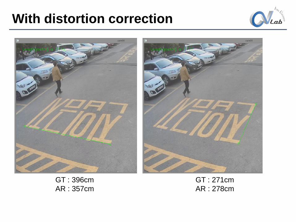
With distortion correction
GT : 396cm
AR : 357cm
GT : 271cm
AR : 278cm
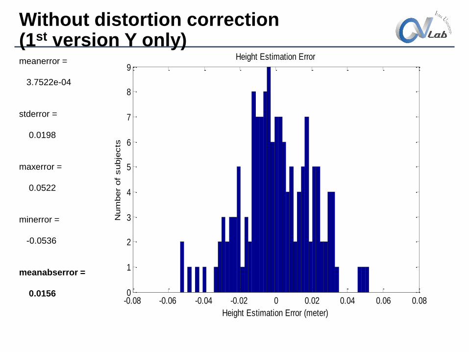
-0.08 -0.06 -0.04 -0.02 0 0.02 0.04 0.06 0.080
1
2
3
4
5
6
7
8
9Height Estimation Error
Height Estimation Error (meter)
Num
ber
of
subje
cts
meanerror =
3.7522e-04
stderror =
0.0198
maxerror =
0.0522
minerror =
-0.0536
meanabserror =
0.0156
Without distortion correction(1st version Y only)
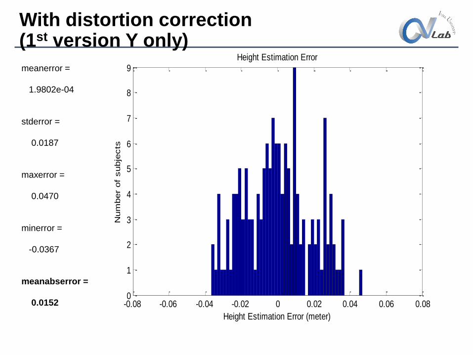
With distortion correction(1st version Y only)
-0.08 -0.06 -0.04 -0.02 0 0.02 0.04 0.06 0.080
1
2
3
4
5
6
7
8
9Height Estimation Error
Height Estimation Error (meter)
Num
ber
of
subje
cts
meanerror =
1.9802e-04
stderror =
0.0187
maxerror =
0.0470
minerror =
-0.0367
meanabserror =
0.0152
-0.08 -0.06 -0.04 -0.02 0 0.02 0.04 0.06 0.080
1
2
3
4
5
6
7
8
9
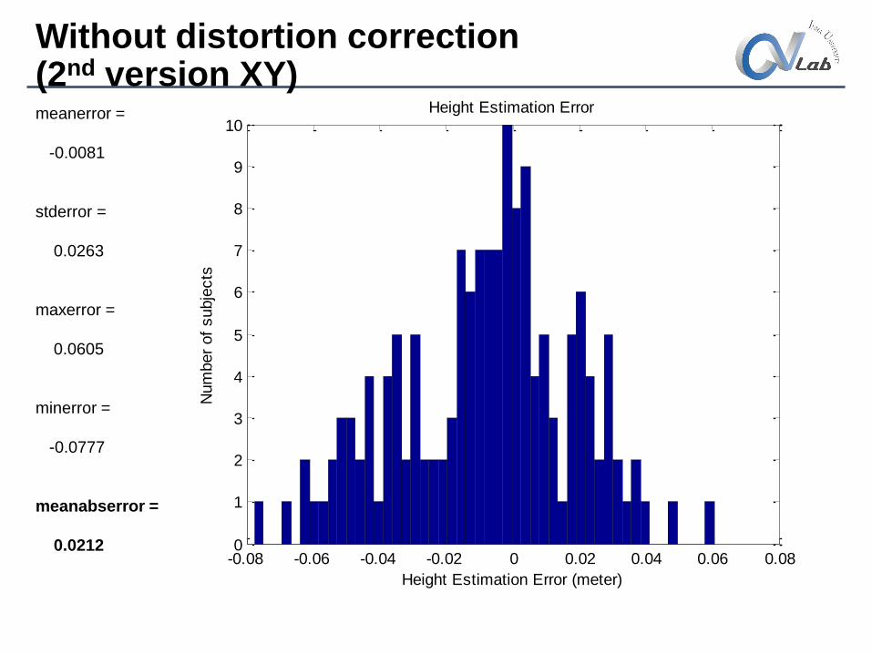
10Height Estimation Error
Height Estimation Error (meter)
Num
ber
of
subje
cts
meanerror =
-0.0081
stderror =
0.0263
maxerror =
0.0605
minerror =
-0.0777
meanabserror =
0.0212
Without distortion correction(2nd version XY)
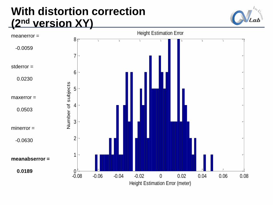
meanerror =
-0.0059
stderror =
0.0230
maxerror =
0.0503
minerror =
-0.0630
meanabserror =
0.0189-0.08 -0.06 -0.04 -0.02 0 0.02 0.04 0.06 0.080
1
2
3
4
5
6
7
8Height Estimation Error
Height Estimation Error (meter)
Num
ber
of
subje
cts
With distortion correction(2nd version XY)
Conclusion
• Camera distortion correction offers more accurate height estimation especially for boarder area as well as the length in the floor.