Embed Size (px)
Citation preview
A
PROJECT REPORT
Submitted on
“HOME AUTOMATION USING ANDROID PHONE OVER BLUETOOTH”
Submitted in partial fulfillment of the
Requirements for the award of the degree of
BACHELOR OF TECHNOLOGY
IN
Electronics’ & Communication Engineering.
(Session 2012-2015)
Submitted To: Submitted By:Mr. Sandeep Kumar Parveen Kumar(H.O.D E.C.E Dep’t.) Roll.No:2557003Yaduvanshi College of Engineering & TechnologyNarnaul (Haryana)
Department of Electronics’ & Communication Engineering
YADUVANSHI COLLEGE OF ENGINEERING & TECHNOLOGY
HOME AUTOMATION USING ANDROID PHONE OVER BLUETOOTH
Narnaul Rewari Road, Patikra, Narnaul-123001(Haryana)
DECLARATION
I hereby declare that the Institutional Project Work entitled “HOME AUTOMATION USING
ANDROID PHONE OVER BLUETOOTH.” is an authentic record of my own work as
requirements of 6-months Industrial Training/Institutional Project Work in the 8th Sem. For
the award of degree of B.Tech. (Electronics & Communication Engineering), Yaduvanshi
College of Engineering & Technology, Narnaul, Mahendergarh, under the guidance of Mr.
Sandeep (H.O.D E.C.E Dep’t)
Parveen KumarRoll. No 255703E.C.E 8th SEM
Date: ____________________
Certified that the above statement made by the student is correct to the best of our knowledge and belief.
Signatures
Examined by:
1. 2.
3. 4.
Head of Department(Signature and Seal)
DEPARTMENT OF ELECTRONIC’S & COMMUNICATION ENGINEERING, YADUVANSHI COLLEGE OF ENGINEERING & TECHNOLOGY,
Page 2
HOME AUTOMATION USING ANDROID PHONE OVER BLUETOOTH
Department of Electronics’ & Comm. Engg.Narnaul-Haryana 123002
CERTIFICATE
Certified that this is the bonafied report of Project entitled “Certified that this is the bonafied report of Project entitled “HOME AUTOMATIONHOME AUTOMATION
USING ANDROID PHONE OVER BLUETOOTH” USING ANDROID PHONE OVER BLUETOOTH” done by Parveen Kumar of 8done by Parveen Kumar of 8 thth
Semester in “ELECTRONICS & COMMUNICATION ENGINEERING” in theSemester in “ELECTRONICS & COMMUNICATION ENGINEERING” in the
Yaduvanshi College of Engineering & Technology during the academic sessionYaduvanshi College of Engineering & Technology during the academic session
2012-2015 and submitted for practical examination conducted by “M.D.U University2012-2015 and submitted for practical examination conducted by “M.D.U University
Rohtak”.Rohtak”. We express our delight on its Successful completion.We express our delight on its Successful completion.
We wish her successful in all her future endeavors.We wish her successful in all her future endeavors.
Guided by:-Guided by:- Mrs. Sandeep (H.O.D of E.C.E Deptt.)Mrs. Sandeep (H.O.D of E.C.E Deptt.)
DEPARTMENT OF ELECTRONIC’S & COMMUNICATION ENGINEERING, YADUVANSHI COLLEGE OF ENGINEERING & TECHNOLOGY,
Page 3
HOME AUTOMATION USING ANDROID PHONE OVER BLUETOOTH
ACKNOWLEDGMENT
We take this opportunity to thank Mr. Pradeep, Principal, YADUVANSHI College of Engineering & Technology for granting us the permission to carry out the project.
We are extremely thankful to Mr. Sandeep H.O.D, Electronics and Communication department, for his timely advices and all the facilities he provided us, to carry out the project and finish it successfully.
He has always been a source of inspiration and has been guiding us constantly through all our ups and downs of our endeavor in completing out project, for which we are greatly indebted to them.
We are also very grateful to the whole Electronics’ & Communication Department for their support and guidance. Also, we are highly obliged to the head of our training and placement cell that provided me such a great opportunity to do my summer training in a reputed institute like.
Parveen KumarRoll. No: 2557003E.C.E 8th Sem.
AbstractDEPARTMENT OF ELECTRONIC’S & COMMUNICATION ENGINEERING, YADUVANSHI COLLEGE OF ENGINEERING &
TECHNOLOGY,
Page 4
HOME AUTOMATION USING ANDROID PHONE OVER BLUETOOTH
The past decade has seen significant advancement in the field of consumer electronics.
Various ‘intelligent’ appliances such as cellular phones, air-conditioners, home
security devices, home theatres, etc. are set to realize the concept of a smart home.
They have given rise to a Personal Area Network in home environment, where all
these appliances can be interconnected and monitored using a single controller.
Busy families and individuals with physical limitation represent an attractive market
for home automation and networking. A wireless home network that does not incur
additional costs of wiring would be desirable. Bluetooth technology, which has
emerged in late 1990s, is an ideal solution for this purpose.
Home automation involves introducing a degree of computerized or automatic control
to
Certain electrical and electronic systems in a building. These include lighting,
temperature
Control etc.
This project demonstrates a simple home automation system which contains a remote
mobile host controller and several client modules (home appliances). The client
modules communicate with the host controller through a wireless device such as a
Bluetooth enabled mobile phone, in this case, an android based Smart phone.
Table of Content
DEPARTMENT OF ELECTRONIC’S & COMMUNICATION ENGINEERING, YADUVANSHI COLLEGE OF ENGINEERING & TECHNOLOGY,
Page 5
HOME AUTOMATION USING ANDROID PHONE OVER BLUETOOTH
Chapter No.
Particulars Page No.
DEPARTMENT OF ELECTRONIC’S & COMMUNICATION ENGINEERING, YADUVANSHI COLLEGE OF ENGINEERING & TECHNOLOGY,
Page 6
HOME AUTOMATION USING ANDROID PHONE OVER BLUETOOTH
i Declaration iii Certificate iiiii Acknowledgment iiiiv Abstract ivvi Table of Contents v-viivi List of figures viii
viii Abbreviations ix
Chapter 1. Overview of Project 1-3
1.1 Introduction 1-2
1.2 Block diagram 3
1.3 Project Modules 3
Chapter 2. Hardware Description 4-22
2.1 Microcontroller 4-12
2.1.1 89552 4
2.1.2 Block Diagram 5
2.1.3 Features 5
2.1.4 Pin diagram 6
2.1.5 Pin description 7-10
2.1.6 Special Function Registers 11
2.1.7 Memory Organization 11
2.1.7.1 Program Memory 11
2.1.7.2 Data Memory 12
2.1.8 Watchdog Timer 12
2.2 BLUETOOTH MODULE (HC-05):Overview 13-16
2.2.1. Specifications 14
2.2.2. Pin out configuration 15
2.2.3 Typical Application Circuit 15
2.2.4. Pairing 16
2.2.5. Hc-05 Bluetooth module working voltage 16
2.2.6. Serial communication 16
2.3 Driver IC 17-20
2.3.1 ULN2803A Darlington Transistor Arrays 17
2.3.2 Simplified Schematics 17
2.3.3. Functional Block Diagram 18
2.3.4 Pin diagram 19
DEPARTMENT OF ELECTRONIC’S & COMMUNICATION ENGINEERING, YADUVANSHI COLLEGE OF ENGINEERING & TECHNOLOGY,
Page 7
HOME AUTOMATION USING ANDROID PHONE OVER BLUETOOTH
2.3.5 Inductive Load Drive 19
2.3.6 Resistive Load Drive 20
2.4 Switches 20
2.4.1 Relay 20
2.5 Connector 21
2.6 Vp812 burner 21
2.7 Power supply 22
Chapter 3. Software 23-27
Introduction 23
3.1 PROTEUS 23
3.2 KEIL 24
3.3 VP812 25
3.4 Android App 26-27
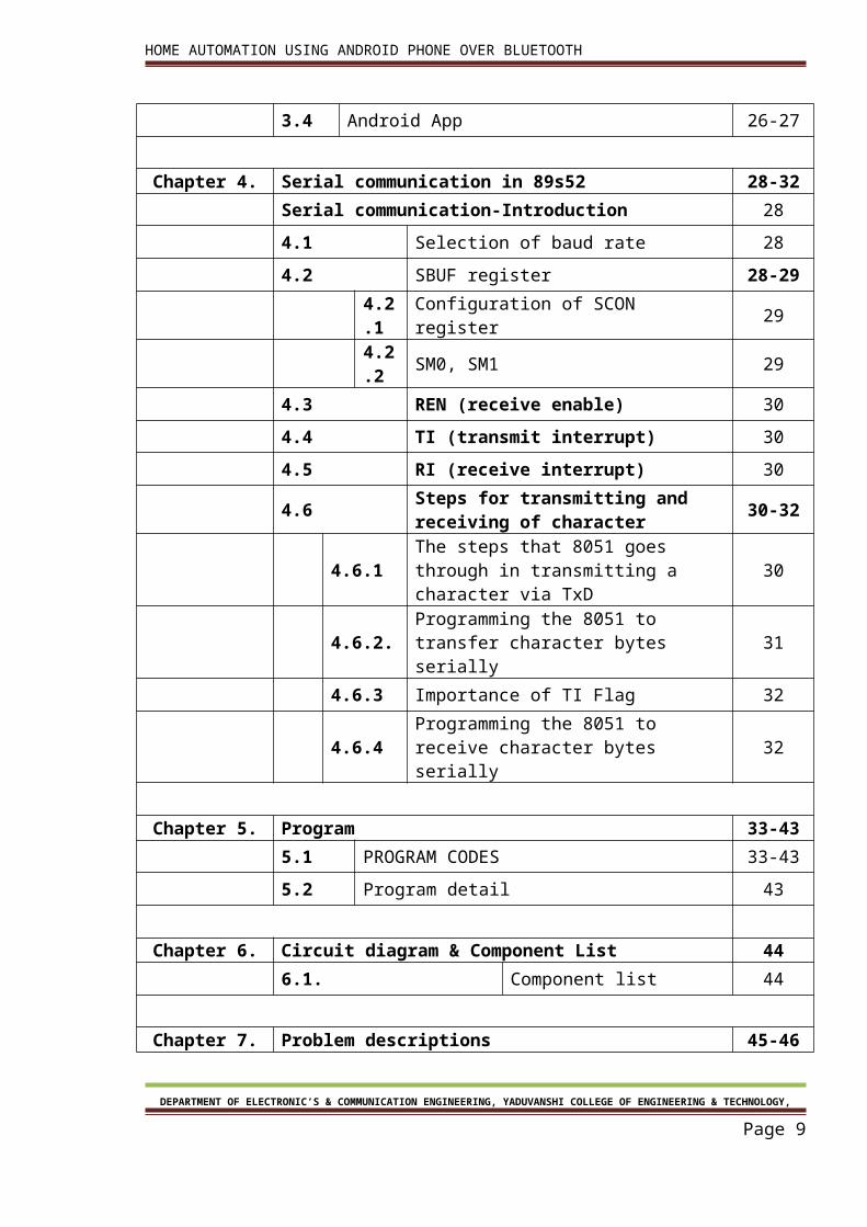
Chapter 4. Serial communication in 89s52 28-32
Serial communication-Introduction 28
4.1 Selection of baud rate 28
4.2 SBUF register 28-29
4.2.1 Configuration of SCON register 29
4.2.2 SM0, SM1 29
4.3 REN (receive enable) 30
4.4 TI (transmit interrupt) 30
4.5 RI (receive interrupt) 30
4.6 Steps for transmitting and receiving of character
30-32
4.6.1 The steps that 8051 goes through in transmitting a character via TxD
30
4.6.2. Programming the 8051 to transfer character bytes serially
31
4.6.3 Importance of TI Flag 32
4.6.4 Programming the 8051 to receive character bytes serially
32
Chapter 5. Program 33-43
5.1 PROGRAM CODES 33-43
5.2 Program detail 43
DEPARTMENT OF ELECTRONIC’S & COMMUNICATION ENGINEERING, YADUVANSHI COLLEGE OF ENGINEERING & TECHNOLOGY,
Page 8
HOME AUTOMATION USING ANDROID PHONE OVER BLUETOOTH
Chapter 6. Circuit diagram & Component List 44
6.1. Component list 44
Chapter 7. Problem descriptions 45-46
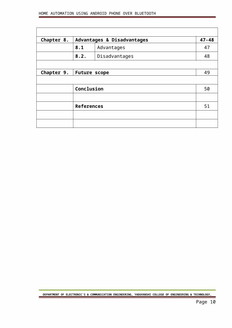
Chapter 8. Advantages & Disadvantages 47-48
8.1 Advantages 47
8.2. Disadvantages 48
Chapter 9. Future scope 49
Conclusion 50
References 51
DEPARTMENT OF ELECTRONIC’S & COMMUNICATION ENGINEERING, YADUVANSHI COLLEGE OF ENGINEERING & TECHNOLOGY,
Page 9
HOME AUTOMATION USING ANDROID PHONE OVER BLUETOOTH
List of Figures
Figure No
Figure Name Page No.
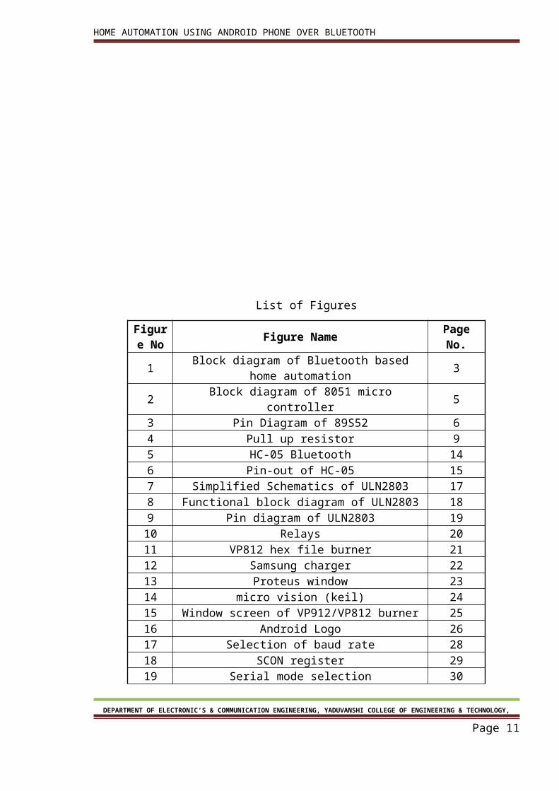
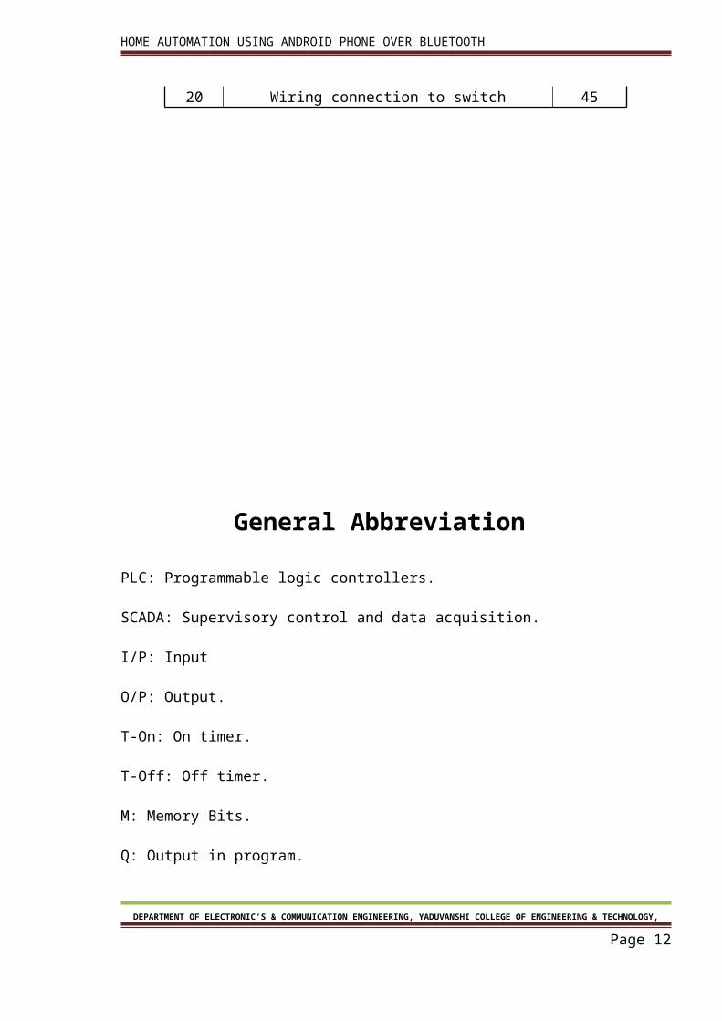
1 Block diagram of Bluetooth based home automation 32 Block diagram of 8051 micro controller 53 Pin Diagram of 89S52 64 Pull up resistor 95 HC-05 Bluetooth 146 Pin-out of HC-05 157 Simplified Schematics of ULN2803 178 Functional block diagram of ULN2803 189 Pin diagram of ULN2803 1910 Relays 2011 VP812 hex file burner 2112 Samsung charger 2213 Proteus window 2314 micro vision (keil) 2415 Window screen of VP912/VP812 burner 2516 Android Logo 2617 Selection of baud rate 2818 SCON register 2919 Serial mode selection 3020 Wiring connection to switch 45
DEPARTMENT OF ELECTRONIC’S & COMMUNICATION ENGINEERING, YADUVANSHI COLLEGE OF ENGINEERING & TECHNOLOGY,
Page 10
HOME AUTOMATION USING ANDROID PHONE OVER BLUETOOTH
General Abbreviation
PLC: Programmable logic controllers.
SCADA: Supervisory control and data acquisition.
I/P: Input
O/P: Output.
T-On: On timer.
T-Off: Off timer.
M: Memory Bits.
Q: Output in program.
MW: Memory words.
NO: Normally open.
NC: Normally closed.
DCS: Distributed Control System.
HMI: Human machine interference.
VFD: Variable Frequency Drive.
MD: Memory Double Word.
DEPARTMENT OF ELECTRONIC’S & COMMUNICATION ENGINEERING, YADUVANSHI COLLEGE OF ENGINEERING & TECHNOLOGY,
Page 11
HOME AUTOMATION USING ANDROID PHONE OVER BLUETOOTH
MB: Memory Byte
XIC: Examine If Closed
XIO: Examine If Open
Chapter 1OVERVIEW OF PROJECT
DEPARTMENT OF ELECTRONIC’S & COMMUNICATION ENGINEERING, YADUVANSHI COLLEGE OF ENGINEERING & TECHNOLOGY,
Page 12
HOME AUTOMATION USING ANDROID PHONE OVER BLUETOOTH
Chapter 1OVERVIEW OF PROJECT
1.1. INTRODUCTION:
DEPARTMENT OF ELECTRONIC’S & COMMUNICATION ENGINEERING, YADUVANSHI COLLEGE OF ENGINEERING & TECHNOLOGY,
Page 13
HOME AUTOMATION USING ANDROID PHONE OVER BLUETOOTH
Automation involves introducing a degree of computerized or automatic control to certain
electrical and electronic systems in a building. These include lighting, temperature control,
etc. The past decade has seen significant advancement in the field of consumer electronics.
Various intelligent appliances such as cellular phone, air conditioners, home security devices,
home theaters, etc., are set to realize the concept of a smart home. They have given rise to a
Personal Area Network in home environment, where all these appliances can be
interconnected and monitored using a single controller.
This project demonstrates an automation system which contains a remote mobile host
controller and several client modules (eg.Office, home appliances). The client modules
communicate with the host controller through a wireless device such as a Bluetooth enabled
mobile phone, in this case, an android based Smart phone.
Although automation today is not a new thing but most advanced home automation systems
in existence today require a big and expensive change of infrastructure. We have proposed
an automation system that can control appliances like TVs, Fan, Tube lights from an android
mobile using Bluetooth. In this a low cost secure cell phone based, flexible automation
system is introduced. Devices are connected to the microcontroller based switching circuit.
The communication between the cell phone and the microcontroller board is wireless.
Additional devices can be connected into the system with little modifications. The phone will
be Android OS based phone. The switching circuit will be having microcontroller coding to
control the electronics devices like fans and lights etc. 8-bit microcontroller board based on
the atmel89s52 and the HC-05 Bluetooth module is used. It supports wireless serial
communication over Bluetooth. This board has 32 digital input and output ports.
The 89s52 can be programmed using the microcontroller’s high-level interactive embedded
C language. The Bluetooth antenna in our module picks up the packets sent from the cell
DEPARTMENT OF ELECTRONIC’S & COMMUNICATION ENGINEERING, YADUVANSHI COLLEGE OF ENGINEERING & TECHNOLOGY,
Page 14
HOME AUTOMATION USING ANDROID PHONE OVER BLUETOOTH
phone. Subsequently, these packets containing the device status as commands are pipelined
through 89s52 microcontroller and the designed analogue circuitry according to the
definition of each output.
Different home or office appliances are connected to the digital output ports of the circuit
via relays to provide sufficiently high currents and voltage compatibility. For test purposes,
25W, 240V lamps will be used.
We send commands from an application which is developed in phone to turn ON/OFF a
device. A feedback circuit has been designed and implemented to indicate the devices actual
status after it receives the command (ON/OFF) from the cell phone. Once the command has
been sent to turn ON a device, the feedback circuit senses the current and gives an output
signal by turning ON a respective led on the switching circuitry indicating that the device is
ON. Otherwise, the device is malfunctioning indicating that the command was not executed
successfully. We can also operate the appliances of Home or Office in Bluetooth range area.
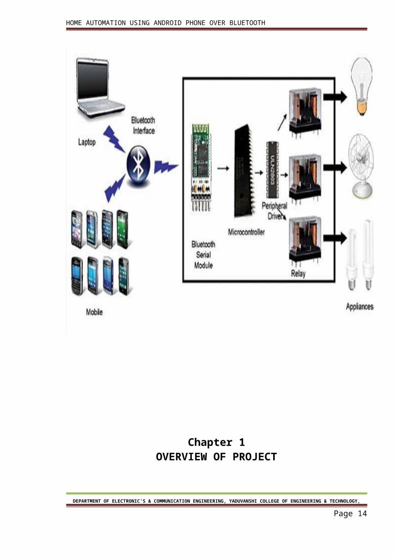
1.2. Block diagram:-
DEPARTMENT OF ELECTRONIC’S & COMMUNICATION ENGINEERING, YADUVANSHI COLLEGE OF ENGINEERING & TECHNOLOGY,
Page 15
HOME AUTOMATION USING ANDROID PHONE OVER BLUETOOTH
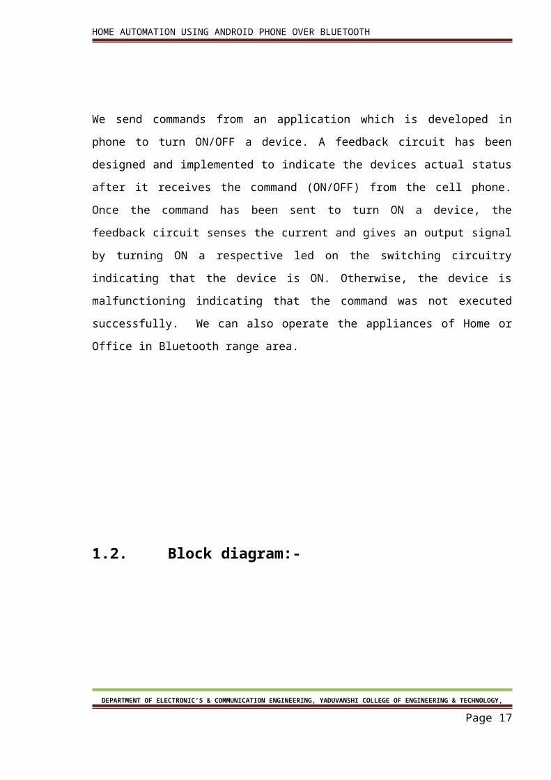
Figure 1: Block diagram of Bluetooth based home automation
In this block diagram communication is in both direction between android mobile and
Bluetooth module. This communication is done one by one only one at a time. This
communication is called half duplex.
Feedback is done by getting 220v.feedback circuitry is so deigned that microcontroller can
easily sense.
1.3. Project Modules :-
The project can be better described by dividing it into two categories, namely,1. Hardware2. Software
DEPARTMENT OF ELECTRONIC’S & COMMUNICATION ENGINEERING, YADUVANSHI COLLEGE OF ENGINEERING & TECHNOLOGY,
Page 16
HOME AUTOMATION USING ANDROID PHONE OVER BLUETOOTH
Chapter 2Hardware Description
DEPARTMENT OF ELECTRONIC’S & COMMUNICATION ENGINEERING, YADUVANSHI COLLEGE OF ENGINEERING & TECHNOLOGY,
Page 17
HOME AUTOMATION USING ANDROID PHONE OVER BLUETOOTH
Chapter 2Hardware Description
2.1 Microcontroller:-Micro controller is just like a small computer but the basic
difference comes in size and memory. These have CPU, RAM, ROM, I/O and timers are all on
a single chip. It means you don’t need any extra device to make it functional like with a
micro-processor. Generally this microcontroller is used where a specific task is needed to do.
So fixed amount of on-chip ROM, RAM, and number of I/O ports makes them ideal for a
many applications in which cost and space are critical The microcontroller is used by us in
over project is AT89S52.
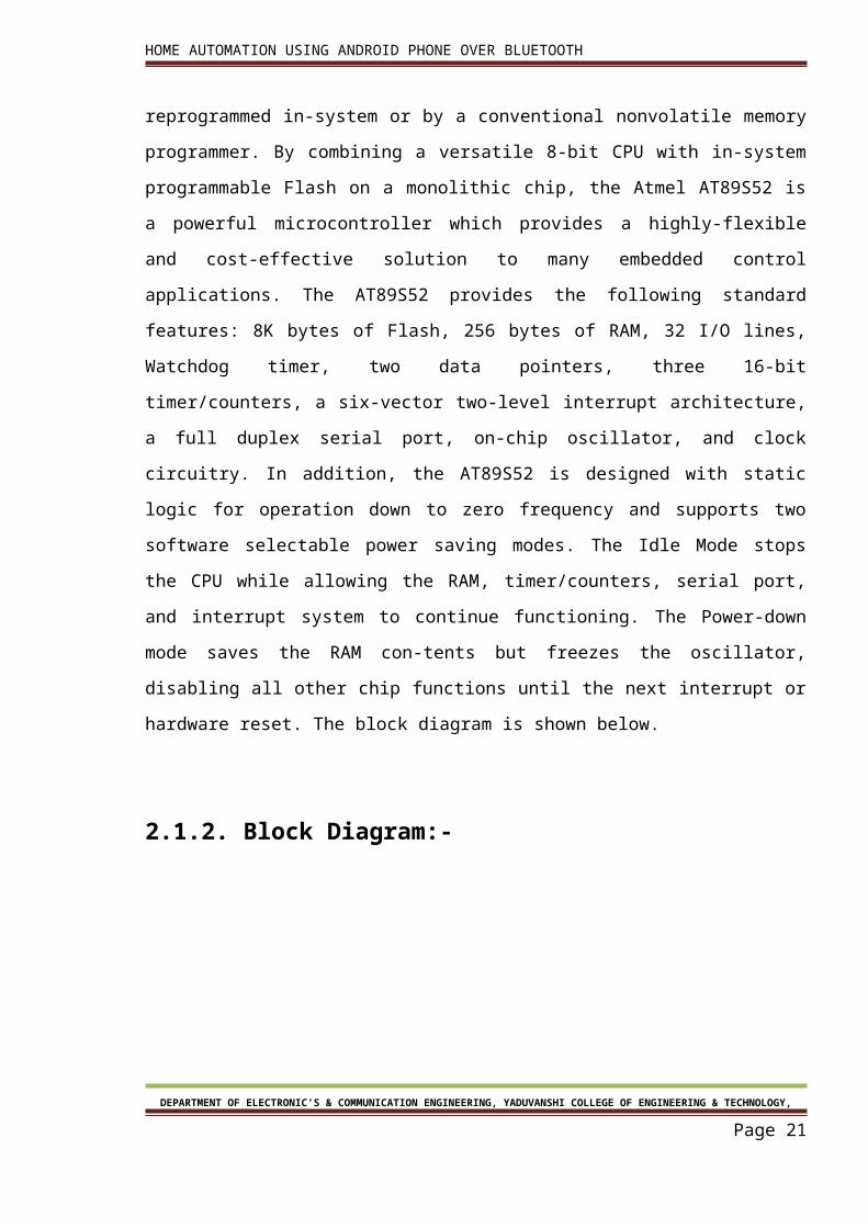
2.1.1.89S52:- The AT89S52 is a low-power, high-performance CMOS 8-bit
microcontroller with 8K bytes of in-system programmable Flash memory. The device is
manufactured using Atmel’s high-density nonvolatile memory technology and is compatible
with the industry-standard 80C51 instruction set and pin out. The on-chip Flash allows the
program memory to be reprogrammed in-system or by a conventional nonvolatile memory
programmer. By combining a versatile 8-bit CPU with in-system programmable Flash on a
monolithic chip, the Atmel AT89S52 is a powerful microcontroller which provides a highly-
flexible and cost-effective solution to many embedded control applications. The AT89S52
provides the following standard features: 8K bytes of Flash, 256 bytes of RAM, 32 I/O lines,
Watchdog timer, two data pointers, three 16-bit timer/counters, a six-vector two-level
interrupt architecture, a full duplex serial port, on-chip oscillator, and clock circuitry. In
addition, the AT89S52 is designed with static logic for operation down to zero frequency and
supports two software selectable power saving modes. The Idle Mode stops the CPU while
allowing the RAM, timer/counters, serial port, and interrupt system to continue functioning.
The Power-down mode saves the RAM con-tents but freezes the oscillator, disabling all
other chip functions until the next interrupt or hardware reset. The block diagram is shown
below.
DEPARTMENT OF ELECTRONIC’S & COMMUNICATION ENGINEERING, YADUVANSHI COLLEGE OF ENGINEERING & TECHNOLOGY,
Page 18
HOME AUTOMATION USING ANDROID PHONE OVER BLUETOOTH
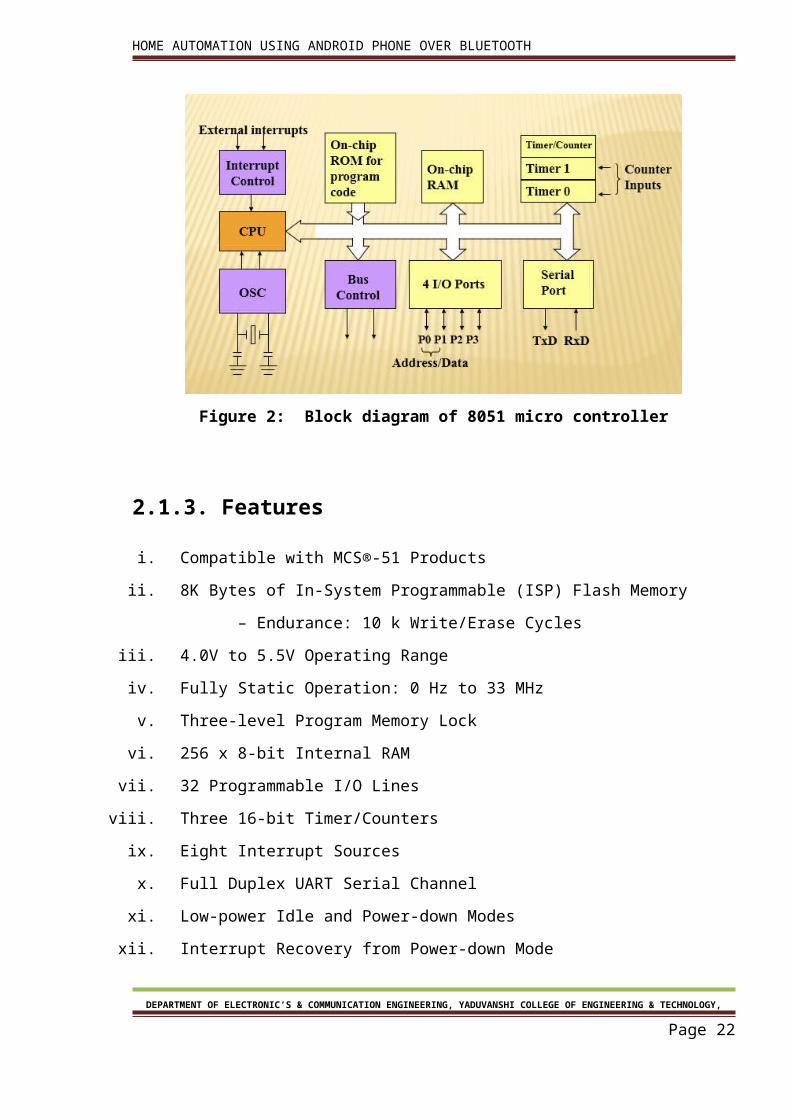
2.1.2. Block Diagram:-
Figure 2: Block diagram of 8051 micro controller
2.1.3. Features
i. Compatible with MCS®-51 Products
ii. 8K Bytes of In-System Programmable (ISP) Flash Memory
– Endurance: 10 k Write/Erase Cycles
iii. 4.0V to 5.5V Operating Range
iv. Fully Static Operation: 0 Hz to 33 MHz
v. Three-level Program Memory Lock
vi. 256 x 8-bit Internal RAM
vii. 32 Programmable I/O Lines
viii. Three 16-bit Timer/Counters
ix. Eight Interrupt Sources
x. Full Duplex UART Serial Channel
xi. Low-power Idle and Power-down Modes
xii. Interrupt Recovery from Power-down Mode
xiii. Watchdog Timer
DEPARTMENT OF ELECTRONIC’S & COMMUNICATION ENGINEERING, YADUVANSHI COLLEGE OF ENGINEERING & TECHNOLOGY,
Page 19
HOME AUTOMATION USING ANDROID PHONE OVER BLUETOOTH
xiv. Dual Data Pointer
xv. Power-off Flag
xvi. Fast Programming Time
xvii. Flexible ISP Programming (Byte and Page Mode)
xviii. Green (Pb/Halide-free) Packaging Option
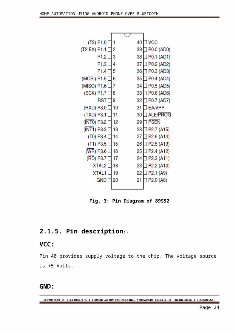
2.1.4 Pin diagram:-
Fig. 3: Pin Diagram of 89S52
DEPARTMENT OF ELECTRONIC’S & COMMUNICATION ENGINEERING, YADUVANSHI COLLEGE OF ENGINEERING & TECHNOLOGY,
Page 20
HOME AUTOMATION USING ANDROID PHONE OVER BLUETOOTH
2.1.5. Pin description:-
VCC:
Pin 40 provides supply voltage to the chip. The voltage source is +5 Volts.
GND:
Pin 20 is the ground.
XTAL1 and XTAL2:
The 8051 has an on chip oscillator but requires an external clock to run it. Most often a
quartz crystal oscillator is connected to inputs XTAL1 (pin 19) and XTAL2 (pin 18). The quartz
crystal oscillator connected to XTAL1 and XTAL2 also needs two capacitors of 30 pf value.
One side of each capacitor is connected to the ground. Speed refers to the maximum
oscillator frequency connected to XTAL .When the 8051 is connected to a crystal oscillator is
powered up we can observe the frequency on the XTAL2 pin using the oscilloscope.
RST:
Pin 9 is the RESET pin. It is an input and is active high. Upon applying a high pulse to this pin
the microcontroller well reset and terminate all activities. This is often referred to as a power
on reset .Activating a power on reset will cause all values the registers to be lost. It will set
program counter to all 0s.
In order for the RESET input to be effective it must have a minimum duration of two machine
cycles. In other words the high pulse must be high for a minimum of two machine cycles
before it is allowed to go low.
EA:
The 8051 family members such as the 8751/52, 89C51/52 or DS89C4*0 all come with on chip
DEPARTMENT OF ELECTRONIC’S & COMMUNICATION ENGINEERING, YADUVANSHI COLLEGE OF ENGINEERING & TECHNOLOGY,
Page 21
HOME AUTOMATION USING ANDROID PHONE OVER BLUETOOTH
ROM to store programs. In such cases the EA pin is connected to Vcc. For family members
such as the 8031 and 8032 in which there is no on chip ROM, code is stored on an external
ROM and is fetched by 8031/32. Therefore for the 8031 the EA pin must be connected to
GND to indicate that the code is stored externally. EA which stands for “external access” is
pin number 31 in the DIP packages. It is an input pin and must be connected to either Vcc or
GND. In other words it cannot be unconnected.
PSEN:
This is an output pin. PSEN stands for “program store enable”. In an 8031 based system in
which an external ROM holds the program code, this pin is connected to the OE pin of the
ROM.
ALE:
ALE stands for “address latch enable. It is an output pin and is active high. When connecting
an 8031 to external memory, port 0 provides both address and data. In other words the
8031 multiplexes address and data through port 0 to save pins. The ALE pin is used for de-
multiplexing the address and data by connecting to G pin of the 74LS373 chip.
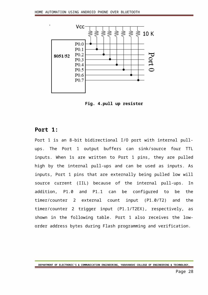
PORTS 0,1,2,3:
All the ports upon RESET are configured as input, since P0-P3 have value FFH on them. The
following is a summary of features of P0-P3.
PORT 0:
Port 0 is also designated as AD0-AD7 allowing it to be used for both address and data. When
connecting an 8051/31 to an external memory, port 0 provides both address and data. The
8051 multiplexes address and data through port 0 to save pins. ALE indicates if p0 has
address A0-A7.in the 8051 based systems where there is no external memory connection the
pins of P0 must be connected externally to 10k-ohm pull-up resistor. This is due to the fact
DEPARTMENT OF ELECTRONIC’S & COMMUNICATION ENGINEERING, YADUVANSHI COLLEGE OF ENGINEERING & TECHNOLOGY,
Page 22
HOME AUTOMATION USING ANDROID PHONE OVER BLUETOOTH
that P0 is an open drain, unlike P1, P2 and P3. Open drain is a term used for MOS chips in the
same way that open collector is used for TTL chips. In many systems using the 8751, 89c51
or DS89c4*0 chips we normally connect P0 to pull up resistors.
Port 0 also receives the code bytes during Flash programming and outputs the code bytes
during program verification. External pull-ups are required during program verification.
Fig. 4.pull up resistor
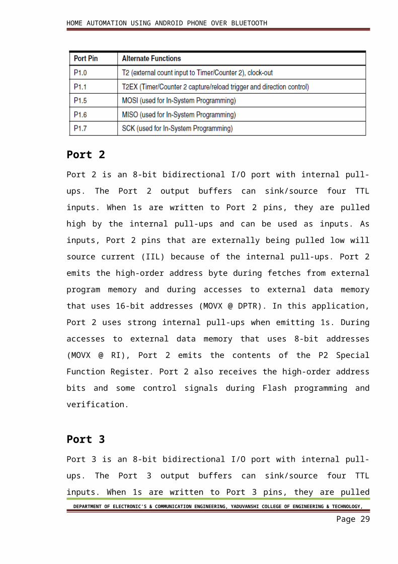
Port 1:
Port 1 is an 8-bit bidirectional I/O port with internal pull-ups. The Port 1 output buffers can
sink/source four TTL inputs. When 1s are written to Port 1 pins, they are pulled high by the
internal pull-ups and can be used as inputs. As inputs, Port 1 pins that are externally being
pulled low will source current (IIL) because of the internal pull-ups. In addition, P1.0 and P1.1
can be configured to be the timer/counter 2 external count input (P1.0/T2) and the
timer/counter 2 trigger input (P1.1/T2EX), respectively, as shown in the following table. Port
1 also receives the low-order address bytes during Flash programming and verification.
DEPARTMENT OF ELECTRONIC’S & COMMUNICATION ENGINEERING, YADUVANSHI COLLEGE OF ENGINEERING & TECHNOLOGY,
Page 23
HOME AUTOMATION USING ANDROID PHONE OVER BLUETOOTH
Port 2
Port 2 is an 8-bit bidirectional I/O port with internal pull-ups. The Port 2 output buffers can
sink/source four TTL inputs. When 1s are written to Port 2 pins, they are pulled high by the
internal pull-ups and can be used as inputs. As inputs, Port 2 pins that are externally being
pulled low will source current (IIL) because of the internal pull-ups. Port 2 emits the high-
order address byte during fetches from external program memory and during accesses to
external data memory that uses 16-bit addresses (MOVX @ DPTR). In this application, Port 2
uses strong internal pull-ups when emitting 1s. During accesses to external data memory
that uses 8-bit addresses (MOVX @ RI), Port 2 emits the contents of the P2 Special Function
Register. Port 2 also receives the high-order address bits and some control signals during
Flash programming and verification.
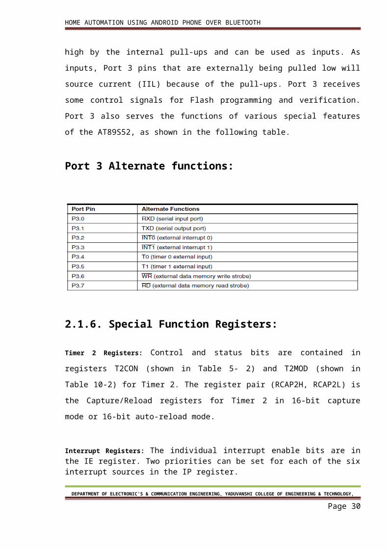
Port 3
Port 3 is an 8-bit bidirectional I/O port with internal pull-ups. The Port 3 output buffers can
sink/source four TTL inputs. When 1s are written to Port 3 pins, they are pulled high by the
internal pull-ups and can be used as inputs. As inputs, Port 3 pins that are externally being
pulled low will source current (IIL) because of the pull-ups. Port 3 receives some control
signals for Flash programming and verification. Port 3 also serves the functions of various
special features of the AT89S52, as shown in the following table.
Port 3 Alternate functions:
DEPARTMENT OF ELECTRONIC’S & COMMUNICATION ENGINEERING, YADUVANSHI COLLEGE OF ENGINEERING & TECHNOLOGY,
Page 24
HOME AUTOMATION USING ANDROID PHONE OVER BLUETOOTH
2.1.6. Special Function Registers:
Timer 2 Registers: Control and status bits are contained in registers T2CON (shown in Table
5- 2) and T2MOD (shown in Table 10-2) for Timer 2. The register pair (RCAP2H, RCAP2L) is
the Capture/Reload registers for Timer 2 in 16-bit capture mode or 16-bit auto-reload mode.
Interrupt Registers: The individual interrupt enable bits are in the IE register. Two priorities can be set for each of the six interrupt sources in the IP register.
Dual Data Pointer Registers: To facilitate accessing both internal and external data memory,
two banks of 16-bit Data Pointer Registers are provided: DP0 at SFR address locations 82H-
83H and DP1 at 84H-85H. Bit DPS = 0 in SFR AUXR1 selects DP0 and DPS = 1 selects DP1. The
user should ALWAYS initialize the DPS bit to the appropriate value before accessing the
respective Data Pointer Register.
Power off Flag: The Power Off Flag (POF) is located at bit 4 (PCON.4) in the PCON SFR. POF is set to “1” during power up. It can be set and rest under software control and is not affected by reset.
2.1.7. Memory Organization
MCS-51 devices have a separate address space for Program and Data Memory. Up to 64K
bytes each of external Program and Data Memory can be addressed.
DEPARTMENT OF ELECTRONIC’S & COMMUNICATION ENGINEERING, YADUVANSHI COLLEGE OF ENGINEERING & TECHNOLOGY,
Page 25
HOME AUTOMATION USING ANDROID PHONE OVER BLUETOOTH
2.1.7.1. Program Memory
If the EA pin is connected to GND, all program fetches are directed to external memory. On
the AT89S52, if EA is connected to VCC, program fetches to addresses 0000H through 1FFFH
are directed to internal memory and fetches to addresses 2000H through FFFFH are to
external memory.
2.1.7.2. Data Memory
The AT89S52 implements 256 bytes of on-chip RAM. The upper 128 bytes occupy a parallel
address space to the Special Function Registers. This means that the upper 128 bytes have
the same addresses as the SFR space but are physically separate from SFR space.
When an instruction accesses an internal location above address 7FH, the address mode
used in the instruction specifies whether the CPU accesses the upper 128 bytes of RAM or
the SFR space. Instructions which use direct addressing access the SFR space.
For example, the following direct addressing instruction accesses the SFR at location 0A0H
(which is P2).
MOV 0A0H, #data
Instructions that use indirect addressing access the upper 128 bytes of RAM. For example,
the following indirect addressing instruction, where R0 contains 0A0H, accesses the data
byte at address 0A0H, rather than P2 (whose address is 0A0H).
MOV @R0, #data
Note that stack operations are examples of indirect addressing, so the upper 128 bytes of
data RAM are available as stack space.
2.1.8. Watchdog Timer (One-time Enabled with Reset-out)
DEPARTMENT OF ELECTRONIC’S & COMMUNICATION ENGINEERING, YADUVANSHI COLLEGE OF ENGINEERING & TECHNOLOGY,
Page 26
HOME AUTOMATION USING ANDROID PHONE OVER BLUETOOTH
The WDT is intended as a recovery method in situations where the CPU may be subjected to
software upsets. The WDT consists of a 14-bit counter and the Watchdog Timer Reset
(WDTRST) SFR. The WDT is defaulted to disable from exiting reset. To enable the WDT, a
user must write 01EH and 0E1H in sequence to the WDTRST register (SFR location 0A6H).
When the WDT is enabled, it will increment every machine cycle while the oscillator is
running. The WDT timeout period is dependent on the external clock frequency. There is no
way to disable the WDT except through reset (either hardware reset or WDT overflow reset).
When WDT over-flows, it will drive an output RESET HIGH pulse at the RST pin.
2.2 BLUETOOTH MODULE (HC-05):
Overview: Communication device:-over project is based on wireless communication
between micro controller and mobile phone. But alone micro controller is not able to
communicate directly to the android mobile phone. Bluetooth Serial module’s operation
doesn’t need drive, and can communicate with the other Bluetooth device that has the
serial. But communication between two Bluetooth modules requires at
Least two conditions:
(1) The communication must be between master and slave.
(2) The password must be correct.
HC-05 module is an easy to use Bluetooth SPP (Serial Port Protocol) module, designed for
transparent wireless serial connection setup. Serial port Bluetooth module is fully qualified
Bluetooth V2.0+EDR (Enhanced Data Rate) 3Mbps Modulation with complete 2.4GHz radio
transceiver and baseband. It uses CSR Blue core 04 External single chip Bluetooth system‐
with CMOS technology and with AFH (Adaptive Frequency Hopping Feature). It has the
Foot print as small as 12.7mmx27mm.
HC-05 module is an easy to use Bluetooth SPP (Serial Port Protocol) module, designed for
transparent wireless serial connection setup. Serial port Bluetooth module is fully qualified
Bluetooth V2.0+EDR (Enhanced Data Rate) 3Mbps Modulation with complete 2.4GHz radio
transceiver and baseband
DEPARTMENT OF ELECTRONIC’S & COMMUNICATION ENGINEERING, YADUVANSHI COLLEGE OF ENGINEERING & TECHNOLOGY,
Page 27
HOME AUTOMATION USING ANDROID PHONE OVER BLUETOOTH
Bluetooth Wireless networks for short range communications have a wide spread usage of
Bluetooth radio transmissions between 2400–2480 MHz Modern mobile devices embed
small, low-powered and cheap integrated chips functioning as short-range radio transceivers
for Bluetooth radio communications. Device pairing, authentication, encryption and
authorization techniques have given recognition to Bluetooth technology due to its vital
security mechanisms.
Different types of Bluetooth applications can be developed using Android platform
architecture using the Bluetooth profiles. The device manufacturers provide the services
using the support of these profiles in their devices to maintain compatibility for the
Bluetooth technology
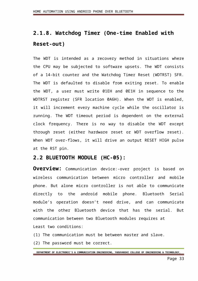
Fig. 5.HC-05 Bluetooth
2.2.1. Specifications Hardware features
Typical -80dBm sensitivity.
Up to +4dBm RF transmits power.
Low Power 1.8V Operation, 3.3 to 5 V I/O.
PIO control.
UART interface with programmable baud rate.
With integrated antenna.
With edge connector.
Software features Slave default Baud rate: 9600, Data bits:8, Stop bit:1,Parity:No parity.
DEPARTMENT OF ELECTRONIC’S & COMMUNICATION ENGINEERING, YADUVANSHI COLLEGE OF ENGINEERING & TECHNOLOGY,
Page 28
HOME AUTOMATION USING ANDROID PHONE OVER BLUETOOTH
PIO9 and PIO8 can be connected to red and blue led separately. When master and slave
are paired, red and blue led blinks 1time/2s in interval, while disconnected only blue led
blinks 2times/s.
Auto connects to the last device on power as default.
Permit pairing device to connect as default.
Auto pairing PINCODE:”1234” as default.
Auto reconnect in 30 min when disconnected as a result of beyond the
range of connection.
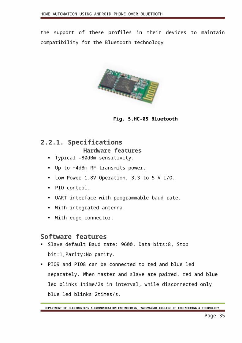
2.2.2. Pin out configuration
Figure 6: Pin-out of HC-05
2.2.3. Typical Application Circuit:
DEPARTMENT OF ELECTRONIC’S & COMMUNICATION ENGINEERING, YADUVANSHI COLLEGE OF ENGINEERING & TECHNOLOGY,
Page 29
HOME AUTOMATION USING ANDROID PHONE OVER BLUETOOTH
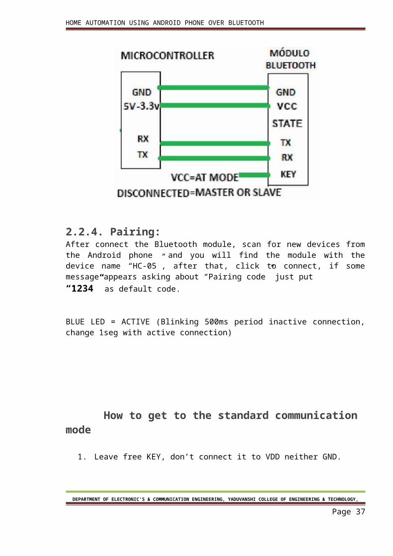
2.2.4. Pairing:After connect the Bluetooth module, scan for new devices from the Android phone and you will find the module with the device name “HC-05”, after that, click to connect, if some message appears asking about “Pairing code” just put“1234” as default code.
BLUE LED = ACTIVE (Blinking 500ms period inactive connection, change 1seg with active connection)
How to get to the standard communication mode
1. Leave free KEY, don’t connect it to VDD neither GND.
2. Supply power to the module. Then the module will enter to communication mode. It
can be used for pairing.
DEPARTMENT OF ELECTRONIC’S & COMMUNICATION ENGINEERING, YADUVANSHI COLLEGE OF ENGINEERING & TECHNOLOGY,
Page 30
HOME AUTOMATION USING ANDROID PHONE OVER BLUETOOTH
2.2.5. HC-05 BLUETOOTH MODULE WORKING VOLTAGE:-The Bluetooth module HC-05 is used to receive & transmit data between Bluetooth device
and MCU. It requires power supply from 3.3V to 5V.
2.2.6. SERIAL COMMUNICATION:-
To transfer to a device located many meters away, the serial method is used. The data is
sent one bit at a time. Here not 8bit data is send 2 extra bit are send along with it .this two
bit are called start bit and stop bit. These tow bit are used so synchronization can be done
between transmitter and receiver.
2.3 Driver IC:
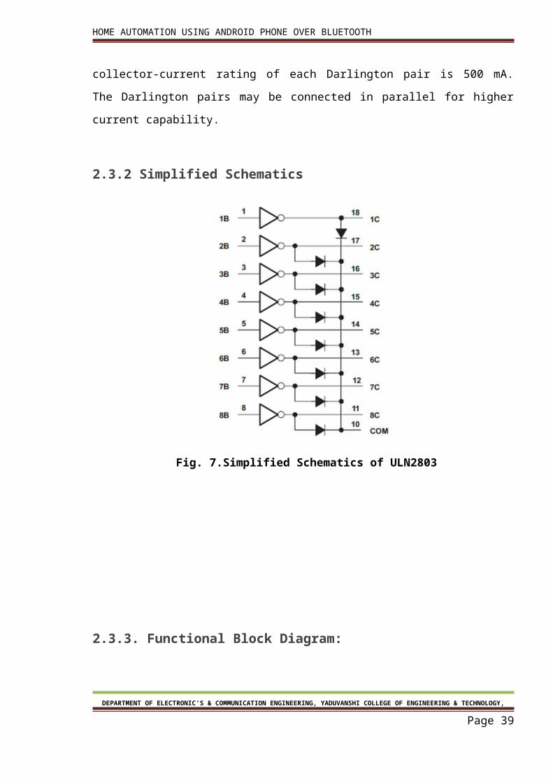
2.3.1 ULN2803A Darlington Transistor Arrays:-
The ULN2803A device is a high-voltage, high- current Darlington transistor array. The
device consists of eight NPN Darlington pairs that feature high-voltage outputs with
common-cathode clamp diodes for switching inductive loads. The collector-current rating of
each Darlington pair is 500 mA. The Darlington pairs may be connected in parallel for higher
current capability.
2.3.2 Simplified Schematics
DEPARTMENT OF ELECTRONIC’S & COMMUNICATION ENGINEERING, YADUVANSHI COLLEGE OF ENGINEERING & TECHNOLOGY,
Page 31
HOME AUTOMATION USING ANDROID PHONE OVER BLUETOOTH
Fig. 7.Simplified Schematics of ULN2803
2.3.3. Functional Block Diagram:
DEPARTMENT OF ELECTRONIC’S & COMMUNICATION ENGINEERING, YADUVANSHI COLLEGE OF ENGINEERING & TECHNOLOGY,
Page 32
HOME AUTOMATION USING ANDROID PHONE OVER BLUETOOTH
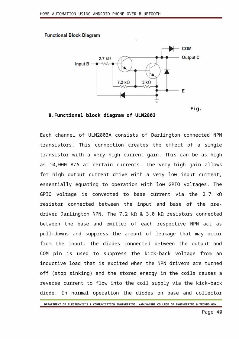
Fig. 8.Functional block diagram of ULN2803
Each channel of ULN2803A consists of Darlington connected NPN transistors. This
connection creates the effect of a single transistor with a very high current gain. This can be
as high as 10,000 A/A at certain currents. The very high gain allows for high output current
drive with a very low input current, essentially equating to operation with low GPIO voltages.
The GPIO voltage is converted to base current via the 2.7 kΩ resistor connected between the
input and base of the pre-driver Darlington NPN. The 7.2 kΩ & 3.0 kΩ resistors connected
between the base and emitter of each respective NPN act as pull-downs and suppress the
amount of leakage that may occur from the input. The diodes connected between the
output and COM pin is used to suppress the kick-back voltage from an inductive load that is
excited when the NPN drivers are turned off (stop sinking) and the stored energy in the coils
causes a reverse current to flow into the coil supply via the kick-back diode. In normal
operation the diodes on base and collector pins to emitter will be reversed biased. If these
diode are forward biased, internal parasitic NPN transistors will draw (a nearly equal) current
from other (nearby) device pins.
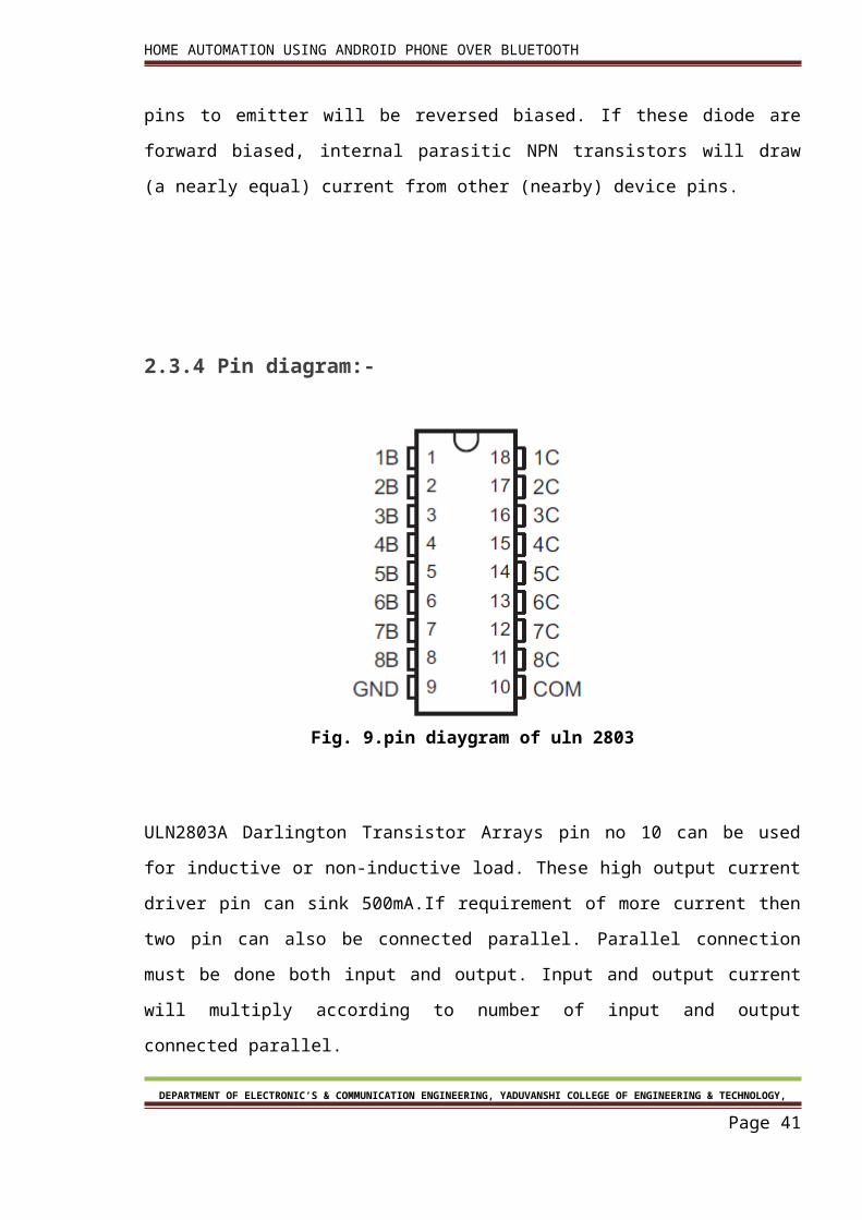
2.3.4 Pin diagram:-
DEPARTMENT OF ELECTRONIC’S & COMMUNICATION ENGINEERING, YADUVANSHI COLLEGE OF ENGINEERING & TECHNOLOGY,
Page 33
HOME AUTOMATION USING ANDROID PHONE OVER BLUETOOTH
Fig. 9.pin diaygram of uln 2803
ULN2803A Darlington Transistor Arrays pin no 10 can be used for inductive or non-inductive
load. These high output current driver pin can sink 500mA.If requirement of more current
then two pin can also be connected parallel. Parallel connection must be done both input
and output. Input and output current will multiply according to number of input and output
connected parallel.
2.3.5 Inductive Load Drive
When the COM pin is tied to the coil supply voltage, ULN2803A is able to drive inductive
loads and suppress the Kick-back voltage via the internal freewheeling diodes.
2.3.6 Resistive Load Drive
DEPARTMENT OF ELECTRONIC’S & COMMUNICATION ENGINEERING, YADUVANSHI COLLEGE OF ENGINEERING & TECHNOLOGY,
Page 34
HOME AUTOMATION USING ANDROID PHONE OVER BLUETOOTH
When driving a resistive load, a pull-up resistor is needed in order for ULN2803A to sink
current and for there to be a logic high level. The COM pin can be left floating for these
applications
2.4 Switches:-
Switches are used for connecting or disconnecting electrical circuit. Many types of switches
are there. Some are operate mechanically or electrically. Some types are SPST, SPDT, DPST
and DPDT in case of switch. SPST stands for single pole single through, SPDT stands for single
pole double through, DPST stands for double pole single through and DPDT stands for
double pole double through,
In relays points are defines by NO, NC. NO stand for normally
on and NC stands for normally off.
2.4.1 Relay:-
Relays are electromagnetic switch. Which can be turn on and off by Appling electrical
current. Working voltage is printed on the relay. In this project we are using 6volt relay.
Many relay use an electromagnet to mechanically operate a switch.
Fig.10. .Relays
2.5 Connector:-DEPARTMENT OF ELECTRONIC’S & COMMUNICATION ENGINEERING, YADUVANSHI COLLEGE OF ENGINEERING &
TECHNOLOGY,
Page 35
HOME AUTOMATION USING ANDROID PHONE OVER BLUETOOTH
Connectors are used for joining two wires temporally by using connector big circuit can be
divided and after completion they can rejoin. Now a day’s every time inverter circuited can
be removed out without using de soldering.
2.6 Vp812 burner:-
This is the vp812 burner hardware. This is used to burn hex file to the ATMEL 89s52
microcontroller. This burner we can also burn PIC, AVR microcontrollers.
Figure 11: VP812 hex file burner
There is a method given which shows how to place microcontroller on this burner. If wrong
method is used then there will be error display “id not matched”. This vp812 burner comes
with support cd which has software. This cd includes usb to serial software.
This software support window 7, vista and XP only.
DEPARTMENT OF ELECTRONIC’S & COMMUNICATION ENGINEERING, YADUVANSHI COLLEGE OF ENGINEERING & TECHNOLOGY,
Page 36
HOME AUTOMATION USING ANDROID PHONE OVER BLUETOOTH
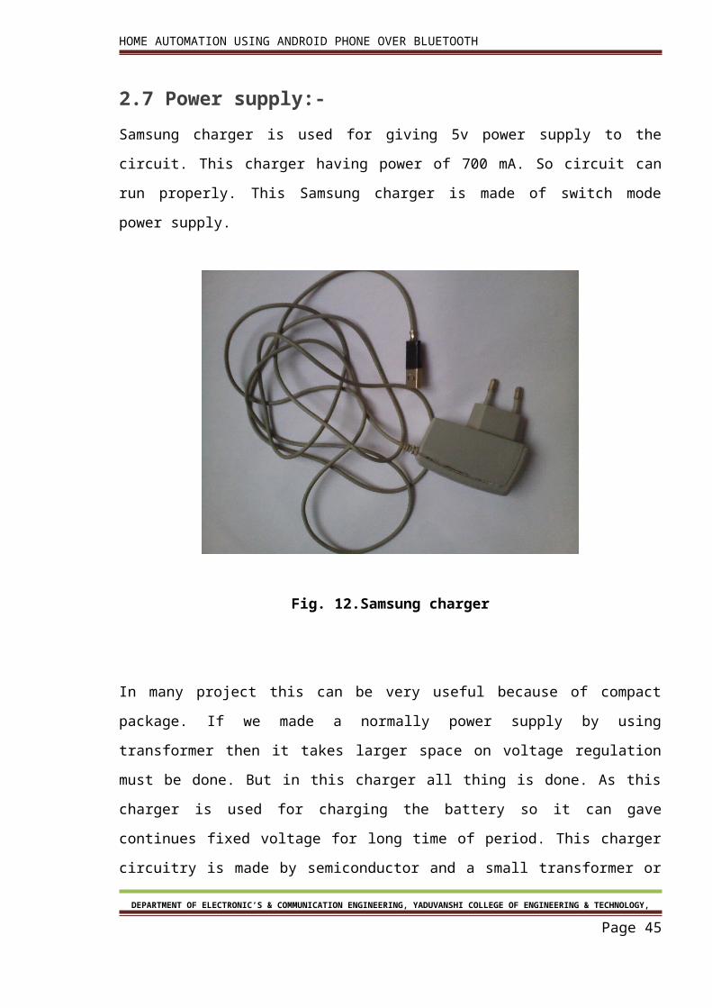
2.7 Power supply:-
Samsung charger is used for giving 5v power supply to the circuit. This charger having power
of 700 mA. So circuit can run properly. This Samsung charger is made of switch mode power
supply.
Fig. 12.Samsung charger
In many project this can be very useful because of compact package. If we made a normally
power supply by using transformer then it takes larger space on voltage regulation must be
done. But in this charger all thing is done. As this charger is used for charging the battery so
it can gave continues fixed voltage for long time of period. This charger circuitry is made by
semiconductor and a small transformer or we can say SMPS “switch mode power supply” as
a capacitor is used in this charger so charger can gave output for a short duration if power is
switched-off.
DEPARTMENT OF ELECTRONIC’S & COMMUNICATION ENGINEERING, YADUVANSHI COLLEGE OF ENGINEERING & TECHNOLOGY,
Page 37
HOME AUTOMATION USING ANDROID PHONE OVER BLUETOOTH
Chapter 3 Software
DEPARTMENT OF ELECTRONIC’S & COMMUNICATION ENGINEERING, YADUVANSHI COLLEGE OF ENGINEERING & TECHNOLOGY,
Page 38
HOME AUTOMATION USING ANDROID PHONE OVER BLUETOOTH
Chapter 3 Software
INTRODUCTION: Electronic design automation (EDA or ECAD) is a category of software tools for designing electronic systems such as printed circuit boards and integrated circuits. The tools work together in a design flow that chip designers use to design and analyze entire semiconductor chips. The various software’s used are:
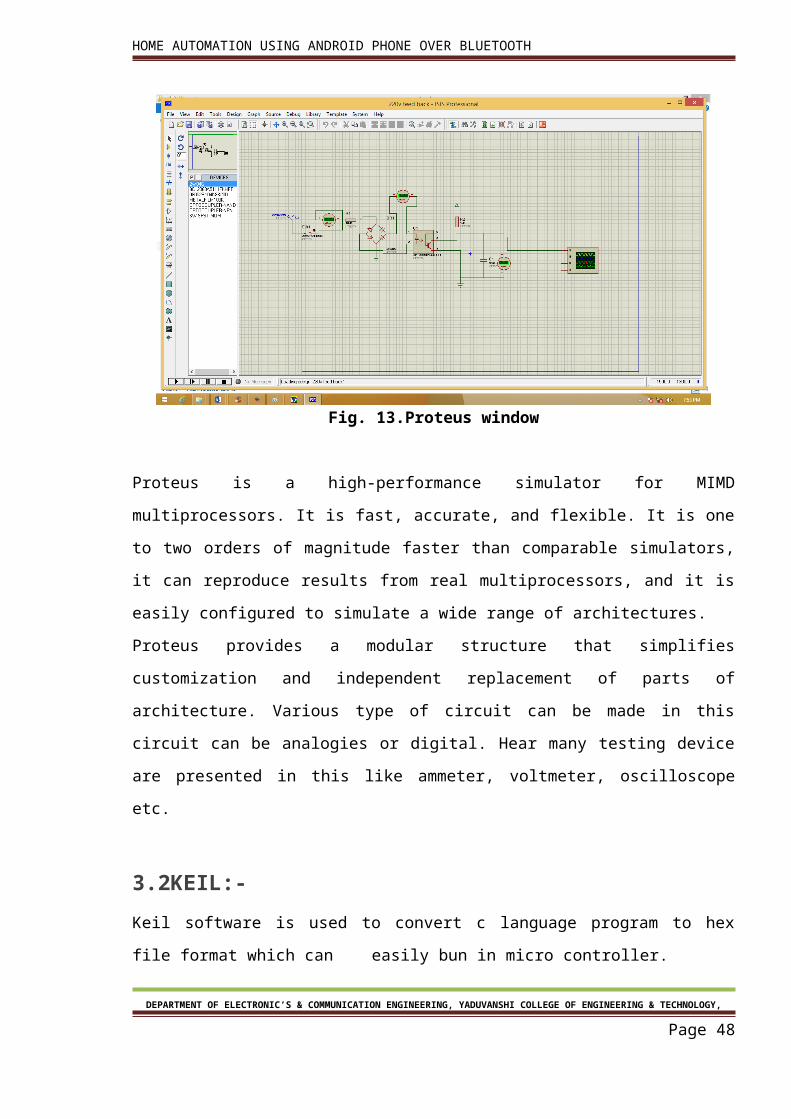
3.1 PROTEUS:-
Proteus is software in which we can design the circuit with using hard ware component. In
this software input and output relation is shows in this software.
Fig. 13.Proteus window
Proteus is a high-performance simulator for MIMD multiprocessors. It is fast, accurate, and
flexible. It is one to two orders of magnitude faster than comparable simulators, it can
reproduce results from real multiprocessors, and it is easily configured to simulate a wide
range of architectures.
DEPARTMENT OF ELECTRONIC’S & COMMUNICATION ENGINEERING, YADUVANSHI COLLEGE OF ENGINEERING & TECHNOLOGY,
Page 39
HOME AUTOMATION USING ANDROID PHONE OVER BLUETOOTH
Proteus provides a modular structure that simplifies customization and independent
replacement of parts of architecture. Various type of circuit can be made in this circuit can
be analogies or digital. Hear many testing device are presented in this like ammeter,
voltmeter, oscilloscope etc.
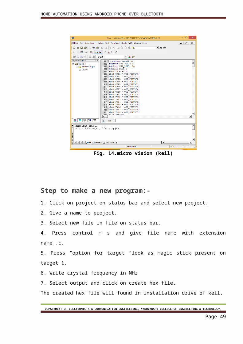
3.2KEIL:-
Keil software is used to convert c language program to hex file format which can easily bun
in micro controller.
Fig. 14.micro vision (keil)
Step to make a new program:-
1. Click on project on status bar and select new project.
2. Give a name to project.
3. Select new file in file on status bar.
4. Press control + s and give file name with extension name .c.
DEPARTMENT OF ELECTRONIC’S & COMMUNICATION ENGINEERING, YADUVANSHI COLLEGE OF ENGINEERING & TECHNOLOGY,
Page 40
HOME AUTOMATION USING ANDROID PHONE OVER BLUETOOTH
5. Press “option for target “look as magic stick present on target 1.
6. Write crystal frequency in MHz
7. Select output and click on create hex file.
The created hex file will found in installation drive of keil.
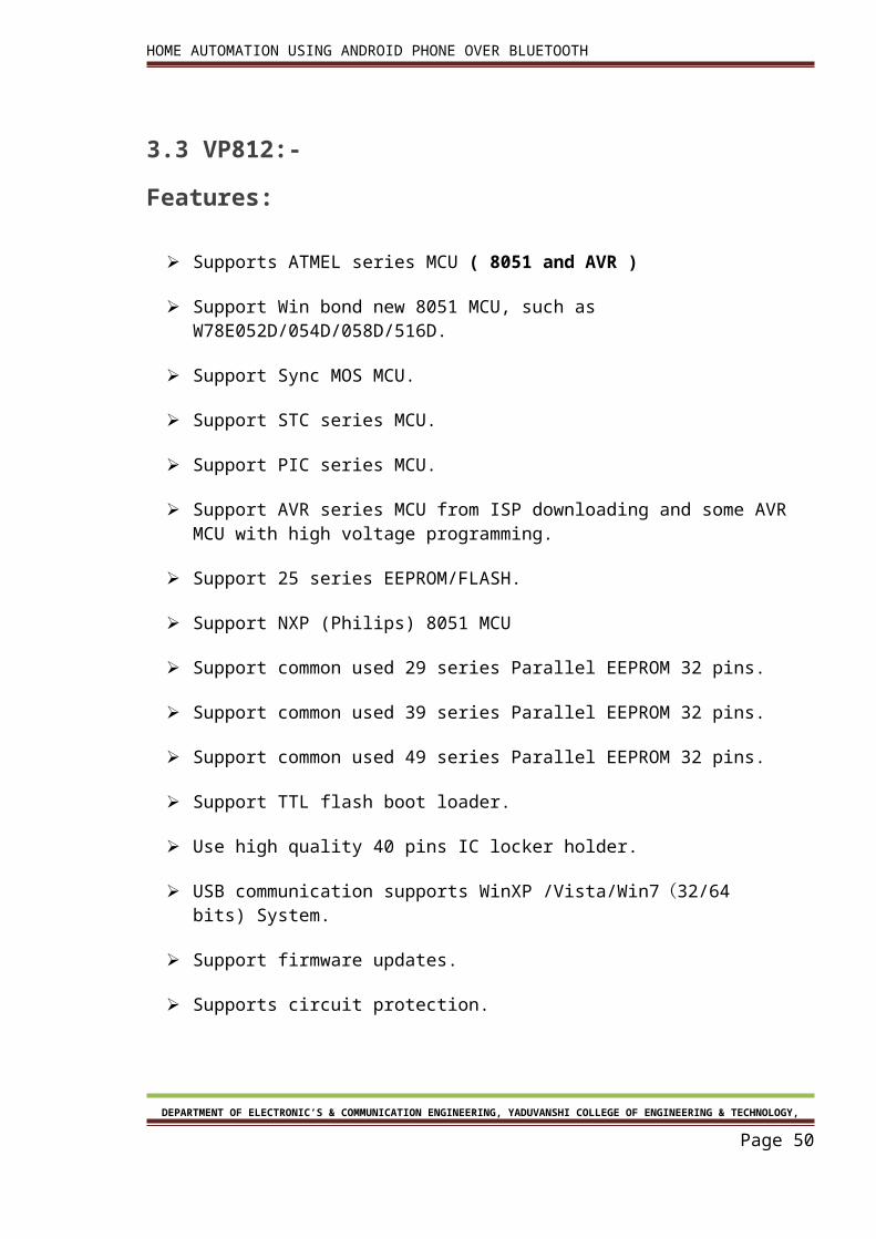
3.3 VP812:-
Features:
Supports ATMEL series MCU ( 8051 and AVR )
Support Win bond new 8051 MCU, such as W78E052D/054D/058D/516D.
Support Sync MOS MCU.
Support STC series MCU.
Support PIC series MCU.
Support AVR series MCU from ISP downloading and some AVR MCU with high voltage programming.
Support 25 series EEPROM/FLASH.
Support NXP (Philips) 8051 MCU
Support common used 29 series Parallel EEPROM 32 pins.
Support common used 39 series Parallel EEPROM 32 pins.
Support common used 49 series Parallel EEPROM 32 pins.
Support TTL flash boot loader.
Use high quality 40 pins IC locker holder.
USB communication supports WinXP /Vista/Win7(32/64 bits) System.
Support firmware updates.
Supports circuit protection.
DEPARTMENT OF ELECTRONIC’S & COMMUNICATION ENGINEERING, YADUVANSHI COLLEGE OF ENGINEERING & TECHNOLOGY,
Page 41
HOME AUTOMATION USING ANDROID PHONE OVER BLUETOOTH
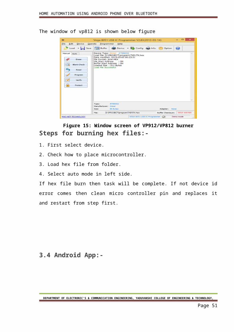
The window of vp812 is shown below figure
Figure 15: Window screen of VP912/VP812 burner
Steps for burning hex files:-
1. First select device.
2. Check how to place microcontroller.
3. Load hex file from folder.
4. Select auto mode in left side.
If hex file burn then task will be complete. If not device id error comes then clean micro
controller pin and replaces it and restart from step first.
3.4 Android App:-
Figure 16: Android Logo
DEPARTMENT OF ELECTRONIC’S & COMMUNICATION ENGINEERING, YADUVANSHI COLLEGE OF ENGINEERING & TECHNOLOGY,
Page 42
HOME AUTOMATION USING ANDROID PHONE OVER BLUETOOTH
Android has a dictionary meaning of being a human that resembles automation. The true
character of its name is it’s the Google created software stack for creating comprehensive
Mobile Applications and Software to realize the full potential of one’s Mobile handset and its
possibilities.
Android is a comprehensive software stack of mobile devices that includes an operating
system, middleware and key application. This rich source of software bunch is used in
Mobile Technology through its innovation module of The Android Software Development Kit
(SDK).
Applications:
These are the basics of Android applications:
• Android applications are composed of one or more application components (activities,
services, content providers, and broadcast receivers)
• Each component performs a different role in the overall application behavior, and each
one can be activated individually (even by other applications)
• The manifest file must declare all components in the application and should also
declare all application requirements, such as the minimum version of Android required and
any hardware configurations required
• Non-code application resources (images, strings, layout files, etc.) should include
alternatives for different device configurations (such as different strings for different
languages)
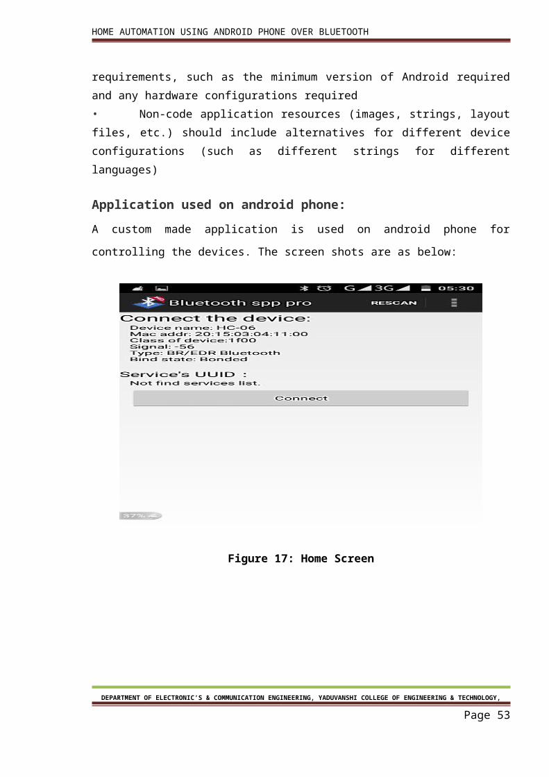
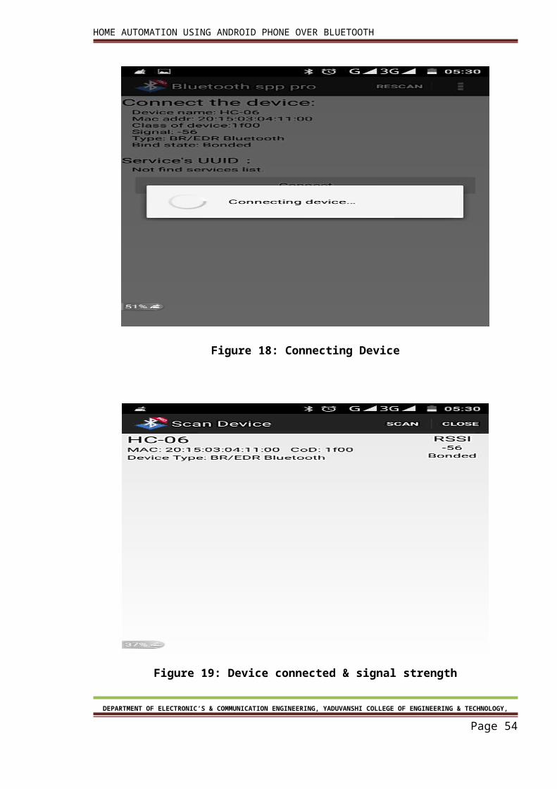
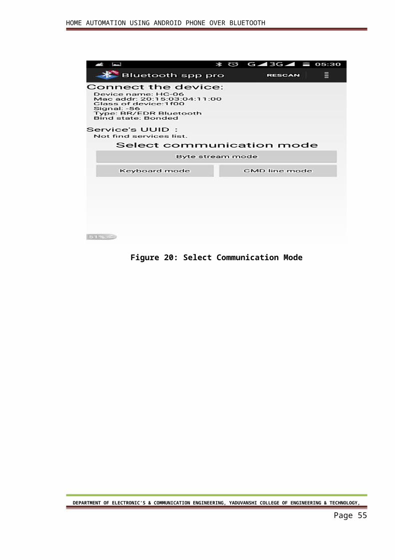
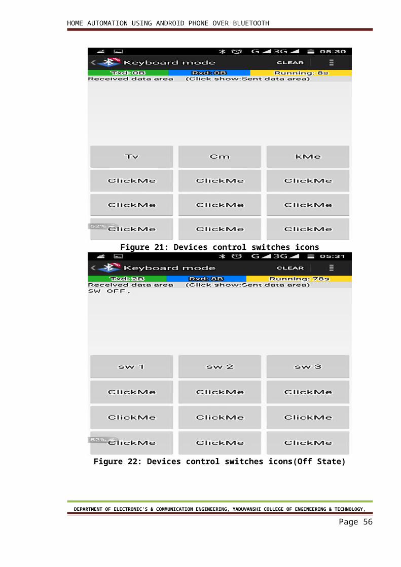
Application used on android phone:
A custom made application is used on android phone for controlling the devices. The screen
shots are as below:
DEPARTMENT OF ELECTRONIC’S & COMMUNICATION ENGINEERING, YADUVANSHI COLLEGE OF ENGINEERING & TECHNOLOGY,
Page 43
HOME AUTOMATION USING ANDROID PHONE OVER BLUETOOTH
Figure 17: Home Screen
Figure 18: Connecting Device
DEPARTMENT OF ELECTRONIC’S & COMMUNICATION ENGINEERING, YADUVANSHI COLLEGE OF ENGINEERING & TECHNOLOGY,
Page 44
HOME AUTOMATION USING ANDROID PHONE OVER BLUETOOTH
Figure 19: Device connected & signal strength
Figure 20: Select Communication Mode
DEPARTMENT OF ELECTRONIC’S & COMMUNICATION ENGINEERING, YADUVANSHI COLLEGE OF ENGINEERING & TECHNOLOGY,
Page 45
HOME AUTOMATION USING ANDROID PHONE OVER BLUETOOTH
Figure 21: Devices control switches icons
Figure 22: Devices control switches icons(Off State)
DEPARTMENT OF ELECTRONIC’S & COMMUNICATION ENGINEERING, YADUVANSHI COLLEGE OF ENGINEERING & TECHNOLOGY,
Page 46
HOME AUTOMATION USING ANDROID PHONE OVER BLUETOOTH
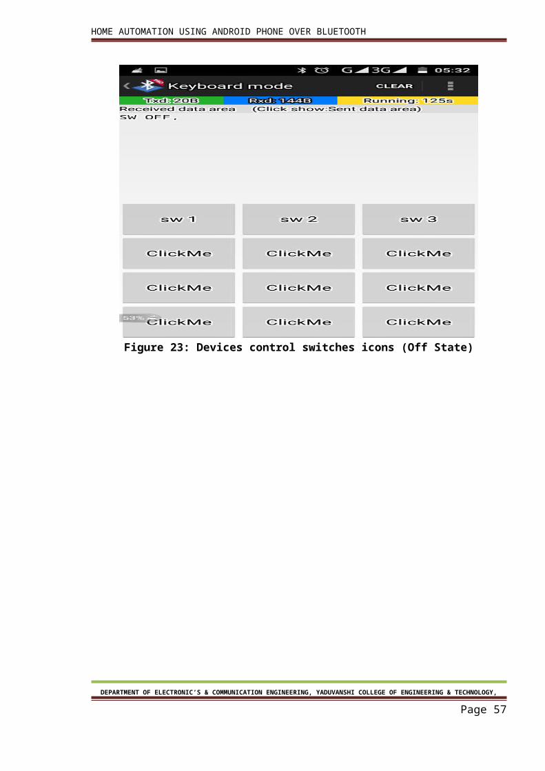
Figure 23: Devices control switches icons (Off State)
DEPARTMENT OF ELECTRONIC’S & COMMUNICATION ENGINEERING, YADUVANSHI COLLEGE OF ENGINEERING & TECHNOLOGY,
Page 47
HOME AUTOMATION USING ANDROID PHONE OVER BLUETOOTH
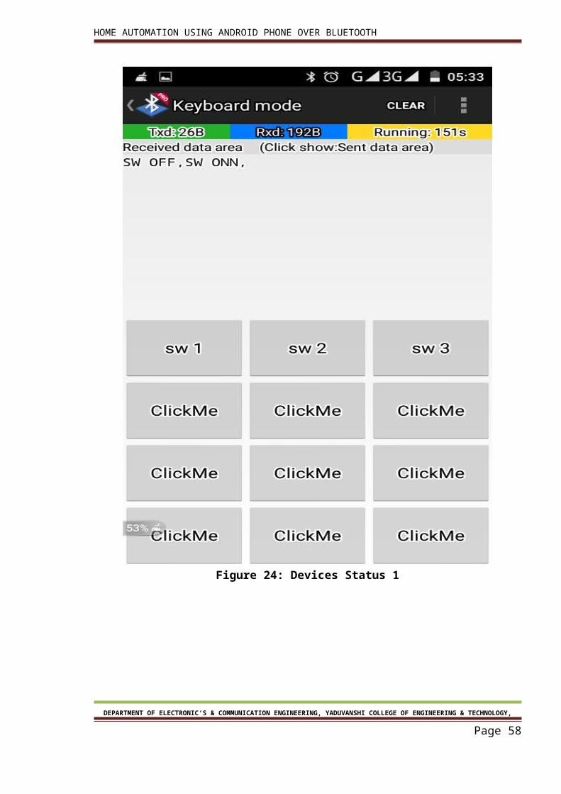
Figure 24: Devices Status 1
DEPARTMENT OF ELECTRONIC’S & COMMUNICATION ENGINEERING, YADUVANSHI COLLEGE OF ENGINEERING & TECHNOLOGY,
Page 48
HOME AUTOMATION USING ANDROID PHONE OVER BLUETOOTH
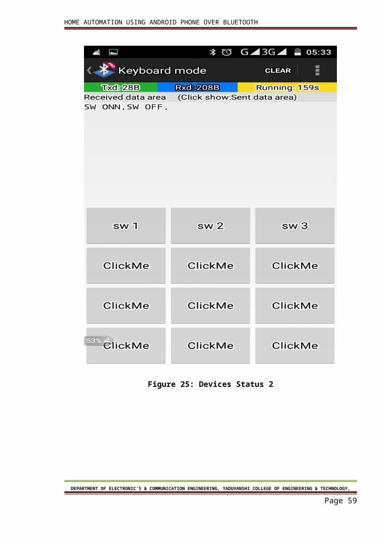
Figure 25: Devices Status 2
DEPARTMENT OF ELECTRONIC’S & COMMUNICATION ENGINEERING, YADUVANSHI COLLEGE OF ENGINEERING & TECHNOLOGY,
Page 49
HOME AUTOMATION USING ANDROID PHONE OVER BLUETOOTH
Chapter4 Serial communication in 89s52
DEPARTMENT OF ELECTRONIC’S & COMMUNICATION ENGINEERING, YADUVANSHI COLLEGE OF ENGINEERING & TECHNOLOGY,
Page 50
HOME AUTOMATION USING ANDROID PHONE OVER BLUETOOTH
Chapter4 Serial communication in 89s52
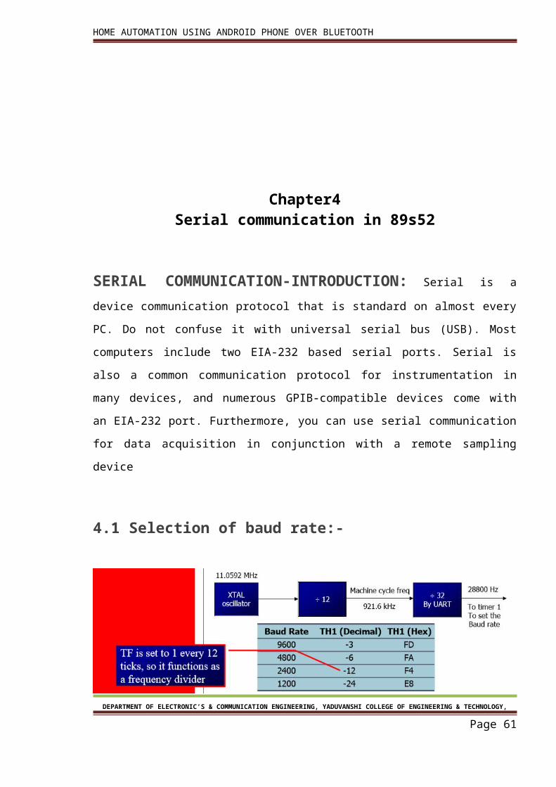
SERIAL COMMUNICATION-INTRODUCTION: Serial is a device communication
protocol that is standard on almost every PC. Do not confuse it with universal serial bus
(USB). Most computers include two EIA-232 based serial ports. Serial is also a common
communication protocol for instrumentation in many devices, and numerous GPIB-
compatible devices come with an EIA-232 port. Furthermore, you can use serial
communication for data acquisition in conjunction with a remote sampling device
4.1 Selection of baud rate:-
Figure 27: Selection of baud rate
4.2 SBUF register:-
SBUF is an 8-bit register used for serial communication.
For a byte data to be transferred via the Txd line, it must be placed in the SBUF register. The
moment a byte is written into SBUF, it is framed with the start and stop bits and transferred
serially via the Txd line
DEPARTMENT OF ELECTRONIC’S & COMMUNICATION ENGINEERING, YADUVANSHI COLLEGE OF ENGINEERING & TECHNOLOGY,
Page 51
HOME AUTOMATION USING ANDROID PHONE OVER BLUETOOTH
SBUF holds the byte of data when it is received by 8051 RxD line .When the bits are received
serially via RxD, the 8051 de frames it by eliminating the stop and start bits, making a byte
out of the data received, and then placing it in SBUF.
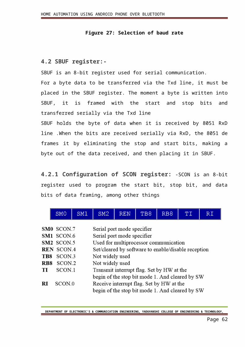
4.2.1 Configuration of SCON register: -SCON is an 8-bit register used to program the
start bit, stop bit, and data bits of data framing, among other things
Fig. 28.SCON register
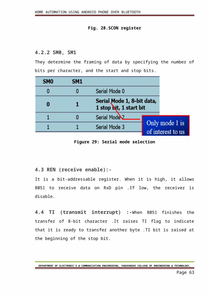
4.2.2 SM0, SM1
They determine the framing of data by specifying the number of bits per character, and the
start and stop bits.
DEPARTMENT OF ELECTRONIC’S & COMMUNICATION ENGINEERING, YADUVANSHI COLLEGE OF ENGINEERING & TECHNOLOGY,
Page 52
HOME AUTOMATION USING ANDROID PHONE OVER BLUETOOTH
Figure 29: Serial mode selection
4.3 REN (receive enable):-
It is a bit-addressable register. When it is high, it allows 8051 to receive data on RxD pin .If
low, the receiver is disable.
4.4 TI (transmit interrupt) :-When 8051 finishes the transfer of 8-bit character .It raises
TI flag to indicate that it is ready to transfer another byte .TI bit is raised at the beginning of
the stop bit.
4.5 RI (receive interrupt) :-When 8051 receives data serially via RxD, it gets rid of the
start and stop bits and places the byte in SBUF register .It raises the RI flag bit to indicate
that a byte has been received and should be picked up before it is lost .RI is raised halfway
through the stop bit.
4.6 Steps for transmitting and receiving of character
4.6.1 The steps that 8051 goes through in transmitting a character via TxD
1. The byte character to be transmitted is written into the SBUF register
2. The start bit is transferred
DEPARTMENT OF ELECTRONIC’S & COMMUNICATION ENGINEERING, YADUVANSHI COLLEGE OF ENGINEERING & TECHNOLOGY,
Page 53
HOME AUTOMATION USING ANDROID PHONE OVER BLUETOOTH
3. The 8-bit character is transferred on bit at a time
4. The stop bit is transferred .It is during the transfer of the stop bit that 8051 raises the
TI flag, indicating that the last character was transmitted
5. By monitoring the TI flag, we make sure that we are not overloading the SBUF .If we
write another byte into the SBUF before TI is raised; the un-transmitted portion of
the previous byte will be lost
6. After SBUF is loaded with a new byte, the TI flag bit must be forced to 0 by CLR TI in
order for this new byte to be transferred.
By checking the TI flag bit, we know whether or not the 8051 is ready to transfer another
byte .It must be noted that TI flag bit is raised by 8051 itself when it finishes data transfer ¾It
must be cleared by the programmer with instruction CLR TI ¾If we write a byte into SBUF
before the TI flag bit is raised, we risk the loss of a portion of the byte being transferred .The
TI bit can be checked by ¾The instruction JNB TI, xx .Using an interrupt.
4.6.2. Programming the 8051 to transfer character bytes serially
1. TMOD register is loaded with the value 20H, indicating the use of timer 1 in mode 2
(8-bit auto-reload) to set baud rate
2. The TH1 is loaded with one of the values to set baud rate for serial data transfer
3. The SCON register is loaded with the value 50H, indicating serial mode 1, where an 8-
bit data is framed with start and stop bits
4. TR1 is set to 1 to start timer 1
5. TI is cleared by CLR TI instruction
6. The character byte to be transferred serially is written into SBUF register
7. The TI flag bit is monitored with the use of instruction JNB TI, xx to see if the
character has been transferred completely
8. To transfer the next byte, go to step 5
9. The steps that 8051 goes through in transmitting a character via Txd
DEPARTMENT OF ELECTRONIC’S & COMMUNICATION ENGINEERING, YADUVANSHI COLLEGE OF ENGINEERING & TECHNOLOGY,
Page 54
HOME AUTOMATION USING ANDROID PHONE OVER BLUETOOTH
10. The byte character to be transmitted is written into the SBUF register
11. The start bit is transferred
12. The 8-bit character is transferred on bit at a time
13. The stop bit is transferred .It is during the transfer of the stop bit that 8051 raises the
TI flag, indicating that the last character was transmitted
14. By monitoring the TI flag, we make sure that we are not overloading the SBUF .If we
write another byte into the SBUF before TI is raised, the transmitted portion of the
previous byte will be lost
15. After SBUF is loaded with a new byte, the TI flag bit must be forced to 0 by CLR TI in
order for this new byte to be transferred
4.6.3 Importance of TI Flag
By checking the TI flag bit, we know whether or not the 8051 is ready to transfer another
byte It must be noted that TI flag bit is raised by 8051 itself when it finishes data transfer .It
must be cleared by the programmer with instruction CLR TI ¾If we write a byte into SBUF
before the TI flag bit is raised, we risk the loss of a portion of the byte being transferred .he
TI bit can be checked by The instruction JNB TI, xx .Using an interrupt
4.6.4 Programming the 8051 to receive character bytes serially
1. TMOD register is loaded with the value 20H, indicating the use of timer 1 in mode 2
(8-bit auto-reload) to set baud rate
2. TH1 is loaded to set baud rate
3. The SCON register is loaded with the value 50H, indicating serial mode 1, where an 8-
bit data is framed with start and stop bits
4. TR1 is set to 1 to start timer 1
5. RI is cleared by CLR Reinstruction
6. The RI flag bit is monitored with the use of instruction JNB RI, xxto see if an entire
character has been received yet
7. When RI is raised, SBUF has the byte, its contents are moved into a safe place
8. To receive the next character, go to step 5
DEPARTMENT OF ELECTRONIC’S & COMMUNICATION ENGINEERING, YADUVANSHI COLLEGE OF ENGINEERING & TECHNOLOGY,
Page 55
HOME AUTOMATION USING ANDROID PHONE OVER BLUETOOTH
Chapter 5Program
Chapter 5
Program
DEPARTMENT OF ELECTRONIC’S & COMMUNICATION ENGINEERING, YADUVANSHI COLLEGE OF ENGINEERING & TECHNOLOGY,
Page 56
HOME AUTOMATION USING ANDROID PHONE OVER BLUETOOTH
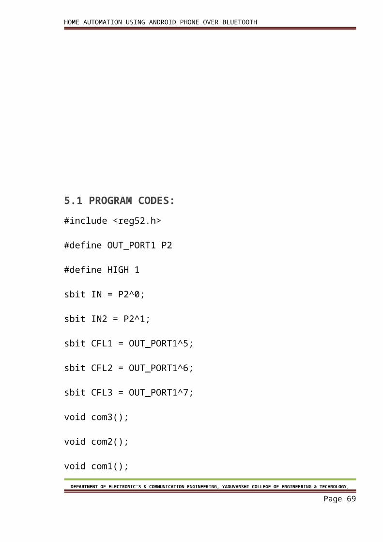
5.1 PROGRAM CODES:
#include <reg52.h>
#define OUT_PORT1 P2
#define HIGH 1
sbit IN = P2^0;
sbit IN2 = P2^1;
sbit CFL1 = OUT_PORT1^5;
sbit CFL2 = OUT_PORT1^6;
sbit CFL3 = OUT_PORT1^7;
void com3();
void com2();
void com1();
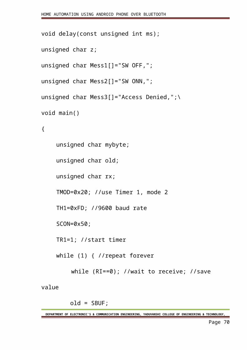
void delay(const unsigned int ms);
DEPARTMENT OF ELECTRONIC’S & COMMUNICATION ENGINEERING, YADUVANSHI COLLEGE OF ENGINEERING & TECHNOLOGY,
Page 57
HOME AUTOMATION USING ANDROID PHONE OVER BLUETOOTH
unsigned char z;
unsigned char Mess1[]="SW OFF,";
unsigned char Mess2[]="SW ONN,";
unsigned char Mess3[]="Access Denied,";\
void main()
{
unsigned char mybyte;
unsigned char old;
unsigned char rx;
TMOD=0x20; //use Timer 1, mode 2
TH1=0xFD; //9600 baud rate
SCON=0x50;
TR1=1; //start timer
while (1) { //repeat forever
while (RI==0); //wait to receive; //save value
old = SBUF;
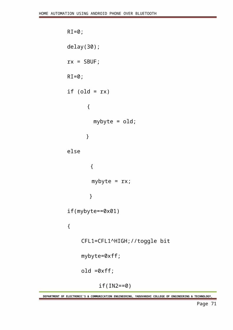
RI=0;
delay(30);
rx = SBUF;
RI=0;DEPARTMENT OF ELECTRONIC’S & COMMUNICATION ENGINEERING, YADUVANSHI COLLEGE OF ENGINEERING &
TECHNOLOGY,
Page 58
HOME AUTOMATION USING ANDROID PHONE OVER BLUETOOTH
if (old = rx)
{
mybyte = old;
}
else
{
mybyte = rx;
}
if(mybyte==0x01)
{
CFL1=CFL1^HIGH;//toggle bit
mybyte=0xff;
old =0xff;
if(IN2==0)
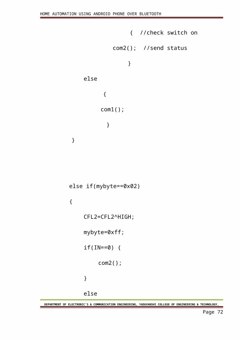
{ //check switch on
com2(); //send status
}
else
{
com1();DEPARTMENT OF ELECTRONIC’S & COMMUNICATION ENGINEERING, YADUVANSHI COLLEGE OF ENGINEERING &
TECHNOLOGY,
Page 59
HOME AUTOMATION USING ANDROID PHONE OVER BLUETOOTH
}
}
else if(mybyte==0x02)
{
CFL2=CFL2^HIGH;
mybyte=0xff;
if(IN==0) {
com2();
}
else
{
com1();
}
}
else if(mybyte==0x03)
{
CFL3=CFL3^HIGH;
mybyte=0xff;DEPARTMENT OF ELECTRONIC’S & COMMUNICATION ENGINEERING, YADUVANSHI COLLEGE OF ENGINEERING &
TECHNOLOGY,
Page 60
HOME AUTOMATION USING ANDROID PHONE OVER BLUETOOTH
if(CFL3==0) {
com1();
}
else
{
com2();
}
}
else if(mybyte==0x04) // check port 1 value
{
SBUF=P2;
while(TI==0); //wait for transmit
TI=0;
}
else if(mybyte==0x05) // check port 1 value
{
if(IN==0)
DEPARTMENT OF ELECTRONIC’S & COMMUNICATION ENGINEERING, YADUVANSHI COLLEGE OF ENGINEERING & TECHNOLOGY,
Page 61
HOME AUTOMATION USING ANDROID PHONE OVER BLUETOOTH
{ //check switch on
com2(); //send status
}
else
{
com1();
}
}
else if(mybyte==0x06) // check port 1 value
{
if(IN2==0)
{ //check switch on
com2(); //send status
}
else
{
com1();
}
}DEPARTMENT OF ELECTRONIC’S & COMMUNICATION ENGINEERING, YADUVANSHI COLLEGE OF ENGINEERING &
TECHNOLOGY,
Page 62
HOME AUTOMATION USING ANDROID PHONE OVER BLUETOOTH
else
{
com3();
}
}
}
void com3()
{
for (z=0;z<15;z++) {
SBUF=Mess3[z]; //place value in buffer
while(TI==0); //wait for transmit
TI=0;
}
}
void com2()
{
for (z=0;z<8;z++) {DEPARTMENT OF ELECTRONIC’S & COMMUNICATION ENGINEERING, YADUVANSHI COLLEGE OF ENGINEERING &
TECHNOLOGY,
Page 63
HOME AUTOMATION USING ANDROID PHONE OVER BLUETOOTH
SBUF=Mess2[z]; //place value in buffer
while(TI==0); //wait for transmit
TI=0;
}
}
void com1()
{
for (z=0;z<8;z++) {
SBUF=Mess1[z]; //place value in buffer
while(TI==0); //wait for transmit
TI=0;
}
}
void delay(const unsigned int ms)
{
unsigned int x, y;
for(x = 0; x<=ms;x++)
{DEPARTMENT OF ELECTRONIC’S & COMMUNICATION ENGINEERING, YADUVANSHI COLLEGE OF ENGINEERING &
TECHNOLOGY,
Page 64
HOME AUTOMATION USING ANDROID PHONE OVER BLUETOOTH
for(y=0;y<=1275;y++);
}
}
5.2 Program detail 1. #include <reg52.h>:-By using this we define the header file of micro –controller
89s52.
2. #define OUT_PORT2 P1:-this line is used for defining a port with output port.
3. SBUF is an 8-bit register used solely for serial communication ¾For a byte data to be
transferred via the Txd line, it must be placed in the SBUF register .The moment a
byte is written into SBUF, it is framed with the start and stop bits and transferred
serially via the Txd line .SBUF holds the byte of data when it is received by 8051 RxD
line .When the bits are received serially via RxD, the 8051 deframes it by eliminating
the stop and start bits, making a byte out of the data received, and then placing it in
SBUF.
4. SCON is an 8-bit register used to program the start bit, stop bit, and data bits of data
framing, among other things.
5. TI (transmit interrupt) When 8051 finishes the transfer of 8-bit character .It raises TI
flag to indicate that it is ready to transfer another byte TI bit is raised at the
beginning of the stop bit.
6. RI (receive interrupt) When 8051 receives data serially via RxD, it gets rid of the start
and stop bits and places the byte in SBUF register It raises the RI flag bit to indicate
that a byte has been received and should be picked up before it is lost .RI is raised
halfway through the stop bit.
DEPARTMENT OF ELECTRONIC’S & COMMUNICATION ENGINEERING, YADUVANSHI COLLEGE OF ENGINEERING & TECHNOLOGY,
Page 65
HOME AUTOMATION USING ANDROID PHONE OVER BLUETOOTH
Chapter 6Circuit diagram
& Component List
DEPARTMENT OF ELECTRONIC’S & COMMUNICATION ENGINEERING, YADUVANSHI COLLEGE OF ENGINEERING & TECHNOLOGY,
Page 66
HOME AUTOMATION USING ANDROID PHONE OVER BLUETOOTH
Chapter 6
Circuit diagram & Component List
6.1. Component list:-
S.No Component Name Nos. Required
1 HC-05 Bluetooth module 1
2 AT89S52 micro controller IC 1
3 ULN2003 IC 3
4 5V relay 2
5 Crystal 12MHz or 11.0592MHz 1
6 1K Resistor 1
7 22µf or 10µf electrolyte capacitor 2
8 30pf or 22pf ceramic capacitor 2
9 10k resistor network 3
DEPARTMENT OF ELECTRONIC’S & COMMUNICATION ENGINEERING, YADUVANSHI COLLEGE OF ENGINEERING & TECHNOLOGY,
Page 67
HOME AUTOMATION USING ANDROID PHONE OVER BLUETOOTH
10 7805 IC 2
11 9V battery 2
12 220v to 6v-0-6v step down transformer 1
13 1N4007 diode 3
6.2. Circuit Diagram:
DEPARTMENT OF ELECTRONIC’S & COMMUNICATION ENGINEERING, YADUVANSHI COLLEGE OF ENGINEERING & TECHNOLOGY,
Page 68
HOME AUTOMATION USING ANDROID PHONE OVER BLUETOOTH
DEPARTMENT OF ELECTRONIC’S & COMMUNICATION ENGINEERING, YADUVANSHI COLLEGE OF ENGINEERING & TECHNOLOGY,
Page 69
HOME AUTOMATION USING ANDROID PHONE OVER BLUETOOTH
Chapter 7Problem description
DEPARTMENT OF ELECTRONIC’S & COMMUNICATION ENGINEERING, YADUVANSHI COLLEGE OF ENGINEERING & TECHNOLOGY,
Page 70
HOME AUTOMATION USING ANDROID PHONE OVER BLUETOOTH
Chapter 7
Problem description
The various problems & FAQ’s associated with the project are:
7.1. No manual control to switch on and off or in system when failed:-
In that case we can use a two way switch so if automation system fails than control
given to manual. As the manual control provided unskilled user can perform his
routine control. As shown below.
In fig a two way connection with relay is shown. The control act as a XOR operation
mines that output is one when both input are same. So output is available when
positions of both switches are same.
Fig. 29.Wiring connection to switch
7.2. No confirmation of change of output:-
To overcome this problem programming can be do so that controller can compare
its previous state. So if state of switch not changes than controller send an error
comes or no change.
7.3. No debugging option:-
DEPARTMENT OF ELECTRONIC’S & COMMUNICATION ENGINEERING, YADUVANSHI COLLEGE OF ENGINEERING & TECHNOLOGY,
Page 71
HOME AUTOMATION USING ANDROID PHONE OVER BLUETOOTH
This can be a very good feature of project i.e. you can check that where problem
comes at hardware or in software. So controller gave all information about
communication.
7.4. Complex user interface:-
User interface must be simple so no need to teach the other every time. But in
similar project interface is complex.
7.5. Different key to on and off:-
In survey it is seen that there are two different key to turn n and off appliances.
But if in programming toggle of bit is done then more automation can be done in
this project.
7.6. Restart power at every new pairing of device:-
In HV-05 Bluetooth module if a device is parried then this configuration is save. So
at every new device pairing needs restart of circuit power. This problem can be
removed if we use a feature of HC-05 Bluetooth i.e. “key” this a pin in Bluetooth
that can remove all paired detail when this pin high pulses. So connection of this
pin with micro controller can rest the pairing.
7.7. Large change in house wiring:-
In similar project the automation done by mobile only so all connection needs to
change in wiring and removal of button connection is needed .So to avoid this
circuit is so design as sown in problem 1 solution.
7.8. Security of hacking control:-
The Bluetooth connection kept open so other con connect and take control. so the
master user must connect to Bluetooth and removal of pair info must by master
controller by software control.
DEPARTMENT OF ELECTRONIC’S & COMMUNICATION ENGINEERING, YADUVANSHI COLLEGE OF ENGINEERING & TECHNOLOGY,
Page 72
HOME AUTOMATION USING ANDROID PHONE OVER BLUETOOTH
Chapter 8Advantages
& Disadvantages
DEPARTMENT OF ELECTRONIC’S & COMMUNICATION ENGINEERING, YADUVANSHI COLLEGE OF ENGINEERING & TECHNOLOGY,
Page 73
HOME AUTOMATION USING ANDROID PHONE OVER BLUETOOTH
Chapter 8
Advantages & Disadvantages
8.1 Advantages
1. Wireless control:-
By using this project wireless control can be within the hands of user.
2. Monitoring:-
This circuit allow monitoring of all appliance within range of communication with
Bluetooth.
3. Status checking :-
When user doesn’t know appliances is on off then user can only check the status
only.
4. Confirmation of changing switch state:-
When switch is press ten two status will be shown on mobile phone i.e. old status
and new status
5. Manual control:-
Manual control is given so an unskilled user can be change the current status.
DEPARTMENT OF ELECTRONIC’S & COMMUNICATION ENGINEERING, YADUVANSHI COLLEGE OF ENGINEERING & TECHNOLOGY,
Page 74
HOME AUTOMATION USING ANDROID PHONE OVER BLUETOOTH
8.2. Disadvantages:-
1. Bluetooth range:-
It is good to use Bluetooth for automation but automation is kept within a range 0f
10-30 metres. So control can be achieved from outside range.
2. Connection:-
Application must be connected after disconnection from Bluetooth.
3. configuration of application software:-
If new user want to connect then first download application software and then code
must be enter and more configuration must be done.
DEPARTMENT OF ELECTRONIC’S & COMMUNICATION ENGINEERING, YADUVANSHI COLLEGE OF ENGINEERING & TECHNOLOGY,
Page 75
HOME AUTOMATION USING ANDROID PHONE OVER BLUETOOTH
Chapter 9FUTURE SCOPE
DEPARTMENT OF ELECTRONIC’S & COMMUNICATION ENGINEERING, YADUVANSHI COLLEGE OF ENGINEERING & TECHNOLOGY,
Page 76
HOME AUTOMATION USING ANDROID PHONE OVER BLUETOOTH
Chapter 9
FUTURE SCOPE
This project can be further developed by integrating it with the internet to monitor your
home while sitting in a remote area. By doing this, one can keep an eye on his or her home
through an internet connected to the user’s mobile phone or PC or laptop. This will not only
improve the security of your home in this modern day world but will also assist in
conservation of energy like if you left any home appliance switched on by mistake, then you
can check the status of the appliance on the graphical interface made on your mobile and
can switch it off using the internet connectivity.
DEPARTMENT OF ELECTRONIC’S & COMMUNICATION ENGINEERING, YADUVANSHI COLLEGE OF ENGINEERING & TECHNOLOGY,
Page 77
HOME AUTOMATION USING ANDROID PHONE OVER BLUETOOTH
CONCLUSION &
REFERENCES
DEPARTMENT OF ELECTRONIC’S & COMMUNICATION ENGINEERING, YADUVANSHI COLLEGE OF ENGINEERING & TECHNOLOGY,
Page 78
HOME AUTOMATION USING ANDROID PHONE OVER BLUETOOTH
CONCLUSION
In conclusion, this low cost system is designed to improve the standard living in home. The
remote control function by smart phone provides help and assistance especially to disabled
and elderly. In order to provide safety protection to the user, a low voltage activating
switches is replaced current electrical switches. Moreover, implementation of wireless
Bluetooth connection in control board allows the system install in more simple way. The
control board is directly installed beside the electrical switches whereby the switching
connection is controlled by relay.
Furthermore, flexible types of connections are designed as backup connections to the
system. The connected GUIs are synchronized to the control board. They indicate the real-
time switches status. The system is designed in user-friendly interface. The easy to use
interface on Window and Android GUI provides simple control by the elderly and disabled
people.
For future work, the Window GUI will be implemented with speech recognition voice
control. The android GUI will be implemented as a remote Bluetooth microphone to the
Window GUI. All the voice signal inputs to the smart phone will be transmitted to the
Window GUI for signal processing. Also, the push buttons implemented in low voltage
activating switches will be replaced by capacitive sensing switches. All the future work is
expected without spend extra cost, even one cent from the current system.
DEPARTMENT OF ELECTRONIC’S & COMMUNICATION ENGINEERING, YADUVANSHI COLLEGE OF ENGINEERING & TECHNOLOGY,
Page 79
HOME AUTOMATION USING ANDROID PHONE OVER BLUETOOTH
REFERENCES
1. Electronics for you magine June 2013
2. Keil µvision IDE, http://www.keil.com/uvision.
3. www.vp812.com
4. Serial Bluetooth Module, Tiny OS Electronics, http://www.tinyosshop.com
5. AT89s52 8 bit Microcontroller, ATMEL Corporations, http://www.atmel.com3.
6. The official Bluetooth website from Bluetooth SIG: http://www.bluetooth.com
7. The 8051 microcontroller and embedded systems by Muhammad Ali Mazidi and
Janice Gillispie Mazidi.
DEPARTMENT OF ELECTRONIC’S & COMMUNICATION ENGINEERING, YADUVANSHI COLLEGE OF ENGINEERING & TECHNOLOGY,
Page 80