Embed Size (px)
Citation preview
LINE PROTECTION WITH DISTANCE RELAYS 295
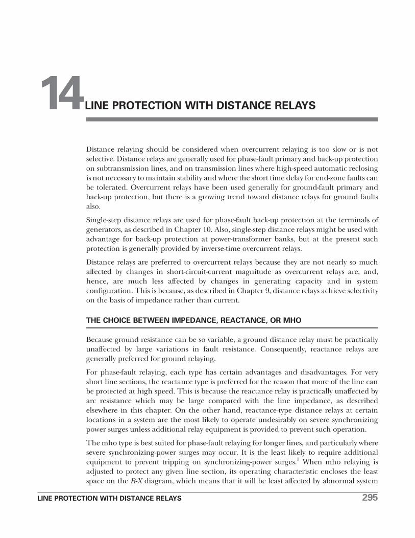
Distance relaying should be considered when overcurrent relaying is too slow or is notselective. Distance relays are generally used for phase-fault primary and back-up protectionon subtransmission lines, and on transmission lines where high-speed automatic reclosingis not necessary to maintain stability and where the short time delay for end-zone faults canbe tolerated. Overcurrent relays have been used generally for ground-fault primary andback-up protection, but there is a growing trend toward distance relays for ground faultsalso.
Single-step distance relays are used for phase-fault back-up protection at the terminals ofgenerators, as described in Chapter 10. Also, single-step distance relays might be used withadvantage for back-up protection at power-transformer banks, but at the present suchprotection is generally provided by inverse-time overcurrent relays.
Distance relays are preferred to overcurrent reIays because they are not nearly so muchaffected by changes in short-circuit-current magnitude as overcurrent relays are, and,hence, are much less affected by changes in generating capacity and in systemconfiguration. This is because, as described in Chapter 9, distance relays achieve selectivityon the basis of impedance rather than current.
THE CHOICE BETWEEN IMPEDANCE, REACTANCE, OR MHO
Because ground resistance can be so variable, a ground distance relay must be practicallyunaffected by large variations in fault resistance. Consequently, reactance relays aregenerally preferred for ground relaying.
For phase-fault relaying, each type has certain advantages and disadvantages. For veryshort line sections, the reactance type is preferred for the reason that more of the line canbe protected at high speed. This is because the reactance relay is practically unaffected byarc resistance which may be large compared with the line impedance, as describedelsewhere in this chapter. On the other hand, reactance-type distance relays at certainlocations in a system are the most likely to operate undesirably on severe synchronizingpower surges unless additional relay equipment is provided to prevent such operation.
The mho type is best suited for phase-fault relaying for longer lines, and particularly wheresevere synchronizing-power surges may occur. It is the least likely to require additionalequipment to prevent tripping on synchronizing-power surges.1 When mho relaying isadjusted to protect any given line section, its operating characteristic encloses the leastspace on the R-X diagram, which means that it will be least affected by abnormal system
14LINE PROTECTION WITH DISTANCE RELAYS
296 LINE PROTECTION WITH DISTANCE RELAYS
conditions other than line faults; in other words, it is the most selective of all distancerelays. Because the mho relay is affected by arc resistance more than any other type, it isapplied to longer lines. The fact that it combines both the directional and the distance-measuring functions in one unit with one contact makes it very reliable.
The impedance relay is better suited for phase-fault relaying for lines of moderate lengththan for either very short or very long lines. Arcs affect an impedance relay more than areactance relay but less than a mho relay. Synchronizing-power surges affect an impedancerelay less than a reactance relay but more than a mho relay. If an impedance-relaycharacteristic is offset, so as to make it a modified� relay, it can be made to resemble eithera reactance relay or a mho relay but it will always require a separate directional unit.
There is no sharp dividing line between areas of application where one or another type ofdistance relay is best suited. Actually, there is much overlapping of these areas. Also,changes that are made in systems, such as the addition of terminals to a line, can changethe type of relay best suited to a particular location. Consequently, to realize the fullestcapabilities of distance relaying, one should use the type best suited for each application.In some cases much better selectivity can be obtained between relays of the same type, but,if relays are used that are best suited to each line, different types on adjacent lines have noappreciable adverse effect on selectivity.
THE ADJUSTMENT OF DISTANCE RELAYS
Chapter 9 shows that phase distance relays are adjusted on the basis of the positive-phase-sequence impedance between the relay location and the fault location beyond whichoperation of a given relay unit should stop. Ground distance relays are adjusted in thesame way, although some types may respond to the zero-phase-sequence impedance. Thisimpedance, or the corresponding distance, is called the "reach" of the relay or unit. Forpurposes of rough approximation, it is customary to assume an average positive-phase-sequence-reactance value of about 0.8 ohm per mile for open transmission-lineconstruction, and to neglect resistance. Accurate data are available in textbooks devoted topower-system analysis.2
To convert primary impedance to a secondary value for use in adjusting a phase or grounddistance relay, the following formula is used:
CT ratioZsec = Zpri × ————
VT ratio
where the CT ratio is the ratio of the high-voltage phase current to the relay phase current,and the VT ratio is the ratio of the high-voltage phase-to-phase voltage to the relay phase-to-phase voltage–all under balanced three-phase conditions. Thus, for a 50-mile, 138-kvline with 600/5 wye-connected CT’s, the secondary positive-phase-sequence reactance is
600 115about 50 × 0.8 × —— × ———— = 4.00 ohms.
5 138,000
It is the practice to adjust the first, or high-speed, zone of distance relays to reach to 80%to 90% of the length of a two-ended line or to 80% to 90% of the distance to the nearestterminal of a multiterminal line. There is no time-delay adjustment for this unit.
LINE PROTECTION WITH DISTANCE RELAYS 297
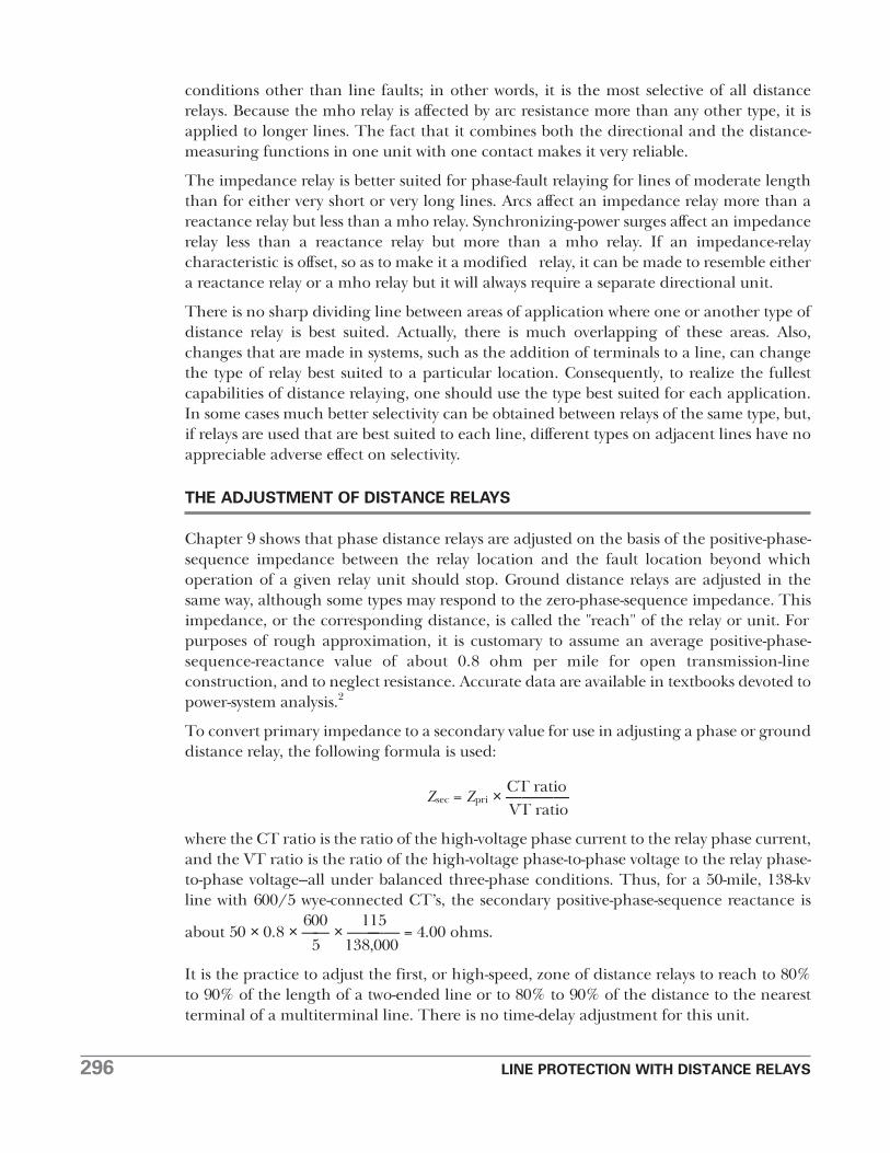
The principal purpose of the second-zone unit of a distance relay is to provide protectionfor the rest of the line beyond the reach of the first-zone unit. It should be adjusted so thatit will be able to operate even for arcing faults at the end of the line. To do this, the unitmust reach beyond the end of the line. Even if arcing faults did not have to be considered,one would have to take into account an underreaching tendency because of the effect ofintermediate current sources, and of errors in: (1) the data on which adjustments arebased, (2) the current and voltage transformers, and (3) the relays. It is customary to tryto have the second-zone unit reach to at least 20% of an adjoining line section; the fartherthis can be extended into the adjoining line section, the more leeway is allowed in thereach of the third-zone unit of the next line-section back that must be selective with thissecond-zone unit.
The maximum value of the second-zone reach also has a limit. Under conditions ofmaximum overreach, the second-zone reach should be short enough to be selective withthe second-zone units of distance relays on the shortest adjoining line sections, asillustrated in Fig. 1. Transient overreach need not be considered with relays having a highratio of reset to pickup because the transient that causes overreach will have expired beforethe second-zone tripping time. However, if the ratio of reset to pickup is low, the second-zone unit must be set either (1) with a reach short enough so that its overreach will notextend beyond the reach of the first-zone unit of the adjoining line section under the sameconditions, or (2) with a time delay long enough to be selective with the second-zone timeof the adjoining section, as shown in Fig. 2. In this connection, any underreachingtendencies of the relays on the adjoining line sections must be taken into account. Whenan adjoining line is so short that it is impossible to get the required selectivity on the basisof react, it becomes necessary to increase the time delay, as illustrated in Fig. 2. Otherwise,the time delay of the second-zone unit should be long enough to provide selectivity withthe slowest of (1) bus-differential relays of the bus at the other end of the line,(2) transformer-differential relays of transformers on the bus at the other end of the line,
Fig. 1. Normal selectivity adjustment of second-zone unit.
Fig. 2. Second-zone adjustment with additional time for selectivitywith relay of a very short adjoining line section.
298 LINE PROTECTION WITH DISTANCE RELAYS
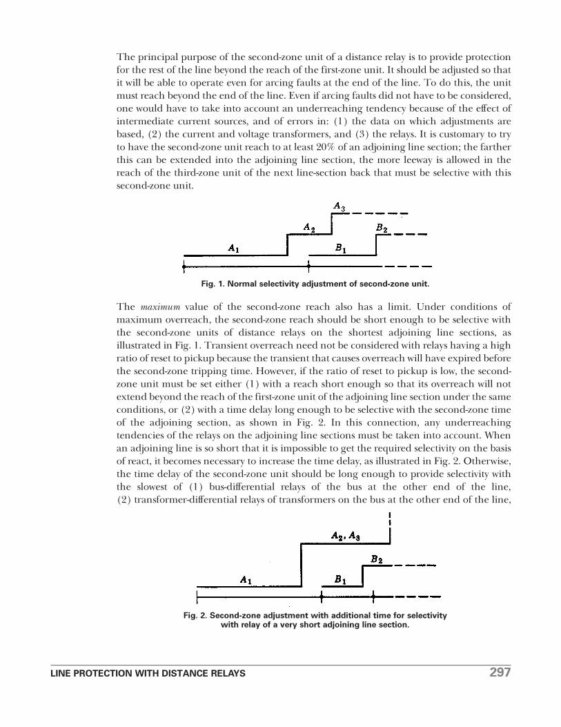
or (3) line relays of adjoining line sections. The interrupting time of the circuit breakersof these various elements will also affect the second-zone time. This second-zone time isnormally about 0.2 second to 0.5 second.
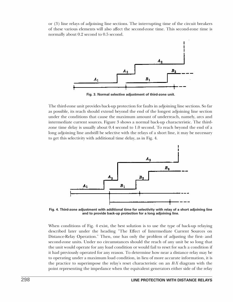
The third-zone unit provides back-up protection for faults in adjoining line sections. So faras possible, its reach should extend beyond the end of the longest adjoining line sectionunder the conditions that cause the maximum amount of underreach, namely, arcs andintermediate current sources. Figure 3 shows a normal back-up characteristic. The third-zone time delay is usually about 0.4 second to 1.0 second. To reach beyond the end of along adjoining line andstill be selective with the relays of a short line, it may be necessaryto get this selectivity with additional time delay, as in Fig. 4.
When conditions of Fig. 4 exist, the best solution is to use the type of back-up relayingdescribed later under the heading "The Effect of Intermediate Current Sources onDistance-Relay Operation." Then, one has only the problem of adjusting the first- andsecond-zone units. Under no circumstances should the reach of any unit be so long thatthe unit would operate for any load condition or would fail to reset for such a condition ifit had previously operated for any reason. To determine how near a distance relay may beto operating under a maximum load condition, in lieu of more accurate information, it isthe practice to superimpose the relay's reset characteristic on an R-X diagram with thepoint representing the impedance when the equivalent generators either side of the relay
Fig. 3. Normal selective adjustment of third-zone unit.
Fig. 4. Third-zone adjustment with additional time for selectivity with relay of a short adjoining lineand to provide back-up protection for a long adjoining line.
LINE PROTECTION WITH DISTANCE RELAYS 299
location are 90° out of phase. This is done by the method described in Chapter 9 fordrawing the loss-of-synchronism characteristic. Stability can be maintained with somewhatmore than a 90° displacement, but 90° is nearly the limit and is easy to depict, as describedin Chapter 9.
THE EFFECT OF ARCS ON DISTANCE-RELAY OPERATION
Chapter 9 shows the effect of fault or arc resistance on the appearance of different kinds ofshort circuits when plotted on an R-X diagram in terms of the voltages and currents used bydistance relays. Chapter 13 gives data from which arc resistance can be estimated forplotting such fault characteristics on the R-X diagram. It is only necessary, then, tosuperimpose the characteristic of any distance relay in order to see what its response will be.
The critical arc location is just short of the point on a line at which a distance relay'soperation changes from high-speed to intermediate time or from intermediate time toback-up time. We are concerned with the possibility that an arc within the high-speed zonewill make the relay operate in intermediate time, that an arc within the intermediate zonewill make the relay operate in back-up time, or that an arc within the back-up zone willprevent relay operation completely. In other words, the effect of an arc may be to cause adistance relay to underreach.
For an arc just short of the end of the first- or high-speed zone, it is the initial characteristicof the arc that concerns us. A distance relay's first-zone unit is so fast that, if the impedanceis such that the unit can operate immediately when the arc is struck, it will do so before thearc can stretch appreciably and thereby increase its resistance. Therefore, we can calculatethe arc characteristic for a length equal to the distance between conductors for phase-to-phase faults, or across an insulator string for phase-to-ground faults. On the other hand,for arcs in the intermediate-time or back-up zones, the effect of wind stretching the arcshould be considered, and then the operating time for which the relay is adjusted has animportant bearing on the outcome.
Tending to offset the longer time an arc has to stretch in the wind when it is in theintermediate or back-up zones is the fact that, the farther an arcing fault is from a relay,the less will its effect be on the relay's operation. In other words, the more line impedancethere is between the relay and the fault, the less change there will be in the total impedancewhen the arc resistance is added. On the other hand, the farther away an arc is, the higherits apparent resistance will be because the current contribution from the relay end of theline will be smaller, as considered later.
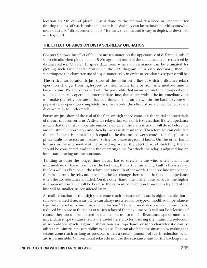
A small reduction in the high-speed-zone reach because of an arc is objectionable, but itcan be tolerated if necessary. One can always use a reactance-type or modified-impendance-type distance relay to minimize such reduction.3 The intermediate-zone reach must not bereduced by an arc to the point at which relays of the next line back will not be selective; ofcourse, they too will be affected by the arc, but not so much. Reactance-type or modified-impendance-type distance relays are useful here also for assuring the minimum reductionin second-zone reach. Figure 5 shows how an impedance or mho characteristic can beoffset to minimize its susceptibility to an arc. One can also help the situation by making thesecond-zone reach as long as possible so that a certain amount of reach reduction by anarc is permissible. Conventional relays do not use the reactance unit for the back-up zone;
300 LINE PROTECTION WITH DISTANCE RELAYS
instead, they use either an impedance unit, a modified-impendance unit, or a mho unit.If failure of the back-up unit to operate because of an arc extended by the wind is aproblem, the modified-impendance unit can be used or the mho–or "starting"–unitcharacteristic can also be shifted to make its operation less affected by arc resistance. Thelow-reset characteristic of some types of distance relay is advantageous in preventing resetas the wind stretches out an arc.
Although an arc itself is practically all resistance, it may have a capacitive-reactance or aninductive-reactance component when viewed from the end of a line where the relays are.The impedance of an arc (ZA) has the appearance:
(I1 + I2) I2ZA = ——— RA = RA + — RAI1 I1
where I1 = the complex expression for the current flowing into the arc from the end of the line where the relays under consideration are.
I2 = the complex expression for the current flowing into the arc from the other end of the line.
RA = the arc resistance with current (I1 + I2) flowing into it.
If I1 and I2 are out of phase, ZA will be a complex number. Therefore, even a reactance-typedistance relay may be adversely affected by an arc. This effect is small, however, and isgenerally neglected.
Of more practical significance is the fact that, as shown by the equation, the arc resistancewill appear to be higher than it actually is, and it may be very much higher. After the otherend of the line trips, the arc resistance will be higher because the arc current will be lower.However, its appearance to the relays will no longer be magnified, because I2 will be zero.Whether its resistance will appear to the relays to be higher or lower than before willdepend on the relative and actual magnitudes of the currents before and after the distantbreaker opens.
Fig. 5. Offsetting relay characteristic to minimize susceptibility to arcs.
LINE PROTECTION WITH DISTANCE RELAYS 301
THE EFFECT OF INTERMEDIATE CURRENT SOURCES ON DISTANCE-RELAY OPERATION
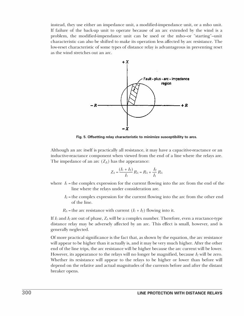
An "intermediate-current source" is a source of short-circuit current between a distance-relay location and a fault for which distance-relay operation is desired. Consider theexample of Fig. 6. The true impedance to the fault is ZA + ZB, but, when the intermediatecurrent I2 flows, the impedance appears to the distance relays as ZA + ZB + (I2/I1) ZB; inother words, the fault appears to be farther away because of the current I2. This effect hasbeen called the "mutual impedance" effect. It will be evident that, if I1 and I2 are out ofphase, the impedance (I2/I1) ZB will have a different angle from ZB.
If the distance relays are adjusted to operate for a fault at a given location when a givenvalue of I2 flows, they will operate for faults beyond that location for smaller values of I2.Therefore, it is the practice to adjust distance relays to operate as desired on the basis ofno intermediate current source. Then, they will not overreach and operate undesirably.Of course, when current flows from an intermediate source, the relays will "underreach,"i.e., they will not operate for faults as far away as one might desire, but this is to bepreferred to overreach.
Because of the effect of intermediate current sources, the full capabilities of distancerelaying cannot be realized on multiterminal lines. It is the practice to adjust the high-speed zone of the relays at a given terminal to reach 80% to 90% of the distance to thenearest terminal, neglecting the effect of an intermediate current source. Thus, in Fig. 6,the maximum reach of the high-speed zone of the relays at M would be 80% to 90% ofZA + ZB or of ZA + ZC, whichever was smaller. Neglecting the effect of an arc, if this maximumreach of the high-speed zone is less than ZA, it will become evident that intermediatecurrent cannot affect the high-speed-zone reach; if the maximum reach is greater than ZA,intermediate current will cause the reach to approach ZA, as a minimum limit. If thesecond-zone reach is made to include double the impedance of the common branch,tripping will always be assured although it might be sequential.4
Back-up protection of the conventional type described in Chapter 1 is often impossible inthe presence of intermediate current sources. In Fig. 7, consider the problem of adjustingrelays at A to provide back-up for the fault location shown, in the event that breaker B failsto trip for any reason. The problem is similar whether inverse-time or distance relays areinvolved at A. The magnitude of the fault current flowing at A, or the impedancemeasured by a distance relay at A, may vary considerably, depending on the magnitude offault current fed into the intermediate station from other sources. The range of such
Fig. 6. Illustrating the effect of intermediate current sources on distance-relay operation.
302 LINE PROTECTION WITH DISTANCE RELAYS
variations must be taken into account in determining the back-up adjustment. In someextreme cases, the apparent impedance between A and the fault may be such as to put thefault beyond the reach of the relays at A. Obviously, this problem may apply also to therelays in the other lines except the faulted one.
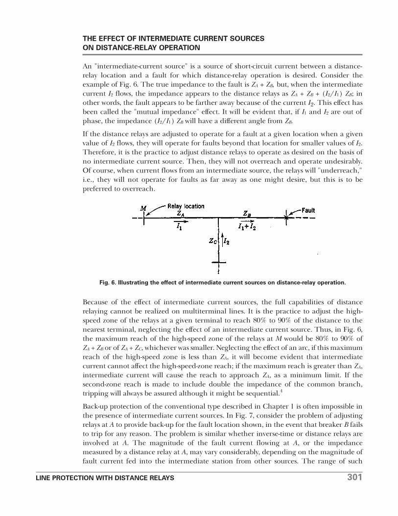
A solution that has been resorted to, when a fault can be beyond the reach of conventionalback-up relays, is to have the back-up unit of the relaying equipment of each line at theintermediate station operate a timer which, after a definite time, will energize a multi-contact auxiliary tripping relay to trip all the breakers connected to the bus of theintermediate station.5 Admittedly, this solution violates one of the fundamental principlesof back-up protection by assuming that the failure to trip is owing only to failure in thebreaker or in the tripping circuit between the relay and the breaker; it assumes that theprotective-relaying equipment or the source of tripping voltage will not fail. However, it isa practical solution, and it has been considered worth the risk. A more reliablearrangement is to use separate CT's and protective relays to energize the multicontacttripping relay, employing only the battery in common. It is also possible to have the back-up relay first try to trip the breaker of the faulty line before tripping all the other breakers.5
The back-up elements of mho-type distance relays can be made to operate for faults in thedirection opposite to the conventional back-up direction. In fact, the reversed back-updirection, called "reversed third zone," is normally provided when mho-type distance relaysare used with directional-comparison carrier-current-pilot relaying. This feature gives somerelief in the problem of reaching far enough to provide back-up protection for adjoiningline sections, since the backup elements, being closer to these adjoining line sections, donot have to reach so far. Referring to Fig. 7, for example, if the back-up elements locatedat breaker C are arranged to operate for current flow toward the fault, their reach can bereduced by the distance from A to C as compared with back-up elements at A lookingtoward the fault.
Various other solutions have been resorted to, depending on how many differentpossibilities of failure one may wish to anticipate.6
OVERREACH BECAUSE OF OFFSET CURRENT WAVES
Distance relays have a tendency to overreach, similar to that described in Chapter 13 forovercurrent relays, when the fault current contains a d-c offset. Other things being equal,
Fig. 7. A situation in which conventional back-up relaying is inadequate.
LINE PROTECTION WITH DISTANCE RELAYS 303
the tendency to overreach is greatest in magnetic-attraction types of distance relays, andparticularly in the impedance type where the contact-closing torque is generated bycurrent alone. The tendency is the least with induction-type relays.
"Percent overreach" for distance relays has been defined as follows:
Z O - ZSPercent overreach = 100 ———( )ZS
where ZO = the maximum impedance for which the relay will operate with an offset current wave, for a given adjustment.
ZS = the maximum impedance for which the relay will operate for symmetrical currents, for the same adjustment as for ZO.
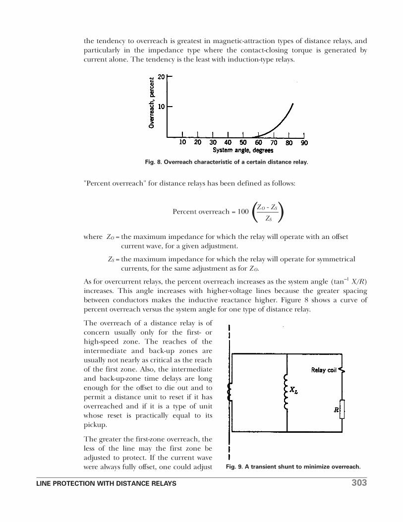
As for overcurrent relays, the percent overreach increases as the system angle (tan–1 X/R)increases. This angle increases with higher-voltage lines because the greater spacingbetween conductors makes the inductive reactance higher. Figure 8 shows a curve ofpercent overreach versus the system angle for one type of distance relay.
The overreach of a distance relay is ofconcern usually only for the first- orhigh-speed zone. The reaches of theintermediate and back-up zones areusually not nearly as critical as the reachof the first zone. Also, the intermediateand back-up-zone time delays are longenough for the offset to die out and topermit a distance unit to reset if it hasoverreached and if it is a type of unitwhose reset is practically equal to itspickup.
The greater the first-zone overreach, theless of the line may the first zone beadjusted to protect. If the current wavewere always fully offset, one could adjust
Fig. 8. Overreach characteristic of a certain distance relay.
Fig. 9. A transient shunt to minimize overreach.
304 LINE PROTECTION WITH DISTANCE RELAYS
the relay, relying on overreach, so as to protect the desired portion of the line at highspeed. But the current wave will rarely be fully offset; it will usually have little offset.Therefore, one cannot depend on I overreach, and less than the desired portion of the linewill usually be protected at high speed. If the relays at both ends of the line are considered,and if each protects P percent of the line from its end at high speed, only the middle (2P– 100) percent of the line is protected at high speed at both ends simultaneously.
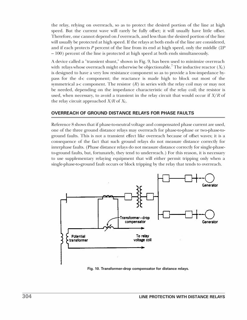
A device called a "transient shunt," shown in Fig. 9, has been used to minimize overreachwith relays whose overreach might otherwise be objectionable.7 The inductive reactor (XL)is designed to have a very low resistance component so as to provide a low-impedance by-pass for the d-c component; the reactance is made high to block out most of thesymmetrical a-c component. The resistor (R) in series with the relay coil may or may notbe needed, depending on the impedance characteristic of the relay coil; the resistor isused, when necessary, to avoid a transient in the relay circuit that would occur if X/R ofthe relay circuit approached X/R of XL.
OVERREACH OF GROUND DISTANCE RELAYS FOR PHASE FAULTS
Reference 8 shows that if phase-to-neutral voltage and compensated phase current are used,one of the three ground distance relays may overreach for phase-to-phase or two-phase-to-ground faults. This is not a transient effect like overreach because of offset waves; it is aconsequence of the fact that such ground relays do not measure distance correctly forinterphase faults. (Phase distance relays do not measure distance correctly for single-phase-to-ground faults, but, fortunately, they tend to underreach.) For this reason, it is necessaryto use supplementary relaying equipment that will either permit tripping only when asingle-phase-to-ground fault occurs or block tripping by the relay that tends to overreach.
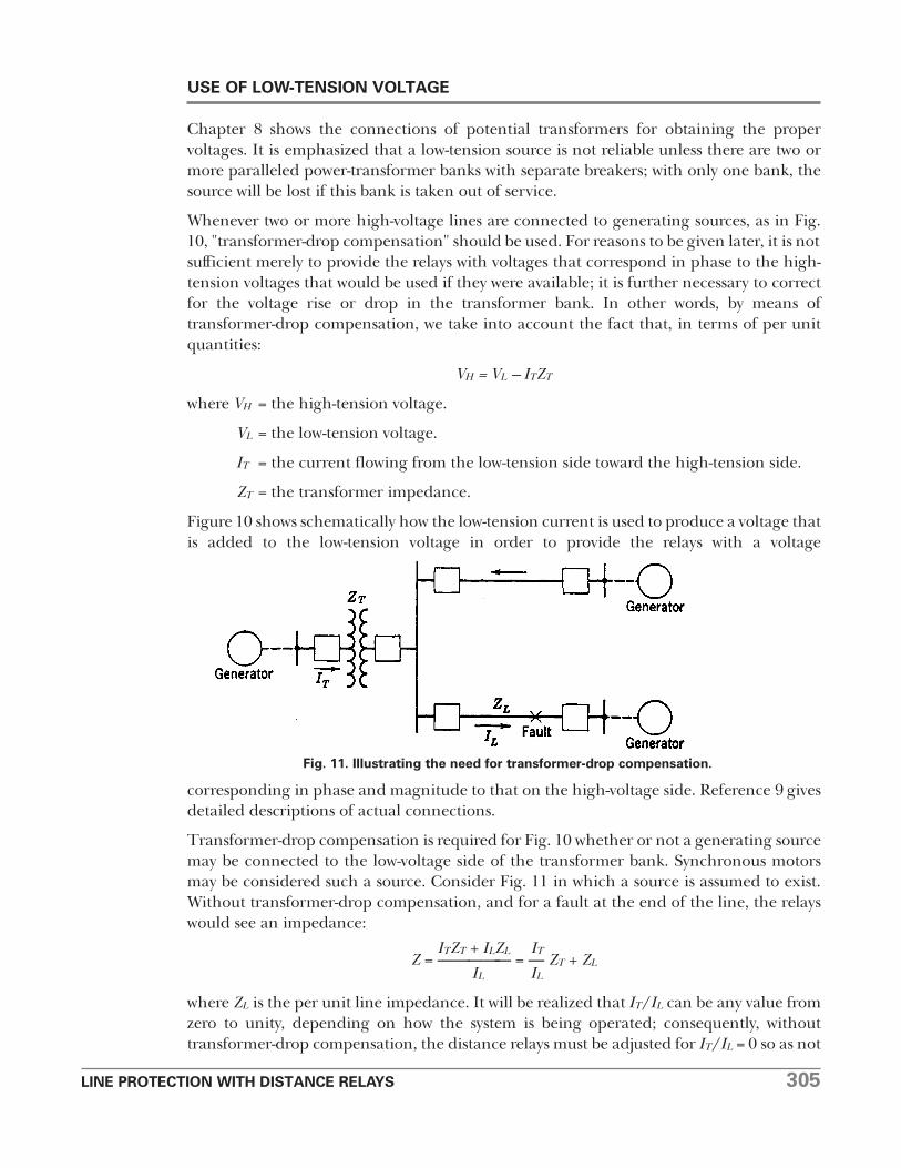
Fig. 10. Transformer-drop compensator for distance relays.
LINE PROTECTION WITH DISTANCE RELAYS 305
USE OF LOW-TENSION VOLTAGE
Chapter 8 shows the connections of potential transformers for obtaining the propervoltages. It is emphasized that a low-tension source is not reliable unless there are two ormore paralleled power-transformer banks with separate breakers; with only one bank, thesource will be lost if this bank is taken out of service.
Whenever two or more high-voltage lines are connected to generating sources, as in Fig.10, "transformer-drop compensation" should be used. For reasons to be given later, it is notsufficient merely to provide the relays with voltages that correspond in phase to the high-tension voltages that would be used if they were available; it is further necessary to correctfor the voltage rise or drop in the transformer bank. In other words, by means oftransformer-drop compensation, we take into account the fact that, in terms of per unitquantities:
VH = VL – ITZT
where VH = the high-tension voltage.
VL = the low-tension voltage.
IT = the current flowing from the low-tension side toward the high-tension side.
ZT = the transformer impedance.
Figure 10 shows schematically how the low-tension current is used to produce a voltage thatis added to the low-tension voltage in order to provide the relays with a voltage
corresponding in phase and magnitude to that on the high-voltage side. Reference 9 givesdetailed descriptions of actual connections.
Transformer-drop compensation is required for Fig. 10 whether or not a generating sourcemay be connected to the low-voltage side of the transformer bank. Synchronous motorsmay be considered such a source. Consider Fig. 11 in which a source is assumed to exist.Without transformer-drop compensation, and for a fault at the end of the line, the relayswould see an impedance:
ITZT + ILZL ITZ = ————— = — ZT + ZL
IL IL
where ZL is the per unit line impedance. It will be realized that IT/IL can be any value fromzero to unity, depending on how the system is being operated; consequently, withouttransformer-drop compensation, the distance relays must be adjusted for IT/IL = 0 so as not
Fig. 11. Illustrating the need for transformer-drop compensation.
306 LINE PROTECTION WITH DISTANCE RELAYS
to overreach. Then, for other values of IT/IL, the relays will underreach, andunderreaching is objectionable because less of the line is protected at high speed. Withtransformer-drop compensation, most of the first term is eliminated and the relays seepractically the correct impedance ZL, regardless of IT/IL, thus minimizing underreaching.
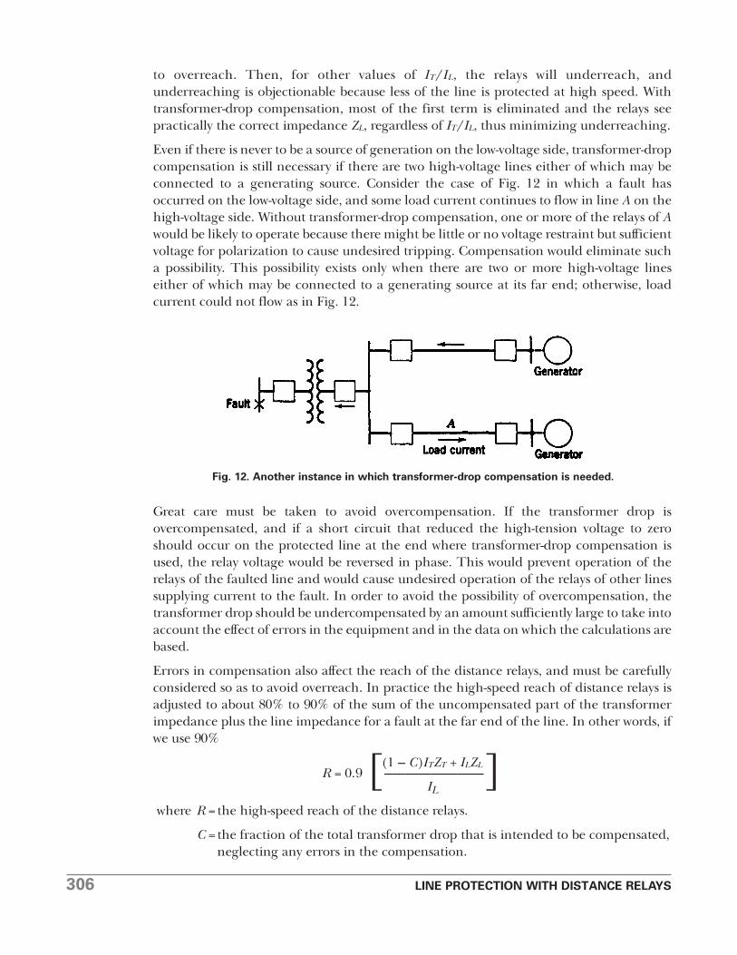
Even if there is never to be a source of generation on the low-voltage side, transformer-dropcompensation is still necessary if there are two high-voltage lines either of which may beconnected to a generating source. Consider the case of Fig. 12 in which a fault hasoccurred on the low-voltage side, and some load current continues to flow in line A on thehigh-voltage side. Without transformer-drop compensation, one or more of the relays of Awould be likely to operate because there might be little or no voltage restraint but sufficientvoltage for polarization to cause undesired tripping. Compensation would eliminate sucha possibility. This possibility exists only when there are two or more high-voltage lineseither of which may be connected to a generating source at its far end; otherwise, loadcurrent could not flow as in Fig. 12.
Great care must be taken to avoid overcompensation. If the transformer drop isovercompensated, and if a short circuit that reduced the high-tension voltage to zeroshould occur on the protected line at the end where transformer-drop compensation isused, the relay voltage would be reversed in phase. This would prevent operation of therelays of the faulted line and would cause undesired operation of the relays of other linessupplying current to the fault. In order to avoid the possibility of overcompensation, thetransformer drop should be undercompensated by an amount sufficiently large to take intoaccount the effect of errors in the equipment and in the data on which the calculations arebased.
Errors in compensation also affect the reach of the distance relays, and must be carefullyconsidered so as to avoid overreach. In practice the high-speed reach of distance relays isadjusted to about 80% to 90% of the sum of the uncompensated part of the transformerimpedance plus the line impedance for a fault at the far end of the line. In other words, ifwe use 90%
(1 – C)ITZT + ILZLR = 0.9 [–———————]IL
where R = the high-speed reach of the distance relays.
C = the fraction of the total transformer drop that is intended to be compensated, neglecting any errors in the compensation.
Fig. 12. Another instance in which transformer-drop compensation is needed.
LINE PROTECTION WITH DISTANCE RELAYS 307
IT, ZT, IL, and ZL are as previously defined. The actual uncompensated part of the effectivetransformer impedance, taking into account the effect of error, is:
ITZTZTU = [(1 – C) – EC] --------
IL
where E = the fractional error in C, being positive when the actual compensation is greaterthan C.
Therefore, the amount of the line (RL) that is actually protected when the relay is adjustedfor reach R is:
RL = R – ZTU
ITZT= [–0.1(1 – C) + EC] ------- + 0.9ZL
IL
Now, it would be undesirable for RL to exceed 0.9ZL because we need 0.1ZL as a factor ofsafety against overreaching because of other reasons that are always applicable whether wehave transformer-drop compensation or not. Therefore, the first term of the equation forRL, must be practically zero or be negative. If we let the first term be zero, we lose thesignificance of ITZT/IL; so let us assume that the first term is 10% of our factor of safety, or0.01ZL. In other words:
ITZT0.01ZL= [–0.1(1 – C) + EC] --------
IL
Solving for E we get:
ZLIL (1 – C)E = -------------- + 0.1 -----------
100C(ZTIT) C
Let ZLIL/ZTIT = N. Then:
0.01N + 0.1(1 – C)E = ————––———
C
For any value of compensation, this equation gives the maximum positive error in thecompensation that we can tolerate without having the relay's reach exceed 91% of the linelength. An error of about ±3% is reasonable to expect, which permits about 80% to 90%compensation.
Negative compensation error will cause underreaching. This is objectionable also becauseless of the line will be protected at high speed, but it can be tolerated if necessary.
When a single line terminates in a power transformer with a low-voltage generating source,transformer-drop compensation offers no benefit unless it is so accurate that more than90% of the transformer drop can be safely compensated, which is not apt to be the case.In practice compensation is not used, but the reach of the distance relays is adjusted for80% to 90% of the sum of the transformer impedance plus the line impedance. Thus, ifwe adjust for 90%,
R = 0.9 (ZT + ZL)
The amount of the line (RL) that is protected with this reach is:
308 LINE PROTECTION WITH DISTANCE RELAYS
RL = 0.9 (ZT + ZL) – ZT
= 0.9ZL – 0.lZT
If low-tension voltage is to be obtained from one low-tension side of a three-winding power-transformer bank having generating sources on both low-tension sides, it becomesnecessary to use two sets of transformer-drop compensators. The details of this applicationare presented in Reference 9.
It will probably be evident from the foregoing that low-tension voltage for distance relays isan inferior alternative to high-tension voltage.10 It will not permit the full capabilities ofthe relays to be realized, and, unless great care is taken in the adjustment of the equipment,it may even cause faulty operation.
USE OF LOW-TENSION CURRENT
Where a suitable current-transformer source of current for distance relays is not availablein the high-voltage circuit to be protected, a source on the low-voltage side of anintervening power-transformer bank may be used. This practice is usually followed forexternal-fault back-up relays of unit generator-transformer arrangements. Low-tensioncurrent may infrequently be used where a line terminates in a power-transformer bankwith no high-voltage breaker. In either of such circumstances, the possibility of losing thecurrent source is not a consideration, as with a low-tension-voltage source, because thecurrent source is not needed when the transformer bank is out of service.
When low-tension current is used where a line terminates in a transformer bank without ahigh-voltage breaker, it is theoretically possible that occasionally the distance relays mightoperate undesirably on magnetizing-current inrush. If such operation is possible, it can beavoided, if desired, by the addition of supplementary equipment that will open the tripcircuit during the inrush period; such equipment uses the harmonic components of theinrush current in a manner similar to that of the harmonic-current-restraint relaydescribed in Chapter 11 for power-transformer protection. However, there is really no needfor concern. The probability of getting enough inrush current to operate a distance relayis quite low. In those infrequent cases in which a distance relay does operate to trip thetransformer breaker, one may merely reclose the breaker and it probably will not trip again;this is permissible so long as the transformer-differential relay has not operated. Asmentioned in Chapter 11, tripping on magnetizing-current inrush is objectionable onlybecause one cannot be sure if it was actually an inrush or a fault that caused tripping; but,if the transformer-differential� relay has not operated, one can be sure that it was not atransformer fault.
To use low-tension current, it is necessary to supply the relays with the same currentcomponents as when high-tension current is used. It will be seen from Chapter 9 thatphase distance relays use the difference between the currents of the phases from whichtheir voltage is obtained. � (When high-tension current is used, this phase-difference–or so-called "delta" current is obtained either by connecting the high-voltage CT's in delta orby providing two current coils on the magnetic circuits of each relay and passing the twophase currents through these coils in opposite directions. The two-coil type of relay has theadvantage of permitting the CT's to be connected in wye; this is preferred because it avoidsauxiliary CT's when the wye connection is needed for ground relaying.)
LINE PROTECTION WITH DISTANCE RELAYS 309
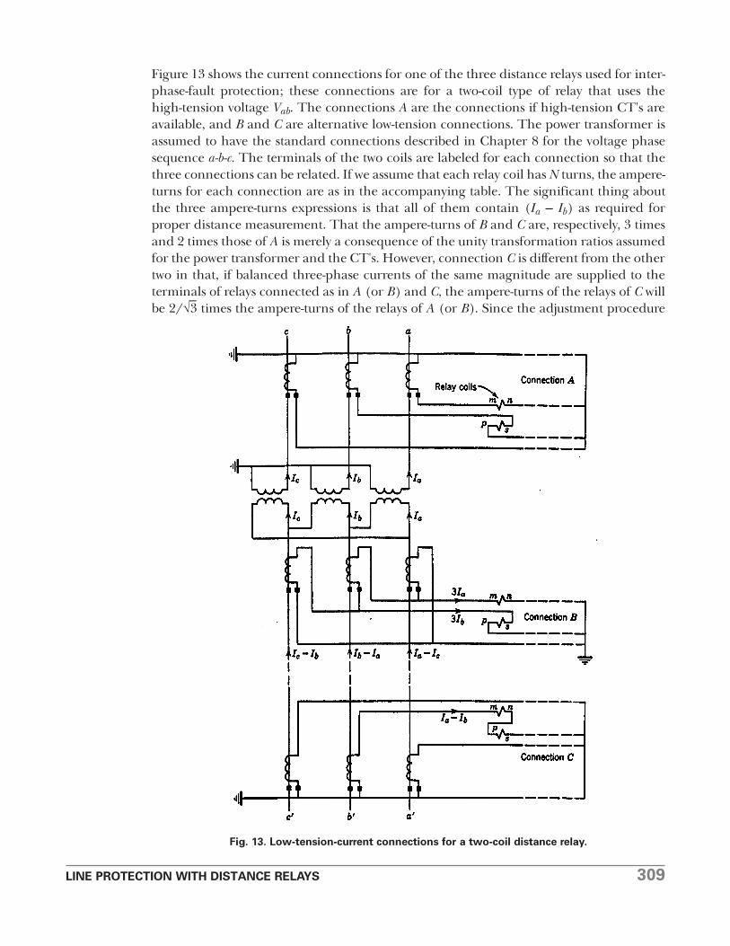
Figure 13 shows the current connections for one of the three distance relays used for inter-phase-fault protection; these connections are for a two-coil type of relay that uses thehigh-tension voltage Vab. The connections A are the connections if high-tension CT's areavailable, and B and C are alternative low-tension connections. The power transformer isassumed to have the standard connections described in Chapter 8 for the voltage phasesequence a-b-c. The terminals of the two coils are labeled for each connection so that thethree connections can be related. If we assume that each relay coil has N turns, the ampere-turns for each connection are as in the accompanying table. The significant thing aboutthe three ampere-turns expressions is that all of them contain (Ia – Ib) as required forproper distance measurement. That the ampere-turns of B and C are, respectively, 3 timesand 2 times those of A is merely a consequence of the unity transformation ratios assumedfor the power transformer and the CT's. However, connection C is different from the othertwo in that, if balanced three-phase currents of the same magnitude are supplied to theterminals of relays connected as in A (or B) and C, the ampere-turns of the relays of C willbe 2/√
–3 times the ampere-turns of the relays of A (or B). Since the adjustment procedure
Fig. 13. Low-tension-current connections for a two-coil distance relay.
310 LINE PROTECTION WITH DISTANCE RELAYS
for such relays is usually given for the connections of A, the difference in ampere-turns canbe taken care of by assuming that the magnitude of the current supplied to C is 2/√
–3 times
that supplied to A, or, in other words, that the CT ratio for C is √–3/2–or 87%– of its actual
value. The actual CT ratio for any connection is the ratio of the high-voltage-circuit phase-current magnitude to the relay phase-current magnitude under normal balancedthree-phase conditions.
Connection Ampere-Turns
A (Ia - Ib)N
B 3(Ia - Ib)N
C 2(Ia - Ib)N
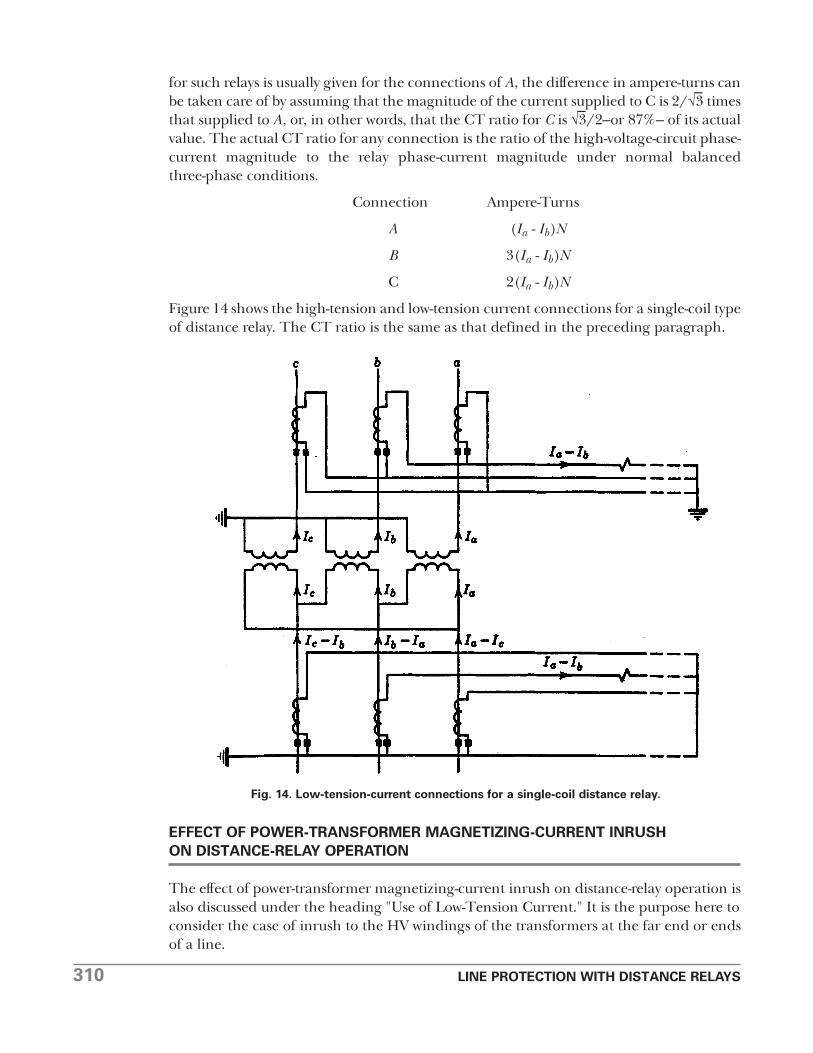
Figure 14 shows the high-tension and low-tension current connections for a single-coil typeof distance relay. The CT ratio is the same as that defined in the preceding paragraph.
EFFECT OF POWER-TRANSFORMER MAGNETIZING-CURRENT INRUSHON DISTANCE-RELAY OPERATION
The effect of power-transformer magnetizing-current inrush on distance-relay operation isalso discussed under the heading "Use of Low-Tension Current." It is the purpose here toconsider the case of inrush to the HV windings of the transformers at the far end or endsof a line.
Fig. 14. Low-tension-current connections for a single-coil distance relay.
LINE PROTECTION WITH DISTANCE RELAYS 311
The writer does not know of any cases of tests, theoretical studies, or actual trouble in thisrespect. Therefore, it is concluded that, if the possibility of distance-relay misoperationexists, it must be extremely remote. The most severe inrush that can occur in existingconventional power transformers would be less likely to operate a distance relay thanwould a three-phase fault on the other side of the transformer bank. This is because therms magnitude of the initial inrush current is generally less than that of the fault current.Furthermore, the inrush contains harmonic currents to which certain relays do notrespond as well as to the fundamental components. The high-speed zone of a distancerelay is not permitted to reach through transformers at the far ends of a line, and,therefore, if any relay unit is to operate it would have to be either the second- or third-zoneunit. These units generally have enough time delay so that the inrush will have subsidedconsiderably before a unit could operate, which further lessens the likelihood of theiroperation. And, finally, the distance relays in question will usually get only a part of theinrush current in those cases in which misoperation would be most objectionable, such aswhen energizing a transformer bank tapped to an important line. Therefore, there is littlewonder that this subject is not cause for concern.
THE CONNECTIONS OF GROUND DISTANCE RELAYS
Reference 11 shows that for accurate distance measurement, a ground relay may besupplied with a phase-to-neutral voltage and the sum of the corresponding phase currentand an amount proportional to the zero-phase-sequence current. If there is another linenearby that can induce voltage in the line under consideration when a ground fault occursanywhere, there must also be added to the phase current an amount proportional to thezero-phase-sequence current of the other line. The addition of these zero-phase-sequence�quantities is called "current compensation." Reference 11 also describes an alternative tocurrent compensation called "voltage compensation," whereby the voltage is compensatedby zero-phase� quantities. Compensation is necessary because variations in the distributionof zero-phase-sequence current relative to the distribution of positive- and negative-phase-sequence current would otherwise cause objectionable errors in distance measurement.
Ground distance relays can also be energized by zero-phase-sequence-voltage drop andzero-phase-sequence current to measure distance by measuring the zero-phase-sequenceimpedance.l2
OPERATION WHEN PT FUSES BLOW
Distance relays that are capable of operating on less than normal load current may operateto trip their breaker when a potential-transformer fuse blows. In one system, blown fusescaused more undesired tripping than any other thing until suitable fusing was provided.l3
Since potential-transformers are generally energized from a bus and supply voltage to therelays of several lines, it is advisable to provide separate voltage circuits for the relays ofeach line and to fuse them separately if fusing is to be used at all. With separate fusing,trouble in the circuit of one set of relays will not blow the fuses of another circuit. Theprincipal objection to bus PT's is that "all the eggs are in one basket"; but, with separatelyfused circuits, this objection is largely eliminated.
312 LINE PROTECTION WITH DISTANCE RELAYS
Neon lamps should be used for pilot indication of the voltage supply to each set ofdistance relays.
When the relays do not have to operate on less than load current, instantaneousovercurrent units can be used to prevent tripping for a blown fuse during normal loadconditions. The overcurrent-relay contacts are in series with the trip circuit. Undesiredtripping is still possible should a fault occur before the blown fuse has been replaced; it isto minimize this possibility that the indicating lamps are recommended. If the ground-fault current is high enough, a single set of three instantaneous overcurrent relays can beused separately from the distance relays to prevent undesired tripping by either the phaseor ground relays; otherwise, a single ground overcurrent relay would be used for theground relays.
PURPOSEFUL TRIPPING ON LOSS OF SYNCHRONISM
When generators have gone out of synchronism, all ties between them should be openedto maintain service and to permit the generators to be resynchronized. The separationshould be made only at such locations that the generating capacity and the loads on eitherside of the point of separation will be evenly matched so that there will be no interruptionto the service.14 Distance relays at those locations are sometimes suitable for tripping theirbreakers on loss of synchronism, and in some aystems they are used for this purpose inaddition to their usual protective functions. However, as mentioned in Chapter 9,additions or removals of generators or lines during normal operation will often change theresponse of certain distance relays to loss of synchronism. Therefore, each applicationshould be examined to see if certain distance relays can always be relied on to trip.
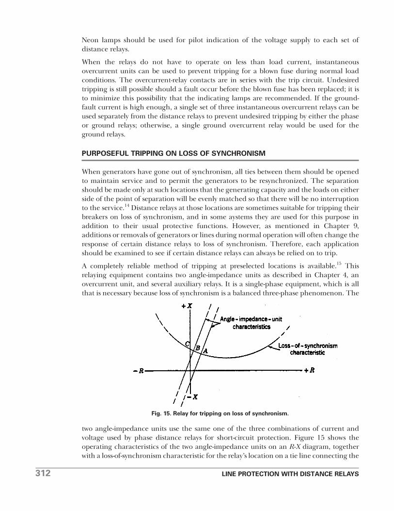
A completely reliable method of tripping at preselected locations is available.15 Thisrelaying equipment contains two angle-impedance units as described in Chapter 4, anovercurrent unit, and several auxiliary relays. It is a single-phase equipment, which is allthat is necessary because loss of synchronism is a balanced three-phase phenomenon. The
two angle-impedance units use the same one of the three combinations of current andvoltage used by phase distance relays for short-circuit protection. Figure 15 shows theoperating characteristics of the two angle-impedance units on an R-X diagram, togetherwith a loss-of-synchronism characteristic for the relay’s location on a tie line connecting the
Fig. 15. Relay for tripping on loss of synchronism.
LINE PROTECTION WITH DISTANCE RELAYS 313
generators that have lost synchronism. The significant feature of the equipment is that thetwo angle-impedance units divide the diagram into the three regions A, B, and C. As theimpedance changes during loss of synchronism, the point representing this impedancemoves along the loss-of-synchronism characteristic from region A into B and then into C,or from C into B and then into A, depending on which generators are running the faster.As the point crosses the operating characteristic of an angle-impendance unit, the unitreverses its direction of torque and closes a contact to pick up an auxiliary relay. As theimpedance point moves into one region after another, a chain of auxiliary relays picks up,one after the other. When the third region is entered, the last auxiliary relay of the chainpicks up and trips its breaker. There are two such chains–one for each direction ofmovement–and the contacts of the two last auxiliary relays of the chains are connected inparallel so that either one can trip the breaker.
The purpose of the overcurrent unit is to prevent tripping during hunting between thegenerators at light load. This condition is represented by movement along a portion of theloss-of-synchronism characteristic diametrically opposite to the portion shown in Fig. 15.Such movement would also fulfill the requirements for tripping that have been described.Relatively very little current flows during hunting at light load compared with the highcurrent flowing when generators pass through the 180° out-of-phase position which is inthe B region on the portion of the loss-of-synchronism characteristic shown in Fig. 15.Therefore, the overcurrent unit's pickup can be adjusted so that the equipment will selectbetween hunting and loss of synchronism.
No other condition can cause the impedance point to move successively through the threeregions, and therefore the equipment is completely selective.
Changes in a system cannot cause the equipment to fail so long as there is enough currentto operate the overcurrent unit when synchronism is lost. The loss-of-synchronismcharacteristic may shift up or down on the R-X diagram, or the characteristic may changefrom one of overexcitation to one of underexcitation, without adversely affecting theoperation of the equipment.
When tripping is desired at a location where the current is too low to actuate a loss-of-synchronism relay, remote tripping is necessary over a suitable pilot channel from alocation where a loss-of-synchronism relay can be actuated.16
When two or more loss-of-synchronism relays are used at different locations, one or moreof these relays may need a supplementary single-step distance unit because the overcurrentunits may not provide the desired additional selectivity.
The locations where tripping is desired on loss of synchronism may change from time totime as the relations between load and generation change. Under such circumstances, it isdesirable to have installations of loss-of-synchronism-relay equipments at several locations sothat the load dispatcher can select the equipments to be made operative during any period.
In lieu of complete freedom to choose the best locations to separate parts of a systemwhen synchronism is lost, it may be necessary to resort to some automatic "load shedding."By such means, nonessential load can be dropped automatically either directly when thetie breakers are tripped or indirectly through the operation of relays such as theunderfrequency type. This subject is treated in detail in Reference 24 of Chapter 13.
314 LINE PROTECTION WITH DISTANCE RELAYS
BLOCKING TRIPPING ON LOSS OF SYNCHRONISM
Tripping at certain locations is required when generators lose synchronism, but it shouldbe limited to those locations only. If distance relays at any other locations have a tendencyto trip, supplementary relaying equipment should be used to block tripping there. Also,wherever tripping can occur during severe power swings when a system is recovering fromthe effects of a shock, such as that caused by a short circuit, equipment to block tripping ismost desirable; tripping a sound line that is carrying synchronizing power would very likelycause instability.
The method by which tripping on loss of synchronism can be blocked is very ingenious.17
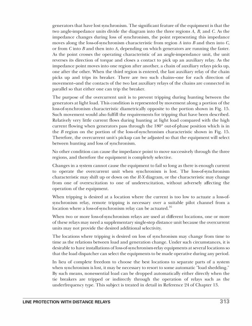
Consider the R-X diagram of Fig. 16. The point P represents the impedance for a three-phase fault well within the operating characteristic of an impedance-type distance relay.Assuming that the loss-of-synchronism characteristic passes through P, the problem, then,
is to devise a selective relaying equipment that will permit tripping when the faultrepresented by P occurs, but not when loss of synchronism reaches a stage that is alsorepresented by P. The way in which this selection is made is based on the fact that thechange in impedance from the operating conditions just before the fault is instantaneous,whereas the change in impedance during loss of synchronism is relatively slow. Themethod used for recognizing this difference is to encircle the distance-relay characteristicwith a blocking-relay characteristic such as that shown on Fig. 16. (For balanced three-phase conditions, such as those during loss of synchronism, all three phase distance relayssee the same impedance; therefore, the one characteristic represents all three relays.)Then, a control circuit is provided so that, if the blocking relay operates sufficiently aheadof a distance relay, as when the impedance is changing from S to T, the distance-relay tripcircuit will be opened. But, if the impedance changes instantly to any value such as P insidethe distance-relay characteristic, the trip circuit will not be opened.
Fig. 16. Relay characteristics of equipment of Fig. 17.
LINE PROTECTION WITH DISTANCE RELAYS 315
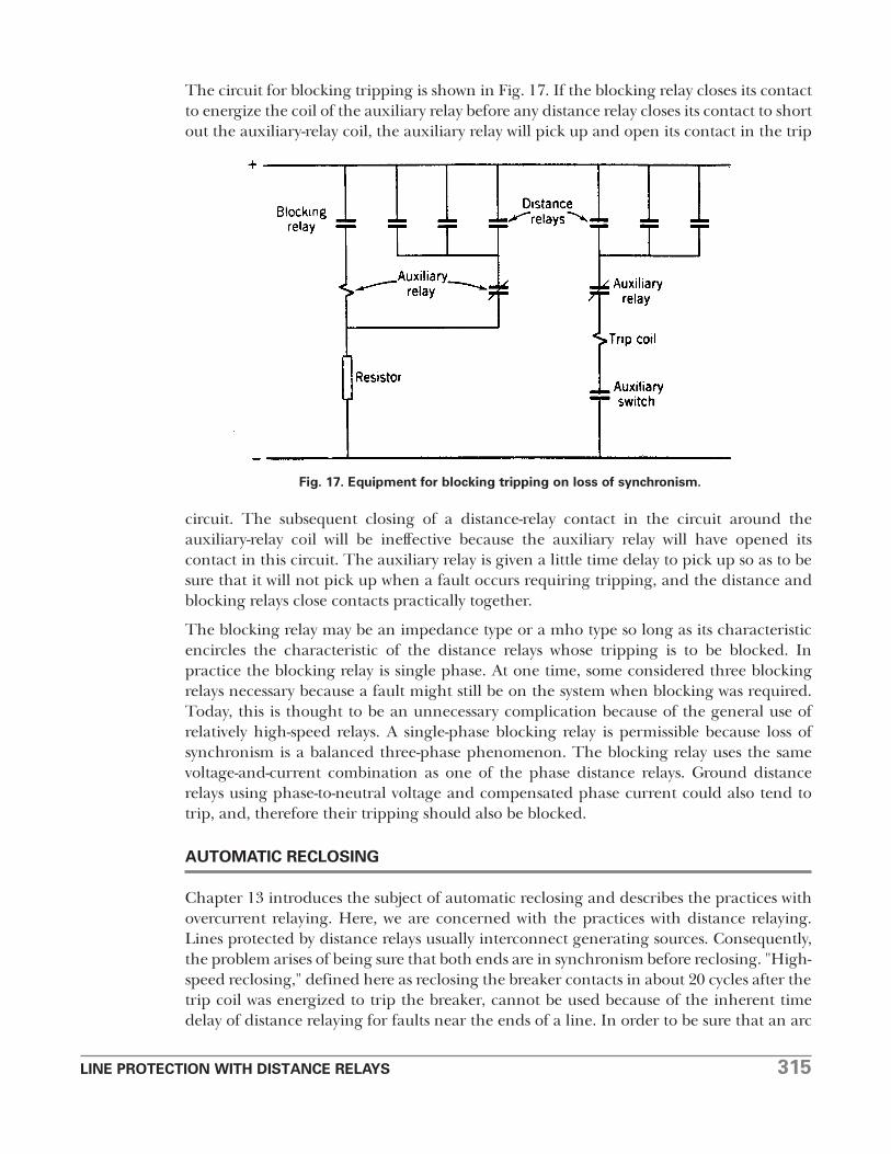
The circuit for blocking tripping is shown in Fig. 17. If the blocking relay closes its contactto energize the coil of the auxiliary relay before any distance relay closes its contact to shortout the auxiliary-relay coil, the auxiliary relay will pick up and open its contact in the trip
circuit. The subsequent closing of a distance-relay contact in the circuit around theauxiliary-relay coil will be ineffective because the auxiliary relay will have opened itscontact in this circuit. The auxiliary relay is given a little time delay to pick up so as to besure that it will not pick up when a fault occurs requiring tripping, and the distance andblocking relays close contacts practically together.
The blocking relay may be an impedance type or a mho type so long as its characteristicencircles the characteristic of the distance relays whose tripping is to be blocked. Inpractice the blocking relay is single phase. At one time, some considered three blockingrelays necessary because a fault might still be on the system when blocking was required.Today, this is thought to be an unnecessary complication because of the general use ofrelatively high-speed relays. A single-phase blocking relay is permissible because loss ofsynchronism is a balanced three-phase phenomenon. The blocking relay uses the samevoltage-and-current combination as one of the phase distance relays. Ground distancerelays using phase-to-neutral voltage and compensated phase current could also tend totrip, and, therefore their tripping should also be blocked.
AUTOMATIC RECLOSING
Chapter 13 introduces the subject of automatic reclosing and describes the practices withovercurrent relaying. Here, we are concerned with the practices with distance relaying.Lines protected by distance relays usually interconnect generating sources. Consequently,the problem arises of being sure that both ends are in synchronism before reclosing. "High-speed reclosing," defined here as reclosing the breaker contacts in about 20 cycles after thetrip coil was energized to trip the breaker, cannot be used because of the inherent timedelay of distance relaying for faults near the ends of a line. In order to be sure that an arc
Fig. 17. Equipment for blocking tripping on loss of synchronism.
316 LINE PROTECTION WITH DISTANCE RELAYS
will not restrike when reclosing the line breakers, the line has to be disconnected at bothends for a time long enough for the ionized gas in the arc path to be dispersed. This takesfrom about 6 to 16 cycles, depending on the magnitude of the arc current and the systemvoltage, the average being about 8 to 10 cycles.18 To provide this time with high-speedreclosing, both ends of a line must be tripped practically simultaneously. Since, withdistance relays, one end may trip 6 to 12 cycles or more ahead of the other, depending onthe intermediate-time adjustment, this additional time must be added to the reclosingcycle. In other words, about the fastest permissible reclosing time with distance relays is 26to 32 cycles or longer. The only exceptions are lines with wye-delta power transformers atboth ends; there simultaneous high-speed tripping is possible.
Because of the foregoing reclosing times and also the fact that inverse-time-overcurrentrelays are generally used for ground-fault protection, such lines require synchronism check,as described in Chapter 13. Of course, one end of a line can be reclosed withoutsynchronism check. Synchronism check is unnecessary if there are enough otherinterconnections between the generating sources that the line interconnects so that onecan be sure that both sides will always be in synchronism. Automatic reclosing can be veryharmful if it causes the connection of parts of a system that are out of synchronism; this isknown to have been the "last straw" that caused a major system shutdown.
It is usually the practice to provide one immediate (which is slower than high-speed)reclosure followed by 2 or 3 time-delay reclosures and then lockout if the fault persists.
When a line ends in a power-transformer bank with no high-voltage breaker, but with agrounding switch for remote tripping in the event of a transformer-bank fault, automaticreclosing of the remote breaker is affected. Some users adjust ground-distance relays’first-zone reach to 80% to 90% of the line (i.e., not to reach to the transformer) in orderthat the first-zone unit will not operate when the grounding switch is closed. Then,automatic reclosing is permitted only if a first-zone unit operates, thereby avoidingreclosing on the grounding switch and a transformer fault. If a three-phase groundingswitch is used, the high-speed zone of the remote distance relays may be permitted toreach into the transformer bank; this will permit automatic reclosure on the groundingswitch without harming the transformer, which may be permissible if the shock to thesystem is not too great.
EFFECT OF PRESENCE OF EXPULSION PROTECTIVE GAPS
It is generally necessary to delay tripping by the high-speed zone of distance relaying ifa line is equipped with expulsion protective gaps. A minimum relay-operating time of 2or 3 cycles is usually sufficient to prevent high-speed-relay tripping while an expulsionprotective gap is functioning. This additional delay in the tripping time is provided bythe addition of an auxiliary relay. The tripping circuit should be carried through theprotective-relay contacts to avoid undesired tripping because of overtravel of theauxiliary relay.
LINE PROTECTION WITH DISTANCE RELAYS 317
EFFECT OF A SERIES CAPACITOR
A series capacitor can upset the basic premises on which the principles of distance anddirectional relaying are founded. These premises are (1) that the ratio of voltage to currentat a relay location is a measure of the distance to a fault, and (2) that fault currents areapproximately reversed in phase only for faults on opposite sides of a relay location. Aseries capacitor introduces a discontinuity in the ratio of voltage to current, andparticularly in the reactance component of that ratio, as a fault is moved from the relaylocation toward and beyond a series capacitor. One can easily visualize the effect byplotting the impedance points on an R-X diagram. As a fault is moved from the relay sideof the capacitor to the other side, the capacity reactance subtracts from the accumulatedline reactance between the relay and the fault. As a consequence, the fault may appear tobe much closer to the relay location or it may even have the appearance to some relays ofbeing back of the relay location.
One way that series capacitors are used19 minimizes their adverse effect on distance relays.A single capacitor bank is chosen to compensate no more than about half of the reactanceof a given line section; if a higher degree of compensation is used, the capacitors aredivided into two or more banks located at different places along a line. Also, a protectivegap is provided across each capacitor bank, and this gap flashes over immediately when afault occurs and effectively shorts out the capacitor bank while fault current flows. In otherwords, the capacitor banks are in service normally, are shorted out while a fault exists, andare returned to service immediately when the faulty line section is tripped.
Where capacitors are located otherwise, it will probably be necessary to add slight timedelay to the distance-relay trip circuit. For fault currents that are too low to dash over thecapacitor gap, it may be necessary to use phase-comparison relaying, probably with greater-than-normal sensitivity.
COST-REDUCTION SCHEMES FOR DISTANCE RELAYING
Many ways have been suggested for reducing the cost of highspeed distance relaying sothat its use on lower-voltage circuits could be justified. What has been sought is a “class ofprotection somewhere in the middle ground between the cost, performance, andcomplexity of overcurrent and conventional 3-zone distance relays.”20 These schemes maybe classified as follows:
(a) Abbreviated relays.20
(b) Three conventional relays for phase faults and three conventional relays for groundfaults, except that certain units are used in common.21
(c) Three conventional relays for both phase and ground faults by means of “current andvoltage switching.”22
(d) One conventional relay for phase faults and/or one conventional relay for groundfaults by means of current and voltage switching.l2,23
(e) One conventional relay for both phase and ground faults by means of current andvoltage switching.22
318 LINE PROTECTION WITH DISTANCE RELAYS
Current and voltage switching is a means for automatically connecting the relay to theproper current and voltage sources so that it will measure distance correctly for any faultthat occurs.
With the possible exception of (e), all these schemes are in use in this country, althoughnone of them very extensively. The greater the departure from the conventionalarrangement of three phase and three ground relays, the poorer is the quality of relaying.They either have more time delay, are harder to apply, are less accurate, or require morefrequent maintenance. Voltage switching may not be permitted with capacitance potentialdevices because of the errors that result from changing the burden. It is probablyeconomically feasible to standardize on one intermediate arrangement, but there is littlejustification for much more.
To complete the list, other combinations of units should be included, most of which maybe classified as "abbreviated" relays. They consist of various combinations of units likethose used in conventional high� relays.7 Such relays supplement existing relays forspeeding up the protection. For example, three single-step directional-distance relaysmight supplement directional-overcurrent inverse-time relays; this would provide high-speed relaying for 80% to 90% of a line plus inverse-time-overcurrent relaying for theremainder of the line and for back-up protection.
ELECTRONIC DISTANCE RELAYS
Electronic distance relays have been extensively tested24 that are functionally equivalent toconventional electromechanical distance relays, but that are faster and imposeconsiderably lower burden on a-c sources of current and voltage. At the same time, they aremore shock resistant. Their greater speed is most effective when they are used inconjunction with a carrier-current or microwave pilot. When they are used alone, it is stillnecessary to have some time delay for faults near the ends of a line, which tends to reducethe advantage of a higher-speed first-zone unit.
The lower-burden characteristic of electronic relays may contribute to less expensivecurrent and voltage transformers, and therefore may increase the use of such relays eventhough the greater speed may not be required.
Apart from differences in physical characteristics, the basic principles of electromechanicaldistance relays and their application apply equally well to electronic distance relays.
PROBLEMS
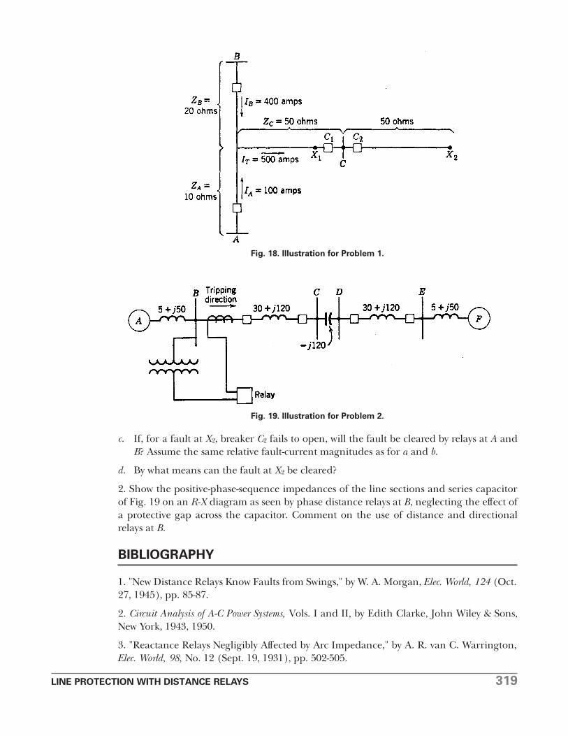
1. Referring to Fig. 18, it has been determined that load transfer from A to B or from B toA prevents setting a distance relay at either A or B with a greater ohmic reach than justsufficient to protect a l00-ohm, 2-terminal line with a 25% margin (i.e., third-zone reach =125 ohms).
a. What is the apparent impedance of the fault at X1 to the relay at A? Can the relay at Asee the fault before the breaker at B has tripped?
b. Can the relay at B see the fault at X1 before the breaker at A has tripped? Why?
LINE PROTECTION WITH DISTANCE RELAYS 319
c. If, for a fault at X2, breaker C2 fails to open, will the fault be cleared by relays at A andB? Assume the same relative fault-current magnitudes as for a and b.
d. By what means can the fault at X2 be cleared?
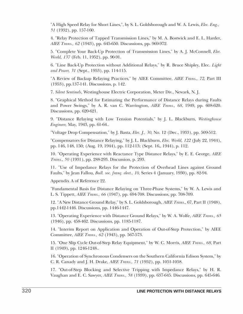
2. Show the positive-phase-sequence impedances of the line sections and series capacitorof Fig. 19 on an R-X diagram as seen by phase distance relays at B, neglecting the effect ofa protective gap across the capacitor. Comment on the use of distance and directionalrelays at B.
BIBLIOGRAPHY
1. "New Distance Relays Know Faults from Swings," by W. A. Morgan, Elec. World, 124 (Oct.27, 1945), pp. 85-87.
2. Circuit Analysis of A-C Power Systems, Vols. I and II, by Edith Clarke, John Wiley & Sons,New York, 1943, 1950.
3. "Reactance Relays Negligibly Affected by Arc Impedance," by A. R. van C. Warrington,Elec. World, 98, No. 12 (Sept. 19, 1931), pp. 502-505.
Fig. 19. Illustration for Problem 2.
Fig. 18. Illustration for Problem 1.
320 LINE PROTECTION WITH DISTANCE RELAYS
"A High Speed Relay for Short Lines,", by S. L. Goldsborough and W. A. Lewis, Elec. Eng.,51 (1932), pp. 157-160.
4. "Relay Protection of Tapped Transmission Lines," by M. A. Bostwick and E. L. Harder,AIEE Trans., 62 (1943), pp. 645-650. Discussions, pp. 969-972.
5. "Complete Your Back-Up Protection of Transmission Lines," by A. J. McConnell, Elec.World, 137 (Feb. 11, 1952), pp. 90-91.
6. "Line Back-Up Protection without Additional Relays," by R. Bruce Shipley, Elec. Lightand Power, 31 (Sept., 1953), pp. 114-115.
"A Review of Backup Relaying Practices," by AIEE Committee, AIEE Trans., 72, Part III(1953), pp.137-141. Discussions, p. 142.
7. Silent Sentinels, Westinghouse Electric Corporation, Meter Div., Newark, N. J.
8. "Graphical Method for Estimating the Performance of Distance Relays during Faultsand Power Swings," by A. R. van C. Warrington, AIEE Trans., 68, 1949, pp. 608-620.Discussions, pp. 620-621.
9. "Distance Relaying with Low Tension Potentials," by J. L. Blackburn, WestinghouseEngineer, May, 1943, pp. 61-64..
"Voltage Drop Compensation," by J. Basta, Elec. J., 30, No. 12 (Dec., 1933), pp. 509-512.
"Compensators for Distance Relaying," by J. L. Blackburn, Elec. World, 122 (July 22, 1944),pp. 146, 148, 150; (Aug. 19, 1944), pp. 112-113; (Sept. 16,, 1944), p. 112.
10. "Operating Experience with Reactance Type Distance Relays," by E. E. George, AIEETrans., 50 (1931), pp. 288-293. Discussion, p. 293.
11. "Use of Impedance Relays for the Protection of Overhead Lines against GroundFaults," by Jean Fallou, Bull. soc. franç. elect., 10, Series 4 (January, 1930), pp. 82-94.
Appendix A of Reference 22.
"Fundamental Basis for Distance Relaying on Three-Phase Systems," by W. A. Lewis andL. S. Tippett, AIEE Trans., 66 (1947), pp. 694-708. Discussions, pp. 708-709.
12. "A New Distance Ground Relay," by S. L. Goldsborough, AIEE Trans., 67, Part II (1948),pp.1442-1446. Discussions, pp. 1446-1447.
13. "Operating Experience with Distance Ground Relays," by W. A. Wolfe, AIEE Trans., 65(1946), pp. 458-462. Discussions, pp. 1185-1187.
14. "Interim Report on Application and Operation of Out-of-Step Protection," by AIEECommittee, AIEE Trans., 62 (1943), pp. 567-573.
15. "One Slip Cycle Out-of-Step Relay Equipment," by W. C. Morris, AIEE Trans., 68, PartII (1949), pp. 1246-1248..
16. "Operation of Synchronous Condensers on the Southern California Edison System," byC. R. Canady and J. H. Drake, AIEE Trans., 71 (1952), pp. 1051-1058.
17. "Out-of-Step Blocking and Selective Tripping with Impedance Relays," by H. R.Vaughan and E. C. Sawyer, AIEE Trans., 58 (1939), pp. 637-645. Discussions, pp. 645-646.
LINE PROTECTION WITH DISTANCE RELAYS 321
18. "Insulator Flashover Deionization Times As a Factor in Applying High ReclosingBreakers," by A. C. Boisseau, B. W. Wyman, and W. F. Skeats, AIEE Trans., 68 Part II (1949),pp. 1058-1066. Discussions, pp. 1066-1067.
19. "The Series Capacitor in Sweden," by Gunnar Jancke and K. F. Akerström, Elec. Eng.,71 (1952), pp. 222-227.
"Characteristics of a 400-Mile 230-Kv Series-Capacitor-Compensated Transmission Line,"by B. V. Hoard, AIEE Trans., 65 (1946), pp. 1102-1114. Discussions pp. 1178-1180.
"Series Capacitors in High-Voltage Lines of the Bonneville Power Administration," byAlexander Dovjikov and E. C. Starr, Elec. Eng., 71 (1952), pp. 228-232.
"Series Capacitors during Faults and Reclosing," by E. L. Harder, J. E. Barkle, and R. W.Ferguson, AIEE Trans., 70 (1951). pp. 1627-1641. Discussions, pp. 1641-1642.
20. "A Simplified Unit for Distance Relaying," by A. W. Adams and F. R. Bergseth, AIEETrans., 72, Part III (1953), pp. 996-998.
21. "Combined Phase and Ground Distance Relaying," by Warren C. New, AIEE Trans., 69,1950, pp. 37-42. Discussions, pp. 42-44.
22. "Control of Distance Relay Potential Connections," by A. R. van C. Warrington, AIEETrans., 53 (1934), pp. 206-213. Discussions, pp. 465, 466, 617.
23. "Distance Relay Protection for Subtransmission Lines Made Economical," by L. J.Audlin and A. R. van C. Warrington, AIEE Trans., 62 (1943), pp. 574-578. Discussions,pp. 976-979.
24. "Field Experience–Electronic Mho Distance Relay," by H. C. Barnes and R. H.Mcpherson, AIEE Trans., 72., Part III (1953), pp. 857-864. Discussions, p. 865.
"Electronic Protective Relays," by R. H. Macpherson, A. R. van C. Warrington, and A. J.McConnell, AIEE Trans., 67, Part II (1948), pp. 1702-1707. Discussions, pp. 1707-1708.
"An Electronic Distance Relay Using a Phase-Discrimination Principle," by F. R. Bergseth,AIEE Trans., 73, Part III-B (1954), pp. 1276-1279. Discussions, p. 1279.