Embed Size (px)
Citation preview
MANUFACTURING ENG. & PRODUCTION TECH. DEPARTMENT
MINI CNC MACHINE
(3 – AXIS)
Presented By:
Amir Tawfic Dawa
Mohamed Ahmed Abo yadak
Ahmed Mohamed Ibrahem
Mahmoud Abd El Wahab
Ramy Abd El – Aziz
Waleed Fathy Hamed
Supervised By:
Prof. Dr. Abd El Naser Zayed
July 2012
MODERN ACADEMY
FOR ENGINEERING & TECHNOLOGY

Table of Contents
CHAPTER (1)
INTRODUCTION ......................................................................................... 1
1.1 OVERVIEW ................................................................................................ 1
1.2 CNC SYSTEM ELEMENTS ...................................................................... 1
1.3 COMPUTER NUMERICAL CONTROL (CNC) ...................................... 2
1.4 STRUCTURAL MATERIALS FOR ROUTER ......................................... 2
1.5 CAD / CAM ................................................................................................ 2
1.6 COMPUTER AIDED MANUFACTURING ............................................. 3
1.7 COMPUTER AIDED DESIGN TYPES ..................................................... 4
1.8 MACHINING PROCESS ........................................................................... 5
1.8.1 Roughing .......................................................................................... 5
1.8.2 Semi-Finishing ................................................................................. 5
1.8.3 Finishing ........................................................................................... 6
1.8.4 Contour Milling ................................................................................ 6
1.9 ADVANTAGES OF CNC .......................................................................... 6
1.10 LIMITATIONS OF CNC .......................................................................... 7
CHAPTER(2)
DESIGN .......................................................................................................... 8
2.1 DETAIL DRAWING ........................................................................................... 8
2.2 SELECTION OF SPINDLE ............................................................................. 34
2.2.1 Select work piece and tool type ........................................................... 34
2.2.2 Calculate ( .................................................................................... 34
2.2.3 Calculate (N) ........................................................................................... 34
2.2.4 Calculate machine power ...................................................................... 34
2.2.5 Calculate material removal rate ........................................................... 35
2.2.6 Calculate efficiency factor (E) for m/c tool ....................................... 35
2.2.7 Calculate drive motor power ................................................................ 35
2.2.8 Calculate drive motor torque ................................................................ 35
2.3 ACTING FORCES : .......................................................................................... 37
2.4 DESIGN OF POWER SCREW ....................................................................... 37
2.4.1 TYPES OF POWER SCREW.............................................................. 37
2.5 CALCULATION OF POWER SCREW: ...................................................... 40
2.6 SELECTION OF BEARINGS ......................................................................... 45
2.6.1 PRINCIPLES OF OPERATION ........................................................ 45
2.6.2 MOTIONS ............................................................................................... 46
2.6.3 FRICTION ............................................................................................... 46
2.6.4 LOADS..................................................................................................... 46
2.6.5 SPEEDS ................................................................................................... 47
2.6.6 TYPES OF BEARING .......................................................................... 47
2.6.7 Calculation of Bearing ........................................................................... 48
2.7 DESIGN OF GUIDE WAY ............................................................................... 54
2.7.1 Linear Motion ......................................................................................... 54
2.7.2 Supporting Machine Components ....................................................... 54
2.7.3 Providing Precise Linear Motion......................................................... 54
2.7.4 Supporting Secondary Loads ............................................................... 54
2.7.5 Categories of Linear Motion systems ................................................. 56
2.7.6 Round rail bearings system................................................................... 57
2.7.7 Selection option ...................................................................................... 58
2.7.8 Linear bearing accuracy ........................................................................ 59
2.7.9 Calculation of guide way ...................................................................... 60
CHAPTER(3)
ASSEMBLY ................................................................................................... 78
CHAPTER(4)
CONTROL SYSTEM ................................................................................... 91
4.1 DEFINITION ............................................................................................ 91
4.2 CONROL PARTS ..................................................................................... 91
4.2.1 Controller ....................................................................................... 92
4.2.1.1 Types of Controller (Software) can be used ............................ 92
4.2.1.2 Features of Mach3 Software .................................................... 92
4.2.1.3 Configuration of Software ....................................................... 93
4.2.1.4 Determined Steps per Unit Length .......................................... 97
4.2.2 Power Supply ................................................................................. 99
4.2.3 Breakout Board Or Interface ......................................................... 99
4.2.3.1 Interface features ................................................................... 100
4.2.3.2 Parallel port ............................................................................ 100
4.2.3.3 Input and output ports ............................................................ 101
4.2.4 Motors driver ............................................................................... 101
4.2.4.1 Type of common driver circuits, ........................................... 101
4.2.4.2 Advantages of H-bridge and l297 circuit .............................. 102
4.2.4.3 Driver Circuit ......................................................................... 103
4.2.4.4 Driver PCB ............................................................................ 104
4.2.4.5 Driver Picture ......................................................................... 104
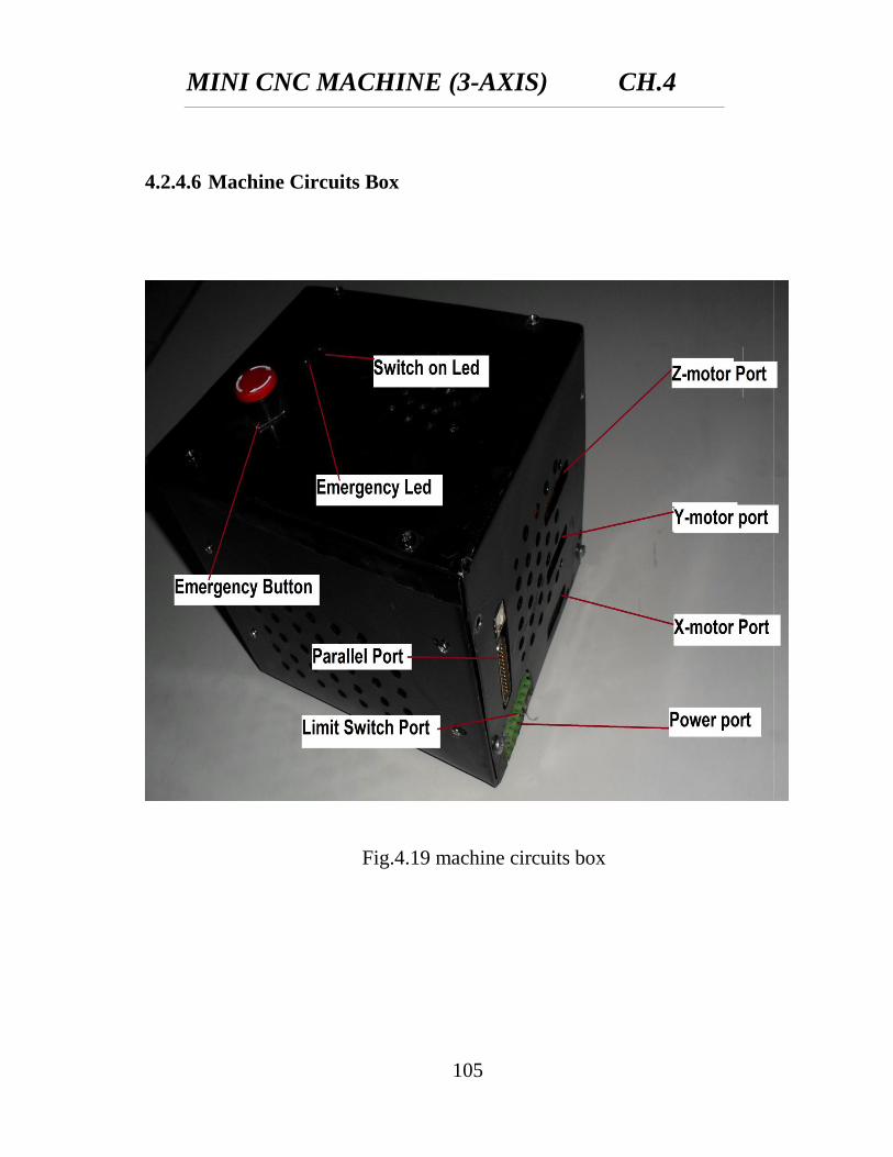
4.2.4.6 Machine Circuits Box ............................................................ 106
4.2.5 Motors .......................................................................................... 106
4.2.5.1 Motors type ............................................................................ 107
4.2.5.2 Open Loop Versus Closed Loop ........................................... 108
4.2.5.3 Stepper Motors Advantages And Disadvantages .................. 109
4.2.6 Switches ....................................................................................... 110
CHAPTER(5)
EXPERIMENTAL WORK AND VERIFICATION ............................... 111
5.1. MACHINING PARTS ............................................................................ 111
5.1.1. First Sample (Mdf) ...................................................................... 111
5.1.1.3. Machined Part ........................................................................... 112
5.1.1.4. G-Codes For First Sample ........................................................ 112
5.1.2. The Second Sample (MDF) ................................................................. 119
5.1.3. The Third Sample (From Aluminum) ................................................. 135
5.2. CONCLUSION ....................................................................................... 143
REFERENCES ............................................................................................. 144
Appendix ...................................................................................................... 145

CHAPTER (1)
INTRODUCTION
MINI CNC MACHINE (3-AXIS) CH.1
1
CHAPTER 1
INTRODUCTION
1.1 OVERVIEW
The goal of this project to constrain, design, manufacturing, assemble for min
CNC milling machine tool and design and create the controller for it.
The process of manufacturing machined parts using a computerized
controller to command motors which drive each machine axis.
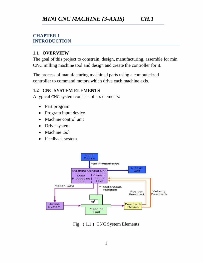
1.2 CNC SYSTEM ELEMENTS
A typical CNC system consists of six elements:
Part program
Program input device
Machine control unit
Drive system
Machine tool
Feedback system
Fig. ( 1.1 ) CNC System Elements
MINI CNC MACHINE (3-AXIS) CH.1
2
1.3 COMPUTER NUMERICAL CONTROL (CNC)
Nowadays, products can be produced by modern technology, which uses
computer software, hardware and firm ware in industries. It is needed to use
CNC mill machine to get more accurate dimensions and irregular shape. End
milling is the most important milling operation, widely used in most of the
manufacturing industries due to its capability of producing complex geometric
surfaces with reasonable accuracy and surface finish. However, with the
inventions of CNC milling machine, the flexibility has been adopted along
with versatility in end milling process. In order to build up a bridge between
quality and productivity and to achieve the same in an economic way, the
present study highlights optimization of CNC end milling process parameters
to provide good surface finish and high material removal rate (MRR).
1.4 STRUCTURAL MATERIALS FOR ROUTER
The overall goal in constructing a CNC router machine is typically to have the
heavy immovable stationary portions to help reduce vibration. Another goal is
to have the movable parts be as light weight as possible (yet strong and stiff
enough to handle the intended loads). Thus, faster accelerations will be
possible because of lower inertia mass of the movable parts.
Wood Composites
Aluminum
1.5 CAD / CAM
Computer Aided Design (CAD) involves the use of computer hardware and
graphics software to generate design drawings. Modern CAD equipment
enables the designer to quickly produce very accurate and realistic images of
products to be manufactured. Computer Aided Manufacturing (CAM) is a
system of automatically producing finished products by using computer
controlled production machines. CAD and CAM work together in that the
digital model generated in CAD is inputted to the CAM software package.
MINI CNC MACHINE (3-AXIS) CH.1
3
The CAM software needs to know the physical shape of the product (CAD
model) before it can compose a proper set of fabrication instructions to a
production machine.
1.6 COMPUTER AIDED MANUFACTURING
A computer aided manufacturing system allows the manufacturer to
systematically communicate work instructions to the machine. CAM has
evolved from a technology referred to as the Computer Numerical Control
(CNC), invented in the 1950s. CNC performed a set of coded instructions in a
punched paper tape.
Computer aided manufacturing facilitates effortless and quick computer
programming and faster execution of design changes. The computer aided
management system integrates the computer aided design systems and
controls tasks that involve order placement, scheduling, and replacement of
tools. The implementation of CAM system leads to overall increase in
efficiency of the manufacturing process. CAM systems are used in the
automotive, aviation and furniture manufacturing sectors and areas such as
mechanical engineering and electronic designing. Another significant benefit
of using the computer aided management system is that it allows
customization of the manufacturing process for creating client specific
designs.
A computer aided manufacturing system requires a 3D environment for
making it compliant with CAD systems. The CAM system can cost $18,000
or more along with the appropriate software. CAM allows automated
integration of the manufacturing procedure with other mechanization systems
such as Computer-Integrated Manufacturing (CIM), Integrated Computer-
Aided Manufacturing (ICAM), Flexible Manufacturing System (FMS), Direct
Numerical Control (DNC), and Manufacturing Process Management (MP).
Repetitive tasks involved in the manufacturing process are delegated to
machines using the CAM system, allowing workers involved to concentrate
on quality control and productivity.
MINI CNC MACHINE (3-AXIS) CH.1
4
1.7 COMPUTER AIDED DESIGN TYPES
There are several different types of CAD. Each of these different types of
CAD systems requires the operator to think differently about how he or she
will use them and he or she must design their virtual components in a different
manner for each.
There are many producers of the lower-end 2D systems, including a number
of free and open source programs. These provide an approach to the drawing
process without all the fuss over scale and placement on the drawing sheet
that accompanied hand drafting, since these can be adjusted as required during
the creation of the final draft.
3D wireframe is basically an extension of 2D drafting (not often used today).
Each line has to be manually inserted into the drawing. The final product has
no mass properties associated with it and cannot have features directly added
to it, such as holes. The operator approaches these in a similar fashion to the
2D systems, although many 3D systems allow using the wireframe model to
make the final engineering drawing views.
3D "dumb" solids are created in a way analogous to manipulations of real
world objects (not often used today). Basic three-dimensional geometric
forms (prisms, cylinders, spheres, and so on) have solid volumes added or
subtracted from them, as if assembling or cutting real-world objects. Two-
dimensional projected views can easily be generated from the models. Basic
3D solids don't usually include tools to easily allow motion of components,
set limits to their motion, or identify interference between components.
3D parametric solid modeling requires the operator to use what is referred to
as "design intent". The objects and features created are adjustable. Any future
modifications will be simple, difficult, or nearly impossible, depending on
how the original part was created. One must think of this as being a "perfect
world" representation of the component. If a feature was intended to be
located from the center of the part, the operator needs to locate it from the
center of the model, not, perhaps, from a more convenient edge or an arbitrary
MINI CNC MACHINE (3-AXIS) CH.1
5
point, as he could when using "dumb" solids. Parametric solids require the
operator to consider the consequences of his actions carefully.
Some software packages provide the ability to edit parametric and non-
parametric geometry without the need to understand or undo the design intent
history of the geometry by use of direct modeling functionality. This ability
may also include the additional ability to infer the correct relationships
between selected geometry (e.g., tangency, concentricity) which makes the
editing process less time and labor intensive while still freeing the engineer
from the burden of understanding the model’s.
1.8 MACHINING PROCESS
Most machining progresses through four stages, each of which is implemented
by a variety of basic and sophisticated strategies, depending on the material
and the software available.
The stages are:
1.8.1 Roughing
This process begins with raw stock, known as billet, and cuts it very roughly
to shape of the final model. In milling, the result often gives the appearance of
terraces, because the strategy has taken advantage of the ability to cut the
model horizontally. Common strategies are zigzag clearing, offset clearing,
and plunge roughing, rest-roughing.
1.8.2 Semi-Finishing
This process begins with a roughed part that unevenly approximates the model
and cuts to within a fixed offset distance from the model. The semi-finishing
pass must leave a small amount of material so the tool can cut accurately
while finishing, but not so little that the tool and material deflect instead of
shearing. Common strategies are raster passes, waterline passes, constant step-
over passes, pencil milling.
MINI CNC MACHINE (3-AXIS) CH.1
6
1.8.3 Finishing
Finishing involves a slow pass across the material in very fine steps to
produce the finished part. In finishing, the step between one pass and another
is minimal. Feed rates are low and spindle speeds are raised to produce an
accurate surface.
1.8.4 Contour Milling
In milling applications on hardware with five or more axes, a separate
finishing process called contouring can be performed. Instead of stepping
down in fine-grained increments to approximate a surface, the work piece is
rotated to make the cutting surfaces of the tool tangent to the ideal part
features. This produces an excellent surface finish with high dimensional
accuracy.
1.9 ADVANTAGES OF CNC
Flexibility of operation is improved, as is the ability toproduce complex
shapes with good dimensional accuracy, repeatability, reduced scrap
loss, and high production rates, productivity, and product quality.
Tooling costs are reduced, since templates and other fixtures are not
required.
Machine adjustments are easy to make with microcomputers and digital
readouts.
More operations can be performed with each setup, and less lead time
for setup and machining is required compared to conventional methods.
Design changes are facilitated, and inventory is reduced.
Programs can be prepared rapidly and can be recalled at any time
utilizing microprocessors. Less paperwork is involved.
Faster prototype production is possible.
Required operator skill is less than that for a qualified machinist, and
the operator has more time to attend to other tasks in the work area.

MINI CNC MACHINE (3-AXIS) CH.1
7
1.10 LIMITATIONS OF CNC
Relatively high initial cost of the equipment.
The need and cost for programming and computer time.
Special maintenance with trained personnel.
High preventative maintenance since breakdowns are costly.

CHAPTER (2)
DESIGN
MINI CNC MACHINE (3-AXIS) CH.2
8
CHAPTER 2
DESIGN
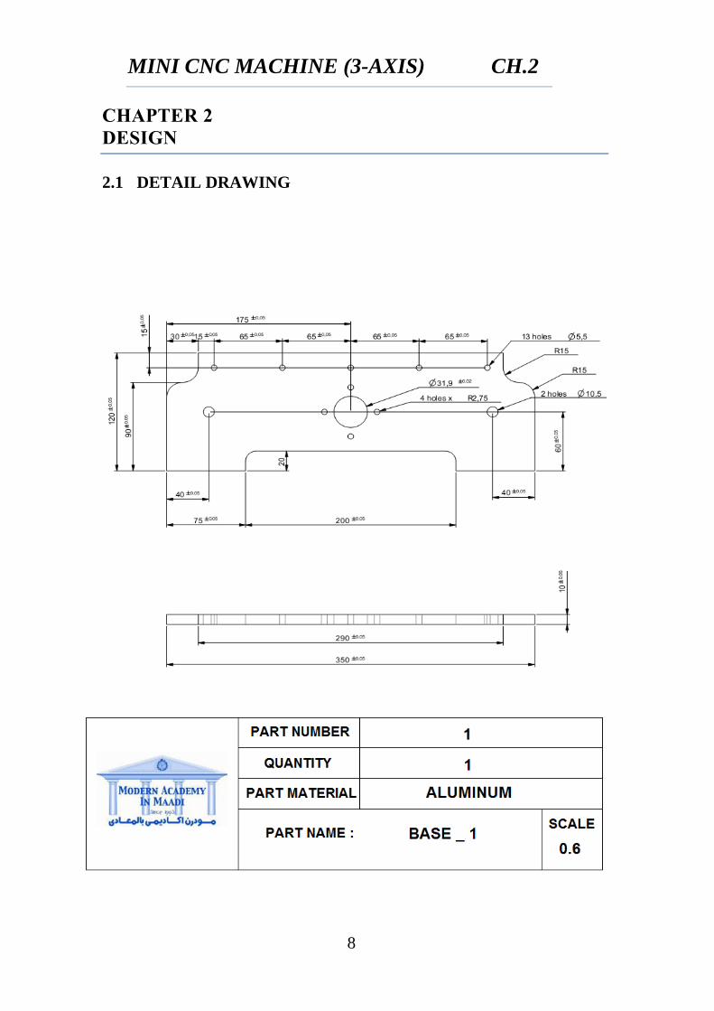
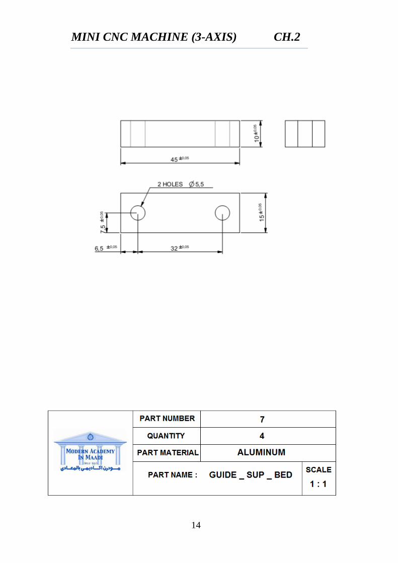
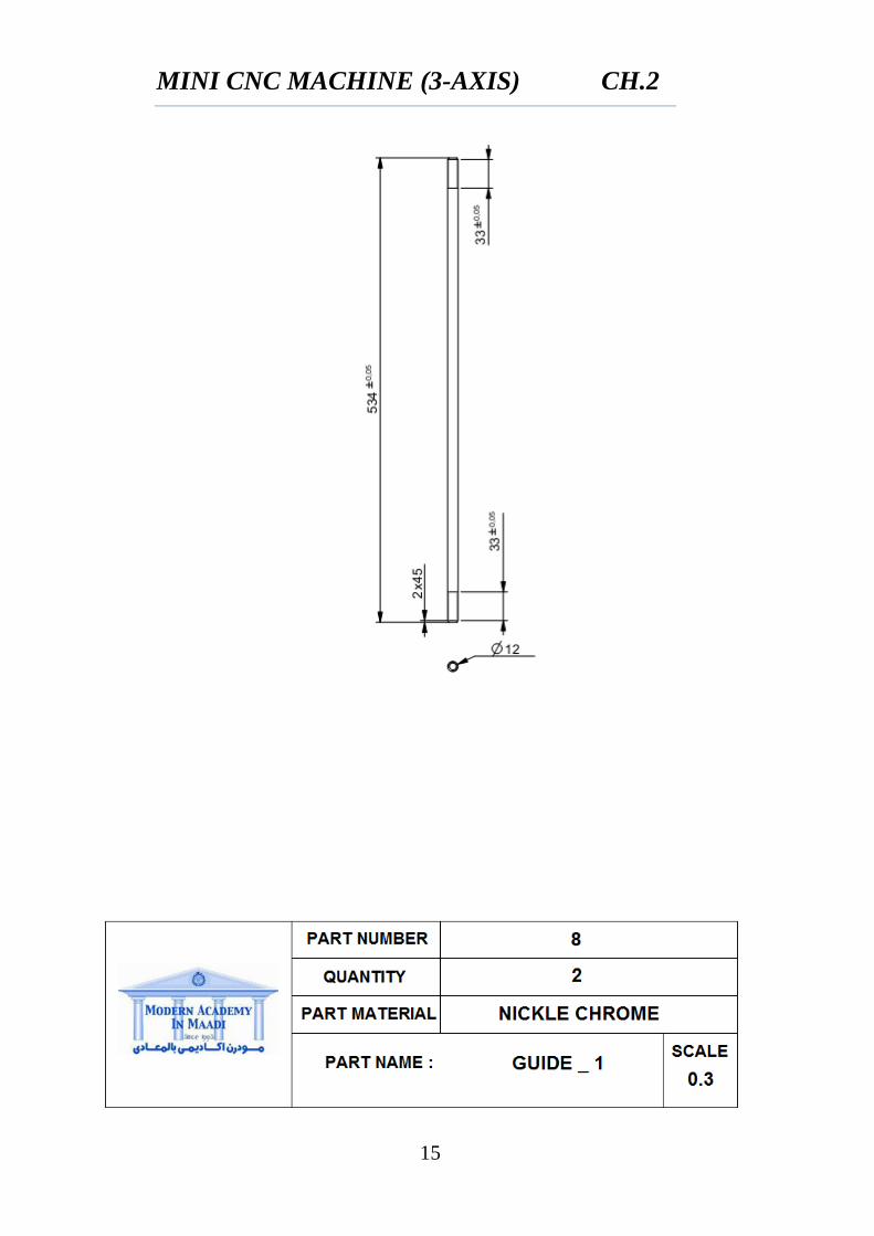
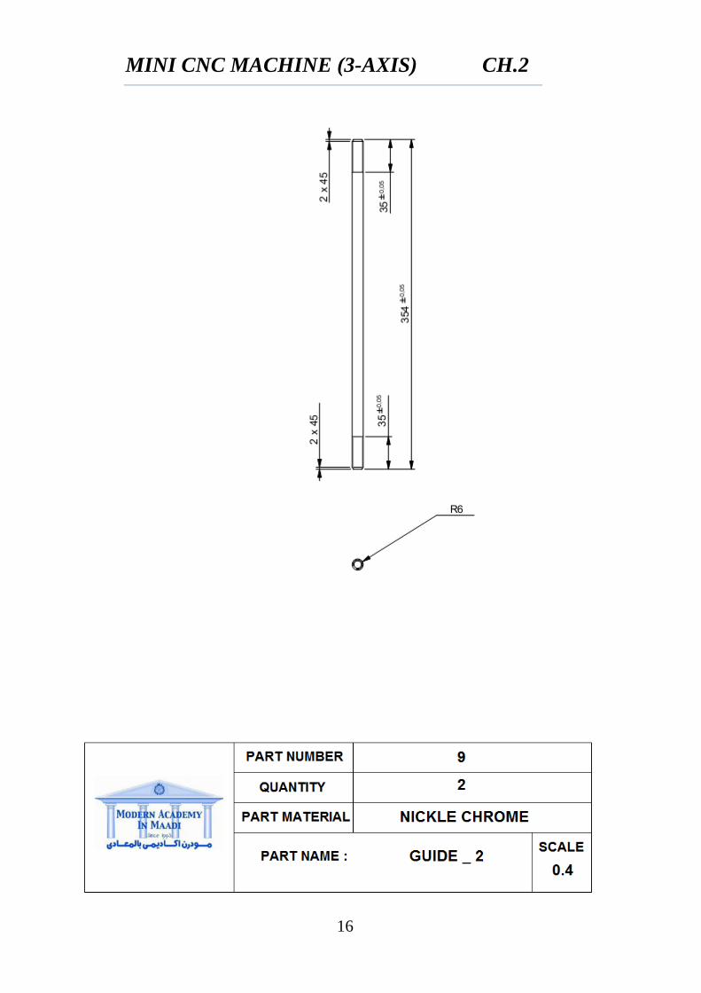
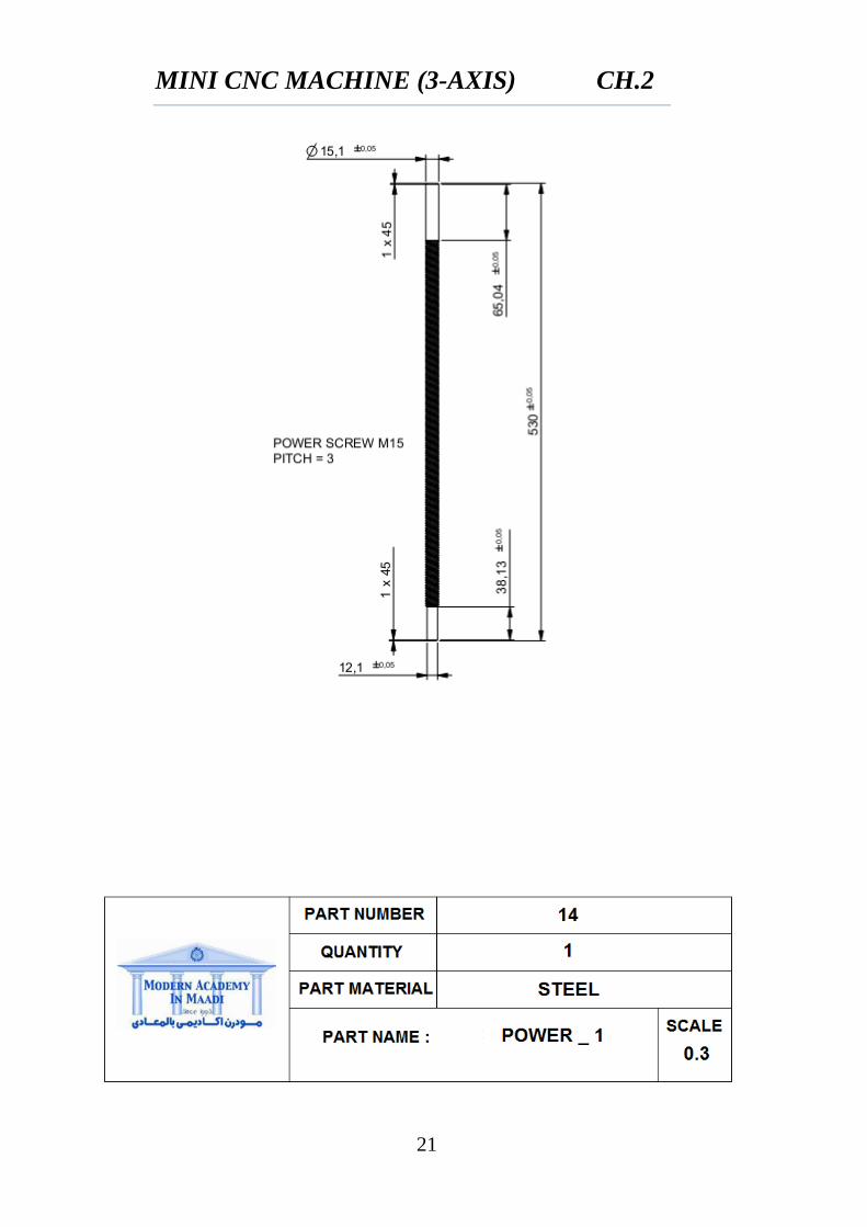
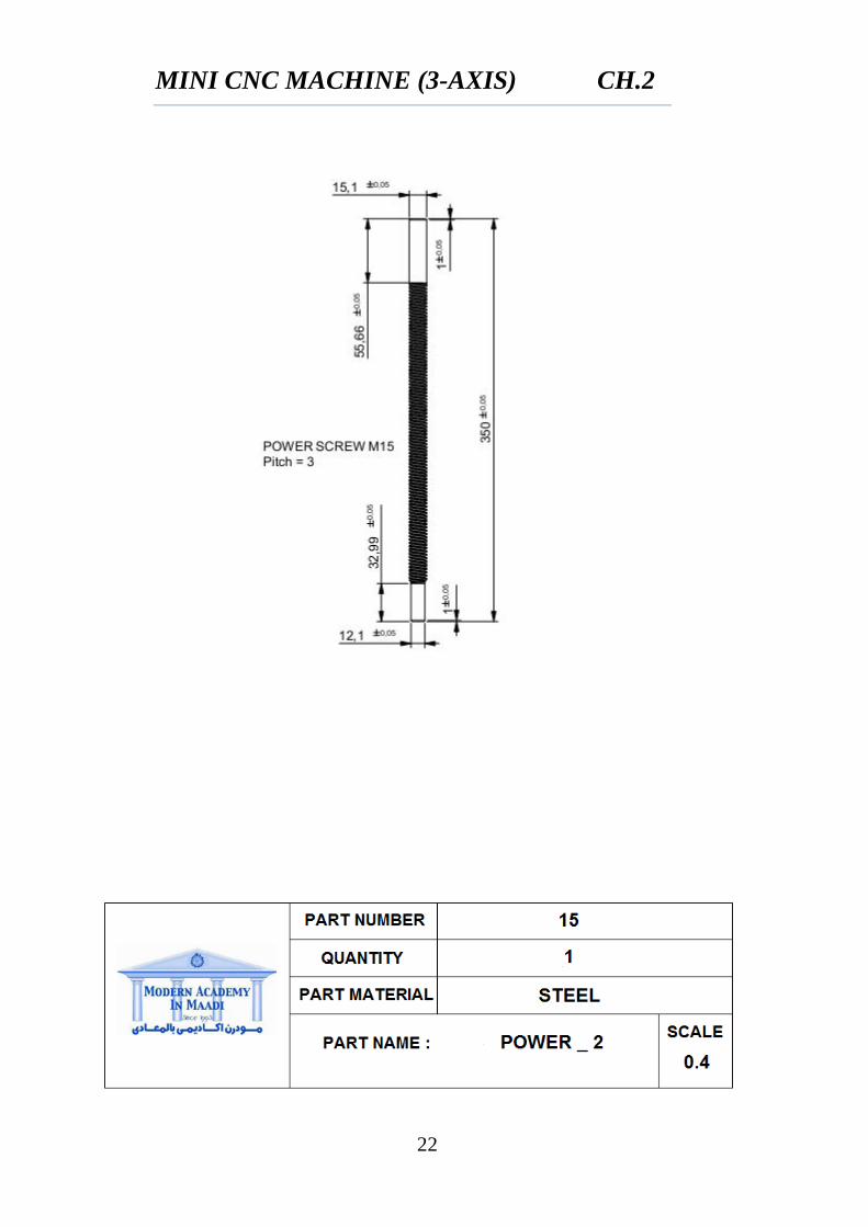
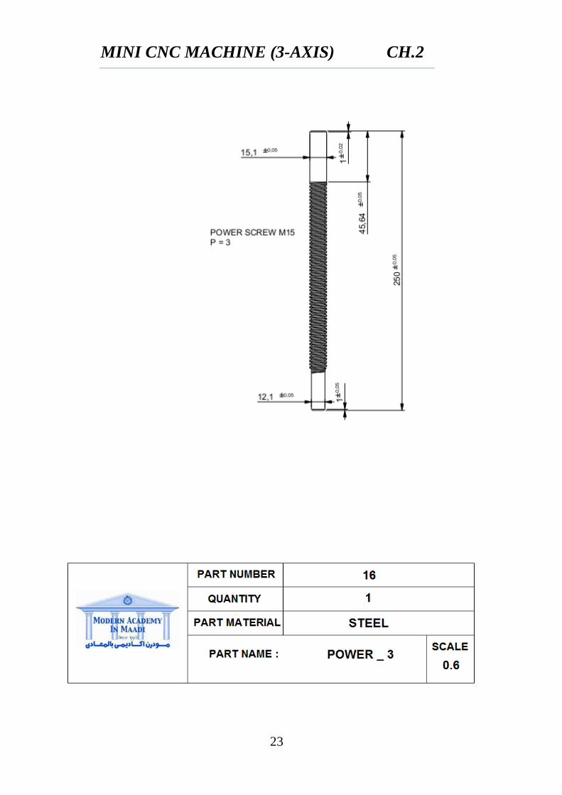
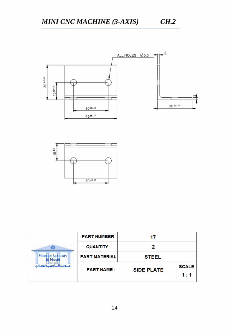
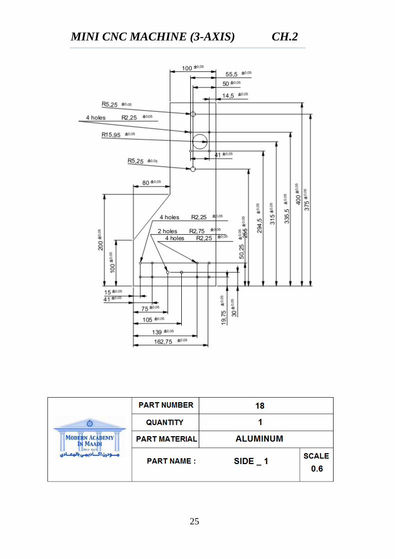
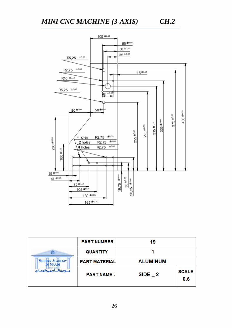
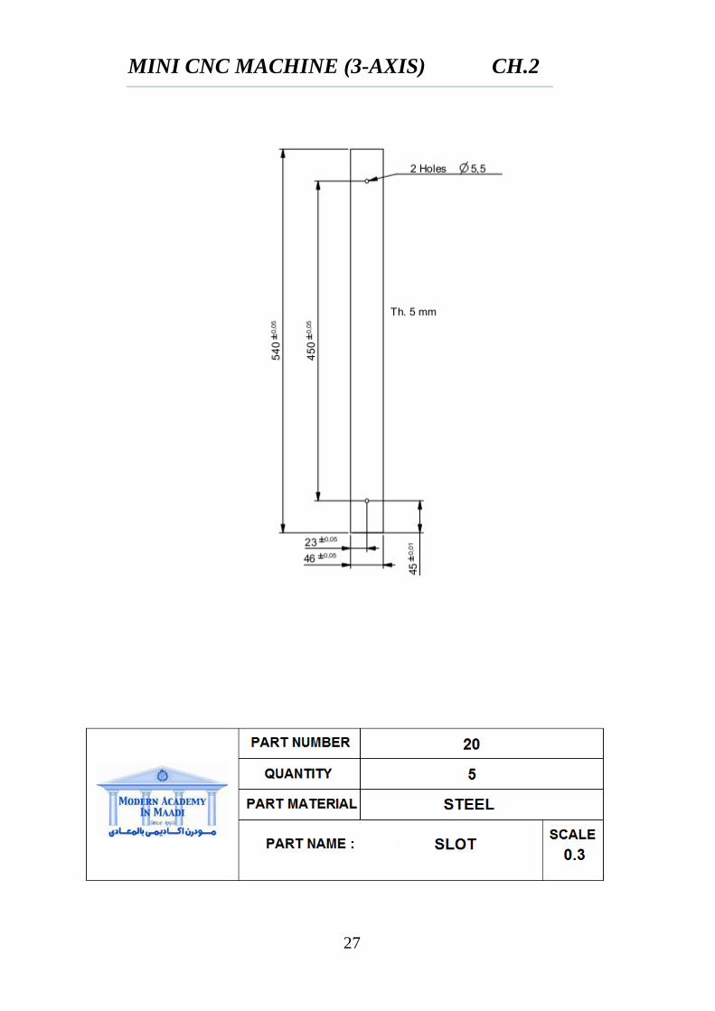
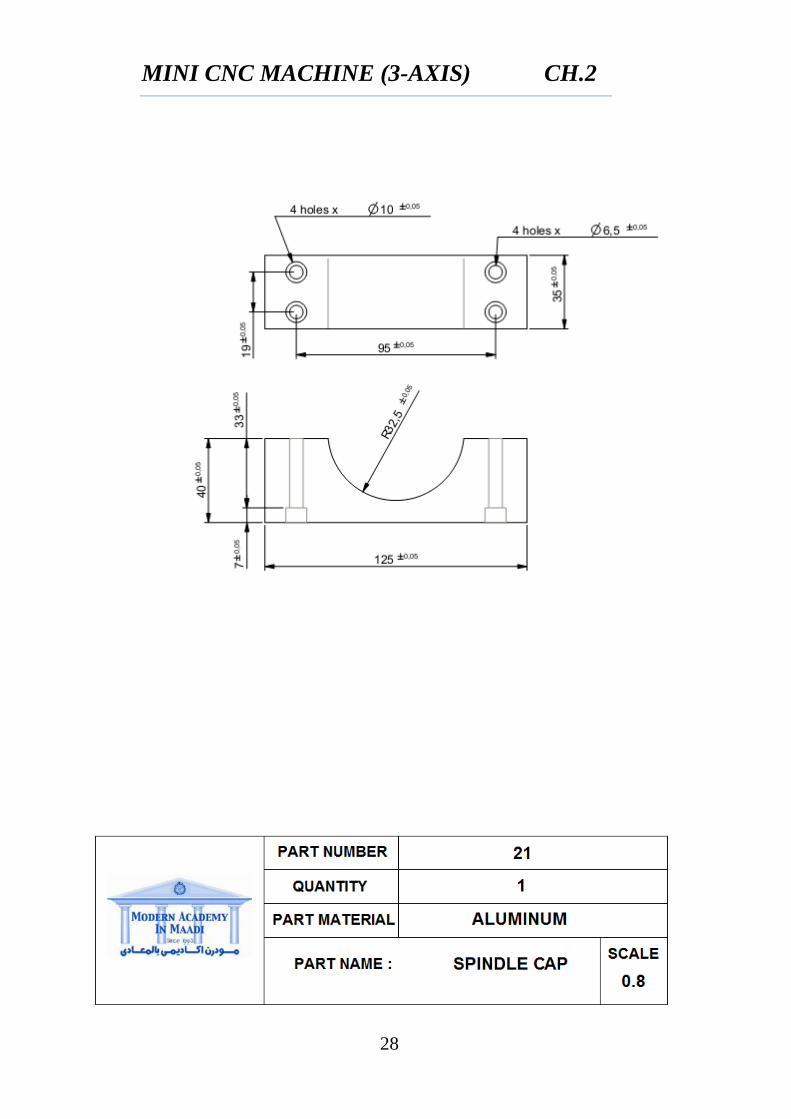
2.1 DETAIL DRAWING
MINI CNC MACHINE (3-AXIS) CH.2
9
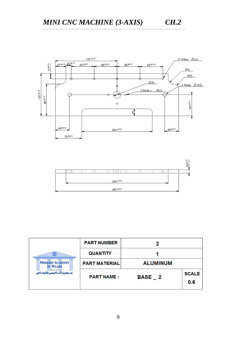
MINI CNC MACHINE (3-AXIS) CH.2
10
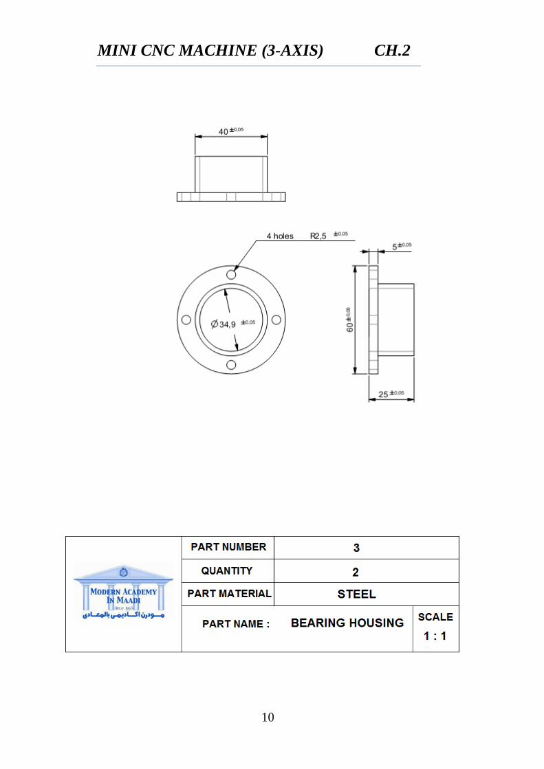
MINI CNC MACHINE (3-AXIS) CH.2
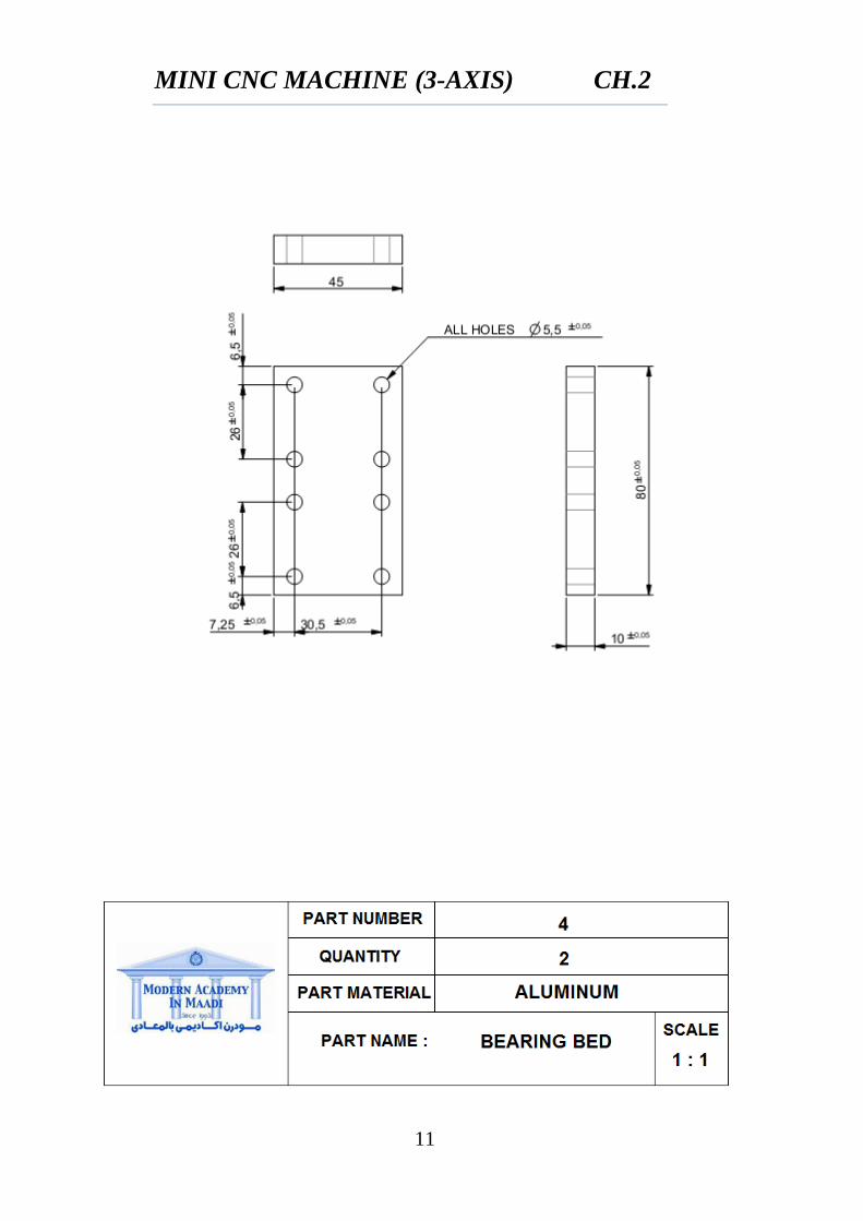
11
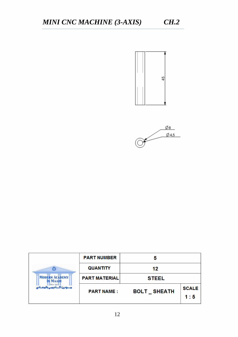
MINI CNC MACHINE (3-AXIS) CH.2
12
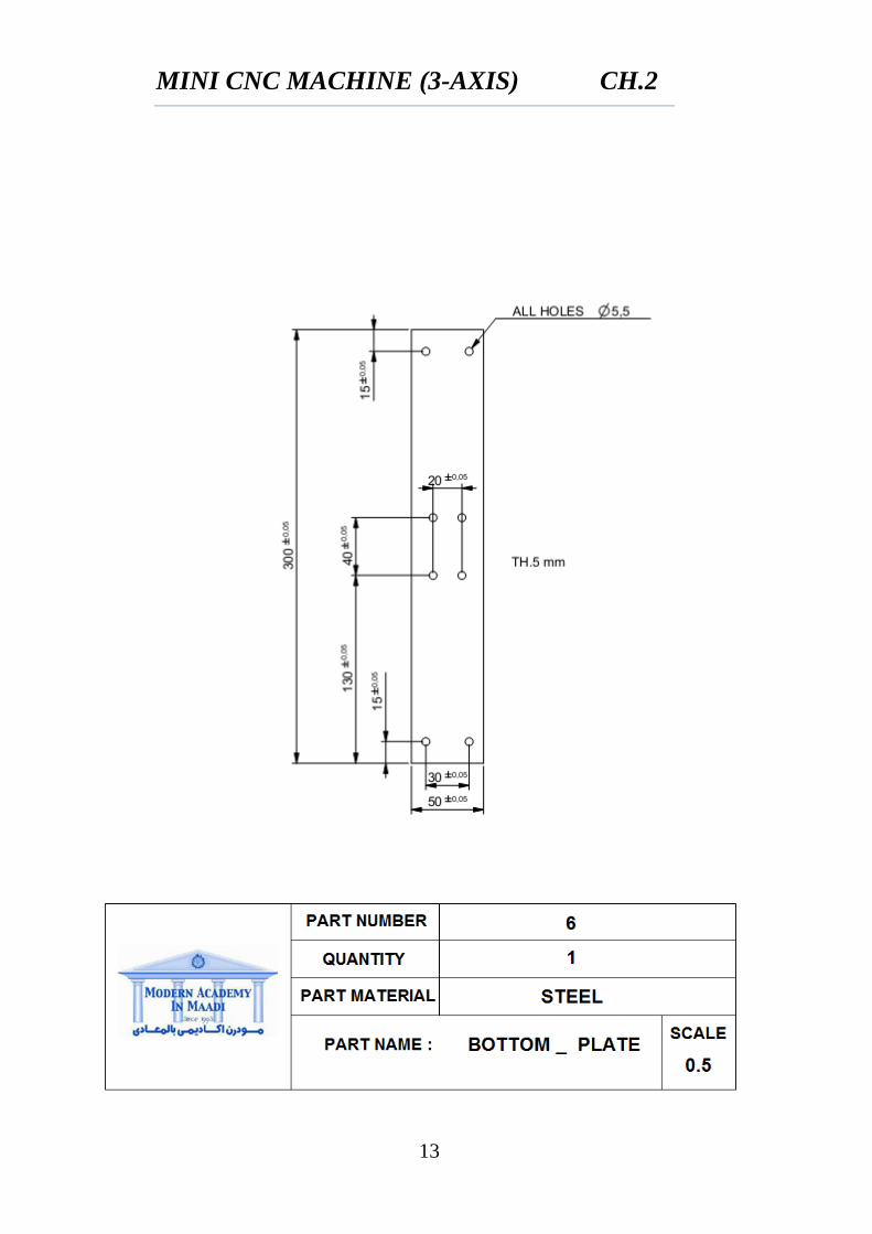
MINI CNC MACHINE (3-AXIS) CH.2
13
MINI CNC MACHINE (3-AXIS) CH.2
14
MINI CNC MACHINE (3-AXIS) CH.2
15
MINI CNC MACHINE (3-AXIS) CH.2
16
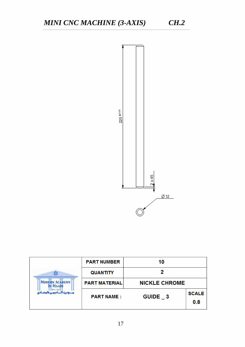
MINI CNC MACHINE (3-AXIS) CH.2
17
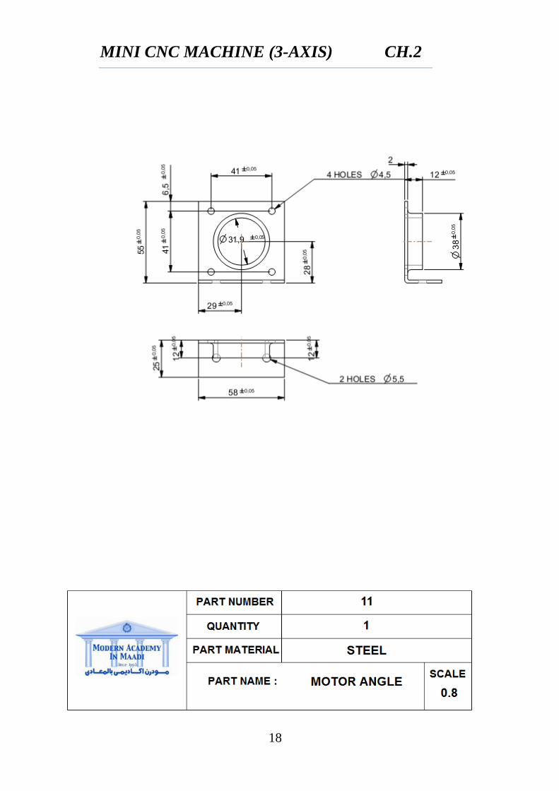
MINI CNC MACHINE (3-AXIS) CH.2
18
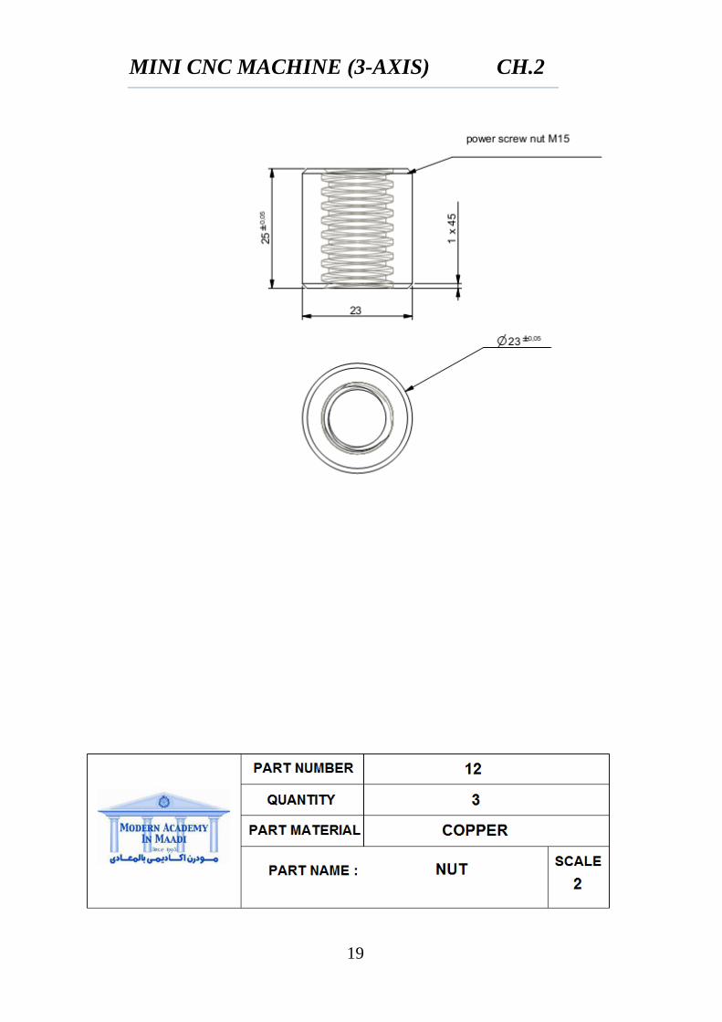
MINI CNC MACHINE (3-AXIS) CH.2
19
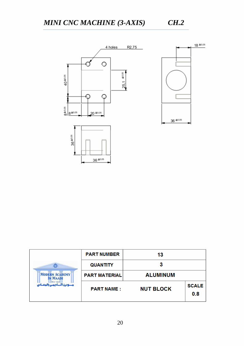
MINI CNC MACHINE (3-AXIS) CH.2
20
MINI CNC MACHINE (3-AXIS) CH.2
21
MINI CNC MACHINE (3-AXIS) CH.2
22
MINI CNC MACHINE (3-AXIS) CH.2
23
MINI CNC MACHINE (3-AXIS) CH.2
24
MINI CNC MACHINE (3-AXIS) CH.2
25
MINI CNC MACHINE (3-AXIS) CH.2
26
MINI CNC MACHINE (3-AXIS) CH.2
27
MINI CNC MACHINE (3-AXIS) CH.2
28
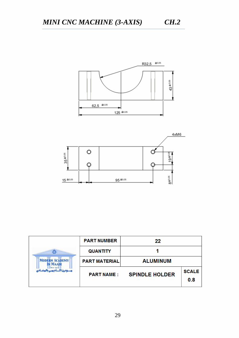
MINI CNC MACHINE (3-AXIS) CH.2
29
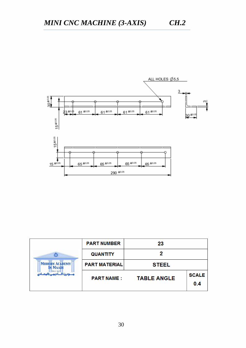
MINI CNC MACHINE (3-AXIS) CH.2
30
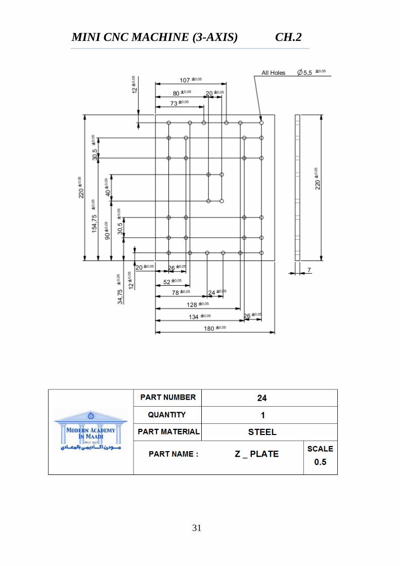
MINI CNC MACHINE (3-AXIS) CH.2
31
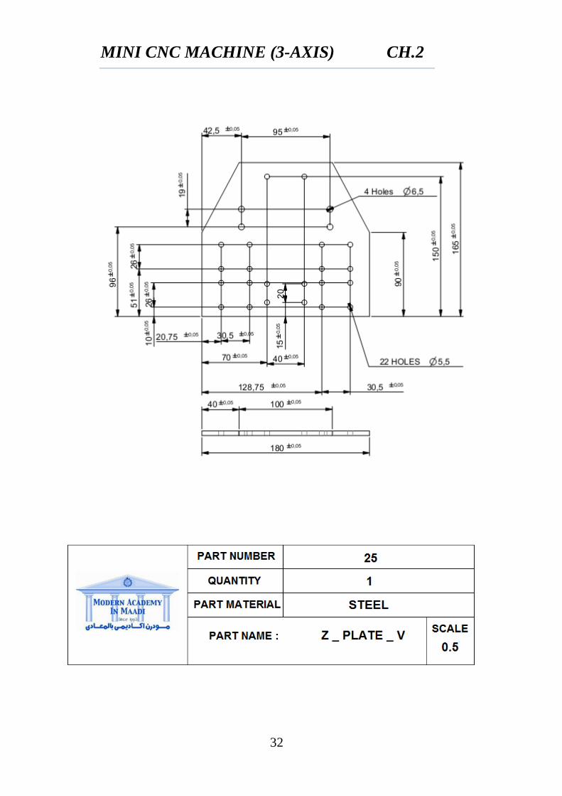
MINI CNC MACHINE (3-AXIS) CH.2
32
MINI CNC MACHINE (3-AXIS) CH.2
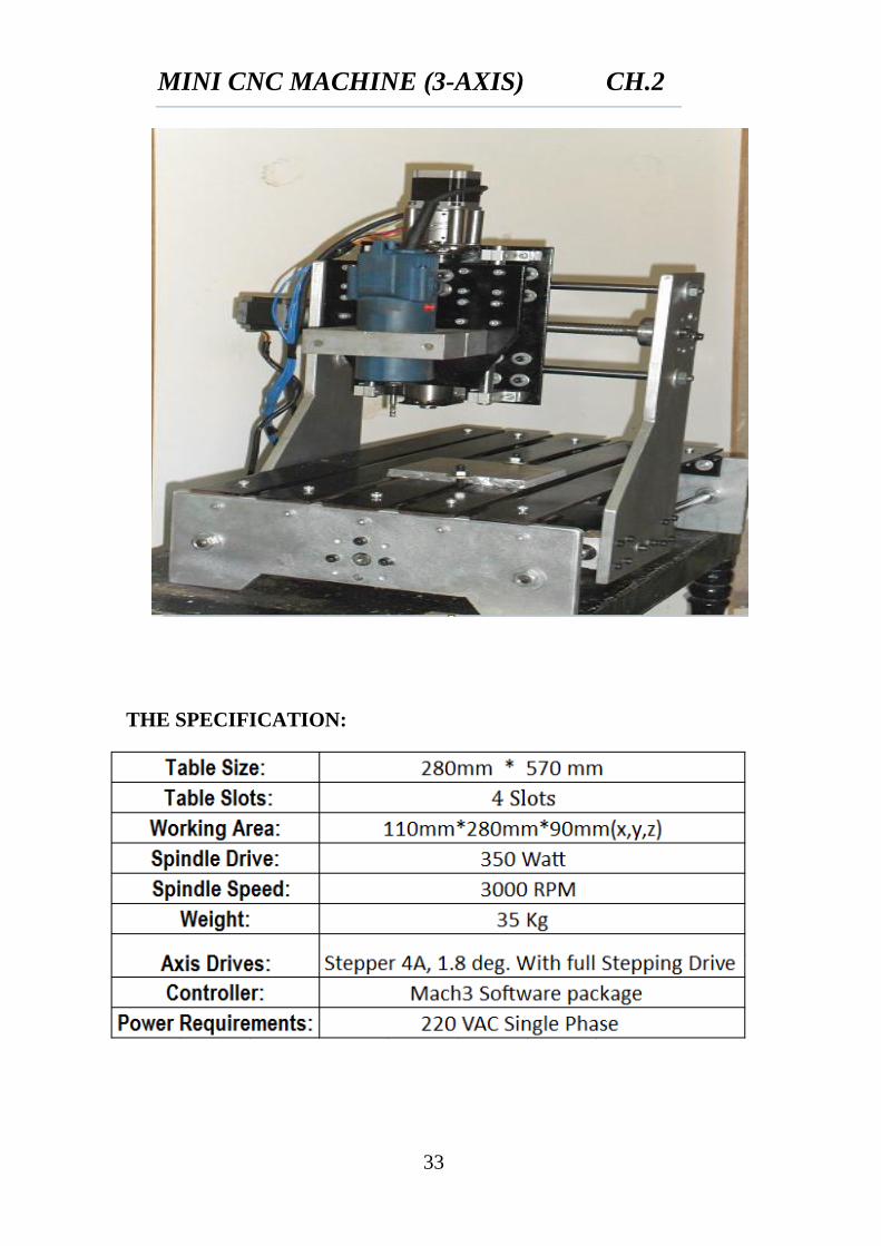
33
THE SPECIFICATION:
MINI CNC MACHINE (3-AXIS) CH.2
34
2.2 SELECTION OF SPINDLE
2.2.1 Select work piece and tool type
Work piece…Aluminum
Tool………...shank end mill Φ40 (high speed steel)
2.2.2 Calculate (
⁄
f ……feed
Range of from 150 to 360 [ ⁄ ]
Range of feed from 0.12 to 0.3
2.2.3 Calculate (N)
(2.1)
N…..rotational speed
D….diameter of tool
N=
2.2.4 Calculate machine power
c….feed factor
C= from 1 to 1.2
w….tool wear factor
w= from 1.1 to 1.25 for light and medium milling
For Aluminum
MINI CNC MACHINE (3-AXIS) CH.2
35
2.2.5 Calculate material removal rate
(2.2)
d….depth of cut d=2
w….width of cut w=40
f….feed rate f=0.3
*
⁄ +
2.2.6 Calculate efficiency factor (E) for m/c tool
For direct and belt drive E=0.9
2.2.7 Calculate drive motor power
(2.3)
2.2.8 Calculate drive motor torque
(2.4)
MINI CNC MACHINE (3-AXIS) CH.2
36
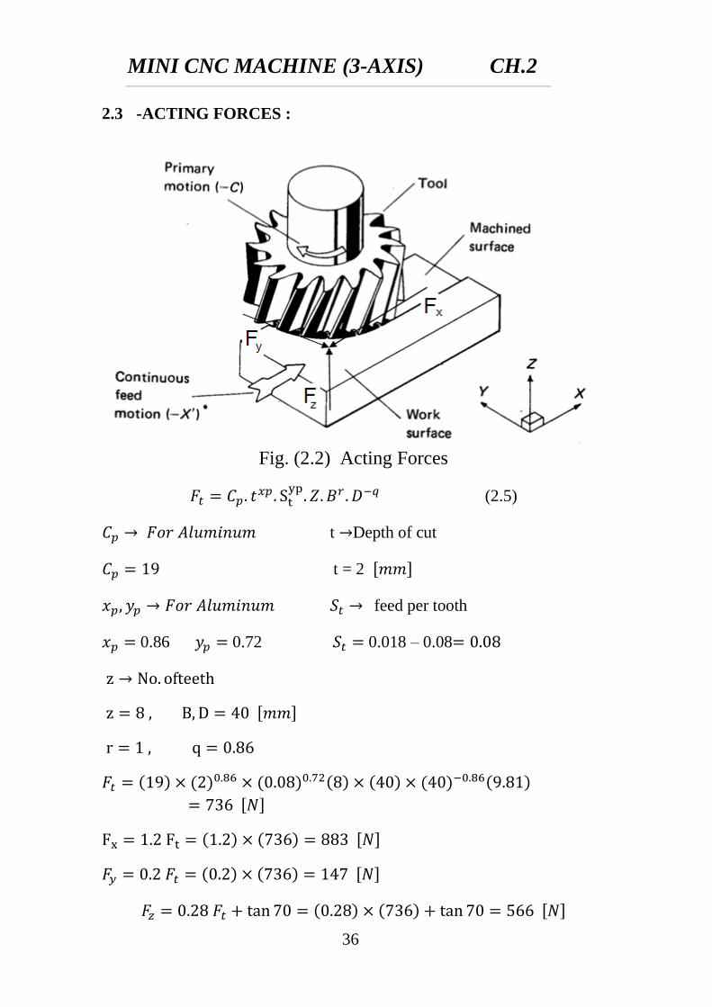
2.3 -ACTING FORCES :
Fig. (2.2) Acting Forces
(2.5)
t Depth of cut
t = 2
feed per tooth
0.86 0.72 0.018 – 0.08
MINI CNC MACHINE (3-AXIS) CH.2
37
2.4 DESIGN OF POWER SCREW
Power Screws are used for providing linear motion in a smooth uniform manner. They are linear actuators that transform rotary motion into linear motion. Power screws are are generally based on Acme , Square, and Buttress threads. Ball screws are a type of power screw. Efficiencies of between 30% and 70% are obtained with conventional power screws. Ball screws have efficiencies of above 90%. Power Screws are used for the following three reasons
To obtain high mechanical advantage in order to move large loads with minimum effort. e.g Screw Jack.
To generate large forces e.g A compactor press. To obtain precise axial movements e.g. A machine tool lead screw.
2.4.1 TYPES OF POWER SCREW
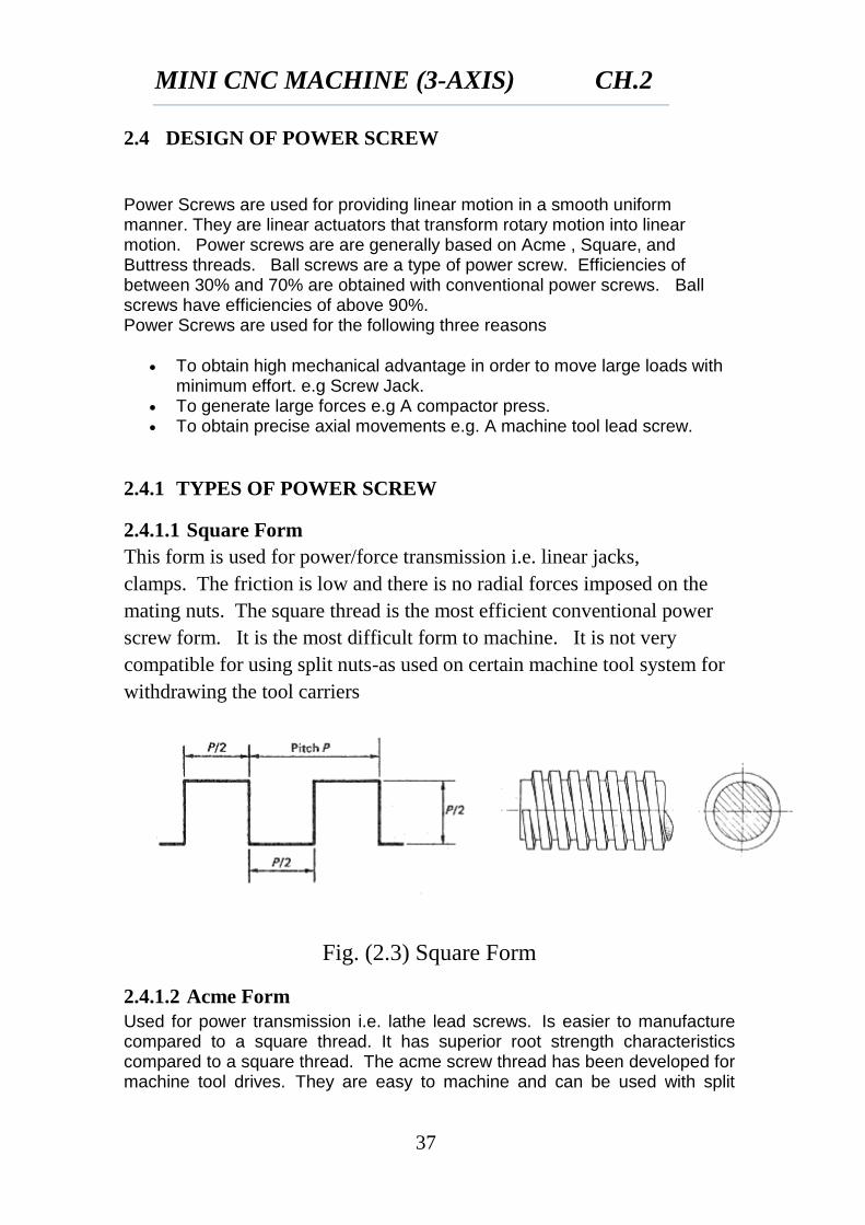
2.4.1.1 Square Form
This form is used for power/force transmission i.e. linear jacks,
clamps. The friction is low and there is no radial forces imposed on the
mating nuts. The square thread is the most efficient conventional power
screw form. It is the most difficult form to machine. It is not very
compatible for using split nuts-as used on certain machine tool system for
withdrawing the tool carriers
Fig. (2.3) Square Form
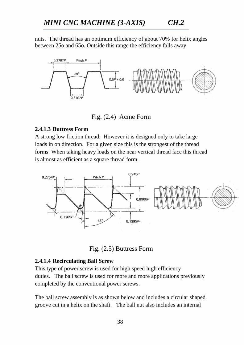
2.4.1.2 Acme Form
Used for power transmission i.e. lathe lead screws. Is easier to manufacture compared to a square thread. It has superior root strength characteristics compared to a square thread. The acme screw thread has been developed for machine tool drives. They are easy to machine and can be used with split
MINI CNC MACHINE (3-AXIS) CH.2
38
nuts. The thread has an optimum efficiency of about 70% for helix angles
between 25o and 65o. Outside this range the efficiency falls away.
Fig. (2.4) Acme Form
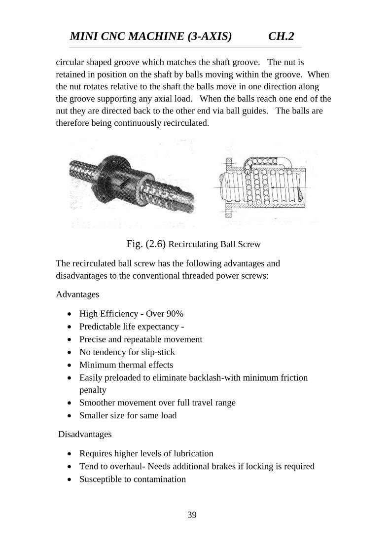
2.4.1.3 Buttress Form
A strong low friction thread. However it is designed only to take large
loads in on direction. For a given size this is the strongest of the thread
forms. When taking heavy loads on the near vertical thread face this thread
is almost as efficient as a square thread form.
Fig. (2.5) Buttress Form
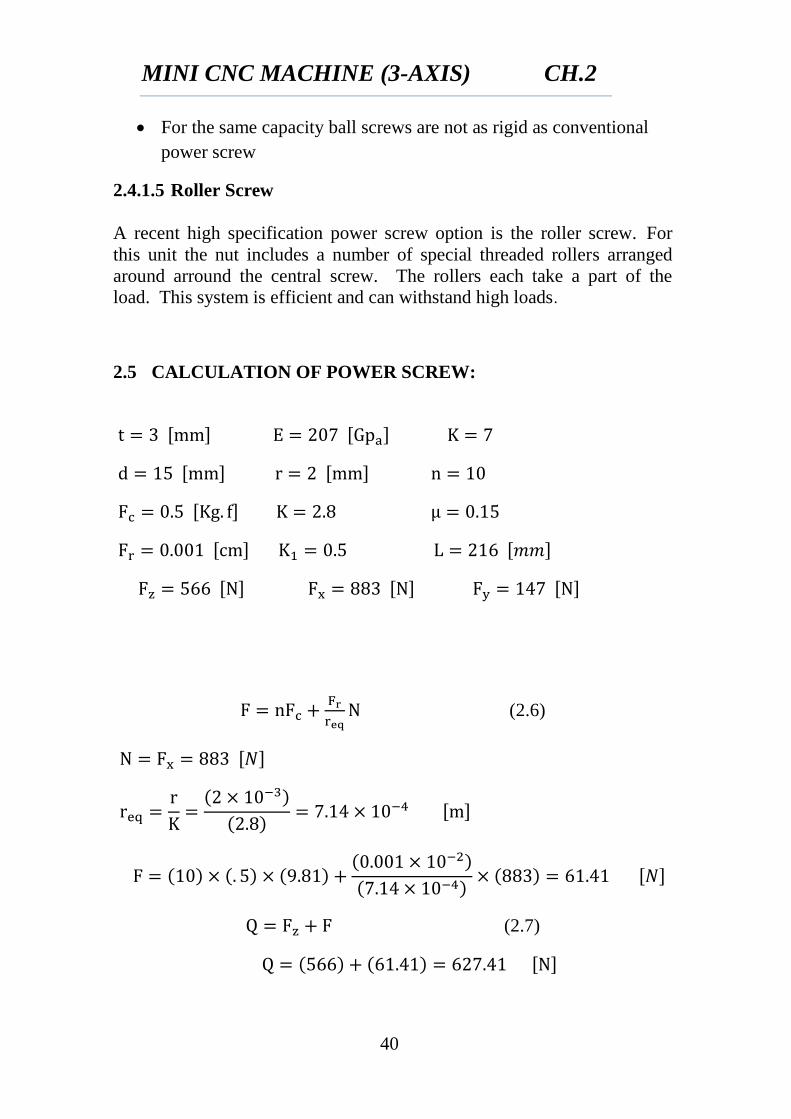
2.4.1.4 Recirculating Ball Screw
This type of power screw is used for high speed high efficiency
duties. The ball screw is used for more and more applications previously
completed by the conventional power screws.
The ball screw assembly is as shown below and includes a circular shaped
groove cut in a helix on the shaft. The ball nut also includes an internal
MINI CNC MACHINE (3-AXIS) CH.2
39
circular shaped groove which matches the shaft groove. The nut is
retained in position on the shaft by balls moving within the groove. When
the nut rotates relative to the shaft the balls move in one direction along
the groove supporting any axial load. When the balls reach one end of the
nut they are directed back to the other end via ball guides. The balls are
therefore being continuously recirculated.
Fig. (2.6) Recirculating Ball Screw
The recirculated ball screw has the following advantages and
disadvantages to the conventional threaded power screws:
Advantages
High Efficiency - Over 90%
Predictable life expectancy -
Precise and repeatable movement
No tendency for slip-stick
Minimum thermal effects
Easily preloaded to eliminate backlash-with minimum friction
penalty
Smoother movement over full travel range
Smaller size for same load
Disadvantages
Requires higher levels of lubrication
Tend to overhaul- Needs additional brakes if locking is required
Susceptible to contamination
MINI CNC MACHINE (3-AXIS) CH.2
40
For the same capacity ball screws are not as rigid as conventional
power screw
2.4.1.5 Roller Screw
A recent high specification power screw option is the roller screw. For
this unit the nut includes a number of special threaded rollers arranged
around arround the central screw. The rollers each take a part of the
load. This system is efficient and can withstand high loads.
2.5 CALCULATION OF POWER SCREW:
(2.6)
(2.7)
MINI CNC MACHINE (3-AXIS) CH.2
41
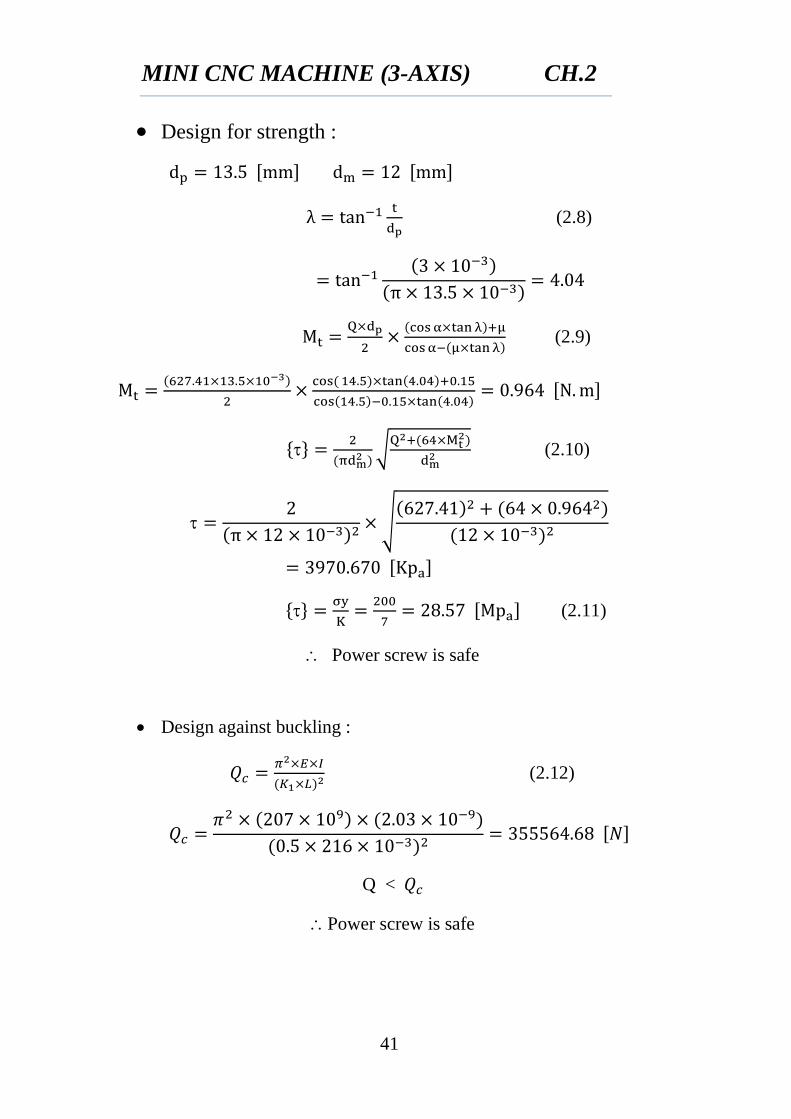
Design for strength :
(2.8)
(2.9)
{ }
√
(2.10)
√
{ }
(2.11)
Power screw is safe
Design against buckling :
(2.12)
Q <
Power screw is safe
MINI CNC MACHINE (3-AXIS) CH.2
42
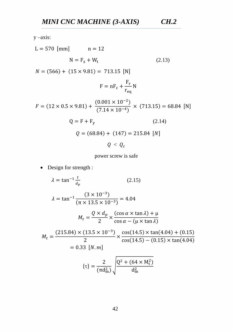
y –axis:
(2.13)
(2.14)
<
power screw is safe
Design for strength :
(2.15)
{ }
√
MINI CNC MACHINE (3-AXIS) CH.2
43
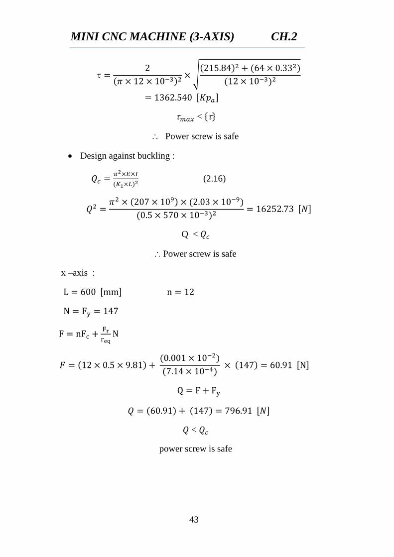
√
< { }
Power screw is safe
Design against buckling :
(2.16)
Q <
Power screw is safe
x –axis :
<
power screw is safe
MINI CNC MACHINE (3-AXIS) CH.2
44
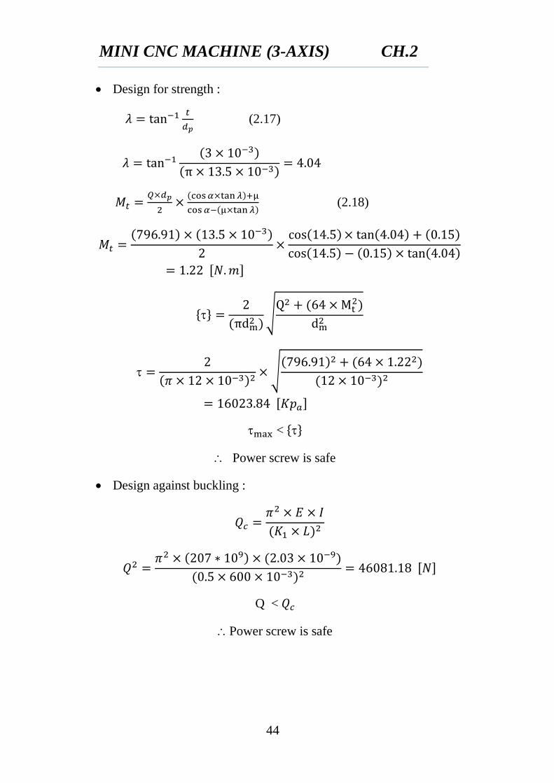
Design for strength :
(2.17)
(2.18)
{ }
√
√
< { }
Power screw is safe
Design against buckling :
Q <
Power screw is safe
MINI CNC MACHINE (3-AXIS) CH.2
45
2.6 SELECTION OF BEARINGS
A bearing is any of various machine elements that constrain the relative
motion between two or more parts to only the desired type of motion. This
is typically to allow and promote free rotation around a fixed axis or
free linear movement; it may also be to prevent any motion, such as by
controlling the vectors of normal forces. Bearings may be classified
broadly according to the motions they allow and according to their
principle of operation, as well as by the directions of applied loads they
can handle.
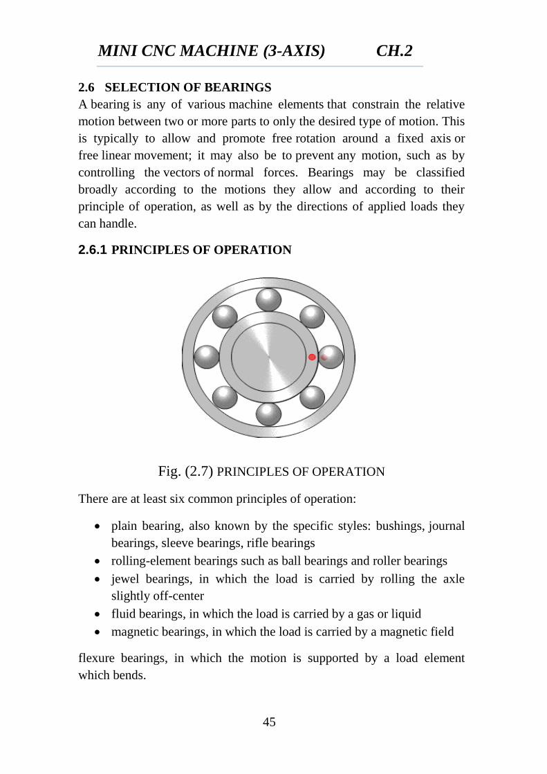
2.6.1 PRINCIPLES OF OPERATION
Fig. (2.7) PRINCIPLES OF OPERATION
There are at least six common principles of operation:
plain bearing, also known by the specific styles: bushings, journal
bearings, sleeve bearings, rifle bearings
rolling-element bearings such as ball bearings and roller bearings
jewel bearings, in which the load is carried by rolling the axle
slightly off-center
fluid bearings, in which the load is carried by a gas or liquid
magnetic bearings, in which the load is carried by a magnetic field
flexure bearings, in which the motion is supported by a load element
which bends.
MINI CNC MACHINE (3-AXIS) CH.2
46
2.6.2 MOTIONS
Common motions permitted by bearings are:
axial rotation e.g. shaft rotation
linear motion e.g. drawer
spherical rotation e.g. ball and socket joint
hinge motion e.g. door, elbow, knee
2.6.3 FRICTION
Reducing friction in bearings is often important for efficiency, to reduce
wear and to facilitate extended use at high speeds and to avoid overheating
and premature failure of the bearing. Essentially, a bearing can reduce
friction by virtue of its shape, by its material, or by introducing and
containing a fluid between surfaces or by separating the surfaces with an
electromagnetic field.
By shape, gains advantage usually by using spheres or rollers, or by
forming flexure bearings.
By material exploits the nature of the bearing material used. (An
example would be using plastics that have low surface friction.)
By fluid exploits the low viscosity of a layer of fluid, such as a
lubricant or as a pressurized medium to keep the two solid parts
from touching, or by reducing the normal force between them.
By fields exploits electromagnetic fields, such as magnetic fields, to
keep solid parts from touching.
Combinations of these can even be employed within the same bearing. An
example of this is where the cage is made of plastic, and it separates the
rollers/balls, which reduce friction by their shape and finish.
2.6.4 LOADS
Bearings vary greatly over the size and directions of forces that they can
support.
Forces can be predominately radial, axial (thrust bearings) or bending
moments perpendicular to the main axis.
MINI CNC MACHINE (3-AXIS) CH.2
47
2.6.5 SPEEDS
Different bearing types have different operating speed limits. Speed is
typically specified as maximum relative surface speeds, often specified ft/s
or m/s. Rotational bearings typically describe performance in terms of the
product DN where D is the diameter (often in mm) of the bearing and N is
the rotation rate in revolutions per minute.
Generally there is considerable speed range overlap between bearing
types. Plain bearings typically handle only lower speeds, rolling element
bearings are faster, followed by fluid bearings and finally magnetic
bearings which are limited ultimately by centripetal force overcoming
material strength.
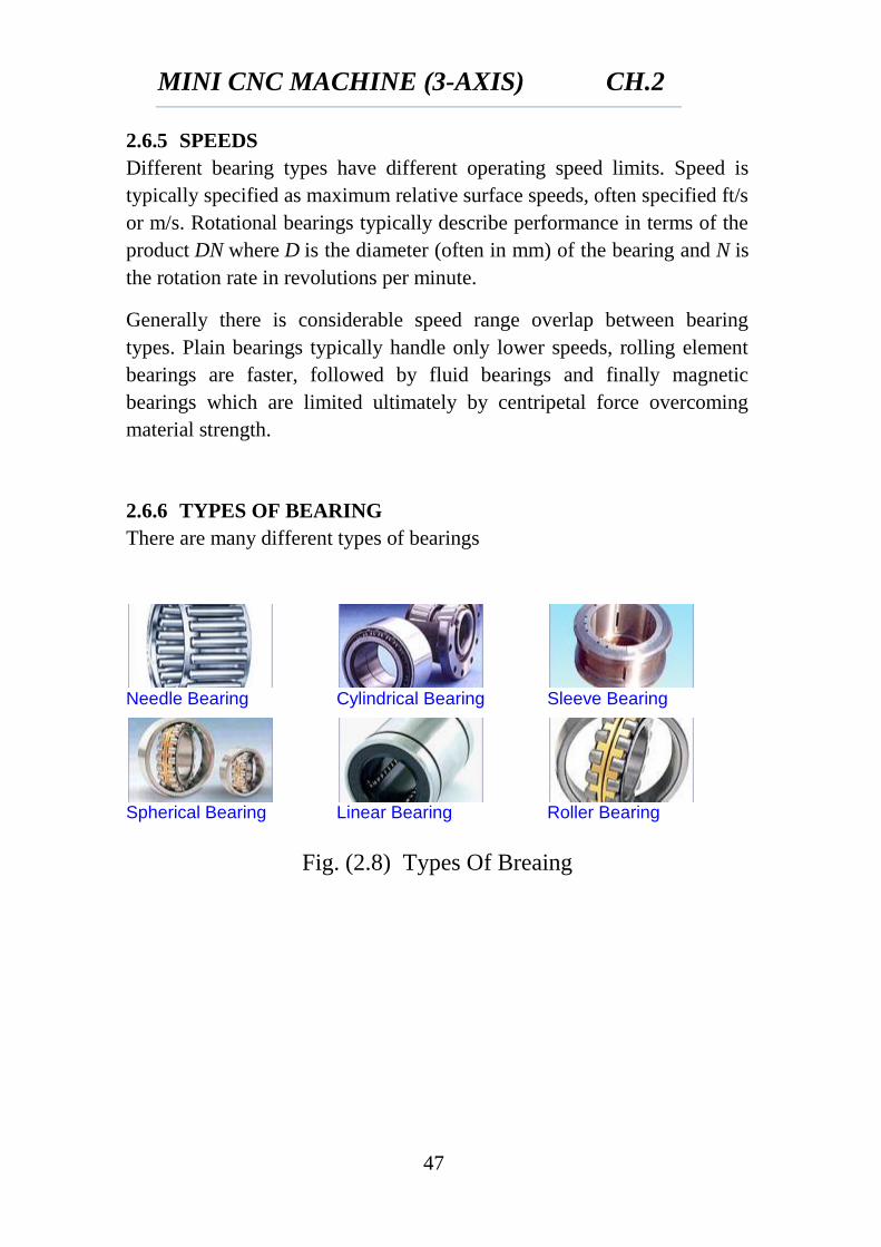
2.6.6 TYPES OF BEARING
There are many different types of bearings
Needle Bearing
Cylindrical Bearing
Sleeve Bearing
Spherical Bearing
Linear Bearing
Roller Bearing
Fig. (2.8) Types Of Breaing
MINI CNC MACHINE (3-AXIS) CH.2
48
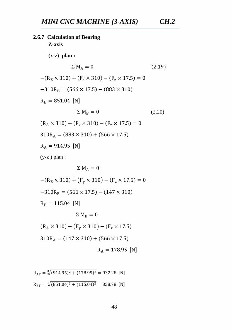
2.6.7 Calculation of Bearing
Z-axis
(x-z) plan :
Ʃ
Ʃ (2.20)
(y-z ) plan :
Ʃ
( )
Ʃ
( )
√
√
MINI CNC MACHINE (3-AXIS) CH.2
49
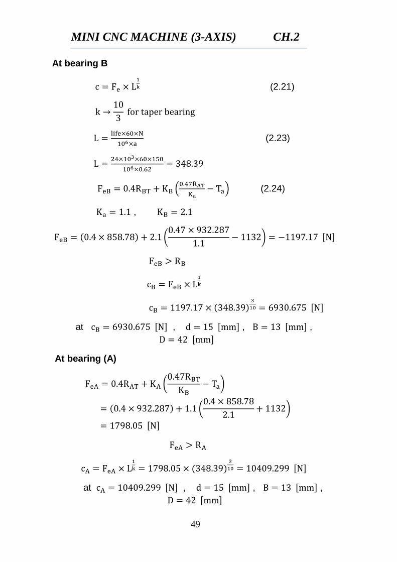
At bearing B
(2.21)
(2.23)
(
) (2.24)
,
(
)
at , , ,
At bearing (A)
(
)
(
)
at , , ,
MINI CNC MACHINE (3-AXIS) CH.2
50
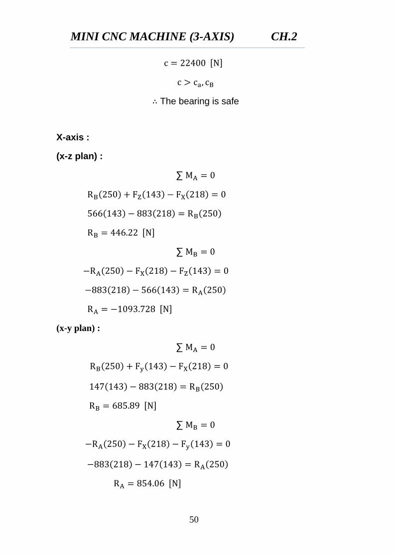
The bearing is safe
X-axis :
(x-z plan) :
∑
∑
(x-y plan) :
∑
∑
MINI CNC MACHINE (3-AXIS) CH.2
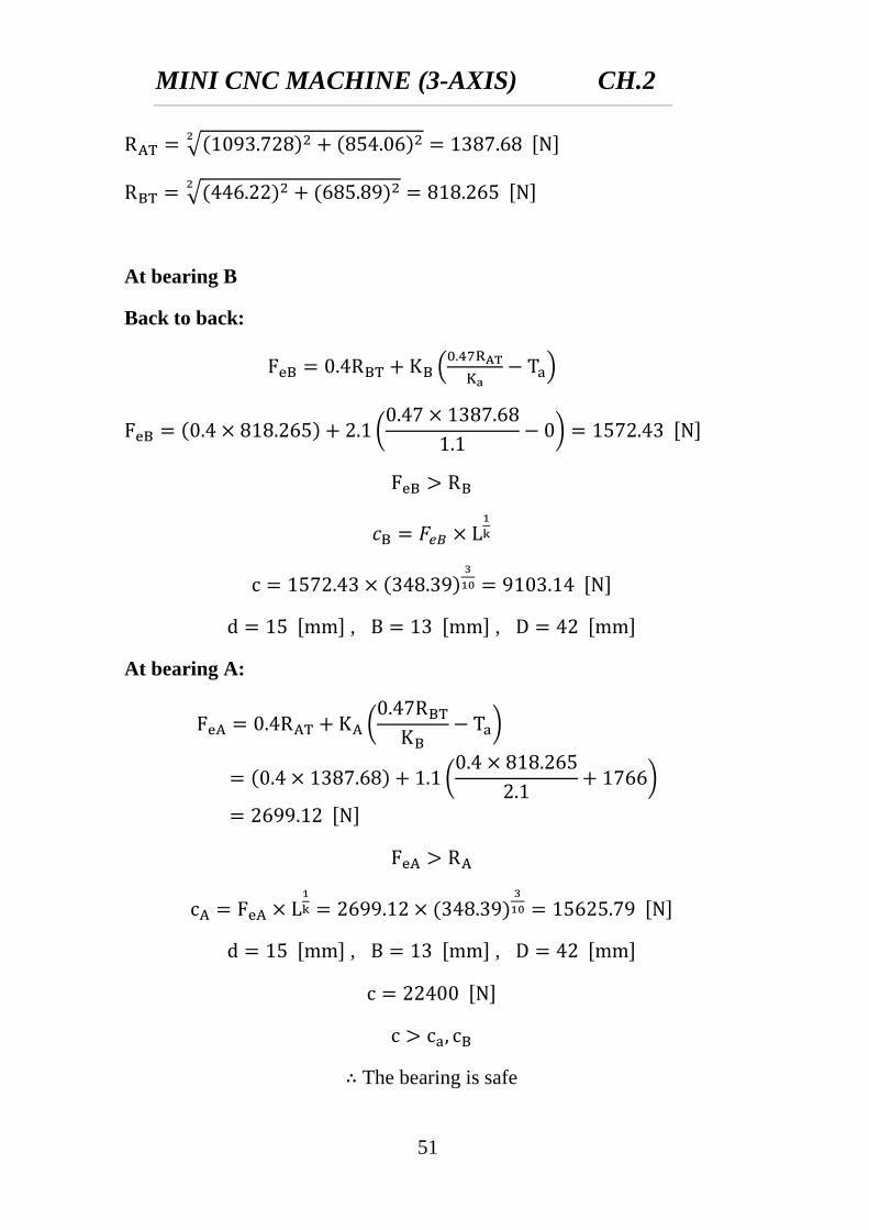
51
√
√
At bearing B
Back to back:
(
)
(
)
, ,
At bearing A:
(
)
(
)
, ,
The bearing is safe
MINI CNC MACHINE (3-AXIS) CH.2
52
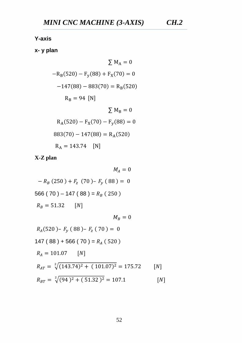
Y-axis
x- y plan
∑
∑
X-Z plan
566 ( 70 ) – 147 ( 88 ) =
147 ( 88 ) + 566 ( 70 ) =
√
√
MINI CNC MACHINE (3-AXIS) CH.2
53
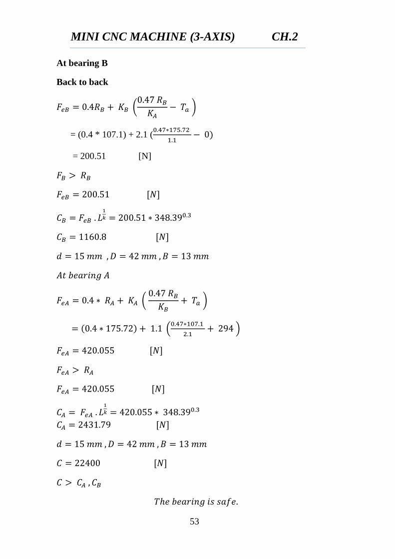
At bearing B
Back to back
(
)
= (0.4 * 107.1) + 2.1 (
= 200.51 [N]
(
)
(
)
MINI CNC MACHINE (3-AXIS) CH.2
54
2.7 DESIGN OF GUIDE WAY
2.7.1 Linear Motion
The LM system is responsible for three primary tasks
1. Support machine components.
2. Guide the machine in a precise linear motion with minimal friction.
3. Support secondary loads (Torque, Lateral loads, etc).
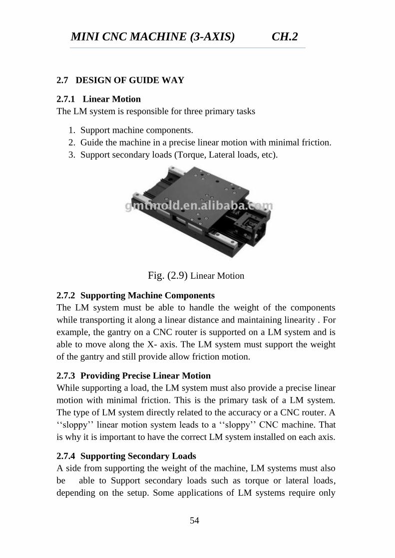
Fig. (2.9) Linear Motion
2.7.2 Supporting Machine Components
The LM system must be able to handle the weight of the components
while transporting it along a linear distance and maintaining linearity . For
example, the gantry on a CNC router is supported on a LM system and is
able to move along the X- axis. The LM system must support the weight
of the gantry and still provide allow friction motion.
2.7.3 Providing Precise Linear Motion
While supporting a load, the LM system must also provide a precise linear
motion with minimal friction. This is the primary task of a LM system.
The type of LM system directly related to the accuracy or a CNC router. A
‘‘sloppy’’ linear motion system leads to a ‘‘sloppy’’ CNC machine. That
is why it is important to have the correct LM system installed on each axis.
2.7.4 Supporting Secondary Loads
A side from supporting the weight of the machine, LM systems must also
be able to Support secondary loads such as torque or lateral loads,
depending on the setup. Some applications of LM systems require only
MINI CNC MACHINE (3-AXIS) CH.2
55
one dimensional load ratings, such as supporting a vertical load like
weight. Other applications require multi-dimensional load ratings. For
example, the LM system of the CNC router is required to support the
vertical loads caused by the weight of the Z-axis assemble, and also
support torsion forces cause by the cutting action. We will cover more on
load ratings in later sections.
Every LM system is rated for certain loads and certain applications.
Choosing or identifying the right system for your CNC router is a vital
ability to have when buying or building.
2.7.5 Categories of Linear Motion systems
If you could categorize linear motion systems into 2 categories it would
be:
1. Fully Supported Systems
2. Partially/End Supported Systems
Fully supported LM systems are supported throughout the entire length of
the system. This type of system can usually support more lead without
sacrificing linear precision due to deflection. A quality CNC router will
have fully supported LM systems on all axes. Some mid or low range
machines use fully supported systems on the X and Y-axis while using end
supported systems on the Z-axis. As the length of the axis increases the
more vital it is to have fully supported systems. Examples of these
systems include linear rails and guide blocks as well as track rollers.
Partially or end supported LM systems are just what they seam. These
systems are supported on their ends. These systems are due to flex and
deformation because of the machine weight or the forces applied.
However, these systems are more suitable in some applications. The most
common type of end supported of LM systems is the linear rod and
bushing setup.
Of course each category contains many different types of linear motion
system which will be covered in their respective sections.
There are several advantages of linear guide systems. For starters, they are
very robust and accurate due to their construction. Most all guide block
systems use ball bearings to roll the load along the rail, which means high
MINI CNC MACHINE (3-AXIS) CH.2
56
efficiency. This high efficiency means less work must be done by the drive
system to move the load.
Rolling element linear-motion bearings guide, supported, locate and
accurately move the machinery components and productizes. Rolling
element linear bearings and guides ensure low friction, smooth, accurate
motion for nearly any moment or normal loading condition.
Understanding the tradeoffs of each bearing type is important to accurately
size and select not only the right bearing, but also the right integrated
controls and components for the application. The right choice ensures
machine accuracy, repeatability, and life.
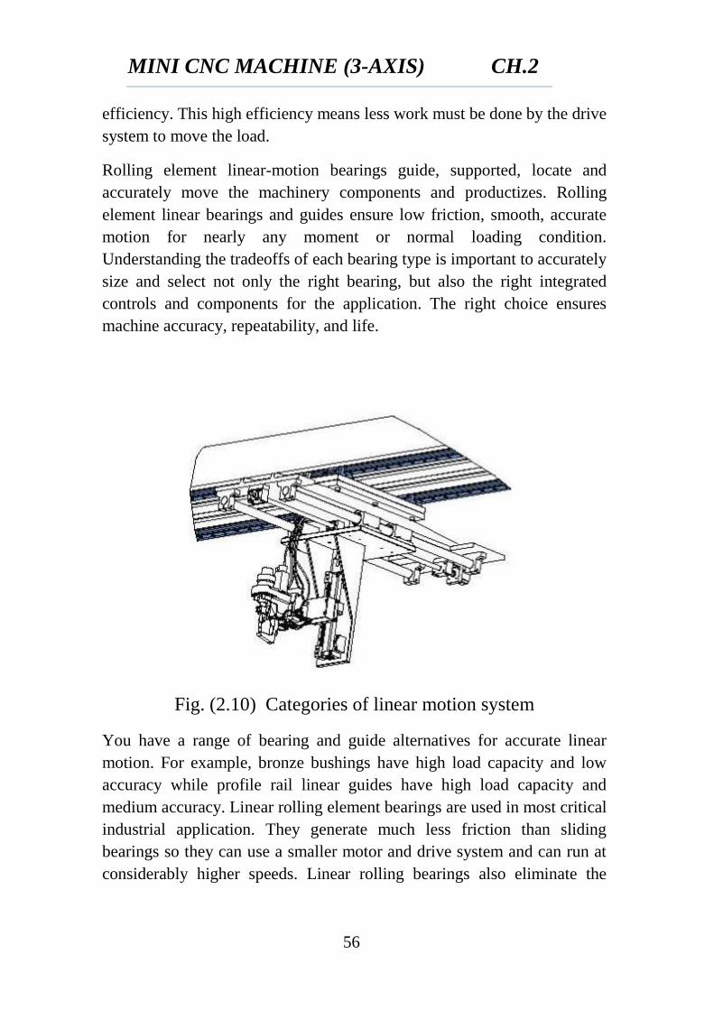
Fig. (2.10) Categories of linear motion system
You have a range of bearing and guide alternatives for accurate linear
motion. For example, bronze bushings have high load capacity and low
accuracy while profile rail linear guides have high load capacity and
medium accuracy. Linear rolling element bearings are used in most critical
industrial application. They generate much less friction than sliding
bearings so they can use a smaller motor and drive system and can run at
considerably higher speeds. Linear rolling bearings also eliminate the
MINI CNC MACHINE (3-AXIS) CH.2
57
stick-slip effect that often causes chatter. They offer a predictable life and
do not lose tolerance over their lives.
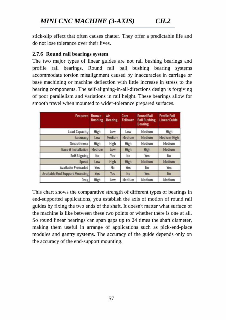
2.7.6 Round rail bearings system
The two major types of linear guides are not rail bushing bearings and
profile rail bearings. Round rail ball bushing bearing systems
accommodate torsion misalignment caused by inaccuracies in carriage or
base machining or machine deflection with little increase in stress to the
bearing components. The self-aligning-in-all-directions design is forgiving
of poor parallelism and variations in rail height. These bearings allow for
smooth travel when mounted to wider-tolerance prepared surfaces.
This chart shows the comparative strength of different types of bearings in
end-supported applications, you establish the axis of motion of round rail
guides by fixing the two ends of the shaft. It doesn't matter what surface of
the machine is like between these two points or whether there is one at all.
So round linear bearings can span gaps up to 24 times the shaft diameter,
making them useful in arrange of applications such as pick-end-place
modules and gantry systems. The accuracy of the guide depends only on
the accuracy of the end-support mounting.
MINI CNC MACHINE (3-AXIS) CH.2
58
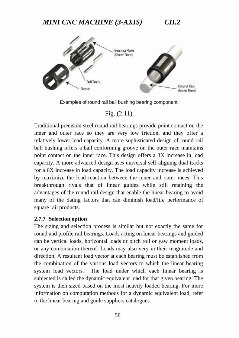
Examples of round rail ball bushing bearing component
Fig. (2.11)
Traditional precision steel round rail bearings provide point contact on the
inner and outer race so they are very low friction, and they offer a
relatively lower load capacity. A more sophisticated design of round rail
ball bushing offers a ball conforming groove on the outer race maintains
point contact on the inner race. This design offers a 3X increase in load
capacity. A more advanced design uses universal self-aligning dual tracks
for a 6X increase in load capacity. The load capacity increase is achieved
by maximize the load reaction between the inner and outer races. This
breakthrough rivals that of linear guides while still retaining the
advantages of the round rail design that enable the linear bearing to avoid
many of the dating factors that can diminish load/life performance of
square rail products.
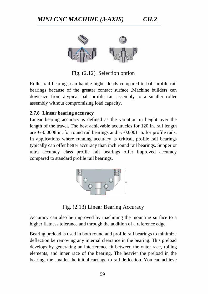
2.7.7 Selection option
The sizing and selection process is similar but not exactly the same for
round and profile rail bearings. Loads acting on linear bearings and guided
can be vertical loads, horizontal loads or pitch roll or yaw moment loads,
or any combination thereof. Loads may also very in their magnitude and
direction. A resultant load vector at each bearing must be established from
the combination of the various load vectors to which the linear bearing
system load vectors. The load under which each linear bearing is
subjected is called the dynamic equivalent load for that given bearing. The
system is then sized based on the most heavily loaded bearing. For more
information on computation methods for a dynamic equivalent load, refer
to the linear bearing and guide suppliers catalogues.
MINI CNC MACHINE (3-AXIS) CH.2
59
Fig. (2.12) Selection option
Roller rail bearings can handle higher loads compared to ball profile rail
bearings because of the greater contact surface .Machine builders can
downsize from atypical ball profile rail assembly to a smaller roller
assembly without compromising load capacity.
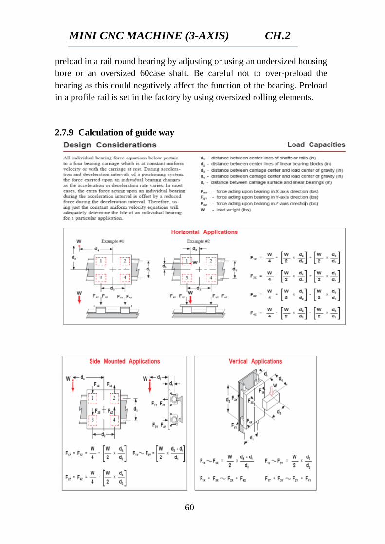
2.7.8 Linear bearing accuracy
Linear bearing accuracy is defined as the variation in height over the
length of the travel. The best achievable accuracies for 120 in. rail length
are +/-0.0008 in. for round rail bearings and +/-0.0001 in. for profile rails.
In applications where running accuracy is critical, profile rail bearings
typically can offer better accuracy than inch round rail bearings. Supper or
ultra accuracy class profile rail bearings offer improved accuracy
compared to standard profile rail bearings.
Fig. (2.13) Linear Bearing Accuracy
Accuracy can also be improved by machining the mounting surface to a
higher flatness tolerance and through the addition of a reference edge.
Bearing preload is used in both round and profile rail bearings to minimize
deflection be removing any internal clearance in the bearing. This preload
develops by generating an interference fit between the outer race, rolling
elements, and inner race of the bearing. The heavier the preload in the
bearing, the smaller the initial carriage-to-rail deflection. You can achieve
MINI CNC MACHINE (3-AXIS) CH.2
60
preload in a rail round bearing by adjusting or using an undersized housing
bore or an oversized 60case shaft. Be careful not to over-preload the
bearing as this could negatively affect the function of the bearing. Preload
in a profile rail is set in the factory by using oversized rolling elements.
2.7.9 Calculation of guide way
MINI CNC MACHINE (3-AXIS) CH.2
61
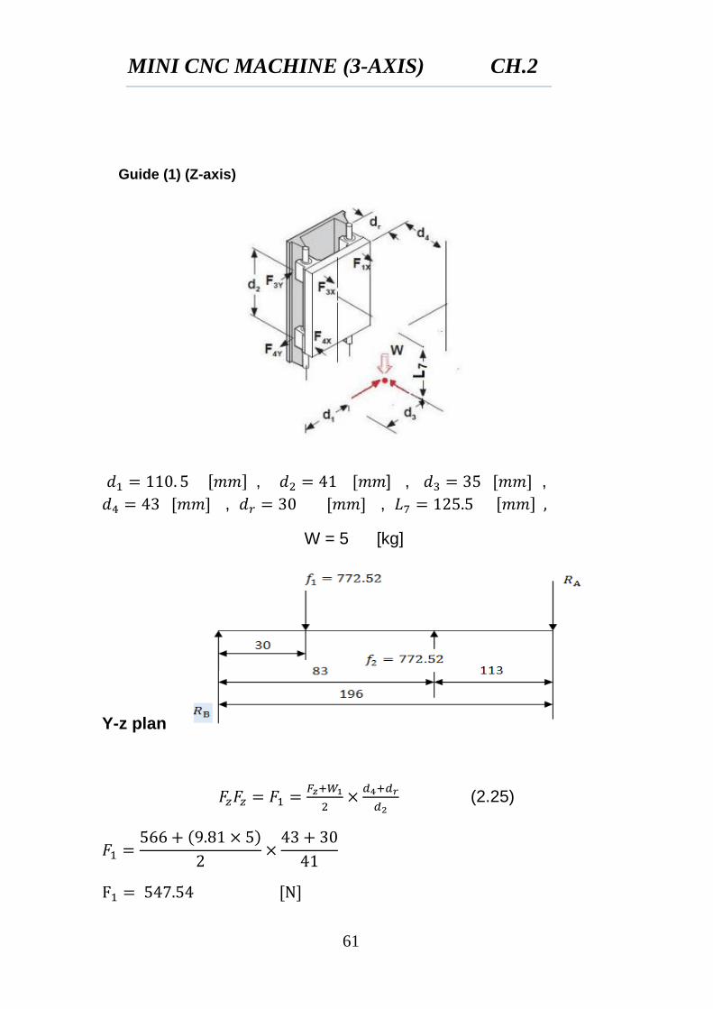
Guide (1) (Z-axis)
, ] , ,
, ,
W = 5 [kg]
Y-z plan
(2.25)
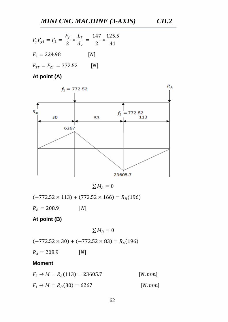
MINI CNC MACHINE (3-AXIS) CH.2
62
]
At point (A)
∑
]
At point (B)
∑
]
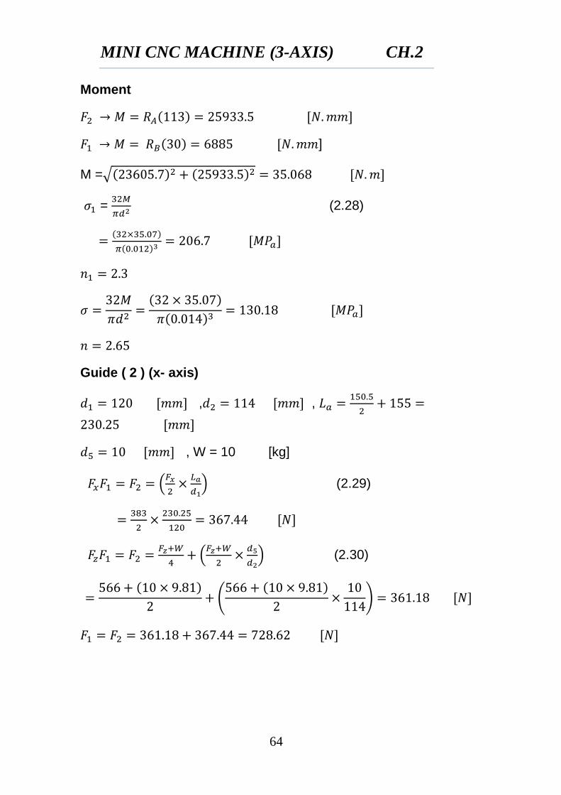
Moment
]
MINI CNC MACHINE (3-AXIS) CH.2
63
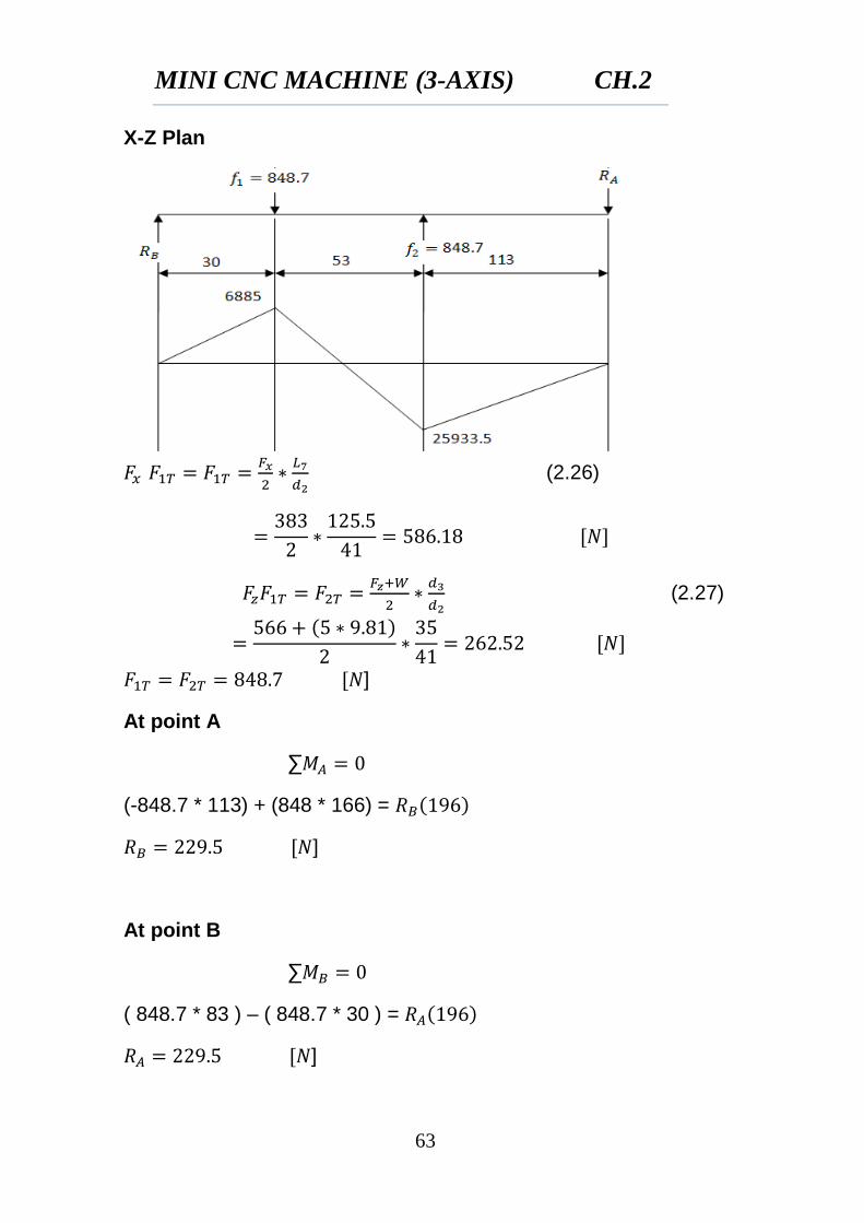
X-Z Plan
(2.26)
(2.27)
]
At point A
∑
(-848.7 * 113) + (848 * 166) =
]
At point B
∑
( 848.7 * 83 ) – ( 848.7 * 30 ) =
]
MINI CNC MACHINE (3-AXIS) CH.2
64
Moment
]
M =√
=
(2.28)
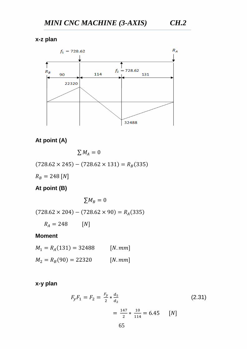
Guide ( 2 ) (x- axis)
, ,
, W = 10 [kg]
(
) (2.29)
(
) (2.30)
(
)
MINI CNC MACHINE (3-AXIS) CH.2
65
x-z plan
At point (A)
∑
]
At point (B)
∑
Moment
x-y plan
(2.31)
MINI CNC MACHINE (3-AXIS) CH.2
66
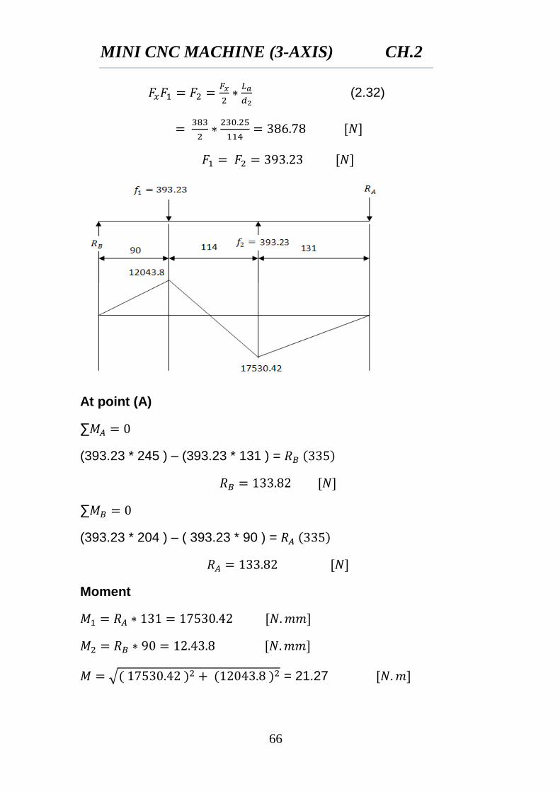
(2.32)
At point (A)
∑
(393.23 * 245 ) – (393.23 * 131 ) =
∑
(393.23 * 204 ) – ( 393.23 * 90 ) =
Moment
√ = 21.27
MINI CNC MACHINE (3-AXIS) CH.2
67
σ =
n =
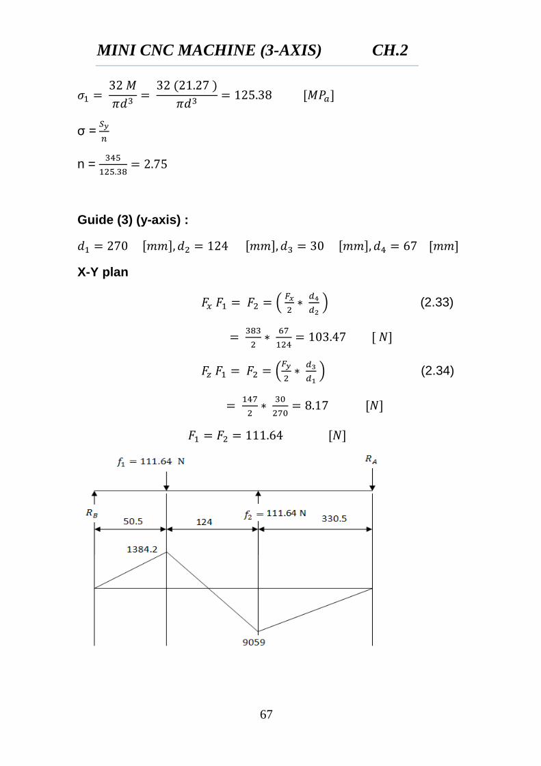
Guide (3) (y-axis) :
X-Y plan
(
) (2.33)
(
) (2.34)
MINI CNC MACHINE (3-AXIS) CH.2
68
At point A
∑
(111.64 * 454.5 ) – (111.64 * 330.5 ) =
At point B
∑
( - 111.64 * 50.5 ) + (111.64 * 174.5 ) =
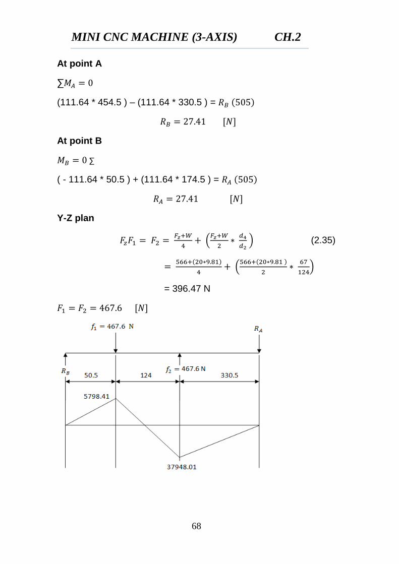
Y-Z plan
(
) (2.35)
(
)
= 396.47 N
MINI CNC MACHINE (3-AXIS) CH.2
69
At point A
∑
( 467.6 * 454.5 ) – ( 467.5 * 330.5 ) =
At point B
∑
( 467.6 * 174.5 ) – ( 467.6 * 50.5 ) =
Moment
√
=
σ
σ =
n =
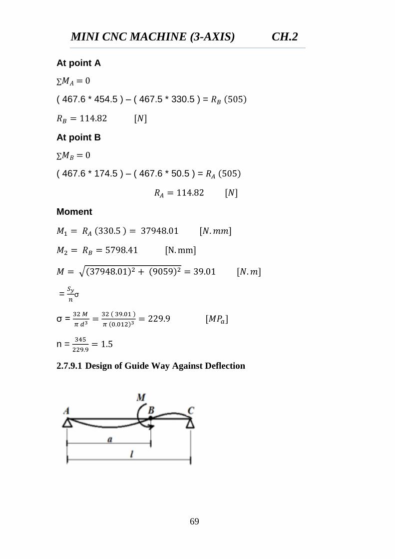
2.7.9.1 Design of Guide Way Against Deflection
MINI CNC MACHINE (3-AXIS) CH.2
70
Y=
(
)
(2.36)
(2.37)
E=207 GPa = 207000 [N/
]
= 1017.88
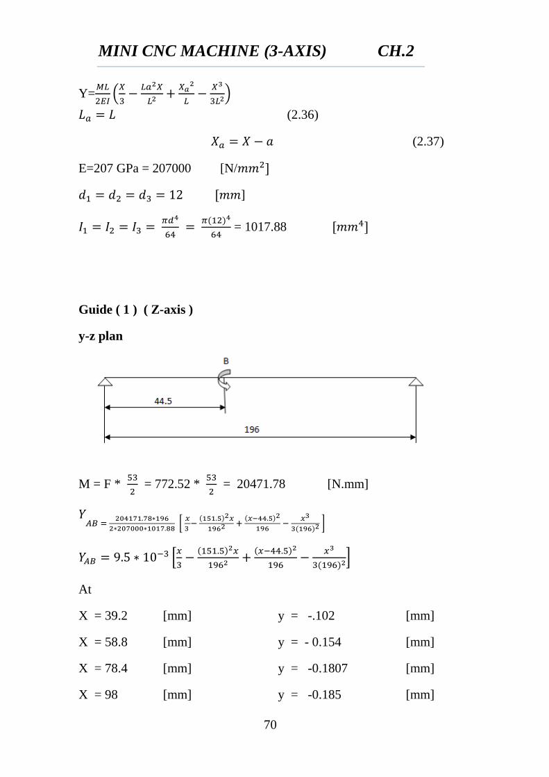
Guide ( 1 ) ( Z-axis )
y-z plan
M = F *
= 772.52 *
= 20471.78 [N.mm]
[
]
*
+
At
X = 39.2 [mm] y = -.102 [mm]
X = 58.8 [mm] y = - 0.154 [mm]
X = 78.4 [mm] y = -0.1807 [mm]
X = 98 [mm] y = -0.185 [mm]
MINI CNC MACHINE (3-AXIS) CH.2
71
X = 117.6 [mm] y = -0.166 [mm]
X = 137.2 [mm] y = -0.1406 [mm]
X = 156.8 [mm] y = -0.0999 [mm]
X = 176.4 [mm] y = -.0519 [mm]
X = 196 [mm] y = 0 [mm]
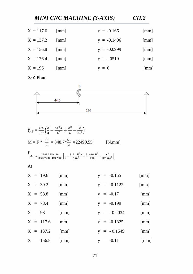
X-Z Plan
=
(
)
M = F *
= 848.7*
=22490.55 [N.mm]
[
]
At
X = 19.6 [mm] y = -0.155 [mm]
X = 39.2 [mm] y = -0.1122 [mm]
X = 58.8 [mm] y = -0.17 [mm]
X = 78.4 [mm] y = -0.199 [mm]
X = 98 [mm] y = -0.2034 [mm]
X = 117.6 [mm] y = -0.1825 [mm]
X = 137.2 [mm] y = - 0.1549 [mm]
X = 156.8 [mm] y = -0.11 [mm]
MINI CNC MACHINE (3-AXIS) CH.2
72
X = 176.4 [mm] y = -0.0577 [mm]
X = 196 [mm] y = 0 [mm]
Y=√
(2.38)
Y = 0.1563 [mm]
Y = 0.023 [mm]
Y = 0.2294 [mm]
Y = 0.2688 [mm]
Y = 0.2749 [mm] (maximum deflection)
Y = 0.2467 [mm]
Y = 0.2092 [mm]
Y = 0.1486 [mm]
Y = 0.0776 [mm]
Y = 0 [mm]
When we use linear bearing D=12 maximum deflection =0.2749 mm
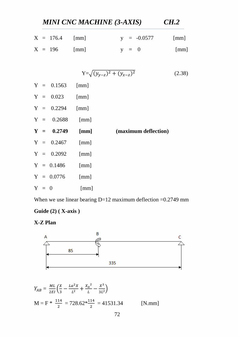
Guide (2) ( X-axis )
X-Z Plan
=
(
)
M = F *
= 728.62*
= 41531.34 [N.mm]
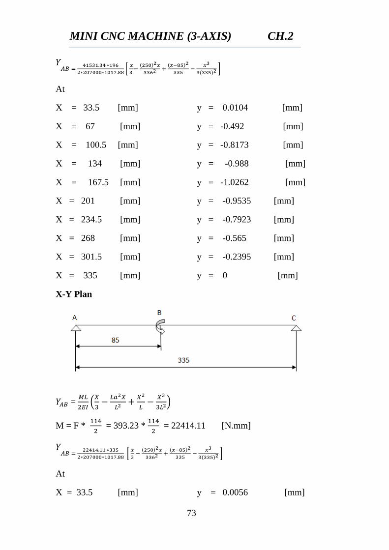
MINI CNC MACHINE (3-AXIS) CH.2
73
[
]
At
X = 33.5 [mm] y = 0.0104 [mm]
X = 67 [mm] y = -0.492 [mm]
X = 100.5 [mm] y = -0.8173 [mm]
X = 134 [mm] y = -0.988 [mm]
X = 167.5 [mm] y = -1.0262 [mm]
X = 201 [mm] y = -0.9535 [mm]
X = 234.5 [mm] y = -0.7923 [mm]
X = 268 [mm] y = -0.565 [mm]
X = 301.5 [mm] y = -0.2395 [mm]
X = 335 [mm] y = 0 [mm]
X-Y Plan
=
(
)
M = F *
= 393.23 *
= 22414.11 [N.mm]
[
]
At
X = 33.5 [mm] y = 0.0056 [mm]
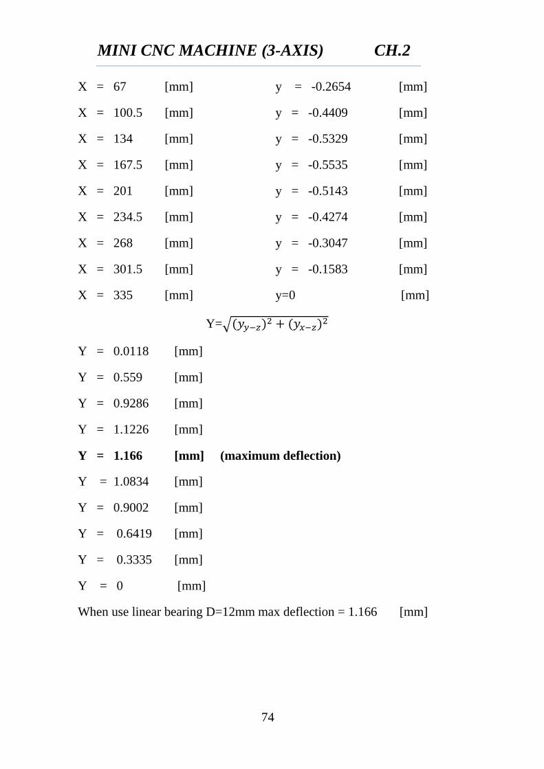
MINI CNC MACHINE (3-AXIS) CH.2
74
X = 67 [mm] y = -0.2654 [mm]
X = 100.5 [mm] y = -0.4409 [mm]
X = 134 [mm] y = -0.5329 [mm]
X = 167.5 [mm] y = -0.5535 [mm]
X = 201 [mm] y = -0.5143 [mm]
X = 234.5 [mm] y = -0.4274 [mm]
X = 268 [mm] y = -0.3047 [mm]
X = 301.5 [mm] y = -0.1583 [mm]
X = 335 [mm] y=0 [mm]
Y=√
Y = 0.0118 [mm]
Y = 0.559 [mm]
Y = 0.9286 [mm]
Y = 1.1226 [mm]
Y = 1.166 [mm] (maximum deflection)
Y = 1.0834 [mm]
Y = 0.9002 [mm]
Y = 0.6419 [mm]
Y = 0.3335 [mm]
Y = 0 [mm]
When use linear bearing D=12mm max deflection = 1.166 [mm]
MINI CNC MACHINE (3-AXIS) CH.2
75
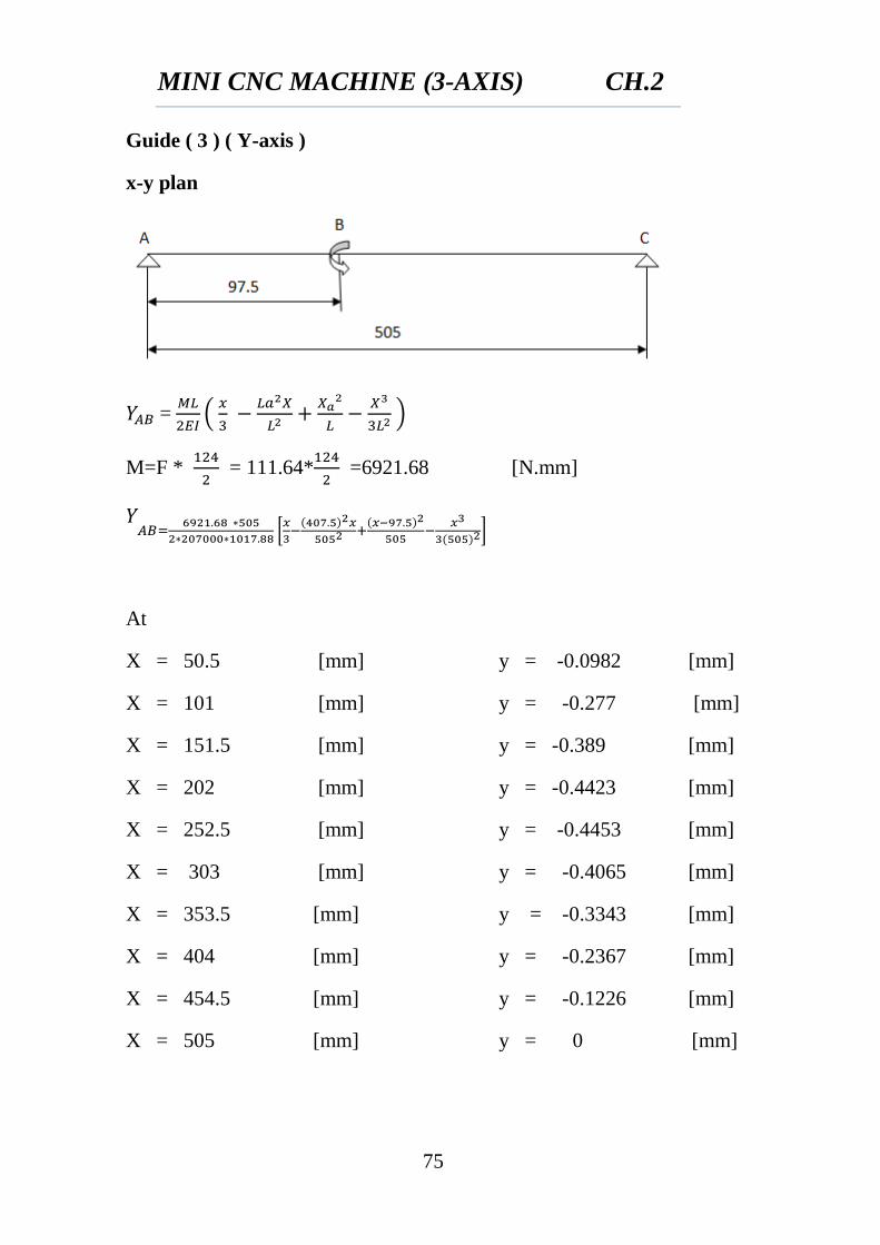
Guide ( 3 ) ( Y-axis )
x-y plan
=
(
)
M=F *
= 111.64*
=6921.68 [N.mm]
[
]
At
X = 50.5 [mm] y = -0.0982 [mm]
X = 101 [mm] y = -0.277 [mm]
X = 151.5 [mm] y = -0.389 [mm]
X = 202 [mm] y = -0.4423 [mm]
X = 252.5 [mm] y = -0.4453 [mm]
X = 303 [mm] y = -0.4065 [mm]
X = 353.5 [mm] y = -0.3343 [mm]
X = 404 [mm] y = -0.2367 [mm]
X = 454.5 [mm] y = -0.1226 [mm]
X = 505 [mm] y = 0 [mm]
MINI CNC MACHINE (3-AXIS) CH.2
76
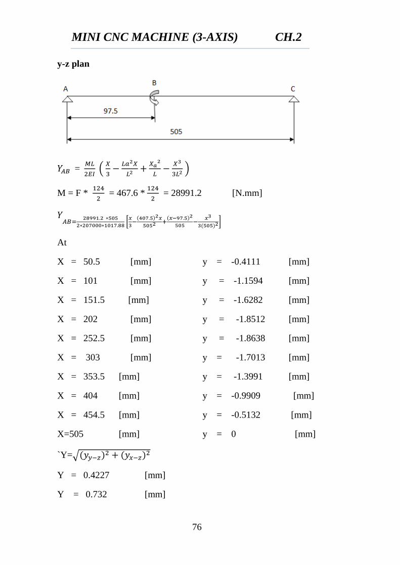
y-z plan
=
(
)
M = F *
= 467.6 *
= 28991.2 [N.mm]
[
]
At
X = 50.5 [mm] y = -0.4111 [mm]
X = 101 [mm] y = -1.1594 [mm]
X = 151.5 [mm] y = -1.6282 [mm]
X = 202 [mm] y = -1.8512 [mm]
X = 252.5 [mm] y = -1.8638 [mm]
X = 303 [mm] y = -1.7013 [mm]
X = 353.5 [mm] y = -1.3991 [mm]
X = 404 [mm] y = -0.9909 [mm]
X = 454.5 [mm] y = -0.5132 [mm]
X=505 [mm] y = 0 [mm]
`Y=√
Y = 0.4227 [mm]
Y = 0.732 [mm]
MINI CNC MACHINE (3-AXIS) CH.2
77
Y = 0.632 [mm]
Y = 0.554 [mm]
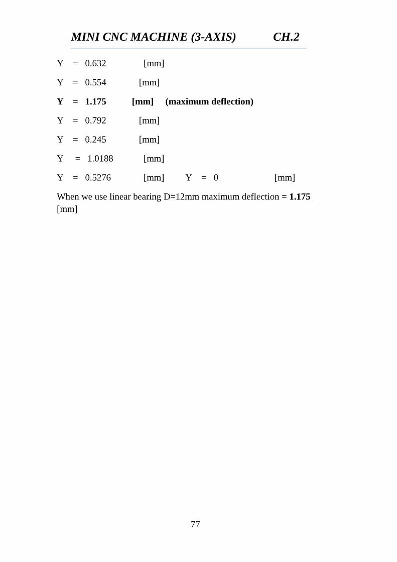
Y = 1.175 [mm] (maximum deflection)
Y = 0.792 [mm]
Y = 0.245 [mm]
Y = 1.0188 [mm]
Y = 0.5276 [mm] Y = 0 [mm]
When we use linear bearing D=12mm maximum deflection = 1.175
[mm]

CHAPTER (3)
ASSEMBLY
MINI CNC MACHINE (3-AXIS) CH.3
78
CHAPTER 3
ASSEMBLY
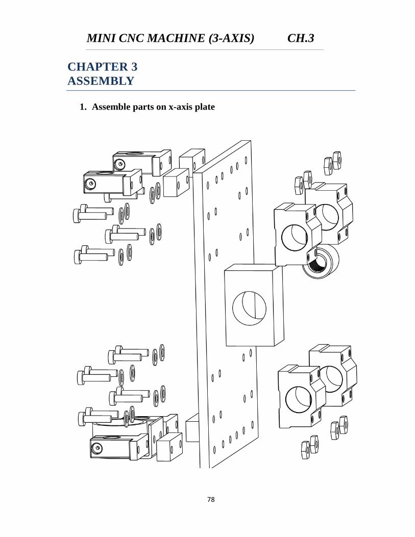
1. Assemble parts on x-axis plate
MINI CNC MACHINE (3-AXIS) CH.3
79
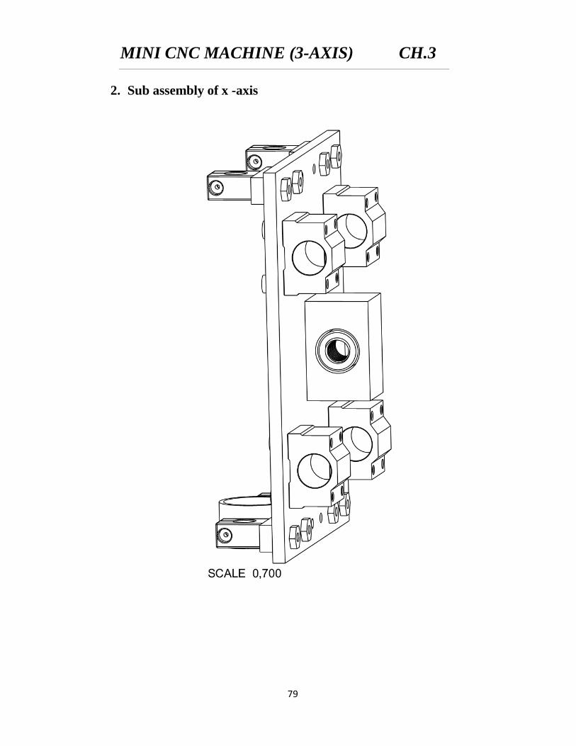
2. Sub assembly of x -axis
MINI CNC MACHINE (3-AXIS) CH.3
80
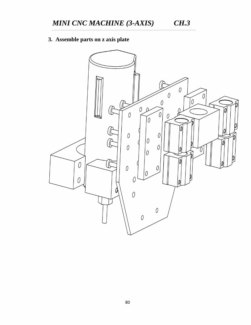
3. Assemble parts on z axis plate
MINI CNC MACHINE (3-AXIS) CH.3
81
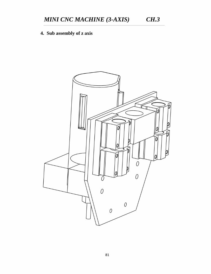
4. Sub assembly of z axis
MINI CNC MACHINE (3-AXIS) CH.3
82
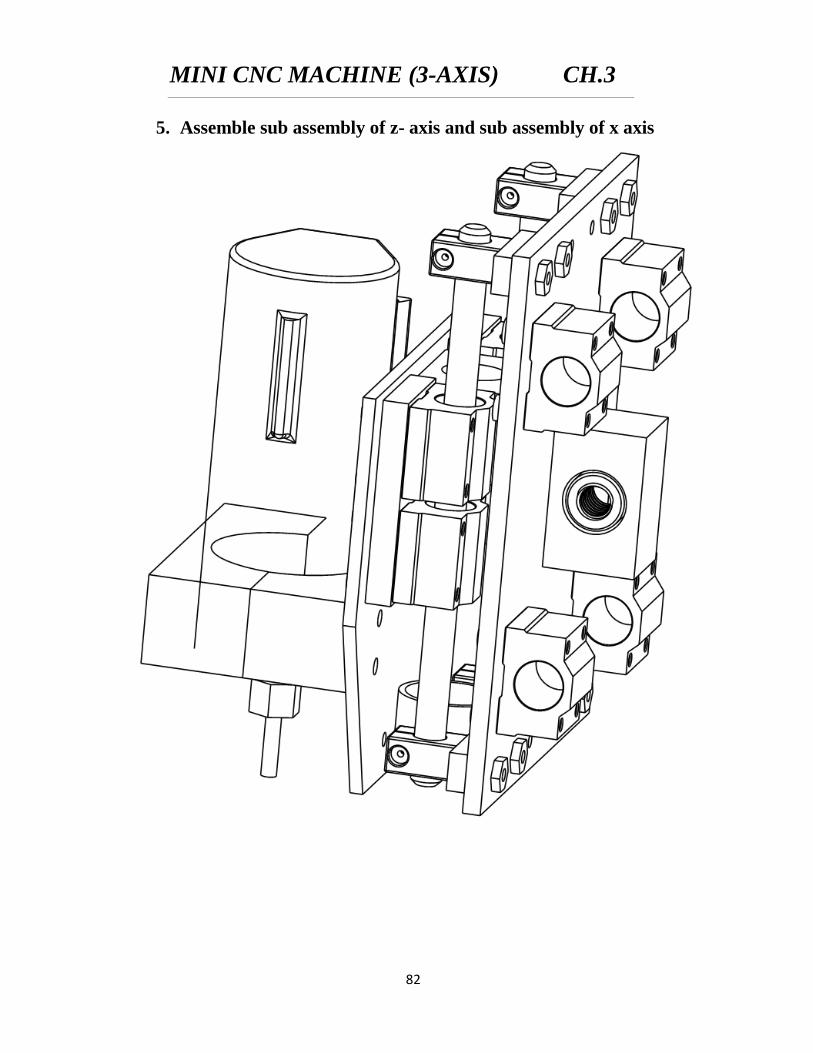
5. Assemble sub assembly of z- axis and sub assembly of x axis
MINI CNC MACHINE (3-AXIS) CH.3
83
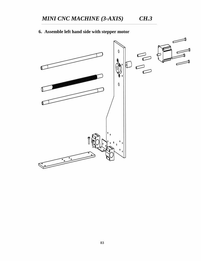
6. Assemble left hand side with stepper motor
MINI CNC MACHINE (3-AXIS) CH.3
84
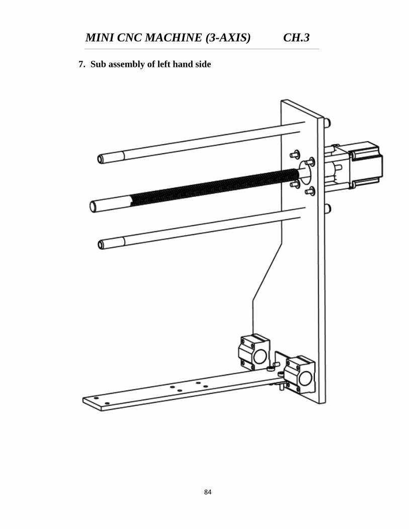
7. Sub assembly of left hand side
MINI CNC MACHINE (3-AXIS) CH.3
85
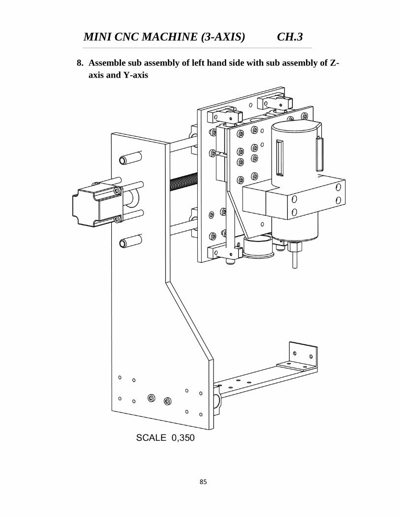
8. Assemble sub assembly of left hand side with sub assembly of Z-
axis and Y-axis
MINI CNC MACHINE (3-AXIS) CH.3
86
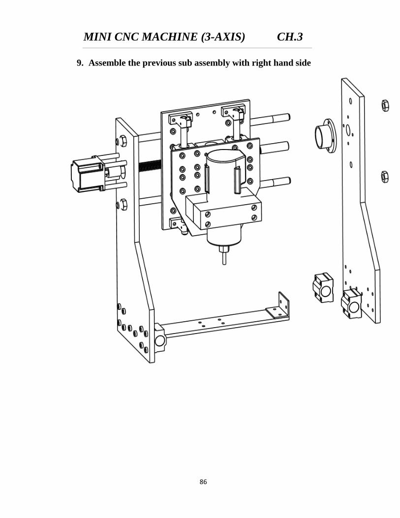
9. Assemble the previous sub assembly with right hand side
MINI CNC MACHINE (3-AXIS) CH.3
87
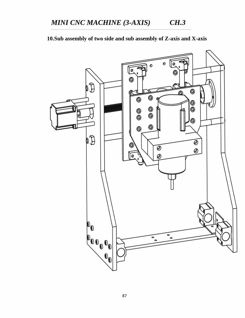
10. Sub assembly of two side and sub assembly of Z-axis and X-axis
MINI CNC MACHINE (3-AXIS) CH.3
88
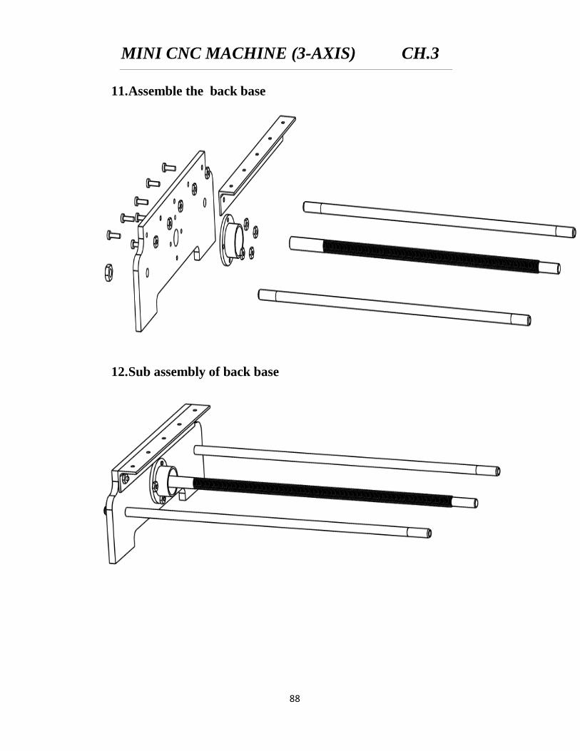
11. Assemble the back base
12. Sub assembly of back base
MINI CNC MACHINE (3-AXIS) CH.3
89
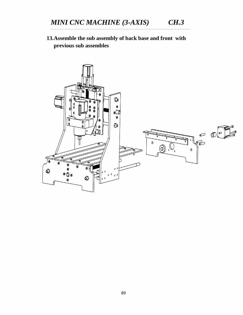
13. Assemble the sub assembly of back base and front with
previous sub assembles
MINI CNC MACHINE (3-AXIS) CH.3
90
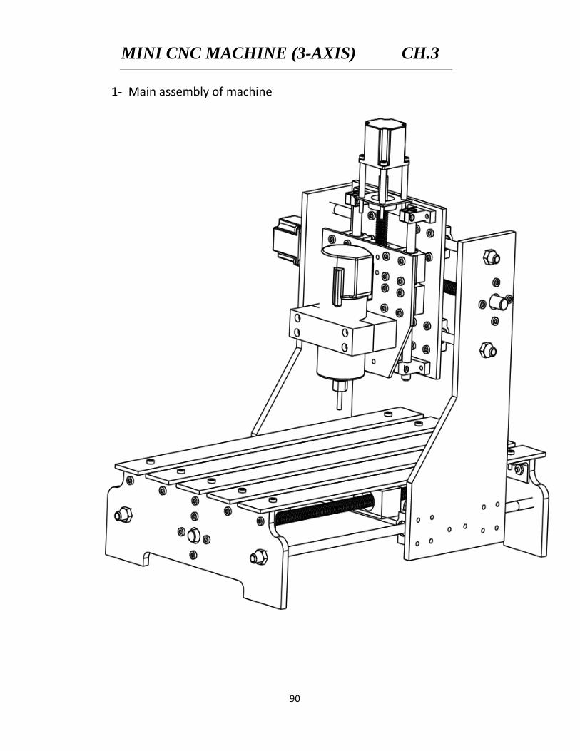
1- Main assembly of machine

CHAPTER (4)
CONTROL
SYSTEM
MINI CNC MACHINE (3-AXIS) CH.4
91
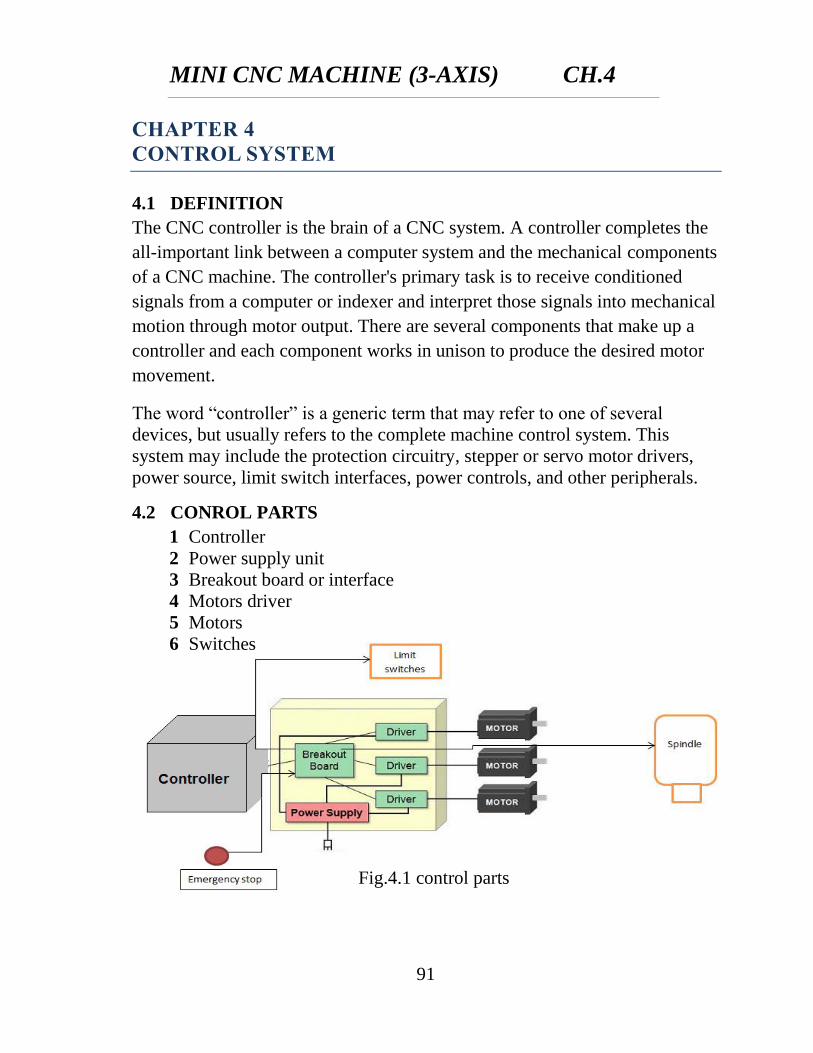
CHAPTER 4
CONTROL SYSTEM
4.1 DEFINITION
The CNC controller is the brain of a CNC system. A controller completes the
all-important link between a computer system and the mechanical components
of a CNC machine. The controller's primary task is to receive conditioned
signals from a computer or indexer and interpret those signals into mechanical
motion through motor output. There are several components that make up a
controller and each component works in unison to produce the desired motor
movement.
The word “controller” is a generic term that may refer to one of several
devices, but usually refers to the complete machine control system. This
system may include the protection circuitry, stepper or servo motor drivers,
power source, limit switch interfaces, power controls, and other peripherals.
4.2 CONROL PARTS
1 Controller
2 Power supply unit
3 Breakout board or interface
4 Motors driver
5 Motors
6 Switches
Fig.4.1 control parts
MINI CNC MACHINE (3-AXIS) CH.4
92
4.2.1 Controller
The CNC controller is the brain of a CNC system. A controller completes the
all-important link between a computer system and the mechanical components
of a CNC machine. The controller's primary task is to receive conditioned
signals from a computer or indexer and interpret those signals into mechanical
motion through motor output. There are several components that make up a
controller and each component works in unison to produce the desired motor
movement.
Controllers still require operators to create a program for the controller to
follow. Operators today receive help from Software such as Computer-Aided
Design (CAD) packages and Computer-Aided Manufacturing (CAM)
software along with the controller software to create the necessary numerical
code such as G-code
The Controller unit replaced by software controller which can be run from
Computer
4.2.1.1 Types of Controller (Software) Can Be Used
a) Mach3
b) K Cam
c) other
The controller used is mach3 software. Mach3 is a software package which
runs on a PC and turns it into a very powerful and economical Machine
Controller to replace Controller unit.
4.2.1.2 Features of Mach3 Software
a) Converts a standard PC to a fully featured, 6‐axis CNC controller.
b) Allows direct import of DXF, BMP, JPG, and HPGL files through
LazyCam.
c) Visual G‐code display.
d) Generates G‐code via LazyCam or Wizards.
e) Contain many common cycles shown in Fig.4.2
f) Fully customizable interface.
g) Spindle Speed control.
h) Multiple relay control.
MINI CNC MACHINE (3-AXIS) CH.4
93
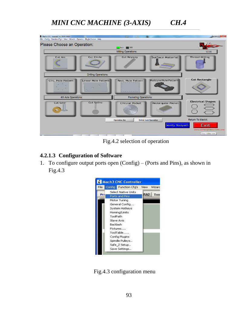
4.2.1.3 Configuration of Software
1. To configure output ports open (Config) – (Ports and Pins), as shown in
Fig.4.3
Fig.4.2 selection of operation
Fig.4.3 configuration menu
MINI CNC MACHINE (3-AXIS) CH.4
94
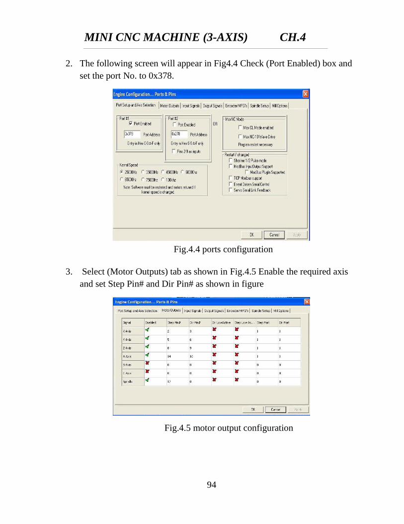
2. The following screen will appear in Fig4.4 Check (Port Enabled) box and
set the port No. to 0x378.
3. Select (Motor Outputs) tab as shown in Fig.4.5 Enable the required axis
and set Step Pin# and Dir Pin# as shown in figure
Fig.4.4 ports configuration
Fig.4.5 motor output configuration
MINI CNC MACHINE (3-AXIS) CH.4
95
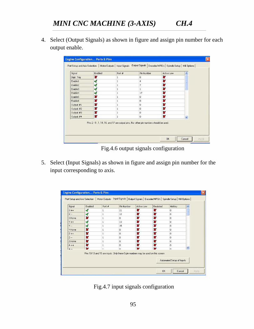
4. Select (Output Signals) as shown in figure and assign pin number for each
output enable.
5. Select (Input Signals) as shown in figure and assign pin number for the
input corresponding to axis.
Fig.4.6 output signals configuration
Fig.4.7 input signals configuration
MINI CNC MACHINE (3-AXIS) CH.4
96
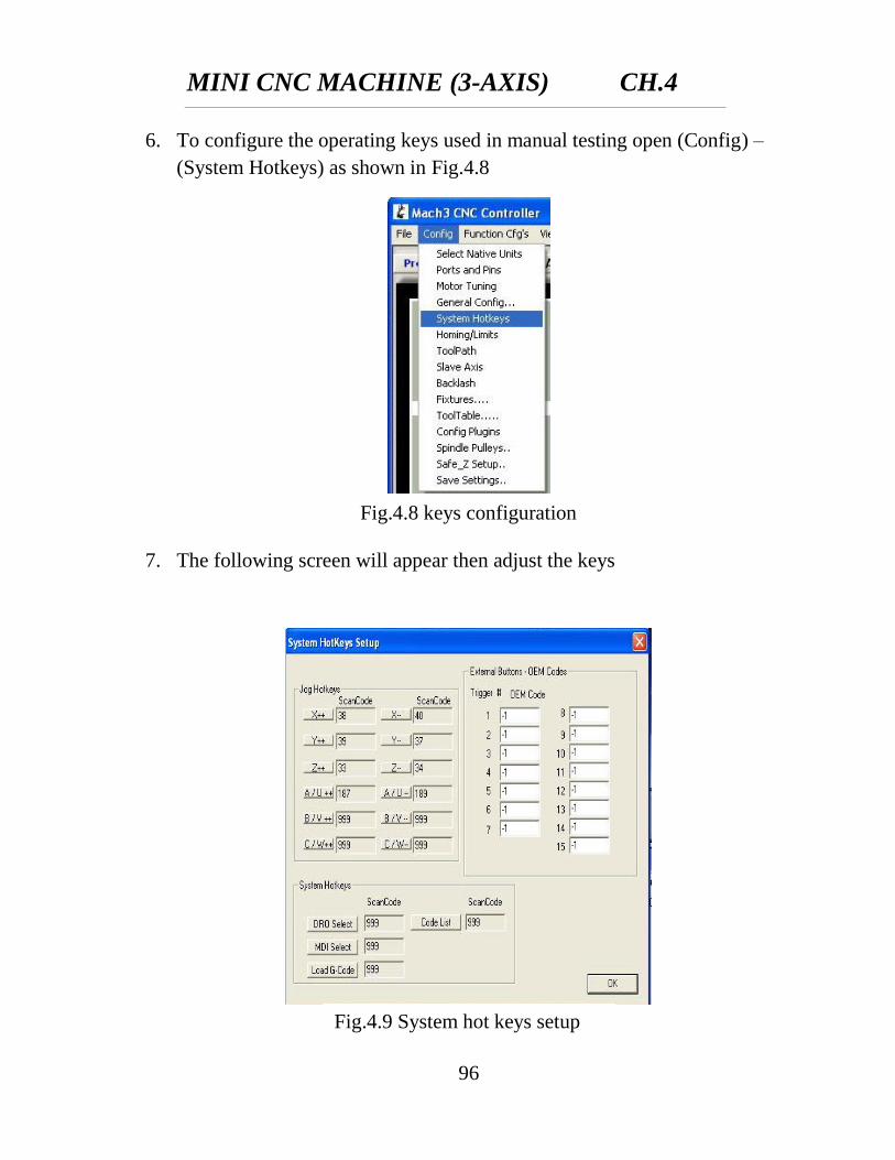
6. To configure the operating keys used in manual testing open (Config) –
(System Hotkeys) as shown in Fig.4.8
7. The following screen will appear then adjust the keys
Fig.4.8 keys configuration
Fig.4.9 System hot keys setup
MINI CNC MACHINE (3-AXIS) CH.4
97
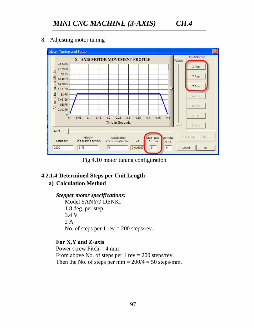
8. Adjusting motor tuning
4.2.1.4 Determined Steps per Unit Length
a) Calculation Method
Stepper motor specifications:
Model SANYO DENKI
1.8 deg. per step
3.4 V
2 A
No. of steps per 1 rev = 200 steps/rev.
For X,Y and Z-axis
Power screw Pitch = 4 mm
From above No. of steps per 1 rev = 200 steps/rev.
Then the No. of steps per mm = 200/4 = 50 steps/mm.
Fig.4.10 motor tuning configuration
MINI CNC MACHINE (3-AXIS) CH.4
98
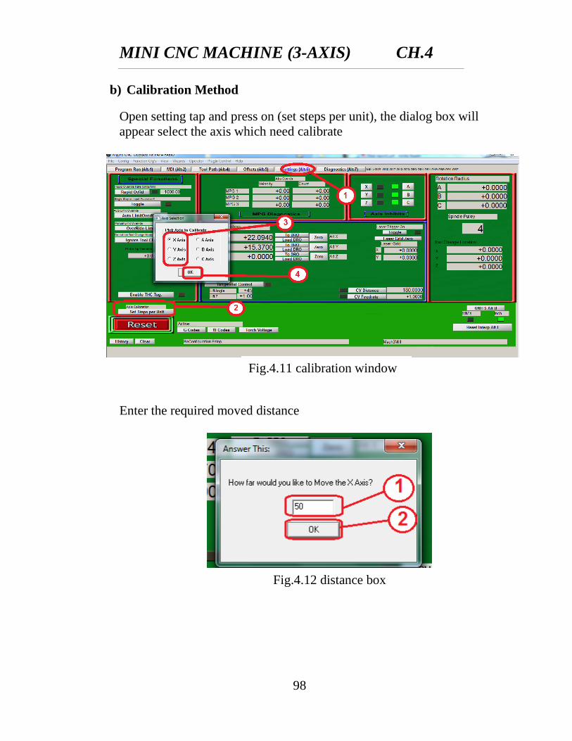
b) Calibration Method
Open setting tap and press on (set steps per unit), the dialog box will
appear select the axis which need calibrate
Enter the required moved distance
Fig.4.11 calibration window
Fig.4.12 distance box
MINI CNC MACHINE (3-AXIS) CH.4
99
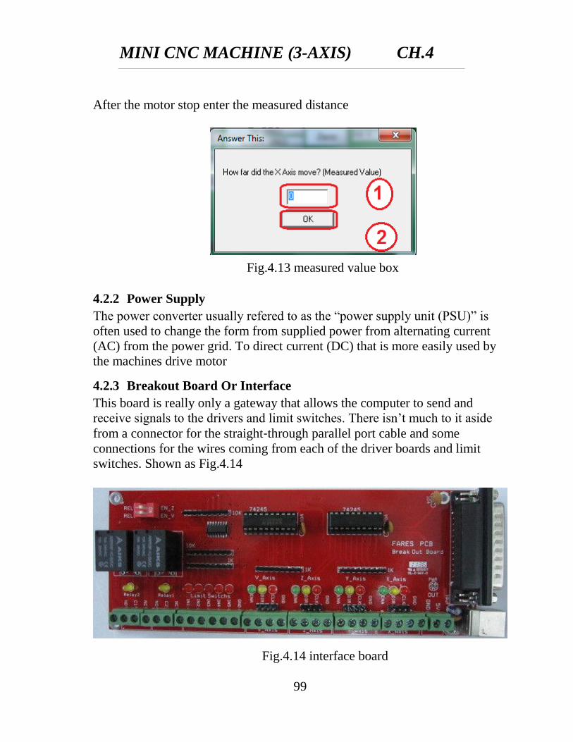
After the motor stop enter the measured distance
4.2.2 Power Supply
The power converter usually refered to as the “power supply unit (PSU)” is
often used to change the form from supplied power from alternating current
(AC) from the power grid. To direct current (DC) that is more easily used by
the machines drive motor
4.2.3 Breakout Board Or Interface
This board is really only a gateway that allows the computer to send and
receive signals to the drivers and limit switches. There isn’t much to it aside
from a connector for the straight‐through parallel port cable and some
connections for the wires coming from each of the driver boards and limit
switches. Shown as Fig.4.14
Fig.4.13 measured value box
Fig.4.14 interface board
MINI CNC MACHINE (3-AXIS) CH.4
100
This board is a simple, cheap, buffered no isolated parallel breakout board. It
supports four output control signal groups to drive four axis CNC machine.
Each signal group supports three control signals ( Enable , Direction and
Clock ) . Two output relays could be enabled via DIP switch for additional
spindle control. The interface also supports five dry contact inputs for travel
limit switches.
4.2.3.1 Interface Features
1. Four output control signal groups. labeled X-axis, Y-axis, Z-axis, V-
Axis.
2. Ena , Dir , Clk control signals are available. For pin assignment and
address show table 4.1.
3. Two output relays 5V coil / 10A contacts (resistive load).
4. Normally open and normally closed contacts are available..
5. Five external inputs (dry contact).
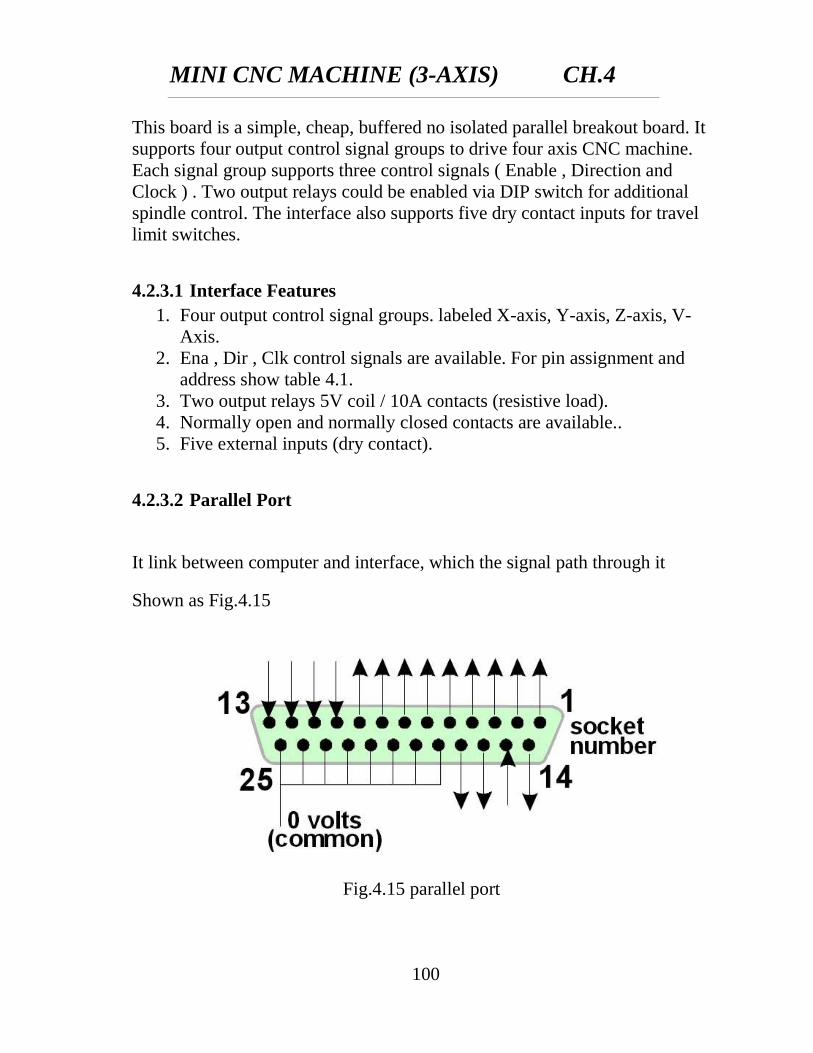
4.2.3.2 Parallel Port
It link between computer and interface, which the signal path through it
Shown as Fig.4.15
Fig.4.15 parallel port
MINI CNC MACHINE (3-AXIS) CH.4
101
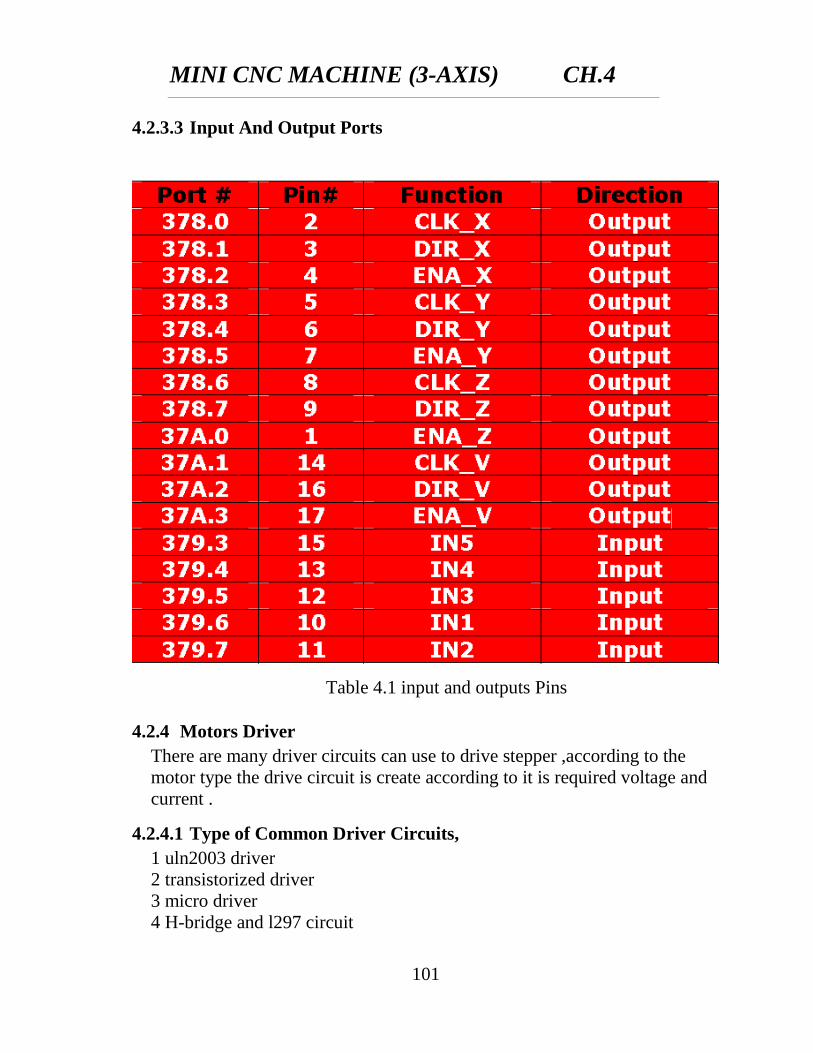
4.2.3.3 Input And Output Ports
4.2.4 Motors Driver
There are many driver circuits can use to drive stepper ,according to the
motor type the drive circuit is create according to it is required voltage and
current .
4.2.4.1 Type of Common Driver Circuits,
1 uln2003 driver
2 transistorized driver
3 micro driver
4 H-bridge and l297 circuit
Table 4.1 input and outputs Pins
MINI CNC MACHINE (3-AXIS) CH.4
102
Using H-bridge and l297 circuit
It is the last driver that has been made and the simplest one because it solve
the problems of above circuits, it solve the problem of the need to a
programmer to create the program in micro controller chip by using l297
chip and it don’t need program. And it solve the problem of the transistor
connection and installation by using l298 chip which the is have transistors
inside and it is easy to connect it .
4.2.4.2 Advantages of H-bridge and l297 circuit
1 Easy to build
2 More reliable
3 Its component is available and cheap
MINI CNC MACHINE (3-AXIS) CH.4
103
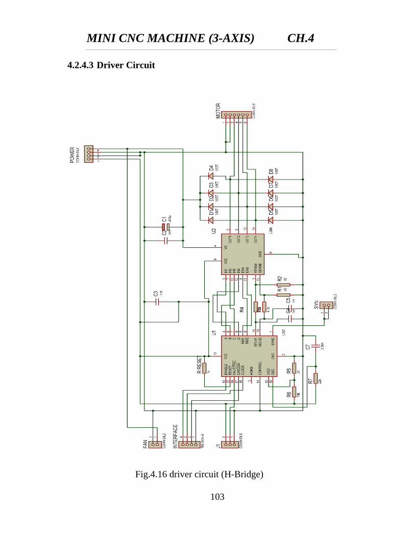
4.2.4.3 Driver Circuit
Fig.4.16 driver circuit (H-Bridge)
MINI CNC MACHINE (3-AXIS) CH.4
104
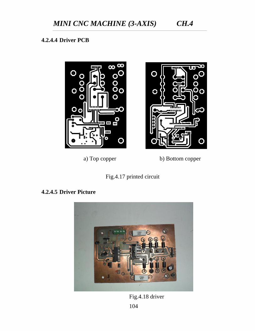
4.2.4.4 Driver PCB
4.2.4.5 Driver Picture
Fig.4.17 printed circuit
board
a) Top copper b) Bottom copper
Fig.4.18 driver
MINI CNC MACHINE (3-AXIS) CH.4
105
4.2.4.6 Machine Circuits Box
Fig.4.19 machine circuits box
MINI CNC MACHINE (3-AXIS) CH.4
106
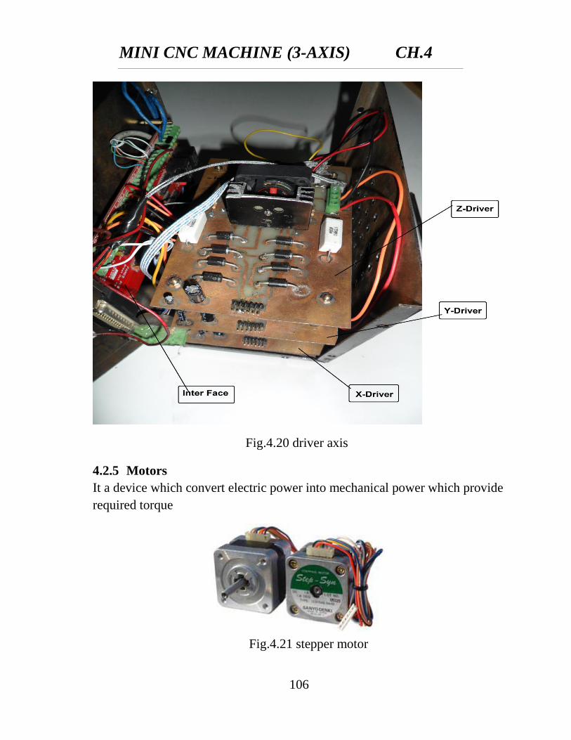
4.2.5 Motors
It a device which convert electric power into mechanical power which provide
required torque
Fig.4.20 driver axis
Fig.4.21 stepper motor
MINI CNC MACHINE (3-AXIS) CH.4
107
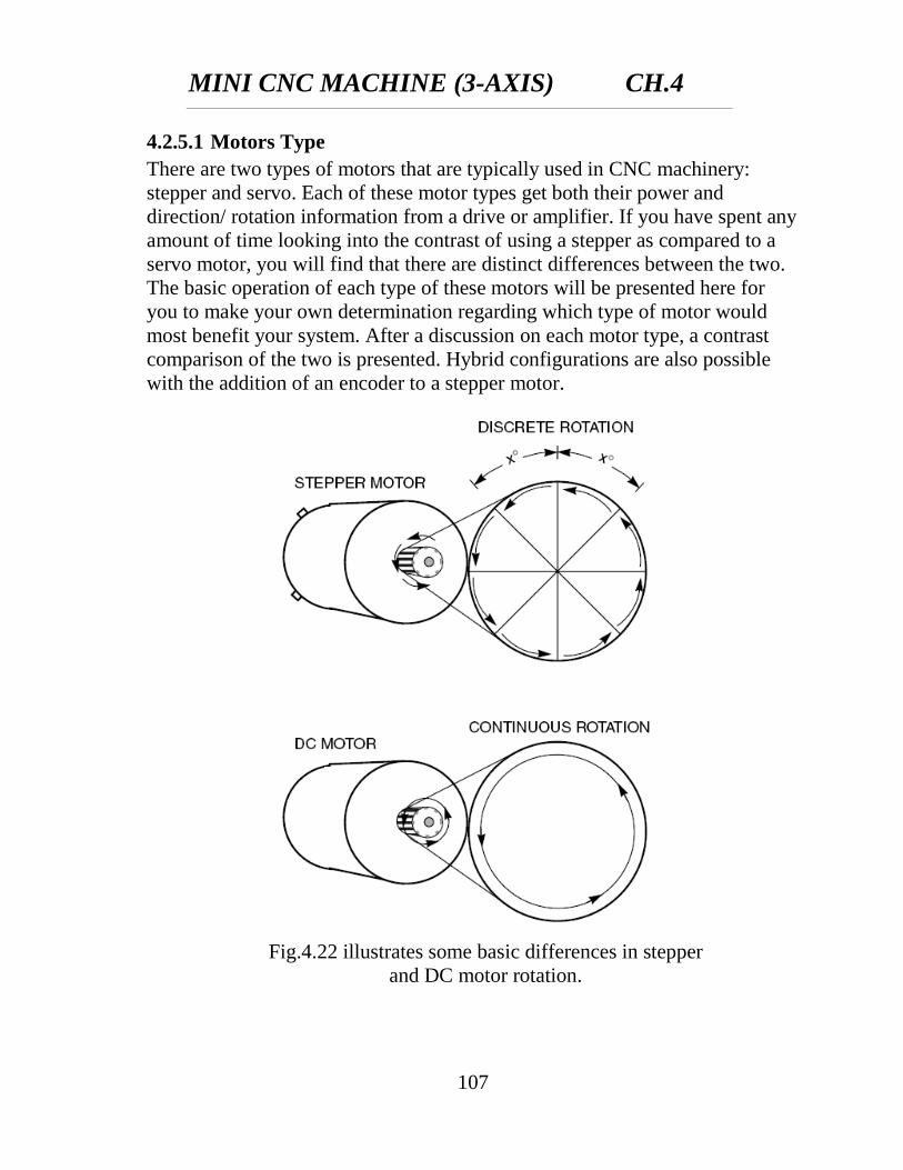
4.2.5.1 Motors Type
There are two types of motors that are typically used in CNC machinery:
stepper and servo. Each of these motor types get both their power and
direction/ rotation information from a drive or amplifier. If you have spent any
amount of time looking into the contrast of using a stepper as compared to a
servo motor, you will find that there are distinct differences between the two.
The basic operation of each type of these motors will be presented here for
you to make your own determination regarding which type of motor would
most benefit your system. After a discussion on each motor type, a contrast
comparison of the two is presented. Hybrid configurations are also possible
with the addition of an encoder to a stepper motor.
Fig.4.22 illustrates some basic differences in stepper
and DC motor rotation.
MINI CNC MACHINE (3-AXIS) CH.4
108
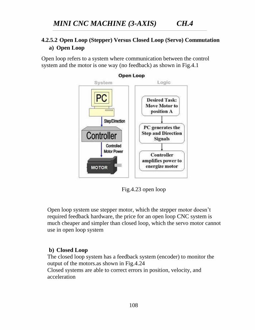
4.2.5.2 Open Loop (Stepper) Versus Closed Loop (Servo) Commutation
a) Open Loop
Open loop refers to a system where communication between the control
system and the motor is one way (no feedback) as shown in Fig.4.1
Open loop system use stepper motor, which the stepper motor doesn’t
required feedback hardware, the price for an open loop CNC system is
much cheaper and simpler than closed loop, which the servo motor cannot
use in open loop system
b) Closed Loop
The closed loop system has a feedback system (encoder) to monitor the
output of the motors.as shown in Fig.4.24
Closed systems are able to correct errors in position, velocity, and
acceleration
Fig.4.23 open loop
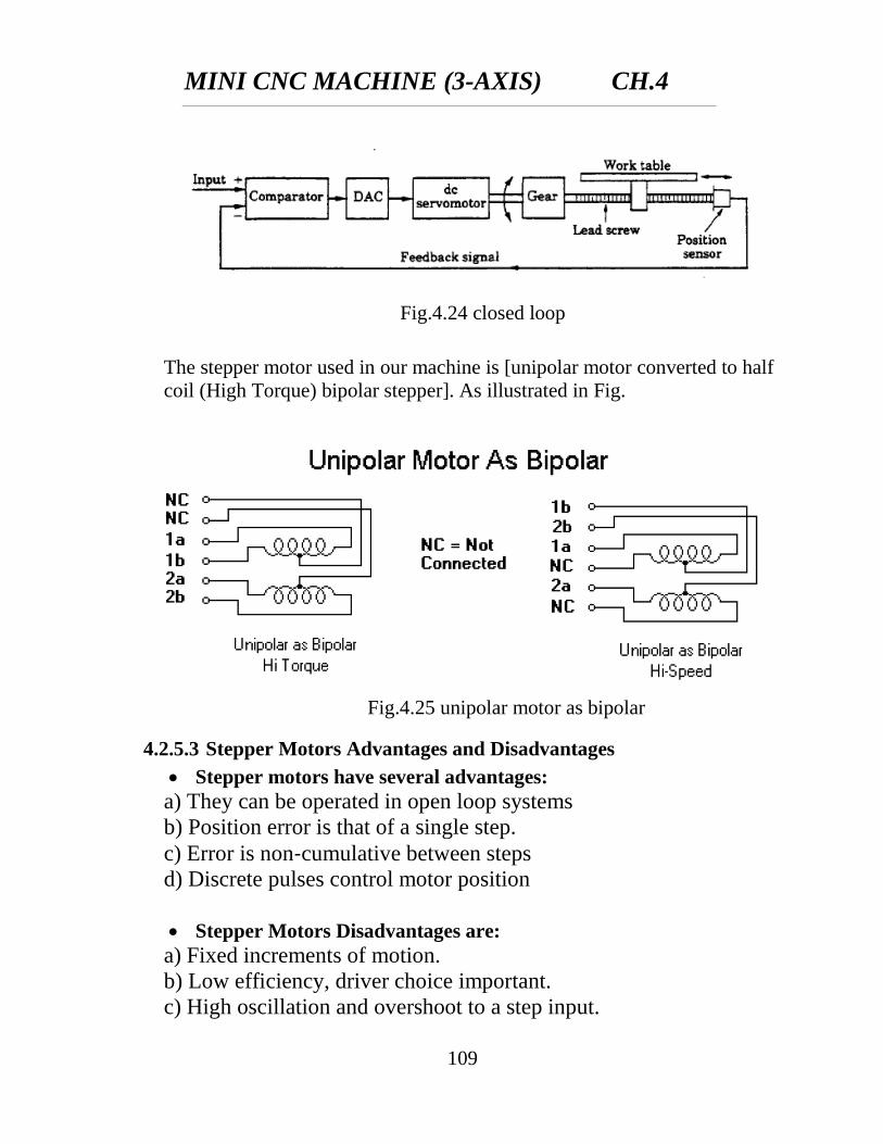
MINI CNC MACHINE (3-AXIS) CH.4
109
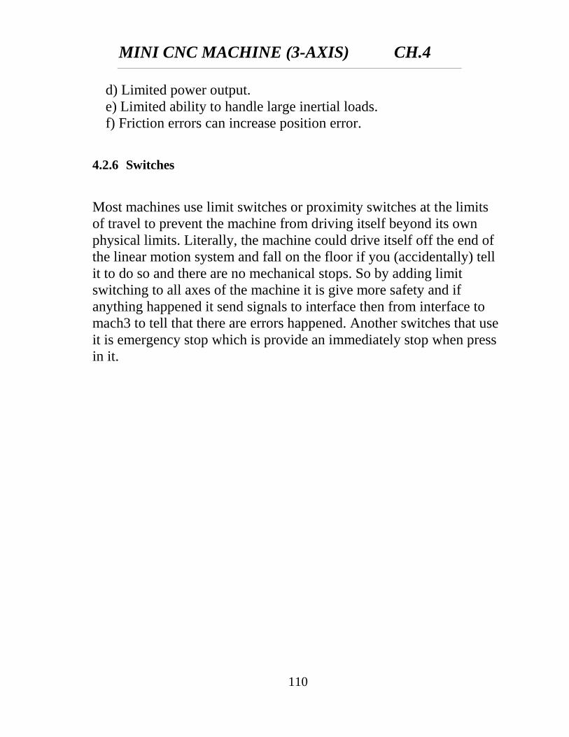
The stepper motor used in our machine is [unipolar motor converted to half
coil (High Torque) bipolar stepper]. As illustrated in Fig.
4.2.5.3 Stepper Motors Advantages and Disadvantages
Stepper motors have several advantages:
a) They can be operated in open loop systems
b) Position error is that of a single step.
c) Error is non‐cumulative between steps
d) Discrete pulses control motor position
Stepper Motors Disadvantages are:
a) Fixed increments of motion.
b) Low efficiency, driver choice important.
c) High oscillation and overshoot to a step input.
Fig.4.24 closed loop
Fig.4.25 unipolar motor as bipolar
MINI CNC MACHINE (3-AXIS) CH.4
110
d) Limited power output.
e) Limited ability to handle large inertial loads.
f) Friction errors can increase position error.
4.2.6 Switches
Most machines use limit switches or proximity switches at the limits
of travel to prevent the machine from driving itself beyond its own
physical limits. Literally, the machine could drive itself off the end of
the linear motion system and fall on the floor if you (accidentally) tell
it to do so and there are no mechanical stops. So by adding limit
switching to all axes of the machine it is give more safety and if
anything happened it send signals to interface then from interface to
mach3 to tell that there are errors happened. Another switches that use
it is emergency stop which is provide an immediately stop when press
in it.

CHAPTER (5)
EXPERIMENTAL
WORK AND
VERIFICATION
MINI CNC MACHINE (3-AXIS) CH.5
111
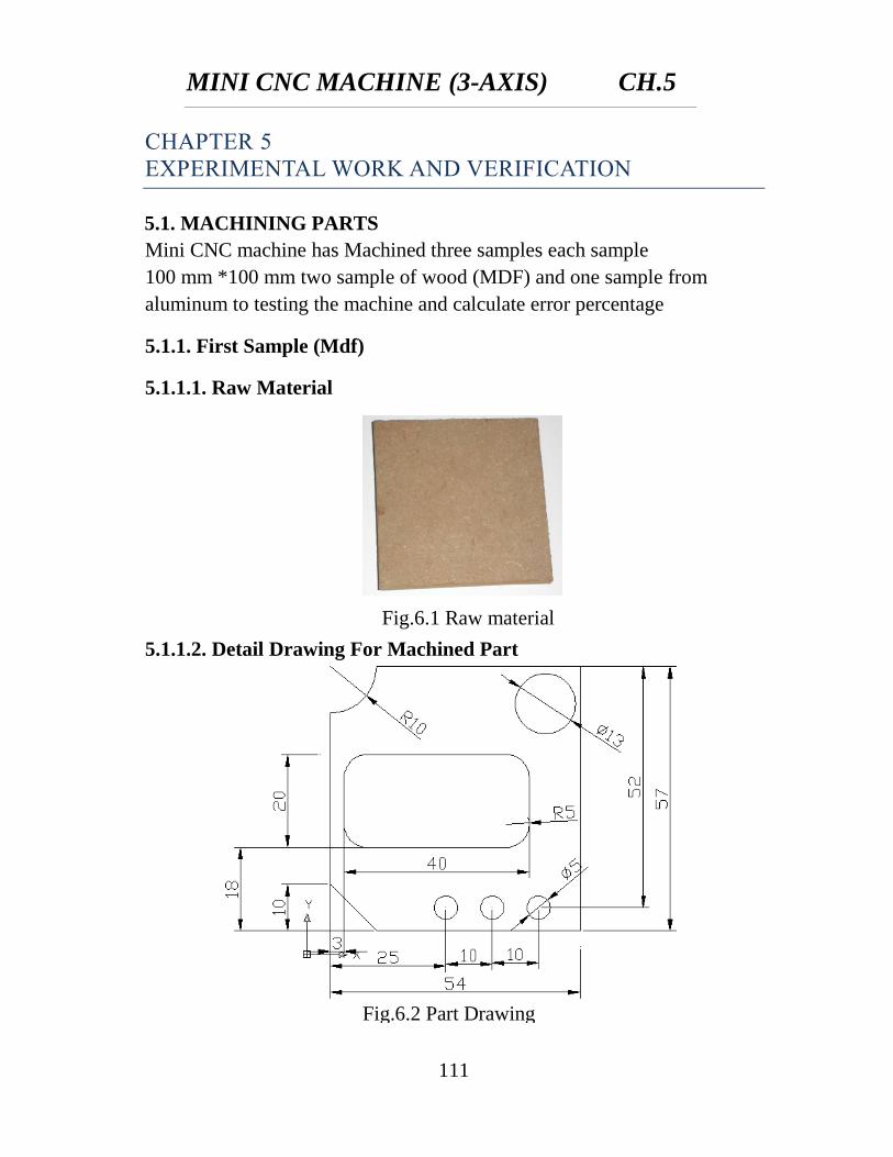
Fig.6.1 Raw material
CHAPTER 5
EXPERIMENTAL WORK AND VERIFICATION
5.1. MACHINING PARTS
Mini CNC machine has Machined three samples each sample
100 mm *100 mm two sample of wood (MDF) and one sample from
aluminum to testing the machine and calculate error percentage
5.1.1. First Sample (Mdf)
5.1.1.1. Raw Material
5.1.1.2. Detail Drawing For Machined Part
Fig.6.2 Part Drawing
MINI CNC MACHINE (3-AXIS) CH.5
112
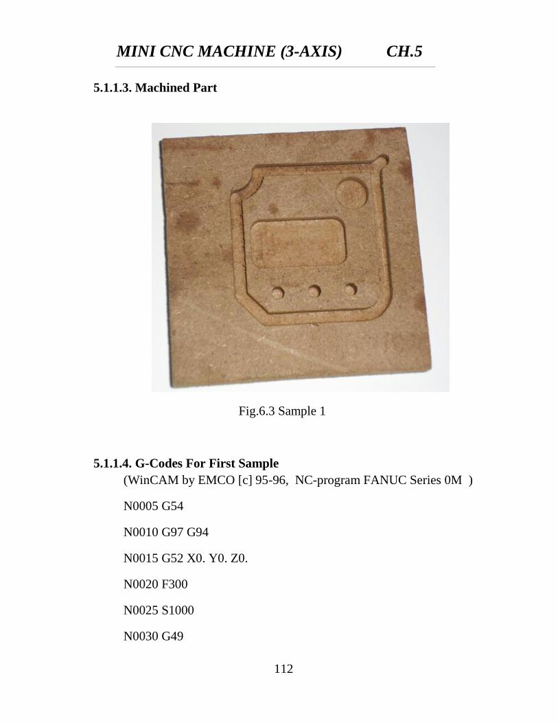
Fig.6.3 Sample 1
5.1.1.3. Machined Part
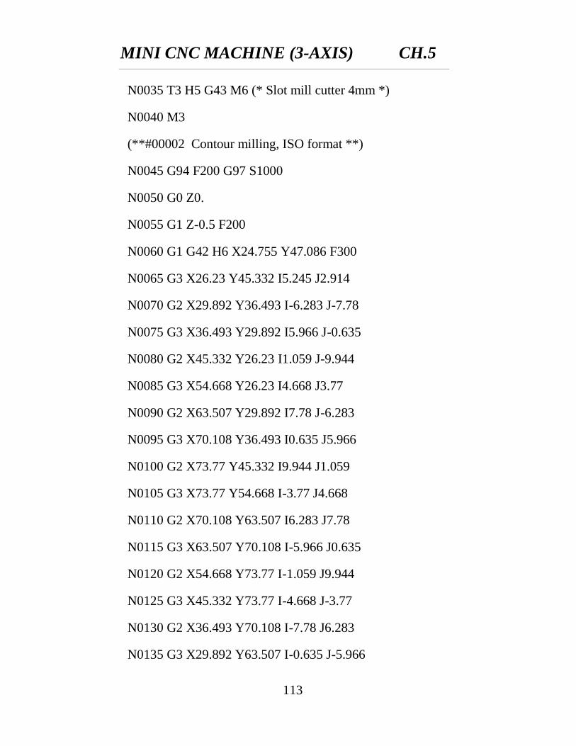
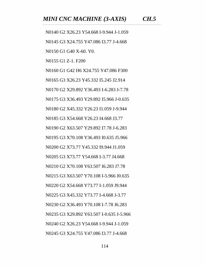
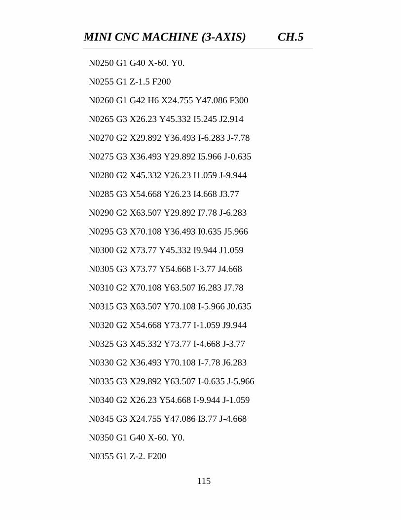
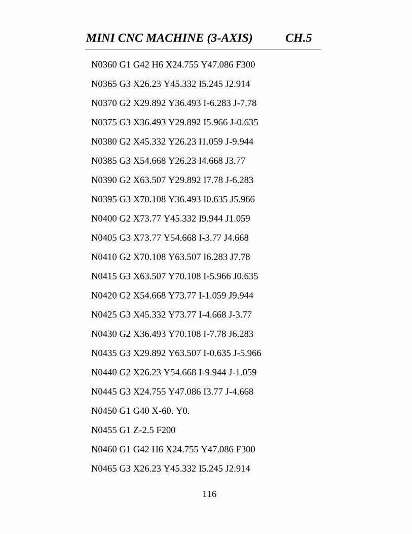
5.1.1.4. G-Codes For First Sample
(WinCAM by EMCO [c] 95-96, NC-program FANUC Series 0M )
N0005 G54
N0010 G97 G94
N0015 G52 X0. Y0. Z0.
N0020 F300
N0025 S1000
N0030 G49
MINI CNC MACHINE (3-AXIS) CH.5
113
N0035 T3 H5 G43 M6 (* Slot mill cutter 4mm *)
N0040 M3
(**#00002 Contour milling, ISO format **)
N0045 G94 F200 G97 S1000
N0050 G0 Z0.
N0055 G1 Z-0.5 F200
N0060 G1 G42 H6 X24.755 Y47.086 F300
N0065 G3 X26.23 Y45.332 I5.245 J2.914
N0070 G2 X29.892 Y36.493 I-6.283 J-7.78
N0075 G3 X36.493 Y29.892 I5.966 J-0.635
N0080 G2 X45.332 Y26.23 I1.059 J-9.944
N0085 G3 X54.668 Y26.23 I4.668 J3.77
N0090 G2 X63.507 Y29.892 I7.78 J-6.283
N0095 G3 X70.108 Y36.493 I0.635 J5.966
N0100 G2 X73.77 Y45.332 I9.944 J1.059
N0105 G3 X73.77 Y54.668 I-3.77 J4.668
N0110 G2 X70.108 Y63.507 I6.283 J7.78
N0115 G3 X63.507 Y70.108 I-5.966 J0.635
N0120 G2 X54.668 Y73.77 I-1.059 J9.944
N0125 G3 X45.332 Y73.77 I-4.668 J-3.77
N0130 G2 X36.493 Y70.108 I-7.78 J6.283
N0135 G3 X29.892 Y63.507 I-0.635 J-5.966
MINI CNC MACHINE (3-AXIS) CH.5
114
N0140 G2 X26.23 Y54.668 I-9.944 J-1.059
N0145 G3 X24.755 Y47.086 I3.77 J-4.668
N0150 G1 G40 X-60. Y0.
N0155 G1 Z-1. F200
N0160 G1 G42 H6 X24.755 Y47.086 F300
N0165 G3 X26.23 Y45.332 I5.245 J2.914
N0170 G2 X29.892 Y36.493 I-6.283 J-7.78
N0175 G3 X36.493 Y29.892 I5.966 J-0.635
N0180 G2 X45.332 Y26.23 I1.059 J-9.944
N0185 G3 X54.668 Y26.23 I4.668 J3.77
N0190 G2 X63.507 Y29.892 I7.78 J-6.283
N0195 G3 X70.108 Y36.493 I0.635 J5.966
N0200 G2 X73.77 Y45.332 I9.944 J1.059
N0205 G3 X73.77 Y54.668 I-3.77 J4.668
N0210 G2 X70.108 Y63.507 I6.283 J7.78
N0215 G3 X63.507 Y70.108 I-5.966 J0.635
N0220 G2 X54.668 Y73.77 I-1.059 J9.944
N0225 G3 X45.332 Y73.77 I-4.668 J-3.77
N0230 G2 X36.493 Y70.108 I-7.78 J6.283
N0235 G3 X29.892 Y63.507 I-0.635 J-5.966
N0240 G2 X26.23 Y54.668 I-9.944 J-1.059
N0245 G3 X24.755 Y47.086 I3.77 J-4.668
MINI CNC MACHINE (3-AXIS) CH.5
115
N0250 G1 G40 X-60. Y0.
N0255 G1 Z-1.5 F200
N0260 G1 G42 H6 X24.755 Y47.086 F300
N0265 G3 X26.23 Y45.332 I5.245 J2.914
N0270 G2 X29.892 Y36.493 I-6.283 J-7.78
N0275 G3 X36.493 Y29.892 I5.966 J-0.635
N0280 G2 X45.332 Y26.23 I1.059 J-9.944
N0285 G3 X54.668 Y26.23 I4.668 J3.77
N0290 G2 X63.507 Y29.892 I7.78 J-6.283
N0295 G3 X70.108 Y36.493 I0.635 J5.966
N0300 G2 X73.77 Y45.332 I9.944 J1.059
N0305 G3 X73.77 Y54.668 I-3.77 J4.668
N0310 G2 X70.108 Y63.507 I6.283 J7.78
N0315 G3 X63.507 Y70.108 I-5.966 J0.635
N0320 G2 X54.668 Y73.77 I-1.059 J9.944
N0325 G3 X45.332 Y73.77 I-4.668 J-3.77
N0330 G2 X36.493 Y70.108 I-7.78 J6.283
N0335 G3 X29.892 Y63.507 I-0.635 J-5.966
N0340 G2 X26.23 Y54.668 I-9.944 J-1.059
N0345 G3 X24.755 Y47.086 I3.77 J-4.668
N0350 G1 G40 X-60. Y0.
N0355 G1 Z-2. F200
MINI CNC MACHINE (3-AXIS) CH.5
116
N0360 G1 G42 H6 X24.755 Y47.086 F300
N0365 G3 X26.23 Y45.332 I5.245 J2.914
N0370 G2 X29.892 Y36.493 I-6.283 J-7.78
N0375 G3 X36.493 Y29.892 I5.966 J-0.635
N0380 G2 X45.332 Y26.23 I1.059 J-9.944
N0385 G3 X54.668 Y26.23 I4.668 J3.77
N0390 G2 X63.507 Y29.892 I7.78 J-6.283
N0395 G3 X70.108 Y36.493 I0.635 J5.966
N0400 G2 X73.77 Y45.332 I9.944 J1.059
N0405 G3 X73.77 Y54.668 I-3.77 J4.668
N0410 G2 X70.108 Y63.507 I6.283 J7.78
N0415 G3 X63.507 Y70.108 I-5.966 J0.635
N0420 G2 X54.668 Y73.77 I-1.059 J9.944
N0425 G3 X45.332 Y73.77 I-4.668 J-3.77
N0430 G2 X36.493 Y70.108 I-7.78 J6.283
N0435 G3 X29.892 Y63.507 I-0.635 J-5.966
N0440 G2 X26.23 Y54.668 I-9.944 J-1.059
N0445 G3 X24.755 Y47.086 I3.77 J-4.668
N0450 G1 G40 X-60. Y0.
N0455 G1 Z-2.5 F200
N0460 G1 G42 H6 X24.755 Y47.086 F300
N0465 G3 X26.23 Y45.332 I5.245 J2.914
MINI CNC MACHINE (3-AXIS) CH.5
117
N0470 G2 X29.892 Y36.493 I-6.283 J-7.78
N0475 G3 X36.493 Y29.892 I5.966 J-0.635
N0480 G2 X45.332 Y26.23 I1.059 J-9.944
N0485 G3 X54.668 Y26.23 I4.668 J3.77
N0490 G2 X63.507 Y29.892 I7.78 J-6.283
N0495 G3 X70.108 Y36.493 I0.635 J5.966
N0500 G2 X73.77 Y45.332 I9.944 J1.059
N0505 G3 X73.77 Y54.668 I-3.77 J4.668
N0510 G2 X70.108 Y63.507 I6.283 J7.78
N0515 G3 X63.507 Y70.108 I-5.966 J0.635
N0520 G2 X54.668 Y73.77 I-1.059 J9.944
N0525 G3 X45.332 Y73.77 I-4.668 J-3.77
N0530 G2 X36.493 Y70.108 I-7.78 J6.283
N0535 G3 X29.892 Y63.507 I-0.635 J-5.966
N0540 G2 X26.23 Y54.668 I-9.944 J-1.059
N0545 G3 X24.755 Y47.086 I3.77 J-4.668
N0550 G1 G40 X-60. Y0.
N0555 G1 Z-3. F200
N0560 G1 G42 H6 X24.755 Y47.086 F300
N0565 G3 X26.23 Y45.332 I5.245 J2.914
N0570 G2 X29.892 Y36.493 I-6.283 J-7.78
N0575 G3 X36.493 Y29.892 I5.966 J-0.635
MINI CNC MACHINE (3-AXIS) CH.5
118
N0580 G2 X45.332 Y26.23 I1.059 J-9.944
N0585 G3 X54.668 Y26.23 I4.668 J3.77
N0590 G2 X63.507 Y29.892 I7.78 J-6.283
N0595 G3 X70.108 Y36.493 I0.635 J5.966
N0600 G2 X73.77 Y45.332 I9.944 J1.059
N0605 G3 X73.77 Y54.668 I-3.77 J4.668
N0610 G2 X70.108 Y63.507 I6.283 J7.78
N0615 G3 X63.507 Y70.108 I-5.966 J0.635
N0620 G2 X54.668 Y73.77 I-1.059 J9.944
N0625 G3 X45.332 Y73.77 I-4.668 J-3.77
N0630 G2 X36.493 Y70.108 I-7.78 J6.283
N0635 G3 X29.892 Y63.507 I-0.635 J-5.966
N0640 G2 X26.23 Y54.668 I-9.944 J-1.059
N0645 G3 X24.755 Y47.086 I3.77 J-4.668
N0650 G1 G40 X-60. Y0.
N0655 G0 Z2.
(**#00002 end **)
N0660 G0 Z30.
N0665 M5
N0670 M30
MINI CNC MACHINE (3-AXIS) CH.5
119
Fig.6.4 Drawing
Fig.6.5 Sample 2
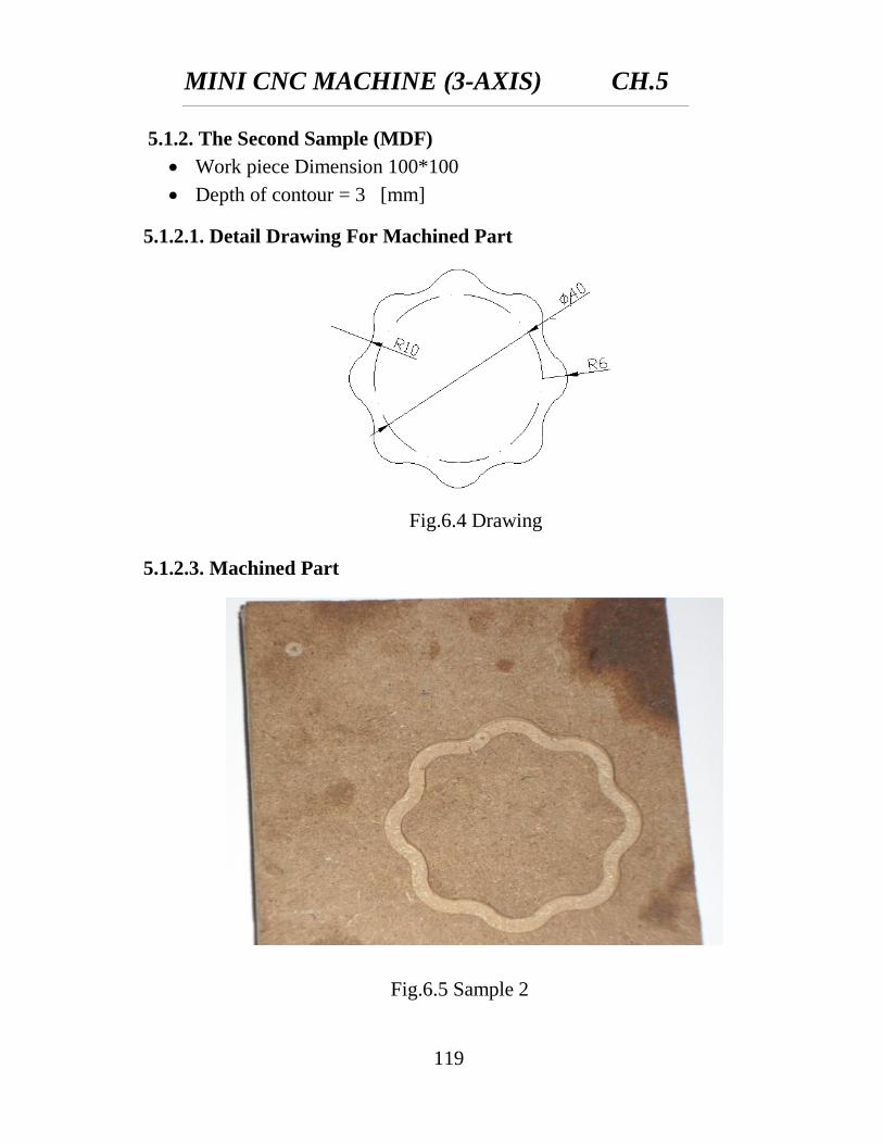
5.1.2. The Second Sample (MDF)
Work piece Dimension 100*100
Depth of contour = 3 [mm]
5.1.2.1. Detail Drawing For Machined Part
5.1.2.3. Machined Part
MINI CNC MACHINE (3-AXIS) CH.5
120
5.1.2.4. G-Codes For Machined Part
(* WinCAM by EMCO [c] 95-96, NC-program FANUC Series 0M *)
N0005 G54
N0010 G97 G94
N0015 G52 X0. Y0. Z0.
N0020 F100
N0025 S1000
N0030 F300
N0035 G49
N0040 T2 H3 G43 M6 (* Slot mill cutter 5mm *)
N0045 G0 Z3.
N0050 G0 X1.564 Y2.356
N0055 M3
N0060 G49
N0065 T2 H3 G43 M6 (* Slot mill cutter 5mm *)
(**#00002 Contour milling, ISO format **)
N0070 G94 F300 G97 S1000
N0075 G0 Z1.
N0080 G1 Z0. F300
N0085 G1 G42 H4 X5. Y5. F300
N0090 G1 X55. Y5.
MINI CNC MACHINE (3-AXIS) CH.5
121
N0095 G2 X65. Y15. I10. J0.
N0100 G1 X65. Y55.
N0105 G1 X55. Y65.
N0110 G1 X15. Y65.
N0115 G3 X5. Y55. I0. J-10.
N0120 G1 X5. Y5.
N0125 G1 G40 X1.564 Y2.356
N0130 G1 Z-1. F300
N0135 G1 G42 H4 X5. Y5. F300
N0140 G1 X55. Y5.
N0145 G2 X65. Y15. I10. J0.
N0150 G1 X65. Y55.
N0155 G1 X55. Y65.
N0160 G1 X15. Y65.
N0165 G3 X5. Y55. I0. J-10.
N0170 G1 X5. Y5.
N0175 G1 G40 X1.564 Y2.356
N0180 G1 Z-2. F300
N0185 G1 G42 H4 X5. Y5. F300
N0190 G1 X55. Y5.
N0195 G2 X65. Y15. I10. J0.
N0200 G1 X65. Y55.
MINI CNC MACHINE (3-AXIS) CH.5
122
N0205 G1 X55. Y65.
N0210 G1 X15. Y65.
N0215 G3 X5. Y55. I0. J-10.
N0220 G1 X5. Y5.
N0225 G1 G40 X1.564 Y2.356
N0230 G1 Z-3. F300
N0235 G1 G42 H4 X5. Y5. F300
N0240 G1 X55. Y5.
N0245 G2 X65. Y15. I10. J0.
N0250 G1 X65. Y55.
N0255 G1 X55. Y65.
N0260 G1 X15. Y65.
N0265 G3 X5. Y55. I0. J-10.
N0270 G1 X5. Y5.
N0275 G1 G40 X1.564 Y2.356
N0280 G1 Z-4. F300
N0285 G1 G42 H4 X5. Y5. F300
N0290 G1 X55. Y5.
N0295 G2 X65. Y15. I10. J0.
N0300 G1 X65. Y55.
N0305 G1 X55. Y65.
N0310 G1 X15. Y65.
MINI CNC MACHINE (3-AXIS) CH.5
123
N0315 G3 X5. Y55. I0. J-10.
N0320 G1 X5. Y5.
N0325 G1 G40 X1.564 Y2.356
N0330 G1 Z-5. F300
N0335 G1 G42 H4 X5. Y5. F300
N0340 G1 X55. Y5.
N0345 G2 X65. Y15. I10. J0.
N0350 G1 X65. Y55.
N0355 G1 X55. Y65.
N0360 G1 X15. Y65.
N0365 G3 X5. Y55. I0. J-10.
N0370 G1 X5. Y5.
N0375 G1 G40 X1.564 Y2.356
N0380 G0 Z2.
(**#00002 end **)
(**#00004 rectangular pocket, ISO format **)
N0385 G94 F300 G97 S1000
N0390 G0 X40. Y35. M3
N0395 G1 Z1.
N0400 G1 X30. Y35.
N0405 G1 Z0. F300
MINI CNC MACHINE (3-AXIS) CH.5
124
N0410 X50. Y35. F300
N0415 G1 X50. Y32.5
N0420 X27.5 Y32.5
N0425 X27.5 Y37.5
N0430 X52.5 Y37.5
N0435 X52.5 Y32.5
N0440 G1 X52.5 Y30.
N0445 X25. Y30.
N0450 X25. Y40.
N0455 X55. Y40.
N0460 X55. Y30.
N0465 G1 Y27.5 X55.
N0470 G1 X25. Y27.5
N0475 G2 X22.5 Y30. I0. J2.5
N0480 G1 X22.5 Y40.
N0485 G2 X25. Y42.5 I2.5 J0.
N0490 G1 X55. Y42.5
N0495 G2 X57.5 Y40. I0. J-2.5
N0500 G1 X57.5 Y30.
N0505 G2 X55. Y27.5 I-2.5 J0.
N0510 G1 X40. Y27.5
N0515 G2 X40. Y35. I0. J3.75
MINI CNC MACHINE (3-AXIS) CH.5
125
N0520 G1 X30. Y35.
N0525 G1 Z-1. F300
N0530 X50. Y35. F300
N0535 G1 X50. Y32.5
N0540 X27.5 Y32.5
N0545 X27.5 Y37.5
N0550 X52.5 Y37.5
N0555 X52.5 Y32.5
N0560 G1 X52.5 Y30.
N0565 X25. Y30.
N0570 X25. Y40.
N0575 X55. Y40.
N0580 X55. Y30.
N0585 G1 Y27.5 X55.
N0590 G1 X25. Y27.5
N0595 G2 X22.5 Y30. I0. J2.5
N0600 G1 X22.5 Y40.
N0605 G2 X25. Y42.5 I2.5 J0.
N0610 G1 X55. Y42.5
N0615 G2 X57.5 Y40. I0. J-2.5
N0620 G1 X57.5 Y30.
N0625 G2 X55. Y27.5 I-2.5 J0.
MINI CNC MACHINE (3-AXIS) CH.5
126
N0630 G1 X40. Y27.5
N0635 G2 X40. Y35. I0. J3.75
N0640 G1 X30. Y35.
N0645 G1 Z-2. F300
N0650 X50. Y35. F300
N0655 G1 X50. Y32.5
N0660 X27.5 Y32.5
N0665 X27.5 Y37.5
N0670 X52.5 Y37.5
N0675 X52.5 Y32.5
N0680 G1 X52.5 Y30.
N0685 X25. Y30.
N0690 X25. Y40.
N0695 X55. Y40.
N0700 X55. Y30.
N0705 G1 Y27.5 X55.
N0710 G1 X25. Y27.5
N0715 G2 X22.5 Y30. I0. J2.5
N0720 G1 X22.5 Y40.
N0725 G2 X25. Y42.5 I2.5 J0.
N0730 G1 X55. Y42.5
N0735 G2 X57.5 Y40. I0. J-2.5
MINI CNC MACHINE (3-AXIS) CH.5
127
N0740 G1 X57.5 Y30.
N0745 G2 X55. Y27.5 I-2.5 J0.
N0750 G1 X40. Y27.5
N0755 G2 X40. Y35. I0. J3.75
N0760 G1 X30. Y35.
N0765 G1 Z-3. F300
N0770 X50. Y35. F300
N0775 G1 X50. Y32.5
N0780 X27.5 Y32.5
N0785 X27.5 Y37.5
N0790 X52.5 Y37.5
N0795 X52.5 Y32.5
N0800 G1 X52.5 Y30.
N0805 X25. Y30.
N0810 X25. Y40.
N0815 X55. Y40.
N0820 X55. Y30.
N0825 G1 Y27.5 X55.
N0830 G1 X25. Y27.5
N0835 G2 X22.5 Y30. I0. J2.5
N0840 G1 X22.5 Y40.
N0845 G2 X25. Y42.5 I2.5 J0.
MINI CNC MACHINE (3-AXIS) CH.5
128
N0850 G1 X55. Y42.5
N0855 G2 X57.5 Y40. I0. J-2.5
N0860 G1 X57.5 Y30.
N0865 G2 X55. Y27.5 I-2.5 J0.
N0870 G1 X40. Y27.5
N0875 G2 X40. Y35. I0. J3.75
N0880 G1 X30. Y35.
N0885 G1 Z-4. F300
N0890 X50. Y35. F300
N0895 G1 X50. Y32.5
N0900 X27.5 Y32.5
N0905 X27.5 Y37.5
N0910 X52.5 Y37.5
N0915 X52.5 Y32.5
N0920 G1 X52.5 Y30.
N0925 X25. Y30.
N0930 X25. Y40.
N0935 X55. Y40.
N0940 X55. Y30.
N0945 G1 Y27.5 X55.
N0950 G1 X25. Y27.5
N0955 G2 X22.5 Y30. I0. J2.5
MINI CNC MACHINE (3-AXIS) CH.5
129
N0960 G1 X22.5 Y40.
N0965 G2 X25. Y42.5 I2.5 J0.
N0970 G1 X55. Y42.5
N0975 G2 X57.5 Y40. I0. J-2.5
N0980 G1 X57.5 Y30.
N0985 G2 X55. Y27.5 I-2.5 J0.
N0990 G1 X40. Y27.5
N0995 G2 X40. Y35. I0. J3.75
N1000 G1 X30. Y35.
N1005 G1 Z-5. F300
N1010 X50. Y35. F300
N1015 G1 X50. Y32.5
N1020 X27.5 Y32.5
N1025 X27.5 Y37.5
N1030 X52.5 Y37.5
N1035 X52.5 Y32.5
N1040 G1 X52.5 Y30.
N1045 X25. Y30.
N1050 X25. Y40.
N1055 X55. Y40.
N1060 X55. Y30.
N1065 G1 Y27.5 X55.
MINI CNC MACHINE (3-AXIS) CH.5
130
N1070 G1 X25. Y27.5
N1075 G2 X22.5 Y30. I0. J2.5
N1080 G1 X22.5 Y40.
N1085 G2 X25. Y42.5 I2.5 J0.
N1090 G1 X55. Y42.5
N1095 G2 X57.5 Y40. I0. J-2.5
N1100 G1 X57.5 Y30.
N1105 G2 X55. Y27.5 I-2.5 J0.
N1110 G1 X40. Y27.5
N1115 G2 X40. Y35. I0. J3.75
N1120 G0 X40. Y35. Z3.
(**#00004 end **)
(**#00031 Drilling cycle – chip cutting, FANUC 0M **)
N1125 G94 F300 G97 S1000
N1130 G0 Z1.
N1135 G73 X35. Y55. Z-7. R1. Q1.
N1140 G0 Z2.
N1145 G0 X20. Y55.
N1150 G0 Z1.
N1155 G73 X20. Y55. Z-7. R1. Q1.
N1160 G0 Z2.
MINI CNC MACHINE (3-AXIS) CH.5
131
N1165 G0 X50. Y55.
N1170 G0 Z1.
N1175 G73 X50. Y55. Z-7. R1. Q1.
N1180 G0 Z2.
N1185 G80
(**#00031 end **)
N1190 G0 Z3.
X16 Y16
G01 Z-1 F300
G3 Y16 X17 R0.5 F300
Y16 X15 R1
Y16 X18 R1.5
Y16 X14 R2
Y16 X19 R2.5
Y16 X13 R3
Y16 X20 R3.5
Y16 X12 R4
Y16 X20.5 R4.25
Y16 X11.5 R4.5
X20.5 Y16 R4.5
Y16.375 X20.125 R0.375
G00 Z2
MINI CNC MACHINE (3-AXIS) CH.5
132
X16 Y16
G01 Z-2 F300
G3 Y16 X17 R0.5 F300
Y16 X15 R1
Y16 X18 R1.5
Y16 X14 R2
Y16 X19 R2.5
Y16 X13 R3
Y16 X20 R3.5
Y16 X12 R4
Y16 X20.5 R4.25
Y16 X11.5 R4.5
X20.5 Y16 R4.5
Y16.375 X20.125 R0.375
G00 Z2
X16 Y16
G01 Z-3 F300
G3 Y16 X17 R0.5 F300
Y16 X15 R1
Y16 X18 R1.5
Y16 X14 R2
Y16 X19 R2.5
MINI CNC MACHINE (3-AXIS) CH.5
133
Y16 X13 R3
Y16 X20 R3.5
Y16 X12 R4
Y16 X20.5 R4.25
Y16 X11.5 R4.5
X20.5 Y16 R4.5
Y16.375 X20.125 R0.375
G00 Z2
X16 Y16
G01 Z-4 F300
G3 Y16 X17 R0.5 F300
Y16 X15 R1
Y16 X18 R1.5
Y16 X14 R2
Y16 X19 R2.5
Y16 X13 R3
Y16 X20 R3.5
Y16 X12 R4
Y16 X20.5 R4.25
Y16 X11.5 R4.5
X20.5 Y16 R4.5
Y16.375 X20.125 R0.375
MINI CNC MACHINE (3-AXIS) CH.5
134
G00 Z2
X16 Y16
G01 Z-5 F300
G3 Y16 X17 R0.5 F300
Y16 X15 R1
Y16 X18 R1.5
Y16 X14 R2
Y16 X19 R2.5
Y16 X13 R3
Y16 X20 R3.5
Y16 X12 R4
Y16 X20.5 R4.25
Y16 X11.5 R4.5
X20.5 Y16 R4.5
Y16.375 X20.125 R0.375
G00 Z30
M5 M9
M30
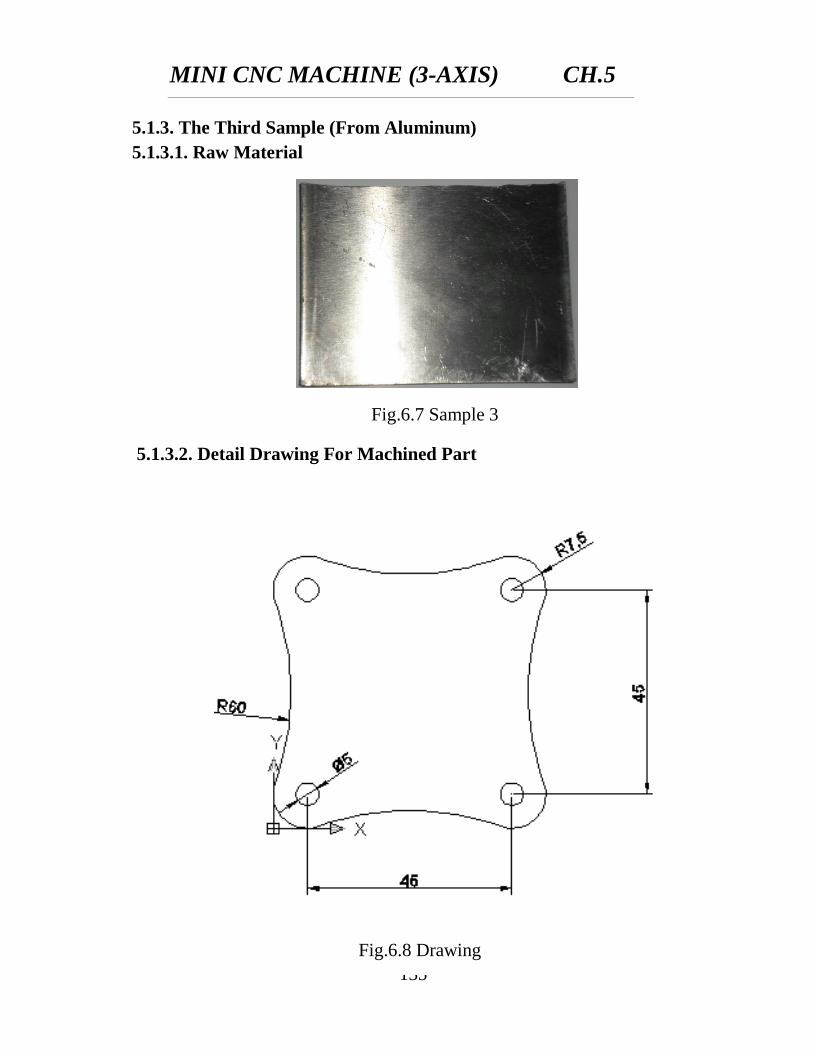
MINI CNC MACHINE (3-AXIS) CH.5
135
Fig.6.7 Sample 3
Fig.6.8 Drawing
5.1.3. The Third Sample (From Aluminum)
5.1.3.1. Raw Material
5.1.3.2. Detail Drawing For Machined Part
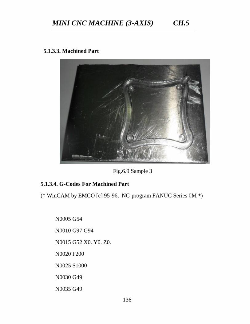
MINI CNC MACHINE (3-AXIS) CH.5
136
Fig.6.9 Sample 3
5.1.3.3. Machined Part
5.1.3.4. G-Codes For Machined Part
(* WinCAM by EMCO [c] 95-96, NC-program FANUC Series 0M *)
N0005 G54
N0010 G97 G94
N0015 G52 X0. Y0. Z0.
N0020 F200
N0025 S1000
N0030 G49
N0035 G49
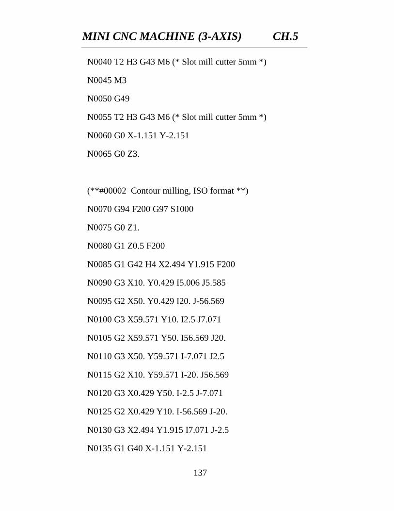
MINI CNC MACHINE (3-AXIS) CH.5
137
N0040 T2 H3 G43 M6 (* Slot mill cutter 5mm *)
N0045 M3
N0050 G49
N0055 T2 H3 G43 M6 (* Slot mill cutter 5mm *)
N0060 G0 X-1.151 Y-2.151
N0065 G0 Z3.
(**#00002 Contour milling, ISO format **)
N0070 G94 F200 G97 S1000
N0075 G0 Z1.
N0080 G1 Z0.5 F200
N0085 G1 G42 H4 X2.494 Y1.915 F200
N0090 G3 X10. Y0.429 I5.006 J5.585
N0095 G2 X50. Y0.429 I20. J-56.569
N0100 G3 X59.571 Y10. I2.5 J7.071
N0105 G2 X59.571 Y50. I56.569 J20.
N0110 G3 X50. Y59.571 I-7.071 J2.5
N0115 G2 X10. Y59.571 I-20. J56.569
N0120 G3 X0.429 Y50. I-2.5 J-7.071
N0125 G2 X0.429 Y10. I-56.569 J-20.
N0130 G3 X2.494 Y1.915 I7.071 J-2.5
N0135 G1 G40 X-1.151 Y-2.151
MINI CNC MACHINE (3-AXIS) CH.5
138
N0140 G1 Z0. F200
N0145 G1 G42 H4 X2.494 Y1.915 F200
N0150 G3 X10. Y0.429 I5.006 J5.585
N0155 G2 X50. Y0.429 I20. J-56.569
N0160 G3 X59.571 Y10. I2.5 J7.071
N0165 G2 X59.571 Y50. I56.569 J20.
N0170 G3 X50. Y59.571 I-7.071 J2.5
N0175 G2 X10. Y59.571 I-20. J56.569
N0180 G3 X0.429 Y50. I-2.5 J-7.071
N0185 G2 X0.429 Y10. I-56.569 J-20.
N0190 G3 X2.494 Y1.915 I7.071 J-2.5
N0195 G1 G40 X-1.151 Y-2.151
N0200 G1 Z-0.5 F200
N0205 G1 G42 H4 X2.494 Y1.915 F200
N0210 G3 X10. Y0.429 I5.006 J5.585
N0215 G2 X50. Y0.429 I20. J-56.569
N0220 G3 X59.571 Y10. I2.5 J7.071
N0225 G2 X59.571 Y50. I56.569 J20.
N0230 G3 X50. Y59.571 I-7.071 J2.5
N0235 G2 X10. Y59.571 I-20. J56.569
N0240 G3 X0.429 Y50. I-2.5 J-7.071
N0245 G2 X0.429 Y10. I-56.569 J-20.
MINI CNC MACHINE (3-AXIS) CH.5
139
N0250 G3 X2.494 Y1.915 I7.071 J-2.5
N0255 G1 G40 X-1.151 Y-2.151
N0260 G1 Z-1. F200
N0265 G1 G42 H4 X2.494 Y1.915 F200
N0270 G3 X10. Y0.429 I5.006 J5.585
N0275 G2 X50. Y0.429 I20. J-56.569
N0280 G3 X59.571 Y10. I2.5 J7.071
N0285 G2 X59.571 Y50. I56.569 J20.
N0290 G3 X50. Y59.571 I-7.071 J2.5
N0295 G2 X10. Y59.571 I-20. J56.569
N0300 G3 X0.429 Y50. I-2.5 J-7.071
N0305 G2 X0.429 Y10. I-56.569 J-20.
N0310 G3 X2.494 Y1.915 I7.071 J-2.5
N0315 G1 G40 X-1.151 Y-2.151
N0320 G1 Z-1.5 F200
N0325 G1 G42 H4 X2.494 Y1.915 F200
N0330 G3 X10. Y0.429 I5.006 J5.585
N0335 G2 X50. Y0.429 I20. J-56.569
N0340 G3 X59.571 Y10. I2.5 J7.071
N0345 G2 X59.571 Y50. I56.569 J20.
N0350 G3 X50. Y59.571 I-7.071 J2.5
N0355 G2 X10. Y59.571 I-20. J56.569
MINI CNC MACHINE (3-AXIS) CH.5
140
N0360 G3 X0.429 Y50. I-2.5 J-7.071
N0365 G2 X0.429 Y10. I-56.569 J-20.
N0370 G3 X2.494 Y1.915 I7.071 J-2.5
N0375 G1 G40 X-1.151 Y-2.151
N0380 G1 Z-2. F200
N0385 G1 G42 H4 X2.494 Y1.915 F200
N0390 G3 X10. Y0.429 I5.006 J5.585
N0395 G2 X50. Y0.429 I20. J-56.569
N0400 G3 X59.571 Y10. I2.5 J7.071
N0405 G2 X59.571 Y50. I56.569 J20.
N0410 G3 X50. Y59.571 I-7.071 J2.5
N0415 G2 X10. Y59.571 I-20. J56.569
N0420 G3 X0.429 Y50. I-2.5 J-7.071
N0425 G2 X0.429 Y10. I-56.569 J-20.
N0430 G3 X2.494 Y1.915 I7.071 J-2.5
N0435 G1 G40 X-1.151 Y-2.151
N0440 G1 Z-2.5 F200
N0445 G1 G42 H4 X2.494 Y1.915 F200
N0450 G3 X10. Y0.429 I5.006 J5.585
N0455 G2 X50. Y0.429 I20. J-56.569
N0460 G3 X59.571 Y10. I2.5 J7.071
N0465 G2 X59.571 Y50. I56.569 J20.
MINI CNC MACHINE (3-AXIS) CH.5
141
N0470 G3 X50. Y59.571 I-7.071 J2.5
N0475 G2 X10. Y59.571 I-20. J56.569
N0480 G3 X0.429 Y50. I-2.5 J-7.071
N0485 G2 X0.429 Y10. I-56.569 J-20.
N0490 G3 X2.494 Y1.915 I7.071 J-2.5
N0495 G1 G40 X-1.151 Y-2.151
N0500 G1 Z-3. F200
N0505 G1 G42 H4 X2.494 Y1.915 F200
N0510 G3 X10. Y0.429 I5.006 J5.585
N0515 G2 X50. Y0.429 I20. J-56.569
N0520 G3 X59.571 Y10. I2.5 J7.071
N0525 G2 X59.571 Y50. I56.569 J20.
N0530 G3 X50. Y59.571 I-7.071 J2.5
N0535 G2 X10. Y59.571 I-20. J56.569
N0540 G3 X0.429 Y50. I-2.5 J-7.071
N0545 G2 X0.429 Y10. I-56.569 J-20.
N0550 G3 X2.494 Y1.915 I7.071 J-2.5
N0555 G1 G40 X-1.151 Y-2.151
N0560 G0 Z2.
(**#00002 end **)
(**#00031 Drilling cycle - chip cutting, FANUC 0M **)
MINI CNC MACHINE (3-AXIS) CH.5
142
N0565 G94 F200 G97 S1000
N0570 G0 Z1.
N0575 G73 X7.5 Y7.5 Z-5. R1. Q0.5
N0580 G0 Z2.
N0585 G0 X52.5 Y7.5
N0590 G0 Z1.
N0595 G73 X52.5 Y7.5 Z-5. R1. Q0.5
N0600 G0 Z2.
N0605 G0 X52.5 Y52.5
N0610 G0 Z1.
N0615 G73 X52.5 Y52.5 Z-5. R1. Q0.5
N0620 G0 Z2.
N0625 G0 X7.5 Y52.5
N0630 G0 Z1.
N0635 G73 X7.5 Y52.5 Z-5. R1. Q0.5
N0640 G0 Z30.
N0645 G80
m5
(**#00031 end **)
N0650 M30
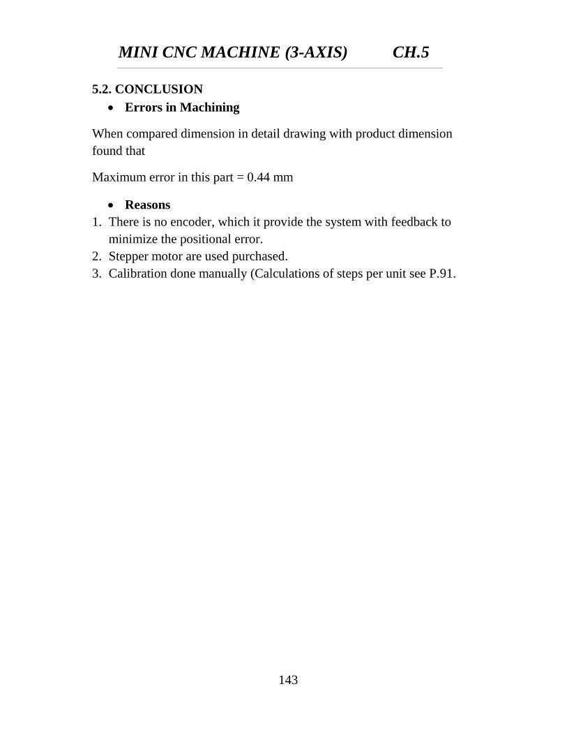
MINI CNC MACHINE (3-AXIS) CH.5
143
5.2. CONCLUSION
Errors in Machining
When compared dimension in detail drawing with product dimension
found that
Maximum error in this part = 0.44 mm
Reasons
1. There is no encoder, which it provide the system with feedback to
minimize the positional error.
2. Stepper motor are used purchased.
3. Calibration done manually (Calculations of steps per unit see P.91.

CHAPTER (6)
FUTURE WORK
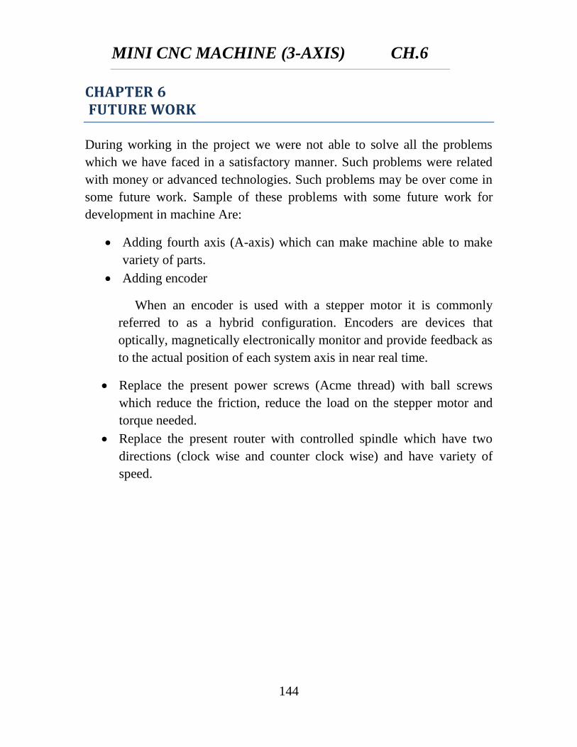
MINI CNC MACHINE (3-AXIS) CH.6
144
CHAPTER 6 FUTURE WORK
During working in the project we were not able to solve all the problems
which we have faced in a satisfactory manner. Such problems were related
with money or advanced technologies. Such problems may be over come in
some future work. Sample of these problems with some future work for
development in machine Are:
Adding fourth axis (A-axis) which can make machine able to make
variety of parts.
Adding encoder
When an encoder is used with a stepper motor it is commonly
referred to as a hybrid configuration. Encoders are devices that
optically, magnetically electronically monitor and provide feedback as
to the actual position of each system axis in near real time.
Replace the present power screws (Acme thread) with ball screws
which reduce the friction, reduce the load on the stepper motor and
torque needed.
Replace the present router with controlled spindle which have two
directions (clock wise and counter clock wise) and have variety of
speed.
MINI CNC MACHINE (3-AXIS)
127
References
1. Koren, J. (1983) Computer Control of Manufacturing Systems, 1st
Edition, McGraw-Hill, Tokyo, 40(2):603–614.
2. McMahon, C. and Browne, J. (1998) CADCAM—Principles,
Practice and Manufacturing Management, 2nd
Edition, Addison-
Wesley, Reading, MA, 47(2):525–540
3. Diamond, W.J. (2001). Practical experiment design for engineers
and scientists. Third edition. John Wiley & Sons. New York.
4. MCP2551 High-Speed CAN Transceiver Data Sheet (2003).
Microchip Technology, Document No.DS21667D.
5. http://tamcam.tamu.edu/courses/inen416/Handouts/AGV%2CNC0Pr
esentation.html
6. http://tamcam.tamu.edu/Courses/Micro%20Controller/books/Contro
ller/KCam,%20EMC2,%20Mach3,%20TurboCNC,and%20other%2
0CNC%20related%20software%20links.htm
7. http://www.stadna.com/forums/index.php?mode=t&t=8279.html
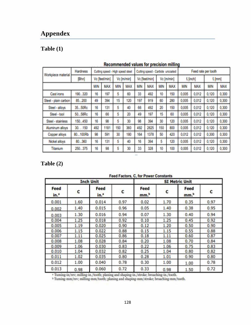
128
Appendex
Table (1)
Table (2)
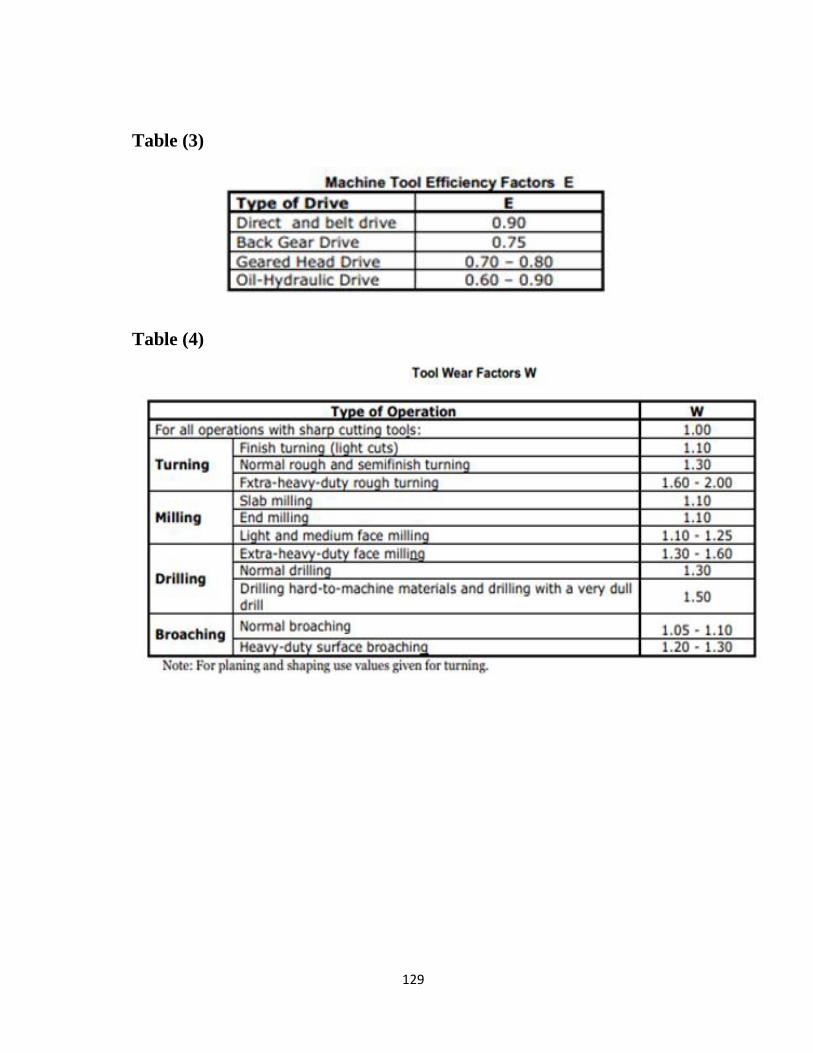
129
Table (3)
Table (4)
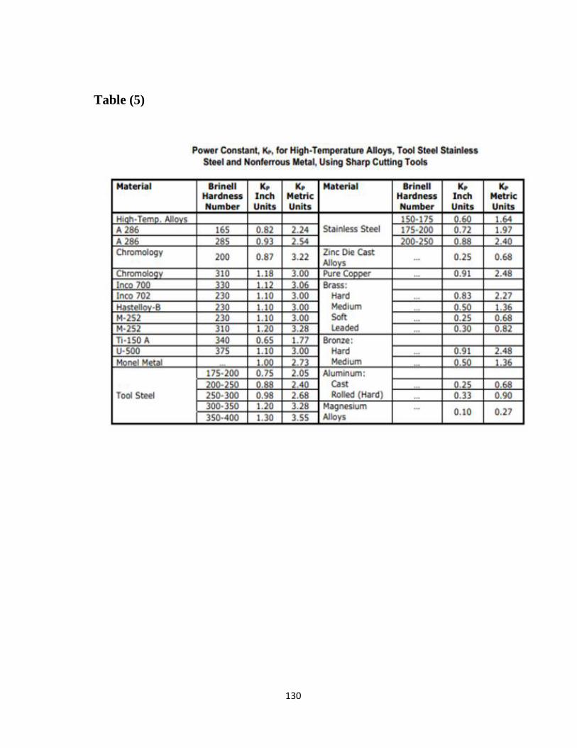
130
Table (5)