Embed Size (px)
Citation preview

G.H. PATEL COLLEGE OF ENGINEERING AND TECHNOLOGY
COMPUTER ORGANIZATION
SHIFT MICROOPERATIONS
PRESENTED BY:DARSHIT METALIYA
( 130110107020 )CHIRAG SONAGRA
( 130110107055 )
Shift Microoperations
• Shift microoperations are used for serial transfer of data. They are also used in conjunction with arithmetic, logic, and other data-processing operations.
• The contents of a register can be shifted to the left or the right. At the same time that the bits are shifted, the first flip-flop receives its binary information from the serial input.
• There are three type of shifts :
1. Logical Shift
2. Circular Shift
3. Arithmetic Shift
1. Logical Shift
• A logical shift is one that transfers 0 through the serial input.
• We will adopt the symbol shl and shr for logical shift-left and shift-right microoperations.
• For example :• R1 shl R1
• R2 shr R2
• These are two microoperations that specify a 1-bit shift to the left of the
content of register R1 and 1-bit shift to the right of the content of register R2.
• The register symbol must be same on both sides of arrow.
• The bit transferred to the end position though the serial input is assumed to be 0 during a logical shift
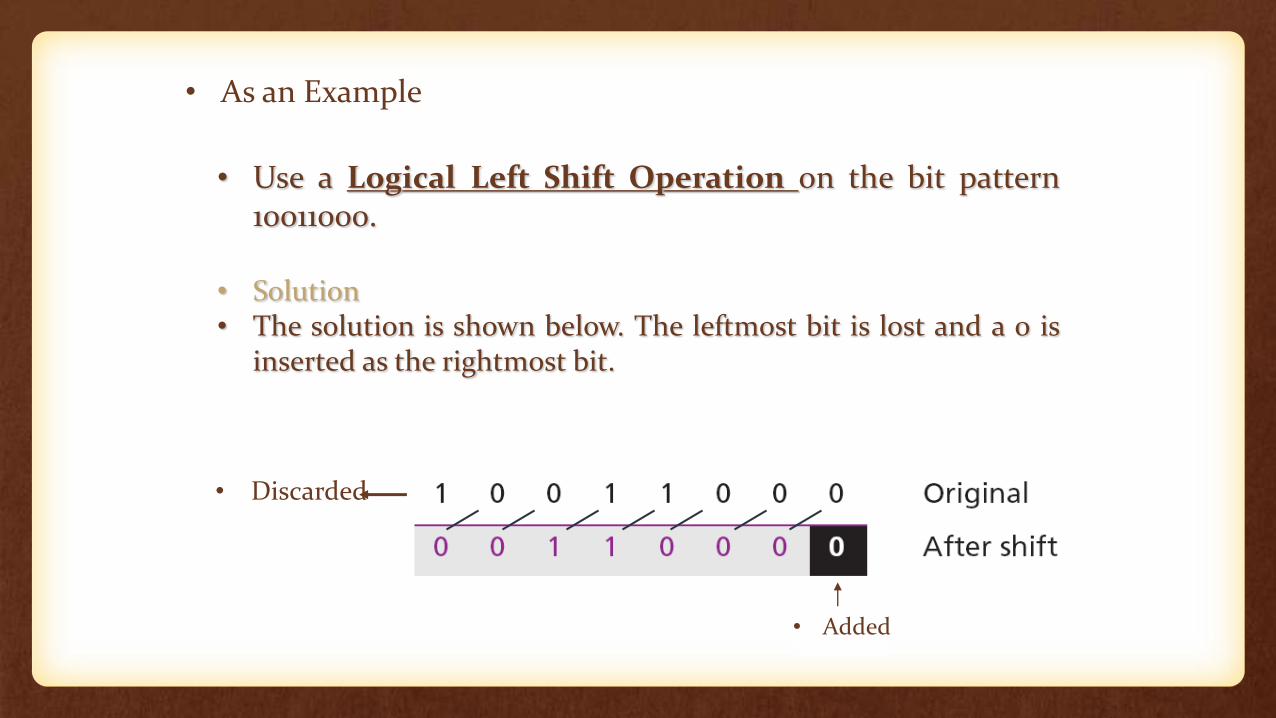
• Use a Logical Left Shift Operation on the bit pattern10011000.
• Solution• The solution is shown below. The leftmost bit is lost and a 0 is
inserted as the rightmost bit.
• Discarded
• Added
• As an Example
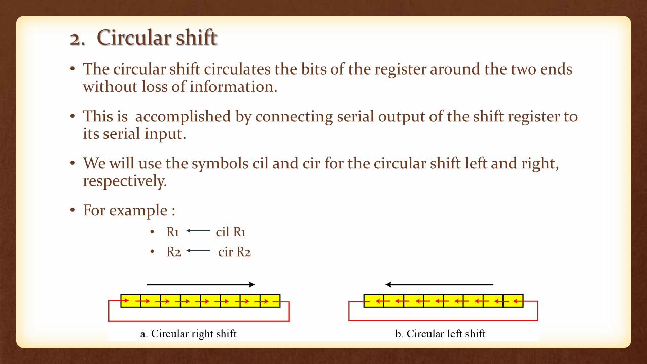
2. Circular shift
• The circular shift circulates the bits of the register around the two ends without loss of information.
• This is accomplished by connecting serial output of the shift register to its serial input.
• We will use the symbols cil and cir for the circular shift left and right, respectively.
• For example :
• R1 cil R1
• R2 cir R2
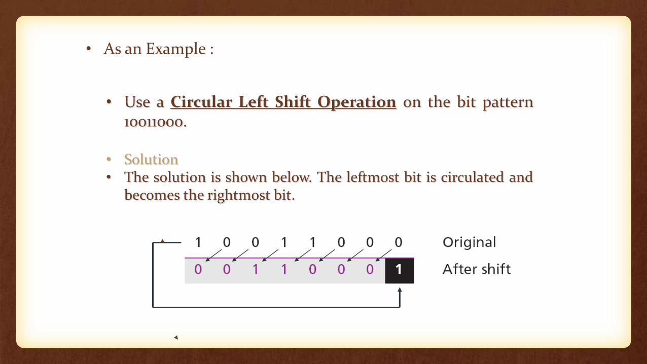
• Use a Circular Left Shift Operation on the bit pattern10011000.
• Solution• The solution is shown below. The leftmost bit is circulated and
becomes the rightmost bit.
• As an Example :
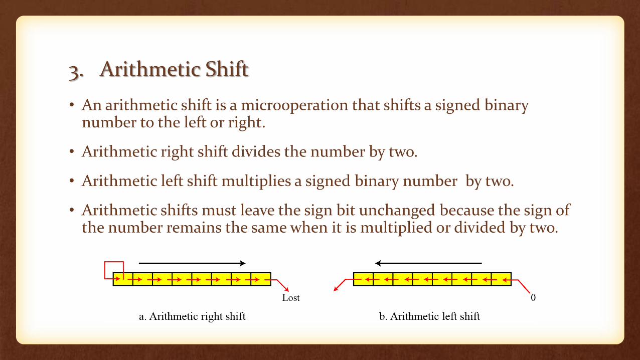
3. Arithmetic Shift
• An arithmetic shift is a microoperation that shifts a signed binary number to the left or right.
• Arithmetic right shift divides the number by two.
• Arithmetic left shift multiplies a signed binary number by two.
• Arithmetic shifts must leave the sign bit unchanged because the sign of the number remains the same when it is multiplied or divided by two.
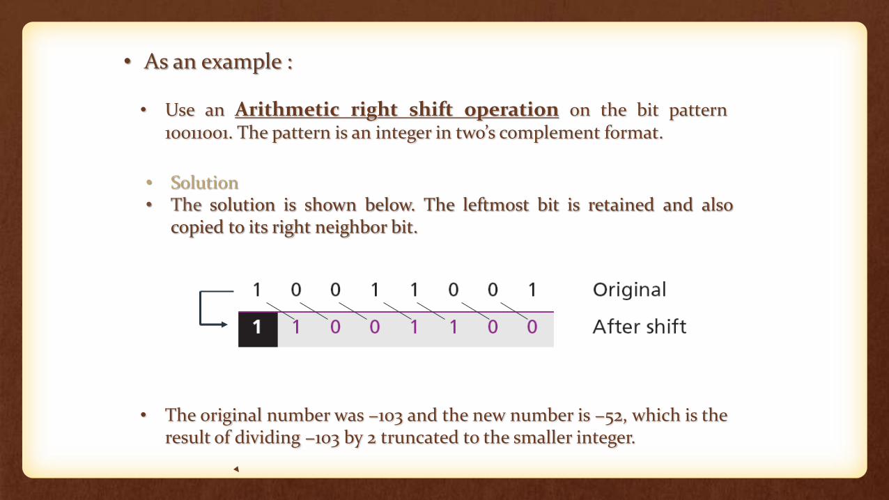
• Use an Arithmetic right shift operation on the bit pattern10011001. The pattern is an integer in two’s complement format.
• Solution• The solution is shown below. The leftmost bit is retained and also
copied to its right neighbor bit.
• The original number was −103 and the new number is −52, which is theresult of dividing −103 by 2 truncated to the smaller integer.
• As an example :
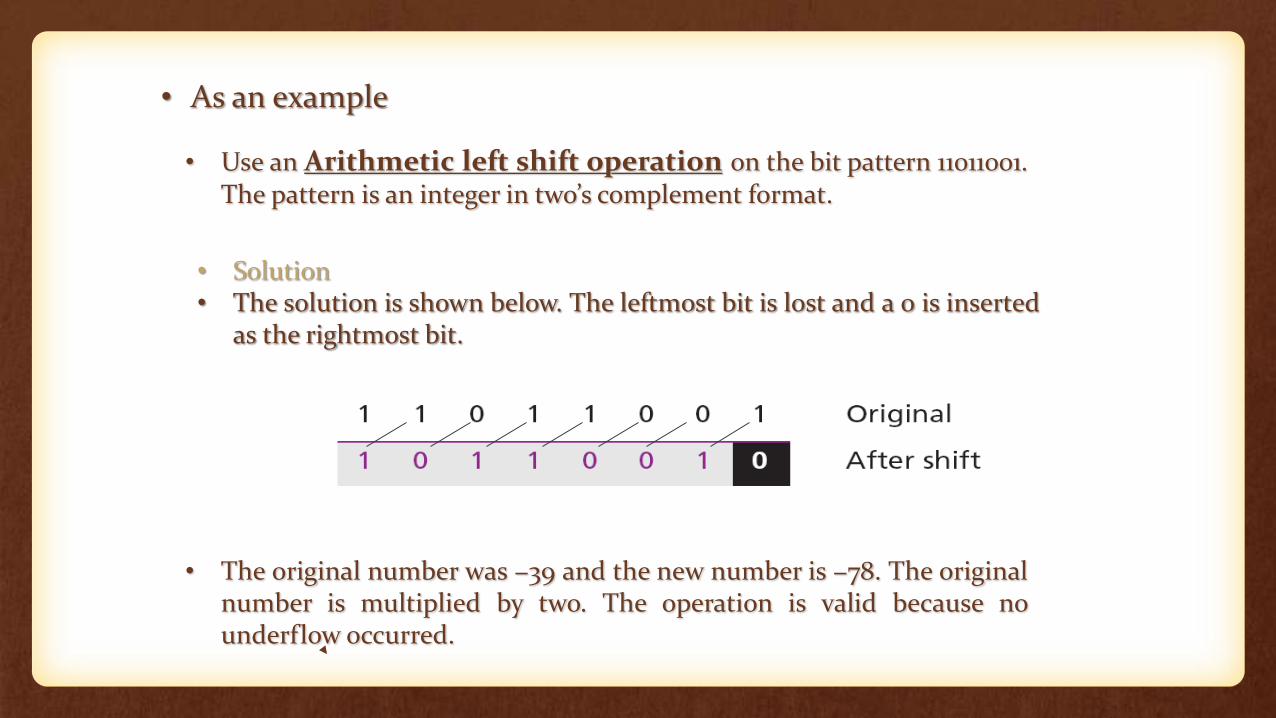
• Use an Arithmetic left shift operation on the bit pattern 11011001.The pattern is an integer in two’s complement format.
• Solution• The solution is shown below. The leftmost bit is lost and a 0 is inserted
as the rightmost bit.
• The original number was −39 and the new number is −78. The originalnumber is multiplied by two. The operation is valid because nounderflow occurred.
• As an example
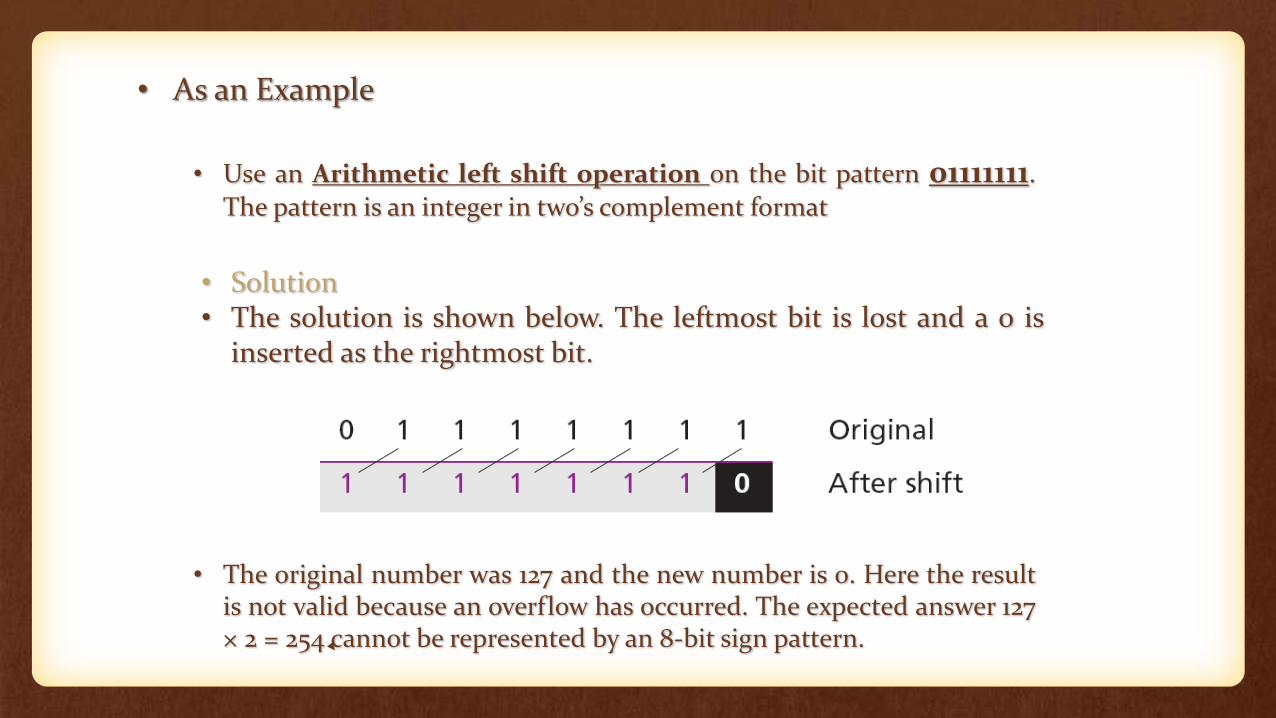
• Use an Arithmetic left shift operation on the bit pattern 01111111.
The pattern is an integer in two’s complement format
• Solution• The solution is shown below. The leftmost bit is lost and a 0 is
inserted as the rightmost bit.
• The original number was 127 and the new number is 0. Here the resultis not valid because an overflow has occurred. The expected answer 127× 2 = 254 cannot be represented by an 8-bit sign pattern.
• As an Example
• Hardware Implementation
S
01
H0MUX
S
01
H1MUX
S
01
H2MUX
S
01
H3MUX
Select0 for shift right (down)
1 for shift left (up)Serialinput (IR)
A0
A1
A2
A3
Serial
input (IL)
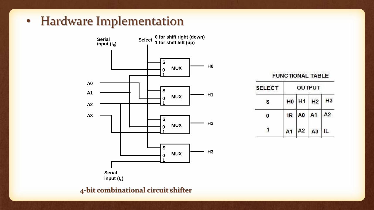
4-bit combinational circuit shifter
• A combinational circuit shifter can be constructed with multiplexers as shown in Fig.
• The 4-bit shifter has four data inputs, A0 through A3, and four data outputs, H0 through H3.
• There are two serial inputs , one for shift left(IL) and the other for shift right(IR).
• When the selection input S=0, the input data are shifted right (down in the diagram). When S=1, the input data are shifted left (up in the diagram).
• The function table in Fig. shows which inputs goes to each output after shift.
• A shifter with n data inputs and outputs requires n multiplexers. The two serial inputs can be controlled by another multiplexer to provide the three possible types of shifts.

???

THANK YOU