Embed Size (px)
Citation preview
Materials 2014, 7, 5268-5304; doi:10.3390/ma7075268
materials ISSN 1996-1944
www.mdpi.com/journal/materials
Review
Effect of Secondary Phase Precipitation on the Corrosion Behavior of Duplex Stainless Steels
Kai Wang Chan and Sie Chin Tjong *
Department of Physics and Materials Science, City University of Hong Kong, Tat Chee Avenue,
Kowloon, Hong Kong, China; E-Mail: [email protected]
* Author to whom correspondence should be addressed; E-Mail: [email protected];
Tel.: +852-3442-7702.
Received: 17 April 2014; in revised form: 2 July 2014 / Accepted: 11 July 2014 /
Published: 22 July 2014
Abstract: Duplex stainless steels (DSSs) with austenitic and ferritic phases have been
increasingly used for many industrial applications due to their good mechanical properties
and corrosion resistance in acidic, caustic and marine environments. However, DSSs
are susceptible to intergranular, pitting and stress corrosion in corrosive environments due
to the formation of secondary phases. Such phases are induced in DSSs during the
fabrication, improper heat treatment, welding process and prolonged exposure to high
temperatures during their service lives. These include the precipitation of sigma and chi
phases at 700–900 °C and spinodal decomposition of ferritic grains into Cr-rich and
Cr-poor phases at 350–550 °C, respectively. This article gives the state-of the-art review
on the microstructural evolution of secondary phase formation and their effects on the
corrosion behavior of DSSs.
Keywords: duplex stainless steel; sigma phase; spinodal decomposition; nitride; intergranular
corrosion; critical pitting temperature; stress corrosion; welding
1. Introduction
Stainless steels are an important class of engineering alloys that have found widespread applications
from domestic home appliances to structural components in aerospace industries. In particular, duplex
stainless steels (DSSs) with austenitic (fcc) and ferritic (bcc) grains possess beneficial combinations of
these two phases [1–6]. DSSs exhibit greater toughness and better weldability than ferritics. Compared
OPEN ACCESS
Materials 2014, 7 5269
with austenitic grades, DSSs have higher resistance to pitting and stress corrosion cracking. Accordingly,
they are widely used in various chemical, petrochemical, food, power, transportation, pulp and paper
industries as well as oil refineries.
The high corrosion resistance of DSSs derives from their high Cr content in combination with
substantial additions of Mo, Ni and N. Chromium contributes to the corrosion resistance of stainless
steels by forming protective Cr-oxide/hydoxide in the passive film [7]. The presence of Mo within the
passive film of DSSs and synergistic effect between the oxides/hydroxides of Cr and Mo improve the
film stability against pitting corrosion [8]. As recognized, Cr, Mo and Si alloying elements stabilize
ferritic phase, while Ni and N are the γ-phase stabilizers [9]. N is an interstitial solid solution
strengthener that increases the strength of DSSs [10]. It also increases the pitting resistance of DSSs
and concentrates mainly at the metal-passive film interface. Manganese stabilizes the austenite, but it
is not effective as Ni in stabilizing the γ-phase. Therefore, N is added with Mn simultaneously to DSSs
to balance a decrease in the Ni content [11–15]. Cu addition is beneficial for enhancing the resistance
of DSSs in non-oxidizing solutions. Its content is limited to ~2.5% since higher content reduces hot
ductility [2]. The ferrite/austenite ratio in DSSs must be close to 50:50 by adding appropriate alloying
elements for achieving desired microstructures and mechanical properties. A wide range of DSSs with
different alloying elements has been developed and commercialized. The most widely used DSS is the
standard 2205 grade. To further improve corrosion resistance, DSSs with higher Cr content such as
25% Cr grade (UNS S32550 and S32950), superduplex (UNS S32750), and hyperduplex (S32707 and
S33207) are produced [16,17]. Superduplex (UNS S32750) is a highly alloyed grade having good
chloride resistance and high mechanical strength. Recently, hyperduplex grade steels with higher
amounts of alloying elements and N content up to 0.5 wt% are particularly suitable for use in severe
marine solutions. The high Cr, Mo and N contents render them with excellent corrosion resistance,
high strength and good formability for extrusion into seamless tubes for subsea umbilical applications [17].
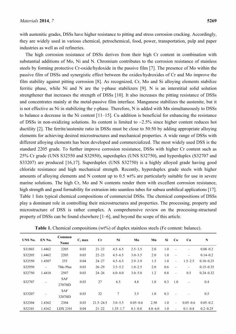
Table 1 lists typical chemical compositions of commercial DSSs. The chemical compositions of DSSs
play a dominant role in controlling their microstructures and properties. The processing, property and
microstructure of DSS is rather complex. A comprehensive review on the processing-structural
property of DSSs can be found elsewhere [1–6], and beyond the scope of this article.
Table 1. Chemical compositions (wt%) of duplex stainless steels (Fe content: balance).
UNS No. EN No. Common
Name C, max Cr Ni Mo Mn Si Co Cu N
S31803 1.4462 2205 0.03 21–23 4.5–6.5 2.5–3.5 2.0 1.0 – – 0.08–0.2
S32205 1.4462 2205 0.03 22–23 4.5–6.5 3.0–3.5 2.0 1.0 – – 0.14–0.2
S32550 1.4507 255 0.04 24–27 4.5–6.5 2.9–3.9 1.5 1.0 – 1.5–2.5 0.10–0.25
S32950 – 7Mo Plus 0.03 26–29 3.5–5.2 1.0–2.5 2.0 0.6 – – 0.15–0.35
S32750 1.4410 2507 0.03 24–26 6.0–8.0 3.0–5.0 1.2 0.8 – 0.5 0.24–0.32
S32707 – SAF
2707HD 0.03 27 6.5 4.8 1.0 0.3 1.0 – 0.4
S33207 – SAF
3207HD 0.03 32 7 3.5 1.0 0.3 – – 0.5
S32304 1.4362 2304 0.03 21.5–24.5 3.0–5.5 0.05–0.6 2.50 1.0 – 0.05–0.6 0.05–0.2
S32101 1.4162 LDX 2101 0.04 21–22 1.35–1.7 0.1–0.8 4.0–6.0 1.0 – 0.1–0.8 0.2–0.25
Materials 2014, 7 5270
DSSs undergo microstructural changes during heat treatment, welding process and prolonged
engineering service at high temperatures. Several undesirable precipitates such as carbides, nitrides,
intermetallic phases (sigma and chi), and Cr-rich α’ phase can induce in DSSs upon exposure to
950–400 °C temperature range [1–6,16]. Sigma phase is preferentially nucleated at the ferrite-austenite
and ferrite-ferrite boundaries of DSSs at 700–950 °C [18,19]. Is formation depletes Cr and Mo at these
regions, resulting in intergranular corrosion (IGC) and pitting corrosion [18–23]. Chromium carbides
(Cr23C6) may form at the DSSs’ grain boundaries upon heating at ~550–750 °C. The risk of Cr23C6
precipitation in commercial DSSs is rather small since their C content is kept at a maximum value of
0.03 wt%. At lower temperature regime of 350–550 °C, the α- phase transforms into Cr-rich (α’)
and Cr-poor (α) phases via a spinodal decomposition [24]. The Cr-rich α’ precipitates reduces the
impact toughness and corrosion resistance of DSSs significantly [25,26]. The spinodal decomposition
is more pronounced at 475 °C, commonly referred to as the 475 °C embrittlement. This article focuses
exclusively on the deleterious effect of these undesired phases on the corrosion resistance of DSSs.
2. Secondary Phase Formation
2.1. Sigma, Chi and Nitride Phases
The literatures from 1983 to 2009 have reported the structures, morphologies and techniques for
detecting intermetallic compounds and spinodal decomposed phases in details [1–6], with particular
emphasis on the formation, characteristics and morphology of such precipitates and their adverse
effects on the mechanical properties of DSSs [5,6]. The readers may refer to the literatures for further
details [1–6]. Thus, we briefly presented such topics herein. Sigma phase exhibits tetragonal structure
containing about 30% Cr, 4% Ni and 7% Mo [2]. The austenitic phase of DSSs exhibits closed-packed,
face centered cubic structure. The precipitation reaction of σ-phase in the γ-phase is sluggish due to a
slow diffusivity of solute atoms in this phase. As just mentioned, Cr, Mo and Si are ferrite formers that
promote the σ-phase precipitation in DSSs aged at 700–950 °C. The diffusion rates of these elements
in ferrite are much faster than in the austenite. As the precipitation continues, Cr and Mo diffuse to the
σ-phase, leading to a depletion of these elements in ferrite, especially Mo content. Therefore, Mo from
the inner region of ferrite diffuses to the σ-phase. Sigma phase nucleates preferentially at the α- and
α-γ boundaries, then grows into the adjacent ferritic grains. Mo is the main element controlling
secondary phase precipitation. It is noted that the χ-phase (bcc; Fe36Cr12Mo10) containing about 25% Cr,
3% Ni and 14% Mo also forms between 700 and 900 °C, but in much smaller amounts [2]. The
χ-phase contains even more Mo than the σ-phase, and nucleates in the early stage of aging due to the
low interfacial energy of highly coherent χ/α interface with a characteristic of cubic-to-cubic
orientation relationship [2,27]. Generally, ferrite can transform to secondary phases via the following
eutectoid reaction,
α (ferrite) → σ + χ + Cr2N (1)
Although the χ-phase forms earlier than the σ-phase, it transforms into the σ-phase after prolonged
aging [27,28]. The growth of σ-and χ-phase precipitates further depletes Cr and Mo in ferrite.
Consequently, ferrite phase with high Ni content becomes unstable and eventually transforms into
secondary austenite (γ2). DSSs generally contain N up to 0.5 wt% for enhancing mechanical strength
Materials 2014, 7 5271
and pitting corrosion resistance (Table 1) Chromium nitride (Cr2N; hexagonal structure) can form in
DSSs with higher N content, and in the fusion zone of DSSs during welding.
Time-temperature transformation (TTT) diagrams obtained from isothermal heat treatment followed
by quenching, can be used to investigate the susceptibility of DSSs to the σ-phase formation. This
diagram indicates the time for a phase to decompose into other phases isothermally at different
temperatures. In contrast, continuous-cooling transformation (CCT) diagram displays the time for a
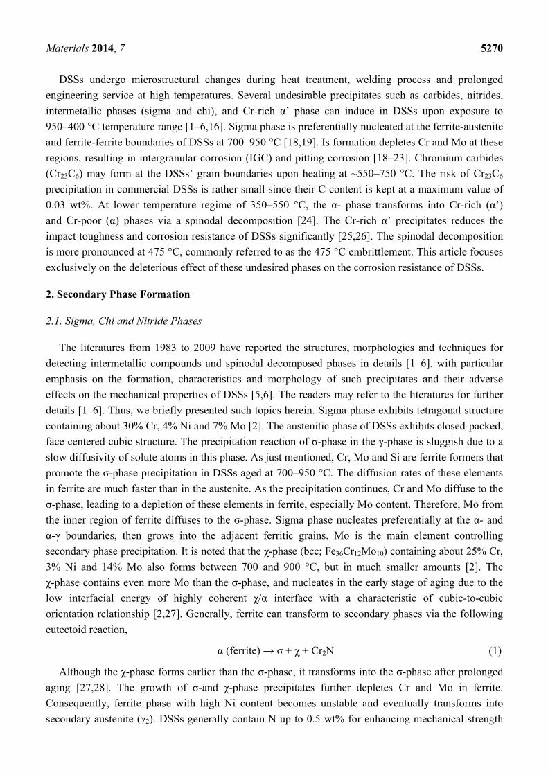
phase to decompose into other phases continuously at different rates of cooling. Figure 1 shows typical
TTT and CCT curves for DSS 2205 with different σ-phase contents [29]. Isothermal heat treatment at
865 °C for 134 s precipitates 1% σ-phase. This implies that the aging time at 865 °C should not exceed
134 s. The 1% σ content can be obtained at room temperature after continuous cooling with 0.23 °C/s
at 940 °C and above. To avoid the formation of more than 1% σ, the cooling rate from the solution
annealing temperature must exceed 0.23 °C/s.
Figure 1. Time-temperature transformation (TTT) and continuous-cooling transformation
(CCT) curves of duplex stainless steel (DSS) 2205 showing transformation of 1, 3, 5 and
10% σ-phase. The cooling rates are 0.23, 0.11, 0.07 and 0.04 °C/s, Reprinted with
permission from [30]. Copyright 2007 Elsevier.
Materials examination techniques are very important for the detection and identification of
deleterious precipitates in DSSs. The structures of secondary phases can be determined with the X-ray
diffraction (XRD), electron diffraction and electron backscattered diffraction (EBSD) techniques. The
microstructural features of these phases in DSSs can be obtained using optical microscopy, scanning
electron microscopy (SEM) and transmission electron microscopy (TEM) [27,30,31]. Combining with
electron diffraction, TEM permits the examination of structural and morphological of localized region
in a thin foil specimen at high magnifications. TEM is useful for characterizing the structures of fine
precipitates such as σ- and χ- phases, especially in small amounts. However, the preparation of TEM
thin film specimens is tedious, time consuming and difficult. EBSD involves the analysis of Kikuchi
line bands formed by diffusively scattered electrons of individual crystals of a specimen. It provides
easier identification of the crystal structure, grain orientation of unknown phases without the need for
Materials 2014, 7 5272
thin film sample preparation and enables observation of larger areas of a specimen. Recently, EBSD
has been found to be very effective for detecting σ-phase formed in DSSs [32].
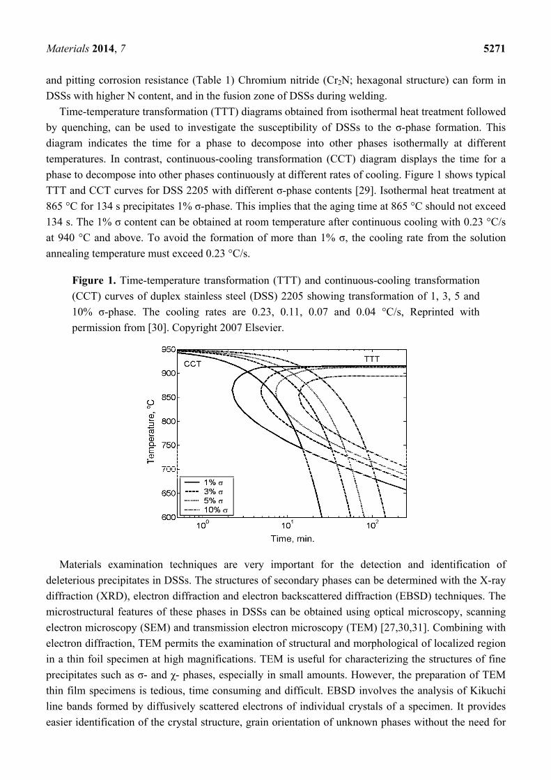
Figure 2 shows the XRD patterns of solution-annealed and aged DSS 2205 specimens. Solution
annealing DSSs at high temperatures followed by water quenching is very effective to eliminate the
σ-phase formation. The σ-phase peaks are observed in DSSs after aging at 800 and 900 °C. The typical
solution temperature range is 1050–1080 °C. Above 1080 °C, e.g., at 1200 °C, unfavorable high α
(62 vol%) and low γ-phase (38 vol%) content is produced [33]. The cooling rate from solution
annealing temperature must exceed 0.23 °C/s to avoid the σ-phase formation as mentioned previously.
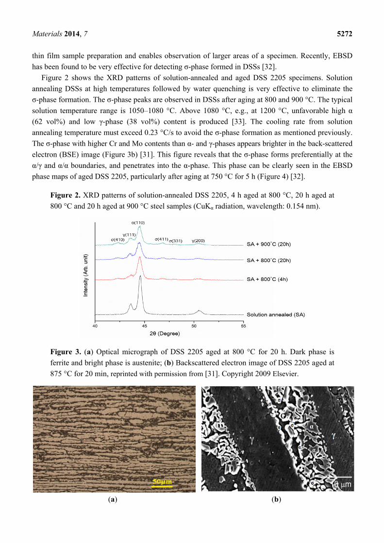
The σ-phase with higher Cr and Mo contents than α- and γ-phases appears brighter in the back-scattered
electron (BSE) image (Figure 3b) [31]. This figure reveals that the σ-phase forms preferentially at the
α/γ and α/α boundaries, and penetrates into the α-phase. This phase can be clearly seen in the EBSD
phase maps of aged DSS 2205, particularly after aging at 750 °C for 5 h (Figure 4) [32].
Figure 2. XRD patterns of solution-annealed DSS 2205, 4 h aged at 800 °C, 20 h aged at
800 °C and 20 h aged at 900 °C steel samples (CuKα radiation, wavelength: 0.154 nm).
Figure 3. (a) Optical micrograph of DSS 2205 aged at 800 °C for 20 h. Dark phase is
ferrite and bright phase is austenite; (b) Backscattered electron image of DSS 2205 aged at
875 °C for 20 min, reprinted with permission from [31]. Copyright 2009 Elsevier.
(a) (b)
Materials 2014, 7 5273
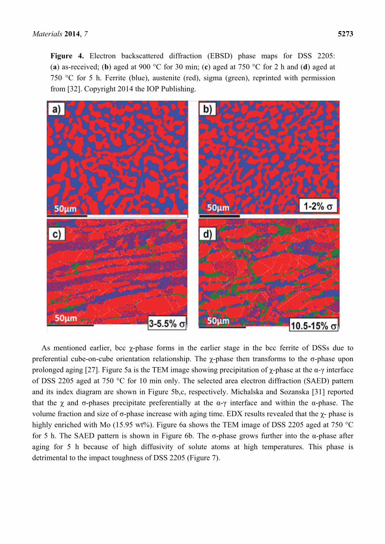
Figure 4. Electron backscattered diffraction (EBSD) phase maps for DSS 2205:
(a) as-received; (b) aged at 900 °C for 30 min; (c) aged at 750 °C for 2 h and (d) aged at
750 °C for 5 h. Ferrite (blue), austenite (red), sigma (green), reprinted with permission
from [32]. Copyright 2014 the IOP Publishing.
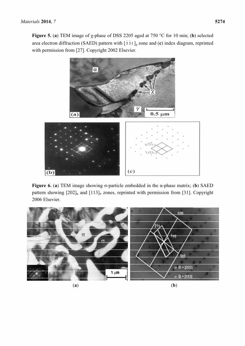
As mentioned earlier, bcc χ-phase forms in the earlier stage in the bcc ferrite of DSSs due to
preferential cube-on-cube orientation relationship. The χ-phase then transforms to the σ-phase upon
prolonged aging [27]. Figure 5a is the TEM image showing precipitation of χ-phase at the α-γ interface
of DSS 2205 aged at 750 °C for 10 min only. The selected area electron diffraction (SAED) pattern
and its index diagram are shown in Figure 5b,c, respectively. Michalska and Sozanska [31] reported
that the χ and σ-phases precipitate preferentially at the α-γ interface and within the α-phase. The
volume fraction and size of σ-phase increase with aging time. EDX results revealed that the χ- phase is
highly enriched with Mo (15.95 wt%). Figure 6a shows the TEM image of DSS 2205 aged at 750 °C
for 5 h. The SAED pattern is shown in Figure 6b. The σ-phase grows further into the α-phase after
aging for 5 h because of high diffusivity of solute atoms at high temperatures. This phase is
detrimental to the impact toughness of DSS 2205 (Figure 7).
Materials 2014, 7 5274
Figure 5. (a) TEM image of χ-phase of DSS 2205 aged at 750 °C for 10 min; (b) selected
area electron diffraction (SAED) pattern with [ 135
]χ zone and (c) index diagram, reprinted
with permission from [27]. Copyright 2002 Elsevier.
Figure 6. (a) TEM image showing σ-particle embedded in the α-phase matrix; (b) SAED
pattern showing [202]α and [113]σ zones, reprinted with permission from [31]. Copyright
2006 Elsevier.
(a) (b)
Materials 2014, 7 5275
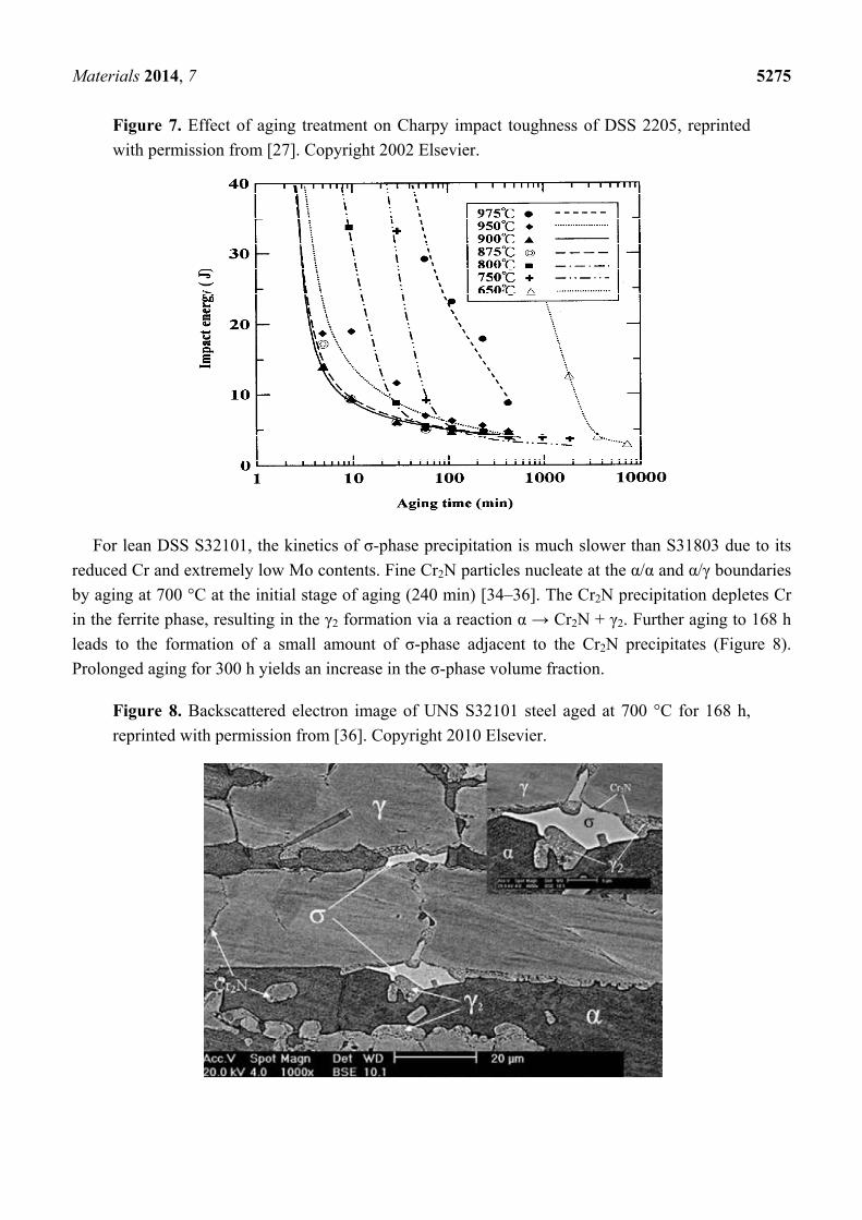
Figure 7. Effect of aging treatment on Charpy impact toughness of DSS 2205, reprinted
with permission from [27]. Copyright 2002 Elsevier.
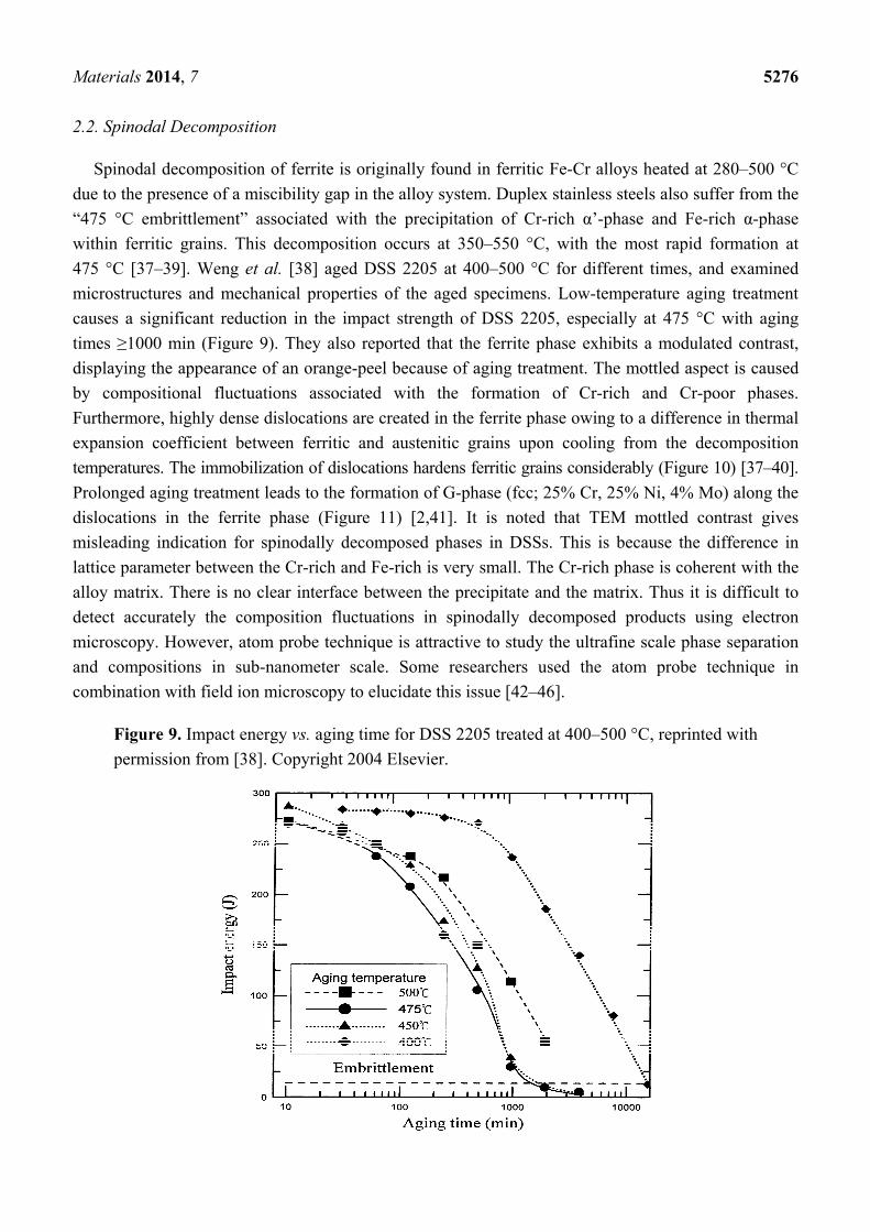
For lean DSS S32101, the kinetics of σ-phase precipitation is much slower than S31803 due to its
reduced Cr and extremely low Mo contents. Fine Cr2N particles nucleate at the α/α and α/γ boundaries
by aging at 700 °C at the initial stage of aging (240 min) [34–36]. The Cr2N precipitation depletes Cr
in the ferrite phase, resulting in the γ2 formation via a reaction α → Cr2N + γ2. Further aging to 168 h
leads to the formation of a small amount of σ-phase adjacent to the Cr2N precipitates (Figure 8).
Prolonged aging for 300 h yields an increase in the σ-phase volume fraction.
Figure 8. Backscattered electron image of UNS S32101 steel aged at 700 °C for 168 h,
reprinted with permission from [36]. Copyright 2010 Elsevier.
Materials 2014, 7 5276
2.2. Spinodal Decomposition
Spinodal decomposition of ferrite is originally found in ferritic Fe-Cr alloys heated at 280–500 °C
due to the presence of a miscibility gap in the alloy system. Duplex stainless steels also suffer from the
“475 °C embrittlement” associated with the precipitation of Cr-rich α’-phase and Fe-rich α-phase
within ferritic grains. This decomposition occurs at 350–550 °C, with the most rapid formation at
475 °C [37–39]. Weng et al. [38] aged DSS 2205 at 400–500 °C for different times, and examined
microstructures and mechanical properties of the aged specimens. Low-temperature aging treatment
causes a significant reduction in the impact strength of DSS 2205, especially at 475 °C with aging
times ≥1000 min (Figure 9). They also reported that the ferrite phase exhibits a modulated contrast,
displaying the appearance of an orange-peel because of aging treatment. The mottled aspect is caused
by compositional fluctuations associated with the formation of Cr-rich and Cr-poor phases.
Furthermore, highly dense dislocations are created in the ferrite phase owing to a difference in thermal
expansion coefficient between ferritic and austenitic grains upon cooling from the decomposition
temperatures. The immobilization of dislocations hardens ferritic grains considerably (Figure 10) [37–40].
Prolonged aging treatment leads to the formation of G-phase (fcc; 25% Cr, 25% Ni, 4% Mo) along the
dislocations in the ferrite phase (Figure 11) [2,41]. It is noted that TEM mottled contrast gives
misleading indication for spinodally decomposed phases in DSSs. This is because the difference in
lattice parameter between the Cr-rich and Fe-rich is very small. The Cr-rich phase is coherent with the
alloy matrix. There is no clear interface between the precipitate and the matrix. Thus it is difficult to
detect accurately the composition fluctuations in spinodally decomposed products using electron
microscopy. However, atom probe technique is attractive to study the ultrafine scale phase separation
and compositions in sub-nanometer scale. Some researchers used the atom probe technique in
combination with field ion microscopy to elucidate this issue [42–46].
Figure 9. Impact energy vs. aging time for DSS 2205 treated at 400–500 °C, reprinted with
permission from [38]. Copyright 2004 Elsevier.
Materials 2014, 7 5277
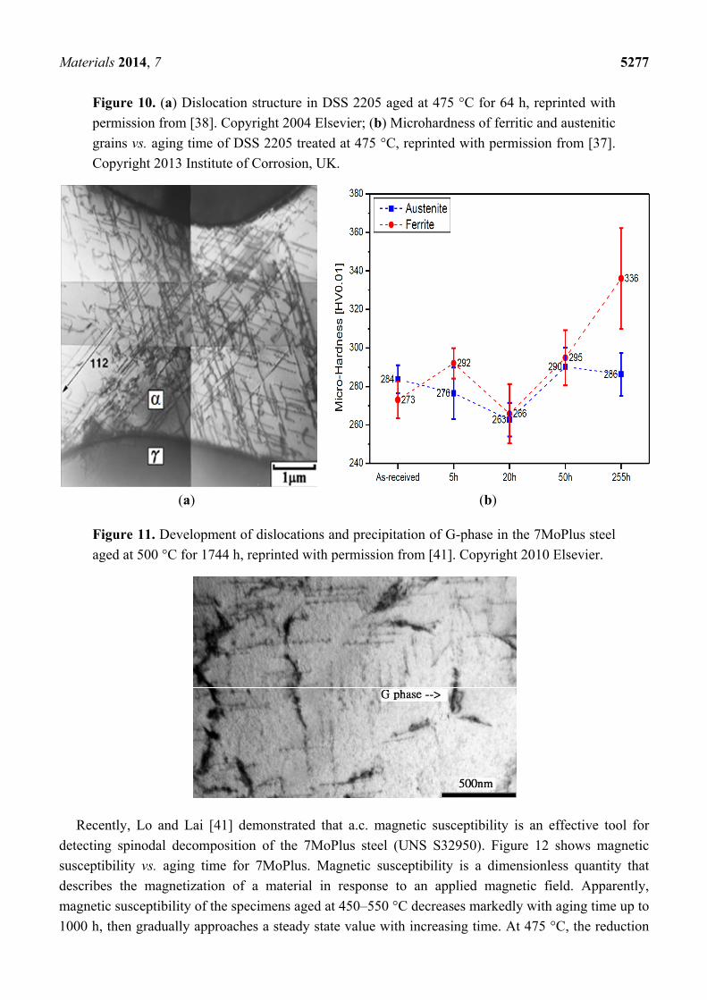
Figure 10. (a) Dislocation structure in DSS 2205 aged at 475 °C for 64 h, reprinted with
permission from [38]. Copyright 2004 Elsevier; (b) Microhardness of ferritic and austenitic
grains vs. aging time of DSS 2205 treated at 475 °C, reprinted with permission from [37].
Copyright 2013 Institute of Corrosion, UK.
(a) (b)
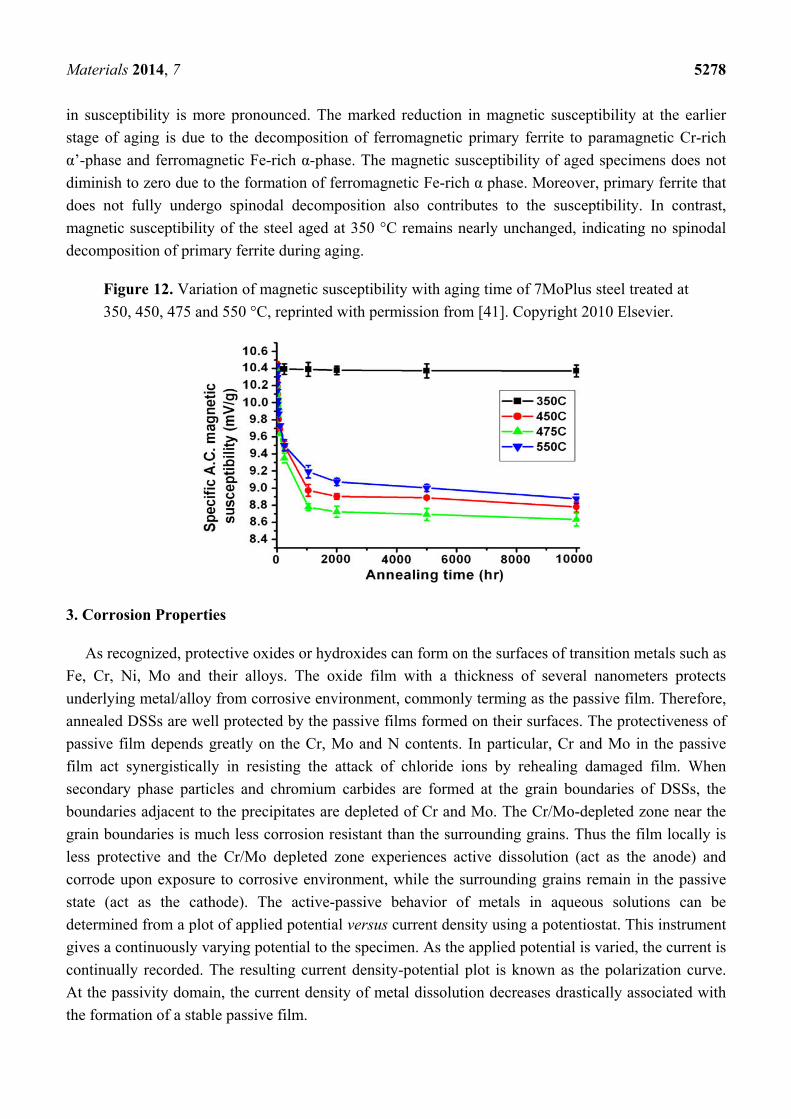
Figure 11. Development of dislocations and precipitation of G-phase in the 7MoPlus steel
aged at 500 °C for 1744 h, reprinted with permission from [41]. Copyright 2010 Elsevier.
Recently, Lo and Lai [41] demonstrated that a.c. magnetic susceptibility is an effective tool for
detecting spinodal decomposition of the 7MoPlus steel (UNS S32950). Figure 12 shows magnetic
susceptibility vs. aging time for 7MoPlus. Magnetic susceptibility is a dimensionless quantity that
describes the magnetization of a material in response to an applied magnetic field. Apparently,
magnetic susceptibility of the specimens aged at 450–550 °C decreases markedly with aging time up to
1000 h, then gradually approaches a steady state value with increasing time. At 475 °C, the reduction
Materials 2014, 7 5278
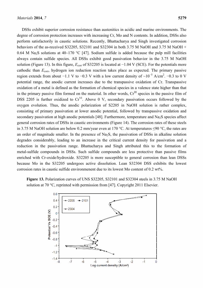
in susceptibility is more pronounced. The marked reduction in magnetic susceptibility at the earlier
stage of aging is due to the decomposition of ferromagnetic primary ferrite to paramagnetic Cr-rich
α’-phase and ferromagnetic Fe-rich α-phase. The magnetic susceptibility of aged specimens does not
diminish to zero due to the formation of ferromagnetic Fe-rich α phase. Moreover, primary ferrite that
does not fully undergo spinodal decomposition also contributes to the susceptibility. In contrast,
magnetic susceptibility of the steel aged at 350 °C remains nearly unchanged, indicating no spinodal
decomposition of primary ferrite during aging.
Figure 12. Variation of magnetic susceptibility with aging time of 7MoPlus steel treated at
350, 450, 475 and 550 °C, reprinted with permission from [41]. Copyright 2010 Elsevier.
3. Corrosion Properties
As recognized, protective oxides or hydroxides can form on the surfaces of transition metals such as
Fe, Cr, Ni, Mo and their alloys. The oxide film with a thickness of several nanometers protects
underlying metal/alloy from corrosive environment, commonly terming as the passive film. Therefore,
annealed DSSs are well protected by the passive films formed on their surfaces. The protectiveness of
passive film depends greatly on the Cr, Mo and N contents. In particular, Cr and Mo in the passive
film act synergistically in resisting the attack of chloride ions by rehealing damaged film. When
secondary phase particles and chromium carbides are formed at the grain boundaries of DSSs, the
boundaries adjacent to the precipitates are depleted of Cr and Mo. The Cr/Mo-depleted zone near the
grain boundaries is much less corrosion resistant than the surrounding grains. Thus the film locally is
less protective and the Cr/Mo depleted zone experiences active dissolution (act as the anode) and
corrode upon exposure to corrosive environment, while the surrounding grains remain in the passive
state (act as the cathode). The active-passive behavior of metals in aqueous solutions can be
determined from a plot of applied potential versus current density using a potentiostat. This instrument
gives a continuously varying potential to the specimen. As the applied potential is varied, the current is
continually recorded. The resulting current density-potential plot is known as the polarization curve.
At the passivity domain, the current density of metal dissolution decreases drastically associated with
the formation of a stable passive film.
Materials 2014, 7 5279
DSSs exhibit superior corrosion resistance than austenitics in acidic and marine environments. The
degree of corrosion protection increases with increasing Cr, Mo and N contents. In addition, DSSs also
perform satisfactorily in caustic solutions. Recently, Bhattacharya and Singh investigated corrosion
behaviors of the as-received S32205, S32101 and S32304 in both 3.75 M NaOH and 3.75 M NaOH +
0.64 M Na2S solutions at 40–170 °C [47]. Sodium sulfide is added because the pulp mill facilities
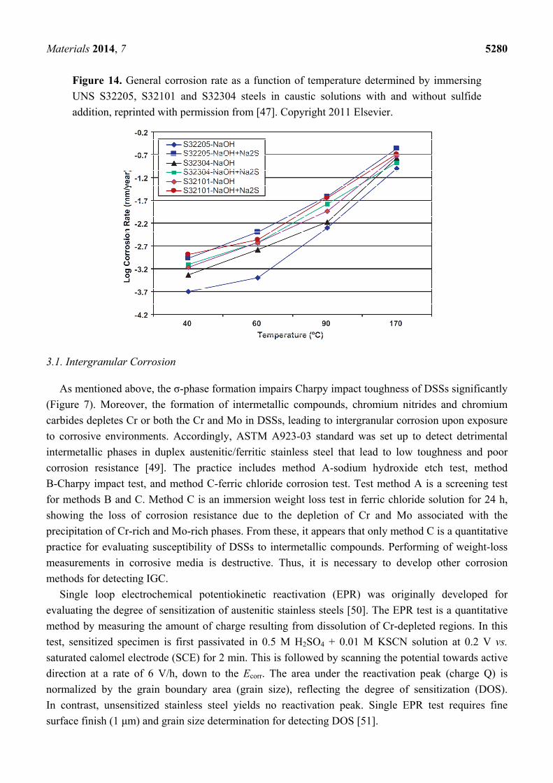
always contain sulfide species. All DSSs exhibit good passivation behavior in the 3.75 M NaOH
solution (Figure 13). In this figure, Ecorr of S32205 is located at −1.04 V (SCE). For the potentials more
cathodic than Ecorr, hydrogen ion reduction reaction takes place as expected. The primary passive
region extends from about −1.1 V to −0.3 V with a low current density of ~10−5 A/cm2. −0.3 to 0 V
potential range, the anodic current increases due to the transpassive oxidation of Cr. Transpassive
oxidation of a metal is defined as the formation of chemical species in a valence state higher than that
in the primary passive film formed on the material. In other words, CrIII species in the passive film of
DSS 2205 is further oxidized to CrVI. Above 0 V, secondary passivation occurs followed by the
oxygen evolution. Thus, the anodic polarization of S2205 in NaOH solution is rather complex,
consisting of primary passivation at lower anodic potential, followed by transpassive oxidation and
secondary passivation at high anodic potentials [48]. Furthermore, temperature and Na2S species affect
general corrosion rates of DSSs in caustic environments (Figure 14). The corrosion rates of these steels
in 3.75 M NaOH solution are below 0.2 mm/year even at 170 °C. At temperatures ≤90 °C, the rates are
an order of magnitude smaller. In the presence of Na2S, the passivation of DSSs in alkaline solution
degrades considerably, leading to an increase in the critical current density for passivation and a
reduction in the passivation range. Bhattacharya and Singh attributed this to the formation of
metal-sulfide compounds in DSSs. Such sulfide compounds are less protective than passive films
enriched with Cr-oxide/hydroxide. S32205 is more susceptible to general corrosion than lean DSSs
because Mo in the S32205 undergoes active dissolution. Lean S32304 DSS exhibits the lowest
corrosion rates in caustic sulfide environmenent due to its lowest Mo content of 0.2 wt%.
Figure 13. Polarization curves of UNS S32205, S32101 and S32304 steels in 3.75 M NaOH
solution at 70 °C, reprinted with permission from [47]. Copyright 2011 Elsevier.
Materials 2014, 7 5280
Figure 14. General corrosion rate as a function of temperature determined by immersing
UNS S32205, S32101 and S32304 steels in caustic solutions with and without sulfide
addition, reprinted with permission from [47]. Copyright 2011 Elsevier.
3.1. Intergranular Corrosion
As mentioned above, the σ-phase formation impairs Charpy impact toughness of DSSs significantly
(Figure 7). Moreover, the formation of intermetallic compounds, chromium nitrides and chromium
carbides depletes Cr or both the Cr and Mo in DSSs, leading to intergranular corrosion upon exposure
to corrosive environments. Accordingly, ASTM A923-03 standard was set up to detect detrimental
intermetallic phases in duplex austenitic/ferritic stainless steel that lead to low toughness and poor
corrosion resistance [49]. The practice includes method A-sodium hydroxide etch test, method
B-Charpy impact test, and method C-ferric chloride corrosion test. Test method A is a screening test
for methods B and C. Method C is an immersion weight loss test in ferric chloride solution for 24 h,
showing the loss of corrosion resistance due to the depletion of Cr and Mo associated with the
precipitation of Cr-rich and Mo-rich phases. From these, it appears that only method C is a quantitative
practice for evaluating susceptibility of DSSs to intermetallic compounds. Performing of weight-loss
measurements in corrosive media is destructive. Thus, it is necessary to develop other corrosion
methods for detecting IGC.
Single loop electrochemical potentiokinetic reactivation (EPR) was originally developed for
evaluating the degree of sensitization of austenitic stainless steels [50]. The EPR test is a quantitative
method by measuring the amount of charge resulting from dissolution of Cr-depleted regions. In this
test, sensitized specimen is first passivated in 0.5 M H2SO4 + 0.01 M KSCN solution at 0.2 V vs.
saturated calomel electrode (SCE) for 2 min. This is followed by scanning the potential towards active
direction at a rate of 6 V/h, down to the Ecorr. The area under the reactivation peak (charge Q) is
normalized by the grain boundary area (grain size), reflecting the degree of sensitization (DOS).
In contrast, unsensitized stainless steel yields no reactivation peak. Single EPR test requires fine
surface finish (1 μm) and grain size determination for detecting DOS [51].
Materials 2014, 7 5281
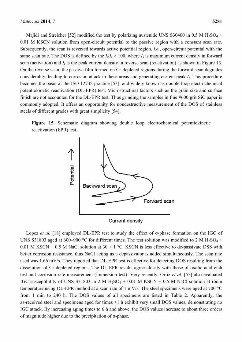
Majidi and Streicher [52] modified the test by polarizing austenitic UNS S30400 in 0.5 M H2SO4 +
0.01 M KSCN solution from open-circuit potential to the passive region with a constant scan rate.
Subsequently, the scan is reversed towards active potential region, i.e., open-circuit potential with the
same scan rate. The DOS is defined by the Ir/Ia × 100, where Ia is maximum current density in forward
scan (activation) and Ir is the peak current density in reverse scan (reactivation) as shown in Figure 15.
On the reverse scan, the passive film formed on Cr-depleted regions during the forward scan degrades
considerably, leading to corrosion attack in these areas and generating current peak Ir. This procedure
becomes the basis of the ISO 12732 practice [53], and widely known as double loop electrochemical
potentiokinetic reactivation (DL-EPR) test. Microstructural factors such as the grain size and surface
finish are not accounted for the DL-EPR test. Thus grinding the samples in fine #600 grit SiC paper is
commonly adopted. It offers an opportunity for nondestructive measurement of the DOS of stainless
steels of different grades with great simplicity [54].
Figure 15. Schematic diagram showing double loop electrochemical potentiokinetic
reactivation (EPR) test.
Lopez et al. [18] employed DL-EPR test to study the effect of σ-phase formation on the IGC of
UNS S31803 aged at 600–900 °C for different times. The test solution was modified to 2 M H2SO4 +
0.01 M KSCN + 0.5 M NaCl solution at 30 ± 1 °C. KSCN is less effective to de-passivate DSS with
better corrosion resistance, thus NaCl acting as a depassivator is added simultaneously. The scan rate
used was 1.66 mV/s. They reported that DL-EPR test is effective for detecting DOS resulting from the
dissolution of Cr-depleted regions. The DL-EPR results agree closely with those of oxalic acid etch
test and corrosion rate measurement (immersion test). Very recently, Ortiz et al. [55] also evaluated
IGC susceptibility of UNS S31803 in 2 M H2SO4 + 0.01 M KSCN + 0.5 M NaCl solution at room
temperature using DL-EPR method at a scan rate of 1 mV/s. The steel specimens were aged at 700 °C
from 1 min to 240 h. The DOS values of all specimens are listed in Table 2. Apparently, the
as-received steel and specimens aged for times ≤1 h exhibit very small DOS values, demonstrating no
IGC attack. By increasing aging times to 6 h and above, the DOS values increase to about three orders
of magnitude higher due to the precipitation of σ-phase.
Materials 2014, 7 5282
Table 2. Degree of sensitization (DOS) values of as-received UNS S31803 steel and DSS
specimens aged at 700 °C for different times, reprinted with permission from [55].
Copyright 2013 Elsevier.
Specimen Activation Peak Current
Density, Ia (A/cm2) Reactivation Peak Current
Density, Ir (A/cm2) DOS (Ir/Ia) × 100%
As received 0.0163 1.59 × 10⁻⁶ 9.74 × 10⁻³ 1 min 0.0126 2.63 × 10⁻⁶ 2.09 × 10⁻²
30 min 0.0177 4.16 × 10⁻⁶ 2.34 × 10⁻² 1 h 0.0066 5.06 × 10⁻⁶ 7.66 × 10⁻² 6 h 0.0240 0.0041 17.40
12 h 0.0251 0.0083 33.15 24 h 0.0472 0.0228 48.37 48 h 0.0579 0.0376 64.91
120 h 0.0830 0.0579 69.69 240 h 0.0753 0.0669 88.83
To improve sensitivity of DL-EPR, HCl depassivator of different concentrations, electrolyte
temperatures and scan rates were investigated by some researchers [23,36,56–58]. Hong et al. [23]
reported that the optimal conditions for evaluating DOS of S32750 in a 2 M H2SO4 solution can be
obtained by using 1.5 M HCl, a scan rate of 1.5 mV/s and a solution temperature of 30 °C.
Gong et al. [57] reported that an electrolyte of 2 M H2SO4 + 1 M HCl at 30 °C and a scan rate of
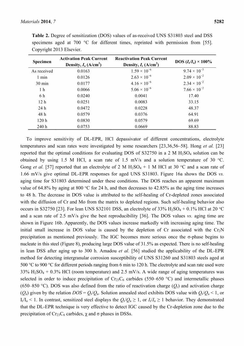
1.66 mV/s give optimal DL-EPR responses for aged UNS S31803. Figure 16a shows the DOS vs.
aging time for S31803 determined under these conditions. The DOS reaches an apparent maximum
value of 64.8% by aging at 800 °C for 24 h, and then decreases to 42.85% as the aging time increases
to 48 h. The decrease in DOS value is attributed to the self-healing of Cr-depleted zones associated
with the diffusion of Cr and Mo from the matrix to depleted regions. Such self-healing behavior also
occurs in S32750 [23]. For lean UNS S32101 DSS, an electrolyte of 33% H2SO4 + 0.1% HCl at 20 °C
and a scan rate of 2.5 mV/s give the best reproducibility [36]. The DOS values vs. aging time are
shown in Figure 16b. Apparently, the DOS values increase markedly with increasing aging time. The
initial small increase in DOS value is caused by the depletion of Cr associated with the Cr2N
precipitation as mentioned previously. The IGC becomes more serious once the σ-phase begins to
nucleate in this steel (Figure 8), producing large DOS value of 31.5% as expected. There is no self-healing
in lean DSS after aging up to 300 h. Amadou et al. [56] studied the applicability of the DL-EPR
method for detecting intergranular corrosion susceptibility of UNS S31260 and S31803 steels aged at
500 °C to 900 °C for different periods ranging from 6 min to 120 h. The electrolyte and scan rate used were
33% H2SO4 + 0.3% HCl (room temperature) and 2.5 mV/s. A wide range of aging temperatures was
selected in order to induce precipitation of Cr23C6 carbides (550–650 °C) and intermetallic phases
(650–850 °C). DOS was also defined from the ratio of reactivation charge (Qr) and activation charge
(Qa) given by the relation DOS = Qr/Qa. Solution annealed steel exhibits DOS value with Qr/Qa < 1, or
Ir/Ia < 1. In contrast, sensitized steel displays the Qr/Qa ≥ 1, or Ir/Ia ≥ 1 behavior. They demonstrated
that the DL-EPR technique is very effective to detect IGC caused by the Cr-depletion zone due to the
precipitation of Cr23C6 carbides, χ and σ phases in DSSs.
Materials 2014, 7 5283
Figure 16. DOS vs. aging time of (a) UNS S31803 steel treated at 800 °C, reprinted with
permission from [57]. Copyright 2010 Elsevier; and (b) UNS S32101 steel treated at
700 °C, reprinted with permission from [36]. Copyright 2010 Elsevier.
(a) (b)
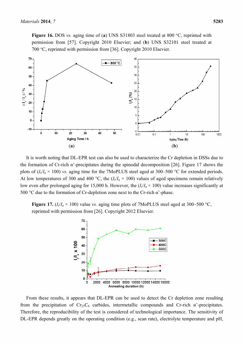
It is worth noting that DL-EPR test can also be used to characterize the Cr depletion in DSSs due to
the formation of Cr-rich α’-precipitates during the spinodal decomposition [26]. Figure 17 shows the
plots of (Ir/Ia × 100) vs. aging time for the 7MoPLUS steel aged at 300–500 °C for extended periods.
At low temperatures of 300 and 400 °C, the (Ir/Ia × 100) values of aged specimens remain relatively
low even after prolonged aging for 15,000 h. However, the (Ir/Ia × 100) value increases significantly at
500 °C due to the formation of Cr-depletion zone next to the Cr-rich α’-phase.
Figure 17. (Ir/Ia × 100) value vs. aging time plots of 7MoPLUS steel aged at 300–500 °C,
reprinted with permission from [26]. Copyright 2012 Elsevier.
From these results, it appears that DL-EPR can be used to detect the Cr depletion zone resulting
from the precipitation of Cr23C6 carbides, intermetallic compounds and Cr-rich α’-precipitates.
Therefore, the reproducibility of the test is considered of technological importance. The sensitivity of
DL-EPR depends greatly on the operating condition (e.g., scan rate), electrolyte temperature and pH,
Materials 2014, 7 5284
depassivator content, etc. At present, there is no general agreement among researchers concerning the
concentrations of electrolyte and depassivator, the scan rate and electrolyte temperature for this
test [23,36,55–58]. The optimal conditions for achieving good reproducibility are still under
investigation. Amadou et al. [56] determined the DOS from the ratio of reactivation charge and
activation charge during the DL-EPR test, but the DOS value was not normalized by the grain size
(grain boundary area) of duplex steels as the DOS in austenitic stainless steels. Therefore, careful
consideration should be given to the issues of microstructural and electrolyte parameters such that the
DL-EPR test can yield data with high reproducibility.
3.2. Localized Corrosion
It is well recognized that crevice and pitting corrosion are caused by a breakdown of the passive
films of stainless steels exposed to chloride containing environments. Chloride ions can induce failure
of the passive film formed on the inclusions (e.g., MnS) and secondary phases, leading to anodic
dissolution of underlying metal locally. The adjacent metal surfaces act as the cathode for oxygen
reduction process. Rapid dissolution at localized region initiates the pit formation. An excess of
metallic ions with positive charge is accumulated in this region, resulting in the migration of chloride
ions from the solution to maintain electroneutrality. Consequently, a high concentration of MCl within
the pit undergoes hydrolysis, producing low pH due to the formation of hydrochloric acid. This
increases the local dissolution rate causing more chloride ions to migrate into the pit. The process is a
self-propagating or autocatalytic mechanism of pit growth [59]. Moreover, pitting can lead to other
causes of failure such as stress corrosion. The simultaneous presence of tensile stress and corrosive
environment can breakdown the passive film even more readily, forming fine cracks that fracture in a
brittle manner. These cracks propagate across the grains in either transgranular or intergranular mode.
This phenomenon is referred to as the “stress corrosion cracking” (SCC). Residual or thermal stresses
resulting from the fabrication, improper heat treatment and welding process of DSSs form the basis for
tensile loads. Moreover, the presence of intermetallic phases at the α/α and α/γ grain boundaries
facilities the cracks to propagate along those boundaries.
3.2.1. Pitting Corrosion
The pitting resistance of DSSs in marine environment depends mainly on their Cr, Mo and N
contents. Thus, the pitting corrosion resistance is correlated with the chemical compositions of DSSs,
and can be expressed in term of an empirical pitting resistance equivalent number (PREN) given by [12]:
PREN = wt% Cr + 3.3 wt% Mo + xwt% N (2)
where the x value ranges from 16 to 30. Larger PREN value gives rise to higher pitting resistance.
There is no universal equation for evaluating PREN of DSSs. A value of x = 16 is typically adopted in
industrial sector [16], while x = 20 is commonly used by the researchers [60–62]. For x = 16, the
PREN values of standard 2205 grade, 25% Cr, superduplex and hyperduplex steels are ~ 35, 35–40,
40–50 and ≥50, respectively [16]. Equation (5) only takes into account the beneficial effect of Cr, Mo
and N on the pitting corrosion resistance of DSSs. However, other elements such as Mn, S and P that
exhibit deleterious effect on the pitting resistance are ignored. Partitioning of Cr and Mo in ferritic
Materials 2014, 7 5285
phase, and of Ni and N in austenitic phase can affect the PREN values of both phases. Furthermore, the
precipitation of secondary phase particles can cause compositional changes in the α- and γ-phases,
resulting in selective pitting corrosion of a weak phase [22].
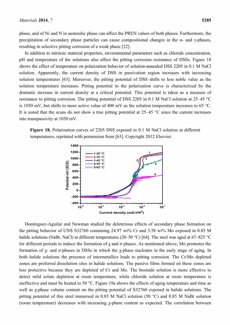
In addition to intrinsic material properties, environmental parameters such as chloride concentration,
pH and temperature of the solutions also affect the pitting corrosion resistance of DSSs. Figure 18
shows the effect of temperature on polarization behavior of solution-annealed DSS 2205 in 0.1 M NaCl
solution. Apparently, the current density of DSS in passivation region increases with increasing
solution temperatures [63]. Moreover, the pitting potential of DSS shifts to less noble value as the
solution temperature increases. Pitting potential in the polarization curve is characterized by the
dramatic increase in current density at a critical potential. This potential is taken as a measure of
resistance to pitting corrosion. The pitting potential of DSS 2205 in 0.1 M NaCl solution at 25–45 °C
is 1050 mV, but shifts to more active value of 400 mV as the solution temperature increases to 65 °C.
It is noted that the scans do not show a true pitting potential at 25–45 °C since the current increases
into transpassivity at 1050 mV.
Figure 18. Polarization curves of 2205 DSS exposed in 0.1 M NaCl solution at different
temperatures, reprinted with permission from [63]. Copyright 2012 Elsevier.
Domínguez-Aguilar and Newman studied the deleterious effects of secondary phase formation on
the pitting behavior of UNS S32760 containing 24.97 wt% Cr and 3.58 wt% Mo exposed in 0.85 M
halide solutions (NaBr, NaCl) at different temperatures (20–50 °C) [64]. The steel was aged at 67–825 °C
for different periods to induce the formation of χ and σ phases. As mentioned above, Mo promotes the
formation of χ- and σ-phases in DSSs in which the χ-phase nucleates in the early stage of aging. In
both halide solutions the presence of intermetallics leads to pitting corrosion. The Cr/Mo depleted
zones are preferred dissolution sites in halide solutions. The passive films formed on these zones are
less protective because they are depleted of Cr and Mo. The bromide solution is more effective to
detect mild solute depletion at room temperature, while chloride solution at room temperature is
ineffective and must be heated to 50 °C. Figure 19a shows the effects of aging temperature and time as
well as χ-phase volume content on the pitting potential of S32760 exposed in halide solutions. The
pitting potential of this steel immersed in 0.85 M NaCl solution (50 °C) and 0.85 M NaBr solution
(room temperature) decreases with increasing χ-phase content as expected. The correlation between
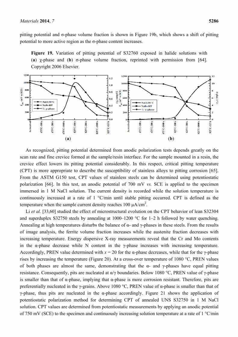
Materials 2014, 7 5286
pitting potential and σ-phase volume fraction is shown in Figure 19b, which shows a shift of pitting
potential to more active region as the σ-phase content increases.
Figure 19. Variation of pitting potential of S32760 exposed in halide solutions with
(a) χ-phase and (b) σ-phase volume fraction, reprinted with permission from [64].
Copyright 2006 Elsevier.
(a) (b)
As recognized, pitting potential determined from anodic polarization tests depends greatly on the
scan rate and fine crevice formed at the sample/resin interface. For the sample mounted in a resin, the
crevice effect lowers its pitting potential considerably. In this respect, critical pitting temperature
(CPT) is more appropriate to describe the susceptibility of stainless alloys to pitting corrosion [65].
From the ASTM G150 test, CPT values of stainless steels can be determined using potentiostatic
polarization [66]. In this test, an anodic potential of 700 mV vs. SCE is applied to the specimen
immersed in 1 M NaCl solution. The current density is recorded while the solution temperature is
continuously increased at a rate of 1 °C/min until stable pitting occurred. CPT is defined as the
temperature when the sample current density reaches 100 μA/cm2.
Li et al. [33,60] studied the effect of microstructural evolution on the CPT behavior of lean S32304
and superduplex S32750 steels by annealing at 1000–1200 °C for 1–2 h followed by water quenching.
Annealing at high temperatures disturbs the balance of α- and γ-phases in these steels. From the results
of image analysis, the ferrite volume fraction increases while the austenite fraction decreases with
increasing temperature. Energy dispersive X-ray measurements reveal that the Cr and Mo contents
in the α-phase decrease while N content in the γ-phase increases with increasing temperature.
Accordingly, PREN value determined with x = 20 for the α-phase decreases, while that for the γ-phase
rises by increasing the temperature (Figure 20). At a cross-over temperature of 1080 °C, PREN values
of both phases are almost the same, demonstrating that the α- and γ-phases have equal pitting
resistance. Consequently, pits are nucleated at α/γ boundaries. Below 1080 °C, PREN value of γ-phase
is smaller than that of α-phase, implying that α-phase is more corrosion resistant. Therefore, pits are
preferentially nucleated in the γ-grains. Above 1080 °C, PREN value of α-phase is smaller than that of
γ-phase, thus pits are nucleated in the α-phase accordingly. Figure 21 shows the application of
potentiostatic polarization method for determining CPT of annealed UNS S32750 in 1 M NaCl
solution. CPT values are determined from potentiostatic measurements by applying an anodic potential
of 750 mV (SCE) to the specimen and continuously increasing solution temperature at a rate of 1 °C/min
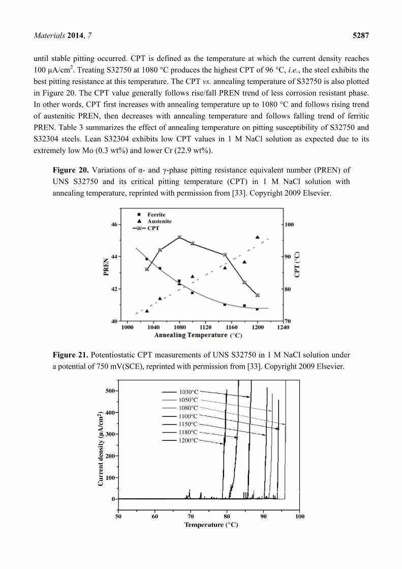
Materials 2014, 7 5287
until stable pitting occurred. CPT is defined as the temperature at which the current density reaches
100 μA/cm2. Treating S32750 at 1080 °C produces the highest CPT of 96 °C, i.e., the steel exhibits the
best pitting resistance at this temperature. The CPT vs. annealing temperature of S32750 is also plotted
in Figure 20. The CPT value generally follows rise/fall PREN trend of less corrosion resistant phase.
In other words, CPT first increases with annealing temperature up to 1080 °C and follows rising trend
of austenitic PREN, then decreases with annealing temperature and follows falling trend of ferritic
PREN. Table 3 summarizes the effect of annealing temperature on pitting susceptibility of S32750 and
S32304 steels. Lean S32304 exhibits low CPT values in 1 M NaCl solution as expected due to its
extremely low Mo (0.3 wt%) and lower Cr (22.9 wt%).
Figure 20. Variations of α- and γ-phase pitting resistance equivalent number (PREN) of
UNS S32750 and its critical pitting temperature (CPT) in 1 M NaCl solution with
annealing temperature, reprinted with permission from [33]. Copyright 2009 Elsevier.
Figure 21. Potentiostatic CPT measurements of UNS S32750 in 1 M NaCl solution under
a potential of 750 mV(SCE), reprinted with permission from [33]. Copyright 2009 Elsevier.
Materials 2014, 7 5288
Table 3. Effect of annealing temperature on pitting behavior of S32750 and S32304
steels [33,60].
Material Annealing Temperature,
°C and Time α-Phase
Content, vol%γ-Phase
Content, vol% CPT (°C), 1 M NaCl
Pitting Phase
S32750
1050, 2 h 47 53 92 γ 1080, 2 h 49 51 96 α/γ boundary 1150, 2 h 55 45 90 α 1200, 2 h 62 38 78 α
S32304
1030, 1 h 47 53 58 γ 1080, 2 h 51 49 67.8 α/γ boundary 1150, 1 h 58 42 56 α 1200, 1 h 63 37 52 α
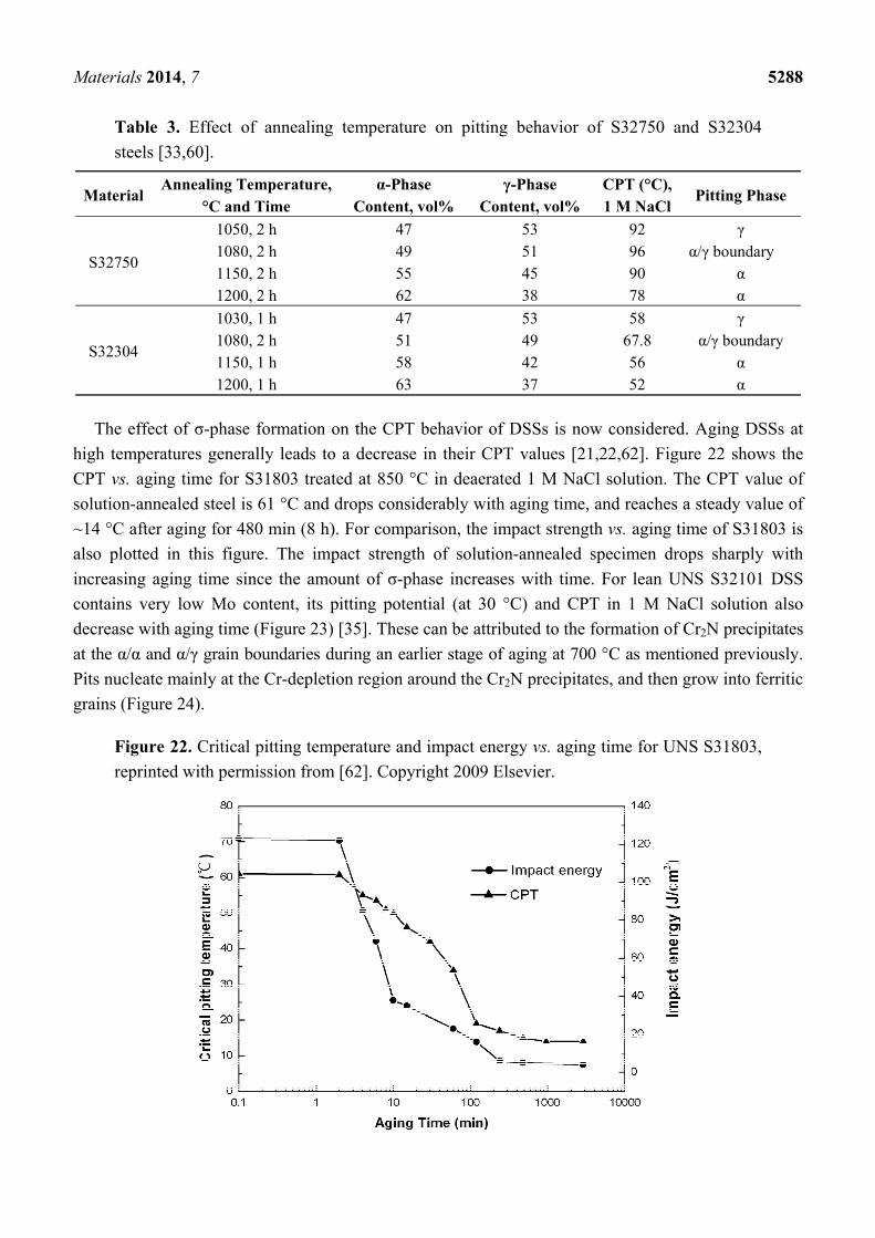
The effect of σ-phase formation on the CPT behavior of DSSs is now considered. Aging DSSs at
high temperatures generally leads to a decrease in their CPT values [21,22,62]. Figure 22 shows the
CPT vs. aging time for S31803 treated at 850 °C in deaerated 1 M NaCl solution. The CPT value of
solution-annealed steel is 61 °C and drops considerably with aging time, and reaches a steady value of
~14 °C after aging for 480 min (8 h). For comparison, the impact strength vs. aging time of S31803 is
also plotted in this figure. The impact strength of solution-annealed specimen drops sharply with
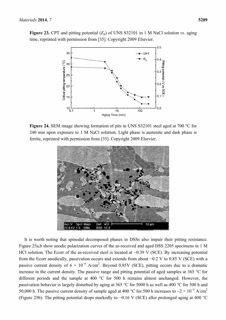
increasing aging time since the amount of σ-phase increases with time. For lean UNS S32101 DSS
contains very low Mo content, its pitting potential (at 30 °C) and CPT in 1 M NaCl solution also
decrease with aging time (Figure 23) [35]. These can be attributed to the formation of Cr2N precipitates
at the α/α and α/γ grain boundaries during an earlier stage of aging at 700 °C as mentioned previously.
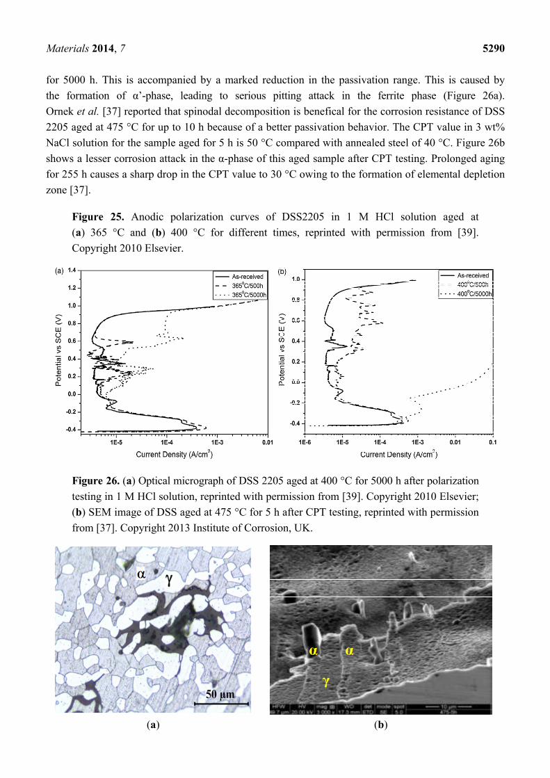
Pits nucleate mainly at the Cr-depletion region around the Cr2N precipitates, and then grow into ferritic
grains (Figure 24).
Figure 22. Critical pitting temperature and impact energy vs. aging time for UNS S31803,
reprinted with permission from [62]. Copyright 2009 Elsevier.
Materials 2014, 7 5289
Figure 23. CPT and pitting potential (Ep) of UNS S32101 in 1 M NaCl solution vs. aging
time, reprinted with permission from [35]. Copyright 2009 Elsevier.
Figure 24. SEM image showing formation of pits in UNS S32101 steel aged at 700 °C for
240 min upon exposure to 1 M NaCl solution. Light phase is austenite and dark phase is
ferrite, reprinted with permission from [35]. Copyright 2009 Elsevier.
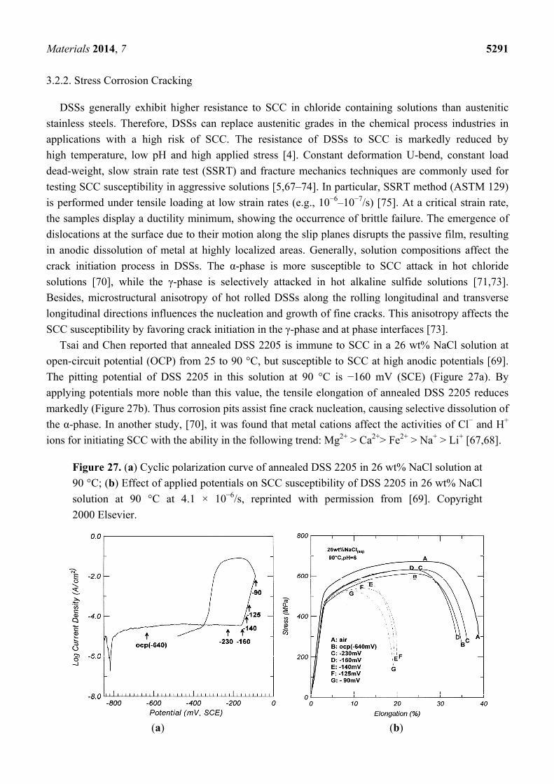
It is worth noting that spinodal decomposed phases in DSSs also impair their pitting resistance.
Figure 25a,b show anodic polarization curves of the as-received and aged DSS 2205 specimens in 1 M
HCl solution. The Ecorr of the as-received steel is located at −0.39 V (SCE). By increasing potential
from the Ecorr anodically, passivation occurs and extends from about −0.2 V to 0.85 V (SCE) with a
passive current density of 6 × 10⁻⁶ A/cm2. Beyond 0.85V (SCE), pitting occurs due to a dramatic
increase in the current density. The passive range and pitting potential of aged samples at 365 °C for
different periods and the sample at 400 °C for 500 h remains almost unchanged. However, the
passivation behavior is largely disturbed by aging at 365 °C for 5000 h as well as 400 °C for 500 h and
50,000 h. The passive current density of sample aged at 400 °C for 500 h increases to ~2 × 10⁻⁵ A/cm2
(Figure 25b). The pitting potential drops markedly to −0.16 V (SCE) after prolonged aging at 400 °C
Materials 2014, 7 5290
for 5000 h. This is accompanied by a marked reduction in the passivation range. This is caused by
the formation of α’-phase, leading to serious pitting attack in the ferrite phase (Figure 26a).
Ornek et al. [37] reported that spinodal decomposition is benefical for the corrosion resistance of DSS
2205 aged at 475 °C for up to 10 h because of a better passivation behavior. The CPT value in 3 wt%
NaCl solution for the sample aged for 5 h is 50 °C compared with annealed steel of 40 °C. Figure 26b
shows a lesser corrosion attack in the α-phase of this aged sample after CPT testing. Prolonged aging
for 255 h causes a sharp drop in the CPT value to 30 °C owing to the formation of elemental depletion
zone [37].
Figure 25. Anodic polarization curves of DSS2205 in 1 M HCl solution aged at
(a) 365 °C and (b) 400 °C for different times, reprinted with permission from [39].
Copyright 2010 Elsevier.
Figure 26. (a) Optical micrograph of DSS 2205 aged at 400 °C for 5000 h after polarization
testing in 1 M HCl solution, reprinted with permission from [39]. Copyright 2010 Elsevier;
(b) SEM image of DSS aged at 475 °C for 5 h after CPT testing, reprinted with permission
from [37]. Copyright 2013 Institute of Corrosion, UK.
(a) (b)
Materials 2014, 7 5291
3.2.2. Stress Corrosion Cracking
DSSs generally exhibit higher resistance to SCC in chloride containing solutions than austenitic
stainless steels. Therefore, DSSs can replace austenitic grades in the chemical process industries in
applications with a high risk of SCC. The resistance of DSSs to SCC is markedly reduced by
high temperature, low pH and high applied stress [4]. Constant deformation U-bend, constant load
dead-weight, slow strain rate test (SSRT) and fracture mechanics techniques are commonly used for
testing SCC susceptibility in aggressive solutions [5,67–74]. In particular, SSRT method (ASTM 129)
is performed under tensile loading at low strain rates (e.g., 10−6–10−7/s) [75]. At a critical strain rate,
the samples display a ductility minimum, showing the occurrence of brittle failure. The emergence of
dislocations at the surface due to their motion along the slip planes disrupts the passive film, resulting
in anodic dissolution of metal at highly localized areas. Generally, solution compositions affect the
crack initiation process in DSSs. The α-phase is more susceptible to SCC attack in hot chloride
solutions [70], while the γ-phase is selectively attacked in hot alkaline sulfide solutions [71,73].
Besides, microstructural anisotropy of hot rolled DSSs along the rolling longitudinal and transverse
longitudinal directions influences the nucleation and growth of fine cracks. This anisotropy affects the
SCC susceptibility by favoring crack initiation in the γ-phase and at phase interfaces [73].
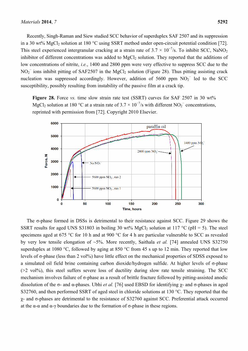
Tsai and Chen reported that annealed DSS 2205 is immune to SCC in a 26 wt% NaCl solution at
open-circuit potential (OCP) from 25 to 90 °C, but susceptible to SCC at high anodic potentials [69].
The pitting potential of DSS 2205 in this solution at 90 °C is −160 mV (SCE) (Figure 27a). By
applying potentials more noble than this value, the tensile elongation of annealed DSS 2205 reduces
markedly (Figure 27b). Thus corrosion pits assist fine crack nucleation, causing selective dissolution of
the α-phase. In another study, [70], it was found that metal cations affect the activities of Cl− and H+
ions for initiating SCC with the ability in the following trend: Mg2+ > Ca2+> Fe2+ > Na+ > Li+ [67,68].
Figure 27. (a) Cyclic polarization curve of annealed DSS 2205 in 26 wt% NaCl solution at
90 °C; (b) Effect of applied potentials on SCC susceptibility of DSS 2205 in 26 wt% NaCl
solution at 90 °C at 4.1 × 10⁻⁶/s, reprinted with permission from [69]. Copyright
2000 Elsevier.
(a) (b)
Materials 2014, 7 5292
Recently, Singh-Raman and Siew studied SCC behavior of superduplex SAF 2507 and its suppression
in a 30 wt% MgCl2 solution at 180 °C using SSRT method under open-circuit potential condition [72].
This steel experienced intergranular cracking at a strain rate of 3.7 × 10⁻⁷/s. To inhibit SCC, NaNO2
inhibitor of different concentrations was added to MgCl2 solution. They reported that the additions of
low concentrations of nitrite, i.e., 1400 and 2800 ppm were very effective to suppress SCC due to the
NO2− ions inhibit pitting of SAF2507 in the MgCl2 solution (Figure 28). Thus pitting assisting crack
nucleation was suppressed accordingly. However, addition of 5600 ppm NO2− led to the SCC
susceptibility, possibly resulting from instability of the passive film at a crack tip.
Figure 28. Force vs. time slow strain rate test (SSRT) curves for SAF 2507 in 30 wt%
MgCl2 solution at 180 °C at a strain rate of 3.7 × 10⁻⁷/s with different NO2− concentrations,
reprinted with permission from [72]. Copyright 2010 Elsevier.
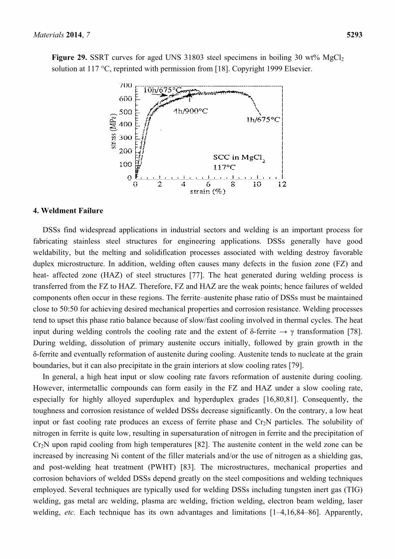
The σ-phase formed in DSSs is detrimental to their resistance against SCC. Figure 29 shows the
SSRT results for aged UNS S31803 in boiling 30 wt% MgCl2 solution at 117 °C (pH = 5). The steel
specimens aged at 675 °C for 10 h and at 900 °C for 4 h are particular vulnerable to SCC as revealed
by very low tensile elongation of ~5%. More recently, Saithala et al. [74] annealed UNS S32750
superduplex at 1080 °C, followed by aging at 850 °C from 45 s up to 12 min. They reported that low
levels of σ-phase (less than 2 vol%) have little effect on the mechanical properties of SDSS exposed to
a simulated oil field brine containing carbon dioxide/hydrogen sulfide. At higher levels of σ-phase
(>2 vol%), this steel suffers severe loss of ductility during slow rate tensile straining. The SCC
mechanism involves failure of σ-phase as a result of brittle fracture followed by pitting-assisted anodic
dissolution of the σ- and α-phases. Ubhi et al. [76] used EBSD for identifying χ- and σ-phases in aged
S32760, and then performed SSRT of aged steel in chloride solutions at 130 °C. They reported that the
χ- and σ-phases are detrimental to the resistance of S32760 against SCC. Preferential attack occurred
at the α-α and α-γ boundaries due to the formation of σ-phase in these regions.
Materials 2014, 7 5293
Figure 29. SSRT curves for aged UNS 31803 steel specimens in boiling 30 wt% MgCl2
solution at 117 °C, reprinted with permission from [18]. Copyright 1999 Elsevier.
4. Weldment Failure
DSSs find widespread applications in industrial sectors and welding is an important process for
fabricating stainless steel structures for engineering applications. DSSs generally have good
weldability, but the melting and solidification processes associated with welding destroy favorable
duplex microstructure. In addition, welding often causes many defects in the fusion zone (FZ) and
heat- affected zone (HAZ) of steel structures [77]. The heat generated during welding process is
transferred from the FZ to HAZ. Therefore, FZ and HAZ are the weak points; hence failures of welded
components often occur in these regions. The ferrite–austenite phase ratio of DSSs must be maintained
close to 50:50 for achieving desired mechanical properties and corrosion resistance. Welding processes
tend to upset this phase ratio balance because of slow/fast cooling involved in thermal cycles. The heat
input during welding controls the cooling rate and the extent of δ-ferrite → γ transformation [78].
During welding, dissolution of primary austenite occurs initially, followed by grain growth in the
δ-ferrite and eventually reformation of austenite during cooling. Austenite tends to nucleate at the grain
boundaries, but it can also precipitate in the grain interiors at slow cooling rates [79].
In general, a high heat input or slow cooling rate favors reformation of austenite during cooling.
However, intermetallic compounds can form easily in the FZ and HAZ under a slow cooling rate,
especially for highly alloyed superduplex and hyperduplex grades [16,80,81]. Consequently, the
toughness and corrosion resistance of welded DSSs decrease significantly. On the contrary, a low heat
input or fast cooling rate produces an excess of ferrite phase and Cr2N particles. The solubility of
nitrogen in ferrite is quite low, resulting in supersaturation of nitrogen in ferrite and the precipitation of
Cr2N upon rapid cooling from high temperatures [82]. The austenite content in the weld zone can be
increased by increasing Ni content of the filler materials and/or the use of nitrogen as a shielding gas,
and post-welding heat treatment (PWHT) [83]. The microstructures, mechanical properties and
corrosion behaviors of welded DSSs depend greatly on the steel compositions and welding techniques
employed. Several techniques are typically used for welding DSSs including tungsten inert gas (TIG)
welding, gas metal arc welding, plasma arc welding, friction welding, electron beam welding, laser
welding, etc. Each technique has its own advantages and limitations [1–4,16,84–86]. Apparently,
Materials 2014, 7 5294
welding can reduce the corrosion resistance of DSSs by changing the steel composition and
microstructure in the FZ. The intermetallic phases and Cr-nitrides induced in weld metals of DSSs can
lead to poor corrosion resistance upon exposure in aggressive environments [5,87,88]. In this section,
the deleterious effects of these phases on the corrosion behavior of welded DSSs are briefly discussed.
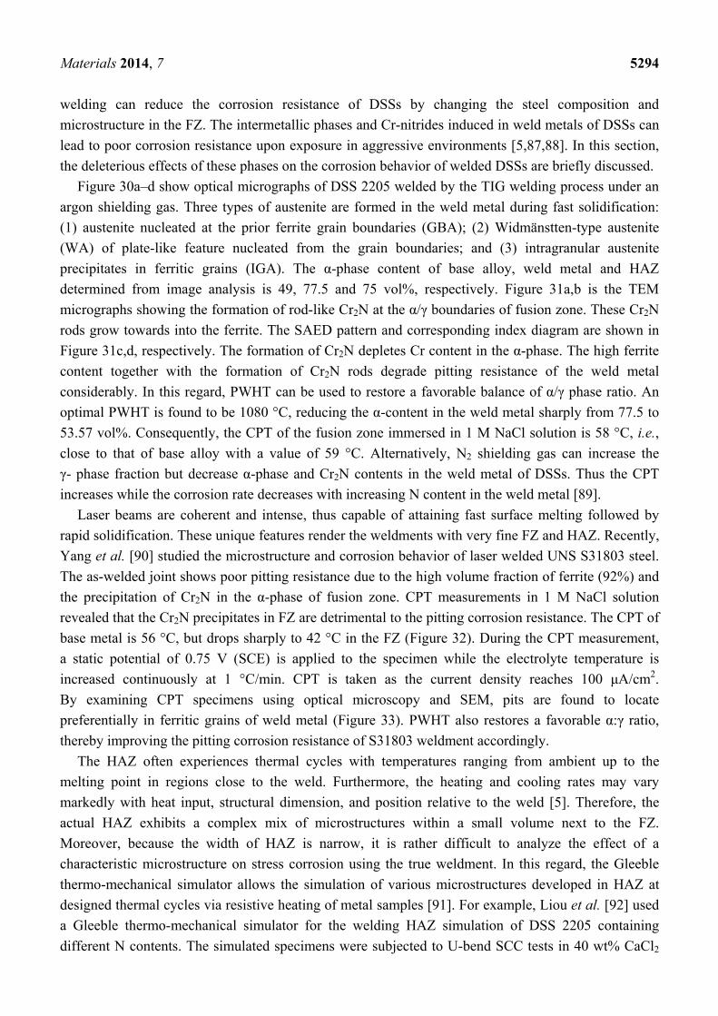
Figure 30a–d show optical micrographs of DSS 2205 welded by the TIG welding process under an
argon shielding gas. Three types of austenite are formed in the weld metal during fast solidification:
(1) austenite nucleated at the prior ferrite grain boundaries (GBA); (2) Widmänstten-type austenite
(WA) of plate-like feature nucleated from the grain boundaries; and (3) intragranular austenite
precipitates in ferritic grains (IGA). The α-phase content of base alloy, weld metal and HAZ
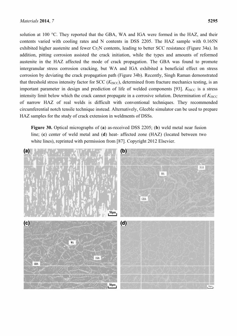
determined from image analysis is 49, 77.5 and 75 vol%, respectively. Figure 31a,b is the TEM
micrographs showing the formation of rod-like Cr2N at the α/γ boundaries of fusion zone. These Cr2N
rods grow towards into the ferrite. The SAED pattern and corresponding index diagram are shown in
Figure 31c,d, respectively. The formation of Cr2N depletes Cr content in the α-phase. The high ferrite
content together with the formation of Cr2N rods degrade pitting resistance of the weld metal
considerably. In this regard, PWHT can be used to restore a favorable balance of α/γ phase ratio. An
optimal PWHT is found to be 1080 °C, reducing the α-content in the weld metal sharply from 77.5 to
53.57 vol%. Consequently, the CPT of the fusion zone immersed in 1 M NaCl solution is 58 °C, i.e.,
close to that of base alloy with a value of 59 °C. Alternatively, N2 shielding gas can increase the
γ- phase fraction but decrease α-phase and Cr2N contents in the weld metal of DSSs. Thus the CPT
increases while the corrosion rate decreases with increasing N content in the weld metal [89].
Laser beams are coherent and intense, thus capable of attaining fast surface melting followed by
rapid solidification. These unique features render the weldments with very fine FZ and HAZ. Recently,
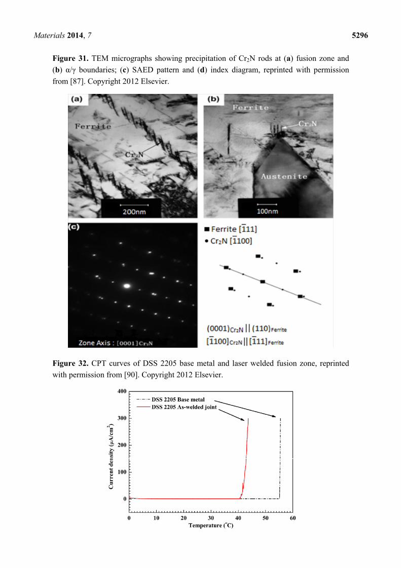
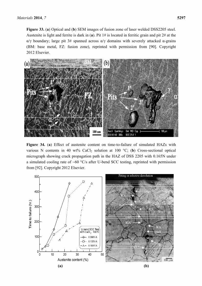
Yang et al. [90] studied the microstructure and corrosion behavior of laser welded UNS S31803 steel.
The as-welded joint shows poor pitting resistance due to the high volume fraction of ferrite (92%) and
the precipitation of Cr2N in the α-phase of fusion zone. CPT measurements in 1 M NaCl solution
revealed that the Cr2N precipitates in FZ are detrimental to the pitting corrosion resistance. The CPT of
base metal is 56 °C, but drops sharply to 42 °C in the FZ (Figure 32). During the CPT measurement,
a static potential of 0.75 V (SCE) is applied to the specimen while the electrolyte temperature is
increased continuously at 1 °C/min. CPT is taken as the current density reaches 100 μA/cm2.
By examining CPT specimens using optical microscopy and SEM, pits are found to locate
preferentially in ferritic grains of weld metal (Figure 33). PWHT also restores a favorable α:γ ratio,
thereby improving the pitting corrosion resistance of S31803 weldment accordingly.
The HAZ often experiences thermal cycles with temperatures ranging from ambient up to the
melting point in regions close to the weld. Furthermore, the heating and cooling rates may vary
markedly with heat input, structural dimension, and position relative to the weld [5]. Therefore, the
actual HAZ exhibits a complex mix of microstructures within a small volume next to the FZ.
Moreover, because the width of HAZ is narrow, it is rather difficult to analyze the effect of a
characteristic microstructure on stress corrosion using the true weldment. In this regard, the Gleeble
thermo-mechanical simulator allows the simulation of various microstructures developed in HAZ at
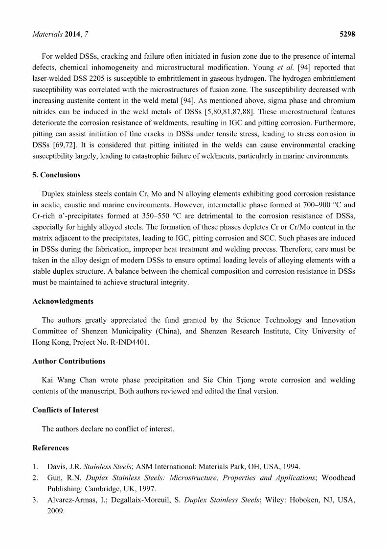
designed thermal cycles via resistive heating of metal samples [91]. For example, Liou et al. [92] used
a Gleeble thermo-mechanical simulator for the welding HAZ simulation of DSS 2205 containing
different N contents. The simulated specimens were subjected to U-bend SCC tests in 40 wt% CaCl2
Materials 2014, 7 5295
solution at 100 °C. They reported that the GBA, WA and IGA were formed in the HAZ, and their
contents varied with cooling rates and N contents in DSS 2205. The HAZ sample with 0.165N
exhibited higher austenite and fewer Cr2N contents, leading to better SCC resistance (Figure 34a). In
addition, pitting corrosion assisted the crack initiation, while the types and amounts of reformed
austenite in the HAZ affected the mode of crack propagation. The GBA was found to promote
intergranular stress corrosion cracking, but WA and IGA exhibited a beneficial effect on stress
corrosion by deviating the crack propagation path (Figure 34b). Recently, Singh Raman demonstrated
that threshold stress intensity factor for SCC (KISCC), determined from fracture mechanics testing, is an
important parameter in design and prediction of life of welded components [93]. KISCC is a stress
intensity limit below which the crack cannot propagate in a corrosive solution. Determination of KISCC
of narrow HAZ of real welds is difficult with conventional techniques. They recommended
circumferential notch tensile technique instead. Alternatively, Gleeble simulator can be used to prepare
HAZ samples for the study of crack extension in weldments of DSSs.
Figure 30. Optical micrographs of (a) as-received DSS 2205; (b) weld metal near fusion
line; (c) center of weld metal and (d) heat- affected zone (HAZ) (located between two
white lines), reprinted with permission from [87]. Copyright 2012 Elsevier.
Materials 2014, 7 5296
Figure 31. TEM micrographs showing precipitation of Cr2N rods at (a) fusion zone and
(b) α/γ boundaries; (c) SAED pattern and (d) index diagram, reprinted with permission
from [87]. Copyright 2012 Elsevier.
Figure 32. CPT curves of DSS 2205 base metal and laser welded fusion zone, reprinted
with permission from [90]. Copyright 2012 Elsevier.
Materials 2014, 7 5297
Figure 33. (a) Optical and (b) SEM images of fusion zone of laser welded DSS2205 steel.
Austenite is light and ferrite is dark in (a). Pit 1# is located in ferritic grain and pit 2# at the
α/γ boundary; large pit 3# spanned across α/γ domains with severely attacked α-grains
(BM: base metal, FZ: fusion zone), reprinted with permission from [90]. Copyright
2012 Elsevier.
Figure 34. (a) Effect of austenite content on time-to-failure of simulated HAZs with
various N contents in 40 wt% CaCl2 solution at 100 °C; (b) Cross-sectional optical
micrograph showing crack propagation path in the HAZ of DSS 2205 with 0.165N under
a simulated cooling rate of ~60 °C/s after U-bend SCC testing, reprinted with permission
from [92]. Copyright 2012 Elsevier.
(a) (b)
Materials 2014, 7 5298
For welded DSSs, cracking and failure often initiated in fusion zone due to the presence of internal
defects, chemical inhomogeneity and microstructural modification. Young et al. [94] reported that
laser-welded DSS 2205 is susceptible to embrittlement in gaseous hydrogen. The hydrogen embrittlement
susceptibility was correlated with the microstructures of fusion zone. The susceptibility decreased with
increasing austenite content in the weld metal [94]. As mentioned above, sigma phase and chromium
nitrides can be induced in the weld metals of DSSs [5,80,81,87,88]. These microstructural features
deteriorate the corrosion resistance of weldments, resulting in IGC and pitting corrosion. Furthermore,
pitting can assist initiation of fine cracks in DSSs under tensile stress, leading to stress corrosion in
DSSs [69,72]. It is considered that pitting initiated in the welds can cause environmental cracking
susceptibility largely, leading to catastrophic failure of weldments, particularly in marine environments.
5. Conclusions
Duplex stainless steels contain Cr, Mo and N alloying elements exhibiting good corrosion resistance
in acidic, caustic and marine environments. However, intermetallic phase formed at 700–900 °C and
Cr-rich α’-precipitates formed at 350–550 °C are detrimental to the corrosion resistance of DSSs,
especially for highly alloyed steels. The formation of these phases depletes Cr or Cr/Mo content in the
matrix adjacent to the precipitates, leading to IGC, pitting corrosion and SCC. Such phases are induced
in DSSs during the fabrication, improper heat treatment and welding process. Therefore, care must be
taken in the alloy design of modern DSSs to ensure optimal loading levels of alloying elements with a
stable duplex structure. A balance between the chemical composition and corrosion resistance in DSSs
must be maintained to achieve structural integrity.
Acknowledgments
The authors greatly appreciated the fund granted by the Science Technology and Innovation
Committee of Shenzen Municipality (China), and Shenzen Research Institute, City University of
Hong Kong, Project No. R-IND4401.
Author Contributions
Kai Wang Chan wrote phase precipitation and Sie Chin Tjong wrote corrosion and welding
contents of the manuscript. Both authors reviewed and edited the final version.
Conflicts of Interest
The authors declare no conflict of interest.
References
1. Davis, J.R. Stainless Steels; ASM International: Materials Park, OH, USA, 1994.
2. Gun, R.N. Duplex Stainless Steels: Microstructure, Properties and Applications; Woodhead
Publishing: Cambridge, UK, 1997.
3. Alvarez-Armas, I.; Degallaix-Moreuil, S. Duplex Stainless Steels; Wiley: Hoboken, NJ, USA,
2009.
Materials 2014, 7 5299
4. Solomon, D.S.; Devine, T.M., Jr. Duplex stainless steel—A tale of two phases. In
Duplex Stainless Steels; Lula, R.A., Ed.; ASM International: Materials Park, OH, USA, 1983;
pp. 693–756.
5. Nilsson, J.O. Overview of super duplex stainless steel. Mater. Sci. Technol. 1992, 8, 685–700.
6. Lo, K.H.; Shek, C.H.; Lai, J.K.L. Recent developments in stainless steels. Mater. Sci. Eng. R.
2009, 65, 39–104.
7. Tjong, S.C.; Hoffman, R.W.; Yeager, E.B. Electron and ion spectroscopic studies of the passive
film on iron-chromium alloys. J. Electrochem. Soc. 1982, 129, 1662–1668.
8. Mesquita, T.J.; Chauveau, E.; Mantel, M.; Nogueira, R.P. A XPS study of the Mo effect on
passivation behaviors for highly controlled stainless steels in neutral and alkaline conditions.
Appl. Surf. Sci. 2013, 270, 90–97.
9. Weber, L.; Uggowitzer, P.J. Partitioning of chromium and molybdenum in super duplex stainless
steels with respect to nitrogen and nickel content. Mater. Sci. Eng. A 1998, 242, 222–229.
10. Simmons, J.W. Overview: High-nitrogen alloying of stainless steels. Mater. Sci. Eng. A 1996, 207,
159–169.
11. Wang, J.; Uggowitzer, P.J.; Magdowski, R.; Speidel, M.O. Nickel-free duplex stainless steels.
Scripta Mater. 1999, 40, 123–129.
12. Merello, R.; Botana, F.J.; Botella, J.; Matres, M.V.; Marcos, M. Influence of chemical composition
on the pitting corrosion resistance of non-standard low-Ni high Mn-N duplex stainless steels.
Corros. Sci. 2003, 45, 909–921.
13. Toor, I.; Hyn, P.J.; Kwon, H.S. Development of high Mn–N duplex stainless steel for automobile
structural components. Corros. Sci. 2008, 50, 404–410.
14. Li, J.; Xu, Y.; Xiao, X.; Zhao, J.; Jiang, L.; Hu, J. A new resource-saving, high manganese
and nitrogen super duplex stainless steel 25Cr-2Ni-3Mo-xMn-N. Mater. Sci. Eng. A 2009, 527,
245–251.
15. Li, J.; Ma, Z.; Xiao, X.; Zhao, J.; Jiang, L. On the behavior of nitrogen in a low-Ni high Mn super
duplex stainless steel. Mater. Des. 2011, 32, 2199–2205.
16. Karlsson, L. Welding duplex stainless steel—A review of current recommendations.
Weld. World 2012, 56, 65–77.
17. Göransson, K.; Nyman, M.L.; Holmquist, M.; Gomes, E. Sandvik SAF 2707 HD (UNS S32707):
A hyper-duplex stainless steel for severe chloride containing environments. Rev. Metall. 2007,
104, 411–417.
18. Lopez, N.; Cid, M.; Puiggali, M. Influence of σ-phase precipitation on mechanical properties and
corrosion resistance of duplex stainless steels. Corros. Sci. 1999, 41, 1615–1631.
19. Chen, T.H.; Yang, J.R. Effects of solution treatment and continuous cooling on σ-phase
precipitation in a 2205 duplex stainless steel. Mater. Sci. Eng. A 2001, 311, 28–40.
20. Adhe, K.N.; Kain, V.; Madangopal, K.; Gadiyar, H.S. Influence of sigma phase formation on
the localized corrosion behavior of a duplex stainless steel. J. Mater. Eng. Perform. 1996, 5,
500–506.
21. Park, C.J.; Rao, V.S.; Kwon, H.S. Effect of sigma phase on the initiation and propagation of
pitting corrosion of duplex stainless steel. Corrosion 2005, 61, 76–83.
Materials 2014, 7 5300
22. Ebrahimi, N.; Momeni, M.; Moayed, M.H.; Davoodi, A. Correlation between critical pitting
temperature and degree of sensitization on alloy 2205 duplex stainless steel. Corros. Sci. 2011, 53,
637–644.
23. Hong, J.; Han, D.; Tan, H.; Li, J.; Jiang, Y. Evaluation of aged duplex stainless steel UNS S32750
susceptibility to intergranular corrosion by optimized double loop electrochemical potentiokinetic
reactivation method. Corros. Sci. 2013, 68, 249–255.
24. Tavares, S.S.M.; Terra, V.F. Corrosion resistance evaluation of the UNS S31803 duplex stainless
steels aged at low temperatures (350 to 550 °C) using DLEPR tests. J. Mater. Sci. 2005, 40,
4025–4082.
25. Tjong, S.C.; Lau, K.C. Abrasion resistance of stainless steel composites reinforced with hard TiB2
particles. Compos. Sci. Technol. 2000, 60, 1141–1146.
26. Lo, K.H.; Kwok, C.T.; Chan, W.K.; Zeng, D. Corrosion resistance of duplex stainless steel
subjected to long-term annealing in the spinodal decomposition temperature range. Corros. Sci.
2012, 55, 267–271.
27. Chen, T.H.; Weng, K.L.; Yang, J.R. The effect of high-temperature exposure on the microstructural
stability and toughness property in a 2205 duplex stainless steel. Mater. Sci. Eng. A 2002, 338,
259–270.
28. Calliari, I.; Brunelli, K.; Dabala, M.; Ramous, E. Measuring secondary phases in duplex
stainless steels. JOM 2009, 61, 80–83.
29. Sieurin, H.; Sandstrom, R. Sigma phase precipitation in duplex stainless steel 2205. Mater. Sci.
Eng. A 2007, 444, 271–276.
30. Fargas, G.; Anglada, M. Effect of the annealing temperature on the mechanical properties,
formability and corrosion resistance of hot-rolled duplex stainless steel. J. Mater. Proc. Technol.
2009, 209, 1770–1982.
31. Michalska, J.; Sozanska, M. Qualitative and quantitative analysis of σ and χ phases in 2205
duplex stainless steel. Mater. Charact. 2006, 56, 355–362.
32. Michalska, J.; Chmiela, B. Phase analysis in duplex stainless steels: Comparison of EBSD and
quantitative metallographic methods. IOP Conf. Series Mater. Sci. Eng. 2014, 55,
doi:10.1088/1757-899X/55/1/012010.
33. Tan, H.; Jiang, Y.; Deng, B.; Xu, J.; Li, J. Effect of annealing temperature on the pitting resistance
of super duplex stainless steel UNS 32750. Mater. Charact. 2009, 60, 1049–1054.
34. Zhang, W.; Jiang, L.; Hu, J.; Song, H. Effect of ageing on precipitation and impact energy of 2101
economical duplex stainless steel. Mater. Charact. 2009, 60, 50–55.
35. Zhang, L.; Jiang, Y.; Deng, B.; Zhang, W.; Xu, J.; Li, J. Effect of aging on the corrosion
resistance of 2101 lean duplex stainless steel. Mater. Charact. 2009, 60, 1522–1528.
36. Deng, B.; Jiang, Y.; Xu, J.; Sun, T.; Gao, J.; Zhang, L.; Zhang, W.; Li, J. Application of
the modified electrochemical potentiodynamic reactivation method to detect susceptibility to
intergranular corrosion of a newly developed lean duplex stainless steel LDX2101. Corros. Sci.
2010, 52, 969–977.
37. Ornek, C.; Engelberg, D.L.; Lyon, S.B.; Ladwein, T.L. Effect of “475 °C embrittlement” on
the corrosion behavior of grade 2205 stainless steel investigated using local probing technique.
Corros. Manag. Mag. 2013, 115, 9–11.
Materials 2014, 7 5301
38. Weng, K.L.; Chen, H.R.; Yang, J.R. The low-temperature aging embrittlement in a 2205 duplex
stainless steel. Mater. Sci. Eng. 2004, 379, 119–132.
39. Chandra, K.; Singhal, R.; Kain, V.; Raja, V.S. Low temperature embrittlement of duplex stainless
steel: Correlation between mechanical and electrochemical behavior. Mater. Sci. Eng. 2010, 527,
3904–3912.
40. Della Rovere, C.A.; Santos, F.S.; Silva, R.; Souza, C.A.; Kuri, S.E. Influence of long-term
low-temperature aging on the microhardness and corrosion properties of duplex stainless steel.
Corros. Sci. 2013, 68, 84–90.
41. Lo, K.H.; Lai, J.K. Microstructural characterization and change in ac magnetic susceptibility of
duplex stainless steel during spinodal decomposition. J. Nucl. Mater. 2010, 401, 143–148.
42. Hyde, J.M.; Miller, M.K.; Hetherington, M.G.; Cerezo, A.; Smith, G.D.; Elliot, C.M. Spinodal
decomposition in Fe-Cr alloys: Experimental study at the atomic level and comparison with
computer models-II. Acta Metall. Mater. 1991, 43, 3403–3413.
43. Hetherington, M.G.; Hyde, J.M.; Miller, M.K.; Smith, G.D. Measurement of the amplitude of a
spinodal. Surf. Sci. 1991, 246, 304–314.
44. Brown, J.E.; Smith, G.D. Atom probe study of spinodal processes in duplex stainless steels and in
single- and dual phase Fe-Cr-Ni alloys. Surf. Sci. 1991, 246, 285–291.
45. Miller, M.K. The development of atom probe field-ion microscopy. Mater. Charact. 2000, 44,
11–27.
46. Danoix, F.; Auger, P. Atom probe studies of the Fe-Cr system and stainless steels aged at
intermediate temperature: A review. Mater. Charact. 2000, 44, 177–201.
47. Bhattacharya, A.; Singh, P.M. Electrochemical behavior of duplex stainless steels in caustic
environment. Corros. Sci. 2011, 53, 71–81.
48. Thierry, D.; Persson, D.; Leygraf, C.; Delichere, D.; Joiret, S.; Pallotta, D.; Golf, A. In-situ
Raman spectroscopy combined with X-ray photoelectron spectroscopy and nuclear microanalysis
of anodic corrosion film formation on Fe-Cr single crystals. J. Electrochem. Soc. 1988, 135,
305–310.
49. Standard Test Methods for Detecting Detrimental Intermetallic Phase in Duplex
Austenitic/Ferritic Stainless Steels; ASTM A923–03; American Society for Testing and Materials:
West Conshohocken, PA, USA, 2003.
50. Standard Test Method for Electrochemical Reactivation (EPR) for Detecting Sensitization of AISI
Type 304 and 304L Stainless Steels; American Society for Testing and Materials:
West Conshohocken, PA, USA, 1994.
51. Clarke, W.L.; Romero, V.M.; Danko, J.C. Detection of sensitization in stainless steels using
electrochemical techniques. Corrosion 1977, 77, 130–133.
52. Majidi, A.P.; Streicher, M.A. The double loop reactivation method for detecting sensitization in
AISI-304 stainless steel. Corrosion 1984, 40, 584–593.
53. Corrosion of Metals and Alloys—Electrochemical Potentiokinetic Reactivation Measurement
Using the Double Loop Method (Based on Cihal’s Method); ISO 12732:2006; International
Organization for Standardization: Geneva, Switzerland, 2009.
54. Cihal, V.; Stefec, R. On the development of electrochemical potentiokinetic method.
Electrochim. Acta 2001, 46, 3867–3877.
Materials 2014, 7 5302
55. Ortiz, N.; Curiel, F.F.; Lopez, V.H.; Ruiz, A. Evaluation of the intergranular corrosion susceptibility
of UNS S31803 duplex stainless steel with thermoelectric power measurements. Corros. Sci. 2013,
69, 236–244.
56. Amadou, T.; Braham, C.; Sidhom, H. Double loop electrochemical potentiokinetic reactivation
test optimization in checking of duplex stainless steel intergranular corrosion susceptibility.
Metall. Mater. Trans. A 2004, 35, 3499–3513.
57. Gong, J.; Jiang, Y.M.; Deng, B.; Xu, J.L.; Hu, J.P.; Li, J. Evaluation of intergranular corrosion
susceptibility of UNS S31803 duplex stainless steel with an optimized double loop electrochemical
potentiokinetic reactivation method. Electrochim. Acta 2010, 55, 5077–5083.
58. Lo, K.H.; Kwok, C.T.; Chan, W.K. Characterization of duplex stainless steel subjected to long-term
annealing in the sigma phase formation temperature range by the DLEPR test. Corros. Sci. 2011,
53, 3697–3703.
59. Fontana, M.G. Corrosion Engineering; McGraw-Hill: New York, NY, USA, 1987.
60. Zhang, Z.; Han, D.; Jiang, Y.; Shi, C.; Li, J. Microstructural evolution and pitting resistance of
annealed lean duplex stainless steel UNS S32304. Nucl. Eng. Des. 2012, 243, 56–62.
61. Deng, B.; Jiang, Y.; Gong, J.; Gao, J.; Li, J. Critical pitting and repassivation temperatures for
duplex stainless steel in chloride solutions. Electrochim. Acta 2008, 53, 5220–5225.
62. Deng, B.; Wang, Z.; Jiang, Y.; Wang, H.; Gao, J.; Li, J. Evaluation of localized corrosion in duplex
stainless steel aged at 850 °C with critical pitting temperature measurement. Electrochim. Acta
2009, 54, 2790–2794.
63. Ebrahimi, N.; Momeni, M.; Kosari, A.; Zakeri, M.; Moayed, M.H. A comparative study of critical
pitting temperature (CPT) of stainless steels by electrochemical impedance spectroscopy (EIS),
potentiodynamic and potentiostatic techniques. Corros. Sci. 2012, 59, 96–102.
64. Domínguez-Aguilar, M.A.; Newman, R.C. Detection of deleterious phases in duplex stainless
steel by weak galvanostatic polarization in halide solutions. Corros. Sci. 2006, 48, 2577–2591.
65. Brigham, R.J.; Tozer, E.W. Temperature as a pitting criterion. Corrosion 1973, 29, 33–36.
66. Standard Test Method for Electrochemical Critical Pitting Temperature Testing of Stainless Steels;
ASTM G150–13; American Society for Testing and Materials: West Conshohocken, PA, USA,
2013.
67. Prosek, T.; Iversen, A.; Taxen, C.; Thierry, D. Low-temperature stress corrosion cracking
of stainless steels in the atmosphere in the presence of chloride deposits. Corrosion 2009, 65,
105–117.
68. Kangas, P.; Nicholls, J.M. Chloride induced stress corrosion cracking of duplex stainless steels:
Models, test methods and experience. Mater. Corros. 1995, 46, 354–365.
69. Tsai, W.T.; Chen, M.S. Stress corrosion cracking behavior of 2205 duplex stainless steel in
concentrated NaCl solution. Corros. Sci. 2000, 42, 545–559.
70. Tseng, C.M.; Liou, H.Y.; Tsai, W.T. Effect of nitrogen content of the environmentally-assisted
cracking susceptibility of duplex stainless steel. Metall. Mater. Trans. A 2003, 34, 95–103.
71. Bhattacharya, A.; Singh, P.M. Effect of heat treatment on corrosion and stress corrosion cracking
of S32205 duplex stainless steel in caustic solutions. Metall. Mater. Trans. A 2009, 40, 1388–1399.
72. Singh Raman, R.K.; Siew, W.H. Role of nitrite addition in chloride stress corrosion cracking of a
super duplex stainless steel. Corros. Sci. 2010, 52, 113–117.
Materials 2014, 7 5303
73. Chasse K.R.; Singh, P.M. Effect of microstructural anisotropy on stress corrosion cracking of hot
rolled duplex stainless steels. Corros. Eng. Sci. Technol. 2012, 47, 170–178.
74. Saithala, J.R.; Mahajanam, S.; Ubhi, H.S.; Atkinson, J. Environmental-assisted cracking behavior
of sigmatized super duplex stainless steel in oilfield production line. Corrosion 2013, 69,
276–285.
75. Standard Practice for Slow Strain Rate Testing to Evaluate the Susceptibility
of Metallic Materials to Environmentally Assisted Cracking; ASTM G129–00; American Society
for Testing and Materials: West Conshohocken, PA, USA, 2000.
76. Application of the EBSD technique in corrosion studies of super duplex stainless steels.
Available online: http://www.oxford-instruments.com/getmedia/bea996d1-4617-4df2-bc23-
2281753bdd9f/application-of-the-EBSD-technique-in-corrosion-studies-of-super-duplex-stainless-steels
(accessed on 18 July 2014).
77. Nowacki, J.; Rybicki, P. The influence of welding heat input on submerged arc welded duplex
steel joints imperfections. J. Mater. Proc. Technol. 2005, 164–165, 1082–1088.
78. Baeslack, W.A., III; Lippold, J.C. Phase transformation behavior in duplex stainless steel
weldments. Met. Constr. 1988, 20, 26R–31R.
79. Seurin, H.; Sandstrom, R. Austenite reformation in the heat-affected zone of duplex stainless
steel 2205. Mater. Sci. Eng. A 2006, 418, 250–256.
80. Karlsson, L.; Pak, S.; Ryen, L. Precipitation of intermetallic phases in 22% Cr duplex stainless
weld metals. Weld. J. 1995, 74, 28–39.
81. Sato, Y.S.; Kokawa, H. Preferential precipitation of sigma phase in duplex stainless steel weld metal.
Scr. Mater. 1999, 40, 659–653.
82. Muthupandi, V.; Bala Srinivasan, P.; Sundaresan, S. Effect of weld chemistry and heat input on
the structure and properties of duplex stainless steel welds. Mater. Sci. Eng. A 2003, 358, 9–16.
83. Igual Munoz, A.; Garcia Anton, J.; Guinon, J.L.; Perez Herranz, V. Effect of nitrogen in argon as
a shielding gas on TIG welds of duplex stainless steels. Corrosion 2005, 61, 693–705.
84. Urena, A.; Otero, E.; Utrilla, M.V.; Munez, C.J. Weldability of a 2205 duplex stainless steel using
plasma arc welding. J. Mater. Proc. Technol. 2007, 182, 624–631.
85. Zambon, A.; Bonollo, F. Rapid solidification in laser welding of stainless steels. Mater. Sci. Eng. A
1994, 178, 203–207.
86. Gooch, T.G. Weldability of duplex ferritic-austenitic stainless steel. In Duplex Stainless Steels;
Lula, R.A., Ed.; ASM International: Materials Park, OH, USA, 1983; pp. 573–602.
87. Zhang, Z.; Wang, Z.; Jiang, Y.; Tan, H.; Han, D.; Guo, Y. Effect of post-weld heat treatment on
microstructure evolution and pitting corrosion behavior of UNS S31803 duplex stainless steel welds.
Corros. Sci. 2012, 62, 42–50.
88. Turnbull, A.; Francis, P.E.; Ryan, M.P.; Orkney, L.P.; Griffith, A.J.; Hawkins, B. A novel
approach to characterizing corrosion resistance of super duplex stainless steel weld. Corrosion
2002, 58, 1039–1048.
89. Matsunaga, H.; Sato, Y.S.; Kokawa, H.; Kuwana, T. Effect of nitrogen on corrosion of duplex
stainless steel weld metal. Sci. Technol. Weld. Join. 1998, 3, 225–232.

Materials 2014, 7 5304
90. Yang, Y.; Wang, Z.; Tan, H.; Hong, J.; Jiang, Y.; Jiang, L.; Li, J. Effect of a brief post-weld heat
treatment on the microstructure evolution and pitting corrosion of laser beam welded UNS
S31803 duplex stainless steel. Corros. Sci. 2012, 65, 472–470.
91. Adonyi, Y. Heat-affected zone characterization by physical simulations. Weld. J. 2006, 85,
42–47.
92. Liou, H.Y.; Hsieh, R.I.; Tsai, W.T. Microstructure and stress corrosion cracking in simulated
heat-affected zone of duplex stainless steels. Corros. Sci. 2002, 44, 2841–2856.
93. Singh Raman, R.K. Advances in techniques for determination of susceptibility of welds to stress
corrosion cracking (KISCC). In Weld Cracking in Ferrous Alloys; Singh Raman, R.K., Ed.;
Woodhead Publishing: Cambridge, UK, 2009; pp. 521–533.
94. Young, M.C.; Tsay, L.W.; Shin, C.S. Hydrogen-enhanced cracking of 2205 duplex stainless
steel welds. Mater. Chem. Phys. 2005, 91, 21–27.
© 2014 by the authors; licensee MDPI, Basel, Switzerland. This article is an open access article
distributed under the terms and conditions of the Creative Commons Attribution license
(http://creativecommons.org/licenses/by/3.0/).


![An Introduction to Duplex Stainless Steels[1]](https://img.pdfslide.net/doc/110x75/5476ed11b4af9fc80a8b654f/an-introduction-to-duplex-stainless-steels1.jpg)