Embed Size (px)
DESCRIPTION
This document help you to find concepts of protocols high level in networking
Citation preview
Denise Donohue, CCIE No. 9566Brent Stewart
Jerold Swan, CCIE No. 17783
Cisco Press
800 East 96th Street
Indianapolis, Indiana 46240 USA
CCNP Quick Reference
CCNP Quick ReferenceDenise Donohue, Brent Stewart, Jerold Swan
Copyright® 2008 Cisco Systems, Inc.
Published by:Cisco Press800 East 96th Street Indianapolis, IN 46240 USA
All rights reserved. No part of this book may be reproducedor transmitted in any form or by any means, electronic ormechanical, including photocopying, recording, or by anyinformation storage and retrieval system, without writtenpermission from the publisher, except for the inclusion ofbrief quotations in a review.
Printed in the United States of America
First Printing June 2008
Library of Congress Cataloging-in-Publication Date available upon request
ISBN-13: 978-1-58720-236-0
ISBN-10: 1-58720-236-0
Warning and Disclaimer
This book is designed to provide information about networking. Every effort has beenmade to make this book as complete and as accurate as possible, but no warranty orfitness is implied.
The information is provided on an “as is” basis. The authors, Cisco Press, and CiscoSystems, Inc. shall have neither liability nor responsibility to any person or entitywith respect to any loss or damages arising from the information contained in thisbook or from the use of the discs or programs that may accompany it.
The opinions expressed in this book belong to the author and are not necessarily thoseof Cisco Systems, Inc.
Trademark Acknowledgments
All terms mentioned in this book that are known to be trademarks or service markshave been appropriately capitalized. Cisco Press or Cisco Systems, Inc., cannot attestto the accuracy of this information. Use of a term in this book should not be regardedas affecting the validity of any trademark or service mark.
[ ii ] CCNP Quick Reference
Publisher
Paul Boger
Associate Publisher
Dave Dusthimer
Cisco Press
Program Manager
Jeff Brady
Executive Editor
Brett Bartow
Managing Editor
Patrick Kanouse
Editorial Assistant
Vanessa Evans
Designer
Louisa Adair
Corporate and Government Sales
The publisher offers excellent discounts on this book when ordered in quantity forbulk purchases or special sales, which may include electronic versions and/orcustom covers and content particular to your business, training goals, marketingfocus, and branding interests. For more information, please contact:U.S. Corporate and Government Sales 1-800-382-3419 [email protected]
For sales outside the United States please contact:International Sales [email protected]
Feedback Information
At Cisco Press, our goal is to create in-depth technical books of the highest qualityand value. Each book is crafted with care and precision, undergoing rigorousdevelopment that involves the unique expertise of members from the professionaltechnical community.
Readers’ feedback is a natural continuation of this process. If you have anycomments regarding how we could improve the quality of this book, or otherwisealter it to better suit your needs, you can contact us through email [email protected]. Please make sure to include the book title and ISBN inyour message.
We greatly appreciate your assistance.
[ iii ]
About the AuthorsDenise Donohue, CCIE No. 9566, is manager of Solutions Engineering for ePlusTechnology in Maryland. She is responsible for designing and implementing dataand VoIP networks, supporting companies based in the National Capital region.Prior to this role, she was a systems engineer for the data consulting arm ofSBC/AT&T. Denise was a Cisco instructor and course director for GlobalKnowledge and did network consulting for many years.
Brent Stewart, CCNP, CCDP, CCSI, MCSE, is a network administrator forCommScope. He is responsible for designing and managing a large-scale world-wide IP network. He participated in the development of BSCI with Cisco and haswritten and taught extensively on CCNA and CCNP.
Jerold Swan, CCIE No. 17783, is a senior network engineer for the SouthernUte Indian Tribe Growth Fund in Ignacio, CO. Prior to that he was a Ciscoinstructor and course director for Global Knowledge. He has also worked in IT inthe higher education and service provider fields. He holds CCNP and CCSPcertifications.
About the Technical Editors
Rus Healy, CCIE No. 15025, works as a senior engineer for Annese &Associates, a Cisco partner in upstate New York. He also holds CCNP and CCDPcertifications. His other interests include bicycling, skiing, and camping with hisfamily, as well as competitive amateur radio events.
John Mistichelli, CCIE No. 7536, CCSI No. 20000, CCNP, CCDP, CCIP,MCSE, CNE, is a self employed Cisco consultant and trainer. He providesnetwork-consulting services for businesses and government organizations through-out the United States. John is also a world-class technical trainer for ConvergentCommunications where he teaches service provider courses for Cisco AdvancedServices Education. John is a coauthor of the book Cisco Routers 24Seven (ISBN:0782126464).
[ iv ] CCNP Quick Reference
Contents at a Glance
Part I BSCI 1
Chapter 1 The Evolving Network Model 3
Chapter 2 EIGRP 14
Chapter 3 OSPF 26
Chapter 4 IS-IS 41
Chapter 5 Optimizing Routing 47
Chapter 6 BGP 58
Chapter 7 IP Multicast 69
Chapter 8 IPv6 Introduction 77
Part II BCMSN 89
Chapter 1 The Evolving Network Model 91
Chapter 2 VLAN Implementation 99
Chapter 3 Spanning Tree 112
Chapter 4 InterVLAN Routing 129
Chapter 5 Layer 3 Redundancy 136
Chapter 6 Using Wireless LANs 141
Chapter 7 VoIP in a Campus Network 152
Chapter 8 Campus Network Security 159
Part III ISCW 171
Chapter 1 Network Conceptual Models 173
Chapter 2 Providing SOHO/Teleworker Connectivity 176
[ v ]
Chapter 3 Frame Mode MPLS 190
Chapter 4 IPsec 200
Chapter 5 Cisco Device Hardening 217
Chapter 6 Cisco IOS Threat Defenses 236
Part IV ONT 245
Chapter 1 Network Architecture 247
Chapter 2 Cisco VoIP 253
Chapter 3 QoS Overview 264
Chapter 4 QoS Details 275
Chapter 5 AutoQoS 303
Chapter 6 Wireless Scalability 308
Index 315
[ vi ] CCNP Quick Reference
[ vii ]
Contents
Part I BSCI 1
Chapter 1 The Evolving Network Model 3
The Hierarchical Design Model 3
Problems with the Hierarchical Design Model 5
Enterprise Composite Network Model 5
SONA and IIN 7
IP Routing Protocols 11
Administrative Distance 11
Building the Routing Table 12
Comparing Routing Protocols 12
CHAPTER 2 EIGRP 14
EIGRP Overview 14
EIGRP Messages 15
Packet Types 15
Neighbor Discovery and Route Exchange 16
EIGRP Route Selection 16
EIGRP Metric 16
Diffusing Update Algorithm (DUAL) 17
Route Selection Example 18
Basic EIGRP Configuration 19
Creating an EIGRP Default Route 20
Troubleshooting EIGRP 20
Advanced EIGRP Configuration 21
Summarization 21
Load Balancing 21
WAN Bandwidth 22
EIGRP Authentication 24
EIGRP Scalability 25
CHAPTER 3 OSPF 26
OSPF Overview 26
OSPF Network Structure 26
OSPF Metric 28
LSAs 28
LSDB Overload Protection 29
LSA Types 29
OSPF Operation 31
OSPF Packets 31
OSPF Neighbor Relationships 31
Establishing Neighbors and Exchanging Routes 32
Basic OSPF Configuration 33
Router ID 33
Troubleshooting OSPF 34
OSPF Network Types 34
Designated Routers 35
Nonbroadcast Multiaccess (NBMA) Networks 36
Advanced OSPF Configuration 36
OSPF Summarization 36
Creating a Default Route 37
Stub and Not-So-Stubby Areas 38
Configuring Virtual Links 39
Configuring OSPF Authentication 39
Chapter 4 IS-IS 41
IS-IS Overview 42
Types of IS-IS Routers 42
NSAP Address Structure 44
Adjacency Formation in IS-IS 44
IS-IS Network Types 44
Configuring IS-IS 45
Verifying and Troubleshooting IS-IS 46
Chapter 5 Optimizing Routing 47
Using Multiple Routing Protocols 47
Configuring Route Redistribution 47
Seed Metric 48
Tools for Controlling/Preventing Routing Updates 49
Passive Interface 49
Distribute Lists 49
[ viii ] CCNP Quick Reference
[ ix ]
Route Maps 50
Route Map Syntax 50
Match and Set Conditions 51
Manipulating Administrative Distance 52
DHCP 55
Configuring DHCP 55
DHCP Relay Agent 56
Chapter 6 BGP 58
BGP Overview 58
Multihoming 59
BGP Databases 60
BGP Message Types 60
Internal and External BGP 60
BGP Next-Hop Selection 61
BGP Next Hop on a Multiaccess Network 62
BGP Synchronization Rule 62
Configuring BGP 63
The BGP Network Command 63
BGP Peering 64
BGP Peering States 64
BGP Path Selection 64
BGP Attributes 65
Influencing BGP Path Selection 66
BGP Path Selection Criteria 67
BGP Authentication 67
Chapter 7 IP Multicast 69
Multicast MAC Address 70
Multicast IP Addresses 71
Multicast Distribution Trees 71
Reverse Path Forwarding 72
Protocol Independent Multicast (PIM) 72
PIM Dense Mode 72
PIM Sparse Mode 73
PIM Sparse-Dense Mode 73
Configuring Multicast Routing and PIM 73
Auto-RP 73
PIM Version 2 74
IGMP 74
IGMP Version 1 75
IGMP Version 2 75
IGMP Version 3 75
CGMP 75
IGMP Snooping 75
Verifying Multicast Routing 76
Chapter 8 IPv6 Introduction 77
IPv6 Routing Prefix 77
IPv6 Interface ID 78
Simplified Presentation of IPv6 Address 78
IPv6 Header 78
Advanced Features 80
Specifying Destinations 80
Specifying Sources 80
Renumbering 81
Mobility 81
IPv6 Routing 81
Static Routing 82
RIPng for IPv6 82
EIGRP 83
MP-BGP for IPv6 83
OSPFv3 84OSPFv3 LSAs 85Configuration 85
Troubleshooting 86
Integrating IPv4 and IPv6 87
NAT-PT, ALG, and BIA/BIS 87
[ x ] CCNP Quick Reference
[ xi ]
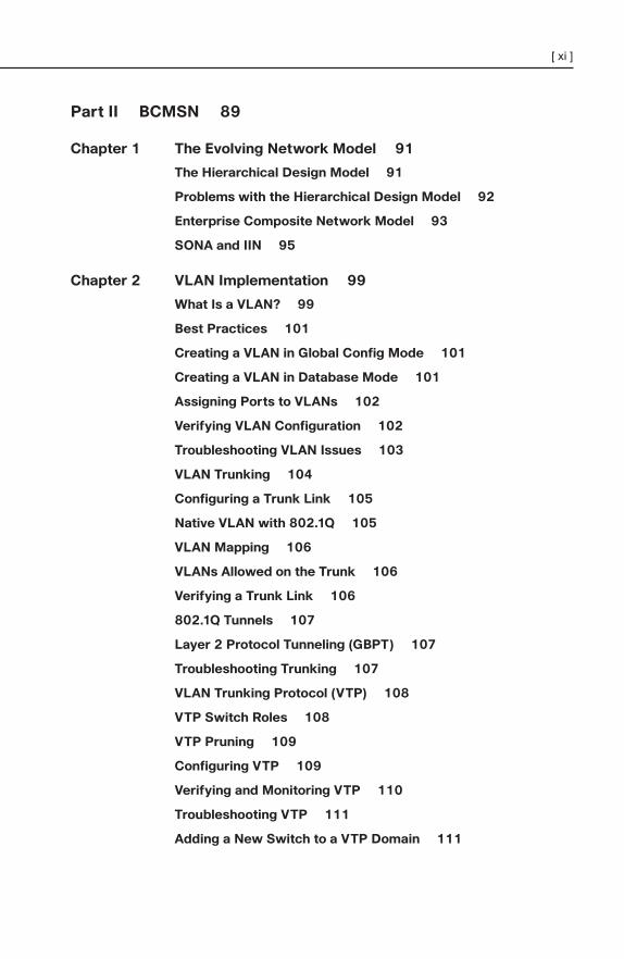
Part II BCMSN 89
Chapter 1 The Evolving Network Model 91
The Hierarchical Design Model 91
Problems with the Hierarchical Design Model 92
Enterprise Composite Network Model 93
SONA and IIN 95
Chapter 2 VLAN Implementation 99
What Is a VLAN? 99
Best Practices 101
Creating a VLAN in Global Config Mode 101
Creating a VLAN in Database Mode 101
Assigning Ports to VLANs 102
Verifying VLAN Configuration 102
Troubleshooting VLAN Issues 103
VLAN Trunking 104
Configuring a Trunk Link 105
Native VLAN with 802.1Q 105
VLAN Mapping 106
VLANs Allowed on the Trunk 106
Verifying a Trunk Link 106
802.1Q Tunnels 107
Layer 2 Protocol Tunneling (GBPT) 107
Troubleshooting Trunking 107
VLAN Trunking Protocol (VTP) 108
VTP Switch Roles 108
VTP Pruning 109
Configuring VTP 109
Verifying and Monitoring VTP 110
Troubleshooting VTP 111
Adding a New Switch to a VTP Domain 111
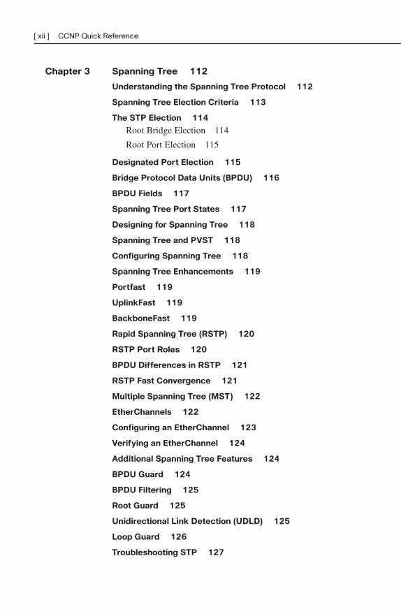
Chapter 3 Spanning Tree 112
Understanding the Spanning Tree Protocol 112
Spanning Tree Election Criteria 113
The STP Election 114
Root Bridge Election 114
Root Port Election 115
Designated Port Election 115
Bridge Protocol Data Units (BPDU) 116
BPDU Fields 117
Spanning Tree Port States 117
Designing for Spanning Tree 118
Spanning Tree and PVST 118
Configuring Spanning Tree 118
Spanning Tree Enhancements 119
Portfast 119
UplinkFast 119
BackboneFast 119
Rapid Spanning Tree (RSTP) 120
RSTP Port Roles 120
BPDU Differences in RSTP 121
RSTP Fast Convergence 121
Multiple Spanning Tree (MST) 122
EtherChannels 122
Configuring an EtherChannel 123
Verifying an EtherChannel 124
Additional Spanning Tree Features 124
BPDU Guard 124
BPDU Filtering 125
Root Guard 125
Unidirectional Link Detection (UDLD) 125
Loop Guard 126
Troubleshooting STP 127
[ xii ] CCNP Quick Reference
[ xiii ]
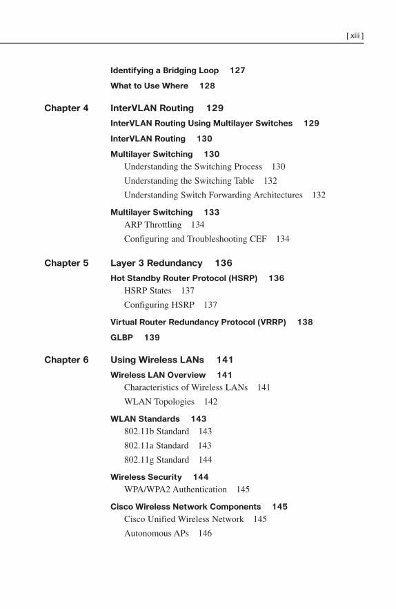
Identifying a Bridging Loop 127
What to Use Where 128
Chapter 4 InterVLAN Routing 129
InterVLAN Routing Using Multilayer Switches 129
InterVLAN Routing 130
Multilayer Switching 130
Understanding the Switching Process 130
Understanding the Switching Table 132
Understanding Switch Forwarding Architectures 132
Multilayer Switching 133
ARP Throttling 134
Configuring and Troubleshooting CEF 134
Chapter 5 Layer 3 Redundancy 136
Hot Standby Router Protocol (HSRP) 136
HSRP States 137
Configuring HSRP 137
Virtual Router Redundancy Protocol (VRRP) 138
GLBP 139
Chapter 6 Using Wireless LANs 141
Wireless LAN Overview 141
Characteristics of Wireless LANs 141
WLAN Topologies 142
WLAN Standards 143
802.11b Standard 143
802.11a Standard 143
802.11g Standard 144
Wireless Security 144
WPA/WPA2 Authentication 145
Cisco Wireless Network Components 145
Cisco Unified Wireless Network 145
Autonomous APs 146
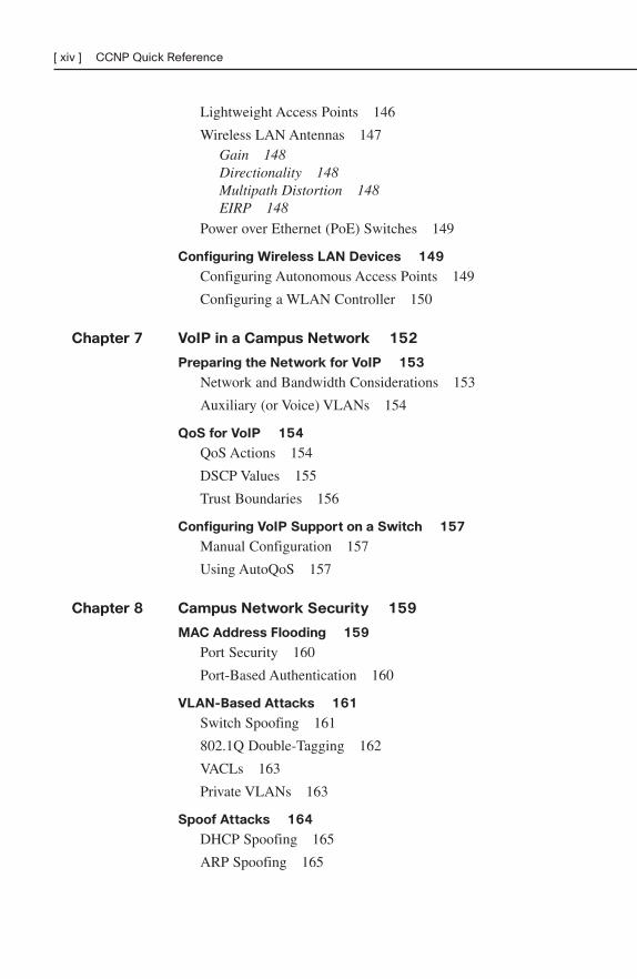
Lightweight Access Points 146
Wireless LAN Antennas 147Gain 148Directionality 148Multipath Distortion 148EIRP 148
Power over Ethernet (PoE) Switches 149
Configuring Wireless LAN Devices 149
Configuring Autonomous Access Points 149
Configuring a WLAN Controller 150
Chapter 7 VoIP in a Campus Network 152
Preparing the Network for VoIP 153
Network and Bandwidth Considerations 153
Auxiliary (or Voice) VLANs 154
QoS for VoIP 154
QoS Actions 154
DSCP Values 155
Trust Boundaries 156
Configuring VoIP Support on a Switch 157
Manual Configuration 157
Using AutoQoS 157
Chapter 8 Campus Network Security 159
MAC Address Flooding 159
Port Security 160
Port-Based Authentication 160
VLAN-Based Attacks 161
Switch Spoofing 161
802.1Q Double-Tagging 162
VACLs 163
Private VLANs 163
Spoof Attacks 164
DHCP Spoofing 165
ARP Spoofing 165
[ xiv ] CCNP Quick Reference
[ xv ]
Securing Spanning Tree 166
BPDU Guard 167
BPDU Filtering 167
Root Guard 167
Prevent Spanning Tree Loops 167
Unidirectional Link Detection (UDLD) 168
Loop Guard 168
Securing Your Switch 169
Part III ISCW 171
Chapter 1 Network Conceptual Models 173
Intelligent Information Network 173
Service-Oriented Network Architecture 173
Cisco Enterprise Architecture 174
Chapter 2 Providing SOHO/Teleworker Connectivity 176
Broadband Cable 177
Cable Components 177
Cable Standards 178
Provisioning the Cable Modem 179
Digital Subscriber Line 180
Types of DSL 180
ADSL 181Carrierless Amplitude and Phase Line Coding 182Discrete Multi-Tone Line Coding 182
Layer 2 over DSL 182PPPoE 183PPPoA 184
Configuring DSL CPE 184
Configuring PPPoE CPE 184
Configuring PPPoA CPE 187
Troubleshooting ADSL 188Troubleshooting ADSL at Layer 1 188Troubleshooting ADSL at Layer 2 188
Chapter 3 Frame Mode MPLS 190
Cisco Express Forwarding 191
MPLS Routers 191
MPLS Labels 193
Label Distribution and Label Tables 193
Penultimate Hop Popping 194
Configuring Frame Mode MPLS 195
Enabling CEF 195
Enabling MPLS 196
Increasing the MTU Size 196
MPLS VPNs 197
Handling Customer Routes 197
Route Distinguishers 198
Route Targets 198
Chapter 4 IPsec 200
IPsec Headers 200
Authentication Header 200
Encapsulating Security Payload 201IPsec Modes 201
Authentication Methods 202
Encryption Methods 202
Symmetric Key Algorithms 202
Asymmetric Key Algorithm 203
Diffie-Hellman Key Exchange 203
Key Management 203
Establishing an IPsec VPN 204
Configuring a Site-to-Site VPN Using Cisco IOS
Commands 204
Configuring an ISAKMP Policy 205
Configuring an IPsec Transform Set 206
Configuring a Crypto ACL 206
Configuring a Crypto Map 207
Applying the Crypto Map to an Interface 207
Configuring an Optional Interface Access List 207
[ xvi ] CCNP Quick Reference
[ xvii ]
Configuring a Site-to-Site VPN Using SDM 208
Monitoring and Troubleshooting IPsec VPNs 209
Using GRE with IPsec 209
Configuring a GRE Tunnel Using Cisco IOS
Commands 210
Configuring a GRE over IPsec Tunnel Using the SDM 210
High-Availability VPNs 211
Detecting a Failure Using DPD 211
Detecting a Failure Using HSRP 212
Using IPsec Stateful Failover 212
Using an IPsec Tunnel as a Backup WAN Link 214
Cisco Easy VPN 214
Establishing an Easy VPN IPsec Session 214
Using SDM to Configure the Easy VPN Server 215
Configuring the Cisco VPN Client 216
Chapter 5 Cisco Device Hardening 217
Mitigating Network Attacks 217
Cisco Self-Defending Network 217
Types of Network Attacks 217
Mitigating Reconnaissance Attacks 218
Mitigating Access Attacks 219
Mitigating Denial-of-Service Attacks 219
Disabling Unused Cisco Router Network Services and
Interfaces 220
Unused Router Interfaces 220
Vulnerable Router Services 220
Hardening with AutoSecure 221
Configuring AutoSecure 222
Security Device Manager 222
Securing Cisco Router Installations and Administrative
Access 222
Password-Creation Rules 222
Types of Router Passwords 222
Password-Length Enforcement 223
Password Encryption 223
Enhanced Username Password Security 223
Password Example 224
Securing ROMMON 224
Rate-Limiting Authentication Attempts 224
Setting Timeouts 225
Privilege Levels 225
Configuring Banner Messages 225
Role-Based CLI 226
Cisco IOS Resilient Configuration 227
Mitigating Threats and Attacks with Access Lists 227
ACL Review 227
Mitigating Spoofed Addresses (Inbound) 227
Mitigating Spoofed Addresses (Outbound) 228
Mitigating SYN Attacks 228Using the established Keyword in ACLs 228Using TCP Intercept 228ACL Caveats 229
Securing Management and Reporting Features 229
Types of Management Traffic 229
Configuring Secure Shell 230
Configuring Syslog 231
Simple Network Management Protocol 231
Network Time Protocol 232
Configuring AAA on Cisco Routers 232
AAA Services 233
Router Access Modes 233
Configuring AAA 233
Configuring CLI Authentication on a Cisco Router 234
Configuring Authorization 234
Configuring Accounting 235
Troubleshooting AAA 235
Chapter 6 Cisco IOS Threat Defenses 236
DMZ Design Review 236
Firewall Technologies 236
[ xviii ] CCNP Quick Reference
[ xix ]
Cisco IOS Firewall 237
TCP Handling in the Cisco IOS Firewall 237
UDP Handling in the Cisco IOS Firewall 237
Alerts and Audit Trails 238
Cisco IOS Authentication Proxy 238
Configuring Cisco IOS Firewalls 238
Defining External and Internal Interfaces 238
Configuring Access Lists on the Interfaces 239
Defining Inspection Rules 239
Applying Inspection Rules to Interfaces 240
Verifying Inspection 240
Introducing Cisco IOS IPS 241
Defining IDS/IPS Terms 241
Cisco IOS IPS Signatures 242
Cisco IOS IPS Alarms 242
Configuring Cisco IOS IPS 242
Part IV ONT 245
Chapter 1 Network Architecture 247
SONA and IIN 247
Network Models 250
Hierarchical Design Model 250
Enterprise Composite Network Model 251
Chapter 2 Cisco VoIP 253
Transmission 254
Packetization 256
Transmitting 257
Bandwidth Requirements 259
A Worksheet for Calculating VoIP Bandwidth 260
An Example for G.711, No Compression over Ethernet,20 ms Samples 260
Implementing IP Telephony 261
Configuring Cisco Routers to Support VoIP 262
Chapter 3 QoS Overview 264
Bandwidth 264
Delay and Jitter 265
Packet Loss Issues 266
Defining QoS Requirements for Network Traffic 266
QoS Models 267
Best Effort 267
IntServ 267
DiffServ 269
QoS Implementation Methods 269
Legacy CLI 269
MQC 270MQC Configuration 270Verifying QoS Configuration 271
AutoQoS 271
SDM QoS Wizard 272
QoS Methods Comparison 274
Chapter 4 QoS Details 275
Classification and Marking 275
Using NBAR for Classifying Traffic 275
Marking at Layer 2 278
Marking at Layer 3 279Default PHB 280Assured Forwarding and Class Selector PHB 280DiffServ Expedited Forwarding PHB 281
Classifying and Marking in a VoIP Network 281
Queuing Overview 286
Hardware Queue 286
Software Queue 287
Legacy Queuing Techniques 287
FIFO Queuing 287
Priority Queuing 287
Round Robin Queuing 288
Weighted Fair Queuing 288Configuring WFQ 289
[ xx ] CCNP Quick Reference
[ xxi ]
CBWFQ and LLQ 290
CBWFQ 290
LLQ 291
Congestion Avoidance 293
Traffic Policing and Shaping 294
Traffic Policing 295
Traffic Shaping 295
Link Efficiency Mechanisms 296
Compression 296
Link Fragmentation and Interleave (LFI) 297
QoS with VPNs 297
GRE Tunnels 298
IPsec Tunnels 298
Enterprise-Wide QoS Deployment 300
SLA 300
Enterprise QoS 300
CoPP 302
Chapter 5 AutoQoS 303
AutoQoS for Switches 303
AutoQos for Routers 304
AutoQoS Restrictions and Caveats 304
Tuning AutoQoS 305
AutoQoS Classes 305
AutoQoS and Changing Network Conditions 306
Manually Tuning AutoQoS Configurations 307
Chapter 6 Wireless Scalability 308
WLAN QoS 308
LWAP 308
802.1x and WLAN Security 309
Configuring WLAN Security on Controller 312
WLAN Management 312
Index 315
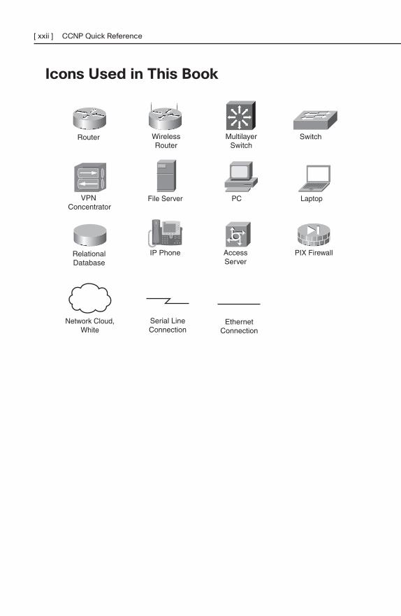
Icons Used in This Book
[ xxii ] CCNP Quick Reference
PIX Firewall
VPNConcentrator
LaptopPCFile Server
EthernetConnection
RelationalDatabase
Serial LineConnection
Network Cloud,White
IP Phone
Router SwitchMultilayerSwitch
WirelessRouter
AccessServer
[ xxiii ]
Command Syntax ConventionsThe conventions used to present command syntax in this book are the sameconventions used in the IOS Command Reference. The Command Referencedescribes these conventions as follows:
■ Boldface indicates commands and keywords that are entered literally asshown. In actual configuration examples and output (not general commandsyntax), boldface indicates commands that are manually input by the user(such as a show command).
■ Italic indicates arguments for which you supply actual values.
■ Vertical bars (|) separate alternative, mutually exclusive elements.
■ Square brackets ([ ]) indicate an optional element.
■ Braces ({ }) indicate a required choice.
■ Braces within brackets ([{ }]) indicate a required choice within an optionalelement.

This page intentionally left blank
BSCIChapter 1: The Evolving Network Model . . . . . . . . . . . . . . . 3
Chapter 2: EIGRP. . . . . . . . . . . . . . . . . . . . . . . . . . . . . . . . . . . 14
Chapter 3: OSPF . . . . . . . . . . . . . . . . . . . . . . . . . . . . . . . . . . . 26
Chapter 4: IS-IS . . . . . . . . . . . . . . . . . . . . . . . . . . . . . . . . . . . . 41
Chapter 5: Optimizing Routing . . . . . . . . . . . . . . . . . . . . . . . 47
Chapter 6: BGP . . . . . . . . . . . . . . . . . . . . . . . . . . . . . . . . . . . . 58
Chapter 7: IP Multicast. . . . . . . . . . . . . . . . . . . . . . . . . . . . . . 69
Chapter 8: IPv6 Introduction. . . . . . . . . . . . . . . . . . . . . . . . . 77
PART I

This page intentionally left blank
CHAPTER 1
The Evolving Network Model
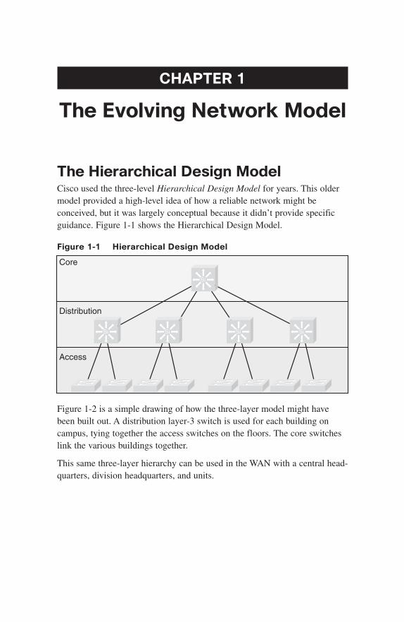
The Hierarchical Design ModelCisco used the three-level Hierarchical Design Model for years. This oldermodel provided a high-level idea of how a reliable network might beconceived, but it was largely conceptual because it didn’t provide specificguidance. Figure 1-1 shows the Hierarchical Design Model.
Figure 1-1 Hierarchical Design Model
Core
Access
Distribution
Si
Si Si Si Si
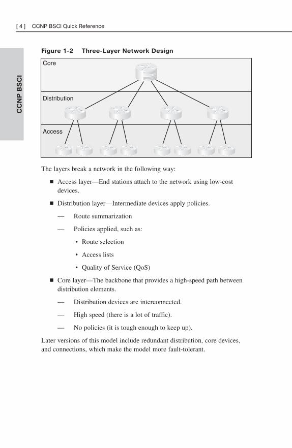
Figure 1-2 is a simple drawing of how the three-layer model might havebeen built out. A distribution layer-3 switch is used for each building oncampus, tying together the access switches on the floors. The core switcheslink the various buildings together.
This same three-layer hierarchy can be used in the WAN with a central head-quarters, division headquarters, and units.
CC
NP
BS
CI
[ 4 ] CCNP BSCI Quick Reference
Figure 1-2 Three-Layer Network Design
Core
Access
Distribution
The layers break a network in the following way:
■ Access layer—End stations attach to the network using low-costdevices.
■ Distribution layer—Intermediate devices apply policies.
— Route summarization
— Policies applied, such as:
• Route selection
• Access lists
• Quality of Service (QoS)
■ Core layer—The backbone that provides a high-speed path betweendistribution elements.
— Distribution devices are interconnected.
— High speed (there is a lot of traffic).
— No policies (it is tough enough to keep up).
Later versions of this model include redundant distribution, core devices,and connections, which make the model more fault-tolerant.
Problems with the Hierarchical Design Model
This early model was a good starting point, but it failed to address keyissues, such as:
■ Where do wireless devices fit in?
■ How should Internet access and security be provisioned?
■ How do you account for remote access, such as dial-up or VPN?
■ Where should workgroup and enterprise services be located?
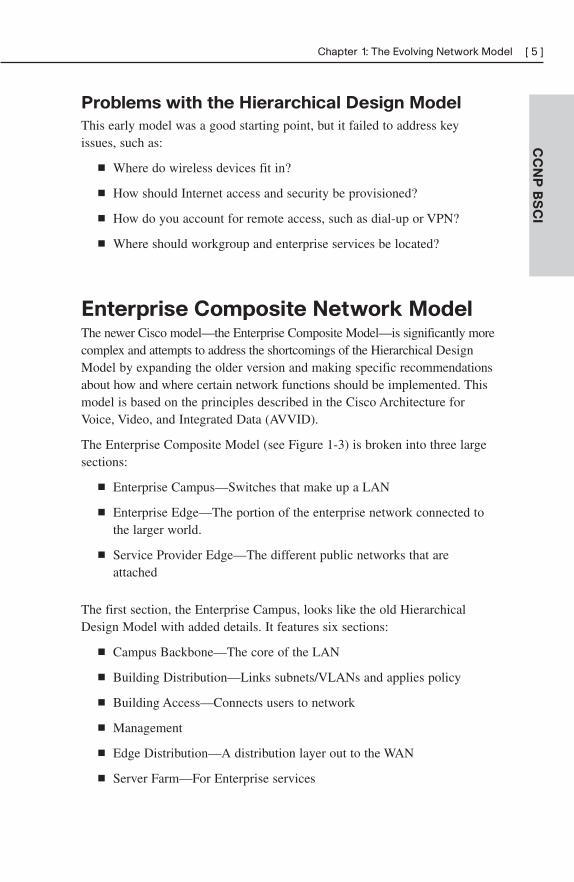
Enterprise Composite Network ModelThe newer Cisco model—the Enterprise Composite Model—is significantly morecomplex and attempts to address the shortcomings of the Hierarchical DesignModel by expanding the older version and making specific recommendationsabout how and where certain network functions should be implemented. Thismodel is based on the principles described in the Cisco Architecture forVoice, Video, and Integrated Data (AVVID).
The Enterprise Composite Model (see Figure 1-3) is broken into three largesections:
■ Enterprise Campus—Switches that make up a LAN
■ Enterprise Edge—The portion of the enterprise network connected tothe larger world.
■ Service Provider Edge—The different public networks that areattached
The first section, the Enterprise Campus, looks like the old HierarchicalDesign Model with added details. It features six sections:
■ Campus Backbone—The core of the LAN
■ Building Distribution—Links subnets/VLANs and applies policy
■ Building Access—Connects users to network
■ Management
■ Edge Distribution—A distribution layer out to the WAN
■ Server Farm—For Enterprise services
CC
NP
BS
CI
Chapter 1: The Evolving Network Model [ 5 ]
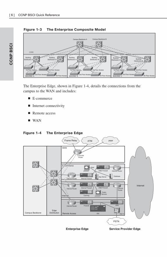
Figure 1-3 The Enterprise Composite Model
CC
NP
BS
CI
[ 6 ] CCNP BSCI Quick Reference
CORE
BUILDING B
Campus Backbone A Campus Backbone B
BUILDING CBUILDING A
BuildingDistribution A
BuildingDistribution B
BuildingDistribution A
BuildingDistribution B
BuildingDistribution A Building
Distribution B
2nd Floor Access4th Floor Access
2nd Floor Access4th Floor Access
2nd Floor Access4th Floor Access
1st Floor Access 3rd Floor Access 1st Floor Access 3rd Floor Access1st Floor Access 3rd Floor Access
The Enterprise Edge, shown in Figure 1-4, details the connections from thecampus to the WAN and includes:
■ E-commerce
■ Internet connectivity
■ Remote access
■ WAN
Figure 1-4 The Enterprise Edge
Remote Access
WAN
Campus BackboneEdge
Distribution
Internal Router
DMZ Firewall
Web
DatabaseIDC
App Server
Internet Router
Corporate Router
Dial-In
Internal RouterDMZ Firewall
PublicServers
Internet Router
Internal Router VPN
IDS
PPP
Service Provider EdgeEnterprise Edge
Internet
PSTN
Frame Relay ATM
Internal Firewall
Internal Firewall
Caching
Firewall
E-Commerce
Internet
The Service Provider Edge is just a list of the public networks that facilitatewide-area connectivity and include:
■ Internet service provider (ISP)
■ Public switched telephone network (PSTN)
■ Frame Relay, ATM, and PPP
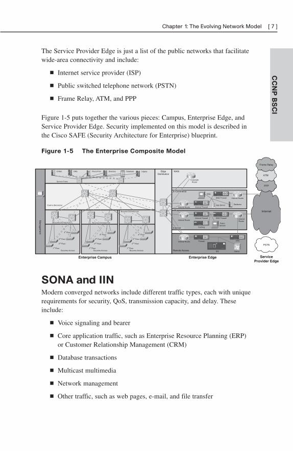
Figure 1-5 puts together the various pieces: Campus, Enterprise Edge, andService Provider Edge. Security implemented on this model is described inthe Cisco SAFE (Security Architecture for Enterprise) blueprint.
Figure 1-5 The Enterprise Composite Model
CC
NP
BS
CI
Chapter 1: The Evolving Network Model [ 7 ]
SONA and IINModern converged networks include different traffic types, each with uniquerequirements for security, QoS, transmission capacity, and delay. Theseinclude:
■ Voice signaling and bearer
■ Core application traffic, such as Enterprise Resource Planning (ERP)or Customer Relationship Management (CRM)
■ Database transactions
■ Multicast multimedia
■ Network management
■ Other traffic, such as web pages, e-mail, and file transfer
CAMPUS BACKBONE
BUILDING ACCESS
1st Floor
2nd Floor
3rd Floor
1st Floor
2nd Floor
3rd Floor
1st Floor
2nd Floor
3rd Floor
SERVER FARM
LegacyFile & Print DatabaseE-Mail DNS Directory
ServiceProvider Edge
Enterprise EdgeEnterprise CampusM
anagement
Remote Access
WANEdgeDistribution
Internal Router
DMZ Firewall
Web
DatabaseI DC
App Server
Internet Router
Corporate Router
Dial-In
Internal RouterDMZ Firewall
PublicServers
Internet Router
Internal Router VPN
IDS
Internet
PSTN
Internal Firewall
Internal Firewall
Caching
Firewall
PPP
ATM
Frame Relay
BUILDING DISTRIBUTIONBUILDING DISTRIBUTION
BUILDING ACCESS BUILDING ACCESS
4th Floor4th Floor 4th Floor
BUILDING DISTRIBUTION
E-Commerce
Internet
IDC
IDC
IDC
Cisco routers are able to implement filtering, compression, prioritization,and policing. Except for filtering, these capabilities are referred to collec-tively as QoS.
Note
The best way to meet capacity requirements is to have twice as much bandwidth as needed.Financial reality, however, usually requires QoS instead.
Although QoS is wonderful, it is not the only way to address bandwidthshortage. Cisco espouses an idea called the Intelligent Information Network(IIN).
IIN describes an evolutionary vision of a network that integrates network andapplication functionality cooperatively and allows the network to be smartabout how it handles traffic to minimize the footprint of applications. IIN is builton top of the Enterprise Composite Model and describes structures overlaidon to the Composite design as needed in three phases (see Figure 1-6).
Phase 1, “Integrated Transport,” describes a converged network, which is builtalong the lines of the Composite model and based on open standards. This isthe phase that the industry has been transitioning to recently. The CiscoIntegrated Services Routers (ISR) are an example of this trend.
Phase 2, “Integrated Services,” attempts to virtualize resources, such asservers, storage, and network access. It is a move to an “on-demand” model.
By “virtualize,” Cisco means that the services are not associated with a particulardevice or location. Instead, many services can reside in one device to easemanagement, or many devices can provide one service that is more reliable.
An ISR brings together routing, switching, voice, security, and wireless. It isan example of many services existing on one device. A load balancer, whichmakes many servers look like one, is an example of one service residing onmany devices.
VRFs are an example of taking one resource and making it look like many. Someversions of IOS are capable of having a router present itself as many virtualrouter (VRF) instances, allowing your company to deliver different logicaltopologies on the same physical infrastructure. Server virtualization is
CC
NP
BS
CI
[ 8 ] CCNP BSCI Quick Reference
another example. The classic example of taking one resource and making itappear to be many resources is the use of a virtual LAN (VLAN) and avirtual storage area network (VSAN).
Virtualization provides flexibility in configuration and management.
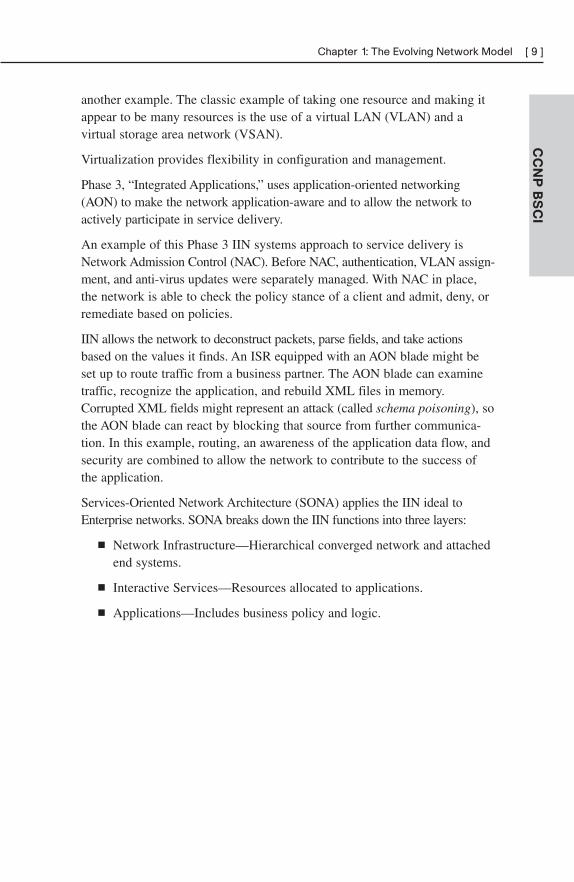
Phase 3, “Integrated Applications,” uses application-oriented networking(AON) to make the network application-aware and to allow the network toactively participate in service delivery.
An example of this Phase 3 IIN systems approach to service delivery isNetwork Admission Control (NAC). Before NAC, authentication, VLAN assign-ment, and anti-virus updates were separately managed. With NAC in place,the network is able to check the policy stance of a client and admit, deny, orremediate based on policies.
IIN allows the network to deconstruct packets, parse fields, and take actionsbased on the values it finds. An ISR equipped with an AON blade might beset up to route traffic from a business partner. The AON blade can examinetraffic, recognize the application, and rebuild XML files in memory.Corrupted XML fields might represent an attack (called schema poisoning), sothe AON blade can react by blocking that source from further communica-tion. In this example, routing, an awareness of the application data flow, andsecurity are combined to allow the network to contribute to the success ofthe application.
Services-Oriented Network Architecture (SONA) applies the IIN ideal toEnterprise networks. SONA breaks down the IIN functions into three layers:
■ Network Infrastructure—Hierarchical converged network and attachedend systems.
■ Interactive Services—Resources allocated to applications.
■ Applications—Includes business policy and logic.
CC
NP
BS
CI
Chapter 1: The Evolving Network Model [ 9 ]
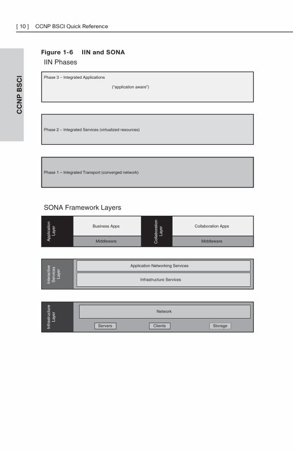
Figure 1-6 IIN and SONA
CC
NP
BS
CI
[ 10 ] CCNP BSCI Quick Reference
Phase 1 – Integrated Transport (converged network)
Phase 3 – Integrated Applications
(“application aware”)
Phase 2 – Integrated Services (virtualized resources)
IIN Phases
Business Apps Collaboration Apps
Middleware Middleware
SONA Framework Layers
Infr
astr
uctu
reLa
yer
App
licat
ion
Laye
rIn
tera
ctiv
e S
ervi
ces
Laye
r
Network
Servers StorageClients
Application Networking Services
Infrastructure Services
Col
labo
ratio
n La
yer
CC
NP
BS
CI
Chapter 1: The Evolving Network Model [ 11 ]
IP Routing ProtocolsRouting protocols are used to pass information about the structure of thenetwork between routers. Cisco routers support the following IP routingprotocols RIP (versions 1 and 2), IGRP, EIGRP, IS-IS, OSPF, and BGP. Thissection compares routing protocols and calls out key differences betweenthem.
Administrative Distance
Cisco routers are capable of supporting several IP routing protocols concur-rently. When identical prefixes are discovered from two or more separatesources, Administrative Distance (AD) is used to discriminate between thepaths. AD is a poor choice of words; trustworthiness is a better name.Routers use paths with the lower AD.
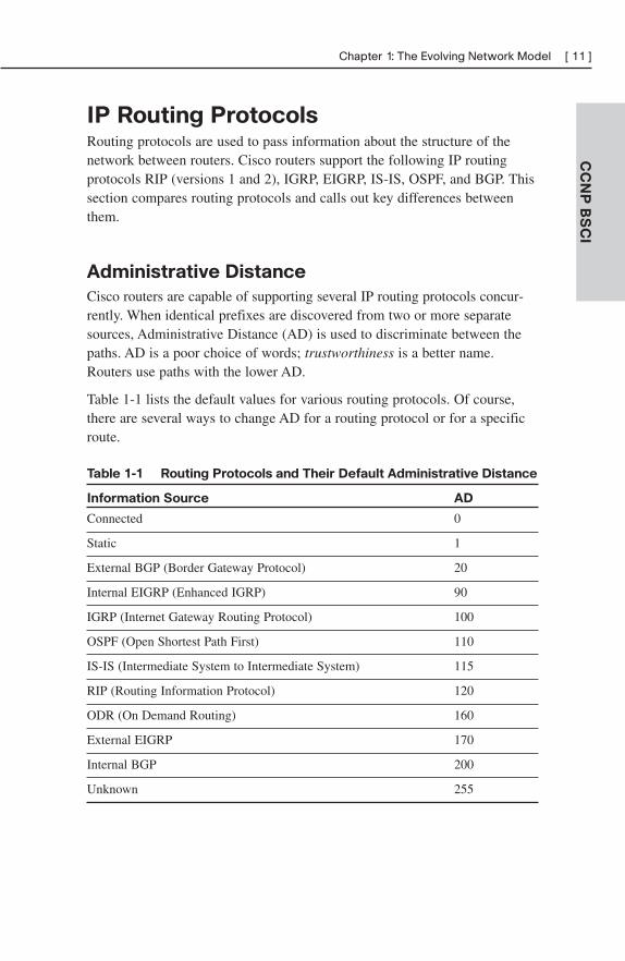
Table 1-1 lists the default values for various routing protocols. Of course,there are several ways to change AD for a routing protocol or for a specificroute.
Table 1-1 Routing Protocols and Their Default Administrative Distance
Information Source AD
Connected 0
Static 1
External BGP (Border Gateway Protocol) 20
Internal EIGRP (Enhanced IGRP) 90
IGRP (Internet Gateway Routing Protocol) 100
OSPF (Open Shortest Path First) 110
IS-IS (Intermediate System to Intermediate System) 115
RIP (Routing Information Protocol) 120
ODR (On Demand Routing) 160
External EIGRP 170
Internal BGP 200
Unknown 255
Building the Routing Table
The router builds a routing table by ruling out invalid routes and consideringthe remaining advertisements. The procedure is:
1. For each route received, verify the next hop. If invalid, discard theroute.
2. If multiple, valid routes are advertised by a routing protocol, choosethe lowest metric.
3. Routes are identical if they advertise the same prefix and mask, so192.168.0.0/16 and 192.168.0.0/24 are separate paths and are eachplaced into the routing table.
4. If more than one specific valid route is advertised by different routingprotocols, choose the path with the lowest AD.
Comparing Routing Protocols
Two things should always be considered in choosing a routing protocol: fastconvergence speed and support for VLSM. EIGRP, OSPF, and IS-IS meetthese criteria. Although all three meet the minimum, there are still importantdistinctions, as described below:
■ EIGRP is proprietary, but it is simple to configure and support.
■ OSPF is an open standard, but it is difficult to implement and support.
■ There are few books on IS-IS and even fewer engineers with experience who use it. IS-IS is therefore uncommon.
Table 1-2 compares routing protocols.
CC
NP
BS
CI
[ 12 ] CCNP BSCI Quick Reference
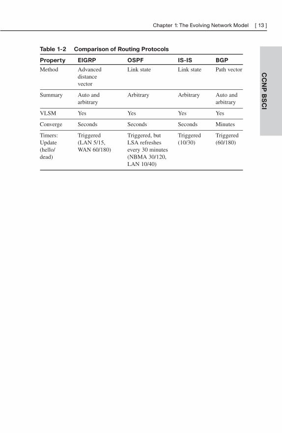
Table 1-2 Comparison of Routing Protocols
Property EIGRP OSPF IS-IS BGP
Method Advanced Link state Link state Path vectordistancevector
Summary Auto and Arbitrary Arbitrary Auto and arbitrary arbitrary
VLSM Yes Yes Yes Yes
Converge Seconds Seconds Seconds Minutes
Timers: Triggered Triggered, but Triggered Triggered Update (LAN 5/15, LSA refreshes (10/30) (60/180)(hello/ WAN 60/180) every 30 minutes dead) (NBMA 30/120,
LAN 10/40)
CC
NP
BS
CI
Chapter 1: The Evolving Network Model [ 13 ]
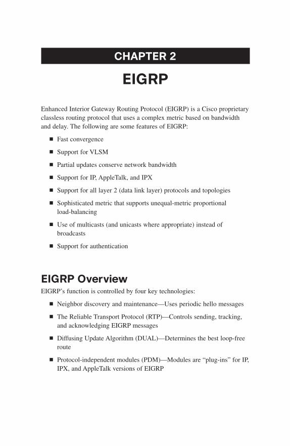
CHAPTER 2
EIGRP
Enhanced Interior Gateway Routing Protocol (EIGRP) is a Cisco proprietaryclassless routing protocol that uses a complex metric based on bandwidthand delay. The following are some features of EIGRP:
■ Fast convergence
■ Support for VLSM
■ Partial updates conserve network bandwidth
■ Support for IP, AppleTalk, and IPX
■ Support for all layer 2 (data link layer) protocols and topologies
■ Sophisticated metric that supports unequal-metric proportional load-balancing
■ Use of multicasts (and unicasts where appropriate) instead of broadcasts
■ Support for authentication
EIGRP OverviewEIGRP’s function is controlled by four key technologies:
■ Neighbor discovery and maintenance—Uses periodic hello messages
■ The Reliable Transport Protocol (RTP)—Controls sending, tracking,and acknowledging EIGRP messages
■ Diffusing Update Algorithm (DUAL)—Determines the best loop-freeroute
■ Protocol-independent modules (PDM)—Modules are “plug-ins” for IP,IPX, and AppleTalk versions of EIGRP
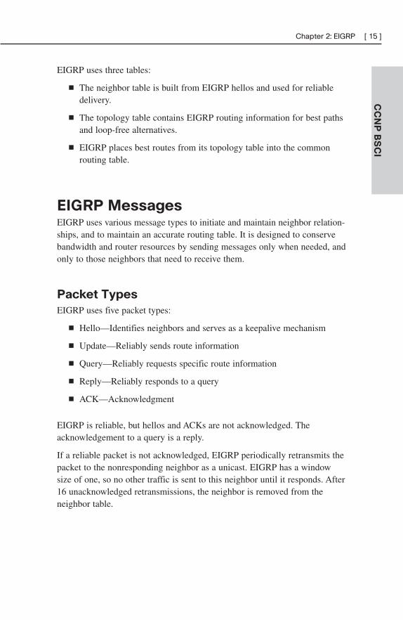
EIGRP uses three tables:
■ The neighbor table is built from EIGRP hellos and used for reliabledelivery.
■ The topology table contains EIGRP routing information for best pathsand loop-free alternatives.
■ EIGRP places best routes from its topology table into the commonrouting table.
EIGRP MessagesEIGRP uses various message types to initiate and maintain neighbor relation-ships, and to maintain an accurate routing table. It is designed to conservebandwidth and router resources by sending messages only when needed, andonly to those neighbors that need to receive them.
Packet Types
EIGRP uses five packet types:
■ Hello—Identifies neighbors and serves as a keepalive mechanism
■ Update—Reliably sends route information
■ Query—Reliably requests specific route information
■ Reply—Reliably responds to a query
■ ACK—Acknowledgment
EIGRP is reliable, but hellos and ACKs are not acknowledged. Theacknowledgement to a query is a reply.
If a reliable packet is not acknowledged, EIGRP periodically retransmits thepacket to the nonresponding neighbor as a unicast. EIGRP has a windowsize of one, so no other traffic is sent to this neighbor until it responds. After16 unacknowledged retransmissions, the neighbor is removed from theneighbor table.
CC
NP
BS
CI
Chapter 2: EIGRP [ 15 ]
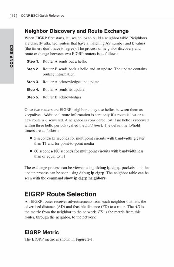
Neighbor Discovery and Route Exchange
When EIGRP first starts, it uses hellos to build a neighbor table. Neighborsare directly attached routers that have a matching AS number and k values(the timers don’t have to agree). The process of neighbor discovery androute exchange between two EIGRP routers is as follows:
Step 1. Router A sends out a hello.
Step 2. Router B sends back a hello and an update. The update containsrouting information.
Step 3. Router A acknowledges the update.
Step 4. Router A sends its update.
Step 5. Router B acknowledges.
Once two routers are EIGRP neighbors, they use hellos between them askeepalives. Additional route information is sent only if a route is lost or anew route is discovered. A neighbor is considered lost if no hello is receivedwithin three hello periods (called the hold time). The default hello/holdtimers are as follows:
■ 5 seconds/15 seconds for multipoint circuits with bandwidth greaterthan T1 and for point-to-point media
■ 60 seconds/180 seconds for multipoint circuits with bandwidth lessthan or equal to T1
The exchange process can be viewed using debug ip eigrp packets, and theupdate process can be seen using debug ip eigrp. The neighbor table can beseen with the command show ip eigrp neighbors.
EIGRP Route SelectionAn EIGRP router receives advertisements from each neighbor that lists theadvertised distance (AD) and feasible distance (FD) to a route. The AD isthe metric from the neighbor to the network. FD is the metric from thisrouter, through the neighbor, to the network.
EIGRP Metric
The EIGRP metric is shown in Figure 2-1.
CC
NP
BS
CI
[ 16 ] CCNP BSCI Quick Reference
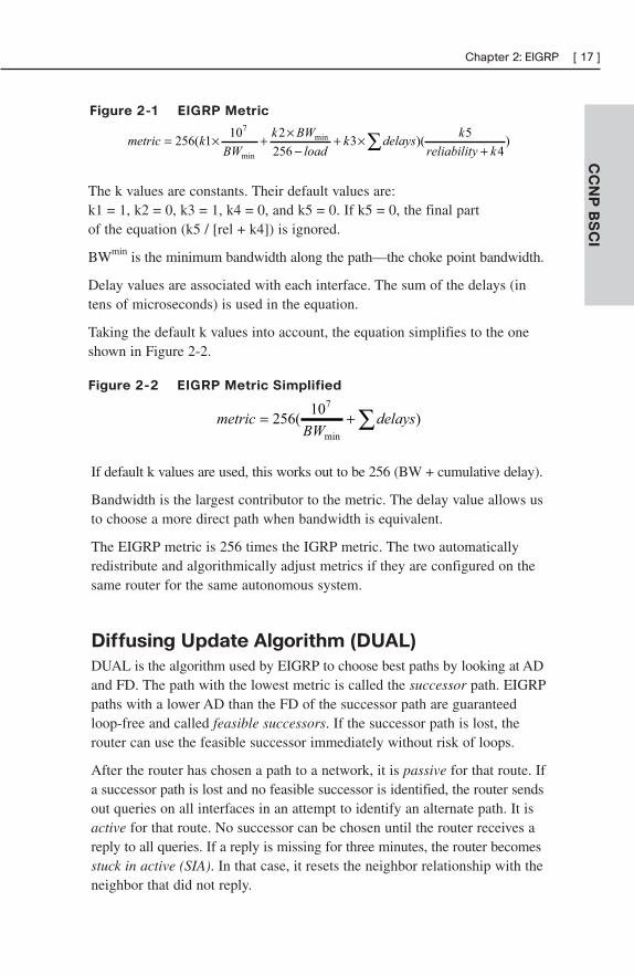
Figure 2-1 EIGRP Metric
CC
NP
BS
CI
Chapter 2: EIGRP [ 17 ]
)4
5)(3
256
2101(256 min
min
7
kyreliabilit
kdelaysk
load
BWk
BWkmetric
+×+
−×+×= ∑
∑+= )10
(256min
7
delaysBW
metric
The k values are constants. Their default values are:k1 = 1, k2 = 0, k3 = 1, k4 = 0, and k5 = 0. If k5 = 0, the final part of the equation (k5 / [rel + k4]) is ignored.
BWmin is the minimum bandwidth along the path—the choke point bandwidth.
Delay values are associated with each interface. The sum of the delays (intens of microseconds) is used in the equation.
Taking the default k values into account, the equation simplifies to the oneshown in Figure 2-2.
Figure 2-2 EIGRP Metric Simplified
If default k values are used, this works out to be 256 (BW + cumulative delay).
Bandwidth is the largest contributor to the metric. The delay value allows usto choose a more direct path when bandwidth is equivalent.
The EIGRP metric is 256 times the IGRP metric. The two automaticallyredistribute and algorithmically adjust metrics if they are configured on thesame router for the same autonomous system.
Diffusing Update Algorithm (DUAL)
DUAL is the algorithm used by EIGRP to choose best paths by looking at ADand FD. The path with the lowest metric is called the successor path. EIGRPpaths with a lower AD than the FD of the successor path are guaranteedloop-free and called feasible successors. If the successor path is lost, therouter can use the feasible successor immediately without risk of loops.
After the router has chosen a path to a network, it is passive for that route. Ifa successor path is lost and no feasible successor is identified, the router sendsout queries on all interfaces in an attempt to identify an alternate path. It isactive for that route. No successor can be chosen until the router receives areply to all queries. If a reply is missing for three minutes, the router becomesstuck in active (SIA). In that case, it resets the neighbor relationship with theneighbor that did not reply.
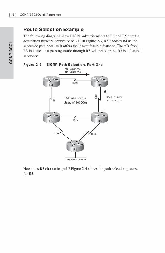
Route Selection Example
The following diagrams show EIGRP advertisements to R3 and R5 about adestination network connected to R1. In Figure 2-3, R5 chooses R4 as thesuccessor path because it offers the lowest feasible distance. The AD fromR3 indicates that passing traffic through R3 will not loop, so R3 is a feasiblesuccessor.
Figure 2-3 EIGRP Path Selection, Part One
CC
NP
BS
CI
[ 18 ] CCNP BSCI Quick Reference
FD: 21,024,000AD: 2,170,031
FD: 14,869,333AD: 14,357,333
Destination network
192k
192k 12
8kAll links have a
delay of 20000us
256k
576k 1544k
R4 R5
R3R2
R1
How does R3 choose its path? Figure 2-4 shows the path selection processfor R3.
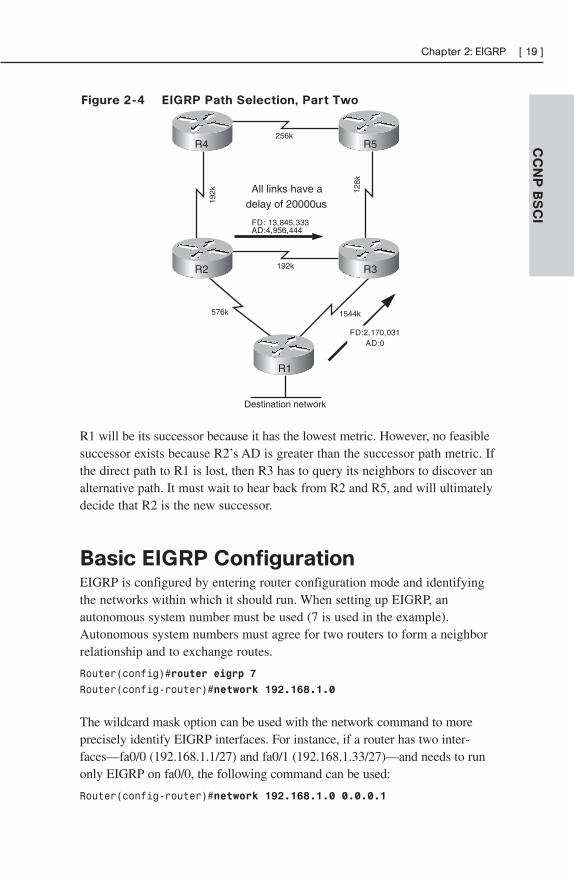
Figure 2-4 EIGRP Path Selection, Part Two
CC
NP
BS
CI
Chapter 2: EIGRP [ 19 ]
Destination network
192k
192k
FD:2,170,031AD:0
FD: 13,845,333AD:4,956,444
128k
All links have adelay of 20000us
256k
576k 1544k
R4 R5
R3R2
R1
R1 will be its successor because it has the lowest metric. However, no feasiblesuccessor exists because R2’s AD is greater than the successor path metric. Ifthe direct path to R1 is lost, then R3 has to query its neighbors to discover analternative path. It must wait to hear back from R2 and R5, and will ultimatelydecide that R2 is the new successor.
Basic EIGRP ConfigurationEIGRP is configured by entering router configuration mode and identifyingthe networks within which it should run. When setting up EIGRP, anautonomous system number must be used (7 is used in the example).Autonomous system numbers must agree for two routers to form a neighborrelationship and to exchange routes.
Router(config)#router eigrp 7
Router(config-router)#network 192.168.1.0
The wildcard mask option can be used with the network command to moreprecisely identify EIGRP interfaces. For instance, if a router has two inter-faces—fa0/0 (192.168.1.1/27) and fa0/1 (192.168.1.33/27)—and needs to runonly EIGRP on fa0/0, the following command can be used:
Router(config-router)#network 192.168.1.0 0.0.0.1
In this command, a wildcard mask of 0.0.0.1 matches only two IP addressesin network 192.168.1.0–192.168.1.0 and 192.168.1.1. Therefore, only inter-face fa0/0 is included in EIGRP routing.
Creating an EIGRP Default Route
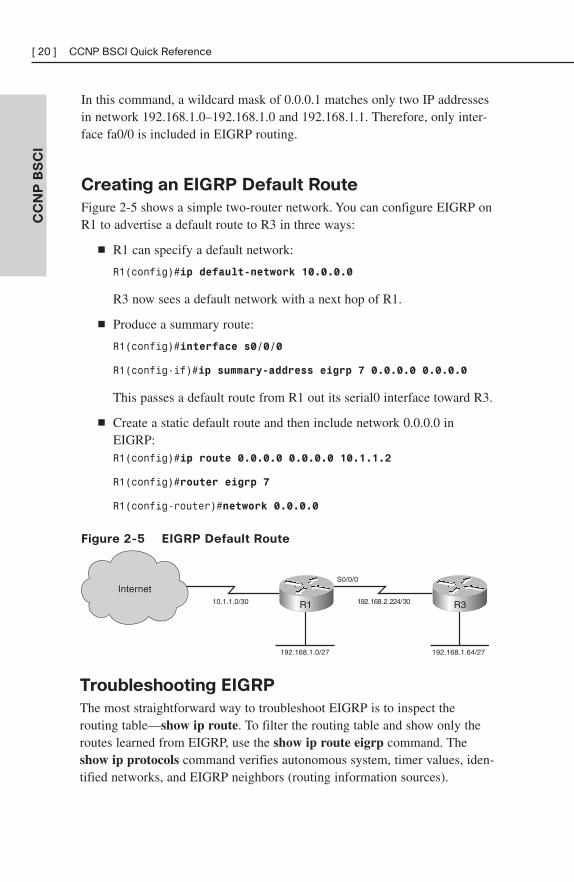
Figure 2-5 shows a simple two-router network. You can configure EIGRP onR1 to advertise a default route to R3 in three ways:
■ R1 can specify a default network:
R1(config)#ip default-network 10.0.0.0
R3 now sees a default network with a next hop of R1.
■ Produce a summary route:
R1(config)#interface s0/0/0
R1(config-if)#ip summary-address eigrp 7 0.0.0.0 0.0.0.0
This passes a default route from R1 out its serial0 interface toward R3.
■ Create a static default route and then include network 0.0.0.0 inEIGRP:R1(config)#ip route 0.0.0.0 0.0.0.0 10.1.1.2
R1(config)#router eigrp 7
R1(config-router)#network 0.0.0.0
Figure 2-5 EIGRP Default Route
CC
NP
BS
CI
[ 20 ] CCNP BSCI Quick Reference
10.1.1.0/30 192.168.2.224/30
S0/0/0Internet
192.168.1.0/27 192.168.1.64/27
R1 R3
Troubleshooting EIGRP
The most straightforward way to troubleshoot EIGRP is to inspect therouting table—show ip route. To filter the routing table and show only theroutes learned from EIGRP, use the show ip route eigrp command. Theshow ip protocols command verifies autonomous system, timer values, iden-tified networks, and EIGRP neighbors (routing information sources).
The command show ip eigrp topology shows the EIGRP topology table andidentifies successors and feasible successors. Use show ip eigrp neighborsto verify that the correct routers are neighbors, and use show ip eigrp trafficto show the amount and types of EIGRP messages.
Advanced EIGRP ConfigurationEIGRP provides some ways to customize its operation, such as route sum-marization, unequal-metric load balancing, controlling the percent of interfacebandwidth used, and authentication. This section describes how to configurethese.
Summarization
EIGRP defaults to automatically summarizing at classful network boundaries.Automatic summarization is usually disabled using the following command:
Router(config-router)#no auto-summary
Summaries can be produced manually on any interface. When a summary isproduced, a matching route to null0 also becomes active as a loop preventionmechanism. Configure a summary route out a particular interface using theip summary-address eigrp autonomous_system command. The followingexample advertises a default route out FastEthernet0/1 and the summaryroute 172.16.104.0/22 out Serial0/0/0 for EIGRP AS 7.
Router(config)#int fa0/1
Router(config-if)#ip summary-address eigrp 7 0.0.0.0 0.0.0.0
!
Router(config)#int s0/0/0
Router(config-if)#ip summary-address eigrp 7 172.16.104.0255.255.252.0
Load Balancing
EIGRP, like most IP routing protocols, automatically load balances overequal metric paths. What makes EIGRP unique is that you can configure it toproportionally load balance over unequal metric paths. The variance commandis used to configure load balancing over up to six loop-free paths with a metriclower than the product of the variance and the best metric. Figure 2-3, in the“Route Selection Example” section, shows routers advertising a path to thenetwork connected to R1.
CC
NP
BS
CI
Chapter 2: EIGRP [ 21 ]
By default, R5 uses the path through R4 because it offers the lowest metric(14,869,333). To set up unequal cost load balancing, assign a variance of 2under the EIGRP process on R5. R5 multiplies the best metric of 14,869,333by 2, to get 29,738,666. R5 then uses all loop-free paths with a metric lessthan 29,738,666, which includes the path through R3. By default, R5 loadbalances over these paths, sending traffic along each path in proportion to itsmetric.
R5(config)#router eigrp 7
R5(config-router)#variance 2
WAN Bandwidth
By default, EIGRP limits itself to bursting to half the link bandwidth. Thislimit is configurable per interface using the ip bandwidth-percentcommand. The following example assumes EIGRP AS 7 and limits EIGRPto one quarter of the link bandwidth:
Router(config)#int s0/0/0
Router(config-if)#ip bandwidth-percent eigrp 7 25
The real issue with WAN links is that the router assumes that each link has1544 kbps bandwidth. If interface Serial0/0/0 is attached to a 128 k frac-tional T1, EIGRP assumes it can burst to 768 k and could overwhelm theline. This is rectified by correctly identifying link bandwidth.
Router (config)#int serial 0/0/0
Router (config-if)#bandwidth 128
Figure 2-6 shows a situation in which these techniques can be combined—Frame Relay.
CC
NP
BS
CI
[ 22 ] CCNP BSCI Quick Reference
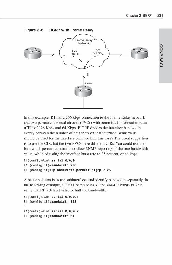
Figure 2-6 EIGRP with Frame Relay
CC
NP
BS
CI
Chapter 2: EIGRP [ 23 ]
Frame RelayNetwork
PVC64K CIR
PVC128K CIR
S0/0/0
256K
In this example, R1 has a 256 kbps connection to the Frame Relay networkand two permanent virtual circuits (PVCs) with committed information rates(CIR) of 128 Kpbs and 64 Kbps. EIGRP divides the interface bandwidthevenly between the number of neighbors on that interface. What valueshould be used for the interface bandwidth in this case? The usual suggestionis to use the CIR, but the two PVCs have different CIRs. You could use thebandwidth-percent command to allow SNMP reporting of the true bandwidthvalue, while adjusting the interface burst rate to 25 percent, or 64 kbps.
R1(config)#int serial 0/0/0
R1 (config-if)#bandwidth 256
R1 (config-if)#ip bandwidth-percent eigrp 7 25
A better solution is to use subinterfaces and identify bandwidth separately. Inthe following example, s0/0/0.1 bursts to 64 k, and s0/0/0.2 bursts to 32 k,using EIGRP’s default value of half the bandwidth.
R1(config)#int serial 0/0/0.1
R1 (config-if)#bandwidth 128
!
R1(config)#int serial 0/0/0.2
R1 (config-if)#bandwidth 64
In cases where the hub interface bandwidth is oversubscribed, it may benecessary to set bandwidth for each subinterface arbitrarily low, and thenspecify an EIGRP bandwidth percent value over 100 in order to allowEIGRP to use half the PVC bandwidth.
EIGRP Authentication
By default, no authentication is used for any routing protocol. Some proto-cols, such as RIPv2, IS-IS, and OSPF, can be configured to do simple pass-word authentication between neighboring routers. In this type ofauthentication, a clear-text password is used. EIGRP does not support simpleauthentication. However, it can be configured to authenticate each packetexchanged, using an MD5 hash. This is more secure than clear text, as onlythe message digest is exchanged, not the password.
EIGRP authenticates each of its packets by including the hash in each one.This helps verify the source of each routing update.
To configure EIGRP authentication, follow these steps:
Step 1. Configure a key chain to group the keys.
Step 2. Configure a key within that key chain.
Step 3. Configure the password or authentication string for that key.Repeat Steps 2 and 3 to add more keys if desired.
Step 4. Optionally configure a lifetime for the keys within that key chain.If you do this, be sure that the time is synchronized between thetwo routers.
Step 5. Enable authentication and assign a key chain to an interface.
Step 6. Designate MD5 as the type of authentication.
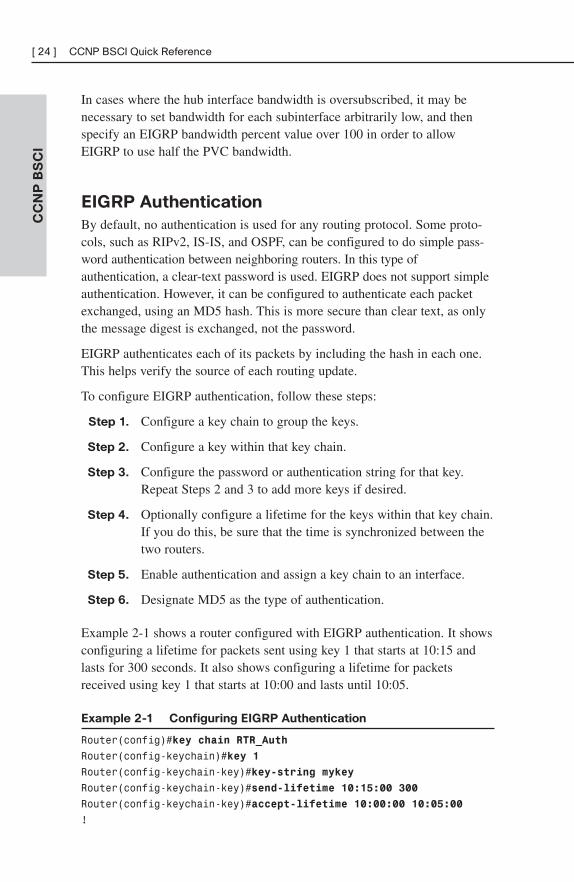
Example 2-1 shows a router configured with EIGRP authentication. It showsconfiguring a lifetime for packets sent using key 1 that starts at 10:15 andlasts for 300 seconds. It also shows configuring a lifetime for packetsreceived using key 1 that starts at 10:00 and lasts until 10:05.
Example 2-1 Configuring EIGRP Authentication
Router(config)#key chain RTR_Auth
Router(config-keychain)#key 1
Router(config-keychain-key)#key-string mykey
Router(config-keychain-key)#send-lifetime 10:15:00 300
Router(config-keychain-key)#accept-lifetime 10:00:00 10:05:00
!
CC
NP
BS
CI
[ 24 ] CCNP BSCI Quick Reference
Router(config)#interface s0/0/0
Router(config-if)#ip authentication mode eigrp 10 md5
Router(config-if)#ip authentication key-chain eigrp 10 RTR_Auth
Verify your configuration with the show ip eigrp neighbors command, asno neighbor relationship will be formed if authentication fails. Using thedebug eigrp packets command should show packets containing authentica-tion information sent and received, and it will allow you to troubleshootconfiguration issues.
EIGRP ScalabilityFour factors influence EIGRP’s scalability:
■ The number of routes that must be exchanged
■ The number of routers that must know of a topology change
■ The number of alternate routes to a network
■ The number of hops from one end of the network to the other
To improve scalability, summarize routes when possible, try to have anetwork depth of no more than seven hops, and limit the scope of EIGRPqueries.
Stub routing is one way to limit queries. A stub router is one that isconnected to no more than two neighbors and should never be a transitrouter. When a router is configured as an EIGRP stub, it notifies its neigh-bors. The neighbors then do not query that router for a lost route. Underrouter configuration mode, use the command eigrp stub [receive-only|connected|static|summary]. An EIGRP stub router still receives allroutes from its neighbors by default.
Routers use SIA-Queries and SIA-Replies to prevent loss of a neighborunnecessarily during SIA conditions. A router sends its neighbor a SIA-Queryafter no reply to a normal query. If the neighbor responds with a SIA-Reply,then the router does not terminate the neighbor relationship after threeminutes, because it knows the neighbor is available.
Graceful shutdown is another feature that speeds network convergence.Whenever the EIGRP process is shut down, the router sends a “goodbye”message to its neighbors. The neighbors can then immediately recalculateany paths that used the router as the next hop, rather than waiting for thehold timer to expire.
CC
NP
BS
CI
Chapter 2: EIGRP [ 25 ]
CHAPTER 3
OSPF
OSPF OverviewOSPF is an open-standard, classless routing protocol that converges quicklyand uses cost as a metric (Cisco IOS automatically associates cost withbandwidth).
OSPF is a link-state routing protocol and uses Dijkstra’s Shortest Path First(SPF) algorithm to determine its best path to each network. The first respon-sibility of a link-state router is to create a database that reflects the structureof the network. Link state routing protocols learn more information on thestructure of the network than other routing protocols, and thus are able tomake more informed routing decisions.
OSPF routers exchange hellos with each neighbor, learning Router ID (RID)and cost. Neighbor information is kept in the adjacency database.
The router then constructs the appropriate Link State Advertisements (LSA),which include information such as the RIDs of, and cost to, each neighbor.Each router in the routing domain shares its LSAs with all other routers.Each router keeps the complete set of LSAs in a table—the Link StateDatabase (LSDB).
Each router runs the SPF algorithm to compute best paths. It then submitsthese paths for inclusion in the routing table, or forwarding database.
OSPF Network Structure
OSPF routing domains are broken up into areas. An OSPF network mustcontain an area 0, and may contain other areas. The SPF algorithm runswithin an area, and inter-area routes are passed between areas. A two-levelhierarchy to OSPF areas exists; area 0 is designed as a transit area, and otherareas should be attached directly to area 0 and only to area 0. The link-statedatabase must be identical for each router in an area. OSPF areas typicallycontain a maximum of 50–100 routers, depending on network volatility.Figure 3-1 shows a network of five routers that has been divided into threeareas: area 0, area 1, and area 2.
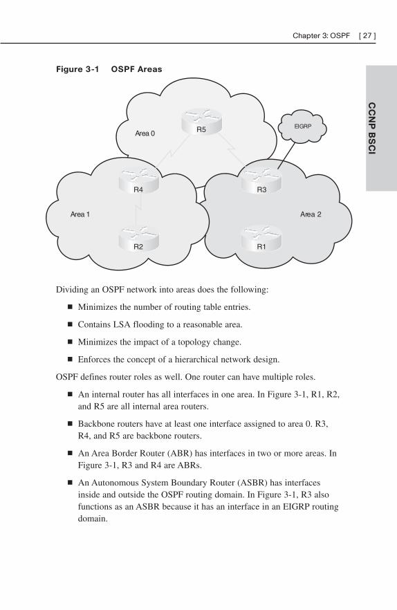
Figure 3-1 OSPF Areas
CC
NP
BS
CI
Chapter 3: OSPF [ 27 ]
Area 2Area 1
Area 0EIGRPR5
R3R4
R2 R1
Dividing an OSPF network into areas does the following:
■ Minimizes the number of routing table entries.
■ Contains LSA flooding to a reasonable area.
■ Minimizes the impact of a topology change.
■ Enforces the concept of a hierarchical network design.
OSPF defines router roles as well. One router can have multiple roles.
■ An internal router has all interfaces in one area. In Figure 3-1, R1, R2,and R5 are all internal area routers.
■ Backbone routers have at least one interface assigned to area 0. R3,R4, and R5 are backbone routers.
■ An Area Border Router (ABR) has interfaces in two or more areas. InFigure 3-1, R3 and R4 are ABRs.
■ An Autonomous System Boundary Router (ASBR) has interfacesinside and outside the OSPF routing domain. In Figure 3-1, R3 alsofunctions as an ASBR because it has an interface in an EIGRP routingdomain.
OSPF Metric
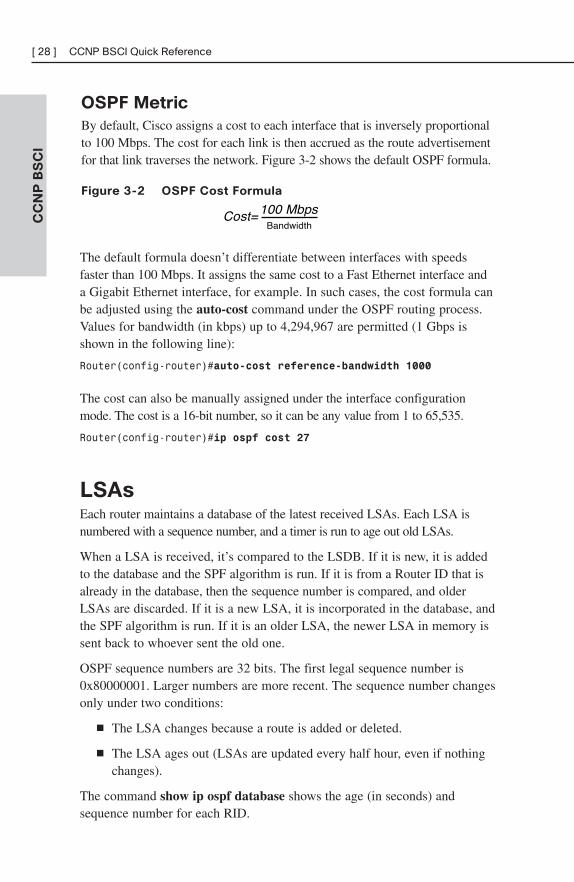
By default, Cisco assigns a cost to each interface that is inversely proportionalto 100 Mbps. The cost for each link is then accrued as the route advertisementfor that link traverses the network. Figure 3-2 shows the default OSPF formula.
Figure 3-2 OSPF Cost Formula
CC
NP
BS
CI
[ 28 ] CCNP BSCI Quick Reference
Cost= 100 MbpsBandwidth
The default formula doesn’t differentiate between interfaces with speedsfaster than 100 Mbps. It assigns the same cost to a Fast Ethernet interface anda Gigabit Ethernet interface, for example. In such cases, the cost formula canbe adjusted using the auto-cost command under the OSPF routing process.Values for bandwidth (in kbps) up to 4,294,967 are permitted (1 Gbps isshown in the following line):
Router(config-router)#auto-cost reference-bandwidth 1000
The cost can also be manually assigned under the interface configurationmode. The cost is a 16-bit number, so it can be any value from 1 to 65,535.
Router(config-router)#ip ospf cost 27
LSAsEach router maintains a database of the latest received LSAs. Each LSA isnumbered with a sequence number, and a timer is run to age out old LSAs.
When a LSA is received, it’s compared to the LSDB. If it is new, it is addedto the database and the SPF algorithm is run. If it is from a Router ID that isalready in the database, then the sequence number is compared, and olderLSAs are discarded. If it is a new LSA, it is incorporated in the database, andthe SPF algorithm is run. If it is an older LSA, the newer LSA in memory issent back to whoever sent the old one.
OSPF sequence numbers are 32 bits. The first legal sequence number is0x80000001. Larger numbers are more recent. The sequence number changesonly under two conditions:
■ The LSA changes because a route is added or deleted.
■ The LSA ages out (LSAs are updated every half hour, even if nothingchanges).
The command show ip ospf database shows the age (in seconds) andsequence number for each RID.
LSDB Overload Protection
Because each router sends an LSA for each link, routers in large networksmay receive—and must process—numerous LSAs. This can tax the router’sCPU and memory resources, and adversely affect its other functions. You canprotect your router by configuring OSPF LSDB overload protection. LDSBoverload protection monitors the number of LSAs received and placed intothe LSDB. If the specified threshold is exceeded for one minute, the routerenters the “ignore” state by dropping all adjacencies and clearing the OSPFdatabase. The router resumes OSPF operations after things have been normalfor a specified period. Be careful when using this command, as it disruptsrouting when invoked.
Configure LSDB overload protection with the OSPF router processcommand max-lsa maximum-number [threshold-percentage][warningonly][ignore-time minutes] [ignore-count number] [reset-timeminutes]. The meaning of the keywords of this command are:
■ Maximum-number—The threshold. This is the most nonlocal LSAsthat the router can maintain in its LSDB.
■ Threshold-percentage—A warning message is sent when this percent-age of the threshold number is reached. The default is 75 percent.
■ Warningonly—This causes the router to send only a warning; it doesnot enter the ignore state.
■ Ignore-time minutes—Specifies the length of time to stay in theignore state. The default is five minutes.
■ Ignore-count number—Specifies the maximum number of times arouter can go into the ignore state. When this number is exceeded,OSPF processing stays down and must be manually restarted. Thedefault is five times.
■ Reset-time minutes—The length of time to stay in the ignore state.The default is ten minutes.
LSA Types
OSPF uses different types of LSAs to advertise different types of routes, suchas internal area or external routing domain. Many of these are represented inthe routing table with a distinctive prefix. Table 3-1 describes these LSA types.
CC
NP
BS
CI
Chapter 3: OSPF [ 29 ]
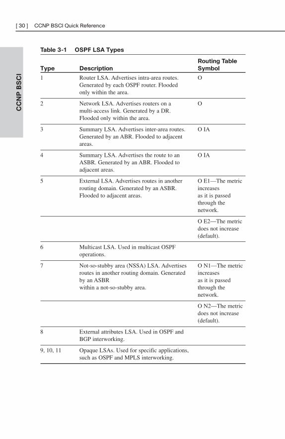
Table 3-1 OSPF LSA Types
Routing Table
Type Description Symbol
1 Router LSA. Advertises intra-area routes. OGenerated by each OSPF router. Flooded only within the area.
2 Network LSA. Advertises routers on a Omulti-access link. Generated by a DR. Flooded only within the area.
3 Summary LSA. Advertises inter-area routes. O IAGenerated by an ABR. Flooded to adjacent areas.
4 Summary LSA. Advertises the route to an O IAASBR. Generated by an ABR. Flooded to adjacent areas.
5 External LSA. Advertises routes in another O E1—The metric routing domain. Generated by an ASBR. increases Flooded to adjacent areas. as it is passed
through the network.
O E2—The metric does not increase (default).
6 Multicast LSA. Used in multicast OSPF operations.
7 Not-so-stubby area (NSSA) LSA. Advertises O N1—The metric routes in another routing domain. Generated increasesby an ASBR as it is passed within a not-so-stubby area. through the
network.
O N2—The metric does not increase (default).
8 External attributes LSA. Used in OSPF and BGP interworking.
9, 10, 11 Opaque LSAs. Used for specific applications,such as OSPF and MPLS interworking.
CC
NP
BS
CI
[ 30 ] CCNP BSCI Quick Reference
OSPF OperationOSPF uses several different message types to establish and maintain itsneighbor relationships, and to maintain correct routing information. Whenpreparing for the exam, be sure you understand each OSPF packet type, andthe OSPF neighbor establishment procedure.
OSPF Packets
OSPF uses five packet types. It does not use UDP or TCP for transmittingits packets. Instead, it runs directly over IP (IP protocol 89) using an OSPFheader. One field in this header identifies the type of packet being carried.The five OSPF packet types are:
■ Hello—Identifies neighbors and serves as a keepalive.
■ Link State Request (LSR)—A request for an Link State Update(LSU). Contains the type of LSU requested and the ID of the routerrequesting it.
■ Database Description (DBD)—A summary of the LSDB, includingthe RID and sequence number of each LSA in the LSDB.
■ Link State Update (LSU)—Contains a full LSA entry. An LSAincludes topology information; for example, the RID of this router andthe RID and cost to each neighbor. One LSU can contain multipleLSAs.
■ Link State Acknowledgment (LSAck)—Acknowledges all otherOSPF packets (except hellos).
OSPF traffic is multicast to either of two addresses: 224.0.0.5 for all OSPFrouters or 224.0.0.6 for all OSPF DRs.
OSPF Neighbor Relationships
OSPF routers send out periodic multicast packets to introduce themselves toother routers on a link. They become neighbors when they see their ownrouter ID included in the Neighbor field of the hello from another router.Seeing this tells each router that they have bidirectional communication. Inaddition, two routers must be on a common subnet for a neighbor relation-ship to be formed. (Virtual links are sometimes an exception to this rule.)
CC
NP
BS
CI
Chapter 3: OSPF [ 31 ]
Certain parameters within the OSPF hellos must also match in order for tworouters to become neighbors. They include:
■ Hello/dead timers
■ Area ID
■ Authentication type and password
■ Stub area flag
OSPF routers can be neighbors without being adjacent. Only adjacent neighborsexchange routing updates and synchronize their databases. On a point-to-pointlink, an adjacency is established between the two routers when they cancommunicate. On a multiaccess link, each router establishes an adjacencyonly with the DR and the backup DR (BDR).
Hellos also serve as keepalives. A neighbor is considered lost if no Hello isreceived within four Hello periods (called the dead time). The defaulthello/dead timers are as follows:
■ 10 seconds/40 seconds for LAN and point-to-point interfaces
■ 30 seconds/120 seconds for nonbroadcast multiaccess (NBMA) interfaces
Establishing Neighbors and Exchanging Routes
The process of neighbor establishment and route exchange between twoOSPF routers is as follows:
Step 1. Down state—OSPF process not yet started, so no hellos sent.
Step 2. Init state—Router sends hello packets out all OSPF interfaces.
Step 3. Two-way state—Router receives a hello from another router thatcontains its own router ID in the neighbor list. All other requiredelements match, so routers can become neighbors.
Step 4. Exstart state—If routers become adjacent (exchange routes), theydetermine who will start the exchange process.
Step 5. Exchange state—Routers exchange DBDs listing the LSAs intheir LSD by RID and sequence number.
Step 6. Loading state—Each router compares the DBD received to thecontents of its LS database. It then sends a LSR for missing oroutdated LSAs. Each router responds to its neighbor’s LSR with aLink State Update. Each LSU is acknowledged.
Step 7. Full state—The LSDB has been synchronized with the adjacentneighbor.
CC
NP
BS
CI
[ 32 ] CCNP BSCI Quick Reference
Basic OSPF ConfigurationOSPF is configured by entering router configuration mode and identifyingthe range of interface addresses on which it should run and the areas theyare in. When setting up OSPF, a process ID must be used (8 is used in theexample), but the process ID does not have to agree on different OSPFdevices for them to exchange information. The network statement uses awildcard mask and can specify any range from a single address to alladdresses. Unlike EIGRP, the wildcard mask is not optional. The followingexample shows a router configured as an ABR. Interfaces falling with the192.168.1.0 network are placed in area 0, and interfaces falling within the172.16.1.0 network are placed in area 1.
Router(config)#router ospf 8
Router(config-router)#network 192.168.1.0 0.0.0.255 area 0
Router(config-router)#network 172.16.1.0 0.0.0.255 area 1
Router ID
The SPF algorithm is used to map the shortest path between a series ofnodes. This causes an issue with IP, because an IP router is not identified bya single IP address—its interfaces are. For this reason, a single IP address isdesignated as the “name” of the router—the RID.
By default, the RID is the highest loopback IP address. If no loopbackaddresses are configured, the RID is the highest IP address on an activeinterface when the OSPF process is started. The RID is selected when OSPFstarts and—for reasons of stability—is not changed until OSPF restarts. TheOSPF process can be restarted by rebooting or by using the command clearip ospf process. Either choice affects routing in your network for a period oftime and should be used only with caution.
A loopback interface is a virtual interface, so it is more stable than a physicalinterface for RID use. A loopback address is configured by creating an inter-face and assigning an IP address.
Router(config)#interface loopback0
Router(config-if)#ip address 10.0.0.1 255.255.255.255
The loopback address does not have to be included in the OSPF routingprocess, but if you advertise it, you are able to ping or trace to it. This canhelp in troubleshooting.
A way to override the default RID selection is to statically assign it usingthe OSPF router-id command.
CC
NP
BS
CI
Chapter 3: OSPF [ 33 ]
Router(config)#router ospf 8
Router(config-router)#router-id 10.0.0.1
Troubleshooting OSPF
The neighbor initialization process can be viewed using the debug ip ospfadjacencies command. The neighbor table can be seen with show ip ospfneighbors, which also identifies adjacency status, and reveals the designatedrouter and backup designated router. Use the debug ip ospf packetcommand to view all OSPF packets in real time.
Often, the first place OSPF issues are noticed is when inspecting the routingtable—show ip route. To filter the routing table and show only the routeslearned from OSPF, use show ip route ospf.
The command show ip protocols offers a wealth of information for anyrouting protocol issue. Use this command to verify parameters, timer values,identified networks, and OSPF neighbors (routing information sources).
Use show ip ospf to verify the RID, timers, and counters. Because wildcardmasks sometimes incorrectly group interfaces to areas, another good place tocheck is show ip ospf interface. This shows the interfaces on which OSPFruns and their current correct assigned area.
OSPF Network TypesThe SPF algorithm builds a directed graph—paths made up of a series ofpoints connected by direct links. One of the consequences of this directed-graph approach is that the algorithm has no way to handle a multiaccessnetwork, such as an Ethernet VLAN. The solution used by OSPF is to electone router, called the Designated Router (DR), to represent the entiresegment. Point-to-point links fit the SPF model perfectly and don’t need anyspecial modeling method. On a point-to-point link, no DR is elected and alltraffic is multicast to 224.0.0.5.
OSPF supports five network types:
■ NBMA—Default for multipoint serial interfaces. RFC-compliantmode that uses DRs and requires manual neighbor configuration.
■ Point-to–multipoint (P2MP)—Doesn’t use DRs so adjacenciesincrease logarithmically with routers. Resilient RFC compliant modethat automatically discovers neighbors.
CC
NP
BS
CI
[ 34 ] CCNP BSCI Quick Reference
■ Point-to-multipoint nonbroadcast (P2MNB)—Proprietary mode thatis used on Layer 2 facilities where dynamic neighbor discovery is notsupported. Requires manual neighbor configuration.
■ Broadcast—Default mode for LANs. Uses DRs and automatic neigh-bor discovery. Proprietary when used on WAN interface.
■ Point-to–point (P2P)—Proprietary mode that discovers neighbors anddoesn’t require a DR.
If the default interface type is unsatisfactory, you can statically configure itwith the command ip ospf network under interface configuration mode:
Router(config-if)#ip ospf network point-to-multipoint
When using the NBMA or P2MP nonbroadcast mode, neighbors must bemanually defined under the routing process:
Router(config-router)#neighbor 172.16.0.1
Designated Routers
On a multiaccess link, one of the routers is elected as a DR and another as abackup DR (BDR). All other routers on that link become adjacent only tothe DR and BDR, not to each other (they stop at the two-way state). The DRis responsible for creating and flooding a network LSA (type 2) advertisingthe multiaccess link. NonDR (DROTHER) routers communicate with DRsusing the IP address 224.0.0.6. The DRs use IP address 224.0.0.5 to passinformation to other routers.
The DR and BDR are elected as follows:
Step 1. A router starting the OSPF process listens for OSPF hellos. Ifnone are heard within the dead time, it declares itself the DR.
Step 2. If hellos from any other routers are heard, the router with thehighest OSPF priority is elected DR, and the election processstarts again for BDR. A priority of zero removes a router fromthe election.
Step 3. If two or more routers have the same OSPF priority, the routerwith the highest RID is elected DR, and the election processstarts again for BDR.
After a DR is elected, elections do not take place again unless the DR orBDR are lost. Because of this, the DR is sometimes the first device thatcomes online with a nonzero priority.
CC
NP
BS
CI
Chapter 3: OSPF [ 35 ]
The best way to control DR election is to set OSPF priority for the DR andBDR for other routers. The default priority is one. A priority of zero meansthat a router cannot act as DR or BDR; it can be a DROTHER only. Prioritycan be set with the ip ospf priority command in interface configurationmode.
Router(config)#int fa 0/1
Router(config-if)#ip ospf priority 2
Nonbroadcast Multiaccess (NBMA) Networks
Routing protocols assume that multiaccess links support broadcast and havefull-mesh connectivity from any device to any device. In terms of OSPF, thismeans the following:
■ All Frame Relay or ATM maps should include the broadcast attribute.
■ The DR and BDR should have full virtual circuit connectivity to allother devices.
■ Hub-and-spoke environments should either configure the DR as thehub or use point-to-point subinterfaces, which require no DR.
■ Partial-mesh environments should be configured using point-to-pointsubinterfaces, especially when no single device has full connectivity toall other devices. If there is a subset of the topology with full connec-tivity, then that subset can use a multipoint subinterface.
■ Full-mesh environments can be configured using the physical inter-face, but often logical interfaces are used to take advantage of theother benefits of subinterfaces.
■ It may be necessary to statically identify neighbor IP addresses.
Advanced OSPF ConfigurationOSPF provides many different ways to customize its operation to fit yournetwork needs. This section discusses route summarization, default routes,stub areas, and virtual links.
OSPF Summarization
Summarization helps all routing protocols scale to larger networks, butOSPF especially benefits because its processes tax the memory and CPU
CC
NP
BS
CI
[ 36 ] CCNP BSCI Quick Reference
resources of the routers. The SPF algorithm consumes all CPU resourceswhen it runs. Summarization prevents topology changes from being passedoutside an area and thus saves routers in other areas from having to run theSPF algorithm. OSPF’s multiple databases use more memory the larger theyare. Summarization decreases the number of routes exchanged, and thus thesize of the databases. OSPF can produce summaries within a classfulnetwork (VLSM) or summaries of blocks of classful networks (CIDR).There are two types of summarizations:
■ Inter-area route summarizations are created on the ABR under theOSPF routing process using the area range command. The followingcommand advertises 172.16.0.0/12 from area 1:
Router(config-router)#area 1 range 172.16.0.0 255.240.0.0
■ External route summarization is done on an ASBR using thesummary-address command under the OSPF routing process. Thefollowing example summarizes a range of external routes to192.168.0.0/16 and injects a single route into OSPF:
Router(config-router)#summary-address 192.168.0.0255.255.0.0
Creating a Default Route
The default route is a special type of summarization; it summarizes allnetworks down to one route announcement. This provides the ultimatebenefit of summarization by reducing routing information to a minimum.There are several ways to use the router IOS to place a default route intoOSPF.
The best-known way to produce an OSPF default is to use the default-infor-mation command under the OSPF routing process. This command, withoutthe keyword always, readvertises a default route learned from anothersource into OSPF. If the always keyword is present, OSPF advertises adefault even if one does not already exist in the routing table. The metrickeyword sets the starting metric for this route.
Router(config-router)#default-information originate [always] [metric metric]
Alternatively, a default summary route can also be produced using thesummary-address command or the area range command. Thesecommands cause the router to advertise a default route pointing to itself.
CC
NP
BS
CI
Chapter 3: OSPF [ 37 ]
Reducing routing information in non-backbone areas is a common require-ment because these routers are typically the most vulnerable in terms ofprocessor and speed, and the links that connect them usually have the leastbandwidth. A specific concern is that an area will be overwhelmed by exter-nal routing information.
Stub and Not-So-Stubby Areas
Another way to reduce the route information advertised is to make an area astub area. Configuring an area as a stub area forces its ABR to drop allexternal (type 5) routes and replaces them with a default route. To limitrouting information even more, an area can be made totally stubby using theno-summary keyword on the ABR only. In that case, all interarea and exter-nal routes are dropped by the ABR and replaced by a default route. Thedefault route starts with a cost of 1; to change it, use the area default-costcommand. The example that follows shows area 2 configured as a totallystubby area, and the default route injected with a cost of 5:
Router(config-router)#area 2 stub no-summary
Router(config-router)#area 2 default-cost 5
Stub areas are attractive because of their low overhead. They do have somelimitations, including the following:
■ Stub areas can’t include a virtual link.
■ Stub areas can’t include an ASBR.
■ Stubbiness must be configured on all routers in the area.
Another kind of stub area is a not-so-stubby area (NSSA). NSSA is like astub or totally stub area, but allows an ASBR within the area. Externalroutes are advertised as type 7 routes by the ASBR. The ABR converts themto type 5 external routes when it advertises them into adjacent areas. NSSAis configured with the area nssa command under the OSPF routing process.The no-summary keyword on the ABR configures the area as a totallyNSSA area; this is a Cisco proprietary feature. By default, the ABR does notinject a default route back into an NSSA area. Use the default-information-originate keyword on the ABR or ABR to create this route.
Router(config-router)#area 7 nssa [no-summary] [default-information-originate]
CC
NP
BS
CI
[ 38 ] CCNP BSCI Quick Reference
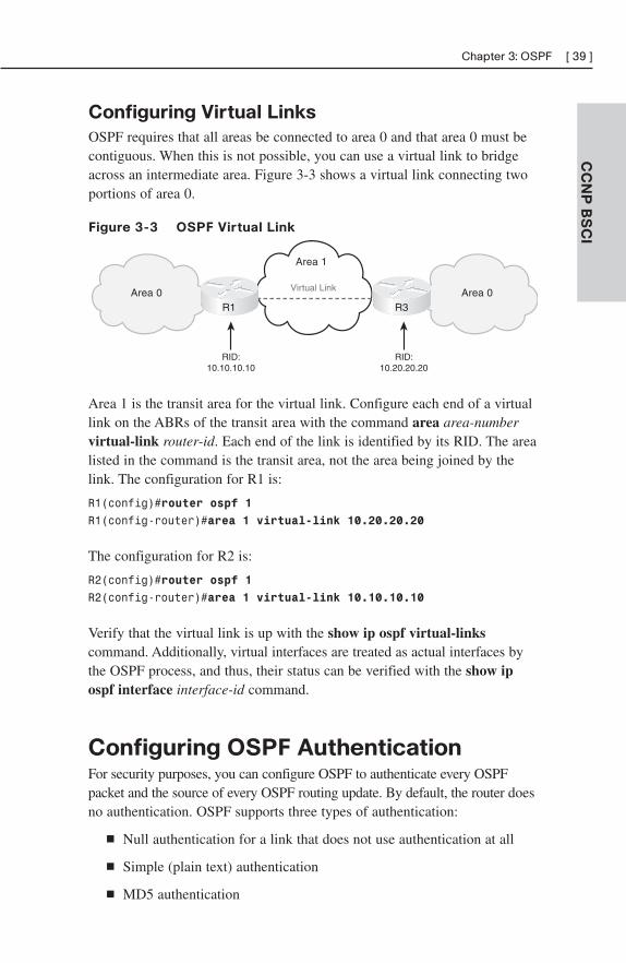
Configuring Virtual Links
OSPF requires that all areas be connected to area 0 and that area 0 must becontiguous. When this is not possible, you can use a virtual link to bridgeacross an intermediate area. Figure 3-3 shows a virtual link connecting twoportions of area 0.
Figure 3-3 OSPF Virtual Link
CC
NP
BS
CI
Chapter 3: OSPF [ 39 ]
Area 0Area 0
Area 1
RID:10.10.10.10
RID:10.20.20.20
Virtual Link
R3R1
Area 1 is the transit area for the virtual link. Configure each end of a virtuallink on the ABRs of the transit area with the command area area-numbervirtual-link router-id. Each end of the link is identified by its RID. The arealisted in the command is the transit area, not the area being joined by thelink. The configuration for R1 is:
R1(config)#router ospf 1
R1(config-router)#area 1 virtual-link 10.20.20.20
The configuration for R2 is:
R2(config)#router ospf 1
R2(config-router)#area 1 virtual-link 10.10.10.10
Verify that the virtual link is up with the show ip ospf virtual-linkscommand. Additionally, virtual interfaces are treated as actual interfaces bythe OSPF process, and thus, their status can be verified with the show ipospf interface interface-id command.
Configuring OSPF AuthenticationFor security purposes, you can configure OSPF to authenticate every OSPFpacket and the source of every OSPF routing update. By default, the router doesno authentication. OSPF supports three types of authentication:
■ Null authentication for a link that does not use authentication at all
■ Simple (plain text) authentication
■ MD5 authentication
The following example shows a router configured for simple passwordauthentication in OSPF area 1, using a password of “simple”. Note thatauthentication commands are necessary both under the OSPF process andthe interface configuration. All OSPF neighbors reachable through an inter-face configured for authentication must use the same password. You can,however, use different passwords for different interfaces.
Router(config)#int gi0/0
Router(config-if)#ip ospf authentication-key simple
Router(config-if)#ip ospf authentication
Router(config-if)#!
Router(config-if)#router ospf 1
Router(config-router)#area 1 authentication
The next example shows the same router configured for OSPF MD5 authen-tication for area 0, using a password of “secure”. Note that the commandsare slightly different. The optional keyword message-digest is required intwo of the commands, and a key number must be specified. Any neighborsreachable through the Gi0/1 interface must also be configured with the samekey.
Router(config-router)#int gi0/1
Router(config-if)#ip ospf message-digest-key 2 md5 secure
Router(config-if)#ip ospf authentication message-digest
Router(config-if)#!
Router(config-if)#router ospf 1
Router(config-router)#area 0 authentication message-digest
CC
NP
BS
CI
[ 40 ] CCNP BSCI Quick Reference
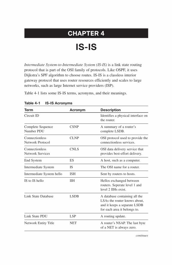
CHAPTER 4
IS-IS
Intermediate System-to-Intermediate System (IS-IS) is a link state routingprotocol that is part of the OSI family of protocols. Like OSPF, it usesDijkstra’s SPF algorithm to choose routes. IS-IS is a classless interiorgateway protocol that uses router resources efficiently and scales to largenetworks, such as large Internet service providers (ISP).
Table 4-1 lists some IS-IS terms, acronyms, and their meanings.
Table 4-1 IS-IS Acronyms
Term Acronym Description
Circuit ID Identifies a physical interface on the router.
Complete Sequence CSNP A summary of a router’s Number PDU complete LSDB.
Connectionless CLNP OSI protocol used to provide the Network Protocol connectionless services.
Connectionless CNLS OSI data delivery service thatNetwork Services provides best-effort delivery.
End System ES A host, such as a computer.
Intermediate System IS The OSI name for a router.
Intermediate System hello ISH Sent by routers to hosts.
IS to IS hello IIH Hellos exchanged between routers. Seperate level 1 and level 2 IIHs exist.
Link State Database LSDB A database containing all the LSAs the router knows about,and it keeps a separate LSDB for each area it belongs to.
Link State PDU LSP A routing update.
Network Entity Title NET A router’s NSAP. The last byte of a NET is always zero.
continues
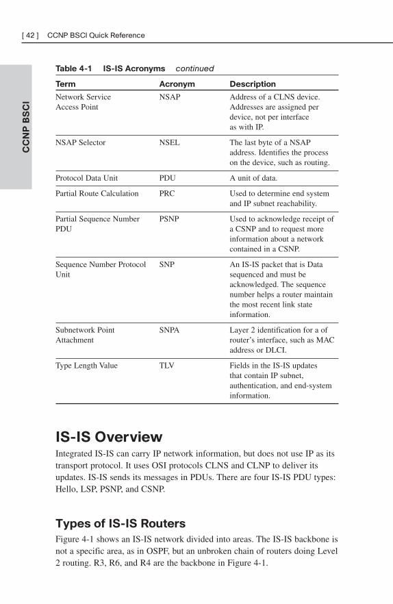
Table 4-1 IS-IS Acronyms continued
Term Acronym Description
Network Service NSAP Address of a CLNS device.Access Point Addresses are assigned per
device, not per interface as with IP.
NSAP Selector NSEL The last byte of a NSAP address. Identifies the process on the device, such as routing.
Protocol Data Unit PDU A unit of data.
Partial Route Calculation PRC Used to determine end system and IP subnet reachability.
Partial Sequence Number PSNP Used to acknowledge receipt of PDU a CSNP and to request more
information about a network contained in a CSNP.
Sequence Number Protocol SNP An IS-IS packet that is DataUnit sequenced and must be
acknowledged. The sequence number helps a router maintain the most recent link state information.
Subnetwork Point SNPA Layer 2 identification for a ofAttachment router’s interface, such as MAC
address or DLCI.
Type Length Value TLV Fields in the IS-IS updates that contain IP subnet,authentication, and end-system information.
IS-IS OverviewIntegrated IS-IS can carry IP network information, but does not use IP as itstransport protocol. It uses OSI protocols CLNS and CLNP to deliver itsupdates. IS-IS sends its messages in PDUs. There are four IS-IS PDU types:Hello, LSP, PSNP, and CSNP.
Types of IS-IS Routers
Figure 4-1 shows an IS-IS network divided into areas. The IS-IS backbone isnot a specific area, as in OSPF, but an unbroken chain of routers doing Level2 routing. R3, R6, and R4 are the backbone in Figure 4-1.
CC
NP
BS
CI
[ 42 ] CCNP BSCI Quick Reference
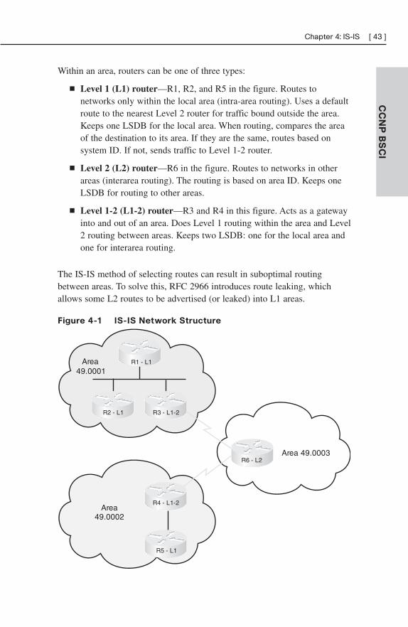
Within an area, routers can be one of three types:
■ Level 1 (L1) router—R1, R2, and R5 in the figure. Routes tonetworks only within the local area (intra-area routing). Uses a defaultroute to the nearest Level 2 router for traffic bound outside the area.Keeps one LSDB for the local area. When routing, compares the areaof the destination to its area. If they are the same, routes based onsystem ID. If not, sends traffic to Level 1-2 router.
■ Level 2 (L2) router—R6 in the figure. Routes to networks in otherareas (interarea routing). The routing is based on area ID. Keeps oneLSDB for routing to other areas.
■ Level 1-2 (L1-2) router—R3 and R4 in this figure. Acts as a gatewayinto and out of an area. Does Level 1 routing within the area and Level2 routing between areas. Keeps two LSDB: one for the local area andone for interarea routing.
The IS-IS method of selecting routes can result in suboptimal routingbetween areas. To solve this, RFC 2966 introduces route leaking, whichallows some L2 routes to be advertised (or leaked) into L1 areas.
Figure 4-1 IS-IS Network Structure
CC
NP
BS
CI
Chapter 4: IS-IS [ 43 ]
Area49.0001
Area49.0002
Area 49.0003
R1 - L1
R2 - L1 R3 - L1-2
R4 - L1-2
R5 - L1
R6 - L2
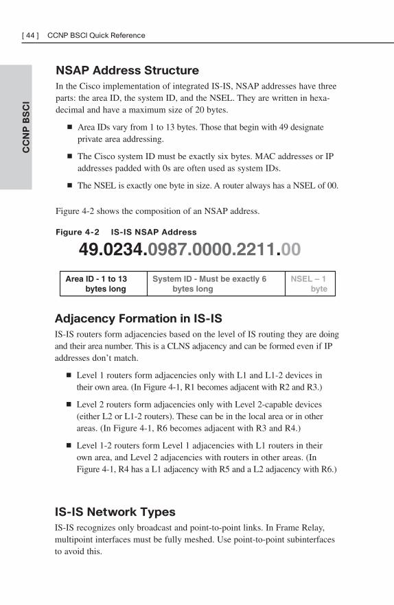
NSAP Address Structure
In the Cisco implementation of integrated IS-IS, NSAP addresses have threeparts: the area ID, the system ID, and the NSEL. They are written in hexa-decimal and have a maximum size of 20 bytes.
■ Area IDs vary from 1 to 13 bytes. Those that begin with 49 designateprivate area addressing.
■ The Cisco system ID must be exactly six bytes. MAC addresses or IPaddresses padded with 0s are often used as system IDs.
■ The NSEL is exactly one byte in size. A router always has a NSEL of 00.
Figure 4-2 shows the composition of an NSAP address.
Figure 4-2 IS-IS NSAP Address
CC
NP
BS
CI
[ 44 ] CCNP BSCI Quick Reference
NSEL – 1byte
System ID - Must be exactly 6bytes long
Area ID - 1 to 13bytes long
49.0234.0987.0000.2211.00
Adjacency Formation in IS-IS
IS-IS routers form adjacencies based on the level of IS routing they are doingand their area number. This is a CLNS adjacency and can be formed even if IPaddresses don’t match.
■ Level 1 routers form adjacencies only with L1 and L1-2 devices intheir own area. (In Figure 4-1, R1 becomes adjacent with R2 and R3.)
■ Level 2 routers form adjacencies only with Level 2-capable devices(either L2 or L1-2 routers). These can be in the local area or in otherareas. (In Figure 4-1, R6 becomes adjacent with R3 and R4.)
■ Level 1-2 routers form Level 1 adjacencies with L1 routers in theirown area, and Level 2 adjacencies with routers in other areas. (InFigure 4-1, R4 has a L1 adjacency with R5 and a L2 adjacency with R6.)
IS-IS Network Types
IS-IS recognizes only broadcast and point-to-point links. In Frame Relay,multipoint interfaces must be fully meshed. Use point-to-point subinterfacesto avoid this.
On a broadcast network, IS-IS routers elect a Designated IntermediateSystem (DIS). The DIS is elected based on priority, with MAC address asthe tie breaker (the lowest number wins for both priority and MAC address).Routers form adjacencies with the DIS and all other routers on the LAN.The DIS creates a pseudonode to represent the network and sends out anadvertisement to represent the LAN. All routers advertise only an adjacencyto the pseudonode. If the DIS fails, another is elected; no backup DIS exists.The DIS sends Hellos every 3.3 seconds; other routers send them every 10seconds. The DIS also multicasts a CSNP every 10 seconds.
No DIS exists on a point-to-point link. When an adjacency is first formedover the link, the routers exchange CSNPs. If one of the routers needs moreinformation about a specific network, it sends a PSNP requesting that. Afterthe initial exchange, LSPs are sent to describe link changes, and they areacknowledged with PSNPs. Hellos are sent every 10 seconds.
Configuring IS-ISThe essential tasks to begin IS-IS routing are:
■ Enable IS-IS on the router:
Router(config)#router isis
■ Configure each router’s NET:
Router(config-router)#net 49.0010.1111.2222.3333.00
■ Enable IS-IS on the router’s interfaces:
Router(config)#interface s0/0/0
Router(config-int)#ip router isis
You may wish to do some tuning of IS-IS routing. Following are the tasks:
■ Set the IS level. Cisco routers are L1-2 by default. If the router iscompletely an internal area router, set the IS level to L1. If the routerroutes only to other areas and has no internal area interfaces, set the ISlevel to L2. If the router has both internal and external area interfaces,leave the IS level at L1-2.
Router(config-router)is-type {level-1 | level 1-2 | level-2-only}
■ Set the circuit type on L1-2 routers. On L1-2 routers, all interfacessend out both L1 and L2 hellos, trying to establish both types of adja-cencies. This can waste bandwidth. If only an L1 router is attached to
CC
NP
BS
CI
Chapter 4: IS-IS [ 45 ]
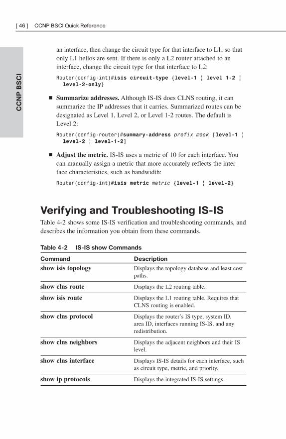
an interface, then change the circuit type for that interface to L1, so thatonly L1 hellos are sent. If there is only a L2 router attached to aninterface, change the circuit type for that interface to L2:
Router(config-int)#isis circuit-type {level-1 | level 1-2 | level-2-only}
■ Summarize addresses. Although IS-IS does CLNS routing, it cansummarize the IP addresses that it carries. Summarized routes can bedesignated as Level 1, Level 2, or Level 1-2 routes. The default isLevel 2:
Router(config-router)#summary-address prefix mask [level-1 | level-2 | level-1-2]
■ Adjust the metric. IS-IS uses a metric of 10 for each interface. Youcan manually assign a metric that more accurately reflects the inter-face characteristics, such as bandwidth:
Router(config-int)#isis metric metric {level-1 | level-2}
Verifying and Troubleshooting IS-ISTable 4-2 shows some IS-IS verification and troubleshooting commands, anddescribes the information you obtain from these commands.
Table 4-2 IS-IS show Commands
Command Description
show isis topology Displays the topology database and least cost paths.
show clns route Displays the L2 routing table.
show isis route Displays the L1 routing table. Requires that CLNS routing is enabled.
show clns protocol Displays the router’s IS type, system ID,area ID, interfaces running IS-IS, and any redistribution.
show clns neighbors Displays the adjacent neighbors and their IS level.
show clns interface Displays IS-IS details for each interface, such as circuit type, metric, and priority.
show ip protocols Displays the integrated IS-IS settings.
CC
NP
BS
CI
[ 46 ] CCNP BSCI Quick Reference
CHAPTER 5
Optimizing Routing
There are times when you need to go beyond just turning on a routing proto-col in your network. You may need to use multiple protocols, control exactlywhich routes are advertised or redistributed, or which paths are chosen. Mostnetworks use DHCP; your router may need to be a DHCP server, or relayDHCP broadcasts.
Using Multiple Routing ProtocolsThere are several reasons you may need to run multiple routing protocols inyour network. Some include:
■ Migrating from one routing protocol to another, where both protocolswill run in the network temporarily
■ Applications that run under certain routing protocols but not others
■ Areas of the network under different administrative control (“layer 8”issues)
■ A multi-vendor environment in which some parts of the networkrequire a standards-based protocol
Configuring Route Redistribution
If routinginformation must be exchanged among the different protocols orrouting domains, redistribution can be used. Only routes that are in therouting table and learned via the specified protocol are redistributed. Eachprotocol has some unique characteristics when redistributing, as shown inTable 5-1.
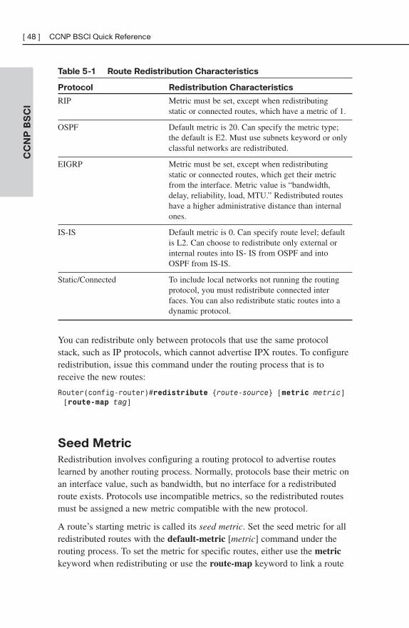
Table 5-1 Route Redistribution Characteristics
Protocol Redistribution Characteristics
RIP Metric must be set, except when redistributing static or connected routes, which have a metric of 1.
OSPF Default metric is 20. Can specify the metric type; the default is E2. Must use subnets keyword or only classful networks are redistributed.
EIGRP Metric must be set, except when redistributing static or connected routes, which get their metric from the interface. Metric value is “bandwidth,delay, reliability, load, MTU.” Redistributed routes have a higher administrative distance than internal ones.
IS-IS Default metric is 0. Can specify route level; default is L2. Can choose to redistribute only external or internal routes into IS- IS from OSPF and into OSPF from IS-IS.
Static/Connected To include local networks not running the routing protocol, you must redistribute connected interfaces. You can also redistribute static routes into a dynamic protocol.
You can redistribute only between protocols that use the same protocolstack, such as IP protocols, which cannot advertise IPX routes. To configureredistribution, issue this command under the routing process that is toreceive the new routes:
Router(config-router)#redistribute {route-source} [metric metric][route-map tag]
Seed Metric
Redistribution involves configuring a routing protocol to advertise routeslearned by another routing process. Normally, protocols base their metric onan interface value, such as bandwidth, but no interface for a redistributedroute exists. Protocols use incompatible metrics, so the redistributed routesmust be assigned a new metric compatible with the new protocol.
A route’s starting metric is called its seed metric. Set the seed metric for allredistributed routes with the default-metric [metric] command under therouting process. To set the metric for specific routes, either use the metrickeyword when redistributing or use the route-map keyword to link a route
CC
NP
BS
CI
[ 48 ] CCNP BSCI Quick Reference
map to the redistribution. After the seed metric is specified, it incrementsnormally as the route is advertised through the network (except for certainOSPF routes).
Tools for Controlling/Preventing
Routing UpdatesCisco IOS provides several ways to control routing updates. They include:
■ Passive interface
■ Default and/or static routes
■ Distribute list
■ Route map
■ Change administrative distance
Passive Interface
The passive-interface command prevents routing updates from being sent outan interface that runs the routing protocol. RIP and IGRP do not send updatesout an interface. It prevents other routing protocols from sending hellos out ofan interface; thus, they don’t discover neighbors or form an adjacency out thatinterface. To disable the protocol on one interface, use the command passive-interface interface. To turn off the protocol on all interfaces, use passive-interface default. You can then use no passive-interface interface for theones that should run the protocol, as shown:
Router(config)#router eigrp 7
Router(config-router)#passive-interface default
Router(config-router)#no passive-interface s0/0/0
Distribute Lists
A distribute list allows you to filter routing updates and also routes beingredistributed through an access list. Configure an access list that permits theroutes to be advertised or redistributed, and then link that access list to therouting process with the distribute-list command, given under router config-uration mode. This command has two options:
CC
NP
BS
CI
Chapter 5: Optimizing Routing [ 49 ]
■ distribute-list access-list in—Filters updates as they come in an inter-face. For OSPF, this controls routes placed in the routing table but notthe database. For other protocols, this controls the routes the protocolknows about.
■ distribute-list access-list out—Filters updates going out of an inter-face and also updates being redistributed out of another routing proto-col into this one.
Route Maps
Route maps are a bit like programs that use a “if/then/else” decision-makingcapability. They match traffic against certain conditions, and then set speci-fied options for that traffic. Each statement has a sequence number, state-ments are read from the lowest number to highest, and the router stopsreading when it gets a match. The sequence number can be used to insert ordelete statements. Like an access list, there is an implicit “deny” at the end ofeach route map; any traffic not matched with a route map statement isdenied. Some uses for route maps include:
■ Filtering redistributed routes—Use the route-map keyword in theredistribute command.
■ Policy-based routing—To specify which traffic should be policyrouted, based on very granular controls.
■ BGP policy—To control routing updates and to manipulate path attrib-utes.
Route Map Syntax
Route maps are created with the global command:
Router(config)#route-map {tag} permit | deny [sequence_number]
Each statement in a route map begins this same way, with the same route mapname but different sequence numbers, and with match and/or set conditionsbelow it. Permit means that any traffic matching the match conditions isused. Deny means that any traffic matching the match conditions is not used.
CC
NP
BS
CI
[ 50 ] CCNP BSCI Quick Reference
Match and Set Conditions
Each route map statement can have from none to multiple match and setconditions. If no match condition exists, the statement matches anything,similar to a “permit any” in an access list. If there is no set condition, thematching traffic is either permitted or denied, with no other conditions being set.
Multiple match conditions on the same line use a logical OR. For example,the router interprets match a b c as “match a or b or c.” Multiple matchconditions on different lines use a logical AND. For example, the routerinterprets the following route map statement as “match a and b and c:”
route-map Logical-AND permit 10
match a
match b
match c
In route redistribution, some common conditions to match include:
■ ip address—Refers the router to an access list that permits or deniesnetworks.
■ ip next-hop—Refers the router to an access list that permits or deniesnext-hop IP addresses.
■ ip route-source—Refers the router to an access list that permits ordenies advertising router IP addresses.
■ metric—Permits or denies routes with the specified metric from beingredistributed.
■ route-type—Permits or denies redistribution of the route type listed,such as internal or external.
■ tag—Routes can be labeled (tagged) with a number, and route mapscan look for that number.
In route redistribution, some common conditions to set are:
■ metric—Sets the metric for redistributed routes.
■ metric-type—Sets the type, such as E1 for OSPF.
■ tag—Tags a route with a number that can be matched on later by otherroute maps.
■ level—For IS-IS, sets the IS level for this route.
CC
NP
BS
CI
Chapter 5: Optimizing Routing [ 51 ]
The following configuration example shows a route map named BGP-LPwith three statements that are used to control which routes will be redistrib-uted from OSPF into BGP. The router has already been configured with twoaccess lists, numbered 23 and 103 (not shown.) The first route map state-ment, with sequence number 10, is a permit statement. The match conditiontells it to use access list 23. Any traffic permitted by access list 23 matchesthis statement and will be redistributed into BGP. Any traffic explicitlydenied by access list 23 will not be redistributed into BGP. The set conditiontells it to set a BGP local preference for all traffic that matches statement 10.Traffic not matching access list 23 will be checked against the second routemap statement.
The second route map statement, sequence number 20, is a deny statementthat matches access list 103. Any traffic permitted by access list 103 will bedenied by this statement, and thus will not be redistributed. Any trafficexplicitly denied by access list 103 will be ignored by this statement, andchecked against the next route map statement. This route map statement hasno set conditions. Traffic not matching route map statements 10 or 20 willbe checked against statement 30.
The third route map statement, sequence number 30, is a permit statementwith no match or set conditions. This statement matches everything and setsnothing, thus permitting all other traffic without changing it. Without thisstatement, all other traffic would be denied.
Lastly, the route map is applied to the redistribution command, to filterroutes redistributed from OSPF into BGP.
Router(config)#route-map BGP-LP permit 10
Router(config-route-map)#match ip address 23
Router(config-route-map)#set local-preference 200
Router(config-route-map)#!
Router(config-route-map)#route-map BGP-LP deny 20
Router(config-route-map)#match ip address 103
Router(config-route-map)#!
Router(config-route-map)#route-map BGP-LP permit 30
!
Router(config)#router bgp 65001
Router(config-router)#redistribute ospf 1 route-map BGP-LP
Manipulating Administrative Distance
When a router receives routes to the same destination network from morethan one routing process, it decides which to put in the routing table by
CC
NP
BS
CI
[ 52 ] CCNP BSCI Quick Reference
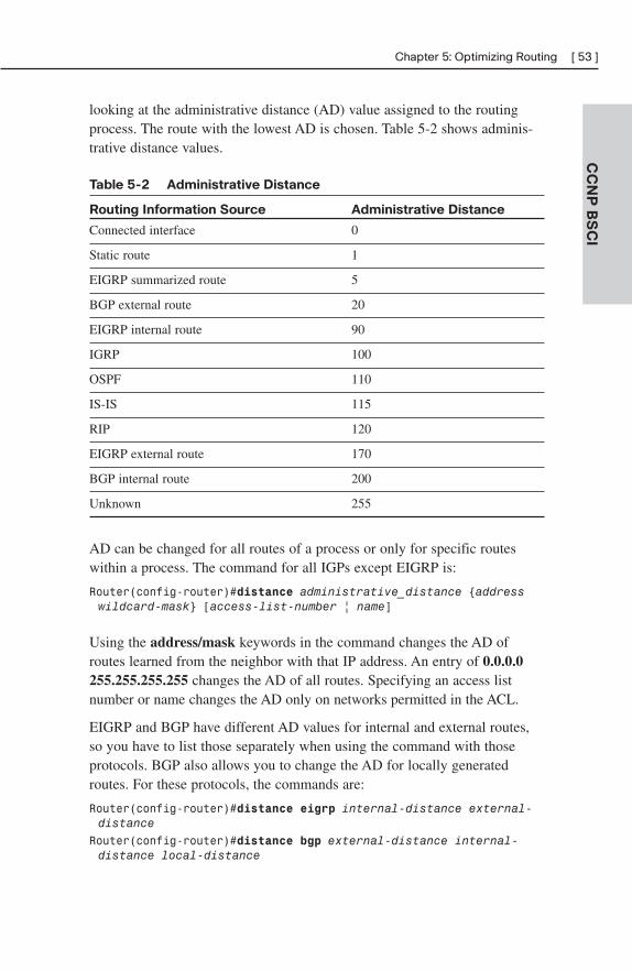
looking at the administrative distance (AD) value assigned to the routingprocess. The route with the lowest AD is chosen. Table 5-2 shows adminis-trative distance values.
Table 5-2 Administrative Distance
Routing Information Source Administrative Distance
Connected interface 0
Static route 1
EIGRP summarized route 5
BGP external route 20
EIGRP internal route 90
IGRP 100
OSPF 110
IS-IS 115
RIP 120
EIGRP external route 170
BGP internal route 200
Unknown 255
AD can be changed for all routes of a process or only for specific routeswithin a process. The command for all IGPs except EIGRP is:
Router(config-router)#distance administrative_distance {addresswildcard-mask} [access-list-number | name]
Using the address/mask keywords in the command changes the AD ofroutes learned from the neighbor with that IP address. An entry of 0.0.0.0255.255.255.255 changes the AD of all routes. Specifying an access listnumber or name changes the AD only on networks permitted in the ACL.
EIGRP and BGP have different AD values for internal and external routes,so you have to list those separately when using the command with thoseprotocols. BGP also allows you to change the AD for locally generatedroutes. For these protocols, the commands are:
Router(config-router)#distance eigrp internal-distance external-distance
Router(config-router)#distance bgp external-distance internal-distance local-distance
CC
NP
BS
CI
Chapter 5: Optimizing Routing [ 53 ]
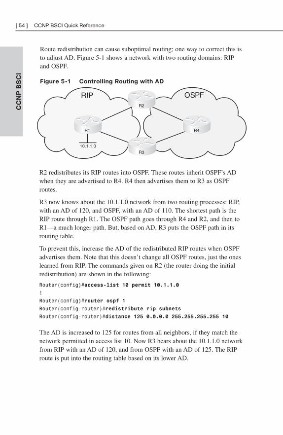
Route redistribution can cause suboptimal routing; one way to correct this isto adjust AD. Figure 5-1 shows a network with two routing domains: RIPand OSPF.
Figure 5-1 Controlling Routing with AD
CC
NP
BS
CI
[ 54 ] CCNP BSCI Quick Reference
RIP OSPF
10.1.1.0
R2
R4
R3
R1
R2 redistributes its RIP routes into OSPF. These routes inherit OSPF’s ADwhen they are advertised to R4. R4 then advertises them to R3 as OSPFroutes.
R3 now knows about the 10.1.1.0 network from two routing processes: RIP,with an AD of 120, and OSPF, with an AD of 110. The shortest path is theRIP route through R1. The OSPF path goes through R4 and R2, and then toR1—a much longer path. But, based on AD, R3 puts the OSPF path in itsrouting table.
To prevent this, increase the AD of the redistributed RIP routes when OSPFadvertises them. Note that this doesn’t change all OSPF routes, just the oneslearned from RIP. The commands given on R2 (the router doing the initialredistribution) are shown in the following:
Router(config)#access-list 10 permit 10.1.1.0
!
Router(config)#router ospf 1
Router(config-router)#redistribute rip subnets
Router(config-router)#distance 125 0.0.0.0 255.255.255.255 10
The AD is increased to 125 for routes from all neighbors, if they match thenetwork permitted in access list 10. Now R3 hears about the 10.1.1.0 networkfrom RIP with an AD of 120, and from OSPF with an AD of 125. The RIProute is put into the routing table based on its lower AD.
DHCPDHCP automates the assignment of IP addresses to network hosts. DHCPaddresses can be allocated:
■ Manually—A specific IP address is assigned to a MAC address.
■ Automatic—An IP address is permanently assigned to a host.
■ Dynamic—The IP address is assigned for a limited amount of time oruntil the client releases it.
The process of acquiring an IP address from a DHCP server has four steps:
Step 1. The host broadcasts a DHCPDISCOVER message.
Step 2. The server responds with a DHCPOFFER message containing IPaddress and optionally other settings.
Step 3. The client broadcasts a DHCPREQUEST message, requesting theoffered IP address.
Step 4. The server sends a DHCPACK confirming the address assignment.
Configuring DHCP
Cisco routers can be DHCP clients, servers, or relay agents. To configure anIOS device as a DHCP client, use the ip address dhcp command on theinterface that needs to obtain the DHCP address. To configure a router as aDHCP server, you must create an IP address pool and assign a network orsubnet to that pool. You can optionally add information, such as defaultgateway, DNS server, lease duration, or options such as Option 150 forCisco IP phones. Exclude any static IP addresses within the pool, such asthe router’s address. You may also want to identify an external server to holdthe DHCP database of IP address bindings.
Cisco routers have an auto-configuration feature that allows the downloadingof some DHCP information from a central server. This saves the trouble ofconfiguring every router with complete DHCP information. To do this, oneinterface on the router must have a DHCP address. The following exampleshows a router configured as a DHCP server that imports its domain name,DNS servers, and other information from another DHCP server off interfaceGi0/0. The IP address range of 10.6.3.1–10.6.3.5 is excluded from the pool.
CC
NP
BS
CI
Chapter 5: Optimizing Routing [ 55 ]
Router(config)#ip dhcp excluded-address 10.6.3.1 10.6.3.5
!
Router(config)#ip dhcp pool Gator
Router(dhcp-config)#network 10.6.3.0 /24
Router(dhcp-config)#default-router 10.6.3.1
Router(dhcp-config)#import all
!
Router(config)#int gi 0/0
Router(config-if)#ip address dhcp
DHCP Relay Agent
Hosts discover their DHCP server by sending broadcasts. If that server is ona different subnet, those broadcasts must be routed to the server as unicasts.You can configure a router to relay DHCP messages with the ip helper-address interface command. It is important to understand that this commandmust be given on the interface that receives the host broadcasts. A CiscoDHCP relay agent functions as follows:
Step 1. A client broadcasts a DHCP request, which is seen by the IOSdevice (a router, for instance).
Step 2. The router changes the destination address of the packet to theunicast address of the server. It optionally adds option 82 (relayagent option) information.
Step 3. The router sends the unicast packet to the server.
Step 4. The server responds with the IP address and other parameters,such as the default gateway assigned to the client.
Step 5. The router gets the packet from the server, removes any option 82information, and forwards it to the client.
The ip helper-address command enables the relaying of UDP broadcastsonly. By default, eight broadcast types are enabled:
■ Time, port 37
■ TACACS, port 49
■ DNS, port 53
■ BOOTP/DHCP server, port 67
■ BOOTP/DHCP client, port 68
■ TFTP, port 69
CC
NP
BS
CI
[ 56 ] CCNP BSCI Quick Reference
■ NetBIOS name service, port 137
■ NetBIOS datagram service, port 138
To disable the forwarding any of these protocols, use the interface commandno ip forward-protocol udp port-number. To add UDP protocols to berelayed, use the interface command ip forward-protocol udp port-number.
Verify your DHCP configuration with the commands show ip dhcp data-base, show ip dhcp server statistics, and show ip dhcp binding. Deleteaddress assignments with the clear ip dhcp binding {address | *}command.
CC
NP
BS
CI
Chapter 5: Optimizing Routing [ 57 ]
CHAPTER 6
BGP
BGP is an external gateway protocol, meant to be used between differentnetworks. It is the protocol used on the internet. It was built for reliability,scalability and control, not speed. Because of this, it behaves differentlyfrom the protocols covered thus far in this book.
BGP Overview■ BGP stands for Border Gateway Protocol.
■ BGP uses the concept of autonomous systems. An autonomous systemis a group of networks under a common administration.
■ Autonomous systems run Interior Gateway Protocols (IGP) within thesystem. They run an Exterior Gateway Protocol (EGP) between them.
■ BGP version 4 is the only EGP currently in use.
■ BGP neighbors are called peers and must be statically configured.
■ BGP uses TCP port 179.
■ BGP is a path-vector protocol. Its route to a network consists of a listof autonomous systems on the path to that network.
■ BGP’s loop prevention mechanism is autonomous system number.When an update about a network leaves an autonomous system, thatautonomous system’s number is prepended to the list of autonomoussystems that have handled that update. When an autonomous systemreceives an update, it examines the autonomous system list. If it findsits own autonomous system number in that list, the update isdiscarded.
In Figure 6-1, BGP routers in AS 65100 see network 10.1.1.0 as having anautonomous system path of 65200 65300 65400.
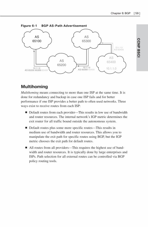
Figure 6-1 BGP AS-Path Advertisement
CC
NP
BS
CI
Chapter 6: BGP [ 59 ]
AS65100
AS65300
10.1.1.0AS 65400
10.1.1.0AS 65300 65400
10.1.1.0AS 65200 65300 65400
AS65200
AS65400
10.1.1.0
Multihoming
Multihoming means connecting to more than one ISP at the same time. It isdone for redundancy and backup in case one ISP fails and for betterperformance if one ISP provides a better path to often used networks. Threeways exist to receive routes from each ISP:
■ Default routes from each provider—This results in low use of bandwidthand router resources. The internal network’s IGP metric determines theexit router for all traffic bound outside the autonomous system.
■ Default routes plus some more specific routes—This results inmedium use of bandwidth and router resources. This allows you tomanipulate the exit path for specific routes using BGP, but the IGPmetric chooses the exit path for default routes.
■ All routes from all providers—This requires the highest use of band-width and router resources. It is typically done by large enterprises andISPs. Path selection for all external routes can be controlled via BGPpolicy routing tools.
BGP Databases
BGP uses three databases. The first two listed are BGP-specific; the third isshared by all routing processes on the router:
■ Neighbor database—This is a list of all configured BGP neighbors. Toview it, use the show ip bgp summary command.
■ BGP database, or RIB (Routing Information Base)—This is a listof networks known by BGP, along with their paths and attributes. Toview it, use the show ip bgp command.
■ Routing table—This is a list of the paths to each network used by therouter, and the next hop for each network. To view it, use the show iproute command.
BGP Message Types
BGP has four types of messages:
■ Open—After a neighbor is configured, BGP sends an open message totry to establish peering with that neighbor. Includes information suchas autonomous system number, router ID, and hold time.
■ Update—Message used to transfer routing information between peers.
■ Keepalive—BGP peers exchange keepalive messages every 60seconds by default. These keep the peering session active.
■ Notification—When a problem occurs that causes a router to end theBGP peering session, a notification message is sent to the BGP neigh-bor and the connection is closed.
Internal and External BGP
Internal BGP (IBGP) is BGP peering relationship between routers in thesame autonomous system. External BGP (EBGP) is BGP peering relation-ship between routers in different autonomous systems. BGP treats updatesfrom internal peers differently than updates from external peers.
In Figure 6-2, routers A and B are EBGP peers. Routers B, C, and D areIBGP peers.
CC
NP
BS
CI
[ 60 ] CCNP BSCI Quick Reference
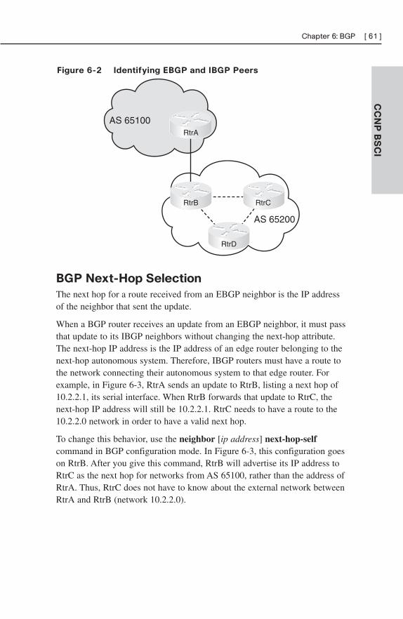
Figure 6-2 Identifying EBGP and IBGP Peers
CC
NP
BS
CI
Chapter 6: BGP [ 61 ]
AS 65100
AS 65200
RtrC
RtrA
RtrB RtrC
RtrD
BGP Next-Hop Selection
The next hop for a route received from an EBGP neighbor is the IP addressof the neighbor that sent the update.
When a BGP router receives an update from an EBGP neighbor, it must passthat update to its IBGP neighbors without changing the next-hop attribute.The next-hop IP address is the IP address of an edge router belonging to thenext-hop autonomous system. Therefore, IBGP routers must have a route tothe network connecting their autonomous system to that edge router. Forexample, in Figure 6-3, RtrA sends an update to RtrB, listing a next hop of10.2.2.1, its serial interface. When RtrB forwards that update to RtrC, thenext-hop IP address will still be 10.2.2.1. RtrC needs to have a route to the10.2.2.0 network in order to have a valid next hop.
To change this behavior, use the neighbor [ip address] next-hop-selfcommand in BGP configuration mode. In Figure 6-3, this configuration goeson RtrB. After you give this command, RtrB will advertise its IP address toRtrC as the next hop for networks from AS 65100, rather than the address ofRtrA. Thus, RtrC does not have to know about the external network betweenRtrA and RtrB (network 10.2.2.0).
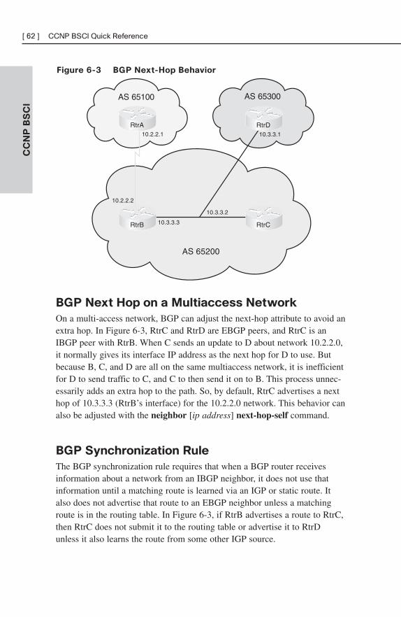
Figure 6-3 BGP Next-Hop Behavior
CC
NP
BS
CI
[ 62 ] CCNP BSCI Quick Reference
AS 65100
AS 65200
AS 65300
10.2.2.1
10.2.2.2
10.3.3.1
10.3.3.2
10.3.3.3
RtrA RtrD
RtrCRtrB
BGP Next Hop on a Multiaccess Network
On a multi-access network, BGP can adjust the next-hop attribute to avoid anextra hop. In Figure 6-3, RtrC and RtrD are EBGP peers, and RtrC is anIBGP peer with RtrB. When C sends an update to D about network 10.2.2.0,it normally gives its interface IP address as the next hop for D to use. Butbecause B, C, and D are all on the same multiaccess network, it is inefficientfor D to send traffic to C, and C to then send it on to B. This process unnec-essarily adds an extra hop to the path. So, by default, RtrC advertises a nexthop of 10.3.3.3 (RtrB’s interface) for the 10.2.2.0 network. This behavior canalso be adjusted with the neighbor [ip address] next-hop-self command.
BGP Synchronization Rule
The BGP synchronization rule requires that when a BGP router receivesinformation about a network from an IBGP neighbor, it does not use thatinformation until a matching route is learned via an IGP or static route. Italso does not advertise that route to an EBGP neighbor unless a matchingroute is in the routing table. In Figure 6-3, if RtrB advertises a route to RtrC,then RtrC does not submit it to the routing table or advertise it to RtrDunless it also learns the route from some other IGP source.
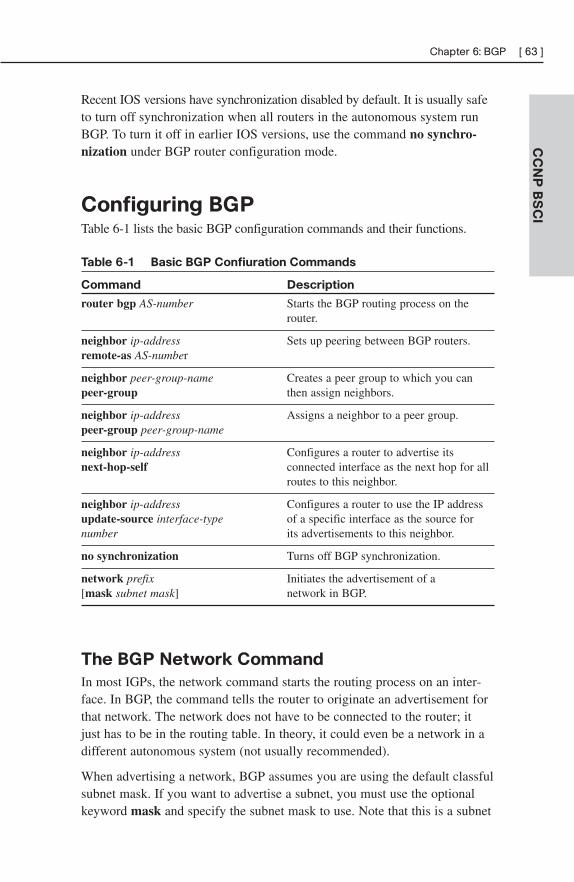
Recent IOS versions have synchronization disabled by default. It is usually safeto turn off synchronization when all routers in the autonomous system runBGP. To turn it off in earlier IOS versions, use the command no synchro-nization under BGP router configuration mode.
Configuring BGPTable 6-1 lists the basic BGP configuration commands and their functions.
Table 6-1 Basic BGP Confiuration Commands
Command Description
router bgp AS-number Starts the BGP routing process on the router.
neighbor ip-address Sets up peering between BGP routers.remote-as AS-number
neighbor peer-group-name Creates a peer group to which you can peer-group then assign neighbors.
neighbor ip-address Assigns a neighbor to a peer group.peer-group peer-group-name
neighbor ip-address Configures a router to advertise its next-hop-self connected interface as the next hop for all
routes to this neighbor.
neighbor ip-address Configures a router to use the IP address update-source interface-type of a specific interface as the source fornumber its advertisements to this neighbor.
no synchronization Turns off BGP synchronization.
network prefix Initiates the advertisement of a [mask subnet mask] network in BGP.
The BGP Network Command
In most IGPs, the network command starts the routing process on an inter-face. In BGP, the command tells the router to originate an advertisement forthat network. The network does not have to be connected to the router; itjust has to be in the routing table. In theory, it could even be a network in adifferent autonomous system (not usually recommended).
When advertising a network, BGP assumes you are using the default classfulsubnet mask. If you want to advertise a subnet, you must use the optionalkeyword mask and specify the subnet mask to use. Note that this is a subnet
CC
NP
BS
CI
Chapter 6: BGP [ 63 ]
mask, not the inverse mask used by OSPF and EIGRP network statements.The routing table must contain an exact match (prefix and subnet mask) tothe network listed in the network statement before BGP will advertise the route.
BGP Peering
BGP assumes that external neighbors are directly connected and that theyare peering with the IP address of the directly connected interface of theirneighbor. If not, you must tell BGP to look more than one hop away for itsneighbor, with the neighbor ip-address ebgp-multihop number-of-hopscommand. You might use this command if you are peering with loopbackinterface IP addresses, for instance. BGP assumes that internal neighborsmight not be directly connected, so this command is not needed with IBGP.
BGP Peering States
The command show ip bgp neighbors shows a list of peers, and the statusof their peering session. This status can include the following states:
■ Idle—No peering; router is looking for neighbor. Idle (admin) meansthat the neighbor relationship has been administratively shut down.
■ Connect—TCP handshake completed.
■ OpenSent, or Active—An open message was sent to try to establishthe peering.
■ OpenConfirm—Router has received a reply to the open message.
■ Established—Routers have a BGP peering session. This is the desiredstate.
You can troubleshoot session establishment with debug commands. Usedebug ip bgp events or debug ip bgp ipv4 unicast (in IOS versions 12.4and up) to see where the process fails. Some common failure causes includeAS number misconfiguration, neighbor IP address misconfiguration, neigh-bor with no neighbor statement for your router, and neighbor with no routeto the source address of your router’s BGP messages.
BGP Path SelectionIGPs, such as EIGRP or OSPF, choose routes based on lowest metric. Theyattempt to find the shortest, fastest way to get traffic to its destination. BGP,however, has a very different way of route selection. It assigns various
CC
NP
BS
CI
[ 64 ] CCNP BSCI Quick Reference
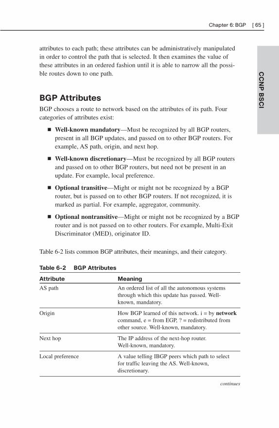
attributes to each path; these attributes can be administratively manipulatedin order to control the path that is selected. It then examines the value ofthese attributes in an ordered fashion until it is able to narrow all the possi-ble routes down to one path.
BGP Attributes
BGP chooses a route to network based on the attributes of its path. Fourcategories of attributes exist:
■ Well-known mandatory—Must be recognized by all BGP routers,present in all BGP updates, and passed on to other BGP routers. Forexample, AS path, origin, and next hop.
■ Well-known discretionary—Must be recognized by all BGP routersand passed on to other BGP routers, but need not be present in anupdate. For example, local preference.
■ Optional transitive—Might or might not be recognized by a BGProuter, but is passed on to other BGP routers. If not recognized, it ismarked as partial. For example, aggregator, community.
■ Optional nontransitive—Might or might not be recognized by a BGProuter and is not passed on to other routers. For example, Multi-ExitDiscriminator (MED), originator ID.
Table 6-2 lists common BGP attributes, their meanings, and their category.
Table 6-2 BGP Attributes
Attribute Meaning
AS path An ordered list of all the autonomous systems through which this update has passed. Well-known, mandatory.
Origin How BGP learned of this network. i = by networkcommand, e = from EGP, ? = redistributed from other source. Well-known, mandatory.
Next hop The IP address of the next-hop router. Well-known, mandatory.
Local preference A value telling IBGP peers which path to select for traffic leaving the AS. Well-known,discretionary.
continues
CC
NP
BS
CI
Chapter 6: BGP [ 65 ]
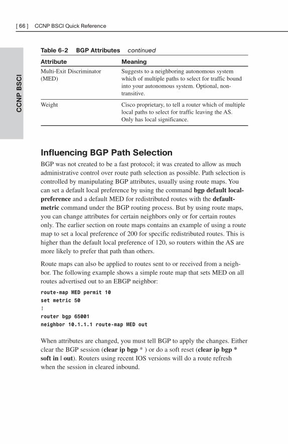
Table 6-2 BGP Attributes continued
Attribute Meaning
Multi-Exit Discriminator Suggests to a neighboring autonomous system (MED) which of multiple paths to select for traffic bound
into your autonomous system. Optional, non-transitive.
Weight Cisco proprietary, to tell a router which of multiple local paths to select for traffic leaving the AS. Only has local significance.
Influencing BGP Path Selection
BGP was not created to be a fast protocol; it was created to allow as muchadministrative control over route path selection as possible. Path selection iscontrolled by manipulating BGP attributes, usually using route maps. Youcan set a default local preference by using the command bgp default local-preference and a default MED for redistributed routes with the default-metric command under the BGP routing process. But by using route maps,you can change attributes for certain neighbors only or for certain routesonly. The earlier section on route maps contains an example of using a routemap to set a local preference of 200 for specific redistributed routes. This ishigher than the default local preference of 120, so routers within the AS aremore likely to prefer that path than others.
Route maps can also be applied to routes sent to or received from a neigh-bor. The following example shows a simple route map that sets MED on allroutes advertised out to an EBGP neighbor:
route-map MED permit 10
set metric 50
!
router bgp 65001
neighbor 10.1.1.1 route-map MED out
When attributes are changed, you must tell BGP to apply the changes. Eitherclear the BGP session (clear ip bgp * ) or do a soft reset (clear ip bgp *soft in | out). Routers using recent IOS versions will do a route refreshwhen the session in cleared inbound.
CC
NP
BS
CI
[ 66 ] CCNP BSCI Quick Reference
BGP Path Selection Criteria
BGP tries to narrow its path selection down to one best path; it does not loadbalance by default. To do so, it examines the path attributes of any loop-free,synchronized (if synchronization is enabled) routes with a reachable next-hop in the following order:
1. Choose the route with the highest weight.
2. If weight is not set, choose the route with the highest local preference.
3. Choose routes that you advertise.
4. Choose the path with the shortest autonomous system path.
5. Choose the path with the lowest origin code (i is lowest, e is next, ? islast).
6. Choose the route with the lowest MED, if the same autonomoussystem advertises the possible routes.
7. Choose an eBGP route over an iBGP route.
8. Choose the route through the nearest IGP neighbor.
9. Choose the oldest route.
10. Choose a path through the neighbor with the lowest router ID.
11. Choose a path through the neighbor with the lowest IP address.
To enable BGP to load balance over more than one path, you must enter thecommand maximum-paths number-of-paths. BGP can load balance over amaximum of six paths.
BGP Authentication
BGP supports MD5 authentication between neighbors, using a shared pass-word. It is configured under BGP router configuration mode with thecommand neighbor {ip-address | peer-group-name} password password.When authentication is configured, BGP authenticates every TCP segmentfrom its peer and checks the source of each routing update. Most ISPsrequire authentication for their EBGP peers.
Peering will succeed only if both routers are configured for authenticationand have the same password. If your router has authentication configuredand the neighbor does not, your router will display the error message“%TCP-6-BADAUTH: No MD5 digest from peer’s-IP-address:11003 tolocal-router’s-IP-address:179.”
CC
NP
BS
CI
Chapter 6: BGP [ 67 ]
If the neighbor router is configured with a nonmatching password, yourrouter will display the error message “%TCP-6-BADAUTH: Invalid MD5digest from peer’s-IP-address:11004 to local-router’s-IP-address:179.”
If a router has a password configured for a neighbor, but the neighbor routerdoes not, a message such as the following will display on the console whilethe routers attempt to establish a BGP session between them:
%TCP-6-BADAUTH: No MD5 digest from [peer’s IP address]:11003 to[local router’s IP address]:179
Similarly, if the two routers have different passwords configured, a messagesuch as the following will display on the screen:
%TCP-6-BADAUTH: Invalid MD5 digest from [peer’s IP address]:11004to [local router’s IP address]:179
CC
NP
BS
CI
[ 68 ] CCNP BSCI Quick Reference
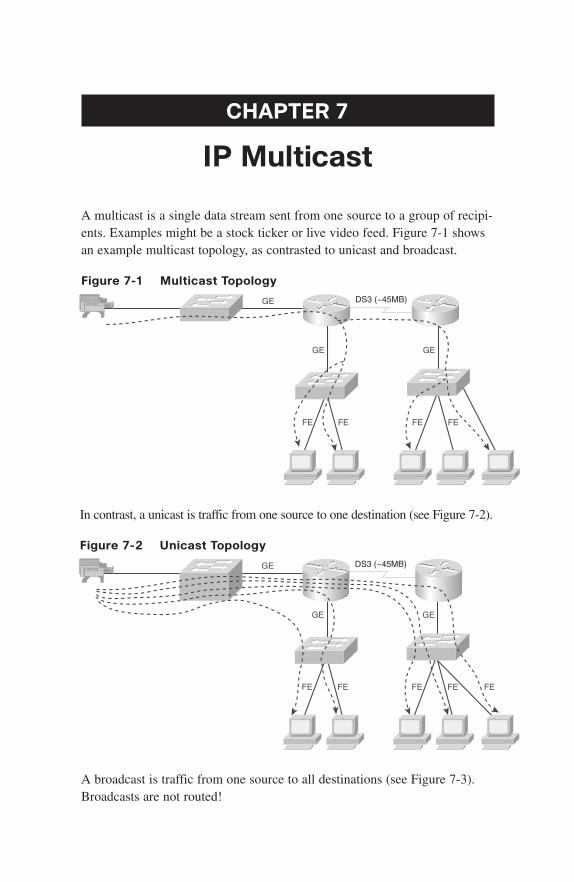
CHAPTER 7
IP Multicast
A multicast is a single data stream sent from one source to a group of recipi-ents. Examples might be a stock ticker or live video feed. Figure 7-1 showsan example multicast topology, as contrasted to unicast and broadcast.
Figure 7-1 Multicast Topology
GE
GE GE
FE FE FE FE
DS3 (~45MB)
In contrast, a unicast is traffic from one source to one destination (see Figure 7-2).
Figure 7-2 Unicast Topology
GE
GE GE
FE FE FE FE FE
DS3 (~45MB)
A broadcast is traffic from one source to all destinations (see Figure 7-3).Broadcasts are not routed!
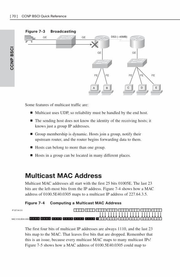
Figure 7-3 Broadcasting
CC
NP
BS
CI
[ 70 ] CCNP BSCI Quick Reference
GEGE
GE GE
FE FE FE FE FE
DS3 (~45MB)
A B C D E
Some features of multicast traffic are:
■ Multicast uses UDP, so reliability must be handled by the end host.
■ The sending host does not know the identity of the receiving hosts; itknows just a group IP addresses.
■ Group membership is dynamic. Hosts join a group, notify theirupstream router, and the router begins forwarding data to them.
■ Hosts can belong to more than one group.
■ Hosts in a group can be located in many different places.
Multicast MAC AddressMulticast MAC addresses all start with the first 25 bits 01005E. The last 23bits are the left-most bits from the IP address. Figure 7-4 shows how a MACaddress of 0100.5E40.0305 maps to a multicast IP address of 227.64.3.5.
Figure 7-4 Computing a Multicast MAC Address
IP 227.64.3.5 1 011
0 101
0 110
1 0110 000 0 000MAC 0100.5E40.0305 0 000 0 100
0 101
0 101
0 000
0 000
0 001
0 001
0 000
0 000
0 110
0 110
0 000
0 000
The first four bits of multicast IP addresses are always 1110, and the last 23bits map to the MAC. That leaves five bits that are dropped. Remember thatthis is an issue, because every multicast MAC maps to many multicast IPs!Figure 7-5 shows how a MAC address of 0100.5E40.0305 could map to
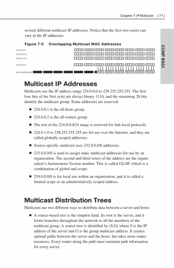
several different multicast IP addresses. Notice that the first two octets canvary in the IP addresses.
Figure 7-5 Overlapping Multicast MAC Addresses CC
NP
BS
CI
Chapter 7: IP Multicast [ 71 ]
1 011 0 110 0 001 0 000 0 000 0 110 0 000 0 101IP 227.64.3.5
0 101 1 011 0 001 0 000 0 000 0 110 0 000 0 101MAC 0100.5E40.0305 0 000 0 0000 000 0 100
1 011 0 011 1 110 0 100 0 000 0 110 0 000 0 101IP 230.177.3.5
1 011 0 100 1 001 0 000 0 000 0 110 0 000 0 101IP 225.192.3.5
1 011 1 010 0 001 0 000 0 000 0 110 0 000 0 101IP 234.64.3.5
Multicast IP AddressesMulticasts use the IP address range 224.0.0.0 to 239.255.255.255. The firstfour bits of the first octet are always binary 1110, and the remaining 28 bitsidentify the multicast group. Some addresses are reserved:
■ 224.0.0.1 is the all-hosts group.
■ 224.0.0.2 is the all-routers group.
■ The rest of the 224.0.0.0/24 range is reserved for link-local protocols.
■ 224.0.1.0 to 238.255.255.255 are for use over the Internet, and they arecalled globally-scoped addresses.
■ Source-specific multicast uses 232.0.0.0/8 addresses.
■ 233.0.0.0/8 is used to assign static multicast addresses for use by anorganization. The second and third octets of the address are the organi-zation’s Autonomous System number. This is called GLOP, which is acombination of global and scope.
■ 239.0.0.0/8 is for local use within an organization, and it is called alimited scope or an administratively scoped address.
Multicast Distribution TreesMulticasts use two different ways to distribute data between a server and hosts:
■ A source-based tree is the simplest kind. Its root is the server, and itforms branches throughout the network to all the members of themulticast group. A source tree is identified by (S,G) where S is the IPaddress of the server and G is the group multicast address. It createsoptimal paths between the server and the hosts, but takes more routerresources. Every router along the path must maintain path informationfor every server.
■ A shared tree selects a common root called a rendezvous point (RP).The server sends traffic to the RP, which forwards it to hosts belongingto the group. The tree is identified by (*,G) where * means any sourceand G is the group multicast address. Shared trees use less routerresources, but can result in suboptimal paths.
Reverse Path ForwardingMulticast routers identify upstream ports (pointing to the server or RP) anddownstream ports (pointing to other receivers) for each multicast group. Theupstream port is found using Reverse Path Forwarding (RPF). RPF involveslooking at the routing table to see which interface the router uses to sendunicast traffic to that server or RP. That interface is the upstream port, orRPF port, for the multicast group. The RFP check is done every fiveseconds. It is used in this way:
■ If a multicast packet arrives on the RPF port, the router forwards thepacket out to the interfaces listed in the outgoing interface list of amulticast routing table.
■ If the packet does not arrive on the RPF port, the packet is discardedto prevent loops.
Protocol Independent Multicast (PIM)PIM is a protocol used between routers to keep track of where to forwardtraffic for each multicast group. It can use information gathered from anyrouting protocol. PIM can run in dense mode or sparse mode.
PIM Dense Mode
PIM dense mode uses source-based trees. When running in dense mode,PIM assumes that every router needs to receive multicasts. Any router thatdoesn’t want to receive it must send a prune message upstream to the server.PIM dense mode is most appropriate when:
■ Multicast servers and receivers are near each other.
■ There are just a few servers and many receivers.
■ You have a high volume of multicast traffic.
■ The multicast stream is fairly constant.
CC
NP
BS
CI
[ 72 ] CCNP BSCI Quick Reference
PIM Sparse Mode
PIM sparse mode uses shared distribution trees. It does not assume that anyrouters want to receive the multicast, but instead waits to hear an explicitmessage from them, joining the group. Then it adds branches to the tree toreach the hosts behind those routers. PIM sparse mode uses RPs to connecthosts and servers. After the connection is made, PIM switches over to asource tree. Sparse mode is used when:
■ Pockets of users are widely dispersed around the network.
■ Multicast traffic is intermittent.
PIM Sparse-Dense Mode
An interface can be configured in sparse-dense mode. Then, if the routerknows of an RP for its group, it uses sparse mode. Otherwise, it uses densemode. In addition, it makes the interface capable of receiving multicastsfrom both sparse and dense-mode groups.
Configuring Multicast Routing and PIM
Use the following command to enable multicast routing:
(config)# ip multicast-routing
PIM mode must be configured at each interface with the followingcommand. Configuring PIM on an interface also enables Internet GroupManagement Protocol (IGMP) on that interface:
(config-if)# ip pim {sparse-mode | dense-mode | sparse-dense-mode}
When using sparse mode, an RP must be specified. A router knows that it isan RP when it sees its own address in the command:
(config)# ip pim rp-address ip-address
Auto-RP
Auto-RP automates the discovery of RPs in a sparse or sparse-dense PIMnetwork. RPs advertise themselves to a router designated as an RP mappingagent. The mapping agent then decides on one RP per group and sends thatinformation to the other routers.
CC
NP
BS
CI
Chapter 7: IP Multicast [ 73 ]
To configure a router as an RP, type the following:
(config)# ip pim send-rp-announce type number scope ttl
group-list access-list-number
To configure a router as a mapping agent, type the following:
(config)# ip pim send-rp-discovery scope ttl
PIM Version 2
Cisco routers with recent versions of the IOS use PIM Version 2 by default.Some differences between PIM Version 1 and PIM Version 2 include:
■ PIM Version 1 is Cisco proprietary, whereas PIM Version 2 is stan-dards-based.
■ Both versions can dynamically map RPs to multicast groups. PIMVersion 1 uses an auto-RP mapping agent, and PIM Version 2 uses abootstrap router (BSR).
■ PIM Version 1 uses a Time-to-Live value to bound its announcements,and PIM Version 2 uses a configured domain border.
■ In PIM Version 2, sparse and dense mode are group properties, notinterface properties.
To configure PIM Version 2, configure at least one router as a BSR, andselected routers as RPs. To configure a BSR, use the following:
(config)# ip pim bsr-candidate interface hash-mask-length [priority]
To configure a router as a candidate RP, use the following:
(config)# ip pim rp-candidate type number ttl group-list access-
list-number
IGMPWhen a host wishes to join a multicast group, it sends an Internet GroupManagement Protocol (IGMP) message to the router. The router periodicallychecks for group members on each segment. There are three versions of IGMP.
CC
NP
BS
CI
[ 74 ] CCNP BSCI Quick Reference
IGMP Version 1
Multicast routers query each segment periodically to see if there are stillhosts in multicast groups with a query sent to the all-hosts address of224.0.0.1. One host on the segment responds. Hosts silently leave a group;the router doesn’t know they are gone until it queries and no one responds.
IGMP Version 2
Version 2 adds explicit leave messages that hosts send when they leave agroup. Queries are sent to specific multicast group addresses, not the all-hosts address.
IGMP Version 3
Hosts are able to tell the router not only which multicast groups they belongto, but also from which sources they will accept multicasts. It adds twomodes for requesting membership in a multicast group:
■ Include mode—The receiver lists the group or groups to which it willbelong and the servers it will use.
■ Exclude mode—The receiver lists the group or groups to which it willbelong and the servers it will not use.
CGMP
Switches flood multicasts by default. Cisco Group Management Protocol(CGMP) lets a router tell a switch which hosts belong to which multicastgroup, so the switch can add that information to its port-to-MAC addressmapping. Then when a multicast comes in, the switch forwards it only toports that have hosts belonging to that group. CGMP is Cisco proprietary.
IGMP Snooping
IGMP snooping is another way for the switch to find out which ports havemulticast hosts. When it is enabled, the switch opens all multicast packets,looking for IGMP join or leave messages. When it finds one, it records thatinformation and uses it for forwarding multicasts. Because every multicastpacket has to be opened, this can cause a performance hit on the switch.
CC
NP
BS
CI
Chapter 7: IP Multicast [ 75 ]
Verifying Multicast RoutingSome commands to verify multicast routing include the following:
■ show ip mroute—This shows the contents of the multicast routingtable. For each group, it lists the mode, the RPF neighbor, the groupidentifier, and the outgoing interfaces.
■ show ip mroute summary—Lists each multicast group without asmuch detail.
■ show ip mroute active—Shows the active sources and the sendingrate of each.
■ show ip mroute count—Shows traffic statistics for each multicastgroup.
■ show ip pim interface—Lists each interface doing multicasting, itsPIM mode, and number of neighbors.
■ show ip pim rp—Lists the RPs the router knows.
■ show ip pim rp-hash—Shows the RP selected for each multicastgroup.
■ show ip pim bsr—Lists the current BSR.
CC
NP
BS
CI
[ 76 ] CCNP BSCI Quick Reference
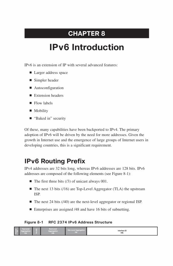
CHAPTER 8
IPv6 Introduction
IPv6 is an extension of IP with several advanced features:
■ Larger address space
■ Simpler header
■ Autoconfiguration
■ Extension headers
■ Flow labels
■ Mobility
■ “Baked in” security
Of these, many capabilities have been backported to IPv4. The primaryadoption of IPv6 will be driven by the need for more addresses. Given thegrowth in Internet use and the emergence of large groups of Internet users indeveloping countries, this is a significant requirement.
IPv6 Routing PrefixIPv4 addresses are 32 bits long, whereas IPv6 addresses are 128 bits. IPv6addresses are composed of the following elements (see Figure 8-1):
■ The first three bits (/3) of unicast always 001.
■ The next 13 bits (/16) are Top-Level Aggregator (TLA) the upstreamISP.
■ The next 24 bits (/40) are the next-level aggregator or regional ISP.
■ Enterprises are assigned /48 and have 16 bits of subnetting.
Figure 8-1 RFC 2374 IPv6 Address Structure
Form
at3
b Site-Level Aggregation16b
Next-LevelAggregation
24bRsv
d8bTop-Level
Aggregation13b
Interface ID64b
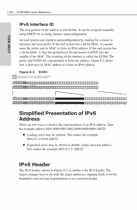
IPv6 Interface ID
The host portion of the address is last 64 bits. It can be assigned manually,using DHCP v6, or using stateless autoconfiguration.
An end-system uses stateless autoconfiguration by waiting for a router toadvertise the local prefix. If the end system has a 64-bit MAC, it concate-nates the prefix and its MAC to form an IPv6 address. If the end system hasa 48-bit MAC, it flips the global/local bit and inserts 0xFFEE into themiddle of the MAC. The resulting 64-bit number is called the EUI64. Theprefix and EUI64 are concatenated to form the address. Figure 8-2 showshow a host uses its MAC address to create its IPv6 address.
Figure 8-2 EUI64
CC
NP
BS
CI
[ 78 ] CCNP BSCI Quick Reference
48 bit MAC Address FormatLG
UL
OUIUL bit is “universal/local” and is set to one to indicate locally determined MAC.L/G bit is “local/group” and is set to one for broadcasts and multicasts.
Example 48 bit MAC Address: 00:11:2F:1D:1B:48
0 000 0 000 0 010 1 1110 100 0 100 0 100 1 101 0 100 1 110 0 001 1 000
0 0 2 F1 1 1 D 1 B 4 8
EUI64LG
UL
Example 48 bit MAC Address 00:11:2F:1D:1B:48 becomes EUI64 02:11:2F:FF:FE:1B:48
0 000 0 010 0 010 1 1110 100 0 100 0 100 1 101 0 100 1 110 0 001 1 000
0 0 2 F1 1 1 D 1 B 4 8
1 111 1 111 1 111 1 011
F F F E
Simplified Presentation of IPv6
AddressThere are two ways to shorten the representation of an IPv6 address. Takethe example address 4001:0000:0001:0002:0000:0000:0000:ABCD.
■ Leading zeros may be omitted. This makes the example4001:0:1:2:0:0:0:ABCD.
■ Sequential zeros may be shown as double colons once per address.This makes the example 4001:0:1:2::ABCD.
IPv6 HeaderThe IPv6 header, shown in Figure 8-3, is similar o the IPv4 header. Thelargest changes have to do with the larger addresses, aligning fields to 64-bitboundaries and moving fragmentation to an extension header.
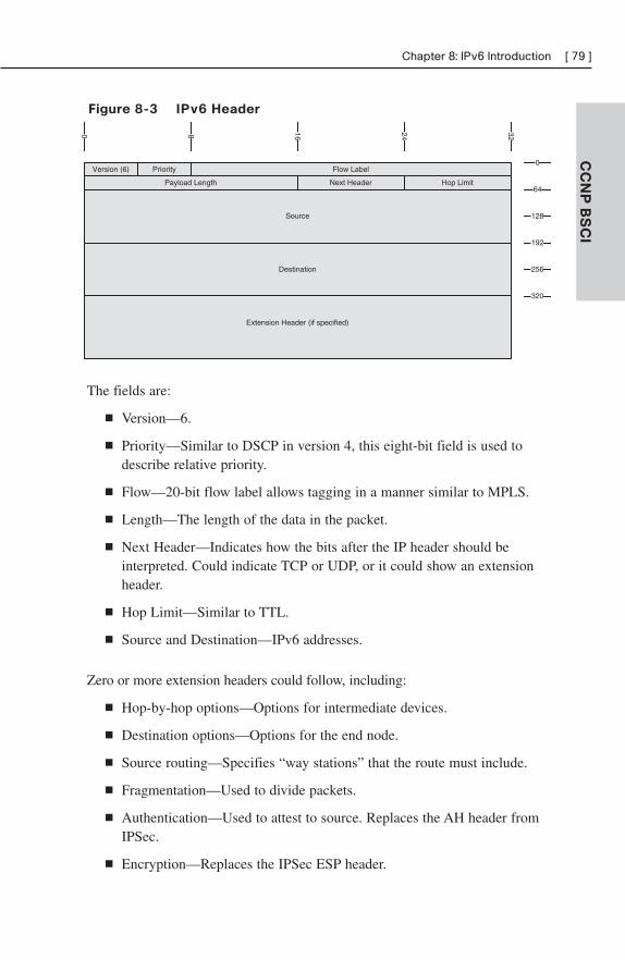
CC
NP
BS
CI
Chapter 8: IPv6 Introduction [ 79 ]
Version (6) Priority Flow Label
0 16 248 32
Payload Length Next Header Hop Limit
Source
0
64
128
192
320
256
Extension Header (if specified)
Destination
Figure 8-3 IPv6 Header
The fields are:
■ Version—6.
■ Priority—Similar to DSCP in version 4, this eight-bit field is used todescribe relative priority.
■ Flow—20-bit flow label allows tagging in a manner similar to MPLS.
■ Length—The length of the data in the packet.
■ Next Header—Indicates how the bits after the IP header should beinterpreted. Could indicate TCP or UDP, or it could show an extensionheader.
■ Hop Limit—Similar to TTL.
■ Source and Destination—IPv6 addresses.
Zero or more extension headers could follow, including:
■ Hop-by-hop options—Options for intermediate devices.
■ Destination options—Options for the end node.
■ Source routing—Specifies “way stations” that the route must include.
■ Fragmentation—Used to divide packets.
■ Authentication—Used to attest to source. Replaces the AH header fromIPSec.
■ Encryption—Replaces the IPSec ESP header.
Advanced Features“Advanced” features are elements that are not available in IPv4 or havesignificantly changed. For instance, it’s important to know that the idea ofbroadcasts has been abandoned and that devices will typically respond to aset of IPv6 addresses.
Specifying Destinations
IPv6 does not support broadcasts, but replaces broadcasts with multicasts.IPv6 also uses Anycast, which involves using the same address on twodevices. Anycast can be used to implement redundancy and has been back-ported to IPv4.
Specifying Sources
Each IPv6 system must recognize the following addresses:
■ Unicast address
■ Link local address (FE80/10 | EUI64)
■ Loopback (::1)
■ All-nodes multicast (FF00::1)
■ Site-local multicast (FF02::2)
■ Solicited-nodes multicast (FF02::1:FF00/104)
Additionally, some systems will also use the following addresses:
■ IPv4 mapped address (0::FFFF | 32-bit, IPv4 address).
■ Second unicast address shared with another system (anycast).
■ Additional multicast groups.
■ Routers must support subnet-router anycast (all zeros EUI64).
■ Routers must support local all-routers multicast (FF01::2), link-local(FF02::2), and site-local (FF05:2).
■ Routers must support routing protocol multicast groups.
CC
NP
BS
CI
[ 80 ] CCNP BSCI Quick Reference
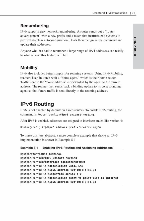
Renumbering
IPv6 supports easy network renumbering. A router sends out a “routeradvertisement” with a new prefix and a token that instructs end systems toperform stateless autoconfiguration. Hosts then recognize the command andupdate their addresses.
Anyone who has had to renumber a large range of IPv4 addresses can testifyto what a boon this feature will be!
Mobility
IPv6 also includes better support for roaming systems. Using IPv6 Mobility,roamers keep in touch with a “home agent,” which is their home router.Traffic sent to the “home address” is forwarded by the agent to the currentaddress. The roamer then sends back a binding update to its correspondingagent so that future traffic is sent directly to the roaming address.
IPv6 RoutingIPv6 is not enabled by default on Cisco routers. To enable IPv6 routing, thecommand is Router(config)#ipv6 unicast-routing.
After IPv6 is enabled, addresses are assigned to interfaces much like version 4:
Router(config-if)#ipv6 address prefix/prefix-length
To make this less abstract, a more complete example that shows an IPv6implementation is shown in Example 8-1.
Example 8-1 Enabling IPv6 Routing and Assigning Addresses
RouterA#configure terminal
RouterA(config)#ipv6 unicast-routing
RouterA(config)#interface fastethernet0/0
RouterA(config-if)#description Local LAN
RouterA(config-if)#ipv6 address 4001:0:1:1::2/64
RouterA(config-if)#interface serial 1/0
RouterA(config-if)#description point-to-point line to Internet
RouterA(config-if)#ipv6 address 4001:0:1:5::1/64
CC
NP
BS
CI
Chapter 8: IPv6 Introduction [ 81 ]
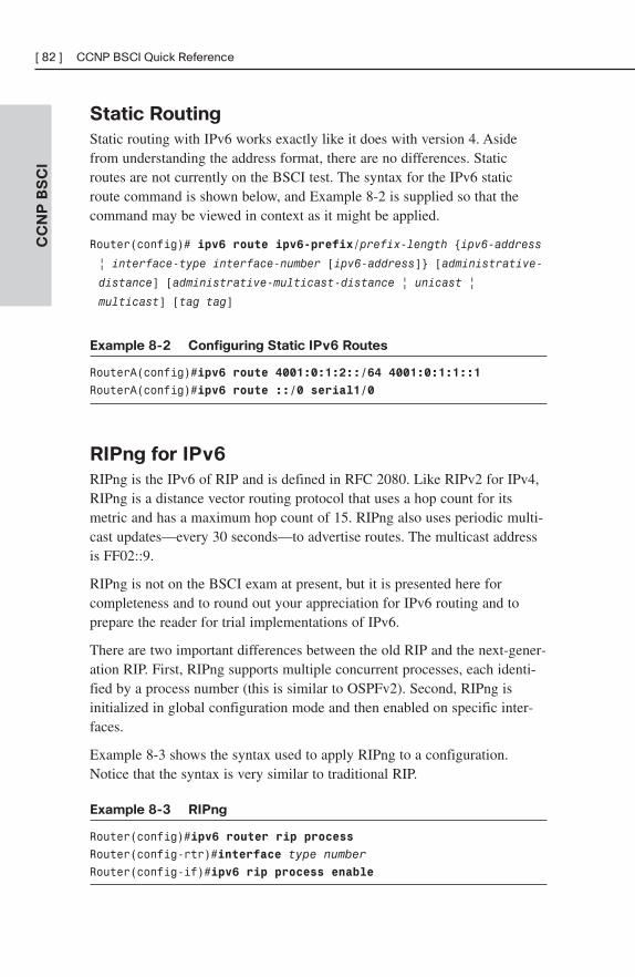
Static Routing
Static routing with IPv6 works exactly like it does with version 4. Asidefrom understanding the address format, there are no differences. Staticroutes are not currently on the BSCI test. The syntax for the IPv6 staticroute command is shown below, and Example 8-2 is supplied so that thecommand may be viewed in context as it might be applied.
Router(config)# ipv6 route ipv6-prefix/prefix-length {ipv6-address
| interface-type interface-number [ipv6-address]} [administrative-
distance] [administrative-multicast-distance | unicast |
multicast] [tag tag]
Example 8-2 Configuring Static IPv6 Routes
RouterA(config)#ipv6 route 4001:0:1:2::/64 4001:0:1:1::1
RouterA(config)#ipv6 route ::/0 serial1/0
RIPng for IPv6
RIPng is the IPv6 of RIP and is defined in RFC 2080. Like RIPv2 for IPv4,RIPng is a distance vector routing protocol that uses a hop count for itsmetric and has a maximum hop count of 15. RIPng also uses periodic multi-cast updates—every 30 seconds—to advertise routes. The multicast addressis FF02::9.
RIPng is not on the BSCI exam at present, but it is presented here forcompleteness and to round out your appreciation for IPv6 routing and toprepare the reader for trial implementations of IPv6.
There are two important differences between the old RIP and the next-gener-ation RIP. First, RIPng supports multiple concurrent processes, each identi-fied by a process number (this is similar to OSPFv2). Second, RIPng isinitialized in global configuration mode and then enabled on specific inter-faces.
Example 8-3 shows the syntax used to apply RIPng to a configuration.Notice that the syntax is very similar to traditional RIP.
Example 8-3 RIPng
Router(config)#ipv6 router rip process
Router(config-rtr)#interface type number
Router(config-if)#ipv6 rip process enable
CC
NP
BS
CI
[ 82 ] CCNP BSCI Quick Reference
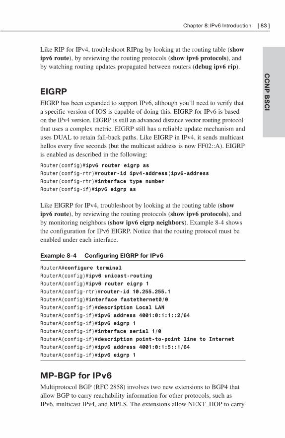
Like RIP for IPv4, troubleshoot RIPng by looking at the routing table (showipv6 route), by reviewing the routing protocols (show ipv6 protocols), andby watching routing updates propagated between routers (debug ipv6 rip).
EIGRP
EIGRP has been expanded to support IPv6, although you’ll need to verify thata specific version of IOS is capable of doing this. EIGRP for IPv6 is basedon the IPv4 version. EIGRP is still an advanced distance vector routing protocolthat uses a complex metric. EIGRP still has a reliable update mechanism anduses DUAL to retain fall-back paths. Like EIGRP in IPv4, it sends multicasthellos every five seconds (but the multicast address is now FF02::A). EIGRPis enabled as described in the following:
Router(config)#ipv6 router eigrp as
Router(config-rtr)#router-id ipv4-address|ipv6-address
Router(config-rtr)#interface type number
Router(config-if)#ipv6 eigrp as
Like EIGRP for IPv4, troubleshoot by looking at the routing table (showipv6 route), by reviewing the routing protocols (show ipv6 protocols), andby monitoring neighbors (show ipv6 eigrp neighbors). Example 8-4 showsthe configuration for IPv6 EIGRP. Notice that the routing protocol must beenabled under each interface.
Example 8-4 Configuring EIGRP for IPv6
RouterA#configure terminal
RouterA(config)#ipv6 unicast-routing
RouterA(config)#ipv6 router eigrp 1
RouterA(config-rtr)#router-id 10.255.255.1
RouterA(config)#interface fastethernet0/0
RouterA(config-if)#description Local LAN
RouterA(config-if)#ipv6 address 4001:0:1:1::2/64
RouterA(config-if)#ipv6 eigrp 1
RouterA(config-if)#interface serial 1/0
RouterA(config-if)#description point-to-point line to Internet
RouterA(config-if)#ipv6 address 4001:0:1:5::1/64
RouterA(config-if)#ipv6 eigrp 1
MP-BGP for IPv6
Multiprotocol BGP (RFC 2858) involves two new extensions to BGP4 thatallow BGP to carry reachability information for other protocols, such asIPv6, multicast IPv4, and MPLS. The extensions allow NEXT_HOP to carry
CC
NP
BS
CI
Chapter 8: IPv6 Introduction [ 83 ]
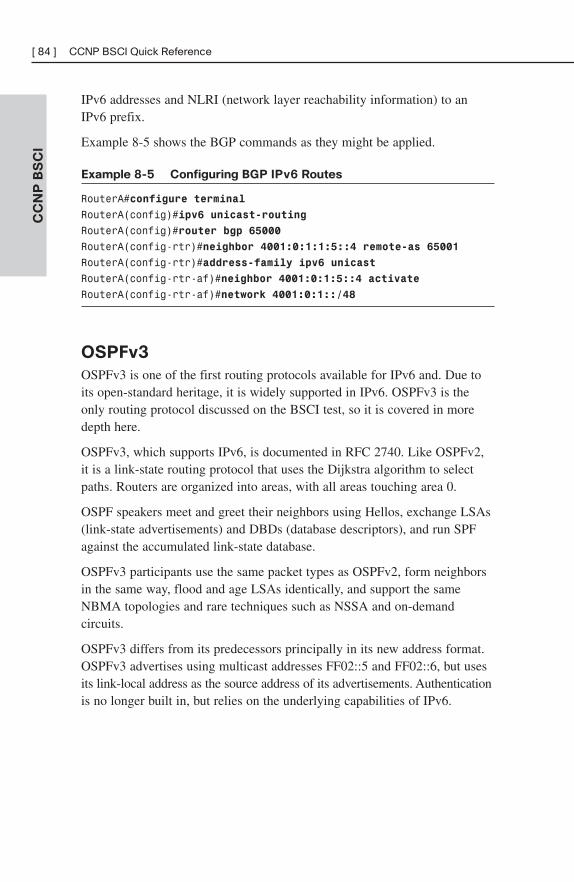
IPv6 addresses and NLRI (network layer reachability information) to anIPv6 prefix.
Example 8-5 shows the BGP commands as they might be applied.
Example 8-5 Configuring BGP IPv6 Routes
RouterA#configure terminal
RouterA(config)#ipv6 unicast-routing
RouterA(config)#router bgp 65000
RouterA(config-rtr)#neighbor 4001:0:1:1:5::4 remote-as 65001
RouterA(config-rtr)#address-family ipv6 unicast
RouterA(config-rtr-af)#neighbor 4001:0:1:5::4 activate
RouterA(config-rtr-af)#network 4001:0:1::/48
OSPFv3
OSPFv3 is one of the first routing protocols available for IPv6 and. Due toits open-standard heritage, it is widely supported in IPv6. OSPFv3 is theonly routing protocol discussed on the BSCI test, so it is covered in moredepth here.
OSPFv3, which supports IPv6, is documented in RFC 2740. Like OSPFv2,it is a link-state routing protocol that uses the Dijkstra algorithm to selectpaths. Routers are organized into areas, with all areas touching area 0.
OSPF speakers meet and greet their neighbors using Hellos, exchange LSAs(link-state advertisements) and DBDs (database descriptors), and run SPFagainst the accumulated link-state database.
OSPFv3 participants use the same packet types as OSPFv2, form neighborsin the same way, flood and age LSAs identically, and support the sameNBMA topologies and rare techniques such as NSSA and on-demandcircuits.
OSPFv3 differs from its predecessors principally in its new address format.OSPFv3 advertises using multicast addresses FF02::5 and FF02::6, but usesits link-local address as the source address of its advertisements. Authenticationis no longer built in, but relies on the underlying capabilities of IPv6.
CC
NP
BS
CI
[ 84 ] CCNP BSCI Quick Reference
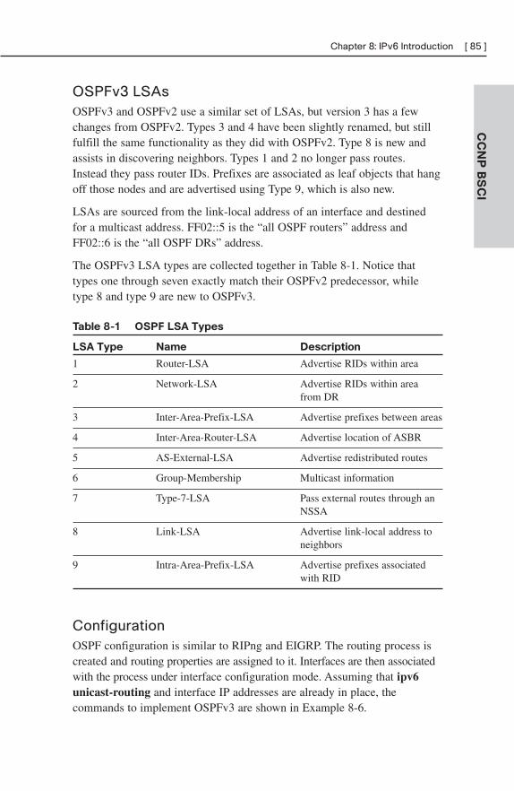
OSPFv3 LSAsOSPFv3 and OSPFv2 use a similar set of LSAs, but version 3 has a fewchanges from OSPFv2. Types 3 and 4 have been slightly renamed, but stillfulfill the same functionality as they did with OSPFv2. Type 8 is new andassists in discovering neighbors. Types 1 and 2 no longer pass routes.Instead they pass router IDs. Prefixes are associated as leaf objects that hangoff those nodes and are advertised using Type 9, which is also new.
LSAs are sourced from the link-local address of an interface and destinedfor a multicast address. FF02::5 is the “all OSPF routers” address andFF02::6 is the “all OSPF DRs” address.
The OSPFv3 LSA types are collected together in Table 8-1. Notice thattypes one through seven exactly match their OSPFv2 predecessor, whiletype 8 and type 9 are new to OSPFv3.
Table 8-1 OSPF LSA Types
LSA Type Name Description
1 Router-LSA Advertise RIDs within area
2 Network-LSA Advertise RIDs within area from DR
3 Inter-Area-Prefix-LSA Advertise prefixes between areas
4 Inter-Area-Router-LSA Advertise location of ASBR
5 AS-External-LSA Advertise redistributed routes
6 Group-Membership Multicast information
7 Type-7-LSA Pass external routes through an NSSA
8 Link-LSA Advertise link-local address to neighbors
9 Intra-Area-Prefix-LSA Advertise prefixes associated with RID
ConfigurationOSPF configuration is similar to RIPng and EIGRP. The routing process iscreated and routing properties are assigned to it. Interfaces are then associatedwith the process under interface configuration mode. Assuming that ipv6unicast-routing and interface IP addresses are already in place, thecommands to implement OSPFv3 are shown in Example 8-6.
CC
NP
BS
CI
Chapter 8: IPv6 Introduction [ 85 ]
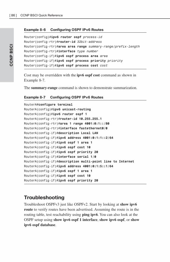
Example 8-6 Configuring OSPF IPv6 Routes
Router(config)#ipv6 router ospf process-id
Router(config-rtr)#router-id 32bit-address
Router(config-rtr)#area area range summary-range/prefix-length
Router(config-rtr)#interface type number
Router(config-if)#ipv6 ospf process area area
Router(config-if)#ipv6 ospf process priority priority
Router(config-if)#ipv6 ospf process cost cost
Cost may be overridden with the ipv6 ospf cost command as shown inExample 8-7.
The summary-range command is shown to demonstrate summarization.
Example 8-7 Configuring OSPF IPv6 Routes
RouterA#configure terminal
RouterA(config)#ipv6 unicast-routing
RouterA(config)#ipv6 router ospf 1
RouterA(config-rtr)#router-id 10.255.255.1
RouterA(config-rtr)#area 1 range 4001:0:1::/80
RouterA(config-rtr)#interface fastethernet0/0
RouterA(config-if)#description Local LAN
RouterA(config-if)#ipv6 address 4001:0:1:1::2/64
RouterA(config-if)#ipv6 ospf 1 area 1
RouterA(config-if)#ipv6 ospf cost 10
RouterA(config-if)#ipv6 ospf priority 20
RouterA(config-if)#interface serial 1/0
RouterA(config-if)#description multi-point line to Internet
RouterA(config-if)#ipv6 address 4001:0:1:5::1/64
RouterA(config-if)#ipv6 ospf 1 area 1
RouterA(config-if)#ipv6 ospf cost 10
RouterA(config-if)#ipv6 ospf priority 20
Troubleshooting
Troubleshoot OSPFv3 just like OSPFv2. Start by looking at show ipv6route to verify routes have been advertised. Assuming the route is in therouting table, test reachability using ping ipv6. You can also look at theOSPF setup using show ipv6 ospf 1 interface, show ipv6 ospf, or showipv6 ospf database.
CC
NP
BS
CI
[ 86 ] CCNP BSCI Quick Reference
Integrating IPv4 and IPv6There are several strategies for migrating from IPv4 to IPv6. Each of thesestrategies should be considered when organizations decide to make the moveto IPv6 because each has positive points to aiding a smooth migration. Itshould also be said that there does not have to be a global decision on strat-egy—your organization may choose to run dual-stack in the U.S., gocompletely to IPv6 in Japan, and use tunneling in Europe. The transitionmechanisms include:
■ Dual stack—Running IPv6 and IPv4 concurrently.
■ IPv6 to IPv4 tunneling (6-to-4)—Routers that straddle the IPv4 andIPv6 worlds to encapsulate the IPv6 traffic inside IPv4 packets.
■ Intra-Site Automatic Tunnel Addressing Protocol (ISATAP)—Thisprotocol is similar to 6-to-4, but it treats the IPv4 network as anNBMA network.
■ Teredo/Shipworm—Encapsulates IPv6 packets in IPv4/UDP segments.
NAT-PT, ALG, and BIA/BIS
Instead of replacing IPv4, there are several ways to coordinate the function-ing of IPv4 and v6 concurrently. NAT-protocol translation is an example ofthis coexistence strategy. NAT-PT maps IPv6 addresses to IPv4 addresses. IfIPv6 is used on the inside of your network, a NAT-PT device will receiveIPv6 traffic on its inside interface and replace the IPv6 header with an IPv4header before sending it to an outside interface. Reply traffic will be able tofollow the mapping backward to enable two-way communication.
NAT-PT is able to interpret application traffic and understand when IP infor-mation is included in the application data.
It is also possible to connect IPv4 and IPv6 routing domains using applica-tion-level gateways (ALG), proxies, or Bump-in-the-API (BIA) and Bump-in-the-Stack (BIS), which are NAT-PT implementations within a host.
CC
NP
BS
CI
Chapter 8: IPv6 Introduction [ 87 ]

This page intentionally left blank
BCMSNChapter 1: The Evolving Network Model . . . . . . . . . . . . . . 91
Chapter 2: VLAN Implementation . . . . . . . . . . . . . . . . . . . . 99
Chapter 3: Spanning Tree . . . . . . . . . . . . . . . . . . . . . . . . . . 112
Chapter 4: InterVLAN Routing . . . . . . . . . . . . . . . . . . . . . . 128
Chapter 5: Layer 3 Redundancy . . . . . . . . . . . . . . . . . . . . 136
Chapter 6: Using Wireless LANs . . . . . . . . . . . . . . . . . . . . 141
Chapter 7: VoIP in a Campus Network . . . . . . . . . . . . . . . 152
Chapter 8: Campus Network Security . . . . . . . . . . . . . . . 159
PART II

This page intentionally left blank
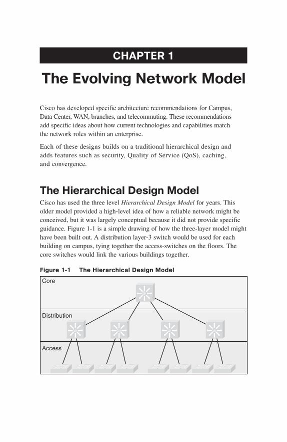
CHAPTER 1
The Evolving Network Model
Cisco has developed specific architecture recommendations for Campus,Data Center, WAN, branches, and telecommuting. These recommendationsadd specific ideas about how current technologies and capabilities matchthe network roles within an enterprise.
Each of these designs builds on a traditional hierarchical design and adds features such as security, Quality of Service (QoS), caching,and convergence.
The Hierarchical Design ModelCisco has used the three level Hierarchical Design Model for years. Thisolder model provided a high-level idea of how a reliable network might beconceived, but it was largely conceptual because it did not provide specificguidance. Figure 1-1 is a simple drawing of how the three-layer model mighthave been built out. A distribution layer-3 switch would be used for eachbuilding on campus, tying together the access-switches on the floors. Thecore switches would link the various buildings together.
Figure 1-1 The Hierarchical Design Model
Core
Access
Distribution
Si
Si Si Si Si
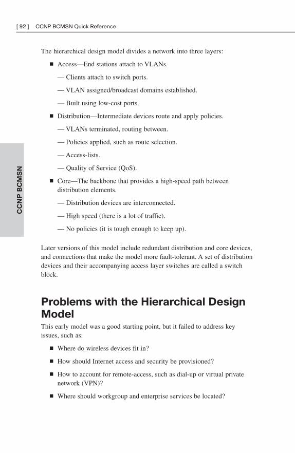
CC
NP
BC
MS
N[ 92 ] CCNP BCMSN Quick Reference
The hierarchical design model divides a network into three layers:
■ Access—End stations attach to VLANs.
— Clients attach to switch ports.
— VLAN assigned/broadcast domains established.
— Built using low-cost ports.
■ Distribution—Intermediate devices route and apply policies.
— VLANs terminated, routing between.
— Policies applied, such as route selection.
— Access-lists.
— Quality of Service (QoS).
■ Core—The backbone that provides a high-speed path between distribution elements.
— Distribution devices are interconnected.
— High speed (there is a lot of traffic).
— No policies (it is tough enough to keep up).
Later versions of this model include redundant distribution and core devices,and connections that make the model more fault-tolerant. A set of distributiondevices and their accompanying access layer switches are called a switchblock.
Problems with the Hierarchical Design
ModelThis early model was a good starting point, but it failed to address keyissues, such as:
■ Where do wireless devices fit in?
■ How should Internet access and security be provisioned?
■ How to account for remote-access, such as dial-up or virtual privatenetwork (VPN)?
■ Where should workgroup and enterprise services be located?
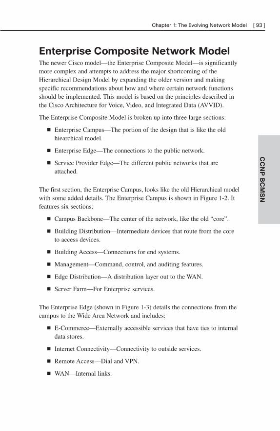
CC
NP
BC
MS
N
Chapter 1: The Evolving Network Model [ 93 ]
Enterprise Composite Network ModelThe newer Cisco model—the Enterprise Composite Model—is significantlymore complex and attempts to address the major shortcoming of theHierarchical Design Model by expanding the older version and makingspecific recommendations about how and where certain network functionsshould be implemented. This model is based on the principles described inthe Cisco Architecture for Voice, Video, and Integrated Data (AVVID).
The Enterprise Composite Model is broken up into three large sections:
■ Enterprise Campus—The portion of the design that is like the oldhiearchical model.
■ Enterprise Edge—The connections to the public network.
■ Service Provider Edge—The different public networks that areattached.
The first section, the Enterprise Campus, looks like the old Hierarchical modelwith some added details. The Enterprise Campus is shown in Figure 1-2. Itfeatures six sections:
■ Campus Backbone—The center of the network, like the old “core”.
■ Building Distribution—Intermediate devices that route from the core to access devices.
■ Building Access—Connections for end systems.
■ Management—Command, control, and auditing features.
■ Edge Distribution—A distribution layer out to the WAN.
■ Server Farm—For Enterprise services.
The Enterprise Edge (shown in Figure 1-3) details the connections from thecampus to the Wide Area Network and includes:
■ E-Commerce—Externally accessible services that have ties to internaldata stores.
■ Internet Connectivity—Connectivity to outside services.
■ Remote Access—Dial and VPN.
■ WAN—Internal links.
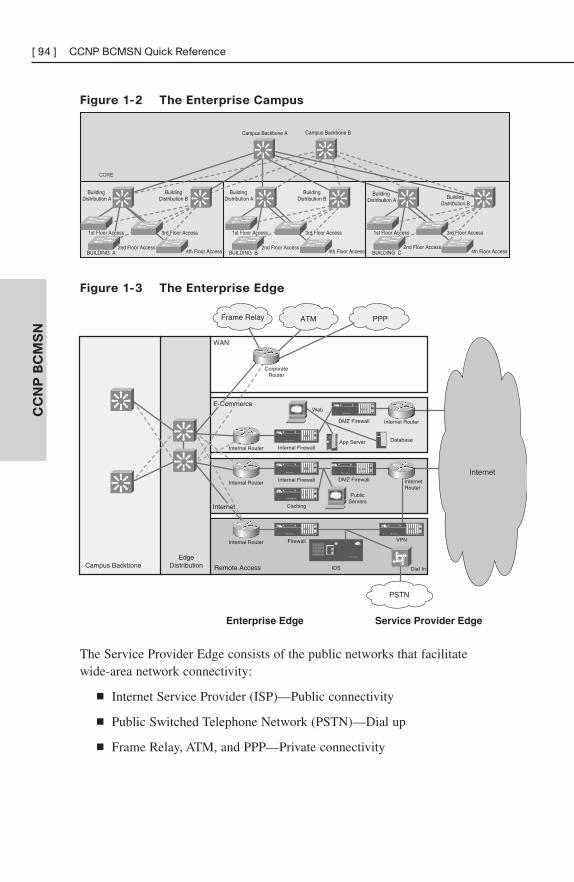
CC
NP
BC
MS
N[ 94 ] CCNP BCMSN Quick Reference
Figure 1-3 The Enterprise Edge
Figure 1-2 The Enterprise Campus
CORE
BUILDING B
Campus Backbone A Campus Backbone B
BUILDING CBUILDING A
BuildingDistribution A
BuildingDistribution B
BuildingDistribution A
BuildingDistribution B
BuildingDistribution A Building
Distribution B
2nd Floor Access4th Floor Access
2nd Floor Access4th Floor Access
2nd Floor Access4th Floor Access
1st Floor Access 3rd Floor Access 1st Floor Access 3rd Floor Access1st Floor Access 3rd Floor Access
Remote Access
WAN
Campus BackboneEdge
Distribution
Internal Router
DMZ Firewall
Web
DatabaseIDC
App Server
Internet Router
Corporate Router
Dial-In
Internal RouterDMZ Firewall
PublicServers
Internet Router
Internal Router VPN
IDS
PPP
Service Provider EdgeEnterprise Edge
Internet
PSTN
Frame Relay ATM
Internal Firewall
Internal Firewall
Caching
Firewall
E-Commerce
Internet
The Service Provider Edge consists of the public networks that facilitatewide-area network connectivity:
■ Internet Service Provider (ISP)—Public connectivity
■ Public Switched Telephone Network (PSTN)—Dial up
■ Frame Relay, ATM, and PPP—Private connectivity
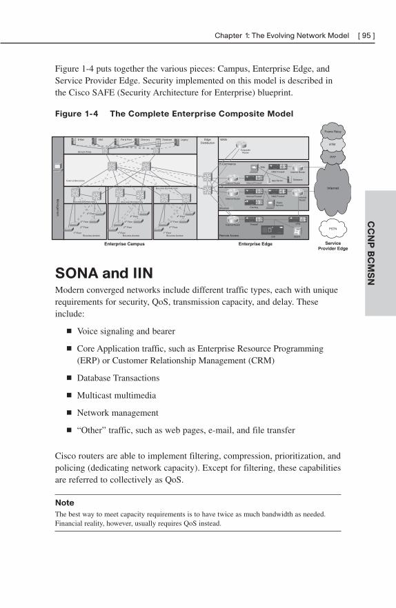
CC
NP
BC
MS
N
Chapter 1: The Evolving Network Model [ 95 ]
Figure 1-4 puts together the various pieces: Campus, Enterprise Edge, andService Provider Edge. Security implemented on this model is described inthe Cisco SAFE (Security Architecture for Enterprise) blueprint.
Figure 1-4 The Complete Enterprise Composite Model
CAMPUS BACKBONE
BUILDING ACCESS
1st Floor
2nd Floor
3rd Floor
1st Floor
2nd Floor
3rd Floor
1st Floor
2nd Floor
3rd Floor
SERVER FARM
LegacyFile & Print DatabaseE-Mail DNS Directory
ServiceProvider Edge
Enterprise EdgeEnterprise Campus
Managem
ent
Remote Access
WANEdgeDistribution
Internal Router
DMZ Firewall
Web
DatabaseI DC
App Server
Internet Router
Corporate Router
Dial-In
Internal RouterDMZ Firewall
PublicServers
Internet Router
Internal Router VPN
IDS
Internet
PSTN
Internal Firewall
Internal Firewall
Caching
Firewall
PPP
ATM
Frame Relay
BUILDING DISTRIBUTIONBUILDING DISTRIBUTION
BUILDING ACCESS BUILDING ACCESS
4th Floor4th Floor 4th Floor
BUILDING DISTRIBUTION
E-Commerce
Internet
IDC
IDC
IDC
SONA and IINModern converged networks include different traffic types, each with uniquerequirements for security, QoS, transmission capacity, and delay. Theseinclude:
■ Voice signaling and bearer
■ Core Application traffic, such as Enterprise Resource Programming(ERP) or Customer Relationship Management (CRM)
■ Database Transactions
■ Multicast multimedia
■ Network management
■ “Other” traffic, such as web pages, e-mail, and file transfer
Cisco routers are able to implement filtering, compression, prioritization, andpolicing (dedicating network capacity). Except for filtering, these capabilitiesare referred to collectively as QoS.
Note
The best way to meet capacity requirements is to have twice as much bandwidth as needed.Financial reality, however, usually requires QoS instead.
CC
NP
BC
MS
N[ 96 ] CCNP BCMSN Quick Reference
Although QoS is wonderful, it is not the only way to address bandwidthshortage. Cisco espouses an ideal called the Intelligent Information Network(IIN).
IIN describes an evolutionary vision of a network that integrates network andapplication functionality cooperatively and allows the network to be smartabout how it handles traffic to minimize the footprint of applications. IIN isbuilt on top of the Enterprise Composite Model and describes structuresoverlaid on to the Composite design as needed in three phases.
Phase 1, “Integrated Transport,” describes a converged network, which isbuilt along the lines of the Composite model and based on open standards.This is the phase that the industry has been transitioning to for the last fewyears, and the Cisco Integrated Services Routers (ISR) are an example of thistrend.
Phase 2, “Integrated Services,” attempts to virtualize resources, such asservers, storage, and network access and move to an “on-demand” model.
By “virtualize” Cisco means that the services are not associated with aparticular device or location. Instead, many services can reside in one deviceto ease management, or many devices can provide one service that is morereliable.
An ISR brings together routing, switching, voice, security, and wireless. It isan example of many services existing on one device. A load balancer, whichmakes many servers look like one, is a second example.
VRFs are an example of taking one resource and making it look like many.Some versions of IOS are capable of having a router present itself as manyvirtual router forwarding (VRF) instances, allowing your company to deliverdifferent logical topologies on the same physical infrastructure. Server virtu-alization is another example. The classic example of taking one resource andmaking it appear to be many resources is the use of a virtual LAN (VLAN)and a virtual storage area network (VSAN).
Virtualization provides flexibility in configuration and management.
CC
NP
BC
MS
N
Chapter 1: The Evolving Network Model [ 97 ]
Phase 3, “Integrated Applications,” uses application-oriented networking(AON) to make the network application-aware and to allow the network toactively participate in service delivery.
An example of this phase 3 IIN systems approach to service delivery isNetwork Admission Control (NAC). Before NAC, authentication, VLANassignment, and anti-virus updates were separately managed. With NAC inplace, the network is able to check the policy stance of a client and admit,deny, or remediate based on policies.
IIN allows the network to deconstruct packets, parse fields, and take actionsbased on the values it finds. An ISR equipped with an AON blade might beconfigured to route traffic from a business partner. The AON blade canexamine traffic, recognize the application, and rebuild XML files in memory.Corrupted XML fields might represent an attack (called schema poisoning),so the AON blade could react by blocking that source from further communi-cation. In this example, routing, an awareness of the application data flow,and security are combined to allow the network to contribute to the successof the application.
Services-Oriented Network Architecture (SONA) applies the IIN ideals toEnterprise networks. Figure 1-5 shows how SONA breaks down the IINfunctions into three layers:
■ Network Infrastructure—Hierarchical converged network and attachedend systems.
■ Interactive Services—Resources allocated to applications.
■ Applications—Includes business policy and logic.
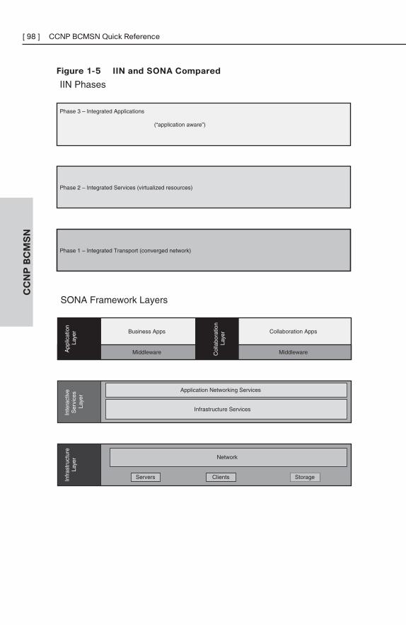
CC
NP
BC
MS
N[ 98 ] CCNP BCMSN Quick Reference
Figure 1-5 IIN and SONA Compared
Phase 1 – Integrated Transport (converged network)
Phase 3 – Integrated Applications
(“application aware”)
Phase 2 – Integrated Services (virtualized resources)
IIN Phases
Business Apps Collaboration Apps
Middleware Middleware
SONA Framework Layers
Infr
astr
uctu
reLa
yer
App
licat
ion
Laye
rIn
tera
ctiv
e S
ervi
ces
Laye
r
Network
Servers StorageClients
Application Networking Services
Infrastructure Services
Col
labo
ratio
n La
yer
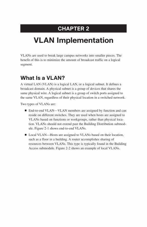
CHAPTER 2
VLAN Implementation
VLANs are used to break large campus networks into smaller pieces. Thebenefit of this is to minimize the amount of broadcast traffic on a logicalsegment.
What Is a VLAN?A virtual LAN (VLAN) is a logical LAN, or a logical subnet. It defines abroadcast domain. A physical subnet is a group of devices that shares thesame physical wire. A logical subnet is a group of switch ports assigned tothe same VLAN, regardless of their physical location in a switched network.
Two types of VLANs are:
■ End-to-end VLAN—VLAN members are assigned by function and canreside on different switches. They are used when hosts are assigned toVLANs based on functions or workgroups, rather than physical loca-tion. VLANs should not extend past the Building Distribution submod-ule. Figure 2-1 shows end-to-end VLANs.
■ Local VLAN—Hosts are assigned to VLANs based on their location,such as a floor in a building. A router accomplishes sharing ofresources between VLANs. This type is typically found in the BuildingAccess submodule. Figure 2-2 shows an example of local VLANs.
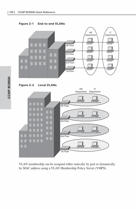
CC
NP
BC
MS
N[ 100 ] CCNP BCMSN Quick Reference
4th Floor
HRDepartment
ITDepartment
3rd Floor
2nd Floor
1st Floor
Figure 2-1 End-to-end VLANs
Figure 2-2 Local VLANs
4th Floor
HRDepartment
ITDepartment
3rd Floor
2nd Floor
1st Floor
VLAN membership can be assigned either statically by port or dynamicallyby MAC address using a VLAN Membership Policy Server (VMPS).
CC
NP
BC
MS
N
Chapter 2: VLAN Implementation [ 101 ]
Best PracticesVLAN networks need many of the same considerations that normal Ethernetlines demand. For instance, VLANs should have one IP subnet. By supplyingconsecutive subnets to VLANs, the routing advertisements can be summarized(which has many benefits to convergence).
A stereotypical description of capacity requirements is possible. Access portsare assigned to a single VLAN and should be Fast Ethernet or faster. Ports tothe distribution layer should be Gigabit Ethernet or better. Core ports areGigabit Etherchannel or 10-Gig Ethernet. Remember that uplink ports needto be able to handle all hosts communicating concurrently, and rememberthat although VLANs logically separate traffic, traffic in different VLANscan still experience contention with other VLANs when both VLANs travelover the same trunk line.
Take into account the entire traffic pattern of applications found in yournetwork. For instance, Voice VLANs pass traffic to a remote Call Manager.Multicast traffic has to communicate back to the routing process and possi-bly call upon a Rendezvous Point.
Creating a VLAN in Global Config ModeVLANs must be created before they may be used. VLANs may be created inglobal configuration mode or in VLAN database mode. Creating VLANs inglobal configuration is easy—just identify the VLAN number and name it!
(config)#vlan 12
(config-vlan)#name MYVLAN
Creating a VLAN in Database ModeCreating a VLAN in VLAN database mode is very similar to global configu-ration. There are no advantages to either method. Either method creates anentry in a VLAN.DAT file. Remember that copying the configuration, byitself, does not move the VLAN information! To do that you must move theVLAN.DAT file.
#vlan database
(vlan)#vlan 12 name MYVLAN
Delete a VLAN by using the same command with no in front of it. There isno need to include the name when deleting.
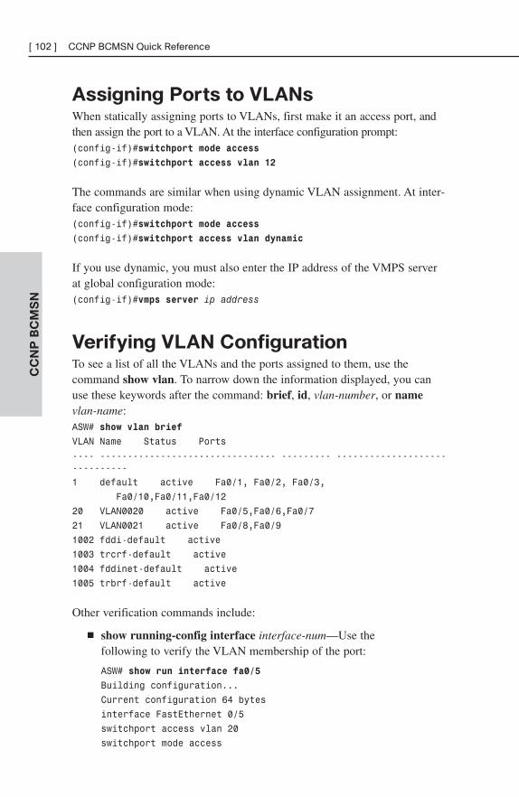
CC
NP
BC
MS
N[ 102 ] CCNP BCMSN Quick Reference
Assigning Ports to VLANsWhen statically assigning ports to VLANs, first make it an access port, andthen assign the port to a VLAN. At the interface configuration prompt:(config-if)#switchport mode access
(config-if)#switchport access vlan 12
The commands are similar when using dynamic VLAN assignment. At inter-face configuration mode:(config-if)#switchport mode access
(config-if)#switchport access vlan dynamic
If you use dynamic, you must also enter the IP address of the VMPS serverat global configuration mode:(config-if)#vmps server ip address
Verifying VLAN ConfigurationTo see a list of all the VLANs and the ports assigned to them, use thecommand show vlan. To narrow down the information displayed, you canuse these keywords after the command: brief, id, vlan-number, or namevlan-name:ASW# show vlan brief
VLAN Name Status Ports
---- -------------------------------- --------- ------------------------------
1 default active Fa0/1, Fa0/2, Fa0/3,
Fa0/10,Fa0/11,Fa0/12
20 VLAN0020 active Fa0/5,Fa0/6,Fa0/7
21 VLAN0021 active Fa0/8,Fa0/9
1002 fddi-default active
1003 trcrf-default active
1004 fddinet-default active
1005 trbrf-default active
Other verification commands include:
■ show running-config interface interface-num—Use the following to verify the VLAN membership of the port:
ASW# show run interface fa0/5
Building configuration...
Current configuration 64 bytes
interface FastEthernet 0/5
switchport access vlan 20
switchport mode access
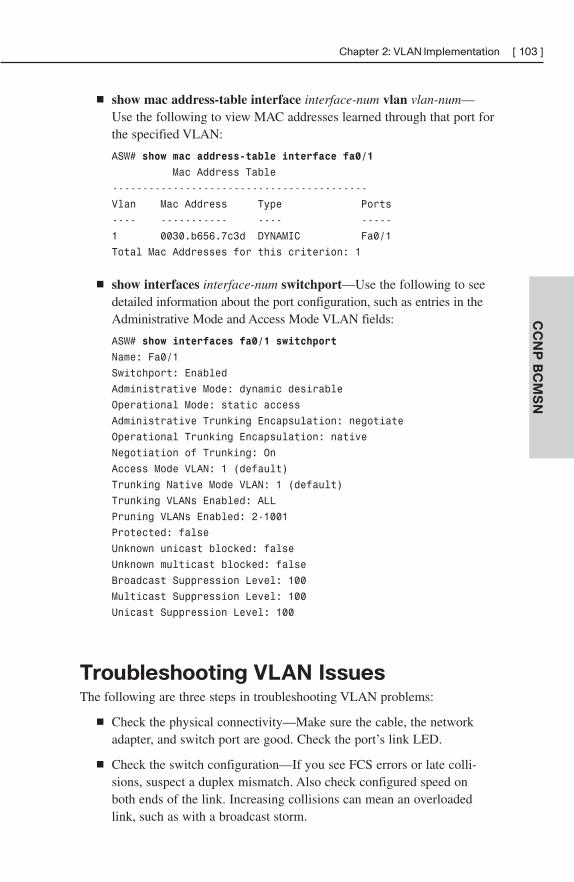
CC
NP
BC
MS
N
Chapter 2: VLAN Implementation [ 103 ]
■ show mac address-table interface interface-num vlan vlan-num—Use the following to view MAC addresses learned through that port forthe specified VLAN:
ASW# show mac address-table interface fa0/1
Mac Address Table
------------------------------------------
Vlan Mac Address Type Ports
---- ----------- ---- -----
1 0030.b656.7c3d DYNAMIC Fa0/1
Total Mac Addresses for this criterion: 1
■ show interfaces interface-num switchport—Use the following to seedetailed information about the port configuration, such as entries in theAdministrative Mode and Access Mode VLAN fields:
ASW# show interfaces fa0/1 switchport
Name: Fa0/1
Switchport: Enabled
Administrative Mode: dynamic desirable
Operational Mode: static access
Administrative Trunking Encapsulation: negotiate
Operational Trunking Encapsulation: native
Negotiation of Trunking: On
Access Mode VLAN: 1 (default)
Trunking Native Mode VLAN: 1 (default)
Trunking VLANs Enabled: ALL
Pruning VLANs Enabled: 2-1001
Protected: false
Unknown unicast blocked: false
Unknown multicast blocked: false
Broadcast Suppression Level: 100
Multicast Suppression Level: 100
Unicast Suppression Level: 100
Troubleshooting VLAN IssuesThe following are three steps in troubleshooting VLAN problems:
■ Check the physical connectivity—Make sure the cable, the networkadapter, and switch port are good. Check the port’s link LED.
■ Check the switch configuration—If you see FCS errors or late colli-sions, suspect a duplex mismatch. Also check configured speed onboth ends of the link. Increasing collisions can mean an overloadedlink, such as with a broadcast storm.
CC
NP
BC
MS
N[ 104 ] CCNP BCMSN Quick Reference
■ Check the VLAN configuration—If two hosts cannot communicate,make sure they are both in the same VLAN. If a host cannot connect toa switch, make sure the host and the switch are in the same VLAN.
VLAN TrunkingA trunk is a link that carries traffic for more than one VLAN. Trunks multi-plex traffic from multiple VLANs. Trunks connect switches and allow portson multiple switches to be assigned to the same VLAN.
Two methods of identifying VLANs over trunk links are:
■ Inter-Switch Link (ISL)—A Cisco proprietary method that encapsu-lates the original frame in a header, which contains VLAN informa-tion. It is protocol-independent and can identify Cisco DiscoveryProtocol (CDP) and bridge protocol data unit (BPDU) frames.
■ 802.1Q—Standards-based, tags the frames (inserts a field into the orig-inal frame immediately after the source MAC address field), andsupports Ethernet and Token Ring networks.
When aframe comes into a switch port, the frame is tagged internally withinthe switch with the VLAN number of the port. When it reaches the outgoingport, the internal tag is removed. If the exit port is a trunk port, then itsVLAN is identified in either the ISL encapsulation or the 802.1Q tag. Theswitch on the other end of the trunk removes the ISL or 802.1Q information,checks the VLAN of the frame, and adds the internal tag. If the exit port is auser port, then the original frame is sent out unchanged, making the use ofVLANs transparent to the user.
If a nontrunking port receives an ISL-encapsulated frame, the frame isdropped. If the ISL header and footer cause the MTU size to be exceeded,it might be counted as an error.
If a nontrunking port receives an 802.1Q frame, the source and destinationMAC addresses are read, the tag field is ignored, and the frame is switchednormally at Layer 2 .
CC
NP
BC
MS
N
Chapter 2: VLAN Implementation [ 105 ]
Configuring a Trunk LinkPorts can become trunk ports either by static configuration or dynamic nego-tiation using Dynamic Trunking Protocol (DTP). A switch port can be in oneof five DTP modes:
■ Access—The port is a user port in a single VLAN.
■ Trunk—The port negotiates trunking with the port on the other end ofthe link.
■ Non-negotiate—The port is a trunk and does not do DTP negotiationwith the other side of the link.
■ Dynamic Desirable—Actively negotiates trunking with the other sideof the link. It becomes a trunk if the port on the other switch is set totrunk, dynamic desirable, or dynamic auto mode.
■ Dynamic Auto—Passively waits to be contacted by the other switch. Itbecomes a trunk if the other end is set to trunk or dynamic desirablemode.
Configure a port for trunking at the interface configuration mode:
(config-if)#switchport mode {dynamic {auto | desirable} | trunk}
If dynamic mode is used, DTP negotiates the trunking state and encapsulation.If trunk mode is used, you must specify encapsulation:
(config-if)#switchport trunk encapsulation {isl | dot1q | negotiate}
Native VLAN with 802.1QIf you are using 802.1Q, specify a native VLAN for the trunk link with thecommand:
(config-if)#switchport trunk native vlan vlan-num
Frames from the native VLAN are sent over the trunk link untagged. NativeVLAN is the VLAN the port would be in if it were not a trunk, and it mustmatch on both sides of the trunk link. VLAN 1 is the default native VLAN for all ports.
CC
NP
BC
MS
N[ 106 ] CCNP BCMSN Quick Reference
VLAN MappingISL trunking recognizes only VLANs numbered 1–1001, but 802.1Q can useVLANs 0–4094. If you are using both ISL and 802.1Q in your network and have VLANs numbered above 1001, you have to map the 802.1Q VLANS to ISL numbers. Some rules about mapping VLANs include:
■ You can configure only eight mappings.
■ Mappings are local to the switch; the same mappings must be config-ured on all switches in the network.
■ You can map only to Ethernet ISL VLANs.
■ The 802.1Q VLANs with the same number as mapped ISL VLANs areblocked. (For example, you map 802.1Q VLAN 1500 to ISL VLAN150, then 802.1Q VLAN 150 is blocked on that switch.)
■ You should not map the 802.1Q native VLAN.
VLANs Allowed on the TrunkBy default, a trunk carries traffic for all VLANs. You can change that behav-ior for a particular trunk link by giving the following command at the inter-face config mode:
switchport trunk allowed vlan vlans
Make sure that both sides of a trunk link allow the same VLANs.
Verifying a Trunk LinkTwo commands you can use to verify your trunk configuration are:
#show running-config
#show interfaces [interface-num] switchport | trunk
Using the trunk keyword with the show interfaces command gives informa-tion about the trunk link:
# show interfaces fastethernet 0/1 trunk
Port Mode Encapsulation Status Native vlan
Fa0/1 desirable n-802.1q trunking 1
Port Vlans allowed on trunk
Fa0/1 1-150
<further output omitted>
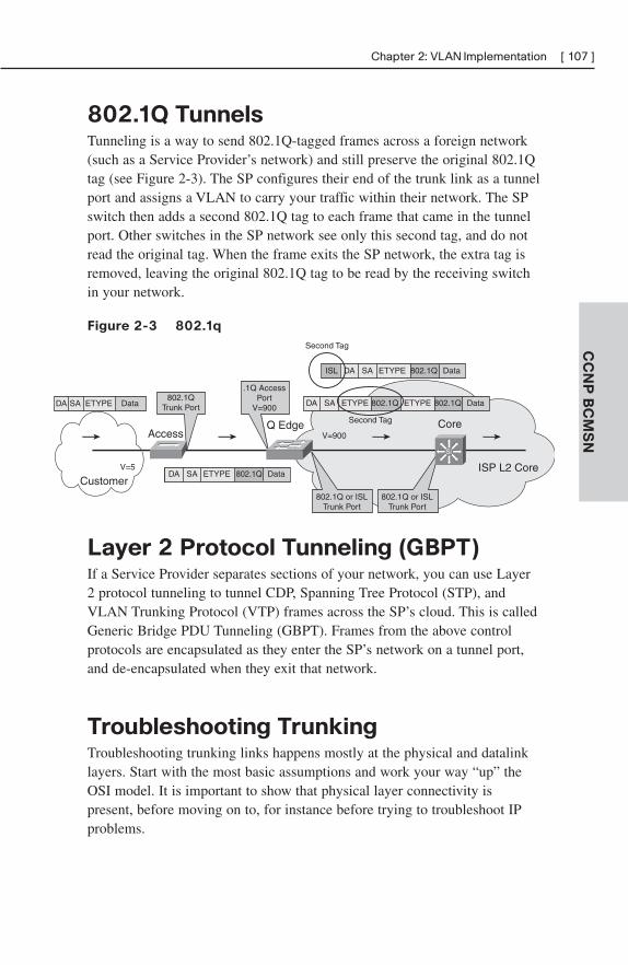
CC
NP
BC
MS
N
Chapter 2: VLAN Implementation [ 107 ]
802.1Q TunnelsTunneling is a way to send 802.1Q-tagged frames across a foreign network(such as a Service Provider’s network) and still preserve the original 802.1Qtag (see Figure 2-3). The SP configures their end of the trunk link as a tunnelport and assigns a VLAN to carry your traffic within their network. The SPswitch then adds a second 802.1Q tag to each frame that came in the tunnelport. Other switches in the SP network see only this second tag, and do notread the original tag. When the frame exits the SP network, the extra tag isremoved, leaving the original 802.1Q tag to be read by the receiving switchin your network.
Figure 2-3 802.1q
DA SA ETYPE Data802.1Q
Trunk Port
.1Q AccessPort
V=900DA SA ETYPE DataETYPE802.1Q 802.1Q
DA SA DataETYPE 802.1QISL
DA SA DataETYPE 802.1QV=5
AccessQ Edge
V=900
Second Tag
Second Tag Core
CustomerISP L2 Core
802.1Q or ISLTrunk Port
802.1Q or ISLTrunk Port
Si
Layer 2 Protocol Tunneling (GBPT)If a Service Provider separates sections of your network, you can use Layer2 protocol tunneling to tunnel CDP, Spanning Tree Protocol (STP), andVLAN Trunking Protocol (VTP) frames across the SP’s cloud. This is calledGeneric Bridge PDU Tunneling (GBPT). Frames from the above controlprotocols are encapsulated as they enter the SP’s network on a tunnel port,and de-encapsulated when they exit that network.
Troubleshooting TrunkingTroubleshooting trunking links happens mostly at the physical and datalinklayers. Start with the most basic assumptions and work your way “up” theOSI model. It is important to show that physical layer connectivity ispresent, before moving on to, for instance before trying to troubleshoot IPproblems.
CC
NP
BC
MS
N[ 108 ] CCNP BCMSN Quick Reference
■ Are both sides of the link in the correct trunking mode?
■ Is the same trunk encapsulation on both sides?
■ If 802.1Q, is the same native VLAN on both sides?
■ Are the same VLANs permitted on both sides?
VLAN Trunking Protocol (VTP)VTP is a protocol that runs over trunk links and synchronizes the VLANdatabases of all switches in the VTP domain. A VTP domain is an adminis-trative group—all switches within that group must have the same VTPdomain name configured or they do not synchronize databases.
VTP works by using Configuration Revision numbers and VTP advertisements:
■ All switches send out VTP advertisements every five minutes, or whenthere is a change to the VLAN database (when a VLAN is created,deleted, or renamed).
■ VTP advertisements contain a Configuration Revision number. Thisnumber is increased by one for every VLAN change.
■ When a switch receives a VTP advertisement, it compares theConfiguration Revision number against the one in its VLAN database.
■ If the new number is higher, the switch overwrites its database with thenew VLAN information, and forwards the information to its neighborswitches.
■ If the number is the same, the switch ignores the advertisement.
■ If the new number is lower, the switch replies with the more up-to-dateinformation contained in its own database .
VTP Switch RolesA switch can be a VTP:
■ Server—The default VTP role. Servers can create, delete, and renameVLANs. They originate both periodic and triggered VTP advertisementsand synchronize their databases with other switches in the domain.
CC
NP
BC
MS
N
Chapter 2: VLAN Implementation [ 109 ]
■ Client—Clients cannot make VLAN changes. They originate periodicVTP advertisements and synchronize their databases with otherswitches in the domain.
■ Transparent—It can create, delete, and rename VLANs, but itsVLANs are only local. It does not originate advertisements or synchro-nize its database with any other switches. It forwards VTP advertise-ments out its trunk links, however.
VTP PruningBy default, switches flood broadcasts, multicasts, and unknown unicasts acrosstrunk links. Suppose a host in VLAN 10 on Switch B sends a broadcast.Hosts in VLAN 10 on Switch C need to see that broadcast, but Switch A hasno ports in VLAN 10, so it doesn’t need to receive the broadcast traffic.
Enabling VTP pruning causes the switch to keep track of VLAN portassignments in its downstream switches. The switch then sends floodedtraffic only on trunks toward switches that have ports assigned to the VLANoriginating the traffic. It prunes flooded traffic from all other trunks. VTPpruning increases the available bandwidth by preventing unnecessary trafficon trunk links.
There are two versions of VTP: Version 1 and Version 2. To use Version 2,all switches in the domain must be capable of using it. Configure one serverfor Version 2, and the information is propagated through VTP. Version 2 hasthe following added features:
■ It supports Token Ring VLANs.
■ Transparent switches pass along messages from both versions of VTP.
■ Consistency checks are performed only when changes are configuredthrough the CLI or SNMP.
Configuring VTPVTP configuration is done at the global config mode. To configure theswitch’s VTP mode:
(config)#vtp {server | client |transparent}
CC
NP
BC
MS
N[ 110 ] CCNP BCMSN Quick Reference
To configure the VTP domain name :
(config)#vtp domain name
To configure a VTP password (all switches in the domain must use the samepassword):
(config)#vtp password password
To configure the switch to use VTP Version 2:
(config)#vtp version 2
To enable pruning:
vtp pruning
To specify which VLANs are to be pruned:
(config-if)#switchport trunk pruning vlan {add | except | none |remove} vlan-list [,vlan[,vlan[,,,]]
Verifying and Monitoring VTPTo get basic information about the VTP configuration, use show vtp status.The example shows the default settings:
# show vtp status
VTP Version : 1
Configuration Revision : 0
Maximum VLANs supported locally : 1005
Number of existing VLANs : 5
VTP Operating Mode : Server
VTP Domain Name :
(config)#
VTP Pruning Mode : Disabled
VTP V2 Mode : Disabled
VTP Traps Generation : Disabled
MD5 digest :
CC
NP
BC
MS
N
Chapter 2: VLAN Implementation [ 111 ]
Troubleshooting VTPThe following are some common things to check when troubleshootingproblems with VTP:
■ Make sure you are trunking between the switches. VTP is sent onlyover trunk links.
■ Make sure the domain name matches on both switches (name is casesensitive).
■ If the switch is not updating its database, make sure it is not in trans-parent mode.
■ If using passwords, make sure they all match. To remove a password,use no vtp password.
Adding a New Switch to a VTP DomainAdding a new switch in client mode does not prevent it from propagating itsincorrect VLAN information. A server synchronizes to a client if the clienthas the higher configuration revision number. You must reset the revisionnumber back to 0 on the new switch. The easiest way to do this is to changethe domain name. Then change it back to the correct one, and attach theswitch to the network.
CHAPTER 3
Spanning Tree
Ethernet network design balances two separate imperatives. First, Ethernethas no capacity for detecting circular paths. If such paths exist, traffic loopsaround and accumulates until new traffic is shut out (this is called a broad-cast storm). Second, having secondary paths is good preparation forinevitable link failure.
Spanning Tree is a protocol that prevents loop formation by detecting redun-dant links and disabling them until needed. Designers can therefore buildredundant links and the protocol will allow one to pass traffic and keep theother in reserve. When the active link fails, the secondary link is enabledquickly.
Understanding the Spanning Tree
ProtocolSwitches either forward or filter Layer 2 frames. The way they make theforwarding/filtering decision can lead to loops in a network with redundantlinks. Spanning Tree is a protocol that detects potential loops and breaksthem.
A Layer 2 switch is functionally the same thing as a transparent bridge.Transparent bridges:
■ Learn MAC (Media Access Control) addresses by looking at thesource address of incoming frames. They build a table mapping MACaddress to port number.
■ Forward broadcasts and multicasts out all ports except the on whichthey came. (This is called flooding.)
■ Forward unknown unicasts out all ports except the one on which theycame. An unknown unicast is a message bound for a unicast MACaddress that is not in the switch’s table of addresses and ports.
■ Do not make any changes to the frames as they forward them.
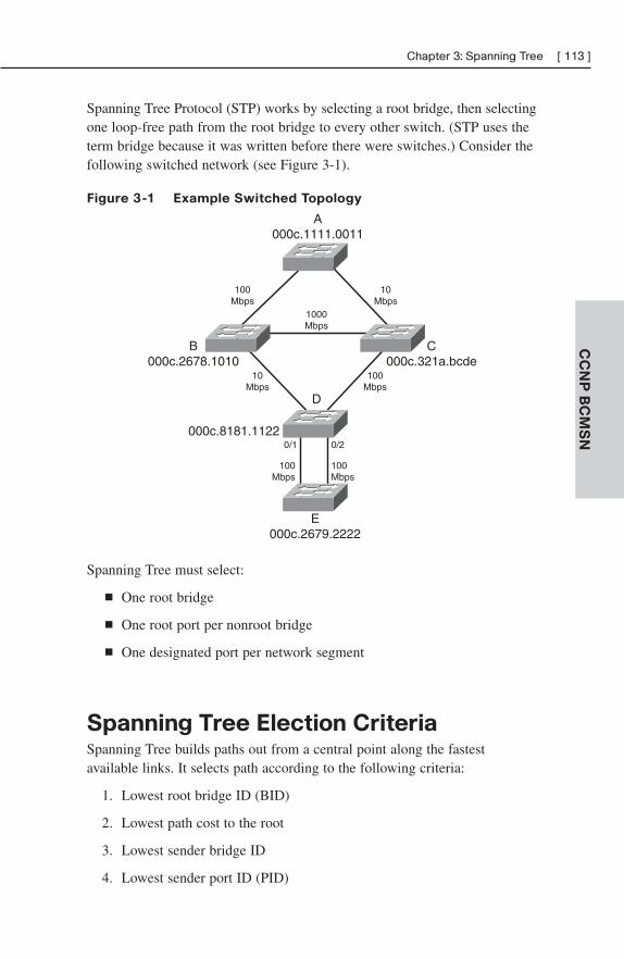
CC
NP
BC
MS
N
Chapter 3: Spanning Tree [ 113 ]
Spanning Tree Protocol (STP) works by selecting a root bridge, then selectingone loop-free path from the root bridge to every other switch. (STP uses theterm bridge because it was written before there were switches.) Consider thefollowing switched network (see Figure 3-1).
Figure 3-1 Example Switched Topology
A000c.1111.0011
B000c.2678.1010
C000c.321a.bcde
000c.8181.1122
E000c.2679.2222
100Mbps
1000Mbps
10Mbps
10Mbps
100Mbps
100Mbps
100Mbps
0/1 0/2
D
Spanning Tree must select:
■ One root bridge
■ One root port per nonroot bridge
■ One designated port per network segment
Spanning Tree Election CriteriaSpanning Tree builds paths out from a central point along the fastest available links. It selects path according to the following criteria:
1. Lowest root bridge ID (BID)
2. Lowest path cost to the root
3. Lowest sender bridge ID
4. Lowest sender port ID (PID)
CC
NP
BC
MS
N[ 114 ] CCNP BCMSN Quick Reference
When reading the path selection criteria, remember the following:
■ Bridge ID—Bridge priority: Bridge MAC address.
■ Bridge priority—2-btye value, 0–65,535 (0–0xFFFF).
■ Default priority is 32,768 (0x8000).
■ Port ID—Port priority: port number.
■ Port priority—A 6-bit value, 0–63, default is 32.
■ Path cost—This is the cumulative value of the cost of each linkbetween the bridge and the root. Cost values were updated in 2000 andyou should see only new cost values, but both are given in the follow-ing table (see Table 3-1). Old and new switches work together.
Table 3-1 Spanning Tree Costs
Link Speed Old Cost New Cost
10 Mbps 100 100
100 Mbps 10 19
1 Gbps 1 4
10 Gbps 1 2
The STP ElectionSpanning Tree builds paths out from a starting point, the “root” of the tree.The first step in selecting paths is to identify this root device. Then, eachdevice selects its best path back to the root, according to the criteria laid outin the previous sections (lowest root BID, lowest cost, lowest advertisingBID, lowest port).
Root Bridge Election
Looking at Figure 3-1, first select the root bridge. Assume each switch usesthe default priority.
■ Switch A BID = 80-00-00-0c-11-11-00-11
■ Switch B BID = 80-00-00-0c-26-78-10-10
■ Switch C BID = 80-00-00-0c-32-1a-bc-de
■ Switch D BID = 80-00-00-0c-81-81-11-22
■ Switch E BID = 80-00-00-0c-26-79-22-22
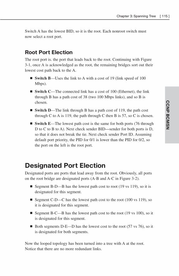
CC
NP
BC
MS
N
Chapter 3: Spanning Tree [ 115 ]
Switch A has the lowest BID, so it is the root. Each nonroot switch mustnow select a root port.
Root Port Election
The root port is. the port that leads back to the root. Continuing with Figure3-1, once A is acknowledged as the root, the remaining bridges sort out theirlowest cost path back to the A.
■ Switch B—Uses the link to A with a cost of 19 (link speed of 100Mbps).
■ Switch C—The connected link has a cost of 100 (Ethernet), the linkthrough B has a path cost of 38 (two 100 Mbps links), and so B ischosen.
■ Switch D—The link through B has a path cost of 119, the path costthrough C to A is 119, the path through C then B is 57, so C is chosen.
■ Switch E—The lowest path cost is the same for both ports (76 throughD to C to B to A). Next check sender BID—sender for both ports is D,so that it does not break the tie. Next check sender Port ID. Assumingdefault port priority, the PID for 0/1 is lower than the PID for 0/2, sothe port on the left is the root port.
Designated Port ElectionDesignated ports are ports that lead away from the root. Obviously, all portson the root bridge are designated ports (A-B and A-C in Figure 3-2).
■ Segment B-D—B has the lowest path cost to root (19 vs 119), so it isdesignated for this segment.
■ Segment C-D—C has the lowest path cost to the root (100 vs 119), soit is designated for this segment.
■ Segment B-C—B has the lowest path cost to the root (19 vs 100), so itis designated for this segment.
■ Both segments D-E—D has the lowest cost to the root (57 vs 76), so itis designated for both segments.
Now the looped topology has been turned into a tree with A at the root.Notice that there are no more redundant links.
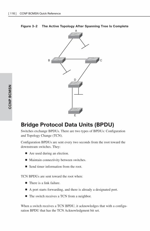
CC
NP
BC
MS
N[ 116 ] CCNP BCMSN Quick Reference
Figure 3-2 The Active Topology After Spanning Tree Is Complete
A
B C
D
E
Bridge Protocol Data Units (BPDU)Switches exchange BPDUs. There are two types of BPDUs: Configurationand Topology Change (TCN).
Configuration BPDUs are sent every two seconds from the root toward thedownstream switches. They:
■ Are used during an election.
■ Maintain connectivity between switches.
■ Send timer information from the root.
TCN BPDUs are sent toward the root when:
■ There is a link failure.
■ A port starts forwarding, and there is already a designated port.
■ The switch receives a TCN from a neighbor.
When a switch receives a TCN BPDU, it acknowledges that with a configu-ration BPDU that has the TCN Acknowledgment bit set.
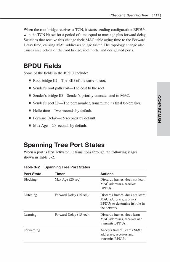
CC
NP
BC
MS
N
Chapter 3: Spanning Tree [ 117 ]
When the root bridge receives a TCN, it starts sending configuration BPDUswith the TCN bit set for a period of time equal to max age plus forward delay.Switches that receive this change their MAC table aging time to the ForwardDelay time, causing MAC addresses to age faster. The topology change alsocauses an election of the root bridge, root ports, and designated ports.
BPDU FieldsSome of the fields in the BPDU include:
■ Root bridge ID—The BID of the current root.
■ Sender’s root path cost—The cost to the root.
■ Sender’s bridge ID—Sender’s priority concatenated to MAC.
■ Sender’s port ID—The port number, transmitted as final tie-breaker.
■ Hello time—Two seconds by default.
■ Forward Delay—15 seconds by default.
■ Max Age—20 seconds by default.
Spanning Tree Port StatesWhen a port is first activated, it transitions through the following stagesshown in Table 3-2.
Table 3-2 Spanning Tree Port States
Port State Timer Actions
Blocking Max Age (20 sec) Discards frames, does not learn MAC addresses, receives BPDUs.
Listening Forward Delay (15 sec) Discards frames, does not learn MAC addresses, receivesBPDUs to determine its role in the network.
Learning Forward Delay (15 sec) Discards frames, does learn MAC addresses, receives and transmits BPDUs.
Forwarding Accepts frames, learns MAC addresses, receives and transmits BPDUs.
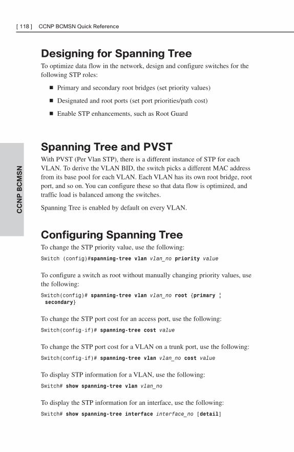
CC
NP
BC
MS
N[ 118 ] CCNP BCMSN Quick Reference
Designing for Spanning TreeTo optimize data flow in the network, design and configure switches for thefollowing STP roles:
■ Primary and secondary root bridges (set priority values)
■ Designated and root ports (set port priorities/path cost)
■ Enable STP enhancements, such as Root Guard
Spanning Tree and PVSTWith PVST (Per Vlan STP), there is a different instance of STP for eachVLAN. To derive the VLAN BID, the switch picks a different MAC addressfrom its base pool for each VLAN. Each VLAN has its own root bridge, rootport, and so on. You can configure these so that data flow is optimized, andtraffic load is balanced among the switches.
Spanning Tree is enabled by default on every VLAN.
Configuring Spanning TreeTo change the STP priority value, use the following:
Switch (config)#spanning-tree vlan vlan_no priority value
To configure a switch as root without manually changing priority values, usethe following:
Switch(config)# spanning-tree vlan vlan_no root {primary | secondary}
To change the STP port cost for an access port, use the following:
Switch(config-if)# spanning-tree cost value
To change the STP port cost for a VLAN on a trunk port, use the following:
Switch(config-if)# spanning-tree vlan vlan_no cost value
To display STP information for a VLAN, use the following:
Switch# show spanning-tree vlan vlan_no
To display the STP information for an interface, use the following:
Switch# show spanning-tree interface interface_no [detail]
CC
NP
BC
MS
N
Chapter 3: Spanning Tree [ 119 ]
To verify STP timers, use the following:
Switch#show spanning-tree bridge brief
Spanning Tree EnhancementsCisco has some proprietary enhancements to Spanning Tree that help speedup network convergence. They include:
■ PortFast
■ UplinkFast
■ BackboneFast
PortfastPortfast is for access (user) ports only. It causes the port to bypass the STP listening and learning states and transition directly to forwarding.Connecting a switch to a Portfast port can cause loops to develop.
(config-if)#spanning-tree portfast
UplinkFastUplinkFast is for speeding convergence when a direct link to an upstreamswitch fails. The switch identifies backup ports for the root port (these arecalled an uplink group). If the root port fails, then one of the ports in theuplink group is unblocked and transitions immediately to forwarding—itbypasses the listening and learning stages. It should be used in wiring closetswitches with at least one blocked port.
The command to enable uplinkfast is shown below. Please note that uplinkfast isenabled globally, so the command affects all ports and all VLANs.
(config)# spanning-tree uplinkfast
BackboneFastBackboneFast is used for speeding convergence when a link fails that is notdirectly connected to the switch. It helps the switch detect indirect failures. Ifa switch running BackboneFast receives an inferior BPDU from its designatedbridge, it knows a link on the path to the root has failed. (An inferior BPDUis one that lists the same switch for root bridge and designated bridge.)
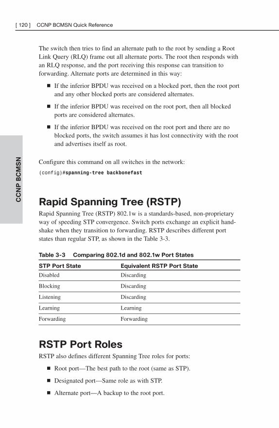
CC
NP
BC
MS
N[ 120 ] CCNP BCMSN Quick Reference
The switch then tries to find an alternate path to the root by sending a RootLink Query (RLQ) frame out all alternate ports. The root then responds withan RLQ response, and the port receiving this response can transition toforwarding. Alternate ports are determined in this way:
■ If the inferior BPDU was received on a blocked port, then the root portand any other blocked ports are considered alternates.
■ If the inferior BPDU was received on the root port, then all blockedports are considered alternates.
■ If the inferior BPDU was received on the root port and there are noblocked ports, the switch assumes it has lost connectivity with the rootand advertises itself as root.
Configure this command on all switches in the network:
(config)#spanning-tree backbonefast
Rapid Spanning Tree (RSTP)Rapid Spanning Tree (RSTP) 802.1w is a standards-based, non-proprietaryway of speeding STP convergence. Switch ports exchange an explicit hand-shake when they transition to forwarding. RSTP describes different portstates than regular STP, as shown in the Table 3-3.
Table 3-3 Comparing 802.1d and 802.1w Port States
STP Port State Equivalent RSTP Port State
Disabled Discarding
Blocking Discarding
Listening Discarding
Learning Learning
Forwarding Forwarding
RSTP Port RolesRSTP also defines different Spanning Tree roles for ports:
■ Root port—The best path to the root (same as STP).
■ Designated port—Same role as with STP.
■ Alternate port—A backup to the root port.
CC
NP
BC
MS
N
Chapter 3: Spanning Tree [ 121 ]
■ Backup port—A backup to the designated port.
■ Disabled port—One not used in the Spanning Tree.
■ Edge port—One connected only to an end user.
BPDU Differences in RSTPIn regular STP, BPDUs are originated by the root and relayed by eachswitch. In RSTP, each switch originates BPDUs, whether or not it receives aBPDU on its root port. All eight bits of the BPDU type field are used byRSTP. The TC and TC Ack bits are still used. The other six bits specify theport’s role and its RSTP state, and are used in the port handshake. The RSTPBPDU is set to Type 2, Version 2. PVST is done by Rapid PVST+ onCatalyst switches.
RSTP Fast ConvergenceThe Rapid Spanning tree process understands and incorporates topologychanges much quicker than the previous version.
■ RSTP uses a mechanism similar to BackboneFast—When an inferiorBPDU is received, the switch accepts it. If the switch has another paththe root, it uses that and informs its downstream switch of the alternatepath.
■ Edge ports work the same as Portfast ports—They automatically transition directly to forwarding.
■ Link type—If you connect two switches through a point-to-point linkand the local port becomes a designated port, it exchanges a handshakewith the other port to quickly transition to forwarding. Full-duplexlinks are assumed to be point-to-point, half-duplex links are assumedto be shared.
■ Backup and alternate ports—Ports that can transition to forwardingwhen no BPDUs are received from a neighbor switch (similar toUplinkFast).
If an RSTP switch detects a topology change, it sets a TC timer to twice thehello time and sets the TC bit on all BPDUs sent out to its designated androot ports until the timer expires. It also clears the MAC addresses learnedon these ports.
CC
NP
BC
MS
N[ 122 ] CCNP BCMSN Quick Reference
If an RSTP switch receives a TC BPDU, it clears the MAC addresses on thatport and sets the TC bit on all BPDUs sent out its designated and root portsuntil the TC timer expires.
Multiple Spanning Tree (MST)With Multiple Spanning Tree (MST), you can group VLANs and run oneinstance of Spanning Tree for a group of VLANs. This cuts down on thenumber of root bridges, root ports, designated ports, and BPDUs in yournetwork. Switches in the same MST Region share the same configurationand VLAN mappings. Configure MST with these commands:
(config)# spanning-tree mode mst
(config)# spanning-tree mst configuration
(config-mst)# name region_name
(config-mst)# revision number
(config-mst)# instance number vlan vlan_range
(config-mst)# end
To be compatible with 802.1Q trunking, which has one common SpanningTree (CST) for all VLANs, MST runs one instance of an Internal SpanningTree (IST). The IST appears as one bridge to a CST area and is MSTinstance number 0. The original MST Spanning Trees (called M-Trees) areactive only in the region—they combine at the edge of the CST area to formone.
EtherChannelsEtherChannel is a way of combining several physical links between switchesinto one logical connection. Normally, Spanning Tree blocks redundantlinks; EtherChannel gets around that and allows load balancing across thoselinks. Load is balancing on the basis of such things as source or destinationMAC address or IP address. The Etherchannel load-balancing method isconfigured at global configuration mode.
(config)#port-channel load-balance type
A logical interface—the Port Channel interface—is created. Configurationcan be applied to both the logical and physical interfaces.
Some guidelines for EtherChannels are as follows:
■ Interfaces in the channel do not have to be physically next to eachother or on the same module.
CC
NP
BC
MS
N
Chapter 3: Spanning Tree [ 123 ]
■ All ports must be the same speed and duplex.
■ All ports in the bundle should be enabled.
■ None of the bundle ports can be a SPAN port.
■ Assign an IP address to the logical Port Channel interface, not thephysical ones.
■ Put all bundle ports in the same VLAN, or make them all trunks. Ifthey are trunks, they must all carry the same VLANs and use the sametrunking mode.
■ Configuration you apply to the Port Channel interface affects the entireEtherChannel. Configuration you apply to a physical interface onlyaffects that interface.
Configuring an EtherChannelBasically, for a Layer 3 EtherChannel, you should configure the logicalinterface and then put the physical interfaces into the channel group:
(config)#interface port-channel number
(config-if)#no switchport
(config-if)#ip address address mask
Then, at each port that is part of the EtherChannel, use the following:
(config)#interface {number | range interface – interface}
(config-if)#channel-group number mode {auto | desirable | on}
Putting the IP address on the Port Channel interface creates a Layer 3EtherChannel. Simply putting interfaces into a channel group creates a Layer 2 EtherChannel, and the logical interface is automatically created.
The Cisco proprietary Port Aggregation Protocol (PAgP) dynamically negotiates the formation of a channel. There are three PAgP modes:
■ On—The port channels without using PAgP negotiation. The port onthe other side must also be set to On.
■ Auto—Responds to PAgP messages but does not initiate them. Portchannels if the port on the other end is set to Desirable. This is thedefault mode.
■ Desirable—Port actively negotiates channeling status with the interfaceon the other end of the link. Port channels if the other side is Auto orDesirable.
CC
NP
BC
MS
N[ 124 ] CCNP BCMSN Quick Reference
There is also a non-proprietary protocol called Link Aggregation ControlProtocol (LACP), IEEE 802.3ad, which does the same thing. LACP has twomodes:
■ Active—Port actively negotiates channeling with the port on the otherend of the link. A channel forms if the other side is Passive or Active.
■ Passive—Responds to LACP messages but does not initiate them. Achannel forms if the other end is set to Active.
If you want to use LACP, specify it under the interface and put the interfacein either active or passive mode:
(config-if)#channel-protocol lacp
Verifying an EtherChannelSome typical commands for verifying include:
■ #show running-config interface number
■ #show interfaces number etherchannel
■ #show etherchannel number port-channel
■ #show etherchannel summary
Additional Spanning Tree FeaturesSome additional features available to help you tune Spanning Tree include:
■ BPDU Guard
■ BPDU Filtering
■ Root Guard
■ UDLD
■ Loop Guard
BPDU GuardBPDU Guard is used to prevent loops if another switch is attached to aPortfast port. When BPDU Guard is enabled on an interface, it is put into anerror-disabled state (basically, shut down) if a BPDU is received on the
CC
NP
BC
MS
N
Chapter 3: Spanning Tree [ 125 ]
interface. It can be enabled at either global config mode—in which case itaffects all Portfast interfaces, or at interface mode. Portfast does not have tobe enabled for it to be configured at a specific interface. The followingconfiguration example shows BPDU guard being enabled.
(config)#spanning-tree portfast bpduguard default
(config-if)#spanning-tree bpduguard enable
BPDU FilteringBPDU filtering is another way of preventing loops in the network. It also canbe enabled either globally or at the interface, and functions differently ateach. In global config, if a Portfast interface receives any BPDUs, it is takenout of Portfast status. At interface config mode, it prevents the port fromsending or receiving BPDUs. The commands are:
■ (config)# spanning-tree portfast bpdufilter default
■ (config-if)# spanning-tree bpdufilter enable
Root GuardRoot Guard is meant to prevent the wrong switch from becoming theSpanning Tree root. It is enabled on ports other than the root port and onswitches other than the root. If a Root Guard port receives a BPDU thatmight cause it to become a root port, then the port is put into “root-inconsis-tent” state and does not pass traffic through it. If the port stops receivingthese BPDUs, it automatically re-enables itself.
(config-if)# spanning-tree guard root
Unidirectional Link Detection (UDLD)A switch notices when a physical connection is broken by the absence ofLayer 1 electrical keepalives (Ethernet calls this a link beat). However, some-times a cable is intact enough to maintain keepalives, but not to pass data inboth directions. This is a Unidirectional Link. Unidirectional Link Detection(UDLD) detects a unidirectional link by sending periodic hellos out to theinterface. It also uses probes, which must be acknowledged by the device onthe other end of the link. UDLD operates at Layer 2. The port is shut down ifa unidirectional link is found.
CC
NP
BC
MS
N[ 126 ] CCNP BCMSN Quick Reference
To enable UDLD on all fiber-optic interfaces, use the following command:
(config)# udld enable
Although this command is given at global config mode, it applies only tofiber ports.
To enable UDLD on non-fiber ports, give the same command at interfaceconfig mode.
To disable UDLD on a specific fiber port, use the following command:
(config-if)# udld disable
To disable UDLD on a specific non-fiber port, use the following command:
(config-if)#no udld enable
To re-enable all interfaces shut by UDLD, use the following:
#udld reset
To verify UDLD status, use the following:
#show udld interface
Loop GuardLoop Guard prevents loops that might develop if a port that should be block-ing inadvertently transitions to the forwarding state. This can happen if theport stops receiving BPDUs (perhaps because of a unidirectional link or asoftware/configuration problem in its neighbor switch). When one of theports in a physically redundant topology stops receiving BPDUs, the STPconceives the topology as loop-free. Eventually, the blocking port becomesdesignated and moves to forwarding state, thus creating a loop. With LoopGuard enabled, an additional check is made.
If no BPDUs are received on a blocked port for a specific length of time.Loop Guard puts that port into “loop inconsistent” blocking state, rather thantransitioning to forwarding state. Loop Guard should be enabled on allswitch ports that have a chance of becoming root or designated ports. It ismost effective when enabled in the entire switched network in conjunctionwith UDLD.
To enable Loop Guard for all point-to-point links on the switch, use thefollowing command:
(config)# spanning-tree loopguard default
CC
NP
BC
MS
N
Chapter 3: Spanning Tree [ 127 ]
To enable Loop Guard on a specific interface, use the following:
(config-if)# spanning-tree guard loop
Loop Guard automatically re-enables the port if it starts receiving BPDUsagain.
Troubleshooting STPSome common things to look for when troubleshooting Spanning TreeProtocol include:
■ Duplex mismatch—When one side of a link is half-duplex and theother is full-duplex. This causes late collisions and FCS errors.
■ Unidirectional link failure—The link is up but data flows only in onedirection. It can cause loops.
■ Frame corruption—Physical errors on the line cause BPDUs to be lost,and the port incorrectly begins forwarding. This is caused by duplexmismatch, bad cable, or cable too long.
■ Resource errors—STP is implemented in software, so a switch with anoverloaded CPU or memory might neglect some STP duties.
■ Port Fast configuration errors—Connecting a switch to two ports thathave Port Fast enabled. This can cause a loop.
■ STP tuning errors—Max age or forward delay set too short can cause aloop. A network diameter that is set too low causes BPDUs to bediscarded and affects STP convergence.
Identifying a Bridging LoopSuspect a loop if you see the following:
■ You capture traffic on a link, and see the same frames multiple times.
■ All users in a bridging domain have connectivity problems at the sametime.
■ There is abnormally high port utilization.
To remedy a loop quickly, shut redundant ports and then enable them one ata time. Some switches allow debugging of STP (not 3550/2950) to help indiagnosing problems.
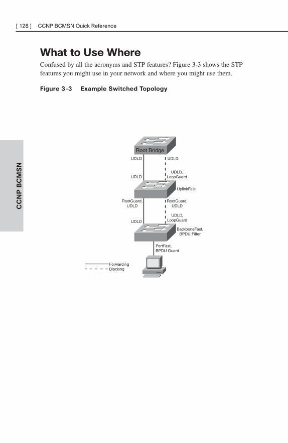
CC
NP
BC
MS
N[ 128 ] CCNP BCMSN Quick Reference
What to Use WhereConfused by all the acronyms and STP features? Figure 3-3 shows the STPfeatures you might use in your network and where you might use them.
Figure 3-3 Example Switched Topology
Root Bridge
UDLD
UDLD
UDLD
UDLD,LoopGuard
RootGuard,UDLD
RootGuard,UDLD
UDLD
UDLD,LoopGuard
BackboneFast,BPDU Filter
PortFast,BPDU Guard
ForwardingBlocking
UplinkFast
CHAPTER 4
InterVLAN Routing
VLANs divide the network into smaller broadcast domains, but also prohibitcommunication between domains To enable communication between thosegroups—without also passing broadcasts—routing is used.
InterVLAN Routing Using Multilayer
SwitchesPort roles:
■ Virtual LAN (VLAN) Port—Acts as layer 2 switching port with aVLAN.
■ Static VLAN—Use the switchport command to identify VLAN.
■ Dynamic VLAN—Use VLAN Membership Policy Server (VMPS).
■ Trunk port—Passes multiple VLANs and differentiates by tagging.
Use the switchport command to set parameters:
■ ISL(Interswitch Link) or 802.1Q
■ Switched Virtual Interface (SVI)—Virtual routed port in a VLAN
— Use to route or fallback bridge between VLANs
— Default SVI for VLAN 1 automatically created
— Associate with VLAN using interface vlan-num
■ Routed port—Acts as layer 3 routed port
— Place in layer 3 mode with no switchport
— Not associated with VLAN
— Turn on routing using ip routing
— Assign address and enable routing protocols as needed
CC
NP
BC
MS
N[ 130 ] CCNP BCMSN Quick Reference
InterVLAN RoutingMultilayer switches do the following:
■ Enable IP routing using ip routing
■ Create SVI using interface vlan-num
■ Assign an IP address to each interface
A router on a stick attaches the router to the switch using a trunk line (ISL or802.1Q). Following are features of these:
■ Easy to implement
■ Use existing equipment
■ Much more latency than Multi-layer switching (MLS) solution
■ Configure by creating subinterface with interface fastethernet 1/0.7
■ Associate the VLAN to the interface with command encapsulationisl 7 or encapsulation dot1q 7
■ ISL—No address on main interface
■ 802.1Q—Address on main interface for native (untagged) VLAN
Multilayer SwitchingThis next section walks through the switching process and focuses on orderof operations. The order things happen is extremely important for tworeasons. First, order of events is good test material. Second, understandingthe processing order allows you to evaluate how the various filtering andforwarding mechanisms interact (examples include error checking, access-lists, VLAN access-lists, routing, and QoS).
Understanding the Switching Process
Steps involved in layer 2 forwarding are as follows:
■ Input
1. Receive frame.
2. Verify frame integrity.
CC
NP
BC
MS
N
Chapter 4: InterVLAN Routing [ 131 ]
3. Apply inbound VLAN ACL (Virtual Local Area Network Access List).
4. Look up destination MAC (Media Address Code).
■ Output
1. Apply outbound VLAN ACL.
2. Apply outbound QoS ACL.
3. Select output port.
4. Queue on port.
5. Rewrite.
6. Forward.
Steps involved in layer 3 forwarding are as follows:
■ Input
1. Receive frame.
2. Verify frame integrity.
3. Apply inbound VLAN ACL.
4. Look up destination MAC.
■ Routing
1. Input ACL.
2. Switch if entry cached.
3. Identify exit interface and next-hop address using routing table.
4. Output ACL.
■ Output
1. Apply outbound VLAN ACL.
2. Apply outbound QoS ACL.
3. Select output port.
4. Queue on port.
5. Rewrite source and destination MAC, IP checksum and framecheck sequence, and decrement TTL (Time to Live field in the IPheader).
6. Forward.
CC
NP
BC
MS
N[ 132 ] CCNP BCMSN Quick Reference
Understanding the Switching Table
Content Addressable Memory (CAM) is used for MAC tables for layer twoswitching.
■ Used for Catalyst 4500 layer 2 forwarding tables
■ Used for Catalyst 6500 layer 2 and Netflow forwarding tables
■ Contains binary values (0 or 1)
■ Match must be exact
In comparison, MLS uses Ternary Content Addressable Memory (TCAM).
■ Used for Catalyst 3500/3700, 4500, and 6500 layer 3 switching
■ Ternary (3) values (0, 1, or wildcard)
■ Entries are in VMR form
— Value—Pattern to be matched.
— Mask—Masking bits associated with pattern.
— Result—Consequences of a match (permit/deny or more complexinformation).
Understanding Switch Forwarding Architectures
In a Centralized Forwarding model, the CPU controls forwarding decisions:
■ Decision made by single table
■ Used by 4500 and 6500
With Distributed Forwarding, the forwarding decisions are spread throughoutthe interface ASICs:
■ Decision made at port or module
■ Used by 3500/3700 and 6500 with distributed forwarding card
■ NetFlow switching
■ Decision made cooperatively by Route Processor and MLS
■ First packet switched in software, result cached
■ Subsequent packets switched in hardware
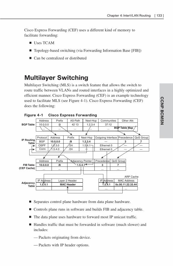
CC
NP
BC
MS
N
Chapter 4: InterVLAN Routing [ 133 ]
Cisco Express Forwarding (CEF) uses a different kind of memory to facilitate forwarding:
■ Uses TCAM
■ Topology-based switching (via Forwarding Information Base [FIB])
■ Can be centralized or distributed
Multilayer SwitchingMultilayer Switching (MLS) is a switch feature that allows the switch toroute traffic between VLANs and routed interfaces in a highly optimized andefficient manner. Cisco Express Forwarding (CEF) is an example technologyused to facilitate MLS (see Figure 4-1). Cisco Express Forwarding (CEF)does the following:
Figure 4-1 Cisco Express Forwarding
BGP TableAddress Prefix AS-Path Communities Other Attr.Next-Hop
10.0.0.0 /8 42 13 37:121.2.3.4
... ... ... ... ......
IP RoutingTable
Address Prefix
... ...
FIB Table(CEF Cache)
Next-Hop Outgoing InterfaceAddressProtocol
BGP
ARP Cache
Adjacency Pointer
...
1.5.4.1 Ethernet 01.2.3.0OSPF
MAC Address
...
IP Address
...
Layer 2 Header
...
AdjacencyTable
IP Address
...
1.5.4.1 MAC Header
Prefix
/24
Precedence
—
QoS Group
—
—
1.2.3.4 —10.0.0.0 /8 3 7
BGP Table Map
Precedence
...
QoS Group
...
0c.00.11.22.33.441.5.4.1
10.0.0.0 /8 1.5.4.1 3 7
Conn. 1.5.4.0 /24 — Ethernet 0 —
■ Separates control plane hardware from data plane hardware.
■ Controls plane runs in software and builds FIB and adjacency table.
■ The data plane uses hardware to forward most IP unicast traffic.
■ Handles traffic that must be forwarded in software (much slower) andincludes:
— Packets originating from device.
— Packets with IP header options.
CC
NP
BC
MS
N[ 134 ] CCNP BCMSN Quick Reference
— Tunneled traffic.
— 802.3 (IPX) frames.
— Load sharing traffic.
— FIB is an optimized routing table, stored in TCAM.
— Builds adjacencies from ARP data.
— Eliminates recursive loops.
ARP Throttling
ARP throttling is a tool to limit ARPs into a VLAN. ARPs, you may recall,are sent as broadcast. Once an ARP is sent for a given IP, the switch preventsrepetitive ARPs for a short period of time:
■ First packet to destination forwarded to Route Processor.
■ Subsequent traffic dropped until MAC is resolved.
■ It prevents overwhelming the Route Processor (RP) with redundantARP requests.
■ It helps during Denial of Service attacks.
■ It is removed when MAC is resolved in two seconds.
Configuring and Troubleshooting CEF
By default, CEF is on and supports per destination load sharing.
To disable CEF:
■ 4500—Use (config)#no ip cef.
■ 3500/3700—On each interface, use (config)#no ip route-cache cef.
■ 6550 with policy feature card, distributed FC, and multilayer switchFC—Cannot be disabled.
View CEF information with the following:
#show interface fastethernet 2/2 | begin L3
CC
NP
BC
MS
N
Chapter 4: InterVLAN Routing [ 135 ]
View switching statistics with the following:
#show interface fastethernet 2/2 | include switched
View FIB with the following:
#show ip cef
View detailed CEF FIB entry with the following:
#show ip cef fastethernet 2/2 10.0.0.1 detail
Troubleshoot CEF drops with the following:
#debug ip cef drops
Troubleshoot packets not forwarded by CEF with the following:
#debug ip cef receive
Troubleshoot CEF events with the following:
#debug ip cef events
CHAPTER 5
Layer 3 Redundancy
Specifying a default gateway leads to a single point of failure. Proxy AddressResolution Protocol (ARP) is one method for hosts to dynamically discovergateways, but it has issues in a highly-available environment. With ProxyARP:
■ Hosts ARP for all destinations, even remote.
■ Router responds with its MAC.
■ Problem: Slow failover because ARP entries take minutes to timeout.
Instead of making the host responsible for choosing a new gateway, Layer 3redundancy protocols allow two or more routers to support a shared MACaddress. If the primary router is lost, the backup router assumes control oftraffic forwarded to that MAC. This section refers to routers, but includesthose Layer 3 switches that can also implement Layer 3 redundancy.
Hot Standby Router Protocol (HSRP)HSRP is a Cisco proprietary protocol.
With HSRP, two or more devices support a virtual router with a fictitiousMAC address and unique IP address. Hosts use this IP address as theirdefault gateway, and the MAC address for the Layer 2 header. The virtualrouter’s MAC address is 0000.0c07.ACxx, where xx is the HSRP group.Multiple groups (virtual routers) are allowed.
The Active router forwards traffic. The Standby is backup. The standbymonitors periodic hellos (multicast to 224.0.0.2, UDP port 1985) to detect afailure of the active router. On failure, the standby device starts answeringmessages sent to the IP and MAC addresses of the virtual router.
The active router is chosen because it has the highest HSRP priority (defaultpriority is 100). In case of a tie, the router with the highest configured IPaddress wins the election. A new router with a higher priority does not causean election unless it is configured to preempt—that is, take over from a lower
CC
NP
BC
MS
N
Chapter 5: Layer 3 Redundancy [ 137 ]
priority router. Configuring a router to preempt also insures that the highestpriority router regains its active status if it goes down but then comes backonline again.
Interface tracking reduces the active router’s priority if a specified circuit isdown. This allows the standby router to take over even though the activerouter is still up.
HSRP States
HSRP devices move between these states:
■ Initial—HSRP is not running.
■ Learn—The router does not know the virtual IP address and is waitingto hear from the active router.
■ Listen—The router knows the IP and MAC of the virtual router, but itis not the active or standby router.
■ Speak—Router sends periodic HSRP hellos and participates in theelection of the active router.
■ Standby—Router monitors hellos from active router and assumesresponsibility if active router fails.
■ Active—Router forwards packets on behalf of the virtual router.
Configuring HSRP
To begin configuring HSRP, use the standby group-number ip virtual-IP-address command in interface configuration mode. Routers in the sameHSRP group must belong to the same subnet/virtual LAN (VLAN.) Give this command under the interface connecting to that subnet or VLAN. Forinstance, use the following to configure the router as a member of HSRPgroup 39 with virtual router IP address 10.0.0.1:
Router(config-if)#standby 39 ip 10.0.0.1
Tune HSRP with four options: Priority, Preempt, Timers, and InterfaceTracking.
Manually select the active router by configuring its priority higher than thedefault of 100:
Router(config-if)#standby 39 priority 150
CC
NP
BC
MS
N[ 138 ] CCNP BCMSN Quick Reference
Along with configuring priority, configure preempt to allow a router to takeover if the active router has lower priority, as shown in the followingcommands. This helps lead to a predictable data path through the network.The second command shown delays preemption until the router or switchhas fully booted, and the routing protocol has converged. Time how long ittakes to boot and add 50 percent to get the delay value in seconds:
Router(config-if)#standby 39 preempt
Router(config-if)#standby 39 preempt delay minimum 90
Speed convergence by changing the hello and hold timers. The followingsets the hello interval to 2 seconds and the hold time to 7 seconds. They canbe set between 1–255 seconds (the default hello is 3 seconds and hold timeis 10 seconds):
Router(config-if)#standby 39 timers 2 7
Tracking an interface can trigger an election if the active router is still up,but a critical interface (such as the one to the Internet) is down. In thefollowing, if serial 1/0/0 is down, the router’s HSRP priority is decrementedby 100:
Router(config-if)#standby 39 track s1/0/00 100
Note
The standby router must be configured with the preempt command for it to take control.
Multiple HSRP standby groups can be configured, and the same router canbe active for some groups and standby for others by adjusting priorities. Youcan have a maximum of 255 groups. When using Layer 3 switches, config-ure the same switch as the primary HSRP router and the Spanning Tree root.
To view the HSRP status, use the show standby interface interfacecommand, or show standby brief. To monitor HSRP activity, use the debugstandby command.
Virtual Router Redundancy Protocol
(VRRP)Virtual Router Redundancy Protocol (VRRP) is similar to HSRP, but it is anopen standard (RFC 2338). Two or more devices act as a virtual router. WithVRRP, however, the IP address used can be either a virtual one or the actualIP address of the primary router.
CC
NP
BC
MS
N
Chapter 5: Layer 3 Redundancy [ 139 ]
The VRRP Master router forwards traffic. The master is chosen because 1) itowns the real address, or 2) it has the highest priority (default is 100). If areal address is being supported, the owner of real address must be master. ABackup router takes over if the master fails, and there can be multiple backuprouters. They monitor periodic hellos multicast by the master to 224.0.0.18,using UDP port 112, to detect a failure of the master router.
Multiple VRRP groups are allowed, just as with HSRP.
Routers in the same VRRP group must belong to the same subnet/VLAN. Toenable VRRP, give this command vrrp group-number ip virtual-IP-addressunder the interface connecting to that subnet or VLAN:
Router(config-if)#vrrp 39 ip 10.0.0.1
Control the master and backup elections by configuring priority values from1–255. If a master VRRP router is shutdown, it advertises a priority of 0.This triggers the backup routers to hold an election without waiting for themaster’s hellos to time out.
Router(config-if)#vrrp 39 priority 175
VRRP uses the following timers:
■ Advertisement, or hello, interval in seconds. Default is 1 second.
■ Master down interval. Equals (3 x advertisement interval) plus skewtime. Similar to a hold or dead timer.
■ Skew time. (256–priority) / 256. This is meant to ensure that thehighest priority backup router becomes master, since higher priorityrouters have shorter master down intervals.
To change the timers on the master, use the following command because it isthe router that advertises the hellos:
Router(config-if)#vrrp 39 timers advertise 5
To change the timers on the backup routers, use the following commandbecause they hear the hellos from the master:
Router(config-if)#vrrp 39 timers learn
GLBPOne issue with both HSRP and VRRP is that only the primary router is inuse, the others must wait for the primary to fail before they are used. Thesetwo protocols use groups to get around that limitation. However, Gateway
CC
NP
BC
MS
N[ 140 ] CCNP BCMSN Quick Reference
Load Balancing Protocol (GLBP) allows the simultaneous use of up to fourgateways, thus maximizing bandwidth. With GLBP, there is still one virtualIP address. However, each participating router has a virtual MAC address,and different routers’ virtual MAC addresses are sent in answer to ARPs sentto the virtual IP address. GLBP can also use groups up to a maximum of1024 per physical interface.
The load sharing is done in one of three ways:
■ Weighted load balancing—Traffic is balanced proportional to a config-ured weight.
■ Host-dependent load balancing—A given host always uses the samerouter.
■ Round-robin load balancing—Each router MAC is used to respond toARP requests in turn.
GLBP routers elect an Active Virtual Gateway (AVG). It is the only router torespond to ARPs. It uses this capacity to balance the load among the GLBProuters. The highest priority router is the AVG; the highest configured IPaddress is used in case of a tie.
The actual router used by a host is its Active Virtual Forwarder (AVF).GLBP group members multicast hellos every 3 seconds to IP address224.0.0.102, UDP port 3222. If one router goes down, another routeranswers for its MAC address.
Configure GLBP with the interface command glbp group-number ip virtual-IP-address, as shown:
Router(config-if)#glbp 39 ip 10.0.0.1
To ensure deterministic elections, each router can be configured with a prior-ity. The default priority is 100:
Router(config-if)#glbp 39 priority 150
Hello and hold (or dead) timers can be configured for each interface with thecommand glbp group-number timers [msec] hello-time [msec] hold-time.Values are in seconds unless the msec keyword is used.
GLBP can also track interfaces; if an interface goes down, another routeranswers for the first router’s MAC address.
CHAPTER 6
Using Wireless LANs
Wireless LAN OverviewDevices on a wireless LAN (WLAN) transmit and receive data using radioor infrared signals, sent through an access point (AP). WLANs functionsimilarly to Ethernet LANs with the access point providing connectivity tothe rest of the network as would a hub or switch. WLANs use an Institute ofElectrical and Electronics Engineers (IEEE) standard that defines the physi-cal and data link specifications, including the use of Media Access Control(MAC) addresses. The same protocols (such as IP) and applications (such asIPSec) can run over both wired and wireless LANs.
WLANs are local to a building or a campus, use customer-owned equipment,and are not usually required to have radio frequency (RF) licenses.
Service Set Identifiers (SSID) correspond to a VLAN and can be used tosegment users. SSIDs can be broadcast by the access point, or staticallyconfigured on the client, but the client must have the same SSID as the AP toregister with it. SSIDs are case sensitive. Clients associate with access pointsas follows:
Step 1. The client sends a probe request.
Step 2. The AP sends a probe response.
Step 3. The client initiates an association to an AP. Authentication andany other security information is sent to the AP.
Step 4. The AP accepts the association.
Step 5. The AP adds the client’s MAC address to its association table.
Characteristics of Wireless LANs
The following lists some characteristics of wireless LANs, and the datatransmitted over wireless networks.
CC
NP
BC
MS
N[ 142 ] CCNP BCMSN Quick Reference
■ WLANs use Carrier Sense Multi-Access/Collision Avoidance(CSMA/CA). Wireless data is half-duplex. CSMA/CA uses Request toSend (RTS) and Clear to Send (CTS) messages to avoid collisions.
■ WLANs use a different frame type than Ethernet.
■ Radio waves have unique potential issues. They are susceptible tointerference, multipath distortion, and noise. Their coverage area canbe blocked by building features, such as elevators. The signal mightreach outside the building and lead to privacy issues.
■ WLAN hosts have no physical network connection. They are oftenmobile and often battery-powered. The wireless network design mustaccommodate this.
■ WLANs must adhere to each country’s RF standards.
Clients can roam between APs that are configured with the sameSSIDs/VLANs. Layer 2 roaming is done between APs on the same subnet;Layer 3 roaming is done between APs on different subnets.
WLAN Topologies
Use of the Cisco Aironet line of wireless products falls into three categories:
■ Client access, which allows mobile users to access the wired LANresources
■ Wireless connections between buildings
■ Wireless mesh
Wireless connections can be made in ad-hoc mode or infrastructure mode.Ad-hoc mode (or Independent Basic Service Set [IBSS]) is simply a group ofcomputers talking wirelessly to each other with no access point (AP). It islimited in range and functionality. Infrastructure mode’s BSS uses one AP toconnect clients. The range of the AP’s signal, called its microcell, mustencompass all clients. The Extended Service Set (ESS) uses multiple APswith overlapping microcells to cover all clients. Microcells should overlap by10–15 percent for data, and 15–20 percent for voice traffic. Each AP shoulduse a different channel.
Wireless repeaters extend an AP’s range. They use the same channel as theirAP, they must be configured with the AP’s SSID, and they should have 50percent signal overlap.
CC
NP
BC
MS
N
Chapter 6: Using Wireless LANs [ 143 ]
Workgroup bridges connect to devices without a wireless network interfacecard (NIC) to allow them access to the wireless network.
Wireless mesh networks can span large distances because only the edge APsconnect to the wired network. The intermediate APs connect wirelessly tomultiple other APs and act as repeaters for them. Each AP has multiple pathsthrough the wireless network. The Adaptive Wireless Path (AWP) protocolruns between APs to determine the best path to the wired network. APschoose backup paths if the best path fails.
WLAN StandardsWLANs use three unlicensed frequency bands: 900 MHz, 2.4 GHz, and 5GHz. These bands are all in the Industrial, Scientific, and Medical (ISM)frequency range. Higher frequency bands allow greater bandwidth, but havesmaller transmission ranges. Within all bands, the data rate decreases as theclient moves away from the AP.
802.11b Standard
802.11b is a widely adopted standard that operates in the 2.4 GHz range anduses Direct Sequence Spread Spectrum (DSSS). It has four data rates: 1, 2,5.5, and 11 Mbps. 802.11b provides from 11–14 channels, depending oncountry standards, but only three channels have nonoverlapping frequencies:1, 6, and 11. Cisco recommends a maximum of 25 users per cell; expect anactual peak throughput of about 6.8 Mbps.
Note
Japan provides a 14 channel, which does not overlap with channel 11 and gives a fourth available nonoverlapping channel.
802.11a Standard
802.11a operates in the 5 GHz range and uses Orthogonal Frequency-Division Multiplexing (OFDM). It has eight data rates: 6, 9, 12, 18, 24, 36,48, and 54 Mbps. 802.11a provides from 12–23 nonoverlapping channels,depending on country regulations. Portions of the 5 GHz range are allocatedto radar, so 802.11a uses Dynamic Frequency Selection (DFS) to check forradar signals and choose a different channel if it detects them. It also usesTransmit Power Control (TMC) to adjust client power, so that they use onlyenough to stay in contact with the AP. DFS and TMC are part of the 802.11h
CC
NP
BC
MS
N[ 144 ] CCNP BCMSN Quick Reference
specification. Cisco recommends a maximum of 15 users per cell; expect anactual peak throughput of about 32 Mbps.
802.11g Standard
802.11g operates in the same 2.4 GHz range as 802.11b and uses the samethree nonoverlapping channels: 1, 6, and 11. It can provide higher data rates;however. 802.11g uses DSSS to provide 1, 2, 5.5, and 11 Mbps throughput,which makes it backward compatible with 802.11b. It uses OFDM to provide6, 9, 12, 18, 24, 36, 48, and 54 Mbps throughput, as does 802.11a.
802.11b/g access points can register both 802.11b and 802.11g clients.Because 802.11b clients do not understand OFDM messages, when 802.11bclients register, the AP implements an RTS/CTS protection mechanismagainst collisions. When a client wants to talk, it sends an RTS message. TheAP must answer with a CTS message before the client is allowed to transmit.This creates overhead for the AP and causes a drop in overall throughput forall clients. Cisco recommends a maximum of 20 users per cell; expect anactual peak throughput of about 32 Mbps.
Wireless SecurityWireless security methods, listed from weakest to strongest, include:
■ Wired Equivalent Privacy (WEP)—It uses static keys, weak authentica-tion, and is not scalable.
■ 802.1x Extensible Authentication Protocol (EAP)—Uses RADIUS forauthentication, dynamic keys, and stronger encryption. Cisco supportsit via Lightweight EAP (LEAP) and Protected EAP (PEAP).
■ Wi-Fi Protected Access (WPA)—This is a Wi-Fi Alliance standard.Uses Temporal Key Integrity Protocol (TKIP) for encryption, dynamickeys, and 802.1x user authentication. Cisco supports it via LightweightEAP (LEAP), Protected EAP (PEAP), and Extensible AuthenticationProtocol-Flexible Authentication via Secure Tunneling (EAP-FAST).
■ WPA2—The Wi-Fi Alliance’s implementation of the 802.11i standard,which specifies the use of Advanced Encryption Standard (AES) fordata encryption and uses 802.1x authentication methods. Can also useTKIP encryption.
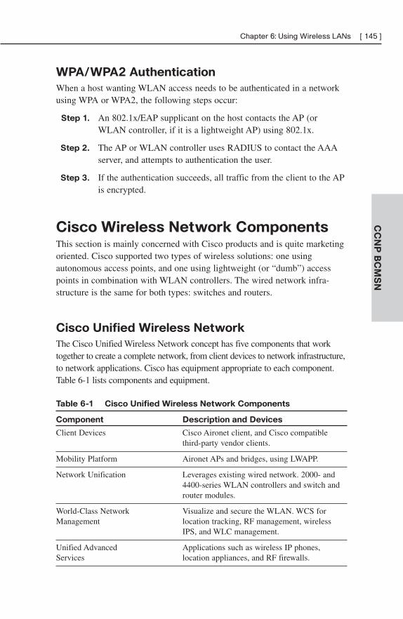
CC
NP
BC
MS
N
Chapter 6: Using Wireless LANs [ 145 ]
WPA/WPA2 Authentication
When a host wanting WLAN access needs to be authenticated in a networkusing WPA or WPA2, the following steps occur:
Step 1. An 802.1x/EAP supplicant on the host contacts the AP (orWLAN controller, if it is a lightweight AP) using 802.1x.
Step 2. The AP or WLAN controller uses RADIUS to contact the AAAserver, and attempts to authentication the user.
Step 3. If the authentication succeeds, all traffic from the client to the APis encrypted.
Cisco Wireless Network ComponentsThis section is mainly concerned with Cisco products and is quite marketingoriented. Cisco supported two types of wireless solutions: one usingautonomous access points, and one using lightweight (or “dumb”) accesspoints in combination with WLAN controllers. The wired network infra-structure is the same for both types: switches and routers.
Cisco Unified Wireless Network
The Cisco Unified Wireless Network concept has five components that worktogether to create a complete network, from client devices to network infrastructure,to network applications. Cisco has equipment appropriate to each component.Table 6-1 lists components and equipment.
Table 6-1 Cisco Unified Wireless Network Components
Component Description and Devices
Client Devices Cisco Aironet client, and Cisco compatible third-party vendor clients.
Mobility Platform Aironet APs and bridges, using LWAPP.
Network Unification Leverages existing wired network. 2000- and 4400-series WLAN controllers and switch and router modules.
World-Class Network Visualize and secure the WLAN. WCS forManagement location tracking, RF management, wireless
IPS, and WLC management.
Unified Advanced Applications such as wireless IP phones,Services location appliances, and RF firewalls.
CC
NP
BC
MS
N[ 146 ] CCNP BCMSN Quick Reference
You should review the following link for more information on Cisco wirelesscontrollers and access points before you take the exam:http://www.cisco.com/en/US/products/hw/wireless/products_category_buyers_guide.htmlWireless Clients.
Cisco has a wireless NIC that can be installed on Windows 2000 andWindows XP systems. It comes with some utilities: Aironet Desktop Utility(ADU), Aironet Client Monitor (ACM), and Aironet Client AdministrationUtility (ACAU). Cisco recommends using the ADU and ACM utilities tocontrol your wireless card, rather than the built-in Windows controls to get theincreased functionality Cisco provides. The Cisco ACAU allows loading andconfiguration of the Cisco client software over the network, using encryptedfiles. There is also an Aironet Site Survey Utility to scan for APs and getinformation about them.
Cisco wireless IP phones have the same features as Cisco wired IP phonesand can use LEAP for authentication.
The Cisco Compatible Extensions Program tests other vendors’ devices forcompatibility with Cisco wireless products. Using products certified by thisprogram ensures full functionality of Cisco enhancements and proprietaryextensions. A list of these products can be found at www.cisco.com/go/cisco-compatible/wireless.
Autonomous APs
Autonomous APs run Cisco IOS, are programmed individually, and act inde-pendently. They can be centrally managed with the CiscoWorks WirelessLAN Solution Engine (WLSE) and can use Cisco Secure Access ControlServer (ACS) for RADIUS and TACAS+ authentication. Redundancyconsists of multiple APs.
Lightweight Access Points
Lightweight APs divide the 802.11 processing between the AP and a CiscoWireless LAN Controller (WLC). This is sometimes called “split MAC,”because they split the functions of the MAC layer—Layer 2. Their manage-ment components also include the Wireless Control System (WCS) and alocation-tracking appliance. Redundancy consists of multiple WLCs. The APhandles real-time processes, and the WLC handles processes such as:
■ Authentication
■ Client association/mobility management
CC
NP
BC
MS
N
Chapter 6: Using Wireless LANs [ 147 ]
■ Security management
■ QoS policies
■ VLAN tagging
■ Forwarding of user traffic
The Lightweight Access Point Protocol (LWAP) supports the split MACfunction in traffic between a lightweight AP and its controller. LWAP usesAES-encrypted control messages and encapsulates, but does not encrypt,data traffic. LWAP operates at Layer 2, and also at Layer 3 over UDP.(However, Layer 2 operation has been deprecated by Cisco.) The controllercan be either in the same broadcast domain and IP subnet or in a differentbroadcast domain and IP subnets for Layer 3 operation. The AP follows thisprocess to discover its controller:
Step 1. The AP requests a DHCP address. The DHCP response includesthe management IP address of one or more WLCs.
Step 2. The AP sends an LWAPP Discovery Request message to eachWLC.
Step 3. The WLCs respond with an LWAPP Discovery Response thatincludes the number of APs currently associated to it.
Step 4. The AP sends a Join Request to the WLC with the fewest APsassociated to it.
Step 5. The WLC responds with a Join Response message, the AP andthe controller mutually authenticate each other and derive encryp-tion keys to be used with future control messages. The WLC thenconfigures the AP with settings, such as SSIDs, channels, securitysettings, and 802.11 parameters.
The Cisco Aironet 2000 series WLC can handle up to six APs; thus, it issized for small- to medium-sized operations.
The Cisco Aironet 4400 series WLC supports medium to large facilities withthe 4402 handling up to 50 APs, and the 4404 handling up to 100 APs.
Wireless LAN Antennas
Several concepts are important in understanding wireless antennas:
■ Gain—The energy an antenna adds to the RF signal.
■ Directionality—How the radio coverage is distributed.
CC
NP
BC
MS
N[ 148 ] CCNP BCMSN Quick Reference
■ Polarization—The physical orientation the RF element. Cisco Aironetantennas use vertical polarization.
■ Multipath Distortion—Receiving both direct and reflected signalsarriving from different directions.
■ Effective Isotropic Radiated Power (EIRP)—The AP radio’s effectivetransmission power. Includes gain from the antenna and loss from theantenna’s cable.
GainCisco measures gain in dBi, which stands for decibel isotropic and is ameasure of decibels relative to an isotropic source in free space. A decibel isthe ratio between two signal levels. An isotropic antenna is a theoretical onein which the signal spreads out evenly in all directions from one point. Thus,dBi is the ratio of an antenna’s signal to that of an isotropic antenna.
DirectionalityOmnidirectional antennas have signals that theoretically extend in all directions,both vertically and horizontally. When gain in increased, the signal expandshorizontally, but decreases vertically. One omnidirectional example is thedipole “Rubber Duck” antenna.
Directional antennas aim their signal in a specific direction. Signals can spreadfairly wide in one direction or can be narrowly focused. Some examplesinclude the Diversity Patch Wall Mount Antenna, Yagi, and dish antennas.
Multipath DistortionBecause radio waves are transmitted in many directions, not all go in a straightline to every client’s antenna. Some bounce off walls or other objects and arriveat the client in varying intervals. Thus, the client receives several copies ofthe same RF signal, which can cause degraded data quality. This is multipathdistortion, or multipath interference. Diversity systems try to minimize this byusing two antennas; you might try moving antennas or changing the frequencyif this is a problem in your facility. OFDM uses multiple frequencies operatingtogether to increase performance in multipath situations.
EIRPEIRP is the actual power of the signal that comes from the antenna, measuredin Decibel Milliwatts (dBm). (0 dBm equals 1 milliwatt of power.) EIRP iscalculated by taking the transmitter power, subtracting the amount of signal
CC
NP
BC
MS
N
Chapter 6: Using Wireless LANs [ 149 ]
lost traversing the cable between the transmitter and antenna, and adding theantenna’s gain. This can be expressed:
EIRP = (power – cable loss) + antenna gain.
Different countries have different rules about the amount of EIRP allowed.For instance, the maximum in the United States is 36 dBm. To minimizesignal loss, use the shortest low-loss cable possible. Wider cables conservemore signal but are also more expensive.
Power over Ethernet (PoE) Switches
Access points can receive their power over Ethernet cables from Power overEthernet (PoE) switches, routers with PoE switch modules, or midspanpower injectors, thus alleviating the need for electrical outlets near them.APs require up to 15W of power, so plan your power budget accordingly.Two power standards are the Cisco Prestandard PoE and the IEEE’s 802.3afstandard. Both have a method for sensing that a powered device is connectedto the port. 802.3af specifies a method for determining the amount of powerneeded by the device. Cisco devices, when connected to Cisco switches, canadditionally use CDP to send that information. Power can be supplied overthe data pairs—1, 2, 3, and 6—or over the unused pairs of 4, 5, 7, and 8.
Cisco PoE switches are configured by default to automatically detect andprovide power. To disable this function, or to re-enable it, use the interfacecommand power inline {never | auto}. To view interfaces and the powerallotted to each, use show power inline [interface].
Configuring Wireless LAN DevicesAutonomous APs must be configured individually, while the WLC providesconfiguration to lightweight APs. WLAN clients must also be configured;this process varies depending on the client software used.
Configuring Autonomous Access Points
Autonomous APs can be configured in one of three ways:
■ IOS Command Line—Either via Telnet or the console port.
■ Web browser—This is the Cisco preferred way.
■ CiscoWorks WLSE—For centralized configuration control.
CC
NP
BC
MS
N[ 150 ] CCNP BCMSN Quick Reference
The AP must already have an IP address to use any of these except the consoleport. It attempts to obtain one via DHCP by default. This link has directionsand screen shots for both the command line and web browser configuration:http://www.cisco.com/en/US/products/ps6087/products_installation_and_configuration_guides_list.html.
Aironet 1100, 1200, and 1300 series APs perform various functions:
■ Wireless AP
■ Root bridge
■ Nonroot bridge
■ Repeater
■ Scanner
■ Workgroup bridge
Configuring a WLAN Controller
Cisco lightweight APs receive their configuration from the Wireless LANController, which must be configured first. Initial configuration of the light-weight WLC can be done via command line using the console port or viaweb browser using the service port. Subsequent configuration can be donevia:
■ IOS Command Line—Either by Telnet, SSH, or the console port.
■ Web browser—Using the WLC’s IP address and Internet Explorer.
■ Cisco Wireless Control System—For centralized configuration control.
You need to configure the WLC with information such as VLANs, SSIDs,and security policies. It downloads a configuration to its associated APs, andyou can also configure, monitor, or reset individual APs through the webbrowser of the WLC. Review the material at this link for screen shots andWLC configuration information:http://www.cisco.com/en/US/products/ps6366/products_configuration_guide_book09186a00806b0077.html.
WLCs use several different types of physical and logical interfaces that aredescribed in Table 6-2.
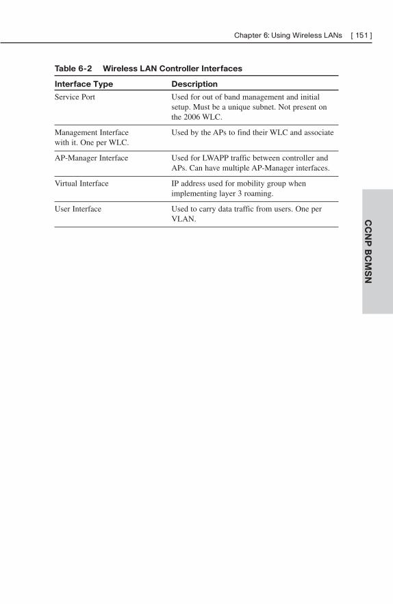
CC
NP
BC
MS
N
Chapter 6: Using Wireless LANs [ 151 ]
Table 6-2 Wireless LAN Controller Interfaces
Interface Type Description
Service Port Used for out of band management and initial setup. Must be a unique subnet. Not present on the 2006 WLC.
Management Interface Used by the APs to find their WLC and associate with it. One per WLC.
AP-Manager Interface Used for LWAPP traffic between controller and APs. Can have multiple AP-Manager interfaces.
Virtual Interface IP address used for mobility group when implementing layer 3 roaming.
User Interface Used to carry data traffic from users. One per VLAN.
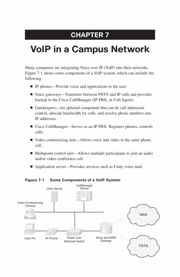
CHAPTER 7
VoIP in a Campus Network
Many companies are integrating Voice over IP (VoIP) into their networks.Figure 7-1 shows some components of a VoIP system, which can include thefollowing:
■ IP phones—Provide voice and applications to the user.
■ Voice gateways—Translates between PSTN and IP calls and providesbackup to the Cisco CallManager (IP PBX, or Call Agent).
■ Gatekeepers—An optional component that can do call admissioncontrol, allocate bandwidth for calls, and resolve phone numbers intoIP addresses.
■ Cisco CallManager—Serves as an IP PBX. Registers phones, controlscalls.
■ Video conferencing unit—Allows voice and video in the same phonecall.
■ Multipoint control unit—Allows multiple participants to join an audioand/or video conference call.
■ Application server—Provides services such as Unity voice mail.
Figure 7-1 Some Components of a VoIP System
WAN
PSTN
Unity ServerCallManager
Server
Power overEthernet Switch
IP PhoneUser PC Voice and WANGateway
Video ConferencingCamera
CC
NP
BC
MS
N
Chapter 7: VoIP in a Campus Network [ 153 ]
Voice and data have different network requirements. Although TCP dataadjusts to dropped packets, packet loss is one of the biggest enemies of voicetransmissions and is often caused by jitter and congestion. Jitter (variabledelay) causes buffer over- and under-runs. Congestion at the interface can becaused by traffic from a fast port being switched to exit out a slower port,which causes the transmit buffer to be overrun.
VoIP traffic consists of two types: voice bearer and call control signaling.Voice bearer traffic is carried over the UDP-based Real Time Protocol (RTP).Call control uses one of several different protocols to communicate betweenthe phone and CallManager and between the CallManager and the voicegateways.
Preparing the Network for VoIPWhen adding voice or video to an existing network, you should examineseveral things in advance to provide the high level of availability usersexpect in their phone system:
■ What features are needed?—Power for IP phones, voice VLANs on theswitches, network redundancy for high availability, security for voicecalls, and Quality of Service (QoS) settings.
■ The physical plant—Cabling at least CAT-5.
■ Electrical power for the IP phones—Use either inline power fromCatalyst switch or power patch panel. Need uninterruptible powersupply (UPS) with auto-restart, monitoring, and 4-hour responsecontract. May need generator backup. Maintain correct operatingtemperatures.
■ Bandwidth—Commit no more than 75 percent of bandwidth. Considerall types of traffic—voice, video, and data. Have more than enoughbandwidth if possible. Include both voice and call-control traffic inyour planning.
■ Network management—Need to monitor and proactively manage thenetwork so that it does not go down.
Network and Bandwidth Considerations
The network requirements for VoIP include:
■ Maximum delay of 150–200 ms (one-way)
CC
NP
BC
MS
N[ 154 ] CCNP BCMSN Quick Reference
■ No more than 1 percent packet loss
■ Maximum average jitter of 30 ms
■ Bandwidth of 21–106 kbps per call, plus about 150 bps per phone forcontrol traffic
A formula to use when calculating bandwidth needed for voice calls is asfollows:
(Packet payload + all headers) * Packet rate per second
Auxiliary (or Voice) VLANs
Cisco switches can be configured to dynamically place IP telephones into a VLAN separate from the data VLANs. They can do this even when thephone and PC are physically connected to the same switch port. This iscalled an auxiliary VLAN or a voice VLAN. Voice VLANs allow phones to be dynamically placed in a separate IP subnet from hosts, to have QoS(using 802.1Q/p headers) and security policies applied, and makes trou-bleshooting easier.
QoS for VoIPQoS gives special treatment to certain traffic at the expense of others. UsingQoS in the network has several advantages:
■ Prioritizes access to resources, so that critical traffic can be served.
■ Allows good management of network resources.
■ Allows service to be tailored to network needs.
■ Allows mission-critical applications to share the network with otherdata.
People sometimes think that there is no need for QoS strategies in a LAN.However, switch ports can experience congestion because of port speedmismatches, many people trying to access the switch backbone, and manypeople trying to send traffic to the same switch port (such as a server port).
QoS Actions
Three QoS strategies are commonly implemented on interfaces where trafficenters the switch:
CC
NP
BC
MS
N
Chapter 7: VoIP in a Campus Network [ 155 ]
■ Classification—Distinguishing one type of traffic from another. Aftertraffic is classified, other actions can be performed on it. Some classifica-tion methods include access lists, ingress interface, and NBAR.
■ Marking—At layer 2, placing 802.1p class of service (CoS) valuewithin the 802.1Q tag. At layer 3, setting IP Precedence orDifferentiated Services Code Point (DSCP) values on the classifiedtraffic.
■ Policing—Determining whether or not a specific type of traffic iswithin preset bandwidth levels. If so, it is usually allowed and might bemarked. If not, the traffic is typically marked or dropped. CAR andclass-based policing are examples of policing techniques.
Other QoS techniques are typically used on outbound interfaces:
■ Traffic shaping and conditioning—Attempts to send traffic out in asteady stream at a specified rate. Buffers traffic that goes above thatrate and sends it when there is less traffic on the line.
■ Queuing—After traffic is classified and marked, one way it can begiven special treatment is to be put into different queues on the inter-face to be sent out at different rates and times. Some examples includepriority queuing, weighted fair queuing, and custom queuing. Thedefault queuing method for a switch port is FIFO.
■ Dropping—Normally interface queues accept packets until they arefull and then drop everything after that. You can implement prioritizeddropping, so that less important packets are dropped before moreimportant ones—such as with Weighted Random Early Detection(WRED).
DSCP Values
Differentiated services provide levels of service based on the value of certainbits in the IP or ISL header or the 802.1Q tag. Each hop along the way mustbe configured to treat the marked traffic the way you want—this is calledper-hop behavior (PHB).
In the Layer 3 IP header, you use the 8-bit ToS field. You can set either IPPrecedence using the top 3 bits or Differentiated Services Code Points(DSCP) using the top 6 bits of the field. The bottom 2 bits are set aside forcongestion notification. The default DSCP value is zero, which correspondsto best-effort delivery.
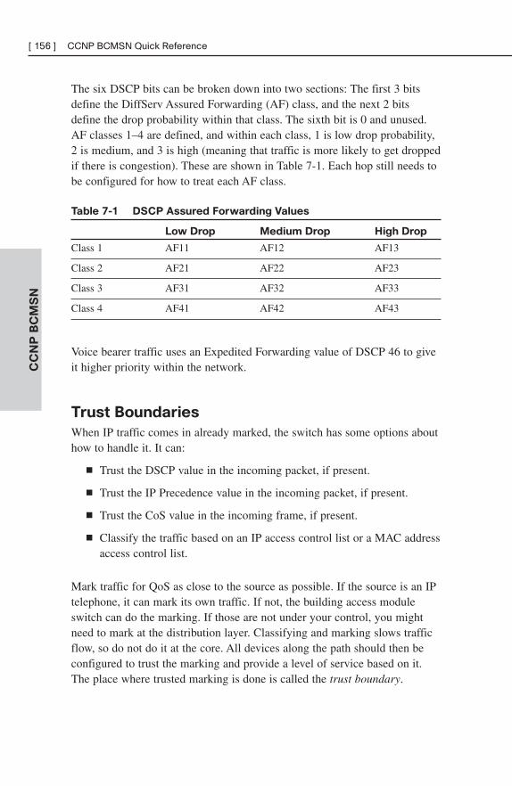
CC
NP
BC
MS
N[ 156 ] CCNP BCMSN Quick Reference
The six DSCP bits can be broken down into two sections: The first 3 bitsdefine the DiffServ Assured Forwarding (AF) class, and the next 2 bitsdefine the drop probability within that class. The sixth bit is 0 and unused.AF classes 1–4 are defined, and within each class, 1 is low drop probability,2 is medium, and 3 is high (meaning that traffic is more likely to get droppedif there is congestion). These are shown in Table 7-1. Each hop still needs tobe configured for how to treat each AF class.
Table 7-1 DSCP Assured Forwarding Values
Low Drop Medium Drop High Drop
Class 1 AF11 AF12 AF13
Class 2 AF21 AF22 AF23
Class 3 AF31 AF32 AF33
Class 4 AF41 AF42 AF43
Voice bearer traffic uses an Expedited Forwarding value of DSCP 46 to giveit higher priority within the network.
Trust Boundaries
When IP traffic comes in already marked, the switch has some options abouthow to handle it. It can:
■ Trust the DSCP value in the incoming packet, if present.
■ Trust the IP Precedence value in the incoming packet, if present.
■ Trust the CoS value in the incoming frame, if present.
■ Classify the traffic based on an IP access control list or a MAC addressaccess control list.
Mark traffic for QoS as close to the source as possible. If the source is an IPtelephone, it can mark its own traffic. If not, the building access moduleswitch can do the marking. If those are not under your control, you mightneed to mark at the distribution layer. Classifying and marking slows trafficflow, so do not do it at the core. All devices along the path should then beconfigured to trust the marking and provide a level of service based on it.The place where trusted marking is done is called the trust boundary.
CC
NP
BC
MS
N
Chapter 7: VoIP in a Campus Network [ 157 ]
Configuring VoIP Support on a Switch
Manual Configuration
To associate a voice VLAN with a switch port, use the following:
Switch(config-if)#switchport voice vlan vlan-ID
To configure an IOS switch to trust the markings on traffic entering an interface, use the following:
Switch(config-if)#mls qos trust {dscp | cos}
To configure the switch to trust the traffic markings only if a Cisco phone isconnected, use the following:
Switch(config-if)#mls qos trust device cisco-phone
To set a COS value for frames coming from a PC attached to the phone, usethe following:
Switch(config-if)#switchport priority extend cos cos-value
To verify the interface parameters, use the following:
Switch(config-if)#show interfaces interface switchport
To verify the QoS parameters on an interface, use the following:
Switch(config-if)#show mls qos interface interface
Using AutoQoS
When AutoQoS is enabled, the switch configures its interfaces based on abest-practices template. AutoQoS has the following benefits:
■ Automatic discovery and classification of network applications.
■ Creates QoS policies for those applications.
■ Configures the switch to support Cisco IP phones as well as network
applications. Manual configuration can be done afterward, also.
■ Sets up SNMP traps for network reporting.
■ Configures consistently across your network when used on all routers
and switches.
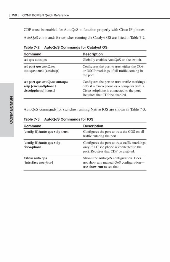
CC
NP
BC
MS
N[ 158 ] CCNP BCMSN Quick Reference
CDP must be enabled for AutoQoS to function properly with Cisco IP phones.
AutoQoS commands for switches running the Catalyst OS are listed in Table 7-2.
Table 7-2 AutoQoS Commands for Catalyst OS
Command Description
set qos autoqos Globally enables AutoQoS on the switch.
set port qos mod/port Configures the port to trust either the COSautoqos trust [cos|dscp] or DSCP markings of all traffic coming in
the port.
set port qos mod/port autoqos Configures the port to trust traffic markingsvoip [ciscosoftphone | only if a Cisco phone or a computer with aciscoipphone] [trust] Cisco softphone is connected to the port.
Requires that CDP be enabled.
AutoQoS commands for switches running Native IOS are shown in Table 7-3.
Table 7-3 AutoQoS Commands for IOS
Command Description
(config-if)#auto qos voip trust Configures the port to trust the COS on all traffic entering the port.
(config-if)#auto qos voip Configures the port to trust traffic markingscisco-phone only if a Cisco phone is connected to the
port. Requires that CDP be enabled.
#show auto qos Shows the AutoQoS configuration. Does[interface interface] not show any manual QoS configuration—
use show run to see that.
CHAPTER 8
Campus Network Security
Attention has traditionally been paid to network perimeter security, such asfirewall, and to mitigating Layer 3 attacks. However, networks must beprotected against Layer 2 attacks, also. These are launched from devicesinside the network by either a rogue device or a legitimate device that hasbeen compromised. Rogue devices might be placed maliciously or might justbe connected to an access switch by an employee wanting more switch portor wireless access. They include:
■ Wireless routers or hubs
■ Access switches
■ Hubs
A switch might become the Spanning Tree root bridge, and disrupt usertraffic. Use root guard and bpdu guard commands to prevent this.(Spanning tree security is discussed later in this chapter.)
There are four typical types of attacks against a switched network:
■ MAC-based attacks, such as MAC address flooding
■ VLAN-based attacks, such as VLAN hopping and attacks againstdevices on the same VLAN
■ Spoofing attacks, such as DHCP spoofing, MAC spoofing, AddressResolution Protocol (ARP) spoofing, and Spanning Tree attacks
■ Attacks against the switch, such as Cisco Discovery Protocol (CDP)manipulation, Telnet attacks, and Secure Shell (SSH) attacks
MAC Address FloodingIn a MAC address flooding attack, the attacker fills the switch’s ContentAddressable Memory (CAM) table with invalid MAC addresses. After the tableis full, all traffic with an address not in the table is flooded out all interfaces.This has two bad effects—more traffic on the LAN and more work for theswitch. Additionally, the intruder’s traffic is also flooded, so they have access
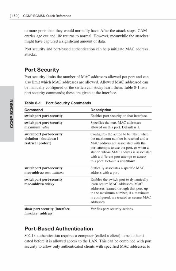
CC
NP
BC
MS
N[ 160 ] CCNP BCMSN Quick Reference
to more ports than they would normally have. After the attack stops, CAMentries age out and life returns to normal. However, meanwhile the attackermight have captured a significant amount of data.
Port security and port-based authentication can help mitigate MAC addressattacks.
Port Security
Port security limits the number of MAC addresses allowed per port and canalso limit which MAC addresses are allowed. Allowed MAC addressed canbe manually configured or the switch can sticky learn them. Table 8-1 listsport security commands; these are given at the interface.
Table 8-1 Port Security Commands
Command Description
switchport port-security Enables port security on that interface.
switchport port-security Specifies the max MAC addressesmaximum value allowed on this port. Default is 1.
switchport port-security Configures the action to be taken whenviolation {shutdown | the maximum number is reached and arestrict | protect} MAC address not associated with the
port attempts to use the port, or when a station whose MAC address is associatedwith a different port attempt to access this port. Default is shutdown.
switchport port-security Statically associates a specific MACmac-address mac-address address with a port.
switchport port-security Enables the switch port to dynamicallymac-address sticky learn secure MAC addresses. MAC
addresses learned through that port, up to the maximum number, if a maximum is configured, are treated as secure MACaddresses.
show port security [interface Verifies port security actions.interface | address]
Port-Based Authentication
802.1x authentication requires a computer (called a client) to be authenti-cated before it is allowed access to the LAN. This can be combined with portsecurity to allow only authenticated clients with specified MAC addresses to
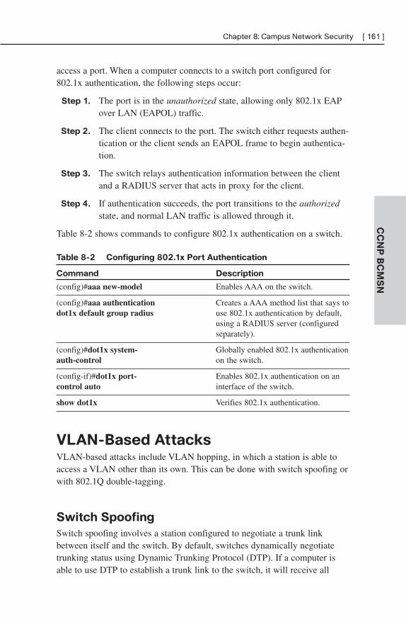
CC
NP
BC
MS
N
Chapter 8: Campus Network Security [ 161 ]
access a port. When a computer connects to a switch port configured for802.1x authentication, the following steps occur:
Step 1. The port is in the unauthorized state, allowing only 802.1x EAPover LAN (EAPOL) traffic.
Step 2. The client connects to the port. The switch either requests authen-tication or the client sends an EAPOL frame to begin authentica-tion.
Step 3. The switch relays authentication information between the clientand a RADIUS server that acts in proxy for the client.
Step 4. If authentication succeeds, the port transitions to the authorizedstate, and normal LAN traffic is allowed through it.
Table 8-2 shows commands to configure 802.1x authentication on a switch.
Table 8-2 Configuring 802.1x Port Authentication
Command Description
(config)#aaa new-model Enables AAA on the switch.
(config)#aaa authentication Creates a AAA method list that says todot1x default group radius use 802.1x authentication by default,
using a RADIUS server (configured separately).
(config)#dot1x system- Globally enabled 802.1x authenticationauth-control on the switch.
(config-if)#dot1x port- Enables 802.1x authentication on ancontrol auto interface of the switch.
show dot1x Verifies 802.1x authentication.
VLAN-Based AttacksVLAN-based attacks include VLAN hopping, in which a station is able toaccess a VLAN other than its own. This can be done with switch spoofing orwith 802.1Q double-tagging.
Switch Spoofing
Switch spoofing involves a station configured to negotiate a trunk linkbetween itself and the switch. By default, switches dynamically negotiatetrunking status using Dynamic Trunking Protocol (DTP). If a computer isable to use DTP to establish a trunk link to the switch, it will receive all
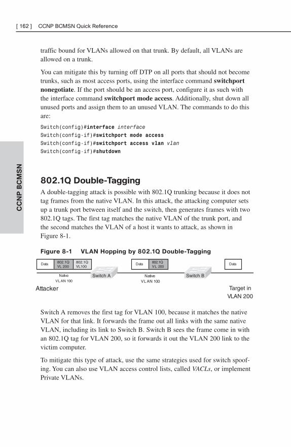
CC
NP
BC
MS
N[ 162 ] CCNP BCMSN Quick Reference
traffic bound for VLANs allowed on that trunk. By default, all VLANs areallowed on a trunk.
You can mitigate this by turning off DTP on all ports that should not becometrunks, such as most access ports, using the interface command switchportnonegotiate. If the port should be an access port, configure it as such withthe interface command switchport mode access. Additionally, shut down allunused ports and assign them to an unused VLAN. The commands to do thisare:
Switch(config)#interface interface
Switch(config-if)#switchport mode access
Switch(config-if)#switchport access vlan vlan
Switch(config-if)#shutdown
802.1Q Double-Tagging
A double-tagging attack is possible with 802.1Q trunking because it does nottag frames from the native VLAN. In this attack, the attacking computer setsup a trunk port between itself and the switch, then generates frames with two802.1Q tags. The first tag matches the native VLAN of the trunk port, andthe second matches the VLAN of a host it wants to attack, as shown inFigure 8-1.
Figure 8-1 VLAN Hopping by 802.1Q Double-Tagging
Attacker Target inVLAN 200
NativeVLAN 100
Native
VLAN 100
Data
Switch A Switch B
Data802.1QVL 200
Data 802.1QVL 200
802.1QVL100
Switch A removes the first tag for VLAN 100, because it matches the nativeVLAN for that link. It forwards the frame out all links with the same nativeVLAN, including its link to Switch B. Switch B sees the frame come in withan 802.1Q tag for VLAN 200, so it forwards it out the VLAN 200 link to thevictim computer.
To mitigate this type of attack, use the same strategies used for switch spoof-ing. You can also use VLAN access control lists, called VACLs, or implementPrivate VLANs.
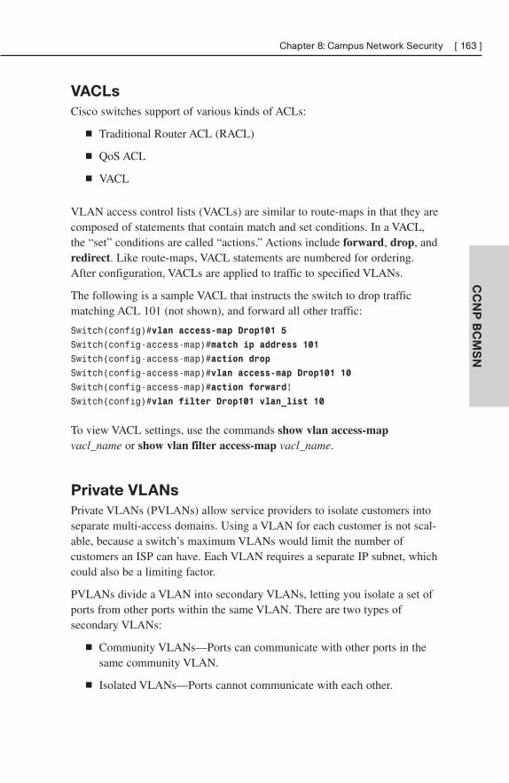
CC
NP
BC
MS
N
Chapter 8: Campus Network Security [ 163 ]
VACLs
Cisco switches support of various kinds of ACLs:
■ Traditional Router ACL (RACL)
■ QoS ACL
■ VACL
VLAN access control lists (VACLs) are similar to route-maps in that they arecomposed of statements that contain match and set conditions. In a VACL,the “set” conditions are called “actions.” Actions include forward, drop, andredirect. Like route-maps, VACL statements are numbered for ordering.After configuration, VACLs are applied to traffic to specified VLANs.
The following is a sample VACL that instructs the switch to drop trafficmatching ACL 101 (not shown), and forward all other traffic:
Switch(config)#vlan access-map Drop101 5
Switch(config-access-map)#match ip address 101
Switch(config-access-map)#action drop
Switch(config-access-map)#vlan access-map Drop101 10
Switch(config-access-map)#action forward!
Switch(config)#vlan filter Drop101 vlan_list 10
To view VACL settings, use the commands show vlan access-mapvacl_name or show vlan filter access-map vacl_name.
Private VLANs
Private VLANs (PVLANs) allow service providers to isolate customers intoseparate multi-access domains. Using a VLAN for each customer is not scal-able, because a switch’s maximum VLANs would limit the number ofcustomers an ISP can have. Each VLAN requires a separate IP subnet, whichcould also be a limiting factor.
PVLANs divide a VLAN into secondary VLANs, letting you isolate a set ofports from other ports within the same VLAN. There are two types ofsecondary VLANs:
■ Community VLANs—Ports can communicate with other ports in thesame community VLAN.
■ Isolated VLANs—Ports cannot communicate with each other.
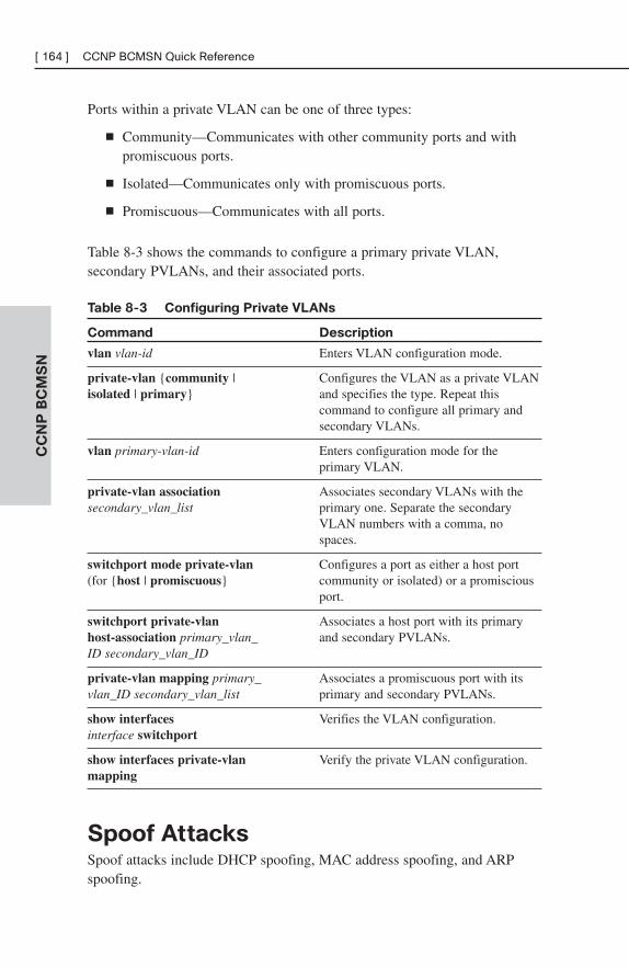
CC
NP
BC
MS
N[ 164 ] CCNP BCMSN Quick Reference
Ports within a private VLAN can be one of three types:
■ Community—Communicates with other community ports and withpromiscuous ports.
■ Isolated—Communicates only with promiscuous ports.
■ Promiscuous—Communicates with all ports.
Table 8-3 shows the commands to configure a primary private VLAN,secondary PVLANs, and their associated ports.
Table 8-3 Configuring Private VLANs
Command Description
vlan vlan-id Enters VLAN configuration mode.
private-vlan {community | Configures the VLAN as a private VLANisolated | primary} and specifies the type. Repeat this
command to configure all primary and secondary VLANs.
vlan primary-vlan-id Enters configuration mode for the primary VLAN.
private-vlan association Associates secondary VLANs with thesecondary_vlan_list primary one. Separate the secondary
VLAN numbers with a comma, nospaces.
switchport mode private-vlan Configures a port as either a host port(for {host | promiscuous} community or isolated) or a promiscious
port.
switchport private-vlan Associates a host port with its primaryhost-association primary_vlan_ and secondary PVLANs.ID secondary_vlan_ID
private-vlan mapping primary_ Associates a promiscuous port with itsvlan_ID secondary_vlan_list primary and secondary PVLANs.
show interfaces Verifies the VLAN configuration.interface switchport
show interfaces private-vlan Verify the private VLAN configuration.mapping
Spoof AttacksSpoof attacks include DHCP spoofing, MAC address spoofing, and ARPspoofing.
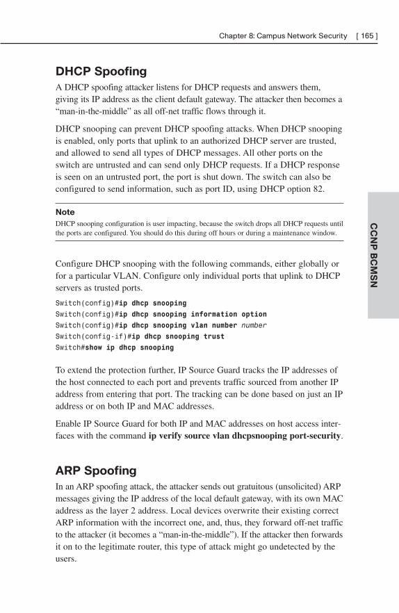
CC
NP
BC
MS
N
Chapter 8: Campus Network Security [ 165 ]
DHCP Spoofing
A DHCP spoofing attacker listens for DHCP requests and answers them,giving its IP address as the client default gateway. The attacker then becomes a“man-in-the-middle” as all off-net traffic flows through it.
DHCP snooping can prevent DHCP spoofing attacks. When DHCP snoopingis enabled, only ports that uplink to an authorized DHCP server are trusted,and allowed to send all types of DHCP messages. All other ports on theswitch are untrusted and can send only DHCP requests. If a DHCP responseis seen on an untrusted port, the port is shut down. The switch can also beconfigured to send information, such as port ID, using DHCP option 82.
Note
DHCP snooping configuration is user impacting, because the switch drops all DHCP requests untilthe ports are configured. You should do this during off hours or during a maintenance window.
Configure DHCP snooping with the following commands, either globally orfor a particular VLAN. Configure only individual ports that uplink to DHCPservers as trusted ports.
Switch(config)#ip dhcp snooping
Switch(config)#ip dhcp snooping information option
Switch(config)#ip dhcp snooping vlan number number
Switch(config-if)#ip dhcp snooping trust
Switch#show ip dhcp snooping
To extend the protection further, IP Source Guard tracks the IP addresses ofthe host connected to each port and prevents traffic sourced from another IPaddress from entering that port. The tracking can be done based on just an IPaddress or on both IP and MAC addresses.
Enable IP Source Guard for both IP and MAC addresses on host access inter-faces with the command ip verify source vlan dhcpsnooping port-security.
ARP Spoofing
In an ARP spoofing attack, the attacker sends out gratuitous (unsolicited) ARPmessages giving the IP address of the local default gateway, with its own MACaddress as the layer 2 address. Local devices overwrite their existing correctARP information with the incorrect one, and, thus, they forward off-net trafficto the attacker (it becomes a “man-in-the-middle”). If the attacker then forwardsit on to the legitimate router, this type of attack might go undetected by theusers.
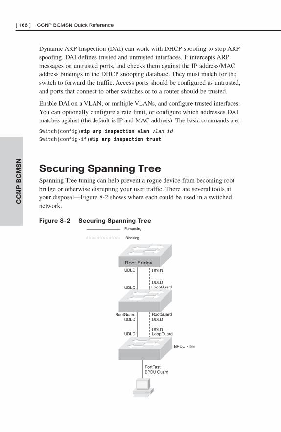
CC
NP
BC
MS
N[ 166 ] CCNP BCMSN Quick Reference
Dynamic ARP Inspection (DAI) can work with DHCP spoofing to stop ARPspoofing. DAI defines trusted and untrusted interfaces. It intercepts ARPmessages on untrusted ports, and checks them against the IP address/MACaddress bindings in the DHCP snooping database. They must match for theswitch to forward the traffic. Access ports should be configured as untrusted,and ports that connect to other switches or to a router should be trusted.
Enable DAI on a VLAN, or multiple VLANs, and configure trusted interfaces.You can optionally configure a rate limit, or configure which addresses DAImatches against (the default is IP and MAC address). The basic commands are:
Switch(config)#ip arp inspection vlan vlan_id
Switch(config-if)#ip arp inspection trust
Securing Spanning TreeSpanning Tree tuning can help prevent a rogue device from becoming rootbridge or otherwise disrupting your user traffic. There are several tools atyour disposal—Figure 8-2 shows where each could be used in a switchednetwork.
Figure 8-2 Securing Spanning Tree
Blocking
Forwarding
PortFast,BPDU Guard
RootGuard
UDLDUDLD
UDLD
UDLD
LoopGuard
RootGuard
LoopGuard
BPDU Filter
Root Bridge
UDLD
UDLDUDLD
UDLD
CC
NP
BC
MS
N
Chapter 8: Campus Network Security [ 167 ]
BPDU Guard
BPDU Guard prevents loops if another switch is attached to a Portfast port.When BPDU Guard is enabled on an interface, it is put into an error-disabledstate (basically, it is shut down) if a BPDU is received on the interface. It canbe enabled at either global configuration mode—in which case it affects allPortfast interfaces—or at interface mode. Portfast does not have to be enabledfor it to be configured at a specific interface.
Switch(config)#spanning-tree portfast bpduguard default
Switch(config-if)#spanning-tree bpduguard enable
BPDU Filtering
BPDU filtering is another way of preventing loops in the network. It also canbe enabled either globally or at the interface, and it functions differently ateach. In global configuration, if a Portfast interface receives any BPDUs, it istaken out of Portfast status. At interface configuration mode, it prevents theport from sending or receiving BPDUs. The commands are:
Switch(config)#spanning-tree portfast bpdufilter default
Switch(config-if)#spanning-tree bpdufilter enable
Root Guard
Root Guard is meant to prevent the wrong switch from becoming the spanning-tree root. It is enabled on ports other than the root port and on switches otherthan the root. If a Root Guard port receives a BPDU that causes it to becomea root port, the port is put into a “root-inconsistent” state and does not passtraffic through it. If the port stops receiving these BPDUs, it automaticallyre-enables itself.
Switch(config-if)#spanning-tree guard root
Switch#show spanning-tree inconsistentports
Prevent Spanning Tree LoopsA switch notices when a physical connection is broken by the absence ofLayer 1 electrical keepalives (Ethernet calls this a link beat). However, some-times a cable is intact enough to maintain keepalives, but not to pass data inboth directions. This is a unidirectional link.
CC
NP
BC
MS
N[ 168 ] CCNP BCMSN Quick Reference
Unidirectional Link Detection (UDLD)
UDLD detects a unidirectional link by sending periodic hellos out the inter-face. It also uses probes, which must be acknowledged by the device on theother end of the link. UDLD operates at Layer 2. The port is shut down if aunidirectional link is found.
To enable UDLD on all fiber-optic interfaces, use this command:
Switch(config)#udld enable
Although this command is given at global configuration mode, it appliesonly to fiber ports. To enable UDLD on nonfiber ports, give the samecommand at interface config mode.
To disable UDLD on a specific fiber port, use this command:
Switch(config-if)#udld disable
To disable UDLD on a specific nonfiber port, use this command:
Switch(config-if)#no udld enable
To re-enable all interfaces shut by UDLD, use the following:
Switch#udld reset
To verify UDLD status, use the following:
Switch#show udld interface
Loop Guard
Loop Guard prevents loops that might develop if a port that should be block-ing inadvertently transitions to the forwarding state. This can happen if theport stops receiving BPDUs (perhaps because of a unidirectional link or asoftware/configuration problem in its neighbor switch). When one of theports in a physically redundant topology stops receiving BPDUs, the STPconceives the topology as loop-free. Eventually, the blocking port becomesdesignated and moves to a forwarding state, thus creating a loop. With LoopGuard enabled, an additional check is made.
If no BPDUs are received on a blocked port for a specific length of time,Loop Guard puts that port into loop inconsistent blocking state, rather thantransitioning to a forwarding state. Loop Guard should be enabled on allswitch ports that have a chance of becoming root or designated ports. It ismost effective when enabled in the entire switched network, in conjunctionwith UDLD.
CC
NP
BC
MS
N
Chapter 8: Campus Network Security [ 169 ]
To enable Loop Guard for all point-to-point links on the switch, use thefollowing command:
Switch(config)#spanning-tree loopguard default
To enable Loop Guard on a specific interface, use:
Switch(config-if)#spanning-tree guard loop
Loop Guard automatically re-enables the port if it starts receiving BPDUsonce again.
Securing Your SwitchHere are some basic security suggestions for network devices:
■ Use passwords that are not susceptible to a dictionary attack. Addnumbers or substitute numbers and symbols for letters.
■ Limit Telnet access using access lists.
■ Use SSH instead of Telnet.
■ Physically secure access to the device.
■ Use banners that warn against unauthorized access.
■ Remove unused services, such as finger, the TCP and UDP smallservers, service config, and HTTP server.
■ Set up and monitor Syslog.
■ Disable automatic trunking on all nontrunk ports.
■ Disable CDP on ports where it is not needed.

This page intentionally left blank
ISCWChapter 1: Network Conceptual Models . . . . . . . . . . . . . 173
Chapter 2: Providing SOHO/Teleworker
Connectivity. . . . . . . . . . . . . . . . . . . . . . . . . . . . 176
Chapter 3: Frame Mode MPLS . . . . . . . . . . . . . . . . . . . . . . 190
Chapter 4: IPsec . . . . . . . . . . . . . . . . . . . . . . . . . . . . . . . . . . 200
Chapter 5: Cisco Device Hardening . . . . . . . . . . . . . . . . . 217
Chapter 6: Cisco IOS Threat Defenses . . . . . . . . . . . . . . 236
PART III

This page intentionally left blank
CHAPTER 1
Network Conceptual Models
Conceptual models allow network designers to move from looking at thenetwork as a collection of devices to viewing it as a way to provide servicesto users, no matter where the users and the services are located. Ciscocurrently defines three models as the building blocks of a world-class enter-prise network: the Intelligent Information Network, the Service-OrientedNetwork Architecture, and the Cisco Enterprise Architecture.
Intelligent Information NetworkThe Intelligent Information Network (IIN) seeks to create a holistic networkthat integrates with and enables your business processes. It allows centralizedcontrol and interoperation of distributed systems. This control and interoper-ability can provide increased network security and efficiency.
The IIN consists of three components:
■ Integrated transport—Data, voice, and video all transported over asecure IP network.
■ Integrated services—Shared/virtualized resources, such as storageand servers.
■ Integrated applications—The network is application aware, enhanc-ing the efficiency of applications. This component includesApplication-Oriented Networking (AON), which offloads shared,common functions, such as logging and security, to the network.
Service-Oriented Network Architecture An intelligent network is delivered using the Service-Oriented NetworkArchitecture (SONA) framework. SONA sees a converged network as theconnecting thread for all the portions of the network and the services provided.The network is application aware; that is, it contains the intelligence neededto tie all the various types of traffic together to deliver required services.SONA defines three layers:
[ 174 ] CCNP ISCW Quick ReferenceC
CN
P I
SC
W
■ Network Infrastructure—IT resources such as servers, users, WANs,and office locations all connected and accessible to each other
■ Integrated Services—Services such as voice, network management,mobility, security, and storage that are delivered using the networkinfrastructure
■ Application—Business applications that function using the integratedservices
In an enterprise, the campus and branch offices, teleworker access, and WANaccess all fall under the Network Infrastructure layer of the SONA. Thiscategorization allows workers in all types of locations to access the servicesand applications of the other layers. The Cisco Enterprise Architecturedefines how each of these components should be designed and structured.
Cisco Enterprise ArchitectureThe Cisco Enterprise Architecture model divides the network into buildingblocks and gives best practices for the architecture of each one. The traditionalthree-layer model (Core, Distribution, and Access) is still around and can beintegrated into the design of components of the Enterprise Architecture model.
Enterprise Architecture building blocks include the following:
■ Campus—The enterprise core, or headquarters. The campus buildingblock contains routing, switching, security, Voice over IP (VoIP), wire-less, and so on.
■ Data center—Server and application resources. Redundant datacenters provide business continuity and allow load balancing.
■ Branch office—Remote locations that contain services similar to thecampus but are administered centrally rather than at each location.
■ Teleworker—Either a small office, home office, or a mobile user.Extends data (and possibly voice) services to these users over a virtualprivate network (VPN) using broadband WAN access.
■ WAN—Connects all the different blocks together. Converges voice,video, and data over an IP WAN that provides security, quality ofservice (QoS), and ubiquitous access.
Chapter 1: Network Conceptual Models [ 175 ]
CC
NP
ISC
W
WAN options between the campus and branch offices include traditionalLayer 2 connections such as Frame Relay, ATM, and leased lines. MultiprotocolLabel Switching (MPLS) can provide any-to-any connectivity between thesites and is highly scalable. IPsec VPNs across the Internet can also be used.
This short cut is concerned mainly with how the campus, branch, and smalloffice, home office (SOHO)/teleworker portions of the network use the WANto communicate with each other to provide network services to their users.
CHAPTER 2
Providing SOHO/TeleworkerConnectivity
The traditional teleworker solution consists of a virtual private network(VPN) client on the user’s computer connecting over the Internet to a VPNconcentrator, firewall, or Cisco Adaptive Security Appliance (ASA) at thecorporate site. This requires only a dialup or broadband Internet connectionand a dialup or broadband modem. However, this approach has severalshortcomings:
■ Dialup does not provide the necessary bandwidth to take advantage ofall the corporate services, such as Voice over IP (VoIP).
■ There is no centralized control of the teleworker equipment, so security,virus protection, and so forth are left to the teleworker to implement.
■ There is no control over quality of service (QoS) for advanced services.
■ It is hard for corporate IT staff to support.
The Cisco Business-Ready Teleworker Solution addresses these issues withthe traditional teleworker approach. It seeks to secure corporate data byusing IPsec VPNs, allow corporate control of the connection components,and provide a scalable architecture as part of disaster planning. It consists ofan always-on broadband connection, a corporate-owned and -managed routerconfigured for VPN and QoS, IP phone, and (optionally) video equipment.
Two typical broadband connection types are digital subscriber line (DSL)and cable.
Chapter 2: Providing SOHO/Teleworker Connectivity [ 177 ]
CC
NP
ISC
W
Broadband Cable CATV, or Community Antenna Television, was originally developed toprovide improved TV signals by sharing antennas and satellite dishes. It usedcoaxial cable to transport the TV signals to each subscriber. Current systemstypically use a combination of fiber and coaxial. When both fiber and coaxialcables are used, the system is referred to as a hybrid fiber-coaxial (HFC)network.
Broadband cable uses frequency-division multiplexing (FDM) to deliver dataover a radio frequency (RF) network. Cable provides relatively inexpensivehigh-speed Internet access that supports analog and digital video, voice, anddata. Its downsides include possible bandwidth and security issues because itis a shared medium. The provider can increase bandwidth by using smallerservice areas and more channels. Security can be addressed by the userwithin the cable modem or with an onsite router.
Cable Components
Five basic components comprise a cable TV/data system:
■ Antenna site—Receives TV signals from antennas or satellite dishes.
■ Headend site—Converts TV signals for distribution to end users andconverts data for transport to and from end users. Similar to a tele-phone central office.
■ Transportation network—Links the antenna site to the headend orthe headend to the distribution network. Can use microwave, coaxialcable, or fiber cable.
■ Distribution network—Carries signals between the end user and thetransportation network. Consists of trunks and feeder cables. Backbonetrunks are either fiber or coaxial cable. Feeder cables are usuallycoaxial and connect the distribution network to the subscriber drops.
■ Subscriber drops—Connects the customer premises equipment (CPE)such as TV, set-top box, or cable modem to the distribution network.Uses coaxial cable.
Figure 2-1 shows more detail about how these components work together todeliver combined cable TV and data to an end user. Each acronym andcomponent is further explained following the figure.
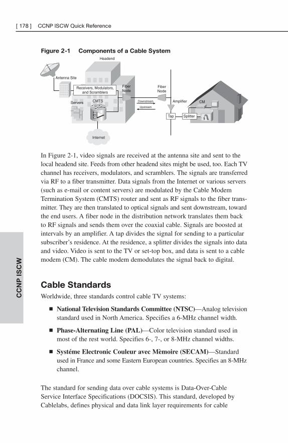
[ 178 ] CCNP ISCW Quick ReferenceC
CN
P I
SC
W
Figure 2-1 Components of a Cable System
Headend
Antenna Site
CM
Receivers, Modulators,and Scramblers
Amplifier
FiberNode
FiberNode
CMTSServers Downstream
Upstream
Internet
Tap Splitter
In Figure 2-1, video signals are received at the antenna site and sent to thelocal headend site. Feeds from other headend sites might be used, too. Each TVchannel has receivers, modulators, and scramblers. The signals are transferredvia RF to a fiber transmitter. Data signals from the Internet or various servers(such as e-mail or content servers) are modulated by the Cable ModemTermination System (CMTS) router and sent as RF signals to the fiber trans-mitter. They are then translated to optical signals and sent downstream, towardthe end users. A fiber node in the distribution network translates them backto RF signals and sends them over the coaxial cable. Signals are boosted atintervals by an amplifier. A tap divides the signal for sending to a particularsubscriber’s residence. At the residence, a splitter divides the signals into dataand video. Video is sent to the TV or set-top box, and data is sent to a cablemodem (CM). The cable modem demodulates the signal back to digital.
Cable Standards
Worldwide, three standards control cable TV systems:
■ National Television Standards Committee (NTSC)—Analog televisionstandard used in North America. Specifies a 6-MHz channel width.
■ Phase-Alternating Line (PAL)—Color television standard used inmost of the rest world. Specifies 6-, 7-, or 8-MHz channel widths.
■ Systéme Electronic Couleur avec Mèmoire (SECAM)—Standardused in France and some Eastern European countries. Specifies an 8-MHzchannel.
The standard for sending data over cable systems is Data-Over-CableService Interface Specifications (DOCSIS). This standard, developed byCablelabs, defines physical and data link layer requirements for cable
Chapter 2: Providing SOHO/Teleworker Connectivity [ 179 ]
CC
NP
ISC
W
modems. Cablelabs also certifies cable modems and CMTS systems to workwith the standard. At the physical layer, DOCSIS specifies channel widthsand modulation methods. At the data link layer it specifies access methods,some QoS capabilities, and some security features.
Cable RF waves use different frequencies for upstream and downstreamsignaling. Downstream signals are allowed 810 MHz of bandwidth, in the50- to 860-MHz range. This is then further subdivided into channels of 6-,7-, or 8-MHz depending on the standard used. Upstream signals have only37 MHz of bandwidth, in the 5- to 42-MHz range.
Provisioning the Cable Modem
Cable modems communicate with their CMTS across whatever physicalnetworks connect them. The service provider must have the necessary auxiliaryservices, such as DHCP, TFTP, and Time of Day (TOD), available at its headend.When a cable modem boots, it registers with the CMTS and acquires itsconfiguration using the following steps:
Step 1. The cable modem scans for a downstream channel to use forcommunication with the CMTS. Once it finds a channel, the CMlocks it in.
Step 2. CMTS tells the CM the parameters to use for upstream messages.
Step 3. Communication is established at Layers 1 and 2 (physical anddata link layers).
Step 4. The cable modem broadcasts for a DHCP server. It obtains an IPaddress, the address of the TFTP and TOD servers, and the nameof the TFTP file to download.
Step 5. The cable modem downloads the DOCSIS configuration file fromthe TFTP server.
Step 6. The cable modem forwards the configuration file to the CMTSand attempts to register with it. If the configuration is valid, themodem is registered. The two devices negotiate QoS and securitysettings.
Step 7. The user device—either a PC or a router—requests an IP address,DNS server, and default gateway information from the cable provider.
[ 180 ] CCNP ISCW Quick ReferenceC
CN
P I
SC
W
Digital Subscriber Line Voice does not use all the available bandwidth on a phone line—it usesfrequencies only up to about 3 kHz. DSL was created to use the space between3 kHz and 1 MHz to send data traffic over a telephone local loop. Thus, bothvoice and data can be sent simultaneously over the same connection (somevariants of DSL use the entire spectrum, however, so no voice can be sent).DSL is a physical layer medium that extends between the subscriber’s DSLmodem and the provider’s DSL access multiplexer (DSLAM.)
Types of DSL
Asymmetrical DSL has higher downstream (from the provider’s centraloffice [CO] to the subscriber) bandwidth than upstream (from the subscriberto the CO.) Symmetrical DSL has the same bandwidth both downstream and upstream. You will sometimes see these referred to as “asynchronous”and “synchronous” DSL.
The various types of DSL include the following:
■ ADSL—Asymmetric DSL supports both voice and data. Downstreambandwidth goes up to 8 Mbps; upstream goes up to 1 Mbps. Two otherversions, ADSL2 and ADSL2+, provide 24 Mbps downstream and 1.5Mbps upstream. The maximum distance from the CO is 18,000 feet, or5.46 km.
■ RADSL—Rate-adaptive DSL changes the rate based on the local loop.
■ VDSL—Very-high-rate DSL can be either symmetric or asymmetricand can carry voice along with data. Maximum symmetric bandwidthis 26 Mbps; maximum asymmetric is 52 Mbps downstream and 13Mbps upstream. The maximum distance from the CO is 4,500 feet, or1.37 km.
■ IDSL—ISDN DSL carries only digital data (other forms of DSL sendanalog signals). It uses both ISDN B channels and the D channel, for asymmetric bandwidth of 144 kbps. The maximum distance for IDSL is18,000 feet, or 5.46 km.
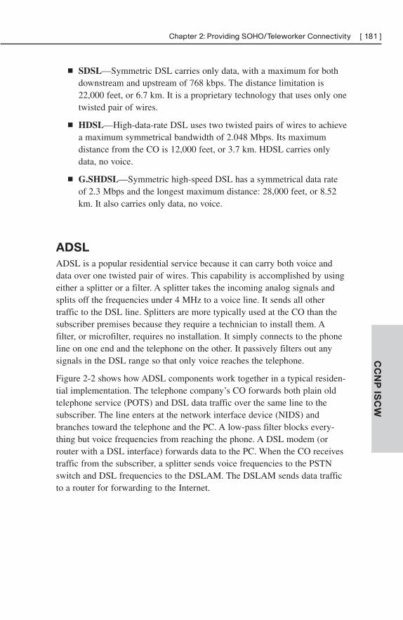
Chapter 2: Providing SOHO/Teleworker Connectivity [ 181 ]
CC
NP
ISC
W
■ SDSL—Symmetric DSL carries only data, with a maximum for bothdownstream and upstream of 768 kbps. The distance limitation is22,000 feet, or 6.7 km. It is a proprietary technology that uses only onetwisted pair of wires.
■ HDSL—High-data-rate DSL uses two twisted pairs of wires to achievea maximum symmetrical bandwidth of 2.048 Mbps. Its maximumdistance from the CO is 12,000 feet, or 3.7 km. HDSL carries onlydata, no voice.
■ G.SHDSL—Symmetric high-speed DSL has a symmetrical data rateof 2.3 Mbps and the longest maximum distance: 28,000 feet, or 8.52km. It also carries only data, no voice.
ADSL
ADSL is a popular residential service because it can carry both voice anddata over one twisted pair of wires. This capability is accomplished by usingeither a splitter or a filter. A splitter takes the incoming analog signals andsplits off the frequencies under 4 MHz to a voice line. It sends all othertraffic to the DSL line. Splitters are more typically used at the CO than thesubscriber premises because they require a technician to install them. Afilter, or microfilter, requires no installation. It simply connects to the phoneline on one end and the telephone on the other. It passively filters out anysignals in the DSL range so that only voice reaches the telephone.
Figure 2-2 shows how ADSL components work together in a typical residen-tial implementation. The telephone company’s CO forwards both plain oldtelephone service (POTS) and DSL data traffic over the same line to thesubscriber. The line enters at the network interface device (NIDS) andbranches toward the telephone and the PC. A low-pass filter blocks every-thing but voice frequencies from reaching the phone. A DSL modem (orrouter with a DSL interface) forwards data to the PC. When the CO receivestraffic from the subscriber, a splitter sends voice frequencies to the PSTNswitch and DSL frequencies to the DSLAM. The DSLAM sends data trafficto a router for forwarding to the Internet.
[ 182 ] CCNP ISCW Quick ReferenceC
CN
P I
SC
W
Figure 2-2 Components of an ADSL System
Internet
AggregationRouter
DSLAM
PSTN Switch
Central Office
Splitter
NIDSFilter
DSLModem
PSTNVoice
DSL Voice + DSL
Carrierless Amplitude and Phase Line CodingCarrierless Amplitude and Phase (CAP) is a DSL line-coding method thatdivides the bandwidth into three channels: one for voice, one for downstreamdata, and one for upstream data. Each type of traffic is carried within onefrequency band, and so CAP is termed a single-carrier modulationtechnique. The bands are fairly wide. Voice uses 0 to 4 kHz, upstream trafficuses 25 to 160 kHz, and downstream uses 240 kHz to 1.5 MHz. CAP issimple to understand and implement but does not scale as well as DiscreteMulti-Tone (DMT) modulation.
Discrete Multi-Tone Line CodingDiscrete Multi-Tone (DMT) is the most widely used method of ADSL linecoding. It divides the DSL frequency band into 256 channels of 4 kHz each.Some channels are duplex and used for both downstream and upstreamtraffic. Others are used only for downstream. Channel quality is constantlymonitored, and the channels used can be changed when conditions warrant.DMT is more complex than CAP but is also more flexible and scalable andcan achieve higher speeds.
A version of DMT, G.Lite ADSL, uses half the number of channels as DMT.
Layer 2 over DSL
Recall that DSL is a Layer 1 (physical layer) technology. There are threemethods of carrying data at Layer 2 over DSL:
Chapter 2: Providing SOHO/Teleworker Connectivity [ 183 ]
CC
NP
ISC
W
■ Bridging—Based on RFCs 1483 and 2684. Ethernet traffic is justbridged from the subscriber PCs, through the DSL modem and theDSLAM, to a provider router. Bridging is not as secure or scalable asother methods.
■ PPP over Ethernet (PPPoE)—The most common Layer 2 method ofcarrying data over DSL. PPP traffic is encapsulated in Ethernetframes.
■ PPP over ATM (PPPoA)—PPP packets are routed over ATMbetween the subscriber equipment and the provider.
PPPoEWhen PPPoE is used, a PPP session is established, similar to when usingdialup. Either Password Authentication Protocol (PAP) or ChallengeHandshake Authentication Protocol (CHAP) authentication can be used. Theprovider’s aggregation router and the subscriber’s CPE establish a sessionbetween them. There are three ways to do this:
■ The PPP client on a subscriber router with a DSL interface terminatesboth the DSL and the PPP sessions. The router can allow multipleusers over the DSL with just one PPP login, by acting as a DHCPserver and doing Network Address Translation (NAT) or Port AddressTranslation (PAT) for the subscriber users. The router obtains itsoutside IP address via PPP’s IP Control Protocol (IPCP.)
■ A DSL modem terminates the DSL session, and the PPP client on aCPE router terminates the PPP session. The router can act as a DHCPserver and do NAT/PAT, to allow multiple internal users. It obtains itsoutside address via IPCP.
■ A DSL modem terminates the DSL session, and a PPP client on thesubscriber PC terminates the PPP session. Traffic is bridged from thePC to the aggregation router. This allows only a single DSL user. Ifmultiple users are at the same residence, they must each have theirown PPP login, and they each obtain an IP address via IPCP.
PPP was created to be used over a point-to-point connection, and Ethernet isinherently multipoint, so PPPoE uses a PPP server discovery process. Aftera server has been discovered, a virtual point-to-point link can be established,and the PPP session process can continue. The PPP server discovery stagehas four steps:
[ 184 ] CCNP ISCW Quick ReferenceC
CN
P I
SC
W
Step 1. The PPP client sends a PPPoE Active Discovery Initiation(PADI) broadcast.
Step 2. Any PPP servers (aggregation routers) reply with a PPPoE ActiveDiscovery Offer (PADO), sent as a unicast to the client’s MACaddress.
Step 3. The client replies to the server with a PPPoE Active DiscoveryRequest (PADR).
Step 4. The server confirms the association with a PPPoE ActiveDiscovery Session-confirmation (PADS) message.
When these steps have been completed, the normal PPP session negotiationsproceed, and a session is established.
PPPoAPPPoA requires a CPE router; traffic is routed from the subscriber PCs tothe aggregation router—it cannot be bridged as with PPPoE. The PPPsession is established between the CPE router and the aggregation router.Multiple users are supported if the CPE router is configured to do DHCPand NAT. Traffic between the CPE router and the aggregation router isencapsulated as ATM at Layer 2, rather than Ethernet. Therefore, the CPErouter must have an ATM interface.
Configuring DSL CPEWhen a CPE router is used as the PPP client, it must be configured. Theconfiguration will differ depending on whether you are using PPPoE orPPPoA. PPPoE can be used with an Ethernet or an ATM interface on therouter connecting to the DSL network. An Ethernet interface is used if therouter connects to a DSL modem; an ATM interface is used if the routerconnects directly to the DSL network. A dialer interface must also becreated and configured with PPP parameters.
Configuring PPPoE CPE
The following tasks must be completed to configure a CPE router with forPPPoE:
1. Configure the internal and external interfaces.
2. Configure a dialer interface.
3. Configure NAT/PAT.
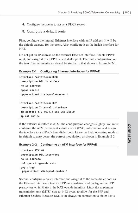
Chapter 2: Providing SOHO/Teleworker Connectivity [ 185 ]
CC
NP
ISC
W
4. Configure the router to act as a DHCP server.
5. Configure a default route.
First, configure the internal Ethernet interface with an IP address. It will bethe default gateway for the users. Also, configure it as the inside interface forNAT.
Do not put an IP address on the external Ethernet interface. Enable PPPoEon it, and assign it to a PPPoE client dialer pool. The final configuration onthe two Ethernet interfaces should be similar to that shown in Example 2-1.
Example 2-1 Configuring Ethernet Interfaces for PPPoE
interface FastEthernet0/0
description DSL interface
no ip address
pppoe enable
pppoe-client dial-pool-number 1
!
interface FastEthernet0/1
description Internal interface
ip address 172.16.1.1 255.255.255.0
ip nat inside
If the external interface is ATM, the configuration changes slightly. You mustconfigure the ATM permanent virtual circuit (PVC) information and assignthe interface to a PPPoE client dialer pool. Leave the DSL operating mode atits default to auto-detect the correct modulation, as shown in Example 2-2.
Example 2-2 Configuring an ATM Interface for PPPoE
interface ATM1/0
description DSL interface
no ip address
dsl operating-mode auto
pvc 1/100
pppoe-client dial-pool-number 1
Second, configure a dialer interface and assign it to the same dialer pool asthe Ethernet interface. Give it a PPP encapsulation and configure the PPPparameters on it. Make it the NAT outside interface. Limit the maximumtransmission unit (MTU) size to 1492 bytes, to allow for the PPP andEthernet headers. Because DSL is an always-on connection, a dialer list is
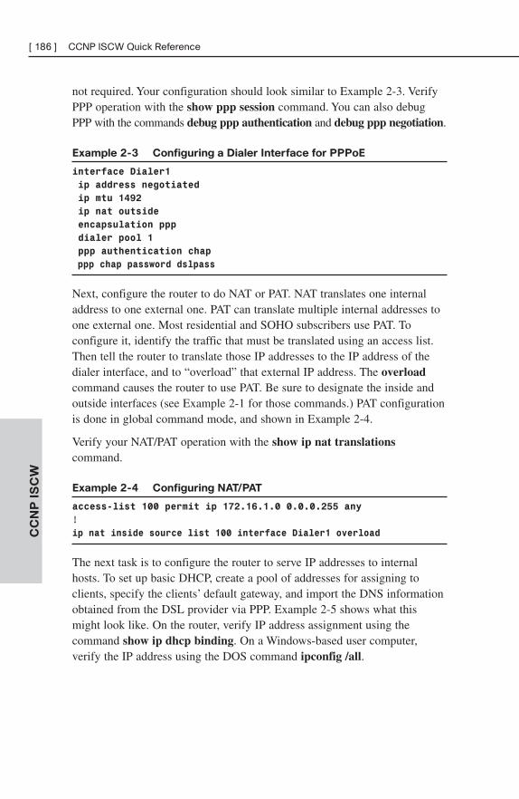
[ 186 ] CCNP ISCW Quick ReferenceC
CN
P I
SC
W
not required. Your configuration should look similar to Example 2-3. VerifyPPP operation with the show ppp session command. You can also debugPPP with the commands debug ppp authentication and debug ppp negotiation.
Example 2-3 Configuring a Dialer Interface for PPPoE
interface Dialer1
ip address negotiated
ip mtu 1492
ip nat outside
encapsulation ppp
dialer pool 1
ppp authentication chap
ppp chap password dslpass
Next, configure the router to do NAT or PAT. NAT translates one internaladdress to one external one. PAT can translate multiple internal addresses toone external one. Most residential and SOHO subscribers use PAT. Toconfigure it, identify the traffic that must be translated using an access list.Then tell the router to translate those IP addresses to the IP address of thedialer interface, and to “overload” that external IP address. The overloadcommand causes the router to use PAT. Be sure to designate the inside andoutside interfaces (see Example 2-1 for those commands.) PAT configurationis done in global command mode, and shown in Example 2-4.
Verify your NAT/PAT operation with the show ip nat translationscommand.
Example 2-4 Configuring NAT/PAT
access-list 100 permit ip 172.16.1.0 0.0.0.255 any
!ip nat inside source list 100 interface Dialer1 overload
The next task is to configure the router to serve IP addresses to internalhosts. To set up basic DHCP, create a pool of addresses for assigning toclients, specify the clients’ default gateway, and import the DNS informationobtained from the DSL provider via PPP. Example 2-5 shows what thismight look like. On the router, verify IP address assignment using thecommand show ip dhcp binding. On a Windows-based user computer,verify the IP address using the DOS command ipconfig /all.
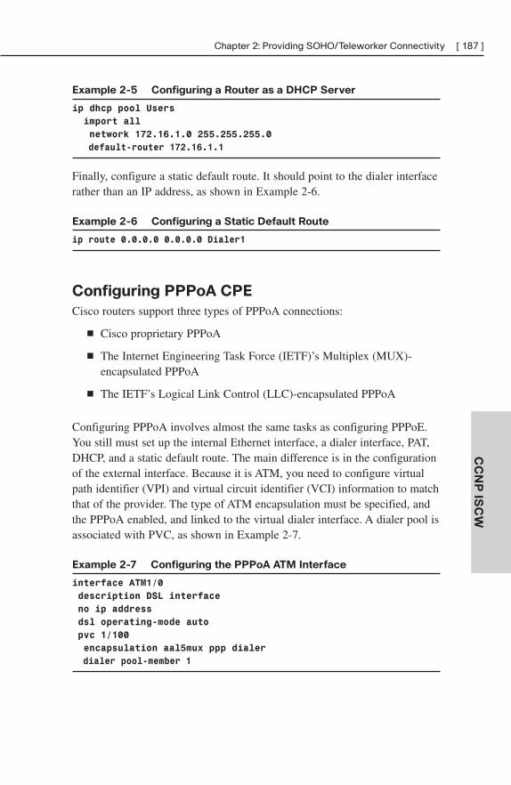
Chapter 2: Providing SOHO/Teleworker Connectivity [ 187 ]
CC
NP
ISC
W
Example 2-5 Configuring a Router as a DHCP Server
ip dhcp pool Users
import all
network 172.16.1.0 255.255.255.0
default-router 172.16.1.1
Finally, configure a static default route. It should point to the dialer interfacerather than an IP address, as shown in Example 2-6.
Example 2-6 Configuring a Static Default Route
ip route 0.0.0.0 0.0.0.0 Dialer1
Configuring PPPoA CPE
Cisco routers support three types of PPPoA connections:
■ Cisco proprietary PPPoA
■ The Internet Engineering Task Force (IETF)’s Multiplex (MUX)-encapsulated PPPoA
■ The IETF’s Logical Link Control (LLC)-encapsulated PPPoA
Configuring PPPoA involves almost the same tasks as configuring PPPoE.You still must set up the internal Ethernet interface, a dialer interface, PAT,DHCP, and a static default route. The main difference is in the configurationof the external interface. Because it is ATM, you need to configure virtualpath identifier (VPI) and virtual circuit identifier (VCI) information to matchthat of the provider. The type of ATM encapsulation must be specified, andthe PPPoA enabled, and linked to the virtual dialer interface. A dialer pool isassociated with PVC, as shown in Example 2-7.
Example 2-7 Configuring the PPPoA ATM Interface
interface ATM1/0
description DSL interface
no ip address
dsl operating-mode auto
pvc 1/100
encapsulation aal5mux ppp dialer
dialer pool-member 1
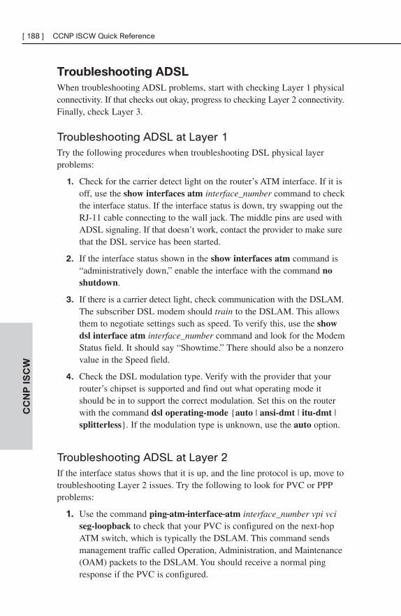
[ 188 ] CCNP ISCW Quick ReferenceC
CN
P I
SC
W
Troubleshooting ADSL
When troubleshooting ADSL problems, start with checking Layer 1 physicalconnectivity. If that checks out okay, progress to checking Layer 2 connectivity.Finally, check Layer 3.
Troubleshooting ADSL at Layer 1Try the following procedures when troubleshooting DSL physical layerproblems:
1. Check for the carrier detect light on the router’s ATM interface. If it isoff, use the show interfaces atm interface_number command to checkthe interface status. If the interface status is down, try swapping out theRJ-11 cable connecting to the wall jack. The middle pins are used withADSL signaling. If that doesn’t work, contact the provider to make surethat the DSL service has been started.
2. If the interface status shown in the show interfaces atm command is“administratively down,” enable the interface with the command noshutdown.
3. If there is a carrier detect light, check communication with the DSLAM.The subscriber DSL modem should train to the DSLAM. This allowsthem to negotiate settings such as speed. To verify this, use the showdsl interface atm interface_number command and look for the ModemStatus field. It should say “Showtime.” There should also be a nonzerovalue in the Speed field.
4. Check the DSL modulation type. Verify with the provider that yourrouter’s chipset is supported and find out what operating mode itshould be in to support the correct modulation. Set this on the routerwith the command dsl operating-mode {auto | ansi-dmt | itu-dmt |splitterless}. If the modulation type is unknown, use the auto option.
Troubleshooting ADSL at Layer 2If the interface status shows that it is up, and the line protocol is up, move totroubleshooting Layer 2 issues. Try the following to look for PVC or PPPproblems:
1. Use the command ping atm interface atm interface_number vpi vciseg-loopback to check that your PVC is configured on the next-hopATM switch, which is typically the DSLAM. This command sendsmanagement traffic called Operation, Administration, and Maintenance(OAM) packets to the DSLAM. You should receive a normal pingresponse if the PVC is configured.
Chapter 2: Providing SOHO/Teleworker Connectivity [ 189 ]
CC
NP
ISC
W
2. Debug the events occurring on the interface processor with the debugatm events command. This should show no output when everything isworking well; when there are problems, however, it can show usefulinformation such as the VPI/VCI number that the DSLAM expects.The ISCW course recommends beginning a continuous ping over theInternet (not over the internal network) to the router’s IP addressbefore giving this command.
3. Verify that the router is receiving data by using the show interfacesatm interface_number command. Look for packets input and output.
4. If the previous procedures show that everything is working, check for PPP problems. PPP should go through three phases: Link ControlProtocol (LCP) negotiation, authentication, and Network ControlProtocol (NCP) negotiation. The IP address is assigned by IPCP duringthe NCP phase. Use the commands debug ppp negotiation and debugppp authentication to see whether there is a failure at any of thesephases.
When debugging PPP, look first for a lack of response from the aggre-gation router. If data link parameters cannot be negotiated, LCP willnot open. If the authentication parameters are incorrectly configured,CHAP authentication will fail. If IPCP fails, the IP parameters arelikely configured incorrectly either on the CPE or on the aggregationrouter.
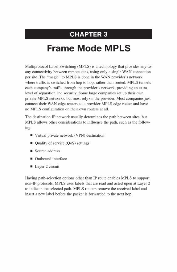
CHAPTER 3
Frame Mode MPLS
Multiprotocol Label Switching (MPLS) is a technology that provides any-to-any connectivity between remote sites, using only a single WAN connectionper site. The “magic” to MPLS is done in the WAN provider’s networkwhere traffic is switched from hop to hop, rather than routed. MPLS tunnelseach company’s traffic through the provider’s network, providing an extralevel of separation and security. Some large companies set up their ownprivate MPLS networks, but most rely on the provider. Most companies justconnect their WAN edge routers to a provider MPLS edge router and haveno MPLS configuration on their own routers at all.
The destination IP network usually determines the path between sites, butMPLS allows other considerations to influence the path, such as the follow-ing:
■ Virtual private network (VPN) destination
■ Quality of service (QoS) settings
■ Source address
■ Outbound interface
■ Layer 2 circuit
Having path-selection options other than IP route enables MPLS to supportnon-IP protocols. MPLS uses labels that are read and acted upon at Layer 2to indicate the selected path. MPLS routers remove the received label andinsert a new label before the packet is forwarded to the next hop.

Chapter 3: Frame Mode MPLS [ 191 ]
CC
NP
ISC
W
Cisco Express ForwardingMPLS relies on Cisco Express Forwarding (CEF) to indicate the next hopfor a packet to use. Cisco routers can use three types of packet switching:
■ Process switching—The CPU must be interrupted and a route tablelookup done for every packet. This is the slowest type of switching.
■ Fast switching—A route table lookup is done only for the first packetin a flow. The next-hop information, including the Layer 2 header, iscached and used for the remainder of the packets in the flow. Fasterthan process switching.
■ CEF switching—The router builds tables of next-hop and Layer 2information before any traffic is received. This is the fastest type ofswitching.
CEF takes information from the IP routing table and builds its own table, theForwarding Information Base (FIB). Because the CEF table is based on therouting table, any route changes are immediately reflected in it. CEF also buildsan adjacency table, which contains the Layer 2 header for each next-hopneighbor. When a packet needs to be forwarded through the router, CEF canusually do all the processing in hardware, making it extremely fast. WithMPLS, an extra field with label information is added to the FIB.
MPLS RoutersMPLS defines two roles for routers. A Label Switch Router (LSR) has all itsinterfaces within the MPLS network and does its path selection primarilybased on labels. An Edge LSR has some interfaces in the MPLS network andsome in a normal IP network, and so does some routing and some labelswitching. An LSR is sometimes referred to as a provider (P) router, and theedge LSR as a provider edge (PE) router.
LSRs function at two planes, the control plane and the data plane. Thecontrol plane handles routing protocols and a label-exchange protocol calledLabel Distribution Protocol (LDP). It contains the routing table and theLabel Information Base (LIB). The data plane contains the CEF FIB andadjacency table and the MPLS Label FIB (LFIB); it forwards traffic basedon those. Figure 3-1 shows the functions at each plane.
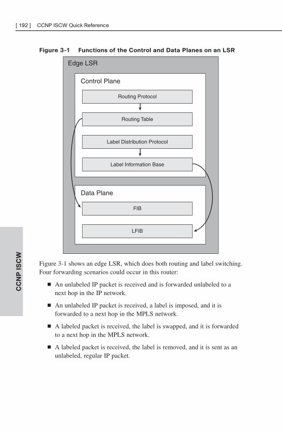
[ 192 ] CCNP ISCW Quick ReferenceC
CN
P I
SC
W
Figure 3-1 Functions of the Control and Data Planes on an LSR
Edge LSR
Routing Protocol
Routing Table
Label Distribution Protocol
Label Information Base
Control Plane
FIB
LFIB
Data Plane
Figure 3-1 shows an edge LSR, which does both routing and label switching.Four forwarding scenarios could occur in this router:
■ An unlabeled IP packet is received and is forwarded unlabeled to anext hop in the IP network.
■ An unlabeled IP packet is received, a label is imposed, and it isforwarded to a next hop in the MPLS network.
■ A labeled packet is received, the label is swapped, and it is forwardedto a next hop in the MPLS network.
■ A labeled packet is received, the label is removed, and it is sent as anunlabeled, regular IP packet.
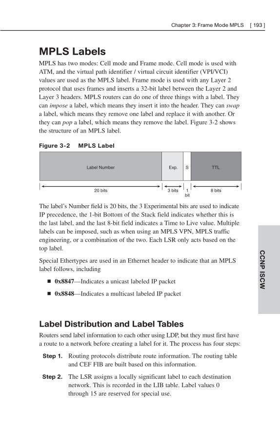
Chapter 3: Frame Mode MPLS [ 193 ]
CC
NP
ISC
W
MPLS LabelsMPLS has two modes: Cell mode and Frame mode. Cell mode is used withATM, and the virtual path identifier / virtual circuit identifier (VPI/VCI)values are used as the MPLS label. Frame mode is used with any Layer 2protocol that uses frames and inserts a 32-bit label between the Layer 2 andLayer 3 headers. MPLS routers can do one of three things with a label. Theycan impose a label, which means they insert it into the header. They can swapa label, which means they remove one label and replace it with another. Orthey can pop a label, which means they remove the label. Figure 3-2 showsthe structure of an MPLS label.
Figure 3-2 MPLS Label
Label Number Exp. S TTL
20 bits 3 bits 1bit
8 bits
The label’s Number field is 20 bits, the 3 Experimental bits are used to indicateIP precedence, the 1-bit Bottom of the Stack field indicates whether this isthe last label, and the last 8-bit field indicates a Time to Live value. Multiplelabels can be imposed, such as when using an MPLS VPN, MPLS trafficengineering, or a combination of the two. Each LSR only acts based on thetop label.
Special Ethertypes are used in an Ethernet header to indicate that an MPLSlabel follows, including
■ 0x8847—Indicates a unicast labeled IP packet
■ 0x8848—Indicates a multicast labeled IP packet
Label Distribution and Label Tables
Routers send label information to each other using LDP, but they must first havea route to a network before creating a label for it. The process has four steps:
Step 1. Routing protocols distribute route information. The routing tableand CEF FIB are built based on this information.
Step 2. The LSR assigns a locally significant label to each destinationnetwork. This is recorded in the LIB table. Label values 0through 15 are reserved for special use.

[ 194 ] CCNP ISCW Quick ReferenceC
CN
P I
SC
W
Step 3. Each LSR sends the local label for each network to its neighborsvia LDP. This is done asynchronously—a router does not wait toreceive a label from its downstream router before advertising itsown label. Labels are advertised to every neighbor, even the onechosen as the next hop for that network.
Step 4. The LSR records label information received from its neighbors inits LIB, FIB, and LFIB.
Each forwarding table is used as follows:
■ The LIB lists each IP network, the local label for that network, andany labels received from neighbors for that network. It is in thecontrol plane.
■ The FIB is used to forward unlabeled IP packets. It is in the data plane.
■ The LFIB lists each label, what label to swap it for, and the next-hopneighbor. It is in the data plane.
Penultimate Hop Popping
The LSR directly connected to a destination network (typically the PE router)is referred to as the ultimate hop for that network. The router right before itis the penultimate hop for that network. The directly connected LSR canadvertise a label value of 3 for that destination network. Label 3 tells theneighbor router to pop the label before forwarding the packet—referred toas penultimate hop popping (PHP). This is recorded in the neighbor’s FIBsas a null label.
PHP saves time and work for the PE LSR. Without it, the PE router wouldhave to do an LFIB lookup, remove the top label, and then do a FIB lookup.With PHP, it only needs to do the FIB lookup, which helps optimize MPLSperformance.
Figure 3-3 puts all these concepts together to show how MPLS routers uselabels and each of the tables to forward traffic.
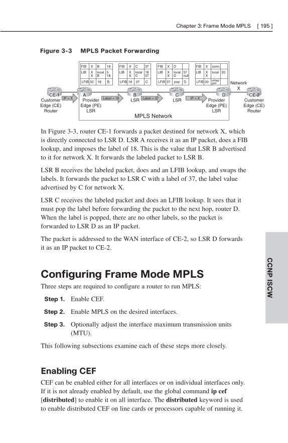
Chapter 3: Frame Mode MPLS [ 195 ]
CC
NP
ISC
W
Figure 3-3 MPLS Packet Forwarding
IP = X Label = 18 Label = 37 IP = XCustomerEdge (CE)
Router
CustomerEdge (CE)
Router
NetworkX
MPLS Network
LSR LSRProviderEdge (PE)
LSR
ProviderEdge (PE)
LSR
CE-1 CE-2DCBA
FIB
LIB
LFIB
18
518
B
B
localB
18
X
XX
52
FIB
LIB
LFIB
37
1837
C
C
localC
37
X
XX
18
FIB
LIB
LFIB
37null
D
D
localD
pop
X
XX
37
FIB
LIB
LFIB
20
conn.
local
untag-ged
X
XX
20
In Figure 3-3, router CE-1 forwards a packet destined for network X, whichis directly connected to LSR D. LSR A receives it as an IP packet, does a FIBlookup, and imposes the label of 18. This is the value that LSR B advertisedto it for network X. It forwards the labeled packet to LSR B.
LSR B receives the labeled packet, does and an LFIB lookup, and swaps thelabels. It forwards the packet to LSR C with a label of 37, the label valueadvertised by C for network X.
LSR C receives the labeled packet and does an LFIB lookup. It sees that itmust pop the label before forwarding the packet to the next hop, router D.When the label is popped, there are no other labels, so the packet isforwarded to LSR D as an IP packet.
The packet is addressed to the WAN interface of CE-2, so LSR D forwardsit as an IP packet to CE-2.
Configuring Frame Mode MPLSThree steps are required to configure a router to run MPLS:
Step 1. Enable CEF.
Step 2. Enable MPLS on the desired interfaces.
Step 3. Optionally adjust the interface maximum transmission units(MTU).
This following subsections examine each of these steps more closely.
Enabling CEF
CEF can be enabled either for all interfaces or on individual interfaces only.If it is not already enabled by default, use the global command ip cef[distributed] to enable it on all interface. The distributed keyword is usedto enable distributed CEF on line cards or processors capable of running it.
[ 196 ] CCNP ISCW Quick ReferenceC
CN
P I
SC
W
To enable CEF on an individual interface, use the ip route-cache cef inter-face command. Note that CEF is not supported on logical interfaces, such asloopbacks.
Verify CEF operation with any of several variables of the show ip cefcommand. The show ip cef detail option is good to start with because itshows a summary of CEF routes and a list of all adjacencies.
Enabling MPLS
MPLS is globally enabled by default on Cisco routers. If it has beendisabled, enable it with the global command mpls ip. It must then beenabled on each interface that will participate in label switching; enable itwith the interface command mpls ip.
LDP is the default label distribution protocol in Cisco IOS Release 12.4(3)and later. There is an older Cisco prestandard version called Tag DistributionProtocol (TDP.) You might need to enable it if you are connecting to a Ciscorouter that does not support LDP; if you need to specify the protocol, use theinterface command mpls label protocol [tdp | ldp | both]. Both protocolscan run on the same router, and even on the same interface. In some Cisco IOSversions, MPLS commands show in the running configuration as “tag-switching”commands.
Increasing the MTU Size
The MPLS Frame mode tag adds 4 bytes to every frame. You might need toincrease the interface MTU size to accommodate this, to prevent packets frombeing fragmented. The MTU is automatically increased on WAN interfaces,but must be manually configured on LAN interfaces.
Ethernet uses a default MTU of 1500 bytes. If you are using an MPLSimplementation that uses just one label, increase it to 1504 bytes. MPLSVPNs and MPLS traffic engineering (TE) use two labels, so you mustincrease the MTU size to 1508 bytes if you are using either of these.Increase the MTU to 1512 bytes when using MPLS VPNs with TE, toaccommodate three headers.
To manually set MTU size, use the mpls mtu bytes command in interfaceconfiguration mode. You may also need to enable jumbo frame support onthe connecting switch.
Chapter 3: Frame Mode MPLS [ 197 ]
CC
NP
ISC
W
MPLS VPNsThere are two basic types of VPNs: overlay and peer to peer. In an overlayVPN, the service provider sets up the connections. Frame Relay permanentvirtual circuits (PVC) are an example of an overlay VPN. The serviceprovider does not participate in the customer’s routing when using an overlayVPN. In a peer-to-peer VPN, the service provider transports the customer’sroutes across its network. Only one circuit per customer site is required, butthe service provider is required to have knowledge of each customer’s routes.Customers may be required to re-IP address their networks, depending onwhether the provider uses a dedicated or a shared PE router. In addition,there is no separation of customer routes.
MPLS VPNs provide the advantages of both types and minimize their draw-backs. They provide the following:
■ The service provider participates in customer routing, thus providingoptimum paths through the provider network.
■ Each customer’s routes are kept separate from other customers’ routes.
■ Overlapping IP addresses are permitted, so customers do not have torenumber.
MPLS VPNs use a two-label stack. In a traditional VPN, the IP header ishidden by a tunnel IP header. In an MPLS VPN, the label identifying theinterface to the customer router is hidden by a label identifying the PE routerconnected to that customer. MPLS switching through the provider network isbased on the top label until it reaches the edge (or egress) router. The toplabel is popped, and the egress router reads the second label to learn whereto send that traffic. PHP can be used with MPLS VPNs. If so, the PE routercan use the second label to identify the VPN customer and do a route lookupbased on it. Otherwise, the PE router must do two lookups.
Handling Customer Routes
MPLS PE routers use a separate virtual routing instance for each customer,called a Virtual Routing and Forwarding (VRF) table. Each customer routeradvertises its routes to its PE router. C routers can use a standard routingprotocol to advertise their routes. The PE router looks like any other neighborto the C router. Because VRFs must be configured on the PE router, therouting protocol needs to support them. EIGRP, OSPF, RIPv2, BGP, andstatic routing support VRFs.
[ 198 ] CCNP ISCW Quick ReferenceC
CN
P I
SC
W
C routes are then advertised via Multiprotocol BGP (MP-BGP) to other PErouters participating in that VRF. BGP runs only between the edge routers;internal P routers use an Interior Gateway Protocol (IGP) such as OSPF orEIGRP to tell them how to reach the PE routers. P routers have no knowl-edge of customer routes. Thus, PE routers do the following types of routing:
■ IGP, BGP, or static routing with its customer routers to exchange IPv4routes
■ MP-BGP with its peer PE routers to exchange VPNv4 routes
■ IGP with its neighboring P routers to exchange core network routes
Route Distinguishers
To support customers with overlapping IP address space, MPLS providersuse route distinguishers (RD). An RD is a 64-bit prefix added to eachcustomer’s IP address to make it globally unique. The resulting 96-bit IPaddress is called a VPNv4 address.
RDs are used to propagate routes across provider networks in the followingway:
Step 1. A C router advertises its normal IPv4 networks to the PE router.
Step 2. The PE router prepends the RD to the C networks to createVPNv4 addresses.
Step 3. The PE router advertises the VPNv4 addresses to its MP-BGPpeers.
Step 4. Other PE routers strip the RD from the network address andadvertise the route to C routers in the same VRF.
Note
The RD is used only within the MPLS network and only to create a globally unique address. Crouters never see the RD and are not aware of their VPNv4 address.
Route Targets
Sometimes, customer sites need to participate in more than one MPLS VPN.Export and import route targets (RT) are attributes attached to BGP routes toindicate which VPNs the route belongs to. This allows the creation ofcomplex topologies with overlapping VPNs:

Chapter 3: Frame Mode MPLS [ 199 ]
CC
NP
ISC
W
■ Export RT—Attached to routes when they are imported into the VRFdatabase to identify the VPNs to which the route belongs. These routesare then advertised to other PE routers.
■ Import RT—Used by the PE router receiving the routes to identifywhich VRFs should receive the routes. VRFs with an import RTmatching the route’s RT will import the route. These networks are theninstalled in the VRF table and advertised to the appropriate customerrouters.
CHAPTER 4
IPsec
IP Security, or IPsec, is a set of rules for securing data communicationsacross a public, untrusted network such as the Internet. It provides thefollowing:
■ Data confidentiality by encrypting portions of a packet
■ Data integrity by ensuring the packet has not been altered in transit
■ Data source authentication to ensure that the data originated with a trusted source
■ Anti-replay protection to ensure that packets are not copied and sent
IPsec standards do not specify exactly how packets should be encrypted orauthenticated; it relies on other protocols to accomplish those functions. Forencryption, it can use Data Encryption Standard (DES), Triple Data EncryptionStandard (3DES), and Advanced Encryption Standard (AES). For authentication,it can use Hash-based Message Authentication Codes (HMAC). An HMACcombines a hash function such as Message Digest 5 (MD5) and Secure HashAlgorithm 1 (SHA-1) with a shared secret key. MD5 uses a 128-bit hash,whereas SHA-1 uses a 160-bit hash. Only 96 bits of the SHA-1 hash areused with IPsec, however.
IPsec HeadersIPsec defines two types of headers: Authentication Header andEncapsulating Security Payload.
Authentication Header
Authentication Header (AH) is IP protocol number 51. It authenticates thepacket, including the IP header, but does not encrypt the packet payload. AHworks by creating an MD5 or SHA-1 hash from the IP header (except anychangeable fields such as Time to Live) and the packet payload. It sends thishash in an AH header after the Layer 3 IP header. The receiving host alsocreates a hash value from the IP header and original payload and compares
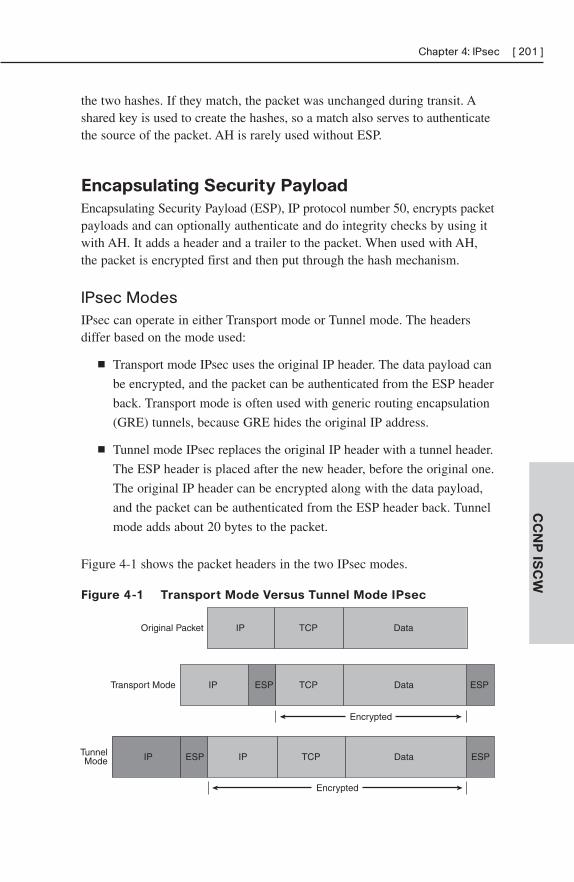
Chapter 4: IPsec [ 201 ]
CC
NP
ISC
W
the two hashes. If they match, the packet was unchanged during transit. Ashared key is used to create the hashes, so a match also serves to authenticatethe source of the packet. AH is rarely used without ESP.
Encapsulating Security Payload
Encapsulating Security Payload (ESP), IP protocol number 50, encrypts packetpayloads and can optionally authenticate and do integrity checks by using itwith AH. It adds a header and a trailer to the packet. When used with AH,the packet is encrypted first and then put through the hash mechanism.
IPsec ModesIPsec can operate in either Transport mode or Tunnel mode. The headersdiffer based on the mode used:
■ Transport mode IPsec uses the original IP header. The data payload can
be encrypted, and the packet can be authenticated from the ESP header
back. Transport mode is often used with generic routing encapsulation
(GRE) tunnels, because GRE hides the original IP address.
■ Tunnel mode IPsec replaces the original IP header with a tunnel header.
The ESP header is placed after the new header, before the original one.
The original IP header can be encrypted along with the data payload,
and the packet can be authenticated from the ESP header back. Tunnel
mode adds about 20 bytes to the packet.
Figure 4-1 shows the packet headers in the two IPsec modes.
Figure 4-1 Transport Mode Versus Tunnel Mode IPsec
Original Packet IP TCP Data
Transport Mode IP
IP IP
ESP
ESP
TCP
TCP
Data
Data
ESP
ESPTunnelMode
Encrypted
Encrypted
[ 202 ] CCNP ISCW Quick ReferenceC
CN
P I
SC
W
Tunnel mode ESP can cause problems when used with Network AddressTranslation (NAT). The original TCP or UDP header is encrypted andhidden, so there are no Layer 4 port numbers for NAT to use. NAT Traversaldetects the existence of a NAT device and adds a UDP header after thetunnel IP header. NAT can then use the port number in that UDP header.
Authentication MethodsSeveral authentication methods are supported with IPsec virtual privatenetworks (VPN):
■ Username and password
■ A one-time password
■ Biometric features, such as fingerprint
■ Preshared key values
■ Digital certificates
Encryption MethodsIPsec encryption uses key values to encrypt and decrypt data. Keys can beeither symmetric or asymmetric. Symmetric keys use the same value to bothencrypt and decrypt the data. These include DES, 3DES, and AES. Asymmetrickeys use one value to encrypt the data and another one to decrypt it. Diffie-Hellman and RSA use asymmetric keys.
Note
RSA is not an acronym—it is the initials of the last names of the algorithm’s inventors: RonRivest, Adi Shamir, and Len Adleman.
Symmetric Key Algorithms
DES uses a 56-bit key and can be broken fairly easily. It is a block cipher—it encrypts 64-bit blocks of data at a time.
3DES is also a block cipher, but it encrypts each block, decrypts it, and thenencrypts it again. A 56-bit key is used each time, thus equaling a key lengthof 168 bits. It is more secure than DES but also requires more processingpower.
Chapter 4: IPsec [ 203 ]
CC
NP
ISC
W
AES is a stronger block cipher encryption method than DES or 3DES. Ituses a 128-bit data block and a key length of 128, 192, or 256 bits. AES hasbeen approved for use with government classified data.
Asymmetric Key Algorithm
RSA uses asymmetric keys and can be used for signing messages andencrypting them. A public key is used to encrypt or sign the data. It can onlybe decrypted with a private key held by the receiver. RSA is slower thansymmetrical key algorithms, but more secure if a large enough key is used.A key length of 2048 bits is recommended.
Diffie-Hellman Key Exchange
The Diffie-Hellman protocol solves the problem of exchanging keys over aninsecure network. Each device creates a public key and a private key. Theyexchange their public keys in the open, unencrypted. They each then use theother device’s public key and their own private key to generate a sharedsecret key that each will use.
Key ManagementThe Public Key Infrastructure (PKI) manages encryption and identity infor-mation such as public keys and certificates. It consists of the followingcomponents:
■ Peer devices that need to communicate securely.
■ Digital certificates that validate the peer’s identity and transmit theirpublic key.
■ Certificate authorities (CA), also known as trustpoints, that grant,manage, and revoke certificates. This could be a third-party CA or aninternal one. Cisco has a Cisco IOS Certificate Server.
■ Optional registration authorities (RA) that handle certificate enroll-ment requests.
■ A way to distribute Certificate Revocation Lists (CRL), such as HTTPor Lightweight Directory Access Protocol (LDAP).
PKI credentials, such as RSA keys and digital certificates, can be stored in arouter’s nonvolatile random-access memory (NVRAM). They can also bestored in USB eTokens on routers that support them.
[ 204 ] CCNP ISCW Quick ReferenceC
CN
P I
SC
W
Establishing an IPsec VPNWhen IPsec establishes a VPN between two peer hosts, it sets up a securityassociation (SA) between them. SAs are unidirectional, so each bidirectionaldata session requires two. The Internet Security Association and KeyManagement Protocol (ISAKMP) defines how SAs are created and deleted.There are five basic steps:
Step 1. Interesting traffic arrives at the router—“Interesting” traffic isthat which should be sent over the VPN. This is specified by acrypto access list. Any traffic not identified as “interesting” issent in the clear, unprotected.
Step 2. Internet Key Exchange (IKE) Phase 1—Negotiates the algorithmsand hashes to use, authenticates the peers, and sets up anISAKMP SA. Has two modes: Main and Aggressive. Main modeuses three exchanges during Phase 1. Aggressive mode sends all the information in oneexchange. The proposed settings are contained in transform sets,which list the proposed encryption algorithm, authenticationalgorithm, key length, and mode. Multiple transform sets can bespecified, but both peers must have at least one matching trans-form set; otherwise, the session is torn down.
Step 3. IKE Phase 2—Uses the secure communication channel created inPhase 1 to set up the SAs for ESP/AH, negotiating the SA param-eters and settings to be used to protect the data transmitted.Periodically renegotiates the SAs. SAs have lifetimes that can bemeasured in either amount of data transferred or length of time.May do an additional Diffie-Hellman key exchange during Phase2.
Step 4. Data is transferred along the VPN between the two peers. It isencrypted by one peer and decrypted by the other, according tothe transform sets negotiated.
Step 5. Tunnel termination—the IPsec session drops either because ofdirect termination or timeout.
Configuring a Site-to-Site VPN Using
Cisco IOS CommandsConfiguring a site-to-site IPsec VPN using Cisco IOS commands requiressix steps, as follows:
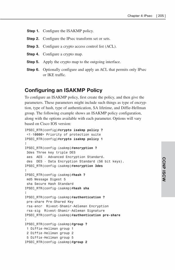
Chapter 4: IPsec [ 205 ]
CC
NP
ISC
W
Step 1. Configure the ISAKMP policy.
Step 2. Configure the IPsec transform set or sets.
Step 3. Configure a crypto access control list (ACL).
Step 4. Configure a crypto map.
Step 5. Apply the crypto map to the outgoing interface.
Step 6. Optionally configure and apply an ACL that permits only IPsecor IKE traffic.
Configuring an ISAKMP Policy
To configure an ISAKMP policy, first create the policy, and then give theparameters. These parameters might include such things as type of encryp-tion, type of hash, type of authentication, SA lifetime, and Diffie-Hellmangroup. The following example shows an ISAKMP policy configuration,along with the options available with each parameter. Options will varybased on Cisco IOS version:
IPSEC_RTR(config)#crypto isakmp policy ?<1-10000> Priority of protection suiteIPSEC_RTR(config)#crypto isakmp policy 1!IPSEC_RTR(config-isakmp)#encryption ?3des Three key triple DESaes AES - Advanced Encryption Standard.des DES - Data Encryption Standard (56 bit keys).IPSEC_RTR(config-isakmp)#encryption 3des! IPSEC_RTR(config-isakmp)#hash ?md5 Message Digest 5sha Secure Hash StandardIPSEC_RTR(config-isakmp)#hash sha!IPSEC_RTR(config-isakmp)#authentication ?pre-share Pre-Shared Keyrsa-encr Rivest-Shamir-Adleman Encryptionrsa-sig Rivest-Shamir-Adleman SignatureIPSEC_RTR(config-isakmp)#authentication pre-share!IPSEC_RTR(config-isakmp)#group ?1 Diffie-Hellman group 12 Diffie-Hellman group 25 Diffie-Hellman group 5IPSEC_RTR(config-isakmp)#group 2
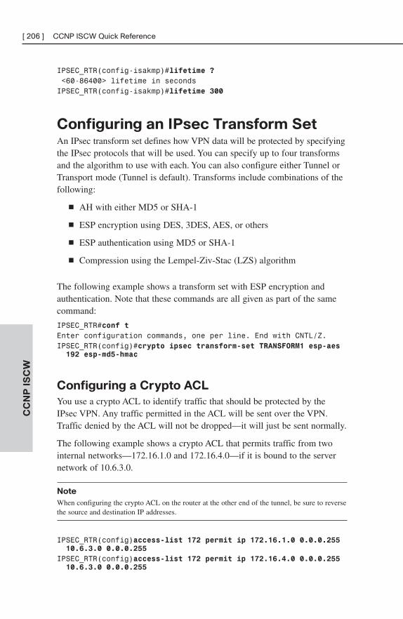
[ 206 ] CCNP ISCW Quick ReferenceC
CN
P I
SC
W
IPSEC_RTR(config-isakmp)#lifetime ?<60-86400> lifetime in secondsIPSEC_RTR(config-isakmp)#lifetime 300
Configuring an IPsec Transform SetAn IPsec transform set defines how VPN data will be protected by specifyingthe IPsec protocols that will be used. You can specify up to four transformsand the algorithm to use with each. You can also configure either Tunnel orTransport mode (Tunnel is default). Transforms include combinations of thefollowing:
■ AH with either MD5 or SHA-1
■ ESP encryption using DES, 3DES, AES, or others
■ ESP authentication using MD5 or SHA-1
■ Compression using the Lempel-Ziv-Stac (LZS) algorithm
The following example shows a transform set with ESP encryption andauthentication. Note that these commands are all given as part of the samecommand:
IPSEC_RTR#conf tEnter configuration commands, one per line. End with CNTL/Z.IPSEC_RTR(config)#crypto ipsec transform-set TRANSFORM1 esp-aes 192 esp-md5-hmac
Configuring a Crypto ACL
You use a crypto ACL to identify traffic that should be protected by theIPsec VPN. Any traffic permitted in the ACL will be sent over the VPN.Traffic denied by the ACL will not be dropped—it will just be sent normally.
The following example shows a crypto ACL that permits traffic from twointernal networks—172.16.1.0 and 172.16.4.0—if it is bound to the servernetwork of 10.6.3.0.
Note
When configuring the crypto ACL on the router at the other end of the tunnel, be sure to reversethe source and destination IP addresses.
IPSEC_RTR(config)access-list 172 permit ip 172.16.1.0 0.0.0.255 10.6.3.0 0.0.0.255
IPSEC_RTR(config)access-list 172 permit ip 172.16.4.0 0.0.0.255 10.6.3.0 0.0.0.255
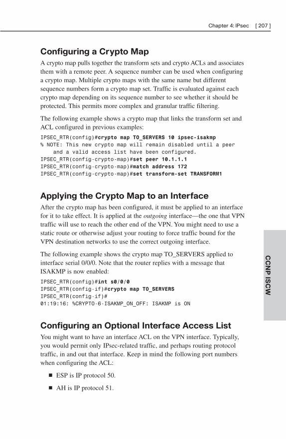
Chapter 4: IPsec [ 207 ]
CC
NP
ISC
W
Configuring a Crypto Map
A crypto map pulls together the transform sets and crypto ACLs and associatesthem with a remote peer. A sequence number can be used when configuringa crypto map. Multiple crypto maps with the same name but differentsequence numbers form a crypto map set. Traffic is evaluated against eachcrypto map depending on its sequence number to see whether it should beprotected. This permits more complex and granular traffic filtering.
The following example shows a crypto map that links the transform set andACL configured in previous examples:
IPSEC_RTR(config)#crypto map TO_SERVERS 10 ipsec-isakmp% NOTE: This new crypto map will remain disabled until a peer
and a valid access list have been configured.IPSEC_RTR(config-crypto-map)#set peer 10.1.1.1IPSEC_RTR(config-crypto-map)#match address 172IPSEC_RTR(config-crypto-map)#set transform-set TRANSFORM1
Applying the Crypto Map to an Interface
After the crypto map has been configured, it must be applied to an interfacefor it to take effect. It is applied at the outgoing interface—the one that VPNtraffic will use to reach the other end of the VPN. You might need to use astatic route or otherwise adjust your routing to force traffic bound for theVPN destination networks to use the correct outgoing interface.
The following example shows the crypto map TO_SERVERS applied tointerface serial 0/0/0. Note that the router replies with a message thatISAKMP is now enabled:
IPSEC_RTR(config)#int s0/0/0IPSEC_RTR(config-if)#crypto map TO_SERVERSIPSEC_RTR(config-if)#01:19:16: %CRYPTO-6-ISAKMP_ON_OFF: ISAKMP is ON
Configuring an Optional Interface Access List
You might want to have an interface ACL on the VPN interface. Typically,you would permit only IPsec-related traffic, and perhaps routing protocoltraffic, in and out that interface. Keep in mind the following port numberswhen configuring the ACL:
■ ESP is IP protocol 50.
■ AH is IP protocol 51.
[ 208 ] CCNP ISCW Quick ReferenceC
CN
P I
SC
W
■ IKE uses UDP port 500.
■ NAT Traversal uses UDP port 4500.
The source and destination addresses should be the IP addresses of theoutgoing VPN interfaces. The following example shows an ACL that permitsIPsec traffic between two hosts:
IPSEC_RTR(config)#access-list 101 permit ahp host 10.1.1.2 host 10.1.1.1
IPSEC_RTR(config)#access-list 101 permit esp host 10.1.1.2 host 10.1.1.1
IPSEC_RTR(config)#access-list 101 permit udp host 10.1.1.2 eq isakmp host 10.1.1.2
IPSEC_RTR(config)#access-list 101 permit udp host 10.1.1.2 host 10.1.1.2 eq isakmp
!IPSEC_RTR(config)#interface s 0/0/0IPSEC_RTR(config-if)#ip address 10.1.1.2 255.255.255.252IPSEC_RTR(config-if)#ip access-group 101 out
Configuring a Site-to-Site VPN Using
SDMCisco Security Device Manager (SDM) provides a graphical user interface(GUI) for configuring and monitoring your routers. It has wizards tosimplify common tasks and is designed to allow small to medium-size busi-nesses to easily deploy their routers. It comes with 800 to 3800 series routersat no extra charge. You can use the SDM to configure site-to-site VPNs,among other things.
The VPN Wizard comes with two IKE policies and an IPsec transform set. Italso has a way for you to enter information manually and edit configurationscreated by the wizard.
The Quick Setup Wizard requires just one screen. On it, you enter thefollowing information:
■ Outgoing interface
■ Peer IP address
■ Authentication information
■ What traffic to encrypt
Chapter 4: IPsec [ 209 ]
CC
NP
ISC
W
SDM then shows you a recap of the configuration. You click the Finishbutton to apply it.
You can also use the Step-by-step Setup Wizard, which leads you througheach of the tasks separately, letting you have more control over the settings.It also lets you review the completed configuration before applying it.
When the configuration is complete for one side of the tunnel, you can clickthe Generate Mirror button to generate a configuration for the router on theother side of the tunnel. When both routers are configured, the Test Tunnelbutton lets you verify that it is working. There is also a tab to monitor theVPN tunnel status.
Monitoring and Troubleshooting IPsec
VPNsSome useful Cisco IOS commands for monitoring your IPsec VPNs includethe following:
■ show crypto isakmp sa—This command shows all the IKE SAscurrently active on the router. Look for a status of QM_IDLE to verifythat the SA is active.
■ show crypto ipsec sa—This command shows the parameters used byeach SA and shows traffic flow. Look for the count of packets beingencrypted and decrypted, to verify the VPNs operation.
To troubleshoot VPN problems, first verify IP connectivity. If that exists,review your configuration one more time. If the configuration looks correcton both peers, you can view detailed information about the IKE negotiationsby using the command debug crypto isakmp.
Using GRE with IPsecGRE is a tunneling protocol that can support multiple Layer 3 protocols,such as IP, IPX, and AppleTalk. It also allows the use of multicast routingprotocols across the tunnel. It adds a 20-byte IP header and a 4-byte GRE header, hiding the existing packet headers. The GRE headercontains a Flag field, and a Protocol Type field to identify the Layer 3 proto-col being transported. It may optionally contain a tunnel checksum, tunnelkey, and tunnel sequence number. GRE does not encrypt traffic or use anystrong security measures to protect the traffic.
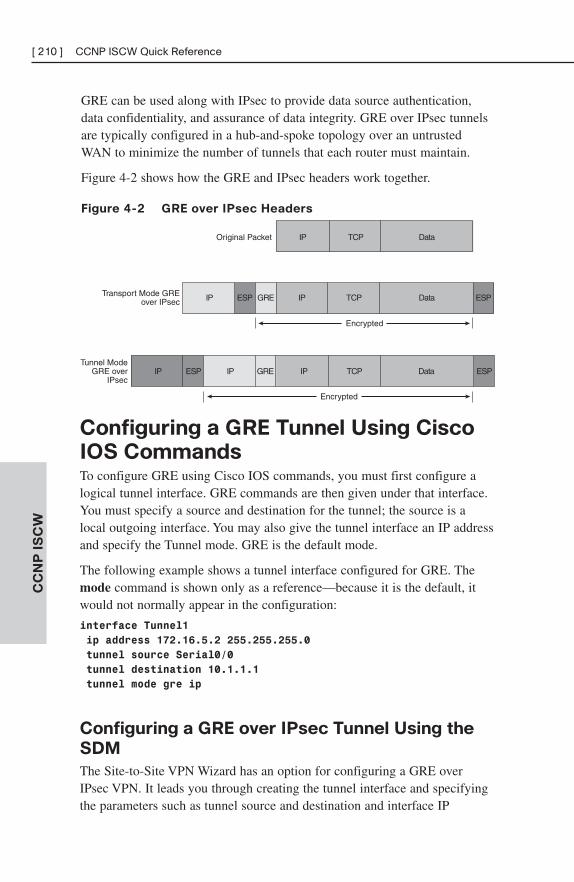
[ 210 ] CCNP ISCW Quick ReferenceC
CN
P I
SC
W
GRE can be used along with IPsec to provide data source authentication,data confidentiality, and assurance of data integrity. GRE over IPsec tunnelsare typically configured in a hub-and-spoke topology over an untrustedWAN to minimize the number of tunnels that each router must maintain.
Figure 4-2 shows how the GRE and IPsec headers work together.
Figure 4-2 GRE over IPsec Headers
Original Packet
Transport Mode GREover IPsec
Tunnel ModeGRE over
IPsec
Encrypted
Encrypted
IP
IP ESP
IP ESP IP GRE IP TCP Data ESP
GRE IP TCP Data ESP
TCP Data
Configuring a GRE Tunnel Using Cisco
IOS CommandsTo configure GRE using Cisco IOS commands, you must first configure alogical tunnel interface. GRE commands are then given under that interface.You must specify a source and destination for the tunnel; the source is alocal outgoing interface. You may also give the tunnel interface an IP addressand specify the Tunnel mode. GRE is the default mode.
The following example shows a tunnel interface configured for GRE. Themode command is shown only as a reference—because it is the default, itwould not normally appear in the configuration:
interface Tunnel1
ip address 172.16.5.2 255.255.255.0
tunnel source Serial0/0
tunnel destination 10.1.1.1
tunnel mode gre ip
Configuring a GRE over IPsec Tunnel Using the
SDM
The Site-to-Site VPN Wizard has an option for configuring a GRE overIPsec VPN. It leads you through creating the tunnel interface and specifyingthe parameters such as tunnel source and destination and interface IP
Chapter 4: IPsec [ 211 ]
CC
NP
ISC
W
address. The wizard also leads you through creating an optional backupGRE tunnel in case the primary one goes down.
Next, the IPsec parameters are presented. The wizard walks you throughcreating an IKE policy and transform set. You can either use the onesincluded with SDM or create new ones through the wizard.
You then have the option of configuring either static routing or the dynamicrouting protocols Enhanced Interior Gateway Routing Protocol (EIGRP) orOpen Shortest Path First (OSPF).
As before, the wizard shows a summary of the VPN configuration so thatyou can review it before applying it by clicking Finish. You can test thetunnel and monitor its status through SDM. Use the same show crypto anddebug commands shown earlier to verify and troubleshoot the VPN. In addi-tion, the show interfaces command shows the status of the logical tunnelinterface as the physical outgoing interface.
High-Availability VPNsFour typical types of failures that affect a VPN, and ways to mitigate them,are as follows:
■ Failure of an access link—Use multiple links to mitigate an accesslink failure.
■ Failure of a remote IPsec peer—Use multiple peers to mitigate aremote peer failure.
■ Failure of a VPN device—Use multiple devices in critical locations tomitigate a device failure.
■ Failure someplace along the Internet path—Provide multiple inde-pendent paths to mitigate a path failure.
Routers can use a routing protocol or IPsec’s Dead Peer Detection (DPD) todetect a failure across a VPN. Hot Standby Routing Protocol (HSRP),Virtual Router Redundancy Protocol (VRRP), and Gateway Load BalancingProtocol (GLBP) can detect local failures.
Detecting a Failure Using DPD
DPD sends periodic keepalives to its remote peer (similar to an older propri-etary Cisco IOS method called IKE Keepalives). Periodic keepalives helprouters quickly detect the failure of a remote peer, but they also mean more
[ 212 ] CCNP ISCW Quick ReferenceC
CN
P I
SC
W
packets to encrypt and decrypt. DPD has an on-demand option. If the routerneeds to send traffic and has not received anything from the peer recently, itsends a DPD message to verify the peer’s status. No messages are sent ifthere is no traffic.
You can configure multiple peers in a crypto map. Then, if DPD discoversthat the primary peer (designated by the default keyword) is down, IPsecremoves any SAs associated with that peer. It can then fail over to thebackup peer listed in the crypto map. Configure the router to use DPD withthe command crypto isakmp keepalive seconds [retries] [periodic | on-demand]. The periodic option causes the router to use keepalives, whereasthe on-demand option causes it to use on-demand DPD. If neither option isspecified, the IPsec peers negotiate the type of DPD.
Detecting a Failure Using HSRP
HSRP, VRRP, and GLBP are all protocols that allow multiple routers toshare a single IP address. They are typically used for default gateway redun-dancy on a local LAN. You can also use these protocols on a WAN-facinginterface. They use the shared, or virtual, IP address as the peer address forIPsec. Then, if the physical router fails, one of the other routers in the grouptakes over. The IPsec tunnel drops and is then reestablished using the samepeer IP address but a new physical router.
HSRP defines an active and a standby router, which form a standby group.The active router answers traffic to the virtual IP address. If it fails, thestandby router takes over. HSRP routers share a virtual MAC address, too.Determining the return path to a remote site can be a problem when usingHSRP at the headend. Either additionally configure HSRP on the internalinterfaces of the routers, or use Reverse Path Injection (RRI). RRI injectsremote networks into the internal routing protocol and is enabled with thecommand reverse-route in a crypto map.
Using IPsec Stateful Failover
DPD, routing protocols, and HSRP provide stateless failover—the tunneldrops and must be re-created if a peer fails. Stateful failover maintains SAinformation between an active and a failover device. It depends on twoprotocols:
■ HSRP—Tracks both the inside and outside interfaces. If either goesdown, it removes the router from active status, and ownership of theIPsec and IKE SAs passes to the standby router.
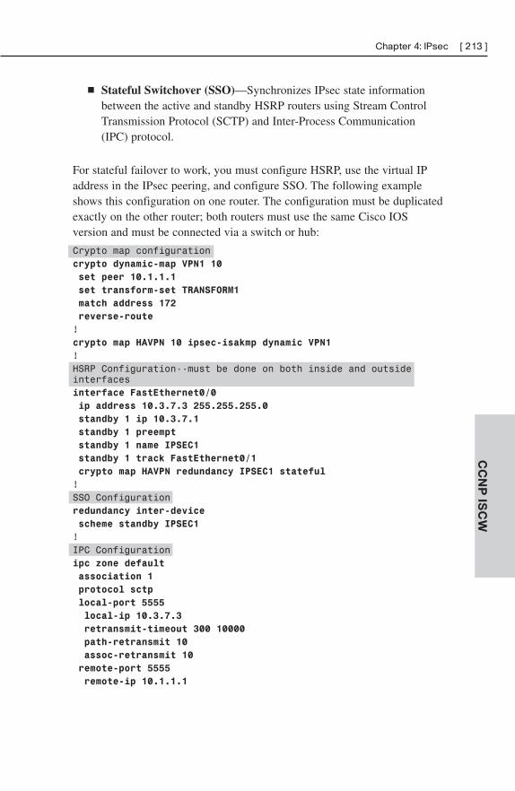
Chapter 4: IPsec [ 213 ]
CC
NP
ISC
W
■ Stateful Switchover (SSO)—Synchronizes IPsec state informationbetween the active and standby HSRP routers using Stream ControlTransmission Protocol (SCTP) and Inter-Process Communication(IPC) protocol.
For stateful failover to work, you must configure HSRP, use the virtual IPaddress in the IPsec peering, and configure SSO. The following exampleshows this configuration on one router. The configuration must be duplicatedexactly on the other router; both routers must use the same Cisco IOSversion and must be connected via a switch or hub:
Crypto map configurationcrypto dynamic-map VPN1 10
set peer 10.1.1.1
set transform-set TRANSFORM1
match address 172
reverse-route
!crypto map HAVPN 10 ipsec-isakmp dynamic VPN1
!HSRP Configuration--must be done on both inside and outsideinterfacesinterface FastEthernet0/0
ip address 10.3.7.3 255.255.255.0
standby 1 ip 10.3.7.1
standby 1 preempt
standby 1 name IPSEC1
standby 1 track FastEthernet0/1
crypto map HAVPN redundancy IPSEC1 stateful
!SSO Configurationredundancy inter-device
scheme standby IPSEC1
!IPC Configurationipc zone default
association 1
protocol sctp
local-port 5555
local-ip 10.3.7.3
retransmit-timeout 300 10000
path-retransmit 10
assoc-retransmit 10
remote-port 5555
remote-ip 10.1.1.1
[ 214 ] CCNP ISCW Quick ReferenceC
CN
P I
SC
W
Using an IPsec Tunnel as a Backup WAN Link
You can configure an IPsec VPN tunnel over the Internet as a backup to yourprimary WAN link. Switchover can use either an IGP or HSRP. Ensure thatthe primary WAN link is used when it is available by either adjusting therouting protocol metric or using floating static routes.
Cisco Easy VPNEasy VPN allows a server to push down VPN configuration to a client. It is away to create site-to-site VPNs without manually configuring each remoterouter. Therefore, it is good for remote sites without technical support. It canalso be used with software clients for remote users.
Cisco Easy VPN dynamically handles the following items:
■ Negotiating VPN tunnel parameters
■ Establishing the VPN tunnel based on those parameters
■ NAT, PAT, or ACL configuration
■ User authentication
■ Managing encryption and decryption keys
■ Authenticating, encrypting, and decrypting traffic
Cisco Easy VPN has two components: a server and a remote client. TheEasy VPN Server can be a Cisco router, PIX firewall, or Cisco VPN concen-trator. It contains security policies and pushes those to remote clients. TheEasy VPN Remote can be a Cisco router, PIX or ASA firewall, or a hardwareclient or a software client. It contacts the server and receives policies from itto establish the tunnel.
Establishing an Easy VPN IPsec Session
The steps in establishing an IPsec session differ slightly when using EasyVPN. They are as follows:
Step 1. The remote client contacts the server and begins IKE Phase 1. Ifpreshared keys are used, the client initiates Aggressive mode. Ifdigital certificates are used, the client initiates Main mode.
Step 2. The remote client attempts to establish an ISAKMP SA with theserver. It sends proposals with various combinations of hashes,authentication types, and Diffie-Hellman groups.
Chapter 4: IPsec [ 215 ]
CC
NP
ISC
W
Step 3. The server finds a match to one of the client’s proposals, acceptsit, and establishes an ISAKMP SA. The device is now authenticated.
Step 4. When using Extended Authentication (XAuth), the server issues ausername and password challenge. It checks the remote client’sresponse against a RADIUS or TACACS+ authentication, author-ization, and accounting (AAA) server, or uses tokens. The user isnow authenticated.
Step 5. The server pushes configuration parameters to the device. At aminimum, this must include an IP address.
Step 6. RRI creates a static route to the remote client.
Step 7. IPsec Quick mode is used to negotiate an IPsec SA. When this iscomplete, the VPN is established.
Using SDM to Configure the Easy VPN Server
You can use SDM to create and configure an Easy VPN Server. Beforebeginning, decide on the IKE authentication method, the user authenticationmethod, and the IP addressing scheme you will use. In addition, set up AAAservers or certification authority information, any needed DNS resolution forthe Easy VPN servers, and Network Time Protocol if needed for keyexchange. The tasks to create an Easy VPN server include the following:
■ Create a privileged user.
■ Configure an enable secret password.
■ Enable the router to use the AAA server’s database.
■ Use the SDM’s Easy VPN Wizard to configure the following:
■ The tunnel interface
■ IKE policies
■ RADIUS or TACACS+ policy lookup
■ User authentication
■ Local group policies
■ IPsec transform set
SDM enables you to test the configuration. In addition to crypto showcommands mentioned earlier in this chapter, the following Cisco IOScommands help in verifying and troubleshooting your configuration:
[ 216 ] CCNP ISCW Quick ReferenceC
CN
P I
SC
W
■ debug crypto isakmp—Shows IKE messages
■ debug aaa authentication—Shows user authentication messages
■ debug aaa authorization—Shows messages relating to group policyconfiguration
■ debug radius—Shows RADIUS messages
Configuring the Cisco VPN Client The Cisco VPN Client runs on a computer and communicates with an EasyVPN Server to create a VPN between the user and the server. Installing andconfiguring the Cisco VPN Client on a remote user’s computer requires thefollowing steps:
Step 1. Install the Cisco VPN Client software on the computer.
Step 2. Create at least one client connection entry. This includes config-uring the IP address of the server and preshared keys or certifi-cates. You can configure multiple connection entries, but only onecan be used at a time.
Step 3. Configure authentication parameters such as group authentica-tion, mutual group authentication, or certificate authentication.
Step 4. Configure transparent tunneling, which allows the tunnel to workthrough a router or firewall doing NAT or PAT. Access to localLAN resources, and the use of IPsec over UDP or TCP, can alsobe enabled here.
Step 5. Optionally add backup VPN servers.
Step 6. Configure the Internet connection. This can be either through ahome LAN, or through dialup using Microsoft Dial-UpNetworking or a local ISP.
CHAPTER 5
Cisco Device Hardening
Because of their important role in packet forwarding, Cisco routers makeattractive targets for network attacks. This chapter reviews how to hardenCisco devices against the most common types of attacks.
Mitigating Network AttacksBefore starting to harden Cisco devices against attack, you need to under-stand the types of attacks that are in common use today.
Cisco Self-Defending Network
The Cisco Self-Defending Network strategy consists of three interrelatedcomponents:
■ Secure connectivity—Virtual private network (VPN) solutions,including VPN-enabled routers, VPN concentrators, and VPN-enabledfirewalls
■ Threat defense—Cisco IOS-based and appliance-based firewalls
■ Trust and identity—Network Access Control (NAC), Cisco SecureAccess Control Server (ACS), and 802.1x
Types of Network Attacks
There are three major categories of network attacks:
■ Reconnaissance attacks—In reconnaissance attacks, the intruderattempts to gain information about a network, typically in preparationfor a more aggressive attack later. Methods used in reconnaissanceattacks include ping sweeps, installation of packet sniffers to gatherpasswords and other sensitive information, port scans to discovervulnerable services, and Internet information queries (Domain NameSystem [DNS] records, Internet Assigned Numbers Authority [IANA]records, search engine queries, and so on).
[ 218 ] CCNP ISCW Quick ReferenceC
CN
P I
SC
W
■ Access attacks—In access attacks, the intruder attempts to gain unau-thorized access to a network. Methods used in access attacks includepassword cracking or guessing, trust exploitation, port redirection,man-in-the-middle (MitM) attacks, buffer overflows, and attacksagainst network applications
■ Denial-of-service (DoS) attacks—In DoS attacks, the attacker tries todeny legitimate users access to a network resource. This might involvedestruction of a compromised network system (such as erasing harddrives or operating system files) or just flooding the resource withmore traffic than it can process. A DoS attack that is launched from alarge number of hosts simultaneously is called a distributed DoS(DDoS) attack. These types of attacks are usually the most difficult tomitigate.
Mitigating Reconnaissance Attacks
You can mitigate reconnaissance attacks in several ways:
■ Firewall and intrusion prevention system (IPS)—A firewall (eitherCisco IOS based or appliance based) is an effective way to stop pingsweeps, port scans, and other network probes. An IPS can detect andsometimes take countermeasures against these probes.
■ Authentication—Strong authentication is an effective way to defeatpassword sniffers. Use of two-factor authentication such as token cardsmakes it extremely difficult for an attacker to gather passwords with apacket sniffer because the password hashes expire continually.
■ Cryptography—Even with strong authentication, an attacker with apacket sniffer could still gather other sensitive information on thenetwork. Encrypting traffic with standards-based encryption protocolsprevents this.
■ Antisniffer tools—Several manufacturers offer tools designed todetect the presence of packet sniffers on a network.
■ Switched infrastructure—By isolating collision domains to individ-ual ports, switches make it more difficult for packet sniffers to findsensitive information. Advanced switch security tools such as DHCPinspection and dynamic Address Resolution Protocol (ARP) inspectionadd to this functionality.
Chapter 5: Cisco Device Hardening [ 219 ]
CC
NP
ISC
W
Mitigating Access Attacks
You can mitigate access attacks as follows:
■ Strong password security—A surprising number of access attacks arecarried out through simple password-guessing or brute-force dictionaryattacks against passwords. The use of encrypted or hashed authentica-tion protocols (for instance, Secure Shell [SSH] for terminal access,TACACS+ for authentication, authorization, and accounting [AAA])along with a strong password policy (requiring different passwords ondifferent systems, locking out accounts after a string of unsuccessfulattempts, and complex password requirements) greatly reduce theprobability of password access attacks.
■ Principle of minimum trust—Systems should not trust one anotherunnecessarily. A common trust exploitation attack occurs when aninside network host trusts a device in the demilitarized zone (DMZ). Ifan attacker is able to compromise the DMZ system, the DMZ systemcan be used as a stepping-stone to access and compromise the trustedinternal system. Secure network designs take this into account byensuring that inside systems do not trust DMZ systems uncondition-ally.
■ Cryptography—The MitM attack, in which an attacker insertshimself between two trusted hosts and impersonates both to gathersensitive information, can be thwarted only by using cryptography inthe communications channel between the trusted hosts.
Mitigating Denial-of-Service Attacks
DoS attacks are difficult to stop. Companies with a high-profile Internetpresence should plan in advance their responses to potential DoS attacks.Historically, many DoS attacks were sourced from spoofed source addresses.These types of attacks can be thwarted through use of antispoofing accesslists on border routers and firewalls. Today, however, many DoS attacks arecarried out by distributed networks of real hosts that have been compromisedfor the purpose of building attack networks. Mitigating a large DoS or DDoSattack typically requires careful diagnostics, planning, and cooperation fromInternet service providers (ISP).
[ 220 ] CCNP ISCW Quick ReferenceC
CN
P I
SC
W
Disabling Unused Cisco Router
Network Services and InterfacesIn any network security strategy, you need to identify and deactivate servicesthat are on by default but not actually used. This section discusses deactivatingthese services on Cisco routers.
Unused Router Interfaces
Attacks can exploit active, unused router interfaces to gain access to a routeror to gather information about it. Disable unused router interfaces with theshutdown command.
Vulnerable Router Services
The following services have the potential to be exploited by attackers undercertain conditions. If they are not required on a particular router, ensure thatthey are disabled. Remember, however, that many of these services performimportant functions in some networks; they should only be disabled afterconsidering the potential drawbacks of doing so:
■ BOOTP server—Enabled by default. Disable with the no ip bootpserver command.
■ Cisco Discovery Protocol (CDP)—Enabled by default for most interface types. Disable on interfaces where not needed with the nocdp enable command.
■ Configuration auto-loading—Disabled by default.
■ FTP/TFTP servers—Disabled by default.
■ Network Time Protocol (NTP)—Disabled by default, but necessaryfor many security features.
■ Packet assembler/disassembler (PAD) Service—Enabled by default.Disable with the no service pad command.
■ TCP and UDP small servers—For example, Echo, Chargen, Discard,Daytime. Disabled by default.
■ Maintenance Operations Protocol (MOP) service—Enabled forsome Ethernet interfaces by default.
■ Simple Network Management Protocol (SNMP)—Disabled bydefault, but widely used.
Chapter 5: Cisco Device Hardening [ 221 ]
CC
NP
ISC
W
■ HTTP—Enabled by default. Disable with the no ip http server globalcommand if not needed.
■ DNS—Disabled by default.
■ Internet Control Message Protocol (ICMP) redirects—Enabled bydefault. Disable with the no ip redirects command if not needed.
■ IP source routing—Enabled by default. Disable with the no ipsource-route command.
■ Finger service—Disabled by default.
■ ICMP unreachables—Enabled by default. Disable with the no ipunreachables command if not needed.
■ ICMP mask reply—Disabled by default.
■ TCP keepalives—Disabled by default. Enable with the service tcp-keepalives command.
■ Proxy ARP—Enabled by default. Disable with the no ip proxy-arpcommand if unneeded.
■ IP directed broadcasts—Disabled by default.
Hardening with AutoSecure
AutoSecure is a feature found in Cisco IOS Release 12.3T and later thatautomates many of the tasks involved in hardening a router. It can be oper-ated in either Interactive mode or in Noninteractive mode. Interactive modeprompts the user with questions regarding security features such as enablingand disabling services. Noninteractive mode automatically hardens the routeraccording to Cisco-recommended guidelines.
AutoSecure can selectively lock down the router with the following features:
■ Management plane features, including disabling unneeded services
■ Forwarding plane features, such as Cisco Express Forwarding (CEF)and basic access control lists (ACL)
■ Cisco IOS Firewall services
■ Login and password security
■ NTP
■ SSH
■ TCP Intercept
[ 222 ] CCNP ISCW Quick ReferenceC
CN
P I
SC
W
Configuring AutoSecure
In Cisco IOS Release 12.3(8)T and later, AutoSecure retains the pre-lock-down configuration in Flash under the name pre_autosec.cfg. If AutoSecureconfiguration fails, you can revert to the pre-lockdown configuration withthe command configure replace flash:pre_autosec.cfg.
AutoSecure is initiated from the command-line interface (CLI) with the autosecure command. The management, forwarding, ntp, ssh, firewall, andtcp-intercept arguments activate the features described in the preceding list.By default, the AutoSecure script interactively prompts the user with ques-tions about each feature that it configures. To switch to Noninteractive mode,add the no-interact keyword to the auto secure command.
Security Device Manager
The Security Device Manager (SDM) is a web-based security configurationtool that runs on Cisco routers. You can use it to lock down a router in a waysimilar to the AutoSecure script. You can also use it to audit an existingconfiguration for compliance with Cisco security recommendations.
Securing Cisco Router Installations and
Administrative Access
Password-Creation Rules
Cisco router passwords are subject to the following restrictions:
■ 1 to 25 characters in length
■ Can include any alphanumeric characters, symbols, and spaces
■ Cannot have a number as the first character
■ Leading spaces ignored, but subsequent spaces (including trailingspaces) not ignored
Types of Router Passwords
Many different types of passwords are used for Cisco IOS routers. The mostcommon ones are described here:
Chapter 5: Cisco Device Hardening [ 223 ]
CC
NP
ISC
W
■ Enable secret—The enable secret controls access to privileged EXECmode on the router. The password is stored in a nonreversible one-wayMessage Digest 5 (MD5) hash. If the enable secret is present in theconfiguration, it overrides the enable password. To configure theenable secret password, use the enable secret password command.
■ Enable password—The enable password controls access to privilegedEXEC mode on the router if the enable secret command is notpresent. The enable password is stored in clear text in the configura-tion, unless the service password-encryption command is present. Toconfigure the enable password, use the enable password passwordcommand.
■ Line passwords—Access to a router’s tty lines can be controlledeither with AAA or with individual passwords applied to the lines.AAA configuration is discussed later. To configure individual pass-words on a TTY line, use the password password command in lineconfiguration mode. Line passwords are stored in clear text in theconfiguration, unless the service password-encryption command ispresent. tty lines include the console port, vty lines for Telnet/SSHaccess, the AUX port, as well as regular tty lines. The login commandmust also be present in the line configuration for password prompts tobe displayed.
Password-Length Enforcement
You can globally set a minimum length for all router passwords with thesecurity passwords min-length length command.
Password Encryption
Many types of passwords are stored in clear text in the configuration, bydefault. To prevent casual discovery of these passwords, use the servicepassword-encryption command. Software to decrypt passwords that areciphered with this command is widely available on the Internet, so it shouldnot be relied on to protect highly sensitive passwords.
Enhanced Username Password Security
When configuring a local username/password database on a router, use theusername username secret password command. This protects the passwordwith a MD5 hash rather than plain text or weak Type 7 encryption.
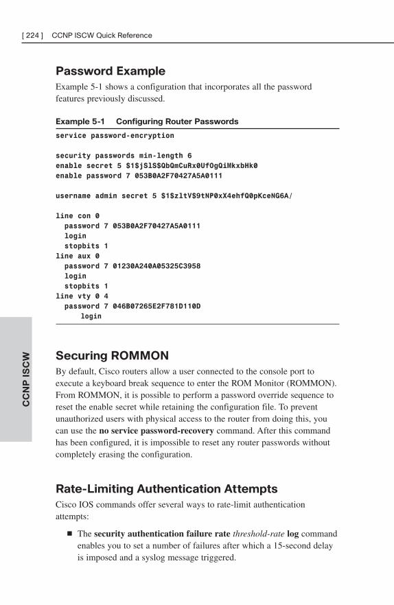
[ 224 ] CCNP ISCW Quick ReferenceC
CN
P I
SC
W
Password Example
Example 5-1 shows a configuration that incorporates all the passwordfeatures previously discussed.
Example 5-1 Configuring Router Passwords
service password-encryption
security passwords min-length 6
enable secret 5 $1$jSlS$QbQmCuRx0UfOgQiMkxbHk0
enable password 7 053B0A2F70427A5A0111
username admin secret 5 $1$zltV$9tNP0xX4ehfQ0pKceNG6A/
line con 0
password 7 053B0A2F70427A5A0111
login
stopbits 1
line aux 0
password 7 01230A240A05325C3958
login
stopbits 1
line vty 0 4
password 7 046B07265E2F781D110D
login
Securing ROMMON
By default, Cisco routers allow a user connected to the console port toexecute a keyboard break sequence to enter the ROM Monitor (ROMMON).From ROMMON, it is possible to perform a password override sequence toreset the enable secret while retaining the configuration file. To preventunauthorized users with physical access to the router from doing this, youcan use the no service password-recovery command. After this commandhas been configured, it is impossible to reset any router passwords withoutcompletely erasing the configuration.
Rate-Limiting Authentication Attempts
Cisco IOS commands offer several ways to rate-limit authenticationattempts:
■ The security authentication failure rate threshold-rate log commandenables you to set a number of failures after which a 15-second delayis imposed and a syslog message triggered.
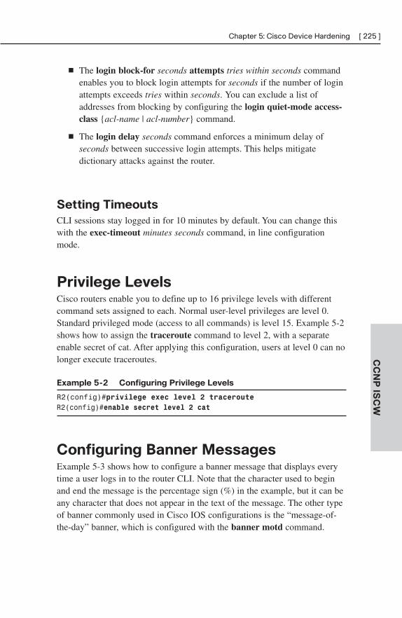
Chapter 5: Cisco Device Hardening [ 225 ]
CC
NP
ISC
W
■ The login block-for seconds attempts tries within seconds commandenables you to block login attempts for seconds if the number of loginattempts exceeds tries within seconds. You can exclude a list ofaddresses from blocking by configuring the login quiet-mode access-class {acl-name | acl-number} command.
■ The login delay seconds command enforces a minimum delay ofseconds between successive login attempts. This helps mitigatedictionary attacks against the router.
Setting Timeouts
CLI sessions stay logged in for 10 minutes by default. You can change thiswith the exec-timeout minutes seconds command, in line configurationmode.
Privilege LevelsCisco routers enable you to define up to 16 privilege levels with differentcommand sets assigned to each. Normal user-level privileges are level 0.Standard privileged mode (access to all commands) is level 15. Example 5-2shows how to assign the traceroute command to level 2, with a separateenable secret of cat. After applying this configuration, users at level 0 can nolonger execute traceroutes.
Example 5-2 Configuring Privilege Levels
R2(config)#privilege exec level 2 tracerouteR2(config)#enable secret level 2 cat
Configuring Banner MessagesExample 5-3 shows how to configure a banner message that displays everytime a user logs in to the router CLI. Note that the character used to beginand end the message is the percentage sign (%) in the example, but it can beany character that does not appear in the text of the message. The other typeof banner commonly used in Cisco IOS configurations is the “message-of-the-day” banner, which is configured with the banner motd command.
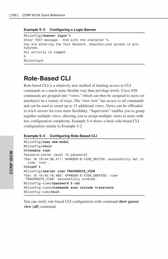
[ 226 ] CCNP ISCW Quick ReferenceC
CN
P I
SC
W
Example 5-3 Configuring a Login Banner
R2(config)#banner login %Enter TEXT message. End with the character %.You are entering the Test Network. Unauthorized access is pro-hibited.All activity is logged.%R2(config)#
Role-Based CLIRole-based CLI is a relatively new method of limiting access to CLIcommands in a much more flexible way than privilege levels. Cisco IOScommands are grouped into “views,” which can then be assigned to users (orinterfaces) in a variety of ways. The “root view” has access to all commandsand can be used to create up to 15 additional views. Views can be offloadedto AAA servers for even more flexibility. “Superviews” enables you to grouptogether multiple views, allowing you to assign multiple views to users withless configuration complexity. Example 5-4 shows a basic role-based CLIconfiguration similar to Example 5-2.
Example 5-4 Configuring Role-Based CLI
R2(config)#aaa new-modelR2(config)#exitR2#enable viewPassword:[enter level 15 password]*Dec 16 19:44:39.411: %PARSER-6-VIEW_SWITCH: successfully set to view ‘root’.
R2#conf tR2(config)#parser view TRACEROUTE_VIEW*Dec 16 19:45:16.403: %PARSER-6-VIEW_CREATED: view‘TRACEROUTE_VIEW’ successfully created.R2(config-view)#password 5 catR2(config-view)#commands exec include tracerouteR2(config-view)#exit
You can verify role-based CLI configuration with command show parserview [all] command.
Chapter 5: Cisco Device Hardening [ 227 ]
CC
NP
ISC
W
Cisco IOS Resilient ConfigurationThe Cisco IOS Resilient Configuration feature allows for faster recovery insituations in which an attacker has compromised a router and erased itsCisco IOS image / configuration file. This feature is available only on plat-forms with PCMCIA ATA Flash drives. When enabled, this feature savesnonerasable copies of the running Cisco IOS image and running configura-tion to the Flash drive. If the configuration / Cisco IOS image is then erased,the secure backup copy of the Cisco IOS image can be booted fromROMMON. After the boot, you can restore the secure backup copy of theconfiguration from the Flash drive.
Mitigating Threats and Attacks with
Access Lists
ACL Review
Standard access lists (standard ACLs) allow filtering based on source IPaddress only. Extended access lists (extended ACLs) allow filtering based on source or destination address and most other fields in the IP packetheader (Layer 4 protocol type, source/destination port number, IP options,Differentiated Services Code Point [DSCP] values, fragmentation parame-ters, and so on).
Access lists can be either numbered or named. Numbered standard ACLshave numbers from 1 to 99 or 1300 to 1999. Numbered extended ACLs havenumbers from 100 to 199 or 2000 to 2699.
You can apply access lists either inbound or outbound on an interface.Inbound ACLs affect traffic moving toward the interface. Outbound ACLsaffect traffic leaving the interface.
Access lists are used extensively in router security configurations for permit-ting or denying access to services, mitigating address spoofing, mitigatingvarious attack types, and more.
Mitigating Spoofed Addresses (Inbound)
You can use access lists to prevent packets with spoofed source addressesfrom entering your network. When configuring inbound antispoof ACLs, youshould deny packets from, at a minimum, the following:
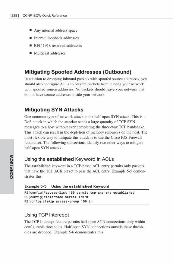
[ 228 ] CCNP ISCW Quick ReferenceC
CN
P I
SC
W
■ Any internal address space
■ Internal loopback addresses
■ RFC 1918 reserved addresses
■ Multicast addresses
Mitigating Spoofed Addresses (Outbound)
In addition to dropping inbound packets with spoofed source addresses, youshould also configure ACLs to prevent packets from leaving your networkwith spoofed source addresses. No packets should leave your network thatdo not have source addresses inside your network.
Mitigating SYN Attacks
One common type of network attack is the half-open SYN attack. This is aDoS attack in which the attacker sends a large quantity of TCP SYNmessages to a host without ever completing the three-way TCP handshake.This attack can result in the depletion of memory resources on the host. Themost flexible way to mitigate this attack is to use the Cisco IOS Firewallfeature set. The following subsections identify two other ways to mitigatehalf-open SYN attacks.
Using the established Keyword in ACLsThe established keyword in a TCP-based ACL entry permits only packetsthat have the TCP ACK bit set to pass the ACL entry. Example 5-5 demon-strates this.
Example 5-5 Using the established Keyword
R2(config)#access-list 150 permit tcp any any establishedR2(config)#interface serial 1/0/0R2(config-if)#ip access-group 150 in
Using TCP InterceptThe TCP Intercept feature permits half-open SYN connections only withinconfigurable thresholds. Half-open SYN connections outside these thresh-olds are dropped. Example 5-6 demonstrates this.
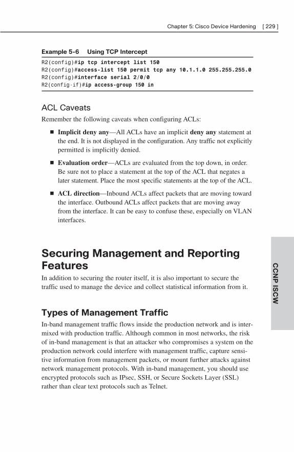
Chapter 5: Cisco Device Hardening [ 229 ]
CC
NP
ISC
W
Example 5-6 Using TCP Intercept
R2(config)#ip tcp intercept list 150R2(config)#access-list 150 permit tcp any 10.1.1.0 255.255.255.0R2(config)#interface serial 2/0/0R2(config-if)#ip access-group 150 in
ACL CaveatsRemember the following caveats when configuring ACLs:
■ Implicit deny any—All ACLs have an implicit deny any statement atthe end. It is not displayed in the configuration. Any traffic not explicitlypermitted is implicitly denied.
■ Evaluation order—ACLs are evaluated from the top down, in order.Be sure not to place a statement at the top of the ACL that negates alater statement. Place the most specific statements at the top of the ACL.
■ ACL direction—Inbound ACLs affect packets that are moving towardthe interface. Outbound ACLs affect packets that are moving awayfrom the interface. It can be easy to confuse these, especially on VLANinterfaces.
Securing Management and Reporting
FeaturesIn addition to securing the router itself, it is also important to secure thetraffic used to manage the device and collect statistical information from it.
Types of Management Traffic
In-band management traffic flows inside the production network and is inter-mixed with production traffic. Although common in most networks, the riskof in-band management is that an attacker who compromises a system on theproduction network could interfere with management traffic, capture sensi-tive information from management packets, or mount further attacks againstnetwork management protocols. With in-band management, you should useencrypted protocols such as IPsec, SSH, or Secure Sockets Layer (SSL)rather than clear text protocols such as Telnet.
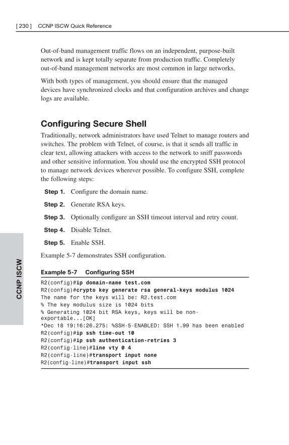
[ 230 ] CCNP ISCW Quick ReferenceC
CN
P I
SC
W
Out-of-band management traffic flows on an independent, purpose-builtnetwork and is kept totally separate from production traffic. Completely out-of-band management networks are most common in large networks.
With both types of management, you should ensure that the manageddevices have synchronized clocks and that configuration archives and changelogs are available.
Configuring Secure Shell
Traditionally, network administrators have used Telnet to manage routers andswitches. The problem with Telnet, of course, is that it sends all traffic inclear text, allowing attackers with access to the network to sniff passwordsand other sensitive information. You should use the encrypted SSH protocolto manage network devices wherever possible. To configure SSH, completethe following steps:
Step 1. Configure the domain name.
Step 2. Generate RSA keys.
Step 3. Optionally configure an SSH timeout interval and retry count.
Step 4. Disable Telnet.
Step 5. Enable SSH.
Example 5-7 demonstrates SSH configuration.
Example 5-7 Configuring SSH
R2(config)#ip domain-name test.comR2(config)#crypto key generate rsa general-keys modulus 1024The name for the keys will be: R2.test.com% The key modulus size is 1024 bits% Generating 1024 bit RSA keys, keys will be non-exportable...[OK]*Dec 18 19:16:26.275: %SSH-5-ENABLED: SSH 1.99 has been enabledR2(config)#ip ssh time-out 10R2(config)#ip ssh authentication-retries 3R2(config-line)#line vty 0 4R2(config-line)#transport input noneR2(config-line)#transport input ssh
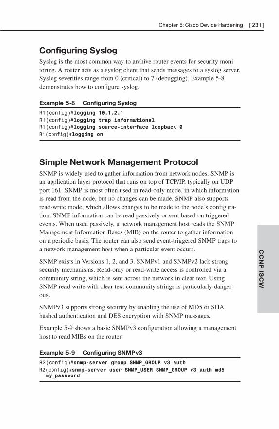
Chapter 5: Cisco Device Hardening [ 231 ]
CC
NP
ISC
W
Configuring Syslog
Syslog is the most common way to archive router events for security moni-toring. A router acts as a syslog client that sends messages to a syslog server.Syslog severities range from 0 (critical) to 7 (debugging). Example 5-8demonstrates how to configure syslog.
Example 5-8 Configuring Syslog
R1(config)#logging 10.1.2.1R1(config)#logging trap informationalR1(config)#logging source-interface loopback 0R1(config)#logging on
Simple Network Management Protocol
SNMP is widely used to gather information from network nodes. SNMP isan application layer protocol that runs on top of TCP/IP, typically on UDPport 161. SNMP is most often used in read-only mode, in which informationis read from the node, but no changes can be made. SNMP also supportsread-write mode, which allows changes to be made to the node’s configura-tion. SNMP information can be read passively or sent based on triggeredevents. When used passively, a network management host reads the SNMPManagement Information Bases (MIB) on the router to gather informationon a periodic basis. The router can also send event-triggered SNMP traps toa network management host when a particular event occurs.
SNMP exists in Versions 1, 2, and 3. SNMPv1 and SNMPv2 lack strongsecurity mechanisms. Read-only or read-write access is controlled via acommunity string, which is sent across the network in clear text. UsingSNMP read-write with clear text community strings is particularly danger-ous.
SNMPv3 supports strong security by enabling the use of MD5 or SHAhashed authentication and DES encryption with SNMP messages.
Example 5-9 shows a basic SNMPv3 configuration allowing a managementhost to read MIBs on the router.
Example 5-9 Configuring SNMPv3
R2(config)#snmp-server group SNMP_GROUP v3 authR2(config)#snmp-server user SNMP_USER SNMP_GROUP v3 auth md5 my_password
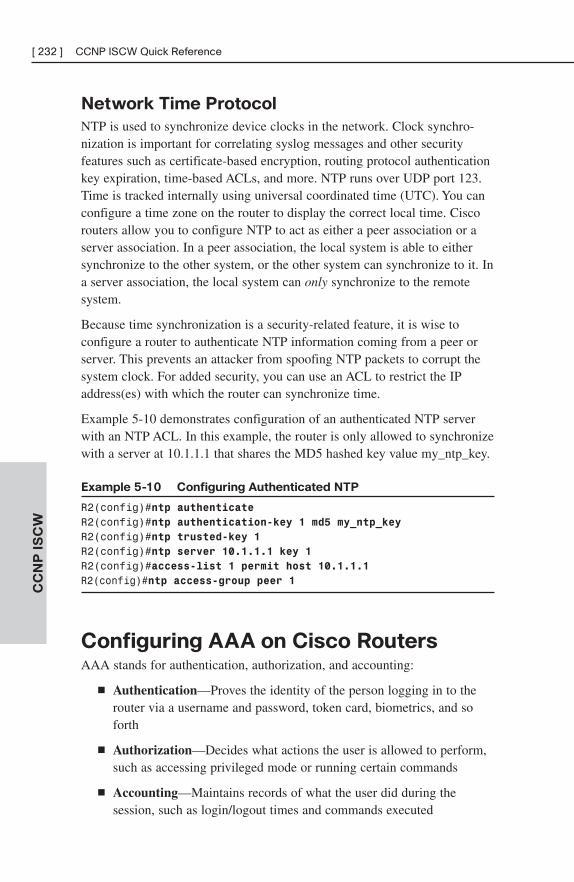
[ 232 ] CCNP ISCW Quick ReferenceC
CN
P I
SC
W
Network Time Protocol
NTP is used to synchronize device clocks in the network. Clock synchro-nization is important for correlating syslog messages and other securityfeatures such as certificate-based encryption, routing protocol authenticationkey expiration, time-based ACLs, and more. NTP runs over UDP port 123.Time is tracked internally using universal coordinated time (UTC). You canconfigure a time zone on the router to display the correct local time. Ciscorouters allow you to configure NTP to act as either a peer association or aserver association. In a peer association, the local system is able to eithersynchronize to the other system, or the other system can synchronize to it. Ina server association, the local system can only synchronize to the remotesystem.
Because time synchronization is a security-related feature, it is wise toconfigure a router to authenticate NTP information coming from a peer orserver. This prevents an attacker from spoofing NTP packets to corrupt thesystem clock. For added security, you can use an ACL to restrict the IPaddress(es) with which the router can synchronize time.
Example 5-10 demonstrates configuration of an authenticated NTP serverwith an NTP ACL. In this example, the router is only allowed to synchronizewith a server at 10.1.1.1 that shares the MD5 hashed key value my_ntp_key.
Example 5-10 Configuring Authenticated NTP
R2(config)#ntp authenticateR2(config)#ntp authentication-key 1 md5 my_ntp_keyR2(config)#ntp trusted-key 1R2(config)#ntp server 10.1.1.1 key 1R2(config)#access-list 1 permit host 10.1.1.1R2(config)#ntp access-group peer 1
Configuring AAA on Cisco RoutersAAA stands for authentication, authorization, and accounting:
■ Authentication—Proves the identity of the person logging in to therouter via a username and password, token card, biometrics, and soforth
■ Authorization—Decides what actions the user is allowed to perform,such as accessing privileged mode or running certain commands
■ Accounting—Maintains records of what the user did during thesession, such as login/logout times and commands executed
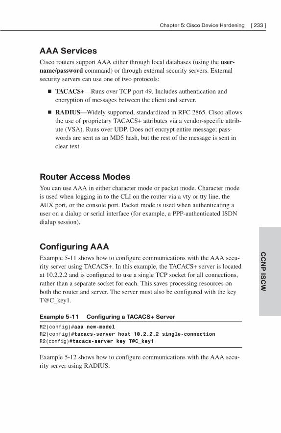
Chapter 5: Cisco Device Hardening [ 233 ]
CC
NP
ISC
W
AAA Services
Cisco routers support AAA either through local databases (using the user-name/password command) or through external security servers. Externalsecurity servers can use one of two protocols:
■ TACACS+—Runs over TCP port 49. Includes authentication andencryption of messages between the client and server.
■ RADIUS—Widely supported, standardized in RFC 2865. Cisco allowsthe use of proprietary TACACS+ attributes via a vendor-specific attrib-ute (VSA). Runs over UDP. Does not encrypt entire message; pass-words are sent as an MD5 hash, but the rest of the message is sent inclear text.
Router Access Modes
You can use AAA in either character mode or packet mode. Character modeis used when logging in to the CLI on the router via a vty or tty line, theAUX port, or the console port. Packet mode is used when authenticating auser on a dialup or serial interface (for example, a PPP-authenticated ISDNdialup session).
Configuring AAA
Example 5-11 shows how to configure communications with the AAA secu-rity server using TACACS+. In this example, the TACACS+ server is locatedat 10.2.2.2 and is configured to use a single TCP socket for all connections,rather than a separate socket for each. This saves processing resources onboth the router and server. The server must also be configured with the keyT@C_key1.
Example 5-11 Configuring a TACACS+ Server
R2(config)#aaa new-modelR2(config)#tacacs-server host 10.2.2.2 single-connectionR2(config)#tacacs-server key T@C_key1
Example 5-12 shows how to configure communications with the AAA secu-rity server using RADIUS:
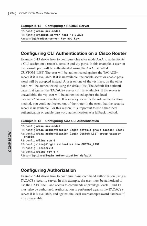
[ 234 ] CCNP ISCW Quick ReferenceC
CN
P I
SC
W
Example 5-12 Configuring a RADIUS Server
R2(config)#aaa new-modelR2(config)#radius-server host 10.3.3.3R2(config)#radius-server key R@D_key1
Configuring CLI Authentication on a Cisco Router
Example 5-13 shows how to configure character mode AAA to authenticatea CLI session on a router’s console and vty ports. In this example, a user onthe console port will be authenticated using the AAA list calledCUSTOM_LIST. The user will be authenticated against the TACACS+server if it is available. If it is unavailable, the enable secret or enable pass-word will be accepted instead. A user on one of the vty lines, on the otherhand, will be authenticated using the default list. The default list authenti-cates first against the TACACS+ server (if it is available). If the server isunavailable, the vty user will be authenticated against the localusername/password database. If a security server is the sole authenticationmethod, you could get locked out of the router in the event that the securityserver is unavailable. For this reason, it is important to use either localauthentication or enable password authentication as a fallback method.
Example 5-13 Configuring AAA CLI Authentication
R2(config)#aaa new-modelR2(config)#aaa authentication login default group tacacs+ localR2(config)#aaa authentication login CUSTOM_LIST group tacacs+ enable
R2(config)#line con 0R2(config-line)#login authentication CUSTOM_LISTR2(config-line)#exitR2(config)#line vty 0 4R2(config-line)#login authentication default
Configuring Authorization
Example 5-14 shows how to configure basic command authorization using aTACACS+ security server. In this example, the user must be authorized touse the EXEC shell, and access to commands at privilege levels 1 and 15must also be authorized. Authorization is performed against the TACACS+server if it is available, and against the local username/password database ifit is unavailable.
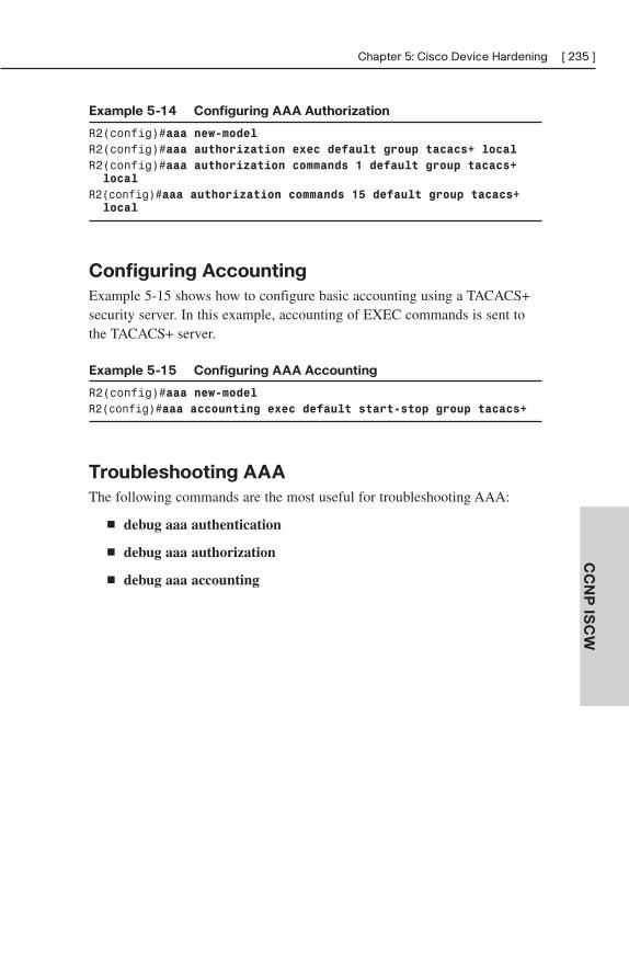
Chapter 5: Cisco Device Hardening [ 235 ]
CC
NP
ISC
W
Example 5-14 Configuring AAA Authorization
R2(config)#aaa new-modelR2(config)#aaa authorization exec default group tacacs+ localR2(config)#aaa authorization commands 1 default group tacacs+ local
R2(config)#aaa authorization commands 15 default group tacacs+ local
Configuring Accounting
Example 5-15 shows how to configure basic accounting using a TACACS+security server. In this example, accounting of EXEC commands is sent tothe TACACS+ server.
Example 5-15 Configuring AAA Accounting
R2(config)#aaa new-modelR2(config)#aaa accounting exec default start-stop group tacacs+
Troubleshooting AAA
The following commands are the most useful for troubleshooting AAA:
■ debug aaa authentication
■ debug aaa authorization
■ debug aaa accounting
CHAPTER 6
Cisco IOS Threat Defenses
The router-hardening techniques discussed in Chapter 5, “Cisco DeviceHardening,” help to protect the router against many types of infrastructureattacks. The Cisco IOS Firewall feature set enables you to integrate a statefulfirewall and an intrusion prevention system (IPS) to protect end stationslocated behind the router.
DMZ Design ReviewA demilitarized zone (DMZ) is an intermediate network between an organi-zation’s “inside” network and the “outside” world. Most organizations use aDMZ to host their Internet-accessible devices, such as web servers or mailservers. Some type of security system (for example, stateful firewall, filter-ing router, application layer gateway) filters packets traveling between theoutside world and the systems in the DMZ, and between the DMZ and theinside network. Depending on the design, there can be one filtering devicethat performs both functions or two separate devices.
Traffic initiated from the outside world should be filtered so that all traffic tononessential services is dropped. If possible, the systems in the DMZ shouldnot be allowed to initiate conversations with systems on the inside; allcommunications between the inside and the DMZ should be initiated fromthe inside. This reduces the probability of a trust exploitation attack in theevent that an attacker compromises a DMZ system.
Firewall TechnologiesA variety of firewall technologies exist:
■ Packet filtering—A packet filter (such as an access list on a router)permits or denies packets based in information in the Layer 3 or Layer4 packet headers.
■ Application layer gateway—An application layer gateway (ALG) is apiece of software that intercepts application layer requests between theendpoints of a network conversation. The ALG typically passesrequests from a client to a server and vice versa after inspecting the
Chapter 6: Cisco IOS Threat Defenses [ 237 ]
CC
NP
ISC
W
application layer packets to ensure that they pass configured securitycriteria. In some circumstances, the ALG may change the contents ofpackets moving in either direction.
■ Stateful packet filtering—A stateful packet filter combines aspects ofa packet filter and an ALG. The attributes of each communicationssession are maintained in a state table. Only packets whose attributesmatch the rules of the state table are permitted to pass. For example,an HTTP response packet would typically only be allowed to pass if itis a response to a query packet that was previously permitted by thefirewall. Modern stateful packet filters are also capable of trackingcomplex information about application sessions. For example, a Voiceover IP (VoIP)-aware stateful firewall would typically be able to“know” that it should dynamically open UDP ports for a Real-timeTransport Protocol (RTP) session based on information gained fromexamining the call setup traffic that takes place inside various call-control protocols.
Cisco IOS FirewallThe Cisco IOS Firewall is a stateful packet filter that is built in to Cisco IOSsecurity images. Some of its features include the ability to dynamically alterrouter access control lists (ACL) to permit return traffic for sessions origi-nated on the inside, the ability to track TCP sequence numbers and permitonly expected TCP traffic, and the ability to mitigate some types of TCP-based and IP fragmentation-based denial-of-service (DoS) attacks.
TCP Handling in the Cisco IOS Firewall
When a router running the Cisco IOS Firewall detects an outbound TCPpacket, it tracks the source and destination IP addresses, source and destinationTCP port numbers, the TCP flags, and the SYN/ACK numbers associatedwith the session. Only inbound packets whose packet headers match theexpected parameters for a legitimate response to the session are permitted.
UDP Handling in the Cisco IOS Firewall
Because UDP packets do not have the same kind of state information asTCP packets (that is, there are no TCP flags or SYN/ACK numbers), UDPreturn packets are permitted based on matching source/destination IPaddresses and port numbers and a configurable timeout interval. If the UDP
[ 238 ] CCNP ISCW Quick ReferenceC
CN
P I
SC
W
return packet arrives outside the timeout window, or with unexpected packetheaders, it is dropped.
Alerts and Audit Trails
The Cisco IOS Firewall can trigger, based on configurable parameters,syslog alerts and log audit information about firewall sessions to a syslogserver.
Cisco IOS Authentication Proxy
The Cisco IOS Firewall can authenticate HTTP, HTTPS, Telnet, and FTPsessions against local username/password databases or against TACACS+ orRADIUS security servers. Therefore, an administrator can define specificaccess policies for each user rather than generic policies for entire subnets orinterfaces.
Configuring Cisco IOS FirewallsTo configure the Cisco IOS Firewall, follow these five steps:
Step 1. Define external and internal interfaces.
Step 2. Configure access lists on the interfaces.
Step 3. Define inspection rules.
Step 4. Apply inspection rules to interfaces.
Step 5. Test and verify the configuration.
Defining External and Internal Interfaces
The external interface is the one connected to the “outside” network,whereas the internal interface is the one connected to the inside, protectednetwork. For example, the external address might be connected to anInternet service provider (ISP), whereas the internal interface might beconnected to your corporate LAN. Traffic arriving on the external interfaceis considered less trusted than traffic arriving on the internal interface. Themost common type of firewall configuration is to allow outside traffic topass the external interface only if it is a response to a legitimate session thatwas originated from the inside.
Chapter 6: Cisco IOS Threat Defenses [ 239 ]
CC
NP
ISC
W
Configuring Access Lists on the Interfaces
Consider the following guidelines when configuring ACLs in associationwith the Cisco IOS Firewall:
■ Extended ACLs (as opposed to standard ACLs) are required if youwant to dynamically allow return traffic for sessions originated fromthe inside.
■ Consider implementing antispoofing ACLs, as discussed in Chapter 5.
■ If you want to enable application layer inspection for a protocol that ispermitted through the firewall, that protocol must also be permitted bythe relevant extended ACLs. For example, if you want to performH.323 inspection, your extended ACLs must permit H.323.
Defining Inspection Rules
Inspection rules determine which application layer protocols are inspected atthe firewall interface. Typically, only one inspection rule is defined, and allthe protocols you want to inspect are added to it. The exception to thisscenario is where you want to inspect different protocols in different direc-tions. You define inspection rules with the ip inspect command. Example 6-1 demonstrates how to configure basic protocol inspection.
Example 6-1 Basic Protocol Inspection
R2(config)#ip inspect name FW tcp alert on audit-trail on timeout 300
R2(config)#ip inspect name FW ftp alert on audit-trail on timeout 300
R2(config)#ip inspect name FW h323 alert on audit-trail on timeout 300
R2(config)#ip inspect name FW udp alert on audit-trail on timeout 300
Example 6-1 defines an inspection rule named FW with four protocols thatwill be inspected: generic TCP, FTP, H.323, and generic UDP. When apacket initiated from the inside interface exits the router, the inspection ruleallows replies to that session to pass through the external interface’s ACL,provided that the reply packet does not violate any parameters of the proto-col. The alert and audit-trail keywords configure syslog alerting and audit-ing for the protocol. The timeout keyword sets the period (in seconds) afterwhich the dynamic “hole” in the external ACL will be closed if there is noactivity.
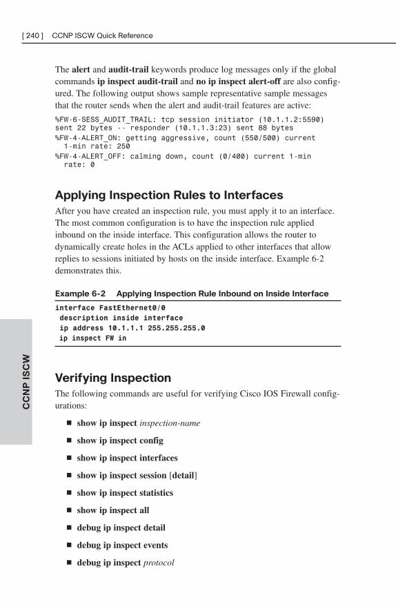
[ 240 ] CCNP ISCW Quick ReferenceC
CN
P I
SC
W
The alert and audit-trail keywords produce log messages only if the globalcommands ip inspect audit-trail and no ip inspect alert-off are also config-ured. The following output shows sample representative sample messagesthat the router sends when the alert and audit-trail features are active:
%FW-6-SESS_AUDIT_TRAIL: tcp session initiator (10.1.1.2:5590)sent 22 bytes -- responder (10.1.1.3:23) sent 88 bytes%FW-4-ALERT_ON: getting aggressive, count (550/500) current 1-min rate: 250
%FW-4-ALERT_OFF: calming down, count (0/400) current 1-min rate: 0
Applying Inspection Rules to Interfaces
After you have created an inspection rule, you must apply it to an interface.The most common configuration is to have the inspection rule appliedinbound on the inside interface. This configuration allows the router todynamically create holes in the ACLs applied to other interfaces that allowreplies to sessions initiated by hosts on the inside interface. Example 6-2demonstrates this.
Example 6-2 Applying Inspection Rule Inbound on Inside Interface
interface FastEthernet0/0
description inside interface
ip address 10.1.1.1 255.255.255.0
ip inspect FW in
Verifying Inspection
The following commands are useful for verifying Cisco IOS Firewall config-urations:
■ show ip inspect inspection-name
■ show ip inspect config
■ show ip inspect interfaces
■ show ip inspect session [detail]
■ show ip inspect statistics
■ show ip inspect all
■ debug ip inspect detail
■ debug ip inspect events
■ debug ip inspect protocol
Chapter 6: Cisco IOS Threat Defenses [ 241 ]
CC
NP
ISC
W
Introducing Cisco IOS IPSThe Cisco IOS Intrusion Prevention System can help detect and mitigateattacks against routers and hosts. This section reviews the components andconfiguration of the IOS IPS.
Defining IDS/IPS Terms
The following terms are important to an understanding of intrusion detectionsystems (IDS) and intrusion prevention systems (IPS):
■ Intrusion detection system—An IDS is a device that listens passivelyto network traffic and produces alerts when suspicious activity isdetected. An IDS is often located outside the traffic forwarding pathand monitors traffic that is copied to a Switched Port Analyzer (SPAN)port on a switch.
■ Intrusion prevention system—An IPS is a device that not only alertson suspicious activity, but that can also be configured to actively blockit. An IPS is typically located in the forwarding path. The Cisco IOSIPS is a feature offered in Cisco IOS security images that allows therouter to detect and respond to possible network attacks.
■ Signature-based approach—Signature-based IDS/IPS devices detectpossible attacks by matching preconfigured patterns (that is, “signa-tures”) in network traffic.
■ Policy-based approach—Policy-based IDS/IPS devices detect attacksbased on thresholds or other policies, such as a number of half-openTCP SYN sessions.
■ Anomaly-based approach—Anomaly-based IDS/IPS devices profilenetwork traffic and build up a set of patterns that is considered“normal.” Traffic that falls outside of normal parameters triggers alertsor other actions.
■ Honeypot approach—“Honeypots” are systems that are deliberatelyleft vulnerable to network attacks so that security researchers cananalyze an attack methodology. The network design must prevent acompromised honeypot from ever having access to legitimate systems.
■ Host-based IDS/IPS—A host-based IDS/IPS (HIDS/HIPS) resides onend-system hosts. It is typically written to prevent attacks against aparticularly operating system, such as the installation of unauthorizedsoftware.
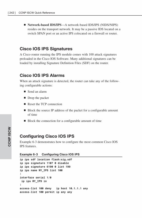
[ 242 ] CCNP ISCW Quick ReferenceC
CN
P I
SC
W
■ Network-based IDS/IPS—A network-based IDS/IPS (NIDS/NIPS)resides on the transport network. It may be a passive IDS located on aswitch SPAN port or an active IPS colocated on a firewall or router.
Cisco IOS IPS Signatures
A Cisco router running the IPS module comes with 100 attack signaturespreloaded in the Cisco IOS Software. Many additional signatures can beloaded by installing Signature Definition Files (SDF) on the router.
Cisco IOS IPS Alarms
When an attack signature is detected, the router can take any of the follow-ing configurable actions:
■ Send an alarm
■ Drop the packet
■ Reset the TCP connection
■ Block the source IP address of the packet for a configurable amount of time
■ Block the connection for a configurable amount of time
Configuring Cisco IOS IPS
Example 6-3 demonstrates how to configure the most common Cisco IOSIPS features.
Example 6-3 Configuring Cisco IOS IPS
ip ips sdf location flash:sig.sdf
ip ips signature 1107 0 disable
ip ips signature 6190 0 list 199
ip ips name MY_IPS list 100
!interface serial 1/0
ip ips MY_IPS in
!access-list 100 deny ip host 10.1.1.1 any
access-list 100 permit ip any any
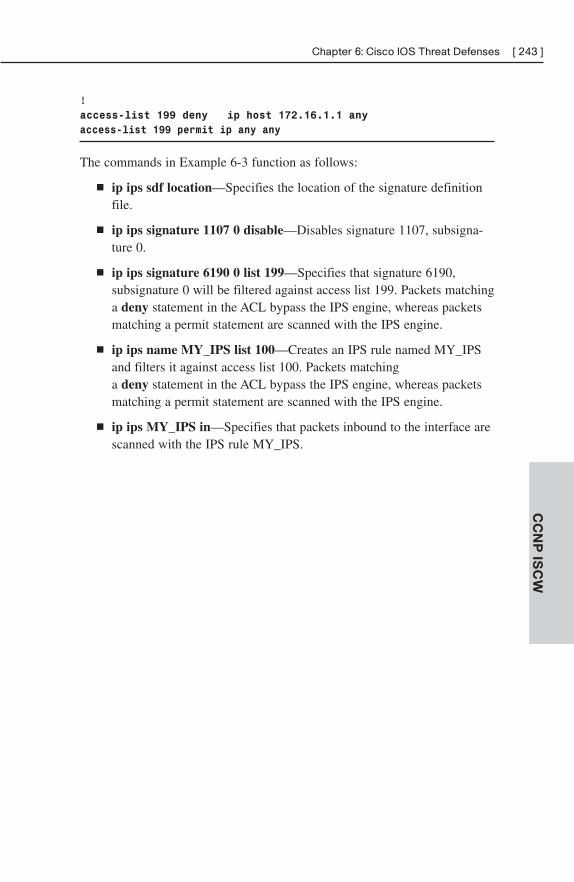
Chapter 6: Cisco IOS Threat Defenses [ 243 ]
CC
NP
ISC
W
!access-list 199 deny ip host 172.16.1.1 any
access-list 199 permit ip any any
The commands in Example 6-3 function as follows:
■ ip ips sdf location—Specifies the location of the signature definitionfile.
■ ip ips signature 1107 0 disable—Disables signature 1107, subsigna-ture 0.
■ ip ips signature 6190 0 list 199—Specifies that signature 6190,subsignature 0 will be filtered against access list 199. Packets matchinga deny statement in the ACL bypass the IPS engine, whereas packetsmatching a permit statement are scanned with the IPS engine.
■ ip ips name MY_IPS list 100—Creates an IPS rule named MY_IPSand filters it against access list 100. Packets matching a deny statement in the ACL bypass the IPS engine, whereas packetsmatching a permit statement are scanned with the IPS engine.
■ ip ips MY_IPS in—Specifies that packets inbound to the interface arescanned with the IPS rule MY_IPS.

This page intentionally left blank
ONTChapter 1: Network Architecture . . . . . . . . . . . . . . . . . . . 247
Chapter 2: Cisco VoIP . . . . . . . . . . . . . . . . . . . . . . . . . . . . . 253
Chapter 3: QoS Overview . . . . . . . . . . . . . . . . . . . . . . . . . . 264
Chapter 4: QoS Details . . . . . . . . . . . . . . . . . . . . . . . . . . . . 275
Chapter 5: AutoQoS . . . . . . . . . . . . . . . . . . . . . . . . . . . . . . . 303
Chapter 6: Wireless Scalability . . . . . . . . . . . . . . . . . . . . . 308
PART IV

This page intentionally left blank
CHAPTER 1
Network Architecture
Modern converged networks include different traffic types, each with uniquerequirements for security, Quality of Service (QoS), transmission capacity,and delay. Some examples include:
■ Voice signaling and bearer
■ Core application traffic, such as Enterprise Resource Planning (ERP)or Customer Relationship Management (CRM)
■ Database transactions
■ Multicast multimedia
■ Network management
■ “Other” traffic, such as web pages, e-mail, and file transfer
Cisco routers are able to implement filtering, compression, prioritization,and policing (dedicating network capacity). Except for filtering, these capa-bilities are referred to collectively as QoS.
Although QoS is wonderful, it is not the only way to address bandwidthshortage. Cisco espouses an idea called the Intelligent Information Network(IIN). IIN builds on standard network design models to enable these newservices to be reliable and layered on top of traditional data delivery.
SONA and IINIIN describes an evolutionary vision of a network that integrates networkand application functionality cooperatively and allows the network to besmart about how it handles traffic to minimize the footprint of applications.IIN is built on top of the Enterprise Composite Model and describes struc-tures overlaid on to the Composite design as needed in three phases.
Phase 1, “Integrated Transport,” describes a converged network, which isbuilt along the lines of the Composite model and based on open standards.This is the phase that the industry has been transitioning. The CiscoIntegrated Services Routers (ISR) are an example of this trend.
Phase 2, “Integrated Services,” attempts to virtualize resources, such asservers, storage, and network access. It is a move to an “on-demand” model.
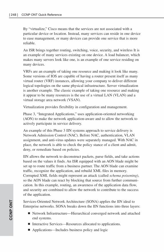
By “virtualize,” Cisco means that the services are not associated with aparticular device or location. Instead, many services can reside in one deviceto ease management, or many devices can provide one service that is morereliable.
An ISR brings together routing, switching, voice, security, and wireless It isan example of many services existing on one device. A load balancer, whichmakes many servers look like one, is an example of one service residing onmany devices.
VRFs are an example of taking one resource and making it look like many.Some versions of IOS are capable of having a router present itself as manyvirtual router (VRF) instances, allowing your company to deliver differentlogical topologies on the same physical infrastructure. Server virtualizationis another example. The classic example of taking one resource and makingit appear to be many resources is the use of a virtual LAN (VLAN) and avirtual storage area network (VSAN).
Virtualization provides flexibility in configuration and management.
Phase 3, “Integrated Applications,” uses application-oriented networking(AON) to make the network application-aware and to allow the network toactively participate in service delivery.
An example of this Phase 3 IIN systems approach to service delivery isNetwork Admission Control (NAC). Before NAC, authentication, VLANassignment, and anti-virus updates were separately managed. With NAC inplace, the network is able to check the policy stance of a client and admit,deny, or remediate based on policies.
IIN allows the network to deconstruct packets, parse fields, and take actionsbased on the values it finds. An ISR equipped with an AON blade might beset up to route traffic from a business partner. The AON blade can examinetraffic, recognize the application, and rebuild XML files in memory.Corrupted XML fields might represent an attack (called schema poisoning),so the AON blade can react by blocking that source from further communi-cation. In this example, routing, an awareness of the application data flow,and security are combined to allow the network to contribute to the successof the application.
Services-Oriented Network Architecture (SONA) applies the IIN ideal toEnterprise networks. SONA breaks down the IIN functions into three layers:
■ Network Infrastructure—Hierarchical converged network and attachedend systems.
■ Interactive Services—Resources allocated to applications.
■ Applications—Includes business policy and logic
CC
NP
ON
T[ 248 ] CCNP ONT Quick Reference
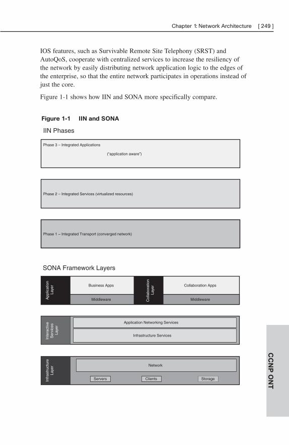
IOS features, such as Survivable Remote Site Telephony (SRST) andAutoQoS, cooperate with centralized services to increase the resiliency ofthe network by easily distributing network application logic to the edges ofthe enterprise, so that the entire network participates in operations instead ofjust the core.
Figure 1-1 shows how IIN and SONA more specifically compare.
CC
NP
ON
T
Chapter 1: Network Architecture [ 249 ]
Phase 1 – Integrated Transport (converged network)
Phase 3 – Integrated Applications
(“application aware”)
Phase 2 – Integrated Services (virtualized resources)
IIN Phases
Business Apps Collaboration Apps
Middleware Middleware
SONA Framework Layers
Infr
astr
uctu
reLa
yer
App
licat
ion
Laye
rIn
tera
ctiv
e S
ervi
ces
Laye
r
Network
Servers StorageClients
Application Networking Services
Infrastructure Services
Col
labo
ratio
n La
yer
Figure 1-1 IIN and SONA
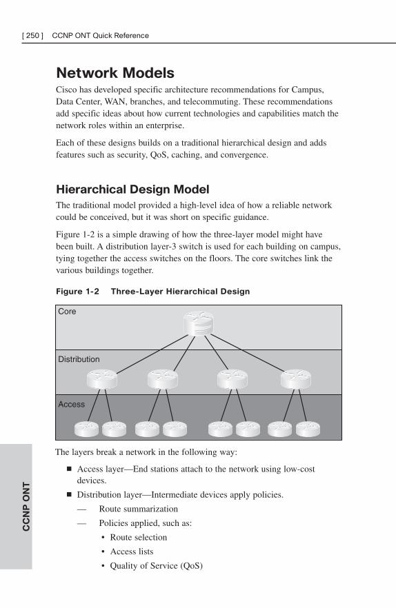
Network ModelsCisco has developed specific architecture recommendations for Campus,Data Center, WAN, branches, and telecommuting. These recommendationsadd specific ideas about how current technologies and capabilities match thenetwork roles within an enterprise.
Each of these designs builds on a traditional hierarchical design and addsfeatures such as security, QoS, caching, and convergence.
Hierarchical Design Model
The traditional model provided a high-level idea of how a reliable networkcould be conceived, but it was short on specific guidance.
Figure 1-2 is a simple drawing of how the three-layer model might havebeen built. A distribution layer-3 switch is used for each building on campus,tying together the access switches on the floors. The core switches link thevarious buildings together.
Figure 1-2 Three-Layer Hierarchical Design
CC
NP
ON
T[ 250 ] CCNP ONT Quick Reference
Core
Access
Distribution
The layers break a network in the following way:
■ Access layer—End stations attach to the network using low-costdevices.
■ Distribution layer—Intermediate devices apply policies.
— Route summarization
— Policies applied, such as:
• Route selection
• Access lists
• Quality of Service (QoS)
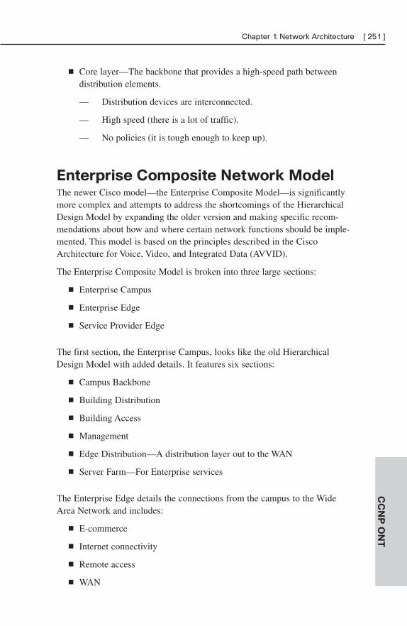
■ Core layer—The backbone that provides a high-speed path betweendistribution elements.
— Distribution devices are interconnected.
— High speed (there is a lot of traffic).
— No policies (it is tough enough to keep up).
Enterprise Composite Network ModelThe newer Cisco model—the Enterprise Composite Model—is significantlymore complex and attempts to address the shortcomings of the HierarchicalDesign Model by expanding the older version and making specific recom-mendations about how and where certain network functions should be imple-mented. This model is based on the principles described in the CiscoArchitecture for Voice, Video, and Integrated Data (AVVID).
The Enterprise Composite Model is broken into three large sections:
■ Enterprise Campus
■ Enterprise Edge
■ Service Provider Edge
The first section, the Enterprise Campus, looks like the old HierarchicalDesign Model with added details. It features six sections:
■ Campus Backbone
■ Building Distribution
■ Building Access
■ Management
■ Edge Distribution—A distribution layer out to the WAN
■ Server Farm—For Enterprise services
The Enterprise Edge details the connections from the campus to the WideArea Network and includes:
■ E-commerce
■ Internet connectivity
■ Remote access
■ WAN
CC
NP
ON
T
Chapter 1: Network Architecture [ 251 ]
The Service Provider Edge is just a list of the public networks that facilitatewide-area connectivity. These include:
■ Internet service providers (ISP)
■ Analog phone dialup
■ Frame Relay, ATM, and PPP, which have private connectivity
Figure 1-3 shows the Campus, Enterprise Edge, and Service Provider Edgemodules assembled. Security implemented on this model is described in theCisco SAFE (Security Architecture for Enterprise) blueprint.
Figure 1-3 Enterprise Design
CC
NP
ON
T[ 252 ] CCNP ONT Quick Reference
Remote Access
WAN
Campus BackboneEdge
Distribution
Internal Router
DMZ Firewall
Web
DatabaseIDC
App Server
Internet Router
Corporate Router
Dial-In
Internal RouterDMZ Firewall
PublicServers
Internet Router
Internal Router VPN
IDS
PPP
Service Provider EdgeEnterprise Edge
Internet
PSTN
Frame Relay ATM
Internal Firewall
Internal Firewall
Caching
Firewall
E-Commerce
Internet
CHAPTER 2
Cisco VoIP
Voice over IP (VoIP) is a set of technologies that seeks to replace traditionalanalog voice services. There are three main compelling benefits to VoIP:
■ VoIP makes better use of network capacity. Traditional voice uses a64-kbps circuit, even when it is not active, but VoIP can use much lessand no capacity when the line is not in use.
■ VoIP allows new and revolutionary features, such as the following:
— Integration of voice and data systems (so that operators getcustomer information popped on to the screen when a phone callarrives).
— Voice CODECs can improve sound quality (at the expense of bandwidth).
— Integration with new clients. Instead of an analog phone, VoIPclients can include television boxes, Personal Digital Assistants(PDAs), cell phones, laptops, and so on.
■ VoIP can save money by avoiding toll calls.
IP telephony solutions include many pieces:
■ Internet Protocol (IP) phones
■ Analog phones connected to IP by a Gateway
■ Control and number resolution by a Gatekeeper
■ Conferencing capabilities provided by a multipoint control unit (MCU)
■ Applications, such as directories and product information that interfacewith smart IP phones
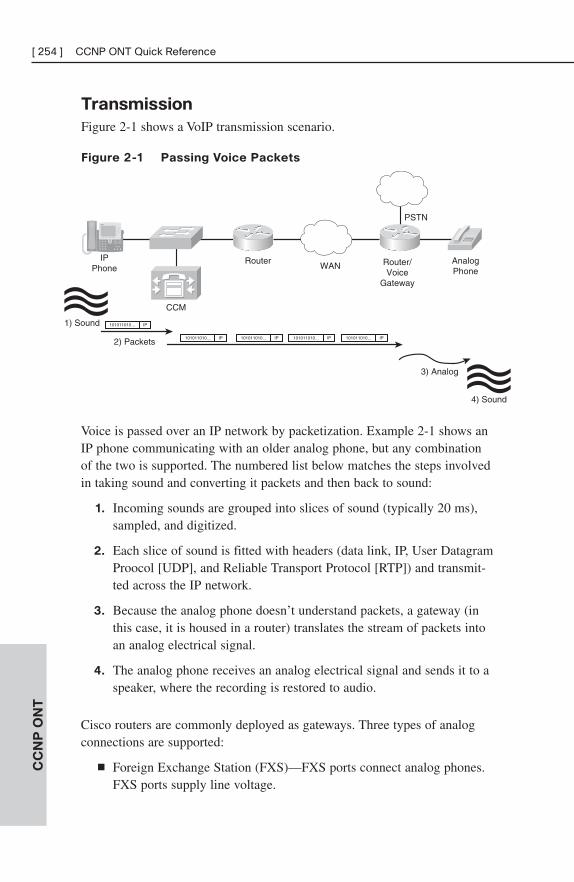
Transmission
Figure 2-1 shows a VoIP transmission scenario.
Figure 2-1 Passing Voice Packets
CC
NP
ON
T[ 254 ] CCNP ONT Quick Reference
IPPhone
AnalogPhone
CCM
RouterWAN Router/
VoiceGateway
PSTN
2) Packets
1) Sound
3) Analog
4) Sound
101011010... IP
101011010... IP 101011010... IP 101011010... IP 101011010... IP
Voice is passed over an IP network by packetization. Example 2-1 shows anIP phone communicating with an older analog phone, but any combinationof the two is supported. The numbered list below matches the steps involvedin taking sound and converting it packets and then back to sound:
1. Incoming sounds are grouped into slices of sound (typically 20 ms),sampled, and digitized.
2. Each slice of sound is fitted with headers (data link, IP, User DatagramProocol [UDP], and Reliable Transport Protocol [RTP]) and transmit-ted across the IP network.
3. Because the analog phone doesn’t understand packets, a gateway (inthis case, it is housed in a router) translates the stream of packets intoan analog electrical signal.
4. The analog phone receives an analog electrical signal and sends it to aspeaker, where the recording is restored to audio.
Cisco routers are commonly deployed as gateways. Three types of analogconnections are supported:
■ Foreign Exchange Station (FXS)—FXS ports connect analog phones.FXS ports supply line voltage.
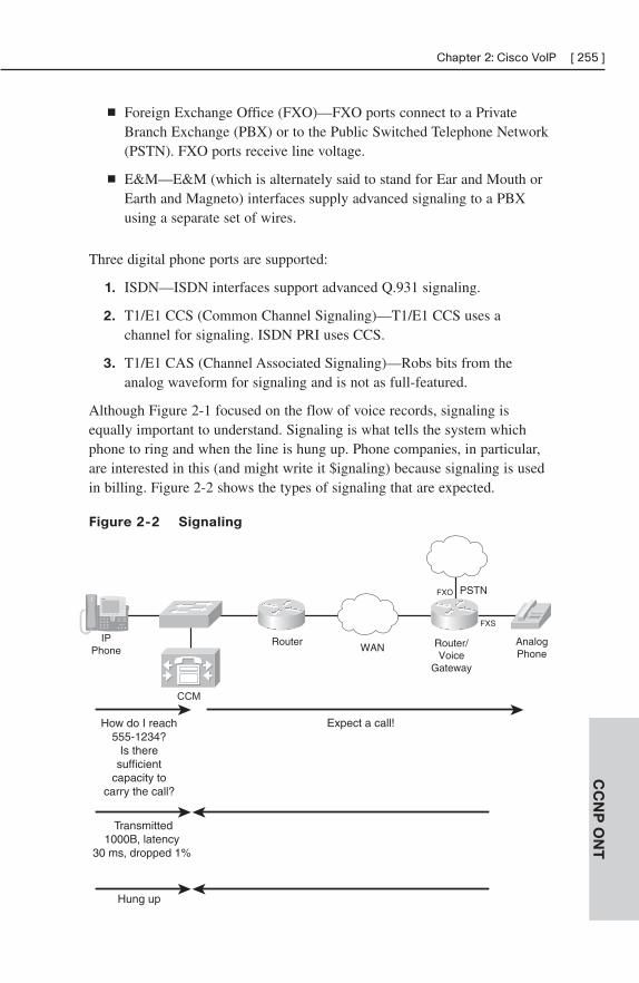
CC
NP
ON
T
Chapter 2: Cisco VoIP [ 255 ]
CCM
How do I reach 555-1234?
Is there sufficient
capacity to carry the call?
Transmitted1000B, latency
30 ms, dropped 1%
Expect a call!
Hung up
IPPhone
AnalogPhone
RouterWAN Router/
VoiceGateway
PSTNFXO
FXS
■ Foreign Exchange Office (FXO)—FXO ports connect to a PrivateBranch Exchange (PBX) or to the Public Switched Telephone Network(PSTN). FXO ports receive line voltage.
■ E&M—E&M (which is alternately said to stand for Ear and Mouth orEarth and Magneto) interfaces supply advanced signaling to a PBXusing a separate set of wires.
Three digital phone ports are supported:
1. ISDN—ISDN interfaces support advanced Q.931 signaling.
2. T1/E1 CCS (Common Channel Signaling)—T1/E1 CCS uses achannel for signaling. ISDN PRI uses CCS.
3. T1/E1 CAS (Channel Associated Signaling)—Robs bits from theanalog waveform for signaling and is not as full-featured.
Although Figure 2-1 focused on the flow of voice records, signaling isequally important to understand. Signaling is what tells the system whichphone to ring and when the line is hung up. Phone companies, in particular,are interested in this (and might write it $ignaling) because signaling is usedin billing. Figure 2-2 shows the types of signaling that are expected.
Figure 2-2 Signaling
Signaling plays several important roles:
■ Information about the receiver is obtained.
■ Capacity is checked before starting; otherwise, call quality suffers.
■ Call quality is monitored so that adjustments may be made to maintaincall quality.
■ Connect and disconnect times are kept for billing.
In Figure 2-2, a Call Manager is shown receiving the signaling. A CallManager allows centralized call control, which provides oversight of the calland records of connections and quality. Voice trunking may be accomplishedwithout such supervision (called distributed call control), but care must betaken to not overburden links and quality must be manually maintained.
PacketizationBefore voice may be transmitted over a network, sound has to be capturedfrom a microphone and digitized. The digital recording is then chopped intosections (each is typically 20 ms), which are sent sequentially and replayedin order out a speaker.
Sound is captured at a microphone by sampling (periodically taking a powerreading). The Nyquist theorem says that to reproduce a signal, sampling mustoccur at twice the maximum frequency. The phone system is designed to capturefrequencies less than 4 kHz, which are samples of 8,000 times per second.
Pulse Amplitude Modulation (PAM) is used in the PSTN. Samples are quantizedto 8-bit numbers 8,000 times per second (yielding a 64-kbps DS0).
Two forms of quantization are used. A linear scale is used in the U.S., whileabroad, a logarithmic scale is used. The U.S. system (called μ-law) was developed earlier, and it suffered from lower-powered samplingsystems. A-law (logarithmic sampling) was developed later to be differentand give domestic opportunities to European companies that were stillrecovering from World War II. A-law benefits from greater computingresources, and the logarithmic scale does a better job of reproducing sound.
After being captured, Pulse Amplitude Modulation (PAM) samples areencoded using a coder/decoder (CODEC). Coders work using two maintechniques: PCM, which encodes the signal straight to bits, and CELP,which matches the waveform to a predefined library and sends a code.C
CN
P O
NT
[ 256 ] CCNP ONT Quick Reference
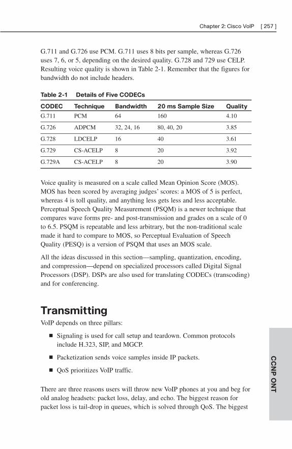
G.711 and G.726 use PCM. G.711 uses 8 bits per sample, whereas G.726uses 7, 6, or 5, depending on the desired quality. G.728 and 729 use CELP.Resulting voice quality is shown in Table 2-1. Remember that the figures forbandwidth do not include headers.
Table 2-1 Details of Five CODECs
CODEC Technique Bandwidth 20 ms Sample Size Quality
G.711 PCM 64 160 4.10
G.726 ADPCM 32, 24, 16 80, 40, 20 3.85
G.728 LDCELP 16 40 3.61
G.729 CS-ACELP 8 20 3.92
G.729A CS-ACELP 8 20 3.90
Voice quality is measured on a scale called Mean Opinion Score (MOS).MOS has been scored by averaging judges’ scores: a MOS of 5 is perfect,whereas 4 is toll quality, and anything less gets less and less acceptable.Perceptual Speech Quality Measurement (PSQM) is a newer technique thatcompares wave forms pre- and post-transmission and grades on a scale of 0to 6.5. PSQM is repeatable and less arbitrary, but the non-traditional scalemade it hard to compare to MOS, so Perceptual Evaluation of SpeechQuality (PESQ) is a version of PSQM that uses an MOS scale.
All the ideas discussed in this section—sampling, quantization, encoding,and compression—depend on specialized processors called Digital SignalProcessors (DSP). DSPs are also used for translating CODECs (transcoding)and for conferencing.
TransmittingVoIP depends on three pillars:
■ Signaling is used for call setup and teardown. Common protocolsinclude H.323, SIP, and MGCP.
■ Packetization sends voice samples inside IP packets.
■ QoS prioritizes VoIP traffic.
There are three reasons users will throw new VoIP phones at you and beg forold analog headsets: packet loss, delay, and echo. The biggest reason forpacket loss is tail-drop in queues, which is solved through QoS. The biggest
CC
NP
ON
T
Chapter 2: Cisco VoIP [ 257 ]
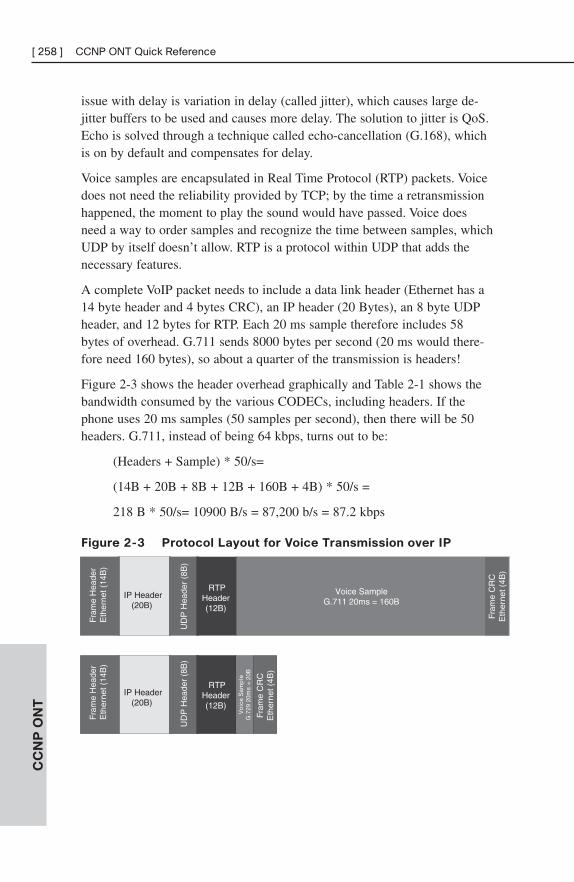
issue with delay is variation in delay (called jitter), which causes large de-jitter buffers to be used and causes more delay. The solution to jitter is QoS.Echo is solved through a technique called echo-cancellation (G.168), whichis on by default and compensates for delay.
Voice samples are encapsulated in Real Time Protocol (RTP) packets. Voicedoes not need the reliability provided by TCP; by the time a retransmissionhappened, the moment to play the sound would have passed. Voice doesneed a way to order samples and recognize the time between samples, whichUDP by itself doesn’t allow. RTP is a protocol within UDP that adds thenecessary features.
A complete VoIP packet needs to include a data link header (Ethernet has a14 byte header and 4 bytes CRC), an IP header (20 Bytes), an 8 byte UDPheader, and 12 bytes for RTP. Each 20 ms sample therefore includes 58bytes of overhead. G.711 sends 8000 bytes per second (20 ms would there-fore need 160 bytes), so about a quarter of the transmission is headers!
Figure 2-3 shows the header overhead graphically and Table 2-1 shows thebandwidth consumed by the various CODECs, including headers. If thephone uses 20 ms samples (50 samples per second), then there will be 50headers. G.711, instead of being 64 kbps, turns out to be:
(Headers + Sample) * 50/s=
(14B + 20B + 8B + 12B + 160B + 4B) * 50/s =
218 B * 50/s= 10900 B/s = 87,200 b/s = 87.2 kbps
Figure 2-3 Protocol Layout for Voice Transmission over IP
CC
NP
ON
T[ 258 ] CCNP ONT Quick Reference
IP Header(20B)
UD
P H
eade
r (8
B)
Fram
e H
eade
rE
ther
net (
14B
)
RTPHeader (12B)
Voice SampleG.711 20ms = 160B
Fram
e C
RC
Eth
erne
t (4B
)
Vo
ice
Sam
ple
G.7
29 2
0ms
= 2
0B
IP Header(20B)
UD
P H
eade
r (8
B)
Fram
e H
eade
rE
ther
net (
14B
)
RTPHeader (12B)
Fram
e C
RC
Eth
erne
t (4B
)
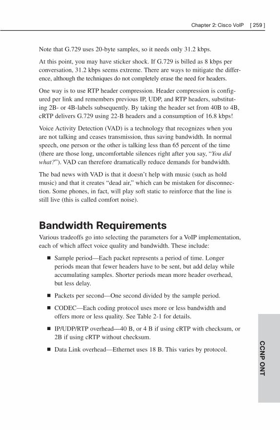
Note that G.729 uses 20-byte samples, so it needs only 31.2 kbps.
At this point, you may have sticker shock. If G.729 is billed as 8 kbps perconversation, 31.2 kbps seems extreme. There are ways to mitigate the differ-ence, although the techniques do not completely erase the need for headers.
One way is to use RTP header compression. Header compression is config-ured per link and remembers previous IP, UDP, and RTP headers, substitut-ing 2B- or 4B-labels subsequently. By taking the header set from 40B to 4B,cRTP delivers G.729 using 22-B headers and a consumption of 16.8 kbps!
Voice Activity Detection (VAD) is a technology that recognizes when youare not talking and ceases transmission, thus saving bandwidth. In normalspeech, one person or the other is talking less than 65 percent of the time(there are those long, uncomfortable silences right after you say, “You didwhat?”). VAD can therefore dramatically reduce demands for bandwidth.
The bad news with VAD is that it doesn’t help with music (such as holdmusic) and that it creates “dead air,” which can be mistaken for disconnec-tion. Some phones, in fact, will play soft static to reinforce that the line isstill live (this is called comfort noise).
Bandwidth RequirementsVarious tradeoffs go into selecting the parameters for a VoIP implementation,each of which affect voice quality and bandwidth. These include:
■ Sample period—Each packet represents a period of time. Longerperiods mean that fewer headers have to be sent, but add delay whileaccumulating samples. Shorter periods mean more header overhead,but less delay.
■ Packets per second—One second divided by the sample period.
■ CODEC—Each coding protocol uses more or less bandwidth andoffers more or less quality. See Table 2-1 for details.
■ IP/UDP/RTP overhead—40 B, or 4 B if using cRTP with checksum, or2B if using cRTP without checksum.
■ Data Link overhead—Ethernet uses 18 B. This varies by protocol.
CC
NP
ON
T
Chapter 2: Cisco VoIP [ 259 ]
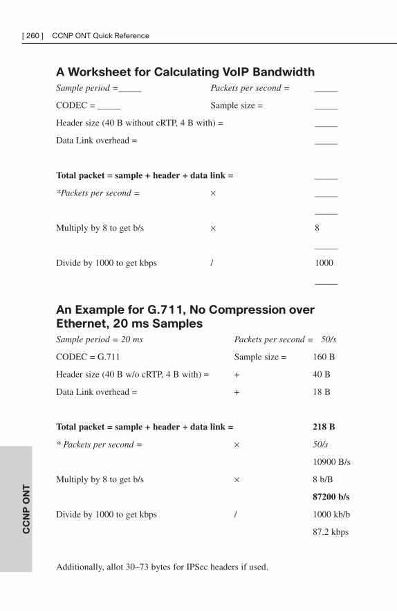
A Worksheet for Calculating VoIP Bandwidth
Sample period =_____ Packets per second = _____
CODEC = _____ Sample size = _____
Header size (40 B without cRTP, 4 B with) = _____
Data Link overhead = _____
Total packet = sample + header + data link = _____
*Packets per second = × _____
_____
Multiply by 8 to get b/s × 8
_____
Divide by 1000 to get kbps / 1000
_____
An Example for G.711, No Compression over
Ethernet, 20 ms Samples
Sample period = 20 ms Packets per second = 50/s
CODEC = G.711 Sample size = 160 B
Header size (40 B w/o cRTP, 4 B with) = + 40 B
Data Link overhead = + 18 B
Total packet = sample + header + data link = 218 B
* Packets per second = × 50/s
10900 B/s
Multiply by 8 to get b/s × 8 b/B
87200 b/s
Divide by 1000 to get kbps / 1000 kb/b
87.2 kbps
Additionally, allot 30–73 bytes for IPSec headers if used.
CC
NP
ON
T[ 260 ] CCNP ONT Quick Reference
Implementing IP TelephonyIn the enterprise, IP telephony is deployed to replace a PBX. A typical PBXcontains a switching function (the “brains”) and cards that attach extensions(station cards) and connect to the outside world (line cards). Figure 2-4shows the evolution from an old PBX to a modern distributed IP telephonysolution.
Figure 2-4 Evolution from PBX to IP Telephony
CC
NP
ON
T
Chapter 2: Cisco VoIP [ 261 ]
Switching Engine
Network
Router with FXO
PC withSoftphone
Call Manager
Router with FXS
( )
( )
PBX
Other Resources
Station CardConnections to desktop phones
External Line CardConnections to PSTN
A Cisco Call Manager takes the place of the “brains” and helps end stationsunderstand how to reach each other. CCM also oversees the dial plan,produces utilization reports, and determines functionality. CCM is typicallydeployed in a cluster, so that the system does not rely on one machine.
Note
Cisco Call Manager Express runs on a router and can be used for small offices. Routers are alsodeployed as backup call managers (this is called Survivable Remote Site Telephony or SRST),so being disconnected from a remote CCM does not disable a branch phone system.
IP phones and soft phones connect directly to the network, whereas legacyphones connect to the network through FXS ports on routers. Routers oper-ating this way are called gateways. Think of the network and gateways asbeing equivalent to the station cards in an old PBX.
Routers with external connections, such as FXO ports, are also called gateways.In this scenario, however, the router takes the place of an external line card.
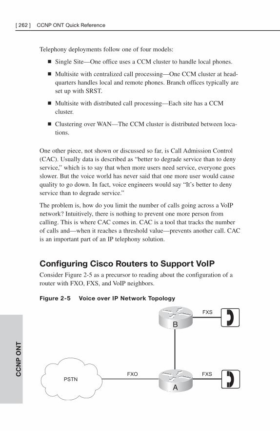
Telephony deployments follow one of four models:
■ Single Site—One office uses a CCM cluster to handle local phones.
■ Multisite with centralized call processing—One CCM cluster at head-quarters handles local and remote phones. Branch offices typically areset up with SRST.
■ Multisite with distributed call processing—Each site has a CCMcluster.
■ Clustering over WAN—The CCM cluster is distributed between loca-tions.
One other piece, not shown or discussed so far, is Call Admission Control(CAC). Usually data is described as “better to degrade service than to denyservice,” which is to say that when more users need service, everyone goesslower. But the voice world has never said that one more user would causequality to go down. In fact, voice engineers would say “It’s better to denyservice than to degrade service.”
The problem is, how do you limit the number of calls going across a VoIPnetwork? Intuitively, there is nothing to prevent one more person fromcalling. This is where CAC comes in. CAC is a tool that tracks the numberof calls and—when it reaches a threshold value—prevents another call. CACis an important part of an IP telephony solution.
Configuring Cisco Routers to Support VoIP
Consider Figure 2-5 as a precursor to reading about the configuration of arouter with FXO, FXS, and VoIP neighbors.
Figure 2-5 Voice over IP Network Topology
CC
NP
ON
T[ 262 ] CCNP ONT Quick Reference
FXSFXO
FXS
B
APSTN
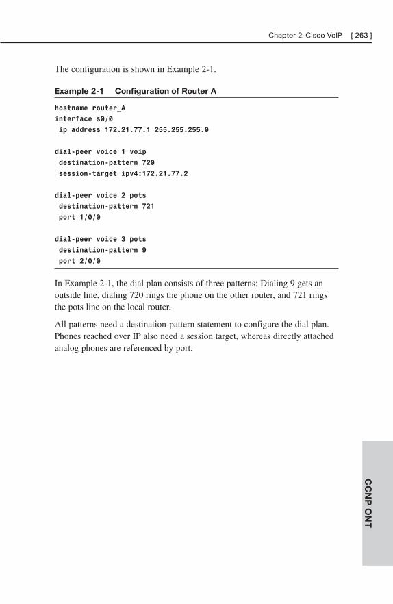
The configuration is shown in Example 2-1.
Example 2-1 Configuration of Router A
hostname router_A
interface s0/0
ip address 172.21.77.1 255.255.255.0
dial-peer voice 1 voip
destination-pattern 720
session-target ipv4:172.21.77.2
dial-peer voice 2 pots
destination-pattern 721
port 1/0/0
dial-peer voice 3 pots
destination-pattern 9
port 2/0/0
In Example 2-1, the dial plan consists of three patterns: Dialing 9 gets anoutside line, dialing 720 rings the phone on the other router, and 721 ringsthe pots line on the local router.
All patterns need a destination-pattern statement to configure the dial plan.Phones reached over IP also need a session target, whereas directly attachedanalog phones are referenced by port.
CC
NP
ON
T
Chapter 2: Cisco VoIP [ 263 ]
CHAPTER 3
QoS Overview
Quality of service (QoS) configurations give special treatment to certaintraffic at the expense of others. This helps make your network performancemore deterministic and predictable for this traffic. Using QoS in the networkaddresses the following problems:
■ Lack of bandwidth for important applications
■ Delay of sensitive data, such as voice and video
■ Jitter (variable delay)
■ Packet loss due to data being dropped at a congested interface
Bandwidth
In a network with several hops, the available bandwidth is only as much asthe smallest link. When multiple applications and multiple flows use thesame links, the available bandwidth per application is even smaller—itequals the smallest link bandwidth divided by the number of flows.Insufficient bandwidth especially affects time-sensitive and interactivetraffic, and traffic with large flows.
You can increase link speeds to get more bandwidth—that can be expensive,time-consuming, and introduce technological difficulties. Alternatively, QoSmechanisms can guarantee bandwidth to specific applications.
Compressing the traffic on slower links creates more useable bandwidth;because each frame is smaller, there are fewer bits to transmit. However,compressing data uses processor and memory resources and introduces somelatency while the compression is being done. Because of this, use compres-sion only on T1 links or less. You can compress the whole payload or justcompress the protocol headers with TCP or Real-time Protocol (RTP) headercompression (cRTP). Cisco supports three payload compression algorithms:
■ Stacker
■ Predictor
■ Microsoft Point-to-Point Compression (MPPC)
For voice, use Low Latency Queuing (LLQ) and cRTP compression, and fordata, use Class-Based Weighted Fair Queuing (CBWFQ) and TCP compres-sion. LLQ and CBWFQ are discussed later in this chapter.
Delay and Jitter
Network traffic experiences four types of delay:
■ Processing delay—The time it takes a packet to move from the inputinterface of a router or Layer 3 switch, to the output interface.Processing delay depends on switching mode, CPU speed and utiliza-tion, the router’s architecture, and interface configuration. This is avariable delay.
■ Queuing delay—The length of time a packet waits in the interfacequeue before being sent to the transmit ring. Queuing delay dependson the number and size of packets in the queue, and the queuingmethods in place. This is a variable delay.
■ Serialization delay—The length of time it take to place the bits fromthe interface transmit ring onto the wire. Serialization delay dependson the bandwidth of the interface—higher bandwidth equals smallerserialization delay. This is a fixed delay.
■ Propagation delay—The length of time it takes the packet to movefrom one end of the link to the other. Propagation delay depends on thetype of media, such as fiber or satellite links. This is a fixed delay.
The total delay is the sum of all four delays on every link along the path.Because processing and queuing delay times can vary, end-to-end delay canvary from packet to packet. This variation is called jitter.
To decrease delay, you can increase the link bandwidth, prioritize importantpackets (note that this increases the delay for non-priority traffic), orcompress the packet headers or the payloads. On links under T1 speed, youcan fragment large packets and interleave smaller, interactive, packetsbetween them—this is called Link Fragmentation and Interleave (LFI).
When your traffic traverses an ISP network, you might need to reprioritize itto match the provider’s standards.
CC
NP
ON
T
Chapter 3: QoS Overview [ 265 ]
Packet Loss Issues
Packet loss can cause jerky transmission of voice or video, slow applicationperformance, or corrupt data. By default, when a software queue is full(congested), the switch or router drops all other traffic bound for that queue.This is called tail drop. It can cause some problems:
■ TCP global synchronization.
■ TCP buffer starvation.
■ Delay and jitter.
■ High-priority traffic is dropped, whereas low-priority traffic is sent.
Congestion avoidance attempts to prevent tail drop. To accomplish this,increase link bandwidth, use queuing to guarantee a certain amount of trafficto each application, or use Weighted Random Early Detection (WRED).WRED drops lower-priority traffic (based on Differentiated Services CodePoint [DSCP] or IP Precedence values) as a queue starts to fill and dropshigh-priority traffic only when the queue is almost full. If the queue fillscompletely, however, tail drop is used. The drop thresholds and the dropratios are configurable. WRED works best with TCP traffic, because TCPdynamically adjusts its sending rate when packets are dropped. Do not useWRED for voice traffic. The “Congestion Avoidance” section describes thismore completely.
Four other causes of packet drop are: frame errors, lack of buffer space(called an ignore), a CPU that is unable to assign a free buffer to it (calledan overrun), or a CPU that is too busy to process inbound packets so theinbound queue fills.
Defining QoS Requirements for Network Traffic
To implement QoS, you need to identify the types of network traffic, deter-mine the requirements for each, divide the traffic into classes, and then setpolicies for those classes.
A network audit helps identify the types of traffic on the network.
The relative importance of each application is a business decision, accom-plished by a business audit. Applications should be grouped into classes thathave about the same QoS requirements. Some common classes include:Voice, Interactive, Mission-critical, Transactional, Best-effort, andScavenger.
CC
NP
ON
T[ 266 ] CCNP ONT Quick Reference
A QoS policy then can be created for each class of traffic. You need todecide such things as allocated bandwidth (minimum and/or maximum),prioritization, and congestion avoidance.
QoS ModelsThere are three QoS models:
■ Best effort—Traffic is sent with no guarantees of bandwidth or priority.
■ Integrated Services (IntServ)—The QoS parameters are signaledthroughout the path and guaranteed for the length of the session.
■ Differentiated Services (DiffServ)—QoS parameters are applied totraffic classes at each hop along the path.
Best Effort
Best-effort delivery is the default method—traffic is sent out in the order itarrives with no differentiation between types of traffic and no guarantee ofdelivery. Benefits of best effort include its scalability (the Internet is basedon best-effort delivery), and its ease of deployment. Drawbacks include thefact that all traffic is given the same service level.
IntServ
IntServ is a QoS model that guarantees a specific level of service to eachflow of identified traffic, throughout the entire network, for the length of thesession. This is done using Resource Reservation Protocol (RSVP). AnRSVP-aware application, or a router or CallManager acting in proxy for anonRSVP-aware device, requests a specific level of service from its next-hoprouter. A check is made along the path between the two endpoints, and eachRSVP-enabled router along the way reserves bandwidth for that flow. If thenetwork cannot provide the required bandwidth, the session is not allowed orits service level is downgraded.
RSVP works for any type of traffic, but it is usually used for real-time appli-cations that are either rate-sensitive or delay-sensitive, such as voice andvideo. Figure 3-1 shows a call between two IP phones.
CC
NP
ON
T
Chapter 3: QoS Overview [ 267 ]
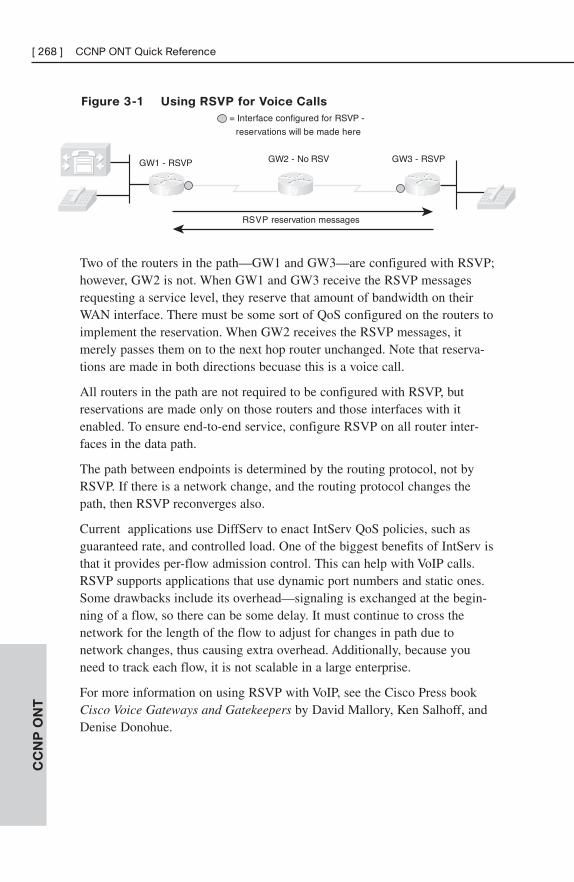
Figure 3-1 Using RSVP for Voice Calls
CC
NP
ON
T[ 268 ] CCNP ONT Quick Reference
GW1 - RSVP GW2 - No RSV GW3 - RSVP
RSVP reservation messages
= Interface configured for RSVP -
reservations will be made here
V V V
Two of the routers in the path—GW1 and GW3—are configured with RSVP;however, GW2 is not. When GW1 and GW3 receive the RSVP messagesrequesting a service level, they reserve that amount of bandwidth on theirWAN interface. There must be some sort of QoS configured on the routers toimplement the reservation. When GW2 receives the RSVP messages, itmerely passes them on to the next hop router unchanged. Note that reserva-tions are made in both directions becuase this is a voice call.
All routers in the path are not required to be configured with RSVP, butreservations are made only on those routers and those interfaces with itenabled. To ensure end-to-end service, configure RSVP on all router inter-faces in the data path.
The path between endpoints is determined by the routing protocol, not byRSVP. If there is a network change, and the routing protocol changes thepath, then RSVP reconverges also.
Current applications use DiffServ to enact IntServ QoS policies, such asguaranteed rate, and controlled load. One of the biggest benefits of IntServ isthat it provides per-flow admission control. This can help with VoIP calls.RSVP supports applications that use dynamic port numbers and static ones.Some drawbacks include its overhead—signaling is exchanged at the begin-ning of a flow, so there can be some delay. It must continue to cross thenetwork for the length of the flow to adjust for changes in path due tonetwork changes, thus causing extra overhead. Additionally, because youneed to track each flow, it is not scalable in a large enterprise.
For more information on using RSVP with VoIP, see the Cisco Press bookCisco Voice Gateways and Gatekeepers by David Mallory, Ken Salhoff, andDenise Donohue.
DiffServ
DiffServ groups network traffic into classes comprised of traffic needing thesame type of QoS treatment. For instance, voice traffic is separated from emailtraffic. However, e-mail might be placed in the same class as web traffic. Theexact classes, traffic, and QoS policies used are a business decision.
These classes are distinguished from each other based on the value of certainbits in the IP or ISL header or the 802.1Q tag. Each hop along the way mustbe configured to treat the marked traffic the way you want—this is calledper-hop behavior (PHB).
■ In the Layer 3 IP header, you use the 8-bit Type of Service (ToS) field.You can set either IP Precedence, using the top 3 bits, or DSCP usingthe top 6 bits of the field. The bottom 2 bits are not used for settingpriority. The default DSCP value is zero, which corresponds to best-effort delivery.
■ At Layer 2, with ISL, you can set 3 of the 4 bits in the ISL priorityfield to reflect the class of service (CoS). With 802.1Q, you set the 3802.1p bits to the CoS. The values of these 3 bits correspond to the IPPrecedence values.
Benefits of DiffServ include the many classes of service possible, and itsscalability. As a drawback, it can be complex to configure. It also does notabsolutely guarantee a level of service.
QoS Implementation MethodsThe legacy method of configuring QoS was at each interface, on each router,using the Command Line Interface (CLI). The current recommended methodis to use the Modular QoS CLI (MQC), which allows you to create oneconfiguration that can then be applied to many interfaces. Common QoSsettings have been automated with AutoQoS. For those who prefer a GUIinterface, there is the Cisco Router and Security Device Manager (SDM).
Legacy CLI
The traditional QoS configuration using legacy CLI involves accessing therouter via Telnet or console port. Traffic classification and policy enforcementare combined in the configuration at each interface, which is time-consumingand can lead to errors.
CC
NP
ON
T
Chapter 3: QoS Overview [ 269 ]
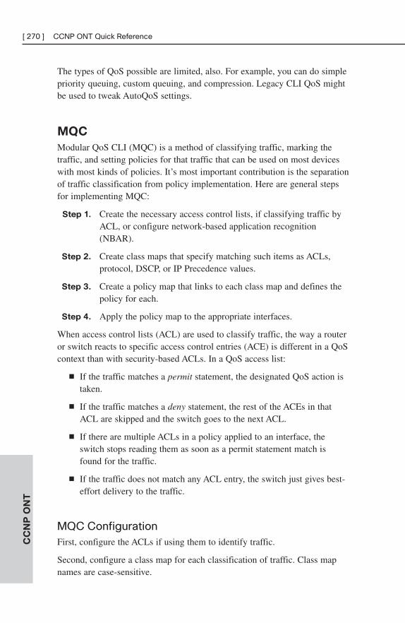
The types of QoS possible are limited, also. For example, you can do simplepriority queuing, custom queuing, and compression. Legacy CLI QoS mightbe used to tweak AutoQoS settings.
MQC
Modular QoS CLI (MQC) is a method of classifying traffic, marking thetraffic, and setting policies for that traffic that can be used on most deviceswith most kinds of policies. It’s most important contribution is the separationof traffic classification from policy implementation. Here are general stepsfor implementing MQC:
Step 1. Create the necessary access control lists, if classifying traffic byACL, or configure network-based application recognition(NBAR).
Step 2. Create class maps that specify matching such items as ACLs,protocol, DSCP, or IP Precedence values.
Step 3. Create a policy map that links to each class map and defines thepolicy for each.
Step 4. Apply the policy map to the appropriate interfaces.
When access control lists (ACL) are used to classify traffic, the way a routeror switch reacts to specific access control entries (ACE) is different in a QoScontext than with security-based ACLs. In a QoS access list:
■ If the traffic matches a permit statement, the designated QoS action istaken.
■ If the traffic matches a deny statement, the rest of the ACEs in thatACL are skipped and the switch goes to the next ACL.
■ If there are multiple ACLs in a policy applied to an interface, theswitch stops reading them as soon as a permit statement match isfound for the traffic.
■ If the traffic does not match any ACL entry, the switch just gives best-effort delivery to the traffic.
MQC ConfigurationFirst, configure the ACLs if using them to identify traffic.
Second, configure a class map for each classification of traffic. Class mapnames are case-sensitive.
CC
NP
ON
T[ 270 ] CCNP ONT Quick Reference
(config)#class-map [match-any | match-all] name
(config-cmap)#match {match options, such as ACL}
Third, configure a policy map that calls the class maps and sets policies ortypes of treatment for each class. Policy map names are also case sensitive.
(config)#policy-map name
(config-pmap)#class class-map-name
(config-pmap-c)#policy options, such as set DSCP or bandwidth
Finally, apply the MQC policy to the desired interface(s), either inbound oroutbound:
(config-if)#service-policy {output | input} name
Verifying QoS ConfigurationUse the following commands to verify your QoS configurations and actions:
■ show class-map [name]—Displays the configured class maps or justthe one named.
■ show policy-map [name]—Displays the configured policy maps orjust the one named.
■ show policy-map [interface [interface-number [input | output]] | [class class-name]—Displays the policy maps and statistics by interfaceor class.
■ show queueing [interface interface-number]—Shows the queuingstrategy and statistics for any queues configured on the interface.
■ show policy interface interface-number—Displays the policies for allclasses applied to the interface, along with statistics.
■ debug ip rsvp—If using RSVP for voice, shows information aboutpackets received and sent.
AutoQoS
AutoQoS is a utility that automates and simplifies QoS configuration, givinga consistent configuration across the network. It discovers the applicationstraversing the router or switch and configures standard best practice QoSpolicies for them. It can be used with both LAN and WAN interfaces.Automatic configurations can be tuned if necessary by using the MQC orwith legacy CLI. AutoQoS was originally only for VoIP applications, butrecent versions can be used with data applications also.
CC
NP
ON
T
Chapter 3: QoS Overview [ 271 ]
When configured on a WAN interface, AutoQoS:
■ Detects and classifies VoIP and data traffic (typically using NBAR).
■ Builds appropriate services policies, including placing Real-TimeProtocol (RTP) traffic into a low-latency queue (LLQ) and guarantee-ing bandwidth to VoIP control traffic.
■ Sets up traffic shaping, fragmentation, or compression where needed.
■ Enables SNMP traps and syslog alerting for VoIP events.
When configured on a LAN interface, AutoQoS:
■ Sets up priority/expedited queuing on the switch interface.
■ Configures the COS mapping to queues, and adjusts queue size andweights.
■ Sets up trust boundaries on user access ports and links betweenswitches. Trusts the incoming CoS only when an IP phone is present.
To use AutoQoS, CEF must be enabled, and the correct bandwidth config-ured on each interface, then AutoQos is enabled as follows. This exampleenables AutoQoS for VoIP only. Notice that after the commands are given,the router has created a policy map (not shown) and applied it to the inter-face:
Router(config)#int s1/0/0:1
Router(config-if)#bandwidth 1544
Router(config-if)#auto qos voip
!
Router#show auto qos int s1/0/0:1
Serial1/0/0:1 -
!
interface Serial1/0/0:1
service-policy output AutoQoS-Policy-UnTrust
SDM QoS Wizard
SDM allows GUI configuration of router interfaces, firewall, ACL features,VPNs, routing, Network Address Translation (NAT), Intrusion Prevention,Network Access Control (NAC), and QoS. It helps nonexpert users toconfigure these router functions. SDM comes preinstalled on the ISRrouters, but to use the SDM Wizard, the router’s HTTP server function mustbe enabled.
CC
NP
ON
T[ 272 ] CCNP ONT Quick Reference
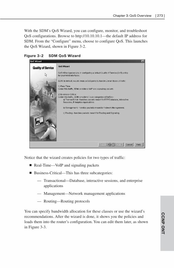
With the SDM’s QoS Wizard, you can configure, monitor, and troubleshootQoS configurations. Browse to http://10.10.10.1—the default IP address forSDM. From the “Configure” menu, choose to configure QoS. This launchesthe QoS Wizard, shown in Figure 3-2.
Figure 3-2 SDM QoS Wizard
CC
NP
ON
T
Chapter 3: QoS Overview [ 273 ]
Notice that the wizard creates policies for two types of traffic:
■ Real-Time—VoIP and signaling packets
■ Business-Critical—This has three subcategories:
— Transactional—Database, interactive sessions, and enterprise applications
— Management—Network management applications
— Routing—Routing protocols
You can specify bandwidth allocation for these classes or use the wizard’srecommendations. After the wizard is done, it shows you the policies andloads them into the router’s configuration. You can edit them later, as shownin Figure 3-3.
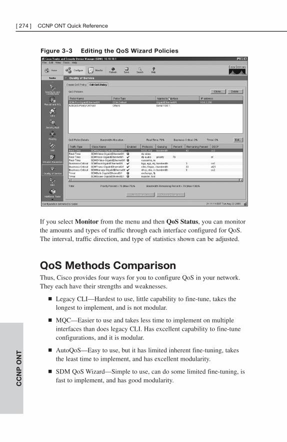
Figure 3-3 Editing the QoS Wizard Policies
CC
NP
ON
T[ 274 ] CCNP ONT Quick Reference
If you select Monitor from the menu and then QoS Status, you can monitorthe amounts and types of traffic through each interface configured for QoS.The interval, traffic direction, and type of statistics shown can be adjusted.
QoS Methods ComparisonThus, Cisco provides four ways for you to configure QoS in your network.They each have their strengths and weaknesses.
■ Legacy CLI—Hardest to use, little capability to fine-tune, takes thelongest to implement, and is not modular.
■ MQC—Easier to use and takes less time to implement on multipleinterfaces than does legacy CLI. Has excellent capability to fine-tuneconfigurations, and it is modular.
■ AutoQoS—Easy to use, but it has limited inherent fine-tuning, takesthe least time to implement, and has excellent modularity.
■ SDM QoS Wizard—Simple to use, can do some limited fine-tuning, isfast to implement, and has good modularity.
CHAPTER 4
QoS Details
This chapter explores, in detail, ways of choosing and configuring quality ofservice. The way you classify and mark traffic, and the type of QoS policiesyou implement, will depend on the policy location and types of networktraffic present.
Classification and MarkingClassification is the most basic Quality of Service (QoS) step—until traffic isidentified, it cannot be provided a unique level of service. Traffic is oftenclassified by application, source or destination IP address, or inbound interface.
After traffic is classified, an appropriate marking can be applied to it. Thelocation where traffic is marked defines a trust boundary. If the device thatmarked the traffic is trusted, then that marking is passed through the networkand honored by each device. If that device is untrusted, then some trustednetwork entity must re-mark the traffic.
Classification and marking should be done as close to the traffic source aspossible because they can be resource intensive. Marking at the end device,such as an IP phone, is ideal. Otherwise, mark (or re-mark) traffic at theaccess switch or distribution switch if necessary.
Layer 2 markings include 802.1Q Class of Service (CoS) and MultiprotocolLabel Switching (MPLS) experimental bits. Frame relay markings are different—they include setting the Backward Explicit Congestion Notification (BECN)bit, the Forward Explicit Congestion Notification (FECN) bit, or the DiscardEligible (DE) bit in the frame relay header. Layer 3 markings includeDifferentiated Services Code Point (DSCP) and IP precedence. After trafficis classified and marked, other routers and switches in the network can beconfigured to provide QoS to it.
Using NBAR for Classifying Traffic
There are several ways to identify traffic so that it can be classified. Accesslists are commonly used to identify application data, but Cisco has an IOS-based tool that provides more granularity and goes beyond static port
numbers. Network-Based Application Recognition (NBAR) is an IOS proto-col discovery and classification mechanism. It monitors the traffic going inand out of an interface, identifies it by protocol, port number, or payloadcontents (up to 400 bytes), and provides traffic statistics. NBAR recognizescommon applications, even those that use dynamic ports. For instance, Real-Time Protocol (RTP) carries voice and video traffic and uses dynamic portnumbers within a large range. An access list can match traffic within thatrange of port numbers, but NBAR can match on the following RTP charac-teristics:
■ Audio traffic (using payload types 0–23)
■ Video traffic (using payload types 24–33)
■ Payload type for a specific payload type value
Note
NBAR does not identify RTP control traffic, just RTP bearer traffic.
You can additionally configure NBAR to recognize custom applications.Cisco provides downloadable Packet Description Language Modules(PDLM) that also add additional applications.
CEF must be enabled on each interface where NBAR is used. To enableNBAR at an interface, and then view the traffic that it discovers, use thecommands:
Router(config-if)#ip nbar protocol-discovery
Router#show ip nbar protocol-discovery
You can download new PDLMs from the Cisco web site:http://www.cisco.com/cgi-bin/tablebuild.pl/pdlm. You must be a registereduser. After the file is downloaded, you should either save it in the router’sflash or place it on a TFTP server reachable by the router. Instruct the routerto load the PDLM with the following command:
Router(config)#ip nbar pdlm pdlm_name
The name is in URL format, and points the router either to the file in flashor to the TFTP server. For example, you might use ip nbar pdlmflash://bittorent.pdlm to load the PDLM for Bit Torrent from flashmemory.
Sometimes users map protocols to different ports than NBAR expects. Totell NBAR to look for a protocol on additional ports and to then verify yourconfiguration, use the commands:
CC
NP
ON
T[ 276 ] CCNP ONT Quick Reference
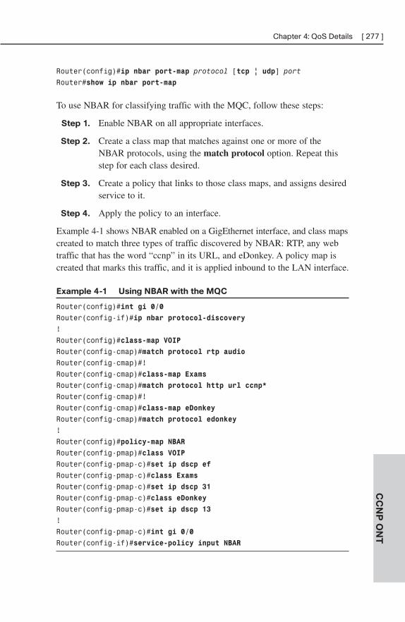
Router(config)#ip nbar port-map protocol [tcp | udp] port
Router#show ip nbar port-map
To use NBAR for classifying traffic with the MQC, follow these steps:
Step 1. Enable NBAR on all appropriate interfaces.
Step 2. Create a class map that matches against one or more of theNBAR protocols, using the match protocol option. Repeat thisstep for each class desired.
Step 3. Create a policy that links to those class maps, and assigns desiredservice to it.
Step 4. Apply the policy to an interface.
Example 4-1 shows NBAR enabled on a GigEthernet interface, and class mapscreated to match three types of traffic discovered by NBAR: RTP, any webtraffic that has the word “ccnp” in its URL, and eDonkey. A policy map iscreated that marks this traffic, and it is applied inbound to the LAN interface.
Example 4-1 Using NBAR with the MQC
Router(config)#int gi 0/0
Router(config-if)#ip nbar protocol-discovery
!
Router(config)#class-map VOIP
Router(config-cmap)#match protocol rtp audio
Router(config-cmap)#!
Router(config-cmap)#class-map Exams
Router(config-cmap)#match protocol http url ccnp*
Router(config-cmap)#!
Router(config-cmap)#class-map eDonkey
Router(config-cmap)#match protocol edonkey
!
Router(config)#policy-map NBAR
Router(config-pmap)#class VOIP
Router(config-pmap-c)#set ip dscp ef
Router(config-pmap-c)#class Exams
Router(config-pmap-c)#set ip dscp 31
Router(config-pmap-c)#class eDonkey
Router(config-pmap-c)#set ip dscp 13
!
Router(config-pmap-c)#int gi 0/0
Router(config-if)#service-policy input NBAR
CC
NP
ON
T
Chapter 4: QoS Details [ 277 ]
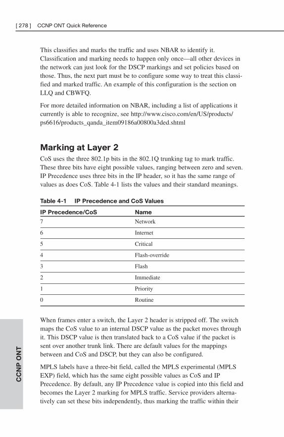
This classifies and marks the traffic and uses NBAR to identify it.Classification and marking needs to happen only once—all other devices inthe network can just look for the DSCP markings and set policies based onthose. Thus, the next part must be to configure some way to treat this classi-fied and marked traffic. An example of this configuration is the section onLLQ and CBWFQ.
For more detailed information on NBAR, including a list of applications itcurrently is able to recognize, see http://www.cisco.com/en/US/products/ps6616/products_qanda_item09186a00800a3ded.shtml
Marking at Layer 2
CoS uses the three 802.1p bits in the 802.1Q trunking tag to mark traffic.These three bits have eight possible values, ranging between zero and seven.IP Precedence uses three bits in the IP header, so it has the same range ofvalues as does CoS. Table 4-1 lists the values and their standard meanings.
Table 4-1 IP Precedence and CoS Values
IP Precedence/CoS Name
7 Network
6 Internet
5 Critical
4 Flash-override
3 Flash
2 Immediate
1 Priority
0 Routine
When frames enter a switch, the Layer 2 header is stripped off. The switchmaps the CoS value to an internal DSCP value as the packet moves throughit. This DSCP value is then translated back to a CoS value if the packet issent over another trunk link. There are default values for the mappingsbetween and CoS and DSCP, but they can also be configured.
MPLS labels have a three-bit field, called the MPLS experimental (MPLSEXP) field, which has the same eight possible values as CoS and IPPrecedence. By default, any IP Precedence value is copied into this field andbecomes the Layer 2 marking for MPLS traffic. Service providers alterna-tively can set these bits independently, thus marking the traffic within their
CC
NP
ON
T[ 278 ] CCNP ONT Quick Reference
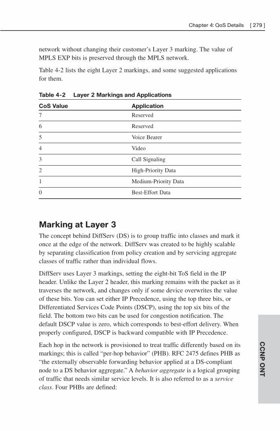
network without changing their customer’s Layer 3 marking. The value ofMPLS EXP bits is preserved through the MPLS network.
Table 4-2 lists the eight Layer 2 markings, and some suggested applicationsfor them.
Table 4-2 Layer 2 Markings and Applications
CoS Value Application
7 Reserved
6 Reserved
5 Voice Bearer
4 Video
3 Call Signaling
2 High-Priority Data
1 Medium-Priority Data
0 Best-Effort Data
Marking at Layer 3
The concept behind DiffServ (DS) is to group traffic into classes and mark itonce at the edge of the network. DiffServ was created to be highly scalableby separating classification from policy creation and by servicing aggregateclasses of traffic rather than individual flows.
DiffServ uses Layer 3 markings, setting the eight-bit ToS field in the IPheader. Unlike the Layer 2 header, this marking remains with the packet as ittraverses the network, and changes only if some device overwrites the valueof these bits. You can set either IP Precedence, using the top three bits, orDifferentiated Services Code Points (DSCP), using the top six bits of thefield. The bottom two bits can be used for congestion notification. Thedefault DSCP value is zero, which corresponds to best-effort delivery. Whenproperly configured, DSCP is backward compatible with IP Precedence.
Each hop in the network is provisioned to treat traffic differently based on itsmarkings; this is called “per-hop behavior” (PHB). RFC 2475 defines PHB as“the externally observable forwarding behavior applied at a DS-compliantnode to a DS behavior aggregate.” A behavior aggregate is a logical groupingof traffic that needs similar service levels. It is also referred to as a serviceclass. Four PHBs are defined:
CC
NP
ON
T
Chapter 4: QoS Details [ 279 ]
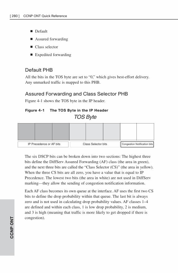
■ Default
■ Assured forwarding
■ Class selector
■ Expedited forwarding
Default PHBAll the bits in the TOS byte are set to “0,” which gives best-effort delivery.Any unmarked traffic is mapped to this PHB.
Assured Forwarding and Class Selector PHBFigure 4-1 shows the TOS byte in the IP header.
Figure 4-1 The TOS Byte in the IP Header
CC
NP
ON
T[ 280 ] CCNP ONT Quick Reference
Congestion Notification bitsIP Precedence or AF bits Class Selector bits
TOS Byte
The six DSCP bits can be broken down into two sections: The highest threebits define the DiffServ Assured Forwarding (AF) class (the area in green),and the next three bits are called the “Class Selector (CS)” (the area in yellow).When the three CS bits are all zero, you have a value that is equal to IPPrecedence. The lowest two bits (the area in white) are not used in DiffServmarking—they allow the sending of congestion notification information.
Each AF class becomes its own queue at the interface. AF uses the first two CSbits to define the drop probability within that queue. The last bit is alwayszero and is not used in calculating drop probability values. AF classes 1–4are defined and within each class, 1 is low drop probability, 2 is medium,and 3 is high (meaning that traffic is more likely to get dropped if there iscongestion).
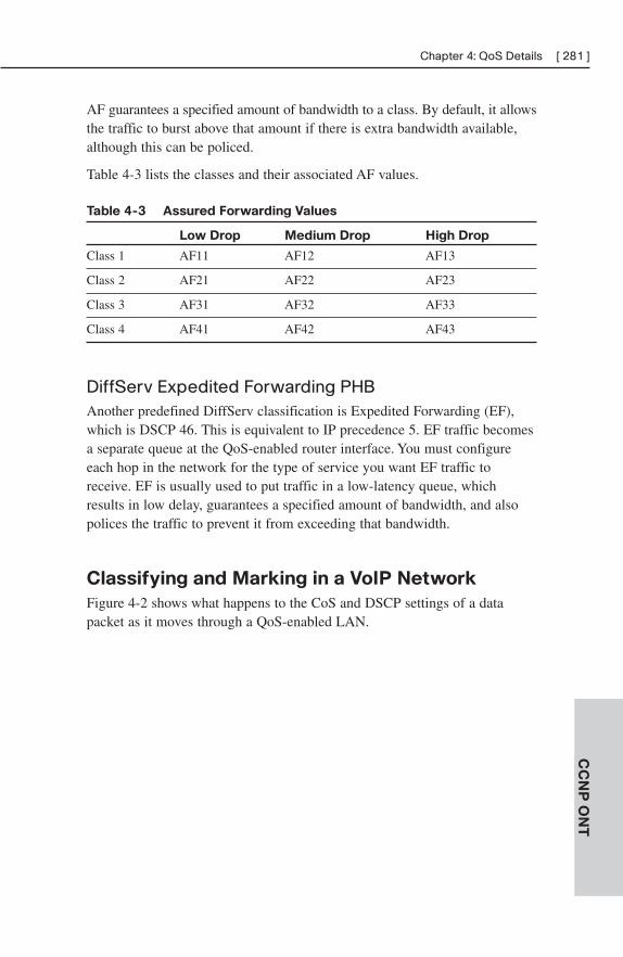
AF guarantees a specified amount of bandwidth to a class. By default, it allowsthe traffic to burst above that amount if there is extra bandwidth available,although this can be policed.
Table 4-3 lists the classes and their associated AF values.
Table 4-3 Assured Forwarding Values
Low Drop Medium Drop High Drop
Class 1 AF11 AF12 AF13
Class 2 AF21 AF22 AF23
Class 3 AF31 AF32 AF33
Class 4 AF41 AF42 AF43
DiffServ Expedited Forwarding PHBAnother predefined DiffServ classification is Expedited Forwarding (EF),which is DSCP 46. This is equivalent to IP precedence 5. EF traffic becomesa separate queue at the QoS-enabled router interface. You must configureeach hop in the network for the type of service you want EF traffic toreceive. EF is usually used to put traffic in a low-latency queue, whichresults in low delay, guarantees a specified amount of bandwidth, and alsopolices the traffic to prevent it from exceeding that bandwidth.
Classifying and Marking in a VoIP Network
Figure 4-2 shows what happens to the CoS and DSCP settings of a datapacket as it moves through a QoS-enabled LAN.
CC
NP
ON
T
Chapter 4: QoS Details [ 281 ]
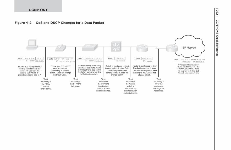
Figure 4-2 CoS and DSCP Changes for a Data Packet
CCNP ONT[ 2
82
]C
CN
P O
NT
Quick R
efe
rence
Trustboundary ifthe PC istrusted
(rarely done).
Trustboundary if
the IP Phoneis trusted.
Trustboundary if
the IP Phoneis untrusted,
but the Accessswitch is trusted.
Trustboundary ifthe Access
switch isuntrusted, butthe Distribution
switch is trusted.
Trustboundary ifISP if the
customer’smarkings arenot trusted.
ISP Network
PC with 802.1Q-capable NICsends a packet through thephone. PC user sets thepacket’s DSCP to 56 (IP
precedence 7) and CoS to 7.
Data DSCP = 56IP Header
CoS = 7802.1p bits
Phone sets CoS on PCtraffic to 0 before
forwarding to Accessswitch. Does not change
the DSCP value.
Data DSCP = 56IP Header
CoS = 0802.1p bits
Switch is configured classifyand mark data traffic. It setsboth DSCP and CoS on PCtraffic to 1 before forwarding
to Distribution switch.
Data DSCP = 1IP Header
CoS = 1802.1p bits
Data DSCP = 1IP Header
Switch is configured to trustAccess switch. It gives QoS
service to packet whensending to router, does not
change DSCP.
Router is configured to trustDistribution switch. It givesQoS service to packet whennsending to WAN, does not
change DSCP.
Data DSCP = 1IP Header
Data DSCP = 1IP Header
ISP does not trust customerrouter, leaves DSCP at 1 butsets MPLS EXP to 0. Trafficwill be given best-effort QoSthrough provider’s network.
MPLS EXP = 0MPLS Label
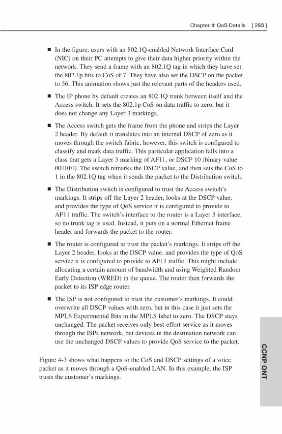
■ In the figure, users with an 802.1Q-enabled Network Interface Card(NIC) on their PC attempts to give their data higher priority within thenetwork. They send a frame with an 802.1Q tag in which they have setthe 802.1p bits to CoS of 7. They have also set the DSCP on the packetto 56. This animation shows just the relevant parts of the headers used.
■ The IP phone by default creates an 802.1Q trunk between itself and theAccess switch. It sets the 802.1p CoS on data traffic to zero, but itdoes not change any Layer 3 markings.
■ The Access switch gets the frame from the phone and strips the Layer2 header. By default it translates into an internal DSCP of zero as itmoves through the switch fabric; however, this switch is configured toclassify and mark data traffic. This particular application falls into aclass that gets a Layer 3 marking of AF11, or DSCP 10 (binary value001010). The switch remarks the DSCP value, and then sets the CoS to1 in the 802.1Q tag when it sends the packet to the Distribution switch.
■ The Distribution switch is configured to trust the Access switch’smarkings. It strips off the Layer 2 header, looks at the DSCP value,and provides the type of QoS service it is configured to provide toAF11 traffic. The switch’s interface to the router is a Layer 3 interface,so no trunk tag is used. Instead, it puts on a normal Ethernet frameheader and forwards the packet to the router.
■ The router is configured to trust the packet’s markings. It strips off theLayer 2 header, looks at the DSCP value, and provides the type of QoSservice it is configured to provide to AF11 traffic. This might includeallocating a certain amount of bandwidth and using Weighted RandomEarly Detection (WRED) in the queue. The router then forwards thepacket to its ISP edge router.
■ The ISP is not configured to trust the customer’s markings. It couldoverwrite all DSCP values with zero, but in this case it just sets theMPLS Experimental Bits in the MPLS label to zero. The DSCP staysunchanged. The packet receives only best-effort service as it movesthrough the ISPs network, but devices in the destination network canuse the unchanged DSCP values to provide QoS service to the packet.
Figure 4-3 shows what happens to the CoS and DSCP settings of a voicepacket as it moves through a QoS-enabled LAN. In this example, the ISPtrusts the customer’s markings.
CC
NP
ON
T
Chapter 4: QoS Details [ 283 ]
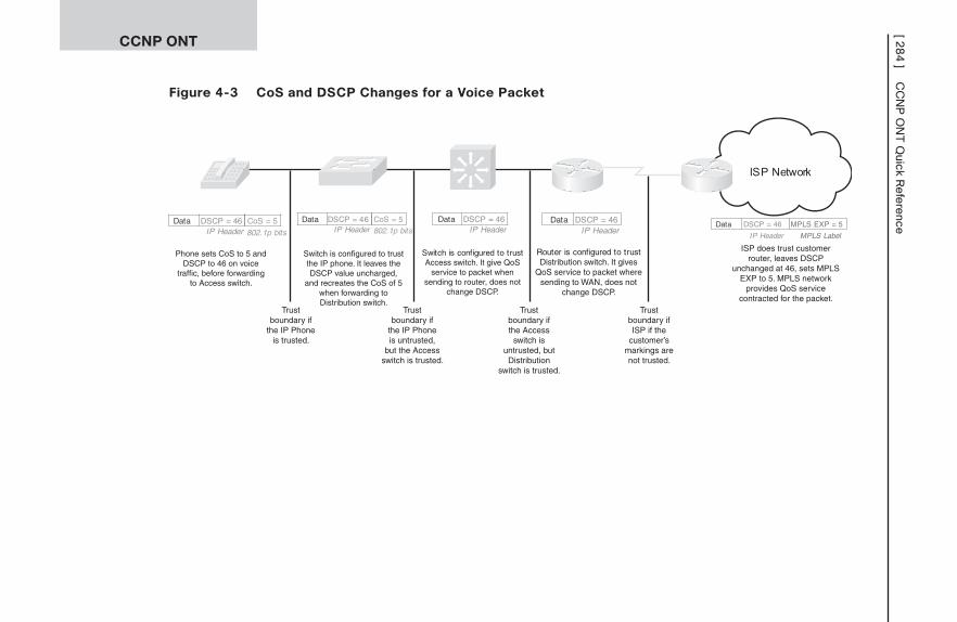
Figure 4-3 CoS and DSCP Changes for a Voice Packet
CCNP ONT[ 2
84
]C
CN
P O
NT
Quick R
efe
rence
Trustboundary if
the IP Phoneis trusted.
Trustboundary if
the IP Phoneis untrusted,
but the Accessswitch is trusted.
Trustboundary ifthe Access
switch isuntrusted, but
Distributionswitch is trusted.
Trustboundary ifISP if the
customer’smarkings arenot trusted.
ISP Network
Phone sets CoS to 5 andDSCP to 46 on voice
traffic, before forwardingto Access switch.
Switch is configured to trustthe IP phone. It leaves theDSCP value uncharged,
and recreates the CoS of 5when forwarding toDistribution switch.
Data DSCP = 46IP Header
CoS = 5802.1p bits
Data DSCP = 46IP Header
CoS = 5802.1p bits
Data DSCP = 46IP Header
Switch is configured to trustAccess switch. It give QoS
service to packet whensending to router, does not
change DSCP.
Router is configured to trustDistribution switch. It gives
QoS service to packet wheresending to WAN, does not
change DSCP.
Data DSCP = 46IP Header
Data DSCP = 46
IP Header
ISP does trust customerrouter, leaves DSCP
unchanged at 46, sets MPLSEXP to 5. MPLS network
provides QoS servicecontracted for the packet.
MPLS EXP = 5
MPLS Label
■ The Cisco IP phone creates an 802.1Q trunk between itself and theAccess switch. It sets the 802.1p CoS on its own voice media traffic to5, and it sets the Layer 3 marking to EF or DSCP 46 (binary value101110). If this were voice signaling traffic, the phone would set aCoS of 3 and a Layer 3 marking of CS3, or DSCP 24 (binary value011000).
■ The Access switch gets the frame from the phone and strips the Layer2 header. It is configured to trust the IP phone, so it translates the CoSvalue into an internal DSCP as the packet moves through the switchfabric. The switch then translates that internal DSCP value back to aCoS of 5 in the 802.1Q tag when it sends the packet to the Distributionswitch. The Access switch applies any outbound policies configuredfor this traffic, such as putting it into a priority interface queue, as itsends it to the outbound interface.
■ The Distribution switch is configured to trust the Access switch’smarkings. It strips off the Layer 2 header, looks at the DSCP value,and provides the type of QoS service it is configured to provide to EFtraffic. This typically includes placing the packet in a priority queue atthe interface. The switch’s interface to the router is a Layer 3 interface,so no trunk tag is used. Instead it puts on a normal Ethernet frameheader and forwards the packet to the router.
■ The router is configured to trust the packet’s markings. It strips off theLayer 2 header, looks at the DSCP value, and provides the type of QoSservice it is configured to provide to EF traffic. This typically includesplacing the packet in an LLQ and allocating a certain amount of band-width to that queue. The router then forwards the packet to its ISPedge router.
■ The ISP is configured to trust the customer’s markings. It translates theIP precedence value of 5 into an MPLS Experimental Bits value of 5.The DSCP stays unchanged. The packet receives prioritized, real-timeservice as it moves through the ISPs network, and devices in the desti-nation network can use the unchanged DSCP values to also provideQoS service to the packet.
CC
NP
ON
T
Chapter 4: QoS Details [ 285 ]
Queuing OverviewQueuing configuration usually acts on outbound traffic. Each interface has ahardware queue, or transmit ring (TxQ), that holds traffic ready to be serial-ized onto the interface media. This queue is always First In/First Out (FIFO).When outbound traffic arrives at an interface, the interface scheduler sends itto the transmit ring to be placed on the media. If the transmit ring is full,other traffic must wait in some buffer memory space assigned to that inter-face called a software queue. When traffic must be placed into queues, theinterface is said to be congested.
Causes of congestion include:
■ Speed mismatches—Typically LAN traffic needing to go across amuch slower WAN link (persistent congestion). It can also beGigEthernet traffic bound out a FastEthernet interface (transientcongestion).
■ Link aggregation—For WAN links, this occurs when multiple remotesites access a hub site across an oversubscribed link. For LAN links,this typically occurs on a distribution switch with multiple accessswitches feeding in to it on the uplink port(s) to the core switch.
Hardware Queue
Logical interfaces, such as subinterfaces and tunnel interfaces, use the hard-ware queue of the physical interface; they do not have their own transmitqueues.
The number of packets a TxQ can hold depends on the speed of the inter-face. It is automatically determined, and that length is typically fine but canbe tuned if desired. Most devices use the tx ring-limit command for tuningTxQ size.
Lowering the Tx ring size lessens the length of time a packet waits in theFIFO queue, and it increases the chance of a packet hitting the softwarequeue. However, too short of a TxQ results in router resource use, as theCPU must be interrupted each time the Tx ring requests a packet from asoftware queue. A decrease in ring size means an increase in interrupts.
Increasing the TxQ size is usually not recommended when using QoS,because it decreases the use of the software queue.
Use the show controllers interface command to find information about thetransmit ring size.
CC
NP
ON
T[ 286 ] CCNP ONT Quick Reference
Software Queue
The software queuing strategy is configurable, and the next sections dealwith various techniques to do this. This is where you can influence the orderin which packets are scheduled into the TxQ and the number of packets sent.When using queuing mechanisms, several different logical queues arecreated, and traffic is placed into the appropriate software queue when itarrives at the interface. Each software queue has size limits, and packetsabove that limit are dropped.
Remember that fast-switched or CEF-switched traffic enters the softwarequeue only if the hardware queue is congested. Process-switched trafficalways goes into the software queue.
Legacy Queuing TechniquesQueuing mechanisms allow you to control the way congested traffic isbuffered and send out the interface by placing each type of traffic in its ownqueue. The router or switch then services each queue, scheduling transmittalof its traffic, according to a configured policy.
FIFO Queuing
By default, most interfaces use FIFO queuing—there is just one softwarequeue, and traffic is buffered and then scheduled onto the interface in theorder it is received.
Note
Serial interfaces of E1 speed and below use weighted fair queuing by default, rather than FIFOqueuing.
Priority Queuing
With Priority queuing, queues are assigned different priority values andplaced in one of four queues. The high-priority queue is a strict priorityqueue, which means that it gets serviced before anything else until it isempty. After that, each queue is serviced in turn, as long as the priorityqueue remains empty. The lower-priority queues may never be serviced if there is sufficient traffic in higher-priority queues (a condition called “starvation”).
CC
NP
ON
T
Chapter 4: QoS Details [ 287 ]
Round Robin Queuing
Round Robin queuing takes one packet from each queue and then startsover. Each queue is serviced, none starve, but there is no way to prioritizeany of the traffic or apply any sort of differential treatment to it.
During times of interface congestion, Weighted Round Robin (WRR)queuing weights queues, and more packets are sent from higher weightedqueues, thus giving them more bandwidth. However, the bandwidth alloca-tions are done in a way that might lead to more bytes being sent from somequeues than desired, which causes other packets to be delayed.
Weighted Fair Queuing
Weighted Fair Queuing (WFQ) attempts to address some of the failing ofFIFO and Priority queuing by allowing all traffic some access to the inter-face. Some characteristics of WFQ include:
■ Queues traffic by flow or conversation.
■ Flows are identified by header information, such as source and desti-nation IP address, protocol, source and destination ports, and type ofservice field value. These are used by a hash algorithm to create aqueue index number.
■ Each interface has a limited number of WFQ queues. Default for mostinterfaces is 256; it can be configured from 16–4096.
■ If the number of flows exceeds the number of queues, multiple flowsare placed in the same queue, resulting in less bandwidth per flow.
■ Provides queues for system traffic and RSVP traffic separate from theWFQ queues.
■ Traffic is weighted by flow, based on IP precedence.
■ WFQ schedules small interactive flows before high-bandwidth flows.
■ Allows lower-weighted flows relatively more bandwidth than higher-weighted conversations.
■ Drops packets from high-volume flows more aggressively than thoseof low-volume flows.
■ The hold-queue limit determines how many packets can be held in theWFQ system before all new packets are dropped (tail drop). Thedefault is 1000.
CC
NP
ON
T[ 288 ] CCNP ONT Quick Reference
■ The congestive discard threshold (CDT) determines how many packetscan be held by the WFQ before it begins dropping packets from high-volume flows. Packets are dropped from the queues with the mostpackets first. Packets are not dropped from low-volume conversations.The default CDT is 64.
Advantages of WFQ include simplicity of configuration, support on mostplatforms and IOS versions, allowing some bandwidth to all traffic, anddropping more packets from higher-bandwidth flows.
Disadvantages of WFQ include lack of support for tunneling or encryption,lack of manual control over traffic classification, lack of minimum or fixedbandwidth guarantees, and chance of multiple flows placed in the samequeue.
Configuring WFQWFQ is enabled by default on physical interfaces with a bandwidth less than2.048 Mbps. If it has been disabled, or to enable it on another interface, usethe interface command fair-queue [congestive-discard-threshold [dynamic-queues [reservable-queues]]]. For example, the following commands enableWFQ on the serial interface, set a CDT of 100, increase the number of flowqueues to 512, and reserve 10 queues for RSVP to use.
Router(config)#int s1/0/0:0
Router(config-if)#fair-queue 100 512 10
To change the size of the hold queue, use the hold-queue number {in | out}interface command, as shown:
Router(config-if)#hold-queue 2000 out
To monitor the interface queues, use either show interface interface or showqueue interface:
Router#show interface s1/0/0:0
[output omitted]
Input queue: 0/75/0/0 (size/max/drops/flushes); Total outputdrops: 0
Queueing strategy: weighted fair
Output queue: 0/2000/100/0 (size/max total/threshold/drops)
Conversations 0/0/512 (active/max active/max total)
Reserved Conversations 0/0 (allocated/max allocated)
Available Bandwidth 2250 kilobits/sec
[output omitted]
CC
NP
ON
T
Chapter 4: QoS Details [ 289 ]
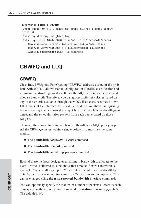
Router#show queue s1/0/0:0
Input queue: 0/75/0/0 (size/max/drops/flushes); Total outputdrops: 0
Queueing strategy: weighted fair
Output queue: 0/1000/100/0 (size/max total/threshold/drops)
Conversations 0/0/512 (active/max active/max total)
Reserved Conversations 0/0 (allocated/max allocated)
Available Bandwidth 2250 kilobits/sec
CBWFQ and LLQ
CBWFQ
Class-Based Weighted Fair Queuing (CBWFQ) addresses some of the prob-lems with WFQ. It allows manual configuration of traffic classification andminimum bandwidth guarantees. It uses the MQC to configure classes andallocate bandwidth. Therefore, you can group traffic into classes based onany of the criteria available through the MQC. Each class becomes its ownFIFO queue at the interface. This is still considered Weighted Fair Queuingbecause each queue is assigned a weight based on the class bandwidth guar-antee, and the scheduler takes packets from each queue based on thoseweights.
There are three ways to designate bandwidth within an MQC policy map.All the CBWFQ classes within a single policy map must use the samemethod.
■ The bandwidth bandwidth-in-kbps command
■ The bandwidth percent command
■ The bandwidth remaining percent command
Each of these methods designates a minimum bandwidth to allocate to theclass. Traffic is allowed to burst above that amount if extra bandwidth isavailable. You can allocate up to 75 percent of the interface bandwidth bydefault; the rest is reserved for system traffic, such as routing updates. Thiscan be changed using the max-reserved-bandwidth interface command.
You can optionally specify the maximum number of packets allowed in eachclass queue with the policy map command queue-limit number-of-packets.The default is 64.
CC
NP
ON
T[ 290 ] CCNP ONT Quick Reference
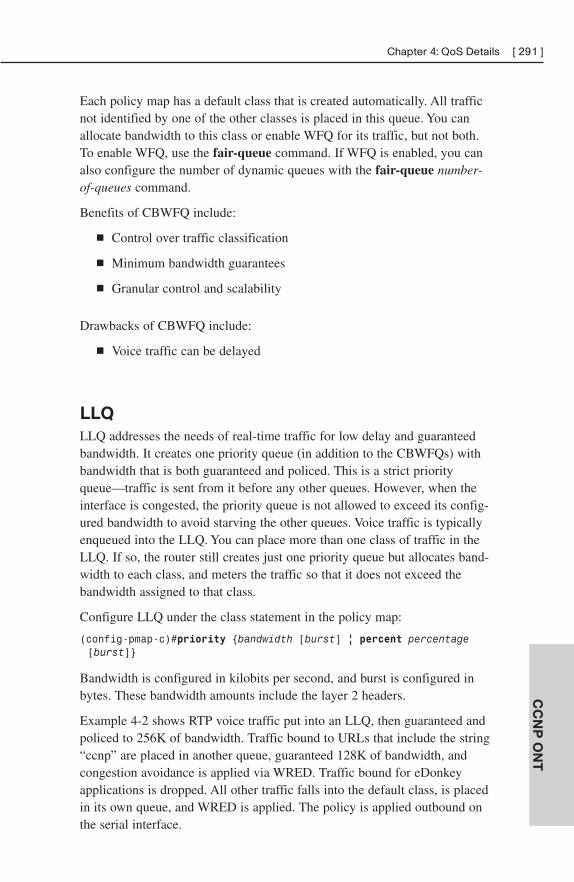
Each policy map has a default class that is created automatically. All trafficnot identified by one of the other classes is placed in this queue. You canallocate bandwidth to this class or enable WFQ for its traffic, but not both.To enable WFQ, use the fair-queue command. If WFQ is enabled, you canalso configure the number of dynamic queues with the fair-queue number-of-queues command.
Benefits of CBWFQ include:
■ Control over traffic classification
■ Minimum bandwidth guarantees
■ Granular control and scalability
Drawbacks of CBWFQ include:
■ Voice traffic can be delayed
LLQ
LLQ addresses the needs of real-time traffic for low delay and guaranteedbandwidth. It creates one priority queue (in addition to the CBWFQs) withbandwidth that is both guaranteed and policed. This is a strict priorityqueue—traffic is sent from it before any other queues. However, when theinterface is congested, the priority queue is not allowed to exceed its config-ured bandwidth to avoid starving the other queues. Voice traffic is typicallyenqueued into the LLQ. You can place more than one class of traffic in theLLQ. If so, the router still creates just one priority queue but allocates band-width to each class, and meters the traffic so that it does not exceed thebandwidth assigned to that class.
Configure LLQ under the class statement in the policy map:
(config-pmap-c)#priority {bandwidth [burst] | percent percentage[burst]}
Bandwidth is configured in kilobits per second, and burst is configured inbytes. These bandwidth amounts include the layer 2 headers.
Example 4-2 shows RTP voice traffic put into an LLQ, then guaranteed andpoliced to 256K of bandwidth. Traffic bound to URLs that include the string“ccnp” are placed in another queue, guaranteed 128K of bandwidth, andcongestion avoidance is applied via WRED. Traffic bound for eDonkeyapplications is dropped. All other traffic falls into the default class, is placedin its own queue, and WRED is applied. The policy is applied outbound onthe serial interface.
CC
NP
ON
T
Chapter 4: QoS Details [ 291 ]
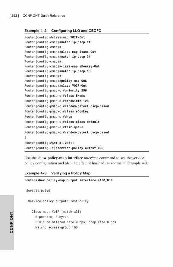
Example 4-2 Configuring LLQ and CBQFQ
Router(config)#class-map VOIP-Out
Router(config-cmap)#match ip dscp ef
Router(config-cmap)#!
Router(config-cmap)#class-map Exams-Out
Router(config-cmap)#match ip dscp 31
Router(config-cmap)#!
Router(config-cmap)#class-map eDonkey-Out
Router(config-cmap)#match ip dscp 13
Router(config-cmap)#!
Router(config-cmap)#policy-map QOS
Router(config-pmap)#class VOIP-Out
Router(config-pmap-c)#priority 256
Router(config-pmap-c)#class Exams
Router(config-pmap-c)#bandwidth 128
Router(config-pmap-c)#random-detect dscp-based
Router(config-pmap-c)#class eDonkey
Router(config-pmap-c)#drop
Router(config-pmap-c)#class class-default
Router(config-pmap-c)#fair-queue
Router(config-pmap-c)#random-detect dscp-based
!
Router(config)#int s1/0/0:1
Router(config-if)#service-policy output QOS
Use the show policy-map interface interface command to see the servicepolicy configuration and also the effect it has had, as shown in Example 4-3.
Example 4-3 Verifying a Policy Map
Router#show policy-map output interface s1/0/0:0
Serial1/0/0:0
Service-policy output: TestPolicy
Class-map: VoIP (match-all)
0 packets, 0 bytes
5 minute offered rate 0 bps, drop rate 0 bps
Match: access-group 100
CC
NP
ON
T[ 292 ] CCNP ONT Quick Reference
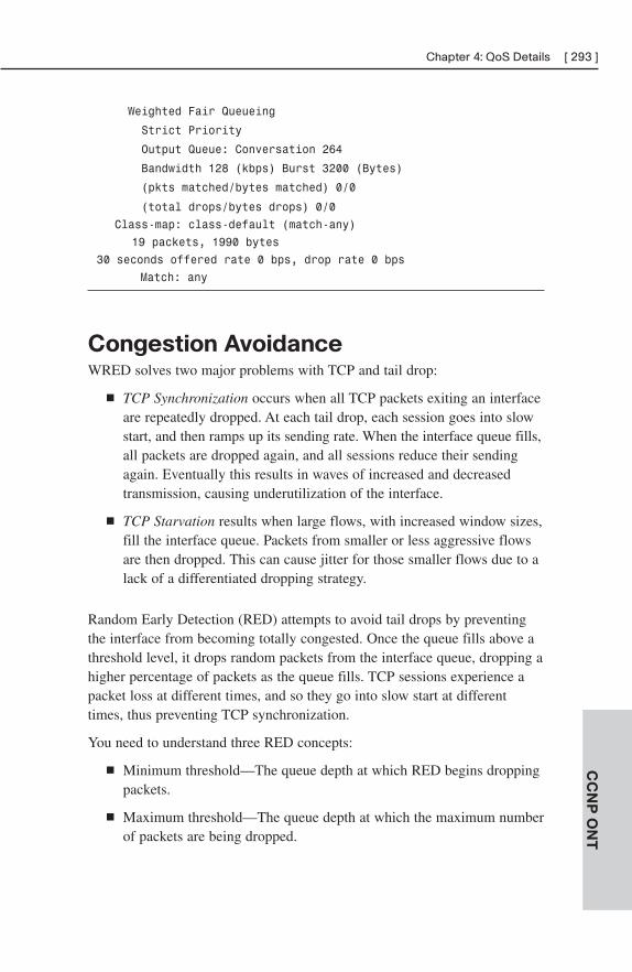
Weighted Fair Queueing
Strict Priority
Output Queue: Conversation 264
Bandwidth 128 (kbps) Burst 3200 (Bytes)
(pkts matched/bytes matched) 0/0
(total drops/bytes drops) 0/0
Class-map: class-default (match-any)
19 packets, 1990 bytes
30 seconds offered rate 0 bps, drop rate 0 bps
Match: any
Congestion AvoidanceWRED solves two major problems with TCP and tail drop:
■ TCP Synchronization occurs when all TCP packets exiting an interfaceare repeatedly dropped. At each tail drop, each session goes into slowstart, and then ramps up its sending rate. When the interface queue fills,all packets are dropped again, and all sessions reduce their sendingagain. Eventually this results in waves of increased and decreasedtransmission, causing underutilization of the interface.
■ TCP Starvation results when large flows, with increased window sizes,fill the interface queue. Packets from smaller or less aggressive flowsare then dropped. This can cause jitter for those smaller flows due to alack of a differentiated dropping strategy.
Random Early Detection (RED) attempts to avoid tail drops by preventingthe interface from becoming totally congested. Once the queue fills above athreshold level, it drops random packets from the interface queue, dropping ahigher percentage of packets as the queue fills. TCP sessions experience apacket loss at different times, and so they go into slow start at differenttimes, thus preventing TCP synchronization.
You need to understand three RED concepts:
■ Minimum threshold—The queue depth at which RED begins droppingpackets.
■ Maximum threshold—The queue depth at which the maximum numberof packets are being dropped.
CC
NP
ON
T
Chapter 4: QoS Details [ 293 ]
■ Mark probability denominator—Controls how many packets aredropped when the maximum threshold is reached. The probability of apacket being dropped equals 1/max-prob-denom.
RED has three packet-dropping modes:
■ No drop—When the queue depth is between zero and the minimumthreshold.
■ Random drop—When the queue depth is between the minimum andthe maximum thresholds.
■ Tail drop—When the queue depth is above the maximum threshold.
Basic RED does not distinguish between flows or types of traffic. WeightedRED, on the other hand, drops traffic differently depending on its IP prece-dence or DSCP value. WRED is combined with CBWFQ to implementDiffServ’s Assured Forwarding PHB. Each PHB has a unique WREDprofile, identifying a minimum threshold, maximum threshold, and markprobability denominator for that profile. There are default profiles for eachPHB, but they can also be manually configured.
Configure WRED under a physical interface, a VC, or a class within a policymap with the command random-detect [dscp-based]. Packet drop decisionsare based on IP precedence value unless the dscp-based option is configured.To change the default profile for a specific DSCP value, use the random-detectdscp dscp-value min-threshold max-threshold mark-probability-denominatorcommand.
Traffic Policing and ShapingTraffic policing and traffic shaping are both ways to control the amount oftraffic through an interface. Policing drops traffic, whereas shaping buffers itfor sending later. Policing can be used inbound or outbound, but shaping isused only on outbound traffic.
Both mechanisms use a token bucket concept to measure the amount ofbandwidth allowed. Enough tokens enter the bucket at regular intervals toallow the interface to send the number of bytes configured for that interval.If a packet enqueued has fewer bytes than are represented by tokens in thebucket, it considered a conforming packet. The packet is sent and an equiva-lent number of tokens are subtracted from the bucket. If it has more bytesthan there are tokens to send, it is considered an exceeding packet. Therouter then takes action based on whether policing or shaping is configured.
CC
NP
ON
T[ 294 ] CCNP ONT Quick Reference
Some implementations use two token buckets. If a packet exceeds the firstbucket, it is checked against the second one. If there are not enough tokensin the second bucket to send the packet, it is considered a violation.
If all the tokens are not used within the interval, they can accrue and remainavailable to future packets if bursting is enabled.
Traffic Policing
By using the QoS policing function, bandwidth use can be controlled onphysical interfaces. Policing specifies an amount of bandwidth allowed for aparticular type of traffic, and generally drops traffic over that amount. It canalso be configured to allow the excess traffic, but it marks it with a different(usually lower) DSCP value.
Some uses for policing include:
■ Limiting the bandwidth of a high-speed interface to a lower rate
■ Limiting the rate of an application or a traffic class
■ Remarking the DSCP of traffic exceeding a specified rate
Class-based policing is configured in a policy map. Its possible conditionsare: Conform, Exceed, and Violate. Its possible actions are: Drop, Set(DSCP, for example), and Transmit.
Traffic Shaping
Traffic shaping also controls the amount of traffic sent out an interface, butshaping buffers excess traffic instead of dropping it. Because data is usuallybursty, the buffered traffic can be sent out between bursts. Thus, shapingsmoothes out the flow of traffic. This also results in fewer packet drops, andthus fewer TCP retransmits. It does, however, introduce some delay fortraffic that must be buffered. It does not support remarking traffic.
Some uses for shaping include:
■ Making the outgoing traffic rate match the contracted committed infor-mation rate (CIR).
■ To avoid overrunning remote links in networks, such as ATM, FrameRelay, and Metro Ethernet, that might have different bandwidths onhub and spoke devices.
■ Interacting with Frame Relay congestion notifications, causing therouter to throttle-back its sending rate.
CC
NP
ON
T
Chapter 4: QoS Details [ 295 ]
Class-based traffic shaping is configured under the policy map. It works withany type of interface, not just Frame Relay interfaces.
Link Efficiency MechanismsAlthough QoS mechanisms cannot actually create bandwidth, they can helpyour network use the available bandwidth more efficiently. Two ways ofdoing this are compression and fragmentation. These mechanisms are typi-cally applied at the WAN edge, where links are slower than within the LAN.
Compression
Compressing the traffic on a line creates more useable bandwidth; becauseeach frame is smaller, there are fewer bits to transmit. Thus, the serializationdelay is reduced, and more frames can be sent. Cisco IOS supports twotypes of compression: payload and header.
Payload compression can be done at either Layer 2 or Layer 3.
■ Layer 2 Payload Compression—The Layer 2 payload compressioncompresses the Layer 3 and 4 headers and the packet data. Layer 2payload compression is typically a hop-by-hop mechanism, becausethe Layer 2 header is removed at each hop. Layer 2 compression donein software is CPU-intensive and might actually add extra delay to thetraffic flow. Hardware compression, however, adds little delay. Ciscosupports three Layer 2 payload compression algorithms:
— Stacker
— Predictor
— Microsoft Point-to-Point Compression (MPPC)
■ Layer 3 Payload Compression—Layer 3 payload compressioncompresses the Layer 4 header and the packet data. It is generallydone session-by-session.
Header compression leaves the payload intact but compresses the headers.TCP header compression compresses the IP and TCP headers. RTP headercompression compresses the IP, UDP, and RTP headers. It is most effectivewhen the headers are much larger than the payload, such as with Telnet orVoIP. Headers do not change much over the life of a flow and contain manyredundant fields (such as source and destination IP address, protocol, andport). Compression removes the redundant information and sends only thenew information and an index pointing to the unchanged information.
CC
NP
ON
T[ 296 ] CCNP ONT Quick Reference
Compression configured on a physical interface applies to all flows. Formore granular control over which traffic is compressed, configure it in theMQC policy map under the desired classes. Header compression uses fairlyfew CPU resources.
Link Fragmentation and Interleave (LFI)
A typical network has a range of packet sizes. Small packets can be delayedwaiting for a large packet to be sent out the interface. This can happen evenif LLQ is configured—a small voice packet might be sent immediately to thehardware queue. However, the hardware queue is FIFO. If a large packetarrived there just before the voice packet, it is serialized out the interfacefirst. The voice packet has to wait. This causes delay and jitter.
LFI breaks large packets into smaller segments and intersperses the smallerpackets between the pieces of the big ones. Thus, delay and jitter are reducedfor the small packets.
The target serialization delay for voice is 10–15 ms. At 2 Mbps link speed, a1500 byte packet can be serialized in 10 ms. Thus, there is typically no needfor LFI on links over E1 speed.
QoS with VPNsA Virtual Private Network (VPN) is a way of creating a virtual point-to-pointlink over a shared network (often over the Internet). It can be used either foruser remote access or for intrasite links. Two types of remote access VPNsare:
■ Client-initiated—The user has a VPN client application, such asCisco’s VPN Client, on their computer. After they are connected to theInternet, they use the application to connect them to their network.
■ Network Access Server (NAS) initiated—Users connect into an accessserver at their ISP. The NAS then sets up a VPN to the private network.
Two types of intrasite VPNs are:
■ Intranet VPN—Links sites within the same company to each other.
■ Extranet VPN—Links an external group (such as a customer orsupplier) to the company’s private network.
CC
NP
ON
T
Chapter 4: QoS Details [ 297 ]
VPNs have several advantages, including:
■ The ability to encrypt traffic across the public network and keep itconfidential.
■ The ability to verify that the data was not changed between the sourceand destination.
■ The ability to authenticate the packet sender.
Router-to-router VPN tunnels use a logical tunnel interface that is created onthe router. This interface is where you put configuration pertaining to thetunnel itself. Tunnel traffic uses one of the router’s physical interfaces, deter-mined by the routing table. Configuration on this interface applies to alltraffic, even if several tunnels use that interface.
VPNs create an extra challenge for QoS. A VPN tunnels traffic from onedevice to another by adding an IP header on top of the original one. Thus,the original header, with its QoS markings, is hidden from routers in thepacket’s path. If the packet needs any special QoS treatment, the markingsmust be copied from the original IP header into the tunnel IP header.
GRE Tunnels
Generic Routing Encapsulation (GRE) tunnels add a GRE header and atunnel IP header to the packet. By default, TOS markings on the originalpacket are copied into the tunnel IP header. When the packet arrives at thephysical interface, classification and queuing are based on the markings inthe tunnel IP header.
IPsec Tunnels
IP Security (IPSec) can operate in either tunnel mode or transport mode. Intunnel mode, it creates a tunnel through the underlying network. In transportmode, it provides security over normal physical links or over a tunnelcreated with a different protocol. IPSec can also provide either authentica-tion alone using Authentication Headers (AH) or encryption and authentica-tion using Encapsulation Security Protocol (ESP). Table 4-4 describes thedifferences between AH and ESP.
CC
NP
ON
T[ 298 ] CCNP ONT Quick Reference
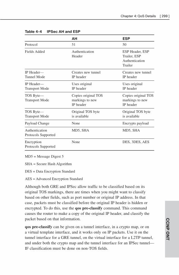
Table 4-4 IPSec AH and ESP
AH ESP
Protocol 51 50
Fields Added Authentication ESP Header, ESP Header Trailer, ESP
AuthenticationTrailer
IP Header— Creates new tunnel Creates new tunnel Tunnel Mode IP header IP header
IP Header— Uses original Uses original Transport Mode IP header IP header
TOS Byte— Copies original TOS Copies original TOS Transport Mode markings to new markings to new
IP header IP header
TOS Byte— Original TOS byte Original TOS byte Transport Mode is available is available
Payload Change None Encrypts payload
Authentication MD5, SHA MD5, SHAProtocols Supported
Encryption None DES, 3DES, AESProtocols Supported
MD5 = Message Digest 5
SHA = Secure Hash Algorithm
DES = Data Encryption Standard
AES = Advanced Encryption Standard
Although both GRE and IPSec allow traffic to be classified based on its original TOS markings, there are times when you might want to classifybased on other fields, such as port number or original IP address. In thatcase, packets must be classified before the original IP header is hidden orencrypted. To do this, use the qos pre-classify command. This commandcauses the router to make a copy of the original IP header, and classify thepacket based on that information.
qos pre-classify can be given on a tunnel interface, in a crypto map, or on a virtual template interface, and it works only on IP packets. Use it on thetunnel interface for a GRE tunnel, on the virtual interface for a L2TP tunnel,and under both the crypto map and the tunnel interface for an IPSec tunnel—IF classification must be done on non-TOS fields.
CC
NP
ON
T
Chapter 4: QoS Details [ 299 ]
Enterprise-Wide QoS Deployment
SLA
A company might use a Service Level Agreement (SLA) to contract withtheir ISP for certain levels of service. This typically provides levels ofthroughput, delay, jitter, packet loss, and link availability, along with penal-ties for missing the SLA. With Layer 2 links (such as frame relay), theservice provider is not involved in providing QoS through its network. WithLayer 3 links (such as MPLS), the service provider can contract for QoSSLAs through its network.
Service providers use a set number of classes, and your marking mustconform to their guidelines to use QoS SLAs. When calculating the amountof delay (or latency), jitter, and packet loss for your SLA, remember to takeinto account your internal network performance. For example, voice is bestwith an end-to-end delay of 150 ms or less. If the latency in the LAN at eachsite is 25 ms, then your latency SLA with the ISP should be no more than100 ms.
Enterprise QoS
Each block within an enterprise network has its own QoS needs and consid-erations. In general, you should:
■ Classify and mark traffic as close to the access edge as possible.Switches that can accomplish this in hardware are more efficient thanrouters that must do it in software.
■ Establish the correct trust boundaries.
■ Prioritize real-time traffic (such as voice and video).
■ Configure the appropriate queues on outbound interfaces.
At the Access switch level:
■ Set the trust boundary appropriately.
■ Classify and mark non-VoIP traffic.
■ Place VoIP traffic in interface priority queue.
■ Set speed and duplex.
■ Can use multiple queues, especially on uplink ports.
CC
NP
ON
T[ 300 ] CCNP ONT Quick Reference
At the Distribution switch level:
■ Set the trust boundary appropriately.
■ Place VoIP traffic in interface priority queue.
■ Set speed and duplex.
■ Can use multiple queues, especially on uplink ports.
■ Might use Layer 3 policing and marking.
■ Use WRED in data queues.
At the WAN edge:
■ Determine SLA.
■ Might need to reclassify and remark traffic.
■ Use LLQ for real-time traffic.
■ Use WRED in data queues.
■ Might need to use shaping, compression, or LFI.
Within the service provider’s network:
■ Have a DiffServ-compliant backbone.
■ Use LLQ or modified deficit round robin (MDRR).
■ Plan for adequate capacity.
■ Use WRED in data queues.
The actual configuration done on WAN edge routers depends on whether ornot the router is managed by the provider. If it is managed, then the providerconfigures output policies on the customer router and does not need any inputpolicies on the provider edge router. For traffic bound from the provider networkto the customer network, the provider edge router has the configuration toenforce SLAs.
If the customer edge router is not managed, then customers must configuretheir own QoS policies. The service provider likely also configures their edgerouter to enforce contracted SLAs on traffic from the customer. For trafficbound from the provider network to the customer network, the provider edgerouter has the configuration to enforce SLAs. The customer might have othertypes of configuration, such as reclassifying and remarking to fit their internalQoS policies.
CC
NP
ON
T
Chapter 4: QoS Details [ 301 ]
CoPP
Control Plane Policing (CoPP) allows QoS to be applied to the router’scontrol plane to avoid overrunning the router’s CPU. The control planeconsists of high-level processes that run on the route processor, and handlesmanagement tasks, such as traffic bound to or from the router or switchitself.
CoPP uses the MQC to control the traffic bound to and from the router orswitch’s control plane. Two policy options are available—police or drop. Toconfigure CoPP, take the following steps:
Step 1. Configure a class map that identifies traffic to be policed.
Step 2. Configure a policy map that either polices the traffic permitted bythe class map or drops it.
Step 3. Enter control plane configuration mode using the global control-plane command.
Step 4. Apply the service policy to the control plane.
During a DoS attack, or times of heavy processor use, CoPP can ensure that the network device remains available and critical network traffic can be processed.
CC
NP
ON
T[ 302 ] CCNP ONT Quick Reference
CHAPTER 5
AutoQoS
Chapter 3 contained an introduction to AutoQoS. This chapter expands onthat and offers some restrictions, caveats, and ways to tune it.
Some benefits of AutoQoS include:
■ Classification of applications
■ Automatic policy generation
■ QoS configuration
■ Monitoring and recording via SNMP and Cisco QPM
■ Consistent QoS policies
AutoQoS originally supported only VoIP applications. AutoQoS for VoIP isavailable on all Cisco routers and switches. Implementing it is basically aone-step process, as shown in the example in Chapter 3.
AutoQoS for SwitchesTo configure AutoQoS on a switch, use the interface command auto qosvoip {cisco-phone | cisco-softphone | trust}. Use the cisco-phone keywordwhen the interface connects to a phone; QoS markings are trusted when aCisco IP phone is detected. Use the cisco-softphone keyword when theinterface connects to a computer using the Cisco’ SoftPhone. Use the trustkeyword when the interface links to a trusted switch or a router. Giving thiscommand automatically enables global QoS support (mls qos). Use showauto qos or show mls qos interface interface-id to view the AutoQoSconfiguration and the QoS actions.
AutoQos for RoutersRouters can also use AutoQoS; recent IOS versions support AutoQos forEnterprise applications. AutoQoS for Enterprise is currently supported onlyon routers, and is a two-step process. The configuration can be manuallytuned after it is automatically generated.
Step 1. Application discovery and policy generation—The first step isto enable application discovery on interfaces where QoS isconfigured. NBAR is typically used for this. The router thencollects application data for the desired number of days, analyzesthe data, and creates QoS templates. You can review these config-urations before applying them to the interface.
Use the interface command auto discovery qos [trust] to enableapplication discovery. Without the optional trust keyword, therouter uses NBAR. With it, the router classifies traffic by DSCPmarkings. Use show auto discovery qos to view the trafficdiscovered and the configuration that is implemented.
Step 2. Implement the AutoQoS policies—Apply the policies generatedby AutoQoS to the interface(s). Use the interface command autoqos [voip [trust] fr-atm]. The optional voip keywork enablesonly AutoQoS for VoIP. If you use this, you can then optionallychoose to trust the existing DSCP markings with the keywordtrust, or enable AutoQoS for frame-relay to ATM with theoptional keyword fr-atm. Use show auto qos to view theAutoQoS configuration.
AutoQoS Restrictions and CaveatsCEF must be enabled for AutoQoS to work. The interface must not have anexisting QoS policy configured. Bandwidth should be configured on eachinterface. If you change the bandwidth after enabling AutoQoS, the routerdoes not change its QoS policies to reflect the new bandwidth. It classifieslinks as slow or fast, with slow being 768 kbps or less. An IP address mustbe configured on slow speed links prior to enabling AutoQoS because therouter uses Multilink PPP and transfers the IP address to the multilink inter-face by default. On access switches, CDP must be enabled for the switch todetect a Cisco IP phone.
CC
NP
ON
T[ 304 ] CCNP ONT Quick Reference
SNMP support and an SNMP server address must be configured on therouter for SNMP traps to work. The SNMP string “AutoQoS” needs to havewrite permissions.
AutoQoS supports the following WAN interfaces:
■ Frame Relay point-to-point subinterfaces. The PVC must not have amap class or virtual template already assigned to it. If LFI is needed,AutoQoS configures it for G.729 codec use. Manual tuning is neededfor G.711 use.
■ ATM point-to-point PVCs. The PVC must not have a virtual templatealready assigned to it. Configure it as VBR-NRT.
■ Serial interfaces using PPP or HDLC. AutoQoS must be configured onboth sides of the link, and both sides must use the same bandwidth.
Tuning AutoQoSAutoQoS might need tuning for three common reasons. First, it can config-ure too many classes for your network needs. Second, it does not adapt tochanging network conditions. Third, it just might not include the types ofpolicies you want.
Some questions to ask as you evaluate the policies generated by AutoQoSinclude:
■ How many classes were created using class maps?
■ What classification criterion was used to place traffic into each class?
■ What DSCP and COS markings were configured for each traffic class?
■ What types of queuing or other QoS mechanisms were implemented?
■ Was the policy applied to the interface, PVC, or subinterface?
AutoQoS Classes
AutoQoS uses up to ten different traffic classes, as shown in Table 5-1. Thetable also shows the type of traffic included in each class, along with itsDSCP and COS markings.
CC
NP
ON
T
Chapter 5: AutoQoS [ 305 ]
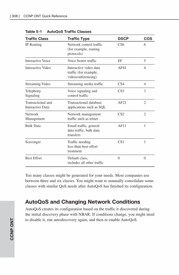
Table 5-1 AutoQoS Traffic Classes
Traffic Class Traffic Type DSCP COS
IP Routing Network control traffic CS6 6(for example, routing protocols)
Interactive Voice Voice bearer traffic EF 5
Interactive Video Interactive video data AF41 4traffic (for example,videoconferencing)
Streaming Video Streaming media traffic CS4 4
Telephony Voice signaling and CS3 3Signaling control traffic
Transactional and Transactional database AF21 2Interactive Data applications such as SQL
Network Network management CS2 2Management traffic such as telnet
Bulk Data Email traffic, general AF11 1data traffic, bulk data transfers
Scavenger Traffic needing CS1 1less-than-best-effort treatment
Best Effort Default class, 0 0includes all other traffic
Too many classes might be generated for your needs. Most companies usebetween three and six classes. You might want to manually consolidate someclasses with similar QoS needs after AutoQoS has finished its configuration.
AutoQoS and Changing Network Conditions
AutoQoS creates its configuration based on the traffic it discovered duringthe initial discovery phase with NBAR. If conditions change, you might needto disable it, run autodiscovery again, and then re-enable AutoQoS.
CC
NP
ON
T[ 306 ] CCNP ONT Quick Reference
Manually Tuning AutoQoS Configurations
The show auto qos command shows the class maps that AutoQoS created,along with their match criteria and any access lists it created. It shows thepolicy maps, and the policy configured for each class. It shows where thepolicy was applied and any monitoring that was implemented. This can helpyou determine what changes are needed to the configuration.
You can modify AutoQoS configuration in two ways:
■ Using Cisco QPM
■ Manually with the MQC
To modify using the MQC, allow the router/switch to apply its AutoQoSconfiguration. Copy the relevant portions to a text editor and make thedesired changes. This might include changing the classification criteria,combining classes, or altering the policy for a particular class, for instance.Then replace the old configuration with the new one.
CC
NP
ON
T
Chapter 5: AutoQoS [ 307 ]
CHAPTER 6
Wireless Scalability
Wireless LANs (WLAN) are an extension to wired networks using wirelessstandards, such as 802.11A/B/G. The 802.11 standards take the place of theEthernet standard, but both data-links support the same types of services.The benefit of WLANs is that it allows users to relocate within the work-space, closer to machinery or conference rooms, for instance.
WLAN QoS802.11 wireless uses carrier sense multiple access/collision avoidance(CSMA/CA), meaning transmissions are pre-announced, because systemsmay not be able to hear each other or recognize collisions later. CA uses aDistributed Coordination Function (DCF) to implement timers and delays toensure cooperation.
Unfortunately, DCF timers interfere with low-latency applications, such asvoice and video. Wi-Fi Multimedia (WMM or 802.11e) is an attempt toshorten timers—proportional to Differentiated Services Code Point (DSCP)priority—and prioritize important traffic. WMM replaces DCF withenhanced DCF (EDCF) that creates four categories (platinum, gold, silver,and bronze) and forces longer interframe waits on lower-priority traffic.
LWAPCisco introduced Lightweight Access Points (LWAP) that use the concept of“split MAC,” which separates the real-time communication and managementfunctions. An LWAP controls beaconing, buffering, and encryption and usesa controller for 802.1x, Extensible Authentication Protocol (EAP), keymanagement, and bridging functions.
In the LWAP scenario, QoS is handled at the controller. QoS is marked atLayer 2 using 802.11e. 802.11e, like 802.1p, will not pass through a router,so it has to be converted to DSCP if used end-to-end in a large network.Similarly, .1p and DSCP fields must be mapped back to WMM when trafficgoes to the client.
Controllers host profiles that describe traffic handling. At the controller, anadministrator can specify:
■ Average and burst “best-effort” data rate
■ Average and burst “real-time” data rate
■ Maximum RF usage (set to 100%)
■ Queue depth, which is the number of packets that will be in the queu ifthe line is busy
■ WMM-to-802.1p mapping
Furthermore, the controller may be set up to ignore, allow, or require802.11e.
802.1x and WLAN SecurityWLAN security is important because wireless systems are designed to alloweasy access and may extend beyond the physical perimeter of your building.Many WLAN implementations do not have encryption or authentication.Small wonder then that “war driving,” or the act of randomly wondering insearch of an open AP, is so easy to perform.
The number-one problem is that most APs are insecure by default and fewhave any security added to them. When present, security for WLANs isaccomplished through authenticating users and encrypting traffic. Old formsof authentication and encryption have been found vulnerable, so APs must bekept current. Types of wireless security include:
■ Service Set Identifier (SSID)
■ Authentication by MAC
■ Static Wired Equivalent Privacy (WEP) keys
■ One-way authentication
Network administrators must not only ensure their APs are secure, they mustalways look for rogue APs (access points put up by users to accomplish anarrow goal without regard to corporate security).
Note
LWAPs and their controllers help with AP security and rogue AP detection. LWAPs, becausethey are controlled from a central point, are more scalable because administration is mucheasier. Cisco LWAP/Controller model also has rogue detection baked in.
CC
NP
ON
T
Chapter 6: Wireless Scalability [ 309 ]
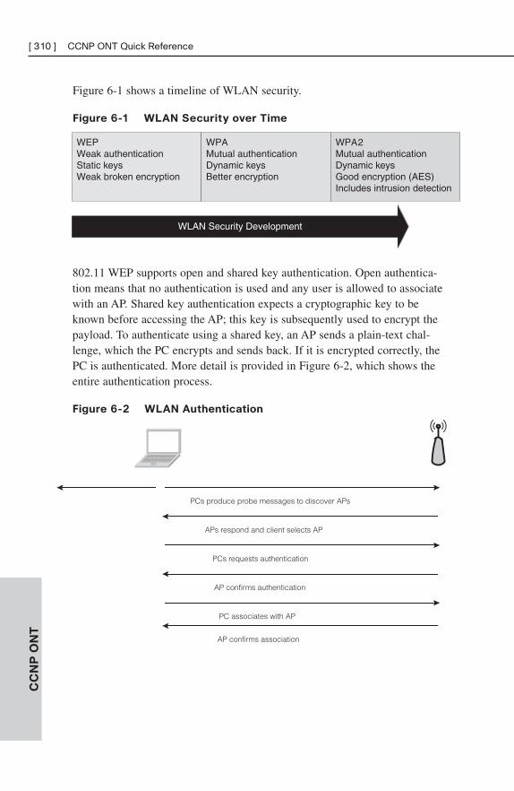
Figure 6-1 shows a timeline of WLAN security.
Figure 6-1 WLAN Security over Time
CC
NP
ON
T[ 310 ] CCNP ONT Quick Reference
WLAN Security Development
WEPWeak authenticationStatic keysWeak broken encryption
WPAMutual authenticationDynamic keysBetter encryption
WPA2Mutual authenticationDynamic keysGood encryption (AES)Includes intrusion detection
802.11 WEP supports open and shared key authentication. Open authentica-tion means that no authentication is used and any user is allowed to associatewith an AP. Shared key authentication expects a cryptographic key to beknown before accessing the AP; this key is subsequently used to encrypt thepayload. To authenticate using a shared key, an AP sends a plain-text chal-lenge, which the PC encrypts and sends back. If it is encrypted correctly, thePC is authenticated. More detail is provided in Figure 6-2, which shows theentire authentication process.
Figure 6-2 WLAN Authentication
PCs produce probe messages to discover APs
APs respond and client selects AP
PCs requests authentication
AP confirms authentication
PC associates with AP
AP confirms association
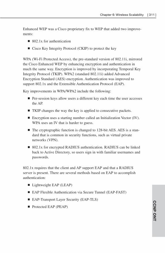
Enhanced WEP was a Cisco proprietary fix to WEP that added two improve-ments:
■ 802.1x for authentication
■ Cisco Key Integrity Protocol (CKIP) to protect the key
WPA (Wi-Fi Protected Access), the pre-standard version of 802.11i, mirroredthe Cisco Enhanced WEP by enhancing encryption and authentication inmuch the same way. Encryption is improved by incorporating Temporal KeyIntegrity Protocol (TKIP). WPA2 (standard 802.11i) added AdvancedEncryption Standard (AES) encryption. Authentication was improved tosupport 802.1x and the Extensible Authentication Protocol (EAP).
Key improvements in WPA/WPA2 include the following:
■ Per-session keys allow users a different key each time the user accessesthe AP.
■ TKIP changes the way the key is applied to consecutive packets.
■ Encryption uses a starting number called an Initialization Vector (IV).WPA uses an IV that is harder to guess.
■ The cryptographic function is changed to 128-bit AES. AES is a stan-dard that is common in security functions, such as virtual privatenetworks (VPN).
■ 802.1x for encrypted RADIUS authentication. RADIUS can be linkedback to Active Directory, so users sign in with familiar usernames andpasswords.
802.1x requires that the client and AP support EAP and that a RADIUSserver is present. There are several methods based on EAP to accomplishauthentication:
■ Lightweight EAP (LEAP)
■ EAP Flexible Authentication via Secure Tunnel (EAP-FAST)
■ EAP-Transport Layer Security (EAP-TLS)
■ Protected EAP (PEAP)
CC
NP
ON
T
Chapter 6: Wireless Scalability [ 311 ]
Configuring WLAN Security on
ControllerOpen (no authentication) is typically set up on public APs. On a CiscoWLAN controller, choose WLANs > Edit and then set Layer 2 Security toNone.
Setting Layer 2 Security to Static WEP, WPA, or WPA2 allows control ofparameters for a static key. If no WPA static key is entered, then thecontroller will use EAP 802.1x to RADIUS.
Setting Layer 2 Security to 802.1X supports dynamic WEP keys. Key sizemay be selected, but remember that Windows XP supports only 40-bit and104-bit keys.
If Layer 3 Security is selected, then users will enter credentials on acustomizable web page, which then checks an internal database or a remoteRADIUS server.
WLAN ManagementCisco supports two WLAN models.
■ Autonomous APs:
— Users connect to APs.
— APs are aggregated by Wireless Domain Services (WDS).
— WDS is controlled by a Wireless Solution Engine (WLSE),which centralizes control similar to an LW Controller.
■ Lightweight APs connected to a controller:
— Users attach to LWAPs.
— LWAPs are controlled by controllers.
— Controllers are managed by Wireless Control System (WCS).
The benefit of LWAPs is centralized control. The problem is that loss of thecontroller brings the whole campus down, so redundancy is recommended.The lightweight model provides displays of RF coverage, dynamic manage-ment of the radio environment, detection of rogue APs, and easier roaming.
CC
NP
ON
T[ 312 ] CCNP ONT Quick Reference
WLSE brings many of the benefits of a controller to an existing autonomousdeployment. WLSE is offered in two versions, both of which also handleAAA:
■ Ciscoworks WLSE for large deployments
■ Ciscoworks WLSE Express for fewer than 100 APs
WCS allows management of the entire network as a unit. It runs as a serviceon Linux or Windows. Three feature sets are supported:
■ Base, which detects rogue APs and tracks a device to the closest AP.
■ WCS with Location, which adds support for RF fingerprinting andtracks a device to within 10 meters.
■ WCS with Location+, which adds the ability to track 1500 clients atthe same time and collects historical information.
Location is important to support VoIP calls to 911.
CC
NP
ON
T
Chapter 6: Wireless Scalability [ 313 ]

This page intentionally left blank
INDEX
NUMBERS3DES encryption method, IPsec, 202
8
802.11a Internet standard, WLAN,143-144
802.11b Internet standard, WLAN,143
802.11g Internet standard, WLAN,144
802.1Qdouble-tagging attacks, 162VLAN
trunking, 104-105tunneling, 107
802.1x, WLAN security, 309-311
Aaaa authentication command, port
authentication, 161
aaa new-model command, portauthentication, 161
AAA(authentication, authorization,accounting)
access attacks, 219Character mode, 233-234configuring, 232-233
accounting, 235authentication, 234authorization, 234
Packet mode, 233RADIUS, 233TACACS+, 233troubleshooting, 235
ABR (Area Border Routers), OSPF,27
ACAU (Aironet ClientAdministration Utility), Cisco NIC,146
access attacks, 218-219
Access layer (Hierarchical DesignModel), 4, 92, 250
Access mode (DTP), 105
Access ports, VLAN, 101
accounting, configuring, 235
ACK (acknowledgment) packet,EIGRP, 15
ACL (Access Control Lists)Cisco IOS Firewall external/internal
interfaces, 239crypto ACL, IPsec transform set
configuration, 206directional effects on packets, 229established keywords in, 228evaluation order in, 229implicit deny statements, 229interface ACL, IPsec transform set
configuration, 207-208mitigating threats/attacks via
spoofed addresses, 227SYN attacks, 228
QoS, 270TCPIntercept, 228VACL, 163
ACM (Aironet Client Monitor), CiscoNIC, 146
Active mode (LACP), 124
active routers (HSRP), 212
Active stateBGP steering, 64HSRP, 137
AD (Administrative Distance)IProuting protocols, 11, 16route optimization, 52-54
ad-hoc mode (WLAN), 142
adjacencies, IS-IS, 44
ADSL (Asymmetric DigitalSubscriber Line) Internet connec-tions, 180
CAP line coding, 182components of, 181DMT line coding, 182troubleshooting, 188
ADU (Aironet Desktop Utility), CiscoNIC, 146
AES encryption method, IPsec, 203
AH (Authentication Headers), IPsec,200
alarms, Cisco IOSIPS, 242
alerts (Syslog), Cisco IOS Firewall,238
ALG (application layer gateways),87, 236
anomaly-based IDS/IPS, 241
antenna sites (broadband cableInternet connections), 177
antennas, WLAN, 147-148
antisniffer tools, reconnaissanceattacks, 218
Anycasts, IPv6 support for, 80
AON blades, 9, 97, 248
AP (Access Points)autonomous AP, 146
configuring, 149-150WLAN, 312
LWAP, 146-147configuring, 150QoS, 308-309WLAN, 312
WLAN, 142-143Application layer (SONA), 174
Application servers, VoIP, 152
area nssa command, 38
area range command, OSPF defaultroute creation, 37
ARP (Address Resolution Protocol)DAI, 166dynamic ARP, reconnaissance
attacks, 218Proxy ARP, 136, 221
spoofing, 165throttling, MLS, 134
ASBR (Autonomous SystemBoundary Routers), OSPF, 27
assured forwarding PHB (per-hopbehaviors), 280-281
asymmetric key algorithms (encryp-tion), 203
ATM interfacesPPPoA, 187PPPoE, 185
audits, Syslog alerts, 238
auth-control command, port authen-tication, 161
authenticationBGP, 67-68Cisco IOS Firewall, 238configuring, 234EIGRP, 24IPsec VPN, 202MAC address flooding attacks,
160-161OSPF, 39-40rate-limiting, 224reconnaissance attacks, 218WLAN, 145, 311
authorization, configuring, 234
Auto mode (PAgP), 123
auto qos command, AutoQoS routerconfigurations via, 304
Auto qos voip command, AutoQoSswitch configurations via, 303
auto secure command, 222
auto-loading configurations, security,220
auto-RP, multicast routing configura-tion, 73
autonomous AP (Access Points), 146configuring, 149-150WLAN, 312
autonomous systems, BGP, 58
AutoQoSenabling, 304QoS configuration, 271-274routers, 304SNMP support, 305switches, 303-304
[ 316 ] adjacencies
traffic classes, 305-306tuning
changing network conditions,306
manually tuning, 307traffic classes, 305-306
WAN interface support, 305AutoSecure, router configuration,
221-222
AVF (Active Virtual Forwarder),GLBP, 140
AVG (Active Virtual Gateways),GLBP, 140
AWP (Adaptive Wireless Path) proto-col, WLAN, 143
Bbackbone routers, OSPF, 27
BackbonefastSpanning Tree Protocol, 120STP, 119
bandwidthEIGRP
metric, 17WAN, 22-24
IINIntegrated Applications phase, 9,
97, 248Integrated Services phase, 8, 96,
247Integrated Transport phase, 8,
96, 247SONA versus, 97, 249
LLQ configuration, 291policy maps, designating in
CBWFQ, 290LLQ, 292-293
QoS, 8, 95, 264-265VoIP
calculating for, 259-260requirements for, 153, 259
WAN, EIGRP, 22-24bandwidth command, designating
bandwidth in MQC policy maps,290
bandwidth percent command, desig-nating bandwidth in MQC policymaps, 290
bandwidth remaining percentcommand, designating bandwidthin MQC policy maps, 290
banner messages (logins), configur-ing, 225
banner motd command, configuringbanner messages, 225
BDR (Backup Designated Routers),OSPF configuration, 35-36
behavior aggregates, 279
best effort delivery mode (QoS), 267
BGP (Border Gateway Protocol)authentication, 67-68autonomous systems, 58configuring, 63databases, 60EBGP, 60IBGP, 60Keepalive messages, 60loop prevention, 58MG-BGP, IPv6 routing, 83multihoming, 59neighbor databases, 60network command, 63next hop selection, 61-62Notification messages, 60Open messages, 60path selection
attributes of, 65-66criteria for, 67setting preferences to, 66
peering, 64RIB databases, 60routing tables, 60synchronization, 62Update messages, 60
bgp default local-preferencecommand, BGP path selection, 66
BIA (Bump-in-the-API), IPv6addressing, 87
BIS (Bumo-in-the-Stack), IPv6addressing, 87
Blocking state (STP ports), 117
BOOTP servers, disabling, 220
bpdu guard command, 159
bpdu guard command [ 317 ]
BPDU (Bridge Protocol Data Units),120
Configuration BPDU, 116fields of, 117RSTP, 121-122TCN BPDU, 116
BPDU Filtering, 125, 167
BPDU Guard, 124, 167
branch offices (Cisco EnterpriseArchitectures), 174
bridgesLayer 2 over DSL techniques, 183root bridges, STP, 113-114transparent bridges, STP, 112workgroup bridges, WLAN, 143
bridging loops, STP, 127
broadband cable Internet connec-tions
antenna sites, 177CMTS routers, 178-179components of, 178distribution networks, 177DOCSIS cable standard, 178FDM, 177headend sites, 177HFC networks, 177modem provisioning, 179NTSC cable standard, 178PAL cable standard, 178SECAM cable standard, 178SOHO/teleworker connectivity,
177-179subscriber drops, 177transportation networks, 177
broadcast networksIS-IS, 45OSPF, 35
broadcast storms, 112
broadcasts, defining, 69
Ccable Internet connections (broad-
band)antenna sites, 177CMTS routers, 178-179components of, 178distribution networks, 177DOCSIS cable standard, 178FDM, 177
headend sites, 177HFC networks, 177modem provisioning, 179NTSC cable standard, 178PAL cable standard, 178SECAM cable standard, 178SOHO/teleworker connectivity,
177-179subscriber drops, 177transportation networks, 177
cable modems, broadband cableInternet connections, 179
CAC (Call Admission Control), 262
call control signaling, VoIP, 153
CallManager (Cisco), VoIP, 152
CAM (Content AddressableMemory), 132, 159
campus networkssecurity
ARP snooping, 165BPDU filtering, 167BPDU Guard, 167bpdu guard command, 159DHCP snooping, 165double-tagging attacks, 162Loop Guard, 168-169port security, 160port-based authentication,
160-161PVLAN, 163-164root guard command, 159RootGuard, 167switch spoofing, 161switches, 169UDLD, 168VACL, 163VLAN hopping, 161
VoIPcall control signaling, 153components of, 152-153configuring, 157-158DSCP, 156PHB, 155QoS, 154-155requirements for, 153trust boundaries, 156voice bearer traffic, 153Voice VLAN, 154
campuses (Cisco EnterpriseArchitectures), 174
[ 318 ] BPDU
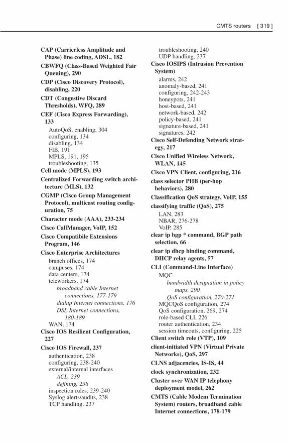
CAP (Carrierless Amplitude andPhase) line coding, ADSL, 182
CBWFQ (Class-Based Weighted FairQueuing), 290
CDP (Cisco Discovery Protocol),disabling, 220
CDT (Congestive DiscardThresholds), WFQ, 289
CEF (Cisco Express Forwarding),133
AutoQoS, enabling, 304configuring, 134disabling, 134FIB, 191MPLS, 191, 195troubleshooting, 135
Cell mode (MPLS), 193
Centralized Forwarding switch archi-tecture (MLS), 132
CGMP (Cisco Group ManagementProtocol), multicast routing config-uration, 75
Character mode (AAA), 233-234
Cisco CallManager, VoIP, 152
Cisco Compatibile ExtensionsProgram, 146
Cisco Enterprise Architecturesbranch offices, 174campuses, 174data centers, 174teleworkers, 174
broadband cable Internetconnections, 177-179
dialup Internet connections, 176DSL Internet connections,
180-189WAN, 174
Cisco IOS Resilient Configuration,227
Cisco IOS Firewall, 237authentication, 238configuring, 238-240external/internal interfaces
ACL, 239defining, 238
inspection rules, 239-240Syslog alerts/audits, 238TCP handling, 237
troubleshooting, 240UDP handling, 237
Cisco IOSIPS (Intrusion PreventionSystem)
alarms, 242anomaly-based, 241configuring, 242-243honeypots, 241host-based, 241network-based, 242policy-based, 241signature-based, 241signatures, 242
Cisco Self-Defending Network strat-egy, 217
Cisco Unified Wireless Network,WLAN, 145
Cisco VPN Client, configuring, 216
class selector PHB (per-hopbehaviors), 280
Classification QoS strategy, VoIP, 155
classifying traffic (QoS), 275LAN, 283NBAR, 276-278VoIP, 285
clear ip bgp * command, BGP pathselection, 66
clear ip dhcp binding command,DHCP relay agents, 57
CLI (Command-Line Interface)MQC
bandwidth designation in policymaps, 290
QoS configuration, 270-271MQCQoS configuration, 274QoS configuration, 269, 274role-based CLI, 226router authentication, 234session timeouts, configuring, 225
Client switch role (VTP), 109
client-initiated VPN (Virtual PrivateNetworks), QoS, 297
CLNS adjacencies, IS-IS, 44
clock synchronization, 232
Cluster over WAN IP telephonydeployment model, 262
CMTS (Cable Modem TerminationSystem) routers, broadband cableInternet connections, 178-179
CMTS routers [ 319 ]
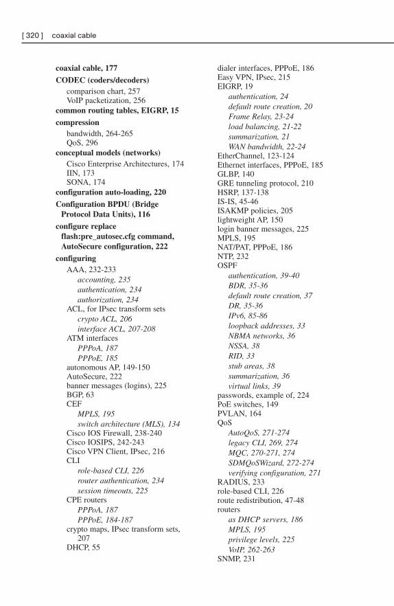
coaxial cable, 177
CODEC (coders/decoders)comparison chart, 257VoIP packetization, 256
common routing tables, EIGRP, 15
compressionbandwidth, 264-265QoS, 296
conceptual models (networks)Cisco Enterprise Architectures, 174IIN, 173SONA, 174
configuration auto-loading, 220
Configuration BPDU (BridgeProtocol Data Units), 116
configure replaceflash:pre_autosec.cfg command,AutoSecure configuration, 222
configuringAAA, 232-233
accounting, 235authentication, 234authorization, 234
ACL, for IPsec transform setscrypto ACL, 206interface ACL, 207-208
ATM interfacesPPPoA, 187PPPoE, 185
autonomous AP, 149-150AutoSecure, 222banner messages (logins), 225BGP, 63CEF
MPLS, 195switch architecture (MLS), 134
Cisco IOS Firewall, 238-240Cisco IOSIPS, 242-243Cisco VPN Client, IPsec, 216CLI
role-based CLI, 226router authentication, 234session timeouts, 225
CPE routersPPPoA, 187PPPoE, 184-187
crypto maps, IPsec transform sets,207
DHCP, 55
dialer interfaces, PPPoE, 186Easy VPN, IPsec, 215EIGRP, 19
authentication, 24default route creation, 20Frame Relay, 23-24load balancing, 21-22summarization, 21WAN bandwidth, 22-24
EtherChannel, 123-124Ethernet interfaces, PPPoE, 185GLBP, 140GRE tunneling protocol, 210HSRP, 137-138IS-IS, 45-46ISAKMP policies, 205lightweight AP, 150login banner messages, 225MPLS, 195NAT/PAT, PPPoE, 186NTP, 232OSPF
authentication, 39-40BDR, 35-36default route creation, 37DR, 35-36IPv6, 85-86loopback addresses, 33NBMA networks, 36NSSA, 38RID, 33stub areas, 38summarization, 36virtual links, 39
passwords, example of, 224PoE switches, 149PVLAN, 164QoS
AutoQoS, 271-274legacy CLI, 269, 274MQC, 270-271, 274SDMQoSWizard, 272-274verifying configuration, 271
RADIUS, 233role-based CLI, 226route redistribution, 47-48routers
as DHCP servers, 186MPLS, 195privilege levels, 225VoIP, 262-263
SNMP, 231
[ 320 ] coaxial cable
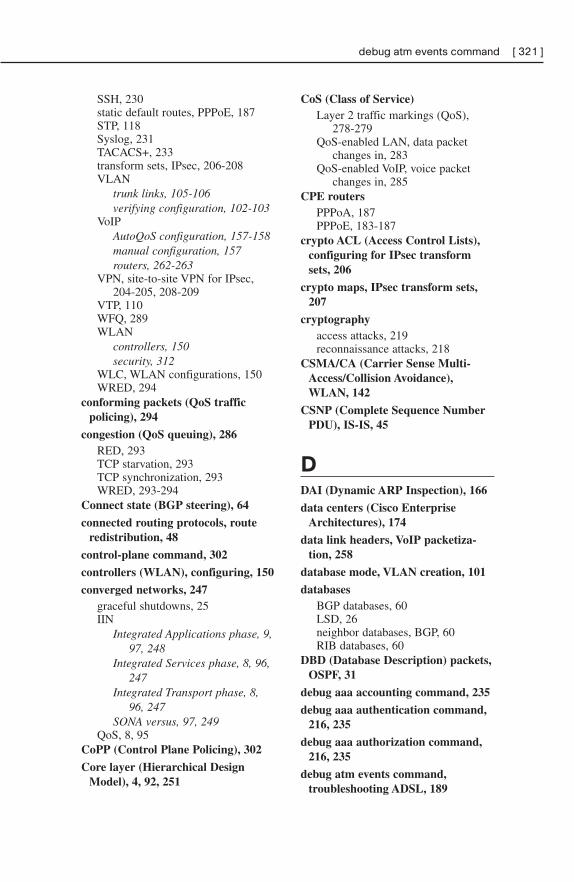
SSH, 230static default routes, PPPoE, 187STP, 118Syslog, 231TACACS+, 233transform sets, IPsec, 206-208VLAN
trunk links, 105-106verifying configuration, 102-103
VoIPAutoQoS configuration, 157-158manual configuration, 157routers, 262-263
VPN, site-to-site VPN for IPsec,204-205, 208-209
VTP, 110WFQ, 289WLAN
controllers, 150security, 312
WLC, WLAN configurations, 150WRED, 294
conforming packets (QoS trafficpolicing), 294
congestion (QoS queuing), 286RED, 293TCP starvation, 293TCP synchronization, 293WRED, 293-294
Connect state (BGP steering), 64
connected routing protocols, routeredistribution, 48
control-plane command, 302
controllers (WLAN), configuring, 150
converged networks, 247graceful shutdowns, 25IIN
Integrated Applications phase, 9,97, 248
Integrated Services phase, 8, 96,247
Integrated Transport phase, 8,96, 247
SONA versus, 97, 249QoS, 8, 95
CoPP (Control Plane Policing), 302
Core layer (Hierarchical DesignModel), 4, 92, 251
CoS (Class of Service)Layer 2 traffic markings (QoS),
278-279QoS-enabled LAN, data packet
changes in, 283QoS-enabled VoIP, voice packet
changes in, 285CPE routers
PPPoA, 187PPPoE, 183-187
crypto ACL (Access Control Lists),configuring for IPsec transformsets, 206
crypto maps, IPsec transform sets,207
cryptographyaccess attacks, 219reconnaissance attacks, 218
CSMA/CA (Carrier Sense Multi-Access/Collision Avoidance),WLAN, 142
CSNP (Complete Sequence NumberPDU), IS-IS, 45
DDAI (Dynamic ARP Inspection), 166
data centers (Cisco EnterpriseArchitectures), 174
data link headers, VoIP packetiza-tion, 258
database mode, VLAN creation, 101
databasesBGP databases, 60LSD, 26neighbor databases, BGP, 60RIB databases, 60
DBD (Database Description) packets,OSPF, 31
debug aaa accounting command, 235
debug aaa authentication command,216, 235
debug aaa authorization command,216, 235
debug atm events command,troubleshooting ADSL, 189
debug atm events command [ 321 ]
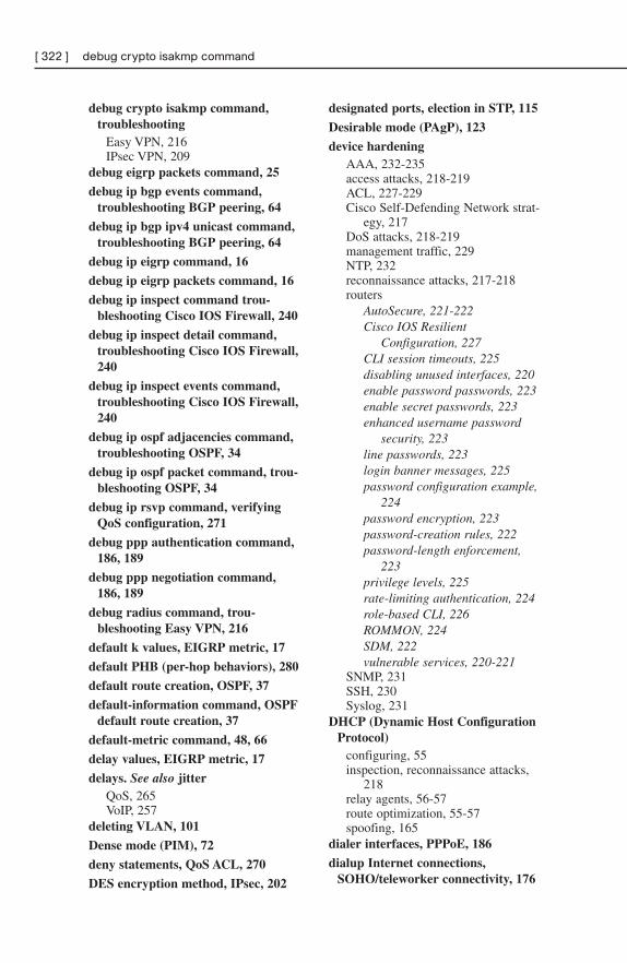
debug crypto isakmp command,troubleshooting
Easy VPN, 216IPsec VPN, 209
debug eigrp packets command, 25
debug ip bgp events command,troubleshooting BGP peering, 64
debug ip bgp ipv4 unicast command,troubleshooting BGP peering, 64
debug ip eigrp command, 16
debug ip eigrp packets command, 16
debug ip inspect command trou-bleshooting Cisco IOS Firewall, 240
debug ip inspect detail command,troubleshooting Cisco IOS Firewall,240
debug ip inspect events command,troubleshooting Cisco IOS Firewall,240
debug ip ospf adjacencies command,troubleshooting OSPF, 34
debug ip ospf packet command, trou-bleshooting OSPF, 34
debug ip rsvp command, verifyingQoS configuration, 271
debug ppp authentication command,186, 189
debug ppp negotiation command,186, 189
debug radius command, trou-bleshooting Easy VPN, 216
default k values, EIGRP metric, 17
default PHB (per-hop behaviors), 280
default route creation, OSPF, 37
default-information command, OSPFdefault route creation, 37
default-metric command, 48, 66
delay values, EIGRP metric, 17
delays. See also jitterQoS, 265VoIP, 257
deleting VLAN, 101
Dense mode (PIM), 72
deny statements, QoS ACL, 270
DES encryption method, IPsec, 202
designated ports, election in STP, 115
Desirable mode (PAgP), 123
device hardeningAAA, 232-235access attacks, 218-219ACL, 227-229Cisco Self-Defending Network strat-
egy, 217DoS attacks, 218-219management traffic, 229NTP, 232reconnaissance attacks, 217-218routers
AutoSecure, 221-222Cisco IOS Resilient
Configuration, 227CLI session timeouts, 225disabling unused interfaces, 220enable password passwords, 223enable secret passwords, 223enhanced username password
security, 223line passwords, 223login banner messages, 225password configuration example,
224password encryption, 223password-creation rules, 222password-length enforcement,
223privilege levels, 225rate-limiting authentication, 224role-based CLI, 226ROMMON, 224SDM, 222vulnerable services, 220-221
SNMP, 231SSH, 230Syslog, 231
DHCP (Dynamic Host ConfigurationProtocol)
configuring, 55inspection, reconnaissance attacks,
218relay agents, 56-57route optimization, 55-57spoofing, 165
dialer interfaces, PPPoE, 186
dialup Internet connections,SOHO/teleworker connectivity, 176
[ 322 ] debug crypto isakmp command
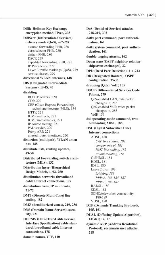
Diffie-Hellman Key Exchangeencryption method, IPsec, 203
DiffServ (Differentiated Services)delivery mode (QoS), 267-269
assured forwarding PHB, 280class selector PHB, 280default PHB, 280DSCP, 279expedited forwarding PHB, 281IP Precedence, 279Layer 3 traffic markings (QoS), 279service classes, 279
directional WLAN antennas, 148
DIS (Designated IntermediateSystems), IS-IS, 45
disablingBOOTP servers, 220CDP, 220CEF (Cisco Express Forwarding)
switch architecture (MLS), 134HTTP, 221ICMP redirects, 221ICMP unreachables, 221IP source routing, 221PAD service, 220Proxy ARP, 221unused router interfaces, 220
distortion (multipath), WLAN anten-nas, 148
distribute lists, routing updates,49-50
Distributed Forwarding switch archi-tecture (MLS), 132
Distribution layer (HierarchicalDesign Model), 4, 92, 250
distribution networks (broadbandcable Internet connections, 177
distribution trees, IP multicasts,71-72
DMT (Discrete Multi-Tone) linecoding, 182
DMZ (demilitarized zones), 219, 236
DNS (Domain Name Servers), secu-rity, 221
DOCSIS (Data-Over-Cable ServiceInterface Specification) cable stan-dard, broadband cable Internetconnections, 178
domain names, VTP, 110
DoS (Denial-of-Service) attacks,218-219, 302
dotlx port command, port authenti-cation, 161
dotlx system command, port authen-tication, 161
double-tagging attacks, 162
Down state (OSPF neighbor relation-ships/rout exchanges), 32
DPD (Deed Peer Detection), 211-212
DR (Designated Routers), OSPFconfiguration, 35-36
dropping (QoS), VoIP, 155
DSCP (Differentiated Services CodePoints), 279
QoS-enabled LAN, data packetchanges in, 283
QoS-enabled VoIP, voice packetchanges in, 285
VoIP, 156dsl operating-mode command, trou-
bleshooting ADSL, 188
DSL (Digital Subscriber Line)Internet connections
ADSL, 180CAP line coding, 182components of, 181DMT line coding, 182troubleshooting, 188
G.SHDSL, 181HDSL, 181IDSL, 180Layer 2 over, 182
bridging, 183PPPoA, 183-184, 187PPPoE, 183-187
RADSL, 180SDSL, 181SOHO/teleworker connectivity,
180-189VDSL, 180
DTP (Dynamic Trunking Protocol),105, 161
DUAL (Diffusing Update Algorithm),EIGRP, 14, 17
dynamic ARP (Address ResolutionProtocol), reconnaissance attacks,218
dynamic ARP [ 323 ]
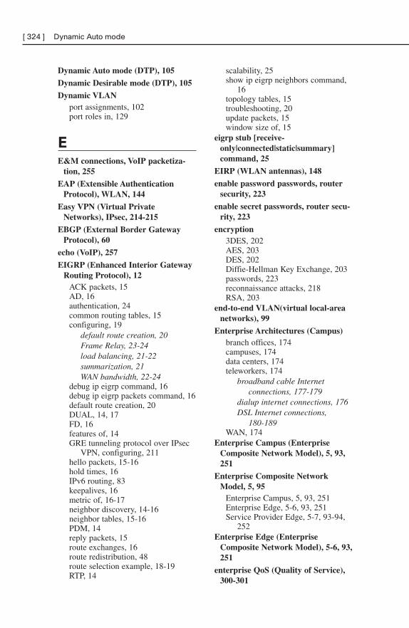
Dynamic Auto mode (DTP), 105
Dynamic Desirable mode (DTP), 105
Dynamic VLANport assignments, 102port roles in, 129
EE&M connections, VoIP packetiza-
tion, 255
EAP (Extensible AuthenticationProtocol), WLAN, 144
Easy VPN (Virtual PrivateNetworks), IPsec, 214-215
EBGP (External Border GatewayProtocol), 60
echo (VoIP), 257
EIGRP (Enhanced Interior GatewayRouting Protocol), 12
ACK packets, 15AD, 16authentication, 24common routing tables, 15configuring, 19
default route creation, 20Frame Relay, 23-24load balancing, 21-22summarization, 21WAN bandwidth, 22-24
debug ip eigrp command, 16debug ip eigrp packets command, 16default route creation, 20DUAL, 14, 17FD, 16features of, 14GRE tunneling protocol over IPsec
VPN, configuring, 211hello packets, 15-16hold times, 16IPv6 routing, 83keepalives, 16metric of, 16-17neighbor discovery, 14-16neighbor tables, 15-16PDM, 14reply packets, 15route exchanges, 16route redistribution, 48route selection example, 18-19RTP, 14
scalability, 25show ip eigrp neighbors command,
16topology tables, 15troubleshooting, 20update packets, 15window size of, 15
eigrp stub [receive-only|connected|static|summary]command, 25
EIRP (WLAN antennas), 148
enable password passwords, routersecurity, 223
enable secret passwords, router secu-rity, 223
encryption3DES, 202AES, 203DES, 202Diffie-Hellman Key Exchange, 203passwords, 223reconnaissance attacks, 218RSA, 203
end-to-end VLAN(virtual local-areanetworks), 99
Enterprise Architectures (Campus)branch offices, 174campuses, 174data centers, 174teleworkers, 174
broadband cable Internetconnections, 177-179
dialup internet connections, 176DSL Internet connections,
180-189WAN, 174
Enterprise Campus (EnterpriseComposite Network Model), 5, 93,251
Enterprise Composite NetworkModel, 5, 95
Enterprise Campus, 5, 93, 251Enterprise Edge, 5-6, 93, 251Service Provider Edge, 5-7, 93-94,
252Enterprise Edge (Enterprise
Composite Network Model), 5-6, 93,251
enterprise QoS (Quality of Service),300-301
[ 324 ] Dynamic Auto mode
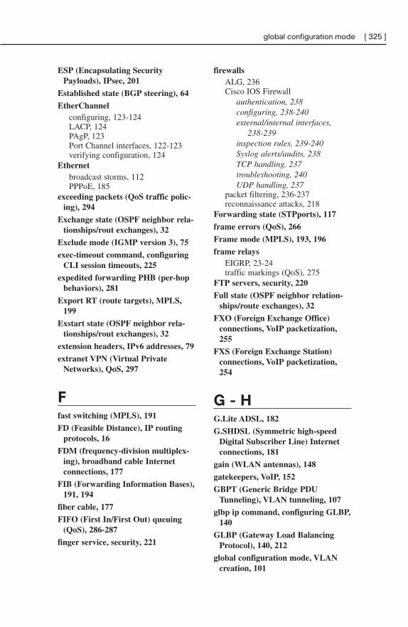
ESP (Encapsulating SecurityPayloads), IPsec, 201
Established state (BGP steering), 64
EtherChannelconfiguring, 123-124LACP, 124PAgP, 123Port Channel interfaces, 122-123verifying configuration, 124
Ethernetbroadcast storms, 112PPPoE, 185
exceeding packets (QoS traffic polic-ing), 294
Exchange state (OSPF neighbor rela-tionships/rout exchanges), 32
Exclude mode (IGMP version 3), 75
exec-timeout command, configuringCLI session timeouts, 225
expedited forwarding PHB (per-hopbehaviors), 281
Export RT (route targets), MPLS,199
Exstart state (OSPF neighbor rela-tionships/rout exchanges), 32
extension headers, IPv6 addresses, 79
extranet VPN (Virtual PrivateNetworks), QoS, 297
Ffast switching (MPLS), 191
FD (Feasible Distance), IP routingprotocols, 16
FDM (frequency-division multiplex-ing), broadband cable Internetconnections, 177
FIB (Forwarding Information Bases),191, 194
fiber cable, 177
FIFO (First In/First Out) queuing(QoS), 286-287
finger service, security, 221
firewallsALG, 236Cisco IOS Firewall
authentication, 238configuring, 238-240external/internal interfaces,
238-239inspection rules, 239-240Syslog alerts/audits, 238TCP handling, 237troubleshooting, 240UDP handling, 237
packet filtering, 236-237reconnaissance attacks, 218
Forwarding state (STPports), 117
frame errors (QoS), 266
Frame mode (MPLS), 193, 196
frame relaysEIGRP, 23-24traffic markings (QoS), 275
FTP servers, security, 220
Full state (OSPF neighbor relation-ships/route exchanges), 32
FXO (Foreign Exchange Office)connections, VoIP packetization,255
FXS (Foreign Exchange Station)connections, VoIP packetization,254
G - HG.Lite ADSL, 182
G.SHDSL (Symmetric high-speedDigital Subscriber Line) Internetconnections, 181
gain (WLAN antennas), 148
gatekeepers, VoIP, 152
GBPT (Generic Bridge PDUTunneling), VLAN tunneling, 107
glbp ip command, configuring GLBP,140
GLBP (Gateway Load BalancingProtocol), 140, 212
global configuration mode, VLANcreation, 101
global configuration mode [ 325 ]
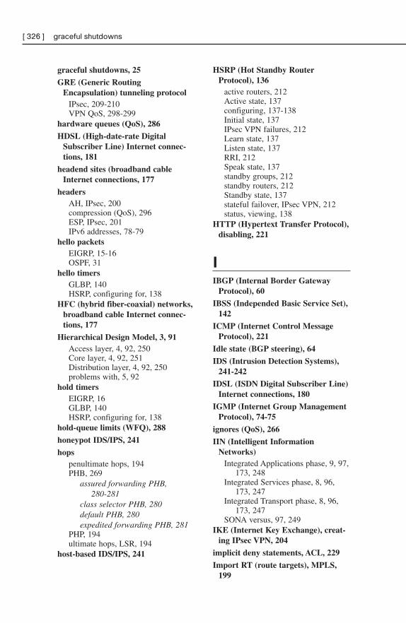
graceful shutdowns, 25
GRE (Generic RoutingEncapsulation) tunneling protocol
IPsec, 209-210VPN QoS, 298-299
hardware queues (QoS), 286
HDSL (High-date-rate DigitalSubscriber Line) Internet connec-tions, 181
headend sites (broadband cableInternet connections, 177
headersAH, IPsec, 200compression (QoS), 296ESP, IPsec, 201IPv6 addresses, 78-79
hello packetsEIGRP, 15-16OSPF, 31
hello timersGLBP, 140HSRP, configuring for, 138
HFC (hybrid fiber-coaxial) networks,broadband cable Internet connec-tions, 177
Hierarchical Design Model, 3, 91Access layer, 4, 92, 250Core layer, 4, 92, 251Distribution layer, 4, 92, 250problems with, 5, 92
hold timersEIGRP, 16GLBP, 140HSRP, configuring for, 138
hold-queue limits (WFQ), 288
honeypot IDS/IPS, 241
hopspenultimate hops, 194PHB, 269
assured forwarding PHB,280-281
class selector PHB, 280default PHB, 280expedited forwarding PHB, 281
PHP, 194ultimate hops, LSR, 194
host-based IDS/IPS, 241
HSRP (Hot Standby RouterProtocol), 136
active routers, 212Active state, 137configuring, 137-138Initial state, 137IPsec VPN failures, 212Learn state, 137Listen state, 137RRI, 212Speak state, 137standby groups, 212standby routers, 212Standby state, 137stateful failover, IPsec VPN, 212status, viewing, 138
HTTP (Hypertext Transfer Protocol),disabling, 221
IIBGP (Internal Border Gateway
Protocol), 60
IBSS (Independed Basic Service Set),142
ICMP (Internet Control MessageProtocol), 221
Idle state (BGP steering), 64
IDS (Intrusion Detection Systems),241-242
IDSL (ISDN Digital Subscriber Line)Internet connections, 180
IGMP (Internet Group ManagementProtocol), 74-75
ignores (QoS), 266
IIN (Intelligent InformationNetworks)
Integrated Applications phase, 9, 97,173, 248
Integrated Services phase, 8, 96,173, 247
Integrated Transport phase, 8, 96,173, 247
SONA versus, 97, 249IKE (Internet Key Exchange), creat-
ing IPsec VPN, 204
implicit deny statements, ACL, 229
Import RT (route targets), MPLS,199
[ 326 ] graceful shutdowns
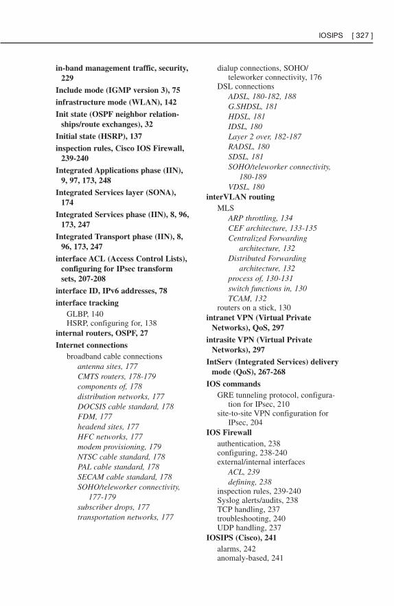
in-band management traffic, security,229
Include mode (IGMP version 3), 75
infrastructure mode (WLAN), 142
Init state (OSPF neighbor relation-ships/route exchanges), 32
Initial state (HSRP), 137
inspection rules, Cisco IOS Firewall,239-240
Integrated Applications phase (IIN),9, 97, 173, 248
Integrated Services layer (SONA),174
Integrated Services phase (IIN), 8, 96,173, 247
Integrated Transport phase (IIN), 8,96, 173, 247
interface ACL (Access Control Lists),configuring for IPsec transformsets, 207-208
interface ID, IPv6 addresses, 78
interface trackingGLBP, 140HSRP, configuring for, 138
internal routers, OSPF, 27
Internet connectionsbroadband cable connections
antenna sites, 177CMTS routers, 178-179components of, 178distribution networks, 177DOCSIS cable standard, 178FDM, 177headend sites, 177HFC networks, 177modem provisioning, 179NTSC cable standard, 178PAL cable standard, 178SECAM cable standard, 178SOHO/teleworker connectivity,
177-179subscriber drops, 177transportation networks, 177
dialup connections, SOHO/teleworker connectivity, 176
DSL connectionsADSL, 180-182, 188G.SHDSL, 181HDSL, 181IDSL, 180Layer 2 over, 182-187RADSL, 180SDSL, 181SOHO/teleworker connectivity,
180-189VDSL, 180
interVLAN routingMLS
ARP throttling, 134CEF architecture, 133-135Centralized Forwarding
architecture, 132Distributed Forwarding
architecture, 132process of, 130-131switch functions in, 130TCAM, 132
routers on a stick, 130intranet VPN (Virtual Private
Networks), QoS, 297
intrasite VPN (Virtual PrivateNetworks), 297
IntServ (Integrated Services) deliverymode (QoS), 267-268
IOS commandsGRE tunneling protocol, configura-
tion for IPsec, 210site-to-site VPN configuration for
IPsec, 204IOS Firewall
authentication, 238configuring, 238-240external/internal interfaces
ACL, 239defining, 238
inspection rules, 239-240Syslog alerts/audits, 238TCP handling, 237troubleshooting, 240UDP handling, 237
IOSIPS (Cisco), 241alarms, 242anomaly-based, 241
IOSIPS [ 327 ]
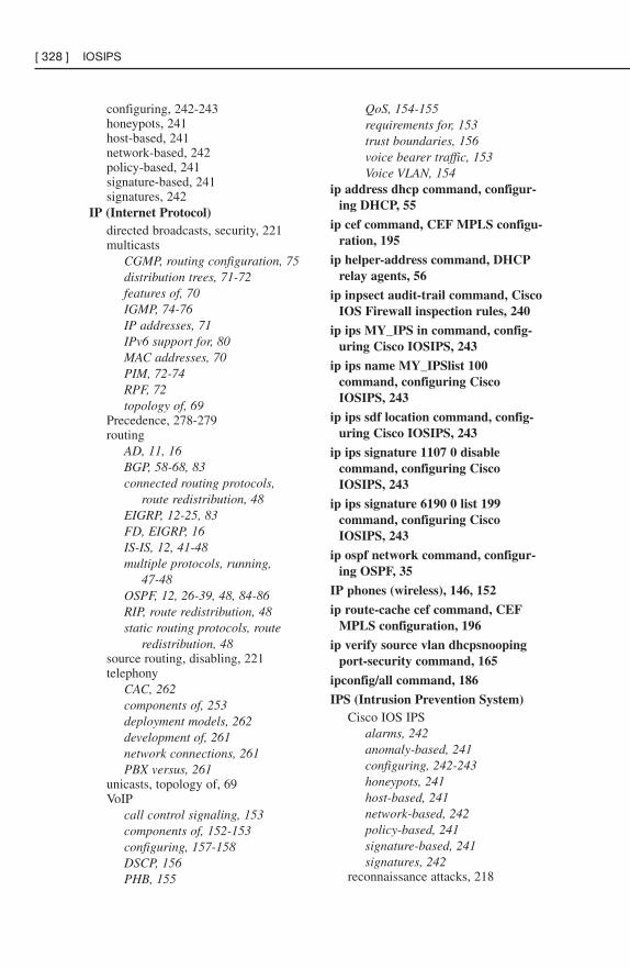
configuring, 242-243honeypots, 241host-based, 241network-based, 242policy-based, 241signature-based, 241signatures, 242
IP (Internet Protocol)directed broadcasts, security, 221multicasts
CGMP, routing configuration, 75distribution trees, 71-72features of, 70IGMP, 74-76IP addresses, 71IPv6 support for, 80MAC addresses, 70PIM, 72-74RPF, 72topology of, 69
Precedence, 278-279routing
AD, 11, 16BGP, 58-68, 83connected routing protocols,
route redistribution, 48EIGRP, 12-25, 83FD, EIGRP, 16IS-IS, 12, 41-48multiple protocols, running,
47-48OSPF, 12, 26-39, 48, 84-86RIP, route redistribution, 48static routing protocols, route
redistribution, 48source routing, disabling, 221telephony
CAC, 262components of, 253deployment models, 262development of, 261network connections, 261PBX versus, 261
unicasts, topology of, 69VoIP
call control signaling, 153components of, 152-153configuring, 157-158DSCP, 156PHB, 155
QoS, 154-155requirements for, 153trust boundaries, 156voice bearer traffic, 153Voice VLAN, 154
ip address dhcp command, configur-ing DHCP, 55
ip cef command, CEF MPLS configu-ration, 195
ip helper-address command, DHCPrelay agents, 56
ip inpsect audit-trail command, CiscoIOS Firewall inspection rules, 240
ip ips MY_IPS in command, config-uring Cisco IOSIPS, 243
ip ips name MY_IPSlist 100command, configuring CiscoIOSIPS, 243
ip ips sdf location command, config-uring Cisco IOSIPS, 243
ip ips signature 1107 0 disablecommand, configuring CiscoIOSIPS, 243
ip ips signature 6190 0 list 199command, configuring CiscoIOSIPS, 243
ip ospf network command, configur-ing OSPF, 35
IP phones (wireless), 146, 152
ip route-cache cef command, CEFMPLS configuration, 196
ip verify source vlan dhcpsnoopingport-security command, 165
ipconfig/all command, 186
IPS (Intrusion Prevention System)Cisco IOS IPS
alarms, 242anomaly-based, 241configuring, 242-243honeypots, 241host-based, 241network-based, 242policy-based, 241signature-based, 241signatures, 242
reconnaissance attacks, 218
[ 328 ] IOSIPS
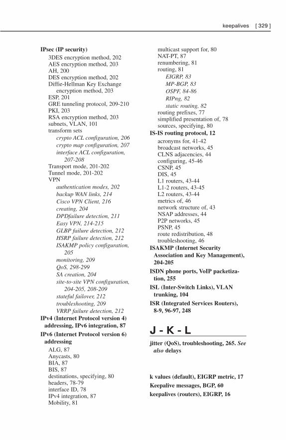
IPsec (IP security)3DES encryption method, 202AES encryption method, 203AH, 200DES encryption method, 202Diffie-Hellman Key Exchange
encryption method, 203ESP, 201GRE tunneling protocol, 209-210PKI, 203RSA encryption method, 203subnets, VLAN, 101transform sets
crypto ACL configuration, 206crypto map configuration, 207interface ACL configuration,
207-208Transport mode, 201-202Tunnel mode, 201-202VPN
authentication modes, 202backup WAN links, 214Cisco VPN Client, 216creating, 204DPDfailure detection, 211Easy VPN, 214-215GLBP failure detection, 212HSRP failure detection, 212ISAKMP policy configuration,
205monitoring, 209QoS, 298-299SA creation, 204site-to-site VPN configuration,
204-205, 208-209stateful failover, 212troubleshooting, 209VRRP failure detection, 212
IPv4 (Internet Protocol version 4)addressing, IPv6 integration, 87
IPv6 (Internet Protocol version 6)addressing
ALG, 87Anycasts, 80BIA, 87BIS, 87destinations, specifying, 80headers, 78-79interface ID, 78IPv4 integration, 87Mobility, 81
multicast support for, 80NAT-PT, 87renumbering, 81routing, 81
EIGRP, 83MP-BGP, 83OSPF, 84-86RIPng, 82static routing, 82
routing prefixes, 77simplified presentation of, 78sources, specifying, 80
IS-IS routing protocol, 12acronyms for, 41-42broadcast networks, 45CLNS adjacencies, 44configuring, 45-46CSNP, 45DIS, 45L1 routers, 43-44L1-2 routers, 43-45L2 routers, 43-44metrics of, 46network structure of, 43NSAP addresses, 44P2P networks, 45PSNP, 45route redistribution, 48troubleshooting, 46
ISAKMP (Internet SecurityAssociation and Key Management),204-205
ISDN phone ports, VoIP packetiza-tion, 255
ISL (Inter-Switch Links), VLANtrunking, 104
ISR (Integrated Services Routers),8-9, 96-97, 248
J - K - Ljitter (QoS), troubleshooting, 265. See
also delays
k values (default), EIGRP metric, 17
Keepalive messages, BGP, 60
keepalives (routers), EIGRP, 16
keepalives [ 329 ]
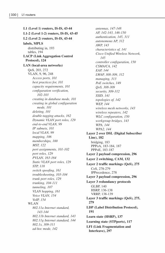
L1 (Level 1) routers, IS-IS, 43-44
L1-2 (Level 1-2) routers, IS-IS, 43-45
L2 (Level 2) routers, IS-IS, 43-44
labels, MPLSdistributing in, 193tables, 194
LACP (Link Aggregation ControlProtocol), 124
LAN (local-area networks)QoS, 203, 272VLAN, 9, 96, 248
Access ports, 101best practices for, 101capacity requirements, 101configuration verification,
102-103creating in database mode, 101creating in global configuration
mode, 101deleting, 101double-tagging attacks, 162Dynamic VLAN port roles, 129end-to-end VLAN, 99IP subnets, 101local VLAN, 99mapping, 106 memberships, 100MST, 122port assignments, 101-102port roles, 129PVLAN, 163-164Static VLAN port roles, 129STP, 118switch spoofing, 161troubleshooting, 103-104trunk port roles, 129trunking, 104-111tunneling, 107VLAN hopping, 161Voice VLAN, 154VoIP, 154
WLAN802.11a Internet standard,
143-144802.11b Internet standard, 143802.11g Internet standard, 144802.1x, 309-311ad-hoc mode, 142
antennas, 147-148AP, 142-143, 146-150authentication, 145, 311autonomous AP, 312AWP, 143characteristics of, 141Cisco Unified Wireless Network,
145controller configuration, 150CSMA/CA, 142EAP, 144LWAP, 308-309, 312managing, 313PoE switches, 149QoS, 308-309security, 309-312SSID, 141topologies of, 142WEP, 144wireless mesh networks, 143wireless repeaters, 142WLC configuration, 150workgroup bridges, 143WPA, 144WPA2, 144
Layer 2 over DSL (Digital SubscriberLine), 182
bridging, 183PPPoA, 183-184, 187PPPoE, 183-187
Layer 2 payload compression, 296
Layer 2 switching, CAM, 132
Layer 2 traffic markings (QoS), 275CoS, 278-279IPPrecedence, 278
Layer 3 payload compression, 296
Layer 3 redundancy protocolsGLBP, 140HSRP, 136-138VRRP, 138-139
Layer 3 traffic markings (QoS), 275,279
LDP (Label Distribution Protocol),191
Learn state (HSRP), 137
Learning state (STPports), 117
LFI (Link Fragmentation andInterleave), 297
[ 330 ] L1 routers
LFIB lists, 194
LIB (Label Information Bases), 191
lightweight AP (Access Points),146-147, 150
line passwords, router security, 223
linksaggregation, QoS queuing conges-
tion, 286efficiency (QoS)
compression, 296LFI, 297
VLAN trunk links, configuring,105-106
Listen state (HSRP), 137
Listening state (STP ports), 117
LLQ, 291-293
load balancing, EIGRP, 21-22
Loading state (OSPF neighbor rela-tionships/rout exchanges), 32
local VLAN (virtual local-areanetworks), 99
login block-for attempts command,rate-limiting authentication, 225
login delay command, rate-limitingauthentication, 225
logins, banner messages, 225
Loop Guard, 126, 168-169
loopback addresses, OSPF configura-tion, 33
loopsbridging loops, STP, 127preventing
BGP, 58BPDUFiltering, 125BPDUGuard, 124Loop Guard, 126
Spanning Tree loopsLoop Guard, 168-169UDLD, 168
LSA (Link State Advertisements)LSD, 26OSPF, 26-30, 85
LSAck (Link State Acknowledgment)packets, OSPF, 31
LSD (Link State Databases), OSPF,26
LSDB overload protection, OSPF, 29
LSR (Label Switch Routers), 193control plane functions, 192data plane functions, 192forwarding scenarios, 192LDP, 191LIB, 191MPLS, 191, 195ultimate hops, 194
LSR (Link State Request) packets,OSPF, 31
LSU (Link State Update) packets,OSPF, 31
LWAP (Lightweight Access Point)protocol, 147
LWAP (Lightweight Access Points),146-147
configuring, 150QoS, 308-309WLAN, 312
MM-Trees, 122
MAC (Media Access Control)addresses
flooding attacks, 159-161IP multicasts, 70
split MAC. See LWAP (LightweightAccess Points)
tables, CAM, 132management traffic, security, 229
managing WLAN, 313
mapping VLAN. See also trunkingVLAN
Marking QoS strategy, VoIP, 155
marking traffic (QoS)frame relay markings, 275LAN, 283Layer 2 markings, 275, 278-279Layer 3 markings, 275, 279trust boundaries, 275VoIP, 285
Master routers (VRRP), 139
match conditions, routing updates,51-52
max-lsa command, 29
max-lsa command [ 331 ]
MCU (Multipoint Control Units),VoIP, 152
MD5 authentication, BGP, 67-68
memberships, VLAN, 100
memoryCAM, 132, 159TCAM, 132
MG-BGP (Multiprotocol BGP), IPv6routing, 83
minimum trust principle, accessattacks, 219
mitigating attacksAAA, 232
Character mode, 233-234configuring, 233-235Packet mode, 233RADIUS, 233TACACS+, 233troubleshooting, 235
access attacks, 218-219ACL
directional effects on packets,229
established keywords in, 228evaluation order in, 229implicit deny statements, 229spoofed addresses, 227SYN attacks, 228TCPIntercept, 228
Cisco IOS IPS, 241-243Cisco Self-Defending Network strat-
egy, 217DMZ design filtering, 236DoS attacks, 218-219firewalls
ALG, 236Cisco IOS Firewall, 237-240packet filtering, 236-237
IDS, 241-242management traffic, 229NTP, 232reconnaissance attacks, 217-218routers
AutoSecure, 221-222Cisco IOS Resilient
Configuration, 227CLI session timeouts, 225disabling unused interfaces, 220
enable password passwords, 223enable secret passwords, 223enhanced username password
security, 223line passwords, 223login banner messages, 225password configuration example,
224password encryption, 223password-creation rules, 222password-length enforcement,
223privilege levels, 225rate-limiting authentication, 224role-based CLI, 226ROMMON, 224SDM, 222vulnerable services, 220-221
SNMP, 231SSH, 230Syslog, 231
MitM attacks, 219
MLS (Multilayer Switching)ARP throttling, 134CEF architecture, 133
configuring, 134disabling, 134troubleshooting, 135
Centralized Forwarding architecture,132
Distributed Forwarding architecture,132
process of, 130-131switch functions in, 130TCAM, 132
Mobility (IPv6), 81
mode command, configuring GREtunneling command, 210
modemscable modems, broadband cable
Internet connections, 179DSL modems, PPPoE, 183
MOP (Maintenance OperationsProtocol) service, security, 220
MOS (Mean Opinion Score) scale,VoIP, 257
MP-BGP (Multiprotocol BGP),MPLS, 198
[ 332 ] MCU
mpls ip command, enabling MPLS,196
mpls label protocol command,enabling MPLS, 196
mpls mtu command, sizing MTU inFrame mode (MPLS), 196
MPLS (Multiprotocol LabelSwitching)
CEF switching, 191, 195Cell mode, 193configuring, 195enabling, 196fast switching, 191Frame mode, 193, 196labels
distributing, 193tables, 194
LSR, 191packet forwarding, 195path selection options, 190process switching, 191VPN
custom routes, 197MG-BGP, 198RD, 198RT, 198VRF tables, 197
MQC (Modular QoSCLI)NBAR, 277policy maps, bandwidth designation
in, 290QoS configuration, 270-271, 274
MST (Multiple Spanning Tree), 122.See also STP (Spanning TreeProtocol)
MTU (Maximum TransmissionUnits), sizing, 196
multicasts (IP)CGMP, routing configuration, 75distribution trees, 71-72features of, 70IGMP
routing configuration, 74-75routing verification commands,
76snooping, 75
IP addresses, 71IPv6 support for, 80MAC addresses, 70
PIMauto-RP, 73Dense mode, 72PIM version 2, 74routing configuration, 73Sparse mode, 73Sparse-Dense mode, 73
RPF, 72topology of, 69
multihoming, BGP, 59
multipath distortion (WLANantennas), 148
multiple routing protocols, runningroute redistribution, 47-48seed metrics, 48
Multisite IP telephony deploymentmodel with centralized callprocessing, 262
Multisite IP telephony deploymentmodel with distributed callprocessing, 262
NNAC (Network Admission Control),
9, 97, 248
NAS-initiated VPN (Virtual PrivateNetworks), QoS, 297
NAT traversal, 202
NAT-PT, 87
NAT/PAT, PPPoE, 186
NBAR (Network-Based ApplicationRecognition), 276-278
NBMA (Nonbroadcast Multiaccess)networks, OSPF configuration,34-36
neighbor databases, BGP, 60
neighbor discovery, EIGRP, 14, 16
neighbor ebgp-multihop command,BGP peering, 64
neighbor next-hop-self commandBGP configuration, 63BGP next hop selection, 61-62
neighbor password command, BGPauthentication, 67-68
neighbor peer-group command, BGPconfiguration, 63
neighbor peer-group command [ 333 ]
neighbor relationships, OSPF, 31-32
neighbor remote-as command, BGPconfiguration, 63
neighbor tables, EIGRP, 15-16
neighbor update-source command,BGP configuration, 63
network command, BGP configura-tion, 63
network conceptual modelsCisco Enterprise Architectures, 174IIN, 173SONA, 174
Network Infrastructure layer(SONA), 174
network modelsEnterprise Composite Network
Model, 95Enterprise Campus, 5, 93, 251Enterprise Edge, 5-6, 93, 251Service Provider Edge, 5, 7,
93-94, 252Hierarchical Design Model, 3, 91
Access layer, 4, 92, 250Core layer, 4, 92, 251Distribution layer, 4, 92, 250problems with, 5, 92
network renumbering, IPv6, 81
network-based IDS/IPS, 242
next hop selection, BGP, 61-62
NIC (Network Identification Cards),Cisco NIC, 146
no cd enable command, disablingCDP, 220
no ip bootp server command,disabling BOOTP servers, 220
no ip forward-protocol udpcommand, DHCP relay agents, 57
no ip http server command, disablingHTTP, 221
no ip inspect alert-off command,Cisco IOS Firewall inspection rules,240
no ip proxy-arp command, disablingProxy ARP, 221
no ip redirects command, disablingICMP redirects, 221
no ip source-route command,disabling IP source routing, 221
no ip unreachables command,disabling ICMP unreachables, 221
no service pad command, disablingPADservice, 220
no service password-recoverycommand, ROMMON security, 224
no shutdown command, troubleshoot-ing ADSL, 188
no synchronization command, BGPconfiguration, 63
Non-negotiate mode (DTP), 105
Notification messages, BGP, 60
NSAP addresses, IS-IS, 44
NSSA (not-so-stubby areas), OSPF,38.
NTP (Network Time Protocol), 220,232
NTSC (National Television StandardsCommittee) cable standard, broad-band cable Internet connections,178
Nyquist theorem, VoIP packetization,256
Oomnidirectional WLAN antennas,
148
On mode (PAgP), 123
Open messages, BGP, 60
OpenConfirm state (BGP steering),64
OpenSent state (BGP steering), 64
optimizing routingAD, 52-54DHCP, 55-57multiple routing protocols, 47-48updates, 49-52
optional nontransitive attribute cate-gory (BGP path selection), 65
optional transitive attribute category(BGP path selection), 65
[ 334 ] neighbor relationships
OSPF (Open Shortest Path First)routing protocol, 12
ABR, 27areas of, 27ASBR, 27backbone routers, 27Broadcast networks, 35configuring
authentication, 39-40BDR, 35-36default route creation, 37DR, 35-36IPv6, 85-86loopback addresses, 33NBMAnetworks, 36NSSA, 38RID, 33stub areas, 38summarization, 36virtual links, 39
cost formulas, 28DBD packets, 31GRE tunneling protocol over IPsec
VPN, configuring, 211Hello packets, 31internal routers, 27IPv6 routing, 84-86LSA, 26-30, 85LSAck packets, 31LSD, 26LSDB overload protection, 29LSR packets, 31LSU packets, 31metrics of, 28NBMA networks, 34neighbor relationships, 31-32network structure of, 26P2MNB networks, 35P2MP networks, 34P2P networks, 35route exchanges, 32route redistribution, 48router roles, 27troubleshooting, 34, 86
out-of-band management traffic,security, 230
overload command, 186
overloads, LSDB overload protection,29
overruns (QoS), 266
PP2MNB (Point-to-Multipoint
Nonbroadcast) networks, OSPF, 35
P2MP (Point-to-Multipoint)networks, OSPF, 34
P2P (Point-to-Point) networksIS-IS, 45OSPF, 35
packet filtering, 236-237
packet forwarding, MPLS, 195
packet loss (QoS)causes of, 266VoIP, 257
Packet mode (AAA), 233
packet switching, MPLS, 191
packetization (VoIP), 257CODEC, 256data link headers, 258E&M connections, 255FXO connections, 255FXS connections, 254ISDN phone ports, 255Nyquist theorem, 256PAM, 256PSTN, 256quantization, 256RTP, 258-259T1/E1 CAS phone ports, 255T1/E1 CCS phone ports, 255
PAD (PacketAssembler/Disassembler) service,disabling, 220
PAgP (Port Aggregation Protocol),EtherChannel, 123
PAL (Phase-Alternating Line) cablestandard, broadband cable Internetconnections, 178
PAM (Pulse Amplitude Modulation),256
Passive mode (LACP), 124
passive-interface command, routingupdates, 49
passive-interface default command,routing updates, 49
passwordsaccess attacks, 219enable password type, 223
passwords [ 335 ]
enable secret type, 223encryption, 223example of, 224length enforcement, 223line type, 223rules for creating, 222service password-encryption
command, 223username secret command, 223VTP, 110
path selectionMPLS options, 190STP, 113
payload compression (QoS), 296
PBX (Private Branch Exchange)versus IP telephony, 261
PDLM (Packet Description LanguageModules), 276
PDM (protocol-independentmodules), EIGRP, 14
peering (BGP), 64
penultimate hops, 194
permit statements, QoS ACL, 270
PESQ (Perceptual Evaluation ofSpeech Quality) scale, VoIP, 257
PHB (per-hop behaviors), 269assured forwarding PHB, 280-281class selector PHB, 280default PHB, 280expedited forwarding PHB, 281VoIP, 155
phone ports, VoIP packetization, 255
phonesIP phones, VoIP, 152wireless IP, 146
PHP (penultimate hop popping), 194
PIM (Protocol IndependentMulticast)
auto-RP, 73Dense mode, 72multicast routing configuration, 73PIM version 2, 74Sparse mode, 73Sparse-Dense mode, 73
ping-atm-interface-atm command,troubleshooting ADSL, 188
PKI (Public Key Infrastructure),IPsec, 203
PoE (Power over Ethernet) switches,WLAN, 149
Policing QoS strategy, VoIP, 155
policing traffic (QoS), 294
policy maps, bandwidth designationin
CBWFQ, 290LLQ, 292-293
policy-based IDS/IPS, 241
Port Channel interfaces,EtherChannel, 122-123
Portfast, STP, 119
portsAccess ports, VLAN assignments,
101campus network security, 160-161designted ports, STP, 115Dynamic VLAN, roles in, 129root ports, STP, 115RSTP, 120Static VLAN, roles in, 129STP
configuring in, 118RSTP port comparisons, 120states in, 117
trunk ports, roles of, 129VLAN
assignments, 101-102roles in, 129
power inline command, configuringPoE switches, 149
PPPoA (PPP over ATM), Layer 2over DSL techniques, 183-184, 187
PPPoE (PPP over Ethernet), Layer 2over DSL techniques, 183
ATM interface configuration, 185CPE router configuration, 184-187dialer interface configuration, 186Ethernet interface configuration, 185NAT/PAT configuration, 186router configuration as DHCP
server, 186static default route configuration,
187Priority queuing (QoS), 287
private-vlan association command,configuring PVLAN, 164
private-vlan command, configuringPVLAN, 164
[ 336 ] passwords
private-vlan mapping command,configuring PVLAN, 164
privilege levels (router security), 225
process switching (MPLS), 191
processing delays (QoS), 265
propagation delays (QoS), 265
Proxy ARP (Address ResolutionProtocol), 136, 221
pruning (VTP), 109-110
PSNP (Partial Sequence NumberPDU), IS-IS, 45
PSQM (Perceptual Speech QualityMeasurement) scale, VoIP, 257
PSTN (Public Switched TelephoneNetworks), VoIP packetization, 256
PVLAN (private virtual local-areanetworks), 163-164
PVST (Per Vlan STP), STP, 118
QQoS (quality of service), 8, 95
ACL, 270AutoQoS
enabling, 304routers, 304SNMP, 305switches, 303-304traffic classes, 305-306tuning, 305-307WAN interface support, 305
bandwidth, compression, 264-265best effort delivery model, 267classifying traffic, 275
CoS data packet changes in LAN,283
CoS voice packet changes inVoIP, 285
DSCP data packet changes inLAN, 283
DSCP voice packet changes inVoIP, 285
NBAR, 276-278MQC usage example, 277
compression, 296
configuringAutoQoS, 271-274legacy CLI, 269, 274MQC, 270-271, 274SDMQoSWizard, 272-274verifying configuration, 271
CoPP, 302defining, 247delays, 265DiffServ delivery model, 267-269enterprise QoS, 300-301frame errors, 266ignores, 266IntServ delivery model, 267-268jitter, 265LFI, 297link efficiency
compression, 296LFI, 297
LWAP, 308-309marking traffic
CoS data packet changes in LAN,283
CoS voice packet changes inVoIP, 285
DSCP data packet changes inLAN, 283
DSCP voice packet changes inVoIP, 285
frame relay markings, 275Layer 2 markings, 275, 278-279Layer 3 markings, 275, 279trust boundaries, 275
overruns, 266packet loss, 266queuing
CBWFQ, 290congestion, 286, 293-294FIFO queuing, 286-287hardware queues, 286LLQ, 291-293Priority queuing, 287Round Robin queuing, 288software queues, 286-287starvation, 287WFQ, 288-289
requirements, defining, 266tail drop, 266traffic policing, 294-295traffic shaping, 294-296
QoS [ 337 ]
VoIP, 154-155, 257VPN
advantages of, 298client-initiated VPN, 297extranet VPN, 297GRE tunnels, 298-299intranet VPN, 297IPsec tunnels, 298-299NAS-initiated VPN, 297router-to-router VPN, 298
WLAN, LWAP, 308-309quantization, VoIP packetization, 256
queuing (QoS)CBWFQ, 290congestion, 286, 293-294delays (QoS), 265FIFO queuing, 286-287hardware queues, 286LLQ, 291-293Priority queuing, 287Round Robin queuing, 288software queues, 286-287starvation, 287VoIP, 155WFQ, 288-289
Quick SetupWizard, site-to-site VPNconfiguration, 208
RRADIUS (Remote Authentication
Dial In User Service), 233
RADSL (Rate-Adaptive DigitalSubscriber Line) Internet connec-tions, 180
random-detect dscp command,WRED configuration, 294
rate-limiting authentication, 224
RD (route distinguishers), MPLS, 198
reconnaissance attacks, 217-218
RED (Random Early Detection), QoSqueuing congestion, 293
redistribution (route), configuring,47-48
redundancy protocols (Layer 3)GLBP, 140HSRP, 136-138VRRP, 138-139
relay agents (DHCP), 56-57
remote access VPN (Virtual PrivateNetworks), QoS, 297
renumbering networks, IPv6, 81
repeaters (wireless), WLAN, 142
reply packets, EIGRP, 15
RIB (Routing Information Base)databases, 60
RID (Router ID), OSPFconfiguration, 33
RIP (Routing Information Protocol),route redistribution, 48
RIPng, IPv6, 82
RLQ (Root Link Queries), STP, 120
role-based CLI, 226
ROMMON (ROMMonitor), security,224
root bridgesSpanning Tree root bridges, 159STP, 113-114
root guard command, 159
root ports, election in STP, 115
RootGuard, 125, 167
Round Robin queuing (QoS), 288
route creation (default), OSPF, 37
route exchangesEIGRP, 16OSPF, 32
route maps, 50
router bgp command, BGP configu-ration, 63
router-id command, OSPF configura-tion, 33
router-to-router VPN(Virtual PrivateNetworks), QoS, 298
routersABR, OSPF, 27active routers (HSRP), 212ASBR, OSPF, 27auto-RP, 73AutoQoS, 304backbone routers, OSPF, 27BDR (Designated Routers), OSPF
configuration, 35-36CLI authentication, 234
[ 338 ] QoS
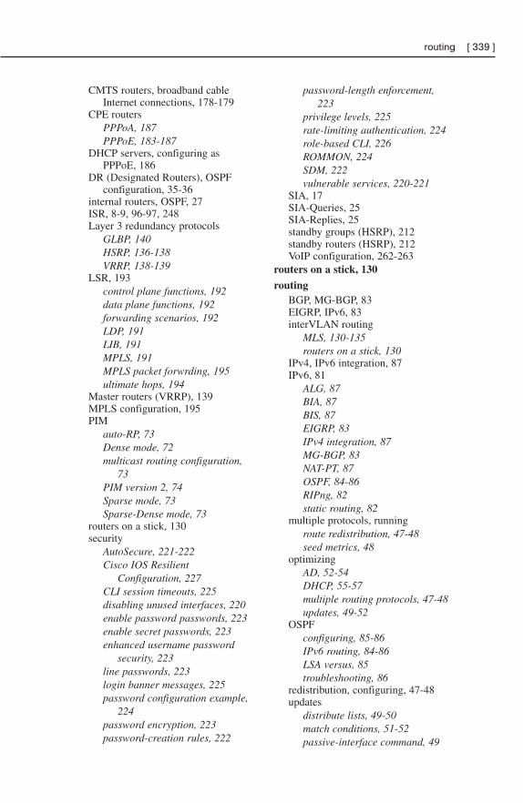
CMTS routers, broadband cableInternet connections, 178-179
CPE routersPPPoA, 187PPPoE, 183-187
DHCP servers, configuring asPPPoE, 186
DR (Designated Routers), OSPFconfiguration, 35-36
internal routers, OSPF, 27ISR, 8-9, 96-97, 248Layer 3 redundancy protocols
GLBP, 140HSRP, 136-138VRRP, 138-139
LSR, 193control plane functions, 192data plane functions, 192forwarding scenarios, 192LDP, 191LIB, 191MPLS, 191MPLS packet forwrding, 195ultimate hops, 194
Master routers (VRRP), 139MPLS configuration, 195PIM
auto-RP, 73Dense mode, 72multicast routing configuration,
73PIM version 2, 74Sparse mode, 73Sparse-Dense mode, 73
routers on a stick, 130security
AutoSecure, 221-222Cisco IOS Resilient
Configuration, 227CLI session timeouts, 225disabling unused interfaces, 220enable password passwords, 223enable secret passwords, 223enhanced username password
security, 223line passwords, 223login banner messages, 225password configuration example,
224password encryption, 223password-creation rules, 222
password-length enforcement,223
privilege levels, 225rate-limiting authentication, 224role-based CLI, 226ROMMON, 224SDM, 222vulnerable services, 220-221
SIA, 17SIA-Queries, 25SIA-Replies, 25standby groups (HSRP), 212standby routers (HSRP), 212VoIP configuration, 262-263
routers on a stick, 130
routingBGP, MG-BGP, 83EIGRP, IPv6, 83interVLAN routing
MLS, 130-135routers on a stick, 130
IPv4, IPv6 integration, 87IPv6, 81
ALG, 87BIA, 87BIS, 87EIGRP, 83IPv4 integration, 87MG-BGP, 83NAT-PT, 87OSPF, 84-86RIPng, 82static routing, 82
multiple protocols, runningroute redistribution, 47-48seed metrics, 48
optimizingAD, 52-54DHCP, 55-57multiple routing protocols, 47-48updates, 49-52
OSPFconfiguring, 85-86IPv6 routing, 84-86LSA versus, 85troubleshooting, 86
redistribution, configuring, 47-48updates
distribute lists, 49-50match conditions, 51-52passive-interface command, 49
routing [ 339 ]
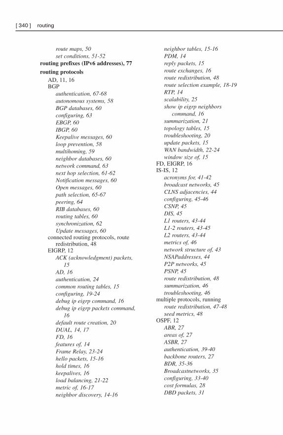
route maps, 50set conditions, 51-52
routing prefixes (IPv6 addresses), 77
routing protocolsAD, 11, 16BGP
authentication, 67-68autonomous systems, 58BGP databases, 60configuring, 63EBGP, 60IBGP, 60Keepalive messages, 60loop prevention, 58multihoming, 59neighbor databases, 60network command, 63next hop selection, 61-62Notification messages, 60Open messages, 60path selection, 65-67peering, 64RIB databases, 60routing tables, 60synchronization, 62Update messages, 60
connected routing protocols, routeredistribution, 48
EIGRP, 12ACK (acknowledgment) packets,
15AD, 16authentication, 24common routing tables, 15configuring, 19-24debug ip eigrp command, 16debug ip eigrp packets command,
16default route creation, 20DUAL, 14, 17FD, 16features of, 14Frame Relay, 23-24hello packets, 15-16hold times, 16keepalives, 16load balancing, 21-22metric of, 16-17neighbor discovery, 14-16
neighbor tables, 15-16PDM, 14reply packets, 15route exchanges, 16route redistribution, 48route selection example, 18-19RTP, 14scalability, 25show ip eigrp neighbors
command, 16summarization, 21topology tables, 15troubleshooting, 20update packets, 15WAN bandwidth, 22-24window size of, 15
FD, EIGRP, 16IS-IS, 12
acronyms for, 41-42broadcast networks, 45CLNS adjacencies, 44configuring, 45-46CSNP, 45DIS, 45L1 routers, 43-44L1-2 routers, 43-45L2 routers, 43-44metrics of, 46network structure of, 43NSAPaddresses, 44P2P networks, 45PSNP, 45route redistribution, 48summarization, 46troubleshooting, 46
multiple protocols, runningroute redistribution, 47-48seed metrics, 48
OSPF, 12ABR, 27areas of, 27ASBR, 27authentication, 39-40backbone routers, 27BDR, 35-36Broadcastnetworks, 35configuring, 33-40cost formulas, 28DBD packets, 31
[ 340 ] routing
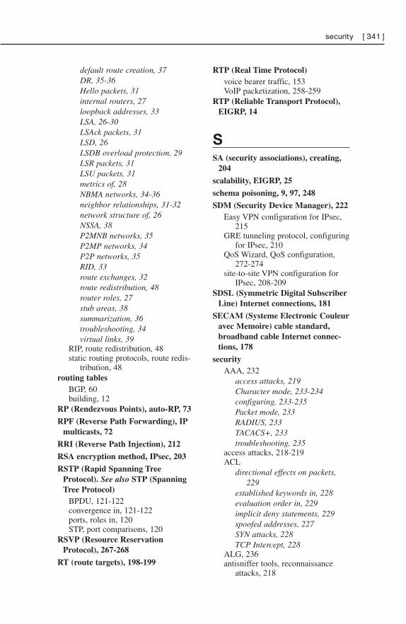
default route creation, 37DR, 35-36Hello packets, 31internal routers, 27loopback addresses, 33LSA, 26-30LSAck packets, 31LSD, 26LSDB overload protection, 29LSR packets, 31LSU packets, 31metrics of, 28NBMA networks, 34-36neighbor relationships, 31-32network structure of, 26NSSA, 38P2MNB networks, 35P2MP networks, 34P2P networks, 35RID, 33route exchanges, 32route redistribution, 48router roles, 27stub areas, 38summarization, 36troubleshooting, 34virtual links, 39
RIP, route redistribution, 48static routing protocols, route redis-
tribution, 48routing tables
BGP, 60building, 12
RP (Rendezvous Points), auto-RP, 73
RPF (Reverse Path Forwarding), IPmulticasts, 72
RRI (Reverse Path Injection), 212
RSA encryption method, IPsec, 203
RSTP (Rapid Spanning TreeProtocol). See also STP (SpanningTree Protocol)
BPDU, 121-122convergence in, 121-122ports, roles in, 120STP, port comparisons, 120
RSVP (Resource ReservationProtocol), 267-268
RT (route targets), 198-199
RTP (Real Time Protocol)voice bearer traffic, 153VoIP packetization, 258-259
RTP (Reliable Transport Protocol),EIGRP, 14
SSA (security associations), creating,
204
scalability, EIGRP, 25
schema poisoning, 9, 97, 248
SDM (Security Device Manager), 222Easy VPN configuration for IPsec,
215GRE tunneling protocol, configuring
for IPsec, 210QoS Wizard, QoS configuration,
272-274site-to-site VPN configuration for
IPsec, 208-209SDSL (Symmetric Digital Subscriber
Line) Internet connections, 181
SECAM (Systeme Electronic Couleuravec Memoire) cable standard,broadband cable Internet connec-tions, 178
securityAAA, 232
access attacks, 219Character mode, 233-234configuring, 233-235Packet mode, 233RADIUS, 233TACACS+, 233troubleshooting, 235
access attacks, 218-219ACL
directional effects on packets,229
established keywords in, 228evaluation order in, 229implicit deny statements, 229spoofed addresses, 227SYN attacks, 228TCP Intercept, 228
ALG, 236antisniffer tools, reconnaissance
attacks, 218
security [ 341 ]
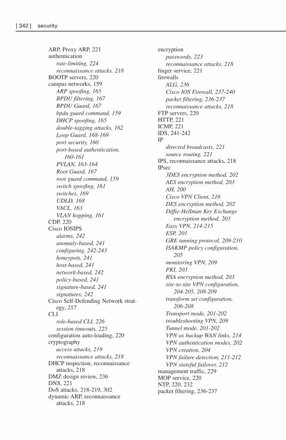
ARP, Proxy ARP, 221authentication
rate-limiting, 224reconnaissance attacks, 218
BOOTP servers, 220campus networks, 159
ARP spoofing, 165BPDU filtering, 167BPDU Guard, 167bpdu guard command, 159DHCP spoofing, 165double-tagging attacks, 162Loop Guard, 168-169port security, 160port-based authentication,
160-161PVLAN, 163-164Root Guard, 167root guard command, 159switch spoofing, 161switches, 169UDLD, 168VACL, 163VLAN hopping, 161
CDP, 220Cisco IOSIPS
alarms, 242anomaly-based, 241configuring, 242-243honeypots, 241host-based, 241network-based, 242policy-based, 241signature-based, 241signatures, 242
Cisco Self-Defending Network strat-egy, 217
CLIrole-based CLI, 226session timeouts, 225
configuration auto-loading, 220cryptography
access attacks, 219reconnaissance attacks, 218
DHCP inspection, reconnaissanceattacks, 218
DMZ design review, 236DNS, 221DoS attacks, 218-219, 302dynamic ARP, reconnaissance
attacks, 218
encryptionpasswords, 223reconnaissance attacks, 218
finger service, 221firewalls
ALG, 236Cisco IOS Firewall, 237-240packet filtering, 236-237reconnaissance attacks, 218
FTP servers, 220HTTP, 221ICMP, 221IDS, 241-242IP
directed broadcasts, 221source routing, 221
IPS, reconnaissance attacks, 218IPsec
3DES encryption method, 202AES encryption method, 203AH, 200Cisco VPN Client, 216DES encryption method, 202Diffie-Hellman Key Exchange
encryption method, 203Easy VPN, 214-215ESP, 201GRE tunning protocol, 209-210ISAKMP policy configuration,
205monitoring VPN, 209PKI, 203RSA encryption method, 203site-to-site VPN configuration,
204-205, 208-209transform set configuration,
206-208Transport mode, 201-202troubleshooting VPN, 209Tunnel mode, 201-202VPN as backup WAN links, 214VPN authentication modes, 202VPN creation, 204VPN failure detection, 211-212VPN stateful failover, 212
management traffic, 229MOP service, 220NTP, 220, 232packet filtering, 236-237
[ 342 ] security
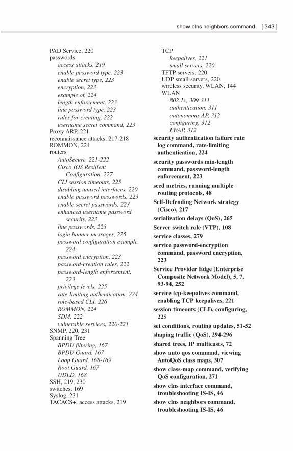
PAD Service, 220passwords
access attacks, 219enable password type, 223enable secret type, 223encryption, 223example of, 224length enforcement, 223line password type, 223rules for creating, 222username secret command, 223
Proxy ARP, 221reconnaissance attacks, 217-218ROMMON, 224routers
AutoSecure, 221-222Cisco IOS Resilient
Configuration, 227CLI session timeouts, 225disabling unused interfaces, 220enable password passwords, 223enable secret passwords, 223enhanced username password
security, 223line passwords, 223login banner messages, 225password configuration example,
224password encryption, 223password-creation rules, 222password-length enforcement,
223privilege levels, 225rate-limiting authentication, 224role-based CLI, 226ROMMON, 224SDM, 222vulnerable services, 220-221
SNMP, 220, 231Spanning Tree
BPDU filtering, 167BPDU Guard, 167Loop Guard, 168-169Root Guard, 167UDLD, 168
SSH, 219, 230switches, 169Syslog, 231TACACS+, access attacks, 219
TCPkeepalives, 221small servers, 220
TFTP servers, 220UDP small servers, 220wireless security, WLAN, 144WLAN
802.1x, 309-311authentication, 311autonomous AP, 312configuring, 312LWAP, 312
security authentication failure ratelog command, rate-limitingauthentication, 224
security passwords min-lengthcommand, password-lengthenforcement, 223
seed metrics, running multiplerouting protocols, 48
Self-Defending Network strategy(Cisco), 217
serialization delays (QoS), 265
Server switch role (VTP), 108
service classes, 279
service password-encryptioncommand, password encryption,223
Service Provider Edge (EnterpriseComposite Network Model), 5, 7,93-94, 252
service tcp-keepalives command,enabling TCP keepalives, 221
session timeouts (CLI), configuring,225
set conditions, routing updates, 51-52
shaping traffic (QoS), 294-296
shared trees, IP multicasts, 72
show auto qos command, viewingAutoQoS class maps, 307
show class-map command, verifyingQoS configuration, 271
show clns interface command,troubleshooting IS-IS, 46
show clns neighbors command,troubleshooting IS-IS, 46
show clns neighbors command [ 343 ]
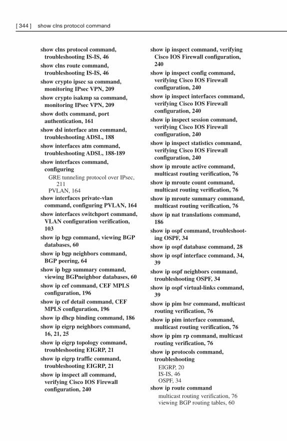
show clns protocol command,troubleshooting IS-IS, 46
show clns route command,troubleshooting IS-IS, 46
show crypto ipsec sa command,monitoring IPsec VPN, 209
show crypto isakmp sa command,monitoring IPsec VPN, 209
show dotlx command, portauthentication, 161
show dsl interface atm command,troubleshooting ADSL, 188
show interfaces atm command,troubleshooting ADSL, 188-189
show interfaces command,configuring
GRE tunneling protocol over IPsec,211
PVLAN, 164show interfaces private-vlan
command, configuring PVLAN, 164
show interfaces switchport command,VLAN configuration verification,103
show ip bgp command, viewing BGPdatabases, 60
show ip bgp neighbors command,BGP peering, 64
show ip bgp summary command,viewing BGPneighbor databases, 60
show ip cef command, CEF MPLSconfiguration, 196
show ip cef detail command, CEFMPLS configuration, 196
show ip dhcp binding command, 186
show ip eigrp neighbors command,16, 21, 25
show ip eigrp topology command,troubleshooting EIGRP, 21
show ip eigrp traffic command,troubleshooting EIGRP, 21
show ip inspect all command,verifying Cisco IOS Firewallconfiguration, 240
show ip inspect command, verifyingCisco IOS Firewall configuration,240
show ip inspect config command,verifying Cisco IOS Firewallconfiguration, 240
show ip inspect interfaces command,verifying Cisco IOS Firewallconfiguration, 240
show ip inspect session command,verifying Cisco IOS Firewallconfiguration, 240
show ip inspect statistics command,verifying Cisco IOS Firewallconfiguration, 240
show ip mroute active command,multicast routing verification, 76
show ip mroute count command,multicast routing verification, 76
show ip mroute summary command,multicast routing verification, 76
show ip nat translations command,186
show ip ospf command, troubleshoot-ing OSPF, 34
show ip ospf database command, 28
show ip ospf interface command, 34,39
show ip ospf neighbors command,troubleshooting OSPF, 34
show ip ospf virtual-links command,39
show ip pim bsr command, multicastrouting verification, 76
show ip pim interface command,multicast routing verification, 76
show ip pim rp command, multicastrouting verification, 76
show ip protocols command,troubleshooting
EIGRP, 20IS-IS, 46OSPF, 34
show ip route commandmulticast routing verification, 76viewing BGP routing tables, 60
[ 344 ] show clns protocol command
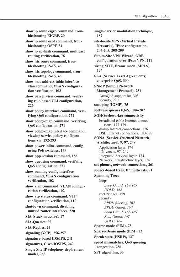
show ip route eigrp command, trou-bleshooting EIGRP, 20
show ip route ospf command, trou-bleshooting OSPF, 34
show ip rp-hash command, multicastrouting verification, 76
show isis route command, trou-bleshooting IS-IS, 46
show isis topology command, trou-bleshooting IS-IS, 46
show mac address-table interfacevlan command, VLAN configura-tion verification, 103
show parser view command, verify-ing role-based CLI configuration,226
show policy interface command, veri-fying QoS configuration, 271
show policy-map command, verifyingQoS configuration, 271
show policy-map interface command,viewing service policy configura-tions via, 292-293
show power inline command, config-uring PoE switches, 149
show ppp session command, 186
show queueing command, verifyingQoS configuration, 271
show running-config interfacecommand, VLAN configurationverification, 102
show vlan command, VLAN configu-ration verification, 102
show vtp status command, VTPconfiguration verification, 110
shutdown command, disablingunused router interfaces, 220
SIA (stuck in active), 17
SIA-Queries, 25
SIA-Replies, 25
signaling (VoIP), 256-257
signature-based IDS/IPS, 241
signatures, Cisco IOSIPS, 242
Single Site IP telephony deploymentmodel, 262
single-carrier modulation technique,182
site-to-site VPN (Virtual PrivateNetworks), IPsec configuration,204-205, 208-209
Site-to-Site VPN Wizard, GREconfiguration over IPsec VPN, 211
sizing MTU, Frame mode (MPLS),196
SLA (Service Level Agreements),enterprise QoS, 300
SNMP (Simple NetworkManagement Protocol), 231
AutoQoS support for, 305security, 220
snooping (IGMP), 75
software queues (QoS), 286-287
SOHO/teleworker connectivitybroadband cable Internet connec-
tions, 177-179dialup Internet connections, 176DSL Internet connections, 180-189
SONA (Service-Oriented NetworkArchitecture), 9, 97, 248
Application layer, 174IIN versus, 97, 249Integrated Services layer, 174Network Infrastructure layer, 174
sot phones, network connections, 261
source-based trees, IP multicasts, 71
Spanning Treesloops
Loop Guard, 168-169UDLD, 168
root bridges, 159security
BPDU filtering, 167BPDU Guard, 167Loop Guard, 168-169Root Guard, 167UDLD, 168
Sparse mode (PIM), 73
Sparse-Dense mode (PIM), 73
Speak state (HSRP), 137
speed mismatches, QoS queuingcongestion, 286
SPF algorithm, 33
SPF algorithm [ 345 ]
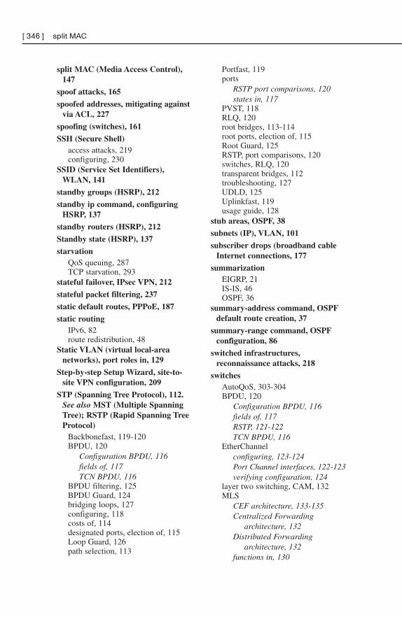
split MAC (Media Access Control),147
spoof attacks, 165
spoofed addresses, mitigating againstvia ACL, 227
spoofing (switches), 161
SSH (Secure Shell)access attacks, 219configuring, 230
SSID (Service Set Identifiers),WLAN, 141
standby groups (HSRP), 212
standby ip command, configuringHSRP, 137
standby routers (HSRP), 212
Standby state (HSRP), 137
starvationQoS queuing, 287TCP starvation, 293
stateful failover, IPsec VPN, 212
stateful packet filtering, 237
static default routes, PPPoE, 187
static routingIPv6, 82route redistribution, 48
Static VLAN (virtual local-areanetworks), port roles in, 129
Step-by-step Setup Wizard, site-to-site VPN configuration, 209
STP (Spanning Tree Protocol), 112.See also MST (Multiple SpanningTree); RSTP (Rapid Spanning TreeProtocol)
Backbonefast, 119-120BPDU, 120
Configuration BPDU, 116fields of, 117TCN BPDU, 116
BPDU filtering, 125BPDU Guard, 124bridging loops, 127configuring, 118costs of, 114designated ports, election of, 115Loop Guard, 126path selection, 113
Portfast, 119ports
RSTP port comparisons, 120states in, 117
PVST, 118RLQ, 120root bridges, 113-114root ports, election of, 115Root Guard, 125RSTP, port comparisons, 120switches, RLQ, 120transparent bridges, 112troubleshooting, 127UDLD, 125Uplinkfast, 119usage guide, 128
stub areas, OSPF, 38
subnets (IP), VLAN, 101
subscriber drops (broadband cableInternet connections, 177
summarizationEIGRP, 21IS-IS, 46OSPF, 36
summary-address command, OSPFdefault route creation, 37
summary-range command, OSPFconfiguration, 86
switched infrastructures,reconnaissance attacks, 218
switchesAutoQoS, 303-304BPDU, 120
Configuration BPDU, 116fields of, 117RSTP, 121-122TCN BPDU, 116
EtherChannelconfiguring, 123-124Port Channel interfaces, 122-123verifying configuration, 124
layer two switching, CAM, 132MLS
CEF architecture, 133-135Centralized Forwarding
architecture, 132Distributed Forwarding
architecture, 132functions in, 130
[ 346 ] split MAC
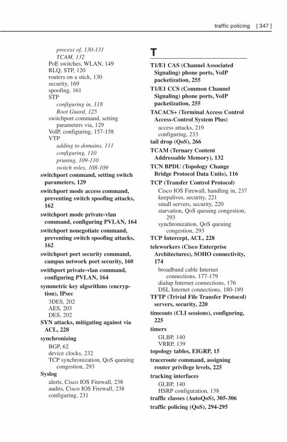
process of, 130-131TCAM, 132
PoE switches, WLAN, 149RLQ, STP, 120routers on a stick, 130security, 169spoofing, 161STP
configuring in, 118Root Guard, 125
switchport command, settingparameters via, 129
VoIP, configuring, 157-158VTP
adding to domains, 111configuring, 110pruning, 109-110switch roles, 108-109
switchport command, setting switchparameters, 129
switchport mode access command,preventing switch spoofing attacks,162
switchport mode private-vlancommand, configuring PVLAN, 164
switchport nonegotiate command,preventing switch spoofing attacks,162
switchport port security command,campus network port security, 160
swithport private-vlan command,configuring PVLAN, 164
symmetric key algorithms (encryp-tion), IPsec
3DES, 202AES, 203DES, 202
SYN attacks, mitigating against viaACL, 228
synchronizingBGP, 62device clocks, 232TCP synchronization, QoS queuing
congestion, 293Syslog
alerts, Cisco IOS Firewall, 238audits, Cisco IOS Firewall, 238configuring, 231
TT1/E1 CAS (Channel Associated
Signaling) phone ports, VoIPpacketization, 255
T1/E1 CCS (Common ChannelSignaling) phone ports, VoIPpacketization, 255
TACACS+ (Terminal Access ControlAccess-Control System Plus)
access attacks, 219configuring, 233
tail drop (QoS), 266
TCAM (Ternary ContentAddressable Memory), 132
TCN BPDU (Topology ChangeBridge Protocol Data Units), 116
TCP (Transfer Control Protocol)Cisco IOS Firewall, handling in, 237keepalives, security, 221small servers, security, 220starvation, QoS queuing congestion,
293synchronization, QoS queuing
congestion, 293TCP Intercept, ACL, 228
teleworkers (Cisco EnterpriseArchitectures), SOHO connectivity,174
broadband cable Internetconnections, 177-179
dialup Internet connections, 176DSL Internet connections, 180-189
TFTP (Trivial File Transfer Protocol)servers, security, 220
timeouts (CLI sessions), configuring,225
timersGLBP, 140VRRP, 139
topology tables, EIGRP, 15
traceroute command, assigningrouter privilege levels, 225
tracking interfacesGLBP, 140HSRP configuration, 138
traffic classes (AutoQoS), 305-306
traffic policing (QoS), 294-295
traffic policing [ 347 ]
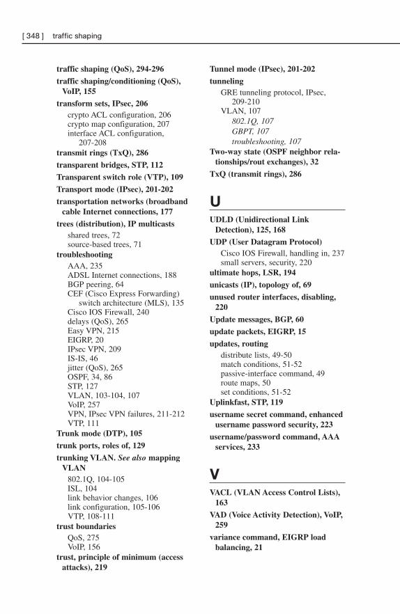
traffic shaping (QoS), 294-296
traffic shaping/conditioning (QoS),VoIP, 155
transform sets, IPsec, 206crypto ACL configuration, 206crypto map configuration, 207interface ACL configuration,
207-208transmit rings (TxQ), 286
transparent bridges, STP, 112
Transparent switch role (VTP), 109
Transport mode (IPsec), 201-202
transportation networks (broadbandcable Internet connections, 177
trees (distribution), IP multicastsshared trees, 72source-based trees, 71
troubleshootingAAA, 235ADSL Internet connections, 188BGP peering, 64CEF (Cisco Express Forwarding)
switch architecture (MLS), 135Cisco IOS Firewall, 240delays (QoS), 265Easy VPN, 215EIGRP, 20IPsec VPN, 209IS-IS, 46jitter (QoS), 265OSPF, 34, 86STP, 127VLAN, 103-104, 107VoIP, 257VPN, IPsec VPN failures, 211-212VTP, 111
Trunk mode (DTP), 105
trunk ports, roles of, 129
trunking VLAN. See also mappingVLAN
802.1Q, 104-105ISL, 104link behavior changes, 106link configuration, 105-106VTP, 108-111
trust boundariesQoS, 275VoIP, 156
trust, principle of minimum (accessattacks), 219
Tunnel mode (IPsec), 201-202
tunnelingGRE tunneling protocol, IPsec,
209-210VLAN, 107
802.1Q, 107GBPT, 107troubleshooting, 107
Two-way state (OSPF neighbor rela-tionships/rout exchanges), 32
TxQ (transmit rings), 286
UUDLD (Unidirectional Link
Detection), 125, 168
UDP (User Datagram Protocol)Cisco IOS Firewall, handling in, 237small servers, security, 220
ultimate hops, LSR, 194
unicasts (IP), topology of, 69
unused router interfaces, disabling,220
Update messages, BGP, 60
update packets, EIGRP, 15
updates, routingdistribute lists, 49-50match conditions, 51-52passive-interface command, 49route maps, 50set conditions, 51-52
Uplinkfast, STP, 119
username secret command, enhancedusername password security, 223
username/password command, AAAservices, 233
VVACL (VLAN Access Control Lists),
163
VAD (Voice Activity Detection), VoIP,259
variance command, EIGRP loadbalancing, 21
[ 348 ] traffic shaping
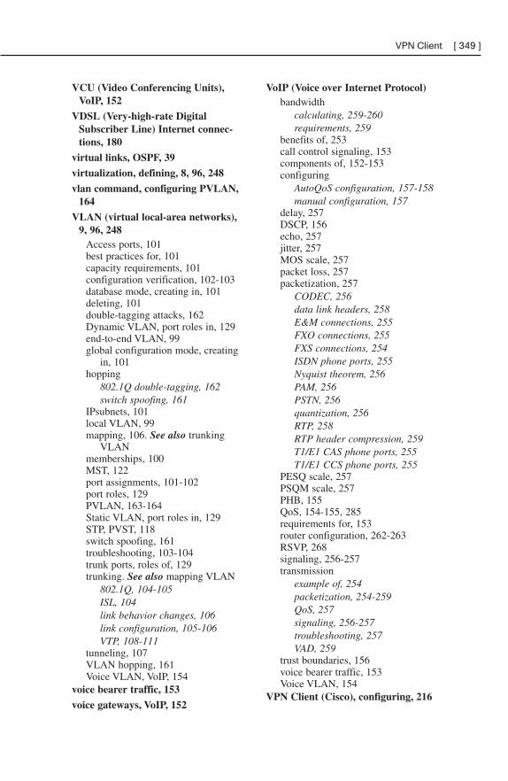
VCU (Video Conferencing Units),VoIP, 152
VDSL (Very-high-rate DigitalSubscriber Line) Internet connec-tions, 180
virtual links, OSPF, 39
virtualization, defining, 8, 96, 248
vlan command, configuring PVLAN,164
VLAN (virtual local-area networks),9, 96, 248
Access ports, 101best practices for, 101capacity requirements, 101configuration verification, 102-103database mode, creating in, 101deleting, 101double-tagging attacks, 162Dynamic VLAN, port roles in, 129end-to-end VLAN, 99global configuration mode, creating
in, 101hopping
802.1Q double-tagging, 162switch spoofing, 161
IPsubnets, 101local VLAN, 99mapping, 106. See also trunking
VLANmemberships, 100MST, 122port assignments, 101-102port roles, 129PVLAN, 163-164Static VLAN, port roles in, 129STP, PVST, 118switch spoofing, 161troubleshooting, 103-104trunk ports, roles of, 129trunking. See also mapping VLAN
802.1Q, 104-105ISL, 104link behavior changes, 106link configuration, 105-106VTP, 108-111
tunneling, 107VLAN hopping, 161Voice VLAN, VoIP, 154
voice bearer traffic, 153
voice gateways, VoIP, 152
VoIP (Voice over Internet Protocol)bandwidth
calculating, 259-260requirements, 259
benefits of, 253call control signaling, 153components of, 152-153configuring
AutoQoS configuration, 157-158manual configuration, 157
delay, 257DSCP, 156echo, 257jitter, 257MOS scale, 257packet loss, 257packetization, 257
CODEC, 256data link headers, 258E&M connections, 255FXO connections, 255FXS connections, 254ISDN phone ports, 255Nyquist theorem, 256PAM, 256PSTN, 256quantization, 256RTP, 258RTP header compression, 259T1/E1 CAS phone ports, 255T1/E1 CCS phone ports, 255
PESQ scale, 257PSQM scale, 257PHB, 155QoS, 154-155, 285requirements for, 153router configuration, 262-263RSVP, 268signaling, 256-257transmission
example of, 254packetization, 254-259QoS, 257signaling, 256-257troubleshooting, 257VAD, 259
trust boundaries, 156voice bearer traffic, 153Voice VLAN, 154
VPN Client (Cisco), configuring, 216
VPN Client [ 349 ]
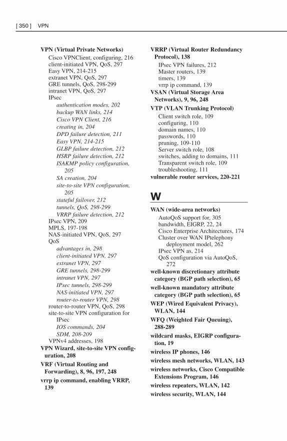
VPN (Virtual Private Networks)Cisco VPNClient, configuring, 216client-initiated VPN, QoS, 297Easy VPN, 214-215extranet VPN, QoS, 297GRE tunnels, QoS, 298-299intranet VPN, QoS, 297IPsec
authentication modes, 202backup WAN links, 214Cisco VPN Client, 216creating in, 204DPD failure detection, 211Easy VPN, 214-215GLBP failure detection, 212HSRP failure detection, 212ISAKMP policy configuration,
205SA creation, 204site-to-site VPN configuration,
205stateful failover, 212tunnels, QoS, 298-299VRRP failure detection, 212
IPsec VPN, 209MPLS, 197-198NAS-initiated VPN, QoS, 297QoS
advantages in, 298client-initiated VPN, 297extranet VPN, 297GRE tunnels, 298-299intranet VPN, 297IPsec tunnels, 298-299NAS-initiated VPN, 297router-to-router VPN, 298
router-to-router VPN, QoS, 298site-to-site VPN configuration for
IPsecIOS commands, 204SDM, 208-209
VPNv4 addresses, 198VPN Wizard, site-to-site VPN config-
uration, 208
VRF (Virtual Routing andForwarding), 8, 96, 197, 248
vrrp ip command, enabling VRRP,139
VRRP (Virtual Router RedundancyProtocol), 138
IPsec VPN failures, 212Master routers, 139timers, 139vrrp ip command, 139
VSAN (Virtual Storage AreaNetworks), 9, 96, 248
VTP (VLAN Trunking Protocol)Client switch role, 109configuring, 110domain names, 110passwords, 110pruning, 109-110Server switch role, 108switches, adding to domains, 111Transparent switch role, 109troubleshooting, 111
vulnerable router services, 220-221
WWAN (wide-area networks)
AutoQoS support for, 305bandwidth, EIGRP, 22, 24Cisco Enterprise Architectures, 174Cluster over WAN IPtelephony
deployment model, 262IPsec VPN as, 214QoS configuration via AutoQoS,
272well-known discretionary attribute
category (BGP path selection), 65
well-known mandatory attributecategory (BGP path selection), 65
WEP (Wired Equivalent Privacy),WLAN, 144
WFQ (Weighted Fair Queuing),288-289
wildcard masks, EIGRP configura-tion, 19
wireless IP phones, 146
wireless mesh networks, WLAN, 143
wireless networks, Cisco CompatibleExtensions Program, 146
wireless repeaters, WLAN, 142
wireless security, WLAN, 144
[ 350 ] VPN
wizardsQuick Setup Wizard, site-to-site
VPN configuration, 208SDM QoS Wizard, QoS configura-
tion, 272, 274Site-to-Site VPN Wizard, GRE
configuration over IPsec, 211Step-by-step Setup Wizard, site-to-
site VPN configuration, 209VPN Wizard, site-to-site VPN
configuration, 208WLAN (wireless local-area networks)
802.11a Internet standard, 143-144802.11b Internet standard, 143802.11g Internet standard, 144ad-hoc mode, 142antennas, 147-148AP, 142-143
autonomous AP, 146configuring, 149-150lightweight AP, 146-147, 150
authentication, 145autonomous AP, 312AWP, 143characteristics of, 141Cisco Unified Wireless Network,
145controllers, configuring, 150CSMA/CA, 142EAP, 144LWAP, 312managing, 313PoE switches, 149QoS, 308-309security
802.1x, 309-311authentication, 311configuring, 312
SSID, 141topologies of, 142WEP, 144wireless mesh networks, 143wireless repeaters, 142wireless security, 144WLC, configuring, 150workgroup bridges, 143WPA, 144WPA2, 144
WLC (Wireless LAN Controllers),WLAN configurations, 150
WLSE (Wireless LAN SolutionEngines), WLAN management, 313
workgroup bridges, WLAN, 143
WPA (Wi-fi Protected Access),WLAN, 144
WPA2 (Wi-fi Protected Accessversion 2.0), WLAN, 144
WRED (Weighted Random EarlyDetection)
configuring, 294QoS queuing congestion, 293-294
WSC (Wi-fi Simple Config), WLANmanagement, 313
X - Y - ZXML (Extensible Markup
Language), schema poisoning, 9, 97,248
XML [ 351 ]


![CCNP BCMSN Quick Reference Sheets - Lagout Quick Reference... · CCNP BCMSN Quick Reference Sheets Exam 642-812 ... [ 4 ] CCNP BCMSN Quick Reference Sheets. ... switch would be used](https://img.pdfslide.net/doc/110x75/5a7a6ec87f8b9a05538dccf5/ccnp-bcmsn-quick-reference-sheets-lagout-quick-referenceccnp-bcmsn-quick-reference.jpg)


![CCNP Routing and Switching TSHOOT 300-135 …...[ iv ] CCNP Routing and Switching TSHOOT 300-135 Quick Reference About the Author Brent Stewart, CCNP, CCDP, CCSI, MCSE, is the vice](https://img.pdfslide.net/doc/110x75/5f10b1cc7e708231d44a5dc3/ccnp-routing-and-switching-tshoot-300-135-iv-ccnp-routing-and-switching.jpg)