Embed Size (px)
Citation preview
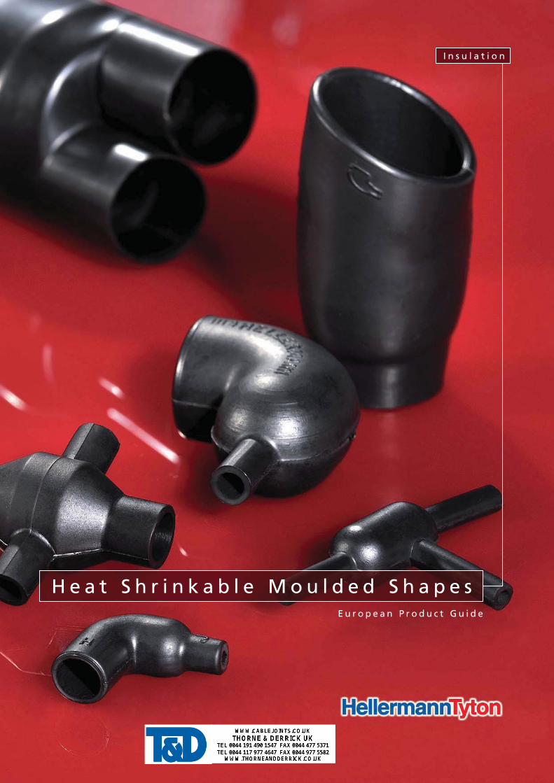
E u r o p e a n P r o d u c t G u i d e
H e a t S h r i n k a b l e M o u l d e d S h a p e s
I n s u l a t i o n
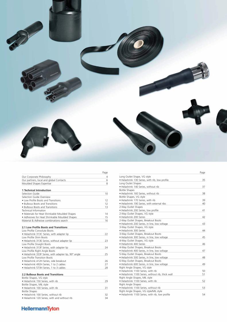
Our Corporate Philosophy 4Our partners, local and global Contacts 6Moulded Shapes Expertise 8
1 Technical IntroductionSelection Guide 10Selection Guide Overview• Low Profile Boots and Transitions 12• Bulbous Boots and Transitions 12• Bulbous Boots and Transitions 13Technical Information• Materials for Heat Shrinkable Moulded Shapes 14• Adhesives for Heat Shrinkable Moulded Shapes 15Material & Adhesive combinations search 16
2.1 Low Profile Boots and TransitionsLow Profile Convolute Boots• Helashrink 313C Series, with adapter lip 22Low Profile Shim Boots• Helashrink 313E Series, without adapter lip 23Low Profile Straight Boots• Helashrink 313F Series, with adapter lip 24Low Profile Right Angle Boots• Helashrink 333F Series, with adapter lip, 90° angle 25Low Profile Transition Boots• Helashrink 412H Series, side breakout 26• Helashrink 492H Series, 1 to 2 cables 27• Helashrink 573H Series, 1 to 3 cables 28
2.2 Bulbous Boots and TransitionsBottle Shapes, VG style• Helashrink 150 Series, with rib 29Bottle Shapes, MIL style• Helashrink 100 Series, with rib 31Bottle Shapes• Helashrink 100 Series, without rib 32• Helashrink 120 Series, with and without rib 34
Long Outlet Shape, VG style• Helashrink 130 Series, with rib, low profile 35Long Outlet Shapes• Helashrink 140 Series, without rib 37Bottle Shapes• Helashrink 160 Series, without rib 38Bottle Shapes, VG style• Helashrink 170 Series, with rib 39• Helashrink 190 Series, with external ribs 402-Way Outlet Shapes• Helashrink 200 Series, low profile 412-Way Outlet Shapes, VG style• Helashrink 200 Series 422-Way Outlet Shapes, Breakout Boots• Helashrink 200 Series, in line, low voltage 433-Way Outlet Shapes, VG style• Helashrink 300 Series 443-Way Outlet Shapes, Breakout Boots• Helashrink 300 Series, in line, low voltage 454-Way Outlet Shapes, VG style• Helashrink 400 Series 464-Way Outlet Shapes, Breakout Boots• Helashrink 400 Series, in line, low voltage 475-Way Outlet Shapes, Breakout Boots• Helashrink 500 Series, in line, low voltage 486-Way Outlet Shapes, Breakout Boots• Helashrink 600 Series, in line, low voltage 49Right Angle Shapes, VG style• Helashrink 1100 Series, with rib 50• Helashrink 1100 Series, without rib, thick wall 51Right Angle Shapes, MIL style• Helashrink 1100 Series, with rib 52Right Angle Shapes• Helashrink 1100 Series, without rib 53Right Angle Shapes, VG style/MIL style• Helashrink 1100 Series, with rib, low profile 54
Page Page

Right Angle Shapes, VG style• Helashrink 1100 Series, with rib, low profile, high ratio 56T-Shapes, VG style• Helashrink 1200 Series 57T-Shapes• Helashrink 1200 Series, Offset 58T-Shapes, VG style• Helashrink 1200 Series, Offset 59Angled T-Shapes, VG style• Helashrink 1300 Series, 30° & 45° angle 60Double T-Shapes• Helashrink 1310 Series, 30° angle 61Angle Elbow Shapes• Helashrink 1400 Series, 90° angle 62Connector Cover for Min-D Series• Helashrink 1500 Series, with top entry 63GSR Graduated Strain Relief• Helashrink 1750 Series with rib 64Angle Shapes• Helashrink 1800 Series, with rib, 30°, 45°, 60° angle 65Right-Angle Cross Shapes• Helashrink 2000 Series - T-Joint 66Locating Bushes• Helashrink 1760, 1790, 1820 Series 67Connector Cover for Min-D Series• Helashrink 2100 Series, with 90° entry 68
3.1 Breakout Boots and End Caps2-Way Outlet Shapes, Breakout Boots• Helashrink 200 Series, in line, low voltage 703-Way Outlet Shapes, Breakout Boots• Helashrink 300 Series, in line, low voltage 714-Way Outlet Shapes, Breakout Boots• Helashrink 400 Series, in line, low voltage 72End Caps• Helashrink 1600 Series, low voltage 73
Pinched End Caps• Helashrink PEC Series, low voltage 74
3.2 Heat Shrinkable TubingHeat Shrinkable Tubing 2:1 - Fluororubber• Viton®-E 75Heat Shrinkable Tubing 2:1 - Elastomer• SE28 76• TE28 - light weight 77Heat Shrinkable Tubing up to 4:1 - 1 m lengths• MU47 - medium wall unlined 78• MA47 - medium wall adhesive lined
3.3 Adaptor Springs Constant Force Spring Adaptor• Zetalok 79
3.4 AdhesivesTwo-component Adhesive for Heat Shrinkable Tubing and Shapes• V9500 Dosing Gun 80Hot Melt Tape for Heat Shrinkable Tubing and Shapes• HMT200A 81High Temperature Hot Melt Adhesive Tape for Low Profile Products• TSA 200 82
4.1 HellermannTyton Product StandardsStandards for HellermannTyton Heat Shrinkable Tubing and Heat Shrinkable Moulded Shapes according to VG Norm 84Standards for HellermannTyton Heat Shrinkable Tubing 85VG/MIL Specification Cross Reference 86HellermannTyton Shapes for use with MIL Connectors 87MIL Specification Slash Sheet Cross Reference 88
4.2 Terms and Conditions 95
Page Page
C o n t e n t
4
Moving the market takes more than good ideas.
Developing the product solutions for the future, requires visionary
thinking and the passion to turn ideas into reality.
When visions become functional products, innovations are
generated that benefit our customers.
We create the conditions for this by employing motivated people
who are committed to working as a team. When only the best
solutions will do, you need dedicated professionals with expert
knowledge.
The result is product solutions that not only reshape the market
but re-develope it.
We are able to offer product solutions before our customers
know they need them.
We maintain good relationships with our customers and also keep
a close eye on the latest market developments. This allows us to
recognise trends affecting trade and industry at an early stage. And
enables us to remain a step ahead of customer requirements at all
times.
Meeting high expectations calls for ongoing development.
As well as paying particular attention to communicating with
our customers and knowledge of the market, we invest heavily in
research and development. To ensure that we can support our
customers into the future by offering custom product solutions,
we continually optimise our technical and logistical processes.

5
Certified processes and quality, for your security.
HellermannTyton always aim for the highest quality.
To live up to this claim we have implemented a quality
and environmental management systems.
Our quality management is certified to DIN EN ISO 9001:2008
and DIN EN ISO/TS 16949:2002.
In addition, our environmental management complies with the
requirements of DIN EN ISO 14001:2005.
At your service wherever – and whenever – you need us.
What use are the best product solutions if they are not available to
local markets in a timely way? HellermannTyton’s motto is therefore
“Think global, act local”. For us, this not only means responding to
the needs of local markets – we also have a presence there for the
benefit of our customers.
Employees on the ground allow us to cater for cultural, market-
specific and linguistic factors effectively. In addition, our customers
have access to a worldwide distribution network. This adds value
that makes us one of the leading providers for trade and industry.
O u r C o r p o r a t e P h i l o s o p h y
To t r u l y e x c e l , y o u n e e d t ok e e p i m p r o v i n g a l l t h e t i m e .
DIN EN ISO
9001:2000
DIN EN ISO
14001:2004
DIN EN ISO/TS
16949:2002

6
W h e n e v e r y o u n e e d u s . . .
... you will find your local contact here:
www.HellermannTyton.com
E u r o p e
HellermannTyton GmbH – AustriaObachgasse 61221 ViennaTel: +43 (0) 1 259 99 55 - 0Fax: +43 (0)1 259 99 11E-Mail: [email protected]
HellermannTyton B.V. – BelgiumE-Mail: [email protected]
HellermannTyton – Czech RepublicE-Mail: [email protected]
HellermannTyton DenmarkBaldersbuen 15D 1. TV2640 HedehuseneTel: +45 702 371 20Fax: +45 702 371 21E-Mail: [email protected]
HellermannTyton Oy – FinlandSähkötie 801510 VantaaTel: +358 9 8700 450Fax: +358 9 8700 4520E-Mail: [email protected]
HellermannTyton S.A.S. – France2 rue des Hêtres, B.P. 13078196 Trappes CedexTel: +33 1 30 13 80 00Fax: +33 1 30 13 80 60E-Mail: [email protected]
HellermannTyton GmbH – GermanyGroßer Moorweg 4525436 TorneschTel: +49 4122 701-0Fax: +49 4122 701-400E-Mail: [email protected]
HellermannTyton KFT – HungaryKisfaludy u. 131044 BudapestTel: +36 1 369 4151Fax: +36 1 369 4151E-Mail: [email protected]
HellermannTyton S.r.l. – ItalyVia Praimbole 9 Bis35010 Limena (PD)Tel: +39 049 767 870Fax: +39 049 767 985E-Mail: [email protected]
HellermannTyton Ltd – IrelandUnit 77 Cherry OrchardIndustrial EstateBallyfermot, Dublin 10Tel: +353 1 626 8267Fax: +353 1 626 8022E-Mail: [email protected]
HellermannTyton B.V. – NetherlandsVanadiumweg 11-C3812 PX AmersfoortTel: +31 33 460 06 90Fax: +31 33 460 06 99E-Mail: [email protected]
HellermannTyton AS – NorwayPO Box 240 Alnabru0614 OsloTel: +47 23 17 47 00Fax: +47 22 97 09 70E-Mail: [email protected]
HellermannTyton – PolandE-Mail: [email protected]
OOO HellermannTyton – RussiaSt. PetersburgE-Mail: [email protected]
HellermannTyton – SloveniaBranch Office LjubljanaTrubarjeva 791101 LjubljanaTel: +386 1 433 70 56Fax: +386 1 433 63 21E-Mail: [email protected]
HellermannTyton España s.l. –Spain/PortugalAvda. de la Industria nº 37, 2º 2ª28.108 Alcobendas, Madrid Tel: +34 91 661 2835Fax: +34 91 661 2368E-Mail: [email protected]
HellermannTyton AB – SwedenDatavägen 5, PO Box 56917526 JärfällaTel: +46 8 580 890 00Fax: +46 8 580 890 01E-Mail: [email protected]
HellermannTyton Ltd – UKManufacturing SiteWilliam Prance RoadPlymouth International Technology ParkPlymouth PL6 5WRUnited KingdomTel: +44 (0) 1752 761211Fax: +44 (0) 1752 761210E-Mail: [email protected]
HellermannTyton Ltd – UKManufacturing SiteSharston Green Business Park1 Robeson WayAltrincham Road, WythenshaweManchester M22 4TYTel: +44 161 945 4181Fax: +44 161 947 2220E-Mail: [email protected]
HellermannTyton Ltd – UKMain Contact for Customer ServiceWharf ApproachAldridge, Walsall, West MidlandsWS9 8BXTel: +44 1922 458 151Fax: +44 1922 743 237E-Mail: [email protected]
HellermannTyton Data Ltd – UK43-45 Salthouse RoadCornwell Business Park BrackmillsNorthampton NN4 7EXTel: +44 1604 707 420Fax: +44 1604 705 454E-Mail: [email protected]
N o r t h A m e r i c a
HellermannTyton – CanadaTel: +1 905 726 1221Fax: +1 905 726 8538E-Mail: [email protected]
HellermannTyton – MexicoTel: +52 333 133 9880Fax: +52 333 133 9861E-Mail: [email protected]
HellermannTyton – USATel: +1 414 355 1130Fax: +1 414 355 7341E-Mail: [email protected]
S o u t h A m e r i c a
HellermannTyton – ArgentinaTel: +54 11 4754 5400Fax: +54 11 4752 0374E-Mail: [email protected]
HellermannTyton – BrazilTel: +55 11 4815 9000Fax: +55 11 4815 9030E-Mail: [email protected]
A s i a - P a c i f i c
HellermannTyton – AustraliaTel: +61 2 9525 2133Fax: +61 2 9526 2495E-Mail: [email protected]
HellermannTyton – ChinaTel: +86 510 528 2536Fax: +86 510 528 0112E-Mail: [email protected]
HellermannTyton – Hong KongTel: +852 2832 9090Fax: +852 2832 9381E-Mail: [email protected]
HellermannTyton – IndiaTel: +91 11-2620 9230/6661 9230Fax: +91 11-2620 9330/6661 9330E-Mail: [email protected]
HellermannTyton – JapanTel: +81 3 5790 3111Fax: +81 3 5790 3112E-Mail: [email protected]
HellermannTyton – KoreaTel: +82 2 2614 0157Fax: +82 2 2614 0284E-Mail: [email protected]
HellermannTyton – PhilippinesTel: +63 2 752 6551Fax: +63 2 752 6553E-Mail: [email protected]
HellermannTyton – SingaporeTel: +65 6 852 8585Fax: +65 6 756 6798E-Mail: [email protected] www.HellermannTyton.com.sg
HellermannTyton – ThailandTel: +66 2 237 6702Fax: +66 2 266 8664E-Mail: [email protected]
A f r i c a
HellermannTyton – South AfricaTel: +27 11 879 6680Fax: +27 11 879 6601E-Mail: [email protected]
7
C o n t a c t
If you have a particular problem that you would like us to help you with then please contact us.
With our vast experience and practically unlimited technical capabilities we are confident of being able to help you find a solution.
Remember, we are a service provider and not just a supplier.
Give us a call! Here are your contacts for enquiries and orders
For all product information please visit our Website www.HellermannTyton.co.uk
Heat Shrinkable Moulded Shapes
PlymouthTelephone 00 44 1752 701 261
Facsimile 00 44 1752 790 058e-mail [email protected]
AldridgeTelephone 00 44 1922 458 151
Facsimile 00 44 1922 743 237e-mail [email protected]
General Contacts
UK Head OfficeTelephone 00 44 161 945 4181
Facsimile 00 44 161 947 2233e-mail [email protected]
OEM Sales - Fixings & FasteningsTelephone 00 44 161 947 2200
Facsimile 00 44 161 945 3708e-mail [email protected]
OEM Sales - Insulation & ProtectionTelephone 00 44 1752 701 261
Facsimile 00 44 1752 790 058e-mail insulation&[email protected]
OEM Sales - IdentificationTelephone 00 44 1752 701 261
Facsimile 00 44 1752 790 058e-mail [email protected]
OEM Sales - Automated SystemsTelephone 00 44 161 947 2200Facsimilie 00 44 161 945 3708
e-mail [email protected]
8
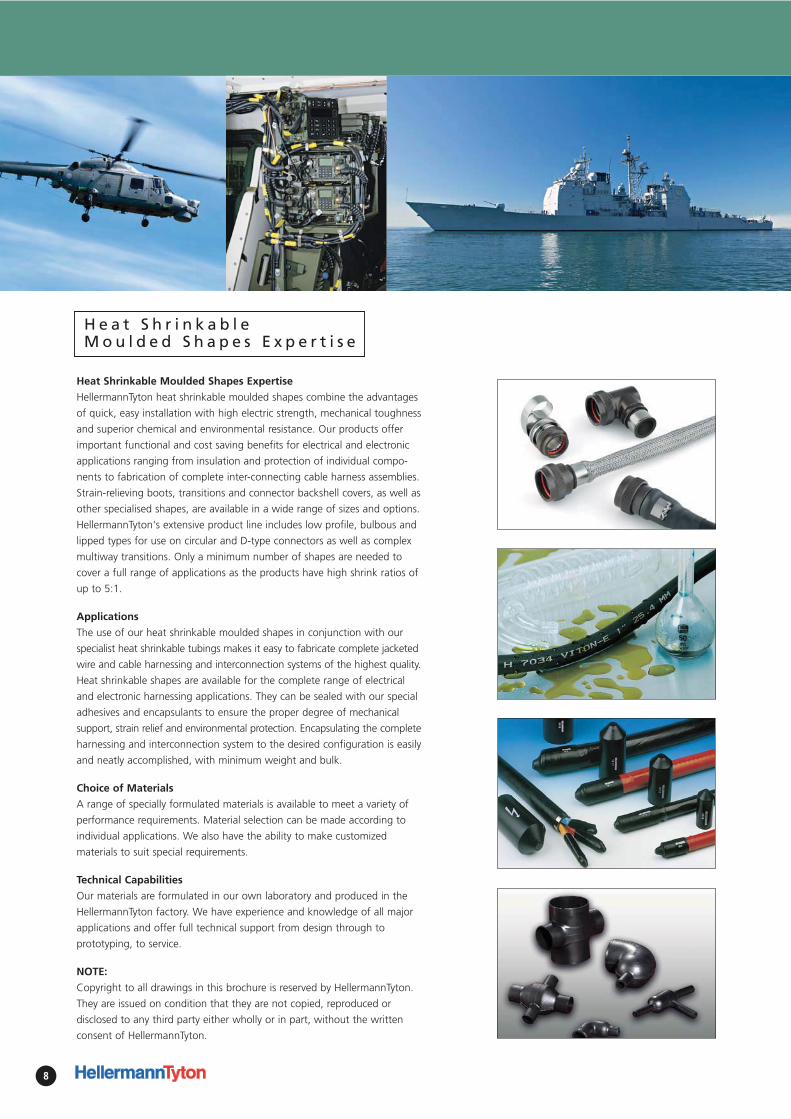
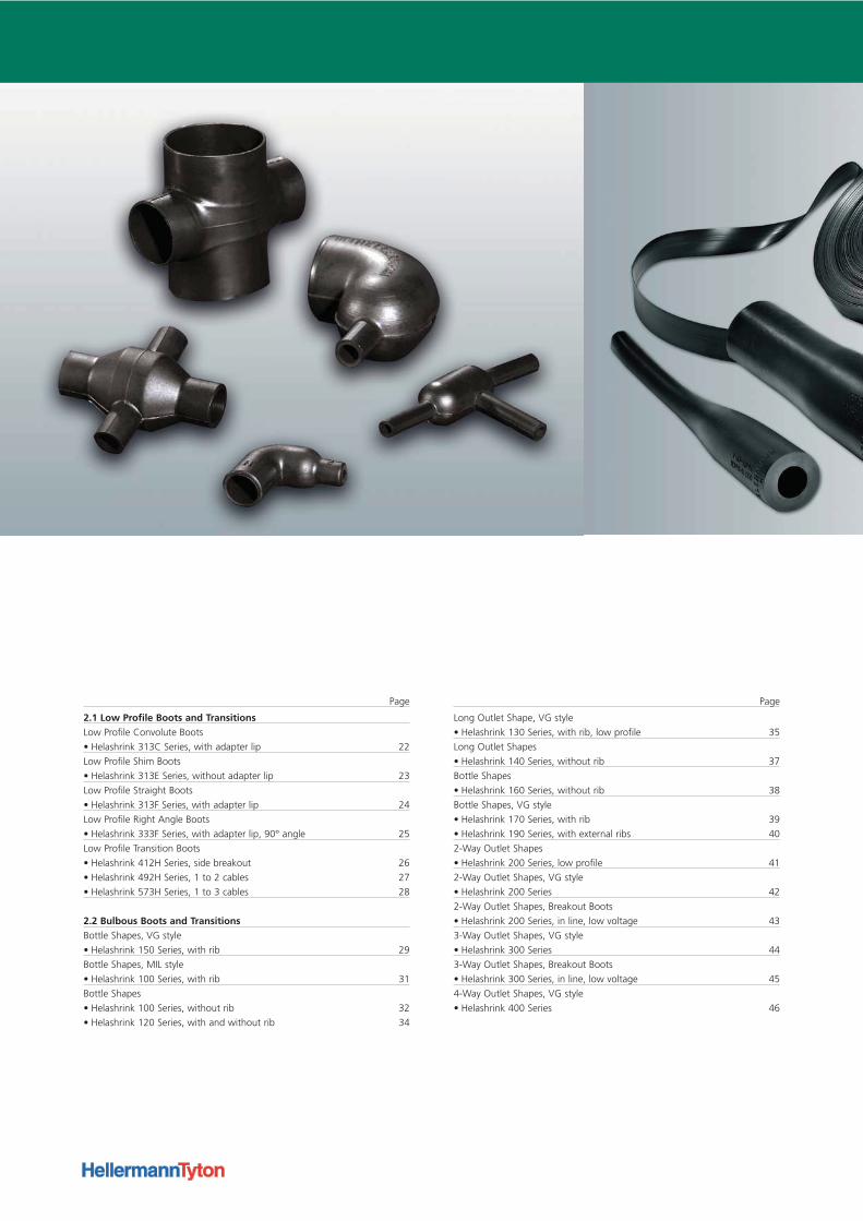
Heat Shrinkable Moulded Shapes Expertise
HellermannTyton heat shrinkable moulded shapes combine the advantages
of quick, easy installation with high electric strength, mechanical toughness
and superior chemical and environmental resistance. Our products offer
important functional and cost saving benefits for electrical and electronic
applications ranging from insulation and protection of individual compo-
nents to fabrication of complete inter-connecting cable harness assemblies.
Strain-relieving boots, transitions and connector backshell covers, as well as
other specialised shapes, are available in a wide range of sizes and options.
HellermannTyton's extensive product line includes low profile, bulbous and
lipped types for use on circular and D-type connectors as well as complex
multiway transitions. Only a minimum number of shapes are needed to
cover a full range of applications as the products have high shrink ratios of
up to 5:1.
Applications
The use of our heat shrinkable moulded shapes in conjunction with our
specialist heat shrinkable tubings makes it easy to fabricate complete jacketed
wire and cable harnessing and interconnection systems of the highest quality.
Heat shrinkable shapes are available for the complete range of electrical
and electronic harnessing applications. They can be sealed with our special
adhesives and encapsulants to ensure the proper degree of mechanical
support, strain relief and environmental protection. Encapsulating the complete
harnessing and interconnection system to the desired configuration is easily
and neatly accomplished, with minimum weight and bulk.
Choice of Materials
A range of specially formulated materials is available to meet a variety of
performance requirements. Material selection can be made according to
individual applications. We also have the ability to make customized
materials to suit special requirements.
Technical Capabilities
Our materials are formulated in our own laboratory and produced in the
HellermannTyton factory. We have experience and knowledge of all major
applications and offer full technical support from design through to
prototyping, to service.
NOTE:
Copyright to all drawings in this brochure is reserved by HellermannTyton.
They are issued on condition that they are not copied, reproduced or
disclosed to any third party either wholly or in part, without the written
consent of HellermannTyton.
H e a t S h r i n k a b l e M o u l d e d S h a p e s E x p e r t i s e
1 Technical InformationSelection Guide 10
Selection Guide Overview
• Low Profile Boots and Transitions 12
• Bulbous Boots and Transitions 12
• Bulbous Boots and Transitions 13
Technical Information
• Materials for Heat Shrinkable Moulded Shapes 14
• Adhesives for Heat Shrinkable Moulded Shapes 15
Material & Adhesive combinations search 16
Te c h n i c a l I n t r o d u c t i o n
Page
1
I n s u l a t i o n
Se le c t ion Gu ide
10
1I n s u l a t i o n
XXX
10
I n s u l a t i o n
Se le c t ion Gu ide
10
This selection guide will help you to find the correct moulded shape for your application:
Step 1. Product Style
Use the Selection Guide Overview on page 12 to quickly select a suitable product profile.
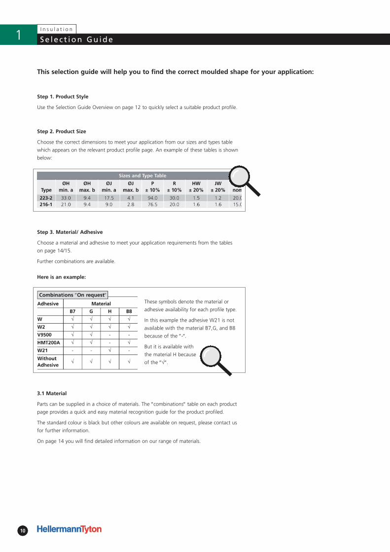
Step 2. Product Size
Choose the correct dimensions to meet your application from our sizes and types table
which appears on the relevant product profile page. An example of these tables is shown
below:
Step 3. Material/ Adhesive
Choose a material and adhesive to meet your application requirements from the tables
on page 14/15.
Further combinations are available.
Here is an example:
These symbols denote the material or
adhesive availability for each profile type.
In this example the adhesive W21 is not
available with the material B7,G, and B8
because of the ″-″.
But it is available with
the material H because
of the ″√″.
3.1 Material
Parts can be supplied in a choice of materials. The ″combinations″ table on each product
page provides a quick and easy material recognition guide for the product profiled.
The standard colour is black but other colours are available on request, please contact us
for further information.
On page 14 you will find detailed information on our range of materials.
I n s u l a t i o n
Se le c t ion Gu ide
11
1I n s u l a t i o n
XXX
11
I n s u l a t i o n
Se le c t ion Gu ide
11
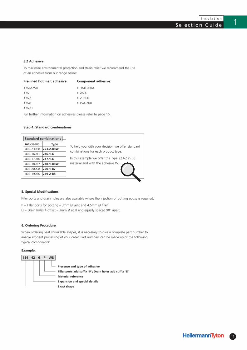
6. Ordering Procedure
When ordering heat shrinkable shapes, it is necessary to give a complete part number to
enable efficient processing of your order. Part numbers can be made up of the following
typical components:
Example:
154 - 42 - G - P - W8
Presence and type of adhesive
Filler ports add suffix ″P″; Drain holes add suffix ″D″
Material reference
Expansion and special details
Exact shape
Step 4. Standard combinations
To help you with your decision we offer standard
combinations for each product type.
In this example we offer the Type 223-2 in B8
material and with the adhesive W.
5. Special Modifications
Filler ports and drain holes are also available where the injection of potting epoxy is required.
P = Filler ports for potting – 3mm Ø vent and 4.5mm Ø filler.
D = Drain holes 4 offset – 3mm Ø at H end equally spaced 90° apart.
3.2 Adhesive
To maximise environmental protection and strain relief we recommend the use
of an adhesive from our range below.
Pre-lined hot melt adhesive:
• WM250
• W
• W2
• W8
• W21
Component adhesive:
• HMT200A
• W24
• V9500
• TSA-200
For further information on adhesives please refer to page 15.
Page 44
Page 42
Page 40
Page 38
Page 35
Page 32
Page 29 Page 31
Page 34
Page 37
Page 39
Page 41
Page 43
Page 45
I n s u l a t i o n
Se le c t ion Gu ide Overv iew
12
1
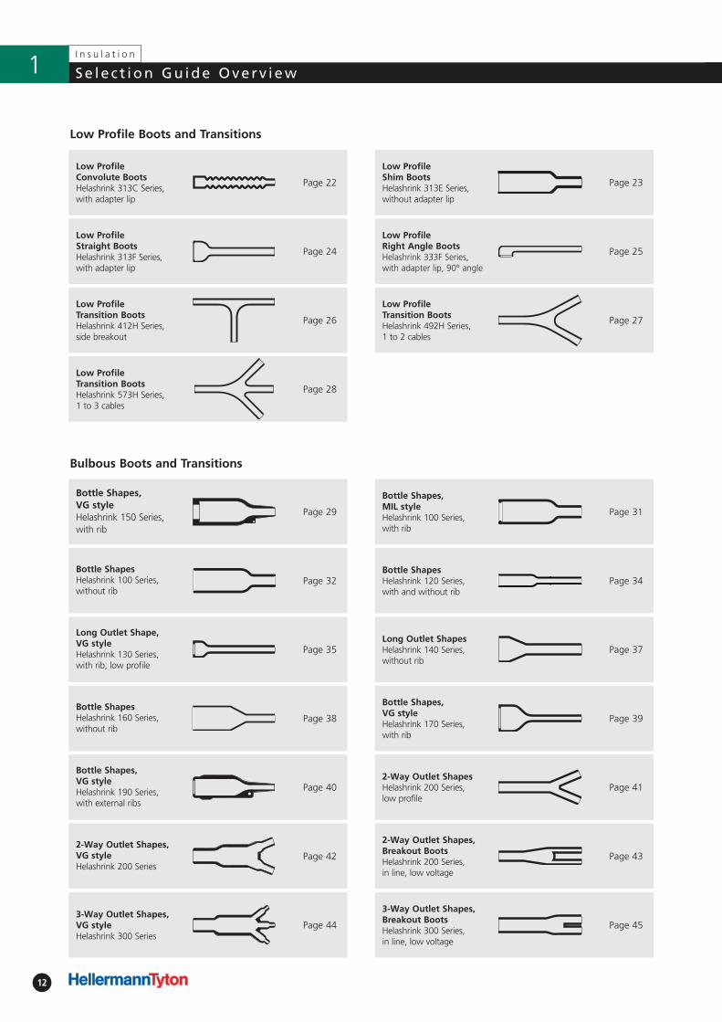
Low Profile Boots and Transitions
Bulbous Boots and Transitions
Page 22 Page 23
Page 25
Page 27
Page 24
Page 26
Page 28
Low Profile Transition BootsHelashrink 573H Series, 1 to 3 cables
Low Profile Shim BootsHelashrink 313E Series,without adapter lip
Low Profile Right Angle BootsHelashrink 333F Series, with adapter lip, 90° angle
Low Profile Convolute BootsHelashrink 313C Series,with adapter lip
Low Profile Straight BootsHelashrink 313F Series,with adapter lip
Low Profile Transition BootsHelashrink 412H Series,side breakout
Low Profile Transition BootsHelashrink 492H Series, 1 to 2 cables
Bottle ShapesHelashrink 160 Series,without rib
Bottle Shapes, MIL styleHelashrink 100 Series,with rib
Bottle ShapesHelashrink 120 Series,with and without rib
Bottle Shapes, VG styleHelashrink 150 Series,with rib
Bottle ShapesHelashrink 100 Series,without rib
Long Outlet Shape, VG styleHelashrink 130 Series,with rib, low profile
Long Outlet ShapesHelashrink 140 Series,without rib
Bottle Shapes, VG styleHelashrink 170 Series,with rib
2-Way Outlet Shapes,VG styleHelashrink 200 Series
Bottle Shapes, VG styleHelashrink 190 Series,with external ribs
2-Way Outlet ShapesHelashrink 200 Series, low profile
2-Way Outlet Shapes,Breakout BootsHelashrink 200 Series, in line, low voltage
3-Way Outlet Shapes,VG styleHelashrink 300 Series
3-Way Outlet Shapes,Breakout BootsHelashrink 300 Series, in line, low voltage
I n s u l a t i o n
13
Se le c t ion Gu ide Overv iew 1
Page 46 Page 47
Page 49
Page 51
Page 53
Page 56
Page 58
Page 60
Page 62
Page 64
Page 66
Page 68
Page 48
Page 50
Page 52
Page 54
Page 57
Page 59
Page 61
Page 63
Page 65
Page 67
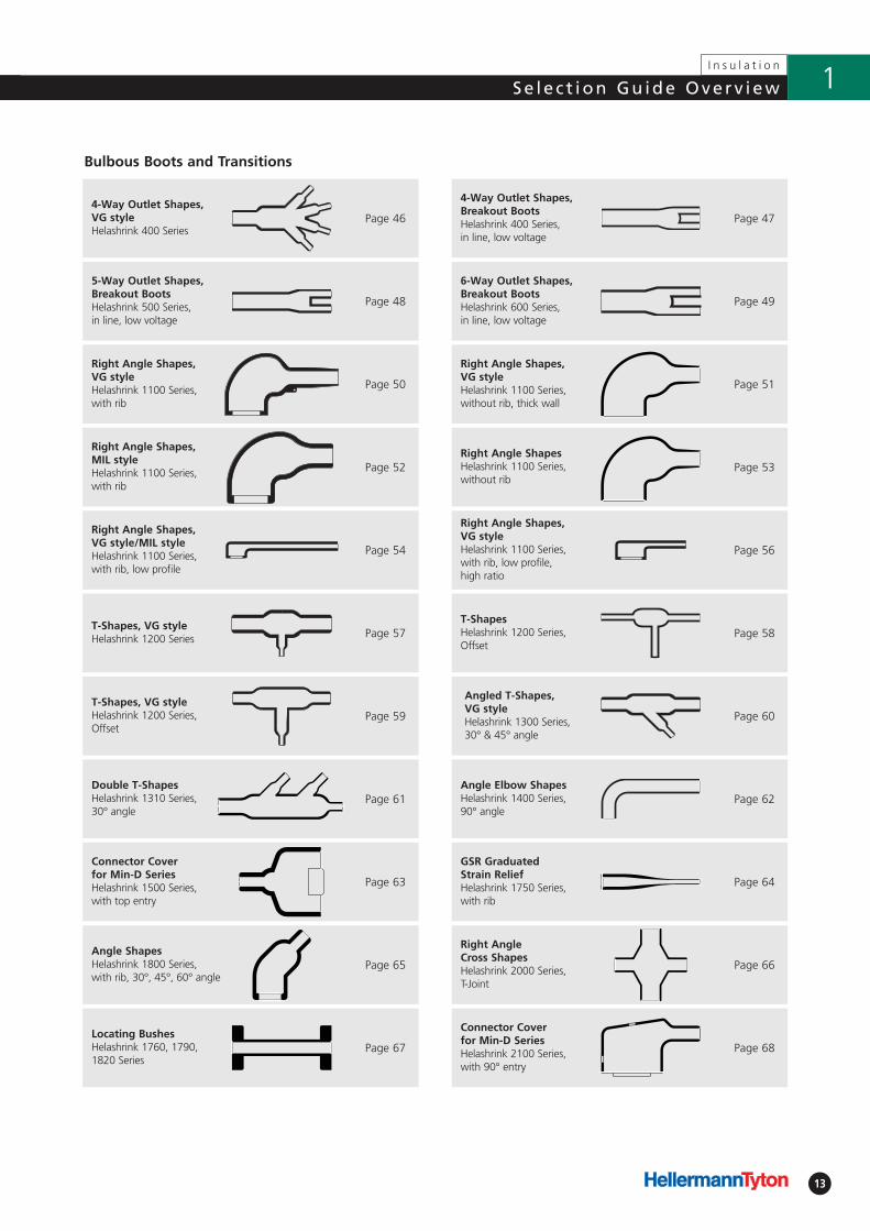
Bulbous Boots and Transitions
Right Angle Shapes,MIL styleHelashrink 1100 Series,with rib
4-Way Outlet Shapes,Breakout BootsHelashrink 400 Series, in line, low voltage
6-Way Outlet Shapes,Breakout BootsHelashrink 600 Series, in line, low voltage
4-Way Outlet Shapes,VG styleHelashrink 400 Series
5-Way Outlet Shapes,Breakout BootsHelashrink 500 Series, in line, low voltage
Right Angle Shapes,VG styleHelashrink 1100 Series,with rib
Right Angle Shapes,VG styleHelashrink 1100 Series,without rib, thick wall
Right Angle ShapesHelashrink 1100 Series,without rib
Right Angle Shapes,VG style/MIL styleHelashrink 1100 Series,with rib, low profile
Right Angle Shapes,VG styleHelashrink 1100 Series,with rib, low profile, high ratio
T-Shapes, VG styleHelashrink 1200 Series
T-ShapesHelashrink 1200 Series,Offset
T-Shapes, VG styleHelashrink 1200 Series,Offset
Angled T-Shapes, VG styleHelashrink 1300 Series,30° & 45° angle
Double T-ShapesHelashrink 1310 Series,30° angle
Angle Elbow ShapesHelashrink 1400 Series,90° angle
Connector Cover for Min-D SeriesHelashrink 1500 Series,with top entry
GSR Graduated Strain ReliefHelashrink 1750 Series,with rib
Locating BushesHelashrink 1760, 1790,1820 Series
Connector Cover for Min-D SeriesHelashrink 2100 Series,with 90° entry
Angle ShapesHelashrink 1800 Series, with rib, 30°, 45°, 60° angle
Right AngleCross ShapesHelashrink 2000 Series, T-Joint
14
I n s u l a t i o n
Techn i ca l I n fo rmat ion1
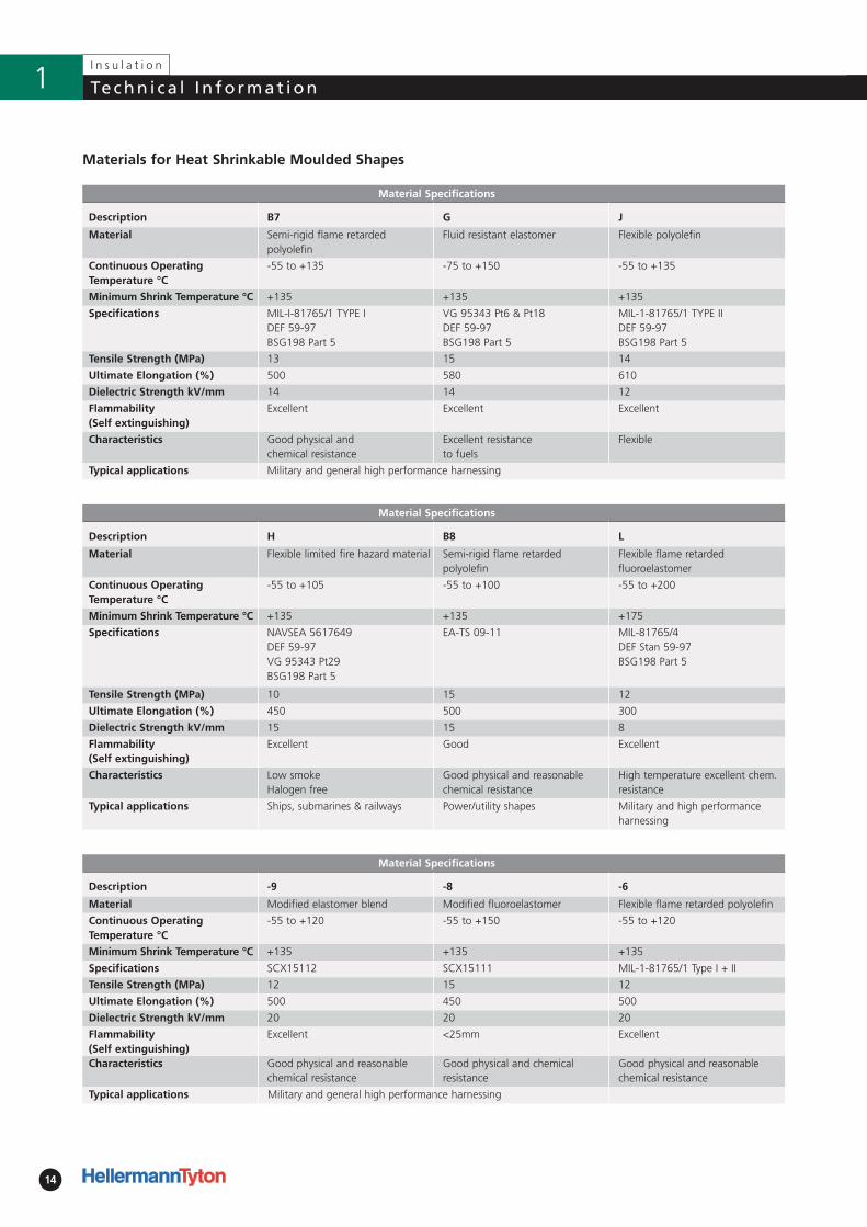
Material Specifications
Description -9 -8 -6
Material Modified elastomer blend Modified fluoroelastomer Flexible flame retarded polyolefin
Continuous OperatingTemperature °C
-55 to +120 -55 to +150 -55 to +120
Minimum Shrink Temperature °C +135 +135 +135
Specifications SCX15112 SCX15111 MIL-1-81765/1 Type I + II
Tensile Strength (MPa) 12 15 12
Ultimate Elongation (%) 500 450 500
Dielectric Strength kV/mm 20 20 20
Flammability (Self extinguishing)
Excellent <25mm Excellent
Characteristics Good physical and reasonablechemical resistance
Good physical and chemical resistance
Good physical and reasonable chemical resistance
Typical applications
Material Specifications
Description B7 G J
Material Semi-rigid flame retarded polyolefin
Fluid resistant elastomer Flexible polyolefin
Continuous OperatingTemperature °C
-55 to +135 -75 to +150 -55 to +135
Minimum Shrink Temperature °C +135 +135 +135
Specifications MIL-I-81765/1 TYPE IDEF 59-97BSG198 Part 5
VG 95343 Pt6 & Pt18DEF 59-97BSG198 Part 5
MIL-1-81765/1 TYPE IIDEF 59-97BSG198 Part 5
Tensile Strength (MPa) 13 15 14
Ultimate Elongation (%) 500 580 610
Dielectric Strength kV/mm 14 14 12
Flammability (Self extinguishing)
Excellent Excellent Excellent
Characteristics Good physical andchemical resistance
Excellent resistanceto fuels
Flexible
Typical applications Military and general high performance harnessing
Materials for Heat Shrinkable Moulded Shapes
Material Specifications
Description H B8 L
Material Flexible limited fire hazard material Semi-rigid flame retarded polyolefin
Flexible flame retarded fluoroelastomer
Continuous OperatingTemperature °C
-55 to +105 -55 to +100 -55 to +200
Minimum Shrink Temperature °C +135 +135 +175
Specifications NAVSEA 5617649DEF 59-97VG 95343 Pt29BSG198 Part 5
EA-TS 09-11 MIL-81765/4DEF Stan 59-97BSG198 Part 5
Tensile Strength (MPa) 10 15 12
Ultimate Elongation (%) 450 500 300
Dielectric Strength kV/mm 15 15 8
Flammability (Self extinguishing)
Excellent Good Excellent
Characteristics Low smokeHalogen free
Good physical and reasonablechemical resistance
High temperature excellent chem.resistance
Typical applications Ships, submarines & railways Power/utility shapes Military and high performanceharnessing
Military and general high performance harnessing
15
Techn i ca l I n fo rmat ionI n s u l a t i o n
1
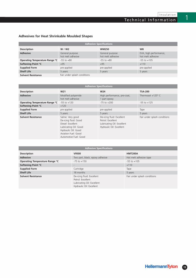
Adhesives for Heat Shrinkable Moulded Shapes
Adhesive Specifications
Description W / W2 WM250 W8
Adhesive General purpose hot melt adhesive
General purpose hot melt adhesive
EVA, high performance, hot melt adhesive
Operating Temperature Range °C -55 to +80 -55 to +80 -55 to +105
Softening Point °C +95 +95 +110
Supplied Form pre-applied pre-applied pre-applied
Shelf Life 5 years 5 years 5 years
Solvent Resistance
Adhesive Specifications
Description W21 W24 TSA-200
Adhesive Modified polyamide hot melt adhesive
High performance, pre-coat, 1 part epoxy
Thermoset +125° C
Operating Temperature Range °C -55 to +120 -75 to +200 -55 to +125Softening Point °C +120 - -
Supplied Form pre-applied pre-applied Tape
Shelf Life 5 years 5 years 5 years
Solvent Resistance Saline: Very goodDe-icing fluid: GoodDiesel: ExcellentLubricating Oil: GoodHydraulic Oil: GoodAviation Fuel: GoodAutomotive Fuel: Good
De-icing fluid: ExcellentPetrol: ExcellentLubricating Oil: ExcellentHydraulic Oil: Excellent
Fair under splash conditions
Adhesive Specifications
Description V9500 HMT200A
Adhesive Two part, black, epoxy adhesive Hot melt adhesive tape
Operating Temperature Range °C -75 to +150 -55 to +105
Softening Point °C - +110
Supplied Form Cartridge Tape
Shelf Life 18 months 5 years
Solvent Resistance De-icing fluid: ExcellentPetrol: ExcellentLubricating Oil: ExcellentHydraulic Oil: Excellent
Fair under splash conditions
Fair under splash conditions
16
I n s u l a t i o n
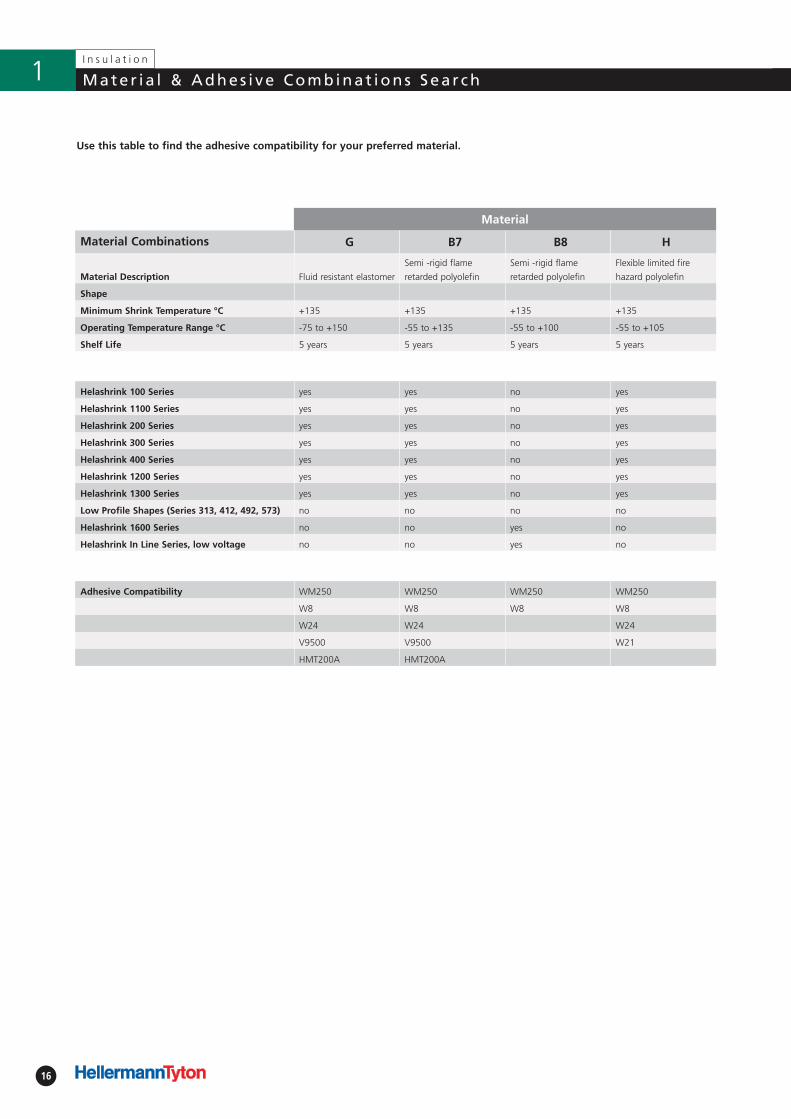
Mater ia l & Adhes i ve Combinat ions Sea r ch1
Use this table to find the adhesive compatibility for your preferred material.
Material
Material Combinations G B7 B8 H
Material Description Fluid resistant elastomer
Semi -rigid flame
retarded polyolefin
Semi -rigid flame
retarded polyolefin
Flexible limited fire
hazard polyolefin
Shape
Minimum Shrink Temperature °C +135 +135 +135 +135
Operating Temperature Range °C -75 to +150 -55 to +135 -55 to +100 -55 to +105
Shelf Life 5 years 5 years 5 years 5 years
Helashrink 100 Series yes yes no yes
Helashrink 1100 Series yes yes no yes
Helashrink 200 Series yes yes no yes
Helashrink 300 Series yes yes no yes
Helashrink 400 Series yes yes no yes
Helashrink 1200 Series yes yes no yes
Helashrink 1300 Series yes yes no yes
Low Profile Shapes (Series 313, 412, 492, 573) no no no no
Helashrink 1600 Series no no yes no
Helashrink In Line Series, low voltage no no yes no
Adhesive Compatibility WM250 WM250 WM250 WM250
W8 W8 W8 W8
W24 W24 W24
V9500 V9500 W21
HMT200A HMT200A
17
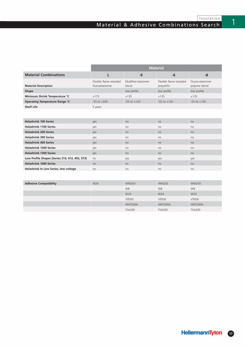
I n s u l a t i o n
Mater ia l & Adhes i ve Combinat ions Sea r ch 1
Material
Material Combinations L -9 -6 -8
Material Description
Flexible flame retarded
fluoroelastomer
Modified elastomer
blend
Flexible flame retarded
polyolefin
Fluoro-elastomer
polymer blend
Shape low profile low profile low profile
Minimum Shrink Temperature °C +175 +135 +135 +135
Operating Temperature Range °C -55 to +200 -55 to +120 -55 to +120 -55 to +150
Shelf Life 5 years
Helashrink 100 Series yes no no no
Helashrink 1100 Series yes no no no
Helashrink 200 Series yes no no no
Helashrink 300 Series yes no no no
Helashrink 400 Series yes no no no
Helashrink 1200 Series yes no no no
Helashrink 1300 Series yes no no no
Low Profile Shapes (Series 313, 412, 492, 573) no yes yes yes
Helashrink 1600 Series no no no no
Helashrink In Line Series, low voltage no no no no
Adhesive Compatibility W24 WM250 WM250 WM250
W8 W8 W8
W24 W24 W24
V9500 V9500 V9500
HMT200A HMT200A HMT200A
TSA200 TSA200 TSA200
18
I n s u l a t i o n
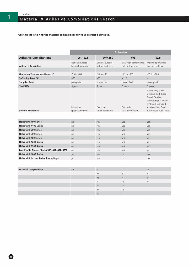
Mater ia l & Adhes i ve Combinat ions Sea r ch1
Use this table to find the material compatibility for your preferred adhesive.
Adhesive
Adhesive Combinations W / W2 WM250 W8 W21
Adhesive Description
General purpose
hot melt adhesive
General purpose
hot melt adhesive
EVA, high performance,
hot melt adhesive
Modified polyamide
hot melt adhesive
Operating Temperature Range °C -55 to +80 -55 to +80 -55 to +105 -55 to +120
Softening Point °C +95 +95 +110 -
Supplied Form pre-applied pre-applied pre-applied pre-applied
Shelf Life 5 years 5 years 5 years 5 years
Solvent Resistance
Fair under
splash conditions
Fair under
splash conditions
Fair under
splash conditions
Saline: Very good
De-icing fluid: Good
Diesel: Excellent
Lubricating Oil: Good
Hydraulic Oil: Good
Aviation Fuel: Good
Automotive Fuel: Good
Helashrink 100 Series no yes yes yes
Helashrink 1100 Series no yes yes yes
Helashrink 200 Series no yes yes yes
Helashrink 300 Series no yes yes yes
Helashrink 400 Series no yes yes yes
Helashrink 1200 Series no yes yes yes
Helashrink 1300 Series no yes yes yes
Low Profile Shapes (Series 313, 412, 492, 573) no yes yes yes
Helashrink 1600 Series yes yes no no
Helashrink In Line Series, low voltage yes yes no no
Material Compatibility B8 G G G
B7 B7 B7
B8 H B8
H -6 H
-6 -9
-9 -8
-8
19
I n s u l a t i o n
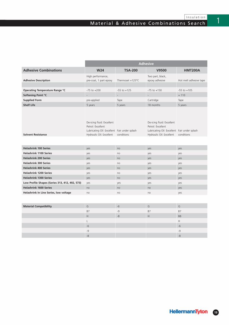
Mater ia l & Adhes i ve Combinat ions Sea r ch 1
Adhesive
Adhesive Combinations W24 TSA-200 V9500 HMT200A
Adhesive Description
High performance,
pre-coat, 1 part epoxy Thermoset +125°C
Two part, black,
epoxy adhesive Hot melt adhesive tape
Operating Temperature Range °C -75 to +200 -55 to +125 -75 to +150 -55 to +105
Softening Point °C - - - + 110
Supplied Form pre-applied Tape Cartridge Tape
Shelf Life 5 years 5 years 18 months 5 years
Solvent Resistance
De-icing fluid: Excellent
Petrol: Excellent
Lubricating Oil: Excellent
Hydraulic Oil: Excellent
Fair under splash
conditions
De-icing fluid: Excellent
Petrol: Excellent
Lubricating Oil: Excellent
Hydraulic Oil: Excellent
Fair under splash
conditions
Helashrink 100 Series yes no yes yes
Helashrink 1100 Series yes no yes yes
Helashrink 200 Series yes no yes yes
Helashrink 300 Series yes no yes yes
Helashrink 400 Series yes no yes yes
Helashrink 1200 Series yes no yes yes
Helashrink 1300 Series yes no yes yes
Low Profile Shapes (Series 313, 412, 492, 573) yes yes yes yes
Helashrink 1600 Series no no no yes
Helashrink In Line Series, low voltage no no no yes
Material Compatibility G -6 G G
B7 -9 B7 B7
H -8 H B8
L H
-6 -6
-9 -9
-8 -8
2.1 Low Profile Boots and TransitionsLow Profile Convolute Boots
• Helashrink 313C Series, with adapter lip 22
Low Profile Shim Boots
• Helashrink 313E Series, without adapter lip 23
Low Profile Straight Boots
• Helashrink 313F Series, with adapter lip 24
Low Profile Right Angle Boots
• Helashrink 333F Series, with adapter lip, 90° angle 25
Low Profile Transition Boots
• Helashrink 412H Series, side breakout 26
• Helashrink 492H Series, 1 to 2 cables 27
• Helashrink 573H Series, 1 to 3 cables 28
2.2 Bulbous Boots and TransitionsBottle Shapes, VG style
• Helashrink 150 Series, with rib 29
Bottle Shapes, MIL style
• Helashrink 100 Series, with rib 31
Bottle Shapes
• Helashrink 100 Series, without rib 32
• Helashrink 120 Series, with and without rib 34
Long Outlet Shape, VG style
• Helashrink 130 Series, with rib, low profile 35
Long Outlet Shapes
• Helashrink 140 Series, without rib 37
Bottle Shapes
• Helashrink 160 Series, without rib 38
Bottle Shapes, VG style
• Helashrink 170 Series, with rib 39
• Helashrink 190 Series, with external ribs 40
2-Way Outlet Shapes
• Helashrink 200 Series, low profile 41
2-Way Outlet Shapes, VG style
• Helashrink 200 Series 42
2-Way Outlet Shapes, Breakout Boots
• Helashrink 200 Series, in line, low voltage 43
3-Way Outlet Shapes, VG style
• Helashrink 300 Series 44
3-Way Outlet Shapes, Breakout Boots
• Helashrink 300 Series, in line, low voltage 45
4-Way Outlet Shapes, VG style
• Helashrink 400 Series 46
Page Page
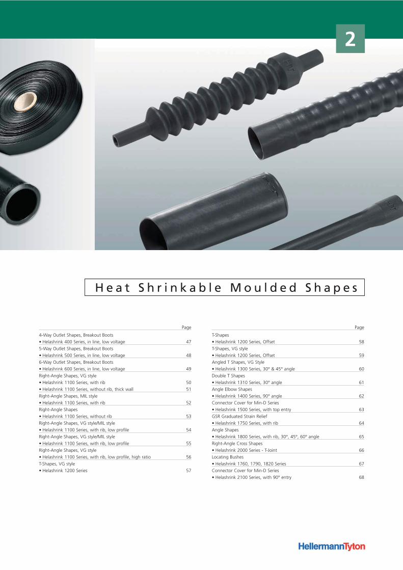
H e a t S h r i n k a b l e M o u l d e d S h a p e s
4-Way Outlet Shapes, Breakout Boots
• Helashrink 400 Series, in line, low voltage 47
5-Way Outlet Shapes, Breakout Boots
• Helashrink 500 Series, in line, low voltage 48
6-Way Outlet Shapes, Breakout Boots
• Helashrink 600 Series, in line, low voltage 49
Right-Angle Shapes, VG style
• Helashrink 1100 Series, with rib 50
• Helashrink 1100 Series, without rib, thick wall 51
Right-Angle Shapes, MIL style
• Helashrink 1100 Series, with rib 52
Right-Angle Shapes
• Helashrink 1100 Series, without rib 53
Right-Angle Shapes, VG style/MIL style
• Helashrink 1100 Series, with rib, low profile 54
Right-Angle Shapes, VG style/MIL style
• Helashrink 1100 Series, with rib, low profile 55
Right-Angle Shapes, VG style
• Helashrink 1100 Series, with rib, low profile, high ratio 56
T-Shapes, VG style
• Helashrink 1200 Series 57
T-Shapes
• Helashrink 1200 Series, Offset 58
T-Shapes, VG style
• Helashrink 1200 Series, Offset 59
Angled T Shapes, VG Style
• Helashrink 1300 Series, 30° & 45° angle 60
Double T Shapes
• Helashrink 1310 Series, 30° angle 61
Angle Elbow Shapes
• Helashrink 1400 Series, 90° angle 62
Connector Cover for Min-D Series
• Helashrink 1500 Series, with top entry 63
GSR Graduated Strain Relief
• Helashrink 1750 Series, with rib 64
Angle Shapes
• Helashrink 1800 Series, with rib, 30°, 45°, 60° angle 65
Right-Angle Cross Shapes
• Helashrink 2000 Series - T-Joint 66
Locating Bushes
• Helashrink 1760, 1790, 1820 Series 67
Connector Cover for Min-D Series
• Helashrink 2100 Series, with 90° entry 68
Page Page
2
22
I n s u l a t i o n
Low P ro f i l e Boot s and Trans i t ion2.1 Low P ro f i l e Boot s and Trans i t ions
Adhesive Material
9 8 6
TSA-200 √ √ √
WM250 √ √ √
W8 √ √ √
W24 √ √ √
V9500 √ √ √
HMT200A √ √ √
WithoutAdhesive
√ √ √
b: Fully recovered form (after heating)
• Helashrink 313C Series, with adapter lip
T
ØH
R
S
P
JO-
W
ØJ
B
Article-No. Type
422-00001 313C722-9
422-00101 313C732-9
422-00201 313C743-9
422-00302 313C753-9
422-00400 313C764-9
422-00501 313C774-9
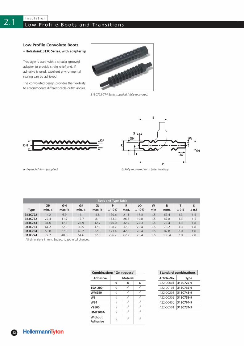
Low Profile Convolute Boots
This style is used with a circular grooved
adapter to provide strain relief and, if
adhesive is used, excellent environmental
sealing can be achieved.
The convoluted design provides the flexibility
to accommodate different cable outlet angles.
313C722-774 Series supplied / fully recovered.
a: Expanded form (supplied)
Standard combinationsCombinations ″On request″
Sizes and Type Table
TypeØH
min. aØH
max. bØJ
min. aØJ
max. bP
± 10%R
max.JO
± 10%W
minB
nom.T
± 0.5 S
± 0.5
313C722 14.2 6.9 11.1 4.8 120.6 21.1 17.3 1.5 62.4 1.3 1.5313C732 22.4 11.7 17.7 8.1 133.3 26.5 19.8 1.5 67.8 1.3 1.5313C743 34.0 17.5 26.9 12.7 146.0 32.7 22.3 1.5 73.4 1.3 1.8313C753 44.2 22.3 36.5 17.5 158.7 37.8 25.4 1.5 78.2 1.3 1.8313C764 53.8 27.9 45.7 22.3 171.4 42.9 28.4 1.5 82.8 2.0 1.8313C774 77.2 40.6 54.6 22.8 236.2 62.2 25.4 1.5 138.4 2.0 2.0All dimensions in mm. Subject to technical changes.
!! Adhesive Material
9 8 6
TSA-200 √ √ √
WM250 √ √ √
W8 √ √ √
W24 √ √ √
V9500 √ √ √
HMT200A √ √ √
WithoutAdhesive
√ √ √
23
I n s u l a t i o n
Low P ro f i l e Boot s and Trans i t ion 2.1Low P ro f i l e Boot s and Trans i t ions
• Helashrink 313E Series,
without adapter lip
b: Fully recovered form (after heating)
Article-No. Type
422-10000 313E445-9
422-10200 313E455-9
422-10100 313E447-9
422-10300 313E457-9
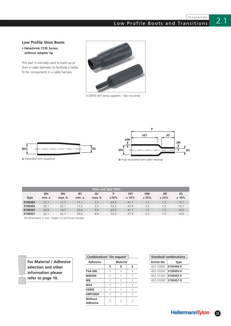
Low Profile Shim Boots
This part is normally used to build up or
shim a cable diameter to facilitate a better
fit for components in a cable harness.
313E445-457 Series supplied / fully recovered.
a: Expanded form (supplied)
For Material / Adhesive selection and otherinformation pleaserefer to page 10.
Combinations ″On request″ Standard combinations
Sizes and Type Table
TypeØH
min. aØH
max. bØJ
min. aØJ
max. bP
±10%HO
± 10%HW
± 25%JW
± 25%JO
± 10%
313E445 12.7 12.7 11.1 3.3 63.5 41.1 1.5 1.5 15.7313E455 22.1 22.1 11.2 3.3 53.3 27.9 2.3 1.5 15.7313E447 20.8 14.7 20.6 9.9 63.5 41.1 1.5 1.5 16.5313E457 22.1 22.1 20.6 9.9 53.3 27.9 2.3 1.5 14.0All dimensions in mm. Subject to technical changes.
24
I n s u l a t i o n
2.1 Low P ro f i l e Boot s and Trans i t ions
b: Fully recovered form (after heating)
• Helashrink 313F Series, with adapter lip
Adhesive Material
9 8 6
TSA-200 √ √ √
WM250 √ √ √
W8 √ √ √
W24 √ √ √
V9500 √ √ √
HMT200A √ √ √
WithoutAdhesive
√ √ √
Article-No. Type
422-20000 313F322-9
422-20100 313F332-9
422-20200 313F343-9
422-20300 313F353-9
422-20400 313F364-9
422-20500 313F374-9
422-20600 313F385-9
422-20700 313F396-9
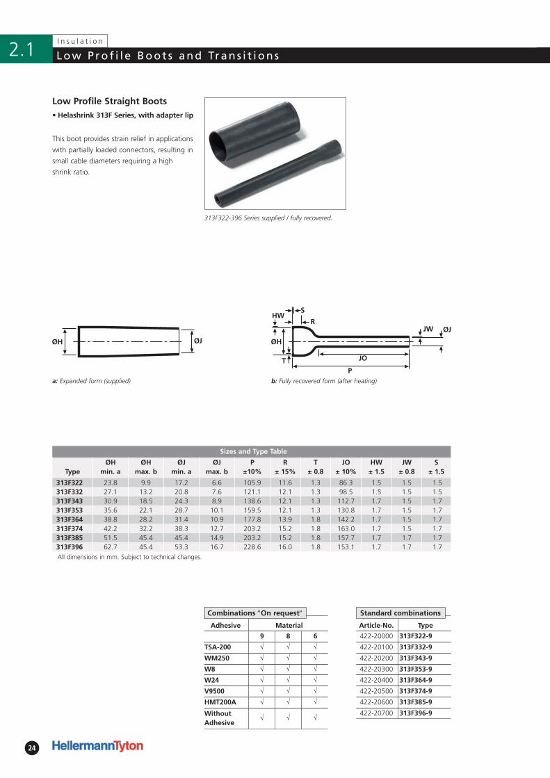
Low Profile Straight Boots
This boot provides strain relief in applications
with partially loaded connectors, resulting in
small cable diameters requiring a high
shrink ratio.
313F322-396 Series supplied / fully recovered.
a: Expanded form (supplied)
Standard combinations
Sizes and Type Table
TypeØH
min. aØH
max. bØJ
min. aØJ
max. bP
±10%R
± 15%T
± 0.8 JO
± 10%HW
± 1.5 JW
± 0.8 S
± 1.5
313F322 23.8 9.9 17.2 6.6 105.9 11.6 1.3 86.3 1.5 1.5 1.5313F332 27.1 13.2 20.8 7.6 121.1 12.1 1.3 98.5 1.5 1.5 1.5313F343 30.9 18.5 24.3 8.9 138.6 12.1 1.3 112.7 1.7 1.5 1.7313F353 35.6 22.1 28.7 10.1 159.5 12.1 1.3 130.8 1.7 1.5 1.7313F364 38.8 28.2 31.4 10.9 177.8 13.9 1.8 142.2 1.7 1.5 1.7313F374 42.2 32.2 38.3 12.7 203.2 15.2 1.8 163.0 1.7 1.5 1.7313F385 51.5 45.4 45.4 14.9 203.2 15.2 1.8 157.7 1.7 1.7 1.7313F396 62.7 45.4 53.3 16.7 228.6 16.0 1.8 153.1 1.7 1.7 1.7All dimensions in mm. Subject to technical changes.
Combinations ″On request″
25
I n s u l a t i o n
2.1Low P ro f i l e Boot s and Trans i t ions
b: Fully recovered form (after heating)
• Helashrink 333F Series, with adapter
lip, 90° angle
Adhesive Material
9 8 6
TSA-200 √ √ √
WM250 √ √ √
W8 √ √ √
W24 √ √ √
V9500 √ √ √
HMT200A √ √ √
WithoutAdhesive
√ √ √
ØH ØJ
Article-No. Type
422-30000 333F322-9
422-30004 333F332-9
422-30100 333F343-9
422-30200 333F353-9
422-30301 333F364-9
422-30400 333F374-9
422-30500 333F385-9
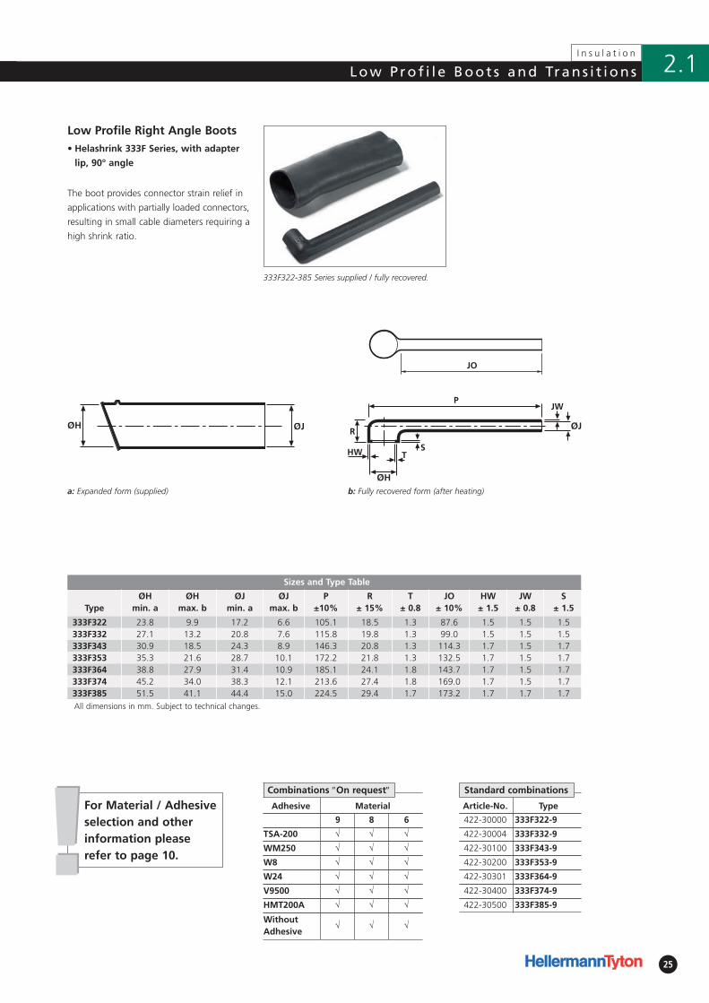
Low Profile Right Angle Boots
The boot provides connector strain relief in
applications with partially loaded connectors,
resulting in small cable diameters requiring a
high shrink ratio.
333F322-385 Series supplied / fully recovered.
a: Expanded form (supplied)
Standard combinationsCombinations ″On request″
Sizes and Type Table
TypeØH
min. aØH
max. bØJ
min. aØJ
max. bP
±10%R
± 15%T
± 0.8 JO
± 10%HW
± 1.5 JW
± 0.8 S
± 1.5
333F322 23.8 9.9 17.2 6.6 105.1 18.5 1.3 87.6 1.5 1.5 1.5333F332 27.1 13.2 20.8 7.6 115.8 19.8 1.3 99.0 1.5 1.5 1.5333F343 30.9 18.5 24.3 8.9 146.3 20.8 1.3 114.3 1.7 1.5 1.7333F353 35.3 21.6 28.7 10.1 172.2 21.8 1.3 132.5 1.7 1.5 1.7333F364 38.8 27.9 31.4 10.9 185.1 24.1 1.8 143.7 1.7 1.5 1.7333F374 45.2 34.0 38.3 12.1 213.6 27.4 1.8 169.0 1.7 1.5 1.7333F385 51.5 41.1 44.4 15.0 224.5 29.4 1.7 173.2 1.7 1.7 1.7All dimensions in mm. Subject to technical changes.
!!For Material / Adhesive selection and otherinformation pleaserefer to page 10.
26
I n s u l a t i o n
2.1 Low P ro f i l e Boot s and Trans i t ions
• Helashrink 412H Series, side breakout
Adhesive Material
9 8 6
TSA-200 √ √ √
WM250 √ √ √
W8 √ √ √
W24 √ √ √
V9500 √ √ √
HMT200A √ √ √
WithoutAdhesive
√ √ √
Article-No. Type
422-40000 412H622-9
422-40100 412H623-9
422-40200 412H624-9
422-40300 412H625-9
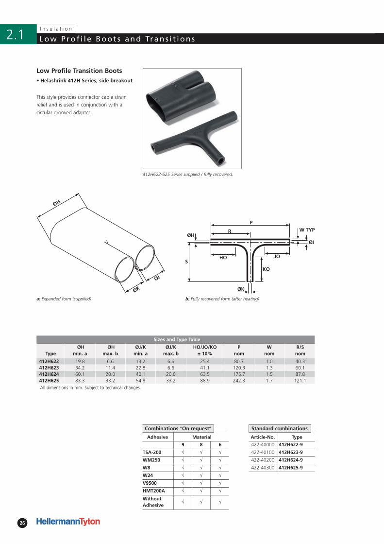
Low Profile Transition Boots
This style provides connector cable strain
relief and is used in conjunction with a
circular grooved adapter.
412H622-625 Series supplied / fully recovered.
a: Expanded form (supplied)
Standard combinations
b: Fully recovered form (after heating)
Combinations ″On request″
Sizes and Type Table
TypeØH
min. aØH
max. bØJ/K
min. aØJ/K
max. bHO/JO/KO
± 10%P
nomW
nomR/S nom
412H622 19.8 6.6 13.2 6.6 25.4 80.7 1.0 40.3412H623 34.2 11.4 22.8 6.6 41.1 120.3 1.3 60.1412H624 60.1 20.0 40.1 20.0 63.5 175.7 1.5 87.8412H625 83.3 33.2 54.8 33.2 88.9 242.3 1.7 121.1All dimensions in mm. Subject to technical changes.
27
I n s u l a t i o n
2.1Low P ro f i l e Boot s and Trans i t ions
• Helashrink 492H Series, 1 to 2 cables
Adhesive Material
9 8 6
TSA-200 √ √ √
WM250 √ √ √
W8 √ √ √
W24 √ √ √
V9500 √ √ √
HMT200A √ √ √
WithoutAdhesive
√ √ √
Article-No. Type
422-50000 492H412-9
422-50101 492H413-9
422-50202 492H414-9
422-50302 492H415-9
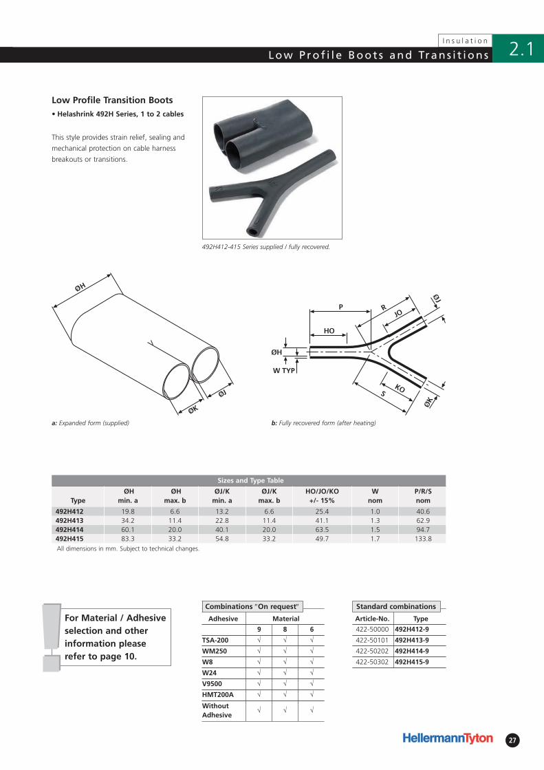
Low Profile Transition Boots
This style provides strain relief, sealing and
mechanical protection on cable harness
breakouts or transitions.
492H412-415 Series supplied / fully recovered.
a: Expanded form (supplied)
Standard combinations
b: Fully recovered form (after heating)
Combinations ″On request″
Sizes and Type Table
TypeØH
min. aØH
max. bØJ/K
min. aØJ/K
max. bHO/JO/KO
+/- 15%W
nomP/R/S nom
492H412 19.8 6.6 13.2 6.6 25.4 1.0 40.6492H413 34.2 11.4 22.8 11.4 41.1 1.3 62.9492H414 60.1 20.0 40.1 20.0 63.5 1.5 94.7492H415 83.3 33.2 54.8 33.2 49.7 1.7 133.8All dimensions in mm. Subject to technical changes.
!!For Material / Adhesive selection and otherinformation pleaserefer to page 10.
28
I n s u l a t i o n
2.1 Low P ro f i l e Boot s and Trans i t ions
b: Fully recovered form (after heating)
Article-No. Type
422-60000 573H532-9
422-60100 573H533-9
422-60202 573H534-9
422-60302 573H535-9
• Helashrink 573H Series, 1 to 3 cables
Adhesive Material
9 8 6
TSA-200 √ √ √
WM250 √ √ √
W8 √ √ √
V9500 √ √ √
HMT200A √ √ √
WithoutAdhesive
√ √ √
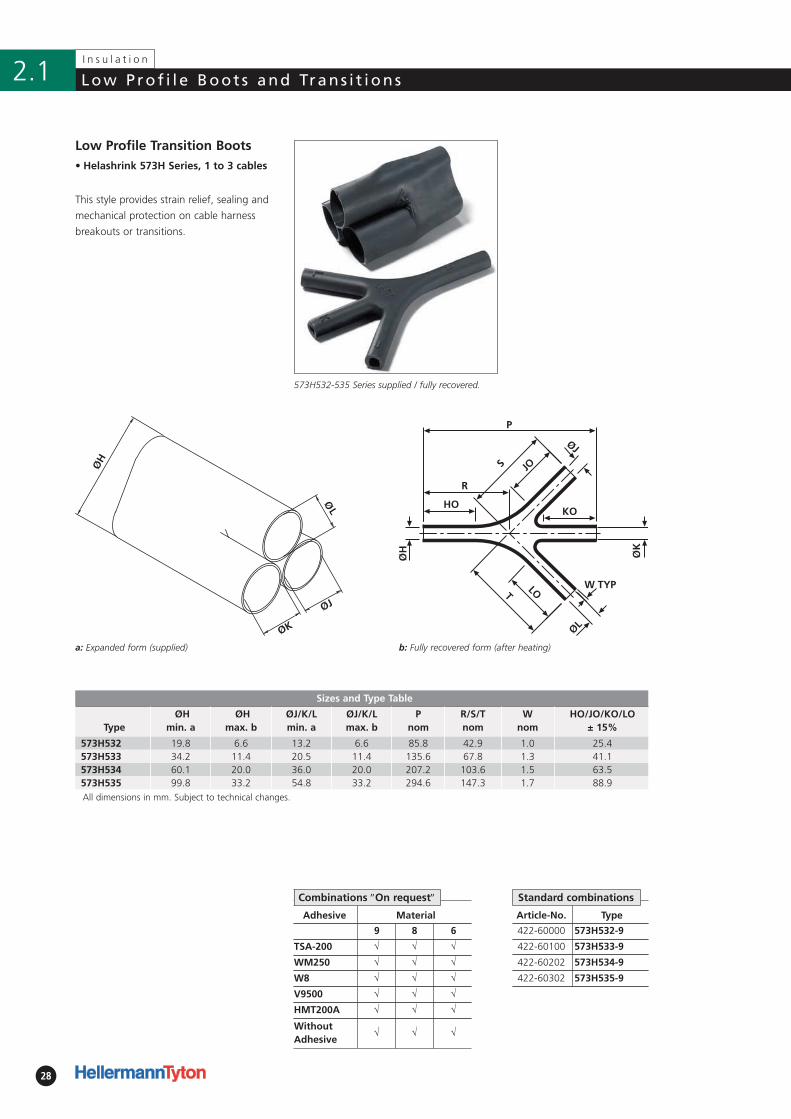
Low Profile Transition Boots
This style provides strain relief, sealing and
mechanical protection on cable harness
breakouts or transitions.
573H532-535 Series supplied / fully recovered.
a: Expanded form (supplied)
Combinations ″On request″ Standard combinations
Sizes and Type Table
TypeØH
min. aØH
max. bØJ/K/L min. a
ØJ/K/L max. b
P nom
R/S/T nom
W nom
HO/JO/KO/LO ± 15%
573H532 19.8 6.6 13.2 6.6 85.8 42.9 1.0 25.4573H533 34.2 11.4 20.5 11.4 135.6 67.8 1.3 41.1573H534 60.1 20.0 36.0 20.0 207.2 103.6 1.5 63.5573H535 99.8 33.2 54.8 33.2 294.6 147.3 1.7 88.9All dimensions in mm. Subject to technical changes.
29
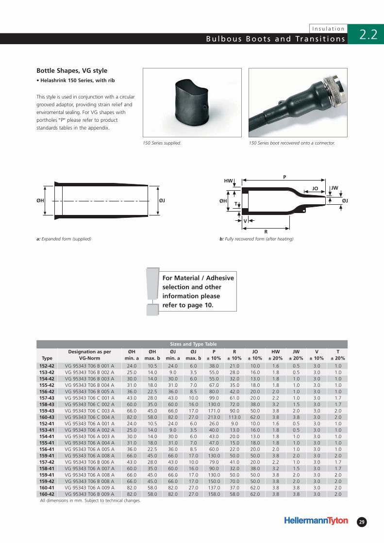
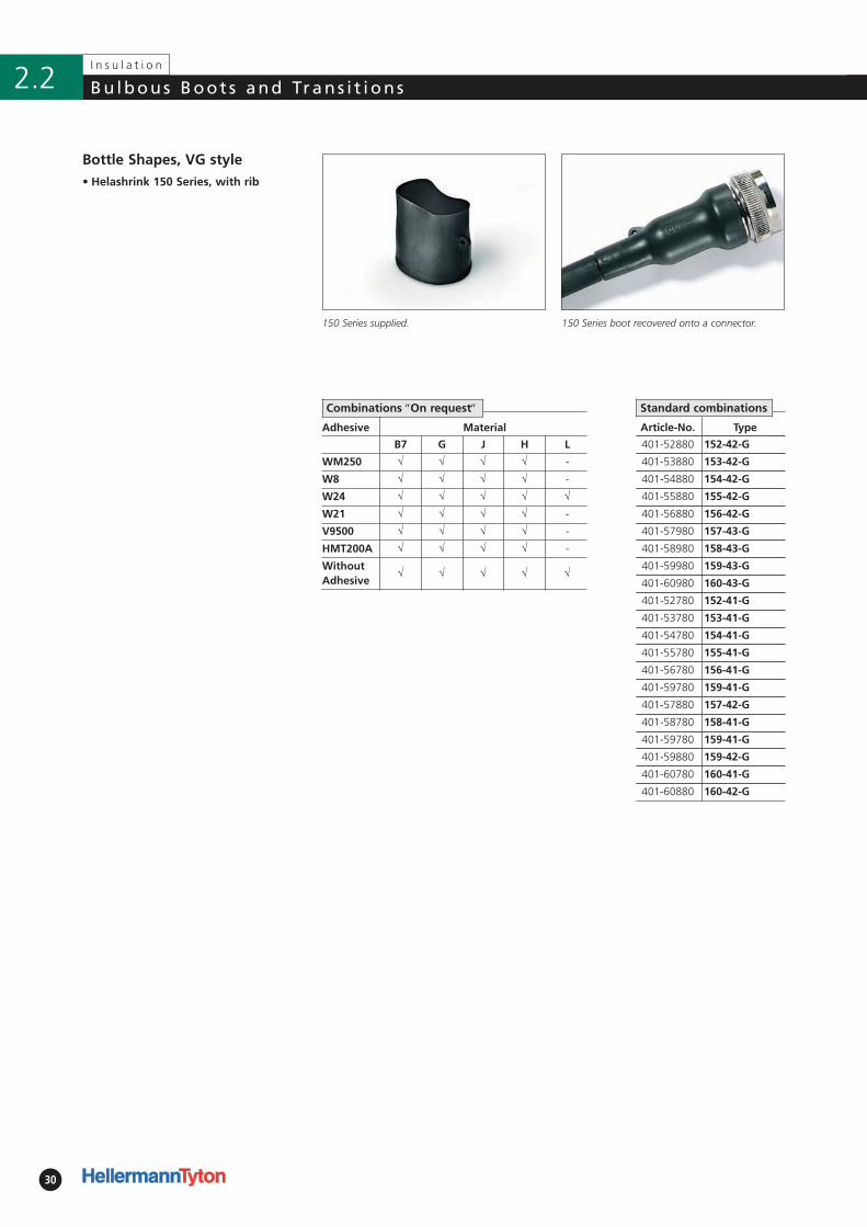
150 Series supplied.
b: Fully recovered form (after heating)
Sizes and Type Table
TypeDesignation as per
VG-NormØH
min. aØH
max. bØJ
min. aØJ
max. bP
± 10%R
± 10%JO
± 10%HW
± 20%JW
± 20%V
± 10%T
± 20%
152-42 VG 95343 T06 B 001 A 24.0 10.5 24.0 6.0 38.0 21.0 10.0 1.6 0.5 3.0 1.0153-42 VG 95343 T06 B 002 A 25.0 14.0 9.0 3.5 55.0 28.0 16.0 1.8 0.5 3.0 1.0154-42 VG 95343 T06 B 003 A 30.0 14.0 30.0 6.0 55.0 32.0 13.0 1.8 1.0 3.0 1.0155-42 VG 95343 T06 B 004 A 31.0 18.0 31.0 7.0 67.0 35.0 18.0 1.8 1.0 3.0 1.0156-42 VG 95343 T06 B 005 A 36.0 22.5 36.0 8.5 80.0 42.0 20.0 2.0 1.0 3.0 1.0157-43 VG 95343 T06 C 001 A 43.0 28.0 43.0 10.0 99.0 61.0 20.0 2.2 1.0 3.0 1.7158-43 VG 95343 T06 C 002 A 60.0 35.0 60.0 16.0 130.0 72.0 38.0 3.2 1.5 3.0 1.7159-43 VG 95343 T06 C 003 A 66.0 45.0 66.0 17.0 171.0 90.0 50.0 3.8 2.0 3.0 2.0160-43 VG 95343 T06 C 004 A 82.0 58.0 82.0 27.0 213.0 113.0 62.0 3.8 3.8 3.0 2.0152-41 VG 95343 T06 A 001 A 24.0 10.5 24.0 6.0 26.0 9.0 10.0 1.6 0.5 3.0 1.0153-41 VG 95343 T06 A 002 A 25.0 14.0 9.0 3.5 40.0 13.0 16.0 1.8 0.5 3.0 1.0154-41 VG 95343 T06 A 003 A 30.0 14.0 30.0 6.0 43.0 20.0 13.0 1.8 1.0 3.0 1.0155-41 VG 95343 T06 A 004 A 31.0 18.0 31.0 7.0 47.0 15.0 18.0 1.8 1.0 3.0 1.0156-41 VG 95343 T06 A 005 A 36.0 22.5 36.0 8.5 60.0 22.0 20.0 2.0 1.0 3.0 1.0159-41 VG 95343 T06 A 008 A 66.0 45.0 66.0 17.0 130.0 50.0 50.0 3.8 2.0 3.0 2.0157-42 VG 95343 T06 B 006 A 43.0 28.0 43.0 10.0 79.0 41.0 20.0 2.2 1.0 3.0 1.7158-41 VG 95343 T06 A 007 A 60.0 35.0 60.0 16.0 90.0 32.0 38.0 3.2 1.5 3.0 1.7159-41 VG 95343 T06 A 008 A 66.0 45.0 66.0 17.0 130.0 50.0 50.0 3.8 2.0 3.0 2.0159-42 VG 95343 T06 B 008 A 66.0 45.0 66.0 17.0 150.0 70.0 50.0 3.8 2.0 3.0 2.0160-41 VG 95343 T06 A 009 A 82.0 58.0 82.0 27.0 137.0 37.0 62.0 3.8 3.8 3.0 2.0160-42 VG 95343 T06 B 009 A 82.0 58.0 82.0 27.0 158.0 58.0 62.0 3.8 3.8 3.0 2.0All dimensions in mm. Subject to technical changes.
150 Series boot recovered onto a connector.
• Helashrink 150 Series, with rib
ØH ØJ
Bottle Shapes, VG style
This style is used in conjunction with a circular
grooved adaptor, providing strain relief and
enviromental sealing. For VG shapes with
port holes ″P″ please refer to product
standards tables in the appendix.
a: Expanded form (supplied)
I n s u l a t i o n
2.2Bu lbous Boot s and Trans i t ions
!!For Material / Adhesiveselection and otherinformation pleaserefer to page 10.
30
I n s u l a t i o n
Bu lbous Boot s and Trans i t ions2.2
• Helashrink 150 Series, with rib
Adhesive Material
B7 G J H L
WM250 √ √ √ √ -
W8 √ √ √ √ -
W24 √ √ √ √ √
W21 √ √ √ √ -
V9500 √ √ √ √ -
HMT200A √ √ √ √ -
WithoutAdhesive
√ √ √ √ √
Article-No. Type
401-52880 152-42-G
401-53880 153-42-G
401-54880 154-42-G
401-55880 155-42-G
401-56880 156-42-G
401-57980 157-43-G
401-58980 158-43-G
401-59980 159-43-G
401-60980 160-43-G
401-52780 152-41-G
401-53780 153-41-G
401-54780 154-41-G
401-55780 155-41-G
401-56780 156-41-G
401-59780 159-41-G
401-57880 157-42-G
401-58780 158-41-G
401-59780 159-41-G
401-59880 159-42-G
401-60780 160-41-G
401-60880 160-42-G
Bottle Shapes, VG style
Standard combinationsCombinations ″On request″
150 Series supplied. 150 Series boot recovered onto a connector.
31
I n s u l a t i o n
2.2Bu lbous Boot s and Trans i t ions
a: Expanded form (supplied)
• Helashrink 100 Series, with rib
Sizes and Type Table
TypeØH
min. aØH
max. bØJ
min. aØJ
max. bP
± 10%R
± 10%HW
± 20%JW
± 20%V
± 10%T
± 20%S
nom
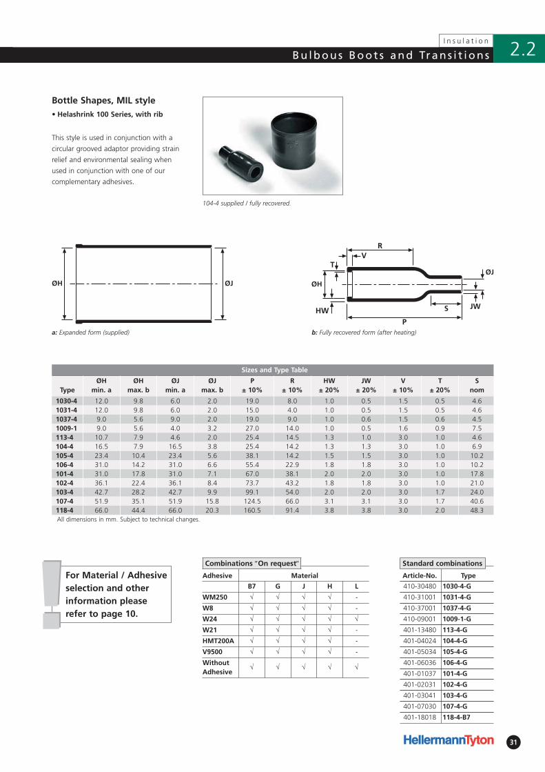
1030-4 12.0 9.8 6.0 2.0 19.0 8.0 1.0 0.5 1.5 0.5 4.61031-4 12.0 9.8 6.0 2.0 15.0 4.0 1.0 0.5 1.5 0.5 4.61037-4 9.0 5.6 9.0 2.0 19.0 9.0 1.0 0.6 1.5 0.6 4.51009-1 9.0 5.6 4.0 3.2 27.0 14.0 1.0 0.5 1.6 0.9 7.5113-4 10.7 7.9 4.6 2.0 25.4 14.5 1.3 1.0 3.0 1.0 4.6104-4 16.5 7.9 16.5 3.8 25.4 14.2 1.3 1.3 3.0 1.0 6.9105-4 23.4 10.4 23.4 5.6 38.1 14.2 1.5 1.5 3.0 1.0 10.2106-4 31.0 14.2 31.0 6.6 55.4 22.9 1.8 1.8 3.0 1.0 10.2101-4 31.0 17.8 31.0 7.1 67.0 38.1 2.0 2.0 3.0 1.0 17.8102-4 36.1 22.4 36.1 8.4 73.7 43.2 1.8 1.8 3.0 1.0 21.0103-4 42.7 28.2 42.7 9.9 99.1 54.0 2.0 2.0 3.0 1.7 24.0107-4 51.9 35.1 51.9 15.8 124.5 66.0 3.1 3.1 3.0 1.7 40.6118-4 66.0 44.4 66.0 20.3 160.5 91.4 3.8 3.8 3.0 2.0 48.3All dimensions in mm. Subject to technical changes.
Adhesive Material
B7 G J H L
WM250 √ √ √ √ -
W8 √ √ √ √ -
W24 √ √ √ √ √
W21 √ √ √ √ -
HMT200A √ √ √ √ -
V9500 √ √ √ √ -
WithoutAdhesive
√ √ √ √ √
ØJØH
Article-No. Type
410-30480 1030-4-G
410-31001 1031-4-G
410-37001 1037-4-G
410-09001 1009-1-G
401-13480 113-4-G
401-04024 104-4-G
401-05034 105-4-G
401-06036 106-4-G
401-01037 101-4-G
401-02031 102-4-G
401-03041 103-4-G
401-07030 107-4-G
401-18018 118-4-B7
Bottle Shapes, MIL style
This style is used in conjunction with a
circular grooved adaptor providing strain
relief and environmental sealing when
used in conjunction with one of our
complementary adhesives.
104-4 supplied / fully recovered.
b: Fully recovered form (after heating)
Standard combinations
!!For Material / Adhesive selection and otherinformation pleaserefer to page 10.
Combinations ″On request″
32
I n s u l a t i o n
Bu lbous Boot s and Trans i t ions2.2
b: Fully recovered form (after heating)
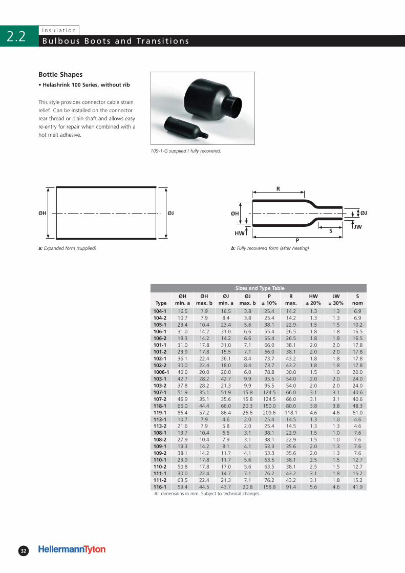
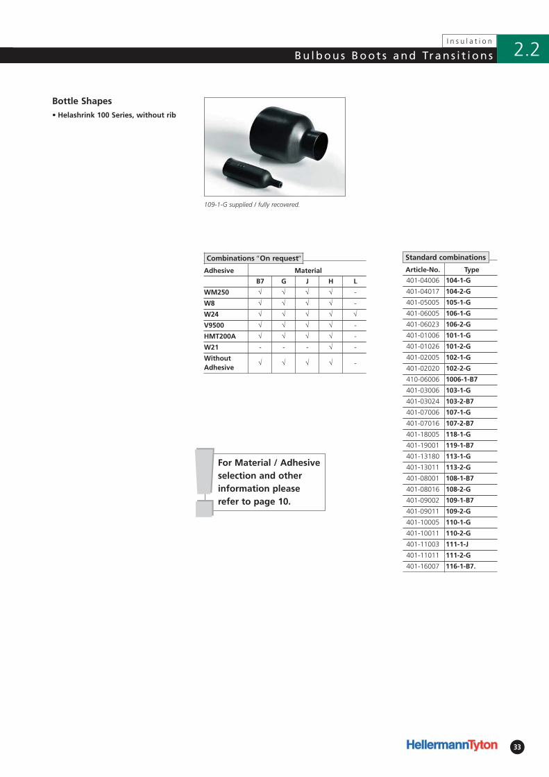
• Helashrink 100 Series, without rib
Sizes and Type Table
TypeØH
min. aØH
max. bØJ
min. aØJ
max. bP
± 10%R
max.HW
± 20%JW
± 30%S
nom
104-1 16.5 7.9 16.5 3.8 25.4 14.2 1.3 1.3 6.9104-2 10.7 7.9 8.4 3.8 25.4 14.2 1.3 1.3 6.9105-1 23.4 10.4 23.4 5.6 38.1 22.9 1.5 1.5 10.2106-1 31.0 14.2 31.0 6.6 55.4 26.5 1.8 1.8 16.5106-2 19.3 14.2 14.2 6.6 55.4 26.5 1.8 1.8 16.5101-1 31.0 17.8 31.0 7.1 66.0 38.1 2.0 2.0 17.8101-2 23.9 17.8 15.5 7.1 66.0 38.1 2.0 2.0 17.8102-1 36.1 22.4 36.1 8.4 73.7 43.2 1.8 1.8 17.8102-2 30.0 22.4 18.0 8.4 73.7 43.2 1.8 1.8 17.81006-1 40.0 20.0 20.0 6.0 78.8 30.0 1.5 1.0 20.0103-1 42.7 28.2 42.7 9.9 95.5 54.0 2.0 2.0 24.0103-2 37.8 28.2 21.3 9.9 95.5 54.0 2.0 2.0 24.0107-1 51.9 35.1 51.9 15.8 124.5 66.0 3.1 3.1 40.6107-2 46.9 35.1 35.6 15.8 124.5 66.0 3.1 3.1 40.6118-1 66.0 44.4 66.0 20.3 150.0 80.0 3.8 3.8 48.3119-1 86.4 57.2 86.4 26.6 209.6 118.1 4.6 4.6 61.0113-1 10.7 7.9 4.6 2.0 25.4 14.5 1.3 1.0 4.6113-2 21.6 7.9 5.8 2.0 25.4 14.5 1.3 1.3 4.6108-1 13.7 10.4 6.6 3.1 38.1 22.9 1.5 1.0 7.6108-2 27.9 10.4 7.9 3.1 38.1 22.9 1.5 1.0 7.6109-1 19.3 14.2 8.1 4.1 53.3 35.6 2.0 1.3 7.6109-2 38.1 14.2 11.7 4.1 53.3 35.6 2.0 1.3 7.6110-1 23.9 17.8 11.7 5.6 63.5 38.1 2.5 1.5 12.7110-2 50.8 17.8 17.0 5.6 63.5 38.1 2.5 1.5 12.7111-1 30.0 22.4 14.7 7.1 76.2 43.2 3.1 1.8 15.2111-2 63.5 22.4 21.3 7.1 76.2 43.2 3.1 1.8 15.2116-1 59.4 44.5 43.7 20.8 158.8 91.4 5.6 4.6 41.9All dimensions in mm. Subject to technical changes.
ØJØH
Bottle Shapes
This style provides connector cable strain
relief. Can be installed on the connector
rear thread or plain shaft and allows easy
re-entry for repair when combined with a
hot melt adhesive.
109-1-G supplied / fully recovered.
a: Expanded form (supplied)
33
I n s u l a t i o n
2.2Bu lbous Boot s and Trans i t ions
• Helashrink 100 Series, without rib
Article-No. Type
401-04006 104-1-G
401-04017 104-2-G
401-05005 105-1-G
401-06005 106-1-G
401-06023 106-2-G
401-01006 101-1-G
401-01026 101-2-G
401-02005 102-1-G
401-02020 102-2-G
410-06006 1006-1-B7
401-03006 103-1-G
401-03024 103-2-B7
401-07006 107-1-G
401-07016 107-2-B7
401-18005 118-1-G
401-19001 119-1-B7
401-13180 113-1-G
401-13011 113-2-G
401-08001 108-1-B7
401-08016 108-2-G
401-09002 109-1-B7
401-09011 109-2-G
401-10005 110-1-G
401-10011 110-2-G
401-11003 111-1-J
401-11011 111-2-G
401-16007 116-1-B7.
Bottle Shapes
109-1-G supplied / fully recovered.
Standard combinations
!!For Material / Adhesiveselection and otherinformation pleaserefer to page 10.
Adhesive Material
B7 G J H L
WM250 √ √ √ √ -
W8 √ √ √ √ -
W24 √ √ √ √ √
V9500 √ √ √ √ -
HMT200A √ √ √ √ -
W21 - - - √ -
WithoutAdhesive
√ √ √ √ -
Combinations ″On request″
34
I n s u l a t i o n
Bu lbous Boot s and Trans i t ions2.2
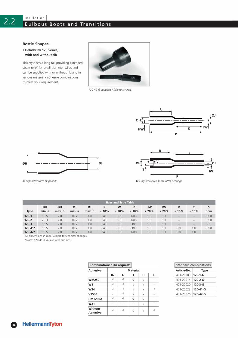
b: Fully recovered form (after heating)
*Note: 120-41 & 42 are with end ribs.
• Helashrink 120 Series,
with and without rib
Article-No. Type
401-20003 120-1-G
401-20014 120-2-G
401-20020 120-3-G
401-20022 120-41-G
401-20026 120-42-G
Bottle Shapes
This style has a long tail providing extended
strain relief for small diameter wires and
can be supplied with or without rib and in
various material / adhesive combinations
to meet your requirement.
120-42-G supplied / fully recovered.
a: Expanded form (supplied)
Standard combinations
Sizes and Type Table
TypeØH
min. aØH
max. bØJ
min. aØJ
max. bR
± 10%W
± 20% P
± 10%HW
± 20%JW
± 20%V
± 10%T
± 10%S
nom
120-1 16.5 7.0 10.2 3.0 24.0 1.3 60.9 1.3 1.3 – – 32.0120-2 20.3 7.0 10.2 3.0 24.0 1.3 60.9 1.3 1.3 – – 32.0120-3 16.5 7.0 10.7 3.0 24.0 1.3 38.0 1.3 1.3 – – 9.1120-41* 16.5 7.0 10.7 3.0 24.0 1.3 38.0 1.3 1.3 3.0 1.0 32.0120-42* 16.5 7.0 10.2 3.0 24.0 1.3 60.9 1.3 1.3 3.0 1.0 –All dimensions in mm. Subject to technical changes.
Adhesive Material
B7 G J H L
WM250 √ √ √ √ -
W8 √ √ √ √ -
W24 √ √ √ √ √
V9500 - √ √ √ -
HMT200A √ √ √ √ -
W21 - - - √ -
WithoutAdhesive
√ √ √ √ √
Combinations ″On request″
35
I n s u l a t i o n
2.2Bu lbous Boot s and Trans i t ions
b: Fully recovered form (after heating)
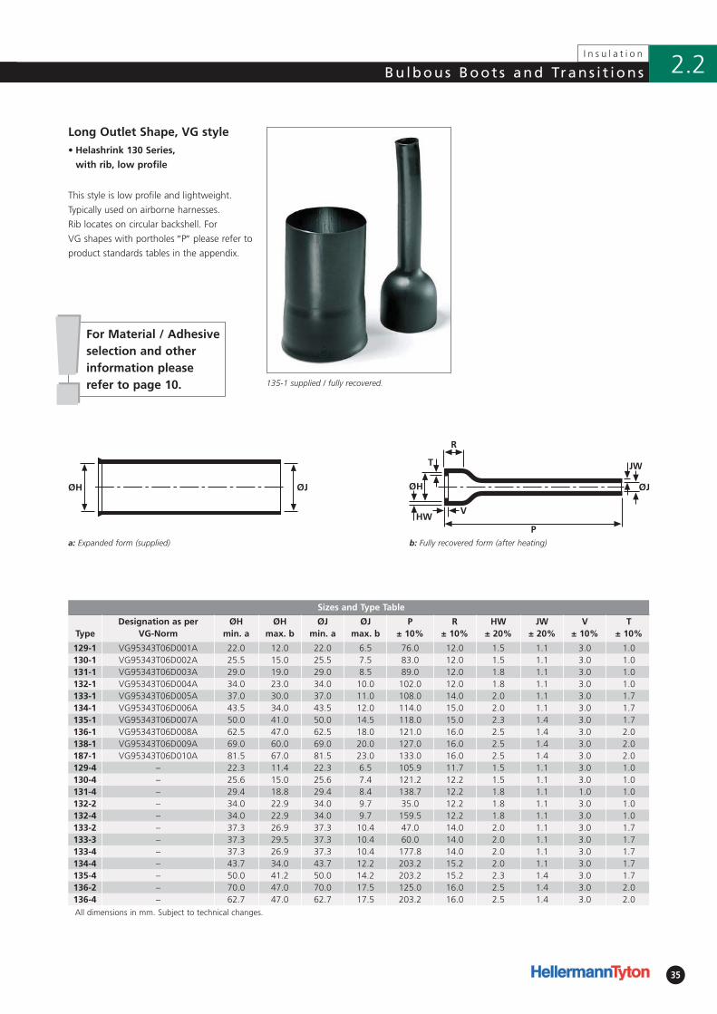
• Helashrink 130 Series,
with rib, low profile
Sizes and Type Table
TypeDesignation as per
VG-NormØH
min. aØH
max. bØJ
min. aØJ
max. bP
± 10%R
± 10%HW
± 20%JW
± 20%V
± 10%T
± 10%
129-1 VG95343T06D001A 22.0 12.0 22.0 6.5 76.0 12.0 1.5 1.1 3.0 1.0130-1 VG95343T06D002A 25.5 15.0 25.5 7.5 83.0 12.0 1.5 1.1 3.0 1.0131-1 VG95343T06D003A 29.0 19.0 29.0 8.5 89.0 12.0 1.8 1.1 3.0 1.0132-1 VG95343T06D004A 34.0 23.0 34.0 10.0 102.0 12.0 1.8 1.1 3.0 1.0133-1 VG95343T06D005A 37.0 30.0 37.0 11.0 108.0 14.0 2.0 1.1 3.0 1.7134-1 VG95343T06D006A 43.5 34.0 43.5 12.0 114.0 15.0 2.0 1.1 3.0 1.7135-1 VG95343T06D007A 50.0 41.0 50.0 14.5 118.0 15.0 2.3 1.4 3.0 1.7136-1 VG95343T06D008A 62.5 47.0 62.5 18.0 121.0 16.0 2.5 1.4 3.0 2.0138-1 VG95343T06D009A 69.0 60.0 69.0 20.0 127.0 16.0 2.5 1.4 3.0 2.0187-1 VG95343T06D010A 81.5 67.0 81.5 23.0 133.0 16.0 2.5 1.4 3.0 2.0129-4 – 22.3 11.4 22.3 6.5 105.9 11.7 1.5 1.1 3.0 1.0130-4 – 25.6 15.0 25.6 7.4 121.2 12.2 1.5 1.1 3.0 1.0131-4 – 29.4 18.8 29.4 8.4 138.7 12.2 1.8 1.1 1.0 1.0132-2 – 34.0 22.9 34.0 9.7 35.0 12.2 1.8 1.1 3.0 1.0132-4 – 34.0 22.9 34.0 9.7 159.5 12.2 1.8 1.1 3.0 1.0133-2 – 37.3 26.9 37.3 10.4 47.0 14.0 2.0 1.1 3.0 1.7133-3 – 37.3 29.5 37.3 10.4 60.0 14.0 2.0 1.1 3.0 1.7133-4 – 37.3 26.9 37.3 10.4 177.8 14.0 2.0 1.1 3.0 1.7134-4 – 43.7 34.0 43.7 12.2 203.2 15.2 2.0 1.1 3.0 1.7135-4 – 50.0 41.2 50.0 14.2 203.2 15.2 2.3 1.4 3.0 1.7136-2 – 70.0 47.0 70.0 17.5 125.0 16.0 2.5 1.4 3.0 2.0136-4 – 62.7 47.0 62.7 17.5 203.2 16.0 2.5 1.4 3.0 2.0All dimensions in mm. Subject to technical changes.
ØH ØJ
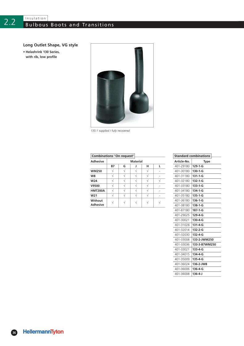
Long Outlet Shape, VG style
This style is low profile and lightweight.
Typically used on airborne harnesses.
Rib locates on circular backshell. For
VG shapes with port holes ″P″ please refer to
product standards tables in the appendix.
135-1 supplied / fully recovered.
a: Expanded form (supplied)
!!For Material / Adhesiveselection and otherinformation pleaserefer to page 10.
36
I n s u l a t i o n
Bu lbous Boot s and Trans i t ions2.2
• Helashrink 130 Series,
with rib, low profile
Adhesive Material
B7 G J H L
WM250 √ √ √ √ -
W8 √ √ √ √ -
W24 √ √ √ √ √
V9500 √ √ √ √ -
HMT200A √ √ √ √ -
W21 √ √ √ √ -
WithoutAdhesive
√ √ √ √ √
Article-No. Type
401-29180 129-1-G
401-30180 130-1-G
401-31180 131-1-G
401-32180 132-1-G
401-33180 133-1-G
401-34180 134-1-G
401-35180 135-1-G
401-36180 136-1-G
401-38180 138-1-G
401-87180 187-1-G
401-29025 129-4-G
401-30021 130-4-G
401-31028 131-4-G
401-32014 132-2-G
401-32030 132-4-G
401-33008 133-2-JWM250
401-33036 133-3-B7WM250
401-33021 133-4-G
401-34015 134-4-G
401-35009 135-4-G
401-36024 136-2-JW8
401-36006 136-4-G
401-36008 136-4-J
Long Outlet Shape, VG style
Combinations ″On request″ Standard combinations
135-1 supplied / fully recovered.
37
I n s u l a t i o n
2.2Bu lbous Boot s and Trans i t ions
b: Fully recovered form (after heating)
• Helashrink 140 Series, without rib
Sizes and Type Table
TypeØH
min. aØH
max. bØJ
min. aØJ
max. bP
± 10%R
± 10%HW
± 20%JW
± 30%S
nom
146-1 20.1 14.5 20.1 5.3 127.0 15.7 2.0 2.0 97.0146-2 22.3 14.5 10.2 5.3 127.0 15.7 2.0 2.0 97.0148-1 30.5 18.0 30.5 7.9 146.0 15.7 2.0 2.0 125.0148-2 30.5 18.0 15.2 7.9 146.0 15.7 2.3 2.3 125.0149-1 41.2 21.8 41.2 10.2 162.1 22.4 2.3 2.3 –All dimensions in mm. Subject to technical changes.
Article-No. Type
401-46001 146-1-B7
401-46009 146-2-G
401-48006 148-1-G
401-48016 148-2-J
401-49006 149-1-J
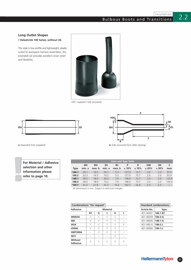
Long Outlet Shapes
This style is low profile and lightweight, ideally
suited to aerospace harness assemblies, the
extended tail provides excellent strain relief
and flexibility.
146-1 supplied / fully recovered.
a: Expanded form (supplied)
Standard combinations
Adhesive Material
B7 G J H L
WM250 √ √ √ √ -
W8 √ √ √ √ -
W24 √ √ √ √ √
V9500 √ √ √ √ -
HMT200A - √ √ √ -
W21 - - - √ -
WithoutAdhesive
√ √ √ √ √
Combinations ″On request″
!!For Material / Adhesiveselection and otherinformation pleaserefer to page 10.
38
I n s u l a t i o n
Bu lbous Boot s and Trans i t ions2.2
Adhesive Material
B7 G J H
WM250 √ √ √ √
W8 √ √ √ √
W24 √ √ √ √
V9500 √ √ √ √
HMT200A √ √ √ √
W21 - - - √
WithoutAdhesive
√ √ √ √
Article-No. Type
401-62180 162-1-G
Combinations ″On request″ Standard combinations
ØJØH
a: Expanded form (supplied)
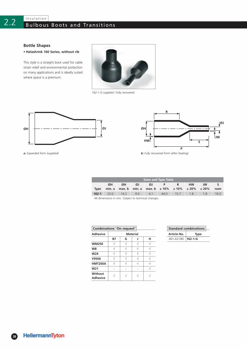
162-1-G supplied / fully recovered.
This style is a straight boot used for cable
strain relief and environmental protection
on many applications and is ideally suited
where space is a premium.
Bottle Shapes• Helashrink 160 Series, without rib
b: Fully recovered form (after heating)
Sizes and Type Table
TypeØH
min. aØH
max. bØJ
min. aØJ
max. bP
± 10%R
± 10%HW
± 20%JW
± 20%S
nom
162-1 22.0 14.2 9.0 4.1 44.0 15.7 1.8 1.8 16.0All dimensions in mm. Subject to technical changes.
39
I n s u l a t i o n
2.2Bu lbous Boot s and Trans i t ions
b: Fully recovered form (after heating)
• Helashrink 170 Series, with rib
Adhesive Material
B7 G J H L
WM250 √ √ √ √ -
W8 √ √ √ √ -
W24 √ √ √ √ √
V9500 √ √ √ √ -
HMT200A √ √ √ √ -
W21 - - - √ -
WithoutAdhesive
√ √ √ √ √
ØH ØJ
Article-No. Type
417-24003 1724-1-B7WM250B
417-38002 1738-1-B8WM250
401-76180 176-1-G
401-76014 176-2-B7
401-76018 176-3-G
401-77023 177-1-G
401-77180 177-1-G
401-78180 178-1-G
401-79180 179-1-G
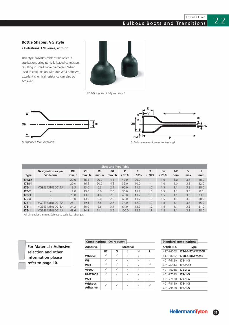
Bottle Shapes, VG style
This style provides cable strain relief in
applications using partially loaded connectors,
resulting in small cable diameters. When
used in conjunction with our W24 adhesive,
excellent chemical resistance can also be
achieved.
177-1-G supplied / fully recovered.
a: Expanded form (supplied)
Combinations ″On request″ Standard combinations
!!For Material / Adhesiveselection and otherinformation pleaserefer to page 10.
Sizes and Type Table
TypeDesignation as per
VG-NormØH
min. aØH
max. bØJ
min. aØJ
max. bP
± 10%R
± 10%T
± 20%HW
± 20%JW
nomV
maxS
nom
1724-1 – 20.0 16.5 20.0 4.5 42.0 20.0 – 1.0 1.0 3.3 10.01738-1 – 20.0 16.5 20.0 4.5 32.0 10.0 – 1.0 1.0 3.3 22.0176-1 VG95343T06D011A 19.3 13.0 6.3 2.1 60.0 11.7 1.0 1.5 1.1 3.3 38.0176-2 – 19.0 13.0 6.0 2.0 30.0 11.7 1.0 1.5 1.1 3.3 8.0176-3 – 25.0 13.0 4.0 2.0 45.0 11.7 1.0 1.5 1.1 3.3 23.0176-4 – 19.0 13.0 6.0 2.0 60.0 11.7 1.0 1.5 1.1 3.3 38.0177-1 VG95343T06D012A 26.1 19.1 7.6 2.6 74.0 12.2 1.0 1.8 1.1 3.3 45.0178-1 VG95343T06D013A 34.2 26.0 9.6 3.1 84.0 12.2 1.0 1.8 1.1 3.3 51.0179-1 VG95343T06D014A 43.6 34.1 11.4 3.6 100.0 12.2 1.7 1.8 1.1 3.3 58.0All dimensions in mm. Subject to technical changes.
40
I n s u l a t i o n
Bu lbous Boot s and Trans i t ions2.2
b: Fully recovered form (after heating)
• Helashrink 190 Series,
with external ribs
Sizes and Type Table
TypeDesignation as per
VG-NormØH
min. aØH
max. bØJ
min. aØJ
max. bP
± 10%R
± 10%HW
± 20%JW
± 20%V
± 10%T
± 20%S
nom
199-4 VG 95343 T06 A 010 A 17.5 14.0 7.0 4.3 70.0 35.0 1.8 0.5 1.5 1.0 20.0199-6 – 18.5 14.0 18.5 4.3 70.0 35.0 1.8 0.5 1.5 1.0 20.0All dimensions in mm. Subject to technical changes.
Adhesive Material
B7 G J H
WM250 √ √ √ √
W8 √ √ √ √
W24 √ √ √ √
V9500 √ √ √ √
HMT200A √ √ √ √
W21 - - - √
WithoutAdhesive
√ √ √ √
Article-No. Type
401-99480 199-4-G
401-99007 199-6-G
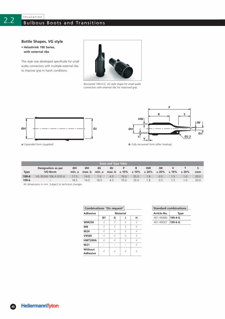
Bottle Shapes, VG style
This style was developed specifically for small
audio connectors with multiple external ribs
to improve grip in harsh conditions.
Recovered 199-4-G, VG style shape for small audioconnectors with external ribs for improved grip.
a: Expanded form (supplied)
Standard combinations
ØH
T
JW
ØJ
V
R S
P
Ø2.3
HW
Combinations ″On request″
Adhesive Material
B7 G J H B8
WM250 √ √ √ √ √
W8 √ √ √ √ -
W24 √ √ √ √ -
V9500 √ √ √ - -
HMT200A √ √ √ - √
W21 - - - - -
WithoutAdhesive
√ √ √ √ √
41
I n s u l a t i o n
2.2Bu lbous Boot s and Trans i t ions
b: Fully recovered form (after heating)
• Helashrink 200 Series, low profile
Sizes and Type Table
TypeØH
min. aØH
max. bØJ
min. aØJ
max. bØK
min. aØK
max. bP
± 10%R
± 10%W
± 20%
201-1 19.0 9.4 6.4 14.0 6.4 14.0 50.8 30.5 1.5201-3 24.5 9.4 14.0 6.4 14.0 6.4 50.8 30.5 1.5202-1 19.0 9.4 7.6 3.8 7.6 3.8 50.8 30.5 1.5202-2 20.0 9.4 12.5 3.8 12.5 3.8 50.8 30.5 1.5202-3 24.5 9.4 16.0 3.8 16.0 3.8 50.8 30.5 1.5All dimensions in mm. Subject to technical changes.
Article-No. Type
402-01180 201-1-G
402-01020 201-3-G
402-02004 202-1-G
402-02011 202-2-G
402-02019 202-3-G
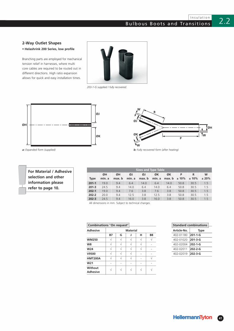
2-Way Outlet Shapes
Branching parts are employed for mechanical
tension relief in harnesses, where multi
core cables are required to be routed out in
different directions. High ratio expansion
allows for quick and easy installation times.
203-1-G supplied / fully recovered.
a: Expanded form (supplied)
Standard combinations
!!For Material / Adhesiveselection and otherinformation pleaserefer to page 10.
Combinations ″On request″

42
I n s u l a t i o n
Bu lbous Boot s and Trans i t ions2.2
b: Fully recovered form (after heating)
• Helashrink 200 Series
Article-No. Type
402-06180 206-1-G
402-13180 213-1-G
402-13021 213-2-G
402-12180 212-1-G
402-03180 203-1-G
402-04180 204-1-G
2-Way Outlet Shapes, VG style
Branching parts are employed for mechanical
tension relief in cable harnesses. For VG
shapes with port holes ″P″ please refer to
product standards tables in the appendix.
203-1-G supplied / fully recovered.
a: Expanded form (supplied)
Standard combinations
Sizes and Type Table
TypeDesignation as per
VG-NormØH
min. aØH
max. bØJ
min. aØJ
max. bP
± 10%R
± 10%HW
± 20%JW
nomS
nom
206-1 VG95343T08C001A 13.0 6.0 7.0 3.0 41.0 19.0 1.5 1.0 19.0213-1 – 17.3 7.9 11.1 7.9 140.0 83.1 2.3 1.0 64.0213-2 – 40.0 8.5 31.8 7.9 140.0 83.1 2.3 2.3 64.0212-1 VG95343T08C005A 14.5 8.0 8.5 5.5 136.0 83.0 2.3 2.0 63.0203-1 VG95343T08C002A 27.0 12.0 13.0 6.0 80.0 43.0 2.5 1.5 43.0204-1 VG95343T08C003A 39.0 18.0 27.0 12.0 131.0 81.0 3.1 2.0 81.0All dimensions in mm. Subject to technical changes.
Adhesive Material
B7 G J H L
WM250 √ √ √ √ -
W8 √ √ √ √ -
W24 √ √ √ √ √
V9500 √ √ √ - -
HMT200A √ √ √ - -
W21 - - - √ -
WithoutAdhesive
√ √ √ √ √
Combinations ″On request″
!!
43
I n s u l a t i o n
2.2Bu lbous Boot s and Trans i t ions
• Helashrink 200 Series, in line,
low voltage
Adhesive Material
B7 G H B8
W √ √ √ √
W2 √ √ √ √
V9500 √ √ √ -
HMT200A √ √ √ √
W21 - - √ -
WithoutAdhesive
√ √ √ √
S
Article-No. Type
402-23058 223-2-B8W
402-16038 216-2-B7WM250
402-17014 217-2-B7
402-18020 218-2-B7
402-20008 220-1-B7
402-19020 219-2-B8
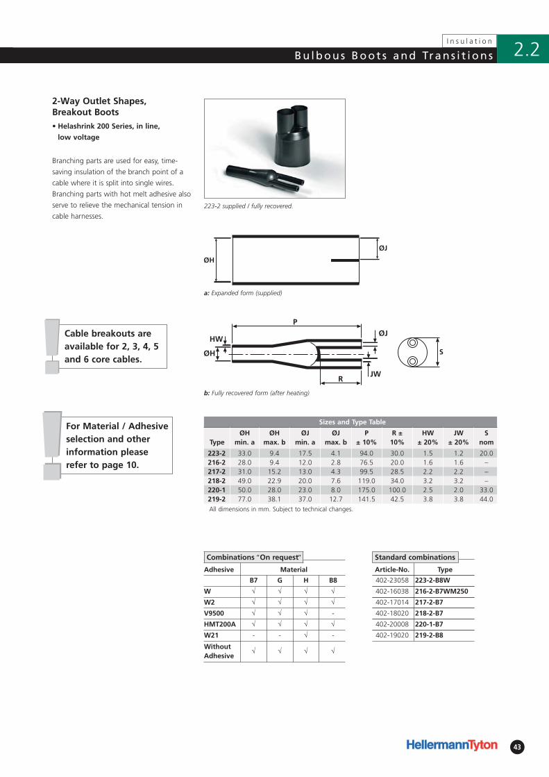
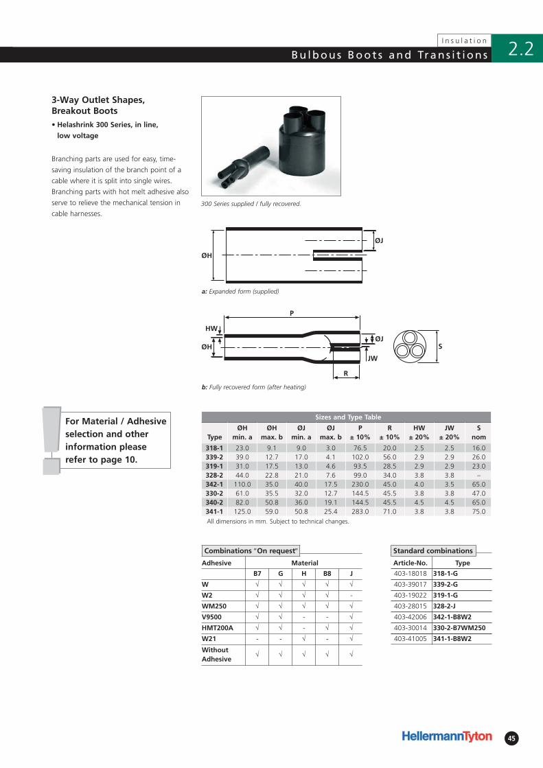
2-Way Outlet Shapes, Breakout Boots
Branching parts are used for easy, time-
saving insulation of the branch point of a
cable where it is split into single wires.
Branching parts with hot melt adhesive also
serve to relieve the mechanical tension in
cable harnesses. 223-2 supplied / fully recovered.
a: Expanded form (supplied)
Combinations ″On request″
!!For Material / Adhesiveselection and otherinformation pleaserefer to page 10.
Sizes and Type Table
TypeØH
min. aØH
max. bØJ
min. aØJ
max. bP
± 10%R ±
10%HW
± 20%JW
± 20%S
nom
223-2 33.0 9.4 17.5 4.1 94.0 30.0 1.5 1.2 20.0216-2 28.0 9.4 12.0 2.8 76.5 20.0 1.6 1.6 –217-2 31.0 15.2 13.0 4.3 99.5 28.5 2.2 2.2 –218-2 49.0 22.9 20.0 7.6 119.0 34.0 3.2 3.2 –220-1 50.0 28.0 23.0 8.0 175.0 100.0 2.5 2.0 33.0219-2 77.0 38.1 37.0 12.7 141.5 42.5 3.8 3.8 44.0All dimensions in mm. Subject to technical changes.
Standard combinations
Cable breakouts areavailable for 2, 3, 4, 5and 6 core cables.
b: Fully recovered form (after heating)
44
I n s u l a t i o n
Bu lbous Boot s and Trans i t ions2.2
b: Fully recovered form (after heating)
• Helashrink 300 Series
Sizes and Type Table
TypeDesignation as per
VG-NormØH
min. aØH
max. bØJ/K/L min. a
ØJ/K/L max. b
P ± 10%
R ± 10%
HW ± 20%
W ± 20%
T ± 10%
306-1 VG95343T08D001A 13.0 6.5 6.5 3.5 46.0 25.4 1.3 1.0 20.3304-1 VG95343T08D002A 27.0 13.5 13.0 7.0 93.0 50.3 2.5 1.5 42.9310-1 VG95343T08D003A 38.5 19.0 19.0 10.0 135.0 73.7 3.1 1.8 61.0311-1 VG95343T08D004A 55.5 25.5 27.0 12.5 192.0 103.1 4.6 3.1 88.9All dimensions in mm. Subject to technical changes.
Adhesive Material
B7 G J H L
WM250 √ √ √ √ -
W8 √ √ √ √ -
W24 √ √ √ √ √
V9500 √ √ √ √ -
HMT200A √ √ √ √ -
W21 - - - √ -
WithoutAdhesive
√ √ √ √ √
ØH ØK
ØJ
ØL
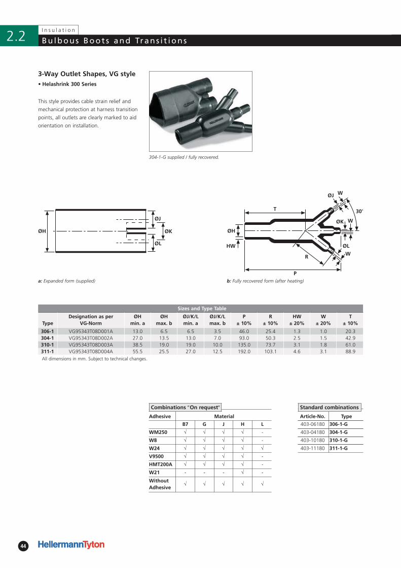
3-Way Outlet Shapes, VG style
This style provides cable strain relief and
mechanical protection at harness transition
points, all outlets are clearly marked to aid
orientation on installation.
304-1-G supplied / fully recovered.
a: Expanded form (supplied)
Combinations ″On request″
Article-No. Type
403-06180 306-1-G
403-04180 304-1-G
403-10180 310-1-G
403-11180 311-1-G
Standard combinations
45
I n s u l a t i o n
2.2Bu lbous Boot s and Trans i t ions
• Helashrink 300 Series, in line,
low voltage
Article-No. Type
403-18018 318-1-G
403-39017 339-2-G
403-19022 319-1-G
403-28015 328-2-J
403-42006 342-1-B8W2
403-30014 330-2-B7WM250
403-41005 341-1-B8W2
3-Way Outlet Shapes, Breakout Boots
Branching parts are used for easy, time-
saving insulation of the branch point of a
cable where it is split into single wires.
Branching parts with hot melt adhesive also
serve to relieve the mechanical tension in
cable harnesses. 300 Series supplied / fully recovered.
a: Expanded form (supplied)
Standard combinations
b: Fully recovered form (after heating)
Adhesive Material
B7 G H B8 J
W √ √ √ √ √
W2 √ √ √ √ -
WM250 √ √ √ √ √
V9500 √ √ - - √
HMT200A √ √ - √ √
W21 - - √ - √
WithoutAdhesive
√ √ √ √ √
Combinations ″On request″
!!For Material / Adhesiveselection and otherinformation pleaserefer to page 10.
Sizes and Type Table
TypeØH
min. aØH
max. bØJ
min. aØJ
max. bP
± 10%R
± 10%HW
± 20%JW
± 20%S
nom
318-1 23.0 9.1 9.0 3.0 76.5 20.0 2.5 2.5 16.0339-2 39.0 12.7 17.0 4.1 102.0 56.0 2.9 2.9 26.0319-1 31.0 17.5 13.0 4.6 93.5 28.5 2.9 2.9 23.0328-2 44.0 22.8 21.0 7.6 99.0 34.0 3.8 3.8 –342-1 110.0 35.0 40.0 17.5 230.0 45.0 4.0 3.5 65.0330-2 61.0 35.5 32.0 12.7 144.5 45.5 3.8 3.8 47.0340-2 82.0 50.8 36.0 19.1 144.5 45.5 4.5 4.5 65.0341-1 125.0 59.0 50.8 25.4 283.0 71.0 3.8 3.8 75.0All dimensions in mm. Subject to technical changes.
46
I n s u l a t i o n
Bu lbous Boot s and Trans i t ions2.2
a: Expanded form (supplied)
Article-No. Type
404-11180 411-1-G
404-03180 403-1-G
404-13180 413-1-G
• Helashrink 400 Series
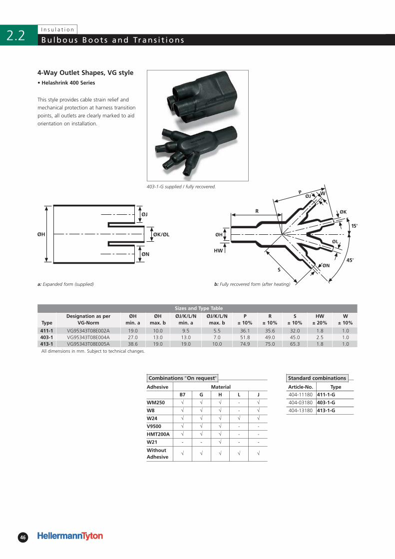
Sizes and Type Table
TypeDesignation as per
VG-NormØH
min. aØH
max. bØJ/K/L/N
min. aØJ/K/L/N max. b
P ± 10%
R ± 10%
S ± 10%
HW ± 20%
W ± 10%
411-1 VG95343T08E002A 19.0 10.0 9.5 5.5 36.1 35.6 32.0 1.8 1.0403-1 VG95343T08E004A 27.0 13.0 13.0 7.0 51.8 49.0 45.0 2.5 1.0413-1 VG95343T08E005A 38.6 19.0 19.0 10.0 74.9 75.0 65.3 1.8 1.0All dimensions in mm. Subject to technical changes.
Adhesive Material
B7 G H L J
WM250 √ √ √ - √
W8 √ √ √ - √
W24 √ √ √ √ √
V9500 √ √ √ - -
HMT200A √ √ √ - -
W21 - - √ - -
WithoutAdhesive
√ √ √ √ √
4-Way Outlet Shapes, VG style
This style provides cable strain relief and
mechanical protection at harness transition
points, all outlets are clearly marked to aid
orientation on installation.
403-1-G supplied / fully recovered.
b: Fully recovered form (after heating)
Combinations ″On request″ Standard combinations
47
I n s u l a t i o n
2.2Bu lbous Boot s and Trans i t ions
!!For Material / Adhesiveselection and otherinformation pleaserefer to page 10.
S
• Helashrink 400 Series, in line,
low voltage
ØH
ØJ
Article-No. Type
404-42022 442-1-B8W
404-34017 434-2-G
404-43002 443-1-B8
404-08022 408-2-B8W2
404-35007 435-2-J
404-09021 409-2-B8W2
404-18020 418-4-B8W2
404-37001 437-1-B7
404-38008 438-2-J
404-44022 444-2-B8W2
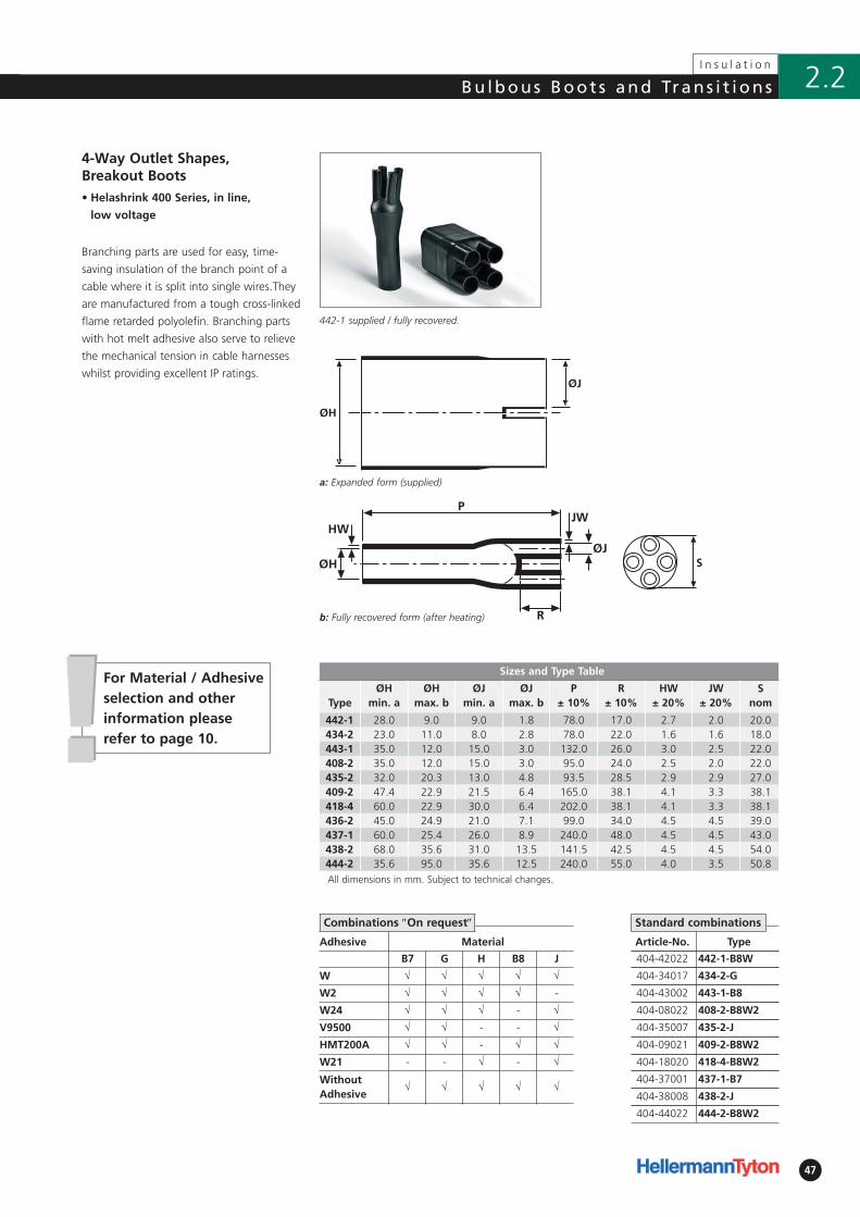
4-Way Outlet Shapes, Breakout Boots
Branching parts are used for easy, time-
saving insulation of the branch point of a
cable where it is split into single wires.They
are manufactured from a tough cross-linked
flame retarded polyolefin. Branching parts
with hot melt adhesive also serve to relieve
the mechanical tension in cable harnesses
whilst providing excellent IP ratings.
442-1 supplied / fully recovered.
a: Expanded form (supplied)
Standard combinations
Adhesive Material
B7 G H B8 J
W √ √ √ √ √
W2 √ √ √ √ -
W24 √ √ √ - √
V9500 √ √ - - √
HMT200A √ √ - √ √
W21 - - √ - √
WithoutAdhesive
√ √ √ √ √
Combinations ″On request″
Sizes and Type Table
TypeØH
min. aØH
max. bØJ
min. aØJ
max. bP
± 10%R
± 10%HW
± 20%JW
± 20%S
nom
442-1 28.0 9.0 9.0 1.8 78.0 17.0 2.7 2.0 20.0434-2 23.0 11.0 8.0 2.8 78.0 22.0 1.6 1.6 18.0443-1 35.0 12.0 15.0 3.0 132.0 26.0 3.0 2.5 22.0408-2 35.0 12.0 15.0 3.0 95.0 24.0 2.5 2.0 22.0435-2 32.0 20.3 13.0 4.8 93.5 28.5 2.9 2.9 27.0409-2 47.4 22.9 21.5 6.4 165.0 38.1 4.1 3.3 38.1418-4 60.0 22.9 30.0 6.4 202.0 38.1 4.1 3.3 38.1436-2 45.0 24.9 21.0 7.1 99.0 34.0 4.5 4.5 39.0437-1 60.0 25.4 26.0 8.9 240.0 48.0 4.5 4.5 43.0438-2 68.0 35.6 31.0 13.5 141.5 42.5 4.5 4.5 54.0444-2 35.6 95.0 35.6 12.5 240.0 55.0 4.0 3.5 50.8All dimensions in mm. Subject to technical changes.
b: Fully recovered form (after heating)
48
I n s u l a t i o n
Bu lbous Boot s and Trans i t ions2.2
• Helashrink 500 Series, in line,
low voltage
Adhesive Material
B7 G H
W √ √ √
W2 √ √ -
V9500 √ √ √
HMT200A √ √ √
W21 - - √
WithoutAdhesive
√ √ √
S
Article-No. Type
405-08021 508-1-B7
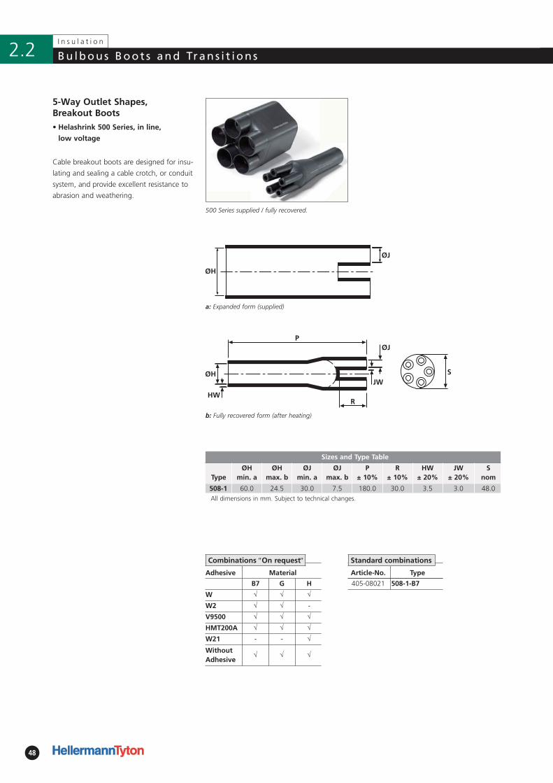
5-Way Outlet Shapes, Breakout Boots
Cable breakout boots are designed for insu-
lating and sealing a cable crotch, or conduit
system, and provide excellent resistance to
abrasion and weathering.
500 Series supplied / fully recovered.
a: Expanded form (supplied)
Standard combinationsCombinations ″On request″
Sizes and Type Table
TypeØH
min. aØH
max. bØJ
min. aØJ
max. bP
± 10%R
± 10%HW
± 20%JW
± 20%S
nom
508-1 60.0 24.5 30.0 7.5 180.0 30.0 3.5 3.0 48.0All dimensions in mm. Subject to technical changes.
b: Fully recovered form (after heating)
49
I n s u l a t i o n
2.2Bu lbous Boot s and Trans i t ions
• Helashrink 600 Series, in line,
low voltage
Adhesive Material
B7 G H
W √ √ √
W2 √ √ -
V9500 √ √ -
HMT200A √ √ √
W21 - - √
WithoutAdhesive
√ √ √
S
Article-No. Type
406-09003 609-1-G
406-09023 609-2-B7
406-08007 608-1-G
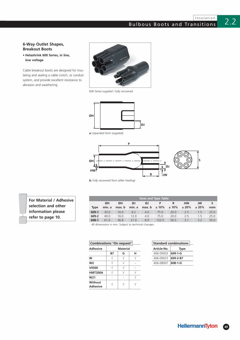
6-Way Outlet Shapes, Breakout Boots
Cable breakout boots are designed for insu-
lating and sealing a cable crotch, or conduit
system, and provide excellent resistance to
abrasion and weathering.
600 Series supplied / fully recovered.
a: Expanded form (supplied)
!!For Material / Adhesiveselection and otherinformation pleaserefer to page 10.
Sizes and Type Table
TypeØH
min. aØH
max. bØJ
min. aØJ
max. bP
± 10%R
± 10%HW
± 20%JW
± 20%S
nom
609-1 30.0 16.0 8.2 4.0 75.0 20.0 2.5 1.5 25.0609-2 40.0 16.0 12.0 4.0 75.0 20.0 2.5 1.5 25.0608-1 61.0 36.8 21.0 8.9 152.5 56.5 3.1 3.2 50.0All dimensions in mm. Subject to technical changes.
Combinations ″On request″ Standard combinations
b: Fully recovered form (after heating)
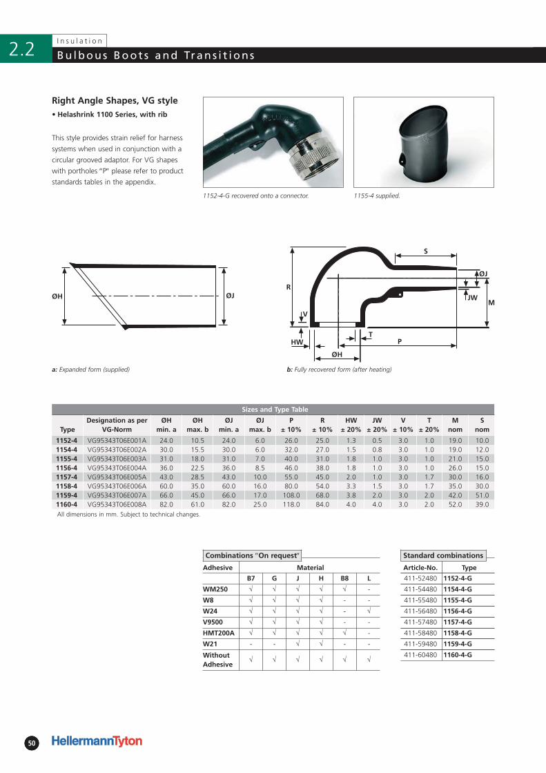
505050
I n s u l a t i o n
Bu lbous Boot s and Trans i t ions2.2
1155-4 supplied.
b: Fully recovered form (after heating)
Adhesive Material
B7 G J H B8 L
WM250 √ √ √ √ √ -
W8 √ √ √ √ - -
W24 √ √ √ √ - √
V9500 √ √ √ √ - -
HMT200A √ √ √ √ √ -
W21 - - √ √ - -
WithoutAdhesive
√ √ √ √ √ √
• Helashrink 1100 Series, with rib
ØH ØJ
Article-No. Type
411-52480 1152-4-G
411-54480 1154-4-G
411-55480 1155-4-G
411-56480 1156-4-G
411-57480 1157-4-G
411-58480 1158-4-G
411-59480 1159-4-G
411-60480 1160-4-G
Right Angle Shapes, VG style
This style provides strain relief for harness
systems when used in conjunction with a
circular grooved adaptor. For VG shapes
with port holes ″P″ please refer to product
standards tables in the appendix.
1152-4-G recovered onto a connector.
a: Expanded form (supplied)
Standard combinations
Sizes and Type Table
TypeDesignation as per
VG-NormØH
min. aØH
max. bØJ
min. aØJ
max. bP
± 10%R
± 10%HW
± 20%JW
± 20%V
± 10%T
± 20%M
nomS
nom
1152-4 VG95343T06E001A 24.0 10.5 24.0 6.0 26.0 25.0 1.3 0.5 3.0 1.0 19.0 10.01154-4 VG95343T06E002A 30.0 15.5 30.0 6.0 32.0 27.0 1.5 0.8 3.0 1.0 19.0 12.01155-4 VG95343T06E003A 31.0 18.0 31.0 7.0 40.0 31.0 1.8 1.0 3.0 1.0 21.0 15.01156-4 VG95343T06E004A 36.0 22.5 36.0 8.5 46.0 38.0 1.8 1.0 3.0 1.0 26.0 15.01157-4 VG95343T06E005A 43.0 28.5 43.0 10.0 55.0 45.0 2.0 1.0 3.0 1.7 30.0 16.01158-4 VG95343T06E006A 60.0 35.0 60.0 16.0 80.0 54.0 3.3 1.5 3.0 1.7 35.0 30.01159-4 VG95343T06E007A 66.0 45.0 66.0 17.0 108.0 68.0 3.8 2.0 3.0 2.0 42.0 51.01160-4 VG95343T06E008A 82.0 61.0 82.0 25.0 118.0 84.0 4.0 4.0 3.0 2.0 52.0 39.0All dimensions in mm. Subject to technical changes.
Combinations ″On request″
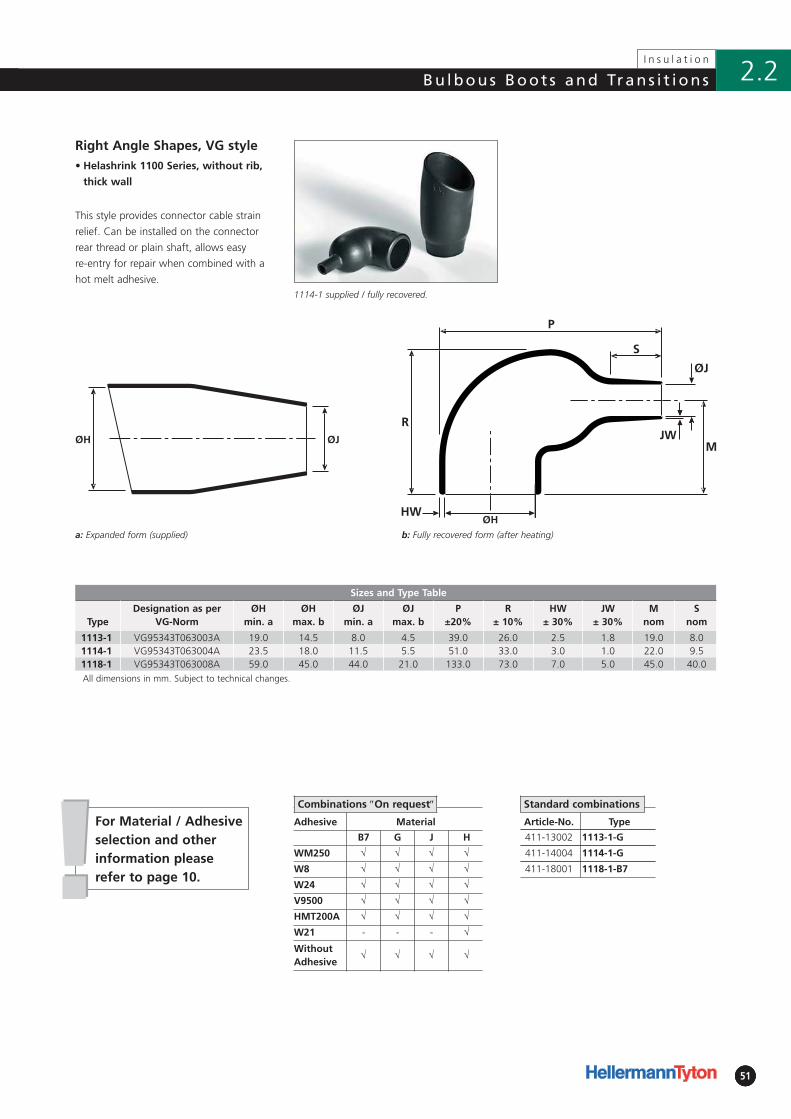
5151
Bu lbous Boot s and Trans i t ions
51
I n s u l a t i o n
2.2
Adhesive Material
B7 G J H
WM250 √ √ √ √
W8 √ √ √ √
W24 √ √ √ √
V9500 √ √ √ √
HMT200A √ √ √ √
W21 - - - √
WithoutAdhesive
√ √ √ √
• Helashrink 1100 Series, without rib,
thick wall
ØJØH
Article-No. Type
411-13002 1113-1-G
411-14004 1114-1-G
411-18001 1118-1-B7
Right Angle Shapes, VG style
This style provides connector cable strain
relief. Can be installed on the connector
rear thread or plain shaft, allows easy
re-entry for repair when combined with a
hot melt adhesive.1114-1 supplied / fully recovered.
!!For Material / Adhesiveselection and otherinformation pleaserefer to page 10.
Sizes and Type Table
TypeDesignation as per
VG-NormØH
min. aØH
max. bØJ
min. aØJ
max. bP
±20%R
± 10%HW
± 30%JW
± 30%M
nomS
nom
1113-1 VG95343T063003A 19.0 14.5 8.0 4.5 39.0 26.0 2.5 1.8 19.0 8.01114-1 VG95343T063004A 23.5 18.0 11.5 5.5 51.0 33.0 3.0 1.0 22.0 9.51118-1 VG95343T063008A 59.0 45.0 44.0 21.0 133.0 73.0 7.0 5.0 45.0 40.0All dimensions in mm. Subject to technical changes.
Combinations ″On request″ Standard combinations
b: Fully recovered form (after heating)a: Expanded form (supplied)
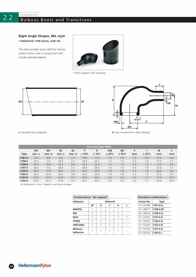
525252
I n s u l a t i o n
Bu lbous Boot s and Trans i t ions2.2
b: Fully recovered form (after heating)
• Helashrink 1100 Series, with rib
Article-No. Type
411-81480 1181-4-G
411-08015 1108-4-B7
411-06019 1106-4-G
411-07020 1107-4-G
411-04032 1104-4-G
411-03024 1103-4-G
411-01020 1101-4-G
411-05019 1105-4-J
Right Angle Shapes, MIL style
This style provides strain relief for harness
systems when used in conjunction with
circular grooved adaptor.
1108-4 supplied / fully recovered
a: Expanded form (supplied)
Standard combinations
Adhesive Material
B7 G J H L
WM250 √ √ √ √ -
W8 √ √ √ √ -
W24 √ √ √ √ √
V9500 √ √ √ - -
HMT200A √ √ √ √ -
WithoutAdhesive
√ √ √ √ -
Combinations ″On request″
Sizes and Type Table
TypeØH
min. aØH
max. bØJ
min. aØJ
max. bP
± 10%R
± 10%HW
± 20%JW
± 30%V
maxT
± 20%M
nomS
nom
1181-4 12.0 9.8 6.0 2.0 19.0 13.0 1.0 0.5 1.5 0.6 11.0 6.01108-4 16.5 7.9 16.5 2.5 18.3 20.1 1.0 1.6 3.3 1.0 15.2 5.11106-4 23.3 10.4 23.3 5.6 20.3 22.9 1.3 1.3 3.3 1.0 15.2 5.81107-4 28.4 14.2 28.4 6.3 29.8 28.5 1.5 1.5 3.3 1.0 21.4 7.11104-4 30.9 17.8 30.9 7.1 35.6 30.5 1.8 1.8 3.3 1.0 20.6 8.61103-4 36.0 22.4 36.0 8.4 43.2 35.6 1.8 1.8 3.3 1.0 22.9 12.71101-4 42.6 27.9 42.6 9.7 53.3 43.2 2.0 2.0 3.3 1.7 27.9 15.71105-4 51.8 35.1 51.8 15.7 78.7 53.3 3.3 3.3 3.3 1.7 33.0 30.5All dimensions in mm. Subject to technical changes.
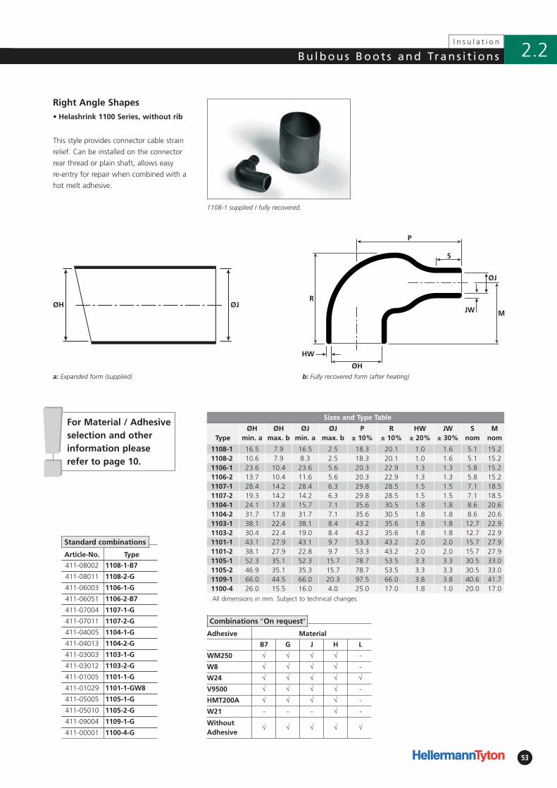
!!
5353
Bu lbous Boot s and Trans i t ions
53
I n s u l a t i o n
2.2
For Material / Adhesiveselection and otherinformation pleaserefer to page 10.
b: Fully recovered form (after heating)
Adhesive Material
B7 G J H L
WM250 √ √ √ √ -
W8 √ √ √ √ -
W24 √ √ √ √ √
V9500 √ √ √ √ -
HMT200A √ √ √ √ -
W21 - - - √ -
WithoutAdhesive
√ √ √ √ √
• Helashrink 1100 Series, without rib
ØH ØJ
Article-No. Type
411-08002 1108-1-B7
411-08011 1108-2-G
411-06003 1106-1-G
411-06051 1106-2-B7
411-07004 1107-1-G
411-07011 1107-2-G
411-04005 1104-1-G
411-04013 1104-2-G
411-03003 1103-1-G
411-03012 1103-2-G
411-01005 1101-1-G
411-01029 1101-1-GW8
411-05005 1105-1-G
411-05010 1105-2-G
411-09004 1109-1-G
411-00001 1100-4-G
Right Angle Shapes
This style provides connector cable strain
relief. Can be installed on the connector
rear thread or plain shaft, allows easy
re-entry for repair when combined with a
hot melt adhesive.
1108-1 supplied / fully recovered.
a: Expanded form (supplied)
Combinations ″On request″
Standard combinations
Sizes and Type Table
TypeØH
min. aØH
max. bØJ
min. aØJ
max. bP
± 10%R
± 10%HW
± 20%JW
± 30%S
nomM
nom
1108-1 16.5 7.9 16.5 2.5 18.3 20.1 1.0 1.6 5.1 15.21108-2 10.6 7.9 8.3 2.5 18.3 20.1 1.0 1.6 5.1 15.21106-1 23.6 10.4 23.6 5.6 20.3 22.9 1.3 1.3 5.8 15.21106-2 13.7 10.4 11.6 5.6 20.3 22.9 1.3 1.3 5.8 15.21107-1 28.4 14.2 28.4 6.3 29.8 28.5 1.5 1.5 7.1 18.51107-2 19.3 14.2 14.2 6.3 29.8 28.5 1.5 1.5 7.1 18.51104-1 24.1 17.8 15.7 7.1 35.6 30.5 1.8 1.8 8.6 20.61104-2 31.7 17.8 31.7 7.1 35.6 30.5 1.8 1.8 8.6 20.61103-1 38.1 22.4 38.1 8.4 43.2 35.6 1.8 1.8 12.7 22.91103-2 30.4 22.4 19.0 8.4 43.2 35.6 1.8 1.8 12.7 22.91101-1 43.1 27.9 43.1 9.7 53.3 43.2 2.0 2.0 15.7 27.91101-2 38.1 27.9 22.8 9.7 53.3 43.2 2.0 2.0 15.7 27.91105-1 52.3 35.1 52.3 15.7 78.7 53.5 3.3 3.3 30.5 33.01105-2 46.9 35.1 35.3 15.7 78.7 53.5 3.3 3.3 30.5 33.01109-1 66.0 44.5 66.0 20.3 97.5 66.0 3.8 3.8 40.6 41.71100-4 26.0 15.5 16.0 4.0 25.0 17.0 1.8 1.0 20.0 17.0All dimensions in mm. Subject to technical changes.
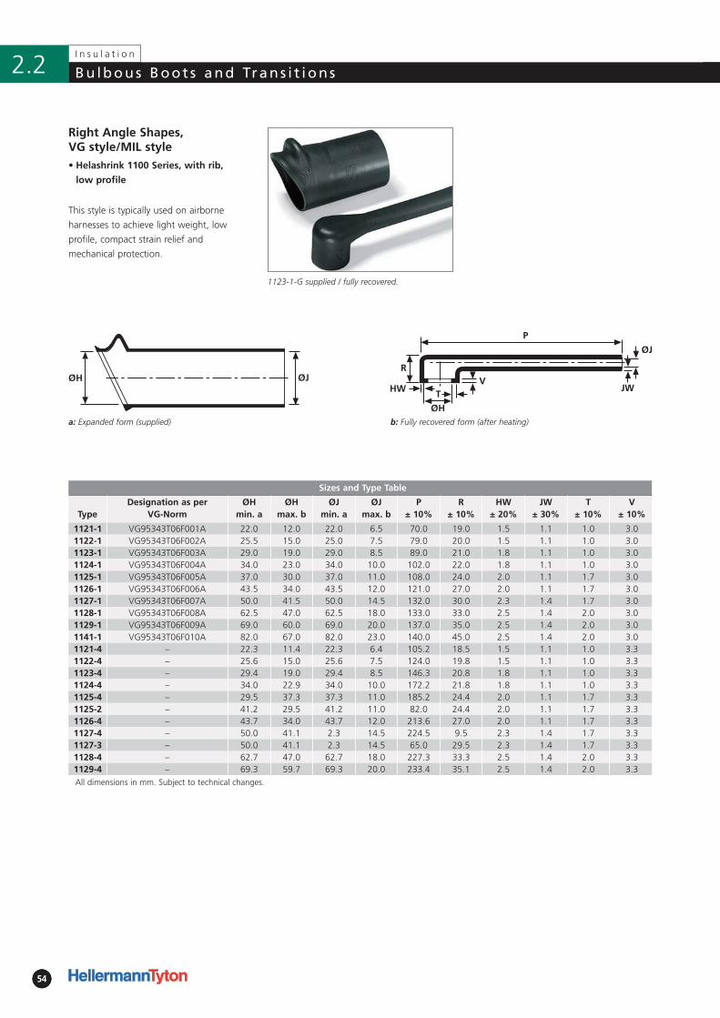
ØH ØJ
545454
I n s u l a t i o n
Bu lbous Boot s and Trans i t ions2.2
b: Fully recovered form (after heating)
• Helashrink 1100 Series, with rib,
low profile
Right Angle Shapes, VG style/MIL style
This style is typically used on airborne
harnesses to achieve light weight, low
profile, compact strain relief and
mechanical protection.
1123-1-G supplied / fully recovered.
a: Expanded form (supplied)
Sizes and Type Table
TypeDesignation as per
VG-NormØH
min. aØH
max. bØJ
min. aØJ
max. bP
± 10%R
± 10%HW
± 20%JW
± 30%T
± 10%V
± 10%
1121-1 VG95343T06F001A 22.0 12.0 22.0 6.5 70.0 19.0 1.5 1.1 1.0 3.01122-1 VG95343T06F002A 25.5 15.0 25.0 7.5 79.0 20.0 1.5 1.1 1.0 3.01123-1 VG95343T06F003A 29.0 19.0 29.0 8.5 89.0 21.0 1.8 1.1 1.0 3.01124-1 VG95343T06F004A 34.0 23.0 34.0 10.0 102.0 22.0 1.8 1.1 1.0 3.01125-1 VG95343T06F005A 37.0 30.0 37.0 11.0 108.0 24.0 2.0 1.1 1.7 3.01126-1 VG95343T06F006A 43.5 34.0 43.5 12.0 121.0 27.0 2.0 1.1 1.7 3.01127-1 VG95343T06F007A 50.0 41.5 50.0 14.5 132.0 30.0 2.3 1.4 1.7 3.01128-1 VG95343T06F008A 62.5 47.0 62.5 18.0 133.0 33.0 2.5 1.4 2.0 3.01129-1 VG95343T06F009A 69.0 60.0 69.0 20.0 137.0 35.0 2.5 1.4 2.0 3.01141-1 VG95343T06F010A 82.0 67.0 82.0 23.0 140.0 45.0 2.5 1.4 2.0 3.01121-4 – 22.3 11.4 22.3 6.4 105.2 18.5 1.5 1.1 1.0 3.31122-4 – 25.6 15.0 25.6 7.5 124.0 19.8 1.5 1.1 1.0 3.31123-4 – 29.4 19.0 29.4 8.5 146.3 20.8 1.8 1.1 1.0 3.31124-4 – 34.0 22.9 34.0 10.0 172.2 21.8 1.8 1.1 1.0 3.31125-4 – 29.5 37.3 37.3 11.0 185.2 24.4 2.0 1.1 1.7 3.31125-2 – 41.2 29.5 41.2 11.0 82.0 24.4 2.0 1.1 1.7 3.31126-4 – 43.7 34.0 43.7 12.0 213.6 27.0 2.0 1.1 1.7 3.31127-4 – 50.0 41.1 2.3 14.5 224.5 9.5 2.3 1.4 1.7 3.31127-3 – 50.0 41.1 2.3 14.5 65.0 29.5 2.3 1.4 1.7 3.31128-4 – 62.7 47.0 62.7 18.0 227.3 33.3 2.5 1.4 2.0 3.31129-4 – 69.3 59.7 69.3 20.0 233.4 35.1 2.5 1.4 2.0 3.3All dimensions in mm. Subject to technical changes.

!!
5555
Bu lbous Boot s and Trans i t ions
55
I n s u l a t i o n
2.2
For Material / Adhesiveselection and otherinformation pleaserefer to page 10.
• Helashrink 1100 Series, with rib,
low profile
Article-No. Type
411-21180 1121-1-G
411-22180 1122-1-G
411-23180 1123-1-G
411-24180 1124-1-G
411-25180 1125-1-G
411-26180 1126-1-G
411-27180 1127-1-G
411-28180 1128-1-G
411-29180 1129-1-G
411-41180 1141-1-G
411-21007 1121-4-G
411-22015 1122-4-G
411-23013 1123-4-G
411-24009 1124-4-G
411-25008 1125-4-G
411-25027 1125-2-G
411-26008 1126-4-G
411-27008 1127-4-G
411-27005 1127-3-B7
411-28002 1128-4-G
411-29001 1129-4-J
Right Angle Shapes, VG style/MIL style
1123-1-G supplied / fully recovered.
Standard combinations
Adhesive Material
B7 G J H L
WM250 √ √ √ √ -
W8 √ √ √ √ -
W24 √ √ √ √ √
V9500 √ √ √ √ -
HMT200A √ √ √ √ -
W21 - - - √ -
WithoutAdhesive
√ √ √ √ √
Combinations ″On request″
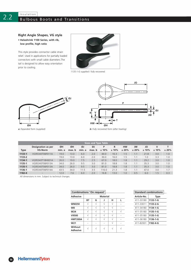
565656
I n s u l a t i o n
Bu lbous Boot s and Trans i t ions2.2
b: Fully recovered form (after heating)
Adhesive Material
B7 G J H L
WM250 √ √ √ √ -
W8 √ √ √ √ -
W24 √ √ √ √ √
V9500 √ √ √ √ -
HMT200A √ √ √ √ -
W21 - - - √ -
WithoutAdhesive
√ √ √ √ √
• Helashrink 1100 Series, with rib,
low profile, high ratio
Right Angle Shapes, VG style
This style provides connector cable strain
relief. Used in applications for partially loaded
connectors with small cable diameters.The
tail is designed to allow easy orientation
prior to cooling.
1135-1-G supplied / fully recovered.
a: Expanded form (supplied)
Combinations ″On request″
Article-No. Type
411-33180 1133-1-G
411-33011 1133-2-G
411-34180 1134-1-G
411-35180 1135-1-G
411-35180 1135-1-G
411-36180 1136-1-G
411-82001 1182-4-G
Standard combinations
Sizes and Type Table
TypeDesignation as per
VG-NormØH
min. aØH
max. bØJ
min. aØJ
max. bP
± 10%R
± 10%HW
± 20%JW
± 20%JO
± 10%V
± 10%T
± 20%
1133-1 VG95343T06F011A 19.0 13.0 6.0 2.0 44.0 16.3 1.5 1.1 21.8 3.0 1.01133-2 – 19.0 13.0 6.0 2.0 30.0 16.0 1.5 1.1 1.0 3.3 1.01134-1 VG95343T18H001A 26.0 19.0 7.5 2.5 67.0 18.0 1.8 1.1 29.2 3.0 1.01135-1 VG95343T06F013A 34.0 26.0 9.5 3.0 81.0 18.8 1.8 1.1 35.3 3.0 1.01135-1 VG95343T06F013A 34.0 26.0 9.5 3.0 81.0 18.8 1.8 1.1 35.3 3.0 1.01136-1 VG95343T06F014A 43.5 34.0 11.5 3.5 116.0 21.3 1.8 1.1 47.0 3.0 1.71182-4 – 12.0 7.6 6.0 2.0 16.8 13.0 1.0 0.5 6.0 1.5 0.3All dimensions in mm. Subject to technical changes.
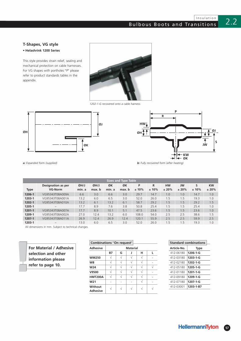
!!5757
Bu lbous Boot s and Trans i t ions
57
I n s u l a t i o n
2.2
For Material / Adhesiveselection and otherinformation pleaserefer to page 10.
b: Fully recovered form (after heating)
Adhesive Material
B7 G J H L
WM250 √ √ √ √ -
W8 √ √ √ √ -
W24 √ √ √ √ √
V9500 √ √ √ √ -
HMT200A √ √ √ √ -
W21 - - - √ -
WithoutAdhesive
√ √ √ √ √
• Helashrink 1200 Series
Sizes and Type Table
TypeDesignation as per
VG-NormØH/J
min. aØH/J
max. bØK
min. aØK
max. bP
± 10%R
± 10%HW
± 20%JW
± 20%S
± 10%KW
± 20%
1206-1 VG95343T08A009A 6.6 3.0 6.6 3.0 29.7 14.7 1.0 1.0 14.7 1.01203-1 VG95343T08A001A 13.2 6.0 6.5 3.0 52.0 26.0 1.5 1.5 19.3 1.01202-1 VG95343T08A010A 13.2 6.1 13.2 6.1 58.7 29.2 1.5 1.5 29.2 1.51205-1 – 17.7 8.9 7.6 3.8 50.8 25.4 1.5 1.5 25.4 1.01201-1 VG95343T08A007A 17.7 8.9 10.1 5.1 47.5 23.6 1.5 1.5 23.6 1.01209-1 VG95343T08A002A 27.0 12.4 13.2 6.0 108.0 54.0 2.5 2.5 38.6 1.51207-1 VG95343T08A011A 26.9 12.4 26.9 12.4 120.1 55.9 2.5 2.5 59.9 2.51203-1 – 13.0 6.0 6.5 3.0 52.0 26.0 1.5 1.5 19.3 1.0All dimensions in mm. Subject to technical changes.
ØH
ØK
ØJ
Article-No. Type
412-06180 1206-1-G
412-03180 1203-1-G
412-02180 1202-1-G
412-05180 1205-1-G
412-01180 1201-1-G
412-09180 1209-1-G
412-07180 1207-1-G
412-03001 1203-1-B7
T-Shapes, VG style
This style provides strain relief, sealing and
mechanical protection on cable harnesses.
For VG shapes with port holes ″P″ please
refer to product standards tables in the
appendix.
1202-1-G recovered onto a cable harness.
a: Expanded form (supplied)
Standard combinationsCombinations ″On request″
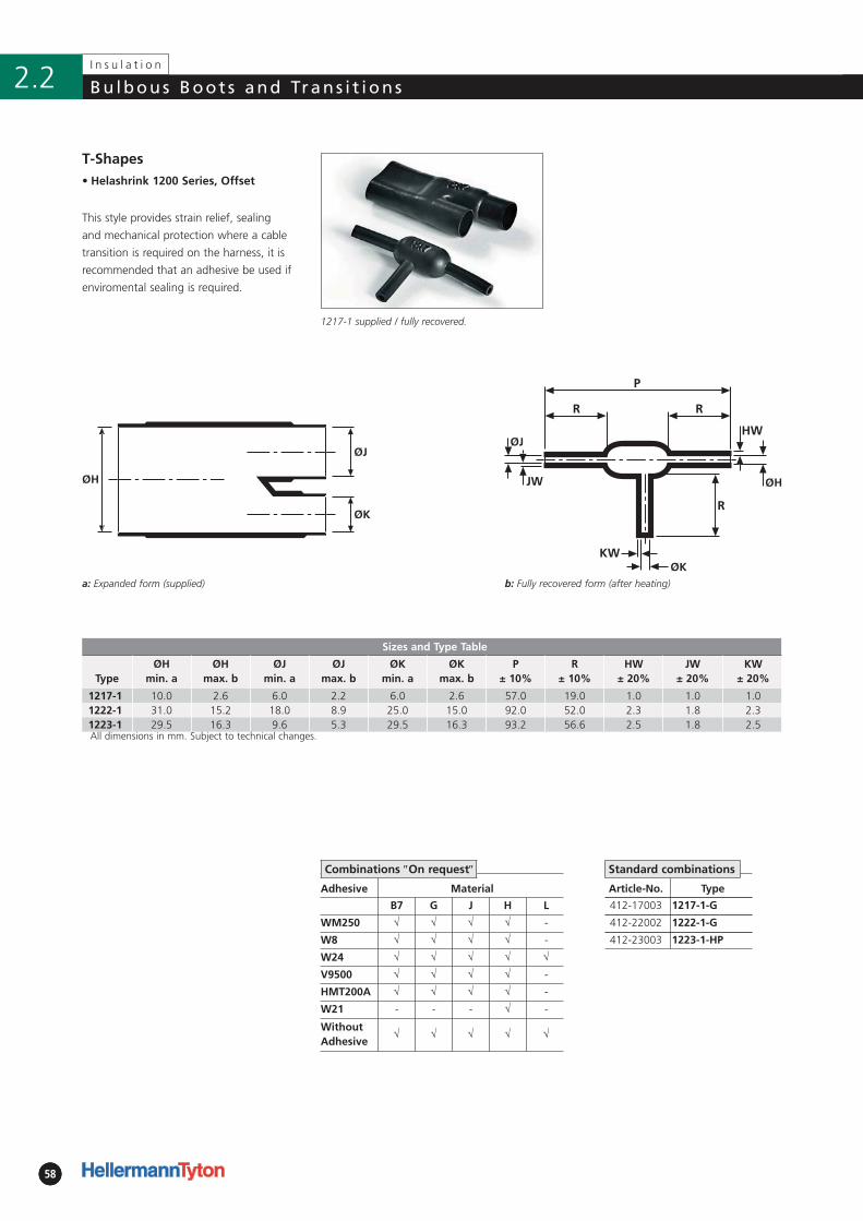
585858
I n s u l a t i o n
Bu lbous Boot s and Trans i t ions2.2
b: Fully recovered form (after heating)
Adhesive Material
B7 G J H L
WM250 √ √ √ √ -
W8 √ √ √ √ -
W24 √ √ √ √ √
V9500 √ √ √ √ -
HMT200A √ √ √ √ -
W21 - - - √ -
WithoutAdhesive
√ √ √ √ √
• Helashrink 1200 Series, Offset
ØH
ØJ
ØK
Article-No. Type
412-17003 1217-1-G
412-22002 1222-1-G
412-23003 1223-1-HP
T-Shapes
This style provides strain relief, sealing
and mechanical protection where a cable
transition is required on the harness, it is
recommended that an adhesive be used if
enviromental sealing is required.
1217-1 supplied / fully recovered.
a: Expanded form (supplied)
Standard combinationsCombinations ″On request″
Sizes and Type Table
TypeØH
min. aØH
max. bØJ
min. aØJ
max. bØK
min. aØK
max. bP
± 10%R
± 10%HW
± 20%JW
± 20%KW
± 20%
1217-1 10.0 2.6 6.0 2.2 6.0 2.6 57.0 19.0 1.0 1.0 1.01222-1 31.0 15.2 18.0 8.9 25.0 15.0 92.0 52.0 2.3 1.8 2.31223-1 29.5 16.3 9.6 5.3 29.5 16.3 93.2 56.6 2.5 1.8 2.5All dimensions in mm. Subject to technical changes.
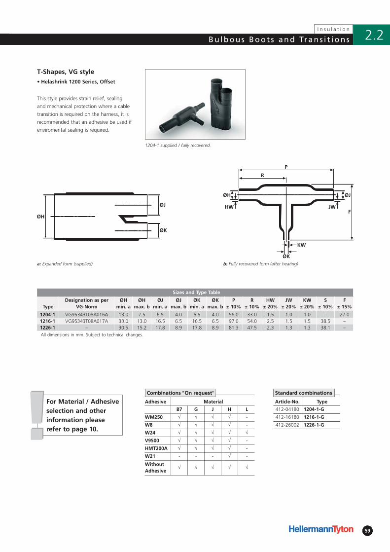
!!5959
Bu lbous Boot s and Trans i t ions
59
I n s u l a t i o n
2.2
For Material / Adhesiveselection and otherinformation pleaserefer to page 10.
b: Fully recovered form (after heating)
Adhesive Material
B7 G J H L
WM250 √ √ √ √ -
W8 √ √ √ √ -
W24 √ √ √ √ √
V9500 √ √ √ √ -
HMT200A √ √ √ √ -
W21 - - - √ -
WithoutAdhesive
√ √ √ √ √
• Helashrink 1200 Series, Offset
Sizes and Type Table
TypeDesignation as per
VG-NormØH
min. aØH
max. bØJ
min. aØJ
max. bØK
min. aØK
max. bP
± 10%R
± 10%HW
± 20%JW
± 20%KW
± 20%S
± 10%F
± 15%
1204-1 VG95343T08A016A 13.0 7.5 6.5 4.0 6.5 4.0 56.0 33.0 1.5 1.0 1.0 – 27.01216-1 VG95343T08A017A 33.0 13.0 16.5 6.5 16.5 6.5 97.0 54.0 2.5 1.5 1.5 38.5 –1226-1 – 30.5 15.2 17.8 8.9 17.8 8.9 81.3 47.5 2.3 1.3 1.3 38.1 –All dimensions in mm. Subject to technical changes.
Article-No. Type
412-04180 1204-1-G
412-16180 1216-1-G
412-26002 1226-1-G
T-Shapes, VG style
This style provides strain relief, sealing
and mechanical protection where a cable
transition is required on the harness, it is
recommended that an adhesive be used if
enviromental sealing is required.
1204-1 supplied / fully recovered.
a: Expanded form (supplied)
Combinations ″On request″ Standard combinations
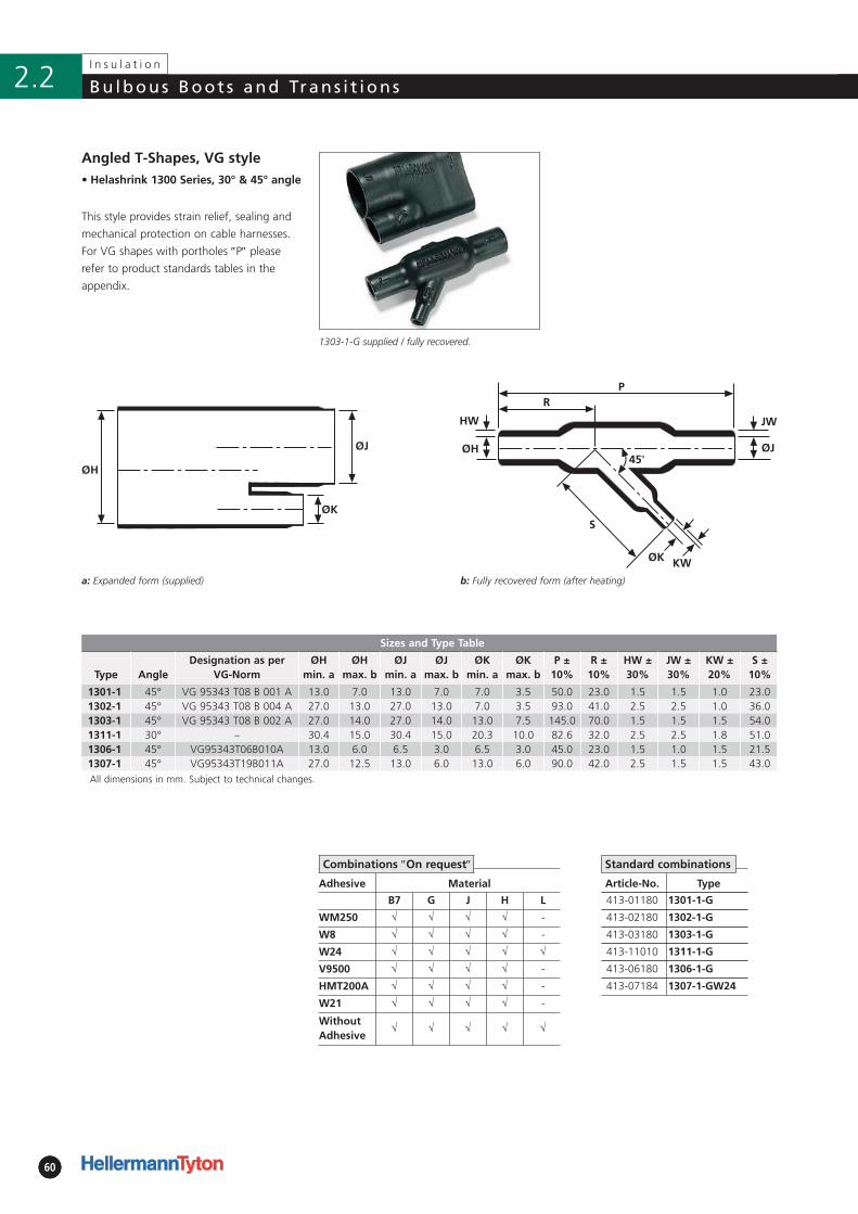
606060
I n s u l a t i o n
Bu lbous Boot s and Trans i t ions2.2
b: Fully recovered form (after heating)
Adhesive Material
B7 G J H L
WM250 √ √ √ √ -
W8 √ √ √ √ -
W24 √ √ √ √ √
V9500 √ √ √ √ -
HMT200A √ √ √ √ -
W21 √ √ √ √ -
WithoutAdhesive
√ √ √ √ √
• Helashrink 1300 Series, 30° & 45° angle
Sizes and Type Table
Type AngleDesignation as per
VG-NormØH
min. aØH
max. bØJ
min. aØJ
max. bØK
min. aØK
max. bP ±
10%R ±
10%HW ±30%
JW ±30%
KW ±20%
S ±10%
1301-1 45° VG 95343 T08 B 001 A 13.0 7.0 13.0 7.0 7.0 3.5 50.0 23.0 1.5 1.5 1.0 23.01302-1 45° VG 95343 T08 B 004 A 27.0 13.0 27.0 13.0 7.0 3.5 93.0 41.0 2.5 2.5 1.0 36.01303-1 45° VG 95343 T08 B 002 A 27.0 14.0 27.0 14.0 13.0 7.5 145.0 70.0 1.5 1.5 1.5 54.01311-1 30° – 30.4 15.0 30.4 15.0 20.3 10.0 82.6 32.0 2.5 2.5 1.8 51.01306-1 45° VG95343T06B010A 13.0 6.0 6.5 3.0 6.5 3.0 45.0 23.0 1.5 1.0 1.5 21.51307-1 45° VG95343T19B011A 27.0 12.5 13.0 6.0 13.0 6.0 90.0 42.0 2.5 1.5 1.5 43.0All dimensions in mm. Subject to technical changes.
ØH
ØJ
ØK
Article-No. Type
413-01180 1301-1-G
413-02180 1302-1-G
413-03180 1303-1-G
413-11010 1311-1-G
413-06180 1306-1-G
413-07184 1307-1-GW24
Angled T-Shapes, VG style
This style provides strain relief, sealing and
mechanical protection on cable harnesses.
For VG shapes with port holes ″P″ please
refer to product standards tables in the
appendix.
1303-1-G supplied / fully recovered.
a: Expanded form (supplied)
Standard combinationsCombinations ″On request″
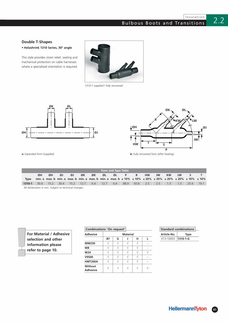
!!6161
Bu lbous Boot s and Trans i t ions
61
I n s u l a t i o n
2.2
For Material / Adhesiveselection and otherinformation pleaserefer to page 10.
b: Fully recovered form (after heating)
• Helashrink 1310 Series, 30° angle
Sizes and Type Table
TypeØH
min. aØH
max. bØJ
min. aØJ
max. bØK
min. aØK
max. bØL
min. aØL
max. bP
± 10%R
± 10%HW
± 20%JW
± 20%KW
± 20%LW
± 20%S
± 10%T
± 10%
1310-1 30.4 15.2 30.4 15.2 12.7 6.4 12.7 6.4 88.9 50.8 2.5 2.5 1.3 1.3 25.4 19.1All dimensions in mm. Subject to technical changes.
ØH ØJ
ØK ØL
Article-No. Type
413-10003 1310-1-G
Double T-Shapes
This style provides strain relief, sealing and
mechanical protection on cable harnesses
where a specialised orientation is required.
1310-1 supplied / fully recovered.
a: Expanded form (supplied)
Standard combinations
Adhesive Material
B7 G J H L
WM250 √ √ √ √ -
W8 √ √ √ √ -
W24 √ √ √ √ √
V9500 √ √ √ √ -
HMT200A √ √ √ √ -
WithoutAdhesive
√ √ √ √ √
Combinations ″On request″
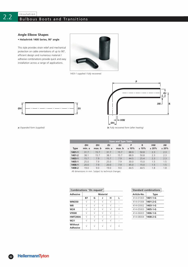
626262
I n s u l a t i o n
Bu lbous Boot s and Trans i t ions2.2
b: Fully recovered form (after heating)
Adhesive Material
B7 G J H L
WM250 √ √ √ √ -
W8 √ √ √ √ -
W24 √ √ √ √ √
V9500 √ √ √ √ -
HMT200A √ √ √ √ -
W21 √ √ √ √ -
WithoutAdhesive
√ √ √ √ √
• Helashrink 1400 Series, 90° angle
Sizes and Type Table
TypeØH
min. aØH
max. bØJ
min. aØJ
max. bP
± 10%R
± 10%HW
± 20%JW
± 20%
1401-1 31.7 15.7 31.7 15.7 88.9 50.8 2.3 2.31401-2 38.1 15.7 38.1 15.7 88.9 50.8 2.3 2.31403-1 15.7 7.9 15.7 7.9 44.5 25.4 2.3 2.31405-1 25.0 7.9 25.0 7.9 30.0 15.0 1.5 1.51406-1 20.0 7.9 20.0 7.9 45.0 15.0 1.5 1.51408-2 19.0 9.0 19.0 9.0 44.5 44.5 1.8 1.8All dimensions in mm. Subject to technical changes.
ØH ØJ
Article-No. Type
414-01003 1401-1-G
414-01006 1401-2-G
414-03002 1403-1-G
414-05003 1405-1-G
414-06003 1406-1-G
414-08004 1408-2-G
Angle Elbow Shapes
This style provides strain relief and mechanical
protection on cable orientations of up to 90°,
efficient design and numerous material /
adhesive combinations provide quick and easy
installation across a range of applications.
1403-1 supplied / fully recovered.
a: Expanded form (supplied)
Standard combinationsCombinations ″On request″
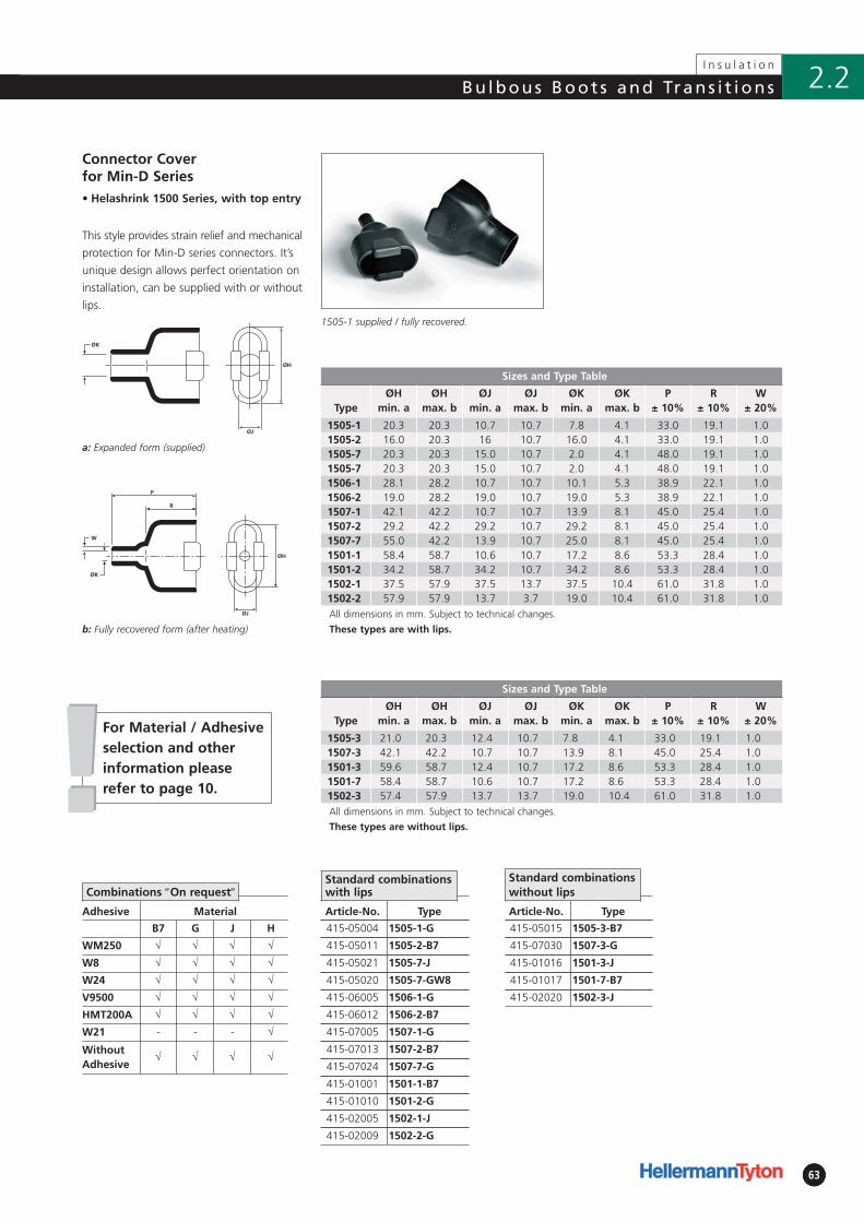
6363
Bu lbous Boot s and Trans i t ions
63
I n s u l a t i o n
2.2
ØH
ØJ
ØH
ØJ
b: Fully recovered form (after heating)
Adhesive Material
B7 G J H
WM250 √ √ √ √
W8 √ √ √ √
W24 √ √ √ √
V9500 √ √ √ √
HMT200A √ √ √ √
W21 - - - √
WithoutAdhesive
√ √ √ √
• Helashrink 1500 Series, with top entry
Sizes and Type Table
TypeØH
min. aØH
max. bØJ
min. aØJ
max. bØK
min. aØK
max. bP
± 10%R
± 10%W
± 20%
1505-1 20.3 20.3 10.7 10.7 7.8 4.1 33.0 19.1 1.01505-2 16.0 20.3 16 10.7 16.0 4.1 33.0 19.1 1.01505-7 20.3 20.3 15.0 10.7 2.0 4.1 48.0 19.1 1.01505-7 20.3 20.3 15.0 10.7 2.0 4.1 48.0 19.1 1.01506-1 28.1 28.2 10.7 10.7 10.1 5.3 38.9 22.1 1.01506-2 19.0 28.2 19.0 10.7 19.0 5.3 38.9 22.1 1.01507-1 42.1 42.2 10.7 10.7 13.9 8.1 45.0 25.4 1.01507-2 29.2 42.2 29.2 10.7 29.2 8.1 45.0 25.4 1.01507-7 55.0 42.2 13.9 10.7 25.0 8.1 45.0 25.4 1.01501-1 58.4 58.7 10.6 10.7 17.2 8.6 53.3 28.4 1.01501-2 34.2 58.7 34.2 10.7 34.2 8.6 53.3 28.4 1.01502-1 37.5 57.9 37.5 13.7 37.5 10.4 61.0 31.8 1.01502-2 57.9 57.9 13.7 3.7 19.0 10.4 61.0 31.8 1.0All dimensions in mm. Subject to technical changes.
These types are with lips.
ØK
W
P
R
ØK
Article-No. Type
415-05004 1505-1-G
415-05011 1505-2-B7
415-05021 1505-7-J
415-05020 1505-7-GW8
415-06005 1506-1-G
415-06012 1506-2-B7
415-07005 1507-1-G
415-07013 1507-2-B7
415-07024 1507-7-G
415-01001 1501-1-B7
415-01010 1501-2-G
415-02005 1502-1-J
415-02009 1502-2-G
Connector Cover for Min-D Series
This style provides strain relief and mechanical
protection for Min-D series connectors. It’s
unique design allows perfect orientation on
installation, can be supplied with or without
lips.1505-1 supplied / fully recovered.
a: Expanded form (supplied)
Standard combinations with lipsCombinations ″On request″
Sizes and Type Table
TypeØH
min. aØH
max. bØJ
min. aØJ
max. bØK
min. aØK
max. bP
± 10%R
± 10%W
± 20%
1505-3 21.0 20.3 12.4 10.7 7.8 4.1 33.0 19.1 1.01507-3 42.1 42.2 10.7 10.7 13.9 8.1 45.0 25.4 1.01501-3 59.6 58.7 12.4 10.7 17.2 8.6 53.3 28.4 1.01501-7 58.4 58.7 10.6 10.7 17.2 8.6 53.3 28.4 1.01502-3 57.4 57.9 13.7 13.7 19.0 10.4 61.0 31.8 1.0All dimensions in mm. Subject to technical changes.
These types are without lips.
!!For Material / Adhesiveselection and otherinformation pleaserefer to page 10.
Article-No. Type
415-05015 1505-3-B7
415-07030 1507-3-G
415-01016 1501-3-J
415-01017 1501-7-B7
415-02020 1502-3-J
Standard combinations without lips
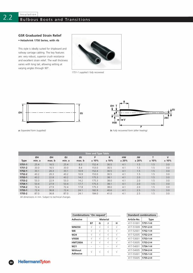
646464
I n s u l a t i o n
Bu lbous Boot s and Trans i t ions2.2
b: Fully recovered form (after heating)
• Helashrink 1750 Series, with rib
Sizes and Type Table
TypeØH
min. aØH
max. bØJ
min. aØJ
max. bP
± 10%R
± 10%HW
± 20%JW
± 20%T
± 10%V
± 10%
1751-1 25.4 16.5 25.4 8.3 152.4 30.5 4.1 1.5 1.5 3.01751-2 33.0 16.5 33.0 8.4 153.0 30.5 4.1 1.5 1.5 3.01752-1 33.1 20.3 33.1 10.9 152.4 30.5 4.1 1.5 1.5 3.01752-2 43.2 20.3 43.2 10.9 153.0 30.5 4.1 1.5 1.5 3.01753-1 43.2 22.8 43.2 14.2 175.3 38.1 4.1 2.0 1.5 3.01753-2 53.3 22.9 53.3 14.2 175.3 38.0 4.1 2.0 1.5 3.01754-1 53.4 27.9 53.4 17.7 175.3 38.1 4.1 2.0 1.5 3.01754-2 72.4 27.9 72.4 17.8 175.3 38.0 4.1 2.0 1.5 3.01755-1 72.4 36.8 72.4 24.1 182.9 40.6 4.1 2.5 1.5 3.01755-2 87.0 36.8 87.0 24.1 184.0 41.0 4.1 2.5 1.5 3.0All dimensions in mm. Subject to technical changes.
ØJØH
Article-No. Type
417-51001 1751-1-H
417-51009 1751-2-H
417-52001 1752-1-H
417-52005 1752-2-H
417-53001 1753-1-H
417-53005 1753-2-H
417-54001 1754-1-H
417-54005 1754-2-H
417-55001 1755-1-H
417-55005 1755-2-H
GSR Graduated Strain Relief
This style is ideally suited for shipboard and
railway carriage cabling. The key features
are: very robust, superior crush resistance
and excellent strain relief. The wall thickness
varies with long tail, allowing setting at
varying angles through 90°.
1751-1 supplied / fully recovered.
a: Expanded form (supplied)
Standard combinations
Adhesive Material
B7 G J H
WM250 √ √ √ √
W8 √ √ √ √
W24 √ √ √ √
V9500 √ √ √ √
HMT200A √ √ √ √
W21 - - - √
WithoutAdhesive
√ √ √ √
Combinations ″On request″
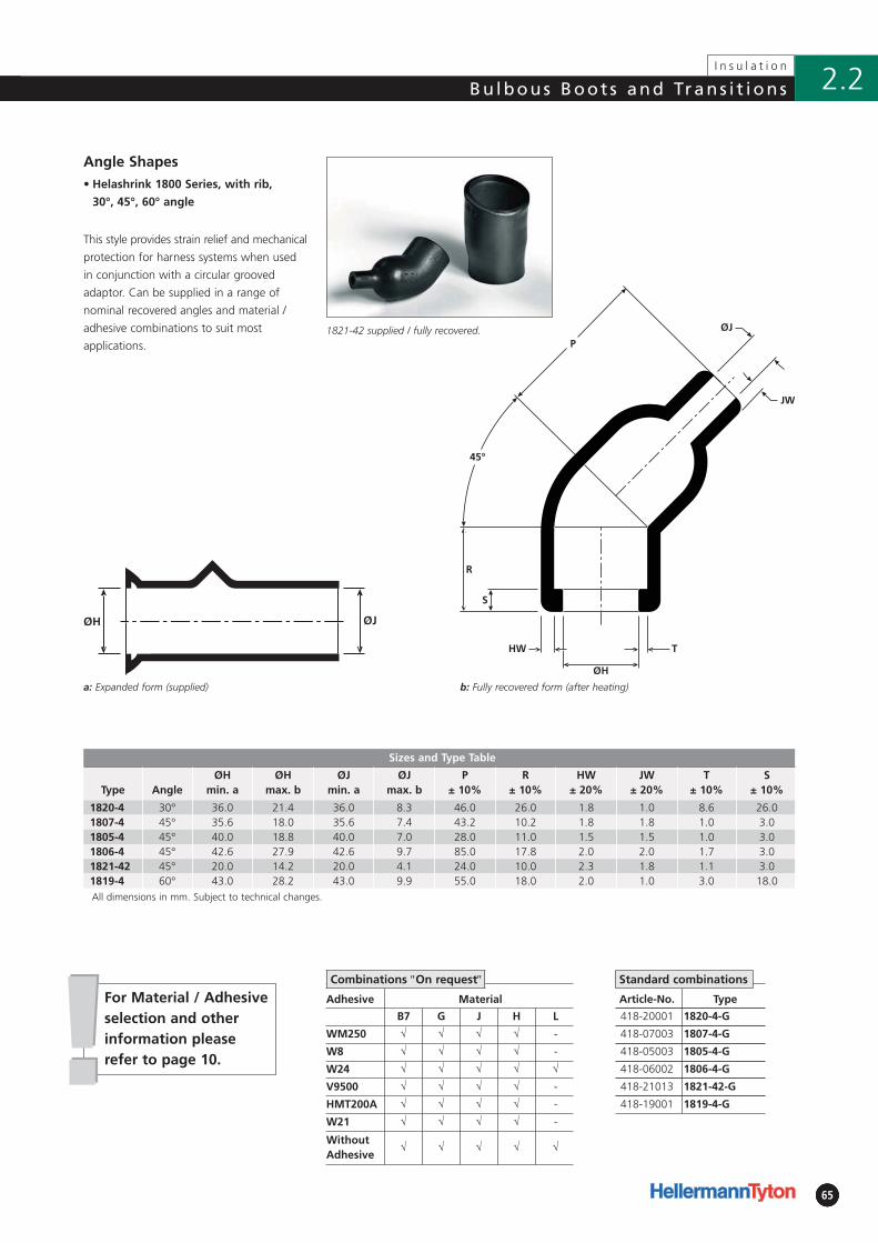
!!6565
Bu lbous Boot s and Trans i t ions
65
I n s u l a t i o n
2.2
For Material / Adhesiveselection and otherinformation pleaserefer to page 10.
b: Fully recovered form (after heating)
Adhesive Material
B7 G J H L
WM250 √ √ √ √ -
W8 √ √ √ √ -
W24 √ √ √ √ √
V9500 √ √ √ √ -
HMT200A √ √ √ √ -
W21 √ √ √ √ -
WithoutAdhesive
√ √ √ √ √
• Helashrink 1800 Series, with rib,
30°, 45°, 60° angle
Sizes and Type Table
Type AngleØH
min. aØH
max. bØJ
min. aØJ
max. bP
± 10%R
± 10%HW
± 20%JW
± 20%T
± 10%S
± 10%
1820-4 30° 36.0 21.4 36.0 8.3 46.0 26.0 1.8 1.0 8.6 26.01807-4 45° 35.6 18.0 35.6 7.4 43.2 10.2 1.8 1.8 1.0 3.01805-4 45° 40.0 18.8 40.0 7.0 28.0 11.0 1.5 1.5 1.0 3.01806-4 45° 42.6 27.9 42.6 9.7 85.0 17.8 2.0 2.0 1.7 3.01821-42 45° 20.0 14.2 20.0 4.1 24.0 10.0 2.3 1.8 1.1 3.01819-4 60° 43.0 28.2 43.0 9.9 55.0 18.0 2.0 1.0 3.0 18.0All dimensions in mm. Subject to technical changes.
ØH ØJ
Article-No. Type
418-20001 1820-4-G
418-07003 1807-4-G
418-05003 1805-4-G
418-06002 1806-4-G
418-21013 1821-42-G
418-19001 1819-4-G
Angle Shapes
This style provides strain relief and mechanical
protection for harness systems when used
in conjunction with a circular grooved
adaptor. Can be supplied in a range of
nominal recovered angles and material /
adhesive combinations to suit most
applications.1821-42 supplied / fully recovered.
a: Expanded form (supplied)
Standard combinationsCombinations ″On request″
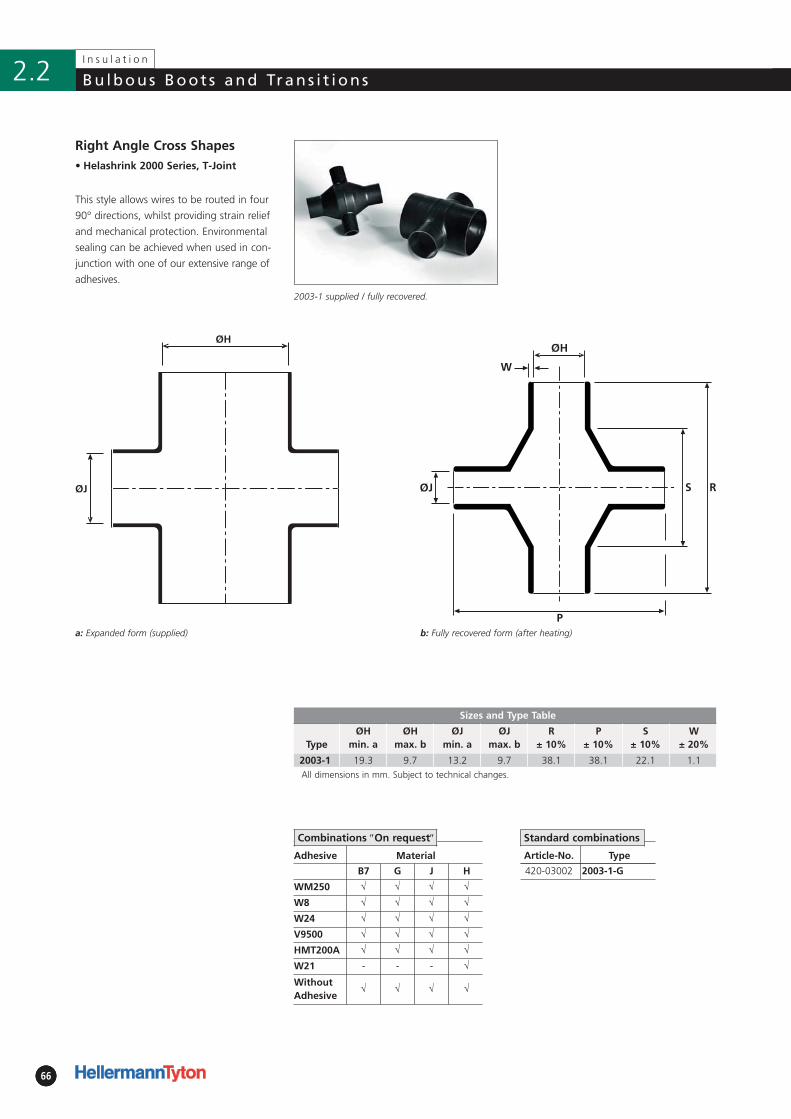
666666
I n s u l a t i o n
Bu lbous Boot s and Trans i t ions2.2
b: Fully recovered form (after heating)
Adhesive Material
B7 G J H
WM250 √ √ √ √
W8 √ √ √ √
W24 √ √ √ √
V9500 √ √ √ √
HMT200A √ √ √ √
W21 - - - √
WithoutAdhesive
√ √ √ √
• Helashrink 2000 Series, T-Joint
Sizes and Type Table
TypeØH
min. aØH
max. bØJ
min. aØJ
max. bR
± 10%P
± 10%S
± 10%W
± 20%
2003-1 19.3 9.7 13.2 9.7 38.1 38.1 22.1 1.1All dimensions in mm. Subject to technical changes.
ØJ
ØH
Article-No. Type
420-03002 2003-1-G
Right Angle Cross Shapes
This style allows wires to be routed in four
90° directions, whilst providing strain relief
and mechanical protection. Environmental
sealing can be achieved when used in con-
junction with one of our extensive range of
adhesives.
2003-1 supplied / fully recovered.
a: Expanded form (supplied)
Standard combinationsCombinations ″On request″
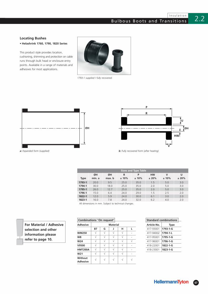
!!6767
Bu lbous Boot s and Trans i t ions
67
I n s u l a t i o n
2.2
For Material / Adhesiveselection and otherinformation pleaserefer to page 10.
b: Fully recovered form (after heating)
Adhesive Material
B7 G J H L
WM250 √ √ √ √ -
W8 √ √ √ √ -
W24 √ √ √ √ √
V9500 √ √ √ √ -
HMT200A √ √ √ √ -
W21 √ √ √ √ -
WithoutAdhesive
√ √ √ √ √
• Helashrink 1760, 1790, 1820 Series
ØH
Article-No. Type
417-93001 1793-1-G
417-94002 1794-1-L
417-95001 1795-1-G
417-96001 1796-1-G
418-22001 1822-1-G
418-23001 1823-1-G
Locating Bushes
This product style provides location,
cushioning, shimming and protection on cable
runs through bulk head or enclosure entry
points. Available in a range of materials and
adhesives for most applications.
1793-1 supplied / fully recovered.
a: Expanded form (supplied)
Standard combinations
Sizes and Type Table
TypeØH
min. aØH
max. bR
± 10%P
± 10%HW
± 20%V
± 10%U
± 20%
1793-1 20.0 9.5 25.0 35.0 1.5 5.0 3.01794-1 30.0 18.0 25.0 35.0 2.0 5.0 3.01795-1 26.0 12.7 25.0 35.0 2.0 5.0 3.01796-1 15.0 6.4 24.0 29.0 1.5 2.5 2.01822-1 12.0 5.9 24.0 30.0 6.1 3.0 2.01823-1 16.0 7.8 24.0 32.0 6.2 4.0 2.0All dimensions in mm. Subject to technical changes.
Combinations ″On request″
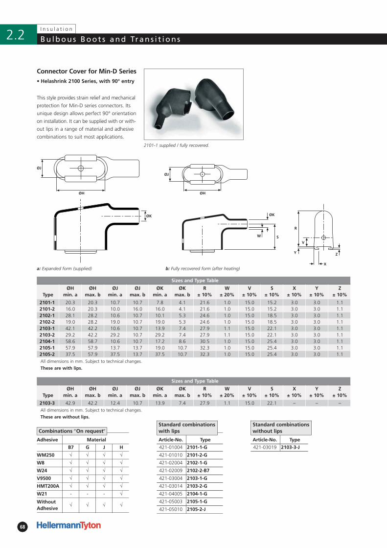
686868
I n s u l a t i o n
Bu lbous Boot s and Trans i t ions2.2
Article-No. Type
421-03019 2103-3-J
Adhesive Material
B7 G J H
WM250 √ √ √ √
W8 √ √ √ √
W24 √ √ √ √
V9500 √ √ √ √
HMT200A √ √ √ √
W21 - - - √
WithoutAdhesive
√ √ √ √
• Helashrink 2100 Series, with 90° entry
Sizes and Type Table
TypeØH
min. aØH
max. bØJ
min. aØJ
max. bØK
min. aØK
max. bR
± 10%W
± 20% V
± 10%S
± 10%X
± 10%Y
± 10%Z
± 10%
2101-1 20.3 20.3 10.7 10.7 7.8 4.1 21.6 1.0 15.0 15.2 3.0 3.0 1.12101-2 16.0 20.3 10.0 16.0 16.0 4.1 21.6 1.0 15.0 15.2 3.0 3.0 1.12102-1 28.1 28.2 10.6 10.7 10.1 5.3 24.6 1.0 15.0 18.5 3.0 3.0 1.12102-2 19.0 28.2 19.0 10.7 19.0 5.3 24.6 1.0 15.0 18.5 3.0 3.0 1.12103-1 42.1 42.2 10.6 10.7 13.9 7.4 27.9 1.1 15.0 22.1 3.0 3.0 1.12103-2 29.2 42.2 29.2 10.7 29.2 7.4 27.9 1.1 15.0 22.1 3.0 3.0 1.12104-1 58.6 58.7 10.6 10.7 17.2 8.6 30.5 1.0 15.0 25.4 3.0 3.0 1.12105-1 57.9 57.9 13.7 13.7 19.0 10.7 32.3 1.0 15.0 25.4 3.0 3.0 1.12105-2 37.5 57.9 37.5 13.7 37.5 10.7 32.3 1.0 15.0 25.4 3.0 3.0 1.1All dimensions in mm. Subject to technical changes.
These are with lips.
Article-No. Type
421-01004 2101-1-G
421-01010 2101-2-G
421-02004 2102-1-G
421-02009 2102-2-B7
421-03004 2103-1-G
421-03014 2103-2-G
421-04005 2104-1-G
421-05003 2105-1-G
421-05010 2105-2-J
Connector Cover for Min-D Series
2101-1 supplied / fully recovered.
Standard combinationswith lips
Standard combinations without lips
Sizes and Type Table
TypeØH
min. aØH
max. bØJ
min. aØJ
max. bØK
min. aØK
max. bR
± 10%W
± 20% V
± 10%S
± 10%X
± 10%Y
± 10%Z
± 10%
2103-3 42.9 42.2 12.4 10.7 13.9 7.4 27.9 1.1 15.0 22.1 – – –All dimensions in mm. Subject to technical changes.
These are without lips.
Combinations ″On request″
W S
ØK
ØH
ØJ
ØK
b: Fully recovered form (after heating)
R
Y
V
Z
X
ØJ
ØH
a: Expanded form (supplied)
This style provides strain relief and mechanical
protection for Min-D series connectors. Its
unique design allows perfect 90° orientation
on installation. It can be supplied with or with -
out lips in a range of material and adhesive
combinations to suit most applications.

3.1 Breakout Boots and End Caps2-Way Outlet Shapes, Breakout Boots• Helashrink 200 Series, in line, low voltage 703-Way Outlet Shapes, Breakout Boots• Helashrink 300 Series, in line, low voltage 714-Way Outlet Shapes, Breakout Boots• Helashrink 400 Series, in line, low voltage 72End Caps• Helashrink 1600 Series, low voltage 73Pinched End Caps• Helashrink PEC Series, low voltage 74
3.2 Heat Shrinkable TubingHeat Shrinkable Tubing 2:1 - Fluororubber• Viton®-E 75Heat Shrinkable Tubing 2:1 - Elastomer• SE28 76• TE28 - light weight 77Heat Shrinkable Tubing up to 4:1 - 1 m lengths• MU47 - medium wall unlined 78• MA47 - medium wall adhesive lined
3.3 Adaptor SpringsConstant Force Spring Adaptor• Zetalok 79
3.4 AdhesivesTwo-component Adhesive for Heat Shrinkable Tubing and Shapes• V9500 Dosing Gun 80Hot Melt Tape for Heat Shrinkable Tubing and Shapes• HMT200A 81High Temperature Hot Melt Adhesive Tape for Low Profile Products• TSA 200 82
3
C a b l e M a n a g e m e n t P r o d u c t s
Page
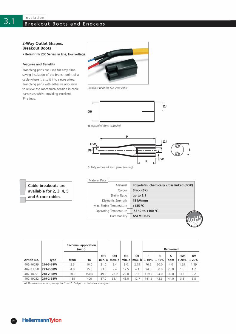
!!
70
I n s u l a t i o n
Breakout Boot s and Endcaps3.1
2-Way Outlet Shapes, Breakout Boots
Features and Benefits
Branching parts are used for easy, time-
saving insulation of the branch point of a
cable where it is split into single wires.
Branching parts with adhesive also serve
to relieve the mechanical tension in cable
harnesses whilst providing excellent
IP ratings.
Breakout boot for two-core cable.
• Helashrink 200 Series, in line, low voltage
Material Polyolefin, chemically cross linked (POX)
Colour Black (BK)
Shrink Ratio up to 3:1
Dielectric Strength 15 kV/mm
Min. Shrink Temperature +135 °C
Operating Temperature -55 °C to +100 °C
Flammability ASTM D635
Article-No. Type
Recomm. application(mm²)
ØH min. a
ØH max. b
ØJ min. a
ØJ max. b
Recovered
from toP
± 10%R
± 10%S
nomHW
± 20%JW
± 20%
402-16039 216-3-B8W 2.5 10.0 21.0 9.4 9.0 2.79 76.5 20.0 4.0 1.59 1.59
402-23058 223-2-B8W 4.0 35.0 33.0 9.4 17.5 4.1 94.0 30.0 20.0 1.5 1.2
402-18051 218-2-B8W 50.0 150.0 49.0 22.9 20.0 7.6 119.0 34.0 30.0 3.2 3.2
402-19032 219-2-B8W 185 400 87.0 38.1 43.0 12.7 141.5 42.5 44.0 3.8 3.8
All Dimensions in mm, except for ″mm²″. Subject to technical changes.
S
Cable breakouts areavailable for 2, 3, 4, 5and 6 core cables.
a: Expanded form (supplied)
b: Fully recovered form (after heating)
�
Material Data
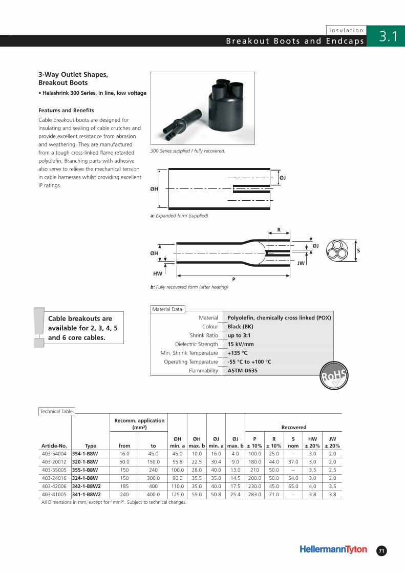
!!
71
I n s u l a t i o n
3.1Breakout Boot s and Endcaps
Features and Benefits
Cable breakout boots are designed for
insulating and sealing of cable crutches and
provide excellent resistance from abrasion
and weathering. They are manufactured
from a tough cross-linked flame retarded
polyolefin, Branching parts with adhesive
also serve to relieve the mechanical tension
in cable harnesses whilst providing excellent
IP ratings.
300 Series supplied / fully recovered.
Article-No. Type
Recomm. application(mm²)
ØH min. a
ØH max. b
ØJ min. a
ØJ max. b
Recovered
from toP
± 10%R
± 10%S
nomHW
± 20%JW
± 20%
403-54004 354-1-B8W 16.0 45.0 45.0 10.0 16.0 4.0 100.0 25.0 – 3.0 2.0
403-20012 320-1-B8W 50.0 150.0 55.8 22.5 30.4 9.0 180.0 44.0 37.0 3.0 2.0
403-55005 355-1-B8W 150 240 100.0 28.0 40.0 13.0 210 50.0 – 3.5 2.5
403-24016 324-1-B8W 150 300.0 90.0 35.5 35.0 14.5 200.0 50.0 54.0 3.0 2.0
403-42006 342-1-B8W2 185 400 110.0 35.0 40.0 17.5 230.0 45.0 65.0 4.0 3.5
403-41005 341-1-B8W2 240 400.0 125.0 59.0 50.8 25.4 283.0 71.0 – 3.8 3.8
All Dimensions in mm, except for ″mm²″. Subject to technical changes.
3-Way Outlet Shapes, Breakout Boots• Helashrink 300 Series, in line, low voltage
Material Polyolefin, chemically cross linked (POX)
Colour Black (BK)
Shrink Ratio up to 3:1
Dielectric Strength 15 kV/mm
Min. Shrink Temperature +135 °C
Operating Temperature -55 °C to +100 °C
Flammability ASTM D635
S
Technical Table
a: Expanded form (supplied)
b: Fully recovered form (after heating)
Cable breakouts areavailable for 2, 3, 4, 5and 6 core cables.
Material Data
�
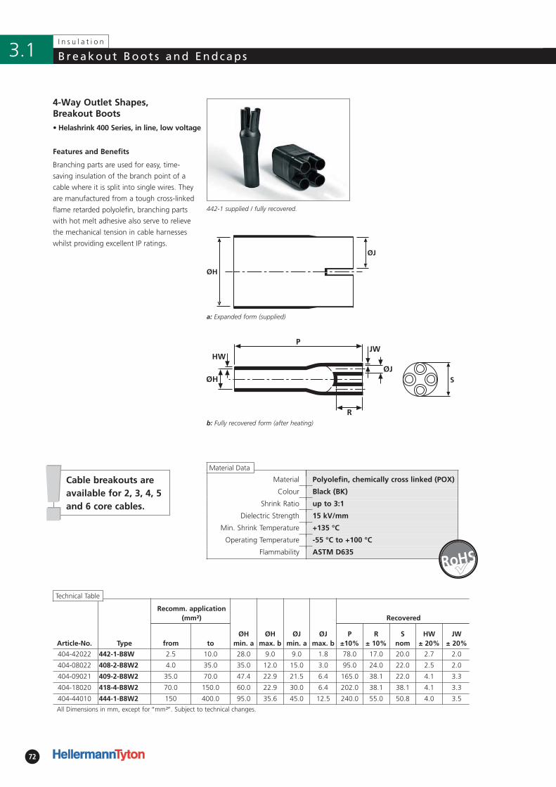
72
I n s u l a t i o n
Breakout Boot s and Endcaps3.1
Article-No. Type
Recomm. application(mm²)
ØHmin. a
ØHmax. b
ØJmin. a
ØJmax. b
Recovered
from toP
±10%R
± 10%S
nomHW
± 20%JW
± 20%
404-42022 442-1-B8W 2.5 10.0 28.0 9.0 9.0 1.8 78.0 17.0 20.0 2.7 2.0
404-08022 408-2-B8W2 4.0 35.0 35.0 12.0 15.0 3.0 95.0 24.0 22.0 2.5 2.0
404-09021 409-2-B8W2 35.0 70.0 47.4 22.9 21.5 6.4 165.0 38.1 22.0 4.1 3.3
404-18020 418-4-B8W2 70.0 150.0 60.0 22.9 30.0 6.4 202.0 38.1 38.1 4.1 3.3
404-44010 444-1-B8W2 150 400.0 95.0 35.6 45.0 12.5 240.0 55.0 50.8 4.0 3.5
All Dimensions in mm, except for ″mm²″. Subject to technical changes.
• Helashrink 400 Series, in line, low voltage
4-Way Outlet Shapes, Breakout Boots
Features and Benefits
Branching parts are used for easy, time-
saving insulation of the branch point of a
cable where it is split into single wires. They
are manufactured from a tough cross-linked
flame retarded polyolefin, branching parts
with hot melt adhesive also serve to relieve
the mechanical tension in cable harnesses
whilst providing excellent IP ratings.
442-1 supplied / fully recovered.
Material Polyolefin, chemically cross linked (POX)
Colour Black (BK)
Shrink Ratio up to 3:1
Dielectric Strength 15 kV/mm
Min. Shrink Temperature +135 °C
Operating Temperature -55 °C to +100 °C
Flammability ASTM D635
Technical Table
S
ØH
ØJ
a: Expanded form (supplied)
b: Fully recovered form (after heating)
!!Cable breakouts areavailable for 2, 3, 4, 5and 6 core cables.
�
Material Data
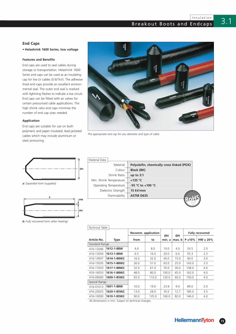
73
I n s u l a t i o n
3.1Breakout Boot s and Endcaps
Article-No. Type
Recomm. applicationØH
min. aØH
max. b
Fully recovered
from to P ±10% HW ± 20%
Standard Range
416-12046 1612-1-B8W 4.0 8.0 10.0 4.0 33.5 2.0
416-13054 1613-1-B8W 6.5 16.0 20.0 6.0 55.3 2.3
416-14047 1614-1-B8W2 16.0 32.0 40.0 15.0 90.0 3.0
416-15035 1615-1-B8W2 26.0 51.0 63.0 25.0 143.0 3.3
416-17033 1617-1-B8W2 32.0 61.0 76.0 30.0 158.0 4.0
416-16053 1616-1-B8W2 48.0 80.0 100.0 45.0 162.0 4.0
416-09000 1609-1-B5W2 65.0 110.0 120.0 60.0 150.0 4.0
Special Range
416-01013 1601-1-B8W 10.0 19.0 23.8 9.4 89.0 2.0
416-20025 1620-1-B5W2 13.0 28.0 35.0 12.7 185.0 3.5
416-10000 1610-1-B5W2 90.0 135.0 160.0 82.0 146.0 4.0
All dimensions in mm. Subject to technical changes.
Material Polyolefin, chemically cross linked (POX)
Colour Black (BK)
Shrink Ratio up to 3:1
Min. Shrink Temperature +135 °C
Operating Temperature -55 °C to +100 °C
Dielectric Strength 15 kV/mm
Flammability ASTM D635
• Helashrink 1600 Series, low voltage
End Caps
The appropriate end cap for any diameter and type of cable.
End caps are used to seal cables during
storage or transportation. Helashrink 1600
Series end caps can be used as an insulating
cap for live LV cables (0.6/1kV). The adhesive
lined end caps provide an excellent environ-
mental seal. The outer end seal is marked
with lightning flashes to indicate a live circuit.
End caps can be fitted with air valves for
certain pressurised cable applications. The
high shrink ratio end caps minimise the
number of end cap sizes needed.
Application
End caps are suitable for use on both
polymeric and paper insulated, lead jacketed
cables which may include aluminium or
steel armouring.
Features and Benefits
Material Data
�
Technical Table
a: Expanded form (supplied)
b: Fully recovered form (after heating)
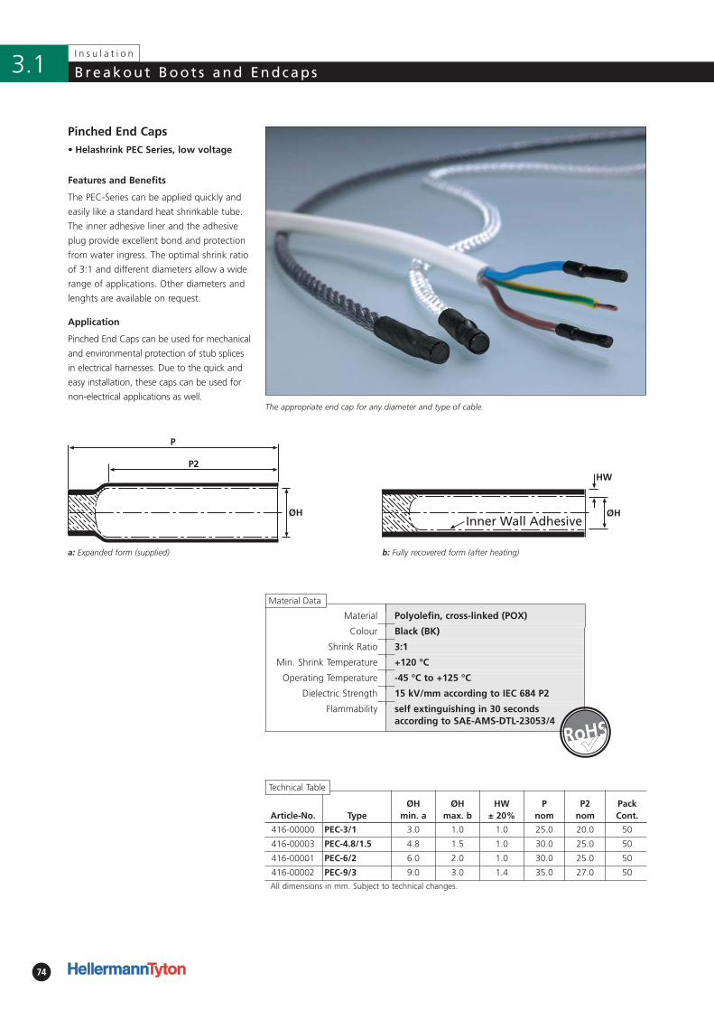
74
I n s u l a t i o n
Breakout Boot s and Endcaps3.1
Article-No. TypeØH
min. aØH
max. bHW
± 20%P
nomP2
nomPackCont.
416-00000 PEC-3/1 3.0 1.0 1.0 25.0 20.0 50
416-00003 PEC-4.8/1.5 4.8 1.5 1.0 30.0 25.0 50
416-00001 PEC-6/2 6.0 2.0 1.0 30.0 25.0 50
416-00002 PEC-9/3 9.0 3.0 1.4 35.0 27.0 50
All dimensions in mm. Subject to technical changes.
Inner Wall Adhesive
HW
H
• Helashrink PEC Series, low voltage
Pinched End Caps
P
P2
H
Material Polyolefin, cross-linked (POX)
Colour Black (BK)
Shrink Ratio 3:1
Min. Shrink Temperature +120 °C
Operating Temperature -45 °C to +125 °C
Dielectric Strength 15 kV/mm according to IEC 684 P2
Flammability self extinguishing in 30 seconds according to SAE-AMS-DTL-23053/4
The appropriate end cap for any diameter and type of cable.
The PEC-Series can be applied quickly and
easily like a standard heat shrinkable tube.
The inner adhesive liner and the adhesive
plug provide excellent bond and protection
from water ingress. The optimal shrink ratio
of 3:1 and different diameters allow a wide
range of applications. Other diameters and
lenghts are available on request.
Application
Pinched End Caps can be used for mechanical
and environmental protection of stub splices
in electrical harnesses. Due to the quick and
easy installation, these caps can be used for
non-electrical applications as well.
Features and Benefits
�
Material Data
a: Expanded form (supplied) b: Fully recovered form (after heating)
Technical Table
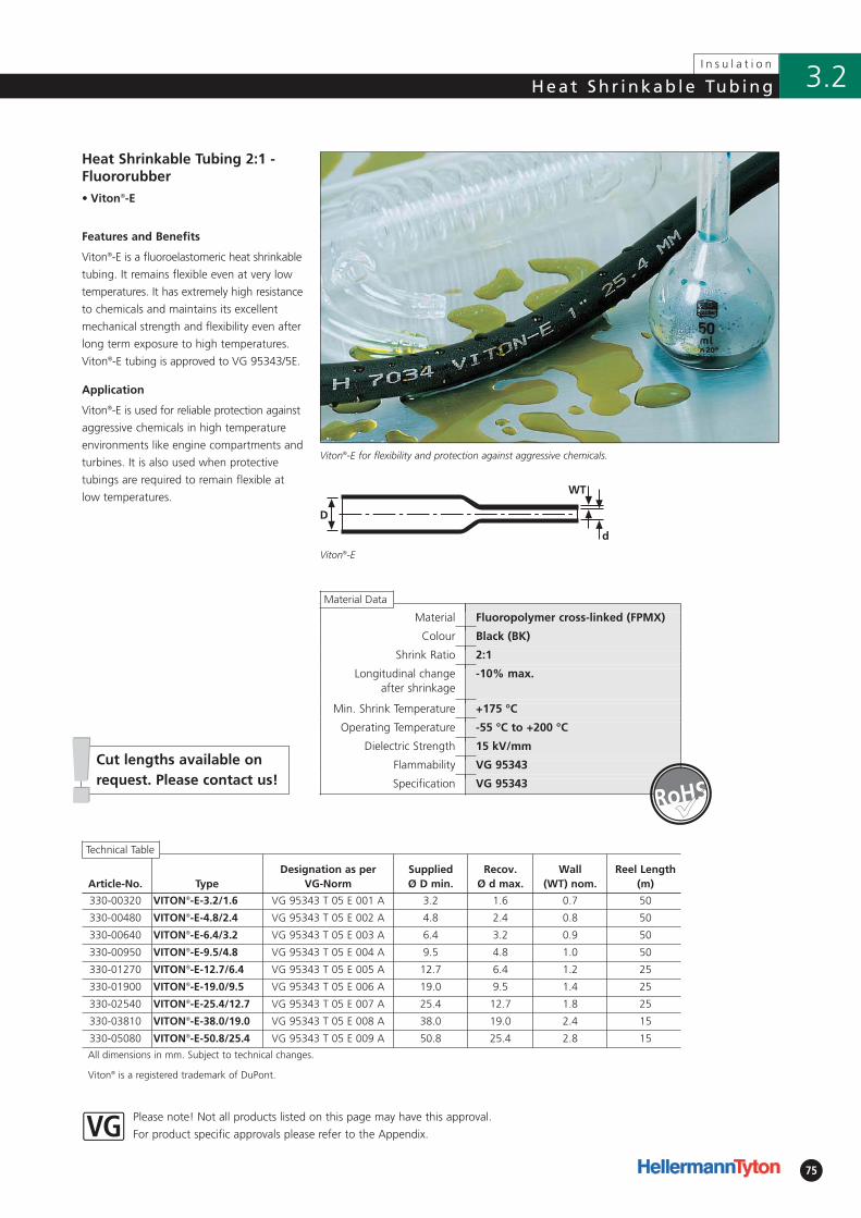
75
!!
Material Fluoropolymer cross-linked (FPMX)
Colour Black (BK)
Shrink Ratio 2:1
Longitudinal change after shrinkage
-10% max.
Min. Shrink Temperature +175 °C
Operating Temperature -55 °C to +200 °C
Dielectric Strength 15 kV/mm
Flammability VG 95343
Specification VG 95343
Please note! Not all products listed on this page may have this approval.
For product specific approvals please refer to the Appendix.
• Viton®-E
Cut lengths available onrequest. Please contact us!
Article-No. TypeDesignation as per
VG-NormSupplied Ø D min.
Recov. Ø d max.
Wall (WT) nom.
Reel Length(m)
330-00320 VITON®-E-3.2/1.6 VG 95343 T 05 E 001 A 3.2 1.6 0.7 50
330-00480 VITON®-E-4.8/2.4 VG 95343 T 05 E 002 A 4.8 2.4 0.8 50
330-00640 VITON®-E-6.4/3.2 VG 95343 T 05 E 003 A 6.4 3.2 0.9 50
330-00950 VITON®-E-9.5/4.8 VG 95343 T 05 E 004 A 9.5 4.8 1.0 50
330-01270 VITON®-E-12.7/6.4 VG 95343 T 05 E 005 A 12.7 6.4 1.2 25
330-01900 VITON®-E-19.0/9.5 VG 95343 T 05 E 006 A 19.0 9.5 1.4 25
330-02540 VITON®-E-25.4/12.7 VG 95343 T 05 E 007 A 25.4 12.7 1.8 25
330-03810 VITON®-E-38.0/19.0 VG 95343 T 05 E 008 A 38.0 19.0 2.4 15
330-05080 VITON®-E-50.8/25.4 VG 95343 T 05 E 009 A 50.8 25.4 2.8 15
All dimensions in mm. Subject to technical changes.
Viton® is a registered trademark of DuPont.
D
d
WT
Viton®-E for flexibility and protection against aggressive chemicals.
Viton®-E
Heat Shrinkable Tubing 2:1 -Fluororubber
Viton®-E is a fluoroelastomeric heat shrinkable
tubing. It remains flexible even at very low
temperatures. It has extremely high resistance
to chemicals and maintains its excellent
mechanical strength and flexibility even after
long term exposure to high temperatures.
Viton®-E tubing is approved to VG 95343/5E.
Viton®-E is used for reliable protection against
aggressive chemicals in high temperature
environments like engine compartments and
turbines. It is also used when protective
tubings are required to remain flexible at
low temperatures.
�
Material Data
Technical Table
I n s u l a t i o n
3.2Heat Sh r inkab le Tub ing
Features and Benefits
Application
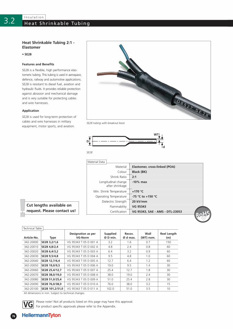
Article-No. TypeDesignation as per
VG-NormSupplied Ø D min.
Recov. Ø d max.
Wall (WT) nom.
Reel Length(m)
342-20000 SE28 3,2/1,6 VG 95343 T 05 D 001 A 3.2 1.6 0.7 150
342-20010 SE28 4,8/2,4 VG 95343 T 05 D 002 A 4.8 2.4 0.8 60
342-20020 SE28 6,4/3,2 VG 95343 T 05 D 003 A 6.4 3.2 0.9 60
342-20030 SE28 9,5/4,8 VG 95343 T 05 D 004 A 9.5 4.8 1.0 60
342-20040 SE28 12,7/6,4 VG 95343 T 05 D 005 A 12.7 6.4 1.2 60
342-20050 SE28 19,0/9,5 VG 95343 T 05 D 006 A 19.0 9.5 1.4 30
342-20060 SE28 25,4/12,7 VG 95343 T 05 D 007 A 25.4 12.7 1.8 30
342-20070 SE28 38,0/19,0 VG 95343 T 05 D 008 A 38.0 19.0 2.4 30
342-20080 SE28 51,0/25,4 VG 95343 T 05 D 009 A 51.0 25.4 2.8 30
342-20090 SE28 76,0/38,0 VG 95343 T 05 D 010 A 76.0 38.0 3.2 15
342-20100 SE28 101,2/51,0 VG 95343 T 05 D 011 A 102.0 51.0 3.5 10
All dimensions in mm. Subject to technical changes.
Material Elastomer, cross-linked (POA)
Colour Black (BK)
Shrink Ratio 2:1
Longitudinal change after shrinkage
-10% max
Min. Shrink Temperature +170 °C
Operating Temperature -75 °C to +150 °C
Dielectric Strength 20 kV/mm
Flammability VG 95343
Certification VG 95343, SAE - AMS - DTL-23053
76
I n s u l a t i o n
Heat Sh r inkab le Tub ing3.2
!!Cut lengths available onrequest. Please contact us!
Please note! Not all products listed on this page may have this approval.
For product specific approvals please refer to the Appendix.
• SE28
Heat Shrinkable Tubing 2:1 -Elastomer
Features and Benefits
SE28 is a flexible, high performance elas-
tomeric tubing. This tubing is used in aerospace,
defence, railway and automotive applications.
SE28 is resistant to diesel fuel, aviation and
hydraulic fluids. It provides reliable protection
against abrasion and mechanical damage
and is very suitable for protecting cables
and wire harnesses.
Application
SE28 is used for long-term protection of
cables and wire harnesses in military
equipment, motor sports, and aviation.
D
d
WT
SE28 tubing with breakout boot.
SE28
Material Data
Technical Table
�
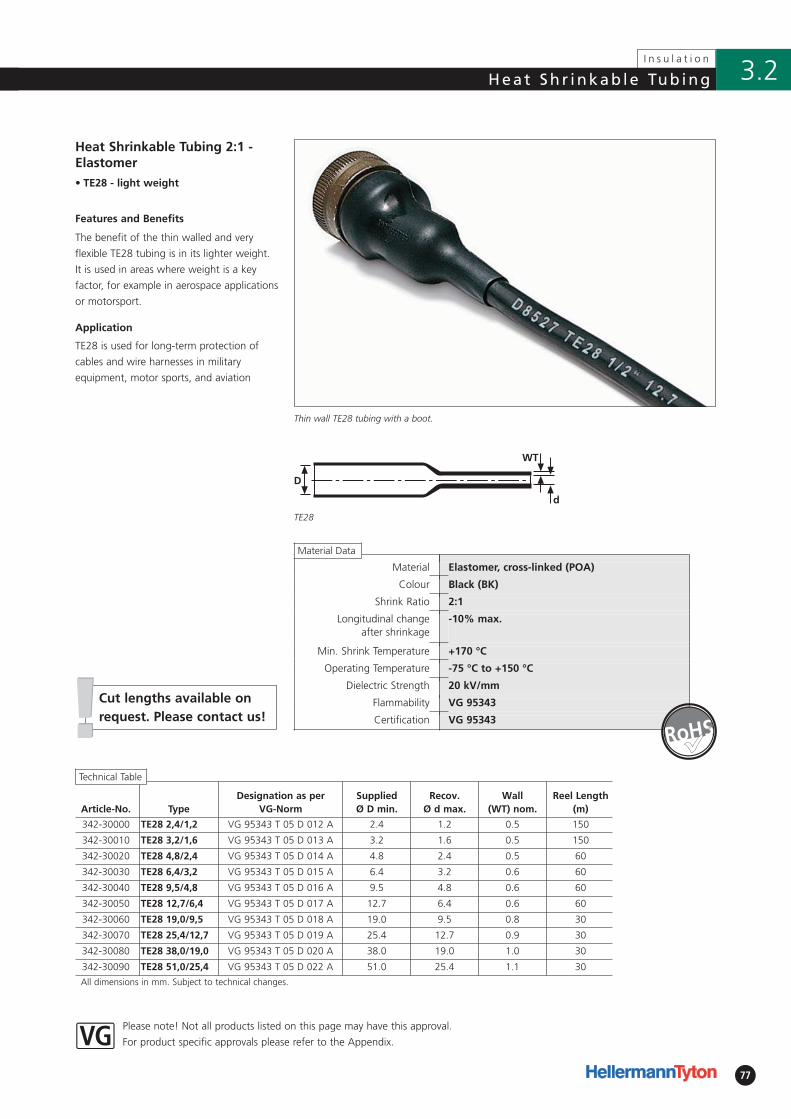
Article-No. TypeDesignation as per
VG-NormSupplied Ø D min.
Recov. Ø d max.
Wall (WT) nom.
Reel Length(m)
342-30000 TE28 2,4/1,2 VG 95343 T 05 D 012 A 2.4 1.2 0.5 150
342-30010 TE28 3,2/1,6 VG 95343 T 05 D 013 A 3.2 1.6 0.5 150
342-30020 TE28 4,8/2,4 VG 95343 T 05 D 014 A 4.8 2.4 0.5 60
342-30030 TE28 6,4/3,2 VG 95343 T 05 D 015 A 6.4 3.2 0.6 60
342-30040 TE28 9,5/4,8 VG 95343 T 05 D 016 A 9.5 4.8 0.6 60
342-30050 TE28 12,7/6,4 VG 95343 T 05 D 017 A 12.7 6.4 0.6 60
342-30060 TE28 19,0/9,5 VG 95343 T 05 D 018 A 19.0 9.5 0.8 30
342-30070 TE28 25,4/12,7 VG 95343 T 05 D 019 A 25.4 12.7 0.9 30
342-30080 TE28 38,0/19,0 VG 95343 T 05 D 020 A 38.0 19.0 1.0 30
342-30090 TE28 51,0/25,4 VG 95343 T 05 D 022 A 51.0 25.4 1.1 30
All dimensions in mm. Subject to technical changes.
-10% max.
Material Elastomer, cross-linked (POA)
Colour Black (BK)
Shrink Ratio 2:1
Longitudinal change after shrinkage
Min. Shrink Temperature +170 °C
Operating Temperature -75 °C to +150 °C
Dielectric Strength 20 kV/mm
Flammability VG 95343
Certification VG 95343
77
I n s u l a t i o n
3.2Heat Sh r inkab le Tub ing
!!Cut lengths available onrequest. Please contact us!
Please note! Not all products listed on this page may have this approval.
For product specific approvals please refer to the Appendix.
• TE28 - light weight
Features and Benefits
Heat Shrinkable Tubing 2:1 -Elastomer
The benefit of the thin walled and very
flexible TE28 tubing is in its lighter weight.
It is used in areas where weight is a key
factor, for example in aerospace applications
or motorsport.
Application
TE28 is used for long-term protection of
cables and wire harnesses in military
equipment, motor sports, and aviation
D
d
WT
TE28
Thin wall TE28 tubing with a boot.
�Technical Table
Material Data
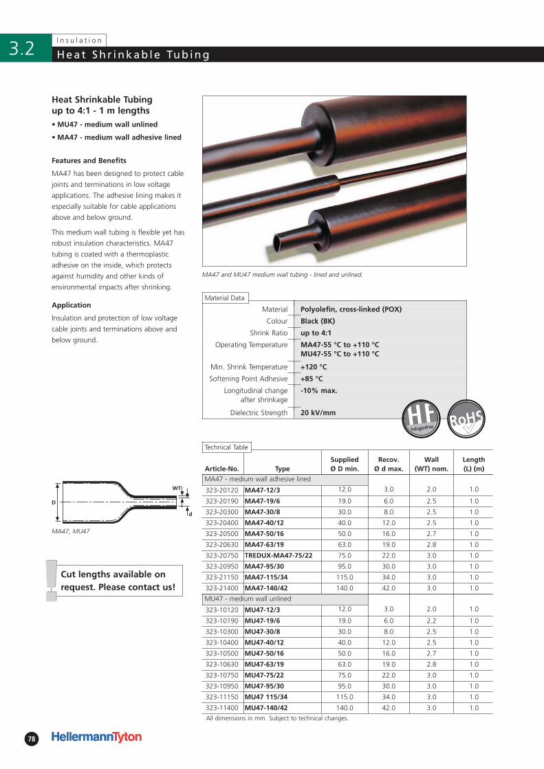
78
I n s u l a t i o n
Heat Sh r inkab le Tub ing3.2
!!
Material Polyolefin, cross-linked (POX)
Colour Black (BK)
Shrink Ratio up to 4:1
Operating Temperature MA47-55 °C to +110 °CMU47-55 °C to +110 °C
Min. Shrink Temperature +120 °C
Softening Point Adhesive +85 °C
Longitudinal change after shrinkage
-10% max.
Dielectric Strength 20 kV/mm
• MU47 - medium wall unlined
• MA47 - medium wall adhesive lined
Application
Insulation and protection of low voltage
cable joints and terminations above and
below ground.
D
d
WT
Article-No. TypeSupplied Ø D min.
Recov. Ø d max.
Wall (WT) nom.
Length (L) (m)
MA47 - medium wall adhesive lined
323-20120 MA47-12/3 12.0 3.0 2.0 1.0
323-20190 MA47-19/6 19.0 6.0 2.5 1.0
323-20300 MA47-30/8 30.0 8.0 2.5 1.0
323-20400 MA47-40/12 40.0 12.0 2.5 1.0
323-20500 MA47-50/16 50.0 16.0 2.7 1.0
323-20630 MA47-63/19 63.0 19.0 2.8 1.0
323-20750 TREDUX-MA47-75/22 75.0 22.0 3.0 1.0
323-20950 MA47-95/30 95.0 30.0 3.0 1.0
323-21150 MA47-115/34 115.0 34.0 3.0 1.0
323-21400 MA47-140/42 140.0 42.0 3.0 1.0
MU47 - medium wall unlined
323-10120 MU47-12/3 12.0 3.0 2.0 1.0
323-10190 MU47-19/6 19.0 6.0 2.2 1.0
323-10300 MU47-30/8 30.0 8.0 2.5 1.0
323-10400 MU47-40/12 40.0 12.0 2.5 1.0
323-10500 MU47-50/16 50.0 16.0 2.7 1.0
323-10630 MU47-63/19 63.0 19.0 2.8 1.0
323-10750 MU47-75/22 75.0 22.0 3.0 1.0
323-10950 MU47-95/30 95.0 30.0 3.0 1.0
323-11150 MU47 115/34 115.0 34.0 3.0 1.0
323-11400 MU47-140/42 140.0 42.0 3.0 1.0
All dimensions in mm. Subject to technical changes.
Cut lengths available onrequest. Please contact us!
Heat Shrinkable Tubing up to 4:1 - 1 m lengths
Features and Benefits
MA47 and MU47 medium wall tubing - lined and unlined.
MA47 has been designed to protect cable
joints and terminations in low voltage
applications. The adhesive lining makes it
especially suitable for cable applications
above and below ground.
This medium wall tubing is flexible yet has
robust insulation characteristics. MA47
tubing is coated with a thermoplastic
adhesive on the inside, which protects
against humidity and other kinds of
environmental impacts after shrinking.
Technical Table
halogenfree �
Material Data
MA47, MU47
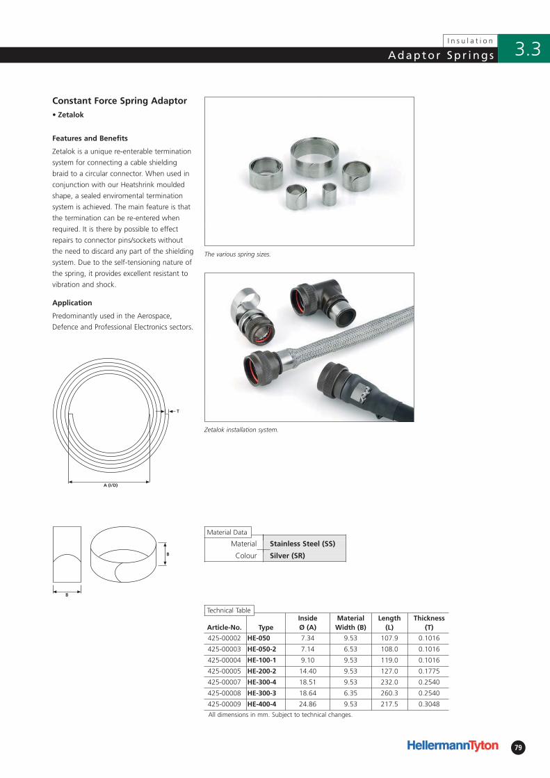
79
I n s u l a t i o n
3.3Adaptor Sp r ings
A (I/D)
T
B
B
Material Stainless Steel (SS)
Colour Silver (SR)
Constant Force Spring Adaptor• Zetalok
Features and Benefits
Zetalok is a unique re-enterable termination
system for connecting a cable shielding
braid to a circular connector. When used in
conjunction with our Heatshrink moulded
shape, a sealed enviromental termination
system is achieved. The main feature is that
the termination can be re-entered when
required. It is there by possible to effect
repairs to connector pins/sockets without
the need to discard any part of the shielding
system. Due to the self-tensioning nature of
the spring, it provides excellent resistant to
vibration and shock.
Application
Predominantly used in the Aerospace,
Defence and Professional Electronics sectors.
Article-No. TypeInside Ø (A)
MaterialWidth (B)
Length (L)
Thickness(T)
425-00002 HE-050 7.34 9.53 107.9 0.1016
425-00003 HE-050-2 7.14 6.53 108.0 0.1016
425-00004 HE-100-1 9.10 9.53 119.0 0.1016
425-00005 HE-200-2 14.40 9.53 127.0 0.1775
425-00007 HE-300-4 18.51 9.53 232.0 0.2540
425-00008 HE-300-3 18.64 6.35 260.3 0.2540
425-00009 HE-400-4 24.86 9.53 217.5 0.3048
All dimensions in mm. Subject to technical changes.
Zetalok installation system.
The various spring sizes.
Material Data
Technical Table
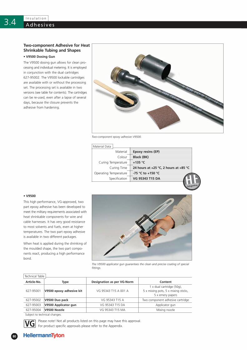
8080
I n s u l a t i o n
Adhes i ve s3.4
Material Epoxy resins (EP)
Colour Black (BK)
Curing Temperature +135 °C
Curing Time 24 hours at +25 °C, 2 hours at +85 °C
Operating Temperature -75 °C to +150 °C
Specification VG 95343 T15 DA
Please note! Not all products listed on this page may have this approval.
For product specific approvals please refer to the Appendix.
• V9500 Dosing Gun
The V9500 dosing gun allows for clean pro-
cessing and individual metering. It is employed
in conjunction with the dual cartridges
627-95002. The V9500 lockable cartridges
are available with or without the processing
set. The processing set is available in two
versions (see table for contents). The cartridges
can be re-used, even after a lapse of several
days, because the closure prevents the
adhesive from hardening.
The V9500 applicator gun guarantees the clean and precise coating of specialfittings.
Article-No. Type Designation as per VG-Norm Content
627-95001 V9500 epoxy adhesive kit VG 95343 T15 A 001 A1 x dual cartridge (50g),
5 x mixing pots, 5 x mixing sticks, 5 x emery papers
627-95002 V9500 Duo pack VG 95343 T15 A Two component adhesive cartridge
627-95003 V9500 Applicator gun VG 95343 T15 DA Applicator gun
627-95004 V9500 Nozzle VG 95343 T15 MA Mixing nozzle
Subject to technical changes.
• V9500
Two-component epoxy adhesive V9500.
Two-component Adhesive for HeatShrinkable Tubing and Shapes
This high performance, VG-approved, two
part epoxy adhesive has been developed to
meet the military requirements associated with
heat shrinkable components for wire and
cable harnesses. It has very good resistance
to most solvents and fuels, even at higher
temperatures. The two part epoxy adhesive
is available in two different packages.
When heat is applied during the shrinking of
the moulded shape, the two part compo-
nents react, producing a high performance
bond.
Technical Table
Material Data
halogenfree
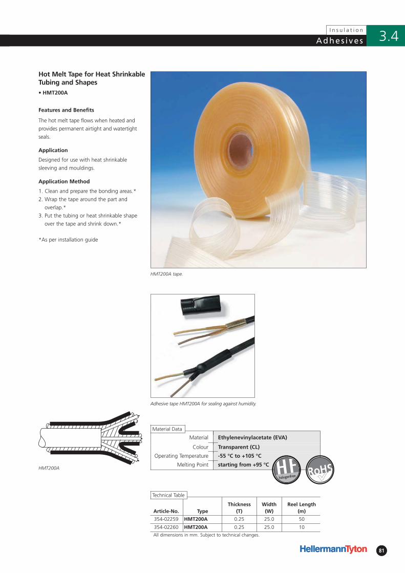
81
Adhes i ve s
81
I n s u l a t i o n
3.4
• HMT200A
HMT200A tape.
Application
Designed for use with heat shrinkable
sleeving and mouldings.
Material Ethylenevinylacetate (EVA)
Colour Transparent (CL)
Operating Temperature -55 °C to +105 °C
Melting Point starting from +95 °C
Adhesive tape HMT200A for sealing against humidity.
Hot Melt Tape for Heat ShrinkableTubing and Shapes
Features and Benefits
The hot melt tape flows when heated and
provides permanent airtight and watertight
seals.
Application Method
1. Clean and prepare the bonding areas.*
2. Wrap the tape around the part and
overlap.*
3. Put the tubing or heat shrinkable shape
over the tape and shrink down.*
*As per installation guide
HMT200A
Article-No. TypeThickness
(T)Width
(W)Reel Length
(m)
354-02259 HMT200A 0.25 25.0 50
354-02260 HMT200A 0.25 25.0 10
All dimensions in mm. Subject to technical changes.
halogenfree �
Material Data
Technical Table
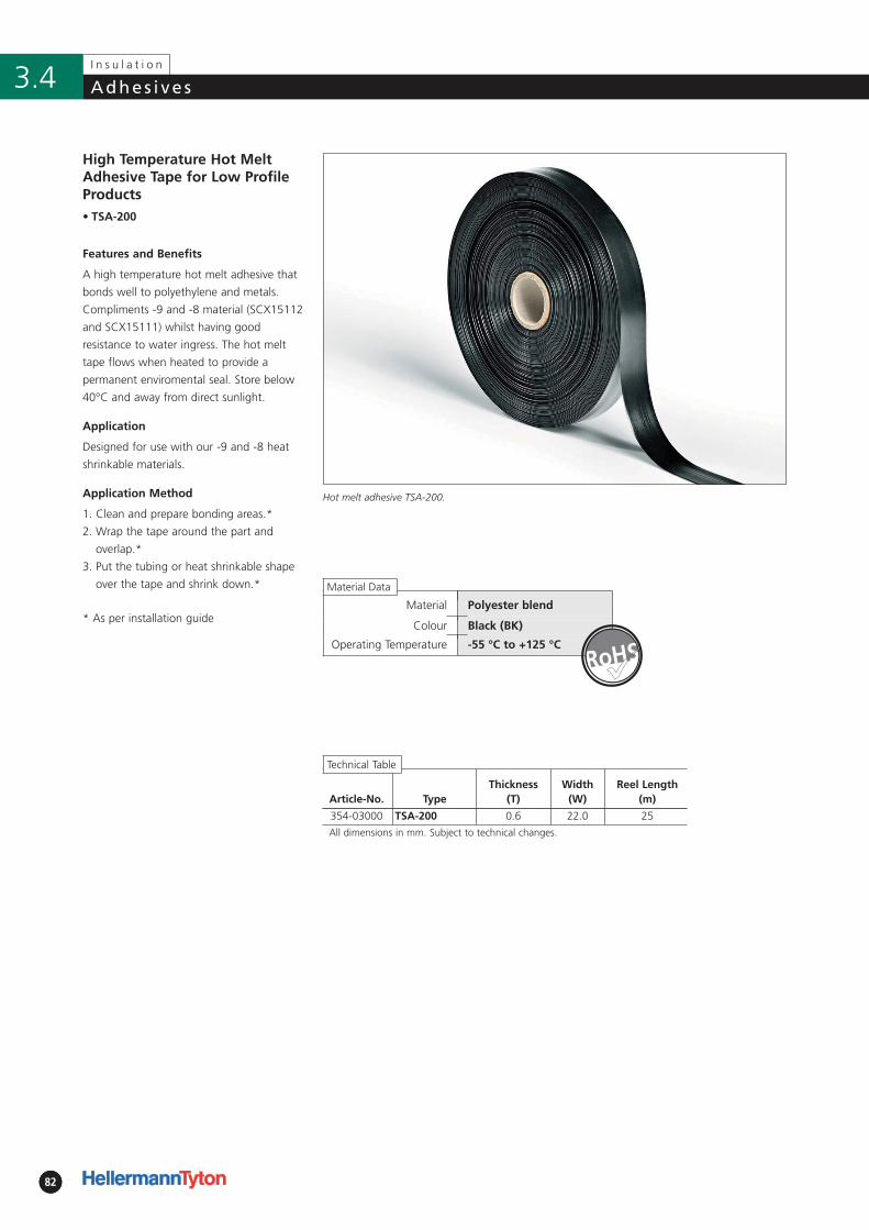
Material Polyester blend
Colour Black (BK)
Operating Temperature -55 °C to +125 °C
8282
I n s u l a t i o n
Adhes i ve s3.4
Article-No. TypeThickness
(T)Width
(W)Reel Length
(m)
354-03000 TSA-200 0.6 22.0 25
All dimensions in mm. Subject to technical changes.
Application
Designed for use with our -9 and -8 heat
shrinkable materials.
Application Method
• TSA-200
Hot melt adhesive TSA-200.
High Temperature Hot MeltAdhesive Tape for Low ProfileProducts
Features and Benefits
A high temperature hot melt adhesive that
bonds well to polyethylene and metals.
Compliments -9 and -8 material (SCX15112
and SCX15111) whilst having good
resistance to water ingress. The hot melt
tape flows when heated to provide a
permanent enviromental seal. Store below
40°C and away from direct sunlight.
Technical Table
1. Clean and prepare bonding areas.*
2. Wrap the tape around the part and
overlap.*
3. Put the tubing or heat shrinkable shape
over the tape and shrink down.*
* As per installation guide
Material Data
�
4.1 HellermannTyton Product StandardsStandards for HellermannTyton Heat Shrinkable Tubing and
Heat Shrinkable Moulded Shapes according to VG Norm 84
Standards for HellermannTyton Heat Shrinkable Tubing 85
VG/MIL Specification Cross Reference 86
HellermannTyton Shapes for use with MIL Connectors 87
MIL Specification Slash Sheet Cross Reference 88
4.2 Terms and Conditions 95
4
A p p e n d i x
Page
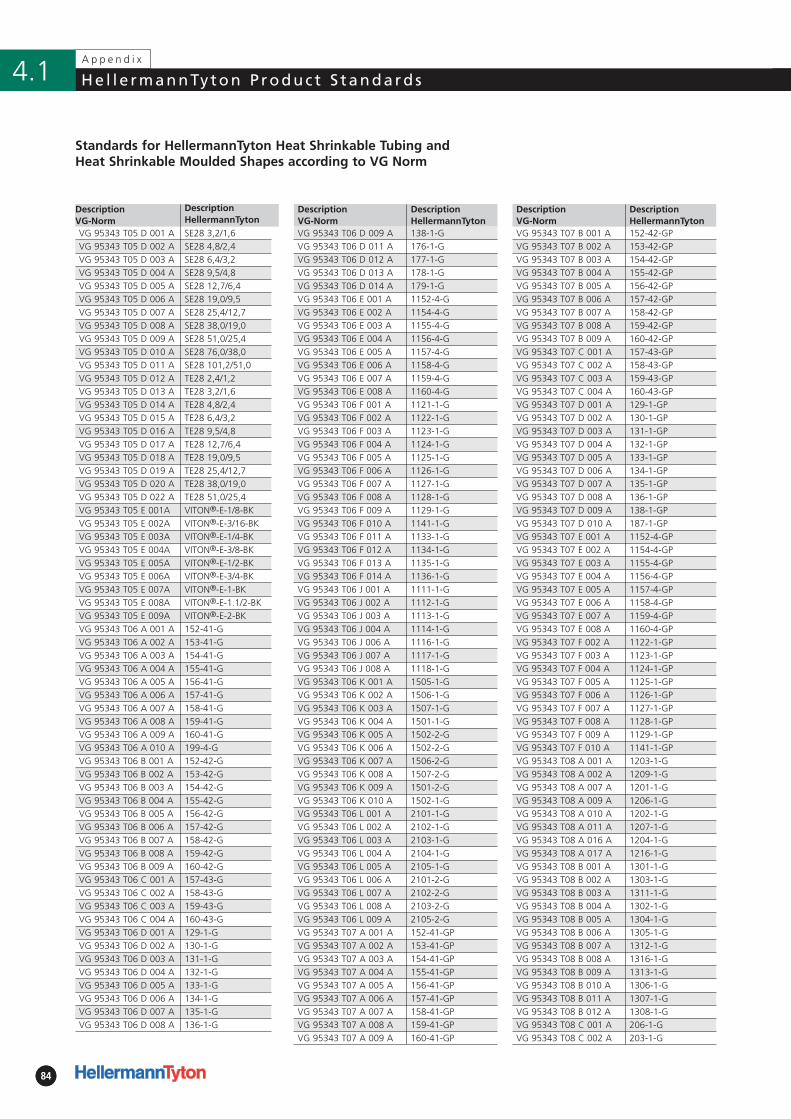
8484
4.1
Standards for HellermannTyton Heat Shrinkable Tubing andHeat Shrinkable Moulded Shapes according to VG Norm
A p p e n d i x
He l l e rmannTyton P roduc t S tandards
Description VG-Norm
DescriptionHellermannTyton
VG 95343 T07 B 001 A 152-42-GPVG 95343 T07 B 002 A 153-42-GPVG 95343 T07 B 003 A 154-42-GPVG 95343 T07 B 004 A 155-42-GPVG 95343 T07 B 005 A 156-42-GPVG 95343 T07 B 006 A 157-42-GPVG 95343 T07 B 007 A 158-42-GPVG 95343 T07 B 008 A 159-42-GPVG 95343 T07 B 009 A 160-42-GPVG 95343 T07 C 001 A 157-43-GPVG 95343 T07 C 002 A 158-43-GPVG 95343 T07 C 003 A 159-43-GPVG 95343 T07 C 004 A 160-43-GPVG 95343 T07 D 001 A 129-1-GPVG 95343 T07 D 002 A 130-1-GPVG 95343 T07 D 003 A 131-1-GPVG 95343 T07 D 004 A 132-1-GPVG 95343 T07 D 005 A 133-1-GPVG 95343 T07 D 006 A 134-1-GPVG 95343 T07 D 007 A 135-1-GPVG 95343 T07 D 008 A 136-1-GPVG 95343 T07 D 009 A 138-1-GPVG 95343 T07 D 010 A 187-1-GPVG 95343 T07 E 001 A 1152-4-GPVG 95343 T07 E 002 A 1154-4-GPVG 95343 T07 E 003 A 1155-4-GPVG 95343 T07 E 004 A 1156-4-GPVG 95343 T07 E 005 A 1157-4-GPVG 95343 T07 E 006 A 1158-4-GPVG 95343 T07 E 007 A 1159-4-GPVG 95343 T07 E 008 A 1160-4-GPVG 95343 T07 F 002 A 1122-1-GPVG 95343 T07 F 003 A 1123-1-GPVG 95343 T07 F 004 A 1124-1-GPVG 95343 T07 F 005 A 1125-1-GPVG 95343 T07 F 006 A 1126-1-GPVG 95343 T07 F 007 A 1127-1-GPVG 95343 T07 F 008 A 1128-1-GPVG 95343 T07 F 009 A 1129-1-GPVG 95343 T07 F 010 A 1141-1-GPVG 95343 T08 A 001 A 1203-1-GVG 95343 T08 A 002 A 1209-1-GVG 95343 T08 A 007 A 1201-1-GVG 95343 T08 A 009 A 1206-1-GVG 95343 T08 A 010 A 1202-1-GVG 95343 T08 A 011 A 1207-1-GVG 95343 T08 A 016 A 1204-1-GVG 95343 T08 A 017 A 1216-1-GVG 95343 T08 B 001 A 1301-1-GVG 95343 T08 B 002 A 1303-1-GVG 95343 T08 B 003 A 1311-1-GVG 95343 T08 B 004 A 1302-1-GVG 95343 T08 B 005 A 1304-1-GVG 95343 T08 B 006 A 1305-1-GVG 95343 T08 B 007 A 1312-1-GVG 95343 T08 B 008 A 1316-1-GVG 95343 T08 B 009 A 1313-1-GVG 95343 T08 B 010 A 1306-1-GVG 95343 T08 B 011 A 1307-1-GVG 95343 T08 B 012 A 1308-1-GVG 95343 T08 C 001 A 206-1-GVG 95343 T08 C 002 A 203-1-G
Description VG-Norm
DescriptionHellermannTyton
VG 95343 T06 D 009 A 138-1-GVG 95343 T06 D 011 A 176-1-GVG 95343 T06 D 012 A 177-1-GVG 95343 T06 D 013 A 178-1-GVG 95343 T06 D 014 A 179-1-GVG 95343 T06 E 001 A 1152-4-GVG 95343 T06 E 002 A 1154-4-GVG 95343 T06 E 003 A 1155-4-GVG 95343 T06 E 004 A 1156-4-GVG 95343 T06 E 005 A 1157-4-GVG 95343 T06 E 006 A 1158-4-GVG 95343 T06 E 007 A 1159-4-GVG 95343 T06 E 008 A 1160-4-GVG 95343 T06 F 001 A 1121-1-GVG 95343 T06 F 002 A 1122-1-GVG 95343 T06 F 003 A 1123-1-GVG 95343 T06 F 004 A 1124-1-GVG 95343 T06 F 005 A 1125-1-GVG 95343 T06 F 006 A 1126-1-GVG 95343 T06 F 007 A 1127-1-GVG 95343 T06 F 008 A 1128-1-GVG 95343 T06 F 009 A 1129-1-GVG 95343 T06 F 010 A 1141-1-GVG 95343 T06 F 011 A 1133-1-GVG 95343 T06 F 012 A 1134-1-GVG 95343 T06 F 013 A 1135-1-GVG 95343 T06 F 014 A 1136-1-GVG 95343 T06 J 001 A 1111-1-GVG 95343 T06 J 002 A 1112-1-GVG 95343 T06 J 003 A 1113-1-GVG 95343 T06 J 004 A 1114-1-GVG 95343 T06 J 006 A 1116-1-GVG 95343 T06 J 007 A 1117-1-GVG 95343 T06 J 008 A 1118-1-GVG 95343 T06 K 001 A 1505-1-GVG 95343 T06 K 002 A 1506-1-GVG 95343 T06 K 003 A 1507-1-GVG 95343 T06 K 004 A 1501-1-GVG 95343 T06 K 005 A 1502-2-GVG 95343 T06 K 006 A 1502-2-GVG 95343 T06 K 007 A 1506-2-GVG 95343 T06 K 008 A 1507-2-GVG 95343 T06 K 009 A 1501-2-GVG 95343 T06 K 010 A 1502-1-GVG 95343 T06 L 001 A 2101-1-GVG 95343 T06 L 002 A 2102-1-GVG 95343 T06 L 003 A 2103-1-GVG 95343 T06 L 004 A 2104-1-GVG 95343 T06 L 005 A 2105-1-GVG 95343 T06 L 006 A 2101-2-GVG 95343 T06 L 007 A 2102-2-GVG 95343 T06 L 008 A 2103-2-GVG 95343 T06 L 009 A 2105-2-GVG 95343 T07 A 001 A 152-41-GPVG 95343 T07 A 002 A 153-41-GPVG 95343 T07 A 003 A 154-41-GPVG 95343 T07 A 004 A 155-41-GPVG 95343 T07 A 005 A 156-41-GPVG 95343 T07 A 006 A 157-41-GPVG 95343 T07 A 007 A 158-41-GPVG 95343 T07 A 008 A 159-41-GPVG 95343 T07 A 009 A 160-41-GP
Description VG-Norm
DescriptionHellermannTyton
VG 95343 T05 D 001 A SE28 3,2/1,6VG 95343 T05 D 002 A SE28 4,8/2,4VG 95343 T05 D 003 A SE28 6,4/3,2VG 95343 T05 D 004 A SE28 9,5/4,8VG 95343 T05 D 005 A SE28 12,7/6,4VG 95343 T05 D 006 A SE28 19,0/9,5VG 95343 T05 D 007 A SE28 25,4/12,7VG 95343 T05 D 008 A SE28 38,0/19,0VG 95343 T05 D 009 A SE28 51,0/25,4VG 95343 T05 D 010 A SE28 76,0/38,0VG 95343 T05 D 011 A SE28 101,2/51,0VG 95343 T05 D 012 A TE28 2,4/1,2VG 95343 T05 D 013 A TE28 3,2/1,6VG 95343 T05 D 014 A TE28 4,8/2,4VG 95343 T05 D 015 A TE28 6,4/3,2VG 95343 T05 D 016 A TE28 9,5/4,8VG 95343 T05 D 017 A TE28 12,7/6,4VG 95343 T05 D 018 A TE28 19,0/9,5VG 95343 T05 D 019 A TE28 25,4/12,7VG 95343 T05 D 020 A TE28 38,0/19,0VG 95343 T05 D 022 A TE28 51,0/25,4VG 95343 T05 E 001A VITON®-E-1/8-BKVG 95343 T05 E 002A VITON®-E-3/16-BKVG 95343 T05 E 003A VITON®-E-1/4-BKVG 95343 T05 E 004A VITON®-E-3/8-BKVG 95343 T05 E 005A VITON®-E-1/2-BKVG 95343 T05 E 006A VITON®-E-3/4-BKVG 95343 T05 E 007A VITON®-E-1-BKVG 95343 T05 E 008A VITON®-E-1.1/2-BKVG 95343 T05 E 009A VITON®-E-2-BKVG 95343 T06 A 001 A 152-41-GVG 95343 T06 A 002 A 153-41-GVG 95343 T06 A 003 A 154-41-GVG 95343 T06 A 004 A 155-41-GVG 95343 T06 A 005 A 156-41-GVG 95343 T06 A 006 A 157-41-GVG 95343 T06 A 007 A 158-41-GVG 95343 T06 A 008 A 159-41-GVG 95343 T06 A 009 A 160-41-GVG 95343 T06 A 010 A 199-4-GVG 95343 T06 B 001 A 152-42-GVG 95343 T06 B 002 A 153-42-GVG 95343 T06 B 003 A 154-42-GVG 95343 T06 B 004 A 155-42-GVG 95343 T06 B 005 A 156-42-GVG 95343 T06 B 006 A 157-42-GVG 95343 T06 B 007 A 158-42-GVG 95343 T06 B 008 A 159-42-GVG 95343 T06 B 009 A 160-42-GVG 95343 T06 C 001 A 157-43-GVG 95343 T06 C 002 A 158-43-GVG 95343 T06 C 003 A 159-43-GVG 95343 T06 C 004 A 160-43-GVG 95343 T06 D 001 A 129-1-GVG 95343 T06 D 002 A 130-1-GVG 95343 T06 D 003 A 131-1-GVG 95343 T06 D 004 A 132-1-GVG 95343 T06 D 005 A 133-1-GVG 95343 T06 D 006 A 134-1-GVG 95343 T06 D 007 A 135-1-GVG 95343 T06 D 008 A 136-1-G
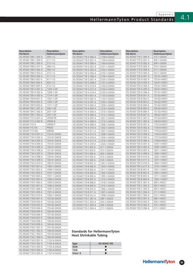
8585
4.1He l l e rmannTyton P roduc t S tandardsA p p e n d i x
Type VG 95343 T05SE28 �
Viton®-E �
Standards for HellermannTytonHeat Shrinkable Tubing
TE28 �
DescriptionVG-Norm
DescriptionHellermannTyton
VG 95343 T18 D 006 A 1158-4-GW24VG 95343 T18 D 007 A 1159-4-GW24VG 95343 T18 D 008 A 1160-4-GW24VG 95343 T18 G 001 A 2101-1-GW24VG 95343 T18 G 003 A 2102-1-GW24VG 95343 T18 G 005 A 2103-1-GW24VG 95343 T18 G 006 A 2104-1-GW24VG 95343 T18 G 007 A 2105-1-GW24VG 95343 T18 G 008 A 2101-2-GW24VG 95343 T18 G 010 A 2102-2-GW24VG 95343 T18 G 012 A 2103-2-GW24VG 95343 T18 G 014 A 2105-2-GW24VG 95343 T18 H 001 A 1133-2-GW24VG 95343 T18 H 002 A 1133-1-GW24VG 95343 T19 A 001 A 1203-1-GW24VG 95343 T19 A 002 A 1209-1-GW24VG 95343 T19 A 003 A 1214-1-GW24VG 95343 T19 A 004 A 1210-1-GW24VG 95343 T19 A 006 A 1212-1-GW24VG 95343 T19 A 007 A 1201-1-GW24VG 95343 T19 A 008 A 1213-1-GW24VG 95343 T19 A 009 A 1206-1-GW24VG 95343 T19 A 010 A 1202-1-GW24VG 95343 T19 A 011 A 1207-1-GW24VG 95343 T19 A 012 A 1208-1-GW24VG 95343 T19 A 016 A 1204-1-GW24VG 95343 T19 A 017 A 1216-1-GW24VG 95343 T19 A 018 A 1220-1-GW24VG 95343 T19 E 002 A 411-1-GW24VG 95343 T19 E 003 A 412-1-GW24VG 95343 T19 E 004 A 403-1-GW24VG 95343 T19 E 005 A 413-1-GW24VG 95343 T19 E 009 A 414-1-GW24VG 95343 T19 B 001 A 1301-1-GW24VG 95343 T19 B 002 A 1303-1-GW24VG 95343 T19 B 003 A 1311-1-GW24VG 95343 T19 B 004 A 1302-1-GW24VG 95343 T19 B 006 A 1305-1-GW24VG 95343 T19 B 007 A 1312-1-GW24VG 95343 T19 B 008 A 1316-1-GW24VG 95343 T19 B 009 A 1313-1-GW24VG 95343 T19 B 010 A 1306-1-GW24VG 95343 T19 B 011 A 1307-1-GW24VG 95343 T19 B 012 A 1308-1-GW24VG 95343 T19 C 001 A 206-1-GW24VG 95343 T19 C 002 A 203-1-GW24VG 95343 T19 C 003 A 204-1-GW24VG 95343 T19 C 004 A 211-1-GW24
DescriptionVG-Norm
DescriptionHellermannTyton
VG 95343 T08 C 003 A 204-1-GVG 95343 T08 C 004 A 211-1-GVG 95343 T08 C 005 A 212-1-GVG 95343 T08 D 001 A 306-1-GVG 95343 T08 D 002 A 304-1-GVG 95343 T08 D 003 A 310-1-GVG 95343 T08 D 004 A 311-1-GVG 95343 T08 E 002 A 411-1-GVG 95343 T08 E 004 A 403-1-GVG 95343 T08 E 005 A 413-1-GVG 95343 T09 A 001 A 1203-1-GPVG 95343 T09 A 002 A 1209-1-GPVG 95343 T09 A 003 A 1214-1-GPVG 95343 T09 B 001 A 1301-1-GPVG 95343 T09 B 002 A 1303-1-GPVG 95343 T09 B 003 A 1311-1-GPVG 95343 T09 C 001 A 206-1-GPVG 95343 T09 C 002 A 203-1-GPVG 95343 T09 C 003 A 204-1-GPVG 95343 T15 A 001 A V9500 PKVG 95343 T15 A 002 B V9500 BVG 95343 T15 A V9500 PVG 95343 T15 DA P9500VG 95343 T15 MA M9500VG 95343 T18 A 001 A 152-41-GW24VG 95343 T18 A 002 A 153-41-GW24VG 95343 T18 A 003 A 154-41-GW24VG 95343 T18 A 004 A 155-41-GW24VG 95343 T18 A 005 A 156-41-GW24VG 95343 T18 A 006 A 157-41-GW24VG 95343 T18 A 007 A 158-41-GW24VG 95343 T18 A 008 A 159-41-GW24VG 95343 T18 A 009 A 160-41-GW24VG 95343 T18 A 010 A 199-41-GW24VG 95343 T18 E 001 A 1505-1-GW24VG 95343 T18 E 002 A 1506-1-GW24VG 95343 T18 E 003 A 1507-1-GW24VG 95343 T18 E 004 A 1501-1-GW24VG 95343 T18 E 005 A 1502-2-GW24VG 95343 T18 E 006 A 1505-2-GW24VG 95343 T18 E 007 A 1506-2-GW24VG 95343 T18 E 008 A 1507-2-GW24VG 95343 T18 E 009 A 1501-2-GW24VG 95343 T18 E 010 A 1502-1-GW24VG 95343 T18 B 001 A 152-42-GW24VG 95343 T18 B 002 A 153-42-GW24VG 95343 T18 B 003 A 154-42-GW24VG 95343 T18 B 004 A 155-42-GW24VG 95343 T18 B 005 A 156-42-GW24VG 95343 T18 B 006 A 157-42-GW24VG 95343 T18 B 007 A 158-42-GW24VG 95343 T18 B 008 A 159-42-GW24VG 95343 T18 B 009 A 160-42-GW24VG 95343 T18 C 001 A 157-43-GW24VG 95343 T18 C 002 A 158-43-GW24VG 95343 T18 C 003 A 159-43-GW24VG 95343 T18 C 004 A 160-43-GW24VG 95343 T18 D 001 A 1152-4-GW24VG 95343 T18 D 002 A 1154-4-GW24VG 95343 T18 D 003 A 1155-4-GW24VG 95343 T18 D 004 A 1156-4-GW24VG 95343 T18 D 005 A 1157-4-GW24
DescriptionVG-Norm
DescriptionHellermannTyton
VG 95343 T19 C 005 A 212-1-GW24VG 95343 T19 D 001 A 306-1-GW24VG 95343 T19 D 002 A 304-1-GW24VG 95343 T19 D 003 A 310-1-GW24VG 95343 T19 D 004 A 311-1-GW24VG 95343 T19 D 005 A 312-1-GW24VG 95343 T29 A 001 A 152-61-HW21VG 95343 T29 A 002 A 153-61-HW21VG 95343 T29 A 003 A 154-61-HW21VG 95343 T29 A 004 A 155-61-HW21VG 95343 T29 A 005 A 156-61-HW21VG 95343 T29 A 006 A 157-61-HW21VG 95343 T29 B 001 A 152-62-HW21VG 95343 T29 B 002 A 153-62-HW21VG 95343 T29 B 003 A 154-62-HW21VG 95343 T29 B 004 A 155-62-HW21VG 95343 T29 B 005 A 156-62-HW21VG 95343 T29 B 006 A 157-62-HW21VG 95343 T29 B 007 A 158-62-HW21VG 95343 T29 C 001 A 157-63-HW21VG 95343 T29 C 002 A 158-63-HW21VG 95343 T29 D 001 A 1152-6-HW21VG 95343 T29 D 002 A 1154-6-HW21VG 95343 T29 D 003 A 1155-6-HW21VG 95343 T29 D 004 A 1156-6-HW21VG 95343 T29 D 005 A 1157-6-HW21VG 95343 T29 D 006 A 1158-6-HW21VG 95343 T30 A 001 A 1203-1-HW21VG 95343 T30 A 002 A 1209-1-HW21VG 95343 T30 A 007 A 1201-1-HW21VG 95343 T30 A 009 A 1206-1-HW21VG 95343 T30 A 010 A 1202-1-HW21VG 95343 T30 A 011 A 1207-1-HW21VG 95343 T30 A 016 A 1204-1-HW21VG 95343 T30 A 017 A 1216-1-HW21VG 95343 T30 B 001 A 1301-1-HW21VG 95343 T30 B 002 A 1303-1-HW21VG 95343 T30 B 003 A 1311-1-HW21VG 95343 T30 B 004 A 1302-1-HW21VG 95343 T30 C 001 A 206-1-HW21VG 95343 T30 C 002 A 203-1-HW21VG 95343 T30 C 003 A 204-1-HW21VG 95343 T30 C 004 A 211-1-HW21VG 95343 T30 C 005 A 212-1-HW21VG 95343 T30 D 001 A 306-1-HW21VG 95343 T30 D 002 A 304-1-HW21VG 95343 T30 D 003 A 310-1-HW21VG 95343 T30 D 004 A 311-1-HW21
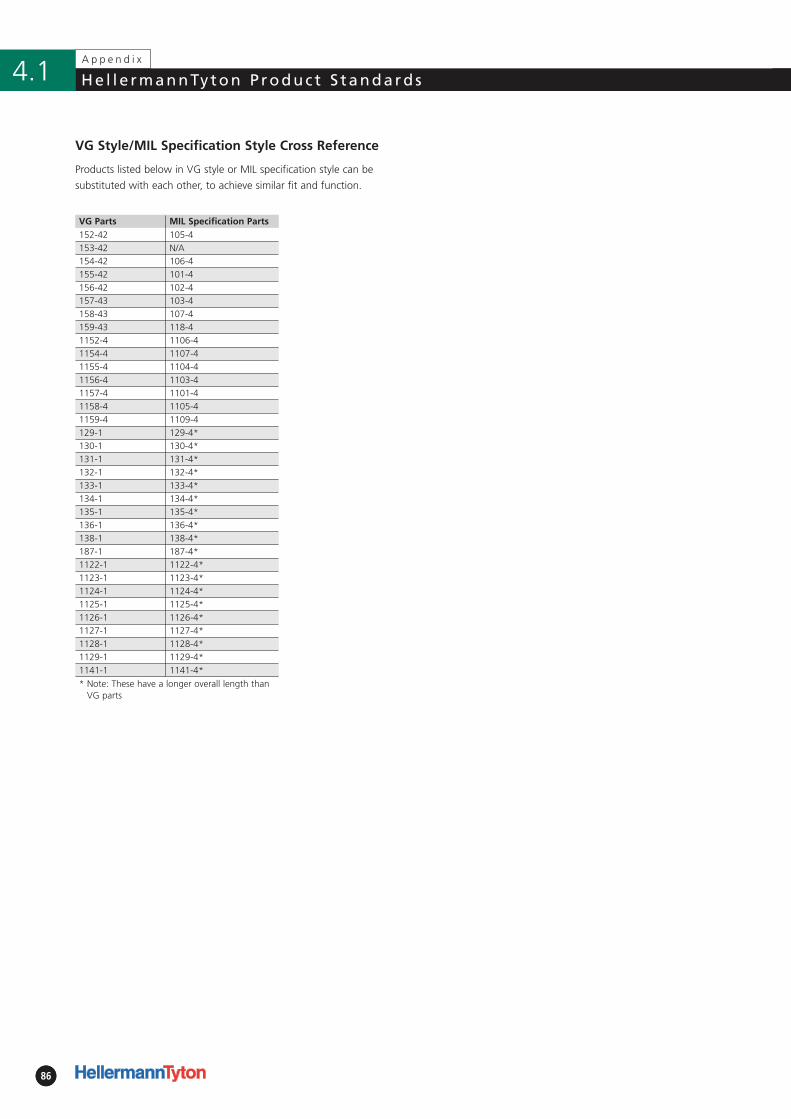
VG Parts MIL Specification Parts152-42 105-4153-42 N/A154-42 106-4155-42 101-4156-42 102-4157-43 103-4158-43 107-4159-43 118-41152-4 1106-41154-4 1107-41155-4 1104-41156-4 1103-41157-4 1101-41158-4 1105-41159-4 1109-4129-1 129-4*130-1 130-4*131-1 131-4*132-1 132-4*133-1 133-4*134-1 134-4*135-1 135-4*136-1 136-4*138-1 138-4*187-1 187-4*1122-1 1122-4*1123-1 1123-4*1124-1 1124-4*1125-1 1125-4*1126-1 1126-4*1127-1 1127-4*1128-1 1128-4*1129-1 1129-4*1141-1 1141-4** Note: These have a longer overall length than
VG parts
8686
4.1A p p e n d i x
He l l e rmannTyton P roduc t S tandards
VG Style/MIL Specification Style Cross Reference
Products listed below in VG style or MIL specification style can be
substituted with each other, to achieve similar fit and function.
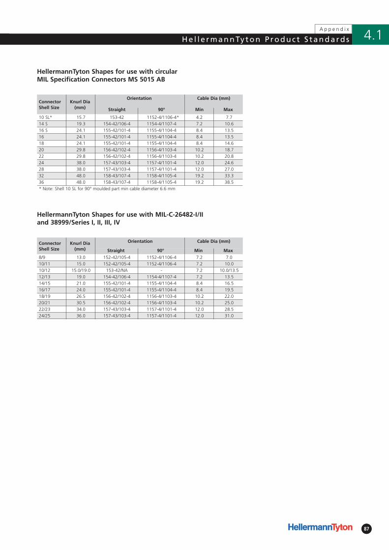
ConnectorShell Size
Knurl Dia(mm)
Orientation Cable Dia (mm)
Straight 90° Min Max
10 SL* 15.7 153-42 1152-4/1106-4* 4.2 7.714 S 19.3 154-42/106-4 1154-4/1107-4 7.2 10.616 S 24.1 155-42/101-4 1155-4/1104-4 8.4 13.516 24.1 155-42/101-4 1155-4/1104-4 8.4 13.518 24.1 155-42/101-4 1155-4/1104-4 8.4 14.620 29.8 156-42/102-4 1156-4/1103-4 10.2 18.722 29.8 156-42/102-4 1156-4/1103-4 10.2 20.824 38.0 157-43/103-4 1157-4/1101-4 12.0 24.628 38.0 157-43/103-4 1157-4/1101-4 12.0 27.032 48.0 158-43/107-4 1158-4/1105-4 19.2 33.336 48.0 158-43/107-4 1158-4/1105-4 19.2 38.5* Note: Shell 10 SL for 90° moulded part min cable diameter 6.6 mm
8787
4.1He l l e rmannTyton P roduc t S tandardsA p p e n d i x
HellermannTyton Shapes for use with MIL-C-26482-I/II and 38999/Series I, II, III, IV
HellermannTyton Shapes for use with circular MIL Specification Connectors MS 5015 AB
ConnectorShell Size
Knurl Dia(mm)
Orientation Cable Dia (mm)
Straight 90° Min Max
8/9 13.0 152-42/105-4 1152-4/1106-4 7.2 7.010/11 15.0 152-42/105-4 1152-4/1106-4 7.2 10.010/12 15.0/19.0 153-42/NA - 7.2 10.0/13.512/13 19.0 154-42/106-4 1154-4/1107-4 7.2 13.514/15 21.0 155-42/101-4 1155-4/1104-4 8.4 16.516/17 24.0 155-42/101-4 1155-4/1104-4 8.4 19.518/19 26.5 156-42/102-4 1156-4/1103-4 10.2 22.020/21 30.5 156-42/102-4 1156-4/1103-4 10.2 25.022/23 34.0 157-43/103-4 1157-4/1101-4 12.0 28.524/25 36.0 157-43/103-4 1157-4/1101-4 12.0 31.0
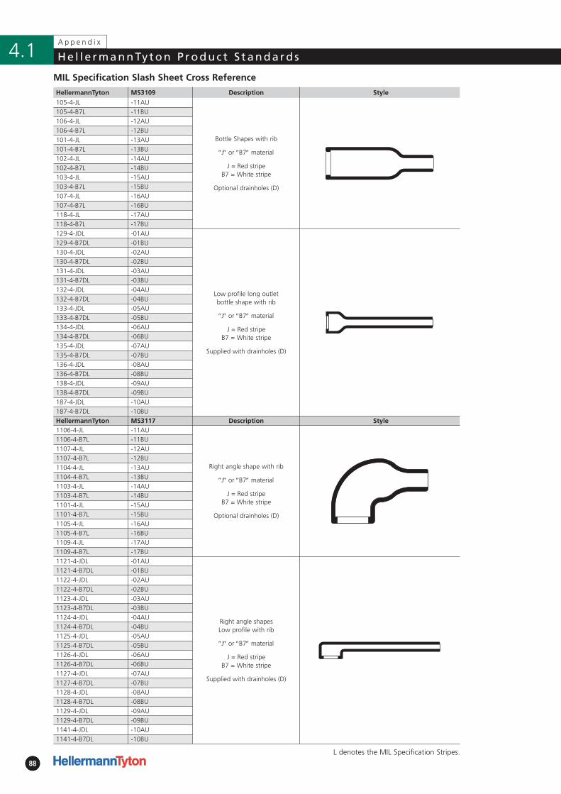
8888
4.1A p p e n d i x
He l l e rmannTyton P roduc t S tandards
1141-4-JDL -10AU1141-4-B7DL -10BU
HellermannTyton MS3109 Description Style
105-4-JL -11AU
Bottle Shapes with rib
″J″ or ″B7″ material
J = Red stripeB7 = White stripe
Optional drainholes (D)
105-4-B7L -11BU106-4-JL -12AU106-4-B7L -12BU101-4-JL -13AU101-4-B7L -13BU102-4-JL -14AU102-4-B7L -14BU103-4-JL -15AU103-4-B7L -15BU107-4-JL -16AU107-4-B7L -16BU118-4-JL -17AU118-4-B7L -17BU129-4-JDL -01AU
Low profile long outlet bottle shape with rib
″J″ or ″B7″ material
J = Red stripeB7 = White stripe
Supplied with drainholes (D)
129-4-B7DL -01BU130-4-JDL -02AU130-4-B7DL -02BU131-4-JDL -03AU131-4-B7DL -03BU132-4-JDL -04AU132-4-B7DL -04BU133-4-JDL -05AU133-4-B7DL -05BU134-4-JDL -06AU134-4-B7DL -06BU135-4-JDL -07AU135-4-B7DL -07BU136-4-JDL -08AU136-4-B7DL -08BU138-4-JDL -09AU138-4-B7DL -09BU187-4-JDL -10AU187-4-B7DL -10BUHellermannTyton MS3117 Description Style1106-4-JL -11AU
Right angle shape with rib
″J″ or ″B7″ material
J = Red stripe B7 = White stripe
Optional drainholes (D)
1106-4-B7L -11BU1107-4-JL -12AU1107-4-B7L -12BU1104-4-JL -13AU1104-4-B7L -13BU1103-4-JL -14AU1103-4-B7L -14BU1101-4-JL -15AU1101-4-B7L -15BU1105-4-JL -16AU1105-4-B7L -16BU1109-4-JL -17AU1109-4-B7L -17BU1121-4-JDL -01AU
Right angle shapes Low profile with rib
″J″ or ″B7″ material
J = Red stripe B7 = White stripe
Supplied with drainholes (D)
1121-4-B7DL -01BU1122-4-JDL -02AU1122-4-B7DL -02BU1123-4-JDL -03AU1123-4-B7DL -03BU1124-4-JDL -04AU1124-4-B7DL -04BU1125-4-JDL -05AU1125-4-B7DL -05BU1126-4-JDL -06AU1126-4-B7DL -06BU1127-4-JDL -07AU1127-4-B7DL -07BU1128-4-JDL -08AU1128-4-B7DL -08BU1129-4-JDL -09AU1129-4-B7DL -09BU
MIL Specification Slash Sheet Cross Reference
L denotes the MIL Specification Stripes.
Notes 4.2
89
A p p e n d i x

Notes4.2
90
A p p e n d i x

Notes 4.2
91
A p p e n d i x

Notes4.2
92
A p p e n d i x
Notes 4.2
93
A p p e n d i x
Notes4.2
94
A p p e n d i x
95
Genera l Te rms and Cond i t ions o f Sa le 4.2A p p e n d i x
2.4 Any typographical clerical or other erroror omission in any sales literature quotationprice list Acknowledgement of Order invoiceor other documentation or information issuedby the Seller shall be subject to correctionwithout any liability on the part of theSeller.
3. Orders and Specifications
3.1 Every acceptance by the Buyer of anyquotation given by the Seller shall be deemedan offer by the Buyer to purchase Goodsfrom the Seller and will not be deemed to beaccepted by the Seller until a duly authorisedrepresentative of the Seller has provided anAcknowledgement of Order in relation tosuch offer by the Buyer.
3.2 No Order submitted by the Buyer shall be deemed to be accepted by theSeller unless and until confirmed by anAcknowledgement of Order.
3.3 The Buyer shall be responsible to theSeller for ensuring the accuracy of the terms of any Order (including any applicablespecification) submitted by the Buyer and forgiving the Seller any necessary informationrelating to the Goods within a sufficienttime to enable the Seller to perform theContract in accordance with its terms.
3.4 The quantity quality and description ofand any specification for the Goods shall bethose set out in the Seller’s Acknowledgementof Order.
3.5 If the Goods are to be manufactured bythe Seller in accordance with a specificationor instructions submitted by the Buyer:
3.5.1 The Buyer shall indemnify the Selleragainst all Loss suffered by the Seller inconnection with any claim by a third partythat the manufacture and/or supply of theGoods to such specification or instructionsinfringes the rights of any third party; and
3.5.2 The Buyer shall be responsible for supplying reliable and accurate informationto the Seller (including, without limitation,drawings, plans and designs) to enable theSeller to manufacture the Goods. The Sellershall be entitled to assume that all information supplied by the Buyer is true, accurate, com-plete and fit for the purpose for which it issupplied and that the Seller can rely on thesame. The Seller shall not be liable for anyLoss or delay in Delivery of the Goods whichdirectly or indirectly arises from the Buyer'sfailure to supply accurate information at allor on time.
“ORDER” shall mean the Buyer's order forGoods.
“SELLER” shall mean Hellermann Tyton, aDivision of Spirent PLC, a company registe-red in England and Wales under companynumber 470893 and having its registeredoffice at Crawley Business Quarter, FlemingWay, Crawley, West Sussex RH10 9QL.
“SPECIFICATION” shall mean the descriptionof the Goods set out in the Acknowledgementof Order pursuant to clause 3.4.
1.2 Any reference in these Conditions to anyprovision of a statute shall be construed asa reference to that provision as amended re-enacted or extended at the relevant time.
1.3 The headings in these Conditions are forconvenience only and shall not affect theirinterpretation.
1.4 In these Conditions “Incoterms” meansthe international rules for the interpretationof trade terms of the International Chamberof Commerce 2000. Unless the Contractotherwise requires any terms or expressionwhich is defined in or given a particularmeaning by the provisions of Incoterms shallhave the same meaning in these Conditions,but if there is any conflict between the pro-visions of Incoterms and these Conditionsthe latter shall prevail.
2. Basis of Sale
2.1 These Conditions together with the Seller'sAcknowledgement of Order apply to allContracts between the Seller and the Buyerand shall prevail and be effective notwith-standing any variations or additions whethercontained or referred to in the Buyer's order,or other document submitted by the Buyerincluding without limitation any standardconditions of purchase of the Buyer, accep-tance of quotation or in correspondence orelsewhere, or implied by trade, custom,practice or course of dealing, and shallsupersede all other and any prior promises,representations or undertakings.
2.2 No variation to these Conditions shallbe binding unless agreed in writing by anauthorised representative of the Seller.
2.3 The Seller’s employees or agents are notauthorised to make any representations orrecommendations concerning the Goodsunless confirmed by a duly authorised repre-sentative of the Seller in writing. In enteringinto the Contract the Buyer acknowledgesthat it does not rely on and waives any claimfor breach of any such representations whichare not so confirmed. For the avoidance ofdoubt, nothing herein contained shall bedeemed to exclude the Seller's liability dueto fraudulent misrepresentation.
1. Interpretation
1.1 In these Conditions:
″ACKNOWLEDGEMENT OF ORDER″ shallmean the document by which the Seller'sauthorised representative accepts the Order.
″BUYER″ shall mean the purchaser of theGoods from the Seller.
″CONDITIONS″ means the terms and condi-tions of sale set out herein and includes anyspecial terms and conditions included in theAcknowledgement of Order.
″CONTRACT″ shall mean the contract forthe sale and purchase of the Goods madepursuant to these Conditions.
″DELIVERY″ shall mean delivery of the Goodsor any part of them in accordance with clause6.1 of these Conditions.
″DELIVERY DATE″ shall mean the date or periodfor Delivery set out in an Acknowledgementof Order or which is otherwise agreed by theSeller and the Buyer.
″FORCE MAJEURE″ shall mean any circum-stances beyond the reasonable control ofthe Seller.
″GOODS″ shall mean the goods which theSeller has agreed to supply to the Buyerpursuant to these Conditions.
″INFORMATION″ shall mean any and all IPR,technical or commercial data, know-how,show-how, formulae, processes, designs,photographs, drawings, specifications, sam-ples, details of customers and suppliers, pri-cing information, samples, prototypes andother sensitive business information and anyother information of a confidential naturetogether with any experimental or test dataand results produced by the Seller as a resultof it carrying out necessary tests for the pur-poses of performing the Contract which eit-her directly or indirectly is disclosed by or onbehalf of the Seller to the Buyer or to anyperson on behalf of the Buyer orally, in writ-ing, by physical embodiment, by data trans-mission or in any other way.
″INTELLECTUAL PROPERTY RIGHTS″ (″IPR″)shall mean all patents, trade marks, servicemarks, design rights (whether patentable,registrable or otherwise), applications forany of the foregoing copyright, know-how,trade or business names, rights in databases,topography rights and other similar rights orobligations whether registrable or not in anycountry (including, but not limited to theUnited Kingdom). ″LOSS″ shall mean all actions,claims, demands, losses (direct, indirect, con-sequential or otherwise), expenses, costs,actions and proceedings.
96
Genera l Te rms and Cond i t ions o f Sa le4.2A p p e n d i x
3.6 The Seller reserves the right to make any changes in the Specification of the Goodswhich are required to conform with anyapplicable UK safety or other statutoryrequirements and/or where such changes donot materially affect the quality or perfor-mance of the Goods. For the avoidance ofdoubt and subject to clause 10.1, the Sellerprovides no implied warranties in relation to Goods supplied to the Buyer'sspecification.
3.7 No Order which has been accepted bythe Seller by an Acknowledgement of Ordermay be cancelled by the Buyer except withthe agreement in writing of the Seller andon terms that the Buyer shall indemnify theSeller in full against all Loss incurred by theSeller as a result of cancellation.
4. Price of the Goods
4.1 The price shall be the price in theAcknowledgement of Order (″Price″).
4.2 The Seller reserves the right by givingnotice to the Buyer at any time beforeDelivery to increase the Price to reflect anyincrease in the cost to the Seller which isdue to any factor beyond the control of theSeller (such as without limitation any foreignexchange fluctuation, currency regulationalteration of duties significant increase inthe costs of labour materials or other costsof manufacture), any change in DeliveryDates quantities or specifications for theGoods which is requested by the Buyer orany delay caused by any instructions of theBuyer or failure of the Buyer to give theSeller adequate information or instructions.
4.3 Except as otherwise stated in anAcknowledgement of Order all prices aregiven by the Seller for Delivery as defined in clause 6.1. Where the Seller agrees todeliver the Goods otherwise than as definedin clause 6.1 the Buyer shall be liable to paythe Seller’s charges for transport packagingand insurance where requested.
4.4 The price is exclusive of any applicablevalue added tax (which will be applied inaccordance with the legislation in force atthe tax point date) and which the Buyershall be additionally liable to pay to theSeller.
5. Terms of Payment
5.1 Subject to any special terms agreed in anAcknowledgement of Order the Seller shallbe entitled to invoice the Buyer for the Priceon Delivery immediately the Goods have beendespatched, when they are ready for despatchbut are prevented or delayed from being
despatched due to Force Majeure or the daythe Goods are put out ready for collection(whichever event occurs the earliest).
5.2 The Buyer shall pay the Price withoutdeduction within 30 days of the date of theSeller’s invoice notwithstanding that Deliverymay not have taken place and the propertyin the Goods has not passed to the Buyer.The time of payment of the Price shall be ofthe essence of the Contract. Receipts forpayment will be issued only upon request.
5.3 If the Buyer fails to make any paymentin accordance with clause 5.2 then withoutprejudice to any other right or remedy avai-lable to the Seller the Seller shall be entitledto:-
5.3.1 Cancel the contract or suspend anyDeliveries to the Buyer;
5.3.2 Appropriate any payment made bythe Buyer to such of the Goods (or thegoods supplied under any other contractbetween the Buyer and the Seller) as theSeller may think fit (notwithstanding anypurported appropriation by the Buyer);
5.3.3 Charge the Buyer interest on the amount unpaid at the rate of 3 percent per annum above HSBC Bank base ratefrom time to time until payment in full ismade (a part of a month being treated as a full month for the purpose of calculatinginterest); and
5.3.4 Demand payment of all outstandingbalances from the Buyer whether due or notand/or cancel all outstanding Orders and/ordecline to make further Deliveries (underthis or any other contract between theBuyer and the Seller) or provision of services.
5.4 Except where insolvency laws provideotherwise the Buyer shall not be entitled towithhold or set off payment for Goods forany reason whatsoever. All Goods for whichpayment has not been made in accordancewith clause 5.2 and which are held by theSeller at its premises are so held at theBuyer's risk.
6. Delivery
6.1 Except as otherwise stated in anAcknowledgement of Order delivery shalltake place when the Seller places the Goodsat the disposal of the Buyer at the Seller'spremises and not loaded on any collectingvehicle.
6.2 Any Delivery Date is approximate only.The Seller shall not be liable for any Loss arising from any failure to deliver the Goodson the Delivery Date howsoever caused.Time for delivery shall not be of the essenceunless previously agreed by the Seller inwriting. The Goods may be delivered by the Seller in advance of the quoted deliverydate upon giving reasonable notice to theBuyer.
6.3 The Buyer shall not be entitled to changethe Delivery Date without the consent of aduly authorised representative of the Seller.
6.4 Where delivery of the Goods is to bemade by the Seller, the Seller reserves theright to deliver up to 10 per cent more or10 per cent less than the quantity orderedprovided that there is a pro rata adjustmentto the Price to reflect the Goods actuallydelivered and the quantity so delivered shallbe deemed to be the quantity ordered.Goods delivered in excess of such tolerancemay be rejected by the Buyer provided thatit serves notice of rejection within 10 wor-king days of Delivery.
6.5 Where the Goods are to be delivered ininstallments each delivery shall constitute aseparate contract and failure by the Seller todeliver any one or more of the installmentsin accordance with these Conditions or anyclaim by the Buyer in respect of any one ormore installments shall not entitle the Buyerto treat the Contract as a whole as repudia-ted.
6.6 Subject to clause 10.6 if the Seller failsto deliver the Goods for any reason otherthan Force Majeure or the Buyer’s fault andthe Seller is accordingly liable to the Buyerthe Seller’s only liability shall be limited tothe excess (if any) of the cost to the Buyer(having used its best endeavours to replacethe Goods by purchasing them in the chea-pest available market) of purchasing similargoods to replace those not delivered.
6.7 If the Buyer fails to take Delivery on theDelivery Date then without prejudice to anyother right or remedy available to the Sellerthe Seller may:
6.7.1 store the Goods until actual deliveryand charge the Buyer for the costs (includinginsurance) of storage; or
6.7.2 treat the Contract as repudiated bythe Buyer and without prejudice to anyother right it may have against the Buyerthe Seller shall be entitled to resell theGoods and be indemnified by the Buyer for any Loss which it suffers.
97
Genera l Te rms and Cond i t ions o f Sa le 4.2A p p e n d i x
Genera l Te rms and Cond i t ions o f Sa le
7. Risk and Property
7.1 Risk of damage to or loss of the Goodsshall pass to the Buyer on Delivery of theGoods;
7.2 Notwithstanding Delivery and the passing of risk in the Goods or any otherprovision of these Conditions the propertyin the Goods shall remain with the Selleruntil the Seller has received in cash or clea-red funds payment in full of the Price andany other monies due to the Seller in respect of the Goods and all other goods agreed to be sold by the Seller to the Buyerfor which payment is then due under theContract or any other contract between the Seller and the Buyer (including without limitation costs of Delivery).
7.3 Until such time as the property in theGoods passes to the Buyer the Buyer shallhold the goods as the Seller’s fiduciary agentand bailee and shall keep the Goods separatefrom those of the Buyer and third partiesand properly stored protected and insuredand identified as the Seller’s property.
7.4 Until such time as the property in theGoods passes to the Buyer the Buyer shallbe entitled to resell or use the Goods in the ordinary course of its business but shallaccount to the Seller for the proceeds ofsale or otherwise of the Goods whethertangible or intangible including insuranceproceeds and shall keep all such proceedsseparate from any monies or property of theBuyer and third parties and in the case oftangible proceeds properly stored protected and insured.
7.5 If the Goods are prior to sale by the Buyermade up or incorporated in or mixed withother goods, then if they remain separatelyidentifiable the Seller shall retain propertyand title thereof and if they do not remainseparately identifiable the Seller shall becomea joint owner of the goods in or which theGoods are incorporated or mixed in suchproportion as the value of the Goods bearsto the value of the Goods in which theGoods are so incorporated or mixed.
7.6 If the Buyer sells the Goods or thegoods in which the Goods have been incor-porated or mixed the sale shall be on behalfof the Seller as the joint owner thereof asthe case may be and the proceeds of anysuch sale for the Seller’s share thereof if thesale is of jointly owned property shall beheld on trust for the Seller and in a separateidentified account.
7.7 Until such time as the property in theGoods passes to the Buyer (and providedthe Goods are still in existence and have notbeen resold) the Seller shall be entitled at
any time to require the Buyer to deliver upthe Goods to the Seller and if the Buyer failsto do so forthwith to enter the premises ofthe Buyer or any third party where theGoods are stored and take possession ofany Goods in which property remains in theSeller and remove and dispose of them asthe Seller thinks fit. The Seller shall applythe proceeds of disposal (after deduction ofall expenses) in discharge of the amountunpaid by the Buyer.
7.8 The Buyer shall not be entitled to pled-ge or in any way charge by way of securityfor any indebtedness any of the Goodswhich remain the property of the Sellerwithout the Seller's consent but if the Buyerdoes so all moneys owing by the Buyer tothe Seller shall (without prejudice to anyother right or remedy of the Seller)forthwith become due and payable.
8. Confidentiality and IPR
8.1 The Buyer agrees and undertakes that itwill keep confidential and will not discloseor use for any purpose (other than to per-form its obligations under the Contract) any Information. Any Information suppliedto the Buyer by the Seller shall at all timesremain the property of the Seller.The Buyer shall not acquire any rights in theInformation, which shall be returned to theSeller immediately upon request.
8.2 Unless otherwise agreed in writing allIPR in relation to the Goods including with-out limitation their method of manufactureshall vest in the Seller and remain the pro-perty of the Seller not withstanding thepurchase of the Goods by the Buyer and theBuyer undertakes to do all acts and/or enterinto such agreements or deeds as the Sellershall require to vest any such IPR in the Seller.
8.3 Unless otherwise agreed in writing andnotwithstanding that the Buyer may havecontributed towards the costs of such itemsall tooling (and all IPR in relation to suchtooling) produced or acquired by the Sellerin relation to the manufacture of the Goodsshall be and remain the property of the Seller.
9. Lien
9.1 In addition to any other right or lien towhich the Seller may by law or pursuant tothese Conditions be entitled, the Seller shallbe entitled to a general lien on all the goodsand the property of the Buyer in the Seller’spossession and a right of sale of such goodsand property at the Seller’s sole discretionfor any unpaid money due under the termsof the same or any other Contract betweenthe Seller and the Buyer.
9.2 In addition and without prejudice to itsother rights, the Seller shall have the righton fourteen days notice to the Buyer to putany goods or property over which it has alien into a saleable state by any meanswhatsoever and (without prior notice to theBuyer) to sell such goods and shall be dee-med the Buyer's agent for the purposes ofeffecting such sale. Out of the proceeds ofthe sale the Seller shall be entitled to retaina sum equivalent to all unpaid monies dueto it from the Buyer as aforesaid togetherwith the cost of putting the goods into asaleable state and the expenses of salewithout prejudice to the Seller's right torecover the balance thereof from the Buyer.
10. Warranties and Liability
10.1 The Seller warrants that at Delivery theGoods will be free from defect in materials,workmanship and design (where designedby the Seller) provided that subject as afore-said and expressly provided in these Conditions,and except where the Goods are sold to aperson dealing as a consumer (within themeaning of the Unfair Contract Terms Act1977) all warranties conditions or otherterms implied by statute and/or commonlaw are excluded to the fullest extent per-mitted by law.
10.2 Where the Goods are sold under aconsumer transaction (as defined by theConsumer Transactions (Restrictions onStatements) Order 1976) the statutory rights of the Buyer are not affected by these Conditions.
10.3 Any specification supplied by the Seller in any estimate or quotation shall beapproximate only and for information andguidance only and shall not form part of theContract.
10.4 Any claim based upon the quality orcondition of the Goods or any failure of theGoods to meet the Specification (″Claim″)by the Buyer shall (whether or not delivery isrefused by the Buyer) be notified to theSeller in writing within 7 days from the dateof delivery or (where the defect or failurewas not apparent on reasonable inspection)within one month after discovery of thedefect or failure. If delivery is not refusedand the Buyer does not notify the Selleraccordingly, the Buyer shall not be entitledto reject the Goods and the Seller shall haveno liability in respect of such a Claim andthe Buyer shall be bound to pay the Price asif the Goods had been delivered in accor-dance with the Contract. The Buyer shallnot be entitled to make any Claim after theexpiration of six months from the date ofDelivery of the Goods.
98
Genera l Te rms and Cond i t ions o f Sa le4.2A p p e n d i x
10.5 Where any valid Claim in respect of anyof the Goods is notified to the Seller in accor-dance with clause 10.4 the Seller shall beentitled to replace the Goods (or the part inquestion) free of charge or at the Seller’s solediscretion refund to the Buyer the Price (or aproportionate part of the Price) but the Sellershall have no further liability to the Buyerand the Buyer shall have no other remedy.
10.6 The Seller shall have no liability to theBuyer in relation to non-delivery or shortdelivery of the Goods unless such non-deli-very or short delivery is notified to the Sellerin writing within fourteen days of theDelivery Date.
10.7 Where any valid claim in respect of theGoods is notified to the Seller in accordancewith clause 10.6 the Seller shall be entitledto deliver the Goods or the shortfall of theGoods, but the Buyer shall have no otherremedy
10.8 Except in respect of death or personalinjury caused by the Seller’s negligence theSeller's total liability to the Buyer under theseConditions shall not exceed the total priceof all Goods supplied hereunder.
10.9 The Seller shall have no liability to theBuyer under or arising out of or otherwisein connection with the Contract or the sup-ply of Goods by the Seller to the Buyer and/or their use or resale by the Buyer in contracttort (including negligence or breach of statutory duty) or otherwise for loss of pro-fit, business, contracts, revenues or anti-cipated savings or for any special indirect or consequential damage or loss of anynature or for the costs of recall of any Goodsexcept as may otherwise be expressly pro-vided for in these Conditions.
10.10 Notwithstanding any provision of theseConditions the Seller shall have no liabilityto the Buyer in respect of any defect in thequality of the Goods or the failure of theGoods to meet Specification where the defector failure has arisen as a result of improperstorage or any act or omission of the Buyer.
10.11 For the avoidance of doubt nothingherein contained shall be deemed to excludeor restrict the Seller's liability for death orpersonal injury arising due to the Seller'snegligence.
10.12 Where any claim is made under thisclause 10 the Buyer grants the Seller or itsagents the right to enter upon the Buyer'spremises to inspect the Goods Unless anduntil the Seller has been afforded an oppor-tunity to examine the Goods no claim willbe accepted.
10.13 The Seller shall not be liable to theBuyer or be deemed to be in breach of the
Contract by reason of any delay in performingor any failure to perform any of the Seller’sobligations in relation to the Goods if thedelay or failure was due to Force Majeure.
10.14 The Buyer shall indemnify the Selleragainst all Loss suffered by the Seller whicharises as a result of the breach by the Buyerof any provision of the Contract or the negligence of the Buyer or any of its representatives.
11. Insolvency of Buyer
11.1 In the event that:
11.1.1 The Buyer makes any voluntaryarrangement with its creditors or becomessubject to an administration order or (beingan individual or firm) becomes bankrupt or (being a company) goes into liquidation(otherwise than for the purposes of amal-gamation or reconstruction);
11.1.2 An encumbrancer takes possessionor a receiver or administrator is appointedof any of the property or assets of the Buyer;
11.1.3 the Buyer ceases or threatens tocease to carry on business;
11.1.4 the Seller reasonably apprehendsthat any of the events mentioned above isabout to occur in relation to the Buyer andnotifies the Buyer accordingly; or
11.1.5 if the Buyer's jurisdiction is not inEngland and Wales any events similar tothose described in clauses 11.1.1 to 11.1.4occur then without prejudice to any otherright or remedy available to the Seller theSeller shall be entitled to suspend furtherperformance of the Contract for such timeas it shall in its absolute discretion see fit ortreat the Contract as wrongfully repudiatedby the Buyer and forthwith terminate theContract (either with or without notice tothe Buyer) without any liability to the Buyerand if the Goods have been delivered but notpaid for the Price shall become immediatelydue and payable notwithstanding any previousagreement or arrangement to the contrary.
12. Export Terms
12.1 Where the Goods are supplied for exportfrom the United Kingdom the provision ofthis clause 12 shall (subject to any special and the Seller) terms agreed in writing betweenthe Buyer apply notwithstanding any otherprovision of these Conditions.
12.2 The Buyer shall be responsible for com-plying with any legislation or regulations go-verning the importation of the Goods intothe country of destination and for the pay-ment of any duties thereon. In particular, ifany licence or consent of any governmentor other authority shall be required for
the acquisition, carriage or use of theGoods by the Buyer the Buyer shall obtainthe same at its own expense and if neces-sary produce evidence of the same to theSeller on demand. Failure to do so shall notentitle the Buyer to withhold or delay paym-ent of the Price. Any additional expenses orcharges incurred by the Seller resulting fromsuch failure shall be for the Buyer's account.
12.3 Unless otherwise agreed in writing between the Buyer and the Seller the Goodsshall be delivered ex-works and the Sellershall be under no obligation to give the Buyernotice under section 32(3) of the Sale ofGoods Act 1979.
12.4 Notwithstanding clause 5.2 paymentof all amounts due to the Seller shall bemade by irrevocable letter of credit openedby the Buyer in favour of the Seller and con-firmed by a bank in the United Kingdomacceptable to the Seller or if the Seller hasagreed in writing on or before acceptanceof the Buyer’s order to waive this requirementfor any other agreed method of payment
13. General
13.1 The Seller shall be entitled to assign orsubcontract all or any of its rights and obli-gations hereunder. The Buyer shall not beentitled to assign, transfer, subcontract orotherwise delegate any of its rights or obli-gations hereunder.
13.2 Any notice required or permitted to begiven by either party to the other under theseConditions shall be given in writing at itsregistered office or principal place of businessor such other address as may be notified forsuch purpose to the party giving notice.
13.3 No waiver by the Seller of any breachof Contract by the Buyer shall be consideredas a waiver of any subsequent breach of thesame or any other provision.
13.4 If any provision of these Conditions isheld by any competent authority to be invalidor unenforceable in whole or in part thevalidity of the other provisions of theseConditions and the remainder of the provisionin question shall not be affected thereby.
13.5 The parties hereto intend that no termof the Contract may be enforced by anyperson, entity or body that is not a party tothe Contract.
13.6 The Contract shall be governed by thelaws of England and Wales and the Buyerand the Seller hereby submit to the exclusi-ve jurisdiction of the English Courts savewith respect to enforcement where theirjurisdiction shall be non-exclusive.
HT UK Cond of Sale
June 2002

• Operating Temperature -75°C to +200°C
• Can be factory pre-coated into all HellermannTyton
range of small electronic Heatshrink shapes
• W24 is a low tack gel, and does not need excessive
initial heating in order to melt the adhesive, before
surface wetting and subsequent bonding
• W24 is not susceptible to moisture absorption, there-
fore delamination from the surface will not take place
• Product does not need to be kept in sealed packaging
• Handling strength achieved after initial recovery 80% cure.
Cable can be bent when cool at 90° around mandrel 6 x
dia of cable
• Harness can be moved immediately, ultimate properties in
7 days
• Stored at normal temperatures, and away from direct sun-
light W24 adhesive lined shapes have a 5 year shelf life
• W24 also flows when the shape is shrunk, enabling the
customer to form a smooth fillet of adhesive between the
tail of the heatshrink shape and jacket
W 2 4 - H i g h p e r f o r m a n c e o n e p a r t e p o x y a d h e s i v e
W 2 4 - F e a t u r e s W 2 4 - B e n e f i t s
V i s i b l e a d h e s i v e f l o w
För mer information kontakta
06/2
011
HellermannTyton
Datvägen 5
Box 569
175 26 Järfälla
Sverige
Tel: 08-580 890 00
Fax: 08-580 348 02
E-Mail: [email protected]
www.HellermannTyton.se