Embed Size (px)
DESCRIPTION
iPDC is a free Phasor Data Concentrator based on IEEEC37.118 synchrophasor standard. It also has Database Server for iPDC and PMU Simulator modules. The objective of iPDC project is to create a IEEE C37.118 Synchrophasor standardized Phasor Data Concentrator and PMU Simulator, on which research students and others can develop and test their algorithms and applications. The purpose of iPDC released as a Free Software to its availability for users without any restriction regarding its usage and modification. And to get the contribution from users and developers all around the world. iPDC do the time alignment and combining of the received data into frames as per IEEEC37.118 and can send to other iPDCs, and applications. iPDC can also archive received data in the MySQL database on local/remote machine. PMU Simulator is also IEEEC37.118 std compliant. Software is built to be working on Linux platform.
Citation preview
Design and Implementation of IEEE C37.118 basedPhasor Data Concentrator & PMU Simulator for
Wide Area Measurement System
Technical Report
Authors
Nitesh PanditKedar Khandeparkar
Indian Institute of Technology, Bombay
Mumbai, India
May 2012

To
Our Familiesand
Faculties
Acknowledgments
It is difficult to find adequate English words to thank everyone who has contributed in
innumerable way to the completion of work. Before starting to thank everyone who has
helped me here, I want to thanks my God, the most beneficent, the most compassionate,
and the most merciful.
I would like to express my sincere thanks and gratitude to Prof. A.M. Kulkarni, Prof.
S.A.Soman, Prof. V.Z. Attar, and Prof. S.U. Ghumbre for the constant motivation and
valuable guidance they provided me throughout the project. I am highly indebted to
them for giving me this opportunity to work under them and also clarifying my doubts
and for bringing into perspective, the different aspects of the project topic. They con-
stantly encouraged me by giving suggestions and criticisms on my work. Working under
them has been a great learning experience for me.
iii
Abstract
With information and measurement technology evolving rapidly within the electric
power industry, wide-area measurement is deemed to be the key technology to improve
power system efficiency and reliability. Phasor Measurement Unit (PMU) deployment for
Wide Area Measurement System (WAMS) results in large amount of data being generated
every second across the PMU network. Currently, many transmission operators do not
have the ability to process, store, and utilize this data. It also gives the design and
implementation details of PMU-PDC and PDC-PDC communication over TCP and UDP.
This design enable PDC to handle data from PMUs or other PDCs that are IEEEC37.118
synchrophasor standard compliant. The working of storage & archival of PMU/PDC data
in MySQL database has also been explained in the report. Storage enables post analysis
that can reveal useful information of the PMU data patterns. PMU Simulator design and
working details are also included.
iv
Contents
Abstract iv
List of Figures vii
1 Introduction 1
1.1 Smart Grid . . . . . . . . . . . . . . . . . . . . . . . . . . . . . . . . . . . 1
1.2 Organization Of the Report . . . . . . . . . . . . . . . . . . . . . . . . . . 2
2 Wide Area Measurement System 3
2.1 Components of WAMS . . . . . . . . . . . . . . . . . . . . . . . . . . . . . 4
2.1.1 Phasor Measurement Unit . . . . . . . . . . . . . . . . . . . . . . . 5
2.1.1.1 Introduction . . . . . . . . . . . . . . . . . . . . . . . . . 5
2.1.1.2 PMU Standards . . . . . . . . . . . . . . . . . . . . . . . 6
2.1.2 Phasor Data Concentrator . . . . . . . . . . . . . . . . . . . . . . . 10
2.1.2.1 Introduction . . . . . . . . . . . . . . . . . . . . . . . . . 10
2.1.2.2 Functionality . . . . . . . . . . . . . . . . . . . . . . . . . 10
2.1.2.3 Applications . . . . . . . . . . . . . . . . . . . . . . . . . 11
2.2 Communication . . . . . . . . . . . . . . . . . . . . . . . . . . . . . . . . . 12
2.3 WAMS Implementations . . . . . . . . . . . . . . . . . . . . . . . . . . . . 15
2.4 Database . . . . . . . . . . . . . . . . . . . . . . . . . . . . . . . . . . . . . 17
3 Design Model 18
3.1 iPDC WAMS Architecture . . . . . . . . . . . . . . . . . . . . . . . . . . . 18
3.1.1 iPDC Design . . . . . . . . . . . . . . . . . . . . . . . . . . . . . . 19
3.1.2 iPDC Working . . . . . . . . . . . . . . . . . . . . . . . . . . . . . 20
3.1.3 iPDC Data Processing . . . . . . . . . . . . . . . . . . . . . . . . . 26
3.1.3.1 Time Aligning . . . . . . . . . . . . . . . . . . . . . . . . 27
3.1.3.2 Sorting of Data Frames . . . . . . . . . . . . . . . . . . . 28
3.1.3.3 Generation of Data Frame . . . . . . . . . . . . . . . . . . 29
3.1.3.4 Clear Time Stamp Buffer . . . . . . . . . . . . . . . . . . 30
3.1.3.5 Generation of Configuration Frame for iPDC . . . . . . . 30
3.1.3.6 Implementation Details . . . . . . . . . . . . . . . . . . . 32
v
3.2 iPDC Features . . . . . . . . . . . . . . . . . . . . . . . . . . . . . . . . . 39
3.3 Database Design . . . . . . . . . . . . . . . . . . . . . . . . . . . . . . . . 39
3.3.1 DBServer Working . . . . . . . . . . . . . . . . . . . . . . . . . . . 39
3.3.2 Implementation Details . . . . . . . . . . . . . . . . . . . . . . . . . 40
3.4 PMU Simulator . . . . . . . . . . . . . . . . . . . . . . . . . . . . . . . . . 42
3.4.1 Design . . . . . . . . . . . . . . . . . . . . . . . . . . . . . . . . . . 42
3.4.2 Architecture . . . . . . . . . . . . . . . . . . . . . . . . . . . . . . . 43
3.4.3 Working . . . . . . . . . . . . . . . . . . . . . . . . . . . . . . . . . 44
3.4.4 Implementation Details . . . . . . . . . . . . . . . . . . . . . . . . . 47
3.4.5 Features . . . . . . . . . . . . . . . . . . . . . . . . . . . . . . . . . 51
4 Experiments & Results 52
4.1 Requirement Analysis . . . . . . . . . . . . . . . . . . . . . . . . . . . . . . 52
4.2 Test Cases . . . . . . . . . . . . . . . . . . . . . . . . . . . . . . . . . . . . 52
5 Conclusion and Future Work 61
5.1 Future Work . . . . . . . . . . . . . . . . . . . . . . . . . . . . . . . . . . . 61
References 63
vi
List of Figures
2.1 Transmisson Order of IEEE 1344 Frame . . . . . . . . . . . . . . . . . . . 6
2.2 Transmission Order of IEEE C37.118 Frame . . . . . . . . . . . . . . . . . 7
2.3 IEEE C37.118 Configuration Frame Format . . . . . . . . . . . . . . . . . 8
2.4 IEEE C37.118 Data Frame Format . . . . . . . . . . . . . . . . . . . . . . 9
2.5 Phasor Data Concentrator . . . . . . . . . . . . . . . . . . . . . . . . . . . 10
2.6 TCP Communication . . . . . . . . . . . . . . . . . . . . . . . . . . . . . . 14
3.1 iPDC WAMS Architecture . . . . . . . . . . . . . . . . . . . . . . . . . . . 18
3.2 iPDC Design . . . . . . . . . . . . . . . . . . . . . . . . . . . . . . . . . . 19
3.3 iPDC Working . . . . . . . . . . . . . . . . . . . . . . . . . . . . . . . . . 21
3.4 Data Frame Arrival at iPDC . . . . . . . . . . . . . . . . . . . . . . . . . . 23
3.5 Configuration Frame Arrival at iPDC . . . . . . . . . . . . . . . . . . . . . 23
3.6 iPDC Connection Tables . . . . . . . . . . . . . . . . . . . . . . . . . . . . 25
3.7 Recreate configuration objects . . . . . . . . . . . . . . . . . . . . . . . . . 26
3.8 iPDC Data Processing . . . . . . . . . . . . . . . . . . . . . . . . . . . . . 27
3.9 Time Stamp Buffer Block Diagram . . . . . . . . . . . . . . . . . . . . . . 27
3.10 Time Aligning . . . . . . . . . . . . . . . . . . . . . . . . . . . . . . . . . . 28
3.11 Sorting of Data Frames . . . . . . . . . . . . . . . . . . . . . . . . . . . . . 29
3.12 Generation of Data Frame . . . . . . . . . . . . . . . . . . . . . . . . . . . 29
3.13 Clear TSB . . . . . . . . . . . . . . . . . . . . . . . . . . . . . . . . . . . . 30
3.14 Generation of Cofiguration Frame for iPDC . . . . . . . . . . . . . . . . . 31
3.15 iPDC Software Interface . . . . . . . . . . . . . . . . . . . . . . . . . . . . 31
3.16 Data Structure for Configuration Frame . . . . . . . . . . . . . . . . . . . 35
3.17 Data Structure for Data Frame . . . . . . . . . . . . . . . . . . . . . . . . 36
3.18 Time Stamp Buffer Structure . . . . . . . . . . . . . . . . . . . . . . . . . 37
3.19 Data Structure PMU Status Change . . . . . . . . . . . . . . . . . . . . . 37
3.20 Data Structure Source Device Details . . . . . . . . . . . . . . . . . . . . . 38
3.21 Data Structure Destination Device Details . . . . . . . . . . . . . . . . . . 38
3.22 Working of iPDC-DBServer . . . . . . . . . . . . . . . . . . . . . . . . . . 40
3.23 iPDC Database . . . . . . . . . . . . . . . . . . . . . . . . . . . . . . . . . 42
vii
3.24 PMU Simulator Design . . . . . . . . . . . . . . . . . . . . . . . . . . . . . 43
3.25 PMU Simulator Architecture . . . . . . . . . . . . . . . . . . . . . . . . . . 43
3.26 Working of PMU Simulator . . . . . . . . . . . . . . . . . . . . . . . . . . 44
3.27 PMU Simulator Software Interface . . . . . . . . . . . . . . . . . . . . . . 45
3.28 Configuration Frame Structure . . . . . . . . . . . . . . . . . . . . . . . . . 50
3.29 Change Configuration Structure . . . . . . . . . . . . . . . . . . . . . . . . 51
4.1 Resource Details . . . . . . . . . . . . . . . . . . . . . . . . . . . . . . . . 53
4.2 Case1 . . . . . . . . . . . . . . . . . . . . . . . . . . . . . . . . . . . . . . 53
4.3 Case1-Resources Utilization . . . . . . . . . . . . . . . . . . . . . . . . . . 54
4.4 Case2 . . . . . . . . . . . . . . . . . . . . . . . . . . . . . . . . . . . . . . 55
4.5 Case2-Resources Utilization . . . . . . . . . . . . . . . . . . . . . . . . . . 56
4.6 Case3 . . . . . . . . . . . . . . . . . . . . . . . . . . . . . . . . . . . . . . 57
4.7 Case3-Resources Utilization . . . . . . . . . . . . . . . . . . . . . . . . . . 58
4.8 Case4 . . . . . . . . . . . . . . . . . . . . . . . . . . . . . . . . . . . . . . 59
4.9 Case4-Resources Utilization . . . . . . . . . . . . . . . . . . . . . . . . . . 60
viii
Chapter 1
Introduction
Power is produced by creating a force to spin a large electric generator. The generator
produces electricity which is then transferred into the power grid system. These generators
are powered through many different sources. In damns, water is used to spin the wheels.
Many are spun by steam power generated by nuclear power, or by burning coal or gas.
Regardless of how the power is produced, all of these production plants and facilities are
connected to the national power grid. Their power is then transferred through high voltage
transmission lines to a control center. These Transmission lines, when interconnected with
each other, become high voltage transmission networks. These are typically referred to
as Power Grids.
Control centers then transfer the power to different regions or areas. The
control facilities are run by experts who monitor the needs of the different areas and
regions under their control. They transfer power from areas of low demand to areas of
high demand to ensure that all areas have the power that they need to operate. Usually
power is transferred by simply flipping a switch which automatically transfers the power.
Power transferred out of the control center goes to substations. These substations can
be either regional or in residential neighborhoods, depending on the amount of people in
an area. Before the electricity can be delivered to a community to be used in homes and
businesses, it is necessary to reduce the current. This reduction of the current is referred
to as stepping down the current. After the current is stepped down at the substation it
is pumped into power lines.
1.1 Smart Grid
A SMART Grid is an intelligent, digitized electricity system providing an energy net-
work that delivers electricity in an optimal way from source to consumption, enabling
better energy management, minimizing power disruptions and transporting only the re-
quired amount of power. SMART Grid in large, sits at the intersection of Energy, IT and
Telecommunication Technologies. Much like computers and routers manage the flow of
bits on the Internet, SMART Grid technologies use information to optimize the flow of
electricity. Smart Grid enables better energy management. It can also serve as a platform
1
for innovation in energy services, which gives customers more information about their en-
ergy footprint and ways to manage their electricity consumption. Without Smart Grids,
if there is a breakdown at local substation, the utility usually finds out when customers
call to complain. Placing a networked sensor inside a transformer or along wires could
locate and report a problem, or prevent it from happening in the first place. SMART
Grid features include Phasor Measurement Technique, Wide Area Measurement (WAM),
Self healing Grids, Probabilistic and Dynamic Stability Assessment etc.
This report contains the design and implementaion details of communi-
cation, storage & archival, GUI design, and time aligning algotithm of IEEEC37.118
Standard based iPDC and PMU Simulator. The organization of the report is given be-
low.
1.2 Organization Of the Report
1. Chapter 2 describes the Wide Area Measurement System and its components.
2. Chapter 3 describes the design and implementation details of iPDC, DBServer, and
PMU Simulator.
3. Chapter 4 describes Experiments & Results - test cases.
4. Chapter 5 discusses future work that is to be done.
2
Chapter 2
Wide Area Measurement System
As a new technology and an important approach for the dynamic real-time monitoring
of the power grid, the Wide Area Measurement System has played a significant role for
the safe and stable operation of the power grids. A typical Wide Area Measurement Sys-
tem is built up on a reliable communication system connecting power stations, network
control centers and sub stations. The GPS satellite system is used for timing accuracy
and a number of Phasor measurement units are deployed across the power network. The
Phasor measurement unit or PMU streams the required real time data through the com-
munication link to the WAMS.
Wide Area Measurement System evolved as an advanced measurement
technology to collect information not available from contemporary Supervisory Control
And Data Acquisition (SCADA) technology. The WAMS technologies are comprised of
two major functions:
• Obtaining the data
• Extracting value from it
The initial data source for this system is the Phasor Measurement Unit
(PMU), which provides high quality measurements of bus angles and frequencies in ad-
dition to more conventional quantities. Measurements are precisely synchronized against
the satellite based Global Positioning System (GPS), and are readily merged to form in-
tegrated views of power system behavior. However, the network is a generic one that can
accommodate high speed data from control systems and low speed SCADA data from
Energy Management Systems (EMS).
Extracting value from this measured data is a critical element of the WAMS
effort. Data is extracted and analyzed using several signal analysis tools and algorithms.
This includes tools for interactive batch processing of response data from power system
monitors or simulation programs, filtering options, several kinds of advanced signal analy-
sis routines, and graphical user interfaces. These tools provide the virtual instrumentation
3
necessary to measure electric power system performance, enhance the ability of system
engineers and planners to design and control system operations, and better manage these
assets.
SCADA
SCADA is an acronym for Supervisory Control and Data Acquisition. SCADA systems
are used to monitor and control a plant or equipment in industries such as telecommu-
nications, water and waste control, energy, oil and gas refining and transportation. A
SCADA system gathers information (such as where a leak in a pipeline) transfers the
information back to a central site then alerts the home station that a leak has occurred
carrying out necessary analysis and control, such as determining if the leak is critical and
displaying the information in a logical and organized fashion.
Need of WAMS
A sophisticated system of control is required to ensure electric generation very closely
matches the demand. If supply and demand are not in balance, generation plants and
transmission equipment can shut down which, in the worst cases, can lead to a major
regional blackout. Such blackouts has occurred in California in 1996 and in the US
Northeast in 1965, 1977 and 2003. To reduce the risk of such failures, we need to take the
wide area measurements for continuous monitoring. If any hazardous event is detected
necessary action can be taken. Traditional SCADA system can only provides steady, low
sampling density, and non synchronous information of the network. WAMS enables us to
observe the power system synchronously in more elaborate time scale. WAMS operates
on the data to be sent and captured at a very fast rate.
2.1 Components of WAMS
Wide Area Measurement System has two components
1. Phasor Measurement Unit (PMU)
2. Phasor Data Concentrator (PDC)
4
2.1.1 Phasor Measurement Unit
2.1.1.1 Introduction
A phasor measurement unit (PMU) is a device which measures the electrical waves
on an electricity grid to determine the health of the system. A phasor is a complex
number that represents both the magnitude and phase angle of the sine waves found in
electricity. Phasor measurements that occur at the same time are called ”synchrophasors”,
as are the PMU devices that allow their measurement. In typical applications phasor
measurement units are sampled from widely dispersed locations in the power system
network and synchronized from the common time source of a Global Positioning System
(GPS). GPS provides 1 microsecond accuracy and this error translates into 0.018◦ for a 50
Hz system and 0.021◦ for a 60 Hz system. Synchrophasor technology provides a tool for
system operators and planners to measure the state of the electrical system and manage
power quality. Synchrophasors measure voltages and currents at diverse locations on a
power grid and can output accurately time-stamped voltage and current phasors. Because
these phasors are truly synchronized, then the synchronized comparison of two quantities
is possible in real time. These comparisons can be used to assess system conditions.
Phasor networks
A phasor network consists of Phasor Measurement Units dispersed throughout the
electricity system, Phasor Data Concentrators (PDCs) to collect the information and
a Supervisory Control And Data Acquisition (SCADA) system at the central control
facility. Such a network is used in Wide Area Measurement Systems (WAMS) the first of
which was begun in 2000 by the Bonneville Power Administration (BPA). The complete
network requires rapid data transfer within the frequency of sampling of the phasor data.
GPS time stamping can provide a theoretical accuracy of synchronization better than
1 microsecond. PMUs must deliver between 10 and 60 synchronous reports per second
depending on the application. The PDC correlates the data, and monitor & control the
PMUs. SCADA system delivers the data from generators and substations to the central
control facility every 2 to 10 seconds. PMUs often use phone lines to connect to PDC,
which then send data to the SCADA and/or WAMS server.
5
2.1.1.2 PMU Standards
• IEEE 1344
• IEEE C37.118
• BPA PDCStream
• PDCxchng
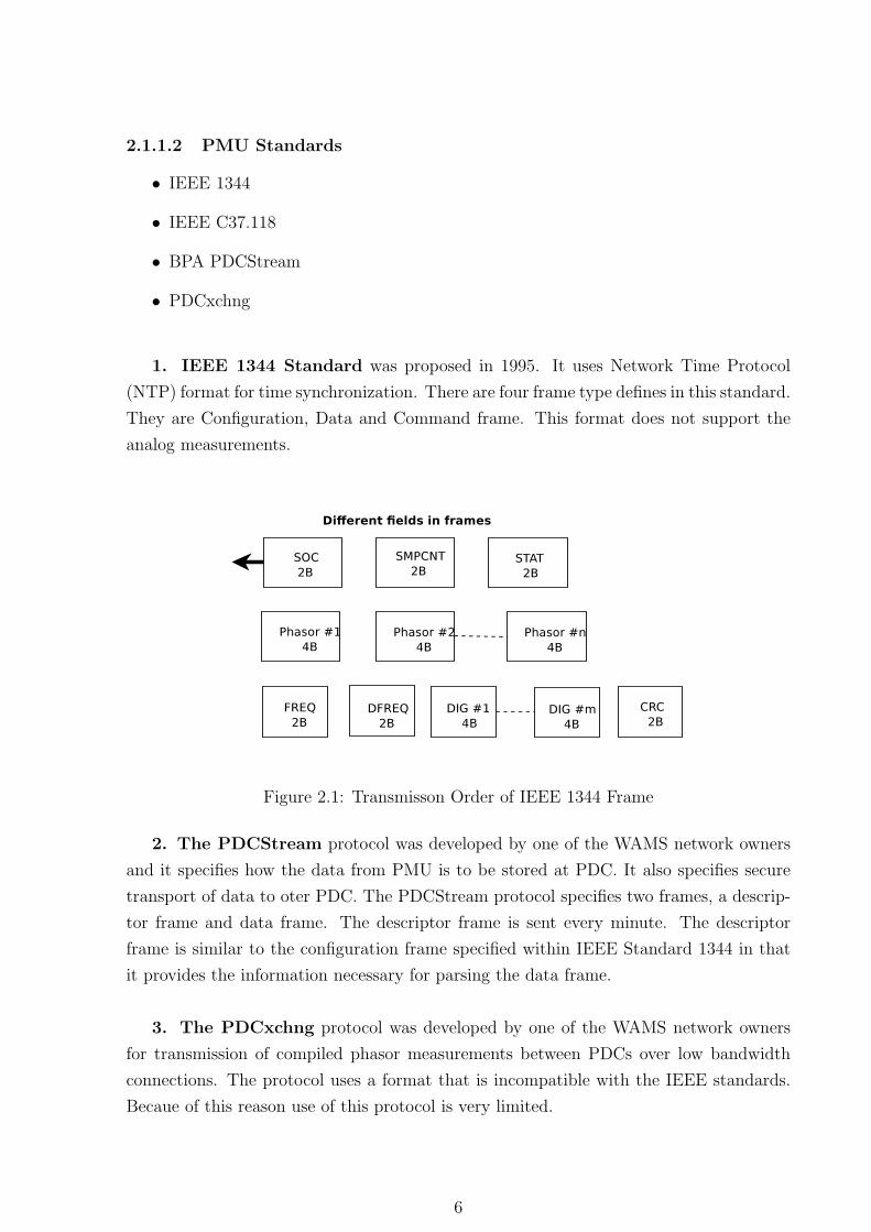
1. IEEE 1344 Standard was proposed in 1995. It uses Network Time Protocol
(NTP) format for time synchronization. There are four frame type defines in this standard.
They are Configuration, Data and Command frame. This format does not support the
analog measurements.
Figure 2.1: Transmisson Order of IEEE 1344 Frame
2. The PDCStream protocol was developed by one of the WAMS network owners
and it specifies how the data from PMU is to be stored at PDC. It also specifies secure
transport of data to oter PDC. The PDCStream protocol specifies two frames, a descrip-
tor frame and data frame. The descriptor frame is sent every minute. The descriptor
frame is similar to the configuration frame specified within IEEE Standard 1344 in that
it provides the information necessary for parsing the data frame.
3. The PDCxchng protocol was developed by one of the WAMS network owners
for transmission of compiled phasor measurements between PDCs over low bandwidth
connections. The protocol uses a format that is incompatible with the IEEE standards.
Becaue of this reason use of this protocol is very limited.
6
4. IEEE C37.118 standard is widely adopted by all the vendors. The IEEE 1344
standard for synchrophasors was completed in 1995, it was replaced by IEEE Standard
C37.118 in 2005, which was a complete revision and dealt with issues concerning use of
PMUs in electric power systems. There are Four frame type define in this standard. They
are as follows
• Command Frame
• Configuration Frame
• Data Frame
• Header Frame
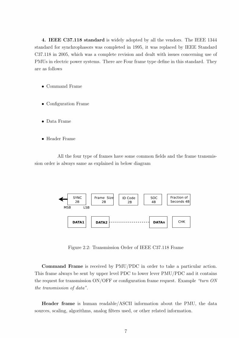
All the four type of frames have some common fields and the frame transmis-
sion order is always same as explained in below diagram
Figure 2.2: Transmission Order of IEEE C37.118 Frame
Command Frame is received by PMU/PDC in order to take a particular action.
This frame always be sent by upper level PDC to lower lever PMU/PDC and it contains
the request for transmission ON/OFF or configuration frame request. Example “turn ON
the transmission of data”.
Header frame is human readable/ASCII information about the PMU, the data
sources, scaling, algorithms, analog filters used, or other related information.
7
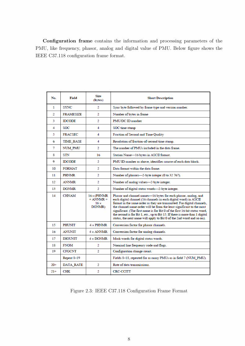
Configuration frame contains the information and processing parameters of the
PMU, like frequency, phasor, analog and digital value of PMU. Below figure shows the
IEEE C37.118 configuration frame format.
Figure 2.3: IEEE C37.118 Configuration Frame Format
8
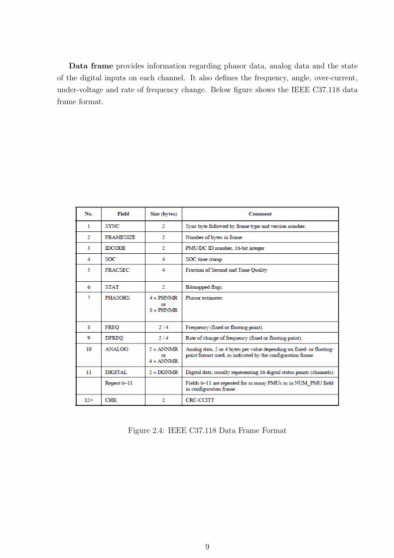
Data frame provides information regarding phasor data, analog data and the state
of the digital inputs on each channel. It also defines the frequency, angle, over-current,
under-voltage and rate of frequency change. Below figure shows the IEEE C37.118 data
frame format.
Figure 2.4: IEEE C37.118 Data Frame Format
9
2.1.2 Phasor Data Concentrator
2.1.2.1 Introduction
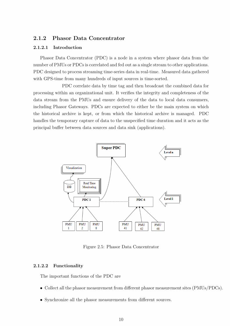
Phasor Data Concentrator (PDC) is a node in a system where phasor data from the
number of PMUs or PDCs is correlated and fed out as a single stream to other applications.
PDC designed to process streaming time-series data in real-time. Measured data gathered
with GPS-time from many hundreds of input sources is time-sorted.
PDC correlate data by time tag and then broadcast the combined data for
processing within an organizational unit. It verifies the integrity and completeness of the
data stream from the PMUs and ensure delivery of the data to local data consumers,
including Phasor Gateways. PDCs are expected to either be the main system on which
the historical archive is kept, or from which the historical archive is managed. PDC
handles the temporary capture of data to the unspecified time duration and it acts as the
principal buffer between data sources and data sink (applications).
Figure 2.5: Phasor Data Concentrator
2.1.2.2 Functionality
The important functions of the PDC are
• Collect all the phasor measurement from different phasor measurement sites (PMUs/PDCs).
• Synchronize all the phasor measurements from different sources.
10
• Package all the phasor measurements from all the phasor measurement as snapshot
of the power network with timestamp (do padding if required) and send to the
advanced applications.
• Remotely set up the phasor measurement units.
• Support protocols like IEEE C37.118, IEEE 1344 via serial or Ethernet.
• Guarantee the maximum delay with multiple CPUs and RTOS support.
• PDC provides additional functionalities as well, such as it performs various quality
checks on the phasor data and insert appropriate flag into the correlated data stream.
It checks disturbance flags and record file of data for analysis.
• It also performs the archiving for offline and historical data analysis.
2.1.2.3 Applications
Thses are some applications where PDC plays a important role
• Real Time Dynamics Monitoring and Analysis -
The main objective of the real time monitoring and anlaysis application is to mon-
itor the real-time power angle difference between two different areas which could
give the system operator the views and feel of the system’s strength and power flow.
It also includes wide area Real Time Grid Dynamics Monitoring.
• Real Time Control -
The real time control application uses phasor measurements as the basic input. The
real phasor measurements are sent by PDC to control application. The applicaton
uses one or more algorithms to determine if the system is close to a stability limit.
If a power swing exceeds limits, the control application would take some predefined
action that prevent the whole system to crash.
• Real Time Adaptive Protection -
The Real Time Adaptive Protection or wide area protection is used to save the
system from partial or total blackout in operational situations when no particular
equipment is faulted or operated outside its limitations. The protection system re-
acts to an emergency by taking additional switching actions to restrict the impact
of a wrong operation.
11
• Data Archiving -
The Data Archiver of Wide area measurements is used for reviewing the system
performance in the previous days or post analysis . This application enables opera-
tor to analyze data recorded in two ways they are Phasor Analysis and Disturbance
Analysis.
• Other Applications -
– Dynamic disturbance recordingd & data logging
– Wide area protection
– Dynamic transaction limits monitoring
– Dynamics performance monitoring
– Machine model verification
– Damping/oscillation analysis
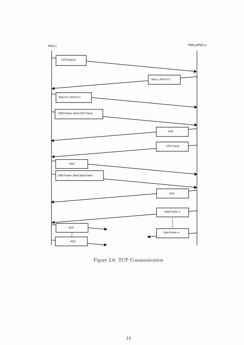
2.2 Communication
PDC can coomunicate to PMU and other PDC via TCP or UDP protocol. UDP is
a unreliable protocol insted of TCP can be use but it requires high bandwidth. PDCx,
PDCy denotes the PDC installed on machine x and y respectively.
1. Initially, PDCx will send a command frame to PMUy/PDCz to send its configuration
frame.
2. PMUy/PDCz will reply with the configuration frame.
3. PDCx will then send another command frame to PMUy/PDCz to start sending the
data frames.
4. PMUy/PDCz will then start sending the data frames.
5. If PDCx detects any change in data sent by PMUy/PDCz which it can know from
the bits in the STAT word of the data frame, it will send a command frame to
PMUy/PDCz to send its changed configuration frame.
6. PMUy/PDCz will then send the changed configuration frame.
7. The PDCx will then send command frame to PMUy/PDCz to start the transmission
of data frames.
8. PMUy/PDCz will then start sending the data frames.
12
PMU-PDC can communicate with each other over TCP or UDP protocols. UDP is an
unreliable communication protocol. The UDP server in client-server model is stateless. It
does not retain the connection state. UDP does not handle packet loss. Thus if a packet
is lost or corrupted then it cannot be retained. It is mostly used to transfer real time
streaming data such as videos where timely delivery is more critical. TCP is a reliable
communication protocol. The TCP server in client-server model is stateful. It maintains
state information of all client connections. TCP handles packet loss, error control, re-
transmission of the lost packets etc. For every packet sent there is an acknowledge(ACK)
packet sent by the receiver. There is a three way handshake to establish and terminate
the connection between the client and server. A connection is initiated by a SYN packet
and terminated by FIN packet.
13
PDC-x PMU-y/PDC-z
Seq=y, ACK=x+1
Seq=x+1, ACK=y+1
SYN (Seq=x)
CMD Frame- Send CGF Frame
ACK
CFG Frame
ACK
CMD Frame- Send Data Frame
ACK
Data Frame -1
ACK
Data Frame -n
ACK
Figure 2.6: TCP Communication
14
2.3 WAMS Implementations
openPDC
The openPDC is a complete Phasor Data Concentrator software system designed to
process streaming time-series data in real-time. Measured data gathered with GPS-time
from many hundreds of input sources is time-sorted and provided to user defined actions
as well as to custom outputs for archival. The openPDC runs as a Windows service.
The open source phasor data concentrator (openPDC) is a system that is
used to manage, process and respond to dynamic changes in fast moving streaming phasor
data. More specifically, the openPDC can process any kind of data that can be described
as “time-stamped measured values”. These measured values are simply numeric quanti-
ties that have been acquired at a source device and are typically called points, signals,
events, time-series values or measurements. Examples of measurements include tempera-
ture, voltage, vibration, location, luminosity and, of course, phasors. When a value gets
measured, an exact timestamp is taken, typically using a GPS-clock for accuracy, along
with its timestamp, is then streamed to the openPDC where it can be “time-aligned”
with other incoming measurements so that an action can then be taken on a complete
slice of data that was all measured at the exact same moment in time.
Applications provided by openPDC includes
• WSU Oscillation Monitoring System.
• Allow remote access and simplify adapter configurations in the database.
• Display Real-time SynchroPhasor Measurements.
ePDC
enhanced Phasor Data Concentrator (ePDC) is designed to accept data from phasor
measurement units, time-synchronize all the inputs, and provide time-synchronized output
for applications. It is a platform independent, software-based open system Phasor Data
Concentrator. It operates on a standard Windows operating system, or a Linux system.
It accepts phasor data in the standard formats and data rates. It will provide multiple
data outputs to serve applications like visualization, monitoring, archiving, historians. It
is also designed to support SCADA type protocols and other advanced applications. It
has an extensive GUI driven XML configuration system to simplify user setup. All oper-
ation is logged for quality control and monitor functions can be used to pinpoint system
problems.
15
Applications provided by ePDC includes
• Scalable input capacity, support over 100 PMUs.
• Capable of 10+ data streams output, each stream individually configurable.
• Real time reliability monitoring and visualization by grid operators in control rooms.
SYNC 4000 Phasor Data Concentrator
SYNC 4000 developed by Kalki Technologies can also function as a high performance
and scalable synchro-phasor data concentrator and protocol conversion gateway for Wide
Area Monitoring applications. It is capable of collecting phasor data streamed from
any IEEE C37.118 compliant phasor measurement unit via Ethernet and aggre- gates
all the C37.118 input streams, performs data validation and time alignment, and trans-
mitsC37.118 super packets to multiple clients.
It can also perform protocol conversion from C37.118 to a number of com-
mon power system protocols, for interfacing with SCADA, EMS or other third party
applications. User friendly tools for configuration and diagnostics make engineering, sys-
tem integration and commissioning quick and easy. The SYNC 4000 PDC can collect data
streams from up to 100 PMUs simultaneously at rates of 60 samples/sec. The SYNC 4000
is based on standard quad-core server hardware. The SYNC 4000 is designed with scal-
ability and performance as the key objectives. The current generation SYNC 4000 can
handle up to 1000 PMUs.
Other WAMS implementations
• SEL : Provide both hardware and software PDC.
• SIEMENS : SIGUARD PDP.
• WAFM : Developed by IIT Bombay. It is a frequency monitoring system through
frequency measuring sensors located over wide area.
16
2.4 Database
Of the available open source databases, MySQL & PostgreSQL are the widely popular
one. From the information available in the the Wikipedia some of the features of both
have been listed. Both PostgreSQL and MySQL support Not-Null, Unique, Primary Key.
Foreign Key constraints are supported by PostgreSQL and MySQL DB storage engine,
but not other engines. MySQL supports stored procedures, PostgreSQL supports stored
functions, which are in practice very similar. Both PostgreSQL and MySQL support trig-
gers. Replication is a database management system ability to duplicate its stored data
for the purposes of backup safety and is one way to prevent database downtime. Post-
greSQL and MySQL both support replication. But support for MySQL is found to be
more compared to the PostgreSQL.
17
Chapter 3
Design Model
3.1 iPDC WAMS Architecture
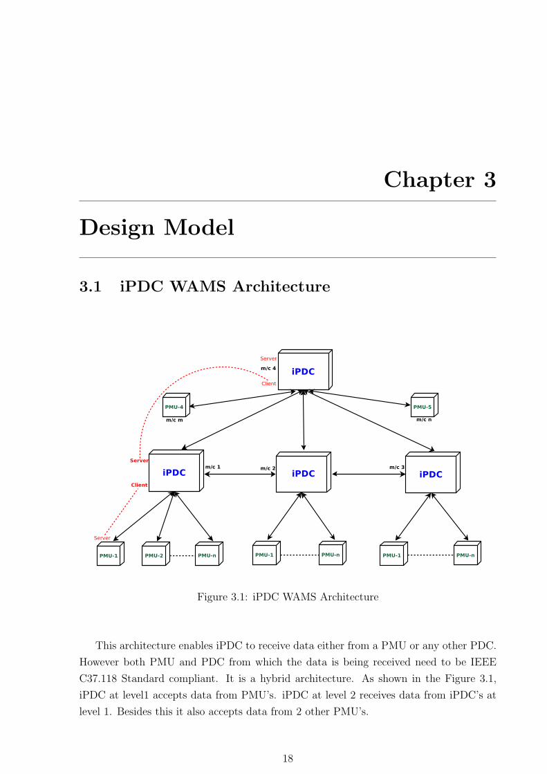
Figure 3.1: iPDC WAMS Architecture
This architecture enables iPDC to receive data either from a PMU or any other PDC.
However both PMU and PDC from which the data is being received need to be IEEE
C37.118 Standard compliant. It is a hybrid architecture. As shown in the Figure 3.1,
iPDC at level1 accepts data from PMU’s. iPDC at level 2 receives data from iPDC’s at
level 1. Besides this it also accepts data from 2 other PMU’s.
18
3.1.1 iPDC Design
The client server architecture is common in networks when two entities are commini-
cating with each other. In WAMS too, of the two entities(PMU and iPDC) that are com-
municating with each other one has to be client and the other a server. The PMUbeing
a receiver of command frames which serve as requests is a server. It listens for command
frames from iPDC. PMU can communicate either in TCP or UDP communication pro-
tocol on two different ports. On receiving command frames, it replies to the iPDC with
data or configuration frames according to the type of request.
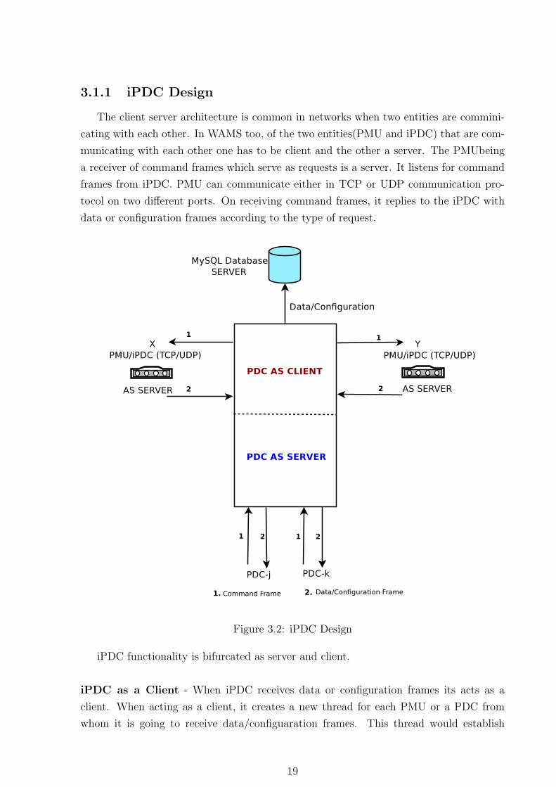
Figure 3.2: iPDC Design
iPDC functionality is bifurcated as server and client.
iPDC as a Client - When iPDC receives data or configuration frames its acts as a
client. When acting as a client, it creates a new thread for each PMU or a PDC from
whom it is going to receive data/configuaration frames. This thread would establish
19
connection between the two communication entities. It handles both TCP and UDP con-
nections. The first frame that the server(PMU/iPDC) would receive is the command for
sending the configuration frame. When the server replies with the configuration frame,
iPDC(client) would generate another request to start sending the data frames. On receiv-
ing such a command frame, the server starts sending the data frames. If there is some
change in the status bits of data frame which the client(iPDC) notices, it would take an
action. For example if it notices a bit 10 has been set, it would internally send a command
to server to send the latest configuartion frame.
iPDC as a Server- When iPDC receives command frames from another iPDC it would
acts as a server. There would be two reserved ports one for UDP and other for TCP on
which the PDC would receive command frame requests. Thus iPDC now plays the role of
PMU waiting for command frames. Figure 3.2 shows the both the parts of iPDC, client
& server.
3.1.2 iPDC Working
PMU’s/iPDC’s act as servers when they are communicating with another iPDC whom
they are sending the data/configuration frames. The iPDC receiving data in this case acts
as a client. However when the same iPDC sends data to another iPDC, it would act as
a server. This pattern will be repeated in the WAMS topology with one peer acting as
server and its counterpart a client.
The iPDC when acting as a server binds to 2 ports UDPPORT and TCP-
PORT. It would be listening for UDP connections on UDPPORT and TCP connections on
TCPPORT. The iPDC can then send the combined configuration frames to any number
of other iPDCs. Both the communicating peers authenticate each other. iPDC authenti-
cates for each received packets irrespective of communcation protocols used(TCP/UDP).
When the iPDC starts for the first time the user is prompted to enter iPDC Idcode, UDP
Port, TCP Port and Database Server IP. The ports enable iPDC to receive requests from
other iPDC and to send the combined data and configuration frames. Database Server IP
is the IP address of the machine where the process dbserver is running. The default port
on which dbserver is listening for data is 9000 and it is a UDP server. The data which
the iPDC receives would also be directed to dbserver for storage in MySQL database.
The user is provided with the following options at iPDC
• Enter iPDC Setup
• Open iPDC Setup
• Add a Source Device
20
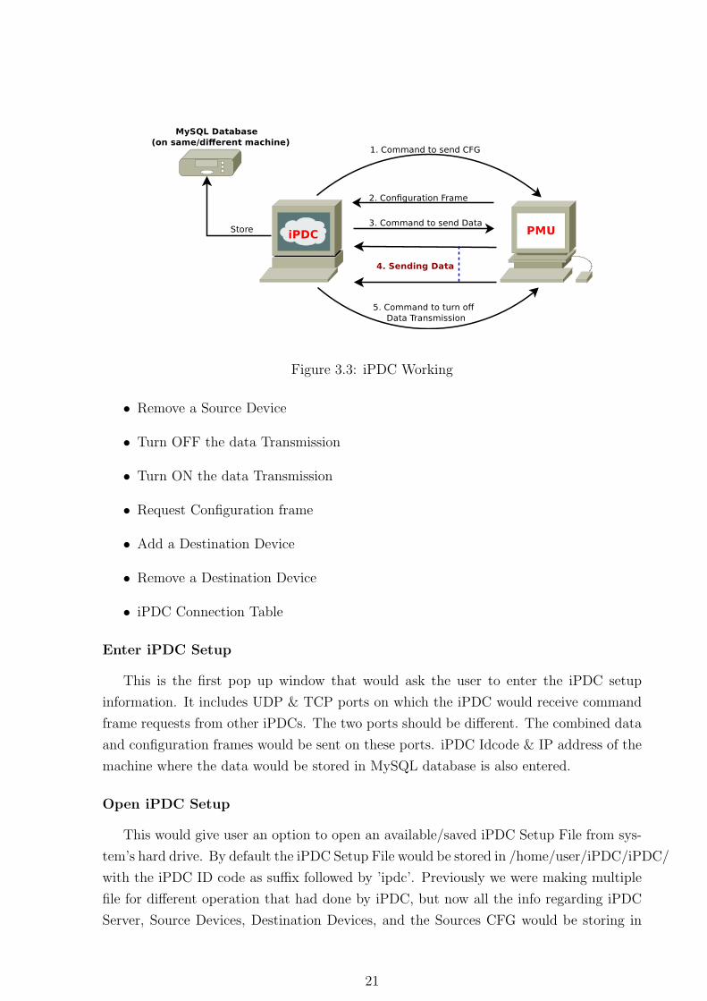
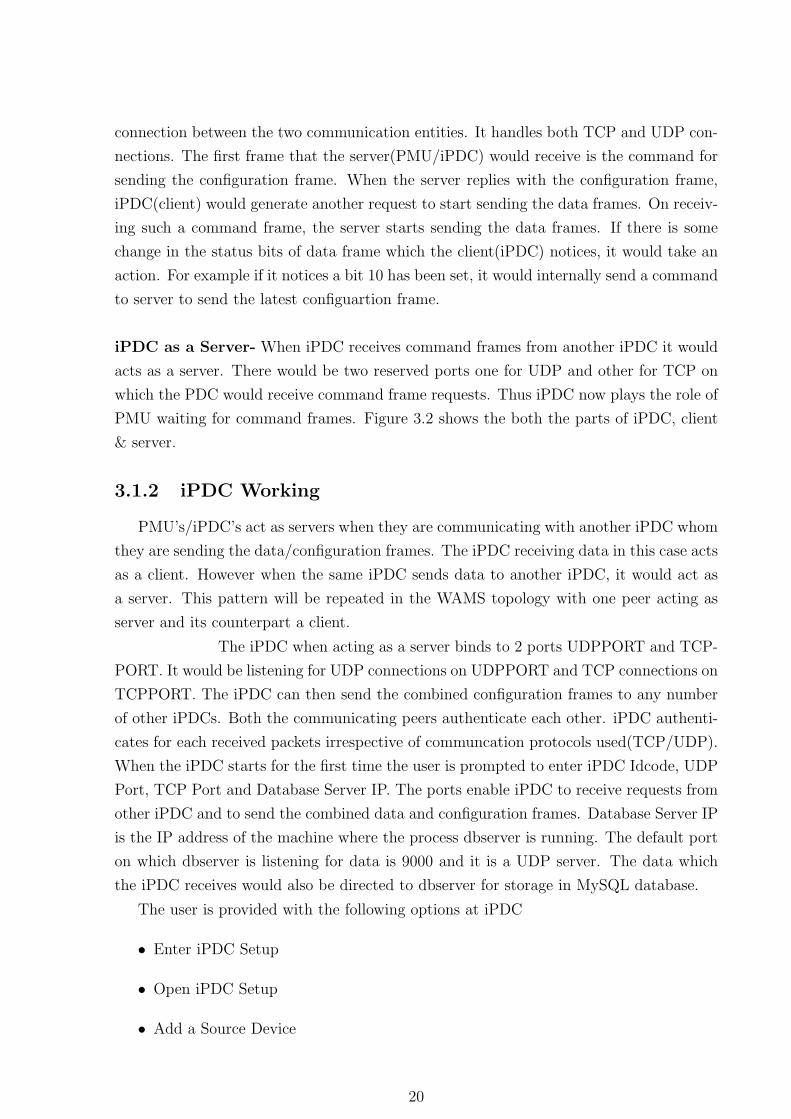
Figure 3.3: iPDC Working
• Remove a Source Device
• Turn OFF the data Transmission
• Turn ON the data Transmission
• Request Configuration frame
• Add a Destination Device
• Remove a Destination Device
• iPDC Connection Table
Enter iPDC Setup
This is the first pop up window that would ask the user to enter the iPDC setup
information. It includes UDP & TCP ports on which the iPDC would receive command
frame requests from other iPDCs. The two ports should be different. The combined data
and configuration frames would be sent on these ports. iPDC Idcode & IP address of the
machine where the data would be stored in MySQL database is also entered.
Open iPDC Setup
This would give user an option to open an available/saved iPDC Setup File from sys-
tem’s hard drive. By default the iPDC Setup File would be stored in /home/user/iPDC/iPDC/
with the iPDC ID code as suffix followed by ’ipdc’. Previously we were making multiple
file for different operation that had done by iPDC, but now all the info regarding iPDC
Server, Source Devices, Destination Devices, and the Sources CFG would be storing in
21
a single bin file called iPDC Setup File. All the previous operations are same. Before
loading a Setup File on the iPDC, user are able to see what are the information it contains.
Add a Source Device
This would make an entry in his setup file under ’SourceSevices’ for each newly added
PMU. Before making the entry it would check if there is already a connection with the
same node. If so, no entry is made. Otherwise a new thread would be created for
connection with the device based on type of the protocol that have been selected by user
(TCP/UDP). Also a new node of the type Lower Layer Details would be created.
Remove a Source Device
This would display the user with available PMU node entries and would prompt the
user to enter the details of node to be removed. When user enters the correct details,
the PMU node entry would be removed from the his setup file. Also the corresponding
Lower Layer Details node would be removed from doubly LL. A signal would be sent to
the thread that handles this connection. On receival of the signal the thread would close
the socket and exit.
Turn OFF the data Transmission
This would display the user with available PMU entries and would prompt the user to
enter the details of node whose data transmission is to be put off. When user enters the
correct details, the command frame would be sent to that node. The flag data transmission
OFF of the corresponding node in Lower Layer Details structure doubly LL would be set.
Turn ON the data Transmission
This would display the user with available PMU entries whose data transmission has
been put off and would prompt the user to enter the details of node whose data trans-
mission is to be put on. When user enters the correct details, the command frame to
put off data tramsission would be sent to that node. The flag data transmission off of
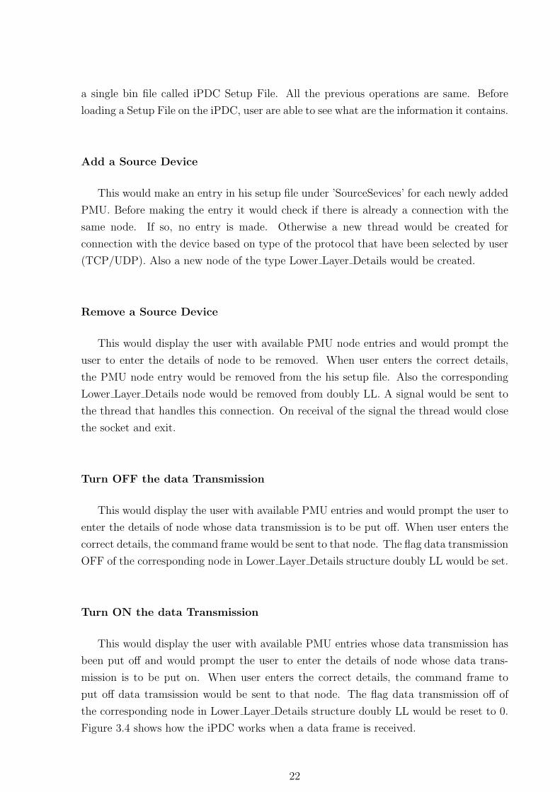
the corresponding node in Lower Layer Details structure doubly LL would be reset to 0.
Figure 3.4 shows how the iPDC works when a data frame is received.
22
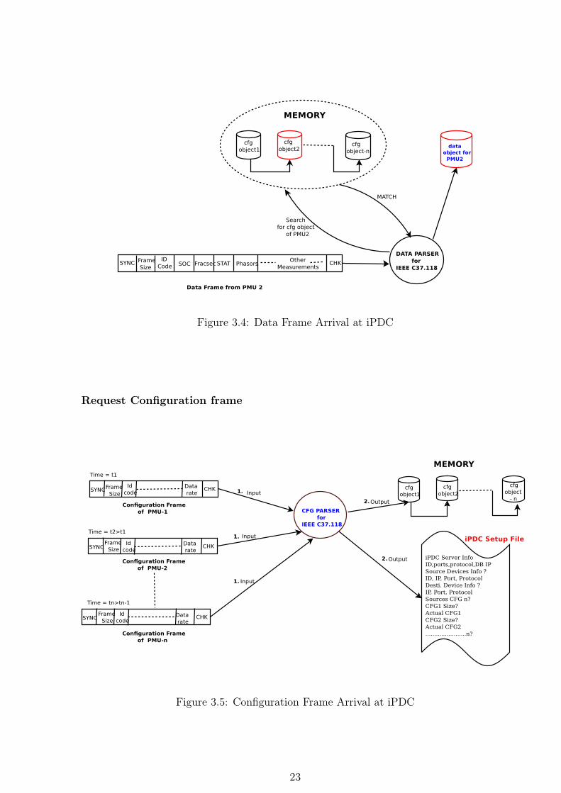
Figure 3.4: Data Frame Arrival at iPDC
Request Configuration frame
Figure 3.5: Configuration Frame Arrival at iPDC
23
This would display the user with available PMU entries and would prompt the user
to enter the details of node to whom the configuration frame request is to be sent. When
user enters the correct details, the command frame to send the configuration frame would
be sent to that node. Figure 3.5 shows how the iPDC works when a configuration frame
is received.
Add a Destination Device
An entry is made in the his setup file. Also a node of the type Upper Layer Details
is created. It includes ip, port and protocol details of other iPDC. iPDC when act-
ing as a server may get connection requests on 6000 and 6001 ports for UDP and TCP
repectively. The received command frames are authenticated against the entries in the Up-
per Layer Details doubly LL. If the command frame is for configuration frame then, check
is made if there are no Idcodes in the ’status change pmupdcid’. ’status change pmupdcid’
a LL which maintains the idcodes of all PMU’s whose connfiguration has beed changed.
If the list is not empty, till the list is empty the configuration frame won’t be sent. When
a new Configuration frame of the corresponding ID codes arrives then its entry is removed
from the list. After the list is empty create cfgframe() is called that creates combined
configuration frame from configuration objects. Then the flag UL upper pdc cfgsent in
the corresponding Upper Layer Details node of the PDC is set. If the command frame
is for data then, UL upper pdc datasent is set and UL data transmission off in the cor-
responding Upper Layer Details node of the iPDC is reset. The functions dispatch()
in align sort() will send the combined data on one of the sockets by checking the vari-
ables UL use udp, UL upper pdc cfgsent and UL data transmission off. If the command
frame is for data transmisssion off then UL data transmission off in the corresponding
Upper Layer Details node is set.
24
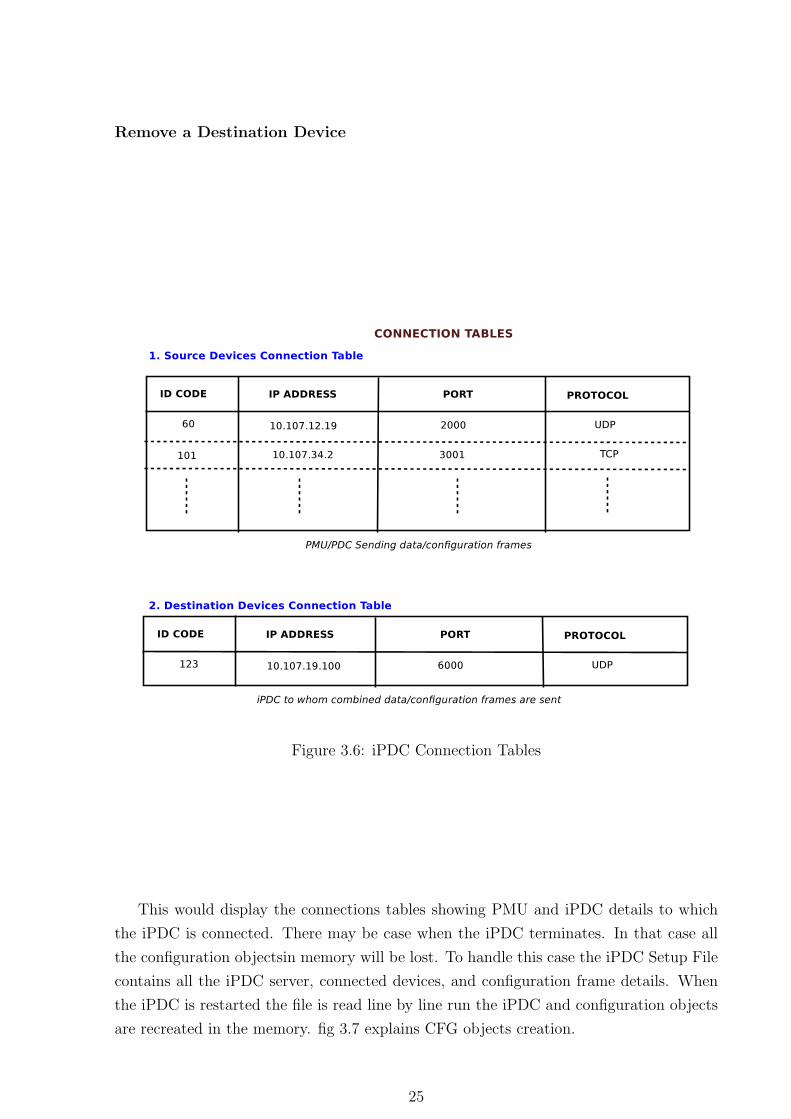
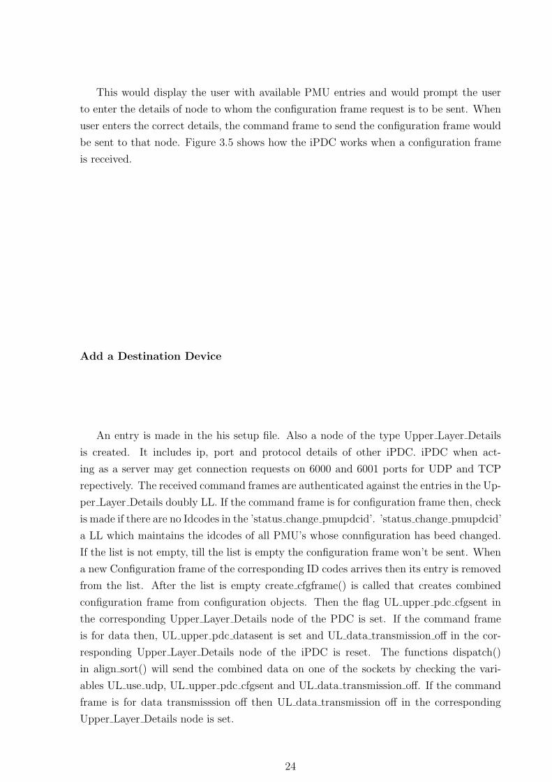
Remove a Destination Device
Figure 3.6: iPDC Connection Tables
This would display the connections tables showing PMU and iPDC details to which
the iPDC is connected. There may be case when the iPDC terminates. In that case all
the configuration objectsin memory will be lost. To handle this case the iPDC Setup File
contains all the iPDC server, connected devices, and configuration frame details. When
the iPDC is restarted the file is read line by line run the iPDC and configuration objects
are recreated in the memory. fig 3.7 explains CFG objects creation.
25
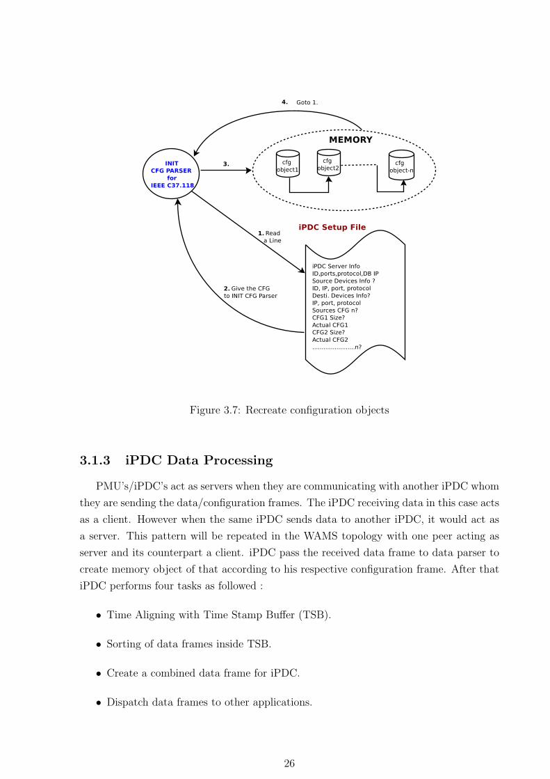
Figure 3.7: Recreate configuration objects
3.1.3 iPDC Data Processing
PMU’s/iPDC’s act as servers when they are communicating with another iPDC whom
they are sending the data/configuration frames. The iPDC receiving data in this case acts
as a client. However when the same iPDC sends data to another iPDC, it would act as
a server. This pattern will be repeated in the WAMS topology with one peer acting as
server and its counterpart a client. iPDC pass the received data frame to data parser to
create memory object of that according to his respective configuration frame. After that
iPDC performs four tasks as followed :
• Time Aligning with Time Stamp Buffer (TSB).
• Sorting of data frames inside TSB.
• Create a combined data frame for iPDC.
• Dispatch data frames to other applications.
26
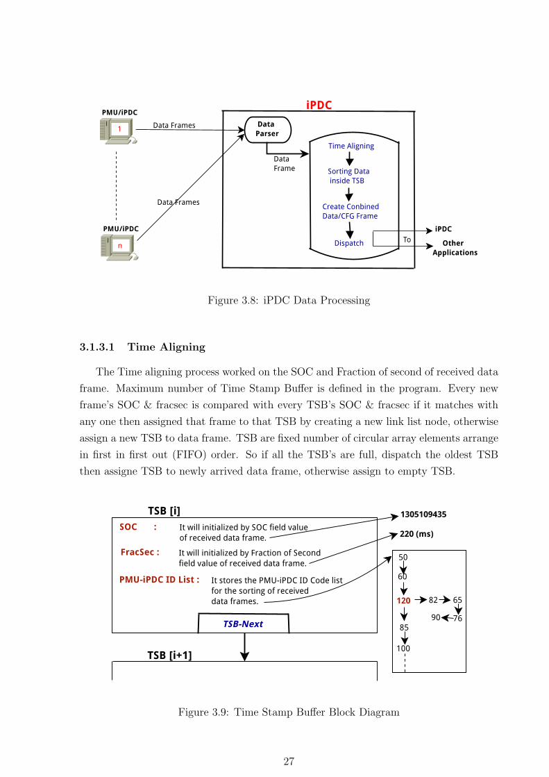
Figure 3.8: iPDC Data Processing
3.1.3.1 Time Aligning
The Time aligning process worked on the SOC and Fraction of second of received data
frame. Maximum number of Time Stamp Buffer is defined in the program. Every new
frame’s SOC & fracsec is compared with every TSB’s SOC & fracsec if it matches with
any one then assigned that frame to that TSB by creating a new link list node, otherwise
assign a new TSB to data frame. TSB are fixed number of circular array elements arrange
in first in first out (FIFO) order. So if all the TSB’s are full, dispatch the oldest TSB
then assigne TSB to newly arrived data frame, otherwise assign to empty TSB.
Figure 3.9: Time Stamp Buffer Block Diagram
27
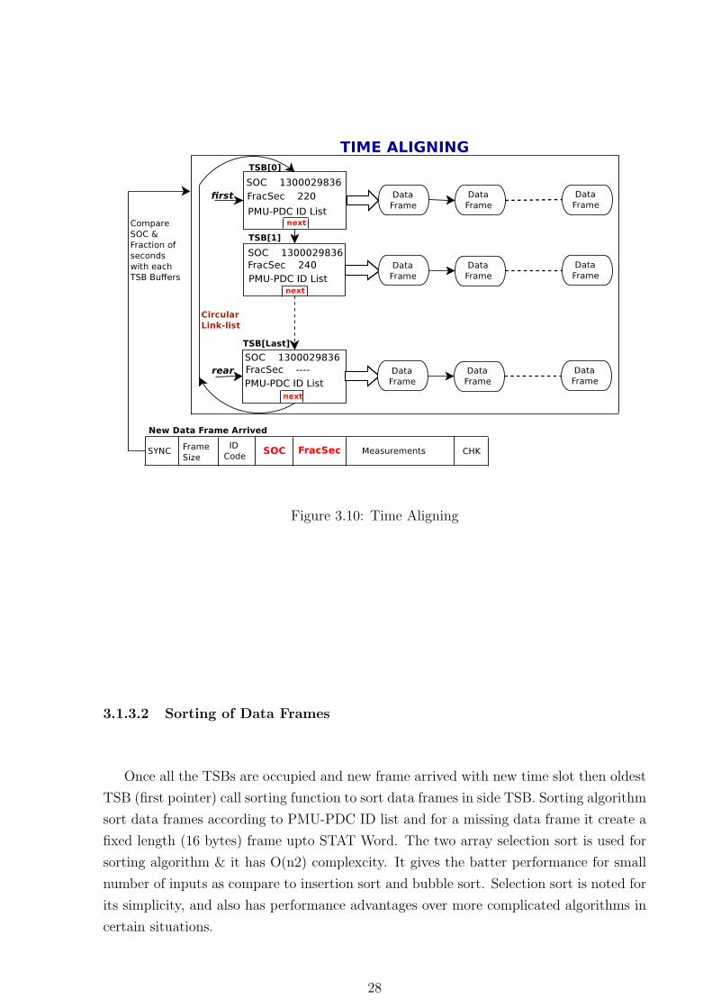
Figure 3.10: Time Aligning
3.1.3.2 Sorting of Data Frames
Once all the TSBs are occupied and new frame arrived with new time slot then oldest
TSB (first pointer) call sorting function to sort data frames in side TSB. Sorting algorithm
sort data frames according to PMU-PDC ID list and for a missing data frame it create a
fixed length (16 bytes) frame upto STAT Word. The two array selection sort is used for
sorting algorithm & it has O(n2) complexcity. It gives the batter performance for small
number of inputs as compare to insertion sort and bubble sort. Selection sort is noted for
its simplicity, and also has performance advantages over more complicated algorithms in
certain situations.
28
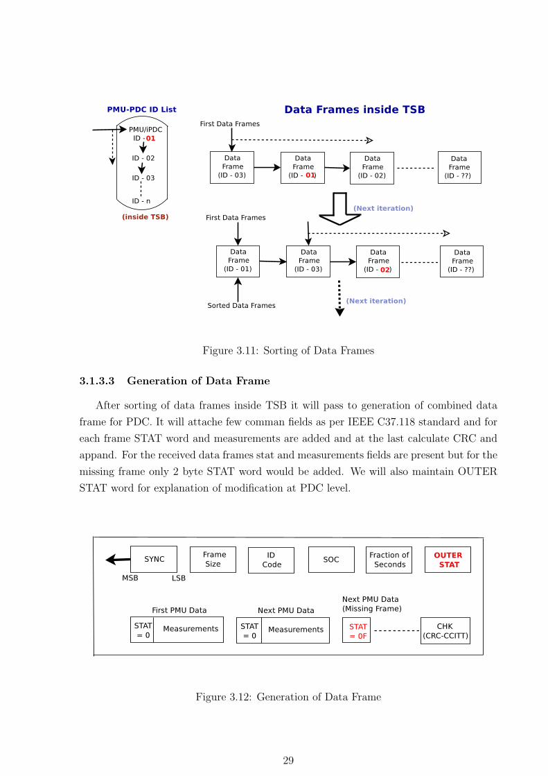
Figure 3.11: Sorting of Data Frames
3.1.3.3 Generation of Data Frame
After sorting of data frames inside TSB it will pass to generation of combined data
frame for PDC. It will attache few comman fields as per IEEE C37.118 standard and for
each frame STAT word and measurements are added and at the last calculate CRC and
appand. For the received data frames stat and measurements fields are present but for the
missing frame only 2 byte STAT word would be added. We will also maintain OUTER
STAT word for explanation of modification at PDC level.
Figure 3.12: Generation of Data Frame
29
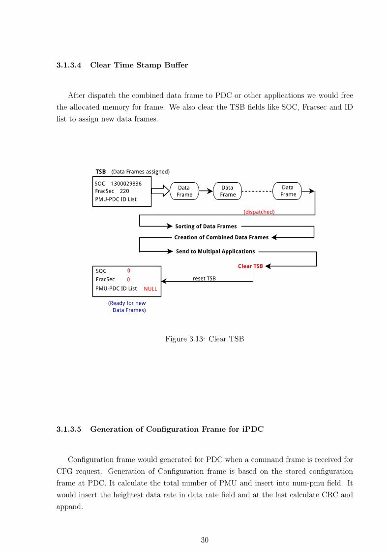
3.1.3.4 Clear Time Stamp Buffer
After dispatch the combined data frame to PDC or other applications we would free
the allocated memory for frame. We also clear the TSB fields like SOC, Fracsec and ID
list to assign new data frames.
Figure 3.13: Clear TSB
3.1.3.5 Generation of Configuration Frame for iPDC
Configuration frame would generated for PDC when a command frame is received for
CFG request. Generation of Configuration frame is based on the stored configuration
frame at PDC. It calculate the total number of PMU and insert into num-pmu field. It
would insert the heightest data rate in data rate field and at the last calculate CRC and
appand.
30
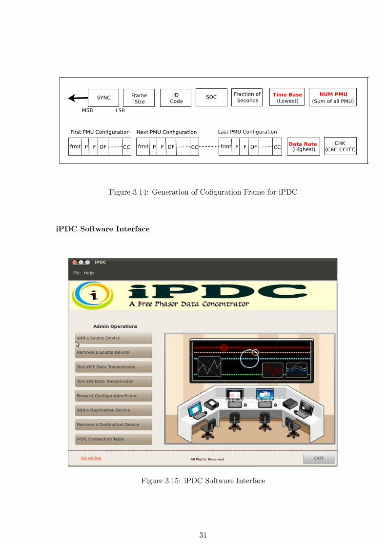
Figure 3.14: Generation of Cofiguration Frame for iPDC
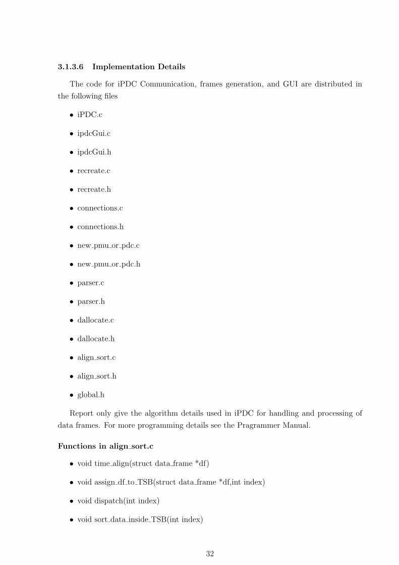
iPDC Software Interface
Figure 3.15: iPDC Software Interface
31
3.1.3.6 Implementation Details
The code for iPDC Communication, frames generation, and GUI are distributed in
the following files
• iPDC.c
• ipdcGui.c
• ipdcGui.h
• recreate.c
• recreate.h
• connections.c
• connections.h
• new pmu or pdc.c
• new pmu or pdc.h
• parser.c
• parser.h
• dallocate.c
• dallocate.h
• align sort.c
• align sort.h
• global.h
Report only give the algorithm details used in iPDC for handling and processing of
data frames. For more programming details see the Pragrammer Manual.
Functions in align sort.c
• void time align(struct data frame *df)
• void assign df to TSB(struct data frame *df,int index)
• void dispatch(int index)
• void sort data inside TSB(int index)
32
• void clear TSB(int index)
• void create dataframe(int index)
• void create cfgframe()
Detailed Description
align sort.c
• void time align(struct data frame *df)
We use Circular queue to align the data frame objects as per their soc and fracsec.
The size of circular queue is defined as MAXTSB. This function finds the corrects
TSB[] and calls assign df to TSB() by passing the index of the TSB to which the
data frame object df is to be assigned to. Also if all TSB[] buffers are full it calls
dispatch(rear), clear TSB(rear), assign df to TSB(df,rear) in the same order.
• void assign df to TSB(struct data frame *df,int index)
It assigns df data frame object to the TSB[index] at the end of list as indicated by
struct data frame *first data frame. It traverses the end of the list of data frame
objects and then assigns df to the *dnext of last data frame object. Also if the
TSB[] is used for the first time it allocates memory to the member variables of the
TSB[index] and fills the ıdlistwith the pmu/pdc ids from whom data frames would
arrive.
• void dispatch(int index)
It internally calls void sort data inside TSB(index), void create dataframe(index),
clear TSB(index) in the same order.
• void sort data inside TSB(int index)
This function will sort the data frame object LL as per the ids in ıdlistLL.
• void clear TSB(int index)
This will clear TSB[index] member variables to 0 .
• void create dataframe(int index)
This will create combined data frame to be sent to a Destination PDC when a
command frame is received.
• void create cfgframe()
This will create combined configuration frame to be sent to a Destination PDC when
a command frame is received.
33
Data Structures Used
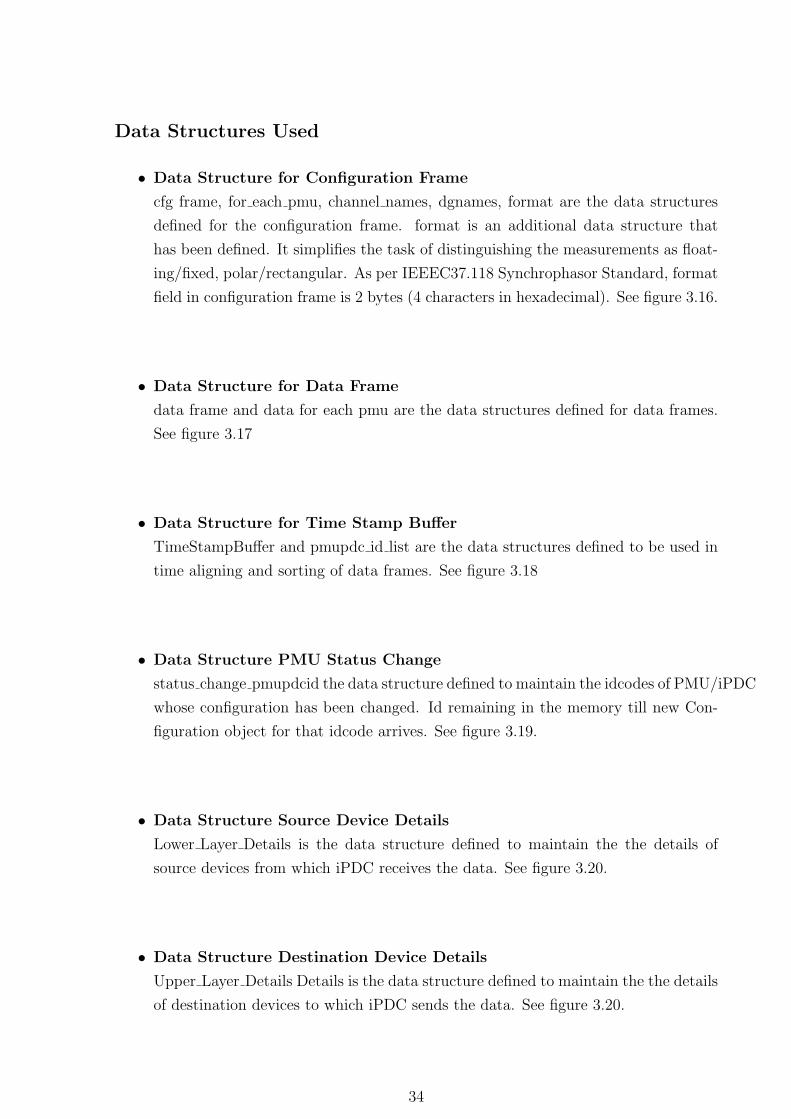
• Data Structure for Configuration Frame
cfg frame, for each pmu, channel names, dgnames, format are the data structures
defined for the configuration frame. format is an additional data structure that
has been defined. It simplifies the task of distinguishing the measurements as float-
ing/fixed, polar/rectangular. As per IEEEC37.118 Synchrophasor Standard, format
field in configuration frame is 2 bytes (4 characters in hexadecimal). See figure 3.16.
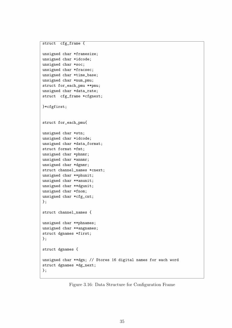
• Data Structure for Data Frame
data frame and data for each pmu are the data structures defined for data frames.
See figure 3.17
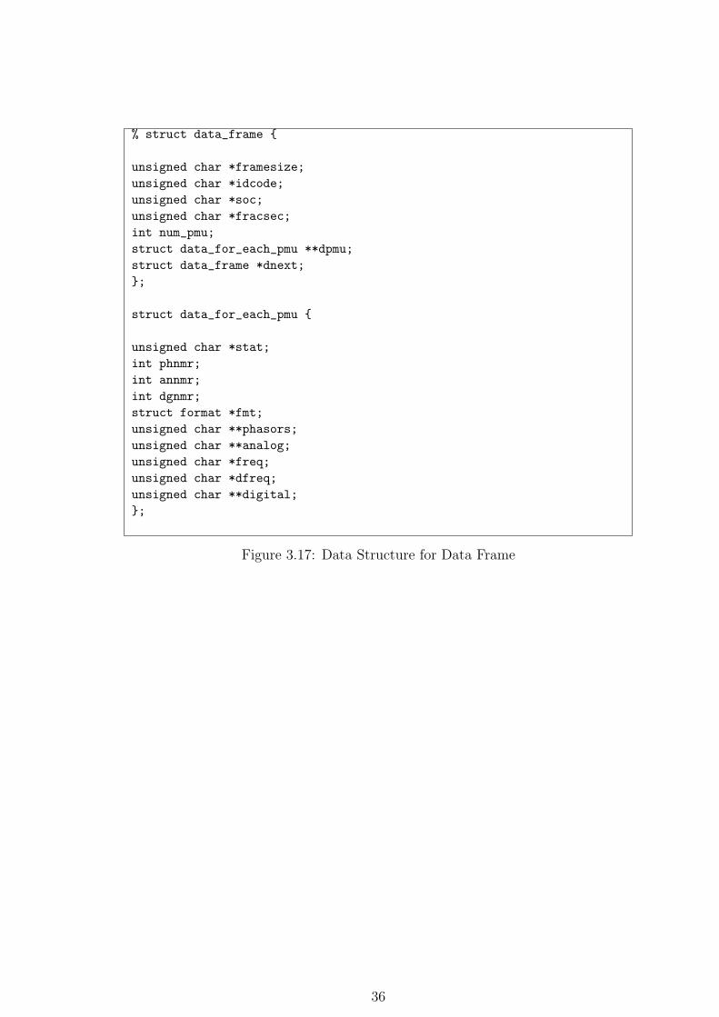
• Data Structure for Time Stamp Buffer
TimeStampBuffer and pmupdc id list are the data structures defined to be used in
time aligning and sorting of data frames. See figure 3.18
• Data Structure PMU Status Change
status change pmupdcid the data structure defined to maintain the idcodes of PMU/iPDC
whose configuration has been changed. Id remaining in the memory till new Con-
figuration object for that idcode arrives. See figure 3.19.
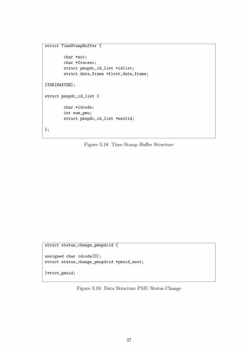
• Data Structure Source Device Details
Lower Layer Details is the data structure defined to maintain the the details of
source devices from which iPDC receives the data. See figure 3.20.
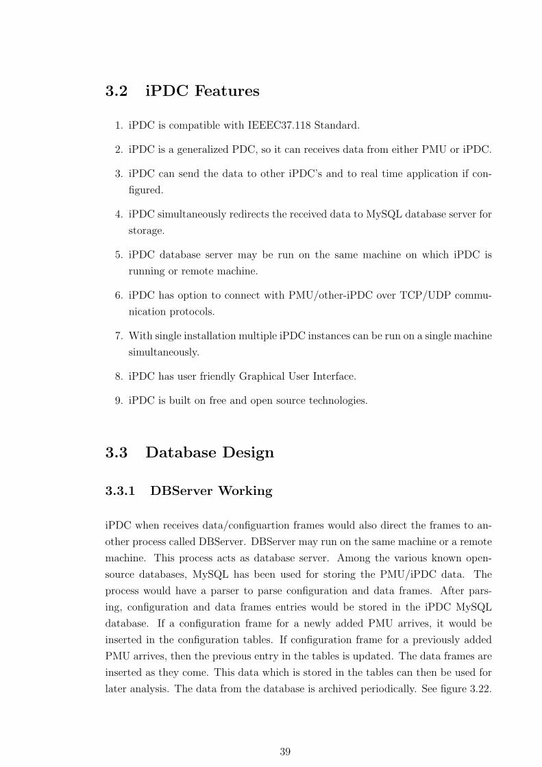
• Data Structure Destination Device Details
Upper Layer Details Details is the data structure defined to maintain the the details
of destination devices to which iPDC sends the data. See figure 3.20.
34
struct cfg_frame {
unsigned char *framesize;
unsigned char *idcode;
unsigned char *soc;
unsigned char *fracsec;
unsigned char *time_base;
unsigned char *num_pmu;
struct for_each_pmu **pmu;
unsigned char *data_rate;
struct cfg_frame *cfgnext;
}*cfgfirst;
struct for_each_pmu{
unsigned char *stn;
unsigned char *idcode;
unsigned char *data_format;
struct format *fmt;
unsigned char *phnmr;
unsigned char *annmr;
unsigned char *dgnmr;
struct channel_names *cnext;
unsigned char **phunit;
unsigned char **anunit;
unsigned char **dgunit;
unsigned char *fnom;
unsigned char *cfg_cnt;
};
struct channel_names {
unsigned char **phnames;
unsigned char **angnames;
struct dgnames *first;
};
struct dgnames {
unsigned char **dgn; // Stores 16 digital names for each word
struct dgnames *dg_next;
};
Figure 3.16: Data Structure for Configuration Frame
35
% struct data_frame {
unsigned char *framesize;
unsigned char *idcode;
unsigned char *soc;
unsigned char *fracsec;
int num_pmu;
struct data_for_each_pmu **dpmu;
struct data_frame *dnext;
};
struct data_for_each_pmu {
unsigned char *stat;
int phnmr;
int annmr;
int dgnmr;
struct format *fmt;
unsigned char **phasors;
unsigned char **analog;
unsigned char *freq;
unsigned char *dfreq;
unsigned char **digital;
};
Figure 3.17: Data Structure for Data Frame
36
struct TimeStampBuffer {
char *soc;
char *fracsec;
struct pmupdc_id_list *idlist;
struct data_frame *first_data_frame;
}TSB[MAXTSB];
struct pmupdc_id_list {
char *idcode;
int num_pmu;
struct pmupdc_id_list *nextid;
};
Figure 3.18: Time Stamp Buffer Structure
struct status_change_pmupdcid {
unsigned char idcode[3];
struct status_change_pmupdcid *pmuid_next;
}*root_pmuid;
Figure 3.19: Data Structure PMU Status Change
37
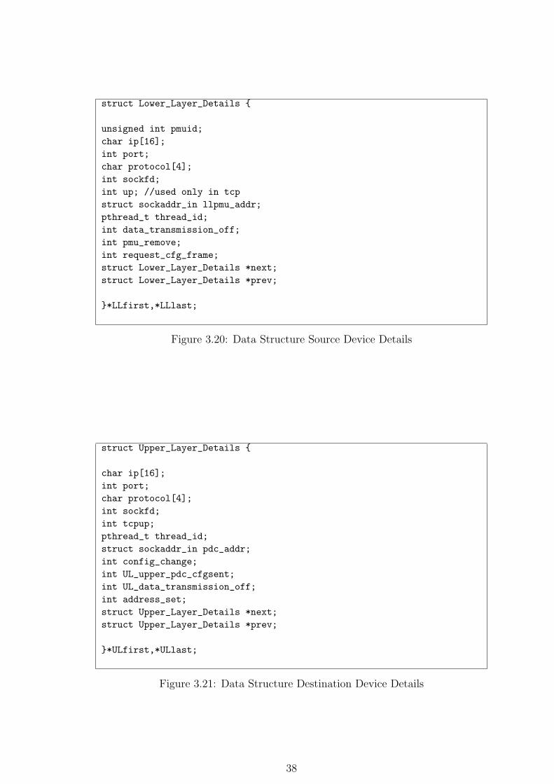
struct Lower_Layer_Details {
unsigned int pmuid;
char ip[16];
int port;
char protocol[4];
int sockfd;
int up; //used only in tcp
struct sockaddr_in llpmu_addr;
pthread_t thread_id;
int data_transmission_off;
int pmu_remove;
int request_cfg_frame;
struct Lower_Layer_Details *next;
struct Lower_Layer_Details *prev;
}*LLfirst,*LLlast;
Figure 3.20: Data Structure Source Device Details
struct Upper_Layer_Details {
char ip[16];
int port;
char protocol[4];
int sockfd;
int tcpup;
pthread_t thread_id;
struct sockaddr_in pdc_addr;
int config_change;
int UL_upper_pdc_cfgsent;
int UL_data_transmission_off;
int address_set;
struct Upper_Layer_Details *next;
struct Upper_Layer_Details *prev;
}*ULfirst,*ULlast;
Figure 3.21: Data Structure Destination Device Details
38
3.2 iPDC Features
1. iPDC is compatible with IEEEC37.118 Standard.
2. iPDC is a generalized PDC, so it can receives data from either PMU or iPDC.
3. iPDC can send the data to other iPDC’s and to real time application if con-
figured.
4. iPDC simultaneously redirects the received data to MySQL database server for
storage.
5. iPDC database server may be run on the same machine on which iPDC is
running or remote machine.
6. iPDC has option to connect with PMU/other-iPDC over TCP/UDP commu-
nication protocols.
7. With single installation multiple iPDC instances can be run on a single machine
simultaneously.
8. iPDC has user friendly Graphical User Interface.
9. iPDC is built on free and open source technologies.
3.3 Database Design
3.3.1 DBServer Working
iPDC when receives data/configuartion frames would also direct the frames to an-
other process called DBServer. DBServer may run on the same machine or a remote
machine. This process acts as database server. Among the various known open-
source databases, MySQL has been used for storing the PMU/iPDC data. The
process would have a parser to parse configuration and data frames. After pars-
ing, configuration and data frames entries would be stored in the iPDC MySQL
database. If a configuration frame for a newly added PMU arrives, it would be
inserted in the configuration tables. If configuration frame for a previously added
PMU arrives, then the previous entry in the tables is updated. The data frames are
inserted as they come. This data which is stored in the tables can then be used for
later analysis. The data from the database is archived periodically. See figure 3.22.
39
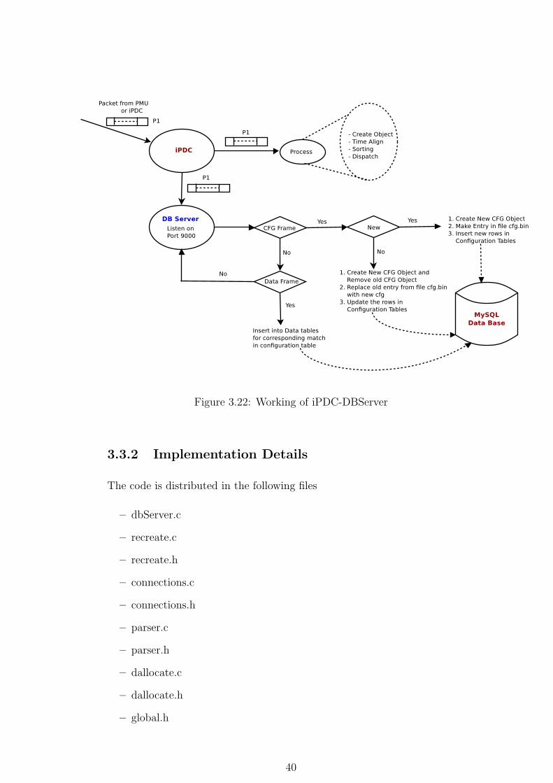
Figure 3.22: Working of iPDC-DBServer
3.3.2 Implementation Details
The code is distributed in the following files
– dbServer.c
– recreate.c
– recreate.h
– connections.c
– connections.h
– parser.c
– parser.h
– dallocate.c
– dallocate.h
– global.h
40
Data Structures Used
The data structured used in DBServer are for Configuration Frame and Data Frame.Same
as in iPDC.
– Data Structure for Configuration Frame
– Data Structure for Data Frame
Script db.sql gives the DDL statements to create the schema. In the MySQL
database named openPDC there are 9 tables namely:-
1. MAIN CFG TABLE
2. SUB CFG TABLE
3. PHASOR
4. ANALOG
5. DIGITAL
6. PHASOR MEASUREMENTS
7. ANALOG MEASUREMENTS
8. FREQUENCY MEASUREMENTS
9. DIGITAL MEASUREMENTS
Configuration frames entries are stored in MAIN CFG TABLE, SUB CFG TABLE,
PHASOR, ANALOG, DIGITAL. Data frames entries are stored in the tables
PHASOR MEASUREMENTS, ANALOG MEASUREMENTS, FREQUENCY
MEASUREMENTS, DIGITAL MEASUREMENTS. Figure 3.23 shows the func-
tional dependencies of the tables.
41
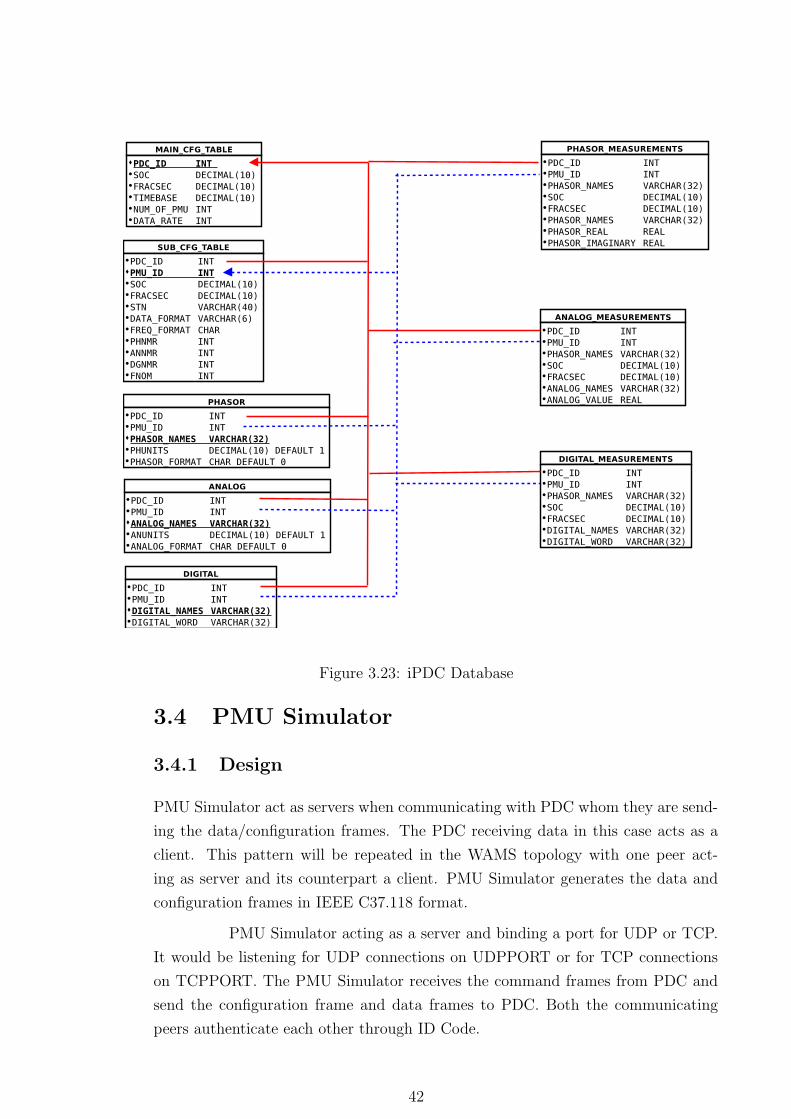
Figure 3.23: iPDC Database
3.4 PMU Simulator
3.4.1 Design
PMU Simulator act as servers when communicating with PDC whom they are send-
ing the data/configuration frames. The PDC receiving data in this case acts as a
client. This pattern will be repeated in the WAMS topology with one peer act-
ing as server and its counterpart a client. PMU Simulator generates the data and
configuration frames in IEEE C37.118 format.
PMU Simulator acting as a server and binding a port for UDP or TCP.
It would be listening for UDP connections on UDPPORT or for TCP connections
on TCPPORT. The PMU Simulator receives the command frames from PDC and
send the configuration frame and data frames to PDC. Both the communicating
peers authenticate each other through ID Code.
42
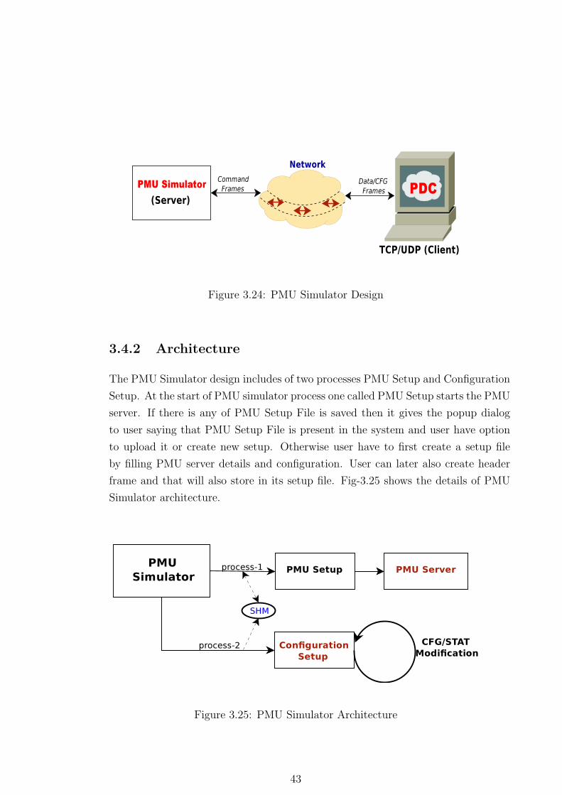
Figure 3.24: PMU Simulator Design
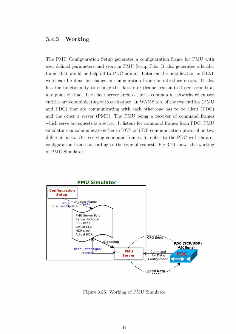
3.4.2 Architecture
The PMU Simulator design includes of two processes PMU Setup and Configuration
Setup. At the start of PMU simulator process one called PMU Setup starts the PMU
server. If there is any of PMU Setup File is saved then it gives the popup dialog
to user saying that PMU Setup File is present in the system and user have option
to upload it or create new setup. Otherwise user have to first create a setup file
by filling PMU server details and configuration. User can later also create header
frame and that will also store in its setup file. Fig-3.25 shows the details of PMU
Simulator architecture.
Figure 3.25: PMU Simulator Architecture
43
3.4.3 Working
The PMU Configuaration Setup generates a configuaration frame for PMU with
user defined parameters and store in PMU Setup File. It also generates a header
frame that would be helpfull to PDC admin. Later on the modification in STAT
word can be done by change in configuration frame or introduce errors. It also
has the functionality to change the data rate (frame transmitted per second) at
any point of time. The client server architecture is common in networks when two
entities are comminicating with each other. In WAMS too, of the two entities (PMU
and PDC) that are communicating with each other one has to be client (PDC)
and the other a server (PMU). The PMU being a receiver of command frames
which serve as requests is a server. It listens for command frames from PDC. PMU
simulator can communicate either in TCP or UDP communication protocol on two
different ports. On receiving command frames, it replies to the PDC with data or
configuration frames according to the type of request. Fig-3.26 shows the working
of PMU Simulator.
Figure 3.26: Working of PMU Simulator
44
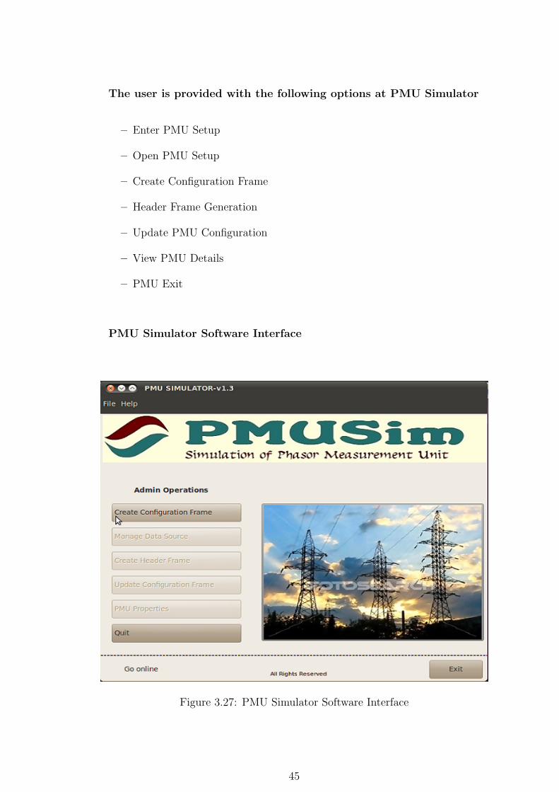
The user is provided with the following options at PMU Simulator
– Enter PMU Setup
– Open PMU Setup
– Create Configuration Frame
– Header Frame Generation
– Update PMU Configuration
– View PMU Details
– PMU Exit
PMU Simulator Software Interface
Figure 3.27: PMU Simulator Software Interface
45
Enter PMU Setup
This is the first pop up window that would ask the user to enter the PMU setup
information. It includes port on which the PMU would receive command frame
requests from PDC. The data and configuration frames would be sent on this port.
Communication protocol (UDP/TCP) also need to be entered. This details would
be save in its PMU Setup File. At PMU restart it would read the entries and start
PMU Server and create configuaration objects.
Open PMU Setup
This would give user an option to open an available/saved PMU Setup File from sys-
tem’s hard drive. Default PMU Setup File would stored in /home/user/iPDC/PMU/
with the PMU ID code as suffix followed by ’pmu’. Previously we were making mul-
tiple file for different operation that had done by PMU Simulator, but now all the
info regarding PMU Server, PMU Configuaration Frame, and PMU Header Frame
would be storing in a single bin file called PMU Setup File. All the previous opera-
tions are same. Before loading a Setup File on the PMU, user are able to see what
are the information it contains.
Create Configuration Frame
After finishing the PMU Setup, PMU configuration objects would be craeted if the
PMU Setup File available, otherwise user has to enter the configuration details. In
order to complete the configuration frame user has to fill details through multiple
pop up windows, and finally store in the PMU Setup File.
Header Frame Generation
User can enter details about algorithm, scaling, filtering and other informantion
about PMU, and this will store in the file header.bin. Header frame also followse
the IEEE C37.118 Standard.
Update PMU Configuration
User can change the STAT Word bit in data frame by using the Update PMU
Configuration. It can also modifies in the configuration frame to add or remove
channels.
46
View PMU Details
This would display the PMU Server details and latest PMU Configuration details
to user.
PMU Exit
It will close all the threads and processes of PMU Simulator and terminate it.
3.4.4 Implementation Details
The code of PMU Simulator is distributed in the following files
1. pmu.c
2. PmuGui.c
3. PmuGui.h
4. ServerFunction.c
5. ServerFunction.h
6. CfgGuiFunctions.c
7. CfgGuiFunctions.h
8. CfgFunction.c
9. CfgFunction.h
10. function.c
11. function.h
Detailed Description
ServerFunction.c
– void start server()
start server() is present in the file ServerFunction.c. It is called by child process
from pmu.c. It will be continuously running in while loop and waiting for his
signal from PMU’s other process. After receiving the appropriate signal it will
get the port number and protocol from shared memory. The port and protocol
has been entered by the user through other process. Then it will start the PMU
Server as per the details. It will create thread for TCP/UDP and continuously
listening for PDC (client).
47
– void frame size()
it will called by pmu udp() and new pmu tcp(void * nfd) to calculate the cur-
rent configuration frame size and data frame size and initialize few global vari-
ables. Configuration frame would be stored in “cfg2.bin” file.
– void generate data frame()
This will generate the data frame followed the IEEE C37.118 standard as per
configuration made. It is called by udp send data() and tcp send data(void *
newfd).
– void* udp send data() / tcp send data(void * newfd)
This function (seprate for UDP and TCP) task is send data frames to requested
PDC as per defined data rate. A fresh data frame would be generated for each
send by calling generate data frame(). It is called by a seprate thread when
PMU get the data transmission ON command from PDC.
– void* pmu udp() / new pmu tcp(void * nfd)
This function (seprate for UDP and TCP) task is to entertained the command
frames from PDC and service them as reply to PDC.
CfgFunction.c
– int create cfg()
It create the configuration frame for PMU Simulator followed the IEEE C37.118
standard as per user entered values and save in “cfg2.bin” file. It is called by
final cfg create (), after got all the necessary informantion from user.
– void reconfig cfg CC()
It reconfigure the configuration frame as per user wish. User can add remove
channels and change data rate. Final updated configuration frame store in
“cfg2.bin” file, and also update the status in “change.bin” file.
– void header frm gen(int len)
It create header frame followed the IEEE C37.118 standard as per user defined
description and save in “header.bin” file.
– void show pmu details (GtkWidget *widget, gpointer udata)
It is called by “View PMU Details” from PMU main window to display the
PMU server & configuration details to user. It will display the information
from configuration object and few globally stablished variables.
48
function.c
– void B copy (unsigned char main[], unsigned char tmp[], int ind, int
n)
Performs copy of size bytes to destination array from its index position to index
+ n.
– void H2S (char a[], unsigned char temp 6[])
Performs unsigned char hex to char string conversion.
– void i2c (int t, unsigned char temp[])
Converts the integer to equivalent binary 2 byte unsigned character value.
– void li2c (long int t1, unsigned char temp 1[])
Converts the long integer to equivalent binary 4 byte unsigned character value.
– void f2c (float f, unsigned char temp 1[])
Converts the float to equivalent binary 4 byte unsigned character value.
– int c2i (unsigned char temp[])
Converts the binary 2 byte unsigned character value to equivalent int.
– long int c2li (unsigned char temp 3[])
Converts the binary 4 byte unsigned character value to equivalent long int.
– uint16 t compute CRC(unsigned char *message,char length)
Calculates checksum of a frame of size length.
CfgGuiFunctions.c & PmuGui.c
Both the file contains GTK functions of PMU Simulator GUI. PmuGui.c contains
the functions for PMU-server start initialize and display & some functions for main
window also. CfgGuiFunctions.c contains the functions for configuration generation,
modification & PMU details display.
Data Structures Used
– Data Structure for Configuration Frame
As per IEEEC37.118 Synchrophasor Standard, format field in configuration
frame is 2 bytes (4 characters in hexadecimal). in structure it define by cfg fdf,
cfg af, cfg pf, cfg pn. Bits 15-4 Unused
Bit 3:
0 = FREQ/DFREQ 16 -bit integer,
1 = floating point
49
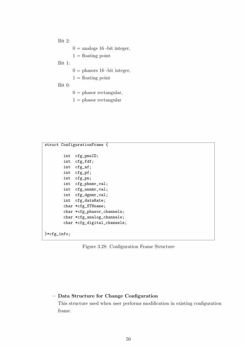
Bit 2:
0 = analogs 16 -bit integer,
1 = floating point
Bit 1:
0 = phasors 16 -bit integer,
1 = floating point
Bit 0:
0 = phasor rectangular,
1 = phasor rectangular
struct ConfigurationFrame {
int cfg_pmuID;
int cfg_fdf;
int cfg_af;
int cfg_pf;
int cfg_pn;
int cfg_phnmr_val;
int cfg_annmr_val;
int cfg_dgnmr_val;
int cfg_dataRate;
char *cfg_STNname;
char *cfg_phasor_channels;
char *cfg_analog_channels;
char *cfg_digital_channels;
}*cfg_info;
Figure 3.28: Configuration Frame Structure
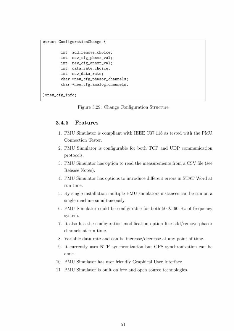
– Data Structure for Change Configuration
This structure used when user performs modification in existing configuration
frame.
50
struct ConfigurationChange {
int add_remove_choice;
int new_cfg_phnmr_val;
int new_cfg_annmr_val;
int data_rate_choice;
int new_data_rate;
char *new_cfg_phasor_channels;
char *new_cfg_analog_channels;
}*new_cfg_info;
Figure 3.29: Change Configuration Structure
3.4.5 Features
1. PMU Simulator is compliant with IEEE C37.118 as tested with the PMU
Connection Tester.
2. PMU Simulator is configurable for both TCP and UDP communication
protocols.
3. PMU Simulator has option to read the measurements from a CSV file (see
Release Notes).
4. PMU Simulator has options to introduce different errors in STAT Word at
run time.
5. By single installation multiple PMU simulators instances can be run on a
single machine simultaneously.
6. PMU Simulator could be configurable for both 50 & 60 Hz of frequency
system.
7. It also has the configuration modification option like add/remove phasor
channels at run time.
8. Variable data rate and can be increase/decrease at any point of time.
9. It currently uses NTP synchronization but GPS synchronization can be
done.
10. PMU Simulator has user friendly Graphical User Interface.
11. PMU Simulator is built on free and open source technologies.
51
Chapter 4
Experiments & Results
4.1 Requirement Analysis
System/Hardware Requirement
∗ RAM : 512 MB
∗ HDD : 5 GB
∗ Operating System : LINUX
Note that hard drive space may vary based on database usage.
Software Requirement
∗ C, GTK+2.5, Glade 3.6.
∗ MySQL Database Server.
∗ GCC Compiler.
4.2 Test Cases
iPDC application was tested at different levels in WAMS toplology. Its perfor-
mance interms of memory usage & CPU utilization was noted. The hardware
details of machines on which iPDC was installed is listed in the table 4.1.
Note that all the test were performed over LAN at Power System
Lab, IIT Bombay, India. Performance of iPDC and PMU Simulator tool may
vary from machine to machine and by network bandwidth.
52
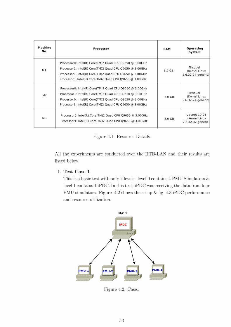
Figure 4.1: Resource Details
All the experiments are conducted over the IITB-LAN and their results are
listed below.
1. Test Case 1
This is a basic test with only 2 levels. level 0 contains 4 PMU Simulators &
level 1 contains 1 iPDC. In this test, iPDC was receiving the data from four
PMU simulators. Figure 4.2 shows the setup & fig 4.3 iPDC performance
and resource utilization.
Figure 4.2: Case1
53
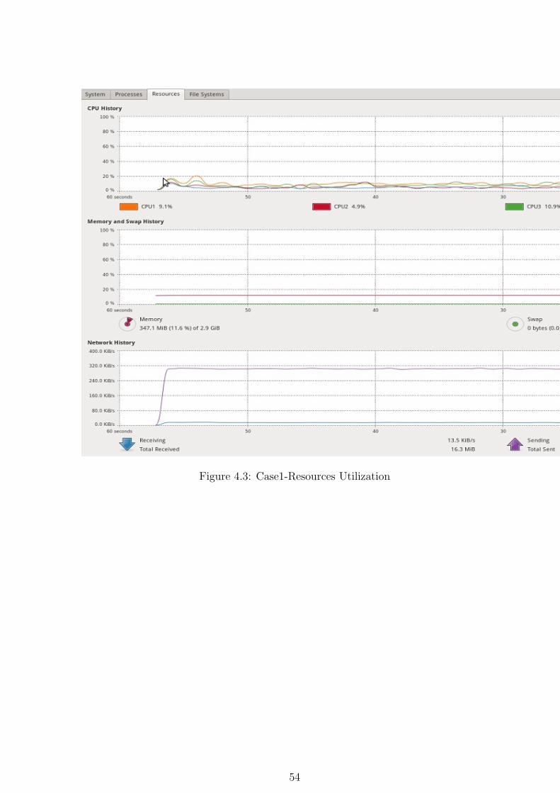
Figure 4.3: Case1-Resources Utilization
54
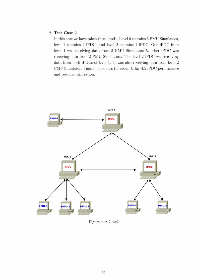
2. Test Case 2
In this case we have taken three levels. Level 0 contains 5 PMU Simulators,
level 1 contains 2 iPDCs and level 2 contains 1 iPDC. One iPDC from
level 1 was receiving data from 3 PMU Simulators & other iPDC was
receiving data from 2 PMU Simulators. The level 2 iPDC was receiving
data from both iPDCs of level 1. It was also receiving data from level 2
PMU Simulator. Figure 4.4 shows the setup & fig 4.5 iPDC performance
and resource utilization.
Figure 4.4: Case2
55
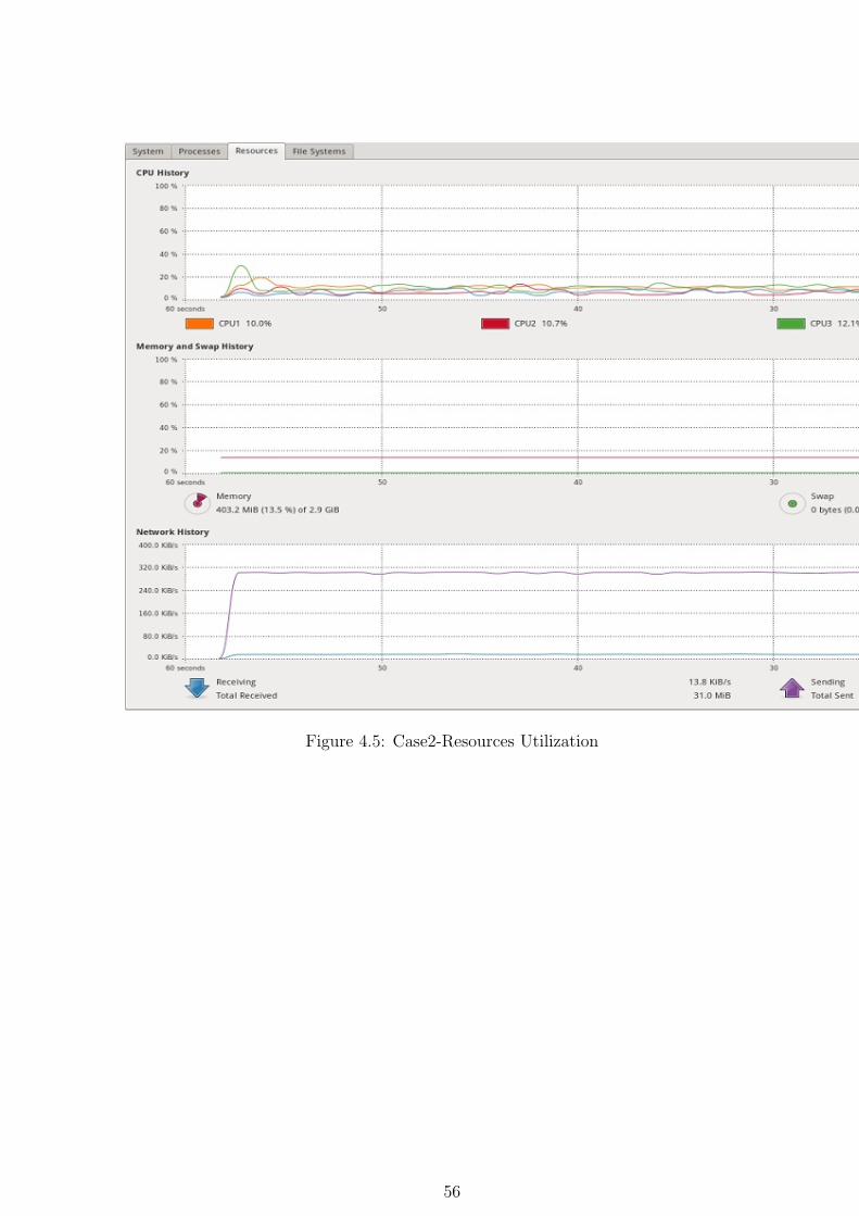
Figure 4.5: Case2-Resources Utilization
56
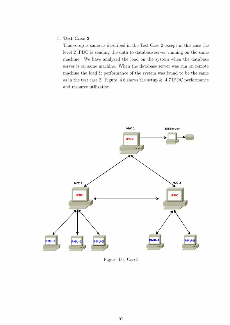
3. Test Case 3
This setup is same as described in the Test Case 2 except in this case the
level 2 iPDC is sending the data to database server running on the same
machine. We have analyzed the load on the system when the database
server is on same machine. When the database server was run on remote
machine the load & performance of the system was found to be the same
as in the test case 2. Figure 4.6 shows the setup & 4.7 iPDC performance
and resource utilization.
Figure 4.6: Case3
57
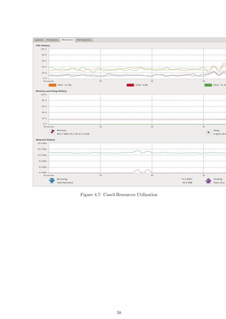
Figure 4.7: Case3-Resources Utilization
58
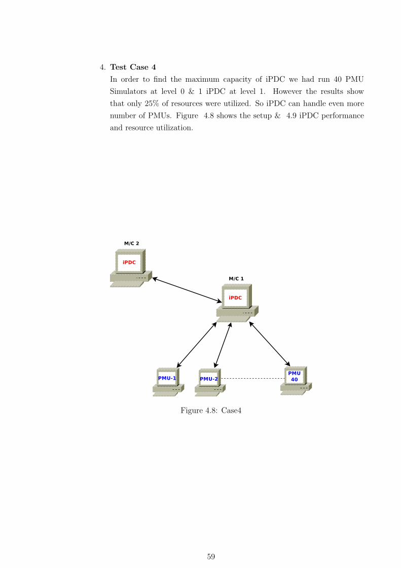
4. Test Case 4
In order to find the maximum capacity of iPDC we had run 40 PMU
Simulators at level 0 & 1 iPDC at level 1. However the results show
that only 25% of resources were utilized. So iPDC can handle even more
number of PMUs. Figure 4.8 shows the setup & 4.9 iPDC performance
and resource utilization.
Figure 4.8: Case4
59
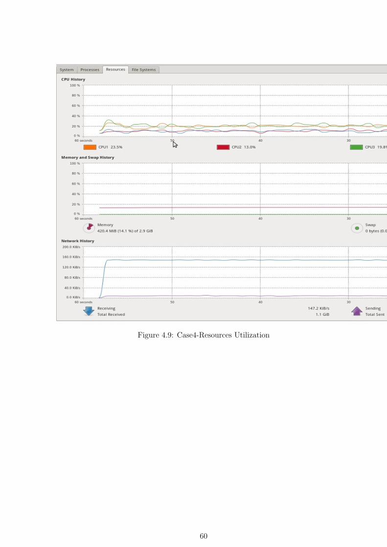
Figure 4.9: Case4-Resources Utilization
60
Chapter 5
Conclusion and Future Work
PMU-PDC communication over UDP/TCP provides the user with an option
to select between fast and unreliable delivery of packets with UDP and reliable
delivery with TCP. MySQL has an advantage over other open source databases
in performance & support. iPDC was able to easily handle data from 40 PMU’s
and can still be improved to increase this number. The sorting algorithm need
to be very efficient to order the data frames while combining at PDC. GUI
that provies configuration of PMU/PDC with different protocols (UDP/TCP)
and also statistics display provieds operator to current flow of overall system.
Since the Phasor Measurement Unit is very costly so the PMU simulator is
made up of a software system that replicates the functionalities of a real Phasor
Measurement Unit (upto some extend), and is also able to reproduce typical
phasor data output in IEEE PC37.118 format through measurement file. The
PMU simulator would test strength of our iPDC software.
Use of Linux OS and other open source tools in the development of
iPDC has provided easy portability of software on Real Time Operating Sys-
tems like RTLinux, RTai etc. Use of RTOS can necessarily further speed up op-
eration carried out by iPDC in real time compared to the normal Linux OS. As
iPDC Software has been released under General Public License(GPL) and up-
loaded on http://ipdc.codeplex.com/ & https://sourceforge.net/projects/iitbpdc/ .
More contributions would be expected from the free and open source commu-
nity.
5.1 Future Work
The future work will involve the following:
∗ Need to study and implement iPDC on RTOS and check its performance
& scalability in Real Time.
∗ An upper time bound needed to be kept for the packets received at iPDC.
61
∗ Study of how iPDC can serve as an input to real time control & decision
making need to be done.
∗ At iPDC can have two array of TSB, one will daspatched after small
amount of time and other one will wait for longer time.
∗ Developement of an application that display the archived data for post
analysis.
∗ Differerent aspects of security in WAMS need to studied and implemented.
∗ iPDC and PMU Simulator has to be updated to support more PMU stan-
dards.
∗ On field testing of iPDC application need to be done to know its perfor-
mance & limitations.
62
References
[1] IEEE Standard for Synchrophasors for Power Systems, IEEE Standard
C37.118, 2006.
[2] IEEE Standard for Synchrophasors for Power Systems, IEEE Standard
1344, 1995.
[3] EIPP Real Time Task Team, White Paper DRAFT 3: “Real Time Wide-
Area Monitoring, Control and Protection,” Wide Area Monitoring-Control
Phasor Data Requirements.
[4] Andrew Armenia, “A Flexible Phasor Data Concentrator Design Leverag-
ing Existing Software Technologies,” IEEE TRANSACTIONS ON SMART
GRID, VOL. 1, NO. 1, JUNE 2010.
[5] Moustafa Chenine, “Investigation of Communication Delays and Data In-
completeness in Multi-PMU Wide Area Monitoring and Control Systems,”
the Swedish Centre of Excellence in Electric Power Engineering ELEKTRA
project 36005.
[6] Yingchen Zhang, “Wide-Area Frequency Monitoring Network (FNET)
Architecture and Applications,” Richard IEEE TRANSACTIONS ON
SMART GRID, VOL. 1, NO. 2, SEPTEMBER 2010.
[7] by M.D. Hadley, J.B. McBride, T.W. Edgar, “Securing Wide Area Mea-
surement Systems,” Prepared for U.S. Department of Energy June 2007.
[8] Biju Naduvathuparambil, Metthew C. Valenti & Ali, “Communication De-
lays in Wide Area Measurement System,” West Virginia University 2002.
[9] Abhishek Kumar & Jia Wang, “Data Streaming Algorithms for Efficient
and Accurate Estimation of Flow Size Distribution”.
[10] K.E. Martin, Chairman, G. Benmouyal, A. G. Phadke & M. S. Sachdev,
“ IEEE STANDARD FOR SYNCHROPHASORS FOR POWER SYS-
TEME(1344),” 1998.
[11] “NASPI The Role of Phasor Data Concentrators,” by NASPI.
[12] Kenneth E. Martin, “Phasor Measurement Systems in the WECC,“ Bon-
neville Power Administration, Vancouver, WA
63
[13] M.D. Hadley & J.B. McBride, “Securing Wide Area Measurement Sys-
tems,” U.S. Department of Energy.
[14] Sheikh Kamar Bin Sheikh Abdullah* and Nik Sofizan Bin Nik Yusuf,
“Tenaga Nasional Berhad Wide Area Measurement System Based Applica-
tions,” 2nd IEEE International Conference on Power and Energy (PECon
08), December 1-3, 2008, Johor Baharu, Malaysia.
[15] “Increasing Information Flow between PDCs,” Sandia National Labora-
tories.
[16] Enrique Martnez, “Wide Area Measurement & Control System in Mex-
ico,” DRPT2008 6-9 April 2008 Nanjing China.
64