Embed Size (px)
DESCRIPTION
Citation preview
1
Presented ByMalik Sameeullah
M.Tech (RES)
NATIONAL INSTITUTE OF TECHNOLOGY, KURUKSHETRA
MPPT BASED OPTIMAL BATTERY CHARGE CONTROLLER IN PV SYSTEM
2
ContentsSolar PV SectorType of Solar PV systemNeed of Charge Controller and MPPTSolar PV Cell: Basic modelType of Battery: features and characteristicsBasic Charge controller modelBuck Boost ConverterMPPT modelMPPT Based Optimum Controller DesignConclusionResearch Work and Future WorkReferences
3
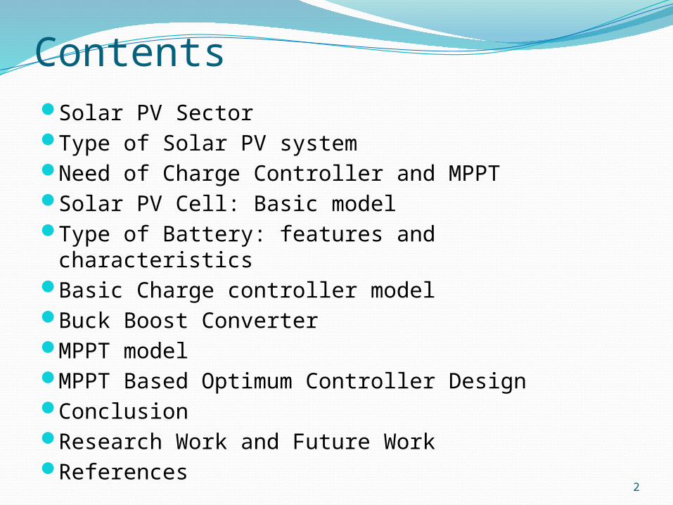
Solar Power Sector India lies in a sunny tropical belt (High
insolation) Total approximate potential annually over 5000 trillion kWh
Over 70% of India’s households experience significant power cuts every year
National Solar Mission and other Generation Based Incentives (GBI) are available through Ministry of New and Renewable Energy (MNRE)
JNNSM have a mission to install 20 GW solar PV plant by 2022
Cost of PV module, land scarcity and technological barrier is a main restriction.
Current cost of production is ` 12/KWh and expected cost is ` 6/KWh by 2020
Jawahar Lal Nehru National Solar Mission Target
2010-2013
On grid PV power of 1000-2000 MWOff grid PV application 200 MWSolar collector 7 million sq. meter
2013-2017
On grid PV power of 4000-10000 MWOff grid PV application 1000 MWSolar collector 15 million sq. meter
2017-2022
On grid PV power of 22000 MWOff grid PV application 2000 MWSolar collector 20 million sq. meter
4
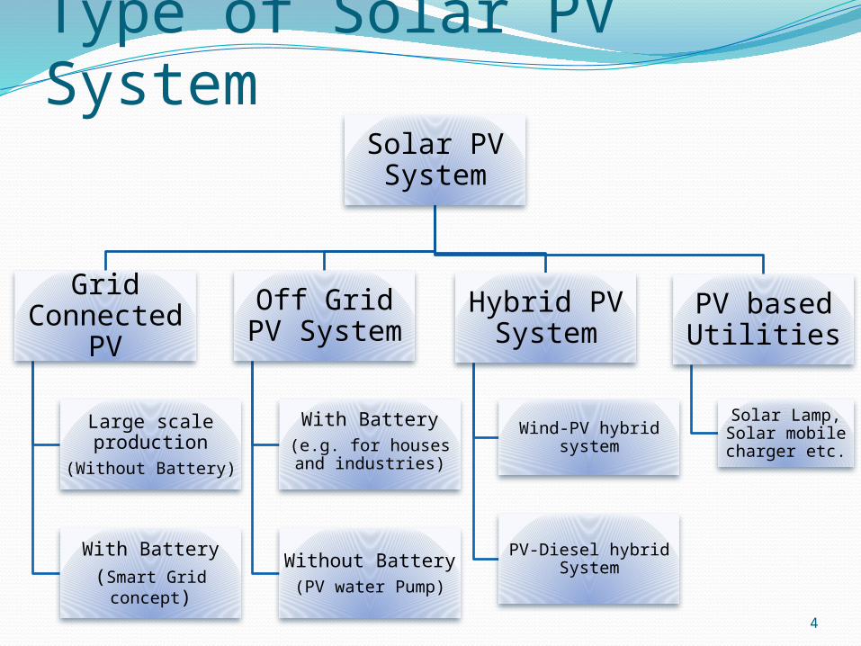
Type of Solar PV SystemSolar PV System
Grid Connected
PV
Large scale production
(Without Battery)
With Battery(Smart Grid
concept)
Off Grid PV System
With Battery(e.g. for houses and
industries)
Without Battery(PV water Pump)
Hybrid PV System
Wind-PV hybrid system
PV-Diesel hybrid System
PV based Utilities
Solar Lamp, Solar mobile charger etc.
5
Need of Charge Controller and MPPTBattery is a costly device and must be managed properly.
It is found if proper care is taken then life of battery increase significantly
A charge controller limits the rate at which electric current is added to or drawn from electric batteries
Charge Controller take care of battery under voltage and over voltage condition
MPPT (Maximum Power Point Tracker) is a electronic device which maximize PV module output under varying operating condition
6
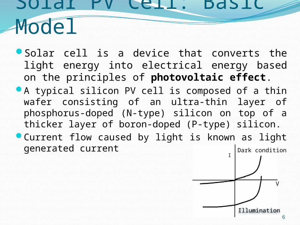
Solar PV Cell: Basic ModelSolar cell is a device that converts the light energy into
electrical energy based on the principles of photovoltaic effect.
A typical silicon PV cell is composed of a thin wafer consisting of an ultra-thin layer of phosphorus-doped (N-type) silicon on top of a thicker layer of boron-doped (P-type) silicon.
Current flow caused by light is known as light generated current
Illumination
Dark conditionI
V
7
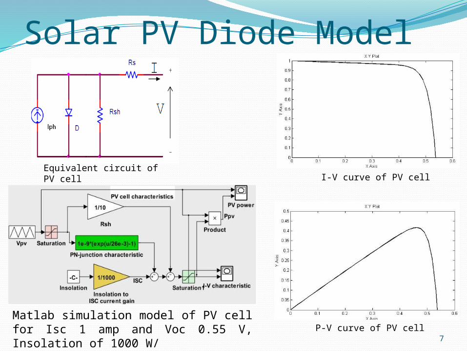
Solar PV Diode Model
Equivalent circuit of PV cell I-V curve of PV cell
P-V curve of PV cellMatlab simulation model of PV cell for Isc 1 amp and Voc 0.55 V, Insolation of 1000 W/
8
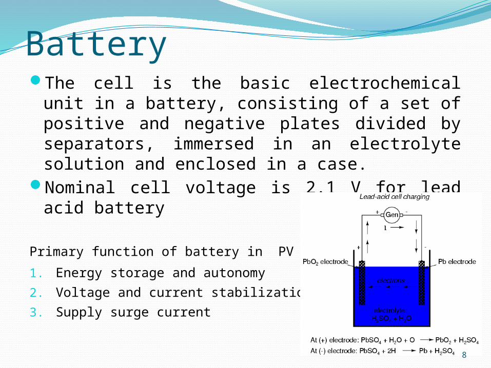
BatteryThe cell is the basic electrochemical unit in a battery,
consisting of a set of positive and negative plates divided by separators, immersed in an electrolyte solution and enclosed in a case.
Nominal cell voltage is 2.1 V for lead acid battery
Primary function of battery in PV system:
1. Energy storage and autonomy
2. Voltage and current stabilization
3. Supply surge current
9
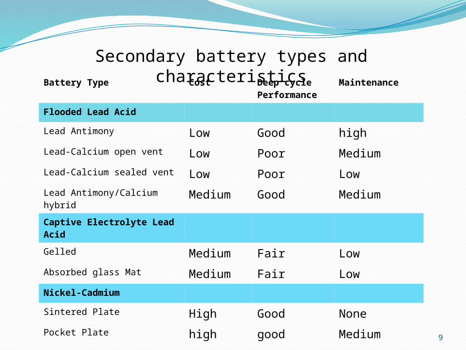
Secondary battery types and characteristicsBattery Type Cost Deep cycle
PerformanceMaintenance
Flooded Lead Acid
Lead Antimony Low Good highLead-Calcium open vent Low Poor MediumLead-Calcium sealed vent Low Poor LowLead Antimony/Calcium hybrid
Medium Good Medium
Captive Electrolyte Lead Acid
Gelled Medium Fair LowAbsorbed glass Mat Medium Fair LowNickel-Cadmium
Sintered Plate High Good NonePocket Plate high good Medium
10
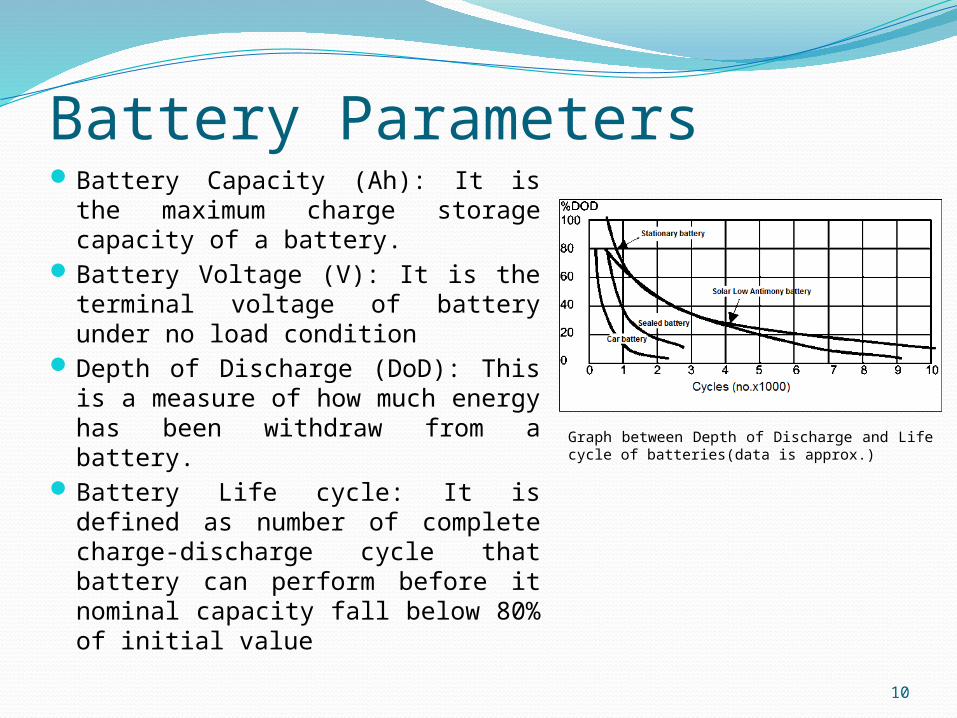
Battery ParametersBattery Capacity (Ah): It is the
maximum charge storage capacity of a battery.
Battery Voltage (V): It is the terminal voltage of battery under no load condition
Depth of Discharge (DoD): This is a measure of how much energy has been withdraw from a battery.
Battery Life cycle: It is defined as number of complete charge-discharge cycle that battery can perform before it nominal capacity fall below 80% of initial value
Graph between Depth of Discharge and Life cycle of batteries(data is approx.)
11
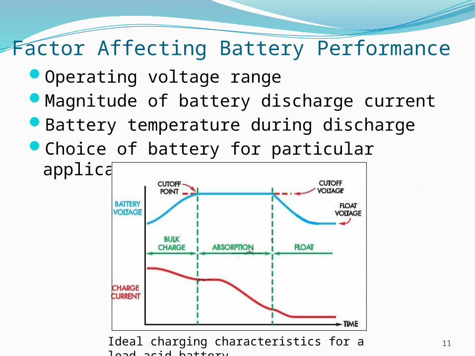
Factor Affecting Battery PerformanceOperating voltage rangeMagnitude of battery discharge currentBattery temperature during dischargeChoice of battery for particular application
Ideal charging characteristics for a lead-acid battery
12
DC-DC ConverterUsed for converting DC voltage from one level to anotherIt is used to convert unregulated DC into a controlled DC
outputSuitable for PV system where due to change in
atmospheric condition DC output change continuouslyIt is also a basic component of MPPT system
13
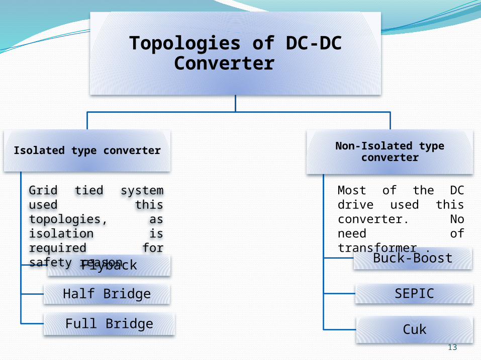
Topologies of DC-DC Converter
Isolated type converter
Flyback
Half Bridge
Full Bridge
Non-Isolated type converter
Buck-Boost
SEPIC
Cuk
Grid tied system used this topologies, as isolation is required for safety reason
Most of the DC drive used this converter. No need of transformer .
14
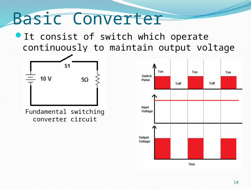
Basic ConverterIt consist of switch which operate
continuously to maintain output voltage
Fundamental switching converter circuit
15
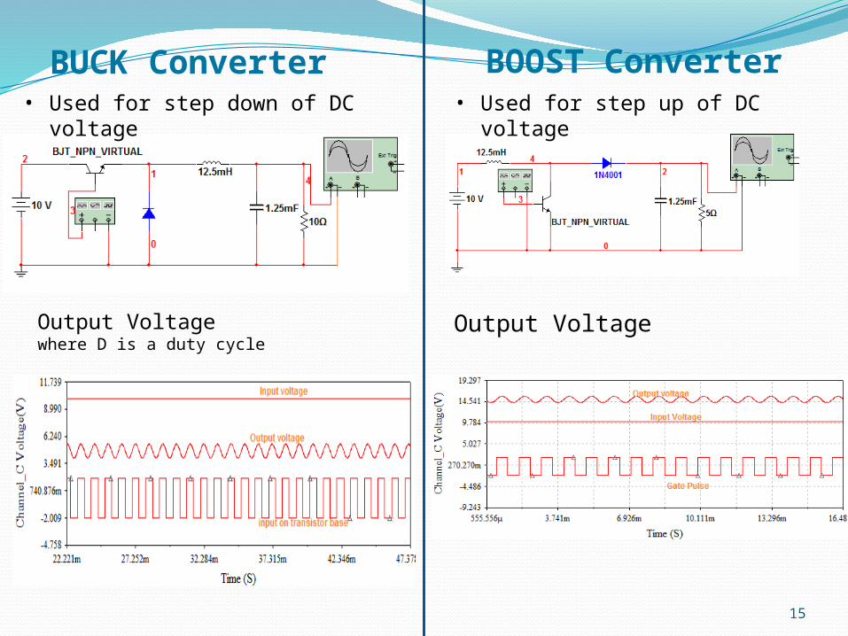
BUCK Converter• Used for step down of DC
voltage
Output Voltage where D is a duty cycle
BOOST Converter• Used for step up of DC
voltage
Output Voltage
16
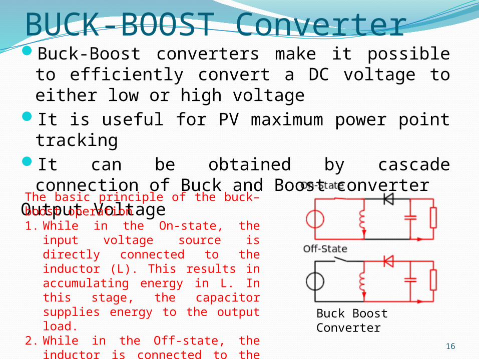
BUCK-BOOST ConverterBuck-Boost converters make it possible to
efficiently convert a DC voltage to either low or high voltage
It is useful for PV maximum power point tracking
It can be obtained by cascade connection of Buck and Boost converter
Output Voltage The basic principle of the buck–boost operation1. While in the On-state, the input
voltage source is directly connected to the inductor (L). This results in accumulating energy in L. In this stage, the capacitor supplies energy to the output load.
2. While in the Off-state, the inductor is connected to the output load and capacitor, so energy is transferred from L to C and R.
Buck Boost Converter
17
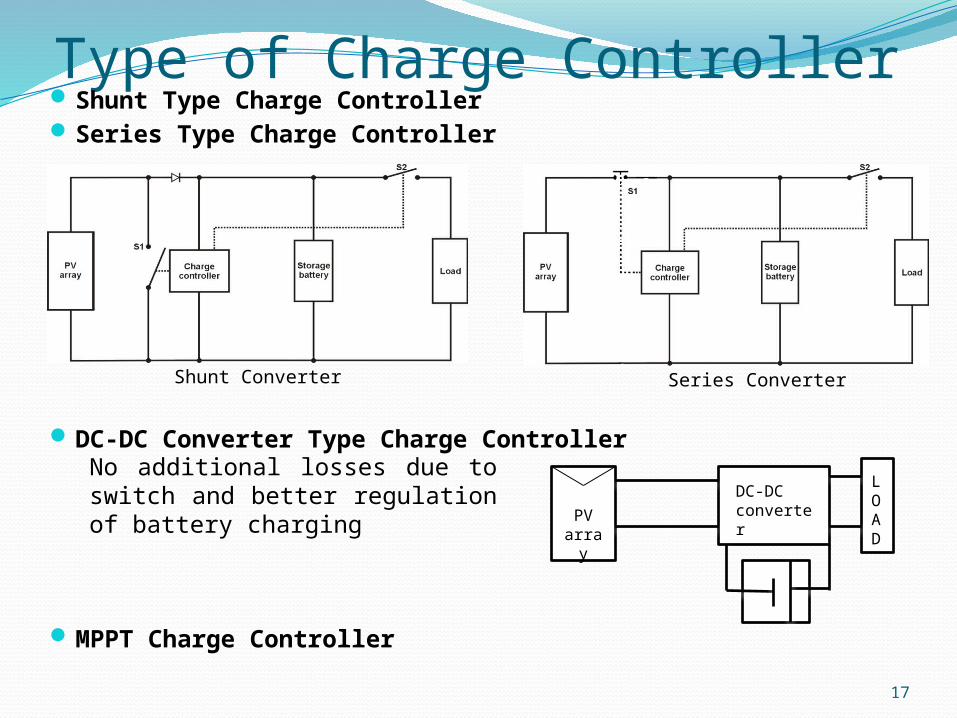
Type of Charge Controller Shunt Type Charge Controller Series Type Charge Controller
DC-DC Converter Type Charge Controller
MPPT Charge Controller
Shunt Converter Series Converter
No additional losses due to switch and better regulation of battery charging
DC-DC converterPV
array
LOAD
18
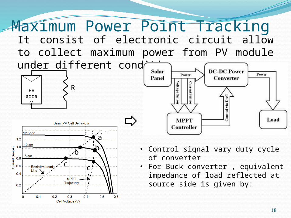
Maximum Power Point TrackingIt consist of electronic circuit allow to collect maximum power from PV module under different condition
PVarray
R
• Control signal vary duty cycle of converter
• For Buck converter , equivalent impedance of load reflected at source side is given by:
a
b
c
b’
c’
19
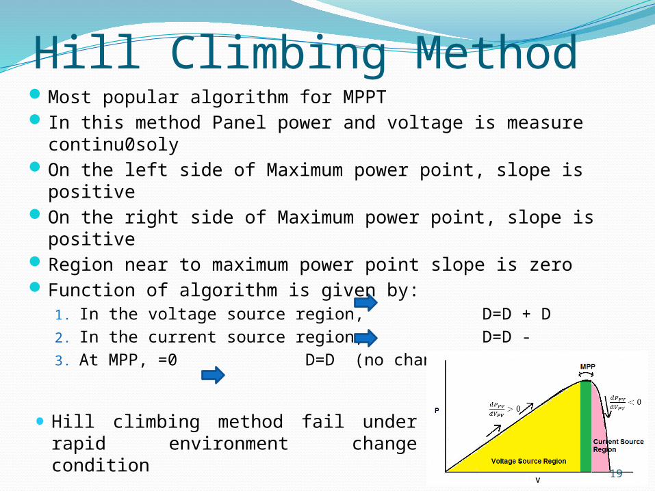
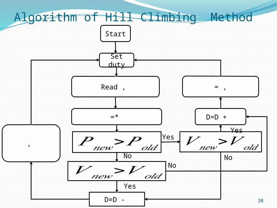
Hill Climbing MethodMost popular algorithm for MPPT In this method Panel power and voltage is measure
continu0solyOn the left side of Maximum power point, slope is positiveOn the right side of Maximum power point, slope is positiveRegion near to maximum power point slope is zero Function of algorithm is given by:
1. In the voltage source region, D=D + D2. In the current source region, D=D - 3. At MPP, =0 D=D (no change)
• Hill climbing method fail under rapid environment change condition
20
Algorithm of Hill Climbing MethodStart
Set duty
Read ,
=*
𝑃𝑛𝑒𝑤>𝑃𝑜𝑙𝑑
𝑉 𝑛𝑒𝑤>𝑉𝑜𝑙𝑑
D=D -
= ,
D=D +
𝑉 𝑛𝑒𝑤>𝑉𝑜𝑙𝑑, Yes
Yes
Yes
NoNoNo
21
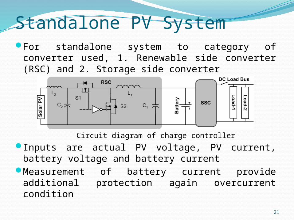
Standalone PV SystemFor standalone system to category of converter
used, 1. Renewable side converter (RSC) and 2. Storage side converter
Inputs are actual PV voltage, PV current, battery voltage and battery current
Measurement of battery current provide additional protection again overcurrent condition
Circuit diagram of charge controller
22
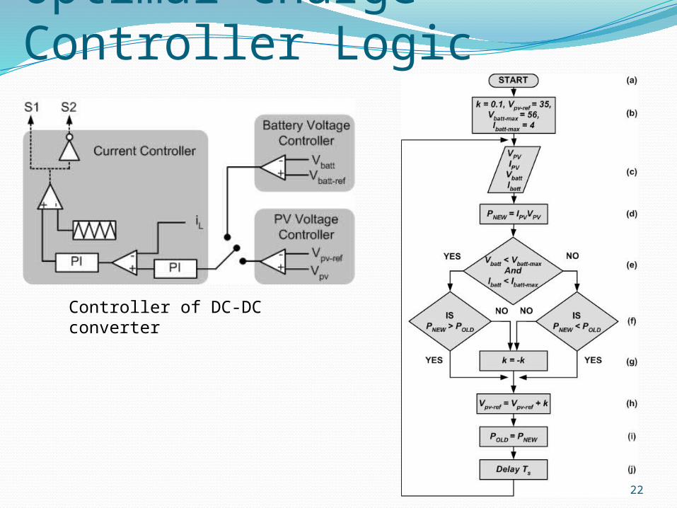
Optimal Charge Controller Logic
Controller of DC-DC converter
23
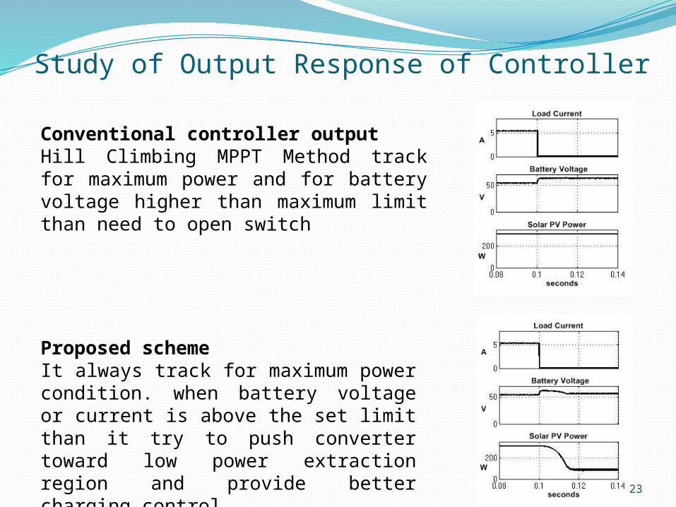
Study of Output Response of Controller
Conventional controller outputHill Climbing MPPT Method track for maximum power and for battery voltage higher than maximum limit than need to open switch
Proposed schemeIt always track for maximum power condition. when battery voltage or current is above the set limit than it try to push converter toward low power extraction region and provide better charging control
24
ConclusionIn solar PV based battery charging, MPPT
algorithms are used When the state of charge (SoC) of battery is
high and system is on no-load, excess power flows into the battery
This results in low operational life of the battery
Slight variation in design of MPPT improve the charging condition of battery
25
Research Area and Future WorkThere is number of MPPT control algorithm.
Fuzzy and Neural network based MPPT algorithm are more accurate.
No of improved DC-DC converter topologies are in picture like CUK converter, Isolated converter etc.
By choosing the optimal combination of DC-DC converter and MPPT algorithm better regulation of battery is possible
26
References1. Sandeep Anand, Rajesh Singh Farswan, Bhukya Mangu, B.G. Fernades, “Optimal
charging of Battery Using Solar PV in Standalone DC System,” Industrial Electronics Magazine , vol.7, no-3,pp.6 – 20, Sep 2013
2. Trishan Esram, and Patrick L. Chapman, “Comparison of Photovoltaic Array Maximum Power Point Tracking Techniques,” IEEE Trans. on Energy Conversion, vol. 22, no. 2, June 2007
3. Tom Markvark, Luis Castaner,” Solar Cells: Material, Manufactures and operation,” Elsevier, ISBN-1856174573
4. Chetan Singh Solanki, “Solar Photovoltaic: Fundamentals, Technology and Applications,” Eastern Economy Edition, ISBN-9788120343863
5. Simon S. Ang, “Power Switching Converters,” Marcel Dekker Inc., ISBN-0824796306
6. Paras Karki, Brijesh Adhikary, “ MATLAB/Simulink based Modeling and Simulation of Gird-connected Solar Photovoltaic System in Distribution Power Network,”Fifth International Conference on Power and Energy Systems, Kathmandu, Nepal, pp.28 - 30 October, 2013
7. James P. Dunlop, P. E. Florida, “Batteries and Charge Control in Stand-Alone Photovoltaic Systems Fundamentals and Application,” Solar Energy Center1-679, Clearlake RoadCocoa, FL 32922-5703

27
THANK YOU