Embed Size (px)
Citation preview
Cloud Administrator Guide May 12, 2015 current
ii
OpenStack Cloud Administrator Guidecurrent (2015-05-12)Copyright © 2013-2015 OpenStack Foundation Some rights reserved.
OpenStack offers open source software for cloud administrators to manage and troubleshoot an Open-Stack cloud.
This guide documents OpenStack Kilo, OpenStack Juno, and OpenStack Icehouse releases.
Licensed under the Apache License, Version 2.0 (the "License"); you may not use this file except in compliance with the License. Youmay obtain a copy of the License at
http://www.apache.org/licenses/LICENSE-2.0
Unless required by applicable law or agreed to in writing, software distributed under the License is distributed on an "AS IS" BASIS,WITHOUT WARRANTIES OR CONDITIONS OF ANY KIND, either express or implied. See the License for the specific language governingpermissions and limitations under the License.
Except where otherwise noted, this document is licensed underCreative Commons Attribution ShareAlike 3.0 License.http://creativecommons.org/licenses/by-sa/3.0/legalcode
Cloud Administrator Guide May 12, 2015 current
iii
Table of ContentsPreface ........................................................................................................................... ix
Conventions ............................................................................................................ ixDocument change history ....................................................................................... ix
1. Get started with OpenStack ........................................................................................ 1Conceptual architecture .......................................................................................... 2Logical architecture ................................................................................................. 3OpenStack services .................................................................................................. 4Feedback ............................................................................................................... 18
2. Identity management ................................................................................................ 19Identity concepts ................................................................................................... 19Certificates for PKI ................................................................................................ 25Configure the Identity Service with SSL .................................................................. 28External authentication with Identity .................................................................... 29Integrate Identity with LDAP ................................................................................. 29Configure Identity service for token binding .......................................................... 39Use trusts .............................................................................................................. 40Caching layer ........................................................................................................ 40User CRUD ............................................................................................................ 42Logging ................................................................................................................. 43Start the Identity services ...................................................................................... 43Example usage ...................................................................................................... 43Authentication middleware with user name and password .................................... 44Identity API protection with role-based access control (RBAC) ................................ 45Troubleshoot the Identity service ........................................................................... 48
3. Dashboard ................................................................................................................ 51Customize the dashboard ...................................................................................... 51Set up session storage for the dashboard .............................................................. 53
4. Compute ................................................................................................................... 58System architecture ............................................................................................... 58Images and instances ............................................................................................ 64Networking with nova-network ............................................................................. 71System administration ........................................................................................... 87Troubleshoot Compute ........................................................................................ 126
5. Object Storage ........................................................................................................ 131Introduction to Object Storage ............................................................................ 131Features and benefits .......................................................................................... 131Object Storage characteristics .............................................................................. 132Components ........................................................................................................ 133Ring-builder ......................................................................................................... 139Cluster architecture ............................................................................................. 142Replication .......................................................................................................... 145Account reaper ................................................................................................... 146Configure tenant-specific image locations with Object Storage ............................. 147Object Storage monitoring .................................................................................. 147System administration for Object Storage ............................................................ 151Troubleshoot Object Storage ............................................................................... 151
6. Block Storage .......................................................................................................... 155Introduction to Block Storage .............................................................................. 155
Cloud Administrator Guide May 12, 2015 current
iv
Increase Block Storage API service throughput ..................................................... 156Manage volumes ................................................................................................. 156Troubleshoot your installation ............................................................................. 190
7. Networking ............................................................................................................. 201Introduction to Networking ................................................................................. 201Plug-in configurations .......................................................................................... 208Configure neutron agents ................................................................................... 213Networking architecture ...................................................................................... 221Configure Identity Service for Networking ........................................................... 225Networking scenarios .......................................................................................... 229Advanced configuration options .......................................................................... 251Scalable and highly available DHCP agents ........................................................... 257Use Networking .................................................................................................. 266Advanced features through API extensions .......................................................... 273Advanced operational features ............................................................................ 290Authentication and authorization ........................................................................ 292Plug-in pagination and sorting support ................................................................ 296
8. Telemetry ................................................................................................................ 297Introduction ........................................................................................................ 297System architecture ............................................................................................. 298Data collection .................................................................................................... 300Data retrieval ...................................................................................................... 314Alarms ................................................................................................................. 322Measurements ..................................................................................................... 326Events ................................................................................................................. 341Troubleshoot Telemetry ....................................................................................... 344
9. Database ................................................................................................................. 346Introduction ........................................................................................................ 346Create a datastore .............................................................................................. 346Configure a cluster .............................................................................................. 350
10. Orchestration ......................................................................................................... 351Introduction ........................................................................................................ 351Orchestration authorization model ...................................................................... 351Stack domain users .............................................................................................. 353
A. Community support ................................................................................................ 356Documentation ................................................................................................... 356ask.openstack.org ................................................................................................ 357OpenStack mailing lists ........................................................................................ 357The OpenStack wiki ............................................................................................. 357The Launchpad Bugs area ................................................................................... 358The OpenStack IRC channel ................................................................................. 359Documentation feedback .................................................................................... 359OpenStack distribution packages ......................................................................... 359
Cloud Administrator Guide May 12, 2015 current
v
List of Figures1.1. OpenStack conceptual architecture ........................................................................... 21.2. Logical architecture .................................................................................................. 34.1. Base image state with no running instances ............................................................ 654.2. Instance creation from image and runtime state ..................................................... 654.3. End state of image and volume after instance exits ................................................. 664.4. multinic flat manager ............................................................................................. 834.5. multinic flatdhcp manager ...................................................................................... 834.6. multinic VLAN manager .......................................................................................... 844.7. noVNC process ..................................................................................................... 1114.8. Trusted compute pool .......................................................................................... 1205.1. Object Storage (swift) ........................................................................................... 1335.2. Object Storage building blocks .............................................................................. 1345.3. The ring ............................................................................................................... 1355.4. Zones ................................................................................................................... 1365.5. Accounts and containers ....................................................................................... 1365.6. Partitions .............................................................................................................. 1375.7. Replication ............................................................................................................ 1375.8. Object Storage in use ........................................................................................... 1395.9. Object Storage architecture .................................................................................. 1435.10. Object Storage (swift) ......................................................................................... 1447.1. FWaaS architecture ............................................................................................... 2047.2. Tenant and provider networks .............................................................................. 2237.3. VMware NSX deployment example - two Compute nodes ..................................... 2247.4. VMware NSX deployment example - single Compute node .................................... 2257.5. Example VXLAN tunnel ......................................................................................... 239
Cloud Administrator Guide May 12, 2015 current
vi
List of Tables1.1. OpenStack services ................................................................................................... 11.2. Storage types ........................................................................................................... 84.1. Description of IPv6 configuration options ............................................................... 764.2. Description of metadata configuration options ....................................................... 794.3. Identity Service configuration file sections ............................................................... 894.4. rootwrap.conf configuration options .................................................................... 1034.5. .filters configuration options ................................................................................. 1034.6. Description of live migration configuration options ............................................... 1064.7. Description of VNC configuration options ............................................................. 1124.8. Description of SPICE configuration options ............................................................ 1154.9. Description of Zookeeper configuration options .................................................... 1174.10. Description of trusted computing configuration options ...................................... 1195.1. Description of configuration options for [drive-audit] in drive-audit.conf .............................................................................................................. 1526.1. Image settings reported by glance image-list for image ID .................................... 1957.1. Networking resources ........................................................................................... 2017.2. LBaaS features ...................................................................................................... 2037.3. Available networking plug-ins ............................................................................... 2067.4. Plug-in compatibility with Compute drivers ............................................................ 2077.5. Basic operations on Networking agents ................................................................ 2207.6. Networking agents ............................................................................................... 2217.7. General distinct physical data center networks ...................................................... 2227.8. nova.conf API and credential settings ................................................................... 2277.9. nova.conf security group settings .......................................................................... 2287.10. nova.conf metadata settings ............................................................................... 2287.11. Settings .............................................................................................................. 2527.12. Settings .............................................................................................................. 2537.13. Settings .............................................................................................................. 2537.14. Settings .............................................................................................................. 2557.15. Hosts for demo ................................................................................................... 2587.16. API abstractions .................................................................................................. 2677.17. Network attributes ............................................................................................. 2687.18. Subnet attributes ................................................................................................ 2687.19. Port attributes .................................................................................................... 2697.20. Basic Networking operations ............................................................................... 2697.21. Advanced Networking operations ....................................................................... 2717.22. Basic Compute and Networking operations ......................................................... 2727.23. Advanced VM creation operations ...................................................................... 2727.24. Provider extension terminology ........................................................................... 2747.25. Provider network attributes ................................................................................ 2757.26. Router ................................................................................................................ 2777.27. Floating IP .......................................................................................................... 2777.28. Basic L3 operations ............................................................................................. 2787.29. Security group attributes .................................................................................... 2797.30. Security group rules ............................................................................................ 2797.31. Basic security group operations ........................................................................... 2807.32. Firewall rules ....................................................................................................... 2827.33. Firewall policies ................................................................................................... 283
Cloud Administrator Guide May 12, 2015 current
vii
7.34. Firewalls .............................................................................................................. 2837.35. VMware NSX QoS attributes ............................................................................... 2847.36. Basic VMware NSX QoS operations ..................................................................... 2857.37. Recommended values for max_lp_per_bridged_ls ................................................ 2857.38. Configuration options for tuning operational status synchronization in the NSXplug-in ......................................................................................................................... 2867.39. Big Switch Router rule attributes ......................................................................... 2877.40. Label .................................................................................................................. 2887.41. Rules ................................................................................................................... 2887.42. Basic L3 operations ............................................................................................. 2907.43. Plug-ins that support native pagination and sorting ............................................. 2968.1. Consumed event types from OpenStack services .................................................... 3018.2. List of available transformers ................................................................................ 3098.3. Time-to-live support for database back ends ......................................................... 3148.4. Telemetry meter types .......................................................................................... 3278.5. OpenStack Compute meters ................................................................................. 3288.6. OpenStack Compute host meters .......................................................................... 3328.7. Metrics of Bare metal module for OpenStack ........................................................ 3328.8. IPMI based meters ................................................................................................ 3338.9. SNMP based meters .............................................................................................. 3348.10. OpenStack Image Service meters ......................................................................... 3348.11. OpenStack Block Storage meters ......................................................................... 3358.12. OpenStack Object Storage meters ....................................................................... 3358.13. Metrics for Ceph Object Storage ......................................................................... 3368.14. OpenStack Identity meters .................................................................................. 3378.15. OpenStack Networking meters ........................................................................... 3378.16. SDN meters ........................................................................................................ 3388.17. LoadBalancer as a Service meters ........................................................................ 3398.18. VPN as a Service meters ...................................................................................... 3398.19. Firewall as a Service meters ................................................................................. 3408.20. Metrics for the Orchestration module ................................................................. 3408.21. Metrics of the Data processing service for OpenStack .......................................... 3418.22. Key Value Store module meters .......................................................................... 3418.23. Energy meters .................................................................................................... 341

Cloud Administrator Guide May 12, 2015 current
viii
List of Examples2.1. Configure the Memcached backend ........................................................................ 42
Cloud Administrator Guide May 12, 2015 current
ix
Preface
ConventionsThe OpenStack documentation uses several typesetting conventions.
Notices
Notices take these forms:
Note
A handy tip or reminder.
Important
Something you must be aware of before proceeding.
Warning
Critical information about the risk of data loss or security issues.
Command prompts
$ prompt Any user, including the root user, can run commands that are prefixed withthe $ prompt.
# prompt The root user must run commands that are prefixed with the # prompt. Youcan also prefix these commands with the sudo command, if available, to runthem.
Document change historyThis version of the guide replaces and obsoletes all earlier versions.
The following table describes the most recent changes:
Revision Date Summary of Changes
February 20, 2015 • For the Kilo release, the guide has been updated with a new Measurements section in theTelemetry chapter. The tables contain the release information for all collected meters re-garding to when they were introduced in the module. In addition, the Orchestration chapterhas been added to the guide. It describes in details Orchestration module available in Open-Stack since Havana release.
October 15, 2014 • For the Juno release, the guide has been updated with a new Telemetry chapter.
July 21, 2014 • Updated variables to use correct formatting.
April 17, 2014 • For the Icehouse release, the guide was organized with system administration and systemarchitecture sections. Also, how-to sections were moved to this guide instead of the Open-Stack Configuration Reference.
November 12, 2013 • Adds options for tuning operational status synchronization in the NSX plug-in.
Cloud Administrator Guide May 12, 2015 current
x
Revision Date Summary of Changes
October 17, 2013 • Havana release.
September 5, 2013 • Moves object storage monitoring section to this guide.• Removes redundant object storage information.
September 3, 2013 • Moved all but configuration and installation information from these component guides tocreate the new guide:
• OpenStack Compute Administration Guide
• OpenStack Networking Administration Guide
• OpenStack Object Storage Administration Guide
• OpenStack Block Storage Service Administration Guide
Cloud Administrator Guide May 12, 2015 current
1
1. Get started with OpenStack
Table of ContentsConceptual architecture .................................................................................................. 2Logical architecture ......................................................................................................... 3OpenStack services .......................................................................................................... 4Feedback ....................................................................................................................... 18
The OpenStack project is an open source cloud computing platform for all types of clouds,which aims to be simple to implement, massively scalable, and feature rich. Developers andcloud computing technologists from around the world create the OpenStack project.
OpenStack provides an Infrastructure-as-a-Service (IaaS) solution through a set of interrelat-ed services. Each service offers an application programming interface (API) that facilitatesthis integration. Depending on your needs, you can install some or all services.
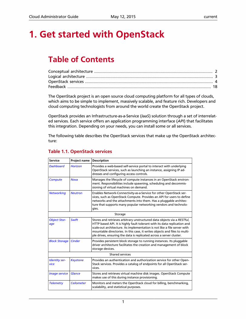
The following table describes the OpenStack services that make up the OpenStack architec-ture:
Table 1.1. OpenStack services
Service Project name Description
Dashboard Horizon Provides a web-based self-service portal to interact with underlyingOpenStack services, such as launching an instance, assigning IP ad-dresses and configuring access controls.
Compute Nova Manages the lifecycle of compute instances in an OpenStack environ-ment. Responsibilities include spawning, scheduling and decommis-sioning of virtual machines on demand.
Networking Neutron Enables Network-Connectivity-as-a-Service for other OpenStack ser-vices, such as OpenStack Compute. Provides an API for users to definenetworks and the attachments into them. Has a pluggable architec-ture that supports many popular networking vendors and technolo-gies.
Storage
Object Stor-age
Swift Stores and retrieves arbitrary unstructured data objects via a RESTful,HTTP based API. It is highly fault tolerant with its data replication andscale-out architecture. Its implementation is not like a file server withmountable directories. In this case, it writes objects and files to multi-ple drives, ensuring the data is replicated across a server cluster.
Block Storage Cinder Provides persistent block storage to running instances. Its pluggabledriver architecture facilitates the creation and management of blockstorage devices.
Shared services
Identity ser-vice
Keystone Provides an authentication and authorization service for other Open-Stack services. Provides a catalog of endpoints for all OpenStack ser-vices.
Image service Glance Stores and retrieves virtual machine disk images. OpenStack Computemakes use of this during instance provisioning.
Telemetry Ceilometer Monitors and meters the OpenStack cloud for billing, benchmarking,scalability, and statistical purposes.
Cloud Administrator Guide May 12, 2015 current
2
Service Project name Description
Higher-level services
Orchestration Heat Orchestrates multiple composite cloud applications by using either thenative HOT template format or the AWS CloudFormation templateformat, through both an OpenStack-native REST API and a CloudFor-mation-compatible Query API.
Database ser-vice
Trove Provides scalable and reliable Cloud Database-as-a-Service functionali-ty for both relational and non-relational database engines.
Data process-ing service
Sahara Provides capabilties to provision and scale Hadoop clusters in Open-Stack by specifying parameters like Hadoop version, cluster topologyand nodes hardware details.
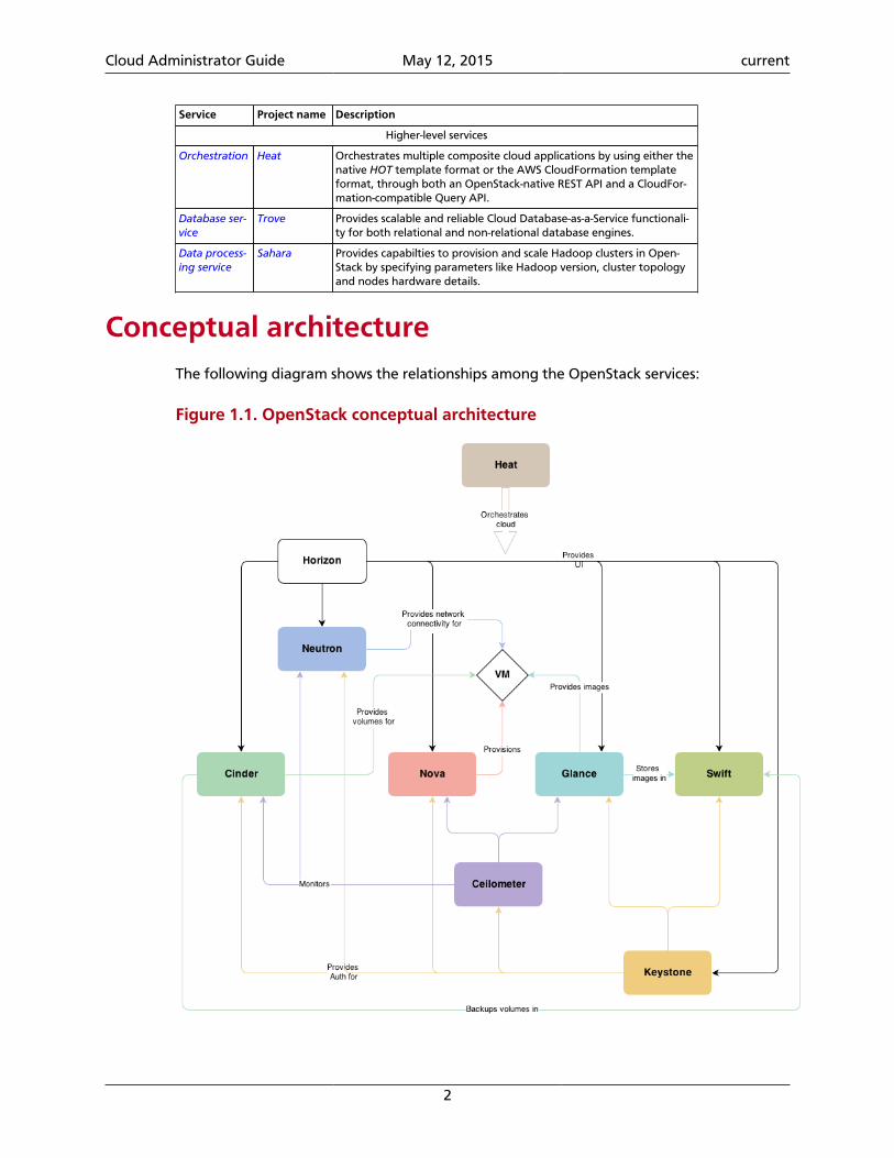
Conceptual architectureThe following diagram shows the relationships among the OpenStack services:
Figure 1.1. OpenStack conceptual architecture
Cloud Administrator Guide May 12, 2015 current
3
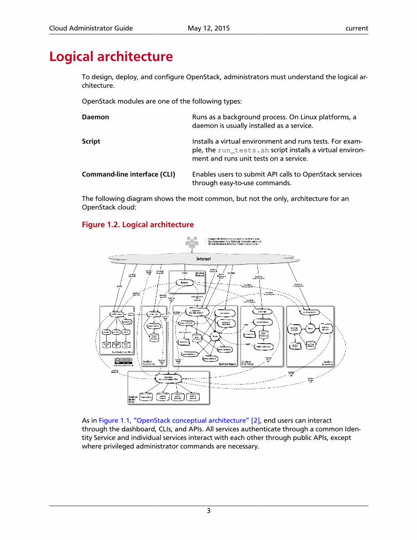
Logical architectureTo design, deploy, and configure OpenStack, administrators must understand the logical ar-chitecture.
OpenStack modules are one of the following types:
Daemon Runs as a background process. On Linux platforms, adaemon is usually installed as a service.
Script Installs a virtual environment and runs tests. For exam-ple, the run_tests.sh script installs a virtual environ-ment and runs unit tests on a service.
Command-line interface (CLI) Enables users to submit API calls to OpenStack servicesthrough easy-to-use commands.
The following diagram shows the most common, but not the only, architecture for anOpenStack cloud:
Figure 1.2. Logical architecture
As in Figure 1.1, “OpenStack conceptual architecture” [2], end users can interactthrough the dashboard, CLIs, and APIs. All services authenticate through a common Iden-tity Service and individual services interact with each other through public APIs, exceptwhere privileged administrator commands are necessary.
Cloud Administrator Guide May 12, 2015 current
4
OpenStack servicesThis section describes OpenStack services in detail.
OpenStack Compute
Use OpenStack Compute to host and manage cloud computing systems. OpenStack Com-pute is a major part of an Infrastructure-as-a-Service (IaaS) system. The main modules areimplemented in Python.
OpenStack Compute interacts with OpenStack Identity for authentication, OpenStack Im-age service for disk and server images, and OpenStack dashboard for the user and admin-istrative interface. Image access is limited by projects, and by users; quotas are limited perproject (the number of instances, for example). OpenStack Compute can scale horizontallyon standard hardware, and download images to launch instances.
OpenStack Compute consists of the following areas and their components:
API
nova-api service Accepts and responds to end user compute API calls.The service supports the OpenStack Compute API, theAmazon EC2 API, and a special Admin API for privilegedusers to perform administrative actions. It enforcessome policies and initiates most orchestration activities,such as running an instance.
nova-api-metadata service Accepts metadata requests from instances. The no-va-api-metadata service is generally used when yourun in multi-host mode with nova-network installa-tions. For details, see Metadata service in the OpenStackCloud Administrator Guide.
On Debian systems, it is included in the nova-api pack-age, and can be selected through debconf.
Compute core
nova-compute service A worker daemon that creates and terminates virtualmachine instances through hypervisor APIs. For exam-ple:
• XenAPI for XenServer/XCP
• libvirt for KVM or QEMU
• VMwareAPI for VMware
Processing is fairly complex. Basically, the daemon ac-cepts actions from the queue and performs a series ofsystem commands such as launching a KVM instanceand updating its state in the database.
Cloud Administrator Guide May 12, 2015 current
5
nova-scheduler service Takes a virtual machine instance request from thequeue and determines on which compute server host itruns.
nova-conductor module Mediates interactions between the nova-compute ser-vice and the database. It eliminates direct accesses tothe cloud database made by the nova-compute ser-vice. The nova-conductor module scales horizontal-ly. However, do not deploy it on nodes where the no-va-compute service runs. For more information, see Anew Nova service: nova-conductor.
nova-cert module A server daemon that serves the Nova Cert service forX509 certificates. Used to generate certificates for eu-ca-bundle-image. Only needed for the EC2 API.
Networking for VMs
nova-network worker dae-mon
Similar to the nova-compute service, accepts network-ing tasks from the queue and manipulates the network.Performs tasks such as setting up bridging interfaces orchanging IPtables rules.
Cloud Administrator Guide May 12, 2015 current
6
Console interface
nova-consoleauth daemon Authorizes tokens for users that console proxies pro-vide. See nova-novncproxy and nova-xvpn-vcproxy. This service must be running for console prox-ies to work. You can run proxies of either type against asingle nova-consoleauth service in a cluster configu-ration. For information, see About nova-consoleauth.
nova-novncproxy daemon Provides a proxy for accessing running instancesthrough a VNC connection. Supports browser-basednovnc clients.
nova-spicehtml5proxy dae-mon
Provides a proxy for accessing running instancesthrough a SPICE connection. Supports browser-basedHTML5 client.
nova-xvpnvncproxy daemon Provides a proxy for accessing running instancesthrough a VNC connection. Supports an OpenStack-spe-cific Java client.
nova-cert daemon x509 certificates.
In Debian, a unique nova-consoleproxy package provides the nova-novncproxy, no-va-spicehtml5proxy, and nova-xvpvncproxy packages. To select packages, edit the /etc/default/nova-consoleproxy file or use the debconf interface. You can also manuallyedit the /etc/default/nova-consoleproxy file, and stop and start the console dae-mons.
Image management (EC2 scenario)
nova-objectstore daemon An S3 interface for registering images with the Open-Stack Image service. Used primarily for installations thatmust support euca2ools. The euca2ools tools talk tonova-objectstore in S3 language, and nova-ob-jectstore translates S3 requests into Image service re-quests.
euca2ools client A set of command-line interpreter commands for man-aging cloud resources. Although it is not an OpenStackmodule, you can configure nova-api to support thisEC2 interface. For more information, see the Eucalyptus3.4 Documentation.
Command-line clients and other interfaces
nova client Enables users to submit commands as a tenant administrator or end user.
Other components
The queue A central hub for passing messages between daemons. Usually imple-mented with RabbitMQ, but can be implemented with an AMQP mes-sage queue, such as Apache Qpid or Zero MQ.
Cloud Administrator Guide May 12, 2015 current
7
SQL database Stores most build-time and run-time states for a cloud infrastructure, in-cluding:
• Available instance types
• Instances in use
• Available networks
• Projects
Theoretically, OpenStack Compute can support any database that SQL-Alchemy supports. Common databases are SQLite3 for test and develop-ment work, MySQL, and PostgreSQL.
Cloud Administrator Guide May 12, 2015 current
8
Storage concepts
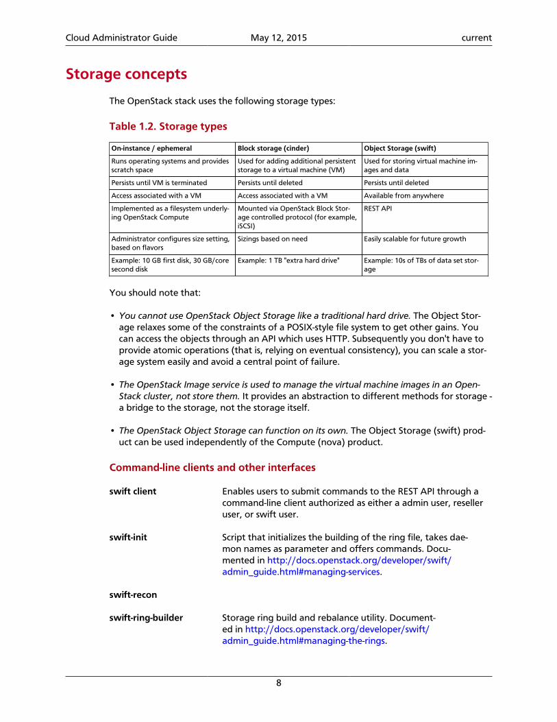
The OpenStack stack uses the following storage types:
Table 1.2. Storage types
On-instance / ephemeral Block storage (cinder) Object Storage (swift)
Runs operating systems and providesscratch space
Used for adding additional persistentstorage to a virtual machine (VM)
Used for storing virtual machine im-ages and data
Persists until VM is terminated Persists until deleted Persists until deleted
Access associated with a VM Access associated with a VM Available from anywhere
Implemented as a filesystem underly-ing OpenStack Compute
Mounted via OpenStack Block Stor-age controlled protocol (for example,iSCSI)
REST API
Administrator configures size setting,based on flavors
Sizings based on need Easily scalable for future growth
Example: 10 GB first disk, 30 GB/coresecond disk
Example: 1 TB "extra hard drive" Example: 10s of TBs of data set stor-age
You should note that:
• You cannot use OpenStack Object Storage like a traditional hard drive. The Object Stor-age relaxes some of the constraints of a POSIX-style file system to get other gains. Youcan access the objects through an API which uses HTTP. Subsequently you don't have toprovide atomic operations (that is, relying on eventual consistency), you can scale a stor-age system easily and avoid a central point of failure.
• The OpenStack Image service is used to manage the virtual machine images in an Open-Stack cluster, not store them. It provides an abstraction to different methods for storage -a bridge to the storage, not the storage itself.
• The OpenStack Object Storage can function on its own. The Object Storage (swift) prod-uct can be used independently of the Compute (nova) product.
Command-line clients and other interfaces
swift client Enables users to submit commands to the REST API through acommand-line client authorized as either a admin user, reselleruser, or swift user.
swift-init Script that initializes the building of the ring file, takes dae-mon names as parameter and offers commands. Docu-mented in http://docs.openstack.org/developer/swift/admin_guide.html#managing-services.
swift-recon
swift-ring-builder Storage ring build and rebalance utility. Document-ed in http://docs.openstack.org/developer/swift/admin_guide.html#managing-the-rings.
Cloud Administrator Guide May 12, 2015 current
9
OpenStack Object Storage
The OpenStack Object Storage is a multi-tenant object storage system. It is highly scalableand can manage large amounts of unstructured data at low cost through a RESTful HTTPAPI.
It includes the following components:
Proxy servers (swift-proxy-server)
Accepts OpenStack Object Storage API and raw HTTPrequests to upload files, modify metadata, and createcontainers. It also serves file or container listings to webbrowsers. To improve performance, the proxy servercan use an optional cache that is usually deployed withmemcache.
Account servers (swift-ac-count-server)
Manages accounts defined with Object Storage.
Container servers (swift-container-server)
Manages the mapping of containers or folders, withinObject Storage.
Object servers (swift-ob-ject-server)
Manages actual objects,such as files, on the storagenodes.
Various periodic processes Performs housekeeping tasks on the large data store.The replication services ensure consistency and availabil-ity through the cluster. Other periodic processes includeauditors, updaters, and reapers.
WSGI middleware Handles authentication and is usually OpenStack Identi-ty.
OpenStack Block Storage
The OpenStack Block Storage service (cinder) adds persistent storage to a virtual machine.Block Storage provides an infrastructure for managing volumes, and interacts with Open-Stack Compute to provide volumes for instances. The service also enables management ofvolume snapshots, and volume types.
The Block Storage service consists of the following components:
cinder-api Accepts API requests, and routes them to the cin-der-volume for action.
cinder-volume Interacts directly with the Block Storage service, andprocesses such as the cinder-scheduler. It also in-teracts with these processes through a message queue.The cinder-volume service responds to readand write requests sent to the Block Storage service tomaintain state. It can interact with a variety of storageproviders through a driver architecture.
Cloud Administrator Guide May 12, 2015 current
10
cinder-scheduler daemon Selects the optimal storage provider node on whichto create the volume. A similar component to the no-va-scheduler.
cinder-backup daemon The cinder-backup service provides backing up vol-umes of any type to a backup storage provider. Like thecinder-volume service, it can interact with a varietyof storage providers through a driver architecture.
Messaging queue Routes information between the Block Storage process-es.
Cloud Administrator Guide May 12, 2015 current
11
OpenStack Networking
OpenStack Networking allows you to create and attach interface devices managed by oth-er OpenStack services to networks. Plug-ins can be implemented to accommodate differentnetworking equipment and software, providing flexibility to OpenStack architecture anddeployment.
It includes the following components:
neutron-server Accepts and routes API requests to the appropriateOpenStack Networking plug-in for action.
OpenStack Networking plug-insand agents
Plugs and unplugs ports, creates networks or subnets,and provides IP addressing. These plug-ins and agentsdiffer depending on the vendor and technologies usedin the particular cloud. OpenStack Networking shipswith plug-ins and agents for Cisco virtual and physicalswitches, NEC OpenFlow products, Open vSwitch, Linuxbridging, and the VMware NSX product.
The common agents are L3 (layer 3), DHCP (dynamichost IP addressing), and a plug-in agent.
Messaging queue Used by most OpenStack Networking installations toroute information between the neutron-server and var-ious agents, as well as a database to store networkingstate for particular plug-ins.
OpenStack Networking mainly interacts with OpenStack Compute to provide networks andconnectivity for its instances.
Cloud Administrator Guide May 12, 2015 current
12
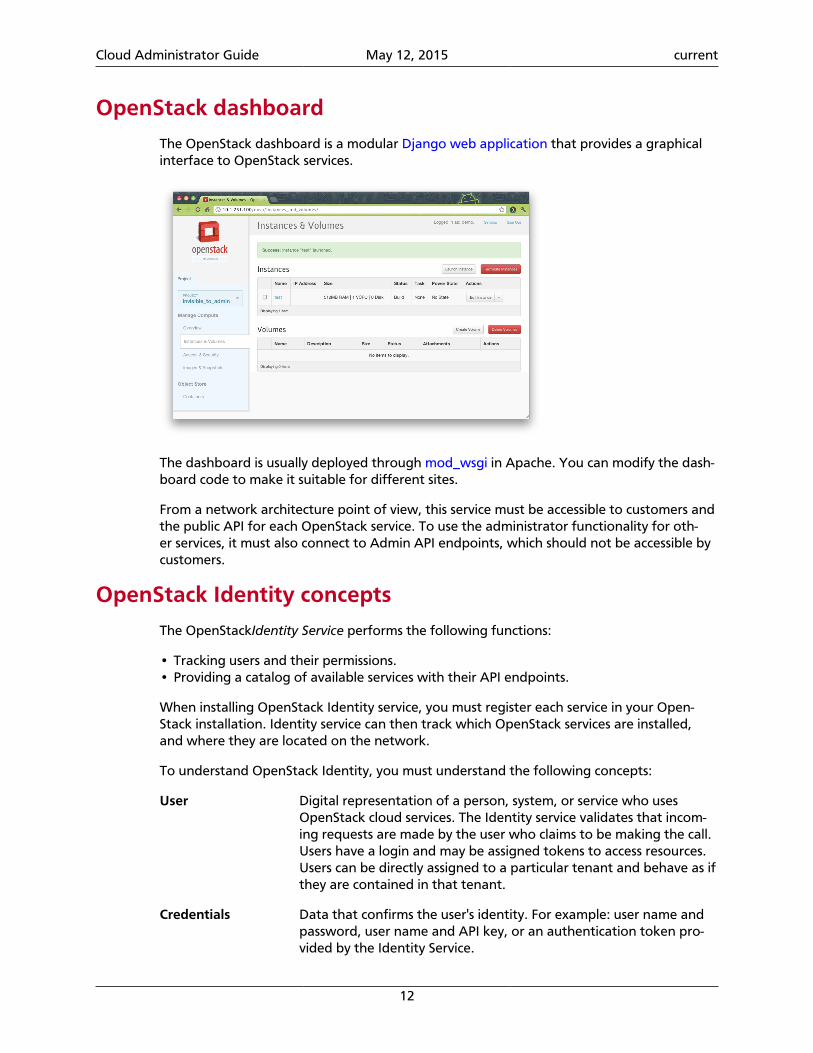
OpenStack dashboardThe OpenStack dashboard is a modular Django web application that provides a graphicalinterface to OpenStack services.
The dashboard is usually deployed through mod_wsgi in Apache. You can modify the dash-board code to make it suitable for different sites.
From a network architecture point of view, this service must be accessible to customers andthe public API for each OpenStack service. To use the administrator functionality for oth-er services, it must also connect to Admin API endpoints, which should not be accessible bycustomers.
OpenStack Identity conceptsThe OpenStackIdentity Service performs the following functions:
• Tracking users and their permissions.• Providing a catalog of available services with their API endpoints.
When installing OpenStack Identity service, you must register each service in your Open-Stack installation. Identity service can then track which OpenStack services are installed,and where they are located on the network.
To understand OpenStack Identity, you must understand the following concepts:
User Digital representation of a person, system, or service who usesOpenStack cloud services. The Identity service validates that incom-ing requests are made by the user who claims to be making the call.Users have a login and may be assigned tokens to access resources.Users can be directly assigned to a particular tenant and behave as ifthey are contained in that tenant.
Credentials Data that confirms the user's identity. For example: user name andpassword, user name and API key, or an authentication token pro-vided by the Identity Service.
Cloud Administrator Guide May 12, 2015 current
13
Authentication The process of confirming the identity of a user. OpenStack Identityconfirms an incoming request by validating a set of credentials sup-plied by the user.
These credentials are initially a user name and password, or a username and API key. When user credentials are validated, OpenStackIdentity issues an authentication token which the user provides insubsequent requests.
Token An alpha-numeric string of text used to access OpenStack APIs andresources. A token may be revoked at any time and is valid for a fi-nite duration.
While OpenStack Identity supports token-based authentication inthis release, the intention is to support additional protocols in the fu-ture. Its main purpose is to be an integration service, and not aspireto be a full-fledged identity store and management solution.
Tenant A container used to group or isolate resources. Tenants also groupor isolate identity objects. Depending on the service operator, a ten-ant may map to a customer, account, organization, or project.
Service An OpenStack service, such as Compute (nova), Object Storage(swift), or Image service (glance). It provides one or more endpointsin which users can access resources and perform operations.
Endpoint A network-accessible address where you access a service, usually aURL address. If you are using an extension for templates, an end-point template can be created, which represents the templates of allthe consumable services that are available across the regions.
Role A personality with a defined set of user rights and privileges to per-form a specific set of operations.
In the Identity service, a token that is issued to a user includes thelist of roles. Services that are being called by that user determinehow they interpret the set of roles a user has and to which opera-tions or resources each role grants access.
Keystone Client A command line interface for the OpenStack Identity API. For exam-ple, users can run the keystone service-create and keystone end-point-create commands to register services in their OpenStack instal-lations.
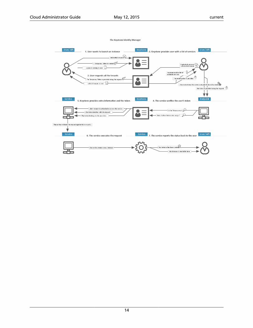
The following diagram shows the OpenStack Identity process flow:
Cloud Administrator Guide May 12, 2015 current
14
Cloud Administrator Guide May 12, 2015 current
15
OpenStack Image service
The OpenStack Image service is central to Infrastructure-as-a-Service (IaaS) as shown in thesection called “Conceptual architecture” [2]. It accepts API requests for disk or server im-ages, and image metadata from end users or OpenStack Compute components. It also sup-ports the storage of disk or server images on various repository types, including OpenStackObject Storage.
A number of periodic processes run on the OpenStack Image service to support caching.Replication services ensure consistency and availability through the cluster. Other periodicprocesses include auditors, updaters, and reapers.
The OpenStack Image service includes the following components:
glance-api Accepts Image API calls for image discovery, retrieval,and storage.
glance-registry Stores, processes, and retrieves metadata about images.Metadata includes items such as size and type.
Security note
The registry is a private internal servicemeant for use by OpenStack Image service.Do not disclose it to users.
Database Stores image metadata and you can choose yourdatabase depending on your preference. Most deploy-ments use MySQL or SQLite.
Storage repository for imagefiles
Various repository types are supported including nor-mal file systems, Object Storage, RADOS block devices,HTTP, and Amazon S3. Note that some repositories willonly support read-only usage.
Telemetry module
The Telemetry module performs the following functions:
• Efficiently polls metering data related to OpenStack services.
• Collects event and metering data by monitoring notifications sent from services.
• Publishes collected data to various targets including data stores and message queues.
• Creates alarms when collected data breaks defined rules.
The Telemetry module consists of the following components:
A compute agent (ceilome-ter-agent-compute)
Runs on each compute node and polls for resource uti-lization statistics. There may be other types of agents inthe future, but for now our focus is creating the com-pute agent.
Cloud Administrator Guide May 12, 2015 current
16
A central agent (ceilome-ter-agent-central)
Runs on a central management server to poll for re-source utilization statistics for resources not tied to in-stances or compute nodes. Multiple agents can be start-ed to scale service horizontally.
A notification agent (ceilome-ter-agent-notification)
Runs on a central management server(s) and consumesmessages from the message queue(s) to build event andmetering data.
A collector (ceilometer-col-lector)
Runs on central management server(s) and dispatchescollected telemetry data to a data store or external con-sumer without modification.
An alarm evaluator (ceilome-ter-alarm-evaluator)
Runs on one or more central management servers to de-termine when alarms fire due to the associated statistictrend crossing a threshold over a sliding time window.
An alarm notifier (ceilome-ter-alarm-notifier)
Runs on one or more central management servers to al-low alarms to be set based on the threshold evaluationfor a collection of samples.
An API server (ceilome-ter-api)
Runs on one or more central management servers toprovide data access from the data store.
These services communicate by using the OpenStack messaging bus. Only the collector andAPI server have access to the data store.
Orchestration module concepts
The Orchestration module provides a template-based orchestration for describing a cloudapplication, by running OpenStack API calls to generate running cloud applications. Thesoftware integrates other core components of OpenStack into a one-file template system.The templates allow you to create most OpenStack resource types, such as instances, float-ing IPs, volumes, security groups and users. It also provides advanced functionality, such asinstance high availability, instance auto-scaling, and nested stacks. This enables OpenStackcore projects to receive a larger user base.
The service enables deployers to integrate with the Orchestration module directly orthrough custom plug-ins.
The Orchestration module consists of the following components:
heat command-line client A CLI that communicates with the heat-api to run AWSCloudFormation APIs. End developers can directly usethe Orchestration REST API.
heat-api component An OpenStack-native REST API that processes API re-quests by sending them to the heat-engine over RemoteProcedure Call (RPC).
heat-api-cfn component An AWS Query API that is compatible with AWS Cloud-Formation. It processes API requests by sending them tothe heat-engine over RPC.
Cloud Administrator Guide May 12, 2015 current
17
heat-engine Orchestrates the launching of templates and providesevents back to the API consumer.
Database service overview
The Database service provides scalable and reliable cloud provisioning functionality for bothrelational and non-relational database engines. Users can quickly and easily use databasefeatures without the burden of handling complex administrative tasks. Cloud users anddatabase administrators can provision and manage multiple database instances as needed.
The Database service provides resource isolation at high performance levels, and automatescomplex administrative tasks such as deployment, configuration, patching, backups, re-stores, and monitoring.
Process flow example. This example is a high-level process flow for using Database ser-vices:
1. The OpenStack Administrator configures the basic infrastructure using the followingsteps:
a. Install the Database service.
b. Create an image for each type of database. For example, one for MySQL and onefor MongoDB.
c. Use the trove-manage command to import images and offer them to tenants.
2. The OpenStack end user deploys the Database service using the following steps:
a. Create a Database service instance using the trove create command.
b. Use the trove list command to get the ID of the instance, followed by the troveshow command to get the IP address of it.
c. Access the Database service instance using typical database access commands. Forexample, with MySQL:
$ mysql -u myuser -p -h TROVE_IP_ADDRESS mydb
The Database service includes the following components:
python-troveclient com-mand-line client
A CLI that communicates with the trove-api compo-nent.
trove-api component Provides an OpenStack-native RESTful API that supportsJSON to provision and manage Trove instances.
trove-conductor service Runs on the host, and receives messages from guest in-stances that want to update information on the host.
trove-taskmanager service Instruments the complex system flows that support pro-visioning instances, managing the lifecycle of instances,and performing operations on instances.
Cloud Administrator Guide May 12, 2015 current
18
trove-guestagent service Runs within the guest instance. Manages and performsoperations on the database itself.
Data processing service
The Data processing service for OpenStack (sahara) aims to provide users with a simplemeans to provision data processing (Hadoop, Spark) clusters by specifying several parame-ters like Hadoop version, cluster topology, node hardware details and a few more. After auser fills in all the parameters, the Data processing service deploys the cluster in a few min-utes. Sahara also provides a means to scale already provisioned clusters by adding/remov-ing worker nodes on demand.
The solution addresses the following use cases:
• Fast provisioning of Hadoop clusters on OpenStack for development and QA.
• Utilization of unused compute power from general purpose OpenStack IaaS cloud.
• Analytics-as-a-Service for ad-hoc or bursty analytic workloads.
Key features are:
• Designed as an OpenStack component.
• Managed through REST API with UI available as part of OpenStack dashboard.
• Support for different Hadoop distributions:
• Pluggable system of Hadoop installation engines.
• Integration with vendor specific management tools, such as Apache Ambari or Cloud-era Management Console.
• Predefined templates of Hadoop configurations with the ability to modify parameters.
• User-friendly UI for ad-hoc analytics queries based on Hive or Pig.
FeedbackTo provide feedback on documentation, join and use the<[email protected]> mailing list at OpenStack DocumentationMailing List, or report a bug.
Cloud Administrator Guide May 12, 2015 current
19
2. Identity management
Table of ContentsIdentity concepts ........................................................................................................... 19Certificates for PKI ........................................................................................................ 25Configure the Identity Service with SSL ......................................................................... 28External authentication with Identity ............................................................................ 29Integrate Identity with LDAP ......................................................................................... 29Configure Identity service for token binding .................................................................. 39Use trusts ...................................................................................................................... 40Caching layer ................................................................................................................ 40User CRUD .................................................................................................................... 42Logging ......................................................................................................................... 43Start the Identity services .............................................................................................. 43Example usage .............................................................................................................. 43Authentication middleware with user name and password ............................................ 44Identity API protection with role-based access control (RBAC) ........................................ 45Troubleshoot the Identity service .................................................................................. 48
OpenStack Identity, code-named keystone, is the default identity management system forOpenStack. After you install Identity, you configure it through the etc/keystone.confconfiguration file and, possibly, a separate logging configuration file. You initialize data in-to Identity by using the keystone command-line client.
Identity concepts
User managementThe main components of Identity user management are:
• User. Represents a human user. Has associated information such as user name, password,and email. This example creates a user named alice:
$ openstack user create --password-prompt --email [email protected] alice
• Project. A tenant, group, or organization. When you make requests to OpenStack ser-vices, you must specify a project. For example, if you query the Compute service for a listof running instances, you get a list of all running instances in the project that you speci-fied in your query. This example creates a project named acme:
$ openstack project create acme
• Domain. Defines administrative boundaries for the management of Identity entities. Adomain may represent an individual, company, or operator-owned space. It is used forexposing administrative activities directly to the system users.
A domain is a collection of projects and users. Users may be given a domain's administra-tor role. A domain administrator may create projects, users, and groups within a domainand assign roles to users and groups.

Cloud Administrator Guide May 12, 2015 current
20
This example creates a domain named emea:
$ openstack domain create emea
• Role. Captures the operations that a user can perform in a given tenant.
This example creates a role named compute-user:
$ openstack role create compute-user
Note
Individual services, such as Compute and the Image service, assign meaningto roles. In the Identity Service, a role is simply a name.
Cloud Administrator Guide May 12, 2015 current
21
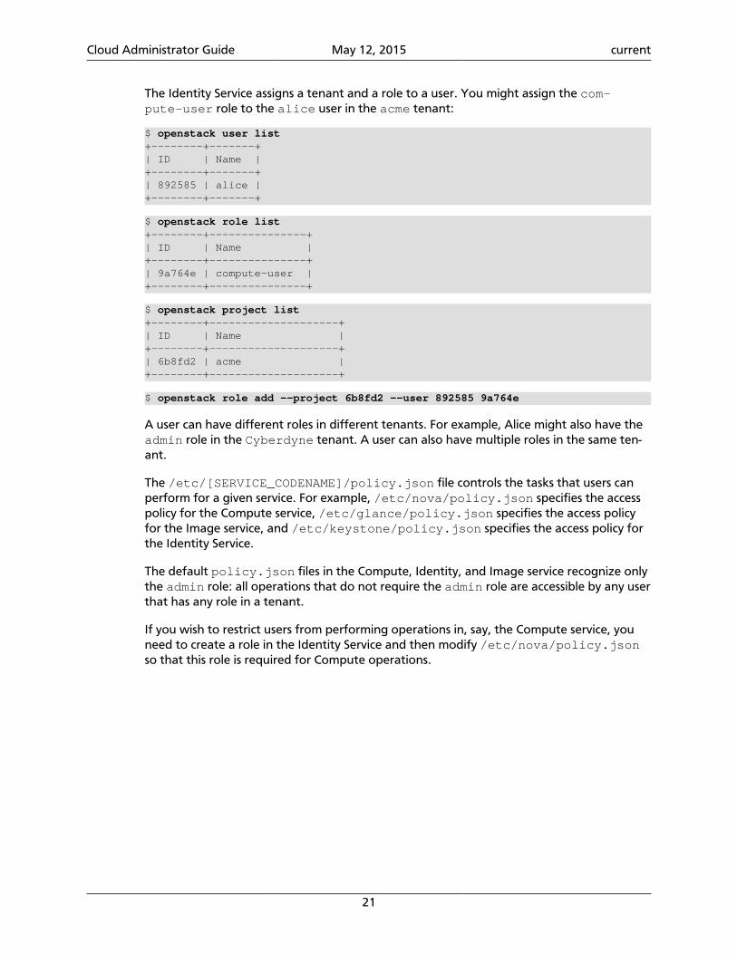
The Identity Service assigns a tenant and a role to a user. You might assign the com-pute-user role to the alice user in the acme tenant:
$ openstack user list+--------+-------+| ID | Name |+--------+-------+| 892585 | alice |+--------+-------+
$ openstack role list+--------+---------------+| ID | Name |+--------+---------------+| 9a764e | compute-user |+--------+---------------+
$ openstack project list+--------+--------------------+| ID | Name |+--------+--------------------+| 6b8fd2 | acme |+--------+--------------------+
$ openstack role add --project 6b8fd2 --user 892585 9a764e
A user can have different roles in different tenants. For example, Alice might also have theadmin role in the Cyberdyne tenant. A user can also have multiple roles in the same ten-ant.
The /etc/[SERVICE_CODENAME]/policy.json file controls the tasks that users canperform for a given service. For example, /etc/nova/policy.json specifies the accesspolicy for the Compute service, /etc/glance/policy.json specifies the access policyfor the Image service, and /etc/keystone/policy.json specifies the access policy forthe Identity Service.
The default policy.json files in the Compute, Identity, and Image service recognize onlythe admin role: all operations that do not require the admin role are accessible by any userthat has any role in a tenant.
If you wish to restrict users from performing operations in, say, the Compute service, youneed to create a role in the Identity Service and then modify /etc/nova/policy.jsonso that this role is required for Compute operations.
Cloud Administrator Guide May 12, 2015 current
22
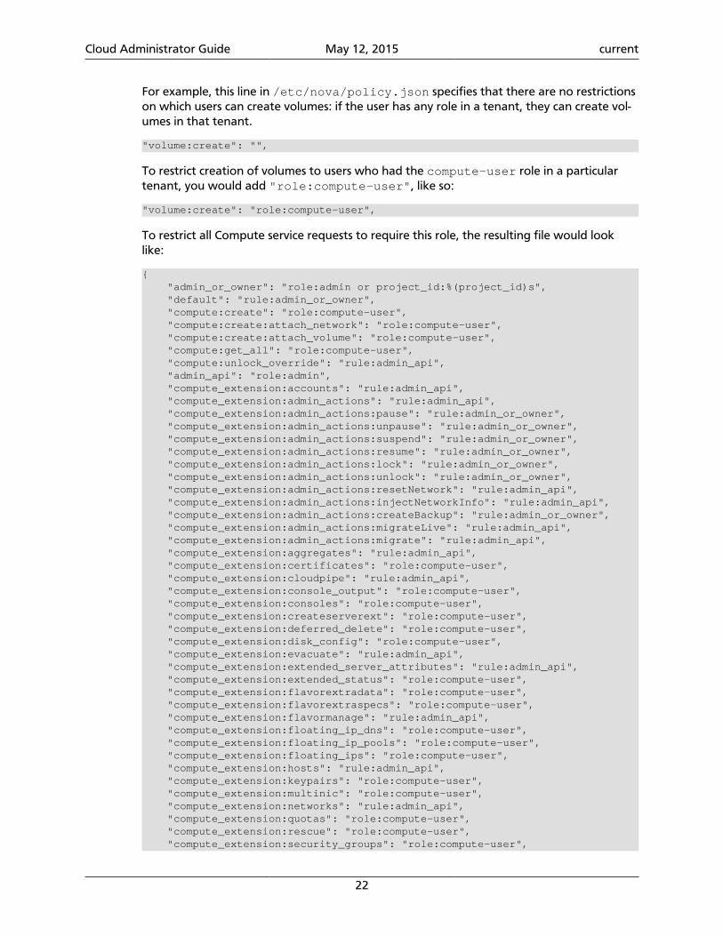
For example, this line in /etc/nova/policy.json specifies that there are no restrictionson which users can create volumes: if the user has any role in a tenant, they can create vol-umes in that tenant.
"volume:create": "",
To restrict creation of volumes to users who had the compute-user role in a particulartenant, you would add "role:compute-user", like so:
"volume:create": "role:compute-user",
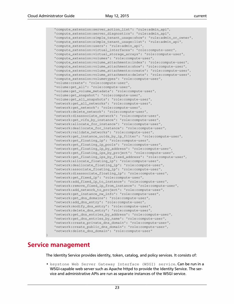
To restrict all Compute service requests to require this role, the resulting file would looklike:
{ "admin_or_owner": "role:admin or project_id:%(project_id)s", "default": "rule:admin_or_owner", "compute:create": "role:compute-user", "compute:create:attach_network": "role:compute-user", "compute:create:attach_volume": "role:compute-user", "compute:get_all": "role:compute-user", "compute:unlock_override": "rule:admin_api", "admin_api": "role:admin", "compute_extension:accounts": "rule:admin_api", "compute_extension:admin_actions": "rule:admin_api", "compute_extension:admin_actions:pause": "rule:admin_or_owner", "compute_extension:admin_actions:unpause": "rule:admin_or_owner", "compute_extension:admin_actions:suspend": "rule:admin_or_owner", "compute_extension:admin_actions:resume": "rule:admin_or_owner", "compute_extension:admin_actions:lock": "rule:admin_or_owner", "compute_extension:admin_actions:unlock": "rule:admin_or_owner", "compute_extension:admin_actions:resetNetwork": "rule:admin_api", "compute_extension:admin_actions:injectNetworkInfo": "rule:admin_api", "compute_extension:admin_actions:createBackup": "rule:admin_or_owner", "compute_extension:admin_actions:migrateLive": "rule:admin_api", "compute_extension:admin_actions:migrate": "rule:admin_api", "compute_extension:aggregates": "rule:admin_api", "compute_extension:certificates": "role:compute-user", "compute_extension:cloudpipe": "rule:admin_api", "compute_extension:console_output": "role:compute-user", "compute_extension:consoles": "role:compute-user", "compute_extension:createserverext": "role:compute-user", "compute_extension:deferred_delete": "role:compute-user", "compute_extension:disk_config": "role:compute-user", "compute_extension:evacuate": "rule:admin_api", "compute_extension:extended_server_attributes": "rule:admin_api", "compute_extension:extended_status": "role:compute-user", "compute_extension:flavorextradata": "role:compute-user", "compute_extension:flavorextraspecs": "role:compute-user", "compute_extension:flavormanage": "rule:admin_api", "compute_extension:floating_ip_dns": "role:compute-user", "compute_extension:floating_ip_pools": "role:compute-user", "compute_extension:floating_ips": "role:compute-user", "compute_extension:hosts": "rule:admin_api", "compute_extension:keypairs": "role:compute-user", "compute_extension:multinic": "role:compute-user", "compute_extension:networks": "rule:admin_api", "compute_extension:quotas": "role:compute-user", "compute_extension:rescue": "role:compute-user", "compute_extension:security_groups": "role:compute-user",
Cloud Administrator Guide May 12, 2015 current
23
"compute_extension:server_action_list": "rule:admin_api", "compute_extension:server_diagnostics": "rule:admin_api", "compute_extension:simple_tenant_usage:show": "rule:admin_or_owner", "compute_extension:simple_tenant_usage:list": "rule:admin_api", "compute_extension:users": "rule:admin_api", "compute_extension:virtual_interfaces": "role:compute-user", "compute_extension:virtual_storage_arrays": "role:compute-user", "compute_extension:volumes": "role:compute-user", "compute_extension:volume_attachments:index": "role:compute-user", "compute_extension:volume_attachments:show": "role:compute-user", "compute_extension:volume_attachments:create": "role:compute-user", "compute_extension:volume_attachments:delete": "role:compute-user", "compute_extension:volumetypes": "role:compute-user", "volume:create": "role:compute-user", "volume:get_all": "role:compute-user", "volume:get_volume_metadata": "role:compute-user", "volume:get_snapshot": "role:compute-user", "volume:get_all_snapshots": "role:compute-user", "network:get_all_networks": "role:compute-user", "network:get_network": "role:compute-user", "network:delete_network": "role:compute-user", "network:disassociate_network": "role:compute-user", "network:get_vifs_by_instance": "role:compute-user", "network:allocate_for_instance": "role:compute-user", "network:deallocate_for_instance": "role:compute-user", "network:validate_networks": "role:compute-user", "network:get_instance_uuids_by_ip_filter": "role:compute-user", "network:get_floating_ip": "role:compute-user", "network:get_floating_ip_pools": "role:compute-user", "network:get_floating_ip_by_address": "role:compute-user", "network:get_floating_ips_by_project": "role:compute-user", "network:get_floating_ips_by_fixed_address": "role:compute-user", "network:allocate_floating_ip": "role:compute-user", "network:deallocate_floating_ip": "role:compute-user", "network:associate_floating_ip": "role:compute-user", "network:disassociate_floating_ip": "role:compute-user", "network:get_fixed_ip": "role:compute-user", "network:add_fixed_ip_to_instance": "role:compute-user", "network:remove_fixed_ip_from_instance": "role:compute-user", "network:add_network_to_project": "role:compute-user", "network:get_instance_nw_info": "role:compute-user", "network:get_dns_domains": "role:compute-user", "network:add_dns_entry": "role:compute-user", "network:modify_dns_entry": "role:compute-user", "network:delete_dns_entry": "role:compute-user", "network:get_dns_entries_by_address": "role:compute-user", "network:get_dns_entries_by_name": "role:compute-user", "network:create_private_dns_domain": "role:compute-user", "network:create_public_dns_domain": "role:compute-user", "network:delete_dns_domain": "role:compute-user"}
Service management
The Identity Service provides identity, token, catalog, and policy services. It consists of:
• keystone Web Server Gateway Interface (WSGI) service. Can be run in aWSGI-capable web server such as Apache httpd to provide the Identity Service. The ser-vice and administrative APIs are run as separate instances of the WSGI service.
Cloud Administrator Guide May 12, 2015 current
24
• Identity Service functions. Each has a pluggable back end that allows different ways touse the particular service. Most support standard back ends like LDAP or SQL.
• keystone-all. Starts both the service and administrative APIs in a single process. Usingfederation with keystone-all is not supported. keystone-all is deprecated in favor of theWSGI service.
The Identity Service also maintains a user that corresponds to each service, such as, a usernamed nova for the Compute service, and a special service tenant called service.
For information about how to create services and endpoints, see the OpenStack Admin Us-er Guide.
Groups
A group is a collection of users. Administrators can create groups and add users to them.Then, rather than assign a role to each user individually, assign a role to the group. Everygroup is in a domain. Groups were introduced with the Identity API v3.
Identity API V3 provides the following group-related operations:
• Create a group
• Delete a group
• Update a group (change its name or description)
• Add a user to a group
• Remove a user from a group
• List group members
• List groups for a user
• Assign a role on a tenant to a group
• Assign a role on a domain to a group
• Query role assignments to groups
Note
The Identity service server might not allow all operations. For example, if usingthe Identity server with the LDAP Identity back end and group updates are dis-abled, then a request to create, delete, or update a group fails.
Here are a couple of examples:
• Group A is granted Role A on Tenant A. If User A is a member of Group A, when User Agets a token scoped to Tenant A, the token also includes Role A.
• Group B is granted Role B on Domain B. If User B is a member of Domain B, if User B getsa token scoped to Domain B, the token also includes Role B.
Cloud Administrator Guide May 12, 2015 current
25
Certificates for PKIPKI stands for Public Key Infrastructure. Tokens are documents, cryptographically signed us-ing the X509 standard. In order to work correctly token generation requires a public/pri-vate key pair. The public key must be signed in an X509 certificate, and the certificate usedto sign it must be available as a Certificate Authority (CA) certificate. These files can begenerated either using the keystone-manage utility, or externally generated. The filesneed to be in the locations specified by the top level Identity Service configuration filekeystone.conf as specified in the above section. Additionally, the private key should on-ly be readable by the system user that will run the Identity Service.
Warning
The certificates can be world readable, but the private key cannot be. The pri-vate key should only be readable by the account that is going to sign tokens.When generating files with the keystone-manage pki_setup command, yourbest option is to run as the pki user. If you run keystone-manage as root, youcan append --keystone-user and --keystone-group parameters to setthe user name and group keystone is going to run under.
The values that specify where to read the certificates are under the [signing] section ofthe configuration file. The configuration values are:
• certfile - Location of certificate used to verify tokens. Default is /etc/key-stone/ssl/certs/signing_cert.pem.
• keyfile - Location of private key used to sign tokens. Default is /etc/key-stone/ssl/private/signing_key.pem.
• ca_certs - Location of certificate for the authority that issued the above certificate. De-fault is /etc/keystone/ssl/certs/ca.pem.
• ca_key - Location of the private key used by the CA. Default is /etc/keystone/ssl/private/cakey.pem.
• key_size - Default is 2048.
• valid_days - Default is 3650.
• cert_subject - Certificate subject (auto generated certificate) for token signing. De-fault is /C=US/ST=Unset/L=Unset/O=Unset/CN=www.example.com.
When generating certificates with the keystone-manage pki_setup command, theca_key, key_size, and valid_days configuration options are used.
If the keystone-manage pki_setup command is not used to generate certificates, or youare providing your own certificates, these values do not need to be set.
If provider=keystone.token.providers.uuid.Providerin the [token] section of the keystone configuration, a typi-cal token looks like 53f7f6ef0cc344b5be706bcc8b1479e1. Ifprovider=keystone.token.providers.pki.Provider, a typical token is a muchlonger string, such as:
Cloud Administrator Guide May 12, 2015 current
26
MIIKtgYJKoZIhvcNAQcCoIIKpzCCCqMCAQExCTAHBgUrDgMCGjCCCY8GCSqGSIb3DQEHAaCCCYAEggl8eyJhY2Nlc3MiOiB7InRva2VuIjogeyJpc3N1ZWRfYXQiOiAiMjAxMy0wNS0zMFQxNTo1MjowNi43MzMxOTgiLCAiZXhwaXJlcyI6ICIyMDEzLTA1LTMxVDE1OjUyOjA2WiIsICJpZCI6ICJwbGFjZWhvbGRlciIsICJ0ZW5hbnQiOiB7ImRlc2NyaXB0aW9uIjogbnVsbCwgImVuYWJsZWQiOiB0cnVlLCAiaWQiOiAiYzJjNTliNGQzZDI4NGQ4ZmEwOWYxNjljYjE4MDBlMDYiLCAibmFtZSI6ICJkZW1vIn19LCAic2VydmljZUNhdGFsb2ciOiBbeyJlbmRwb2ludHMiOiBbeyJhZG1pblVSTCI6ICJodHRwOi8vMTkyLjE2OC4yNy4xMDA6ODc3NC92Mi9jMmM1OWI0ZDNkMjg0ZDhmYTA5ZjE2OWNiMTgwMGUwNiIsICJyZWdpb24iOiAiUmVnaW9uT25lIiwgImludGVybmFsVVJMIjogImh0dHA6Ly8xOTIuMTY4LjI3LjEwMDo4Nzc0L3YyL2MyYzU5YjRkM2QyODRkOGZhMDlmMTY5Y2IxODAwZTA2IiwgImlkIjogIjFmYjMzYmM5M2Y5ODRhNGNhZTk3MmViNzcwOTgzZTJlIiwgInB1YmxpY1VSTCI6ICJodHRwOi8vMTkyLjE2OC4yNy4xMDA6ODc3NC92Mi9jMmM1OWI0ZDNkMjg0ZDhmYTA5ZjE2OWNiMTgwMGUwNiJ9XSwgImVuZHBvaW50c19saW5rcyI6IFtdLCAidHlwZSI6ICJjb21wdXRlIiwgIm5hbWUiOiAibm92YSJ9LCB7ImVuZHBvaW50cyI6IFt7ImFkbWluVVJMIjogImh0dHA6Ly8xOTIuMTY4LjI3LjEwMDozMzMzIiwgInJlZ2lvbiI6ICJSZWdpb25PbmUiLCAiaW50ZXJuYWxVUkwiOiAiaHR0cDovLzE5Mi4xNjguMjcuMTAwOjMzMzMiLCAiaWQiOiAiN2JjMThjYzk1NWFiNDNkYjhmMGU2YWNlNDU4NjZmMzAiLCAicHVibGljVVJMIjogImh0dHA6Ly8xOTIuMTY4LjI3LjEwMDozMzMzIn1dLCAiZW5kcG9pbnRzX2xpbmtzIjogW10sICJ0eXBlIjogInMzIiwgIm5hbWUiOiAiczMifSwgeyJlbmRwb2ludHMiOiBbeyJhZG1pblVSTCI6ICJodHRwOi8vMTkyLjE2OC4yNy4xMDA6OTI5MiIsICJyZWdpb24iOiAiUmVnaW9uT25lIiwgImludGVybmFsVVJMIjogImh0dHA6Ly8xOTIuMTY4LjI3LjEwMDo5MjkyIiwgImlkIjogIjczODQzNTJhNTQ0MjQ1NzVhM2NkOTVkN2E0YzNjZGY1IiwgInB1YmxpY1VSTCI6ICJodHRwOi8vMTkyLjE2OC4yNy4xMDA6OTI5MiJ9XSwgImVuZHBvaW50c19saW5rcyI6IFtdLCAidHlwZSI6ICJpbWFnZSIsICJuYW1lIjogImdsYW5jZSJ9LCB7ImVuZHBvaW50cyI6IFt7ImFkbWluVVJMIjogImh0dHA6Ly8xOTIuMTY4LjI3LjEwMDo4Nzc2L3YxL2MyYzU5YjRkM2QyODRkOGZhMDlmMTY5Y2IxODAwZTA2IiwgInJlZ2lvbiI6ICJSZWdpb25PbmUiLCAiaW50ZXJuYWxVUkwiOiAiaHR0cDovLzE5Mi4xNjguMjcuMTAwOjg3NzYvdjEvYzJjNTliNGQzZDI4NGQ4ZmEwOWYxNjljYjE4MDBlMDYiLCAiaWQiOiAiMzQ3ZWQ2ZThjMjkxNGU1MGFlMmJiNjA2YWQxNDdjNTQiLCAicHVibGljVVJMIjogImh0dHA6Ly8xOTIuMTY4LjI3LjEwMDo4Nzc2L3YxL2MyYzU5YjRkM2QyODRkOGZhMDlmMTY5Y2IxODAwZTA2In1dLCAiZW5kcG9pbnRzX2xpbmtzIjogW10sICJ0eXBlIjogInZvbHVtZSIsICJuYW1lIjogImNpbmRlciJ9LCB7ImVuZHBvaW50cyI6IFt7ImFkbWluVVJMIjogImh0dHA6Ly8xOTIuMTY4LjI3LjEwMDo4NzczL3NlcnZpY2VzL0FkbWluIiwgInJlZ2lvbiI6ICJSZWdpb25PbmUiLCAiaW50ZXJuYWxVUkwiOiAiaHR0cDovLzE5Mi4xNjguMjcuMTAwOjg3NzMvc2VydmljZXMvQ2xvdWQiLCAiaWQiOiAiMmIwZGMyYjNlY2U4NGJjYWE1NDAzMDMzNzI5YzY3MjIiLCAicHVibGljVVJMIjogImh0dHA6Ly8xOTIuMTY4LjI3LjEwMDo4NzczL3NlcnZpY2VzL0Nsb3VkIn1dLCAiZW5kcG9pbnRzX2xpbmtzIjogW10sICJ0eXBlIjogImVjMiIsICJuYW1lIjogImVjMiJ9LCB7ImVuZHBvaW50cyI6IFt7ImFkbWluVVJMIjogImh0dHA6Ly8xOTIuMTY4LjI3LjEwMDozNTM1Ny92Mi4wIiwgInJlZ2lvbiI6ICJSZWdpb25PbmUiLCAiaW50ZXJuYWxVUkwiOiAiaHR0cDovLzE5Mi4xNjguMjcuMTAwOjUwMDAvdjIuMCIsICJpZCI6ICJiNTY2Y2JlZjA2NjQ0ZmY2OWMyOTMxNzY2Yjc5MTIyOSIsICJwdWJsaWNVUkwiOiAiaHR0cDovLzE5Mi4xNjguMjcuMTAwOjUwMDAvdjIuMCJ9XSwgImVuZHBvaW50c19saW5rcyI6IFtdLCAidHlwZSI6ICJpZGVudGl0eSIsICJuYW1lIjogImtleXN0b25lIn1dLCAidXNlciI6IHsidXNlcm5hbWUiOiAiZGVtbyIsICJyb2xlc19saW5rcyI6IFtdLCAiaWQiOiAiZTVhMTM3NGE4YTRmNDI4NWIzYWQ3MzQ1MWU2MDY4YjEiLCAicm9sZXMiOiBbeyJuYW1lIjogImFub3RoZXJyb2xlIn0sIHsibmFtZSI6ICJNZW1iZXIifV0sICJuYW1lIjogImRlbW8ifSwgIm1ldGFkYXRhIjogeyJpc19hZG1pbiI6IDAsICJyb2xlcyI6IFsiYWRiODM3NDVkYzQzNGJhMzk5ODllNjBjOTIzYWZhMjgiLCAiMzM2ZTFiNjE1N2Y3NGFmZGJhNWUwYTYwMWUwNjM5MmYiXX19fTGB-zCB-AIBATBcMFcxCzAJBgNVBAYTAlVTMQ4wDAYDVQQIEwVVbnNldDEOMAwGA1UEBxMFVW5zZXQxDjAMBgNVBAoTBVVuc2V0MRgwFgYDVQQDEw93d3cuZXhhbXBsZS5jb20CAQEwBwYFKw4DAhowDQYJKoZIhvcNAQEBBQAEgYCAHLpsEs2RnouriuiCgFayIqCssK3SVdhOMINiuJtqv0sE-wBDFiEj-Prcudqlz-n+6q7VgV4mwMPszz39-rwp+P5l4AjrJasUm7FrO-4l02tPLaaZXU1gBQ1jUG5e5aL5jPDP08HbCWuX6wr-QQQBSrWY8lF3HrTcJT23sZIleg==
Sign certificate issued by external CAYou can use a signing certificate issued by an external CA instead of generated by key-stone-manage. However, a certificate issued by an external CA must satisfy the followingconditions:
• all certificate and key files must be in Privacy Enhanced Mail (PEM) format
• private key files must not be protected by a password
When using a signing certificate issued by an external CA, you do not need to specifykey_size, valid_days, and ca_password as they will be ignored.
The basic workflow for using a signing certificate issued by an external CA involves:
1. Request Signing Certificate from External CA
2. Convert certificate and private key to PEM if needed
3. Install External Signing Certificate
Request a signing certificate from an external CAOne way to request a signing certificate from an external CA is to first generate a PKCS #10Certificate Request Syntax (CRS) using OpenSSL CLI.
Create a certificate request configuration file. For example, create the cert_req.conffile, as follows:
Cloud Administrator Guide May 12, 2015 current
27
[ req ]default_bits = 1024default_keyfile = keystonekey.pemdefault_md = sha1
prompt = nodistinguished_name = distinguished_name
[ distinguished_name ]countryName = USstateOrProvinceName = CAlocalityName = SunnyvaleorganizationName = OpenStackorganizationalUnitName = KeystonecommonName = Keystone SigningemailAddress = [email protected]
Then generate a CRS with OpenSSL CLI. Do not encrypt the generated private key. Mustuse the -nodes option.
For example:
$ openssl req -newkey rsa:1024 -keyout signing_key.pem -keyform PEM \ -out signing_cert_req.pem -outform PEM -config cert_req.conf -nodes
If everything is successful, you should end up with signing_cert_req.pem andsigning_key.pem. Send signing_cert_req.pem to your CA to request a token sign-ing certificate and make sure to ask the certificate to be in PEM format. Also, make sureyour trusted CA certificate chain is also in PEM format.
Install an external signing certificateAssuming you have the following already:
• signing_cert.pem - (Keystone token) signing certificate in PEM format
• signing_key.pem - corresponding (non-encrypted) private key in PEM format
• cacert.pem - trust CA certificate chain in PEM format
Copy the above to your certificate directory. For example:
# mkdir -p /etc/keystone/ssl/certs# cp signing_cert.pem /etc/keystone/ssl/certs/# cp signing_key.pem /etc/keystone/ssl/certs/# cp cacert.pem /etc/keystone/ssl/certs/# chmod -R 700 /etc/keystone/ssl/certs
Note
Make sure the certificate directory is only accessible by root.
Note
The procedure of copying the key and cert files may be improved if done afterfirst running keystone-manage pki_setup since this command also creates oth-er needed files, such as the index.txt and serial files.
Cloud Administrator Guide May 12, 2015 current
28
Also, when copying the necessary files to a different server for replicating thefunctionality, the entire directory of files is needed, not just the key and certfiles.
If your certificate directory path is different from the default /etc/keystone/ssl/certs, make sure it is reflected in the [signing] section of the configuration file.
Configure the Identity Service with SSLYou can configure the Identity Service to support two-way SSL.
You must obtain the x509 certificates externally and configure them.
The Identity Service provides a set of sample certificates in the examples/pki/certs andexamples/pki/private directories:
Certificate types
cacert.pem Certificate Authority chain to validate against.
ssl_cert.pem Public certificate for Identity Service server.
middleware.pem Public and private certificate for Identity Service middleware/client.
cakey.pem Private key for the CA.
ssl_key.pem Private key for the Identity Service server.
Note
You can choose names for these certificates. You can also combine the pub-lic/private keys in the same file, if you wish. These certificates are provided asan example.
Client authentication with keystone-all
When running keystone-all, the server can be configured to enable SSL with client authenti-cation using the following instructions. Modify the [eventlet_server_ssl] section inthe etc/keystone.conf file. The following SSL configuration example uses the includedsample certificates:
[eventlet_server_ssl]enable = Truecertfile = <path to keystone.pem>keyfile = <path to keystonekey.pem>ca_certs = <path to ca.pem>cert_required = True
Options
• enable. True enables SSL. Default is False.
• certfile. Path to the Identity Service public certificate file.
Cloud Administrator Guide May 12, 2015 current
29
• keyfile. Path to the Identity Service private certificate file. If you include the privatekey in the certfile, you can omit the keyfile.
• ca_certs. Path to the CA trust chain.
• cert_required. Requires client certificate. Default is False.
When running the Identity Service as a WSGI service in a web server such as Apachehttpd, this configuration is done in the web server instead. In this case the options in the[eventlet_server_ssl] section are ignored.
External authentication with IdentityWhen Identity runs in apache-httpd, you can use external authentication methods thatdiffer from the authentication provided by the identity store back end. For example, youcan use an SQL identity back end together with X.509 authentication and Kerberos, insteadof using the user name and password combination.
Use HTTPD authentication
Web servers, like Apache HTTP, support many methods of authentication. Identity can al-low the web server to perform the authentication. The web server then passes the authen-ticated user to Identity by using the REMOTE_USER environment variable. This user must al-ready exist in the Identity back end to get a token from the controller. To use this method,Identity should run on apache-httpd.
Use X.509
The following Apache configuration snippet authenticates the user based on a valid X.509certificate from a known CA:
<VirtualHost _default_:5000> SSLEngine on SSLCertificateFile /etc/ssl/certs/ssl.cert SSLCertificateKeyFile /etc/ssl/private/ssl.key
SSLCACertificatePath /etc/ssl/allowed_cas SSLCARevocationPath /etc/ssl/allowed_cas SSLUserName SSL_CLIENT_S_DN_CN SSLVerifyClient require SSLVerifyDepth 10
(...) </VirtualHost>
Integrate Identity with LDAPThe Openstack Identity Service supports integration with existing LDAP directories for au-thentication and authorization services.
When the Openstack Identity service is configured to use LDAP back ends, you can split au-thentication (using the identity feature) and authorization (using the assignment feature).
Cloud Administrator Guide May 12, 2015 current
30
The identity feature enables administrators to manage users and groups by each domain orthe Openstack Identity Service entirely.
The Assignments feature enables administrators to manage project role authorization usingthe Openstack Identity service SQL database, while providing user authentication throughthe LDAP directory.
Important
For OpenStack Identity service to access LDAP servers, you must enable theauthlogin_nsswitch_use_ldap boolean value for SELinux on the Open-stack Identity server. To enable and make the option persistent across reboots:
# setsebool -P authlogin_nsswitch_use_ldap on
Identity configuration is split into two separate back ends: identity (back end for users andgroups) and assignments (back end for domains, projects, roles, role assignments). To con-figure identity, set options in the /etc/keystone/keystone.conf file. See the sectioncalled “Integrate identity back end with LDAP” [32] for identity back end configurationexamples and the section called “Integrate assignment back end with LDAP” [35] for as-signment back end configuration examples. Modify these examples as needed.
Note
Multiple back ends are supported. You can integrate the Openstack Identityservice with a single LDAP server (configure both identity and assignments toLDAP, or set identity and assignments back end with SQL or LDAP), or multipleback ends using domain-specific configuration files.
To define the destination LDAP server. Define the destination LDAP server in thekeystone.conf file:
[ldap]url = ldap://localhostuser = dc=Manager,dc=example,dc=orgpassword = samplepasswordsuffix = dc=example,dc=orguse_dumb_member = Falseallow_subtree_delete = False
Note
Configure dumb_member if you set use_dumb_member to true.
[ldap]dumb_member = cn=dumb,dc=nonexistent
Additional LDAP integration settings. Set these options in the /etc/key-stone/keystone.conf file for a single LDAP server, or /etc/keystone/do-mains/keystone.DOMAIN_NAME.conf files for multiple back ends.
Query option Use query_scope to control the scope level of datapresented (search only the first level or search an entiresub-tree) through LDAP.
Cloud Administrator Guide May 12, 2015 current
31
Use page_size to control the maximum results perpage. A value of zero disables paging.
Use alias_dereferencing to control the LDAPdereferencing option for queries.
Use chase_referrals to override the system's de-fault referral chasing behavior for queries.
[ldap]query_scope = subpage_size = 0alias_dereferencing = defaultchase_referrals =
Debug Use debug_level to set the LDAP debugging level forLDAP calls. A value of zero means that debugging is notenabled.
[ldap]debug_level = 0
Warning
This value is a bitmask, consult your LDAPdocumentation for possible values.
Connection pooling Use use_pool to enable LDAP connection pooling.Configure connection pool size, maximum retry, recon-nect trials, timeout (-1 indicates indefinite wait) and life-time in seconds.
[ldap]use_pool = truepool_size = 10pool_retry_max = 3pool_retry_delay = 0.1pool_connection_timeout = -1pool_connection_lifetime = 600
Connection pooling for end us-er authentication
Use use_auth_pool to enable LDAP connection pool-ing for end user authentication. Configure connectionpool size and lifetime in seconds.
[ldap]use_auth_pool = falseauth_pool_size = 100auth_pool_connection_lifetime = 60
When you have finished configuration, restart the Openstack Identity service:
# service keystone restart
Warning
During service restart, authentication and authorization are unavailable.
Cloud Administrator Guide May 12, 2015 current
32
Integrate identity back end with LDAP
The identity back end contains information for users, groups, and group member lists. In-tegrating the identity back end with LDAP allows administrators to use users and groups inLDAP.
Important
For OpenStack Identity Service to access LDAP servers, you must define the des-tination LDAP server in the keystone.conf file. For more information, seethe section called “Integrate Identity with LDAP” [29].
Integrating an identity back end with LDAP
1. Enable the LDAP identity driver in the keystone.conf file. This allows LDAP as anidentity back end:
[identity]#driver = keystone.identity.backends.sql.Identitydriver = keystone.identity.backends.ldap.Identity
2. Create the organizational units (OU) in the LDAP directory, and define the correspond-ing location in the keystone.conf file:
[ldap]user_tree_dn = ou=Users,dc=example,dc=orguser_objectclass = inetOrgPerson
group_tree_dn = ou=Groups,dc=example,dc=orggroup_objectclass = groupOfNames
Note
These schema attributes are extensible for compatibility with variousschemas. For example, this entry maps to the person attribute in ActiveDirectory:
user_objectclass = person
3. A read-only implementation is recommended for LDAP integration. These permissionsare applied to object types in the keystone.conf file:
[ldap]user_allow_create = Falseuser_allow_update = Falseuser_allow_delete = False
group_allow_create = Falsegroup_allow_update = Falsegroup_allow_delete = False
4. Restart the OpenStack Identity service:
# service keystone restart
Cloud Administrator Guide May 12, 2015 current
33
Warning
During service restart, authentication and authorization are unavailable.
Integrating identity with multiple back ends
1. Set the following options in the /etc/keystone/keystone.conf file:
a. Enable the LDAP driver:
[identity]#driver = keystone.identity.backends.sql.Identitydriver = keystone.identity.backends.ldap.Identity
b. Enable domain-specific drivers:
[identity]domain_specific_drivers_enabled = Truedomain_config_dir = /etc/keystone/domains
2. Restart the service:
# service keystone restart
3. List the domains using the dashboard, or the OpenStackClient CLI. Refer to the Com-mand List for a list of OpenStackClient commands.
4. Create domains using OpenStack dashboard, or the OpenStackClient CLI.
5. For each domain, create a domain-specific configuration file in the /etc/keystone/domains directory. Use the file naming conventionkeystone.DOMAIN_NAME.conf, where DOMAIN_NAME is the domain name assignedin the previous step.
Note
The options set in the /etc/keystone/do-mains/keystone.DOMAIN_NAME.conf file will override options in the/etc/keystone/keystone.conf file.
6. Define the destination LDAP server in the /etc/keystone/do-mains/keystone.DOMAIN_NAME.conf file. For example:
[ldap]url = ldap://localhostuser = dc=Manager,dc=example,dc=orgpassword = samplepasswordsuffix = dc=example,dc=orguse_dumb_member = Falseallow_subtree_delete = False
7. Create the organizational units (OU) in the LDAP directories, and de-fine their corresponding locations in the /etc/keystone/do-mains/keystone.DOMAIN_NAME.conf file. For example:
Cloud Administrator Guide May 12, 2015 current
34
[ldap]user_tree_dn = ou=Users,dc=example,dc=orguser_objectclass = inetOrgPerson
group_tree_dn = ou=Groups,dc=example,dc=orggroup_objectclass = groupOfNames
Note
These schema attributes are extensible for compatibility with variousschemas. For example, this entry maps to the person attribute in ActiveDirectory:
user_objectclass = person
8. A read-only implementation is recommended for LDAP integration. Thesepermissions are applied to object types in the /etc/keystone/do-mains/keystone.DOMAIN_NAME.conf file:
[ldap]user_allow_create = Falseuser_allow_update = Falseuser_allow_delete = False
group_allow_create = Falsegroup_allow_update = Falsegroup_allow_delete = False
9. Restart the OpenStack Identity service:
# service keystone restart
Warning
During service restart, authentication and authorization are unavailable.
Additional LDAP integration settings. Set these options in the /etc/key-stone/keystone.conf file for a single LDAP server, or /etc/keystone/do-mains/keystone. DOMAIN_NAME.conf files for multiple back ends.
Filters Use filters to control the scope of data presentedthrough LDAP.
[ldap]user_filter = (memberof=cn=openstack-users,ou=workgroups,dc=example,dc=org)group_filter =
Identity attribute mapping Mask account status values (include any additional at-tribute mappings) for compatibility with various direc-tory services. Superfluous accounts are filtered withuser_filter.
Setting attribute ignore to list of attributes stripped offon update.
Cloud Administrator Guide May 12, 2015 current
35
For example, you can mask Active Directory account sta-tus attributes in the keystone.conf file:
[ldap]user_id_attribute = cnuser_name_attribute = snuser_mail_attribute = mailuser_pass_attribute = userPassworduser_enabled_attribute = userAccountControluser_enabled_mask = 2user_enabled_invert = falseuser_enabled_default = 51user_default_project_id_attribute =user_attribute_ignore = default_project_id,tenantsuser_additional_attribute_mapping =
group_id_attribute = cngroup_name_attribute = ougroup_member_attribute = membergroup_desc_attribute = descriptiongroup_attribute_ignore =group_additional_attribute_mapping =
Enabled emulation An alternative method to determine if a user is enabledor not is by checking if that user is a member of the em-ulation group.
Use DN of the group entry to hold enabled user whenusing enabled emulation.
[ldap]user_enabled_emulation = falseuser_enabled_emulation_dn = false
Integrate assignment back end with LDAP
When you configure the OpenStack Identity service to use LDAP servers, you can split au-thentication and authorization using the assignment feature. Integrating the assignmentback end with LDAP allows administrators to use projects (tenant), roles, domains, and roleassignments in LDAP.
Note
Using LDAP as an assignment back end is not recommended.
Note
The OpenStack Identity service does not support domain-specific assignmentback ends.
Cloud Administrator Guide May 12, 2015 current
36
Important
For OpenStack Identity assignments to access LDAP servers, you must definethe destination LDAP server in the keystone.conf file. For more information,see the section called “Integrate Identity with LDAP” [29].
Integrating assignment back ends with LDAP
1. Enable the assignment driver. In the [assignment] section, set the driver configu-ration key to keystone.assignment.backends.sql.Assignment:
[assignment]#driver = keystone.assignment.backends.sql.Assignmentdriver = keystone.assignment.backends.ldap.Assignment
2. Create the organizational units (OU) in the LDAP directory, and define their corre-sponding location in the keystone.conf file:
[ldap]role_tree_dn =role_objectclass = inetOrgPerson
project_tree_dn = ou=Groups,dc=example,dc=orgproject_objectclass = groupOfNames
Note
These schema attributes are extensible for compatibility with variousschemas. For example, this entry maps to the groupOfNames attribute inActive Directory:
project_objectclass = groupOfNames
3. A read-only implementation is recommended for LDAP integration. These permissionsare applied to object types in the keystone.conf file:
[ldap]role_allow_create = Falserole_allow_update = Falserole_allow_delete = False
project_allow_create = Falseproject_allow_update = Falseproject_allow_delete = False
4. Restart the OpenStack Identity service:
# service keystone restart
Warning
During service restart, authentication and authorization are unavailable.
Additional LDAP integration settings. Set these options in the /etc/key-stone/keystone.conf file for a single LDAP server, or /etc/keystone/do-mains/keystone. DOMAIN_NAME.conf files for multiple back ends.
Cloud Administrator Guide May 12, 2015 current
37
Filters Use filters to control the scope of data presentedthrough LDAP.
[ldap]project_filter = (member=cn=openstack-user,ou=workgroups,dc=example,dc=org)role_filter =
Warning
Filtering method
Assignment attribute mapping Mask account status values (include any additional at-tribute mappings) for compatibility with various direc-tory services. Superfluous accounts are filtered withuser_filter.
Setting attribute ignore to list of attributes stripped offon update.
[ldap]role_id_attribute = cnrole_name_attribute = ourole_member_attribute = roleOccupantrole_additional_attribute_mapping =role_attribute_ignore =
project_id_attribute = cnproject_name_attribute = ouproject_member_attribute = memberproject_desc_attribute = descriptionproject_enabled_attribute = enabledproject_domain_id_attribute = businessCategoryproject_additional_attribute_mapping =project_attribute_ignore =
Enabled emulation An alternative method to determine if a project is en-abled or not is to check if that project is a member ofthe emulation group.
Use DN of the group entry to hold enabled projectswhen using enabled emulation.
[ldap]project_enabled_emulation = falseproject_enabled_emulation_dn = false
Secure the OpenStack Identity service connection to anLDAP back end
The Identity service supports the use of TLS to encrypt LDAP traffic. Before configuring this,you must first verify where your certificate authority file is located. For more information,see the section called “Certificates for PKI” [25].
Once you verify the location of your certificate authority file:
Cloud Administrator Guide May 12, 2015 current
38
Configuring TLS encryption on LDAP traffic
1. Open the /etc/keystone/keystone.conf configuration file.
2. Find the [ldap] section.
3. In the [ldap] section, set the use_tls configuration key to True. Doing so will en-able TLS.
4. Configure the Identity service to use your certificate authorities file. To do so, set thetls_cacertfile configuration key in the ldap section to the certificate authoritiesfile's path.
Note
You can also set the tls_cacertdir (also in the ldap section) tothe directory where all certificate authorities files are kept. If bothtls_cacertfile and tls_cacertdir are set, then the latter will be ig-nored.
5. Specify what client certificate checks to perform on incoming TLS sessions from theLDAP server. To do so, set the tls_req_cert configuration key in the [ldap] sec-tion to demand, allow, or never:
• demand: a certificate will always be requested from the LDAP server. The session willbe terminated if no certificate is provided, or if the certificate provided cannot beverified against the existing certificate authorities file.
• allow: a certificate will always be requested from the LDAP server. The session willproceed as normal even if a certificate is not provided. If a certificate is provided butit cannot be verified against the existing certificate authorities file, the certificate willbe ignored and the session will proceed as normal.
• never: a certificate will never be requested.
On distributions that include openstack-config, you can configure TLS encryption on LDAPtraffic by running the following commands instead:
# openstack-config --set /etc/keystone/keystone.conf \ldap use_tls True# openstack-config --set /etc/keystone/keystone.conf \ldap tls_cacertfile CA_FILE# openstack-config --set /etc/keystone/keystone.conf \ldap tls_req_cert CERT_BEHAVIOR
Where:
• CA_FILE is the absolute path to the certificate authorities file that should be used to en-crypt LDAP traffic.
• CERT_BEHAVIOR: specifies what client certificate checks to perform on an incoming TLSsession from the LDAP server (demand, allow, or never).
Cloud Administrator Guide May 12, 2015 current
39
Configure Identity service for token bindingToken binding embeds information from an external authentication mechanism, such asa Kerberos server or X.509 certificate, inside a token. By using token binding, a client canenforce the use of a specified external authentication mechanism with the token. This ad-ditional security mechanism ensures that if a token is stolen, for example, it is not usablewithout external authentication.
You configure the authentication types for a token binding in the keystone.conf file:
[token]bind = kerberos
or
[token]bind = x509
Currently kerberos and x509 are supported.
To enforce checking of token binding, set the enforce_token_bind option to one ofthese modes:
• disabled
Disables token bind checking.
• permissive
Enables bind checking. If a token is bound to an unknown authentication mechanism,the server ignores it. The default is this mode.
• strict
Enables bind checking. If a token is bound to an unknown authentication mechanism,the server rejects it.
• required
Enables bind checking. Requires use of at least authentication mechanism for tokens.
• kerberos
Enables bind checking. Requires use of kerberos as the authentication mechanism for to-kens:
[token]enforce_token_bind = kerberos
• x509
Enables bind checking. Requires use of X.509 as the authentication mechanism for to-kens:
[token]enforce_token_bind = x509
Cloud Administrator Guide May 12, 2015 current
40
Use trustsOpenStack Identity manages authentication and authorization. A trust is an OpenStackIdentity extension that enables delegation and, optionally, impersonation through key-stone. A trust extension defines a relationship between:
Trustor The user delegating a limited set of their own rights to another user.
Trustee The user trust is being delegated to, for a limited time.
The trust can eventually allow the trustee to impersonate the trustor. For security reasons,some safeties are added. For example, if a trustor loses a given role, any trusts the user is-sued with that role, and the related tokens, are automatically revoked.
The delegation parameters are:
User ID The user IDs for the trustor and trustee.
Privileges The delegated privileges are a combination of a tenant ID and anumber of roles that must be a subset of the roles assigned to thetrustor.
If you omit all privileges, nothing is delegated. You cannot dele-gate everything.
Delegation depth Defines whether or not the delegation is recursive. If it is recursive,defines the delegation chain length.
Specify one of the following values:
• 0. The delegate cannot delegate these permissions further.
• 1. The delegate can delegate the permissions to any set of dele-gates but the latter cannot delegate further.
• inf. The delegation is infinitely recursive.
Endpoints A list of endpoints associated with the delegation.
This parameter further restricts the delegation to the specified end-points only. If you omit the endpoints, the delegation is useless. Aspecial value of all_endpoints allows the trust to be used by allendpoints associated with the delegated tenant.
Duration (Optional) Comprised of the start time and end time for the trust.
Caching layerOpenStack Identity supports a caching layer that is above the configurable subsystems (forexample, token, assignment). OpenStack Identity uses the dogpile.cache library whichallows flexible cache backends. The majority of the caching configuration options are set inthe [cache] section of the keystone.conf file. However, each section that has the ca-pability to be cached usually has a caching boolean value that toggles caching.
Cloud Administrator Guide May 12, 2015 current
41
So to enable only the token backend caching, set the values as follows:
[cache]enabled=true
[assignment]caching=false
[token]caching=true
Note
For the Juno release, the default setting is enabled for subsystem caching, butthe global toggle is disabled. As a result, no caching in available unless the glob-al toggle for [cache] is enabled by setting the value to true.
Caching for tokens and tokens validation
The token system has a separate cache_time configuration option, that can be set toa value above or below the global expiration_time default, allowing for differentcaching behavior from the other systems in OpenStack Identity. This option is set in the[token] section of the configuration file.
The token revocation list cache time is handled by the configuration optionrevocation_cache_time in the [token] section. The revocation list is refreshed when-ever a token is revoked. It typically sees significantly more requests than specific token re-trievals or token validation calls.
Here is a list of actions that are affected by the cached time: getting a new token, revokingtokens, validating tokens, checking v2 tokens, and checking v3 tokens.
The delete token API calls invalidate the cache for the tokens being acted upon, as well asinvalidating the cache for the revoked token list and the validate/check token calls.
Token caching is configurable independently of the revocation_list caching. Lifted ex-piration checks from the token drivers to the token manager. This ensures that cached to-kens will still raise a TokenNotFound flag when expired.
For cache consistency, all token IDs are transformed into the short token hash at theprovider and token driver level. Some methods have access to the full ID (PKI Tokens), andsome methods do not. Cache invalidation is inconsistent without token ID normalization.
Caching around assignment CRUD
The assignment system has a separate cache_time configuration option, that can be setto a value above or below the global expiration_time default, allowing for differentcaching behavior from the other systems in Identity service. This option is set in the [as-signment] section of the configuration file.
Currently assignment has caching for project, domain, and role specific requests(primarily around the CRUD actions). Caching is currently not implemented on grants. Thelist methods are not subject to caching.
Cloud Administrator Guide May 12, 2015 current
42
Here is a list of actions that are affected by the assignment: assign domain API, assignproject API, and assign role API.
The create, update, and delete actions for domains, projects and roles will perform properinvalidations of the cached methods listed above.
Note
If a read-only assignment back end is in use, the cache will not immedi-ately reflect changes on the back end. Any given change may take up to thecache_time (if set in the [assignment] section of the configuration file)or the global expiration_time (set in the [cache] section of the config-uration file) before it is reflected. If this type of delay (when using a read-onlyassignment backend) is an issue, it is recommended that caching be disabledon assignment. To disable caching specifically on assignment, in the [as-signment] section of the configuration set caching to False.
For more information about the different backends (and configuration options), see:
• dogpile.cache.backends.memory
• dogpile.cache.backends.memcached
Note
The memory backend is not suitable for use in a production environment.
• dogpile.cache.backends.redis
• dogpile.cache.backends.file
• keystone.common.cache.backends.mongo
Example 2.1. Configure the Memcached backend
The following example shows how to configure the memcached backend:
[cache]
enabled = truebackend = dogpile.cache.memcachedbackend_argument = url:127.0.0.1:11211
You need to specify the URL to reach the memcached instance with thebackend_argument parameter.
User CRUDIdentity provides a user CRUD (Create, Read, Update, and Delete) filter that can beadded to the public_api pipeline. The user CRUD filter enables users to use a HTTPPATCH to change their own password. To enable this extension you should definea user_crud_extension filter, insert it after the *_body middleware and be-
Cloud Administrator Guide May 12, 2015 current
43
fore the public_service application in the public_api WSGI pipeline in key-stone-paste.ini. For example:
[filter:user_crud_extension]paste.filter_factory = keystone.contrib.user_crud:CrudExtension.factory
[pipeline:public_api]pipeline = sizelimit url_normalize request_id build_auth_context token_auth admin_token_auth json_body ec2_extension user_crud_extension public_service
Each user can then change their own password with a HTTP PATCH:
$ curl -X PATCH http://localhost:5000/v2.0/OS-KSCRUD/users/USERID -H "Content-type: application/json" \ -H "X_Auth_Token: AUTHTOKENID" -d '{"user": {"password": "ABCD", "original_password": "DCBA"}}'
In addition to changing their password, all current tokens for the user are invalidated.
Note
Only use a KVS back end for tokens when testing.
LoggingYou configure logging externally to the rest of Identity. The name of the file specifying thelogging configuration is set using the log_config option in the [DEFAULT] section ofthe keystone.conf file. To route logging through syslog, set use_syslog=true in the[DEFAULT] section.
A sample logging configuration file is available with the project in etc/logging.conf.sample. Like other OpenStack projects, Identity uses the Python loggingmodule, which provides extensive configuration options that let you define the output lev-els and formats.
Start the Identity servicesTo start the services for Identity, run the following command:
$ keystone-all
This command starts two wsgi.Server instances configured by the keystone.conf file asdescribed previously. One of these wsgi servers is admin (the administration API) and theother is main (the primary/public API interface). Both run in a single process.
Example usageThe keystone client is set up to expect commands in the general form of keystone com-mand argument, followed by flag-like keyword arguments to provide additional (often op-tional) information. For example, the command user-list and tenant-create can beinvoked as follows:
# Using token auth env variablesexport OS_SERVICE_ENDPOINT=http://127.0.0.1:5000/v2.0/export OS_SERVICE_TOKEN=secrete_tokenkeystone user-list
Cloud Administrator Guide May 12, 2015 current
44
keystone tenant-create --name demo
# Using token auth flagskeystone --os-token secrete --os-endpoint http://127.0.0.1:5000/v2.0/ user-listkeystone --os-token secrete --os-endpoint http://127.0.0.1:5000/v2.0/ tenant-create --name=demo
# Using user + password + project_name env variablesexport OS_USERNAME=adminexport OS_PASSWORD=secreteexport OS_PROJECT_NAME=adminopenstack user listopenstack project create demo
# Using user + password + project-name flagsopenstack --os-username admin --os-password secrete --os-project-name admin user listopenstack --os-username admin --os-password secrete --os-project-name admin project create demo
Authentication middleware with user name andpassword
You can also configure Identity authentication middleware using the admin_user andadmin_password options.
Note
The admin_token option is deprecated, and no longer used for configuringauth_token middleware.
For services that have a separate paste-deploy .ini file, you can configure the authentica-tion middleware in the [keystone_authtoken] section of the main configuration file,such as nova.conf. In Compute, for example, you can remove the middleware parame-ters from api-paste.ini, as follows:
[filter:authtoken]paste.filter_factory = keystonemiddleware.auth_token:filter_factory
Note
Prior to the Juno release, the auth_token middleware wasin python-keystoneclient. The filter_factory must be set tokeystoneclient.middleware.auth_token:filter_factory in thosereleases.
And set the following values in nova.conf as follows:
[DEFAULT]...auth_strategy=keystone
[keystone_authtoken]auth_uri = http://controller:5000/v2.0identity_uri = http://controller:35357admin_user = adminadmin_password = SuperSekretPasswordadmin_tenant_name = service
Note
The middleware parameters in the paste config take priority. You must removethem to use the values in the [keystone_authtoken] section.
Cloud Administrator Guide May 12, 2015 current
45
Note
Comment out any auth_host, auth_port, and auth_protocol options be-cause the identity_uri option replaces them.
This sample paste config filter makes use of the admin_user and admin_password op-tions:
[filter:authtoken]paste.filter_factory = keystonemiddleware.auth_token:filter_factoryauth_uri = http://controller:5000/v2.0identity_uri = http://controller:35357auth_token = 012345SECRET99TOKEN012345admin_user = adminadmin_password = keystone123
Note
Using this option requires an admin tenant/role relationship. The admin user isgranted access to the admin role on the admin tenant.
Note
Comment out any auth_host, auth_port, and auth_protocol options be-cause the identity_uri option replaces them.
Note
Prior to the Juno release, the auth_token middleware wasin python-keystoneclient. The filter_factory must be set tokeystoneclient.middleware.auth_token:filter_factory in thosereleases.
Identity API protection with role-based accesscontrol (RBAC)
Like most OpenStack projects, Identity supports the protection of its APIs by definingpolicy rules based on an RBAC approach. Identity stores a reference to a policy JSONfile in the main Identity configuration file, keystone.conf. Typically this file is namedpolicy.json, and it contains the rules for which roles have access to certain actions in de-fined services.
Each Identity API v3 call has a line in the policy file that dictates which level of governanceof access applies.
API_NAME: RULE_STATEMENT or MATCH_STATEMENT
Where:
RULE_STATEMENT can contain RULE_STATEMENT or MATCH_STATEMENT.
MATCH_STATEMENT is a set of identifiers that must match between the token provided bythe caller of the API and the parameters or target entities of the API call in question. For ex-ample:
Cloud Administrator Guide May 12, 2015 current
46
"identity:create_user": [["role:admin", "domain_id:%(user.domain_id)s"]]
Indicates that to create a user, you must have the admin role in your token and thedomain_id in your token (which implies this must be a domain-scoped token) must matchthe domain_id in the user object that you are trying to create. In other words, you musthave the admin role on the domain in which you are creating the user, and the token thatyou use must be scoped to that domain.
Each component of a match statement uses this format:
ATTRIB_FROM_TOKEN:CONSTANT or ATTRIB_RELATED_TO_API_CALL
The Identity service expects these attributes:
Attributes from token: user_id, the domain_id or project_id depending on thescope, and the list of roles you have within that scope.
Attributes related to API call: Any parameters passed into the API call are available, alongwith any filters specified in the query string. You reference attributes of objects passed withan object.attribute syntax (such as, user.domain_id). The target objects of an API are al-so available using a target.object.attribute syntax. For instance:
"identity:delete_user": [["role:admin", "domain_id:%(target.user.domain_id)s"]]
would ensure that Identity only deletes the user object in the same domain as the providedtoken.
Every target object has an `id` and a `name` available as `target.OBJECT.id` and`target.OBJECT.name`. Identity retrieves other attributes from the database, and the at-tributes vary between object types. The Identity service filters out some database fields,such as user passwords.
List of object attributes:
role: target.role.id target.role.name
user: target.user.default_project_id target.user.description target.user.domain_id target.user.enabled target.user.id target.user.name
group: target.group.description target.group.domain_id target.group.id target.group.name
domain: target.domain.enabled target.domain.id target.domain.name
Cloud Administrator Guide May 12, 2015 current
47
project: target.project.description target.project.domain_id target.project.enabled target.project.id target.project.name
The default policy.json file supplied provides a somewhat basic exampleof API protection, and does not assume any particular use of domains. Refer topolicy.v3cloudsample.json as an example of multi-domain configuration instal-lations where a cloud provider wants to delegate administration of the contents of adomain to a particular admin domain. This example policy file also shows the use of anadmin_domain to allow a cloud provider to enable cloud administrators to have wider ac-cess across the APIs.
A clean installation could start with the standard policy file, to allow creation of theadmin_domain with the first users within it. You could then obtain the domain_id of theadmin domain, paste the ID into a modified version of policy.v3cloudsample.json,and then enable it as the main policy file.
Cloud Administrator Guide May 12, 2015 current
48
Troubleshoot the Identity serviceTo troubleshoot the Identity service, review the logs in the /var/log/key-stone/keystone.log file.
Note
Use the /etc/keystone/logging.conf file to configure the location of logfiles.
The logs show the components that have come in to the WSGI request, and ideally showan error that explains why an authorization request failed. If you do not see the request inthe logs, run keystone with --debug parameter. Pass the --debug parameter before thecommand parameters.
Debug PKI middleware
If you receive an Invalid OpenStack Identity Credentials message when youtalk to an OpenStack service, it might be caused by the changeover from UUID tokens toPKI tokens in the Grizzly release. Learn how to troubleshoot this error.
The PKI-based token validation scheme relies on certificates from Identity that are fetchedthrough HTTP and stored in a local directory. The location for this directory is specified bythe signing_dir configuration option. In your services configuration file, look for a sec-tion like this:
[keystone_authtoken]signing_dir = /var/cache/glance/apiauth_uri = http://controller:5000/v2.0identity_uri = http://controller:35357admin_tenant_name = serviceadmin_user = glance
If your service lacks this stanza, the keystoneclient/middleware/auth_token.py file specifiesthe defaults. If no value is specified for this directory, it defaults to a secure temporary di-rectory. Initialization code for the service checks that the directory exists and is writable. Ifit does not exist, the code tries to create it. If this fails, the service fails to start. However, itoften succeeds but problems occur later.
The first thing to check is that the signing_dir does, in fact, exist. If it does, check forthe presence of the certificate files inside there:
$ ls -la /var/cache/glance/api/
total 24drwx------. 2 ayoung root 4096 Jul 22 10:58 .drwxr-xr-x. 4 root root 4096 Nov 7 2012 ..-rw-r-----. 1 ayoung ayoung 1424 Jul 22 10:58 cacert.pem-rw-r-----. 1 ayoung ayoung 15 Jul 22 10:58 revoked.pem-rw-r-----. 1 ayoung ayoung 4518 Jul 22 10:58 signing_cert.pem
This directory contains two certificates and the token revocation list. If these files are notpresent, your service cannot fetch them from Identity. To troubleshoot, try to talk to Identi-ty to make sure it correctly serves files, as follows:
Cloud Administrator Guide May 12, 2015 current
49
$ curl http://localhost:35357/v2.0/certificates/signing
This command fetches the signing certificate:
Certificate: Data: Version: 3 (0x2) Serial Number: 1 (0x1) Signature Algorithm: sha1WithRSAEncryption Issuer: C=US, ST=Unset, L=Unset, O=Unset, CN=www.example.com Validity Not Before: Jul 22 14:57:31 2013 GMT Not After : Jul 20 14:57:31 2023 GMT Subject: C=US, ST=Unset, O=Unset, CN=www.example.com
Note the expiration dates of the certificate:
Not Before: Jul 22 14:57:31 2013 GMTNot After : Jul 20 14:57:31 2023 GMT
The token revocation list is updated once a minute, but the certificates are not. One possi-ble problem is that the certificates are the wrong files or garbage. You can remove thesefiles and run another command against your server: They are fetched on demand.
The Identity service log should show the access of the certificate files. You might have toturn up your logging levels. Set debug = True and verbose = True in your Identityconfiguration file and restart the Identity server.
(keystone.common.wsgi): 2013-07-24 12:18:11,461 DEBUG wsgi __call__arg_dict: {}(access): 2013-07-24 12:18:11,462 INFO core __call__ 127.0.0.1 - - [24/Jul/2013:16:18:11 +0000]"GET http://localhost:35357/v2.0/certificates/signing HTTP/1.0" 200 4518
If the files do not appear in your directory after this, it is likely one of the following issues:
• Your service is configured incorrectly and cannot talk to Identity. Check the auth_portand auth_host values and make sure that you can talk to that service through cURL, asshown previously.
• Your signing directory is not writable. Use the chmod command to change its permissionsso that the service (POSIX) user can write to it. Verify the change through su and touchcommands.
• The SELinux policy is denying access to the directory.
SELinux troubles often occur when you use Fedora/RHEL-based packages and you chooseconfiguration options that do not match the standard policy. Run the setenforce permis-sive command. If that makes a difference, you should relabel the directory. If you are usinga sub-directory of the /var/cache/ directory, run the following command:
# restorecon /var/cache/
If you are not using a /var/cache sub-directory, you should. Modify the signing_dirconfiguration option for your service and restart.
Set back to setenforce enforcing to confirm that your changes solve the problem.
Cloud Administrator Guide May 12, 2015 current
50
If your certificates are fetched on demand, the PKI validation is working properly. Most like-ly, the token from Identity is not valid for the operation you are attempting to perform,and your user needs a different role for the operation.
Debug signing key file errors
If an error occurs when the signing key file opens, it is possible that the person who ran thekeystone-manage pki_setup command to generate certificates and keys did not use thecorrect user. When you run the keystone-manage pki_setup command, Identity generatesa set of certificates and keys in /etc/keystone/ssl*, which is owned by root:root.
This can present a problem when you run the Identity daemon under the keystone user ac-count (nologin) when you try to run PKI. Unless you run the chown command against thefiles keystone:keystone or run the keystone-manage pki_setup command with the --key-stone-user and --keystone-group parameters, you get an error, as follows:
2012-07-31 11:10:53 ERROR [keystone.common.cms] Error opening signing key file/etc/keystone/ssl/private/signing_key.pem140380567730016:error:0200100D:system library:fopen:Permissiondenied:bss_file.c:398:fopen('/etc/keystone/ssl/private/signing_key.pem','r')140380567730016:error:20074002:BIO routines:FILE_CTRL:system lib:bss_file.c:400:unable to load signing key file
Flush expired tokens from the token database table
As you generate tokens, the token database table on the Identity server grows. To clearthe token table, an administrative user must run the keystone-manage token_flush com-mand to flush the tokens. When you flush tokens, expired tokens are deleted and traceabil-ity is eliminated.
Use cron to schedule this command to run frequently based on your workload. For largeworkloads, running it every minute is recommended.
Cloud Administrator Guide May 12, 2015 current
51
3. Dashboard
Table of ContentsCustomize the dashboard .............................................................................................. 51Set up session storage for the dashboard ...................................................................... 53
The OpenStack dashboard is a web-based interface that allows you to manage OpenStackresources and services. The dashboard allows you to interact with the OpenStack Computecloud controller using the OpenStack APIs. For more information about installing and con-figuring the dashboard, see the OpenStack Installation Guide for your operating system.
Dashboard resources:
• To customize the dashboard, see the section called “Customize the dashboard” [51].
• To set up session storage for the dashboard, see the section called “Set up session stor-age for the dashboard” [53].
• To deploy the dashboard, see the Horizon documentation.
• To launch instances with the dashboard, see the OpenStack End User Guide.
Customize the dashboardOnce you have the dashboard installed you can customize the way it looks and feels to suityour own needs.
Note
The OpenStack dashboard by default on Ubuntu installs the open-stack-dashboard-ubuntu-theme package.
If you do not want to use this theme you can remove it and its dependencies us-ing the following command:
# apt-get remove --auto-remove openstack-dashboard-ubuntu-theme
Note
This guide focuses on the local_settings.py file, stored in /open-stack-dashboard/openstack_dashboard/local/.
This guide is adapted from How To Custom Brand The OpenStack "Horizon" Dashboard.
The following can easily be customized:
• Site colors
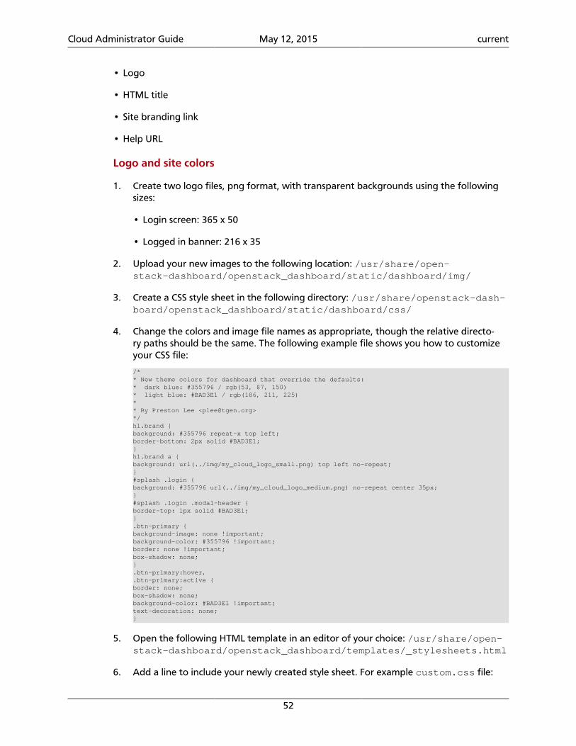
Cloud Administrator Guide May 12, 2015 current
52
• Logo
• HTML title
• Site branding link
• Help URL
Logo and site colors
1. Create two logo files, png format, with transparent backgrounds using the followingsizes:
• Login screen: 365 x 50
• Logged in banner: 216 x 35
2. Upload your new images to the following location: /usr/share/open-stack-dashboard/openstack_dashboard/static/dashboard/img/
3. Create a CSS style sheet in the following directory: /usr/share/openstack-dash-board/openstack_dashboard/static/dashboard/css/
4. Change the colors and image file names as appropriate, though the relative directo-ry paths should be the same. The following example file shows you how to customizeyour CSS file:
/** New theme colors for dashboard that override the defaults:* dark blue: #355796 / rgb(53, 87, 150)* light blue: #BAD3E1 / rgb(186, 211, 225)** By Preston Lee <[email protected]>*/h1.brand {background: #355796 repeat-x top left;border-bottom: 2px solid #BAD3E1;}h1.brand a {background: url(../img/my_cloud_logo_small.png) top left no-repeat;}#splash .login {background: #355796 url(../img/my_cloud_logo_medium.png) no-repeat center 35px;}#splash .login .modal-header {border-top: 1px solid #BAD3E1;}.btn-primary {background-image: none !important;background-color: #355796 !important;border: none !important;box-shadow: none;}.btn-primary:hover,.btn-primary:active {border: none;box-shadow: none;background-color: #BAD3E1 !important;text-decoration: none;}
5. Open the following HTML template in an editor of your choice: /usr/share/open-stack-dashboard/openstack_dashboard/templates/_stylesheets.html
6. Add a line to include your newly created style sheet. For example custom.css file:
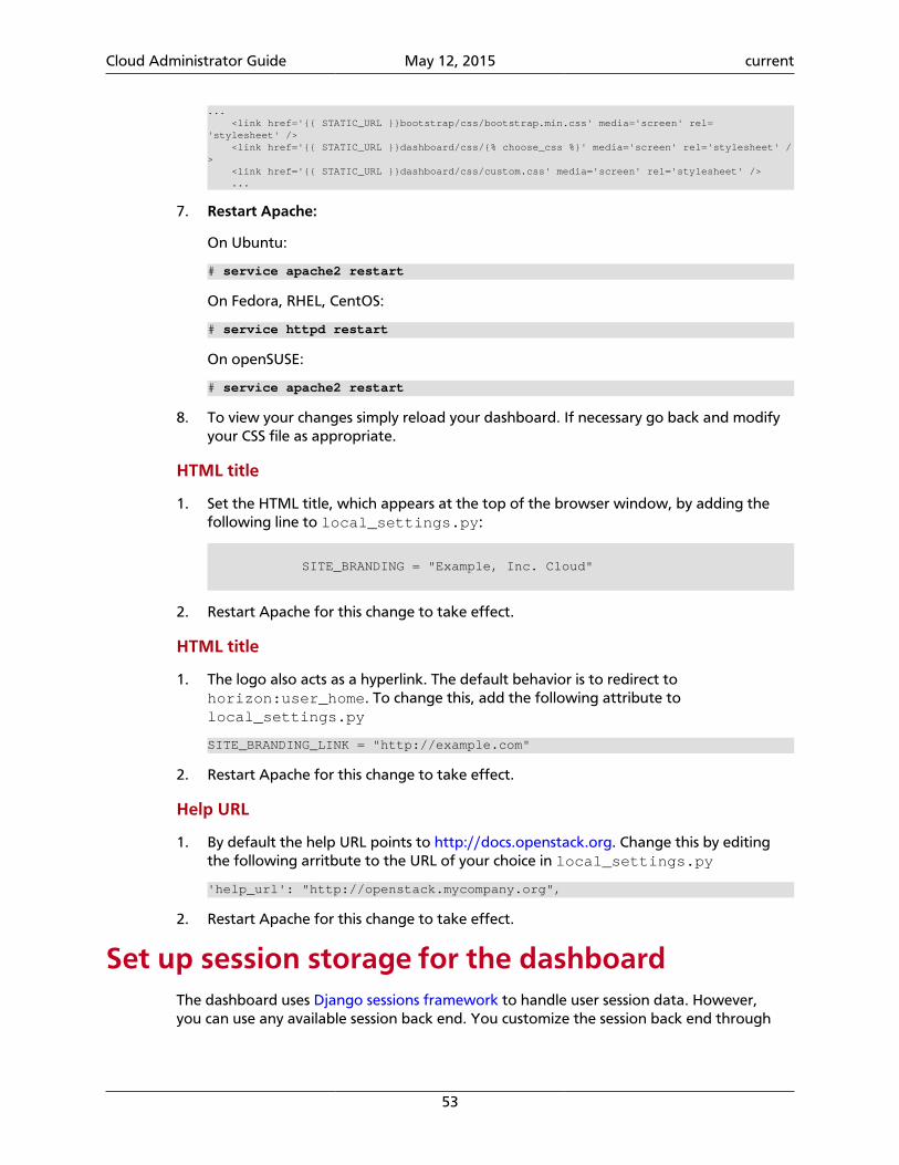
Cloud Administrator Guide May 12, 2015 current
53
... <link href='{{ STATIC_URL }}bootstrap/css/bootstrap.min.css' media='screen' rel='stylesheet' /> <link href='{{ STATIC_URL }}dashboard/css/{% choose_css %}' media='screen' rel='stylesheet' /> <link href='{{ STATIC_URL }}dashboard/css/custom.css' media='screen' rel='stylesheet' /> ...
7. Restart Apache:
On Ubuntu:
# service apache2 restart
On Fedora, RHEL, CentOS:
# service httpd restart
On openSUSE:
# service apache2 restart
8. To view your changes simply reload your dashboard. If necessary go back and modifyyour CSS file as appropriate.
HTML title
1. Set the HTML title, which appears at the top of the browser window, by adding thefollowing line to local_settings.py:
SITE_BRANDING = "Example, Inc. Cloud"
2. Restart Apache for this change to take effect.
HTML title
1. The logo also acts as a hyperlink. The default behavior is to redirect tohorizon:user_home. To change this, add the following attribute tolocal_settings.py
SITE_BRANDING_LINK = "http://example.com"
2. Restart Apache for this change to take effect.
Help URL
1. By default the help URL points to http://docs.openstack.org. Change this by editingthe following arritbute to the URL of your choice in local_settings.py
'help_url': "http://openstack.mycompany.org",
2. Restart Apache for this change to take effect.
Set up session storage for the dashboardThe dashboard uses Django sessions framework to handle user session data. However,you can use any available session back end. You customize the session back end through
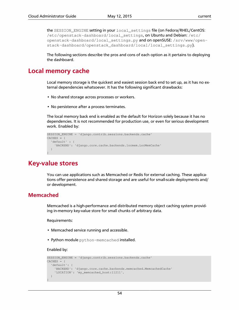
Cloud Administrator Guide May 12, 2015 current
54
the SESSION_ENGINE setting in your local_settings file (on Fedora/RHEL/CentOS: /etc/openstack-dashboard/local_settings, on Ubuntu and Debian: /etc/openstack-dashboard/local_settings.py and on openSUSE: /srv/www/open-stack-dashboard/openstack_dashboard/local/local_settings.py).
The following sections describe the pros and cons of each option as it pertains to deployingthe dashboard.
Local memory cache
Local memory storage is the quickest and easiest session back end to set up, as it has no ex-ternal dependencies whatsoever. It has the following significant drawbacks:
• No shared storage across processes or workers.
• No persistence after a process terminates.
The local memory back end is enabled as the default for Horizon solely because it has nodependencies. It is not recommended for production use, or even for serious developmentwork. Enabled by:
SESSION_ENGINE = 'django.contrib.sessions.backends.cache'CACHES = { 'default' : { 'BACKEND': 'django.core.cache.backends.locmem.LocMemCache' }}
Key-value stores
You can use applications such as Memcached or Redis for external caching. These applica-tions offer persistence and shared storage and are useful for small-scale deployments and/or development.
Memcached
Memcached is a high-performance and distributed memory object caching system provid-ing in-memory key-value store for small chunks of arbitrary data.
Requirements:
• Memcached service running and accessible.
• Python module python-memcached installed.
Enabled by:
SESSION_ENGINE = 'django.contrib.sessions.backends.cache'CACHES = { 'default': { 'BACKEND': 'django.core.cache.backends.memcached.MemcachedCache' 'LOCATION': 'my_memcached_host:11211', }}
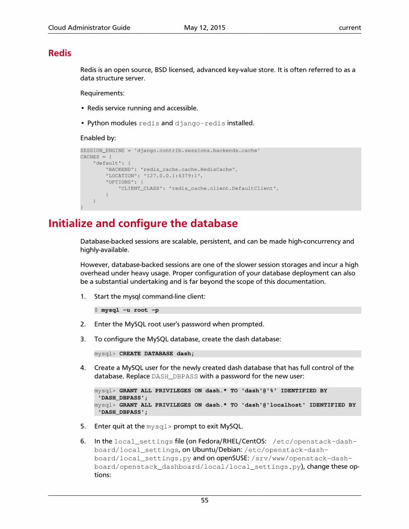
Cloud Administrator Guide May 12, 2015 current
55
Redis
Redis is an open source, BSD licensed, advanced key-value store. It is often referred to as adata structure server.
Requirements:
• Redis service running and accessible.
• Python modules redis and django-redis installed.
Enabled by:
SESSION_ENGINE = 'django.contrib.sessions.backends.cache'CACHES = { "default": { "BACKEND": "redis_cache.cache.RedisCache", "LOCATION": "127.0.0.1:6379:1", "OPTIONS": { "CLIENT_CLASS": "redis_cache.client.DefaultClient", } }}
Initialize and configure the databaseDatabase-backed sessions are scalable, persistent, and can be made high-concurrency andhighly-available.
However, database-backed sessions are one of the slower session storages and incur a highoverhead under heavy usage. Proper configuration of your database deployment can alsobe a substantial undertaking and is far beyond the scope of this documentation.
1. Start the mysql command-line client:
$ mysql -u root -p
2. Enter the MySQL root user's password when prompted.
3. To configure the MySQL database, create the dash database:
mysql> CREATE DATABASE dash;
4. Create a MySQL user for the newly created dash database that has full control of thedatabase. Replace DASH_DBPASS with a password for the new user:
mysql> GRANT ALL PRIVILEGES ON dash.* TO 'dash'@'%' IDENTIFIED BY 'DASH_DBPASS';mysql> GRANT ALL PRIVILEGES ON dash.* TO 'dash'@'localhost' IDENTIFIED BY 'DASH_DBPASS';
5. Enter quit at the mysql> prompt to exit MySQL.
6. In the local_settings file (on Fedora/RHEL/CentOS: /etc/openstack-dash-board/local_settings, on Ubuntu/Debian: /etc/openstack-dash-board/local_settings.py and on openSUSE: /srv/www/openstack-dash-board/openstack_dashboard/local/local_settings.py), change these op-tions:
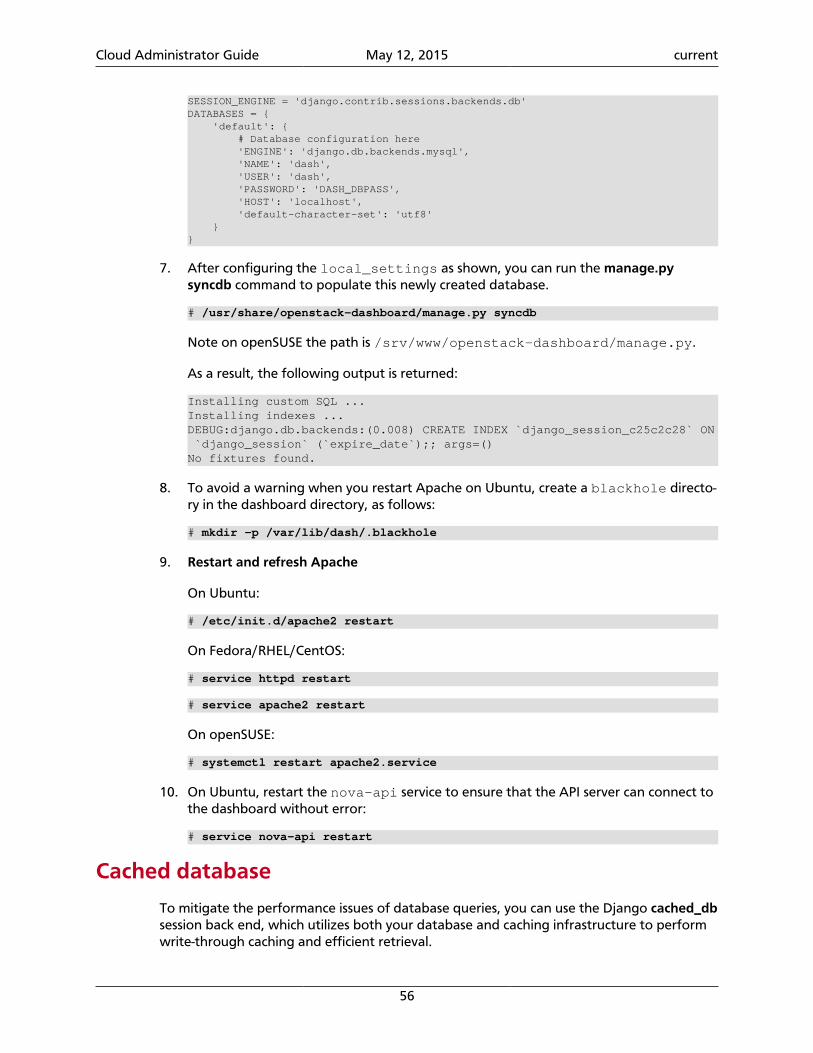
Cloud Administrator Guide May 12, 2015 current
56
SESSION_ENGINE = 'django.contrib.sessions.backends.db'DATABASES = { 'default': { # Database configuration here 'ENGINE': 'django.db.backends.mysql', 'NAME': 'dash', 'USER': 'dash', 'PASSWORD': 'DASH_DBPASS', 'HOST': 'localhost', 'default-character-set': 'utf8' }}
7. After configuring the local_settings as shown, you can run the manage.pysyncdb command to populate this newly created database.
# /usr/share/openstack-dashboard/manage.py syncdb
Note on openSUSE the path is /srv/www/openstack-dashboard/manage.py.
As a result, the following output is returned:
Installing custom SQL ...Installing indexes ...DEBUG:django.db.backends:(0.008) CREATE INDEX `django_session_c25c2c28` ON `django_session` (`expire_date`);; args=()No fixtures found.
8. To avoid a warning when you restart Apache on Ubuntu, create a blackhole directo-ry in the dashboard directory, as follows:
# mkdir -p /var/lib/dash/.blackhole
9. Restart and refresh Apache
On Ubuntu:
# /etc/init.d/apache2 restart
On Fedora/RHEL/CentOS:
# service httpd restart
# service apache2 restart
On openSUSE:
# systemctl restart apache2.service
10. On Ubuntu, restart the nova-api service to ensure that the API server can connect tothe dashboard without error:
# service nova-api restart
Cached database
To mitigate the performance issues of database queries, you can use the Django cached_dbsession back end, which utilizes both your database and caching infrastructure to performwrite-through caching and efficient retrieval.
Cloud Administrator Guide May 12, 2015 current
57
Enable this hybrid setting by configuring both your database and cache, as discussed previ-ously. Then, set the following value:
SESSION_ENGINE = "django.contrib.sessions.backends.cached_db"
Cookies
If you use Django 1.4 or later, the signed_cookies back end avoids server load and scalingproblems.
This back end stores session data in a cookie, which is stored by the user's browser. Theback end uses a cryptographic signing technique to ensure session data is not tamperedwith during transport. This is not the same as encryption; session data is still readable by anattacker.
The pros of this engine are that it requires no additional dependencies or infrastructureoverhead, and it scales indefinitely as long as the quantity of session data being stored fitsinto a normal cookie.
The biggest downside is that it places session data into storage on the user's machine andtransports it over the wire. It also limits the quantity of session data that can be stored.
See the Django cookie-based sessions documentation.
Cloud Administrator Guide May 12, 2015 current
58
4. Compute
Table of ContentsSystem architecture ....................................................................................................... 58Images and instances .................................................................................................... 64Networking with nova-network ..................................................................................... 71System administration ................................................................................................... 87Troubleshoot Compute ................................................................................................ 126
The OpenStack Compute service allows you to control an Infrastructure-as-a-Service (IaaS)cloud computing platform. It gives you control over instances and networks, and allows youto manage access to the cloud through users and projects.
Compute does not include virtualization software. Instead, it defines drivers that interactwith underlying virtualization mechanisms that run on your host operating system, and ex-poses functionality over a web-based API.
System architectureOpenStack Compute contains several main components.
• The cloud controller represents the global state and interacts with the other components.The API server acts as the web services front end for the cloud controller. The com-pute controller provides compute server resources and usually also contains theCompute service.
• The object store is an optional component that provides storage services; you can al-so instead use OpenStack Object Storage.
• An auth manager provides authentication and authorization services when used withthe Compute system; you can also instead use OpenStack Identity as a separate authenti-cation service.
• A volume controller provides fast and permanent block-level storage for the com-pute servers.
• The network controller provides virtual networks to enable compute servers to in-teract with each other and with the public network. You can also instead use OpenStackNetworking.
• The scheduler is used to select the most suitable compute controller to host an in-stance.
Compute uses a messaging-based, shared nothing architecture. All major componentsexist on multiple servers, including the compute, volume, and network controllers, and theobject store or image service. The state of the entire system is stored in a database. Thecloud controller communicates with the internal object store using HTTP, but it communi-
Cloud Administrator Guide May 12, 2015 current
59
cates with the scheduler, network controller, and volume controller using AMQP (advancedmessage queuing protocol). To avoid blocking a component while waiting for a response,Compute uses asynchronous calls, with a callback that is triggered when a response is re-ceived.
Hypervisors
Compute controls hypervisors through an API server. Selecting the best hypervisor to usecan be difficult, and you must take budget, resource constraints, supported features, andrequired technical specifications into account. However, the majority of OpenStack devel-opment is done on systems using KVM and Xen-based hypervisors. For a detailed list of fea-tures and support across different hypervisors, see http://wiki.openstack.org/Hypervisor-SupportMatrix.
You can also orchestrate clouds using multiple hypervisors in different availability zones.Compute supports the following hypervisors:
• Baremetal
• Docker
• Hyper-V
• Kernel-based Virtual Machine (KVM)
• Linux Containers (LXC)
• Quick Emulator (QEMU)
• User Mode Linux (UML)
• VMware vSphere
• Xen
For more information about hypervisors, see the Hypervisors section in the OpenStack Con-figuration Reference.
Tenants, users, and roles
The Compute system is designed to be used by different consumers in the form of tenantson a shared system, and role-based access assignments. Roles control the actions that a useris allowed to perform.
Tenants are isolated resource containers that form the principal organizational structurewithin the Compute service. They consist of an individual VLAN, and volumes, instances, im-ages, keys, and users. A user can specify the tenant by appending :project_id to theiraccess key. If no tenant is specified in the API request, Compute attempts to use a tenantwith the same ID as the user.
For tenants, you can use quota controls to limit the:
• Number of volumes that can be launched.
Cloud Administrator Guide May 12, 2015 current
60
• Number of processor cores and the amount of RAM that can be allocated.
• Floating IP addresses assigned to any instance when it launches. This allows instances tohave the same publicly accessible IP addresses.
• Fixed IP addresses assigned to the same instance when it launches. This allows instancesto have the same publicly or privately accessible IP addresses.
Roles control the actions a user is allowed to perform. By default, most actions do not re-quire a particular role, but you can configure them by editing the policy.json file for us-er roles. For example, a rule can be defined so that a user must have the admin role in or-der to be able to allocate a public IP address.
A tenant limits users' access to particular images. Each user is assigned a user name andpassword. Keypairs granting access to an instance are enabled for each user, but quotasare set, so that each tenant can control resource consumption across available hardware re-sources.
Note
Earlier versions of OpenStack used the term project instead of tenant. Be-cause of this legacy terminology, some command-line tools use --project_idwhere you would normally expect to enter a tenant ID.
Block storageOpenStack provides two classes of the block storage: ephemeral storage and persistent vol-ume.
Ephemeral storage
An ephemeral storage includes a root ephemeral volume and an additional ephemeral vol-ume.
The root disk is associated with an instance, and exists only for the life of this very instance.Generally, it is used to store an instance`s root file system, persists across the guest op-erating system reboots, and is removed on an instance deletion. The amount of the rootephemeral volume is defined by the flavor of an instance.
In addition to the ephemeral root volume, all default types of flavors, except m1.tiny,which is the smallest one, provide an additional ephemeral block device sized between 20and 160 GB (a configurable value to suit an environment). It is represented as a raw blockdevice with no partition table or file system. A cloud-aware operating system can discover,format, and mount such a storage device. OpenStack Compute defines the default file sys-tem for different operating systems as Ext4 for Linux distributions, VFAT for non-Linux andnon-Windows operating systems, and NTFS for Windows. However, it is possible to specifyany other filesystem type by using virt_mkfs or default_ephemeral_format config-uration options.
Note
For example, the cloud-init package included into an Ubuntu's stock cloudimage, by default, formats this space as an Ext4 file system and mounts it on
Cloud Administrator Guide May 12, 2015 current
61
/mnt. This is a cloud-init feature, and is not an OpenStack mechanism. Open-Stack only provisions the raw storage.
Persistent volume
A persistent volume is represented by a persistent virtualized block device independent ofany particular instance, and provided by OpenStack Block Storage.
A persistent volume is created by a user, and its size is limited only by a user's quota andavailability limits. Upon initial creation, a volume is a raw block device without a partitiontable or a file system. To partition or format a volume, you must attach it to an instance.Once it is attached, it can be used the same way as an external hard disk drive. A single vol-ume can be attached to one instance at a time, though you can detach and reattach it toother instances as many times as required.
You can configure a persistent volume as bootable and use it to provide a persistent virtualinstance similar to the traditional non-cloud-based virtualization system. It is still possible forthe resulting instance to keep ephemeral storage, depending on the flavor selected. In thiscase, the root file system can be on the persistent volume, and its state is maintained, evenif the instance is shut down. For more information about this type of configuration, see the OpenStack Configuration Reference.
Note
A persistent volume does not provide concurrent access from multiple in-stances. That type of configuration requires a traditional network file systemlike NFS, or CIFS, or a cluster file system such as GlusterFS. These systems can bebuilt within an OpenStack cluster, or provisioned outside of it, but OpenStacksoftware does not provide these features.
EC2 compatibility APIIn addition to the native compute API, OpenStack provides an EC2-compatible API. This APIallows EC2 legacy workflows built for EC2 to work with OpenStack. For more informationand configuration options about this compatibility API, see the OpenStack ConfigurationReference.
Numerous third-party tools and language-specific SDKs can be used to interact with Open-Stack clouds, using both native and compatibility APIs. Some of the more popular third-par-ty tools are:
Euca2ools A popular open source command-line tool for interacting with the EC2API. This is convenient for multi-cloud environments where EC2 is thecommon API, or for transitioning from EC2-based clouds to OpenStack.For more information, see the euca2ools site.
Hybridfox A Firefox browser add-on that provides a graphical interface to manypopular public and private cloud technologies, including OpenStack.For more information, see the hybridfox site.
boto A Python library for interacting with Amazon Web Services. It can beused to access OpenStack through the EC2 compatibility API. For moreinformation, see the boto project page on GitHub.
Cloud Administrator Guide May 12, 2015 current
62
fog A Ruby cloud services library. It provides methods for interacting witha large number of cloud and virtualization platforms, including Open-Stack. For more information, see the fog site.
php-opencloud A PHP SDK designed to work with most OpenStack- based cloud de-ployments, as well as Rackspace public cloud. For more information,see the php-opencloud site.
Building blocks
In OpenStack the base operating system is usually copied from an image stored in theOpenStack Image service. This is the most common case and results in an ephemeral in-stance that starts from a known template state and loses all accumulated states on virtu-al machine deletion. It is also possible to put an operating system on a persistent volume inthe Cinder volume system. This gives a more traditional persistent system that accumulatesstates, which are preserved on the Cinder volume across the deletion and re-creation of thevirtual machine. To get a list of available images on your system run:$ nova image-list+--------------------------------------+-------------------------------+--------+--------------------------------------+| ID | Name | Status | Server |+--------------------------------------+-------------------------------+--------+--------------------------------------+| aee1d242-730f-431f-88c1-87630c0f07ba | Ubuntu 14.04 cloudimg amd64 | ACTIVE | || 0b27baa1-0ca6-49a7-b3f4-48388e440245 | Ubuntu 14.10 cloudimg amd64 | ACTIVE | || df8d56fc-9cea-4dfd-a8d3-28764de3cb08 | jenkins | ACTIVE | |+--------------------------------------+-------------------------------+--------+--------------------------------------+
The displayed image attributes are:
ID Automatically generated UUID of the image
Name Free form, human-readable name for image
Status The status of the image. Images marked ACTIVE are available for use.
Server For images that are created as snapshots of running instances, this is the UUID ofthe instance the snapshot derives from. For uploaded images, this field is blank.
Virtual hardware templates are called flavors. The default installation provides five fla-vors. By default, these are configurable by admin users, however that behavior can bechanged by redefining the access controls for compute_extension:flavormanage in /etc/nova/policy.json on the compute-api server.
For a list of flavors that are available on your system:
$ nova flavor-list+-----+-----------+-----------+------+-----------+------+-------+-------------+-----------+| ID | Name | Memory_MB | Disk | Ephemeral | Swap | VCPUs | RXTX_Factor | Is_Public |+-----+-----------+-----------+------+-----------+------+-------+-------------+-----------+| 1 | m1.tiny | 512 | 1 | 0 | | 1 | 1.0 | True || 2 | m1.small | 2048 | 20 | 0 | | 1 | 1.0 | True || 3 | m1.medium | 4096 | 40 | 0 | | 2 | 1.0 | True |
Cloud Administrator Guide May 12, 2015 current
63
| 4 | m1.large | 8192 | 80 | 0 | | 4 | 1.0 | True || 5 | m1.xlarge | 16384 | 160 | 0 | | 8 | 1.0 | True |+-----+-----------+-----------+------+-----------+------+-------+-------------+-----------+
Compute service architecture
These basic categories describe the service architecture and information about the cloudcontroller.
API server
At the heart of the cloud framework is an API server, which makes command and controlof the hypervisor, storage, and networking programmatically available to users.
The API endpoints are basic HTTP web services which handle authentication, authorization,and basic command and control functions using various API interfaces under the Amazon,Rackspace, and related models. This enables API compatibility with multiple existing toolsets created for interaction with offerings from other vendors. This broad compatibility pre-vents vendor lock-in.
Message queue
A messaging queue brokers the interaction between compute nodes (processing), the net-working controllers (software which controls network infrastructure), API endpoints, thescheduler (determines which physical hardware to allocate to a virtual resource), and sim-ilar components. Communication to and from the cloud controller is handled by HTTP re-quests through multiple API endpoints.
A typical message passing event begins with the API server receiving a request from a us-er. The API server authenticates the user and ensures that they are permitted to issue thesubject command. The availability of objects implicated in the request is evaluated and, ifavailable, the request is routed to the queuing engine for the relevant workers. Workerscontinually listen to the queue based on their role, and occasionally their type host name.When an applicable work request arrives on the queue, the worker takes assignment ofthe task and begins executing it. Upon completion, a response is dispatched to the queuewhich is received by the API server and relayed to the originating user. Database entries arequeried, added, or removed as necessary during the process.
Compute worker
Compute workers manage computing instances on host machines. The API dispatches com-mands to compute workers to complete these tasks:
• Run instances
• Terminate instances
• Reboot instances
• Attach volumes
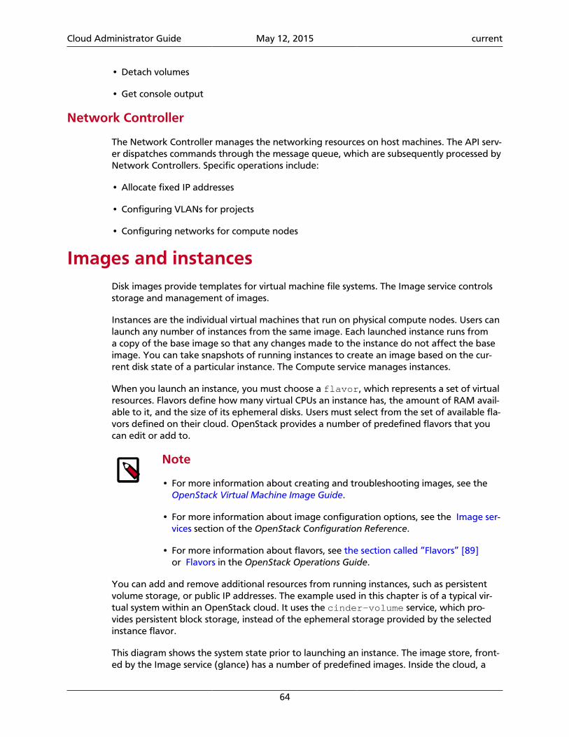
Cloud Administrator Guide May 12, 2015 current
64
• Detach volumes
• Get console output
Network Controller
The Network Controller manages the networking resources on host machines. The API serv-er dispatches commands through the message queue, which are subsequently processed byNetwork Controllers. Specific operations include:
• Allocate fixed IP addresses
• Configuring VLANs for projects
• Configuring networks for compute nodes
Images and instancesDisk images provide templates for virtual machine file systems. The Image service controlsstorage and management of images.
Instances are the individual virtual machines that run on physical compute nodes. Users canlaunch any number of instances from the same image. Each launched instance runs froma copy of the base image so that any changes made to the instance do not affect the baseimage. You can take snapshots of running instances to create an image based on the cur-rent disk state of a particular instance. The Compute service manages instances.
When you launch an instance, you must choose a flavor, which represents a set of virtualresources. Flavors define how many virtual CPUs an instance has, the amount of RAM avail-able to it, and the size of its ephemeral disks. Users must select from the set of available fla-vors defined on their cloud. OpenStack provides a number of predefined flavors that youcan edit or add to.
Note
• For more information about creating and troubleshooting images, see the OpenStack Virtual Machine Image Guide.
• For more information about image configuration options, see the Image ser-vices section of the OpenStack Configuration Reference.
• For more information about flavors, see the section called “Flavors” [89]or Flavors in the OpenStack Operations Guide.
You can add and remove additional resources from running instances, such as persistentvolume storage, or public IP addresses. The example used in this chapter is of a typical vir-tual system within an OpenStack cloud. It uses the cinder-volume service, which pro-vides persistent block storage, instead of the ephemeral storage provided by the selectedinstance flavor.
This diagram shows the system state prior to launching an instance. The image store, front-ed by the Image service (glance) has a number of predefined images. Inside the cloud, a
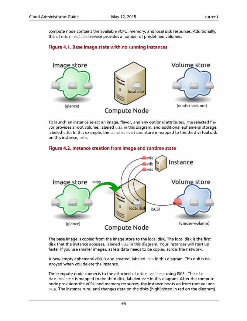
Cloud Administrator Guide May 12, 2015 current
65
compute node contains the available vCPU, memory, and local disk resources. Additionally,the cinder-volume service provides a number of predefined volumes.
Figure 4.1. Base image state with no running instances
To launch an instance select an image, flavor, and any optional attributes. The selected fla-vor provides a root volume, labeled vda in this diagram, and additional ephemeral storage,labeled vdb. In this example, the cinder-volume store is mapped to the third virtual diskon this instance, vdc.
Figure 4.2. Instance creation from image and runtime state
The base image is copied from the image store to the local disk. The local disk is the firstdisk that the instance accesses, labeled vda in this diagram. Your instances will start upfaster if you use smaller images, as less data needs to be copied across the network.
A new empty ephemeral disk is also created, labeled vdb in this diagram. This disk is de-stroyed when you delete the instance.
The compute node connects to the attached cinder-volume using ISCSI. The cin-der-volume is mapped to the third disk, labeled vdc in this diagram. After the computenode provisions the vCPU and memory resources, the instance boots up from root volumevda. The instance runs, and changes data on the disks (highlighted in red on the diagram).
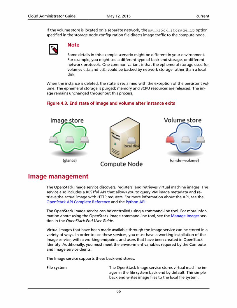
Cloud Administrator Guide May 12, 2015 current
66
If the volume store is located on a separate network, the my_block_storage_ip optionspecified in the storage node configuration file directs image traffic to the compute node.
Note
Some details in this example scenario might be different in your environment.For example, you might use a different type of back-end storage, or differentnetwork protocols. One common variant is that the ephemeral storage used forvolumes vda and vdb could be backed by network storage rather than a localdisk.
When the instance is deleted, the state is reclaimed with the exception of the persistent vol-ume. The ephemeral storage is purged; memory and vCPU resources are released. The im-age remains unchanged throughout this process.
Figure 4.3. End state of image and volume after instance exits
Image management
The OpenStack Image service discovers, registers, and retrieves virtual machine images. Theservice also includes a RESTful API that allows you to query VM image metadata and re-trieve the actual image with HTTP requests. For more information about the API, see theOpenStack API Complete Reference and the Python API.
The OpenStack Image service can be controlled using a command-line tool. For more infor-mation about using the OpenStack Image command-line tool, see the Manage Images sec-tion in the OpenStack End User Guide.
Virtual images that have been made available through the Image service can be stored in avariety of ways. In order to use these services, you must have a working installation of theImage service, with a working endpoint, and users that have been created in OpenStackIdentity. Additionally, you must meet the environment variables required by the Computeand Image service clients.
The Image service supports these back-end stores:
File system The OpenStack Image service stores virtual machine im-ages in the file system back end by default. This simpleback end writes image files to the local file system.
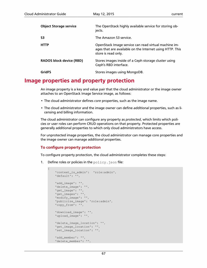
Cloud Administrator Guide May 12, 2015 current
67
Object Storage service The OpenStack highly available service for storing ob-jects.
S3 The Amazon S3 service.
HTTP OpenStack Image service can read virtual machine im-ages that are available on the Internet using HTTP. Thisstore is read only.
RADOS block device (RBD) Stores images inside of a Ceph storage cluster usingCeph's RBD interface.
GridFS Stores images using MongoDB.
Image properties and property protectionAn image property is a key and value pair that the cloud administrator or the image ownerattaches to an OpenStack Image Service image, as follows:
• The cloud administrator defines core properties, such as the image name.
• The cloud administrator and the image owner can define additional properties, such as li-censing and billing information.
The cloud administrator can configure any property as protected, which limits which poli-cies or user roles can perform CRUD operations on that property. Protected properties aregenerally additional properties to which only cloud administrators have access.
For unprotected image properties, the cloud administrator can manage core properties andthe image owner can manage additional properties.
To configure property protection
To configure property protection, the cloud administrator completes these steps:
1. Define roles or policies in the policy.json file:
{ "context_is_admin": "role:admin", "default": "",
"add_image": "", "delete_image": "", "get_image": "", "get_images": "", "modify_image": "", "publicize_image": "role:admin", "copy_from": "",
"download_image": "", "upload_image": "",
"delete_image_location": "", "get_image_location": "", "set_image_location": "",
"add_member": "", "delete_member": "",
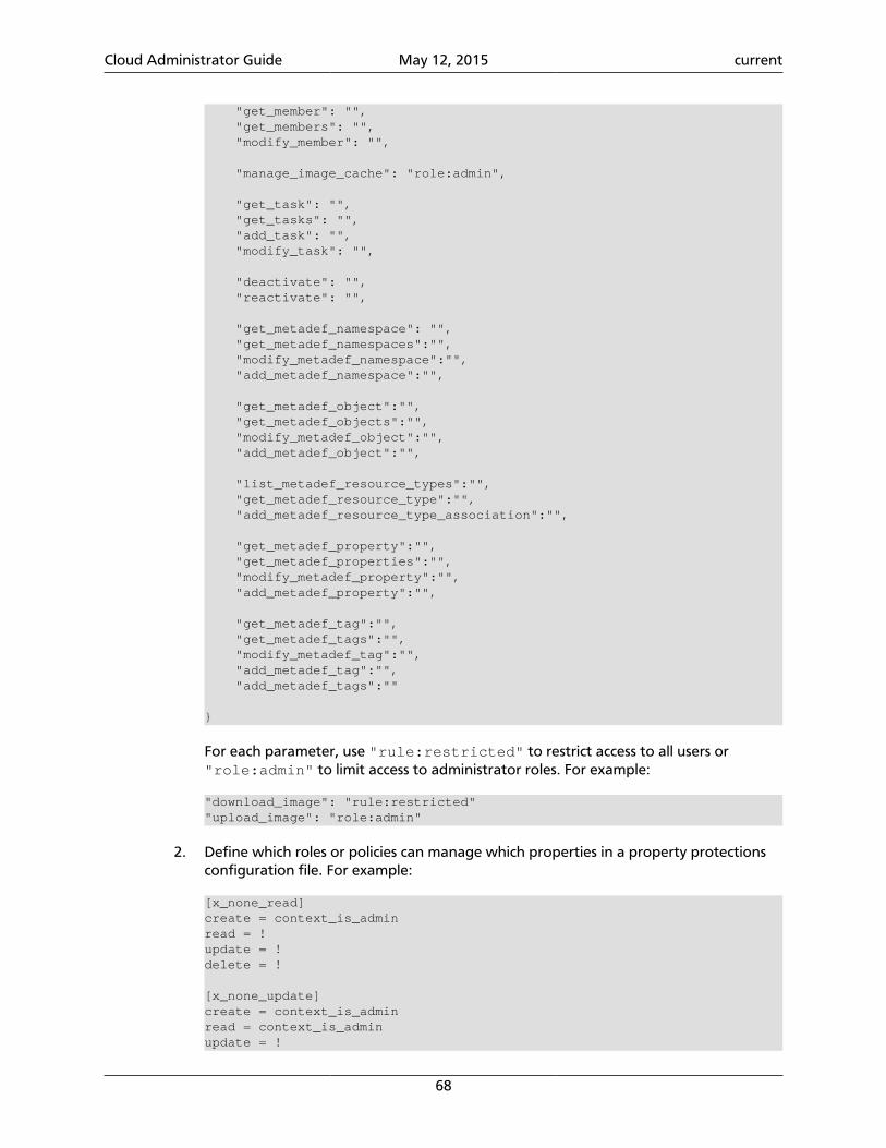
Cloud Administrator Guide May 12, 2015 current
68
"get_member": "", "get_members": "", "modify_member": "",
"manage_image_cache": "role:admin",
"get_task": "", "get_tasks": "", "add_task": "", "modify_task": "",
"deactivate": "", "reactivate": "",
"get_metadef_namespace": "", "get_metadef_namespaces":"", "modify_metadef_namespace":"", "add_metadef_namespace":"",
"get_metadef_object":"", "get_metadef_objects":"", "modify_metadef_object":"", "add_metadef_object":"",
"list_metadef_resource_types":"", "get_metadef_resource_type":"", "add_metadef_resource_type_association":"",
"get_metadef_property":"", "get_metadef_properties":"", "modify_metadef_property":"", "add_metadef_property":"",
"get_metadef_tag":"", "get_metadef_tags":"", "modify_metadef_tag":"", "add_metadef_tag":"", "add_metadef_tags":""
}
For each parameter, use "rule:restricted" to restrict access to all users or"role:admin" to limit access to administrator roles. For example:
"download_image": "rule:restricted""upload_image": "role:admin"
2. Define which roles or policies can manage which properties in a property protectionsconfiguration file. For example:
[x_none_read]create = context_is_adminread = !update = !delete = !
[x_none_update]create = context_is_adminread = context_is_adminupdate = !
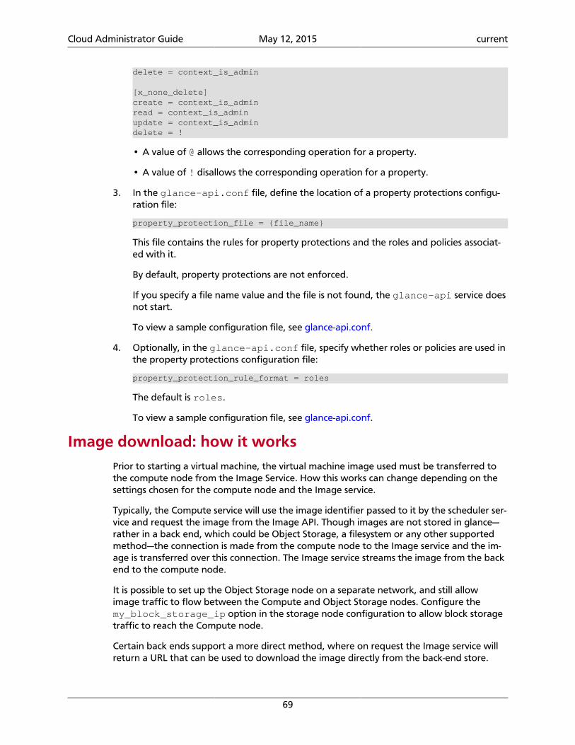
Cloud Administrator Guide May 12, 2015 current
69
delete = context_is_admin
[x_none_delete]create = context_is_adminread = context_is_adminupdate = context_is_admindelete = !
• A value of @ allows the corresponding operation for a property.
• A value of ! disallows the corresponding operation for a property.
3. In the glance-api.conf file, define the location of a property protections configu-ration file:
property_protection_file = {file_name}
This file contains the rules for property protections and the roles and policies associat-ed with it.
By default, property protections are not enforced.
If you specify a file name value and the file is not found, the glance-api service doesnot start.
To view a sample configuration file, see glance-api.conf.
4. Optionally, in the glance-api.conf file, specify whether roles or policies are used inthe property protections configuration file:
property_protection_rule_format = roles
The default is roles.
To view a sample configuration file, see glance-api.conf.
Image download: how it worksPrior to starting a virtual machine, the virtual machine image used must be transferred tothe compute node from the Image Service. How this works can change depending on thesettings chosen for the compute node and the Image service.
Typically, the Compute service will use the image identifier passed to it by the scheduler ser-vice and request the image from the Image API. Though images are not stored in glance—rather in a back end, which could be Object Storage, a filesystem or any other supportedmethod—the connection is made from the compute node to the Image service and the im-age is transferred over this connection. The Image service streams the image from the backend to the compute node.
It is possible to set up the Object Storage node on a separate network, and still allowimage traffic to flow between the Compute and Object Storage nodes. Configure themy_block_storage_ip option in the storage node configuration to allow block storagetraffic to reach the Compute node.
Certain back ends support a more direct method, where on request the Image service willreturn a URL that can be used to download the image directly from the back-end store.
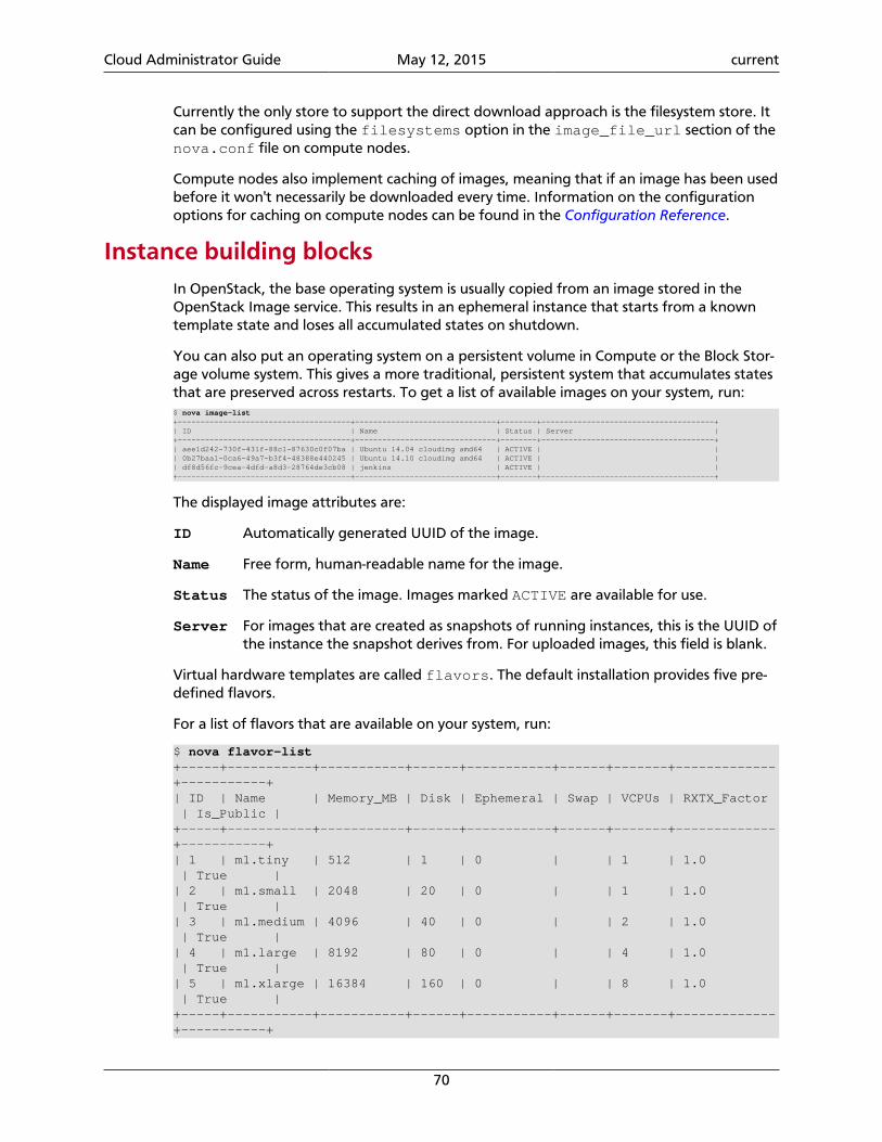
Cloud Administrator Guide May 12, 2015 current
70
Currently the only store to support the direct download approach is the filesystem store. Itcan be configured using the filesystems option in the image_file_url section of thenova.conf file on compute nodes.
Compute nodes also implement caching of images, meaning that if an image has been usedbefore it won't necessarily be downloaded every time. Information on the configurationoptions for caching on compute nodes can be found in the Configuration Reference.
Instance building blocksIn OpenStack, the base operating system is usually copied from an image stored in theOpenStack Image service. This results in an ephemeral instance that starts from a knowntemplate state and loses all accumulated states on shutdown.
You can also put an operating system on a persistent volume in Compute or the Block Stor-age volume system. This gives a more traditional, persistent system that accumulates statesthat are preserved across restarts. To get a list of available images on your system, run:$ nova image-list+--------------------------------------+-------------------------------+--------+--------------------------------------+| ID | Name | Status | Server |+--------------------------------------+-------------------------------+--------+--------------------------------------+| aee1d242-730f-431f-88c1-87630c0f07ba | Ubuntu 14.04 cloudimg amd64 | ACTIVE | || 0b27baa1-0ca6-49a7-b3f4-48388e440245 | Ubuntu 14.10 cloudimg amd64 | ACTIVE | || df8d56fc-9cea-4dfd-a8d3-28764de3cb08 | jenkins | ACTIVE | |+--------------------------------------+-------------------------------+--------+--------------------------------------+
The displayed image attributes are:
ID Automatically generated UUID of the image.
Name Free form, human-readable name for the image.
Status The status of the image. Images marked ACTIVE are available for use.
Server For images that are created as snapshots of running instances, this is the UUID ofthe instance the snapshot derives from. For uploaded images, this field is blank.
Virtual hardware templates are called flavors. The default installation provides five pre-defined flavors.
For a list of flavors that are available on your system, run:
$ nova flavor-list+-----+-----------+-----------+------+-----------+------+-------+-------------+-----------+| ID | Name | Memory_MB | Disk | Ephemeral | Swap | VCPUs | RXTX_Factor | Is_Public |+-----+-----------+-----------+------+-----------+------+-------+-------------+-----------+| 1 | m1.tiny | 512 | 1 | 0 | | 1 | 1.0 | True || 2 | m1.small | 2048 | 20 | 0 | | 1 | 1.0 | True || 3 | m1.medium | 4096 | 40 | 0 | | 2 | 1.0 | True || 4 | m1.large | 8192 | 80 | 0 | | 4 | 1.0 | True || 5 | m1.xlarge | 16384 | 160 | 0 | | 8 | 1.0 | True |+-----+-----------+-----------+------+-----------+------+-------+-------------+-----------+
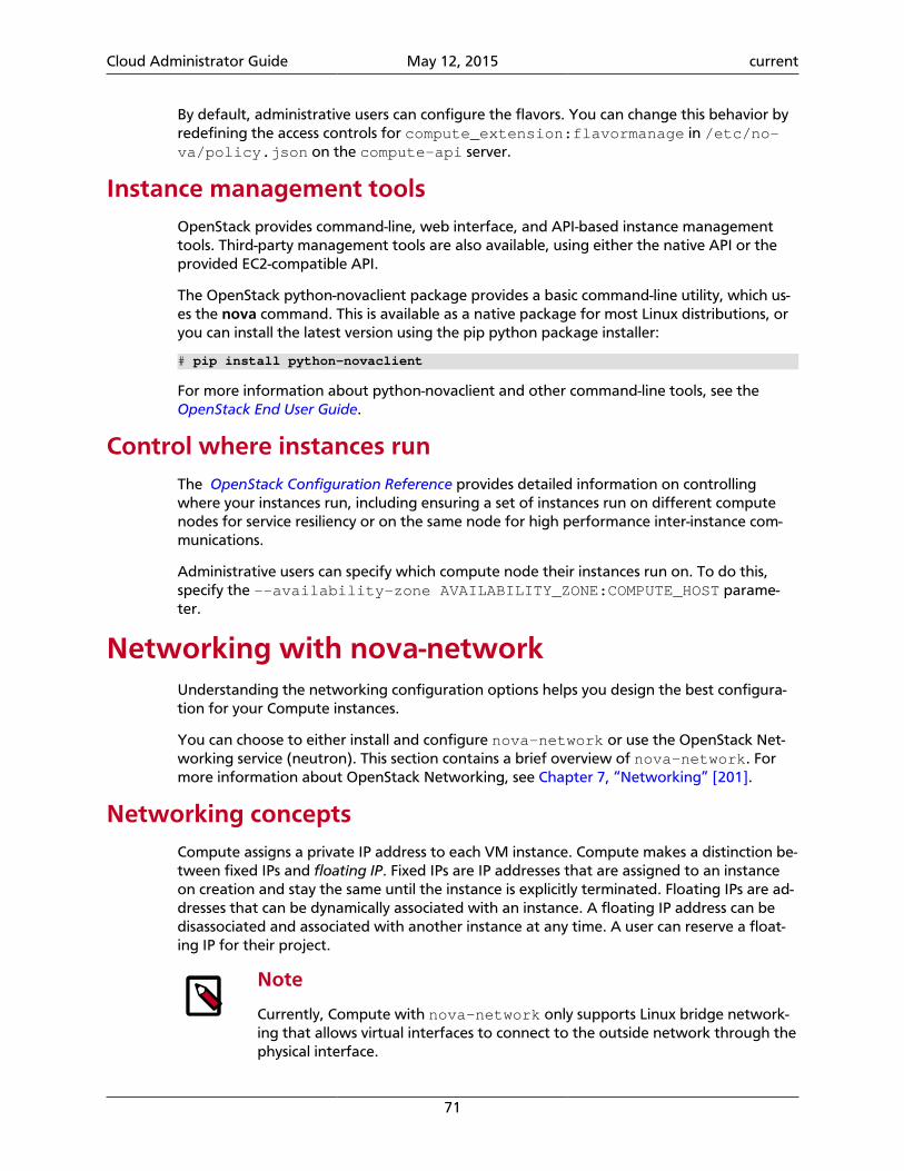
Cloud Administrator Guide May 12, 2015 current
71
By default, administrative users can configure the flavors. You can change this behavior byredefining the access controls for compute_extension:flavormanage in /etc/no-va/policy.json on the compute-api server.
Instance management toolsOpenStack provides command-line, web interface, and API-based instance managementtools. Third-party management tools are also available, using either the native API or theprovided EC2-compatible API.
The OpenStack python-novaclient package provides a basic command-line utility, which us-es the nova command. This is available as a native package for most Linux distributions, oryou can install the latest version using the pip python package installer:
# pip install python-novaclient
For more information about python-novaclient and other command-line tools, see the OpenStack End User Guide.
Control where instances runThe OpenStack Configuration Reference provides detailed information on controllingwhere your instances run, including ensuring a set of instances run on different computenodes for service resiliency or on the same node for high performance inter-instance com-munications.
Administrative users can specify which compute node their instances run on. To do this,specify the --availability-zone AVAILABILITY_ZONE:COMPUTE_HOST parame-ter.
Networking with nova-networkUnderstanding the networking configuration options helps you design the best configura-tion for your Compute instances.
You can choose to either install and configure nova-network or use the OpenStack Net-working service (neutron). This section contains a brief overview of nova-network. Formore information about OpenStack Networking, see Chapter 7, “Networking” [201].
Networking conceptsCompute assigns a private IP address to each VM instance. Compute makes a distinction be-tween fixed IPs and floating IP. Fixed IPs are IP addresses that are assigned to an instanceon creation and stay the same until the instance is explicitly terminated. Floating IPs are ad-dresses that can be dynamically associated with an instance. A floating IP address can bedisassociated and associated with another instance at any time. A user can reserve a float-ing IP for their project.
Note
Currently, Compute with nova-network only supports Linux bridge network-ing that allows virtual interfaces to connect to the outside network through thephysical interface.
Cloud Administrator Guide May 12, 2015 current
72
The network controller with nova-network provides virtual networks to enable com-pute servers to interact with each other and with the public network. Compute with no-va-network supports the following network modes, which are implemented as NetworkManager types:
Flat Network Manager In this mode, a network administrator specifies a sub-net. IP addresses for VM instances are assigned fromthe subnet, and then injected into the image on launch.Each instance receives a fixed IP address from the poolof available addresses. A system administrator mustcreate the Linux networking bridge (typically namedbr100, although this is configurable) on the systemsrunning the nova-network service. All instances of thesystem are attached to the same bridge, which is config-ured manually by the network administrator.
Note
Configuration injection currently only workson Linux-style systems that keep networkingconfiguration in /etc/network/inter-faces.
Flat DHCP Network Manager In this mode, OpenStack starts a DHCP server (dns-masq) to allocate IP addresses to VM instances from thespecified subnet, in addition to manually configuringthe networking bridge. IP addresses for VM instancesare assigned from a subnet specified by the network ad-ministrator.
Like flat mode, all instances are attached to a singlebridge on the compute node. Additionally, a DHCP serv-er configures instances depending on single-/multi-hostmode, alongside each nova-network. In this mode,Compute does a bit more configuration. It attemptsto bridge into an Ethernet device (flat_interface,eth0 by default). For every instance, Compute allocatesa fixed IP address and configures dnsmasq with theMAC ID and IP address for the VM. dnsmasq does nottake part in the IP address allocation process, it onlyhands out IPs according to the mapping done by Com-pute. Instances receive their fixed IPs with the dhcpdis-cover command. These IPs are not assigned to any ofthe host's network interfaces, only to the guest-side in-terface for the VM.
In any setup with flat networking, the hosts providingthe nova-network service are responsible for forward-ing traffic from the private network. They also run andconfigure dnsmasq as a DHCP server listening on thisbridge, usually on IP address 10.0.0.1 (see DHCP serv-er: dnsmasq ). Compute can determine the NAT entries
Cloud Administrator Guide May 12, 2015 current
73
for each network, although sometimes NAT is not used,such as when the network has been configured withall public IPs, or if a hardware router is used (which isa high availability option). In this case, hosts need tohave br100 configured and physically connected toany other nodes that are hosting VMs. You must set theflat_network_bridge option or create networkswith the bridge parameter in order to avoid raising anerror. Compute nodes have iptables or ebtables entriescreated for each project and instance to protect againstMAC ID or IP address spoofing and ARP poisoning.
Note
In single-host Flat DHCP mode you will beable to ping VMs through their fixed IP fromthe nova-network node, but you cannotping them from the compute nodes. This isexpected behavior.
VLAN Network Manager This is the default mode for OpenStack Compute. In thismode, Compute creates a VLAN and bridge for eachtenant. For multiple-machine installations, the VLANNetwork Mode requires a switch that supports VLANtagging (IEEE 802.1Q). The tenant gets a range of pri-vate IPs that are only accessible from inside the VLAN.In order for a user to access the instances in their ten-ant, a special VPN instance (code named cloudpipe)needs to be created. Compute generates a certificateand key for the user to access the VPN and starts theVPN automatically. It provides a private network seg-ment for each tenant's instances that can be accessedthrough a dedicated VPN connection from the internet.In this mode, each tenant gets its own VLAN, Linux net-working bridge, and subnet.
The subnets are specified by the network administra-tor, and are assigned dynamically to a tenant when re-quired. A DHCP server is started for each VLAN to passout IP addresses to VM instances from the subnet as-signed to the tenant. All instances belonging to onetenant are bridged into the same VLAN for that ten-ant. OpenStack Compute creates the Linux networkingbridges and VLANs when required.
These network managers can co-exist in a cloud system. However, because you cannot se-lect the type of network for a given tenant, you cannot configure multiple network types ina single Compute installation.
All network managers configure the network using network drivers. For example, the Lin-ux L3 driver (l3.py and linux_net.py), which makes use of iptables, route and oth-er network management facilities, and the libvirt network filtering facilities. The driver is
Cloud Administrator Guide May 12, 2015 current
74
not tied to any particular network manager; all network managers use the same driver. Thedriver usually initializes only when the first VM lands on this host node.
All network managers operate in either single-host or multi-host mode. This choice great-ly influences the network configuration. In single-host mode, a single nova-network ser-vice provides a default gateway for VMs and hosts a single DHCP server (dnsmasq). In mul-ti-host mode, each compute node runs its own nova-network service. In both cases, alltraffic between VMs and the internet flows through nova-network. Each mode has ben-efits and drawbacks. For more on this, see the Network Topology section in the OpenStackOperations Guide.
All networking options require network connectivity to be already set up between Open-Stack physical nodes. OpenStack does not configure any physical network interfaces. Allnetwork managers automatically create VM virtual interfaces. Some network managers canalso create network bridges such as br100.
The internal network interface is used for communication with VMs. The interface shouldnot have an IP address attached to it before OpenStack installation, it serves only as a fabricwhere the actual endpoints are VMs and dnsmasq. Additionally, the internal network inter-face must be in promiscuous mode, so that it can receive packets whose target MAC ad-dress is the guest VM, not the host.
All machines must have a public and internal network interface (controlled by theseoptions: public_interface for the public interface, and flat_interface andvlan_interface for the internal interface with flat or VLAN managers). This guide refersto the public network as the external network and the private network as the internal ortenant network.
For flat and flat DHCP modes, use the nova network-create command to create a network:
$ nova network-create vmnet \--fixed-range-v4 10.0.0.0/16 --fixed-cidr 10.0.20.0/24 --bridge br100
This example uses the following parameters:
• --fixed-range-v4- specifies the network subnet.
• --fixed-cidr specifies a range of fixed IP addresses to allocate, and can be a subset ofthe --fixed-range-v4 argument.
• --bridge specifies the bridge device to which this network is connected on every com-pute node.
DHCP server: dnsmasq
The Compute service uses dnsmasq as the DHCP server when using either Flat DHCP Net-work Manager or VLAN Network Manager. For Compute to operate in IPv4/IPv6 dual-stackmode, use at least dnsmasq v2.63. The nova-network service is responsible for startingdnsmasq processes.
The behavior of dnsmasq can be customized by creating a dnsmasq configuration file.Specify the configuration file using the dnsmasq_config_file configuration option:
Cloud Administrator Guide May 12, 2015 current
75
dnsmasq_config_file=/etc/dnsmasq-nova.conf
For more information about creating a dnsmasq configuration file, see the OpenStackConfiguration Reference, and the dnsmasq documentation.
dnsmasq also acts as a caching DNS server for instances. You can specify the DNS serv-er that dnsmasq uses by setting the dns_server configuration option in /etc/no-va/nova.conf. This example configures dnsmasq to use Google's public DNS server:
dns_server=8.8.8.8
dnsmasq logs to syslog (typically /var/log/syslog or /var/log/messages, de-pending on Linux distribution). Logs can be useful for troubleshooting, especially in a situa-tion where VM instances boot successfully but are not reachable over the network.
Administrators can specify the starting point IP address to reserve with the DHCP server (inthe format n.n.n.n) with this command:
$nova-manage fixed reserve --address IP_ADDRESS
This reservation only affects which IP address the VMs start at, not the fixed IP addressesthat nova-network places on the bridges.
Configure Compute to use IPv6 addresses
If you are using OpenStack Compute with nova-network, you can put Compute into du-al-stack mode, so that it uses both IPv4 and IPv6 addresses for communication. In dual-stackmode, instances can acquire their IPv6 global unicast address by using a stateless addressauto-configuration mechanism [RFC 4862/2462]. IPv4/IPv6 dual-stack mode works withboth VlanManager and FlatDHCPManager networking modes.
In VlanManager networking mode, each project uses a different 64-bit global routing pre-fix. In FlatDHCPManager mode, all instances use one 64-bit global routing prefix.
This configuration was tested with virtual machine images that have an IPv6 stateless ad-dress auto-configuration capability. This capability is required for any VM to run with anIPv6 address. You must use an EUI-64 address for stateless address auto-configuration. Eachnode that executes a nova-* service must have python-netaddr and radvd installed.
Switch into IPv4/IPv6 dual-stack mode
1. For every node running a nova-* service, install python-netaddr:
# apt-get install python-netaddr
2. For every node running nova-network, install radvd and configure IPv6 networking:
# apt-get install radvd # echo 1 > /proc/sys/net/ipv6/conf/all/forwarding # echo 0 > /proc/sys/net/ipv6/conf/all/accept_ra
3. On all nodes, edit the nova.conf file and specify use_ipv6 = True.
4. Restart all nova-* services.
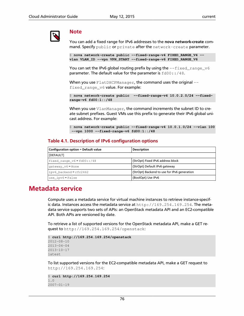
Cloud Administrator Guide May 12, 2015 current
76
Note
You can add a fixed range for IPv6 addresses to the nova network-create com-mand. Specify public or private after the network-create parameter.
$ nova network-create public --fixed-range-v4 FIXED_RANGE_V4 --vlan VLAN_ID --vpn VPN_START --fixed-range-v6 FIXED_RANGE_V6
You can set the IPv6 global routing prefix by using the --fixed_range_v6parameter. The default value for the parameter is fd00::/48.
When you use FlatDHCPManager, the command uses the original --fixed_range_v6 value. For example:
$ nova network-create public --fixed-range-v4 10.0.2.0/24 --fixed-range-v6 fd00:1::/48
When you use VlanManager, the command increments the subnet ID to cre-ate subnet prefixes. Guest VMs use this prefix to generate their IPv6 global uni-cast address. For example:
$ nova network-create public --fixed-range-v4 10.0.1.0/24 --vlan 100 --vpn 1000 --fixed-range-v6 fd00:1::/48
Table 4.1. Description of IPv6 configuration options
Configuration option = Default value Description
[DEFAULT]
fixed_range_v6 = fd00::/48 (StrOpt) Fixed IPv6 address block
gateway_v6 = None (StrOpt) Default IPv6 gateway
ipv6_backend = rfc2462 (StrOpt) Backend to use for IPv6 generation
use_ipv6 = False (BoolOpt) Use IPv6
Metadata service
Compute uses a metadata service for virtual machine instances to retrieve instance-specif-ic data. Instances access the metadata service at http://169.254.169.254. The meta-data service supports two sets of APIs: an OpenStack metadata API and an EC2-compatibleAPI. Both APIs are versioned by date.
To retrieve a list of supported versions for the OpenStack metadata API, make a GET re-quest to http://169.254.169.254/openstack:
$ curl http://169.254.169.254/openstack2012-08-102013-04-042013-10-17latest
To list supported versions for the EC2-compatible metadata API, make a GET request tohttp://169.254.169.254:
$ curl http://169.254.169.2541.02007-01-19
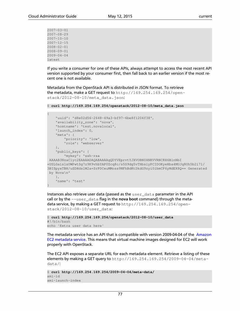
Cloud Administrator Guide May 12, 2015 current
77
2007-03-012007-08-292007-10-102007-12-152008-02-012008-09-012009-04-04latest
If you write a consumer for one of these APIs, always attempt to access the most recent APIversion supported by your consumer first, then fall back to an earlier version if the most re-cent one is not available.
Metadata from the OpenStack API is distributed in JSON format. To retrievethe metadata, make a GET request to http://169.254.169.254/open-stack/2012-08-10/meta_data.json:
$ curl http://169.254.169.254/openstack/2012-08-10/meta_data.json
{ "uuid": "d8e02d56-2648-49a3-bf97-6be8f1204f38", "availability_zone": "nova", "hostname": "test.novalocal", "launch_index": 0, "meta": { "priority": "low", "role": "webserver" }, "public_keys": { "mykey": "ssh-rsa AAAAB3NzaC1yc2EAAAADAQABAAAAgQDYVEprvtYJXVOBN0XNKVVRNCRX6BlnNbI+USLGais1sUWPwtSg7z9K9vhbYAPUZcq8c/s5S9dg5vTHbsiyPCIDOKyeHba4MUJq8Oh5b2i71/3BISpyxTBH/uZDHdslW2a+SrPDCeuMMoss9NFhBdKtDkdG9zyi0ibmCP6yMdEX8Q== Generated by Nova\n" }, "name": "test"}
Instances also retrieve user data (passed as the user_data parameter in the APIcall or by the --user_data flag in the nova boot command) through the meta-data service, by making a GET request to http://169.254.169.254/open-stack/2012-08-10/user_data:
$ curl http://169.254.169.254/openstack/2012-08-10/user_data#!/bin/bashecho 'Extra user data here'
The metadata service has an API that is compatible with version 2009-04-04 of the AmazonEC2 metadata service. This means that virtual machine images designed for EC2 will workproperly with OpenStack.
The EC2 API exposes a separate URL for each metadata element. Retrieve a listing of theseelements by making a GET query to http://169.254.169.254/2009-04-04/meta-data/:
$ curl http://169.254.169.254/2009-04-04/meta-data/ami-idami-launch-index
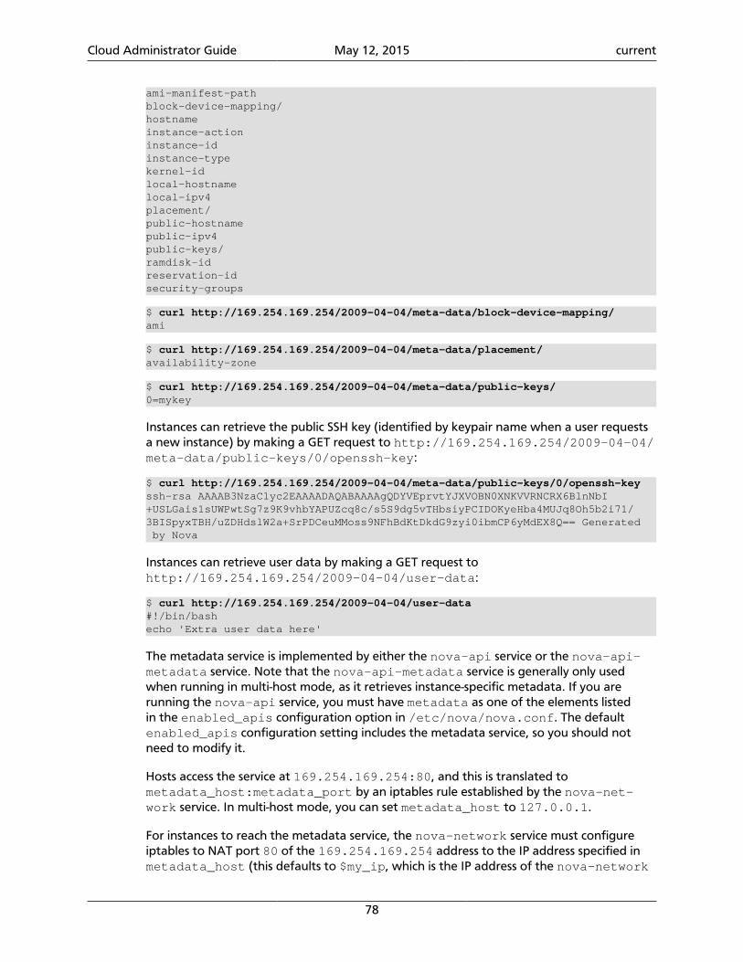
Cloud Administrator Guide May 12, 2015 current
78
ami-manifest-pathblock-device-mapping/hostnameinstance-actioninstance-idinstance-typekernel-idlocal-hostnamelocal-ipv4placement/public-hostnamepublic-ipv4public-keys/ramdisk-idreservation-idsecurity-groups
$ curl http://169.254.169.254/2009-04-04/meta-data/block-device-mapping/ami
$ curl http://169.254.169.254/2009-04-04/meta-data/placement/availability-zone
$ curl http://169.254.169.254/2009-04-04/meta-data/public-keys/0=mykey
Instances can retrieve the public SSH key (identified by keypair name when a user requestsa new instance) by making a GET request to http://169.254.169.254/2009-04-04/meta-data/public-keys/0/openssh-key:
$ curl http://169.254.169.254/2009-04-04/meta-data/public-keys/0/openssh-keyssh-rsa AAAAB3NzaC1yc2EAAAADAQABAAAAgQDYVEprvtYJXVOBN0XNKVVRNCRX6BlnNbI+USLGais1sUWPwtSg7z9K9vhbYAPUZcq8c/s5S9dg5vTHbsiyPCIDOKyeHba4MUJq8Oh5b2i71/3BISpyxTBH/uZDHdslW2a+SrPDCeuMMoss9NFhBdKtDkdG9zyi0ibmCP6yMdEX8Q== Generated by Nova
Instances can retrieve user data by making a GET request tohttp://169.254.169.254/2009-04-04/user-data:
$ curl http://169.254.169.254/2009-04-04/user-data#!/bin/bashecho 'Extra user data here'
The metadata service is implemented by either the nova-api service or the nova-api-metadata service. Note that the nova-api-metadata service is generally only usedwhen running in multi-host mode, as it retrieves instance-specific metadata. If you arerunning the nova-api service, you must have metadata as one of the elements listedin the enabled_apis configuration option in /etc/nova/nova.conf. The defaultenabled_apis configuration setting includes the metadata service, so you should notneed to modify it.
Hosts access the service at 169.254.169.254:80, and this is translated tometadata_host:metadata_port by an iptables rule established by the nova-net-work service. In multi-host mode, you can set metadata_host to 127.0.0.1.
For instances to reach the metadata service, the nova-network service must configureiptables to NAT port 80 of the 169.254.169.254 address to the IP address specified inmetadata_host (this defaults to $my_ip, which is the IP address of the nova-network
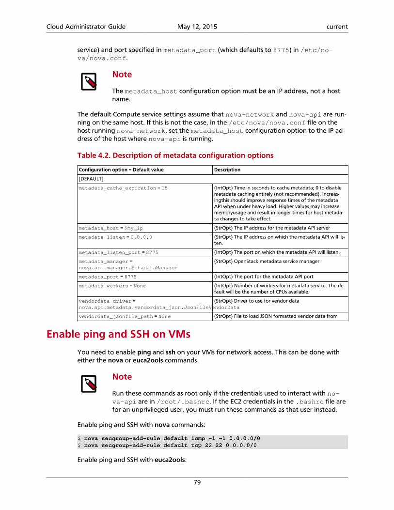
Cloud Administrator Guide May 12, 2015 current
79
service) and port specified in metadata_port (which defaults to 8775) in /etc/no-va/nova.conf.
Note
The metadata_host configuration option must be an IP address, not a hostname.
The default Compute service settings assume that nova-network and nova-api are run-ning on the same host. If this is not the case, in the /etc/nova/nova.conf file on thehost running nova-network, set the metadata_host configuration option to the IP ad-dress of the host where nova-api is running.
Table 4.2. Description of metadata configuration options
Configuration option = Default value Description
[DEFAULT]
metadata_cache_expiration = 15 (IntOpt) Time in seconds to cache metadata; 0 to disablemetadata caching entirely (not recommended). Increas-ingthis should improve response times of the metadataAPI when under heavy load. Higher values may increasememoryusage and result in longer times for host metada-ta changes to take effect.
metadata_host = $my_ip (StrOpt) The IP address for the metadata API server
metadata_listen = 0.0.0.0 (StrOpt) The IP address on which the metadata API will lis-ten.
metadata_listen_port = 8775 (IntOpt) The port on which the metadata API will listen.
metadata_manager =nova.api.manager.MetadataManager
(StrOpt) OpenStack metadata service manager
metadata_port = 8775 (IntOpt) The port for the metadata API port
metadata_workers = None (IntOpt) Number of workers for metadata service. The de-fault will be the number of CPUs available.
vendordata_driver =nova.api.metadata.vendordata_json.JsonFileVendorData
(StrOpt) Driver to use for vendor data
vendordata_jsonfile_path = None (StrOpt) File to load JSON formatted vendor data from
Enable ping and SSH on VMs
You need to enable ping and ssh on your VMs for network access. This can be done witheither the nova or euca2ools commands.
Note
Run these commands as root only if the credentials used to interact with no-va-api are in /root/.bashrc. If the EC2 credentials in the .bashrc file arefor an unprivileged user, you must run these commands as that user instead.
Enable ping and SSH with nova commands:
$ nova secgroup-add-rule default icmp -1 -1 0.0.0.0/0$ nova secgroup-add-rule default tcp 22 22 0.0.0.0/0
Enable ping and SSH with euca2ools:
Cloud Administrator Guide May 12, 2015 current
80
$ euca-authorize -P icmp -t -1:-1 -s 0.0.0.0/0 default$ euca-authorize -P tcp -p 22 -s 0.0.0.0/0 default
If you have run these commands and still cannot ping or SSH your instances, check thenumber of running dnsmasq processes, there should be two. If not, kill the processes andrestart the service with these commands: command:
# killall dnsmasq# service nova-network restart
Configure public (floating) IP addresses
This section describes how to configure floating IP addresses with nova-network. For in-formation about doing this with OpenStack Networking, see the section called “L3 routingand NAT” [276].
Private and public IP addresses
In this section, the term floating IP address is used to refer to an IP address, usually public,that you can dynamically add to a running virtual instance.
Every virtual instance is automatically assigned a private IP address. You can choose to as-sign a public (or floating) IP address instead. OpenStack Compute uses network addresstranslation (NAT) to assign floating IPs to virtual instances.
To be able to assign a floating IP address, edit the /etc/nova/nova.conf file to specifywhich interface the nova-network service should bind public IP addresses to:
public_interface=VLAN100
If you make changes to the /etc/nova/nova.conf file while the nova-network ser-vice is running, you will need to restart the service to pick up the changes.
Traffic between VMs using floating IPs
Floating IPs are implemented by using a source NAT (SNAT rule in iptables), sosecurity groups can sometimes display inconsistent behavior if VMs use theirfloating IP to communicate with other VMs, particularly on the same physicalhost. Traffic from VM to VM across the fixed network does not have this is-sue, and so this is the recommended setup. To ensure that traffic does not getSNATed to the floating range, explicitly set:
dmz_cidr=x.x.x.x/y
The x.x.x.x/y value specifies the range of floating IPs for each pool of float-ing IPs that you define. This configuration is also required if the VMs in thesource group have floating IPs.
Enable IP forwarding
IP forwarding is disabled by default on most Linux distributions. You will need to enable itin order to use floating IPs.
Cloud Administrator Guide May 12, 2015 current
81
Note
IP forwarding only needs to be enabled on the nodes that run nova-net-work. However, you will need to enable it on all compute nodes if you usemulti_host mode.
To check if IP forwarding is enabled, run:
$ cat /proc/sys/net/ipv4/ip_forward0
Alternatively, run:
$ sysctl net.ipv4.ip_forwardnet.ipv4.ip_forward = 0
In these examples, IP forwarding is disabled.
To enable IP forwarding dynamically, run:
# sysctl -w net.ipv4.ip_forward=1
Alternatively, run:
# echo 1 > /proc/sys/net/ipv4/ip_forward
To make the changes permanent, edit the /etc/sysctl.conf file and update the IP for-warding setting:
net.ipv4.ip_forward = 1
Save the file and run this command to apply the changes:
# sysctl -p
You can also apply the changes by restarting the network service:
• on Ubuntu, Debian:
# /etc/init.d/networking restart
• on RHEL, Fedora, CentOS, openSUSE and SLES:
# service network restart
Create a list of available floating IP addresses
Compute maintains a list of floating IP addresses that are available for assigning to in-stances. Use the nova-manage floating create command to add entries to the list:
# nova-manage floating create --pool nova --ip_range 68.99.26.170/31
Use these nova-manage commands to perform floating IP operations:
• # nova-manage floating list
Lists the floating IP addresses in the pool.
• # nova-manage floating create --pool POOL_NAME --ip_range CIDR
Creates specific floating IPs for either a single address or a subnet.
Cloud Administrator Guide May 12, 2015 current
82
• # nova-manage floating delete CIDR
Removes floating IP addresses using the same parameters as the create command.
For more information about how administrators can associate floating IPs with instances,see Manage IP addresses in the OpenStack Admin User Guide.
Automatically add floating IPs
You can configure nova-network to automatically allocate and assign a floating IPaddress to virtual instances when they are launched. Add this line to the /etc/no-va/nova.conf file:
auto_assign_floating_ip=True
Save the file, and restart nova-network
Note
If this option is enabled, but all floating IP addresses have already been allocat-ed, the nova boot command will fail.
Remove a network from a project
You cannot delete a network that has been associated to a project. This section describesthe procedure for dissociating it so that it can be deleted.
In order to disassociate the network, you will need the ID of the project it has been associ-ated to. To get the project ID, you will need to be an administrator.
Disassociate the network from the project using the scrub command, with the project ID asthe final parameter:
# nova-manage project scrub --project ID
Multiple interfaces for instances (multinic)
The multinic feature allows you to use more than one interface with your instances. This isuseful in several scenarios:
• SSL Configurations (VIPs)
• Services failover/HA
• Bandwidth Allocation
• Administrative/Public access to your instances
Each VIP represents a separate network with its own IP block. Every network mode has itsown set of changes regarding multinic usage:
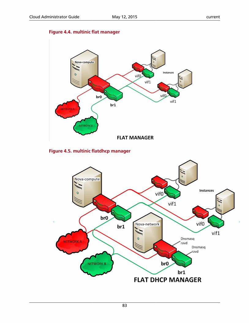
Cloud Administrator Guide May 12, 2015 current
83
Figure 4.4. multinic flat manager
Figure 4.5. multinic flatdhcp manager
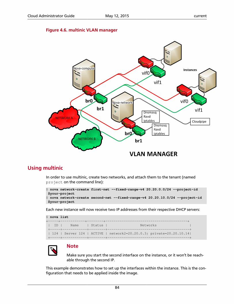
Cloud Administrator Guide May 12, 2015 current
84
Figure 4.6. multinic VLAN manager
Using multinic
In order to use multinic, create two networks, and attach them to the tenant (namedproject on the command line):
$ nova network-create first-net --fixed-range-v4 20.20.0.0/24 --project-id $your-project$ nova network-create second-net --fixed-range-v4 20.20.10.0/24 --project-id $your-project
Each new instance will now receive two IP addresses from their respective DHCP servers:
$ nova list+-----+------------+--------+----------------------------------------+ | ID | Name | Status | Networks | +-----+------------+--------+----------------------------------------+ | 124 | Server 124 | ACTIVE | network2=20.20.0.3; private=20.20.10.14| +-----+------------+--------+----------------------------------------+
Note
Make sure you start the second interface on the instance, or it won't be reach-able through the second IP.
This example demonstrates how to set up the interfaces within the instance. This is the con-figuration that needs to be applied inside the image.
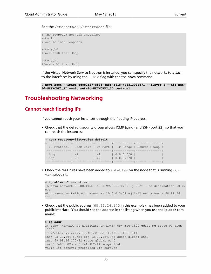
Cloud Administrator Guide May 12, 2015 current
85
Edit the /etc/network/interfaces file:
# The loopback network interfaceauto loiface lo inet loopback
auto eth0iface eth0 inet dhcp
auto eth1iface eth1 inet dhcp
If the Virtual Network Service Neutron is installed, you can specify the networks to attachto the interfaces by using the --nic flag with the the nova command:
$ nova boot --image ed8b2a37-5535-4a5f-a615-443513036d71 --flavor 1 --nic net-id=NETWORK1_ID --nic net-id=NETWORK2_ID test-vm1
Troubleshooting Networking
Cannot reach floating IPs
If you cannot reach your instances through the floating IP address:
• Check that the default security group allows ICMP (ping) and SSH (port 22), so that youcan reach the instances:
$ nova secgroup-list-rules default+-------------+-----------+---------+-----------+--------------+| IP Protocol | From Port | To Port | IP Range | Source Group |+-------------+-----------+---------+-----------+--------------+| icmp | -1 | -1 | 0.0.0.0/0 | || tcp | 22 | 22 | 0.0.0.0/0 | |+-------------+-----------+---------+-----------+--------------+
• Check the NAT rules have been added to iptables on the node that is running no-va-network:
# iptables -L -nv -t nat-A nova-network-PREROUTING -d 68.99.26.170/32 -j DNAT --to-destination 10.0.0.3-A nova-network-floating-snat -s 10.0.0.3/32 -j SNAT --to-source 68.99.26.170
• Check that the public address (68.99.26.170 in this example), has been added to yourpublic interface. You should see the address in the listing when you use the ip addr com-mand:
$ ip addr2: eth0: <BROADCAST,MULTICAST,UP,LOWER_UP> mtu 1500 qdisc mq state UP qlen 1000link/ether xx:xx:xx:17:4b:c2 brd ff:ff:ff:ff:ff:ffinet 13.22.194.80/24 brd 13.22.194.255 scope global eth0inet 68.99.26.170/32 scope global eth0inet6 fe80::82b:2bf:fe1:4b2/64 scope linkvalid_lft forever preferred_lft forever
Cloud Administrator Guide May 12, 2015 current
86
Note
You cannot ssh to an instance with a public IP from within the same serverbecause the routing configuration does not allow it.
• Use tcpdump to identify if packets are being routed to the inbound interface on thecompute host. If the packets are reaching the compute hosts but the connection is fail-ing, the issue may be that the packet is being dropped by reverse path filtering. Try dis-abling reverse-path filtering on the inbound interface. For example, if the inbound inter-face is eth2, run:
# sysctl -w net.ipv4.conf.ETH2.rp_filter=0
If this solves the problem, add the following line to /etc/sysctl.conf so that the re-verse-path filter is persistent:
net.ipv4.conf.rp_filter=0
Temporarily disable the firewall
To help debug networking issues with reaching VMs, you can disable the firewall by settingthis option in /etc/nova/nova.conf:
firewall_driver=nova.virt.firewall.NoopFirewallDriver
We strongly recommend you remove this line to re-enable the firewall once your network-ing issues have been resolved.
Packet loss from instances to nova-network server (VLANManagermode)
If you can SSH to your instances but the network to your instance is slow, or if you find thatrunning certain operations are slower than they should be (for example, sudo), packet losscould be occurring on the connection to the instance.
Packet loss can be caused by Linux networking configuration settings related to bridges.Certain settings can cause packets to be dropped between the VLAN interface (for exam-ple, vlan100) and the associated bridge interface (for example, br100) on the host run-ning nova-network.
One way to check whether this is the problem is to open three terminals and run the fol-lowing commands:
1. In the first terminal, on the host running nova-network, use tcpdump on the VLAN in-terface to monitor DNS-related traffic (UDP, port 53). As root, run:
# tcpdump -K -p -i vlan100 -v -vv udp port 53
2. In the second terminal, also on the host running nova-network, use tcpdump to moni-tor DNS-related traffic on the bridge interface. As root, run:
# tcpdump -K -p -i br100 -v -vv udp port 53
Cloud Administrator Guide May 12, 2015 current
87
3. In the third terminal, SSH to the instance and generate DNS requests by using thenslookup command:
$ nslookup www.google.com
The symptoms may be intermittent, so try running nslookup multiple times. If the net-work configuration is correct, the command should return immediately each time. If it isnot correct, the command hangs for several seconds before returning.
4. If the nslookup command sometimes hangs, and there are packets that appear in thefirst terminal but not the second, then the problem may be due to filtering done on thebridges. Try disabling filtering, and running these commands as root:
# sysctl -w net.bridge.bridge-nf-call-arptables=0# sysctl -w net.bridge.bridge-nf-call-iptables=0# sysctl -w net.bridge.bridge-nf-call-ip6tables=0
If this solves your issue, add the following line to /etc/sysctl.conf so that thechanges are persistent:
net.bridge.bridge-nf-call-arptables=0net.bridge.bridge-nf-call-iptables=0net.bridge.bridge-nf-call-ip6tables=0
KVM: Network connectivity works initially, then fails
With KVM hypervisors, instances running Ubuntu 12.04 sometimes lose network connectiv-ity after functioning properly for a period of time. Try loading the vhost_net kernel mod-ule as a workaround for this issue (see bug #997978) . This kernel module may also improvenetwork performance on KVM. To load the kernel module:
# modprobe vhost_net
Note
Loading the module has no effect on running instances.
System administrationTo effectively administer Compute, you must understand how the different installed nodesinteract with each other. Compute can be installed in many different ways using multipleservers, but generally multiple compute nodes control the virtual servers and a cloud con-troller node contains the remaining Compute services.
The Compute cloud works using a series of daemon processes named nova-* that existpersistently on the host machine. These binaries can all run on the same machine or bespread out on multiple boxes in a large deployment. The responsibilities of services anddrivers are:
Services
• nova-api: receives XML requests and sends them to the rest of the system. A WSGI approutes and authenticates requests. Supports the EC2 and OpenStack APIs. A nova.confconfiguration file is created when Compute is installed.
Cloud Administrator Guide May 12, 2015 current
88
• nova-cert: manages certificates.
• nova-compute: manages virtual machines. Loads a Service object, and exposes the pub-lic methods on ComputeManager through a Remote Procedure Call (RPC).
• nova-conductor: provides database-access support for Compute nodes (thereby re-ducing security risks).
• nova-consoleauth: manages console authentication.
• nova-objectstore: a simple file-based storage system for images that replicates mostof the S3 API. It can be replaced with OpenStack Image service and either a simple imagemanager or OpenStack Object Storage as the virtual machine image storage facility. Itmust exist on the same node as nova-compute.
• nova-network: manages floating and fixed IPs, DHCP, bridging and VLANs. Loadsa Service object which exposes the public methods on one of the subclasses of Net-workManager. Different networking strategies are available by changing thenetwork_manager configuration option to FlatManager, FlatDHCPManager, orVLANManager (defaults to VLANManager if nothing is specified).
• nova-scheduler: dispatches requests for new virtual machines to the correct node.
• nova-novncproxy: provides a VNC proxy for browsers, allowing VNC consoles to ac-cess virtual machines.
Note
Some services have drivers that change how the service implements its corefunctionality. For example, the nova-compute service supports drivers thatlet you choose which hypervisor type it can use. nova-network and no-va-scheduler also have drivers.
Manage Compute users
Access to the Euca2ools (ec2) API is controlled by an access key and a secret key. The user'saccess key needs to be included in the request, and the request must be signed with the se-cret key. Upon receipt of API requests, Compute verifies the signature and runs commandson behalf of the user.
To begin using Compute, you must create a user with the Identity Service.
Manage Volumes
Depending on the setup of your cloud provider, they may give you an endpoint to use tomanage volumes, or there may be an extension under the covers. In either case, you canuse the nova CLI to manage volumes:
volume-attach Attach a volume to a server. volume-create Add a new volume. volume-delete Remove a volume. volume-detach Detach a volume from a server. volume-list List all the volumes.
Cloud Administrator Guide May 12, 2015 current
89
volume-show Show details about a volume. volume-snapshot-create Add a new snapshot. volume-snapshot-delete Remove a snapshot. volume-snapshot-list List all the snapshots. volume-snapshot-show Show details about a snapshot. volume-type-create Create a new volume type. volume-type-delete Delete a specific flavor volume-type-list Print a list of available 'volume types'. volume-update Update an attached volume.
For example, to list IDs and names of Compute volumes, run:
$ nova volume-list+--------------------------------------+-----------+--------------+------+-------------+-------------+| ID | Status | Display Name | Size | Volume Type | Attached to |+--------------------------------------+-----------+--------------+------+-------------+-------------+| 1af4cb93-d4c6-4ee3-89a0-4b7885a3337e | available | PerfBlock | 1 | Performance | |+--------------------------------------+-----------+--------------+------+-------------+-------------+
Flavors
Admin users can use the nova flavor- commands to customize and manage flavors. To seethe available flavor-related commands, run:
$ nova help | grep flavor- flavor-access-add Add flavor access for the given tenant. flavor-access-list Print access information about the given flavor. flavor-access-remove Remove flavor access for the given tenant. flavor-create Create a new flavor flavor-delete Delete a specific flavor flavor-key Set or unset extra_spec for a flavor. flavor-list Print a list of available 'flavors' (sizes of flavor-show Show details about the given flavor.
Note
• Configuration rights can be delegated to additional users by redefining theaccess controls for compute_extension:flavormanage in /etc/no-va/policy.json on the nova-api server.
• To modify an existing flavor in the dashboard, you must delete the flavor andcreate a modified one with the same name.
Flavors define these elements:
Table 4.3. Identity Service configuration file sections
Element Description
Name A descriptive name. XX.SIZE_NAME is typically not required, though somethird party tools may rely on it.
Memory_MB Virtual machine memory in megabytes.
Cloud Administrator Guide May 12, 2015 current
90
Element Description
Disk Virtual root disk size in gigabytes. This is an ephemeral disk that the baseimage is copied into. When booting from a persistent volume it is not used.The "0" size is a special case which uses the native base image size as thesize of the ephemeral root volume.
Ephemer-al
Specifies the size of a secondary ephemeral data disk. This is an empty, un-formatted disk and exists only for the life of the instance.
Swap Optional swap space allocation for the instance.
VCPUs Number of virtual CPUs presented to the instance.
RXTX_FactorOptional property allows created servers to have a different bandwidthcap than that defined in the network they are attached to. This factor ismultiplied by the rxtx_base property of the network. Default value is 1.0.That is, the same as attached network. This parameter is only available forXen or NSX based systems.
Is_Public Boolean value, whether flavor is available to all users or private to the ten-ant it was created in. Defaults to True.
extra_specsKey and value pairs that define on which compute nodes a flavor can run.These pairs must match corresponding pairs on the compute nodes. Useto implement special resources, such as flavors that run on only computenodes with GPU hardware.
Flavor customization can be limited by the hypervisor in use. For example the libvirtdriver enables quotas on CPUs available to a VM, disk tuning, bandwidth I/O, watchdog be-havior, random number generator device control, and instance VIF traffic control.
CPU limits You can configure the CPU limits with control parameterswith the nova client. For example, to configure the I/Olimit, use:
$ nova flavor-key m1.small set quota:read_bytes_sec=10240000$ nova flavor-key m1.small set quota:write_bytes_sec=10240000
Use these optional parameters to control weight shares,enforcement intervals for runtime quotas, and a quotafor maximum allowed bandwidth:
• cpu_shares. Specifies the proportional weightedshare for the domain. If this element is omitted, theservice defaults to the OS provided defaults. There isno unit for the value; it is a relative measure based onthe setting of other VMs. For example, a VM config-ured with value 2048 gets twice as much CPU time as aVM configured with value 1024.
• cpu_period. Specifies the enforcement interval (unit:microseconds) for QEMU and LXC hypervisors. Within aperiod, each VCPU of the domain is not allowed to con-sume more than the quota worth of runtime. The val-ue should be in range [1000, 1000000]. A periodwith value 0 means no value.
• cpu_limit. Specifies the upper limit for VMwaremachine CPU allocation in MHz. This parameter en-
Cloud Administrator Guide May 12, 2015 current
91
sures that a machine never uses more than the definedamount of CPU time. It can be used to enforce a limiton the machine's CPU performance.
• cpu_reservation. Specifies the guaranteed mini-mum CPU reservation in MHz for VMware. This meansthat if needed, the machine will definitely get allocatedthe reserved amount of CPU cycles.
• cpu_quota. Specifies the maximum allowed band-width (unit: microseconds). A domain with a neg-ative-value quota indicates that the domain has in-finite bandwidth, which means that it is not band-width controlled. The value should be in range [1000,18446744073709551] or less than 0. A quota withvalue 0 means no value. You can use this feature to en-sure that all vCPUs run at the same speed. For example:
$ nova flavor-key m1.low_cpu set quota:cpu_quota=10000$ nova flavor-key m1.low_cpu set quota:cpu_period=20000
In this example, the instance of m1.low_cpu can on-ly consume a maximum of 50% CPU of a physical CPUcomputing capability.
Disk tuning Using disk I/O quotas, you can set maximum disk write to10 MB per second for a VM user. For example:
$ nova flavor-key m1.medium set quota:disk_write_bytes_sec=10485760
The disk I/O options are:
• disk_read_bytes_sec
• disk_read_iops_sec
• disk_write_bytes_sec
• disk_write_iops_sec
• disk_total_bytes_sec
• disk_total_iops_sec
Bandwidth I/O The vif I/O options are:
• vif_inbound_ average
• vif_inbound_burst
• vif_inbound_peak
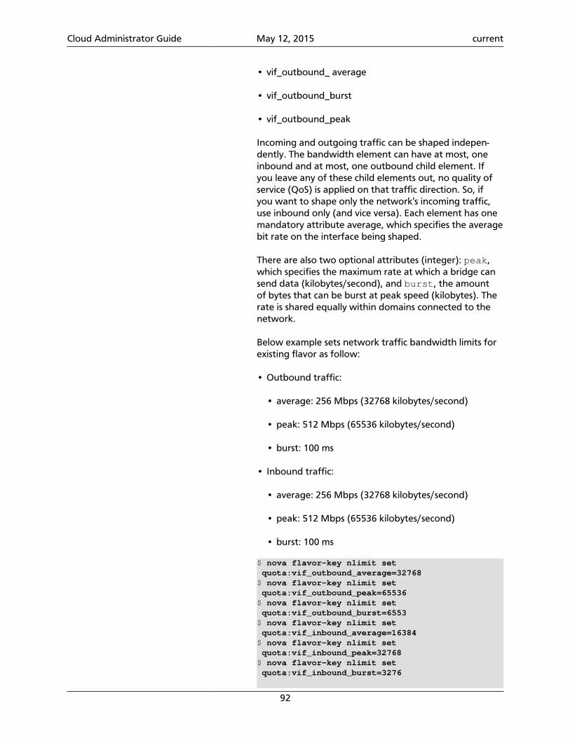
Cloud Administrator Guide May 12, 2015 current
92
• vif_outbound_ average
• vif_outbound_burst
• vif_outbound_peak
Incoming and outgoing traffic can be shaped indepen-dently. The bandwidth element can have at most, oneinbound and at most, one outbound child element. Ifyou leave any of these child elements out, no quality ofservice (QoS) is applied on that traffic direction. So, ifyou want to shape only the network's incoming traffic,use inbound only (and vice versa). Each element has onemandatory attribute average, which specifies the averagebit rate on the interface being shaped.
There are also two optional attributes (integer): peak,which specifies the maximum rate at which a bridge cansend data (kilobytes/second), and burst, the amountof bytes that can be burst at peak speed (kilobytes). Therate is shared equally within domains connected to thenetwork.
Below example sets network traffic bandwidth limits forexisting flavor as follow:
• Outbound traffic:
• average: 256 Mbps (32768 kilobytes/second)
• peak: 512 Mbps (65536 kilobytes/second)
• burst: 100 ms
• Inbound traffic:
• average: 256 Mbps (32768 kilobytes/second)
• peak: 512 Mbps (65536 kilobytes/second)
• burst: 100 ms
$ nova flavor-key nlimit set quota:vif_outbound_average=32768$ nova flavor-key nlimit set quota:vif_outbound_peak=65536$ nova flavor-key nlimit set quota:vif_outbound_burst=6553$ nova flavor-key nlimit set quota:vif_inbound_average=16384$ nova flavor-key nlimit set quota:vif_inbound_peak=32768$ nova flavor-key nlimit set quota:vif_inbound_burst=3276
Cloud Administrator Guide May 12, 2015 current
93
Note
All the speed limit values in above exampleare specified in kilobytes/second. And burstvalues are in kilobytes.
Watchdog behavior For the libvirt driver, you can enable and set the be-havior of a virtual hardware watchdog device for eachflavor. Watchdog devices keep an eye on the guest serv-er, and carry out the configured action, if the serverhangs. The watchdog uses the i6300esb device (emulat-ing a PCI Intel 6300ESB). If hw:watchdog_action is notspecified, the watchdog is disabled.
To set the behavior, use:
$ nova flavor-key FLAVOR-NAME set hw:watchdog_action=ACTION
Valid ACTION values are:
• disabled—(default) The device is not attached.
• reset—Forcefully reset the guest.
• poweroff—Forcefully power off the guest.
• pause—Pause the guest.
• none—Only enable the watchdog; do nothing if theserver hangs.
Note
Watchdog behavior set using a specificimage's properties will override behavior setusing flavors.
Random-number generator If a random-number generator device has been added tothe instance through its image properties, the device canbe enabled and configured using:
$ nova flavor-key FLAVOR-NAME set hw_rng:allowed=True$ nova flavor-key FLAVOR-NAME set hw_rng:rate_bytes=RATE-BYTES$ nova flavor-key FLAVOR-NAME set hw_rng:rate_period=RATE-PERIOD
Where:
• RATE-BYTES—(Integer) Allowed amount of bytes thatthe guest can read from the host's entropy per period.
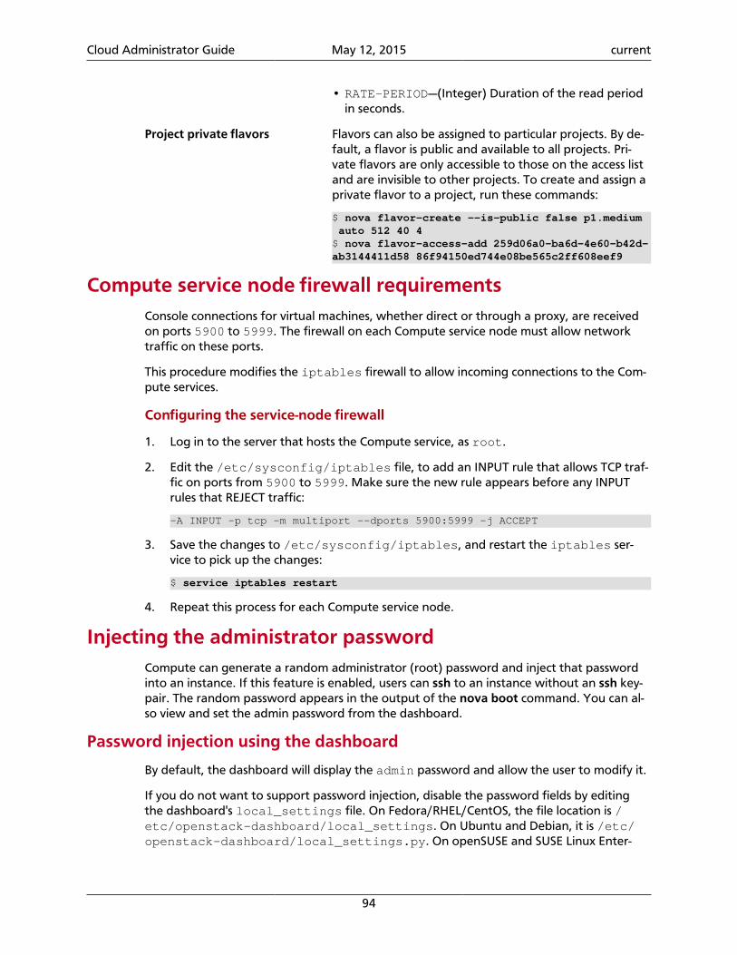
Cloud Administrator Guide May 12, 2015 current
94
• RATE-PERIOD—(Integer) Duration of the read periodin seconds.
Project private flavors Flavors can also be assigned to particular projects. By de-fault, a flavor is public and available to all projects. Pri-vate flavors are only accessible to those on the access listand are invisible to other projects. To create and assign aprivate flavor to a project, run these commands:
$ nova flavor-create --is-public false p1.medium auto 512 40 4$ nova flavor-access-add 259d06a0-ba6d-4e60-b42d-ab3144411d58 86f94150ed744e08be565c2ff608eef9
Compute service node firewall requirementsConsole connections for virtual machines, whether direct or through a proxy, are receivedon ports 5900 to 5999. The firewall on each Compute service node must allow networktraffic on these ports.
This procedure modifies the iptables firewall to allow incoming connections to the Com-pute services.
Configuring the service-node firewall
1. Log in to the server that hosts the Compute service, as root.
2. Edit the /etc/sysconfig/iptables file, to add an INPUT rule that allows TCP traf-fic on ports from 5900 to 5999. Make sure the new rule appears before any INPUTrules that REJECT traffic:
-A INPUT -p tcp -m multiport --dports 5900:5999 -j ACCEPT
3. Save the changes to /etc/sysconfig/iptables, and restart the iptables ser-vice to pick up the changes:
$ service iptables restart
4. Repeat this process for each Compute service node.
Injecting the administrator passwordCompute can generate a random administrator (root) password and inject that passwordinto an instance. If this feature is enabled, users can ssh to an instance without an ssh key-pair. The random password appears in the output of the nova boot command. You can al-so view and set the admin password from the dashboard.
Password injection using the dashboard
By default, the dashboard will display the admin password and allow the user to modify it.
If you do not want to support password injection, disable the password fields by editingthe dashboard's local_settings file. On Fedora/RHEL/CentOS, the file location is /etc/openstack-dashboard/local_settings. On Ubuntu and Debian, it is /etc/openstack-dashboard/local_settings.py. On openSUSE and SUSE Linux Enter-
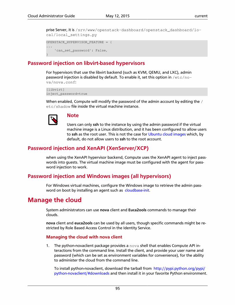
Cloud Administrator Guide May 12, 2015 current
95
prise Server, it is /srv/www/openstack-dashboard/openstack_dashboard/lo-cal/local_settings.py
OPENSTACK_HYPERVISOR_FEATURE = {... 'can_set_password': False,}
Password injection on libvirt-based hypervisors
For hypervisors that use the libvirt backend (such as KVM, QEMU, and LXC), adminpassword injection is disabled by default. To enable it, set this option in /etc/no-va/nova.conf:
[libvirt]inject_password=true
When enabled, Compute will modify the password of the admin account by editing the /etc/shadow file inside the virtual machine instance.
Note
Users can only ssh to the instance by using the admin password if the virtualmachine image is a Linux distribution, and it has been configured to allow usersto ssh as the root user. This is not the case for Ubuntu cloud images which, bydefault, do not allow users to ssh to the root account.
Password injection and XenAPI (XenServer/XCP)
when using the XenAPI hypervisor backend, Compute uses the XenAPI agent to inject pass-words into guests. The virtual machine image must be configured with the agent for pass-word injection to work.
Password injection and Windows images (all hypervisors)
For Windows virtual machines, configure the Windows image to retrieve the admin pass-word on boot by installing an agent such as cloudbase-init.
Manage the cloudSystem administrators can use nova client and Euca2ools commands to manage theirclouds.
nova client and euca2ools can be used by all users, though specific commands might be re-stricted by Role Based Access Control in the Identity Service.
Managing the cloud with nova client
1. The python-novaclient package provides a nova shell that enables Compute API in-teractions from the command line. Install the client, and provide your user name andpassword (which can be set as environment variables for convenience), for the abilityto administer the cloud from the command line.
To install python-novaclient, download the tarball from http://pypi.python.org/pypi/python-novaclient/#downloads and then install it in your favorite Python environment.
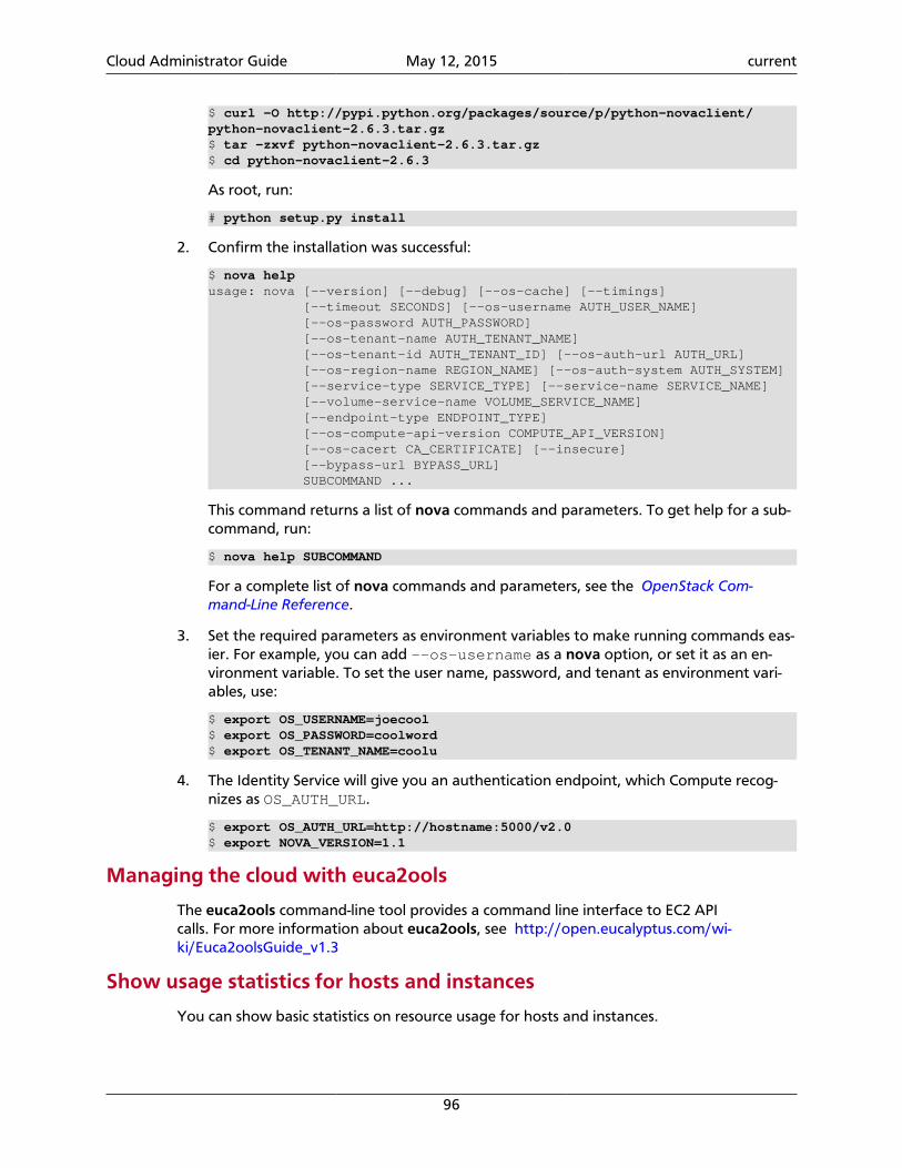
Cloud Administrator Guide May 12, 2015 current
96
$ curl -O http://pypi.python.org/packages/source/p/python-novaclient/python-novaclient-2.6.3.tar.gz$ tar -zxvf python-novaclient-2.6.3.tar.gz$ cd python-novaclient-2.6.3
As root, run:
# python setup.py install
2. Confirm the installation was successful:
$ nova helpusage: nova [--version] [--debug] [--os-cache] [--timings] [--timeout SECONDS] [--os-username AUTH_USER_NAME] [--os-password AUTH_PASSWORD] [--os-tenant-name AUTH_TENANT_NAME] [--os-tenant-id AUTH_TENANT_ID] [--os-auth-url AUTH_URL] [--os-region-name REGION_NAME] [--os-auth-system AUTH_SYSTEM] [--service-type SERVICE_TYPE] [--service-name SERVICE_NAME] [--volume-service-name VOLUME_SERVICE_NAME] [--endpoint-type ENDPOINT_TYPE] [--os-compute-api-version COMPUTE_API_VERSION] [--os-cacert CA_CERTIFICATE] [--insecure] [--bypass-url BYPASS_URL] SUBCOMMAND ...
This command returns a list of nova commands and parameters. To get help for a sub-command, run:
$ nova help SUBCOMMAND
For a complete list of nova commands and parameters, see the OpenStack Com-mand-Line Reference.
3. Set the required parameters as environment variables to make running commands eas-ier. For example, you can add --os-username as a nova option, or set it as an en-vironment variable. To set the user name, password, and tenant as environment vari-ables, use:
$ export OS_USERNAME=joecool$ export OS_PASSWORD=coolword$ export OS_TENANT_NAME=coolu
4. The Identity Service will give you an authentication endpoint, which Compute recog-nizes as OS_AUTH_URL.
$ export OS_AUTH_URL=http://hostname:5000/v2.0$ export NOVA_VERSION=1.1
Managing the cloud with euca2ools
The euca2ools command-line tool provides a command line interface to EC2 APIcalls. For more information about euca2ools, see http://open.eucalyptus.com/wi-ki/Euca2oolsGuide_v1.3
Show usage statistics for hosts and instances
You can show basic statistics on resource usage for hosts and instances.
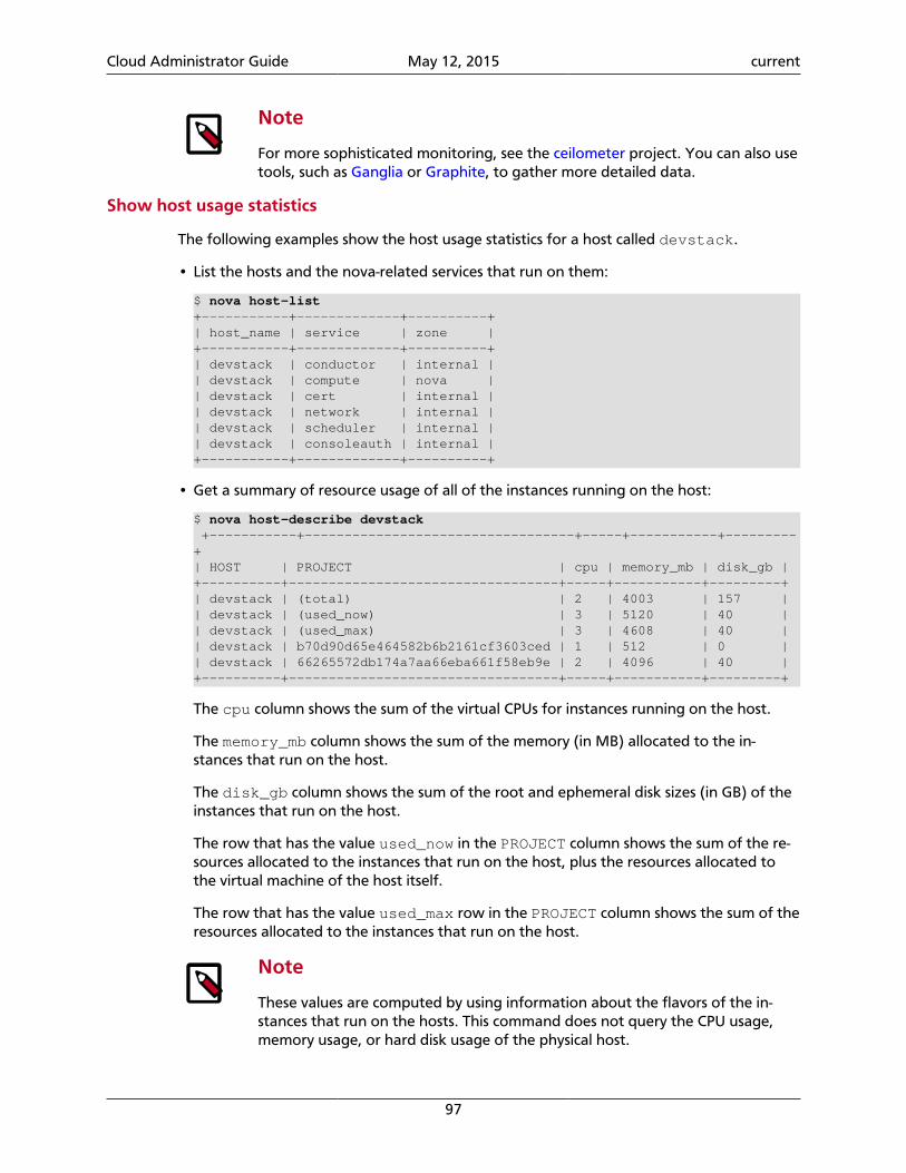
Cloud Administrator Guide May 12, 2015 current
97
Note
For more sophisticated monitoring, see the ceilometer project. You can also usetools, such as Ganglia or Graphite, to gather more detailed data.
Show host usage statistics
The following examples show the host usage statistics for a host called devstack.
• List the hosts and the nova-related services that run on them:
$ nova host-list+-----------+-------------+----------+| host_name | service | zone |+-----------+-------------+----------+| devstack | conductor | internal || devstack | compute | nova || devstack | cert | internal || devstack | network | internal || devstack | scheduler | internal || devstack | consoleauth | internal |+-----------+-------------+----------+
• Get a summary of resource usage of all of the instances running on the host:
$ nova host-describe devstack +-----------+----------------------------------+-----+-----------+---------+| HOST | PROJECT | cpu | memory_mb | disk_gb |+----------+----------------------------------+-----+-----------+---------+| devstack | (total) | 2 | 4003 | 157 || devstack | (used_now) | 3 | 5120 | 40 || devstack | (used_max) | 3 | 4608 | 40 || devstack | b70d90d65e464582b6b2161cf3603ced | 1 | 512 | 0 || devstack | 66265572db174a7aa66eba661f58eb9e | 2 | 4096 | 40 |+----------+----------------------------------+-----+-----------+---------+
The cpu column shows the sum of the virtual CPUs for instances running on the host.
The memory_mb column shows the sum of the memory (in MB) allocated to the in-stances that run on the host.
The disk_gb column shows the sum of the root and ephemeral disk sizes (in GB) of theinstances that run on the host.
The row that has the value used_now in the PROJECT column shows the sum of the re-sources allocated to the instances that run on the host, plus the resources allocated tothe virtual machine of the host itself.
The row that has the value used_max row in the PROJECT column shows the sum of theresources allocated to the instances that run on the host.
Note
These values are computed by using information about the flavors of the in-stances that run on the hosts. This command does not query the CPU usage,memory usage, or hard disk usage of the physical host.
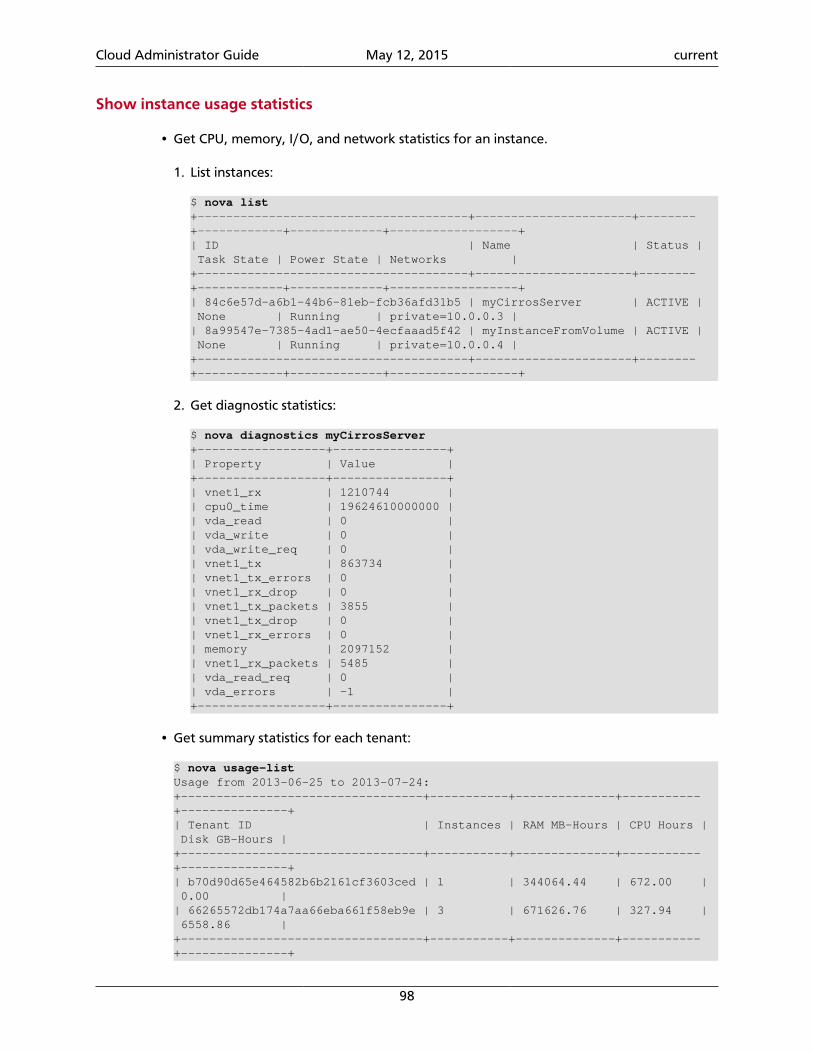
Cloud Administrator Guide May 12, 2015 current
98
Show instance usage statistics
• Get CPU, memory, I/O, and network statistics for an instance.
1. List instances:
$ nova list+--------------------------------------+----------------------+--------+------------+-------------+------------------+| ID | Name | Status | Task State | Power State | Networks |+--------------------------------------+----------------------+--------+------------+-------------+------------------+| 84c6e57d-a6b1-44b6-81eb-fcb36afd31b5 | myCirrosServer | ACTIVE | None | Running | private=10.0.0.3 || 8a99547e-7385-4ad1-ae50-4ecfaaad5f42 | myInstanceFromVolume | ACTIVE | None | Running | private=10.0.0.4 |+--------------------------------------+----------------------+--------+------------+-------------+------------------+
2. Get diagnostic statistics:
$ nova diagnostics myCirrosServer+------------------+----------------+| Property | Value |+------------------+----------------+| vnet1_rx | 1210744 || cpu0_time | 19624610000000 || vda_read | 0 || vda_write | 0 || vda_write_req | 0 || vnet1_tx | 863734 || vnet1_tx_errors | 0 || vnet1_rx_drop | 0 || vnet1_tx_packets | 3855 || vnet1_tx_drop | 0 || vnet1_rx_errors | 0 || memory | 2097152 || vnet1_rx_packets | 5485 || vda_read_req | 0 || vda_errors | -1 |+------------------+----------------+
• Get summary statistics for each tenant:
$ nova usage-listUsage from 2013-06-25 to 2013-07-24:+----------------------------------+-----------+--------------+-----------+---------------+| Tenant ID | Instances | RAM MB-Hours | CPU Hours | Disk GB-Hours |+----------------------------------+-----------+--------------+-----------+---------------+| b70d90d65e464582b6b2161cf3603ced | 1 | 344064.44 | 672.00 | 0.00 || 66265572db174a7aa66eba661f58eb9e | 3 | 671626.76 | 327.94 | 6558.86 |+----------------------------------+-----------+--------------+-----------+---------------+
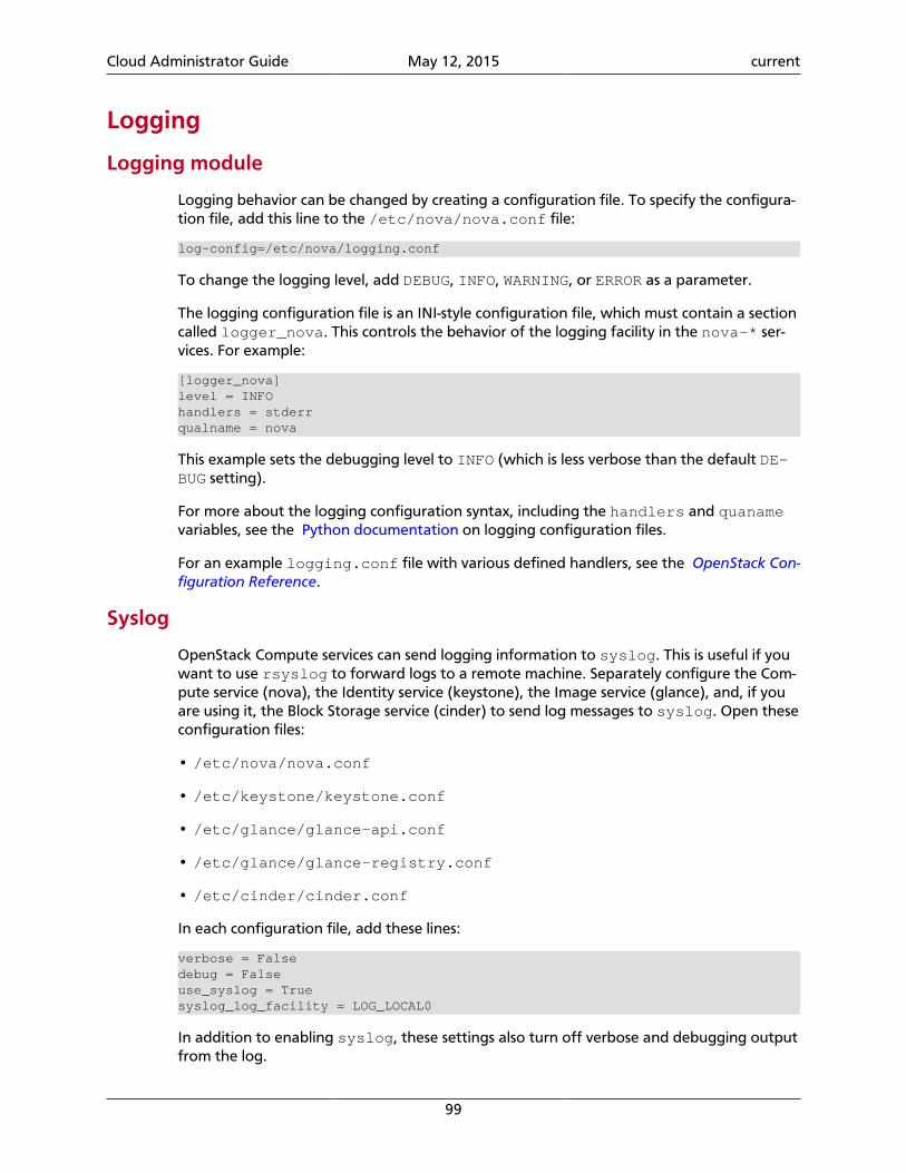
Cloud Administrator Guide May 12, 2015 current
99
Logging
Logging module
Logging behavior can be changed by creating a configuration file. To specify the configura-tion file, add this line to the /etc/nova/nova.conf file:
log-config=/etc/nova/logging.conf
To change the logging level, add DEBUG, INFO, WARNING, or ERROR as a parameter.
The logging configuration file is an INI-style configuration file, which must contain a sectioncalled logger_nova. This controls the behavior of the logging facility in the nova-* ser-vices. For example:
[logger_nova]level = INFOhandlers = stderrqualname = nova
This example sets the debugging level to INFO (which is less verbose than the default DE-BUG setting).
For more about the logging configuration syntax, including the handlers and quanamevariables, see the Python documentation on logging configuration files.
For an example logging.conf file with various defined handlers, see the OpenStack Con-figuration Reference.
Syslog
OpenStack Compute services can send logging information to syslog. This is useful if youwant to use rsyslog to forward logs to a remote machine. Separately configure the Com-pute service (nova), the Identity service (keystone), the Image service (glance), and, if youare using it, the Block Storage service (cinder) to send log messages to syslog. Open theseconfiguration files:
• /etc/nova/nova.conf
• /etc/keystone/keystone.conf
• /etc/glance/glance-api.conf
• /etc/glance/glance-registry.conf
• /etc/cinder/cinder.conf
In each configuration file, add these lines:
verbose = Falsedebug = Falseuse_syslog = Truesyslog_log_facility = LOG_LOCAL0
In addition to enabling syslog, these settings also turn off verbose and debugging outputfrom the log.
Cloud Administrator Guide May 12, 2015 current
100
Note
Although this example uses the same local facility for each service(LOG_LOCAL0, which corresponds to syslog facility LOCAL0), we recommendthat you configure a separate local facility for each service, as this provides bet-ter isolation and more flexibility. For example, you can capture logging informa-tion at different severity levels for different services. syslog allows you to de-fine up to eight local facilities, LOCAL0, LOCAL1, ..., LOCAL7. For moreinformation, see the syslog documentation.
Rsyslog
rsyslog is useful for setting up a centralized log server across multiple machines. This sec-tion briefly describe the configuration to set up an rsyslog server. A full treatment ofrsyslog is beyond the scope of this book. This section assumes rsyslog has already beeninstalled on your hosts (it is installed by default on most Linux distributions).
This example provides a minimal configuration for /etc/rsyslog.conf on the log serverhost, which receives the log files:
# provides TCP syslog reception$ModLoad imtcp$InputTCPServerRun 1024
Add a filter rule to /etc/rsyslog.conf which looks for a host name. This example usesCOMPUTE_01 as the compute host name:
:hostname, isequal, "COMPUTE_01" /mnt/rsyslog/logs/compute-01.log
On each compute host, create a file named /etc/rsyslog.d/60-nova.conf, with thefollowing content:
# prevent debug from dnsmasq with the daemon.none parameter*.*;auth,authpriv.none,daemon.none,local0.none -/var/log/syslog# Specify a log level of ERRORlocal0.error @@172.20.1.43:1024
Once you have created the file, restart the rsyslog service. Error-level log messages onthe compute hosts should now be sent to the log server.
Serial console
The serial console provides a way to examine kernel output and other system messages dur-ing troubleshooting if the instance lacks network connectivity.
OpenStack Icehouse and earlier supports read-only access using the serial console using theos-GetSerialOutput server action. Most cloud images enable this feature by default. Formore information, see Troubleshoot Compute.
OpenStack Juno and later supports read-write access using the serial console using the os-GetSerialConsole server action. This feature also requires a websocket client to access theserial console.
Configuring read-write serial console access
On a compute node, edit the /etc/nova/nova.conf file:
Cloud Administrator Guide May 12, 2015 current
101
1. In the [serial_console] section, enable the serial console:
[serial_console]...enabled = true
2. In the [serial_console] section, configure the serial console proxy similar tographical console proxies:
[serial_console]...base_url = ws://controller:6083/listen = 0.0.0.0proxyclient_address = MANAGEMENT_INTERFACE_IP_ADDRESS
The base_url option specifies the base URL that clients receive from the API upon re-questing a serial console. Typically, this refers to the host name of the controller node.
The listen option specifies the network interface nova-compute should listen onfor virtual console connections. Typically, 0.0.0.0 will enable listening on all interfaces.
The proxyclient_address option specifies which network interface the proxyshould connect to. Typically, this refers to the IP address of the management interface.
When you enable read-write serial console access, Compute will add serial console informa-tion to the Libvirt XML file for the instance. For example:
<console type='tcp'> <source mode='bind' host='127.0.0.1' service='10000'/> <protocol type='raw'/> <target type='serial' port='0'/> <alias name='serial0'/></console>
Accessing the serial console on an instance
1. Use the nova get-serial-proxy command to retrieve the websocket URL for the serialconsole on the instance:
$ nova get-serial-proxy INSTANCE_NAME+--------+-----------------------------------------------------------------+| Type | Url |+--------+-----------------------------------------------------------------+| serial | ws://127.0.0.1:6083/?token=18510769-71ad-4e5a-8348-4218b5613b3d |+--------+-----------------------------------------------------------------+
Alternatively, use the API directly:
$ curl -i 'http://<controller>:8774/v2/<tenant_uuid>/servers/<instance_uuid>/action' \ -X POST \ -H "Accept: application/json" \ -H "Content-Type: application/json" \ -H "X-Auth-Project-Id: <project_id>" \
Cloud Administrator Guide May 12, 2015 current
102
-H "X-Auth-Token: <auth_token>" \ -d '{"os-getSerialConsole": {"type": "serial"}}'
2. Use Python websocket with the URL to generate .send, .recv, and .fileno meth-ods for serial console access. For example:
import websocketws = websocket.create_connection( 'ws://127.0.0.1:6083/?token=18510769-71ad-4e5a-8348-4218b5613b3d', subprotocols=['binary', 'base64'])
Alternatively, use a Python websocket client such as https://github.com/larsks/nova-console/.
Note
When you enable the serial console, typical instance logging using the novaconsole-log command is disabled. Kernel output and other system messageswill not be visible unless you are actively viewing the serial console.
Secure with rootwrap
Rootwrap allows unprivileged users to safely run Compute actions as the root user. Com-pute previously used sudo for this purpose, but this was difficult to maintain, and did notallow advanced filters. The rootwrap command replaces sudo for Compute.
To use rootwrap, prefix the Compute command with nova-rootwrap. For example:
$ sudo nova-rootwrap /etc/nova/rootwrap.conf command
A generic sudoers entry lets the Compute user run nova-rootwrap as root. The no-va-rootwrap code looks for filter definition directories in its configuration file, and loadscommand filters from them. It then checks if the command requested by Compute matchesone of those filters and, if so, executes the command (as root). If no filter matches, it deniesthe request.
Note
Be aware of issues with using NFS and root-owned files. The NFS share must beconfigured with the no_root_squash option enabled, in order for rootwrapto work correctly.
Rootwrap is fully controlled by the root user. The root user owns the sudoers entry whichallows Compute to run a specific rootwrap executable as root, and only with a specific con-figuration file (which should also be owned by root). The nova-rootwrap command im-ports the Python modules it needs from a cleaned, system-default PYTHONPATH. The root-owned configuration file points to root-owned filter definition directories, which containroot-owned filters definition files. This chain ensures that the Compute user itself is not incontrol of the configuration or modules used by the nova-rootwrap executable.
Rootwrap is configured using the rootwrap.conf file. Because it's in the trusted se-curity path, it must be owned and writable by only the root user. The file's location isspecified in both the sudoers entry and in the nova.conf configuration file with therootwrap_config=entry parameter.
Cloud Administrator Guide May 12, 2015 current
103
The rootwrap.conf file uses an INI file format with these sections and parameters:
Table 4.4. rootwrap.conf configuration options
Configuration option=Default value (Type) Description
[DEFAULT]
filters_path=/etc/nova/rootwrap.d,/usr/share/no-va/rootwrap
(ListOpt) Comma-separated list of directories containingfilter definition files. Defines where rootwrap filters arestored. Directories defined on this line should all exist, andbe owned and writable only by the root user.
If the root wrapper is not performing correctly, you can add a workaround option into thenova.conf configuration file. This workaround re-configures the root wrapper configura-tion to fall back to running commands as sudo, and is a Kilo release feature.
Including this workaround in your configuration file safeguards your environment from is-sues that can impair root wrapper performance. Tool changes that have impacted PythonBuild Reasonableness (PBR), for example, are a known issue that affects root wrapper per-formance.
To set up this workaround, configure the disable_rootwrap option in the[workaround] section of the nova.conf configuration file.
The filters definition files contain lists of filters that rootwrap will use to allow or deny aspecific command. They are generally suffixed by .filters. Since they are in the trustedsecurity path, they need to be owned and writable only by the root user. Their location isspecified in the rootwrap.conf file.
Filter definition files use an INI file format with a [Filters] section and several lines, eachwith a unique parameter name, which should be different for each filter you define:
Table 4.5. .filters configuration options
Configuration option=Default value (Type) Description
[Filters]
filter_name=kpartx: CommandFilter, /sbin/kpartx, root
(ListOpt) Comma-separated list containing the filter classto use, followed by the Filter arguments (which vary de-pending on the Filter class selected).
Configure migrations
Note
Only cloud administrators can perform live migrations. If your cloud is config-ured to use cells, you can perform live migration within but not between cells.
Migration enables an administrator to move a virtual-machine instance from one computehost to another. This feature is useful when a compute host requires maintenance. Migra-tion can also be useful to redistribute the load when many VM instances are running on aspecific physical machine.
The migration types are:
• Non-live migration (sometimes referred to simply as 'migration'). The instance is shutdown for a period of time to be moved to another hypervisor. In this case, the instancerecognizes that it was rebooted.
Cloud Administrator Guide May 12, 2015 current
104
• Live migration (or 'true live migration'). Almost no instance downtime. Useful when theinstances must be kept running during the migration. The different types of live migra-tion are:
• Shared storage-based live migration. Both hypervisors have access to shared storage.
• Block live migration. No shared storage is required. Incompatible with read-only de-vices such as CD-ROMs and Configuration Drive (config_drive).
• Volume-backed live migration. Instances are backed by volumes rather than ephemer-al disk, no shared storage is required, and migration is supported (currently only avail-able for libvirt-based hypervisors).
The following sections describe how to configure your hosts and compute nodes for migra-tions by using the KVM and XenServer hypervisors.
KVM-Libvirt
Shared storage
Prerequisites
• Hypervisor: KVM with libvirt
• Shared storage: NOVA-INST-DIR/instances/ (for example, /var/lib/nova/in-stances) has to be mounted by shared storage. This guide uses NFS but other options,including the OpenStack Gluster Connector are available.
• Instances: Instance can be migrated with iSCSI-based volumes.
Note
• Because the Compute service does not use the libvirt live migration function-ality by default, guests are suspended before migration and might experienceseveral minutes of downtime. For details, see the section called “Enablingtrue live migration” [107].
• This guide assumes the default value for instances_path in yournova.conf file (NOVA-INST-DIR/instances). If you have changed thestate_path or instances_path variables, modify the commands accord-ingly.
• You must specify vncserver_listen=0.0.0.0 or live migration will notwork correctly.
Example Compute installation environment
• Prepare at least three servers. In this example, we refer to the servers as HostA, HostB,and HostC:
• HostA is the Cloud Controller, and should run these services: nova-api, no-va-scheduler, nova-network, cinder-volume, and nova-objectstore.
• HostB and HostC are the compute nodes that run nova-compute.
Cloud Administrator Guide May 12, 2015 current
105
Ensure that NOVA-INST-DIR (set with state_path in the nova.conf file) is the sameon all hosts.
• In this example, HostA is the NFSv4 server that exports NOVA-INST-DIR/instancesdirectory. HostB and HostC are NFSv4 clients that mount HostA.
Configuring your system
1. Configure your DNS or /etc/hosts and ensure it is consistent across all hosts. Makesure that the three hosts can perform name resolution with each other. As a test, usethe ping command to ping each host from one another.
$ ping HostA$ ping HostB$ ping HostC
2. Ensure that the UID and GID of your Compute and libvirt users are identical betweeneach of your servers. This ensures that the permissions on the NFS mount works cor-rectly.
3. Export NOVA-INST-DIR/instances from HostA, and ensure it is readable andwritable by the Compute user on HostB and HostC.
For more information, see: SettingUpNFSHowTo or CentOS/Red Hat: Setup NFS v4.0File Server
4. Configure the NFS server at HostA by adding the following line to the /etc/ex-ports file:
NOVA-INST-DIR/instances HostA/255.255.0.0(rw,sync,fsid=0,no_root_squash)
Change the subnet mask (255.255.0.0) to the appropriate value to include the IPaddresses of HostB and HostC. Then restart the NFS server:
# /etc/init.d/nfs-kernel-server restart# /etc/init.d/idmapd restart
5. On both compute nodes, enable the 'execute/search' bit on your shared directory to al-low qemu to be able to use the images within the directories. On all hosts, run the fol-lowing command:
$ chmod o+x NOVA-INST-DIR/instances
6. Configure NFS on HostB and HostC by adding the following line to the /etc/fstabfile:
HostA:/ /NOVA-INST-DIR/instances nfs4 defaults 0 0
Ensure that you can mount the exported directory:
$ mount -a -v
Check that HostA can see the NOVA-INST-DIR/instances/" directory:
$ ls -ld NOVA-INST-DIR/instances/drwxr-xr-x 2 nova nova 4096 2012-05-19 14:34 nova-install-dir/instances/
Cloud Administrator Guide May 12, 2015 current
106
Perform the same check on HostB and HostC, paying special attention to the permis-sions (Compute should be able to write):
$ ls -ld NOVA-INST-DIR/instances/drwxr-xr-x 2 nova nova 4096 2012-05-07 14:34 nova-install-dir/instances/
$ df -kFilesystem 1K-blocks Used Available Use% Mounted on/dev/sda1 921514972 4180880 870523828 1% /none 16498340 1228 16497112 1% /devnone 16502856 0 16502856 0% /dev/shmnone 16502856 368 16502488 1% /var/runnone 16502856 0 16502856 0% /var/locknone 16502856 0 16502856 0% /lib/init/rwHostA: 921515008 101921792 772783104 12% /var/lib/nova/instances ( <--- this line is important.)
7. Update the libvirt configurations so that the calls can be made securely. These methodsenable remote access over TCP and are not documented here.
• SSH tunnel to libvirtd's UNIX socket
• libvirtd TCP socket, with GSSAPI/Kerberos for auth+data encryption
• libvirtd TCP socket, with TLS for encryption and x509 client certs for authentication
• libvirtd TCP socket, with TLS for encryption and Kerberos for authentication
Restart libvirt. After you run the command, ensure that libvirt is successfully restarted:
# stop libvirt-bin && start libvirt-bin$ ps -ef | grep libvirtroot 1145 1 0 Nov27 ? 00:00:03 /usr/sbin/libvirtd -d -l
8. Configure your firewall to allow libvirt to communicate between nodes.
By default, libvirt listens on TCP port 16509, and an ephemeral TCP range from 49152to 49261 is used for the KVM communications. Based on the secure remote access TCPconfiguration you chose, be careful which ports you open, and always understand whohas access. For information about ports that are used with libvirt, see the libvirt docu-mentation.
9. You can now configure options for live migration. In most cases, you will not need toconfigure any options. The following chart is for advanced users only.
Table 4.6. Description of live migration configuration options
Configuration option = Default value Description
[DEFAULT]
live_migration_retry_count = 30 (IntOpt) Number of 1 second retries needed inlive_migration
[libvirt]
live_migration_bandwidth = 0 (IntOpt) Maximum bandwidth to be used during migra-tion, in Mbps
live_migration_flag =VIR_MIGRATE_UNDEFINE_SOURCE,
(StrOpt) Migration flags to be set for live migration
Cloud Administrator Guide May 12, 2015 current
107
Configuration option = Default value Description
VIR_MIGRATE_PEER2PEER, VIR_MIGRATE_LIVE,VIR_MIGRATE_TUNNELLED
live_migration_uri = qemu+tcp://%s/system (StrOpt) Migration target URI (any included "%s" is re-placed with the migration target hostname)
Enabling true live migration
By default, the Compute service does not use the libvirt live migration function. To enablethis function, add the following line to the nova.conf file:
live_migration_flag=VIR_MIGRATE_UNDEFINE_SOURCE,VIR_MIGRATE_PEER2PEER,VIR_MIGRATE_LIVE, VIR_MIGRATE_TUNNELLED
The Compute service does not use libvirt's live migration by default because there is a riskthat the migration process will never end. This can happen if the guest operating system us-es blocks on the disk faster than they can be migrated.
Block Migration
Configuring KVM for block migration is exactly the same as the above configuration in thesection called “Shared storage” [104], except that NOVA-INST-DIR/instances is localto each host rather than shared. No NFS client or server configuration is required.
Note
• To use block migration, you must use the --block-migrate parameterwith the live migration command.
• Block migration is incompatible with read-only devices such as CD-ROMs andConfiguration Drive (config_drive).
• Since the ephemeral drives are copied over the network in block migration,migrations of instances with heavy I/O loads may never complete if the drivesare writing faster than the data can be copied over the network.
XenServer
Shared storage
Prerequisites
• Compatible XenServer hypervisors. For more information, see the Requirements for Cre-ating Resource Pools section of the XenServer Administrator's Guide.
• Shared storage. An NFS export, visible to all XenServer hosts.
Note
For the supported NFS versions, see the NFS VHD section of the XenServerAdministrator's Guide.
To use shared storage live migration with XenServer hypervisors, the hosts must be joinedto a XenServer pool. To create that pool, a host aggregate must be created with specificmetadata. This metadata is used by the XAPI plugins to establish the pool.
Cloud Administrator Guide May 12, 2015 current
108
Using shared storage live migration with XenServer hypervisors
1. Add an NFS VHD storage to your master XenServer, and set it as the default storagerepository. For more information, see NFS VHD in the XenServer Administrator's Guide.
2. Configure all compute nodes to use the default storage repository (sr) for pool opera-tions. Add this line to your nova.conf configuration files on all compute nodes:
sr_matching_filter=default-sr:true
3. Create a host aggregate. This command creates the aggregate, and then displays a ta-ble that contains the ID of the new aggregate:
$ nova aggregate-create POOL_NAME AVAILABILITY_ZONE
Add metadata to the aggregate, to mark it as a hypervisor pool:
$ nova aggregate-set-metadata AGGREGATE_ID hypervisor_pool=true
$ nova aggregate-set-metadata AGGREGATE_ID operational_state=created
Make the first compute node part of that aggregate:
$ nova aggregate-add-host AGGREGATE_ID MASTER_COMPUTE_NAME
The host is now part of a XenServer pool.
4. Add hosts to the pool:
$ nova aggregate-add-host AGGREGATE_ID COMPUTE_HOST_NAME
Note
The added compute node and the host will shut down to join the hostto the XenServer pool. The operation will fail if any server other than thecompute node is running or suspended on the host.
Block migration
Prerequisites
• Compatible XenServer hypervisors. The hypervisors must support the Storage XenMo-tion feature. See your XenServer manual to make sure your edition has this feature.
Note
• To use block migration, you must use the --block-migrate parameterwith the live migration command.
• Block migration works only with EXT local storage storage repositories, andthe server must not have any volumes attached.
Migrate instancesThis section discusses how to migrate running instances from one OpenStack Compute serv-er to another OpenStack Compute server.
Cloud Administrator Guide May 12, 2015 current
109
Before starting a migration, review the Configure migrations section.
Note
Although the nova command is called live-migration, under the default Com-pute configuration options, the instances are suspended before migration. Formore information, see Configure migrations in the OpenStack ConfigurationReference.
Migrating instances
1. Check the ID of the instance to be migrated:
$ nova list+--------------------------------------+------+--------+-----------------+| ID | Name | Status |Networks |+--------------------------------------+------+--------+-----------------+| d1df1b5a-70c4-4fed-98b7-423362f2c47c | vm1 | ACTIVE | private=a.b.c.d || d693db9e-a7cf-45ef-a7c9-b3ecb5f22645 | vm2 | ACTIVE | private=e.f.g.h |+--------------------------------------+------+--------+-----------------+
2. Check the information associated with the instance. In this example, vm1 is running onHostB:
$ nova show d1df1b5a-70c4-4fed-98b7-423362f2c47c+-------------------------------------+----------------------------------------------------------+| Property | Value |+-------------------------------------+----------------------------------------------------------+...| OS-EXT-SRV-ATTR:host | HostB |...| flavor | m1.tiny || id | d1df1b5a-70c4-4fed-98b7-423362f2c47c || name | vm1 || private network | a.b.c.d || status | ACTIVE |...+-------------------------------------+----------------------------------------------------------+
3. Select the compute node the instance will be migrated to. In this example, we will mi-grate the instance to HostC, because nova-compute is running on it.:
# nova service-list+------------------+------------+----------+---------+-------+----------------------------+-----------------+| Binary | Host | Zone | Status | State | Updated_at | Disabled Reason |+------------------+------------+----------+---------+-------+----------------------------+-----------------+
Cloud Administrator Guide May 12, 2015 current
110
| nova-consoleauth | HostA | internal | enabled | up | 2014-03-25T10:33:25.000000 | - || nova-scheduler | HostA | internal | enabled | up | 2014-03-25T10:33:25.000000 | - || nova-conductor | HostA | internal | enabled | up | 2014-03-25T10:33:27.000000 | - || nova-compute | HostB | nova | enabled | up | 2014-03-25T10:33:31.000000 | - || nova-compute | HostC | nova | enabled | up | 2014-03-25T10:33:31.000000 | - || nova-cert | HostA | internal | enabled | up | 2014-03-25T10:33:31.000000 | - |+------------------+------------+----------+---------+-------+----------------------------+-----------------+
4. Check that HostC has enough resources for migration:
# nova host-describe HostC+-----------+------------+-----+-----------+---------+| HOST | PROJECT | cpu | memory_mb | disk_gb |+-----------+------------+-----+-----------+---------+| HostC | (total) | 16 | 32232 | 878 || HostC | (used_now) | 13 | 21284 | 442 || HostC | (used_max) | 13 | 21284 | 442 || HostC | p1 | 13 | 21284 | 442 || HostC | p2 | 13 | 21284 | 442 |+-----------+------------+-----+-----------+---------+
• cpu: Number of CPUs
• memory_mb: Total amount of memory, in MB
• disk_gb: Total amount of space for NOVA-INST-DIR/instances, in GB
In this table, the first row shows the total amount of resources available on the physi-cal server. The second line shows the currently used resources. The third line shows themaximum used resources. The fourth line and below shows the resources available foreach project.
5. Migrate the instances using the nova live-migration command:
$ nova live-migration SERVER HOST_NAME
In this example, SERVER can be the ID or name of the instance. Another example:
$ nova live-migration d1df1b5a-70c4-4fed-98b7-423362f2c47c HostCMigration of d1df1b5a-70c4-4fed-98b7-423362f2c47c initiated.
6. Check the instances have been migrated successfully, using nova list. If instances arestill running on HostB, check the log files at src/dest for nova-compute and no-va-scheduler) to determine why.
Configure remote console access
To provide a remote console or remote desktop access to guest virtual machines, use VNCor SPICE HTML5 through either the OpenStack dashboard or the command line. Best prac-tice is to select one or the other to run.
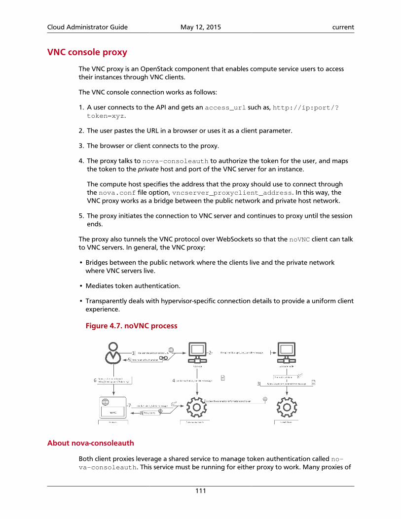
Cloud Administrator Guide May 12, 2015 current
111
VNC console proxy
The VNC proxy is an OpenStack component that enables compute service users to accesstheir instances through VNC clients.
The VNC console connection works as follows:
1. A user connects to the API and gets an access_url such as, http://ip:port/?token=xyz.
2. The user pastes the URL in a browser or uses it as a client parameter.
3. The browser or client connects to the proxy.
4. The proxy talks to nova-consoleauth to authorize the token for the user, and mapsthe token to the private host and port of the VNC server for an instance.
The compute host specifies the address that the proxy should use to connect throughthe nova.conf file option, vncserver_proxyclient_address. In this way, theVNC proxy works as a bridge between the public network and private host network.
5. The proxy initiates the connection to VNC server and continues to proxy until the sessionends.
The proxy also tunnels the VNC protocol over WebSockets so that the noVNC client can talkto VNC servers. In general, the VNC proxy:
• Bridges between the public network where the clients live and the private networkwhere VNC servers live.
• Mediates token authentication.
• Transparently deals with hypervisor-specific connection details to provide a uniform clientexperience.
Figure 4.7. noVNC process
About nova-consoleauth
Both client proxies leverage a shared service to manage token authentication called no-va-consoleauth. This service must be running for either proxy to work. Many proxies of
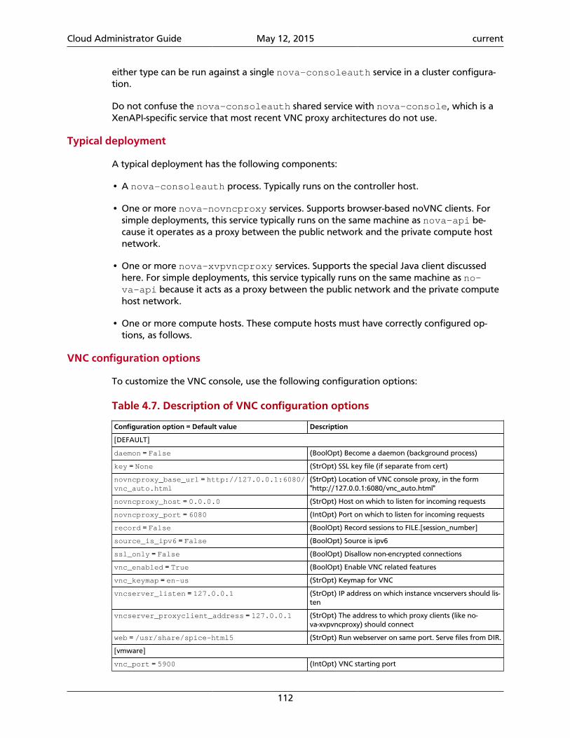
Cloud Administrator Guide May 12, 2015 current
112
either type can be run against a single nova-consoleauth service in a cluster configura-tion.
Do not confuse the nova-consoleauth shared service with nova-console, which is aXenAPI-specific service that most recent VNC proxy architectures do not use.
Typical deployment
A typical deployment has the following components:
• A nova-consoleauth process. Typically runs on the controller host.
• One or more nova-novncproxy services. Supports browser-based noVNC clients. Forsimple deployments, this service typically runs on the same machine as nova-api be-cause it operates as a proxy between the public network and the private compute hostnetwork.
• One or more nova-xvpvncproxy services. Supports the special Java client discussedhere. For simple deployments, this service typically runs on the same machine as no-va-api because it acts as a proxy between the public network and the private computehost network.
• One or more compute hosts. These compute hosts must have correctly configured op-tions, as follows.
VNC configuration options
To customize the VNC console, use the following configuration options:
Table 4.7. Description of VNC configuration options
Configuration option = Default value Description
[DEFAULT]
daemon = False (BoolOpt) Become a daemon (background process)
key = None (StrOpt) SSL key file (if separate from cert)
novncproxy_base_url = http://127.0.0.1:6080/vnc_auto.html
(StrOpt) Location of VNC console proxy, in the form"http://127.0.0.1:6080/vnc_auto.html"
novncproxy_host = 0.0.0.0 (StrOpt) Host on which to listen for incoming requests
novncproxy_port = 6080 (IntOpt) Port on which to listen for incoming requests
record = False (BoolOpt) Record sessions to FILE.[session_number]
source_is_ipv6 = False (BoolOpt) Source is ipv6
ssl_only = False (BoolOpt) Disallow non-encrypted connections
vnc_enabled = True (BoolOpt) Enable VNC related features
vnc_keymap = en-us (StrOpt) Keymap for VNC
vncserver_listen = 127.0.0.1 (StrOpt) IP address on which instance vncservers should lis-ten
vncserver_proxyclient_address = 127.0.0.1 (StrOpt) The address to which proxy clients (like no-va-xvpvncproxy) should connect
web = /usr/share/spice-html5 (StrOpt) Run webserver on same port. Serve files from DIR.
[vmware]
vnc_port = 5900 (IntOpt) VNC starting port
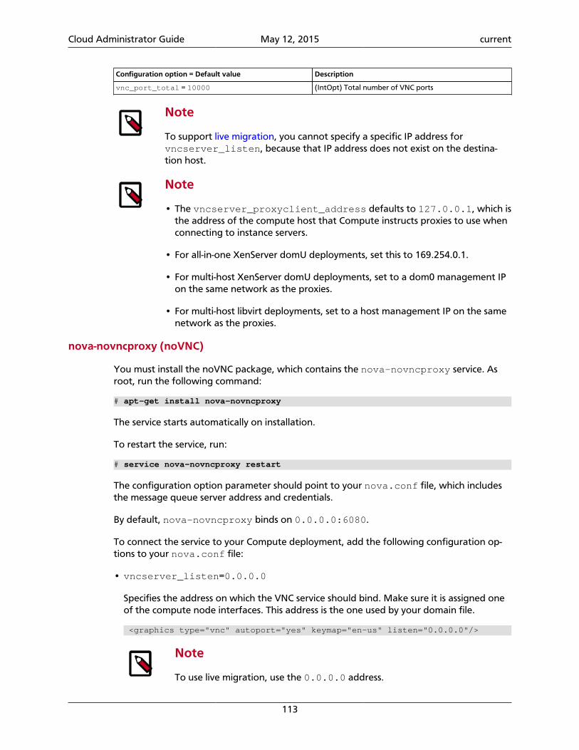
Cloud Administrator Guide May 12, 2015 current
113
Configuration option = Default value Description
vnc_port_total = 10000 (IntOpt) Total number of VNC ports
Note
To support live migration, you cannot specify a specific IP address forvncserver_listen, because that IP address does not exist on the destina-tion host.
Note
• The vncserver_proxyclient_address defaults to 127.0.0.1, which isthe address of the compute host that Compute instructs proxies to use whenconnecting to instance servers.
• For all-in-one XenServer domU deployments, set this to 169.254.0.1.
• For multi-host XenServer domU deployments, set to a dom0 management IPon the same network as the proxies.
• For multi-host libvirt deployments, set to a host management IP on the samenetwork as the proxies.
nova-novncproxy (noVNC)
You must install the noVNC package, which contains the nova-novncproxy service. Asroot, run the following command:
# apt-get install nova-novncproxy
The service starts automatically on installation.
To restart the service, run:
# service nova-novncproxy restart
The configuration option parameter should point to your nova.conf file, which includesthe message queue server address and credentials.
By default, nova-novncproxy binds on 0.0.0.0:6080.
To connect the service to your Compute deployment, add the following configuration op-tions to your nova.conf file:
• vncserver_listen=0.0.0.0
Specifies the address on which the VNC service should bind. Make sure it is assigned oneof the compute node interfaces. This address is the one used by your domain file.
<graphics type="vnc" autoport="yes" keymap="en-us" listen="0.0.0.0"/>
Note
To use live migration, use the 0.0.0.0 address.
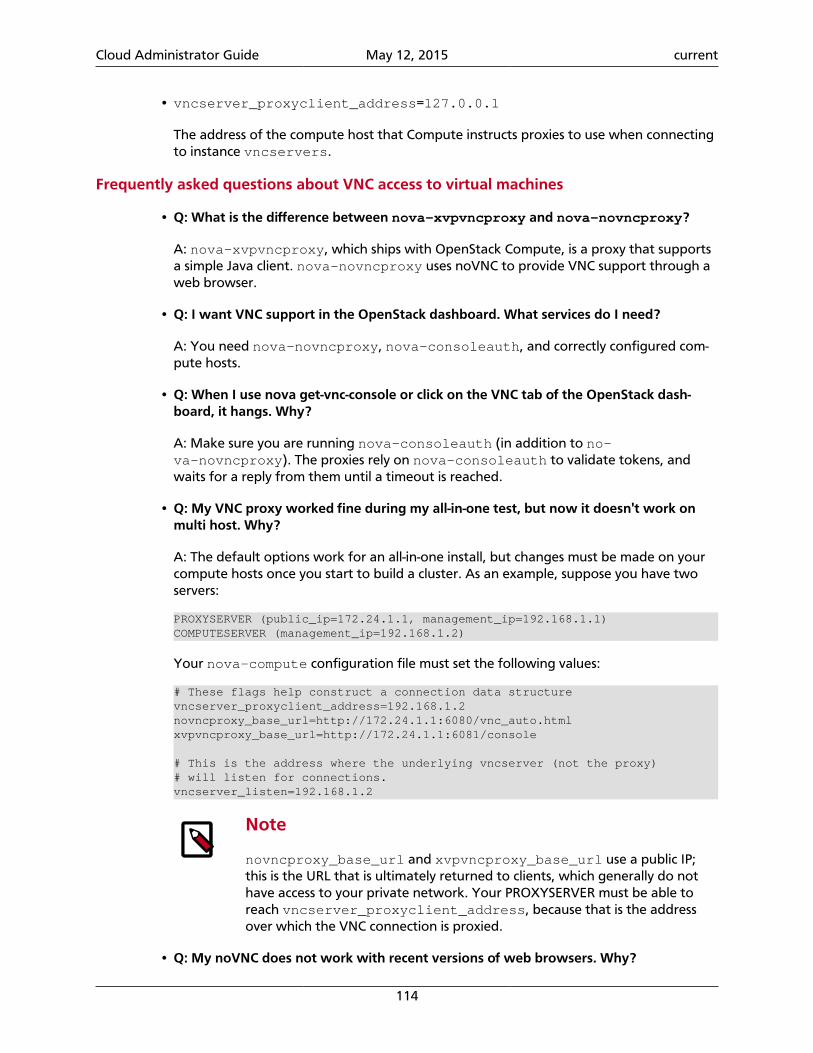
Cloud Administrator Guide May 12, 2015 current
114
• vncserver_proxyclient_address=127.0.0.1
The address of the compute host that Compute instructs proxies to use when connectingto instance vncservers.
Frequently asked questions about VNC access to virtual machines
• Q: What is the difference between nova-xvpvncproxy and nova-novncproxy?
A: nova-xvpvncproxy, which ships with OpenStack Compute, is a proxy that supportsa simple Java client. nova-novncproxy uses noVNC to provide VNC support through aweb browser.
• Q: I want VNC support in the OpenStack dashboard. What services do I need?
A: You need nova-novncproxy, nova-consoleauth, and correctly configured com-pute hosts.
• Q: When I use nova get-vnc-console or click on the VNC tab of the OpenStack dash-board, it hangs. Why?
A: Make sure you are running nova-consoleauth (in addition to no-va-novncproxy). The proxies rely on nova-consoleauth to validate tokens, andwaits for a reply from them until a timeout is reached.
• Q: My VNC proxy worked fine during my all-in-one test, but now it doesn't work onmulti host. Why?
A: The default options work for an all-in-one install, but changes must be made on yourcompute hosts once you start to build a cluster. As an example, suppose you have twoservers:
PROXYSERVER (public_ip=172.24.1.1, management_ip=192.168.1.1)COMPUTESERVER (management_ip=192.168.1.2)
Your nova-compute configuration file must set the following values:
# These flags help construct a connection data structurevncserver_proxyclient_address=192.168.1.2novncproxy_base_url=http://172.24.1.1:6080/vnc_auto.htmlxvpvncproxy_base_url=http://172.24.1.1:6081/console
# This is the address where the underlying vncserver (not the proxy)# will listen for connections.vncserver_listen=192.168.1.2
Note
novncproxy_base_url and xvpvncproxy_base_url use a public IP;this is the URL that is ultimately returned to clients, which generally do nothave access to your private network. Your PROXYSERVER must be able toreach vncserver_proxyclient_address, because that is the addressover which the VNC connection is proxied.
• Q: My noVNC does not work with recent versions of web browsers. Why?
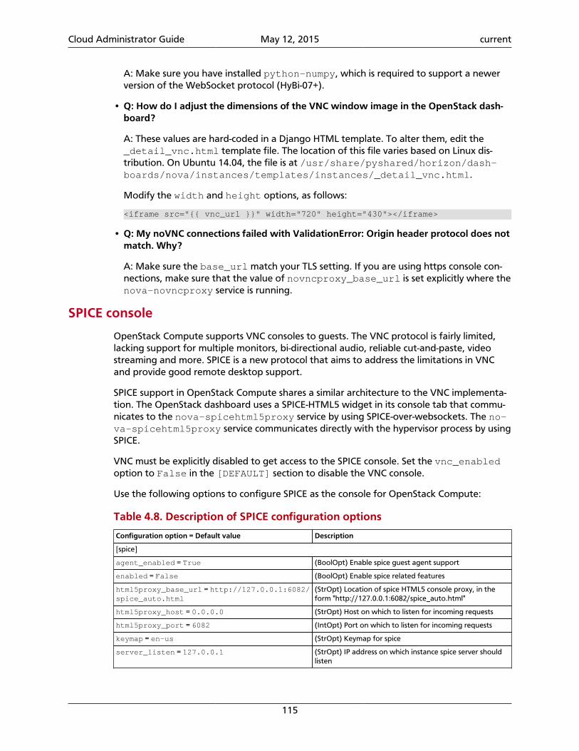
Cloud Administrator Guide May 12, 2015 current
115
A: Make sure you have installed python-numpy, which is required to support a newerversion of the WebSocket protocol (HyBi-07+).
• Q: How do I adjust the dimensions of the VNC window image in the OpenStack dash-board?
A: These values are hard-coded in a Django HTML template. To alter them, edit the_detail_vnc.html template file. The location of this file varies based on Linux dis-tribution. On Ubuntu 14.04, the file is at /usr/share/pyshared/horizon/dash-boards/nova/instances/templates/instances/_detail_vnc.html.
Modify the width and height options, as follows:
<iframe src="{{ vnc_url }}" width="720" height="430"></iframe>
• Q: My noVNC connections failed with ValidationError: Origin header protocol does notmatch. Why?
A: Make sure the base_url match your TLS setting. If you are using https console con-nections, make sure that the value of novncproxy_base_url is set explicitly where thenova-novncproxy service is running.
SPICE console
OpenStack Compute supports VNC consoles to guests. The VNC protocol is fairly limited,lacking support for multiple monitors, bi-directional audio, reliable cut-and-paste, videostreaming and more. SPICE is a new protocol that aims to address the limitations in VNCand provide good remote desktop support.
SPICE support in OpenStack Compute shares a similar architecture to the VNC implementa-tion. The OpenStack dashboard uses a SPICE-HTML5 widget in its console tab that commu-nicates to the nova-spicehtml5proxy service by using SPICE-over-websockets. The no-va-spicehtml5proxy service communicates directly with the hypervisor process by usingSPICE.
VNC must be explicitly disabled to get access to the SPICE console. Set the vnc_enabledoption to False in the [DEFAULT] section to disable the VNC console.
Use the following options to configure SPICE as the console for OpenStack Compute:
Table 4.8. Description of SPICE configuration options
Configuration option = Default value Description
[spice]
agent_enabled = True (BoolOpt) Enable spice guest agent support
enabled = False (BoolOpt) Enable spice related features
html5proxy_base_url = http://127.0.0.1:6082/spice_auto.html
(StrOpt) Location of spice HTML5 console proxy, in theform "http://127.0.0.1:6082/spice_auto.html"
html5proxy_host = 0.0.0.0 (StrOpt) Host on which to listen for incoming requests
html5proxy_port = 6082 (IntOpt) Port on which to listen for incoming requests
keymap = en-us (StrOpt) Keymap for spice
server_listen = 127.0.0.1 (StrOpt) IP address on which instance spice server shouldlisten
Cloud Administrator Guide May 12, 2015 current
116
Configuration option = Default value Description
server_proxyclient_address = 127.0.0.1 (StrOpt) The address to which proxy clients (like no-va-spicehtml5proxy) should connect
Configure Compute service groupsThe Compute service must know the status of each compute node to effectively manageand use them. This can include events like a user launching a new VM, the scheduler send-ing a request to a live node, or a query to the ServiceGroup API to determine if a node islive.
When a compute worker running the nova-compute daemon starts, it calls the join APIto join the compute group. Any service (such as the scheduler) can query the group's mem-bership and the status of its nodes. Internally, the ServiceGroup client driver automati-cally updates the compute worker status.
Database ServiceGroup driver
By default, Compute uses the database driver to track if a node is live. In a compute work-er, this driver periodically sends a db update command to the database, saying “I'm OK”with a timestamp. Compute uses a pre-defined timeout (service_down_time) to deter-mine if a node is dead.
The driver has limitations, which can be problematic depending on your environment. If alot of compute worker nodes need to be checked, the database can be put under heavyload, which can cause the timeout to trigger, and a live node could incorrectly be consid-ered dead. By default, the timeout is 60 seconds. Reducing the timeout value can help inthis situation, but you must also make the database update more frequently, which againincreases the database workload.
The database contains data that is both transient (such as whether the node is alive) andpersistent (such as entries for VM owners). With the ServiceGroup abstraction, Computecan treat each type separately.
ZooKeeper ServiceGroup driver
The ZooKeeper ServiceGroup driver works by using ZooKeeper ephemeral nodes. ZooKeep-er, unlike databases, is a distributed system, with its load divided among several servers.On a compute worker node, the driver can establish a ZooKeeper session, then create anephemeral znode in the group directory. Ephemeral znodes have the same lifespan as thesession. If the worker node or the nova-compute daemon crashes, or a network partitionis in place between the worker and the ZooKeeper server quorums, the ephemeral znodesare removed automatically. The driver can be given group membership by running the lscommand in the group directory.
The ZooKeeper driver requires the ZooKeeper servers and client libraries. Setting upZooKeeper servers is outside the scope of this guide (for more information, see ApacheZookeeper). These client-side Python libraries must be installed on every nova node:
python-zookeeper The official Zookeeper Python binding
evzookeeper This library makes the binding work with the eventlet threadingmodel.
Cloud Administrator Guide May 12, 2015 current
117
This example assumes the ZooKeeper server addresses and ports are 192.168.2.1:2181,192.168.2.2:2181, and 192.168.2.3:2181.
These values in the /etc/nova/nova.conf file are required on every node for theZooKeeper driver:
# Driver for the ServiceGroup serviceservicegroup_driver="zk"
[zookeeper]address="192.168.2.1:2181,192.168.2.2:2181,192.168.2.3:2181"
To customize the Compute Service groups, use these configuration option settings:
Table 4.9. Description of Zookeeper configuration options
Configuration option = Default value Description
[zookeeper]
address = None (StrOpt) The ZooKeeper addresses for servicegroup servicein the format of host1:port,host2:port,host3:port
recv_timeout = 4000 (IntOpt) The recv_timeout parameter for the zk session
sg_prefix = /servicegroups (StrOpt) The prefix used in ZooKeeper to store ephemeralnodes
sg_retry_interval = 5 (IntOpt) Number of seconds to wait until retrying to jointhe session
Memcache ServiceGroup driver
The memcache ServiceGroup driver uses memcached, a distributed memory object cachingsystem that is used to increase site performance. For more details, see memcached.org.
To use the memcache driver, you must install memcached. You might already have it in-stalled, as the same driver is also used for the OpenStack Object Storage and OpenStackdashboard. If you need to install memcached, see the instructions in the OpenStack Installa-tion Guide.
These values in the /etc/nova/nova.conf file are required on every node for the mem-cache driver:
# Driver for the ServiceGroup serviceservicegroup_driver="mc"
# Memcached servers. Use either a list of memcached servers to use for caching (list value),# or "<None>" for in-process caching (default).memcached_servers=<None>
# Timeout; maximum time since last check-in for up service (integer value).# Helps to define whether a node is deadservice_down_time=60
Security hardening
OpenStack Compute can be integrated with various third-party technologies to increase se-curity. For more information, see the OpenStack Security Guide.
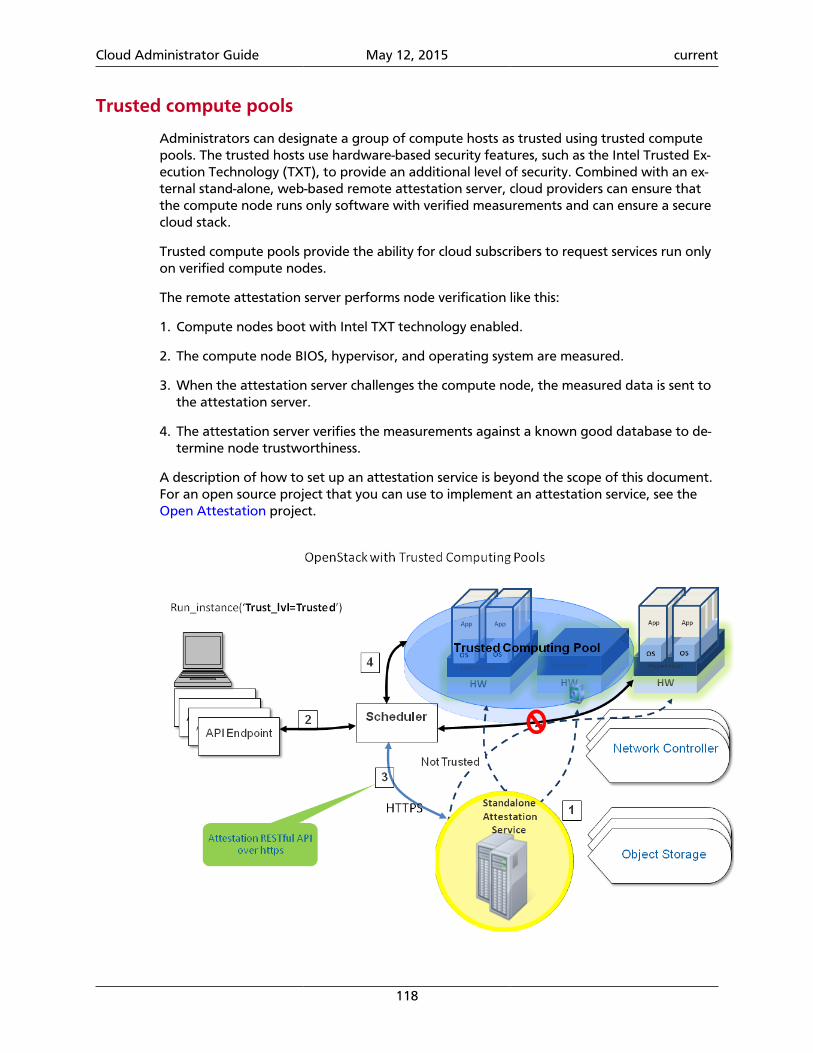
Cloud Administrator Guide May 12, 2015 current
118
Trusted compute pools
Administrators can designate a group of compute hosts as trusted using trusted computepools. The trusted hosts use hardware-based security features, such as the Intel Trusted Ex-ecution Technology (TXT), to provide an additional level of security. Combined with an ex-ternal stand-alone, web-based remote attestation server, cloud providers can ensure thatthe compute node runs only software with verified measurements and can ensure a securecloud stack.
Trusted compute pools provide the ability for cloud subscribers to request services run onlyon verified compute nodes.
The remote attestation server performs node verification like this:
1. Compute nodes boot with Intel TXT technology enabled.
2. The compute node BIOS, hypervisor, and operating system are measured.
3. When the attestation server challenges the compute node, the measured data is sent tothe attestation server.
4. The attestation server verifies the measurements against a known good database to de-termine node trustworthiness.
A description of how to set up an attestation service is beyond the scope of this document.For an open source project that you can use to implement an attestation service, see the Open Attestation project.
Cloud Administrator Guide May 12, 2015 current
119
Configuring Compute to use trusted compute pools
1. Enable scheduling support for trusted compute pools by adding these lines to the DE-FAULT section of the /etc/nova/nova.conf file:
[DEFAULT]compute_scheduler_driver=nova.scheduler.filter_scheduler.FilterSchedulerscheduler_available_filters=nova.scheduler.filters.all_filtersscheduler_default_filters=AvailabilityZoneFilter,RamFilter,ComputeFilter,TrustedFilter
2. Specify the connection information for your attestation service by adding these lines tothe trusted_computing section of the /etc/nova/nova.conf file:
[trusted_computing]attestation_server = 10.1.71.206attestation_port = 8443# If using OAT v2.0 after, use this port:# attestation_port = 8181attestation_server_ca_file = /etc/nova/ssl.10.1.71.206.crt# If using OAT v1.5, use this api_url:attestation_api_url = /AttestationService/resources# If using OAT pre-v1.5, use this api_url:# attestation_api_url = /OpenAttestationWebServices/V1.0attestation_auth_blob = i-am-openstack
In this example:
server Host name or IP address of the host that runs the attestation ser-vice
port HTTPS port for the attestation service
server_ca_file Certificate file used to verify the attestation server's identity
api_url The attestation service's URL path
auth_blob An authentication blob, required by the attestation service.
3. Save the file, and restart the nova-compute and nova-scheduler services to pickup the changes.
To customize the trusted compute pools, use these configuration option settings:
Table 4.10. Description of trusted computing configuration options
Configuration option = Default value Description
[trusted_computing]
attestation_api_url = /OpenAttestationWeb-Services/V1.0
(StrOpt) Attestation web API URL
attestation_auth_blob = None (StrOpt) Attestation authorization blob - must change
attestation_auth_timeout = 60 (IntOpt) Attestation status cache valid period length
attestation_insecure_ssl = False (BoolOpt) Disable SSL cert verification for Attestation ser-vice
attestation_port = 8443 (StrOpt) Attestation server port
attestation_server = None (StrOpt) Attestation server HTTP
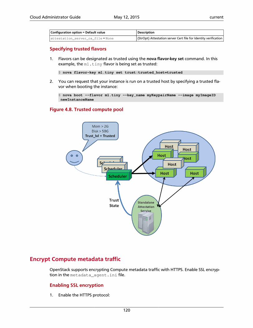
Cloud Administrator Guide May 12, 2015 current
120
Configuration option = Default value Description
attestation_server_ca_file = None (StrOpt) Attestation server Cert file for Identity verification
Specifying trusted flavors
1. Flavors can be designated as trusted using the nova flavor-key set command. In thisexample, the m1.tiny flavor is being set as trusted:
$ nova flavor-key m1.tiny set trust:trusted_host=trusted
2. You can request that your instance is run on a trusted host by specifying a trusted fla-vor when booting the instance:
$ nova boot --flavor m1.tiny --key_name myKeypairName --image myImageID newInstanceName
Figure 4.8. Trusted compute pool
Encrypt Compute metadata traffic
OpenStack supports encrypting Compute metadata traffic with HTTPS. Enable SSL encryp-tion in the metadata_agent.ini file.
Enabling SSL encryption
1. Enable the HTTPS protocol:
Cloud Administrator Guide May 12, 2015 current
121
nova_metadata_protocol = https
2. Determine whether insecure SSL connections are accepted for Compute metadata serv-er requests. The default value is False:
nova_metadata_insecure = False
3. Specify the path to the client certificate:
nova_client_cert = PATH_TO_CERT
4. Specify the path to the private key:
nova_client_priv_key = PATH_TO_KEY
Recover from a failed compute node
If Compute is deployed with a shared file system, and a node fails, there are several meth-ods to quickly recover from the failure. This section discusses manual recovery.
Evacuate instances
If a cloud compute node fails due to a hardware malfunction or another reason, you canevacuate instances to make them available again. You can optionally include the targethost on the evacuate command. If you omit the host, the scheduler determines the targethost.
To preserve user data on server disk, you must configure shared storage on the target host.Also, you must validate that the current VM host is down; otherwise, the evacuation failswith an error.
1. To list hosts and find a different host for the evacuated instance, run:
$ nova host-list
2. Evacuate the instance. You can pass the instance password to the command by usingthe --password <pwd> option. If you do not specify a password, one is generatedand printed after the command finishes successfully. The following command evacu-ates a server without shared storage from a host that is down to the specified host_b:
$ nova evacuate evacuated_server_name host_b
The instance is booted from a new disk, but preserves its configuration including its ID,name, uid, IP address, and so on. The command returns a password:
+-----------+--------------+| Property | Value |+-----------+--------------+| adminPass | kRAJpErnT4xZ |+-----------+--------------+
3. To preserve the user disk data on the evacuated server, deploy OpenStack Computewith a shared file system. To configure your system, see Configure migrations in Open-Stack Cloud Administrator Guide. In the following example, the password remains un-changed:
Cloud Administrator Guide May 12, 2015 current
122
$ nova evacuate evacuated_server_name host_b --on-shared-storage
Manual recovery
To recover a KVM or libvirt compute node, see the section called “Manual recov-ery” [122]. For all other hypervisors, use this procedure:
1. Identify the VMs on the affected hosts. To do this, you can use a combination of novalist and nova show or euca-describe-instances. For example, this command displays in-formation about instance i-000015b9 that is running on node np-rcc54:
$ euca-describe-instancesi-000015b9 at3-ui02 running nectarkey (376, np-rcc54) 0 m1.xxlarge 2012-06-19T00:48:11.000Z 115.146.93.60
2. Query the Compute database to check the status of the host. This example converts anEC2 API instance ID into an OpenStack ID. If you use the nova commands, you can sub-stitute the ID directly (the output in this example has been truncated):
mysql> SELECT * FROM instances WHERE id = CONV('15b9', 16, 10) \G;*************************** 1. row ***************************created_at: 2012-06-19 00:48:11updated_at: 2012-07-03 00:35:11deleted_at: NULL...id: 5561...power_state: 5vm_state: shutoff...hostname: at3-ui02host: np-rcc54...uuid: 3f57699a-e773-4650-a443-b4b37eed5a06...task_state: NULL...
Note
The credentials for your database can be found in /etc/nova.conf.
3. Decide which compute host the affected VM should be moved to, and run thisdatabase command to move the VM to the new host:
mysql> UPDATE instances SET host = 'np-rcc46' WHERE uuid = '3f57699a-e773-4650-a443-b4b37eed5a06';
4. If you are using a hypervisor that relies on libvirt (such as KVM), update thelibvirt.xml file (found in /var/lib/nova/instances/[instance ID]) withthese changes:
• Change the DHCPSERVER value to the host IP address of the new compute host.
• Update the VNC IP to 0.0.0.0.
5. Reboot the VM:
Cloud Administrator Guide May 12, 2015 current
123
$ nova reboot 3f57699a-e773-4650-a443-b4b37eed5a06
The database update and nova reboot command should be all that is required to recov-er a VM from a failed host. However, if you continue to have problems try recreating thenetwork filter configuration using virsh, restarting the Compute services, or updating thevm_state and power_state in the Compute database.
Recover from a UID/GID mismatch
In some cases, files on your compute node can end up using the wrong UID or GID. This canhappen when running OpenStack Compute, using a shared file system, or with an automat-ed configuration tool. This can cause a number of problems, such as inability to perform livemigrations, or start virtual machines.
This procedure runs on nova-compute hosts, based on the KVM hypervisor:
Recovering from a UID/GID mismatch
1. Set the nova UID in /etc/passwd to the same number on all hosts (for example,112).
Note
Make sure you choose UIDs or GIDs that are not in use for other users orgroups.
2. Set the libvirt-qemu UID in /etc/passwd to the same number on all hosts (for ex-ample, 119).
3. Set the nova group in /etc/group file to the same number on all hosts (for example,120).
4. Set the libvirtd group in /etc/group file to the same number on all hosts (for ex-ample, 119).
5. Stop the services on the compute node.
6. Change all the files owned by user or group nova. For example:
# find / -uid 108 -exec chown nova {} \; # note the 108 here is the old nova UID before the change# find / -gid 120 -exec chgrp nova {} \;
7. Repeat all steps for the libvirt-qemu files, if required.
8. Restart the services.
9. Run the find command to verify that all files use the correct identifiers.
Recover cloud after disaster
This section covers procedures for managing your cloud after a disaster, and backing uppersistent storage volumes. Backups are mandatory, even outside of disaster scenarios.
Cloud Administrator Guide May 12, 2015 current
124
For a definition of a disaster recovery plan (DRP), see http://en.wikipedia.org/wi-ki/Disaster_Recovery_Plan.
A disaster could happen to several components of your architecture (for example, a diskcrash, network loss, or a power failure). In this example, the following components are con-figured:
• A cloud controller (nova-api, nova-objectstore, nova-network)
• A compute node (nova-compute)
• A storage area network (SAN) used by OpenStack Block Storage (cinder-volumes)
The worst disaster for a cloud is power loss, which applies to all three components. Before apower loss:
• Create an active iSCSI session from the SAN to the cloud controller (used for the cin-der-volumes LVM's VG).
• Create an active iSCSI session from the cloud controller to the compute node (managedby cinder-volume).
• Create an iSCSI session for every volume (so 14 EBS volumes requires 14 iSCSI sessions).
• Create iptables or ebtables rules from the cloud controller to the compute node. This al-lows access from the cloud controller to the running instance.
• Save the current state of the database, the current state of the running instances, andthe attached volumes (mount point, volume ID, volume status, etc), at least from thecloud controller to the compute node.
After power is recovered and all hardware components have restarted:
• The iSCSI session from the SAN to the cloud no longer exists.
• The iSCSI session from the cloud controller to the compute node no longer exists.
• The iptables and ebtables from the cloud controller to the compute node are recreated.This is because nova-network reapplies configurations on boot.
• Instances are no longer running.
Note that instances will not be lost, because neither destroy nor terminate was invoked.The files for the instances will remain on the compute node.
• The database has not been updated.
Begin recovery
Warning
Do not add any extra steps to this procedure, or perform the steps out of order.
1. Check the current relationship between the volume and its instance, so that you canrecreate the attachment.
Cloud Administrator Guide May 12, 2015 current
125
This information can be found using the nova volume-list. Note that the nova client al-so includes the ability to get volume information from OpenStack Block Storage.
2. Update the database to clean the stalled state. Do this for every volume, using thesequeries:
mysql> use cinder;mysql> update volumes set mountpoint=NULL;mysql> update volumes set status="available" where status <>"error_deleting";mysql> update volumes set attach_status="detached";mysql> update volumes set instance_id=0;
Use nova volume-list commands to list all volumes.
3. Restart the instances using the nova reboot INSTANCE command.
Important
Some instances will completely reboot and become reachable, while somemight stop at the plymouth stage. This is expected behavior, DO NOT re-boot a second time.
Instance state at this stage depends on whether you added an /etc/fstab entry for that volume. Images built with the cloud-init packageremain in a pending state, while others skip the missing volume andstart. This step is performed in order to ask Compute to reboot every in-stance, so that the stored state is preserved. It does not matter if not all in-stances come up successfully. For more information about cloud-init, see help.ubuntu.com/community/CloudInit.
4. Reattach the volumes to their respective instances, if required, using the nova vol-ume-attach command. This example uses a file of listed volumes to reattach them:
#!/bin/bash
while read line; do volume=`echo $line | $CUT -f 1 -d " "` instance=`echo $line | $CUT -f 2 -d " "` mount_point=`echo $line | $CUT -f 3 -d " "` echo "ATTACHING VOLUME FOR INSTANCE - $instance" nova volume-attach $instance $volume $mount_point sleep 2done < $volumes_tmp_file
Instances that were stopped at the plymouth stage will now automatically continuebooting and start normally. Instances that previously started successfully will now beable to see the volume.
5. SSH into the instances and reboot them.
If some services depend on the volume, or if a volume has an entry in fstab, youshould now be able to restart the instance. Restart directly from the instance itself, notthrough nova:
# shutdown -r now
Cloud Administrator Guide May 12, 2015 current
126
When you are planning for and performing a disaster recovery, follow these tips:
• Use the errors=remount parameter in the fstab file to prevent data corruption.
This parameter will cause the system to disable the ability to write to the disk if it detectsan I/O error. This configuration option should be added into the cinder-volume server(the one which performs the iSCSI connection to the SAN), and into the instances' fstabfiles.
• Do not add the entry for the SAN's disks to the cinder-volume's fstab file.
Some systems hang on that step, which means you could lose access to your cloud-con-troller. To re-run the session manually, run this command before performing the mount:
# iscsiadm -m discovery -t st -p $SAN_IP $ iscsiadm -m node --target-name $IQN -p $SAN_IP -l
• On your instances, if you have the whole /home/ directory on the disk, leave a user's di-rectory with the user's bash files and the authorized_keys file (instead of emptyingthe /home directory and mapping the disk on it).
This allows you to connect to the instance even without the volume attached, if you al-low only connections through public keys.
If you want to script the disaster recovery plan (DRP), a bash script is available from https://github.com/Razique which performs the following steps:
1. An array is created for instances and their attached volumes.
2. The MySQL database is updated.
3. All instances are restarted with euca2ools.
4. The volumes are reattached.
5. An SSH connection is performed into every instance using Compute credentials.
The script includes a test mode, which allows you to perform that whole sequence for onlyone instance.
To reproduce the power loss, connect to the compute node which runs that instance andclose the iSCSI session. Do not detach the volume using the nova volume-detach command,manually close the iSCSI session. This example closes an iSCSI session with the number 15:
# iscsiadm -m session -u -r 15
Do not forget the -r flag. Otherwise, you will close all sessions.
Troubleshoot ComputeCommon problems for Compute typically involve misconfigured networking or credentialsthat are not sourced properly in the environment. Also, most flat networking configura-tions do not enable ping or ssh from a compute node to the instances that run on thatnode. Another common problem is trying to run 32-bit images on a 64-bit compute node.This section shows you how to troubleshoot Compute.
Cloud Administrator Guide May 12, 2015 current
127
Compute service logging
Compute stores a log file for each service in /var/log/nova. For example, no-va-compute.log is the log for the nova-compute service. You can set the following op-tions to format log strings for the nova.log module in the nova.conf file:
• logging_context_format_string
• logging_default_format_string
If the log level is set to debug, you can also specify logging_debug_format_suffixto append extra formatting. For information about what variables are available for the for-matter see: http://docs.python.org/library/logging.html#formatter.
You have two options for logging for OpenStack Compute based on configuration settings.In nova.conf, include the logfile option to enable logging. Alternatively you can setuse_syslog = 1 so that the nova daemon logs to syslog.
Guru Meditation reports
A Guru Meditation report is sent by the Compute Service upon receipt of the SIGUSR1signal. This report is a general-purpose error report, including a complete report of theservice's current state, and is sent to stderr.
For example, if you redirect error output to nova-api-err.log using nova-api 2>/var/log/nova/nova-api-err.log, resulting in the process ID 8675, you can then run:
# kill -USR1 8675
This command triggers the Guru Meditation report to be printed to /var/log/nova/no-va-api-err.log.
The report has the following sections:
• Package: Displays information about the package to which the process belongs, includingversion information.
• Threads: Displays stack traces and thread IDs for each of the threads within the process.
• Green Threads: Displays stack traces for each of the green threads within the process(green threads do not have thread IDs).
• Configuration: Lists all configuration options currently accessible through the CONF ob-ject for the current process.
For more information, see Guru Meditation Reports.
Common errors and fixes for Compute
The ask.openstack.org site offers a place to ask and answer questions, and you can alsomark questions as frequently asked questions. This section describes some errors peoplehave posted previously. Bugs are constantly being fixed, so online resources are a great wayto get the most up-to-date errors and fixes.
Cloud Administrator Guide May 12, 2015 current
128
Credential errors, 401, and 403 forbidden errors
Missing credentials cause a 403 forbidden error. To resolve this issue, use one of thesemethods:
1. Manual method. Get get the novarc file from the project ZIP file, save existing creden-tials in case of override. and manually source the novarc file.
2. Script method. Generates novarc from the project ZIP file and sources it for you.
When you run nova-api the first time, it generates the certificate authority information,including openssl.cnf. If you start the CA services before this, you might not be able tocreate your ZIP file. Restart the services. When your CA information is available, create yourZIP file.
Also, check your HTTP proxy settings to see whether they cause problems with novarc cre-ation.
Instance errors
Sometimes a particular instance shows pending or you cannot SSH to it. Sometimes theimage itself is the problem. For example, when you use flat manager networking, you donot have a DHCP server and certain images do not support interface injection; you cannotconnect to them. The fix for this problem is to use an image that does support this method,such as Ubuntu, which obtains an IP address correctly with FlatManager network settings.
To troubleshoot other possible problems with an instance, such as an instance that staysin a spawning state, check the directory for the particular instance under /var/lib/no-va/instances on the nova-compute host and make sure that these files are present:
• libvirt.xml
• disk
• disk-raw
• kernel
• ramdisk
• After the instance starts, console.log
If any files are missing, empty, or very small, the nova-compute service did not successfullydownload the images from the Image Service.
Also check nova-compute.log for exceptions. Sometimes they do not appear in the con-sole output.
Next, check the log file for the instance in the /var/log/libvirt/qemu directory to seeif it exists and has any useful error messages in it.
Finally, from the /var/lib/nova/instances directory for the instance, see if this com-mand returns an error:
Cloud Administrator Guide May 12, 2015 current
129
# virsh create libvirt.xml
Empty log output for Linux instances
You can view the log output of running instances from either the Log tab of the dashboardor the output of nova console-log. In some cases, the log output of a running Linux in-stance will be empty or only display a single character (for example, the ? character).
This occurs when the Compute service attempts to retrieve the log output of the instancevia a serial console while the instance itself is not configured to send output to the con-sole. To rectify this, append the following parameters to kernel arguments specified in theinstance's boot loader:
console=tty0 console=ttyS0,115200n8
Upon rebooting, the instance will be configured to send output to the Compute service.
Reset the state of an instance
If an instance remains in an intermediate state, such as deleting, you can use the novareset-state command to manually reset the state of an instance to an error state. You canthen delete the instance. For example:
$ nova reset-state c6bbbf26-b40a-47e7-8d5c-eb17bf65c485$ nova delete c6bbbf26-b40a-47e7-8d5c-eb17bf65c485
You can also use the --active parameter to force the instance back to an active state in-stead of an error state. For example:
$ nova reset-state --active c6bbbf26-b40a-47e7-8d5c-eb17bf65c485
Injection problems
If instances do not boot or boot slowly, investigate file injection as a cause.
To disable injection in libvirt, set the following in nova.conf:
[libvirt]inject_partition = -2
Note
If you have not enabled the configuration drive and you want to make us-er-specified files available from the metadata server for to improve perfor-mance and avoid boot failure if injection fails, you must disable injection.
Disable live snapshotting
If you use libvirt version 1.2.2, you may experience problems with live snapshots creation.Occasionally, libvirt of the specified version fails to perform the live snapshotting underload that presupposes a concurrent creation of multiple snapshots.
To effectively disable the libvirt live snapshotting, until the problem is resolved, config-ure the disable_libvirt_livesnapshot option. You can turn off the live snapshot-

Cloud Administrator Guide May 12, 2015 current
130
ting mechanism by setting up its value to True in the [workarounds] section of thenova.conf configuration file:
[workarounds]disable_libvirt_livesnapshot = True
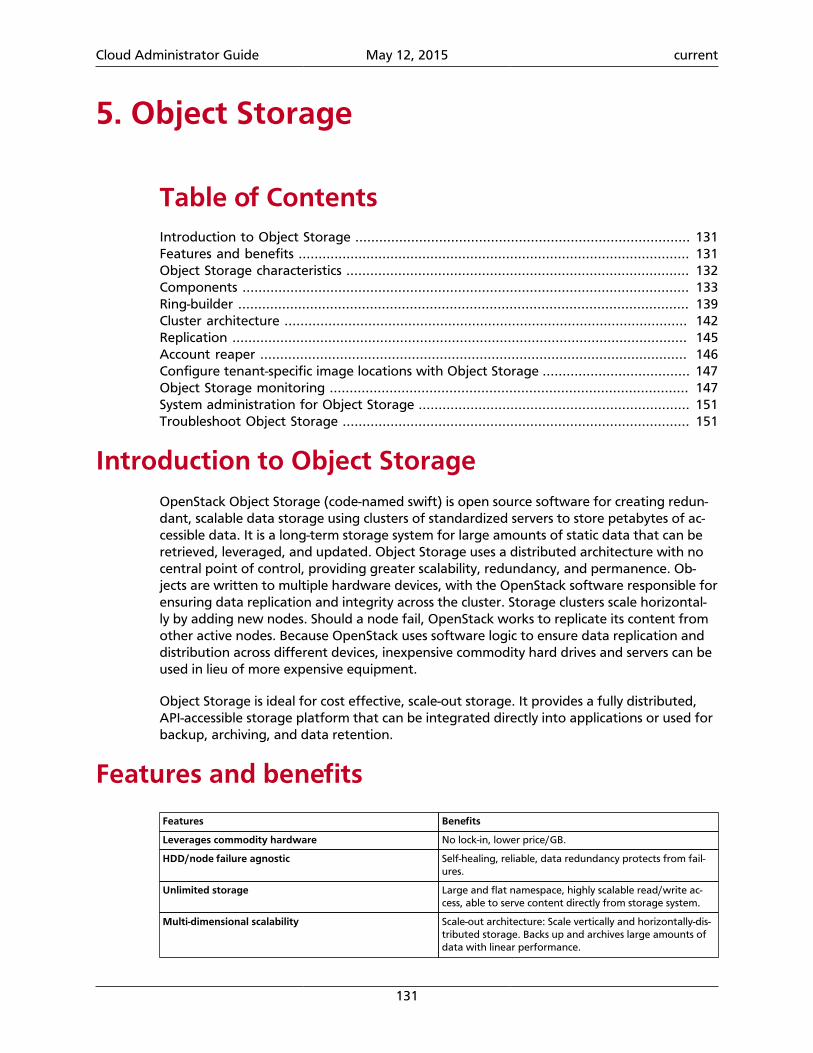
Cloud Administrator Guide May 12, 2015 current
131
5. Object Storage
Table of ContentsIntroduction to Object Storage .................................................................................... 131Features and benefits .................................................................................................. 131Object Storage characteristics ...................................................................................... 132Components ................................................................................................................ 133Ring-builder ................................................................................................................. 139Cluster architecture ..................................................................................................... 142Replication .................................................................................................................. 145Account reaper ........................................................................................................... 146Configure tenant-specific image locations with Object Storage ..................................... 147Object Storage monitoring .......................................................................................... 147System administration for Object Storage .................................................................... 151Troubleshoot Object Storage ....................................................................................... 151
Introduction to Object StorageOpenStack Object Storage (code-named swift) is open source software for creating redun-dant, scalable data storage using clusters of standardized servers to store petabytes of ac-cessible data. It is a long-term storage system for large amounts of static data that can beretrieved, leveraged, and updated. Object Storage uses a distributed architecture with nocentral point of control, providing greater scalability, redundancy, and permanence. Ob-jects are written to multiple hardware devices, with the OpenStack software responsible forensuring data replication and integrity across the cluster. Storage clusters scale horizontal-ly by adding new nodes. Should a node fail, OpenStack works to replicate its content fromother active nodes. Because OpenStack uses software logic to ensure data replication anddistribution across different devices, inexpensive commodity hard drives and servers can beused in lieu of more expensive equipment.
Object Storage is ideal for cost effective, scale-out storage. It provides a fully distributed,API-accessible storage platform that can be integrated directly into applications or used forbackup, archiving, and data retention.
Features and benefits
Features Benefits
Leverages commodity hardware No lock-in, lower price/GB.
HDD/node failure agnostic Self-healing, reliable, data redundancy protects from fail-ures.
Unlimited storage Large and flat namespace, highly scalable read/write ac-cess, able to serve content directly from storage system.
Multi-dimensional scalability Scale-out architecture: Scale vertically and horizontally-dis-tributed storage. Backs up and archives large amounts ofdata with linear performance.
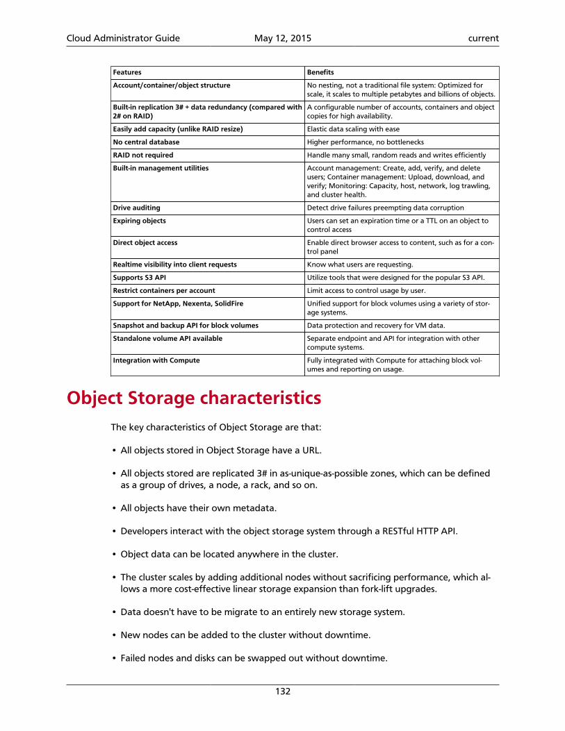
Cloud Administrator Guide May 12, 2015 current
132
Features Benefits
Account/container/object structure No nesting, not a traditional file system: Optimized forscale, it scales to multiple petabytes and billions of objects.
Built-in replication 3✕ + data redundancy (compared with2✕ on RAID)
A configurable number of accounts, containers and objectcopies for high availability.
Easily add capacity (unlike RAID resize) Elastic data scaling with ease
No central database Higher performance, no bottlenecks
RAID not required Handle many small, random reads and writes efficiently
Built-in management utilities Account management: Create, add, verify, and deleteusers; Container management: Upload, download, andverify; Monitoring: Capacity, host, network, log trawling,and cluster health.
Drive auditing Detect drive failures preempting data corruption
Expiring objects Users can set an expiration time or a TTL on an object tocontrol access
Direct object access Enable direct browser access to content, such as for a con-trol panel
Realtime visibility into client requests Know what users are requesting.
Supports S3 API Utilize tools that were designed for the popular S3 API.
Restrict containers per account Limit access to control usage by user.
Support for NetApp, Nexenta, SolidFire Unified support for block volumes using a variety of stor-age systems.
Snapshot and backup API for block volumes Data protection and recovery for VM data.
Standalone volume API available Separate endpoint and API for integration with othercompute systems.
Integration with Compute Fully integrated with Compute for attaching block vol-umes and reporting on usage.
Object Storage characteristicsThe key characteristics of Object Storage are that:
• All objects stored in Object Storage have a URL.
• All objects stored are replicated 3# in as-unique-as-possible zones, which can be definedas a group of drives, a node, a rack, and so on.
• All objects have their own metadata.
• Developers interact with the object storage system through a RESTful HTTP API.
• Object data can be located anywhere in the cluster.
• The cluster scales by adding additional nodes without sacrificing performance, which al-lows a more cost-effective linear storage expansion than fork-lift upgrades.
• Data doesn't have to be migrate to an entirely new storage system.
• New nodes can be added to the cluster without downtime.
• Failed nodes and disks can be swapped out without downtime.
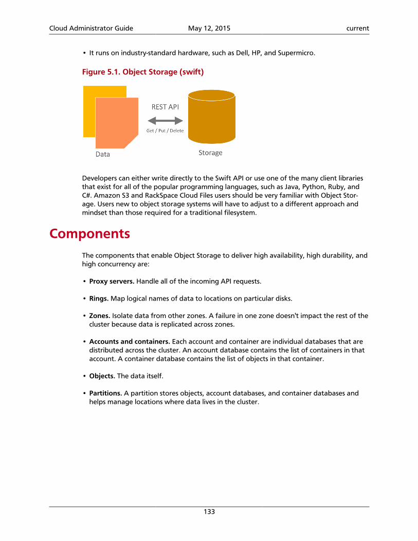
Cloud Administrator Guide May 12, 2015 current
133
• It runs on industry-standard hardware, such as Dell, HP, and Supermicro.
Figure 5.1. Object Storage (swift)
Developers can either write directly to the Swift API or use one of the many client librariesthat exist for all of the popular programming languages, such as Java, Python, Ruby, andC#. Amazon S3 and RackSpace Cloud Files users should be very familiar with Object Stor-age. Users new to object storage systems will have to adjust to a different approach andmindset than those required for a traditional filesystem.
ComponentsThe components that enable Object Storage to deliver high availability, high durability, andhigh concurrency are:
• Proxy servers. Handle all of the incoming API requests.
• Rings. Map logical names of data to locations on particular disks.
• Zones. Isolate data from other zones. A failure in one zone doesn't impact the rest of thecluster because data is replicated across zones.
• Accounts and containers. Each account and container are individual databases that aredistributed across the cluster. An account database contains the list of containers in thataccount. A container database contains the list of objects in that container.
• Objects. The data itself.
• Partitions. A partition stores objects, account databases, and container databases andhelps manage locations where data lives in the cluster.
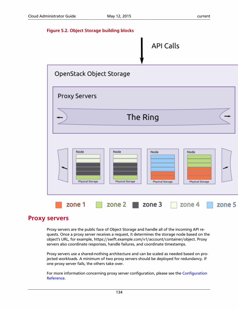
Cloud Administrator Guide May 12, 2015 current
134
Figure 5.2. Object Storage building blocks
Proxy servers
Proxy servers are the public face of Object Storage and handle all of the incoming API re-quests. Once a proxy server receives a request, it determines the storage node based on theobject's URL, for example, https://swift.example.com/v1/account/container/object. Proxyservers also coordinate responses, handle failures, and coordinate timestamps.
Proxy servers use a shared-nothing architecture and can be scaled as needed based on pro-jected workloads. A minimum of two proxy servers should be deployed for redundancy. Ifone proxy server fails, the others take over.
For more information concerning proxy server configuration, please see the ConfigurationReference.
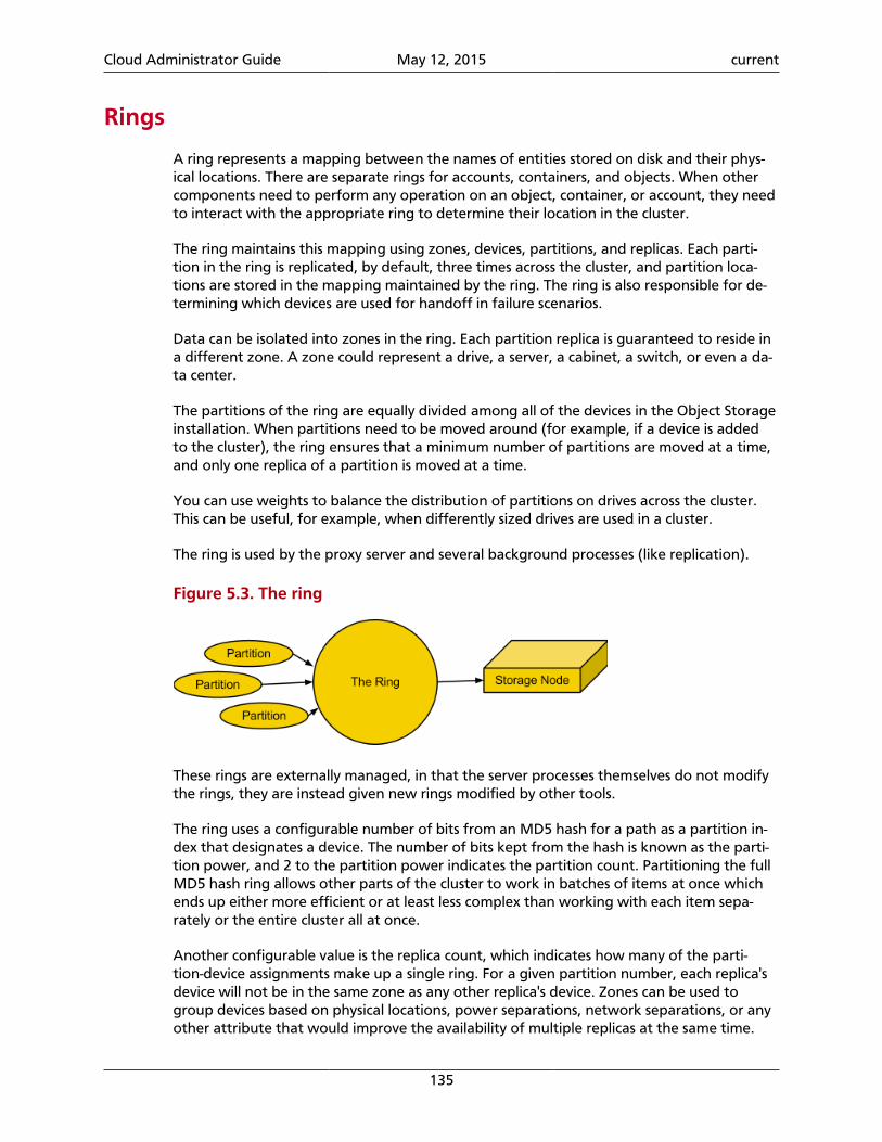
Cloud Administrator Guide May 12, 2015 current
135
Rings
A ring represents a mapping between the names of entities stored on disk and their phys-ical locations. There are separate rings for accounts, containers, and objects. When othercomponents need to perform any operation on an object, container, or account, they needto interact with the appropriate ring to determine their location in the cluster.
The ring maintains this mapping using zones, devices, partitions, and replicas. Each parti-tion in the ring is replicated, by default, three times across the cluster, and partition loca-tions are stored in the mapping maintained by the ring. The ring is also responsible for de-termining which devices are used for handoff in failure scenarios.
Data can be isolated into zones in the ring. Each partition replica is guaranteed to reside ina different zone. A zone could represent a drive, a server, a cabinet, a switch, or even a da-ta center.
The partitions of the ring are equally divided among all of the devices in the Object Storageinstallation. When partitions need to be moved around (for example, if a device is addedto the cluster), the ring ensures that a minimum number of partitions are moved at a time,and only one replica of a partition is moved at a time.
You can use weights to balance the distribution of partitions on drives across the cluster.This can be useful, for example, when differently sized drives are used in a cluster.
The ring is used by the proxy server and several background processes (like replication).
Figure 5.3. The ring
These rings are externally managed, in that the server processes themselves do not modifythe rings, they are instead given new rings modified by other tools.
The ring uses a configurable number of bits from an MD5 hash for a path as a partition in-dex that designates a device. The number of bits kept from the hash is known as the parti-tion power, and 2 to the partition power indicates the partition count. Partitioning the fullMD5 hash ring allows other parts of the cluster to work in batches of items at once whichends up either more efficient or at least less complex than working with each item sepa-rately or the entire cluster all at once.
Another configurable value is the replica count, which indicates how many of the parti-tion-device assignments make up a single ring. For a given partition number, each replica'sdevice will not be in the same zone as any other replica's device. Zones can be used togroup devices based on physical locations, power separations, network separations, or anyother attribute that would improve the availability of multiple replicas at the same time.
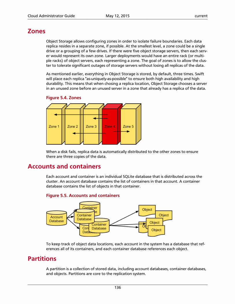
Cloud Administrator Guide May 12, 2015 current
136
ZonesObject Storage allows configuring zones in order to isolate failure boundaries. Each datareplica resides in a separate zone, if possible. At the smallest level, a zone could be a singledrive or a grouping of a few drives. If there were five object storage servers, then each serv-er would represent its own zone. Larger deployments would have an entire rack (or multi-ple racks) of object servers, each representing a zone. The goal of zones is to allow the clus-ter to tolerate significant outages of storage servers without losing all replicas of the data.
As mentioned earlier, everything in Object Storage is stored, by default, three times. Swiftwill place each replica "as-uniquely-as-possible" to ensure both high availability and highdurability. This means that when chosing a replica location, Object Storage chooses a serverin an unused zone before an unused server in a zone that already has a replica of the data.
Figure 5.4. Zones
When a disk fails, replica data is automatically distributed to the other zones to ensurethere are three copies of the data.
Accounts and containersEach account and container is an individual SQLite database that is distributed across thecluster. An account database contains the list of containers in that account. A containerdatabase contains the list of objects in that container.
Figure 5.5. Accounts and containers
To keep track of object data locations, each account in the system has a database that ref-erences all of its containers, and each container database references each object.
PartitionsA partition is a collection of stored data, including account databases, container databases,and objects. Partitions are core to the replication system.
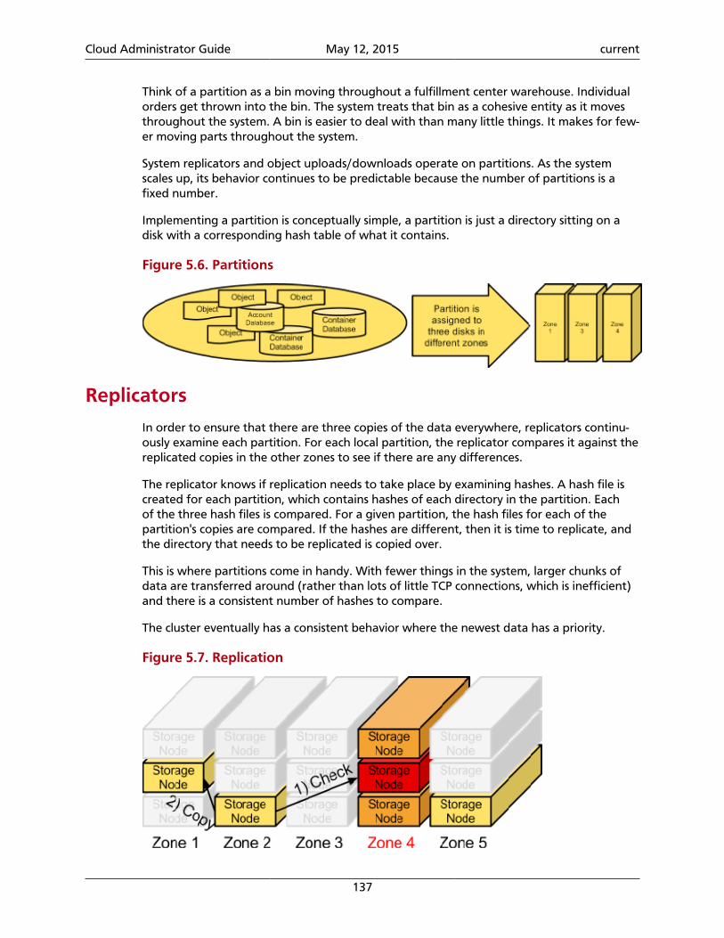
Cloud Administrator Guide May 12, 2015 current
137
Think of a partition as a bin moving throughout a fulfillment center warehouse. Individualorders get thrown into the bin. The system treats that bin as a cohesive entity as it movesthroughout the system. A bin is easier to deal with than many little things. It makes for few-er moving parts throughout the system.
System replicators and object uploads/downloads operate on partitions. As the systemscales up, its behavior continues to be predictable because the number of partitions is afixed number.
Implementing a partition is conceptually simple, a partition is just a directory sitting on adisk with a corresponding hash table of what it contains.
Figure 5.6. Partitions
Replicators
In order to ensure that there are three copies of the data everywhere, replicators continu-ously examine each partition. For each local partition, the replicator compares it against thereplicated copies in the other zones to see if there are any differences.
The replicator knows if replication needs to take place by examining hashes. A hash file iscreated for each partition, which contains hashes of each directory in the partition. Eachof the three hash files is compared. For a given partition, the hash files for each of thepartition's copies are compared. If the hashes are different, then it is time to replicate, andthe directory that needs to be replicated is copied over.
This is where partitions come in handy. With fewer things in the system, larger chunks ofdata are transferred around (rather than lots of little TCP connections, which is inefficient)and there is a consistent number of hashes to compare.
The cluster eventually has a consistent behavior where the newest data has a priority.
Figure 5.7. Replication
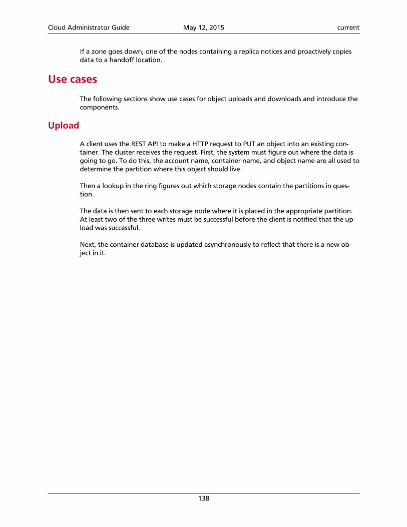
Cloud Administrator Guide May 12, 2015 current
138
If a zone goes down, one of the nodes containing a replica notices and proactively copiesdata to a handoff location.
Use cases
The following sections show use cases for object uploads and downloads and introduce thecomponents.
Upload
A client uses the REST API to make a HTTP request to PUT an object into an existing con-tainer. The cluster receives the request. First, the system must figure out where the data isgoing to go. To do this, the account name, container name, and object name are all used todetermine the partition where this object should live.
Then a lookup in the ring figures out which storage nodes contain the partitions in ques-tion.
The data is then sent to each storage node where it is placed in the appropriate partition.At least two of the three writes must be successful before the client is notified that the up-load was successful.
Next, the container database is updated asynchronously to reflect that there is a new ob-ject in it.
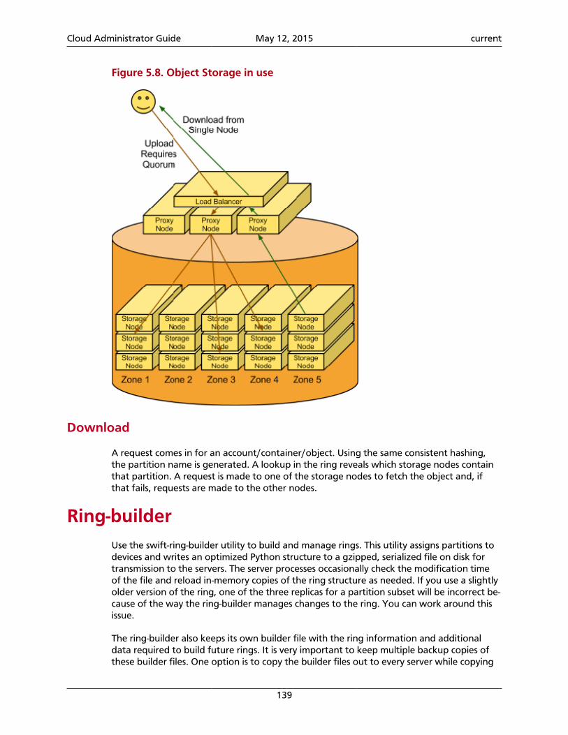
Cloud Administrator Guide May 12, 2015 current
139
Figure 5.8. Object Storage in use
Download
A request comes in for an account/container/object. Using the same consistent hashing,the partition name is generated. A lookup in the ring reveals which storage nodes containthat partition. A request is made to one of the storage nodes to fetch the object and, ifthat fails, requests are made to the other nodes.
Ring-builderUse the swift-ring-builder utility to build and manage rings. This utility assigns partitions todevices and writes an optimized Python structure to a gzipped, serialized file on disk fortransmission to the servers. The server processes occasionally check the modification timeof the file and reload in-memory copies of the ring structure as needed. If you use a slightlyolder version of the ring, one of the three replicas for a partition subset will be incorrect be-cause of the way the ring-builder manages changes to the ring. You can work around thisissue.
The ring-builder also keeps its own builder file with the ring information and additionaldata required to build future rings. It is very important to keep multiple backup copies ofthese builder files. One option is to copy the builder files out to every server while copying
Cloud Administrator Guide May 12, 2015 current
140
the ring files themselves. Another is to upload the builder files into the cluster itself. If youlose the builder file, you have to create a new ring from scratch. Nearly all partitions wouldbe assigned to different devices and, therefore, nearly all of the stored data would haveto be replicated to new locations. So, recovery from a builder file loss is possible, but datawould be unreachable for an extended time.
Ring data structure
The ring data structure consists of three top level fields: a list of devices in the cluster, a listof lists of device ids indicating partition to device assignments, and an integer indicating thenumber of bits to shift an MD5 hash to calculate the partition for the hash.
Partition assignment list
This is a list of array('H') of devices ids. The outermost list contains an array('H') foreach replica. Each array('H') has a length equal to the partition count for the ring. Eachinteger in the array('H') is an index into the above list of devices. The partition list isknown internally to the Ring class as _replica2part2dev_id.
So, to create a list of device dictionaries assigned to a partition, the Python code wouldlook like:
devices = [self.devs[part2dev_id[partition]] forpart2dev_id in self._replica2part2dev_id]
That code is a little simplistic because it does not account for the removal of duplicate de-vices. If a ring has more replicas than devices, a partition will have more than one replica ona device.
array('H') is used for memory conservation as there may be millions of partitions.
Replica counts
To support the gradual change in replica counts, a ring can have a real number of replicasand is not restricted to an integer number of replicas.
A fractional replica count is for the whole ring and not for individual partitions. It indi-cates the average number of replicas for each partition. For example, a replica count of 3.2means that 20 percent of partitions have four replicas and 80 percent have three replicas.
The replica count is adjustable.
Example:
$ swift-ring-builder account.builder set_replicas 4$ swift-ring-builder account.builder rebalance
You must rebalance the replica ring in globally distributed clusters. Operators of these clus-ters generally want an equal number of replicas and regions. Therefore, when an opera-tor adds or removes a region, the operator adds or removes a replica. Removing unneededreplicas saves on the cost of disks.
Cloud Administrator Guide May 12, 2015 current
141
You can gradually increase the replica count at a rate that does not adversely affect clusterperformance.
For example:
$ swift-ring-builder object.builder set_replicas 3.01$ swift-ring-builder object.builder rebalance<distribute rings and wait>...
$ swift-ring-builder object.builder set_replicas 3.02$ swift-ring-builder object.builder rebalance<creatdistribute rings and wait>...
Changes take effect after the ring is rebalanced. Therefore, if you intend to change from 3replicas to 3.01 but you accidentally type 2.01, no data is lost.
Additionally, swift-ring-builder X.builder create can now take a decimal argument forthe number of replicas.
Partition shift value
The partition shift value is known internally to the Ring class as _part_shift. This valueis used to shift an MD5 hash to calculate the partition where the data for that hash shouldreside. Only the top four bytes of the hash is used in this process. For example, to computethe partition for the /account/container/object path, the Python code might looklike the following code:
partition = unpack_from('>I',md5('/account/container/object').digest())[0] >>self._part_shift
For a ring generated with part_power P, the partition shift value is 32 - P.
Build the ring
The ring builder process includes these high-level steps:
1. The utility calculates the number of partitions to assign to each device based on theweight of the device. For example, for a partition at the power of 20, the ring has1,048,576 partitions. One thousand devices of equal weight each want 1,048.576 parti-tions. The devices are sorted by the number of partitions they desire and kept in orderthroughout the initialization process.
Note
Each device is also assigned a random tiebreaker value that is used when twodevices desire the same number of partitions. This tiebreaker is not storedon disk anywhere, and so two different rings created with the same param-eters will have different partition assignments. For repeatable partition as-signments, RingBuilder.rebalance() takes an optional seed value thatseeds the Python pseudo-random number generator.
2. The ring builder assigns each partition replica to the device that requires most parti-tions at that point while keeping it as far away as possible from other replicas. The ring
Cloud Administrator Guide May 12, 2015 current
142
builder prefers to assign a replica to a device in a region that does not already have areplica. If no such region is available, the ring builder searches for a device in a differentzone, or on a different server. If it does not find one, it looks for a device with no repli-cas. Finally, if all options are exhausted, the ring builder assigns the replica to the devicethat has the fewest replicas already assigned.
Note
The ring builder assigns multiple replicas to one device only if the ring hasfewer devices than it has replicas.
3. When building a new ring from an old ring, the ring builder recalculates the desirednumber of partitions that each device wants.
4. The ring builder unassigns partitions and gathers these partitions for reassignment, asfollows:
• The ring builder unassigns any assigned partitions from any removed devices and addsthese partitions to the gathered list.
• The ring builder unassigns any partition replicas that can be spread out for betterdurability and adds these partitions to the gathered list.
• The ring builder unassigns random partitions from any devices that have more parti-tions than they need and adds these partitions to the gathered list.
5. The ring builder reassigns the gathered partitions to devices by using a similar method tothe one described previously.
6. When the ring builder reassigns a replica to a partition, the ring builder records the timeof the reassignment. The ring builder uses this value when it gathers partitions for reas-signment so that no partition is moved twice in a configurable amount of time. The Ring-Builder class knows this configurable amount of time as min_part_hours. The ringbuilder ignores this restriction for replicas of partitions on removed devices because re-moval of a device happens on device failure only, and reassignment is the only choice.
Theses steps do not always perfectly rebalance a ring due to the random nature of gather-ing partitions for reassignment. To help reach a more balanced ring, the rebalance processis repeated until near perfect (less than 1 percent off) or when the balance does not im-prove by at least 1 percent (indicating we probably cannot get perfect balance due to wild-ly imbalanced zones or too many partitions recently moved).
Cluster architecture
Access tier
Large-scale deployments segment off an access tier, which is considered the Object Stor-age system's central hub. The access tier fields the incoming API requests from clients andmoves data in and out of the system. This tier consists of front-end load balancers, ssl-termi-nators, and authentication services. It runs the (distributed) brain of the Object Storage sys-tem: the proxy server processes.
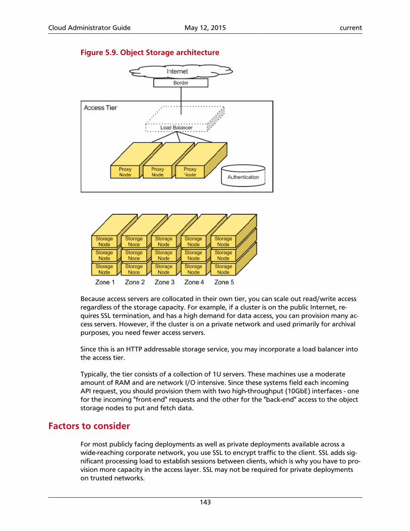
Cloud Administrator Guide May 12, 2015 current
143
Figure 5.9. Object Storage architecture
Because access servers are collocated in their own tier, you can scale out read/write accessregardless of the storage capacity. For example, if a cluster is on the public Internet, re-quires SSL termination, and has a high demand for data access, you can provision many ac-cess servers. However, if the cluster is on a private network and used primarily for archivalpurposes, you need fewer access servers.
Since this is an HTTP addressable storage service, you may incorporate a load balancer intothe access tier.
Typically, the tier consists of a collection of 1U servers. These machines use a moderateamount of RAM and are network I/O intensive. Since these systems field each incomingAPI request, you should provision them with two high-throughput (10GbE) interfaces - onefor the incoming "front-end" requests and the other for the "back-end" access to the objectstorage nodes to put and fetch data.
Factors to consider
For most publicly facing deployments as well as private deployments available across awide-reaching corporate network, you use SSL to encrypt traffic to the client. SSL adds sig-nificant processing load to establish sessions between clients, which is why you have to pro-vision more capacity in the access layer. SSL may not be required for private deploymentson trusted networks.
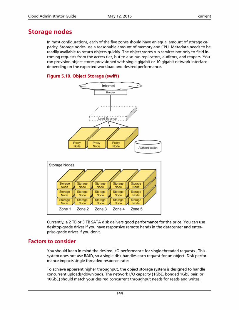
Cloud Administrator Guide May 12, 2015 current
144
Storage nodesIn most configurations, each of the five zones should have an equal amount of storage ca-pacity. Storage nodes use a reasonable amount of memory and CPU. Metadata needs to bereadily available to return objects quickly. The object stores run services not only to field in-coming requests from the access tier, but to also run replicators, auditors, and reapers. Youcan provision object stores provisioned with single gigabit or 10 gigabit network interfacedepending on the expected workload and desired performance.
Figure 5.10. Object Storage (swift)
Currently, a 2 TB or 3 TB SATA disk delivers good performance for the price. You can usedesktop-grade drives if you have responsive remote hands in the datacenter and enter-prise-grade drives if you don't.
Factors to consider
You should keep in mind the desired I/O performance for single-threaded requests . Thissystem does not use RAID, so a single disk handles each request for an object. Disk perfor-mance impacts single-threaded response rates.
To achieve apparent higher throughput, the object storage system is designed to handleconcurrent uploads/downloads. The network I/O capacity (1GbE, bonded 1GbE pair, or10GbE) should match your desired concurrent throughput needs for reads and writes.
Cloud Administrator Guide May 12, 2015 current
145
ReplicationBecause each replica in Object Storage functions independently and clients generally re-quire only a simple majority of nodes to respond to consider an operation successful, tran-sient failures like network partitions can quickly cause replicas to diverge. These differencesare eventually reconciled by asynchronous, peer-to-peer replicator processes. The replicatorprocesses traverse their local file systems and concurrently perform operations in a mannerthat balances load across physical disks.
Replication uses a push model, with records and files generally only being copied from lo-cal to remote replicas. This is important because data on the node might not belong there(as in the case of hand offs and ring changes), and a replicator cannot know which data itshould pull in from elsewhere in the cluster. Any node that contains data must ensure thatdata gets to where it belongs. The ring handles replica placement.
To replicate deletions in addition to creations, every deleted record or file in the system ismarked by a tombstone. The replication process cleans up tombstones after a time periodknown as the consistency window. This window defines the duration of the replication andhow long transient failure can remove a node from the cluster. Tombstone cleanup mustbe tied to replication to reach replica convergence.
If a replicator detects that a remote drive has failed, the replicator uses theget_more_nodes interface for the ring to choose an alternate node with which to syn-chronize. The replicator can maintain desired levels of replication during disk failures,though some replicas might not be in an immediately usable location.
Note
The replicator does not maintain desired levels of replication when failures suchas entire node failures occur; most failures are transient.
The main replication types are:
• Database replication. Replicates containers and objects.
• Object replication. Replicates object data.
Database replication
Database replication completes a low-cost hash comparison to determine whether tworeplicas already match. Normally, this check can quickly verify that most databases inthe system are already synchronized. If the hashes differ, the replicator synchronizes thedatabases by sharing records added since the last synchronization point.
This synchronization point is a high water mark that notes the last record at which twodatabases were known to be synchronized, and is stored in each database as a tuple ofthe remote database ID and record ID. Database IDs are unique across all replicas of thedatabase, and record IDs are monotonically increasing integers. After all new records arepushed to the remote database, the entire synchronization table of the local database ispushed, so the remote database can guarantee that it is synchronized with everything withwhich the local database was previously synchronized.
Cloud Administrator Guide May 12, 2015 current
146
If a replica is missing, the whole local database file is transmitted to the peer by usingrsync(1) and is assigned a new unique ID.
In practice, database replication can process hundreds of databases per concurrency settingper second (up to the number of available CPUs or disks) and is bound by the number ofdatabase transactions that must be performed.
Object replicationThe initial implementation of object replication performed an rsync to push data from alocal partition to all remote servers where it was expected to reside. While this worked atsmall scale, replication times skyrocketed once directory structures could no longer be heldin RAM. This scheme was modified to save a hash of the contents for each suffix directoryto a per-partition hashes file. The hash for a suffix directory is no longer valid when the con-tents of that suffix directory is modified.
The object replication process reads in hash files and calculates any invalidated hashes.Then, it transmits the hashes to each remote server that should hold the partition, and onlysuffix directories with differing hashes on the remote server are rsynced. After pushing filesto the remote server, the replication process notifies it to recalculate hashes for the rsyncedsuffix directories.
The number of uncached directories that object replication must traverse, usually as a resultof invalidated suffix directory hashes, impedes performance. To provide acceptable replica-tion speeds, object replication is designed to invalidate around 2 percent of the hash spaceon a normal node each day.
Account reaperIn the background, the account reaper removes data from the deleted accounts.
A reseller marks an account for deletion by issuing a DELETE request on the account'sstorage URL. This action sets the status column of the account_stat table in the accountdatabase and replicas to DELETED, marking the account's data for deletion.
Typically, a specific retention time or undelete are not provided. However, you can set adelay_reaping value in the [account-reaper] section of the account-server.conf todelay the actual deletion of data. At this time, to undelete you have to update the accountdatabase replicas directly, setting the status column to an empty string and updating theput_timestamp to be greater than the delete_timestamp.
Note
It's on the developers' to-do list to write a utility that performs this task, prefer-ably through a REST call.
The account reaper runs on each account server and scans the server occasionally for ac-count databases marked for deletion. It only fires up on the accounts for which the server isthe primary node, so that multiple account servers aren't trying to do it simultaneously. Us-ing multiple servers to delete one account might improve the deletion speed but requirescoordination to avoid duplication. Speed really is not a big concern with data deletion, andlarge accounts aren't deleted often.
Cloud Administrator Guide May 12, 2015 current
147
Deleting an account is simple. For each account container, all objects are deleted and thenthe container is deleted. Deletion requests that fail will not stop the overall process but willcause the overall process to fail eventually (for example, if an object delete times out, youwill not be able to delete the container or the account). The account reaper keeps trying todelete an account until it is empty, at which point the database reclaim process within thedb_replicator will remove the database files.
A persistent error state may prevent the deletion of an object or container. If this happens,you will see a message such as "Account <name> has not been reaped since<date>" in the log. You can control when this is logged with the reap_warn_after val-ue in the [account-reaper] section of the account-server.conf file. The default value is30 days.
Configure tenant-specific image locations withObject Storage
For some deployers, it is not ideal to store all images in one place to enable all tenantsand users to access them. You can configure the Image service to store image data in ten-ant-specific image locations. Then, only the following tenants can use the Image service toaccess the created image:
• The tenant who owns the image
• Tenants that are defined in swift_store_admin_tenants and that have admin-levelaccounts
To configure tenant-specific image locations
1. Configure swift as your default_store in the glance-api.conf file.
2. Set these configuration options in the glance-api.conf file:
• swift_store_multi_tenant. Set to True to enable tenant-specific storage loca-tions. Default is False.
• swift_store_admin_tenants. Specify a list of tenant IDs that can grant readand write access to all Object Storage containers that are created by the Image ser-vice.
With this configuration, images are stored in an Object Storage service (swift) endpointthat is pulled from the service catalog for the authenticated user.
Object Storage monitoringExcerpted from a blog post by Darrell Bishop
An OpenStack Object Storage cluster is a collection of many daemons that work togetheracross many nodes. With so many different components, you must be able to tell what isgoing on inside the cluster. Tracking server-level meters like CPU utilization, load, memoryconsumption, disk usage and utilization, and so on is necessary, but not sufficient.
Cloud Administrator Guide May 12, 2015 current
148
What are different daemons are doing on each server? What is the volume of object repli-cation on node8? How long is it taking? Are there errors? If so, when did they happen?
In such a complex ecosystem, you can use multiple approaches to get the answers to thesequestions. This section describes several approaches.
Swift Recon
The Swift Recon middleware (see http://swift.openstack.org/admin_guide.html#cluster-telemetry-and-monitoring) provides general machine statistics, such as load average, socketstatistics, /proc/meminfo contents, and so on, as well as Swift-specific meters:
• The MD5 sum of each ring file.
• The most recent object replication time.
• Count of each type of quarantined file: Account, container, or object.
• Count of "async_pendings" (deferred container updates) on disk.
Swift Recon is middleware that is installed in the object servers pipeline and takes one re-quired option: A local cache directory. To track async_pendings, you must set up an ad-ditional cron job for each object server. You access data by either sending HTTP requests di-rectly to the object server or using the swift-recon command-line client.
There are some good Object Storage cluster statistics but the general server meters over-lap with existing server monitoring systems. To get the Swift-specific meters into a monitor-ing system, they must be polled. Swift Recon essentially acts as a middleware meters collec-tor. The process that feeds meters to your statistics system, such as collectd and gmond,probably already runs on the storage node. So, you can choose to either talk to Swift Reconor collect the meters directly.
Swift-Informant
Florian Hines developed the Swift-Informant middleware (see https://github.com/pan-demicsyn/swift-informant) to get real-time visibility into Object Storage client requests. Itsits in the pipeline for the proxy server, and after each request to the proxy server, sendsthree meters to a StatsD server (see http://codeascraft.etsy.com/2011/02/15/measure-any-thing-measure-everything/):
• A counter increment for a meter like obj.GET.200 or cont.PUT.404.
• Timing data for a meter like acct.GET.200 or obj.GET.200. [The README says themeters look like duration.acct.GET.200, but I do not see the duration in thecode. I am not sure what the Etsy server does but our StatsD server turns timing me-ters into five derivative meters with new segments appended, so it probably works ascoded. The first meter turns into acct.GET.200.lower, acct.GET.200.upper,acct.GET.200.mean, acct.GET.200.upper_90, and acct.GET.200.count].
• A counter increase by the bytes transferred for a meter like tfer.obj.PUT.201.
This is good for getting a feel for the quality of service clients are experiencing with the tim-ing meters, as well as getting a feel for the volume of the various permutations of request
Cloud Administrator Guide May 12, 2015 current
149
server type, command, and response code. Swift-Informant also requires no change to coreObject Storage code because it is implemented as middleware. However, it gives you noinsight into the workings of the cluster past the proxy server. If the responsiveness of onestorage node degrades, you can only see that some of your requests are bad, either as highlatency or error status codes. You do not know exactly why or where that request tried togo. Maybe the container server in question was on a good node but the object server wason a different, poorly-performing node.
StatsdlogFlorian's Statsdlog project increments StatsD counters based on logged events. Like Swift-Informant, it is also non-intrusive, but statsdlog can track events from all Object Storagedaemons, not just proxy-server. The daemon listens to a UDP stream of syslog messagesand StatsD counters are incremented when a log line matches a regular expression. Meternames are mapped to regex match patterns in a JSON file, allowing flexible configurationof what meters are extracted from the log stream.
Currently, only the first matching regex triggers a StatsD counter increment, and thecounter is always incremented by one. There is no way to increment a counter by morethan one or send timing data to StatsD based on the log line content. The tool could beextended to handle more meters for each line and data extraction, including timing data.But a coupling would still exist between the log textual format and the log parsing regex-es, which would themselves be more complex to support multiple matches for each line anddata extraction. Also, log processing introduces a delay between the triggering event andsending the data to StatsD. It would be preferable to increment error counters where theyoccur and send timing data as soon as it is known to avoid coupling between a log stringand a parsing regex and prevent a time delay between events and sending data to StatsD.
The next section describes another method for gathering Object Storage operational me-ters.
Swift StatsD loggingStatsD (see http://codeascraft.etsy.com/2011/02/15/measure-anything-measure-every-thing/) was designed for application code to be deeply instrumented; meters are sent in re-al-time by the code that just noticed or did something. The overhead of sending a meter isextremely low: a sendto of one UDP packet. If that overhead is still too high, the StatsDclient library can send only a random portion of samples and StatsD approximates the actu-al number when flushing meters upstream.
To avoid the problems inherent with middleware-based monitoring and after-the-fact logprocessing, the sending of StatsD meters is integrated into Object Storage itself. The sub-mitted change set (see https://review.openstack.org/#change,6058) currently reports 124meters across 15 Object Storage daemons and the tempauth middleware. Details of themeters tracked are in the Administrator's Guide.
The sending of meters is integrated with the logging framework. To enable, configurelog_statsd_host in the relevant config file. You can also specify the port and a defaultsample rate. The specified default sample rate is used unless a specific call to a statsd log-ging method (see the list below) overrides it. Currently, no logging calls override the samplerate, but it is conceivable that some meters may require accuracy (sample_rate == 1) whileothers may not.
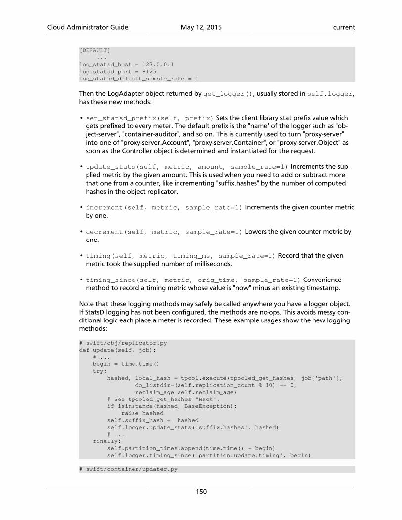
Cloud Administrator Guide May 12, 2015 current
150
[DEFAULT] ...log_statsd_host = 127.0.0.1log_statsd_port = 8125log_statsd_default_sample_rate = 1
Then the LogAdapter object returned by get_logger(), usually stored in self.logger,has these new methods:
• set_statsd_prefix(self, prefix) Sets the client library stat prefix value whichgets prefixed to every meter. The default prefix is the "name" of the logger such as "ob-ject-server", "container-auditor", and so on. This is currently used to turn "proxy-server"into one of "proxy-server.Account", "proxy-server.Container", or "proxy-server.Object" assoon as the Controller object is determined and instantiated for the request.
• update_stats(self, metric, amount, sample_rate=1) Increments the sup-plied metric by the given amount. This is used when you need to add or subtract morethat one from a counter, like incrementing "suffix.hashes" by the number of computedhashes in the object replicator.
• increment(self, metric, sample_rate=1) Increments the given counter metricby one.
• decrement(self, metric, sample_rate=1) Lowers the given counter metric byone.
• timing(self, metric, timing_ms, sample_rate=1) Record that the givenmetric took the supplied number of milliseconds.
• timing_since(self, metric, orig_time, sample_rate=1) Conveniencemethod to record a timing metric whose value is "now" minus an existing timestamp.
Note that these logging methods may safely be called anywhere you have a logger object.If StatsD logging has not been configured, the methods are no-ops. This avoids messy con-ditional logic each place a meter is recorded. These example usages show the new loggingmethods:
# swift/obj/replicator.pydef update(self, job): # ... begin = time.time() try: hashed, local_hash = tpool.execute(tpooled_get_hashes, job['path'], do_listdir=(self.replication_count % 10) == 0, reclaim_age=self.reclaim_age) # See tpooled_get_hashes "Hack". if isinstance(hashed, BaseException): raise hashed self.suffix_hash += hashed self.logger.update_stats('suffix.hashes', hashed) # ... finally: self.partition_times.append(time.time() - begin) self.logger.timing_since('partition.update.timing', begin)
# swift/container/updater.py
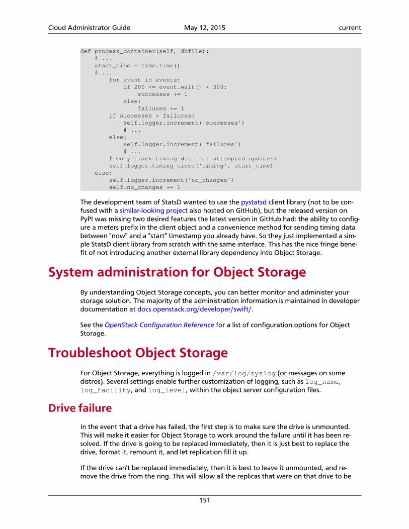
Cloud Administrator Guide May 12, 2015 current
151
def process_container(self, dbfile): # ... start_time = time.time() # ... for event in events: if 200 <= event.wait() < 300: successes += 1 else: failures += 1 if successes > failures: self.logger.increment('successes') # ... else: self.logger.increment('failures') # ... # Only track timing data for attempted updates: self.logger.timing_since('timing', start_time) else: self.logger.increment('no_changes') self.no_changes += 1
The development team of StatsD wanted to use the pystatsd client library (not to be con-fused with a similar-looking project also hosted on GitHub), but the released version onPyPI was missing two desired features the latest version in GitHub had: the ability to config-ure a meters prefix in the client object and a convenience method for sending timing databetween "now" and a "start" timestamp you already have. So they just implemented a sim-ple StatsD client library from scratch with the same interface. This has the nice fringe bene-fit of not introducing another external library dependency into Object Storage.
System administration for Object StorageBy understanding Object Storage concepts, you can better monitor and administer yourstorage solution. The majority of the administration information is maintained in developerdocumentation at docs.openstack.org/developer/swift/.
See the OpenStack Configuration Reference for a list of configuration options for ObjectStorage.
Troubleshoot Object StorageFor Object Storage, everything is logged in /var/log/syslog (or messages on somedistros). Several settings enable further customization of logging, such as log_name,log_facility, and log_level, within the object server configuration files.
Drive failure
In the event that a drive has failed, the first step is to make sure the drive is unmounted.This will make it easier for Object Storage to work around the failure until it has been re-solved. If the drive is going to be replaced immediately, then it is just best to replace thedrive, format it, remount it, and let replication fill it up.
If the drive can't be replaced immediately, then it is best to leave it unmounted, and re-move the drive from the ring. This will allow all the replicas that were on that drive to be
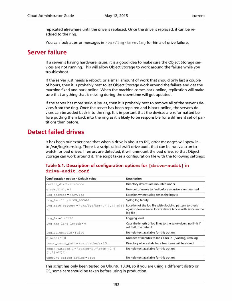
Cloud Administrator Guide May 12, 2015 current
152
replicated elsewhere until the drive is replaced. Once the drive is replaced, it can be re-added to the ring.
You can look at error messages in /var/log/kern.log for hints of drive failure.
Server failureIf a server is having hardware issues, it is a good idea to make sure the Object Storage ser-vices are not running. This will allow Object Storage to work around the failure while youtroubleshoot.
If the server just needs a reboot, or a small amount of work that should only last a coupleof hours, then it is probably best to let Object Storage work around the failure and get themachine fixed and back online. When the machine comes back online, replication will makesure that anything that is missing during the downtime will get updated.
If the server has more serious issues, then it is probably best to remove all of the server's de-vices from the ring. Once the server has been repaired and is back online, the server's de-vices can be added back into the ring. It is important that the devices are reformatted be-fore putting them back into the ring as it is likely to be responsible for a different set of par-titions than before.
Detect failed drivesIt has been our experience that when a drive is about to fail, error messages will spew in-to /var/log/kern.log. There is a script called swift-drive-audit that can be run via cron towatch for bad drives. If errors are detected, it will unmount the bad drive, so that ObjectStorage can work around it. The script takes a configuration file with the following settings:
Table 5.1. Description of configuration options for [drive-audit] indrive-audit.conf
Configuration option = Default value Description
device_dir = /srv/node Directory devices are mounted under
error_limit = 1 Number of errors to find before a device is unmounted
log_address = /dev/log Location where syslog sends the logs to
log_facility = LOG_LOCAL0 Syslog log facility
log_file_pattern = /var/log/kern.*[!.][!g][!z]
Location of the log file with globbing pattern to checkagainst device errors locate device blocks with errors in thelog file
log_level = INFO Logging level
log_max_line_length = 0 Caps the length of log lines to the value given; no limit ifset to 0, the default.
log_to_console = False No help text available for this option.
minutes = 60 Number of minutes to look back in `/var/log/kern.log`
recon_cache_path = /var/cache/swift Directory where stats for a few items will be stored
regex_pattern_1 = \berror\b.*\b(dm-[0-9]{1,2}\d?)\b
No help text available for this option.
unmount_failed_device = True No help text available for this option.
This script has only been tested on Ubuntu 10.04, so if you are using a different distro orOS, some care should be taken before using in production.
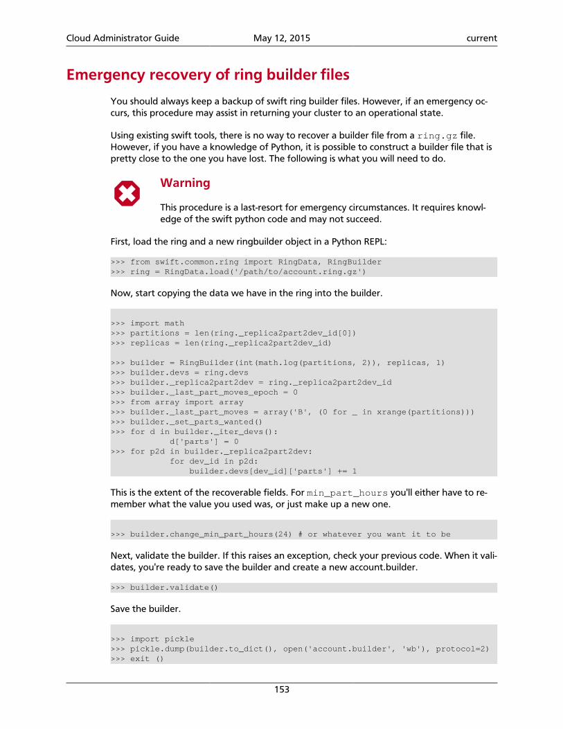
Cloud Administrator Guide May 12, 2015 current
153
Emergency recovery of ring builder files
You should always keep a backup of swift ring builder files. However, if an emergency oc-curs, this procedure may assist in returning your cluster to an operational state.
Using existing swift tools, there is no way to recover a builder file from a ring.gz file.However, if you have a knowledge of Python, it is possible to construct a builder file that ispretty close to the one you have lost. The following is what you will need to do.
Warning
This procedure is a last-resort for emergency circumstances. It requires knowl-edge of the swift python code and may not succeed.
First, load the ring and a new ringbuilder object in a Python REPL:
>>> from swift.common.ring import RingData, RingBuilder>>> ring = RingData.load('/path/to/account.ring.gz')
Now, start copying the data we have in the ring into the builder.
>>> import math>>> partitions = len(ring._replica2part2dev_id[0])>>> replicas = len(ring._replica2part2dev_id)
>>> builder = RingBuilder(int(math.log(partitions, 2)), replicas, 1)>>> builder.devs = ring.devs>>> builder._replica2part2dev = ring._replica2part2dev_id>>> builder._last_part_moves_epoch = 0>>> from array import array>>> builder._last_part_moves = array('B', (0 for _ in xrange(partitions)))>>> builder._set_parts_wanted()>>> for d in builder._iter_devs(): d['parts'] = 0>>> for p2d in builder._replica2part2dev: for dev_id in p2d: builder.devs[dev_id]['parts'] += 1
This is the extent of the recoverable fields. For min_part_hours you'll either have to re-member what the value you used was, or just make up a new one.
>>> builder.change_min_part_hours(24) # or whatever you want it to be
Next, validate the builder. If this raises an exception, check your previous code. When it vali-dates, you're ready to save the builder and create a new account.builder.
>>> builder.validate()
Save the builder.
>>> import pickle>>> pickle.dump(builder.to_dict(), open('account.builder', 'wb'), protocol=2)>>> exit ()

Cloud Administrator Guide May 12, 2015 current
154
You should now have a file called 'account.builder' in the current working directory. Next,run swift-ring-builder account.builder write_ring and compare the newaccount.ring.gz to the account.ring.gz that you started from. They probably won't be byte-for-byte identical, but if you load them up in a REPL and their _replica2part2dev_idand devs attributes are the same (or nearly so), then you're in good shape.
Next, repeat the procedure for container.ring.gz and object.ring.gz, and youmight get usable builder files.
Cloud Administrator Guide May 12, 2015 current
155
6. Block Storage
Table of ContentsIntroduction to Block Storage ...................................................................................... 155Increase Block Storage API service throughput ............................................................. 156Manage volumes ......................................................................................................... 156Troubleshoot your installation ..................................................................................... 190
The OpenStack Block Storage service works through the interaction of a series of daemonprocesses named cinder-* that reside persistently on the host machine or machines. Thebinaries can all be run from a single node, or spread across multiple nodes. They can also berun on the same node as other OpenStack services.
Introduction to Block StorageTo administer the OpenStack Block Storage service, it is helpful to understand a number ofconcepts. You must make certain choices when you configure the Block Storage service inOpenStack. The bulk of the options come down to two choices, single node or multi-nodeinstall. You can read a longer discussion about storage decisions in Storage Decisions in theOpenStack Operations Guide.
OpenStack Block Storage enables you to add extra block-level storage to your OpenStackCompute instances. This service is similar to the Amazon EC2 Elastic Block Storage (EBS) of-fering.
Cloud Administrator Guide May 12, 2015 current
156
Increase Block Storage API service throughputBy default, the Block Storage API service runs in one process. This limits the number of APIrequests that the Block Storage service can process at any given time. In a production envi-ronment, you should increase the Block Storage API throughput by allowing the Block Stor-age API service to run in as many processes as the machine capacity allows.
Note
The Block Storage API service is named openstack-cinder-api on the fol-lowing distributions: CentOS, Fedora, openSUSE, Red Hat Enterprise Linux, andSUSE Linux Enterprise. In Ubuntu and Debian distributions, the Block StorageAPI service is named cinder-api.
To do so, use the Block Storage API service option osapi_volume_workers. This optionallows you to specify the number of API service workers (or OS processes) to launch for theBlock Storage API service.
To configure this option, open the /etc/cinder/cinder.conf configuration file andset the osapi_volume_workers configuration key to the number of CPU cores/threadson a machine.
On distributions that include openstack-config, you can configure this by running the fol-lowing command instead:
# openstack-config --set /etc/cinder/cinder.conf \ DEFAULT osapi_volume_workers CORES
Replace CORES with the number of CPU cores/threads on a machine.
Manage volumesThe default OpenStack Block Storage service implementation is an iSCSI solution that usesLogical Volume Manager (LVM) for Linux.
Note
The OpenStack Block Storage service is not a shared storage solution like a Stor-age Area Network (SAN) of NFS volumes, where you can attach a volume tomultiple servers. With the OpenStack Block Storage service, you can attach avolume to only one instance at a time.
The OpenStack Block Storage service also provides drivers that enable you touse several vendors' back-end storage devices, in addition to or instead of thebase LVM implementation.
This high-level procedure shows you how to create and attach a volume to a server in-stance.
To create and attach a volume to an instance
1. Configure the OpenStack Compute and the OpenStack Block Storage services throughthe cinder.conf file.
Cloud Administrator Guide May 12, 2015 current
157
2. Use the cinder create command to create a volume. This command creates an LV intothe volume group (VG) cinder-volumes.
3. Use the nova volume-attach command to attach the volume to an instance. This com-mand creates a unique iSCSI IQN that is exposed to the compute node.
a. The compute node, which runs the instance, now has an active ISCSI session andnew local storage (usually a /dev/sdX disk).
b. libvirt uses that local storage as storage for the instance. The instance gets a newdisk (usually a /dev/vdX disk).
For this particular walk through, one cloud controller runs nova-api, nova-scheduler,nova-objectstore, nova-network and cinder-* services. Two additional computenodes run nova-compute. The walk through uses a custom partitioning scheme thatcarves out 60 GB of space and labels it as LVM. The network uses the FlatManager andNetworkManager settings for OpenStack Compute.
The network mode does not interfere with OpenStack Block Storage operations, but youmust set up networking for Block Storage to work. For details, see Chapter 7, “Network-ing” [201].
To set up Compute to use volumes, ensure that Block Storage is installed along with lvm2.This guide describes how to troubleshoot your installation and back up your Compute vol-umes.
Boot from volume
In some cases, you can store and run instances from inside volumes. For information, seethe Launch an instance from a volume section in the OpenStack End User Guide.
Cloud Administrator Guide May 12, 2015 current
158
Configure an NFS storage back end
This section explains how to configure OpenStack Block Storage to use NFS storage. Youmust be able to access the NFS shares from the server that hosts the cinder volume ser-vice.
Note
The cinder volume service is named openstack-cinder-volume on thefollowing distributions:
• CentOS
• Fedora
• openSUSE
• Red Hat Enterprise Linux
• SUSE Linux Enterprise
In Ubuntu and Debian distributions, the cinder volume service is named cin-der-volume.
Configure Block Storage to use an NFS storage back end
1. Log in as root to the system hosting the cinder volume service.
2. Create a text file named nfsshares in /etc/cinder/.
3. Add an entry to /etc/cinder/nfsshares for each NFS share that the cinder vol-ume service should use for back end storage. Each entry should be a separate line, andshould use the following format:
HOST:SHARE
Where:
• HOST is the IP address or host name of the NFS server.
• SHARE is the absolute path to an existing and accessible NFS share.
4. Set /etc/cinder/nfsshares to be owned by the root user and the cindergroup:
# chown root:cinder /etc/cinder/nfsshares
5. Set /etc/cinder/nfsshares to be readable by members of the cinder group:
# chmod 0640 /etc/cinder/nfsshares
6. Configure the cinder volume service to use the /etc/cinder/nfsshares file cre-ated earlier. To do so, open the /etc/cinder/cinder.conf configuration file andset the nfs_shares_config configuration key to /etc/cinder/nfsshares.
Cloud Administrator Guide May 12, 2015 current
159
On distributions that include openstack-config, you can configure this by running thefollowing command instead:
# openstack-config --set /etc/cinder/cinder.conf \DEFAULT nfs_shares_config /etc/cinder/nfsshares
The following distributions include openstack-config:
• CentOS
• Fedora
• openSUSE
• Red Hat Enterprise Linux
• SUSE Linux Enterprise
7. Optionally, provide any additional NFS mount options required in your environmentin the nfs_mount_options configuration key of /etc/cinder/cinder.conf.If your NFS shares do not require any additional mount options (or if you are unsure),skip this step.
On distributions that include openstack-config, you can configure this by running thefollowing command instead:
# openstack-config --set /etc/cinder/cinder.conf \DEFAULT nfs_mount_options OPTIONS
Replace OPTIONS with the mount options to be used when accessing NFS shares. Seethe manual page for NFS for more information on available mount options (man nfs).
8. Configure the cinder volume service to use the correct volume driver, namelycinder.volume.drivers.nfs.NfsDriver. To do so, open the /etc/cin-der/cinder.conf configuration file and set the volume_driver configuration keyto cinder.volume.drivers.nfs.NfsDriver.
On distributions that include openstack-config, you can configure this by running thefollowing command instead:
# openstack-config --set /etc/cinder/cinder.conf \DEFAULT volume_driver cinder.volume.drivers.nfs.NfsDriver
9. You can now restart the service to apply the configuration.
To restart the cinder volume service on CentOS, Fedora, openSUSE, Red Hat Enter-prise Linux, or SUSE Linux Enterprise, run:
# service openstack-cinder-volume restart
To restart the cinder volume service on Ubuntu or Debian, run:
# service cinder-volume restart
Cloud Administrator Guide May 12, 2015 current
160
Note
The nfs_sparsed_volumes configuration key determines whether volumesare created as sparse files and grown as needed or fully allocated up front. Thedefault and recommended value is true, which ensures volumes are initiallycreated as sparse files.
Setting nfs_sparsed_volumes to false will result in volumes being fullyallocated at the time of creation. This leads to increased delays in volume cre-ation.
However, should you choose to set nfs_sparsed_volumes to false, youcan do so directly in /etc/cinder/cinder.conf.
On distributions that include openstack-config, you can configure this by run-ning the following command instead:
# openstack-config --set /etc/cinder/cinder.conf \DEFAULT nfs_sparsed_volumes false
Important
If a client host has SELinux enabled, the virt_use_nfs Boolean should alsobe enabled if the host requires access to NFS volumes on an instance. To enablethis Boolean, run the following command as the root user:
# setsebool -P virt_use_nfs on
This command also makes the Boolean persistent across reboots. Run this com-mand on all client hosts that require access to NFS volumes on an instance. Thisincludes all Compute nodes.
Configure a GlusterFS back end
This section explains how to configure OpenStack Block Storage to use GlusterFS as a backend. You must be able to access the GlusterFS shares from the server that hosts the cin-der volume service.
Note
The cinder volume service is named openstack-cinder-volume on thefollowing distributions:
• CentOS
• Fedora
• openSUSE
• Red Hat Enterprise Linux
• SUSE Linux Enterprise
Cloud Administrator Guide May 12, 2015 current
161
In Ubuntu and Debian distributions, the cinder volume service is named cin-der-volume.
Mounting GlusterFS volumes requires utilities and libraries from the glusterfs-fuse package.This package must be installed on all systems that will access volumes backed by GlusterFS.
Note
The utilities and libraries required for mounting GlusterFS volumes on Ubuntuand Debian distributions are available from the glusterfs-client package instead.
For information on how to install and configure GlusterFS, refer to the GlusterDocumenta-tion page.
Configure GlusterFS for OpenStack Block Storage
The GlusterFS server must also be configured accordingly in order to allow OpenStack BlockStorage to use GlusterFS shares:
1. Log in as root to the GlusterFS server.
2. Set each Gluster volume to use the same UID and GID as the cinder user:
# gluster volume set VOL_NAME storage.owner-uid CINDER_UID# gluster volume set VOL_NAME storage.owner-gid CINDER_GID
Where:
• VOL_NAME is the Gluster volume name.
• CINDER_UID is the UID of the cinder user.
• CINDER_GID is the GID of the cinder user.
Note
The default UID and GID of the cinder user is 165 on most distributions.
3. Configure each Gluster volume to accept libgfapi connections. To do this, set eachGluster volume to allow insecure ports:
# gluster volume set VOL_NAME server.allow-insecure on
4. Enable client connections from unprivileged ports. To do this, add the following line to/etc/glusterfs/glusterd.vol:
option rpc-auth-allow-insecure on
5. Restart the glusterd service:
# service glusterd restart
Configure Block Storage to use a GlusterFS back end
After you configure the GlusterFS service, complete these steps:
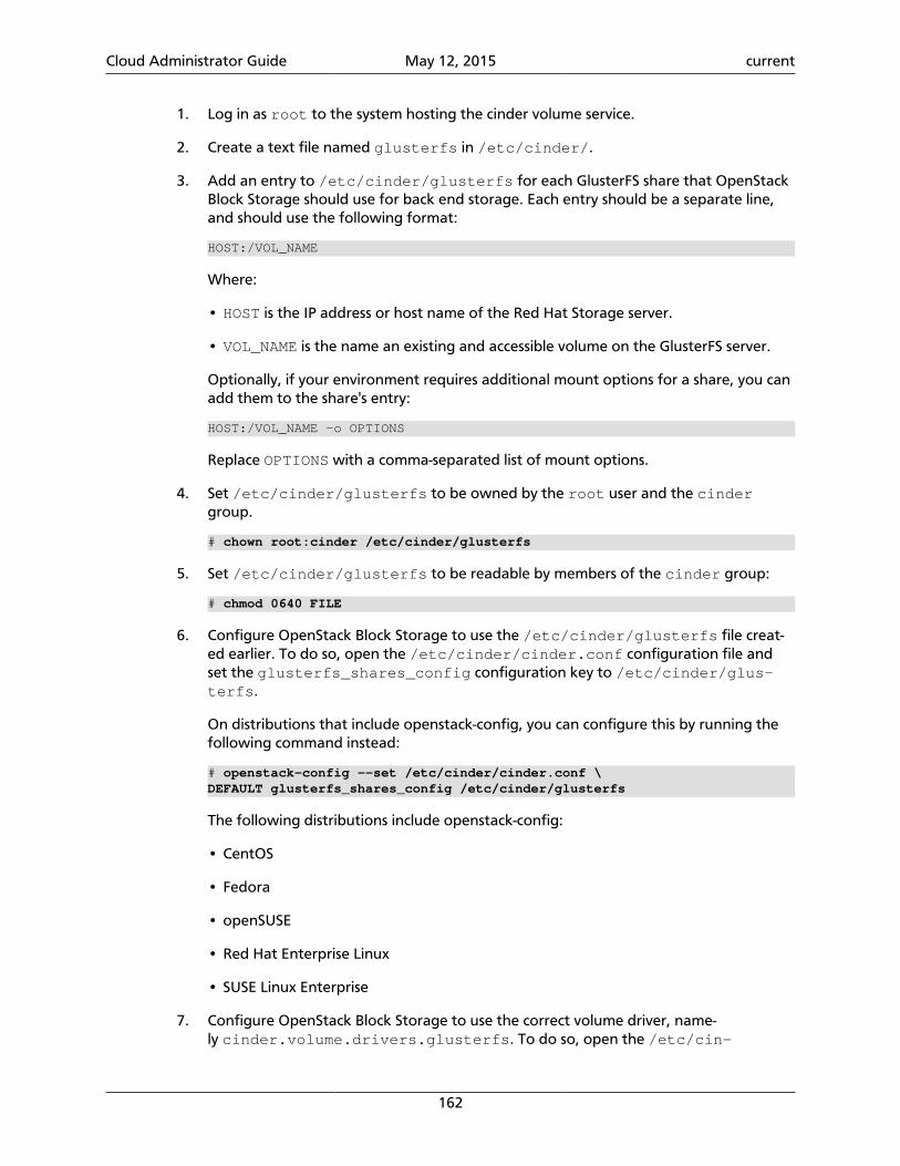
Cloud Administrator Guide May 12, 2015 current
162
1. Log in as root to the system hosting the cinder volume service.
2. Create a text file named glusterfs in /etc/cinder/.
3. Add an entry to /etc/cinder/glusterfs for each GlusterFS share that OpenStackBlock Storage should use for back end storage. Each entry should be a separate line,and should use the following format:
HOST:/VOL_NAME
Where:
• HOST is the IP address or host name of the Red Hat Storage server.
• VOL_NAME is the name an existing and accessible volume on the GlusterFS server.
Optionally, if your environment requires additional mount options for a share, you canadd them to the share's entry:
HOST:/VOL_NAME -o OPTIONS
Replace OPTIONS with a comma-separated list of mount options.
4. Set /etc/cinder/glusterfs to be owned by the root user and the cindergroup.
# chown root:cinder /etc/cinder/glusterfs
5. Set /etc/cinder/glusterfs to be readable by members of the cinder group:
# chmod 0640 FILE
6. Configure OpenStack Block Storage to use the /etc/cinder/glusterfs file creat-ed earlier. To do so, open the /etc/cinder/cinder.conf configuration file andset the glusterfs_shares_config configuration key to /etc/cinder/glus-terfs.
On distributions that include openstack-config, you can configure this by running thefollowing command instead:
# openstack-config --set /etc/cinder/cinder.conf \DEFAULT glusterfs_shares_config /etc/cinder/glusterfs
The following distributions include openstack-config:
• CentOS
• Fedora
• openSUSE
• Red Hat Enterprise Linux
• SUSE Linux Enterprise
7. Configure OpenStack Block Storage to use the correct volume driver, name-ly cinder.volume.drivers.glusterfs. To do so, open the /etc/cin-
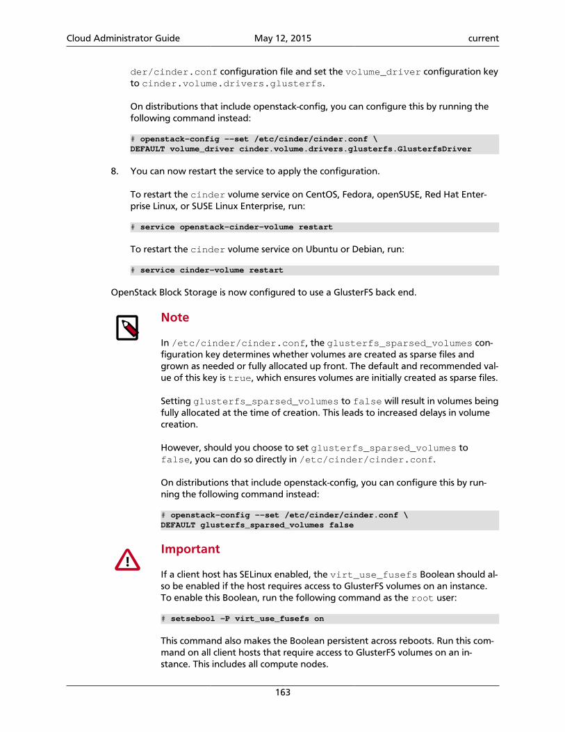
Cloud Administrator Guide May 12, 2015 current
163
der/cinder.conf configuration file and set the volume_driver configuration keyto cinder.volume.drivers.glusterfs.
On distributions that include openstack-config, you can configure this by running thefollowing command instead:
# openstack-config --set /etc/cinder/cinder.conf \DEFAULT volume_driver cinder.volume.drivers.glusterfs.GlusterfsDriver
8. You can now restart the service to apply the configuration.
To restart the cinder volume service on CentOS, Fedora, openSUSE, Red Hat Enter-prise Linux, or SUSE Linux Enterprise, run:
# service openstack-cinder-volume restart
To restart the cinder volume service on Ubuntu or Debian, run:
# service cinder-volume restart
OpenStack Block Storage is now configured to use a GlusterFS back end.
Note
In /etc/cinder/cinder.conf, the glusterfs_sparsed_volumes con-figuration key determines whether volumes are created as sparse files andgrown as needed or fully allocated up front. The default and recommended val-ue of this key is true, which ensures volumes are initially created as sparse files.
Setting glusterfs_sparsed_volumes to false will result in volumes beingfully allocated at the time of creation. This leads to increased delays in volumecreation.
However, should you choose to set glusterfs_sparsed_volumes tofalse, you can do so directly in /etc/cinder/cinder.conf.
On distributions that include openstack-config, you can configure this by run-ning the following command instead:
# openstack-config --set /etc/cinder/cinder.conf \DEFAULT glusterfs_sparsed_volumes false
Important
If a client host has SELinux enabled, the virt_use_fusefs Boolean should al-so be enabled if the host requires access to GlusterFS volumes on an instance.To enable this Boolean, run the following command as the root user:
# setsebool -P virt_use_fusefs on
This command also makes the Boolean persistent across reboots. Run this com-mand on all client hosts that require access to GlusterFS volumes on an in-stance. This includes all compute nodes.
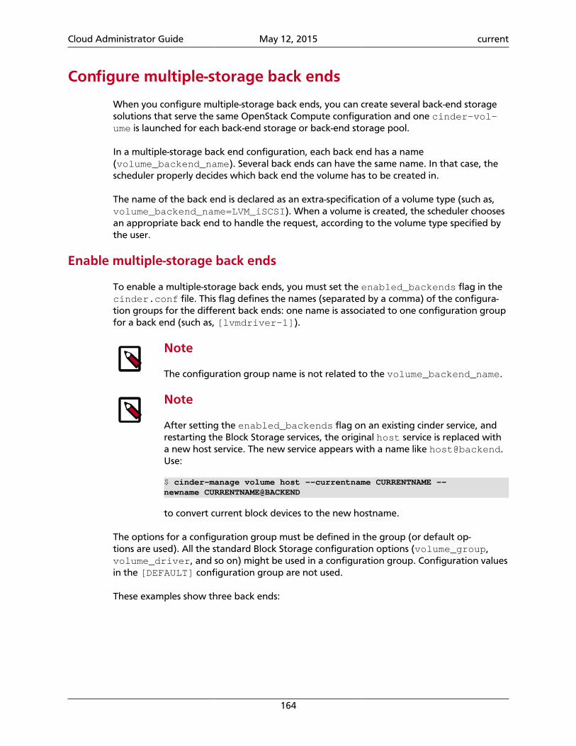
Cloud Administrator Guide May 12, 2015 current
164
Configure multiple-storage back ends
When you configure multiple-storage back ends, you can create several back-end storagesolutions that serve the same OpenStack Compute configuration and one cinder-vol-ume is launched for each back-end storage or back-end storage pool.
In a multiple-storage back end configuration, each back end has a name(volume_backend_name). Several back ends can have the same name. In that case, thescheduler properly decides which back end the volume has to be created in.
The name of the back end is declared as an extra-specification of a volume type (such as,volume_backend_name=LVM_iSCSI). When a volume is created, the scheduler choosesan appropriate back end to handle the request, according to the volume type specified bythe user.
Enable multiple-storage back ends
To enable a multiple-storage back ends, you must set the enabled_backends flag in thecinder.conf file. This flag defines the names (separated by a comma) of the configura-tion groups for the different back ends: one name is associated to one configuration groupfor a back end (such as, [lvmdriver-1]).
Note
The configuration group name is not related to the volume_backend_name.
Note
After setting the enabled_backends flag on an existing cinder service, andrestarting the Block Storage services, the original host service is replaced witha new host service. The new service appears with a name like [email protected]:
$ cinder-manage volume host --currentname CURRENTNAME --newname CURRENTNAME@BACKEND
to convert current block devices to the new hostname.
The options for a configuration group must be defined in the group (or default op-tions are used). All the standard Block Storage configuration options (volume_group,volume_driver, and so on) might be used in a configuration group. Configuration valuesin the [DEFAULT] configuration group are not used.
These examples show three back ends:
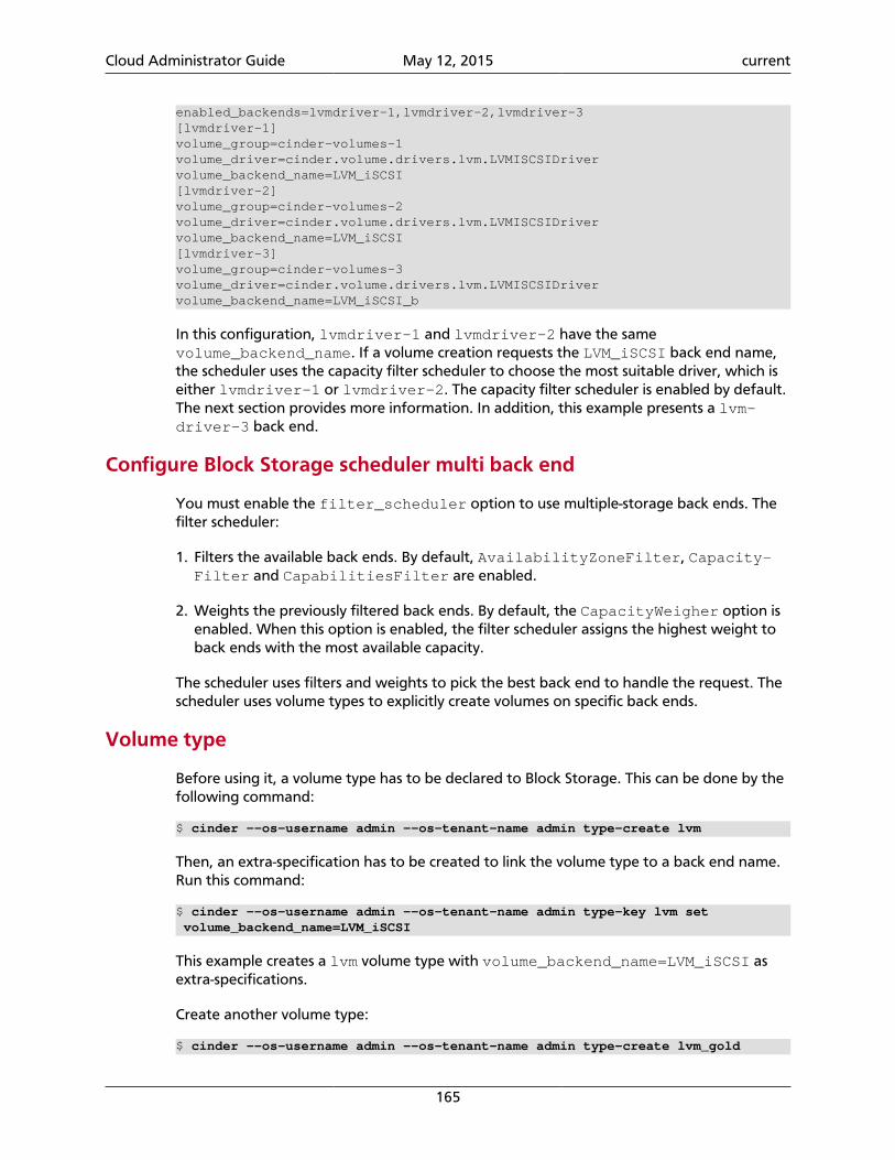
Cloud Administrator Guide May 12, 2015 current
165
enabled_backends=lvmdriver-1,lvmdriver-2,lvmdriver-3[lvmdriver-1]volume_group=cinder-volumes-1volume_driver=cinder.volume.drivers.lvm.LVMISCSIDrivervolume_backend_name=LVM_iSCSI[lvmdriver-2]volume_group=cinder-volumes-2volume_driver=cinder.volume.drivers.lvm.LVMISCSIDrivervolume_backend_name=LVM_iSCSI[lvmdriver-3]volume_group=cinder-volumes-3volume_driver=cinder.volume.drivers.lvm.LVMISCSIDrivervolume_backend_name=LVM_iSCSI_b
In this configuration, lvmdriver-1 and lvmdriver-2 have the samevolume_backend_name. If a volume creation requests the LVM_iSCSI back end name,the scheduler uses the capacity filter scheduler to choose the most suitable driver, which iseither lvmdriver-1 or lvmdriver-2. The capacity filter scheduler is enabled by default.The next section provides more information. In addition, this example presents a lvm-driver-3 back end.
Configure Block Storage scheduler multi back end
You must enable the filter_scheduler option to use multiple-storage back ends. Thefilter scheduler:
1. Filters the available back ends. By default, AvailabilityZoneFilter, Capacity-Filter and CapabilitiesFilter are enabled.
2. Weights the previously filtered back ends. By default, the CapacityWeigher option isenabled. When this option is enabled, the filter scheduler assigns the highest weight toback ends with the most available capacity.
The scheduler uses filters and weights to pick the best back end to handle the request. Thescheduler uses volume types to explicitly create volumes on specific back ends.
Volume type
Before using it, a volume type has to be declared to Block Storage. This can be done by thefollowing command:
$ cinder --os-username admin --os-tenant-name admin type-create lvm
Then, an extra-specification has to be created to link the volume type to a back end name.Run this command:
$ cinder --os-username admin --os-tenant-name admin type-key lvm set volume_backend_name=LVM_iSCSI
This example creates a lvm volume type with volume_backend_name=LVM_iSCSI asextra-specifications.
Create another volume type:
$ cinder --os-username admin --os-tenant-name admin type-create lvm_gold

Cloud Administrator Guide May 12, 2015 current
166
$ cinder --os-username admin --os-tenant-name admin type-key lvm_gold set volume_backend_name=LVM_iSCSI_b
This second volume type is named lvm_gold and has LVM_iSCSI_b as back end name.
Note
To list the extra-specifications, use this command:
$ cinder --os-username admin --os-tenant-name admin extra-specs-list
Note
If a volume type points to a volume_backend_name that does not exist in theBlock Storage configuration, the filter_scheduler returns an error that itcannot find a valid host with the suitable back end.
Usage
When you create a volume, you must specify the volume type. The extra-specifications ofthe volume type are used to determine which back end has to be used.
$ cinder create --volume_type lvm --display_name test_multi_backend 1
Considering the cinder.conf described previously, the scheduler creates this volume onlvmdriver-1 or lvmdriver-2.
$ cinder create --volume_type lvm_gold --display_name test_multi_backend 1
This second volume is created on lvmdriver-3.
Back up Block Storage service disksWhile you can use the LVM snapshot to create snapshots, you can also use it to back upyour volumes. By using LVM snapshot, you reduce the size of the backup; only existing datais backed up instead of the entire volume.
To back up a volume, you must create a snapshot of it. An LVM snapshot is the exact copyof a logical volume, which contains data in a frozen state. This prevents data corruption,because data cannot be manipulated during the volume creation process. Remember thatthe volumes created through a nova volume-create command exist in an LVM logical vol-ume.
You must also make sure that the operating system is not using the volume, and that alldata has been flushed on the guest file systems. This usually means that those file systemshave to be unmounted during the snapshot creation. They can be mounted again as soonas the logical volume snapshot has been created.
Before you create the snapshot, you must have enough space to save it. As a precaution,you should have at least twice as much space as the potential snapshot size. If insufficientspace is available, the snapshot might become corrupted.
For this example, assume that a 100 GB volume named volume-00000001 was createdfor an instance while only 4 GB are used. This example uses these commands to back up on-ly those 4 GB:
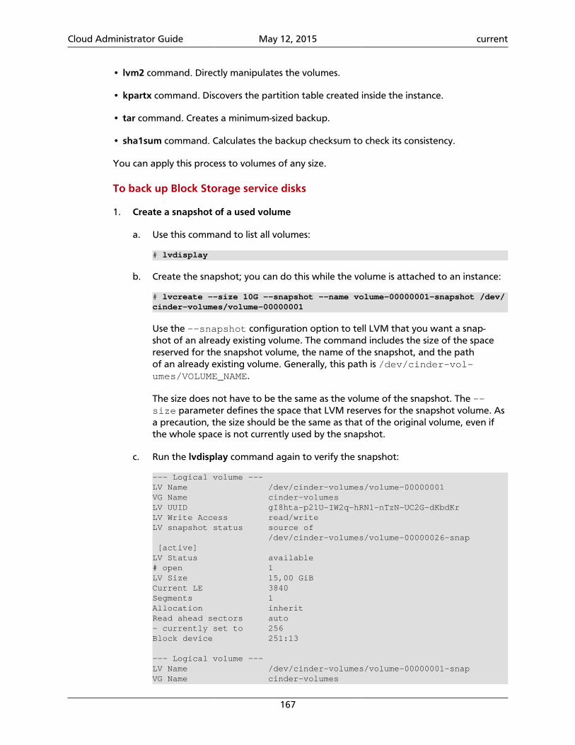
Cloud Administrator Guide May 12, 2015 current
167
• lvm2 command. Directly manipulates the volumes.
• kpartx command. Discovers the partition table created inside the instance.
• tar command. Creates a minimum-sized backup.
• sha1sum command. Calculates the backup checksum to check its consistency.
You can apply this process to volumes of any size.
To back up Block Storage service disks
1. Create a snapshot of a used volume
a. Use this command to list all volumes:
# lvdisplay
b. Create the snapshot; you can do this while the volume is attached to an instance:
# lvcreate --size 10G --snapshot --name volume-00000001-snapshot /dev/cinder-volumes/volume-00000001
Use the --snapshot configuration option to tell LVM that you want a snap-shot of an already existing volume. The command includes the size of the spacereserved for the snapshot volume, the name of the snapshot, and the pathof an already existing volume. Generally, this path is /dev/cinder-vol-umes/VOLUME_NAME.
The size does not have to be the same as the volume of the snapshot. The --size parameter defines the space that LVM reserves for the snapshot volume. Asa precaution, the size should be the same as that of the original volume, even ifthe whole space is not currently used by the snapshot.
c. Run the lvdisplay command again to verify the snapshot:
--- Logical volume ---LV Name /dev/cinder-volumes/volume-00000001VG Name cinder-volumesLV UUID gI8hta-p21U-IW2q-hRN1-nTzN-UC2G-dKbdKrLV Write Access read/writeLV snapshot status source of /dev/cinder-volumes/volume-00000026-snap [active]LV Status available# open 1LV Size 15,00 GiBCurrent LE 3840Segments 1Allocation inheritRead ahead sectors auto- currently set to 256Block device 251:13
--- Logical volume ---LV Name /dev/cinder-volumes/volume-00000001-snapVG Name cinder-volumes
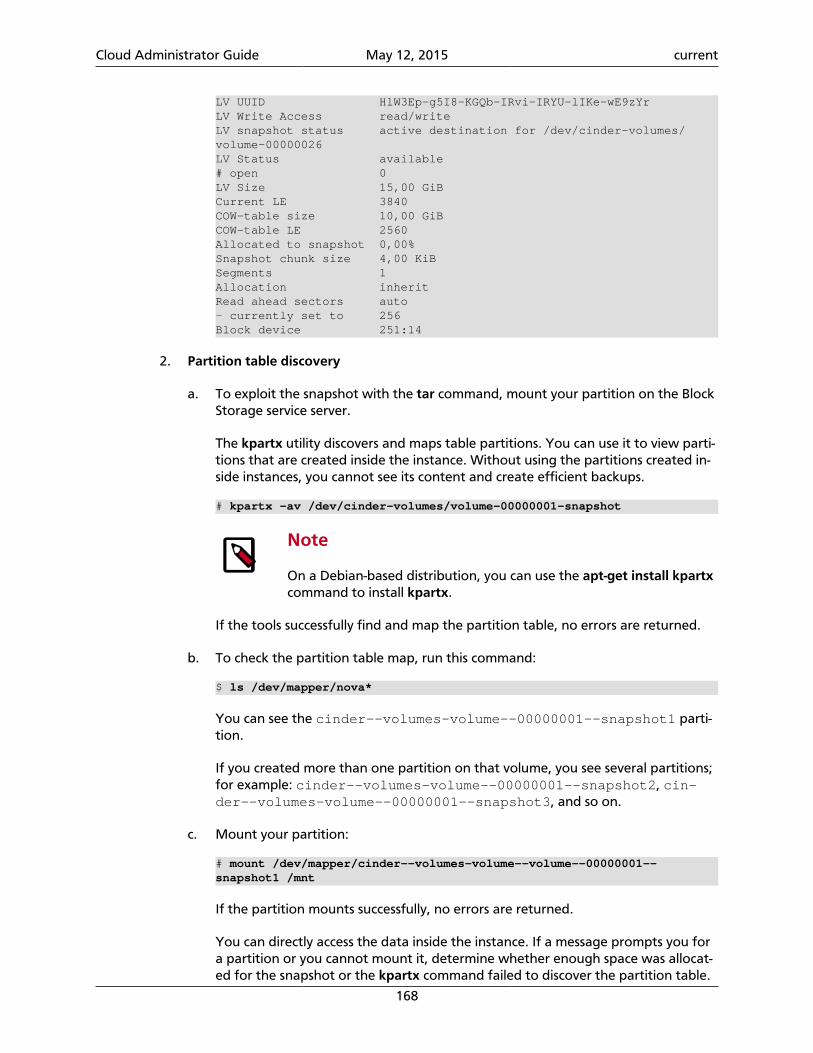
Cloud Administrator Guide May 12, 2015 current
168
LV UUID HlW3Ep-g5I8-KGQb-IRvi-IRYU-lIKe-wE9zYrLV Write Access read/writeLV snapshot status active destination for /dev/cinder-volumes/volume-00000026LV Status available# open 0LV Size 15,00 GiBCurrent LE 3840COW-table size 10,00 GiBCOW-table LE 2560Allocated to snapshot 0,00%Snapshot chunk size 4,00 KiBSegments 1Allocation inheritRead ahead sectors auto- currently set to 256Block device 251:14
2. Partition table discovery
a. To exploit the snapshot with the tar command, mount your partition on the BlockStorage service server.
The kpartx utility discovers and maps table partitions. You can use it to view parti-tions that are created inside the instance. Without using the partitions created in-side instances, you cannot see its content and create efficient backups.
# kpartx -av /dev/cinder-volumes/volume-00000001-snapshot
Note
On a Debian-based distribution, you can use the apt-get install kpartxcommand to install kpartx.
If the tools successfully find and map the partition table, no errors are returned.
b. To check the partition table map, run this command:
$ ls /dev/mapper/nova*
You can see the cinder--volumes-volume--00000001--snapshot1 parti-tion.
If you created more than one partition on that volume, you see several partitions;for example: cinder--volumes-volume--00000001--snapshot2, cin-der--volumes-volume--00000001--snapshot3, and so on.
c. Mount your partition:
# mount /dev/mapper/cinder--volumes-volume--volume--00000001--snapshot1 /mnt
If the partition mounts successfully, no errors are returned.
You can directly access the data inside the instance. If a message prompts you fora partition or you cannot mount it, determine whether enough space was allocat-ed for the snapshot or the kpartx command failed to discover the partition table.
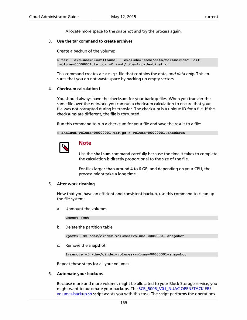
Cloud Administrator Guide May 12, 2015 current
169
Allocate more space to the snapshot and try the process again.
3. Use the tar command to create archives
Create a backup of the volume:
$ tar --exclude="lost+found" --exclude="some/data/to/exclude" -czf volume-00000001.tar.gz -C /mnt/ /backup/destination
This command creates a tar.gz file that contains the data, and data only. This en-sures that you do not waste space by backing up empty sectors.
4. Checksum calculation I
You should always have the checksum for your backup files. When you transfer thesame file over the network, you can run a checksum calculation to ensure that yourfile was not corrupted during its transfer. The checksum is a unique ID for a file. If thechecksums are different, the file is corrupted.
Run this command to run a checksum for your file and save the result to a file:
$ sha1sum volume-00000001.tar.gz > volume-00000001.checksum
Note
Use the sha1sum command carefully because the time it takes to completethe calculation is directly proportional to the size of the file.
For files larger than around 4 to 6 GB, and depending on your CPU, theprocess might take a long time.
5. After work cleaning
Now that you have an efficient and consistent backup, use this command to clean upthe file system:
a. Unmount the volume:
umount /mnt
b. Delete the partition table:
kpartx -dv /dev/cinder-volumes/volume-00000001-snapshot
c. Remove the snapshot:
lvremove -f /dev/cinder-volumes/volume-00000001-snapshot
Repeat these steps for all your volumes.
6. Automate your backups
Because more and more volumes might be allocated to your Block Storage service, youmight want to automate your backups. The SCR_5005_V01_NUAC-OPENSTACK-EBS-volumes-backup.sh script assists you with this task. The script performs the operations
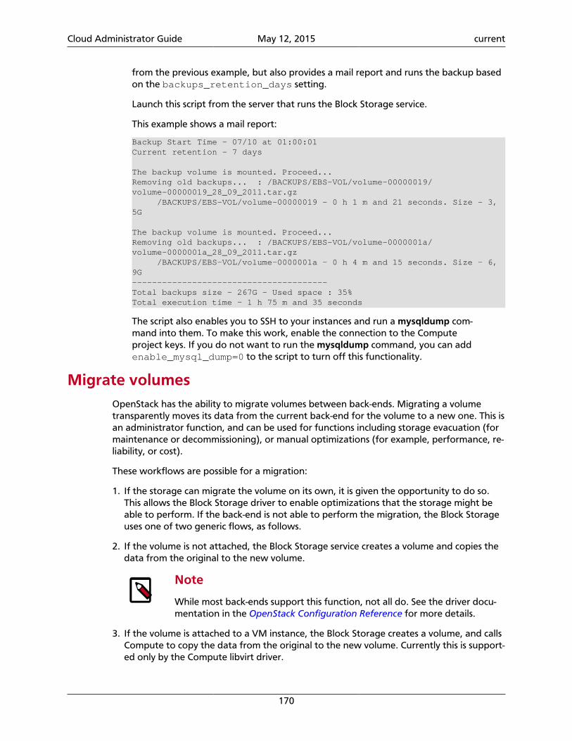
Cloud Administrator Guide May 12, 2015 current
170
from the previous example, but also provides a mail report and runs the backup basedon the backups_retention_days setting.
Launch this script from the server that runs the Block Storage service.
This example shows a mail report:
Backup Start Time - 07/10 at 01:00:01Current retention - 7 days
The backup volume is mounted. Proceed...Removing old backups... : /BACKUPS/EBS-VOL/volume-00000019/volume-00000019_28_09_2011.tar.gz /BACKUPS/EBS-VOL/volume-00000019 - 0 h 1 m and 21 seconds. Size - 3,5G
The backup volume is mounted. Proceed...Removing old backups... : /BACKUPS/EBS-VOL/volume-0000001a/volume-0000001a_28_09_2011.tar.gz /BACKUPS/EBS-VOL/volume-0000001a - 0 h 4 m and 15 seconds. Size - 6,9G---------------------------------------Total backups size - 267G - Used space : 35%Total execution time - 1 h 75 m and 35 seconds
The script also enables you to SSH to your instances and run a mysqldump com-mand into them. To make this work, enable the connection to the Computeproject keys. If you do not want to run the mysqldump command, you can addenable_mysql_dump=0 to the script to turn off this functionality.
Migrate volumesOpenStack has the ability to migrate volumes between back-ends. Migrating a volumetransparently moves its data from the current back-end for the volume to a new one. This isan administrator function, and can be used for functions including storage evacuation (formaintenance or decommissioning), or manual optimizations (for example, performance, re-liability, or cost).
These workflows are possible for a migration:
1. If the storage can migrate the volume on its own, it is given the opportunity to do so.This allows the Block Storage driver to enable optimizations that the storage might beable to perform. If the back-end is not able to perform the migration, the Block Storageuses one of two generic flows, as follows.
2. If the volume is not attached, the Block Storage service creates a volume and copies thedata from the original to the new volume.
Note
While most back-ends support this function, not all do. See the driver docu-mentation in the OpenStack Configuration Reference for more details.
3. If the volume is attached to a VM instance, the Block Storage creates a volume, and callsCompute to copy the data from the original to the new volume. Currently this is support-ed only by the Compute libvirt driver.
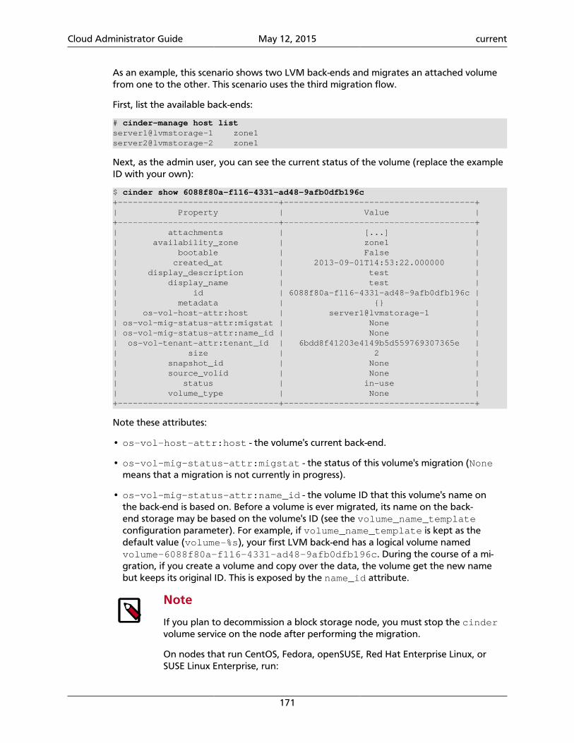
Cloud Administrator Guide May 12, 2015 current
171
As an example, this scenario shows two LVM back-ends and migrates an attached volumefrom one to the other. This scenario uses the third migration flow.
First, list the available back-ends:
# cinder-manage host listserver1@lvmstorage-1 zone1server2@lvmstorage-2 zone1
Next, as the admin user, you can see the current status of the volume (replace the exampleID with your own):
$ cinder show 6088f80a-f116-4331-ad48-9afb0dfb196c+--------------------------------+--------------------------------------+| Property | Value |+--------------------------------+--------------------------------------+| attachments | [...] || availability_zone | zone1 || bootable | False || created_at | 2013-09-01T14:53:22.000000 || display_description | test || display_name | test || id | 6088f80a-f116-4331-ad48-9afb0dfb196c || metadata | {} || os-vol-host-attr:host | server1@lvmstorage-1 || os-vol-mig-status-attr:migstat | None || os-vol-mig-status-attr:name_id | None || os-vol-tenant-attr:tenant_id | 6bdd8f41203e4149b5d559769307365e || size | 2 || snapshot_id | None || source_volid | None || status | in-use || volume_type | None |+--------------------------------+--------------------------------------+
Note these attributes:
• os-vol-host-attr:host - the volume's current back-end.
• os-vol-mig-status-attr:migstat - the status of this volume's migration (Nonemeans that a migration is not currently in progress).
• os-vol-mig-status-attr:name_id - the volume ID that this volume's name onthe back-end is based on. Before a volume is ever migrated, its name on the back-end storage may be based on the volume's ID (see the volume_name_templateconfiguration parameter). For example, if volume_name_template is kept as thedefault value (volume-%s), your first LVM back-end has a logical volume namedvolume-6088f80a-f116-4331-ad48-9afb0dfb196c. During the course of a mi-gration, if you create a volume and copy over the data, the volume get the new namebut keeps its original ID. This is exposed by the name_id attribute.
Note
If you plan to decommission a block storage node, you must stop the cindervolume service on the node after performing the migration.
On nodes that run CentOS, Fedora, openSUSE, Red Hat Enterprise Linux, orSUSE Linux Enterprise, run:
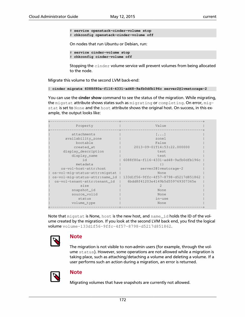
Cloud Administrator Guide May 12, 2015 current
172
# service openstack-cinder-volume stop# chkconfig openstack-cinder-volume off
On nodes that run Ubuntu or Debian, run:
# service cinder-volume stop# chkconfig cinder-volume off
Stopping the cinder volume service will prevent volumes from being allocatedto the node.
Migrate this volume to the second LVM back-end:
$ cinder migrate 6088f80a-f116-4331-ad48-9afb0dfb196c server2@lvmstorage-2
You can use the cinder show command to see the status of the migration. While migrating,the migstat attribute shows states such as migrating or completing. On error, mig-stat is set to None and the host attribute shows the original host. On success, in this ex-ample, the output looks like:
+--------------------------------+--------------------------------------+| Property | Value |+--------------------------------+--------------------------------------+| attachments | [...] || availability_zone | zone1 || bootable | False || created_at | 2013-09-01T14:53:22.000000 || display_description | test || display_name | test || id | 6088f80a-f116-4331-ad48-9afb0dfb196c || metadata | {} || os-vol-host-attr:host | server2@lvmstorage-2 || os-vol-mig-status-attr:migstat | None || os-vol-mig-status-attr:name_id | 133d1f56-9ffc-4f57-8798-d5217d851862 || os-vol-tenant-attr:tenant_id | 6bdd8f41203e4149b5d559769307365e || size | 2 || snapshot_id | None || source_volid | None || status | in-use || volume_type | None |+--------------------------------+--------------------------------------+
Note that migstat is None, host is the new host, and name_id holds the ID of the vol-ume created by the migration. If you look at the second LVM back end, you find the logicalvolume volume-133d1f56-9ffc-4f57-8798-d5217d851862.
Note
The migration is not visible to non-admin users (for example, through the vol-ume status). However, some operations are not allowed while a migration istaking place, such as attaching/detaching a volume and deleting a volume. If auser performs such an action during a migration, an error is returned.
Note
Migrating volumes that have snapshots are currently not allowed.
Cloud Administrator Guide May 12, 2015 current
173
Gracefully remove a GlusterFS volume from usage
Configuring the cinder volume service to use GlusterFS involves creating a shares file (forexample, /etc/cinder/glusterfs). This shares file lists each GlusterFS volume (with itscorresponding storage server) that the cinder volume service can use for back end stor-age.
To remove a GlusterFS volume from usage as a back end, delete the volume's correspond-ing entry from the shares file. After doing so, restart the Block Storage services.
To restart the Block Storage services on CentOS, Fedora, openSUSE, Red Hat Enterprise Lin-ux, or SUSE Linux Enterprise, run:
# for i in api scheduler volume; do service openstack-cinder-$i restart; done
To restart the Block Storage services on Ubuntu or Debian, run:
# for i in api scheduler volume; do service cinder-${i} restart; done
Restarting the Block Storage services will prevent the cinder volume service from export-ing the deleted GlusterFS volume. This will prevent any instances from mounting the vol-ume from that point onwards.
However, the removed GlusterFS volume might still be mounted on an instance at thispoint. Typically, this is the case when the volume was already mounted while its entry wasdeleted from the shares file. Whenever this occurs, you will have to unmount the volume asnormal after the Block Storage services are restarted.
Back up and restore volumes
The cinder command-line interface provides the tools for creating a volume backup. Youcan restore a volume from a backup as long as the backup's associated database informa-tion (or backup metadata) is intact in the Block Storage database.
Run this command to create a backup of a volume:
$ cinder backup-create VOLUME
Where VOLUME is the name or ID of the volume.
This command also returns a backup ID. Use this backup ID when restoring the volume:
$ cinder backup-restore BACKUP_ID
Because volume backups are dependent on the Block Storage database, you must also backup your Block Storage database regularly to ensure data recovery.
Note
Alternatively, you can export and save the metadata of selected volume back-ups. Doing so precludes the need to back up the entire Block Storage database.This is useful if you need only a small subset of volumes to survive a catastrophicdatabase failure.
Cloud Administrator Guide May 12, 2015 current
174
If you specify a UUID encryption key when setting up the volume specifications,the backup metadata ensures that the key will remain valid when you back upand restore the volume.
For more information about how to export and import volume backup metada-ta, see the section called “Export and import backup metadata” [174].
By default, the swift object store is used for the backup repository.
If instead you want to use an NFS export as the backup repository, add the following con-figuration options to the [DEFAULT] section of the cinder.conf file and restart theBlock Storage services:
backup_driver = cinder.backup.drivers.nfsbackup_share = HOST:EXPORT_PATH
For the backup_share option, replace HOST with the DNS resolvable host name or the IPaddress of the storage server for the NFS share, and EXPORT_PATH with the path to thatshare. If your environment requires that non-default mount options be specified for theshare, set these as follows:
backup_mount_options = MOUNT_OPTIONS
MOUNT_OPTIONS is a comma-separated string of NFS mount options as detailed in the NFSman page.
There are several other options whose default values may be overriden as appropriate foryour environment:
backup_compression_algorithm = zlibbackup_sha_block_size_bytes = 32768backup_file_size = 1999994880
The option backup_compression_algorithm can be set to bz2 or None. The lattercan be a useful setting when the server providing the share for the backup repository itselfperforms deduplication or compression on the backup data.
The option backup_file_size must be a multiple ofbackup_sha_block_size_bytes. It is effectively the maximum file size to be used, giv-en your environment, to hold backup data. Volumes larger than this will be stored in mul-tiple files in the backup repository. The backup_sha_block_size_bytes option deter-mines the size of blocks from the cinder volume being backed up on which digital signa-tures are calculated in order to enable incremental backup capability.
Export and import backup metadataA volume backup can only be restored on the same Block Storage service. This is becauserestoring a volume from a backup requires metadata available on the database used by theBlock Storage service.
Note
For information about how to back up and restore a volume, see the sectioncalled “Back up and restore volumes” [173].
Cloud Administrator Guide May 12, 2015 current
175
You can, however, export the metadata of a volume backup. To do so, run this commandas an OpenStack admin user (presumably, after creating a volume backup):
$ cinder backup-export BACKUP_ID
Where BACKUP_ID is the volume backup's ID. This command should return the backup'scorresponding database information as encoded string metadata.
Exporting and storing this encoded string metadata allows you to completely restore thebackup, even in the event of a catastrophic database failure. This will preclude the need toback up the entire Block Storage database, particularly if you only need to keep completebackups of a small subset of volumes.
If you have placed encryption on your volumes, the encryption will still be in place whenyou restore the volume if a UUID encryption key is specified when creating volumes. Usingbackup metadata support, UUID keys set up for a volume (or volumes) will remain validwhen you restore a backed-up volume. The restored volume will remain encrypted, and willbe accessible with your credentials.
In addition, having a volume backup and its backup metadata also provides volume porta-bility. Specifically, backing up a volume and exporting its metadata will allow you to restorethe volume on a completely different Block Storage database, or even on a different cloudservice. To do so, first import the backup metadata to the Block Storage database and thenrestore the backup.
To import backup metadata, run the following command as an OpenStack admin:
$ cinder backup-import METADATA
Where METADATA is the backup metadata exported earlier.
Once you have imported the backup metadata into a Block Storage database, restore thevolume (the section called “Back up and restore volumes” [173]).
Use LIO iSCSI support
The default iscsi_helper tool is tgtadm. To use LIO iSCSI, install the python-rtslibpackage, and set iscsi_helper=lioadm in the cinder.conf file.
Once configured, you can use the cinder-rtstool command to manage the volumes. Thiscommand enables you to create, delete, and verify volumes and determine targets and addiSCSI initiators to the system.
Configure and use volume number weighter
OpenStack Block Storage enables you to choose a volume back end according tofree_capacity and allocated_capacity. The volume number weighter feature letsthe scheduler choose a volume back end based on its volume number in the volume backend. This can provide another means to improve the volume back ends' I/O balance andthe volumes' I/O performance.
Cloud Administrator Guide May 12, 2015 current
176
Enable volume number weighter
To enable a volume number weighter, set the scheduler_default_weighters toVolumeNumberWeigher flag in the cinder.conf file to define VolumeNumber-Weigher as the selected weighter.
Configure multiple-storage back ends
To configure VolumeNumberWeigher, use LVMISCSIDriver as the volume driver.
This configuration defines two LVM volume groups: stack-volumes with 10 GB capacityand stack-volumes-1 with 60 GB capacity. This example configuration defines two backends:
scheduler_default_weighers=VolumeNumberWeigherenabled_backends=lvmdriver-1,lvmdriver-2[lvmdriver-1]volume_group=stack-volumesvolume_driver=cinder.volume.drivers.lvm.LVMISCSIDrivervolume_backend_name=LVM_iSCSI
[lvmdriver-2]volume_group=stack-volumes-1volume_driver=cinder.volume.drivers.lvm.LVMISCSIDrivervolume_backend_name=LVM_iSCSI
Volume type
Define a volume type in Block Storage:
$ cinder type-create lvm
Create an extra specification that links the volume type to a back-end name:
$ cinder type-key lvm set volume_backend_name=LVM_iSCSI
This example creates a lvm volume type with volume_backend_name=LVM_iSCSI asextra specifications.
Usage
To create six 1-GB volumes, run the cinder create --volume-type lvm 1 command six times:
$ cinder create --volume-type lvm 1
This command creates three volumes in stack-volumes and three volumes in stack-volumes-1.
List the available volumes:
# lvs LV VG Attr LSize Pool Origin Data% Move Log Copy% Convert volume-3814f055-5294-4796-b5e6-1b7816806e5d stack-volumes -wi-a---- 1.00g volume-72cf5e79-99d2-4d23-b84e-1c35d3a293be stack-volumes -wi-a---- 1.00g
Cloud Administrator Guide May 12, 2015 current
177
volume-96832554-0273-4e9d-902b-ad421dfb39d1 stack-volumes -wi-a---- 1.00g volume-169386ef-3d3e-4a90-8439-58ceb46889d9 stack-volumes-1 -wi-a---- 1.00g volume-460b0bbb-d8a0-4bc3-9882-a129a5fe8652 stack-volumes-1 -wi-a---- 1.00g volume-9a08413b-0dbc-47c9-afb8-41032ab05a41 stack-volumes-1 -wi-a---- 1.00g
Consistency Groups
Consistency group support is available in OpenStack Block Storage. The support is addedfor creating snapshots of consistency groups. This feature leverages the storage level consis-tency technology. It allows snapshots of multiple volumes in the same consistency group tobe taken at the same point-in-time to ensure data consistency. The consistency group oper-ations can be performed using the Block Storage command line.
Note
Only Block Storage V2 API supports consistency groups. You can specify --os-volume-api-version 2 when using Block Storage command line for consis-tency group operations.
Before using consistency groups, make sure the Block Storage driver that you are runninghas consistency group support by reading the Block Storage manual or consulting the driv-er maintainer. There are a small number of drivers that have implemented this feature. Thedefault LVM driver does not support consistency groups yet because the consistency tech-nology is not available at the storage level.
Before using consistency groups, you must change policies for the consistency group APIsin the /etc/cinder/policy.json file. By default, the consistency group APIs are dis-abled. Enable them before running consistency group operations.
Here are existing policy entries for consistency groups:
"consistencygroup:create": "group:nobody","consistencygroup:delete": "group:nobody","consistencygroup:get": "group:nobody","consistencygroup:get_all": "group:nobody","consistencygroup:create_cgsnapshot" : "group:nobody","consistencygroup:delete_cgsnapshot": "group:nobody","consistencygroup:get_cgsnapshot": "group:nobody","consistencygroup:get_all_cgsnapshots": "group:nobody",
Change them to the following by removing group:nobody to enable these APIs:
"consistencygroup:create": "","consistencygroup:delete": "","consistencygroup:update": "","consistencygroup:get": "","consistencygroup:get_all": "","consistencygroup:create_cgsnapshot" : "","consistencygroup:delete_cgsnapshot": "","consistencygroup:get_cgsnapshot": "","consistencygroup:get_all_cgsnapshots": "",
Restart Block Storage API service after changing policies.
The following consistency group operations are supported:
Cloud Administrator Guide May 12, 2015 current
178
• Create a consistency group, given volume types.
Note
A consistency group can support more than one volume type. The scheduleris responsible for finding a back end that can support all given volume types.
Note
A consistency group can only contain volumes hosted by the same back end.
Note
A consistency group is empty upon its creation. Volumes need to be createdand added to it later.
• Show a consistency group.
• List consistency groups.
• Create a volume and add it to a consistency group, given volume type and consistencygroup id.
• Create a snapshot for a consistency group.
• Show a snapshot of a consistency group.
• List consistency group snapshots.
• Delete a snapshot of a consistency group.
• Delete a consistency group.
• Modify a consistency group.
• Create a consistency group from the snapshot of another consistency group.
The following operations are not allowed if a volume is in a consistency group:
• Volume migration.
• Volume retype.
• Volume deletion.
Note
A consistency group has to be deleted as a whole with all the volumes.
The following operations are not allowed if a volume snapshot is in a consistency groupsnapshot:
• Volume snapshot deletion.
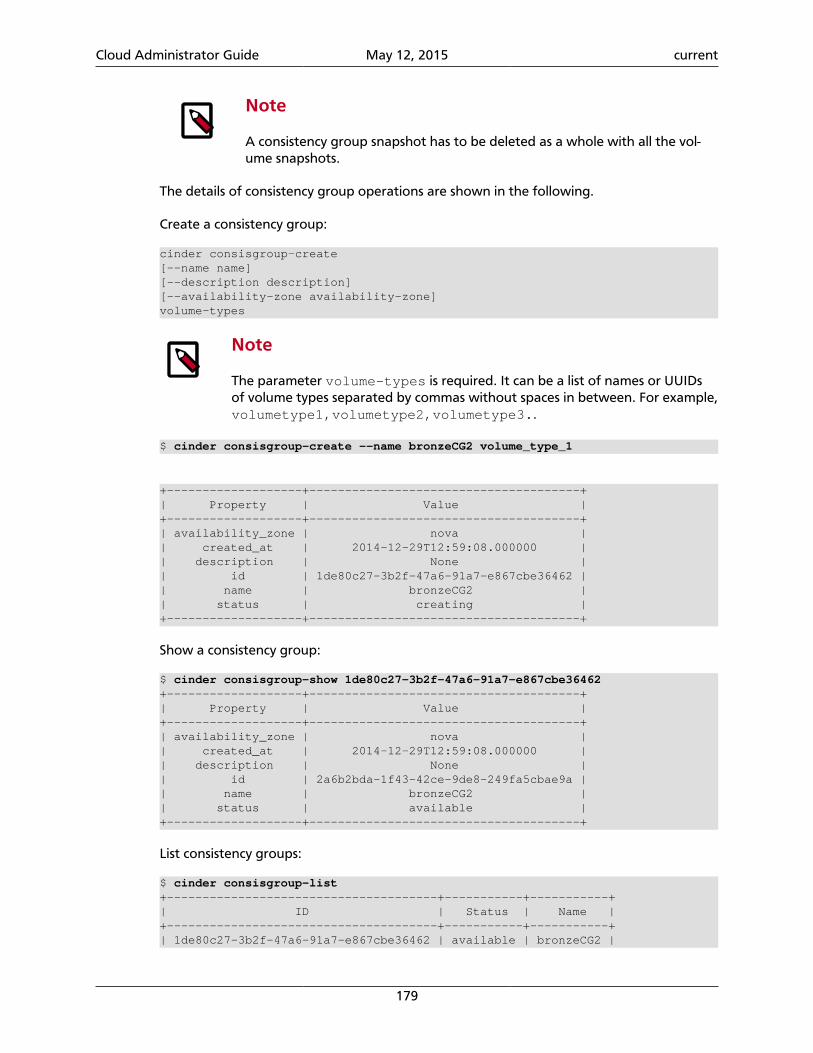
Cloud Administrator Guide May 12, 2015 current
179
Note
A consistency group snapshot has to be deleted as a whole with all the vol-ume snapshots.
The details of consistency group operations are shown in the following.
Create a consistency group:
cinder consisgroup-create[--name name][--description description][--availability-zone availability-zone]volume-types
Note
The parameter volume-types is required. It can be a list of names or UUIDsof volume types separated by commas without spaces in between. For example,volumetype1,volumetype2,volumetype3..
$ cinder consisgroup-create --name bronzeCG2 volume_type_1
+-------------------+--------------------------------------+| Property | Value |+-------------------+--------------------------------------+| availability_zone | nova || created_at | 2014-12-29T12:59:08.000000 || description | None || id | 1de80c27-3b2f-47a6-91a7-e867cbe36462 || name | bronzeCG2 || status | creating |+-------------------+--------------------------------------+
Show a consistency group:
$ cinder consisgroup-show 1de80c27-3b2f-47a6-91a7-e867cbe36462+-------------------+--------------------------------------+| Property | Value |+-------------------+--------------------------------------+| availability_zone | nova || created_at | 2014-12-29T12:59:08.000000 || description | None || id | 2a6b2bda-1f43-42ce-9de8-249fa5cbae9a || name | bronzeCG2 || status | available |+-------------------+--------------------------------------+
List consistency groups:
$ cinder consisgroup-list+--------------------------------------+-----------+-----------+| ID | Status | Name |+--------------------------------------+-----------+-----------+| 1de80c27-3b2f-47a6-91a7-e867cbe36462 | available | bronzeCG2 |
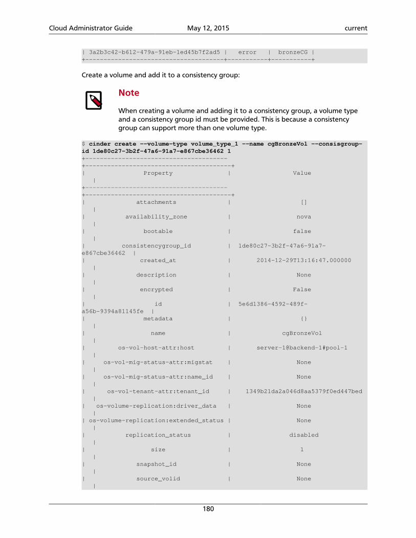
Cloud Administrator Guide May 12, 2015 current
180
| 3a2b3c42-b612-479a-91eb-1ed45b7f2ad5 | error | bronzeCG |+--------------------------------------+-----------+-----------+
Create a volume and add it to a consistency group:
Note
When creating a volume and adding it to a consistency group, a volume typeand a consistency group id must be provided. This is because a consistencygroup can support more than one volume type.
$ cinder create --volume-type volume_type_1 --name cgBronzeVol --consisgroup-id 1de80c27-3b2f-47a6-91a7-e867cbe36462 1+---------------------------------------+----------------------------------------+| Property | Value |+---------------------------------------+----------------------------------------+| attachments | [] || availability_zone | nova || bootable | false || consistencygroup_id | 1de80c27-3b2f-47a6-91a7-e867cbe36462 || created_at | 2014-12-29T13:16:47.000000 || description | None || encrypted | False || id | 5e6d1386-4592-489f-a56b-9394a81145fe || metadata | {} || name | cgBronzeVol || os-vol-host-attr:host | server-1@backend-1#pool-1 || os-vol-mig-status-attr:migstat | None || os-vol-mig-status-attr:name_id | None || os-vol-tenant-attr:tenant_id | 1349b21da2a046d8aa5379f0ed447bed || os-volume-replication:driver_data | None || os-volume-replication:extended_status | None || replication_status | disabled || size | 1 || snapshot_id | None || source_volid | None |
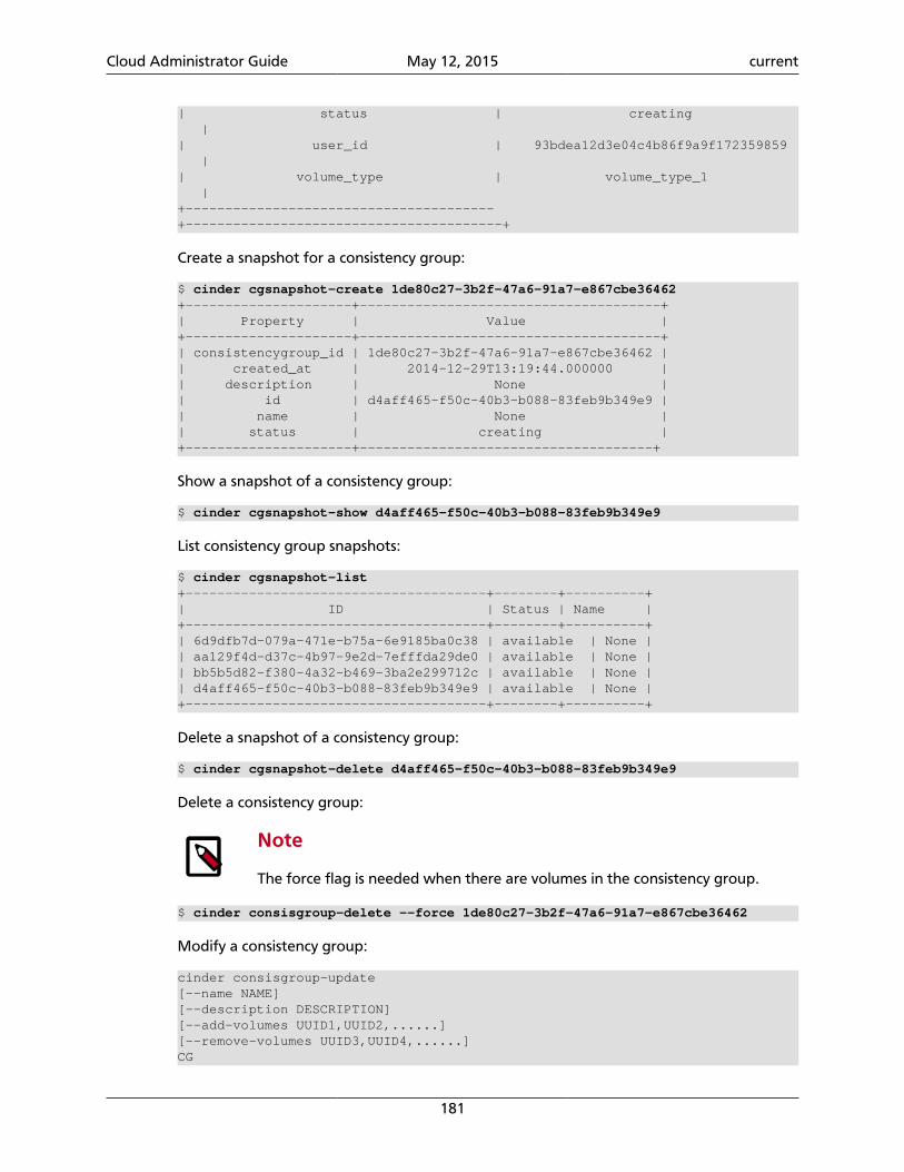
Cloud Administrator Guide May 12, 2015 current
181
| status | creating || user_id | 93bdea12d3e04c4b86f9a9f172359859 || volume_type | volume_type_1 |+---------------------------------------+----------------------------------------+
Create a snapshot for a consistency group:
$ cinder cgsnapshot-create 1de80c27-3b2f-47a6-91a7-e867cbe36462+---------------------+--------------------------------------+| Property | Value |+---------------------+--------------------------------------+| consistencygroup_id | 1de80c27-3b2f-47a6-91a7-e867cbe36462 || created_at | 2014-12-29T13:19:44.000000 || description | None || id | d4aff465-f50c-40b3-b088-83feb9b349e9 || name | None || status | creating |+---------------------+-------------------------------------+
Show a snapshot of a consistency group:
$ cinder cgsnapshot-show d4aff465-f50c-40b3-b088-83feb9b349e9
List consistency group snapshots:
$ cinder cgsnapshot-list+--------------------------------------+--------+----------+| ID | Status | Name |+--------------------------------------+--------+----------+| 6d9dfb7d-079a-471e-b75a-6e9185ba0c38 | available | None || aa129f4d-d37c-4b97-9e2d-7efffda29de0 | available | None || bb5b5d82-f380-4a32-b469-3ba2e299712c | available | None || d4aff465-f50c-40b3-b088-83feb9b349e9 | available | None |+--------------------------------------+--------+----------+
Delete a snapshot of a consistency group:
$ cinder cgsnapshot-delete d4aff465-f50c-40b3-b088-83feb9b349e9
Delete a consistency group:
Note
The force flag is needed when there are volumes in the consistency group.
$ cinder consisgroup-delete --force 1de80c27-3b2f-47a6-91a7-e867cbe36462
Modify a consistency group:
cinder consisgroup-update[--name NAME][--description DESCRIPTION][--add-volumes UUID1,UUID2,......][--remove-volumes UUID3,UUID4,......]CG
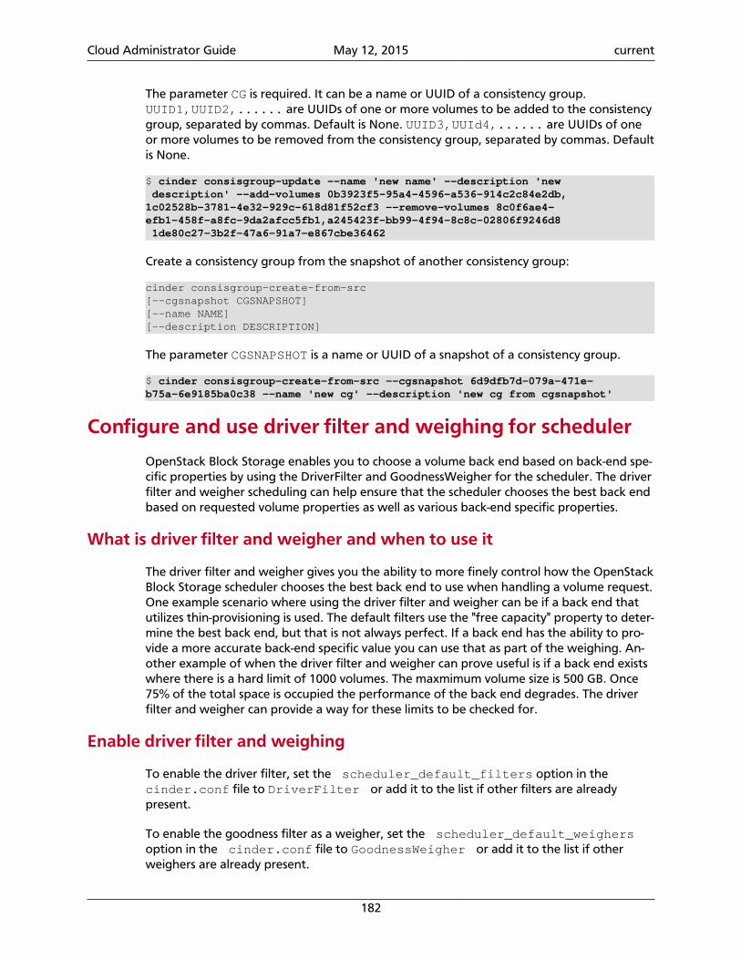
Cloud Administrator Guide May 12, 2015 current
182
The parameter CG is required. It can be a name or UUID of a consistency group.UUID1,UUID2,...... are UUIDs of one or more volumes to be added to the consistencygroup, separated by commas. Default is None. UUID3,UUId4,...... are UUIDs of oneor more volumes to be removed from the consistency group, separated by commas. Defaultis None.
$ cinder consisgroup-update --name 'new name' --description 'new description' --add-volumes 0b3923f5-95a4-4596-a536-914c2c84e2db,1c02528b-3781-4e32-929c-618d81f52cf3 --remove-volumes 8c0f6ae4-efb1-458f-a8fc-9da2afcc5fb1,a245423f-bb99-4f94-8c8c-02806f9246d8 1de80c27-3b2f-47a6-91a7-e867cbe36462
Create a consistency group from the snapshot of another consistency group:
cinder consisgroup-create-from-src[--cgsnapshot CGSNAPSHOT][--name NAME][--description DESCRIPTION]
The parameter CGSNAPSHOT is a name or UUID of a snapshot of a consistency group.
$ cinder consisgroup-create-from-src --cgsnapshot 6d9dfb7d-079a-471e-b75a-6e9185ba0c38 --name 'new cg' --description 'new cg from cgsnapshot'
Configure and use driver filter and weighing for scheduler
OpenStack Block Storage enables you to choose a volume back end based on back-end spe-cific properties by using the DriverFilter and GoodnessWeigher for the scheduler. The driverfilter and weigher scheduling can help ensure that the scheduler chooses the best back endbased on requested volume properties as well as various back-end specific properties.
What is driver filter and weigher and when to use it
The driver filter and weigher gives you the ability to more finely control how the OpenStackBlock Storage scheduler chooses the best back end to use when handling a volume request.One example scenario where using the driver filter and weigher can be if a back end thatutilizes thin-provisioning is used. The default filters use the "free capacity" property to deter-mine the best back end, but that is not always perfect. If a back end has the ability to pro-vide a more accurate back-end specific value you can use that as part of the weighing. An-other example of when the driver filter and weigher can prove useful is if a back end existswhere there is a hard limit of 1000 volumes. The maxmimum volume size is 500 GB. Once75% of the total space is occupied the performance of the back end degrades. The driverfilter and weigher can provide a way for these limits to be checked for.
Enable driver filter and weighing
To enable the driver filter, set the scheduler_default_filters option in the cinder.conf file to DriverFilter or add it to the list if other filters are alreadypresent.
To enable the goodness filter as a weigher, set the scheduler_default_weighersoption in the cinder.conf file to GoodnessWeigher or add it to the list if otherweighers are already present.
Cloud Administrator Guide May 12, 2015 current
183
You can choose to use the DriverFilter without the GoodnessWeigher or vice-versa.The filter and weigher working together, however, create the most benefits when helpingthe scheduler choose an ideal back end.
Important
The support for the DriverFilter and GoodnessWeigher is optional forback ends. If you are using a back end that does not support the filter andweigher functionality you may not get the full benefit.
Example cinder.conf configuration file:
scheduler_default_filters = DriverFilterscheduler_default_weighers = GoodnessWeigher
Note
It is useful to use the other filters and weighers available in OpenStack in com-bination with these custom ones. For example, the CapacityFilter and Ca-pacityWeigher can be combined with these.
Defining your own filter and goodness functions
You can define your own filter and goodness functions through the use of various prop-erties that OpenStack Block Storage has exposed. Properties exposed include informationabout the volume request being made, volume_type settings, and back-end specific infor-mation about drivers. All of these allow for a lot of control over how the ideal back end fora volume request will be decided.
The filter_function option is a string defining an equation that will determinewhether a back end should be considered as a potential candidate in the scheduler.
The goodness_function option is a string defining an equation that will rate the qualityof the potential host (0 to 100, 0 lowest, 100 highest).
Important
Default values for the filter and goodness functions will be used for each backend if you do not define them yourself. If complete control is desired then a fil-ter and goodness function should be defined for each of the back ends in thecinder.conf file.
Supported operations in filter and goodness functions
Below is a table of all the operations currently usable in custom filter and goodness func-tions created by you:
Operations Type
+, -, *, /, ^ standard math
not, and, or, &, |, ! logic
>, >=, <, <=, ==, <>, != equality
+, - sign
x ? a : b ternary
abs(x), max(x, y), min(x, y) math helper functions
Cloud Administrator Guide May 12, 2015 current
184
Caution
Syntax errors in filter or goodness strings defined by you will cause errors to bethrown at volume request time.
Available properties when creating custom functions
There are various properties that can be used in either the filter_function or the goodness_function strings. The properties allow access to volume info, qos settings, ex-tra specs, and so on.
Here is a list of the properties and their sub-properties currently available for use:
• stats—These are the host stats for a back end.
host The host's name.
volume_backend_name The volume back end name.
vendor_name The vendor name.
driver_version The driver version.
storage_protocol The storage protocol.
QoS_support Boolean signifying whether QoS is supported.
total_capacity_gb The total capacity in GB.
allocated_capacity_gb The allocated capacity in GB.
reserved_percentage The reserved storage percentage.
• capabilities—These are the capabilities specific to a back end.
The properties available here are determined by the specific back end you are creating fil-ter and goodness functions for. Some back ends may not have any properties availablehere.
• volume—The requested volume properties.
status Status for the requested volume.
volume_type_id The volume type ID.
display_name The display name of the volume.
volume_metadata Any metadata the volume has.
reservations Any reservations the volume has.
user_id The volume's user ID.
attach_status The attach status for the volume.
Cloud Administrator Guide May 12, 2015 current
185
display_description The volume's display description.
id The volume's ID.
replication_status The volume's replication status.
snapshot_id The volume's snapshot ID.
encryption_key_id The volume's encryption key ID.
source_volid The source volume ID.
volume_admin_metadata Any admin metadata for this volume.
source_replicaid The source replication ID.
consistencygroup_id The consistency group ID.
size The size of the volume in GB.
metadata General metadata.
The property most used from here will most likely be the size sub-property.
• extra—The extra specs for the requested volume type.
View the available properties for volume types by running:
$ cinder extra-specs-list
• qos—The current QoS specs for the requested volume type.
View the available properties for volume types by running:
$ cinder qos-list
In order to access these properties in a custom string use the following format:
<property>.<sub_property>
Driver filter and weigher usage examples
Below are examples for using the filter and weigher separately, together, and using driv-er-specific properties.
Example cinder.conf file configuration for customizing the filter function:
Cloud Administrator Guide May 12, 2015 current
186
[default]scheduler_default_filters = DriverFilterenabled_backends = lvm-1, lvm-2
[lvm-1]volume_driver = cinder.volume.drivers.lvm.LVMVolumeDrivervolume_backend_name = sample_LVMfilter_function = "volume.size < 10"
[lvm-2]volume_driver = cinder.volume.drivers.lvm.LVMVolumeDrivervolume_backend_name = sample_LVMfilter_function = "volume.size >= 10"
The above example will filter volumes to different back ends depending on the size of therequested volume. Default OpenStack Block Storage scheduler weighing is done. Volumeswith a size less than 10 GB are sent to lvm-1 and volumes with a size greater than or equalto 10 GB are sent to lvm-2.
Example cinder.conf file configuration for customizing the goodness function:
[default]scheduler_default_weighers = GoodnessWeigherenabled_backends = lvm-1, lvm-2
[lvm-1]volume_driver = cinder.volume.drivers.lvm.LVMVolumeDrivervolume_backend_name = sample_LVMgoodness_function = "(volume.size < 5) ? 100 : 50"
[lvm-2]volume_driver = cinder.volume.drivers.lvm.LVMVolumeDrivervolume_backend_name = sample_LVMgoodness_function = "(volume.size >= 5) ? 100 : 25"
The above example will determine the goodness rating of a back end based off of the re-quested volume's size. Default OpenStack Block Storage scheduler filtering is done. The ex-ample shows how the ternary if statement can be used in a filter or goodness function. Ifa requested volume is of size 10 GB then lvm-1 is rated as 50 and lvm-2 is rated as 100. Inthis case lvm-2 wins. If a requested volume is of size 3 GB then lvm-1 is rated 100 and lvm-2is rated 25. In this case lvm-1 would win.
Example cinder.conf file configuration for customizing both the filter and goodnessfunctions:
[default]scheduler_default_filters = DriverFilterscheduler_default_weighers = GoodnessWeigherenabled_backends = lvm-1, lvm-2
[lvm-1]volume_driver = cinder.volume.drivers.lvm.LVMVolumeDrivervolume_backend_name = sample_LVMfilter_function = "stats.total_capacity_gb < 500"goodness_function = "(volume.size < 25) ? 100 : 50"
[lvm-2]volume_driver = cinder.volume.drivers.lvm.LVMVolumeDriver
Cloud Administrator Guide May 12, 2015 current
187
volume_backend_name = sample_LVMfilter_function = "stats.total_capacity_gb >= 500"goodness_function = "(volume.size >= 25) ? 100 : 75"
The above example combines the techniques from the first two examples. The best backend is now decided based off of the total capacity of the back end and the requestedvolume's size.
Example cinder.conf file configuration for accessing driver specific properties:
[default]scheduler_default_filters = DriverFilterscheduler_default_weighers = GoodnessWeigherenabled_backends = lvm-1,lvm-2,lvm-3
[lvm-1]volume_group = stack-volumes-lvmdriver-1volume_driver = cinder.volume.drivers.lvm.LVMISCSIDrivervolume_backend_name = lvmdriver-1filter_function = "volume.size < 5"goodness_function = "(capabilities.total_volumes < 3) ? 100 : 50"
[lvm-2]volume_group = stack-volumes-lvmdriver-2volume_driver = cinder.volume.drivers.lvm.LVMISCSIDrivervolume_backend_name = lvmdriver-2filter_function = "volumes.size < 5"goodness_function = "(capabilities.total_volumes < 8) ? 100 : 50"
[lvm-3]volume_group = stack-volumes-lvmdriver-3volume_driver = cinder.volume.drivers.lvm.LVMISCSIDrivervolume_backend_name = lvmdriver-3goodness_function = "55"
The above is an example of how back-end specific properties can be used in the fitler andgoodness functions. In this example the LVM driver's 'total_volumes' capability is being usedto determine which host gets used during a volume request. In the above example, lvm-1and lvm-2 will handle volume requests for all volumes with a size less than 5 GB. The lvm-1host will have priority until it contains three or more volumes. After than lvm-2 will have pri-ority until it contains eight or more volumes. The lvm-3 will collect all volumes greater orequal to 5 GB as well as all volumes once lvm-1 and lvm-2 lose priority.
Rate-limit volume copy bandwidth
When you create a new volume from an image or an existing volume, or when you uploada volume image to the Image Service, large data copy may stress disk and network band-width. To mitigate slow down of data access from the instances, OpenStack Block Storagesupports rate-limiting of volume data copy bandwidth.
Configure volume copy bandwidth limit
To configure the volume copy bandwidth limit, set the volume_copy_bps_limit optionin the configuration groups for each back end in the cinder.conf file. This option takesthe integer of maximum bandwidth allowed for volume data copy in byte per second. Ifthis option is set to 0, the rate-limit is disabled.
Cloud Administrator Guide May 12, 2015 current
188
While multiple volume data copy operations are running in the same back end, the speci-fied bandwidth is divided to each copy.
Example cinder.conf configuration file to limit volume copy bandwidth of lvmdriv-er-1 up to 100 MiB/s:
[lvmdriver-1]volume_group=cinder-volumes-1volume_driver=cinder.volume.drivers.lvm.LVMISCSIDrivervolume_backend_name=LVM_iSCSIvolume_copy_bps_limit=104857600
Note
This feature requires libcgroup to set up blkio cgroup for disk I/O bandwidthlimit. The libcgroup is provided by the cgroup-bin package in Debian and Ubun-tu, or by the libcgroup-tools package in Fedora, Red Hat Enterprise Linux, Cen-tOS, openSUSE, and SUSE Linux Enterprise.
Note
Some back ends which use remote file systems such as NFS are not supportedby this feature.
Oversubscription in thin provisioning
OpenStack Block Storage enables you to choose a volume back end based on virtual capaci-ties for thin provisioning using the oversubscription ratio.
A reference implementation is provided for the default LVM driver. The illustration belowuses the LVM driver as an example.
Configure oversubscription settings
To support oversubscription in thin provisioning, a flagmax_over_subscription_ratio is introduced into cinder.conf. This is a float rep-resentation of the oversubscription ratio when thin provisioning is involved. Default ratiois 20.0, meaning provisioned capacity can be 20 times of the total physical capacity. A ratioof 10.5 means provisioned capacity can be 10.5 times of the total physical capacity. A ratioof 1.0 means provisioned capacity cannot exceed the total physical capacity. A ratio lowerthan 1.0 is ignored and the default value is used instead.
Note
max_over_subscription_ratio can be configured for each backend when multiple-storage back ends are enabled. It is provided as areference implementation and is used by the LVM driver. However, it isnot a requirement for a driver to use this option from cinder.conf.max_over_subscription_ratio is for configuring a back end. For a driverthat supports multiple pools per back end, it can report this ratio for each pool.The LVM driver does not support multiple pools.
Cloud Administrator Guide May 12, 2015 current
189
The existing reserved_percentage flag is used to prevent over provisioning. This flagrepresents the percentage of the back-end capacity that is reserved.
Note
There is a change on how reserved_percentage is used. It was measuredagainst the free capacity in the past. Now it is measured against the total capac-ity.
Capabilities
Drivers can report the following capabilities for a back end or a pool:
thin_provisioning_support=True(or False)thick_provisioning_support=True(or False)provisioned_capacity_gb=PROVISIONED_CAPACITYmax_over_subscription_ratio=MAX_RATIO
Where PROVISIONED_CAPACITY is the apparent allocated space indicating how much ca-pacity has been provisioned and MAX_RATIO is the maximum oversubscription ratio. Forthe LVM driver, it is max_over_subscription_ratio in cinder.conf.
Two capabilities are added here to allow a back end or pool to claim support for thin provi-sioning, or thick provisioning, or both.
The LVM driver reports thin_provisioning_support=True andthick_provisioning_support=False if the lvm_type flag in cinder.conf is thin. Otherwise it reports thin_provisioning_support=False and thick_provisioning_support=True.
Volume type extra specs
If volume type is provided as part of the volume creation request, it can have the followingextra specs defined:
'capabilities:thin_provisioning_support': '<is> True' or '<is> False''capabilities:thick_provisioning_support': '<is> True' or '<is> False'
Note
capabilities scope key before thin_provisioning_support and thick_provisioning_support is not required. So the following works too:
'thin_provisioning_support': '<is> True' or '<is> False''thick_provisioning_support': '<is> True' or '<is> False'
The above extra specs are used by the scheduler to find a back end that supports thin provi-sioning, thick provisioning, or both to match the needs of a specific volume type.
Capacity filter
In the capacity filter, max_over_subscription_ratio is used whenchoosing a back end if thin_provisioning_support is True and max_over_subscription_ratio is greater than 1.0.
Cloud Administrator Guide May 12, 2015 current
190
Capacity weigher
In the capacity weigher, virtual free capacity is used for ranking ifthin_provisioning_support is True. Otherwise, real free capacity will be used as be-fore.
Troubleshoot your installationThis section provides useful tips to help you troubleshoot your Block Storage installation.
Troubleshoot the Block Storage configurationMost Block Storage errors are caused by incorrect volume configurations that result in vol-ume creation failures. To resolve these failures, review these logs:
• cinder-api log (/var/log/cinder/api.log)
• cinder-volume log (/var/log/cinder/volume.log)
The cinder-api log is useful for determining if you have endpoint or connectivity issues.If you send a request to create a volume and it fails, review the cinder-api log to deter-mine whether the request made it to the Block Storage service. If the request is logged andyou see no errors or trace-backs, check the cinder-volume log for errors or trace-backs.
Note
Create commands are listed in the cinder-api log.
These entries in the cinder.openstack.common.log file can be used to assist in trou-bleshooting your block storage configuration.
# Print debugging output (set logging level to DEBUG instead# of default WARNING level). (boolean value)#debug=false
# Print more verbose output (set logging level to INFO instead# of default WARNING level). (boolean value)#verbose=false
# Log output to standard error (boolean value)#use_stderr=true
# Default file mode used when creating log files (string# value)#logfile_mode=0644
# format string to use for log messages with context (string# value)#logging_context_format_string=%(asctime)s.%(msecs)03d %(levelname)s %(name)s [%(request_id)s %(user)s %(tenant)s] %(instance)s%(message)s
# format string to use for log mes #logging_default_format_string=%(asctime)s.%(msecs)03d %(process)d %(levelname)s %(name)s [-] %(instance)s%(message)s
# data to append to log format when level is DEBUG (string
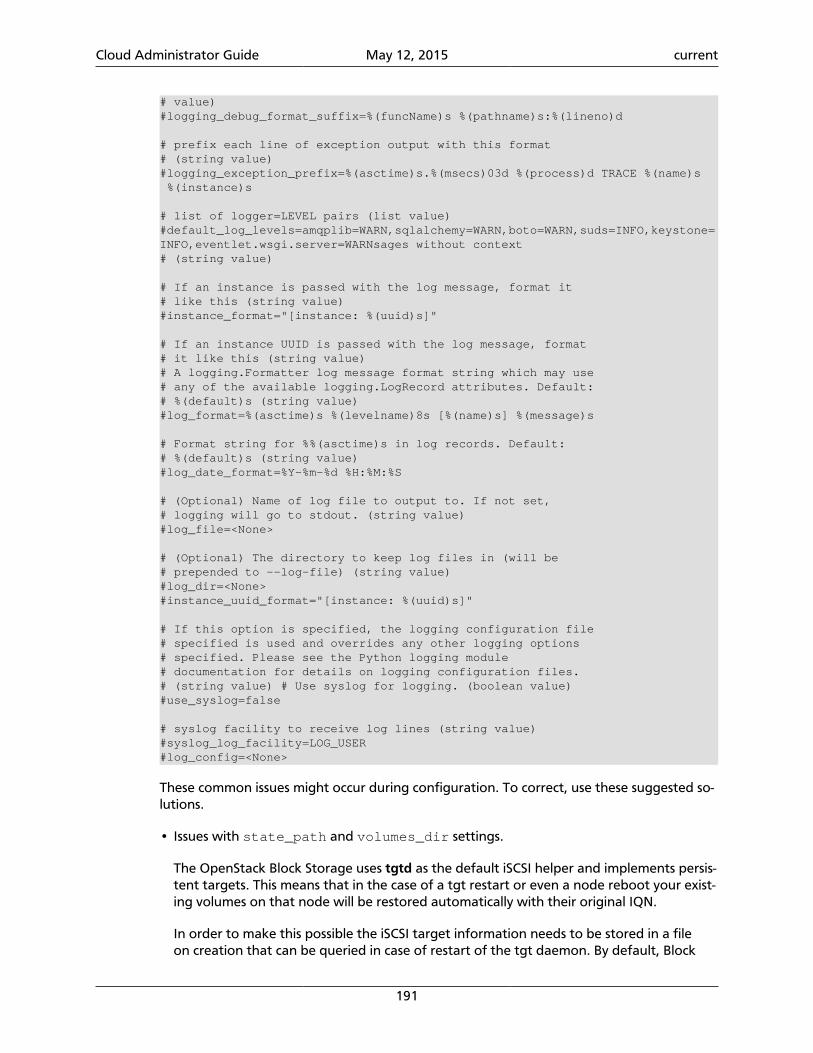
Cloud Administrator Guide May 12, 2015 current
191
# value)#logging_debug_format_suffix=%(funcName)s %(pathname)s:%(lineno)d
# prefix each line of exception output with this format# (string value)#logging_exception_prefix=%(asctime)s.%(msecs)03d %(process)d TRACE %(name)s %(instance)s
# list of logger=LEVEL pairs (list value)#default_log_levels=amqplib=WARN,sqlalchemy=WARN,boto=WARN,suds=INFO,keystone=INFO,eventlet.wsgi.server=WARNsages without context# (string value)
# If an instance is passed with the log message, format it# like this (string value)#instance_format="[instance: %(uuid)s]"
# If an instance UUID is passed with the log message, format# it like this (string value)# A logging.Formatter log message format string which may use# any of the available logging.LogRecord attributes. Default:# %(default)s (string value)#log_format=%(asctime)s %(levelname)8s [%(name)s] %(message)s
# Format string for %%(asctime)s in log records. Default:# %(default)s (string value)#log_date_format=%Y-%m-%d %H:%M:%S
# (Optional) Name of log file to output to. If not set,# logging will go to stdout. (string value)#log_file=<None>
# (Optional) The directory to keep log files in (will be# prepended to --log-file) (string value)#log_dir=<None>#instance_uuid_format="[instance: %(uuid)s]"
# If this option is specified, the logging configuration file# specified is used and overrides any other logging options# specified. Please see the Python logging module# documentation for details on logging configuration files.# (string value) # Use syslog for logging. (boolean value)#use_syslog=false
# syslog facility to receive log lines (string value)#syslog_log_facility=LOG_USER#log_config=<None>
These common issues might occur during configuration. To correct, use these suggested so-lutions.
• Issues with state_path and volumes_dir settings.
The OpenStack Block Storage uses tgtd as the default iSCSI helper and implements persis-tent targets. This means that in the case of a tgt restart or even a node reboot your exist-ing volumes on that node will be restored automatically with their original IQN.
In order to make this possible the iSCSI target information needs to be stored in a fileon creation that can be queried in case of restart of the tgt daemon. By default, Block
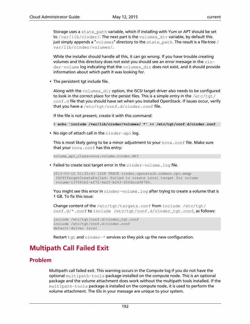
Cloud Administrator Guide May 12, 2015 current
192
Storage uses a state_path variable, which if installing with Yum or APT should be setto /var/lib/cinder/. The next part is the volumes_dir variable, by default thisjust simply appends a "volumes" directory to the state_path. The result is a file-tree /var/lib/cinder/volumes/.
While the installer should handle all this, it can go wrong. If you have trouble creatingvolumes and this directory does not exist you should see an error message in the cin-der-volume log indicating that the volumes_dir does not exist, and it should provideinformation about which path it was looking for.
• The persistent tgt include file.
Along with the volumes_dir option, the iSCSI target driver also needs to be configuredto look in the correct place for the persist files. This is a simple entry in the /etc/tgt/conf.d file that you should have set when you installed OpenStack. If issues occur, verifythat you have a /etc/tgt/conf.d/cinder.conf file.
If the file is not present, create it with this command:
# echo 'include /var/lib/cinder/volumes/ *' >> /etc/tgt/conf.d/cinder.conf
• No sign of attach call in the cinder-api log.
This is most likely going to be a minor adjustment to your nova.conf file. Make surethat your nova.conf has this entry:
volume_api_class=nova.volume.cinder.API
• Failed to create iscsi target error in the cinder-volume.log file.
2013-03-12 01:35:43 1248 TRACE cinder.openstack.common.rpc.amqp ISCSITargetCreateFailed: Failed to create iscsi target for volume volume-137641b2-af72-4a2f-b243-65fdccd38780.
You might see this error in cinder-volume.log after trying to create a volume that is1 GB. To fix this issue:
Change content of the /etc/tgt/targets.conf from include /etc/tgt/conf.d/*.conf to include /etc/tgt/conf.d/cinder_tgt.conf, as follows:
include /etc/tgt/conf.d/cinder_tgt.confinclude /etc/tgt/conf.d/cinder.confdefault-driver iscsi
Restart tgt and cinder-* services so they pick up the new configuration.
Multipath Call Failed Exit
Problem
Multipath call failed exit. This warning occurs in the Compute log if you do not have theoptional multipath-tools package installed on the compute node. This is an optionalpackage and the volume attachment does work without the multipath tools installed. If themultipath-tools package is installed on the compute node, it is used to perform thevolume attachment. The IDs in your message are unique to your system.
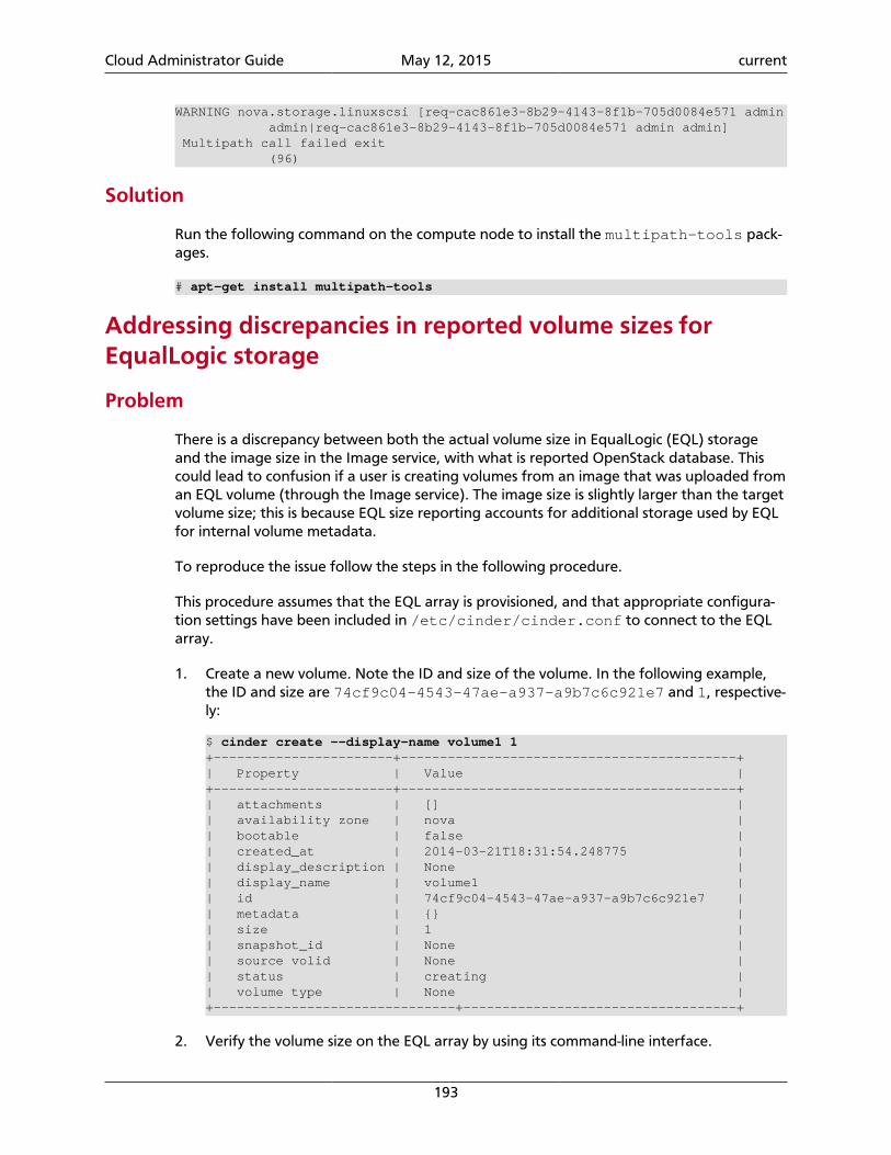
Cloud Administrator Guide May 12, 2015 current
193
WARNING nova.storage.linuxscsi [req-cac861e3-8b29-4143-8f1b-705d0084e571 admin admin|req-cac861e3-8b29-4143-8f1b-705d0084e571 admin admin] Multipath call failed exit (96)
Solution
Run the following command on the compute node to install the multipath-tools pack-ages.
# apt-get install multipath-tools
Addressing discrepancies in reported volume sizes forEqualLogic storage
Problem
There is a discrepancy between both the actual volume size in EqualLogic (EQL) storageand the image size in the Image service, with what is reported OpenStack database. Thiscould lead to confusion if a user is creating volumes from an image that was uploaded froman EQL volume (through the Image service). The image size is slightly larger than the targetvolume size; this is because EQL size reporting accounts for additional storage used by EQLfor internal volume metadata.
To reproduce the issue follow the steps in the following procedure.
This procedure assumes that the EQL array is provisioned, and that appropriate configura-tion settings have been included in /etc/cinder/cinder.conf to connect to the EQLarray.
1. Create a new volume. Note the ID and size of the volume. In the following example,the ID and size are 74cf9c04-4543-47ae-a937-a9b7c6c921e7 and 1, respective-ly:
$ cinder create --display-name volume1 1+-----------------------+-------------------------------------------+| Property | Value |+-----------------------+-------------------------------------------+| attachments | [] || availability zone | nova || bootable | false || created_at | 2014-03-21T18:31:54.248775 || display_description | None || display_name | volume1 || id | 74cf9c04-4543-47ae-a937-a9b7c6c921e7 || metadata | {} || size | 1 || snapshot_id | None || source volid | None || status | creating || volume type | None |+-------------------------------+-----------------------------------+
2. Verify the volume size on the EQL array by using its command-line interface.
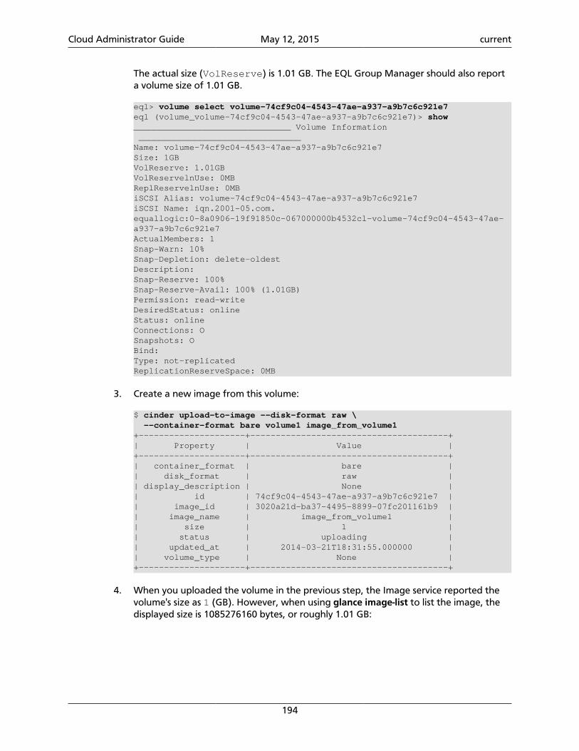
Cloud Administrator Guide May 12, 2015 current
194
The actual size (VolReserve) is 1.01 GB. The EQL Group Manager should also reporta volume size of 1.01 GB.
eql> volume select volume-74cf9c04-4543-47ae-a937-a9b7c6c921e7eql (volume_volume-74cf9c04-4543-47ae-a937-a9b7c6c921e7)> show_______________________________ Volume Information ________________________________Name: volume-74cf9c04-4543-47ae-a937-a9b7c6c921e7Size: 1GBVolReserve: 1.01GBVolReservelnUse: 0MBReplReservelnUse: 0MBiSCSI Alias: volume-74cf9c04-4543-47ae-a937-a9b7c6c921e7iSCSI Name: iqn.2001-05.com.equallogic:0-8a0906-19f91850c-067000000b4532cl-volume-74cf9c04-4543-47ae-a937-a9b7c6c921e7ActualMembers: 1Snap-Warn: 10%Snap-Depletion: delete-oldestDescription:Snap-Reserve: 100%Snap-Reserve-Avail: 100% (1.01GB)Permission: read-writeDesiredStatus: onlineStatus: onlineConnections: OSnapshots: OBind:Type: not-replicatedReplicationReserveSpace: 0MB
3. Create a new image from this volume:
$ cinder upload-to-image --disk-format raw \ --container-format bare volume1 image_from_volume1+---------------------+---------------------------------------+| Property | Value |+---------------------+---------------------------------------+| container_format | bare || disk_format | raw || display_description | None || id | 74cf9c04-4543-47ae-a937-a9b7c6c921e7 || image_id | 3020a21d-ba37-4495-8899-07fc201161b9 || image_name | image_from_volume1 || size | 1 || status | uploading || updated_at | 2014-03-21T18:31:55.000000 || volume_type | None |+---------------------+---------------------------------------+
4. When you uploaded the volume in the previous step, the Image service reported thevolume's size as 1 (GB). However, when using glance image-list to list the image, thedisplayed size is 1085276160 bytes, or roughly 1.01 GB:
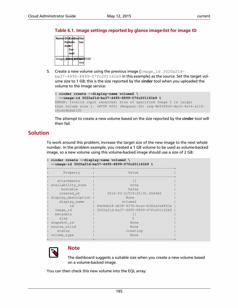
Cloud Administrator Guide May 12, 2015 current
195
Table 6.1. Image settings reported by glance image-list for image ID
Name DiskFor-mat
Con-tain-erFor-mat
SizeSta-tus
image_from_volume1rawbare1085276160ac-tive
5. Create a new volume using the previous image (image_id 3020a21d-ba37-4495-8899-07fc201161b9 in this example) as the source. Set the target vol-ume size to 1 GB; this is the size reported by the cinder tool when you uploaded thevolume to the Image service:
$ cinder create --display-name volume2 \ --image-id 3020a21d-ba37-4495-8899-07fc201161b9 1ERROR: Invalid input received: Size of specified image 2 is largerthan volume size 1. (HTTP 400) (Request-ID: req-4b9369c0-dec5-4e16-a114-c0cdl6bSd210)
The attempt to create a new volume based on the size reported by the cinder tool willthen fail.
Solution
To work around this problem, increase the target size of the new image to the next wholenumber. In the problem example, you created a 1 GB volume to be used as volume-backedimage, so a new volume using this volume-backed image should use a size of 2 GB:
$ cinder create --display-name volume2 \ --image-id 3020a21d-ba37-4495-8899-07fc201161b9 1+---------------------+--------------------------------------+| Property | Value |+---------------------+--------------------------------------+| attachments | [] || availability_zone | nova || bootable | false || created_at | 2014-03-21T19:25:31.564482 || display_description | None || display_name | volume2 || id | 64e8eb18-d23f-437b-bcac-b3S2afa6843a || image_id | 3020a21d-ba37-4495-8899-07fc20116lb9 || metadata | [] || size | 2 || snapshot_id | None || source_volid | None || status | creating || volume_type | None |+---------------------+--------------------------------------+
Note
The dashboard suggests a suitable size when you create a new volume basedon a volume-backed image.
You can then check this new volume into the EQL array:
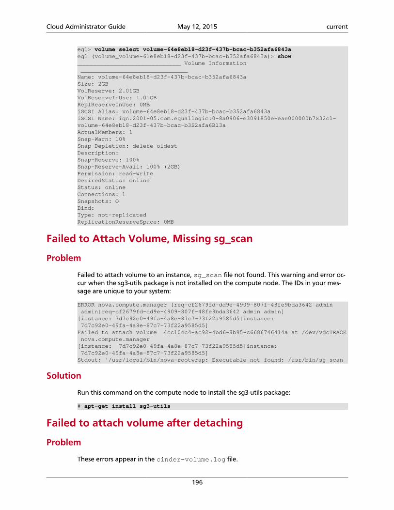
Cloud Administrator Guide May 12, 2015 current
196
eql> volume select volume-64e8eb18-d23f-437b-bcac-b352afa6843aeql (volume_volume-61e8eb18-d23f-437b-bcac-b352afa6843a)> show______________________________ Volume Information _______________________________Name: volume-64e8eb18-d23f-437b-bcac-b352afa6843aSize: 2GBVolReserve: 2.01GBVolReserveInUse: 1.01GBReplReserveInUse: 0MBiSCSI Alias: volume-64e8eb18-d23f-437b-bcac-b352afa6843aiSCSI Name: iqn.2001-05.com.equallogic:0-8a0906-e3091850e-eae000000b7S32cl-volume-64e8eb18-d23f-437b-bcac-b3S2afa6Bl3aActualMembers: 1Snap-Warn: 10%Snap-Depletion: delete-oldestDescription:Snap-Reserve: 100%Snap-Reserve-Avail: 100% (2GB)Permission: read-writeDesiredStatus: onlineStatus: onlineConnections: 1Snapshots: OBind:Type: not-replicatedReplicationReserveSpace: 0MB
Failed to Attach Volume, Missing sg_scan
Problem
Failed to attach volume to an instance, sg_scan file not found. This warning and error oc-cur when the sg3-utils package is not installed on the compute node. The IDs in your mes-sage are unique to your system:
ERROR nova.compute.manager [req-cf2679fd-dd9e-4909-807f-48fe9bda3642 admin admin|req-cf2679fd-dd9e-4909-807f-48fe9bda3642 admin admin][instance: 7d7c92e0-49fa-4a8e-87c7-73f22a9585d5|instance: 7d7c92e0-49fa-4a8e-87c7-73f22a9585d5]Failed to attach volume 4cc104c4-ac92-4bd6-9b95-c6686746414a at /dev/vdcTRACE nova.compute.manager[instance: 7d7c92e0-49fa-4a8e-87c7-73f22a9585d5|instance: 7d7c92e0-49fa-4a8e-87c7-73f22a9585d5]Stdout: '/usr/local/bin/nova-rootwrap: Executable not found: /usr/bin/sg_scan
Solution
Run this command on the compute node to install the sg3-utils package:
# apt-get install sg3-utils
Failed to attach volume after detaching
Problem
These errors appear in the cinder-volume.log file.
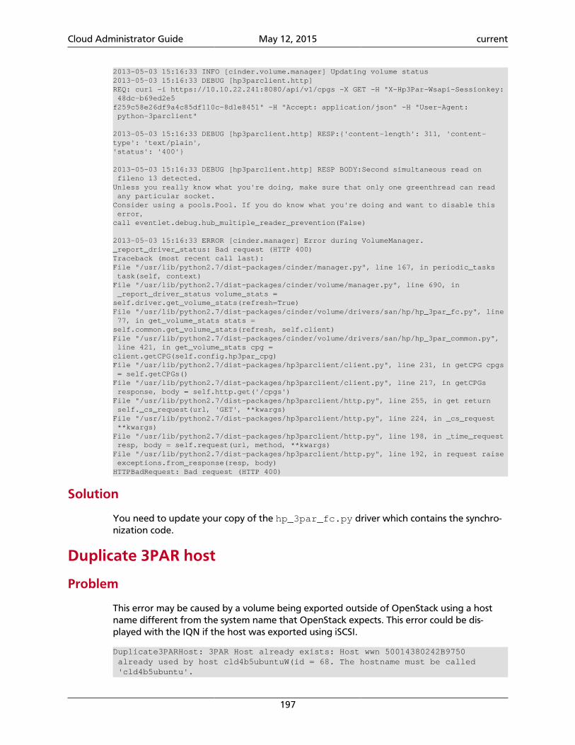
Cloud Administrator Guide May 12, 2015 current
197
2013-05-03 15:16:33 INFO [cinder.volume.manager] Updating volume status2013-05-03 15:16:33 DEBUG [hp3parclient.http]REQ: curl -i https://10.10.22.241:8080/api/v1/cpgs -X GET -H "X-Hp3Par-Wsapi-Sessionkey: 48dc-b69ed2e5f259c58e26df9a4c85df110c-8d1e8451" -H "Accept: application/json" -H "User-Agent: python-3parclient"
2013-05-03 15:16:33 DEBUG [hp3parclient.http] RESP:{'content-length': 311, 'content-type': 'text/plain','status': '400'}
2013-05-03 15:16:33 DEBUG [hp3parclient.http] RESP BODY:Second simultaneous read on fileno 13 detected.Unless you really know what you're doing, make sure that only one greenthread can read any particular socket.Consider using a pools.Pool. If you do know what you're doing and want to disable this error,call eventlet.debug.hub_multiple_reader_prevention(False)
2013-05-03 15:16:33 ERROR [cinder.manager] Error during VolumeManager._report_driver_status: Bad request (HTTP 400)Traceback (most recent call last):File "/usr/lib/python2.7/dist-packages/cinder/manager.py", line 167, in periodic_tasks task(self, context)File "/usr/lib/python2.7/dist-packages/cinder/volume/manager.py", line 690, in _report_driver_status volume_stats =self.driver.get_volume_stats(refresh=True)File "/usr/lib/python2.7/dist-packages/cinder/volume/drivers/san/hp/hp_3par_fc.py", line 77, in get_volume_stats stats =self.common.get_volume_stats(refresh, self.client)File "/usr/lib/python2.7/dist-packages/cinder/volume/drivers/san/hp/hp_3par_common.py", line 421, in get_volume_stats cpg =client.getCPG(self.config.hp3par_cpg)File "/usr/lib/python2.7/dist-packages/hp3parclient/client.py", line 231, in getCPG cpgs = self.getCPGs()File "/usr/lib/python2.7/dist-packages/hp3parclient/client.py", line 217, in getCPGs response, body = self.http.get('/cpgs')File "/usr/lib/python2.7/dist-packages/hp3parclient/http.py", line 255, in get return self._cs_request(url, 'GET', **kwargs)File "/usr/lib/python2.7/dist-packages/hp3parclient/http.py", line 224, in _cs_request **kwargs)File "/usr/lib/python2.7/dist-packages/hp3parclient/http.py", line 198, in _time_request resp, body = self.request(url, method, **kwargs)File "/usr/lib/python2.7/dist-packages/hp3parclient/http.py", line 192, in request raise exceptions.from_response(resp, body)HTTPBadRequest: Bad request (HTTP 400)
Solution
You need to update your copy of the hp_3par_fc.py driver which contains the synchro-nization code.
Duplicate 3PAR host
Problem
This error may be caused by a volume being exported outside of OpenStack using a hostname different from the system name that OpenStack expects. This error could be dis-played with the IQN if the host was exported using iSCSI.
Duplicate3PARHost: 3PAR Host already exists: Host wwn 50014380242B9750 already used by host cld4b5ubuntuW(id = 68. The hostname must be called 'cld4b5ubuntu'.
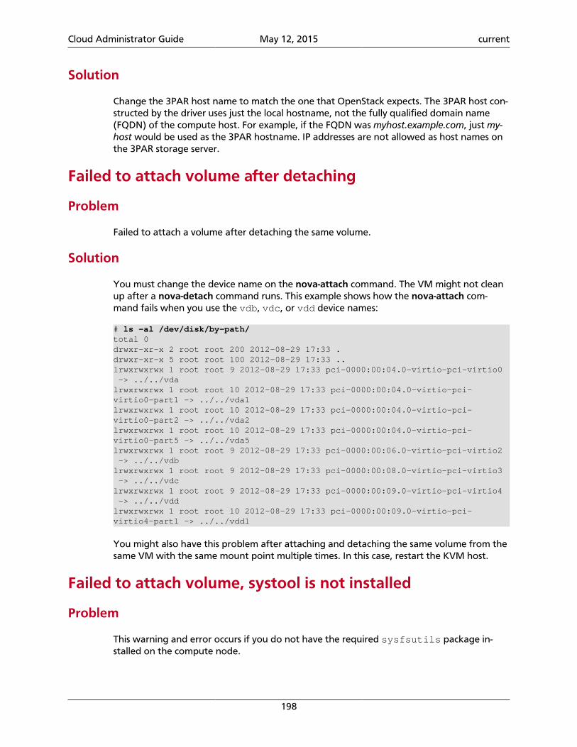
Cloud Administrator Guide May 12, 2015 current
198
Solution
Change the 3PAR host name to match the one that OpenStack expects. The 3PAR host con-structed by the driver uses just the local hostname, not the fully qualified domain name(FQDN) of the compute host. For example, if the FQDN was myhost.example.com, just my-host would be used as the 3PAR hostname. IP addresses are not allowed as host names onthe 3PAR storage server.
Failed to attach volume after detaching
Problem
Failed to attach a volume after detaching the same volume.
Solution
You must change the device name on the nova-attach command. The VM might not cleanup after a nova-detach command runs. This example shows how the nova-attach com-mand fails when you use the vdb, vdc, or vdd device names:
# ls -al /dev/disk/by-path/total 0drwxr-xr-x 2 root root 200 2012-08-29 17:33 .drwxr-xr-x 5 root root 100 2012-08-29 17:33 ..lrwxrwxrwx 1 root root 9 2012-08-29 17:33 pci-0000:00:04.0-virtio-pci-virtio0 -> ../../vdalrwxrwxrwx 1 root root 10 2012-08-29 17:33 pci-0000:00:04.0-virtio-pci-virtio0-part1 -> ../../vda1lrwxrwxrwx 1 root root 10 2012-08-29 17:33 pci-0000:00:04.0-virtio-pci-virtio0-part2 -> ../../vda2lrwxrwxrwx 1 root root 10 2012-08-29 17:33 pci-0000:00:04.0-virtio-pci-virtio0-part5 -> ../../vda5lrwxrwxrwx 1 root root 9 2012-08-29 17:33 pci-0000:00:06.0-virtio-pci-virtio2 -> ../../vdblrwxrwxrwx 1 root root 9 2012-08-29 17:33 pci-0000:00:08.0-virtio-pci-virtio3 -> ../../vdclrwxrwxrwx 1 root root 9 2012-08-29 17:33 pci-0000:00:09.0-virtio-pci-virtio4 -> ../../vddlrwxrwxrwx 1 root root 10 2012-08-29 17:33 pci-0000:00:09.0-virtio-pci-virtio4-part1 -> ../../vdd1
You might also have this problem after attaching and detaching the same volume from thesame VM with the same mount point multiple times. In this case, restart the KVM host.
Failed to attach volume, systool is not installed
Problem
This warning and error occurs if you do not have the required sysfsutils package in-stalled on the compute node.
Cloud Administrator Guide May 12, 2015 current
199
WARNING nova.virt.libvirt.utils [req-1200f887-c82b-4e7c-a891-fac2e3735dbb admin admin|req-1200f887-c82b-4e7c-a891-fac2e3735dbb admin admin] systool is not installedERROR nova.compute.manager [req-1200f887-c82b-4e7c-a891-fac2e3735dbb admin admin|req-1200f887-c82b-4e7c-a891-fac2e3735dbb admin admin][instance: df834b5a-8c3f-477a-be9b-47c97626555c|instance: df834b5a-8c3f-477a-be9b-47c97626555c]Failed to attach volume 13d5c633-903a-4764-a5a0-3336945b1db1 at /dev/vdk.
Solution
Run the following command on the compute node to install the sysfsutils packages.
# apt-get install sysfsutils
Failed to connect volume in FC SAN
Problem
Compute node failed to connect to a volume in a Fibre Channel (FC) SAN configuration.The WWN may not be zoned correctly in your FC SAN that links the compute host to thestorage array.
ERROR nova.compute.manager [req-2ddd5297-e405-44ab-aed3-152cd2cfb8c2 admin demo|req-2ddd5297-e405-44ab-aed3-152cd2cfb8c2 admin demo] [instance: 60ebd6c7-c1e3-4bf0-8ef0-f07aa4c3d5f3|instance: 60ebd6c7-c1e3-4bf0-8ef0-f07aa4c3d5f3]Failed to connect to volume 6f6a6a9c-dfcf-4c8d-b1a8-4445ff883200 while attaching at /dev/vdjTRACE nova.compute.manager [instance: 60ebd6c7-c1e3-4bf0-8ef0-f07aa4c3d5f3|instance: 60ebd6c7-c1e3-4bf0-8ef0-f07aa4c3d5f3]Traceback (most recent call last):…f07aa4c3d5f3\] ClientException: The server has either erred or is incapable of performing the requested operation.(HTTP 500)(Request-ID: req-71e5132b-21aa-46ee-b3cc-19b5b4ab2f00)
Solution
The network administrator must configure the FC SAN fabric by correctly zoning the WWN(port names) from your compute node HBAs.
Cannot find suitable emulator for x86_64
Problem
When you attempt to create a VM, the error shows the VM is in the BUILD then ERRORstate.
Solution
On the KVM host run, cat /proc/cpuinfo. Make sure the vme and svm flags are set.
Follow the instructions in the enabling KVM section of the Configuration Reference to en-able hardware virtualization support in your BIOS.
Cloud Administrator Guide May 12, 2015 current
200
Non-existent host
Problem
This error could be caused by a volume being exported outside of OpenStack using a hostname different from the system name that OpenStack expects. This error could be dis-played with the IQN if the host was exported using iSCSI.
2013-04-19 04:02:02.336 2814 ERROR cinder.openstack.common.rpc.common [-] Returning exception Not found (HTTP 404)NON_EXISTENT_HOST - HOST '10' was not found to caller.
Solution
Host names constructed by the driver use just the local hostname, not the fully qual-ified domain name (FQDN) of the Compute host. For example, if the FQDN wasmyhost.example.com, just myhost would be used as the 3PAR hostname. IP addresses arenot allowed as host names on the 3PAR storage server.
Non-existent VLUN
Problem
This error occurs if the 3PAR host exists with the correct host name that the OpenStackBlock Storage drivers expect but the volume was created in a different Domain.
HTTPNotFound: Not found (HTTP 404) NON_EXISTENT_VLUN - VLUN 'osv-DqT7CE3mSrWi4gZJmHAP-Q' was not found.
Solution
The hp3par_domain configuration items either need to be updated to use the domainthe 3PAR host currently resides in, or the 3PAR host needs to be moved to the domain thatthe volume was created in.
Cloud Administrator Guide May 12, 2015 current
201
7. Networking
Table of ContentsIntroduction to Networking ........................................................................................ 201Plug-in configurations .................................................................................................. 208Configure neutron agents ........................................................................................... 213Networking architecture .............................................................................................. 221Configure Identity Service for Networking ................................................................... 225Networking scenarios .................................................................................................. 229Advanced configuration options .................................................................................. 251Scalable and highly available DHCP agents .................................................................. 257Use Networking .......................................................................................................... 266Advanced features through API extensions .................................................................. 273Advanced operational features .................................................................................... 290Authentication and authorization ................................................................................ 292Plug-in pagination and sorting support ........................................................................ 296
Learn OpenStack Networking concepts, architecture, and basic and advanced neutron andnova command-line interface (CLI) commands.
Introduction to NetworkingThe Networking service, code-named neutron, provides an API that lets you define net-work connectivity and addressing in the cloud. The Networking service enables operatorsto leverage different networking technologies to power their cloud networking. The Net-working service also provides an API to configure and manage a variety of network servicesranging from L3 forwarding and NAT to load balancing, edge firewalls, and IPsec VPN.
For a detailed description of the Networking API abstractions and their attributes, see theOpenStack Networking API v2.0 Reference.
Networking API
Networking is a virtual network service that provides a powerful API to define the networkconnectivity and IP addressing that devices from other services, such as Compute, use.
The Compute API has a virtual server abstraction to describe computing resources. Similarly,the Networking API has virtual network, subnet, and port abstractions to describe network-ing resources.
Table 7.1. Networking resources
Resource Description
Network An isolated L2 segment, analogous to VLAN in the physical networking world.
Subnet A block of v4 or v6 IP addresses and associated configuration state.
Cloud Administrator Guide May 12, 2015 current
202
Resource Description
Port A connection point for attaching a single device, such as the NIC of a virtual server, to a virtual network. Al-so describes the associated network configuration, such as the MAC and IP addresses to be used on thatport.
To configure rich network topologies, you can create and configure networks and subnetsand instruct other OpenStack services like Compute to attach virtual devices to ports onthese networks.
In particular, Networking supports each tenant having multiple private networks and en-ables tenants to choose their own IP addressing scheme, even if those IP addresses overlapwith those that other tenants use.
The Networking service:
• Enables advanced cloud networking use cases, such as building multi-tiered web applica-tions and enabling migration of applications to the cloud without changing IP addresses.
• Offers flexibility for the cloud administrator to customize network offerings.
• Enables developers to extend the Networking API. Over time, the extended functionalitybecomes part of the core Networking API.
Configure SSL support for networking API
OpenStack Networking supports SSL for the Networking API server. By default, SSL is dis-abled but you can enable it in the neutron.conf file.
Set these options to configure SSL:
use_ssl = True Enables SSL on the networking API server.
ssl_cert_file =PATH_TO_CERTFILE
Certificate file that is used when you securely start theNetworking API server.
ssl_key_file =PATH_TO_KEYFILE
Private key file that is used when you securely start theNetworking API server.
ssl_ca_file =PATH_TO_CAFILE
Optional. CA certificate file that is used when you se-curely start the Networking API server. This file verifiesconnecting clients. Set this option when API clients mustauthenticate to the API server by using SSL certificatesthat are signed by a trusted CA.
tcp_keepidle = 600 The value of TCP_KEEPIDLE, in seconds, for each serversocket when starting the API server. Not supported onOS X.
retry_until_window = 30 Number of seconds to keep retrying to listen.
backlog = 4096 Number of backlog requests with which to configurethe socket.
Cloud Administrator Guide May 12, 2015 current
203
Load-Balancer-as-a-Service (LBaaS) overview
Load-Balancer-as-a-Service (LBaaS) enables Networking to distribute incoming requestsevenly among designated instances. This distribution ensures that the workload is sharedpredictably among instances and enables more effective use of system resources. Use oneof these load balancing methods to distribute incoming requests:
Round robin Rotates requests evenly between multiple instances.
Source IP Requests from a unique source IP address are consistently direct-ed to the same instance.
Least connections Allocates requests to the instance with the least number of activeconnections.
Table 7.2. LBaaS features
Feature Description
Monitors LBaaS provides availability monitoring with the ping, TCP, HTTP and HTTPS GET meth-ods. Monitors are implemented to determine whether pool members are available tohandle requests.
Management LBaaS is managed using a variety of tool sets. The REST API is available for program-matic administration and scripting. Users perform administrative management of loadbalancers through either the CLI (neutron) or the OpenStack dashboard.
Connection limits Ingress traffic can be shaped with connection limits. This feature allows workload con-trol, and can also assist with mitigating DoS (Denial of Service) attacks.
Session persistence LBaaS supports session persistence by ensuring incoming requests are routed to thesame instance within a pool of multiple instances. LBaaS supports routing decisionsbased on cookies and source IP address.
Firewall-as-a-Service (FWaaS) overview
The Firewall-as-a-Service (FWaaS) plug-in adds perimeter firewall management to Network-ing. FWaaS uses iptables to apply firewall policy to all Networking routers within a project.FWaaS supports one firewall policy and logical firewall instance per project.
Whereas security groups operate at the instance-level, FWaaS operates at the perimeter tofilter traffic at the neutron router.
Note
FWaaS is currently in technical preview; untested operation is not recommend-ed.
The example diagram illustrates the flow of ingress and egress traffic for the VM2 instance:
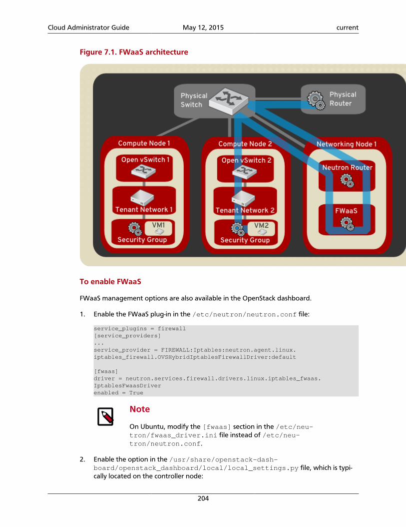
Cloud Administrator Guide May 12, 2015 current
204
Figure 7.1. FWaaS architecture
To enable FWaaS
FWaaS management options are also available in the OpenStack dashboard.
1. Enable the FWaaS plug-in in the /etc/neutron/neutron.conf file:
service_plugins = firewall[service_providers]...service_provider = FIREWALL:Iptables:neutron.agent.linux.iptables_firewall.OVSHybridIptablesFirewallDriver:default
[fwaas]driver = neutron.services.firewall.drivers.linux.iptables_fwaas.IptablesFwaasDriverenabled = True
Note
On Ubuntu, modify the [fwaas] section in the /etc/neu-tron/fwaas_driver.ini file instead of /etc/neu-tron/neutron.conf.
2. Enable the option in the /usr/share/openstack-dash-board/openstack_dashboard/local/local_settings.py file, which is typi-cally located on the controller node:
Cloud Administrator Guide May 12, 2015 current
205
'enable_firewall' = True
3. Restart the neutron-l3-agent and neutron-server services to apply the set-tings.
To configure Firewall-as-a-Service
Create the firewall rules and create a policy that contains them. Then, create a firewall thatapplies the policy.
1. Create a firewall rule:
$ neutron firewall-rule-create --protocol {tcp|udp|icmp|any} --destination-port PORT_RANGE --action {allow|deny}
The Networking client requires a protocol value; if the rule is protocol agnostic, youcan use the any value.
2. Create a firewall policy:
$ neutron firewall-policy-create --firewall-rules "FIREWALL_RULE_IDS_OR_NAMES" myfirewallpolicy
Separate firewall rule IDs or names with spaces. The order in which you specify therules is important.
You can create a firewall policy without any rules and add rules later, as follows:
• To add multiple rules, use the update operation.
• To add a single rule, use the insert-rule operation.
For more details, see Networking command-line client in the OpenStack Command-LineInterface Reference.
Note
FWaaS always adds a default deny all rule at the lowest precedence ofeach policy. Consequently, a firewall policy with no rules blocks all traffic bydefault.
3. Create a firewall:
$ neutron firewall-create FIREWALL_POLICY_UUID
Note
The firewall remains in PENDING_CREATE state until you create a Net-working router and attach an interface to it.
Allowed-address-pairs. Allowed-address-pairs enable you to specify mac_address/ip_address(cidr) pairs that pass through a port regardless of subnet. This enables the use ofprotocols such as VRRP, which floats an IP address between two instances to enable fast da-ta plane failover.
Cloud Administrator Guide May 12, 2015 current
206
Note
Currently, only the ML2, Open vSwitch, and VMware NSX plug-ins support theallowed-address-pairs extension.
Basic allowed-address-pairs operations.
• Create a port with a specified allowed address pairs:
$ neutron port-create net1 --allowed-address-pairs type=dict list=true mac_address=MAC_ADDRESS,ip_address=IP_CIDR
• Update a port by adding allowed address pairs:
$ neutron port-update PORT_UUID --allowed-address-pairs type=dict list=true mac_address=MAC_ADDRESS,ip_address=IP_CIDR
Note
In releases earlier than Juno, OpenStack Networking prevents setting an al-lowed address pair on a port that matches the MAC address and one of thefixed IP addresses of the port.
Plug-in architectureThe original Compute network implementation assumed a basic model of isolation throughLinux VLANs and IP tables. Networking introduces support for vendor plug-ins, which offera custom back-end implementation of the Networking API. A plug-in can use a variety oftechnologies to implement the logical API requests. Some Networking plug-ins might usebasic Linux VLANs and IP tables while others might use more advanced technologies, suchas L2-in-L3 tunneling or OpenFlow, to provide similar benefits.
Table 7.3. Available networking plug-ins
Plug-in Documentation
Big Switch (Floodlight REST Proxy) This guide and http://www.openflowhub.org/display/floodlightcon-troller/Neutron+REST+Proxy+Plugin
Brocade This guide and https://wiki.openstack.org/wiki/Brocade-neutron-plug-in
Cisco http://wiki.openstack.org/cisco-neutron
Cloudbase Hyper-V http://www.cloudbase.it/quantum-hyper-v-plugin/
IBM SDN-VE https://wiki.openstack.org/wiki/IBM-Neutron
Linux Bridge http://wiki.openstack.org/Neutron-Linux-Bridge-Plugin
Midonet http://www.midokura.com/
ML2 (Modular Layer 2) https://wiki.openstack.org/wiki/Neutron/ML2
NEC OpenFlow https://wiki.openstack.org/wiki/Neutron/NEC_OpenFlow_Plugin
Open vSwitch This guide.
OpenFlow Agent https://github.com/osrg/ryu/wiki/Configuration-OpenStack-OFA-gent-agent and https://git.openstack.org/cgit/openstack/neu-tron/tree/neutron/plugins/ofagent/README
PLUMgrid This guide and https://https://wiki.openstack.org/wiki/PLUM-grid-Neutron
VMware NSX This guide and NSX Product Overview, NSX Product Support
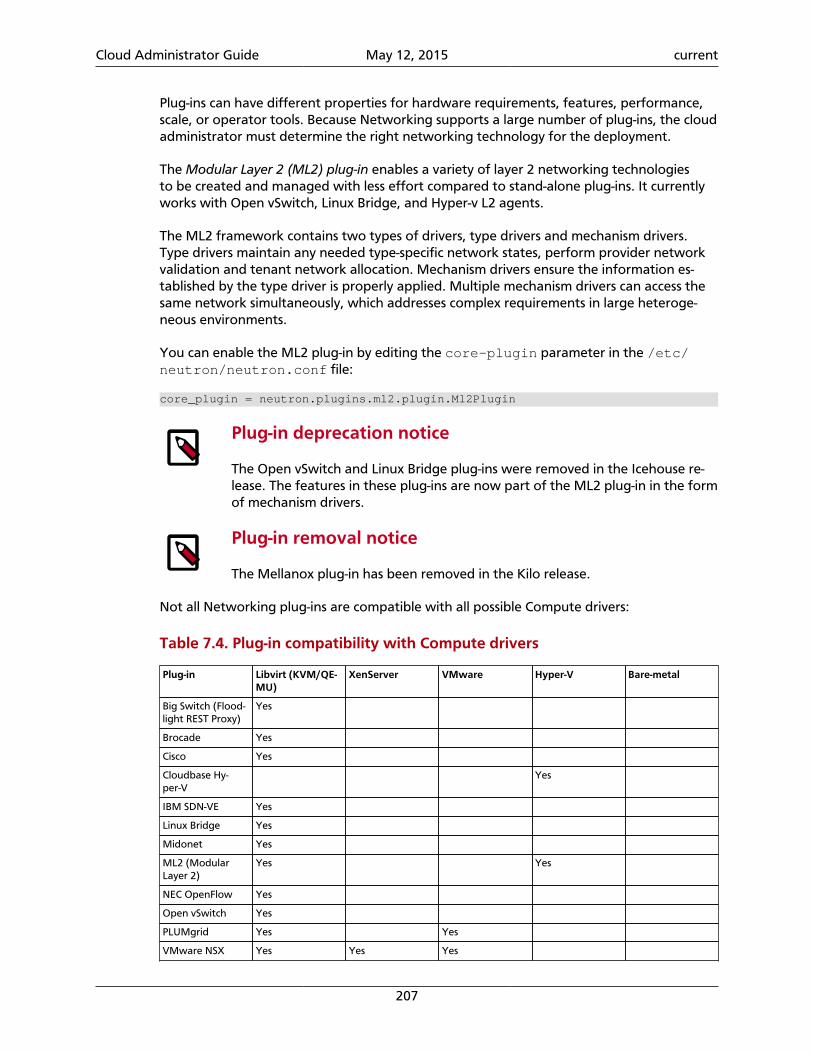
Cloud Administrator Guide May 12, 2015 current
207
Plug-ins can have different properties for hardware requirements, features, performance,scale, or operator tools. Because Networking supports a large number of plug-ins, the cloudadministrator must determine the right networking technology for the deployment.
The Modular Layer 2 (ML2) plug-in enables a variety of layer 2 networking technologiesto be created and managed with less effort compared to stand-alone plug-ins. It currentlyworks with Open vSwitch, Linux Bridge, and Hyper-v L2 agents.
The ML2 framework contains two types of drivers, type drivers and mechanism drivers.Type drivers maintain any needed type-specific network states, perform provider networkvalidation and tenant network allocation. Mechanism drivers ensure the information es-tablished by the type driver is properly applied. Multiple mechanism drivers can access thesame network simultaneously, which addresses complex requirements in large heteroge-neous environments.
You can enable the ML2 plug-in by editing the core-plugin parameter in the /etc/neutron/neutron.conf file:
core_plugin = neutron.plugins.ml2.plugin.Ml2Plugin
Plug-in deprecation notice
The Open vSwitch and Linux Bridge plug-ins were removed in the Icehouse re-lease. The features in these plug-ins are now part of the ML2 plug-in in the formof mechanism drivers.
Plug-in removal notice
The Mellanox plug-in has been removed in the Kilo release.
Not all Networking plug-ins are compatible with all possible Compute drivers:
Table 7.4. Plug-in compatibility with Compute drivers
Plug-in Libvirt (KVM/QE-MU)
XenServer VMware Hyper-V Bare-metal
Big Switch (Flood-light REST Proxy)
Yes
Brocade Yes
Cisco Yes
Cloudbase Hy-per-V
Yes
IBM SDN-VE Yes
Linux Bridge Yes
Midonet Yes
ML2 (ModularLayer 2)
Yes Yes
NEC OpenFlow Yes
Open vSwitch Yes
PLUMgrid Yes Yes
VMware NSX Yes Yes Yes
Cloud Administrator Guide May 12, 2015 current
208
Plug-in configurationsFor configurations options, see Networking configuration options in Configuration Refer-ence. These sections explain how to configure specific plug-ins.
Configure Big Switch (Floodlight REST Proxy) plug-in
To use the REST proxy plug-in with OpenStack Networking
1. Edit the /etc/neutron/neutron.conf file and add this line:
core_plugin = bigswitch
2. In the /etc/neutron/neutron.conf file, set the service_plugins option:
service_plugins = neutron.plugins.bigswitch.l3_router_plugin.L3RestProxy
3. Edit the /etc/neutron/plugins/bigswitch/restproxy.ini file for the plug-in and specify a comma-separated list of controller_ip:port pairs:
server = CONTROLLER_IP:PORT
For database configuration, see Install Networking Services in the Installation Guide inthe OpenStack Documentation index. (The link defaults to the Ubuntu version.)
4. Restart neutron-server to apply the settings:
# service neutron-server restart
Configure Brocade plug-in
To use the Brocade plug-in with OpenStack Networking
1. Install the Brocade-modified Python netconf client (ncclient) library, which is availableat https://github.com/brocade/ncclient:
$ git clone https://github.com/brocade/ncclient
As root, run this command:
# cd ncclient;python setup.py install
2. Edit the /etc/neutron/neutron.conf file and set the following option:
core_plugin = brocade
3. Edit the /etc/neutron/plugins/brocade/brocade.ini file for the Brocadeplug-in and specify the admin user name, password, and IP address of the Brocadeswitch:
[SWITCH]username = ADMINpassword = PASSWORDaddress = SWITCH_MGMT_IP_ADDRESSostype = NOS
Cloud Administrator Guide May 12, 2015 current
209
For database configuration, see Install Networking Services in any of the InstallationGuides in the OpenStack Documentation index. (The link defaults to the Ubuntu ver-sion.)
4. Restart the neutron-server service to apply the settings:
# service neutron-server restart
Configure OVS plug-in
If you use the Open vSwitch (OVS) plug-in in a deployment with multiple hosts, you mustuse either tunneling or VLANs to isolate traffic from multiple networks. Tunneling is easierto deploy because it does not require that you configure VLANs on network switches.
This procedure uses tunneling:
To configure OpenStack Networking to use the OVS plug-in
1. Edit /etc/neutron/plugins/openvswitch/ovs_neutron_plugin.ini file tospecify these values:
enable_tunneling=Truetenant_network_type=gretunnel_id_ranges=1:1000# only required for nodes running agentslocal_ip=DATA_NET_IP_NODE_ADDRESS
Note
Since the Kilo release you can set the quitting_rpc_timeout optionwith a timeout value for RPC API objects. This prevents a long waiting forRPC calls after SIGTERM is received which results in decreasing the amountof time needed to successfully stop the OVS agent.
For database configuration, see Install Networking Services in the Installation Guide.
2. If you use the neutron DHCP agent, add these lines to the /etc/neu-tron/dhcp_agent.ini file:
dnsmasq_config_file=/etc/neutron/dnsmasq/dnsmasq-neutron.conf
Restart the DHCP service to apply the settings:
# service neutron-dhcp-agent restart
3. To lower the MTU size on instances and prevent packet fragmentation over the GREtunnel, create the /etc/neutron/dnsmasq/dnsmasq-neutron.conf file andadd these values:
dhcp-option-force=26,1400
4. Restart the neutron-server service to apply the settings:
# service neutron-server restart
Cloud Administrator Guide May 12, 2015 current
210
Configure NSX plug-in
To configure OpenStack Networking to use the NSX plug-in
While the instructions in this section refer to the VMware NSX platform, this is formerlyknown as Nicira NVP.
1. Install the NSX plug-in:
# apt-get install neutron-plugin-vmware
2. Edit the /etc/neutron/neutron.conf file and set this line:
core_plugin = vmware
Example neutron.conf file for NSX:
core_plugin = vmwarerabbit_host = 192.168.203.10allow_overlapping_ips = True
3. To configure the NSX controller cluster for OpenStack Networking, locate the [de-fault] section in the /etc/neutron/plugins/vmware/nsx.ini file and addthe following entries:
• To establish and configure the connection with the controller cluster you must setsome parameters, including NSX API endpoints, access credentials, and settings forHTTP redirects and retries in case of connection failures:
nsx_user = ADMIN_USER_NAMEnsx_password = NSX_USER_PASSWORDreq_timeout = NSX_REQUEST_TIMEOUT # (seconds) default 30 secondshttp_timeout = HTTP_REQUEST_TIMEOUT # (seconds) default 10 secondsretries = HTTP_REQUEST_RETRIES # default 2redirects = HTTP_REQUEST_MAX_REDIRECTS # default 3nsx_controllers = API_ENDPOINT_LIST # comma-separated list
To ensure correct operations, the nsx_user user must have administrator creden-tials on the NSX platform.
A controller API endpoint consists of the IP address and port for the controller; if youomit the port, port 443 is used. If multiple API endpoints are specified, it is up to theuser to ensure that all these endpoints belong to the same controller cluster. TheOpenStack Networking VMware NSX plug-in does not perform this check, and re-sults might be unpredictable.
When you specify multiple API endpoints, the plug-in load-balances requests on thevarious API endpoints.
• The UUID of the NSX transport zone that should be used by default when a tenantcreates a network. You can get this value from the Transport Zones page for theNSX Manager:
default_tz_uuid = TRANSPORT_ZONE_UUID
• default_l3_gw_service_uuid = GATEWAY_SERVICE_UUID
Cloud Administrator Guide May 12, 2015 current
211
Warning
Ubuntu packaging currently does not update the Neutron init script topoint to the NSX configuration file. Instead, you must manually update /etc/default/neutron-server to add this line:
NEUTRON_PLUGIN_CONFIG = /etc/neutron/plugins/vmware/nsx.ini
For database configuration, see Install Networking Services in the Installation Guide.
4. Restart neutron-server to apply settings:
# service neutron-server restart
Example nsx.ini file:
[DEFAULT]default_tz_uuid = d3afb164-b263-4aaa-a3e4-48e0e09bb33cdefault_l3_gw_service_uuid=5c8622cc-240a-40a1-9693-e6a5fca4e3cfnsx_user=adminnsx_password=changemensx_controllers=10.127.0.100,10.127.0.200:8888
Note
To debug nsx.ini configuration issues, run this command from the host thatruns neutron-server:
# neutron-check-nsx-config PATH_TO_NSX.INI
This command tests whether neutron-server can log into all of the NSXControllers and the SQL server, and whether all UUID values are correct.
Load-Balancer-as-a-Service and Firewall-as-a-Service
The NSX LBaaS and FWaaS services use the standard OpenStack API with the exception ofrequiring routed-insertion extension support.
The NSX implementation and the community reference implementation of these servicesdiffer, as follows:
1. The NSX LBaaS and FWaaS plug-ins require the routed-insertion extension, which addsthe router_id attribute to the VIP (Virtual IP address) and firewall resources and bindsthese services to a logical router.
2. The community reference implementation of LBaaS only supports a one-arm model,which restricts the VIP to be on the same subnet as the back-end servers. The NSX LBaaSplug-in only supports a two-arm model between north-south traffic, which means thatyou can create the VIP on only the external (physical) network.
3. The community reference implementation of FWaaS applies firewall rules to all logicalrouters in a tenant, while the NSX FWaaS plug-in applies firewall rules only to one logicalrouter according to the router_id of the firewall entity.
Cloud Administrator Guide May 12, 2015 current
212
To configure Load-Balancer-as-a-Service and Firewall-as-a-Service with NSX
1. Edit the /etc/neutron/neutron.conf file:
core_plugin = neutron.plugins.vmware.plugin.NsxServicePlugin# Note: comment out service_plug-ins. LBaaS & FWaaS is supported by core_plugin NsxServicePlugin# service_plugins =
2. Edit the /etc/neutron/plugins/vmware/nsx.ini file:
In addition to the original NSX configuration, the default_l3_gw_service_uuidis required for the NSX Advanced plug-in and you must add a vcns section:
[DEFAULT]nsx_password = ADMINnsx_user = ADMINnsx_controllers = 10.37.1.137:443default_l3_gw_service_uuid = aae63e9b-2e4e-4efe-81a1-92cf32e308bfdefault_tz_uuid = 2702f27a-869a-49d1-8781-09331a0f6b9e
[vcns]# VSM management URLmanager_uri = https://10.24.106.219
# VSM admin user nameuser = ADMIN
# VSM admin passwordpassword = DEFAULT
# UUID of a logical switch on NSX which has physical network connectivity (currently using bridge transport type)external_network = f2c023cf-76e2-4625-869b-d0dabcfcc638
# ID of deployment_container on VSM. Optional, if not specified, a default global deployment container is used# deployment_container_id =
# task_status_check_interval configures status check interval for vCNS asynchronous API. Default is 2000 msec.# task_status_check_interval =
3. Restart the neutron-server service to apply the settings:
# service neutron-server restart
Configure PLUMgrid plug-in
To use the PLUMgrid plug-in with OpenStack Networking
1. Edit the /etc/neutron/neutron.conf file and set this line:
core_plugin = plumgrid
2. Edit the [PLUMgridDirector] section in the /etc/neutron/plugins/plum-grid/plumgrid.ini file and specify the IP address, port, admin user name, andpassword of the PLUMgrid Director:
Cloud Administrator Guide May 12, 2015 current
213
[PLUMgridDirector]director_server = "PLUMgrid-director-ip-address"director_server_port = "PLUMgrid-director-port"username = "PLUMgrid-director-admin-username"password = "PLUMgrid-director-admin-password"
For database configuration, see Install Networking Services in the Installation Guide.
3. Restart the neutron-server service to apply the settings:
# service neutron-server restart
Configure neutron agentsPlug-ins typically have requirements for particular software that must be run on each nodethat handles data packets. This includes any node that runs nova-compute and nodesthat run dedicated OpenStack Networking service agents such as neutron-dhcp-agent,neutron-l3-agent, neutron-metering-agent or neutron-lbaas-agent.
A data-forwarding node typically has a network interface with an IP address on the man-agement network and another interface on the data network.
This section shows you how to install and configure a subset of the available plug-ins, whichmight include the installation of switching software (for example, Open vSwitch) and asagents used to communicate with the neutron-server process running elsewhere in thedata center.
Configure data-forwarding nodes
Node set up: OVS plug-in
Note
This section also applies to the ML2 plug-in when you use Open vSwitch as amechanism driver.
If you use the Open vSwitch plug-in, you must install Open vSwitch and the neu-tron-plugin-openvswitch-agent agent on each data-forwarding node:
Warning
Do not install the openvswitch-brcompat package because it prevents the secu-rity group functionality from operating correctly.
To set up each node for the OVS plug-in
1. Install the OVS agent package:
# apt-get install neutron-plugin-openvswitch-agent
This action also installs the Open vSwitch software as a dependency.
2. On each node that runs the neutron-plugin-openvswitch-agent, completethese steps:
Cloud Administrator Guide May 12, 2015 current
214
• Replicate the ovs_neutron_plugin.ini file that you created on the node.
• If you use tunneling, update the ovs_neutron_plugin.ini file for the nodewith the IP address that is configured on the data network for the node by using thelocal_ip value.
3. Restart Open vSwitch to properly load the kernel module:
# service openvswitch-switch restart
4. Restart the agent:
# service neutron-plugin-openvswitch-agent restart
5. Note
The next step only applies to releases prior to Juno.
All nodes that run neutron-plugin-openvswitch-agent must have an OVS br-int bridge.
To create the bridge, run this command:
# ovs-vsctl add-br br-int
Node set up: NSX plug-in
If you use the NSX plug-in, you must also install Open vSwitch on each data-forwardingnode. However, you do not need to install an additional agent on each node.
Warning
It is critical that you run an Open vSwitch version that is compatible with thecurrent version of the NSX Controller software. Do not use the Open vSwitchversion that is installed by default on Ubuntu. Instead, use the Open vSwitchversion that is provided on the VMware support portal for your NSX Controllerversion.
To set up each node for the NSX plug-in
1. Ensure that each data-forwarding node has an IP address on the management net-work, and an IP address on the "data network" that is used for tunneling data traffic.For full details on configuring your forwarding node, see the NSX Administrator Guide.
2. Use the NSX Administrator Guide to add the node as a Hypervisor by using the NSXManager GUI. Even if your forwarding node has no VMs and is only used for servicesagents like neutron-dhcp-agent or neutron-lbaas-agent, it should still beadded to NSX as a Hypervisor.
3. After following the NSX Administrator Guide, use the page for this Hypervisor in theNSX Manager GUI to confirm that the node is properly connected to the NSX Con-troller Cluster and that the NSX Controller Cluster can see the br-int integrationbridge.
Cloud Administrator Guide May 12, 2015 current
215
Configure DHCP agent
The DHCP service agent is compatible with all existing plug-ins and is required for all deploy-ments where VMs should automatically receive IP addresses through DHCP.
To install and configure the DHCP agent
1. You must configure the host running the neutron-dhcp-agent as a data forward-ing node according to the requirements for your plug-in. See the section called “Con-figure neutron agents” [213].
2. Install the DHCP agent:
# apt-get install neutron-dhcp-agent
3. Finally, update any options in the /etc/neutron/dhcp_agent.ini file that de-pend on the plug-in in use. See the sub-sections.
Important
If you reboot a node that runs the DHCP agent, you must run the neutron-ovs-cleanup command before the neutron-dhcp-agent service starts.
On Red Hat, SUSE, and Ubuntu based systems, the neutron-ovs-cleanupservice runs the neutron-ovs-cleanup command automatically. However, on De-bian-based systems, you must manually run this command or write your ownsystem script that runs on boot before the neutron-dhcp-agent servicestarts.
Networking dhcp-agent can use dnsmasq driver which supports stateful and statelessDHCPv6 for subnets created with --ipv6_address_mode set to dhcpv6-stateful ordhcpv6-stateless.
For example:
$ neutron subnet-create --ip-version 6 --ipv6_ra_mode dhcpv6-stateful --ipv6_address_mode dhcpv6-stateful NETWORK CIDR
$ neutron subnet-create --ip-version 6 --ipv6_ra_mode dhcpv6-stateless --ipv6_address_mode dhcpv6-stateless NETWORK CIDR
If no dnsmasq process for subnet's network is launched, Networking will launch a new oneon subnet's dhcp port in qdhcp-XXX namespace. If previous dnsmasq process is alreadylaunched, restart dnsmasq with a new configuration.
Networking will update dnsmasq process and restart it when subnet gets updated.
Note
For dhcp-agent to operate in IPv6 mode use at least dnsmasq v2.63.
After a certain, configured timeframe, networks uncouple from DHCP agents when theagents are no longer in use. You can configure the DHCP agent to automatically detachfrom a network when the agent is out of service, or no longer needed.
Cloud Administrator Guide May 12, 2015 current
216
This feature applies to all plugins that support DHCP scaling. For more information, see the DHCP agent configuration options listed in the OpenStack Configuration Reference.
DHCP agent setup: OVS plug-in
These DHCP agent options are required in the /etc/neutron/dhcp_agent.ini file forthe OVS plug-in:
[DEFAULT]enable_isolated_metadata = Trueuse_namespaces = Trueinterface_driver = neutron.agent.linux.interface.OVSInterfaceDriver
DHCP agent setup: NSX plug-in
These DHCP agent options are required in the /etc/neutron/dhcp_agent.ini file forthe NSX plug-in:
[DEFAULT]enable_metadata_network = Trueenable_isolated_metadata = Trueuse_namespaces = Trueinterface_driver = neutron.agent.linux.interface.OVSInterfaceDriver
Configure L3 agent
The OpenStack Networking Service has a widely used API extension to allow administratorsand tenants to create routers to interconnect L2 networks, and floating IPs to make portson private networks publicly accessible.
Many plug-ins rely on the L3 service agent to implement the L3 functionality. However, thefollowing plug-ins already have built-in L3 capabilities:
• Big Switch/Floodlight plug-in, which supports both the open source Floodlight controllerand the proprietary Big Switch controller.
Note
Only the proprietary BigSwitch controller implements L3 functionality. Whenusing Floodlight as your OpenFlow controller, L3 functionality is not available.
• IBM SDN-VE plug-in
• NSX plug-in
• PLUMgrid plug-in
Warning
Do not configure or use neutron-l3-agent if you use one of these plug-ins.
To install the L3 agent for all other plug-ins
1. Install the neutron-l3-agent binary on the network node:
Cloud Administrator Guide May 12, 2015 current
217
# apt-get install neutron-l3-agent
2. To uplink the node that runs neutron-l3-agent to the external network, create abridge named "br-ex" and attach the NIC for the external network to this bridge.
For example, with Open vSwitch and NIC eth1 connected to the external network, run:
# ovs-vsctl add-br br-ex# ovs-vsctl add-port br-ex eth1
Do not manually configure an IP address on the NIC connected to the external net-work for the node running neutron-l3-agent. Rather, you must have a range of IPaddresses from the external network that can be used by OpenStack Networking forrouters that uplink to the external network. This range must be large enough to havean IP address for each router in the deployment, as well as each floating IP.
3. The neutron-l3-agent uses the Linux IP stack and iptables to perform L3 forward-ing and NAT. In order to support multiple routers with potentially overlapping IP ad-dresses, neutron-l3-agent defaults to using Linux network namespaces to provideisolated forwarding contexts. As a result, the IP addresses of routers are not visible sim-ply by running the ip addr list or ifconfig command on the node. Similarly, you cannotdirectly ping fixed IPs.
To do either of these things, you must run the command within a partic-ular network namespace for the router. The namespace has the name"qrouter-ROUTER_UUID. These example commands run in the router namespace withUUID 47af3868-0fa8-4447-85f6-1304de32153b:
# ip netns exec qrouter-47af3868-0fa8-4447-85f6-1304de32153b ip addr list
# ip netns exec qrouter-47af3868-0fa8-4447-85f6-1304de32153b ping FIXED_IP
Note
By default, networking namespaces are configured to not be deleted. This be-havior can be changed for both DHCP and L3 agents. The configuration files are/etc/neutron/dhcp_agent.ini and /etc/neutron/l3_agent.ini re-spectively.
For DHCP namespace the configuration key is: dhcp_delete_namespaces.This parameter should be set to True to change the default behaviour.
For L3 namespace, the configuration key is: router_delete_namespaces.This parameter should be set to True to change the default behaviour.
Important
If you reboot a node that runs the L3 agent, you must run the neutron-ovs-cleanup command before the neutron-l3-agent service starts.
On Red Hat, SUSE and Ubuntu based systems, the neutron-ovs-cleanupservice runs the neutron-ovs-cleanup command automatically. However, on De-bian-based systems, you must manually run this command or write your ownsystem script that runs on boot before the neutron-l3-agent service starts.
Cloud Administrator Guide May 12, 2015 current
218
Configure metering agent
The Neutron Metering agent resides beside neutron-l3-agent.
To install the metering agent and configure the node
1. Install the agent by running:
# apt-get install neutron-metering-agent
2. If you use one of the following plugins, you need to configure the metering agent withthese lines as well:
• An OVS-based plug-in such as OVS, NSX, NEC, BigSwitch/Floodlight:
interface_driver = neutron.agent.linux.interface.OVSInterfaceDriver
• A plug-in that uses LinuxBridge:
interface_driver = neutron.agent.linux.interface.BridgeInterfaceDriver
3. To use the reference implementation, you must set:
driver = neutron.services.metering.drivers.iptables.iptables_driver.IptablesMeteringDriver
4. Set the service_plugins option in the /etc/neutron/neutron.conf file onthe host that runs neutron-server:
service_plugins = metering
If this option is already defined, add metering to the list, using a comma as separa-tor. For example:
service_plugins = router,metering
Configure Load-Balancer-as-a-Service (LBaaS)
Configure Load-Balancer-as-a-Service (LBaas) with the Open vSwitch or Linux Bridge plug-in.The Open vSwitch LBaaS driver is required when enabling LBaaS for OVS-based plug-ins, in-cluding BigSwitch, Floodlight, NEC, and NSX.
To configure LBaas with Open vSwitch or Linux Bridge plug-in
1. Install the agent:
# apt-get install neutron-lbaas-agent
2. Enable the HAProxy plug-in by using the service_provider option in the /etc/neutron/neutron.conf file:
service_provider = LOADBALANCER:Haproxy:neutron.services.loadbalancer.drivers.haproxy.plugin_driver.HaproxyOnHostPluginDriver:default
Cloud Administrator Guide May 12, 2015 current
219
Warning
The service_provider option is already defined in the /usr/share/neutron/neutron-dist.conf file on Red Hat based systems. Do notdefine it in neutron.conf otherwise the Networking services will fail torestart.
3. Enable the load-balancing plug-in by using the service_plugins option in the /etc/neutron/neutron.conf file:
service_plugins = lbaas
If this option is already defined, add lbaas to the list, using a comma as separator. Forexample:
service_plugins = router,lbaas
4. Enable the HAProxy load balancer in the /etc/neutron/lbaas_agent.ini file:
device_driver = neutron.services.loadbalancer.drivers.haproxy.namespace_driver.HaproxyNSDriver
5. Select the required driver in the /etc/neutron/lbaas_agent.ini file:
Enable the Open vSwitch LBaaS driver:
interface_driver = neutron.agent.linux.interface.OVSInterfaceDriver
Or, enable the Linux Bridge LBaaS driver:
interface_driver = neutron.agent.linux.interface.BridgeInterfaceDriver
Apply the settings by restarting the neutron-server and neutron-lbaas-agentservices.
6. Enable load balancing in the Project section of the dashboard.
Change the enable_lb option to True in the local_settings file (on Fedora,RHEL, and CentOS: /etc/openstack-dashboard/local_settings, on Ubuntuand Debian: /etc/openstack-dashboard/local_settings.py, and on open-SUSE and SLES: /srv/www/openstack-dashboard/openstack_dashboard/local/local_settings.py):
OPENSTACK_NEUTRON_NETWORK = { 'enable_lb': True, ...}
Apply the settings by restarting the web server. You can now view the Load Balancermanagement options in the Project view in the dashboard.
Configure Hyper-V L2 agent
Before you install the OpenStack Networking Hyper-V L2 agent on a Hyper-V computenode, ensure the compute node has been configured correctly using these instructions.
Cloud Administrator Guide May 12, 2015 current
220
To install the OpenStack Networking Hyper-V agent and configure the node
1. Download the OpenStack Networking code from the repository:
> cd C:\OpenStack\> git clone https://git.openstack.org/cgit/openstack/neutron
2. Install the OpenStack Networking Hyper-V Agent:
> cd C:\OpenStack\neutron\> python setup.py install
3. Copy the policy.json file:
> xcopy C:\OpenStack\neutron\etc\policy.json C:\etc\
4. Create the C:\etc\neutron-hyperv-agent.conf file and add the proper config-uration options and the Hyper-V related options. Here is a sample config file:
[DEFAULT]verbose = truecontrol_exchange = neutronpolicy_file = C:\etc\policy.jsonrpc_backend = neutron.openstack.common.rpc.impl_komburabbit_host = IP_ADDRESSrabbit_port = 5672rabbit_userid = guestrabbit_password = <password>logdir = C:\OpenStack\Loglogfile = neutron-hyperv-agent.log
[AGENT]polling_interval = 2physical_network_vswitch_mappings = *:YOUR_BRIDGE_NAMEenable_metrics_collection = true
[SECURITYGROUP]firewall_driver = neutron.plugins.hyperv.agent.security_groups_driver.HyperVSecurityGroupsDriverenable_security_group = true
5. Start the OpenStack Networking Hyper-V agent:
> C:\Python27\Scripts\neutron-hyperv-agent.exe --config-file C:\etc\neutron-hyperv-agent.conf
Basic operations on agents
This table shows examples of Networking commands that enable you to complete basic op-erations on agents:
Table 7.5. Basic operations on Networking agents
Operation Command
List all available agents. $ neutron agent-list
Show information of a given agent. $ neutron agent-show AGENT_ID
Update the admin status and description fora specified agent. The command can be used
$ neutron agent-update --admin-state-up False AGENT_ID
Cloud Administrator Guide May 12, 2015 current
221
Operation Command
to enable and disable agents by using --ad-min-state-up parameter set to False orTrue.
Delete a given agent. Consider disabling theagent before deletion.
$ neutron agent-delete AGENT_ID
See the OpenStack Command-Line Interface Reference for more information on Network-ing commands.
Networking architectureBefore you deploy Networking, it's useful to understand the Networking services and howthey interact with the OpenStack components.
OverviewNetworking is a standalone component in the OpenStack modular architecture. It's posi-tioned alongside OpenStack components such as Compute, Image service, Identity, or theDashboard. Like those components, a deployment of Networking often involves deployingseveral services to a variety of hosts.
The Networking server uses the neutron-server daemon to expose the Networking APIand enable administration of the configured Networking plug-in. Typically, the plug-in re-quires access to a database for persistent storage (also similar to other OpenStack services).
If your deployment uses a controller host to run centralized Compute components, youcan deploy the Networking server to that same host. However, Networking is entirely stan-dalone and can be deployed to a dedicated host. Depending on your configuration, Net-working can also include the following agents:
Table 7.6. Networking agents
Agent Description
plug-in agent (neutron-*-agent)
Runs on each hypervisor to perform local vSwitch configuration. The agent thatruns, depends on the plug-in that you use. Certain plug-ins do not require anagent.
dhcp agent (neutron-dhcp-agent)
Provides DHCP services to tenant networks. Required by certain plug-ins.
l3 agent (neutron-l3-agent) Provides L3/NAT forwarding to provide external network access for VMs on ten-ant networks. Required by certain plug-ins.
metering agent (neutron-me-tering-agent)
Provides L3 traffic metering for tenant networks.
These agents interact with the main neutron process through RPC (for example, RabbitMQor Qpid) or through the standard Networking API. In addition, Networking integrates withOpenStack components in a number of ways:
• Networking relies on the Identity service (keystone) for the authentication and autho-rization of all API requests.
• Compute (nova) interacts with Networking through calls to its standard API. As part ofcreating a VM, the nova-compute service communicates with the Networking API toplug each virtual NIC on the VM into a particular network.
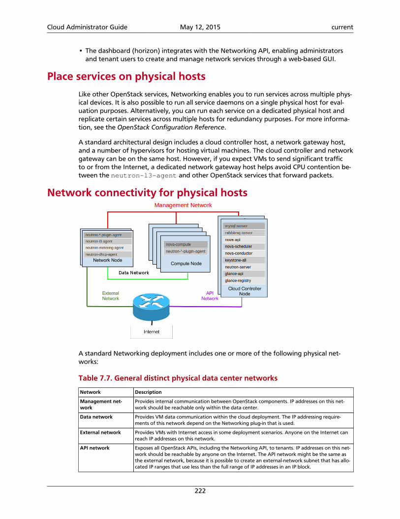
Cloud Administrator Guide May 12, 2015 current
222
• The dashboard (horizon) integrates with the Networking API, enabling administratorsand tenant users to create and manage network services through a web-based GUI.
Place services on physical hosts
Like other OpenStack services, Networking enables you to run services across multiple phys-ical devices. It is also possible to run all service daemons on a single physical host for eval-uation purposes. Alternatively, you can run each service on a dedicated physical host andreplicate certain services across multiple hosts for redundancy purposes. For more informa-tion, see the OpenStack Configuration Reference.
A standard architectural design includes a cloud controller host, a network gateway host,and a number of hypervisors for hosting virtual machines. The cloud controller and networkgateway can be on the same host. However, if you expect VMs to send significant trafficto or from the Internet, a dedicated network gateway host helps avoid CPU contention be-tween the neutron-l3-agent and other OpenStack services that forward packets.
Network connectivity for physical hosts
A standard Networking deployment includes one or more of the following physical net-works:
Table 7.7. General distinct physical data center networks
Network Description
Management net-work
Provides internal communication between OpenStack components. IP addresses on this net-work should be reachable only within the data center.
Data network Provides VM data communication within the cloud deployment. The IP addressing require-ments of this network depend on the Networking plug-in that is used.
External network Provides VMs with Internet access in some deployment scenarios. Anyone on the Internet canreach IP addresses on this network.
API network Exposes all OpenStack APIs, including the Networking API, to tenants. IP addresses on this net-work should be reachable by anyone on the Internet. The API network might be the same asthe external network, because it is possible to create an external-network subnet that has allo-cated IP ranges that use less than the full range of IP addresses in an IP block.
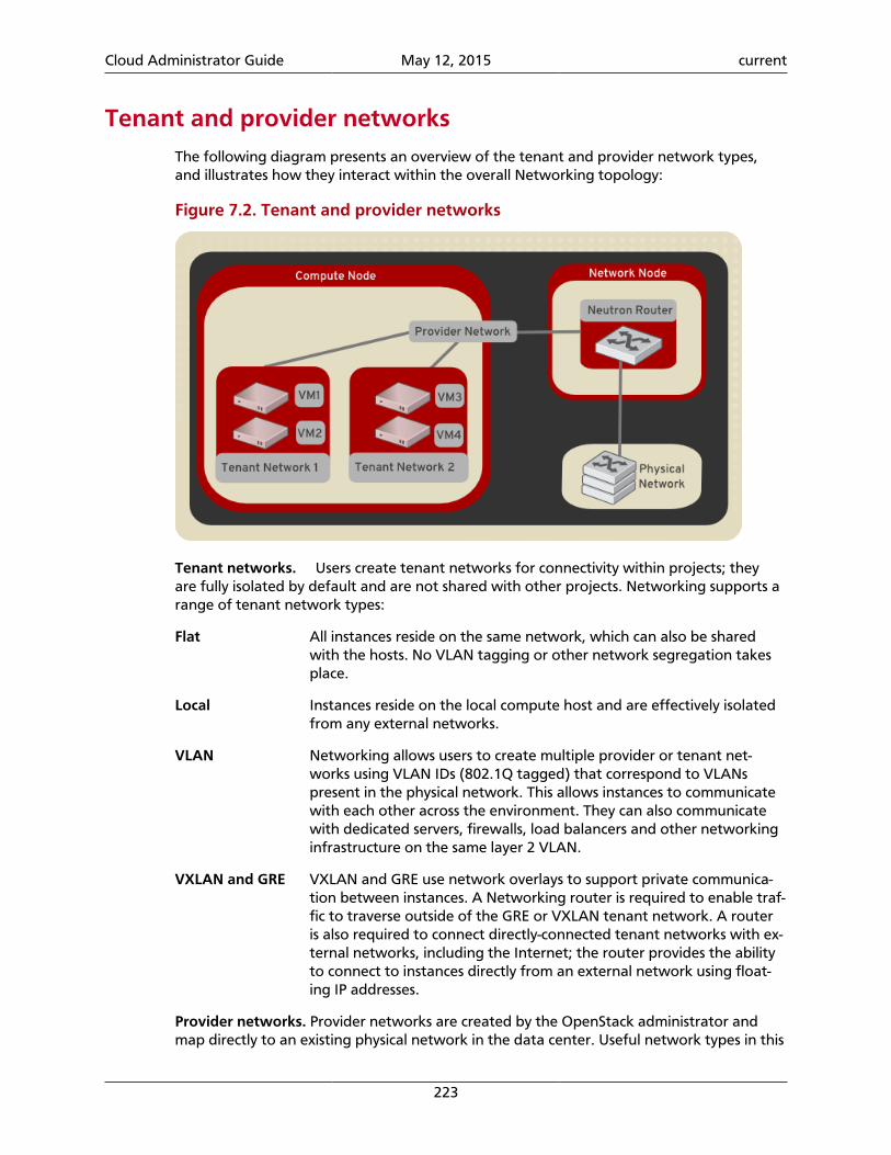
Cloud Administrator Guide May 12, 2015 current
223
Tenant and provider networksThe following diagram presents an overview of the tenant and provider network types,and illustrates how they interact within the overall Networking topology:
Figure 7.2. Tenant and provider networks
Tenant networks. Users create tenant networks for connectivity within projects; theyare fully isolated by default and are not shared with other projects. Networking supports arange of tenant network types:
Flat All instances reside on the same network, which can also be sharedwith the hosts. No VLAN tagging or other network segregation takesplace.
Local Instances reside on the local compute host and are effectively isolatedfrom any external networks.
VLAN Networking allows users to create multiple provider or tenant net-works using VLAN IDs (802.1Q tagged) that correspond to VLANspresent in the physical network. This allows instances to communicatewith each other across the environment. They can also communicatewith dedicated servers, firewalls, load balancers and other networkinginfrastructure on the same layer 2 VLAN.
VXLAN and GRE VXLAN and GRE use network overlays to support private communica-tion between instances. A Networking router is required to enable traf-fic to traverse outside of the GRE or VXLAN tenant network. A routeris also required to connect directly-connected tenant networks with ex-ternal networks, including the Internet; the router provides the abilityto connect to instances directly from an external network using float-ing IP addresses.
Provider networks. Provider networks are created by the OpenStack administrator andmap directly to an existing physical network in the data center. Useful network types in this
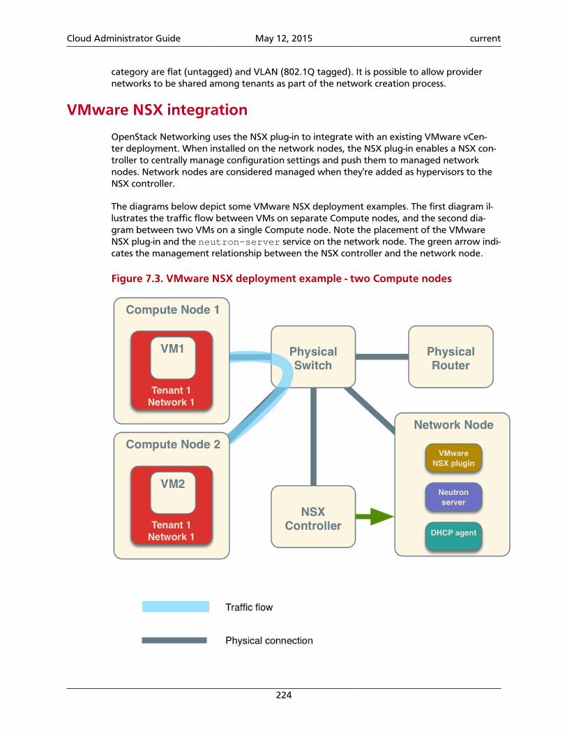
Cloud Administrator Guide May 12, 2015 current
224
category are flat (untagged) and VLAN (802.1Q tagged). It is possible to allow providernetworks to be shared among tenants as part of the network creation process.
VMware NSX integration
OpenStack Networking uses the NSX plug-in to integrate with an existing VMware vCen-ter deployment. When installed on the network nodes, the NSX plug-in enables a NSX con-troller to centrally manage configuration settings and push them to managed networknodes. Network nodes are considered managed when they're added as hypervisors to theNSX controller.
The diagrams below depict some VMware NSX deployment examples. The first diagram il-lustrates the traffic flow between VMs on separate Compute nodes, and the second dia-gram between two VMs on a single Compute node. Note the placement of the VMwareNSX plug-in and the neutron-server service on the network node. The green arrow indi-cates the management relationship between the NSX controller and the network node.
Figure 7.3. VMware NSX deployment example - two Compute nodes

Cloud Administrator Guide May 12, 2015 current
225
Figure 7.4. VMware NSX deployment example - single Compute node
Configure Identity Service for Networking
To configure the Identity Service for use with Networking
1. Create the get_id() function
The get_id() function stores the ID of created objects, and removes the need tocopy and paste object IDs in later steps:
a. Add the following function to your .bashrc file:
function get_id () {echo `"$@" | awk '/ id / { print $4 }'`}
b. Source the .bashrc file:
$ source .bashrc
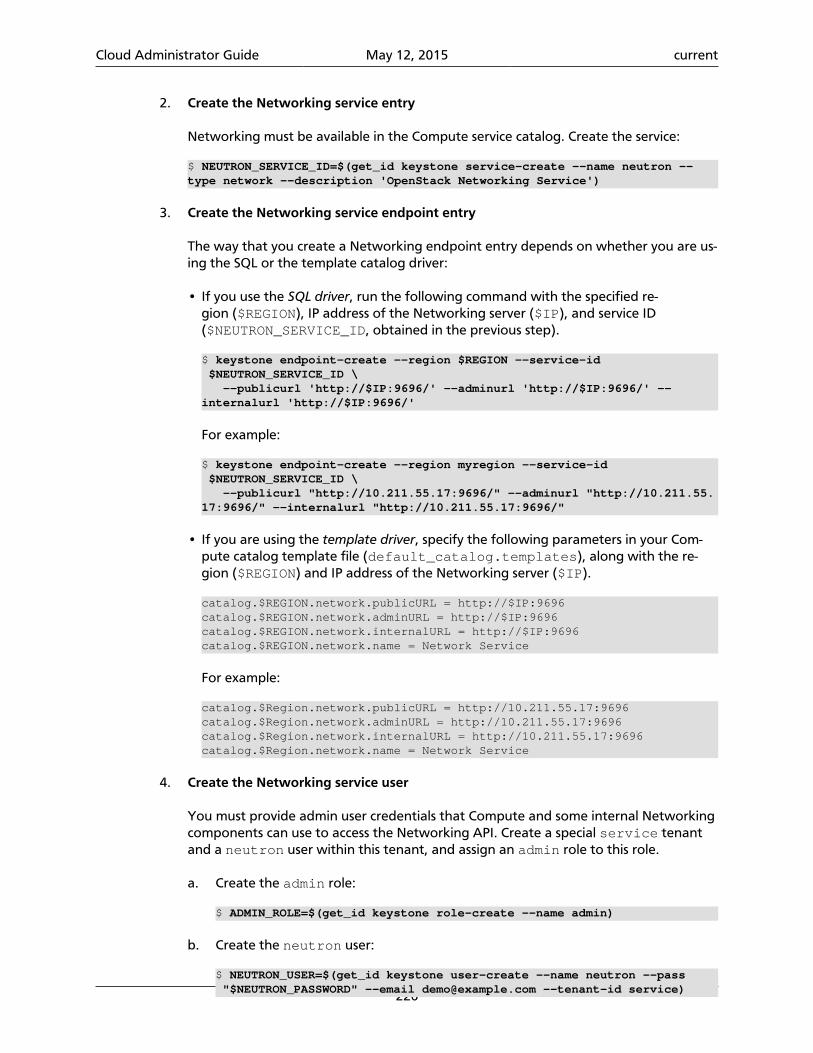
Cloud Administrator Guide May 12, 2015 current
226
2. Create the Networking service entry
Networking must be available in the Compute service catalog. Create the service:
$ NEUTRON_SERVICE_ID=$(get_id keystone service-create --name neutron --type network --description 'OpenStack Networking Service')
3. Create the Networking service endpoint entry
The way that you create a Networking endpoint entry depends on whether you are us-ing the SQL or the template catalog driver:
• If you use the SQL driver, run the following command with the specified re-gion ($REGION), IP address of the Networking server ($IP), and service ID($NEUTRON_SERVICE_ID, obtained in the previous step).
$ keystone endpoint-create --region $REGION --service-id $NEUTRON_SERVICE_ID \ --publicurl 'http://$IP:9696/' --adminurl 'http://$IP:9696/' --internalurl 'http://$IP:9696/'
For example:
$ keystone endpoint-create --region myregion --service-id $NEUTRON_SERVICE_ID \ --publicurl "http://10.211.55.17:9696/" --adminurl "http://10.211.55.17:9696/" --internalurl "http://10.211.55.17:9696/"
• If you are using the template driver, specify the following parameters in your Com-pute catalog template file (default_catalog.templates), along with the re-gion ($REGION) and IP address of the Networking server ($IP).
catalog.$REGION.network.publicURL = http://$IP:9696catalog.$REGION.network.adminURL = http://$IP:9696catalog.$REGION.network.internalURL = http://$IP:9696catalog.$REGION.network.name = Network Service
For example:
catalog.$Region.network.publicURL = http://10.211.55.17:9696catalog.$Region.network.adminURL = http://10.211.55.17:9696catalog.$Region.network.internalURL = http://10.211.55.17:9696catalog.$Region.network.name = Network Service
4. Create the Networking service user
You must provide admin user credentials that Compute and some internal Networkingcomponents can use to access the Networking API. Create a special service tenantand a neutron user within this tenant, and assign an admin role to this role.
a. Create the admin role:
$ ADMIN_ROLE=$(get_id keystone role-create --name admin)
b. Create the neutron user:
$ NEUTRON_USER=$(get_id keystone user-create --name neutron --pass "$NEUTRON_PASSWORD" --email [email protected] --tenant-id service)
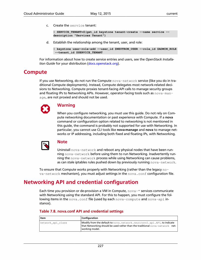
Cloud Administrator Guide May 12, 2015 current
227
c. Create the service tenant:
$ SERVICE_TENANT=$(get_id keystone tenant-create --name service --description "Services Tenant")
d. Establish the relationship among the tenant, user, and role:
$ keystone user-role-add --user_id $NEUTRON_USER --role_id $ADMIN_ROLE --tenant_id $SERVICE_TENANT
For information about how to create service entries and users, see the OpenStack Installa-tion Guide for your distribution (docs.openstack.org).
ComputeIf you use Networking, do not run the Compute nova-network service (like you do in tra-ditional Compute deployments). Instead, Compute delegates most network-related deci-sions to Networking. Compute proxies tenant-facing API calls to manage security groupsand floating IPs to Networking APIs. However, operator-facing tools such as nova-man-age, are not proxied and should not be used.
Warning
When you configure networking, you must use this guide. Do not rely on Com-pute networking documentation or past experience with Compute. If a novacommand or configuration option related to networking is not mentioned inthis guide, the command is probably not supported for use with Networking. Inparticular, you cannot use CLI tools like nova-manage and nova to manage net-works or IP addressing, including both fixed and floating IPs, with Networking.
Note
Uninstall nova-network and reboot any physical nodes that have been run-ning nova-network before using them to run Networking. Inadvertently run-ning the nova-network process while using Networking can cause problems,as can stale iptables rules pushed down by previously running nova-network.
To ensure that Compute works properly with Networking (rather than the legacy no-va-network mechanism), you must adjust settings in the nova.conf configuration file.
Networking API and credential configurationEach time you provision or de-provision a VM in Compute, nova-* services communicatewith Networking using the standard API. For this to happen, you must configure the fol-lowing items in the nova.conf file (used by each nova-compute and nova-api in-stance).
Table 7.8. nova.conf API and credential settings
Item Configuration
network_api_class Modify from the default to nova.network.neutronv2.api.API, to indicatethat Networking should be used rather than the traditional nova-network net-working model.
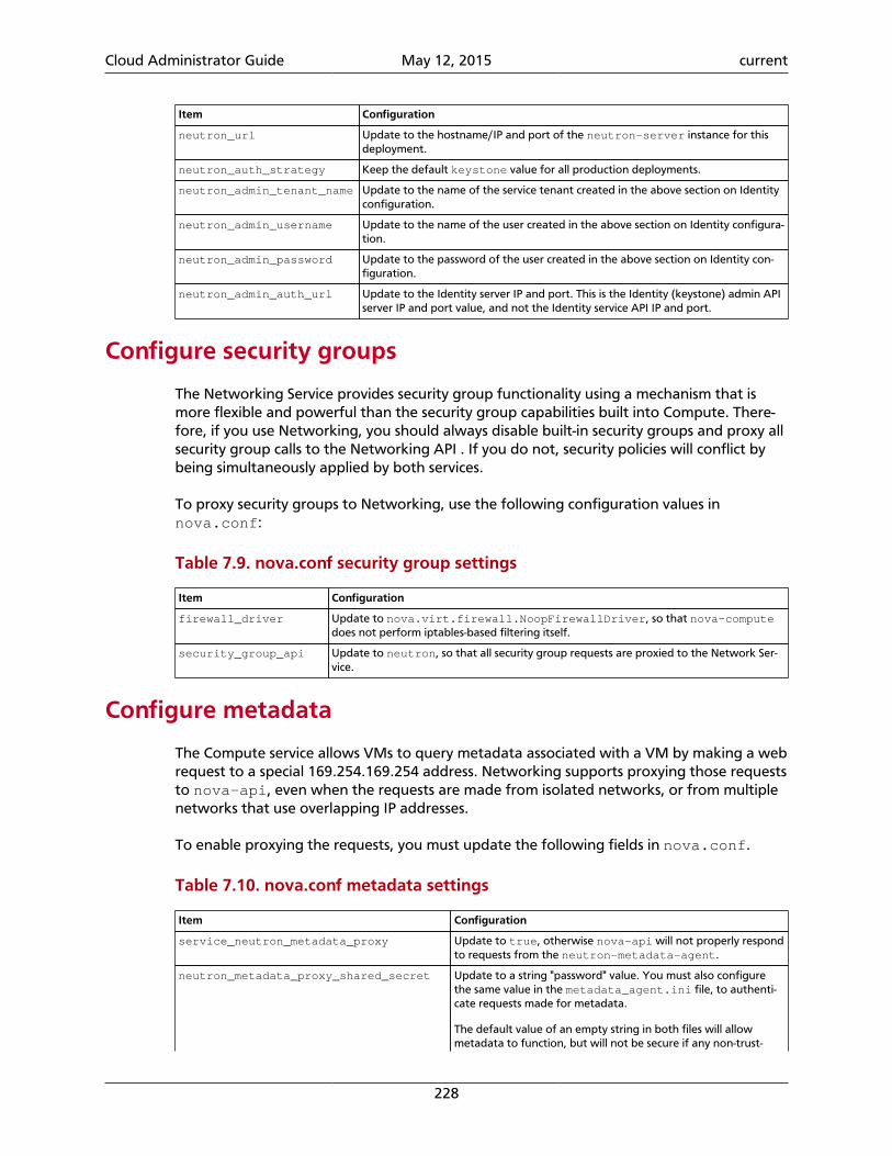
Cloud Administrator Guide May 12, 2015 current
228
Item Configuration
neutron_url Update to the hostname/IP and port of the neutron-server instance for thisdeployment.
neutron_auth_strategy Keep the default keystone value for all production deployments.
neutron_admin_tenant_name Update to the name of the service tenant created in the above section on Identityconfiguration.
neutron_admin_username Update to the name of the user created in the above section on Identity configura-tion.
neutron_admin_password Update to the password of the user created in the above section on Identity con-figuration.
neutron_admin_auth_url Update to the Identity server IP and port. This is the Identity (keystone) admin APIserver IP and port value, and not the Identity service API IP and port.
Configure security groups
The Networking Service provides security group functionality using a mechanism that ismore flexible and powerful than the security group capabilities built into Compute. There-fore, if you use Networking, you should always disable built-in security groups and proxy allsecurity group calls to the Networking API . If you do not, security policies will conflict bybeing simultaneously applied by both services.
To proxy security groups to Networking, use the following configuration values innova.conf:
Table 7.9. nova.conf security group settings
Item Configuration
firewall_driver Update to nova.virt.firewall.NoopFirewallDriver, so that nova-computedoes not perform iptables-based filtering itself.
security_group_api Update to neutron, so that all security group requests are proxied to the Network Ser-vice.
Configure metadata
The Compute service allows VMs to query metadata associated with a VM by making a webrequest to a special 169.254.169.254 address. Networking supports proxying those requeststo nova-api, even when the requests are made from isolated networks, or from multiplenetworks that use overlapping IP addresses.
To enable proxying the requests, you must update the following fields in nova.conf.
Table 7.10. nova.conf metadata settings
Item Configuration
service_neutron_metadata_proxy Update to true, otherwise nova-api will not properly respondto requests from the neutron-metadata-agent.
neutron_metadata_proxy_shared_secret Update to a string "password" value. You must also configurethe same value in the metadata_agent.ini file, to authenti-cate requests made for metadata.
The default value of an empty string in both files will allowmetadata to function, but will not be secure if any non-trust-
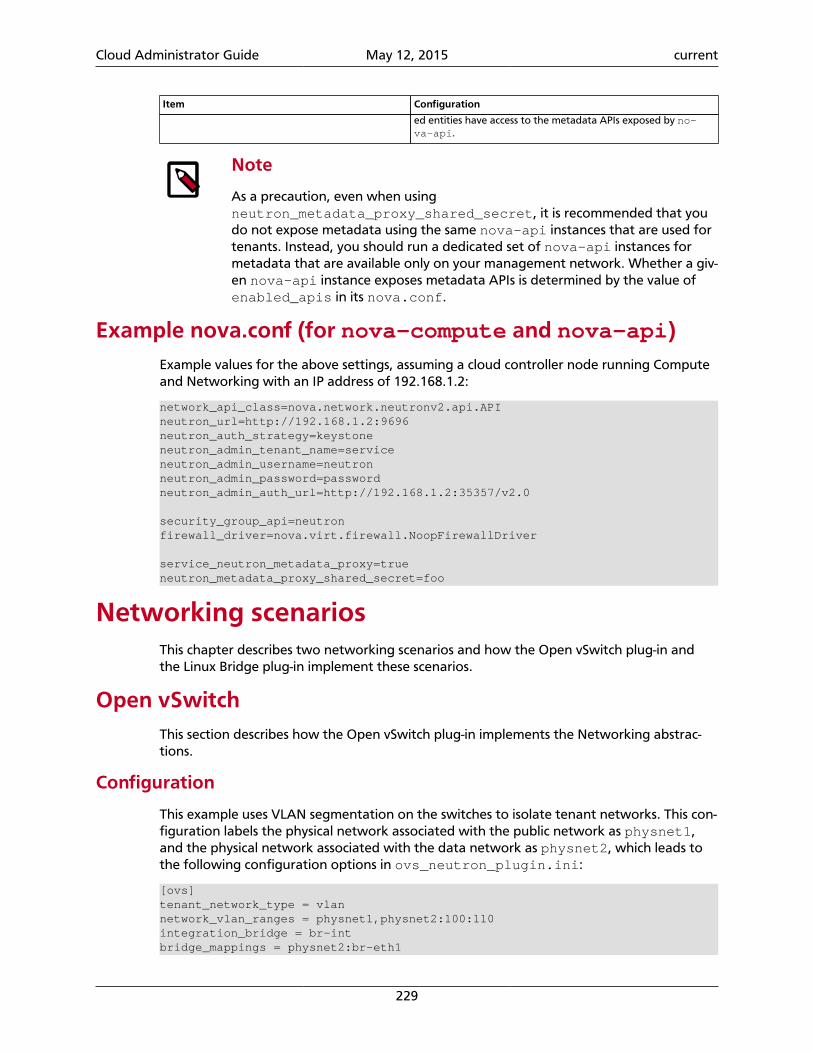
Cloud Administrator Guide May 12, 2015 current
229
Item Configuration
ed entities have access to the metadata APIs exposed by no-va-api.
Note
As a precaution, even when usingneutron_metadata_proxy_shared_secret, it is recommended that youdo not expose metadata using the same nova-api instances that are used fortenants. Instead, you should run a dedicated set of nova-api instances formetadata that are available only on your management network. Whether a giv-en nova-api instance exposes metadata APIs is determined by the value ofenabled_apis in its nova.conf.
Example nova.conf (for nova-compute and nova-api)Example values for the above settings, assuming a cloud controller node running Computeand Networking with an IP address of 192.168.1.2:
network_api_class=nova.network.neutronv2.api.APIneutron_url=http://192.168.1.2:9696neutron_auth_strategy=keystoneneutron_admin_tenant_name=serviceneutron_admin_username=neutronneutron_admin_password=passwordneutron_admin_auth_url=http://192.168.1.2:35357/v2.0
security_group_api=neutronfirewall_driver=nova.virt.firewall.NoopFirewallDriver
service_neutron_metadata_proxy=trueneutron_metadata_proxy_shared_secret=foo
Networking scenariosThis chapter describes two networking scenarios and how the Open vSwitch plug-in andthe Linux Bridge plug-in implement these scenarios.
Open vSwitchThis section describes how the Open vSwitch plug-in implements the Networking abstrac-tions.
Configuration
This example uses VLAN segmentation on the switches to isolate tenant networks. This con-figuration labels the physical network associated with the public network as physnet1,and the physical network associated with the data network as physnet2, which leads tothe following configuration options in ovs_neutron_plugin.ini:
[ovs]tenant_network_type = vlannetwork_vlan_ranges = physnet1,physnet2:100:110integration_bridge = br-intbridge_mappings = physnet2:br-eth1
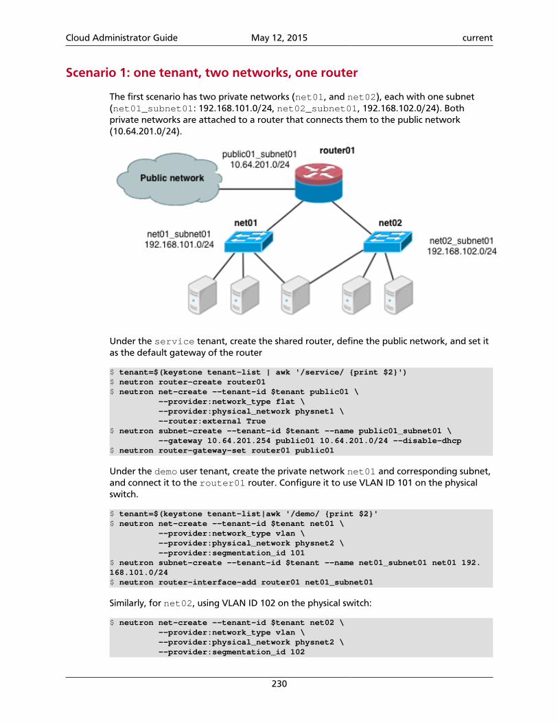
Cloud Administrator Guide May 12, 2015 current
230
Scenario 1: one tenant, two networks, one router
The first scenario has two private networks (net01, and net02), each with one subnet(net01_subnet01: 192.168.101.0/24, net02_subnet01, 192.168.102.0/24). Bothprivate networks are attached to a router that connects them to the public network(10.64.201.0/24).
Under the service tenant, create the shared router, define the public network, and set itas the default gateway of the router
$ tenant=$(keystone tenant-list | awk '/service/ {print $2}')$ neutron router-create router01$ neutron net-create --tenant-id $tenant public01 \ --provider:network_type flat \ --provider:physical_network physnet1 \ --router:external True$ neutron subnet-create --tenant-id $tenant --name public01_subnet01 \ --gateway 10.64.201.254 public01 10.64.201.0/24 --disable-dhcp$ neutron router-gateway-set router01 public01
Under the demo user tenant, create the private network net01 and corresponding subnet,and connect it to the router01 router. Configure it to use VLAN ID 101 on the physicalswitch.
$ tenant=$(keystone tenant-list|awk '/demo/ {print $2}'$ neutron net-create --tenant-id $tenant net01 \ --provider:network_type vlan \ --provider:physical_network physnet2 \ --provider:segmentation_id 101$ neutron subnet-create --tenant-id $tenant --name net01_subnet01 net01 192.168.101.0/24$ neutron router-interface-add router01 net01_subnet01
Similarly, for net02, using VLAN ID 102 on the physical switch:
$ neutron net-create --tenant-id $tenant net02 \ --provider:network_type vlan \ --provider:physical_network physnet2 \ --provider:segmentation_id 102
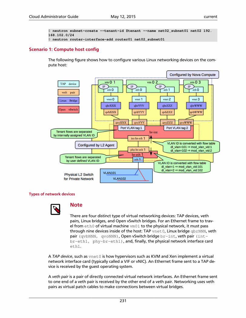
Cloud Administrator Guide May 12, 2015 current
231
$ neutron subnet-create --tenant-id $tenant --name net02_subnet01 net02 192.168.102.0/24$ neutron router-interface-add router01 net02_subnet01
Scenario 1: Compute host config
The following figure shows how to configure various Linux networking devices on the com-pute host:
Types of network devices
Note
There are four distinct type of virtual networking devices: TAP devices, vethpairs, Linux bridges, and Open vSwitch bridges. For an Ethernet frame to trav-el from eth0 of virtual machine vm01 to the physical network, it must passthrough nine devices inside of the host: TAP vnet0, Linux bridge qbrNNN, vethpair (qvbNNN, qvoNNN), Open vSwitch bridge br-int, veth pair (int-br-eth1, phy-br-eth1), and, finally, the physical network interface cardeth1.
A TAP device, such as vnet0 is how hypervisors such as KVM and Xen implement a virtualnetwork interface card (typically called a VIF or vNIC). An Ethernet frame sent to a TAP de-vice is received by the guest operating system.
A veth pair is a pair of directly connected virtual network interfaces. An Ethernet frame sentto one end of a veth pair is received by the other end of a veth pair. Networking uses vethpairs as virtual patch cables to make connections between virtual bridges.
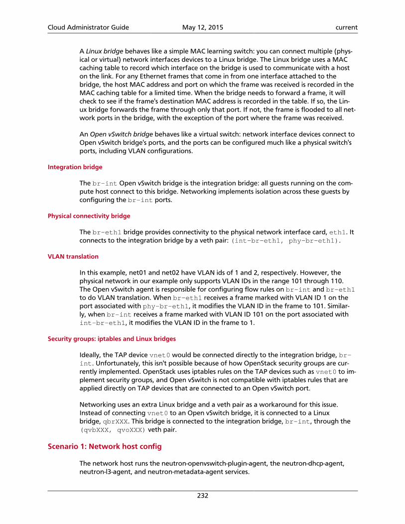
Cloud Administrator Guide May 12, 2015 current
232
A Linux bridge behaves like a simple MAC learning switch: you can connect multiple (phys-ical or virtual) network interfaces devices to a Linux bridge. The Linux bridge uses a MACcaching table to record which interface on the bridge is used to communicate with a hoston the link. For any Ethernet frames that come in from one interface attached to thebridge, the host MAC address and port on which the frame was received is recorded in theMAC caching table for a limited time. When the bridge needs to forward a frame, it willcheck to see if the frame's destination MAC address is recorded in the table. If so, the Lin-ux bridge forwards the frame through only that port. If not, the frame is flooded to all net-work ports in the bridge, with the exception of the port where the frame was received.
An Open vSwitch bridge behaves like a virtual switch: network interface devices connect toOpen vSwitch bridge's ports, and the ports can be configured much like a physical switch'sports, including VLAN configurations.
Integration bridge
The br-int Open vSwitch bridge is the integration bridge: all guests running on the com-pute host connect to this bridge. Networking implements isolation across these guests byconfiguring the br-int ports.
Physical connectivity bridge
The br-eth1 bridge provides connectivity to the physical network interface card, eth1. Itconnects to the integration bridge by a veth pair: (int-br-eth1, phy-br-eth1).
VLAN translation
In this example, net01 and net02 have VLAN ids of 1 and 2, respectively. However, thephysical network in our example only supports VLAN IDs in the range 101 through 110.The Open vSwitch agent is responsible for configuring flow rules on br-int and br-eth1to do VLAN translation. When br-eth1 receives a frame marked with VLAN ID 1 on theport associated with phy-br-eth1, it modifies the VLAN ID in the frame to 101. Similar-ly, when br-int receives a frame marked with VLAN ID 101 on the port associated withint-br-eth1, it modifies the VLAN ID in the frame to 1.
Security groups: iptables and Linux bridges
Ideally, the TAP device vnet0 would be connected directly to the integration bridge, br-int. Unfortunately, this isn't possible because of how OpenStack security groups are cur-rently implemented. OpenStack uses iptables rules on the TAP devices such as vnet0 to im-plement security groups, and Open vSwitch is not compatible with iptables rules that areapplied directly on TAP devices that are connected to an Open vSwitch port.
Networking uses an extra Linux bridge and a veth pair as a workaround for this issue.Instead of connecting vnet0 to an Open vSwitch bridge, it is connected to a Linuxbridge, qbrXXX. This bridge is connected to the integration bridge, br-int, through the(qvbXXX, qvoXXX) veth pair.
Scenario 1: Network host config
The network host runs the neutron-openvswitch-plugin-agent, the neutron-dhcp-agent,neutron-l3-agent, and neutron-metadata-agent services.
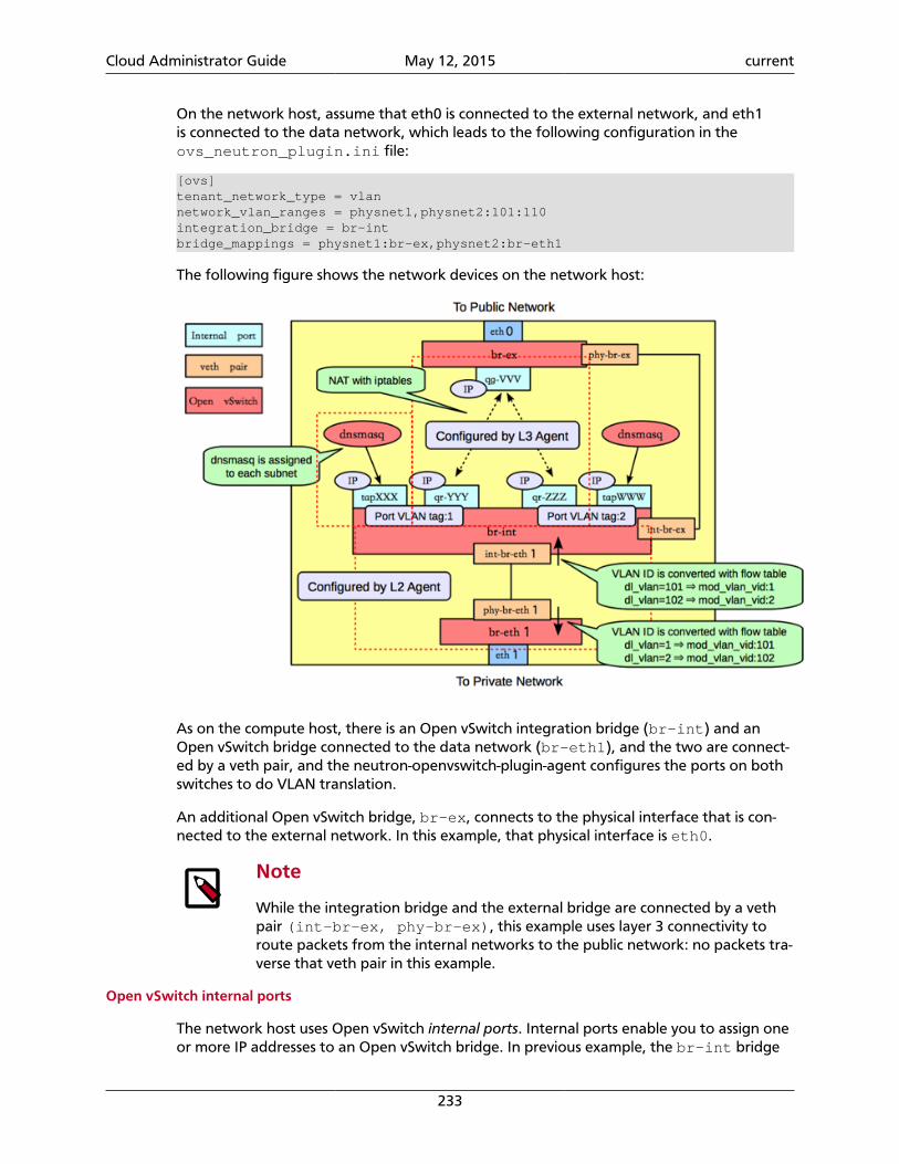
Cloud Administrator Guide May 12, 2015 current
233
On the network host, assume that eth0 is connected to the external network, and eth1is connected to the data network, which leads to the following configuration in theovs_neutron_plugin.ini file:
[ovs]tenant_network_type = vlannetwork_vlan_ranges = physnet1,physnet2:101:110integration_bridge = br-intbridge_mappings = physnet1:br-ex,physnet2:br-eth1
The following figure shows the network devices on the network host:
As on the compute host, there is an Open vSwitch integration bridge (br-int) and anOpen vSwitch bridge connected to the data network (br-eth1), and the two are connect-ed by a veth pair, and the neutron-openvswitch-plugin-agent configures the ports on bothswitches to do VLAN translation.
An additional Open vSwitch bridge, br-ex, connects to the physical interface that is con-nected to the external network. In this example, that physical interface is eth0.
Note
While the integration bridge and the external bridge are connected by a vethpair (int-br-ex, phy-br-ex), this example uses layer 3 connectivity toroute packets from the internal networks to the public network: no packets tra-verse that veth pair in this example.
Open vSwitch internal ports
The network host uses Open vSwitch internal ports. Internal ports enable you to assign oneor more IP addresses to an Open vSwitch bridge. In previous example, the br-int bridge
Cloud Administrator Guide May 12, 2015 current
234
has four internal ports: tapXXX, qr-YYY, qr-ZZZ, and tapWWW. Each internal port has aseparate IP address associated with it. An internal port, qg-VVV, is on the br-ex bridge.
DHCP agent
By default, the Networking DHCP agent uses a process called dnsmasq to provide DHCPservices to guests. Networking must create an internal port for each network that re-quires DHCP services and attach a dnsmasq process to that port. In the previous exam-ple, the tapXXX interface is on net01_subnet01, and the tapWWW interface is onnet02_subnet01.
L3 agent (routing)
The Networking L3 agent uses Open vSwitch internal ports to implement routing and re-lies on the network host to route the packets across the interfaces. In this example, theqr-YYY interface is on net01_subnet01 and has the IP address 192.168.101.1/24. Theqr-ZZZ, interface is on net02_subnet01 and has the IP address 192.168.102.1/24.The qg-VVV interface has the IP address 10.64.201.254/24. Because each of these in-terfaces is visible to the network host operating system, the network host routes the pack-ets across the interfaces, as long as an administrator has enabled IP forwarding.
The L3 agent uses iptables to implement floating IPs to do the network address translation(NAT).
Overlapping subnets and network namespaces
One problem with using the host to implement routing is that one of the Networkingsubnets might overlap with one of the physical networks that the host uses. For exam-ple, if the management network is implemented on eth2 and also happens to be on the192.168.101.0/24 subnet, routing problems will occur because the host can't determinewhether to send a packet on this subnet to qr-YYY or eth2. If end users are permitted tocreate their own logical networks and subnets, you must design the system so that such col-lisions do not occur.
Networking uses Linux network namespaces to prevent collisions between the physical net-works on the network host, and the logical networks used by the virtual machines. It alsoprevents collisions across different logical networks that are not routed to each other, asthe following scenario shows.
A network namespace is an isolated environment with its own networking stack. A net-work namespace has its own network interfaces, routes, and iptables rules. Consider it a ch-root jail, except for networking instead of for a file system. LXC (Linux containers) use net-work namespaces to implement networking virtualization.
Networking creates network namespaces on the network host to avoid subnet collisions.
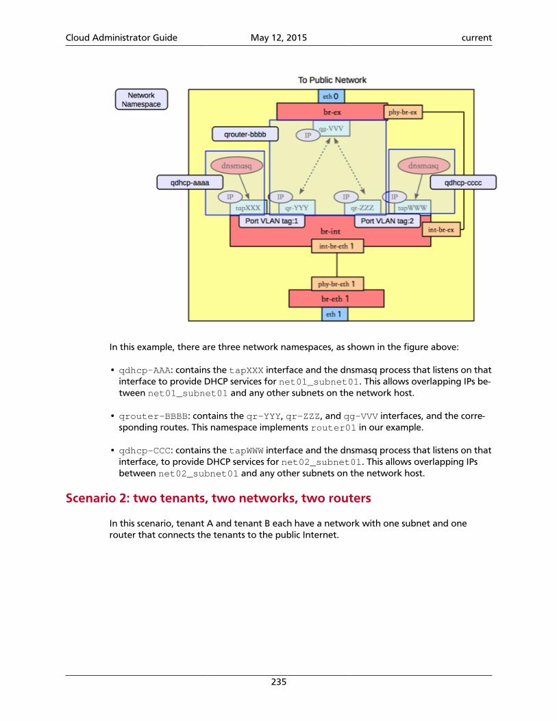
Cloud Administrator Guide May 12, 2015 current
235
In this example, there are three network namespaces, as shown in the figure above:
• qdhcp-AAA: contains the tapXXX interface and the dnsmasq process that listens on thatinterface to provide DHCP services for net01_subnet01. This allows overlapping IPs be-tween net01_subnet01 and any other subnets on the network host.
• qrouter-BBBB: contains the qr-YYY, qr-ZZZ, and qg-VVV interfaces, and the corre-sponding routes. This namespace implements router01 in our example.
• qdhcp-CCC: contains the tapWWW interface and the dnsmasq process that listens on thatinterface, to provide DHCP services for net02_subnet01. This allows overlapping IPsbetween net02_subnet01 and any other subnets on the network host.
Scenario 2: two tenants, two networks, two routers
In this scenario, tenant A and tenant B each have a network with one subnet and onerouter that connects the tenants to the public Internet.
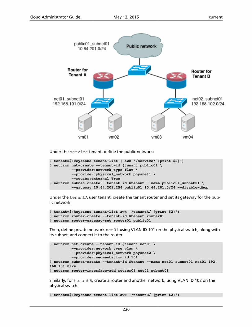
Cloud Administrator Guide May 12, 2015 current
236
Under the service tenant, define the public network:
$ tenant=$(keystone tenant-list | awk '/service/ {print $2}')$ neutron net-create --tenant-id $tenant public01 \ --provider:network_type flat \ --provider:physical_network physnet1 \ --router:external True$ neutron subnet-create --tenant-id $tenant --name public01_subnet01 \ --gateway 10.64.201.254 public01 10.64.201.0/24 --disable-dhcp
Under the tenantA user tenant, create the tenant router and set its gateway for the pub-lic network.
$ tenant=$(keystone tenant-list|awk '/tenantA/ {print $2}')$ neutron router-create --tenant-id $tenant router01$ neutron router-gateway-set router01 public01
Then, define private network net01 using VLAN ID 101 on the physical switch, along withits subnet, and connect it to the router.
$ neutron net-create --tenant-id $tenant net01 \ --provider:network_type vlan \ --provider:physical_network physnet2 \ --provider:segmentation_id 101$ neutron subnet-create --tenant-id $tenant --name net01_subnet01 net01 192.168.101.0/24$ neutron router-interface-add router01 net01_subnet01
Similarly, for tenantB, create a router and another network, using VLAN ID 102 on thephysical switch:
$ tenant=$(keystone tenant-list|awk '/tenantB/ {print $2}')
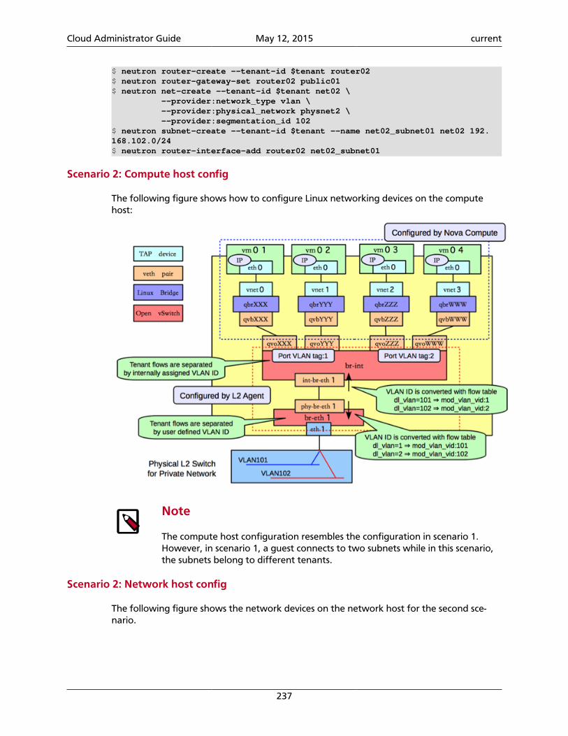
Cloud Administrator Guide May 12, 2015 current
237
$ neutron router-create --tenant-id $tenant router02$ neutron router-gateway-set router02 public01$ neutron net-create --tenant-id $tenant net02 \ --provider:network_type vlan \ --provider:physical_network physnet2 \ --provider:segmentation_id 102$ neutron subnet-create --tenant-id $tenant --name net02_subnet01 net02 192.168.102.0/24$ neutron router-interface-add router02 net02_subnet01
Scenario 2: Compute host config
The following figure shows how to configure Linux networking devices on the computehost:
Note
The compute host configuration resembles the configuration in scenario 1.However, in scenario 1, a guest connects to two subnets while in this scenario,the subnets belong to different tenants.
Scenario 2: Network host config
The following figure shows the network devices on the network host for the second sce-nario.
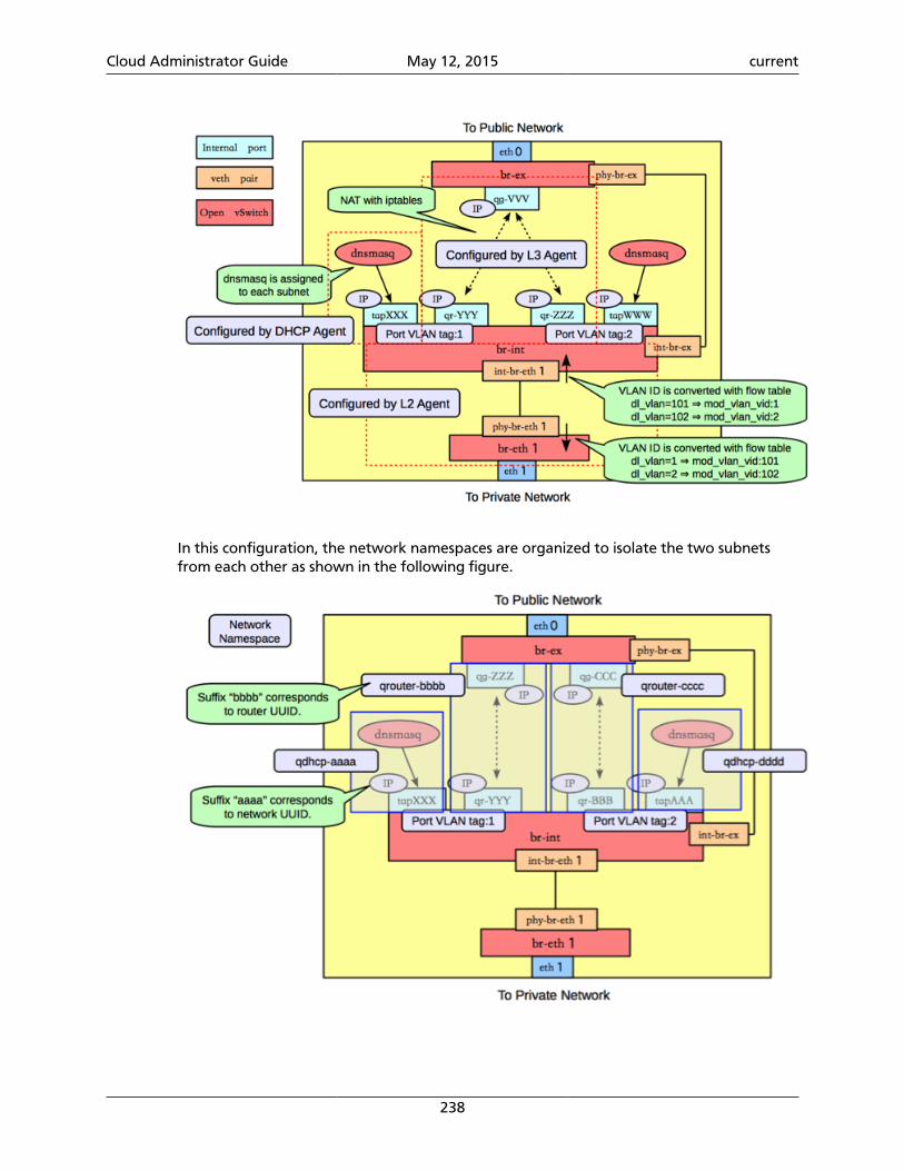
Cloud Administrator Guide May 12, 2015 current
238
In this configuration, the network namespaces are organized to isolate the two subnetsfrom each other as shown in the following figure.
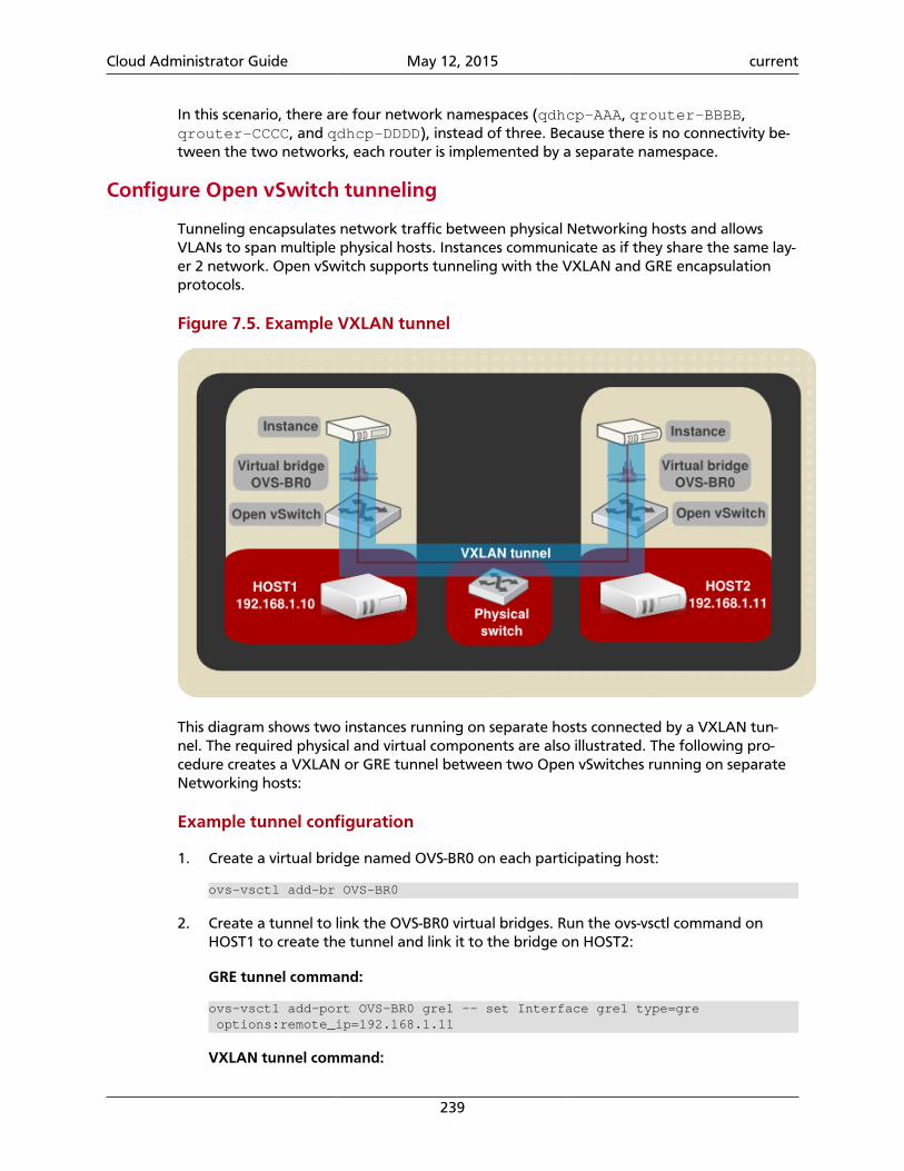
Cloud Administrator Guide May 12, 2015 current
239
In this scenario, there are four network namespaces (qdhcp-AAA, qrouter-BBBB,qrouter-CCCC, and qdhcp-DDDD), instead of three. Because there is no connectivity be-tween the two networks, each router is implemented by a separate namespace.
Configure Open vSwitch tunneling
Tunneling encapsulates network traffic between physical Networking hosts and allowsVLANs to span multiple physical hosts. Instances communicate as if they share the same lay-er 2 network. Open vSwitch supports tunneling with the VXLAN and GRE encapsulationprotocols.
Figure 7.5. Example VXLAN tunnel
This diagram shows two instances running on separate hosts connected by a VXLAN tun-nel. The required physical and virtual components are also illustrated. The following pro-cedure creates a VXLAN or GRE tunnel between two Open vSwitches running on separateNetworking hosts:
Example tunnel configuration
1. Create a virtual bridge named OVS-BR0 on each participating host:
ovs-vsctl add-br OVS-BR0
2. Create a tunnel to link the OVS-BR0 virtual bridges. Run the ovs-vsctl command onHOST1 to create the tunnel and link it to the bridge on HOST2:
GRE tunnel command:
ovs-vsctl add-port OVS-BR0 gre1 -- set Interface gre1 type=gre options:remote_ip=192.168.1.11
VXLAN tunnel command:
Cloud Administrator Guide May 12, 2015 current
240
ovs-vsctl add-port OVS-BR0 vxlan1 -- set Interface vxlan1 type=vxlan options:remote_ip=192.168.1.11
3. Run the ovs-vsctl command on HOST2 to create the tunnel and link it to the bridge onHOST1.
GRE tunnel command:
ovs-vsctl add-port OVS-BR0 gre1 -- set Interface gre1 type=gre options:remote_ip=192.168.1.10
VXLAN tunnel command:
ovs-vsctl add-port OVS-BR0 vxlan1 -- set Interface vxlan1 type=vxlan options:remote_ip=192.168.1.10
Successful completion of these steps results in the two instances sharing a layer 2 network.
Linux Bridge
This section describes how the Linux Bridge plug-in implements the Networking abstrac-tions. For information about DHCP and L3 agents, see the section called “Scenario 1: onetenant, two networks, one router” [230].
Configuration
This example uses VLAN isolation on the switches to isolate tenant networks. This config-uration labels the physical network associated with the public network as physnet1, andthe physical network associated with the data network as physnet2, which leads to thefollowing configuration options in linuxbridge_conf.ini:
[vlans]tenant_network_type = vlannetwork_vlan_ranges = physnet1,physnet2:100:110
[linux_bridge]physical_interface_mappings = physnet2:eth1
Note
In this configuration there isn't a bridge mapping for physnet1 as it is onlyneeded on the network host, which maps it to the Open vSwitch bridge br-exconnected to the external network as seen below.
Scenario 1: one tenant, two networks, one router
The first scenario has two private networks (net01, and net02), each with one subnet(net01_subnet01: 192.168.101.0/24, net02_subnet01, 192.168.102.0/24). Bothprivate networks are attached to a router that connects them to the public network(10.64.201.0/24).
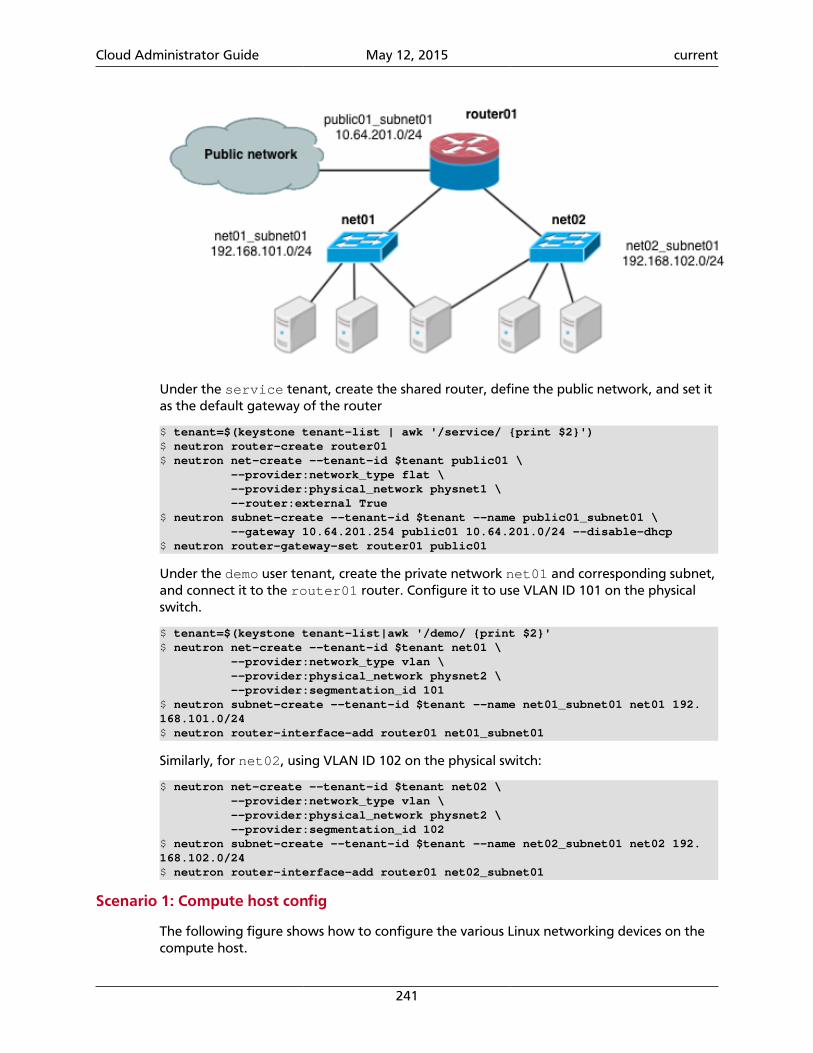
Cloud Administrator Guide May 12, 2015 current
241
Under the service tenant, create the shared router, define the public network, and set itas the default gateway of the router
$ tenant=$(keystone tenant-list | awk '/service/ {print $2}')$ neutron router-create router01$ neutron net-create --tenant-id $tenant public01 \ --provider:network_type flat \ --provider:physical_network physnet1 \ --router:external True$ neutron subnet-create --tenant-id $tenant --name public01_subnet01 \ --gateway 10.64.201.254 public01 10.64.201.0/24 --disable-dhcp$ neutron router-gateway-set router01 public01
Under the demo user tenant, create the private network net01 and corresponding subnet,and connect it to the router01 router. Configure it to use VLAN ID 101 on the physicalswitch.
$ tenant=$(keystone tenant-list|awk '/demo/ {print $2}'$ neutron net-create --tenant-id $tenant net01 \ --provider:network_type vlan \ --provider:physical_network physnet2 \ --provider:segmentation_id 101$ neutron subnet-create --tenant-id $tenant --name net01_subnet01 net01 192.168.101.0/24$ neutron router-interface-add router01 net01_subnet01
Similarly, for net02, using VLAN ID 102 on the physical switch:
$ neutron net-create --tenant-id $tenant net02 \ --provider:network_type vlan \ --provider:physical_network physnet2 \ --provider:segmentation_id 102$ neutron subnet-create --tenant-id $tenant --name net02_subnet01 net02 192.168.102.0/24$ neutron router-interface-add router01 net02_subnet01
Scenario 1: Compute host config
The following figure shows how to configure the various Linux networking devices on thecompute host.
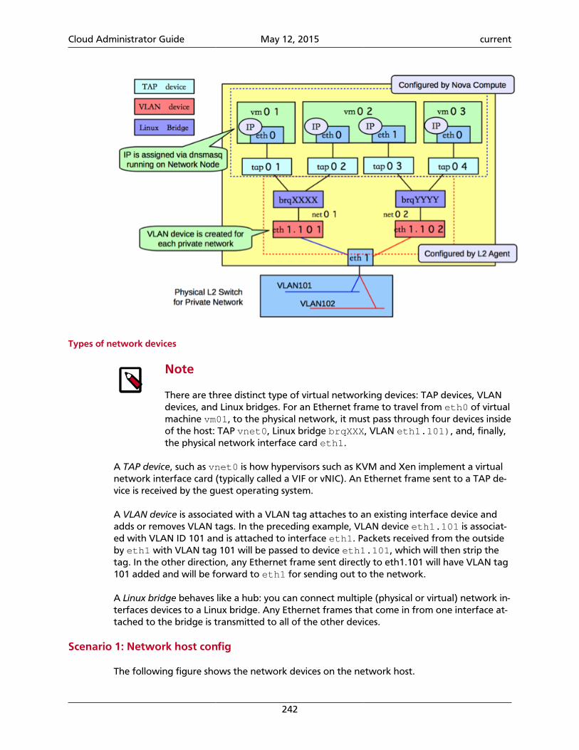
Cloud Administrator Guide May 12, 2015 current
242
Types of network devices
Note
There are three distinct type of virtual networking devices: TAP devices, VLANdevices, and Linux bridges. For an Ethernet frame to travel from eth0 of virtualmachine vm01, to the physical network, it must pass through four devices insideof the host: TAP vnet0, Linux bridge brqXXX, VLAN eth1.101), and, finally,the physical network interface card eth1.
A TAP device, such as vnet0 is how hypervisors such as KVM and Xen implement a virtualnetwork interface card (typically called a VIF or vNIC). An Ethernet frame sent to a TAP de-vice is received by the guest operating system.
A VLAN device is associated with a VLAN tag attaches to an existing interface device andadds or removes VLAN tags. In the preceding example, VLAN device eth1.101 is associat-ed with VLAN ID 101 and is attached to interface eth1. Packets received from the outsideby eth1 with VLAN tag 101 will be passed to device eth1.101, which will then strip thetag. In the other direction, any Ethernet frame sent directly to eth1.101 will have VLAN tag101 added and will be forward to eth1 for sending out to the network.
A Linux bridge behaves like a hub: you can connect multiple (physical or virtual) network in-terfaces devices to a Linux bridge. Any Ethernet frames that come in from one interface at-tached to the bridge is transmitted to all of the other devices.
Scenario 1: Network host config
The following figure shows the network devices on the network host.
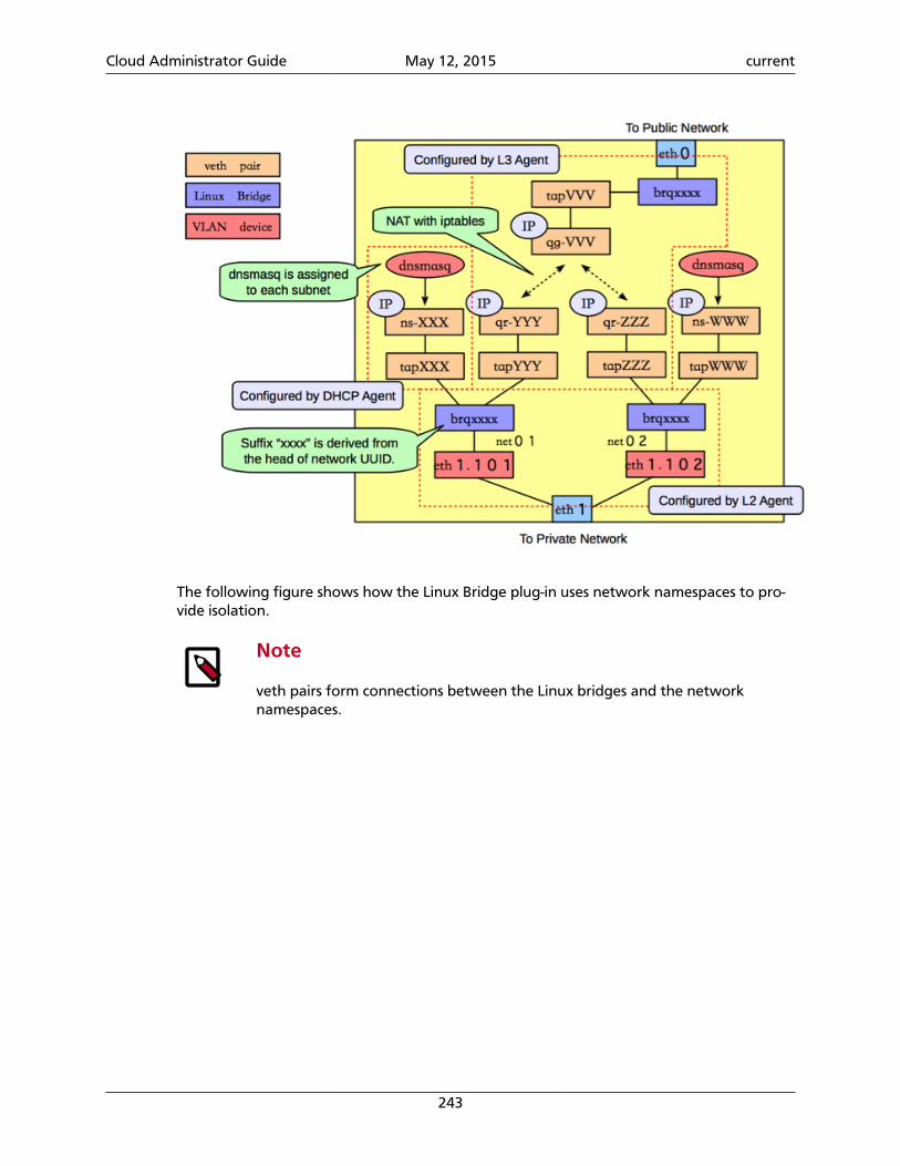
Cloud Administrator Guide May 12, 2015 current
243
The following figure shows how the Linux Bridge plug-in uses network namespaces to pro-vide isolation.
Note
veth pairs form connections between the Linux bridges and the networknamespaces.
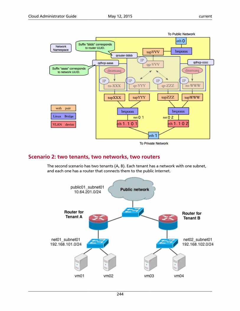
Cloud Administrator Guide May 12, 2015 current
244
Scenario 2: two tenants, two networks, two routers
The second scenario has two tenants (A, B). Each tenant has a network with one subnet,and each one has a router that connects them to the public Internet.
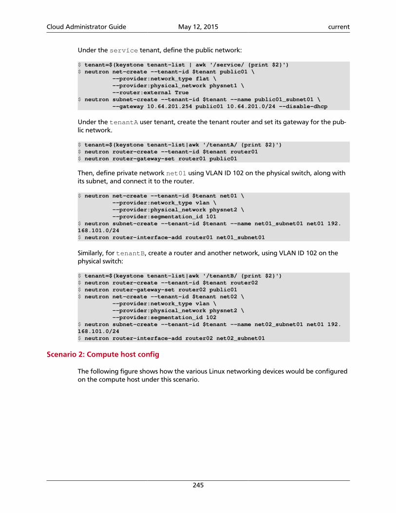
Cloud Administrator Guide May 12, 2015 current
245
Under the service tenant, define the public network:
$ tenant=$(keystone tenant-list | awk '/service/ {print $2}')$ neutron net-create --tenant-id $tenant public01 \ --provider:network_type flat \ --provider:physical_network physnet1 \ --router:external True$ neutron subnet-create --tenant-id $tenant --name public01_subnet01 \ --gateway 10.64.201.254 public01 10.64.201.0/24 --disable-dhcp
Under the tenantA user tenant, create the tenant router and set its gateway for the pub-lic network.
$ tenant=$(keystone tenant-list|awk '/tenantA/ {print $2}')$ neutron router-create --tenant-id $tenant router01$ neutron router-gateway-set router01 public01
Then, define private network net01 using VLAN ID 102 on the physical switch, along withits subnet, and connect it to the router.
$ neutron net-create --tenant-id $tenant net01 \ --provider:network_type vlan \ --provider:physical_network physnet2 \ --provider:segmentation_id 101$ neutron subnet-create --tenant-id $tenant --name net01_subnet01 net01 192.168.101.0/24$ neutron router-interface-add router01 net01_subnet01
Similarly, for tenantB, create a router and another network, using VLAN ID 102 on thephysical switch:
$ tenant=$(keystone tenant-list|awk '/tenantB/ {print $2}')$ neutron router-create --tenant-id $tenant router02$ neutron router-gateway-set router02 public01$ neutron net-create --tenant-id $tenant net02 \ --provider:network_type vlan \ --provider:physical_network physnet2 \ --provider:segmentation_id 102$ neutron subnet-create --tenant-id $tenant --name net02_subnet01 net01 192.168.101.0/24$ neutron router-interface-add router02 net02_subnet01
Scenario 2: Compute host config
The following figure shows how the various Linux networking devices would be configuredon the compute host under this scenario.
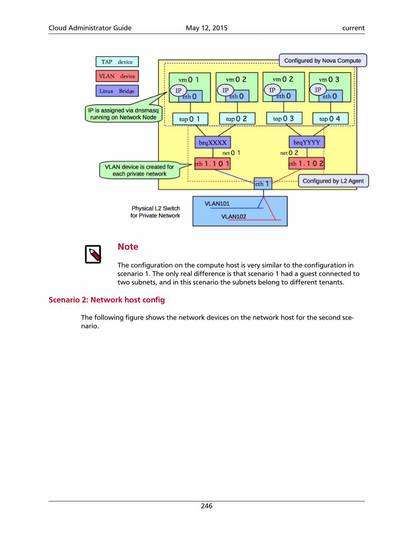
Cloud Administrator Guide May 12, 2015 current
246
Note
The configuration on the compute host is very similar to the configuration inscenario 1. The only real difference is that scenario 1 had a guest connected totwo subnets, and in this scenario the subnets belong to different tenants.
Scenario 2: Network host config
The following figure shows the network devices on the network host for the second sce-nario.
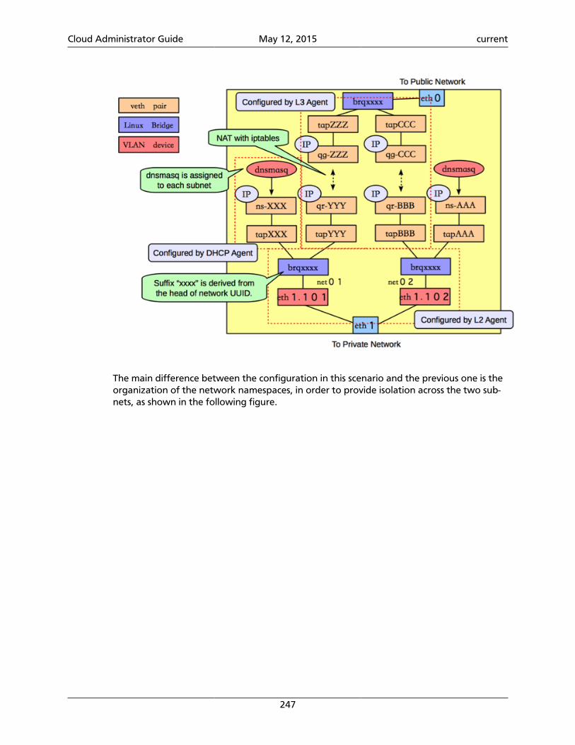
Cloud Administrator Guide May 12, 2015 current
247
The main difference between the configuration in this scenario and the previous one is theorganization of the network namespaces, in order to provide isolation across the two sub-nets, as shown in the following figure.
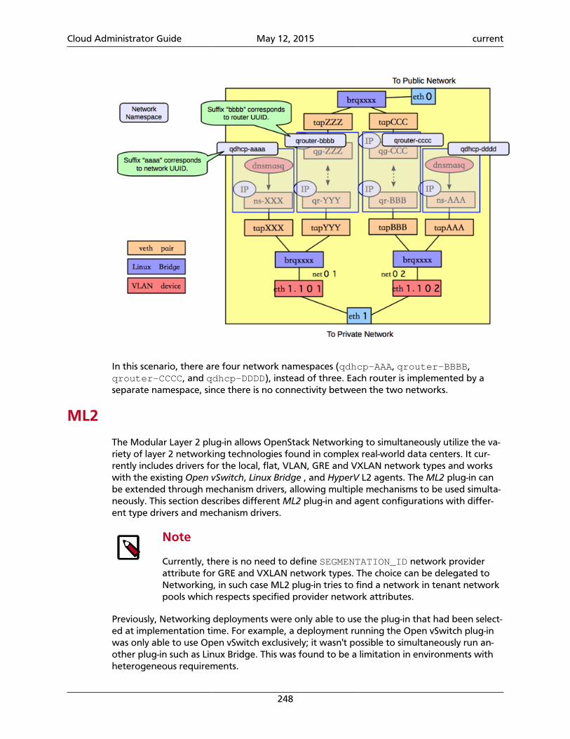
Cloud Administrator Guide May 12, 2015 current
248
In this scenario, there are four network namespaces (qdhcp-AAA, qrouter-BBBB,qrouter-CCCC, and qdhcp-DDDD), instead of three. Each router is implemented by aseparate namespace, since there is no connectivity between the two networks.
ML2
The Modular Layer 2 plug-in allows OpenStack Networking to simultaneously utilize the va-riety of layer 2 networking technologies found in complex real-world data centers. It cur-rently includes drivers for the local, flat, VLAN, GRE and VXLAN network types and workswith the existing Open vSwitch, Linux Bridge , and HyperV L2 agents. The ML2 plug-in canbe extended through mechanism drivers, allowing multiple mechanisms to be used simulta-neously. This section describes different ML2 plug-in and agent configurations with differ-ent type drivers and mechanism drivers.
Note
Currently, there is no need to define SEGMENTATION_ID network providerattribute for GRE and VXLAN network types. The choice can be delegated toNetworking, in such case ML2 plug-in tries to find a network in tenant networkpools which respects specified provider network attributes.
Previously, Networking deployments were only able to use the plug-in that had been select-ed at implementation time. For example, a deployment running the Open vSwitch plug-inwas only able to use Open vSwitch exclusively; it wasn't possible to simultaneously run an-other plug-in such as Linux Bridge. This was found to be a limitation in environments withheterogeneous requirements.

Cloud Administrator Guide May 12, 2015 current
249
Warning
Disabling a ML2 type driver and re-enabling it later may lead to database incon-sistencies if ML2 is reconfigured without support for that type.
ML2 with L2 population mechanism driver
The L2 Population driver enables broadcast, multicast, and unicast traffic to scale out onlarge overlay networks. This traffic is sent to the relevant agent via encapsulation as a tar-geted unicast.
Current Open vSwitch and Linux Bridge tunneling implementations broadcast to everyagent, even if they don't host the corresponding network as illustrated below.
As broadcast emulation on overlay is costly, it may be better to avoid its use for MAC learn-ing and ARP resolution. This supposes the use of proxy ARP on the agent to answer VMrequests, and to populate forwarding table. Currently only the Linux Bridge Agent imple-ments an ARP proxy. The pre-population limits L2 broadcasts in overlay, however it mayanyway be necessary to provide broadcast emulation. This is achieved by broadcastingpackets via unicast only to the relevant agents as illustrated below.
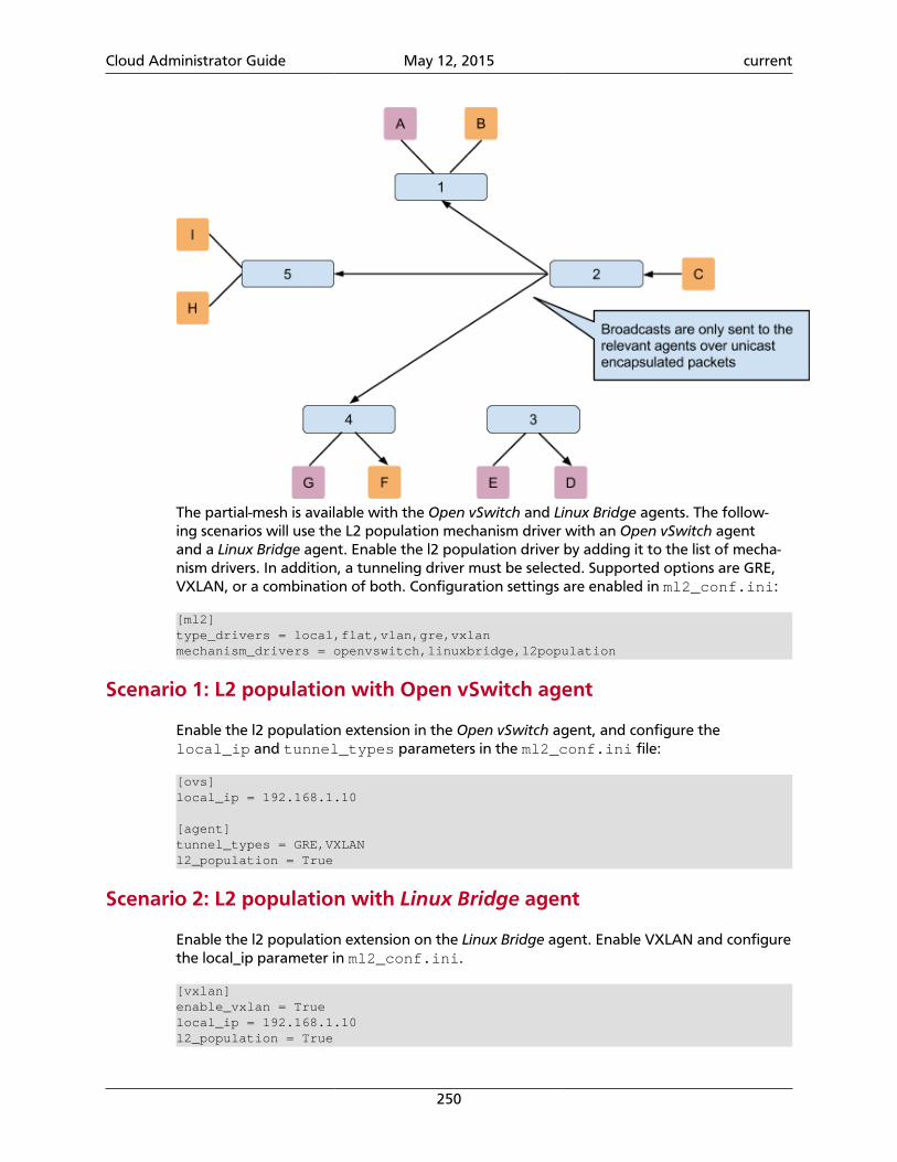
Cloud Administrator Guide May 12, 2015 current
250
The partial-mesh is available with the Open vSwitch and Linux Bridge agents. The follow-ing scenarios will use the L2 population mechanism driver with an Open vSwitch agentand a Linux Bridge agent. Enable the l2 population driver by adding it to the list of mecha-nism drivers. In addition, a tunneling driver must be selected. Supported options are GRE,VXLAN, or a combination of both. Configuration settings are enabled in ml2_conf.ini:
[ml2]type_drivers = local,flat,vlan,gre,vxlanmechanism_drivers = openvswitch,linuxbridge,l2population
Scenario 1: L2 population with Open vSwitch agent
Enable the l2 population extension in the Open vSwitch agent, and configure thelocal_ip and tunnel_types parameters in the ml2_conf.ini file:
[ovs]local_ip = 192.168.1.10
[agent]tunnel_types = GRE,VXLANl2_population = True
Scenario 2: L2 population with Linux Bridge agent
Enable the l2 population extension on the Linux Bridge agent. Enable VXLAN and configurethe local_ip parameter in ml2_conf.ini.
[vxlan]enable_vxlan = Truelocal_ip = 192.168.1.10l2_population = True
Cloud Administrator Guide May 12, 2015 current
251
Enable security group API
The ML2 plug-in can concurrently support different L2 agents (or other mecha-nisms) with different configuration files, so each L2 agent configuration file (suchas ovs_neutron_plugin.ini or linuxbridge_conf.ini) should containthe appropriate firewall_driver value for that agent in addition to settingenable_security_group to True (which is the default).
The firewall_driver value in the API server's ml2_conf.ini file does not matter.
To disable the securitygroup API, edit the ml2_conf.ini file on the API server, andovs_neutron_plugin.ini, linuxbridge_conf.ini or other L2 agent configurationfiles on the agent servers :
[securitygroup]enable_security_group = Falsefirewall_driver = neutron.agent.firewall.NoopFirewallDriver
Advanced configuration optionsThis section describes advanced configuration options for various system components. Forexample, configuration options where the default works but that the user wants to cus-tomize options. After installing from packages, $NEUTRON_CONF_DIR is /etc/neutron.
OpenStack Networking server with plug-in
This web server runs the OpenStack Networking API Web Server. It loads a plug-in andpasses the API calls to the plug-in for processing. The neutron-server service receivesone or more configuration files as input. For example:
neutron-server --config-file NEUTRON_CONFIG_FILE --config-file PLUGIN_CONFIG_FILE
The neutron configuration file contains the common neutron configuration options.
The plug-in configuration file contains the plug-in specific options.
The plug-in that runs on the service is loaded through the core_plugin configuration op-tion. In some cases, a plug-in might have an agent that performs the actual networking.
Most plug-ins require an SQL database. After you install and start the database server, set apassword for the root account and delete the anonymous accounts:
$ > mysql -u rootmysql> update mysql.user set password = password('iamroot') where user = 'root';mysql> delete from mysql.user where user = '';
Create a database and user account specifically for plug-in:
mysql> create database DATABASE_NAMEmysql> create user 'USER_NAME'@'localhost' identified by 'USER_NAME';mysql> create user 'USER_NAME'@'%' identified by 'USER_NAME';
Cloud Administrator Guide May 12, 2015 current
252
mysql> grant all on DATABASE_NAME.* to 'USER_NAME'@'%';
After this step completes, you can update the settings in the relevant plug-in configurationfiles. Find the plug-in specific configuration files at $NEUTRON_CONF_DIR/plugins.
Some plug-ins have an L2 agent that performs the actual networking. That is, the agent at-taches the virtual machine NIC to the OpenStack Networking network. Each node shouldrun an L2 agent. Note that the agent receives the following input parameters:
neutron-plugin-agent --config-file NEUTRON_CONFIG_FILE --config-file PLUGIN_CONFIG_FILE
You must complete these tasks before you can work with the plug-in:
1. Ensure that the core plug-in is updated.
2. Ensure that the database connection is correctly set.
The following table shows sample values for the configuration options. Some Linux pack-ages might provide installation utilities that configure these values.
Table 7.11. Settings
Option Value
Open vSwitch
core_plugin ($NEUTRON_CONF_DIR/neutron.conf) openvswitch
connection (in the plugin configuration file, section[database])
mysql://USERNAME:PASSWORD@localhost/ovs_neutron?charset=utf8
Plug-in Configuration File $NEUTRON_CONF_DIR/plugins/open-vswitch/ovs_neutron_plugin.ini
Agent neutron-openvswitch-agent
Linux Bridge
core_plugin ($NEUTRON_CONF_DIR/neutron.conf) linuxbridge
connection (in the plug-in configuration file, section[database])
mysql://USERNAME:PASSWORD@localhost/neutron_linux_bridge?charset=utf8
Plug-in Configuration File $NEUTRON_CONF_DIR/plugins/lin-uxbridge/linuxbridge_conf.ini
Agent neutron-linuxbridge-agent
DHCP agent
You can run a DHCP server that allocates IP addresses to virtual machines that run on thenetwork. When a subnet is created, by default, the subnet has DHCP enabled.
The node that runs the DHCP agent should run:
neutron-dhcp-agent --config-file NEUTRON_CONFIG_FILE --config-file DHCP_CONFIG_FILE
Currently the DHCP agent uses dnsmasq to perform that static address assignment.
You must configure a driver that matches the plug-in that runs on the service.
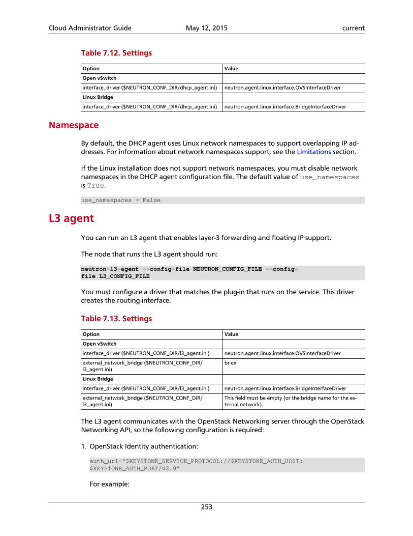
Cloud Administrator Guide May 12, 2015 current
253
Table 7.12. Settings
Option Value
Open vSwitch
interface_driver ($NEUTRON_CONF_DIR/dhcp_agent.ini) neutron.agent.linux.interface.OVSInterfaceDriver
Linux Bridge
interface_driver ($NEUTRON_CONF_DIR/dhcp_agent.ini) neutron.agent.linux.interface.BridgeInterfaceDriver
Namespace
By default, the DHCP agent uses Linux network namespaces to support overlapping IP ad-dresses. For information about network namespaces support, see the Limitations section.
If the Linux installation does not support network namespaces, you must disable networknamespaces in the DHCP agent configuration file. The default value of use_namespacesis True.
use_namespaces = False
L3 agent
You can run an L3 agent that enables layer-3 forwarding and floating IP support.
The node that runs the L3 agent should run:
neutron-l3-agent --config-file NEUTRON_CONFIG_FILE --config-file L3_CONFIG_FILE
You must configure a driver that matches the plug-in that runs on the service. This drivercreates the routing interface.
Table 7.13. Settings
Option Value
Open vSwitch
interface_driver ($NEUTRON_CONF_DIR/l3_agent.ini) neutron.agent.linux.interface.OVSInterfaceDriver
external_network_bridge ($NEUTRON_CONF_DIR/l3_agent.ini)
br-ex
Linux Bridge
interface_driver ($NEUTRON_CONF_DIR/l3_agent.ini) neutron.agent.linux.interface.BridgeInterfaceDriver
external_network_bridge ($NEUTRON_CONF_DIR/l3_agent.ini)
This field must be empty (or the bridge name for the ex-ternal network).
The L3 agent communicates with the OpenStack Networking server through the OpenStackNetworking API, so the following configuration is required:
1. OpenStack Identity authentication:
auth_url="$KEYSTONE_SERVICE_PROTOCOL://$KEYSTONE_AUTH_HOST:$KEYSTONE_AUTH_PORT/v2.0"
For example:
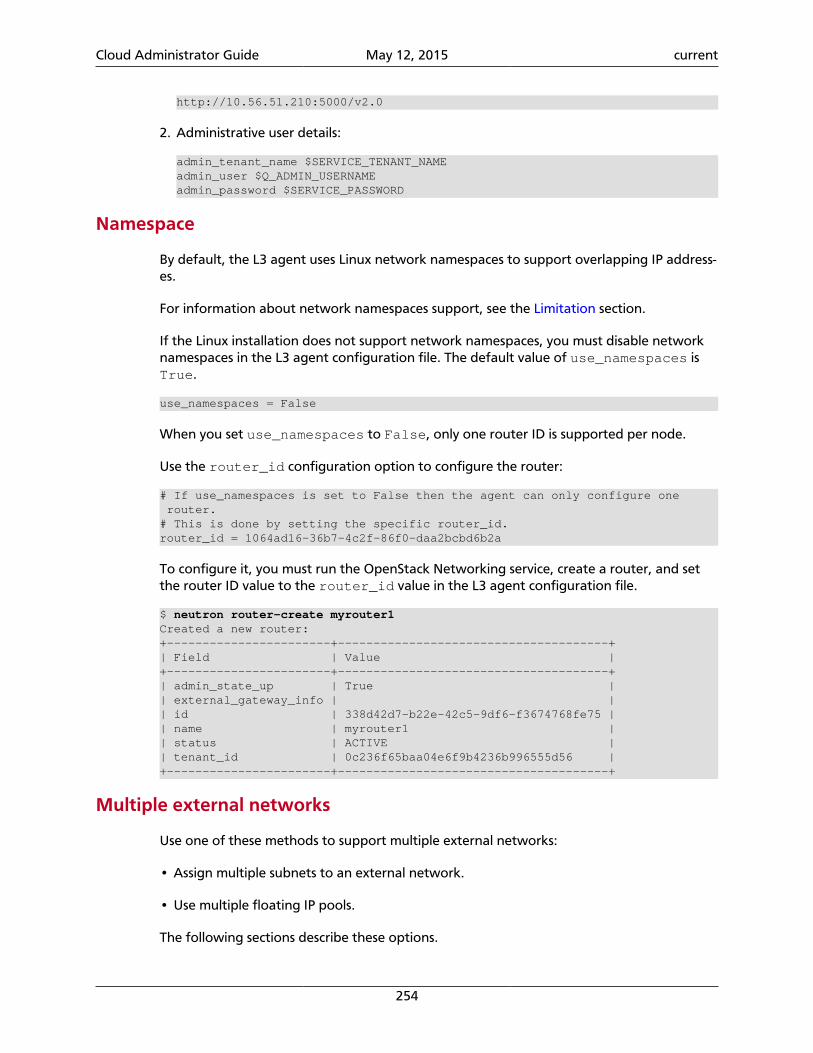
Cloud Administrator Guide May 12, 2015 current
254
http://10.56.51.210:5000/v2.0
2. Administrative user details:
admin_tenant_name $SERVICE_TENANT_NAMEadmin_user $Q_ADMIN_USERNAMEadmin_password $SERVICE_PASSWORD
Namespace
By default, the L3 agent uses Linux network namespaces to support overlapping IP address-es.
For information about network namespaces support, see the Limitation section.
If the Linux installation does not support network namespaces, you must disable networknamespaces in the L3 agent configuration file. The default value of use_namespaces isTrue.
use_namespaces = False
When you set use_namespaces to False, only one router ID is supported per node.
Use the router_id configuration option to configure the router:
# If use_namespaces is set to False then the agent can only configure one router.# This is done by setting the specific router_id.router_id = 1064ad16-36b7-4c2f-86f0-daa2bcbd6b2a
To configure it, you must run the OpenStack Networking service, create a router, and setthe router ID value to the router_id value in the L3 agent configuration file.
$ neutron router-create myrouter1Created a new router:+-----------------------+--------------------------------------+| Field | Value |+-----------------------+--------------------------------------+| admin_state_up | True || external_gateway_info | || id | 338d42d7-b22e-42c5-9df6-f3674768fe75 || name | myrouter1 || status | ACTIVE || tenant_id | 0c236f65baa04e6f9b4236b996555d56 |+-----------------------+--------------------------------------+
Multiple external networks
Use one of these methods to support multiple external networks:
• Assign multiple subnets to an external network.
• Use multiple floating IP pools.
The following sections describe these options.
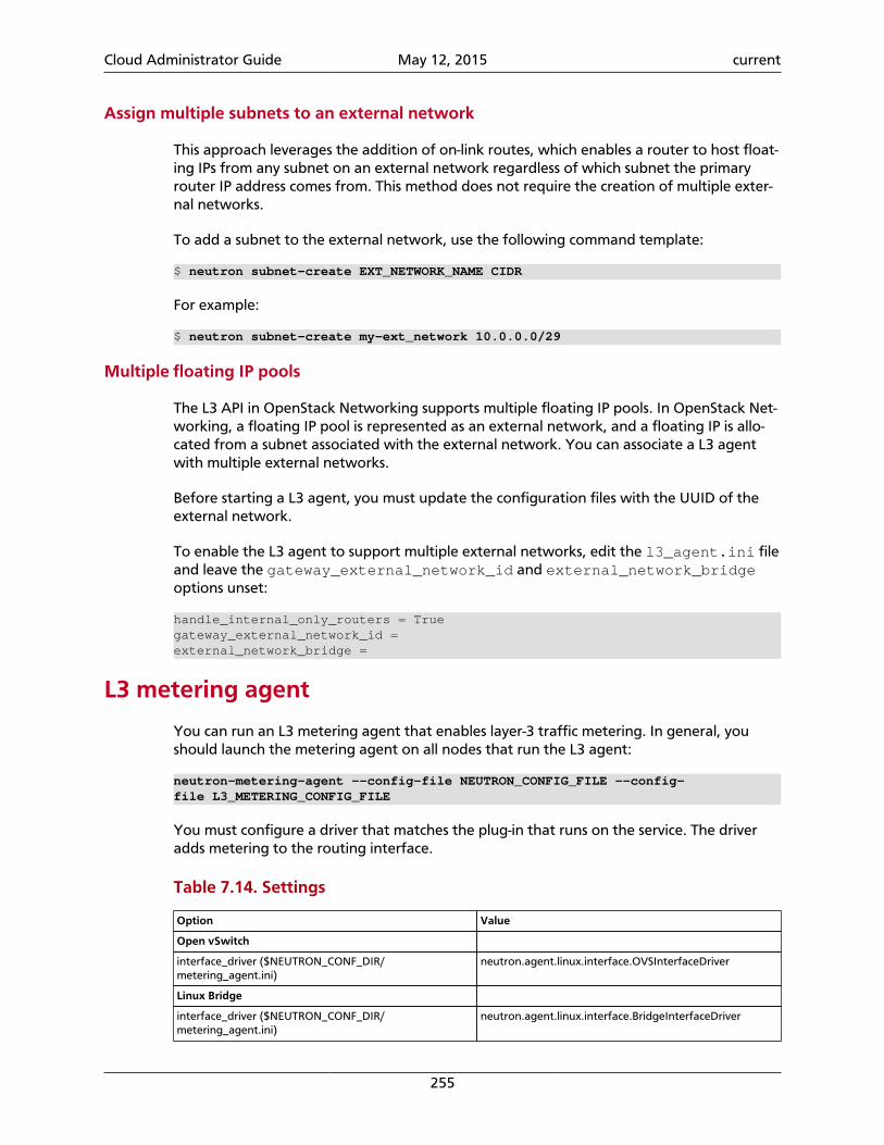
Cloud Administrator Guide May 12, 2015 current
255
Assign multiple subnets to an external network
This approach leverages the addition of on-link routes, which enables a router to host float-ing IPs from any subnet on an external network regardless of which subnet the primaryrouter IP address comes from. This method does not require the creation of multiple exter-nal networks.
To add a subnet to the external network, use the following command template:
$ neutron subnet-create EXT_NETWORK_NAME CIDR
For example:
$ neutron subnet-create my-ext_network 10.0.0.0/29
Multiple floating IP pools
The L3 API in OpenStack Networking supports multiple floating IP pools. In OpenStack Net-working, a floating IP pool is represented as an external network, and a floating IP is allo-cated from a subnet associated with the external network. You can associate a L3 agentwith multiple external networks.
Before starting a L3 agent, you must update the configuration files with the UUID of theexternal network.
To enable the L3 agent to support multiple external networks, edit the l3_agent.ini fileand leave the gateway_external_network_id and external_network_bridgeoptions unset:
handle_internal_only_routers = Truegateway_external_network_id =external_network_bridge =
L3 metering agent
You can run an L3 metering agent that enables layer-3 traffic metering. In general, youshould launch the metering agent on all nodes that run the L3 agent:
neutron-metering-agent --config-file NEUTRON_CONFIG_FILE --config-file L3_METERING_CONFIG_FILE
You must configure a driver that matches the plug-in that runs on the service. The driveradds metering to the routing interface.
Table 7.14. Settings
Option Value
Open vSwitch
interface_driver ($NEUTRON_CONF_DIR/metering_agent.ini)
neutron.agent.linux.interface.OVSInterfaceDriver
Linux Bridge
interface_driver ($NEUTRON_CONF_DIR/metering_agent.ini)
neutron.agent.linux.interface.BridgeInterfaceDriver
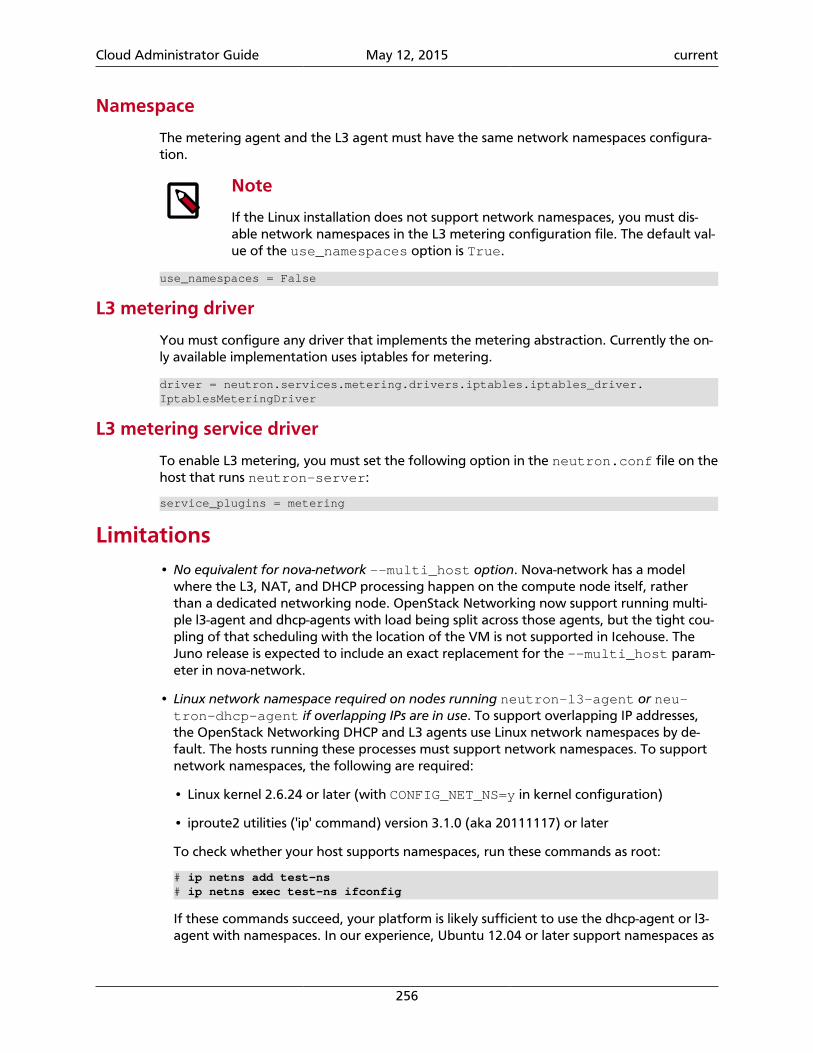
Cloud Administrator Guide May 12, 2015 current
256
Namespace
The metering agent and the L3 agent must have the same network namespaces configura-tion.
Note
If the Linux installation does not support network namespaces, you must dis-able network namespaces in the L3 metering configuration file. The default val-ue of the use_namespaces option is True.
use_namespaces = False
L3 metering driver
You must configure any driver that implements the metering abstraction. Currently the on-ly available implementation uses iptables for metering.
driver = neutron.services.metering.drivers.iptables.iptables_driver.IptablesMeteringDriver
L3 metering service driver
To enable L3 metering, you must set the following option in the neutron.conf file on thehost that runs neutron-server:
service_plugins = metering
Limitations• No equivalent for nova-network --multi_host option. Nova-network has a model
where the L3, NAT, and DHCP processing happen on the compute node itself, ratherthan a dedicated networking node. OpenStack Networking now support running multi-ple l3-agent and dhcp-agents with load being split across those agents, but the tight cou-pling of that scheduling with the location of the VM is not supported in Icehouse. TheJuno release is expected to include an exact replacement for the --multi_host param-eter in nova-network.
• Linux network namespace required on nodes running neutron-l3-agent or neu-tron-dhcp-agent if overlapping IPs are in use. To support overlapping IP addresses,the OpenStack Networking DHCP and L3 agents use Linux network namespaces by de-fault. The hosts running these processes must support network namespaces. To supportnetwork namespaces, the following are required:
• Linux kernel 2.6.24 or later (with CONFIG_NET_NS=y in kernel configuration)
• iproute2 utilities ('ip' command) version 3.1.0 (aka 20111117) or later
To check whether your host supports namespaces, run these commands as root:
# ip netns add test-ns# ip netns exec test-ns ifconfig
If these commands succeed, your platform is likely sufficient to use the dhcp-agent or l3-agent with namespaces. In our experience, Ubuntu 12.04 or later support namespaces as
Cloud Administrator Guide May 12, 2015 current
257
does Fedora 17 and later, but some earlier RHEL platforms do not by default. It might bepossible to upgrade the iproute2 package on a platform that does not support names-paces by default.
If you must disable namespaces, make sure that the neutron.conf file that is used byneutron-server has the following setting:
allow_overlapping_ips=False
Also, ensure that the dhcp_agent.ini and l3_agent.ini files have the followingsetting:
use_namespaces=False
Note
If the host does not support namespaces, the neutron-l3-agent andneutron-dhcp-agent should run on different hosts because there is noisolation between the IP addresses created by the L3 agent and by the DHCPagent. By manipulating the routing, the user can ensure that these networkshave access to one another.
If you run both L3 and DHCP services on the same node, you should enable namespacesto avoid conflicts with routes:
use_namespaces=True
• No IPv6 support for L3 agent. The neutron-l3-agent, used by many plug-ins to imple-ment L3 forwarding, supports only IPv4 forwarding. Currently, there are no errors provid-ed if you configure IPv6 addresses via the API.
• ZeroMQ support is experimental. Some agents, including neutron-dhcp-agent, neu-tron-openvswitch-agent, and neutron-linuxbridge-agent use RPC to com-municate. ZeroMQ is an available option in the configuration file, but has not been test-ed and should be considered experimental. In particular, issues might occur with ZeroMQand the dhcp agent.
• MetaPlugin is experimental. This release includes a MetaPlugin that is intended to sup-port multiple plug-ins at the same time for different API requests, based on the contentof those API requests. The core team has not thoroughly reviewed or tested this func-tionality. Consider this functionality to be experimental until further validation is per-formed.
Scalable and highly available DHCP agentsThis section describes how to use the agent management (alias agent) and scheduler (aliasagent_scheduler) extensions for DHCP agents scalability and HA.
Note
Use the neutron ext-list client command to check if these extensions are en-abled:
$ neutron ext-list -c name -c alias
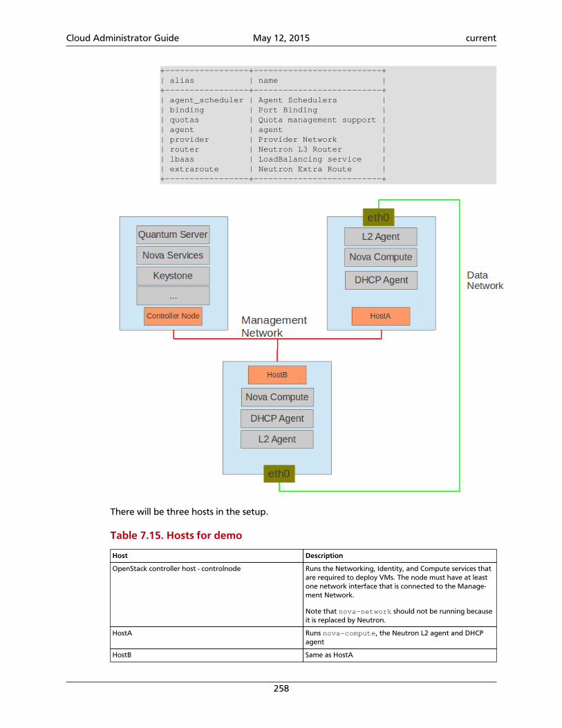
Cloud Administrator Guide May 12, 2015 current
258
+-----------------+--------------------------+| alias | name |+-----------------+--------------------------+| agent_scheduler | Agent Schedulers || binding | Port Binding || quotas | Quota management support || agent | agent || provider | Provider Network || router | Neutron L3 Router || lbaas | LoadBalancing service || extraroute | Neutron Extra Route |+-----------------+--------------------------+
There will be three hosts in the setup.
Table 7.15. Hosts for demo
Host Description
OpenStack controller host - controlnode Runs the Networking, Identity, and Compute services thatare required to deploy VMs. The node must have at leastone network interface that is connected to the Manage-ment Network.
Note that nova-network should not be running becauseit is replaced by Neutron.
HostA Runs nova-compute, the Neutron L2 agent and DHCPagent
HostB Same as HostA
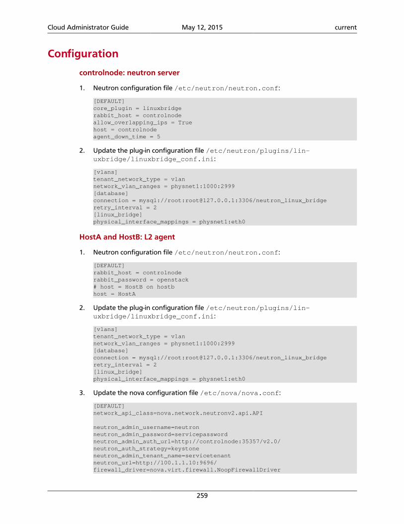
Cloud Administrator Guide May 12, 2015 current
259
Configuration
controlnode: neutron server
1. Neutron configuration file /etc/neutron/neutron.conf:
[DEFAULT]core_plugin = linuxbridgerabbit_host = controlnodeallow_overlapping_ips = Truehost = controlnodeagent_down_time = 5
2. Update the plug-in configuration file /etc/neutron/plugins/lin-uxbridge/linuxbridge_conf.ini:
[vlans]tenant_network_type = vlannetwork_vlan_ranges = physnet1:1000:2999[database]connection = mysql://root:[email protected]:3306/neutron_linux_bridgeretry_interval = 2[linux_bridge]physical_interface_mappings = physnet1:eth0
HostA and HostB: L2 agent
1. Neutron configuration file /etc/neutron/neutron.conf:
[DEFAULT]rabbit_host = controlnoderabbit_password = openstack# host = HostB on hostbhost = HostA
2. Update the plug-in configuration file /etc/neutron/plugins/lin-uxbridge/linuxbridge_conf.ini:
[vlans]tenant_network_type = vlannetwork_vlan_ranges = physnet1:1000:2999[database]connection = mysql://root:[email protected]:3306/neutron_linux_bridgeretry_interval = 2[linux_bridge]physical_interface_mappings = physnet1:eth0
3. Update the nova configuration file /etc/nova/nova.conf:
[DEFAULT]network_api_class=nova.network.neutronv2.api.API
neutron_admin_username=neutronneutron_admin_password=servicepasswordneutron_admin_auth_url=http://controlnode:35357/v2.0/neutron_auth_strategy=keystoneneutron_admin_tenant_name=servicetenantneutron_url=http://100.1.1.10:9696/firewall_driver=nova.virt.firewall.NoopFirewallDriver
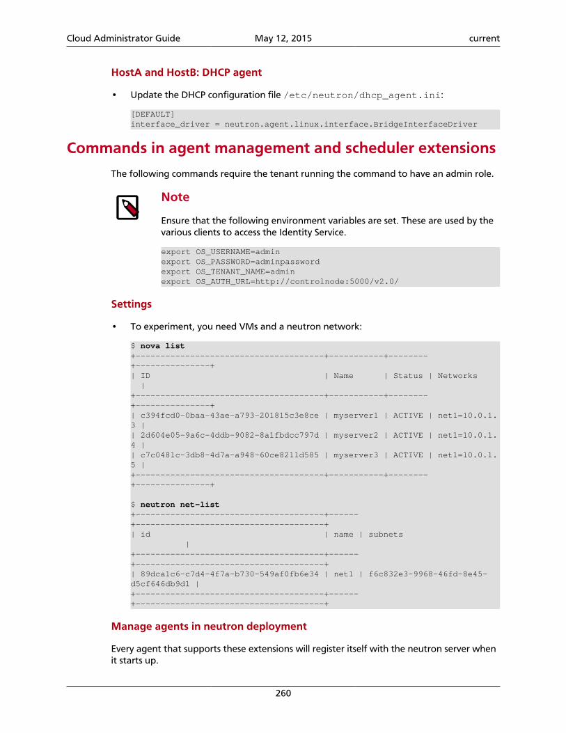
Cloud Administrator Guide May 12, 2015 current
260
HostA and HostB: DHCP agent
• Update the DHCP configuration file /etc/neutron/dhcp_agent.ini:
[DEFAULT]interface_driver = neutron.agent.linux.interface.BridgeInterfaceDriver
Commands in agent management and scheduler extensions
The following commands require the tenant running the command to have an admin role.
Note
Ensure that the following environment variables are set. These are used by thevarious clients to access the Identity Service.
export OS_USERNAME=adminexport OS_PASSWORD=adminpasswordexport OS_TENANT_NAME=adminexport OS_AUTH_URL=http://controlnode:5000/v2.0/
Settings
• To experiment, you need VMs and a neutron network:
$ nova list+--------------------------------------+-----------+--------+---------------+| ID | Name | Status | Networks |+--------------------------------------+-----------+--------+---------------+| c394fcd0-0baa-43ae-a793-201815c3e8ce | myserver1 | ACTIVE | net1=10.0.1.3 || 2d604e05-9a6c-4ddb-9082-8a1fbdcc797d | myserver2 | ACTIVE | net1=10.0.1.4 || c7c0481c-3db8-4d7a-a948-60ce8211d585 | myserver3 | ACTIVE | net1=10.0.1.5 |+--------------------------------------+-----------+--------+---------------+
$ neutron net-list+--------------------------------------+------+--------------------------------------+| id | name | subnets |+--------------------------------------+------+--------------------------------------+| 89dca1c6-c7d4-4f7a-b730-549af0fb6e34 | net1 | f6c832e3-9968-46fd-8e45-d5cf646db9d1 |+--------------------------------------+------+--------------------------------------+
Manage agents in neutron deployment
Every agent that supports these extensions will register itself with the neutron server whenit starts up.
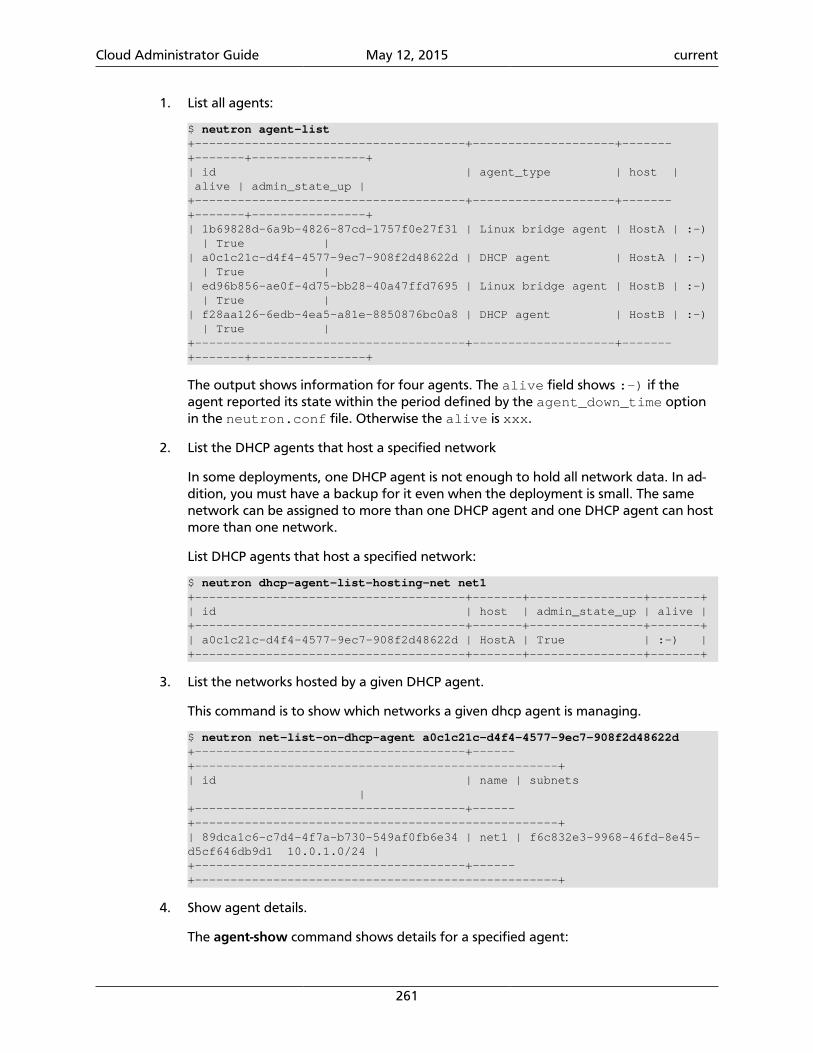
Cloud Administrator Guide May 12, 2015 current
261
1. List all agents:
$ neutron agent-list+--------------------------------------+--------------------+-------+-------+----------------+| id | agent_type | host | alive | admin_state_up |+--------------------------------------+--------------------+-------+-------+----------------+| 1b69828d-6a9b-4826-87cd-1757f0e27f31 | Linux bridge agent | HostA | :-) | True || a0c1c21c-d4f4-4577-9ec7-908f2d48622d | DHCP agent | HostA | :-) | True || ed96b856-ae0f-4d75-bb28-40a47ffd7695 | Linux bridge agent | HostB | :-) | True || f28aa126-6edb-4ea5-a81e-8850876bc0a8 | DHCP agent | HostB | :-) | True |+--------------------------------------+--------------------+-------+-------+----------------+
The output shows information for four agents. The alive field shows :-) if theagent reported its state within the period defined by the agent_down_time optionin the neutron.conf file. Otherwise the alive is xxx.
2. List the DHCP agents that host a specified network
In some deployments, one DHCP agent is not enough to hold all network data. In ad-dition, you must have a backup for it even when the deployment is small. The samenetwork can be assigned to more than one DHCP agent and one DHCP agent can hostmore than one network.
List DHCP agents that host a specified network:
$ neutron dhcp-agent-list-hosting-net net1+--------------------------------------+-------+----------------+-------+| id | host | admin_state_up | alive |+--------------------------------------+-------+----------------+-------+| a0c1c21c-d4f4-4577-9ec7-908f2d48622d | HostA | True | :-) |+--------------------------------------+-------+----------------+-------+
3. List the networks hosted by a given DHCP agent.
This command is to show which networks a given dhcp agent is managing.
$ neutron net-list-on-dhcp-agent a0c1c21c-d4f4-4577-9ec7-908f2d48622d+--------------------------------------+------+---------------------------------------------------+| id | name | subnets |+--------------------------------------+------+---------------------------------------------------+| 89dca1c6-c7d4-4f7a-b730-549af0fb6e34 | net1 | f6c832e3-9968-46fd-8e45-d5cf646db9d1 10.0.1.0/24 |+--------------------------------------+------+---------------------------------------------------+
4. Show agent details.
The agent-show command shows details for a specified agent:
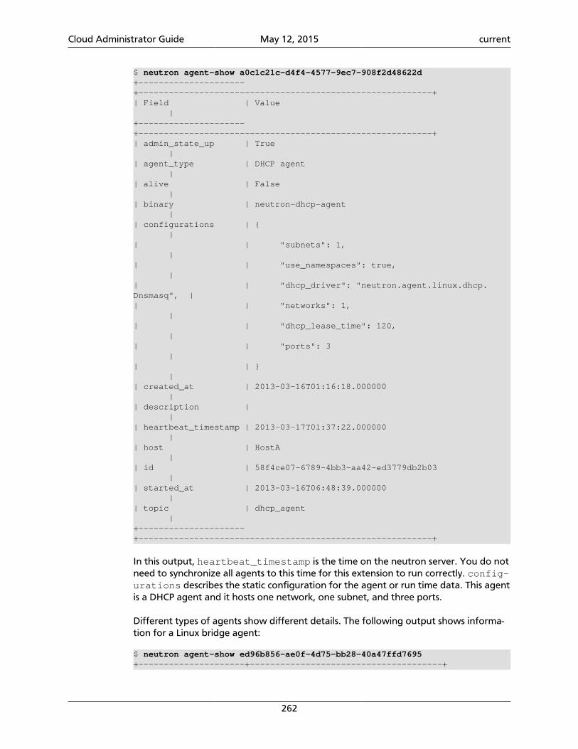
Cloud Administrator Guide May 12, 2015 current
262
$ neutron agent-show a0c1c21c-d4f4-4577-9ec7-908f2d48622d+---------------------+----------------------------------------------------------+| Field | Value |+---------------------+----------------------------------------------------------+| admin_state_up | True || agent_type | DHCP agent || alive | False || binary | neutron-dhcp-agent || configurations | { || | "subnets": 1, || | "use_namespaces": true, || | "dhcp_driver": "neutron.agent.linux.dhcp.Dnsmasq", || | "networks": 1, || | "dhcp_lease_time": 120, || | "ports": 3 || | } || created_at | 2013-03-16T01:16:18.000000 || description | || heartbeat_timestamp | 2013-03-17T01:37:22.000000 || host | HostA || id | 58f4ce07-6789-4bb3-aa42-ed3779db2b03 || started_at | 2013-03-16T06:48:39.000000 || topic | dhcp_agent |+---------------------+----------------------------------------------------------+
In this output, heartbeat_timestamp is the time on the neutron server. You do notneed to synchronize all agents to this time for this extension to run correctly. config-urations describes the static configuration for the agent or run time data. This agentis a DHCP agent and it hosts one network, one subnet, and three ports.
Different types of agents show different details. The following output shows informa-tion for a Linux bridge agent:
$ neutron agent-show ed96b856-ae0f-4d75-bb28-40a47ffd7695+---------------------+--------------------------------------+
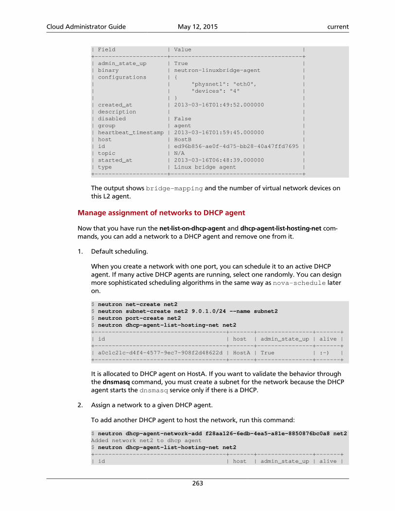
Cloud Administrator Guide May 12, 2015 current
263
| Field | Value |+---------------------+--------------------------------------+| admin_state_up | True || binary | neutron-linuxbridge-agent || configurations | { || | "physnet1": "eth0", || | "devices": "4" || | } || created_at | 2013-03-16T01:49:52.000000 || description | || disabled | False || group | agent || heartbeat_timestamp | 2013-03-16T01:59:45.000000 || host | HostB || id | ed96b856-ae0f-4d75-bb28-40a47ffd7695 || topic | N/A || started_at | 2013-03-16T06:48:39.000000 || type | Linux bridge agent |+---------------------+--------------------------------------+
The output shows bridge-mapping and the number of virtual network devices onthis L2 agent.
Manage assignment of networks to DHCP agent
Now that you have run the net-list-on-dhcp-agent and dhcp-agent-list-hosting-net com-mands, you can add a network to a DHCP agent and remove one from it.
1. Default scheduling.
When you create a network with one port, you can schedule it to an active DHCPagent. If many active DHCP agents are running, select one randomly. You can designmore sophisticated scheduling algorithms in the same way as nova-schedule lateron.
$ neutron net-create net2$ neutron subnet-create net2 9.0.1.0/24 --name subnet2$ neutron port-create net2$ neutron dhcp-agent-list-hosting-net net2+--------------------------------------+-------+----------------+-------+| id | host | admin_state_up | alive |+--------------------------------------+-------+----------------+-------+| a0c1c21c-d4f4-4577-9ec7-908f2d48622d | HostA | True | :-) |+--------------------------------------+-------+----------------+-------+
It is allocated to DHCP agent on HostA. If you want to validate the behavior throughthe dnsmasq command, you must create a subnet for the network because the DHCPagent starts the dnsmasq service only if there is a DHCP.
2. Assign a network to a given DHCP agent.
To add another DHCP agent to host the network, run this command:
$ neutron dhcp-agent-network-add f28aa126-6edb-4ea5-a81e-8850876bc0a8 net2Added network net2 to dhcp agent$ neutron dhcp-agent-list-hosting-net net2+--------------------------------------+-------+----------------+-------+| id | host | admin_state_up | alive |
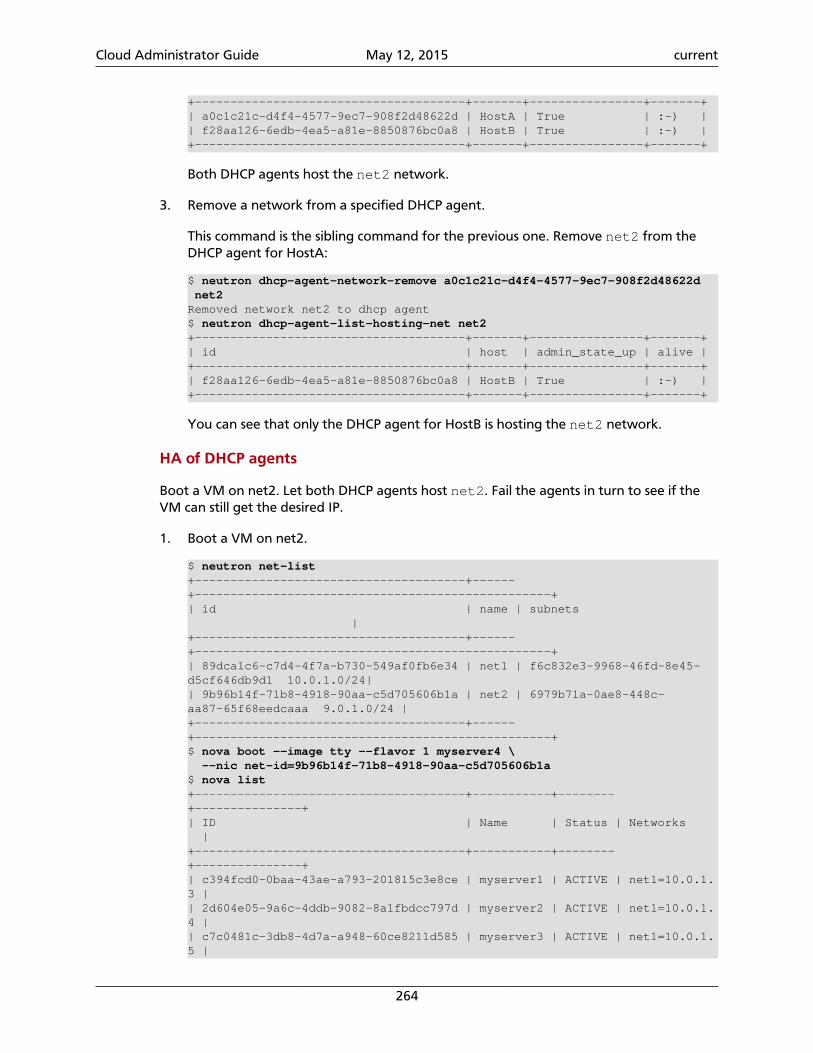
Cloud Administrator Guide May 12, 2015 current
264
+--------------------------------------+-------+----------------+-------+| a0c1c21c-d4f4-4577-9ec7-908f2d48622d | HostA | True | :-) || f28aa126-6edb-4ea5-a81e-8850876bc0a8 | HostB | True | :-) |+--------------------------------------+-------+----------------+-------+
Both DHCP agents host the net2 network.
3. Remove a network from a specified DHCP agent.
This command is the sibling command for the previous one. Remove net2 from theDHCP agent for HostA:
$ neutron dhcp-agent-network-remove a0c1c21c-d4f4-4577-9ec7-908f2d48622d net2Removed network net2 to dhcp agent$ neutron dhcp-agent-list-hosting-net net2+--------------------------------------+-------+----------------+-------+| id | host | admin_state_up | alive |+--------------------------------------+-------+----------------+-------+| f28aa126-6edb-4ea5-a81e-8850876bc0a8 | HostB | True | :-) |+--------------------------------------+-------+----------------+-------+
You can see that only the DHCP agent for HostB is hosting the net2 network.
HA of DHCP agents
Boot a VM on net2. Let both DHCP agents host net2. Fail the agents in turn to see if theVM can still get the desired IP.
1. Boot a VM on net2.
$ neutron net-list+--------------------------------------+------+--------------------------------------------------+| id | name | subnets |+--------------------------------------+------+--------------------------------------------------+| 89dca1c6-c7d4-4f7a-b730-549af0fb6e34 | net1 | f6c832e3-9968-46fd-8e45-d5cf646db9d1 10.0.1.0/24|| 9b96b14f-71b8-4918-90aa-c5d705606b1a | net2 | 6979b71a-0ae8-448c-aa87-65f68eedcaaa 9.0.1.0/24 |+--------------------------------------+------+--------------------------------------------------+$ nova boot --image tty --flavor 1 myserver4 \ --nic net-id=9b96b14f-71b8-4918-90aa-c5d705606b1a$ nova list+--------------------------------------+-----------+--------+---------------+| ID | Name | Status | Networks |+--------------------------------------+-----------+--------+---------------+| c394fcd0-0baa-43ae-a793-201815c3e8ce | myserver1 | ACTIVE | net1=10.0.1.3 || 2d604e05-9a6c-4ddb-9082-8a1fbdcc797d | myserver2 | ACTIVE | net1=10.0.1.4 || c7c0481c-3db8-4d7a-a948-60ce8211d585 | myserver3 | ACTIVE | net1=10.0.1.5 |
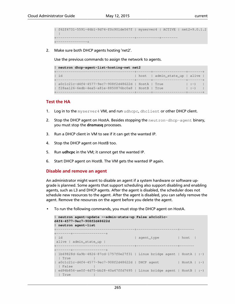
Cloud Administrator Guide May 12, 2015 current
265
| f62f4731-5591-46b1-9d74-f0c901de567f | myserver4 | ACTIVE | net2=9.0.1.2 |+--------------------------------------+-----------+--------+---------------+
2. Make sure both DHCP agents hosting 'net2'.
Use the previous commands to assign the network to agents.
$ neutron dhcp-agent-list-hosting-net net2+--------------------------------------+-------+----------------+-------+| id | host | admin_state_up | alive |+--------------------------------------+-------+----------------+-------+| a0c1c21c-d4f4-4577-9ec7-908f2d48622d | HostA | True | :-) || f28aa126-6edb-4ea5-a81e-8850876bc0a8 | HostB | True | :-) |+--------------------------------------+-------+----------------+-------+
Test the HA
1. Log in to the myserver4 VM, and run udhcpc, dhclient or other DHCP client.
2. Stop the DHCP agent on HostA. Besides stopping the neutron-dhcp-agent binary,you must stop the dnsmasq processes.
3. Run a DHCP client in VM to see if it can get the wanted IP.
4. Stop the DHCP agent on HostB too.
5. Run udhcpc in the VM; it cannot get the wanted IP.
6. Start DHCP agent on HostB. The VM gets the wanted IP again.
Disable and remove an agent
An administrator might want to disable an agent if a system hardware or software up-grade is planned. Some agents that support scheduling also support disabling and enablingagents, such as L3 and DHCP agents. After the agent is disabled, the scheduler does notschedule new resources to the agent. After the agent is disabled, you can safely remove theagent. Remove the resources on the agent before you delete the agent.
• To run the following commands, you must stop the DHCP agent on HostA.
$ neutron agent-update --admin-state-up False a0c1c21c-d4f4-4577-9ec7-908f2d48622d$ neutron agent-list+--------------------------------------+--------------------+-------+-------+----------------+| id | agent_type | host | alive | admin_state_up |+--------------------------------------+--------------------+-------+-------+----------------+| 1b69828d-6a9b-4826-87cd-1757f0e27f31 | Linux bridge agent | HostA | :-) | True || a0c1c21c-d4f4-4577-9ec7-908f2d48622d | DHCP agent | HostA | :-) | False || ed96b856-ae0f-4d75-bb28-40a47ffd7695 | Linux bridge agent | HostB | :-) | True |
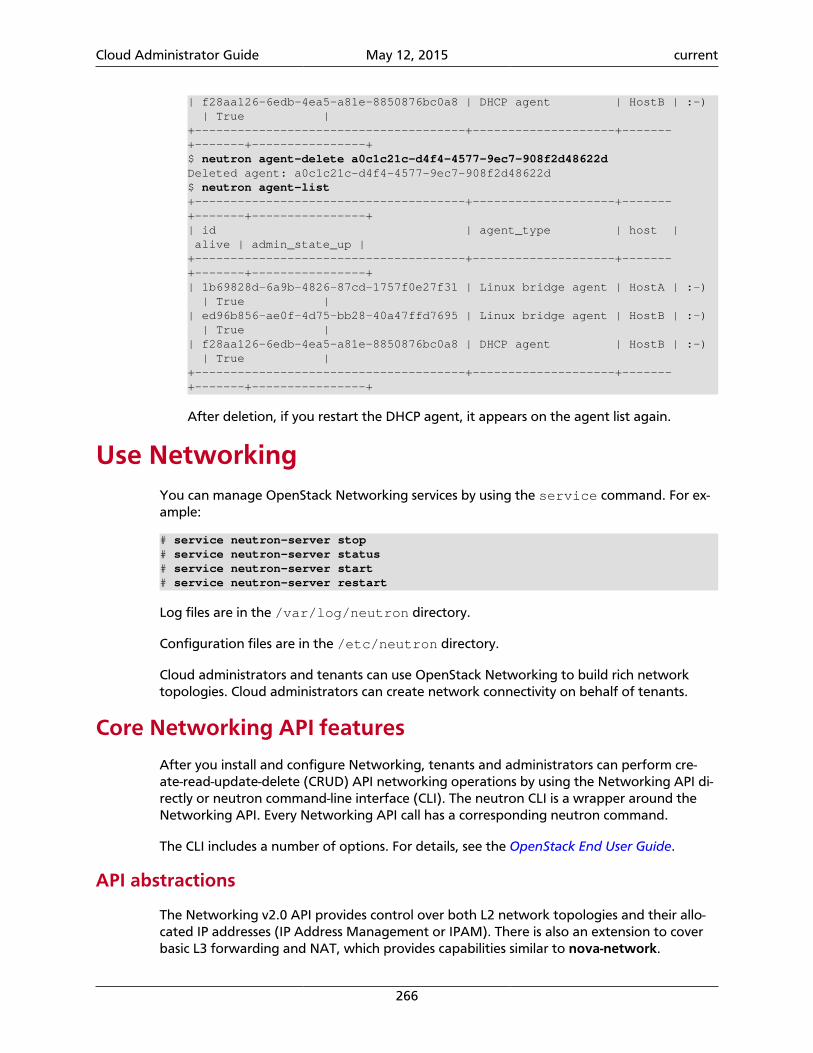
Cloud Administrator Guide May 12, 2015 current
266
| f28aa126-6edb-4ea5-a81e-8850876bc0a8 | DHCP agent | HostB | :-) | True |+--------------------------------------+--------------------+-------+-------+----------------+$ neutron agent-delete a0c1c21c-d4f4-4577-9ec7-908f2d48622dDeleted agent: a0c1c21c-d4f4-4577-9ec7-908f2d48622d$ neutron agent-list+--------------------------------------+--------------------+-------+-------+----------------+| id | agent_type | host | alive | admin_state_up |+--------------------------------------+--------------------+-------+-------+----------------+| 1b69828d-6a9b-4826-87cd-1757f0e27f31 | Linux bridge agent | HostA | :-) | True || ed96b856-ae0f-4d75-bb28-40a47ffd7695 | Linux bridge agent | HostB | :-) | True || f28aa126-6edb-4ea5-a81e-8850876bc0a8 | DHCP agent | HostB | :-) | True |+--------------------------------------+--------------------+-------+-------+----------------+
After deletion, if you restart the DHCP agent, it appears on the agent list again.
Use NetworkingYou can manage OpenStack Networking services by using the service command. For ex-ample:
# service neutron-server stop# service neutron-server status# service neutron-server start# service neutron-server restart
Log files are in the /var/log/neutron directory.
Configuration files are in the /etc/neutron directory.
Cloud administrators and tenants can use OpenStack Networking to build rich networktopologies. Cloud administrators can create network connectivity on behalf of tenants.
Core Networking API features
After you install and configure Networking, tenants and administrators can perform cre-ate-read-update-delete (CRUD) API networking operations by using the Networking API di-rectly or neutron command-line interface (CLI). The neutron CLI is a wrapper around theNetworking API. Every Networking API call has a corresponding neutron command.
The CLI includes a number of options. For details, see the OpenStack End User Guide.
API abstractions
The Networking v2.0 API provides control over both L2 network topologies and their allo-cated IP addresses (IP Address Management or IPAM). There is also an extension to coverbasic L3 forwarding and NAT, which provides capabilities similar to nova-network.
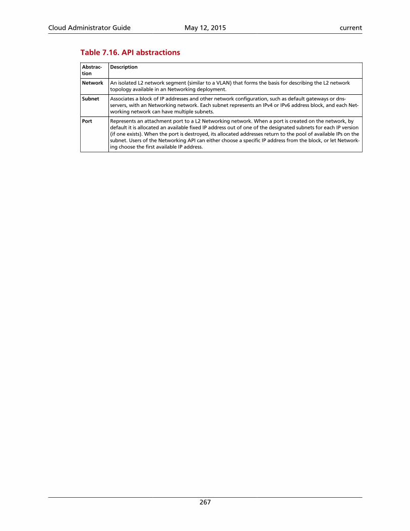
Cloud Administrator Guide May 12, 2015 current
267
Table 7.16. API abstractions
Abstrac-tion
Description
Network An isolated L2 network segment (similar to a VLAN) that forms the basis for describing the L2 networktopology available in an Networking deployment.
Subnet Associates a block of IP addresses and other network configuration, such as default gateways or dns-servers, with an Networking network. Each subnet represents an IPv4 or IPv6 address block, and each Net-working network can have multiple subnets.
Port Represents an attachment port to a L2 Networking network. When a port is created on the network, bydefault it is allocated an available fixed IP address out of one of the designated subnets for each IP version(if one exists). When the port is destroyed, its allocated addresses return to the pool of available IPs on thesubnet. Users of the Networking API can either choose a specific IP address from the block, or let Network-ing choose the first available IP address.
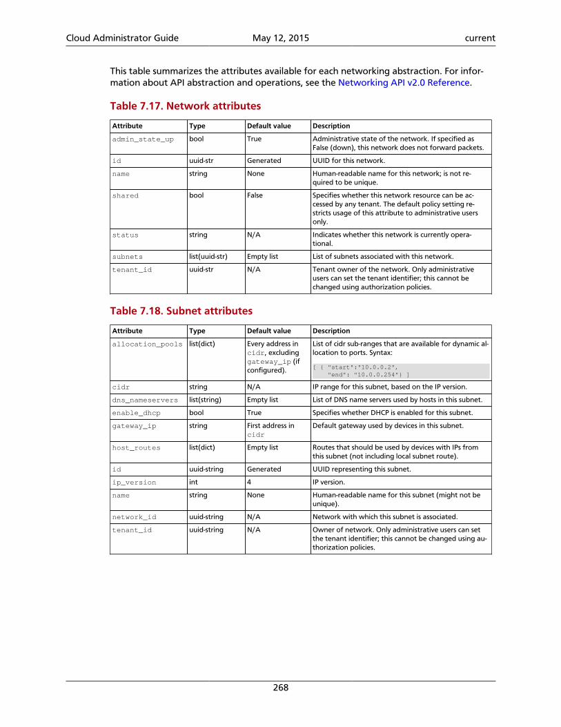
Cloud Administrator Guide May 12, 2015 current
268
This table summarizes the attributes available for each networking abstraction. For infor-mation about API abstraction and operations, see the Networking API v2.0 Reference.
Table 7.17. Network attributes
Attribute Type Default value Description
admin_state_up bool True Administrative state of the network. If specified asFalse (down), this network does not forward packets.
id uuid-str Generated UUID for this network.
name string None Human-readable name for this network; is not re-quired to be unique.
shared bool False Specifies whether this network resource can be ac-cessed by any tenant. The default policy setting re-stricts usage of this attribute to administrative usersonly.
status string N/A Indicates whether this network is currently opera-tional.
subnets list(uuid-str) Empty list List of subnets associated with this network.
tenant_id uuid-str N/A Tenant owner of the network. Only administrativeusers can set the tenant identifier; this cannot bechanged using authorization policies.
Table 7.18. Subnet attributes
Attribute Type Default value Description
allocation_pools list(dict) Every address incidr, excludinggateway_ip (ifconfigured).
List of cidr sub-ranges that are available for dynamic al-location to ports. Syntax:
[ { "start":"10.0.0.2", "end": "10.0.0.254"} ]
cidr string N/A IP range for this subnet, based on the IP version.
dns_nameservers list(string) Empty list List of DNS name servers used by hosts in this subnet.
enable_dhcp bool True Specifies whether DHCP is enabled for this subnet.
gateway_ip string First address incidr
Default gateway used by devices in this subnet.
host_routes list(dict) Empty list Routes that should be used by devices with IPs fromthis subnet (not including local subnet route).
id uuid-string Generated UUID representing this subnet.
ip_version int 4 IP version.
name string None Human-readable name for this subnet (might not beunique).
network_id uuid-string N/A Network with which this subnet is associated.
tenant_id uuid-string N/A Owner of network. Only administrative users can setthe tenant identifier; this cannot be changed using au-thorization policies.
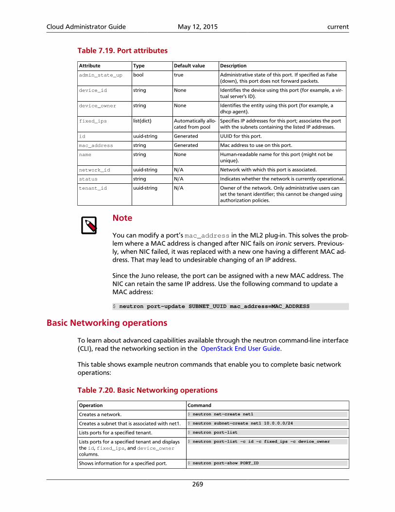
Cloud Administrator Guide May 12, 2015 current
269
Table 7.19. Port attributes
Attribute Type Default value Description
admin_state_up bool true Administrative state of this port. If specified as False(down), this port does not forward packets.
device_id string None Identifies the device using this port (for example, a vir-tual server's ID).
device_owner string None Identifies the entity using this port (for example, adhcp agent).
fixed_ips list(dict) Automatically allo-cated from pool
Specifies IP addresses for this port; associates the portwith the subnets containing the listed IP addresses.
id uuid-string Generated UUID for this port.
mac_address string Generated Mac address to use on this port.
name string None Human-readable name for this port (might not beunique).
network_id uuid-string N/A Network with which this port is associated.
status string N/A Indicates whether the network is currently operational.
tenant_id uuid-string N/A Owner of the network. Only administrative users canset the tenant identifier; this cannot be changed usingauthorization policies.
Note
You can modify a port’s mac_address in the ML2 plug-in. This solves the prob-lem where a MAC address is changed after NIC fails on ironic servers. Previous-ly, when NIC failed, it was replaced with a new one having a different MAC ad-dress. That may lead to undesirable changing of an IP address.
Since the Juno release, the port can be assigned with a new MAC address. TheNIC can retain the same IP address. Use the following command to update aMAC address:
$ neutron port-update SUBNET_UUID mac_address=MAC_ADDRESS
Basic Networking operations
To learn about advanced capabilities available through the neutron command-line interface(CLI), read the networking section in the OpenStack End User Guide.
This table shows example neutron commands that enable you to complete basic networkoperations:
Table 7.20. Basic Networking operations
Operation Command
Creates a network. $ neutron net-create net1
Creates a subnet that is associated with net1. $ neutron subnet-create net1 10.0.0.0/24
Lists ports for a specified tenant. $ neutron port-list
Lists ports for a specified tenant and displaysthe id, fixed_ips, and device_ownercolumns.
$ neutron port-list -c id -c fixed_ips -c device_owner
Shows information for a specified port. $ neutron port-show PORT_ID
Cloud Administrator Guide May 12, 2015 current
270
Note
The device_owner field describes who owns the port. A port whosedevice_owner begins with:
• network is created by Networking.
• compute is created by Compute.
Administrative operations
The cloud administrator can run any neutron command on behalf of tenants by specifyingan Identity tenant_id in the command, as follows:
$ neutron net-create --tenant-id TENANT_ID NETWORK_NAME
For example:
$ neutron net-create --tenant-id 5e4bbe24b67a4410bc4d9fae29ec394e net1
Note
To view all tenant IDs in Identity, run the following command as an Identity Ser-vice admin user:
$ keystone tenant-list
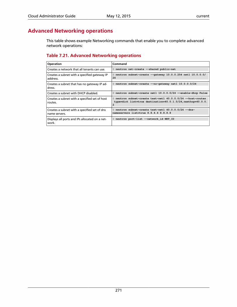
Cloud Administrator Guide May 12, 2015 current
271
Advanced Networking operations
This table shows example Networking commands that enable you to complete advancednetwork operations:
Table 7.21. Advanced Networking operations
Operation Command
Creates a network that all tenants can use. $ neutron net-create --shared public-net
Creates a subnet with a specified gateway IPaddress.
$ neutron subnet-create --gateway 10.0.0.254 net1 10.0.0.0/24
Creates a subnet that has no gateway IP ad-dress.
$ neutron subnet-create --no-gateway net1 10.0.0.0/24
Creates a subnet with DHCP disabled. $ neutron subnet-create net1 10.0.0.0/24 --enable-dhcp False
Creates a subnet with a specified set of hostroutes.
$ neutron subnet-create test-net1 40.0.0.0/24 --host-routes type=dict list=true destination=40.0.1.0/24,nexthop=40.0.0.2
Creates a subnet with a specified set of dnsname servers.
$ neutron subnet-create test-net1 40.0.0.0/24 --dns-nameservers list=true 8.8.4.4 8.8.8.8
Displays all ports and IPs allocated on a net-work.
$ neutron port-list --network_id NET_ID
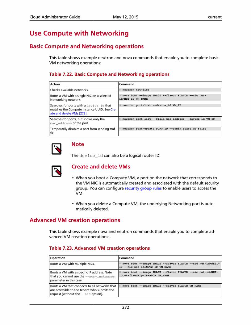
Cloud Administrator Guide May 12, 2015 current
272
Use Compute with Networking
Basic Compute and Networking operations
This table shows example neutron and nova commands that enable you to complete basicVM networking operations:
Table 7.22. Basic Compute and Networking operations
Action Command
Checks available networks. $ neutron net-list
Boots a VM with a single NIC on a selectedNetworking network.
$ nova boot --image IMAGE --flavor FLAVOR --nic net-id=NET_ID VM_NAME
Searches for ports with a device_id thatmatches the Compute instance UUID. See Cre-ate and delete VMs [272].
$ neutron port-list --device_id VM_ID
Searches for ports, but shows only themac_address of the port.
$ neutron port-list --field mac_address --device_id VM_ID
Temporarily disables a port from sending traf-fic.
$ neutron port-update PORT_ID --admin_state_up False
Note
The device_id can also be a logical router ID.
Create and delete VMs
• When you boot a Compute VM, a port on the network that corresponds tothe VM NIC is automatically created and associated with the default securitygroup. You can configure security group rules to enable users to access theVM.
• When you delete a Compute VM, the underlying Networking port is auto-matically deleted.
Advanced VM creation operations
This table shows example nova and neutron commands that enable you to complete ad-vanced VM creation operations:
Table 7.23. Advanced VM creation operations
Operation Command
Boots a VM with multiple NICs. $ nova boot --image IMAGE --flavor FLAVOR --nic net-id=NET1-ID --nic net-id=NET2-ID VM_NAME
Boots a VM with a specific IP address. Notethat you cannot use the --num-instancesparameter in this case.
$ nova boot --image IMAGE --flavor FLAVOR --nic net-id=NET-ID,v4-fixed-ip=IP-ADDR VM_NAME
Boots a VM that connects to all networks thatare accessible to the tenant who submits therequest (without the --nic option).
$ nova boot --image IMAGE --flavor FLAVOR VM_NAME
Cloud Administrator Guide May 12, 2015 current
273
Note
Cloud images that distribution vendors offer usually have only one active NICconfigured. When you boot with multiple NICs, you must configure additionalinterfaces on the image or the NICS are not reachable.
The following Debian/Ubuntu-based example shows how to set up the inter-faces within the instance in the /etc/network/interfaces file. You mustapply this configuration to the image.
# The loopback network interfaceauto loiface lo inet loopback
auto eth0iface eth0 inet dhcp
auto eth1iface eth1 inet dhcp
Enable ping and SSH on VMs (security groups)
You must configure security group rules depending on the type of plug-in you are using. Ifyou are using a plug-in that:
• Implements Networking security groups, you can configure security group rules directlyby using the neutron security-group-rule-create command. This example enables pingand ssh access to your VMs.
$ neutron security-group-rule-create --protocol icmp \ --direction ingress default
$ neutron security-group-rule-create --protocol tcp --port-range-min 22 \ --port-range-max 22 --direction ingress default
• Does not implement Networking security groups, you can configure security group rulesby using the nova secgroup-add-rule or euca-authorize command. These nova com-mands enable ping and ssh access to your VMs.
$ nova secgroup-add-rule default icmp -1 -1 0.0.0.0/0$ nova secgroup-add-rule default tcp 22 22 0.0.0.0/0
Note
If your plug-in implements Networking security groups, you can also leverageCompute security groups by setting security_group_api = neutron inthe nova.conf file. After you set this option, all Compute security group com-mands are proxied to Networking.
Advanced features through API extensionsSeveral plug-ins implement API extensions that provide capabilities similar to what wasavailable in nova-network: These plug-ins are likely to be of interest to the OpenStack com-munity.
Cloud Administrator Guide May 12, 2015 current
274
Provider networks
Networks can be categorized as either tenant networks or provider networks. Tenant net-works are created by normal users and details about how they are physically realized arehidden from those users. Provider networks are created with administrative credentials,specifying the details of how the network is physically realized, usually to match some exist-ing network in the data center.
Provider networks enable cloud administrators to create Networking networks that mapdirectly to the physical networks in the data center. This is commonly used to give tenantsdirect access to a public network that can be used to reach the Internet. It might also beused to integrate with VLANs in the network that already have a defined meaning (for ex-ample, enable a VM from the "marketing" department to be placed on the same VLAN asbare-metal marketing hosts in the same data center).
The provider extension allows administrators to explicitly manage the relationship betweenNetworking virtual networks and underlying physical mechanisms such as VLANs and tun-nels. When this extension is supported, Networking client users with administrative privi-leges see additional provider attributes on all virtual networks and are able to specify theseattributes in order to create provider networks.
The provider extension is supported by the Open vSwitch and Linux Bridge plug-ins. Config-uration of these plug-ins requires familiarity with this extension.
Terminology
A number of terms are used in the provider extension and in the configuration of plug-inssupporting the provider extension:
Table 7.24. Provider extension terminology
Term Description
virtual network An Networking L2 network (identified by a UUID and optional name) whose ports can be at-tached as vNICs to Compute instances and to various Networking agents. The Open vSwitchand Linux Bridge plug-ins each support several different mechanisms to realize virtual net-works.
physical network A network connecting virtualization hosts (such as compute nodes) with each other and withother network resources. Each physical network might support multiple virtual networks.The provider extension and the plug-in configurations identify physical networks using simplestring names.
tenant network A virtual network that a tenant or an administrator creates. The physical details of the net-work are not exposed to the tenant.
provider network A virtual network administratively created to map to a specific network in the data center, typ-ically to enable direct access to non-OpenStack resources on that network. Tenants can be giv-en access to provider networks.
VLAN network A virtual network implemented as packets on a specific physical network containing IEEE802.1Q headers with a specific VID field value. VLAN networks sharing the same physical net-work are isolated from each other at L2 and can even have overlapping IP address spaces. Eachdistinct physical network supporting VLAN networks is treated as a separate VLAN trunk, witha distinct space of VID values. Valid VID values are 1 through 4094.
flat network A virtual network implemented as packets on a specific physical network containing no IEEE802.1Q header. Each physical network can realize at most one flat network.
local network A virtual network that allows communication within each host, but not across a network. Localnetworks are intended mainly for single-node test scenarios, but can have other uses.
Cloud Administrator Guide May 12, 2015 current
275
Term Description
GRE network A virtual network implemented as network packets encapsulated using GRE. GRE networks arealso referred to as tunnels. GRE tunnel packets are routed by the IP routing table for the host,so GRE networks are not associated by Networking with specific physical networks.
Virtual ExtensibleLAN (VXLAN) net-work
VXLAN is a proposed encapsulation protocol for running an overlay network on existing Lay-er 3 infrastructure. An overlay network is a virtual network that is built on top of existing net-work Layer 2 and Layer 3 technologies to support elastic compute architectures.
The ML2, Open vSwitch, and Linux Bridge plug-ins support VLAN networks, flat networks,and local networks. Only the ML2 and Open vSwitch plug-ins currently support GRE andVXLAN networks, provided that the required features exist in the hosts Linux kernel, OpenvSwitch, and iproute2 packages.
Provider attributes
The provider extension extends the Networking network resource with these attributes:
Table 7.25. Provider network attributes
Attribute name Type Default Value Description
provider:network_type String N/A The physical mechanism by which the virtualnetwork is implemented. Possible values areflat, vlan, local, and gre, correspondingto flat networks, VLAN networks, local net-works, and GRE networks as defined above.All types of provider networks can be createdby administrators, while tenant networks canbe implemented as vlan, gre, or local net-work types depending on plug-in configura-tion.
provider:physical_network String If a physical networknamed "default" hasbeen configured and ifprovider:network_type isflat or vlan, then "de-fault" is used.
The name of the physical network over whichthe virtual network is implemented for flatand VLAN networks. Not applicable to thelocal or gre network types.
provider:segmentation_id Integer N/A For VLAN networks, the VLAN VID on thephysical network that realizes the virtual net-work. Valid VLAN VIDs are 1 through 4094.For GRE networks, the tunnel ID. Valid tunnelIDs are any 32 bit unsigned integer. Not appli-cable to the flat or local network types.
To view or set provider extended attributes, a client must be authorized for theextension:provider_network:view and extension:provider_network:setactions in the Networking policy configuration. The default Networking configuration au-thorizes both actions for users with the admin role. An authorized client or an administra-tive user can view and set the provider extended attributes through Networking API calls.See the section called “Authentication and authorization” [292] for details on policy con-figuration.
Provider extension API operations
To use the provider extension with the default policy settings, you must have the adminis-trative role.
This list shows example neutron commands that enable you to complete basic provider ex-tension API operations:
Cloud Administrator Guide May 12, 2015 current
276
• Shows all attributes of a network, including provider attributes:
$ neutron net-show NAME_OR_NET_ID
• Creates a local provider network:
$ neutron net-create NAME --tenant_id TENANT_ID --provider:network_type local
• When you create flat networks, PHYS_NET_NAME must be known to the plug-in. See theOpenStack Configuration Reference for details. Creates a flat provider network:
$ neutron net-create NAME --tenant_id TENANT_ID --provider:network_type flat --provider:physical_network PHYS_NET_NAME
• When you create VLAN networks, PHYS_NET_NAME must be known to the plug-in. Seethe OpenStack Configuration Reference for details on configuring network_vlan_rangesto identify all physical networks. When you create VLAN networks, VID can fall eitherwithin or outside any configured ranges of VLAN IDs from which tenant networks are al-located. Creates a VLAN provider network:
$ neutron net-create NAME --tenant_id TENANT_ID --provider:network_type vlan --provider:physical_network PHYS_NET_NAME --provider:segmentation_id VID
• When you create GRE networks, TUNNEL_ID can be either inside or outside any tunnelID ranges from which tenant networks are allocated.
After you create provider networks, you can allocate subnets, which you can use in thesame way as other virtual networks, subject to authorization policy based on the speci-fied TENANT_ID. Creates a GRE provider network:
$ neutron net-create NAME --tenant_id TENANT_ID --provider:network_type gre --provider:segmentation_id TUNNEL_ID
L3 routing and NAT
The Networking API provides abstract L2 network segments that are decoupled from thetechnology used to implement the L2 network. Networking includes an API extension thatprovides abstract L3 routers that API users can dynamically provision and configure. TheseNetworking routers can connect multiple L2 Networking networks and can also provide agateway that connects one or more private L2 networks to a shared external network. Forexample, a public network for access to the Internet. See the OpenStack Configuration Ref-erence for details on common models of deploying Networking L3 routers.
The L3 router provides basic NAT capabilities on gateway ports that uplink the router toexternal networks. This router SNATs all traffic by default and supports floating IPs, whichcreates a static one-to-one mapping from a public IP on the external network to a privateIP on one of the other subnets attached to the router. This allows a tenant to selectivelyexpose VMs on private networks to other hosts on the external network (and often to allhosts on the Internet). You can allocate and map floating IPs from one port to another, asneeded.
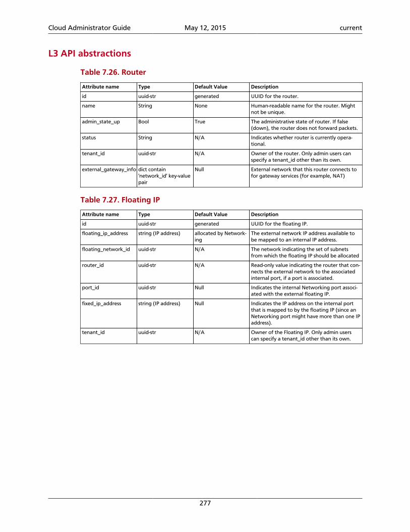
Cloud Administrator Guide May 12, 2015 current
277
L3 API abstractions
Table 7.26. Router
Attribute name Type Default Value Description
id uuid-str generated UUID for the router.
name String None Human-readable name for the router. Mightnot be unique.
admin_state_up Bool True The administrative state of router. If false(down), the router does not forward packets.
status String N/A Indicates whether router is currently opera-tional.
tenant_id uuid-str N/A Owner of the router. Only admin users canspecify a tenant_id other than its own.
external_gateway_info dict contain'network_id' key-valuepair
Null External network that this router connects tofor gateway services (for example, NAT)
Table 7.27. Floating IP
Attribute name Type Default Value Description
id uuid-str generated UUID for the floating IP.
floating_ip_address string (IP address) allocated by Network-ing
The external network IP address available tobe mapped to an internal IP address.
floating_network_id uuid-str N/A The network indicating the set of subnetsfrom which the floating IP should be allocated
router_id uuid-str N/A Read-only value indicating the router that con-nects the external network to the associatedinternal port, if a port is associated.
port_id uuid-str Null Indicates the internal Networking port associ-ated with the external floating IP.
fixed_ip_address string (IP address) Null Indicates the IP address on the internal portthat is mapped to by the floating IP (since anNetworking port might have more than one IPaddress).
tenant_id uuid-str N/A Owner of the Floating IP. Only admin userscan specify a tenant_id other than its own.
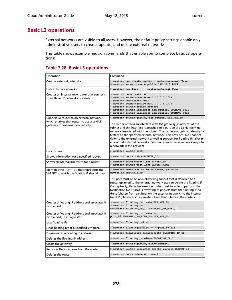
Cloud Administrator Guide May 12, 2015 current
278
Basic L3 operations
External networks are visible to all users. However, the default policy settings enable onlyadministrative users to create, update, and delete external networks.
This table shows example neutron commands that enable you to complete basic L3 opera-tions:
Table 7.28. Basic L3 operations
Operation Command
Creates external networks. # neutron net-create public --router:external True$ neutron subnet-create public 172.16.1.0/24
Lists external networks. $ neutron net-list -- --router:external True
Creates an internal-only router that connectsto multiple L2 networks privately.
$ neutron net-create net1$ neutron subnet-create net1 10.0.0.0/24$ neutron net-create net2$ neutron subnet-create net2 10.0.1.0/24$ neutron router-create router1$ neutron router-interface-add router1 SUBNET1_UUID$ neutron router-interface-add router1 SUBNET2_UUID
Connects a router to an external network,which enables that router to act as a NATgateway for external connectivity.
$ neutron router-gateway-set router1 EXT_NET_ID
The router obtains an interface with the gateway_ip address of thesubnet and this interface is attached to a port on the L2 Networkingnetwork associated with the subnet. The router also gets a gateway in-terface to the specified external network. This provides SNAT connec-tivity to the external network as well as support for floating IPs allocat-ed on that external networks. Commonly an external network maps toa network in the provider
Lists routers. $ neutron router-list
Shows information for a specified router. $ neutron router-show ROUTER_ID
Shows all internal interfaces for a router. $ neutron router-port-list ROUTER_ID$ neutron router-port-list ROUTER_NAME
Identifies the PORT_ID that represents theVM NIC to which the floating IP should map.
$ neutron port-list -c id -c fixed_ips -- --device_id INSTANCE_ID
This port must be on an Networking subnet that is attached to arouter uplinked to the external network used to create the floating IP.Conceptually, this is because the router must be able to perform theDestination NAT (DNAT) rewriting of packets from the floating IP ad-dress (chosen from a subnet on the external network) to the internalfixed IP (chosen from a private subnet that is behind the router).
Creates a floating IP address and associates itwith a port.
$ neutron floatingip-create EXT_NET_ID$ neutron floatingip-associate FLOATING_IP_ID INTERNAL_VM_PORT_ID
Creates a floating IP address and associates itwith a port, in a single step.
$ neutron floatingip-create --port_id INTERNAL_VM_PORT_ID EXT_NET_ID
Lists floating IPs. $ neutron floatingip-list
Finds floating IP for a specified VM port. $ neutron floatingip-list -- --port_id ZZZ
Disassociates a floating IP address. $ neutron floatingip-disassociate FLOATING_IP_ID
Deletes the floating IP address. $ neutron floatingip-delete FLOATING_IP_ID
Clears the gateway. $ neutron router-gateway-clear router1
Removes the interfaces from the router. $ neutron router-interface-delete router1 SUBNET_ID
Deletes the router. $ neutron router-delete router1
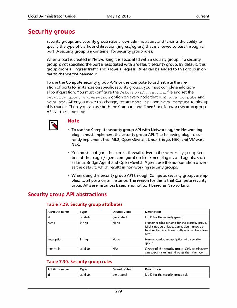
Cloud Administrator Guide May 12, 2015 current
279
Security groupsSecurity groups and security group rules allows administrators and tenants the ability tospecify the type of traffic and direction (ingress/egress) that is allowed to pass through aport. A security group is a container for security group rules.
When a port is created in Networking it is associated with a security group. If a securitygroup is not specified the port is associated with a 'default' security group. By default, thisgroup drops all ingress traffic and allows all egress. Rules can be added to this group in or-der to change the behaviour.
To use the Compute security group APIs or use Compute to orchestrate the cre-ation of ports for instances on specific security groups, you must complete addition-al configuration. You must configure the /etc/nova/nova.conf file and set thesecurity_group_api=neutron option on every node that runs nova-compute andnova-api. After you make this change, restart nova-api and nova-compute to pick upthis change. Then, you can use both the Compute and OpenStack Network security groupAPIs at the same time.
Note
• To use the Compute security group API with Networking, the Networkingplug-in must implement the security group API. The following plug-ins cur-rently implement this: ML2, Open vSwitch, Linux Bridge, NEC, and VMwareNSX.
• You must configure the correct firewall driver in the securitygroup sec-tion of the plug-in/agent configuration file. Some plug-ins and agents, suchas Linux Bridge Agent and Open vSwitch Agent, use the no-operation driveras the default, which results in non-working security groups.
• When using the security group API through Compute, security groups are ap-plied to all ports on an instance. The reason for this is that Compute securitygroup APIs are instances based and not port based as Networking.
Security group API abstractions
Table 7.29. Security group attributes
Attribute name Type Default Value Description
id uuid-str generated UUID for the security group.
name String None Human-readable name for the security group.Might not be unique. Cannot be named de-fault as that is automatically created for a ten-ant.
description String None Human-readable description of a securitygroup.
tenant_id uuid-str N/A Owner of the security group. Only admin userscan specify a tenant_id other than their own.
Table 7.30. Security group rules
Attribute name Type Default Value Description
id uuid-str generated UUID for the security group rule.
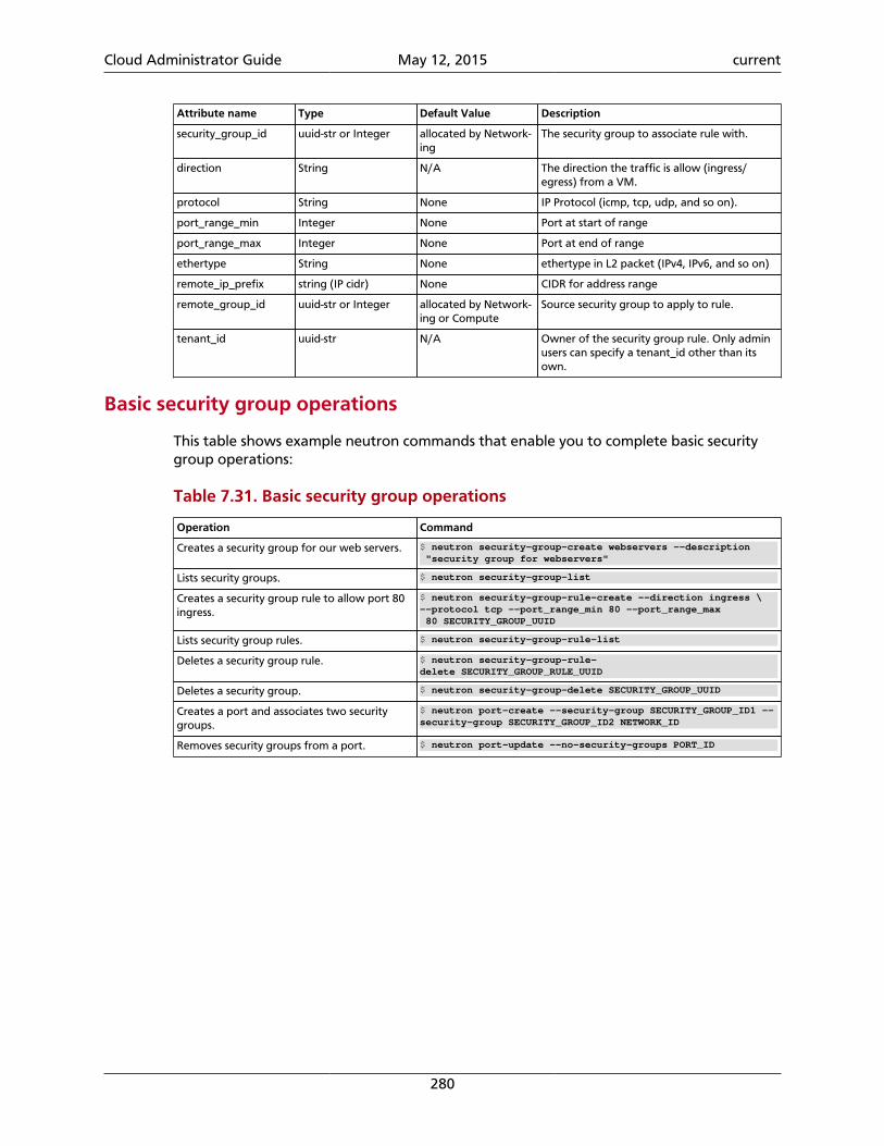
Cloud Administrator Guide May 12, 2015 current
280
Attribute name Type Default Value Description
security_group_id uuid-str or Integer allocated by Network-ing
The security group to associate rule with.
direction String N/A The direction the traffic is allow (ingress/egress) from a VM.
protocol String None IP Protocol (icmp, tcp, udp, and so on).
port_range_min Integer None Port at start of range
port_range_max Integer None Port at end of range
ethertype String None ethertype in L2 packet (IPv4, IPv6, and so on)
remote_ip_prefix string (IP cidr) None CIDR for address range
remote_group_id uuid-str or Integer allocated by Network-ing or Compute
Source security group to apply to rule.
tenant_id uuid-str N/A Owner of the security group rule. Only adminusers can specify a tenant_id other than itsown.
Basic security group operations
This table shows example neutron commands that enable you to complete basic securitygroup operations:
Table 7.31. Basic security group operations
Operation Command
Creates a security group for our web servers. $ neutron security-group-create webservers --description "security group for webservers"
Lists security groups. $ neutron security-group-list
Creates a security group rule to allow port 80ingress.
$ neutron security-group-rule-create --direction ingress \--protocol tcp --port_range_min 80 --port_range_max 80 SECURITY_GROUP_UUID
Lists security group rules. $ neutron security-group-rule-list
Deletes a security group rule. $ neutron security-group-rule-delete SECURITY_GROUP_RULE_UUID
Deletes a security group. $ neutron security-group-delete SECURITY_GROUP_UUID
Creates a port and associates two securitygroups.
$ neutron port-create --security-group SECURITY_GROUP_ID1 --security-group SECURITY_GROUP_ID2 NETWORK_ID
Removes security groups from a port. $ neutron port-update --no-security-groups PORT_ID
Cloud Administrator Guide May 12, 2015 current
281
Basic Load-Balancer-as-a-Service operations
Note
The Load-Balancer-as-a-Service (LBaaS) API provisions and configures load bal-ancers. The reference implementation is based on the HAProxy software loadbalancer.
This list shows example neutron commands that enable you to complete basic LBaaS opera-tions:
• Creates a load balancer pool by using specific provider.
--provider is an optional argument. If not used, the pool is created with de-fault provider for LBaaS service. You should configure the default provider in the[service_providers] section of neutron.conf file. If no default provider is speci-fied for LBaaS, the --provider parameter is required for pool creation.
$ neutron lb-pool-create --lb-method ROUND_ROBIN --name mypool --protocol HTTP --subnet-id SUBNET_UUID --provider PROVIDER_NAME
• Associates two web servers with pool.
$ neutron lb-member-create --address WEBSERVER1_IP --protocol-port 80 mypool$ neutron lb-member-create --address WEBSERVER2_IP --protocol-port 80 mypool
• Creates a health monitor that checks to make sure our instances are still running on thespecified protocol-port.
$ neutron lb-healthmonitor-create --delay 3 --type HTTP --max-retries 3 --timeout 3
• Associates a health monitor with pool.
$ neutron lb-healthmonitor-associate HEALTHMONITOR_UUID mypool
• Creates a virtual IP (VIP) address that, when accessed through the load balancer, directsthe requests to one of the pool members.
$ neutron lb-vip-create --name myvip --protocol-port 80 --protocol HTTP --subnet-id SUBNET_UUID mypool
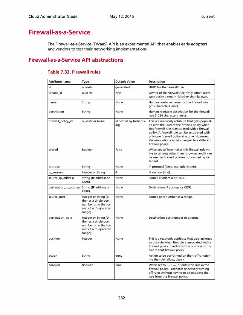
Cloud Administrator Guide May 12, 2015 current
282
Firewall-as-a-Service
The Firewall-as-a-Service (FWaaS) API is an experimental API that enables early adoptersand vendors to test their networking implementations.
Firewall-as-a-Service API abstractions
Table 7.32. Firewall rules
Attribute name Type Default Value Description
id uuid-str generated UUID for the firewall rule.
tenant_id uuid-str N/A Owner of the firewall rule. Only admin userscan specify a tenant_id other than its own.
name String None Human readable name for the firewall rule(255 characters limit).
description String None Human-readable description for the firewallrule (1024 characters limit).
firewall_policy_id uuid-str or None allocated by Network-ing
This is a read-only attribute that gets populat-ed with the uuid of the firewall policy whenthis firewall rule is associated with a firewallpolicy. A firewall rule can be associated withonly one firewall policy at a time. However,the association can be changed to a differentfirewall policy.
shared Boolean False When set to True makes this firewall rule visi-ble to tenants other than its owner and it canbe used in firewall policies not owned by itstenant.
protocol String None IP protocol (icmp, tcp, udp, None).
ip_version Integer or String 4 IP version (4, 6).
source_ip_address String (IP address orCIDR)
None Source IP address or CIDR.
destination_ip_address String (IP address orCIDR)
None Destination IP address or CIDR.
source_port Integer or String (ei-ther as a single portnumber or in the for-mat of a ':' separatedrange)
None Source port number or a range.
destination_port Integer or String (ei-ther as a single portnumber or in the for-mat of a ':' separatedrange)
None Destination port number or a range.
position Integer None This is a read-only attribute that gets assignedto this rule when the rule is associated with afirewall policy. It indicates the position of thisrule in that firewall policy.
action String deny Action to be performed on the traffic match-ing the rule (allow, deny).
enabled Boolean True When set to False, disables this rule in thefirewall policy. Facilitates selectively turningoff rules without having to disassociate therule from the firewall policy.
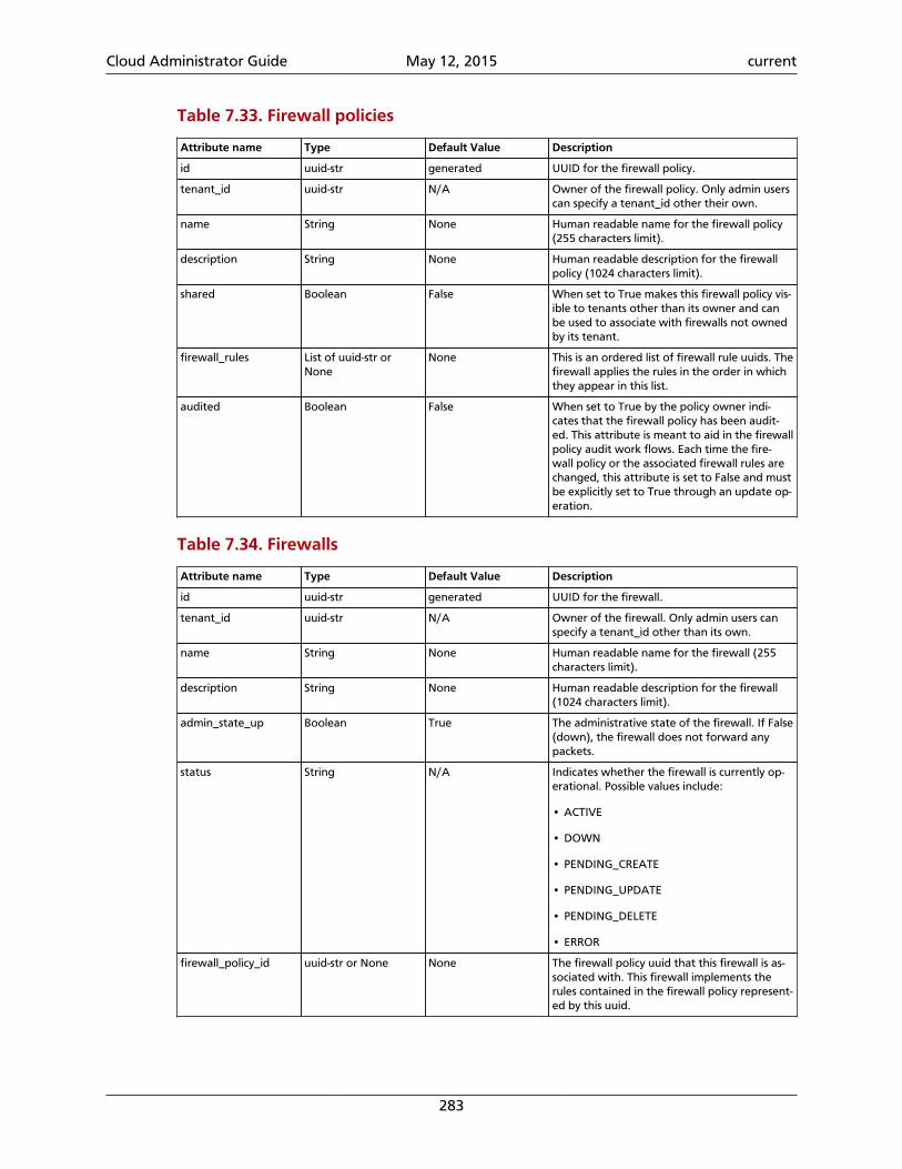
Cloud Administrator Guide May 12, 2015 current
283
Table 7.33. Firewall policies
Attribute name Type Default Value Description
id uuid-str generated UUID for the firewall policy.
tenant_id uuid-str N/A Owner of the firewall policy. Only admin userscan specify a tenant_id other their own.
name String None Human readable name for the firewall policy(255 characters limit).
description String None Human readable description for the firewallpolicy (1024 characters limit).
shared Boolean False When set to True makes this firewall policy vis-ible to tenants other than its owner and canbe used to associate with firewalls not ownedby its tenant.
firewall_rules List of uuid-str orNone
None This is an ordered list of firewall rule uuids. Thefirewall applies the rules in the order in whichthey appear in this list.
audited Boolean False When set to True by the policy owner indi-cates that the firewall policy has been audit-ed. This attribute is meant to aid in the firewallpolicy audit work flows. Each time the fire-wall policy or the associated firewall rules arechanged, this attribute is set to False and mustbe explicitly set to True through an update op-eration.
Table 7.34. Firewalls
Attribute name Type Default Value Description
id uuid-str generated UUID for the firewall.
tenant_id uuid-str N/A Owner of the firewall. Only admin users canspecify a tenant_id other than its own.
name String None Human readable name for the firewall (255characters limit).
description String None Human readable description for the firewall(1024 characters limit).
admin_state_up Boolean True The administrative state of the firewall. If False(down), the firewall does not forward anypackets.
status String N/A Indicates whether the firewall is currently op-erational. Possible values include:
• ACTIVE
• DOWN
• PENDING_CREATE
• PENDING_UPDATE
• PENDING_DELETE
• ERROR
firewall_policy_id uuid-str or None None The firewall policy uuid that this firewall is as-sociated with. This firewall implements therules contained in the firewall policy represent-ed by this uuid.
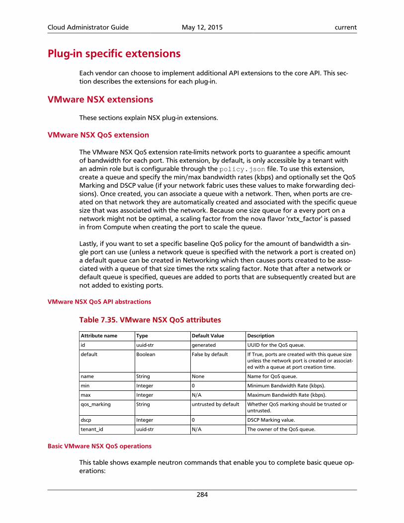
Cloud Administrator Guide May 12, 2015 current
284
Plug-in specific extensions
Each vendor can choose to implement additional API extensions to the core API. This sec-tion describes the extensions for each plug-in.
VMware NSX extensions
These sections explain NSX plug-in extensions.
VMware NSX QoS extension
The VMware NSX QoS extension rate-limits network ports to guarantee a specific amountof bandwidth for each port. This extension, by default, is only accessible by a tenant withan admin role but is configurable through the policy.json file. To use this extension,create a queue and specify the min/max bandwidth rates (kbps) and optionally set the QoSMarking and DSCP value (if your network fabric uses these values to make forwarding deci-sions). Once created, you can associate a queue with a network. Then, when ports are cre-ated on that network they are automatically created and associated with the specific queuesize that was associated with the network. Because one size queue for a every port on anetwork might not be optimal, a scaling factor from the nova flavor 'rxtx_factor' is passedin from Compute when creating the port to scale the queue.
Lastly, if you want to set a specific baseline QoS policy for the amount of bandwidth a sin-gle port can use (unless a network queue is specified with the network a port is created on)a default queue can be created in Networking which then causes ports created to be asso-ciated with a queue of that size times the rxtx scaling factor. Note that after a network ordefault queue is specified, queues are added to ports that are subsequently created but arenot added to existing ports.
VMware NSX QoS API abstractions
Table 7.35. VMware NSX QoS attributes
Attribute name Type Default Value Description
id uuid-str generated UUID for the QoS queue.
default Boolean False by default If True, ports are created with this queue sizeunless the network port is created or associat-ed with a queue at port creation time.
name String None Name for QoS queue.
min Integer 0 Minimum Bandwidth Rate (kbps).
max Integer N/A Maximum Bandwidth Rate (kbps).
qos_marking String untrusted by default Whether QoS marking should be trusted oruntrusted.
dscp Integer 0 DSCP Marking value.
tenant_id uuid-str N/A The owner of the QoS queue.
Basic VMware NSX QoS operations
This table shows example neutron commands that enable you to complete basic queue op-erations:
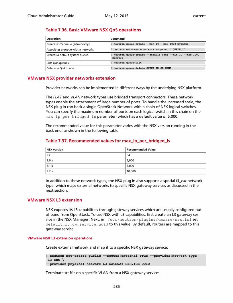
Cloud Administrator Guide May 12, 2015 current
285
Table 7.36. Basic VMware NSX QoS operations
Operation Command
Creates QoS queue (admin-only). $ neutron queue-create --min 10 --max 1000 myqueue
Associates a queue with a network. $ neutron net-create network --queue_id QUEUE_ID
Creates a default system queue. $ neutron queue-create --default True --min 10 --max 2000 default
Lists QoS queues. $ neutron queue-list
Deletes a QoS queue. $ neutron queue-delete QUEUE_ID_OR_NAME'
VMware NSX provider networks extension
Provider networks can be implemented in different ways by the underlying NSX platform.
The FLAT and VLAN network types use bridged transport connectors. These networktypes enable the attachment of large number of ports. To handle the increased scale, theNSX plug-in can back a single OpenStack Network with a chain of NSX logical switches.You can specify the maximum number of ports on each logical switch in this chain on themax_lp_per_bridged_ls parameter, which has a default value of 5,000.
The recommended value for this parameter varies with the NSX version running in theback-end, as shown in the following table.
Table 7.37. Recommended values for max_lp_per_bridged_ls
NSX version Recommended Value
2.x 64
3.0.x 5,000
3.1.x 5,000
3.2.x 10,000
In addition to these network types, the NSX plug-in also supports a special l3_ext networktype, which maps external networks to specific NSX gateway services as discussed in thenext section.
VMware NSX L3 extension
NSX exposes its L3 capabilities through gateway services which are usually configured outof band from OpenStack. To use NSX with L3 capabilities, first create an L3 gateway ser-vice in the NSX Manager. Next, in /etc/neutron/plugins/vmware/nsx.ini setdefault_l3_gw_service_uuid to this value. By default, routers are mapped to thisgateway service.
VMware NSX L3 extension operations
Create external network and map it to a specific NSX gateway service:
$ neutron net-create public --router:external True --provider:network_type l3_ext \--provider:physical_network L3_GATEWAY_SERVICE_UUID
Terminate traffic on a specific VLAN from a NSX gateway service:
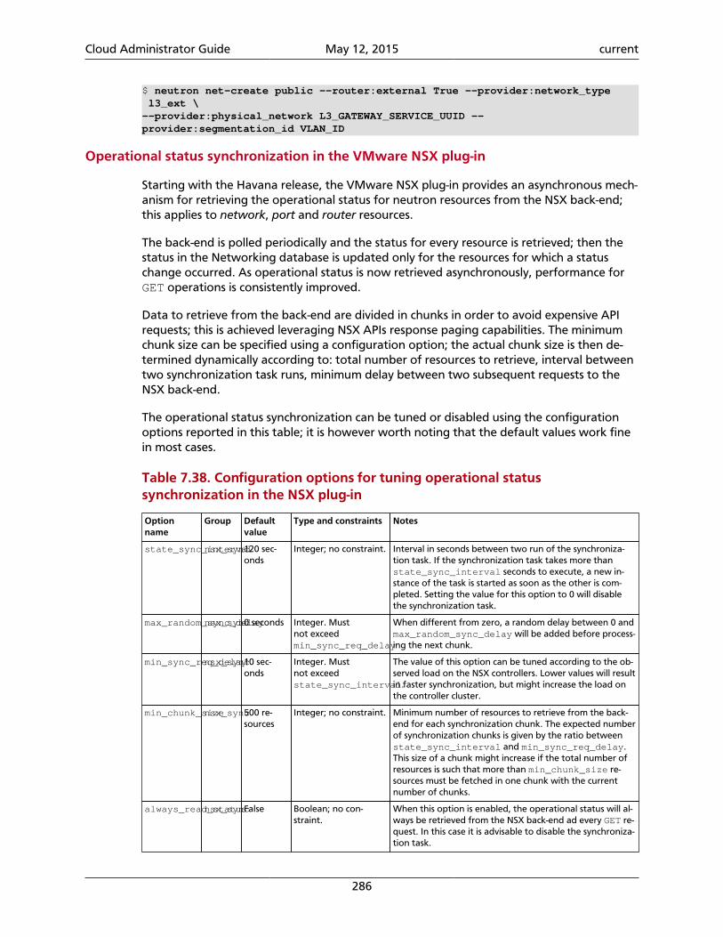
Cloud Administrator Guide May 12, 2015 current
286
$ neutron net-create public --router:external True --provider:network_type l3_ext \--provider:physical_network L3_GATEWAY_SERVICE_UUID --provider:segmentation_id VLAN_ID
Operational status synchronization in the VMware NSX plug-in
Starting with the Havana release, the VMware NSX plug-in provides an asynchronous mech-anism for retrieving the operational status for neutron resources from the NSX back-end;this applies to network, port and router resources.
The back-end is polled periodically and the status for every resource is retrieved; then thestatus in the Networking database is updated only for the resources for which a statuschange occurred. As operational status is now retrieved asynchronously, performance forGET operations is consistently improved.
Data to retrieve from the back-end are divided in chunks in order to avoid expensive APIrequests; this is achieved leveraging NSX APIs response paging capabilities. The minimumchunk size can be specified using a configuration option; the actual chunk size is then de-termined dynamically according to: total number of resources to retrieve, interval betweentwo synchronization task runs, minimum delay between two subsequent requests to theNSX back-end.
The operational status synchronization can be tuned or disabled using the configurationoptions reported in this table; it is however worth noting that the default values work finein most cases.
Table 7.38. Configuration options for tuning operational statussynchronization in the NSX plug-in
Optionname
Group Defaultvalue
Type and constraints Notes
state_sync_intervalnsx_sync120 sec-onds
Integer; no constraint. Interval in seconds between two run of the synchroniza-tion task. If the synchronization task takes more thanstate_sync_interval seconds to execute, a new in-stance of the task is started as soon as the other is com-pleted. Setting the value for this option to 0 will disablethe synchronization task.
max_random_sync_delaynsx_sync0 seconds Integer. Mustnot exceedmin_sync_req_delay
When different from zero, a random delay between 0 andmax_random_sync_delay will be added before process-ing the next chunk.
min_sync_req_delaynsx_sync10 sec-onds
Integer. Mustnot exceedstate_sync_interval.
The value of this option can be tuned according to the ob-served load on the NSX controllers. Lower values will resultin faster synchronization, but might increase the load onthe controller cluster.
min_chunk_sizensx_sync500 re-sources
Integer; no constraint. Minimum number of resources to retrieve from the back-end for each synchronization chunk. The expected numberof synchronization chunks is given by the ratio betweenstate_sync_interval and min_sync_req_delay.This size of a chunk might increase if the total number ofresources is such that more than min_chunk_size re-sources must be fetched in one chunk with the currentnumber of chunks.
always_read_statusnsx_syncFalse Boolean; no con-straint.
When this option is enabled, the operational status will al-ways be retrieved from the NSX back-end ad every GET re-quest. In this case it is advisable to disable the synchroniza-tion task.
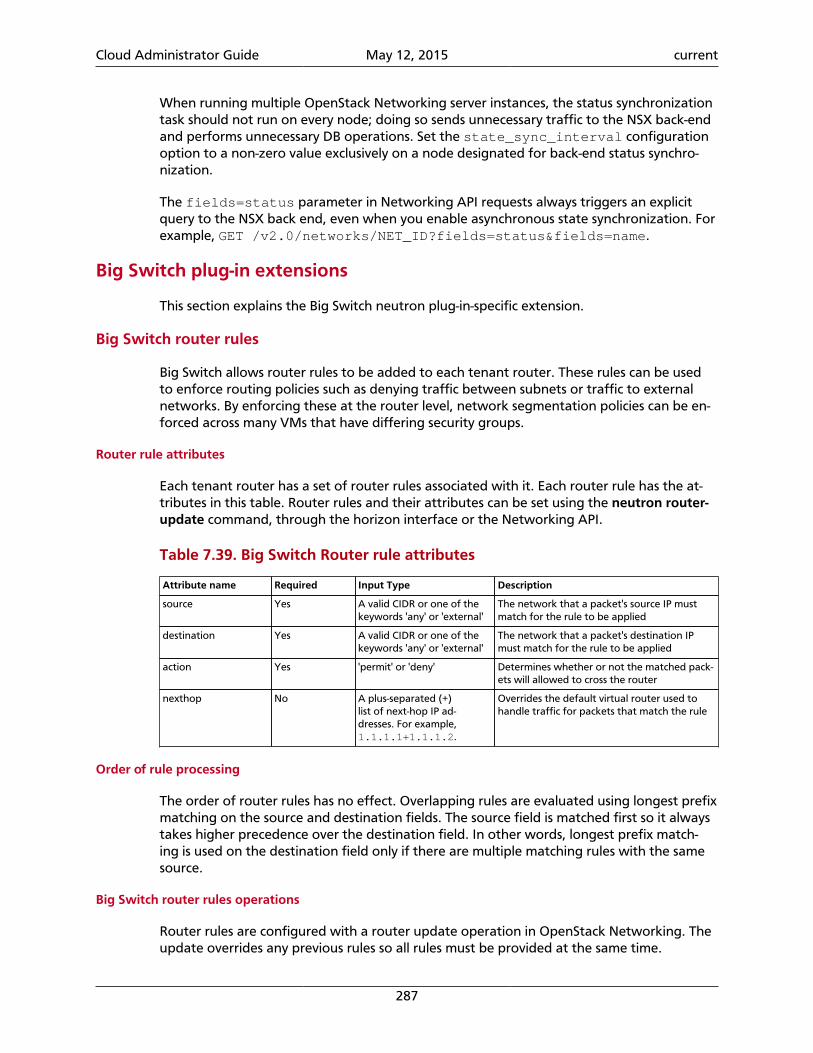
Cloud Administrator Guide May 12, 2015 current
287
When running multiple OpenStack Networking server instances, the status synchronizationtask should not run on every node; doing so sends unnecessary traffic to the NSX back-endand performs unnecessary DB operations. Set the state_sync_interval configurationoption to a non-zero value exclusively on a node designated for back-end status synchro-nization.
The fields=status parameter in Networking API requests always triggers an explicitquery to the NSX back end, even when you enable asynchronous state synchronization. Forexample, GET /v2.0/networks/NET_ID?fields=status&fields=name.
Big Switch plug-in extensions
This section explains the Big Switch neutron plug-in-specific extension.
Big Switch router rules
Big Switch allows router rules to be added to each tenant router. These rules can be usedto enforce routing policies such as denying traffic between subnets or traffic to externalnetworks. By enforcing these at the router level, network segmentation policies can be en-forced across many VMs that have differing security groups.
Router rule attributes
Each tenant router has a set of router rules associated with it. Each router rule has the at-tributes in this table. Router rules and their attributes can be set using the neutron router-update command, through the horizon interface or the Networking API.
Table 7.39. Big Switch Router rule attributes
Attribute name Required Input Type Description
source Yes A valid CIDR or one of thekeywords 'any' or 'external'
The network that a packet's source IP mustmatch for the rule to be applied
destination Yes A valid CIDR or one of thekeywords 'any' or 'external'
The network that a packet's destination IPmust match for the rule to be applied
action Yes 'permit' or 'deny' Determines whether or not the matched pack-ets will allowed to cross the router
nexthop No A plus-separated (+)list of next-hop IP ad-dresses. For example,1.1.1.1+1.1.1.2.
Overrides the default virtual router used tohandle traffic for packets that match the rule
Order of rule processing
The order of router rules has no effect. Overlapping rules are evaluated using longest prefixmatching on the source and destination fields. The source field is matched first so it alwaystakes higher precedence over the destination field. In other words, longest prefix match-ing is used on the destination field only if there are multiple matching rules with the samesource.
Big Switch router rules operations
Router rules are configured with a router update operation in OpenStack Networking. Theupdate overrides any previous rules so all rules must be provided at the same time.
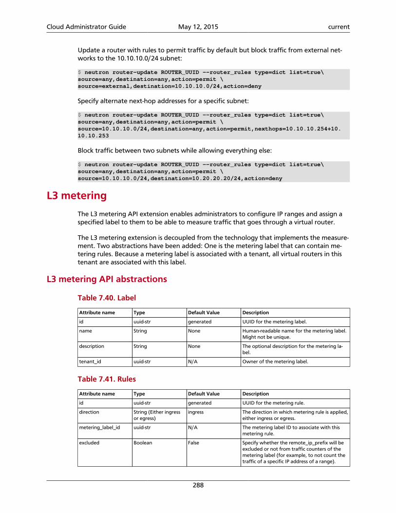
Cloud Administrator Guide May 12, 2015 current
288
Update a router with rules to permit traffic by default but block traffic from external net-works to the 10.10.10.0/24 subnet:
$ neutron router-update ROUTER_UUID --router_rules type=dict list=true\source=any,destination=any,action=permit \source=external,destination=10.10.10.0/24,action=deny
Specify alternate next-hop addresses for a specific subnet:
$ neutron router-update ROUTER_UUID --router_rules type=dict list=true\source=any,destination=any,action=permit \source=10.10.10.0/24,destination=any,action=permit,nexthops=10.10.10.254+10.10.10.253
Block traffic between two subnets while allowing everything else:
$ neutron router-update ROUTER_UUID --router_rules type=dict list=true\source=any,destination=any,action=permit \source=10.10.10.0/24,destination=10.20.20.20/24,action=deny
L3 metering
The L3 metering API extension enables administrators to configure IP ranges and assign aspecified label to them to be able to measure traffic that goes through a virtual router.
The L3 metering extension is decoupled from the technology that implements the measure-ment. Two abstractions have been added: One is the metering label that can contain me-tering rules. Because a metering label is associated with a tenant, all virtual routers in thistenant are associated with this label.
L3 metering API abstractions
Table 7.40. Label
Attribute name Type Default Value Description
id uuid-str generated UUID for the metering label.
name String None Human-readable name for the metering label.Might not be unique.
description String None The optional description for the metering la-bel.
tenant_id uuid-str N/A Owner of the metering label.
Table 7.41. Rules
Attribute name Type Default Value Description
id uuid-str generated UUID for the metering rule.
direction String (Either ingressor egress)
ingress The direction in which metering rule is applied,either ingress or egress.
metering_label_id uuid-str N/A The metering label ID to associate with thismetering rule.
excluded Boolean False Specify whether the remote_ip_prefix will beexcluded or not from traffic counters of themetering label (for example, to not count thetraffic of a specific IP address of a range).

Cloud Administrator Guide May 12, 2015 current
289
Attribute name Type Default Value Description
remote_ip_prefix String (CIDR) N/A Indicates remote IP prefix to be associatedwith this metering rule.
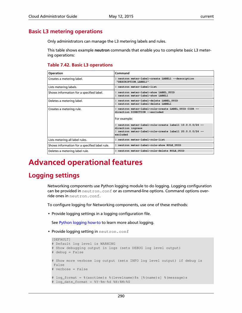
Cloud Administrator Guide May 12, 2015 current
290
Basic L3 metering operations
Only administrators can manage the L3 metering labels and rules.
This table shows example neutron commands that enable you to complete basic L3 meter-ing operations:
Table 7.42. Basic L3 operations
Operation Command
Creates a metering label. $ neutron meter-label-create LABEL1 --description "DESCRIPTION_LABEL1"
Lists metering labels. $ neutron meter-label-list
Shows information for a specified label. $ neutron meter-label-show LABEL_UUID$ neutron meter-label-show LABEL1
Deletes a metering label. $ neutron meter-label-delete LABEL_UUID$ neutron meter-label-delete LABEL1
Creates a metering rule. $ neutron meter-label-rule-create LABEL_UUID CIDR --direction DIRECTION --excluded
For example:
$ neutron meter-label-rule-create label1 10.0.0.0/24 --direction ingress$ neutron meter-label-rule-create label1 20.0.0.0/24 --excluded
Lists metering all label rules. $ neutron meter-label-rule-list
Shows information for a specified label rule. $ neutron meter-label-rule-show RULE_UUID
Deletes a metering label rule. $ neutron meter-label-rule-delete RULE_UUID
Advanced operational features
Logging settingsNetworking components use Python logging module to do logging. Logging configurationcan be provided in neutron.conf or as command-line options. Command options over-ride ones in neutron.conf.
To configure logging for Networking components, use one of these methods:
• Provide logging settings in a logging configuration file.
See Python logging how-to to learn more about logging.
• Provide logging setting in neutron.conf
[DEFAULT]# Default log level is WARNING# Show debugging output in logs (sets DEBUG log level output)# debug = False
# Show more verbose log output (sets INFO log level output) if debug is False# verbose = False
# log_format = %(asctime)s %(levelname)8s [%(name)s] %(message)s# log_date_format = %Y-%m-%d %H:%M:%S
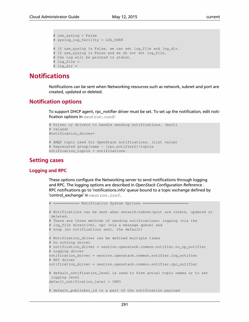
Cloud Administrator Guide May 12, 2015 current
291
# use_syslog = False# syslog_log_facility = LOG_USER
# if use_syslog is False, we can set log_file and log_dir.# if use_syslog is False and we do not set log_file,# the log will be printed to stdout.# log_file =# log_dir =
NotificationsNotifications can be sent when Networking resources such as network, subnet and port arecreated, updated or deleted.
Notification options
To support DHCP agent, rpc_notifier driver must be set. To set up the notification, edit noti-fication options in neutron.conf:
# Driver or drivers to handle sending notifications. (multi# valued)#notification_driver=
# AMQP topic used for OpenStack notifications. (list value)# Deprecated group/name - [rpc_notifier2]/topicsnotification_topics = notifications
Setting cases
Logging and RPC
These options configure the Networking server to send notifications through loggingand RPC. The logging options are described in OpenStack Configuration Reference .RPC notifications go to 'notifications.info' queue bound to a topic exchange defined by'control_exchange' in neutron.conf.
# ============ Notification System Options =====================
# Notifications can be sent when network/subnet/port are create, updated or deleted.# There are three methods of sending notifications: logging (via the# log_file directive), rpc (via a message queue) and# noop (no notifications sent, the default)
# Notification_driver can be defined multiple times# Do nothing driver# notification_driver = neutron.openstack.common.notifier.no_op_notifier# Logging drivernotification_driver = neutron.openstack.common.notifier.log_notifier# RPC drivernotification_driver = neutron.openstack.common.notifier.rpc_notifier
# default_notification_level is used to form actual topic names or to set logging leveldefault_notification_level = INFO
# default_publisher_id is a part of the notification payload
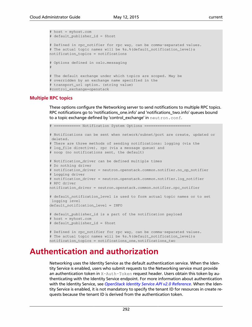
Cloud Administrator Guide May 12, 2015 current
292
# host = myhost.com# default_publisher_id = $host
# Defined in rpc_notifier for rpc way, can be comma-separated values.# The actual topic names will be %s.%(default_notification_level)snotification_topics = notifications
# Options defined in oslo.messaging#
# The default exchange under which topics are scoped. May be# overridden by an exchange name specified in the# transport_url option. (string value)#control_exchange=openstack
Multiple RPC topics
These options configure the Networking server to send notifications to multiple RPC topics.RPC notifications go to 'notifications_one.info' and 'notifications_two.info' queues boundto a topic exchange defined by 'control_exchange' in neutron.conf.
# ============ Notification System Options =====================
# Notifications can be sent when network/subnet/port are create, updated or deleted.# There are three methods of sending notifications: logging (via the# log_file directive), rpc (via a message queue) and# noop (no notifications sent, the default)
# Notification_driver can be defined multiple times# Do nothing driver# notification_driver = neutron.openstack.common.notifier.no_op_notifier# Logging driver# notification_driver = neutron.openstack.common.notifier.log_notifier# RPC drivernotification_driver = neutron.openstack.common.notifier.rpc_notifier
# default_notification_level is used to form actual topic names or to set logging leveldefault_notification_level = INFO
# default_publisher_id is a part of the notification payload# host = myhost.com# default_publisher_id = $host
# Defined in rpc_notifier for rpc way, can be comma-separated values.# The actual topic names will be %s.%(default_notification_level)snotification_topics = notifications_one,notifications_two
Authentication and authorizationNetworking uses the Identity Service as the default authentication service. When the Iden-tity Service is enabled, users who submit requests to the Networking service must providean authentication token in X-Auth-Token request header. Users obtain this token by au-thenticating with the Identity Service endpoint. For more information about authenticationwith the Identity Service, see OpenStack Identity Service API v2.0 Reference. When the Iden-tity Service is enabled, it is not mandatory to specify the tenant ID for resources in create re-quests because the tenant ID is derived from the authentication token.
Cloud Administrator Guide May 12, 2015 current
293
Note
The default authorization settings only allow administrative users to create re-sources on behalf of a different tenant. Networking uses information receivedfrom Identity to authorize user requests. Networking handles two kind of au-thorization policies:
• Operation-based policies specify access criteria for specific operations, possibly with fine-grained control over specific attributes;
• Resource-based policies specify whether access to specific resource is granted or not ac-cording to the permissions configured for the resource (currently available only for thenetwork resource). The actual authorization policies enforced in Networking might varyfrom deployment to deployment.
The policy engine reads entries from the policy.json file. The actual location of thisfile might vary from distribution to distribution. Entries can be updated while the sys-tem is running, and no service restart is required. Every time the policy file is updated,the policies are automatically reloaded. Currently the only way of updating such poli-cies is to edit the policy file. In this section, the terms policy and rule refer to objectsthat are specified in the same way in the policy file. There are no syntax differences be-tween a rule and a policy. A policy is something that is matched directly from the Net-working policy engine. A rule is an element in a policy, which is evaluated. For instance increate_subnet: [["admin_or_network_owner"]], create_subnet is a policy, andadmin_or_network_owner is a rule.
Policies are triggered by the Networking policy engine whenever one of them matches aNetworking API operation or a specific attribute being used in a given operation. For in-stance the create_subnet policy is triggered every time a POST /v2.0/subnets re-quest is sent to the Networking server; on the other hand create_network:sharedis triggered every time the shared attribute is explicitly specified (and set to a val-ue different from its default) in a POST /v2.0/networks request. It is also worthmentioning that policies can also be related to specific API extensions; for instanceextension:provider_network:set is triggered if the attributes defined by theProvider Network extensions are specified in an API request.
An authorization policy can be composed by one or more rules. If more rules are specifiedthen the evaluation policy succeeds if any of the rules evaluates successfully; if an API oper-ation matches multiple policies, then all the policies must evaluate successfully. Also, autho-rization rules are recursive. Once a rule is matched, the rule(s) can be resolved to anotherrule, until a terminal rule is reached.
The Networking policy engine currently defines the following kinds of terminal rules:
• Role-based rules evaluate successfully if the user who submits the request has the speci-fied role. For instance "role:admin" is successful if the user who submits the request isan administrator.
• Field-based rules evaluate successfully if a field of the resource specified in the current re-quest matches a specific value. For instance "field:networks:shared=True" is suc-cessful if the shared attribute of the network resource is set to true.
• Generic rules compare an attribute in the resource with an attribute extracted from theuser's security credentials and evaluates successfully if the comparison is successful. For
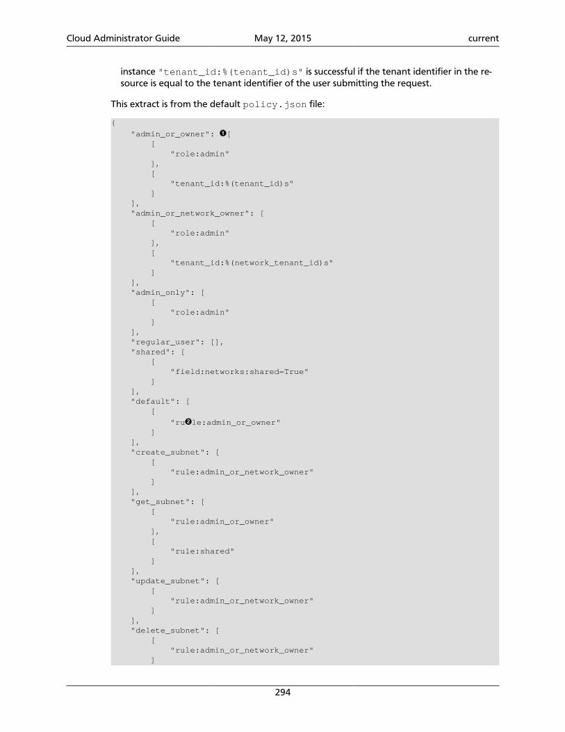
Cloud Administrator Guide May 12, 2015 current
294
instance "tenant_id:%(tenant_id)s" is successful if the tenant identifier in the re-source is equal to the tenant identifier of the user submitting the request.
This extract is from the default policy.json file:
{
"admin_or_owner": [ [ "role:admin" ], [ "tenant_id:%(tenant_id)s" ] ], "admin_or_network_owner": [ [ "role:admin" ], [ "tenant_id:%(network_tenant_id)s" ] ], "admin_only": [ [ "role:admin" ] ], "regular_user": [], "shared": [ [ "field:networks:shared=True" ] ], "default": [ [
"ru le:admin_or_owner" ] ], "create_subnet": [ [ "rule:admin_or_network_owner" ] ], "get_subnet": [ [ "rule:admin_or_owner" ], [ "rule:shared" ] ], "update_subnet": [ [ "rule:admin_or_network_owner" ] ], "delete_subnet": [ [ "rule:admin_or_network_owner" ]
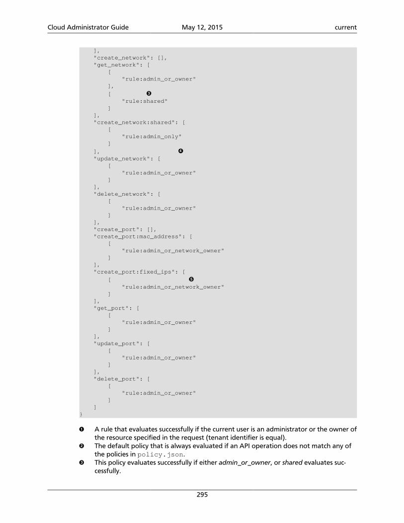
Cloud Administrator Guide May 12, 2015 current
295
], "create_network": [], "get_network": [ [ "rule:admin_or_owner" ],
[ "rule:shared" ] ], "create_network:shared": [ [ "rule:admin_only" ]
], "update_network": [ [ "rule:admin_or_owner" ] ], "delete_network": [ [ "rule:admin_or_owner" ] ], "create_port": [], "create_port:mac_address": [ [ "rule:admin_or_network_owner" ] ], "create_port:fixed_ips": [
[ "rule:admin_or_network_owner" ] ], "get_port": [ [ "rule:admin_or_owner" ] ], "update_port": [ [ "rule:admin_or_owner" ] ], "delete_port": [ [ "rule:admin_or_owner" ] ]}
A rule that evaluates successfully if the current user is an administrator or the owner ofthe resource specified in the request (tenant identifier is equal).The default policy that is always evaluated if an API operation does not match any ofthe policies in policy.json.This policy evaluates successfully if either admin_or_owner, or shared evaluates suc-cessfully.
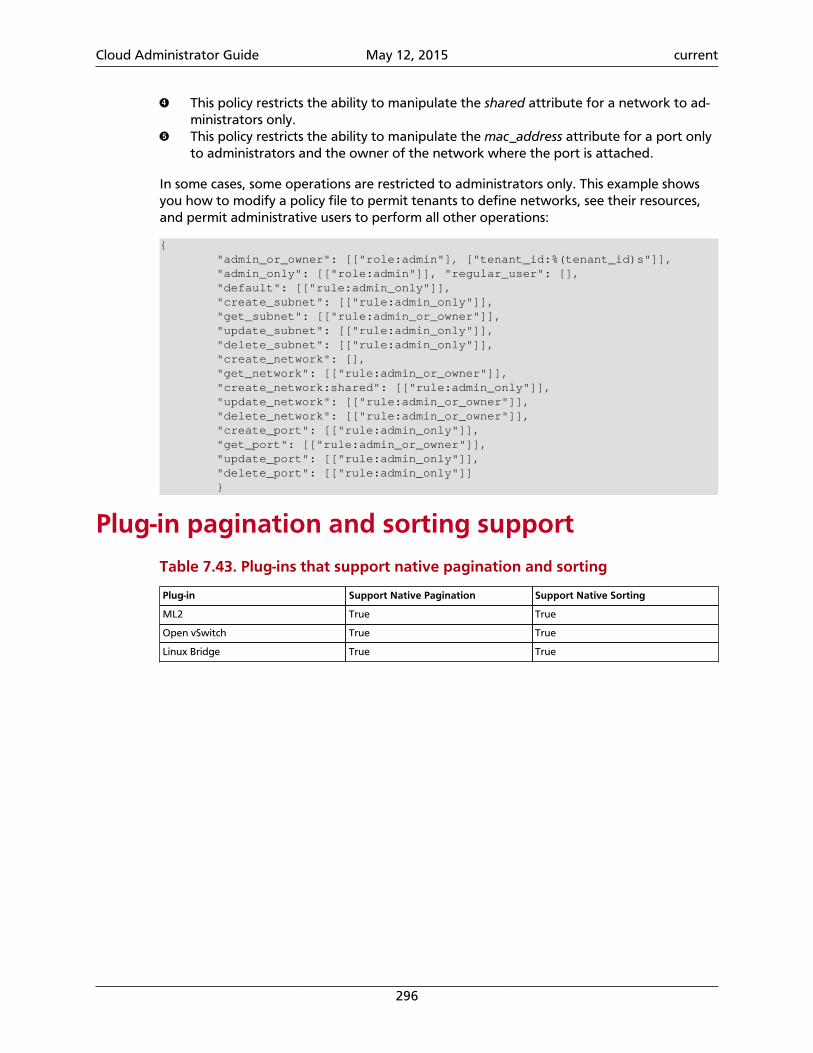
Cloud Administrator Guide May 12, 2015 current
296
This policy restricts the ability to manipulate the shared attribute for a network to ad-ministrators only.This policy restricts the ability to manipulate the mac_address attribute for a port onlyto administrators and the owner of the network where the port is attached.
In some cases, some operations are restricted to administrators only. This example showsyou how to modify a policy file to permit tenants to define networks, see their resources,and permit administrative users to perform all other operations:
{ "admin_or_owner": [["role:admin"], ["tenant_id:%(tenant_id)s"]], "admin_only": [["role:admin"]], "regular_user": [], "default": [["rule:admin_only"]], "create_subnet": [["rule:admin_only"]], "get_subnet": [["rule:admin_or_owner"]], "update_subnet": [["rule:admin_only"]], "delete_subnet": [["rule:admin_only"]], "create_network": [], "get_network": [["rule:admin_or_owner"]], "create_network:shared": [["rule:admin_only"]], "update_network": [["rule:admin_or_owner"]], "delete_network": [["rule:admin_or_owner"]], "create_port": [["rule:admin_only"]], "get_port": [["rule:admin_or_owner"]], "update_port": [["rule:admin_only"]], "delete_port": [["rule:admin_only"]] }
Plug-in pagination and sorting supportTable 7.43. Plug-ins that support native pagination and sorting
Plug-in Support Native Pagination Support Native Sorting
ML2 True True
Open vSwitch True True
Linux Bridge True True
Cloud Administrator Guide May 12, 2015 current
297
8. Telemetry
Table of ContentsIntroduction ................................................................................................................ 297System architecture ..................................................................................................... 298Data collection ............................................................................................................ 300Data retrieval .............................................................................................................. 314Alarms ......................................................................................................................... 322Measurements ............................................................................................................. 326Events ......................................................................................................................... 341Troubleshoot Telemetry ............................................................................................... 344
The Telemetry module is the metering service in OpenStack.
IntroductionEven in the cloud industry, providers must use a multi-step process for billing. The requiredsteps to bill for usage in a cloud environment are metering, rating, and billing. Because theprovider's requirements may be far too specific for a shared solution, rating and billing solu-tions cannot be designed a common module that satisfies all. Providing users with measure-ments on cloud services is required to meet the "measured service" definition of cloud com-puting.
The Telemetry module was originally designed to support billing systems for OpenStackcloud resources. This project only covers the metering portion of the required processingfor billing. This module collects information about the system and stores it in the form ofsamples in order to provide data about anything that can be billed.
In addition to system measurements, the Telemetry module also captures event notifica-tions triggered when various actions are executed in the OpenStack system. This data iscaptured as Events and stored alongside metering data.
The list of meters is continuously growing, which makes it possible to use the data collect-ed by Telemetry for different purposes, other than billing. For example, the autoscaling fea-ture in the Orchestration module can be triggered by alarms this module sets and then getsnotified within Telemetry.
The sections in this document contain information about the architecture and usage ofTelemetry. The first section contains a brief summary about the system architecture used ina typical OpenStack deployment. The second section describes the data collection mecha-nisms. You can also read about alarming to understand how alarm definitions can be post-ed to Telemetry and what actions can happen if an alarm is raised. The last section con-tains a troubleshooting guide, which mentions error situations and possible solutions forthe problems.
You can retrieve the collected samples three different ways: with the REST API, with thecommand line interface, or with the Metering tab on an OpenStack dashboard.
Cloud Administrator Guide May 12, 2015 current
298
System architectureThe Telemetry module uses an agent-based architecture. Several modules combine their re-sponsibilities to collect data, store samples in a database, or provide an API service for han-dling incoming requests.
The Telemetry module is built from the following agents and services:
ceilometer-api Presents aggregated metering data to consumers (suchas billing engines, analytics tools and so forth).
ceilometer-polling Polls for different kinds of meter data by using thepolling plug-ins (pollsters) registered in different names-paces.
ceilometer-agent-central Polls the public RESTful APIs of other OpenStack servicessuch as Compute service and Image service, in order tokeep tabs on resource existence, by using the pollingplug-ins (pollsters) registered in the central pollingnamespace.
ceilometer-agent-compute Polls the local hypervisor or libvirt daemon to acquireperformance data for the local instances, messages andemits the data as AMQP messages, by using the pollingplug-ins (pollsters) registered in the compute pollingnamespace.
ceilometer-agent-ipmi Polls the local node with IPMI support, in order to ac-quire IPMI sensor data and Intel Node Manager data,by using the polling plug-ins (pollsters) registered in theIPMI polling namespace.
ceilometer-agent-notifi-cation
Consumes AMQP messages from other OpenStack ser-vices.
ceilometer-collector Consumes AMQP notifications from the agents, thendispatches these data to the appropriate data store.
ceilometer-alarm-evalua-tor
Determines when alarms fire due to the associatedstatistic trend crossing a threshold over a sliding timewindow.
ceilometer-alarm-notifi-er
Initiates alarm actions, for example calling out to a web-hook with a description of the alarm state transition.
Note
The ceilometer-polling service is available since the Kilo release.
Besides the ceilometer-agent-compute and the ceilometer-agent-ipmi service,all the other services are placed on one or more controller nodes.
Cloud Administrator Guide May 12, 2015 current
299
The Telemetry architecture highly depends on the AMQP service both for consuming notifi-cations coming from OpenStack services and internal communication.
Supported databases
The other key external component of Telemetry is the database, where events, samples,alarm definitions and alarms are stored.
Note
Multiple database back ends can be configured in order to store events, sam-ples and alarms separately.
The list of supported database back ends:
• ElasticSearch (events only)
• MongoDB
• MySQL
• PostgreSQL
• HBase
• DB2
Supported hypervisors
The Telemetry module collects information about the virtual machines, which requires closeconnection to the hypervisor that runs on the compute hosts.
The list of supported hypervisors is:
• The following hypervisors are supported via Libvirt:
• Kernel-based Virtual Machine (KVM)
• Quick Emulator (QEMU)
• Linux Containers (LXC)
• User-mode Linux (UML)
Note
For details about hypervisor support in libvirt please check the Libvirt API sup-port matrix.
• Hyper-V
• XEN
• VMWare vSphere
Cloud Administrator Guide May 12, 2015 current
300
Supported networking services
Telemetry is able to retrieve information from OpenStack Networking and external net-working services:
• OpenStack Networking:
• Basic network meters
• Firewall-as-a-Service (FWaaS) meters
• Loadbalancer-as-a-Service (LBaaS) meters
• VPN-as-a-Service (VPNaaS) meters
• SDN controller meters:
• OpenDaylight
• OpenContrail
Users, roles and tenants
This module of OpenStack uses OpenStack Identity for authenticating and authorizingusers. The required configuration options are listed in the Telemetry section in the Open-Stack Configuration Reference.
Two roles are used in the system basically, which are the 'admin' and 'non-admin'. The au-thorization happens before processing each API request. The amount of returned data de-pends on the role the requestor owns.
The creation of alarm definitions also highly depends on the role of the user, who initi-ated the action. Further details about alarm handling can be found in the section called“Alarms” [322] in this guide.
Data collectionThe main responsibility of Telemetry in OpenStack is to collect information about the sys-tem that can be used by billing systems or interpreted by analytic tooling. The original fo-cus, regarding to the collected data, was on the counters that can be used for billing, butthe range is getting wider continuously.
Collected data can be stored in the form of samples or events in the supported databases,listed in the section called “Supported databases” [299].
Samples can have various sources regarding to the needs and configuration of Telemetry,which requires multiple methods to collect data.
The available data collection mechanisms are:
Notifications Processing notifications from other OpenStack services, by consumingmessages from the configured message queue system.
Cloud Administrator Guide May 12, 2015 current
301
Polling Retrieve information directly from the hypervisor or from the host ma-chine using SNMP, or by using the APIs of other OpenStack services.
RESTful API Pushing samples via the RESTful API of Telemetry.
NotificationsAll the services send notifications about the executed operations or system state in Open-Stack. Several notifications carry information that can be metered, like the CPU time of aVM instance created by OpenStack Compute service.
The Telemetry module has a separate agent that is responsible for consuming notifications,namely the notification agent. This component is responsible for consuming from the mes-sage bus and transforming notifications into events and measurement samples.
The different OpenStack services emit several notifications about the various types ofevents that happen in the system during normal operation. Not all these notifications areconsumed by the Telemetry module, as the intention is only to capture the billable eventsand notifications that can be used for monitoring or profiling purposes. The notificationagent filters by the event type, that is contained by each notification message. The follow-ing table contains the event types by each OpenStack service that are transformed to sam-ples by Telemetry.
Table 8.1. Consumed event types from OpenStack services
OpenStack service Event types Note
OpenStack Compute scheduler.run_instance.scheduled
scheduler.select_destinations
compute.instance.*
For a more detailed list of Computenotifications please check the SystemUsage Data wiki page.
Bare metal service hardware.ipmi.*
OpenStack Image service image.update
image.upload
image.delete
image.send
The required configuration for Imageservice can be found in the Configurethe Image service for Telemetry sec-tion section in the OpenStack Installa-tion Guide.
OpenStack Networking floatingip.create.end
floatingip.update.*
floatingip.exists
network.create.end
network.update.*
network.exists
port.create.end
port.update.*
port.exists
router.create.end
router.update.*
router.exists
Cloud Administrator Guide May 12, 2015 current
302
OpenStack service Event types Note
subnet.create.end
subnet.update.*
subnet.exists
l3.meter
Orchestration module orchestration.stack.create.end
orchestration.stack.update.end
orchestration.stack.delete.end
orchestration.stack.resume.end
orchestration.stack.suspend.end
OpenStack Block Storage volume.exists
volume.create.*
volume.delete.*
volume.update.*
volume.resize.*
volume.attach.*
volume.detach.*
snapshot.exists
snapshot.create.*
snapshot.delete.*
snapshot.update.*
The required configuration for BlockStorage service can be found in the Add the Block Storage service agentfor Telemetry section section in theOpenStack Installation Guide.
Note
Some services require additional configuration to emit the notifications usingthe correct control exchange on the message queue and so forth. These config-uration needs are referred in the above table for each OpenStack service thatneeds it.
Note
When the store_events option is set to True in ceilometer.conf, the no-tification agent needs database access in order to work properly.
Middleware for OpenStack Object Storage service
A subset of Object Store statistics requires an additional middleware to be installed be-hind the proxy of Object Store. This additional component emits notifications containingdata-flow-oriented meters, namely the storage.objects.(incoming|outgoing).bytes values.The list of these meters are listed in the section called “OpenStack Object Storage” [335],marked with notification as origin.
The instructions on how to install this middleware can be found in Configure the ObjectStorage service for Telemetry section in the OpenStack Installation Guide.
Cloud Administrator Guide May 12, 2015 current
303
Telemetry middleware
Telemetry provides the capability of counting the HTTP requests and responses for eachAPI endpoint in OpenStack. This is achieved by storing a sample for each event marked asaudit.http.request, audit.http.response, http.request or http.response.
It is recommended that these notifications be consumed as Events rather than samples tobetter index the appropriate values and avoid massive load on the Metering database. Ifpreferred, Telemetry can consume these events as samples if the services are configured toemit http.* notifications.
Polling
The Telemetry module is intended to store a complex picture of the infrastructure. This goalrequires additional information than what is provided by the events and notifications pub-lished by each service. Some information is not emitted directly, like resource usage of theVM instances.
Therefore Telemetry uses another method to gather this data by polling the infrastructureincluding the APIs of the different OpenStack services and other assets, like hypervisors. Thelatter case requires closer interaction with the compute hosts. To solve this issue, Telemetryuses an agent based architecture to fulfill the requirements against the data collection.
There are three types of agents supporting the polling mechanism, the compute agent, thecentral agent, and the IPMI agent. Under the hood, all the types of polling agents are thesame ceilometer-polling agent, except that they load different polling plug-ins (poll-sters) from differernt namespaces to gather data. The following subsections give further in-formation regarding the architectural and configuration details of these components.
Running ceilometer-agent-compute is exactly the same as:
$ ceilometer-polling --polling-namespaces compute
Running ceilometer-agent-central is exactly the same as:
$ ceilometer-polling --polling-namespaces central
Running ceilometer-agent-ipmi is exactly the same as:
$ ceilometer-polling --polling-namespaces ipmi
In addition to loading all the polling plug-ins registered in the specified namespaces, theceilometer-polling agent can also specify the polling plug-ins to be loaded by usingthe pollster-list option:
$ ceilometer-polling --polling-namespaces central \ --pollster-list image image.size storage.*
Note
HA deployment is NOT supported if the pollster-list option is used.
Cloud Administrator Guide May 12, 2015 current
304
Note
The ceilometer-polling service is available since Kilo release.
Central agent
As the name of this agent shows, it is a central component in the Telemetry architecture.This agent is responsible for polling public REST APIs to retrieve additional information onOpenStack resources not already surfaced via notifications, and also for polling hardwareresources over SNMP.
The following services can be polled with this agent:
• OpenStack Networking
• OpenStack Object Storage
• OpenStack Block Storage
• Hardware resources via SNMP
• Energy consumption meters via Kwapi framework
To install and configure this service use the Install the Telemetry module section in theOpenStack Installation Guide.
The central agent does not need direct database connection. The samples collected by thisagent are sent via AMQP to the collector service or any external service, which is responsi-ble for persisting the data into the configured database back end.
Compute agent
This agent is responsible for collecting resource usage data of VM instances on individualcompute nodes within an OpenStack deployment. This mechanism requires a closer interac-tion with the hypervisor, therefore a separate agent type fulfills the collection of the relat-ed meters, which is placed on the host machines to locally retrieve this information.
A compute agent instance has to be installed on each and every compute node, installa-tion instructions can be found in the Install the Compute agent for Telemetry section in theOpenStack Installation Guide.
Just like the central agent, this component also does not need a direct database connec-tion. The samples are sent via AMQP to the collector.
The list of supported hypervisors can be found in the section called “Supported hypervi-sors” [299]. The compute agent uses the API of the hypervisor installed on the computehosts. Therefore the supported meters may be different in case of each virtualization backend, as each inspection tool provides a different set of meters.
The list of collected meters can be found in the section called “OpenStack Com-pute” [327]. The support column provides the information that which meter is availablefor each hypervisor supported by the Telemetry module.
Cloud Administrator Guide May 12, 2015 current
305
Note
Telemetry supports Libvirt, which hides the hypervisor under it.
Support for HA deployment of the central and compute agent services
Both the central and the compute agent can run in an HA deployment, which means thatmultiple instances of these services can run in parallel with workload partitioning amongthese running instances.
The Tooz library provides the coordination within the groups of service instances. It pro-vides an API above several back ends that can be used for building distributed applications.
Tooz supports various drivers including the following back end solutions:
• Zookeeper. Recommended solution by the Tooz project.
• Redis. Recommended solution by the Tooz project.
• Memcached Recommended for testing.
You must configure a supported Tooz driver for the HA deployment of the Telemetry ser-vices.
For information about the required configuration options that have to be set in theceilometer.conf configuration file for both the central and compute agents, see the coordination section in the OpenStack Configuration Reference.
Note
Without the backend_url option being set only one instance of both the cen-tral and compute agent service is able to run and function correctly.
The availability check of the instances is provided by heartbeat messages. When the con-nection with an instance is lost, the workload will be reassigned within the remained in-stances in the next polling cycle.
Note
Memcached uses a timeout value, which should always be set to a value thatis higher than the heartbeat value set for Telemetry.
For backward compatibility and supporting existing deployments, the central agent con-figuration also supports using different configuration files for groups of service instancesof this type that are running in parallel. For enabling this configuration set a value for thepartitioning_group_prefix option in the central section in the OpenStack Con-figuration Reference.
Warning
For each sub-group of the central agent pool with the samepartitioning_group_prefix a disjoint subset of meters must be polled,otherwise samples may be missing or duplicated. The list of meters to poll canbe set in the /etc/ceilometer/pipeline.yaml configuration file. For
Cloud Administrator Guide May 12, 2015 current
306
more information about pipelines see the section called “Data collection andprocessing” [307].
To enable the compute agent to run multiple instances simultaneously with workload parti-tioning, the workload_partitioning option has to be set to True under the computesection in the ceilometer.conf configuration file.
IPMI agent
This agent is responsible for collecting IPMI sensor data and Intel Node Manager data onindividual compute nodes within an OpenStack deployment. This agent requires an IPMIcapable node with ipmitool installed, which is a common utility for IPMI control on variousLinux distributions.
An IPMI agent instance could be installed on each and every compute node with IP-MI support, except when the node is managed by the Bare metal service and theconductor.send_sensor_data option is set to true in the Bare metal service. It is noharm to install this agent on a compute node without IPMI or Intel Node Manager support,as the agent checks for the hardware and if none is available, returns empty data. It is sug-gested that you install the IPMI agent only on an IPMI capable node for performance rea-sons.
Just like the central agent, this component also does not need direct database access. Thesamples are sent via AMQP to the collector.
The list of collected meters can be found in the section called “Bare metal service” [332].
Note
Do not deploy both the IPMI agent and the Bare metal service on one computenode. If conductor.send_sensor_data set, this misconfiguration causesduplicated IPMI sensor samples.
Send samples to TelemetryWhile most parts of the data collection in the Telemetry module are automated, Teleme-try provides the possibility to submit samples via the REST API to allow users to send customsamples into this module.
This option makes it possible to send any kind of samples without the need of writing extracode lines or making configuration changes.
The samples that can be sent to Telemetry are not limited to the actual existing meters.There is a possibility to provide data for any new, customer defined counter by filling out allthe required fields of the POST request.
If the sample corresponds to an existing meter, then the fields like meter-type and metername should be matched accordingly.
The required fields for sending a sample using the command line client are:
• ID of the corresponding resource. (--resource-id)
• Name of meter. (--meter-name)
Cloud Administrator Guide May 12, 2015 current
307
• Type of meter. (--meter-type)
Predefined meter types:
• Gauge
• Delta
• Cumulative
• Unit of meter. (--meter-unit)
• Volume of sample. (--sample-volume)
To send samples to Telemetry using the command line client, the following commandshould be invoked:
$ ceilometer sample-create -r 37128ad6-daaa-4d22-9509-b7e1c6b08697 \ -m memory.usage --meter-type gauge --meter-unit MB --sample-volume 48+-------------------+--------------------------------------------+| Property | Value |+-------------------+--------------------------------------------+| message_id | 6118820c-2137-11e4-a429-08002715c7fb || name | memory.usage || project_id | e34eaa91d52a4402b4cb8bc9bbd308c1 || resource_id | 37128ad6-daaa-4d22-9509-b7e1c6b08697 || resource_metadata | {} || source | e34eaa91d52a4402b4cb8bc9bbd308c1:openstack || timestamp | 2014-08-11T09:10:46.358926 || type | gauge || unit | MB || user_id | 679b0499e7a34ccb9d90b64208401f8e || volume | 48.0 |+-------------------+--------------------------------------------+
Data collection and processingThe mechanism by which data is collected and processed is called a pipeline. Pipelines, atthe configuration level, describe a coupling between sources of data and the correspondingsinks for transformation and publication of data.
A source is a producer of data: samples or events. In effect, it is a set of pollsters or notifica-tion handlers emitting datapoints for a set of matching meters and event types.
Each source configuration encapsulates name matching, polling interval determination, op-tional resource enumeration or discovery, and mapping to one or more sinks for publica-tion.
Data gathered can be used for different purposes, which can impact how frequently itneeds to be published. Typically, a meter published for billing purposes needs to be updat-ed every 30 minutes while the same meter may be needed for performance tuning everyminute.
Warning
Rapid polling cadences should be avoided, as it results in a huge amount of da-ta in a short time frame, which may negatively affect the performance of bothTelemetry and the underlying database back end. We therefore strongly recom-mend you do not use small granularity values like 10 seconds.
Cloud Administrator Guide May 12, 2015 current
308
A sink, on the other hand, is a consumer of data, providing logic for the transformation andpublication of data emitted from related sources.
In effect, a sink describes a chain of handlers. The chain starts with zero or more transform-ers and ends with one or more publishers. The first transformer in the chain is passed datafrom the corresponding source, takes some action such as deriving rate of change, perform-ing unit conversion, or aggregating, before passing the modified data to the next step thatis described in the section called “Publishers” [320].
Pipeline configuration
Pipeline configuration by default, is stored in separate configuration files, calledpipeline.yaml and event_pipeline.yaml, next to the ceilometer.conffile. The meter pipeline and event pipeline configuration files can be set by thepipeline_cfg_file and event_pipeline_cfg_file options listed in the Descrip-tion of configuration options for api table section in the OpenStack Configuration Refer-ence respectively. Multiple pipelines can be defined in one pipeline configuration file.
The meter pipeline definition looks like the following:
---sources: - name: 'source name' interval: 'how often should the samples be injected into the pipeline' meters: - 'meter filter' resources: - 'list of resource URLs' sinks - 'sink name'sinks: - name: 'sink name' transformers: 'definition of transformers' publishers: - 'list of publishers'
The interval parameter in the sources section should be defined in seconds. It determinesthe polling cadence of sample injection into the pipeline, where samples are produced un-der the direct control of an agent.
There are several ways to define the list of meters for a pipeline source. The list of valid me-ters can be found in the section called “Measurements” [326]. There is a possibility to de-fine all the meters, or just included or excluded meters, with which a source should operate:
• To include all meters, use the * wildcard symbol. It is highly advisable to select only themeters that you intend on using to avoid flooding the metering database with unuseddata.
• To define the list of meters, use either of the following:
• To define the list of included meters, use the meter_name syntax.
• To define the list of excluded meters, use the !meter_name syntax.
• For meters, which have variants identified by a complex name field, use the wildcardsymbol to select all, e.g. for "instance:m1.tiny", use "instance:*".
Cloud Administrator Guide May 12, 2015 current
309
Note
Please be aware that we do not have any duplication check between pipelinesand if you add a meter to multiple pipelines then it is assumed the duplication isintentional and may be stored multiple times according to the specified sinks.
The above definition methods can be used in the following combinations:
• Use only the wildcard symbol.
• Use the list of included meters.
• Use the list of excluded meters.
• Use wildcard symbol with the list of excluded meters.
Note
At least one of the above variations should be included in the meters section.Included and excluded meters cannot co-exist in the same pipeline. Wildcardand included meters cannot co-exist in the same pipeline definition section.
The optional resources section of a pipeline source allows a static list of resource URLs to beconfigured for polling.
The transformers section of a pipeline sink provides the possibility to add a list of trans-former definitions. The available transformers are:
Table 8.2. List of available transformers
Name of transformer Reference name for configuration
Accumulator accumulator
Aggregator aggregator
Arithmetic arithmetic
Rate of change rate_of_change
Unit conversion unit_conversion
The publishers section contains the list of publishers, where the samples data should be sentafter the possible transformations.
Similarly, the event pipeline definition looks like the following:
---sources: - name: 'source name' events: - 'event filter' sinks - 'sink name'sinks: - name: 'sink name' publishers: - 'list of publishers'
Cloud Administrator Guide May 12, 2015 current
310
The event filter uses the same filtering logic as the meter pipeline.
Transformers
The definition of transformers can contain the following fields:
name Name of the transformer.
parameters Parameters of the transformer.
The parameters section can contain transformer specific fields, like source and target fieldswith different subfields in case of the rate of change, which depends on the implementa-tion of the transformer.
Rate of change transformer
In the case of the transformer that creates the cpu_util meter, the definition looks likethe following:
transformers: - name: "rate_of_change" parameters: target: name: "cpu_util" unit: "%" type: "gauge" scale: "100.0 / (10**9 * (resource_metadata.cpu_number or 1))"
The rate of change the transformer generates is the cpu_utilmeter from the sample val-ues of the cpu counter, which represents cumulative CPU time in nanoseconds. The trans-former definition above defines a scale factor (for nanoseconds and multiple CPUs), whichis applied before the transformation derives a sequence of gauge samples with unit '%',from sequential values of the cpu meter.
The definition for the disk I/O rate, which is also generated by the rate of change trans-former:
transformers: - name: "rate_of_change" parameters: source: map_from: name: "disk\\.(read|write)\\.(bytes|requests)" unit: "(B|request)" target: map_to: name: "disk.\\1.\\2.rate" unit: "\\1/s" type: "gauge"
Unit conversion transformer
Transformer to apply a unit conversion. It takes the volume of the meter and multiplies itwith the given 'scale' expression. Also supports map_from and map_to like the rate ofchange transformer.
Cloud Administrator Guide May 12, 2015 current
311
Sample configuration:
transformers: - name: "unit_conversion" parameters: target: name: "disk.kilobytes" unit: "KB" scale: "1.0 / 1024.0"
With the map_from and map_to :
transformers: - name: "unit_conversion" parameters: source: map_from: name: "disk\\.(read|write)\\.bytes" target: map_to: name: "disk.\\1.kilobytes" scale: "1.0 / 1024.0" unit: "KB"
Aggregator transformer
A transformer that sums up the incoming samples until enough samples have come in or atimeout has been reached.
Timeout can be specified with the retention_time option. If we want to flush the ag-gregation after a set number of samples have been aggregated, we can specify the size pa-rameter.
The volume of the created sample is the sum of the volumes of samples that came into thetransformer. Samples can be aggregated by the attributes project_id , user_id andresource_metadata. To aggregate by the chosen attributes, specify them in the config-uration and set which value of the attribute to take for the new sample (first to take thefirst sample's attribute, last to take the last sample's attribute, and drop to discard the at-tribute).
To aggregate 60s worth of samples by resource_metadata and keep theresource_metadata of the latest received sample:
transformers: - name: "aggregator" parameters: retention_time: 60 resource_metadata: last
To aggregate each 15 samples by user_id and resource_metadata and keep theuser_id of the first received sample and drop the resource_metadata:
transformers: - name: "aggregator" parameters: size: 15 user_id: first resource_metadata: drop
Cloud Administrator Guide May 12, 2015 current
312
Accumulator transformer
This transformer simply caches the samples until enough samples have arrived and thenflushes them all down the pipeline at once.
transformers: - name: "accumulator" parameters: size: 15
Multi meter arithmetic transformer
This transformer enables us to perform arithmetic calculations over one or more metersand/or their metadata, for example:
memory_util = 100 * memory.usage / memory
A new sample is created with the properties described in the target section of thetransformer's configuration. The sample's volume is the result of the provided expression.The calculation is performed on samples from the same resource.
Note
The calculation is limited to meters with the same interval.
Example configuration:
transformers: - name: "arithmetic" parameters: target: name: "memory_util" unit: "%" type: "gauge" expr: "100 * $(memory.usage) / $(memory)"
To demonstrate the use of metadata, here is the implementation of a silly meter thatshows average CPU time per core:
transformers: - name: "arithmetic" parameters: target: name: "avg_cpu_per_core" unit: "ns" type: "cumulative" expr: "$(cpu) / ($(cpu).resource_metadata.cpu_number or 1)"
Note
Expression evaluation gracefully handles NaNs and exceptions. In such a case itdoes not create a new sample but only logs a warning.
Block Storage audit script setup to get notificationsIf you want to collect OpenStack Block Storage notification on demand, you can use cin-der-volume-usage-audit from OpenStack Block Storage. This script becomes available whenyou install OpenStack Block Storage, so you can use it without any specific settings and you
Cloud Administrator Guide May 12, 2015 current
313
don't need to authenticate to access the data. To use it, you must run this command in thefollowing format:
$ cinder-volume-usage-audit \ --start_time='YYYY-MM-DD HH:MM:SS' --end_time='YYYY-MM-DD HH:MM:SS' --send_actions
This script outputs what volumes or snapshots were created, deleted, or exists in a given pe-riod of time and some information about these volumes or snapshots. Information aboutthe existence and size of volumes and snapshots is store in the Telemetry module. This datais also stored as an event which is the recommended usage as it provides better indexing ofdata.
Using this script via cron you can get notifications periodically, for example, every 5 min-utes.
*/5 * * * * /path/to/cinder-volume-usage-audit --send_actions
Storing samplesThe Telemetry module has a separate service that is responsible for persisting the data thatcomes from the pollsters or is received as notifications. The data can be stored in a file or adatabase back end, for which the list of supported databases can be found in the sectioncalled “Supported databases” [299]. The data can also be sent to an external data storeby using an HTTP dispatcher.
The ceilometer-collector service receives the data as messages from the messagebus of the configured AMQP service. It sends these datapoints without any modification tothe configured target. The service has to run on a host machine from which it has access tothe configured dispatcher.
Note
Multiple dispatchers can be configured for Telemetry at one time.
Multiple ceilometer-collector process can be run at a time. It is also supported tostart multiple worker threads per collector process. The collector_workers configura-tion option has to be modified in the collector section of the ceilometer.conf configu-ration file.
Note
Prior to the Juno release, it is not recommended to use multiple workers percollector process when using PostgreSQL as the database back end.
Database dispatcher
When the database dispatcher is configured as data store, you have the option to set atime_to_live option (ttl) for samples. By default the time to live value for samples is setto -1, which means that they are kept in the database forever.
The time to live value is specified in seconds. Each sample has a time stamp, and the ttlvalue indicates that a sample will be deleted from the database when the number of sec-onds has elapsed since that sample reading was stamped. For example, if the time to live isset to 600, all samples older than 600 seconds will be purged from the database.
Cloud Administrator Guide May 12, 2015 current
314
Certain databases support native TTL expiration. In cases where this is not possible, a com-mand-line script, which you can use for this purpose is ceilometer-expirer. You canrun it in a cron job, which helps to keep your database in a consistent state.
The level of support differs in case of the configured back end:
Table 8.3. Time-to-live support for database back ends
Database TTL value support Note
MongoDB Yes MongoDB has native TTL support for deleting samples that are old-er than the configured ttl value.
SQL-based back ends Yes ceilometer-expirer has to be used for deleting samples and itsrelated data from the database.
HBase No Telemetry's HBase support does not include native TTL norceilometer-expirer support.
DB2 NoSQL No DB2 NoSQL does not have native TTL nor ceilometer-expirersupport.
HTTP dispatcher
The Telemetry module supports sending samples to an external HTTP target. The samplesare sent without any modification. To set this option as the collector's target, the dis-patcher has to be changed to http in the ceilometer.conf configuration file. Forthe list of options that you need to set, see the see the dispatcher_http section in theOpenStack Configuration Reference.
File dispatcher
You can store samples in a file by setting the dispatcher option in ceilometer.confo file. For the list of configuration options, see the dispatcher_file section in theOpenStack Configuration Reference.
Data retrievalThe Telemetry module offers several mechanisms from which the persisted data can be ac-cessed. As described in the section called “System architecture” [298] and in the sectioncalled “Data collection” [300] the collected information can be stored in one or moredatabase back ends, which are hidden by the Telemetry RESTful API.
Note
It is highly recommended not to access directly the database and read or mod-ify any data in it. The API layer hides all the changes in the actual databaseschema and provides a standard interface to expose the samples, alarms and soforth.
Telemetry v2 APIThe Telemetry module provides a RESTful API, from which the collected samples and all therelated information can be retrieved, like the list of meters, alarm definitions and so forth.
The Telemetry API URL can be retrieved from the service catalog provided by OpenStackIdentity, which is populated during the installation process. The API access needs a valid to-
Cloud Administrator Guide May 12, 2015 current
315
ken and proper permission to retrieve data, as described in the section called “Users, rolesand tenants” [300].
Further information about the available API endpoints can be found in the Telemetry APIReference.
Query
The API provides some additional functionalities, like querying the collected data set. Forthe samples and alarms API endpoints, both simple and complex query styles are available,whereas for the other endpoints only simple queries are supported.
After validating the query parameters, the processing is done on the database side in thecase of most database back ends in order to achieve better performance.
Simple query
Many of the API endpoints accept a query filter argument, which should be a list of datastructures that consist of the following items:
• field
• op
• value
• type
Regardless of the endpoint on which the filter is applied on, it will always target the fieldsof the Sample type.
Several fields of the API endpoints accept shorter names than the ones defined in the ref-erence. The API will do the transformation internally and return the output with the fieldsthat are listed in the API reference. The fields are the following:
• project_id: project
• resource_id: resource
• user_id: user
When a filter argument contains multiple constraints of the above form, a logical AND rela-tion between them is implied.
Complex query
The filter expressions of the complex query feature operate on the fields of Sample,Alarm and AlarmChange types. The following comparison operators are supported:
• =
• !=
• <
• <=
Cloud Administrator Guide May 12, 2015 current
316
• >
• >=
The following logical operators can be used:
• and
• or
• not
Note
The not operator has different behavior in MongoDB and in the SQLAlche-my-based database engines. If the not operator is applied on a non existentmetadata field then the result depends on the database engine. In case ofMongoDB, it will return every sample as the not operator is evaluated true forevery sample where the given field does not exist. On the other hand the SQL-based database engine will return an empty result because of the underlyingjoin operation.
Complex query supports specifying a list of orderby expressions. This means that the re-sult of the query can be ordered based on the field names provided in this list. When multi-ple keys are defined for the ordering, these will be applied sequentially in the order of thespecification. The second expression will be applied on the groups for which the values ofthe first expression are the same. The ordering can be ascending or descending.
The number of returned items can be bounded using the limit option.
The filter, orderby and limit fields are optional.
Note
As opposed to the simple query, complex query is available via a separate APIendpoint. For more information see the Telemetry v2 Web API Reference.
Statistics
The sample data can be used in various ways for several purposes, like billing or profiling.In external systems the data is often used in the form of aggregated statistics. The Teleme-try API provides several built-in functions to make some basic calculations available withoutany additional coding.
Telemetry supports the following statistics and aggregation functions:
avg Average of the sample volumes over each period.
cardinality Count of distinct values in each period identified by a key specified as theparameter of this aggregate function. The supported parameter valuesare:
• project_id
• resource_id
Cloud Administrator Guide May 12, 2015 current
317
• user_id
Note
The aggregate.param option is required.
count Number of samples in each period.
max Maximum of the sample volumes in each period.
min Minimum of the sample volumes in each period.
stddev Standard deviation of the sample volumes in each period.
sum Sum of the sample volumes over each period.
The simple query and the statistics functionality can be used together in a single API re-quest.
Telemetry command line client and SDKThe Telemetry module provides a command line client, with which the collected data isavailable just as the alarm definition and retrieval options. The client uses the TelemetryRESTful API in order to execute the requested operations.
To be able to use the ceilometer command, the python-ceilometerclient package needsto be installed and configured properly. For details about the installation process, see the Telemetry chapter in the OpenStack Installation Guide.
Note
The Telemetry module captures the user-visible resource usage data. There-fore the database will not contain any data without the existence of these re-sources, like VM images in the OpenStack Image service.
Similarly to other OpenStack command line clients, the ceilometer client uses OpenStackIdentity for authentication. The proper credentials and --auth_url parameter have to bedefined via command line parameters or environment variables.
This section provides some examples without the aim of completeness. These commandscan be used for instance for validating an installation of Telemetry.
To retrieve the list of collected meters, the following command should be used:$ ceilometer meter-list+------------------------+------------+------+------------------------------------------+----------------------------------+----------------------------------+| Name | Type | Unit | Resource ID | User ID | Project ID |+------------------------+------------+------+------------------------------------------+----------------------------------+----------------------------------+| cpu | cumulative | ns | bb52e52b-1e42-4751-b3ac-45c52d83ba07 | b6e62aad26174382bc3781c12fe413c8 | cbfa8e3dfab64a27a87c8e24ecd5c60f || cpu | cumulative | ns | c8d2e153-a48f-4cec-9e93-86e7ac6d4b0b | b6e62aad26174382bc3781c12fe413c8 | cbfa8e3dfab64a27a87c8e24ecd5c60f || cpu_util | gauge | % | bb52e52b-1e42-4751-b3ac-45c52d83ba07 | b6e62aad26174382bc3781c12fe413c8 | cbfa8e3dfab64a27a87c8e24ecd5c60f || cpu_util | gauge | % | c8d2e153-a48f-4cec-9e93-86e7ac6d4b0b | b6e62aad26174382bc3781c12fe413c8 | cbfa8e3dfab64a27a87c8e24ecd5c60f || disk.device.read.bytes | cumulative | B | bb52e52b-1e42-4751-b3ac-45c52d83ba07-hdd | b6e62aad26174382bc3781c12fe413c8 | cbfa8e3dfab64a27a87c8e24ecd5c60f || disk.device.read.bytes | cumulative | B | bb52e52b-1e42-4751-b3ac-45c52d83ba07-vda | b6e62aad26174382bc3781c12fe413c8 | cbfa8e3dfab64a27a87c8e24ecd5c60f |
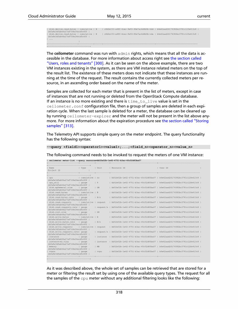
Cloud Administrator Guide May 12, 2015 current
318
| disk.device.read.bytes | cumulative | B | c8d2e153-a48f-4cec-9e93-86e7ac6d4b0b-hdd | b6e62aad26174382bc3781c12fe413c8 | cbfa8e3dfab64a27a87c8e24ecd5c60f || disk.device.read.bytes | cumulative | B | c8d2e153-a48f-4cec-9e93-86e7ac6d4b0b-vda | b6e62aad26174382bc3781c12fe413c8 | cbfa8e3dfab64a27a87c8e24ecd5c60f || ... |+------------------------+------------+------+------------------------------------------+----------------------------------+----------------------------------+
The ceilometer command was run with admin rights, which means that all the data is ac-cessible in the database. For more information about access right see the section called“Users, roles and tenants” [300]. As it can be seen on the above example, there are twoVM instances existing in the system, as there are VM instance related meters on the top ofthe result list. The existence of these meters does not indicate that these instances are run-ning at the time of the request. The result contains the currently collected meters per re-source, in an ascending order based on the name of the meter.
Samples are collected for each meter that is present in the list of meters, except in caseof instances that are not running or deleted from the OpenStack Compute database.If an instance is no more existing and there is time_to_live value is set in theceilometer.conf configuration file, then a group of samples are deleted in each expi-ration cycle. When the last sample is deleted for a meter, the database can be cleaned upby running ceilometer-expirer and the meter will not be present in the list above any-more. For more information about the expiration procedure see the section called “Storingsamples” [313].
The Telemetry API supports simple query on the meter endpoint. The query functionalityhas the following syntax:
--query <field1><operator1><value1>;...;<field_n><operator_n><value_n>
The following command needs to be invoked to request the meters of one VM instance:$ ceilometer meter-list --query resource=bb52e52b-1e42-4751-b3ac-45c52d83ba07+-------------------------+------------+-----------+--------------------------------------+----------------------------------+----------------------------------+| Name | Type | Unit | Resource ID | User ID | Project ID |+-------------------------+------------+-----------+--------------------------------------+----------------------------------+----------------------------------+| cpu | cumulative | ns | bb52e52b-1e42-4751-b3ac-45c52d83ba07 | b6e62aad26174382bc3781c12fe413c8 | cbfa8e3dfab64a27a87c8e24ecd5c60f || cpu_util | gauge | % | bb52e52b-1e42-4751-b3ac-45c52d83ba07 | b6e62aad26174382bc3781c12fe413c8 | cbfa8e3dfab64a27a87c8e24ecd5c60f || disk.ephemeral.size | gauge | GB | bb52e52b-1e42-4751-b3ac-45c52d83ba07 | b6e62aad26174382bc3781c12fe413c8 | cbfa8e3dfab64a27a87c8e24ecd5c60f || disk.read.bytes | cumulative | B | bb52e52b-1e42-4751-b3ac-45c52d83ba07 | b6e62aad26174382bc3781c12fe413c8 | cbfa8e3dfab64a27a87c8e24ecd5c60f || disk.read.bytes.rate | gauge | B/s | bb52e52b-1e42-4751-b3ac-45c52d83ba07 | b6e62aad26174382bc3781c12fe413c8 | cbfa8e3dfab64a27a87c8e24ecd5c60f || disk.read.requests | cumulative | request | bb52e52b-1e42-4751-b3ac-45c52d83ba07 | b6e62aad26174382bc3781c12fe413c8 | cbfa8e3dfab64a27a87c8e24ecd5c60f || disk.read.requests.rate | gauge | request/s | bb52e52b-1e42-4751-b3ac-45c52d83ba07 | b6e62aad26174382bc3781c12fe413c8 | cbfa8e3dfab64a27a87c8e24ecd5c60f || disk.root.size | gauge | GB | bb52e52b-1e42-4751-b3ac-45c52d83ba07 | b6e62aad26174382bc3781c12fe413c8 | cbfa8e3dfab64a27a87c8e24ecd5c60f || disk.write.bytes | cumulative | B | bb52e52b-1e42-4751-b3ac-45c52d83ba07 | b6e62aad26174382bc3781c12fe413c8 | cbfa8e3dfab64a27a87c8e24ecd5c60f || disk.write.bytes.rate | gauge | B/s | bb52e52b-1e42-4751-b3ac-45c52d83ba07 | b6e62aad26174382bc3781c12fe413c8 | cbfa8e3dfab64a27a87c8e24ecd5c60f || disk.write.requests | cumulative | request | bb52e52b-1e42-4751-b3ac-45c52d83ba07 | b6e62aad26174382bc3781c12fe413c8 | cbfa8e3dfab64a27a87c8e24ecd5c60f || disk.write.requests.rate| gauge | request/s | bb52e52b-1e42-4751-b3ac-45c52d83ba07 | b6e62aad26174382bc3781c12fe413c8 | cbfa8e3dfab64a27a87c8e24ecd5c60f || instance | gauge | instance | bb52e52b-1e42-4751-b3ac-45c52d83ba07 | b6e62aad26174382bc3781c12fe413c8 | cbfa8e3dfab64a27a87c8e24ecd5c60f || instance:m1.tiny | gauge | instance | bb52e52b-1e42-4751-b3ac-45c52d83ba07 | b6e62aad26174382bc3781c12fe413c8 | cbfa8e3dfab64a27a87c8e24ecd5c60f || memory | gauge | MB | bb52e52b-1e42-4751-b3ac-45c52d83ba07 | b6e62aad26174382bc3781c12fe413c8 | cbfa8e3dfab64a27a87c8e24ecd5c60f || vcpus | gauge | vcpu | bb52e52b-1e42-4751-b3ac-45c52d83ba07 | b6e62aad26174382bc3781c12fe413c8 | cbfa8e3dfab64a27a87c8e24ecd5c60f |+-------------------------+------------+-----------+--------------------------------------+----------------------------------+----------------------------------+
As it was described above, the whole set of samples can be retrieved that are stored for ameter or filtering the result set by using one of the available query types. The request for allthe samples of the cpu meter without any additional filtering looks like the following:
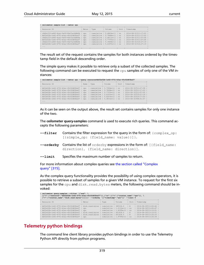
Cloud Administrator Guide May 12, 2015 current
319
$ ceilometer sample-list --meter cpu+--------------------------------------+-------+------------+------------+------+---------------------+| Resource ID | Meter | Type | Volume | Unit | Timestamp |+--------------------------------------+-------+------------+------------+------+---------------------+| c8d2e153-a48f-4cec-9e93-86e7ac6d4b0b | cpu | cumulative | 5.4863e+11 | ns | 2014-08-31T11:17:03 || bb52e52b-1e42-4751-b3ac-45c52d83ba07 | cpu | cumulative | 5.7848e+11 | ns | 2014-08-31T11:17:03 || c8d2e153-a48f-4cec-9e93-86e7ac6d4b0b | cpu | cumulative | 5.4811e+11 | ns | 2014-08-31T11:07:05 || bb52e52b-1e42-4751-b3ac-45c52d83ba07 | cpu | cumulative | 5.7797e+11 | ns | 2014-08-31T11:07:05 || c8d2e153-a48f-4cec-9e93-86e7ac6d4b0b | cpu | cumulative | 5.3589e+11 | ns | 2014-08-31T10:27:19 || bb52e52b-1e42-4751-b3ac-45c52d83ba07 | cpu | cumulative | 5.6397e+11 | ns | 2014-08-31T10:27:19 || ... |+--------------------------------------+-------+------------+------------+------+---------------------+
The result set of the request contains the samples for both instances ordered by the times-tamp field in the default descending order.
The simple query makes it possible to retrieve only a subset of the collected samples. Thefollowing command can be executed to request the cpu samples of only one of the VM in-stances:$ ceilometer sample-list --meter cpu --query resource=bb52e52b-1e42-4751-b3ac-45c52d83ba07+--------------------------------------+------+------------+------------+------+---------------------+| Resource ID | Name | Type | Volume | Unit | Timestamp |+--------------------------------------+------+------------+------------+------+---------------------+| bb52e52b-1e42-4751-b3ac-45c52d83ba07 | cpu | cumulative | 5.7906e+11 | ns | 2014-08-31T11:27:08 || bb52e52b-1e42-4751-b3ac-45c52d83ba07 | cpu | cumulative | 5.7848e+11 | ns | 2014-08-31T11:17:03 || bb52e52b-1e42-4751-b3ac-45c52d83ba07 | cpu | cumulative | 5.7797e+11 | ns | 2014-08-31T11:07:05 || bb52e52b-1e42-4751-b3ac-45c52d83ba07 | cpu | cumulative | 5.6397e+11 | ns | 2014-08-31T10:27:19 || bb52e52b-1e42-4751-b3ac-45c52d83ba07 | cpu | cumulative | 5.6207e+11 | ns | 2014-08-31T10:17:03 || bb52e52b-1e42-4751-b3ac-45c52d83ba07 | cpu | cumulative | 5.3831e+11 | ns | 2014-08-31T08:41:57 || ... |+--------------------------------------+------+------------+------------+------+---------------------+
As it can be seen on the output above, the result set contains samples for only one instanceof the two.
The ceilometer query-samples command is used to execute rich queries. This command ac-cepts the following parameters:
--filter Contains the filter expression for the query in the form of: {complex_op:[{simple_op: {field_name: value}}]}.
--orderby Contains the list of orderby expressions in the form of: [{field_name:direction}, {field_name: direction}].
--limit Specifies the maximum number of samples to return.
For more information about complex queries see the section called “Complexquery” [315].
As the complex query functionality provides the possibility of using complex operators, it ispossible to retrieve a subset of samples for a given VM instance. To request for the first sixsamples for the cpu and disk.read.bytes meters, the following command should be in-voked:$ ceilometer query-samples --filter '{"and": \ [{"=":{"resource":"bb52e52b-1e42-4751-b3ac-45c52d83ba07"}},{"or":[{"=":{"counter_name":"cpu"}}, \ {"=":{"counter_name":"disk.read.bytes"}}]}]}' --orderby '[{"timestamp":"asc"}]' --limit 6+--------------------------------------+-----------------+------------+------------+------+---------------------+| Resource ID | Meter | Type | Volume | Unit | Timestamp |+--------------------------------------+-----------------+------------+------------+------+---------------------+| bb52e52b-1e42-4751-b3ac-45c52d83ba07 | disk.read.bytes | cumulative | 385334.0 | B | 2014-08-30T13:00:46 || bb52e52b-1e42-4751-b3ac-45c52d83ba07 | cpu | cumulative | 1.2132e+11 | ns | 2014-08-30T13:00:47 || bb52e52b-1e42-4751-b3ac-45c52d83ba07 | cpu | cumulative | 1.4295e+11 | ns | 2014-08-30T13:10:51 || bb52e52b-1e42-4751-b3ac-45c52d83ba07 | disk.read.bytes | cumulative | 601438.0 | B | 2014-08-30T13:10:51 || bb52e52b-1e42-4751-b3ac-45c52d83ba07 | disk.read.bytes | cumulative | 601438.0 | B | 2014-08-30T13:20:33 || bb52e52b-1e42-4751-b3ac-45c52d83ba07 | cpu | cumulative | 1.4795e+11 | ns | 2014-08-30T13:20:34 |+--------------------------------------+-----------------+------------+------------+------+---------------------+
Telemetry python bindings
The command line client library provides python bindings in order to use the TelemetryPython API directly from python programs.
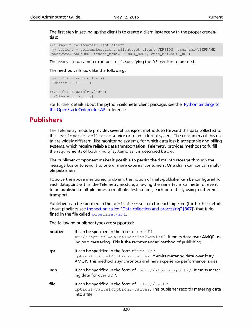
Cloud Administrator Guide May 12, 2015 current
320
The first step in setting up the client is to create a client instance with the proper creden-tials:
>>> import ceilometerclient.client>>> cclient = ceilometerclient.client.get_client(VERSION, username=USERNAME, password=PASSWORD, tenant_name=PROJECT_NAME, auth_url=AUTH_URL)
The VERSION parameter can be 1 or 2, specifying the API version to be used.
The method calls look like the following:
>>> cclient.meters.list() [<Meter ...>, ...]
>>> cclient.samples.list() [<Sample ...>, ...]
For further details about the python-ceilometerclient package, see the Python bindings tothe OpenStack Ceilometer API reference.
PublishersThe Telemetry module provides several transport methods to forward the data collected tothe ceilometer-collector service or to an external system. The consumers of this da-ta are widely different, like monitoring systems, for which data loss is acceptable and billingsystems, which require reliable data transportation. Telemetry provides methods to fulfillthe requirements of both kind of systems, as it is described below.
The publisher component makes it possible to persist the data into storage through themessage bus or to send it to one or more external consumers. One chain can contain multi-ple publishers.
To solve the above mentioned problem, the notion of multi-publisher can be configured foreach datapoint within the Telemetry module, allowing the same technical meter or eventto be published multiple times to multiple destinations, each potentially using a differenttransport.
Publishers can be specified in the publishers section for each pipeline (for further detailsabout pipelines see the section called “Data collection and processing” [307]) that is de-fined in the file called pipeline.yaml.
The following publisher types are supported:
notifier It can be specified in the form of notifi-er://?option1=value1&option2=value2. It emits data over AMQP us-ing oslo.messaging. This is the recommended method of publishing.
rpc It can be specified in the form of rpc://?option1=value1&option2=value2. It emits metering data over lossyAMQP. This method is synchronous and may experience performance issues.
udp It can be specified in the form of udp://<host>:<port>/. It emits meter-ing data for over UDP.
file It can be specified in the form of file://path?option1=value1&option2=value2. This publisher records metering datainto a file.
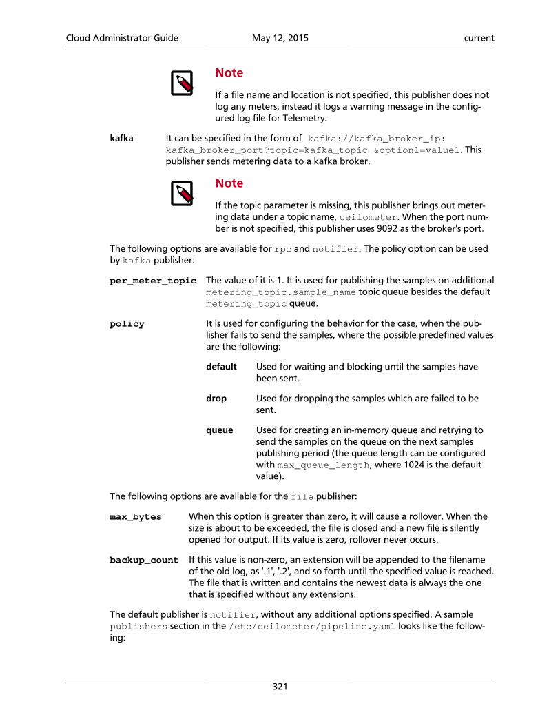
Cloud Administrator Guide May 12, 2015 current
321
Note
If a file name and location is not specified, this publisher does notlog any meters, instead it logs a warning message in the config-ured log file for Telemetry.
kafka It can be specified in the form of kafka://kafka_broker_ip:kafka_broker_port?topic=kafka_topic &option1=value1. Thispublisher sends metering data to a kafka broker.
Note
If the topic parameter is missing, this publisher brings out meter-ing data under a topic name, ceilometer. When the port num-ber is not specified, this publisher uses 9092 as the broker's port.
The following options are available for rpc and notifier. The policy option can be usedby kafka publisher:
per_meter_topic The value of it is 1. It is used for publishing the samples on additionalmetering_topic.sample_name topic queue besides the defaultmetering_topic queue.
policy It is used for configuring the behavior for the case, when the pub-lisher fails to send the samples, where the possible predefined valuesare the following:
default Used for waiting and blocking until the samples havebeen sent.
drop Used for dropping the samples which are failed to besent.
queue Used for creating an in-memory queue and retrying tosend the samples on the queue on the next samplespublishing period (the queue length can be configuredwith max_queue_length, where 1024 is the defaultvalue).
The following options are available for the file publisher:
max_bytes When this option is greater than zero, it will cause a rollover. When thesize is about to be exceeded, the file is closed and a new file is silentlyopened for output. If its value is zero, rollover never occurs.
backup_count If this value is non-zero, an extension will be appended to the filenameof the old log, as '.1', '.2', and so forth until the specified value is reached.The file that is written and contains the newest data is always the onethat is specified without any extensions.
The default publisher is notifier, without any additional options specified. A samplepublishers section in the /etc/ceilometer/pipeline.yaml looks like the follow-ing:
Cloud Administrator Guide May 12, 2015 current
322
publishers: - udp://10.0.0.2:1234 - rpc://?per_meter_topic=1 - notifier://?policy=drop&max_queue_length=512
AlarmsAlarms provide user-oriented Monitoring-as-a-Service for resources running on OpenStack.This type of monitoring ensures you can automatically scale in or out a group of instancesthrough the Orchestration module, but you can also use alarms for general-purpose aware-ness of your cloud resources' health.
These alarms follow a tri-state model:
ok The rule governing the alarm has been evaluated as False.
alarm The rule governing the alarm have been evaluated as True.
insufficient data There are not enough datapoints available in the evaluation peri-ods to meaningfully determine the alarm state.
Alarm definitionsThe definition of an alarm provides the rules that govern when a state transition should oc-cur, and the actions to be taken thereon. The nature of these rules depend on the alarmtype.
Threshold rule alarms
For conventional threshold-oriented alarms, state transitions are governed by:
• A static threshold value with a comparison operator such as greater than or less than.
• A statistic selection to aggregate the data.
• A sliding time window to indicate how far back into the recent past you want to look.
Combination rule alarms
The Telemetry module also supports the concept of a meta-alarm, which aggregates overthe current state of a set of underlying basic alarms combined via a logical operator (ANDor OR).
Alarm dimensioningA key associated concept is the notion of dimensioning which defines the set of matchingmeters that feed into an alarm evaluation. Recall that meters are per-resource-instance,so in the simplest case an alarm might be defined over a particular meter applied to all re-sources visible to a particular user. More useful however would be the option to explicitlyselect which specific resources you are interested in alarming on.
At one extreme you might have narrowly dimensioned alarms where this selection wouldhave only a single target (identified by resource ID). At the other extreme, you could havewidely dimensioned alarms where this selection identifies many resources over which the
Cloud Administrator Guide May 12, 2015 current
323
statistic is aggregated. For example all instances booted from a particular image or all in-stances with matching user metadata (the latter is how the Orchestration module identifiesautoscaling groups).
Alarm evaluationAlarms are evaluated by the alarm-evaluator service on a periodic basis, defaulting toonce every minute.
Alarm actions
Any state transition of individual alarm (to ok, alarm, or insufficient data) mayhave one or more actions associated with it. These actions effectively send a signal to a con-sumer that the state transition has occurred, and provide some additional context. Thisincludes the new and previous states, with some reason data describing the dispositionwith respect to the threshold, the number of datapoints involved and most recent of these.State transitions are detected by the alarm-evaluator, whereas the alarm-notifiereffects the actual notification action.
Webhooks
These are the de facto notification type used by Telemetry alarming and simply involve aHTTP POST request being sent to an endpoint, with a request body containing a descriptionof the state transition encoded as a JSON fragment.
Log actions
These are a lightweight alternative to webhooks, whereby the state transition is simplylogged by the alarm-notifier, and are intended primarily for testing purposes.
Workload partitioning
The alarm evaluation process uses the same mechanism for workload partitioning as thecentral and compute agents. The Tooz library provides the coordination within the groupsof service instances. For further information about this approach see the section called“Support for HA deployment of the central and compute agent services” [305].
To use this workload partitioning solution set the evaluation_service option to de-fault. For more information, see the alarm section in the OpenStack Configuration Refer-ence.
Using alarmsThe ceilometer CLI provides simple verbs for creating and manipulating alarms.
Alarm creation
An example of creating a threshold-oriented alarm, based on an upper bound on the CPUutilization for a particular instance:
$ ceilometer alarm-threshold-create --name cpu_hi \ --description 'instance running hot' \ --meter-name cpu_util --threshold 70.0 \ --comparison-operator gt --statistic avg \
Cloud Administrator Guide May 12, 2015 current
324
--period 600 --evaluation-periods 3 \ --alarm-action 'log://' \ --query resource_id=INSTANCE_ID
This creates an alarm that will fire when the average CPU utilization for an individual in-stance exceeds 70% for three consecutive 10 minute periods. The notification in this case issimply a log message, though it could alternatively be a webhook URL.
Note
Alarm names must be unique for the alarms associated with an individualproject.
The sliding time window over which the alarm is evaluated is 30 minutes in this example.This window is not clamped to wall-clock time boundaries, rather it's anchored on the cur-rent time for each evaluation cycle, and continually creeps forward as each evaluation cyclerolls around (by default, this occurs every minute).
The period length is set to 600s in this case to reflect the out-of-the-box default cadence forcollection of the associated meter. This period matching illustrates an important generalprincipal to keep in mind for alarms:
Note
The alarm period should be a whole number multiple (1 or more) of the intervalconfigured in the pipeline corresponding to the target meter.
Otherwise the alarm will tend to flit in and out of the insufficient data state due tothe mismatch between the actual frequency of datapoints in the metering store and thestatistics queries used to compare against the alarm threshold. If a shorter alarm period isneeded, then the corresponding interval should be adjusted in the pipeline.yaml file.
Other notable alarm attributes that may be set on creation, or via a subsequent update, in-clude:
state The initial alarm state (defaults to insufficient da-ta).
description A free-text description of the alarm (defaults to a synop-sis of the alarm rule).
enabled True if evaluation and actioning is to be enabled for thisalarm (defaults to True).
repeat-actions True if actions should be repeatedly notified while thealarm remains in the target state (defaults to False).
ok-action An action to invoke when the alarm state transitions took.
insufficient-data-action An action to invoke when the alarm state transitions toinsufficient data.
time-constraint Used to restrict evaluation of the alarm to certain timesof the day or days of the week (expressed as cron ex-pression with an optional timezone).
Cloud Administrator Guide May 12, 2015 current
325
An example of creating a combination alarm, based on the combined state of two underly-ing alarms:
$ ceilometer alarm-combination-create --name meta \ --alarm_ids ALARM_ID1 \ --alarm_ids ALARM_ID2 \ --operator or \ --alarm-action 'http://example.org/notify'
This creates an alarm that will fire when ether one of two underlying alarms transition in-to the alarm state. The notification in this case is a webhook call. Any number of underlyingalarms can be combined in this way, using either and or or.
Alarm retrieval
You can display all your alarms via (some attributes are omitted for brevity):
$ ceilometer alarm-list+----------+--------+-------------------+---------------------------------+| Alarm ID | Name | State | Alarm condition |+----------+--------+-------------------+---------------------------------+| ALARM_ID | cpu_hi | insufficient data | cpu_util > 70.0 during 3 x 600s |+----------+--------+-------------------+---------------------------------+
In this case, the state is reported as insufficient data which could indicate that:
• meters have not yet been gathered about this instance over the evaluation window intothe recent past (for example a brand-new instance)
• or, that the identified instance is not visible to the user/tenant owning the alarm
• or, simply that an alarm evaluation cycle hasn't kicked off since the alarm was created (bydefault, alarms are evaluated once per minute).
Note
The visibility of alarms depends on the role and project associated with the userissuing the query:
• admin users see all alarms, regardless of the owner
• non-admin users see only the alarms associated with their project (as per thenormal tenant segregation in OpenStack)
Alarm update
Once the state of the alarm has settled down, we might decide that we set that bar toolow with 70%, in which case the threshold (or most any other alarm attribute) can be up-dated thusly:
$ ceilometer alarm-update --threshold 75 ALARM_ID
The change will take effect from the next evaluation cycle, which by default occurs everyminute.
Cloud Administrator Guide May 12, 2015 current
326
Most alarm attributes can be changed in this way, but there is also a convenient short-cutfor getting and setting the alarm state:
$ ceilometer alarm-state-get ALARM_ID$ ceilometer alarm-state-set --state ok -a ALARM_ID
Over time the state of the alarm may change often, especially if the threshold is chosen tobe close to the trending value of the statistic. You can follow the history of an alarm overits lifecycle via the audit API:
$ ceilometer alarm-history ALARM_ID+------------------+-----------+---------------------------------------+| Type | Timestamp | Detail |+------------------+-----------+---------------------------------------+| creation | time0 | name: cpu_hi || | | description: instance running hot || | | type: threshold || | | rule: cpu_util > 70.0 during 3 x 600s || state transition | time1 | state: ok || rule change | time2 | rule: cpu_util > 75.0 during 3 x 600s |+------------------+-----------+---------------------------------------+
Alarm deletion
An alarm that's no longer required can be disabled so that it is no longer actively evaluated:
$ ceilometer alarm-update --enabled False -a ALARM_ID
or even deleted permanently (an irreversible step):
$ ceilometer alarm-delete ALARM_ID
Note
By default, alarm history is retained for deleted alarms.
MeasurementsThe Telemetry module collects meters within an OpenStack deployment. This section pro-vides a brief summary about meters format and origin and also contains the list of availablemeters.
Telemetry collects meters by polling the infrastructure elements and also by consuming thenotifications emitted by other OpenStack services. For more information about the pollingmechanism and notifications see the section called “Data collection” [300]. There are sev-eral meters which are collected by polling and by consuming. The origin for each meter islisted in the tables below.
Note
You may need to configure Telemetry or other OpenStack services in order tobe able to collect all the samples you need. For further information about con-figuration requirements see the Telemetry chapter in the OpenStack Installa-tion Guide. Also check the Telemetry manual installation description.
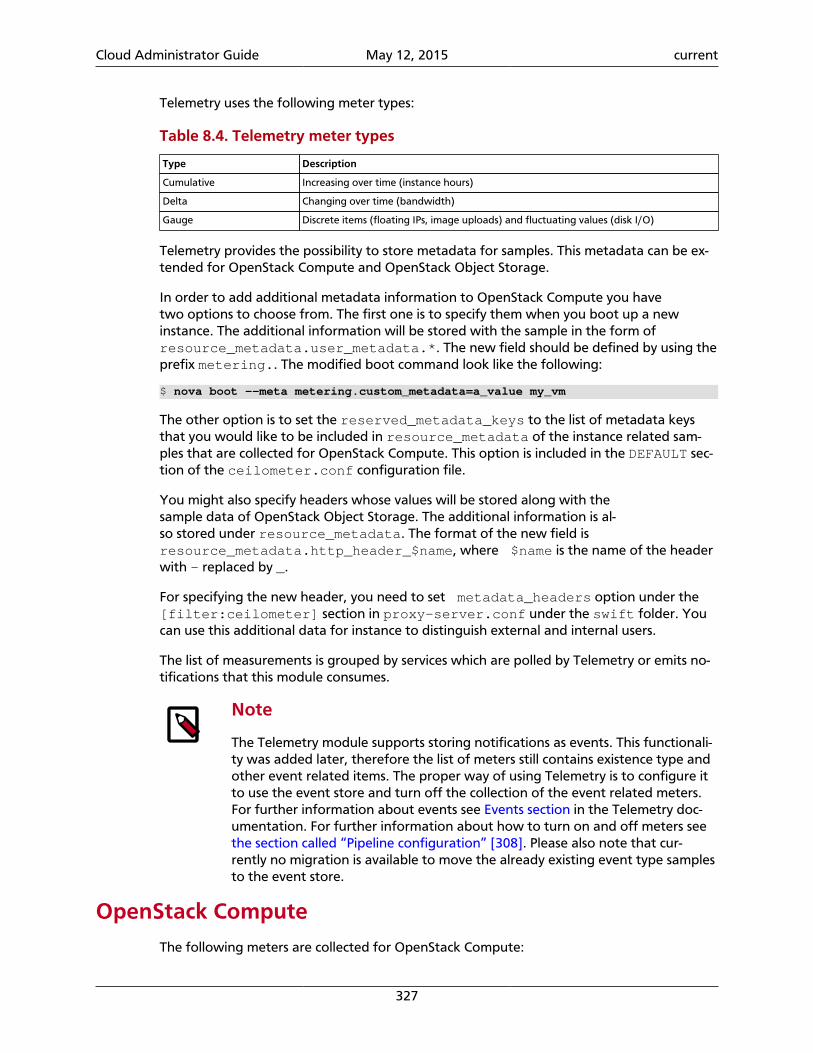
Cloud Administrator Guide May 12, 2015 current
327
Telemetry uses the following meter types:
Table 8.4. Telemetry meter types
Type Description
Cumulative Increasing over time (instance hours)
Delta Changing over time (bandwidth)
Gauge Discrete items (floating IPs, image uploads) and fluctuating values (disk I/O)
Telemetry provides the possibility to store metadata for samples. This metadata can be ex-tended for OpenStack Compute and OpenStack Object Storage.
In order to add additional metadata information to OpenStack Compute you havetwo options to choose from. The first one is to specify them when you boot up a newinstance. The additional information will be stored with the sample in the form ofresource_metadata.user_metadata.*. The new field should be defined by using theprefix metering.. The modified boot command look like the following:
$ nova boot --meta metering.custom_metadata=a_value my_vm
The other option is to set the reserved_metadata_keys to the list of metadata keysthat you would like to be included in resource_metadata of the instance related sam-ples that are collected for OpenStack Compute. This option is included in the DEFAULT sec-tion of the ceilometer.conf configuration file.
You might also specify headers whose values will be stored along with thesample data of OpenStack Object Storage. The additional information is al-so stored under resource_metadata. The format of the new field is resource_metadata.http_header_$name, where $name is the name of the headerwith - replaced by _.
For specifying the new header, you need to set metadata_headers option under the[filter:ceilometer] section in proxy-server.conf under the swift folder. Youcan use this additional data for instance to distinguish external and internal users.
The list of measurements is grouped by services which are polled by Telemetry or emits no-tifications that this module consumes.
Note
The Telemetry module supports storing notifications as events. This functionali-ty was added later, therefore the list of meters still contains existence type andother event related items. The proper way of using Telemetry is to configure itto use the event store and turn off the collection of the event related meters.For further information about events see Events section in the Telemetry doc-umentation. For further information about how to turn on and off meters seethe section called “Pipeline configuration” [308]. Please also note that cur-rently no migration is available to move the already existing event type samplesto the event store.
OpenStack ComputeThe following meters are collected for OpenStack Compute:
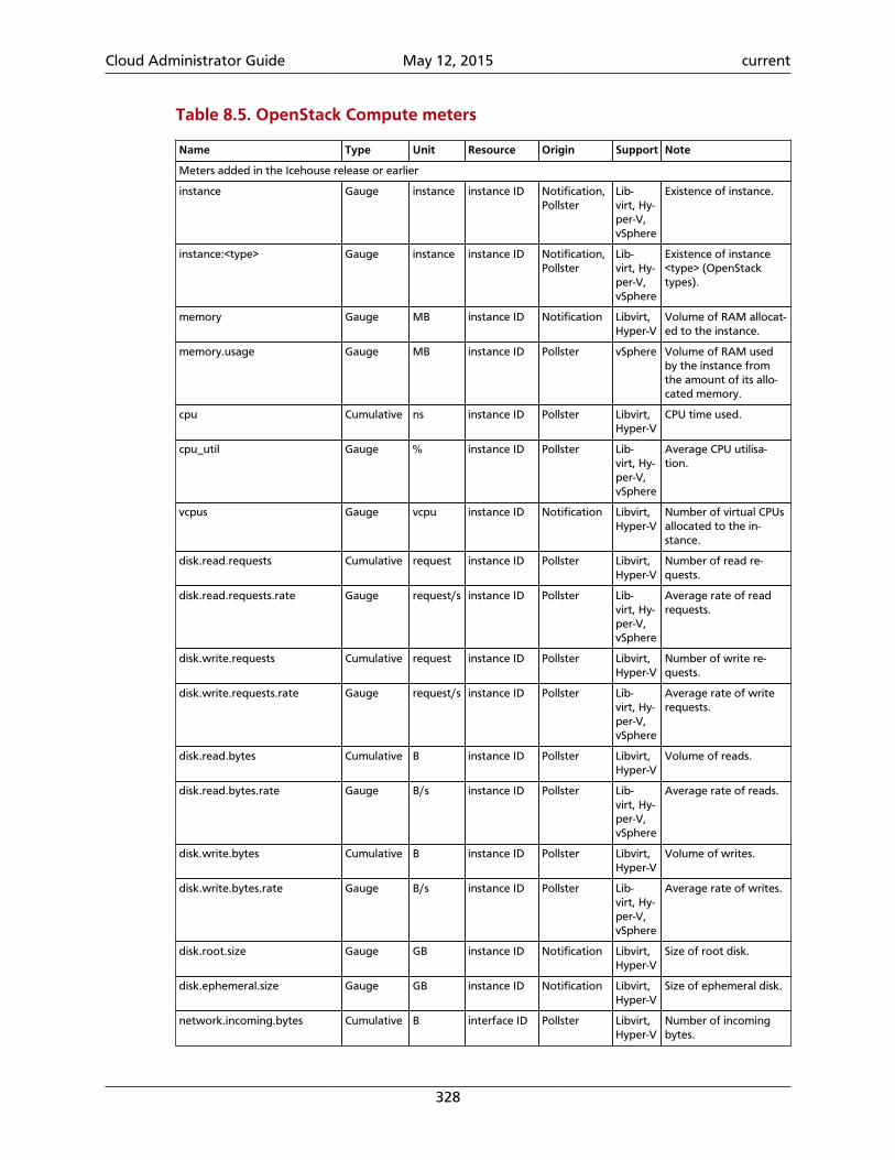
Cloud Administrator Guide May 12, 2015 current
328
Table 8.5. OpenStack Compute meters
Name Type Unit Resource Origin Support Note
Meters added in the Icehouse release or earlier
instance Gauge instance instance ID Notification,Pollster
Lib-virt, Hy-per-V,vSphere
Existence of instance.
instance:<type> Gauge instance instance ID Notification,Pollster
Lib-virt, Hy-per-V,vSphere
Existence of instance<type> (OpenStacktypes).
memory Gauge MB instance ID Notification Libvirt,Hyper-V
Volume of RAM allocat-ed to the instance.
memory.usage Gauge MB instance ID Pollster vSphere Volume of RAM usedby the instance fromthe amount of its allo-cated memory.
cpu Cumulative ns instance ID Pollster Libvirt,Hyper-V
CPU time used.
cpu_util Gauge % instance ID Pollster Lib-virt, Hy-per-V,vSphere
Average CPU utilisa-tion.
vcpus Gauge vcpu instance ID Notification Libvirt,Hyper-V
Number of virtual CPUsallocated to the in-stance.
disk.read.requests Cumulative request instance ID Pollster Libvirt,Hyper-V
Number of read re-quests.
disk.read.requests.rate Gauge request/s instance ID Pollster Lib-virt, Hy-per-V,vSphere
Average rate of readrequests.
disk.write.requests Cumulative request instance ID Pollster Libvirt,Hyper-V
Number of write re-quests.
disk.write.requests.rate Gauge request/s instance ID Pollster Lib-virt, Hy-per-V,vSphere
Average rate of writerequests.
disk.read.bytes Cumulative B instance ID Pollster Libvirt,Hyper-V
Volume of reads.
disk.read.bytes.rate Gauge B/s instance ID Pollster Lib-virt, Hy-per-V,vSphere
Average rate of reads.
disk.write.bytes Cumulative B instance ID Pollster Libvirt,Hyper-V
Volume of writes.
disk.write.bytes.rate Gauge B/s instance ID Pollster Lib-virt, Hy-per-V,vSphere
Average rate of writes.
disk.root.size Gauge GB instance ID Notification Libvirt,Hyper-V
Size of root disk.
disk.ephemeral.size Gauge GB instance ID Notification Libvirt,Hyper-V
Size of ephemeral disk.
network.incoming.bytes Cumulative B interface ID Pollster Libvirt,Hyper-V
Number of incomingbytes.
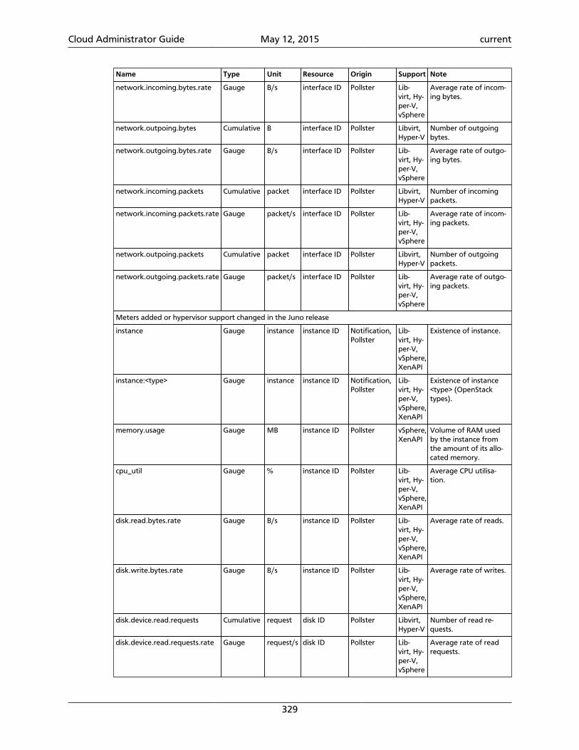
Cloud Administrator Guide May 12, 2015 current
329
Name Type Unit Resource Origin Support Note
network.incoming.bytes.rate Gauge B/s interface ID Pollster Lib-virt, Hy-per-V,vSphere
Average rate of incom-ing bytes.
network.outpoing.bytes Cumulative B interface ID Pollster Libvirt,Hyper-V
Number of outgoingbytes.
network.outgoing.bytes.rate Gauge B/s interface ID Pollster Lib-virt, Hy-per-V,vSphere
Average rate of outgo-ing bytes.
network.incoming.packets Cumulative packet interface ID Pollster Libvirt,Hyper-V
Number of incomingpackets.
network.incoming.packets.rate Gauge packet/s interface ID Pollster Lib-virt, Hy-per-V,vSphere
Average rate of incom-ing packets.
network.outpoing.packets Cumulative packet interface ID Pollster Libvirt,Hyper-V
Number of outgoingpackets.
network.outgoing.packets.rate Gauge packet/s interface ID Pollster Lib-virt, Hy-per-V,vSphere
Average rate of outgo-ing packets.
Meters added or hypervisor support changed in the Juno release
instance Gauge instance instance ID Notification,Pollster
Lib-virt, Hy-per-V,vSphere,XenAPI
Existence of instance.
instance:<type> Gauge instance instance ID Notification,Pollster
Lib-virt, Hy-per-V,vSphere,XenAPI
Existence of instance<type> (OpenStacktypes).
memory.usage Gauge MB instance ID Pollster vSphere,XenAPI
Volume of RAM usedby the instance fromthe amount of its allo-cated memory.
cpu_util Gauge % instance ID Pollster Lib-virt, Hy-per-V,vSphere,XenAPI
Average CPU utilisa-tion.
disk.read.bytes.rate Gauge B/s instance ID Pollster Lib-virt, Hy-per-V,vSphere,XenAPI
Average rate of reads.
disk.write.bytes.rate Gauge B/s instance ID Pollster Lib-virt, Hy-per-V,vSphere,XenAPI
Average rate of writes.
disk.device.read.requests Cumulative request disk ID Pollster Libvirt,Hyper-V
Number of read re-quests.
disk.device.read.requests.rate Gauge request/s disk ID Pollster Lib-virt, Hy-per-V,vSphere
Average rate of readrequests.
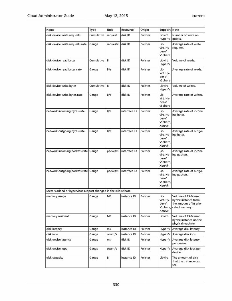
Cloud Administrator Guide May 12, 2015 current
330
Name Type Unit Resource Origin Support Note
disk.device.write.requests Cumulative request disk ID Pollster Libvirt,Hyper-V
Number of write re-quests.
disk.device.write.requests.rate Gauge request/s disk ID Pollster Lib-virt, Hy-per-V,vSphere
Average rate of writerequests.
disk.device.read.bytes Cumulative B disk ID Pollster Libvirt,Hyper-V
Volume of reads.
disk.device.read.bytes.rate Gauge B/s disk ID Pollster Lib-virt, Hy-per-V,vSphere
Average rate of reads.
disk.device.write.bytes Cumulative B disk ID Pollster Libvirt,Hyper-V
Volume of writes.
disk.device.write.bytes.rate Gauge B/s disk ID Pollster Lib-virt, Hy-per-V,vSphere
Average rate of writes.
network.incoming.bytes.rate Gauge B/s interface ID Pollster Lib-virt, Hy-per-V,vSphere,XenAPI
Average rate of incom-ing bytes.
network.outgoing.bytes.rate Gauge B/s interface ID Pollster Lib-virt, Hy-per-V,vSphere,XenAPI
Average rate of outgo-ing bytes.
network.incoming.packets.rate Gauge packet/s interface ID Pollster Lib-virt, Hy-per-V,vSphere,XenAPI
Average rate of incom-ing packets.
network.outgoing.packets.rate Gauge packet/s interface ID Pollster Lib-virt, Hy-per-V,vSphere,XenAPI
Average rate of outgo-ing packets.
Meters added or hypervisor support changed in the Kilo release
memory.usage Gauge MB instance ID Pollster Lib-virt, Hy-per-V,vSphere,XenAPI
Volume of RAM usedby the instance fromthe amount of its allo-cated memory.
memory.resident Gauge MB instance ID Pollster Libvirt Volume of RAM usedby the instance on thephysical machine.
disk.latency Gauge ms instance ID Pollster Hyper-V Average disk latency.
disk.iops Gauge count/s instance ID Pollster Hyper-V Average disk iops.
disk.device.latency Gauge ms disk ID Pollster Hyper-V Average disk latencyper device.
disk.device.iops Gauge count/s disk ID Pollster Hyper-V Average disk iops perdevice.
disk.capacity Gauge B instance ID Pollster Libvirt The amount of diskthat the instance cansee.
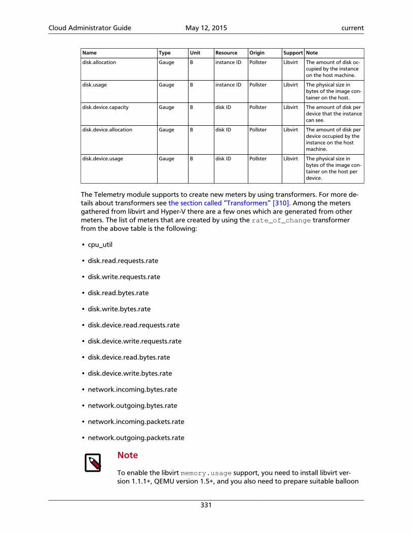
Cloud Administrator Guide May 12, 2015 current
331
Name Type Unit Resource Origin Support Note
disk.allocation Gauge B instance ID Pollster Libvirt The amount of disk oc-cupied by the instanceon the host machine.
disk.usage Gauge B instance ID Pollster Libvirt The physical size inbytes of the image con-tainer on the host.
disk.device.capacity Gauge B disk ID Pollster Libvirt The amount of disk perdevice that the instancecan see.
disk.device.allocation Gauge B disk ID Pollster Libvirt The amount of disk perdevice occupied by theinstance on the hostmachine.
disk.device.usage Gauge B disk ID Pollster Libvirt The physical size inbytes of the image con-tainer on the host perdevice.
The Telemetry module supports to create new meters by using transformers. For more de-tails about transformers see the section called “Transformers” [310]. Among the metersgathered from libvirt and Hyper-V there are a few ones which are generated from othermeters. The list of meters that are created by using the rate_of_change transformerfrom the above table is the following:
• cpu_util
• disk.read.requests.rate
• disk.write.requests.rate
• disk.read.bytes.rate
• disk.write.bytes.rate
• disk.device.read.requests.rate
• disk.device.write.requests.rate
• disk.device.read.bytes.rate
• disk.device.write.bytes.rate
• network.incoming.bytes.rate
• network.outgoing.bytes.rate
• network.incoming.packets.rate
• network.outgoing.packets.rate
Note
To enable the libvirt memory.usage support, you need to install libvirt ver-sion 1.1.1+, QEMU version 1.5+, and you also need to prepare suitable balloon
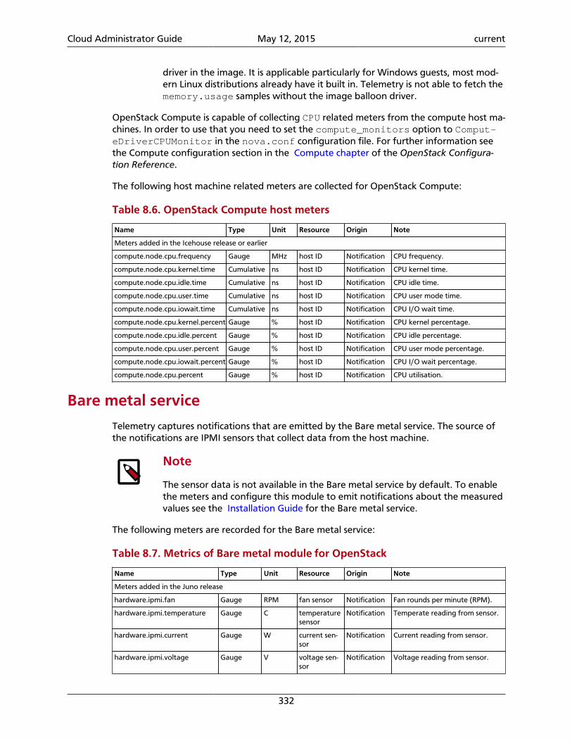
Cloud Administrator Guide May 12, 2015 current
332
driver in the image. It is applicable particularly for Windows guests, most mod-ern Linux distributions already have it built in. Telemetry is not able to fetch thememory.usage samples without the image balloon driver.
OpenStack Compute is capable of collecting CPU related meters from the compute host ma-chines. In order to use that you need to set the compute_monitors option to Comput-eDriverCPUMonitor in the nova.conf configuration file. For further information seethe Compute configuration section in the Compute chapter of the OpenStack Configura-tion Reference.
The following host machine related meters are collected for OpenStack Compute:
Table 8.6. OpenStack Compute host meters
Name Type Unit Resource Origin Note
Meters added in the Icehouse release or earlier
compute.node.cpu.frequency Gauge MHz host ID Notification CPU frequency.
compute.node.cpu.kernel.time Cumulative ns host ID Notification CPU kernel time.
compute.node.cpu.idle.time Cumulative ns host ID Notification CPU idle time.
compute.node.cpu.user.time Cumulative ns host ID Notification CPU user mode time.
compute.node.cpu.iowait.time Cumulative ns host ID Notification CPU I/O wait time.
compute.node.cpu.kernel.percent Gauge % host ID Notification CPU kernel percentage.
compute.node.cpu.idle.percent Gauge % host ID Notification CPU idle percentage.
compute.node.cpu.user.percent Gauge % host ID Notification CPU user mode percentage.
compute.node.cpu.iowait.percent Gauge % host ID Notification CPU I/O wait percentage.
compute.node.cpu.percent Gauge % host ID Notification CPU utilisation.
Bare metal service
Telemetry captures notifications that are emitted by the Bare metal service. The source ofthe notifications are IPMI sensors that collect data from the host machine.
Note
The sensor data is not available in the Bare metal service by default. To enablethe meters and configure this module to emit notifications about the measuredvalues see the Installation Guide for the Bare metal service.
The following meters are recorded for the Bare metal service:
Table 8.7. Metrics of Bare metal module for OpenStack
Name Type Unit Resource Origin Note
Meters added in the Juno release
hardware.ipmi.fan Gauge RPM fan sensor Notification Fan rounds per minute (RPM).
hardware.ipmi.temperature Gauge C temperaturesensor
Notification Temperate reading from sensor.
hardware.ipmi.current Gauge W current sen-sor
Notification Current reading from sensor.
hardware.ipmi.voltage Gauge V voltage sen-sor
Notification Voltage reading from sensor.
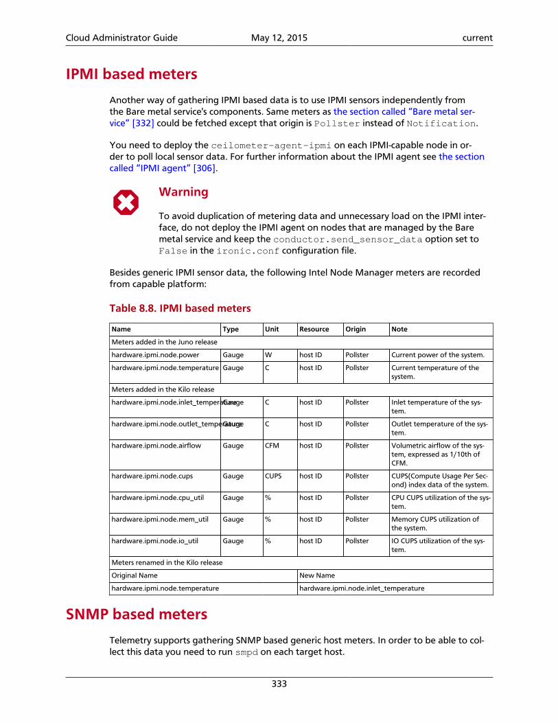
Cloud Administrator Guide May 12, 2015 current
333
IPMI based meters
Another way of gathering IPMI based data is to use IPMI sensors independently fromthe Bare metal service's components. Same meters as the section called “Bare metal ser-vice” [332] could be fetched except that origin is Pollster instead of Notification.
You need to deploy the ceilometer-agent-ipmi on each IPMI-capable node in or-der to poll local sensor data. For further information about the IPMI agent see the sectioncalled “IPMI agent” [306].
Warning
To avoid duplication of metering data and unnecessary load on the IPMI inter-face, do not deploy the IPMI agent on nodes that are managed by the Baremetal service and keep the conductor.send_sensor_data option set toFalse in the ironic.conf configuration file.
Besides generic IPMI sensor data, the following Intel Node Manager meters are recordedfrom capable platform:
Table 8.8. IPMI based meters
Name Type Unit Resource Origin Note
Meters added in the Juno release
hardware.ipmi.node.power Gauge W host ID Pollster Current power of the system.
hardware.ipmi.node.temperature Gauge C host ID Pollster Current temperature of thesystem.
Meters added in the Kilo release
hardware.ipmi.node.inlet_temperatureGauge C host ID Pollster Inlet temperature of the sys-tem.
hardware.ipmi.node.outlet_temperatureGauge C host ID Pollster Outlet temperature of the sys-tem.
hardware.ipmi.node.airflow Gauge CFM host ID Pollster Volumetric airflow of the sys-tem, expressed as 1/10th ofCFM.
hardware.ipmi.node.cups Gauge CUPS host ID Pollster CUPS(Compute Usage Per Sec-ond) index data of the system.
hardware.ipmi.node.cpu_util Gauge % host ID Pollster CPU CUPS utilization of the sys-tem.
hardware.ipmi.node.mem_util Gauge % host ID Pollster Memory CUPS utilization ofthe system.
hardware.ipmi.node.io_util Gauge % host ID Pollster IO CUPS utilization of the sys-tem.
Meters renamed in the Kilo release
Original Name New Name
hardware.ipmi.node.temperature hardware.ipmi.node.inlet_temperature
SNMP based meters
Telemetry supports gathering SNMP based generic host meters. In order to be able to col-lect this data you need to run smpd on each target host.
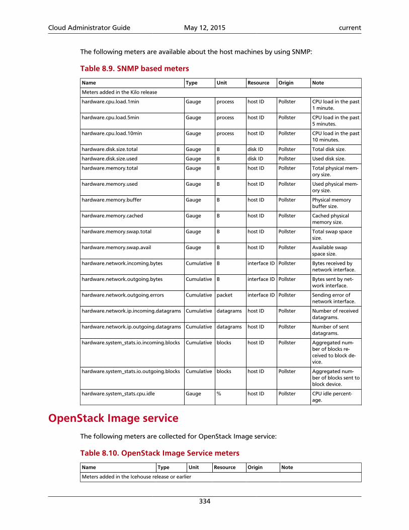
Cloud Administrator Guide May 12, 2015 current
334
The following meters are available about the host machines by using SNMP:
Table 8.9. SNMP based meters
Name Type Unit Resource Origin Note
Meters added in the Kilo release
hardware.cpu.load.1min Gauge process host ID Pollster CPU load in the past1 minute.
hardware.cpu.load.5min Gauge process host ID Pollster CPU load in the past5 minutes.
hardware.cpu.load.10min Gauge process host ID Pollster CPU load in the past10 minutes.
hardware.disk.size.total Gauge B disk ID Pollster Total disk size.
hardware.disk.size.used Gauge B disk ID Pollster Used disk size.
hardware.memory.total Gauge B host ID Pollster Total physical mem-ory size.
hardware.memory.used Gauge B host ID Pollster Used physical mem-ory size.
hardware.memory.buffer Gauge B host ID Pollster Physical memorybuffer size.
hardware.memory.cached Gauge B host ID Pollster Cached physicalmemory size.
hardware.memory.swap.total Gauge B host ID Pollster Total swap spacesize.
hardware.memory.swap.avail Gauge B host ID Pollster Available swapspace size.
hardware.network.incoming.bytes Cumulative B interface ID Pollster Bytes received bynetwork interface.
hardware.network.outgoing.bytes Cumulative B interface ID Pollster Bytes sent by net-work interface.
hardware.network.outgoing.errors Cumulative packet interface ID Pollster Sending error ofnetwork interface.
hardware.network.ip.incoming.datagrams Cumulative datagrams host ID Pollster Number of receiveddatagrams.
hardware.network.ip.outgoing.datagrams Cumulative datagrams host ID Pollster Number of sentdatagrams.
hardware.system_stats.io.incoming.blocks Cumulative blocks host ID Pollster Aggregated num-ber of blocks re-ceived to block de-vice.
hardware.system_stats.io.outgoing.blocks Cumulative blocks host ID Pollster Aggregated num-ber of blocks sent toblock device.
hardware.system_stats.cpu.idle Gauge % host ID Pollster CPU idle percent-age.
OpenStack Image service
The following meters are collected for OpenStack Image service:
Table 8.10. OpenStack Image Service meters
Name Type Unit Resource Origin Note
Meters added in the Icehouse release or earlier
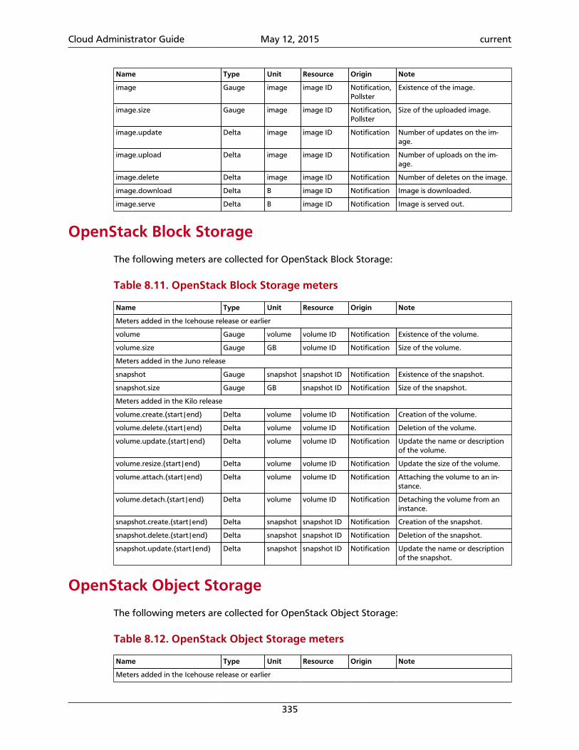
Cloud Administrator Guide May 12, 2015 current
335
Name Type Unit Resource Origin Note
image Gauge image image ID Notification,Pollster
Existence of the image.
image.size Gauge image image ID Notification,Pollster
Size of the uploaded image.
image.update Delta image image ID Notification Number of updates on the im-age.
image.upload Delta image image ID Notification Number of uploads on the im-age.
image.delete Delta image image ID Notification Number of deletes on the image.
image.download Delta B image ID Notification Image is downloaded.
image.serve Delta B image ID Notification Image is served out.
OpenStack Block Storage
The following meters are collected for OpenStack Block Storage:
Table 8.11. OpenStack Block Storage meters
Name Type Unit Resource Origin Note
Meters added in the Icehouse release or earlier
volume Gauge volume volume ID Notification Existence of the volume.
volume.size Gauge GB volume ID Notification Size of the volume.
Meters added in the Juno release
snapshot Gauge snapshot snapshot ID Notification Existence of the snapshot.
snapshot.size Gauge GB snapshot ID Notification Size of the snapshot.
Meters added in the Kilo release
volume.create.(start|end) Delta volume volume ID Notification Creation of the volume.
volume.delete.(start|end) Delta volume volume ID Notification Deletion of the volume.
volume.update.(start|end) Delta volume volume ID Notification Update the name or descriptionof the volume.
volume.resize.(start|end) Delta volume volume ID Notification Update the size of the volume.
volume.attach.(start|end) Delta volume volume ID Notification Attaching the volume to an in-stance.
volume.detach.(start|end) Delta volume volume ID Notification Detaching the volume from aninstance.
snapshot.create.(start|end) Delta snapshot snapshot ID Notification Creation of the snapshot.
snapshot.delete.(start|end) Delta snapshot snapshot ID Notification Deletion of the snapshot.
snapshot.update.(start|end) Delta snapshot snapshot ID Notification Update the name or descriptionof the snapshot.
OpenStack Object Storage
The following meters are collected for OpenStack Object Storage:
Table 8.12. OpenStack Object Storage meters
Name Type Unit Resource Origin Note
Meters added in the Icehouse release or earlier
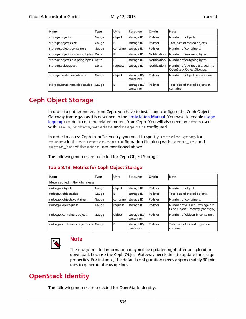
Cloud Administrator Guide May 12, 2015 current
336
Name Type Unit Resource Origin Note
storage.objects Gauge object storage ID Pollster Number of objects.
storage.objects.size Gauge B storage ID Pollster Total size of stored objects.
storage.objects.containers Gauge container storage ID Pollster Number of containers.
storage.objects.incoming.bytes Delta B storage ID Notification Number of incoming bytes.
storage.objects.outgoing.bytes Delta B storage ID Notification Number of outgoing bytes.
storage.api.request Delta request storage ID Notification Number of API requests againstOpenStack Object Storage.
storage.containers.objects Gauge object storage ID/container
Pollster Number of objects in container.
storage.containers.objects.size Gauge B storage ID/container
Pollster Total size of stored objects incontainer.
Ceph Object Storage
In order to gather meters from Ceph, you have to install and configure the Ceph ObjectGateway (radosgw) as it is described in the Installation Manual. You have to enable usagelogging in order to get the related meters from Ceph. You will also need an admin userwith users, buckets, metadata and usage caps configured.
In order to access Ceph from Telemetry, you need to specify a service group forradosgw in the ceilometer.conf configuration file along with access_key andsecret_key of the admin user mentioned above.
The following meters are collected for Ceph Object Storage:
Table 8.13. Metrics for Ceph Object Storage
Name Type Unit Resource Origin Note
Meters added in the Kilo release
radosgw.objects Gauge object storage ID Pollster Number of objects.
radosgw.objects.size Gauge B storage ID Pollster Total size of stored objects.
radosgw.objects.containers Gauge container storage ID Pollster Number of containers.
radosgw.api.request Gauge request storage ID Pollster Number of API requests againstCeph Object Gateway (radosgw).
radosgw.containers.objects Gauge object storage ID/container
Pollster Number of objects in container.
radosgw.containers.objects.size Gauge B storage ID/container
Pollster Total size of stored objects incontainer.
Note
The usage related information may not be updated right after an upload ordownload, because the Ceph Object Gateway needs time to update the usageproperties. For instance, the default configuration needs approximately 30 min-utes to generate the usage logs.
OpenStack Identity
The following meters are collected for OpenStack Identity:
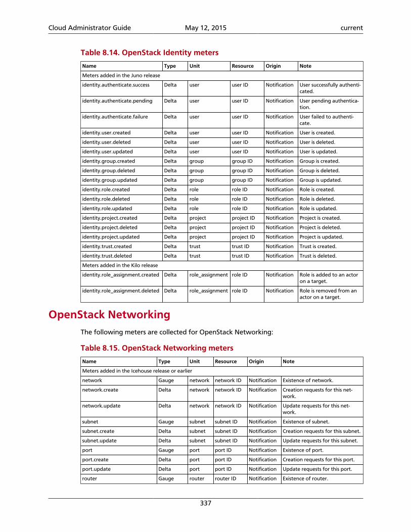
Cloud Administrator Guide May 12, 2015 current
337
Table 8.14. OpenStack Identity meters
Name Type Unit Resource Origin Note
Meters added in the Juno release
identity.authenticate.success Delta user user ID Notification User successfully authenti-cated.
identity.authenticate.pending Delta user user ID Notification User pending authentica-tion.
identity.authenticate.failure Delta user user ID Notification User failed to authenti-cate.
identity.user.created Delta user user ID Notification User is created.
identity.user.deleted Delta user user ID Notification User is deleted.
identity.user.updated Delta user user ID Notification User is updated.
identity.group.created Delta group group ID Notification Group is created.
identity.group.deleted Delta group group ID Notification Group is deleted.
identity.group.updated Delta group group ID Notification Group is updated.
identity.role.created Delta role role ID Notification Role is created.
identity.role.deleted Delta role role ID Notification Role is deleted.
identity.role.updated Delta role role ID Notification Role is updated.
identity.project.created Delta project project ID Notification Project is created.
identity.project.deleted Delta project project ID Notification Project is deleted.
identity.project.updated Delta project project ID Notification Project is updated.
identity.trust.created Delta trust trust ID Notification Trust is created.
identity.trust.deleted Delta trust trust ID Notification Trust is deleted.
Meters added in the Kilo release
identity.role_assignment.created Delta role_assignment role ID Notification Role is added to an actoron a target.
identity.role_assignment.deleted Delta role_assignment role ID Notification Role is removed from anactor on a target.
OpenStack NetworkingThe following meters are collected for OpenStack Networking:
Table 8.15. OpenStack Networking meters
Name Type Unit Resource Origin Note
Meters added in the Icehouse release or earlier
network Gauge network network ID Notification Existence of network.
network.create Delta network network ID Notification Creation requests for this net-work.
network.update Delta network network ID Notification Update requests for this net-work.
subnet Gauge subnet subnet ID Notification Existence of subnet.
subnet.create Delta subnet subnet ID Notification Creation requests for this subnet.
subnet.update Delta subnet subnet ID Notification Update requests for this subnet.
port Gauge port port ID Notification Existence of port.
port.create Delta port port ID Notification Creation requests for this port.
port.update Delta port port ID Notification Update requests for this port.
router Gauge router router ID Notification Existence of router.
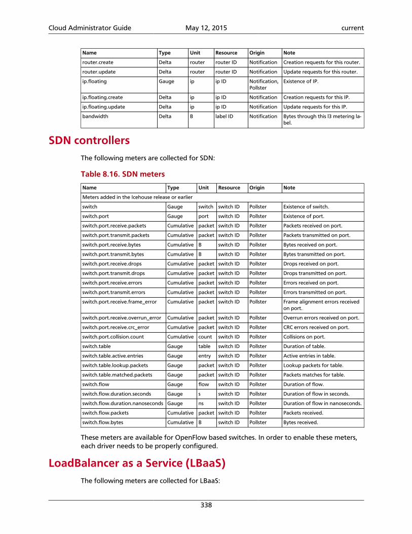
Cloud Administrator Guide May 12, 2015 current
338
Name Type Unit Resource Origin Note
router.create Delta router router ID Notification Creation requests for this router.
router.update Delta router router ID Notification Update requests for this router.
ip.floating Gauge ip ip ID Notification,Pollster
Existence of IP.
ip.floating.create Delta ip ip ID Notification Creation requests for this IP.
ip.floating.update Delta ip ip ID Notification Update requests for this IP.
bandwidth Delta B label ID Notification Bytes through this l3 metering la-bel.
SDN controllersThe following meters are collected for SDN:
Table 8.16. SDN meters
Name Type Unit Resource Origin Note
Meters added in the Icehouse release or earlier
switch Gauge switch switch ID Pollster Existence of switch.
switch.port Gauge port switch ID Pollster Existence of port.
switch.port.receive.packets Cumulative packet switch ID Pollster Packets received on port.
switch.port.transmit.packets Cumulative packet switch ID Pollster Packets transmitted on port.
switch.port.receive.bytes Cumulative B switch ID Pollster Bytes received on port.
switch.port.transmit.bytes Cumulative B switch ID Pollster Bytes transmitted on port.
switch.port.receive.drops Cumulative packet switch ID Pollster Drops received on port.
switch.port.transmit.drops Cumulative packet switch ID Pollster Drops transmitted on port.
switch.port.receive.errors Cumulative packet switch ID Pollster Errors received on port.
switch.port.transmit.errors Cumulative packet switch ID Pollster Errors transmitted on port.
switch.port.receive.frame_error Cumulative packet switch ID Pollster Frame alignment errors receivedon port.
switch.port.receive.overrun_error Cumulative packet switch ID Pollster Overrun errors received on port.
switch.port.receive.crc_error Cumulative packet switch ID Pollster CRC errors received on port.
switch.port.collision.count Cumulative count switch ID Pollster Collisions on port.
switch.table Gauge table switch ID Pollster Duration of table.
switch.table.active.entries Gauge entry switch ID Pollster Active entries in table.
switch.table.lookup.packets Gauge packet switch ID Pollster Lookup packets for table.
switch.table.matched.packets Gauge packet switch ID Pollster Packets matches for table.
switch.flow Gauge flow switch ID Pollster Duration of flow.
switch.flow.duration.seconds Gauge s switch ID Pollster Duration of flow in seconds.
switch.flow.duration.nanoseconds Gauge ns switch ID Pollster Duration of flow in nanoseconds.
switch.flow.packets Cumulative packet switch ID Pollster Packets received.
switch.flow.bytes Cumulative B switch ID Pollster Bytes received.
These meters are available for OpenFlow based switches. In order to enable these meters,each driver needs to be properly configured.
LoadBalancer as a Service (LBaaS)The following meters are collected for LBaaS:
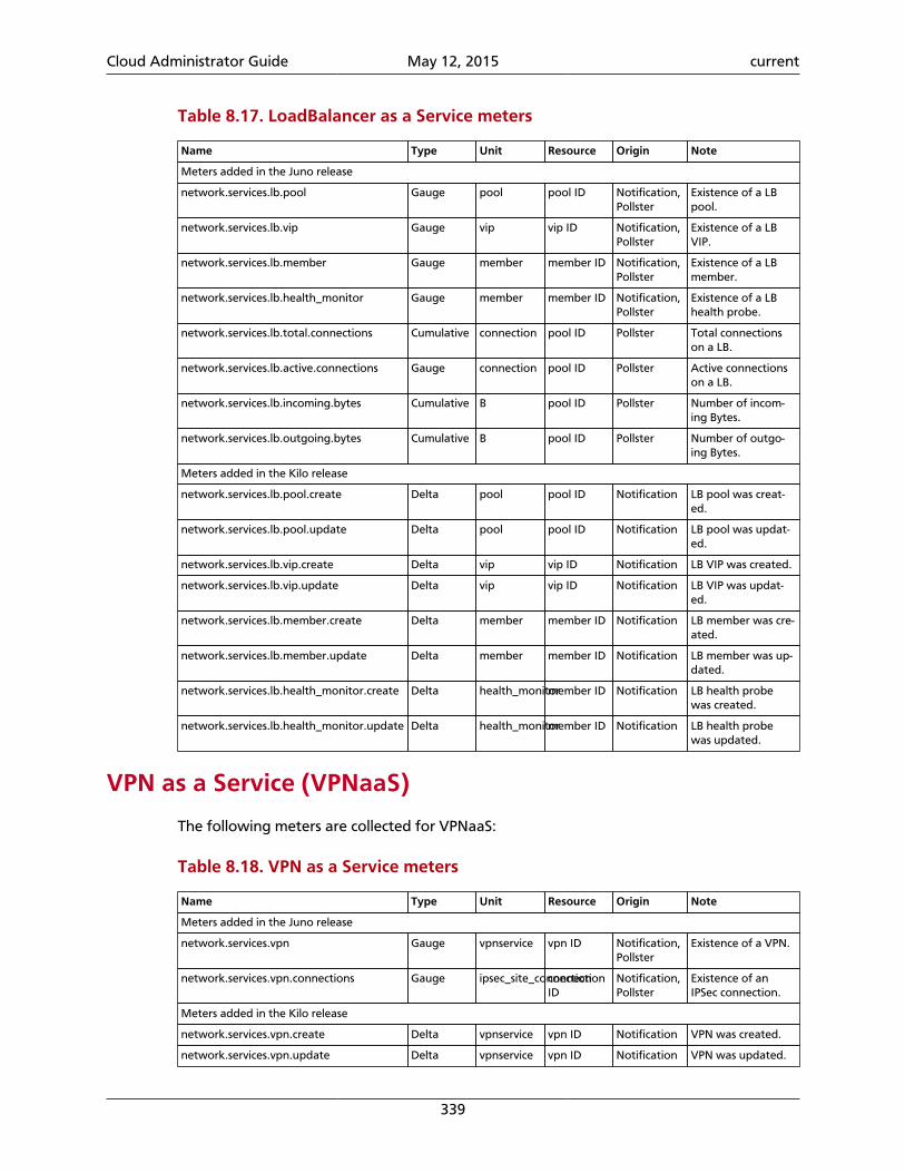
Cloud Administrator Guide May 12, 2015 current
339
Table 8.17. LoadBalancer as a Service meters
Name Type Unit Resource Origin Note
Meters added in the Juno release
network.services.lb.pool Gauge pool pool ID Notification,Pollster
Existence of a LBpool.
network.services.lb.vip Gauge vip vip ID Notification,Pollster
Existence of a LBVIP.
network.services.lb.member Gauge member member ID Notification,Pollster
Existence of a LBmember.
network.services.lb.health_monitor Gauge member member ID Notification,Pollster
Existence of a LBhealth probe.
network.services.lb.total.connections Cumulative connection pool ID Pollster Total connectionson a LB.
network.services.lb.active.connections Gauge connection pool ID Pollster Active connectionson a LB.
network.services.lb.incoming.bytes Cumulative B pool ID Pollster Number of incom-ing Bytes.
network.services.lb.outgoing.bytes Cumulative B pool ID Pollster Number of outgo-ing Bytes.
Meters added in the Kilo release
network.services.lb.pool.create Delta pool pool ID Notification LB pool was creat-ed.
network.services.lb.pool.update Delta pool pool ID Notification LB pool was updat-ed.
network.services.lb.vip.create Delta vip vip ID Notification LB VIP was created.
network.services.lb.vip.update Delta vip vip ID Notification LB VIP was updat-ed.
network.services.lb.member.create Delta member member ID Notification LB member was cre-ated.
network.services.lb.member.update Delta member member ID Notification LB member was up-dated.
network.services.lb.health_monitor.create Delta health_monitormember ID Notification LB health probewas created.
network.services.lb.health_monitor.update Delta health_monitormember ID Notification LB health probewas updated.
VPN as a Service (VPNaaS)
The following meters are collected for VPNaaS:
Table 8.18. VPN as a Service meters
Name Type Unit Resource Origin Note
Meters added in the Juno release
network.services.vpn Gauge vpnservice vpn ID Notification,Pollster
Existence of a VPN.
network.services.vpn.connections Gauge ipsec_site_connectionconnectionID
Notification,Pollster
Existence of anIPSec connection.
Meters added in the Kilo release
network.services.vpn.create Delta vpnservice vpn ID Notification VPN was created.
network.services.vpn.update Delta vpnservice vpn ID Notification VPN was updated.
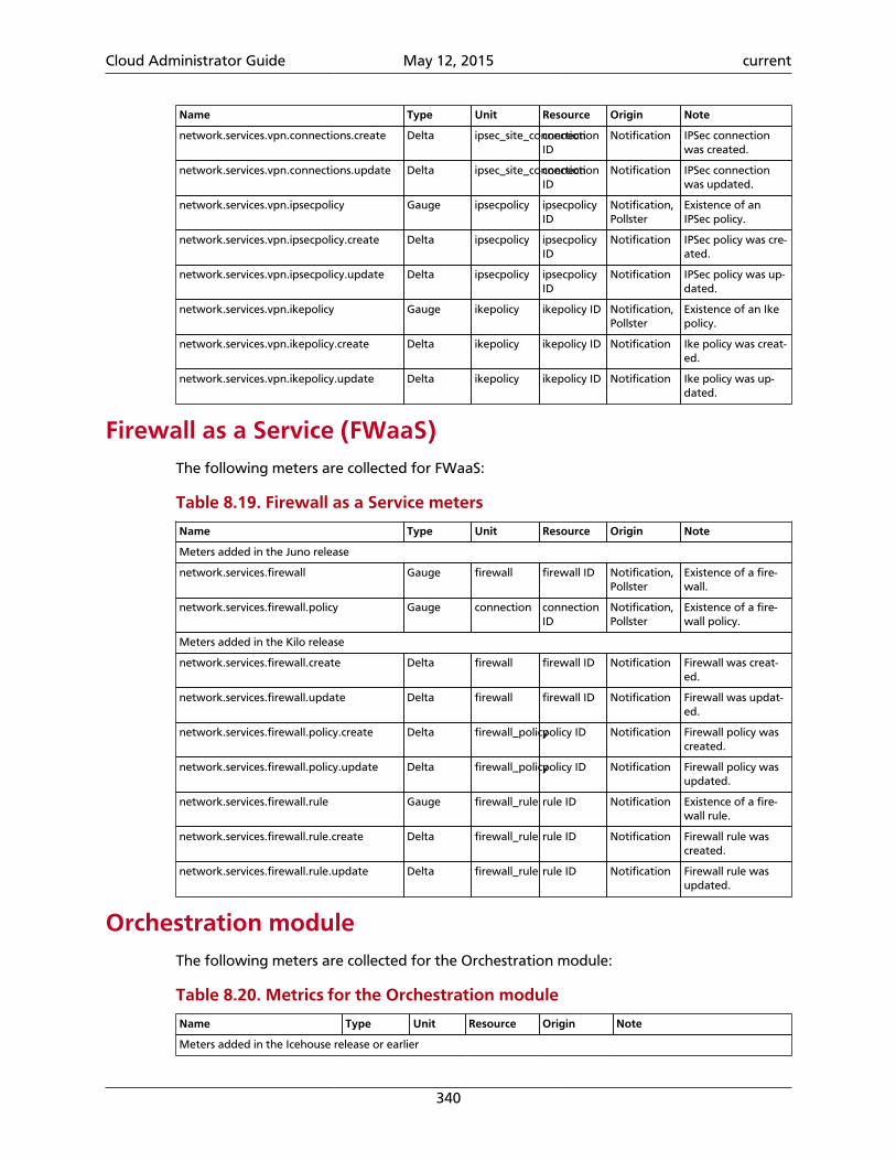
Cloud Administrator Guide May 12, 2015 current
340
Name Type Unit Resource Origin Note
network.services.vpn.connections.create Delta ipsec_site_connectionconnectionID
Notification IPSec connectionwas created.
network.services.vpn.connections.update Delta ipsec_site_connectionconnectionID
Notification IPSec connectionwas updated.
network.services.vpn.ipsecpolicy Gauge ipsecpolicy ipsecpolicyID
Notification,Pollster
Existence of anIPSec policy.
network.services.vpn.ipsecpolicy.create Delta ipsecpolicy ipsecpolicyID
Notification IPSec policy was cre-ated.
network.services.vpn.ipsecpolicy.update Delta ipsecpolicy ipsecpolicyID
Notification IPSec policy was up-dated.
network.services.vpn.ikepolicy Gauge ikepolicy ikepolicy ID Notification,Pollster
Existence of an Ikepolicy.
network.services.vpn.ikepolicy.create Delta ikepolicy ikepolicy ID Notification Ike policy was creat-ed.
network.services.vpn.ikepolicy.update Delta ikepolicy ikepolicy ID Notification Ike policy was up-dated.
Firewall as a Service (FWaaS)The following meters are collected for FWaaS:
Table 8.19. Firewall as a Service meters
Name Type Unit Resource Origin Note
Meters added in the Juno release
network.services.firewall Gauge firewall firewall ID Notification,Pollster
Existence of a fire-wall.
network.services.firewall.policy Gauge connection connectionID
Notification,Pollster
Existence of a fire-wall policy.
Meters added in the Kilo release
network.services.firewall.create Delta firewall firewall ID Notification Firewall was creat-ed.
network.services.firewall.update Delta firewall firewall ID Notification Firewall was updat-ed.
network.services.firewall.policy.create Delta firewall_policypolicy ID Notification Firewall policy wascreated.
network.services.firewall.policy.update Delta firewall_policypolicy ID Notification Firewall policy wasupdated.
network.services.firewall.rule Gauge firewall_rule rule ID Notification Existence of a fire-wall rule.
network.services.firewall.rule.create Delta firewall_rule rule ID Notification Firewall rule wascreated.
network.services.firewall.rule.update Delta firewall_rule rule ID Notification Firewall rule wasupdated.
Orchestration moduleThe following meters are collected for the Orchestration module:
Table 8.20. Metrics for the Orchestration module
Name Type Unit Resource Origin Note
Meters added in the Icehouse release or earlier
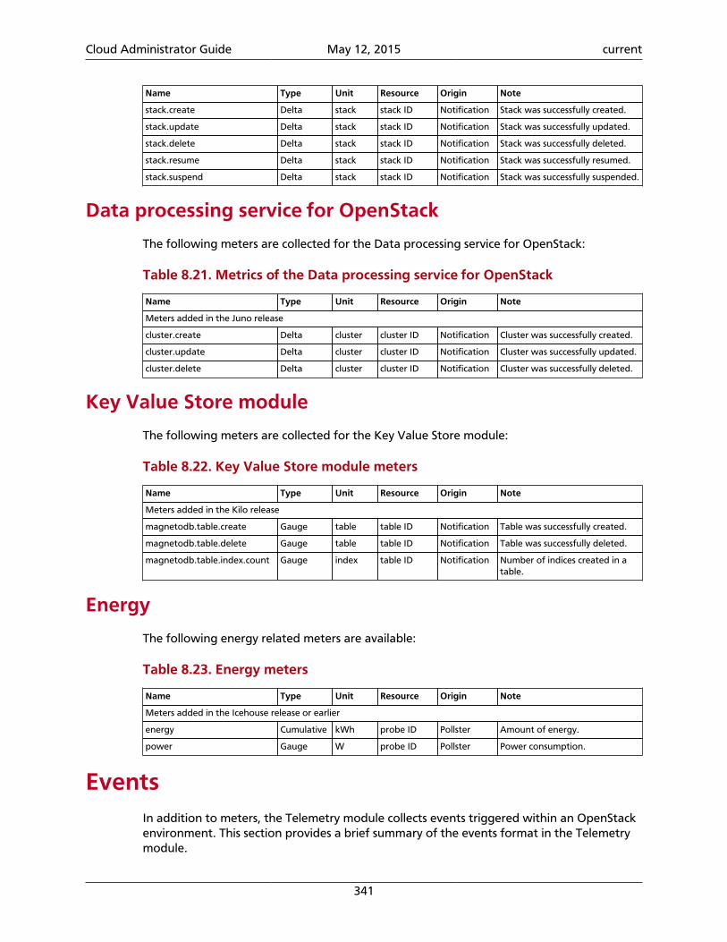
Cloud Administrator Guide May 12, 2015 current
341
Name Type Unit Resource Origin Note
stack.create Delta stack stack ID Notification Stack was successfully created.
stack.update Delta stack stack ID Notification Stack was successfully updated.
stack.delete Delta stack stack ID Notification Stack was successfully deleted.
stack.resume Delta stack stack ID Notification Stack was successfully resumed.
stack.suspend Delta stack stack ID Notification Stack was successfully suspended.
Data processing service for OpenStack
The following meters are collected for the Data processing service for OpenStack:
Table 8.21. Metrics of the Data processing service for OpenStack
Name Type Unit Resource Origin Note
Meters added in the Juno release
cluster.create Delta cluster cluster ID Notification Cluster was successfully created.
cluster.update Delta cluster cluster ID Notification Cluster was successfully updated.
cluster.delete Delta cluster cluster ID Notification Cluster was successfully deleted.
Key Value Store module
The following meters are collected for the Key Value Store module:
Table 8.22. Key Value Store module meters
Name Type Unit Resource Origin Note
Meters added in the Kilo release
magnetodb.table.create Gauge table table ID Notification Table was successfully created.
magnetodb.table.delete Gauge table table ID Notification Table was successfully deleted.
magnetodb.table.index.count Gauge index table ID Notification Number of indices created in atable.
Energy
The following energy related meters are available:
Table 8.23. Energy meters
Name Type Unit Resource Origin Note
Meters added in the Icehouse release or earlier
energy Cumulative kWh probe ID Pollster Amount of energy.
power Gauge W probe ID Pollster Power consumption.
EventsIn addition to meters, the Telemetry module collects events triggered within an OpenStackenvironment. This section provides a brief summary of the events format in the Telemetrymodule.
Cloud Administrator Guide May 12, 2015 current
342
While a sample represents a single, numeric datapoint within a time-series, an event is abroader concept that represents the state of a resource at a point in time. The state may bedescribed using various data types including non-numeric data such as an instance's flavor.In general, events represent any action made in the OpenStack system.
Event configuration
To enable the creation and storage of events in the Telemetry module store_events op-tion needs to be set to True. For further configuration options, see the event section in theOpenStack Configuration Reference.
Note
It is advisable to set disable_non_metric_meters to True when enablingevents in the Telemetry module. The Telemetry module historically represent-ed events as metering data, which may create duplication of data if both eventsand non-metric meters are enabled.
Event structure
Events captured by the Telemetry module are represented by five key attributes:
event_type A dotted string defining what event occurred such ascompute.instance.resize.start".
message_id A UUID for the event.
generated A timestamp of when the event occurred in the system.
traits A flat mapping of key-value pairs which describe the event. The event'sTraits contain most of the details of the event. Traits are typed, and can bestrings, integers, floats, or datetimes.
raw Mainly for auditing purpose, the full event message can be stored (unin-dexed) for future evaluation.
Event indexing
The general philosophy of notifications in OpenStack is to emit any and all data someonemight need, and let the consumer filter out what they are not interested in. In order tomake processing simpler and more efficient, the notifications are stored and processedwithin Ceilometer as events. The notification payload, which can be an arbitrarily complexJSON data structure, is converted to a flat set of key-value pairs. This conversion is specifiedby a config file.
Note
The event format is meant for efficient processing and querying. Storage ofcomplete notifications for auditing purposes can be enabled by configuringstore_raw option.
Cloud Administrator Guide May 12, 2015 current
343
Event conversion
The conversion from notifications to events is driven by a configuration file defined by thedefinitions_cfg_file in the ceilometer.conf configuration file.
This includes descriptions of how to map fields in the notification body to Traits, and op-tional plug-ins for doing any programmatic translations (splitting a string, forcing case).
The mapping of notifications to events is defined per event_type, which can be wildcarded.Traits are added to events if the corresponding fields in the notification exist and are non-null.
Note
The default definition file included with the Telemetry module contains a list ofknown notifications and useful traits. The mappings provided can be modifiedto include more or less data according to user requirements.
If the definitions file is not present, a warning will be logged, but an empty set of defini-tions will be assumed. By default, any notifications that do not have a corresponding eventdefinition in the definitions file will be converted to events with a set of minimal traits.This can be changed by setting the option drop_unmatched_notifications in theceilometer.conf file. If this is set to True, any unmapped notifications will be dropped.
The basic set of traits (all are TEXT type) that will be added to all events if the notificationhas the relevant data are: service (notification's publisher), tenant_id, and request_id. Thesedo not have to be specified in the event definition, they are automatically added, but theirdefinitions can be overridden for a given event_type.
Event definitions format
The event definitions file is in YAML format. It consists of a list of event definitions, whichare mappings. Order is significant, the list of definitions is scanned in reverse order to find adefinition which matches the notification's event_type. That definition will be used to gen-erate the event. The reverse ordering is done because it is common to want to have a moregeneral wildcarded definition (such as compute.instance.*) with a set of traits com-mon to all of those events, with a few more specific event definitions afterwards that haveall of the above traits, plus a few more.
Each event definition is a mapping with two keys:
event_type This is a list (or a string, which will be taken as a 1 element list) ofevent_types this definition will handle. These can be wildcarded with unixshell glob syntax. An exclusion listing (starting with a !) will exclude anytypes listed from matching. If only exclusions are listed, the definition willmatch anything not matching the exclusions.
traits This is a mapping, the keys are the trait names, and the values are trait def-initions.
Each trait definition is a mapping with the following keys:
Cloud Administrator Guide May 12, 2015 current
344
fields A path specification for the field(s) in the notification you wish to extract forthis trait. Specifications can be written to match multiple possible fields. By de-fault the value will be the first such field. The paths can be specified with a dotsyntax (payload.host). Square bracket syntax (payload[host]) is also sup-ported. In either case, if the key for the field you are looking for contains spe-cial characters, like ., it will need to be quoted (with double or single quotes):payload.image_meta.’org.openstack__1__architecture’. The syn-tax used for the field specification is a variant of JSONPath
type (Optional) The data type for this trait. Valid options are: text, int, float, anddatetime. Defaults to text if not specified.
plugin (Optional) Used to execute simple programmatic conversions on the value in anotification field.
Troubleshoot Telemetry
Logging in Telemetry
The Telemetry module has similar log settings as the other OpenStack services. Multiple op-tions are available to change the target of logging, the format of the log entries and thelog levels.
The log settings can be changed in ceilometer.conf. The list of configuration optionsare listed in the logging configuration options table in the Telemetry section in the Open-Stack Configuration Reference.
By default stderr is used as standard output for the log messages. It can be changed toeither a log file or syslog. The debug and verbose options are also set to false in the de-fault settings, the default log levels of the corresponding modules can be found in the tablereferred above.
Recommended order of starting services
As it can be seen in Bug 1355809, the wrong ordering of service startup can result in dataloss.
When the services are started for the first time or in line with the message queue ser-vice restart, it takes time while the ceilometer-collector services establishesthe connection and joins or rejoins to the configured exchanges. Therefore, if the ceilometer-agent-compute, ceilometer-agent-central and the ceilome-ter-agent-notification services are started before ceilometer-collector, itcan loose some messages sent by these services, while connecting to the message queueservice.
The possibility of this issue to happen is higher, when the polling interval is set to a relative-ly short period. In order to avoid this situation, the recommended order of service start-up is to start or restart the ceilometer-collector service after the message queue.All the other Telemetry services should be started or restarted after and the ceilome-ter-agent-compute should be the last in the sequence, as this component emits meter-ing messages in order to send the samples to the collector.
Cloud Administrator Guide May 12, 2015 current
345
Notification agent
In the Icehouse release of OpenStack a new service was introduced to be responsible forconsuming notifications that are coming from other OpenStack services.
If the ceilometer-agent-notification service is not installed and started, sam-ples originating from notifications will not be generated. In case of the lack of notificationbased samples, the state of this service and the log file of Telemetry should be checked first.
For the list of meters that are originated from notifications, see the Telemetry Measure-ments Reference.
Recommended auth_url to be used
When using the commandline client of Telemetry, the credentials and the os_auth_urlhas to be set in order to provide the possibility to the client to authenticate against Open-Stack Identity. For further details about the credentials that has to be provided see the Python API reference of Telemetry.
The service catalog provided by OpenStack Identity contains the available URLs that areavailable for authentication. The URLs contain different ports, based on that the type ofthe given URL is public, internal or admin.
OpenStack Identity is about to change API version from v2 to v3. The adminURL endpoint(which is available via the port: 35357) supports only the v3 version, while the other twosupports both.
The commandline client of Telemetry is not adapted to the v3 version of the OpenStackIdentity API. If the adminURL is used as os_auth_url, the ceilometer command results inthe following error message:
$ ceilometer meter-listUnable to determine the Keystone version to authenticate with using the givenauth_url: http://10.0.2.15:35357/v2.0
Therefore when specifying the os_auth_url parameter on the command line or by usingenvironment variable, use the internalURL or publicURL.
For more details check the bug report Bug 1351841.
Cloud Administrator Guide May 12, 2015 current
346
9. Database
Table of ContentsIntroduction ................................................................................................................ 346Create a datastore ...................................................................................................... 346Configure a cluster ...................................................................................................... 350
The Database service module provides database management features.
IntroductionThe Database service provides scalable and reliable cloud provisioning functionality for bothrelational and non-relational database engines. Users can quickly and easily use databasefeatures without the burden of handling complex administrative tasks. Cloud users anddatabase administrators can provision and manage multiple database instances as needed.
The Database service provides resource isolation at high performance levels, and automatescomplex administrative tasks such as deployment, configuration, patching, backups, re-stores, and monitoring.
Create a datastoreAn administrative user can create datastores for a variety of databases.
This section assumes you do not yet have a MySQL datastore, and shows you how to createa MySQL datastore and populate it with a MySQL 5.5 datastore version.
To create a datastore
1. Create a trove image
Create an image for the type of database you want to use, for example, MySQL, Mon-goDB, Cassandra, and so on.
This image must have the trove guest agent installed, and it must have the trove-guestagent.conf file configured to connect to your OpenStack environment.To configure trove-guestagent.conf, add the following lines to trove-guestagent.conf on the guest instance you are using to build your image:
rabbit_host = controllerrabbit_password = RABBIT_PASSnova_proxy_admin_user = adminnova_proxy_admin_pass = ADMIN_PASSnova_proxy_admin_tenant_name = servicetrove_auth_url = http://controller:35357/v2.0
This example assumes you have created a MySQL 5.5 image calledmysql-5.5.qcow2.
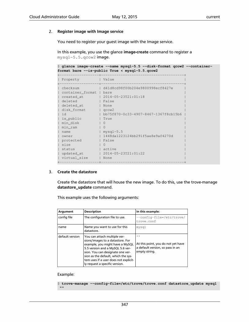
Cloud Administrator Guide May 12, 2015 current
347
2. Register image with Image service
You need to register your guest image with the Image service.
In this example, you use the glance image-create command to register amysql-5.5.qcow2 image.
$ glance image-create --name mysql-5.5 --disk-format qcow2 --container-format bare --is-public True < mysql-5.5.qcow2+------------------+--------------------------------------+| Property | Value |+------------------+--------------------------------------+| checksum | d41d8cd98f00b204e9800998ecf8427e || container_format | bare || created_at | 2014-05-23T21:01:18 || deleted | False || deleted_at | None || disk_format | qcow2 || id | bb75f870-0c33-4907-8467-1367f8cb15b6 || is_public | True || min_disk | 0 || min_ram | 0 || name | mysql-5.5 || owner | 1448da1223124bb291f5ae8e9af4270d || protected | False || size | 0 || status | active || updated_at | 2014-05-23T21:01:22 || virtual_size | None |+------------------+--------------------------------------+
3. Create the datastore
Create the datastore that will house the new image. To do this, use the trove-managedatastore_update command.
This example uses the following arguments:
Argument Description In this example:
config file The configuration file to use. --config-file=/etc/trove/trove.conf
name Name you want to use for thisdatastore.
mysql
default version You can attach multiple ver-sions/images to a datastore. Forexample, you might have a MySQL5.5 version and a MySQL 5.6 ver-sion. You can designate one ver-sion as the default, which the sys-tem uses if a user does not explicit-ly request a specific version.
""
At this point, you do not yet havea default version, so pass in anempty string.
Example:
$ trove-manage --config-file=/etc/trove/trove.conf datastore_update mysql ""
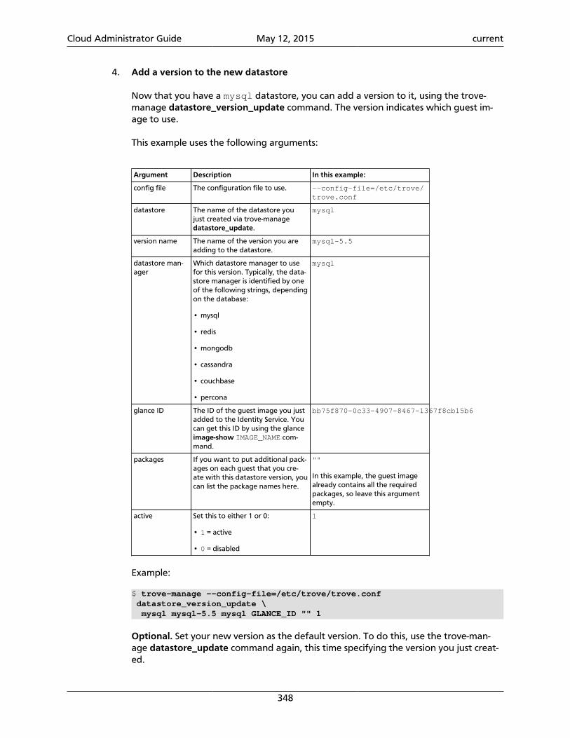
Cloud Administrator Guide May 12, 2015 current
348
4. Add a version to the new datastore
Now that you have a mysql datastore, you can add a version to it, using the trove-manage datastore_version_update command. The version indicates which guest im-age to use.
This example uses the following arguments:
Argument Description In this example:
config file The configuration file to use. --config-file=/etc/trove/trove.conf
datastore The name of the datastore youjust created via trove-managedatastore_update.
mysql
version name The name of the version you areadding to the datastore.
mysql-5.5
datastore man-ager
Which datastore manager to usefor this version. Typically, the data-store manager is identified by oneof the following strings, dependingon the database:
• mysql
• redis
• mongodb
• cassandra
• couchbase
• percona
mysql
glance ID The ID of the guest image you justadded to the Identity Service. Youcan get this ID by using the glanceimage-show IMAGE_NAME com-mand.
bb75f870-0c33-4907-8467-1367f8cb15b6
packages If you want to put additional pack-ages on each guest that you cre-ate with this datastore version, youcan list the package names here.
""
In this example, the guest imagealready contains all the requiredpackages, so leave this argumentempty.
active Set this to either 1 or 0:
• 1 = active
• 0 = disabled
1
Example:
$ trove-manage --config-file=/etc/trove/trove.conf datastore_version_update \ mysql mysql-5.5 mysql GLANCE_ID "" 1
Optional. Set your new version as the default version. To do this, use the trove-man-age datastore_update command again, this time specifying the version you just creat-ed.
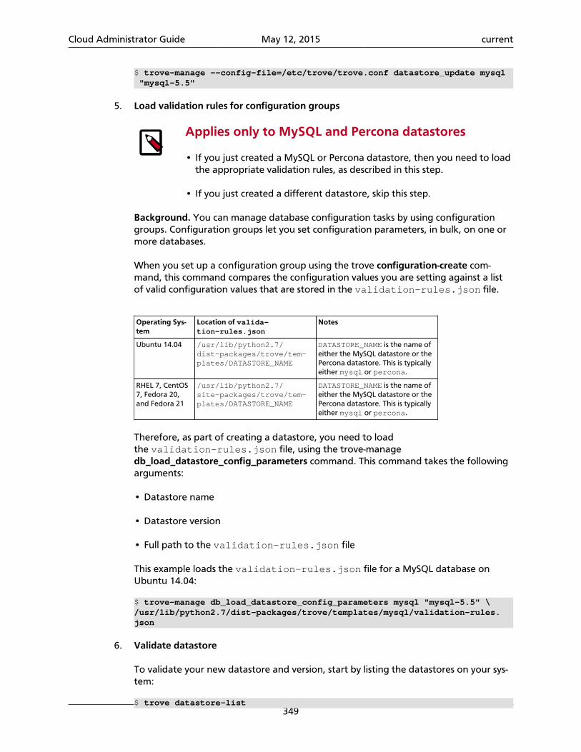
Cloud Administrator Guide May 12, 2015 current
349
$ trove-manage --config-file=/etc/trove/trove.conf datastore_update mysql "mysql-5.5"
5. Load validation rules for configuration groups
Applies only to MySQL and Percona datastores
• If you just created a MySQL or Percona datastore, then you need to loadthe appropriate validation rules, as described in this step.
• If you just created a different datastore, skip this step.
Background. You can manage database configuration tasks by using configurationgroups. Configuration groups let you set configuration parameters, in bulk, on one ormore databases.
When you set up a configuration group using the trove configuration-create com-mand, this command compares the configuration values you are setting against a listof valid configuration values that are stored in the validation-rules.json file.
Operating Sys-tem
Location of valida-tion-rules.json
Notes
Ubuntu 14.04 /usr/lib/python2.7/dist-packages/trove/tem-plates/DATASTORE_NAME
DATASTORE_NAME is the name ofeither the MySQL datastore or thePercona datastore. This is typicallyeither mysql or percona.
RHEL 7, CentOS7, Fedora 20,and Fedora 21
/usr/lib/python2.7/site-packages/trove/tem-plates/DATASTORE_NAME
DATASTORE_NAME is the name ofeither the MySQL datastore or thePercona datastore. This is typicallyeither mysql or percona.
Therefore, as part of creating a datastore, you need to loadthe validation-rules.json file, using the trove-managedb_load_datastore_config_parameters command. This command takes the followingarguments:
• Datastore name
• Datastore version
• Full path to the validation-rules.json file
This example loads the validation-rules.json file for a MySQL database onUbuntu 14.04:
$ trove-manage db_load_datastore_config_parameters mysql "mysql-5.5" \/usr/lib/python2.7/dist-packages/trove/templates/mysql/validation-rules.json
6. Validate datastore
To validate your new datastore and version, start by listing the datastores on your sys-tem:
$ trove datastore-list
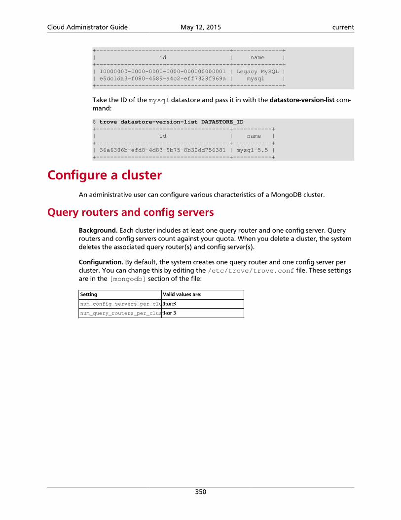
Cloud Administrator Guide May 12, 2015 current
350
+--------------------------------------+--------------+| id | name |+--------------------------------------+--------------+| 10000000-0000-0000-0000-000000000001 | Legacy MySQL || e5dc1da3-f080-4589-a4c2-eff7928f969a | mysql |+--------------------------------------+--------------+
Take the ID of the mysql datastore and pass it in with the datastore-version-list com-mand:
$ trove datastore-version-list DATASTORE_ID+--------------------------------------+-----------+| id | name |+--------------------------------------+-----------+| 36a6306b-efd8-4d83-9b75-8b30dd756381 | mysql-5.5 |+--------------------------------------+-----------+
Configure a clusterAn administrative user can configure various characteristics of a MongoDB cluster.
Query routers and config servers
Background. Each cluster includes at least one query router and one config server. Queryrouters and config servers count against your quota. When you delete a cluster, the systemdeletes the associated query router(s) and config server(s).
Configuration. By default, the system creates one query router and one config server percluster. You can change this by editing the /etc/trove/trove.conf file. These settingsare in the [mongodb] section of the file:
Setting Valid values are:
num_config_servers_per_cluster1 or 3
num_query_routers_per_cluster1 or 3
Cloud Administrator Guide May 12, 2015 current
351
10. Orchestration
Table of ContentsIntroduction ................................................................................................................ 351Orchestration authorization model .............................................................................. 351Stack domain users ...................................................................................................... 353
Orchestration is an orchestration engine that provides the possibility to launch multiplecomposite cloud applications based on templates in the form of text files that can be treat-ed like code. A native Heat Orchestration Template (HOT) format is evolving, but it also en-deavors to provide compatibility with the AWS CloudFormation template format, so thatmany existing CloudFormation templates can be launched on OpenStack.
IntroductionOrchestration is a tool for orchestrating clouds that automatically configures and deploysresources in stacks. Such deployments can be simple — like deploying WordPress on Ubun-tu with a SQL back end. And they can be quite complex, like launching a group of serversthat autoscale: starting and stopping based on realtime CPU loading information from theTelemetry module.
Orchestration stacks are defined with templates, which are non-procedural documentsdescribing tasks in terms of resources, parameters, inputs, constraints and dependencies.When Orchestration module was originally introduced, it worked with AWS CloudForma-tion templates, which are in JSON format.
Now, Orchestration also executes HOT (Heat Orchestration Template) templates, writtenin YAML: a terse notation that loosely follows Python/Ruby-type structural conventions(colons, returns, indentation) so it’s more easily to write, parse, grep, generate with tools,and maintain with source-code management systems.
Orchestration can be accessed via the CLI, and using RESTful queries. Orchestration moduleprovides both an OpenStack-native REST API and a CloudFormation-compatible Query API.Orchestration is also integrated with OpenStack dashboard in order to launching stacksfrom templates through web-interface.
For more details how to use Orchestration module command-line see OpenStack Com-mand line interface reference
Orchestration authorization modelOrchestration authorization model defines the process of authorization that orchestrationmodule uses to authorize requests during so called deferred operations. The typical exam-ple of such operation is autoscaling group update when heat requests another components(nova, neutron or others) to extend (reduce) capacity of autoscaling group.
At the current moment, Orchestration provides two kinds of authorization models:
Cloud Administrator Guide May 12, 2015 current
352
• Password authorization.
• Authorization with OpenStack Identity trusts.
Password authorizationPassword authorization is the initial authorization model that was supported by Orchestra-tion module. This kind of authorization requires from a user to pass a password to Orches-tration. Orchestration stores the encrypted password in database and uses it for deferredoperations.
The following steps are executed for password authorization:
1. User requests stack creation, providing a token and username/password (python-heat-client or OpenStack dashboard normally requests the token for you).
2. If the stack contains any resources marked as requiring deferred operations orchestra-tion engine will fail validation checks if no username/password is provided.
3. The username/password are encrypted and stored in the orchestration DB.
4. Stack creation is completed.
5. At some later stage Orchestration retrieves the credentials and requests another tokenon behalf of the user, the token is not limited in scope and provides access to all roles ofthe stack owner.
Keystone trusts authorizationOpenStack Identity trusts is the new authorization method available since IceHouse release.
Trusts are an OpenStack Identity extension, which provide a method to enable delegation,and optionally impersonation via OpenStack Identity. The key terminology is trustor (the us-er delegating) and trustee (the user being delegated to).
To create a trust, the trustor(in this case the user creating the stack in Orchestration mod-ule) provides OpenStack Identity with the following information:
• The ID of the trustee(who you want to delegate to, in this case the Orchestration serviceuser).
• The roles to be delegated(configurable via the heat.conf, but it needs to containwhatever roles are required to perform the deferred operations on the users behalf, e.glaunching a OpenStack Compute instance in response to an AutoScaling event).
• Whether to enable impersonation.
OpenStack Identity then provides a trust_id, which can be consumed by the trustee (andonly the trustee) to obtain a trust scoped token. This token is limited in scope such that thetrustee has limited access to those roles delegated, along with effective impersonation ofthe trustor user, if it was selected when creating the trust. More information is available inIdentity management section.
The following steps are executed for trusts authorization:
Cloud Administrator Guide May 12, 2015 current
353
1. User creates a stack via an API request (only the token is required).
2. Orchestration uses the token to create a trust between the stack owner (trustor) andthe heat service user (trustee), delegating a special role (or roles) as defined in thetrusts_delegated_roles list in the heat configuration file. By default heat sets all rolesfrom trustor available for trustee. Deployers may modify this list to reflect local RBACpolicy, e.g to ensure the heat process can only access those services expected while im-personating a stack owner.
3. Orchestration stores the encrypted trust id in the Orchestration DB.
4. When a deferred operation is required, Orchestration retrieves the trust id, and requestsa trust scoped token which enables the service user to impersonate the stack ownerfor the duration of the deferred operation, e.g to launch some OpenStack Compute in-stances on behalf of the stack owner in response to an AutoScaling event.
Authorization model configuration
Password authorization model had been the default authorization model enabled for Or-chestration module before Kilo release. Since Kilo release trusts authorization model hasbeen enabled by default.
To enable password authorization model the following change should be made inheat.conf:
deferred_auth_method=password
To enable trusts authorization model the following change should be made in heat.conf:
deferred_auth_method=trusts
To specify trustor roles that will be delegated to trustee during authorizationtrusts_delegated_roles parameter should be specified in heat.conf. Iftrusts_delegated_roles is not defined then all trustor roles will be delegated totrustee. Please pay attention that trust delegated roles should be pre-configured in Open-Stack Identity before using it in Orchestration module.
Stack domain usersOrchestration stack domain users allows heat to authorize inside VMs booted and executethe following operations:
• Provide metadata to agents inside instances, which poll for changes and apply the config-uration expressed in the metadata to the instance.
• Detect signal completion of some action, typically configuration of software on a VMafter it is booted (because OpenStack Compute moves the state of a VM to "Active" assoon as it spawns it, not when orchestration has fully configured it).
• Provide application level status or meters from inside the instance. For example, allowAutoScaling actions to be performed in response to some measure of performance orquality of service.
Cloud Administrator Guide May 12, 2015 current
354
Orchestration provides API's which enable all of these things, but all of those API's requiresome sort of authentication. For example, credentials to access the instance agent is run-ning on. The heat-cfntools agents use signed requests, which requires an ec2 keypair creat-ed via OpenStack Identity, which is then used to sign requests to the Orchestration cloud-formation and cloudwatch compatible API's, which are authenticated by Orchestration viasignature validation (which uses the OpenStack Identity ec2tokens extension). Stack do-main users allow to encapuslate all stack-defined users (users created as a result of thingscontained in a Orchestration template) in a separate domain, which is created specificallyto contain things related only to Orchestration stacks. A user is created which is the domainadmin, and Orchestration uses that user to manage the lifecycle of the users in the stack us-er domain.
Stack domain users configuration
To configure stack domain users the following steps shall be executed:
1. A special OpenStack Identity service domain is created. For example, the one called heatand the ID is set in the stack_user_domain option in heat.conf.
2. A user with sufficient permissions to create and delete projects and users in the heat do-main is created.
3. The username and password for the domain admin user is set in heat.conf(stack_domain_admin and stack_domain_admin_password). This user ad-ministers stack domain users on behalf of stack owners, so they no longer need tobe admins themselves, and the risk of this escalation path is limited because theheat_domain_admin is only given administrative permission for the heat domain.
You must complete the following steps to setup stack domain users:
1. Create the domain:
$OS_TOKEN refers to a token. For example, the service admin token or someother valid token for a user with sufficient roles to create users and domains.$KS_ENDPOINT_V3 refers to the v3 OpenStack Identity endpoint (for examplehttp://keystone_address:5000/v3 where keystone_address is the IP address orresolvable name for the OpenStack Identity service).
$ openstack --os-token $OS_TOKEN --os-url=$KS_ENDPOINT_V3 --os-identity-api-version=3 domain create heat --description "Owns users and projects created by heat"
The domain ID is returned by this command, and is referred to as $HEAT_DOMAIN_IDbelow.
The domain ID is returned by this command, and is referred to as $HEAT_DOMAIN_IDbelow.
2. Create the user:
$ openstack --os-token $OS_TOKEN --os-url=$KS_ENDPOINT_V3 --os-identity-api-version=3 user create --password $PASSWORD --domain $HEAT_DOMAIN_ID heat_domain_admin --description "Manages users and projects created by heat"
Cloud Administrator Guide May 12, 2015 current
355
The user ID is returned by this command and is referred to as $DOMAIN_ADMIN_ID be-low.
3. Make the user a domain admin:
$ openstack --os-token $OS_TOKEN --os-url=$KS_ENDPOINT_V3 --os-identity-api-version=3 role add --user $DOMAIN_ADMIN_ID --domain $HEAT_DOMAIN_ID admin
Then you need to add the domain ID, username and password from these steps toheat.conf:
stack_domain_admin_password = passwordstack_domain_admin = heat_domain_adminstack_user_domain = domain id returned from domain create above
Usage workflow
The following steps will be executed during stack creation:
1. Orchestration creates a new "stack domain project" in the "heat" domain, if the stackcontains any resources which require creation of a "stack domain user".
2. Any resources which require a user, Orchestration creates the user in the "stack domainproject", which is associated with the heat stack in the heat database, but is completelyseparate and unrelated (from an authentication perspective) to the stack owners project(the users created in the stack domain are still assigned the heat_stack_user role,so the API surface they can access is limited via policy.json. See OpenStack Identity docu-mentation for more info).
3. When API requests are processed, Heat Orchestration does an internal lookup, and al-low stack details for a given stack to be retrieved from the database for both the stackowner's project (the default API path to the stack), and also the stack domain project,subject to the policy.json restrictions.
To clarify that last point, that means there are now two paths which can result in retrievalof the same data via the Orchestration API. The example for resource-metadata is below:
GET v1/{stack_owner_project_id}/stacks/{stack_name}/{stack_id}/resources/{resource_name}/metadata
or:
GET v1/{stack_domain_project_id}/stacks/{stack_name}/{stack_id}/resources/{resource_name}/metadata
The stack owner would use the former (via heat resource-metadata {stack_name}{resource_name}), and any agents in the instance will use the latter.
Cloud Administrator Guide May 12, 2015 current
356
Appendix A. Community support
Table of ContentsDocumentation ........................................................................................................... 356ask.openstack.org ........................................................................................................ 357OpenStack mailing lists ................................................................................................ 357The OpenStack wiki ..................................................................................................... 357The Launchpad Bugs area ........................................................................................... 358The OpenStack IRC channel ......................................................................................... 359Documentation feedback ............................................................................................ 359OpenStack distribution packages ................................................................................. 359
The following resources are available to help you run and use OpenStack. The OpenStackcommunity constantly improves and adds to the main features of OpenStack, but if youhave any questions, do not hesitate to ask. Use the following resources to get OpenStacksupport, and troubleshoot your installations.
DocumentationFor the available OpenStack documentation, see docs.openstack.org.
To provide feedback on documentation, join and use the<[email protected]> mailing list at OpenStack DocumentationMailing List, or report a bug.
The following books explain how to install an OpenStack cloud and its associated compo-nents:
• Installation Guide for openSUSE 13.2 and SUSE Linux Enterprise Server 12
• Installation Guide for Red Hat Enterprise Linux 7, CentOS 7, and Fedora 21
• Installation Guide for Ubuntu 14.04 (LTS)
The following books explain how to configure and run an OpenStack cloud:
• Architecture Design Guide
• Cloud Administrator Guide
• Configuration Reference
• Operations Guide
• Networking Guide
• High Availability Guide
• Security Guide
Cloud Administrator Guide May 12, 2015 current
357
• Virtual Machine Image Guide
The following books explain how to use the OpenStack dashboard and command-lineclients:
• API Quick Start
• End User Guide
• Admin User Guide
• Command-Line Interface Reference
The following documentation provides reference and guidance information for the Open-Stack APIs:
• OpenStack API Complete Reference (HTML)
• API Complete Reference (PDF)
The Training Guides offer software training for cloud administration and management.
ask.openstack.orgDuring the set up or testing of OpenStack, you might have questions about how a spe-cific task is completed or be in a situation where a feature does not work correctly. Usethe ask.openstack.org site to ask questions and get answers. When you visit the http://ask.openstack.org site, scan the recently asked questions to see whether your question hasalready been answered. If not, ask a new question. Be sure to give a clear, concise summaryin the title and provide as much detail as possible in the description. Paste in your commandoutput or stack traces, links to screen shots, and any other information which might be use-ful.
OpenStack mailing listsA great way to get answers and insights is to post your question or problematic scenarioto the OpenStack mailing list. You can learn from and help others who might have simi-lar issues. To subscribe or view the archives, go to http://lists.openstack.org/cgi-bin/mail-man/listinfo/openstack. You might be interested in the other mailing lists for specificprojects or development, which you can find on the wiki. A description of all mailing lists isavailable at http://wiki.openstack.org/MailingLists.
The OpenStack wikiThe OpenStack wiki contains a broad range of topics but some of the information can bedifficult to find or is a few pages deep. Fortunately, the wiki search feature enables you tosearch by title or content. If you search for specific information, such as about networkingor nova, you can find a large amount of relevant material. More is being added all the time,so be sure to check back often. You can find the search box in the upper-right corner of anyOpenStack wiki page.
Cloud Administrator Guide May 12, 2015 current
358
The Launchpad Bugs areaThe OpenStack community values your set up and testing efforts and wants your feedback.To log a bug, you must sign up for a Launchpad account at https://launchpad.net/+login.You can view existing bugs and report bugs in the Launchpad Bugs area. Use the searchfeature to determine whether the bug has already been reported or already been fixed. Ifit still seems like your bug is unreported, fill out a bug report.
Some tips:
• Give a clear, concise summary.
• Provide as much detail as possible in the description. Paste in your command output orstack traces, links to screen shots, and any other information which might be useful.
• Be sure to include the software and package versions that you are using, especially ifyou are using a development branch, such as, "Juno release" vs git commitbc79c3ecc55929bac585d04a03475b72e06a3208.
• Any deployment-specific information is helpful, such as whether you are using Ubuntu14.04 or are performing a multi-node installation.
The following Launchpad Bugs areas are available:
• Bugs: OpenStack Block Storage (cinder)
• Bugs: OpenStack Compute (nova)
• Bugs: OpenStack Dashboard (horizon)
• Bugs: OpenStack Identity (keystone)
• Bugs: OpenStack Image service (glance)
• Bugs: OpenStack Networking (neutron)
• Bugs: OpenStack Object Storage (swift)
• Bugs: Bare metal service (ironic)
• Bugs: Data processing service (sahara)
• Bugs: Database service (trove)
• Bugs: Orchestration (heat)
• Bugs: Telemetry (ceilometer)
• Bugs: Message Service (zaqar)
• Bugs: OpenStack API Documentation (developer.openstack.org)
• Bugs: OpenStack Documentation (docs.openstack.org)
Cloud Administrator Guide May 12, 2015 current
359
The OpenStack IRC channelThe OpenStack community lives in the #openstack IRC channel on the Freenode network.You can hang out, ask questions, or get immediate feedback for urgent and pressing issues.To install an IRC client or use a browser-based client, go to https://webchat.freenode.net/.You can also use Colloquy (Mac OS X, http://colloquy.info/), mIRC (Windows, http://www.mirc.com/), or XChat (Linux). When you are in the IRC channel and want to sharecode or command output, the generally accepted method is to use a Paste Bin. The Open-Stack project has one at http://paste.openstack.org. Just paste your longer amounts of textor logs in the web form and you get a URL that you can paste into the channel. The Open-Stack IRC channel is #openstack on irc.freenode.net. You can find a list of all Open-Stack IRC channels at https://wiki.openstack.org/wiki/IRC.
Documentation feedbackTo provide feedback on documentation, join and use the<[email protected]> mailing list at OpenStack DocumentationMailing List, or report a bug.
OpenStack distribution packagesThe following Linux distributions provide community-supported packages for OpenStack:
• Debian: http://wiki.debian.org/OpenStack
• CentOS, Fedora, and Red Hat Enterprise Linux: https://www.rdoproject.org/
• openSUSE and SUSE Linux Enterprise Server: http://en.opensuse.org/Portal:OpenStack
• Ubuntu: https://wiki.ubuntu.com/ServerTeam/CloudArchive