Embed Size (px)
Citation preview
Unmanned Systems Roadmap 2007-2032
Executive Summary
Page i
Executive Summary Today’s military has seen an evolution in technology that is creating an entirely new capability to project power through the use of unmanned systems while reducing the risk to human life. The contributions of unmanned systems continue to increase. As of October 2006, coalition Unmanned Aircraft Systems (UASs), exclusive of hand-launched systems, had flown almost 400,000 flight hours in support of Operations Enduring Freedom and Iraqi Freedom, Unmanned Ground Vehicles (UGVs) had responded to over 11,000 Improvised Explosive Device (IED) situations, and Unmanned Maritime Systems (UMSs) had provided security to ports. As a result of these successes, the Quadrennial Defense Review (QDR) emphasized the importance of unmanned systems in the Global War on Terrorism (GWOT).
Unmanned systems are highly desired by combatant commanders (COCOMs) for the many roles these systems can fulfill. Tasks such as mine detection; signals intelligence; precision target designation; chemical, biological, radiological, nuclear, explosive (CBRNE) reconnaissance; and communications and data relay rank high among the COCOMs’ interests. These unmanned capabilities have helped reduce the complexity and time lag in the “sensor” component of the sensor-to-shooter chain for prosecuting “actionable intelligence.” Unmanned systems are changing the conduct of military operations in the GWOT by providing unrelenting pursuit combined with the elimination of threats to friendly forces; including injury, capture, or death.
As the Department of Defense (DoD) develops and employs an increasingly sophisticated force of unmanned systems over the next 25 years (2007 to 2032), technologists, acquisition officials, and operational planners require a clear, coordinated plan for the evolution and transition of unmanned systems technology. With the publication of this document, individual roadmaps and master plans for UASs, UGVs, and UMSs (defined as Unmanned Undersea Vehicles (UUVs) and Unmanned Surface Vehicles (USVs)) have been incorporated into a comprehensive DoD Unmanned Systems Roadmap. This integrated Unmanned Systems Roadmap is the plan for future prioritization and funding of these systems development and technology, thus ensuring an effective return on the Department’s investment. Its overarching goal, in accordance with the Strategic Planning Guidance (SPG), is to guide military departments and defense agencies toward logically and systematically migrating applicable mission capabilities to this new class of military tools. This Roadmap highlights the most urgent mission needs that are supported both technologically and operationally by various unmanned systems. These needs, listed below, should be considered when prioritizing future research, development, and procurement of unmanned systems technology to ensure an effective return on the Department’s investment.
1. Reconnaissance and Surveillance. Some form of reconnaissance (electronic and visual) is the number one COCOM priority applicable to unmanned systems. Being able to surveil areas of interest while maintaining a degree of covertness is highly desirable. The reconnaissance mission that is currently conducted by unmanned systems needs to increase standardization and interoperability to better support the broad range of DoD users.
2. Target Identification and Designation. The ability to positively identify and precisely locate military targets in real-time is a current shortfall with DOD UAS. Reducing latency and increasing precision for GPS guided weapons is required. The ability to operate in high-threat environments without putting warfighters at risk is not only safer but potentially more effective than the use of current manned systems.
Unmanned Systems Roadmap 2007-2032
Executive Summary
Page ii
3. Counter-Mine Warfare. Since World War II, sea mines have caused more damage to US warships than all other weapons systems combined. Improvised Explosive Devices (IEDs) are the number one cause of of coalition casualties in Operation Iraqi Freedom. A significant amount of effort is already being expended to improve the military’s ability to find, tag, and destroy both land and sea mines. Unmanned Systems are a natural fit for this dangerous mission.
4. Chemical, Biological, Radiological, Nuclear, Explosive (CBRNE) Reconnaissance. The ability to find chemical and biologic agents and to survey the extent of affected areas is a crucial effort.
Some of these missions can be supported by the current state-of-the-art unmanned technology where the capabilities of current or near-term assets are sufficient and the risk to warfighters is relatively low. Other mission areas, however, are in urgent need of additional capability. Current unmanned capabilities must evolve into the future DoD acquisition and operational vision. Current support to the warfighter must be sustained while making the transition, but every effort must be made to accommodate these evolving unmanned technologies along with more traditional technologies as soon as possible. The activities the Department is undertaking to address these mission areas are detailed within this Roadmap.
The Office of the Secretary of Defense (OSD) is responsible for ensuring unmanned systems support the Department’s larger goals of fielding transformational capabilities, establishing joint standards, and controlling costs. OSD has established the following broad goals to steer the Department in that direction. It is anticipated that future versions of the Roadmap will include specific methodology, metrics, and assignments to achieve the stated goals.
Goal 1. Improve the effectiveness of COCOM and coalition unmanned systems through improved integration and Joint Services collaboration.
Goal 2. Emphasize commonality to achieve greater interoperability among system controls, communications, data products, and data links on unmanned systems.
Goal 3. Foster the development of policies, standards, and procedures that enable safe and timely operations and the effective integration of manned and unmanned systems.
Goal 4. Implement standardized and protected positive control measures for unmanned systems and their associated armament.
Goal 5. Support rapid demonstration and integration of validated combat capabilities in fielded/deployed systems through a more flexible prototyping, test and logistical support process.
Goal 6. Aggressively control cost by utilizing competition, refining and prioritizing requirements, and increasing interdependencies (networking) among DoD systems.
The long-term plan is to publish a truly integrated Unmanned Systems Roadmap in January 2009 that builds on this effort and increases focus on manned and unmanned systems interoperability to achieve our future vision.
Unmanned Systems Roadmap 2007-2032
Table of Contents
Page iii
Table of Contents Executive Summary ......................................................................................................................... i
Table of Contents ...........................................................................................................................iii
List of Figures ..............................................................................................................................viii
List of Tables................................................................................................................................viii
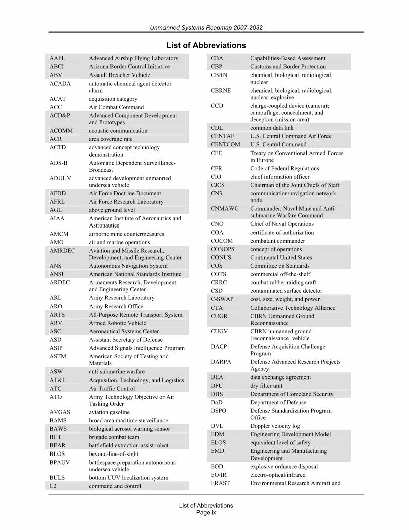
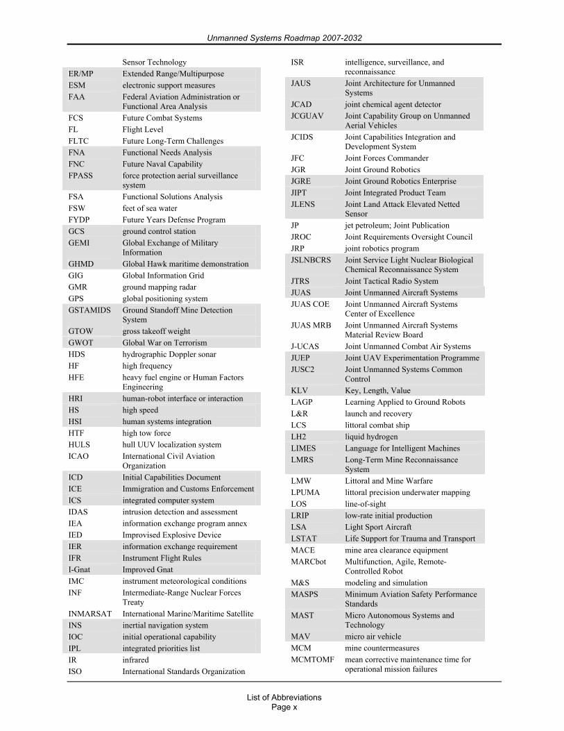
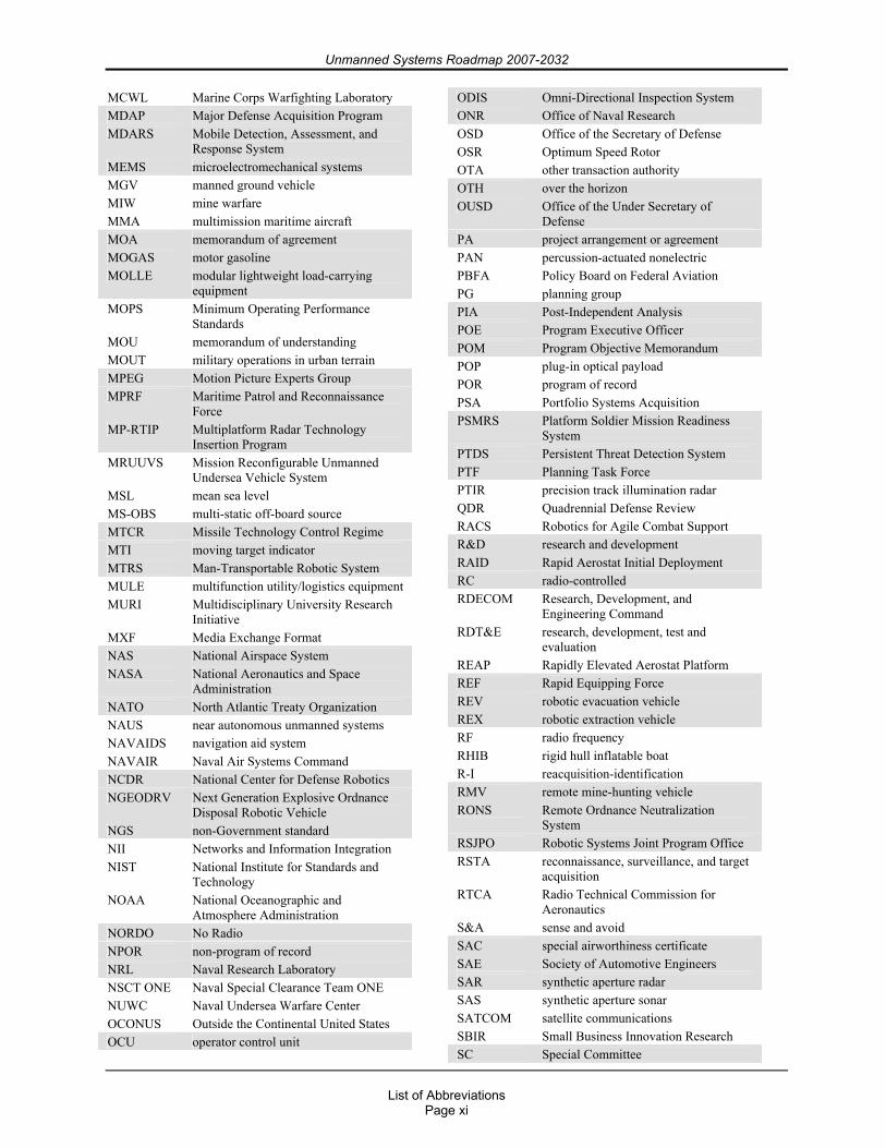
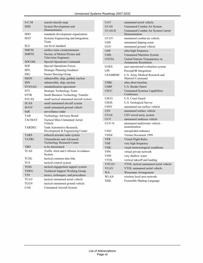
List of Abbreviations...................................................................................................................... ix
Chapter 1. Introduction ................................................................................................................... 1 1.1. Purpose................................................................................................................................. 1 1.2. Scope.................................................................................................................................... 1 1.3. Vision ................................................................................................................................... 1 1.4. Goals and Objectives ........................................................................................................... 3
Chapter 2. Strategic Planning and Policy........................................................................................ 6 2.1. Background .......................................................................................................................... 6 2.2. Congressional Direction....................................................................................................... 6 2.3. Acquisition Policies ............................................................................................................. 7
2.3.1. General .......................................................................................................................... 7 2.3.2. Joint Capabilities Integration and Development System (JCIDS) ................................ 8 2.3.3. DoD 5000 series ............................................................................................................ 8
2.4. Unmanned Systems Funding ............................................................................................. 10 2.5. Departmental Responsibilities ........................................................................................... 11
2.5.1. Naval Warfare ............................................................................................................. 11 2.5.2. Ground Warfare........................................................................................................... 12 2.5.3. Air Warfare ................................................................................................................. 12
Chapter 3. Interoperability and Standards..................................................................................... 13 3.1. Interoperability Requirements............................................................................................ 13 3.2. Unmanned Systems Standards ........................................................................................... 13
3.2.1. UAS Standards ............................................................................................................ 15 3.2.2. UGV Standards ........................................................................................................... 16 3.2.3. UMS Standards ........................................................................................................... 16 3.2.4. Media Standards.......................................................................................................... 16
3.3. Roadmap Interoperability Objectives ................................................................................ 17
Chapter 4. COCOM Mission and Capability Needs ..................................................................... 19 4.1. Why Unmanned Systems? ................................................................................................. 19 4.2. Capability Requirements.................................................................................................... 19
4.2.1. User Priorities Across COCOMs and Military Departments ...................................... 20 4.2.2. UASs Priorities............................................................................................................ 20 4.2.3. UGV Priorities............................................................................................................. 21 4.2.4. UMS Priorities............................................................................................................. 22 4.2.5. DoD Priorities ............................................................................................................. 23
4.2.5.1. Reconnaissance .................................................................................................... 23 4.2.5.2. Target Identification, and Designation................................................................. 23 4.2.5.3. Counter Mine Warfare ......................................................................................... 23 4.2.5.4. Chemical, Biological, Radiological, Nuclear, Explosive (CBRNE)
Reconnaissance ........................................................................................................... 23
Unmanned Systems Roadmap 2007-2032
Table of Contents
Page iv
4.3. Existing Joint Capabilities Being Filled by Unmanned Systems....................................... 24
Chapter 5. Organizational Efforts ................................................................................................. 25 5.1. Department of Defense (DoD) ........................................................................................... 25
5.1.1. Studies ......................................................................................................................... 25 5.1.1.1. 2005 Quadrennial Defense Review (QDR).......................................................... 25 5.1.1.2. Joint Unmanned Aircraft Systems (JUAS) Standards Study ............................... 25 5.1.1.3. Unmanned Air Systems Requirements Study ...................................................... 26 5.1.1.4. Office of Naval Research (ONR) Roles of Unmanned Vehicles ......................... 26 5.1.1.5. Joint Ground Robotics Enterprise (JGRE) Studies .............................................. 26
5.1.2. Working Groups and Organizations............................................................................ 27 5.1.2.1. Joint Ground Robotics Enterprise ........................................................................ 27 5.1.2.2. Technical Support Working Group (TSWG)....................................................... 27 5.1.2.3. Unmanned Systems Capabilities Conference (USCC) ........................................ 28 5.1.2.4. Joint Architecture for Unmanned Systems (JAUS) Working Group................... 28 5.1.2.5. Joint Unmanned Aircraft Systems Material Review Board (JUAS MRB).......... 28 5.1.2.6. Joint Unmanned Aircraft System Center of Excellence (JUAS COE) ................ 29 5.1.2.7. UAS Airspace Integration JIPT ........................................................................... 29 5.1.2.8. Navy Unmanned Systems Executive Steering Group.......................................... 29 5.1.2.9. Joint Government/Industry Unmanned Systems Safety Initiatives ..................... 30
5.1.3. Laboratory Activities................................................................................................... 30 5.1.3.1. Air Force Research Laboratory (AFRL) .............................................................. 30 5.1.3.2. Office of Naval Research (ONR)/Naval Research Laboratory (NRL) ................ 31 5.1.3.3. Army Research Laboratory (ARL) ...................................................................... 31 5.1.3.4. U.S. Army Medical Research and Materiel Command (USAMRMC)
Telemedicine and Advanced Technology Research Center (TATRC)....................... 33 5.1.3.5. Defense Advanced Research Projects Agency (DARPA) ................................... 34 5.1.3.6. Marine Corps Warfighting Laboratory (MCWL) ................................................ 36 5.1.3.7. National Center for Defense Robotics (NCDR)................................................... 36
5.2. Department of Homeland Security (DHS)......................................................................... 37 5.2.1. Customs and Border Protection (CBP) ....................................................................... 38 5.2.2. U.S. Coast Guard (USCG) .......................................................................................... 39
5.3. Department of Transportation............................................................................................ 39 5.3.1. Federal Aviation Administration (FAA) ..................................................................... 39
5.4. Department of the Interior.................................................................................................. 40 5.4.1. U.S. Geological Survey (USGS) ................................................................................. 40 5.4.2. Minerals Management Service.................................................................................... 40
5.5. Department of Commerce .................................................................................................. 40 5.5.1. National Oceanographic and Atmosphere Administration (NOAA) .......................... 40
5.6. National Aeronautics and Space Administration (NASA)................................................. 41
Chapter 6. Technologies for Unmanned Systems ......................................................................... 43 6.1. Technology Challenges...................................................................................................... 43 6.2. Emerging, Applicable Technologies.................................................................................. 44 6.3. Push Factors ....................................................................................................................... 44 6.4. Contextual Factors ............................................................................................................. 47 6.5. Pull Factors ........................................................................................................................ 48 6.6. Unmanned Technology Objectives .................................................................................... 48
6.6.1. Autonomy.................................................................................................................... 49
Unmanned Systems Roadmap 2007-2032
Table of Contents
Page v
6.6.2. Bandwidth Issues......................................................................................................... 49 6.6.3. Cognitive Processes..................................................................................................... 49 6.6.4. Common Control......................................................................................................... 50 6.6.5. Communications.......................................................................................................... 50 6.6.6. Cooperative Behavior.................................................................................................. 50 6.6.7. Data Interfaces............................................................................................................. 51 6.6.8. Dynamic Obstacle/Interference/Collision Avoidance (Including Humans) ............... 51 6.6.9. Human Systems Integration (HSI) in Unmanned Systems ......................................... 52 6.6.10. Launch and Recovery (L&R).................................................................................... 52 6.6.11. Power Systems .......................................................................................................... 52 6.6.12. Processor Technology ............................................................................................... 53 6.6.13. Product Format.......................................................................................................... 53 6.6.14. Reliability .................................................................................................................. 53 6.6.15. Sensors ...................................................................................................................... 53 6.6.16. Survivability .............................................................................................................. 54 6.6.17. Weapons .................................................................................................................... 54
Chapter 7. International Cooperation............................................................................................ 55 7.1. Assessment of Foreign Robotics........................................................................................ 55 7.2. International Robotics Agreements.................................................................................... 56
7.2.1. Office of the Secretary of Defense (OSD) .................................................................. 56 7.2.2. Air Force ..................................................................................................................... 57 7.2.3. Army............................................................................................................................ 58 7.2.4. Navy ............................................................................................................................ 60
7.3. Treaty Concerns for Unmanned Systems........................................................................... 64
Appendix A. Unmanned Aircraft Systems (UASs) ..................................................................... 65 A.1. Unmanned Aircraft Systems (UASs) ................................................................................ 65
A.1.1. MQ-1 Predator............................................................................................................ 65 A.1.2. MQ-1C Sky Warrior (formerly Extended Range/Multipurpose (ER/MP)) ............... 66 A.1.3. RQ-2 Pioneer.............................................................................................................. 67 A.1.4. RQ-4 Global Hawk..................................................................................................... 68 A.1.5. RQ-4 Global Hawk Maritime Demonstration (GHMD) ............................................ 69 A.1.6. RQ-5A/MQ-5B Hunter............................................................................................... 70 A.1.7. RQ-7 Shadow 200 ...................................................................................................... 71 A.1.8. MQ-8 Fire Scout......................................................................................................... 72 A.1.9. MQ-9 Reaper (formerly Predator B) .......................................................................... 73 A.1.10. Unmanned Combat Aircraft System – Carrier Demonstration (UCAS-D).............. 74 A.1.11. Broad Area Maritime Surveillance (BAMS)............................................................ 75 A.1.12. Improved Gnat Extended Range (I-Gnat-ER) / Warrior Alpha ............................... 76 A.1.13. Combat Medic UAS for Resupply and Evacuation.................................................. 77 A.1.14. RQ-15 Neptune......................................................................................................... 78 A.1.15. Maverick................................................................................................................... 79 A.1.16. A160 Hummingbird ................................................................................................. 80 A.1.17. XPV-1 Tern .............................................................................................................. 81 A.1.18. XPV-2 Mako ............................................................................................................ 82 A.1.19. Onyx Autonomously Guided Parafoil System ......................................................... 83 A.1.20. Global Observer ....................................................................................................... 84 A.1.21. RQ-14 Dragon Eye / Swift ....................................................................................... 85
Unmanned Systems Roadmap 2007-2032
Table of Contents
Page vi
A.1.22. Force Protection Aerial Surveillance System (FPASS) ........................................... 86 A.1.23. Aqua / Terra Puma ................................................................................................... 87 A.1.24. RQ-11 Pathfinder Raven .......................................................................................... 88 A.1.25. Silver Fox ................................................................................................................. 89 A.1.26. ScanEagle ................................................................................................................. 90 A.1.27. Aerosonde................................................................................................................. 91 A.1.28. Buster........................................................................................................................ 92 A.1.29. Small Tactical UAS (STUAS) / Tier II UAS........................................................... 93 A.1.30. RQ-16A MAV.......................................................................................................... 94 A.1.31. Wasp......................................................................................................................... 95 A.1.32. Tactical Mini-Unmanned Aerial Vehicle (TACMAV) ............................................ 96
A.2. Unmanned Airship Systems .............................................................................................. 97 A.2.1. Advanced Airship Flying Laboratory (AAFL) .......................................................... 97 A.2.2. Tethered Aerostat Radar System (TARS) .................................................................. 98 A.2.3. Joint Land Attack Elevated Netted Sensor (JLENS).................................................. 99 A.2.4. Rapid Aerostat Initial Deployment (RAID) ............................................................. 100 A.2.5. Rapidly Elevated Aerostat Platform (REAP)........................................................... 101 A.2.6. Persistent Threat Detection System (PTDS) ............................................................ 102
A.3. UAS Airspace Integration ............................................................................................... 103 A.3.1. Overview .................................................................................................................. 103 A.3.2. Background .............................................................................................................. 103
A.3.2.1. Reliability .......................................................................................................... 104 A.3.2.2. Regulation ......................................................................................................... 105
A.3.2.2.1. Air Traffic Operations................................................................................ 105 A.3.2.2.2. Airworthiness Certification ........................................................................ 111 A.3.2.2.3. Crew Qualifications ................................................................................... 112
A.3.2.3. “Sense and Avoid” (S&A) Principle................................................................. 112 A.3.3. Command, Control, Communications...................................................................... 115
A.3.3.1. Data Link Security ............................................................................................ 115 A.3.3.2. Redundant/Independent Navigation.................................................................. 115 A.3.3.3. Autonomy.......................................................................................................... 116 A.3.3.4. Lost Link ........................................................................................................... 116
A.3.4. Future Environment.................................................................................................. 116 A.3.5. DoD Organizations with Roles in UAS Airspace Integration.................................. 117
A.3.5.1. OSD Oversight and Policy ................................................................................ 117 A.3.5.2. Joint Staff Chartered Organizations .................................................................. 117 A.3.5.3. Military Departments’ Chartered Organizations............................................... 118
A.3.5.3.1. JIPT Mission .............................................................................................. 119 A.3.5.3.2. JIPT Scope ................................................................................................. 119 A.3.5.3.3. JIPT Two-Track Strategy........................................................................... 119 A.3.5.3.3.1. Track 1 Definition ................................................................................... 121 A.3.5.3.3.2. Track 2 Definition ................................................................................... 122 A.3.5.3.3.3. UAS Airspace Integration Roadmap....................................................... 122
A.3.6. Summary .................................................................................................................. 123
Appendix B. Unmanned Ground Vehicles (UGVs)................................................................... 125 B.1. All-Purpose Remote Transport System (ARTS) ............................................................. 125 B.2. Armed Robotic Vehicle (ARV)....................................................................................... 126 B.3. Assault Breacher Vehicle (ABV) .................................................................................... 127
Unmanned Systems Roadmap 2007-2032
Table of Contents
Page vii
B.4. BomBot, MK 4 MOD 0 EOD Robot............................................................................... 128 B.5. MV-4 ............................................................................................................................... 129 B.5. MV-4 ............................................................................................................................... 129 B.6. Dragon Runner ................................................................................................................ 130 B.7. Gladiator Tactical Unmanned Ground Vehicle (TUGV) ................................................ 131 B.8. Man-Transportable Robotic System (MTRS) MK 1 MOD 0 (PackBot EOD) and MK 2
MOD 0 (TALON) ............................................................................................................. 132 B.9. Mine Area Clearance Equipment (MACE) ..................................................................... 133 B.10. Mobile Detection, Assessment, and Response System (MDARS) ............................... 134 B.11. Multifunction, Agile, Remote-Controlled Robot (MARCbot)...................................... 135 B.12. Multifunction Utility/Logistics Equipment Vehicle (MULE)....................................... 136 B.13. Omni-Directional Inspection System (ODIS) ............................................................... 137 B.14. MK 3 MOD 0 Remote Ordnance Neutralization System (RONS) ............................... 138 B.15. Robo-Trencher............................................................................................................... 139 B.16. Small Unmanned Ground Vehicle (SUGV).................................................................. 140 B.17. Throwbot ....................................................................................................................... 141 B.18. Toughbot ....................................................................................................................... 142 B.19. Robotic Combat Casualty Extraction and Evacuation .................................................. 143 B.20. Battlefield Extraction-Assist Robot (BEAR) ................................................................ 144 B.21. Crusher Unmanned Ground Combat Vehicle................................................................ 145 B.22. Chemical, Biological, Radiological, Nuclear (CBRN) Unmanned Ground
Reconnaissance (CUGR) UGV (CUGV).......................................................................... 146
Appendix C. Unmanned Maritime Systems (UMSs)................................................................. 147 C.1. Unmanned Undersea Vehicles (UUVs)........................................................................... 147
C.1.1. Heavyweight UUVs.................................................................................................. 147 C.1.1.1. Long-Term Mine Reconnaissance System (LMRS) (AN/BLQ-11) ................. 147 C.1.1.2. Mission Reconfigurable UUV System (MRUUVS) ......................................... 148 C.1.1.3. Surface Mine Countermeasure (SMCM) UUV Increment 3............................. 149 C.1.1.4. Battlespace Preparation Autonomous Undersea Vehicle (BPAUV)................. 150 C.1.1.5. Advanced Development UUV (ADUUV)......................................................... 151
C.1.2. Lightweight Vehicles (LWVs) ................................................................................. 152 C.1.2.1. SMCM UUV Increment 1 ................................................................................. 152 C.1.2.2. SMCM UUV Increment 2 ................................................................................. 153
C.1.3. Man-Portable UUVs ................................................................................................. 154 C.1.3.1. MK 18 MOD 1 (SWORDFISH) Search-Classify-Map (S-C-M) UUV ............ 154 C.1.3.2. Reacquisition-Identification (R-I) UUV............................................................ 155 C.1.3.3. Bottom UUV Localization System (BULS)...................................................... 156 C.1.3.4. Hull UUV Localization System (HULS) .......................................................... 157 C.1.3.5. Defense Acquisition Challenge Program (DACP) – VSW Neutralization
1st Generation – UUV – Neutralization (UUV-N) .................................................... 158 C.2. Unmanned Surface Vehicles (USVs) .............................................................................. 159
C.2.1. Fleet Class USVs ...................................................................................................... 159 C.2.1.1. SPARTAN......................................................................................................... 159 C.2.1.2. Unmanned Sea Surface Vehicle (USSV) .......................................................... 160 C.2.1.3. Mine Warfare (MIW) USV ............................................................................... 161 C.2.1.4 ASW USV .......................................................................................................... 162
C.2.2. Snorkeler Class USVs .............................................................................................. 163 C.2.2.1. AN/WLD-1 Remote Multi-mission Vehicle (RMMV)..................................... 163
Unmanned Systems Roadmap 2007-2032
Table of Contents
Page viii
C.2.3. Harbor Class USVs................................................................................................... 164 C.2.3.1. Protector (7-M Harbor Class USV)................................................................... 164
C.2.4. X Class USVs ........................................................................................................... 165 C.2.4.1. X Class USV...................................................................................................... 165
Appendix D. Unmanned Systems Points of Contact ................................................................. 166
Appendix E. Mission Area Definitions...................................................................................... 168
List of Figures Figure 1.1 DoD Unmanned Systems, Present and Future Roles..................................................... 2 Figure 1.2 Joint Services Roadmap for Achieving DoD Vision for Unmanned Systems .............. 3 Figure 2.1 DoD Annual Funding Profile for Unmanned Systems ($M)....................................... 10 Figure 2.2 OSD Organizational Support for Unmanned Systems ................................................ 11 Figure 5.1 ONR Unmanned System Efforts ................................................................................. 31 Figure 5.2 Example ARL Unmanned System Efforts................................................................... 32 Figure 5.3 ARL MAST research................................................................................................... 33 Figure 5.4 Robotic Combat Casualty Extraction and Evacuation TAGS-CX & BEAR .............. 34 Figure 5.5 Unmanned Vehicles – The Increasing Challenge of Autonomy ................................. 35 Figure 5.6 The Winner of DARPA Grand Challenge 2005: Stanford University’s “Stanley”.... 36 Figure 5.7 Artist Depiction of NOAA/Altair UAS Over the Channel Islands National Marine
Sanctuary............................................................................................................................... 41 Figure 6.1 Trend in Processor Speed ............................................................................................ 46 Figure 6.2 Relationship of Processor Speed and Memory............................................................ 46 Figure A.1 Joint FAA/OSD Approach to Regulating UASs....................................................... 104 Figure A.2 U.S. Military Aircraft and UAS Class A Mishap Rates (Lifetime), 1986–2006...... 105 Figure A.3 UASs and Airspace Classes of the NAS................................................................... 107 Figure A.4 JUAS COE’s Categories of UASs ............................................................................ 109 Figure A.5 JIPT Functional Organization................................................................................... 118 Figure A.6 Track 1 and Track 2 Strategy.................................................................................... 120 Figure A.7 Track 1, Track 2, and SC-203................................................................................... 121 Figure A.8 Proposed UAS Airspace Integration Roadmap ........................................................ 123
List of Tables Table 2.1 FY2007–13 President’s Budget for Unmanned Systems.............................................. 10 Table 3.1 Organizations Developing Standards for Unmanned Systems ..................................... 15 Table 4.1 COCOM and Military Department UAS Needs Prioritized By Aircraft Class ............ 21 Table 4.2 COCOM and Military Department UGV Needs Prioritized By Echelon..................... 21 Table 4.3 COCOM and Military Department UUV/USV Needs Prioritized By Class ................ 22 Table 5.1 DHS Capability Requirements Applicable to UASs..................................................... 37 Table 5.2 DHS-Sponsored Unmanned Aircraft Demonstrations .................................................. 38 Table 6.1 Selected Enabling Technologies for Unmanned System Applications......................... 47 Table A.1 Alignment of UAS Categories with FAA Regulations .............................................. 108
Unmanned Systems Roadmap 2007-2032
List of Abbreviations
Page ix
List of Abbreviations AAFL Advanced Airship Flying Laboratory ABCI Arizona Border Control Initiative ABV Assault Breacher Vehicle ACADA automatic chemical agent detector
alarm ACAT acquisition category ACC Air Combat Command ACD&P Advanced Component Development
and Prototypes ACOMM acoustic communication ACR area coverage rate ACTD advanced concept technology
demonstration ADS-B Automatic Dependent Surveillance-
Broadcast ADUUV advanced development unmanned
undersea vehicle AFDD Air Force Doctrine Document AFRL Air Force Research Laboratory AGL above ground level AIAA American Institute of Aeronautics and
Astronautics AMCM airborne mine countermeasures AMO air and marine operations AMRDEC Aviation and Missile Research,
Development, and Engineering Center ANS Autonomous Navigation System ANSI American National Standards Institute ARDEC Armaments Research, Development,
and Engineering Center ARL Army Research Laboratory ARO Army Research Office ARTS All-Purpose Remote Transport System ARV Armed Robotic Vehicle ASC Aeronautical Systems Center ASD Assistant Secretary of Defense ASIP Advanced Signals Intelligence Program ASTM American Society of Testing and
Materials ASW anti-submarine warfare AT&L Acquisition, Technology, and Logistics ATC Air Traffic Control ATO Army Technology Objective or Air
Tasking Order AVGAS aviation gasoline BAMS broad area maritime surveillance BAWS biological aerosol warning sensor BCT brigade combat team BEAR battlefield extraction-assist robot BLOS beyond-line-of-sight BPAUV battlespace preparation autonomous
undersea vehicle BULS bottom UUV localization system C2 command and control
CBA Capabilities-Based Assessment CBP Customs and Border Protection CBRN chemical, biological, radiological,
nuclear CBRNE chemical, biological, radiological,
nuclear, explosive CCD charge-coupled device (camera);
camouflage, concealment, and deception (mission area)
CDL common data link CENTAF U.S. Central Command Air Force CENTCOM U.S. Central Command CFE Treaty on Conventional Armed Forces
in Europe CFR Code of Federal Regulations CIO chief information officer CJCS Chairman of the Joint Chiefs of Staff CN3 communication/navigation network
node CNMAWC Commander, Naval Mine and Anti-
submarine Warfare Command CNO Chief of Naval Operations COA certificate of authorization COCOM combatant commander CONOPS concept of operations CONUS Continental United States COS Committee on Standards COTS commercial off-the-shelf CRRC combat rubber raiding craft CSD contaminated surface detector C-SWAP cost, size, weight, and power CTA Collaborative Technology Alliance CUGR CBRN Unmanned Ground
Reconnaissance CUGV CBRN unmanned ground
[reconnaissance] vehicle DACP Defense Acquisition Challenge
Program DARPA Defense Advanced Research Projects
Agency DEA data exchange agreement DFU dry filter unit DHS Department of Homeland Security DoD Department of Defense DSPO Defense Standardization Program
Office DVL Doppler velocity log EDM Engineering Development Model ELOS equivalent level of safety EMD Engineering and Manufacturing
Development EOD explosive ordnance disposal EO/IR electro-optical/infrared ERAST Environmental Research Aircraft and
Unmanned Systems Roadmap 2007-2032
List of Abbreviations
Page x
Sensor Technology ER/MP Extended Range/Multipurpose ESM electronic support measures FAA Federal Aviation Administration or
Functional Area Analysis FCS Future Combat Systems FL Flight Level FLTC Future Long-Term Challenges FNA Functional Needs Analysis FNC Future Naval Capability FPASS force protection aerial surveillance
system FSA Functional Solutions Analysis FSW feet of sea water FYDP Future Years Defense Program GCS ground control station GEMI Global Exchange of Military
Information GHMD Global Hawk maritime demonstration GIG Global Information Grid GMR ground mapping radar GPS global positioning system GSTAMIDS Ground Standoff Mine Detection
System GTOW gross takeoff weight GWOT Global War on Terrorism HDS hydrographic Doppler sonar HF high frequency HFE heavy fuel engine or Human Factors
Engineering HRI human-robot interface or interaction HS high speed HSI human systems integration HTF high tow force HULS hull UUV localization system ICAO International Civil Aviation
Organization ICD Initial Capabilities Document ICE Immigration and Customs Enforcement ICS integrated computer system IDAS intrusion detection and assessment IEA information exchange program annex IED Improvised Explosive Device IER information exchange requirement IFR Instrument Flight Rules I-Gnat Improved Gnat IMC instrument meteorological conditions INF Intermediate-Range Nuclear Forces
Treaty INMARSAT International Marine/Maritime Satellite INS inertial navigation system IOC initial operational capability IPL integrated priorities list IR infrared ISO International Standards Organization
ISR intelligence, surveillance, and reconnaissance
JAUS Joint Architecture for Unmanned Systems
JCAD joint chemical agent detector JCGUAV Joint Capability Group on Unmanned
Aerial Vehicles JCIDS Joint Capabilities Integration and
Development System JFC Joint Forces Commander JGR Joint Ground Robotics JGRE Joint Ground Robotics Enterprise JIPT Joint Integrated Product Team JLENS Joint Land Attack Elevated Netted
Sensor JP jet petroleum; Joint Publication JROC Joint Requirements Oversight Council JRP joint robotics program JSLNBCRS Joint Service Light Nuclear Biological
Chemical Reconnaissance System JTRS Joint Tactical Radio System JUAS Joint Unmanned Aircraft Systems JUAS COE Joint Unmanned Aircraft Systems
Center of Excellence JUAS MRB Joint Unmanned Aircraft Systems
Material Review Board J-UCAS Joint Unmanned Combat Air Systems JUEP Joint UAV Experimentation Programme JUSC2 Joint Unmanned Systems Common
Control KLV Key, Length, Value LAGP Learning Applied to Ground Robots L&R launch and recovery LCS littoral combat ship LH2 liquid hydrogen LIMES Language for Intelligent Machines LMRS Long-Term Mine Reconnaissance
System LMW Littoral and Mine Warfare LPUMA littoral precision underwater mapping LOS line-of-sight LRIP low-rate initial production LSA Light Sport Aircraft LSTAT Life Support for Trauma and Transport MACE mine area clearance equipment MARCbot Multifunction, Agile, Remote-
Controlled Robot M&S modeling and simulation MASPS Minimum Aviation Safety Performance
Standards MAST Micro Autonomous Systems and
Technology MAV micro air vehicle MCM mine countermeasures MCMTOMF mean corrective maintenance time for
operational mission failures
Unmanned Systems Roadmap 2007-2032
List of Abbreviations
Page xi
MCWL Marine Corps Warfighting Laboratory MDAP Major Defense Acquisition Program MDARS Mobile Detection, Assessment, and
Response System MEMS microelectromechanical systems MGV manned ground vehicle MIW mine warfare MMA multimission maritime aircraft MOA memorandum of agreement MOGAS motor gasoline MOLLE modular lightweight load-carrying
equipment MOPS Minimum Operating Performance
Standards MOU memorandum of understanding MOUT military operations in urban terrain MPEG Motion Picture Experts Group MPRF Maritime Patrol and Reconnaissance
Force MP-RTIP Multiplatform Radar Technology
Insertion Program MRUUVS Mission Reconfigurable Unmanned
Undersea Vehicle System MSL mean sea level MS-OBS multi-static off-board source MTCR Missile Technology Control Regime MTI moving target indicator MTRS Man-Transportable Robotic System MULE multifunction utility/logistics equipment MURI Multidisciplinary University Research
Initiative MXF Media Exchange Format NAS National Airspace System NASA National Aeronautics and Space
Administration NATO North Atlantic Treaty Organization NAUS near autonomous unmanned systems NAVAIDS navigation aid system NAVAIR Naval Air Systems Command NCDR National Center for Defense Robotics NGEODRV Next Generation Explosive Ordnance
Disposal Robotic Vehicle NGS non-Government standard NII Networks and Information Integration NIST National Institute for Standards and
Technology NOAA National Oceanographic and
Atmosphere Administration NORDO No Radio NPOR non-program of record NRL Naval Research Laboratory NSCT ONE Naval Special Clearance Team ONE NUWC Naval Undersea Warfare Center OCONUS Outside the Continental United States OCU operator control unit
ODIS Omni-Directional Inspection System ONR Office of Naval Research OSD Office of the Secretary of Defense OSR Optimum Speed Rotor OTA other transaction authority OTH over the horizon OUSD Office of the Under Secretary of
Defense PA project arrangement or agreement PAN percussion-actuated nonelectric PBFA Policy Board on Federal Aviation PG planning group PIA Post-Independent Analysis POE Program Executive Officer POM Program Objective Memorandum POP plug-in optical payload POR program of record PSA Portfolio Systems Acquisition PSMRS Platform Soldier Mission Readiness
System PTDS Persistent Threat Detection System PTF Planning Task Force PTIR precision track illumination radar QDR Quadrennial Defense Review RACS Robotics for Agile Combat Support R&D research and development RAID Rapid Aerostat Initial Deployment RC radio-controlled RDECOM Research, Development, and
Engineering Command RDT&E research, development, test and
evaluation REAP Rapidly Elevated Aerostat Platform REF Rapid Equipping Force REV robotic evacuation vehicle REX robotic extraction vehicle RF radio frequency RHIB rigid hull inflatable boat R-I reacquisition-identification RMV remote mine-hunting vehicle RONS Remote Ordnance Neutralization
System RSJPO Robotic Systems Joint Program Office RSTA reconnaissance, surveillance, and target
acquisition RTCA Radio Technical Commission for
Aeronautics S&A sense and avoid SAC special airworthiness certificate SAE Society of Automotive Engineers SAR synthetic aperture radar SAS synthetic aperture sonar SATCOM satellite communications SBIR Small Business Innovation Research SC Special Committee
Unmanned Systems Roadmap 2007-2032
List of Abbreviations
Page xii
S-C-M search-classify-map SDD System Development and
Demonstration SDO standards development organization SEIT Systems Engineering and Integration
Team SLS sea-level standard SMCM surface mine countermeasure SMPTE Society of Motion Picture and
Television Engineers SOCOM Special Operations Command SOF Special Operations Forces SPG Strategic Planning Guidance SSG Senior Steering Group SSGN submersible, ship, guided, nuclear SSN submersible, ship, nuclear STANAG standardization agreement STT Strategic Technology Team STTR Small Business Technology Transfer STUAS small tactical unmanned aircraft system SUAS small unmanned aircraft system SUGV small unmanned ground vehicle SuR surveillance radar TAB Technology Advisory Board TACMAV Tactical Mini-Unmanned Aerial
Vehicle TARDEC Tank-Automotive Research,
Development & Engineering Center TARS tethered aerostat radar system TATRC Telemedicine and Advanced
Technology Research Center TBD to be determined TCAS Traffic Alert and Collision Avoidance
System TCDL tactical common data link TCS tactical control system TESS tactical engagement support system TSWG Technical Support Working Group TTP tactics, techniques, and procedures TUAV tactical unmanned aerial vehicle TUGV tactical unmanned ground vehicle UAS Unmanned Aircraft System
UAV unmanned aerial vehicle UCAS Unmanned Combat Air System UCAS-D Unmanned Combat Air System Carrier
Demonstration UCAV unmanned combat air vehicle UDS unmanned dipping sonar UGV unmanned ground vehicle UHF ultra-high frequency UMS Unmanned Maritime System UNTIA United Nations Transparency in
Armaments Resolution UOES user-operational evaluation system UPI PerceptOR Integration USAMRMC U.S. Army Medical Research and
Materiel Command USBL ultra-short baseline USBP U.S. Border Patrol USCC Unmanned Systems Capabilities
Conference USCG U.S. Coast Guard USGS U.S. Geological Survey USSV unmanned sea surface vehicle USV unmanned surface vehicle UTAS USV towed array system UUV unmanned undersea vehicle UUV-N unmanned underwater vehicle -
neutralization UXO unexploded ordnance VDOC Vienna Document 1999 VFR Visual Flight Rules VHF very high frequency VMC visual meteorological conditions VPN virtual private network VSW very shallow water VTOL vertical takeoff and landing VTUAV VTOL tactical unmanned aerial vehicle VUAV VTOL unmanned aerial vehicle WA Wassenaar Arrangement WLAN wireless local area network XML Extensible Markup Language
Unmanned Systems Roadmap 2007-2032
Chapter 1 Introduction
Page 1
Chapter 1. Introduction
1.1. Purpose
This Unmanned Systems Roadmap provides a strategy to guide the future development of military unmanned systems and related technologies in a manner that leverages across their various forms while meeting joint warfighter needs. It also prioritizes the funding and development of unmanned systems technology within the Department of Defense (DoD) to ensure an effective return on the Department’s investment.
As each Military Department develops a wide range of unmanned capabilities for its unique roles and missions, an unprecedented level of coordination and collaboration is possible to meet the identified capability needs of the COCOMs and reduce acquisition costs by requiring greater standardization and modularity across the Military Departments. Individual Military Department planning documents for unmanned aircraft, ground, and maritime systems have been incorporated into this comprehensive, integrated Unmanned Systems Roadmap. By 2009, this Roadmap will become a single, joint-coordinated, acquisition and technology deployment strategy that will encompass all the Department’s unmanned systems efforts.
1.2. Scope
This document covers all U.S. defense unmanned systems. The definition below is modified from the existing Joint Publication (JP) 1-02 definition of unmanned aerial vehicles (UAVs) to provide a working definition of an “unmanned system.”
Unmanned Vehicle. A powered vehicle that does not carry a human operator, can be operated autonomously or remotely, can be expendable or recoverable, and can carry a lethal or nonlethal payload. Ballistic or semi-ballistic vehicles, cruise missiles, artillery projectiles, torpedoes, mines, satellites, and unattended sensors (with no form of propulsion) are not considered unmanned vehicles. Unmanned vehicles are the primary component of unmanned systems.
This Unmanned Systems Roadmap is focused on the future. All science and technology efforts, future acquisition, and research projects should be consistent with the tenets of this document. While there is a risk of stifling innovation if all future unmanned systems conform to strict requirements, there is a balance between innovation and standardization that each individual effort must consider. Existing acquisition programs are not expected to make significant changes, especially at the expense of delaying delivery of critical capabilities to the warfighter or at a significant increase to development costs. However, each Military Department should consider the direction the DoD is heading and implement changes into existing programs consistent with the goals, when practical.
1.3. Vision
The DoD will develop and employ an increasingly sophisticated force of unmanned systems over the next 25 years (2007 to 2032). This force must evolve to become seamlessly integrated with manned systems as well as with other unmanned systems. The Department will pursue greater autonomy in order to improve the ability of unmanned systems to operate independently, either individually or collaboratively, to execute complex missions in a dynamic environment.
Unmanned Systems Roadmap 2007-2032
Chapter 1 Introduction
Page 2
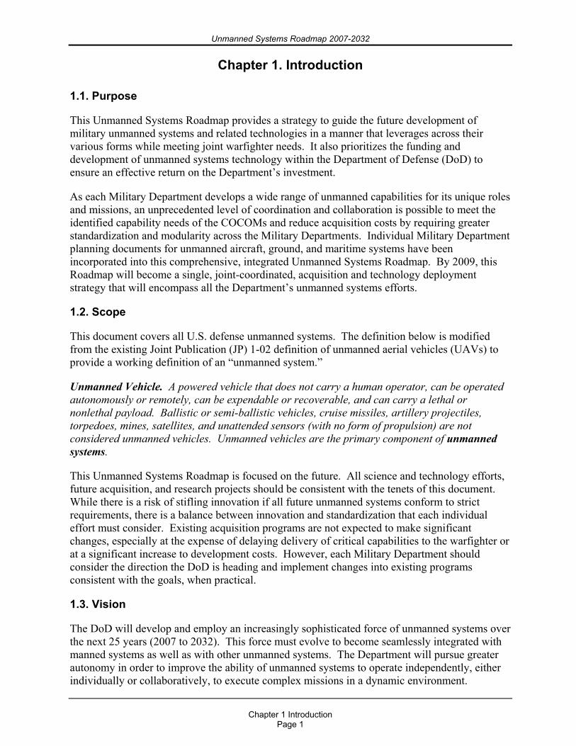
Figure 1.1 illustrates how unmanned systems are already employed in a significant number of roles. The systems are broken out by Military Department to illustrate areas with current and potential future collaboration. Reconnaissance, strike, force protection, and signals collection are already being conducted by fielded systems, and acquisition programs are developing systems to support the warfighter in even broader roles.
Figure 1.1 DoD Unmanned Systems, Present and Future Roles
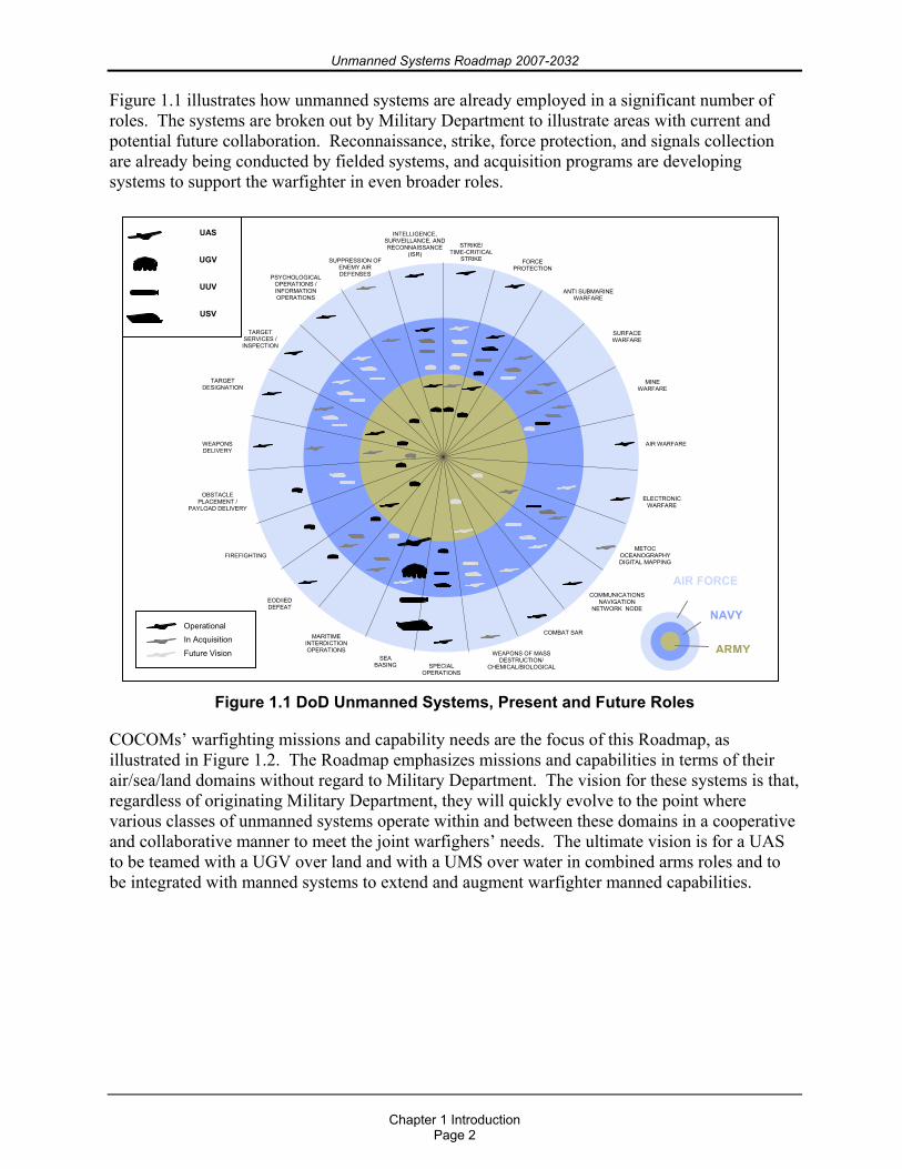
COCOMs’ warfighting missions and capability needs are the focus of this Roadmap, as illustrated in Figure 1.2. The Roadmap emphasizes missions and capabilities in terms of their air/sea/land domains without regard to Military Department. The vision for these systems is that, regardless of originating Military Department, they will quickly evolve to the point where various classes of unmanned systems operate within and between these domains in a cooperative and collaborative manner to meet the joint warfighers’ needs. The ultimate vision is for a UAS to be teamed with a UGV over land and with a UMS over water in combined arms roles and to be integrated with manned systems to extend and augment warfighter manned capabilities.
STRIKE/ TIME-CRITICAL
STRIKE FORCE PROTECTION
ANTI SUBMARINE WARFARE
SURFACE WARFARE
MINE WARFARE
AIR WARFARE
ELECTRONIC WARFARE
METOC OCEANOGRAPHY DIGITAL MAPPING
COMMUNICATIONS NAVIGATION
NETWORK NODE
COMBAT SAR
WEAPONS OF MASS DESTRUCTION/
CHEMICAL/BIOLOGICALSPECIAL OPERATIONS
SEA BASING
EOD/IED DEFEAT
FIREFIGHTING
OBSTACLE PLACEMENT /
PAYLOAD DELIVERY
WEAPONS DELIVERY
TARGET DESIGNATION
TARGET SERVICES / INSPECTION
PSYCHOLOGICAL OPERATIONS / INFORMATION OPERATIONS
SUPPRESSION OF ENEMY AIR DEFENSES
MARITIME INTERDICTION OPERATIONS ARMY
NAVY
AIR FORCE
Operational In Acquisition
Future Vision
INTELLIGENCE, SURVEILLANCE, AND RECONNAISSANCE
(ISR)
UAS
UGV
UUV
USV
Unmanned Systems Roadmap 2007-2032
Chapter 1 Introduction
Page 3
Figure 1.2 Joint Services Roadmap for Achieving DoD Vision for Unmanned Systems
1.4. Goals and Objectives
The DoD is developing a wide range of unmanned system capabilities across each domain. The Office of the Secretary of Defense (OSD) is responsible for ensuring that these capabilities support the Department’s larger goals of fielding transformational capabilities, establishing and implementing joint standards, ensuring interoperability, balancing the portfolio, and controlling costs. To this end, the following broad goals are intended to achieve key unmanned system capabilities:
Goal 1. Improve the effectiveness of COCOM and coalition unmanned systems through improved integration and Joint Services collaboration.
Objective 1.1. Conduct concept demonstration/warfighter experimentation with promising technologies. This step would allow for early assessment to help define realistic requirements underpinned by sound operational concepts.
Objective 1.2. Conduct risk reduction to mature technologies. This step allows the Military Departments to finalize capability requirements and to establish funding for formal program initiation while overcoming the technology transfer challenges.
A
I
R
S
E
A
L
A
N
D
RECONNAISSANCE
TACTICAL STRIKE
COMMS RELAY
SIGINT COLLECTION
MARITIME PATROL
AERIAL REFUELING
SURVEILLANCE / BATTLE MGMT
AIRLIFT
SEAD
PENETRATING STRIKE
INTEGRATED STRIKE / SEAD
COUNTER AIR
INT. STRIKE/SEAD/C-AIR
VSW RECON
Unmanned Aircraft Systems
Unmanned Surface Systems
Unmanned Ground Vehicles
Unmanned Undersea Systems
SUB. AUTONOMOUS MAPPING
INSPECTION / ID
MAN PORTABLE CN3
TELEOPERATED EOD
SHIP DEPLOYED CN3
MCM (INTERIM)
MINE NEUTRALIZATION
ISR
SHIP DEPLOYED MCM INFORMATION OPS
OCEANOGRAPHY ASW PAYLOAD DEL.
MCM INTEL PREP
SUB TRCK & TRAIL
TIME CRITICAL STRIKE
ISR / MARITIME SURVEIL
MARITIME INTERDICT OPS
SOF RIVERINE
SURFACE WARFARE
MCM SEARCH/SWEEP
ASW ASW-MSARMED ASW/MS/SUW
MAN PORTABLE EOD ANTI-P MINE NEUTRALIZATION
SCOUT/ISR/NBC RECCE/DIRECT FIRE/CROWD CONTROL
AT / FP MISSIONS
ACTIVE RANGE CLEAR & DISRUPT LGE-VEHICLE IEDS
EXPEDITIONARY FACILITY PATROL & SURVEILLANCE
LETHAL & NONLETHAL FORWARD DEPLOYED FP
FCS MANEUVER, MANEUVER SUPPORT & SUSTAINMENT
COLLABORATIVE COMBINED ARMS ENGAGEMENT
2005 2010 2015 2020 2025 2030
Unmanned Systems Roadmap 2007-2032
Chapter 1 Introduction
Page 4
Goal 2. Emphasize commonality to achieve greater interoperability among system controls, communications, data products, and data links on unmanned systems.
Objective 2.1. Field secure common data link (CDL) communications systems for unmanned systems control and sensor product data distribution. (BLOS and LOS)
Objective 2.1.1. Improve capability to prevent interception, interference, jamming, and hijacking. Seek integrated solutions between technology, tactics, training, and procedures.
Objective 2.1.2. Migrate, as appropriate, to a capability compliant with the Software Communications Architecture of the Joint Tactical Radio System when available.
Objective 2.2. Increase emphasis on “common control” and “common interface” standards to allow for greater interoperability of unmanned systems.
Objective 2.3. Ensure compliance with the existing DoD/Intelligence Community Motion Imagery Standards Board metadata standard and profiles for all unmanned systems capable of full motion video.
Goal 3. Foster the development of policies, standards, and procedures that enable safe and timely operations and the effective integration of manned and unmanned systems.
Objective 3.1. Promote the development, adoption, and enforcement of Government and commercial standards for the design, manufacturing, and testing of unmanned systems.
Objective 3.2. Coordinate with Federal Aviation Administration (FAA) and other applicable Federal transportation organizations to ensure the operations of DoD unmanned systems adhere to collision avoidance requirements (airspace, waterspace, and ground) comparable to the requirements of their manned counterparts.
Objective 3.3. Develop and field unmanned systems that can “sense” and autonomously avoid other objects in order to provide a level of safety equivalent to comparable manned systems.
Goal 4. Implement standardized and protected positive control measures for unmanned systems and their associated armament.
Objective 4.1. Develop a standard unmanned systems architecture and associated standards for all appropriate unmanned systems.
Objective 4.2. Develop a standard unmanned systems architecture and associated standards for unmanned systems capable of weapons carriage.
Goal 5. Support rapid integration of validated combat capabilities in fielded/deployed systems through a more flexible test and logistical support process.
Objective 5.1. Develop and field reliable propulsion alternatives to gasoline-powered internal combustion engines.
Objective 5.2. Develop common, high-energy-density power sources (primary and renewable) for unmanned systems that meet their challenging size, weight, and space requirements, preferably common with manned systems as well.
Unmanned Systems Roadmap 2007-2032
Chapter 1 Introduction
Page 5
Goal 6. Aggressively control cost by utilizing competition, refining and prioritizing requirements, and increasing interdependencies (networking) among DoD systems.
Objective 6.1. Compete all future unmanned system programs.
Objective 6.2. Implement Configuration Steering Boards to increase the collaboration between engineering and operations to field vital capability within budget constraints.
Objective 6.3. Develop common interoperability profiles for development, design and operation of unmanned systems.
Unmanned Systems Roadmap 2007-2032
Chapter 2 Strategic Planning and Policy
Page 6
Chapter 2. Strategic Planning and Policy
2.1. Background
Unmanned systems are currently serving in key operational roles in the GWOT and routinely garner enthusiastic support from the warfighters who employ them. The operational utility and potential of unmanned systems are growing at an accelerating rate throughout DoD to the extent that unmanned systems will inevitably have a continued and greater presence within the force structure over the foreseeable future. The Department is, therefore, committed and is organizationally postured to shape and capitalize on unmanned systems technology advances to better serve the warfighters.
This Roadmap is focused on providing capability to the warfighter and fostering interoperability of air, ground, and sea systems — both unmanned and manned. The Roadmap describes unmanned systems in the current force structure as well as systems currently in development. The combination of these efforts into a single document with a common vision represents the initial strategy and schedule by which the Department intends to capitalize on unmanned systems to execute missions that today are largely conducted with manned systems. Elements such as the vision, strategy, schedules, and technology investments will be further refined when the 2009 publication of the Unmanned Systems Roadmap is prepared.
2.2. Congressional Direction
In Section 220 of the Floyd D. Spence National Defense Authorization Act for Fiscal Year (FY) 2001 (Public Law 106-398),1 Congress stated two key, overall goals for the DoD with respect to UAS and UGV development:
By 2010, one third of the aircraft in the operational deep strike force should be unmanned, and
By 2015, one third of the Army’s Future Combat Systems (FCS) operational ground combat vehicles should be unmanned.
Since this 2001 expression of Congressional intent to advance the introduction of unmanned systems into the Joint Forces, the DoD has taken positive steps toward achieving those goals. Congress assisted the continued accelerated fielding of existing UASs by amending Section 142 of the National Defense Authorization Act for FY2006, which contained a provision limiting the initiation of new UASs. Section 141 of the John Warner National Defense Authorization Act for FY 2007 makes it clear that the limitations contained in the 2006 authorization act do not apply to systems under contract, previously procured, or for which funds have been appropriated but not yet obligated.2
1 These goals and associated reporting requirements are found in section 220 of the Floyd D. Spence National Defense Authorization Act for FY2001 (Public Law 106-398; 114 Stat 1654A-38). 2 Section 141 of the John Warner National Defense Authorization Act for FY 2007 (Public Law 109-364, 120 Stat 2116) amending Section 142 of National Defense Authorization Act for FY2006 (Public Law 109-163; 119 Stat. 3164).
Unmanned Systems Roadmap 2007-2032
Chapter 2 Strategic Planning and Policy
Page 7
In response to Section 941 of the John Warner National Defense Authorization Act for FY 2007 an interim report was provided by DoD to address unmanned systems requirement generation and acquisition processes. The assessment of the Department in the report is that current policies for capabilities generation, acquisition and sustainment processes, and DoD organizational structures for unmanned systems development are very much aligned with Congressional intent without additional policy development. By recognizing and pursuing the potential of unmanned systems to provide improved capability to the Nation’s warfighters, the Department oversees and manages the focused development of unmanned systems from a single, centralized, organizational vantage point within the Office of the Under Secretary of Defense Acquisition, Technology, and Logistics (OUSD(AT&L)). This Roadmap enables the Department to take deliberate, appropriate, operationally effective steps toward fulfilling the goals of having one third of the aircraft in the operational deep strike force be unmanned by 2010 and having one third of the Army’s FCSs operational ground combat vehicles be unmanned by 2015.
2.3. Acquisition Policies
2.3.1. General Development and acquisition of UASs, UMSs, and UGVs are governed by a myriad of DoD directives that provide policy and direction for specific developments or classes of development activities. Because unmanned systems are really “systems of systems,” including components such as platforms, sensors, weapons, command and control architectures, computers, and communications, the Military Departments and program managers must integrate the policy of multiple documents into their program plans. The following is a partial reference list of key DoD Chief Information Officer (CIO) directives of interest to the unmanned systems community:
3222.3 DoD Electromagnetic Environmental Effects (E3) Program 9/08/2004 4630.5 Interoperability and Supportability of IT and National Security Systems (NSS)
5/5/2004 4640.13 Management of Base and Long-Haul Telecommunications Equipment and Military
Services 12/05/1991 4650.1 Policy for Management and Use of the Electromagnetic Spectrum 6/08/2004 4650.5 Positioning, Navigation, and Timing 6/2/2003 5030.19 DoD Responsibilities on Federal Aviation and National Airspace System Matters
6/15/1997 5100.35 Military Communications-Electronics Board (MCEB) 3/10/1995 5144.1 Assistant Secretary of Defense for Networks and Information Integration/DoD Chief
Information Officer (ASD(NII)/DoD CIO) 5/02/2005 8000.1 Management of DoD Information Resources and Information Technology 2/27/2002 8100.1 Global Information Grid (GIG) Overarching Policy 9/19/2002 8100.2 Use of Commercial Wireless Devices, Services, and Technologies in the DoD Global
Information Grid (GIG) 4/14/2004 8190.1 DoD Logistics Use of Electronic Data Interchange (EDI) Standards 5/5/2000 8320.2 Data Sharing in a Net-Centric Department of Defense 12/02/2004 8500.1 Information Assurance 10/24/2002
Unmanned Systems Roadmap 2007-2032
Chapter 2 Strategic Planning and Policy
Page 8
2.3.2. Joint Capabilities Integration and Development System (JCIDS) JCIDS supports the Chairman of the Joint Chiefs of Staff (CJCS) and the Joint Requirements Oversight Council (JROC) in identifying, assessing and prioritizing joint military capability needs. CJCSI 3170.01E.3 describes the process all military departments should follow when identifying, assessing, prioritizing and determining solutions for needed capabilities. Furthermore, JCIDS “implements an enhanced methodology using joint concepts that will identify and describe existing or future shortcomings and redundancies in warfighting capabilities; describe effective solutions; identify potential approaches to resolve those shortcomings; and provide a foundation for further development.”4
As part of the JCIDS policy and implementation, rigorous assessment and analysis are required before a decision can be made about which (materiel or nonmateriel) approach to pursue in resolving identified capability gaps or redundancies. Performing a Capabilities-Based Assessment (CBA) results in the specific identification of a viable, affordable military solution. A CBA comprises four types of analysis: Functional Area Analysis (FAA), Functional Needs Analysis (FNA), Functional Solutions Analysis (FSA), and Post-Independent Analysis (PIA).
A FAA identifies the operational tasks, conditions, and standards needed to achieve military objectives. A FNA assesses the ability of the current and programmed warfighting systems to deliver needed capabilities, produces a list of capability gaps that require solutions, and indicates the time frame in which those solutions are needed. A FSA identifies potential approaches to satisfying the capability needs including product improvements to existing materiel, adoption of interagency or foreign materiel solutions, and initiation of new materiel programs. A PIA independently reviews the FSA to ensure the latter was thorough and the recommended approaches are reasonable possibilities to deliver the capability identified in the FNA.3
Each of the above analyses affords DoD the opportunity to identify and examine rigorously capability gaps and potential materiel or nonmaterial solutions, both manned and unmanned, to those requirements. The policies and implementation of JCIDS via these analyses are how unmanned systems will be assessed for their ability to meet the capability gaps and potential for greater integration with, and/or replacement of, manned systems in the future. Furthermore, the JCIDS analyses also take into consideration the additional factors of timing, affordability, technical soundness, and sustainability associated with potential unmanned system solutions in order to maximize the investment return in all domains of unmanned systems.
Go to http://www.dtic.mil/cjcs_directives/cdata/unlimit/3170_01.pdf for additional information on the JCIDS process.
2.3.3. DoD 5000 series Following validation of the requirement through the JCIDS process, unmanned systems capability requirements are satisfied through the execution of acquisition programs in the same manner as manned systems through DoDD 5000.1 and DoDI 5000.2.4 In accordance with DoDD 5000.1, “The primary objective of Defense acquisition is to acquire quality products that satisfy user needs with measurable improvements to mission capability and operational support,
3 CJCSI 3170.01E, Enclosure A, p. A-5. 4 Department of Defense Directive (DoDD) 5000.1, The Defense Acquisition System, 12 May 2003, and Department of Defense Instruction (DoDI) 5000.2, Operation of the Defense Acquisition System, 12 May 2003.
Unmanned Systems Roadmap 2007-2032
Chapter 2 Strategic Planning and Policy
Page 9
in a timely manner, and at a fair and reasonable price.”5 DoDD 5000.1 further states, “Advanced technology shall be integrated into producible systems and deployed in the shortest time practicable.”6 DoDI 5000.2 requires the preparation of an analysis of alternatives for potential and designated acquisition category (ACAT) I programs.7 The purpose of the analysis of alternatives is “an analytical comparison of the operational effectiveness, suitability, and life cycle cost of alternatives that satisfy established capability needs.”8
As with JCIDS, DoDD 5000.1 and DoDI 5000.2 direct that rigorous analysis be undertaken to assess the ability of the potential materiel solution to meet validated requirements in the context of other considerations such as affordability, timeliness, and suitability. Because the Defense acquisition system deliberately seeks affordable advanced technology solutions and JCIDS identifies the mission requirements and the associated time frame in which those requirements should be met, existing policies position the Department to satisfy departmental needs and meet Congressional intent with regard to unmanned systems policy and development. When a materiel solution is deemed as the appropriate path for satisfying a capability need, preference is given to advanced technology in accordance with DoDD 5000.1. Unmanned systems are considered as potential solutions because they are considered advanced technology and are assessed for feasibility as part of the PIA.
Go to http://akss.dau.mil/dapc/index.html for more information on the DoD 5000 series documents.
5 DoDD 5000.1, Section 4.2, p. 2. 6 DoDD 5000.1, Section 4.3.2, p. 2. 7 DoDI 5000.2, Enclosure 6, Resource Estimation, paragraph E6.1.5. 8 “Defense Acquisition Guidebook,” 16 December 2004, paragraph 3.3, Analysis of Alternatives.
Unmanned Systems Roadmap 2007-2032
Chapter 2 Strategic Planning and Policy
Page 10
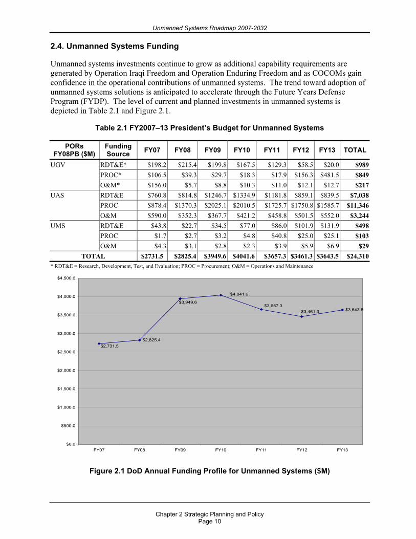
2.4. Unmanned Systems Funding
Unmanned systems investments continue to grow as additional capability requirements are generated by Operation Iraqi Freedom and Operation Enduring Freedom and as COCOMs gain confidence in the operational contributions of unmanned systems. The trend toward adoption of unmanned systems solutions is anticipated to accelerate through the Future Years Defense Program (FYDP). The level of current and planned investments in unmanned systems is depicted in Table 2.1 and Figure 2.1.
Table 2.1 FY2007–13 President’s Budget for Unmanned Systems
PORs FY08PB ($M)
Funding Source FY07 FY08 FY09 FY10 FY11 FY12 FY13 TOTAL
RDT&E* $198.2 $215.4 $199.8 $167.5 $129.3 $58.5 $20.0 $989PROC* $106.5 $39.3 $29.7 $18.3 $17.9 $156.3 $481.5 $849
UGV
O&M* $156.0 $5.7 $8.8 $10.3 $11.0 $12.1 $12.7 $217RDT&E $760.8 $814.8 $1246.7 $1334.9 $1181.8 $859.1 $839.5 $7,038PROC $878.4 $1370.3 $2025.1 $2010.5 $1725.7 $1750.8 $1585.7 $11,346
UAS
O&M $590.0 $352.3 $367.7 $421.2 $458.8 $501.5 $552.0 $3,244RDT&E $43.8 $22.7 $34.5 $77.0 $86.0 $101.9 $131.9 $498PROC $1.7 $2.7 $3.2 $4.8 $40.8 $25.0 $25.1 $103
UMS
O&M $4.3 $3.1 $2.8 $2.3 $3.9 $5.9 $6.9 $29TOTAL $2731.5 $2825.4 $3949.6 $4041.6 $3657.3 $3461.3 $3643.5 $24,310
* RDT&E = Research, Development, Test, and Evaluation; PROC = Procurement; O&M = Operations and Maintenance
$2,825.4
$3,643.5$3,657.3
$2,731.5
$3,461.3
$4,041.6
$3,949.6
$0.0
$500.0
$1,000.0
$1,500.0
$2,000.0
$2,500.0
$3,000.0
$3,500.0
$4,000.0
$4,500.0
FY07 FY08 FY09 FY10 FY11 FY12 FY13
Figure 2.1 DoD Annual Funding Profile for Unmanned Systems ($M)
Unmanned Systems Roadmap 2007-2032
Chapter 2 Strategic Planning and Policy
Page 11
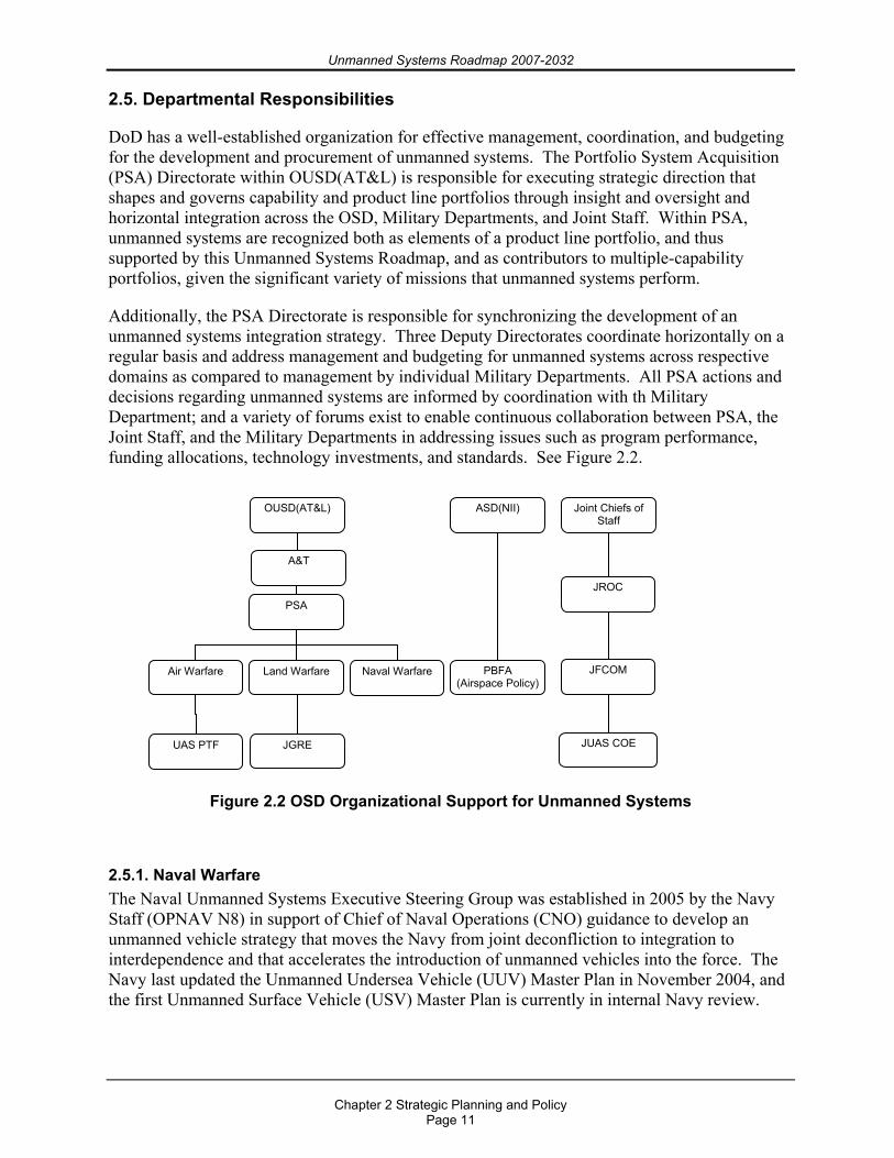
2.5. Departmental Responsibilities
DoD has a well-established organization for effective management, coordination, and budgeting for the development and procurement of unmanned systems. The Portfolio System Acquisition (PSA) Directorate within OUSD(AT&L) is responsible for executing strategic direction that shapes and governs capability and product line portfolios through insight and oversight and horizontal integration across the OSD, Military Departments, and Joint Staff. Within PSA, unmanned systems are recognized both as elements of a product line portfolio, and thus supported by this Unmanned Systems Roadmap, and as contributors to multiple-capability portfolios, given the significant variety of missions that unmanned systems perform.
Additionally, the PSA Directorate is responsible for synchronizing the development of an unmanned systems integration strategy. Three Deputy Directorates coordinate horizontally on a regular basis and address management and budgeting for unmanned systems across respective domains as compared to management by individual Military Departments. All PSA actions and decisions regarding unmanned systems are informed by coordination with th Military Department; and a variety of forums exist to enable continuous collaboration between PSA, the Joint Staff, and the Military Departments in addressing issues such as program performance, funding allocations, technology investments, and standards. See Figure 2.2.
Figure 2.2 OSD Organizational Support for Unmanned Systems
2.5.1. Naval Warfare The Naval Unmanned Systems Executive Steering Group was established in 2005 by the Navy Staff (OPNAV N8) in support of Chief of Naval Operations (CNO) guidance to develop an unmanned vehicle strategy that moves the Navy from joint deconfliction to integration to interdependence and that accelerates the introduction of unmanned vehicles into the force. The Navy last updated the Unmanned Undersea Vehicle (UUV) Master Plan in November 2004, and the first Unmanned Surface Vehicle (USV) Master Plan is currently in internal Navy review.
UAS PTF
OUSD(AT&L)
PSA
Air Warfare Land Warfare Naval Warfare
JGRE
ASD(NII)
PBFA (Airspace Policy)
JROC
JUAS COE
Joint Chiefs of Staff
A&T
JFCOM
Unmanned Systems Roadmap 2007-2032
Chapter 2 Strategic Planning and Policy
Page 12
2.5.2. Ground Warfare Joint Ground Robotics Enterprise (JGRE) policy developed in accordance with direction from Congress and DoD is to perform the following:
Oversee a consolidation of efforts, Concentrate on establishing definitive robotics operational capabilities, and Pursue critical technologies to satisfy capability needs.
The JGRE approach involves additional direction and prioritization and takes into account near-term emerging requirements and GWOT needs; mid-term and long-term technology maturation; and greater collaboration between warfighters, laboratories, and program managers to link doctrine, technology, and capability needs.
As a management tool for UGV development coordination, the JGRE has instituted the Joint Ground Robotics (JGR) Technical Advisory Board (TAB), which coordinates across the Joint Staff and Military Departments the ground robotics acquisition and the efforts to map technology developments (from DoD labs, industry, and academia) to the most pressing military issues and joint priorities. The JGR 06 Council prioritizes and allocates Advanced Component Development and Prototypes (ACD&P) and System Development and Demonstration (SDD) investments based on assessments of technology maturity and feasibility associated with technologies recommended by the TAB. These efforts ensure technologies are assessed, matured, and transitioned to programs of record (PORs) to satisfy validated requirements for ground applications across all the Military Departments. Examples of success include the joint development, upgrade, and sustainment of explosive ordnance disposal (EOD) robots that are used by all Military Departments in theater to counter Improvised Explosive Devices (IEDs).
2.5.3. Air Warfare The UAS Planning Task Force (PTF) was established in 2001 to be the single focal point within the DoD to guide UAS planning and execution, in coordination with the Military Departments, Joint Staff, and other agencies. The UAS PTF promotes payload commonality by developing and enforcing interface standards, ensuring Military Department cooperation, leveraging UAS contributions to precision targeting, promoting joint experimentation for integrating UAS into combat operations, assisting the transition of promising UAS-related technologies, and resolving overarching export policy and airspace issues. The UAS PTF published three DoD UAS roadmaps (formerly “unmanned aerial vehicle roadmaps”) as a technology roadmap, which provided DoD with the opportunity to plan for UAS development and employment over the next 25 years.
Unmanned Systems Roadmap 2007-2032
Chapter 3 Interoperability and Standards
Page 13
Chapter 3. Interoperability and Standards
3.1. Interoperability Requirements
Interoperability is the ability to operate in synergy in the execution of assigned tasks (JP1-02). Properly implemented, it can serve as a force multiplier and can simplify logistics. DoDD 5000.1 establishes the requirement to acquire systems and families of systems that are interoperable.9 DoD’s unmanned systems will need to demonstrate interoperability on a number of levels:
Among different systems of the same modality. The Army’s OneSystem common ground control station (GCS) for its MQ-5 Hunter, RQ-7 Shadow, and MQ-1 Warrior UASs is an example of this level of existing interoperability.
Among systems of different modalities. The planned ability of ground and air vehicles of the Army’s FCS to work cooperatively is an example of this level of future interoperability.
Among systems operated by different Military Departments under various concepts of operations (CONOPSs) and tactics, techniques, and procedures (TTP), i.e., in joint operations. An example of this is the Joint Forces Air Component Commanders’ Air Tasking Order (ATO).
Among military systems and systems operated by other entities in a common environment. The ability of military UASs to share the National Airspace System (NAS) and international airspace with commercial airliners and general aviation is an example of this level of future interoperability.
Among systems operated by non-DoD organizations, allies, and coalition partners, i.e., in combined operations. The MQ-9 Reapers of the Customs and Border Protection (CBP) and the Air Force and the RQ-1/MQ-1 Predators of the Italian Air Force and U.S. Air Force are limited (same modality, same model), existing examples of this level of interoperability.
Interoperability is achieved by buying common components, systems, and software and/or by building systems to common standards. It is most affordable when built into the DoD systems during the design and acquisition phases, and formal standards best ensure interoperability is incorporated during these phases.
3.2. Unmanned Systems Standards
Standards (formal agreements for the design, manufacture, testing, and performance of technologies) are a key enabler of interoperability. PL104-11310 requires Federal organizations to adopt commercial standards where practical rather than expending its resources to create or maintain similar ones, specifically in the case of military standards. Where needed standards do not exist or prove insufficient, OMB Circular A-11911 directs Federal employees to work within consensus-based standards development organizations (SDOs) to create such standards. SDOs are domestic or international organizations that plan, develop, establish, or coordinate voluntary
9 DoDD 5000.1, Enclosure 1, paragraph E1.10. 10 Public Law (PL) 104-113, National Technology Transfer and Advancement Act of 1995. 11 Office of Management and Budget (OMB) Circular A-119, Federal Participation in the Development and Use of Voluntary Consensus Standards and in Conformity Assessment Activities, 1998.
Unmanned Systems Roadmap 2007-2032
Chapter 3 Interoperability and Standards
Page 14
consensus standards using agreed upon procedures that define openness, consensus, balance, due process, and appeals. DoD 4120.24-M12 requires that DoD first consider using non-Government standards (NGSs), or support revising or developing a NGS to meet DoD needs, in preference to using Federal documents whenever feasible. In addition to interoperability, using standards also promotes product quality assurance, furthers DoD commercial acquisition goals, conserves DoD resources, supports the U.S. industrial base, promotes dual-use technology, and improves DoD’s mobilization capabilities.
Recognizing the relationship between interoperability and standards, the Secretary of Defense delegated responsibility to the Under Secretary for Acquisition, Technology, and Logistics, who assigned the Defense Standardization Program Office (DSPO) as the executive agent to encourage and coordinate DoD’s role in standards development and use. DSPO is the DoD representative on the Congressionally mandated Interagency Committee for Standards Policy, which is chaired by the National Institute for Standards and Technology (NIST) and consists of representatives from most Federal agencies. DoD’s unmanned community, represented by Naval Air Systems Command (NAVAIR) PMA-263, began developing UAS standards for NATO in the mid-1990s as a participant in NATO’s Planning Group 35 (PG-35). Beginning in 2002, a number of SDOs began creating committees within their ranks to address the needs of the unmanned community across the spectrum of U.S. and international, as well as military, civil, and commercial, users of unmanned systems (see Table 3.1). DSPO reviews and coordinates standards developed by these SDO committees for adoption by DoD.
DoD personnel are actively participating within these SDOs in the following roles to develop standards for unmanned systems:
Ensuring DoD-relevant standards are being created, Guarding against wording in standards that would be at cross purposes with DoD’s needs
(e.g., compromising DoD’s right to self-certify aircraft airworthiness), and Preventing duplication of standard-creating efforts across SDOs.
This last role is important because the practices of individual industry often provide the starting point of community-wide standards and make the participation of industry experts, which is largely voluntary, crucial in creating worthwhile standards; therefore, it becomes important to not squander industry’s voluntary support to these SDOs. Through their consensus-based processes, SDOs help protect the proprietary concerns of their commercial participants yet draw on the expertise of these participants to produce standards for the good of the unmanned community. DoD personnel should encourage and complement, not supplant, the participation of commercial industries in SDOs. Table 3.1 describes the organizations with which DoD members are now involved in developing standards for unmanned systems.
The DoD unmanned community participates in standards development through three avenues:
NATO Standardization Agency, through the work of its Joint Capability Group on Unmanned Aerial Vehicles (JCGUAV),
OSD JGRE, through its Joint Architecture for Unmanned Systems (JAUS), and
12 DoD 4120.24-M, Defense Standardization Program Policies and Procedures.
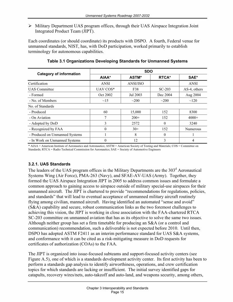
Unmanned Systems Roadmap 2007-2032
Chapter 3 Interoperability and Standards
Page 15
Military Department UAS program offices, through their UAS Airspace Integration Joint Integrated Product Team (JIPT).
Each coordinates (or should coordinate) its products with DSPO. A fourth, Federal venue for unmanned standards, NIST, has, with DoD participation, worked primarily to establish terminology for autonomous capabilities.
Table 3.1 Organizations Developing Standards for Unmanned Systems
SDO Category of information AIAA* ASTM* RTCA* SAE*
Certification ANSI ANSI/ISO ANSI UAS Committee UAV COS* F38 SC-203 AS-4, others - Formed Oct 2002 Jul 2003 Dec 2004 Aug 2004 - No. of Members ~15 ~200 ~200 ~120 No. of Standards - Produced 60 15,000 152 8300 - On Aviation 7 200+ 152 4000+ - Adopted by DoD 3 2572 0 3240 - Recognized by FAA 0 30+ 152 Numerous - Produced on Unmanned Systems 1 8 0 1 - In Work on Unmanned Systems 0 12 3 4 * AIAA = American Institute of Aeronautics and Astronautics; ASTM = American Society of Testing and Materials; COS = Committee on Standards; RTCA = Radio Technical Commission for Aeronautics; SAE = Society of Automotive Engineers
3.2.1. UAS Standards The leaders of the UAS program offices in the Military Departments are the 303d Aeronautical Systems Wing (Air Force), PMA-263 (Navy), and SFAE-AV-UAS (Army). Together, they formed the UAS Airspace Integration JIPT in 2005 to address common issues and formulate a common approach to gaining access to airspace outside of military special-use airspaces for their unmanned aircraft. The JIPT is chartered to provide “recommendations for regulations, policies, and standards” that will lead to eventual acceptance of unmanned military aircraft routinely flying among civilian, manned aircraft. Having identified an automated “sense and avoid” (S&A) capability and secure, robust communication links as the two foremost challenges to achieving this vision, the JIPT is working in close association with the FAA-chartered RTCA SC-203 committee on unmanned aviation that has as its objective to solve the same two issues. Although neither group has set a firm timetable for producing an S&A (or a control and communication) recommendation, such a deliverable is not expected before 2010. Until then, DSPO has adopted ASTM F2411 as an interim performance standard for UAS S&A systems, and conformance with it can be cited as a risk-mitigating measure in DoD requests for certificates of authorization (COAs) to the FAA.
The JIPT is organized into issue-focused subteams and support-focused activity centers (see Figure A.5), one of which is a standards development activity center. Its first activity has been to perform a standards gap analysis to identify airworthiness, operations, and crew certification topics for which standards are lacking or insufficient. The initial survey identified gaps for catapults, recovery wires/nets, auto-takeoff and auto-land, and weapons security, among others,
Unmanned Systems Roadmap 2007-2032
Chapter 3 Interoperability and Standards
Page 16
to be worked by SDOs. One such SDO, ASTM International and its F-38 UAS Committee, published a limited standards gap analysis for unmanned airworthiness in 2005 (ASTM F2501), and its recent F2585 standard for pneumatic and hydraulic catapults was adopted for DoD use by DSPO in 2006. The organization of JIPT is depicted in A.3.
In addition to the JIPT’s standards activities, PMA-263 continues to support NATO JCGUAV’s interoperability efforts in unmanned aviation. JCGUAV subsumed NATO’s three Military Department UAS-related groups (PG-35, Air Group 7, and Task Group 2) in 2006. Its major accomplishments to date have been Standardization Agreement (STANAG) 4586 for UAS message formats and data protocols, STANAG 4660 for interoperable command and control links, STANAG 4670 for training UAS operators, and STANAG 7085 for the CDL communication system, which has been mandated by OSD since 1991. It has also drafted STANAG 4671 for UAS airworthiness.
3.2.2. UGV Standards JAUS began in 1995 as an effort by the Army’s program office for UGVs in the Aviation and Missile Research, Development and Engineering Center (AMRDEC) at Redstone Arsenal to establish a common set of message formats and data protocols for UGVs made by various manufacturers. Deciding to convert JAUS to an international industry standard, the program office approached the SAE, an SDO with robotics experience, which established the AS-4 Unmanned Systems Committee in August 2004. AS-4 has three subcommittees focused on requirements, capabilities, and interfaces and an experimental task group to test its recommended formats and protocols before formally implementing them. It plans to complete its conversion of JAUS and issue it as an SAE standard during fourth quarter FY2009. Although AS-4 is open to its members’ creating standards on other aspects of unmanned systems beyond message formats and data protocols for UGVs, much of this broader work is now being undertaken by other UAS-related SDOs. STANAG 4586 is unmanned aviation’s counterpart to JAUS.
3.2.3. UMS Standards The Navy’s Program Executive Officer of Littoral and Mine Warfare (PEO(LMW)) formally adopted JAUS message formats and data protocols for use with its unmanned undersea, surface, and ground vehicles in 2005. Working through SAE AS-4, the Naval Undersea Warfare Center (NUWC) has been expanding JAUS to serve the UMS community. It has found only 21 percent of UMS message formats to be directly compatible with the formats of JAUS, with the high percentage of new formats needed possibly due to the operation of UMSs in three dimensions versus the two dimensions of UGVs, for which JAUS was developed.
3.2.4. Media Standards NGSs exist that provide a framework for storing digital video content. One such framework is the Media Exchange Format (MXF), which provides an architecture for exchanging digital video content as a file. An MXF file has a file header that includes metadata providing information on the video content, also referred to as the “essence,” that follows the file header. A footer terminates the file. The MXF metadata are composed of objects that are encoded using the Key, Length, Value (KLV) coding scheme.
Unmanned Systems Roadmap 2007-2032
Chapter 3 Interoperability and Standards
Page 17
KLV is defined in SMPTE 336M-2001.13 The key indicates what kind or type of data will be presented in the payload. The length describes how many bytes are expected in this set of data. The value yields the actual payload of the length previously described. The KLV protocol provides a common interchange for all compliant applications irrespective of the method of implementation or transport.14 KLV is the standard that the Department is implementing.
The benefit of KLV lies in its use with MXF. It was designed and implemented to improve file-based interoperability among servers, workstations, and other content-creation devices. These should result in improved workflows and in more efficient working practices than is possible with mixed and proprietary file formats. It is not compression-scheme-specific; it simplifies the integration of systems using Motion Picture Experts Group (MPEG) and digital video formats as well as future compression strategies. In other words, the transportation of these different files will be independent of content and will not dictate the use of specific manufacturers’ equipment. Any required processing can simply be achieved by automatically invoking the appropriate hardware or software codec. However, MXF is designed for operational use; therefore, all the handling processes are seamless to the user.
3.3. Roadmap Interoperability Objectives
To provide future, seamless interoperability by DoD UASs with its UGVs and UMSs, a single standard for message formats and data protocols is needed where two such standards, STANAG 4586 and JAUS, exist today. Currently, some level of overlap exists between these two standards in that both are being applied to UASs [JAUS/SAE to smaller tactical unmanned aerial vehicles (TUAVs)] and some initiatives are underway that are attempting to apply and demonstrate STANAG 4586 for USVs and potentially other platform types. The long-term goal within DoD is the evolution to a unified standard where practical. An effort to integrate or combine these two standards is being pursued by the Joint Unmanned Systems Common Control (JUSC2) advanced concept technology demonstration (ACTD), with the placing of an engineer in both SAE-4 and PG-35 working groups as a fully participating and voting member of both groups. This initiative has led to the identification of a common approach that both groups are now pursuing that will lead to one interoperability standard that can be applied for development of all unmanned systems types in the future. SAE-4 and PG-35 are starting to converge on identification of a set of Internet Protocol-based development schemas [Extensible Markup Language (XML) is an example] and open-source software development and certification tool sets that promise to blur the current distinction between the two standards. This work is documented in a Navy technical report, “Standardization of Unmanned Systems Technical Standards,” from Naval Surface Warfare Center, Panama City, published in July 2007.
13 Society of Motion Picture and Television Engineers (SMPTE) 336M-2001, Television-Data Encoding Protocol Using Key-Length Value, 28 March 2001, http://www.smpte.org or http://en.allexperts.com/e/s/so/society_of_ motion_picture_and_television_engineers.htm. 14 International Standard IEC 62261-2, International Electrotechnical Commission, Geneva, Switzerland, 2005, pg. 6.

Unmanned Systems Roadmap 2007-2032
Chapter 3 Interoperability and Standards
Page 18
Unmanned Systems Roadmap 2007-2032
Chapter 4 COCOM Mission and Capability Needs
Page 19
Chapter 4. COCOM Mission and Capability Needs
4.1. Why Unmanned Systems?
The familiar saying that unmanned systems are better suited for “dull, dirty, or dangerous” missions rather than manned systems presupposes that man is the limiting factor in performing certain warfighting missions. Although most missions can be dull or dangerous at times, humans continue to execute them, whether as a matter of tradition or as a substitute for technology inadequacies.
The Dull. Air warfare’s long-duration sorties represent one of the most pronounced examples of “dull” mission roles. The longest Operation Enduring Freedom B-2 sortie was just over 44 hours, and the longest Operation Iraqi Freedom B-2 sortie was 39 hours. Fatigue management of the two-person crew is a serious concern of unit commanders during long-duration sorties. Contrast this relatively short-term imposition on crew endurance with the nearly continuous string of nearly day-long MQ-1 missions over Afghanistan and Iraq that have been flown by stateside crews rotating through four-hour duty cycle for over four years.
The Dirty. The Air Force and Navy used unmanned B-17s and F6Fs, respectively, from 1946 to 1948 to fly into nuclear clouds within minutes after bomb detonation to collect radioactive samples, clearly a dirty mission. Unmanned surface drone boats, early USVs, were also sent into the blast zone during Operation Crossroads to obtain early samples of radioactive water after each of the nuclear blasts. In 1948, the Air Force decided the risk to aircrews was “manageable” and replaced the unmanned aircraft with manned F-84s whose pilots wore 60-pound lead suits. Some of these pilots subsequently died due to being trapped by their lead suits after crashing or to long-term radiation effects.
The Dangerous. EOD is a prime example of dangerous missions. Coalition forces in Iraq have neutralized over 11,100 IEDs since 2003. Ground robots have been used in a large percentage of these instances. The number of UGVs deployed in Iraq in the EOD role has increased from 162 in 2004 to 1600 in 2005 to over 4000 in 2006.
In the above three roles, the attributes that make the use of unmanned systems preferable to manned platforms include the following:
For the dull, allows the ability to give operators normal mission cycles and crew rest. For the dirty, increases the probability of a successful mission and minimizes human
exposure. For the dangerous, lowers the political and human cost if the mission is lost.
Lower downside risk and higher confidence in mission success are two strong motivators for continued expansion of unmanned systems across a broad spectrum of warfighting and peacetime missions.
4.2. Capability Requirements
Unmanned systems provide additional advantages and contributions beyond replacing humans in dull, dirty, and dangerous roles. For example, higher survivability, increased endurance, and the achievement of higher G-forces, as well as smaller sizes and thus signatures, in UASs are all made possible by removing the human from the aircraft. As another example, Sea Power 21
Unmanned Systems Roadmap 2007-2032
Chapter 4 COCOM Mission and Capability Needs
Page 20
specifies the use of unmanned systems as force multipliers and risk reduction agents for the Navy of the future: indeed 20 percent of the Navy’s 2020 surface fleet will be littoral combat ships (LCSs). LCSs are the first ship class fielded with a significant portion of its warfighting capability tied to reconfigurable “mission modules,” many of which are made up of unmanned systems serving as “force multipliers” that provide critical standoff. UMSs extend the reach of intelligence, surveillance, and reconnaissance (ISR) and other mission monitoring capabilities into denied areas and into waters too shallow or otherwise inaccessible for conventional platforms. Similarly, the JGRE sees UGVs as proving to be essential force multipliers in today’s operations, particularly in the area of IED defeat, and promising to provide advanced warfighting capabilities and reduce risk levels to warfighters.
4.2.1. User Priorities Across COCOMs and Military Departments Each COCOM annually submits an integrated priorities list (IPL) of shortfalls in that theater’s warfighting capabilities. IPLs are the seminal source of joint requirements from U.S. warfighters and possess three essential attributes as requirements sources. They are “direct from the field” in pedigree, joint in perspective, and reexamined annually. Therefore, their requirements remain both current and auditable over the years.
The COCOMs submitted 112 capability gaps in their FY2008–13 IPLs. These 112 capability gaps when combined with Military Department-identified gaps, CONPLAN 7500, and other lessons learned in the GWOT resulted in a total of 526 gaps. These 526 gaps were synthesized into 99 prioritized capability gaps. Of the 99 synthesized gaps, 17 are capabilities that are currently, or could potentially be, addressed by unmanned systems, including 2 of the top 10. In addition, 8 of the 9 COCOMs submitted gaps that could be addressed by unmanned systems. This summary demonstrates the growing role of unmanned systems in meeting critical warfighting capabilities.
In the summer of 2006, OSD, through the Joint Staff, requested COCOM and Military Department input to prioritize DoD’s unmanned mission needs. Each COCOM and Military Department was afforded an opportunity to rank predetermined mission areas across various types and classes of unmanned systems. The priority lists below represent a best fit of the data received, with all inputs receiving equal weight. Future versions of this Unmanned Systems Roadmap will more succinctly define and categorize mission areas to enable a broader definition and standardization of terms. Prior to publication of the 2009 update to this Roadmap, a standard set of mission areas and unmanned systems classes will be developed. This standardization will help facilitate increased joint interoperability and understanding of mission needs that can be filled by unmanned systems. Mission area definitions can be found in Appendix E.
4.2.2. UASs Priorities Table 4.1 represents the COCOM and Military Department needs for UASs prioritized by the following four classes of aircraft, which were defined to differentiate the various capability needs of the COCOMs:
Small. Gross takeoff weight (GTOW) less than 55 pounds. Tactical. GTOW between 55 and 1320 pounds. Theater. GTOW greater than 1320 pounds. Combat. An aircraft designed from inception as a strike platform with internal bomb bays
or external weapons pylons, a high level of survivability, and a GTOW greater than 1320 pounds. An example is the Navy Unmanned Combat Air System.
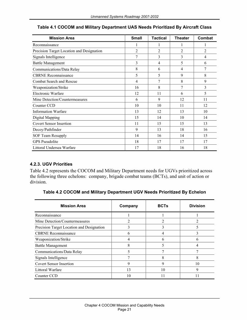
Unmanned Systems Roadmap 2007-2032
Chapter 4 COCOM Mission and Capability Needs
Page 21
Table 4.1 COCOM and Military Department UAS Needs Prioritized By Aircraft Class
Mission Area Small Tactical Theater Combat Reconnaissance 1 1 1 1 Precision Target Location and Designation 2 2 2 2 Signals Intelligence 7 3 3 4 Battle Management 3 4 5 6 Communications/Data Relay 8 6 4 7 CBRNE Reconnaissance 5 5 9 8 Combat Search and Rescue 4 7 8 9 Weaponization/Strike 16 8 7 3 Electronic Warfare 12 11 6 5 Mine Detection/Countermeasures 6 9 12 11 Counter CCD 10 10 11 12 Information Warfare 13 12 13 10 Digital Mapping 15 14 10 14 Covert Sensor Insertion 11 15 15 13 Decoy/Pathfinder 9 13 18 16 SOF Team Resupply 14 16 14 15 GPS Pseudolite 18 17 17 17 Littoral Undersea Warfare 17 18 16 18
4.2.3. UGV Priorities Table 4.2 represents the COCOM and Military Department needs for UGVs prioritized across the following three echelons: company, brigade combat teams (BCTs), and unit of action or division.
Table 4.2 COCOM and Military Department UGV Needs Prioritized By Echelon
Mission Area Company BCTs Division
Reconnaissance 1 1 1 Mine Detection/Countermeasures 2 2 2 Precision Target Location and Designation 3 3 5 CBRNE Reconnaissance 6 4 3 Weaponization/Strike 4 6 6 Battle Management 8 5 4 Communications/Data Relay 5 7 7 Signals Intelligence 7 8 8 Covert Sensor Insertion 9 9 10 Littoral Warfare 13 10 9 Counter CCD 10 11 11
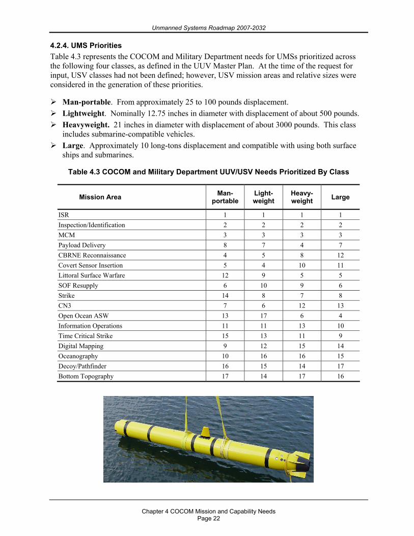
Unmanned Systems Roadmap 2007-2032
Chapter 4 COCOM Mission and Capability Needs
Page 22
4.2.4. UMS Priorities Table 4.3 represents the COCOM and Military Department needs for UMSs prioritized across the following four classes, as defined in the UUV Master Plan. At the time of the request for input, USV classes had not been defined; however, USV mission areas and relative sizes were considered in the generation of these priorities.
Man-portable. From approximately 25 to 100 pounds displacement. Lightweight. Nominally 12.75 inches in diameter with displacement of about 500 pounds. Heavyweight. 21 inches in diameter with displacement of about 3000 pounds. This class
includes submarine-compatible vehicles. Large. Approximately 10 long-tons displacement and compatible with using both surface
ships and submarines.
Table 4.3 COCOM and Military Department UUV/USV Needs Prioritized By Class
Mission Area Man- portable
Light-weight
Heavy-weight Large
ISR 1 1 1 1 Inspection/Identification 2 2 2 2 MCM 3 3 3 3 Payload Delivery 8 7 4 7 CBRNE Reconnaissance 4 5 8 12 Covert Sensor Insertion 5 4 10 11 Littoral Surface Warfare 12 9 5 5 SOF Resupply 6 10 9 6 Strike 14 8 7 8 CN3 7 6 12 13 Open Ocean ASW 13 17 6 4 Information Operations 11 11 13 10 Time Critical Strike 15 13 11 9 Digital Mapping 9 12 15 14 Oceanography 10 16 16 15 Decoy/Pathfinder 16 15 14 17 Bottom Topography 17 14 17 16
Unmanned Systems Roadmap 2007-2032
Chapter 4 COCOM Mission and Capability Needs
Page 23
4.2.5. DoD Priorities Comparing all the COCOM and Military Department inputs across the three domains for the various classes of unmanned systems revealed common themes. The priorities summarized in 4.2.5.1 through 4.2.5.4 represent the Department’s priorities for how unmanned systems can fill gaps or improve capability. These priorities are not intended to focus all of our efforts on the top two or three mission areas, relegating lower priority items to manned or existing systems. With this unmanned coordination effort, the Department does risk stifling the advancement of “out-of-the-box” solutions. Important work is being accomplished across the entire spectrum of mission areas and should continue. In fact, there are likely missions and unmanned solutions that will emerge in the coming years that do not exist today. However, the following priorities represent DoD’s most pressing needs as identified by a survey sent to the COCOMs and Military Departments and should be considered for future unmanned research and procurement.
4.2.5.1. Reconnaissance All three domains, across all classes of unmanned systems, listed some form of reconnaissance (electronic and visual) as the number one priority. Information is the key enabler to today’s joint warfighter. Persistent surveillance was emphasized in the 2006 Quadrennial Defense Review (QDR) and epitomizes the dull mission. Being able to surveil hostile areas while maintaining a degree of covertness is highly desirable. The reconnaissance mission that is currently being conducted by unmanned systems needs increased standardization and interoperability to gain capability and economic efficiencies across the classes and domains. Satellites, manned aircraft and submarines, and unattended sensors all have limitations that can be addressed by unmanned systems. Certain efficiencies can be realized when unmanned systems operate together to improve capability with lower costs.
4.2.5.2. Target Identification, and Designation Finding, fixing, and tagging potential targets is a clear fit for unmanned systems. The ability to operate in high-threat environments without putting warfighters at risk is a significant advantage when compared to current manned systems. UUVs are already at work in conducting underwater hull and pier inspections, and ground target designation by UASs can significantly reduce the dangers encountered by current ground forces.
4.2.5.3. Counter Mine Warfare The quintessential dangerous mission, countermine warfare may be the mission area most suitable for unmanned systems. A significant amount of effort is already being expended to improve the warfighter’s ability to find, tag, and destroy both land and sea mines. The work that ground robots are doing in Iraq to defeat IEDs is saving countless lives. Sea mines represent one of the cheapest and most effective deterrents to unobstructed use of the seas by the fleet and commercial vessels alike.
4.2.5.4. Chemical, Biological, Radiological, Nuclear, Explosive (CBRNE) Reconnaissance The ultimate dirty mission, CBRNE reconnaissance, may be the single most important element of the joint mission to protect the homeland. The thought of a successful chemical or biological attack on U.S. shores or deployed forces is unfathomable and could have a significant impact on the U.S. military, economy, and foreign policy. The ability to find and destroy chemical and biological agents and to survey the extent of affected areas is a crucial effort.
Unmanned Systems Roadmap 2007-2032
Chapter 4 COCOM Mission and Capability Needs
Page 24
4.3. Existing Joint Capabilities Being Filled by Unmanned Systems
Unmanned systems are performing many dull, dangerous, and dirty jobs today. Reviews of existing and draft capability documents reveal a wide range of requirements and capabilities being filled or developed. Parameters to consider include the following:
Typical warfighting specifications (endurance, payload capability, detection avoidance, operational radius/area coverage, and operating parameters such as depth, altitude, and speed),
Material requirements (size, weight, reliability, and availability), Interoperability and open architecture, and Requirements somewhat unique to unmanned systems (level of autonomy, obstacle
avoidance, and fail-safe systems).
The ability of unmanned systems to meet key warfighter needs is growing every day.
Unmanned Systems Roadmap 2007-2032
Chapter 5 Organizational Efforts
Page 25
Chapter 5. Organizational Efforts
There are currently hundreds of efforts underway within DoD, academia, and private industry to advance unmanned systems development across the spectrum of military and nonmilitary operations. Until recently, the majority of these efforts have been undertaken within a narrow scope of a single platform type, Military Department, or technology. This chapter summarizes and provides links to the major efforts underway specifically related to the advancement of DoD-related unmanned systems. Through education and possible consolidation of the various ongoing activities, economies of effort and funding may be possible.
5.1. Department of Defense (DoD)
5.1.1. Studies
5.1.1.1. 2005 Quadrennial Defense Review (QDR) The 2005 QDR (published in February 2006) established the following department goals for unmanned systems:
Investing in new equipment, technology, and platforms for the forces, including advanced combat capabilities such as unmanned vehicles.
Strengthening forces to defeat terrorist networks, including establishing an UAS squadron under Special Operations Command (SOCOM) to provide organic capabilities to locate and target enemy capabilities in denied or contested areas.
Increasing procurement of UASs to increase persistent surveillance to nearly double today’s capacity.
Expanding maritime aviation to include unmanned aircraft for both surveillance and strike. Optimizing Air Force reserve component personnel for new missions that can be performed
from the United States, including UAS operations. Restructuring the Joint Unmanned Combat Air Systems (J-UCAS) program and developing
an unmanned longer range, carrier-based aircraft capable of being air-refueled to provide greater standoff capability, to expand payload and launch options, and to increase naval reach and persistence.
Increasing investment in UASs to provide more flexible capabilities to identify and track moving targets in denied areas.
5.1.1.2. Joint Unmanned Aircraft Systems (JUAS) Standards Study The JUAS Standards Study evaluated the adoption of standards (related to data link and sensor data flow) by a representative set of UASs and assessed the effectiveness of the standards in ensuring common and interoperable systems capable of efficient and effective dissemination of UAS data. The study team examined DoD regulations, directives, and instructions as well as Military Department guidelines and program documentation. The study team met with military department officials, including UAS program managers and contractors, to discuss the current status and future plans for their UAS platforms.
The recommendations presented in this study put greater emphasis on the more immediate actions that can be taken by the joint UAS community to achieve interoperability through currently accepted and proven standards and processes. The recommendations also include the
Unmanned Systems Roadmap 2007-2032
Chapter 5 Organizational Efforts
Page 26
necessary first steps to posture the joint UAS community to take advantage of early joint UAS information or data flow definition and requirements to meet the evolving Global Information Grid (GIG) and network-centric operational warfare environment. Coupled with a lack of proactive, enforceable measures, a gap involving joint capabilities stakeholder definition, application, and oversight exists in recent UAS acquisitions. Key areas of concern, discussed in this study, involve standards definition, acceptance, and implementation for the greater good of joint interoperability. Standards determination and implementation, when well informed with effective Government stakeholder oversight and proactive measures, lead to valid results. Properly enforced, the standards discussed within the study can strengthen UAS developed and integrated subsystems, systems, and systems of systems for greater interoperability. A balanced, well-governed joint process is capable of producing greater benefits for the Joint Forces.
5.1.1.3. Unmanned Air Systems Requirements Study The goal of the Unmanned Air Systems Requirements Study is to update manned and unmanned ISR requirements, which drive force structure for high-altitude (Global Hawk and U-2) and medium-altitude (Predator, Reaper, Sky Warrior) ISR platforms. This update is needed because the last high-altitude ISR requirements were defined in the 2001 Joint Airborne Reconnaissance Analysis, and, to date, a comprehensive requirements analysis for full motion video systems has not been accomplished. This effort will also evaluate operator/pilot skill sets and the need for any adjustments in training equipage.
5.1.1.4. Office of Naval Research (ONR) Roles of Unmanned Vehicles Directed by the Assistant Secretary of the Navy for Research, Development, and Acquisition, a 2002 study on the roles of unmanned vehicles assessed potential concepts of operations and employment across all naval missions with respect to unmanned vehicles. The study panel examined fleet needs, requirements, and desired capabilities and then recommended which concepts were considered to have the greatest potential to improve warfighting capabilities and effectiveness while reducing manpower and operating costs. The study results are available at www.onr.navy.mil/nrac/docs/2003%5Fes%5Frole%5Funmanned%5Fvehicle.pdf.
Additionally, in 2005, the ONR Future Naval Capability (FNC) program was restructured to align with the pillars of the Navy’s vision for the future, Sea Power 21, and to focus on providing enabling capabilities to close warfighting gaps. The FNC program provides the best technology solutions to stated OPNAV requirements by bundling discrete but interrelated science and technology products that deliver a distinctly measurable improvement within a five-year time frame. A three-star Navy and Marine Corps Board of Directors, the technical oversight group, approves the FNC recommendations based on their contribution to closing a warfighting capability gap, rather than on individual products. Thirty-five ongoing enabling capabilities are dedicated to the FNC. For more details on FNC program studies, visit www.onr.navy.mil.
5.1.1.5. Joint Ground Robotics Enterprise (JGRE) Studies As UGVs have proliferated on the battlefield, there have been multiple recommendations for developing a common controller for these systems. The concepts for a common controller range from a single controller to control multiple platforms, to a single controller configuration to control all types of ground robotics, to a single controller configuration for all types of unmanned systems. The JGRE will study each of these concepts, identify their attributes and deficiencies, and provide a characterization of the associated trade space so that a better understanding of the best path forward for addressing common control can be achieved. The study is not intended to
Unmanned Systems Roadmap 2007-2032
Chapter 5 Organizational Efforts
Page 27
recommend a solution or even establish requirements, but will serve as a good definition of the implications associated with each of the options for common control of unmanned systems. The study is expected to be completed by end of FY2007.
In another study, the Unmanned Systems Safety Precepts Policy Study, safety precepts developed by the Unmanned Systems Safety Workshops were mapped to existing DoD policy to determine whether the safety precepts were already addressed as policy or needed to be instantiated in policy as a means of providing needed guidance for achieving safety certifications for unmanned systems. The study identified which policy already addressed each precept and/or gave recommendations for how to incorporate the precept into the policy so that DoD has a comprehensive set of policy guidance that enables consistent, robust safety certification for unmanned systems.
5.1.2. Working Groups and Organizations
5.1.2.1. Joint Ground Robotics Enterprise To accomplish the JGRE mission as defined by Congress and OUSD(AT&L), the organization and functions were revised in FY2006 to better meet future warfighting needs. The JGRE is supported by organizational bodies composed of Military Department, OSD, and Joint Staff representation. These bodies provide a responsive management structure consisting of a flag-level Senior Steering Group (SSG), a JGR Council at the 06 level, and a JGR TAB.
The SSG advises on funding priorities and allocations and provides senior-level guidance for shaping DoD ground robotics development while serving as a direct link to the warfighter community at the flag officer level. The SSG is chaired by the Deputy Director of Land Warfare and Munitions, Portfolio Systems Acquisition, OUSD(AT&L). The Council is chaired by the Enterprise Director of JGR and consists of Military Department representation from both the combat development and material development communities. The group’s membership will act as the ground proponents for an ongoing DoD UGV roadmapping effort and will function to refine the DoD strategy for advancing ground robotics to include addressing Program Objective Memorandum (POM) development for funding ground robotics acquisitions. At the technical level, JGR TAB is composed of Military Department members who will execute the JGRE technology priorities through their ground robotics technology development programs and activities. The TAB will provide membership for various working groups to assess and recommend proposed JGRE technology development and warfighter experimentation based on assessments of robotics technology maturity and criticality to satisfying warfighter capability needs as identified by the COCOMs and Joint Staff.
5.1.2.2. Technical Support Working Group (TSWG) The TSWG was formed in April 1982 as part of the Interdepartmental Group on Terrorism, chaired by the Department of Justice. Today, the TSWG still performs its mission to conduct the national interagency research and development program for combating terrorism requirements as a stand-alone interagency working group. The TSWG has successfully transitioned capabilities to the departments of Agriculture, Defense, Justice, State, and Treasury; the intelligence community; the Transportation Security Agency; the public health Military Department; and many State and local law enforcement agencies. It is through the TSWG and its Improvised Device Defeat Subgroup that the JGRE coordinates its activities with these various agencies. Members of EOD organizations from the Army, Navy, Air Force, serve as members of this Subgroup. In addition, several developers under the JGRE [particularly the Air Force Research
Unmanned Systems Roadmap 2007-2032
Chapter 5 Organizational Efforts
Page 28
Laboratory (AFRL)] have provided technologies to satisfy specific TSWG requirements. In recent years, the JGRE has provided technical support to the development of the TSWG’s Next Generation EOD Robotic Vehicle (NGEODRV) program, which is using a common architecture based upon the JGRE-developed JAUS standard, and is transitioning resulting technology solutions to the JGRE and joint EOD communities.
5.1.2.3. Unmanned Systems Capabilities Conference (USCC) Beginning in 2004, JGRE and TSWG have partnered to sponsor an annual USCC that serves as a forum to bring DoD, interagency, Federal, State, and local bomb squad users in direct contact with developers and industry representatives to share information on emerging capability needs, operational lessons learned, research and development (R&D) activities, and Government and commercial robotic solutions. TSWG has been a continuing JGRE partner for UGV development. TSWG identifies, prioritizes, and coordinates interagency and international R&D requirements for combating terrorism. The JGRE works primarily with the TSWG’s Improvised Device Defeat Subgroup to align and coordinate applicable JGRE Joint Staff and Military Department robotic development efforts and to foster rapid development of technologies and equipment to meet the high-priority needs of the broader combating terrorism community.
5.1.2.4. Joint Architecture for Unmanned Systems (JAUS) Working Group The JGRE initiated a standards-based approach through the adoption of JAUS. Since 1998, the JGRE has sponsored a JAUS/AS-4 Working Group that has, through the active participation of Government, academia, and industry, effectively created a joint standard robotics software architecture that will soon become an industry standard. The objective in pursuing the adoption of JAUS as the primary UGV product line enabler has been to promote efficient development across the Military Departments and to enable DoD-wide opportunities for interoperability (“plug and fight”), rapid technology insertion, and overall systems affordability at lower development costs.
JAUS is the messaging architecture potentially supporting not only UGVs but also UUVs, USVs, and some UASs. One of the JGRE’s goals has been to sponsor the transition of JAUS toward becoming a commercial, international standard. To that end, the JGRE is partnering with the SAE’s Aerospace Council, which chartered an Unmanned Systems Committee in 2004 that remains active in transitioning JAUS into an aerospace standard and fostering activities to expand the architecture’s utility to users and developers. For more details on JAUS, visit www.jauswg.org.
5.1.2.5. Joint Unmanned Aircraft Systems Material Review Board (JUAS MRB) The JUAS MRB’s mission was to provide a UAS forum to identify or resolve requirements and corresponding material issues regarding interoperability and commonality, to prioritize potential solutions, to assess the focus of current and future programs, and to seek strategies common to all military departments. Primary goals included the following:
Facilitating the JCIDS process by coordinating with and making recommendations to the appropriate functional capability board(s), the Joint Capability Board, and the JROC;
Improving commonality of payloads and GCSs; Improving interoperability through adoption of common standards; Improving data dissemination through adoption of a common communication architecture;
and
Unmanned Systems Roadmap 2007-2032
Chapter 5 Organizational Efforts
Page 29
Providing a corporate body of knowledge composed of subject matter experts from all Military Departments and relevant defense agencies to facilitate the JCIDS process.
The issues the MRB was working to resolve will be continued by the new UAS Task Force.
5.1.2.6. Joint Unmanned Aircraft System Center of Excellence (JUAS COE) The JUAS COE provides support to the joint operators and the military departments by facilitating the development and integration of common UAS operating standards, capabilities, concepts, technologies, doctrine, tactics, techniques, procedures, and training. The JUAS COE leverages existing military department initiatives and activities to provide joint integrated solutions and improved interoperability. The stated goals of the JUAS COE are to
Increase standardization among systems, Reduce duplication of effort, Focus new ideas, Address interoperability challenges, and Develop new and/or updated doctrine, TTP, and CONOPSs.
The Joint UAS Concept of Operations was approved in March 2007.
5.1.2.7. UAS Airspace Integration JIPT The UAS Airspace Integration JIPT was established to focus and align DoD resources toward the timely development of standards, processes, procedures, technical solutions, and policy recommendations to meet the near-, mid-, and long-term airspace access needs of the DoD UAS user community. The JIPT will integrate work activities with the FAA, civil SDOs, and Military Department-related airspace organizations such as Air Force Flight Standards Agency, Electronic Security Command/Global Air Traffic Operations, and the Army Aeronautical Services Agency to optimize resource allocation; influence standards, procedures, and policy adoption schedules; and promote convergence of technical and procedural solutions to ensure system interoperability. The JIPT will contribute to the development of the standards, procedures, policy, and enabling technology necessary to safely integrate unmanned aircraft operations with manned aircraft operations in nonsegregated airspace on a timeline that is in alignment with the acquisition schedules of major DoD UAS PORs and the allocated funding for this work. It will also facilitate near- and mid-term expansion of DoD UAS use of the NAS through a modified COA process to meet existing operational requirements.
The focus of the JIPT is on gaining access to the NAS for DoD UASs; however, other Federal and State public-use UASs should also benefit greatly from this effort. A strong effort will be made to coordinate the alignment of resources and activities among internal DoD (at the Military Department, National Guard, and OSD levels) as well as interagency (DHS and FAA) activities. Such activities could include modeling and simulation (M&S), technology development, acquisition, demonstrations, and flight tests.
5.1.2.8. Navy Unmanned Systems Executive Steering Group In April 2005, the Deputy CNO of Warfare Requirements and Programs established the Navy Unmanned Systems Executive Steering Group. A charter was developed to support CNO Guidance for 2005 to develop an unmanned vehicle strategy to move the naval services toward
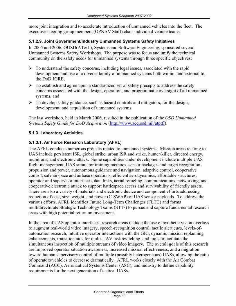
Unmanned Systems Roadmap 2007-2032
Chapter 5 Organizational Efforts
Page 30
more joint integration and to accelerate introduction of unmanned vehicles into the fleet. The executive steering group members (OPNAV Staff) chair individual vehicle teams.
5.1.2.9. Joint Government/Industry Unmanned Systems Safety Initiatives In 2005 and 2006, OUSD(AT&L), Systems and Software Engineering, sponsored several Unmanned Systems Safety Workshops. The purpose was to focus and unify the technical community on the safety needs for unmanned systems through three specific objectives:
To understand the safety concerns, including legal issues, associated with the rapid development and use of a diverse family of unmanned systems both within, and external to, the DoD JGRE,
To establish and agree upon a standardized set of safety precepts to address the safety concerns associated with the design, operation, and programmatic oversight of all unmanned systems, and
To develop safety guidance, such as hazard controls and mitigators, for the design, development, and acquisition of unmanned systems.
The last workshop, held in March 2006, resulted in the publication of the OSD Unmanned Systems Safety Guide for DoD Acquisition (http://www.acq.osd.mil/atptf/).
5.1.3. Laboratory Activities
5.1.3.1. Air Force Research Laboratory (AFRL) The AFRL conducts numerous projects related to unmanned systems. Mission areas relating to UAS include persistent ISR, global strike, urban ISR and strike, hunter/killer, directed energy, munitions, and electronic attack. Some capabilities under development include multiple UAS flight management, UAS simulator training methods, sensor packages and target recognition, propulsion and power, autonomous guidance and navigation, adaptive control, cooperative control, safe airspace and airbase operations, efficient aerodynamics, affordable structures, operator and supervisor interfaces, data links, aerial refueling, communications, networking, and cooperative electronic attack to support battlespace access and survivability of friendly assets. There are also a variety of materials and electronic device and component efforts addressing reduction of cost, size, weight, and power (C-SWAP) of UAS sensor payloads. To address the various efforts, AFRL identifies Future Long-Term Challenges (FLTC) and forms multidirectorate Strategic Technology Teams (STTs) to pursue and capture fundamental research areas with high potential return on investment.
In the area of UAS operator interfaces, research areas include the use of synthetic vision overlays to augment real-world video imagery, speech-recognition control, tactile alert cues, levels-of-automation research, intuitive operator interactions with the GIG, dynamic mission replanning enhancements, transition aids for multi-UAV task switching, and tools to facilitate the simultaneous inspection of multiple streams of video imagery. The overall goals of this research are improved operator situation awareness, increased mission effectiveness, and a migration toward human supervisory control of multiple (possibly heterogeneous) UASs, allowing the ratio of operators/vehicles to decrease dramatically. AFRL works closely with the Air Combat Command (ACC), Aeronautical Systems Center (ASC), and industry to define capability requirements for the next generation of tactical UASs.
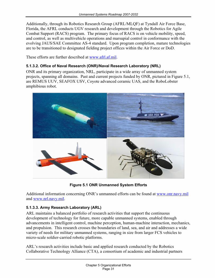
Unmanned Systems Roadmap 2007-2032
Chapter 5 Organizational Efforts
Page 31
Additionally, through its Robotics Research Group (AFRL/MLQF) at Tyndall Air Force Base, Florida, the AFRL conducts UGV research and development through the Robotics for Agile Combat Support (RACS) program. The primary focus of RACS is on vehicle mobility, speed, and control, as well as multivehicle operations and marsupial control in conformance with the evolving JAUS/SAE Committee AS-4 standard. Upon program completion, mature technologies are to be transitioned to designated fielding project offices within the Air Force or DoD.
These efforts are further described at www.afrl.af.mil.
5.1.3.2. Office of Naval Research (ONR)/Naval Research Laboratory (NRL) ONR and its primary organization, NRL, participate in a wide array of unmanned system projects, spanning all domains. Past and current projects funded by ONR, pictured in Figure 5.1, are REMUS UUV, SEAFOX USV, Coyote advanced ceramic UAS, and the RoboLobster amphibious robot.
Figure 5.1 ONR Unmanned System Efforts
Additional information concerning ONR’s unmanned efforts can be found at www.onr.navy.mil and www.nrl.navy.mil.
5.1.3.3. Army Research Laboratory (ARL) ARL maintains a balanced portfolio of research activities that support the continuous development of technology for future, more capable unmanned systems, enabled through advancements in intelligent control, machine perception, human-machine interaction, mechanics, and propulsion. This research crosses the boundaries of land, sea, and air and addresses a wide variety of needs for military unmanned systems, ranging in size from larger FCS vehicles to micro-scale soldier-carried robotic platforms.
ARL’s research activities include basic and applied research conducted by the Robotics Collaborative Technology Alliance (CTA), a consortium of academic and industrial partners
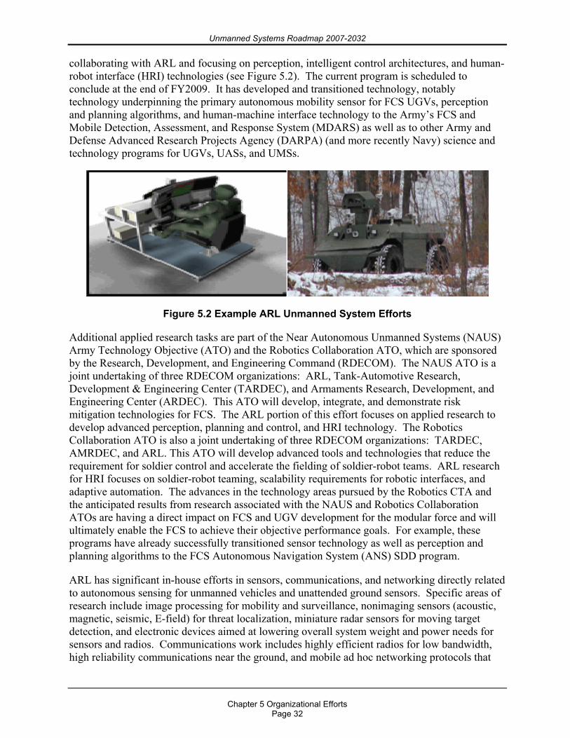
Unmanned Systems Roadmap 2007-2032
Chapter 5 Organizational Efforts
Page 32
collaborating with ARL and focusing on perception, intelligent control architectures, and human-robot interface (HRI) technologies (see Figure 5.2). The current program is scheduled to conclude at the end of FY2009. It has developed and transitioned technology, notably technology underpinning the primary autonomous mobility sensor for FCS UGVs, perception and planning algorithms, and human-machine interface technology to the Army’s FCS and Mobile Detection, Assessment, and Response System (MDARS) as well as to other Army and Defense Advanced Research Projects Agency (DARPA) (and more recently Navy) science and technology programs for UGVs, UASs, and UMSs.
Figure 5.2 Example ARL Unmanned System Efforts
Additional applied research tasks are part of the Near Autonomous Unmanned Systems (NAUS) Army Technology Objective (ATO) and the Robotics Collaboration ATO, which are sponsored by the Research, Development, and Engineering Command (RDECOM). The NAUS ATO is a joint undertaking of three RDECOM organizations: ARL, Tank-Automotive Research, Development & Engineering Center (TARDEC), and Armaments Research, Development, and Engineering Center (ARDEC). This ATO will develop, integrate, and demonstrate risk mitigation technologies for FCS. The ARL portion of this effort focuses on applied research to develop advanced perception, planning and control, and HRI technology. The Robotics Collaboration ATO is also a joint undertaking of three RDECOM organizations: TARDEC, AMRDEC, and ARL. This ATO will develop advanced tools and technologies that reduce the requirement for soldier control and accelerate the fielding of soldier-robot teams. ARL research for HRI focuses on soldier-robot teaming, scalability requirements for robotic interfaces, and adaptive automation. The advances in the technology areas pursued by the Robotics CTA and the anticipated results from research associated with the NAUS and Robotics Collaboration ATOs are having a direct impact on FCS and UGV development for the modular force and will ultimately enable the FCS to achieve their objective performance goals. For example, these programs have already successfully transitioned sensor technology as well as perception and planning algorithms to the FCS Autonomous Navigation System (ANS) SDD program.
ARL has significant in-house efforts in sensors, communications, and networking directly related to autonomous sensing for unmanned vehicles and unattended ground sensors. Specific areas of research include image processing for mobility and surveillance, nonimaging sensors (acoustic, magnetic, seismic, E-field) for threat localization, miniature radar sensors for moving target detection, and electronic devices aimed at lowering overall system weight and power needs for sensors and radios. Communications work includes highly efficient radios for low bandwidth, high reliability communications near the ground, and mobile ad hoc networking protocols that
Unmanned Systems Roadmap 2007-2032
Chapter 5 Organizational Efforts
Page 33
will enable high reliability command and control of autonomous assets. All of this work is aimed at providing key enabling technologies for energy-efficient, reliable operation.
ARL also has a growing in-house research program focused on developing the underpinning science and enabling technologies for sensor integration, data fusion, and algorithms to improve the command and control for a heterogeneous mix of small robots. ARL in-house basic research for unmanned systems is greatly enhanced through CTAs. The Advanced Decision Architectures CTA has as its principal domain HRI, specifically, human-robot team communication and collaboration; mixed initiative system control; and displays, controls, and mobile software agents that compensate for any negative effects of information lag induced by bandwidth limitations. To help facilitate micro-sized unmanned systems research and experimental efforts, ARL has also formulated the Micro Autonomous Systems and Technology (MAST) CTA (see Figure 5.3).
Figure 5.3 ARL MAST research
ARL also conducts extramural basic research that provides underpinning science for future unmanned system capabilities through its Army Research Office (ARO). This includes Multidisciplinary University Research Initiative (MURI) programs such as Language for Intelligent Machines (LIMES) and Micro Hovering Air Vehicles.
More information about the above described programs and others can be found at www.arl.army.mil.
5.1.3.4. U.S. Army Medical Research and Materiel Command (USAMRMC) Telemedicine and Advanced Technology Research Center (TATRC) The Army is the executive agent for medical research, and USAMRMC is the Army’s execution command. TATRC is the USAMRMC’s center for medical information technologies research and development in areas such as telemedicine, medical informatics, and robotics. Based on user guidance and documented capability gaps from the Army’s Medical Combat Developer and in collaboration with DARPA, ARL, RDECOM, TARDEC, National Center for Defense Robotics (NCDR), JGRE, and Robotic Systems Joint Program Office (RSJPO), TATRC executes a robotics program that includes Small Business Innovation Research and Small Business Technology Transfer (SBIR/STTR), Congressionally-funded efforts, and core research projects in robotic surgery, robotic patient intervention and treatment, and unmanned ground and air systems for combat casualty extraction, evacuation, medical logistics, and force health protection. See Figure 5.4, Appendix A, and Appendix B. Additional information can be found at www.tatrc.org.
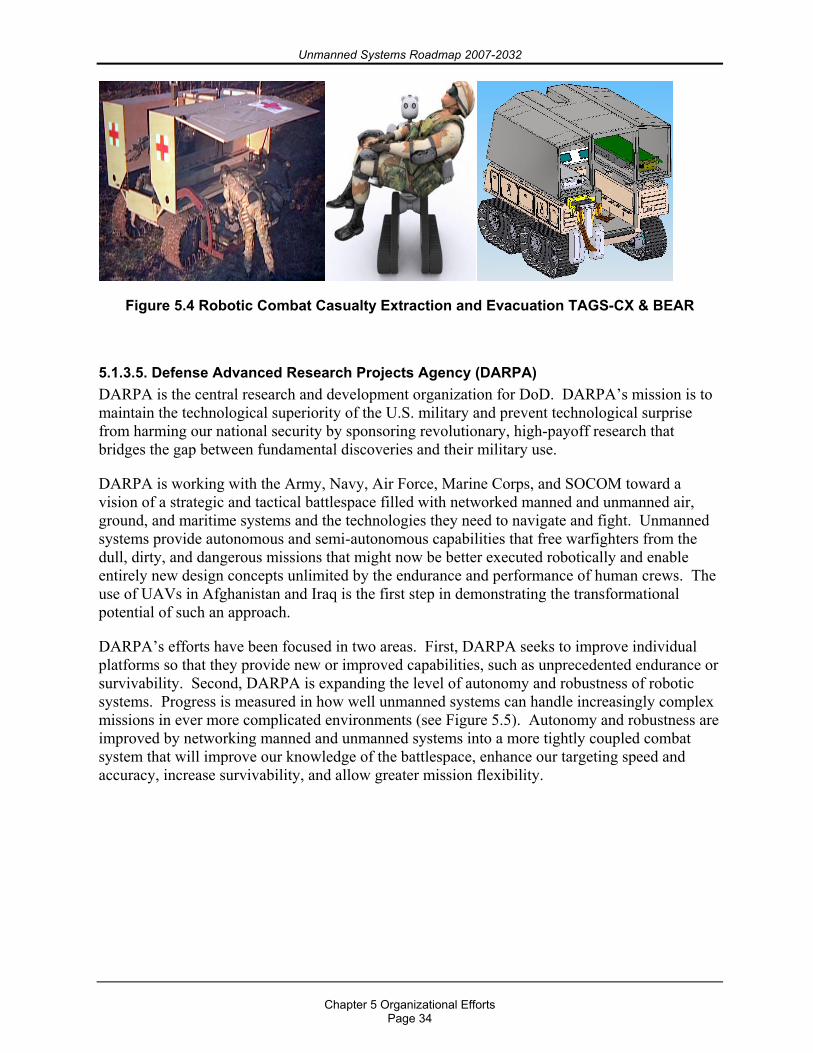
Unmanned Systems Roadmap 2007-2032
Chapter 5 Organizational Efforts
Page 34
Figure 5.4 Robotic Combat Casualty Extraction and Evacuation TAGS-CX & BEAR
5.1.3.5. Defense Advanced Research Projects Agency (DARPA) DARPA is the central research and development organization for DoD. DARPA’s mission is to maintain the technological superiority of the U.S. military and prevent technological surprise from harming our national security by sponsoring revolutionary, high-payoff research that bridges the gap between fundamental discoveries and their military use.
DARPA is working with the Army, Navy, Air Force, Marine Corps, and SOCOM toward a vision of a strategic and tactical battlespace filled with networked manned and unmanned air, ground, and maritime systems and the technologies they need to navigate and fight. Unmanned systems provide autonomous and semi-autonomous capabilities that free warfighters from the dull, dirty, and dangerous missions that might now be better executed robotically and enable entirely new design concepts unlimited by the endurance and performance of human crews. The use of UAVs in Afghanistan and Iraq is the first step in demonstrating the transformational potential of such an approach.
DARPA’s efforts have been focused in two areas. First, DARPA seeks to improve individual platforms so that they provide new or improved capabilities, such as unprecedented endurance or survivability. Second, DARPA is expanding the level of autonomy and robustness of robotic systems. Progress is measured in how well unmanned systems can handle increasingly complex missions in ever more complicated environments (see Figure 5.5). Autonomy and robustness are improved by networking manned and unmanned systems into a more tightly coupled combat system that will improve our knowledge of the battlespace, enhance our targeting speed and accuracy, increase survivability, and allow greater mission flexibility.
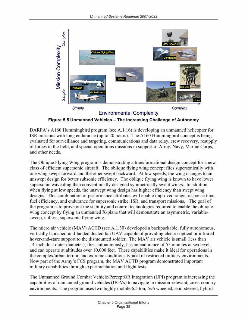
Unmanned Systems Roadmap 2007-2032
Chapter 5 Organizational Efforts
Page 35
Figure 5.5 Unmanned Vehicles – The Increasing Challenge of Autonomy
DARPA’s A160 Hummingbird program (see A.1.16) is developing an unmanned helicopter for ISR missions with long endurance (up to 20 hours). The A160 Hummingbird concept is being evaluated for surveillance and targeting, communications and data relay, crew recovery, resupply of forces in the field, and special operations missions in support of Army, Navy, Marine Corps, and other needs.
The Oblique Flying Wing program is demonstrating a transformational design concept for a new class of efficient supersonic aircraft. The oblique flying wing concept flies supersonically with one wing swept forward and the other swept backward. At low speeds, the wing changes to an unswept design for better subsonic efficiency. The oblique flying wing is known to have lower supersonic wave drag than conventionally designed symmetrically swept wings. In addition, when flying at low speeds, the unswept wing design has higher efficiency than swept wing designs. This combination of performance attributes will enable improved range, response time, fuel efficiency, and endurance for supersonic strike, ISR, and transport missions. The goal of the program is to prove out the stability and control technologies required to enable the oblique wing concept by flying an unmanned X-plane that will demonstrate an asymmetric, variable-sweep, tailless, supersonic flying wing.
The micro air vehicle (MAV) ACTD (see A.1.30) developed a backpackable, fully autonomous, vertically launched-and-landed ducted fan UAV capable of providing electro-optical or infrared hover-and-stare support to the dismounted soldier. The MAV air vehicle is small (less than 14-inch duct outer diameter), flies autonomously, has an endurance of 55 minutes at sea level, and can operate at altitudes over 10,000 feet. These capabilities make it ideal for operations in the complex/urban terrain and extreme conditions typical of restricted military environments. Now part of the Army’s FCS program, the MAV ACTD program demonstrated important military capabilities through experimentation and flight tests.
The Unmanned Ground Combat Vehicle/PerceptOR Integration (UPI) program is increasing the capabilities of unmanned ground vehicles (UGVs) to navigate in mission-relevant, cross-country environments. The program uses two highly mobile 6.5 ton, 6×6 wheeled, skid-steered, hybrid
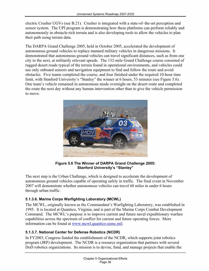
Unmanned Systems Roadmap 2007-2032
Chapter 5 Organizational Efforts
Page 36
electric Crusher UGVs (see B.21). Crusher is integrated with a state-of–the-art perception and sensor system. The UPI program is demonstrating how these platforms can perform reliably and autonomously in obstacle-rich terrain and is also developing tools to allow the vehicles to plan their path using terrain data.
The DARPA Grand Challenge 2005, held in October 2005, accelerated the development of autonomous ground vehicles to replace manned military vehicles in dangerous missions. It demonstrated that autonomous ground vehicles can travel significant distances, such as from one city to the next, at militarily relevant speeds. The 132-mile Grand Challenge course consisted of rugged desert roads typical of the terrain found in operational environments, and vehicles could use only onboard sensors and navigation equipment to find and follow the route and avoid obstacles. Five teams completed the course, and four finished under the required 10-hour time limit, with Stanford University’s “Stanley” the winner at 6 hours, 53 minutes (see Figure 5.6). One team’s vehicle remained in autonomous mode overnight on the desert route and completed the route the next day without any human intervention other than to give the vehicle permission to move.
Figure 5.6 The Winner of DARPA Grand Challenge 2005: Stanford University’s “Stanley”
The next step is the Urban Challenge, which is designed to accelerate the development of autonomous ground vehicles capable of operating safely in traffic. The final event in November 2007 will demonstrate whether autonomous vehicles can travel 60 miles in under 6 hours through urban traffic.
5.1.3.6. Marine Corps Warfighting Laboratory (MCWL) The MCWL, originally known as the Commandant’s Warfighting Laboratory, was established in 1995. It is located at Quantico, Virginia, and is part of the Marine Corps Combat Development Command. The MCWL’s purpose is to improve current and future naval expeditionary warfare capabilities across the spectrum of conflict for current and future operating forces. More information can be found at www.mcwl.quantico.usmc.mil.
5.1.3.7. National Center for Defense Robotics (NCDR) In FY2003, Congress funded the establishment of the NCDR, which supports joint robotics program (JRP) development. The NCDR is a resource organization that partners with several DoD robotics organizations. Its mission is to devise, fund, and manage projects that enable the
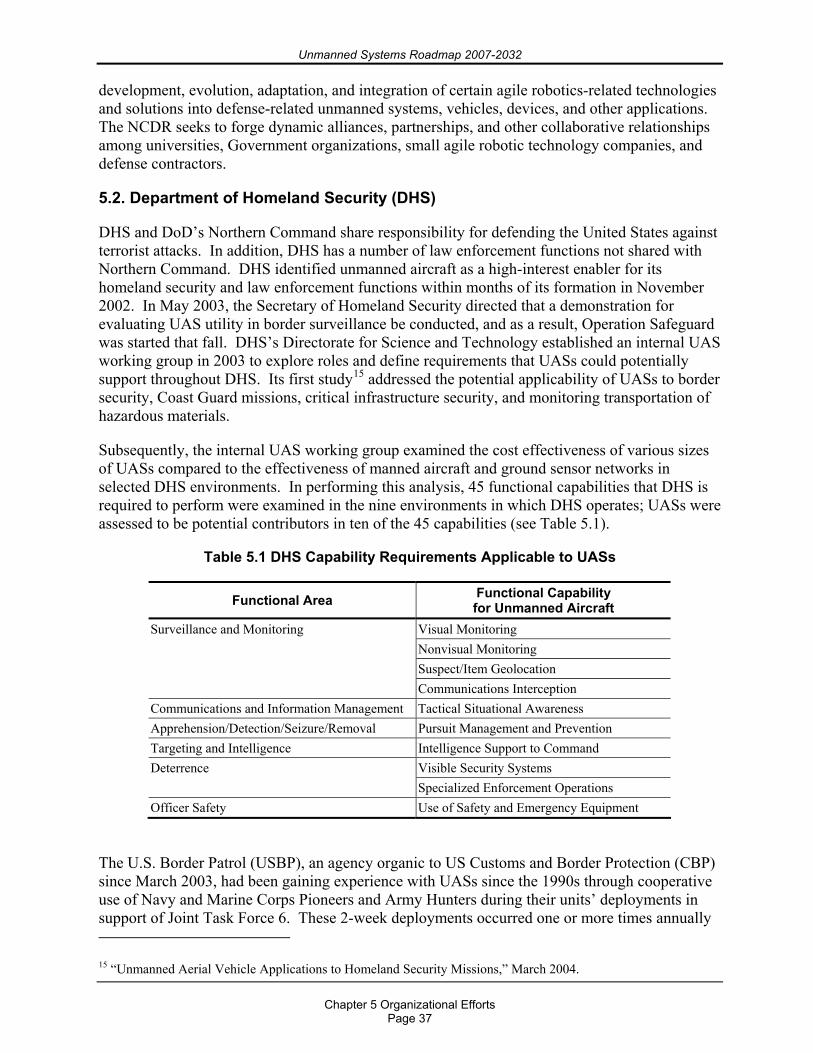
Unmanned Systems Roadmap 2007-2032
Chapter 5 Organizational Efforts
Page 37
development, evolution, adaptation, and integration of certain agile robotics-related technologies and solutions into defense-related unmanned systems, vehicles, devices, and other applications. The NCDR seeks to forge dynamic alliances, partnerships, and other collaborative relationships among universities, Government organizations, small agile robotic technology companies, and defense contractors.
5.2. Department of Homeland Security (DHS)
DHS and DoD’s Northern Command share responsibility for defending the United States against terrorist attacks. In addition, DHS has a number of law enforcement functions not shared with Northern Command. DHS identified unmanned aircraft as a high-interest enabler for its homeland security and law enforcement functions within months of its formation in November 2002. In May 2003, the Secretary of Homeland Security directed that a demonstration for evaluating UAS utility in border surveillance be conducted, and as a result, Operation Safeguard was started that fall. DHS’s Directorate for Science and Technology established an internal UAS working group in 2003 to explore roles and define requirements that UASs could potentially support throughout DHS. Its first study15 addressed the potential applicability of UASs to border security, Coast Guard missions, critical infrastructure security, and monitoring transportation of hazardous materials.
Subsequently, the internal UAS working group examined the cost effectiveness of various sizes of UASs compared to the effectiveness of manned aircraft and ground sensor networks in selected DHS environments. In performing this analysis, 45 functional capabilities that DHS is required to perform were examined in the nine environments in which DHS operates; UASs were assessed to be potential contributors in ten of the 45 capabilities (see Table 5.1).
Table 5.1 DHS Capability Requirements Applicable to UASs
Functional Area Functional Capability for Unmanned Aircraft
Visual Monitoring Nonvisual Monitoring Suspect/Item Geolocation
Surveillance and Monitoring
Communications Interception Communications and Information Management Tactical Situational Awareness Apprehension/Detection/Seizure/Removal Pursuit Management and Prevention Targeting and Intelligence Intelligence Support to Command
Visible Security Systems Deterrence Specialized Enforcement Operations
Officer Safety Use of Safety and Emergency Equipment
The U.S. Border Patrol (USBP), an agency organic to US Customs and Border Protection (CBP) since March 2003, had been gaining experience with UASs since the 1990s through cooperative use of Navy and Marine Corps Pioneers and Army Hunters during their units’ deployments in support of Joint Task Force 6. These 2-week deployments occurred one or more times annually 15 “Unmanned Aerial Vehicle Applications to Homeland Security Missions,” March 2004.
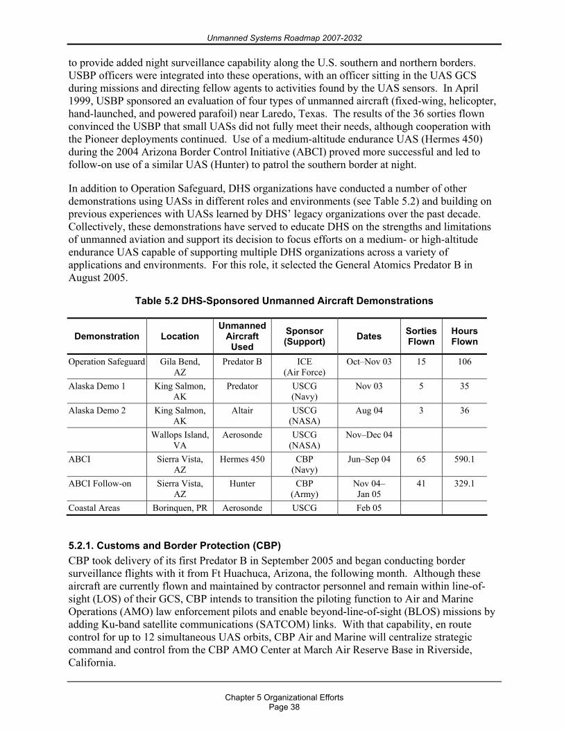
Unmanned Systems Roadmap 2007-2032
Chapter 5 Organizational Efforts
Page 38
to provide added night surveillance capability along the U.S. southern and northern borders. USBP officers were integrated into these operations, with an officer sitting in the UAS GCS during missions and directing fellow agents to activities found by the UAS sensors. In April 1999, USBP sponsored an evaluation of four types of unmanned aircraft (fixed-wing, helicopter, hand-launched, and powered parafoil) near Laredo, Texas. The results of the 36 sorties flown convinced the USBP that small UASs did not fully meet their needs, although cooperation with the Pioneer deployments continued. Use of a medium-altitude endurance UAS (Hermes 450) during the 2004 Arizona Border Control Initiative (ABCI) proved more successful and led to follow-on use of a similar UAS (Hunter) to patrol the southern border at night.
In addition to Operation Safeguard, DHS organizations have conducted a number of other demonstrations using UASs in different roles and environments (see Table 5.2) and building on previous experiences with UASs learned by DHS’ legacy organizations over the past decade. Collectively, these demonstrations have served to educate DHS on the strengths and limitations of unmanned aviation and support its decision to focus efforts on a medium- or high-altitude endurance UAS capable of supporting multiple DHS organizations across a variety of applications and environments. For this role, it selected the General Atomics Predator B in August 2005.
Table 5.2 DHS-Sponsored Unmanned Aircraft Demonstrations
Demonstration Location Unmanned
Aircraft Used
Sponsor (Support) Dates Sorties
Flown Hours Flown
Operation Safeguard Gila Bend, AZ
Predator B ICE (Air Force)
Oct–Nov 03 15 106
Alaska Demo 1 King Salmon, AK
Predator USCG (Navy)
Nov 03 5 35
Alaska Demo 2 King Salmon, AK
Altair USCG (NASA)
Aug 04 3 36
Wallops Island, VA
Aerosonde USCG (NASA)
Nov–Dec 04
ABCI Sierra Vista, AZ
Hermes 450 CBP (Navy)
Jun–Sep 04 65 590.1
ABCI Follow-on Sierra Vista, AZ
Hunter CBP (Army)
Nov 04– Jan 05
41 329.1
Coastal Areas Borinquen, PR Aerosonde USCG Feb 05
5.2.1. Customs and Border Protection (CBP) CBP took delivery of its first Predator B in September 2005 and began conducting border surveillance flights with it from Ft Huachuca, Arizona, the following month. Although these aircraft are currently flown and maintained by contractor personnel and remain within line-of-sight (LOS) of their GCS, CBP intends to transition the piloting function to Air and Marine Operations (AMO) law enforcement pilots and enable beyond-line-of-sight (BLOS) missions by adding Ku-band satellite communications (SATCOM) links. With that capability, en route control for up to 12 simultaneous UAS orbits, CBP Air and Marine will centralize strategic command and control from the CBP AMO Center at March Air Reserve Base in Riverside, California.
Unmanned Systems Roadmap 2007-2032
Chapter 5 Organizational Efforts
Page 39
CBP Air and Marine will determine the total number of UAS required to secure the borders through mission experience in their mission areas of responsibility, including the Southwest, Northern, Southeast, Coastal, and transit zone environments. CBP has successfully proven that UASs augment manned law enforcement aircraft and ground interdiction agents along the Southwest Border, but still needs to evaluate missions in other areas of responsibility. Within each geographic region, CBP Air and Marine envisions three tactical launch and recovery (L&R) centers with strategic Ku-band satellite command and control provided by the CBP AMO Center. Each UAS center supports a geographic region in a “hub and spoke” concept. CBP Air and Marine will assign sufficient aircraft to provide persistent and systematic border surveillance with the CBP AMO Center having constant coverage.
Immigration and Customs Enforcement (ICE) sponsored Operation Safeguard in 2003 in response to the Secretary of Homeland Security’s May 2003 direction to evaluate UASs for DHS applications. During the 14 days of the operation, an Air Force MQ-9 Predator B flew 15 missions from Gila Bend, Arizona, and contributed to the capture of 22 illegal aliens, 3 vehicles, and 2300 pounds of marijuana. This record provided DHS with its initial experience with a medium-altitude (17,000 feet) endurance unmanned aircraft, and Predator B proved to be a complementary adjunct to AMO’s helicopters in detecting and apprehending criminals along the southern border. AMO transferred from ICE to CBP in October 2004.
5.2.2. U.S. Coast Guard (USCG) USCG acquisition plans for UASs were in place prior to the formation of DHS as part of its Deepwater recapitalization program. Deepwater calls for acquiring a ship-based vertical takeoff and landing (VTOL) UAV (VUAV) for its new National Security Cutters and leasing up to seven land-based Global Hawks in 2016. The USCG began conducting a series of experiments in 1999 that have involved small (30-pound Aerosonde) to large (7000-pound Altair) UASs operating from vessels and from land (see Table 5.2). These experiments have been helpful in defining concepts of operation for employing future UASs and their sensors in roles varying from port security to open ocean fisheries protection and in environments from the Caribbean to Alaska.
5.3. Department of Transportation
5.3.1. Federal Aviation Administration (FAA) The FAA established a dedicated Unmanned Aircraft Program Office (AIR-160) in December 2005 to serve as the organization’s focal point for unmanned aviation policies and standards. Together with FAA’s Air Traffic Organization, they evaluate and issue Certificates of Authorization (COAs) for flights by public (i.e., Government-operated) UASs. COAs allow a specific UAS to fly specific profiles in certain areas at certain times for up to a year. DoD uses COAs primarily when it needs to fly its UASs outside of special use airspace, such as during deployments or production deliveries. The FAA issued 54 COAs in 2005, over 100 in 2006, and expects to issue over 400 in 2010. For civil UAS flights, AIR-160 evaluates the airworthiness of the system and issues special airworthiness certificates (SACs) in the experimental category for the systems deemed adequately safe. This certificate process is also available for public UASs. Since issuing its first UAS SAC in 2005, the FAA has awarded a total of five SACs to three companies and anticipates issuing over 40 in 2010. To better map out its approach to integrating unmanned aviation into the NAS, AIR-160, with Lockheed Martin, is currently developing an unmanned aviation roadmap, which it expects to release in September 2007 at www.faa.gov/uas.
Unmanned Systems Roadmap 2007-2032
Chapter 5 Organizational Efforts
Page 40
5.4. Department of the Interior
5.4.1. U.S. Geological Survey (USGS) The USGS use of UASs made studying the eruption of Mount St. Helen’s easier than before. USGS geologists and officials from the U.S. Forest Service deployed the vehicles because they can operate above the extreme heat and toxic collection of gases and solids. Now, scientists are hoping the UASs can help them in other areas, including wildfire mapping and other resource management applications such as invasive species mapping.
5.4.2. Minerals Management Service The Minerals Management Service conducted a joint industry project with the Navy to develop the technology for navigation, data sensing, storage, and telemetry for a free-swimming robot submersible programmed to inspect underwater pipelines and structures.
Two existing testbed vehicles were used to study the feasibility of unmanned, untethered robots for underwater inspection missions. The University of New Hampshire testbed, EAVE-East, evaluated acoustic navigation and communications. The robot is an open-frame, clump-shaped vehicle able to maneuver in three dimensions. It has undergone in-water testing around and through a simulated offshore structure. The Naval Ocean Systems Center testbed, EAVE-West, is torpedo-shaped for high running speeds, such as pipeline following. It navigates by magnetometers and communicates using fiber optics telemetry. These testbeds can perform basic underwater tasks. Because of independent interest in EAVE-West technology, the Center has fabricated and assembled a similar testbed system in an enclosed hydro-dynamically fared vehicle.
5.5. Department of Commerce
5.5.1. National Oceanographic and Atmosphere Administration (NOAA) NOAA has used unmanned, or autonomous, underwater vehicles for some time and is also interested in routinely using UASs to explore and gather data in the atmosphere in the region between where satellite and ground-based observing systems operate. UAS-acquired data will supplement data gathered by current “suborbital” airborne platforms (aircraft, sounding rockets, airships, and balloons) and complement existing surface-based and space-based observing systems.
Carrying a scientific payload developed by NOAA, NASA’s Altair UAS (from Dryden Flight Research Center in California) flew five demonstration missions over the Santa Barbara Channel between April and November 2005 (see Figure 5.7). These demonstration flights marked the first time NOAA had funded an UAS mission aimed at filling critical research and operational data gaps in several areas, including climate, weather and water, ecosystem monitoring and management, and coastal mapping. NOAA collaborated with NASA and industry to develop the mission.
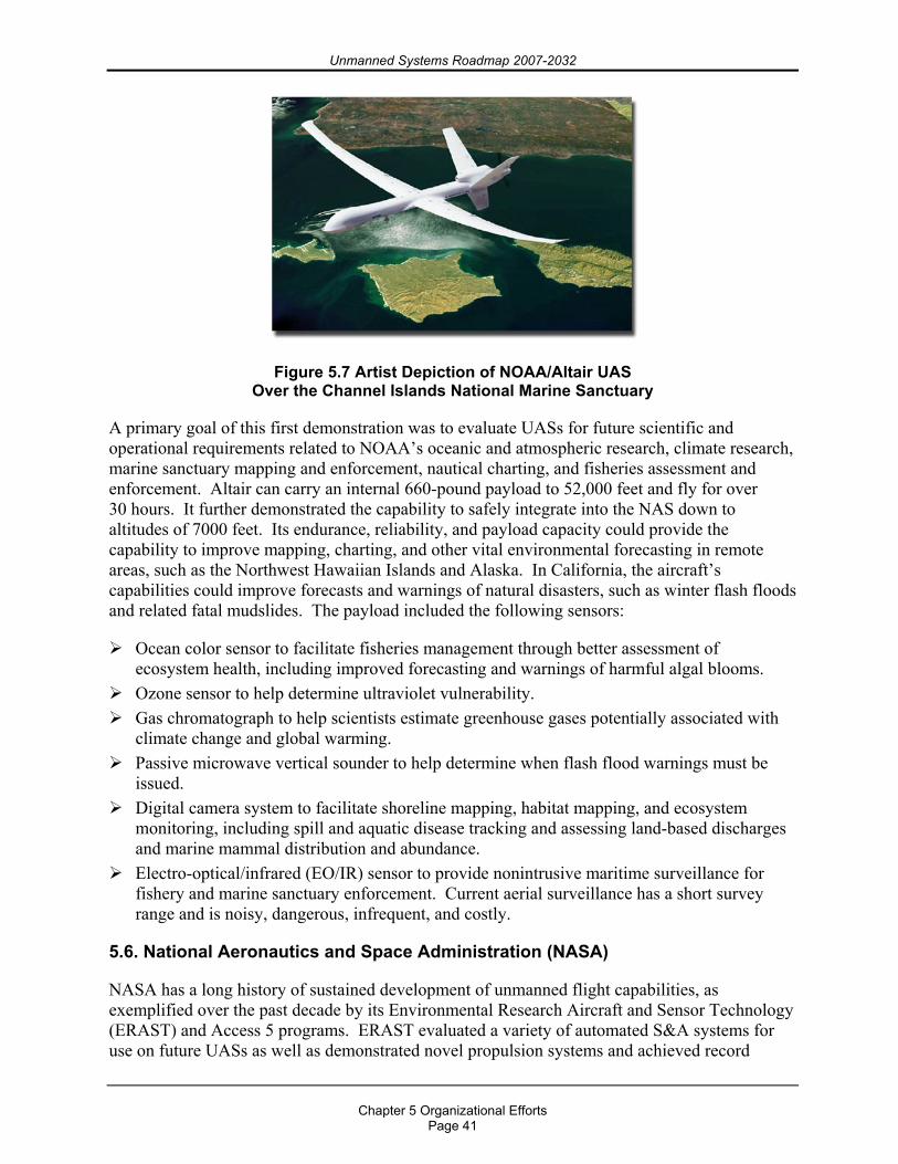
Unmanned Systems Roadmap 2007-2032
Chapter 5 Organizational Efforts
Page 41
Figure 5.7 Artist Depiction of NOAA/Altair UAS Over the Channel Islands National Marine Sanctuary
A primary goal of this first demonstration was to evaluate UASs for future scientific and operational requirements related to NOAA’s oceanic and atmospheric research, climate research, marine sanctuary mapping and enforcement, nautical charting, and fisheries assessment and enforcement. Altair can carry an internal 660-pound payload to 52,000 feet and fly for over 30 hours. It further demonstrated the capability to safely integrate into the NAS down to altitudes of 7000 feet. Its endurance, reliability, and payload capacity could provide the capability to improve mapping, charting, and other vital environmental forecasting in remote areas, such as the Northwest Hawaiian Islands and Alaska. In California, the aircraft’s capabilities could improve forecasts and warnings of natural disasters, such as winter flash floods and related fatal mudslides. The payload included the following sensors:
Ocean color sensor to facilitate fisheries management through better assessment of ecosystem health, including improved forecasting and warnings of harmful algal blooms.
Ozone sensor to help determine ultraviolet vulnerability. Gas chromatograph to help scientists estimate greenhouse gases potentially associated with
climate change and global warming. Passive microwave vertical sounder to help determine when flash flood warnings must be
issued. Digital camera system to facilitate shoreline mapping, habitat mapping, and ecosystem
monitoring, including spill and aquatic disease tracking and assessing land-based discharges and marine mammal distribution and abundance.
Electro-optical/infrared (EO/IR) sensor to provide nonintrusive maritime surveillance for fishery and marine sanctuary enforcement. Current aerial surveillance has a short survey range and is noisy, dangerous, infrequent, and costly.
5.6. National Aeronautics and Space Administration (NASA)
NASA has a long history of sustained development of unmanned flight capabilities, as exemplified over the past decade by its Environmental Research Aircraft and Sensor Technology (ERAST) and Access 5 programs. ERAST evaluated a variety of automated S&A systems for use on future UASs as well as demonstrated novel propulsion systems and achieved record

Unmanned Systems Roadmap 2007-2032
Chapter 5 Organizational Efforts
Page 42
altitudes for propeller-driven aircraft. Access 5 focused on creating the regulatory path forward for routine UAS access into the NAS. Today, NASA operates a small fleet of AAI Aerosonde mini-aircraft from its Wallops Island Flight Facility in Virginia on a lease-to-fly basis for researchers and a General Atomics Altair UAS from its Dryden Flight Research Center in California, which recently supported NOAA research payload flights.
Unmanned Systems Roadmap 2007-2032
Chapter 6 Technologies for Unmanned Systems
Page 43
Chapter 6. Technologies for Unmanned Systems
Although this chapter is largely based on one study of national technology trends,16 the first such report prepared after 9/11, that study built on eight other studies of trends in U.S. technology and industry published within two years of it. The organizations conducting these studies were the Council on Competitiveness, National Intelligence Council, U.S. Commission on National Security, RAND, the Industrial Research Institute, and Battelle show a cross-section of Government, industry, and academia in their composition. There was a high degree of correlation among the forecast technology trends in each study.
6.1. Technology Challenges
The single most important near-term technical challenge facing unmanned systems is to develop an autonomous capability to assess and respond appropriately to near-field objects in their path of travel. For an aircraft, that near field could extend to many nautical miles all around it, whereas for a ground or sea vehicle, near field could mean the next few yards directly in front of it, or as much as 100 meters for “high speed ground vehicles.” This is the UAS community’s S&A requirement17 to provide an autonomous ability to avoid midair collisions in lieu of having a pilot on board. The situation is also critical for UGVs, whose inability to distinguish between a wall of grass or a wall of granite in order to decide whether to go through or around it can thwart or unnecessarily delay mission accomplishment. Whether in an air, ground, or sea implementation, the technology for detecting near-field objects and for maneuvering with respect to them is well in hand. However, significant technical challenges remain in developing assessment tools and logic for maneuver, including a UGV’s ability to rapidly and accurately assess detected stationary obstacles protruding above the ground, conducting pathway trafficability assessments, and performing continuous classification of obstacles, e.g., humans, which could impact mission and path planning.
Securing command links to unmanned systems is an equally daunting challenge for all modalities of unmanned systems. Less than fully secure command links can result in the vehicle being delayed or diverted, destroyed, or even captured.
UGVs and UMSs often depend on a combination of a camera and a teleoperated manipulator (arm and claw) to perform certain tasks, such as de-arming explosive devices or removing mines. Requiring a human in the loop generally necessitates having the operator in the local vicinity due to Line of Sight (LOS) constraints, and this close proximity potentially brings the human into the threat zone of which the robot was meant to keep him clear. Autonomous robotic manipulators, or smart arms, capable of conducting scalable grasp, twist, release, and other such functions independent of human command, are needed to increase the mission flexibility and effectiveness of UGVs and UMSs. Smart arm technology is being tested in space on the DARPA Orbital Express and subsequent Air Force missions.
16 Future R&D Environments, National Academy Press, 2002, http://www.nap.edu. 17 14 Code of Federal Regulations Part 91.113.
Unmanned Systems Roadmap 2007-2032
Chapter 6 Technologies for Unmanned Systems
Page 44
6.2. Emerging, Applicable Technologies
In its 2002 report for NIST, the National Research Council examined current trends and probable developments in emergent technologies. The report contains two sections dedicated to unmanned systems, “Trend 5: The Maturation of Autonomous Machines” (Appendix G) and “Robot Engineering” (Appendix H), and numerous sections on the varied technologies (power, computing, materials, sensing) required to enable unmanned systems. The report stresses the growing interplay between the traditional robotics disciplines (engineering, computer science) and biological ones, as expanded in the following paragraph from its Appendix H:
“Today, robot building depends almost as much on biologists and neuroscientists as it does on engineers and computer scientists. Robot builders seek insights from the animal kingdom in order to develop machines with the same coordinated control, locomotion, and balance as insects and mammals. The purpose is not to create a robot that looks like a dog…but to build one—for battlefield use or planet-surface exploration, say—that can walk, creep, run, leap, wheel about, and roll over with the same fluid ease as a canine. To do this requires not simply electrical wiring and computer logic, but also a deep understanding of insect and mammalian mobility, which in turn requires the inputs of zoologists, entomologists, and neurophysiologists…For now, bioinspired robots are mostly creatures of the laboratory. However, one would expect continued development and application of these robots throughout this decade and a backflow of insights to biologists…as they observe the development of bioinspired machines.”
Although the foregoing extract seems focused on UGVs, it can be made equally applicable to robotic aircraft or sea vehicles by replacing “dog” with “bird” (fly, hover, swoop, perch) or “porpoise” (swim, dive), respectively. The question it raises for DoD robotics technologists and Military Department laboratory directors is whether the biological disciplines are sufficiently represented within their ranks.
The report examines technology development in terms of “push,” “contextual,” and “pull” factors. Push factors arise from the advance of technology itself; in other words, they are the results of the steady march and the occasional breakthroughs of research. Mapping the human genome is a recent example of push factors. Contextual factors are organizational, economic, legal, and regulatory issues that affect technology development. Quotas on foreign students and Federal policy on allowing them to participate in federally funded R&D are examples of contextual factors. Pull factors are social and cultural issues that shape which, how much, and how quickly technology is accepted into society. Internet use (fast, uncontested) and genetically engineered foods entering the food chain (slow, controversial) are two examples of pull factors. The push, contextual, and pull factors surrounding technologies for unmanned systems are discussed in 6.3, 6.4, and 6.5, respectively.
6.3. Push Factors
The NIST study focused on three specific fields of technology because the study’s authors judged it likely that most of the important technological advances over the next 10 years would come from within or at the intersection of these fields: biological science and engineering, materials science, and computer and information science. The report states, “Each is characterized by an extremely rapid rate of change of knowledge; has obvious and wide utility;
Unmanned Systems Roadmap 2007-2032
Chapter 6 Technologies for Unmanned Systems
Page 45
and will benefit from advances in the others, so the potential for synergy among them is particularly great.” Unmanned systems are deeply dependent on advances in each of the three fields, as shown from the following selected summaries from the study:
Transgenic biopolymers fall at the intersection of biological and materials sciences and offer the prospect of ultra-lightweight, ultra-strong, flexible, and low-observable skins (airframes, cowlings) for unmanned systems. As an example, the silk-producing gene of spiders has been spliced into the mammary gland gene of sheep, from whose subsequent milk the silk protein can be extracted. Breeding herds of such sheep enable spider silk, known for its light weight and high strength, to be produced on an industrial scale. The Army’s Natick Laboratory is investigating this same protein for use as an anti-nerve agent drug.
In materials science, nanoparticles, which are single-element materials built on the order of a few hundred to a few atoms in size (1 to 100 nanometers), possess significantly different properties than larger size devices of the same material. One form of nanoparticles, carbon nanotubes, could provide mechanical devices with very high resonant frequencies for use in unmanned system communication links. Surface coatings of combinations of nanoparticles and electrically conducting polymers have been demonstrated that convert from transparent to opaque, change color, and heat or cool with an electrical command and offer an option for camouflaging unmanned vehicles. The thermoelectric performance of bismuth nanoparticles offers the potential for developing high-efficiency, solid-state energy-conversion devices that could significantly reduce their size and weight in unmanned systems.
Microelectromechanical systems (MEMS) offer the prospect of radically reducing the size of all modalities of unmanned systems. Fingernail-size turbines and pinhead-size actuators on future, miniature aircraft could make today’s MAV prototypes appear unnecessarily large and bulky. MEMS-enabled UGVs could be deposited like unnoticed insects. Their UMS counterparts could be released in an underwater cloud to attach themselves to any mines into which they drift. A major challenge with MEMS will be communicating with them.
Proton exchange membrane fuel cells now offer power densities equivalent to internal combustion engines (1 horsepower per pound of engine weight) with the added advantages of quiet operation (low acoustic signature) and being mechanically less complex (lower maintenance cost). Fuel-cell-powered cars are now commercially available (Toyota) or about to be introduced (General Motors), yet only a handful of fuel-cell-powered aircraft have been flown experimentally. Current membrane materials are expensive and have thermal limitations that compromise operating efficiency. Materials research is focused on membranes that can conduct protons in the absence of water.
Smart materials and their constructs (smart structures) combine the sensing, control, and actuation functions into one entity and allow synchronization with the changing environment and self repair of damage. For unmanned aircraft, the concept of a morphing wing, one that optimizes its camber based on flight regime, is a rudimentary form of smart structure being developed by DARPA. Operationally, such a wing would eliminate bulky actuators, jackscrews, and hydraulic pumps used in current aircraft control surfaces, with the resultant weight savings becoming available for additional payload or fuel (in other words, range and/or endurance).
On the border of materials and computer sciences, magnetic nanoparticles may provide the next leap in magnetic storage devices, greatly expanding the memory capacities of the “brains” of unmanned systems. They have the potential to increase storage density to 1000 gigabits per square inch using nanoparticles of 10 to 20 nanometers.
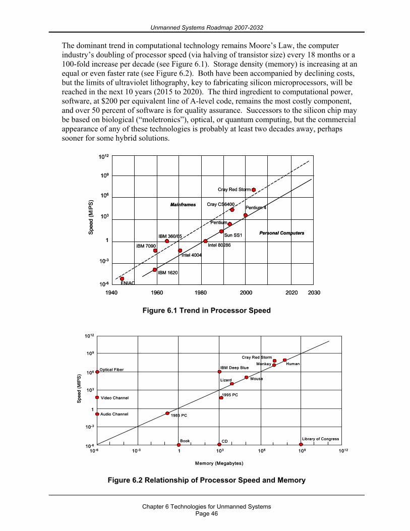
Unmanned Systems Roadmap 2007-2032
Chapter 6 Technologies for Unmanned Systems
Page 46
The dominant trend in computational technology remains Moore’s Law, the computer industry’s doubling of processor speed (via halving of transistor size) every 18 months or a 100-fold increase per decade (see Figure 6.1). Storage density (memory) is increasing at an equal or even faster rate (see Figure 6.2). Both have been accompanied by declining costs, but the limits of ultraviolet lithography, key to fabricating silicon microprocessors, will be reached in the next 10 years (2015 to 2020). The third ingredient to computational power, software, at $200 per equivalent line of A-level code, remains the most costly component, and over 50 percent of software is for quality assurance. Successors to the silicon chip may be based on biological (“moletronics”), optical, or quantum computing, but the commercial appearance of any of these technologies is probably at least two decades away, perhaps sooner for some hybrid solutions.
1940 1960 1980 2000 2020 2030
1012
109
106
103
1
10-3
10-6 ENIAC
IBM 1620
iBM 7090
IBM 360/65
Intel 4004
Intel 80286
Sun SS1
Pentium
Cray CS6400Pentium 4
Spe
ed (M
IPS
)
Cray Red Storm
Personal Computers
Mainframes
1940 1960 1980 2000 2020 2030
1012
109
106
103
1
10-3
10-6 ENIAC
IBM 1620
iBM 7090
IBM 360/65
Intel 4004
Intel 80286
Sun SS1
Pentium
Cray CS6400Pentium 4
Spe
ed (M
IPS
)
Cray Red Storm
Personal Computers
Mainframes
Figure 6.1 Trend in Processor Speed
10-6 10-3 1 103 106 109 1012
1012
109
106
103
1
10-3
10-6
Spee
d (M
IPS
)
Audio Channel
Video Channel
Optical Fiber
1985 PC
Book CD Library of Congress
1995 PC
IBM Deep Blue
Lizard Mouse
Monkey Human
Memory (Megabytes)
Cray Red Storm
10-6 10-3 1 103 106 109 1012
1012
109
106
103
1
10-3
10-6
Spee
d (M
IPS
)
Audio Channel
Video Channel
Optical Fiber
1985 PC
Book CD Library of Congress
1995 PC
IBM Deep Blue
Lizard Mouse
Monkey Human
Memory (Megabytes)
Cray Red Storm
Figure 6.2 Relationship of Processor Speed and Memory
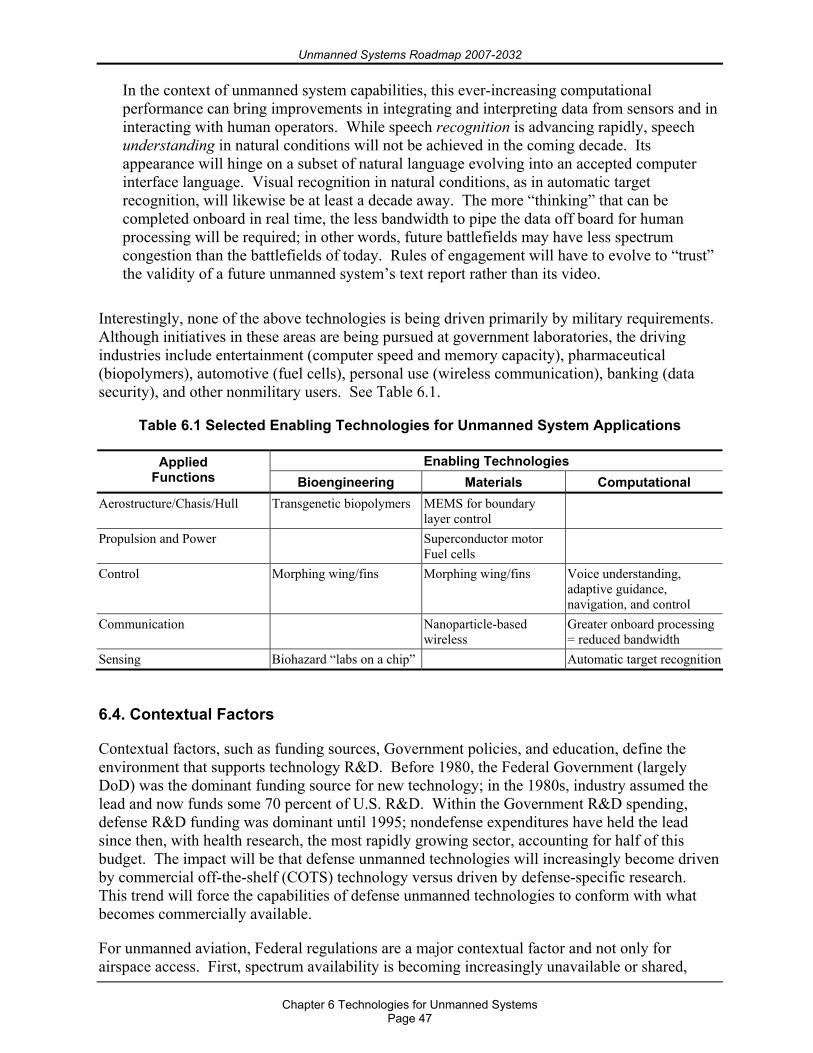
Unmanned Systems Roadmap 2007-2032
Chapter 6 Technologies for Unmanned Systems
Page 47
In the context of unmanned system capabilities, this ever-increasing computational performance can bring improvements in integrating and interpreting data from sensors and in interacting with human operators. While speech recognition is advancing rapidly, speech understanding in natural conditions will not be achieved in the coming decade. Its appearance will hinge on a subset of natural language evolving into an accepted computer interface language. Visual recognition in natural conditions, as in automatic target recognition, will likewise be at least a decade away. The more “thinking” that can be completed onboard in real time, the less bandwidth to pipe the data off board for human processing will be required; in other words, future battlefields may have less spectrum congestion than the battlefields of today. Rules of engagement will have to evolve to “trust” the validity of a future unmanned system’s text report rather than its video.
Interestingly, none of the above technologies is being driven primarily by military requirements. Although initiatives in these areas are being pursued at government laboratories, the driving industries include entertainment (computer speed and memory capacity), pharmaceutical (biopolymers), automotive (fuel cells), personal use (wireless communication), banking (data security), and other nonmilitary users. See Table 6.1.
Table 6.1 Selected Enabling Technologies for Unmanned System Applications
Enabling Technologies Applied Functions Bioengineering Materials Computational
Aerostructure/Chasis/Hull Transgenetic biopolymers MEMS for boundary layer control
Propulsion and Power Superconductor motor Fuel cells
Control Morphing wing/fins Morphing wing/fins Voice understanding, adaptive guidance, navigation, and control
Communication Nanoparticle-based wireless
Greater onboard processing = reduced bandwidth
Sensing Biohazard “labs on a chip” Automatic target recognition
6.4. Contextual Factors
Contextual factors, such as funding sources, Government policies, and education, define the environment that supports technology R&D. Before 1980, the Federal Government (largely DoD) was the dominant funding source for new technology; in the 1980s, industry assumed the lead and now funds some 70 percent of U.S. R&D. Within the Government R&D spending, defense R&D funding was dominant until 1995; nondefense expenditures have held the lead since then, with health research, the most rapidly growing sector, accounting for half of this budget. The impact will be that defense unmanned technologies will increasingly become driven by commercial off-the-shelf (COTS) technology versus driven by defense-specific research. This trend will force the capabilities of defense unmanned technologies to conform with what becomes commercially available.
For unmanned aviation, Federal regulations are a major contextual factor and not only for airspace access. First, spectrum availability is becoming increasingly unavailable or shared,
Unmanned Systems Roadmap 2007-2032
Chapter 6 Technologies for Unmanned Systems
Page 48
whether in the Continental United States (CONUS) or in overseas theaters. Many UAS types, from Global Hawk to Scan Eagle, have lost at least one aircraft to frequency interference or misuse. UASs must compete for spectrum in this crowded market through its national (Federal Communication Commission) and international (World Telecommunication Organization) regulators. Second, studies mandated by the Environmental Protection Agency are impacting where and when UASs can operate. UASs must operate usually over desert and away from urban concentrations or other environmentally or culturally sensitive areas. Third, existing airspace regulations are unfocused and interpretable with regard to unmanned aviation, a situation which is recognized and being addressed by the FAA.
6.5. Pull Factors
Pull factors are market and societal influences affecting technology adoption. For defense-related unmanned systems, the series of regional conflicts in which the United States has been engaged since the end of the Cold War has served to introduce and expand the capabilities of unmanned systems technology to warfighters. This conflict-driven demand has ensured the technology’s evolution and continued funding, with each new conflict reinforcing the interest in such systems. Global Hawk owes its appearance over Afghanistan to the performance of Predator over Bosnia and Kosovo, which in turn owes its start to the record established by Pioneer in the Persian Gulf War. CONUS use of unmanned systems includes crawling through collapsed buildings looking for 9/11 survivors, helping locate lost mountain climbers, and serving as robot astronauts on Mars. The attention such systems have received in the news media acts to increase public acceptance of these systems and to allay concerns over privacy issues raised in some quarters. Societal acceptance typically leads to market growth, which stimulates R&D that can lead to more capable, less costly unmanned systems for defense.
6.6. Unmanned Technology Objectives
Current unmanned systems capabilities must evolve into the future DoD acquisition and operational vision. Current support to the warfighter must be sustained while making the transition, but every effort must be made to accommodate unmanned systems technologies along with more traditional technologies as soon as possible. This section provides a summary of direction for future investments intended to produce common hardware and software to facilitate mechanisms across unmanned systems. A body of written DoD direction already exists with which the unmanned systems community must comply while designing, building, fielding, and sustaining such systems. In 6.6.1 through 6.6.17, the summary of direction to the Military Departments and to industry is intended to guide the unmanned systems community’s investment strategies.
COCOMs’ warfighting missions and capability needs are the focus of the technology way ahead, as illustrated in Figure 1.2. This Unmanned Systems Roadmap emphasizes missions and capabilities in terms of their air/sea/land domains without regard to a specific Military Department. The vision for these systems is that, regardless of originating Military Department, they will quickly evolve to the point where various classes of unmanned systems operate together in a cooperative and collaborative manner to meet the joint warfighers’ needs. UASs will be teamed with UGVs over land and with UMSs over water in combined arms roles that will augment and extend manned capabilities.
Unmanned Systems Roadmap 2007-2032
Chapter 6 Technologies for Unmanned Systems
Page 49
Obstacle avoidance, threat avoidance, and mine search and neutralization are a few of the missions that automatic target recognition facilitates. All of the missions described for unmanned systems depend on the effective use of sensors, most particularly the MCM, ISR, and ASW capabilities. The sensor arena needs to concentrate on increasing area coverage rate (ACR), improving classification and identification capabilities, developing nontraditional tracking techniques, and developing CBRNE sensors.
6.6.1. Autonomy The area of autonomy and control is a major research area for all unmanned systems, whether military, commercial, or academic in origin. It offers the benefit of minimizing manning and bandwidth requirements while extending the tactical range of operations beyond the LOS. A number of system mission support technologies must be advanced before we can achieve autonomous collaboration among multiple unmanned systems. For example, substantial research must still be undertaken in perception to enable small UASs working at low altitude, UGVs, and USVs to achieve forecast potential for working in three-dimensional terrain. Adaptability and learning from past experience are still at early stages of capability. Advances in these technologies for individual systems will go a long way toward enhancing the capabilities and utilization of unmanned systems collaboratively or in teamed applications with manned systems.
Another aspect of autonomy is cooperative (or collaborative) coordination among multiple vehicles. This aspect is viewed as an important enabling capability for large-scale operations where object sensing, intervention, and surveillance are necessary and may occur simultaneously and in stride with other operations. While many current systems operate using radio frequency (RF) communication links to an operator’s control station that can be long range with encrypted high data rates, trade-offs exist, and performance limitations due to issues with communications link allocation during real-world operations are likely. The unmanned systems community must wean itself from the telecommunication bandwidth. Autonomy will certainly be required in order to accomplish this goal.
6.6.2. Bandwidth Issues Many unmanned systems use COTS data link equipment that offers the developers reduced costs for the equipment and shorter development periods. Problems associated with using commercial RF for military applications include being designed within the U.S. authorized spectrum; in other words, they are given the lowest priority within the United States and its Possessions. As a result, use of these frequencies may be prohibited in some countries. The use of COTS equipment for proof of concept is acceptable on a temporary basis, but strong consideration must be given during system development to material solutions that truly take spectrum supportability into account. This effort includes considering equipment designed to operate in properly allocated bands before field testing and especially before entering formal development or before large numbers of systems are procured. Such replacement efforts need to be programmed into the transition plan from ACTDs into a normal acquisition program.
6.6.3. Cognitive Processes Human cognitive process considerations are important for unmanned system development from two perspectives. First, unmanned systems are intended to be tools or assets that extend human perception and action capabilities. Therefore, the manner in which the unmanned-system-provided information is made available to users must be consistent with their critical information requirements, mission tasks, and roles. The information must support human perception,
Unmanned Systems Roadmap 2007-2032
Chapter 6 Technologies for Unmanned Systems
Page 50
understanding, reasoning, and decision making in mission environments. Second, there are human capabilities that can be captured in software algorithms or computational approaches that would be beneficial to host directly on an unmanned system. For example, the human ability to identify objects is highly robust across viewing angles, lighting conditions, etc., and is very efficient. Such a capability would be useful to unmanned systems, both in terms of added functionality and in a potential reduction in computer requirements.
6.6.4. Common Control The effective operation of unmanned system capabilities envisioned by this integrated Roadmap will result in the simultaneous operation of many dissimilar unmanned systems. In order to minimize proliferation of unique hardware and software, manning and training requirements, and communications systems, a common control approach is necessary. Common control for all unmanned systems is the ultimate goal for many reasons:
To allow ready transfer of control of an unmanned vehicle from one operator to another, To allow control of multiple types of vehicles from a single control station, To minimize training across host platforms, operators, and vehicle types due to the resulting
standardization in controls across the unmanned systems community, and To minimize logistics requirements due to the resulting common hardware, spare parts, and
maintenance practices across the unmanned systems community.
6.6.5. Communications Communication is required between the vehicle and support platform for transmission of commands and data. Primary issues to be considered when evaluating a mode of communication for an unmanned systems task include available bandwidth, range between source and receiver, detectability, and the required network infrastructure. These issues are of particular concern for the ISR mission when communication is desired without exposing either the sender or receiver to possible hostile interception. An expansion of bandwidth capability is desired for the more stealthy methods, such as acoustic communications (ACOMMs) and low-probability-of-intercept RF communications. Communication challenges are also associated with multiple vehicles operating together. Reliable communication between vehicles working in a network must be established and proven.
6.6.6. Cooperative Behavior Two of the key features of unmanned systems in the future will be interconnectivity and interoperability. An operational construct and architectural framework will be required that integrates warfighters, sensors, networks, command and control, platforms, and weapons into a networked, distributed combat force, scaleable across the spectrum of conflict from seabed to space and from sea to land. This construct is an inherently joint and coalition concept; it relies on and provides essential capabilities to the joint and coalition communities and other Military Departments and agencies. By developing cooperative behaviors, unmanned systems will ensure that data products are delivered to the proper operating systems and via established communication paths to allow the most effective use and dissemination of those data products to warfighters.
Future unmanned systems will need to be optimized to perform collaboratively with both manned and unmanned team members to accomplish military missions and will require an increasingly complex exchange and fusion of data from individual systems to inform operator
Unmanned Systems Roadmap 2007-2032
Chapter 6 Technologies for Unmanned Systems
Page 51
decision making processes in real time. With the introduction of unmanned systems to the force, the definition of team member has been expanded to include unmanned systems. There are two components to this effort: teaming between the unmanned systems and teaming between the human and the unmanned systems. Human-robot teams provide a unique challenge, that is, how to develop unmanned systems technologies to enable the human to predict, collaborate, and develop trust with the unmanned system. Additional considerations are the coordination between mounted and dismounted soldiers with respect to the exchange and hand-off of information from, and control over, unmanned assets from one operator to the other.
6.6.7. Data Interfaces Information exchanges occur primarily between the unmanned system, its control station, and specially designed external interfaces, such as Air Traffic Control (ATC) and video feeds. Unmanned system products, after being processed, flow to external nodes from the control station servers through network connections. In its current form, the CDL communications system provides a closed circuit between the unmanned system and its control station to carry commands, status, and sensor products. As an edge device on the GIG, the control station then provides this information to the user community while keeping the unmanned system isolated from the GIG. CDL-equipped unmanned systems must transition from a closed circuit (or merely using communications services) to a network node (or actually providing communications services).
The first step to achieving network-centricity involves network-enabling the interfaces. In other words, Internet Protocol-based network connections and routers between unmanned subsystems and the on-board data link must be created with corresponding network interfaces between the control station data link, control station subsystems, and the GIG. This changes the paradigm from a closed circuit to a network node. Functions and products of unmanned systems implemented as network nodes would be accessible to other authorized nodes on the GIG, not just to the control station. The unmanned system itself becomes an edge device on the GIG.
The second step involves unmanned systems that can connect directly to more than one node on the GIG. During times when the demand on the data links is low, such as during cruise portions of the mission, unmanned systems capable of connecting to more than one node can act as network routers, passing Internet data packets between the multiple connected nodes. In this way, unmanned systems can contribute their unused bandwidth to the overall carrying capacity of the GIG.
6.6.8. Dynamic Obstacle/Interference/Collision Avoidance (Including Humans) All unmanned systems except the smallest special purpose vehicles must have the ability to autonomously avoid obstacles. In addition to the simple avoidance of obstacles (which is not simple if both the “obstacle” and the vehicle are moving independently), we must consider perception elements impacting trafficability, tactical maneuver, and mission execution. While most control algorithms are sufficiently mature, sensor processing is lacking for autonomous operations. Some combination of radar, optical, and infrared (IR) sensors will likely be required; and image processing algorithms, especially for the latter two, are in their infancy. Most of the mission capabilities also require the autonomous avoidance of threat systems, including ships, boats, craft, active sensor systems, and, to whatever extent possible, passive detection systems. The community would benefit greatly from increased developments in this area.
Unmanned Systems Roadmap 2007-2032
Chapter 6 Technologies for Unmanned Systems
Page 52
6.6.9. Human Systems Integration (HSI) in Unmanned Systems Despite the implication of the name, unmanned systems still include a human element. Even in highly autonomous systems, humans are required to provide high-level objectives, set rules of engagement, supply operational constraints, and support launch-and-recovery operations. Humans need to interpret sensor information, monitor systems, diagnose problems, coordinate mission time lines, manage consumables and other resources, authorize the use of weapons or other mission activities, and maintain system components. That the human is no longer necessarily co-located in mission execution with the dynamic components of the unmanned system represents a modification rather than an elimination of the role of humans.
Because the human must interact with the unmanned system using some form of system interface and because that interaction is clearly mission critical, it is essential that system design accommodate the human user. This requires attention to all elements of HSI when developing, acquiring, and operating unmanned systems. This includes optimizing design of the human-machine interface and consideration of how the operators and maintainers are selected and trained, how many will be required or are available to operate the system, and how their performance may be degraded by elements of the operational environment. For example, the presence and availability of information within these unmanned systems does not automatically equate to situation awareness on the part of the human operators. It does little good to develop a world-class sensor system if the human operator cannot easily perceive and interpret the information or if the operator is unable to put the information into the overall contextual framework of the mission.
6.6.10. Launch and Recovery (L&R) The successful operation of unmanned systems is dependent on the capability of delivering and recovering the unmanned systems from the operational area. A variety of challenges and conflicts need to be addressed, including
Safety and operability throughout all L&R operations and conditions, Adaptation of the L&R system to accommodate unmanned system variants, Host platform interfaces, Commonality and portability of the unmanned system L&R system interfaces, and Development of a simple system that reduces required manpower, maintenance, and number
of operations.
For many platforms that will be deployed and dependent on the utility of multiple unmanned systems, satisfying these issues as well as automating portions of the process will provide enhanced operational capability. Developmental goals for unmanned system L&R should include operations at higher speeds and higher sea states.
6.6.11. Power Systems Energy has long been a major consideration due to its effect on the ultimate performance of extended vehicle missions. For air-independent power, the energy source becomes a major factor in the design and efficiency of vehicle systems. For all operations, there is a desire to minimize the size, cost, and signature of the energy and propulsion system. Missions such as ASW and ISR with high speed and endurance requirements will require more sophisticated energy systems, such as fuel cells and hybrid systems. The type of energy source selected for an unmanned systems application is driven primarily by mission requirements for speed and
Unmanned Systems Roadmap 2007-2032
Chapter 6 Technologies for Unmanned Systems
Page 53
endurance. Long endurance, payload power, and high speed are all factors that require increased energy capacity on the unmanned system. It is important to note that energy source selection cannot be completed without consideration to the impact on vehicle design, size, and type. There is no clear-cut choice of energy system that meets all mission needs and all vehicle design constraints.
6.6.12. Processor Technology Just as computer components have evolved from vacuum tubes to transistors to integrated circuits of semiconductors, future ones will need to use different technologies to achieve ever faster speeds and larger memories. Military, as well as business and gaming applications, will continue to put higher demands on processors. Although today’s processors allow some unmanned systems, particularly UASs, to conduct entire missions with little or no human intervention, the ultimate goal is to replace the operators with a mechanical facsimile or equal or superior thinking speed, memory capacity, and responses gained from training and experience. To improve performance in the past, threading was enabled in the software by splitting instructions into multiple streaming so that multiple processors could act upon them. Hyper-threading technology offers potentially even more efficient use of processor resources, higher processing throughput, and improved performance. Optical, biochemical, quantum interference switching, and molecular processors, or some combination of these, will be required as well as low-power technologies. Size and cost of such “supercomputers” present equal challenges to overcome.
6.6.13. Product Format Engineering implementation is as important as technology development for success. System engineering considerations are often driven by the sensors, energy sources, and payloads as well as logistic concerns. However, size and number of vehicles to be used, overall system costs, and interoperability of systems all need to be considered in developing needed capabilities.
6.6.14. Reliability Reliability is the probability that an item will perform its intended function for a specified time under stated conditions. Unmanned systems reliability is important because it underlies their affordability, availability, and acceptance and must be addressed earlier in the development process. Design changes are significantly more costly during low-rate initial production (LRIP) and final production phases than during product design. High reliability is critical to warfighter acceptance of and confidence in a platform and is the first hurdle in airspace considerations as it underlies UAS acceptance into civil airspace. To achieve the goals outlined in this Roadmap, validation and verification of on-board software will become more critical, while also becoming more complex and less deterministic.
6.6.15. Sensors All unmanned systems missions depend on the effective use of sensors, most particularly the battlespace access and survivability, mine countermeasures (MCM), ISR, and ASW capabilities. Development in the sensor arena needs to concentrate on increasing area coverage rate (ACR), improving classification and identification capabilities, developing nontraditional tracking techniques, and developing CBRNE sensors. Synthetic aperture sonar (SAS) is the current leading candidate to best meet the requirements of the MCM mission. SAS promises to provide both increased ACR and increased resolution. However, the real breakthrough ASW sensor, for example, may be nonacoustic. This technology is not as strongly aperture-dependent as acoustic
Unmanned Systems Roadmap 2007-2032
Chapter 6 Technologies for Unmanned Systems
Page 54
sensors and can, therefore, be exploited in smaller systems. Sensor processing and the automated decision making associated with the processing remain a developmental area for both MCM and ASW. For MCMs, the principal risk will be the autonomous processing of sonar and optical images to classify mine-like objects and identify mines. The biggest challenges are associated with autonomous processing, target recognition, countermeasure rejection, target motion analysis, and tactics.
6.6.16. Survivability As unmanned systems use proliferates into an ever-increasing sphere of combat applications and becomes progressively more important to the warfighter, mission effectiveness and, by extension, combat survivability become increasingly critical. It is imperative that the survivability of an unmanned system be a key consideration during the system design process. The unmanned platform is but one component within the unmanned system. Addressing the survivability of simply the platform only partially addresses the survivability of the total system as the components operate within a collaborative multiplatform environment. Future efforts should concentrate on reducing the total system susceptibility and vulnerability.
6.6.17. Weapons Weaponizing unmanned systems is a highly controversial issue that will require a patient “crawl-walk-run” approach as each application’s reliability and performance is proved. This approach will require starting with the vehicle itself to ensure its performance within and adherence to appropriate operational regulations. Initial applications of weaponizing any unmanned systems may require a “man in the loop” (e.g., MQ-1B Predator, MQ-1C Sky Warrior, and MQ-5 Hunter UASs) to ensure positive control of the vehicle and its weapon. For weaponized unmanned systems operations during war or other categories of hostile action, rules of engagement will likely follow the precedence from other weapon release doctrine. Guns, missiles, torpedoes, and nonlethal projectiles can “hang up” and create a potentially dangerous condition for unmanned systems recovery personnel and other platforms within the operating area. The challenge is the ability to remotely render unmanned weapon systems safe (with verification) or face the choice of having to destroy or scuttle the system. As confidence in system reliability, function, and targeting algorithms grows, more autonomous operations with weapons may be considered. Primary technical challenges for weapon release from unmanned systems include the ability to reliably target the right objective and achieve proper tracking under all conditions where the system is likely to be employed. Maintaining communications for man-in-the-loop operations will be a challenge, particularly over the horizon (OTH).
Unmanned Systems Roadmap 2007-2032
Chapter 7 International Cooperation
Page 55
Chapter 7. International Cooperation
7.1. Assessment of Foreign Robotics
In general, U.S. capabilities, research, and technologies are leading the way for the international efforts. However, Japan’s effort with HRI is comparable, while the humanoid-like robotic technology may be somewhat ahead of efforts in the United States at present. South Korea began investing heavily in HRI and may partner with the United States in the future. Canada is increasing its investing efforts with platforms and may be considered comparable to U.S. platform technology.
A number of U.S. allies currently conduct R&D activities directed toward developing military capabilities for robotics and UGVs. Canada conducts research in the areas of autonomous systems with a focus on sensors and integration for robotic systems, control systems for robotic applications, data communications systems, robotic vehicle platforms, artificial intelligence for robotic systems, and the ergonomic aspects of human-machine interface. Germany has sponsored science and technology efforts directed toward the development of critical technologies for UGVs including perception, intelligent control, and autonomous robotic vehicle platforms as well as human interface and planning. Recently, Germany began to focus on the development of small (i.e., man-packable) robots. Australia is concentrating on the areas of platform-related technologies and weapons, man-unmanned systems, control theory, and control systems.
France is focusing on the areas of system collaboration, weapons, level of autonomy, and night vision and electronic sensors to include countermine and demining technologies. The United Kingdom is primarily working on navigation, mobility, communication, and ground vehicle integration. Israel is conducting work on tank systems dealing with laser rangefinders and the design and fabrication of tank systems. South Korea recently initiated research focused on the development of a platform similar to multifunction utility/logistics equipment (MULE) as well as on real-time tracking and HRI efforts, which they hope will ultimately result in a vehicle that can be used to monitor the Demilitarization Zone. Other international efforts include HRI by Switzerland and systems for mine clearing and mobility by Denmark. In summary, these countries are concentrating on capabilities for urban operation and combat application, as opposed to Japan, where defense applications for robotic technologies are their primary goal.
The current population and societal structure in China create an environment in which requirements for use of robotics do not necessarily parallel those of the United States. As a broad generalization, work appears to be primarily directed toward functions where human operators cannot function, as opposed to replacing human operators in hazardous military environments. One of the few references to military robotics found, an abstract from a thesis posted by the Institute for Intelligent Machines of the National Academy of Sciences, makes reference to Chinese developments in military robotics as “very late compared with other developed countries.” The thesis is aimed at teleoperation for ordnance disposal and represents a modest state of the art. Biomimetics, including serpentine, swimming, and human/quadrupedal approaches, are the primary focus in terms of R&D efforts in locomotion. Space robotics is an area of focus in several institutions, and there are reports of joint developments of intelligent multirobot (leader/host with four “followers”) at the Beijing University of Aerospace and Aeronautics and the Polytechnic University of Milan. Work at Tsinghua University’s Robotics
Unmanned Systems Roadmap 2007-2032
Chapter 7 International Cooperation
Page 56
and Automation Laboratory focuses on what are referred to as “Special Mobile Robots” for such applications as humanoid/multipedal locomotion, pipe crawling, and biochip manufacturing.
Other work at Tsinghua University and other institutes reflects an emphasis on intelligent systems for robotics. In this area, China has a number of apparent interests and infrastructure strengths. Much of the effort is directed toward sensing, perception, and information technologies, including multi-agent systems that would be applicable to advanced robotic concepts. Work in mobile ad hoc networking and intelligent agents is also widespread and addresses one of the key enabling technologies for advanced multirobot systems. To summarize, while Chinese efforts in robotic military systems may currently trail efforts of the United States and other western countries (notably France, Germany, and the United Kingdom), they have strong infrastructure capabilities. On-going research is addressing a number of enabling technologies that will be required for future robotics. Their ability to pursue and develop military robotics, should they choose that route, should be taken as a given.
7.2. International Robotics Agreements
The United States is sharing R&D information on unmanned systems with the United Kingdom, Australia, Sweden, France, Israel, Germany, Canada, Singapore, Norway, Italy, Japan, and South Korea. There are also active or planned cooperative efforts on unmanned systems with Singapore, France, the United Kingdom, Canada, Germany, Australia, Sweden, and Italy.
Key efforts include the Air Force’s high-altitude long-endurance UAS flight demonstration (performing Global Hawk flight trials with Germany), the SPARTAN SCOUT advanced concept technology demonstrations with participation from France and Singapore (demonstrating the military utility of UMSs for assured access and force protection in the littorals), and the NATO airborne ground surveillance program (whose concept includes the use of Global Hawk UASs).
The following terminology and abbreviations are used in 7.2.1 through 7.2.4:
Data Exchange Agreement (DEA). An international agreement that allows for the exchange of R&D information in a technical area under the auspices of a master information exchange agreement. DEAs are the same as information exchange program annexes (IEAs).
Memorandum of Understanding/Agreement (MOU/MOA). Either a framework international agreement to allow for cooperative R&D project arrangements or agreements (PAs) to be placed or large cooperative agreements for large programs or phases of programs.
Project Arrangement or Agreement (PA). An international agreement for a specific project under the auspices of an MOU or MOA.
7.2.1. Office of the Secretary of Defense (OSD) 1. Project Title: Electronic Warfare Support (ES) Unmanned Aerial Vehicle Demonstration
Country: Canada, UK Agreement Dates: 10/1/2004 – 9/30/2007 Description: The purpose of this project is to expand current capabilities to support more accurate geo-location of GPS jammers in a high-threat situation by improving anti-jamming protection on an UAS to support electronic warfare collection efforts.
Unmanned Systems Roadmap 2007-2032
Chapter 7 International Cooperation
Page 57
2. Project Title: NATO Airborne Ground Surveillance System Program Country: NATO Description: NATO Airborne Ground Surveillance System includes Global Hawk UASs equipped with a Multiplatform Radar Technology Insertion Program (MP-RTIP) radar.
3. Project Title: Land Warfare Concept Technology (LWCT) Country: Singapore Agreement Dates: 9/13/2004 – 12/31/2008 Description: DARPA provided two Learning Applied to Ground Robots (LAGR) vehicles to the Singapore Defense Sciences Organization National Laboratory for experimentation and testing.
7.2.2. Air Force 1. Project Title: Unmanned Air Vehicles (DEA)
Country: UK Agreement Dates: 11/13/2002 – 11/13/2007 Description: The scope of the IEA comprises the exchange of R&D information on unmanned, combat and offensive air vehicles technology and related studies and analyses.
2. Project Title: Unmanned Aerial Vehicles (UAVs) (DEA) Country: Australia Agreement Dates: 5/20/2004 – 5/19/2009 Description: The purpose of this DEA is to exchange research, development, test, and evaluation (RDT&E) information on UASs. The RDT&E information that will be exchanged focuses on the technologies, processes, and systems attributes that are key to understanding the utilization of unmanned air technology.
3. Project Title: Future Technology for Aerial Refueling (PA) Country: France, Germany, Italy and UK Agreement Dates: Proposed for FY2007–12 (Proposed PA, to be established under new Five-Power Research Technology Project (RTP) MOU) Description: The nations will conduct collaborative study work in the automation of aerial refueling, to include manned and unmanned receivers, operation in a mixed manned and unmanned combat environment, and operation of unmanned tankers.
4. Project Title: Unmanned Aerial Vehicles (UAVs) (DEA) Country: Australia Agreement Dates: 5/20/2004 – 05/19/2009 Description: The purpose of this DEA is to exchange RDT&E information on UASs. The RDT&E information that will be exchanged focuses on the technologies, processes, and systems attributes that are key to understanding the utilization of unmanned air technology.
5. Project Title: Refractive Turbulence, the Surveillance Mission, and Transient Propagation Disturbances (PA) Country: Australia Agreement Dates: 10/16/2006 – 10/15/2009 Description: AFRL/VS (Space Vehicle Directorate) and Defense Science and Technology Organization intend to demonstrate increased ability to measure, analyze, and predict the severity, duration, and location of the refractive turbulence events that lead to transient
Unmanned Systems Roadmap 2007-2032
Chapter 7 International Cooperation
Page 58
electronic disconnectivity and fluctuating surveillance image degradation within the same global environment in which manned and unmanned systems are required to operate.
6. Project Title: Operator Functional State Assessment and Adaptive Aiding Implementation (PA) Country: Sweden Agreement Dates: 2/16/2007 – 2/16/2011 Description: This PA will develop accurate methods of on-line assessment of the operator’s cognitive state and investigate methods by which intelligent agents tailor, in real time, the system’s demands upon the operator. This PA will also demonstrate how adaptive systems can aid and support the human operator during situations of high mental load.
7.2.3. Army 1. Project Title: Unmanned Aerial Vehicles (DEA)
Country: UK Agreement Dates: 12/1999 – 11/2009 Description: This DEA provides for the exchange of scientific and technical information on the research and development of UASs and remotely piloted vehicles in support of land combat.
2. Project Title: Mines, Countermine, and Demolitions (DEA) Country: Sweden Agreement Dates: 11/2002 – 11/2007 Description: This DEA provides for the exchange of RDT&E information on mines, countermine, and demolition technologies.
3. Project Title: Missile Technologies (DEA) Country: France Agreement Dates: Proposed Description: This DEA provides for the exchange of scientific and technical information of mutual interest on the RDT&E of technologies applicable to Army missile systems. The DEA specifically relates to the reconnaissance, surveillance, target acquisition, and engagement technology of unmanned systems.
4. Project Title: Electronic Warfare (DEA) Country: Israel Agreement Dates: 8/1972 Description: Classified
5. Project Title: Advanced VTOL Technology (DEA) Country: Germany Agreement Dates: 12/2003 – 12/2008 Description: This DEA provides for the exchange of R&D information of mutual interest in the field of advanced VTOL technology.
6. Project Title: Missiles (DEA) Country: United Kingdom Agreement Dates: 2/1996 – 6/2011 Description: This DEA provides for the exchange of information on capabilities and
Unmanned Systems Roadmap 2007-2032
Chapter 7 International Cooperation
Page 59
technologies of missiles, guided weapons, rockets, smart weapons and munitions, UASs, and remotely piloted vehicles in support of land combat. The DEA specifically relates to the integration of reconnaissance, surveillance, target acquisition, and engagement technology into unmanned systems.
7. Project Title: Unmanned Systems (DEA) Country: Singapore Agreement Dates: 2/2004 – 2/2009 Description: This DEA concerns a broad range of technologies related to U.S. Army programs for unmanned systems including UASs, UGVs, and supporting equipment.
8. Project Title: Military Rotorcraft and UAVs (DEA) Country: Australia Agreement Dates: 5/2004 – 5/2009 Description: This DEA provides for an exchange of data for military rotorcraft and UASs between the United States and Australia.
9. Project Title: Missile Technologies for Land Forces (DEA) Country: Canada Agreement Dates: 12/2004 – 12/2014 Description: This DEA provides for the exchange of scientific and technical information of mutual interest on the RDT&E on missile technologies for land forces. The DEA specifically relates to the integration of reconnaissance, surveillance, target acquisition, and engagement technology into unmanned systems.
10. Project Title: Survivability Technologies for Force Protection (DEA) Country: Israel Agreement Dates: 12/2003 – Description: This DEA covers the exchange of scientific and technical information of mutual interest on information related to RDT&E of military materiel and facilities.
11. Project Title: Countermine R&D and Systems (DEA) Country: Japan Agreement Dates: 4/1984 – Description: This DEA provides for the exchange of technical data related to RDT&E of systems and technologies in mine and minefield detection, mine and minefield neutralization, vehicle protection and hardening, and applications of robotics and automated equipment technology.
12. Project Title: Unmanned Systems (DEA) Country: Australia Agreement Dates: 11/2002 – 11/2012 Description: This DEA provides for the exchange of scientific and technical information of mutual interest on conceptual, operational, methodological, architectural, and technical aspects confined to the individual and combined development of command, control, and communications technology.
13. Project Title: Robotic Systems (DEA) Country: United Kingdom
Unmanned Systems Roadmap 2007-2032
Chapter 7 International Cooperation
Page 60
Agreement Dates: 4/1996 – 5/2008 Description: This DEA provides for the exchange of data, programs, and experience in the field of robotics for the planning, design, and operation of robotics systems for military purposes.
14. Project Title: Tactical Missiles (DEA) Country: Korea Agreement Dates: 6/2003 – 6/2013 Description: This DEA provides for the exchange of scientific and technical information of mutual interest on the RDT&E of tactical missiles. The DEA specifically relates to the integration of reconnaissance, surveillance, target acquisition, and engagement technology into unmanned systems.
15. Project Title: Armored Vehicles (DEA) Country: France Agreement Dates: 11/1961 – Description: This DEA provides for the exchange of armored vehicles research and development on current and future programs.
16. Project Title: Robotic Systems for Military Systems (DEA) Country: Germany Agreement Dates: 3/05 – 3/10 Description: Exchange of data, programs, and experience in the field of robotics for the planning, design, and operation of robotics systems for military purposes.
17. Project Title: Robotic Systems for Military Forces (DEA) Country: Israel Agreement Dates: 11/03 – 11/07 Description: Exchange of scientific and technical information of mutual interest on robotic systems to include the following teleoperated/autonomous technology areas: communications, navigation, mobility/control architecture, mission modules, man-robot interfaces, performance measurement, and operational concept development.
7.2.4. Navy 1. Project Title: Broad Area Maritime Surveillance (BAMS) Unmanned Aircraft System
(UAS) Cooperative Development Program (MOU) Country: Australia Agreement Dates: 01/13/2007 – 7/13/2008 Description: The SDD phase for multimission maritime aircraft (MMA) and BAMS UAS (Framework MOU) encompasses either or both the MMA and the BAMS UAS and potentially associated technologies or cooperative projects leading to full-scale development of the MMA and/or BAMS system.
2. Project Title: SPARTAN SCOUT ACTD (MOA) Country: France Agreement Dates: 01/29/2004 – 01/29/2012 Description: This ACTD is to demonstrate the military utility of USVs for assured access and force protection in the littorals.
Unmanned Systems Roadmap 2007-2032
Chapter 7 International Cooperation
Page 61
3. Project Title: SPARTAN SCOUT ACTD (PA) Country: Singapore Agreement Dates: 03/08/2003 – 03/08/2010 Description: This PA is the first under the new Singapore RDT&E agreement. The ACTD is set up to demonstrate the military utility of USVs.
4. Project Title: Feature-Based Navigation for Autonomous Underwater Vehicles (AUV) in Very Shallow Water (PA) Country: Singapore Agreement Dates: 03/30/2006 – 03/30/2010 Description: This work will involve joint development of algorithms and techniques, supporting data collection, and laboratory experiments carried out by each nation and lead up to an integration of jointly developed algorithms on a Singapore-supplied autonomous underwater vehicle equipped with sonar and other sensors for a demonstration in Singapore waters.
5. Project Title: Unmanned Underwater Vehicles (UUV) for Mine Countermeasures (MCM) (PA) Country: UK Agreement Dates: 08/09/2002 – 08/09/2007 Description: Currently, both nations have MCM capability requirements and similar concepts for application of autonomous platform systems to address the capability requirements. Leveraging the experience from the past investments and coordinating the planned resources and efforts of each, the collaboration will investigate different approaches within the key technology areas cost effectively.
6. Project Title: Unmanned Underwater Vehicle (UUV) Intelligence, Surveillance and Reconnaissance (ISR) and Anti-Submarine Warfare (ASW) Technology (PA) Country: UK Agreement Dates: 11/21/2003 – 11/21/2007 Description: This project will develop and demonstrate an integrated suite of sensors and autonomous vehicle systems for ISR and ASW missions and investigate energy storage systems for long-endurance operations. It enhances the U.S. efforts in the FNC area of underwater autonomy and ASW sensors.
7. Project Title: Information Exchange Program Annex Unmanned Aerial Vehicles (IEA) Country: France Agreement Dates: 5/16/2003 – 5/16/2008 Description: This project is a reciprocal government-to-government exchange of R&D information on UASs with France.
8. Project Title: Information Exchange Program Annex Unmanned Aerial Vehicle Technology Country: Australia Agreement Dates: 6/17/2004 – 6/17/2009 Description: This project is a reciprocal government-to-government exchange of R&D information on UASs with Australia.
Unmanned Systems Roadmap 2007-2032
Chapter 7 International Cooperation
Page 62
9. Project Title: Information Exchange Program Annex Unmanned Aerial Vehicle Systems (IEA) Country: Germany Agreement Dates: 8/30/2004 – 8/30/2009 Description: This project is a reciprocal government-to-government exchange of R&D information on UASs with Germany.
10. Project Title: Information Exchange Program Annex Unmanned Aerial Vehicles (IEA) Country: Italy Agreement Dates: 3/22/2004 – 3/22/2009 Description: This project is a reciprocal government-to-government exchange of R&D information on UASs with Italy.
11. Project Title: Information Exchange Program Annex Unmanned Aerial Vehicles (IEA) Country: Canada Agreement Dates: 6/13/1995 – 3/14/2007 Description: This project is a reciprocal government-to-government exchange of R&D information on UASs with Canada.
12. Project Title: Information Exchange Program Annex Unmanned Air Vehicles (IEA) Country: Korea Agreement Dates: 3/14/1997 – 3/14/2007 Description: This project is a reciprocal government-to-government exchange of R&D information on UASs with Korea.
13. Project Title: Information Exchange Program Annex Unmanned Aerial Vehicles (IEA) Country: Israel Agreement Dates: 1/16/1996 – 1/16/2011 Description: This project is a reciprocal government-to-government exchange of R&D information on UASs with Israel.
14. Project Title: Information Exchange Program Annex Unmanned Aircraft Systems (IEA) Country: Singapore Agreement Dates: Proposed in development Description: This project is a reciprocal government-to-government exchange of R&D information on UASs with Singapore.
15. Project Title: Information Exchange Program Annex Unmanned Underwater Vehicles (IEA) Country: UK Agreement Dates: 8/2/2004 – 8/2/2009 Description: This project is a reciprocal government-to-government exchange of R&D information on UUVs with the United Kingdom.
16. Project Title: Information Exchange Program Annex Unmanned Aerial Vehicles (IEA) Country: UK Agreement Dates: 06/06/1995 – 6/6/2010 Description: This project is a reciprocal government-to-government exchange of R&D information on UASs with the United Kingdom.
Unmanned Systems Roadmap 2007-2032
Chapter 7 International Cooperation
Page 63
17. Project Title: Information Exchange Program Annex Anti-Submarine/Anti-Surface Ship Torpedo and Unmanned Underwater Vehicle Systems (IEA) Country: Japan Agreement Dates: 2/4/2002 – 2/4/2007 Description: This project is a reciprocal government-to-government exchange of R&D information on anti-submarine and anti-surface ship torpedoes and UUVs with Japan.
18. Project Title: Information Exchange Program Annex Mine Warfare and Unmanned Vehicles (IEA) Country: Norway Agreement Dates: 3/18/2005 – 3/18/2010 Description: This project is a reciprocal government-to-government exchange of R&D information on mine warfare and UUVs with Norway.
19. Project Title: Project Churchill, agreement with UK as part of the Navy-led Unmanned Combat Air Systems (UCAS) Program Country: UK Dates: 12/21/2004 – 07/31/2009 Description: The United States and United Kingdom will jointly create a distributed simulation environment capability using Navy, Air Force, and U.K. Defence Science and Technology Laboratory M&S capabilities. They will then select portions of the U.K. unmanned combat air vehicle (UCAV) demonstration results of efforts functionality already completed; jointly participate in modeling, simulation, tests, and demonstrations; and conduct additional tests using U.S. J-UCAS and U.K. UCAV assets to gather further information regarding coalition employment and interoperability of UCAV.
Unmanned Systems Roadmap 2007-2032
Chapter 7 International Cooperation
Page 64
7.3. Treaty Concerns for Unmanned Systems
DoDD 2060.1 directs that “all DoD activities shall be fully compliant with arms control agreements of the U.S. Government.”17 Additionally, DoDD 5000.1 directs that the “acquisition and procurement of DoD weapons and weapon systems shall be consistent with all applicable domestic law and treaties and international agreements” and that “an attorney authorized to conduct such legal reviews in the Department shall conduct the legal review of the intended acquisition of weapons or weapons systems.”18 U.S. Government arms control agreements concerning unmanned systems include the Wassenaar Arrangement (WA), the Missile Technology Control Regime (MTCR), the Treaty on Conventional Armed Forces in Europe (CFE), the Vienna Document 1999 (VDOC), the Intermediate-Range Nuclear Forces Treaty (INF), the Global Exchange of Military Information (GEMI), and the United Nations Transparency in Armaments Resolution (UNTIA). Conventional arms agreements that do not name unmanned systems, but mention military air and ground vehicles include the CFE, VDOC, INF, GEMI, and UNTIA. Conventional arms agreements that address unmanned systems directly include the WA and MTCR.
WA-controlled dual-use items include unmanned systems in item ML 10I munitions list in section 9.A.12 and technology applicable to unmanned systems in sections 9.D.1, 9.E.3, and 9.D.2. MTCR restricts unmanned systems as a Category I item in section 1.A.2, provided that the UAS can carry a 1100-pound payload for 162 nautical miles. MTCR Category II items, under sections 19.A.2 and 19.A.3, include technology and equipment that may be used in Category I unmanned systems.
CFE articles I and II obligate participant adherence and define conventional weapons that, within the area of application, are subject to terms of reduction and limits outlined in articles IV–VI. Unmanned systems may, subject to review, meet the definitions of conventional armaments and equipment subject to the CFE treaty. Also subject to review, VDOC may require the U.S. Government to report combat equipment and/or new weapons systems as they fall under article I, paragraphs 10.2.5, 10.5, and 11.2, and follow-on items of the VDOC. Ground-launched cruise missiles are restricted by INF in article II, paragraph 2; however, air-to-surface weapons are not considered under the INF treaty. Unmanned systems that are not ground launched, or take off without the aid of launching equipment, and are designed to return from mission, do not fall within the definition of a ground-launched cruise missile. GEMI requires the U.S. Government to share information on holdings of major weapons and equipment systems listed under paragraph 3. Air and ground vehicles, irrespective of manned or unmanned, may, upon review, fall under the categories of major weapon and equipment systems subject to information sharing under paragraph 3 of GEMI. Under the UNTIA Annex, Register of Conventional Arms, unmanned systems, subject to review, may meet the definitions of items defined in paragraph 2.a., “concerning international arms transfers.”
17 DoDD 2060.1, paragraph 3.3.1, June 9, 2001. 18 DoDD 5000.1, paragraph E1.1.15, Legal Compliance, 12 May 2003.
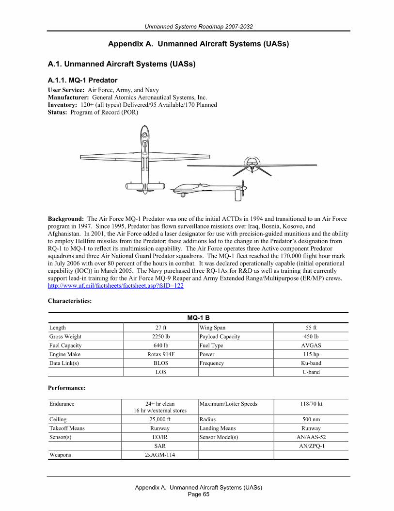
Unmanned Systems Roadmap 2007-2032
Appendix A. Unmanned Aircraft Systems (UASs)
Page 65
Appendix A. Unmanned Aircraft Systems (UASs) A.1. Unmanned Aircraft Systems (UASs)
A.1.1. MQ-1 Predator User Service: Air Force, Army, and Navy Manufacturer: General Atomics Aeronautical Systems, Inc. Inventory: 120+ (all types) Delivered/95 Available/170 Planned Status: Program of Record (POR)
Background: The Air Force MQ-1 Predator was one of the initial ACTDs in 1994 and transitioned to an Air Force program in 1997. Since 1995, Predator has flown surveillance missions over Iraq, Bosnia, Kosovo, and Afghanistan. In 2001, the Air Force added a laser designator for use with precision-guided munitions and the ability to employ Hellfire missiles from the Predator; these additions led to the change in the Predator’s designation from RQ-1 to MQ-1 to reflect its multimission capability. The Air Force operates three Active component Predator squadrons and three Air National Guard Predator squadrons. The MQ-1 fleet reached the 170,000 flight hour mark in July 2006 with over 80 percent of the hours in combat. It was declared operationally capable (initial operational capability (IOC)) in March 2005. The Navy purchased three RQ-1As for R&D as well as training that currently support lead-in training for the Air Force MQ-9 Reaper and Army Extended Range/Multipurpose (ER/MP) crews. http://www.af.mil/factsheets/factsheet.asp?fsID=122
Characteristics:
MQ-1 B Length 27 ft Wing Span 55 ft Gross Weight 2250 lb Payload Capacity 450 lb Fuel Capacity 640 lb Fuel Type AVGAS Engine Make Rotax 914F Power 115 hp Data Link(s) BLOS Frequency Ku-band LOS C-band Performance:
Endurance 24+ hr clean 16 hr w/external stores
Maximum/Loiter Speeds 118/70 kt
Ceiling 25,000 ft Radius 500 nm Takeoff Means Runway Landing Means Runway Sensor(s) EO/IR Sensor Model(s) AN/AAS-52 SAR AN/ZPQ-1 Weapons 2xAGM-114
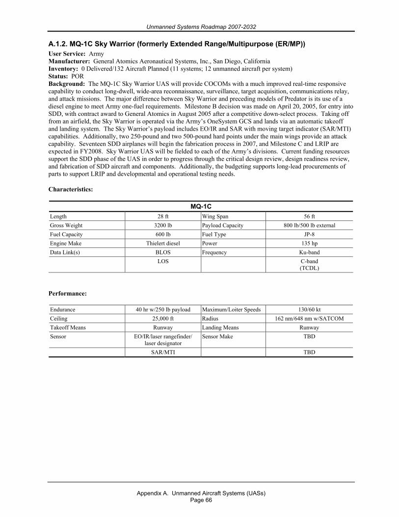
Unmanned Systems Roadmap 2007-2032
Appendix A. Unmanned Aircraft Systems (UASs)
Page 66
A.1.2. MQ-1C Sky Warrior (formerly Extended Range/Multipurpose (ER/MP)) User Service: Army Manufacturer: General Atomics Aeronautical Systems, Inc., San Diego, California Inventory: 0 Delivered/132 Aircraft Planned (11 systems; 12 unmanned aircraft per system) Status: POR Background: The MQ-1C Sky Warrior UAS will provide COCOMs with a much improved real-time responsive capability to conduct long-dwell, wide-area reconnaissance, surveillance, target acquisition, communications relay, and attack missions. The major difference between Sky Warrior and preceding models of Predator is its use of a diesel engine to meet Army one-fuel requirements. Milestone B decision was made on April 20, 2005, for entry into SDD, with contract award to General Atomics in August 2005 after a competitive down-select process. Taking off from an airfield, the Sky Warrior is operated via the Army’s OneSystem GCS and lands via an automatic takeoff and landing system. The Sky Warrior’s payload includes EO/IR and SAR with moving target indicator (SAR/MTI) capabilities. Additionally, two 250-pound and two 500-pound hard points under the main wings provide an attack capability. Seventeen SDD airplanes will begin the fabrication process in 2007, and Milestone C and LRIP are expected in FY2008. Sky Warrior UAS will be fielded to each of the Army’s divisions. Current funding resources support the SDD phase of the UAS in order to progress through the critical design review, design readiness review, and fabrication of SDD aircraft and components. Additionally, the budgeting supports long-lead procurements of parts to support LRIP and developmental and operational testing needs.
Characteristics:
MQ-1C Length 28 ft Wing Span 56 ft Gross Weight 3200 lb Payload Capacity 800 lb/500 lb external Fuel Capacity 600 lb Fuel Type JP-8 Engine Make Thielert diesel Power 135 hp Data Link(s) BLOS Frequency Ku-band LOS C-band
(TCDL)
Performance:
Endurance 40 hr w/250 lb payload Maximum/Loiter Speeds 130/60 kt Ceiling 25,000 ft Radius 162 nm/648 nm w/SATCOM Takeoff Means Runway Landing Means Runway Sensor EO/IR/laser rangefinder/
laser designator Sensor Make TBD
SAR/MTI TBD
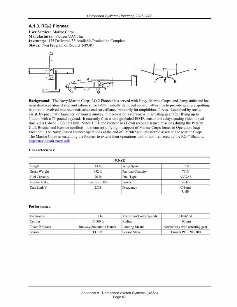
Unmanned Systems Roadmap 2007-2032
Appendix A. Unmanned Aircraft Systems (UASs)
Page 67
A.1.3. RQ-2 Pioneer User Service: Marine Corps Manufacturer: Pioneer UAV, Inc. Inventory: 175 Delivered/33 Available/Production Complete Status: Non Program of Record (NPOR)
Background: The Navy/Marine Corps RQ-2 Pioneer has served with Navy, Marine Corps, and Army units and has been deployed aboard ship and ashore since 1986. Initially deployed aboard battleships to provide gunnery spotting, its mission evolved into reconnaissance and surveillance, primarily for amphibious forces. Launched by rocket assist, by pneumatic launcher, or from a runway, it recovers on a runway with arresting gear after flying up to 5 hours with a 75-pound payload. It currently flies with a gimbaled EO/IR sensor and relays analog video in real time via a C-band LOS data link. Since 1991, the Pioneer has flown reconnaissance missions during the Persian Gulf, Bosnia, and Kosovo conflicts. It is currently flying in support of Marine Corps forces in Operation Iraqi Freedom. The Navy ceased Pioneer operations at the end of FY2002 and transferred assets to the Marine Corps. The Marine Corps is sustaining the Pioneer to extend their operations with it until replaced by the RQ-7 Shadow. http://uav.navair.navy.mil/
Characteristics:
RQ-2B Length 14 ft Wing Span 17 ft Gross Weight 452 lb Payload Capacity 75 lb Fuel Capacity 76 lb Fuel Type AVGAS Engine Make Sachs SF 350 Power 26 hp Data Link(s) LOS Frequency C-band
UHF
Performance:
Endurance 5 hr Maximum/Loiter Speeds 110/65 kt Ceiling 15,000 ft Radius 100 nm Takeoff Means Runway/pneumatic launch Landing Means Net/runway with arresting gear Sensor EO/IR Sensor Make Tamam POP 200/300
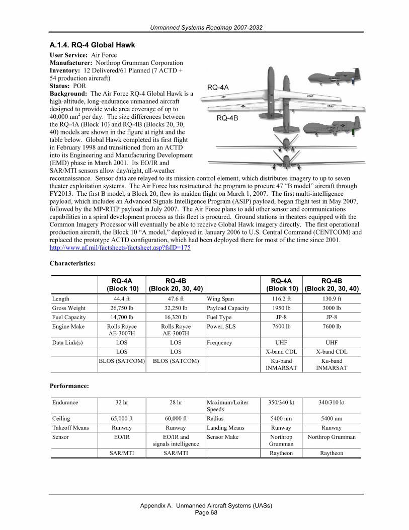
Unmanned Systems Roadmap 2007-2032
Appendix A. Unmanned Aircraft Systems (UASs)
Page 68
A.1.4. RQ-4 Global Hawk User Service: Air Force Manufacturer: Northrop Grumman Corporation Inventory: 12 Delivered/61 Planned (7 ACTD + 54 production aircraft) Status: POR Background: The Air Force RQ-4 Global Hawk is a high-altitude, long-endurance unmanned aircraft designed to provide wide area coverage of up to 40,000 nm2 per day. The size differences between the RQ-4A (Block 10) and RQ-4B (Blocks 20, 30, 40) models are shown in the figure at right and the table below. Global Hawk completed its first flight in February 1998 and transitioned from an ACTD into its Engineering and Manufacturing Development (EMD) phase in March 2001. Its EO/IR and SAR/MTI sensors allow day/night, all-weather reconnaissance. Sensor data are relayed to its mission control element, which distributes imagery to up to seven theater exploitation systems. The Air Force has restructured the program to procure 47 “B model” aircraft through FY2013. The first B model, a Block 20, flew its maiden flight on March 1, 2007. The first multi-intelligence payload, which includes an Advanced Signals Intelligence Program (ASIP) payload, began flight test in May 2007, followed by the MP-RTIP payload in July 2007. The Air Force plans to add other sensor and communications capabilities in a spiral development process as this fleet is procured. Ground stations in theaters equipped with the Common Imagery Processor will eventually be able to receive Global Hawk imagery directly. The first operational production aircraft, the Block 10 “A model,” deployed in January 2006 to U.S. Central Command (CENTCOM) and replaced the prototype ACTD configuration, which had been deployed there for most of the time since 2001. http://www.af.mil/factsheets/factsheet.asp?fsID=175
Characteristics:
RQ-4A (Block 10)
RQ-4B (Block 20, 30, 40)
RQ-4A (Block 10)
RQ-4B (Block 20, 30, 40)
Length 44.4 ft 47.6 ft Wing Span 116.2 ft 130.9 ft Gross Weight 26,750 lb 32,250 lb Payload Capacity 1950 lb 3000 lb Fuel Capacity 14,700 lb 16,320 lb Fuel Type JP-8 JP-8 Engine Make Rolls Royce
AE-3007H Rolls Royce AE-3007H
Power, SLS 7600 lb 7600 lb
Data Link(s) LOS LOS Frequency UHF UHF LOS LOS X-band CDL X-band CDL BLOS (SATCOM) BLOS (SATCOM) Ku-band
INMARSAT Ku-band
INMARSAT
Performance:
Endurance 32 hr 28 hr Maximum/Loiter Speeds
350/340 kt 340/310 kt
Ceiling 65,000 ft 60,000 ft Radius 5400 nm 5400 nm Takeoff Means Runway Runway Landing Means Runway Runway Sensor EO/IR EO/IR and
signals intelligence Sensor Make Northrop
Grumman Northrop Grumman
SAR/MTI SAR/MTI Raytheon Raytheon
Unmanned Systems Roadmap 2007-2032
Appendix A. Unmanned Aircraft Systems (UASs)
Page 69
A.1.5. RQ-4 Global Hawk Maritime Demonstration (GHMD) User Service: Navy Manufacturer: Northrop Grumman Corporation Inventory: 2 Delivered/2 Planned Status: NPOR Background: The GHMD program is a nonacquisition demonstration program. Its purpose is to provide the Navy with a multi-intelligence, high-altitude, persistent ISR demonstration capability for doctrine; CONOPS; TTP development; and participation in naval, joint, and homeland defense exercises. In FY2003, the Navy contracted with Northrop Grumman through the Air Force Global Hawk program office for the purchase of
Two RQ-4A (Block 10) Global Hawks with EO/IR and SAR sensors, Ground control/support equipment, Engineering to include Navy changes for
Maritime sensor modes software (maritime surveillance, target acquisition, inverse SAR), 360-degree field-of-regard electronic support measures capability, Satellite and direct data link upgrades.
These two unmanned aircraft with sensors and ground control and support equipment are based at the Navy’s GHMD main operating base at Patuxent River, Maryland. http://uav.navair.navy.mil
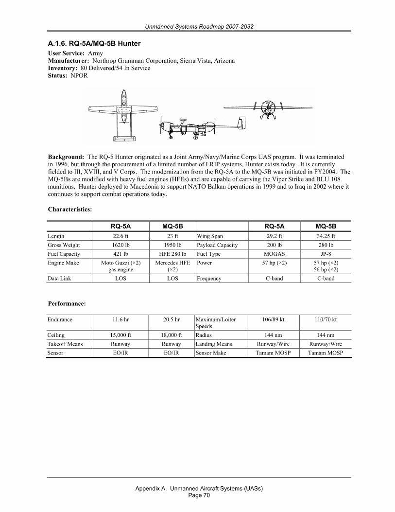
Unmanned Systems Roadmap 2007-2032
Appendix A. Unmanned Aircraft Systems (UASs)
Page 70
A.1.6. RQ-5A/MQ-5B Hunter User Service: Army Manufacturer: Northrop Grumman Corporation, Sierra Vista, Arizona Inventory: 80 Delivered/54 In Service Status: NPOR
Background: The RQ-5 Hunter originated as a Joint Army/Navy/Marine Corps UAS program. It was terminated in 1996, but through the procurement of a limited number of LRIP systems, Hunter exists today. It is currently fielded to III, XVIII, and V Corps. The modernization from the RQ-5A to the MQ-5B was initiated in FY2004. The MQ-5Bs are modified with heavy fuel engines (HFEs) and are capable of carrying the Viper Strike and BLU 108 munitions. Hunter deployed to Macedonia to support NATO Balkan operations in 1999 and to Iraq in 2002 where it continues to support combat operations today.
Characteristics:
RQ-5A MQ-5B RQ-5A MQ-5B Length 22.6 ft 23 ft Wing Span 29.2 ft 34.25 ft Gross Weight 1620 lb 1950 lb Payload Capacity 200 lb 280 lb Fuel Capacity 421 lb HFE 280 lb Fuel Type MOGAS JP-8 Engine Make Moto Guzzi (×2)
gas engine Mercedes HFE
(×2) Power 57 hp (×2) 57 hp (×2)
56 hp (×2) Data Link LOS LOS Frequency C-band C-band
Performance:
Endurance 11.6 hr 20.5 hr Maximum/Loiter Speeds
106/89 kt 110/70 kt
Ceiling 15,000 ft 18,000 ft Radius 144 nm 144 nm Takeoff Means Runway Runway Landing Means Runway/Wire Runway/Wire Sensor EO/IR EO/IR Sensor Make Tamam MOSP Tamam MOSP
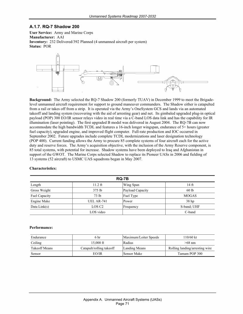
Unmanned Systems Roadmap 2007-2032
Appendix A. Unmanned Aircraft Systems (UASs)
Page 71
A.1.7. RQ-7 Shadow 200 User Service: Army and Marine Corps Manufacturer: AAI Inventory: 232 Delivered/392 Planned (4 unmanned aircraft per system) Status: POR
Background: The Army selected the RQ-7 Shadow 200 (formerly TUAV) in December 1999 to meet the Brigade-level unmanned aircraft requirement for support to ground maneuver commanders. The Shadow either is catapulted from a rail or takes off from a strip. It is operated via the Army’s OneSystem GCS and lands via an automated takeoff and landing system (recovering with the aid of arresting gear) and net. Its gimbaled upgraded plug-in optical payload (POP) 300 EO/IR sensor relays video in real time via a C-band LOS data link and has the capability for IR illumination (laser pointing). The first upgraded B model was delivered in August 2004. The RQ-7B can now accommodate the high bandwidth TCDL and features a 16-inch longer wingspan, endurance of 5+ hours (greater fuel capacity), upgraded engine, and improved flight computer. Full-rate production and IOC occurred in September 2002. Future upgrades include complete TCDL modernizations and laser designation technology (POP 400). Current funding allows the Army to procure 85 complete systems of four aircraft each for the active duty and reserve forces. The Army’s acquisition objective, with the inclusion of the Army Reserve component, is 85 total systems, with potential for increase. Shadow systems have been deployed to Iraq and Afghanistan in support of the GWOT. The Marine Corps selected Shadow to replace its Pioneer UASs in 2006 and fielding of 13 systems (52 aircraft) to USMC UAS squadrons began in May 2007.
Characteristics:
RQ-7B Length 11.2 ft Wing Span 14 ft Gross Weight 375 lb Payload Capacity 60 lb Fuel Capacity 73 lb Fuel Type MOGAS Engine Make UEL AR-741 Power 38 hp Data Link(s) LOS C2 Frequency S-band; UHF LOS video C-band
Performance:
Endurance 6 hr Maximum/Loiter Speeds 110/60 kt Ceiling 15,000 ft Radius >68 nm Takeoff Means Catapult/rolling takeoff Landing Means Rolling landing/arresting wire Sensor EO/IR Sensor Make Tamam POP 300
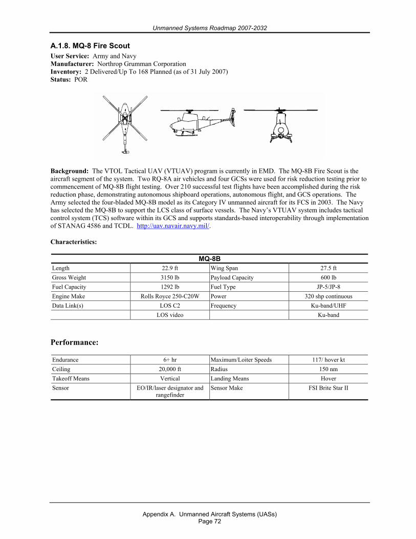
Unmanned Systems Roadmap 2007-2032
Appendix A. Unmanned Aircraft Systems (UASs)
Page 72
A.1.8. MQ-8 Fire Scout User Service: Army and Navy Manufacturer: Northrop Grumman Corporation Inventory: 2 Delivered/Up To 168 Planned (as of 31 July 2007) Status: POR
Background: The VTOL Tactical UAV (VTUAV) program is currently in EMD. The MQ-8B Fire Scout is the aircraft segment of the system. Two RQ-8A air vehicles and four GCSs were used for risk reduction testing prior to commencement of MQ-8B flight testing. Over 210 successful test flights have been accomplished during the risk reduction phase, demonstrating autonomous shipboard operations, autonomous flight, and GCS operations. The Army selected the four-bladed MQ-8B model as its Category IV unmanned aircraft for its FCS in 2003. The Navy has selected the MQ-8B to support the LCS class of surface vessels. The Navy’s VTUAV system includes tactical control system (TCS) software within its GCS and supports standards-based interoperability through implementation of STANAG 4586 and TCDL. http://uav.navair.navy.mil/.
Characteristics:
MQ-8B Length 22.9 ft Wing Span 27.5 ft Gross Weight 3150 lb Payload Capacity 600 lb Fuel Capacity 1292 lb Fuel Type JP-5/JP-8 Engine Make Rolls Royce 250-C20W Power 320 shp continuous Data Link(s) LOS C2 Frequency Ku-band/UHF LOS video Ku-band
Performance:
Endurance 6+ hr Maximum/Loiter Speeds 117/ hover kt Ceiling 20,000 ft Radius 150 nm Takeoff Means Vertical Landing Means Hover Sensor EO/IR/laser designator and
rangefinder Sensor Make FSI Brite Star II
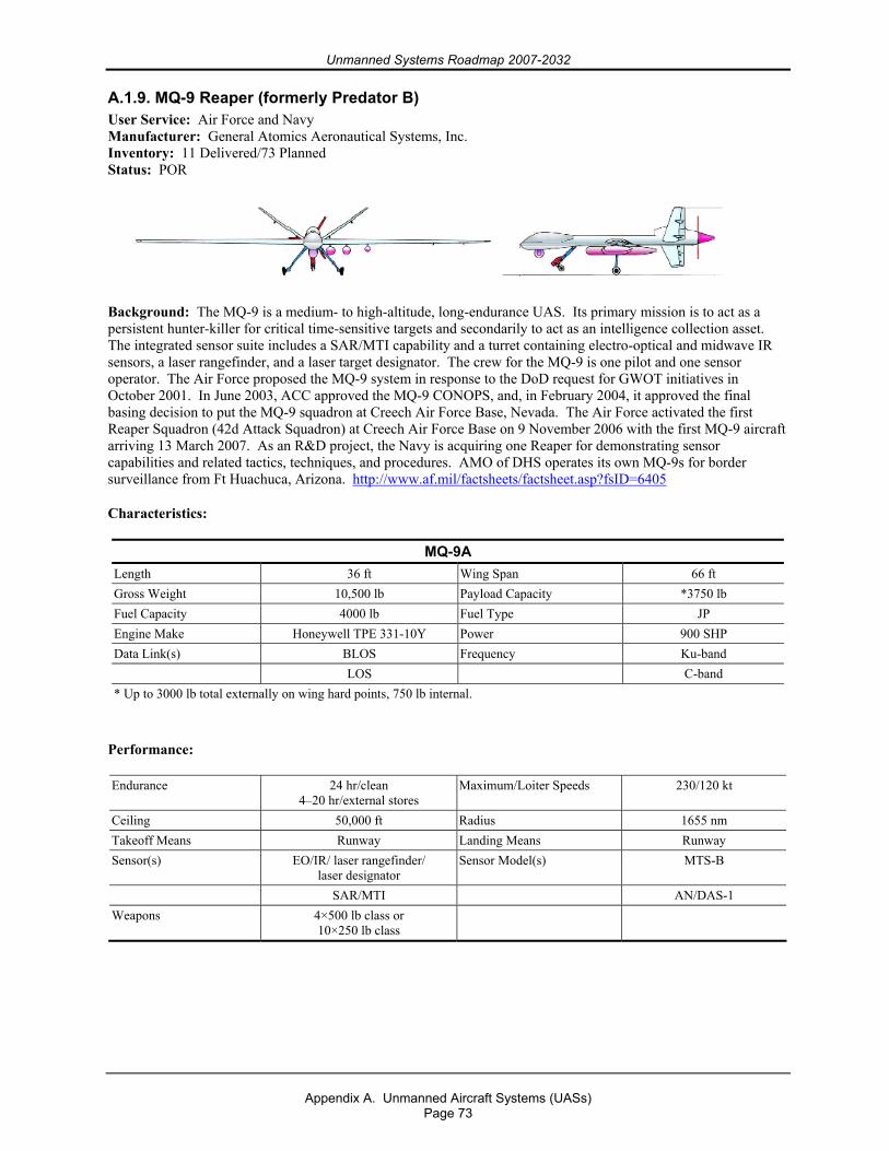
Unmanned Systems Roadmap 2007-2032
Appendix A. Unmanned Aircraft Systems (UASs)
Page 73
A.1.9. MQ-9 Reaper (formerly Predator B) User Service: Air Force and Navy Manufacturer: General Atomics Aeronautical Systems, Inc. Inventory: 11 Delivered/73 Planned Status: POR
Background: The MQ-9 is a medium- to high-altitude, long-endurance UAS. Its primary mission is to act as a persistent hunter-killer for critical time-sensitive targets and secondarily to act as an intelligence collection asset. The integrated sensor suite includes a SAR/MTI capability and a turret containing electro-optical and midwave IR sensors, a laser rangefinder, and a laser target designator. The crew for the MQ-9 is one pilot and one sensor operator. The Air Force proposed the MQ-9 system in response to the DoD request for GWOT initiatives in October 2001. In June 2003, ACC approved the MQ-9 CONOPS, and, in February 2004, it approved the final basing decision to put the MQ-9 squadron at Creech Air Force Base, Nevada. The Air Force activated the first Reaper Squadron (42d Attack Squadron) at Creech Air Force Base on 9 November 2006 with the first MQ-9 aircraft arriving 13 March 2007. As an R&D project, the Navy is acquiring one Reaper for demonstrating sensor capabilities and related tactics, techniques, and procedures. AMO of DHS operates its own MQ-9s for border surveillance from Ft Huachuca, Arizona. http://www.af.mil/factsheets/factsheet.asp?fsID=6405
Characteristics:
MQ-9A Length 36 ft Wing Span 66 ft Gross Weight 10,500 lb Payload Capacity *3750 lb Fuel Capacity 4000 lb Fuel Type JP Engine Make Honeywell TPE 331-10Y Power 900 SHP Data Link(s) BLOS Frequency Ku-band LOS C-band * Up to 3000 lb total externally on wing hard points, 750 lb internal.
Performance:
Endurance 24 hr/clean 4–20 hr/external stores
Maximum/Loiter Speeds 230/120 kt
Ceiling 50,000 ft Radius 1655 nm Takeoff Means Runway Landing Means Runway Sensor(s) EO/IR/ laser rangefinder/
laser designator Sensor Model(s) MTS-B
SAR/MTI AN/DAS-1 Weapons 4×500 lb class or
10×250 lb class
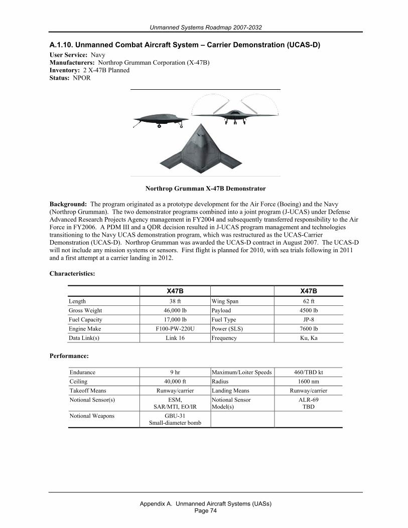
Unmanned Systems Roadmap 2007-2032
Appendix A. Unmanned Aircraft Systems (UASs)
Page 74
A.1.10. Unmanned Combat Aircraft System – Carrier Demonstration (UCAS-D) User Service: Navy Manufacturers: Northrop Grumman Corporation (X-47B) Inventory: 2 X-47B Planned Status: NPOR
Northrop Grumman X-47B Demonstrator
Background: The program originated as a prototype development for the Air Force (Boeing) and the Navy (Northrop Grumman). The two demonstrator programs combined into a joint program (J-UCAS) under Defense Advanced Research Projects Agency management in FY2004 and subsequently transferred responsibility to the Air Force in FY2006. A PDM III and a QDR decision resulted in J-UCAS program management and technologies transitioning to the Navy UCAS demonstration program, which was restructured as the UCAS-Carrier Demonstration (UCAS-D). Northrop Grumman was awarded the UCAS-D contract in August 2007. The UCAS-D will not include any mission systems or sensors. First flight is planned for 2010, with sea trials following in 2011 and a first attempt at a carrier landing in 2012.
Characteristics:
X47B X47B Length 38 ft Wing Span 62 ft Gross Weight 46,000 lb Payload 4500 lb Fuel Capacity 17,000 lb Fuel Type JP-8 Engine Make F100-PW-220U Power (SLS) 7600 lb Data Link(s) Link 16 Frequency Ku, Ka
Performance:
Endurance 9 hr Maximum/Loiter Speeds 460/TBD kt Ceiling 40,000 ft Radius 1600 nm Takeoff Means Runway/carrier Landing Means Runway/carrier Notional Sensor(s) ESM,
SAR/MTI, EO/IR Notional Sensor Model(s)
ALR-69 TBD
Notional Weapons GBU-31 Small-diameter bomb
Unmanned Systems Roadmap 2007-2032
Appendix A. Unmanned Aircraft Systems (UASs)
Page 75
A.1.11. Broad Area Maritime Surveillance (BAMS) User Service: Navy Manufacturer: TBD Inventory: 0 Delivered/TBD Planned Status: POR Background: The BAMS UAS is a pre-Major Defense Acquisition Program (pre-MDAP) ACAT 1D program to develop a multiple-sensor, persistent maritime ISR UAS that provides persistent ISR to supported commanders. BAMS UAS will be a force multiplier for the Joint Forces and fleet commanders: it will enhance their situation awareness of the battlespace and shorten the sensor-to-shooter kill chain. BAMS UAS will operate both independently and cooperatively with other assets to provide a more effective and supportable persistent maritime surveillance capability than currently exists. BAMS UAS will be a Navy fleet asset for operational and tactical users. Additionally, BAMS collected data will support a variety of intelligence activities and nodes. In a secondary role, it will also be used alone or in conjunction with other assets to respond to theater level, operational, or national strategic tasking. The BAMS UAS will serve as an adjunct to the MMA to leverage the unique attributes of each platform to optimize the family-of-systems approach to contribute to dominant maritime domain awareness. Collocation of BAMS UAS mission crews with Maritime Patrol and Reconnaissance Force (MPRF) will provide operator synergy: it will allow close coordination of missions and leverage common mission support infrastructure. BAMS UAS also complements the current national, theater, and other Military Department collection systems by providing persistent ISR in the maritime and littoral areas 24 hours a day. The BAMS UAS will provide DoD with a unique capability to persistently detect, classify, and identify maritime targets within a large volume of the maritime battlespace. The request for proposals for the SDD and LRIP phases was released on 15 February 2007 to support Milestone B in the fourth quarter FY2007. IOC is planned for 2014. http://uav.navair.navy.mil
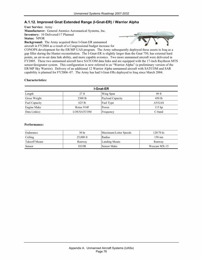
Unmanned Systems Roadmap 2007-2032
Appendix A. Unmanned Aircraft Systems (UASs)
Page 76
A.1.12. Improved Gnat Extended Range (I-Gnat-ER) / Warrior Alpha User Service: Army Manufacturer: General Atomics Aeronautical Systems, Inc. Inventory: 10 Delivered/17 Planned Status: NPOR Background: The Army acquired three I-Gnat-ER unmanned aircraft in FY2004 as a result of a Congressional budget increase for CONOPS development for the ER/MP UAS program. The Army subsequently deployed these assets to Iraq as a gap filler during the Hunter reconstitution. The I-Gnat-ER is slightly larger than the Gnat 750, has external hard points, an air-to-air data link ability, and more capable avionics. Two more unmanned aircraft were delivered in FY2005. These two unmanned aircraft have SATCOM data links and are equipped with the 17-inch Raytheon MTS sensor/designator system. This configuration is now referred to as “Warrior Alpha” (a preliminary version of the ER/MP Sky Warrior). Delivery of an additional 12 Warrior Alpha unmanned aircraft with SATCOM and SAR capability is planned for FY2006–07. The Army has had I-Gnat-ERs deployed to Iraq since March 2004.
Characteristics:
I-Gnat-ER Length 27 ft Wing Span 49 ft Gross Weight 2300 lb Payload Capacity 450 lb Fuel Capacity 625 lb Fuel Type AVGAS Engine Make Rotax 914F Power 115 hp Data Link(s) LOS/SATCOM Frequency C-band
Performance:
Endurance 30 hr Maximum/Loiter Speeds 120/70 kt Ceiling 25,000 ft Radius 150 nm Takeoff Means Runway Landing Means Runway Sensor EO/IR Sensor Make Wescam MX-15
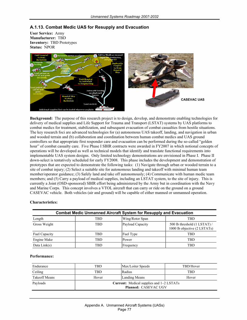
Unmanned Systems Roadmap 2007-2032
Appendix A. Unmanned Aircraft Systems (UASs)
Page 77
A.1.13. Combat Medic UAS for Resupply and Evacuation User Service: Army Manufacturer: TBD Inventory: TBD Prototypes Status: NPOR
Background: The purpose of this research project is to design, develop, and demonstrate enabling technologies for delivery of medical supplies and Life Support for Trauma and Transport (LSTAT) systems by UAS platforms to combat medics for treatment, stabilization, and subsequent evacuation of combat casualties from hostile situations. The key research foci are advanced technologies for (a) autonomous UAS takeoff, landing, and navigation in urban and wooded terrain and (b) collaboration and coordination between human combat medics and UAS ground controllers so that appropriate first responder care and evacuation can be performed during the so-called “golden hour” of combat casualty care. Five Phase I SBIR contracts were awarded in FY2007 in which notional concepts of operations will be developed as well as technical models that identify and translate functional requirements into implementable UAS system designs. Only limited technology demonstrations are envisioned in Phase I. Phase II down-select is tentatively scheduled for early FY2008. This phase includes the development and demonstration of prototypes that are expected to demonstrate the following tasks: (1) Navigate through urban or wooded terrain to a site of combat injury; (2) Select a suitable site for autonomous landing and takeoff with minimal human team member/operator guidance; (3) Safely land and take off autonomously; (4) Communicate with human medic team members; and (5) Carry a payload of medical supplies, including an LSTAT system, to the site of injury. This is currently a Joint (OSD-sponsored) SBIR effort being administered by the Army but in coordination with the Navy and Marine Corps. This concept involves a VTOL aircraft that can carry or ride on the ground on a ground CASEVAC vehicle. Both vehicles (air and ground) will be capable of either manned or unmanned operation.
Characteristics:
Combat Medic Unmanned Aircraft System for Resupply and Evacuation Length TBD Wing/Rotor Span TBD Gross Weight TBD Payload Capacity 500 lb threshold (1 LSTAT) /
1000 lb objective (2 LSTATs) Fuel Capacity TBD Fuel Type TBD Engine Make TBD Power TBD Data Link(s) TBD Frequency TBD
Performance:
Endurance TBD Max/Loiter Speeds TBD/Hover Ceiling TBD Radius TBD Takeoff Means Hover Landing Means Hover Payloads Current: Medical supplies and 1–2 LSTATs
Planned: CASEVAC UGV
CASEVAC UAS
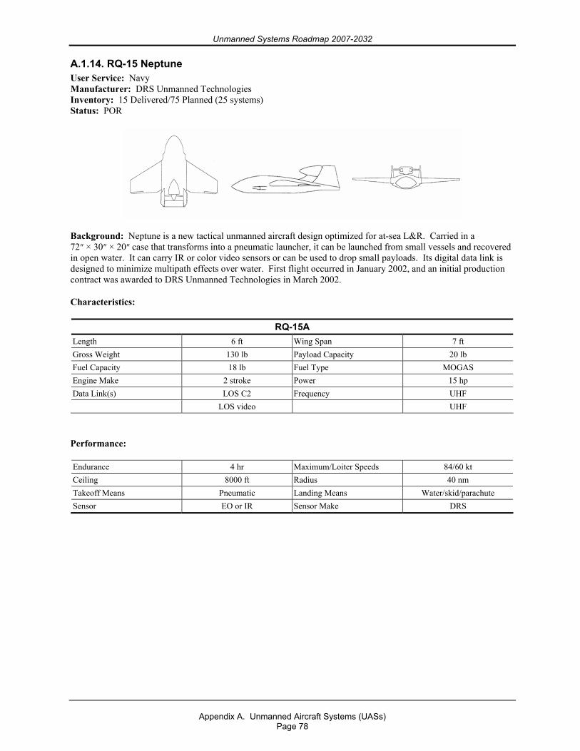
Unmanned Systems Roadmap 2007-2032
Appendix A. Unmanned Aircraft Systems (UASs)
Page 78
A.1.14. RQ-15 Neptune User Service: Navy Manufacturer: DRS Unmanned Technologies Inventory: 15 Delivered/75 Planned (25 systems) Status: POR
Background: Neptune is a new tactical unmanned aircraft design optimized for at-sea L&R. Carried in a 72″ × 30″ × 20″ case that transforms into a pneumatic launcher, it can be launched from small vessels and recovered in open water. It can carry IR or color video sensors or can be used to drop small payloads. Its digital data link is designed to minimize multipath effects over water. First flight occurred in January 2002, and an initial production contract was awarded to DRS Unmanned Technologies in March 2002.
Characteristics:
RQ-15A Length 6 ft Wing Span 7 ft Gross Weight 130 lb Payload Capacity 20 lb Fuel Capacity 18 lb Fuel Type MOGAS Engine Make 2 stroke Power 15 hp Data Link(s) LOS C2 Frequency UHF LOS video UHF
Performance:
Endurance 4 hr Maximum/Loiter Speeds 84/60 kt Ceiling 8000 ft Radius 40 nm Takeoff Means Pneumatic Landing Means Water/skid/parachute Sensor EO or IR Sensor Make DRS
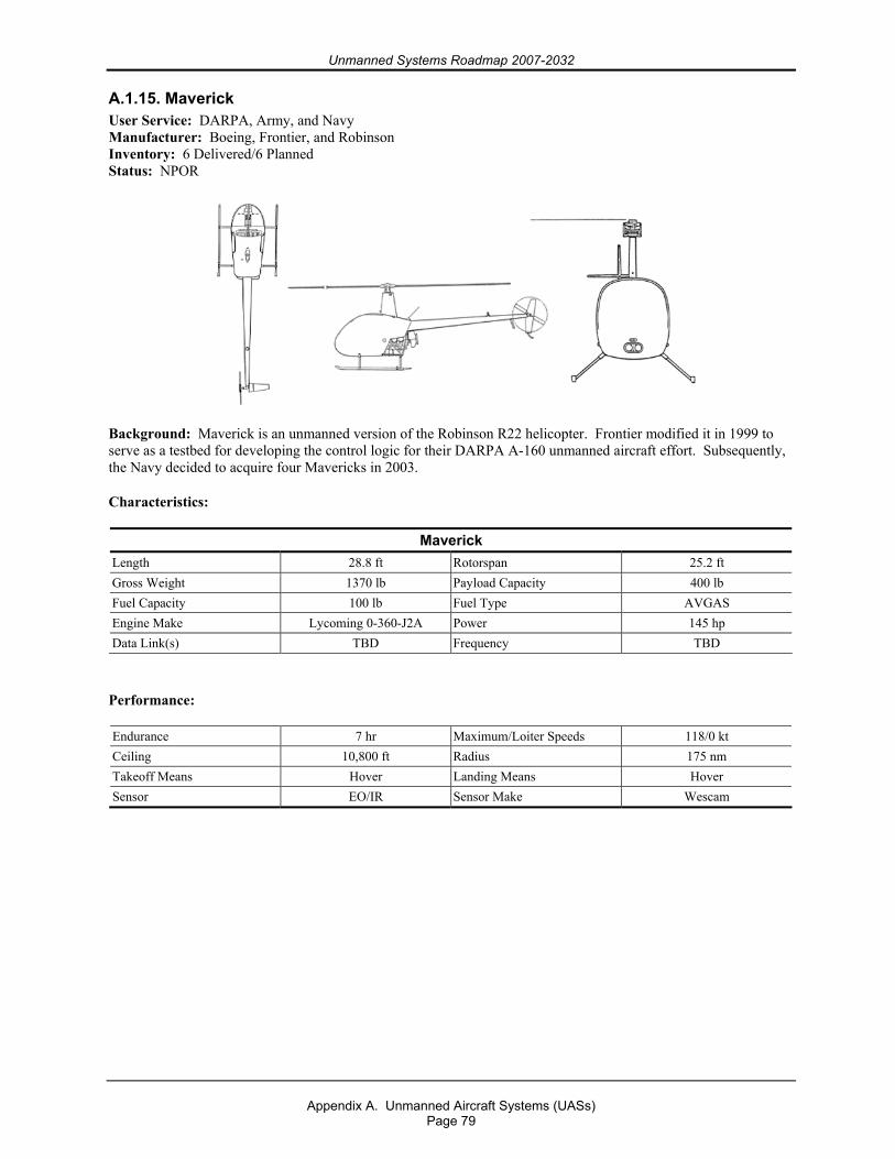
Unmanned Systems Roadmap 2007-2032
Appendix A. Unmanned Aircraft Systems (UASs)
Page 79
A.1.15. Maverick User Service: DARPA, Army, and Navy Manufacturer: Boeing, Frontier, and Robinson Inventory: 6 Delivered/6 Planned Status: NPOR
Background: Maverick is an unmanned version of the Robinson R22 helicopter. Frontier modified it in 1999 to serve as a testbed for developing the control logic for their DARPA A-160 unmanned aircraft effort. Subsequently, the Navy decided to acquire four Mavericks in 2003.
Characteristics:
Maverick Length 28.8 ft Rotorspan 25.2 ft Gross Weight 1370 lb Payload Capacity 400 lb Fuel Capacity 100 lb Fuel Type AVGAS Engine Make Lycoming 0-360-J2A Power 145 hp Data Link(s) TBD Frequency TBD
Performance:
Endurance 7 hr Maximum/Loiter Speeds 118/0 kt Ceiling 10,800 ft Radius 175 nm Takeoff Means Hover Landing Means Hover Sensor EO/IR Sensor Make Wescam
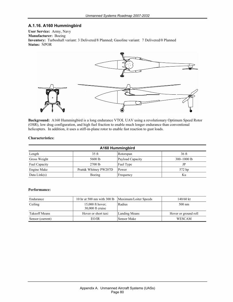
Unmanned Systems Roadmap 2007-2032
Appendix A. Unmanned Aircraft Systems (UASs)
Page 80
A.1.16. A160 Hummingbird User Service: Army, Navy Manufacturer: Boeing Inventory: Turboshaft variant: 3 Delivered/8 Planned; Gasoline variant: 7 Delivered/0 Planned Status: NPOR
Background: A160 Hummingbird is a long endurance VTOL UAV using a revolutionary Optimum Speed Rotor (OSR), low drag configuration, and high fuel fraction to enable much longer endurance than conventional helicopters. In addition, it uses a stiff-in-plane rotor to enable fast reaction to gust loads.
Characteristics:
A160 Hummingbird Length 35 ft Rotorspan 36 ft Gross Weight 5600 lb Payload Capacity 300–1000 lb Fuel Capacity 2700 lb Fuel Type JP Engine Make Pratt& Whitney PW207D Power 572 hp Data Link(s) Boeing Frequency Ku
Performance:
Endurance 10 hr at 500 nm with 300 lb Maximum/Loiter Speeds 140/60 kt Ceiling 15,000 ft hover;
30,000 ft cruise Radius 500 nm
Takeoff Means Hover or short taxi Landing Means Hover or ground roll Sensor (current) EO/IR Sensor Make WESCAM
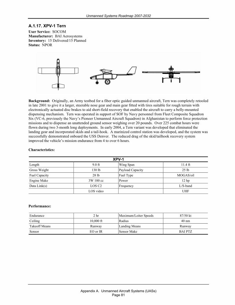
Unmanned Systems Roadmap 2007-2032
Appendix A. Unmanned Aircraft Systems (UASs)
Page 81
A.1.17. XPV-1 Tern User Service: SOCOM Manufacturer: BAI Aerosystems Inventory: 15 Delivered/15 Planned Status: NPOR
Background: Originally, an Army testbed for a fiber optic guided unmanned aircraft, Tern was completely retooled in late 2001 to give it a larger, steerable nose gear and main gear fitted with tires suitable for rough terrain with electronically actuated disc brakes to aid short-field recovery that enabled the aircraft to carry a belly-mounted dispensing mechanism. Tern was operated in support of SOF by Navy personnel from Fleet Composite Squadron Six (VC-6, previously the Navy’s Pioneer Unmanned Aircraft Squadron) in Afghanistan to perform force protection missions and to dispense an unattended ground sensor weighing over 20 pounds. Over 225 combat hours were flown during two 3-month long deployments. In early 2004, a Tern variant was developed that eliminated the landing gear and incorporated skids and a tail-hook. A marinized control station was developed, and the system was successfully demonstrated onboard the USS Denver. The reduced drag of the skid/tailhook recovery system improved the vehicle’s mission endurance from 4 to over 6 hours.
Characteristics:
XPV-1 Length 9.0 ft Wing Span 11.4 ft Gross Weight 130 lb Payload Capacity 25 lb Fuel Capacity 28 lb Fuel Type MOGAS/oil Engine Make 3W 100 cc Power 12 hp Data Link(s) LOS C2 Frequency L/S-band LOS video UHF
Performance:
Endurance 2 hr Maximum/Loiter Speeds 87/50 kt Ceiling 10,000 ft Radius 40 nm Takeoff Means Runway Landing Means Runway Sensor EO or IR Sensor Make BAI PTZ
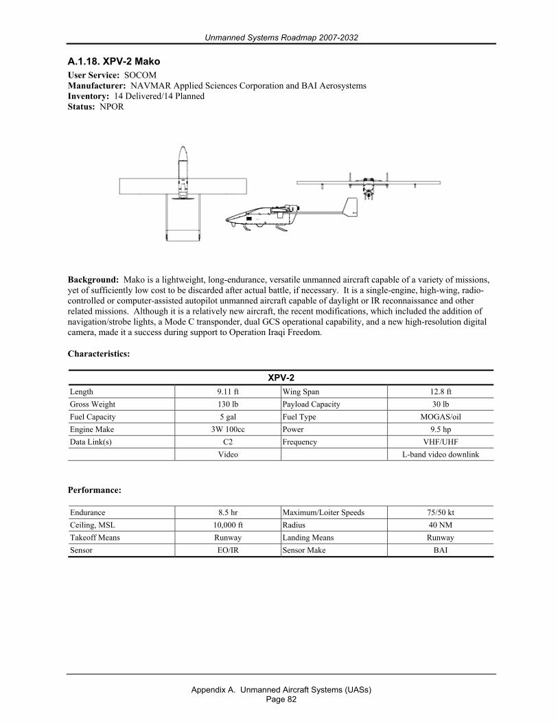
Unmanned Systems Roadmap 2007-2032
Appendix A. Unmanned Aircraft Systems (UASs)
Page 82
A.1.18. XPV-2 Mako User Service: SOCOM Manufacturer: NAVMAR Applied Sciences Corporation and BAI Aerosystems Inventory: 14 Delivered/14 Planned Status: NPOR
Background: Mako is a lightweight, long-endurance, versatile unmanned aircraft capable of a variety of missions, yet of sufficiently low cost to be discarded after actual battle, if necessary. It is a single-engine, high-wing, radio-controlled or computer-assisted autopilot unmanned aircraft capable of daylight or IR reconnaissance and other related missions. Although it is a relatively new aircraft, the recent modifications, which included the addition of navigation/strobe lights, a Mode C transponder, dual GCS operational capability, and a new high-resolution digital camera, made it a success during support to Operation Iraqi Freedom.
Characteristics:
XPV-2 Length 9.11 ft Wing Span 12.8 ft Gross Weight 130 lb Payload Capacity 30 lb Fuel Capacity 5 gal Fuel Type MOGAS/oil Engine Make 3W 100cc Power 9.5 hp Data Link(s) C2 Frequency VHF/UHF Video L-band video downlink
Performance:
Endurance 8.5 hr Maximum/Loiter Speeds 75/50 kt Ceiling, MSL 10,000 ft Radius 40 NM Takeoff Means Runway Landing Means Runway Sensor EO/IR Sensor Make BAI
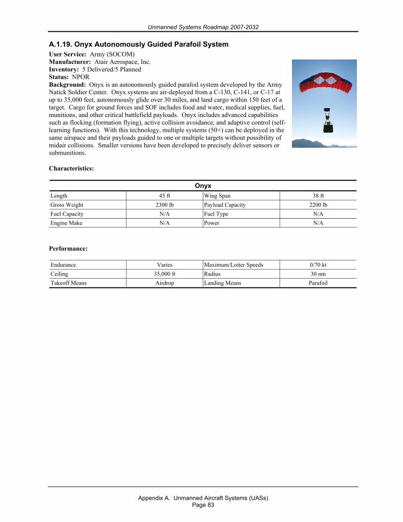
Unmanned Systems Roadmap 2007-2032
Appendix A. Unmanned Aircraft Systems (UASs)
Page 83
A.1.19. Onyx Autonomously Guided Parafoil System User Service: Army (SOCOM) Manufacturer: Atair Aerospace, Inc. Inventory: 5 Delivered/5 Planned Status: NPOR Background: Onyx is an autonomously guided parafoil system developed by the Army Natick Soldier Center. Onyx systems are air-deployed from a C-130, C-141, or C-17 at up to 35,000 feet, autonomously glide over 30 miles, and land cargo within 150 feet of a target. Cargo for ground forces and SOF includes food and water, medical supplies, fuel, munitions, and other critical battlefield payloads. Onyx includes advanced capabilities such as flocking (formation flying), active collision avoidance, and adaptive control (self-learning functions). With this technology, multiple systems (50+) can be deployed in the same airspace and their payloads guided to one or multiple targets without possibility of midair collisions. Smaller versions have been developed to precisely deliver sensors or submunitions.
Characteristics:
Onyx Length 45 ft Wing Span 38 ft Gross Weight 2300 lb Payload Capacity 2200 lb Fuel Capacity N/A Fuel Type N/A Engine Make N/A Power N/A
Performance:
Endurance Varies Maximum/Loiter Speeds 0/70 kt Ceiling 35,000 ft Radius 30 nm Takeoff Means Airdrop Landing Means Parafoil
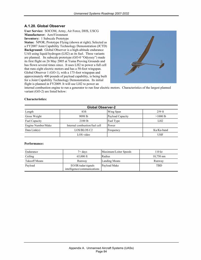
Unmanned Systems Roadmap 2007-2032
Appendix A. Unmanned Aircraft Systems (UASs)
Page 84
A.1.20. Global Observer User Service: SOCOM, Army, Air Force, DHS, USCG Manufacturer: AeroVironment Inventory: 1 Subscale Prototype Status: NPOR; Prototype Flying (shown at right); Selected as a FY2007 Joint Capability Technology Demonstration (JCTD) Background: Global Observer is a high-altitude endurance UAS using liquid hydrogen (LH2) as its fuel. Three variants are planned. Its subscale prototype (GO-0 “Odyssey”) made its first flight on 26 May 2005 at Yuma Proving Grounds and has flown several times since. It uses LH2 to power a full cell that runs eight electric motors and has a 50-foot wingspan. Global Observer 1 (GO-1), with a 175-foot wingspan and approximately 400 pounds of payload capability, is being built for a Joint Capability Technology Demonstration. Its initial flight is planned in FY2009. It will use LH2 to power an internal combustion engine to run a generator to run four electric motors. Characteristics of the largest planned variant (GO-2) are listed below:
Characteristics:
Global Observer-2 Length 83ft Wing Span 259 ft Gross Weight 9098 lb Payload Capacity >1000 lb Fuel Capacity 2100 lb Fuel Type LH2 Engine Number/Make Internal combustion/fuel cell Power Data Link(s) LOS/BLOS C2 Frequency Ku/Ka-band LOS video UHF
Performance:
Endurance 7+ days Maximum/Loiter Speeds 110 kt Ceiling 65,000 ft Radius 10,750 nm Takeoff Means Runway Landing Means Runway Payload EO/IR/radar/signals
intelligence/communications Payload Make TBD
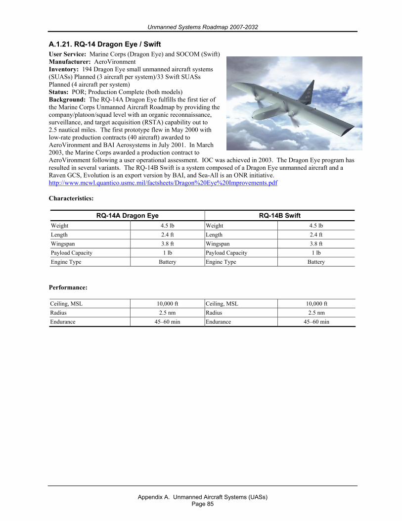
Unmanned Systems Roadmap 2007-2032
Appendix A. Unmanned Aircraft Systems (UASs)
Page 85
A.1.21. RQ-14 Dragon Eye / Swift User Service: Marine Corps (Dragon Eye) and SOCOM (Swift) Manufacturer: AeroVironment Inventory: 194 Dragon Eye small unmanned aircraft systems (SUASs) Planned (3 aircraft per system)/33 Swift SUASs Planned (4 aircraft per system) Status: POR; Production Complete (both models) Background: The RQ-14A Dragon Eye fulfills the first tier of the Marine Corps Unmanned Aircraft Roadmap by providing the company/platoon/squad level with an organic reconnaissance, surveillance, and target acquisition (RSTA) capability out to 2.5 nautical miles. The first prototype flew in May 2000 with low-rate production contracts (40 aircraft) awarded to AeroVironment and BAI Aerosystems in July 2001. In March 2003, the Marine Corps awarded a production contract to AeroVironment following a user operational assessment. IOC was achieved in 2003. The Dragon Eye program has resulted in several variants. The RQ-14B Swift is a system composed of a Dragon Eye unmanned aircraft and a Raven GCS, Evolution is an export version by BAI, and Sea-All is an ONR initiative. http://www.mcwl.quantico.usmc.mil/factsheets/Dragon%20Eye%20Improvements.pdf
Characteristics:
RQ-14A Dragon Eye RQ-14B Swift Weight 4.5 lb Weight 4.5 lb Length 2.4 ft Length 2.4 ft Wingspan 3.8 ft Wingspan 3.8 ft Payload Capacity 1 lb Payload Capacity 1 lb Engine Type Battery Engine Type Battery
Performance:
Ceiling, MSL 10,000 ft Ceiling, MSL 10,000 ft Radius 2.5 nm Radius 2.5 nm Endurance 45–60 min Endurance 45–60 min
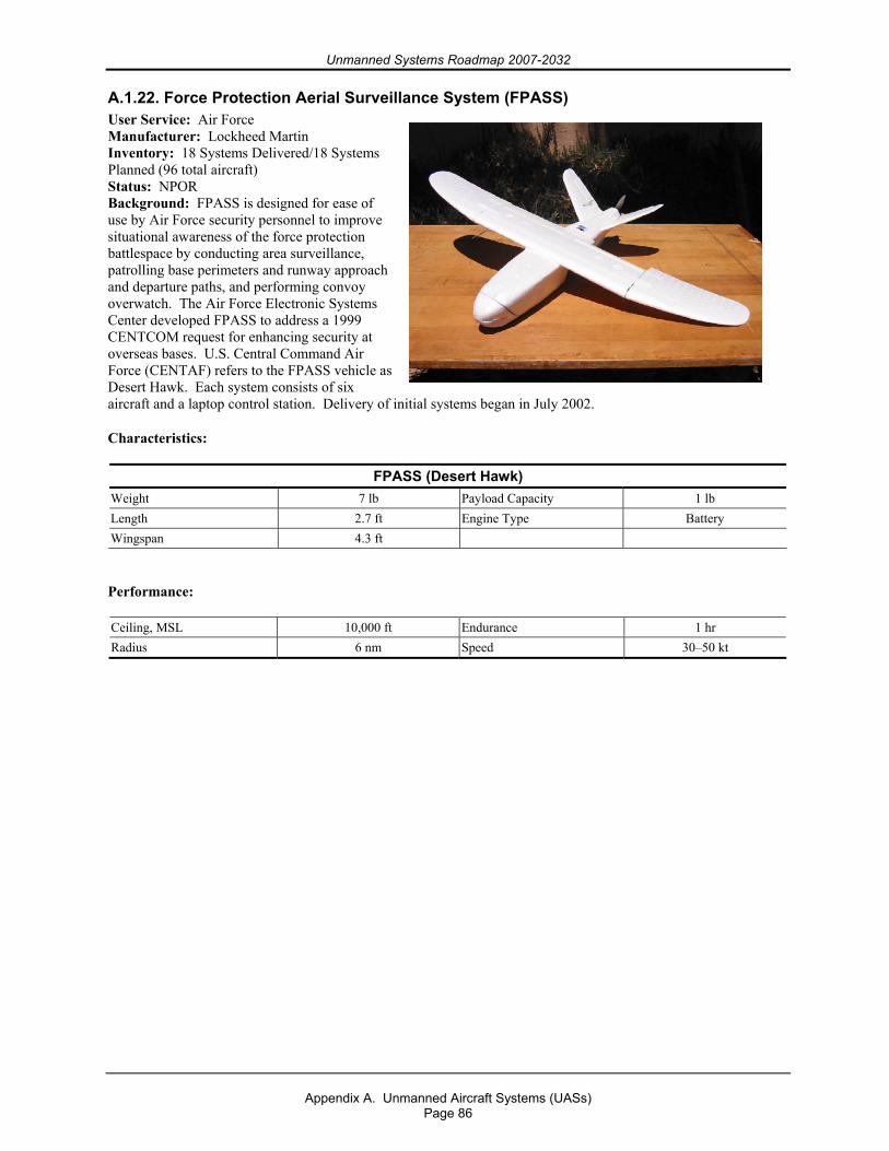
Unmanned Systems Roadmap 2007-2032
Appendix A. Unmanned Aircraft Systems (UASs)
Page 86
A.1.22. Force Protection Aerial Surveillance System (FPASS) User Service: Air Force Manufacturer: Lockheed Martin Inventory: 18 Systems Delivered/18 Systems Planned (96 total aircraft) Status: NPOR Background: FPASS is designed for ease of use by Air Force security personnel to improve situational awareness of the force protection battlespace by conducting area surveillance, patrolling base perimeters and runway approach and departure paths, and performing convoy overwatch. The Air Force Electronic Systems Center developed FPASS to address a 1999 CENTCOM request for enhancing security at overseas bases. U.S. Central Command Air Force (CENTAF) refers to the FPASS vehicle as Desert Hawk. Each system consists of six aircraft and a laptop control station. Delivery of initial systems began in July 2002.
Characteristics:
FPASS (Desert Hawk) Weight 7 lb Payload Capacity 1 lb Length 2.7 ft Engine Type Battery Wingspan 4.3 ft
Performance:
Ceiling, MSL 10,000 ft Endurance 1 hr Radius 6 nm Speed 30–50 kt

Unmanned Systems Roadmap 2007-2032
Appendix A. Unmanned Aircraft Systems (UASs)
Page 87
A.1.23. Aqua / Terra Puma User Service: SOCOM and Army Manufacturer: AeroVironment Inventory: 6 Systems Planned (3 aircraft per system) Status: NPOR; Under Evaluation Background: Puma is an evolution of AeroVironment’s earlier Pointer hand-launched design and comes in two variants, Aqua Puma for use in a marine environment and Terra Puma for land use. It is under evaluation by the Army’s Natick Laboratory and is fielded with support for one year only at this time.
Characteristics:
Aqua/Terra Puma Weight 14 lb Payload Capacity 2–4 lb Length 5.9 ft Engine Type Battery Wingspan 8.5 ft
Performance:
Ceiling, MSL 10,000 ft Endurance 2.5 hr Radius 6 nm
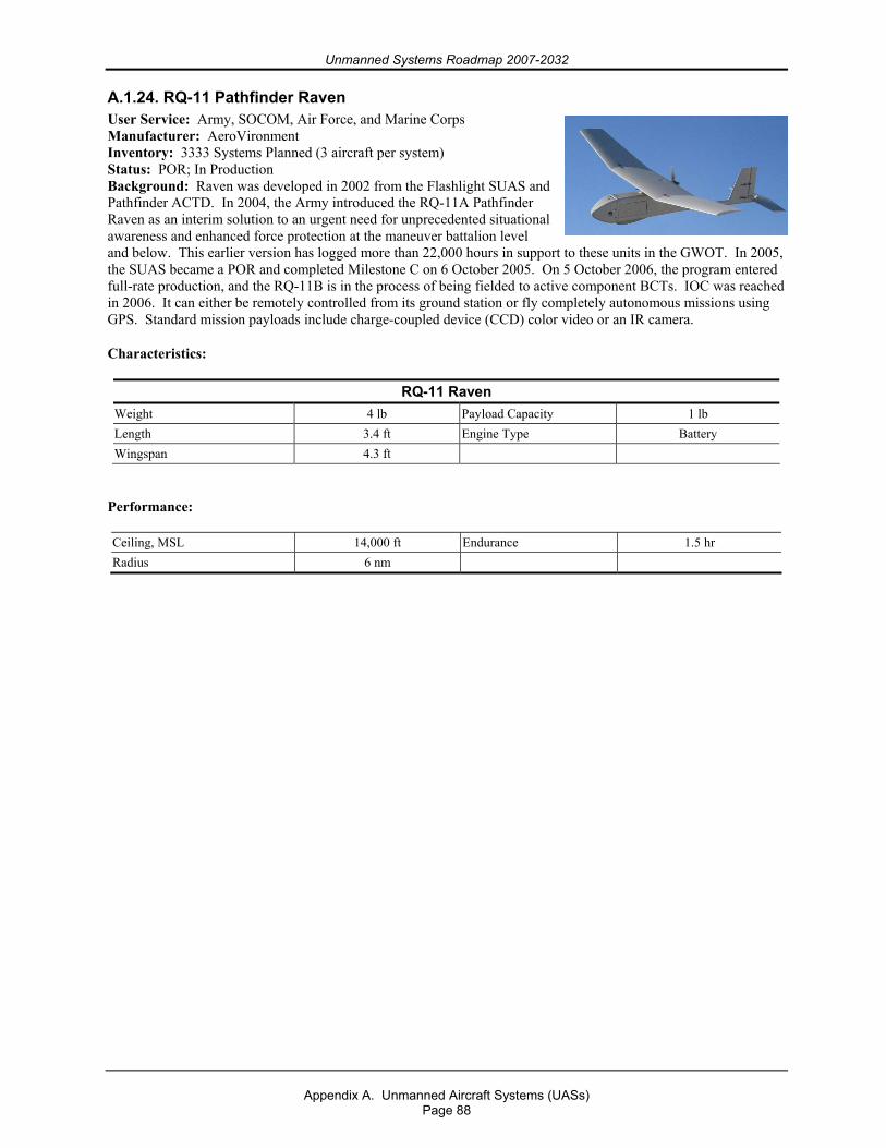
Unmanned Systems Roadmap 2007-2032
Appendix A. Unmanned Aircraft Systems (UASs)
Page 88
A.1.24. RQ-11 Pathfinder Raven User Service: Army, SOCOM, Air Force, and Marine Corps Manufacturer: AeroVironment Inventory: 3333 Systems Planned (3 aircraft per system) Status: POR; In Production Background: Raven was developed in 2002 from the Flashlight SUAS and Pathfinder ACTD. In 2004, the Army introduced the RQ-11A Pathfinder Raven as an interim solution to an urgent need for unprecedented situational awareness and enhanced force protection at the maneuver battalion level and below. This earlier version has logged more than 22,000 hours in support to these units in the GWOT. In 2005, the SUAS became a POR and completed Milestone C on 6 October 2005. On 5 October 2006, the program entered full-rate production, and the RQ-11B is in the process of being fielded to active component BCTs. IOC was reached in 2006. It can either be remotely controlled from its ground station or fly completely autonomous missions using GPS. Standard mission payloads include charge-coupled device (CCD) color video or an IR camera.
Characteristics:
RQ-11 Raven Weight 4 lb Payload Capacity 1 lb Length 3.4 ft Engine Type Battery Wingspan 4.3 ft
Performance:
Ceiling, MSL 14,000 ft Endurance 1.5 hr Radius 6 nm
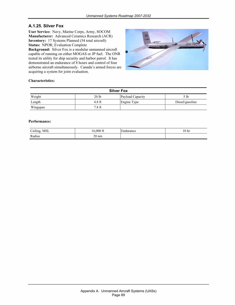
Unmanned Systems Roadmap 2007-2032
Appendix A. Unmanned Aircraft Systems (UASs)
Page 89
A.1.25. Silver Fox User Service: Navy, Marine Corps, Army, SOCOM Manufacturer: Advanced Ceramics Research (ACR) Inventory: 17 Systems Planned (54 total aircraft) Status: NPOR; Evaluation Complete Background: Silver Fox is a modular unmanned aircraft capable of running on either MOGAS or JP fuel. The ONR tested its utility for ship security and harbor patrol. It has demonstrated an endurance of 8 hours and control of four airborne aircraft simultaneously. Canada’s armed forces are acquiring a system for joint evaluation.
Characteristics:
Silver Fox Weight 20 lb Payload Capacity 5 lb Length 4.8 ft Engine Type Diesel/gasoline Wingspan 7.8 ft
Performance:
Ceiling, MSL 16,000 ft Endurance 10 hr Radius 20 nm
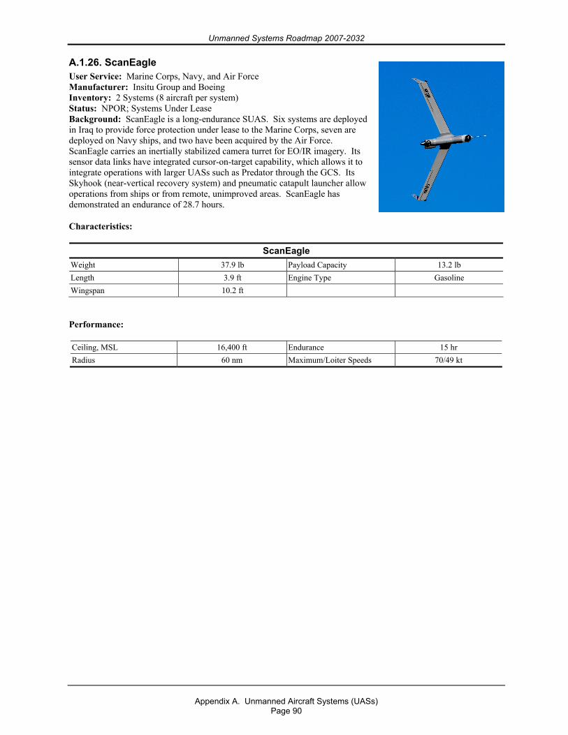
Unmanned Systems Roadmap 2007-2032
Appendix A. Unmanned Aircraft Systems (UASs)
Page 90
A.1.26. ScanEagle User Service: Marine Corps, Navy, and Air Force Manufacturer: Insitu Group and Boeing Inventory: 2 Systems (8 aircraft per system) Status: NPOR; Systems Under Lease Background: ScanEagle is a long-endurance SUAS. Six systems are deployed in Iraq to provide force protection under lease to the Marine Corps, seven are deployed on Navy ships, and two have been acquired by the Air Force. ScanEagle carries an inertially stabilized camera turret for EO/IR imagery. Its sensor data links have integrated cursor-on-target capability, which allows it to integrate operations with larger UASs such as Predator through the GCS. Its Skyhook (near-vertical recovery system) and pneumatic catapult launcher allow operations from ships or from remote, unimproved areas. ScanEagle has demonstrated an endurance of 28.7 hours.
Characteristics:
ScanEagle Weight 37.9 lb Payload Capacity 13.2 lb Length 3.9 ft Engine Type Gasoline Wingspan 10.2 ft
Performance:
Ceiling, MSL 16,400 ft Endurance 15 hr Radius 60 nm Maximum/Loiter Speeds 70/49 kt
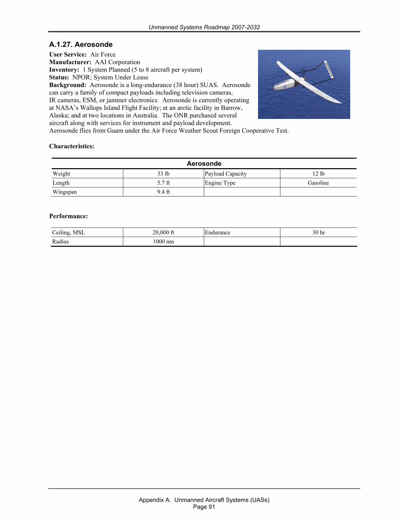
Unmanned Systems Roadmap 2007-2032
Appendix A. Unmanned Aircraft Systems (UASs)
Page 91
A.1.27. Aerosonde User Service: Air Force Manufacturer: AAI Corporation Inventory: 1 System Planned (5 to 8 aircraft per system) Status: NPOR; System Under Lease Background: Aerosonde is a long-endurance (38 hour) SUAS. Aerosonde can carry a family of compact payloads including television cameras, IR cameras, ESM, or jammer electronics. Aerosonde is currently operating at NASA’s Wallops Island Flight Facility; at an arctic facility in Barrow, Alaska; and at two locations in Australia. The ONR purchased several aircraft along with services for instrument and payload development. Aerosonde flies from Guam under the Air Force Weather Scout Foreign Cooperative Test.
Characteristics:
Aerosonde Weight 33 lb Payload Capacity 12 lb Length 5.7 ft Engine Type Gasoline Wingspan 9.4 ft
Performance:
Ceiling, MSL 20,000 ft Endurance 30 hr Radius 1000 nm
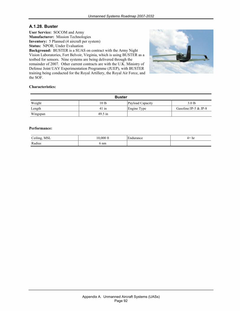
Unmanned Systems Roadmap 2007-2032
Appendix A. Unmanned Aircraft Systems (UASs)
Page 92
A.1.28. Buster User Service: SOCOM and Army Manufacturer: Mission Technologies Inventory: 5 Planned (4 aircraft per system) Status: NPOR; Under Evaluation Background: BUSTER is a SUAS on contract with the Army Night Vision Laboratories, Fort Belvoir, Virginia, which is using BUSTER as a testbed for sensors. Nine systems are being delivered through the remainder of 2007. Other current contracts are with the U.K. Ministry of Defense Joint UAV Experimentation Programme (JUEP), with BUSTER training being conducted for the Royal Artillery, the Royal Air Force, and the SOF.
Characteristics:
Buster Weight 10 lb Payload Capacity 3.0 lb Length 41 in Engine Type Gasoline/JP-5 & JP-8 Wingspan 49.5 in
Performance:
Ceiling, MSL 10,000 ft Endurance 4+ hr Radius 6 nm
Unmanned Systems Roadmap 2007-2032
Appendix A. Unmanned Aircraft Systems (UASs)
Page 93
A.1.29. Small Tactical UAS (STUAS) / Tier II UAS User Service: Navy and Marine Corps Manufacturer: TBD Inventory: TBD Status: Awaiting RFP Release Background: The STUAS/Tier II UAS program plans to enter the SDD phase of the acquisition process as an ACAT III program per SECNAVINST 5000.2C. STUAS/Tier II UAS is a new start program that will provide persistent ISR support for tactical-level maneuver decisions and unit-level force defense and force protection for Navy ships and Marine Corps land forces. This system will fill the ISR capability shortfalls identified by the Navy STUAS and Marine Corps Tier II UAS efforts and delineated in the JROC-approved Joint Tier II Initial Capabilities Document (ICD), which was validated in January 2007. This Joint ICD incorporates Marine Corps, Navy, Air Force, and SOCOM inputs identifying a joint capability gap set. Consisting of three air vehicles, one GCS, multimission (plug-and-play) payloads, and associated launch, recovery, and support equipment, this system will support Navy missions, including building the recognized maritime picture, maritime security operations, maritime interdiction operations, and support of Navy units operating from sea or shore. Marine Corps Tier II UAS will provide a small, organic, tactical ISR/Target Acquisition capability to the battalion/regimental/division/Marine Expeditionary Unit commander and enable enhanced decision making and improved integration with ground schemes of maneuver.
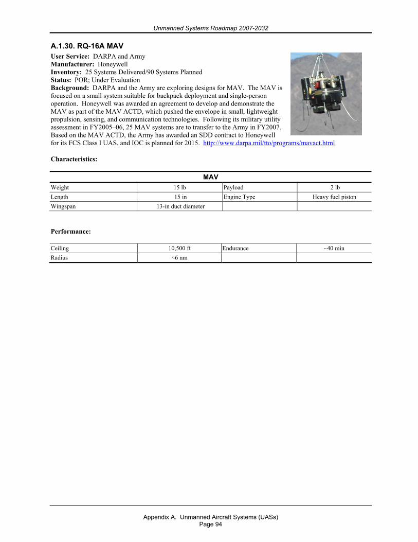
Unmanned Systems Roadmap 2007-2032
Appendix A. Unmanned Aircraft Systems (UASs)
Page 94
A.1.30. RQ-16A MAV User Service: DARPA and Army Manufacturer: Honeywell Inventory: 25 Systems Delivered/90 Systems Planned Status: POR; Under Evaluation Background: DARPA and the Army are exploring designs for MAV. The MAV is focused on a small system suitable for backpack deployment and single-person operation. Honeywell was awarded an agreement to develop and demonstrate the MAV as part of the MAV ACTD, which pushed the envelope in small, lightweight propulsion, sensing, and communication technologies. Following its military utility assessment in FY2005–06, 25 MAV systems are to transfer to the Army in FY2007. Based on the MAV ACTD, the Army has awarded an SDD contract to Honeywell for its FCS Class I UAS, and IOC is planned for 2015. http://www.darpa.mil/tto/programs/mavact.html
Characteristics:
MAV Weight 15 lb Payload 2 lb Length 15 in Engine Type Heavy fuel piston Wingspan 13-in duct diameter
Performance:
Ceiling 10,500 ft Endurance ~40 min Radius ~6 nm
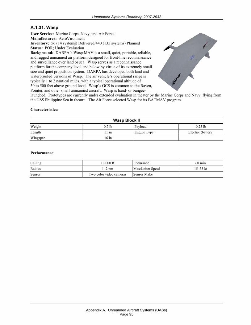
Unmanned Systems Roadmap 2007-2032
Appendix A. Unmanned Aircraft Systems (UASs)
Page 95
A.1.31. Wasp User Service: Marine Corps, Navy, and Air Force Manufacturer: AeroVironment Inventory: 56 (14 systems) Delivered/440 (135 systems) Planned Status: POR; Under Evaluation Background: DARPA’s Wasp MAV is a small, quiet, portable, reliable, and rugged unmanned air platform designed for front-line reconnaissance and surveillance over land or sea. Wasp serves as a reconnaissance platform for the company level and below by virtue of its extremely small size and quiet propulsion system. DARPA has developed both land and waterproofed versions of Wasp. The air vehicle’s operational range is typically 1 to 2 nautical miles, with a typical operational altitude of 50 to 500 feet above ground level. Wasp’s GCS is common to the Raven, Pointer, and other small unmanned aircraft. Wasp is hand- or bungee-launched. Prototypes are currently under extended evaluation in theater by the Marine Corps and Navy, flying from the USS Philippine Sea in theatre. The Air Force selected Wasp for its BATMAV program.
Characteristics:
Wasp Block II Weight 0.7 lb Payload 0.25 lb Length 11 in Engine Type Electric (battery) Wingspan 16 in
Performance:
Ceiling 10,000 ft Endurance 60 min Radius 1–2 nm Max/Loiter Speed 15–35 kt Sensor Two color video cameras Sensor Make

Unmanned Systems Roadmap 2007-2032
Appendix A. Unmanned Aircraft Systems (UASs)
Page 96
A.1.32. Tactical Mini-Unmanned Aerial Vehicle (TACMAV) User Service: Army Manufacturer: Applied Research Associates (ARA) Inventory: Spiral 1 (6 systems)/Spiral 2 (78 systems) Status: NPOR Background: In late 2004, the Army’s Rapid Equipping Force (REF) leveraged an Air Force contract to acquire the TACMAV. After an initial evaluation of six Spiral 1 systems, the REF purchased 78 additional TACMAV systems in support of OIF and OEF. The cost of each system is $36,000 for a total program cost of $3,024,000. The REF is no longer procuring the TACMAV.
The TACMAV uses flexible wings, which fold around its fuselage, allowing the entire UAV to be stored in a 22-inch long, 5-inch diameter tube and carried in the user’s backpack. The TACMAV uses a payload pod containing two color Charge Couple Device cameras and a video transmitter. The user can select a forward- or side-looking camera. The GCU uses the standard Air Force Portable Flight Planning System interface for mission planning, in-flight updates, and manual control.
Platoon, squad, and fire team elements employed the TACMAV for real-time reconnaissance and surveillance support. Operational feedback was either neutral or negative. Soldiers complained about the poor image and lack of stability, grid coordinates, and IR capability. Use of the TACMAV is very dependent on weather conditions (wind). Following REF involvement, newer configurations made by ARA included an IR camera and longer flight time.
Characteristics:
TACMAV Weight 0.8 lb Payload Capacity 0.1 lb Length 19.7 in Engine Type Electric (Li battery) Wingspan 20.9 in
Performance:
Ceiling, MSL 11,000 ft MSL Endurance 25 min Radius 1.5 nm Max Airspeed 43 kt
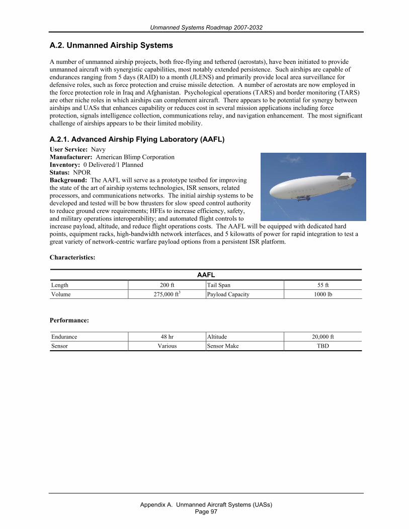
Unmanned Systems Roadmap 2007-2032
Appendix A. Unmanned Aircraft Systems (UASs)
Page 97
A.2. Unmanned Airship Systems
A number of unmanned airship projects, both free-flying and tethered (aerostats), have been initiated to provide unmanned aircraft with synergistic capabilities, most notably extended persistence. Such airships are capable of endurances ranging from 5 days (RAID) to a month (JLENS) and primarily provide local area surveillance for defensive roles, such as force protection and cruise missile detection. A number of aerostats are now employed in the force protection role in Iraq and Afghanistan. Psychological operations (TARS) and border monitoring (TARS) are other niche roles in which airships can complement aircraft. There appears to be potential for synergy between airships and UASs that enhances capability or reduces cost in several mission applications including force protection, signals intelligence collection, communications relay, and navigation enhancement. The most significant challenge of airships appears to be their limited mobility.
A.2.1. Advanced Airship Flying Laboratory (AAFL) User Service: Navy Manufacturer: American Blimp Corporation Inventory: 0 Delivered/1 Planned Status: NPOR Background: The AAFL will serve as a prototype testbed for improving the state of the art of airship systems technologies, ISR sensors, related processors, and communications networks. The initial airship systems to be developed and tested will be bow thrusters for slow speed control authority to reduce ground crew requirements; HFEs to increase efficiency, safety, and military operations interoperability; and automated flight controls to increase payload, altitude, and reduce flight operations costs. The AAFL will be equipped with dedicated hard points, equipment racks, high-bandwidth network interfaces, and 5 kilowatts of power for rapid integration to test a great variety of network-centric warfare payload options from a persistent ISR platform.
Characteristics:
AAFL Length 200 ft Tail Span 55 ft Volume 275,000 ft3 Payload Capacity 1000 lb
Performance:
Endurance 48 hr Altitude 20,000 ft Sensor Various Sensor Make TBD
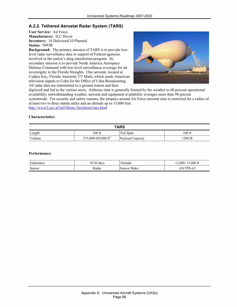
Unmanned Systems Roadmap 2007-2032
Appendix A. Unmanned Aircraft Systems (UASs)
Page 98
A.2.2. Tethered Aerostat Radar System (TARS) User Service: Air Force Manufacturer: ILC Dover Inventory: 10 Delivered/10 Planned Status: NPOR Background: The primary mission of TARS is to provide low-level radar surveillance data in support of Federal agencies involved in the nation’s drug interdiction program. Its secondary mission is to provide North America Aerospace Defense Command with low-level surveillance coverage for air sovereignty in the Florida Straights. One aerostat, located at Cudjoe Key, Florida, transmits TV Marti, which sends American television signals to Cuba for the Office of Cuba Broadcasting. All radar data are transmitted to a ground station and then digitized and fed to the various users. Airborne time is generally limited by the weather to 60 percent operational availability; notwithstanding weather, aerostat and equipment availability averages more than 98 percent systemwide. For security and safety reasons, the airspace around Air Force aerostat sites is restricted for a radius of at least two to three statute miles and an altitude up to 15,000 feet. http://www2.acc.af.mil/library/factsheets/tars.html
Characteristics:
TARS Length 208 ft Tail Span 100 ft Volume 275,000/420,000 ft3 Payload Capacity 1200 lb
Performance:
Endurance 10/30 days Altitude 12,000–15,000 ft Sensor Radar Sensor Make AN/TPS-63
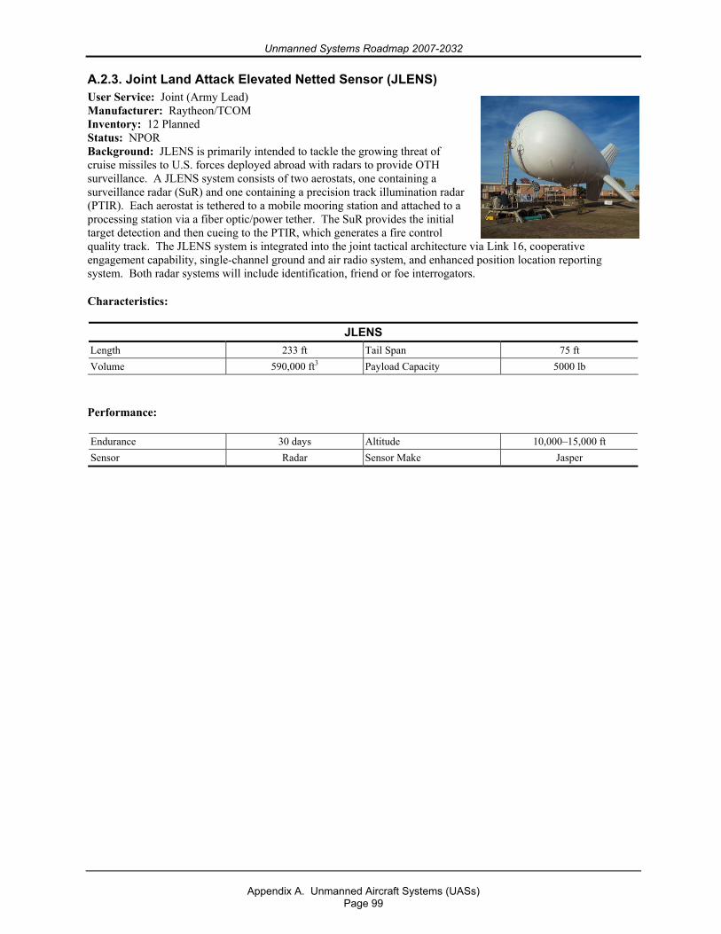
Unmanned Systems Roadmap 2007-2032
Appendix A. Unmanned Aircraft Systems (UASs)
Page 99
A.2.3. Joint Land Attack Elevated Netted Sensor (JLENS) User Service: Joint (Army Lead) Manufacturer: Raytheon/TCOM Inventory: 12 Planned Status: NPOR Background: JLENS is primarily intended to tackle the growing threat of cruise missiles to U.S. forces deployed abroad with radars to provide OTH surveillance. A JLENS system consists of two aerostats, one containing a surveillance radar (SuR) and one containing a precision track illumination radar (PTIR). Each aerostat is tethered to a mobile mooring station and attached to a processing station via a fiber optic/power tether. The SuR provides the initial target detection and then cueing to the PTIR, which generates a fire control quality track. The JLENS system is integrated into the joint tactical architecture via Link 16, cooperative engagement capability, single-channel ground and air radio system, and enhanced position location reporting system. Both radar systems will include identification, friend or foe interrogators.
Characteristics:
JLENS Length 233 ft Tail Span 75 ft Volume 590,000 ft3 Payload Capacity 5000 lb
Performance:
Endurance 30 days Altitude 10,000–15,000 ft Sensor Radar Sensor Make Jasper
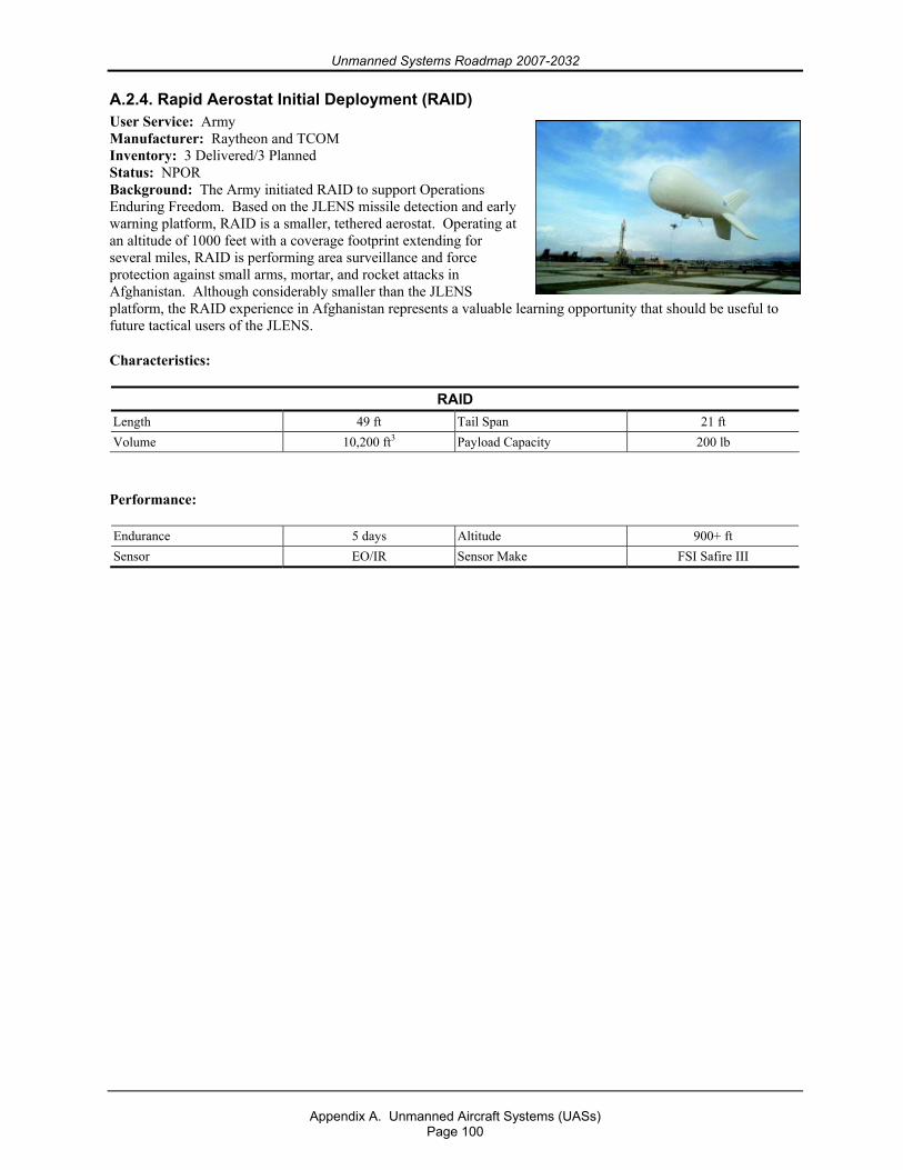
Unmanned Systems Roadmap 2007-2032
Appendix A. Unmanned Aircraft Systems (UASs)
Page 100
A.2.4. Rapid Aerostat Initial Deployment (RAID) User Service: Army Manufacturer: Raytheon and TCOM Inventory: 3 Delivered/3 Planned Status: NPOR Background: The Army initiated RAID to support Operations Enduring Freedom. Based on the JLENS missile detection and early warning platform, RAID is a smaller, tethered aerostat. Operating at an altitude of 1000 feet with a coverage footprint extending for several miles, RAID is performing area surveillance and force protection against small arms, mortar, and rocket attacks in Afghanistan. Although considerably smaller than the JLENS platform, the RAID experience in Afghanistan represents a valuable learning opportunity that should be useful to future tactical users of the JLENS.
Characteristics:
RAID Length 49 ft Tail Span 21 ft Volume 10,200 ft3 Payload Capacity 200 lb
Performance:
Endurance 5 days Altitude 900+ ft Sensor EO/IR Sensor Make FSI Safire III
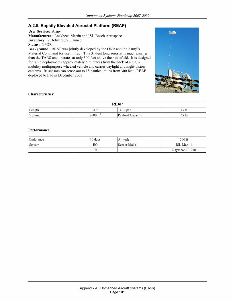
Unmanned Systems Roadmap 2007-2032
Appendix A. Unmanned Aircraft Systems (UASs)
Page 101
A.2.5. Rapidly Elevated Aerostat Platform (REAP) User Service: Army Manufacturer: Lockheed Martin and ISL-Bosch Aerospace Inventory: 2 Delivered/2 Planned Status: NPOR Background: REAP was jointly developed by the ONR and the Army’s Material Command for use in Iraq. This 31-feet long aerostat is much smaller than the TARS and operates at only 300 feet above the battlefield. It is designed for rapid deployment (approximately 5 minutes) from the back of a high-mobility multipurpose wheeled vehicle and carries daylight and night-vision cameras. Its sensors can sense out to 18 nautical miles from 300 feet. REAP deployed to Iraq in December 2003.
Characteristics:
REAP Length 31 ft Tail Span 17 ft Volume 2600 ft3 Payload Capacity 35 lb
Performance:
Endurance 10 days Altitude 300 ft Sensor EO Sensor Make ISL Mark 1 IR Raytheon IR 250
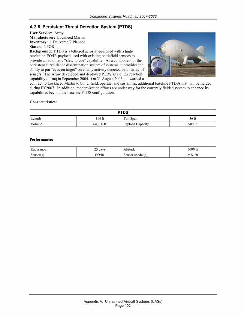
Unmanned Systems Roadmap 2007-2032
Appendix A. Unmanned Aircraft Systems (UASs)
Page 102
A.2.6. Persistent Threat Detection System (PTDS) User Service: Army Manufacturer: Lockheed Martin Inventory: 1 Delivered/7 Planned Status: NPOR Background: PTDS is a tethered aerostat equipped with a high-resolution EO/IR payload used with existing battlefield sensors to provide an automatic “slew to cue” capability. As a component of the persistent surveillance dissemination system of systems, it provides the ability to put “eyes on target” on enemy activity detected by an array of sensors. The Army developed and deployed PTDS as a quick reaction capability to Iraq in September 2004. On 31 August 2006, it awarded a contract to Lockheed Martin to build, field, operate, and sustain six additional baseline PTDSs that will be fielded during FY2007. In addition, modernization efforts are under way for the currently fielded system to enhance its capabilities beyond the baseline PTDS configuration.
Characteristics:
PTDS Length 114 ft Tail Span 36 ft Volume 64,000 ft Payload Capacity 500 lb
Performance:
Endurance 25 days Altitude 5000 ft Sensor(s) EO/IR Sensor Model(s) MX-20
Unmanned Systems Roadmap 2007-2032
Appendix A. Unmanned Aircraft Systems (UASs)
Page 103
A.3. UAS Airspace Integration19
A.3.1. Overview The OSD vision is to have “File and Fly” access for appropriately equipped UASs by the end of 2012 while maintaining an equivalent level of safety (ELOS) to aircraft with a pilot onboard. For military operations, UASs will operate with manned aircraft in civil airspace, including in and around airfields, using concepts of operation that make on- or off-board distinctions transparent to ATC authorities and airspace regulators. The operations tempo at mixed airfields will not be diminished by the integration of unmanned aviation.
In the past, UASs were predominately operated by the DoD for combat operations in military-controlled airspace; however, there is a growing desire to employ UAS in support of homeland defense and civil authorities, e.g., DHS. To be effective, UASs will need routine access to the NAS outside of restricted and warning areas, both over land and over water.
A.3.2. Background Because the current UASs do not have the same capabilities as manned aircraft to safely and efficiently integrate into the NAS, military UAS requirements to operate outside of restricted and warning areas are accommodated on a case-by-case basis. A process used to gain NAS access was jointly developed and agreed to by the DoD and FAA in 1999. Military operators of UASs are required to obtain a COA from the FAA. The process can take up to 60 days and, because UASs do not have an S&A capability, may require such additional and costly measures as providing chase planes and/or primary radar coverage. COAs are typically issued for a specific UAS, limited to specific routes or areas, and are valid for no more than one year. Exceptions are the National COA that was issued to the Air Force for Global Hawk operations in the NAS and the Disaster Relief COA that was issued to NORTHCOM’s Joint Force Air Component Commander for the Predator UAS.
With a COA, the UAS is accommodated into the system when mission needs dictate; however, because the UAS lacks the ability to meet the same regulator requirements as a manned aircraft, it is frequently segregated from manned aviation rather than integrated with it, an exception being the integration of UASs flying on Instrument Flight Rules (IFR) flight plans. As the DoD CONOPS for UASs matures and as we ensure the airworthiness of our UASs, we will look toward developing new procedures to gain access to the NAS. Toward that end, the DoD is working with the FAA to refine and/or replace the COA process to enable more ready access to the NAS for qualified UASs.
From the DoD perspective, three critical issues must be addressed in order to supplant the COA process: UAS reliability, FAA regulations, and an S&A capability. Each is discussed here.
OSD and FAA, working through the DoD Policy Board on Federal Aviation (PBFA), are engaged in establishing the air traffic regulatory infrastructure for integrating military UASs into the NAS. By limiting this effort’s focus to traffic management of domestic flight operations by military UASs, the hope is to establish a solid precedent that can be extended to other public and civil UASs domestically and to civil and military flights in international and non-U.S. airspace.
19 OSD Airspace Integration Plan for Unmanned Aviation, November 2004, provides a more comprehensive discussion of this topic. It is the source of much of the information contained in this appendix.
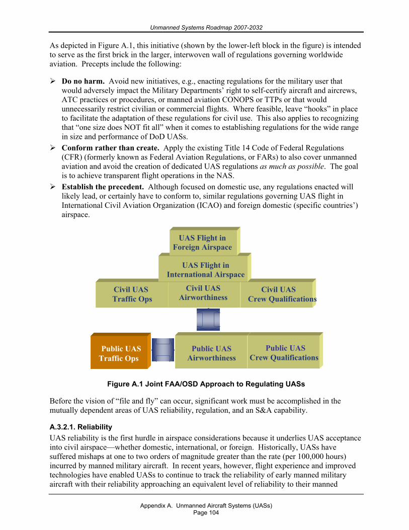
Unmanned Systems Roadmap 2007-2032
Appendix A. Unmanned Aircraft Systems (UASs)
Page 104
As depicted in Figure A.1, this initiative (shown by the lower-left block in the figure) is intended to serve as the first brick in the larger, interwoven wall of regulations governing worldwide aviation. Precepts include the following:
Do no harm. Avoid new initiatives, e.g., enacting regulations for the military user that would adversely impact the Military Departments’ right to self-certify aircraft and aircrews, ATC practices or procedures, or manned aviation CONOPS or TTPs or that would unnecessarily restrict civilian or commercial flights. Where feasible, leave “hooks” in place to facilitate the adaptation of these regulations for civil use. This also applies to recognizing that “one size does NOT fit all” when it comes to establishing regulations for the wide range in size and performance of DoD UASs.
Conform rather than create. Apply the existing Title 14 Code of Federal Regulations (CFR) (formerly known as Federal Aviation Regulations, or FARs) to also cover unmanned aviation and avoid the creation of dedicated UAS regulations as much as possible. The goal is to achieve transparent flight operations in the NAS.
Establish the precedent. Although focused on domestic use, any regulations enacted will likely lead, or certainly have to conform to, similar regulations governing UAS flight in International Civil Aviation Organization (ICAO) and foreign domestic (specific countries’) airspace.
Figure A.1 Joint FAA/OSD Approach to Regulating UASs
Before the vision of “file and fly” can occur, significant work must be accomplished in the mutually dependent areas of UAS reliability, regulation, and an S&A capability.
A.3.2.1. Reliability UAS reliability is the first hurdle in airspace considerations because it underlies UAS acceptance into civil airspace—whether domestic, international, or foreign. Historically, UASs have suffered mishaps at one to two orders of magnitude greater than the rate (per 100,000 hours) incurred by manned military aircraft. In recent years, however, flight experience and improved technologies have enabled UASs to continue to track the reliability of early manned military aircraft with their reliability approaching an equivalent level of reliability to their manned
UAS Flight in Foreign Airspace
UAS Flight in International Airspace Civil UAS
Airworthiness
Civil UAS
Traffic Ops
Civil UAS
Crew Qualifications
Public UAS
Crew Qualifications
Public UAS Airworthiness
Public UAS
Traffic Ops
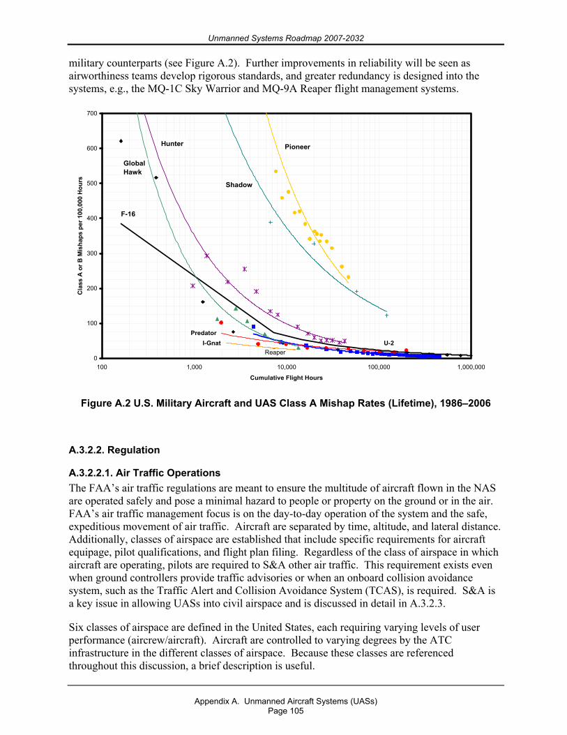
Unmanned Systems Roadmap 2007-2032
Appendix A. Unmanned Aircraft Systems (UASs)
Page 105
military counterparts (see Figure A.2). Further improvements in reliability will be seen as airworthiness teams develop rigorous standards, and greater redundancy is designed into the systems, e.g., the MQ-1C Sky Warrior and MQ-9A Reaper flight management systems.
Reaper0
100
200
300
400
500
600
700
100 1,000 10,000 100,000 1,000,000
Cumulative Flight Hours
Cla
ss A
or B
Mis
haps
per
100
,000
Hou
rs
Pioneer
U-2
Global Hawk
Hunter
Predator
F-16
Shadow
I-Gnat
Figure A.2 U.S. Military Aircraft and UAS Class A Mishap Rates (Lifetime), 1986–2006
A.3.2.2. Regulation
A.3.2.2.1. Air Traffic Operations The FAA’s air traffic regulations are meant to ensure the multitude of aircraft flown in the NAS are operated safely and pose a minimal hazard to people or property on the ground or in the air. FAA’s air traffic management focus is on the day-to-day operation of the system and the safe, expeditious movement of air traffic. Aircraft are separated by time, altitude, and lateral distance. Additionally, classes of airspace are established that include specific requirements for aircraft equipage, pilot qualifications, and flight plan filing. Regardless of the class of airspace in which aircraft are operating, pilots are required to S&A other air traffic. This requirement exists even when ground controllers provide traffic advisories or when an onboard collision avoidance system, such as the Traffic Alert and Collision Avoidance System (TCAS), is required. S&A is a key issue in allowing UASs into civil airspace and is discussed in detail in A.3.2.3.
Six classes of airspace are defined in the United States, each requiring varying levels of user performance (aircrew/aircraft). Aircraft are controlled to varying degrees by the ATC infrastructure in the different classes of airspace. Because these classes are referenced throughout this discussion, a brief description is useful.
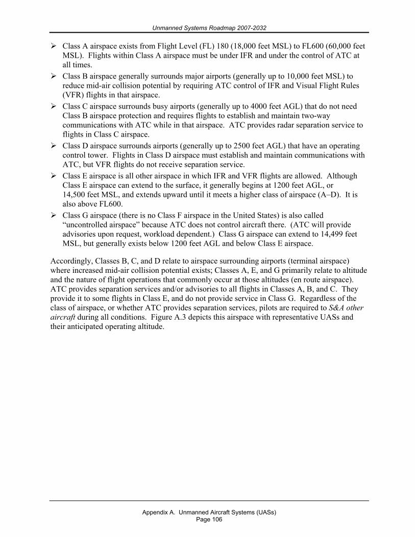
Unmanned Systems Roadmap 2007-2032
Appendix A. Unmanned Aircraft Systems (UASs)
Page 106
Class A airspace exists from Flight Level (FL) 180 (18,000 feet MSL) to FL600 (60,000 feet MSL). Flights within Class A airspace must be under IFR and under the control of ATC at all times.
Class B airspace generally surrounds major airports (generally up to 10,000 feet MSL) to reduce mid-air collision potential by requiring ATC control of IFR and Visual Flight Rules (VFR) flights in that airspace.
Class C airspace surrounds busy airports (generally up to 4000 feet AGL) that do not need Class B airspace protection and requires flights to establish and maintain two-way communications with ATC while in that airspace. ATC provides radar separation service to flights in Class C airspace.
Class D airspace surrounds airports (generally up to 2500 feet AGL) that have an operating control tower. Flights in Class D airspace must establish and maintain communications with ATC, but VFR flights do not receive separation service.
Class E airspace is all other airspace in which IFR and VFR flights are allowed. Although Class E airspace can extend to the surface, it generally begins at 1200 feet AGL, or 14,500 feet MSL, and extends upward until it meets a higher class of airspace (A–D). It is also above FL600.
Class G airspace (there is no Class F airspace in the United States) is also called “uncontrolled airspace” because ATC does not control aircraft there. (ATC will provide advisories upon request, workload dependent.) Class G airspace can extend to 14,499 feet MSL, but generally exists below 1200 feet AGL and below Class E airspace.
Accordingly, Classes B, C, and D relate to airspace surrounding airports (terminal airspace) where increased mid-air collision potential exists; Classes A, E, and G primarily relate to altitude and the nature of flight operations that commonly occur at those altitudes (en route airspace). ATC provides separation services and/or advisories to all flights in Classes A, B, and C. They provide it to some flights in Class E, and do not provide service in Class G. Regardless of the class of airspace, or whether ATC provides separation services, pilots are required to S&A other aircraft during all conditions. Figure A.3 depicts this airspace with representative UASs and their anticipated operating altitude.
Unmanned Systems Roadmap 2007-2032
Appendix A. Unmanned Aircraft Systems (UASs)
Page 107
Figure A.3 UASs and Airspace Classes of the NAS20
It is clear that some taxonomy for UASs is needed to define their operating privileges, airworthiness standards, operator training and certification requirements, and place in the right-of-way rules. Although public (e.g., U.S. military) aircraft are to some degree exempt from a number of FAA regulations such as airworthiness and pilot certification, certain responsibilities still exist.
Meeting equivalent airworthiness and operator qualification standards to operate in the NAS, Conforming to FAA traffic regulations (S&A, lighting, yielding right-of-way) when
operating outside of restricted airspace, and Complying with international (oceanic and foreign domestic) regulations when transiting that
airspace, regulations which often take those of the FAA as precedents.
Military UASs with a need to routinely operate outside of restricted airspace or in international airspace must, therefore, make themselves transparent to air traffic management authorities. In large part, this means conforming by waiver to 14 CFR 91 for the larger UASs, such as the Air Force’s Global Hawk and Predator. This plan calls for these UASs (Cat III) to be treated similarly to manned aircraft.
The FAA has approved a Light Sport Aircraft (LSA) category in the regulations and does not require either airworthiness or pilot certification (similar to Part 103 aircraft) for certain uses and limited operations. These aircraft achieve an equivalent level of safety to certificated aircraft
20 The FAA is moving toward a two-class structure for the NAS, “terminal” and “en route.” Terminal will subsume Class B, C, and D airspace, and en route will include Class A, E, and G airspace.
Class G SFC - 700 ’ or 1,200
Class A
Class E
Class D - 2,5000 ’ MS
L
Class B
SFC - 10,000 ’ MSL
Class C
SFC - 4,000 ’ MSL
Class E
Class G Airspace SFC – 700’ or 1,200’ AGL
60,000 ft MSL
18,000 ft MSL
Class E
Operating Rules-IFRPilot/ Equipment Requirements are IAW 14 CFR 91.167-91.193
Global Hawk
Reaper
Hunter
Shadow
I-GNATPredator
Fire Scout
Class CSFC - 4,000’ AGL
ER/MP Federal Airways (Class E)
1,200’ AGL– 17,999’ MSL
Jet Routes (Class A)
FL180 – FL 450
45,000 ft MSL
Class GSFC – 14,500’ MSL
Class E
Class D SFC - 2,500’ AGL
Class BSFC - 10,000’ MSL
Class ABAMS
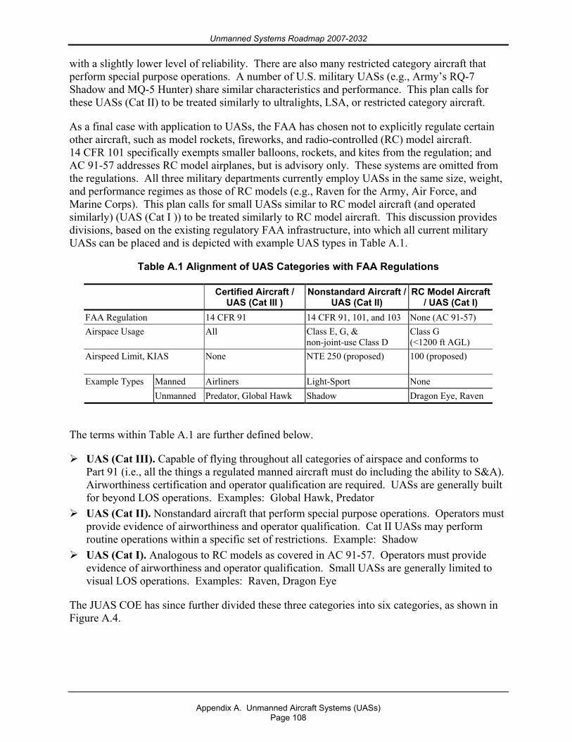
Unmanned Systems Roadmap 2007-2032
Appendix A. Unmanned Aircraft Systems (UASs)
Page 108
with a slightly lower level of reliability. There are also many restricted category aircraft that perform special purpose operations. A number of U.S. military UASs (e.g., Army’s RQ-7 Shadow and MQ-5 Hunter) share similar characteristics and performance. This plan calls for these UASs (Cat II) to be treated similarly to ultralights, LSA, or restricted category aircraft.
As a final case with application to UASs, the FAA has chosen not to explicitly regulate certain other aircraft, such as model rockets, fireworks, and radio-controlled (RC) model aircraft. 14 CFR 101 specifically exempts smaller balloons, rockets, and kites from the regulation; and AC 91-57 addresses RC model airplanes, but is advisory only. These systems are omitted from the regulations. All three military departments currently employ UASs in the same size, weight, and performance regimes as those of RC models (e.g., Raven for the Army, Air Force, and Marine Corps). This plan calls for small UASs similar to RC model aircraft (and operated similarly) (UAS (Cat I )) to be treated similarly to RC model aircraft. This discussion provides divisions, based on the existing regulatory FAA infrastructure, into which all current military UASs can be placed and is depicted with example UAS types in Table A.1.
Table A.1 Alignment of UAS Categories with FAA Regulations
Certified Aircraft / UAS (Cat III )
Nonstandard Aircraft / UAS (Cat II)
RC Model Aircraft / UAS (Cat I)
FAA Regulation 14 CFR 91 14 CFR 91, 101, and 103 None (AC 91-57) Airspace Usage All Class E, G, &
non-joint-use Class D Class G (<1200 ft AGL)
Airspeed Limit, KIAS None NTE 250 (proposed) 100 (proposed)
Manned Airliners Light-Sport None Example Types Unmanned Predator, Global Hawk Shadow Dragon Eye, Raven
The terms within Table A.1 are further defined below.
UAS (Cat III). Capable of flying throughout all categories of airspace and conforms to Part 91 (i.e., all the things a regulated manned aircraft must do including the ability to S&A). Airworthiness certification and operator qualification are required. UASs are generally built for beyond LOS operations. Examples: Global Hawk, Predator
UAS (Cat II). Nonstandard aircraft that perform special purpose operations. Operators must provide evidence of airworthiness and operator qualification. Cat II UASs may perform routine operations within a specific set of restrictions. Example: Shadow
UAS (Cat I). Analogous to RC models as covered in AC 91-57. Operators must provide evidence of airworthiness and operator qualification. Small UASs are generally limited to visual LOS operations. Examples: Raven, Dragon Eye
The JUAS COE has since further divided these three categories into six categories, as shown in Figure A.4.
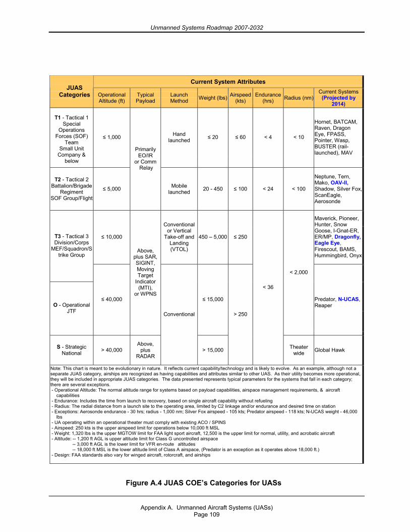
Unmanned Systems Roadmap 2007-2032
Appendix A. Unmanned Aircraft Systems (UASs)
Page 109
Current System Attributes JUAS
Categories Operational Altitude (ft)
Typical Payload
Launch Method Weight (lbs) Airspeed
(kts) Endurance
(hrs) Radius (nm) Current Systems
(Projected by 2014)
T1 - Tactical 1
Special Operations
Forces (SOF) Team
Small Unit Company &
below
≤ 1,000 Hand launched ≤ 20 ≤ 60 < 4 < 10
Hornet, BATCAM, Raven, Dragon Eye, FPASS, Pointer, Wasp, BUSTER (rail- launched), MAV
T2 - Tactical 2 Battalion/Brigade
Regiment SOF Group/Flight
≤ 5,000
Primarily EO/IR
or Comm Relay
Mobile launched 20 - 450 ≤ 100 < 24 < 100
Neptune, Tern, Mako, OAV-II, Shadow, Silver Fox, ScanEagle, Aerosonde
≤ 10,000
Conventional or Vertical
Take-off and Landing (VTOL)
450 – 5,000 ≤ 250
Maverick, Pioneer, Hunter, Snow Goose, I-Gnat-ER, ER/MP, Dragonfly, Eagle Eye, Firescout, BAMS, Hummingbird, Onyx
T3 - Tactical 3 Division/Corps
MEF/Squadron/Strike Group
O - Operational JTF
≤ 40,000
Above, plus SAR, SIGINT, Moving Target
Indicator (MTI),
or WPNS ≤ 15,000
< 2,000
Predator, N-UCAS, Reaper
S - Strategic National > 40,000
Above, plus
RADAR
Conventional
> 15,000
> 250
< 36
Theater wide Global Hawk
Note: This chart is meant to be evolutionary in nature. It reflects current capability/technology and is likely to evolve. As an example, although not a separate JUAS category, airships are recognized as having capabilities and attributes similar to other UAS. As their utility becomes more operational, they will be included in appropriate JUAS categories. The data presented represents typical parameters for the systems that fall in each category; there are several exceptions. - Operational Altitude: The normal altitude range for systems based on payload capabilities, airspace management requirements, & aircraft
capabilities - Endurance: Includes the time from launch to recovery, based on single aircraft capability without refueling - Radius: The radial distance from a launch site to the operating area, limited by C2 linkage and/or endurance and desired time on station - Exceptions: Aerosonde endurance - 30 hrs; radius - 1,000 nm; Silver Fox airspeed - 105 kts; Predator airspeed - 118 kts; N-UCAS weight - 46,000
lbs - UA operating within an operational theater must comply with existing ACO / SPINS - Airspeed: 250 kts is the upper airspeed limit for operations below 10,000 ft MSL - Weight: 1,320 lbs is the upper MGTOW limit for FAA light sport aircraft, 12,500 is the upper limit for normal, utility, and acrobatic aircraft - Altitude: -- 1,200 ft AGL is upper altitude limit for Class G uncontrolled airspace -- 3,000 ft AGL is the lower limit for VFR en-route altitudes -- 18,000 ft MSL is the lower altitude limit of Class A airspace, (Predator is an exception as it operates above 18,000 ft.) - Design: FAA standards also vary for winged aircraft, rotorcraft, and airships
Figure A.4 JUAS COE’s Categories for UASs
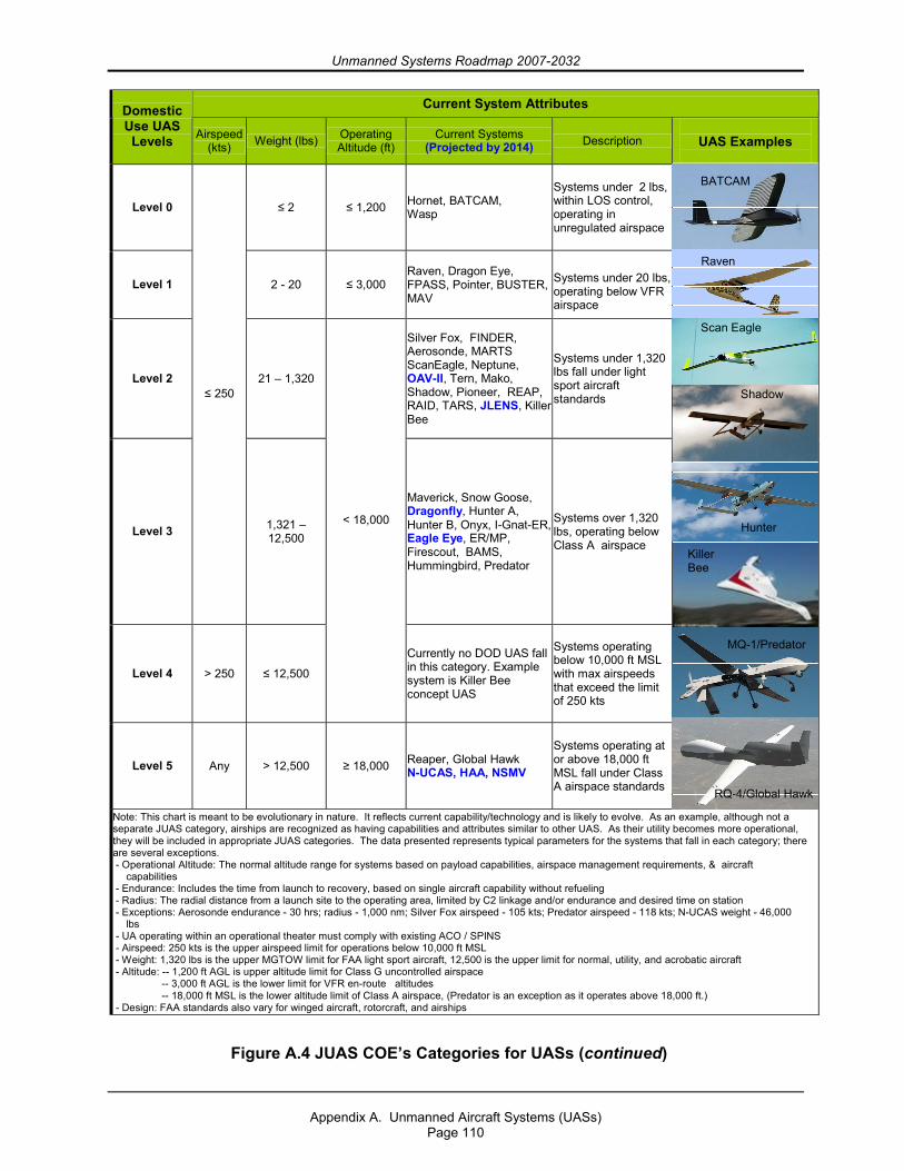
Unmanned Systems Roadmap 2007-2032
Appendix A. Unmanned Aircraft Systems (UASs)
Page 110
Current System Attributes Domestic Use UAS Levels Airspeed
(kts) Weight (lbs) Operating Altitude (ft)
Current Systems (Projected by 2014) Description
UAS Examples
Level 0 ≤ 2 ≤ 1,200 Hornet, BATCAM, Wasp
Systems under 2 lbs, within LOS control, operating in unregulated airspace
Level 1 2 - 20 ≤ 3,000 Raven, Dragon Eye, FPASS, Pointer, BUSTER, MAV
Systems under 20 lbs, operating below VFR airspace
Level 2 21 – 1,320
Silver Fox, FINDER, Aerosonde, MARTS ScanEagle, Neptune, OAV-II, Tern, Mako, Shadow, Pioneer, REAP, RAID, TARS, JLENS, Killer Bee
Systems under 1,320 lbs fall under light sport aircraft standards
Level 3
≤ 250
1,321 – 12,500
Maverick, Snow Goose, Dragonfly, Hunter A, Hunter B, Onyx, I-Gnat-ER, Eagle Eye, ER/MP, Firescout, BAMS, Hummingbird, Predator
Systems over 1,320 lbs, operating below Class A airspace
Level 4 > 250 ≤ 12,500
< 18,000
Currently no DOD UAS fall in this category. Example system is Killer Bee concept UAS
Systems operating below 10,000 ft MSL with max airspeeds that exceed the limit of 250 kts
Level 5 Any > 12,500 ≥ 18,000 Reaper, Global Hawk N-UCAS, HAA, NSMV
Systems operating at or above 18,000 ft MSL fall under Class A airspace standards
Note: This chart is meant to be evolutionary in nature. It reflects current capability/technology and is likely to evolve. As an example, although not a separate JUAS category, airships are recognized as having capabilities and attributes similar to other UAS. As their utility becomes more operational, they will be included in appropriate JUAS categories. The data presented represents typical parameters for the systems that fall in each category; there are several exceptions. - Operational Altitude: The normal altitude range for systems based on payload capabilities, airspace management requirements, & aircraft
capabilities - Endurance: Includes the time from launch to recovery, based on single aircraft capability without refueling - Radius: The radial distance from a launch site to the operating area, limited by C2 linkage and/or endurance and desired time on station - Exceptions: Aerosonde endurance - 30 hrs; radius - 1,000 nm; Silver Fox airspeed - 105 kts; Predator airspeed - 118 kts; N-UCAS weight - 46,000
lbs - UA operating within an operational theater must comply with existing ACO / SPINS - Airspeed: 250 kts is the upper airspeed limit for operations below 10,000 ft MSL - Weight: 1,320 lbs is the upper MGTOW limit for FAA light sport aircraft, 12,500 is the upper limit for normal, utility, and acrobatic aircraft - Altitude: -- 1,200 ft AGL is upper altitude limit for Class G uncontrolled airspace -- 3,000 ft AGL is the lower limit for VFR en-route altitudes -- 18,000 ft MSL is the lower altitude limit of Class A airspace, (Predator is an exception as it operates above 18,000 ft.) - Design: FAA standards also vary for winged aircraft, rotorcraft, and airships
BATCAM
Raven
Scan Eagle
Shadow
Hunter
Killer Bee
MQ-1/Predator
RQ-4/Global Hawk
Figure A.4 JUAS COE’s Categories for UASs (continued)
Unmanned Systems Roadmap 2007-2032
Appendix A. Unmanned Aircraft Systems (UASs)
Page 111
It is important to note that the FAA uses the term “category” in two different ways (14 CFR 1). As used with respect to the certification, ratings, privileges, and limitations of airmen, the term “category” means a broad classification of aircraft. Examples include airplane, rotorcraft, glider, and lighter-than-air. As used with respect to the certification of aircraft, the term “category” means a grouping of aircraft based upon intended use or operating limitations. Examples include transport, normal, utility, acrobatic, limited, restricted, and provisional. When discussing right-of-way rules in 14 CFR 91.113, however, the FAA uses nonmutually exclusive categories such as balloon, glider, airship, airplane, rotorcraft, and engine-driven aircraft for determining which flight has the right of way. 14 CFR 103 requires ultralights to yield the right of way to all other manned aircraft. Similarly, the FAA provides avoidance (right-of-way) advice for RC model aircraft in an Advisory Circular.
It is envisioned, then, that UASs could be assigned their own category in order to facilitate the development of regulations for air operations, airworthiness, operator certification, and right-of-way rules. The UAS category may be exclusive of certain UASs in the same way that model airplanes are omitted from current regulations; and some UASs may be regulated separately, as ultralights, light-sport, or restricted category aircraft are currently.
In addition to regulatory changes necessary for routine operation of military UASs in civil airspace, changes to several other documents, such as Advisory Circulars and FAA Joint Order 7610.4M (Special Operations), will be required.
A.3.2.2.2. Airworthiness Certification The FAA’s airworthiness regulations are meant to ensure that aircraft are built and maintained to minimize their hazard to aircrew, passengers, and people and property on the ground. Airworthiness is concerned with the material and construction integrity of the individual aircraft and the prevention of the aircraft’s coming apart in mid-air and/or causing damage to persons or property on the ground. Over the 19-year period from 1982 to 2000, an annual average of 2.2 percent of all aviation fatalities involved people being hit by parts falling off aircraft. A UAS that must be available for unrestricted operations worldwide (e.g., Global Hawk) in most classes of airspace compels serious consideration for the safety of people on the ground. The operational requirements for UAS operation in civil airspace means flight over populated areas must not raise concerns based on overall levels of airworthiness; therefore, UAS standards cannot vary widely from those for manned aircraft without raising public and regulatory concern.
FAA regulations do not require “public aircraft” (government-owned or -operated) to be certified airworthy to FAA standards. Most nonmilitary public aircraft are versions of aircraft previously certified for commercial or private use; however, the only public aircraft not related to FAA certification standards in some way are almost always military aircraft. These aircraft are certified through the military’s internal airworthiness certification/flight release process. A Tri-Service memorandum of agreement describes the responsibilities and actions associated with mutual acceptance of airworthiness certifications for manned aircraft and UASs within the same certified design configuration, envelope, parameters, and usage limits certified by the originating Military Department.
Unmanned Systems Roadmap 2007-2032
Appendix A. Unmanned Aircraft Systems (UASs)
Page 112
Similarly to manned military aircraft, unmanned military aircraft will also be subject to the airworthiness certification/flight release process. The Global Hawk has completed this process and has been granted an airworthiness certificate.
A.3.2.2.3. Crew Qualifications The FAA’s qualification standards (14 CFR 61, 63, 65, and 67) are meant to ensure the competency of aircrew and aircraft maintainers. As in the case of airworthiness certification, these CFR parts do not pertain to military personnel who are certified in a similar, parallel process. DoD and FAA have signed a memorandum of agreement through which DoD agrees to meet or exceed civil training standards, and the FAA agrees to accept military-rated pilots into the NAS. These factors indicate that a certain minimum knowledge standard is required of all pilots-in-command in order to operate aircraft in the NAS. In order to meet the intent of “do no harm,” training for Cat III aircraft would include, but not be limited to, regulations, airspace clearances and restrictions, aircraft flight rules, air traffic communications, aircraft sequencing and prioritization, takeoff and landing procedures for combined manned and unmanned operations, go-around and abort procedures, flight planning and filing (including in-flight filing), flight and communications procedures for lost link, weather reporting and avoidance, ground operations for combined manned and unmanned operations, flight speed and altitude restrictions, and, when applicable, weapons carriage procedures (including hung ordinance flight restrictions).
Under the international doctrine for public aircraft, the FAA does not have to agree with DoD training or accept military ratings; the Military Departments are entitled to make these judgments independently. Each Military Department identifies what and how it will operate and create the training programs necessary to safely accomplish its missions. Some of the UAS-related training is a fundamental shift away from the skills needed to fly a manned aircraft (e.g., ground-based visual landing). These differences can relate to the means of landing: visual remote, aided visual, or fully autonomous. They may also relate to different interface designs for the UAS functions or the level of control needed to exercise authority over an aircraft based on its autonomous capability. As a result, the Military Departments will have minimum standards for knowledge skills required of UAS operators operating in the NAS; this minimum standard may differ for given classes of UAS. UAS operators21 will be expected to conform to these requirements.
A.3.2.3. “Sense and Avoid” (S&A) Principle A key requirement for routine access to the NAS is UAS compliance with 14 CFR 91.113, “Right-of-Way Rules: Except Water Operations.” This section contains the phrase “sense and avoid” and is the primary restriction to normal operations of UASs. The intent of “sense and avoid” is for pilots to use their sensors (eyes) and other tools to find and maintain situational awareness of other traffic and to yield the right-of-way, in accordance with the rules, when there is a traffic conflict. Since the purpose of this regulation is to avoid mid-air collisions, this should be the focus of technological efforts to address the issue as it relates to UAS rather than trying to mimic and/or duplicate human vision. In June 2003, USAF’s Air Combat Command (ACC) sponsored a joint working group to establish and quantify an S&A system capability for
21 NOTE: UAS operators may, or may not, be “rated pilots.” For the OSD Airspace Integration Plan, “operator” is the generic term to describe the individual with the appropriate training and Service certification for the type of UAS being operated and, as such, is responsible for the aircraft’s operations and safety.

Unmanned Systems Roadmap 2007-2032
Appendix A. Unmanned Aircraft Systems (UASs)
Page 113
submission to the FAA. Their white paper, “See and Avoid Requirement for Remotely Operated Aircraft,” was released in June 2004.
Relying simply on human vision results in mid-air collisions accounting for an average of 0.8 percent of all mishaps and 2.4 percent of all aviation fatalities incurring annually (based on the 3-year average from 1998 to 2000).22 Meaningful S&A performance must alert the UAS operator to local air traffic at ranges sufficient for reaction time and avoidance actions by safe margins. Furthermore, UAS operations BLOS may require an automated S&A system due to potential communications latencies or failures.
The FAA does not provide a quantitative definition of S&A, largely due to the number of combinations of pilot vision, collision vectors, sky background, and aircraft paint schemes involved in seeing oncoming traffic. Having a sufficient field of regard for a UAS S&A system, however, is fundamental to meeting the goal of assured air traffic separation.
Although an elusive issue, one fact is apparent. The challenge with the S&A issue is both a capability constraint and a regulatory one. Given the discussions in this and other analyses, a possible definition for S&A systems emerges: S&A is the onboard, self-contained ability to
Detect traffic that may be a conflict, Evaluate flight paths, Determine traffic right of way, and Maneuver well clear according to the rules in Part 91.113.
The key to providing the “equivalent level of safety” required by FAA Order 7610.4M, “Special Operations,” Chapter 12, Section 9, “UAS Operations in the NAS,” is the provision of some comparable means of S&A to that provided by pilots on board manned aircraft. The purpose of S&A is to avoid mid-air collisions, and this should be the focus of technological efforts to automate this capability, rather than trying to mechanize human vision.
From a technical perspective, the S&A capability can be divided into the detection of oncoming traffic and the execution of a maneuver to avoid a mid-air collision. The detection aspect can be further subdivided into passive or active techniques applicable in cooperative or noncooperative traffic environments.
The active cooperative scenario involves an interrogator monitoring a sector ahead of the UAS to detect oncoming traffic by interrogating the transponder on the other aircraft. Its advantages are that it provides both range and bearing to the traffic and can function in both visual and instrument meteorological conditions (VMC and IMC). Its disadvantages are its relative cost. Current systems available in this category include the various TCASs.
The active noncooperative scenario relies on a radar- or laser-like sensor scanning a sector ahead of the UAS to detect all traffic, whether transponder-equipped or not. The returned signal provides range, bearing, and closure rate and allows prioritization of oncoming traffic for avoidance, in either VMC or IMC. Its potential drawbacks are its relative cost, the bandwidth requirement to route its imagery (for nonautonomous systems), and its weight. An example of
22 National Transportation Safety Board aviation statistics.
Unmanned Systems Roadmap 2007-2032
Appendix A. Unmanned Aircraft Systems (UASs)
Page 114
an active, noncooperative system that is currently available is a combined microwave radar and infrared sensor originally developed to enable helicopters to avoid power lines.
The passive cooperative scenario, like the active cooperative one, relies on everyone having a transponder, but with everyone’s transponder broadcasting position, altitude, and velocity data. Its advantages are its lower relative cost (no onboard interrogator required to activate transponders) and its ability to provide S&A information in both VMC and IMC. Its disadvantage is its dependence on all traffic carrying and continuously operating transponders. In this scenario, UASs should have the capability to change transponder settings while in flight.
The passive noncooperative scenario is the most demanding one. It is also the most analogous to the human eye. An S&A system in this scenario relies on a sensor to detect and provide azimuth and elevation to the oncoming traffic. Its advantages are its moderate relative cost and ability to detect non-transponder-equipped traffic. Its disadvantages are its lack of direct range or closure rate information, potentially high bandwidth requirement (if not autonomous), and its probable inability to penetrate weather. The gimbaled EO/IR sensors currently carried by reconnaissance UASs are examples of such systems; however, if they are looking at the ground for reconnaissance, then they are not available to perform S&A. An emerging approach that would negate the high bandwidth requirement of any active system is optical flow technology, which reports only when it detects an object showing a lack of movement against the sky, instead of sending a continuous video stream to the ground controller. Imagery from one or more inexpensive optical sensors on the UAS is continuously compared to the last image by an onboard processor to detect minute changes in pixels, indicating traffic of potential interest. Only when such objects are detected is their bearing relayed to the ground.
Once the “detect and sense” portion of S&A is satisfied, the UAS must use this information to execute an avoidance maneuver. The latency between seeing and avoiding for the pilot of a manned aircraft ranges from 10 to 12.5 seconds according to FAA and DoD studies.23 If relying on a ground operator to S&A, the UAS incurs the same human latency, but adds the latency of the data link bringing the image to the ground for a decision and the avoidance command back to the UAS. This added latency can range from less than a second for LOS links to more time for satellite links.
An alternative is to empower the UAS to autonomously decide whether and which way to react to avoid a collision once it detects oncoming traffic, thereby removing the latency imposed by data links. This approach has been considered for implementation on TCAS II-equipped manned aircraft since TCAS II already recommends a vertical direction to the pilot, but simulations have found the automated maneuver worsens the situation in a fraction of the scenarios. For this reason, the FAA has not certified automated collision avoidance algorithms based on TCAS resolution advisories; doing so would set a significant precedent for UAS S&A capabilities.
The long-term FAA plan is “to move away from infrastructure-based systems towards a more autonomous, aircraft-based system” for collision avoidance.24 Installation of TCAS is increasing across the aviation community, and TCAS functionality supports increased operator autonomy. Research and testing of Automatic Dependent Surveillance-Broadcast (ADS-B) may afford an 23 Tyndall Air Force Base Mid-Air Collision Avoidance Study; FAA P-8740-51; see also Krause, Avoiding Mid-Air Collisions, p. 13. 24 2001 Federal Radionavigation Systems Plan.
Unmanned Systems Roadmap 2007-2032
Appendix A. Unmanned Aircraft Systems (UASs)
Page 115
even greater capability and affirms the intent of the aviation community to support and continue down this path. Such equipment complements basic S&A, adds to the situational awareness, and helps provide separation from close traffic in all meteorological conditions.
A.3.3. Command, Control, Communications
A.3.3.1. Data Link Security In general, there are two main areas of concern when considering link security: inadvertent or hostile interference of the uplink and downlink. The forward (“up”) link controls the activities of the platform itself and the payload hardware. This command and control link requires a sufficient degree of security to ensure that only authorized agents have access to the control mechanisms of the platform. The return (“down”) link transmits critical data from the platform payload to the warfighter or analyst on the ground or in the air. System health and status information must also be delivered to the GCS or UAS operator without compromise. Effective frequency spectrum allocation and management are key to reducing inadvertent interference of the data links.
A.3.3.2. Redundant/Independent Navigation The air navigation environment is changing, in part, because of the demands of increased traffic flow. Allowances for deviation from intended flight paths are being reduced. This provides another means for increasing air traffic capacity as airways and standard departures and approaches can be constructed with less separation. As tolerances for navigational deviation decrease, the need to precisely maintain course grows. All aircraft must ensure they have robust navigational means. Historically, this robustness has been achieved by installation of redundant navigational systems. The need for dependable, precise navigation reinforces the redundancy requirements.
While navigation accuracy and reliability pertain to military operations and traffic management, current systems are achieving the necessary standard without redundancy and without reliance on ground-based navigation aids. The Federal Radionavigation Plan, signed January 2006, establishes the following national policies:
Properly certified GPS is approved as a supplemental system for domestic en route and terminal navigation, and for nonprecision approach and landing operations.
The FAA’s phase-down plan for ground-based navigation aid systems (NAVAIDS) retains at least a minimum operational network of ground-based NAVAIDS for the foreseeable future.
Sufficient ground-based NAVAIDS will be maintained to provide the FAA and the airspace users with a safe recovery and sustained operations capability in the event of a disruption in satellite navigation service.
These policies apply, as a minimum, to all aircraft flying in civil airspace. With GPS, the prospect for relief of some redundancy requirements in manned aviation may be an option in the future. However, UASs have a diminished prospect for relief since, unlike manned aircraft, a UAS without communication links cannot readily fall back on dead reckoning, contact navigation, and map reading in the same sense that a manned aircraft can.
Unmanned Systems Roadmap 2007-2032
Appendix A. Unmanned Aircraft Systems (UASs)
Page 116
A.3.3.3. Autonomy Advances in computer and communications technologies have enabled the development of autonomous unmanned systems. With the increase in computational power available, developmental UASs are able to achieve much more sophisticated subsystem, guidance, navigation and control, sensor, and communications autonomy than previous systems. For example, Global Hawk’s airborne systems are designed to identify, isolate, and compensate for a wide range of possible system/subsystem failures and autonomously take actions to ensure system safety. Preprogrammed decision trees are built to address each possible failure during each part of the mission.
One of the most difficult aspects of high levels of autonomy is ensuring that all elements remain synchronized. Verifying that 1) all messages are received, 2) all aircraft have correctly interpreted the messages, and 3) the entire squadron has a single set of mission plans to execute will be a key accomplishment.
A.3.3.4. Lost Link In the event of lost C2 links, military UASs are typically programmed to climb to a predefined altitude to attempt to reestablish contact; this “lost link profile” may not be appropriate for operations in the NAS. If contact is not reestablished in a given time, the UAS can be preprogrammed to retrace its outbound route home, fly direct to home, or continue its mission. With an irreversible loss of the C2 data link, however, there is usually no procedure for a communications-out recovery. (Global Hawk does have this capability using differential GPS and pre-programmed divert airfields.) Examination of a lost C2 link scenario illustrates that this communications issue can become a critical UAS failure mode.
No Radio (NORDO) requirements are well documented in 14 CFR 91.185. Remarkably, most lost C2 link situations bear a striking resemblance to NORDO, and UASs would enhance their predictability by autonomously following the guidance. The one exception to this case is the Visual Flight Rules (VFR) conditions clause. UASs, even with an autonomous S&A system, would enhance overall safety by continuing to fly IFR. Should normal ATC-voice communications fail, the FAA also has the capability to patch airspace users through to the controlling ATC authority by phone at any time.
A.3.4. Future Environment The migration of the NAS from ground-based traffic control to airborne traffic management, scheduled to occur over the next decade, will have significant implications for UASs. S&A will become an integrated, automated part of routine position reporting and navigation functions by relying on a combination of ADS-B and GPS. In effect, it will create a virtual bubble of airspace around each aircraft so that when bubbles contact, avoidance is initiated. All aircraft will be required to be equipped to the same level, making the unmanned or manned status of an aircraft transparent to both flyers and to the FAA.
Finally, the pejorative perception that UASs are by nature more dangerous than manned aircraft needs to be countered by recognizing that UASs can provide an equivalent level of safety to that of manned aircraft and possess the following inherent attributes that contribute to flying safety:
Many manned aircraft mishaps occur during the takeoff and landing phases of flight, when human decisions and control inputs are substantial factors. Robotic aircraft are not
Unmanned Systems Roadmap 2007-2032
Appendix A. Unmanned Aircraft Systems (UASs)
Page 117
programmed to take chances; either preprogrammed conditions are met or the system goes around. This will likely reduce the incidence of mishaps during these phases of flight.
Since human support systems are not carried, mishaps from failed life support systems (e.g., Payne Stewart, Helios Airways 522) will not occur.
An automated takeoff and landing capability reduces the need for pattern work and results in reduced exposure to mishaps, particularly in the area surrounding main operating bases.
UAS control stations can access resources not available in the traditional cockpit and thus increase the operator’s situational awareness.
A greater percentage of UAS operator training can be performed through simulation given the nature of GCSs. Using simulations reduces the need to actually fly the aircraft and the related exposure to mishaps.
A.3.5. DoD Organizations with Roles in UAS Airspace Integration As discussed, access to the NAS is currently attained primarily through the COA process, which relies on a combination of procedures and observers to provide the ELOS for UASs. Both regulatory and technical issues need to be addressed to attain UAS integration. The organizations within the DoD that are addressing these issues and are related to current and future operations include OSD Oversight and Policy, the Joint Staff chartered organizations, and the military departments’ chartered organizations.
A.3.5.1. OSD Oversight and Policy The OUSD(AT&L) established the UAS PTF in October 2001 to address the need for an integrated Defense-wide initiative for UAS planning and execution. The UAS PTF provides oversight on all DoD UAS acquisition programs.
DoDD 5030.1925 directs the Assistant Secretary of Defense (Networks and Information Integration) (ASD(NII)) to chair the DoD Policy Board on Federal Aviation (PBFA). The PBFA shall advise and assist the ASD(NII) on ATC, airspace management, NAS matters, joint systems acquisition, and aviation-related international affairs. Supporting the PBFA are the PBFA Working Group and the UAS Subgroup.
The Assistant Secretary of Defense (Homeland Defense) (ASD(HD)) is the Department’s interface with DHS. It has been directed to develop a comprehensive policy document on domestic use of UAS.
A.3.5.2. Joint Staff Chartered Organizations The JROC chartered two organizations to improve UAS interoperability and operational effectiveness of UAS:
The former JUAS Material Review Board (MRB), to provide an UAS forum to identify or resolve requirements and corresponding materiel issues (July 5, 2005), and
The JUAS Center of Excellence (COE), to pursue solutions to optimize UAS capabilities and utilization (including concepts of operation).
25 DoDD 5030.19, DoD Responsibilities on Federal Aviation and National Airspace System Matters.
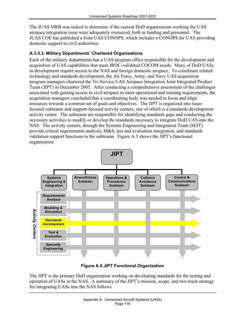
Unmanned Systems Roadmap 2007-2032
Appendix A. Unmanned Aircraft Systems (UASs)
Page 118
The JUAS MRB was tasked to determine if the current DoD organizations working the UAS airspace integration issue were adequately resourced, both in funding and personnel. The JUAS COE has published a Joint UAS CONOPS, which includes a CONOPS for UAS providing domestic support to civil authorities.
A.3.5.3. Military Departments’ Chartered Organizations Each of the military departments has a UAS program office responsible for the development and acquisition of UAS capabilities that meet JROC-validated COCOM needs. Many of DoD UASs in development require access to the NAS and foreign domestic airspace. To coordinate related technology and standards development, the Air Force, Army, and Navy UAS acquisition program managers chartered the Tri-Service UAS Airspace Integration Joint Integrated Product Team (JIPT) in December 2005. After conducting a comprehensive assessment of the challenges associated with gaining access to civil airspace to meet operational and training requirements, the acquisition managers concluded that a coordinating body was needed to focus and align resources towards a common set of goals and objectives. The JIPT is organized into issue-focused subteams and support-focused activity centers, one of which is a standards development activity center. The subteams are responsible for identifying standards gaps and conducting the necessary activities to modify or develop the standards necessary to integrate DoD UAS into the NAS. The activity centers, through the Systems Engineering and Integration Team (SEIT) provide critical requirements analysis, M&S, test and evaluation integration, and standards validation support functions to the subteams. Figure A.5 shows the JIPT’s functional organization.
Figure A.5 JIPT Functional Organization
The JIPT is the primary DoD organization working on developing standards for the testing and operation of UASs in the NAS. A summary of the JIPT’s mission, scope, and two-track strategy for integrating UASs into the NAS follows.
JIPT
CollisionAvoidanceSubteam
Airworthiness Subteam
Operations & Procedures
Subteam
Control & Communications
Subteam
Systems Engineering &
Integration
Requirements Analysis
Modeling & Simulation
Test & Evaluation
Specialty Engineering
Standards Development
Activity C
enters
Unmanned Systems Roadmap 2007-2032
Appendix A. Unmanned Aircraft Systems (UASs)
Page 119
A.3.5.3.1. JIPT Mission The JIPT will develop the standards, policy, and enabling technology necessary to (1) integrate UAS operations with manned aircraft operations in nonsegregated airspace, (2) integrate resources and activities with industry and airspace regulatory authorities to achieve greater alignment with DoD goals and objectives, (3) ensure compatibility and interoperability of global access enabling technology and ATC procedures, and (4) provide the necessary documentation to affect changes in the global ATC systems to meet the near-, mid-, and long-term airspace access needs of the DoD UAS user community. To assist in this, the JIPT will integrate work activities with the FAA, civil SDOs, the DoD PBFA, and Military Department-related airspace organizations (where deemed appropriate) to optimize resource allocation; influence standards, procedures, and policy adoption schedules; and promote convergence of technical and procedural solutions to ensure system interoperability.
A.3.5.3.2. JIPT Scope The JIPT will contribute to the development of the standards, procedures, policy, and enabling technology necessary to safely integrate UAS operations with manned aircraft operations in nonsegregated airspace, on a timeline that is in alignment with the acquisition schedules of major DoD UAS PORs and the allocated funding for this work. It will also facilitate near- and mid-term expansion of DoD UAS use of the NAS through a modified COA process to meet existing operational requirements.
A.3.5.3.3. JIPT Two-Track Strategy In order to accommodate these near-, mid-, and long-term needs, the JIPT intends to use a two-track strategy in which each track will proceed in parallel with the other. The first track, which is focused on resolving near-term operational issues, is an incremental approach that will systematically work with the Military Departments and the FAA to expand access to the NAS beyond the existing COA restrictions for specific (CONOP/UAS) combinations. Initially, one of each Military Department’s UAS operational bases will be focused upon to address, through concentrated effort, the near-term challenges of UAS operations in the NAS. Once an approach for reducing the restrictions on UAS has been proven to work at these locations, this approach will be standardized and then applied to various other base locations to address the Military Departments’ near- and mid-term needs. Track 1 success hinges on development and standardization of a unified safety analysis framework that the FAA and DoD may agree to in principle and in fact.
The second track will build upon the approach used in Track 1 by using a disciplined systems engineering approach to generate performance standards for UAS enabling technologies, as well as the operational procedures, that will provide UASs with an appropriate level of safety for the airspace in which they will operate. Track 2 should address the long-term needs that each of the Military Departments has by ensuring that the necessary standards and procedures are in place and that there is a clear path defined for development of the enabling technologies needed to ensure safe UAS operations in civil airspace. Figure A.6 depicts this two-track approach.
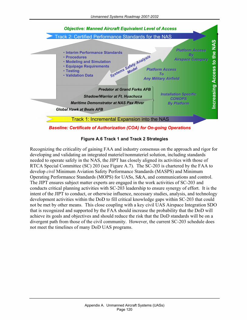
Unmanned Systems Roadmap 2007-2032
Appendix A. Unmanned Aircraft Systems (UASs)
Page 120
Figure A.6 Track 1 and Track 2 Strategies
Recognizing the criticality of gaining FAA and industry consensus on the approach and rigor for developing and validating an integrated materiel/nonmateriel solution, including standards needed to operate safely in the NAS, the JIPT has closely aligned its activities with those of RTCA Special Committee (SC) 203 (see Figure A.7). The SC-203 is chartered by the FAA to develop civil Minimum Aviation Safety Performance Standards (MASPS) and Minimum Operating Performance Standards (MOPS) for UASs, S&A, and communications and control. The JIPT ensures subject matter experts are engaged in the work activities of SC-203 and conducts critical planning activities with SC-203 leadership to ensure synergy of effort. It is the intent of the JIPT to conduct, or otherwise influence, necessary studies, analysis, and technology development activities within the DoD to fill critical knowledge gaps within SC-203 that could not be met by other means. This close coupling with a key civil UAS Airspace Integration SDO that is recognized and supported by the FAA should increase the probability that the DoD will achieve its goals and objectives and should reduce the risk that the DoD standards will be on a divergent path from those of the civil community. However, the current SC-203 schedule does not meet the timelines of many DoD UAS programs.
Track 2: Certified Performance Standards for the NAS
Track 1: Incremental Expansion into the NAS
Incr
easi
ng A
cces
s to
the
NA
S
Global Hawk at Beale AFB
Shadow/Warrior at Ft. HuachucaMaritime Demonstrator at NAS Pax River
Predator at Grand Forks AFB
Baseline: Certificate of Authorization (COA) for OnBaseline: Certificate of Authorization (COA) for On--going Operationsgoing Operations
Objective: Manned Aircraft Equivalent Level of Access Objective: Manned Aircraft Equivalent Level of Access
Installation SpecificInstallation SpecificCONOPSCONOPS
By PlatformBy Platform
Platform AccessPlatform AccessToTo
Any Military AirfieldAny Military Airfield
Platform AccessPlatform AccessByBy
Airspace CategoryAirspace Category
•• Interim Performance StandardsInterim Performance Standards•• ProceduresProcedures•• Modeling and SimulationModeling and Simulation•• Equipage RequirementsEquipage Requirements•• TestingTesting•• Validation Data Validation Data Systems Safety Analysis
Model
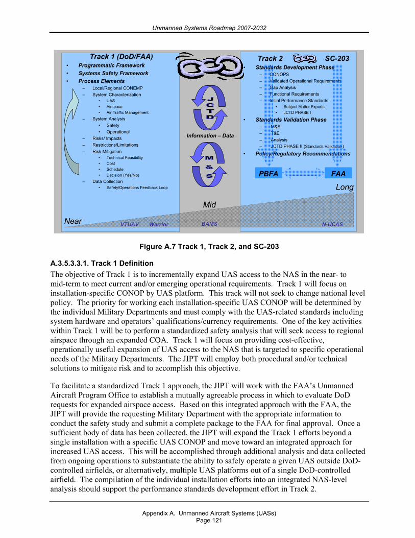
Unmanned Systems Roadmap 2007-2032
Appendix A. Unmanned Aircraft Systems (UASs)
Page 121
Track 1 (DoD/FAA)• Programmatic Framework• Systems Safety Framework• Process Elements
– Local/Regional CONEMP– System Characterization
• UAS• Airspace• Air Traffic Management
– System Analysis• Safety• Operational
– Risks/ Impacts– Restrictions/Limitations– Risk Mitigation
• Technical Feasibility• Cost• Schedule• Decision (Yes/No)
– Data Collection• Safety/Operations Feedback Loop
Track 2 SC-203• Standards Development Phase
– CONOPS– Validated Operational Requirements– Gap Analysis– Functional Requirements– Initial Performance Standards
• Subject Matter Experts• JCTD PHASE I
• Standards Validation Phase– M&S– T&E– Analysis– JCTD PHASE II (Standards Validation)
• Policy/Regulatory Recommendations
Information – Data
Near Near
MidMid
LongLong
VTUAVVTUAV BAMSBAMS NN--UCASUCASWarriorWarrior
PBFAPBFA FAAFAA
Figure A.7 Track 1, Track 2, and SC-203
A.3.5.3.3.1. Track 1 Definition The objective of Track 1 is to incrementally expand UAS access to the NAS in the near- to mid-term to meet current and/or emerging operational requirements. Track 1 will focus on installation-specific CONOP by UAS platform. This track will not seek to change national level policy. The priority for working each installation-specific UAS CONOP will be determined by the individual Military Departments and must comply with the UAS-related standards including system hardware and operators’ qualifications/currency requirements. One of the key activities within Track 1 will be to perform a standardized safety analysis that will seek access to regional airspace through an expanded COA. Track 1 will focus on providing cost-effective, operationally useful expansion of UAS access to the NAS that is targeted to specific operational needs of the Military Departments. The JIPT will employ both procedural and/or technical solutions to mitigate risk and to accomplish this objective.
To facilitate a standardized Track 1 approach, the JIPT will work with the FAA’s Unmanned Aircraft Program Office to establish a mutually agreeable process in which to evaluate DoD requests for expanded airspace access. Based on this integrated approach with the FAA, the JIPT will provide the requesting Military Department with the appropriate information to conduct the safety study and submit a complete package to the FAA for final approval. Once a sufficient body of data has been collected, the JIPT will expand the Track 1 efforts beyond a single installation with a specific UAS CONOP and move toward an integrated approach for increased UAS access. This will be accomplished through additional analysis and data collected from ongoing operations to substantiate the ability to safely operate a given UAS outside DoD-controlled airfields, or alternatively, multiple UAS platforms out of a single DoD-controlled airfield. The compilation of the individual installation efforts into an integrated NAS-level analysis should support the performance standards development effort in Track 2.
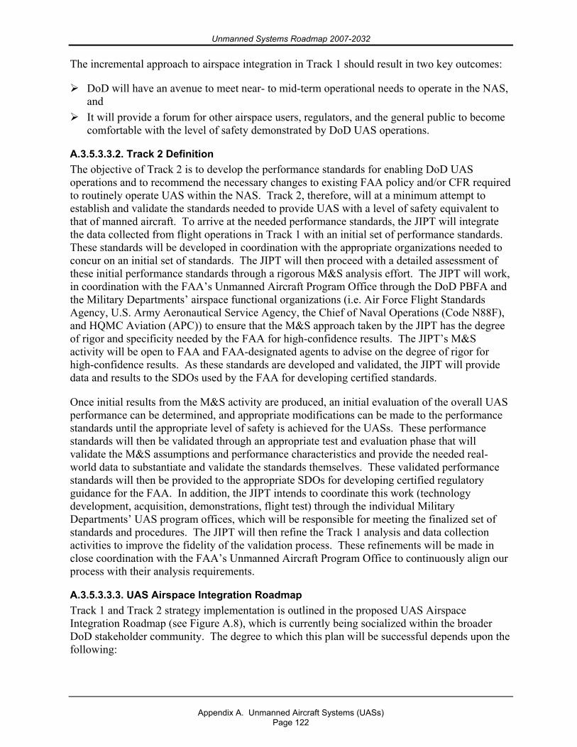
Unmanned Systems Roadmap 2007-2032
Appendix A. Unmanned Aircraft Systems (UASs)
Page 122
The incremental approach to airspace integration in Track 1 should result in two key outcomes:
DoD will have an avenue to meet near- to mid-term operational needs to operate in the NAS, and
It will provide a forum for other airspace users, regulators, and the general public to become comfortable with the level of safety demonstrated by DoD UAS operations.
A.3.5.3.3.2. Track 2 Definition The objective of Track 2 is to develop the performance standards for enabling DoD UAS operations and to recommend the necessary changes to existing FAA policy and/or CFR required to routinely operate UAS within the NAS. Track 2, therefore, will at a minimum attempt to establish and validate the standards needed to provide UAS with a level of safety equivalent to that of manned aircraft. To arrive at the needed performance standards, the JIPT will integrate the data collected from flight operations in Track 1 with an initial set of performance standards. These standards will be developed in coordination with the appropriate organizations needed to concur on an initial set of standards. The JIPT will then proceed with a detailed assessment of these initial performance standards through a rigorous M&S analysis effort. The JIPT will work, in coordination with the FAA’s Unmanned Aircraft Program Office through the DoD PBFA and the Military Departments’ airspace functional organizations (i.e. Air Force Flight Standards Agency, U.S. Army Aeronautical Service Agency, the Chief of Naval Operations (Code N88F), and HQMC Aviation (APC)) to ensure that the M&S approach taken by the JIPT has the degree of rigor and specificity needed by the FAA for high-confidence results. The JIPT’s M&S activity will be open to FAA and FAA-designated agents to advise on the degree of rigor for high-confidence results. As these standards are developed and validated, the JIPT will provide data and results to the SDOs used by the FAA for developing certified standards.
Once initial results from the M&S activity are produced, an initial evaluation of the overall UAS performance can be determined, and appropriate modifications can be made to the performance standards until the appropriate level of safety is achieved for the UASs. These performance standards will then be validated through an appropriate test and evaluation phase that will validate the M&S assumptions and performance characteristics and provide the needed real-world data to substantiate and validate the standards themselves. These validated performance standards will then be provided to the appropriate SDOs for developing certified regulatory guidance for the FAA. In addition, the JIPT intends to coordinate this work (technology development, acquisition, demonstrations, flight test) through the individual Military Departments’ UAS program offices, which will be responsible for meeting the finalized set of standards and procedures. The JIPT will then refine the Track 1 analysis and data collection activities to improve the fidelity of the validation process. These refinements will be made in close coordination with the FAA’s Unmanned Aircraft Program Office to continuously align our process with their analysis requirements.
A.3.5.3.3.3. UAS Airspace Integration Roadmap Track 1 and Track 2 strategy implementation is outlined in the proposed UAS Airspace Integration Roadmap (see Figure A.8), which is currently being socialized within the broader DoD stakeholder community. The degree to which this plan will be successful depends upon the following:
Unmanned Systems Roadmap 2007-2032
Appendix A. Unmanned Aircraft Systems (UASs)
Page 123
The key stakeholders organizations and communities must reach consensus on a common path forward, and
The effort must be prioritized in terms of expertise applied to the effort along with the appropriate level of funding to execute on the timeline provided.
Standards Validation
Standards Implement’n 1
Test and Evaluation
Modeling and Simulation
Standards Development
Q4Q3Q2Q1Q4Q3Q2Q1Activity FY2009FY2008
Standards Validation
Standards Implement’n 1
Test and Evaluation
Modeling and Simulation
Standards Development
Q4Q3Q2Q1Q4Q3Q2Q1Activity FY2009FY2008
Q4Q3Q2Q1Q4Q3Q2Q1FY2011FY2010
Q4Q3Q2Q1Q4Q3Q2Q1FY2011FY2010
Standards JCTDStandards JCTD
Standards Validation
Standards Implement’n 2
Standards Implement’n 1
Modeling and Simulation
Standards Updated
Q4Q3Q2Q1Q4Q3Q2Q1Activity FY2013FY2012
Standards Validation
Standards Implement’n 2
Standards Implement’n 1
Modeling and Simulation
Standards Updated
Q4Q3Q2Q1Q4Q3Q2Q1Activity FY2013FY2012
Q4Q3Q2Q1Q4Q3Q2Q1FY2015FY2014
Q4Q3Q2Q1Q4Q3Q2Q1FY2015FY2014
Track 1 Sites
Implementation JCTDImplementation JCTD
Implementation JCTDImplementation JCTDCompleted DeliverableCompleted Deliverable Interim DeliverableInterim Deliverable MilestoneMilestone
Track 2 Sites
DoDDoD StandardsStandards
66 -- mnth Spirals
mnth Spirals
Annual Spirals
Annual Spirals
FAA Order 7610.4FAA Order 7610.4
M&S Standard Tool KitM&S Standard Tool Kit
Track 2Track 2Track 1Track 1
JCTD
Initial Initial DoDDoD SME StandardsSME Standards
Figure A.8 Proposed UAS Airspace Integration Roadmap
The JIPT is proposing a Joint Capability Technology Demonstration for FY2009 to advance the standards and technology work inside the FY2010 Program Objective Memorandum timeline.
The JIPT, chartered by the Military Departments’ UAS program managers in 2005, has taken action to develop a comprehensive strategy and programmatic roadmap to meet short-, mid-, and long-term Military Department UAS operational and training airspace access needs. To enhance the probability of success, the JIPT is working closely with the FAA’s Unmanned Aircraft Program Office and the FAA-chartered RTCA SC-203 on unmanned aviation and with other DoD UAS stakeholders to gain consensus and support for a single DoD roadmap that addresses the broad materiel/nonmateriel solution set.
A.3.6. Summary To maximize the operational effectiveness of UASs, unmanned aircraft must be able to integrate with manned and unmanned operations, both in the NAS and oceanic and foreign domestic airspace. To attain this goal the DoD must accomplish the following:
1. Foster an airspace regulatory environment that encourages the safe use of UASs in nonsegregated airspace,
Unmanned Systems Roadmap 2007-2032
Appendix A. Unmanned Aircraft Systems (UASs)
Page 124
2. Improve the flight reliability of UASs to equal or better that of their manned counterparts,
3. Secure the control and sensor/relay communications sent to and from UASs,
4. Implement the JIPT’s two-track strategy to gain increased access to the NAS for all UASs under the current COA process and attain a level of access for UAS (Cat III) equivalent to that of manned aircraft, and
5. Work with the FAA to define appropriate conditions and requirements under which a single pilot would be allowed to control multiple airborne UASs simultaneously.
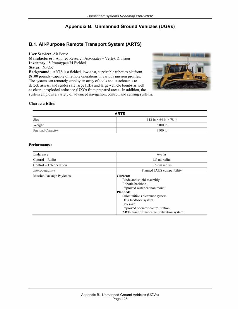
Unmanned Systems Roadmap 2007-2032
Appendix B. Unmanned Ground Vehicles (UGVs)
Page 125
Appendix B. Unmanned Ground Vehicles (UGVs)
B.1. All-Purpose Remote Transport System (ARTS)
User Service: Air Force Manufacturer: Applied Research Associates – Vertek Division Inventory: 5 Prototypes/74 Fielded Status: NPOR Background: ARTS is a fielded, low-cost, survivable robotics platform (8100 pounds) capable of remote operations in various mission profiles. The system can remotely employ an array of tools and attachments to detect, assess, and render safe large IEDs and large-vehicle bombs as well as clear unexploded ordnance (UXO) from prepared areas. In addition, the system employs a variety of advanced navigation, control, and sensing systems.
Characteristics:
ARTS Size 113 in × 64 in × 78 in Weight 8100 lb Payload Capacity 3500 lb
Performance:
Endurance 6–8 hr Control – Radio 1.5-mi radius Control – Teleoperation 1.5-nm radius Interoperability Planned JAUS compatibility Mission Package Payloads Current:
Blade and shield assembly Robotic backhoe Improved water cannon mount
Planned: Submunitions clearance system Data feedback system Box rake Improved operator control station ARTS laser ordnance neutralization system
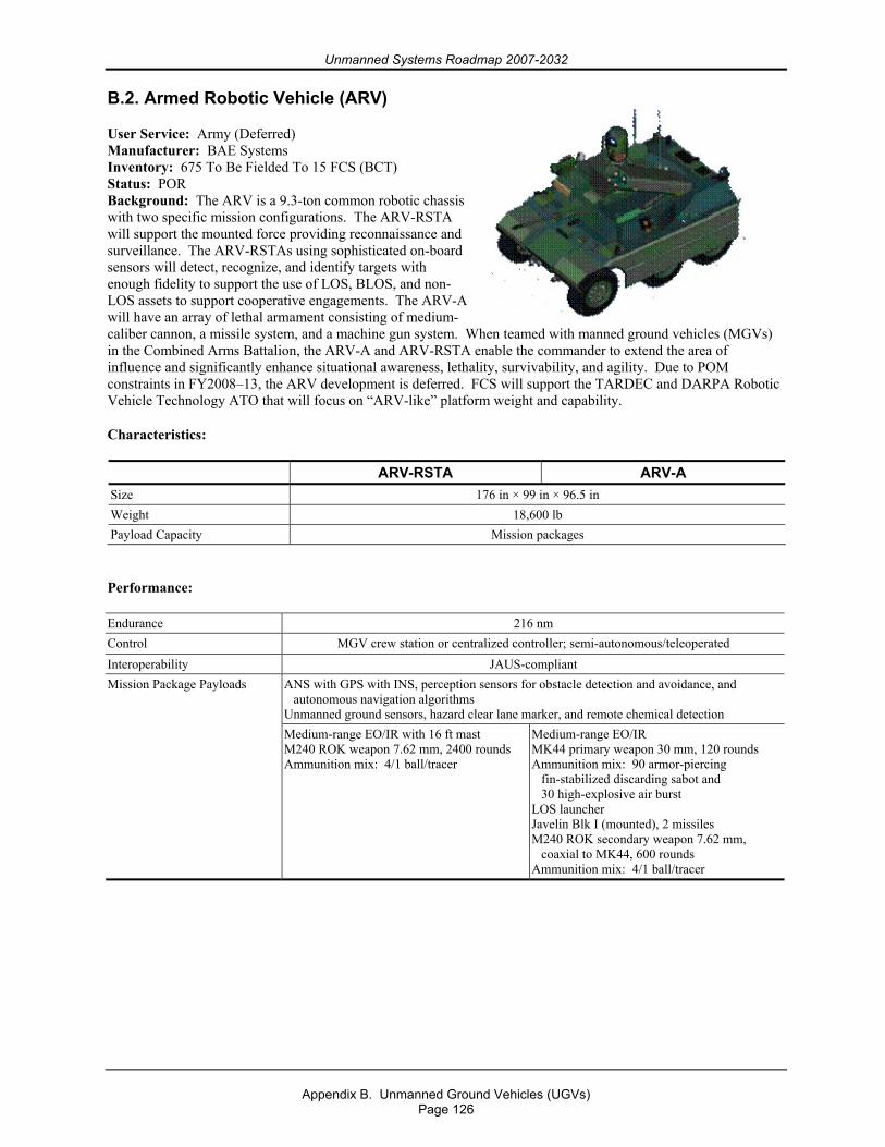
Unmanned Systems Roadmap 2007-2032
Appendix B. Unmanned Ground Vehicles (UGVs)
Page 126
B.2. Armed Robotic Vehicle (ARV)
User Service: Army (Deferred) Manufacturer: BAE Systems Inventory: 675 To Be Fielded To 15 FCS (BCT) Status: POR Background: The ARV is a 9.3-ton common robotic chassis with two specific mission configurations. The ARV-RSTA will support the mounted force providing reconnaissance and surveillance. The ARV-RSTAs using sophisticated on-board sensors will detect, recognize, and identify targets with enough fidelity to support the use of LOS, BLOS, and non-LOS assets to support cooperative engagements. The ARV-A will have an array of lethal armament consisting of medium-caliber cannon, a missile system, and a machine gun system. When teamed with manned ground vehicles (MGVs) in the Combined Arms Battalion, the ARV-A and ARV-RSTA enable the commander to extend the area of influence and significantly enhance situational awareness, lethality, survivability, and agility. Due to POM constraints in FY2008–13, the ARV development is deferred. FCS will support the TARDEC and DARPA Robotic Vehicle Technology ATO that will focus on “ARV-like” platform weight and capability.
Characteristics:
ARV-RSTA ARV-A Size 176 in × 99 in × 96.5 in Weight 18,600 lb Payload Capacity Mission packages
Performance:
Endurance 216 nm Control MGV crew station or centralized controller; semi-autonomous/teleoperated Interoperability JAUS-compliant
ANS with GPS with INS, perception sensors for obstacle detection and avoidance, and autonomous navigation algorithms
Unmanned ground sensors, hazard clear lane marker, and remote chemical detection
Mission Package Payloads
Medium-range EO/IR with 16 ft mast M240 ROK weapon 7.62 mm, 2400 rounds Ammunition mix: 4/1 ball/tracer
Medium-range EO/IR MK44 primary weapon 30 mm, 120 rounds Ammunition mix: 90 armor-piercing
fin-stabilized discarding sabot and 30 high-explosive air burst
LOS launcher Javelin Blk I (mounted), 2 missiles M240 ROK secondary weapon 7.62 mm,
coaxial to MK44, 600 rounds Ammunition mix: 4/1 ball/tracer
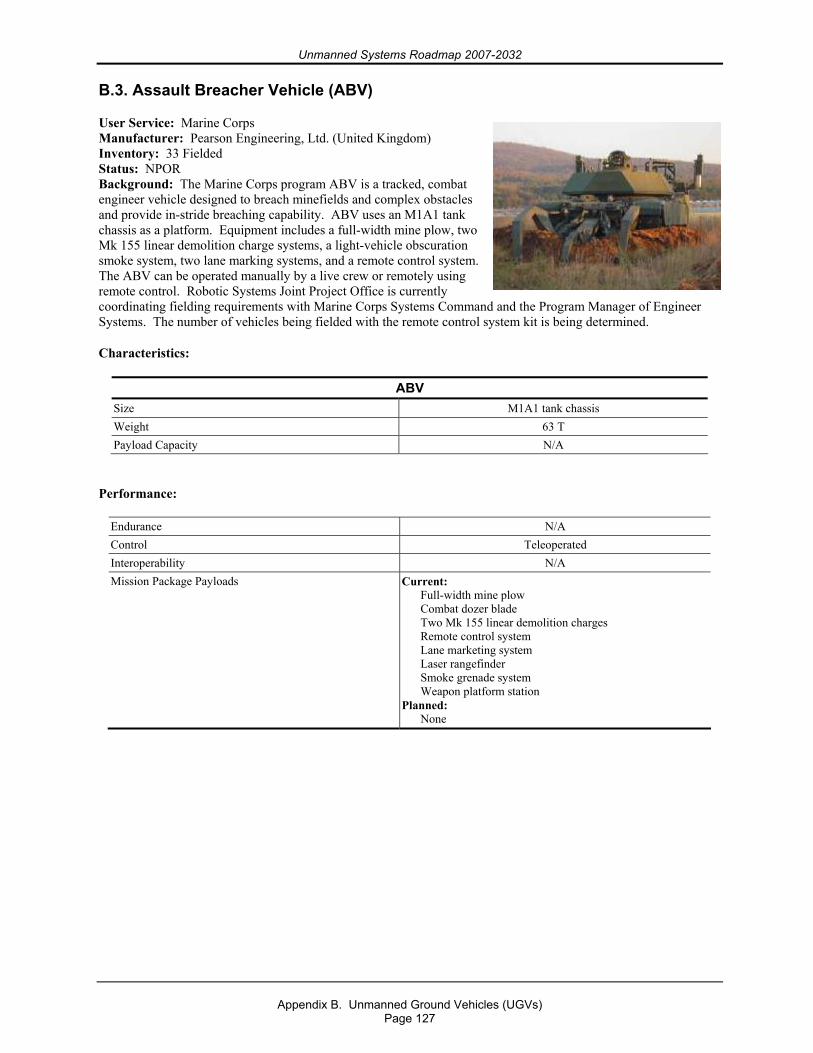
Unmanned Systems Roadmap 2007-2032
Appendix B. Unmanned Ground Vehicles (UGVs)
Page 127
B.3. Assault Breacher Vehicle (ABV)
User Service: Marine Corps Manufacturer: Pearson Engineering, Ltd. (United Kingdom) Inventory: 33 Fielded Status: NPOR Background: The Marine Corps program ABV is a tracked, combat engineer vehicle designed to breach minefields and complex obstacles and provide in-stride breaching capability. ABV uses an M1A1 tank chassis as a platform. Equipment includes a full-width mine plow, two Mk 155 linear demolition charge systems, a light-vehicle obscuration smoke system, two lane marking systems, and a remote control system. The ABV can be operated manually by a live crew or remotely using remote control. Robotic Systems Joint Project Office is currently coordinating fielding requirements with Marine Corps Systems Command and the Program Manager of Engineer Systems. The number of vehicles being fielded with the remote control system kit is being determined.
Characteristics:
ABV Size M1A1 tank chassis Weight 63 T Payload Capacity N/A
Performance:
Endurance N/A Control Teleoperated Interoperability N/A Mission Package Payloads Current:
Full-width mine plow Combat dozer blade Two Mk 155 linear demolition charges Remote control system Lane marketing system Laser rangefinder Smoke grenade system Weapon platform station
Planned: None
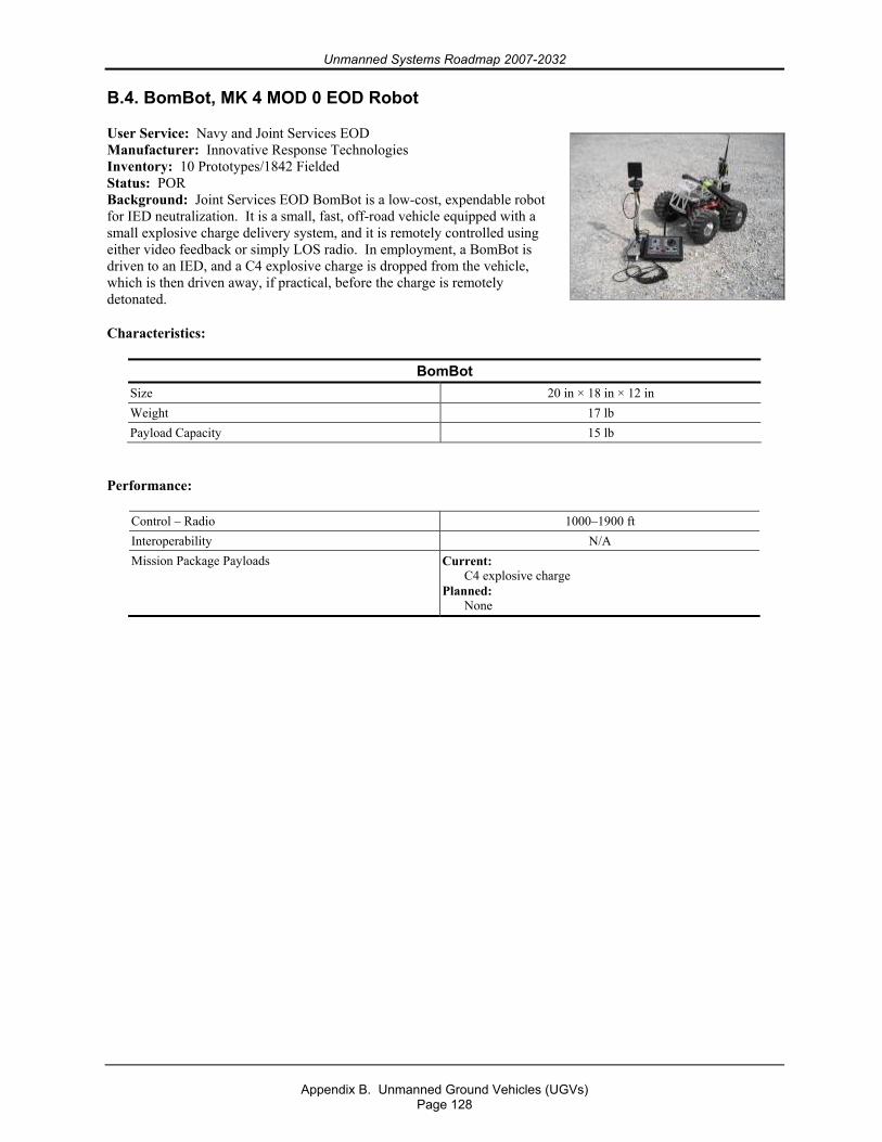
Unmanned Systems Roadmap 2007-2032
Appendix B. Unmanned Ground Vehicles (UGVs)
Page 128
B.4. BomBot, MK 4 MOD 0 EOD Robot
User Service: Navy and Joint Services EOD Manufacturer: Innovative Response Technologies Inventory: 10 Prototypes/1842 Fielded Status: POR Background: Joint Services EOD BomBot is a low-cost, expendable robot for IED neutralization. It is a small, fast, off-road vehicle equipped with a small explosive charge delivery system, and it is remotely controlled using either video feedback or simply LOS radio. In employment, a BomBot is driven to an IED, and a C4 explosive charge is dropped from the vehicle, which is then driven away, if practical, before the charge is remotely detonated.
Characteristics:
BomBot Size 20 in × 18 in × 12 in Weight 17 lb Payload Capacity 15 lb
Performance:
Control – Radio 1000–1900 ft Interoperability N/A Mission Package Payloads Current:
C4 explosive charge Planned:
None
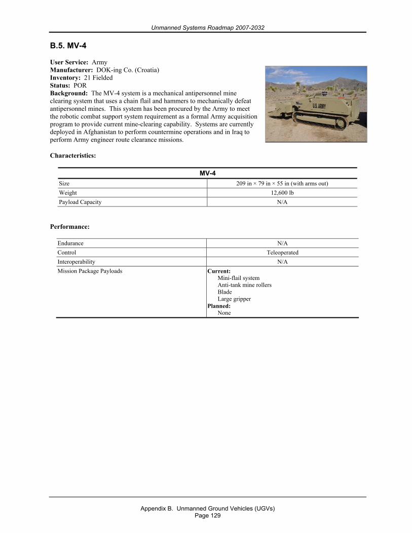
Unmanned Systems Roadmap 2007-2032
Appendix B. Unmanned Ground Vehicles (UGVs)
Page 129
B.5. MV-4
User Service: Army Manufacturer: DOK-ing Co. (Croatia) Inventory: 21 Fielded Status: POR Background: The MV-4 system is a mechanical antipersonnel mine clearing system that uses a chain flail and hammers to mechanically defeat antipersonnel mines. This system has been procured by the Army to meet the robotic combat support system requirement as a formal Army acquisition program to provide current mine-clearing capability. Systems are currently deployed in Afghanistan to perform countermine operations and in Iraq to perform Army engineer route clearance missions.
Characteristics:
MV-4 Size 209 in × 79 in × 55 in (with arms out) Weight 12,600 lb Payload Capacity N/A
Performance:
Endurance N/A Control Teleoperated Interoperability N/A Mission Package Payloads Current:
Mini-flail system Anti-tank mine rollers Blade Large gripper
Planned: None
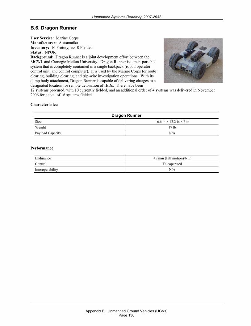
Unmanned Systems Roadmap 2007-2032
Appendix B. Unmanned Ground Vehicles (UGVs)
Page 130
B.6. Dragon Runner
User Service: Marine Corps Manufacturer: Automatika Inventory: 16 Prototypes/10 Fielded Status: NPOR Background: Dragon Runner is a joint development effort between the MCWL and Carnegie Mellon University. Dragon Runner is a man-portable system that is completely contained in a single backpack (robot, operator control unit, and control computer). It is used by the Marine Corps for route clearing, building clearing, and trip-wire investigation operations. With its dump body attachment, Dragon Runner is capable of delivering charges to a designated location for remote detonation of IEDs. There have been 12 systems procured, with 10 currently fielded, and an additional order of 4 systems was delivered in November 2006 for a total of 16 systems fielded.
Characteristics:
Dragon Runner Size 16.6 in × 12.2 in × 6 in Weight 17 lb Payload Capacity N/A
Performance:
Endurance 45 min (full motion)/6 hr Control Teleoperated Interoperability N/A
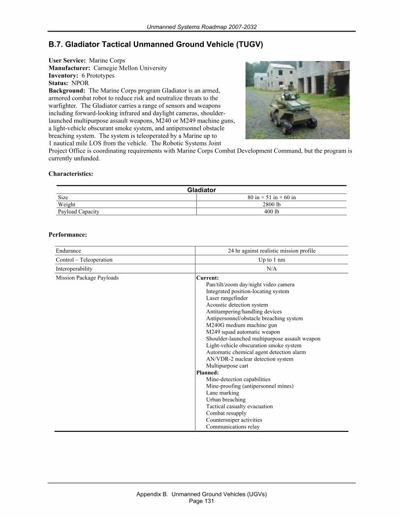
Unmanned Systems Roadmap 2007-2032
Appendix B. Unmanned Ground Vehicles (UGVs)
Page 131
B.7. Gladiator Tactical Unmanned Ground Vehicle (TUGV)
User Service: Marine Corps Manufacturer: Carnegie Mellon University Inventory: 6 Prototypes Status: NPOR Background: The Marine Corps program Gladiator is an armed, armored combat robot to reduce risk and neutralize threats to the warfighter. The Gladiator carries a range of sensors and weapons including forward-looking infrared and daylight cameras, shoulder-launched multipurpose assault weapons, M240 or M249 machine guns, a light-vehicle obscurant smoke system, and antipersonnel obstacle breaching system. The system is teleoperated by a Marine up to 1 nautical mile LOS from the vehicle. The Robotic Systems Joint Project Office is coordinating requirements with Marine Corps Combat Development Command, but the program is currently unfunded.
Characteristics:
Gladiator Size 80 in × 51 in × 60 in Weight 2800 lb Payload Capacity 400 lb
Performance:
Endurance 24 hr against realistic mission profile Control – Teleoperation Up to 1 nm Interoperability N/A Mission Package Payloads Current:
Pan/tilt/zoom day/night video camera Integrated position-locating system Laser rangefinder Acoustic detection system Antitampering/handling devices Antipersonnel/obstacle breaching system M240G medium machine gun M249 squad automatic weapon Shoulder-launched multipurpose assault weapon Light-vehicle obscuration smoke system Automatic chemical agent detection alarm AN/VDR-2 nuclear detection system Multipurpose cart
Planned: Mine-detection capabilities Mine-proofing (antipersonnel mines) Lane marking Urban breaching Tactical casualty evacuation Combat resupply Countersniper activities Communications relay
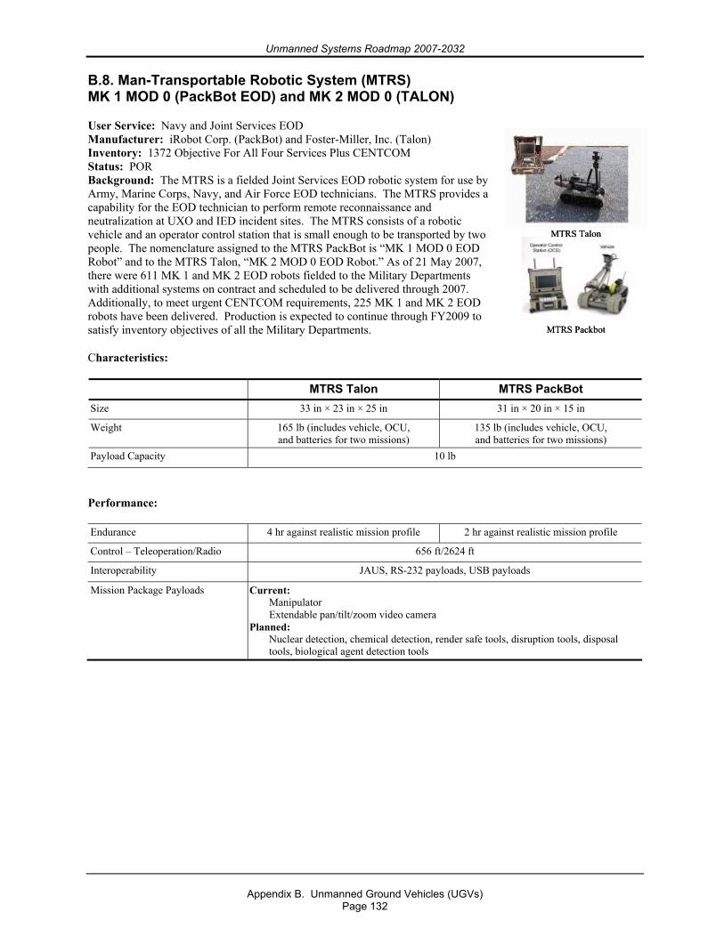
Unmanned Systems Roadmap 2007-2032
Appendix B. Unmanned Ground Vehicles (UGVs)
Page 132
B.8. Man-Transportable Robotic System (MTRS) MK 1 MOD 0 (PackBot EOD) and MK 2 MOD 0 (TALON)
User Service: Navy and Joint Services EOD Manufacturer: iRobot Corp. (PackBot) and Foster-Miller, Inc. (Talon) Inventory: 1372 Objective For All Four Services Plus CENTCOM Status: POR Background: The MTRS is a fielded Joint Services EOD robotic system for use by Army, Marine Corps, Navy, and Air Force EOD technicians. The MTRS provides a capability for the EOD technician to perform remote reconnaissance and neutralization at UXO and IED incident sites. The MTRS consists of a robotic vehicle and an operator control station that is small enough to be transported by two people. The nomenclature assigned to the MTRS PackBot is “MK 1 MOD 0 EOD Robot” and to the MTRS Talon, “MK 2 MOD 0 EOD Robot.” As of 21 May 2007, there were 611 MK 1 and MK 2 EOD robots fielded to the Military Departments with additional systems on contract and scheduled to be delivered through 2007. Additionally, to meet urgent CENTCOM requirements, 225 MK 1 and MK 2 EOD robots have been delivered. Production is expected to continue through FY2009 to satisfy inventory objectives of all the Military Departments.
Characteristics:
MTRS Talon MTRS PackBot Size 33 in × 23 in × 25 in 31 in × 20 in × 15 in
Weight 165 lb (includes vehicle, OCU, and batteries for two missions)
135 lb (includes vehicle, OCU, and batteries for two missions)
Payload Capacity 10 lb
Performance:
Endurance 4 hr against realistic mission profile 2 hr against realistic mission profile
Control – Teleoperation/Radio 656 ft/2624 ft
Interoperability JAUS, RS-232 payloads, USB payloads
Mission Package Payloads Current: Manipulator Extendable pan/tilt/zoom video camera
Planned: Nuclear detection, chemical detection, render safe tools, disruption tools, disposal tools, biological agent detection tools
MTRS Talon
MTRS Packbot
MTRS Talon
MTRS Packbot
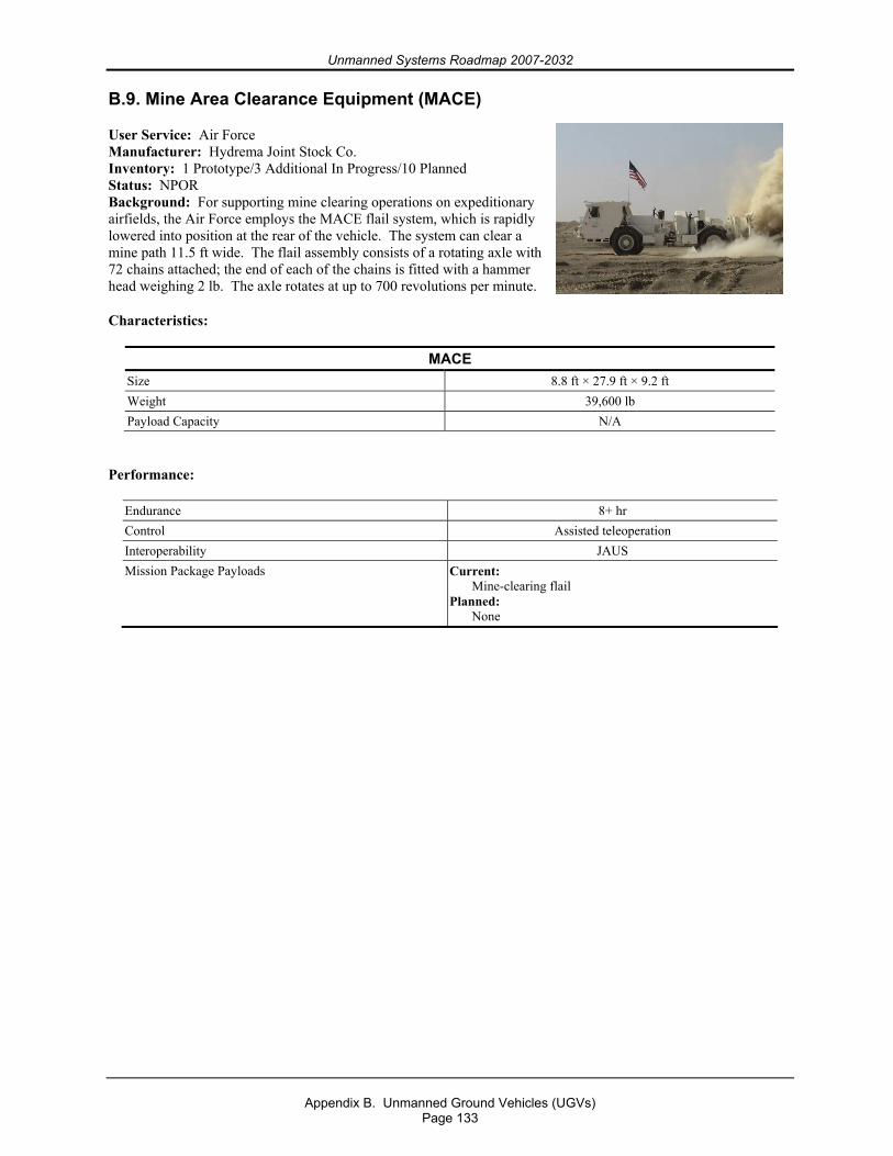
Unmanned Systems Roadmap 2007-2032
Appendix B. Unmanned Ground Vehicles (UGVs)
Page 133
B.9. Mine Area Clearance Equipment (MACE)
User Service: Air Force Manufacturer: Hydrema Joint Stock Co. Inventory: 1 Prototype/3 Additional In Progress/10 Planned Status: NPOR Background: For supporting mine clearing operations on expeditionary airfields, the Air Force employs the MACE flail system, which is rapidly lowered into position at the rear of the vehicle. The system can clear a mine path 11.5 ft wide. The flail assembly consists of a rotating axle with 72 chains attached; the end of each of the chains is fitted with a hammer head weighing 2 lb. The axle rotates at up to 700 revolutions per minute.
Characteristics:
MACE Size 8.8 ft × 27.9 ft × 9.2 ft Weight 39,600 lb Payload Capacity N/A
Performance:
Endurance 8+ hr Control Assisted teleoperation Interoperability JAUS Mission Package Payloads Current:
Mine-clearing flail Planned:
None
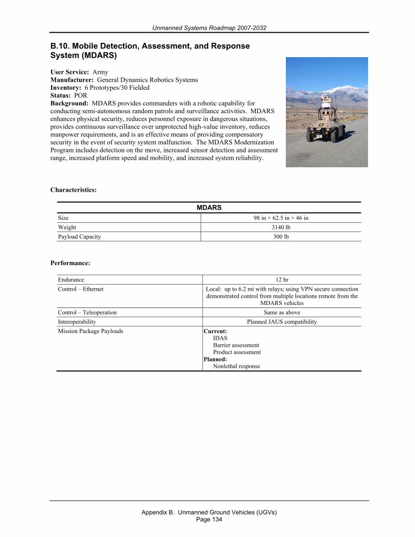
Unmanned Systems Roadmap 2007-2032
Appendix B. Unmanned Ground Vehicles (UGVs)
Page 134
B.10. Mobile Detection, Assessment, and Response System (MDARS)
User Service: Army Manufacturer: General Dynamics Robotics Systems Inventory: 6 Prototypes/30 Fielded Status: POR Background: MDARS provides commanders with a robotic capability for conducting semi-autonomous random patrols and surveillance activities. MDARS enhances physical security, reduces personnel exposure in dangerous situations, provides continuous surveillance over unprotected high-value inventory, reduces manpower requirements, and is an effective means of providing compensatory security in the event of security system malfunction. The MDARS Modernization Program includes detection on the move, increased sensor detection and assessment range, increased platform speed and mobility, and increased system reliability.
Characteristics:
MDARS Size 98 in × 62.5 in × 46 in Weight 3140 lb Payload Capacity 300 lb
Performance:
Endurance 12 hr Control – Ethernet Local: up to 6.2 mi with relays; using VPN secure connection
demonstrated control from multiple locations remote from the MDARS vehicles
Control – Teleoperation Same as above Interoperability Planned JAUS compatibility Mission Package Payloads Current:
IDAS Barrier assessment Product assessment
Planned: Nonlethal response
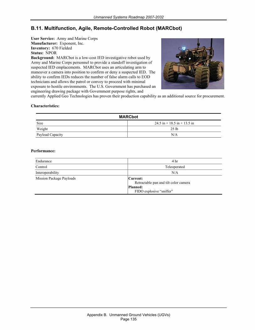
Unmanned Systems Roadmap 2007-2032
Appendix B. Unmanned Ground Vehicles (UGVs)
Page 135
B.11. Multifunction, Agile, Remote-Controlled Robot (MARCbot)
User Service: Army and Marine Corps Manufacturer: Exponent, Inc. Inventory: 670 Fielded Status: NPOR Background: MARCbot is a low-cost IED investigative robot used by Army and Marine Corps personnel to provide a standoff investigation of suspected IED emplacements. MARCbot uses an articulating arm to maneuver a camera into position to confirm or deny a suspected IED. The ability to confirm IEDs reduces the number of false alarm calls to EOD technicians and allows the patrol or convoy to proceed with minimal exposure to hostile environments. The U.S. Government has purchased an engineering drawing package with Government purpose rights, and currently Applied Geo Technologies has proven their production capability as an additional source for procurement.
Characteristics:
MARCbot Size 24.5 in × 18.5 in × 13.5 in Weight 25 lb Payload Capacity N/A
Performance:
Endurance 4 hr Control Teleoperated Interoperability N/A Mission Package Payloads Current:
Retractable pan and tilt color camera Planned:
FIDO explosive “sniffer”
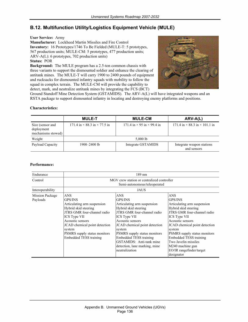
Unmanned Systems Roadmap 2007-2032
Appendix B. Unmanned Ground Vehicles (UGVs)
Page 136
B.12. Multifunction Utility/Logistics Equipment Vehicle (MULE)
User Service: Army Manufacturer: Lockheed Martin Missiles and Fire Control Inventory: 16 Prototypes/1746 To Be Fielded (MULE-T: 5 prototypes, 567 production units; MULE-CM: 5 prototypes, 477 production units; ARV-A(L): 6 prototypes, 702 production units) Status: POR Background: The MULE program has a 2.5-ton common chassis with three variants to support the dismounted soldier and enhance the clearing of antitank mines. The MULE-T will carry 1900 to 2400 pounds of equipment and rucksacks for dismounted infantry squads with mobility to follow the squad in complex terrain. The MULE-CM will provide the capability to detect, mark, and neutralize antitank mines by integrating the FCS (BCT) Ground Standoff Mine Detection System (GSTAMIDS). The ARV-A(L) will have integrated weapons and an RSTA package to support dismounted infantry in locating and destroying enemy platforms and positions.
Characteristics:
MULE-T MULE-CM ARV-A(L) Size (sensor and deployment mechanisms stowed)
171.4 in × 88.3 in × 77.5 in 171.4 in × 95 in × 99.4 in 171.4 in × 88.3 in × 101.1 in
Weight 5,000 lb Payload Capacity 1900–2400 lb Integrate GSTAMIDS Integrate weapon stations
and sensors
Performance:
Endurance 189 nm Control MGV crew station or centralized controller
Semi-autonomous/teleoperated Interoperability JAUS Mission Package Payloads
ANS GPS/INS Articulating arm suspension Hybrid skid steering JTRS GMR four-channel radio ICS Type VII Acoustic sensors JCAD chemical point detection system PSMRS supply status monitors Embedded TESS training
ANS GPS/INS Articulating arm suspension Hybrid skid steering JTRS GMR four-channel radio ICS Type VII Acoustic sensors JCAD chemical point detection system PSMRS supply status monitors Embedded TESS training GSTAMIDS: Anti-tank mine detection, lane marking, mine neutralization
ANS GPS/INS Articulating arm suspension Hybrid skid steering JTRS GMR four-channel radio ICS Type VII Acoustic sensors JCAD chemical point detection system PSMRS supply status monitors Embedded TESS training Two Javelin missiles M240 machine gun EO/IR rangefinder/target designator
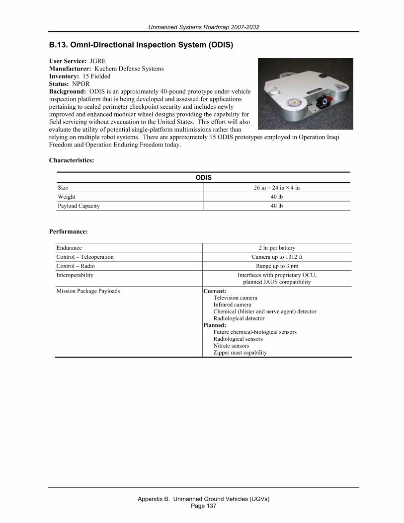
Unmanned Systems Roadmap 2007-2032
Appendix B. Unmanned Ground Vehicles (UGVs)
Page 137
B.13. Omni-Directional Inspection System (ODIS)
User Service: JGRE Manufacturer: Kuchera Defense Systems Inventory: 15 Fielded Status: NPOR Background: ODIS is an approximately 40-pound prototype under-vehicle inspection platform that is being developed and assessed for applications pertaining to sealed perimeter checkpoint security and includes newly improved and enhanced modular wheel designs providing the capability for field servicing without evacuation to the United States. This effort will also evaluate the utility of potential single-platform multimissions rather than relying on multiple robot systems. There are approximately 15 ODIS prototypes employed in Operation Iraqi Freedom and Operation Enduring Freedom today.
Characteristics:
ODIS Size 26 in × 24 in × 4 in Weight 40 lb Payload Capacity 40 lb
Performance:
Endurance 2 hr per battery Control – Teleoperation Camera up to 1312 ft Control – Radio Range up to 3 nm Interoperability Interfaces with proprietary OCU,
planned JAUS compatibility Mission Package Payloads Current:
Television camera Infrared camera Chemical (blister and nerve agent) detector Radiological detector
Planned: Future chemical-biological sensors Radiological sensors Nitrate sensors Zipper mast capability
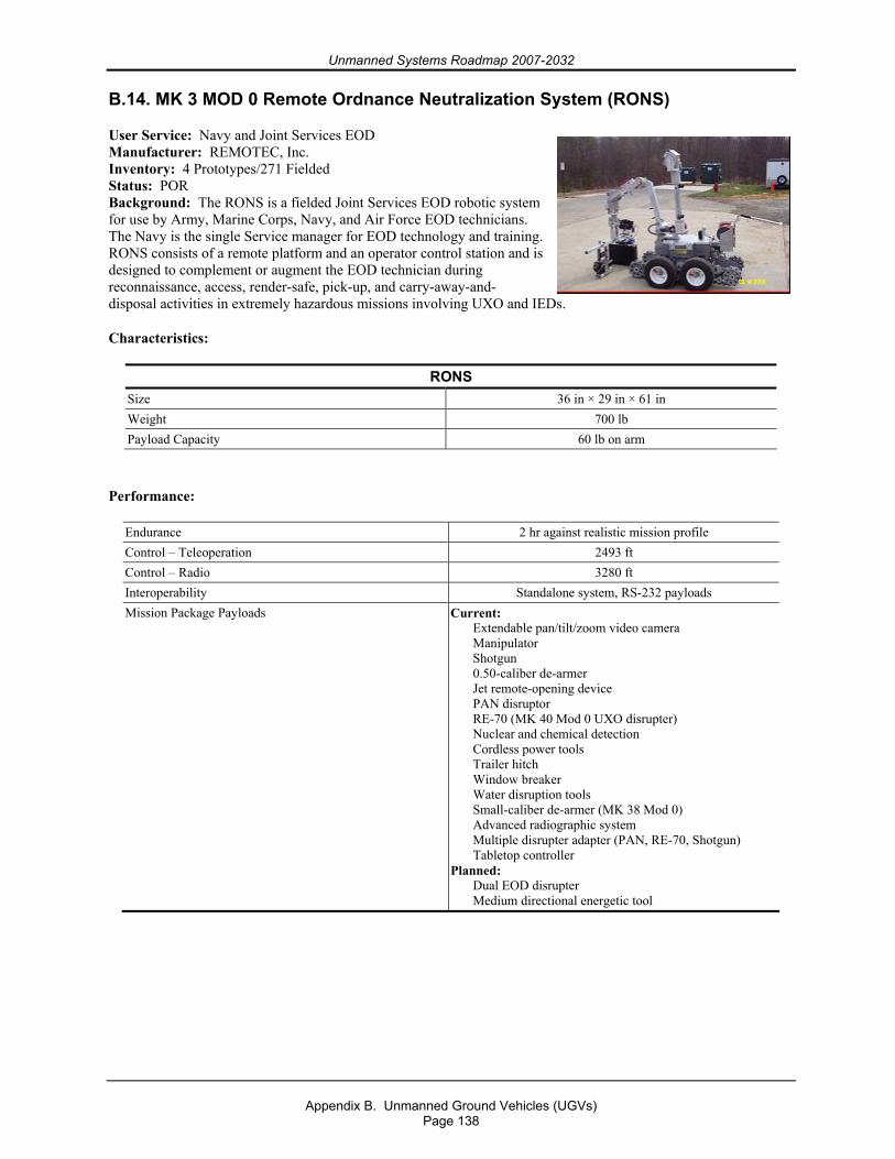
Unmanned Systems Roadmap 2007-2032
Appendix B. Unmanned Ground Vehicles (UGVs)
Page 138
B.14. MK 3 MOD 0 Remote Ordnance Neutralization System (RONS)
User Service: Navy and Joint Services EOD Manufacturer: REMOTEC, Inc. Inventory: 4 Prototypes/271 Fielded Status: POR Background: The RONS is a fielded Joint Services EOD robotic system for use by Army, Marine Corps, Navy, and Air Force EOD technicians. The Navy is the single Service manager for EOD technology and training. RONS consists of a remote platform and an operator control station and is designed to complement or augment the EOD technician during reconnaissance, access, render-safe, pick-up, and carry-away-and-disposal activities in extremely hazardous missions involving UXO and IEDs.
Characteristics:
RONS Size 36 in × 29 in × 61 in Weight 700 lb Payload Capacity 60 lb on arm
Performance:
Endurance 2 hr against realistic mission profile Control – Teleoperation 2493 ft Control – Radio 3280 ft Interoperability Standalone system, RS-232 payloads Mission Package Payloads Current:
Extendable pan/tilt/zoom video camera Manipulator Shotgun 0.50-caliber de-armer Jet remote-opening device PAN disruptor RE-70 (MK 40 Mod 0 UXO disrupter) Nuclear and chemical detection Cordless power tools Trailer hitch Window breaker Water disruption tools Small-caliber de-armer (MK 38 Mod 0) Advanced radiographic system Multiple disrupter adapter (PAN, RE-70, Shotgun) Tabletop controller
Planned: Dual EOD disrupter Medium directional energetic tool
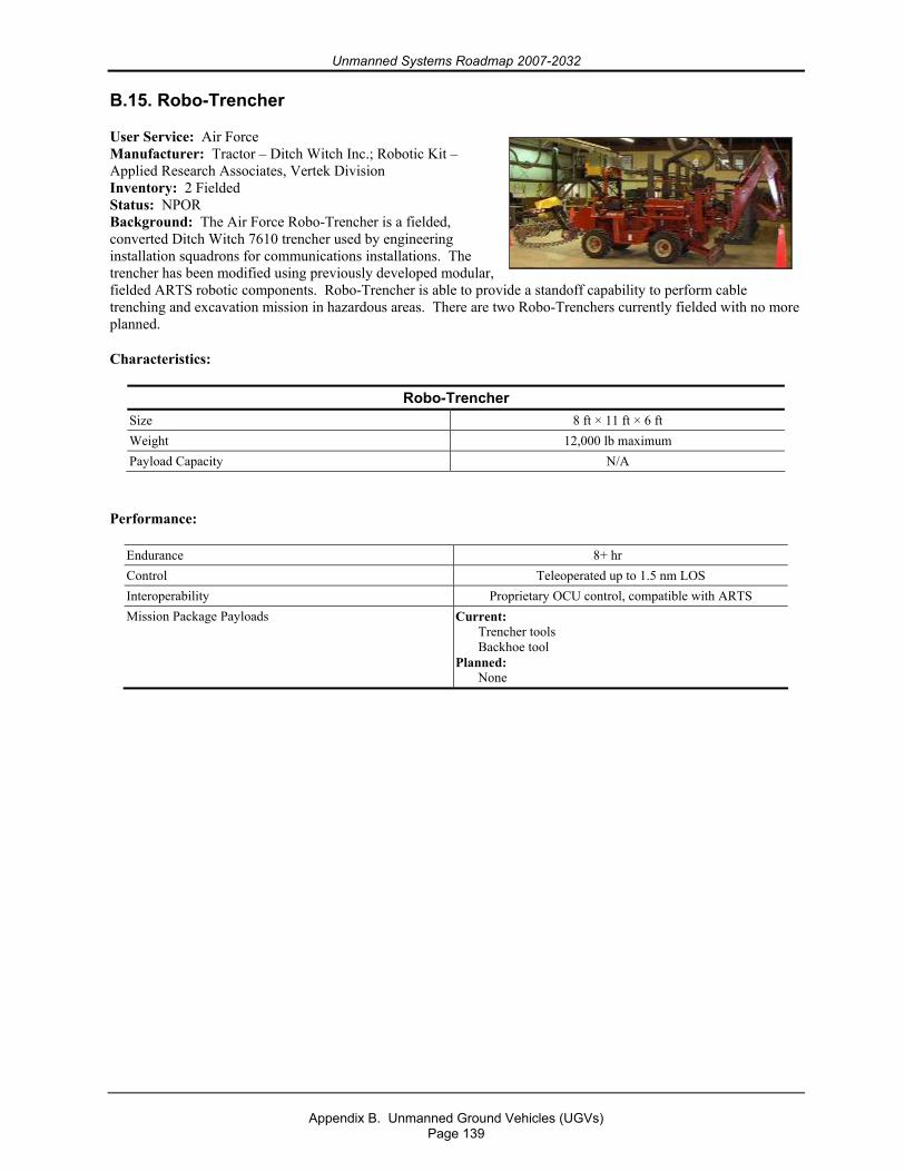
Unmanned Systems Roadmap 2007-2032
Appendix B. Unmanned Ground Vehicles (UGVs)
Page 139
B.15. Robo-Trencher
User Service: Air Force Manufacturer: Tractor – Ditch Witch Inc.; Robotic Kit – Applied Research Associates, Vertek Division Inventory: 2 Fielded Status: NPOR Background: The Air Force Robo-Trencher is a fielded, converted Ditch Witch 7610 trencher used by engineering installation squadrons for communications installations. The trencher has been modified using previously developed modular, fielded ARTS robotic components. Robo-Trencher is able to provide a standoff capability to perform cable trenching and excavation mission in hazardous areas. There are two Robo-Trenchers currently fielded with no more planned.
Characteristics:
Robo-Trencher Size 8 ft × 11 ft × 6 ft Weight 12,000 lb maximum Payload Capacity N/A
Performance:
Endurance 8+ hr Control Teleoperated up to 1.5 nm LOS Interoperability Proprietary OCU control, compatible with ARTS Mission Package Payloads Current:
Trencher tools Backhoe tool
Planned: None
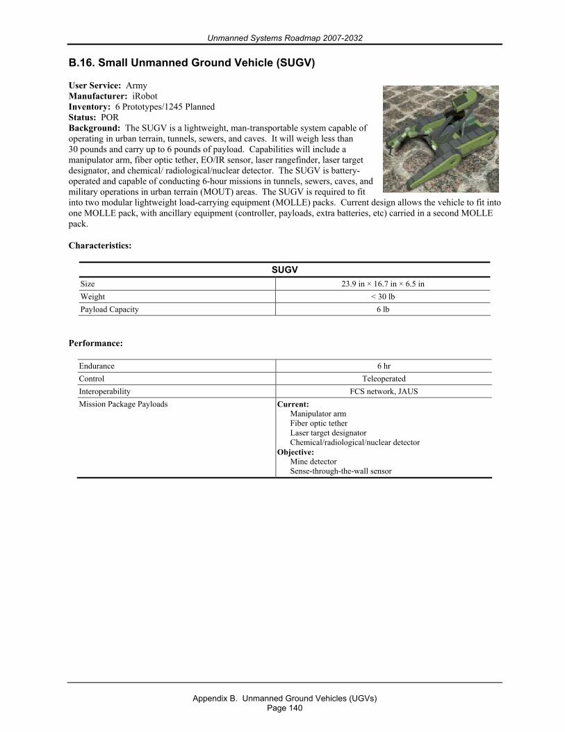
Unmanned Systems Roadmap 2007-2032
Appendix B. Unmanned Ground Vehicles (UGVs)
Page 140
B.16. Small Unmanned Ground Vehicle (SUGV)
User Service: Army Manufacturer: iRobot Inventory: 6 Prototypes/1245 Planned Status: POR Background: The SUGV is a lightweight, man-transportable system capable of operating in urban terrain, tunnels, sewers, and caves. It will weigh less than 30 pounds and carry up to 6 pounds of payload. Capabilities will include a manipulator arm, fiber optic tether, EO/IR sensor, laser rangefinder, laser target designator, and chemical/ radiological/nuclear detector. The SUGV is battery-operated and capable of conducting 6-hour missions in tunnels, sewers, caves, and military operations in urban terrain (MOUT) areas. The SUGV is required to fit into two modular lightweight load-carrying equipment (MOLLE) packs. Current design allows the vehicle to fit into one MOLLE pack, with ancillary equipment (controller, payloads, extra batteries, etc) carried in a second MOLLE pack.
Characteristics:
SUGV Size 23.9 in × 16.7 in × 6.5 in Weight < 30 lb Payload Capacity 6 lb
Performance:
Endurance 6 hr Control Teleoperated Interoperability FCS network, JAUS Mission Package Payloads Current:
Manipulator arm Fiber optic tether Laser target designator Chemical/radiological/nuclear detector
Objective: Mine detector Sense-through-the-wall sensor
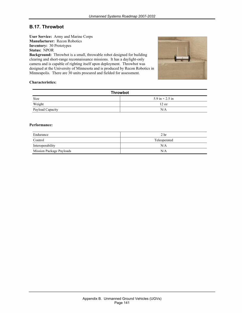
Unmanned Systems Roadmap 2007-2032
Appendix B. Unmanned Ground Vehicles (UGVs)
Page 141
B.17. Throwbot
User Service: Army and Marine Corps Manufacturer: Recon Robotics Inventory: 30 Prototypes Status: NPOR Background: Throwbot is a small, throwable robot designed for building clearing and short-range reconnaissance missions. It has a daylight-only camera and is capable of righting itself upon deployment. Throwbot was designed at the University of Minnesota and is produced by Recon Robotics in Minneapolis. There are 30 units procured and fielded for assessment.
Characteristics:
Throwbot Size 5.9 in × 2.5 in Weight 12 oz Payload Capacity N/A
Performance:
Endurance 2 hr Control Teleoperated Interoperability N/A Mission Package Payloads N/A
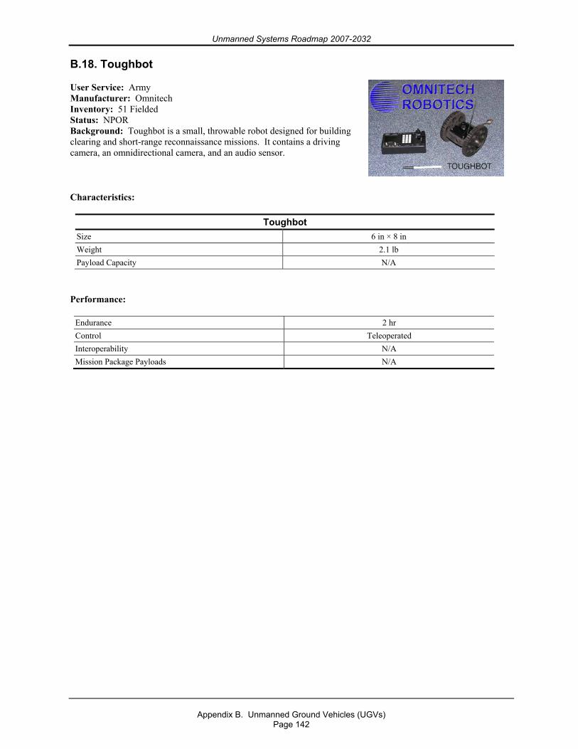
Unmanned Systems Roadmap 2007-2032
Appendix B. Unmanned Ground Vehicles (UGVs)
Page 142
B.18. Toughbot
User Service: Army Manufacturer: Omnitech Inventory: 51 Fielded Status: NPOR Background: Toughbot is a small, throwable robot designed for building clearing and short-range reconnaissance missions. It contains a driving camera, an omnidirectional camera, and an audio sensor.
Characteristics:
Toughbot Size 6 in × 8 in Weight 2.1 lb Payload Capacity N/A
Performance:
Endurance 2 hr Control Teleoperated Interoperability N/A Mission Package Payloads N/A
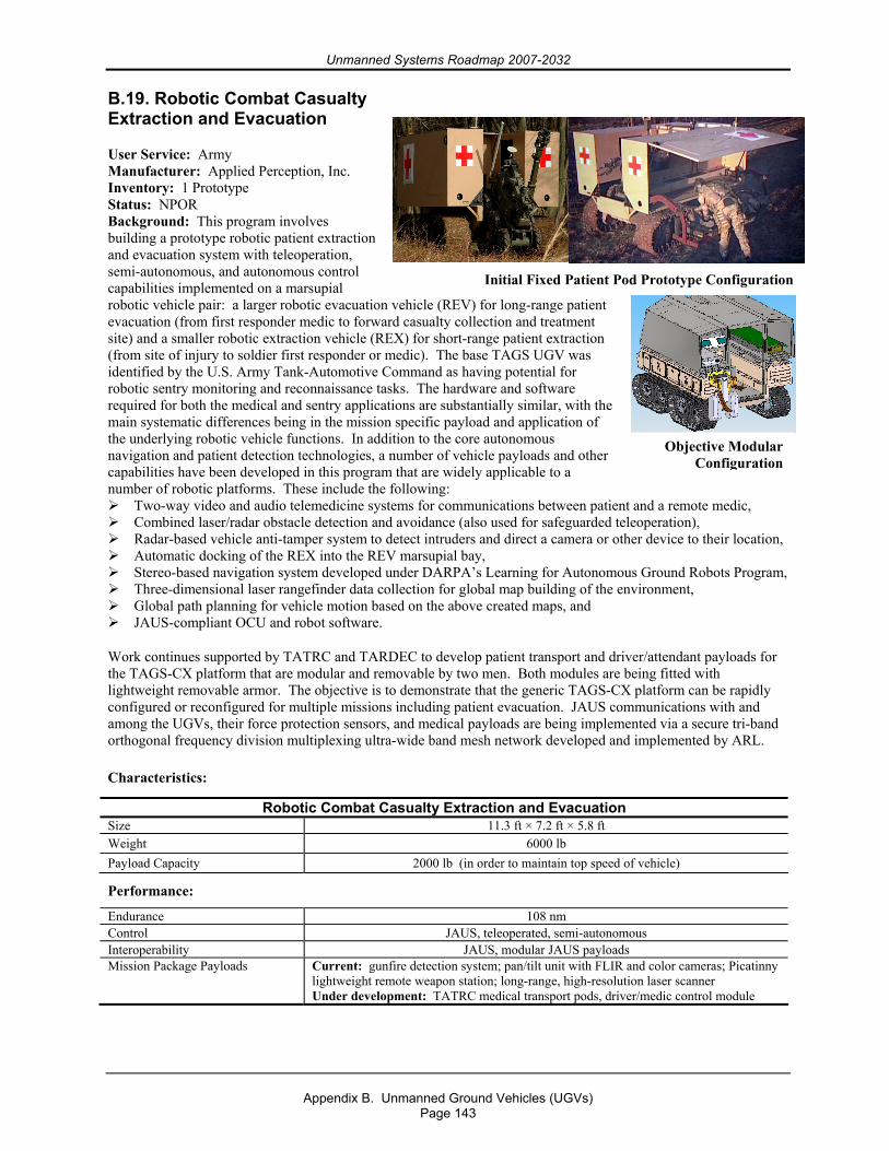
Unmanned Systems Roadmap 2007-2032
Appendix B. Unmanned Ground Vehicles (UGVs)
Page 143
B.19. Robotic Combat Casualty Extraction and Evacuation
User Service: Army Manufacturer: Applied Perception, Inc. Inventory: 1 Prototype Status: NPOR Background: This program involves building a prototype robotic patient extraction and evacuation system with teleoperation, semi-autonomous, and autonomous control capabilities implemented on a marsupial robotic vehicle pair: a larger robotic evacuation vehicle (REV) for long-range patient evacuation (from first responder medic to forward casualty collection and treatment site) and a smaller robotic extraction vehicle (REX) for short-range patient extraction (from site of injury to soldier first responder or medic). The base TAGS UGV was identified by the U.S. Army Tank-Automotive Command as having potential for robotic sentry monitoring and reconnaissance tasks. The hardware and software required for both the medical and sentry applications are substantially similar, with the main systematic differences being in the mission specific payload and application of the underlying robotic vehicle functions. In addition to the core autonomous navigation and patient detection technologies, a number of vehicle payloads and other capabilities have been developed in this program that are widely applicable to a number of robotic platforms. These include the following:
Two-way video and audio telemedicine systems for communications between patient and a remote medic, Combined laser/radar obstacle detection and avoidance (also used for safeguarded teleoperation), Radar-based vehicle anti-tamper system to detect intruders and direct a camera or other device to their location, Automatic docking of the REX into the REV marsupial bay, Stereo-based navigation system developed under DARPA’s Learning for Autonomous Ground Robots Program, Three-dimensional laser rangefinder data collection for global map building of the environment, Global path planning for vehicle motion based on the above created maps, and JAUS-compliant OCU and robot software.
Work continues supported by TATRC and TARDEC to develop patient transport and driver/attendant payloads for the TAGS-CX platform that are modular and removable by two men. Both modules are being fitted with lightweight removable armor. The objective is to demonstrate that the generic TAGS-CX platform can be rapidly configured or reconfigured for multiple missions including patient evacuation. JAUS communications with and among the UGVs, their force protection sensors, and medical payloads are being implemented via a secure tri-band orthogonal frequency division multiplexing ultra-wide band mesh network developed and implemented by ARL.
Characteristics:
Robotic Combat Casualty Extraction and Evacuation Size 11.3 ft × 7.2 ft × 5.8 ft Weight 6000 lb Payload Capacity 2000 lb (in order to maintain top speed of vehicle) Performance: Endurance 108 nm Control JAUS, teleoperated, semi-autonomous Interoperability JAUS, modular JAUS payloads Mission Package Payloads Current: gunfire detection system; pan/tilt unit with FLIR and color cameras; Picatinny
lightweight remote weapon station; long-range, high-resolution laser scanner Under development: TATRC medical transport pods, driver/medic control module
Objective Modular Configuration
Initial Fixed Patient Pod Prototype Configuration
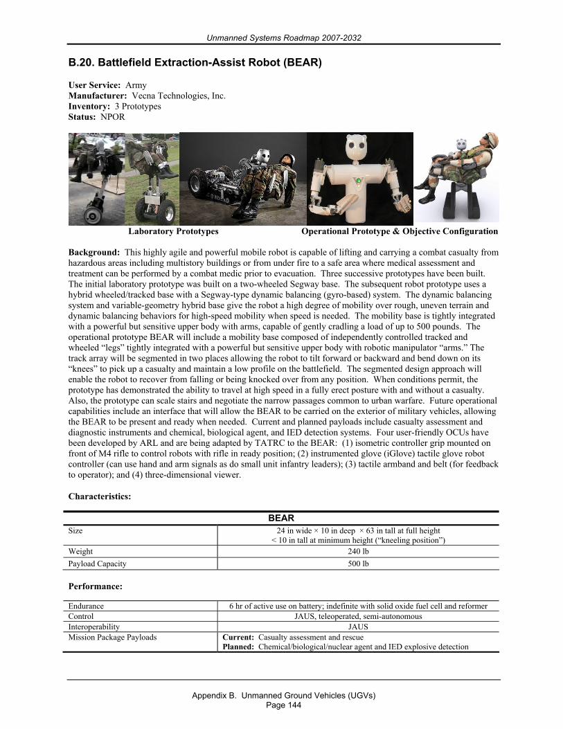
Unmanned Systems Roadmap 2007-2032
Appendix B. Unmanned Ground Vehicles (UGVs)
Page 144
B.20. Battlefield Extraction-Assist Robot (BEAR)
User Service: Army Manufacturer: Vecna Technologies, Inc. Inventory: 3 Prototypes Status: NPOR
Laboratory Prototypes Operational Prototype & Objective Configuration Background: This highly agile and powerful mobile robot is capable of lifting and carrying a combat casualty from hazardous areas including multistory buildings or from under fire to a safe area where medical assessment and treatment can be performed by a combat medic prior to evacuation. Three successive prototypes have been built. The initial laboratory prototype was built on a two-wheeled Segway base. The subsequent robot prototype uses a hybrid wheeled/tracked base with a Segway-type dynamic balancing (gyro-based) system. The dynamic balancing system and variable-geometry hybrid base give the robot a high degree of mobility over rough, uneven terrain and dynamic balancing behaviors for high-speed mobility when speed is needed. The mobility base is tightly integrated with a powerful but sensitive upper body with arms, capable of gently cradling a load of up to 500 pounds. The operational prototype BEAR will include a mobility base composed of independently controlled tracked and wheeled “legs” tightly integrated with a powerful but sensitive upper body with robotic manipulator “arms.” The track array will be segmented in two places allowing the robot to tilt forward or backward and bend down on its “knees” to pick up a casualty and maintain a low profile on the battlefield. The segmented design approach will enable the robot to recover from falling or being knocked over from any position. When conditions permit, the prototype has demonstrated the ability to travel at high speed in a fully erect posture with and without a casualty. Also, the prototype can scale stairs and negotiate the narrow passages common to urban warfare. Future operational capabilities include an interface that will allow the BEAR to be carried on the exterior of military vehicles, allowing the BEAR to be present and ready when needed. Current and planned payloads include casualty assessment and diagnostic instruments and chemical, biological agent, and IED detection systems. Four user-friendly OCUs have been developed by ARL and are being adapted by TATRC to the BEAR: (1) isometric controller grip mounted on front of M4 rifle to control robots with rifle in ready position; (2) instrumented glove (iGlove) tactile glove robot controller (can use hand and arm signals as do small unit infantry leaders); (3) tactile armband and belt (for feedback to operator); and (4) three-dimensional viewer.
Characteristics:
BEAR Size 24 in wide × 10 in deep × 63 in tall at full height
< 10 in tall at minimum height (“kneeling position”) Weight 240 lb Payload Capacity 500 lb Performance:
Endurance 6 hr of active use on battery; indefinite with solid oxide fuel cell and reformer Control JAUS, teleoperated, semi-autonomous Interoperability JAUS Mission Package Payloads Current: Casualty assessment and rescue
Planned: Chemical/biological/nuclear agent and IED explosive detection
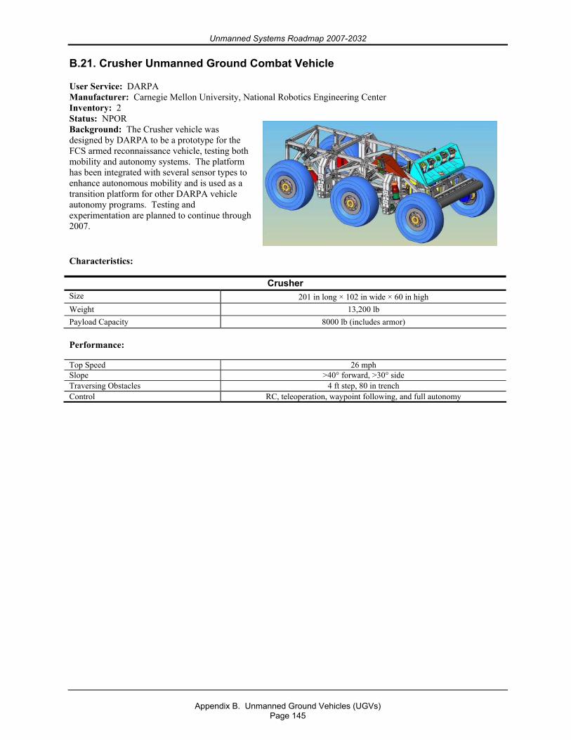
Unmanned Systems Roadmap 2007-2032
Appendix B. Unmanned Ground Vehicles (UGVs)
Page 145
B.21. Crusher Unmanned Ground Combat Vehicle
User Service: DARPA Manufacturer: Carnegie Mellon University, National Robotics Engineering Center Inventory: 2 Status: NPOR Background: The Crusher vehicle was designed by DARPA to be a prototype for the FCS armed reconnaissance vehicle, testing both mobility and autonomy systems. The platform has been integrated with several sensor types to enhance autonomous mobility and is used as a transition platform for other DARPA vehicle autonomy programs. Testing and experimentation are planned to continue through 2007.
Characteristics:
Crusher Size 201 in long × 102 in wide × 60 in high Weight 13,200 lb Payload Capacity 8000 lb (includes armor) Performance:
Top Speed 26 mph Slope >40° forward, >30° side Traversing Obstacles 4 ft step, 80 in trench Control RC, teleoperation, waypoint following, and full autonomy
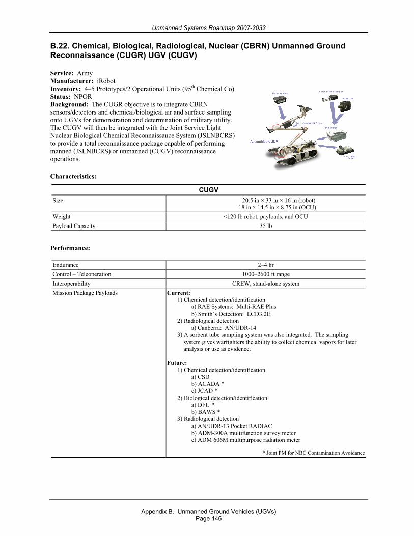
Unmanned Systems Roadmap 2007-2032
Appendix B. Unmanned Ground Vehicles (UGVs)
Page 146
B.22. Chemical, Biological, Radiological, Nuclear (CBRN) Unmanned Ground Reconnaissance (CUGR) UGV (CUGV)
Service: Army Manufacturer: iRobot Inventory: 4–5 Prototypes/2 Operational Units (95th Chemical Co) Status: NPOR Background: The CUGR objective is to integrate CBRN sensors/detectors and chemical/biological air and surface sampling onto UGVs for demonstration and determination of military utility. The CUGV will then be integrated with the Joint Service Light Nuclear Biological Chemical Reconnaissance System (JSLNBCRS) to provide a total reconnaissance package capable of performing manned (JSLNBCRS) or unmanned (CUGV) reconnaissance operations.
Characteristics:
CUGV Size 20.5 in × 33 in × 16 in (robot)
18 in × 14.5 in × 8.75 in (OCU) Weight <120 lb robot, payloads, and OCU Payload Capacity 35 lb
Performance:
Endurance 2–4 hr Control – Teleoperation 1000–2600 ft range Interoperability CREW, stand-alone system Mission Package Payloads Current:
1) Chemical detection/identification a) RAE Systems: Multi-RAE Plus b) Smith’s Detection: LCD3.2E 2) Radiological detection a) Canberra: AN/UDR-14 3) A sorbent tube sampling system was also integrated. The sampling
system gives warfighters the ability to collect chemical vapors for later analysis or use as evidence.
Future:
1) Chemical detection/identification a) CSD b) ACADA * c) JCAD * 2) Biological detection/identification a) DFU * b) BAWS * 3) Radiological detection a) AN/UDR-13 Pocket RADIAC b) ADM-300A multifunction survey meter c) ADM 606M multipurpose radiation meter
* Joint PM for NBC Contamination Avoidance
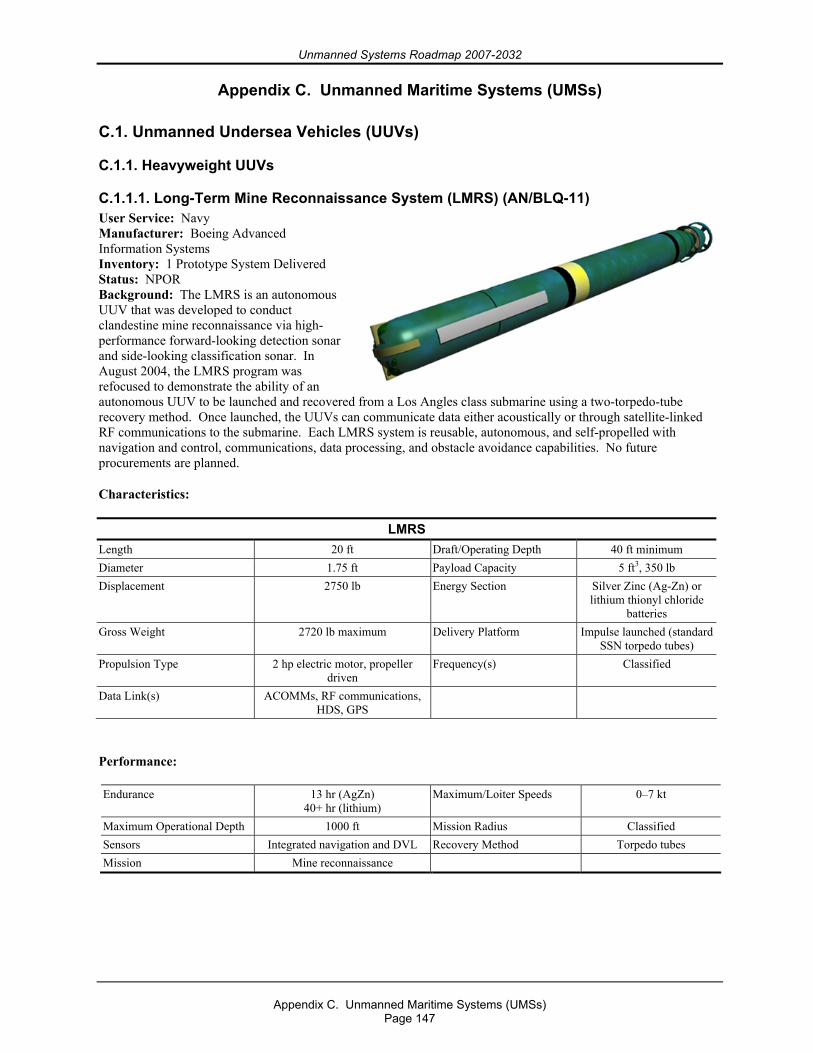
Unmanned Systems Roadmap 2007-2032
Appendix C. Unmanned Maritime Systems (UMSs)
Page 147
Appendix C. Unmanned Maritime Systems (UMSs) C.1. Unmanned Undersea Vehicles (UUVs)
C.1.1. Heavyweight UUVs
C.1.1.1. Long-Term Mine Reconnaissance System (LMRS) (AN/BLQ-11) User Service: Navy Manufacturer: Boeing Advanced Information Systems Inventory: 1 Prototype System Delivered Status: NPOR Background: The LMRS is an autonomous UUV that was developed to conduct clandestine mine reconnaissance via high-performance forward-looking detection sonar and side-looking classification sonar. In August 2004, the LMRS program was refocused to demonstrate the ability of an autonomous UUV to be launched and recovered from a Los Angles class submarine using a two-torpedo-tube recovery method. Once launched, the UUVs can communicate data either acoustically or through satellite-linked RF communications to the submarine. Each LMRS system is reusable, autonomous, and self-propelled with navigation and control, communications, data processing, and obstacle avoidance capabilities. No future procurements are planned.
Characteristics:
LMRS Length 20 ft Draft/Operating Depth 40 ft minimum Diameter 1.75 ft Payload Capacity 5 ft3, 350 lb Displacement 2750 lb Energy Section Silver Zinc (Ag-Zn) or
lithium thionyl chloride batteries
Gross Weight 2720 lb maximum Delivery Platform Impulse launched (standard SSN torpedo tubes)
Propulsion Type 2 hp electric motor, propeller driven
Frequency(s) Classified
Data Link(s) ACOMMs, RF communications, HDS, GPS
Performance:
Endurance 13 hr (AgZn) 40+ hr (lithium)
Maximum/Loiter Speeds 0–7 kt
Maximum Operational Depth 1000 ft Mission Radius Classified Sensors Integrated navigation and DVL Recovery Method Torpedo tubes Mission Mine reconnaissance
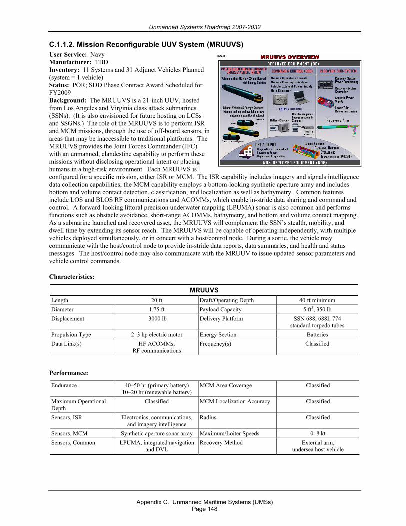
Unmanned Systems Roadmap 2007-2032
Appendix C. Unmanned Maritime Systems (UMSs)
Page 148
C.1.1.2. Mission Reconfigurable UUV System (MRUUVS) User Service: Navy Manufacturer: TBD Inventory: 11 Systems and 31 Adjunct Vehicles Planned (system = 1 vehicle) Status: POR; SDD Phase Contract Award Scheduled for FY2009 Background: The MRUUVS is a 21-inch UUV, hosted from Los Angeles and Virginia class attack submarines (SSNs). (It is also envisioned for future hosting on LCSs and SSGNs.) The role of the MRUUVS is to perform ISR and MCM missions, through the use of off-board sensors, in areas that may be inaccessible to traditional platforms. The MRUUVS provides the Joint Forces Commander (JFC) with an unmanned, clandestine capability to perform these missions without disclosing operational intent or placing humans in a high-risk environment. Each MRUUVS is configured for a specific mission, either ISR or MCM. The ISR capability includes imagery and signals intelligence data collection capabilities; the MCM capability employs a bottom-looking synthetic aperture array and includes bottom and volume contact detection, classification, and localization as well as bathymetry. Common features include LOS and BLOS RF communications and ACOMMs, which enable in-stride data sharing and command and control. A forward-looking littoral precision underwater mapping (LPUMA) sonar is also common and performs functions such as obstacle avoidance, short-range ACOMMs, bathymetry, and bottom and volume contact mapping. As a submarine launched and recovered asset, the MRUUVS will complement the SSN’s stealth, mobility, and dwell time by extending its sensor reach. The MRUUVS will be capable of operating independently, with multiple vehicles deployed simultaneously, or in concert with a host/control node. During a sortie, the vehicle may communicate with the host/control node to provide in-stride data reports, data summaries, and health and status messages. The host/control node may also communicate with the MRUUV to issue updated sensor parameters and vehicle control commands.
Characteristics:
MRUUVS Length 20 ft Draft/Operating Depth 40 ft minimum Diameter 1.75 ft Payload Capacity 5 ft3, 350 lb Displacement 3000 lb Delivery Platform SSN 688, 688I, 774
standard torpedo tubes Propulsion Type 2–3 hp electric motor Energy Section Batteries Data Link(s) HF ACOMMs,
RF communications Frequency(s) Classified
Performance:
Endurance 40–50 hr (primary battery) 10–20 hr (renewable battery)
MCM Area Coverage Classified
Maximum Operational Depth
Classified MCM Localization Accuracy Classified
Sensors, ISR Electronics, communications, and imagery intelligence
Radius Classified
Sensors, MCM Synthetic aperture sonar array Maximum/Loiter Speeds 0–8 kt Sensors, Common LPUMA, integrated navigation
and DVL Recovery Method External arm,
undersea host vehicle
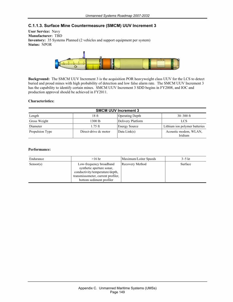
Unmanned Systems Roadmap 2007-2032
Appendix C. Unmanned Maritime Systems (UMSs)
Page 149
C.1.1.3. Surface Mine Countermeasure (SMCM) UUV Increment 3 User Service: Navy Manufacturer: TBD Inventory: 35 Systems Planned (2 vehicles and support equipment per system) Status: NPOR
Background: The SMCM UUV Increment 3 is the acquisition POR heavyweight class UUV for the LCS to detect buried and proud mines with high probability of detection and low false alarm rate. The SMCM UUV Increment 3 has the capability to identify certain mines. SMCM UUV Increment 3 SDD begins in FY2008, and IOC and production approval should be achieved in FY2011.
Characteristics:
SMCM UUV Increment 3 Length 18 ft Operating Depth 30–300 ft Gross Weight 1300 lb Delivery Platform LCS Diameter 1.75 ft Energy Source Lithium ion polymer batteriesPropulsion Type Direct-drive dc motor Data Link(s) Acoustic modem, WLAN,
Iridium
Performance:
Endurance >16 hr Maximum/Loiter Speeds 3–5 kt Sensor(s) Low-frequency broadband
synthetic aperture sonar, conductivity/temperature/depth,
transmissometer, current profiler, bottom sediment profiler
Recovery Method Surface
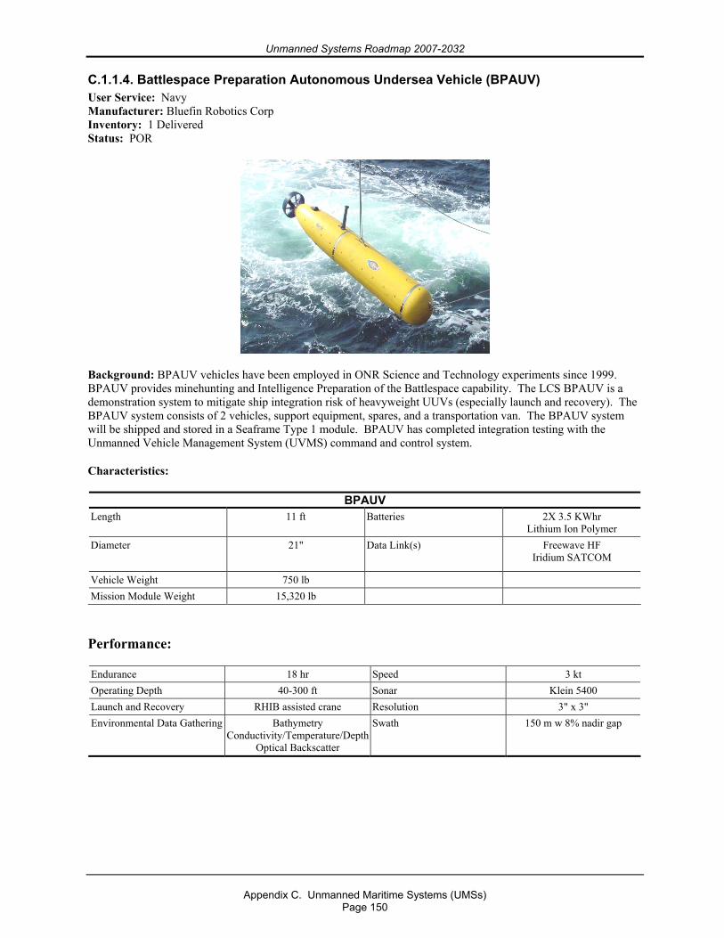
Unmanned Systems Roadmap 2007-2032
Appendix C. Unmanned Maritime Systems (UMSs)
Page 150
C.1.1.4. Battlespace Preparation Autonomous Undersea Vehicle (BPAUV) User Service: Navy Manufacturer: Bluefin Robotics Corp Inventory: 1 Delivered Status: POR
Background: BPAUV vehicles have been employed in ONR Science and Technology experiments since 1999. BPAUV provides minehunting and Intelligence Preparation of the Battlespace capability. The LCS BPAUV is a demonstration system to mitigate ship integration risk of heavyweight UUVs (especially launch and recovery). The BPAUV system consists of 2 vehicles, support equipment, spares, and a transportation van. The BPAUV system will be shipped and stored in a Seaframe Type 1 module. BPAUV has completed integration testing with the Unmanned Vehicle Management System (UVMS) command and control system.
Characteristics:
BPAUV Length 11 ft Batteries 2X 3.5 KWhr
Lithium Ion Polymer Diameter 21" Data Link(s) Freewave HF
Iridium SATCOM
Vehicle Weight 750 lb Mission Module Weight 15,320 lb
Performance:
Endurance 18 hr Speed 3 kt Operating Depth 40-300 ft Sonar Klein 5400 Launch and Recovery RHIB assisted crane Resolution 3" x 3" Environmental Data Gathering Bathymetry
Conductivity/Temperature/DepthOptical Backscatter
Swath 150 m w 8% nadir gap
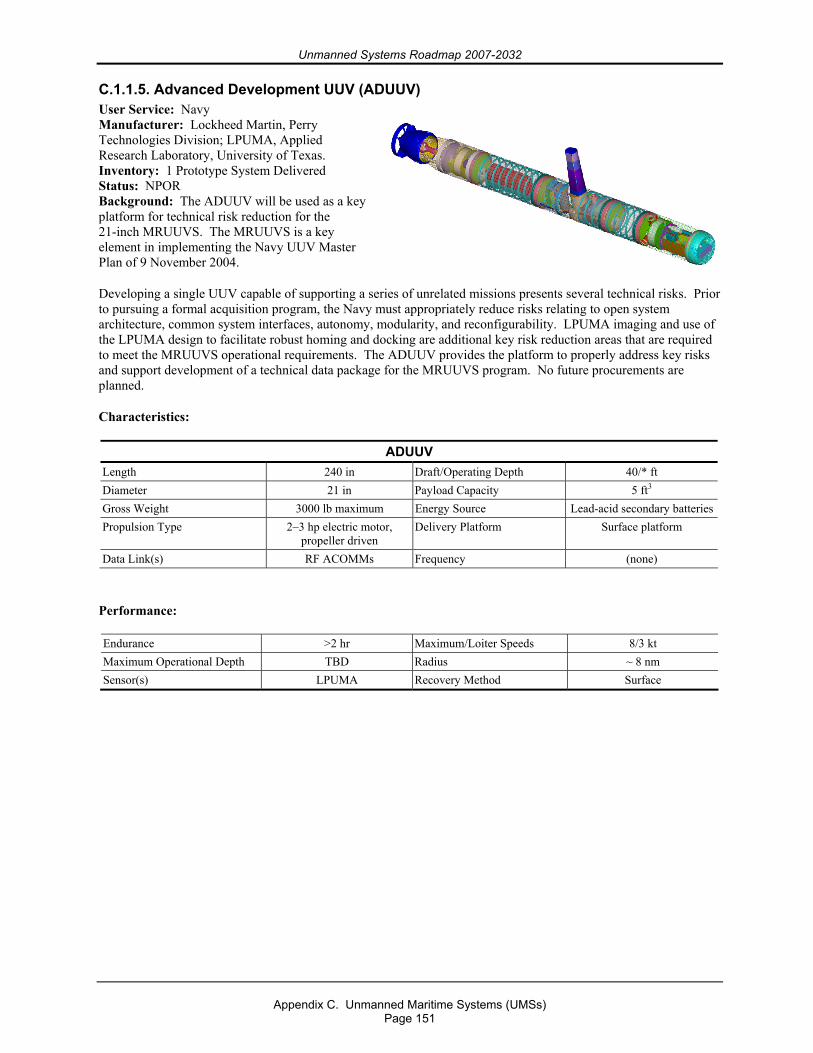
Unmanned Systems Roadmap 2007-2032
Appendix C. Unmanned Maritime Systems (UMSs)
Page 151
C.1.1.5. Advanced Development UUV (ADUUV) User Service: Navy Manufacturer: Lockheed Martin, Perry Technologies Division; LPUMA, Applied Research Laboratory, University of Texas. Inventory: 1 Prototype System Delivered Status: NPOR Background: The ADUUV will be used as a key platform for technical risk reduction for the 21-inch MRUUVS. The MRUUVS is a key element in implementing the Navy UUV Master Plan of 9 November 2004.
Developing a single UUV capable of supporting a series of unrelated missions presents several technical risks. Prior to pursuing a formal acquisition program, the Navy must appropriately reduce risks relating to open system architecture, common system interfaces, autonomy, modularity, and reconfigurability. LPUMA imaging and use of the LPUMA design to facilitate robust homing and docking are additional key risk reduction areas that are required to meet the MRUUVS operational requirements. The ADUUV provides the platform to properly address key risks and support development of a technical data package for the MRUUVS program. No future procurements are planned.
Characteristics:
ADUUV Length 240 in Draft/Operating Depth 40/* ft Diameter 21 in Payload Capacity 5 ft3 Gross Weight 3000 lb maximum Energy Source Lead-acid secondary batteriesPropulsion Type 2–3 hp electric motor,
propeller driven Delivery Platform Surface platform
Data Link(s) RF ACOMMs Frequency (none)
Performance:
Endurance >2 hr Maximum/Loiter Speeds 8/3 kt Maximum Operational Depth TBD Radius ~ 8 nm Sensor(s) LPUMA Recovery Method Surface
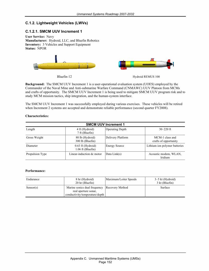
Unmanned Systems Roadmap 2007-2032
Appendix C. Unmanned Maritime Systems (UMSs)
Page 152
C.1.2. Lightweight Vehicles (LWVs)
C.1.2.1. SMCM UUV Increment 1 User Service: Navy Manufacturer: Hydroid, LLC, and Bluefin Robotics Inventory: 3 Vehicles and Support Equipment Status: NPOR
Bluefin-12
Hydroid REMUS 100
Background: The SMCM UUV Increment 1 is a user-operational evaluation system (UOES) employed by the Commander of the Naval Mine and Anti-submarine Warfare Command (CNMAWC) UUV Platoon from MCMs and crafts of opportunity. The SMCM UUV Increment 1 is being used to mitigate SMCM UUV program risk and to study MCM mission tactics, ship integration, and the human-system interface.
The SMCM UUV Increment 1 was successfully employed during various exercises. These vehicles will be retired when Increment 2 systems are accepted and demonstrate reliable performance (second quarter FY2008).
Characteristics:
SMCM UUV Increment 1 Length 4 ft (Hydroid)
7 ft (Bluefin) Operating Depth 30–220 ft
Gross Weight 80 lb (Hydroid) 300 lb (Bluefin)
Delivery Platform MCM-1 class and crafts of opportunity
Diameter 0.63 ft (Hydroid) 1.06 ft (Bluefin)
Energy Source Lithium ion polymer batteries
Propulsion Type Linear-induction dc motor Data Link(s) Acoustic modem, WLAN, Iridium
Performance:
Endurance 8 hr (Hydroid) 20 hr (Bluefin)
Maximum/Loiter Speeds 3–5 kt (Hydroid) 3 kt (Bluefin)
Sensor(s) Marine sonics dual frequency real aperture sonar,
conductivity/temperature/depth
Recovery Method Surface
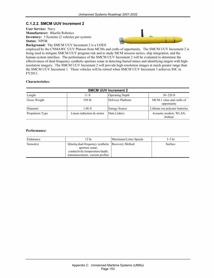
Unmanned Systems Roadmap 2007-2032
Appendix C. Unmanned Maritime Systems (UMSs)
Page 153
C.1.2.2. SMCM UUV Increment 2 User Service: Navy Manufacturer: Bluefin Robotics Inventory: 3 Systems (2 vehicles per system) Status: NPOR Background: The SMCM UUV Increment 2 is a UOES employed by the CNMAWC UUV Platoon from MCMs and crafts of opportunity. The SMCM UUV Increment 2 is being used to mitigate SMCM UUV program risk and to study MCM mission tactics, ship integration, and the human-system interface. The performance of the SMCM UUV Increment 2 will be evaluated to determine the effectiveness of dual-frequency synthetic aperture sonar at detecting buried mines and identifying targets with high-resolution imagery. The SMCM UUV Increment 2 will provide high-resolution images at much greater range than the SMCM UUV Increment 1. These vehicles will be retired when SMCM UUV Increment 3 achieves IOC in FY2011.
Characteristics:
SMCM UUV Increment 2 Length 11 ft Operating Depth 30–220 ft Gross Weight 550 lb Delivery Platform MCM-1 class and crafts of
opportunity Diameter 1.06 ft Energy Source Lithium ion polymer batteriesPropulsion Type Linear-induction dc motor Data Link(s) Acoustic modem, WLAN,
Iridium
Performance:
Endurance 12 hr Maximum/Loiter Speeds 3–5 kt Sensor(s) Qinetiq dual-frequency synthetic
aperture sonar, conductivity/temperature/depth, transmissometer, current profiler
Recovery Method Surface
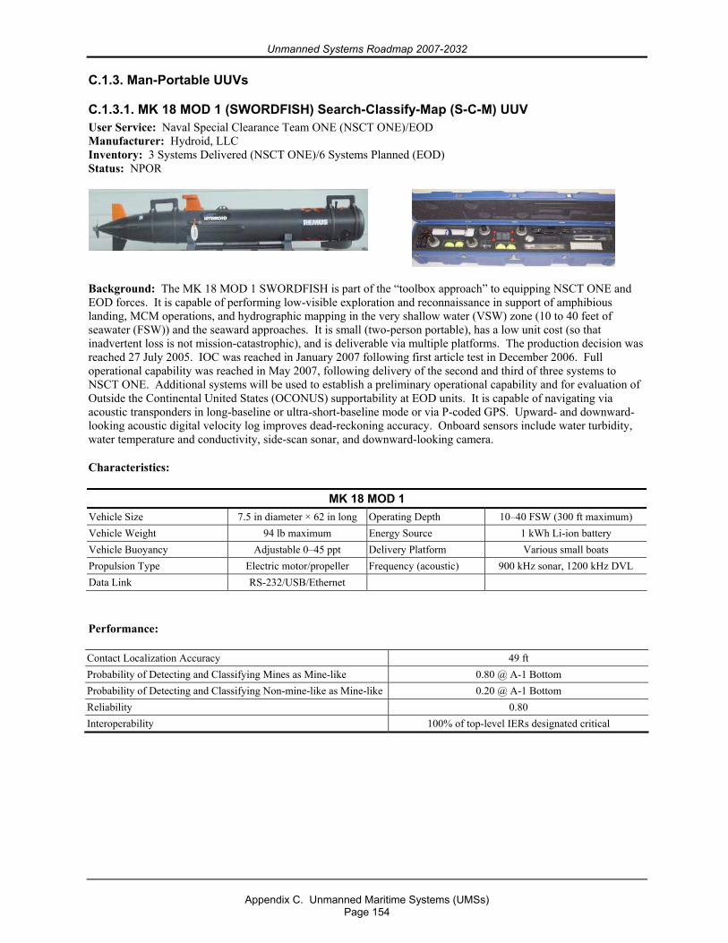
Unmanned Systems Roadmap 2007-2032
Appendix C. Unmanned Maritime Systems (UMSs)
Page 154
C.1.3. Man-Portable UUVs
C.1.3.1. MK 18 MOD 1 (SWORDFISH) Search-Classify-Map (S-C-M) UUV User Service: Naval Special Clearance Team ONE (NSCT ONE)/EOD Manufacturer: Hydroid, LLC Inventory: 3 Systems Delivered (NSCT ONE)/6 Systems Planned (EOD) Status: NPOR
Background: The MK 18 MOD 1 SWORDFISH is part of the “toolbox approach” to equipping NSCT ONE and EOD forces. It is capable of performing low-visible exploration and reconnaissance in support of amphibious landing, MCM operations, and hydrographic mapping in the very shallow water (VSW) zone (10 to 40 feet of seawater (FSW)) and the seaward approaches. It is small (two-person portable), has a low unit cost (so that inadvertent loss is not mission-catastrophic), and is deliverable via multiple platforms. The production decision was reached 27 July 2005. IOC was reached in January 2007 following first article test in December 2006. Full operational capability was reached in May 2007, following delivery of the second and third of three systems to NSCT ONE. Additional systems will be used to establish a preliminary operational capability and for evaluation of Outside the Continental United States (OCONUS) supportability at EOD units. It is capable of navigating via acoustic transponders in long-baseline or ultra-short-baseline mode or via P-coded GPS. Upward- and downward-looking acoustic digital velocity log improves dead-reckoning accuracy. Onboard sensors include water turbidity, water temperature and conductivity, side-scan sonar, and downward-looking camera.
Characteristics:
MK 18 MOD 1 Vehicle Size 7.5 in diameter × 62 in long Operating Depth 10–40 FSW (300 ft maximum) Vehicle Weight 94 lb maximum Energy Source 1 kWh Li-ion battery Vehicle Buoyancy Adjustable 0–45 ppt Delivery Platform Various small boats Propulsion Type Electric motor/propeller Frequency (acoustic) 900 kHz sonar, 1200 kHz DVL Data Link RS-232/USB/Ethernet
Performance:
Contact Localization Accuracy 49 ft Probability of Detecting and Classifying Mines as Mine-like 0.80 @ A-1 Bottom Probability of Detecting and Classifying Non-mine-like as Mine-like 0.20 @ A-1 Bottom Reliability 0.80 Interoperability 100% of top-level IERs designated critical
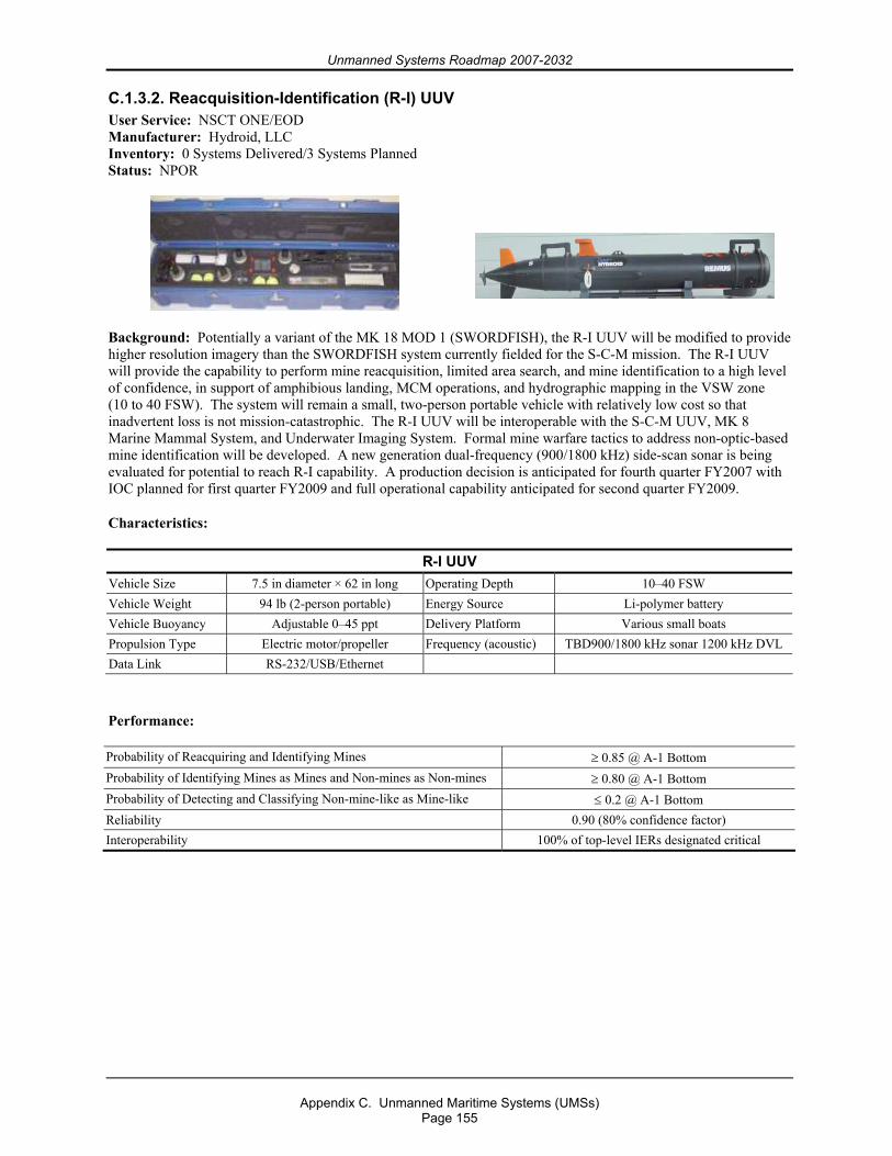
Unmanned Systems Roadmap 2007-2032
Appendix C. Unmanned Maritime Systems (UMSs)
Page 155
C.1.3.2. Reacquisition-Identification (R-I) UUV User Service: NSCT ONE/EOD Manufacturer: Hydroid, LLC Inventory: 0 Systems Delivered/3 Systems Planned Status: NPOR
Background: Potentially a variant of the MK 18 MOD 1 (SWORDFISH), the R-I UUV will be modified to provide higher resolution imagery than the SWORDFISH system currently fielded for the S-C-M mission. The R-I UUV will provide the capability to perform mine reacquisition, limited area search, and mine identification to a high level of confidence, in support of amphibious landing, MCM operations, and hydrographic mapping in the VSW zone (10 to 40 FSW). The system will remain a small, two-person portable vehicle with relatively low cost so that inadvertent loss is not mission-catastrophic. The R-I UUV will be interoperable with the S-C-M UUV, MK 8 Marine Mammal System, and Underwater Imaging System. Formal mine warfare tactics to address non-optic-based mine identification will be developed. A new generation dual-frequency (900/1800 kHz) side-scan sonar is being evaluated for potential to reach R-I capability. A production decision is anticipated for fourth quarter FY2007 with IOC planned for first quarter FY2009 and full operational capability anticipated for second quarter FY2009.
Characteristics:
R-I UUV Vehicle Size 7.5 in diameter × 62 in long Operating Depth 10–40 FSW Vehicle Weight 94 lb (2-person portable) Energy Source Li-polymer battery Vehicle Buoyancy Adjustable 0–45 ppt Delivery Platform Various small boats Propulsion Type Electric motor/propeller Frequency (acoustic) TBD900/1800 kHz sonar 1200 kHz DVL Data Link RS-232/USB/Ethernet
Performance:
Probability of Reacquiring and Identifying Mines ≥ 0.85 @ A-1 Bottom Probability of Identifying Mines as Mines and Non-mines as Non-mines ≥ 0.80 @ A-1 Bottom Probability of Detecting and Classifying Non-mine-like as Mine-like ≤ 0.2 @ A-1 Bottom Reliability 0.90 (80% confidence factor) Interoperability 100% of top-level IERs designated critical
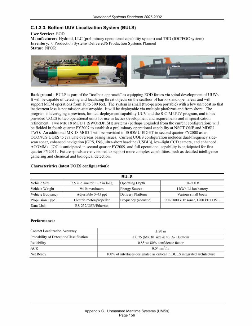
Unmanned Systems Roadmap 2007-2032
Appendix C. Unmanned Maritime Systems (UMSs)
Page 156
C.1.3.3. Bottom UUV Localization System (BULS) User Service: EOD Manufacturer: Hydroid, LLC (preliminary operational capability system) and TBD (IOC/FOC system) Inventory: 0 Production Systems Delivered/6 Production Systems Planned Status: NPOR
Background: BULS is part of the “toolbox approach” to equipping EOD forces via spiral development of UUVs. It will be capable of detecting and localizing threat objects on the seafloor of harbors and open areas and will support MCM operations from 10 to 300 feet. The system is small (two-person portable) with a low unit cost so that inadvertent loss is not mission-catastrophic. It will be deployable via multiple platforms and from shore. The program is leveraging a previous, limited-deployment capability UUV and the S-C-M UUV program, and it has provided UOES to two operational units for use in tactics development and requirements and in specification refinement. Two MK 18 MOD 1 (SWORDFISH) systems (perhaps upgraded from the current configuration) will be fielded in fourth quarter FY2007 to establish a preliminary operational capability at NSCT ONE and MDSU TWO. An additional MK 18 MOD 1 will be provided to EODMU EIGHT in second quarter FY2008 as an OCONUS UOES to evaluate overseas basing issues. Current UOES configuration includes dual-frequency side-scan sonar, enhanced navigation [GPS, INS, ultra-short baseline (USBL)], low-light CCD camera, and enhanced ACOMMs. IOC is anticipated in second quarter FY2009, and full operational capability is anticipated for first quarter FY2011. Future spirals are envisioned to support more complex capabilities, such as detailed intelligence gathering and chemical and biological detection.
Characteristics (latest UOES configuration):
BULS Vehicle Size 7.5 in diameter × 62 in long Operating Depth 10–300 ft Vehicle Weight 94 lb maximum Energy Source 1 kWh Li-ion battery Vehicle Buoyancy Adjustable 0–45 ppt Delivery Platform Various small boats Propulsion Type Electric motor/propeller Frequency (acoustic) 900/1800 kHz sonar, 1200 kHz DVL Data Link RS-232/USB/Ethernet
Performance:
Contact Localization Accuracy ≤ 20 m Probability of Detection/Classification ≥ 0.75 (MK 81 size & >), A-1 Bottom Reliability 0.85 w/ 80% confidence factor ACR 0.04 nm2/hr Net Ready 100% of interfaces designated as critical in BULS integrated architecture
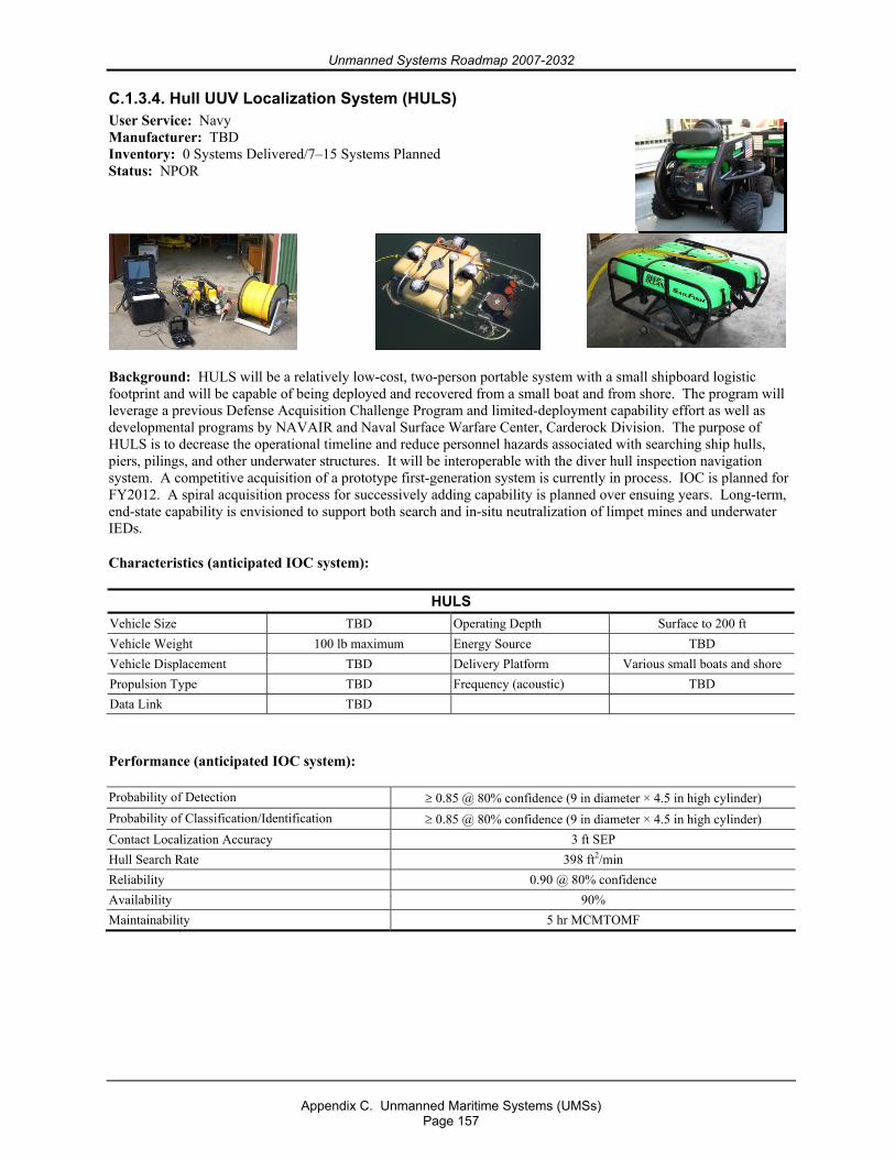
Unmanned Systems Roadmap 2007-2032
Appendix C. Unmanned Maritime Systems (UMSs)
Page 157
C.1.3.4. Hull UUV Localization System (HULS) User Service: Navy Manufacturer: TBD Inventory: 0 Systems Delivered/7–15 Systems Planned Status: NPOR
Background: HULS will be a relatively low-cost, two-person portable system with a small shipboard logistic footprint and will be capable of being deployed and recovered from a small boat and from shore. The program will leverage a previous Defense Acquisition Challenge Program and limited-deployment capability effort as well as developmental programs by NAVAIR and Naval Surface Warfare Center, Carderock Division. The purpose of HULS is to decrease the operational timeline and reduce personnel hazards associated with searching ship hulls, piers, pilings, and other underwater structures. It will be interoperable with the diver hull inspection navigation system. A competitive acquisition of a prototype first-generation system is currently in process. IOC is planned for FY2012. A spiral acquisition process for successively adding capability is planned over ensuing years. Long-term, end-state capability is envisioned to support both search and in-situ neutralization of limpet mines and underwater IEDs.
Characteristics (anticipated IOC system):
HULS Vehicle Size TBD Operating Depth Surface to 200 ft Vehicle Weight 100 lb maximum Energy Source TBD Vehicle Displacement TBD Delivery Platform Various small boats and shore Propulsion Type TBD Frequency (acoustic) TBD Data Link TBD
Performance (anticipated IOC system):
Probability of Detection ≥ 0.85 @ 80% confidence (9 in diameter × 4.5 in high cylinder) Probability of Classification/Identification ≥ 0.85 @ 80% confidence (9 in diameter × 4.5 in high cylinder) Contact Localization Accuracy 3 ft SEP Hull Search Rate 398 ft2/min Reliability 0.90 @ 80% confidence Availability 90% Maintainability 5 hr MCMTOMF
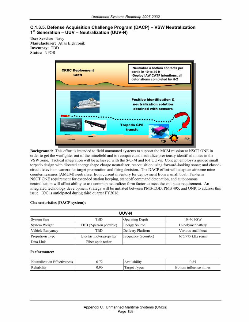
Unmanned Systems Roadmap 2007-2032
Appendix C. Unmanned Maritime Systems (UMSs)
Page 158
C.1.3.5. Defense Acquisition Challenge Program (DACP) – VSW Neutralization 1st Generation – UUV – Neutralization (UUV-N) User Service: Navy Manufacturer: Atlas Elektronik Inventory: TBD Status: NPOR
Background: This effort is intended to field unmanned systems to support the MCM mission at NSCT ONE in order to get the warfighter out of the minefield and to reacquire and neutralize previously identified mines in the VSW zone. Tactical integration will be achieved with the S-C-M and R-I UUVs. Concept employs a guided small torpedo design with directed energy shape charge neutralizer; reacquisition using forward-looking sonar; and closed-circuit television camera for target prosecution and firing decision. The DACP effort will adapt an airborne mine countermeasures (AMCM) neutralizer from current inventory for deployment from a small boat. Far-term NSCT ONE requirement for extended station keeping, standoff command detonation, and autonomous neutralization will affect ability to use common neutralizer form factor to meet the end-state requirement. An integrated technology development strategy will be initiated between PMS-EOD, PMS 495, and ONR to address this issue. IOC is anticipated during third quarter FY2016.
Characteristics (DACP system):
UUV-N System Size TBD Operating Depth 10–40 FSW System Weight TBD (2-person portable) Energy Source Li-polymer battery Vehicle Buoyancy TBD Delivery Platform Various small boat Propulsion Type Electric motor/propeller Frequency (acoustic) 675/975 kHz sonar Data Link Fiber optic tether Performance:
Neutralization Effectiveness 0.72 Availability 0.85 Reliability 0.90 Target Types Bottom influence mines
CRRC Deployment Craft
Torpedo GPS transit
Positive identification & neutralization solution obtained with sensors
•Neutralize 4 bottom contacts per sortie in 10 to 40 ft •Deploy IAW CATF intentions, all detonations completed by H-2
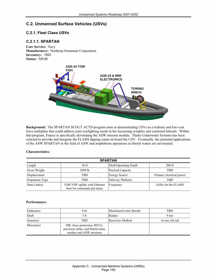
Unmanned Systems Roadmap 2007-2032
Appendix C. Unmanned Maritime Systems (UMSs)
Page 159
C.2. Unmanned Surface Vehicles (USVs)
C.2.1. Fleet Class USVs
C.2.1.1. SPARTAN User Service: Navy Manufacturer: Northrop Grumman Corporation Inventory: TBD Status: NPOR
Background: The SPARTAN SCOUT ACTD program aims at demonstrating USVs as a realistic and low-cost force multiplier that could address joint warfighting needs in the increasing complex and contested littorals. Within that program, France is specifically developing the ASW mission module. Thales Underwater Systems has been selected to provide and integrate the FLASH dipping sonar on board the USV. Eventually, the potential applications of the ASW SPARTAN in the field of ASW and amphibious operations in littoral waters are envisioned.
Characteristics:
SPARTAN Length 36 ft Draft/Operating Depth 200 ft Gross Weight 3690 lb Payload Capacity TBD Displacement TBD Energy Source Primary electrical power Propulsion Type TBD Delivery Platform TBD Data Link(s) UHF/VHF uplink with Ethernet
host for command and status Frequency 4 kHz for the FLASH
Performance:
Endurance 8 hr Maximum/Loiter Speeds TBD Draft 3 ft Radius 9 nm Sensor(s) TBD Recovery Method At sea, tilt rail Mission(s) ISR, force protection, RSTA,
precision strike, and littoral mine warfare and ASW missions
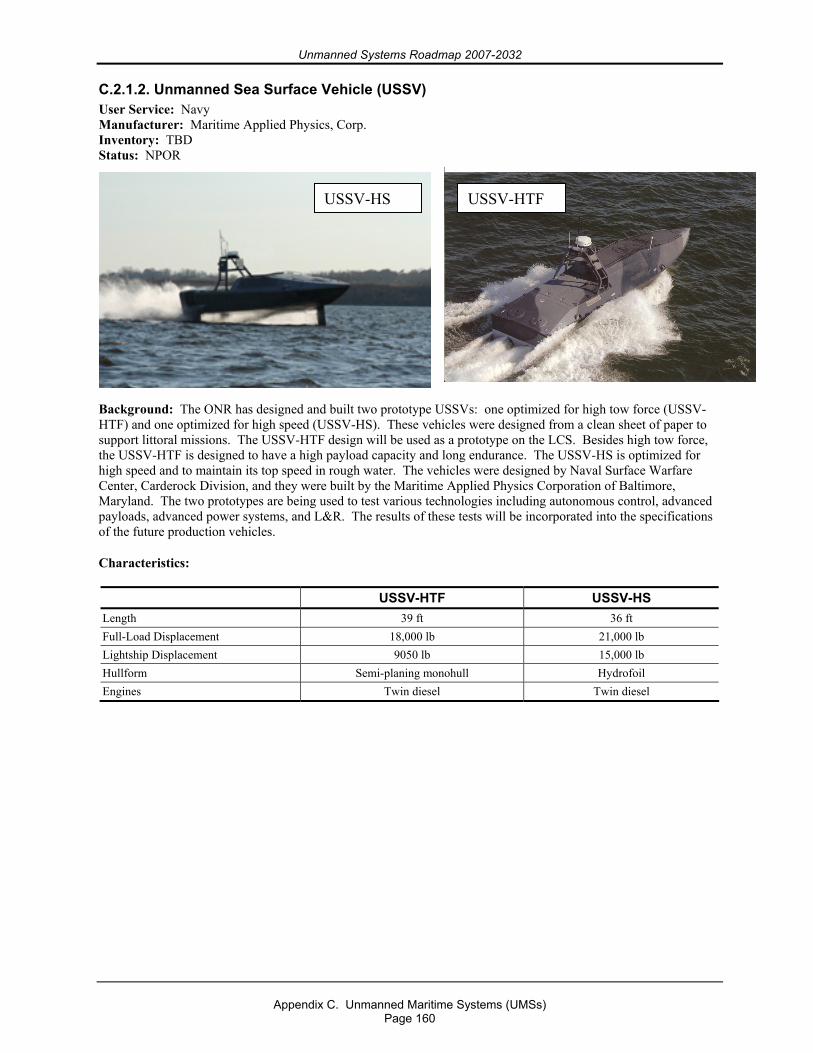
Unmanned Systems Roadmap 2007-2032
Appendix C. Unmanned Maritime Systems (UMSs)
Page 160
C.2.1.2. Unmanned Sea Surface Vehicle (USSV) User Service: Navy Manufacturer: Maritime Applied Physics, Corp. Inventory: TBD Status: NPOR
Background: The ONR has designed and built two prototype USSVs: one optimized for high tow force (USSV-HTF) and one optimized for high speed (USSV-HS). These vehicles were designed from a clean sheet of paper to support littoral missions. The USSV-HTF design will be used as a prototype on the LCS. Besides high tow force, the USSV-HTF is designed to have a high payload capacity and long endurance. The USSV-HS is optimized for high speed and to maintain its top speed in rough water. The vehicles were designed by Naval Surface Warfare Center, Carderock Division, and they were built by the Maritime Applied Physics Corporation of Baltimore, Maryland. The two prototypes are being used to test various technologies including autonomous control, advanced payloads, advanced power systems, and L&R. The results of these tests will be incorporated into the specifications of the future production vehicles.
Characteristics:
USSV-HTF USSV-HS Length 39 ft 36 ft Full-Load Displacement 18,000 lb 21,000 lb Lightship Displacement 9050 lb 15,000 lb Hullform Semi-planing monohull Hydrofoil Engines Twin diesel Twin diesel
USSV-HS USSV-HTF
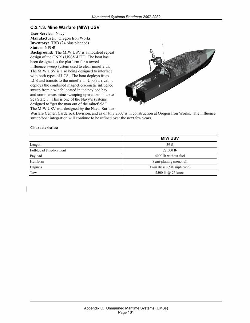
Unmanned Systems Roadmap 2007-2032
Appendix C. Unmanned Maritime Systems (UMSs)
Page 161
C.2.1.3. Mine Warfare (MIW) USV User Service: Navy Manufacturer: Oregon Iron Works Inventory: TBD (24 plus planned) Status: NPOR Background: The MIW USV is a modified repeat design of the ONR’s USSV-HTF. The boat has been designed as the platform for a towed influence sweep system used to clear minefields. The MIW USV is also being designed to interface with both types of LCS. The boat deploys from LCS and transits to the minefield. Upon arrival, it deploys the combined magnetic/acoustic influence sweep from a winch located in the payload bay, and commences mine sweeping operations in up to Sea State 3. This is one of the Navy’s systems designed to “get the man out of the minefield.” The MIW USV was designed by the Naval Surface Warfare Center, Carderock Division, and as of July 2007 is in construction at Oregon Iron Works. The influence sweep/boat integration will continue to be refined over the next few years.
Characteristics:
MIW USV Length 39 ft Full-Load Displacement 22,500 lb Payload 4000 lb without fuel Hullform Semi-planing monohull Engines Twin diesel (540 mph each) Tow 2500 lb @ 25 knots
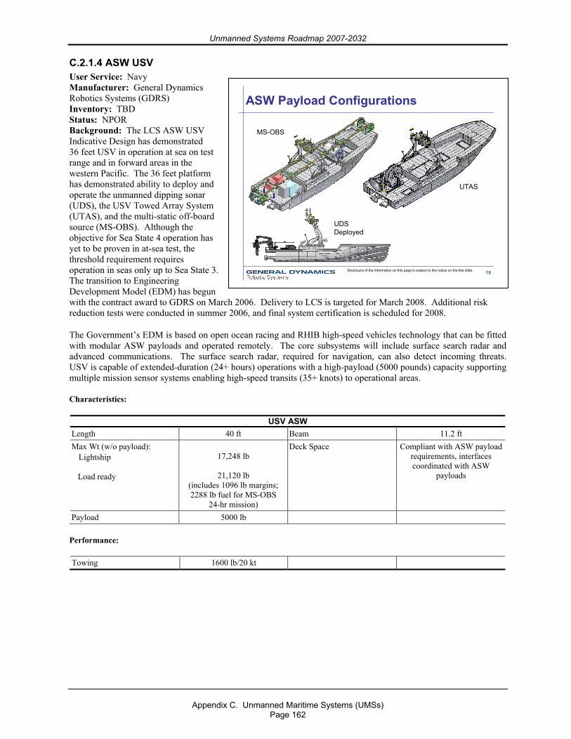
Unmanned Systems Roadmap 2007-2032
Appendix C. Unmanned Maritime Systems (UMSs)
Page 162
C.2.1.4 ASW USV User Service: Navy Manufacturer: General Dynamics Robotics Systems (GDRS) Inventory: TBD Status: NPOR Background: The LCS ASW USV Indicative Design has demonstrated 36 feet USV in operation at sea on test range and in forward areas in the western Pacific. The 36 feet platform has demonstrated ability to deploy and operate the unmanned dipping sonar (UDS), the USV Towed Array System (UTAS), and the multi-static off-board source (MS-OBS). Although the objective for Sea State 4 operation has yet to be proven in at-sea test, the threshold requirement requires operation in seas only up to Sea State 3. The transition to Engineering Development Model (EDM) has begun with the contract award to GDRS on March 2006. Delivery to LCS is targeted for March 2008. Additional risk reduction tests were conducted in summer 2006, and final system certification is scheduled for 2008.
The Government’s EDM is based on open ocean racing and RHIB high-speed vehicles technology that can be fitted with modular ASW payloads and operated remotely. The core subsystems will include surface search radar and advanced communications. The surface search radar, required for navigation, can also detect incoming threats. USV is capable of extended-duration (24+ hours) operations with a high-payload (5000 pounds) capacity supporting multiple mission sensor systems enabling high-speed transits (35+ knots) to operational areas.
Characteristics:
USV ASW Length 40 ft Beam 11.2 ft Max Wt (w/o payload): Lightship Load ready
17,248 lb
21,120 lb
(includes 1096 lb margins; 2288 lb fuel for MS-OBS
24-hr mission)
Deck Space Compliant with ASW payload requirements, interfaces coordinated with ASW
payloads
Payload 5000 lb
Performance:
Towing 1600 lb/20 kt
18Disclosure of the information on this page is subject to the notice on the title slide.
ASW Payload Configurations
MS-OBS
UTAS
UDSDeployed
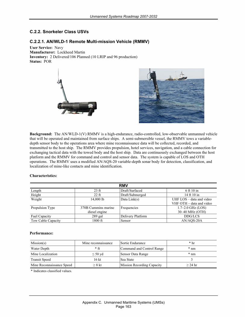
Unmanned Systems Roadmap 2007-2032
Appendix C. Unmanned Maritime Systems (UMSs)
Page 163
C.2.2. Snorkeler Class USVs
C.2.2.1. AN/WLD-1 Remote Multi-mission Vehicle (RMMV) User Service: Navy Manufacturer: Lockheed Martin Inventory: 2 Delivered/106 Planned (10 LRIP and 96 production) Status: POR
Background: The AN/WLD-1(V) RMMV is a high-endurance, radio-controlled, low-observable unmanned vehicle that will be operated and maintained from surface ships. A semi-submersible vessel, the RMMV tows a variable-depth sensor body to the operations area where mine reconnaissance data will be collected, recorded, and transmitted to the host ship. The RMMV provides propulsion, hotel services, navigation, and a cable connection for exchanging tactical data with the towed body and the host ship. Data are continuously exchanged between the host platform and the RMMV for command and control and sensor data. The system is capable of LOS and OTH operations. The RMMV uses a modified AN/AQS-20 variable-depth sonar body for detection, classification, and localization of mine-like contacts and mine identification.
Characteristics:
RMV Length 23 ft Draft/Surfaced 6 ft 10 in Height 22 ft Draft/Submerged 14 ft 10 in Weight 14,000 lb Data Link(s) UHF LOS – data and video
VHF OTH – data and video Propulsion Type 370B Cummins marine
diesel engine Frequencies 1.7–2.0 GHz (LOS)
30–40 MHz (OTH) Fuel Capacity 289 gal Delivery Platform DDG/LCS Tow Cable Capacity 1800 ft Sensor AN/AQS-20A
Performance:
Mission(s) Mine reconnaissance Sortie Endurance * hr Water Depth * ft Command and Control Range * nm Mine Localization ≤ 50 yd Sensor Data Range * nm Transit Speed 16 kt Sea State 3 Mine Reconnaissance Speed ≥ 8 kt Mission Recording Capacity ≥ 24 hr * Indicates classified values.
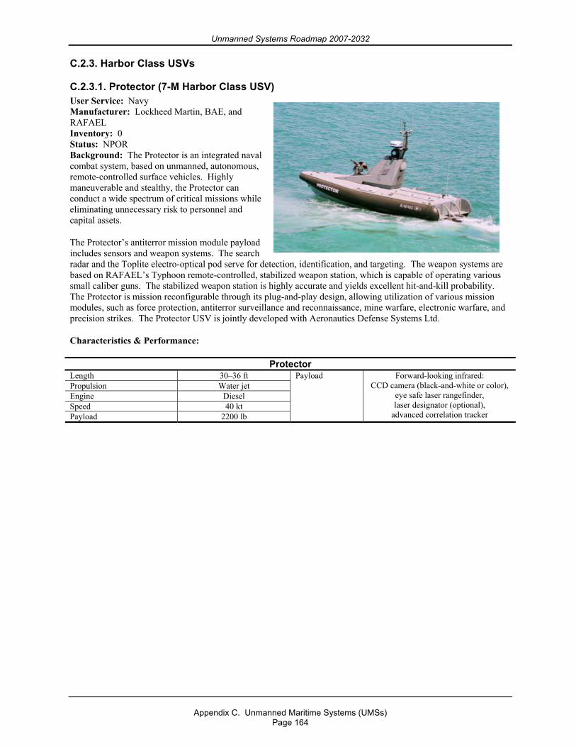
Unmanned Systems Roadmap 2007-2032
Appendix C. Unmanned Maritime Systems (UMSs)
Page 164
C.2.3. Harbor Class USVs
C.2.3.1. Protector (7-M Harbor Class USV) User Service: Navy Manufacturer: Lockheed Martin, BAE, and RAFAEL Inventory: 0 Status: NPOR Background: The Protector is an integrated naval combat system, based on unmanned, autonomous, remote-controlled surface vehicles. Highly maneuverable and stealthy, the Protector can conduct a wide spectrum of critical missions while eliminating unnecessary risk to personnel and capital assets.
The Protector’s antiterror mission module payload includes sensors and weapon systems. The search radar and the Toplite electro-optical pod serve for detection, identification, and targeting. The weapon systems are based on RAFAEL’s Typhoon remote-controlled, stabilized weapon station, which is capable of operating various small caliber guns. The stabilized weapon station is highly accurate and yields excellent hit-and-kill probability. The Protector is mission reconfigurable through its plug-and-play design, allowing utilization of various mission modules, such as force protection, antiterror surveillance and reconnaissance, mine warfare, electronic warfare, and precision strikes. The Protector USV is jointly developed with Aeronautics Defense Systems Ltd.
Characteristics & Performance:
Protector Length 30–36 ft Propulsion Water jet Engine Diesel Speed 40 kt Payload 2200 lb
Payload Forward-looking infrared: CCD camera (black-and-white or color),
eye safe laser rangefinder, laser designator (optional),
advanced correlation tracker
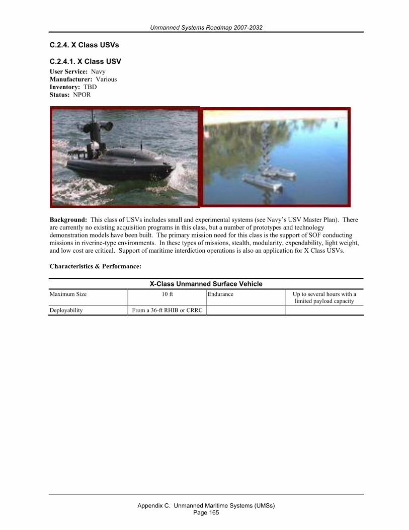
Unmanned Systems Roadmap 2007-2032
Appendix C. Unmanned Maritime Systems (UMSs)
Page 165
C.2.4. X Class USVs
C.2.4.1. X Class USV User Service: Navy Manufacturer: Various Inventory: TBD Status: NPOR
Background: This class of USVs includes small and experimental systems (see Navy’s USV Master Plan). There are currently no existing acquisition programs in this class, but a number of prototypes and technology demonstration models have been built. The primary mission need for this class is the support of SOF conducting missions in riverine-type environments. In these types of missions, stealth, modularity, expendability, light weight, and low cost are critical. Support of maritime interdiction operations is also an application for X Class USVs.
Characteristics & Performance:
X-Class Unmanned Surface Vehicle Maximum Size 10 ft Endurance Up to several hours with a
limited payload capacity Deployability From a 36-ft RHIB or CRRC
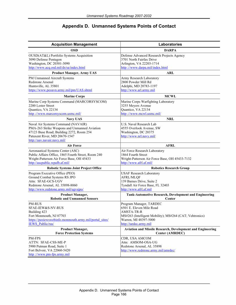
Unmanned Systems Roadmap 2007-2032
Appendix D. Unmanned Systems Points of Contact
Page 166
Appendix D. Unmanned Systems Points of Contact
Acquisition Management Laboratories OSD DARPA
OUSD(AT&L) Portfolio Systems Acquisition 3090 Defense Pentagon Washington, DC 20301-3090 http://www.acq.osd.mil/ds/sa/index.html
Defense Advanced Research Projects Agency 3701 North Fairfax Drive Arlington, VA 22203-1714 http ://www.darpa.mil/index.html
Product Manager, Army UAS ARL PM Unmanned Aircraft Systems Redstone Arsenal Huntsville, AL 35801 https://www.peoavn.army.mil/pm/UAS.shtml
Army Research Laboratory 2800 Powder Mill Rd Adelphi, MD 20783-1197 http://www.arl.army.mil
Marine Corps MCWL Marine Corp Systems Command (MARCORSYSCOM) 2200 Lester Street Quantico, VA 22134 http ://www.marcorsyscom.usmc.mil/
Marine Corps Warfighting Laboratory 3255 Meyers Avenue Quantico, VA 22134 http ://www.mcwl.usmc.mil/
Navy UAS NRL Naval Air Systems Command (NAVAIR) PMA-263 Strike Weapons and Unmanned Aviation 47123 Buse Road; Building 2272, Room 254 Patuxent River, MD 20670-1547 http://uav.navair.navy.mil/
U.S. Naval Research Lab 4555 Overlook Avenue, SW Washington, DC 20375 http://www.nrl.navy.mil/
Air Force AFRL Aeronautical Systems Center (ASC) Public Affairs Office, 1865 Fourth Street, Room 240 Wright-Patterson Air Force Base, OH 45433 http://ascpublic.wpafb.af.mil/
Air Force Research Laboratory 1864 Fourth Street Wright-Patterson Air Force Base, OH 45433-7132 http://www.afrl.af.mil/
Robotic Systems Joint Project Office Robotics Research Group Program Executive Office (PEO) Ground Combat Systems RS JPO Attn: SFAE-GCS-UGV Redstone Arsenal, AL 35898-8060 http://www.redstone.army.mil/ugvsjpo/
USAF Research Laboratory AFRL/MLQF 139 Barnes Drive, Suite 2 Tyndall Air Force Base, FL 32403 http://www.afrl.af.mil
Product Manager, Robotic and Unmanned Sensors
Tank-Automotive Research, Development and Engineering Center
PM-RUS SFAE-IEW&S-NV-RUS Building 423 Fort Monmouth, NJ 07703 https://peoiewswebinfo.monmouth.army.mil/portal_sites/ IEWS_Public/rus/
Program Manager, TARDEC 6501 E. Eleven Mile Road AMSTA-TR-R MS#263 (Intelligent Mobility); MS#264 (CAT; Vehtronics) Warren, MI 48397-5000 http://tardec.army.mil
Product Manager, Force Protection Systems
Aviation and Missile Research, Development and Engineering Center (AMRDEC)
PM-FPS ATTN: SFAE-CSS-ME-P 5900 Putman Road, Suite 1 Fort Belvoir, VA 22060-5420 http ://www.pm-fps.army.mil
CDR, USA AMCOM Attn: AMSOM-OSA-UG Redstone Arsenal, AL 35898 http://www.redstone.army.mil/amrdec/
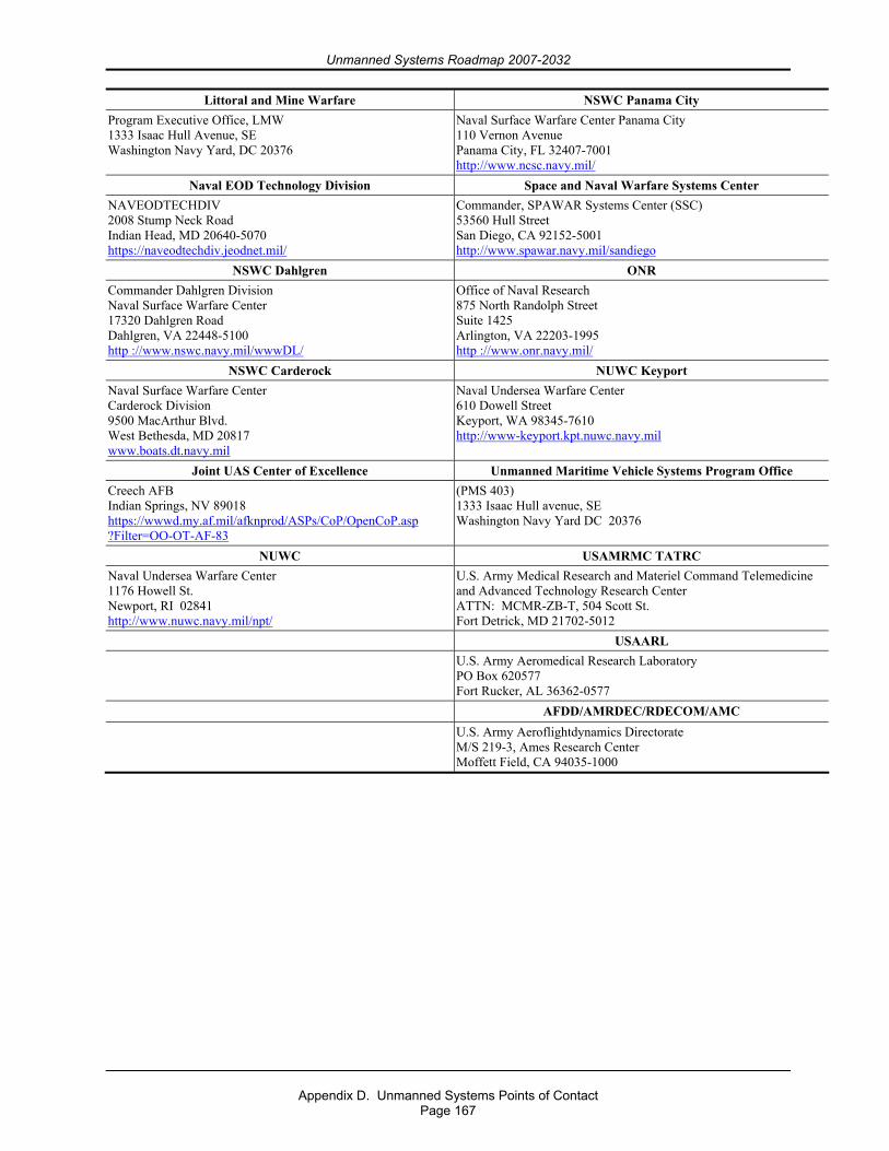
Unmanned Systems Roadmap 2007-2032
Appendix D. Unmanned Systems Points of Contact
Page 167
Littoral and Mine Warfare NSWC Panama City Program Executive Office, LMW 1333 Isaac Hull Avenue, SE Washington Navy Yard, DC 20376
Naval Surface Warfare Center Panama City 110 Vernon Avenue Panama City, FL 32407-7001 http://www.ncsc.navy.mil/
Naval EOD Technology Division Space and Naval Warfare Systems Center NAVEODTECHDIV 2008 Stump Neck Road Indian Head, MD 20640-5070 https://naveodtechdiv.jeodnet.mil/
Commander, SPAWAR Systems Center (SSC) 53560 Hull Street San Diego, CA 92152-5001 http://www.spawar.navy.mil/sandiego
NSWC Dahlgren ONR Commander Dahlgren Division Naval Surface Warfare Center 17320 Dahlgren Road Dahlgren, VA 22448-5100 http ://www.nswc.navy.mil/wwwDL/
Office of Naval Research 875 North Randolph Street Suite 1425 Arlington, VA 22203-1995 http ://www.onr.navy.mil/
NSWC Carderock NUWC Keyport Naval Surface Warfare Center Carderock Division 9500 MacArthur Blvd. West Bethesda, MD 20817 www.boats.dt.navy.mil
Naval Undersea Warfare Center 610 Dowell Street Keyport, WA 98345-7610 http://www-keyport.kpt.nuwc.navy.mil
Joint UAS Center of Excellence Unmanned Maritime Vehicle Systems Program Office Creech AFB Indian Springs, NV 89018 https://wwwd.my.af.mil/afknprod/ASPs/CoP/OpenCoP.asp ?Filter=OO-OT-AF-83
(PMS 403) 1333 Isaac Hull avenue, SE Washington Navy Yard DC 20376
NUWC USAMRMC TATRC Naval Undersea Warfare Center 1176 Howell St. Newport, RI 02841 http://www.nuwc.navy.mil/npt/
U.S. Army Medical Research and Materiel Command Telemedicine and Advanced Technology Research Center ATTN: MCMR-ZB-T, 504 Scott St. Fort Detrick, MD 21702-5012
USAARL U.S. Army Aeromedical Research Laboratory
PO Box 620577 Fort Rucker, AL 36362-0577
AFDD/AMRDEC/RDECOM/AMC U.S. Army Aeroflightdynamics Directorate
M/S 219-3, Ames Research Center Moffett Field, CA 94035-1000
Unmanned Systems Roadmap 2007-2032
Appendix E. Mission Area Definitions
Page 168
Appendix E. Mission Area Definitions
Air Warfare – (AFDD 2-1) Military operations conducted by airplanes, helicopters, or other aircraft against aircraft or targets on the ground and in the water. Air warfare is a set of offensive and defensive aerial operations carried out using the Air Force with the intention of imposing one’s will on the adversary by achieving a sufficient degree of aerial superiority.
Battle Management
Management – The process of directing all or part of an organization through the deployment and manipulation of resources (human, financial, material, intellectual, or intangible).
Battle – A set of related engagements that last longer and involve larger forces than an engagement. Battles can affect the course of a campaign or major operation. An engagement is a small tactical conflict between opposing maneuver forces, usually conducted at brigade level and below. Engagements are usually short: minutes, hours, or a day (FM 3-0).
CASEVAC (Casualty Evacuation) – (JP 1-02) The unregulated movement of casualties in nondedicated combat vehicles or aircraft that can include movement both to and between medical treatment facilities.
Chemical, Biological, Radiological, Nuclear, Explosive (CBRNE) Reconnaissance
Reconnaissance – (JP1-02) A mission undertaken to obtain, by visual observation or other detection methods, information about the activities and resources of an enemy or potential enemy or to secure data concerning the meteorological, hydrographic, or geographic characteristics of a particular area (in this case, chemical or biological agents).
Combat Search and Rescue – (JP1-02) A specific task performed by rescue forces to effect the recovery of distressed personnel during war or military operations other than war.
Communication/Navigation Network Node (CN3)
Communications Network – (JP1-02) An organization of stations capable of intercommunications, but not necessarily on the same channel.
Node – (JP1-02) In communications and computer systems, the physical location that provides terminating, switching, and gateway access services to support information exchange. (JP6-0)
Communications/Data Relay – The ability to increase the time systems/personnel are in communication with higher echelons, each other, etc., and to improve the amount of data that can be transferred.
Unmanned Systems Roadmap 2007-2032
Appendix E. Mission Area Definitions
Page 169
Counter Camouflage/Concealment/Deception – (JP1-02)
Counter(measures) – The form of military science that, by the employment of devices and/or techniques, has as its objective the impairment of the operational effectiveness of enemy activity.
Camouflage – The use of natural or artificial material on personnel, objects, or tactical positions with the aim of confusing, misleading, or evading the enemy.
Concealment – The protection from observation or surveillance.
Counterdeception – Efforts to negate, neutralize, diminish the effects of, or gain advantage from, a foreign deception operation. Counterdeception does not include the intelligence function of identifying foreign deception operations.
Covert Sensor Insertion – (JP1-02) An operation (in this case, sensor insertion) that is planned and executed to conceal the identity of or permit plausible denial by the sponsor. A covert operation differs from a clandestine operation in that emphasis is placed on concealment of sponsor identity rather than on concealment of the operation.
Decoy/Pathfinder – (JP1-02)
Decoy – An imitation in any sense of a person, object, or phenomenon that is intended to deceive enemy surveillance devices or mislead enemy evaluation.
Pathfinder – 1. Experienced aircraft crews who lead a formation to the drop zone, release point, or target. 2. Teams dropped or air landed at an objective to establish and operate navigational aids for the purpose of guiding aircraft to drop and landing zones. 3. A radar device used for navigating or homing to an objective when visibility precludes accurate visual navigation. 4. Teams air delivered into enemy territory for the purpose of determining the best approach and withdrawal lanes, landing zones, and sites for helicopter-borne forces.
Electronic Warfare – (JP1-02) Any military action involving the use of electromagnetic and directed energy to control the electromagnetic spectrum or to attack the enemy. The three major subdivisions within electronic warfare are electronic attack, electronic protection, and electronic warfare support.
Electronic Attack – The division of electronic warfare involving the use of electromagnetic energy, directed energy, or antiradiation weapons to attack personnel, facilities, or equipment with the intent of degrading, neutralizing, or destroying enemy combat capability. Electronic attack is considered a form of fires.
Electronic Protection – The division of electronic warfare involving passive and active means taken to protect personnel, facilities, and equipment from any effects of friendly or enemy employment of electronic warfare that degrade, neutralize, or destroy friendly combat capability.
Electronic Warfare Support – The division of electronic warfare involving actions tasked by, or under direct control of, an operational commander to search for, intercept,
Unmanned Systems Roadmap 2007-2032
Appendix E. Mission Area Definitions
Page 170
identify, and locate or localize sources of intentional and unintentional radiated electromagnetic energy for the purpose of immediate threat recognition, targeting, planning, and conduct of future operations. Thus, electronic warfare support provides information required for decisions involving electronic warfare operations and other tactical actions such as threat avoidance, targeting, and homing.
EOD/IED Defeat
Explosive Ordnance Disposal (EOD) – (JP1-02) The detection, identification, on-site evaluation, rendering safe, recovery, and final disposal of unexploded explosive ordnance. It may also include explosive ordnance that has become hazardous by damage or deterioration.
Improvised Explosive Device (IED) – (JP1-02) A device placed or fabricated in an improvised manner incorporating destructive, lethal, noxious, pyrotechnic, or incendiary chemicals and designed to destroy, incapacitate, harass, or distract. It may incorporate military stores, but is normally devised from nonmilitary components. (JP3-07.2)
Firefighting – The act of carrying out procedures to extinguish an unwanted fire. Firefighting may require evacuation (removal of personnel from a dangerous area, in particular, a hazardous material incident, burning building, or other emergency) and recovery (location and removal of deceased victims). Also, the time needed for a firefighter to spend in rehabilitation before being considered ready to continue working the incident.
Force Protection – (JP1-02) Actions taken to prevent or mitigate hostile actions against Department of Defense personnel (to include family members), resources, facilities, and critical information. Force protection does not include actions to defeat the enemy or protect against accidents, weather, or disease. (JP3-07.2)
GPS Pseudolite – Ground-based transmitters that mimic a global positioning system satellite. GPS pseudolite is intended to improve geometric solutions in a local area and could be used around airports for precision instrument landings.
Information Warfare (Operations) – (JP1-02) The integrated employment of the core capabilities of electronic warfare, computer network operations, psychological operations, military deception, and operations security, in concert with specified supporting and related capabilities, to influence, disrupt, corrupt, or usurp adversarial human and automated decision making while protecting friendly forces.
Intelligence, Surveillance, and Reconnaissance (ISR) – (JP1-02) An activity that synchronizes and integrates the planning and operation of sensors, assets, and processing, exploitation, and dissemination systems in direct support of current and future operations. This activity is an integrated intelligence and operations function. (JP2-01)
Littoral Warfare – (JP1-02) A battlespace that is composed of two segments: Seaward, the area from the open ocean to the shore, which must be controlled to support operations ashore, and landward, the area inland from the shore that can be supported and defended directly from the sea.
Unmanned Systems Roadmap 2007-2032
Appendix E. Mission Area Definitions
Page 171
Logistics – The science of planning and carrying out the movement and maintenance of forces. In its most comprehensive sense, logistics includes the aspects of military operations that deal with the following:
Design and development, acquisition, storage, movement, distribution, maintenance, evacuation, and disposition of materiel;
Movement, evacuation, and hospitalization of personnel; Acquisition or construction, maintenance, operation, and disposition of facilities; and Acquisition or furnishing of services. (JP 1-02)
Medical logistics is a subset of the above definition, i.e., the science of planning and carrying out the movement and maintenance of medical forces. In its most comprehensive sense, medical logistics includes the aspects of military operations that deal with the following:
Design and development, acquisition, storage, movement, distribution, maintenance, evacuation, and disposition of medical materiel;
Movement, evacuation, and hospitalization of personnel; Acquisition or construction, maintenance, operation, and disposition of medical facilities;
and Acquisition or furnishing of medical services.
MEDEVAC – Medical evacuation in dedicated combat medical evacuation vehicles or aircraft. (JP 1-02)
Meteorological/Oceanography/Digital Mapping
Meteorological and Oceanographic – (JP1-02) A phrase used to convey all meteorological (weather) and oceanographic (physical oceanography) factors as provided by Military Department components. These factors include the whole range of atmospheric and oceanographic phenomena, from the sub-bottom of the earth’s oceans up to the space environment (space weather). (JP3-59)
Mapping – The function of creating visualization tools for spatial data. Current trends are moving away from analog methods of mapmaking toward the creation of increasingly dynamic, interactive maps that can be manipulated digitally.
Mine Detection, Countermeasures, and Destruction
Mine Detection – The ability to detect various types of explosives, distinguish them from background clutter, and detect mines regardless of shape, depth of burial, or type of casing. Mine detection is to be accomplished at a good standoff distance with a detection probability of almost 100% and a near-zero false-negative alarm rate, at an acceptable operational speed, and preferably with a viewing (imaging) capability.
Countermeasures – (JP1-02) All methods for preventing or reducing damage or danger from mines. (JP3-15)
Unmanned Systems Roadmap 2007-2032
Appendix E. Mission Area Definitions
Page 172
Obstacle (Placement) – (JP1-02) (Placement of) Any obstruction designed or employed to disrupt, fix, turn, or block the movement of an opposing force and to impose additional losses in personnel, time, and equipment on the opposing force. Obstacles can be natural, manmade, or a combination of both. (JP3-15)
Precision Target Location and Designation
Precision –The closeness with which repeated measurements made under similar conditions are grouped together.
Target Location – A location defined by coordinates. With advancements in systems, the traditional role (previously used only as a “cueing” device to get weapon systems into the proper area) of the coordinate has changed. Targets that are not precisely and accurately located mean higher warhead and sortie costs. While cartographic techniques of deriving coordinates are suitable for supporting the “cueing” function, they cannot provide the precise coordinates needed for many of the newer weapon systems.
Target Designation – The indication of a target for destruction.
Psychological Operations – (JP1-02) Planned operations to convey selected information and indicators to foreign audiences to influence their emotions, motives, objective reasoning, and ultimately the behavior of foreign governments, organizations, groups, and individuals. The purpose of psychological operations is to induce or reinforce foreign attitudes and behavior favorable to the originator’s objectives.
Reconnaissance – (JP1-02) A mission undertaken to obtain, by visual observation or other detection methods, information about the activities and resources of an enemy or potential enemy or to secure data concerning the meteorological, hydrographic, or geographic characteristics of a particular area. Also called RECON.
Seabasing – (JP1-02) In amphibious operations, a technique of basing certain landing force support functions aboard ship to decrease a shore-based presence.
Signals Intelligence – (JP1-02) 1. A category of intelligence comprising either individually or in combination all communications intelligence, electronic intelligence, and foreign instrumentation signals intelligence, however transmitted. 2. Intelligence derived from communications, electronic signals, and foreign instrumentation signals.
Strike – (JP1-02) An attack that is intended to inflict damage on, seize, or destroy an objective.
Special Operations Forces (SOF) (Support to) – (JP1-02) (Support to) Operations conducted in hostile, denied, or politically sensitive environments to achieve military, diplomatic, informational, and/or economic objectives and employing military capabilities for which there is no broad conventional force requirement. These operations often require covert, clandestine, or low-visibility capabilities. Special operations are applicable across the range of military operations. They can be conducted independently or in conjunction with operations of conventional forces or other Government agencies and may include operations through, with, or by indigenous or surrogate forces. Special operations differ from conventional operations in degree of physical and political risk, operational techniques, mode of employment, independence
Unmanned Systems Roadmap 2007-2032
Appendix E. Mission Area Definitions
Page 173
from friendly support, and dependence on detailed operational intelligence and indigenous assets.
Resupply – The act of replenishing stocks in order to maintain required levels of supply.
Surface Warfare – (JP1-02) Maritime warfare in which operations are conducted to destroy or neutralize enemy naval surface forces and merchant vessels. (JP3-33)
Target Designation – (JP3-60) Effective targeting is the ability to generate the type and extent of effects necessary to achieve the commander’s objectives. Identification of centers of gravity (COGs) and decisive points (DPs) is essential to achieving the commander’s objectives in accordance with guidance and intent through Joint Forces efforts. There normally will be more DPs in an operational area than the commander can control, destroy, or neutralize with available resources. Accordingly, planners must analyze potential DPs and determine which points enable eventual attack of the adversary’s COGs.
Center of Gravity (COG) – The characteristics, capabilities, or sources of power from which a military force derives its freedom of action, physical strength, or will to fight.
Decisive Point (DP) – A geographic place, specific key event, or critical system or function that allows commanders to gain a marked advantage over an enemy and greatly influence the outcome of an attack.
Targeting – (JP1-02) (DoD) The process of selecting and prioritizing targets and matching the appropriate response to them while taking account of operational requirements and capabilities.
Target Services (Acquisition) – (JP1-02) The detection, identification, and location of a target in sufficient detail to permit the effective employment of weapons.
Also Target Analysis – An examination of potential targets to determine military importance, priority of attack, and weapons required to obtain a desired level of damage or casualties.
Undersea Warfare – (JP1-02) (DoD) Operations conducted to establish battlespace dominance in the underwater environment. Such dominance permits friendly forces to accomplish the full range of potential missions and denies an opposing force the effective use of underwater systems and weapons. It includes offensive and defensive submarine, antisubmarine, and mine warfare operations.
Weaponization – The process of using something as, making something into, or causing something to change into a weapon or a potential weapon.
Weapons Delivery – The process of transporting a weapon. A weapon is a tool that is intended to or is used to injure, kill, or incapacitate a person; damage or destroy property; or otherwise render resources nonfunctional or unavailable. Weapons may be used to attack and defend and consequently also to threaten or protect.