Embed Size (px)
Citation preview

1F- Engine
F- Engine
Copyright by Hyundai Motor Company. All rights reserved.

2F- Engine
Items F-engine
General
Displacement ( ) 3,933
Bore X Stroke ( ) 103 x 118
Cylinder type I4
Compression ratio 17
Maximum power (ps/rpm) 150 / 2500
Maximum torque (kg·m/rpm) 59 / 1400~1800
Total weight ( kg ) 440
Material of cylinder head and block CGI (Compacted Graphite Iron)
VALVE No. / CAM type 4 / OHC
Turbo type WGT
Fuel injection system Common rail
Emission system EGR+PMC
Electrical system Alternator (Truck/Bus) 70AH / 80AH
Starter 5.5 KW
Engine oil capacity (ℓ) (Oil pan/ total quantity ) 13.5/15
Specifications

3F- Engine
30
50
70
90
110
130
150
170
400 800 1200 1600 2000 2400 2800
Engine Speed (RPM)
Po
we
r (PS
)
To
rque
(kgm)
35
45
55
6559kgm
150PS
Main feature
Features: - 4 valves OHC
- Common rail (1600bar)
- Serpentine belt and Auto-tensioner
- CGI (Compacted Graphite Iron) cylinder block
- Compacted cylinder head (In-Manifold integrated)
- Improve fuel consumption
- Cope with emission regulation (Euro 4)
- Reduce the noise (various step injection)
- Oil replacement period expended

4F- Engine
Rear Gear-train
CGI cylinder block
2 generation common rail
Cylinder head integrated with intake manifold
Double wave gallery piston
Serpentine belt
WGT Turbo charger
Water cooled EGR
Plastic rocker cover
4 valves OHC type
Main feature
PMC

5F- Engine
Position
Bolt
Torque / Angle (Kgm)
Part name No. P/No.
Cylinder block BOLT-MAIN CAP 6 M21114- 52000 17+110˚
Cylinder head BOLT-CAM CAP 7 M22155- 52000 2+90˚
Cylinder block BOLT-CYLINDER HEAD 6 M22321- 52000 10+90˚+90˚
Crankshaft BOLT-CRANKSHAFT PULLEY 6 M23127- 48000 10+80˚
Crankshaft BOLT-FLYWHEEL (M/T) 8 M23231- 52000 14+120˚
Connecting road BOLT-CONNECTING ROD 2 M23513- 52000 4+100˚
Cylinder head BOLT-FLANGE (ROCKER SHAFT) 2 M22229- 52000 2.5+90˚
* Tightening Torque
Main feature

6F- Engine
System Description Structure
Cylinder block
Feature
1. Enhanced durability and decreased weight adopting CGI material.
2. Enhanced cylinder block’s strength by truss structure.
Improvement
1. Enhanced durability 2. Improve NVH Truss structure
Main feature
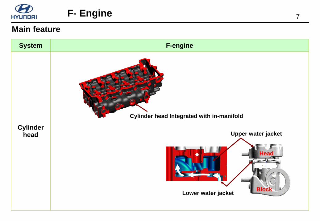
7F- Engine
System F-engine
Cylinder head
Block
Head
Cylinder head Integrated with in-manifold
Upper water jacket
Lower water jacket
Main feature

8F- Engine
System F-engine
Belt system
Alternator
Idler
Idler
Auto Tensioner
Water Pump
A/C Compressor
Main feature

9F- Engine
System F-engine
Moving
Double wave
Cooling gallery
PVD (Physical Vapor deposition) coating
Gas nitriding
Main feature

10F- Engine
System F-engine
Timing(Belt train)
Belt train
Camshaft
Rocker arm
Intake/Exhaust valve
Main feature

11F- Engine
System F-engine
Timing(Gear train)
CamshaftCamshaft
Idler, DIdler, D
Idler, CIdler, C
CrankshaftCrankshaft
Oil PumpOil Pump
P/S PumpP/S Pump
Fuel PumpFuel Pump
Vacuum PumpVacuum Pump
Step Idler (A,B)Step Idler (A,B)Idler, EIdler, E
Main feature

12F- Engine
System F-engine
Oil filter &Oil cooler
Oil filter
Oil cooler
Filter element
Main feature

13F- Engine
System F-engine
Timing(Scissors Gear)
Scissors gear Components Section view
Main feature
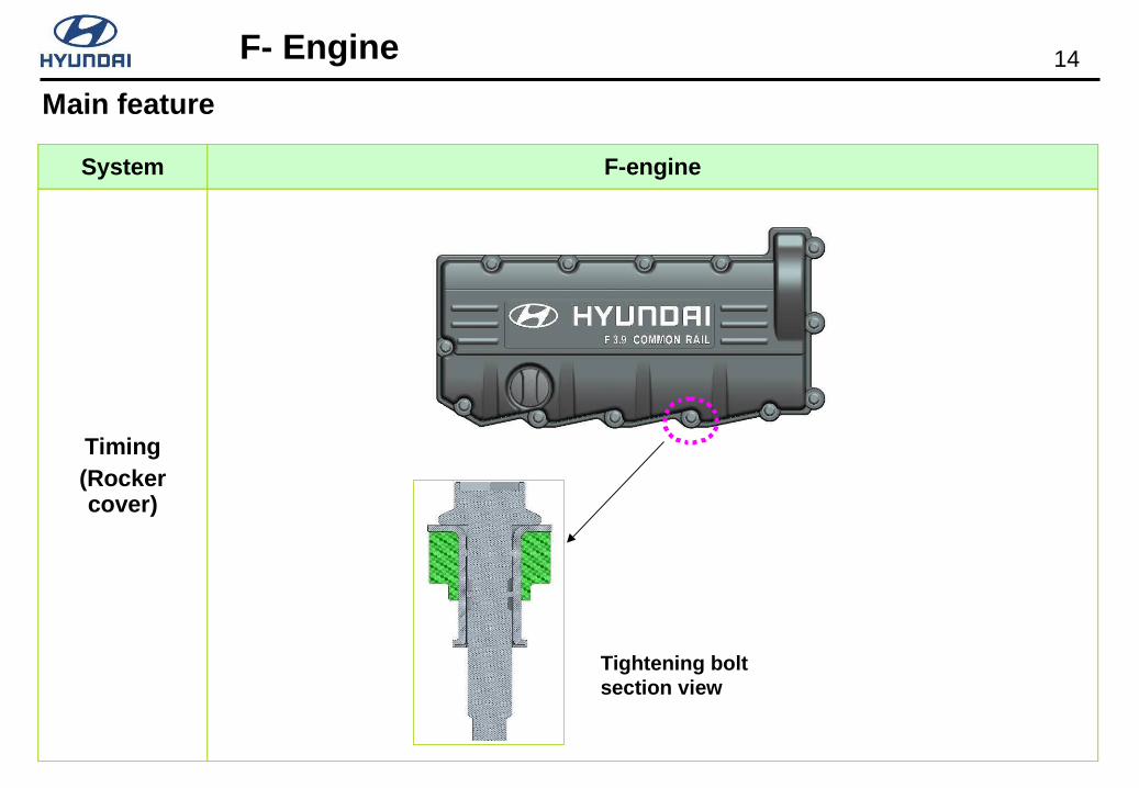
14F- Engine
System F-engine
Timing(Rocker cover)
Tightening bolt section view
Main feature

15F- Engine
System F-engine
Vacuum pump
Vacuum Pump Installation
Exhaust port90˚
Main feature

16F- Engine
System F-engine
EGR system
Wave fin
Oval EGR cooler with wave fin
Strap type mounting
Reed valve
Main feature

17F- Engine
System F-engine
Fuel injection system
ECT
High pressure pump
Common rail
Injector
Main feature

18F- Engine
System F-engine
PMC
- PMC (Particulate Matter Catalyst) -
Metal Substrate
- Catalytic coating place
- NO NO2
Metal Partial Filter
- PM collecting and combustion
- Open flow type
Metal
DOCPM-Metallic
2NO+02 2NO2C + 2NO2 CO2+N2
C + O2 CO2
PMC
Main feature
* DOC: Diesel Oxidation Catalyst

19F- Engine
PMC
2NO + O2 ↔ 2NO2
Material: Metal (Precious metal coating)
PM collecting and combustion 2NO2 + C ↔ CO2 + 2NO
Material: Metal
Diesel oxidation catalyst
Purification
Diesel particulates filter
NO->NO2NO2 will burn off particulates matter.
PM is separated between Waved layer and Special layer, and it is burning with O2/NO2 .
Exhaust gas
PMC (Particulate Matter Catalyst)
*NO: nitric oxide, NO2:nitrogen dioxide
20F- Engine
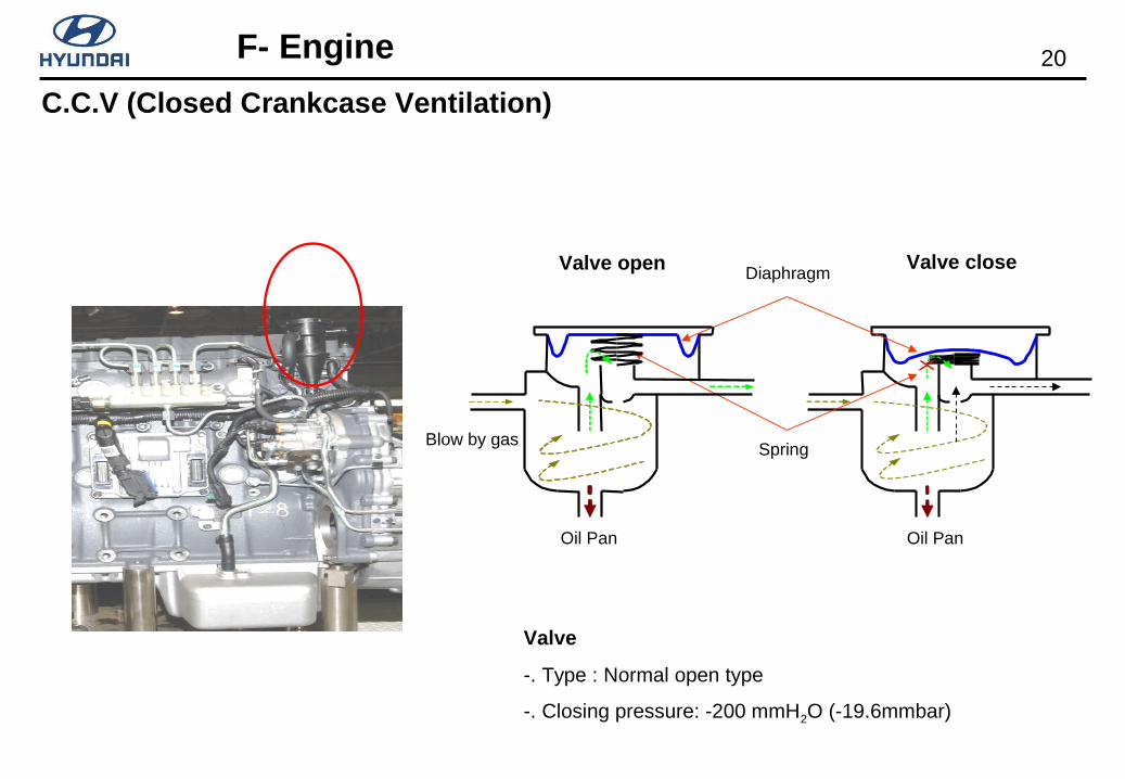
Diaphragm
Spring
Valve
-. Type : Normal open type
-. Closing pressure: -200 mmH2O (-19.6mmbar)
Valve open Valve close
Oil Pan
Blow by gas
C.C.V (Closed Crankcase Ventilation)
Oil Pan

21F- Engine
1) Maximum rotation 181,000 RPM2) Control method Air pressure type (Same as D4 series engine)3) Manufacturer Keyyang Precision Co., Ltd4) Changing items compare with W-engine Maximum rotation (160,000rpm -> 181,000 rpm) Actuator pressure (960+-35 -> 1800+-30) Nozzle diameter size (8cm 2 -> 4cm2) Maximum pressure rate (2.6 -> 3.0)
Turbocharger
22F- Engine
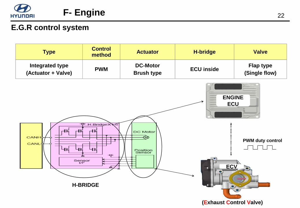
TypeControl method Actuator H-bridge Valve
Integrated type(Actuator + Valve)
PWMDC-Motor
Brush typeECU inside
Flap type(Single flow)
H-BRIDGE
PWM duty control
ENGINEECU
ECV
(Exhaust Control Valve)
E.G.R control system

23F- Engine
1
5
6
EGR SYSTEM
EGR valve cooling
25 6
1 Intake manifoldThermostat
3
4
EGR valve
EGR cooler
Reed valve
E.G.R control system (Valve)

24F- Engine
Supply to
common rail Fuel supply pump
Fuel supply pump

25F- Engine
Return spring
Needle valve
Valve body
SCVFuel In
Fuel Out
SCV OFFSCV ON
SCV (Supply Control Valve)

26F- Engine
Engine stop
Engine running
High pressure fuel leak
Repeat
Flow Damper

27F- Engine
1. Rotate the crankshaft to align the engine No. 1
cylinder at the TDC (Top Dead Center) position.
- Rotate the engine to align the marking line on "1, 4" side
stamped on the periphery of the crankshaft pulley
- Remove the rocker cover and make sure that the mark on the
camshaft position sensor gear plate is align with the upper
surface of the cylinder head.
2. Install the pump to the engine after fixed the plate to
the pump gear.
- Fix the plate to the pump, then install the gear to the pump shaft.
- At installation, ensure that the convex part of the plate is aligned
with the 2 marks on the side of the pump. Fit the flange bolt hole
to the engine correctly then it is automatically adjusted the angle
to the idler gear.
Make sure the mark is aligned.
Fuel supply pump remove and reinstall

28F- Engine
Install the fuel supply pump as above picture.
Fix the 2 stud (e) to the cylinder block lower part. Put the pump (b) to the flange (d), and tighten them with bolts (a).
After the gear (g) and the pump shaft has been assembled temporarily , put the gear and pump assembly in to the stud
(e) and tighten them with bolt (f) and nut (c). Before put it in make sure that the gear and plunger rotational direction is
correctly matched.
Insert the O-ring (33161-52000) between the pump (b) and flange (d), then tighten the bolt (a) (11703-08303) and nut
(h).
c dO-RING33161-52000
O-RING33171-52000
b
a
ef
g
h
Reassemble for fuel supply pump, plate and pump gear
29F- Engine
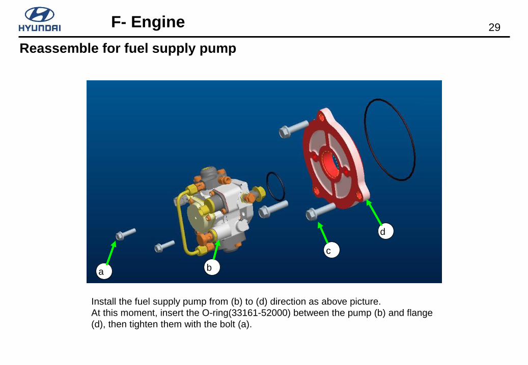
a b
d
c
Install the fuel supply pump from (b) to (d) direction as above picture. At this moment, insert the O-ring(33161-52000) between the pump (b) and flange (d), then tighten them with the bolt (a).
Reassemble for fuel supply pump

30F- Engine
When you fit the pump assembly in cylinder block, make sure that the mark on the flange back side is positioned like the picture.
Match the Idler gear and supply pump gear
31F- Engine
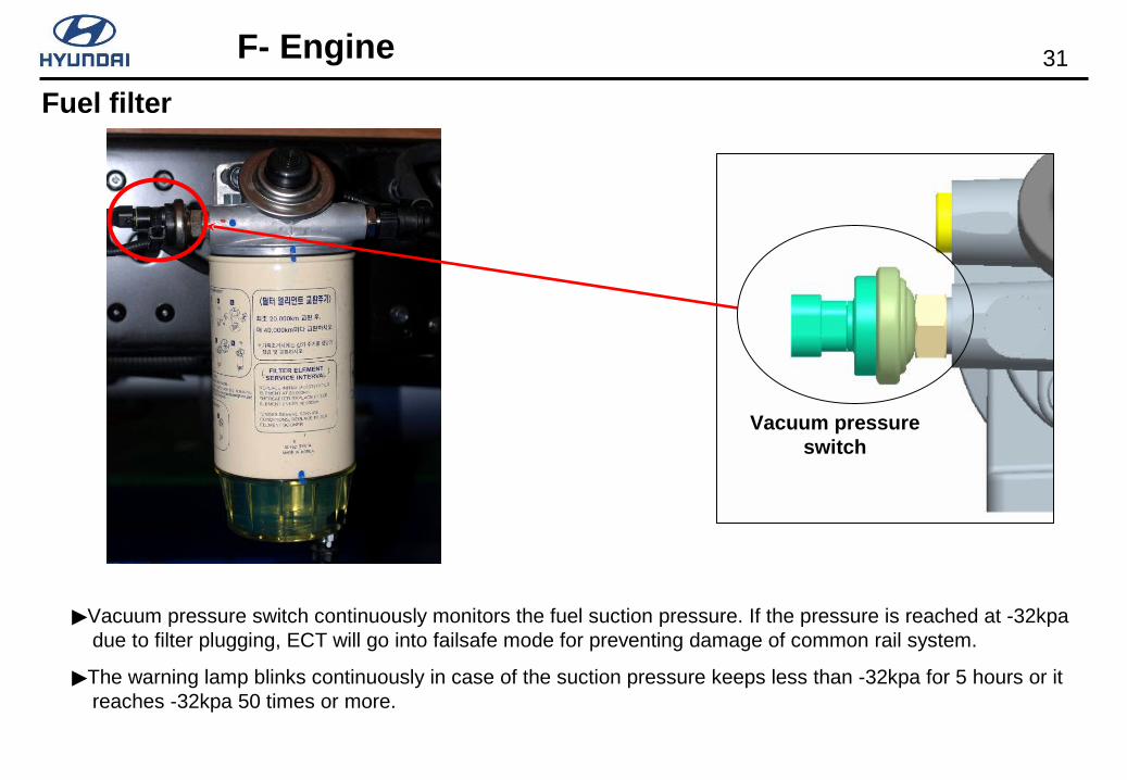
Vacuum pressure switch
Vacuum pressure switch continuously monitors the fuel suction pressure. If the pressure is reached at -32kpa due to filter plugging, ECT will go into failsafe mode for preventing damage of common rail system.
The warning lamp blinks continuously in case of the suction pressure keeps less than -32kpa for 5 hours or it reaches -32kpa 50 times or more.
Fuel filter

32F- Engine
Denso ECTEURO Ⅳ
Denso ECTEURO Ⅳ
Accelerator pedal sensor 1,2
Brake & Clutch S/W
CKPS, CMPS
MAP, Intake air temp. sensor
Rail pressure sensor
MAF sensor
Neutral switch
Water coolant temp. sensor
Fuel temp. sensor
EGR lift sensor
Injector(Quantity/Timing)
Fuel pressure control (SCV)
EGR control
Cooling fan control
CAN communication
Pre-heat deviceFuel filter vacuum pressure S/W
Input and output

33F- Engine
Accelerator
pedal sensor
Specification
Idle condition (0%) Full pressed condition (100%)
0.65V 3.85V
Accelerator pedal position sensor

34F- Engine
Checking items Rail pressure sensor
Data mark Rail pressure
Checking condition Engine idle condition
Rail pressure 35~50MPa (350~500bar)
Normal pressure (Scan tool) 40MPa (400bar)
Rail pressure sensor

35F- Engine
CKP (Crankshaft Position sensor)

36F- Engine
CMP (Camshaft Position sensor)

37F- Engine
1 : Intake air pressure signal 2 : Sensor power source3 : Intake air temp signal 4 : Sensor ground
1 2 3 4
Boost air pressure sensor
Intake air pressure sensor
Specification
Intake air pressure (Kpa)
Voltage (V)
32.5 0.5
50 0.78
70 1.96
270 4.28
284 4.5
300 4.75
Intake air temp.
Specification
0 5.4 ~6.0
10 3.5 ~3.9
30 1.6 ~1.7
50 0.8 ~0.9

38F- Engine
Water coolant temp( ) Specification (KΩ)
-20 15.48
0 5.79
20 2.45
40 1.148
60 0.322
Water Temperature Sensor

39F- Engine
Temperature (Celsius degree )
Specification (KΩ)
-20 13.4 17.7∼
-10 8.24 10.66∼
0 5.23 6.62∼
20 2.26 2.76∼
40 1.08 1.28∼
60 0.56 0.64∼
80 0.3 0.34∼
120 0.11 0.12∼
Fuel Temperature Sensor

40F- Engine
No. Descriptions
1 Intake air temp sensor ground
2 Intake air temp sensor signal
3 Power source
4 Ground
5 Intake air mess signal
12345
Mass air flow sensor

41F- Engine
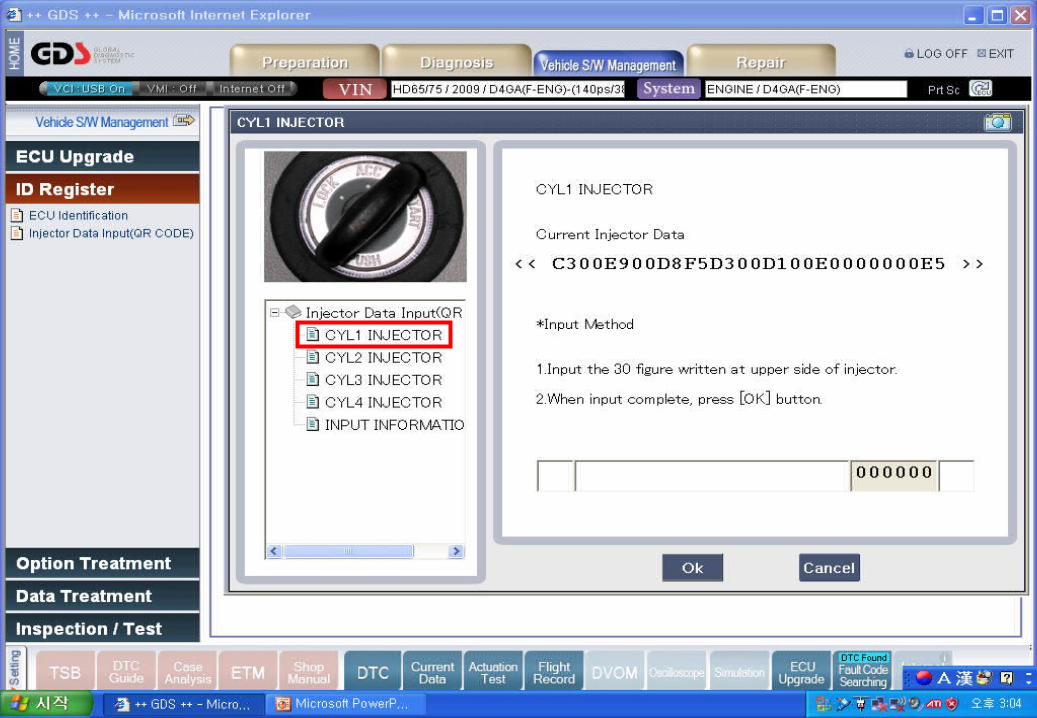
QR compensation
QR compensation

42F- Engine
QR compensation method
43F- Engine
44F- Engine
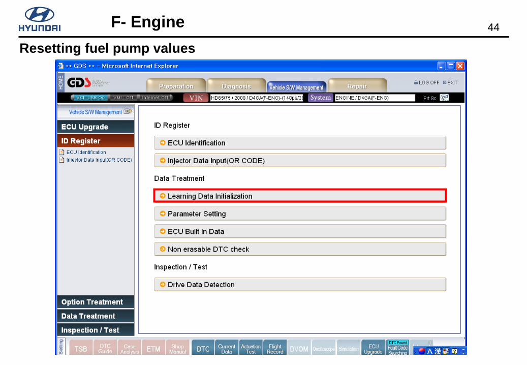
Resetting fuel pump values

45F- Engine
46F- Engine
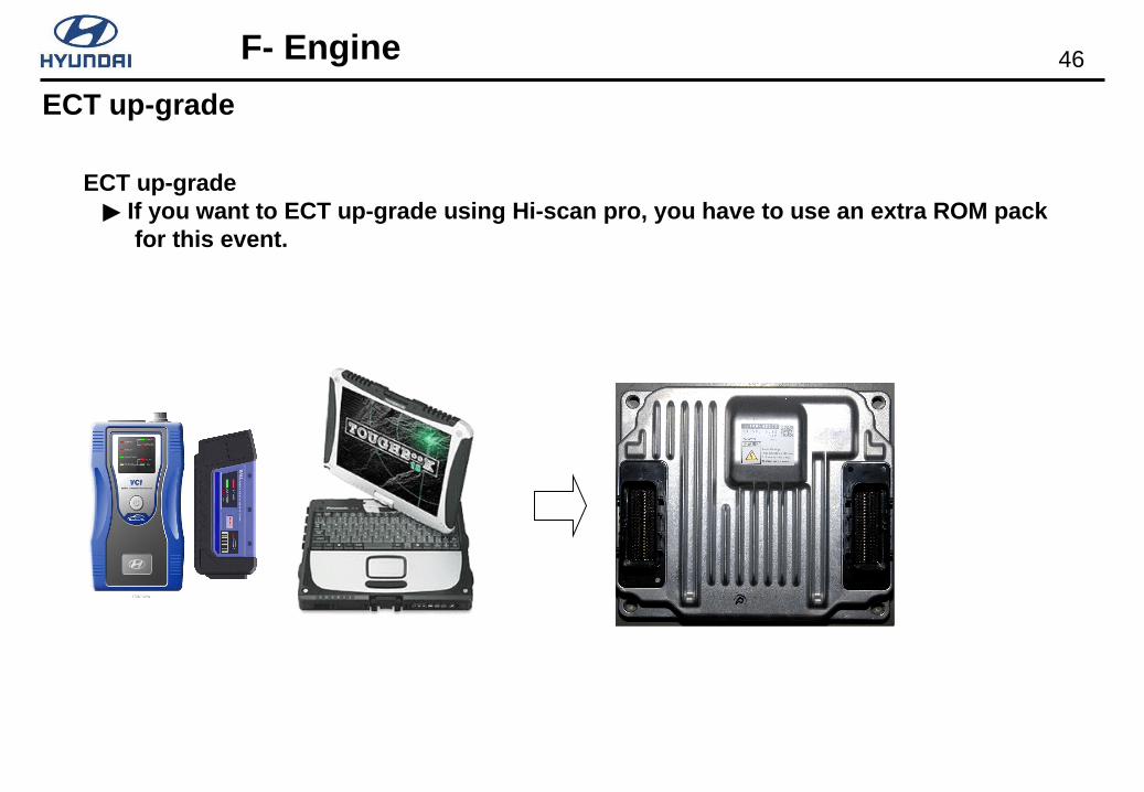
ECT up-grade If you want to ECT up-grade using Hi-scan pro, you have to use an extra ROM pack
for this event.
ECT up-grade

47F- Engine
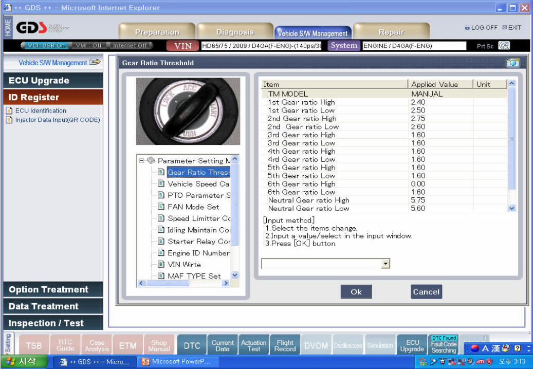
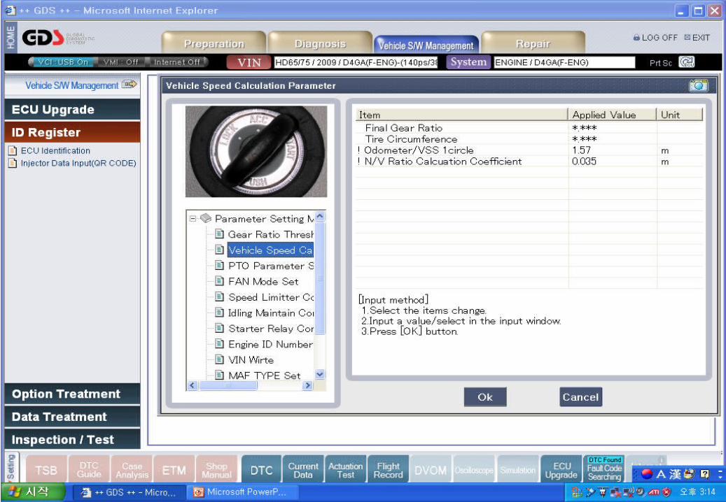
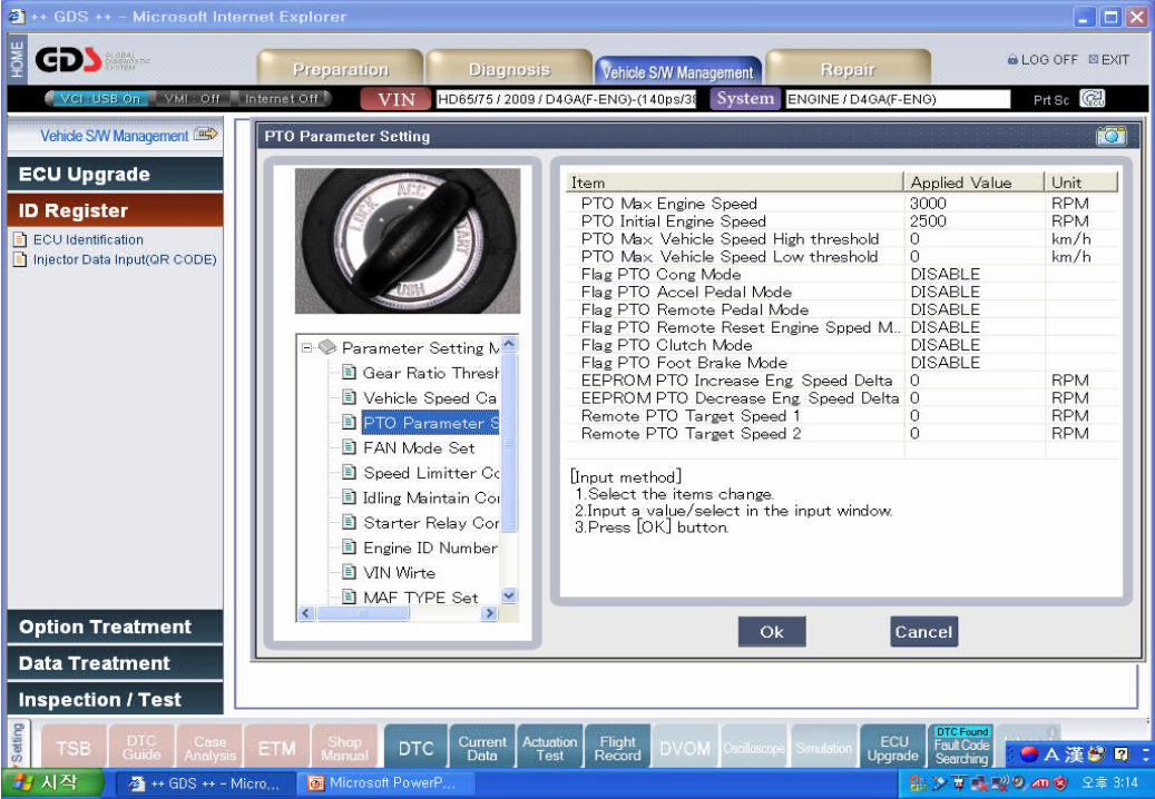
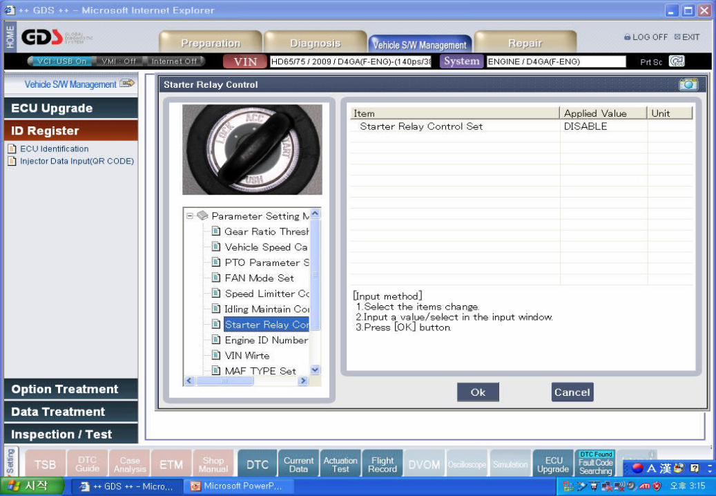
Parameter setting
01. Gear Ratio Threshold
02. Vehicle Speed Calculation Parameter
03. PTO Parameter Setting
04. Fan Mode Setting
05. Speed Limiter Control
06. Idling Maintain Control
07. Starter Relay Control
08. Engine ID Number Write
09. VIN Write
10. MAF TYPE Set

48F- Engine
Compensation method

49F- Engine
7508
50F- Engine
51F- Engine
52F- Engine

53

54

55
56

57

58

59