Embed Size (px)
Citation preview
© 2011 Pearson Education, Inc.All Rights Reserved
Automotive Technology, Fourth EditionJames Halderman
IN-VEHICLE ENGINE SERVICE
27

27 IN-VEHICLE ENGINE SERVICE
Automotive Technology, Fourth EditionJames Halderman
© 2011 Pearson Education, Inc.All Rights Reserved
ObjectivesObjectives
• The student should be able to:– Prepare for ASE certification test content
area “A” (General Engine Diagnosis). – Diagnose and replace the thermostat. – Diagnose and replace the water pump. – Diagnose and replace an intake manifold
gasket.
27 IN-VEHICLE ENGINE SERVICE
Automotive Technology, Fourth EditionJames Halderman
© 2011 Pearson Education, Inc.All Rights Reserved
ObjectivesObjectives
• The student should be able to:– Determine and verify correct cam timing. – Replace a timing a belt. – Describe how to adjust valves. – Explain hybrid engine precautions.

27 IN-VEHICLE ENGINE SERVICE
Automotive Technology, Fourth EditionJames Halderman
© 2011 Pearson Education, Inc.All Rights Reserved
THERMOSTAT THERMOSTAT REPLACEMENTREPLACEMENT

27 IN-VEHICLE ENGINE SERVICE
Automotive Technology, Fourth EditionJames Halderman
© 2011 Pearson Education, Inc.All Rights Reserved
Thermostat ReplacementThermostat Replacement
• Failure Patterns– Stuck open– Stuck closed– Stuck partially open– Skewed

27 IN-VEHICLE ENGINE SERVICE
Automotive Technology, Fourth EditionJames Halderman
© 2011 Pearson Education, Inc.All Rights Reserved
Figure 27-1 If the thermostat has a jiggle valve, it should be placed toward the top to allow air to escape. If a thermostat were to become stuck open or open too soon, this can set a diagnostic trouble code P0128 (coolant temperature below thermostat regulating temperature).
27 IN-VEHICLE ENGINE SERVICE
Automotive Technology, Fourth EditionJames Halderman
© 2011 Pearson Education, Inc.All Rights Reserved
Thermostat ReplacementThermostat Replacement
• Replacement Procedure– STEP 1: Allow engine to cool for several
hours– STEP 2: Drain coolant into a suitable
container– STEP 3: Remove any components to access
thermostat
27 IN-VEHICLE ENGINE SERVICE
Automotive Technology, Fourth EditionJames Halderman
© 2011 Pearson Education, Inc.All Rights Reserved
Thermostat ReplacementThermostat Replacement
• Replacement Procedure– STEP 4: Remove thermostat housing and
thermostat– STEP 5: Replace thermostat housing gasket
and thermostat– STEP 6: Refill cooling system; bleed
trapped air

27 IN-VEHICLE ENGINE SERVICE
Automotive Technology, Fourth EditionJames Halderman
© 2011 Pearson Education, Inc.All Rights Reserved
Thermostat ReplacementThermostat Replacement
• Replacement Procedure– STEP 7: Pressurize cooling system– STEP 8: Run the engine and check for leaks– STEP 9: Verify that engine reaching correct
operating temperature
27 IN-VEHICLE ENGINE SERVICE
Automotive Technology, Fourth EditionJames Halderman
© 2011 Pearson Education, Inc.All Rights Reserved
WATER PUMP WATER PUMP REPLACEMENTREPLACEMENT

27 IN-VEHICLE ENGINE SERVICE
Automotive Technology, Fourth EditionJames Halderman
© 2011 Pearson Education, Inc.All Rights Reserved
Water Pump ReplacementWater Pump Replacement
• Need for Replacement– Leaking coolant from the weep hole– Bearing noisy or loose– Lack of proper coolant flow

27 IN-VEHICLE ENGINE SERVICE
Automotive Technology, Fourth EditionJames Halderman
© 2011 Pearson Education, Inc.All Rights Reserved
Water Pump ReplacementWater Pump Replacement
• Replacement Guidelines– STEP 1: Allow engine to cool to room
temperature– STEP 2: Drain coolant and dispose of
properly or recycle– STEP 3: Remove components to access
water pump

27 IN-VEHICLE ENGINE SERVICE
Automotive Technology, Fourth EditionJames Halderman
© 2011 Pearson Education, Inc.All Rights Reserved
Water Pump ReplacementWater Pump Replacement
• Replacement Guidelines– STEP 4: Remove water pump assembly– STEP 5: Clean gasket surfaces; install new
water pump and new gasket or seal– STEP 6: Install removed engine
components

27 IN-VEHICLE ENGINE SERVICE
Automotive Technology, Fourth EditionJames Halderman
© 2011 Pearson Education, Inc.All Rights Reserved
Water Pump ReplacementWater Pump Replacement
• Replacement Guidelines– STEP 7: Fill cooling system with specified
coolant– STEP 8: Run engine, check for leaks, verify
proper operation

27 IN-VEHICLE ENGINE SERVICE
Automotive Technology, Fourth EditionJames Halderman
© 2011 Pearson Education, Inc.All Rights Reserved
Figure 27-2 Use caution if using a steel scraper to remove a gasket from aluminum parts. It is best to use a wood or plastic scraper.

27 IN-VEHICLE ENGINE SERVICE
Automotive Technology, Fourth EditionJames Halderman
© 2011 Pearson Education, Inc.All Rights Reserved
INTAKE MANIFOLDINTAKE MANIFOLDGASKET INSPECTIONGASKET INSPECTION

27 IN-VEHICLE ENGINE SERVICE
Automotive Technology, Fourth EditionJames Halderman
© 2011 Pearson Education, Inc.All Rights Reserved
Intake Manifold Gasket InspectionIntake Manifold Gasket Inspection
• Causes of Failure– Expansion/contraction rate difference
between cast-iron head and aluminum intake manifold (fretting)

27 IN-VEHICLE ENGINE SERVICE
Automotive Technology, Fourth EditionJames Halderman
© 2011 Pearson Education, Inc.All Rights Reserved
Intake Manifold Gasket InspectionIntake Manifold Gasket Inspection
• Causes of Failure– Plastic (Nylon 6.6) gasket deterioration
caused by coolant
27 IN-VEHICLE ENGINE SERVICE
Automotive Technology, Fourth EditionJames Halderman
© 2011 Pearson Education, Inc.All Rights Reserved
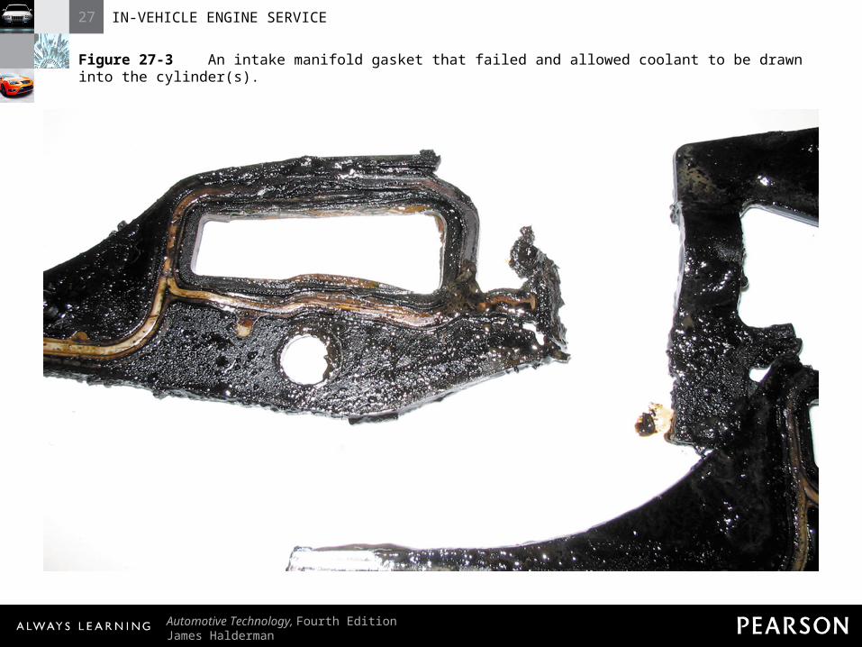
Figure 27-3 An intake manifold gasket that failed and allowed coolant to be drawn into the cylinder(s).

27 IN-VEHICLE ENGINE SERVICE
Automotive Technology, Fourth EditionJames Halderman
© 2011 Pearson Education, Inc.All Rights Reserved
Intake Manifold Gasket InspectionIntake Manifold Gasket Inspection
• Diagnosis of Leaking Intake Manifold Gasket– Visual inspection– Coolant level– Air (vacuum) leak

27 IN-VEHICLE ENGINE SERVICE
Automotive Technology, Fourth EditionJames Halderman
© 2011 Pearson Education, Inc.All Rights Reserved
INTAKE MANIFOLDINTAKE MANIFOLDGASKET REPLACEMENTGASKET REPLACEMENT

27 IN-VEHICLE ENGINE SERVICE
Automotive Technology, Fourth EditionJames Halderman
© 2011 Pearson Education, Inc.All Rights Reserved
Intake Manifold Gasket ReplacementIntake Manifold Gasket Replacement
• STEP 1: Engine off for an hour; drain coolant
• STEP 2: Access to retaining bolts• STEP 3: Loosen fasteners in reverse
order of tightening sequence

27 IN-VEHICLE ENGINE SERVICE
Automotive Technology, Fourth EditionJames Halderman
© 2011 Pearson Education, Inc.All Rights Reserved
Intake Manifold Gasket ReplacementIntake Manifold Gasket Replacement
• STEP 4: Remove upper intake manifold (plenum); inspect for faults
• STEP 5: Remove lower intake manifold• STEP 6: Thoroughly clean area and
replace intake manifold if needed

27 IN-VEHICLE ENGINE SERVICE
Automotive Technology, Fourth EditionJames Halderman
© 2011 Pearson Education, Inc.All Rights Reserved
Intake Manifold Gasket ReplacementIntake Manifold Gasket Replacement
• STEP 7: Install intake manifold using new gaskets as specified
• STEP 8: Torque fasteners to factory specifications and in proper sequences
• STEP 9: Reinstall all parts needed for engine to start and run
27 IN-VEHICLE ENGINE SERVICE
Automotive Technology, Fourth EditionJames Halderman
© 2011 Pearson Education, Inc.All Rights Reserved
Intake Manifold Gasket ReplacementIntake Manifold Gasket Replacement
• STEP 10: Start engine and check for leaks and proper engine operation
• STEP 11: Reset or relearn idle if specified using a scan tool
• STEP 12: Install remaining parts; test drive to verify proper operation and no leaks

27 IN-VEHICLE ENGINE SERVICE
Automotive Technology, Fourth EditionJames Halderman
© 2011 Pearson Education, Inc.All Rights Reserved
Intake Manifold Gasket ReplacementIntake Manifold Gasket Replacement
• STEP 13: Check and replace air filter if needed
• STEP 14: Change engine oil
27 IN-VEHICLE ENGINE SERVICE
Automotive Technology, Fourth EditionJames Halderman
© 2011 Pearson Education, Inc.All Rights Reserved
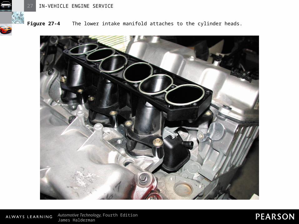
Figure 27-4 The lower intake manifold attaches to the cylinder heads.

27 IN-VEHICLE ENGINE SERVICE
Automotive Technology, Fourth EditionJames Halderman
© 2011 Pearson Education, Inc.All Rights Reserved
Figure 27-5 The upper intake manifold, often called a plenum, attaches to the lower intake manifold.

27 IN-VEHICLE ENGINE SERVICE
Automotive Technology, Fourth EditionJames Halderman
© 2011 Pearson Education, Inc.All Rights Reserved
Figure 27-6 Many aftermarket replacement intake manifolds have a different appearance from the original manifold.

27 IN-VEHICLE ENGINE SERVICE
Automotive Technology, Fourth EditionJames Halderman
© 2011 Pearson Education, Inc.All Rights Reserved
TIMING BELTTIMING BELTREPLACEMENTREPLACEMENT

27 IN-VEHICLE ENGINE SERVICE
Automotive Technology, Fourth EditionJames Halderman
© 2011 Pearson Education, Inc.All Rights Reserved
Timing Belt ReplacementTiming Belt Replacement
• Need for Replacement– Exceeds manufacturer’s recommended
replacement interval– Contaminated with coolant or engine oil

27 IN-VEHICLE ENGINE SERVICE
Automotive Technology, Fourth EditionJames Halderman
© 2011 Pearson Education, Inc.All Rights Reserved
Timing Belt ReplacementTiming Belt Replacement
• Need for Replacement– Failure (missing belt teeth or broken)
27 IN-VEHICLE ENGINE SERVICE
Automotive Technology, Fourth EditionJames Halderman
© 2011 Pearson Education, Inc.All Rights Reserved
Timing Belt ReplacementTiming Belt Replacement
• Timing Belt Replacement Guidelines– STEP 1: Allow engine to cool– STEP 2: Remove components to gain
access to timing belt and marks– STEP 3: If belt not broken, rotate engine so
camshaft and crankshaft timing marks align

27 IN-VEHICLE ENGINE SERVICE
Automotive Technology, Fourth EditionJames Halderman
© 2011 Pearson Education, Inc.All Rights Reserved
Timing Belt ReplacementTiming Belt Replacement
• Timing Belt Replacement Guidelines– STEP 4: Loosen or remove tensioner as
needed to remove belt– STEP 5: Replace belt and any other
recommended items– STEP 6: Verify camshaft timing correct by
rotating engine several revolutions
27 IN-VEHICLE ENGINE SERVICE
Automotive Technology, Fourth EditionJames Halderman
© 2011 Pearson Education, Inc.All Rights Reserved
Timing Belt ReplacementTiming Belt Replacement
• Timing Belt Replacement Guidelines– STEP 7: Reinstall all parts needed for
engine to start to verify proper operation– STEP 8: Complete reassembly and perform
test drive

27 IN-VEHICLE ENGINE SERVICE
Automotive Technology, Fourth EditionJames Halderman
© 2011 Pearson Education, Inc.All Rights Reserved
HYBRID ENGINE HYBRID ENGINE PRECAUTIONSPRECAUTIONS

27 IN-VEHICLE ENGINE SERVICE
Automotive Technology, Fourth EditionJames Halderman
© 2011 Pearson Education, Inc.All Rights Reserved
Hybrid Engine PrecautionsHybrid Engine Precautions
• Hybrid Vehicle Engine Operation– Gasoline engines used in HEVs and EREVs
can be hazardous– Have idle stop feature– Although engine not running, could start at
any time
27 IN-VEHICLE ENGINE SERVICE
Automotive Technology, Fourth EditionJames Halderman
© 2011 Pearson Education, Inc.All Rights Reserved
Hybrid Engine PrecautionsHybrid Engine Precautions
• Precautions– Be sure ignition is off and key out of
ignition– Check that “Ready” light is off

27 IN-VEHICLE ENGINE SERVICE
Automotive Technology, Fourth EditionJames Halderman
© 2011 Pearson Education, Inc.All Rights Reserved
Hybrid Engine PrecautionsHybrid Engine Precautions
• Precautions– Do not touch any circuits that have orange
electrical wires or conduit– Use high-voltage linesman’s gloves when
depowering high-voltage system

27 IN-VEHICLE ENGINE SERVICE
Automotive Technology, Fourth EditionJames Halderman
© 2011 Pearson Education, Inc.All Rights Reserved
Figure 27-8 A Toyota/Lexus hybrid electric vehicle has a ready light. If the ready light is on, the engine can start at anytime without warning.

27 IN-VEHICLE ENGINE SERVICE
Automotive Technology, Fourth EditionJames Halderman
© 2011 Pearson Education, Inc.All Rights Reserved
Hybrid Engine PrecautionsHybrid Engine Precautions
• Hybrid Engine Service– Low viscosity engine oil used to achieve
maximum fuel economy• SAE 0W-20, SAE 5W-20• Not always stocked item; may have to order

27 IN-VEHICLE ENGINE SERVICE
Automotive Technology, Fourth EditionJames Halderman
© 2011 Pearson Education, Inc.All Rights Reserved
Hybrid Engine PrecautionsHybrid Engine Precautions
• Hybrid Engine Service– Some require special spark plugs; may
have to order

27 IN-VEHICLE ENGINE SERVICE
Automotive Technology, Fourth EditionJames Halderman
© 2011 Pearson Education, Inc.All Rights Reserved
Figure 27-9 Always use the viscosity of oil as specified on the oil fill cap.

27 IN-VEHICLE ENGINE SERVICE
Automotive Technology, Fourth EditionJames Halderman
© 2011 Pearson Education, Inc.All Rights Reserved
VALVE ADJUSTMENT 1 Before starting the process of adjusting the valves, look up the specifications and exact procedures. The technician is checking this information from a computer CD-ROM-based information system.

27 IN-VEHICLE ENGINE SERVICE
Automotive Technology, Fourth EditionJames Halderman
© 2011 Pearson Education, Inc.All Rights Reserved
VALVE ADJUSTMENT 2 The tools necessary to adjust the valves on an engine with adjustable rocker arms include basic hand tools, feeler gauge, and a torque wrench.

27 IN-VEHICLE ENGINE SERVICE
Automotive Technology, Fourth EditionJames Halderman
© 2011 Pearson Education, Inc.All Rights Reserved
VALVE ADJUSTMENT 3 An overall view of the 4-cylinder engine that is due for a scheduled valve adjustment according to the vehicle manufacturer’s recommendations.

27 IN-VEHICLE ENGINE SERVICE
Automotive Technology, Fourth EditionJames Halderman
© 2011 Pearson Education, Inc.All Rights Reserved
VALVE ADJUSTMENT 4 Start the valve adjustment procedure by first disconnecting and labeling, if necessary, all vacuum lines that need to be removed to gain access to the valve cover.

27 IN-VEHICLE ENGINE SERVICE
Automotive Technology, Fourth EditionJames Halderman
© 2011 Pearson Education, Inc.All Rights Reserved
VALVE ADJUSTMENT 5 The air intake tube is being removed from the throttle body.

27 IN-VEHICLE ENGINE SERVICE
Automotive Technology, Fourth EditionJames Halderman
© 2011 Pearson Education, Inc.All Rights Reserved
VALVE ADJUSTMENT 6 With all vacuum lines and the intake tube removed, the valve cover can be removed after removing all retaining bolts.
27 IN-VEHICLE ENGINE SERVICE
Automotive Technology, Fourth EditionJames Halderman
© 2011 Pearson Education, Inc.All Rights Reserved
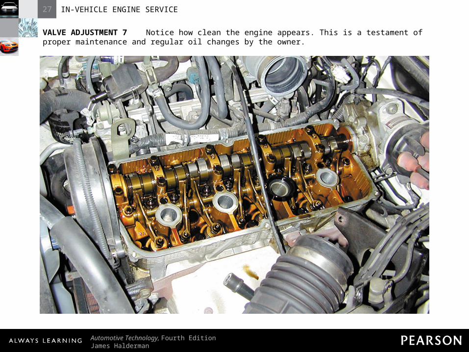
VALVE ADJUSTMENT 7 Notice how clean the engine appears. This is a testament of proper maintenance and regular oil changes by the owner.

27 IN-VEHICLE ENGINE SERVICE
Automotive Technology, Fourth EditionJames Halderman
© 2011 Pearson Education, Inc.All Rights Reserved
VALVE ADJUSTMENT 8 To help locate how far the engine is being rotated, the technician is removing the distributor cap to be able to observe the position of the rotor.

27 IN-VEHICLE ENGINE SERVICE
Automotive Technology, Fourth EditionJames Halderman
© 2011 Pearson Education, Inc.All Rights Reserved
VALVE ADJUSTMENT 9 The engine is rotated until the timing marks on the front of the crankshaft line up with zero degrees—top dead center (TDC)—with both valves closed on #1 cylinder.
27 IN-VEHICLE ENGINE SERVICE
Automotive Technology, Fourth EditionJames Halderman
© 2011 Pearson Education, Inc.All Rights Reserved
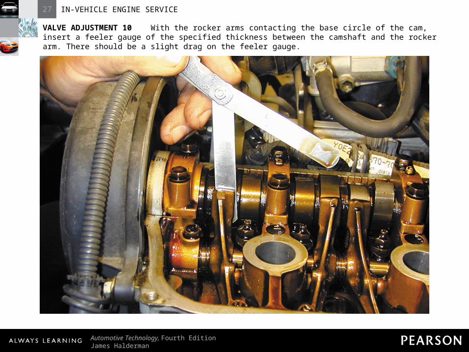
VALVE ADJUSTMENT 10 With the rocker arms contacting the base circle of the cam, insert a feeler gauge of the specified thickness between the camshaft and the rocker arm. There should be a slight drag on the feeler gauge.
27 IN-VEHICLE ENGINE SERVICE
Automotive Technology, Fourth EditionJames Halderman
© 2011 Pearson Education, Inc.All Rights Reserved
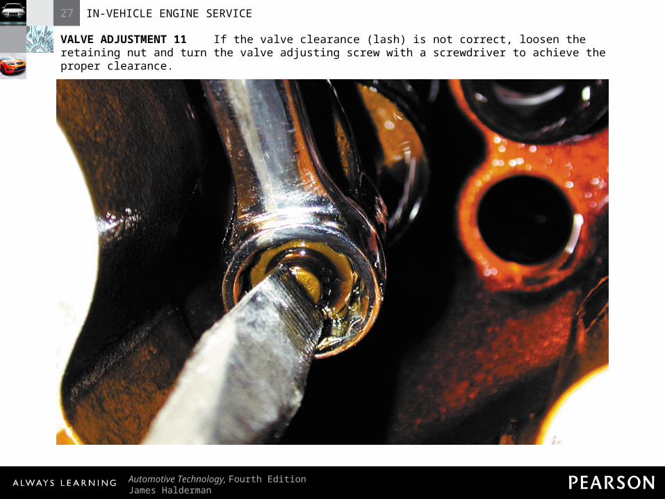
VALVE ADJUSTMENT 11 If the valve clearance (lash) is not correct, loosen the retaining nut and turn the valve adjusting screw with a screwdriver to achieve the proper clearance.
27 IN-VEHICLE ENGINE SERVICE
Automotive Technology, Fourth EditionJames Halderman
© 2011 Pearson Education, Inc.All Rights Reserved
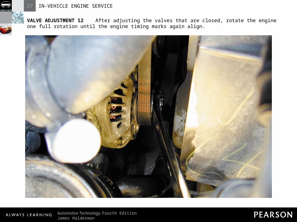
VALVE ADJUSTMENT 12 After adjusting the valves that are closed, rotate the engine one full rotation until the engine timing marks again align.

27 IN-VEHICLE ENGINE SERVICE
Automotive Technology, Fourth EditionJames Halderman
© 2011 Pearson Education, Inc.All Rights Reserved
VALVE ADJUSTMENT 13 The engine is rotated until the timing marks again align indicating that the companion cylinder will now be in position for valve clearance measurement.
27 IN-VEHICLE ENGINE SERVICE
Automotive Technology, Fourth EditionJames Halderman
© 2011 Pearson Education, Inc.All Rights Reserved
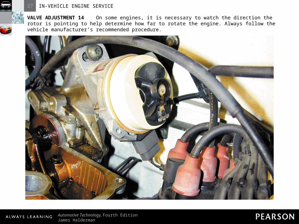
VALVE ADJUSTMENT 14 On some engines, it is necessary to watch the direction the rotor is pointing to help determine how far to rotate the engine. Always follow the vehicle manufacturer’s recommended procedure.

27 IN-VEHICLE ENGINE SERVICE
Automotive Technology, Fourth EditionJames Halderman
© 2011 Pearson Education, Inc.All Rights Reserved
VALVE ADJUSTMENT 15 The technician is using a feeler gauge that is one-thousandth of an inch thinner and another onethousandth of an inch thicker than the specified clearance as a double-check that the clearance is correct.

27 IN-VEHICLE ENGINE SERVICE
Automotive Technology, Fourth EditionJames Halderman
© 2011 Pearson Education, Inc.All Rights Reserved
VALVE ADJUSTMENT 16 Adjusting a valve takes both hands—one to hold the wrench to loosen and tighten the lock nut and one to turn the adjusting screw. Always double check the clearance after an adjustment is made.

27 IN-VEHICLE ENGINE SERVICE
Automotive Technology, Fourth EditionJames Halderman
© 2011 Pearson Education, Inc.All Rights Reserved
VALVE ADJUSTMENT 17 After all valves have been properly measured and adjusted as necessary, start the reassembly process by replacing all gaskets and seals as specified by the vehicle manufacturer.
27 IN-VEHICLE ENGINE SERVICE
Automotive Technology, Fourth EditionJames Halderman
© 2011 Pearson Education, Inc.All Rights Reserved
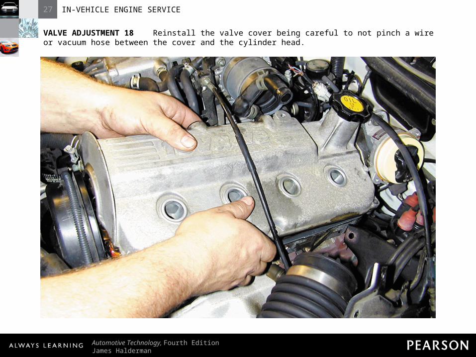
VALVE ADJUSTMENT 18 Reinstall the valve cover being careful to not pinch a wire or vacuum hose between the cover and the cylinder head.
27 IN-VEHICLE ENGINE SERVICE
Automotive Technology, Fourth EditionJames Halderman
© 2011 Pearson Education, Inc.All Rights Reserved
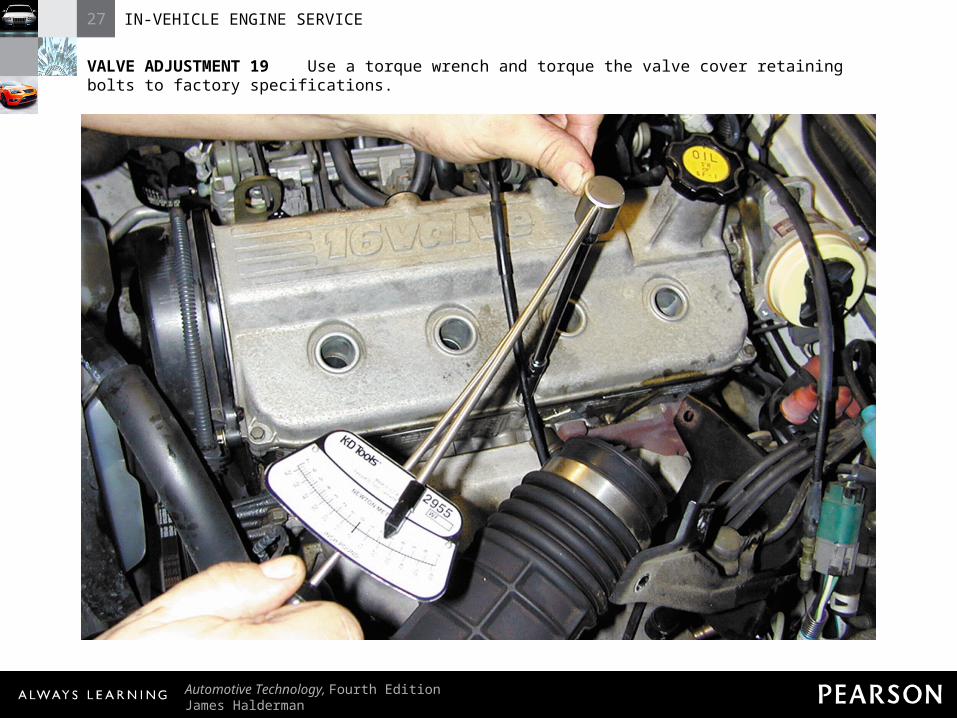
VALVE ADJUSTMENT 19 Use a torque wrench and torque the valve cover retaining bolts to factory specifications.
27 IN-VEHICLE ENGINE SERVICE
Automotive Technology, Fourth EditionJames Halderman
© 2011 Pearson Education, Inc.All Rights Reserved
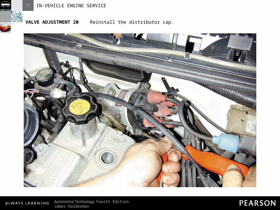
VALVE ADJUSTMENT 20 Reinstall the distributor cap.

27 IN-VEHICLE ENGINE SERVICE
Automotive Technology, Fourth EditionJames Halderman
© 2011 Pearson Education, Inc.All Rights Reserved
VALVE ADJUSTMENT 21 Reinstall the spark plug wires and all brackets that were removed to gain access to the valve cover.

27 IN-VEHICLE ENGINE SERVICE
Automotive Technology, Fourth EditionJames Halderman
© 2011 Pearson Education, Inc.All Rights Reserved
VALVE ADJUSTMENT 22 Reconnect all vacuum and air hoses and tubes. Replace any vacuum hoses that are brittle or swollen with new ones.

27 IN-VEHICLE ENGINE SERVICE
Automotive Technology, Fourth EditionJames Halderman
© 2011 Pearson Education, Inc.All Rights Reserved
VALVE ADJUSTMENT 23 Be sure that the clips are properly installed. Start the engine and check for proper operation.
27 IN-VEHICLE ENGINE SERVICE
Automotive Technology, Fourth EditionJames Halderman
© 2011 Pearson Education, Inc.All Rights Reserved
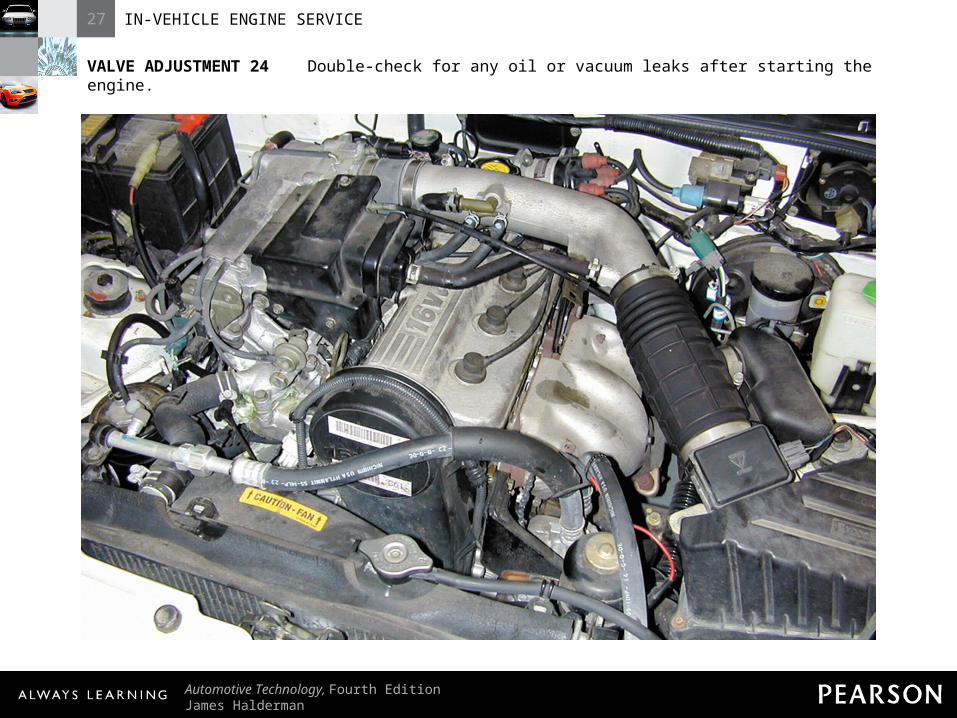
VALVE ADJUSTMENT 24 Double-check for any oil or vacuum leaks after starting the engine.