Embed Size (px)
Citation preview


From the Foreword byColonel Walter J. Boyne, USAF (Ret.)
"Written in a brisk, accessible style, this encyclopedia provides a col-lective description of the principle weapons systems of the UnitedStates at the most definitive juncture of American defense policy . . .
"The authors have provided listings for all U.S. weapons anywherein the world, encompassing systems as old as the Douglas C-47'Gooney Bird' and as new as its twenty-first-century successor, theMcDonnell Douglas C-17 Globemaster III. Each individual listingprovides information on the weapons system, its evolution, devel-opment, variants, combat experience and specifications. The cover-age of ships is particularly valuable, for it includes a listing of everyship within its class, by hull number, ship's name, builder, and withkey dates. Similarly, exhaustive detail is provided for armored fight-ing vehicles, missiles, and other weapons.
"Tim Laur and Steve Llanso are experts in the field and their bookis an important contribution to military literature, providing as itdoes an instant reference to the weapons systems of all the servicesof the United States."
The Army Times Publishing Company is pleased to join with TheBerkley Publishing Group in presenting this new series of books onmilitary history. We have proudly served the military community forover fifty years by means of our independent weekly newspapers,Army Times, Navy Times, and Air Force Times.
The other four books in the series are Generals in Muddy Boots: AConcise Encyclopedia of Combat Commanders by Dan Cragg; The ArmyTimes Book of Great Land Battles by Colonel J. D. Morelock; Clash ofChariots: The Great Tank Battles by Tom Donnelly and Sean Naylor; andThe Navy Times Book of Submarines by Brayton Harris.

Most Berkley Books are available at special quantity discounts for bulkpurchases for sales promotions, premiums, fund raising, or educationaluse. Special books or book excerpts can also be created to fit specificneeds.
For details, write or telephone Special Markets, The Berkley PublishingGroup, 200 Madison Avenue, New York, New York 10016; (212) 951-8891.

ENCYCLOPEDIAOF
MODERNU.S.
MILITARYWEAPONS
BERKLEY BOOKS, NEW YORK
The Army TimesNavy TimesAir Force Times
COLONEL TIMOTHY M. LAURAND STEVEN L. LLANSO
Edited by Walter J. Boyne

Page xi photo: MRLS Missile Launch (courtesy US Army).
This book is an original publication of The Berkley Publishing Group.
ENCYCLOPEDIA OF MODERN U.S. MILITARY WEAPONS
A Berkley Book / published by arrangement withThe Army Times Publishing Company
PRINTING HISTORY
Berkley hardcover edition / August 1995Berkley trade paperback edition / July 1998
All rights reserved.Copyright © 1995 by The Army Times Publishing Company.Book design by Irving Perkins Associates.This book may not be reproduced in whole or in part,by mimeograph or any other means, without permission.For information address:The Berkley Publishing Group, a member of Penguin Putnam Inc.,200 Madison Avenue, New York, New York 10016.
The Penguin Putnam Inc. World Wide Web site address ishttp://www.penguinputnam.com
ISBN: 0-425-16437-3
BERKLEY®Berkley Books are published byThe Berkley Publishing Group, a member of Penguin Putnam Inc.,200 Madison Avenue, New York, New York 10016.BERKLEY and the "B" design are trademarksbelonging to Berkley Publishing Corporation.
PRINTED IN THE UNITED STATES OF AMERICA
1 0 9 8 7 6 5 4 3 2 1

ACKNOWLEDGMENTS
The authors are indebted to several peopleand organizations who have helped us duringthe progress of this work. Of particular valueearly in the discussions of the book were Nor-man Polmar and Walter Boyne, who suggestedit and encouraged us to do it in the first place.
In the accumulation of data, photos, andother supporting documents, many peopleand agencies provided us with help. Most ofthe photographs are from the Department ofDefense's Public Affairs slide and photo-graphic library. Major Jim Bates of the AirForce Space Command and Staff SergeantGeorge Hayward of USSPACECOM providedkey materials. Marge Holtz, Tricia Larsen, andNancy Breen of the Military Sealift Commandhelped with sealift and underway-replenishment-ship information.
The cooperation and support of the UnitedCommunications Group, specifically BruceLevenson, Ed Peskowitz, and Nancy Becker,are particularly appreciated, along with for-mer Periscope Military Database editors Deb-orah Boyle Hoffman, Patricia Byars Ramirez,
Doris Roth Carr, David Wilton, and LaddaTammy Duckworth. Current database senioreditor Greg Beaudoin also contributed bykeeping us supplied with last-minute datachanges.
Also helping us were Mary Anna Kaufer ofthe Air Mobility Command Historian Office,Rita Marcus of Air Weather Service's HistorianOffice, and Joe Wilson and Betty Dahl of theAMC Public Affairs Office. Master SergeantThomas E. Pennington of the 89th MilitaryAirlift Wing provided presidential aircraft in-formation. Guy Asito of the Air Force Associa-tion helped with his time and resources.
Several defense industry public affairs spe-cialists helped us find and use graphics of theirweapons systems, including Dick Shermanand Don Bernstein of Raytheon, Don Gille-land and Karl G. Oskoian of General Dy-namics Land Systems, George Baldwin of BathIron Works, and Karen Hagar of Lockheed-Fort Worth.
Naturally, any errors are the sole respon-sibility of the authors.

CONTENTS
Foreword ix
AIRCRAFT
Attack 1Bombers 15Cargo 28
Electronic/Reconnaissance/Observation 54Fighters 79Rotary Wing 102Tankers 153
ARTILLERY/GUNS
Aircraft Guns 158Mortars 165Naval Guns 168Self-Propelled Guns and Howitzers 173Towed Guns and Howitzers 180Vehicle Guns 187
GROUND COMBAT VEHICLES
Air Defense Vehicles 191Armored Personnel Carriers 196Armored Reconnaissance Vehicles 208Combat Support and Service Vehicles 212Light and Main Battle Tanks 226
MISSILES/ROCKETS/BOMBS
AntiAir 237Antiradar Missiles 257Antiship Missiles 261Antitank Missiles 265Land-Attack Missiles 275

Vlll CONTENTS
NAVAL MINES AND TORPEDOES
Naval Mines 290Torpedoes 294
SENSORS AND ELECTRONIC WARFARE
Airborne Radars 300Ground Radars 319Naval Radars 331Strategic Warning Radars 349Sonars 358Table ofSonobuoys 371Table of Electronic Warfare Systems 372
Airborne 372Ground-Based 379
Naval 381
SHIPS/SUBMARINES (by class)
Aircraft Carriers 385Amphibious Ships 393Auxiliary Ships 403Battleships 412Coast Guard Ships 414Command Ships 419Cruisers 422Destroyers 431
Frigates/Corvettes 436Mine Warfare Ships 439Sealift and Prepositioned Ships 441Small Combatants 445Attack Submarines 447Strategic Submarines 451Underway-Replenishment Ships 453
APPENDICES
Strategic Missiles 461Register of Ships 469

FOREWORD
For the first half of the twentieth century,most major weapons systems had rela-tively short life spans; the Spad XIIIs,which Captain Edward Rickenbackerflew over the Western Front, had a servicelife of only a few years. During World WarII, it was unusual for an aircraft or a tankto have a service life of more than five orsix years. Ships were by their size and ex-pense somewhat longer lived, but almostinevitably their mission was downgradedover time. For supporting systems, likefield telephones, artillery, radio sets,bomb sights, rockets, radar and elec-tronic countermeasures, the life span waseven shorter, sometimes measured inmonths, not years, as technology over-took it.
Today, however, the life span of weaponsystems is often measured in decades;who would have imagined when the B-52first flew in April 1952 that the Strato-fortress would be scheduled for servicewell into the next century? Who wouldhave thought that the great battleshipsIowa, New Jersey, and Missouri would behauled from their mothballs to be putinto combat again? Times and technol-ogy have changed, and as costs have risenand the defense budget reduced, moreeffort is placed in extending the usefullives of the weapons already in existence.
This is but one of the reasons that theEncyclopedia of Modern U.S. Military Weap-ons is such a valuable contribution to theliterature, for the weapons it describeswill be relied upon by the Americanarmed forces and their allies for the fore-seeable future. The book is the most com-prehensive and complete reference avail-able on U.S. military equipment, and will
satisfy the requirements of anyone fromnovice to expert.
Written in a brisk, accessible style, thisencyclopedia provides a collective de-scription of the principal weapons sys-tems of the United States at the mostdefinitive juncture of American defensepolicy, which is being redefined to an un-precedented degree by the end of thecold war. For the first time in two centu-ries, Europe is not threatened by a singlegreat continental power. The U.S. de-fense policy is no longer predicated onmutually assured destruction, or on thedefeat of massive Soviet land armiespouring through the Fulda Gap. Instead,attention now has to be focused on theproliferation of threats—it was not ob-vious to the West that during the cold warthe Soviet Union was maintaining peacewithin its sphere of influence. Russia'ssphere of influence is now much dimin-ished, and the policies of many of theformer states of the Soviet Union un-predictable, to say the least. With the in-evitable proliferation of nuclear weap-ons, the United States faces new and im-ponderable threats which, because ofcontinuing cuts in the U.S. military bud-get, will have to be addressed primarilywith the weapons systems currently in ex-istence.
The authors have provided listings forall U.S. weapons anywhere in the world,encompassing systems as old as the Doug-las C-47 "Gooney Bird" and as new as itstwenty-first-century successor, the Mc-Donnell Douglas C-17 Globemaster III.Each individual listing provides informa-tion on the weapons system, its evolution,development, variants, combat experi-

X FOREWORD
ence, and specifications. The coverage ofships is particularly valuable, for it in-cludes a listing of every ship within itsclass, by hull number, ship's name,builder, and with key dates. Similarly ex-haustive detail is provided for armoredfighting vehicles, missiles, and otherweapons.
Tim Laur and Steve Llanso are expertsin the field and their book is an impor-tant contribution to military literature,providing as it does an instant referenceto the weapons systems of all the servicesof the United States.
—Walter J. Boyne

ENCYCLOPEDIA OF MODERNU.S. MILITARY WEAPONS

AIRCRAFT
ATTACKAvenger (A-12)The Avenger was to be a night/all-weather, high-performance strike air-craft. After several years of controversialsecret development and several monthsof accelerating cost projections andschedule stretch-outs, the program wascanceled in January 1991. The proposedA-l 2, also known as the Advanced TacticalAircraft (ATA), was to provide an eventualreplacement for the Navy and MarineCorps A-6 Intruder/EA-6B Prowler series.
The artist's conception showed a rela-tively high-aspect-ratio delta wing with ap-proximately 2'/2 times the area of the A-6'swing. The leading-edge sweep was about47°; the trailing edge was straight and con-tinuous from tip to tip. The A-12's shapeled to nicknames such as Manta Ray andDorito (after the tortilla chip).
Roll control involved two sections ofelevens on the trailing edge near thewingtip and spoilers ahead of the elevens;used differentially, the elevens providedyaw control. A control surface was cen-tered on the trailing edge to controlpitch. When the wings would be folded,the A-12's span was reduced to 34 ft(10.36 m). Movable surfaces on the outerhalf of the leading edge increased lift fortakeoff and landing.
The two General Electric engines werederived from the F/A-18 Hornet's F404s;the fan diameter was increased forgreater airflow. The delta wing planformcombined with a deep center section pro-vides a large internal volume for fuelwhile keeping the wing's thickness/chord ratio relatively low.
The ATA design featured "stealth"
technology so that it would be difficultto detect on radar. The ATA's avionicswere to be controlled by an IBM com-puter using Very High Speed IntegratedCircuits (VHSIC) technology and Cen-tral Processing Units (CPU) with 1.4 mil-lion words of memory and capable of 3million instructions per second.
Westinghouse, with Texas Instru-ments, was to develop the AN/APQ-183electronically scanned, phased-array mul-timode radar. Harris Corp. developed themultifunction antennas, to have been lo-cated in the wing's leading edges. Magna-vox was supplying the A-RPX-5 GlobalPositioning System (GPS) receiver whileWestinghouse was developing the A-12'scombined-functions Forward-LookingInfrared (FLIR) system.
Tandem seats for the pilot andweapons officer were enclosed by a bub-ble canopy. The instrumentation in-cluded Kaiser's Kroma liquid-crystalMultifunction Displays (MFD) andBendix Tactical Situation Displays(TSD). The front-seat Head-Up Display(HUD) had a 30° X 23° field of view. An8-in X 8-in (203-mm X 203-mm) TSD wasflanked by two 6-in X 6-in (152-mm X152-mm) MFD. In the rear cockpit were aTSD and three MFDs.
Defensive avionics were to be Litton'selectronic surveillance measures systemand General Electric's missile-warningsystem.
The maximum payload was 40%higher than that of the A-6, or 25,200 Ib(11,431 kg) vs. 18,000 Ib (8,165 kg), andits range would be 80% greater.
AIRCRAFT
DEVELOPMENT • The Avenger wascanceled on January 7, 1991. Its plannedinitial operational capability wasscheduled for 1992 but was slipped to atleast 1996 or 1997. First flight had beenexpected to occur in summer 1990 butwas delayed several times.
The program cost was estimated to be$42 billion for 450 Navy and $31-$36 bil-lion for 300-350 Air Force aircraft. TotalNavy buy was to be 858 aircraft (to outfitboth Navy and Marine Corps attacksquadrons) and another 400 for the AirForce. These plans too were revised dur-ing the plane's planning.
SPECIFICATIONS •MANUFACTURER McDonnell Douglas
and General DynamicsCREW 2 (pilot, navigator/weapons sys-
tems operator)ENGINES 2 General Electric F412-GE-
D5F2 turbofanmax power more than 16,000 Ib
(7,257 kg) eachWEIGHT
max takeoff approx 70,000 Ib (31,751kg)
DIMENSIONS (EST.)wingspan 70 ft (21.34 m)length 37 ft (11.28m)wing area 1,300 ft* (120.8 m*)
PERFORMANCEmax speed approx. Mach 1
RADAR Westinghouse AN/APQ483 ra-dar
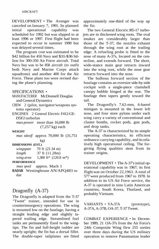
Dragonfly (A-37)The Dragonfly is adapted from the T-37"Tweet" trainer, intended for use incounterinsurgency operations. The wingis mounted low on the fuselage, having astraight leading edge and slightly ta-pered trailing edge. Streamlined fueltanks are permanently fixed to the wing-tips. The fin and full-height rudder arenearly upright; the fin has a dorsal fillet.The double-taper tailplanes are fitted
approximately one-third of the way upthe fin.
The two General Electric J85-17 turbo-jets are in thickened wing roots. The ovalintakes are considerably larger thanthose of the T-37; the nozzles exhaustthrough the wing root at the trailingedge: A refueling probe is fitted to thenose of many A-37s, located on the cen-terline, and extends forward. The short,wide-stance main gear retracts inwardinto the wing root, while the nose gearretracts forward into the nose.
The bulbous forward section of thefuselage contains an oversize side-by-sidecockpit with a single-piece clamshellcanopy bubble hinged at the rear. Thefuselage then tapers gently toward thetail.
The Dragonfly's 7.62-mm, 6-barrelminigun is mounted in the lower leftnose, and four store pylons under eachwing carry a variety of conventional andcluster bombs, rocket pods, gun pods,and drop tanks.
The A-37 is characterized by its simpleoperating characteristics, its efficientordnance-carrying capability, and its rela-tively high operational ceiling. The for-giving flying qualities stem from itstrainer origins.
DEVELOPMENT • The A-37's initial op-erational capability was in 1967; its firstflight was on October 22,1963. A total of577 were produced from 1967 to 1978. Inaddition to its US Air Force service, theA-37 is operated in nine Latin Americancountries, South Korea, Thailand, andprobably Vietnam.
VARIANTS • YA-37A (prototype),A-37A, A-37B, OA-37, T-37 Tweet.
COMBAT EXPERIENCE • In Decem-ber 1989, 21 OA-37s from the Air Force's24th Composite Wing flew 255 sortiesover three days during the US militaryoperation to remove Panamanian leader

AIRCRAFT 3
General Noriega. The aircraft were notused for ground attack, but rather forradio relay, medical evacuation coordina-tion, and flare dispensing.
SPECIFICATIONS •MANUFACTURER Cessna AircraftCREW 2
ENGINES 2 General Electric J85-GE-17Aturbojetmax power 2,850 Ib (1,293 kg) static
thrust eachfuel capacity
507 US gal (1,920 liters)WEIGHTS
empty 6,211 Ib (2,817 kg)max payload
5,680 Ib (2,576 kg)max takeoff 14,000 Ib (6,350 kg)
DIMENSIONS
wingspan 35 ft 10M> in (10.93 m)length 29 ft 3 in (8.92 m)height 8 ft lOVa in (2.7 m)wing area 184 ft* (17.09 m2)
PERFORMANCEmax speed 440 kts (507 mph; 816
km/h)max diving 455 kts (524 mph; 843
km/h)max cruise 425 kts (489 mph; 787
km/h)stall speed max weight: 98 kts (113
mph; 182 km/h)normal weight: 75 kts (86
mph; 139 km/h)climb rate 6,990 ft/min (2,130
m/min)ceiling both engines: 41,765 ft
(12,730 m)1 engine: 25,000 ft
(7,620 m)radius with 4,700-lb (2,132-kg)
weapons load: 74 nm(85 mi; 137 km)
with 3,700-lb (1,678-kg)weapons load: 217 nm(250 mi; 402 km)
with 1,300-lb (590-kg)weapons load: 478 nm(550 mi; 885 km)
range with 4,100-lb (1,860-kg)weapons load: 399 nm(460 mi; 740 km)
with 4 100-US gal (379-liter) drop tanks: 877nm (1,000 mi; 1,625km)
armament 1 GAU-2B/A 7.62-mmminigun with 1,500rounds
8 wing pylons for up to5,600 Ib (2,540 kg) ofordnance
Harrier (AV-8B)The AV-8B Harrier is an advanced Verti-cal Short Takeoff and Landing (VSTOL)fighter/attack aircraft that is coproducedby McDonnell Douglas Aircraft and Brit-ish Aerospace. It has the ability to take offvertically and hover. The AV-8B differsfrom previous Harriers by having a larger,more efficient wing shape, larger trailing-edge flaps and ventral air brake, strakesunder the gun/ammunition pods, re-designed engine intakes and nozzles,strengthened landing gear, a ventral airdam, and a more powerful engine, pro-viding twice the payload of the AV-8A.
The shoulder-mounted, low-aspect-ratio swept wings have supercritical air-foil sections and Leading-Edge RootExtensions (LERX) that increase in-stantaneous turn rate. In later aircraft,the LERX is enlarged for better handlingand survivability. Single-slotted trailing-edge flaps are located inboard of themidwing landing-gear pods. Droopingailerons are located outboard. The flapsare positioned automatically during flightto generate the best lift at a given angle ofattack.
The tail unit features a swept, pointedfin and rudder with a ventral fin belowthe fuselage. The aircraft is also fittedwith a Stability Augmentation and Atti-tude Hold System (SAAHS) and a shorttailboom.

4 AIRCRAFT
The Harrier's single engine providesboth lift and thrust. It has large, semicir-cular engine air intakes with two verticalrows of auxiliary air doors on each side ofthe fuselage. The engine power has beenupgraded several times during produc-tion. In place of a conventional exhaustnozzle, the Harrier uses swiveling ex-hausts that can be repositioned for hover-ing flight and for better combat maneu-vering. A water injection system increasesthrust by 2,500 Ib (1,134 kg) for IVz min-utes to aid in hot-weather takeoffs andlandings.
Retractable bicycle landing gear re-tracts into the fuselage; a single-wheelunit is forward, a twin-wheel unit aft.Rearward-folding outrigger landing gearretracts into pods extending aft from themidspan of each wing. The aircraft's netweight consists of 26% composite compo-nents. Compared to the original Harrierdesign, the cockpit has been raised 12 in(305 mm) and upgraded to include aMultipurpose Display (MPD) for attackand navigation as well as Hands on Throt-tle and Stick (HOTAS) technology.
The principal attack avionics system isthe Hughes nose-mounted AN/ASB-19(V)2 or (V) 3 Angle Rate Bombing Set(ARBS), which uses a TV/laser targetseeker and tracker. Navigation is aidedby the Litton AN/ASN-130A CarrierAircraft Inertial Navigation System(CAINS). The ARBS feeds informationto the Sperry AN/AYK-14(V) missioncomputer, the Lear-Siegler AN/AYQ-13Stores Management Set (SMS), andSmiths Industries SU-128A dual combin-ing, wide field-of-view Head-Up Display(HUD). Radar warning is provided by theLitton AN/ALR-67(V)2 radar-warningreceiver; the Loral AN/ALE-39 chaff/flare dispenser is fitted in the lower rearfuselage.
The aircraft carries an external 25-mmgun pack faired into the underfuselage,with a 1,000-lb (454-kg) capacity fuselagehardpoint for bombs or an AN/ALQ-164defensive ECM pod, four 2,000-lb (907-
kg) capacity wing pylons, two 620-lb(281-kg) capacity outboard pylons avail-able for bombs, rockets, air-to-air andair-to-ground missiles, and fuel tanks.Outrigger pylons were added to USMCAV-8Bs beginning with aircraft num-ber 167.
DEVELOPMENT • The Harrier's initialoperational capability for US MarineCorps service was in January 1985; theYAV-8B's first flight was on November 9,1978, AV-8B on November 5, 1981, andEAV-8B in August 1987. Until the AV-8A/C's retirement, the AV-8B was known asthe Harrier II.
The Marine Corps has been procuring300 AV-8B and 28 TAV-8B aircraft. Thefirst three aircraft of an order of 12EAV-8B were delivered to the SpanishNavy in October 1987, with the last twodelivered by the end of 1988. The produc-tion share for the US and Spanish aircraftis 60% for McDonnell Douglas and 40%for British Aerospace.
The Royal Air Force acquired GR Mk 5aircraft, with the first delivered on July 1,1987; production for the GR Mk 5 isshared equally between the two com-panies.
In October 1990, the United States,Italy, and Spain drafted a Memorandumof Understanding (MU) that guides de-velopment of the AV-8B Plus, a Harrier IIvariant fitted with a version of the AN/APG-65 radar used in the F/A-18 Hornet.Some of the Marines' AV-8Bs, includingthose ordered in FY1991, were upgradedto the Plus standard. The Spanish Navyplans to remanufacture its 11 EAV-8Bsand buy an additional seven.
In May 1990, following the MU nego-tiations, the Italian Parliament approvedthe purchase of 16 AV-8B Plus and twoTAV-8B trainers; delivery of the Jill-million order for the TAV-8Bs was madein August 1991. The AV-8B replaced theearlier British-built AV-8A/C Harrier andA-4M Skyhawk aircraft in US attacksquadrons.

AIRCRAFT 5
VARIANTS • YAV-8B, GR Mk 5, TAV-8B(trainer), EAV-8B Matador II (Spain),AV-8D Night Attack Harrier, Harrier GRMk 7, Harrier T10 (trainer), and AV-8BPlus.
COMBAT EXPERIENCE • US MarineCorps AV-8Bs were deployed to Saudi Ar-abia in mid-August 1990 as part of Opera-tion Desert Shield.
When Operation Desert Storm began,86 AV-8Bs—60 operating from airstripsin Saudi Arabia and 26 flying from am-phibious assault ships Tarawa (LHA 1)and Nassau (LHA 4) in the PersianGulf—compiled 3,567 sorties againstIraqi targets in Kuwait and Iraq. Almost3,000 tons of ordnance were delivered bythe aircraft.
The Harriers used their ARBS to de-tect targets and dropped laser-guidedbombs and launched laser-guidedAGM-65 Mavericks. In one attack, fourAV-8Bs were credited with the destruc-tion of 25 Iraqi tanks. On almost everysortie, 25-mm cannon fire was directedagainst a variety of vehicles (armored and"soft") and was said to have been veryeffective.
Five AV-8Bs were lost during the war,four in combat and one noncombat. Post-war Marine Corps analysis revealed thatthe midfuselage location of the enginenozzles made the Harriers much morevulnerable to an infrared missile hit thanother aircraft.
Many believe that the AV-8B, partic-ularly the Night Attack and AV-8B Plusvariants, represents the first truly effec-tive VSTOL combat aircraft.
SPECIFICATIONS •MANUFACTURER McDonnell Douglas
and British AerospaceCREW 1 (2 in TAV-8B)ENGINES
1 Rolls-Royce F402-RR-406 Pegasus11-21 turbofan
or 1 Rolls-Royce F402-RR-408 Pegasus11-61 turbofan
max power -406: 21,450 Ib (9,730 kg)static thrust
-408: 23,400 Ib (10,614kg) static thrust
internal fuel capacity1,100 US gal (4,164 liters)
max internal and external fuel capacityapprox 2,300 US gal
(8,705 liters)WEIGHTS
empty -406: 13,086 Ib (5,936 kg)-408: 13,968 Ib (6,336 kg)
max weapons load-406: 9,200 Ib (4,173 kg)-408: 13,235 Ib (6,003 kg)
design limit for 7 g operation22,950 Ib (10,410kg)
max takeoff -406, sea level, verticaltakeoff: ISA, 18,950 Ib(8,595kg);at90°F(32°C), 17,950 Ib(8,142 kg)
-408, tropical day: 20,595Ib (9,342 kg)
with 1,640-ft (500-m)takeoff roll: 31,000 Ib(14,061 kg)
DIMENSIONS
wingspan 30 ft 4 in (9.25 m)length 46 ft 4 in (14.12 m)height I l f t7 3 /4 in (3.55m)wing area 230 ft2 (21.37 m2)
PERFORMANCEmax speed sea level: 580 kts (668
mph; 1,075 km/h;Mach 0.88)
at altitude: Mach 0.91climb rate more than 13,000 ft/min
(3,962 m/min)ceiling 50,000 ft (12,240 m)radius with 1,200-ft (366-m) roll, 7 500-
Ib (227-kg) bombs, and 2 300-USgal(1,136-liter) drop tanks
-406: 471 nm (542 mi;873 km)
-408: 594 nm (684 mi;1,100 km)
ferry range with 300-US gal (1,136-liter)drop tanks

6 AIRCRAFT
dropped-406: 2,067 nm (2,380 mi;
3,850 km)-408: l,965nm (2,263 mi;
3,639 km)retained-406: l,720nm (1,981 mi;
3,187 km)-408: l,638nm (1,886 mi;
3,034 km)range 2,560 nm (2,946 mi;
4,741 km) max fuelarmament 1 GAU-12/U multibarrel
25-mm cannon, 250rounds
and 16 500-lb (227-kg)bombs
or 10 Paveway laser-guided bombs
or 12 cluster bombsor 10 rocket podsor 6 AIM-9 Sidewinder
AAMor 2 Sidewinder + 4
AGM-65 Maverick ASM
Intruder (A-6)The Intruder is the US Navy's carrier-based all-weather, night-attack aircraft. Itcan deliver a variety of conventional andnuclear ordnance. The Intruder was de-veloped on the basis of night-attack re-quirements generated during the KoreanWar in the early 1950s.
The A-6 configuration is relatively con-ventional. The wing is mounted at mid-fuselage height and has a modest 25°sweep at the quarter-chord. Nearly theentire leading edge is occupied by slats;virtually all of the trailing edge has single-slotted flaps. Spoilers that run parallel tothe flaps provide roll control when oper-ated differentially, lift dumping when op-erated collectively. The rear half of eachwingtip can be opened into upper andlower halves, thus acting as air brakes.
Almost 180 A-6Es are receiving compositewings to extend their service lives.
The fin leading edge has a slight sweepaft; the trailing edge, with its inset rud-der, sweeps slightly forward. The all-moving tailplanes are slightly swept andare mounted on the fuselage ahead of therudder hinge line.
The two J52 turbojet engines are con-tained in pods under the wing flankingthe fuselage; the airflow is a straight linefrom intake to exhaust. Each intake,headed by a boundary-layer splitter plate,is mounted in a cheek position below thecockpit; the exhausts appear beyond thewing trailing edge on either side of thefuselage. Both wings house integral fueltanks, and additional tankage is in thefuselage behind the cockpit and near thecenter of gravity. Intruders are fitted withan in-flight refueling probe mounted im-mediately ahead of the cockpit.
The fuselage, with its large nose ra-dome, bulged side-by-side cockpit, andtapered after section, resembles to somea tadpole. The side-by-side cockpit im-poses some drag penalty.
The remainder of the fuselage tapersaft and is filled with avionics equipmentand fuel. The retractable main gear unitsfold forward and inward into the intakepod; the nose gear retracts to the rear. Thearrester hook for carrier landings swingsdown from a fuselage point midway be-tween the wing trailing edge and the tail.Dual hydraulic systems power the controlsurfaces, flaps, speed brakes, and wheelbrakes. The design load factor is -1-6.5 g.
The A-6 was one of the first attack air-craft with an integrated offensive avionicssuite, known as DIANE (Digital Inte-grated Attack and Navigational Equip-ment) . The later Navy and Marine CorpsA-6Es had a major revision in its avionicspackage when the two-radar system wasreplaced by the Norden AN/APQ448multimode radar, which offers terrainavoidance as well as target acquisitionand tracking; an improved version is des-ignated APQ-156. The Litton ballistic

AIRCRAFT 7
computer was replaced by the IBMAN/ASQ433 (later improved as theASQ-155) digital, solid-state ballisticcomputer, which oversees some 60 dis-plays and sensors.
The primary cockpit display is the Kai-ser AVA-1 Vertical Display Indicator(VDI), which accepts information fromthe radar and navigational avionics, in-cluding the Litton AN/ASN-92 CarrierAircraft Inertial Navigation System(CAINS). Defensive avionics include theLockheed Sanders AN/ALQ-126B, AN/ALE-39 chaff dispenser, and Litton AN/ALR-67 Threat-Warning System.
The A-6E also has the Hughes AN/AAS-33 Target-Recognition Attack Mul-tisensor (TRAM), which integrates aForward-Looking Infrared (FLIR), a com-bination laser designator/rangefinder,and a laser designation receiver. North-rop's Infrared Video Automatic Tracking(IRVAT) automates the tracking portionof TRAM. The TRAM sensor is fitted in asmall, spherical turret under the nose; theBN uses a separate viewing scope for theTRAM.
Some A-6s have been retrofitted withblue-green cockpit lighting that is com-patible with Cats Eye Night Vision Gog-gles (NVG). These aircraft are able toreduce their minimum altitude duringnight flying (in good weather) from 500-800 ft (152-244 m) to 200 ft (61 m) andcan maneuver more sharply because ofthe pilot's improved field of view.
Weapons and external fuel tanks arecarried on the four wing pylons and an un-derfuselage attachment point; eachweapons station has a capacity of 3,600 Ib(1,633 kg) for a maximum payload of upto 18,000 Ib (8,182 kg). The Intruder'sbomb load makes it the most capable"bomber" in US naval service. AHarpoonantiship missile capability has been fittedto all aircraft, and the aircraft can carrySidewinder air-to-air missiles for self-defense as well as Brunswick Tactical Air-Launched Decoys (TALD). The aircraft is"wired" for carrying nuclear bombs.
A KA-6D tanker variant—-convertedfrom earlier attack models—has avionicsdeleted to provide space for the reel anddrogue; up to five 400-US gal (1,514-liter)drop tanks can be carried.
DEVELOPMENT • The A-6's initial op-erational capability was in 1963; itsfirst flight was on April 9, 1960, andthe KA-6D tanker prototype was on May23, 1966. Over 700 A-6s have been built,with 240 converted to the A-6E con-figuration. Intruders suffered a seriesof wing fatigue problems, with hairlinefractures occurring after approximately2,200 flight hours. Over 180 A-6 air-craft were grounded for wing inspec-tions in early 1987 after a series ofcrashes.
VARIANTS • A-6A, EA-6A Intruder(EW), A-6B, EA-6B Prowler (EW), A-6C,KA-6D, A-6E, A-6E Block 1 (A-6ESystems/Weapons Integration ProgramSWIP), A-6E Composite Rewing Pro-gram, A-6F, A-6G.
COMBAT EXPERIENCE • Intruderswere used extensively in the VietnamWar. A total of 68 Navy and Marine CorpsA-6 aircraft were lost in combat from 1965to 1973.
In December 1983, Intruders from theUSS Independence (CV 62) andJohnF. Ken-nedy (CV 67) participated in air strikesagainst Lebanon's Bekaa Valley; one In-truder and an A-7E Corsair were shotdown by Syrian missile batteries.
In March 1986, an A-6 aircraft from theUSS Coral Sea (CV 43) fired an AGM-84Harpoon missile at a Libyan Nanuchka-class corvette, sinking it. In April 1986,Intruders from the Coral Sea and the USSAmerica (CV 66) attacked five targets innorthern Libya in retaliation for allegedLibyan involvement in a terrorist bomb-ing in West Berlin.
In April 1988, A-6s from the USS Enter-prise (CVN 65) attacked Iranian Bogham-

8 AIRCRAFT
mer patrol boats, sinking one and chas-ing away four others. Later that day, A-6shelped sink the Iranian frigate Sahandand damaged the Sabalan (Sahand'ssistership).
On January 17, 199.1, 90 A-6Es from sixaircraft carriers in the Persian Gulf andRed Sea, along with 20 US Marine CorpsIntruders, attacked Iraqi targets at theinitiation of Operation Desert Storm.For the entire conflict, the Navy's A-6Econtingent flew 4,071 sorties and MarineCorps aircraft amassed 854. Four NavyA-6Es were lost in combat and one was anoncombat loss.
Two US Navy Intruders on separatemissions from the USS Abraham Lincoln(CVN 72) fired single HARM missiles atIraqi surface-to-air missile sites after be-ing illuminated by the radar. The aircraftwere monitoring the no-fly zone oversouthern Iraq in July 1993.
SPECIFICATIONS •MANUFACTURER Grumman AerospaceCREW 2 (pilot, bombardier/navigator)ENGINES 2 Pratt & Whitney J52-P-8B
turbojetmax power 9,300 Ib (4,218 kg) static
thrust eachinternal fuel capacity
2,344 US gal (8,873 liters)WEIGHTS
empty 26,600 Ib (12,065 kg)max weapons load
18,000 Ib (8,165 kg)max takeoff catapult: 58,600 Ib
(26,580 kg)land-based: 60,400 Ib
(27,397 kg)DIMENSIONS
wingspan 53 ft (16.15 m)length 54 ft 9 in (16.69 m)height 16 ft 2 in (4.93 m)wing area 529 ft2 (49.1 m2)
PERFORMANCEmax speed (sea level)
560 kts (644 mph; 1,036km/h)
cruise speed
stall speed
climb rate
ceiling
range
g limitsarmament
radar
412 kts (474 mph; 763km/h)
flaps up: 148 kts (164mph; 264 km/h)
flaps down: 98 kts (113mph; 182 km/h)
clean: 7,620 ft/min(2,323 m/min)
1 engine: 2,120 ft/min(646 m/min)
clean: 42,400 ft (12,924m)
1 engine: 21,000 ft (6,400m)
combat: 880 nm (1,012mi; 1,629 km)
with tanks: 2,375 nm(2,733 mi; 4,399 km)
without tanks: 2,818 nm(3,245 mi; 5,222 km)
+6.543,600-lb (1,933-kg)
capacity wing pylonsand 1 fuselagehardpoint for externalfuel and weapons
30 Mk 82 500-lb bombs0rlOMk831,000-lb
bombsor 3 Mk 84 2,000-lb bombsor3B43/B57/B61H
nuclear bombsor up to 4 missiles:
AGM-84A HarpoonAGM-88 HARMAGM-65 MaverickAGM-123A Skipper
IIAIM-9 Sidewinder
AN/APQ-156 multimode
Skyhawk (A-4)The Skyhawk is a small attack aircraft,originally developed for daylight-only nu-clear strike missions from US aircraft car-riers. It has subsequently been modified

AIRCRAFT 9
to serve as a highly versatile, light attackaircraft for conventional strike and closeair support missions.
The A-4 has a nonfolding, low-aspect-ratio delta wing mounted low on the fu-selage. The wing's quarter-chord sweep is33.2° and the wing dihedral angle is 2.67°.The wing's three spars run from tip to tip;virtually all of the wing is an integral fueltank. The leading edge has automaticslats and wing fences. The trailing edgehas split flaps inboard of horn-balancedailerons; ahead of the flaps are lift-dumping spoilers.
The A-4 has a "cropped delta" fin andribbed rudder; the ribbing reduces flut-ter, although not by design.
The engine air intakes are located onthe fuselage above the wing and behindthe cockpit. Rectangular air brakes arefitted on either side of the fuselage be-hind the wings. The aircraft's long-strokelanding gear retracts forward into thewings and nose. The pilot sits well for-ward and has excellent visibility. Thecockpit is enclosed by a single-piece, rear-hinged canopy.
The 20-mm or 30-mm cannon are lo-cated in the wing roots, and five attach-ment points are provided for weaponsand external fuel tanks. The outboardwing pylons are rated at 570 Ib (258 kg)each, the inboard wing pylons at 1,750 Ib(794 kg) without roll restrictions and2,240 Ib (1,016 kg) with restrictions, andthe centerline fuselage hardpoint at3,575 Ib (1,622 kg). These hardpointscarry antiradar and land-attack missilesas well as conventional bombs, rocketpods, and mines. Avionics include aHead-Up Display (HUD), Angle RateBombing Set (ARBS), a loft bomb com-puter system, and a tailfin-mounted ECMsystem.
DEVELOPMENT • The A-4's initial op-erational capability was in 1956; its firstflight (the XA4D-1) was on June 22,1954.The Skyhawk's production from 1956 to1979 totaled 2,960, of which 555 were
two-seat variants. Although the aircraft isno longer in service with active US Navyor Marine Corps units (last active USMCaircraft retired on July 6, 1990), NewZealand and Singapore are updatingmany of their A-4s, enabling them toserve to the end of the century.
When Iraq invaded Kuwait in August1990, five single-seat A-4KUs and all sixtrainers were captured, but Kuwait'sother 25 attack aircraft escaped to SaudiArabia.
The aircraft has been replaced by theA-7 Corsair. It was replaced in the USBlue Angels flight demonstration team in1987 by the F/A-18 Hornet. It is replacedin US Marine Corps service by the AV-8BHarrier. Both the Navy and Marine Corpsfly large numbers of A-4s for training,target tow, and other special missions.
The A-4 is operated by seven foreign airforces. The Skyhawk has enjoyed a repu-tation for durability and possesses goodhandling characteristics. Recent Argen-tina, New Zealand, and Singapore updateprograms reflect the airplane's versatility.
VARIANTS • XA4D-1, A-4A, A-4B,TA-4B, A-4C, A4D-3, A-4E, A-4F, TA-4F,EA-4F (EW), A-4G/TA-4G, A-4H/TA-4H,TA-4J, A-4K/KAHU, A-4KU/TA-4KU,A-4L, A-4M Skyhawk II, A-4N, A-4P, A-4Q,A-4PTM/TA-4PTM ("Peculiar to Malay-sia"), A-4S, A-4S-1 Super Skyhawk.
COMBAT EXPERIENCE • Skyhawkswere used extensively by the US Navy andMarine Corps in the Vietnam War and byIsrael in the Middle East wars. During the1973 Yom Kippur War, Israel lost 53 of itsSkyhawks. Argentina flew the A-4 in the1982 Falklands War against Britain.
Skyhawks were often used for simulat-ing Soviet threat aircraft in US militarypilot training during the cold war.
During the Iraqi invasion of Kuwait inAugust 1990, Kuwaiti Skyhawks bombedand strafed Iraqi forces until resistanceended on August 4. A total of 21 helicop-ters and four Iraqi patrol boats were

10 AIRCRAFT
destroyed. 25 A-4KUs from the 9th and25th Squadrons flew to Saudi Arabia to re-group.
When Operation Desert Storm beganon January 17, 1991, the Kuwaiti A-4sflew against targets in Kuwait. Thesquadron commander was shot down byground fire in an early raid; no otherA-4KUs were lost. Limited by the lack ofradar or radar-warning systems, the rela-tively "low-tech," day-attack A-4s reliedon E-3 Airborne Warning and ControlSystem (AWACS) for defense againstIraqi fighters. Kuwaiti A-4 sorties contin-ued until the cease-fire on February 28,1991.
SPECIFICATIONS •MANUFACTURER McDonnell DouglasCREW 1 (2 in TA-4 and OA-4 variants)ENGINES 1 Pratt & Whitney J52-P-408
turbojetmax power 11,200 Ib (5,080 kg) static
thrustinternal fuel capacity
800 US gal (3,208 liters)WEIGHTS
empty 10,456 Ib (4,743 kg)max external load
9,195 Ib (4,139 kg)max takeoff 25,500 Ib (13,113 kg)
DIMENSIONS
wingspan 27 ft 6 in (8.38 m)length 40 ft 4V4 in (12.3 m)
TA-4/OA-4: 42 ft 7V4 in(12.98 m)
height 14 ft 11 in (4.55m)TA-4/OA-4: 15 ft 3 in
(4.66 m)wing area 260 ft2 (24.16 m2)
PERFORMANCE
max speed (sea level)clean: 582 kts (670 mph;
1,078 km/h)with 4,000 Ib (1,814 kg) of
weapons: 560 kts (645mph; 1,038 km/h)
climb rate 8,440 ft/min (2,573m/min)
ceiling 42,250 ft (12,878 m)
radius with 4,000 Ib (1,814 kg) ofweapons and external fuel
335 nm (386 mi; 620 km)range with 4,000-lb (1,814-kg) of weapons
and external fuel799 nm (920 mi; 1,480
km)ferry range 2,055 nm (2,366 mi;
3,808 km)armament 2 20-mm Mk 12 cannon
with 200 rounds eachor 2 30-mm DEFA cannon
with 150 rounds eachand 14 500-lb (227-kg)
bombsor31,000-lb (454-kg)
bombsor 1 2,000-lb (907-kg)
bombor 1 4,500-lb (2,041-kg)
bombor4AGM-45Shrike
missilesor 3 AGM-62 Walleye
missilesor 4 AGM-65 Maverick
missilesor IMk 43/57 nuclear
store
Spectre (AC-130)The Spectre gunship is derived from theC-130 Hercules, the most widely used mil-itary transport in the modern militaryera. AC-130s were first used in Vietnamand more recently to support Special Op-erations Forces (SOF) missions. (For adescription of the basic C-130, see CargoAircraft.)
The weapons in the AC-130H consist ofa 105-mm howitzer, two 20-mm VulcanCatling cannon, and a Bofors 40-mm/70-cal cannon, all mounted athwartshipsand firing to port. The howitzer is carriedin a hydraulic mount just ahead of therear cargo ramp. It has a shortened barreland a 49-in (1.24-m) recoil and is fired bya three-man crew (gunner at the control

AIRCRAFT 11
AC-130 SpectreU.S. GOVERNMENT DEPARTMENT OF DEFENSE
panel, loader, and unloader). The how-itzer's pointing angle is 20° in azimuthfore and aft and 40° elevation. 76 readyrounds are carried near the gun with an-other 24 stowed farther forward.
The Bofors cannon is ahead of the 105-mm howitzer in a hydraulic, trainablemount served by two crew members. Ithas a rate of fire of 100 rounds per min-ute and 69 4-round clips. The two VulcanCatling cannon are mounted in parallelbetween the forward door and thelanding-gear sponson. Each fires at a rateof 2,500 rounds/mm and has a magazineof 3,000 rounds.
Avionics are comprehensive and in-clude several sensors. A General ElectricAN/ASQ-145 Low-Light-Level Television(LLLTV) and an AN/AVQ-19 laser desig-nator are mounted in a stabilized turretlocated in the forward door. Ahead of thedoor is a large radome for the AN/ASD-5Black Crow ignition tracking system. The
AN/AAD-7 Forward-Looking Infrared(FLIR) ball is mounted on the nose of theport-landing-gear sponson. The AN/APQ-150 beacon tracking radar is fittedin between the 40-mm cannon and the105-mm howitzer. The AN/AVQ-17 IR/whitelight searchlight is mounted on theport rear fuselage.
The three sensor operators are housedin a single position in the cargo hold be-tween the two sets of gun positions. Be-cause the location of armament and thepilot's Head-Up Display (HUD) are bothon the port side, all firings are in a portorbit.
A Litton AN/ALR-69 radar-warningreceiver is fitted in the fuselage. Fourchaff/flare launcher systems are fittedto each side of the aircraft, and twomore are in the tail; a total of 300 car-tridges are carried. Westinghouse AN/ALQ-119 noise/deception jamming andSUU-42 IR countermeasures pods can becarried on the Triple Ejection Racks(TER) that are fitted to the external fueltanks.
DEVELOPMENT • Although the basicC-130 is flown throughout the world, theAC-130 is flown only by the US Air Force.The AC-130's initial operational capa-bility was in 1967. Two AC-130 variants,the -A and -H, serve with Special Opera-tions Squadrons, the former in an AirForce reserve unit and the latter in anactive unit. The AC-130As are in servicewith a US Air Force Reserve Special Op-erations Squadron, while AC-130Hs arein active service with the 16th Special Op-erations Squadron.
The latest variant, the AC-130U pro-gram, suffered from delays and cost in-creases. Problems in design of thesoftware and the Electronic Warfare(EW) suite and compressed develop-ment and production schedules were sin-gled out as causes. It is air refuelable andincludes a side-firing weapons system.The AC-130U variant's mission is to pro-vide precision fire support for Special

12 AIRCRAFT
Operations Forces, as well as conven-tional forces, plus performing escort, sur-veillance, search and rescue, and armedreconnaissance/interdiction missions.
VARIANTS • C-130 Hercules, AC-130,AC-130A, AC-130E, AC-130H, AC-130U.
COMBAT EXPERIENCE • In Decem-ber 1989, seven AC-130 aircraft flew 74sorties against Panamanian forces as partof the American military operation tooust General Noriega. Gunfire from anAC-130 destroyed or disabled nine vehi-cles from a Panamanian convoy appearedheading toward US forces at Tocumen/Torrijos International Airport.
In late January 1991, an AC-130 wasshot down off the Kuwaiti coast duringOperation Desert Storm against Iraqiforces in Kuwait. All 14 men on boardwere listed as missing; the wreckage wasfound in shallow water in early March.AC-130s supported Special OperationsCommand missions that placed smallteams in Iraq and Kuwait to gather intel-ligence and conduct operations.
Spectres were deployed to Somalia inmid-1993 and used against the forces ofwarlords, marking the first military en-gagement under the Clinton administra-tion.
SPECIFICATIONS •MANUFACTURER Lockheed-GeorgiaCREW 14 (2 pilots, navigator, flight en-
gineer, radio operator, 3 sensor oper-ators, and gun crews)
ENGINES 4 Allison T56-A-15 turbopropmax power 4,591 effective hp eachinternal fuel capacity
9,679 US gal (36,636liters)
WEIGHTSempty 76,469 Ib (34,686 kg)maxpayload 42,673 Ib (19,356 kg)takeoff normal: 155,000 Ib
(70,310 kg)max: 175,000 Ib (79,380
kg)
DIMENSIONSwingspan 132 ft 7 in (40.41 m)length 97 ft 9 in (29.79 m)height 38 ft 3 in (11.66m)wing area 1,745 ft2 (162.12 m2)ramp opening
length: 9 ft 1 in (2.77 m)width: 10 ft (3.05 m)
PERFORMANCEcruise speed
max: 325 kts (374 mph;602 km/h)
econ: 300 kts (345 mph;556 km/h)
stall speed 100 kts (115 mph; 185km/h)
climb rate 1,900 ft/min (579m/min)
ceiling at 130,000 Ib (58,970 kg)4 engines: 33,000 ft
(10,060 m)3 engines: 26,500 ft
(8,075 m)range max payload: 2,046 nm
(2,356 mi; 3,791 km)max fuel with 15,611-lb
(7,081-kg) payload:4,250 nm (4,894 mi;7,876 km)
takeoff run: 3,580ft(1,091 m)
armament 1 X 105-mm howitzer (76ready rounds, 24stowed)
1 X 40-mm Boforscannon (276 rounds)
2 X 20-mm VulcanGalling cannon (6,000rounds)
radar APQ-150
Thunderbolt (A-10)The Thunderbolt was designed specifi-cally for Close Air Support (CAS) opera-tions. It was especially designed andarmed to engage tanks and other ar-mored vehicles and to operate from aus-terely equipped forward bases, a mission

AIRCRAFT 13
U.S. Air Force A-10 Thunderbolt IIU.S. GOVERNMENT DEPARTMENT OF DEFENSE
it carried out effectively during Opera-tion Desert Storm. (The World War II-era Soviet 11-2 Sturmovik ground-attackaircraft and the more recent Su-25Frogfoot were designed for a similar mis-sion.) The A-10 originally had only avisual targeting capability but subse-quently was upgraded with a laser spotseeker.
The design and construction of theA-10 was governed by the desire to delivera heavy weapons load, require little main-tenance, and remain survivable in an in-tensely antiaircraft environment; speedand ceiling were deemphasized. The lowwing is a thick-sectioned airfoil with littletaper. The center section has no dihedralor taper; the outer panels, which are at-tached just outboard of the leading-edgelanding-gear "knees," have dihedral,some taper, and turned-down tips. High-lift devices include slats on the center-section leading edge and trailing-edgedouble-slotted flaps inboard of broad-chord ailerons.
The tail group has low-mounted, rect-
angular horizontal tailplanes, each withan upright endplate fin and rudder. Thefin and rudder have converging taper. Allmovable tail surfaces are left/right inter-changeable; the aircraft can fly with anentire vertical tail missing. Hydrauliccontrol systems for the control surfacesare duplicated, with each system taking adifferent path through the airframe;there is also a mechanical backup system.The A-10 is also fitted with a General Elec-tric two-axis, two-channel Stability Aug-mentation System (SAS).
The two TF34 turbofans are housed inlarge nacelles mounted on short stubs onthe fuselage flanks ahead of the tailgroup. The engine position reduces vul-nerability to small-arms fire while the In-frared (IR) signature is blanketed by thewing and tailplane. Engine-out controlasymmetry is reduced because the en-gine thrust lines are relatively close to thecenterline. Internal fuel tankage consistsof tear-resistant, self-sealing, foam-filledcells.
The fuselage is relatively slender, with

14 AIRCRAFT
the cockpit placed well ahead of thewing leading edge. As part of the air-craft's ballistic protection, the pilotsits in a 700-lb (318-kg) titanium tub de-signed to resist 23-mm antiaircraft artill-ery fire. Further passive protection isprovided by Electronic Support Mea-sures (ESM), such as the LittonAN/ALR-46/69 radar-warning receiver,and 16 Tracor AN/ALE-40(V)10 chaffcartridge dispensers mounted in groupsof four in each wingtip and wheel well;Westinghouse AN/ALQ-119, AN/ALQ-131, or Raytheon AN/ALQ-184 activejammer pods can also be carried on wingpylons.
The main landing struts retract for-ward into "knees" located at the dihedralbreak of the wing leading edges. Thewheels are partially exposed when re-tracted. The nose gear is offset to port toprovide clearance for the 30-mm cannonbarrel; it retracts forward under the cock-pit.
The cockpit is enclosed by a single-piece canopy that is hinged at the rear.Avionics include a Kaiser Head-Up Dis-play (HUD) with a MIL-STD-1553 multi-plex digital databus system, a LittonLN-39 Inertial Navigation System (INS),and the Martin Marietta AN/AAS-35(V)Pave Penny day/night laser tracker. ThePave Penny is mounted on a small pylonattached to the port side of the fuselagebelow the cockpit.
For the A-10's offensive ground-attackcapability, a General Electric GAU-8/AAvenger 7-barrel 30-mm Gatling gun ismounted in the forward fuselage. Theinstallation, including the 1,174-roundammunition drum, is 19 ft 10 in(6.05 m) long and weighs 4,029 Ib (1,829kg). The cannon has a maximum rate offire of 70 1.5-lb (0.68-kg) rounds persecond.
Fuselage weapons stations includethree side-by-side ventral hardpoints. Ei-ther the outer two, each with a 3,500-lb(1,588-kg) capacity, or the centerline5,000-lb (2,268-kg) capacity hardpoint
can be used, but not all three simul-taneously. The center-section wing py-lons have a 3,500-lb (1,588-kg) capacity.Outboard of the landing gear on eachwing are three pylons, the inner one ca-pable of a 2,500-lb (1,134-kg) load, themiddle one 1,200 Ib (544 kg), and theouter pylon 1,000 Ib (454 kg).
The maximum weapons load of 16,000Ib (7,258 kg) can include AGM-65 Mav-erick TV- or IR-guided air-to-groundmissiles, conventional and laser-guidedbombs, rocket pods, gun pods, sub-munitions dispensers, AIM-9 SidewinderAir-to-Air Missiles (AAM), and fueltanks.
DEVELOPMENT • The A-10's officialname was originally Thunderbolt II inhonor of Republic's P-47 fighter-bomberof World War II; the "II" was laterdropped. Pilots and ground crew morecommonly refer to the A-10 as the Wart-hog or Hog; the latter nickname has beenapplied to most Republic Aviation air-craft since World War II. The Warthog'sinitial operational capability was in 1977,and its first flight was on May 10, 1972.Production ended in 1984 after 707 air-craft, and six preproduction aircraft,were delivered. The A-10 has served forthe Air National Guard in addition to theactive US Air Force. Thailand announcedplans to purchase 25 A-lOs in the early1990s.
The FY1991 Defense Authorization billrequired that A-lOs replace US ArmyOV-1 Mohawks and US Marine CorpsOV-10 Broncos over a five-year period.
VARIANTS • A-10A, A-10 NAW(Night/Adverse Weather), A-10 up-grades: Low Altitude Safety and TargetEnhancement (LASTE) program, Close-Air Support/Batdefield Air Interdiction(CAS/BAI) program, OA-10.
COMBAT EXPERIENCE • The A-10participated with distinction in Opera-

AIRCRAFT 15
tion Desert Storm, attacking tactical andtheater targets in Iraq and Kuwait. Beforethe ground war began on February 24,Warthogs attacked a variety of targets in-cluding Scud mobile ballistic missilelaunchers, radar sites, and surface-to-airmissile positions. When preparation forthe ground war began, most A-10 sortieswere directed against Iraqi armored andunarmored vehicles. In all, A-lOs flew ap-proximately 8,100 sorties.
Limitations imposed by the lack of aradar or FLIR were overcome by usingthe AGM-65D Maverick's IR seeker tosearch for targets. The 30-mm cannonproved effective against a variety of tar-gets, including two helicopters shot downover Kuwait. Accounts credited pairs ofA-lOs with destroying 20 or more tanks ina single day. Altogether, Warthogs werecredited with over 1,000 tanks, 2,000 mili-tary vehicles, and 1,200 artillery piecesdestroyed.
Five A-10s were shot down during theseven-week war.
SPECIFICATIONS •MANUFACTURER Fairchild-RepublicCREW 1ENGINES 2 General Electric TF34-GE-
100 turbofanmax power 9,065 Ib (4,112 kg) static
thrust eachWEIGHTS
empty 21,519 Ib (9,761 kg)
forward airstrip weight, armed andfueled
33,412 Ib (15,155 kg)max takeoff 50,000 Ib (22,680 kg)
DIMENSIONSwingspan 57 ft 6 in (17.53 m)length 53 ft 4 in (16.26m)height 14 ft 8 in (4.47m)wing area 506 ft2 (47 m2)
PERFORMANCE
max speed 367 kts (423 mph; 681km/h)
cruise 300 kts (345 mph; 555km/h)
climb rate 6,000 ft/ min (1,829m/min)
radius with 9,000-lb (4,309-kg)weapons load, 1.8-hrloiter: 250 nm (288 mi;463km)
single-store deep strikepenetration: 540 nm(622 mi; 1,000 km)
FERRY RANGE 2,209 nm (2,542 mi;4,091 km)
ARMAMENT1 GAU-8/A 30-mm multibarrel gun in
fuselage w/1,174 rounds18 Mk 82 500-lb (227-kg) or 6 Mk 84
2,000-lb (907-kg) bombsor 6 AGM-65 Maverick air-to-surface
missilesor 18 Rockeye II cluster bombsor 6 500-lb (227-kg) or 4 2,000-lb (907-
kg) laser-guided bombs
BOMBERSF-lll/FB-lllThe FB-111 was the strategic/theaterbomber version of the US F-l 11 multipur-pose aircraft. Both are described here.The FB-111 design differs from the tacti-cal strike aircraft variants by having differ-ent engines, a SVa-ft (1.07-m) extensionon each wingtip, strengthened land-
ing gear and fuselage, greater fuel capac-ity, and improved avionics.
In the basic F-l 11 design, the pivotpoints for the variable-sweep, shoulder-mounted wings are located relativelyclose to the fuselage inside fixed wing"gloves"; the gloves extend forward to
16 AIRCRAFT
the rear of the cockpit and give the planea "hooded cobra" look. Although theclose-set pivots complicated design andrequired a titanium wing carry-throughstructure, they also result in a low mini-mum sweep angle of 16° and a high maxi-mum sweep angle of 72V2°; such a widerange results in an aircraft with relativelylow takeoff, landing, and stall speeds aswell as supersonic, low-altitude penetra-tion flight.
High lift surfaces line the full span ofthe leading and trailing edges of thewing; the trailing-edge flaps are double-slotted. Roll control is achieved throughspoilers and large, all-moving swept tail-planes that move differentially for roll,collectively for pitch. The broad-chord,swept fin has a full-height rudder.
The two TF-30-P-7 twin-spool turbofanengines are buried in the aft fuselage andfed by variable-area intakes that are fittedwith boundary-layer splitter plates and lo-cated on the fuselage flanks under theleading edge of the fixed wing gloves. Theengines are fitted with variable-area noz-
zles with blow-in door ejector. Fuel tanksoccupy much of the fuselage ahead andbehind the wing carry-through structureas well as most of each wing. All F/FB-111shave in-flight refueling capability.
The fuselage is broad enough to ac-commodate a side-by-side cockpit for thepilot and navigator. The aircraft's maxi-mum design load factor at design weightis 3 g.
The cockpit is protected by individualcanopies over each seat; these are hingedon a common centerline rail and, whenopen at the same time, have a gull-wingappearance. The cockpit and glazing arecombined in an escape pod that is ejectedby a single rocket; the crew remains withthe pod while it parachutes to earth.
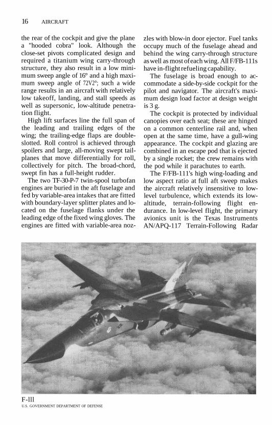
The F/FB-111's high wing-loading andlow aspect ratio at full aft sweep makesthe aircraft relatively insensitive to low-level turbulence, which extends its low-altitude, terrain-following flight en-durance. In low-level flight, the primaryavionics unit is the Texas InstrumentsAN/APQ-117 Terrain-Following Radar
F-lllU.S. GOVERNMENT DEPARTMENT OF DEFENSE

AIRCRAFT 17
(TFR) fitted in the nose radome. Otheravionics include the General ElectricAN/APQ-117 attack radar (upgraded tothe AN/APQ-169), General DynamicsAN/AYK-6 digital computer, AN/AYN-3Horizontal Situation Display, AN/ASG-25 optical display sight, AN/AJN-16 iner-tial bomb navigation system, AN/APN-167 radar altimeter, and AN/APN-185Doppler radar.
The comprehensive Electronic Sup-port Measures/Electronic Counter-measures (ESM/ECM) suite includes aCincinnati Electric AN/AAR-34 Infrared(IR) warning receiver, Loral AN/ALR-41homing receiver, Dalmo Victor AN/APS-109B Radar Homing and WarningSystem (RHAWS), Sanders AN/ALQ-94or AN/ALQ-137 internal noise/decep-tion jammer, and an AN/ALE-28 coun-termeasures dispenser.
The internal weapons bay is located be-tween the nose and main gear bays andhas a volume of 126 ft3 (3.57 m3). The baycarries either two nuclear bombs or twoAGM-69 nuclear Short-Range Attack Mis-siles (SRAM). Of the six externalweapons pylons, the center and inboardpylons under each wing swivel with thewing sweep. The outermost pylon oneach wing is fixed so that it creates theleast drag at a 26° sweep angle; these py-lons are used for fuel tanks and are jet-tisoned with the tanks when the latter areempty. The other four pylons carrySRAMs, nuclear bombs, conventional750-lb (340-kg) bombs, cluster bombs, or600-US gal (2,271-liter) drop tanks.
DEVELOPMENT • The FB-lll's initialoperational capability was in October1969, and its first flight was in July 1967.While in production from 1968 to 1971,76 were built. The last was retired on July10,1991. 22 FB-llls, designated FB-lllGs,were converted to trainers beginning inJune 1990 and would be retired by early1994 at the latest.
An unofficial US Air Force nicknamefor the F/FB-111 is the Aardvark, refer-
ring to the long nose. The FB-111 sawservice only with the USAF and is nolonger in operation; the F-lll is in ser-vice with Australia.
VARIANTS • FB-111A, FB-111G, FB-111H (upgraded engines, stretched fu-selage), F-lll G.
COMBAT EXPERIENCE • First combatuse of the US Air Force F-lll aircraftcame in 1972-1973 with limited resultsand relatively heavy losses during raidsinto North Vietnam.
Twelve England-based F-lllFs aircraftattacked Libyan targets at night on April15,1986. (Five more developed problemsthat forced them to turn back.) One waslost with its two-man crew. Each F-l 11 re-quired three in-flight refuellings enrouteto the target and two more on the returnflight.
On January 17, 1991, the 38 F-lllFsdeployed in the region attacked Iraqi tar-gets as part of the air assault that beganOperation Desert Storm. Together withthe F-l 17 Stealth "Fighter" and the F-15EEagle, the F-lllFs were responsible formany of the precision-bombing strikesusing laser-guided bombs that dislocatedthe Iraqi air-defense system. F-lllFs alsoattacked Scud fixed and mobile ballisticmissile sites, as well as delivering LGBsagainst 1,500 armored vehicles (known as"tank plinking"). No F-l 11s were lost inthe seven-week campaign.
SPECIFICATIONS (FB-111) •MANUFACTURER General DynamicsCREW 2 (pilot, navigator)ENGINES 2 Pratt & Whitney TF30-P-7
turbofanmax power with afterburner: 20,350
Ib (9,231 kg) st (staticthrust) each
intermediate withoutafterburner: 12,350 Ib(5,602 kg) st each
max fuel capacity: 5,623US gal (19,088 liters)

18 AIRCRAFT
WEIGHTSempty 47,481 Ib (21,537 kg)combat 70,380 Ib (31,924 kg)design 110,646 Ib (50,188 kg)max takeoff 119,243 Ib (54,088 kg)
DIMENSIONSwingspan 70 ft (21.34 m) extended,
33 ft 11 in (10.34m)swept
length 75 ft 6Vs in (23.03 m)height 17 ft 1 in (5.22 m)wing area 550 ft2 (51.11 m2)
PERFORMANCEmax speed at high altitude
l,262kts(l,453mph;2,338 km/h) or Mach2.2
basic speed at 35,000ft (10,668 m)1,188 kts (1,368 mph;
2,201 km/h) or Mach2.05
max combat speed at sea level728 kts (838 mph; 1,349
km/h) or Mach 1.1max dash speed, high altitude
1,147 kts (1,321 mph;2,125 km/h) orMach 2
max dash speed, low-level562 kts (647 mph; 1,041
km/h) or Mach 0.85range cruise
444 kts (511 mph; 823km/h)
max rate of climb, with external weaponsstores
22,870 ft/min (6,971m/min)
ceiling at combat weight50,263 ft (15,320m)
armament internal weapons bay with2B43/B61/B83nuclear bombs
and 6 wing pylons for upto 31,500 Ib (14,288kg) weapons loadincluding:4SRAMs
or24750-lb (340-kg)Ml 17 bombs
radar AN/APQ-134 or -171TFR
AN/APQ414or-169attack
SPECIFICATIONS (F-111) •MANUFACTURER General DynamicsCREW 2 (pilot, navigator)ENGINES
F-111A: 2 Pratt & Whitney TF30-P-3turbofan
F-111F: 2 Pratt & Whitney TF30-P-100turbofan
max power with afterburnerF-111A18,500 Ib (8,391
kg) st eachF-111F 25,100 Ib (11,385
kg) st eachmax fuel capacity
5,043 US gal (19,088 liters)WEIGHTS
empty F-111A: 46,172 Ib (20,943kg)
F-111F: 47,481 Ib (21,537kg)
combat weightF-111A: 64,728 Ib (29,360 kg)F-111F: 63,048 Ib (28,598 kg)
typical takeoffF-111A: 82,819 Ib (37,566 kg)F-111F: 85,589 Ib (38,823 kg)
max takeoff F-111A: 98,850 Ib (44,838kg)
F-111F: 100,000 Ib(45,360 kg)
DIMENSIONS
wingspan 63 ft (19.2 m) extended,31 ft 11 in (9.74m)swept
length 73 ft 6 in (22.4 m)height 17 ft 1 in ( 5.22 m)wing area 525 ft2 (48.77 m2)
PERFORMANCEmax speed at high altitude
F-111A: 1,262 kts (1,453mph; 2,338 km/h) orMach 2.2
F-111F: 1,436 kts (1,653mph; 2,660 km/h) orMach 2.5

AIRCRAFT 19
basic speed at 35,000ft (10,668 m)1,196 kts (1,377 mph;
2,216 km/h) or Mach2.1
max combat speed at sea level794 kts (914 mph; 1,471
km/h) or Mach 1.2range cruise
444 kts (511 mph; 823km/h)
max rate of climb with external weaponsstores
F-111A: 26,600 ft/min(8,108 m/min)
F-111F: 43,050 ft/min(13,122 m/min)
ceiling at combat weightF-l 11A: 55,300 ft (16,855
m)F-111F: 57,100 ft (17,404
m)radius F-l 11 A, hi-lo-lo-lo-hi at
combat weight with 12750-lb (340-kg) bombs:681 nm (784 mi; 1,262km)
F-l 1 IF, hi-lo-hi at com-bat weight with 24750-lb (340-kg) bombs:440 nm (507 mi; 815km)
range with 4 600-USgal (2,271-liter) droptanks
F-lllA:3,156nm (3,634mi; 5,848 km)
F-l 1 IF: 2,934 nm (3,379mi; 5,437 km)
armament internal weapons bay for1 M61A1 20-mm gun(2,050 rounds)
and 1 B43 nuclear bombor 2 B43/61/83 nuclear
bombsand 4 wing pylons for
31,500-lb (14,288-kg)weapons load
or 4 AIM-9 SidewinderAAM
or 4 600-US gal (2,271-liter) drop tanks
Lancer (B-l)The B-l is the long-range strategicbomber designed originally for low-altitude penetration missions against mo-bile ICBMs or standoff Air-LaunchedCruise Missile (ALCM) attacks. 100 wereprocured in the early 1980s as a "bridge"in capability between the aging B-52Stratofortress and the planned B-2 Ad-vanced Technology Bomber (ATB or"Stealth").
The B-1B features variable-geometrywings mounted at midfuselage. The wingpivot is located relatively close to the fu-selage, which yields a large change inwing aspect ratio from its minimumsweep angle of 15° to the maximumsweep angle of 67!/2°. As with several other"swing-wing" aircraft designs, the pivotsand wing carry-through structure are ti-tanium. The outer panels are of moreconventional aluminum-alloy construc-tion.
In addition to the low-sweep angle,takeoff and landing performance isaided by leading- and trailing-edge lift de-vices. Each leading edge has full-spanslats in seven sections that droop 20° fortakeoff. Each trailing edge is fitted withsix single-slotted flap sections with a max-imum down flap setting of 40°. Roll con-trol is provided by four sections ofspoilers on each wing; there are noailerons.
The vertical tail is a relatively uprightsurface made of titanium and aluminumalloy. The three-section rudder is insetinto the trailing edge with the lowest sec-tion set below the tailplane. Large, swepttailplanes are mounted on a commonspindle that passes through the fin at areinforced station approximately one-third up the fin. The tailplanes can beused differentially to aid roll control aswell as collectively for pitch control.
Four independent 4,000-psi (276-bar)hydraulic systems power the flight con-trols, flaps, landing-gear actuation,landing-gear doors, and weapons-bay

20 AIRCRAFT
doors. A quadruplex Automatic FlightControl System (AFCS) is fitted. Ridecontrol at low altitudes is provided by theStructural Mode Control Subsystem(SMCS) that uses accelerometers todampen the rough ride at low altitude.Two small, swept vanes are fitted at 30°anhedral in the lower fuselage just aheadof the cockpit; these work in conjunctionwith the lowest rudder section undercommand of the SMCS.
The B-1B initially had little inherentstall warning, and its terrain-followingperformance had deteriorated due tothe substantially higher gross weightscompared to the B-1A. A Stall InhibitorSystem (SIS-1) was fitted to the first 18aircraft to force the pilot to "fail-safe"by limiting his control system powernear the B-lB's Angle of Attack (AoA)limits.
A later SIS-2 is a backup to the triple-redundant Stability Enhancement Func-tion (SEF), which is designed to expandthe AoA limits and permit Mach 0.95speeds at max gross weight from sea levelto about 6,000 ft (1,829 m) while retain-ing an adequate margin of controllability.In addition to reducing the necessarystall warning margin from 20% to 5%above aerodynamic stall, the SEF systemhas permitted successful automaticterrain-following flights at 200 ft (61 m)in a "hard-ride," hands-off mode. AllB-lBs were retrofitted with the SIS-2/SEFsystem, with fully equipped B-lBs enter-ing squadron service between Januaryand April 1990.
Four General Electric turbofans arehoused in pairs in nacelles under thewings. They are fed through fixed-geometry intakes that limit maximumspeed to approximately Mach 1.25. Prob-lems with the engine's first-stage com-pressor fan led to the Air Force'scessation of all B-l routine trainingflights in December 1990 until the sourceof the failures could be found.
Internal fuel tankage is located in thefuselage midbody and in the outer wings.
The in-flight refueling receptacle is fittedahead of the cockpit.
The fuselage has a blended wing-bodyunion similar to that of the F-16 FightingFalcon. The B-lB's Radar Cross Section(RCS) that gives the plane its "stealthi-ness" is approximately ¥7 that of theFB-111A, Via of the B-1A, and VIM of theB-52. The small RCS is achieved throughshaping and Radar-Absorbent Materials(RAM) used at many points on the air-frame.
Although much of the structure is alu-minum alloy, titanium is used where highheat is generated (firewalls, engine bays)or high stress is expected (tail, rear fu-selage skinning). The main landing gearwas strengthened to accept the B-lB'shigher gross weights; the two four-wheelbogies retract into the fuselage betweenthe engine nacelles. The nose gear re-tracts forward.
The pressurized flight deck providesfor two pilots and two weapons systemsofficers, each seated in his own WeberACES II ejection seat. The pilots usecontrol sticks rather than wheels andhave the engine throttles on consoles tothe left of each seat, which is said toenhance the aircraft's fighterlike feel. In-strument displays include vertical tapedisplays and Sperry Multifunction Dis-plays (MFD).
Avionics are grouped under two mainsystems: the Boeing Offensive AvionicsSystem (OAS) and Eaton-AIL AN/ALQ-161 Electronic Countermeasures (ECM)suite; together the two suites account forover 197 Line Replaceable Units (LRU)weighing more than 10,000 Ib (4,536 kg).The main systems computers are linkedthrough a MIL-STD-1553 databus.
The Westinghouse AN/APQ-164 dual-channel, multimode Offensive Radar Sys-tem (ORS) is based on the F-16's APG-66and is located in the nose. AdditionalOAS avionics include dual HoneywellAN/APN-224 radar altimeter systems,the Teledyne Ryan AN/APN-218 Dop-pler velocity sensor, and three Sperry

AIRCRAFT 21
MFDs, two for the offensive-weapons offi-cer and one for the defensive-weaponsofficer. The Air Force plans to fit aForward-Looking Infrared (FLIR) sen-sor.
The AN/ALQ-161 detects, classifies,and analyzes enemy emitters and de-velops passive and active responses tothem. Three sets of phased-array an-tennas are fitted in the wing leadingedges and the tail for high-frequency cov-erage while other antennas are distrib-uted at several points of the fuselage. TheALQ-161 has suffered significant prob-lems and has frequency gaps in its passivecoverage. In January 1989, the LoralAN/ALR-56M radar-warning system wasselected to fill in those gaps.
Internal weapons are carried inweapons bays ahead and behind the wingcarry-through structure. The 31-ft 3-in(9.53-m), two-section forward bay has amovable bulkhead that allows stowage ofeight extended-range AGM-86B Air-Launched Cruise Missiles (ALCM) on aCommon Strategic Rotary Launcher(CSRL). The bays can also hold nucleargravity bombs.
When converted to the conventionalrole, a special bomb-handling module isinserted into each bay. As a result, up to84 Mk 82 500-pound conventional bombscan be carried. The Air Force would alsolike to carry CBU-87, CBU-89, andCBU-97 cluster munitions dispensers aswell as Mk 56, Mk 62, and Mk 65 un-guided weapons. Eight external-storesstations under the fuselage can hold ad-ditional weapons such as the PavewayLaser-Guided Bomb (LGB) series, theAGM-137 Tri-Service Standoff Missile(TSSAM), and possibly the AIM-120 AM-RAAM air-to-air missile. Up to 24 GBU-102,000-lb (907-kg) LGBs can be carried atonce.
DEVELOPMENT • The B-lB's initial op-erational capability was on October 1,1986. The aircraft's first flight was a B-1Aon December 23,1974; the B-1B first flew
on March 23,1983. Four B-1A prototypeswere built in the mid-1970s and used fortest and evaluation.
The Air Force had originally proposeda force of 244 B-ls to replace the entireB-52 force. Production was approved onDecember 2, 1976, but the Carter admin-istration entered office a month later,and in June 1977, die entire program wascanceled in favor of the development ofthe Air-Launched Cruise Missile (ALCM)and modernization of the B-52 force asan alternative.
The manned bomber became an issuein the 1980 presidential campaign. In Au-gust 1980, to help justify the decision tocancel the B-l, then Secretary of DefenseHarold Brown announced that the USwas in fact developing a new bomber insecret, the "Stealth" aircraft (later calledthe B-2 Advanced Technology Bomber orATB). The Reagan administration, whichtook office in January 1981, gave immedi-ate support to the B-l program (repor-tedly based on successful test flights thatdemonstrated the upgraded bomber'sstealthier qualities), and gained congres-sional funding.
100 B-lBs were acquired by the US AirForce, funded as follows:
FISCAL YEAH
19821983198419851986
AIRCRAFT
1
7103448
A crash in September 1987 and twocrashes in November 1988 reduced thenumber in service to 97. The last aircraftwas delivered on April 30, 1988.
The name Lancer was officiallyadopted in 1990 after permission hadbeen granted from Fairchild Republic touse the nickname, which in 1941 was as-signed to the P-43 fighter, an under-powered predecessor of the RepublicP-47 Thunderbolt. Air Force personnelreportedly never refer to the B-l as the

22 AIRCRAFT
Lancer, choosing instead to call it theBone ("B-One").
As part of the overall reduction in ac-tive US nuclear weapons, PresidentGeorge Bush announced that all US stra-tegic bombers were taken off 24-hourstrip alert and their nuclear weapons putin storage.
A B-1B unofficially set several flight re-cords in early July 1987. While carrying33 tons of water as ballast, the aircraftaveraged 676.48 mph on a 620-mile(1,000-km) course, and 669.52 mphon a 1,240-mile (2,000-km) circuit. Theprevious records for that weight/speed/distance were set, respectively, in1959 by a Soviet bomber and in 1962 by aUS Air Force C-135 transport. The B-l set12 time-to-climb records in three weightclasses on February 29, 1992
VARIANTS • B-1A, B-1B.
COMBAT EXPERIENCE • During thedeployment of US weapons for Opera-tion Desert Storm in February 1991, thepotential role of the B-l was debated, butthe aircraft was held out of the conflict.The Air Force gave two official reasonsfor the B-l not being used: because therewere not enough available to significantlycontribute to the effort without degrad-ing strategic deterrence and because theB-l simply wasn't operationally preparedto deploy with conventional arms.
SPECIFICATIONS •MANUFACTURER Rockwell InternationalCREW 4 (2 pilots, 2 systems operators)ENGINES 4 General Electric F101-GE-
F102 turbofanmax power 30,000 Ib (13,620 kg)
static thrust eachfuel capacity
196,600 Ib (89,176 kg)with bay tank
214,000 Ib (97,069 kg)WEIGHTS
empty 192,000 Ib (87,090 kg)
max internal weapons load75,000 Ib (34,019 kg)
max external weapons load59,000 Ib (26,762 kg)
max takeoff 477,000 Ib (216,365 kg)DIMENSIONS
wingspan extended: 136 ft 8Va in(41.67 m) (15° sweep)
67.5° sweep: 78 ft 2M> in(23.84 m)
length 147 ft (44.81 m)height 34 ft (10.36m)wing area 1,950 ft2 (181.2 m2)
PERFORMANCEmax speed at altitude: 717 kts (826
mph; 1,329 km/h) orMach 1.25
at 500 ft (152m): 660 kts(760 mph; 1,223km/h) or Mach 0.99
cruise speedat low altitude: 550 kts
(633 mph; 1,019km/h) or Mach 0.83
ceiling 60,000 ft (18,300 m)combat radius
l,100nm (1,267 mi;2,037 km)
range max at high altitude:5,600 nm (6,449 mi;10,377 km)
low altitude with 8 SRAMand 8 B-61 bombs:1,500 nm (1,727 mi;2,780 km)
armament 2 internal weapons baysfor up to 42,000 Ib ofordnance, such as:
84 Mk 82 500-lb bombsor24Mk842,000-lb
bombsor 12 B28 free-fall nuclear
bombsor 24 B61/B83 free-fall
nuclear bombsor 24 Short-Range Attack
Missiles (SRAM)or 8 Air-Launched Cruise
Missiles (ALCM) and 8hardpoints under

AIRCRAFT 23
radar
fuselage for 14 ALCMor SRAM
or8B28or!4B43/B61/B83
nuclear or Mk 84conventional bombs
or 44 Mk 82AN/APQ464 forward-
looking
Stealth (B-2)The Advanced Technology Bomber(ATB) is popularly called the Stealthbomber but its official name is "Spirit."Although not operational, this contro-versial batlike aircraft has flown testmissions. The combination of its perfor-mance problems, the end of the cold warwith the collapse of the Soviet Union, andthe high cost of the plane may precludethe B-2 from joining the active US AirForce.
The B-2 was designed to complementthe B-1B. It is designed to present thelowest possible visual, radar, acoustic, andinfrared signatures. Its original missionwas to attack mobile ICBMs and hard-ened command-and-control installa-tions. After the loss of a structurednuclear threat, the aircraft's mission wasredefined to emphasize long-range con-ventional strike missions.
The B-2 achieves "invisibility" to radarand infrared sensors for as long as possi-ble by reducing the aircraft's Radar CrossSection (RCS) and decreasing engine ex-haust gas temperatures; it also is claimedto be 50% more aerodynamically effi-cient than the B-l.
The B-2's general design resembles ear-lier Northrop flying wings (the YB-35 andYB-49 of the 1940s), a configuration thathas the smallest head-on and side-viewRCS. A further reduction in RCS is at-tained by using surface skins made of acomposite, ferrite-based carbon-fiberhoneycomb Radar Absorbent Structure
(RAS) over titanium main structuralmembers.
The wing carry-through section wasmodified in 1984 from single front andrear spars to narrow torque boxes to en-able the aircraft to better withstand low-level flight and to reduce the wing'sweight. The wing is quite rigid, showingonly Viath the deflection that the B-52shows at high load.
The wing's leading edges are swept atapproximately 40° to tips that are rakedback toward the centerline to decreasethe flying wing's tendency to yaw whilerolling. The wing's sawtooth trailing edgeis unique, designed to cope with a flyingwing's natural instability even as it helpsto reduce RCS and exhaust heat signa-ture.
At approximately midspan (moving to-ward the fuselage), the trailing edgesturn and head aft to a point just outboardof the engine installations on each side.The two control surfaces are elevens thatcan also be used as flaps. At this point, thetrailing edges again turn almost 90°,heading forward to a point directly aft ofthe center of the unusual engine ex-hausts. Finally, the two halves of the flyingwing's trailing edge turn aft and meet in amovable fuselage "beavertail," which op-erates with the elevens for gust allevia-tion. The hydraulic actuators are the fast-action type and are supported by a 4,000-psi (281.2-kg/cm2) system.
When seen from ahead, the fuselage isthickest through the center, with thecross section tapering out to the outerpanels. Over the center section are twolow engine intakes, one on each side of ashallow, rounded cockpit section that haslarge window panels. The windshield isdesigned to be a load-bearing structureand has an integral metal mesh designedto prevent strong returns from the glaz-ing or emission leakage from flight deckinstruments or systems.
The two four-wheel, main-landing-gearbogies retract inward while the wheels arestowed close to the centerline. The two-

24 AIRCRAFT
wheel nose gear retracts to the rear. Theaircraft is able to use any runway that willsupport a Boeing 727 jet transport.
Each engine intake feeds two of thefour GE nonafterburning turbofan en-gines that are in the wing. Each engineintake has two rear-hinged auxiliary inletdoors that face forward and are angledoff the centerline. These doors are openat low speeds to provide sufficient airflowto the engines.
In October 1990, Northrop was con-tracted to convert the B-2's fuel systemfrom JP-4 fuel, which requires pressuriza-tion, to JP-8, which has a higher flashpoint.
The two-man cockpit has control stickslinked to a computer-controlled, quad-ruple-redundant Stability AugmentationSystem (SAS) produced by General Elec-tric. Honeywell is developing the RadarAltimeter Set (RAS) and GEC Avionics(formerly Kearfott) is responsible for theadvanced Inertial Navigation System(INS). The aircraft has two flat-plateantennas for the Hughes AN/APQ-181multimode phased-array radar.Multifunction Displays (MFD) provideinstrumentation, navigation, and attackinformation.
Nuclear weapons such as gravity bombsand Short-Range Attack Missiles (SRAM)are carried in side-by-side internalweapons bays. Up to 16 B83 gravitybombs, AGM-69A SRAM or AGM-131SRAM II cruise missiles, or 20 smallernuclear weapons could be stowed; alter-native loads include up to 80 conven-tional 500-lb (227-kg) bombs or seamines.
DEVELOPMENT • The B-2 is under de-velopment. First flight had originallybeen planned for late 1987, but a $1-billion design modification to permitlow-level flight delayed the program. Af-ter high- and low-speed taxi tests, the firstflight took place on July 17, 1989, at Ed-wards AFB, California. First flight of thesecond aircraft came on October 19,
1990; this aircraft (AV-2) is the only one ofthe six test aircraft not to be refitted as anoperational bomber.
The planned total number of aircrafthas been reduced first from 132 to 75aircraft and then to 20. The initial opera-tional capability is currently planned forthe mid-1990s. When the 20 B-2 bombersare properly equipped near the turn ofthe century, they could drop 160 tons ofbombs a day in a war area, compared tothe 146 tons/day dropped by 20 B-52bombers in Operations Desert Shield/Desert Storm.
SPECIFICATIONS •MANUFACTURER
Northrop GrummanVought (former LTV) (subcontractor)Boeing Advanced Systems (sub-
contractor)CREW 2 (pilot, weapons systems offi-
cer)ENGINES 4 General Electric F118-GE-
100 turbofanmax power 19,000 Ib (8,618 kg) static
thrust eachWEIGHTS
empty weight approx 158,000 Ib(71,668kg)
max takeoff 240,000-376,000 Ib(108,862-170,551 kg)
maxpayload 50,000 Ib (22,680 kg)internal
DIMENSIONS
wingspanlengthheightwing area
PERFORMANCE
172 ft (52.42 m)69ft (21.03m)17 ft (5.18 m)more than 5,000 ft2
(464.5 m2)
speed Mach 0.85operational ceiling
approx 50,000 ft (15,240m) with weapons load
range (w /weapons)high altitude: 6,600 nm
(7,600 mi; 12,230 km)hi-lo-hi: 4,500 nm (5,182
mi; 8,339 km)

AIRCRAFT 25
hi-lo-hi (optimized):5,400 nm (6,218 mi;10,006 km)
armament 2 internal weapons baysfor up to:
16 B83 gravity bombs,AGM-69A SRAM orAGM-131 SRAM IIcruise missiles
or 20 smaller nuclearweapons (e.g., B61gravity bombs)
wupto80500-lb (227-kg) bombs or seamines
radar Hughes APQ-181multimode
Stratofortress (B-52)The B-52 strategic bomber celebrated its40th anniversary in 1992 and is still oper-ational. Its mission has been altered sev-eral times since its inception, to adjust toUS military operational requirements.B-52s were used in the conventionalbombing role in the Vietnam War andsome are now dedicated to conventionalstrike missions.
The B-52 is a multiengine, long-rangeaircraft capable of both conventionalfree-fall bomb delivery and air-to-groundmissile launch missions. The B-52 carriedthe largest nuclear payload of any US stra-tegic platform.
The B-52 has long shoulder wingsswept at 36° and has a relatively high as-pect ratio of 8.5; the wings flex considera-bly during flight. Each wing has twoengine pods spaced equidistantly alongits leading edge; each pod carries two en-gines (all have turbojets but the B-52H,which has turbofans). Retractable outrig-ger wheels and fuel tank pods are out-board of the engines.
Contemporary B-52s have a 40-ft(12.20-m) tall fin and full-height rudderwith squared-off tops; earlier B-52s had ataller, pointed fin. The relatively large,low-aspect-ratio horizontal stabilizers are
mounted midfuselage, directly below thetailfin.
In addition to the extensive internalfuel tankage, two 700-US gal (2,650-liter)drop tanks are usually carried on dedi-cated pylons outboard of the outer pair ofengines.
The fuselage is long, slab-sided, andcapacious. The flight deck is well forward,behind a stepped windshield and bluntnose. The two main gear legs are ar-ranged side by side, ahead and behindthe weapons bay. The wheels can be"crabbed" into a crosswind, which is acompensation for the aircraft's inabilityto drop a wing during a crosswind land-ing due to its great span. Operationalaircraft have undergone extensive offen-sive avionics and electronic warfare up-dates as well as improvements to basicsystems. In 1969, the G and H modelswere fitted with a Stability AugmentationSystem (SAS) to improve low-altituderide and extend airframe life.
264 B-52G and B-52H aircraft wererefitted with the digital, solid-state Of-fensive Avionics System (OAS) from 1980to 1986. Two IBM navigational/attackcomputers coordinate the IBM/Raytheon AN/ASQ-38 analog bombingand navigational equipment, TeledyneRyan AN/APN-218 Common StrategicDoppler navigation system, HoneywellAN/ASN-131 precision inertial navi-gation system and AN/APN-224 radaraltimeter, and Lear-Siegler Model6000 series attitude/heading referencesystem.
As part of the OAS program, the stra-tegic radar has been reworked by Nor-den, incorporating solid-state, digitalcomponents to gready improve re-liability and to enhance the radar'sground-mapping and terrain-avoidancecapability. The B-52G and B-52H are alsofitted with a chin-mounted Electro-Optical Viewing System (EVS), whichconsists of a Westinghouse AN/AVQ-22Low-Light-Level TV (LLLTV) and aHughes AN/AAQ^ Forward-Looking

26 AIRCRAFT
B-52U.S. GOVERNMENT DEPARTMENT OF DEFENSE
Infrared (FLIR) system. B-52Gs werebeing fitted with a Global PositioningSystem (GPS) to improve accuracy inlong-range strike missions.
Defensive avionics currently includethe Northrop AN/ALQ-155 EW powermanagement system, Motorola AN/ALQ-122 Smart Noise Operation Equip-ment (SNOE) false target generator,Dalmo Victor ALR-46 digital radar-warning receiver, Westinghouse AN/ALQ-153 tail-warning system, and ITTAN/ALQ-117 tail-mounted deceptionjammer for use against radar-guided mis-siles. B-52Hs are fitted with ALQ-172(V)2with phased-array antennas.
The weapons payload can be carried ininternal weapons bays and on wing py-lons located between the inboard pair ofengines and the fuselage. 98 B-52Gs carry12 Air-Launched Cruise Missiles (ALCM)on pylons. 69 non-ALCM B-52Gs are be-ing fitted with the Integrated Conven-tional Stores Management System(ICSMS), a software upgrade that per-mits weapons computers to target and
launch both nuclear and conventionalweapons.
The B-52H has been fitted with theCommon Strategic Rotary Launcher(CSRL) in the weapons bay that will carryfree-fall nuclear weapons, Short-RangeAttack Missiles (SRAM), and ALCMs.
Operational models have an in-flightrefueling capability. A remote-control tailturret is fitted, controlled by the AN/ASG-15 radar gunsight, and is the onlygun armament the B-52 has ever carried.
DEVELOPMENT • Initial operationalcapability was in June 1955, and the firstflight (the YB-52) was on April 15, 1952.744 aircraft were produced through Oc-tober 1962. On September 28, 1991, aspart of an overall reduction in active USnuclear weapons announced by Presi-dent Bush, all US strategic bombers wereremoved from 24-hour strip alert andtheir nuclear weapons were put in stor-age. Airframe aging is a problem withsome B-52s, since some airframes havebeen in service for over 30 years. Modern-

AIRCRAFT 27
ization programs have helped keep theB-52 in operation well into the 1990s. TheUS Air Force has been the only operatorof the B-52.
VARIANTS • XB-52 (prototype), YB-52,B-52A, NB-52A (NASA), B-52B, B-52C/D(production versions, first flight in 1956),B-52E, B-52F, B-52G, B-52H.
COMBAT EXPERIENCE • B-52 aircraftwere used for conventional high-altitudebombing operations in the Vietnam War.
The first aircraft to take off on mis-sions supporting Operation DesertStorm's air assaults on January 17, 1991,were seven B-52s from Barksdale AFB,Louisiana, that departed at 6:35 A.M.GST (1135 Greenwich), almost 12 hoursbefore the first bombs fell. These aircraftcarried AGM-86C ALCMs that had beensecretly modified to carry conventionalwarheads and a guidance system basedon the GPS.
Approximately I1/? hours after the at-tacks began, 35 ACLMs were launchedagainst eight "high-priority" targets.What the Air Force later called the long-est combat mission in aviation historytook 35 hours, covered 14,000 nm(16,121 mi; 25,928 km), and requiredfour refuelings and an augmented crewto complete. No other ALCMs were usedduring Desert Storm, and damage assess-ment was difficult to separate from otherbomb damage. The mission was termed"successful."
Despite the bombers' age, few missionshad to be aborted, and the mission-capable rate was over 81%, a 2% increaseover peacetime operations.
Over 72,000 weapons were dropped,totaling more than 25,700 tons. This to-tal was 29% of all US bomb tonnage deliv-ered. A total of 60-70 B-52Gs were usedagainst Iraq.
SPECIFICATIONS •MANUFACTURER Boeing Military Air-
plane
CREW 6 (2 pilots, navigator, radar navi-gator, electronic warfare operator,gunner)
ENGINES
B-52G: 8 Pratt & Whitney J57-P-43Wturbojet
B-52H: 8 Pratt & Whitney TF33-P-3/P-103 turbofan
max power J57: 13,750 Ib (6,237 kg)static thrust each
TF33: 17,000 Ib (7,718kg) static thrust each
internal fuel capacity46,000 US gal (174,130
liters)WEIGHTS
empty 195,000 Ib (88,450 kg)max bomb load
60,000 Ib (27,216 kg)max long-range weapons load
43,500 Ib (19,731 kg)max takeoff 488,000 Ib (221,350 kg)max with in-flight refueling
566,000 Ib (256,783 kg)DIMENSIONS
wingspan 185 ft (56.39 m)length 157 ft 7 in (48.03 m)height 40 ft 8 in (12.4 m)wing area 4,000 ft2 (372 m2)
PERFORMANCEmax speed at altitude
516 kts (595 mph; 957km/h) or Mach 0.90
cruise speed at altitude442 kts (509 mph; 819
km/h) or Mach 0.77penetration speed at low altitude
352-365 kts (405-420mph; 652-676 km/h)or Mach 0.53-0.55
takeoff run 9,500 ft (2,895 m)ceiling 55,000 ft (16,775 m)range B-52G with 30,000-lb
(13,608-kg) internalpayload, no loiter: norefueling, approx 6,200nm (7,139 mi; 11,482km); 1 refueling,approx 7,800 nm(8,982 mi; 14,446 km)

28 AIRCRAFT
B-52H: 8,800 nm (10,133mi; 16,306 km)
armament I 20-mm Vulcan M61A1gun with 1,242 roundsin tail turret
max internal conventionalbomb load consists of:
27250/500/750-lb(113/227/340-kg)
or 8 2,000-lb (907-kg) radarbombs
external payloads:24250/500/750-lb
(113/227/340-kg)bombs
or 10 2,000-lb (907-kg)bombs
nuclear weapons payloadconsists of:
up to 20 AGM-69ASRAM
or 12 AGM-86B ALCM
or!2AGM-129ACMor 4 gravity nuclear
bombs in weapons bayand 12 SRAM or ALCM
on wing pylons(approx 70 B-52G are
fitted with AGM-84Harpoon antishipmissiles)
AN/ASQ-38 bombing/navigation
AN/ASG-15 turretcontrol system
AN/ALQ-172 Pave MintESM
AN/ALQ-153 pulse-Doppler tail-warning
AN/ALQ:155(V) ECMsuite
AN/ALT-1 6 jammerAN/ALE-29 chaff
dispensers
CARGOGalaxy (C-5)The C-5 Galaxy is a strategic airlift trans-port and one of the largest aircraft in theworld. It has a slightly longer fuselagethan the Soviet An-124 Condor but has a10% lower maximum payload comparedto the Soviet aircraft.
The Galaxy was designed to operatefrom rough fields and has the requisitelow stalling speed and extensive landinggear. However, size and weight limitationsusually restrict the aircraft to improvedairfields. The Galaxy has held severalworld records for payload and weight.
The C-5 has a shoulder-mounted wing.Corrosion and fatigue in the originalC-5A wings considerably shortened theirlifetimes and led to a rebuilding projectin the mid-1980s.
The tall T-tail has a slightly swept finahead of a two-section, full-height rud-der. The fin has a cross section thickenough to enclose a ladder used by air-crew to inspect and maintain the flyingtail.
The immense fuselage has a pear-shaped cross section for most of itslength. The nose comes to a blunt pointand is hinged below and behind the flightdeck, allowing it to swing up and over theflight deck like a visor and affording un-obstructed access to the main cargo deck.The appearance of the "mouth" profileled to the C-5's informal nickname Jaws,after the cinematic great white shark. Theupper deck has space forward for a reliefcrew.

AIRCRAFT 29
C-5U.S. GOVERNMENT DEPARTMENT OF DEFENSE
The 19-ft (5.79-m) wide rear rampforms the bottom of the rear fuselage,which tapers up to meet the tail. Thehinged side panels swing out for groundaccess but are not required to be openduring airdrops. The four General Elec-tric turbofans are mounted in nacellesthat extend on pylons below and ahead ofthe leading edges of the wings.
The unusual landing gear has a totalof 28 wheels. Four wheels are mountedside by side on the single nose-gear strut,which retracts to the rear. The other 24wheels are carried on four six-wheelbogies in tandem sets left and rightthat retract into bulged fairings on thelower fuselage sides under the wing. Thegear can "kneel" to lower the aircraft toput the cargo deck floor at truck-bedheight.
DEVELOPMENT • The Galaxy's initialoperational capability was in 1969; thefirst flight of the C-5A was on June 30,1968, and the C-5B on September 10,
1985. The C-5A has been transferred toAir Force Reserve and Air NationalGuard units. By early 1990, the C-5fleet had accumulated 1 million flighthours.
During its initial development, theG-5 experienced intense disputes overits costs. The original C-5A wings even-tually were all replaced on operationalaircraft.
In June 1989, a C-5B set an airdroprecord at the International Airlift Rodeo1989 by dropping four M551 SheridanArmored Reconnaissance Vehicles and73 paratroopers for a total deliveryweight of 190,346 Ib (86,340 kg).
VARIANTS • C-5A, C-5B, Pacer Snow,C-5A (Space Cargo Modification/SCM;capable of holding a Shuttle ContainerTransport System/SCTS and its tractor).
COMBAT EXPERIENCE • The C-5 firstgained combat experience during the

30 AIRCRAFT
Vietnam conflict. A Galaxy was the leadmilitary aircraft in Operation Babylift,the 1975 airlift of orphans from Vietnam,when it crashed after takeoff, killing 138people, including 78 orphans.
C-5s supported many other crises inwhich the US was tasked to transport per-sonnel and cargo. In support of Opera-tion Desert Shield, C-5s began movingequipment to Saudi Arabia in August1990. A C-5A from the 60th Military Air-lift Wing crashed on takeoff from Ram-stein AFB in Germany on August 28,1990. Of the crew of 17, 13 were killedand four injured.
From August 7, 1990, to April 2, 1991,C-5s flew more than 3,800 missionscarrying 87,850 passengers and 230,600tons of cargo to the theater of opera-tions. Each C-5 carried on the averagethree times as much cargo per missionas the C-141. Their pilots were flying be-tween 80 and 100 hours a month, morethan twice the peacetime rate for active-duty airlift pilots and more than sixtimes a reservist's average monthly total.
SPECIFICATIONS •MANUFACTURER LockheedCREW 5 (pilot, copilot, flight engineer,
2 loadmasters) + 75 troops on upperflight deck + 275 in main cargo bay
WEIGHTS
empty 374,000 Ib (169,643 kg)maxpayload 291,000 Ib (131,995 kg)max fuel 332,500 Ib (150,815 kg)max takeoff 837,000 Ib (379,657 kg)
DIMENSIONS
wingspan 222 ft 8 in (67.88 m)length 247 ft 10 in (75.54 m)height 65 ft 2 in (19.85 m)wing area 6,200 ft2 (576 m2)cargo hold length, lower deck
without ramp: 121 ft 1in (36.91 m)
width: 19 ft (5.79 m)height: 13 ft 6 in
(4.11 m)volume upper deck, forward:
2,010 ft3 (56.91 m3)
upper deck, aft: 6,020 ft3
(170.46 m3)lower deck: 34,795 ft3
(985.29 m3)ENGINES 4 General Electric TF39-
GE-1C turbofanmax power 43,000 Ib (19,505 kg)
static thrustFUEL
internal capacity51,150 US gal (193,624
liters)SPEED
max speed 496 kts (571 mph; 919fcm/h)
cruise speedmax: 480-490 kts (552-564
mph; 888-908 km/h)econ: 450 kts (518 mph;
833 km/h)flap: 104 kts (120 mph;
193 km/h)climb rate 1,725 ft/min (525
m/min)RANGE
max payload 2,982 nm (3,434 mi;5,526 km)
CEILING 35,750 ft (10,895 m)
Nightingale (C-9)The C-9A/C and C-9B are militarizedversions of the DC-9 civil air transport. Inthe US Air Force, the C-9 is employed asa medical (C-9A/C) and as a VIP (C-9B)transport. The aircraft is also used by theUS Navy and Marine Corps as a medium-range transport. Other than markingsand a large cargo door, there are no ob-servable external differences betweenthe commercial and military versions.They differ mainly in avionics andin accommodations for cargo and pas-sengers.
The C-9 design features a swept, lowwing located well aft on the fuselage. Theplanform is a simple triangle with theleading edge swept at a greater anglethan the trailing edge. The two turbofan

AIRCRAFT 31
C-9U.S. GOVERNMENT DEPARTMENT OF DEFENSE
engines are mounted on short stubs nearthe rear of the fuselage.
During the aircraft's long productionhistory, fuselage "stretches" be-came commonplace. Consequently, whatbegan as a stubby, 90-passenger aircrafthas been expanded to 139 seats. All of theaircraft have a distinctive sloping noseand small "eyebrow" windows above thewindshield.
The cabin is fitted with 22 standardelectrical outlets, 11 vacuum and thera-peutic oxygen outlets, ceiling recep-tacles for intravenous bottles, separatespecial-care area, hydraulically oper-ated folding ramp, medical refrigerator,medical supply work area, medical crewdirector's station, galleys, and lava-tories.
DEVELOPMENT • The military C-9achieved initial operational capability in1973. Its first flight was in 1968. It is nolonger in production. Italy, Kuwait, andVenezuela have used the civil version ofthe aircraft in their military as VIP trans-ports.
VARIANTS • C-9A (medical evacua-tion), C-9B (Skytrain II; USN/USMCpassenger/cargo), C-9C (USAF VIP).
COMBAT EXPERIENCE • The C-9 hassupported aeromedical airlift require-ments during several US and allied con-flicts.
SPECIFICATIONS •MANUFACTURER McDonnell DouglasCREW 5 (2 pilots, crew chief, 2 attend-
ants/crew) + 5 medical attendants +40 patients (C-9A)
WEIGHTS
empty 59,706 Ib (27,082 kg)maxpayload 32,444 Ib (14,716 kg)max takeoff 110,000 Ib (49,895 kg)
DIMENSIONS
wingspan 93 ft 5 in (28.47 m)length 119 ft 4 in (36.37 m)height 27 ft 6 in (8.38 m)wing area 1,000 ft2 (92.97 m?)
ENGINES 2 Pratt & Whitney JT8D-9 tur-bofanmax power 14,500 Ib (6,577 kg) static
thrust each

32 AIRCRAFT
SPEED
max 500 kts (576 mph; 927km/h)
cruise 437 kts (504 mph; 811km/h)
RANGE
maxpayload 1,670 nm (1,923 mi;3,095 km)
CEILING 37,000 ft (11,278 m)
Huron (C-12)The C-12 Huron is a military version ofthe popular Beechcraft Super King AirB200C. It is used in the liaison, VIP trans-port, special-operations, and supportroles in its military service.
The C-12 wing is mounted low on thefuselage. The center section is rectangu-lar. The outer sections have a smallleading-edge extension alongside thenacelles.
The slighdy swept vertical tail is broadand has a constant chord and a dorsalfillet. The full-height rudder has a deepchord and a trim tab. The slightly swepthorizontal surfaces are carried at the topof the fin and have full-span, balancedelevators with trim tabs.
The fuselage has a sloping nose lead-ing to a raked windshield. The cabin has aseries of portholes along each side and adoor in the rear on the left side.
The twin-wheel main-landing-gear legsretract forward into bays in the nacelles.The nose gear retracts to the rear.
DEVELOPMENT • The initial opera-tional capability of the basic aircraft wasin 1975. Delivery of the C-12F to the Mili-tary Airlift Command was accomplishedbetween May and December 1984. Morethan 250 C-12s have been delivered to theUS military, with production continuinginto the 1990s. About 20 other countriesoperate approximately 60 of the aircraftin liaison or VIP transport roles.
VARIANTS • C-12A (US Army andUSAF), UC-12B (USN and USMC),
C-12C, C-12D (electronic warfare),C-12E, C-12F, UC-12F, UC-12M, C-12J,C-12L, B200T (maritime patrol; morethan 20 of this variant are in service inAlgeria, Chile, Japan, Peru, and Uru-guay), King Air 90 (C-6B, U-21A).
SPECIFICATIONS •MANUFACTURER BeechcraftCREW 2 (pilot, copilot) + 8 passengers
or 2 litters and attendantsWEIGHTS
empty 7,538 Ib (3,419 kg)max cargo 2,300 Ib (1,043 kg)max takeoff 12,500 Ib (5,670 kg)
DIMENSIONS
wingspan 54 ft 6 in (16.61 m)length 43 ft 9 in (13.34 m)height 15 ft (4.57 m)cabin length: 22 ft (6.71 m)
width: 4 ft 6 in (1.37m)height: 4 ft 9 in (1.45m)
volume 392ft3 (ll.lm3)cargo volume
253 ft3 (7.16 m3)wing area 303 ft2 (28.15 m2)
ENGINES 2 Pratt & Whitney PW-PT6A-42 turbopropmax power 850 hp each
FUELinternal capacity
544 US gal (2,059 liters)SPEED
max 294 kts (339 mph; 545km/h)
cruise at 25,000ft (7,620 m)max: 289 kts (333 mph;
536 km/h)econ: 282 kts (325 mph;
523 km/h)RANGE
at 25,000ft (7,620m)max cruise: 1,461 nm
(1,682 mi; 2,707 km)econ cruise: 1,802 nm
(2,075 mi; 3,339 km)at 35,000ft (10,670m)
2,027 nm (2,334 mi;3,756 km)
CEILING 35,000 ft (10,670 m)

AIRCRAFT 33
C-17MCDONNF.LL DOUGLAS
Globemaster III (C-17)The C-17 is a long-range, heavy-lift cargo/transport aircraft under constructionand intended to combine great interthea-ter cargo lift capacity with ease of opera-tion from semi-improved airfields.Although similar in size to the C-141 Star-lifter, the C-17 has the ability to landequipment usually volume-limited to themammoth C-5 Galaxy at airfields usuallyopen only to much smaller C-130 Her-cules transports.
The C-17's wing offers part of the solu-tion to the severe design constraints. Thewing is swept at 25°, to fulfill the require-ment for short-field operation, and hasfull-span leading-edge slats and exter-nally blown, double-slotted flaps thatspan two-thirds of the trailing edge.Small, swept vertical surfaces ("wing-lets") are mounted on the wingtips;McDonnell Douglas estimates that theuse of winglets permits a wingspan reduc-tion of 20 ft (6.10m).
The T-tail is tapered so that the top isslightly wider than the bottom; an insetrudder is divided into upper and lowersections. Above the rudder, the tail has athicker cross section that supports thehorizontal tailplanes.
The four turbofans are fitted in podsthat extend below and forward of thewing; their exhaust passes through theslotted flaps to increase lift during takeoffand landing. Unlike other jet transports,the engines' thrust reversers in the C-17divert the exhaust upward, allowing use ofthe engines for backing the plane alongthe ground or up a 2° slope. The backingability permits six C-17s to be parked in aspace normally holdingfour C-141s. EightC-17s can park in the same space as threeC-5s, theoretically increasing the cargodelivery per day by almost three times.The landing-field length of a C-17 withmax payload is estimated at 2,700 ft (823m), far less than the C-141 or the C-5.

34 AIRCRAFT
The fuselage has a stubby nose, highflight deck, and a height and width that isonly slightly smaller than the C-5's lowerdeck. It has an 83% increase in volumeover the C-141B. The floor can handletied-down cargo or pallets and is de-signed to be reconfigured quickly inflight.
Possible vehicle loads include one MlAbrams tank or three M2/M3 Bradley ar-mored fighting vehicles; smaller vehiclescan be loaded side by side. Also, up tothree AH-64 Apache attack or four UH-60Blackhawk utility helicopters can be car-ried. 54 fiberglass seats are permanentlyfixed to the sides of the cabin. A typicaltransatlantic configuration could includean M2, an M3, two five-ton trucks, andtwo jeeps with trailers.
The lower fourth of the cargo hold hasbulletproof composite armor to protectseated troops. Most of the airframe andwings are aluminum alloy, and compo-sites will be used in the winglets, controlsurfaces, landing-gear sponsons, andlanding-gear doors. The aircraft can berefueled in flight and can also refuelother aircraft on the ground.
The retractable landing gear reducesthe aircraft's turning radius. Maingear sponsons extend from the fuselagesides at the bottom and under the wing;each sponson contains two three-wheelunits arranged in tandem, with the in-side wheel offset. The two-wheel nosegear retracts forward. In the cockpit, thepilots use stick controls rather thanwheels.
DEVELOPMENT • The C-17's first flightwas scheduled for February 1990, but de-lays slipped the date at least three times.The first flight finally took place on Sep-tember 16, 1991. During its first 100hours of flight testing, pilots describedthe plane's handling as "like a fighter"aircraft. Its initial operational capabilitywas originally planned for September1992 but also has been slipped.
The FulUScale Development (FSD) of
the aircraft was approved in February1985, and in December 1985, a $3.4-billion contract was awarded.
In April 1990, the Secretary of Defensecut the total procurement from 210 air-craft to 120. Only two C-17s were soughtin FY1991 funding, and a full productionrate of 24 (down from a planned 29) wasplanned for funding in FY1994, a yearlater than originally scheduled. An Au-gust 1993 study sponsored by DoD con-cluded that the USAF may exercise anoption to buy half the 120 aircraft.
The C-17 is the third aircraft to becalled the Globemaster. The inauguralflight of the first Globemaster was in1945; it was followed by the C-124 Globe-master II, which first flew in 1949.
The first C-17, #91192, entered opera-tional service with the Air Mobility Com-mand's first operational C-17 wing, the437th Airlift Wing, at Charleston AFB,South Carolina, on June 14, 1993. Thelead aircraft was christened the Spirit ofCharleston.
SPECIFICATIONS •MANUFACTURER McDonnell DouglasCREW 3 (pilot, copilot, loadmaster) +
102 paratroopsWEIGHTS
empty 269,363 Ib (122,181 kg)maxpayload 167,000 Ib (75,750 kg)gross takeoff
580,000 Ib (263,084 kg)DIMENSIONS
wingspan 165 ft (50.29 m)length 175 ft 2 in (53.39m)height 55 ft 1 in (16.79 m)wing area 3,800 ft2 (353 m2)cargo hold length: 88 ft (26.82 m)
width: 18 ft (5.49 m)height: 13 ft 6 in
(4.11 m)volume: 20,900 ft3 (592
m3)ENGINES 4 Pratt & Whitney Fl 17-PW-
100 turbofanmax power 37,000 Ib (16,783 kg)
static thrust

AIRCRAFT 35
SPEEDnormal cruise
high level: 450 kts (518mph; 834 km/h)
low level: 350 kts (403mph; 648 km/h)
radius short-field takeoff/landing, 86,100-lbpayload: 500 nm (575mi; 925 km)
short-field takeoff/landing, zero payload:1,900 nm (2,190 mi;3,520 km)
landing-field length 3,000ft, 140,800-lb payload:1,900 nm (2,190 mi;3,520 km)
RANGE2,900-ft landing field, 158,500-lb pay-
load: 2,700 nm (2,765 mi; 4,445km)
3,000-ft landing field, max payload:2,400 nm (2,765 mi; 4,445 km)
ferry: 4,700 nm (5,412 mi; 8,709 km)
Gulfstream (C-20)The C-20 is the military version of theGulfstream III commercial executivetransport. In its military configuration, itis used as a VIP transport, reconnais-sance aircraft, and special-missions air-craft. The C-20 differs from thecommercial versions only with its com-munications equipment, interior layout,and markings. The Gulfstream IV is alarger variant with very similar commer-cial missions.
The C-20 has a broad, tall vertical tailwith a full-height rudder. Swept horizon-tal stabilizers top the vertical "T" andhave inset elevators. Flight controls, flaps,spoilers, landing gear, and brakes arepowered by two independent hydraulicsystems.
The Gulfstream is powered by Rolls-Royce Spey engines. Fuel is carried in twointegral wing tanks.
The pointed nose is nearly stepless as itleads back to the windshield subdividedby three thin mullions. The fuselage crosssection is circular.
DEVELOPMENT • The C-20's initial op-erational capability was 1983; its firstflight as the Gulfstream III was on De-cember 24,1979. The US Army, Navy, andAir Force operate the Gulfstream, alongwith the air forces of about eight othernations.
The Air Force originally employed theC-20 to replace the C-140 Jetstar as a pri-mary VIP transport.
VARIANTS • C-20A, C-20B, C-20C,C-20D (Navy), C-20E (Army).
SPECIFICATIONS •MANUFACTURER Gulfstream AerospaceCREW 5 + 14 passengersWEIGHTS
empty 38,000 Ib (17,236 kg)max payload 4,000 Ib (1,814 kg)max takeoff 69,700 Ib (31,615 kg)max landing58,500 Ib (26,535 kg)
DIMENSIONSlength 83 ft 1 in (25.32 m)height 24 ft 4'/2 in (7.43 m)wing area 935 ft2 (86.86 m2)cabin length: 41 ft 4 in (12.60 m)
width: 7 ft 4 in (2.24 m)height: 6 ft 1 in (1.85m)volume: 1,502ft3 (42.53
cu m3)ENGINES 2 Rolls-Royce Spey Mk 511-8
turbofanmax power 11,400 Ib (5,171 kg) static
thrustSPEED
max 488 kts (561 mph; 903km/h) ;Mach 0.85
long-range 442 kts (508 mph; 818km/h) ;Mach 0.77
climb rate, both engines4,270 ft/min (1,300
m/min)RANGE 3,650 nm (4,200 mi; 6,760 km)CEILING 46,000 ft (13,940 m)

36 AIRCRAFT
C-20 GulfstreamU.S. GOVERNMENT DEPARTMENT OF DEFENSE
C-21AThe C-21Ais an adaptation of the Learjetbusiness jet. Several models of the Learjethave been adapted by various nations asVIP transports, or as utility, reconnais-sance, and special-purpose aircraft.
The classic Learjet shape is preservedin all of the Learjet variants, althoughsome are adorned with winglets and deltaventral fins and the fuselage is stretchedto varying lengths. Most Learjets, includ-ing the Military Airlift Command'sC-21As, are fitted with long wingtip tankscarried on short stubs extending outfrom the wings.
Contributing to the aircraft's low pro-file is the slightly swept vertical tail, whichis relatively short and has a broad chordand a full-height rudder. Swept, vari-able-incidence horizontal tailplanes aremounted at the top of the fin. A smallventral fin is fitted below the tail.
A large engine nacelle is mounted on ashort stub on either side of the aft fu-selage in line with the wing's trailingedge.
Most of the passenger cabin is ahead ofthe wing, which accounts for the trade-mark fuselage taper that begins at thewing leading edge. The long, pointednose slopes up to a two-piece windshieldthat has a central mullion and curvedtransparencies. The flight deck holds twopilots, and the cabin seats six passengers.A boarding door is located on the forwardleft side. The main gear legs retract in-ward, the wheels nestling in fuselage bays;the nose gear retracts forward.
DEVELOPMENT • The C-21A's initialoperational capability was in 1984. TheAir Force initially leased 80 C-21As fromGates Learjet on September 19, 1983,for $175.4 million to replace CT-39Sabreliners in the Operational SupportAircraft (OSA) program that transportscargo and personnel on time-sensitivemissions. The lease was converted to apurchase in September 1986. Deliverieswere made from March 1984 to October1985.

AIRCRAFT 37
The first flight of the initial Learjet wason October 7, 1963. Over 20 nations op-erate the Learjet in a military/VIP role.
VARIANTS • C-21A, Learjet 24D (VIP),Learjet 25/25B (stretched), U-36A,EC-35A (EW training), PC-35A (mar-itime patrol), RC-35 (reconnaissance),UC-35A.
SPECIFICATIONS •MANUFACTURER LearjetCREW 2 + 6 passengersWEIGHTS
empty 9,571 Ib (4,342 kg)maxpayload 3,153 Ib (1,430 kg)max takeoff 18,300 Ib (8,301 kg)
DIMENSIONSlength 48 ft 8 in (14.83 m)height 12 ft 3 in (3.73 m)cabin length: 21 ft 9 in
(6.63 m)width: 4 ft 11 in (1.50 m)height: 4 ft 4 in (1.32m)volume: 322 ft3 (9.12 m3)
wing area 253 ft2 (23.5 m2)wingspan 39 ft 6 in (12.04 m)
ENGINES 2 Garrett TFE731-2-2B turbo-fanmax power
SPEEDmax speed
cruise speed
3,500 Ib (1,588kg) staticthrust
471 kts (542 mph; 872km/h)
max: 460 kts (530 mph;852 km/h)
long-range: 420 kts (484mph; 778 km/h)
stall speed: 96 kts (111mph; 178 km/h)
RANGE 2,289 nm (2,634 mi; 4,239 km),with 4 pax
CEILING 45,000 ft (13,715 m)
The C-22 has swept wings set low at thefuselage midpoint, a long, tubular fu-selage ending in an exhaust nozzle for itstopmost engine, three turbofan engines,with two set in nacelles on each side of therear fuselage and one set on top of thefuselage at the base of the single tailfin,swept tailfin and tailplane, with the tail-plane set atop the tailfin, and retractabletricycle landing gear.
Modifications for military service areprimarily in the avionics suite and interiorlayout.
DEVELOPMENT • The initial opera-tional capability of the Boeing 727 was in1963; its first flight was in February 1963.C-22A aircraft are currently in service.
VARIANTS • C-22A (staff transport),C-22B (operational support).
SPECIFICATIONS •MANUFACTURER BoeingCREW 3WEIGHTS
empty 89,537 Ib (40,613 kg)maxpayload 38,000 Ib (17,236 kg)max takeoff 169,000 Ib (76,655 kg)
DIMENSIONSwingspan 108 ft (32.92 m)length 133 ft 2 in (40.59 m)height 34 ft (10.36m)wing area 1,700 ft2 (158 m2)
ENGINES 3 Pratt & Whitney JT8D-7 tur-bofanmax power 14,000 Ib static thrust
eachSPEED
max 548 kts (630 mph; 1,014km/h)
RANGE 2,303 nm (2,650 mi; 4,265 km)CEILING 37,400 ft (11,400 m)
C-22The C-22 is an adaptation of commercialBoeing 727 aircraft for staff transportand operational support airlift missions.
Sherpa (C-23)The C-23 Sherpa is an adaptation of theShorts 330 civil Short Takeoff and Land-ing (STOL) utility transport, used by the

38 AIRCRAFT
Air Force for the US Air Force EuropeanDistribution Aircraft System. In its morepowerful C-23B variant, the Sherpa hasalso been adopted by the US Army Na-tional Guard to replace aging G-7 Car-ibou STOL transports.
The C-23 has a straight, high-aspect-ratio wing set high on the boxy fuselage.Three sections of single-slotted flaps areinboard of the single-slotted aileron oneach wing. Wing struts extend from thelanding-gear main wheel pods to themiddle of the outer sections. The laterC-23B wing is strengthened to permitflight at 25,000 Ib (11,340 kg), whichpermits slightly higher payload weightsand a higher zero-fuel weight for greaterrange.
The tail unit consists of two rectangu-lar vertical surfaces mounted as end-plates to the stubby horizontal tailplanes.The horn-balanced rudders are fittedinto the upper two-thirds of the fin trail-ing edges. The elevator extends the fullspan between the rudder. The flight con-trols are moved by rods; a hydraulic sys-tem powers the flaps, landing gear, wheelbrakes, and nosewheel steering.
The cabin is nearly square in cross sec-tion. The nose is pointed and slopes up toa stepped windshield. The top line of thefuselage continues up and back in a gen-tle curve to the wing, where it begins agentle slope to the tail. The lower fu-selage line is mostly straight, eventuallysloping up to the tail. The sloped floorhas a hydraulically operated, full-widthrear ramp.
The two turboprop engines are fittedin wing nacelles. The main-landing-gearpods are mounted on short stubs that ex-tend from the lower fuselage under thewing. The single-wheel main wheels re-tract into the pods, leaving some of thetire showing. The nose gear retracts tothe rear.
DEVELOPMENT • The C-23's initial op-erational capability was in 1984, andits first flight was in December 1982.
The Military Airlift Command had 18Sherpas, obtained between November1984 and December 1985. With the antic-ipated closing of Zweibriicken AB, Ger-many, in the early 1990s, the aircraft wereredistributed among the Air Force Sys-tem Command (AFSC), the US Army,and the US Forest Service. Militarizedvariants (Shorts 330/UTT) have beensold to Thailand's army and police andthe United Arab Emirates.
VARIANTS • C-23A, C-23B (SuperSherpa), Shorts 330/UTT, Shorts 330.
SPECIFICATIONS •MANUFACTURER Shorts Brothers (North-
ern Ireland)CREW 2 + 30 passengers, or 30 para-
troopers + 1 jumpmaster, or 15 litters+ 1 attendant
WEIGHTSempty 14,000 Ib (6,350 kg)max payload 7,000 Ib (3,175 kg)max takeoff 22,900 Ib (10,387 kg)
DIMENSIONSwingspan 74 ft 8 in (22.76 m)length 58 ft O'/z in (17.69 m)height 16 ft 3 in (4.95 m)cabin length: 29 ft 10 in (9.09
m)width: 6 ft 51/? in (1.97 m)height: 6 ft 2% in (1.89
m)volume: 1,246 ft3 (35.28
m3)wing area 453 ft2 (42.10 m2)
ENGINES 2 Pratt & Whitney PT6A-45Rturbopropmax power 1,198 hp each
FUELinternal 673 US gal (2,546 liters)
SPEEDmax cruise 190 kts (218 mph; 352
km/h)econ cruise 157 kts (181 mph; 291
km/h)climb rate 1,180 ft/min (360
m/min)

AIRCRAFT 39
RANGE
maxpayload 195 nm (225 mi; 362km)
5,000 Ib 669 nm (770 mi; 1,239km)
CEILING 20,013 ft (6,100 m)
Air Force One (VC-25A)The VC-25A is the newest in the series ofAir Force One aircraft, the official trans-port for the President of the UnitedStates. It is adapted from the Boeing 747civil airliner. The only observable differ-ences between the VC-25A and the stan-dard Boeing 747 are the insignia, mark-ings, and antennas. The airframe and en-gines are identical.
The low wing has B7W1 sweep at thequarter-chord and 7° dihedral from theroot. Each wing has a profusion of high-lift devices on the leading and trailingedges. The tall, swept fin has an inset,two-section rudder. The horizontal stabi-lizers are mounted on the fuselage belowthe fin and have two-section elevators.Flight controls, flaps, brakes, and landinggear are driven by four independent hy-draulic systems.
The fuselage has a sharply sloped noseleading up to a raised flight deck with anearly stepless windshield. The flight-deck level extends aft, the top line slop-ing down to the main fuselage at a pointin line with the wing's leading edge. Thefuselage has a constant cross section towell aft of the wing trailing edge, at whichpoint the lower fuselage line tapers up tomeet the tail. The VC-25 is equipped forair refueling.
The interior layout and communica-tions suite of the VC-25 have been mod-ified considerably from that of the basic747 to permit the aircraft to operate as anairborne presidential office and resi-dence. The 4,000 ft2 (371.6 m2) of floorspace are subdivided into the President'ssuite, work, and rest areas for 70 pas-sengers (including up to 14 news re-
porters) and 23 crew (including ac-commodations for a complete travelingground crew). Each of the two galleysis capable of preparing meals for 50 peo-ple and has a 10-ft3 (0.28-m3) oven, two5-qt (4.73-liter) coffeemakers, a micro-wave oven, and a four-burner stove. Eachrefrigerator holds 1,000 entrees, andeach freezer stores 1,000 Ib (454 kg) offrozen provisions. The aircraft has sevenlavatories and a medical aid station.
The two engines are carried on pylonsunder each wing. The inboard, four-wheel main-landing-gear bogies retractforward into fuselage bays that are in linewith the wing. When extended, the twooutboard bogies are farther forward thanthe inboard pair; they retract inward, be-ing stowed in wing root bays. The two-wheel nose gear retracts forward underthe flight deck.
The communications gear includes 85telephones, some secured, a facsimilemachine that can transmit secret docu-ments securely, a jamming system offer-ing protection from antiaircraft missiles,and 55 different antennas.
The aircraft is hardened against Elec-tromagnetic Pulses (EMP) resultingfrom a nuclear blast. It is also fitted withan automatic collision-avoidance system.A Canadian Marconi landing system per-mits automatic landings in zero-visibilityconditions. Additionally, two AuxiliaryPower Units (APU) are installed in thetail.
DEVELOPMENT • The VC-25A's initialoperational capability was in September1990 following its delivery to the 89thMilitary Airlift Wing (MAW) at AndrewsAFB, Maryland, on August 23. TheVC-25's first flight was on January 26,1990. Its first flight with then Presi-dent Bush onboard was September 6,1990.
The VC-25A is replacing the twoVC-137 holdovers from the Kennedy andNixon administrations as Air Force One.Only two aircraft were built, with the air-
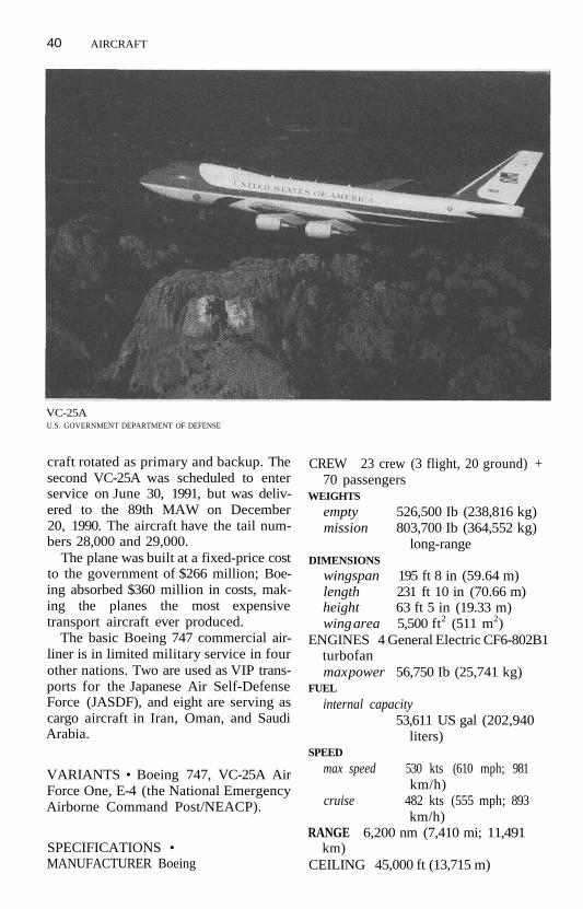
40 AIRCRAFT
VC-25AU.S. GOVERNMENT DEPARTMENT OF DEFENSE
craft rotated as primary and backup. Thesecond VC-25A was scheduled to enterservice on June 30, 1991, but was deliv-ered to the 89th MAW on December20, 1990. The aircraft have the tail num-bers 28,000 and 29,000.
The plane was built at a fixed-price costto the government of $266 million; Boe-ing absorbed $360 million in costs, mak-ing the planes the most expensivetransport aircraft ever produced.
The basic Boeing 747 commercial air-liner is in limited military service in fourother nations. Two are used as VIP trans-ports for the Japanese Air Self-DefenseForce (JASDF), and eight are serving ascargo aircraft in Iran, Oman, and SaudiArabia.
VARIANTS • Boeing 747, VC-25A AirForce One, E-4 (the National EmergencyAirborne Command Post/NEACP).
SPECIFICATIONS •MANUFACTURER Boeing
CREW 23 crew (3 flight, 20 ground) +70 passengers
WEIGHTS
empty 526,500 Ib (238,816 kg)mission 803,700 Ib (364,552 kg)
long-rangeDIMENSIONS
wingspan 195 ft 8 in (59.64 m)length 231 ft 10 in (70.66 m)height 63 ft 5 in (19.33 m)wing area 5,500 ft2 (511 m2)
ENGINES 4 General Electric CF6-802B1turbofanmax power 56,750 Ib (25,741 kg)
FUEL
internal capacity53,611 US gal (202,940
liters)SPEED
max speed 530 kts (610 mph; 981km/h)
cruise 482 kts (555 mph; 893km/h)
RANGE 6,200 nm (7,410 mi; 11,491km)
CEILING 45,000 ft (13,715 m)

AIRCRAFT 41
C-29AThe C-29A is a variant of the British Aero-space BAe 125-800, itself a developmentof the earlier HS125 light executive trans-port. The basic design has been progres-sively improved; several of the 800 seriesare in use as VIP transports. Six were or-dered by the United States as the C-29Aflight inspection aircraft after undergo-ing modification by Sierra Research ofBuffalo, New York.
The low, two-spar wing is mounted in aprominent fairing below the fuselage.The trailing edge has four-position,double-slotted flaps inboard of cable-operated, mass-balanced ailerons. Lift-dumping air brake/spoilers are locatedahead of the flaps.
The relatively tall fin and rudder have amoderately swept tailplane mounted wellup on the fin and above the rudder. A lowdorsal fin extends forward. The full-spanelevators are cable-operated and mass-balanced.
Two turbofan engines are carried innacelles on either side of the rear fu-selage. The fuel tanks are located in thewings, and a ventral tank is behind thepassenger cabin. The main gear legs havetwin wheels and retract into the wings;the nose gear retracts forward. A singlehydraulic system operates the flaps,spoilers, landing gear, main-wheel doorsand brakes, nosewheel steering, and theantiskid braking system.
A passenger door is located on the leftside of the fuselage, forward of the wing.The bulged cockpit roof of the earlierseries has been replaced by a straight topline, and the nose has been lengthened.There are six windows along each side ofthe roomy cabin.
DEVELOPMENT • The initial opera-tional capability of the C-29A was in1984, and its first flight was on May 26,1983.
Six C-29As were built for the US AirForce under a $70-million contract
awarded in March 1988. The final unitwas delivered to the Military Airlift Com-mand on January 11, 1991.
Three other nations have used the air-craft, the most recent being the JapaneseAir Self-Defense Force (JASDF), whichordered three BAel25-800 aircraft in Au-gust 1989.
The mission of the C-29A CombatFlight Inspection (C-FIN) is to verify theaccuracy of airport navigational and land-ing aids.
VARIANTS • Dominie TMkl (Britishtrainer), BAel25, C-29A.
SPECIFICATIONS •MANUFACTURER British AerospaceCREW 2 + 6 passengersWEIGHTS
empty 14,720 Ib (6,676 kg)maxpayload 2,400 Ib (1,088 kg)max takeoff 27,400 Ib (12,430 kg)
DIMENSIONS
wingspan 51 ft 4 in (15.66 m)length 51 ft 2 in (15.60m)height 17 ft 7 in (5.36 m)cabin length: 21 ft 4 in (6.5 m)
width: 6 ft (1.83m)height: 5 ft 9 in (1.75m)volume: 604ft3 (17.1 m3)
wing area 374 ft2 (34.75 m2)ENGINES 2 Garrett TFE731-5R-1H tur-
bofanmax power 4,300 Ib (1,950 kg) static
thrustFUEL
internal 1,499 US gal (5,674 liters)SPEED
max cruise 456 kts (525 mph; 845fcm/h)
econ cruise 400 kts (461 mph; 741km/h)
RANGE
maxpayload 2,870 nm (3,305 mi;5,318 km)
max fuel 3,000 nm (3,454 mi;5,560 km)
CEILING 43,000 ft (13,100 m)

42 AIRCRAFT
Commando (C-46)The C-46 Commando first became fa-mous when it flew over the "hump" of theHimalayan Mountains between India andChina during World War II. The aircraft,also known as the Dumbo, had almostdouble the payload and cabin volume ofthe C-47 Dakota (but not the reliability)and represented the first military trans-port to be built in significant numbers.
The Commando's low wing had a rect-angular center section and tapered outerpanels. It had a broad vertical tail and acurved, full-height rudder.
The Commando's "double-bubble" fu-selage was originally designed to have apressurized upper half for the comfort ofcommercial passengers. As a militarytransport, the C-46 was unpressurized.The main cabin had a large cargo doubledoor on the port side with an inset per-sonnel door.
The two radial piston engines were innacelles faired into the leading edges ofthe wings. The landing gear consisted ofone-wheel main gear legs that retractedforward into each engine nacelle and afixed, castoring tailwheel under the fu-selage ahead of the tail group.
DEVELOPMENT • The C-46's first flightwas on March 26,1940, and its initial oper-ational capability was in 1941. A total of3,180 aircraft were built between 1941and 1945. Of the original military produc-tion version, 1,039 C-46A-CUs were builtin Buffalo, 438 C-46A-CKs in Louisville, 12C-46A-CSs in St. Louis, and two C-46A-HIsby Higgins in New Orleans. The last C-46Eretired from active US service in 1953.Reserve units continued to fly C-46A/D/F aircraft until 1960. Remarkably, someforeign airlines and air forces have contin-ued to fly the C-46 into the 1990s.
VARIANTS • CW-20/C-55, C-46A, XC-46B, C-46D, C-46E, C-46F, C-46G, XC-46L(test bed), R5C-1/2/3/4/5 (US MarineCorps).
SPECIFICATIONS (C-46D) •MANUFACTURER Curtis-WrightCREW 4 + 50 passengers, or 33 litters
and 4 attendantsWEIGHTS
empty 32,400 Ib (14,696 kg)max payload 16,000-17,600 Ib (7,257-
7,983 kg)max takeoff normal: 45,000 Ib (20,410
kg)overload: 48,000 Ib
(21,772 kg)DIMENSIONS
wingspan 108 ft 1 in (32.92 m)length 76 ft 4 in (23.27 m)height 21 ft 9 in (6.63 m)cabin length: 48 ft (14.63 m)
width: 9 ft 10 in (3.0 m)height: 6 ft 8 in (2.03 m)volume: 2,300 ft? (12.88
m3)wing area 1,360 ft2 (126.8 m*)
ENGINES 2 2,000-hp Pratt & WhitneyR-2800-51 2-row, 18-cylinder radial pis-ton
SPEEDmax 233 kts (269 mph; 433
km/h)max cruise 197 kts (227 mph; 365
km/h)econ cruise 162 kts (187 mph; 301
km/h)landing 62 kts (71 mph; 114 km/
h)climb rate 1,300 ft/min (396
m/min)RANGE 27,600 ft (8,410 m)CEILING 955 nm (1,100 mi; 1,770 km)
(with 11,500 Ib); 2,562 nm (2,950 mi;4,748 km) (with 2,000 Ib)
Dakota (C-47)The C-47 is the military version of theDouglas DC-3 commercial airliner.Throughout aviation history, it has beenone of the most widely used aircraft. Theofficial names of the C-47 have been the

AIRCRAFT 43
Dakota and the Skytrain, but the mostwidely used nickname of the airplane wasthe affectionate Gooney Bird.
The popularity of the C-47 stems fromits low cost of operation and mainte-nance, ruggedness, ease of pilot training,and versatility. It has served primarily inthe cargo and transport roles but hasbeen adapted to a wide variety of othermissions, including reconnaissance, ex-treme weather conditions, gunship, spe-cial operations, trainer, and electroniccountermeasures.
The plane's basic configuration in-cludes a low-set wing with a rectangularcenter section and long, tapered outerpanels. The trailing edge has plain splitflaps inboard and a narrow, long aileronoutboard.
The two radial engines are mounted innacelles that extend forward from theleading edge of the center section. Themain wheels are carried on struts thatretract into the rear of the nacelle; themain wheel remains partially exposedand reduces the damage from belly land-
ings. The nonretractable, castoring tail-wheel is fitted below the fin.
The fuselage has a pointed nose,stepped windshield, large cockpit sidewindows, and a two-section cargo door aftof the trailing edge on the left side.
The aircraft has been extensively mod-ified during its life and has flown with anumber of different engines and minorairframe modifications.
DEVELOPMENT • The C-47's initial op-erational capability was in 1941. The firstflight of the DC-3 was on December 17,1935. 10,368 were built in the UnitedStates, and approximately 2,000 werebuilt under license by the Soviet Union asthe Lisunov Li-2 (still in service in Chinaand Vietnam). It remained active with theUSAF's Military Airlift Command untilthe late 1960s.
The C-47 is no longer in US service.More than 400 C-47s remain in service inmore than 40 countries into themid-1990s. The C-47 has served in almost
C-47TIMOTHY M. LAUR

44 AIRCRAFT
every Western and Third World air forceand several communist air forces.
In the 1990s, a few Latin Americancountries have had some of their C-47sconverted by Easier Turbo ConversionsInc. into a turboprop version of theGooney Bird (Turbo-67), but faster andwith a higher payload.
VARIANTS • C-47, AC-47 (USAFSpooky gunship), EC-47 (USN ElectronicWarfare/EW; formerly R4D-5Q/6Q),HC-47 (USAF rescue; formerly SC-47),LC-47 (USN ski-equipped; formerlyR4D-5L/6L), RC-47A (USAF reconnais-sance), TC-47 (trainer), VC-47 (VIP),C-53, C-117 (USN TC-117 trainer; for-merly R4D-8T), VC-117 (VIP), C-117D,Li-2 (Soviet-built), Turbo-67.
COMBAT EXPERIENCE • The GooneyBird distinguished itself as a US cargoaircraft in World War II, the Berlin Airlift,and in Korea. The gunship variant wasflown in the Vietnam War by US andSouth Vietnamese air forces. The RoyalLaotian Air Force also flew C-47 gun-ships. El Salvador has used its AC-47s toattack guerrilla positions.
SPECIFICATIONS •MANUFACTURER DouglasCREW 4 + 26 troops or 24 littersWEIGHTS
empty 16,970 Ib (7,697 kg)normal payload
6,000 Ib (2,721 kg)max payload 7,500 Ib (3,402 kg)max takeoff 26,000 Ib (11,793 kg)max overload
30,600 Ib (13,880 kg)DIMENSIONS
length 64 ft 6 in (19.65 m)height 16 ft 9 in (5.16m)wing area 987 ft2 (91.69 m2)cargo volume
1,245ft3 (35.25m3)ENGINES 2 Pratt & Whitney R-l 830-92
radial pistonmax power 1,200 shp each
SPEED
cruise speed160 kts (185 mph; 296
km/h)max speed 199 kts (229 mph; 368
km/h)stall, wheels and flaps down
58 kts (67 mph; 108 km/h)
RANGEnormal 1,296 nm (1,500 mi;
2,400 km)max range 2,346 nm (2,700 mi;
4,345 km)CEILING 24,100 ft (7,345 m)
Hercules (C-130)The C-130 Hercules airlifter has had along and distinguished career in severalwars throughout the world. It is the mostversatile and widely flown military trans-port in the post-World War II era. Thefour-engine, medium turboprop trans-port has been used for passenger andcargo, paratroop, aerial refueling, pas-senger, Search and Rescue (SAR), Elec-tronic Warfare (EW), combat commandand control, communications relay, andas a gunship. The US Navy has flownC-130 aircraft from an aircraft carrierwithout the use of arresting wires or cata-pult. The Hercules is a utilitarian combi-nation of a graceful, high-aspect-ratiowing on a hulking fuselage followed by alarge, triangular tail. The high wing has arectangular center section and outerpanels with tapered trailing edges.
The tail is carried high as a result of thesloped, rear cargo ramp that forms the aftend of the fuselage. The fin has a smalldorsal fillet and full-height rudder. Thelarge, double-taper tailplanes aremounted just below the fin, in line withthe wings.
The four Allison turboprops are car-ried in thin nacelles along the leadingedge of the wing. The plane has six inte-gral wing tanks. Additionally, external

AIRCRAFT 45
HerculesU.S. GOVERNMENT DEPARTMENT OF DEFENSE
fuel tanks are semipermanently fixed topylons between the engines under eachwing.
The squat, constant-section fuselagehas a short nose; the nearly flat, "Ro-man" nose of the early versions receiveda bulbous "thimble" radome that is nowcharacteristic of virtually all C-130s still inservice. The flight deck has two levels ofglazing and "eyebrow" windows on eachside.
The pressurized main cabin has anearly square cross section and has anunobstructed run from aft of the flightdeck to the rear ramp. Cargo can includefive pallets, a 155-mm howitzer and tow-ing vehicle, plus troops or litters. Theramp qan be lowered in flight for para-chute drops or Low-Altitude ParachuteExtraction System (LAPES) operations.The aircraft has cargo doors at the frontand rear of the cabin on both sides. Largesponsons run along the lower sides of the
fuselage; each carries two one-wheelmain gear legs in tandem.
DEVELOPMENT • The initial opera-tional capability of the C-130 was in 1956,and its first flight was on August 23,1954.C-130H variants are still in production;about 2,000 had been built by the early1990s. The US Air Force, Navy, Marines,and Coast Guard operate the C-130 alongwith about 24 other nations. There arenumerous variants of the basic C-130 thathave been designed to meet the variousrequirements of the many operators. Lat-est in the line is the C-130J, ordered byBritain in 1994. It has new engines, elec-tronic flight instrumentation, and severalother upgrades.
VARIANTS • YC-130, C-130B, C-130D(Arctic/Antarctic operations), C-130E,

46 AIRCRAFT
C-130H (main production version),C-130J (High-Technology Test Bed/HTTB), C-130K (RAF), C-130 AEW (pro-posed Airborne Early Warning/AEW),AC-130 (gunship), HC-130H (search andrescue/aerial recovery), HC-130N,HC-130P (rescue), LC-130H, MC-130HCombat Talon II (Special OperationsCommand/SOC), WC-130E/H (weatherreconnaissance).
SPECIFICATIONS (C-130H) •MANUFACTURER LockheedCREW 5 (2 pilots, navigator, flight engi-
neer, radio operator/loadmaster) and92 troops or 64 paratroops or 74 lit-ters and 2 attendants
WEIGHTS
empty 76,469 Ib (34,686 kg)maxpayload 42,673 Ib (19,356 kg)takeoff
DIMENSIONS
wingspan
normal: 155,000 Ib(70,310 kg)
max: 175,000 Ib (79,380kg)
132 ft 7 in (40.41 m)
length 97 ft 9 in (29.79 m)height 38 ft 3 in (11.66m)wing area 1,745 ft* (162.12 m*)ramp opening
length: 9 ft 1 in (2.77 m)width: 10 ft (3.05 m)
cargo hold length: 40 ft 1 in (12.22m)
width: 10 ft 3 in (3.30 m)height: 9 ft 3 in (2.81 m)volume: 4,500 ft3 (127.4
m3)ENGINES 4 Allison T56-A-15 turboprop
max power 4,591 effective hp eachFUEL
internal capacity9,679 US gal (36,636
liters)SPEED
cruise speedmax: 325 kts (374 mph;
602 km/h)econ: 300 kts (345 mph;
556 km/h)stall speed 100 kts (115 mph; 185
km/h)
EC130MU.S. GOVERNMENT DEPARTMENT OF DEFENSE

AIRCRAFT 47
climb rate 1,900 ft/min (579 m/min)RANGE
max payload 2,046 nm (2,356 mi;3,791 km)
max fuel 4,250 nm (4,894 mi;7,876 km)
CEILING at 130,000 Ib (58,970 kg)4 engines: 33,000 ft (10,060 m)3 engines: 26,500 ft (8,075 m)
Starlifter (C-141)The C-141 Starlifter is a strategic airliftaircraft used primarily for cargo, but alsoused for medical evacuation, paratroopdrops, and troop transport.
The C-141's high wing has a lowquarter-chord sweep that reduces themaximum cruising speed when com-pared to other jet transports, but im-proves handling near stall speed andreduces the required takeoff andlanding-field lengths. Four sections ofspoilers, two ahead of each flap section,act as airbrakes and ground lift dumpers.
The tail group forms a "T." The verti-
cal tail consists of a slightly swept fin withlow dorsal fillet and a full-height rudder.Flight controls, flaps, landing gear, andbrakes are operated by two redundant hy-draulic systems.
The current operational version, theC-141B, was "stretched" to increase itscapabilities. Most of the modifications tothe basic design involved the fuselage.The original design adopted the crosssection of the earlier C-130 Hercules; thiswas not changed in the C-141B. Neitherwas the nose section, which consists of astubby radome and low-stepped flightdeck. An air-refueling capability wasadded.
Side and cargo doors are used as para-troop drop exits. A C-141A set a worldrecord for airdropping a 70,195-lb(31,840-kg) mass. Large clamshell doorsswing out to expose a ramp that dropsdown to create an 11° slope for loading.The modifications improved the cargocapacity of the aircraft, increasing theload from 10 to 13 standard cargo pallets.Total volume increased by 55%, and maxpayload capacity grew to 94,508 Ib
C-141 StarlifterU.S. GOVERNMENT DEPARTMENT OF DEFENSE

48 AIRCRAFT
(42,869 kg). Passenger and medical evac-uee capacity was not changed.
The four turbofan engines aremounted on pylons that extend belowand ahead of the wing's leading edges.The main, four-wheel landing gear re-tracts into streamlined pods mounted onthe lower fuselage below the wings. Thesepods also contain the single-point refuel-ing point hookups. The two-wheel nosegear retracts forward.
The C-141B program was a success onseveral grounds, including meeting allmilestones ahead of schedule.
DEVELOPMENT • The Starlifter's ini-tial operational capability was on April23, 1965; its first flight was on December17, 1963. 285 were built before produc-tion ceased in 1968.
The stretch program began in 1979with the 270 operational C-141As. Theinitial operating capability of the C-141Bwas April 1980. The final converted unitwas delivered on June 29, 1982. TheUSAF is the only operator of the C-141.
VARIANTS • C-141 A, ARTB (AdvancedRadar Test Bed), YC-141B (stretched pro-totype) , C-141B, SOF C-141 (special ops).
COMBAT EXPERIENCE • The Starlif-ter distinguished itself in all conflictssince it started operations. It flew virtuallydaily missions during the Vietnam War. Itwas a primary resource for the resupplyeffort to Israel during the Yom KippurWar of October 1973. On December 20,1989, C-141s made 77 flights to Panamain support of the US ouster of Panama-nian General Noriega, dropping para-troopers airlifting cargo and troops.
The aircraft again distinguished itselfduring the 1990-91 deployment oftroops and cargo in support of the DesertShield/Desert Storm operations in theMiddle East.
SPECIFICATIONS •MANUFACTURER Lockheed
CREW 5 + 155 paratroops or 200
troops or 103 patient litters withattendants
WEIGHTS
empty 144,492 Ib (65,542 kg)maxpayload 94,508 Ib (42,869 kg)max takeoff 343,000 Ib (155,585 kg)
DIMENSIONSwingspan 159 ft 11 in (48.74 m)length 168 ft 3 in (51.29m)height 39 ft 3 in (11.96m)wing area 3,228 ft* (299.9 m*)cargo hold length without ramp
(C-141B):93ft4in(28.45 m)
width: 10 ft 3 in (3.12 m)height: 9 ft 1 in (2.77 m)volume with ramp: 11,399
ft3 (322.7 m3)ENGINES 4 Pratt & Whitney TF33-P-7
turbofanmax power 21,000 Ib (9,525 kg)
FUELinternal capacity
23,592 US gal (89,296liters)
SPEEDmax cruise 492 kts (566 mph; 911
km/h)long-range 430 kts (495 mph; 797
km/h)climb rate 2,600 ft/min (792
m/min)RANGE
with payload of 90,880 Ib (41,223 kg)2,549 nm (2,935 mi;
4,723 km)max fuel 5,330 nm (6,140 mi;
9,880 km)CEILING 41,600 ft (12,680 m)
Trader (C-1A)The C-l A Trader is a derivative of the S-2Tracker aircraft, using the same airframeand engines minus the Tracker's missionavionics. The Trader is used as a US NavyCarrier Onboard Delivery (COD) cargo/passenger aircraft.
The Trader has a fairly distinctive ap-

AIRCRAFT 49
pearance, featuring a short, stubby fu-selage, long, slightly tapered wings sethigh just forward of the midfuselage, twovery large engine nacelles for its radialpiston engines, and a large tailfin andrudder with slightly dihedral tailplanesset at the base. Landing gear is retract-able tricycle, with the main wheels retract-ing into the engine nacelles.
The cargo capacity of the Trader is re-stricted by its limited payload and sidedoor loading system.
DEVELOPMENT • The Trader's initialoperational capability (C-1A) was in1955; the first flight (as the S-2) was inDecember 1952. Few Trader aircraft re-mained operational by the US Navy bythe early 1990s, being gradually phasedinto retirement, replaced by the C-2 Grey-hound.
VARIANTS • TF-1, C-1A, EC-1A (Elec-tronic Countermeasures/ECM).
SPECIFICATIONS •MANUFACTURER GrummanCREW 2 (pilot, copilot) + 7 passengersENGINES 2 Wright R-l 820-82WA 9-cylin-
der radial pistonmax power 1,525 hp each
WEIGHTS
empty 19,033 Ib (8,561 kg)max payload 3,500 Ib (1,587 kg)max takeoff 27,000 Ib (12,272 kg)
DIMENSIONS
wingspan 69 ft 8 in (21.23 m)length 42 ft (12.8m)height 16 ft 4 in (4.98 m)wing area 485 ft2 (45.07 m2)
PERFORMANCEmax speed 290 kts (334 mph; 538
km/h)ceiling 22,000 ft (6,706 m)range 1,200 nm (1,381 mi;
2,222 km)
Greyhound (C-2A)The C-2A Greyhound is derived from theE-2C Hawkeye Airborne Early Warning(AEW) aircraft and is the primary USNavy Carrier Onboard Delivery (COD)aircraft, providing transport for high-priority cargo and passengers betweenshore bases and aircraft carriers. TheGreyhound shares the E-2 wings, power-plant, and four-fin tail configurationbut has a larger fuselage and a rear-fuselage loading ramp.
The high-aspect-ratio wing is mountedon top of the fuselage. The tapered lead-ing edge is detachable for access to hy-draulic systems. The trailing edge hasinboard Fowler-type flaps and longailerons; the ailerons are drooped by aflap-aileron interconnection for low-speed handling. The wings fold outboardof the engines, ending up perpendicularto the center section and parallel to theaft fuselage; the folded wings are securedby jury strut locks fitted on the leadingedge of the outer fins.
The tail-group design reflects the needfor a low profile on US carrier hangardecks. Unlike the E-2, which has consider-able dihedral on the horizontal tailplanes,the C-2's tail has none; an elevator is insetin the trailing edge. Large endplate finsare joined at right angles to the stabilizer;each has a double-section rudder aboveand below the stabilizer plane.
The aircraft is fitted with a Sperry AN/AWS-15 Automatic Flight Control System(AFCS) and two independent hydraulicsystems. The wing and tail-group leadingedges are fitted with deicing boots.
The two Allison turboprop engines arehoused in deep nacelles on the wing lead-ing edges and drive four-blade HamiltonStandard propellers. The two large fueltanks are in the wing center section.
The main gear struts retract forwardinto the nacelles, pivoting 90° to lie flat.The two-wheel nose gear (derived fromthe Grumman A-6 Intruder) retracts tothe rear under the flight deck.

50 AIRCRAFT
DEVELOPMENT • The initial opera-tional capability was in December 1966;its first flight was on November 18, 1964.19 were originally procured. A $687-million, multiyear contract signed in 1983provided for 39 uprated aircraft, the lastbeing delivered in 1989. The originalC-2A aircraft retired from USN service by1987. The second series of 39 aircraftwerealso called C-2A by the Navy to precludethe necessary government documenta-tion required for a "new" aircraft.
VARIANTS • C-2A.
COMBAT EXPERIENCE • During theOperations Desert Shield/Desert Stormdeployments, C-2s were embarked onnearly every carrier and proved invalu-able for shuttling personnel, high-valuecargo, and mail from the carriers to basesin Saudi Arabia.
SPECIFICATIONS •MANUFACTURER GrummanCREW 3 (2 pilots, flight engineer) + 39
troops or 28 passengers or 12 littersENGINES 2 Allison T56-A-425 turbo-
propmax powerinternal fuel
WEIGHTSemptymax payload
max takeoffDIMENSIONS
wingspanlengthheightwing areacargo hold
4,910 equivalent shp eachcapacity1,824 US gal (6,904 liters)
36,346 Ib (16,486 kg)land-based: 15,000 Ib
(6,804 kg)carrier ops: 10,000 Ib
(4,536 kg)54,354 Ib (24,655 kg)
80 ft 7 in (24.57 m)56 ft 10 in (17.32m)15 ft 11 in (4.85m)700 ft2 (65.03 m2)length: 27 ft 6 in (8.38
m)width: 7 ft 4 in (2.24 m)height: 5 ft 5 in (1.65m)volume: 1,920 ft3 (54.37
PERFORMANCEmax speed 310 kts (357 mph; 574
km/h)cruise speed 260 kts (299 mph; 482
km/h)climb rate 2,610 ft/min (796
m/min)ceiling 33,500 ft (10,211 m)range with 10,000-lb (4,536-kg) payload
more than 1,042 nm(1,200 mi; 1,931 km)
max ferry rangel,560nm (1,796 mi;
2,889 km)
Academe (C-4)The C-4 Academe is a "flying classroom"used for training A-6E Intruder naviga-tors and bombardiers. It is based on theGrumman Gulfstream I twin-turbopropexecutive transport.
The basic Gulfstream I has a double-taper, high-aspect-ratio wing mountedlow on the fuselage. Large nacelles aremounted on each wing, with the thinturboprops extending well forward, driv-ing four-blade propellers. The rest ofthe nacelle houses the jet pipe, whichextends to the trailing edge over thewing, and the main landing gear, whichis housed in a bulged section belowthe wing. The fin and balanced rudderare swept; a small dorsal fillet extendsforward. The tailplane is double-tapered.
The fuselage has five oval windows.There is little step in the windshield,which tapers to a pointed nose in the USCoast Guard's single VC-4A executivetransport. The TC-4C Academe has alarge, bulbous nose grafted onto the orig-inal nose; a Forward-Looking Infrared(FLIR) turret was fitted under the falsenose sometime after the original deliv-eries. The aircraft is fitted with an A-6Intruder cockpit and four navigator/bombardier training consoles ahead ofthe A-6 cockpit installation.

AIRCRAFT 51
DEVELOPMENT • The initial opera-tional capability (VC-4A) was in March1963. The Academe's first flight was onJune 14, 1967. Only 11 militaryGulfstream Is were built (nine USNTC-4C and two USCG VC-4A) and usedby the Navy and Coast Guard.
VARIANTS • VC-4A, TC-4C.
SPECIFICATIONS •MANUFACTURER Grumman AerospaceCREW 2 (pilot, copilot) + 2 instructors
and 5 studentsENGINES 2 Rolls-Royce Dart Mk 529-8X
turbopropmax power 2,210 shp each
WEIGHTS
empty 24,575 Ib (11,147 kg)max takeoff 36,000 Ib (16,329 kg)
DIMENSIONSwingspan 78 ft 4 in (23.87 m)length 67 ft 10% in (20.69 m)height 23 ft 4 in (7.1 m)wing area 610 ft2 (186 m2)
PERFORMANCEmax speed 317 kts (365 mph; 587
km/h)cruise speed
217 kts (250 mph; 402km/h)
ceiling 30,000 ft (9,144 m)range at5,000ft (l,524m):996
nm (1,147 mi; 1,846 km)at 30,000 ft (9,144m):
l,741nm (2,005 mi;3,226 km)
King Air 90 (U-21A, C-6B)The King Air was originally designed as ageneral aviation aircraft but has beenadapted for use in many nations as a lightutility/liaison/VIP transport aircraft.
Its configuration is fairly conventionalfor an aircraft of its type, featuring a low-set, slightly dihedral wing, two turbopropengines in wing nacelles, a single, swepttailfin, slightly dihedral tailplanes set onthe tailboom, retractable tricycle landing
gear, and a passenger/cargo door on theleft side of the fuselage, behind the wing.
DEVELOPMENT • The King Air's initialoperational capability was in 1965; its firstflight was in January 1964. Over 250 arein military service worldwide. It is oper-ated by almost 20 nations, including theUS, mostly as VIP transport or liaison air-craft.
VARIANTS • C-6B (USAF), U-21A (USArmy), King Air 90, King Air 100(stretched), King Air 200 (USAF C-12).
COMBAT EXPERIENCE • None di-rectly; used to support local flights of keypersonnel during conflicts in developingareas.
SPECIFICATIONS •MANUFACTURER BeechcraftCREW 2 (pilot, copilot) + 8 passengersENGINES 2 Pratt & Whitney PT6A-20
turbopropmax power 550 shp each
WEIGHTS
empty 5,680 Ib (2,576 kg)max takeoff 9,300 Ib (4,218 kg)
DIMENSIONSwingspan 45 ft 10'/2 in (13.98 m)length 35 ft 6 in (10.82m)height 14 ft 8 in (4.47 m)wing area 280 ft2 (26 m2)
PERFORMANCEmax speed 241 kts (278 mph; 447
km/h)ceiling 31,600 ft (9,632 m)range 1,372 nm (1,580 mi;
2,543 km)
Gulfstream II (VC-11)The Gulfstream II is a large executive jetthat is used as a VIP aircraft by several airforces. A single US Coast GuardGulfstream II is designated VC-11.
The low wing has 25° of leading-edgesweep, 3° of dihedral from the roots, and

52 AIRCRAFT
low wing fences at midspan. The trailingedge has one-piece, single-slotted, Fowler-type flaps inboard of inset ailerons. Aheadof the ailerons is a span-wise line of vortexgenerators. Farther inboard, two sectionsof spoilers are located ahead of the flaps.These can be used for roll-control assist,air brakes, and lift dumpers.
The T-tail has a broad, slightly sweptvertical fin with a small dorsal fillet andfull-height rudder. At the top of the tailare swept, horizontal stabilizers with full-span elevators. All controls are poweredby dual independent, 1,500-psi hydraulicsystems with mechanical reversion.
The two Rolls-Royce turbofan engineswith Rohr thrust reversers are mountedon short stubs that are located high onthe rear fuselage; the inlets overlap thetrailing edges of the wings. Fuel is carriedin wing tanks. The long, semimonocoquefuselage extends well ahead of the wings.An entry door is located on the forwardleft side between the flight deck and thepassenger cabin. The cabin has five oval,"porthole" windows on each side.
The main gear legs retract inward, thetwo-wheel assemblies being stowed in fu-selage bays. The two-wheel nose gear re-tracts forward.
DEVELOPMENT • The aircraft's initialoperational capability was in 1969; its firstflight was on October 2, 1966. Produc-tion ended in the 1980s after 258 werecompleted. The US Coast Guard VG-11 isnormally stationed at National Airport inWashington, DC. The plane is operatedby six other countries.
VARIANTS • Gulfstream II-B, Gulf-stream III/IV.
SPECIFICATIONS •MANUFACTURER Grumman Aircraft (later
Gulfstream Aerospace)CREW 2-3 + 19 passengersENGINES 2 Rolls-Royce RBI63-25 Spey
Mk 511-8 turbofanmax power 11,400 Ib (5,171 kg) static
thrust
internal fuel capacity23,300 Ib (10,569kg) or
3,452 US gal (13,065liters)
WEIGHTSoperating weight empty
36,900 Ib (16,737 kg)cargo 2,000 Ib (907 kg)max takeoff 65,500 Ib (29,711 kg)
DIMENSIONSwingspan 68 ft 10 in (20.98 m)length 79 ft 11 in (25.36m)height 24 ft 6 in (7.47 m)cabin length 34 ft (10.36 m)
width 7 ft 4 in (2.24 m)height 6 ft 1 in (1.85m)volume 1,270 ft3 (36.0
m3)wing area 809.6 ft2 (75.21 m2)
PERFORMANCEmax cruise speed at 25,000ft (7,620 m)
505 kts (581 mph; 936km/h)
econ cruise at 40,000ft (12,192 m)431 kts (496 mph; 798
km/h)stall speed flaps and gear up: 130 kts
(150 mph; 241 km/h)flaps and gear down: 108
kts (124 mph; 200 km/h)
minimum control speed (Vmc)102 kts (117 mph; 189
km/h)climb rate 2 engines: 4,350 ft/min
(1,325 m/min)1 engine: 1,525 ft/min
(465 m/min)ceiling, 2 engines
43,000 ft (13,106 m)max fuel range
3,712 nm (4,275 mi;6,880 km)
Spartan (C-27A)The C-27A Spartan is the Italian G222 inservice with the United States. The air-craft is a low-cost, short-haul cargo aircraft

AIRCRAFT 53
developed for Italian service but subse-quently exported to a number of othernations including the United States. It is aversatile two-engine turboprop used fortransport and special-purpose missionssuch as fire fighting, communicationscalibration, and Electronic Warfare(EW). The G222 is similar to, but smallerthan, the US C-130 Hercules and theFrench-German C160 Transall.
The G222's high wing is mounted for-ward of midfuselage. The high-aspect-ratio airfoil has a rectangular center sec-tion and double-taper outer panels with2V2C dihedral. Two sections of double-slotted flaps line the trailing edge in-board of the ailerons; two sections ofspoilers fitted ahead of the outer flap sec-tions assist in roll control and are used aslift dumpers.
The large tail has a tall fin and full-height, powered rudder. The stubby,variable-incidence horizontal tailplaneshave a slightly swept leading edge andfull-span elevators and are "shoulder-mounted" at the base of the fin. The twoindependent hydraulic systems power therudder, flaps, spoilers, landing gear, andbrakes.
The two General Electric turbopropsare mounted in thin nacelles set in thewing's leading edge and drive three-blade Hamilton Standard propellers. In-ternal fuel storage is two center-sectiontanks and an additional tank in eachouter section.
The fuselage has a nearly stepless nosewith extensive glazing. The pressurizedmain cabin has a nearly constant sectionaft to the trailing edge of the wing, whereit tapers up to the high-flown tail. Therear loading ramp forms the floor of theaft fuselage when stowed. Typical loadsinclude 53 fully equipped troops, 40 para-troopers, 36 litters and four attendants,two light trucks or small armored vehi-cles, small artillery pieces, or five A-22-size standard freight containers; up to19,840 Ib (9,000 kg) can be carried. Longnarrow sponsons along the lower fu-
selage hold the main landing gear, whichconsists of tandem, single-wheel units;die nose gear folds forward.
DEVELOPMENT • The aircraft's initialoperational capability was in 1976; its firstflight was July 18, 1970.
In August 1990, the Air Force orderedfive G222s as the C-27A under an ISO-million contract, with options for 15more. An option for five more C-27s wasexercised in February 1991. Aeritaliateamed with Chrysler Airborne Technol-ogy Systems to build the aircraft, the lat-ter providing navigation and otheravionics equipment.
The Air Force accepted the first C-27on September 27, 1991, when thenickname Spartan was adopted.
VARIANTS • G-222.
SPECIFICATIONS •MANUFACTURER Aeritalia (Naples, Italy)CREW 3 (2 pilots, flight engineer/radio
operator)ENGINES General Electric T64-GE-P4D
turbopropmax power 3,400 shp eachinternal fuel capacity
3,170 US gal (12,000liters)
WEIGHTSempty 32,165 Ib (14,590 kg)maxpayload 19,840 Ib (9,000 kg)max takeoff 61,730 Ib (28,000 kg)
DIMENSIONSwingspan 94 ft 2 in (28.7 m)length 74 ft 5Vz in (22.7 m)height 32 ft 1% in (9.8 m)cabin length: 28 ft P/4 in (8.58
m)width: 8 ft Vz in (2.45 m)height: 7 ft 41/a in (2.25 m)volume: 2,048 ft3 (58 m3)
wing area 883 ft2 (82.00 m2)PERFORMANCE
max speed at 15,000ft (4,575 m)291 kts (336 mph; 540
km/h)

54 AIRCRAFT
cruise speed at 19,680ft (6,000 m)237 kts (273 mph; 439
km/h)stall speed, flaps and gear down
84 kts (97 mph; 155 km/h)
climb rate 1,705 ft/min (520m/min)
single-engine climb rate410 ft/min (125
m/min)time to height (to 14,760 ft/4,500 m)
8 min 35 secceiling 25,000 ft (7,620 m)range with 19,840-lb (9,000-kg) payload
740 nm (852 mi; 1,371 km)
ELECTRONIC/RECONNAISSANCE/OBSERVATIONHawkeye (E-2C)The E-2C Hawkeye is a US Navy carrier-based, all-weather Airborne Early Warn-ing (AEW) aircraft developed specificallyfor carrier operation. It is used for long-range early warning and threat assess-ment as well as fighter direction. A four-or five-plane E-2C squadron is providedto each US aircraft carrier.
The Hawkeye's most distinctive featureis the 24-foot-diameter, saucerlike ro-todome for the AN/APS-120, -125, -138,-139, or -145 UHF radar. The RandtronAN/APA-171 antenna system includesUHF and Identification Friend or Foe(IFF) endfire Yagi arrays. The rotodomerevolves freely in the airstream at the rateof 6 rpm. It provides sufficient lift to off-set its own weight in flight and can belowered to facilitate handling the aircraftaboard ship.
The AN/APS-138 in the E-2C has aneffective aircraft-detection range of ap-proximately 260 nm (300 mi; 482 km)with an improved over-land/water capa-bility through a Total Radiation ApertureControl Antenna (TRAC-A) that featureslow sidelobes.
Using a Loral array track processor,the aircraft can simultaneously trackmore than 600 air targets and control upto 40 interceptions. The APS-139, whichwas fitted to E-2Cs delivered after 1987,has an upgraded processor that allowstracking of more than 2,000 targets. The
follow-on APS-145 features "environ-mental processing" to screen outground clutter as well as a lower pulserepetition frequency and rotodome ro-tation rate. To make the most effectiveuse of the radar, the E-2 cruises with a10° flap setting, which gives the ro-todome the desired 3° of'incidence forscanning.
The E-2 has a high-aspect-ratio wingmounted on top of the fuselage. The ta-pered leading edge is detachable for ac-cess to hydraulic systems. The trailingedge has inboard Fowler-type flaps andlong ailerons; the ailerons are drooped bya flap-aileron interconnection for low-speed handling. The wings fold outboardof the engines, ending up perpendicularto the center section and parallel to theaft fuselage; the folded wings are securedby jury strut locks fitted on the leadingedge of the outer fins.
The tail group design reflects theneed for a low profile on US carrierhangar decks and the control-blanketingeffects of the larger rotodome. The hori-zontal tailplanes are joined on the cen-terline, each having 11° of dihedralrelative to the fuselage and an elevatorinset in the trailing edge. Large endplatefins are joined at right angles to the sta-bilizer; each has a double-section rudderabove and below the stabilizer plane. In-board of the endplates are fins with
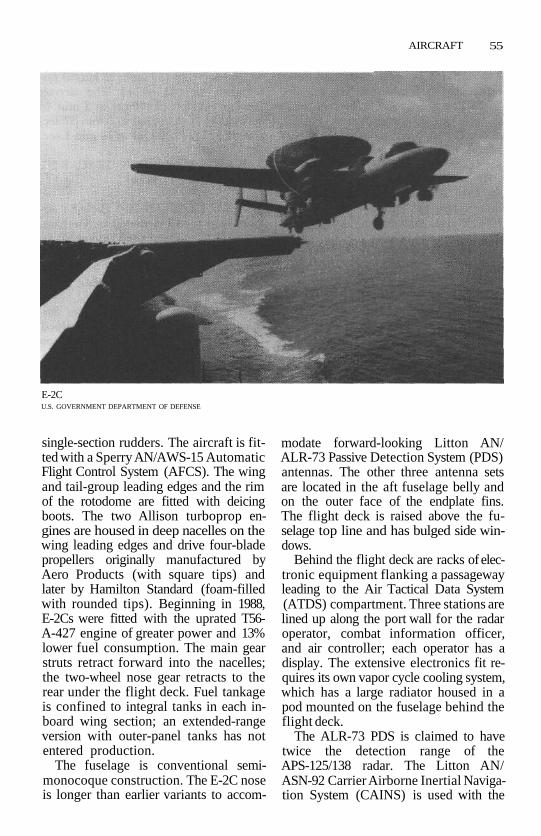
AIRCRAFT 55
E-2CU.S. GOVERNMENT DEPARTMENT OF DEFENSE
single-section rudders. The aircraft is fit-ted with a Sperry AN/AWS-15 AutomaticFlight Control System (AFCS). The wingand tail-group leading edges and the rimof the rotodome are fitted with deicingboots. The two Allison turboprop en-gines are housed in deep nacelles on thewing leading edges and drive four-bladepropellers originally manufactured byAero Products (with square tips) andlater by Hamilton Standard (foam-filledwith rounded tips). Beginning in 1988,E-2Cs were fitted with the uprated T56-A-427 engine of greater power and 13%lower fuel consumption. The main gearstruts retract forward into the nacelles;the two-wheel nose gear retracts to therear under the flight deck. Fuel tankageis confined to integral tanks in each in-board wing section; an extended-rangeversion with outer-panel tanks has notentered production.
The fuselage is conventional semi-monocoque construction. The E-2C noseis longer than earlier variants to accom-
modate forward-looking Litton AN/ALR-73 Passive Detection System (PDS)antennas. The other three antenna setsare located in the aft fuselage belly andon the outer face of the endplate fins.The flight deck is raised above the fu-selage top line and has bulged side win-dows.
Behind the flight deck are racks of elec-tronic equipment flanking a passagewayleading to the Air Tactical Data System(ATDS) compartment. Three stations arelined up along the port wall for the radaroperator, combat information officer,and air controller; each operator has adisplay. The extensive electronics fit re-quires its own vapor cycle cooling system,which has a large radiator housed in apod mounted on the fuselage behind theflight deck.
The ALR-73 PDS is claimed to havetwice the detection range of theAPS-125/138 radar. The Litton AN/ASN-92 Carrier Airborne Inertial Naviga-tion System (CAINS) is used with the

56 AIRCRAFT
AN/APN-153 Doppler navigation radar;other navigation information is suppliedby the Lear-Siegler AN/ASN-50 Headingand Attitude Reference System (HARS).
The E-2 transmits its data to a carriercombat information center through two-way Collins AN/ARC-34 HF and ARC-158UHF data links. The first E-2C fitted withthe Joint Tactical Information Distribu-tion System (JTIDS) flew in February1990, with the first delivery scheduled inDecember 1990. Existing E-2Cs are sched-uled for JTIDS installations beginning in1993.
DEVELOPMENT • The E-2C series wasdesignated W2F until 1962. The aircraft'sinitial operational capability (US Navy)was in 1965; its first flight (W2F-1) on Oc-tober 21,1960; the later E-2C first flew onJanuary 20, 1971. More than 100 E-2 air-craft have been built for the Navy.
In February 1987, the Navy announcedthe grounding of seven of its 91 aircraftand ordered flight restrictions for 10more because of potential wing cracks.The problem was later determined to beconfined to the first 80 aircraft built, andin December 1987, a $200-million con-tract was awarded to Grumman tostrengthen the wings at the rate of 16aircraft per year.
Four E-2Cs were loaned to the US CoastGuard from the US Navy for anti-drug-smuggling patrols from 1986 to October1991. In FY1991, the four E-2Cs were de-ployed for a total of 293 days.
After an original plan for a $300-million contract to supply four E-2Cs tothe Royal Thai Air Force, the plan wastemporarily abandoned because of thehigh cost, but was revived in January 1992with a $382-million letter of offer forthree E-2Cs. Also operated by Egypt, Is-rael, Japan, Singapore, and Taiwan.
On December 17, 1991, an E-2C Plusset new class records in closed-coursespeed and time to altitudes. Over a 54-nrn(62-mi; 100-km) closed course, the E-2averaged 324 kts (373 mph; 600 km/h),
which was 51 kts (59 mph; 95 km/h) fas-ter than the old record. The aircraftreached 9,842 ft (3,000 m) in 2 min 48sec, 19,685 ft (6,000 m) in 5 min 37 sec,and 29,527 ft (9,000 m) in 10 min 1 sec.
VARIANTS • E-2A, E-2B, TE-2C, E-2C,E-2C Plus, E-2T (Taiwan).
COMBAT EXPERIENCE • Early E-2 air-craft were used extensively in Vietnam.
The E-2C was first used in combat byIsrael when it controlled Israeli fightersduring a dogfight with Syrian MiG-21s inJune 1979, in which six MiGs weredowned.
A Hawkeye from the US carrier Sar-atoga (CV 60) in November 1985 helpedtrack the terrorists from the Achille Laurowho were attempting to escape on anEgyptian civilian airliner; the E-2C vec-tored Navy F-14s that forced the airlinerdown.
In January 1989, an E-2C from the JohnF. Kennedy (CV 67) detected two LibyanMiG-23 Flogger fighter aircraft takingoff from Al-Bunbah airfield near To-bruk. The E-2 directed two F-14 Tomcatfighters toward the MiG-23s; the F-14sdowned the MiGs after a series of evasivemaneuvers.
A total of 27 E-2Cs were deployed onthe aircraft carriers that launched strikesagainst Iraqi targets during OperationDesert Storm. The Hawkeyes flew 1,196sorties, during which they vectored strikeaircraft onto Iraqi naval units as well asforming part of the integrated airbornewarning and control network over Iraq,Kuwait, Saudi Arabia, and the PersianGulf. None was lost during the seven-week war.
SPECIFICATIONS •MANUFACTURER Grumman AerospaceCREW 5 (2 pilots, combat information
center officer, air controller, and ra-dar operator or technician)
ENGINES 2 Allison T56-A-425 or -427turboprop

AIRCRAFT 57
power -425: 4,910 equivalent shpeach (flat-rated to4,508 eshp each)
-427: 5,250 eshp eachinternal fuel capacity
1,824 US gal (6,904liters)
WEIGHTSempty 37,678 Ibs (17,090 kg)max takeoff 51,569 Ibs (23,391 kg)
DIMENSIONSwingspan extended: 80 ft 7 in
(24.58 m)folded: 29 ft 4 in (8.94
m)length 57 ft 7 in (17.56m)height rotodome raised: 18 ft 3
3/4 in (5.58 m)rotodome lowered: 16 ft
5!/2 in (5.02 m)wing area 700 ft2 (65.05 m2)
PERFORMANCEmax speed 326 kts (375 mph; 604
km/h)cruise speed max: 311 kts (358 mph;
576 km/h)econ: 269 kts (310 mph;
499 km/h)stall, power off
at takeoff weight: 97kts (112 mph; 180km/h)
at landing weight andapproach power: 71kts (82 mph; 132km/h)
climb rate 2,515 ft/rain (767m/min)
time to 20,000ft (6,096 m)13 min
time to ceiling33 min 30 seconds
ceiling 30,800 ft (9,388 m)radius 175 nm (200 mi; 320 km)
with 3-4 hr on stationferry range 1,394 nm (1,605 mi;
2,583 km)radar AN/APS-139
(APS-120/125/138 inearly E-2C aircraft)
Sentry/AWACS (E-3)The E-3 Sentry is the primary AirborneEarly Warning (AEW) aircraft of theNATO alliance and is popularly known bythe acronym AWACS (for Airborne Warn-ing and Control System). It is a Boeing707 aircraft modified to carry an exten-sive mission avionics package to providelong-range target acquisition and identi-fication, and control/communicationsfor directing other combat aircraft to thetargets.
The E-3 has a conventional planformwith low wings swept 35° at the quarter-chord; they are mounted at a +7° dihe-dral. Along the crescent-shaped trailingedge are two sections of double-slottedflaps that flank the midspan flightaileron. The larger, low-speed aileron isoutboard of the outer set of flaps. Thetall, slightly swept fin has an antenna ex-tending forward from the tip, and alarge, powered rudder. The low, swepttailplanes have full-span elevators.
The four TF33 turbofan engines aremounted on pylons that extend ahead ofthe wing leading edge. The E-3 has an in-flight refueling receptacle over the flightdeck. The aircraft's profile is dominatedby the 30-ft (9.14-m) diameter rotodomemounted on two struts that rest on a rein-forcement ring buried in the rear fu-selage. The oval rotodome weighs 11,800Ib (5,352 kg), is 6 ft (1.83 m) thick, and ismounted on a 7-ft 2-in (2.34-m) turntableat the top of the struts.
The rotodome's central rectangularstructure holds ancillary equipment; thisstructure is flanked by a WestinghouseAN/APY-2 slotted, phased-array antennaon one side and combined Eaton AN/APX-103 Identification Friend or Foe(IFF) interrogator and Tactical DigitalInformation Link (TADIL-C) data linkarray for the Joint Tactical InformationDistribution System (JTIDS) on theother. While in flight, but not in op-eration, the rotodome is hydraulically ro-tated at '/4 rpm to lubricate the bearings.

58 AIRCRAFT
E-3 SentryU.S. GOVERNMENT DEPARTMENT OF DEFENSE
When the radar is operating, the rotationspeed is 6 rpm.
All aircraft in the series are similarin appearance, varying only in the avi-onics package and engines. AWACS soldto Saudi Arabia and France have CFM56engines. Some have been fitted with up-graded Electronic Counter-Counter-measures (ECCM) equipment.
DEVELOPMENT • The aircraft's initialoperational capability was in 1976; its firstflight with full mission capability was inOctober 1975.35 were built for the US AirForce, 18 for NATO, and five for SaudiArabia. The Reagan administration's1985 sale of E-3 and KE-3 aircraft to SaudiArabia was strongly opposed by manypro-Israeli congressmen, who believedthe aircraft could be used against Israel ina future Arab-Israeli conflict. In Decem-ber 1986, Great Britain ordered six E-3DAWACS aircraft with CFM-56 engines; anoption for one additional aircraft was ex-ercised later. Britain passed over itsdomestically produced Nimrod AEW infavor of the E-3D AWACS, leading to criti-cism that the Thatcher government was
undercutting Britain's own aircraft in-dustry.
Negotiations with Pakistan over a po-tential transfer of the aircraft throughsale or lease in 1987 did not occur be-cause of congressional displeasure withPakistan's alleged nuclear weapons devel-opment program.
France ordered three E-3F AWACS inFebruary 1987, later exercising an optionfor one more.
AWACS assigned to NATO service areregistered in Luxembourg; these are theonly aircraft operated directly by NATO.
VARIANTS • E-3A, E-3A NATO Stan-dard, Peace Sentinel (Saudi), E-3B, E-3C,E-3D Sentry AEW Mk 1 (British), E-3F(French).
COMBAT EXPERIENCE • On May 17,1987, a Saudi AWACS detected the IraqiMirage jet that subsequendy attacked theUSS Stark (FFG 31). A US liaison officeron board the AWACS requested theSaudis to vector interceptors against theMirage, but the interception was not ac-

AIRCRAFT 59
complished because command clearancewas not obtained in time. Although theReagan administration did not accusethe Saudis of foot-dragging in the inci-dent, the noninterception was cited bysome congressmen as grounds for oppo-sition to sales of AGM-65 Maverick mis-siles to the Saudis. The proposal for thesale of Mavericks was withdrawn becauseof the likelihood that Congress would notapprove it.
Four US Air Force AWACS aircraft werebased in Saudi Arabia from 1987 to 1989in support of US Navy convoys of re-flagged Kuwaiti oil tankers. They werewithdrawn in April 1989.
In February 1990, at least five E-3s weredeployed from Tinker AFB, Oklahoma,to Roosevelt Roads, Puerto Rico, to pro-vide improved surveillance of drug-smuggling aircraft ships. The Air Forcealso stated that 40% of worldwide AWACS'flying hours were being devoted to anti-drug-smuggling surveillance.
US E-3s returned to the Persian Gulf inAugust 1990 as part of Operations DesertShield/Desert Storm. Before DesertStorm began on January 17, 1991, Saudiand US E-3s coordinated air patrols flownby Saudi, US, and British fighter aircraft.By the end of hostilities, 15 of the 33 USAir Force E-3s were supporting DesertStorm.
SPECIFICATIONS •MANUFACTURER Boeing AerospaceCREW 17 (4 in flight crew, 13 in mis-
sion crew)ENGINES 4 Pratt & Whitney TF33-PW-
100A turbofanmax power 21,000 Ib (9,525 kg) static
thrust eachinternal fuel capacity
23,855 US gal (90,292liters)
WEIGHTSempty 170,277 Ib (77,236 kg)max takeoff 325,000 Ib (147,417 kg)
DIMENSIONS
wingspan 145 ft 9 in (44.42 m)
length 152 ft 11 in (46.61m)height 42 ft 2 in (12.73 m)wing area 2,892 ft? (269.02 m*)
PERFORMANCEmax speed 473 kts (545 mph; 876
km/h)cruise speed
416 kts (479 mph; 771km/h)
on-station speed327 kts (377 mph; 606
km/h)stall speed, power off
129 kts (149 mph; 239km/h)
climb rate 2,640 ft/min (805m/min)
on-station altitude29,000 ft (8,839 m)
ceiling 41,900 ft (12,771 m)time on station at radius of 1,000 nm
(1,151 mi; 1,852km)unrefueled: 6 hr1 refueling: 14.4 hr
NEACP (E-4)The NEACP (pronounced "kneecap"),the National Emergency Airborne Com-mand Post, is a Boeing 747 fitted withcommunications equipment and an-tennas to act as the National CommandAuthority (NCA) operations center in theevent of nuclear war. At the height of itsoperations, the alert staff consists of aJoint Chiefs of Staff (JCS) joint serviceoperations team, a Defense IntelligenceAgency (DIA) element, a flight crew fromthe former Strategic Air Command(SAC), a communications team from theformer Air Force Communications Com-mand, a maintenance crew, and securityforces.
Aside from the markings, the only ob-servable difference between the NEACPand a commercial 747 aircraft is theNEACP's array of antennas and a smallradome bulge on the rear of the upperflight deck. Like the 747, the NEACP fea-

60 AIRCRAFT
tures a fuselage with a distinctive upper-deck bulge, wings mounted low at mid-fuselage, a high single tailfin, and fourengines mounted on wing pylons.
Internal modifications, however, aremuch more extensive. The interior of theNEACP has 4,350 ft* (404.3 m2) of floorspace and has been divided into six work-ing compartments fore to aft that carry atotal of 149,000 Ib (67,585 kg) ofcommand-and-control and communica-tions equipment. The NCA working areais located under the flight deck. Fartheraft is a secure conference room and abriefing room. The operations team areahas 31 console work areas. The communi-cations control area is subdivided into avoice area and a data area. The rearmostcompartment contains a technical con-trol area on the left side forward and amission crew rest area in the rear. Theupper deck houses the flight deck andflight crew rest area.
The communications capability spansthe frequency spectrum from Very LowFrequency (VLF) to Super High Fre-quency (SHF) systems, permitting theNEACP staff to contact almost all nucleardelivery systems directly. The systemshave been hardened against Electromag-netic Pulse (EMP) effects. In February1990, Rockwell Collins was awarded acontract to install an automatic data pro-cessing system in all four E-4Bs that iscontrolled by a Rolm Mil-Spec Hawk 32computer system possessing a 1.2-gigabitmemory and 32-bit processor. All NEACPaircraft are fitted with in-flight refuelingcapability to permit an endurance aloftof over 72 hours.
DEVELOPMENT • The NEACP's initialoperational capability was in 1975; its firstflight was on October 10, 1974. Threewere completed as E-4A and later con-verted to E-4B, and a fourth E-4B wasbuilt subsequently, entering service inJanuary 1980.
VARIANTS • E-4A, E-4B.
SPECIFICATIONS •MANUFACTURER BoeingCREW 4 (pilot, copilot, navigator, flight
engineer) +31 battle staff + com-mand and technical support person-nel (numbers vary)
ENGINES 4 General Electric F103-GE-100 turbofanmax power 52,500 Ib (23,814 kg)
static thrust eachinternal fuel capacity
332,976 Ib (151,036kg)WEIGHTS
max takeoff 803,000 Ib (364,232 kg)DIMENSIONS
wingspan 195 ft 8 in (59.64 m)length 225 ft 2 in (68.63 m)height 63 ft 5 in (19.33 m)wing area 5,500 ft2 (511.0 m2)
PERFORMANCE
max speed 527 kts (607 mph; 977km/h)
ceiling 45,000 ft (13,715 m)
range 7,100 nm (8,176 mi;13,158 km) unrefueled
Hermes (E-6A)The Hermes replaces the EC-130 in theTACAMO (Take Charge and Move Out)role of providing Very Low Frequency(VLF) radio relay to strategic missile sub-marines at sea.
The E-6A is a military version of theBoeing 707-320B aircraft, which alsoserves as the airframe for the E-3AAWACS (Airborne Warning and ControlSystem); the two aircraft share approx-imately 75% of their airframe compo-nents. The aircraft will provide an on-station/all-ocean link between the USNational Command Authority and theUS Navy Trident submarine fleet.
The E-6 has a conventional planformwith low wings swept 35° at the leadingedge. Along the crescent-shaped trailingedge are two sections of double-slottedflaps that flank the midspan flight

AIRCRAFT 61
aileron. The larger, low-speed aileron isoutboard of the outer set of flaps.
The tall, slightly swept fin has anantenna extending forward from thetip, and a large, powered rudder. Thelow, swept tailplanes have full-span ele-vators.
The four CFM turbofan engines aremounted on pylons that extend ahead ofthe wing leading edge. The E-6 can berefueled in flight; the large oil tanks oneach engine permit a maximum refueledendurance of 72 hours.
In the TACAMO role, the E-6A has es-sentially the same VLF communicationsequipment as the EC-130Q, with twoTrailing-Wire Antennas (TWA). Theshorter wire is 4,000 ft (1,220 m) longand streams horizontally from a reel inthe aft fuselage. The other wire is 26,000ft (7,925 m) long and extends below theE-6; it is stabilized by a 95-lb (43.6-kg)drogue. Only the shorter wire is elec-trically charged, with energy reradiatingfrom the longer wire.
To communicate with submarines, thewires are let out and the E-6 flies a low-speed, high-angle (30°-50°) bank; the ob-ject is to achieve 70% "verticality" for themain lower wire by having it stall into anear-vertical line. Wingtip pods on theE-6A contain satellite receiving antennas;the starboard pod also holds a GeneralInstruments ALR-66 threat-warning re-ceiver.
The Hermes is said to be more re-sistant to the electromagnetic pulses,gamma and neutron radiation, and blastand thermal effects of nuclear war thanany other aircraft in service.
DEVELOPMENT • The E-6A's initial op-erational capability was in October 1990.16 E-6A aircraft were funded, including aresearch-and-development aircraft. Theprototype was rolled out on December18, 1986, and its first flight was February19, 1987.
In September 1990, Boeing an-nounced a Navy order for 10 more E-6s,
bringing the total to 16. An $85.5-millionmodification to a contract for seven E-6A"TACAMO aircraft weapons systems"was awarded to Boeing in July 1991.
In May 1991, the Navy announced theend of a 30-year policy of having a TAC-AMO aircraft continuously airborne,moving instead to a ground-based "stripalert" posture.
SPECIFICATIONS •MANUFACTURER BoeingCREW 4 flight, 6 mission, 8 relief crew
seatsENGINES 4 General Electric/SNECMA
CFM-56-2A2 (F108-CF-100) turbofanmax power 22,000 Ib (9,979 kg) static
thrust eachinternal fuel capacity
23,855 US gal (90,299liters)
WEIGHTS
empty 172,795 Ib (78,379 kg)max takeoff 342,000 Ib (155,129 kg)
DIMENSIONS
tuingspan 148 ft 2 in (45.17 m)length 152 ft 11 in (46.62m)height 42 ft 5 in (12.93 m)wing area 3,050 ft2 (283.4 m2)
PERFORMANCEspeed cruise: 454 kts (523 mph;
842 km/h)max: 530 kts (610 mph;
982 km/h)orbit: 127-183 kts (146-
211 mph; 235-339km/h)
ceiling. 40,000+ ft (12,192 m)range 6,350 nm (7,312 mi;
11,767km)endurance 1,000 nm (1,152 mi;
1,853 km) radius with10.5 hr of loiter
normal mission durationwill be about 15 hrwith in-flight refuelingextending it to 29 hr
radar AQS-133 Bendix weatherradar
62 AIRCRAFT
Joint-Stars (E-8A)The E-8A aircraft carries the airborne ele-ments of the Air Force and Army JointSurveillance Target Attack Radar System(Joint-STARS). Joint-STARS (sometimesreferred to as JSTARS) combines tech-nologies developed in the Air Force'sPave Mover and Army's Standoff TargetAcquisition System (SOTAS) programs.
The E-8A's principal mission compo-nents are a Norden AN/APY-3 multi-mode Side-Looking Airborne Radar(SLAR); extensive on-board computerprocessing capability; and Command,Control, Communications, and Intel-ligence (C3I) links with ground-basedcommanders. The only noticeable indica-tion of the aircraft's particular role is the30-ft (9.14-m) "canoe" ventral fairing forthe APY-3 SLAR antenna, located just aftof the nose gear.
The APY-3 has four Traveling WaveTube (TWT) transmitters and 456 phaseshifters; beams are scanned mechanicallyin elevation and electronically in azi-muth. It can be operated as a SyntheticAperture Radar (SAR), which has a wide,high-resolution field of view of +/-600.Smearing of the SAR image is counteredthrough precision interferometry cal-ibration and a Litton LR-85A InertialMeasurement System (IMS). DopplerMoving- or Fixed-Target Indicator (MTI/FTI) processing is used to detect slow-moving targets amid the ground clutter.
At least 10 operator consoles are fittedin the aircraft; space and power are re-served for a total of 17 consoles. 23different radio sets are provided, 16of which are Magnavox Have QuickElectronic Countermeasures (ECM)-resistant, UHF radios; two of the fiveVHF radios are SINCGARS and twomore radios operate in HFband. Target-ing information for Air Force use will beprocessed on board the aircraft andtransmitted to other aircraft or missilesthrough a Joint Tactical Information Dis-tribution System (JTIDS) data link.
DEVELOPMENT • JSTARS' develop-ment contract was awarded to GrummanCorp. in September 1985. Original plan-ning called for 10 conversions, later re-vised to 22 newly built aircraft. First flightof E-8A (modified ex-commercial 707)was on April 1, 1988; first radar test flightwas on December 22,1988. First flight ofsecond test aircraft was on August 31,1989. The first two prototypes were de-ployed to Saudi Arabia in January 1991 aspart of Operations Desert Shield/DesertStorm.
Production E-8s were to be based onthe Navy's E-6 Hermes TACAMO aircraft(a 707-320 airframe with more powerfulCFM turbofans). This plan was derailedin October 1989 when Boeing an-nounced that it would end production ofthat airframe upon completion of Britishand French Airborne Warning and Con-trol System (AWACS) aircraft in 1991.Therefore, refitted used 707s are used;they are designated E-8Cs.
Other customers could include NATO,which operates E-3 AWACS aircraft.
VARIANTS • Pave Mover, SOTAS(Standoff Target Acquisition System),E-8B.
COMBAT EXPERIENCE • Joint-STARSaircraft were deployed to Saudi Arabiabut were limited to 20-hour flights be-cause of cavitation problems in their en-gines. Despite this limitation and theiruntested systems, the Joint-STARS air-craft flew 12-hour missions beginning onJanuary 14,1991. The two aircraft flew 54missions totaling more than 600 flighthours; no mission was canceled becauseof system problems.
SPECIFICATIONS •MANUFACTURER Grumman
airframe Boeing Military AirplaneCREW 3 (pilot, copilot, navigator) +
10-15 surveillance technicians and

AIRCRAFT 63
airborne operators (24 total duringOperation Desert Storm)
ENGINES 4 Pratt & Whitney JT3D tur-bofanmax power 18,000 Ib (8,165 kg) static
thrust eachWEIGHTS
empty 172,795 Ib (78,378 kg)mission payload
57,000 Ib (25,855 kg)max takeoff 342,000 Ib (155,129 kg)
DIMENSIONSwingspan 148 ft 2 in (45.16 m)length 152 ft 11 in (46.61m)height 42 ft 5 in (12.93 m)wing area 3,050 ft2 (283.4 m2)
PERFORMANCEmax speed 530 kts (610 mph; 981
km/h)cruise speed
455 kts (523 mph; 842km/h)
ceiling 42,000 ft (12,800 m)unrefueled range
6,700 nm (7,715 mi;12,415 km)
endurance unrefueled: 11 hrrefueled: 21 hr
radar Norden Systems APY^3
Prowler (EA-6B)The EA-6B is a modified Intruder designwith significantly more Electronic War-fare (EW) /Electronic Countermeasures(ECM) capability than the earlier EA-6Avariant of the A-6 Intruder.
The EA-6B layout resembles that of theA-6 but has a 4-ft 6-in (1.37-m) longerfuselage to accommodate two more crewmembers. The wing is mounted at mid-fuselage height and has a modest 25°sweep at the quarter-chord. Nearly theentire leading edge is occupied by slats;virtually all of the trailing edge has single-slotted, semi-Fowler-type flaps. Spoilersthat run parallel to the flaps provide rollcontrol when operated differentially, liftdumping when operated collectively. Therear half of each wingtip can be opened
into upper and lower halves, thus actingas air brakes.
The fin leading edge has a slight sweepaft; the trailing edge, with its inset rud-der, sweeps slightly forward. The all-moving tailplanes are slightly swept andare mounted on the fuselage ahead of therudder hinge line.
The two J52 turbojet engines are con-tained in pods under the wing, flankingthe fuselage; the airflow is a straight linefrom intake to exhaust. Each intake,headed by a boundary-layer splitter plate,is mounted in a cheek position below therear cockpit; the exhausts appear beyondthe wing trailing edge on either side ofthe fuselage. Each of the two J52s used inthe EA-6B develops 1,900 Ib (822 kg)more thrust than those installed in theA-6.
Both wings have integral fuel tanks,and there is additional tankage in thefuselage behind the cockpit and near thecenter of gravity. Prowlers are fitted withan in-flight refueling probe mounted im-mediately forward of the cockpit.
The fuselage has a bulged cockpit witha short radome well forward. The pilotand an Electronic Countermeasures Offi-cer (ECMO) fly side by side in the frontcockpit while two more ECMOs areseated in the rear, side-by-side cockpit.The canopy enclosing the forward cock-pit is essentially unchanged from die In-truder, while the rear canopy providesside and top visibility only; both canopiesare hinged at the rear.
The retractable main gear units foldforward and inward into the intake pod;the nose gear retracts to the rear. Thearrester hook swings down from a fu-selage point midway between the wingtrailing edge and the tail.
The Prowler's extensive ECM capa-bility derives from successive generationsof the Raytheon AN/ALQ:99 TacticalJamming System (TJS) known as the Ba-sic, EXCAP, and ICAP-1 phases. Someearlier EA-6Bs have been upgraded toICAP-2.

64 AIRCRAFT
All EA-6B variants have the distinctivepod mounted atop the tailfin that holdsthe receivers and antennas for Bands 4-9(known as the System IntegratedReceiver/SIR group); antennas forBands 1 and 2 are mounted on the finbelow the pod. Overall coverage rangesfrom A through I bands.
Information on specific enemy emit-ters likely to be encountered is fed intothe ALQ-99 system by the Tactical EA-6BMission Planning System (TEAMS) be-fore launch.
Up to five jamming pods can be carriedon four wing pylons and a centerline fu-selage hardpoint; each external-storesstation has a capacity of 3,600 Ib (1,633kg). In ICAP-2 aircraft, each pod has auniversal exciter capable of generatingsignals in any of seven frequency bands; acolocated transmitter can jam in twobands simultaneously.
The weight of internal avionics/EWequipment totals 8,000 Ib (3,629 kg) inaddition to 950 Ib (431 kg) for each pod.Wing pylons can also be used for fueltanks or AGM-88 HARM antiradar mis-siles; the latter were introduced in1986.
The front seat ECMO is responsible fornavigation using information supplied bythe Norden AN/APS-130 radar mountedin the nose, and self-defense counter-measures dispensing with the Lundy AN/ALE-29 chaff/infrared decoy dispenser.The Prowler is also fitted with the LittonAN/ASN-130 Carrier Aircraft InertialNavigation System (CAINS).
DEVELOPMENT • The EA-6B has un-dergone a number of EW system up-grades since the original configuration,with these modifications being given thedesignations EXCAP (Expanded Capa-bility), first delivered in 1973, ICAP-1(Improved Capability), first delivered in1976, and ICAP-2, first delivered in1984.
These upgrades respond to changingforeign radar/SAM threats. By 1979 all
earlier aircraft were updated to ICAP-1configuration; the ICAP-2 became opera-tional in 1984.
ADVCAP (Advanced Capability) wasplanned for an initial operational capa-bility of 1993-94. Funding plans for re-manufactured EA-6Bs consist of one inFY1991, three in FY1993, eight in FY1994,and 12 in FY1995-2002.
The aircraft's first flight was on May 25,1968, and its initial operational capabilitywas in July 1971. The EA-6B continues inproduction. The EA-6B name waschanged from Intruder to Prowler in Feb-ruary 1972.
VARIANTS • EA-6B, Extended Capa-bility EA-6B (EXCAP), Improved Capa-bility EA-6B (ICAP-1), ICAP-2, AdvancedCapability EA-6B (ADVCAP).
COMBAT EXPERIENCE • Prowlersfrom two squadrons saw service in theVietnam War beginning in June 1972.They flew 720 sorties, conducting EWmissions for USAF B-52 Stratofortressbombers as well as for US Navy attackaircraft.
In October 1983, four Prowlers fromthe USS Independence (CV 62) operated insupport of the US landings in Grenada.
On October 10,1985, EA-6Bs providedElectronic Support Measures (ESM) pro-tection for four F-14s from the aircraftcarrier USS Saratoga (CV 60) that forcedan EgyptAir Boeing 737 to land atSigonella AB in Sicily. The airliner wascarrying the four terrorists who hijackedthe cruise ship Achille Lauro and killedAmerican Leon Klinghoffer.
In April 1986, Prowlersjammed Libyanradars while aircraft from the Coral Seaand the USS America (CV 66) struck atfive targets in Libya in retaliation for al-leged Libyan involvement in a terroristbombing in West Berlin.
On April 18, 1988, EA-6Bs from theUSS Enterprise (CVN 65) were used to jamIranian Ground Control Intercept (GCI)radars, surface-to-air missile guidance

AIRCRAFT 65
radars, and communications systems dur-ing daylong action against Iranian frig-ates and missile boats.
The combination of the ALQ-99 nowfitted in the Prowlers and the ability tofire HARMs made these aircraft the mosteffective EW aircraft used during theOperation Desert Storm conflict. 39Prowlers—27 operating from six aircraftcarriers and 12 flying from Marine Corpsshore bases—jammed Iraqi air defensesduring the air campaign that began onJanuary 17, 1991. EA-6Bs also fired morethan 150 HARM missiles. In more than4,600 flying hours, Navy Prowlers flew1,132 sorties, and Marine Corps aircraftamassed 516. None was lost during theseven-week war.
SPECIFICATIONS •MANUFACTURER Grumman AircraftCREW 4 (pilot, navigator, 2 electronic
systems operators)ENGINES 2 Pratt & Whitney J52-P-408
turbojetmax power 11,200 Ib (5,080 kg) static
thrust eachWEIGHTS
empty 32,162 Ib (14,588 kg)takeoff with 5 pods: 54,461 Ib
(24,703 kg)max: 65,000 Ib (29,484
kg)DIMENSIONS
wingspan 53 ft (16.15 m)length 59 ft 10 in (18.24m)height 16 ft 3 in (4.95 m)wing area 528.9 ft2 (49.1 m2)
PERFORMANCE
max speed clean: 566 kts (651 mph;1,048 km/h)
with 5 pods; 532 kts (613mph; 987 km/h) at sealevel
cruise speed419 kts (483 mph; 777
km/h)stall speed, clean, power on
flaps up: 124 kts (143mph; 230 km/h)
flaps down: 84 kts (97mph; 156 km/h)
climb rate clean: 12,900 ft/min(3,932 m/min)
with 5 pods: 10,030 ft/min (3,057 m/min)
ceiling clean: 41,200 ft (12,550m)
with 5 pods: 38,000 ft(11,580m)
range with max external load,20 min at sea level: 955nm(l,099mi; 1,769 km)
ferry, max fuel: 1,756 nm(2,022 mi; 3,254 km)(tanks retained); 2,085nm (2,400 mi; 3,861km) (tanks dropped)
armament 2 HARM AGM-88Aantiradar missiles
radar AN/APS-130
Looking Glass(EC-135/RC-135)The EC-135/RC-135 series of researchand special-purpose electronics aircraftare conversions of the basic C-135/KC-135 family of aircraft. The C-135 de-sign is related to the Boeing 707 commer-cial airliner series, which evolved fromthe same design program.
The EC-135 has a conventional plan-form with low, swept wings, swept 35° atthe leading edge. Along the straight trail-ing edge are two sections of double-slotted flaps that flank the midspan flightaileron. The larger, low-speed aileron isoutboard of the outer set of flaps. Thetall, slightly swept fin has an antenna ex-tending forward from the tip, and alarge, powered rudder. The swept tail-planes have inset elevators.
The four turbojet or turbofan enginesare mounted on wing pylons. Many ofthe EC-135 variants retain tanker equip-ment, which includes the long refuelingboom mounted under the rear fuselage.

66 AIRCRAFT
The EC-135/RC-135 aircraft are used forElectronic Warfare (EW), Electronic In-telligence (ELINT), and Airborne Com-mand Post (ACP) missions and have anumber of blisters, antennas, and ra-domes, depending on the specific mis-sion.
DEVELOPMENT • The aircraft's initialoperational capability was in 1957, and itsfirst flight was on August 31, 1956. Pro-duction ended in 1965.
From February 3, 1961, to July 24,1990, at least one Looking Glass aircraft(EC-135C) was airborne at all times. Theprocedure was changed to maintaining aLooking Glass air ground alert and flyingrandom sorties.
Operated by the US Air Force andNavy.
VARIANTS • KC-135A, C-135A, EC-135,EC-135A/G/H/P (command posts),EC-135C/J, EC-135E, EC-135K, EC-135L,EC-135Y, NC-135A (nuclear research),NKC-135, NKC-135A, RC-135 (EW/ELINT), RC-135B/C/D, RC-135E, RC-135M, RC-135S (Cobra Ball), RC-135T,RC-135U (Combat Scent), RC-135V, RC-135W (RivetJoint), RC-135X (CobraEye,Advanced Range Instrumented Aircraft[ARIA]), EC-135B/N, EC-18, EC-18B,EC-18C, EC-18D (Pacer Link/PacerPower), Big Crow.
COMBAT EXPERIENCE • In August1990, RC-135s were sent to the PersianGulf as part of Operation Desert Shield.ELINT/COMINT RC-135U CombatScent, RC-135V, and RC-135W Rivet Jointaircraft conducted surveillance along theIraqi border in the months before DesertStorm. They were also part of the inte-grated airborne surveillance, warning,and control network that dislocated theIraqi air defense network during theseven-week war.
SPECIFICATIONS •MANUFACTURER Boeing Military Air-
planeCREW 3 (pilot, copilot, navigator) + 15
crewENGINES
4 Pratt & Whitney J57-59W or -43Wturbojet
or 4 Pratt & Whitney TF33 or JT3Dturbofan
max power J57: 13,750 Ib (6,237 kg)static thrust each
TF-33/JT3D: 18,000 Ib(8,165 kg) static thrusteach
WEIGHTS
empty 98,466 Ib (44,664 kg)maxpayload 89,000 Ib (40,370 kg)max takeoff 322,500 Ib (146,285 kg)
DIMENSIONSwingspan 130 ft 10 in (39.88 m)length 134 ft 6 in (40.99 m)height 38 ft 4 in (11.68m)wing area 2,433 ft2 (226.0 m2)
PERFORMANCE
cruise speed461 kts (530 mph; 853
km/h)max speed 508 kts (585 mph; 941
km/h)climb rate at sea level
max: 1,290 ft/min (393m/min)
1 engine out: 580 ft/min(177 m/min)
time to 30,500ft (9,300 m)27min
ceiling 36,000 ft (10,900 m)radius 2,998 nm (3,450 mi;
5,552 km)
Raven(EF-lllA)The General Dynamics/GrummanEF-111A Tactical Jamming System (TJS)is based on the F-l 11A variable-geometrystrike aircraft. 42 aircraft were extensivelymodified to carry a comprehensive Elec-tronic Warfare (EW) suite that detects,

AIRCRAFT 67
locates, classifies, and counteracts hostileradars. The Raven is designed to per-form three missions: barrier standoff, inwhich the aircraft remains on the"friendly" side of the battle line while itjams enemy emitters; deep penetration,in which the Raven flies with the strikeaircraft well into hostile airspace; andclose support, in which the aircraft loi-ters in a target area, detecting and jam-ming emitters.
The EF-111 retains many of the advan-tages of the basic F-lll design. Its highwing loading and low-aspect ratio at fullaft sweep makes the aircraft relatively in-sensitive to low-level turbulence, whichextends its low-altitude, terrain-followingflight endurance. Mach 2 speed permitsit to accompany strike aircraft flying theiroptimum penetration profiles. Finally,the EF-lll's large fuel capacity and vari-able sweep allow it to remain on stationfor hours.
In low-level flight, the primary avionicsunit is the Texas Instruments radar suitefitted in the nose radome; this fit consistsof an AN/APQ-160 attack radar and twoAN/APQ-110 Terrain-Following Radar(TFR) scanners. Other avionics includean AN/AJQ-20A Inertial Navigation Sys-tem (INS), Honeywell AN/APN-167 ra-dar altimeter, AN/APX-64 IdentificationFriend or Foe (IFF) transponder, andCollins AN/ARN-118 TACAN. Coordina-tion of avionics and EW equipment ismanaged by three IBM 4 Pi general-purpose digital computers.
The TFR has been upgraded and desig-nated the AN/APQ-171; the GE attack ra-dar was modified as the AN/APQ-169with pulse compression and narrow pulsewidths. In addition, the aircraft has beenrefitted with the Honeywell H-423 ring la-ser gyro INS, Global Positioning System(GPS) receiver, and two digital computerswith dual-redundant multiplex buses.
The pilot and the Electronic WarfareOfficer (EWO) sit side by side in a pres-surized escape pod under a gull-wing can-opy. The EWO commands the 6,500 Ib
(2,950 kg) of full-spectrum jammingequipment. A 16-ft (4.88-m) long palletfitted into the weapons bay holds the 10transmitters and five multiband excitersof the Raytheon ALQ-99E tactical jam-ming system; the pallet can be lowered forservicing. The bottom of the pallet is cov-ered by a "canoe" radome that creates ashallow bulge in the aircraft's profile.
A 600-lb (273-kg) System IntegratedReceiver (SIR) pod constructed by Cana-dair is mounted on top of the fin. The SIRpod (known as the football) holds theALQ-99 receivers and forward, lateral,and aft-facing ALQ-99 antennas. ALQ99Band 1 and Band 2 antennas are fitted infairings on the sides of the fin. The foot-ball also contains lateral antennas for theDalmo Victor AN/ALR-62(V) series Ter-minal Threat Warning System (TTWS),and the aft-facing Cincinnati ElectronicsAN/ALR-23 infrared tail-warning re-ceiver.
Other ALR-62 antennas are mountedin "bullets" on the trailing edges of thetailplanes and in small side-by-side bulletsfitted on the fuselage behind the cockpit.The fuselage bullets also house antennasfor the Sanders AN/ALQ-137 internalnoise/deception jammer; other ALQ-137 antennas are fitted in the forwardfuselage sides and at the aft ends of thetailplane root fairings, outboard of theengines. General Dynamics AN/ALE-28chaff dispensers are fitted in die tailplaneroot fairings, ahead of the ALQ137 an-tenna.
Unlike the F-lll series, the EF-111Ahas no attack or self-defense armament.The two stores pylons under each wingswivel with the wing sweep. The inboardpylons usually carry 600-US gal (2,271-liter) external fuel tanks; the outboardpylons carry data link pods.
DEVELOPMENT • The EF-lll's initialoperational capability was in 1982, and itsfirst flight was on March 10,1977. 42 wereconverted from the F-l 11 A.
In February 1991, the US Air Force an-

68 AIRCRAFT
nounced that all EF-llls would be as-signed to the Nebraska Air NationalGuard as part of a general paring down ofF-lll numbers.
VARIANTS • F-lll, FB-111, EF-111ECM upgrade, EF-111 ECM Upgrade II.
COMBAT EXPERIENCE • Three EF-lllAs of the 42nd and 66th ElectronicCombat Squadrons took part in the April15, 1986, raid against Libya, jammingall surveillance radars in and aroundTripoli.
EF-llls from the 390th ElectronicCombat Squadron jammed Panamanianradars during the first hours of Opera-tion Just Cause, the December 1989 mili-tary ouster of General Noriega.
EF-llls from the same squadron werebased in Saudi Arabia as part of Opera-tions Desert Shield/Desert Storm. OnJanuary 17, 1991, these aircraft (andEA-6B Prowlers) led Operation DesertStorm air assault formations against Iraqitargets, effectively jamming Iraq's air de-fense system. Iraqi interceptors that tookoff to look for the Ravens were detectedby E-3 AWACS airborne warning aircraftradar operators, who warned allied air-craft. EF-111 s used their terrain-followingability to elude Iraqi aircraft, air-to-air,and surface-to-air missiles. One EF-111was lost to noncombat causes during theseven-week war.
SPECIFICATIONS •MANUFACTURER GrummanCREW 2 (pilot, navigator)ENGINES 2 Pratt & Whitney TF30-P-3
turbofanmax power dry: 10,750 Ib (4,876 kg)
static thrust eachwith afterburner: 18,500
Ib (8,391 kg) staticthrust each
max fuel capacity4,998 US gal (18,919
liters)
WEIGHTSempty 55,275 Ib (25,072 kg)combat weight
70,000 Ib (31,751kg)max takeoff 88,948 Ib (40,346 kg)
DIMENSIONSwingspan 63 ft (19.2 m)
(extended); 31 ft 11 in(9.74m) (swept)
length 76 ft (23.16m)height 20 ft (6.1 m)•wing area 525 ft* (48.77 m*)
PERFORMANCEmax speed at 35,000ft (10,668 m)
1,227 kts (1,412 mph;2,274 km/h) or Mach2.15
basic speed at 35,000ft (10,668 m)1,196 kts (1,377 mph; 2,216
km/h) or Mach 2.1max combat speed at sea level
794 kts (914 mph; 1,471km/h) or Mach 1.2
average speed over combat areabarrier standoff: 321 kts
(370 mph; 595 km/h)deep penetration: 507 kts
(584 mph; 940 km/h)close support: 462 kts
(532 mph; 856 km/h)stall speed, power off
143 kts (164 mph; 264km/h)
max rate of climb at combat weightll,000ft/min (3,353
m/min)ceiling at combat weight
45,000 ft (13,715 m)radius barrier standoff, 4-hr
loiter: 200 nm (230 mi;371km)
close support, 1-hr loiter:623 nm (717 mi; 1,155km)
deep penetration: 807nm (929 mi; 1,495 km)
radar AN/APQ-169 attackAN/APQ-171 terrain-
following

AIRCRAFT 69
Viking (ES-3A)The ES-3A Viking is an adaptation of thecarrier-based S-3 Viking maritime patrolaircraft to the Electronic Intelligence(ELINT) intercept mission. They re-placed the aging EA-3 Skywarriors thatentered service in 1960. The ES-3A is theplatform for the airborne part of the Bat-tle Group Passive Horizon Extension Sys-tem (BGPHES).
The basic S-3 design reflects the needto cruise at patrol speeds for long periodsof time, to carry a comprehensive set ofsensors, to take off and land on a carrierdeck, and to occupy as little deck andhangar space as possible. The aircraft hasa shoulder wing with a modest 15° sweepand 3° 50-min incidence at the root wash-ing out to -3° 50 min at the tip. Thewings have asymmetrical wing fold pointsoutboard of the engines such that the leftwing is behind the right wing when bothouter wings are folded over the centersection. The folding section has leading-edge flaps extending to the tip; the trail-ing edge has two sections of single-slotted, Fowler-type flaps inboard of theailerons. Spoilers fitted above and belowthe middle third of the wing help rollcontrol and are used for lift dumping; theDirect Lift Control (DLC) uses the uppersurface spoilers for flight path refine-ment without pitch change during carrierapproaches. Each wingtip has a pod con-taining antennas relating to the aircraft'sAN/ALR-76 Electronic Support Mea-sures (ESM) suite.
All tail surfaces are mildly swept. Theaerodynamic surfaces are close-coupled,which necessitates a tall, broad-chord finand rudder that have a fold joint that an-gles down from a point one-third of theway up the leading edge of the fin; the fold-ing section includes the balanced rudder.The large tailplanes have horn-balancedelevators. All control surfaces are hydrau-lically powered and are harmonized by thedual-channel Automatic Flight ControlSystem (AFCS) autopilot and yaw damper.
The two high-bypass turbofan enginesare mounted on pylons below the wingcenter section. The turbofans are basedon the T64 turboshaft fitted in severalUS helicopter designs and have low fuelconsumption and high reliability. An in-ternal fuel tank is in each wing; droptanks can be mounted on each wingstores pylon. A retractable, midair re-fueling probe is housed over the cockpitwindshield.
The boxy, semimonocoque fuselagehas a sturdy keel on the centerline thatdivides the weapons bay in half. The fourcrew members fly in individual McDon-nell Douglas Escapac ejection seats for-ward of the wing. An arrester hook swingsdown from a two-point anchorage underthe tail. The modified F-8 Crusader maingear legs fold in and back into fuselagewells; the two-wheel nose gear retracts tothe rear behind the radome.
Approximately 6,000 Ib (2,722 kg) ofEW equipment is installed, replacing ap-proximately 3,000 Ib (1,361 kg) of ASWequipment. The avionics and electronicscome from several sources. The Texas In-struments AN/APS-137 Inverse SyntheticAperture Radar (SAR), the IBM AN/ALR-76 Radar-Warning Receiver (RWR)with eight wingtip antennas, and theTI OR-263 Forward-Looking Infrared(FLIR) ball were developed for the S-3Bupgrade.
For ELINT operations, the ES-3A is fit-ted with 63 antennas. The weapons baydoors are being removed and replaced bybulged fairings, and a dorsal hump willhold an omnidirectional receiver aerial.Other ELINT conical antennas protrudefrom the sides of the aircraft ahead of dietail. Many of the avionics systems are be-ing carried over from the LockheedEP-3E Aries upgrade program, includingthe entire mission avionics suite, the AN/AYK-14 digital computers, displays, andrecording equipment. The BGPHESwideband common data link will be sup-plemented with UHF voice and UHF andHF data links using Link 11.

70 AIRCRAFT
DEVELOPMENT • The aircraft's initialoperational capability was in 1992, a yearlater than originally scheduled; its firstflight of the aerodynamic prototype wasin May 1989; first flight with full avionicsin March 1990. Conversion of 16 aircraftbegan in March 1988, scheduled to com-plete mid-1992.
Flight test of the first conversion beganin January 1992 after delivery six monthsbehind schedule. The gap would closeover the next four aircraft, with the sixthbeing delivered according to the originalschedule.
VARIANTS • S-3A, ES-3A.
SPECIFICATIONS •MANUFACTURER Lockheed Aeronauti-
cal SystemsCREW 4 (2 pilots, tactical coordinator,
systems operator)ENGINES 2 General Electric TF34-
GE-400 turbofanmax power 9,275 Ib (4,207 kg) static
thrust eachWEIGHTS
empty
max takeoffDIMENSIONS
wingspanlengthheight
approx 29,000 Ib (13,154kg)
52,539 Ib (23,831 kg)
68 ft 8 in (20.93 m)53 ft 4 in (16.26m)22 ft 9 in (6.94 m)598 ft2 (55.96 m2)wing area
PERFORMANCE
cruise speed348 kts (400 mph; 644
km/h)max speed 440 kts (506 mph; 814
km/h)ceiling 40,000 ft (12,192 m)range 3,000 nm (3,452 mi;
5,556 km)armament not armedavionics ELINT equipment
Guardrail (RC-12/RU-21)The Guardrail and Improved Guardrailaircraft are based on the Beechcraft KingAir and Super King Air series of turbo-prop executive transports. The basic de-sign has been modified to carry severalvariants of the Electromagnetic SystemsLaboratories (ESL) AN/USD-9 Guard-rail Electronic Intelligence (ELINT) andSignals Intelligence (SIGINT) system.The RU-21H flies the Guardrail V whilethe RC-12D carries the Improved Guard-rail V (IGRV). The Army introduced theGuardrail Common Sensor (GRCS) intheRC-12KinFY1991.
The RU-21 is derived from the King Air90 and 100 series, while the later RC-12was developed from the Super King Air200. (Three Super King Airs were pro-cured as RU-21J but were later redesig-nated.) Both series have a low wing, butthe RC-12 series has a higher aspect ratio(9.8 versus 7.6). Most of the difference isrealized in a change in the planform of thecenter section from a swept leading edgeto a rectangular layout and slimmer outerpanels. Both series have two sections oftrailing-edge flaps inboard of ailerons.
The tail group on the RU-21s consistsof a swept vertical tail with full-height,balanced rudder. The large, slightlyswept horizontal tailplanes are mountedlow on the fuselage and have full-span,balanced elevators. On the RC-12s, thevertical tail is broader with a broad, full-height rudder and a larger dorsal fillet.The horizontal surfaces are carried at thetop of the fin and have similar planformto those of the RU-21s.
RU-21s have a relatively stubby fu-selage, while the RC-12s are longer. AllBeech King Airs and Super King Airshave the characteristic sloping nose lead-ing to a raked windshield. All have twoPratt & Whitney Canada PT6 series free-turbine turboprop engines in longnacelles that also contain the main-landing-gear bays. The nose gear retractsto the rear.

AIRCRAFT 71
The SIGINT equipment varies greatlyamong models, as does the avionics fit.The RC-12D has the Improved GuardrailV system—USD-9(V) 2—that operates inthe 20-75, 100-150, and 350-450 MHzfrequency bands. Ground support equip-ment includes the AN/TSQ-105(V)4threat processing facility, AN/TSC-87 tac-tical commander's terminal, and theAN/ARM-63(V)4 flightline van.
An Aircraft Survivability Equipment(ASE) suite includes the ITT AN/ALQ-136 Electronic Countermeasures(ECM), a Sanders AN/ALQ-156 Missile-Warning Set (MWS), and the NorthropAN/ALQ-162 ECM set. The Inertial Navi-gation System (INS) is the Delco AN/ASN-119 Carousel IV-E. Wingtip podscarry part of die ASE antenna system aswell as the AN/ARW-83 airborne data re-lay antennas. Vertical dipole Guardrailantennas are on each wing and behindthe tail.
None of the Guardrail variants isarmed.
DEVELOPMENT • The RU-21 initial op-erational capability was in the late 1960sand the RC-12D's was in 1983; the firstflight of the RU-21 A was in March 1967.Production of the RC-12K continues, asdo update programs for the RU-21 H andthe RC-12D.
King Airs are in US Army, Navy, and AirForce service as C-12 Hurons and U-21Utes, operating as light utility/liaison air-craft.
VARIANTS • RU-21A, RU-21B, RU-21C,RU-21D, RU-21E, RU-21H, RU-21J,RC-12D (Improved Guardrail V), RC-12F(Navy), RC-12G (Army), RC-12H,RC-12K (GuardRail Common Sensor/GRCS or Guardlock, for ELINT andCOMINT),RC-12M.
COMBAT EXPERIENCE • Guardrailaircraft were deployed to Saudi Arabiaduring Operation Desert Storm in 1991,
but the number of aircraft and missionsconducted was not made public.
SPECIFICATIONS •MANUFACTURER Beech AircraftCREW 2ENGINES
RC-12D: 2 Pratt & Whitney PT6A-42turboprop
RC-12K: 2 Pratt & Whitney PT6A-67turboprop
max power RC-12D: 850 shp eachRC-12K: 1,100 shp each
WEIGHTS
mission payloadRC-12D: 2,027 Ib (919 kg)RC-12K: 1,413 Ib (640 kg)
max takeoff RC-12D: 14,200 Ib (6,441kg)
RC-12K: 16,000 Ib (7,257kg)
DIMENSIONSwingspan 54 ft 6 in (16.61 m); with
pods, 57 ft 10 in (17.31m)
length 43 ft 9 in (13.34 m)height 15 ft (4.57 m)wing area 303 ft2 (28.15 m2)
PERFORMANCEcruise speed
RC-12D: 200 kts (230mph; 371 km/h)
RC-12K: 250 kts (288mph; 463 km/h)
ceiling more than 27,000 ft(8,230 m)
range 1,200 nm (1,382 mi;2,224 km)
endurance 5.8 hr
Blackbird (SR-71)The SR-71, a high-speed, high-altitudestrategic reconnaissance aircraft, was oneof the world's fastest airplanes, holdingseveral speed and altitude records beforeits retirement.
The SR-71 was popularly known as theBlackbird because of its black heat-

72 AIRCRAFT
Lockheed SR-71 BlackbirdLOCKHEED CORPORATION
emissive surface, but this nickname wasunofficial. The SR-71 was the successor tothe Lockheed U-2, which was also a prod-uct of the famed Lockheed "SkunkWorks."
The SR-71 was an unconventional de-sign with a long, tapering fuselage of verysmall cross section blending into a deltawing with rounded wingtips. The forwardpart of the fuselage is flattened and hassharp chines along each side. An enginenacelle is blended into the middle ofeach wing, and each supports a low tail-fin, canted slightly inward. Skin tempera-tures on the fuselage rise considerablyduring high-altitude, high-speed flight,and the fuselage stretches 11 in (280mm) as a result.
The engines are continuous-bleed af-terburning turbojets with large center-body cones; they require special JP-7 fuel.
The immense amount of fuel needed fillsmost of the fuselage and acts as a heatsink. The aircraft can be refueled inflight.
The Blackbird has no horizontal stabi-lizers but has a relatively deep under-fuselage, retracting ventral fin and twoshallow underengine fins. Constructionis mainly of titanium, to resist the stressesof upper atmospheric flight, and compo-sites are used in the remainder of diesurface components.
Reconnaissance instrumentation isnormally contained internally, with aminimum of bulges or blisters that adddrag in flight. It is believed to includeSide-Looking Airborne Radars (SLAR)and infrared linescanning equipmentthat can be interchanged. The two-seattandem cockpit also presents a minimalprofile, with the systems officer position

AIRCRAFT 73
having side windows only. Sensors pro-vide coverage of up to 100,000 mi2
(259,000 km2) in one hour.
DEVELOPMENT • The SR-71's initialoperational capability was in 1966; firstflight as the YF-12A was on April 26,1962. Although actual numbers are notavailable, best estimates suggest about 32SR-71s were produced, including vari-ants. Approximately 20 were in the in-ventory when the type was retired, ofwhich eight or nine were operational atany one time.
Because of its flight profile and exoticdesign, the SR-71 was a maintenance-intensive aircraft, with a relatively longturnaround time between missions. Earlyefforts to develop the Blackbird into ahigh-performance interceptor foun-dered because of this, as well as its long-runway requirement and relatively lowweapons payload.
In January 1989, the Air Force an-nounced that it would retire all SR-7lseffective October 1989. The final opera-tional flight was on January 18, 1990, atKadena AB, Okinawa. One aircraft wasoffered to a British museum, another to amuseum in Japan. The rest returned toCalifornia. Later congressional actionled to 3 SR-7ls being restored to U.S. AirForce service in 1995.
VARIANTS • YF-12A, YF-12C, SR-71A,SR-71B (two-seat trainer), SR-71C (two-seat trainer).
SPECIFICATIONS •MANUFACTURER Lockheed-CaliforniaCREW 2 (pilot, reconnaissance systems
officer)ENGINES 2 Pratt & Whitney JT11D-20B
continuous-bleed turbojetmax power 23,000 Ib (10,440 kg)
each dry32,500 Ib (14,755 kg)
each with afterburner
WEIGHTSempty 60,000 Ib (27,240 kg)max takeoff 170,000 Ib (77,180 kg)
DIMENSIONS
wingspan 55 ft 7 in (16.95 m)length 107 ft 5 in (32.74 m)height 18 ft 6 in (5.64 m)wing area 1,800 ft2 (167.4 m2)
PERFORMANCEspeed max: Mach 3+
approach: 180 kts (207mph; 384 km/h)
touchdown: 150 kts (173mph; 278 km/h)
ceiling 80,000 ft (24,400 m)turn radius at Mach 3
78-104 nm (90-120 mi;145-193 km)
typical operating radiusl,043nm (1,200 mi;
1,931 km)range 2,607 nm (3,000 mi;
4,828 km)max fuel consumption per hr
8,000 US gal (30,280liters)
TR-l/U-2The U-2R is a long-range, high-altitudestrategic reconnaissance aircraft that is aprimary component of the US nationaltechnical means of strategic intelligencecollection, including CommunicationsIntelligence (COMINT) and ElectronicIntelligence (ELINT). US Air ForceTR-ls were originally designed for high-altitude standoff ELINT, COMINT, andsurveillance missions in Europe, provid-ing the capability for day/night, all-weather surveillance without having tooverfly the target. The two aircraft mis-sions and designators were merged asU-2R in late 1991.
The design features midmounted,double-tapered, high-aspect-ratio wingsdesigned to function like sailplane wings;the aircraft can soar without power to ex-tend its range. 70% of the wing trailing

74 AIRCRAFT
TR-1U.S. GOVERNMENT DEPARTMENT OF DEFENSE
edges are fitted with slotted flaps inboardof long ailerons; the U-2R has spoilersfitted ahead of the flaps that assist rolland also act as lift dumpers. The lift/dragratio of the later U-2R is reportedly ashigh as 27:1. The U-2R has a significantlylarger wing than the earlier U-2 with inte-gral fuel tanks and slender, permanentlyfitted "superpods" spliced into the wingstructure at midspan. The pods carry sen-sor equipment and up to 105 US gal (398liters) of fuel.
The tall fin has a slightly swept leadingedge and inset rudder. The double-tapered horizontal tailplanes aremounted at the base of the fin and havebalanced, full-span elevators. The U-2Rhas a taller fin than the earlier U-2 and arevised tailplane attachment structure.Air brakes are fitted on the lower fuselagesides ahead of the tailplanes. At the U-2'sservice ceiling, the difference betweenthe never-exceed (Vne) and the stallspeeds is 5 kts (6 mph; 8 km/h); the U-2Rreportedly has a greater margin.
The fuselage has a sloping nose up to asmall cockpit. The rest of the fuselage hasa circular section and is flanked by D-sec-tion engine air intakes. These feed thesingle turbojet engine that is installed inthe aft fuselage. In May 1990, the AirForce decided to retrofit approximately40 U-2R/TR-ls with the 19,000-lb (8,618-kg) F101-GE-F29 engine under a $160-million program that had deliveries be-ginning in 1992. The retrofit improvedthe aircraft's thrust-to-weight ratio, re-duced specific fuel consumption, raisedthe operating ceiling to more than100,000 ft (30,480 m), and increasedmaximum range to more than 3,474 nm(4,000 mi; 6,437 km).
Most surveillance U-2s were fitted witha "sugar scoop" lip to the exhaust nozzleto reduce the aircraft's infrared signaturefrom below. The U-2R enjoyed a 100%increase in fuselage volume over its pre-decessors.
The U-2 gained notoriety as one of themost difficult aircraft to land because of

AIRCRAFT 75
the narrow speed range between recom-mended approach speed and its stallspeed. Its main landing gear is tandem-bicycle type with the larger, forward unitand a much smaller assembly near thetail; the landing gear in the U-2R is moreclosely spaced. Downturned winglets ateach wingtip also serve as skids duringthe U-2's landing roll-out. Because of thegreat span of the wings, the U-2 landinggear also includes two balancing wheels(one under each wing) that are jet-tisoned on takeoff. The U-2 was designedfrom the outset to take off from aircraftcarriers, although it was not so used oper-ationally.
The sensors fit on the U-2 series variedwith the variant and the operational con-text. The original aircraft used large,long-focus cameras and ELINT equip-ment. The U-2R has wingtip Radar Hom-ing and Warning System (RHAWS) podsand ELINT antennas. The 1,200-lb (544-kg) superpods may carry the SeniorSpear COMINT/ELINT system that isthought to have a 350-nm (403-mi; 649-km) line-of-sight range at 70,000 ft(21,336 m). U-2Rs may also carry the Se-nior Stretch near-real-time COMINT sys-tem.
The nose section is detachable, permit-ting rapid reconfiguration.
DEVELOPMENT • Initial operationalcapability was in 1957, and first flight wason August 1, 1955. Taiwan received sixU-2 aircraft in the early 1960s, but all weresubsequently lost (at least three in opera-tions over mainland China). Approx-imately 60 of the U-2 series were built inthe late 1950s and early 1960s, more than40 of which were lost on missions or inoperational accidents. A later batch of 12larger U-2Rs were manufactured in thelate 1960s.
First flight of TR-1 was in August 1981.Production of the TR-1 variant ended inOctober 1989 with a total of 25 TR-lAs,two TR-lBs, and two ER-ls built. Redesig-natedU-2R in late 1991.
All pre-U-2R U-2s were retired by April1989, the last being flown as NASA re-search aircraft.
VARIANTS • U-2A, WU-2A (weather re-connaissance), U-2B, U-2C (ELINT),U-2CT (two-seat trainer), U-2D (two-seat,special mission), WU-2D (weather recon-naissance) , U-2EPX (Navy ocean surveil-lance), U-2R, U-2R (COMINT), U-2R/TR-1, TR-1B (two-seat trainer), ER-2(NASA).
COMBAT EXPERIENCE • U-2 aircraftregularly overflew the Soviet Union onreconnaissance missions until 1960. Amission flown by Francis Gary Powers ledto the shooting down of a U-2 overSverdlovsk on May 1, 1960, by an SA-2surface-to-air missile. The U-2 had a ma-jor role in intelligence during the Cubanmissile crisis of 1962.
The U-2 was succeeded in service inthe late 1960s by the SR-71 Blackbird.
U-2Rs from the 9th Strategic Recon-naissance Wing based at Beale AFB, Cali-fornia, flew surveillance missions duringOperations Desert Shield/Desert Storm.As many as 12 U-2R/TR-1 aircraft and 28pilots are said to have been used. Afterthe cease-fire, concern that Iraq was con-tinuing to hide installations producingnuclear or biological weapons led to theflights in August 1991 of a U-2R over Iraqunder United Nations auspices.
SPECIFICATIONS •MANUFACTURER Lockheed Aeronauti-
cal SystemsCREW 1ENGINES 1 Pratt & Whitney J75-P-13
turbojetmax power 17,000 Ib (7,718 kg) static
thrustWEIGHTS
empty U-2C: 11,700 Ib (5,350kg)
U-2R: 14,990 Ib (6,800kg)

76 AIRCRAFT
takeoff
DIMENSIONSuiingspan
length
height
wing area
PERFORMANCEmax speed
cruise speed
ceiling
range
U-2C, clean: 16,000 Ib(7,285 kg)
U-2C, with 2 89-US gal(337-liter) wing tanks:17,270 Ib (7,833 kg)
U-2R: 41,000 Ib (18,598kg)
U-2C: 80 ft (24.4 m)U-2R: 103 ft (31.89 m)U-2C:49ft7in (15.13m)U-2R:62ft9in (19.13m)U-2C: 13 ft (3.97 m)U-2R: 16f t l in (4.9m)U-2C: 565 ft2 (52.5 m*)U-2R: 1,000 ft2 {92.9 m*)
U-2C: 459 kts (528 mph;850 km/h)
U-2R: 443 kts (510 mph;821 km/h)
400 kts (460 mph; 740km/h)
U-2C: 85,000 ft (25,908m)
U-2R: 90,000 ft (27,432m)
U-2C: 2,605 nm (3,000mi; 4,827 km)
U-2R: 3,039 nm (3,500mi; 5,633 km)
Orion (P-3)The P-3 Orion is the US Navy's long-range maritime patrol and Antisub-marine Warfare (ASW) aircraft, and alsoserves in the navies and air forces of sev-eral other countries. Some have beenadapted to Electronic Intelligence(ELINT) collection and special recon-naissance roles.
The basic airframe is adapted from theL-188 Electra commercial airliner. TheOrion has wings with straight leadingedges, 6° dihedral from the roots, ta-pered tailing edges, and squared wing-
tips. The trailing edge has two sections ofFowler-type flaps inboard of ailerons.
The single, rounded fin has a dorsalfillet and full-height rudder. The rela-tively long horizontal stabilizers aremounted at the base of the fin at a dihe-dral angle, well up on the fuselage. A tail"stinger" houses the Magnetic AnomalyDetector (MAD).
The semimonocoque fuselage has acircular cross section. Compared to theElectra, the Orion has a more pointednose. The cockpit glazing includes small"eyebrow" windows over the side win-dows. The constant cross section con-tinues well aft, at which point the bottomline tapers up to the tail.
The four turboprop engines are fittedin nacelles on the wing, each driving four-blade Hamilton Standard propellers. Be-cause the propeller slipstreams cover alarge percentage of the wing, Electratransports and lightly loaded Orions areknown for their impressive takeoff per-formance and maneuverability.
The ASW variants have a comprehen-sive suite of communications, navigation,acoustic and nonacoustic sensors, anddata processing equipment. Capabilityhas greatly increased during the Orion'soperational life, with most P-3s now hav-ing HF/VHF/UHF radios, a data link,Identification Friend or Foe (IFF) inter-rogator, Litton LTN-72 Inertial Naviga-tion System (INS), Doppler navigationradar, 360° search radar, MAD and mag-netic compensator, Magnavox AN/AQA-7 Direction Low-Frequency Ana-lyzer and Ranging (DIFAR) system, chin-mounted Texas Instruments Forward-Looking Infrared (FLIR) system,bathythermograph, and general-purposedigital computer.
The Orion has an internal weapons bayand 10 external stations for carrying amix of ASW torpedoes, depth bombs,and AGM-84 Harpoon antiship missiles.Six of the 10 wing pylons are grouped inthrees outboard of the engines; the outer-most one on each wing has a 500-lb (227-

AIRCRAFT 77
kg) capacity while the middle pylons cancarry 1,000 Ib (454 kg) of stores. Each ofthe other six pylons—the inner pylon ofeach outboard group and the four pylonsgrouped under the wing's centersection—has a 2,000-lb (907-kg) capacity.
The internal weapons bay can accom-modate a variety of depth bombs andmines or up to eight lightweight ASW tor-pedoes. Sonobuoys can be launched fromexternal pods or from a set of tubes lo-cated internally aft of the weapons bay.AIM-9 Sidewinder air-to-air and AGM-65FMaverick antiship missiles have been test-launched from the P-3.
DEVELOPMENT • The P-3's initial op-erational capability was in 1962; its firstflight as the YP3V-1 was on November 25,1959. 641 had been delivered bymid-1991; the November 1990 order ofeight P-3D Update Ills for South Koreabrought a last-minute reprieve from theshutdown of production. All P-3 produc-tion before 1991 rolled out of Burbank,California; after 1990, all Lockheed pro-duction and modification was moved toMarietta, Georgia, actual metal-cuttingbeginning in August 1991.
The latest ASW variant in service is theP-3C Update III; originally planned for138 P-3Cs, later plans suggested 109Update IV candidates would also get Up-date III.
Boeing Aerospace was the prime con-tractor on the Update IV mission avionicspackage that had been scheduled to en-ter production in 1991; it was canceled bythe US Navy in October 1992.
More than 50 P-3s have been producedunder license by Kawasaki Heavy Indus-tries in Japan with more planned. Theoriginal Memorandum of Understanding(MU) covering production of 75 aircraftwas revised in April 1989 to manufacture100; production of an additional 30 (20P-3 and 10 EP-3J Electronic Intelligence/ELINT aircraft) began in 1991.
The transfer of five ex-US Naval Re-serve P-3As to Thailand over a two-year
period was announced in April 1990; thetotal cost of the program is $100 million.
In July 1990, the US agreed to seek thefree transfer of six P-3As to Greece in aletter accompanying the newly signedeight-year renewal of US basing rights.
In December 1990, South Korea an-nounced that it would buy eight P-3Ds fora unit cost of $82.49 million. The firstdelivery is planned for 1995.
In addition to the US Navy and NavyReserve, and the above countries, the P-3has also operated in Australia, Iran, Nor-way, Pakistan, Portugal, Netherlands,New Zealand, and Spain.
VARIANTS • Electra test bed, P3V-1/P-3A, P-3B, P-3C, P-3C Update I, P-3C Up-date II, P-3C Update II.5, P-3C UpdateIII, P-3C Update IV (Long-Range AirASW Capable Aircraft/LRAACA begunin July 1987 and canceled in October1992), ASUTAA (ASW), IPADS, P-3D,P-3F, P-3G, P-3H, EP-3E Aries/EP-3BBatrack, EP-3E Aries II, EP-3C (ELINT,Kawasaki-built), EP-3J, NP-3 (Japanese),RP-3A (oceanographic reconnaissance),RP-3D, TP-3A (training), VP-3A (NavyVIP transport), UP-3A/UP-3B (utility),UP-3C, WP-3D (weather research), Out-law Hunter (Tomahawk Antiship Missile/TASM), P-3W (Australia), P-3K/RigelI/II/III (New Zealand), P-3N (Norway),Spanish P-3 modernization, Trap Shot,P-3 Sentinel (Airborne Early Warningand Control/AEW&C; US Customs Ser-vice), CP-140 Aurora (Canadian mar-itime patrol).
COMBAT EXPERIENCE • During Op-eration Desert Storm, P-3s searched forIraqi naval units and directed strike air-craft to them. According to the Navy, ofthe 105 Iraqi Navy units destroyed, morethan half were initially detected by P-3s.The P-3's APS-137 in the ISAR mode andthe aircraft's AAS-36 IRDS were bothdescribed as "ideally suited for antisur-

78 AIRCRAFT
face warfare operations and made the dif-ference in coalition efforts to destroy theIraqi Navy." P-3s flew 369 combat sortiestotaling 3,787 flight hours during DesertStorm.
SPECIFICATIONS (P-3C) •MANUFACTURER Lockheed Aeronauti-
cal SystemsCREW 10 (command pilot, 2 pilots,
flight engineer, navigator, radio oper-ator, tactical coordinator, 3 systemsoperators)
ENGINES 4 Allison T56-A-14 turbopropmax power 4,910 equivalent hp eachinternal fuel capacity
9,200 US gal (34,826liters)
WEIGHTS
empty 61,491 Ib (27,892 kg)max weapons load
19,252 Ib (8,733 kg)max takeoff 142,000 Ib (64,410 kg)
DIMENSIONSwingspan 99 ft 8 in (30.37 m)length 116 ft 10 in (35.61m)height 33 ft 8 in (10.29 m)wing area 1,300 ft2 (120.77 m*)
PERFORMANCEmax speed at 105,000 Ib (47,625 kg)
at 15,000 ft (4,575m):411kts(473mph;761km/h)
at max takeoff, samealtitude: 380 kts (438mph; 704 km/h)
cruise speedmax speed at same
altitude: 350 kts (403mph; 649 km/h)
econ at 110,000 Ib(48,895 kg) at 25,000 ft(7,620m): 328 kts (378mph; 608 km/h)
patrol speed at 1,500ft (457 m) altitude203 kts (234 mph; 376
km/h)stall speed flaps up: 133 kts (154
mph; 248 km/h)
flaps down: 112 kts (129mph; 208 km/h)
climb rate at 135,000 Ib (61,235 kg):1,950 ft/min (594m/min)
at 101,440 Ib (46,012kg):3,140 ft/min (957m/min)
ceiling 4 engines: 28,300 ft(8,626 m)
3 engines: 19,000 ft(5,790 m)
radius 3 hours on station at1,500 ft/min (457m/min): 1,346 nm(1,550 mi; 2,494 km)
no time on station at135,000 Ib (61,235kg):2,070 nm (2,383 mi;3,835 km)
ferry range 4,830 nm (5,562 mi;8,950 km)
armament internal weapons bay and10 external weaponsstations for suchweapons mixes as:
12 Mk 46 torpedoesor22,000-lb (907-kg)
mines + 4 Mk 46torpedoes
or41,000-lb (454-kg)mines + 4 Mk 46torpedoes
or 8 Mk 46 torpedoes +16 5-in rockets
orB57 nuclear depthcharges
0rMk82500-lb (227-kg)bombs
or Mk 20 Rockeye clusterbombs
or AGM-84 Harpoonantiship missiles
radar AN/APS-115 I-bandsearch
AN/APN-187 Dopplernavigation

AIRCRAFT 79
FIGHTERSStealth Fighter (F-117)The F-117 is a production fighter aircraftdesigned under the "Stealth" low-observability technology program. It is in-tended to provide the lowest possible Ra-dar Cross Section (RCS) as well asInfrared (IR), noise, and visual signa-tures, thus enhancing its survivability andability to penetrate enemy air defenses.The aircraft is subsonic and has a rela-tively high radius of action. Its mission isto attack high-value targets in raids thatdepend on low-altitude flight and stealthcharacteristics for its defense.
The F-117 is an angular aircraft thatresembles a flat arrowhead with a narrowV-tail (or "butterfly" tail). Its shape isintended to focus incoming radar beamsinto a few narrow beams, greatly reduc-
ing a radar's ability to detect the reflec-tions. As a result, the F-117's shape issubdivided into triangular and trapezoi-dal facets. The low-aspect-ratio wing isswept at approximately 67°-68° and hasa sawtooth trailing edge. A low beak con-tinues the wing's continuous and severeleading-edge sweep from wingtip tonose.
The five-piece cockpit glazing isfronted by a narrow glazed triangle belowwhich is the opening for the electro-optical navigation/targeting system. Adownward-looking IR head is located onthe right-hand side of the nosewheel bay.The nose window is trimmed with ser-rated appliques to align its edges withother major components, as are other ex-
F-l 17 Stealth FighterU.S. GOVERNMENT DEPARTMENT OF DEFENSE

80 AIRCRAFT
crescences, including the landing-geardoors. Behind the cockpit's peak, the topline slopes continuously to the tail.Viewed from above, the flat top of thefuselage and the intake openings parallelthe wing's leading-edge angle; the ex-hausts parallel the opposite outer trailingedge.
The wing's trailing edge returns to thefuselage at a lesser angle, creating high-aspect-ratio outer sections; each wing hasinboard and outboard elevens. The tailsurfaces have short fixed stubs with all-moving "ruddervators" pivoting forpitch and yaw control. All tail airfoils areprismatic in cross section, again to focusradar returns into a few narrow beams.The original metal-alloy tails are beingreplaced by graphite thermoplastic sur-faces developed after an F-117 lost a tailduring flight tests.
The overall configuration requirescontinuous, active control by a Lear-Siegler digital on-board computer in aflight control system derived from thatused in the F-16 Fighting Falcon.
Much of the fuselage structure (95%)is reported to be aluminum, althoughsome elements may be made of a DowChemical pre-preg (fibers and resin com-bined) boron fiber/polymer materialcalled Fibaloy. The surface is said to besheathed with tiles made of a Radar-Absorbing Material (RAM), and the lead-ing edges and nose section are heat-absorbing and nonreflective. Compo-nent door mountings were designed toreduce the change in RCS due to lateralmotion. Cockpit transparencies have aspecial coating to distort and diffuse in-coming radar pulses and outgoing avi-onics emissions, and the sensor turretwindow has a copper-wire screen that re-duces its signature.
Engine intake placement is on the up-per wing surface aft of the cockpit. Thebulky, faceted intakes have a radar-blanking composite mesh covering theopenings; the mesh size makes the inletappear solid to most search radars. The
engines are nonafterburning derivativesof the General Electric F404 series en-gines that are modified to raise the by-pass ratio, which contributes to reducingthe IR signature and stretching the range.A dorsal refueling receptacle extends theF-117's range.
The exhausts are narrow slots alongthe inboard trailing edge and use smallvanes to diffuse the exhaust and cool-airblending to reduce exhaust tempera-ture. The bottom lip of the exhaust isextended aft so that no part of the ex-haust can be seen from below; the lip iscovered with thermal tiles. The tailpipesare nickel-alloy 718 honeycomb sand-wich to withstand acoustic, heat, andpressure stress. The engine exhaust endsare circular.
Modifications to the exhaust system areaimed at reducing maintenance costsdue to heat stress and include new air-flow paths, improved thermal "bricks,"better seals, and better heat shields. Al-though this area glows in certain condi-tions, neither Lockheed nor the Air Forcebelieves this compromises the aircraft'sstealth characteristics.
The tricycle landing gear retracts for-ward. Modifications in this area includethe fitting of carbon/carbon brakes inplace of the original steel brakes. An ar-resting hook is located between the en-gines, and the aircraft streams a brakeparachute from the tail upon landing.
The single-seat cockpit is heavilyframed and bordered by serrated appli-ques along some of the edges; it is hingedat the rear.
Avionics include the Texas Instru-ments Infrared Acquisition and Designa-tion System (IRADS), which includesFLIR, a laser designator, and Downward-Looking IR (DLIR) systems. Both theFLIR and the DLIR are mounted in tur-rets that are controlled by joystick-mounted buttons. During a typical at-tack, the pilot closes on the target usingthe FLIR, then switches to the DLIR viewin the final phase. The IRADS can be

AIRCRAFT 81
used in an air-to-air role as well as forground attack.
The Kaiser Electronics Head-Up Dis-play (HUD) is adapted from the F/A-18.The two Cathode-Ray Tube (CRT) Multi-function Displays (MFD) are being mod-ified to Honeywell Digital TacticalDisplays (DTD) with color CRTs that in-corporate a Harris digital moving mapdisplay. Although space and cooling werereserved for a radar, none has been fitted.
The mechanical SPN/GEANS InertialNavigation System (INS) used in the B-52Stratofortress is fitted. A "four-dimensional" (4D) navigational systemwas added that ensures extreme accuracyin time as well as position; autothrottleshave been fitted to the engines to assist4D navigation.
Armament is usually the Paveway II andPaveway III laser-guided bombs fittedwith a BLU-109/B warhead. AGM-65Maverick TV- or laser-guided air-to-ground missiles and the AGM-88 HARMantiradar missile can also be delivered aswell as Sidewinder Air-to-Air Missiles(AAM). The side-by-side internalweapons bays are each 15 ft 5 in (1.75 m)long; each is fitted with a trapeze tolaunch weapons that are normally carriedon external pylons.
DEVELOPMENT • The F-117's initialoperational capability was in October1983. Its first flight was in June 1981. Thefinal F-117 was transferred to the AirForce on July 12, 1990; a total of 59 weredelivered.
Prior to November 1988, the aircraftdesignator for the stealth fighter was be-lieved to be F-19.
Three F-117s crashed during the air-craft's "black years." The first went downwhile under Lockheed testing. Two otherfatal crashes occurred during Air Forceoperations; the first went down in July1986, the second in October 1987. TheF-117 reportedly has operated in GreatBritain, being transported to forwardbases by the C-5 Galaxy.
VARIANTS • Have Blue (prototypes),F-117.
COMBAT EXPERIENCE • The F-117was first used in combat on December 20,1989, during Operation Just Cause, theUS military action that removed Panama-nian leader General Noriega. In the pre-dawn attack, two F-117s flying nonstopfrom a US base dropped 2,000-lb (907-kg) bombs in a field near a PanamanianDefense Force barracks to "confuse,stun, and disrupt" the troops; the mis-sion was judged a success. It was laterrevealed that one of the two aircraft mis-sed its target.
The US dispatched 19 or 20 F-117s, re-fueled in flight, to Saudi Arabia in themiddle of August 1990 as part of itsbuildup in the region. Another 20-22 air-craft were dispatched in late November.
When Operation Desert Storm's air as-saults on Iraqi targets began on January17, 1991, F-ll7s hit 31% of the precisiontargets in Baghdad. Overall, the aircraftflew approximately 1,300 sorties anddropped more than 2,000 tons of bombs,including most of the aircraft .missionsagainst military targets in Baghdad aswell as attacks against hardened aircraftshelters. Released videos suggested thatthe laser-guided bombs had been very ac-curate; the official success rate was repor-tedly 60%.
No F-117s were lost during the seven-week conflict; the Air Force claimed thatnone was even damaged. The F-117's ap-parent invulnerability was attributed toits low radar, IR, and noise signatures.Reports suggested that in most instancesthe first indication of an F-117 attack wasthe explosion of the bomb on the target.
SPECIFICATIONS •MANUFACTURER Lockheed Aeronauti-
cal SystemsCREW 1
ENGINES 2 General Electric F404-GE-F1D2 nonafterburning turbofan

82 AIRCRAFT
max power 11,000 Ib (4,990 kg) staticthrust each
WEIGHTS
maxpayload 5,000 Ib (2,268 kg)max takeoff 52,500 Ib (23,813 kg)
DIMENSIONSwingspan 43 ft 7 in (13.7 m)length 65 ft 11 in (20.09m)height 12 ft 5 in (3.78 m)
PERFORMANCE
max speed 560 kts (645 mph; 1,038km/h)
takeoff speed at combat weight165 kts (190 mph; 306
km/h)landing speed
approx 150 kts (173 mph;278 km/h)
radius with 5,000-lb (2,268-kg) weaponsload
unrefueled: 600 nm (691mi; 1,111 km)
2 refuelings: 1,800 nm(2,073 mi; 3,334 km)
armament 2 internal stations for2,000-lb (907-kg)GBU-10/B Paveway IIor GBU-24 Paveway IIIlaser-guided bombs
AGM-65B TV or -65Elaser-guided Maverickair-to-surface missiles
AGM-88 HARM antiradarmissiles
Tomcat (F-14)The F-14 Tomcat is the US Navy's stan-dard carrier-based fighter. Its missions in-clude Combat Air Patrol (CAP), Deck-Launched Intercept (DLI), and air supe-riority. It is a large, fast, heavy aircraftdesigned around the long-range AIM-54Phoenix Air-to-Air Missile (AAM) and thepowerful Hughes AWG-9 weapons con-trol system, which weighs 1,300 Ib (590kg) and occupies a volume of 25 ft3
(0.71 m3).
The Tomcat is a two-seat, twin-enginefighter with twin tails and variable-geometry wings. Its general arrangementconsists of a long nacelle containing thelarge nose radar and crew positions ex-tending well forward and above thewidely spaced engines. The engines areparallel to a central structure that flattenstoward the tail; butterfly-shaped airbrakes are located between the fins onthe upper and lower surfaces. Altogether,the fuselage forms more than half of thetotal aerodynamic lifting surface. Theoriginal-design airframe life for the F-14was 6,000 hours but was later extended to7,200 hours.
The wings are shoulder-mounted andprogrammed for automatic sweep duringflight, with a manual override provided.The twin, swept fin-and-rudder verticalsurfaces are mounted on the enginehousings and canted outward. The wingpivot carry-through structure crosses thecentral structure; the carry-through is 22ft (6.7 m) long and constructed from 33electron-welded parts machined from ti-tanium; the pivots are located outboardof the engines. Normal sweep range is 20°to 68° with a 75° "oversweep" positionprovided for shipboard hangar stowage;sweep speed is 7.5°/sec.
For roll control below 57°, the F-14 usesspoilers located along the upper wingnear the trailing edge in conjunctionwith its all-moving, swept tailplanes,which are operated differentially; above57° sweep, the tailplanes operate alone.For unswept, low-speed combat maneu-vering, the outer two sections of trailing-edge flaps can be deployed at 10°, and thenearly full-span leading-edge slats aredrooped to 8.5°. At speeds above Mach1.0, glove vanes in the leading edge of thefixed portion of the wing extend to movethe aerodynamic center forward and re-duce loads on the tailplane.
The sharply raked, two-dimensionalfour-shock engine intakes have twovariable-angle ramps, a bypass door in theintake roof, and a fixed ramp forward;

AIRCRAFT 83
F-14 TomcatU.S. GOVERNMENT DEPARTMENT OF DEFENSE
exhaust nozzles are mechanically vari-able. Viewed from ahead, the top ofthe intakes are tilted toward the air-craft centerline; from above, the en-gines are canted outward slightly to re-duce interference between intakeairflow and the fuselage boundary layer.The engines exhaust through mechan-ically variable, convergent-divergentnozzles.
The F-14's AWG-9 pulse-Doppler, mul-timode radar has a designed capabilityto track 24 targets at the same time whilesimultaneously devising and executingfire control solutions for six targets. Thecockpit is fitted with a Kaiser AN/AVG-12 Head-Up Display (HUD) colo-cated with an AN/AVA-12 vertical situa-tion display and a horizontal situationdisplay. A chin-mounted Northrop AN/AXX-1 Television Camera Set (TCS) isused for visual target identification atlong ranges.
Electronic Support Measures (ESM)equipment include the Litton AN/
ALR-45 radar warning and control sys-tem, the Magnavox AN/ALR-50 radar-warning receiver, Tracer AN/ALE-29/-39 chaff/flare dispensers (fitted in therear fuselage between the fins), andSanders AN/ALQ-100 deception jam-ming pod.
The Tomcat has an internal 20-mmVulcan Gatling-type gun fitted on the leftside, and can carry Phoenix, Sparrow,and Sidewinder AAMs. Up to six Phoenixmissiles can be carried on four fuselagestations between the engines and on twopylons fitted on the fixed portion of thewing; two Sidewinder AAMs can be car-ried on the wing pylons above the Phoe-nix mount.
Since the early 1980s, F-14s have hadprovision for the attachment of the Tacti-cal Air Reconnaissance Pod System(TARPS), carrying optical and infraredcameras and permitting the aircraft toperform the photo reconnaissance rolewithout degrading its performance inother roles. The only modifications re-

84 AIRCRAFT
quired are wiring changes and cockpitreadouts.
DEVELOPMENT • The F-14's initial op-erational capability was in 1973; its firstflightwas December 21,1970. 79 Tomcatswere delivered to Iran before the 1979revolution. They are normally groundedfor lack of parts. The US Navy had almost700 in service or on order in the early1990s; deliveries were continuing.
A complete F-14D fleet was plannedfor 1998, with 127 new-production F-14Dsand modification of 400 F-14A andF-14A+ to D configurations.
VARIANTS • F-14A, F-14A+ (laterF-14B) Super Tomcat, F-14C, F-14D,Quickstrike, Tomcat 21 (Grummanprivate-venture long-range, air-to-groundvariant), Attack Super Tomcat 21 (pro-posed attack variant).
COMBAT EXPERIENCE • F-14 Tom-cats from the carrier USS Nimitz (CVN68) shot down two Libyan Su-22 Fitteraircraft in an encounter over the Gulf ofSidra in August 1981.
On October 10, 1985, four F-14s fromthe aircraft carrier USS Saratoga (CV 60)forced an EgyptAir Boeing 737 to land atSigonella AB in Sicily. The airliner wascarrying four terrorists who hijacked thecruise ship Achilk Lauro and killed anAmerican.
On January 4,1989, two F-14s from thecarrier USS John F. Kennedy (CV 67) inter-cepted and downed two Libyan MiG-23Flogger-E aircraft, one with a radar-guided Sparrow AAM and the other withan IR-seeking Sidewinder. The US pilotsclaimed to have seen two parachutes.
99 F-14s flew 3,401 sorties as CombatAir Patrol (CAP) aircraft from five car-riers during the air assault on Iraqi tar-gets that began Operation Desert Storm;another 781 sorties were devoted toTARPS reconnaissance missions. TheF-14 compiled the most flight hours(14,248) of any Navy fixed-wing aircraft.
Mission-capable rate overall was 77%; ofTARPS aircraft 88%.
An F-14 downed an Iraqi Mi-8 Hip heli-copter in early February 1991. One F-14was lost during the war.
SPECIFICATIONS •MANUFACTURER GrummanCREW 2 (pilot, radar intercept officer)ENGINES 2 Pratt & Whitney TF30-
P-412A turbofanmax power with afterburner
20,900 Ib (9,480 kg) staticthrust each
internal fuel capacity2,385 US gal (9,029 liters)
WEIGHTS
empty 39,762 Ib (18,036 kg)fighter escort, 4 AIM-7 Sparrow missiles
58,904 Ib (26,718 kg)fleet air defense with 4 AIM-54 Phoenix
and 2 267-USgal (1,010-liter) droptanks
68,649 Ib (31,139 kg)max takeoff 74,348 Ib (33,724 kg)
DIMENSIONS
wingspan 64 ft IVa in (19.54 m)(extended)
SSftgVHn (11.65m)(swept)
length 62 ft 8 in (19.1 m)height 16 ft (4.88 m)wing area 565 ft2 (52.49 m2)
PERFORMANCEmax possible speed at 49,000ft (14,395 m)
l,342kts (l,544mph;2,485 km/h) or Mach2.34
F-14 A operational limit speedl,079kts(l,242mph;
1,998 km/h) or Mach1.88
sea level 793 kts (913 mph; 1,469km/h) or Mach 1.2
F-14D max cruise without afterburner631 kts (727 mph; 1,169
km/h) or Mach 1.1range cruise
407 kts (469 mph; 754km/h)

AIRCRAFT 85
acceleration from 245 kts (282 mph; 456km/h), military power
F-14A: 46 sec to 400 kts(461 mph; 741 km/h)
F-14D: 30 sec to 420 kts(484 mph; 778 km/h);46 sec to 500 kts (576mph; 926 km/h)
acceleration from 250 kts (288 mph; 463km/h), with afterburner
F-14A: 21 sec to 400 kts(461 mph; 741 km/h)
F-14D: 10 sec to 350 kts(403 mph; 648 km/h);19 sec to 450 kts (518mph; 833 km/h); 21sec to 500 kts (576mph; 926 km/h)
stall speed, power off, at 52,357 Ib(23,749kg)
110 kts (127 mph; 204km/h)
time to 60,000ft (18,288 m) at 55,000 Ib(24,948kg)
2 min 6 secceiling more than 56,000 ft
(17,070 m)combat radius
500 nm (576 mi; 927 km)ferry range 1,735 nm (2,000 mi;
3,220 km)armament M61A1 20-mm Vulcan
multibarrel cannonwith 675 rounds
plus AAM:6 AIM-54 Phoenix + 2
AIM-9 Sidewinderor 6 AIM-7 Sparrow + 2
Sidewinderor 2 Phoenix 4- 3 Sparrow
+ 2 Sidewinderor 4 Phoenix + 2 Sparrow
+ 2 Sidewinderradar F-14A: AWG-9 long-range
search/weaponscontrol
F-14D: APG-71 digitalmonopulse multimode
Eagle (F-15)The F-15 is an air superiority and strikefighter for the US Air Force and a fewforeign air forces. Along with the F-16Fighting Falcon, the F-15 will be the prin-cipal USAF fighter aircraft into the 21stcentury.
The Eagle's broad wings have a rela-tively low leading-edge sweep, a 1° an-hedral, and raked tips. The trailing edgeis fitted with plain flaps and ailerons; thewings do not have leading-edge lift de-vices, spoilers, or trim tabs.
The two vertical surfaces have no cant;their rudders are inset in the lower trail-ing edges. All-moving tailplanes aremounted on the fuselage outboard of theengines; the outer leading edge of eachtailplane extends forward in a dogtooth.Roll control at low speeds is by aileron;above Mach 1, the tailplanes are operateddifferentially.
The fuselage layout consists of a centralstructure flanked by engine bays; thislarge volume holds more than 2,000 USgal (7,570 liters) of fuel. Aluminum/lightalloy/titanium material is used for themajority of airframe components. Thesharply raked, two-dimensional, external-compression engine air intakes feed twoafterburning turbofans fitted side by sidebetween the tails. The intakes vary theirinlet angle depending on speed and air-craft attitude; variable-area nozzles ex-haust the afterburners. The engine thrustlines converge as they move toward thetail.
Beginning with F-15Cs that became op-erational in mid-1986, F-15s are poweredby the F100-PW-220 engine with Ham-ilton Standard Digital Electronic EngineControl (DEEC) and 4,000-cycle corelife. DEEC reduces acceleration timefrom flight idle to maximum power by30% and eliminates restrictions on en-gine throttling throughout flight regime.
1,500 US gal (5,678 liters) of additionalfuel can be carried in Conformal FuelTanks (CUT) that flank the engine

86 AIRCRAFT
nacelles. CFTs reduce subsonic drag andadd less supersonic drag than do conven-tional drop tanks. The F-15 also has in-flight refueling.
Located on the centerline and in linewith the wing root's leading edge is alarge single-piece air brake hinged on itsforward edge; it is made of compositematerials. The Eagle has retractable tricy-cle landing gear, the main gear wheelsretracting into fuselage bays outboard ofthe intakes and the nose gear folding for-ward under the cockpit.
The cockpit and nose extend well for-ward from a point between the large in-takes. The nose holds a Hughes Aircraftmultimode, pulse-Doppler radar, whichhas a look-down, shoot-down capability;the original APG-63 was replaced in pro-duction by the APG-70 in 1984. TheAPG-70 is faster and has a higher resolu-tion and a larger memory.
Other avionics include a Litton AN/ASN-109 Inertial Navigation System(INS), AN/AWG-20 fire control system,and a central digital computer. The cock-pit is fitted with a McDonnell DouglasElectronics Head-Up Display (HUD) anda Sperry vertical situation display. Theradar and HUD symbology are controlledby Hands-On Throttle and Stick(HOTAS) switches.
The F-15's Tactical Electronic WarningSystem (TEWS) includes Electronic Sup-port Measures/Electronic Counter-measures (ESM/ECM) equipment suchas the Loral AN/ALR-56C radar-warningreceiver (with aerials in the fin tips, wing-tips, and under the fuselage), the Magna-vox AN/ALQ-128 threat-warning re-ceiver, Tracer AN/ALE-45 counter-measures dispenser, and Northrop AN/ALQ-135 jamming system.
A wide variety of armament may becarried on external weapons stations,which vary in number depending onwhether the aircraft is fitted with CFT.Two Sparrow Air-to-Air Missile (AAM)points are located on the lower outeredges of each intake. Two Sidewinder
AAMs can be fitted to a weapons stationunder each wing. The single fuselagehardpoint and the two wing pylons cancarry a total of 16,000 Ib (7,258 kg); eachCFT has additional stub pylons, raisingthe warload capacity to 23,600 Ib (10,705kg).
DEVELOPMENT • The aircraft's initialoperational capability was in 1975, and itsfirst flight was on July 27, 1972. Over1,100 have been delivered to US AirForce squadrons. More than 280 addi-tional aircraft have been delivered to orordered by three other air forces.
Israeli Peace Fox F-15As began deliveryin the late 1970s (25 aircraft). 15 PeaceFox 2 F-15C/D aircraft arrived in 1981,followed by 11 Peace Fox 3s. Deliveries in1991-92 included five new-build F-15C/Ds and 25 surplus F-15A/Bs.
The first US-built Japanese F-15s weredelivered in May 1981 (Squadron initialoperational capability in 1982). Licenseproduction in Japan by Mitsubishi beganin 1982; 171 are planned, with more than120 delivered.
Saudi Arabia took delivery of its 60Peace Sun F-15C/Ds from January 1982to May 1983; two more were purchased asattrition aircraft. October 1987 order of12 more (nine C, three D) under PeaceSun VI, with delivery ending February1992. 24 more were transferred from USAir Force units in Europe in September1990 in a $682-million deal.
On September 15, 1992, the Bush ad-ministration notified Congress of plansto sell 72 F-15XP aircraft to Saudi Arabia.
VARIANTS • F-15A, F-15B, F-15C,F-15D/DJ (Japanese), F-15 MultistageImprovement Program (MSIP), F-15EDual-Role Fighter, F-15J (Japan-built),F-15F, F-15XP (Saudi Arabia), NF-15S/MTD Agile Eagle/STOL Eagle.
COMBAT EXPERIENCE • On June 7,1981, the Israeli Air Force conducted an

AIRCRAFT 87
air raid against the Iraqi Osirak nuclearreactor facility with eight F-15 Eagles fly-ing cover for the F-16 Fighting Falconsthat bombed the facility. The strike de-stroyed the target without the loss of anyaircraft.
During the protracted Israeli cam-paign in the Middle East from the late1970s, approximately 60 Syrian MiG-21,MiG-23, and MiG-25 fighters weredowned. Another 45 of this type of air-craft were claimed during the 1982 inva-sion of Lebanon; the Israelis reported nolosses.
In August 1990, the United States dis-patched two squadrons of F-15C/Ds anda squadron of F-15Es to Saudi Arabia aspart of Operations Desert Shield/DesertStorm. F-15Es flew more than 2,200 sor-ties against targets in Iraq and Kuwait aspart of the air assaults. The two F-15Esquadrons flew 40-60 sorties per nightwith a mission-capable rate of 95.9% (8%higher than peacetime).
US and Saudi F-15Cs flew escort mis-sions that resulted in several Iraqi fightersbeing downed. Two F-15Es were shotdown during the seven-week war; one wasthe first US Air Force aircraft lost in theconflict.
SPECIFICATIONS •MANUFACTURERS
McDonnell DouglasMitsubishi Heavy Industries, Tokyo,
Japan (F-15J/DJ)CREW 1 (2 in F-15B/D/E/DJ)ENGINES 2 Pratt & Whitney F100-
PW-100 or -220 afterburning turbofanmax power (each engine)
dry-100: 14,670 Ib (6,654 kg)
static thrust-220: 14,370 Ib (6,518 kg)
static thrustwith afterburning-100: 23,830 Ib (10,809
kg) static thrust-220: 23,450 Ib (10,637
kg) static thrust
fuel capacityF-15C, internal: 2,070 US
gal (7,836 liters)F-15E, internal: 2,019 US
gal (7,637 liters)F-15C, max internal and
external capacity: 5,400US gal (20,441 liters)
F-15E, 2 CFT and 3 610-US gal (2,304-liter)tanks: 5,349 US gal(20,246 liters)
WEIGHTS
empty F-15C: 28,600 Ib (12,973kg)
F-15E: 31,700 Ib (14,379kg)
F-15C interceptor with 4Sparrow AAMs: 44,630Ib (20,244 kg)
max takeoff F-15C with 3 610-US gal(2,309-liter) droptanks: 58,470 Ib(26,521 kg)
F-15C with 4 Sparrow, 4Sidewinder, and fullCFT: 59,500 Ib (26,989kg)
F-15C with CFT andexternal tanks: 68,000Ib (30,845 kg)
F-15E: 81,0001b (36,741 kg)DIMENSIONS
wingspan 42 ft 9 % in (13.05 m)length 63 ft 9 in (19.43 m)height 18 ft 5^2 in (5.63m)wing area 608 ft2 (56.50 m2)
PERFORMANCE
max speed at altitude: 1,433 kts(1,650 mph; 2,655 km/h) or Mach 2.5+
sea level: 800 kts (921mph; 1,482 km/h) orMach 1.2
approach speed125 kts (144 mph; 232
km/h)time to 40,000ft (12,200 m)
approx 1 ming limits +9/-S

88 AIRCRAFT
ceiling 60,000 ft (18,300 m)max combat radius
F-15C: 1,062 nm (1,223mi; 1,968km)
F-15E: approx 1,000 nm(1,150 mi; 1,853 km)
range 2,500 nm (2,878 mi;4,631 km)
armament M61A1 20-mm VulcanGalling cannon with940 rounds
and 4 AIM-9 Sidewinder,4 AIM-7 Sparrow, or 8AIM-120 AMRAAM air-to-air missiles
and up to 16,000 Ib(7,258kg) of nuclearor conventional bombs,rockets, or otherground-attack stores
AN/APG-63 pulse-Doppler (original)
or AN/APG-70 pulse-Doppler (retrofit)
radar
Fighting Falcon (F-16)The F-16 Fighting Falcon is a highly ma-neuverable, lightweight fighter aircraftflown in large numbers by the US AirForce and several other air forces. Origi-nally intended primarily as a day fighter,the F-16 has proven to be an effectivemultipurpose, continually improving in-terceptor and strike aircraft.
The F-16 has a blended wing/body de-sign in which the fuselage contributes lift,especially at high angles of attack. Aprominent factor in the design is the ac-ceptance of relaxed static stability, whichreduces drag, by incorporating Fly-by-Wire (FEW) control through a Lear-Siegler quadruple-redundant flight con-trol computer. As a result, the F-16 canattain 9 g in sustained turns; the maxi-mum instantaneous turn rate at 400 kts(461 mph; 741 km/h) is 19°/sec.
The 11-spar, cropped delta wing ismade primarily of aluminum alloy; itsmidfuselage location separates the large
F-16 Fighting FalconU.S. GOVERNMENT DEPARTMENT OF DEFENSE

AIRCRAFT 89
engine intake and mount from the cock-pit and nose. Narrow strakes extend for-ward from the wing root. Single-piecemaneuvering flaps along the entire lead-ing edge automatically deploy dependingon the aircraft's angle of attack and Machnumber. Flaperons occupy most of thewing's trailing edge, operating differen-tially for roll control and together to pro-vide more lift at low speeds.
The single, tall fin and rudder and all-moving tailplanes also have aluminumstructures, but have graphite-epoxy skinpanels. Two trapezoidal ventral fins arelocated below and ahead of the tail-planes.
The fuselage has the cockpit well for-ward, ahead of the nose gear. The wide,ventral intake is not variable but is fittedwith a boundary-layer splitter plate. Thesingle engine is an afterburning turbo-fan.
Until FY1985, all F-16s were poweredby the Pratt & Whitney two-shaft F100-PW-200 turbofan. Since FY1985, underthe Alternate Fighter Engine, the F-16has alternated engines with the GeneralElectric F110-GE-100. The intakes on USF46C/DS and Netherlands Air ForceF-16s have been fitted with Radar-Absorbing Material (RAM) designed toprevent radar glint on the turbine face.
The cockpit has a large bubble can-opy, giving the pilot a 360° view in theupper hemisphere as well as excellentforward and downward visibility. USF-16C/Ds and Netherlands Air ForceF-16s have received a gold-colored metalcoating on the inside of the canopy todissipate radar energy by reflecting it inall directions, giving the aircraft a stealthquality.
The seat back reclines 30°, the heel lineis raised, and the conventional, cen-terline control stick is replaced by a side-stick controller located on the right con-sole.
Primary avionics include a Westing-house multimode, I/J-band pulse-Doppler radar, GEC Avionics Head-Up
Display (HUD), angle-of-attack indicator,Combined Altitude Radar Altimeter(CARA), and Litton LN-39 Inertial Navi-gation System (INS).
F-16C/D aircraft have two Honeywell4-in (102-mm) Multifunction Displays(MFD) located below the HUD, provid-ing radar, navigation, and weapons sys-tem information. Pakistani aircraft carrythe Thomson-CSF ATLIS laser target des-ignation pods.
The F-16's Electronic Support Mea-sures (ESM) equipment consists primar-ily of the Litton (or General Instru-ments) AN/ALR46 or Litton AN/ALR-69 Radar-Warning Receivers (RWR)and Tracer ALE-40 chaff/flare dis-pensers. Air National Guard F-16s inSaudi Arabia flew with the WestinghouseAN/ALQ-119(V)15 jamming pod. TheBelgian aircraft's ESM system is the LoralRapport. Turkish aircraft are being fittedwith the Loral AN/ALQ-178 Rapport III.
Standard internal armament consistsof an M61 Vulcan Galling cannon in theleft LERX (Leading-Edge Root Exten-sion). In addition to the centerline hard-point and two stub pylons on the inlet,the F-16 has six wing pylons for externalstores and two tip rails for Air-to-Air Mis-siles (AAM). The F-16A/B aircraft canfire only AIM-9 Sidewinder Infrared (IR)AAM; later models are capable of firingBeyond Visual Range (BVR) AAM suchas the AIM-7 Sparrow, AIM-120 AM-RAAM, and Sky Flash missiles. The F-16has also test-fired Matra Magic 2IRAAM.
Total weapons load on the F-16A/B is15,300 Ib (6,940 kg); F-16C/D weaponsload capacity is 21,850 Ib (9,911 kg) at 5.5g, 13,750 Ib (6,237 kg) at 9 g. F-16s fittedwith Harpoon Interface Adapter Kit(HIAK) in weapons pylon are able tolaunch AGM-84D Harpoon antiship mis-siles.
DEVELOPMENT • The aircraft's initialoperational capability was in 1979; its firstflight was on February 2, 1974. In 1974,

90 AIRCRAFT
the YF-16 defeated the Northrop YF-17 ina US Air Force lightweight fighter compe-tition.
Over 3,000 F-16s have been producedor ordered. Outside of the EPG produc-tion, each country purchasing F-16s is as-signed a "Peace" name.
The F-16 is flown by over 15 other na-tions in Europe, Latin America, the Mid-dle East and Asia.
VARIANTS • F-16A, F-16A (ADF),F-16B (trainer), F-16 Midlife Update(MLU), F-16C, F-16D (two-seat), F-16N(USN threat-simulate aircraft), F-16/79,RF-16 (reconnaissance), F-16X Agile Fal-con, F-16AT/Falcon 21, A-16, F-16 (F/A-16) Close Air Support, FSX/SX-3(Close Support fighter), F-16/AFTI,F-16XL/F-16E, NF-16D VISTA (Variable-Stability In-Flight Simulator Test Air-craft) .
COMBAT EXPERIENCE • The IsraeliAir Force used F-16s in the June 7, 1981,attack against the Iraqi Osirak nuclearreactor and the October 1, 1985, bomb-ing raid against Palestine Liberation Or-ganization forces in Tunisia. During the1982 Peace in Galilee Offensive inLebanon, Israeli F-16s were reported tohave shot down 44 Syrian aircraft withoutloss to themselves.
Pakistani F-16 aircraft engaged in fre-quent combat with Afghan Air Force air-craft during the Afghanistan War,reportedly shooting down five MiG-21Fishbeds and an unknown number ofSu-25 Frogfoot aircraft.
In August 1990, F-16s from the 363rdTactical Fighter Wing, Shaw AFB, SouthCarolina, were deployed to Saudi Arabiaas part of Operation Desert Shield;several more active, Air Force Reserve,and Air National Guard squadrons fol-lowed.
After Operation Desert Storm beganon January 17, 1991, 251 F-16As andCs flew more than 13,500 sorties against
targets in Iraq and Kuwait, 4,000 ofthem at night. Most of these sortieswere flown against ground targets, asIraqi Air Force resistance during the warwas negligible; principal weaponswere bombs and AGM-65 Maverick mis-siles.
F-16 reliability was high, even in theolder Air National Guard F-16As; overallF-16 mission-capable rate was said to be88%. Seven F-16s were lost during theseven-week war, five in combat and two innoncombat accidents.
In 1993, USAF F-16s conducted surveil-lance missions over Bosnia in support ofinternational efforts to end the conflictin the former Yugoslavia.
SPECIFICATIONS •MANUFACTURER General DynamicsCREW 1
ENGINES 1 Pratt & Whitney F100-PW-100 or -220 turbofanor I General Electric F110-GE-100
turbofanmax power F100-PW-220: 23,800 Ib
(10,796 kg) staticthrust
F110-GE-100: 28,900 Ib(13,109 kg) staticthrust
internal fuel capacityF-16C: 6,972 Ib (3,162 kg)
or approx 1,073 US gal(4,060 liters)
F-16D: 5,785 Ib (2,624 kg)or approx 890 US gal(3,369 liters)
external fuel capacity6,760 Ib (3,066 kg) or
approx 1,040 US gal(3,936 liters)
WEIGHTSempty 18,238 Ib (8,273 kg)combat weight (50 % fuel and 2 Side-
winder AAMs)F100-PW-220: 26,250 Ib
(11,907kg)F110-GE-100: 27,350 Ib
(12,406 kg)

AIRCRAFT 91
max takeoff 42,300 Ib (19,187 kg)DIMENSIONS
wingspan to rails: 31 ft (9.45 m)with missiles: 32 ft 10 in
(10m)length 49 ft 3 in (15.03 m)height 16 ft 8 in (4.95 m)wing area 300 ft2 (27.87 m2)
PERFORMANCEmax speed more than 1,146 kts
(1,320 mph; 2,124 km/h) or Mach 2
ceiling 60,000 ft (18,300 m)radius F-16A, with 6 500-lb (227-
kg) bombs, hi-lo-hi,internal fuel: 295 nm(340 mi; 547 km)
F-16C, weapons loadunspecified: more than500 nm (575 mi; 925km)
ferry range more than 2,100 nm(2,420 mi; 3,891 km)
armament 1 M61 20-mm multibarrelcannon with 515rounds
and 2 450-lb (204-kg)capacity wingtip launchrails for AAM
and 6 wing, 1 belly, and 2inlet weapons stationsfor AAM, bombs, air-to-ground missiles, fuel,rockets, chaff/flaredispensers, orelectronics pods; ofthese:
2 700-lb (318-kg) capacityouter wing pylons forAAM only
2 3,500-lb (1,588-kg)middle wing pylonsAAM and other stores
2 4,500-lb (2,041-kg)inboard wing pylons forother stores only
1 2,200-lb (998-kg)capacity fuselagehardpoint for bombs,dispensers, or fuel
2 900-lb (408-kg) inletstub pylons forelectronics pods
radar AN/APG-68 pulse-Doppler
Hornet (F/A-18)The F/A-18 Hornet is a strike-fighter air-craft in wide use by the US Navy and Ma-rine Corps as well as several other airforces. In US service, the F/A-18 re-placed the A-7 Corsair as well as some F-4Phantoms in carrier air wings, while inMarine squadrons, it replaced the F-4 aswell as some A-4 Skyhawk aircraft. TheNight Attack variant is replacing MarineCorps A-6E Intruder aircraft.
The Hornet is flown in both single- andtwo-seat variants. It is characterized byhigh maneuverability, the ability to oper-ate in either the fighter or attack role withonly a change of weapons racks, and com-paratively low maintenance require-ments. The emphasis on easy access toaircraft systems is considered one of theaircraft's strongest points.
The Hornet has slightly swept wingswith a relatively low aspect ratio, 20°sweep at the quarter-chord, 3° of an-hedral, and Leading-Edge Root Exten-sions (LERX). The LERX allow flight ator beyond 60° angles of attack. Retrofit-ted fences on the LERX measure 32 in(813 mm) long by 8 in (203 mm) high.These fences generate vortices that re-duce loads on the tail group and confer asix-times (and perhaps as high as 27-times) increase in the tail section's fa-tigue life. Leading-edge maneuveringflaps can be extended to 30° and be dif-ferentially deflected up to 3°. Thetrailing-edge flaps can be lowered to 45°and have 8° differential deflection.
The twin, swept fin-and-rudder sur-faces are mounted forward of the swept,all-moving stabilators; the fins are canted20° to the outside, and the stabilatorshave 2° of anhedral. A rectangular, front-

F/A-18 HornetU.S. GOVERNMENT DEPARTMENT OF DEFENSE
hinged speed brake is fitted between thevertical fins. Much of the wing, all of thetail surfaces, and the speed brake arecomposed of carbon/epoxy composites.All control surfaces are commanded bythe AN/ASW-44 quadruplex fly-by-wiresystem.
The two low-bypass turbofan enginesare fed by fixed pilot air intakes locatedunder the wings; the exhaust nozzles ex-tend to the rear of the stabilators. Theintake ducts also house the main landinggear, each main wheel turning 90° duringretraction. Finnish, Kuwaiti, Swiss, andUS Navy aircraft delivered in 1992 andbeyond are fitted with the F404-GE-402Enhanced Performance Engine (EPE)variant, developing 17,600 Ib (7,983 kg)static thrust with afterburning.
Approximately 50% of the structuralweight of the aircraft is aluminum, 17% issteel, 13% is titanium, 10% is carbon/epoxy, and 10% other. The cockpit is lo-cated between the LERX and has excel-
lent visibility; it is enclosed by a single-piece canopy that is hinged at the rear.The pilot sits in a Martin-Baker SJU-5/6ejection seat.
Avionics in the F/A-18 include theHughes AN/APG-65 digital, multimodeair-to-air and air-to-ground radar, andElectronic Support Measures (ESM)equipment including the Magnavox AN/ALR-50 and Litton ALR-67 radar-warning receiver (some export aircraftmay be retrofitted with the Litton AN/ALR-87 threat-warning system). Later air-craft are being fitted with the AN/APG-73 radar with three times the mem-ory and a threefold increase in process-ing speed.
Other avionics include a centrallymounted 4.7 X 4.7-in (120 X 120-mm)Kaiser Cathode-Ray Tube (CRT) andAN/AVQ-28 Head-Up Display (HUD)with 20° field of view, and two additionalKaiser multifunction CRTs. Initial pro-duction F/A-18s were fitted with the Lit-
92 AIRCRAFT
AIRCRAFT 93
ton AN/ASN-130 Carrier Aircraft Inter-nal Navigation System (CAINS), whichuses gyros, accelerometers, a com-puter, and a platform. T,he Litton AN/ASN-139 CAINS II is a drop-in replace-ment for the ASN-130 and has an 11-in(280-mm) ring laser gyro, new acceler-ometers, and MIL-STD-1750-level pro-cessors.
In keeping with its dual role, theF/A-18 has a comprehensive weaponscarriage capability. In addition to wingtipSidewinder Air-to-Air Missile (AAM) sta-tions, the aircraft can carry up to fourSparrow semiactive radar-homing AAMson two outboard wing stations and twosemirecessed fuselage hardpoints.
The M61 Vulcan gun system is mountedOn a slide-in pallet in the nose. The cen-terline barrel mount in the airframesteadies the gun; vents to either side directgases away from engine inlets. Firing rateis 4,000 or 6,000 shots per minute.
Three fuselage stations and four wingstations can carry Harpoon antiship andMaverick land-attack missiles, as well asthe Walleye glide bomb, conventionalbombs, up to three 330-US gal (1,250-liter) drop tanks, Loral (formerly Ford)Aeroneutronic AN/AAS-38 NITE HawkLaser Target Designator/Ranger (LTD/R) pod with Forward-Looking Infrared(FLIR) system and Litton laser designa-tor, Hughes AN/AAR-50 Thermal Imag-ing Navigation Set (TINS) pod withFLIR, or other stores.
DEVELOPMENT • The Hornet's initialoperational capability was on January 7,1983 and the F/A-18D in November 1989.Its first flight (F/A-18A) was on Novem-ber 18,1978; the F/A-18C's first flight wason September 18, 1987; the first flight ofthe F/A-18D night-attack variant was onMay 6,1988.
In production, with more than 1,070delivered by early 1992 to US and inter-national customers. The design's 1 mil-lionth flight hour was registered by a USNavy pilot on April 10, 1990.
In early 1987, developmental modelsof the F/A-18 were assigned to the BlueAngels, the Navy-Marine Corps flightdemonstration team (replacing A-4F Sky-hawks) .
At first, Iraq's August 1990 invasion ofKuwait seemed likely to doom Kuwaitiplans to acquire 40 F/A-18s. However,the US DoD authorized a $140-millionadvance on the contract to McDonnellDouglas in September 1990. The firstof the order rolled out on October 8,1991, for delivery in January 1992, withthe entire purchase completed in fall1993.
In May 1992, Finland announced a$2.5-billion deal to purchase 57 F/A-18Cand 7 F/A-18D aircraft after an evalua-tion that included the Dassault Mirage2000-5, the Swedish JAS 39 Gripen, andthe MiG-29 Fulcrum.
Other countries operating the Hornetinclude Australia, Canada, South Korea,Spain, and Switzerland. Malaysia's mixedbuy of 8 F/A-18s and 18 MiG-29s pro-vided an opportunity for side-by-sidecomparisons.
VARIANTS • Northrop YF-17 (unsuc-cessful competition prototype with YF-16Fighting Falcon ACF), YF-18, F/A-18A,EF-18 (Spanish designation), CF-18 (Ca-nadian designation), TF-18 (initial desig-nation for two-seat trainer aircraft; laterF/A-18B), F/A-18C/D (single and twoseats), F/A-18C/D Night Attack,F/A-18E/F (single and two seats), Hor-net 2000, NASA HARV (NASA's High-Angle-of-Attack Research Vehicle), AF-18(Australian), CF-18 (Canadian), EF-18/C.15/CE.15 (Spanish).
COMBAT EXPERIENCE • US NavyHornets patrolled the Persian Gulf andRed Sea from US carriers as part of Oper-ations Desert Shield/Desert Storm: 174Navy and Marine Corps F/A-18s con-ducted both defense suppression andstrike missions against Iraqi targets andproved to be among the most flexible and

94 AIRCRAFT
effective strike aircraft available. 90 NavyHornets flew 4,431 sorties, and 84 MarineCorps F/A-18s flew 5,047 sorties.
In one instance, a Hornet en route toan air-to-ground attack shot down aMiG-21 Fishbed with an AIM-9 beforecontinuing to its target. The aircraft'sfull-mission-capable rate averaged betterthan 90%, with each aircraft amassing anaverage of more than 90 flight hours permonth.
Several F/A-18s were hit by surface-to-air missiles, but most were able to returnto base flying on a single engine. A totalof three US-flown Hornets were lost dur-ing the seven-week war, one to noncom-bat causes.
Canada deployed 26 CF-18s from Lahr,Germany, to the gulf.
SPECIFICATIONS •MANUFACTURER McDonnell Douglas/
NorthropCREW 1 (2 in F/A-18B/D)ENGINES 2 General Electric F404-
GE-400 turbofanmax power 16,000 Ib (7,257 kg) static
thrust each withafterburner
internal fuel capacityapprox 1,700 US gal
(6,435 liters)WEIGHTS
empty 23,050 Ib (10,455 kg)max weapons load
17,000 Ib (7,711kg)takeoff fighter: 36,710 Ib (16,651
kg)attack: 49,224 Ib (22,328
kg)overload: 56,000 Ib
(25,401 kg)DIMENSIONS
wingspan over AIM-9 missiles: 40 ft5 in (12.32 m)
without missiles or tiplaunchers: 37 ft 6 in(11.46m)
folded for storage: 27 ft 6in (8.38 m)
length 56ft (17.07m)height 15 ft 3M> in (4.66 m)wing area 400 ft2 (37.16 m2)
PERFORMANCEmax speed Mach 1.8+launch Wind Over Deck (WOD)
35 kts (40 mph; 65 km/h)
recovery WOD19 kts (22 mph; 35 km/
h)climb rate 45,000 ft/min (13,716
m/min)acceleration from Mach 0.8 to Mach 1.6
at 35,000 ft (10,670m)less than 2 minutes
ceiling 50,000 ft (15,240 m)combat radius
F/A-18A fighter: morethan 400 nm (460 mi;740 km)
F/A-18A attack: morethan 575 nm (662 mi;1,065 km)
F/A-18Cwith41,000-lb(454-kg) Mk 83 bombs,2 Sidewinders, 2 330-US gal (1,249-liter)drop tanks, andexternal sensors: 290nm (334 mi; 537 km)
F/A-18C time on stationat 150 nm (173 mi;278 km) with 6 AAM, 3330-USgal (1,249-liter) drop tanks:1.4 hr
ferry range more than 2,000 nm(2,303 mi; 3,706 km)
armament M61 20-mm 6-barrel gun(570 rounds)
attack: 17,000 Ib (7,711kg) of bombs, rockets,AIM-7 Sparrow, AIM-9Sidewinder, AIM-120AMRAAM air-to-airmissiles, AGM-65Maverick land-attack,AGM-84 Harpoonantiship missiles

AIRCRAFT 95
radar
fighter: 2 Sidewinder + 4Sparrow AAM
AN/APG-65 multimodedigital
Lightning (Advanced TacticalFighter/ATF/F-22A)The US Air Force Advanced TacticalFighter (ATF) program selected a front-line fighter to succeed the F-15 Eaglethrough a competition between the Lock-heed/Boeing/General Dynamics YF-22Aand the Northrop/McDonnell DouglasYF-23A designs, won by the YF-22A.
The Lockheed/Boeing/General Dy-namics YF-22 design has near-deltadouble-taper wings with movable leading-edge flaps that extend from outboard ofthe intakes to the tips; at the inboardedge, both the flap and the fixed leadingedge have a notch to reduce radar reflec-tivity when the flaps are deployed in com-bat maneuvers.
The forward-tapered trailing edges arelined with flaps and ailerons. In the pro-totype, leading-edge sweep is 48°, withthe trailing edge sweeping forward at 17°angle.
All-moving horizontal stabilators arecarried on short stubs outboard of therectangular, thrust-vectoring engine noz-zles. Their leading edges are parallel tothe wing leading edges, just as their trail-ing edges parallel those of the main wing.From being roughly triangular in the pro-totype, the tailplanes are more lozenge-shaped in EMD design, but also measureabout 68 ft2 (6.32 m2). Each edge stillparallels another horizontal or verticalsurface.
On the prototype, a single-piece tear-drop canopy is perched high on theblended wing/body and has a distinctpeak. Forebody shaping consists of adeep-keeled lower half and rounded up-per half with a "seam" or chine runningalong each side of the forward fuselagefrom the nose aft to the top of the intake.
Viewed from above, the wing/bodyblending shows a large fuselage area forengines, ducting, and fuel tankage be-hind the narrower forebody. Seen fromthe side, the large vertical tails andpeaked canopy reduce the prototype'sapparent size and give it a stubby look.
The developed aircraft looks leaner forseveral reasons: the nose is longer, thecanopy is reshaped and moved forward,the intakes have been moved aft to be-hind the cockpit, the vertical tails aresmaller, and the landing gear is relocatedaft to maintain its relation with the air-craft's center of gravity.
The intakes lead aft and toward thecenterline in an S-curve to feed the en-gines mounted side by side between thetails. Two Pratt & Whitney F119 two-spool, low-bypass turbofans with contra-rotating high- and low-pressure turbinespower the ATF.
The top surfaces of the intakes are po-sitioned as Leading-Edge Root Exten-sions (LERX) for each wing; the forwardupper edges have the same sweep as dothe wing's leading edges.
Behind the missile bays are the main-landing-gear bays. The single-wheel gearextends down and slightly outward and isenclosed by doors with serrated edges toreduce their radar signatures. The single-wheel nose gear retracts to the rear underthe cockpit in the prototype. Moving thenose gear aft from the prototype requiresthe gear to retract forward. Each wingskin is a single piece of thermoplasticcomposites; the midbody skin is a ther-moset piece.
Reliability is also strongly stressed. Inte-grated combat turnaround time for theATF should be half that of the F-15 Eagle.Fewer maintenance personnel and cargoaircraft will be required to support theATF, much more of the equipment is in-tended to be field-repairable, and vir-tually all of the systems are at groundlevel. An Auxiliary Power Unit (APU) isfitted in the rear of the fuselage betweenthe engines.

96 AIRCRAFT
Principal requirements of the Elec-tronic Combat (EC) suite will be to detecthostile emitters, counter them, and defeathostile countermeasures; much of its op-eration will be passive. Many elements willuse emitters and receivers that are alsoused by the navigation or radar systems.
The aircraft's avionics have the HughesCommon Integrated Processor (GIF)with 32-bit technology, Harris databus in-terfaces, Sanders graphic-video inter-faces, and General Electric liquid-crystal,flat-panel displays. Sanders and GE areteaming up on an Integrated ElectronicWarfare System (INEWS) linked to theHughes CIP. General Dynamics is leadingdevelopment of the Inertial NavigationSystem (INS).
Armament will consist of BVR Air-to-Air Missiles (AAM) such as the AIM-120AMRAAM as well as shorter-range dog-fight AAMs and an internal gun. The dog-fight missiles are housed in inlet sidewallbays. Two side-by-side belly bays have atleast two weapons stations each for mis-siles the size of an AMRAAM.
DEVELOPMENT • The unofficial nick-name for the YF-22 is Lightning 2, afterthe Lockheed-built P-38 twin-e'nginefighter of World War II. Rumors were thatthe chosen name was Superstar. The air-craft is in Engineering and Manufactur-ing Development (EMD). Selected overthe YF-23A for EMD on April 23, 1991.
YF-22 (El 20 engines) rolled out on Au-gust 29,1990; taxi tests began September19, leading to first flight on September29, 1990. The second YF-22 prototype(F119 engines) first flew on October 30,1990.
First flight in the second series of testscame on October 30, 1991. This aircraftcrashed April 25,1992, during a low-speedpass. Lockheed claimed that 90% of theprogram objectives had been met. Thecrash of the prototype was not imme-diately seen as damaging to the program,but the aircraft ultimately may never bebuilt.
VARIANTS • Naval ATE
SPECIFICATIONS •MANUFACTURER Lockheed/Boeing/
General DynamicsWEIGHTS
operational empty34,000 Ib (15,422 kg)
combat loaded62,000 Ib (28,123 kg)
ENGINES 2 Pratt & Whitney YF119-PW-100 turbofanmax power 30,000-35,000 Ib
(13,608-15,876 kg)static thrust each
internal fuel capacity25,000 Ib (11,340kg)
DIMENSIONSwingspan prototype: 43 ft (13.11
m)EMD: 44 ft 6 in (13.56m)
length prototype: 64 ft 2 in(19.56m)
EMD: 62 ft Vz in (18.91m)
height prototype: 17 ft 9 in (5.41m)
EMD: 16 ft 6 in (5.03 m)wing area 830 ft2 (77.11 m2)
PERFORMANCEmax cruise without afterburner
approx Mach 1.5radar Hughes AN/APG-77
Phantom (F-4)The Phantom is one of the most versatileand widely flown fighter and attack air-craft of the jet era. It is a two-seat twin-engine, multirole fighter that is also oftenused as a reconnaissance aircraft. Origi-nally developed for the US Navy, thePhantom was adopted by the Air Force aswell as the Marine Corps and a number ofother military forces.
The Phantom's design was governed bythe need to combine high speed andlong range, requiring a large and heavyaircraft, with the ability to take off and

AIRCRAFT 97
land on aircraft carriers. The resultingdesign has a tandem cockpit for the pilotand radar intercept officer, extensive in-ternal fuel tankage, a large nose radar,and up to eight Air-to-Air Missiles(AAM), of which six can be medium-range AIM-7 Sparrows.
The configuration of the wings and tailgroup took unusual shape in an effort toobtain the desired low-speed handling.The wing planform is a swept delta, theleading edge having greater sweep thanthe trailing edges. The outer panels have12° dihedral and 10% greater chord, cre-ating a "sawtooth" leading edge. On na-val Phantoms, the wings fold at thedihedral break for handling aboard car-riers. The inboard leading edge wasdrooped at low speeds in the earlier vari-ants; later versions have leading-edgeslats on both inboard and outboard sec-tions as well as drooping inboard"flaperons" on the trailing edge. Thewings gain further lift at low speedthrough Boundary-Layer Control (BLC)that passes engine bleed air over the lead-ing and trailing edges.
The short, sharply swept fin and rud-der are mounted on a boom above and tothe rear of the two variable-area nozzles.In line with the fin are the all-movingstabilators, which have a "cropped delta"planform and 23° anhedral; later variantshave leading-edge slots in the tailplanes.
The two General Electric afterburningturbojets are housed side by side in thefuselage behind the cockpit. Air is fedthrough narrow "cheek" intakes that areheaded by variable boundary-layer split-ter panels. The aircraft can be refueled inflight, either through extendable probe(naval variants) or a boom receptacle lo-cated behind the cockpit.
The F-4's fire control radar has evolvedin a series of Westinghouse radars begin-ning with the AN/APQ-72 and AWG-10and passing through the APQ-100, -109,and -120. Avionics have been continuallyupdated during the aircraft's lifetime.The GEC Avionics Standard Central Air
Data Computer (SCADC) has been fit-ted. Many aircraft were fitted with Gen-eral Electric AN/ASG-26A Lead-Computing Optical Sight (LCOS) andwith Infrared (IR) scanners, and severalhundred Northrop AN/ASX-1 TargetIdentification System Electro-Optical(TISEO) passive, daytime automatic tar-get acquisition and tracking systems havebeen mounted on the port leading edgeof US Air Force F-4s.
The F-4 was designed specifically forcarrier operation as a missile or bombcarrier and was not initially fitted with anintegral gun; F-4B/C/D/J variants oftencarried a Mk 4 gun pod bearing a Mk 11twin-barreled 20-mm cannon on the cen-terline weapons station. F-4Es were builtwith a 20-mm M61 Vulcan Gading can-non mounted in the nose below the ra-dome. When armed as an interceptor, theF-4 carries four Sparrow AAMs in semi-recessed fuselage stations; two moreSparrows or four Sidewinder AAMs canbe carried on the inboard wing pylons.
A centerline hardpoint and two pylonsunder each wing can carry up to 16,000Ib (7,257 kg) of bombs, land-attack mis-siles, rocket pods, and fuel tanks. Pylon-borne sensors include Ford AerospaceAN/AVQ-26 Pave Tack target designa-tion pod, Westinghouse AN/ASQ-153Pave Spike laser tracking and designa-tor pod, Hughes AN/AXQ-14 weaponscontrol system pod for the GBU-15command-guided bomb, reconnaissancepods, and Electronic Countermeasures(ECM) pods.
The Phantom has been a landmarkmilitary aircraft whose design was thebenchmark for every other fighter air-craft design for several decades. Its sizeallows it to carry large payloads over longdistances, and its speed is still competi-tive with most operational fighters. TheF-4 is ruggedly built, which increases itscombat survivability and justifies rebuildprograms that will carry it into the nextcentury.
The Phantom's liabilities are its large
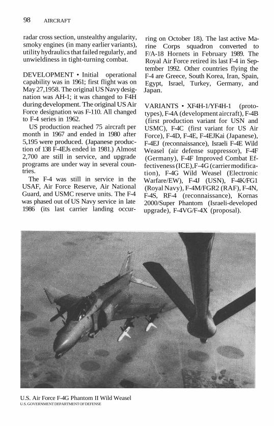
98 AIRCRAFT
radar cross section, unstealthy angularity,smoky engines (in many earlier variants),utility hydraulics that failed regularly, andunwieldiness in tight-turning combat.
DEVELOPMENT • Initial operationalcapability was in 1961; first flight was onMay 27,1958. The original US Navy desig-nation was AH-1; it was changed to F4Hduring development. The original US AirForce designation was F-110. All changedto F-4 series in 1962.
US production reached 75 aircraft permonth in 1967 and ended in 1980 after5,195 were produced. (Japanese produc-tion of 138 F-4EJs ended in 1981.) Almost2,700 are still in service, and upgradeprograms are under way in several coun-tries.
The F-4 was still in service in theUSAF, Air Force Reserve, Air NationalGuard, and USMC reserve units. The F-4was phased out of US Navy service in late1986 (its last carrier landing occur-
ring on October 18). The last active Ma-rine Corps squadron converted toF/A-18 Hornets in February 1989. TheRoyal Air Force retired its last F-4 in Sep-tember 1992. Other countries flying theF-4 are Greece, South Korea, Iran, Spain,Egypt, Israel, Turkey, Germany, andJapan.
VARIANTS • XF4H-1/YF4H-1 (proto-types), F-4A (development aircraft), F-4B(first production variant for USN andUSMC), F-4C (first variant for US AirForce), F-4D, F-4E, F-4EJKai (Japanese),F-4EJ (reconnaissance), Israeli F-4E WildWeasel (air defense suppressor), F-4F(Germany), F-4F Improved Combat Ef-fectiveness (ICE),F-4G (carrier modifica-tion), F-4G Wild Weasel (ElectronicWarfare/EW), F-4J (USN), F-4K/FG1(Royal Navy), F-4M/FGR2 (RAF), F-4N,F-4S, RF-4 (reconnaissance), Kornas2000/Super Phantom (Israeli-developedupgrade), F-4VG/F-4X (proposal).
U.S. Air Force F-4G Phantom II Wild WeaselU.S. GOVERNMENT DEPARTMENT OF DEFENSE

AIRCRAFT 99
COMBAT EXPERIENCE • US Navy andAir Force Phantoms saw extensive com-bat service in Vietnam, Navy beginningon August 5, 1964, and Air Force in June1965.
The Israeli Air Force (IAF) has usedF-4s extensively in Middle East conflictsbeginning in October 1969 during the"War of Attrition." In the Yom KippurWar of October 1973, F-4s flew most ofthe 500 deep-strike missions mounted bythe IAF. During the 1982 Peace in GalileeOffensive into Lebanon, F-4s were cred-ited with destroying most of the Syrian airdefense network in the Bekaa Valley.
During the 1980-88 Gulf War withIraq, the performance of Iranian AirForce F-4s was impeded by difficulties inobtaining spare parts, particularly for theradar and engines. One is said to havebeen shot down by an Iraqi Mi-24Hind.
US Air Force F-4s stationed at Clark ABin the Philippines patrolled the airspaceon December 1, 1989, during a coup at-tempt against the government. The F-4swere authorized to attack any rebel air-craft that launched from rebel-held Phil-ippine airbases. No hostile action wasnecessary.
No F-4s were used by any country dur-ing Operations Desert Shield and DesertStorm; however, some RF-4C and F-4GWild Weasel aircraft flew for the US AirForce.
SPECIFICATIONS (F-4S) •MANUFACTURER McDonnell DouglasCREW 2 (pilot, radar intercept officer)ENGINES 2 General Electric J79-GE-10
turbojetmax power 17,900 Ib (8,119 kg) static
thrust eachinternal fuel capacity
2,000 US gal (7,570 liters)WEIGHTS
empty 30,776 Ib (13,990 kg)max takeoff 56,000 Ib (25,455 kg)
DIMENSIONS
wingspan 38 ft 5 in (11.71 m)
length 58 ft 3 in (17.76m)height 16 ft 3 in (4.96 m)wing area 530 ft2 (49.20 m2)
PERFORMANCEmax speed clean, at 36,000 ft (10,973
m): l,260kts (1,450mph; 2,334 km/h) orMach 2.2
sea level, with Sparrowsonly: 790 kts (910 mph;1,465 km/h) or Mach1.2
low-level penetration speed with 4,750-lb(2,155-kg) weapons load
545 kts (628 mph; 1,010km/h)
climb rate 28,000 ft/min (8,534m/min)
ceiling 71,000 ft (21,641 m)radius 228 nm (262 mi; 422 km)
(fighter role)136 nm (157 mi; 252 km)
(attack role)range 1,600 nm (1,841 mi;
2,963 km) external fuelarmament various options,
including:1 20-mm cannon (Mk 11
in Mk 4 external gunpod or internal M61Vulcan Gading)
4 AIM-7 Sparrow + 4AIM-9 Sidewinder AAM+ 6 X 500-lb (227-kg)bombs
or 4 Sparrow + 8 X 1,000-Ib (454-kg) bombs
or AGM-65 Maverickradar Westinghouse series of
digital radar/firecontrol systems
Tiger II/Freedom Fighter (F-5)The F-5 is a lightweight, supersonic air-craft developed as an inexpensive, easilymaintained fighter capable of operatingfrom unimproved airfields. It was origi-nally offered as a candidate for a US light-

100 AIRCRAFT
weight fighter but found virtually all of itsmarket overseas. Although it is similar inappearance, the F-5E Tiger represented asignificant improvement over the earlierF-5A. The T-38 Talon supersonic trainer issimilar to the F-5 in most respects.
The F-5's small, thin wing is mountedlow on the fuselage well aft of the cockpit.It has a 24° leading-edge sweep, leading-edge flaps, and single-slotted trailing-edge flaps inboard of the inset ailerons.The wingtips have long missile rails. Onthe F-5E Tiger, the leading- and trailing-edge flaps have automatic combat-maneuver settings to increase turn rate.The F-5E also has a Leading-Edge RootExtension (LERX) with compoundsweep that improves the aircraft's han-dling at high angles of attack. Turnrates—both continuous and peak—increased by more than 30% over theF-5A.
The tail-group shape and position haveremained constant throughout F-5 devel-opment. The double-taper fin has a two-section inset rudder; the cropped-delta,all-moving tailplanes are mounted at thebottom of the fuselage in line with thefin. Controls are assisted by two indepen-dent hydraulic systems, and the aircraft isfitted with a stability augmentation sys-tem.
The two J85 turbojet engines areburied side by side in the aft fuselage,with the afterburning nozzles extendingwell beyond the tail group. The air in-takes are located low on either side of thefuselage. A boundary-layer splitter plateis fitted on the fuselage side of each in-take, and the lip is curved aft as it movesaway from the fuselage. The Tiger hasuprated J85s and auxiliary inlet doors fortakeoff and low-speed flight. Internal fueltankage is confined to the fuselage. Ira-nian F-5s were fitted with a "buddy" re-fueling system in 1988 that permits oneF-5 to refuel another.
The fuselage has a long pointed nosethat slopes up to a low canopy; behind thecanopy, a thick dorsal spine slopes down
to the tail. The nose shape has varied,with some aircraft being fitted with a flat-tened "shark nose"; the RF-5E Tigereyereconnaissance variant has a chisel-shaped nose with an underslung palletfor cameras.
The main-landing-gear struts retract infrom midwing pivots, the wheels beinghoused in fuselage wells. The nose gearin many F-5As and all F-5E/Fs has a two-position strut to raise the static angle ofattack by SVs0, thereby increasing thewing's lift and shortening takeoff roll.Side-by-side air brakes are mounted onthe fuselage bottom, forward of the land-ing gear.
The single-seat cockpit of the F-5A andF-5E is enclosed by a single-piece canopythat is hinged at the rear. The two-seatF-5B trainer and F-5F trainer-interceptorhave two canopy sections that are hingedto the side.
The F-5E is equipped with an EmersonElectric AN/APQrl53 or -159 pulse-Doppler radar. The F-5F has the Emer-son Electric APQ-157. In addition to amore comprehensive communicationsand navigation fit, the F-5E also has theGeneral Electric AN/ASG-29 or -31Lead-Computing Optical Sight (LCOS),a central air data computer, and an atti-tude and heading reference system. Sev-eral F-5E users have the Litton LN-33Inertial Navigation System (INS); Saudiaircraft have General Instruments AN/ALR-46 Radar-Warning Receiver (RWR),Tracor AN/ALE-40 countermeasuresdispenser, and Hughes AGM-65 Maver-ick missiles. Swiss and South Korean air-craft are being refitted with the DalmoVictor AN/ALR-87 threat-warning sys-tem. Several air forces have avionics up-grades under way or planned (seeVariants).
Armament consists of two Pontiac-builtM39 20-mm cannon in the upper nose.(The F-5F has one M39 cannon, the otherhaving been removed to make room forcamera pallets.) Each wingtip missilelaunch rail carries an AIM-9 Sidewinder

AIRCRAFT 101
Air-to-Air Missile (AAM). All variantshave one centerline hardpoint and fourwing pylons for external stores, includingAAM, air-to-ground missiles, bombs, gunpods, rocket pods, and external fueltanks.
DEVELOPMENT • The F-5A achieved itsinitial operational capability with the USAir Force in 1964; the F-5E in 1973. Firstflight of Northrop N-156 was on July 30,1959. F-5A through D variants continue toserve with many other countries. The USNavy and Air Force have flown F-5E/F air-craft for aggressor training. The US Ma-rine Corps adversary squadron replacedits F-21A Kfir fighters with F-5E aircraft,completing the changeover in fall 1989.
A total of 879 F-5A/Bs were built byNorthrop, and 320 F-5A variants werebuilt by Canadair in Canada and CASA inSpain. More than 1,400 F-5E/Fs werebuilt, including license assembly by Ko-rean Air in South Korea, F+W in Switzer-land, and AIDC in Taiwan. 2,600 F-5s hadbeen built in the US when productionended in February 1990; the last eight(for Singapore) were assembled fromfactory spares. More than 1,800 remainin service.
Ethiopian F-5A, -5E, and -5F aircrafthad been unserviceable for several yearsbefore they were discarded in 1990. RoyalNetherlands Air Force NF-5s were in ser-vice from 1969 to March 15, 1991. 60Royal Netherlands AF NF-5s were do-nated to the Turkish Air Force, 12 to theGreek Air Force, and seven were sold toVenezuela.
The F-5 series is one of the most suc-cessful examples of a Western lightweightfighter design to have entered service. Itis approximately the same size and weightas the MiG-21 Fishbed, but differs in hav-ing a lower maximum speed, higherweapons payload, and more tractable fly-ing qualities at low fuel states.
The Freedom Fighter is flown by about15 countries throughout the world; theTiger is flown by over 20 nations.
VARIANTS • F-5A (Freedom Fighter),F-5B (trainer), CF-5A/D (Canadair/CF-116), NF-5A/D (Canadair-built forthe Netherlands), Norwegian F-5A/-5BUpgrade, Norwegian Tiger Upgrade Pro-gram for Avionics Weapon and Systems(PAWS), F-5E/F (Singapore Upgrade),SF-5A/D (CASA-built), F-5E Tiger II(second-generation), F-5F (trainer),Chegoong-Ho (Air Master/South Ko-rean F-5F), Chung Cheng (TaiwaneseF-5E), RF-5E Tigereye (reconnaissance),upgrade variants: Chile, Jordan, SouthKorea, Thailand, Venezuela; F-5G, T-38Talon (trainer).
COMBAT EXPERIENCE • Saudi Ara-bian F-5Es flew training missions duringthe 1991 Operation Desert Storm; oneF-5E was lost to noncombat causes.
SPECIFICATIONS •MANUFACTURER NorthropCREW 1 (2 in F-5B/F)ENGINES
F-5A: 2 General Electric J85-GE-13 tur-bojet
F-5E: 2 General Electric J85-GE-21Bturbojet
max power F-5A dry: 2,720 Ib (1,234kg) static thrust each
F-5A with afterburner:4,080 Ib (1,851kg)static thrust each
F-5E with afterburner:5,000 Ib (2,268 kg)static thrust each
internal fuel capacityF-5A: 583 US gal (2,207
liters)F-5E: 677 US gal (2,555
liters)WEIGHTS
empty F-5A: 8,085 Ib (3,667 kg)F-5E: 9,723 Ib (4,410 kg)
max weapons loadF-5A: 6,200 Ib (2,812 kg)F-5E: 7,000 Ib (3,175 kg)
max takeoff F-5A: 20,576 Ib (9,333 kg)F-5E: 24,722 Ib (11,214 kg)

102 AIRCRAFT
DIMENSIONSwingspan F-5A: 25 ft 3 in (7.7 m)
F-5E: 26 ft 8 in (8.13 m)length F-5A: 47 ft 2 in (14.38 m)
F-5E: 47 ft 4 % in (14.45m)
Aeigfa F-5A: 13 ft 2 in (4.01 m)F-5E: 13 ft 4 in (4.06 m)
wing area F-5A: 170 ft2 (15.79 m2)F-5E: 186 ft2 (17.3 m2)
PERFORMANCE (at 13,350 lb/6,055 kg)max speed at 36,000ft (11,000 m)
F-5A: 803 kts (925 mph;1,489 km/h) or Mach1.4
F-5E:935kts (1,077 mph;1,733 km/h) or Mach1.64
typical cruise 488 kts (585 mph; 904km/h) or Mach 0.85
stall speed F-5A: 128 kts (147 mph;237 km/h)
F-5E: 124 kts (143 mph;230 km/h)
climb rate F-5A: 28,700 ft/min(8,748 m/min)
F-5E: 34,500 ft/min(10,516 m/min)
ceiling 51,800 ft (15,789 m)radius F-5A, hi-lo-hi with max
payload and combatreserves: 170 nm (195mi; 314km)
F-5E, lo-lo-lo with 5,200-lb(2,358-kg) payload and
combat reserves: 120nm (138 mi; 222 km)F-5E at 15,000 ft (4,575
m), max fuel, 2 AAM,combat reserves: 570nm (656 mi; 1,056 km)
ferry range, tanks droppedF-5A: 1,359 nm (1,565 mi;
2,519 km)F-5E: l,545nm (1,778 mi;
2,861 km)armament 2 M239A2 20-mm cannon
with 280 rounds eachand 2 AIM-9 Sidewinder
AAM on wingtiplaunchers
and up to 6,200 lb/7,000Ib (F-5A/F-5E) ofmixed ordnance on 4underwing and 1underfuselage stationsincluding:
1 1,985-lb (900-kg) bomb1 AGM-65 Maverick air-to-
surface missile9 500-lb (227-kg) bombssubmunitions dispensersrocket podsup to 3 GPU-5 30-mm
gun podsup to 3 150- or 275-US gal
(568- or 1,041-liter)drop tanks
radar, F-5E AN/APQ-153 or-159 I/J-band pulse Doppler
ROTARY WINGApache (AH-64)The AH-64 is the US Army's principalgunship/antitank helicopter. It was thewinner in the 1973-76 competition foran Advanced Attack Helicopter (AAH),beating out the Bell YAH-63 entry. TheAH-64 is intended primarily for the anti-tank role, with an all-weather/night oper-
ating capability. It is relatively fast andmaneuverable, carries a large antiarmorweapons load, has reduced radar and In-frared (IR) signatures, is damage-resistant against most small and mediumantiaircraft artillery, and is crashworthy.
The four-blade main rotor assembly

AIRCRAFT 103
consists of a hollow mast with an inertia-welded nickel-steel driveshaft. Each bladehas five stainless-steel spars, steel leadingedge, stainless-steel skin, and compositetrailing edge. The blade design features ahigh-lift airfoil section and swept tips; the20° sweep at the tips delays com-pressibility and improves the stability ofboth advancing and retreating blades.
The blades are linked to the hub armswith 22-ply-laminate strap packs. Twolead-lag dampers are fitted to each hubarm, and the flapping hinge is offset to4% of blade radius to augment controlpower. The blades can be folded for trans-port by large cargo aircraft.
The antitorque rotor has two two-bladeteetering rotors with a relatively low tipspeed, which reduces tail rotor noise,and a 4,500-hour fatigue life. The ti-tanium fork assembly carries one set ofblades in elastomeric bearings above theplane of the other and at a 60°/120° an-gle. The tailplane had originally beenmounted at the top of the tail. After tests,the broad, all-moving surface was relo-cated to near the base of the pylon. Itadjusts automatically to provide a levelattitude during Nap of the Earth (NOE)flight.
Primary flight control is by hydraulicactuation; a Sperry Fly-by-Wire (FEW) isprovided as a backup. Stabilization is bythe Sperry Digital Automatic Stabiliza-tion Equipment (DASE). ManufacturerMcDonnell Douglas Helicopters claimsthat the AH-64 can move laterally and tothe rear at speeds up to 45 kts (52 mph;83 km/h). Maximum load factors are+3.5 g/—0.5 g; the positive load factor isreduced to 2.4 g with a 3,350-lb (1,520-kg) weapons load.
The two turboshaft engines areshoulder-mounted on the fuselage be-hind the main rotor mast. Each engine isfitted with a "black hole" passive IR ex-haust suppressor.
The fuselage is designed to be crash-worthy in vertical crashes of up to 42-ft/sec descent; the crew compartment is fur-
ther protected by progressive deforma-tion of the rest of the airframe, whichabsorbs additional energy. The entire air-frame is designed to be invulnerable to12.7-mm rounds. In addition, most vitalcomponents can sustain hits from 23-mmrounds and continue flying to a safe land-ing.
The pilot and copilot/gunner sit intandem, Kevlar-armored seats sur-rounded by boron armor and under aheavily framed canopy. The canopy frameis designed to act as a roll cage, and theglazing between the crew members isimpact-resistant; the glazing is not bal-listically tolerant. The pilot is in the rearseat, which is 19 in (480 mm) above thecopilot/gunner's. The front seat has afull set of flight controls that are typicallystowed under the front sight.
The landing gear is fixed with themain, trailing-arm struts below the pilot'sposition and the tail gear extending be-yond the tail rotor pylon. Detachablestub wings are fitted to the fuselage belowthe main rotor mast; each wing has twoweapons pylons.
The core of the avionics fit is the Mar-tin Marietta Target Acquisition and Des-ignation Sight/Pilot's Night VisionSensor (TADS/PNVS) linked to the Hon-eywell Integrated Helmet and DisplaySight System (IHADSS) worn by bothcrew members. The turrets for the TADSand PNVS systems are fitted in the noseof the Apache. The upper PNVS turretcontains a Forward-Looking Infrared(FLIR) sensor directly linked to theIHADSS and traverses with the user'shead movements. Azimuth range is+/-900; elevation is +20°/-45°. Thelower TADS turret is divided vertically;the left half has direct vision optics withtwo fields of view (4° and 18°) above adaylight TV with 0.9° and 4° fields of view.The right half has a FLIR sensor. TADS isalso fitted with a laser spot tracker andlaser designator. Azimuth coverage is+/-1200, elevation is +30°/-60°. TADSimagery is relayed to the copilot/gunner

104 AIRCRAFT
through an optical relay "tube" that re-sembles a small console; it has both Head-Down and Head-Up Displays (HDD/HUD).
The three principal weapons systemson the Apache are the McDonnell Doug-las Helicopters M230 30-mm Chain Gun,Rockwell AGM-114 Hellfire laser-guidedantitank missiles, and Hydra 2.75-in (70-mm) rocket pods. The Chain Gun is fit-ted in a turret below the cockpit; turrettraverse is +/ —100°, elevation is+ 110/—60°. Ammunition is fed from a1,200-round pallet fitted under the mainrotor assembly; operational experiencehas shown that a 380-round ammunitionload is best. The stub pylons can carry upto 16 Hellfire missiles, although a load ofeight is more typical. As an alternativeload, up to four 19-rocket Hydra pods canbe carried.
To improve its self-defense capabilities,the Apache was tested in November 1987with Loral Aeroneutronic AIM-9 Side-winder Air-to-Air Missiles (AAM) fittedon stub wingtip rails. The usual AAM fit,however, is the Air-to-Air Stinger (ATAS)adaptation of the General DynamicsFIM-92 Stinger shoulder-fired surface-to-air missile. Shorts (UK) Starstreak andMatra Mistral air-to-air and AGM-122Sidearm antiradar missiles are also com-patible.
DEVELOPMENT • The Apache's initialoperational capability was in 1985. Its firstflight was on September 30, 1975, and itsfirst production rollout was in January1984; the 500th production aircraft wasrolled out on September 15, 1989. Thefirst squadron of Apaches stationed inEurope arrived in August 1987 as part ofREFORGER '87. A total of 975 AH-64AApaches had been planned for procure-ment through FY1992, equipping 27 at-tack helicopter battalions. With thedefense drawdowns following the col-lapse of the Soviet Union, the figure wasagain reduced under former DefenseSecretary Cheney.
Since its service entry in 1985, theApache has been the most advanced com-bat helicopter in service as well as pla-gued with reliability shortcomings inseveral key areas. Several studies con-ducted by the General Accounting Office(GAO) found many faults with theApache, both mechanical and with itselectronics.
Several countries have purchased theApache: Bahrain, Egypt, Greece, Israel,Kuwait, Saudi Arabia, and the UnitedArab Emirates.
VARIANTS • Multistage ImprovementProgram (MSIP), AH-64B, AH-64C/DLongbow Apache (mast-mountedmillimeter-wave radar), Naval Apache(shipboard/not funded).
COMBAT EXPERIENCE • In Decem-ber 1989, 11 Apaches flew 200 hours ofmissions in support of the US militaryoperation Just Cause to remove Panama-nian General Noriega from power; 66%of the flying time was at night. Accordingto the US Army, three AH-64s were dam-aged by ground fire and one aircraft took32 7.62-mm hits, but they were back inservice within 24 hours. The Army re-ported that Hellfire missiles used againstfixed targets, including General Nor-iega's headquarters, were very accurateand effective.
In August 1990, Apaches from the101st Airborne Division (Air Assault)were sent to Saudi Arabia as part of theUS response to the Iraqi invasion andannexation of Kuwait. Accounts of theirdegree of readiness varied from 70%to 90%.
Eight Apaches were used to attackearly-warning radar sites in western Iraqon a round-trip of 950 nm (1,094 mi;1,759 km) that opened Operation DesertStorm's air war. The mission, whichcleared an attack lane for precisionstrikes, achieved complete surprise andwithin two minutes had scored 15 hitswith Hellfire missiles.

AIRCRAFT 105
Additional reports during DesertStorm suggest that the Apache per-formed very well, whether alone or whenflown in concert with the A-10. When theground war was launched, Apaches ledthe 101st Airborne's airlift into Iraq. Dur-ing the ground assaults against Iraq'sRepublican Guard formations, someAH-64s hit and destroyed several tankswith a single load of eight Hellfires. Over-all, Apaches fired 2,876 Hellfires duringDesert Storm. The 4th Battalion of the229th Aviation Brigade was credited with50 tanks in a single battle.
Serviceability reportedly remainedhigh, and the Apache ended the cam-paign with an enhanced reputation.
SPECIFICATIONS •MANUFACTURER McDonnell Douglas
HelicoptersCREW 2 (pilot, copilot/gunner)ENGINES 2 General Electric T700-
GE-701 or -701C turboshaftmax power 1,695 shp (-701) or 1,890
shp (-701C) eachinternal fuel capacity
376 US gal (1,422 liters)WEIGHTS
empty 10,760 Ib (4,881 kg)primary mission gross weight
14,445 Ib (6,553 kg)with 3,350 Ib (1,520 kg) weapons load
and 2,500 Ib (1,134 kg) of fuel17,650 Ib (8,006kg)
ferry mission 21,000 Ib (9,525 kg)DIMENSIONS
rotor diam 48 ft (14.63 m)length 48 ft 2 in (14.68 m)height top of rotor: 12 ft 7 in
(3.84 m)top of air data sensor: 15
ft 31/? in (4.66 m)disc area 1,809.5 ft2 (168.1 m2)
PERFORMANCE(Army Hot day = 95° F/(35° C at
4,000 ft/1,220m)speed max
clean: 164 kts (189 mph;304km/h)
Army Hot day: 147-155kts (169-178 mph;272-287 km/h)
Euro theater, 2,000 ft(610 m) at 70° F (21°C): 148-153 kts (170-176 mph; 274-284km/h)
econ cruisesea level, standard day:
128 kts (147 mph; 237km/h)
Army Hot day: 119 kts(137 mph; 221 km/h)
rate of climb maxstandard day: 3,200 ft/
min (975 m/min)Army Hot day: 2,750 ft/
min (783 m/min)max, verticalstandard day: 2,460 ft/
min (750 m/min)Army Hot day: 1,450 ft/
min (442 m/min)ceiling standard day
2 engines: 21,000 ft(6,400 m)
1 engine: 10,800 ft (3,292m)
Army Hot day2 engines: 10,300 ft
(3,139 m)1 engine: 6,400 ft (1,951
m)hovering ceiling in ground effect, 14,445
Ib (6,553 kg)standard day: 15,000 ft
(4,572 m)Army Hot day: 10,200 ft
(3,109 m)hovering ceiling out of ground effect,
14,445 Ib (6,553 kg)standard day: 11,500ft
(3,505 m)Army Hot day: 7,000 ft
(2,134m)range internal fuel: 260 nm
(300 mi; 482 km)ferry: 918 nm (1,057 mi;
1,701 km)

106 AIRCRAFT
armament 1 M230 Chain Gun 30-mm cannon in bellyturret with 1,200rounds
4 wing pylons for up to16 Hellfire antitankmissiles or 76 2.75-in(70-mm) rockets in 4pods
and 4 FIM-92 Stinger air-to-air missiles
Sioux/Scout (OH-13)The OH-13 (also known as the Bell 47) isone of the most widely used helicoptersin history. It is a two-seat, light utility heli-copter that has been adapted for use inthe wire-laying, liaison, medical evacua-tion, training, and Antisubmarine War-fare (ASW) roles.
The OH-13 has a simple two-blademain rotor with a stabilizer bar mountedbelow the main rotor plane and at a 90°angle to it. Some variants have enclosedcabins, but most have a Plexiglas bubblecanopy and an open lattice tailboom withan antitorque rotor on the right side.Twin-skid landing gear with two retract-ing wheels is standard, but some navalversions have pontoons for water opera-tions. Medical evacuation versions carrytwo stretcher pods, one on either side ofthe cabin.
DEVELOPMENT • The OH-13's initialoperational capability was in 1946. It is nolonger in US military service or produc-tion but is still in service in many othercountries. Over 6,000 had been producedwhen production ceased in 1973, amilitary-helicopter production run ex-ceeded in the West only by the UH-1 Iro-quois (Huey). The OH-13 was alsolicense-built in Italy by Agusta, in GreatBritain by Westland, and in Japan by Ka-wasaki.
The aircraft was operating in the mili-
tary services of about 25 nations, mostlyin Africa and Latin America in the 1990s.
VARIANTS • YR-13/Bell 47A (proto-type), H-13B/Bell 47D, H-13D/Bell47D-1 (two-seat), H-13E/OH-13E/Bell47D-1 (three-seat), XH-13F (experimen-tal), H-13G/OH-13G/Bell 47G, H/OH/UH-13H/Bell 47G-2, H/UH-13J (USAF),H/OH-13K/Bell 47G-3 (convertedH-13H), TH-13L (USN trainer), TH-13M(trainer), TH-13N (trainer), UH-13P(USN utility), HH-13Q, (USCG SAR),UH-13R, OH-13S/Bell 47G-3B, TH-13T/Bell 47G-3B-1 (US Army instrumenttrainer), HTL-3/Bell 47E (USN/Braziltrainer), HTL-7/Bell 47J Ranger (USN,USMC, and USCG), Agusta-Bell 47J-3Super Ranger (Agusta-built shipboardASW), Scout (British-built).
COMBAT EXPERIENCE • Used exten-sively in combat by US forces in the Ko-rean War and by French forces in Algeria.
SPECIFICATIONS •MANUFACTURER Bell HelicopterCREW 1ENGINES
H-13H: 1 Lycoming VO-435 pistonOH-13S: 1 Lycoming TVO-435-A1A
pistonmax power H-13H: 200 hp
OH-13S: 260 hpWEIGHTS
empty H-13H: 1,564 Ib (710kg)
OH-13S: l,9361b (879kg)
max takeoff H-13H: 2,450 Ib (1,112kg)
OH-13S: 2,850 Ib (1,293kg)
DIMENSIONSrotor diam H-13H: 35 ft 1 in (10.69
m)OH-13S: 37 ft 2 in (11.35
m)length H-13H: 27 ft 4 in (8.33 m)
AIRCRAFT 107
OH-13S: 32 ft 7 in(9.93 m)
height 9 ft 6 in (2.9 m)disc area H-13H: 966.1 ft* (89.8
m2)OH-13S: 1,089.1 ft2
(101.2m2)PERFORMANCE
max speed H-13H: 87 kts (100 mph;161 km/h)
OH-13S: 91 kts (105 mph;169 km/h)
cruise speed 74 kts ( 85 mph; 137 km/h)
climb rate H-13H: 770 ft/min (235m/min)
OH-13S: 1,190 ft/min(363 m/min)
ceiling H-13H: 13,200 ft (4,023m)
OH-13S: 18,000 ft (5,486m)
hovering ceiling in and out of groundeffect
OH-13S: 18,000 ft (5,486m)
range H-13H: 261 nm (300 mi;483km)
OH-13S: 281 nm (324 mi;521 km)
Defender (MD 500/530)The MD 500MD is a light, multipurposehelicopter adapted for observation,scout, special-operations, antiarmor at-tack, and Antisubmarine Warfare (ASW)roles. It is based on the earlier OH-6ACayuse and its commercial derivative theHughes 500. The Defender is an im-proved military variant of the Model 500with uprated engine, T-tail, and heavierarmament; it is the basis for all subse-quent McDonnell Douglas scout heli-copters.
The 500MD features a five-blade, fullyarticulated main rotor with cross-connected flap and feather straps. The
slender tailboom extends aft from theroof of the egg-shaped fuselage pod to anarrow, swept fin; the fin extends belowthe boom and is fitted with a small tailskid.
The two-blade, antitorque rotor ismounted at the end of the boom on theleft-hand side; a four-blade "quiet" rotorcan also be fitted. The offset-V tail of theOH-6 has been replaced by a narrow hori-zontal stabilizer at the top of the fin; thestabilizer has tapered leading edges andsmall endplate fins.
The Allison turboshaft is carried be-hind the crew compartment, receiving airthrough a small intake on the cabin roofand exhausting through a nozzle at theaft end of the fuselage pod below theboom. The crew cabin features a glazednose for maximum forward visibility. The530 series (and the 500MG) have apointed nose for streamlining. Engine ac-cess is through clamshell doors at the rearof the fuselage pod. The parallel-skidlanding gear has internal oleo-pneumaticshock absorbers.
Variants of the 500MD have differentarmament configurations on detachablepylons. The Scout version is armed with a7.62-mm minigun or Chain Gun pod,rocket pods, or 40-mm grenadelaunchers. The 500MD/TOW mounts atwo-round TOW antitank missilelauncher on each pylon. The 500MDASW carries one or two lightweight ASWtorpedoes between the skids.
DEVELOPMENT • The SOOMD's initialoperational capability was in 1976. It isproduced primarily for export. The USArmy purchased approximately 30 in themid-1980s for 160th Aviation Group, acommando unit; additional ordersbrought the Army's total to at least 54.
Production of military variants was li-censed to Kawasaki in Japan and KoreanAir Lines in South Korea; civilian variants(including some purchased for militaryuse) were also license-built by BredaNardi of Italy.

108 AIRCRAFT
Five Chilean MD530Fs were sold to a"Chilean sardine fishing concern" in1988-89 but later discovered to be in Chi-lean Army service. When the transfer wasrevealed, the United States placed an em-bargo on spare parts.
The MD 500 and its variants have beenin use in 17 foreign nations, primarily inAsia and Latin America. North Korea ac-quired at least 60 of the helicopters dur-ing the mid-1980s, reportedly throughUS dealers.
VARIANTS • OH-6A Cayuse, 500MDScout Defender, 500MD ASW, 500MD/TOW Defender, 500MD/MMS-TOW,500MD Defender II, MD500E, NH-500E(Italian Army), MD530F Lifter, 530MGDefender, 500MG Defender, M/AH-6"Litde Bird," Nightfox (night visionequipment), NOTAR.
COMBAT EXPERIENCE • An undis-closed number of Task Force 160 "LittleBirds" were deployed to Saudi Arabia aspart of Operation Desert Storm.
SPECIFICATIONS •MANUFACTURER McDonnell DouglasCREW 2 (pilot, copilot) + 6 troopsENGINES
500MD/TOW: 1 Allison 250-C20Bturboshaft
530MG: 1 Allison 250-C30 turboshaftmax power 500MD/TOW: 420 shp
(derated to 375 shp)530MG: 650 shp (derated
to 425 shp)internal fuel capacity
63 US gal (240 liters)optional auxiliary tank
21 US gal (79.5 liters)WEIGHTS
empty 500MD/TOW: 1,976 Ib(896 kg)
530MG: 1,591 Ib (722 kg)max takeoff 500MD/TOW: 3,000 Ib
(1,361 kg)530MG: 3,550 Ib (1,610 kg)
DIMENSIONSrotor diam
length
height
disc area
PERFORMANCEcruise speed
climb rate
500MD/TOW: 26 ft 4 in(8.03 m)
530MG:27ft4in(8.33m)500MD/TOW 30 ft 10 in
(9.4 m)530M: 32 ft 1 in (9.78 m)500MD/TOW: 8 ft 8 in
(2.64 m)530MG: to top of rotor
head, 8 ft 7 in (2.62m); to top of Mast-Mounted Sight (MMS),11 ft 2V2in (3.41m)
500MD/TOW: 544.6 ft2(50.6 m2)
530MG: 586.8 ft*(54.5 m2)
500MD/TOW: 119kts(137 mph; 221 km/h)
530MG: 135 kts (155mph; 250 km/h)
500MD/TOW: 1,650ft/min (503 m/min)
530MG: 2,100 ft/min(640 m/min)
15,800 ft (4,815 m)330 nm (380 mi; 611 km)none integral to all
variants, but optionalarmament includes:
7.62-mm and .50-calmachine-gun pods
7.62-mm Chain Gun7-tube or 12-tube 2.75-in
rocket podsStinger air-to-air missiles7.62-mm minigun40-mm grenade launcherTOW antitank missiles
Cobra/TOW(AH-1E/F/G/P/Q/S)The AH-1 Cobra is an attack helicopterdesigned for close air support and anti-tank missions. The Cobra series was de-
rangearmament

AIRCRAFT 109
rived from the UH-1 Huey/Iroquoisutility/transport helicopter, retaining therotor, transmission, and engine in a com-pletely redesigned fuselage. The manu-facturer's designation is Model 209HueyCobra.
The standard Cobra/TOW is theAH-1F, a redesignation of the modern-ized AH-1S; earlier AH-1 aircraft are be-ing either retired or upgraded to theAH-1F level. The two composite bladesare linked to the main rotor hub by "doorhinges," creating a semirigid main rotorsystem.
The two-blade antitorque rotor ismounted on the starboard side of the tailpylon near the top. Short, slightly swept,horizontal stabilizers are midmounted onthe fuselage approximately halfway be-tween the engines and the tail rotorpylon.
The engine is mounted above the fu-selage and behind the main rotor pylon.A cooled, plug-type, Infrared (IR) signa-ture suppressor and cylindrical shroud isfitted to the engine exhaust.
The fuselage provides a minimal crosssection (38 in; 0.99 m) with stub wings forcarrying missiles, rocket packs, or gunpods, a nose turret with a 20-mm, 3-barrelGalling gun, and tandem seating for agunner/copilot (forward) and pilot. Thelanding gear consists of parallel skids onspring struts.
The fire control system has a TeledyneSystems digital ballistic computer andKaiser Head-Up Display (HUD). Otheravionics include the Singer-Kearfott AN/ASN-128 Doppler navigation system,E-Systems AN/APR-39 radar-warning re-ceiver, Sanders AN/ALQ-144 IR counter-measures jammer, and a GEC Avionics IS03-004 low-airspeed air data sensor,which is mounted on an outrigger on thestarboard side.
Targeting for the TOW requires theM65 Airborne TOW missile system withthe primary sensors fitted in the nose-mounted Telescopic Sight Unit (TSU).The TSU has a traverse of 110° to either
side and an elevation range of-60°/+30°. Upgrades to the M65 in-clude the Hughes Laser-Augmented Air-borne TOW (LAAT) stabilized sight andthe Rockwell AN/AAS-32 Airborne LaserTracker (ALT).
Weapons include a chin-mounted Gen-eral Electric Universal Turret capable ofaccepting Gatling-type guns ranging incaliber from 7.62 mm to 30 mm. Theturret traverses 110° to either side andhas an elevation range of —50°/+21°.Gun movement and targeting are con-trolled by the TSU or by a Helmet SightSubunit (HSS) worn by either thegunner/copilot or the pilot. The stubwings have four weapons stations for upto a total of eight TOW or four rocket orgun pods.
DEVELOPMENT • The AH-lG's initialoperational capability was in 1967. Theprototype's first flight was on September7, 1965. Over 1,450 single-engine Cobramodels were built. License production byMitsui in Japan continues.
The C-NITE Cobra variant entered ser-vice with the 77th Aviation Brigade inSouth Korea in 1990. Also in 1990,Pakistan agreed to purchase 24 C-NITEkits.
VARIANTS • Bell Model 209, AH-1G(US Army, USMC, Spain), AH-1Q (Im-proved Cobra Armament Program/ICAP), YAH-1R (Improved Cobra Agilityand Maneuverability/ICAM), YAH-1S,AH-1S, AH-1P, AH-1E (US Army, Israel,Japan), AH-1P (Enhanced Cobra Arma-ment System/ECAS), AH-1F (US Army/Army National Guard, Israel, Jordan,Pakistan, Thailand, South Korea), ARTI(Advanced Rotorcraft Technology Inte-gration), C-FLEX (Cobra Fleet Life Ex-tension), Z-16 (Spain).
COMBAT EXPERIENCE • Cobras havebeen used in combat by US forces inVietnam, in Grenada, and in the Decem-ber 1989 Operation Just Cause military

110 AIRCRAFT
ouster and capture of General Noriega.US Army Cobras were deployed to SaudiArabia as part of Operation DesertShield, and during Desert Storm AH-lsflew escort missions. A Cobra scoredTOW hits on the lead vehicles in a 1,000-vehicle Iraqi column, blocking the rest ofthe force and leading to its capture ordestruction.
Israeli Cobras have operated againstPalestinian and Syrian targets inLebanon's Bekaa Valley since 1982.
SPECIFICATIONS •MANUFACTURER Bell-TextronCREW 2 (pilot, gunner)ENGINES
AH-1G: 1 Avco Lycoming T53-L-13turboshaft
AH-1S: 1 Avco Lycoming T53-L-703turboshaft
max power AH-1G: 1,400 shpAH-1S: 1,800 shp
internal fuel capacityAH-1G: 268 US gal (1,014
liters)AH-1S: 259 US gal (980
liters)WEIGHTS
empty AH-1G: 6,073 Ib (2,735 kg)AH-1S: 6,598 Ib (2,993 kg)
useful load AH-1G: 3,427 Ib (1,554 kg)AH-1S: 3,402 Ib (1,543kg)
max takeoff AH-1G: 9,500 Ib (4,309 kg)AH-1S: 10,000 Ib
(4,535 kg)DIMENSIONS
rotor diam 44 ft (13.41 m)length 44 ft 7 in (13.59m)height AH-1G: 13 ft 6 in
(4.12 m)AH-1S: 13 ft 5 in (4.09m)
disc area 1,520.5 ft2 (141.3 m2)PERFORMANCE
max speed AH-1G: 149 kts (172 mph;277 km/h)
AH-1S: 123 kts (141 mph;195 km/h) with TOW
climb rate AH-1G: 1,375 ft/min (419m/min)
AH-1S: 1,620 ft/min (494m/min)
ceiling AH-1G: 11,400 ft (3,475 m)AH-1S: 12,200ft (3,720m)
hover in ground effectAH-1G: 9,900 ft (3,015 m)AH-1S: 12,200 ft (3,720 m)
range AH-1G: 325 nm (374 mi;602 km)
AH-1S: 274 nm (315 mi;507km)
armament, AH-1GM28 nose turret with 2
GAU-2B/A 7.62-mmminiguns
w2M12940-mmgrenade launchers
or 1 minigun and 1 Ml29and stub wing pylons for 4
Ml 57 pods with 762.75-in (70-mm)rockets
or 4 M157 pods with 28rockets
or 2 M18E1 minigun podsor M35 20-mm automatic
cannon systemarmament, AH-1S
M197 3-barrel 20-mmCatling gun in noseturret
up to 8 Hughes BMG-71TOW antitank missiles
or 4 LAU-68A/A (7-tube)2.75-in rocket pods
or up to 4 LAU-61A/A(19-tube) 2.75-in rocketpods
orM181E minigun pods
SectCobra/SuperCobra(AH-1J/T/W)Note: Only differences from the basicAH-1G Huey are included in this entry.
These Cobra twin-engine variants areall assigned to the US Marine Corps. Themain rotor system is based on the Bell214 and is fitted with a rotor brake and

AIRCRAFT 111
has elastomeric bearings; the two broad-chord blades have swept tips.
The two turboshaft engines aremounted in separate nacelles located oneither side of the main rotor pylon. Theengines' air intakes are large, verticalrectangular inlets; the engine nacelles ofthe AH-1W are much larger and squarerthan those of the AH-1J/T. In theAH-1W, the 73% increase in maximumrated power of the T700 engine installa-tion has restored the operating capa-bilities , found in the AH-1J at 50%greater maximum takeoff weight. TheAH-lW's exhausts are fitted with large,boxy Infrared (IR) suppressors, and thefuel system can tolerate a direct hit froma 23-mm projectile.
The fuselage has a slender cross sec-tion (43 in; 1.09 m) that swells to 10 ft 9in (3.28 m) across the engines; theAH-1T was stretched 12 in (305 mm) toaccount for the addition of TOW anti-tank missiles. The cockpit has tandemseating for a gunner/copilot (forward)and pilot.
The AH-lW's modest night-attack ca-pability is currently limited to Night Vi-sion Goggles (NVG) such as the AN/AVS-6 Aviator Night Vision Imaging Sys-tem (ANVIS). In June 1994, the firstAH-1W with the Taman Night TargetingSystem (NTS) upgrade entered service.The million-dollar improvement includesa gyro-stabilized Forward-Looking Infra-red (FLIR) and laser designator systemfor night and adverse-weather targetingof the Hellfire missile.
DEVELOPMENT • The AH-lJ's initialoperational capability was in 1971. A totalof 160 twin-engine Cobras were built forthe United States; 202 AH-lJs were manu-factured for Iran and eight for South Ko-rea. Most Marine Corps SeaCobras areupdated to the AH-1W level from the ear-lier AH-1T; the AH-1J remains in servicein two other countries. Iran, South Korea,and Turkey operate the SeaCobra in ad-dition to the US Army.
VARIANTS • AH-1J SeaCobra (USMC/Iran), AH-1T Improved SeaCobra,AH-1W SuperCobra, Four-Bladed Whis-key.
COMBAT EXPERIENCE • Cobras havebeen used in combat by US forces in theVietnam War and in the 1983 Grenadaoperation. AH-1T and AH-1 W helicopterswere deployed in support of OperationsDesert Shield/Desert Storm. The MarineCorps Cobras were particularly well suitedto desert operations because their systemshave been sealed against saltwater corro-sion and thus are protected against sandinfiltration as well. Approximately 78USMC Cobras flew 1,273 sorties support-ing the operations. One Marine Corps Co-bra was lost during the seven-week war in anoncombat casualty.
SPECIFICATIONS •MANUFACTURER Bell Helicopter Tex-
tronCREW 2 (pilot, gunner)ENGINES
AH-1J: 2 Pratt & Whitney T400-CP-400turboshaft
AH-1T: 2 Pratt & Whitney T400-WV-402 turboshaft
AH-1W: 2 General Electric T700-GE-401 turboshaft
internal fuel capacity304.5 US gal (1,153 liters)
max power AH-1J: 1,800 shp totalAH-1T: 1,970 shp totalAH-1W: 3,200 shp total
WEIGHTSempty AH-1J: 7,261 Ib (3,294 kg)
AH-1T: 8,014 Ib (3,640 kg)AH-1W: 10,200 Ib (4,627
kg)max takeoff AH-1J: 10,000 Ib (4,535 kg)
AH-1T: 14,000 Ib (6,350kg)
AH-1W: 14,750 Ib (6,690kg)
DIMENSIONSrotor diam AH-1J: 44 ft (13.41 m)

112 AIRCRAFT
AH-1T/W: 48 ft(14.63 m)
length AH-1J: 44 ft 7 in (13.59m)
AH-1T/W: 48 ft 2 in(14.68 m)
height AH-1J/W: 13 ft 8 in (4.15m)
AH-1T: 14 ft 2 in (4.32 m)disc area AH-1J: 1,520.5 ft* (141.3
in*)AH-1T/W: 1,809.6 ft2
(168.1 m2)PERFORMANCE
max speed AH-1J: 180 kts (207 mph;333 km/h)
AH-1T: 149 kts (172 mph;277 km/h)
AH-1W: 189 kts (218mph; 350 km/h)
max cruise at 3,000ft (914 m) at 95°F(35° C)
AH-1T: 135 kts (155 mph;250 km/h)
AH-1W: 160 kts (184mph; 296 km/h)
ceiling AH-1J: 10,550 ft (3,215 m)AH-1T: 11,000ft (3,353
m)AH-1W: 17,500 ft (5,334
m)hover in ground effect
AH-1J: 12,450 ft (3,794 m)AH-1T: 4,500 ft (1,372m)AH-1W: 14,750 ft (4,495 m)
hover out of ground effectAH-1J: 3,600 ft (1,097m)AH-1T: 400 ft (122 m)AH-1W: 3,000 ft (914 m)
range AH-1J: 335 nm (385 mi;620 km)
AH-1T: 310 nm (356 mi;574 km)
AH-1W: 343 nm (395 mi;635km)
armament, AH-1JM197 3-barrel 20-mm
cannon (750 rounds)in nose turret
wing pylons for 4
LAU-68A/A (7-tube)2.75-in (70-mm) rocketpods
or up to 4 LAU-61A/A(19-tube) 2.75-in (70-mm) rocket pods
orM181E minigun podsarmament, AH-1T/W
in addition to AH-1Sarmament, can carry
8 BGM-71 TOW antitankmissiles
plus in AH-1W:2 AIM-9 Sidewinder air-
to-air missilesor2AIM-123Sidearm
antiradar missilesor8AGM-114Hellfire
antitank missilesor 4 CMU-55B fuel-air
explosive weaponsor!65-in (127-mm) Zuni
rocketsor478-USgal (295-liter)
or 2 100-gal (378-liter)auxiliary fuel tanks
Sea Knight (CH-46)The Sea Knight has served as the mediumassault helicopter for the US MarineCorps and as a Vertical On-Board Deliv-ery (VOD) aircraft for the US Navy, andin a variety of other roles with severalother countries.
The Sea Knight has two contra-rotating, three-blade main rotorsmounted on rotor pylons atop the foreand after ends of the fuselage. Whenviewed from above, the forward blade ro-tates counterclockwise, the after bladeclockwise, at a speed of 264 rpm.
The semimonocoque fuselage is anelongated, rounded box with a shortnose, an extensively glazed, side-by-sideflight deck, dorsal spine for the front ro-tor drive, and a loading ramp in the rear.The ramp forms the bottom of the fu-selage as it tapers up to the tail. The fu-

AIRCRAFT 113
selage is watertight and in later variants isalso fitted with flotation bags. Troop ac-cess can be through the rear ramp or bythe side doors, which can each mount a.50-cal machine gun.
The two General Electric turboshaftengines are mounted in faired nacelleson either side of the rear rotor pylon. 49CH-46Es were fitted with 660-US gal(2,498-liter) fuel tanks that have agraphite-epoxy shell and Nomex honey-comb filler. The E's sponsons were en-larged to accept these tanks, whichdoubled the mission radius to 160 nm(184 mi; 296 km). Some are fitted withthe Loral AN/AAR-47 electro-opticalmissile-warning system.
The fixed, two-wheel main-landing-gear main legs are mounted in sponsonson each rear side of the fuselage; thesponsons also carry fuel. The two-wheelnose-gear strut is centered under theflight deck.
The avionics fit was upgraded begin-ning in 1992 with the Rockwell CollinsAN/APN-217 Doppler navigation systemthat has latitude-longitude positioning,ground and wind speed indicators, cross-track and track-angle error messages,and display of time, distance, course, andbearing to next target. Two Cathode-RayTube (CRT) displays, interface controlunits, and situation/hover indicatorunits are also installed in die lower con-sole and instrument panel.
The US Army CH-47 Chinook is highlysimilar in appearance to the Sea Knightdesign but can be distinguished by quad-ricycle landing gear, a larger, boxier fu-selage, and by the lack of die CH-46'slanding-gear sponsons. The CH-46 isknown in the fleet as Phrog.
DEVELOPMENT • The CH-46's initialoperational capability was in 1962; thefirst flight of Model 107 was on April 22,1958. Production ceased in the UnitedStates in 1971 after 666 units had beenbuilt for US service and for export. Ka-wasaki's 25 years of low-rate production
of KV-107 variants ended in February1990 after 160 were built.
Fiberglass rotor blades were intro-duced as an upgrade in the late 1970s. Inaddition to the US Navy and Marines,Burma, Canada, Japan, Saudi Arabia, andSweden have operated the CH-46.
In mid-May 1990, the Department ofthe Navy grounded all 261 US MarineCorps CH- and HH-46 and Navy UH- andHH-46 helicopters to correct a quill shaftproblem "that could cause a loss of driveto the aft rotor."
VARIANTS • Model 107 (civilian),YHC-1A/CH-46C, HRB-1, CH-46A (SAR,utility), H-46B (not produced), CH-46D,CH-46E CILOP (Conversion in Lieu ofProcurement CILOP), CH-46F, SR&M(Safety, Reliability, and Maintainability),CH-113 Labrador (SAR)/CH-113A Voy-ageur (transport) for Canada, HKP-4/HKP-7 (ASW/SAR), KV-107 (Japanese-built), KV107IIA (Kawasaki upgrade forJapan), KV107IIA-SM (Saudi Arabia).
COMBAT EXPERIENCE • The SeaKnight was used extensively by US Navaland Marine Corps forces in the VietnamWar. It also supported operations inLebanon (1982-84) and Grenada (Octo-ber 1983). In January 1991, CH-46sfromthe amphibious assault ship USS Guam(LPH 9) were diverted from OperationDesert Shield to participate in OperationEastern Exit, which rescued 281 US andforeign nationals from the US embassy inMogadishu during the bloody Somaliancivil war.
In the fall of 1990, US Navy and MarineCorps CH-46s were deployed to the Per-sian Gulf as part of Desert Shield; 120Marine Corps Sea Knights—60 operatingfrom shore bases and 60 from ships—flew 1,601 sorties during Operation Des-ert Storm. They supported the drive intoKuwait that began the ground war on Feb-ruary 24,1991. Two CH-46s were lost dur-ing the war for noncombat causes.
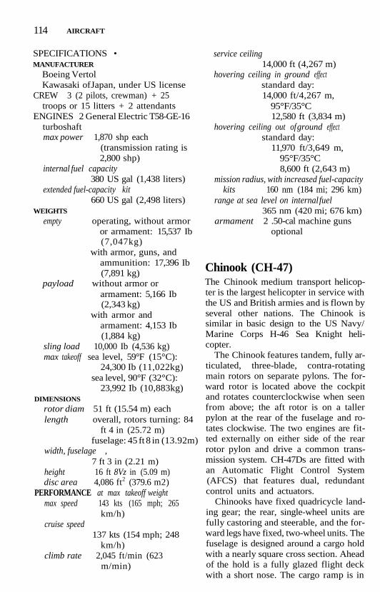
114 AIRCRAFT
SPECIFICATIONS •MANUFACTURER
Boeing VertolKawasaki of Japan, under US license
CREW 3 (2 pilots, crewman) + 25troops or 15 litters + 2 attendants
ENGINES 2 General Electric T58-GE-16turboshaftmax power 1,870 shp each
(transmission rating is2,800 shp)
internal fuel capacity380 US gal (1,438 liters)
extended fuel-capacity kit660 US gal (2,498 liters)
WEIGHTS
empty operating, without armoror armament: 15,537 Ib(7,047kg)
with armor, guns, andammunition: 17,396 Ib(7,891 kg)
payload without armor orarmament: 5,166 Ib(2,343 kg)
with armor andarmament: 4,153 Ib(1,884 kg)
sling load 10,000 Ib (4,536 kg)max takeoff sea level, 59°F (15°C):
24,300 Ib (11,022kg)sea level, 90°F (32°C):
23,992 Ib (10,883kg)DIMENSIONS
rotor diam 51 ft (15.54 m) eachlength overall, rotors turning: 84
ft 4 in (25.72 m)fuselage: 45 ft 8 in (13.92m)
width, fuselage ,7 ft 3 in (2.21 m)
height 16 ft 8Vz in (5.09 m)disc area 4,086 ft2 (379.6 m2)
PERFORMANCE at max takeoff weightmax speed 143 kts (165 mph; 265
km/h)cruise speed
137 kts (154 mph; 248km/h)
climb rate 2,045 ft/min (623m/min)
service ceiling14,000 ft (4,267 m)
hovering ceiling in ground effectstandard day:14,000 ft/4,267 m,
95°F/35°C12,580 ft (3,834 m)
hovering ceiling out of ground effectstandard day:
11,970 ft/3,649 m,95°F/35°C8,600 ft (2,643 m)
mission radius, with increased fuel-capacitykits 160 nm (184 mi; 296 km)
range at sea level on internal fuel365 nm (420 mi; 676 km)
armament 2 .50-cal machine gunsoptional
Chinook (CH-47)The Chinook medium transport helicop-ter is the largest helicopter in service withthe US and British armies and is flown byseveral other nations. The Chinook issimilar in basic design to the US Navy/Marine Corps H-46 Sea Knight heli-copter.
The Chinook features tandem, fully ar-ticulated, three-blade, contra-rotatingmain rotors on separate pylons. The for-ward rotor is located above the cockpitand rotates counterclockwise when seenfrom above; the aft rotor is on a tallerpylon at the rear of the fuselage and ro-tates clockwise. The two engines are fit-ted externally on either side of the rearrotor pylon and drive a common trans-mission system. CH-47Ds are fitted withan Automatic Flight Control System(AFCS) that features dual, redundantcontrol units and actuators.
Chinooks have fixed quadricycle land-ing gear; the rear, single-wheel units arefully castoring and steerable, and the for-ward legs have fixed, two-wheel units. Thefuselage is designed around a cargo holdwith a nearly square cross section. Aheadof the hold is a fully glazed flight deckwith a short nose. The cargo ramp is in

AIRCRAFT 115
the rear of the fuselage and triple exter-nal cargo hook system; fore and aft hookshave 17,000-lb (7,712-kg) capacity, thecenter hook can hold 26,000 Ib (11,793kg), and dual-point capacity is 23,000 Ib(10,433kg).
The fuselage has external fuel tanks insponsons along both sides and has asealed lower half to permit water landings.
Defensive electronics and counter-measures are fitted to many Chinooks invarious configurations.
DEVELOPMENT • The Chinook's ini-tial operational capability was in 1962; itsfirst flight was on September 21, 1961(YCH-47A). The helicopter remained inproduction for foreign users after 736were built by Boeing Vertol (later BoeingHelicopters) for the US Army. Over 200have been built under license by Meridi-onal! in Italy, and 54 were being built byKawasaki in Japan.
The initial operational capability forthe CH-47D was in February 1984.
In February 1991, the Canadian AirCommand announced that it would dis-pose of its seven CH-147s by the middleof 1991 due to a series of comprehensivedefense budget cuts.
All 264 US Army CH-47Ds weregrounded in July 1989 and again in Au-gust 1989 after two aircraft suffered simi-lar failures in the drivetrain for the aftoil-cooling fan assembly. In April 1990,the Army once again grounded itsCH-47Ds because of possible crackedlock nuts in the forward transmissionmounting.
In addition to the US Army, about 13other countries throughout the world op-erate the Chinook.
VARIANTS • YHC-1B (prototype), CH-47A, CH-47B, CH-47C (BV 219) (USArmy, Canada, China, Italy), ChinookHC Mk 1 (BV 352) (RAF), Chinook HCMk 2, CH-47D (US Army, Germany,Greece, Spain), International Chinook
(Model 414-100) (Japan, China), MH-47E (USSOF).
COMBAT EXPERIENCE • Chinookswere widely used in the Vietnam War.Some were armed to act as gunships butwere deemed unsuited to that role. In theFalklands War of 1982, the single avail-able British Chinook—a survivor of thesinking of the requisitioned supply shipAtlantic Conveyor in which four other Chi-nooks were lost—flew 109 hours in com-bat conditions without spares or groundsupport; it carried up to 80 armed troopsat a time.
169 US and 21 British CH-47s were de-ployed to Saudi Arabia in the fall of 1990as part of Operation Desert Shield. Al-though at first beset by increased engineand rotor wear due to the fine sand,changes in operating and maintenanceprocedures improved reliability to ac-ceptable levels.
US Chinooks flew hundreds of sortiesbefore and during Operation DesertStorm. No CH-47s were lost during thewar, although one was damaged, possiblyby missile fire, on the first night of thewar. A British Chinook HC 1 accidentallydetonated a land mine near its touch-down point and was sprayed with frag-ments that left 77 holes and every tire flat.It managed to return to its base after afive-hour flight.
A CH-47 crashed, losing four crewmembers, a few days after the cease-firetook effect. After the cease-fire, Chinooksand other utility helicopters deliveredsupplies to several hundred thousand ref-ugees massing near the Turkish border.
SPECIFICATIONS •MANUFACTURERS
Boeing HelicoptersElicotteri Meridionali, ItalyKawasaki Heavy Industries, Japan
CREW 3 (pilot, copilot, crew chief/combat commander) + 44 troops(see Operational Notes) or 24 littersand 2 attendants

116 AIRCRAFT
ENGINES 2 Avco Lycoming T55-L-712turboshaftmax power 3,750 shp eachinternal fuel capacity
1,030 US gal (3,900 liters)WEIGHTS
empty 22,452 lb (10,184 kg)internal payload over 100 nm (115 mi;
185 km) mission radius14,356 lb (6,512 kg)
max external load over 30 nm (35 mi; 55km) mission radius
15,856 lb (7,192 kg)external load capacity
28,000 lb (12,701 kg)max useful load (internal and external)
26,679 lb (12,101 kg)max takeoff 50,000 lb (22,680 kg)
DIMENSIONS
rotor diam 60 ft (18.29 m)length 51 ft (15.54 m)height 18 ft 8 in (5.68 m)cargo hold length: 30 ft 2 in (9.2 m)
width at floor: 8 ft 3 in(2.51 m)
mean width: 7 ft 6 in(2.29 m)
height: 6 ft 6 in (1.98m)volume: 1,474 ft3 (41.7
m»)disc area 5,655 ft2 (525.4 m2)
PERFORMANCEmax speed 159 kts (183 mph; 295
km/h) no sling loadcruise speed, depending on conditions
120-138 kts (138-159mph; 222-256 km/h)
max climb rate at 44,000 lb (19,958 kg)l,980ft/min (605
m/min)ceilings at 50,000 lb (22,680 kg)
service: 8,500ft (2,591 m)hovering in ground
effect, ISA: 8,250 ft(2,515 m)
hovering out of groundeffect, ISA: 4,950 ft(1,509 m)
mission radius23,030 lb (10,446kg)
external load: 30 nm(35 mi; 55 km)
14,728 lb (6,680 kg)internal payload: 100nm (115 mi; 185km)
ferry range 1,111 nm (1,279 mi;2,059 km)
Sea Stallion/Super Jolly(CH-53A/D)The CH-53 is a heavy lift helicopter inwide military use. Developed specificallyfor the US Navy and Marine Corps, it isemployed for assault, vertical replenish-ment, and Mine Countermeasures(MCM) operations. Some CH/HH-53B/Cs have been modified for special opera-tions and are known as the Pave Low IIIseries.
The CH-53 has a fuselage resemblingan enlarged US Air Force HH-3 "JollyGreen Giant" with a six-blade, fully artic-ulated rotor with aluminum blades thatfold under power. Later variants havebeen retrofitted with composite bladeshaving titanium leading edges.
The main rotor mast rises out of a longcenterline hump that contains the SolarT62T-12 Auxiliary Power Unit (APU).The two T64 turboshaft engines areshoulder-mounted on either side of thecenterline fairing. The inlets are pro-tected by prominent debris screens. Thefour-blade antitorque rotor is mountedon the left side at the top of the slendertailboom; the long-span, unbraced hori-zontal stabilizer extends to starboard op-posite the antitorque rotor hub. Thetailboom has a strut-braced skid and canbe folded to starboard for shipboardstowage.
The semimonocoque fuselage has ablunt, almost stepless nose with tall"cheek" windows as well as a split wind-shield and side windows. The large, unob-structed cabin is roughly square in crosssection—7 ft 6 in (2.29 m) wide and 6 ft 6

AIRCRAFT 117
in (1.98 m) high. The original payloadrequirement was for 38 fully equippedtroops, 24 litters, and four attendants, or8,000 Ib (3,629 kg) of cargo. In later vari-ants, up to 55 troops can be carried, andthe external hoist was ultimately rated at20,000 Ib (9,072kg).
The after part of the cabin tapers up tothe tailboom and holds the stern ramp,which is lowered for ground-loading orairdrops. The ramp opening is wind-shielded by small panels fitted to the fu-selage sides below the tailboom.
Large sponsons are mounted on thelower aft fuselage sides; they have anairfoil cross section. The sponsons holdthe two-wheel main-landing-gear struts,which retract forward behind the fueltanks; additional fuel tanks are carriedon semipermanent pylons mounted out-board of the sponsons. The two-wheelnose gear retracts forward.
DEVELOPMENT • The initial opera-tional capability for the CH-53A was in1966; its first flight was on October 15,1964. Over 300 of these variants remainin service with the US Air Force, Navy,and Marines along with Germany and Is-rael; Iran's CH-53s are no longer opera-tional. Also, eight Pave Low III and 31Pave Low Ill-Enhanced Special Opera-tions Command aircraft are operational.
VARIANTS • CH-53A, RH-53A (USN),HH-53B (USAF SAR), HH-53C, CH-53C,CH-53D (USMC), RH-53D (USN),CH-53E/MH-53E, CH-53G (110 license-built by Germany's VFW-Fokker),HH-53H/MH-53H Pave Low III, S-65-Oe(built for Austria, later transferred to Is-rael) . Yasour 2000 (Israeli Air Force up-date program), MH-53J Pave Low Ill-Enhanced (modified hydraulic and elec-trical systems).
SPECIFICATIONS •MANUFACTURER Sikorsky AircraftCREW 3 (2 pilots, 1 crewman) + 38
troops or 24 litters
ENGINES 2 General Electric T64-GE-413 turboshaftmax power 3,925 shp eachinternal fuel capacity
622 US gal (2,354 liters)WEIGHTS
empty 23,628 Ib (10,717 kg)max takeoff 50,000 Ib (22,680 kg)
DIMENSIONS
rotor diam 72 ft 3 in (22.04 m)length 67 ft 2 in (20.48 m)height 24 ft 11 in (7.59m)disc area 4,100 ft* (380.9 m2)
PERFORMANCE
max speed 171 kts (196 mph; 316km/h)
cruise 151 kts (173 mph; 279km/h)
climb rate 2,180 ft/min (664m/min)
service ceiling21,000 ft (6,400m)
hovering ceiling in ground effect13,400 ft (4,084 m)
hovering ceiling out of ground effect6,500 ft (1,981m)
range 886 nm (1,020 mi; 1,640km)
Super Stallion/Sea Dragon(CH-53E/MH-53E)The E-series of the H-53 is the heaviest lifthelicopter in service in the West. TheH-53E series is similar to the CH-53A/DSea Stallion helicopters in US Navy andMarine Corps service.
The airframe follows the pattern of theearlier CH-53 versions, having an unob-structed cabin with lowering rear rampbehind a blunt nose and flight deck andunder the powertrain. The cabin is spa-cious enough to accept seven pallets mea-suring 3 ft 4 in X 4 ft (1.02 X 1.22 m);seating for 55 troops is also provided. Asingle-point cargo hook below the fu-selage can carry a maximum 18-US ton(16.5-metric ton) sling load, although 16

118 AIRCRAFT
CH-53E Super StallionU.S. GOVERNMENT DEPARTMENT OF DEFENSE
tons (14.5 metric tons) is more typical.The CH-53E flown by the Marine Corpscan lift 93% of the heavy equipment of aMarine division compared to 38% for theCH-53D.
The biggest change is in the power-train. A third T64 turboshaft engine isfitted behind the main rotor mast; it isfed by an intake located to the left of therotor mast. The main transmission gear-box, located directly below the main ro-tor hub, is linked to the three engines bydriveshafts that extend forward and out-ward to the outboard engines and to therear for the third engine.
On either side of the fuselage arelarge fuel sponsons; the main gear unitsfold into the rear of the sponsons. Thenose gear folds forward. Additional aux-iliary fuel tank pylons can be fitted tothe sponsons; the two 650-US gal (2,461-liter) drop tanks increase total fuel ca-pacity by 127%. The aircraft is also fittedwith a retractable in-flight refuelingprobe.
To absorb the increased power, a sev-enth blade was added to the fully articu-lated, titanium and steel main rotor hub.Each blade has a wider chord and greaterlength, a titanium spar, Nomex core, andfiberglass-epoxy skinning. The sevenblades are power-folded.
DEVELOPMENT • The initial opera-tional capability of the CH-53E was Feb-ruary 1981. The first flight of theprototype (YCH-53E) was on March 1,1974, the CH-53E was in December 1980,and the MH-53E in September 1983.Over 100 CH-53Es and about 15 MH-53Esare in service with the US Navy andMarine Corps. The first delivery of theS-80-M-1 export version of the MH-53Ewas made to Japanese Maritime Self-Defense Force (JMSDF) in January1989.
The tail section was altered severaltimes during development, with the finalarrangement having the tail rotor pyloncanted 20° off vertical to port; the large

AIRCRAFT 119
four-blade antitorque rotor is fitted at thetop. A long, strut-braced, gull-wing hori-zontal stabilizer extends to starboard op-posite the antitorque rotor. The tail pylonpower-folds to starboard, reducing over-all height by 9 ft 9 in (2.98 m). Flightcontrol is maintained by a HamiltonStandard FCC-105 Automatic Flight Con-trol System (AFCS) with four-axis auto-pilot and two digital computers.
In 1987, the main transmission gear-box of the CH-53E was inspected and the
bull gears replaced after inspections re-vealed excessive wear. The entire CH-53Efleet was grounded until the replace-ments could be made.
The MH-53E Sea Dragon is a mine-sweeping variant with larger fuel capacity.
The helicopter is used by the US Navyand Marines and by Japan.
VARIANTS • YCH-53E, CH-53E SuperStallion, MH-53E Sea Dragon, S-80-M-1(Japan).
M.ti-$6iL Sea DragonUNITED TECHNOLOGIES/SIKORSKY

120 AIRCRAFT
COMBAT EXPERIENCE • Three Ma-rine Corps squadrons operating theCH-53E were deployed to the PersianGulf in fall 1990 as part of OperationDesert Shield.
During the seven weeks of OperationDesert Storm, 75 Marine Corps SuperStallions—53 operating from shore basesand 22 from ships—flew 2,045 sortiessupporting the preparation and execu-tion of the Marine-Saudi drive up thecoast.
MH-53s operating from amphibiousships in the Persian Gulf conducted anti-mine sorties to sweep Iraqi mines.
The MH-53J Pave Low transported cov-ert reconnaissance teams into Kuwaitand Iraq prior to ground war.
In January 1991, a small detachmentwas diverted to Mogadishu in Somaliato aid CH-46 Sea Knight helicopters inOperation Eastern Exit, which rescued281 US and foreign nationals from theUS embassy during the Somalian civilwar.
SPECIFICATIONS •MANUFACTURER Sikorsky AircraftCREW 3 (2 pilots, 1 crew chief) + 55
troopsENGINES 3 General Electric T64-
GE-416 turboshaftmax power 4,380 shp eachinternal fuel capacity
1,017 US gal (3,849 liters)WEIGHTS
empty 33,226 Ib (15,071 kg)max payload internal: 30,000 Ib
(13,607 kg)sling load: 32,000 Ib
(14,515 kg)max takeoff internal payload: 69,750
Ib (31,640 kg)external payload: 73,500
Ib (33,339 kg)DIMENSIONS
rotor diam 79 ft (24.08 m)length fuselage: 73 ft 4 in (23.55
m)tail and rotor pylon
folded: 60 ft 6 in (18.44m) .
overall: 99 ft 1.2 in (30.19m)
height 27 ft 9 in (8.46 m)cabin length: 30 ft (9.14 m)
width: 7 ft 6 in (2.29 m)height: 6 ft 6 in (1.98m)
disc area 4,902 ft* (455.4 m*)PERFORMANCE
max speed at 56,000 Ib (25,400 kg):170 kts (196 mph; 315km/h)
at max takeoff, 4,000 ft(1,220m): 154 kts (177mph; 285 km/h)
econ cruise speedat 56,000 Ib (25,400kg):
150 kts (173 mph; 278km/h)
at max takeoff, 4,000 ft(1,220m): 136 kts (157mph; 252 km/h)
climb rate at 56,000 Ib (25,400 kg):2,500 ft/min (762m/min)
at max takeoff: 1,630 ft/min (497 m/min)
service ceilingat 56,000 Ib (25,400kg):
18,500 ft (5,640 m)at max takeoff: 12,000 ft
(3,658 m)hovering ceiling in ground effect
at 56,000 Ib (25,400 kg),max power: 11,550 ft(3,520 m)
at max takeoff, maxpower: 7,000 ft (2,134m)
hovering ceiling out of ground effectat 56,000 Ib (25,400kg),
max power: 9,500 ft(2,895 m)
at max takeoff: 1,300ft(396 m)
radius 50 nm (58 mi; 93 km)with 16-US ton (14.5-metric ton) sling load
100 nm (115 mi; 185 km)

AIRCRAFT 121
with max internalcargo
range with 20,000-lb (9,072-kg)payload, external fuel:approx 450 nm (518mi; 834 km)
self-ferry with 4,408-lb(2,000-kg) payload:approx 1,000 nm(1,151 mi; 1,852 km)
Chickasaw (H-19)The H-19 Chickasaw is a 12-seat, multi-purpose helicopter adapted for use in theAntisubmarine Warfare (ASW), troopand VIP transport, Search and Rescue(SAR), and general utility roles.
The H-19 has a fully articulated mainrotor assembly that rotates counterclock-wise when seen from above. The three all-metal blades have design lifetimes of20,000 hours each. The two-blade anti-torque rotor is carried aft on a long tail-boom; it is mounted on the left (tractor)side of the boom. Two small stabilizersare arranged in an inverted "V" on theunderside of the boom ahead of the smalltail skid.
The semimonocoque fuselage layoutwas dictated by a desire to place the maincabin under the main rotor, allowing agreater variety of payload configurationswhile remaining within the center-of-gravity envelope. The radial piston en-gine is located in the nose under abulbous cowling; the driveshaft is led aftand up at a 45° angle under the flightdeck to the main rotor. Its location per-mits easy maintenance through clamshelldoors. The flight deck is located abovethe main cabin with the pilot and copilotsitting ahead of the main rotor mast; theflight-deck glazing is above the top line ofthe fuselage. The boxy main cabin isreached through a large sliding door onthe starboard side. The rear of the cabinis vertical and has the narrow tailboomextending from the upper corners; a
large triangular fillet was fitted to the rearof the fuselage to improve stability in pro-duction variants.
Landing gear is nonretracting quadri-cycle. The rear-landing-gear legs are out-rigged on struts and have a wider trackthan the front pair. The front pair arefitted side by side under the front fu-selage. All gear legs have shock absorbers.Floats can be fitted, as can amphibiouslanding gear.
DEVELOPMENT • The H-19's initial op-erational capability was in 1950; its firstflight was on November 10,1949. Sikorskymanufactured 1,067 H-19/S-55 helicop-ters from 1950 to 1959 and 1961 to 1962.Westland in Great Britain, Sud-Est inFrance, and Mitsubishi in Japan pro-duced an additional 547; most of thesewere Westland Whirlwinds. The H-19 isno longer in production or in opera-tional service with US military services.Only a few remain in service in Chile andTurkey, where they are operated as SARaircraft.
VARIANTS • YH-19 (prototype), H-19A(USAF), HO4S-1 (USN/ASW), HRS-1(production version/USMC), H-19B(USAF), HO4S-3 (USN ASW), HRS-2(USMC; designation changed to CH-19Ein 1962), HRS-3 (UH-19F in 1962),HO4S-3G (USCG SAR; redesignatedHH-19G in 1962), H-19C (US Army),H-19D (US Army), HAR 21/HAS 22,Whirlwind, HAR1/HAR2 (Royal Navy/Air Force), HAR3/HAR4, HAR5/Whirlwind Series 2, HAR6, HAS7 (RNASW), HCC 8 (Queen's Flight VIP air-craft), HAR9, HAR10/Whirlwind Series3 (RAF), HCC12 (Queen's VIP aircraft),S-55 (commercialvariant), S-55T (Chile),Elephant Joyeux (French-assembled),Simulated Hind (modified to simulateRussian Hind).
COMBAT EXPERIENCE • The Chick-asaw was used extensively in combat byUS and South Vietnamese forces in the

122 AIRCRAFT
early stages of the Vietnam War, by Britishforces in Malaysia, and by French forcesin North Africa.
SPECIFICATIONS •MANUFACTURER Sikorsky AircraftCREW 2 (pilot, co-pilot) + 12 troops or
8 littersENGINES 1 Pratt & Whitney R-l 340-57
radial pistonor 1 Wright R-l 300 radial piston
max power R-l 340: 600 hpR-1300: 700 hp
internal fuel capacity185 US gal (700 liters)
WEIGHTS
empty 4,795 Ib (2,177 kg)maxpayload 2,855 Ib (1,296 kg)takeoff normal: 7,200 Ib (3,266
kg)max: 7,900 Ib (3,587 kg)
DIMENSIONSrotor diam 53 ft (16.16 m)length fuselage: 42 ft 2 in (12.85
m)overall: 62 ft 7 in (19.07
m)height 13 ft 4 in (4.07 m)cabin length: 10 ft (3.05 m)
width: 6 ft (1.82m)height: 5 ft 6 in (1.67m)volume: 340 ft3 (9.63 m3)
disc area 2,206.2 ft2 (205 m2)PERFORMANCE
max speed 88 kts (101 mph; 163km/h)
cruise speed 74 kts (85 mph; 137 km/h)
climb rate 700 ft/min (213 m/min)ceiling 10,500 ft (3,200 m)hovering ceiling in ground effect
6,400ft (1,951m)hovering ceiling out of ground effect
2,000 ft (610 m)range 352 nm (405 mi; 652 km)
Choctaw (H-34)The H-34 Choctaw is a multipurpose heli-copter that evolved from US Navy re-quirements for an AntisubmarineWarfare (ASW) helicopter. The H-34 se-ries has been adapted for use in that roleand for transport, utility, Search and Res-cue (SAR), and Antarctic support opera-tions.
The helicopter is similar in overall de-sign to the H-19 Chickasaw but is largerand has a streamlined tail section. TheChoctaw has a fully articulated, four-blade main rotor assembly that rotatescounterclockwise when seen from above.The four-blade antitorque rotor ismounted on the left (tractor) side of theswept tail. A rectangular horizontal stabi-lizer extends from the leading edge of thefin.
The flight deck is located above themain cabin with the pilot and copilot sit-ting ahead of the main rotor mast; theflight-deck glazing is above the top line ofthe fuselage. The boxy main cabin isreached through a large sliding door onthe starboard side. The fuselage is ta-pered from the rear of the cabin to thevertical tailboom.
The Wright radial piston engine is lo-cated in the nose, permitting easy main-tenance through clamshell doors. Thedriveshaft is led aft and up at a 45° angleunder the flight deck to the main rotor.The S-58T conversions have Pratt &Whitney Canada PT6T Twin Pac (two tur-bines coupled to single output shaft) in alengthened nose that has a "lantern jaw"with intake "nostrils."
Landing gear is arranged in a "tail-dragger" layout. The main-landing-gearlegs are outrigged on fixed struts belowthe cockpit. The fixed tailwheel ismounted under the fuselage just aheadof the vertical tail.
DEVELOPMENT • The Choctaw's ini-tial operational capability was in 1955,and its first flight was on March 8,1954. It

AIRCRAFT 123
is no longer in production or in US mili-tary service, but still in service with Ar-gentina, Indonesia, Taiwan, Thailand,and Uruguay, the majority of the aircraftbeing S-58T conversions. A total of 2,187were produced, of which Sud-Aviation ofFrance assembled 135 and license-builtan additional 166 aircraft. Westland pro-duced its own turbine-powered version,dubbed the Wessex.
VARIANTS • XHSS-1 (prototype), HSS-1Seabat (USN ASW), HSS-1N, HUS-1/UH-34D Seahorse (USMC), HUS-1A/UH-34E Seahorse, HUS-1G/HH-34F(USCG SAR), HUS-1L/LH-34D, HUS-1 Z/VH-34D (VIP), CH-34C, VH-34C, S-58T(flying crane), S-58B/C/D (commercialvariants), Wessex.
COMBAT EXPERIENCE • CH-34 trans-port helicopters were widely used by theUS Marine Corps in Vietnam.
SPECIFICATIONS •MANUFACTURER Sikorsky AircraftCREW
ASW: 4 (pilot, copilot, 2 sensor sys-tems operators)
transport: 18 passengers or 8 littersENGINES
CH-34: 1 Wright R-1820-84 radialpiston
S-58T: 1 Pratt & Whitney CanadaPT6T-3/3B/6 coupled turboshaft
max power CH-34: 1,525 hpS-58T: 1,600 shp (-3/-3B)
or 1,675 shp (-6)internal fuel capacity
CH-34: 306 US gal (1,159liters)
S-58T: 283 US gal (1,071liters)
WEIGHTSempty 8,400 Ib (3,814 kg)maxpayload 2,976 Ib (1,350 kg)max takeoff CH-34: 13,300 Ib (6,038
kg)S-58T: 13,000 Ib (5,896
kg)
overload 14,000 Ib (6,350 kg)DIMENSIONS
rotor diam 56 ft 0 in (17.07 m)length 46 ft 9 in (14.25m)height 15 ft 11 in (4.86m)disc area 2,463 ft2 (228.8 m2)
PERFORMANCEmax speed CH-34 107 kts (123 mph;
198 km/h)S-58T120kts (138 mph;
222 km/h)cruise speed CH-34 85 kts (98 mph;
158 km/h)S-58T110kts (127 mph;
204 km/h)econ cruise (S-58T)
80 kts (92 mph; 148 km/h)
climb rate 1,100 ft/min (335m/min)
ceiling 9,500 ft (2,896 m)hovering ceiling in ground effect
CH-34: 4,900 ft(1,494m)
hovering ceiling out of ground effectCH-34: 2,400 ft (732 m)S-58T (PT6T-3 engines):
4,700 ft (1,433 m)S-58T(PT6T-6 engines):
6,500ft (1,981m)range CH-34: 158 nm (182 mi;
293km)S-58T PT6T-3: 260 nm
(299 mi; 481 km)S-58T PT6T-6: 242 nm
(278 mi; 447 km)armament (CH-34)
2 Mk-44 ASW homingtorpedoes
Osage (H-55)The Osage is a small, simply designed,two-seat training helicopter. Its fuselage isconstructed of welded-steel tubes with analuminum skin for the non-plexiglass por-tions of the cabin. A three-bladed, articu-lated main rotor of aluminum and a two-bladed steel and fiberglass tail rotor are

124 AIRCRAFT
powered by a single 180-hp Lycomingflat-four engine located below the cabinseats. The tailboom is a simple mono-coque tube, and the landing gear is com-posed of skids mounted on shock ab-sorbers.
DEVELOPMENT • The Osage's initialoperational capability was in 1964; its firstflight was in October 1956. Still in limitedproduction for commercial customers.About 850 have been delivered to mili-tary customers in Latin America, Asia,and Europe.
VARIANTS • YHO-2 (US Army proto-type), TH-55A, Hughes 269A/200/300(commercial/export).
SPECIFICATIONS •MANUFACTURER HughesCREW 2 (pilot, student)ENGINES 1 Lycoming HIO-360-B1A
pistonmax power 180 hp
WEIGHTSempty 1,008 Ib (457 kg)max takeoff 1,850 Ib (839 kg)
DIMENSIONSrotor diam 25 ft 3 Vz in (7.71 m)length 28 ft 11 in (8.8m)height 8 ft 3 in (2.5 m)
PERFORMANCEmax speed 75 kts (86 mph; 138 km/
h)cruise speed 57 kts (66 mph; 106 km/
h)ceiling 11,900 ft (3,625 m)range 177 nm (204 mi; 328 km)
Chinook SOF (MH-47E)The MH-47E Special Operations Forces(SOF) helicopter is a variation of theCH-47D Chinook medium transport heli-copter. It was developed to achieve a 90%probability of completing a five-hourdeep-penetration, clandestine mission
over a 300-nm (345-mi; 556-km) radius.The aircraft must also be able to lift 30fully equipped troops and hover out ofground effect at the midpoint of a speci-fied mission during hot, adverse weather.
The MH-47E combines CH-47D andInternational Chinook upgrades with sys-tem improvements tested on Boeing'sModel 360 demonstrator. Much of theavionics fit is common to both theMH-47E and the Sikorsky MH-60K vari-ant of the UH-60 Blackhawk.
The two engines have been uprated to7,500 shaft horsepower. The rotors canbe stopped from full speed by rotorbrakes in 45 seconds. Internal fuel is car-ried in lengthened external sponsonsknown as spontoons. A 28-ft (8.53-m)fixed refueling probe extends forwardfrom the right spontoon and has a 300-USgal (l,136-liter)/min capacity. 1,700 USgal (6,435 liters) of auxiliary fuel can becarried in roll-in/roll-out fuel tanks inthe cabin. The engines have Full-Authority Digital Engine Controls(FADEC) developed by Chandler Evansand Hawker Siddeley Dynamics.
To accommodate the longer spon-toons, the front landing gear was movedforward 3 ft 4 in (1.02 m).
The nose of the flight deck on theSOF Chinook has been extended to ac-cept a Texas Instruments AN/APQ-168multimode terrain-following/ terrain-avoidance radar and either a HughesAN/AAQ-16 For ward-Looking Infrared(FLIR) turret or Texas Instruments AN/APQ-174 radar.
The MH-47E features a 600-lb (272-kg) capacity external rescue hoist thatcan also anchor a "fast-rope" rappellingsystem, on-board oxygen generation,and the AAR-Brooks & Perkins internalcargo handling equipment as well as 11additional seats. An Electronic Flight In-strumentation System (EFIS) andmission-management system developedby IBM results in a flight deck having twofull-color (inboard) and two mono-chrome (outboard) Multifunction Dis-

AIRCRAFT 125
plays (MFD), an Allied Signal-Bendixdigital moving map display, and twoControl Display Units (CDU).
Communications and navigation elec-tronics are extensive. In addition to var-ied radio bands, equipment includes anIdentification Friend or Foe (IFF) trans-ponder, Airborne Target Handoff Sys-tem (ATHS), satellite communications,ground communications, intercom, andpersonnel-locator system.
Navigation equipment goes beyondthe basics, incorporating a Global Posi-tioning System (GPS, Inertial NavigationSystem/INS), radar altimeter, Attitudeand Heading Reference System (AHRS),and an air data computer.
DEVELOPMENT • The MH-47E's firstflight was on May 31, 1990. Boeing re-ceived an $81.8-million contract in De-cember 1987 to develop and qualify aprototype. 32 CH-47Ds were converted toMH-47D for operation by the US Army'sSpecial Operations Force as an interimprogram. The aircraft would be replacedby the MH-47E.
SPECIFICATIONS •MANUFACTURER Boeing HelicopterCREW 3 (pilot, copilot, crew chief/
combat commander) + 44 troops or24 litters and 2 attendants
ENGINE 2 Avco Lycoming T55-L-714turboshaftmax continuous power
4,110 shp eachinternal fuel capacity
2,068 US gal (7,827 liters)WEIGHTS
empty 26,094 Ib (11,836 kg)max takeoff 54,000 Ib (24,494 kg)
DIMENSIONSrotor diam 60 ft (18.29 m)length overall: 98 ft 11 in (30.15
m)fuselage: 50 ft 9 in (15.47
m)height 18 ft 9 in (5.68 m)cargo hold length: 30 ft 6 in (9.27 m)
width at floor: 8 ft 3 in(2.51 m)
mean widdu: 7 ft 6 in(2.29 m)
height: 6 ft 6 in (1.98m)
volume: 1,474ft3 (41.7m3)
disc area 5,655 ft2 (525.4 m2)PERFORMANCE
cruise speed 138 kts (159 mph; 256km/h)
rate of climb 1,841 ft/min (561m/min)
ceiling at 33,000 Ib (14,969 kg) :15,000 ft (4,572 m)
at 50,000 Ib (22,680kg):10,150 ft (3,094 m)
hovering ceiling in ground effect at 50,000Ib (22,680 kg)
standard day: 9,800 ft(2,987 m)
hot day: 7,900 ft (2,408m)
hovering ceiling out of ground effect at50,000 Ib (22,680kg)
standard day: 5,500 ft(1,676m)
hot day: 3,300 ft (1,006m)
mission radius, 12,000 Ib (5,443 kg)payload
300 nm (345 mi; 556 km)range, standard fuel, weight of 50,000 Ib
(22,680kg)612 nm (705 mi; 1,135
km)
Blackhawk SOF (MH-60)Two MH-60 variants of the UH-60 Black-hawk tactical transport helicopter havebeen developed. The MH-60G Pave Hawkis a US Air Force night operations/combat Search and Rescue (SAR) aircraftconverted from the UH-60A. TheMH-60K Special Operations Force (SOF)variant has been developed for SpecialOperations Command (SOC); it shares

126 AIRCRAFT
virtually all of its avionics design with theMH-47E Chinook SOF aircraft.
The MH-60K's avionics package isidentical to the MH-47 Chinook SOF air-craft. Communications in the UHF, VHF,and HF bands are provided, with theUHF band being covered by Have QuickII frequency-hopping radios. Remainingcommunications electronics are also thesame as the MH-47E.
The MH-60 also has extensive naviga-tion equipment and self-defense capa-bilities integrated under the AircraftSurvivability Equipment (ASE) concept.It includes a Honeywell AN/AAR-47missile-warning receiver, ITT AN/ALQ-136 pulse-radar jammer, SandersAN/ALQ-144(V)1 pulsed IR jammer,Northrop AN/ALQ-162 ShadowboxContinuous Wave (CW) jammer, GeneralInstruments AN/APR-39A(V)1 pulse-radar-warning receiver, AEL AN/APR-44 (V) 3 CW-radar-warning receiver,Hughes-Danbury Optical Division AN/AVR-2 laser-warning receiver, and CM-130 chaff/flare dispensers.
An external cargo hook will carry up to8,000 Ib (3,629 kg); typical sling loadsinclude a 105-mm howitzer and 50rounds of ammunition.
DEVELOPMENT • The MH-60G's ini-tial operational capability was in Septem-ber 1987, with the aircraft going to AirNational Guard units.
The MH-60K program began in Janu-ary 1988 with an $82.8-million contract todevelop the prototype. It was rolled out inApril 1990, with its first flight on August10,1990, and delivered to the 160th Avia-tion Regiment on August 20, 1991. TheUS Army operates the MH-60K variant,and the USAF operates the MH-60G.
VARIANTS • MH-60G Pave Hawk (spe-cial mission), MH-60K (basic variant).
COMBAT EXPERIENCE • MH-60Gs ofthe Special Operations Command's 55th
Special Operations Squadron were air-lifted to Saudi Arabia as part of Opera-tion Desert Shield; during OperationDesert Storm, the MH-60Gs were usedprimarily for combat search and rescue aswell as transporting covert reconnais-sance teams into Kuwait and Iraq.
SPECIFICATIONS •MANUFACTURER Sikorsky AircraftCREW 3 (pilot, copilot, crew chief) +
7-12 troopsENGINES 2 General Electric T700-
GE-701C turboshaftmax power 1,900 shp each
(transmission rating is3,400 shp)
continuous 1,437 shpinternal fuel capacity
360 US gal (1,361 liters)WEIGHTS
empty hot and high mission(95°F/35°C at 4,000ft/1,220 m): 15,966 Ib(7,242 kg)
European mission(70°F/21°C at 2,000ft/610 m): 16,239 Ib(7,366 kg)
max takeoff hot and high: 21,412 Ib(9,712 kg)
European: 23,676 Ib(10,739kg)
self-deploy: 24,034 Ib(10,902 kg)
DIMENSIONS
rotor diam 53 ft 8 in (16.36 m)length 50 ft (15.26 m) without
refueling probeheight 12 ft 4 in (3.76 m)disc area 2,262 ft2 (210.2 m?)
PERFORMANCE \never-exceed speed (Vne)
194 kts (225 mph; 361km/h)
max cruise speedsea level: 160 kts (184
mph; 296 km/h)hot and high: 145 kts
(167 mph; 269 km/h)

AIRCRAFT 127
earn cruise speed, hot and high137 kts (158 mph; 254
km/h)hover ceiling out of ground effect
(required)European mission: 2,000
ft (610 m)hot and high: 4,000 ft
(1,220 m)radius with 7 troops (hot and high) or 12
troops (European mission)more than 200 nm (230
mi; 370 km)self-deployment with 830 US gal (3,142
liters) auxiliary fuel755 nm (869 mi; 1,398
km)armament 2 12.7-mm machine guns
Kiowa/JetRanger(OH-58/Bell 206)The OH-58 Kiowa is in widespread USArmy and Navy service, as well as with a
number of foreign military forces as theBell 206 series. It is widely used for liai-son, observation, fire direction, andtraining, with a few modified for the anti-tank role.
The Kiowa is a single-engine, general-purpose light helicopter. The semirigid,"seesaw" type two-blade main rotor hasan aluminum spar and skin with a honey-comb core. The two-blade tail rotor ismounted on the left side of the shark-finvertical tail; a fixed, rectangular horizon-tal stabilizer is mounted on the tailboomahead of the fin.
The fuselage is in three sections: tail-boom, semimonocoque center, and nose.The windshield is bulged and has a slightstep down to the flattened nose; lowercheek windows in the nose aid in landing,takeoff, and hovering. Landing gear isparallel skids on struts extending fromthe fuselage.
Basic avionics consist of navigation andcommunications equipment. Beginning
OH-58 Kiowa Scout HelicopterU.S. GOVERNMENT DEPARTMENT OF DEFENSE

128 AIRCRAFT
in 1990, the older AN/ARC-114 radios inthe US Army's OH-58Cs were replacedby the AN/ARC-201 Single-ChannelGround and Airborne Radio System(SINCGARS). In addition, many OH-58Cs are fitted with the AN/ALR-39Radar Warning Receiver (RWR). Subse-quently, the RWR was integrated with theAN/AVR-2 laser warning receiver.
Weapons may be added but are notintegral to the design. For example, a fewhundred OH-58Cs are being fitted withthe Air-to-Air Stinger (ATAS).
DEVELOPMENT • The OH-58A's initialoperational capability was in 1968. Its firstflight as the Bell 206 JetRanger was onNovember 8, 1962. Originally designatedas the OH-4A, it lost the US Army's com-petition for a Light Observation Helicop-ter (LOH) to the Hughes OH-6. Aredesigned 206 then became a commer-cial success and was ordered by the USNavy as a training helicopter (TH-57, Sea-Ranger) , after which the Army reopenedthe LOH competition and began pur-chasing the 206 as the OH-58A Kiowa.
Over 2,400 military 206 and 4,600 com-mercial JetRangers have been built; com-mercial production of JetRangers andLongRangers has been transferred toBell Helicopter Canada with delivery ofthe first Canadian-built JetRanger occur-ring in December 1986. License produc-tion by Chincul SACAIFI in San Juan,Argentina, of the Bell 212 and 214 beganin mid-1991.
In 1990, most of the US Navy's TH-57swere grounded to repair cracks on thelanding skid supports, and over 80% werefound to have the problem.
Approximately 600 US Army OH-58sare expected to remain in service into the21st century. About 35 other nations flythe Kiowa and its variants, scatteredthroughout the Middle East, Asia, Eu-rope, and Latin America.
Bell Helicopter Textron was awarded acontract to build 157 of its 206B Jet-Ranger helicopters for military training.
The new helicopter, the first the US Armyhas bought "off-the-shelf," is designatedthe TH-67 Creek, and is assigned tothe Army's helicopter training school atFort Rucker, Alabama. Close to 8,000 ofthe basic Bell 206 airframes have beenbuilt.
VARIANTS • OH-4A (developmental),TH-57A SeaRanger (USN trainer),TH-57B, TH-57C (instrument trainer),OH-58A (US Army production model),OH-58A Plus, OH-58B (Austrian AF),206B-1 (Australian-built), OH-58C, OH-58D Kiowa Warrior, TH-67 Creek (USArmy), 206L-3 LongRanger (stretchedversion of 206 JetRanger), Cardoen206L-3 Bichito (civilian), 206-L3 (gun-ship), 206L TexasRanger, CH-136 (Cana-dian), AB206A (Agusta-Bell), Zafar 300(Iran).
COMBAT EXPERIENCE • OH-58sweredeployed to Saudi Arabia during Opera-tions Desert Shield/Desert Storm wherethey were used for reconnaissance, for-ward air control training, and personaltransports for commanders. One aircraftwas lost due to combat, one to noncom-bat causes.
SPECIFICATIONS •MANUFACTURERS
Bell Helicopter TextronBell Helicopter CanadaAgusta-Bell (Italy/AB206) licensedChincul SACAIFI (Argentina/212,
214)CREW 2 (pilot, copilot) + 2 troopsENGINES
OH-58A: 1 Allison T63-A-700 turbo-shaft
OH-58C: 1 Allison T63-A-720 turbo-shaft
max power OH-58A: 317 shp (T63-A-700)
OH-58C: 420 shp (T63-A-720)
WEIGHTS
empty OH-58A: 1,464 Ib (664 kg)

AIRCRAFT 129
OH-58C: l,8181b (825kg)
normal OH-58A: 2,768 Ib (1,255kg)
OH-58C: 2,890 Ib (1,311kg)
max takeoff OH-58A: 3,000 Ib (1,362kg)
OH-58C: 3,200 Ib (1,451kg)
DIMENSIONSrotor diam 35 ft 4 in (10.77 m)length fuselage 32 ft 7 in (9.93
m)overall 40 ft 12 in (12.49
m)height 9 ft 6 Vi in (2.91 m)disc area 980.5 ft2 (91.09 m2)
PERFORMANCEspeed never-exceed (Vne): 120
kts (138mph;222km/h)
max range: 102 kts (117mph; 188 km/h)
loitering: 49 kts ( 56 mph;91 km/h)
max climb rateOH-58A: 1,780 ft/min
(543 m/min)OH-58C: 1,800 ft/min
(549 m/min)ceiling OH-58A: 18,900 ft (5,760
m)OH-58C: 18,500 ft (5,640
m)hovering ceiling in ground effect
OH-58A: 13,600 ft (4,145m)
OH-58C: 13,200 ft (4,025m)
hovering ceiling out of ground effect, atgiven weights
OH-58A, normal: 8,800 ft(2,680 m)
OH-58A, max: 6,000 ft(1,830m)
OH-58C, normal: 9,700 ft(2,955 m)
OH-58C, max: 8,200 ft(2,500 m)
range normal: both 260 nm(298 mi; 481 km)
max, OH-58C: 264 nm(305 mi; 490 km)
armament XM-27 armament kit(7.62-mm minigun)
or BGM-71 TOW antitankmissiles optional
Cayuse (OH-6)The OH-6 is a light, multipurpose heli-copter that has been adapted for observa-tion, scout, special-operations, antiarmorattack, and Antisubmarine Warfare(ASW) roles. The OH-6, based on thesuccessful Hughes 269 commercial heli-copter, but turbine-powered and en-larged, won the US Army's 1962-63competition for a Light Observation He-licopter (LOH). The OH-6 later devel-oped into the commercial Model 500.The OH-6 features a four-blade fullyarticulated main rotor with cross-connected flap and feather straps; thelight-alloy spar is wrapped with a singlepiece of light-alloy skin that is shaped intoan airfoil.
The slender tailboom extends aft fromthe roof of the egg-shaped fuselage podto a narrow, swept fin; the fin extendsbelow the boom and is fitted with a smalltail skid. The two-blade, antitorque rotoris mounted at the end of the boom on theleft-hand side. On the starboard side is abroad-chord stabilizer held in at a sharpdihedral by a strut that connects it tothe fin.
The Allison turboshaft, derated forgreater reliability and lower fuel con-sumption, is carried behind the crewcompartment and receives air through asmall intake on the cabin roof and ex-hausts through a nozzle at the aft end ofthe fuselage pod below the boom. Thecrew cabin features a glazed nose formaximum forward visibility. Engine ac-cess is through clamshell doors at the rearof the fuselage pod. The parallel-skid

130 AIRCRAFT
landing gear has internal pneumaticshock absorbers.
The OH-6 has no integral armament,although it can accept gun pods or gre-nade launchers. Spanish 500Ms are fittedfor Antisubmarine Warfare (ASW) withan AN/ASO^Sl Magnetic Anomaly De-tector (MAD) and two Mk 44 lightweightantisubmarine torpedoes.
The OH-6A was often called the Loachby US soldiers in Vietnam, derived from aslurring of the letters LOH.
DEVELOPMENT • The OH-6's initialoperational capability was in 1966; its firstflight was on February 27, 1963. Its pro-duction for the US Army ended in 1970after 1,434 were built; over 300 still servein the Army National Guard. It is alsoassembled under license by RACA in Ar-gentina, Breda Nardi in Italy, and Ka-wasaki in Japan.
The OH-6 is operated in over 20 coun-tries throughout the world, primarilyLatin America, the Middle East, and theFar East.
VARIANTS • YHO-6, OH-6A, OH-6C,Hughes 500 (commercial), 500M (ExportHughes 500, produced under license inItaly, Argentina,Japan, and South Korea),500MD Defender, Super Cayuse (up-graded) .
COMBAT EXPERIENCE • Many USArmy OH-6 "Loaches" flew as observa-tion aircraft during the Vietnam War.
SPECIFICATIONS •MANUFACTURER Hughes Aircraft (later
McDonnell Douglas Helicopter)CREW 2 (pilot, copilot) + 2 troopsENGINES 1 Allison T63-A-5A turboshaft
max power 317 hp (derated to 252.5shp)
WEIGHTS
empty 1,229 Ib (557 kg)takeoff design gross: 2,400 Ib
(1,090 kg)max overload: 2,700 Ib
(1,225 kg)
DIMENSIONS
rotor diam 26 ft 4 in (8.03 m)length 30 ft 3 % in (9.24 m)height 8 ft 1 1A in (2.48 m)disc area 544.6 ft2 (50.6 m*)
PERFORMANCE
max speed 130 kts (150 mph; 241km/h)
cruise speed 116 kts (134 mph; 216km/h)
climb rate 1,840 ft/min (560m/min)
ceiling 15,800 ft (4,815 m)hovering ceiling in ground effect
11,800 ft (3,595m)hovering ceiling out of ground effect
7,300 ft (2,225 m)range at 5,000ft (1,525 m) and 2,400 Ib
(1,090kg)330 nm (380 mi; 611
km)ferry range with approx 200 US gal (757
liters) of fuell,354nm (1,560 mi;
2,510 km)armament none integral to all
variants but can befitted with:
2 twin 7.62-mm machine-gun packs
or 2 M75 40-mm grenadelaunchers
or a combinationASW: 2 Mk 44 torpedoes,
AN/ASQ-81 MAD
Kiowa Warrior (OH-58D)The OH-58D (Bell Model 406) is a con-version of the widely deployed OH-58A(Bell Model 206) Kiowa light observa-tion helicopter, produced under theArmy Helicopter Improvement Program(AHIP). It can perform reconnaissanceand artillery spotting missions as well assearch, classification, and designation ofmobile targets. All AHIP helicopters arebeing fitted with Air-to-Air Missiles(AAM), antitank missiles, rocket pods,

AIRCRAFT 131
and gun pods. About 80 of these arebeing modified further to be multipur-pose transport and reconnaissance air-craft.
Compared to the basic Kiowa, theOH-58D has a four-blade main rotor,more powerful engine, integrated navi-gation/attack equipment, and a Mast-Mounted Sight (MMS). As a result, theOH-58D empty weight is within 75 Ib(34 kg) of the OH-58A maximum takeoffweight.
The main rotor has elastomeric bear-ings and a fiberglass yoke. The rotor'sblades can be folded for transport. A Sta-bility and Control Augmentation System(SCAS) combines with the four-blade ro-tor system to provide a much smootherride than the earlier OH-58 variants. Likeits parent's, the OH-58D's fuselage is inthree sections. Its 650-shp Allison T703-AD-700 turboshaft engine is mounted ina large housing over the cabin. For theKiowa Warrior upgrade, the engine is fit-ted with a new diffuser that results in a15% power increase; the transmission isuprated as well to handle the increasedpower.
To reduce the aircraft's Radar CrossSection (RCS), a kit was developed togive the nose a sharper profile, the wind-shield was tinted, the passenger compart-ment given a cowling, and the rotor bladecuffs were enlarged and softened.
Cockpit avionics are based on dualMIL-STD-1553B databuses and featuretwo Multifunction Displays (MFD), onedisplaying the vertical situation and theother the horizontal (navigational) infor-mation. The AN/ASN-137 Doppler strap-down Inertial Navigation System (INS) iscombined with the Litton LR-80 Attitudeand Heading Reference System (AHRS)to generate very precise way-point naviga-tion, often arriving within 110 yd (100 m)of a destination 54 nm (62 mi; 100 km)distant. Switches mounted on the controlcolumn handgrips permit head-up flying.Among the communications equipmentis a secure UHF voice link.
Armament options include variouscombinations of four AGM-114 Hellfirelaser-guided, air-to-ground missiles; fourFIM-92 Air-to-Air Stinger (ATAS) Infra-red (IR)-homing missiles, two Hydra 702.75-in (70-mm) rocket pods; or two .50-cal machine guns.
A Thomson-CSF VH-100 Head-Up Dis-play (HUD), license-built by HamiltonStandard, is part of the targeting avi-onics. A 20-mm gun may be fitted as wellas BGM-71 TOW antitank missiles. TheKiowa Warrior upgrade includes the ad-dition of the Single-Channel Ground andAirborne Radio System (SINCGARS) andflight data recorder.
DEVELOPMENT • The OH-58D's ini-tial operational capability was in 1986; itsfirst flight was on October 6, 1983. TheUS Army had planned to convert at least477 OH-58As to D standard to operateas "interim LHX" aircraft until the latterprogram begins production deliverieslater in the 1990s; this total has beenreduced to 279 funded and an overallgoal of 375 conversions that may notbe met.
The first OH-58D Kiowa Warriors to besold for export were 12 ordered by Tai-wan in December 1991, with another 14put on option.
15 Model 406CSs were delivered toSaudi Arabia in October 1987. The heli-copter is also flown by Norway, Singa-pore, and Taiwan.
VARIANTS • Kiowa (OH-58A/C),Prime Chance (modification for PersianGulf), Model 406CS (export version).
COMBAT EXPERIENCE • PrimeChance conversions were deployed dur-ing the Iran-Iraq war against Iranian gun-boats and minelaying craft. US ArmyOH-58Ds were deployed to Saudi Arabiaas part of Operations Desert Shield/Desert Storm. Saudi 406CS aircraft alsooperated during the war.

132 AIRCRAFT
SPECIFICATIONS •MANUFACTURER Bell Helicopter Tex-
tronCREW 2 (pilot, copilot) + 2 troopsENGINES 1 Allison T703-AD-700 turbo-
shaftmax power OH-58D: 650 shp;
transmission rating of510 shp
Kiowa Warrior: 750 shp;transmission rating of560 shp
internal fuel capacity105.4 US gal (399 liters)
WEIGHTS
empty 2,825 Ib (1,281 kg)useful load 1,335 Ib (606 kg)max takeoff 4,500 Ib (2,041 kg)
DIMENSIONS
rotor diam 35 ft (10.67 m)length fuselage: 33 ft 10 in
(10.31 m)overall: 42 ft 2 in (12.85m)
height to rotor head: 8 ft 6 in(2.59 m)
overall: 12 ft91A in (3.9 m)disc area 962 ft* (89.38 m*)
PERFORMANCE
speed never-exceed (Vne): 130kts (149mph;241 km/h)
max level at 4,000 ft(1,220m): 128 kts (147mph; 237 km/h)
max cruise: 120 kts (138mph; 222 km/h)
econ cruise at 4,000 ft(1,220m): 110 kts (127mph; 204 km/h)
max climb rateISA: l,540ft/min (469
m/min)at 95°F (35°C) at 4,000 ft
(1,220m): more than500 ft/min (152m/min)
vertical climb rateISA: 760 ft/min (232
m/min)at 95°F (35°C) at 4,000 ft
(1,220m): more than500 ft/min (152m/min)
ceiling 17,200 ft (5,243 m)hovering ceiling in ground effect
ISA: 13,800 ft (4,206 m)at 95°F (35°C) at 4,000 ft
(1,220m): 10,700ft(3,261 m)
hovering ceiling out of ground effectISA: 9,500 ft (2,896 m)at 95°F (35°C) at 4,000 ft
(1,220m): 5,000 ft(1,524 m)
range 300 nm (345 mi; 556 km)armament 2 FIM-92 Stinger missiles
can be carried
S-76The S-76 is a commercial helicopter(called Spirit) in limited military serviceas a transport and in variant form avail-able as a military multirole helicopter. Itis used for VIP transport, scout, medicalevacuation, liaison, Counterinsurgency(COIN), and Search and Rescue (SAR)missions.
The S-76 bears a resemblance to the USH-60 Blackhawk series it was developedfrom. The S-76 has a scaled-down versionof the Blackhawk's rotor system, featur-ing a fully articulated, forged-titaniummain rotor hub with elastomeric bearingsand four blades; the blades have a ti-tanium core, are sheathed in compositematerials, and have swept tips.
The tail pylon is set high on the fu-selage and has a four-blade, composite-material antitorque rotor mounted onthe left side. A double-tapered, all-moving horizontal stabilizer is fitted atthe base of the tail pylon. The later S-76Band variants have tail pylons with!5%lessfin area (taken from the trailing edge,which straightens the profile) and re-shaped tailplanes with greater chord.
The sleek, semimonocoque fuselagehas a flattened nose sloping gently up to

AIRCRAFT 133
a stepped windshield. The flight deck isaccessible through doors on each side.The main cabin is open to the flight deckand has a constant cross section. Largeside doors hinged at the front (or op-tional sliding doors) provide entry. Thelower line of the after half of the fuselagetapers up to the tail pylon. The main-landing-gear legs retract to the rear intofuselage bays under the engines; the nosegear retracts to the rear.
Two turboshaft engines are mountedabove the cabin and behind the mainrotor mast. Allison- and Turbomeca-powered S-76s have small, raked rect-angular intakes faired into the transmis-sion hump and close-set exhausts. PT6B-powered aircraft have much larger en-gine nacelles set out from the hump onshort stubs; each nacelle has its own up-right, rectangular intake and exhaustduct.
Military variants of the S-76 have theSikorsky designation H-76 and are avail-able for both land-based and shipboardservice. None are armed with internalweapons, but the AUH-76, H-76, andH-76N are fitted with external armamentpylons that carry gun and rocket pods,antitank and air-to-ground missiles, air-to-air missiles, or antisubmarine torpe-does.
DEVELOPMENT • The S-76's initial op-erational capability was in 1979; its firstflight was on March 13, 1977.
The S-76 is operated by Bahrain, Hon-duras, Hong Kong, Jordan, Philippines,Spain, and Trinidad and Tobago.
VARIANTS • S-76A, S-76A+ (HongKong), S-76 Mark II, S-76 Utility (Philip-pines), S-76B, S-76C (Hong Kong,Spain), S-76D, S-76 (SHADOW/SikorskyHelicopter Advanced Demonstrator ofOperator Workload), H-76 Eagle, H-76N(Navy).
SPECIFICATIONS •MANUFACTURER Sikorsky Aircraft
CREW 2 (pilot, copilot) + 12 passengersENGINES
S-76A: 2 Allison 250-C30S turboshaftS-76B: 2 Pratt & Whitney Canada
PT6B-36 turboshaftmax power S-76A: 557 shp each
S-76B: 960 shp eachinternal fuel capacity
281 US gal (1,064 liters)WEIGHTS
empty S-76A: 5,600 Ib (2,540 kg)S-76B: 6,548 Ib (2,970 kg)
max useful loadS-76A: 4,700 Ib (2,132 kg)S-76B: 5,250 Ib (2,381 kg)
max external load3,300 Ib (1,497kg)
max takeoff S-76A: 10,300 Ib (4,672kg)
S-76B: 11,400 Ib (5,171kg)
DIMENSIONSrotor diam 44 ft (13.41 m)length fuselage: 43 ft 4 Va in
(13.22m)overall: 52 ft 6 in (16.0
m)height 14 ft 5 % in (4.41 m)disc area 1,520.5 ft2 (141.3 m*)
PERFORMANCEnever-exceed speed (Vne)
sea level:! 55 kts (178mph; 286 km/h)
at altitude: 164 kts (189mph; 304 km/h)
max cruise 145 kts (167 mph; 269km/h)
earn cruise S-76A: 125 kts (144 mph;232 km/h)
S-76B: 130 kts (150 mph;241 km/h)
ceiling 15,000 ft (4,575 m)hovering ceiling in ground effect
S-76A: 6,200 ft (1,890m)S-76B: 9,400 ft (2,865 m)
hovering ceiling out of ground effectS-76A: 2,800 ft (853 m)S-76B: 5,800 ft (1,768m)
range S-76A, max load: 404 nm(465 mi; 749 km)

134 AIRCRAFT
S-76A, max fuel, 8passengers, offshoreequipment: 600 nm(691 mi; 1,112 km)
S-76B, internal fuel, sealevel: 330 nm (380 mi;611km)
S-76B, auxiliary fuel atbest altitude: 416 nm(479 mi; 771 km)
Seasprite (SH-2F/Seasprite)The SH-2F is a US light AntisubmarineWarfare (ASW) helicopter, adapted fromthe earlier HU2K Seasprite utility heli-copter. It is part of the Light AirborneMultipurpose System (LAMPS I) that isoperated from surface combatants thatare too small to carry the larger SikorskySH-60 Seahawk (LAMPS III).
The SH-2F has a four-blade main rotorsystem with a titanium rotor hub and ro-tor brake. Most SH-2Fs have aluminum-fiberglass blades; composite-construc-tion blades were fitted beginning withthe aircraft delivered in October 1987.The blade pitch is adjusted using aunique midspan, trailing-edge servo flapsystem.
The four-blade antitorque rotor ismounted at the top of the tail pylon withthe rotor plane to port. Slim, strut-bracedhorizontal stabilizers are fitted on eachside of the pylon near the fuselage; a por-tion of the pylon trailing edge is cam-bered to port to aid antitorque control.
The SH-2F is powered by two GE turbo-shaft engines mounted on short stubs oneidier side of the main rotor pylon. Theexhaust is directed to the side. The laterSH-2G is fitted with considerably upratedand more reliable GE T700 turboshaftengines. External fuel capacity is 200 USgal (757 liters). The fuselage is a tapered,semimonocoque structure with a water-tight hull. The pilots are seated forwardof the main cabin, which holds the ASWsystem operator's station and sonobuoy
rack. The aircraft can carry three pas-sengers, two litters, or an instructor's seatand is fitted with a 4,000-lb (1,814-kg)external cargo hook and 600-lb (272-kg)rescue hoist over the starboard door. Theretractable main-landing-gear struts havetwo-wheel units and extend to the sideswhen lowered, retracting inward and for-ward into exposed wells; the fixed tail-wheel is located well forward of the tailpylon. For hangar stowage, the main ro-tor blades fold back and the nose com-partment splits into two folding halves.
The avionics fit includes a CanadianMarconi LN-66HP surveillance radar in adrumlike ventral radome located belowthe cockpit, Teledyne Ryan AN/ASN-123C tactical navigation system,Rospatch AN/ARR-75 sonobuoy receiv-ing set, and dual Collins AN/ARC-159 (V)l UHF communications system.The Honeywell AN/APN-171 radar al-timeter fairings are located on both sidesnear the tailwheel. Because the SH-2Fcannot process acoustical signals onboard the aircraft, it is also fitted with aRospatch AN/AKT-22(V)6 sonobuoydata link and AN/ASA-26B sonobuoy re-corder. The antennas for the General In-struments AN/ALR-66(V)1 ElectronicSupport Measures (ESM) radar-warningreceiver are located in the nose avionicscompartment and the trailing edge of thetail pylon. The sonobuoy rack dispenses15 AN/SSQ:53 DIFAR or AN/SSQ-62DICASS sonobuoys to port. Eight Mk 25marine smoke markers are dropped froma forward bay to port of the radome. Astores station on either side carries a sin-gle ASW torpedo or a 100-US gal (379-liter) drop tank.
DEVELOPMENT • The SH-2D's initialoperational capability was in December1971; its first flight was on July 2, 1959(HU2K-1). Between 1961 and 1966, 190HU2K Seasprites were built; the 105 thatremained were converted to SH-2F by1983. Subsequently, 54 new SH-2F heli-copters were procured for a total LAMPS

AIRCRAFT 135
I program of 159; six more requested inFY1987 as SH-2F were built as SH-2GSuper Seasprite. Approximately 115SH-2Fs are being upgraded to SH-2G atthe rate of six to eight aircraft per year.
An initial sale of five SH-2Fs to Portu-gal was announced in May 1989 but fellthrough; in June, a sale to Pakistan wasannounced. In September 1992, a $161-million sale of 12 SH-2Fs to Taiwan wasannounced.
VARIANTS • HU2K Seasprite, SH-2D,SH-2F, SH-2F MEF (Middle East Force),SH-2G Super Seasprite, SH-2H.
COMBAT EXPERIENCE • SH-2F heli-copters were aboard Belknap-classcruisers, Kidd-class destroyers, and Knox-class frigates that deployed to the PersianGulf during Operations Desert Shield/Desert Storm and used for maritime sur-veillance to enforce the economic sanc-tions imposed on Iraq.
SPECIFICATIONS •MANUFACTURER Kaman AerospaceCREW 3 (2 pilots, 1 ASW systems opera-
tor)ENGINES
SH-2F: 2 General Electric T58-GE-8Fturboshaft
SH-2G: 2 General Electric T700-GE-401 turboshaft
max power SH-2F: 1,350 shp eachSH-2G: 1,690 shp each
internal fuel capacity276 US gal (1,045 liters)
WEIGHTS
empty, operatingSH-2F: 7,350 Ib (3,334
kg)SH-2G: 7,710 Ib (3,497
kg)normal landing weight, 20-minfuel
reserveSH-2F: 10,000 Ib (4,356
kg)SH-2G: 10,400 Ib (4,717
kg)
max takeoff SH-2F delivered beforeOctober 1985: 12,800Ib (5,806 kg)
SH-2F delivered afterOctober 1985: 13,500Ib (6,123 kg)
SH-2G: 13,900 Ib (6,305kg)
DIMENSIONSrotor diam SH-2F: 44 ft (13.42 m)
SH-2G:44ft4in(13.51m)
length, blades folded38 ft 4 in (11.69m)
length, blades turningSH-2F: 52 ft 7 in (16.03
m)SH-2G: 52 ft 9 in (16.08
m)height 15 ft Vz in (4.58 m)disc area SH-2F: 1,520.5 ft2 (141.25
m2)SH-2G: 1,543.4 ft2
(143.44 m2)PERFORMANCE
max speed at max takeoff weightSH-2F: 133 kts (153 mph;
246 km/h)SH-2G: 135 kts (155 mph;
250 km/h)max speed at landing weight
SH-2F: 140 kts (161 mph;259 km/h)
SH-2G: 146 kts (168 mph;271 km/h)
typical cruise speed130 kts (150 mph; 241
km/h)econ cruise 120-124 kts (138-143
mph; 222-230 km/h)climb rate, average gross weight
SH-2F: 2,440 ft/min (744m/min)
SH-2G: 2,360 ft/min (719m/min)
climb rate, max takeoff weightSH-2F: 1,600 ft/min (488
m/min)SH-2G: 1,550 ft/min (472
m/min)

136 AIRCRAFT
single-engine climb rateSH-2F: 485 ft/min (148
m/min)SH-2G: 1,260 ft/min (384
m/min)ceiling at average gross weight
SH-2F: 15,250 ft (4,648m)
SH-2G: 20,600 ft (6,280m)
ceiling at max takeoff weightSH-2F: 11,850ft (3,612
m)SH-2G: 16,700 ft (5,090
m)Hovering in Ground Effect (HIGE), max
takeoff weight, ISASH-2F: 10,100 ft (3,078
m)SH-2G: 12,000 ft (3,658
m)HIGE, landing weight, ISA
SH-2F: 18,100 ft (5,517m)
SH-2G: 18,600 ft (5,669m)
Hovering out of Ground Effect (HOGE),max takeoff weight, ISA
SH-2F: 4,700 ft (1,433m)SH-2G: 6,000 ft (1,829
m)HOGE, landing weight, ISA
SH-2F: 14,500 ft (4,420m)
SH-2G: 15,600 ft (4,755m)
ASWpatrol time on station at 30 nm (35mi; 56 km), radius ISA, 20-minfuelreserve
with 1 torpedoSH-2F: 2 hr 0 minSH-2G: 2 hr 42 minwith 2 torpedoesSH-2F: 1 hr 12 minSH-2G: 1 hr 48 min
SAR search time, ISA, 20-minfuel reserveat 30 nm (35 mi; 56 km)
radiusSH-2F: 3 hr 0 minSH-2G: 3 hr 42 min
at 100 nm (115 mi; 185km) radius
SH-2F: 1 hr 30 minSH-2G: 2 hr 18 min
Antiship Surveillance and Targeting(ASST) time on station ISA, 20-minfuel reserve
at 30 nm (35 mi; 56 km)radius
SH-2F: 3 hr 12 minSH-2G: 4 hr 0 minat 100 nm (115 mi; 185
km) radiusSH-2F: 1 hr 42 minSH-2G: 2 hr 30 min
max ferry range, with 3 external tanksSH-2F 425 nm (489 mi;
788km)SH-2G 505 nm (582 mi;
936 km)armament 2 Mk 46 ASW torpedoesradar AN/APS-69 (LN-66)
surface-search radarEW ALR-66(V)
Sea King/Pelican/Jolly GreenGiant (H-3)The H-3 is a relatively long-range, multi-purpose helicopter originally designedfor the US Navy's Antisubmarine War-fare (ASW) role, but subsequently modi-fied for combat Search and Rescue(SAR), minesweeping, troop transport,VIP transport, Airborne Early Warning(AEW), and general utility missions. TheBritish Westland Sea King, although de-rived from the H-3, has a different pow-erplant and avionics.
The H-3 is a high-performance heli-copter that set several speed and distancerecords soon after its first flight. Its largefuel capacity gives it high endurance orlong range. Several variants have beenproduced.
The H-3 series features a fully articu-lated five-blade main rotor, mounted atthe top of the boom; the rotor plane is to

AIRCRAFT 137
the left. A high-aspect-ratio, strut-bracedhorizontal stabilizer is fitted to the rightof the boom at the same level as the tailrotor hub. Naval variants have folding ro-tors, land-based variants do not.
The fuselage of the naval ASW SH-3 isboat-shaped. The cabin section ends in a"boat tail" to which the fixed tailwheel isattached. The retractable main-landing-gear units are carried in outrigger pon-toons located outboard of the lower fu-selage behind the cockpit. The upperhalf of the fuselage is extended as a shal-lower semimonocoque structure thatcontinues to the top of the slanting tail;most SH-3s have folding tailbooms to fa-cilitate carrier storage.
The HH-3 Air Force variants have a re-vised fuselage that is not watertight. Thefuselage width remains constant back to ahydraulically operated, full-width rearramp. The ramp forms the floor of a sec-tion that slopes up to a slim boom thatextends straight back. A more uprightand distinct vertical tail than that of theSH-3 is mounted on the end of the boom.
The HH-3 landing-gear arrangement istricycle and hence reversed from theSH-3. The nose gear retracts forward; themain gear retracts into large sponsonsmounted on the lower fuselage behindthe main rotor shaft line.
The US Navy's SH-3H and comparableforeign ASW models have sonobuoy dis-pensers, AN/AQS-13 dipping sonar, Mag-netic Anomaly Detector (MAD), surface-search radar, and other submarine-detection gear. Brazilian Navy ASH-3Dsbegan carrying two AM-39 Exocet anti-ship missiles in 1991.
DEVELOPMENT • The Sea King's ini-tial operational capability was in Septem-ber 1961; the SH-3's first flight was onMarch 11, 1959. It is no longer in pro-duction in the United States but is stillbeing built under license by Westland inBritain and by Agusta in Italy. Over1,100 have been built; the 167th and lastMitsubishi-built SH-3 was delivered inMarch 1990.
The SH-3 is being replaced in US Navy
SH-3U.S. GOVERNMENT DEPARTMENT OF DEFENSE
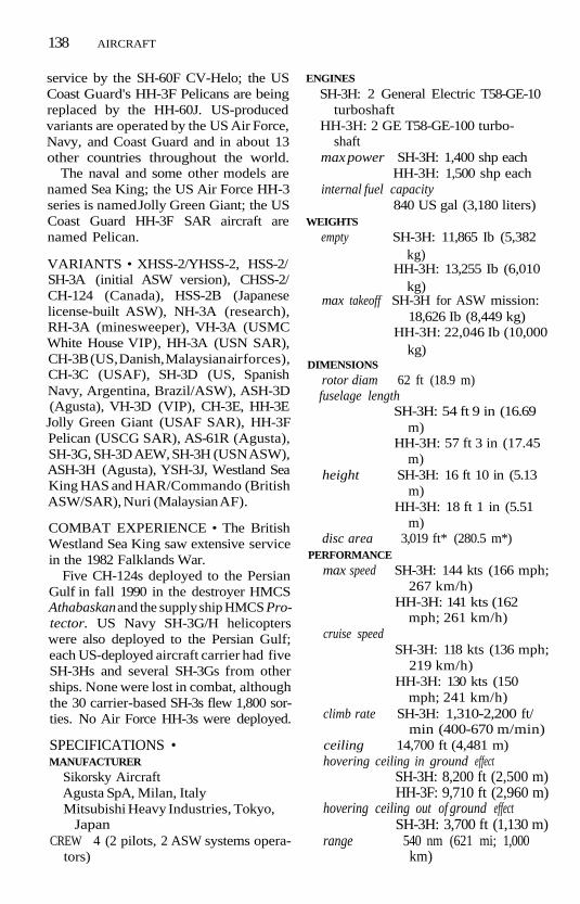
138 AIRCRAFT
service by the SH-60F CV-Helo; the USCoast Guard's HH-3F Pelicans are beingreplaced by the HH-60J. US-producedvariants are operated by the US Air Force,Navy, and Coast Guard and in about 13other countries throughout the world.
The naval and some other models arenamed Sea King; the US Air Force HH-3series is named Jolly Green Giant; the USCoast Guard HH-3F SAR aircraft arenamed Pelican.
VARIANTS • XHSS-2/YHSS-2, HSS-2/SH-3A (initial ASW version), CHSS-2/CH-124 (Canada), HSS-2B (Japaneselicense-built ASW), NH-3A (research),RH-3A (minesweeper), VH-3A (USMCWhite House VIP), HH-3A (USN SAR),CH-3B (US, Danish, Malaysian air forces),CH-3C (USAF), SH-3D (US, SpanishNavy, Argentina, Brazil/ASW), ASH-3D(Agusta), VH-3D (VIP), CH-3E, HH-3EJolly Green Giant (USAF SAR), HH-3FPelican (USCG SAR), AS-61R (Agusta),SH-3G, SH-3D AEW, SH-3H (USN ASW),ASH-3H (Agusta), YSH-3J, Westland SeaKing HAS and HAR/Commando (BritishASW/SAR), Nuri (Malaysian AF).
COMBAT EXPERIENCE • The BritishWestland Sea King saw extensive servicein the 1982 Falklands War.
Five CH-124s deployed to the PersianGulf in fall 1990 in the destroyer HMCSAthabaskan and the supply ship HMCS Pro-tector. US Navy SH-3G/H helicopterswere also deployed to the Persian Gulf;each US-deployed aircraft carrier had fiveSH-3Hs and several SH-3Gs from otherships. None were lost in combat, althoughthe 30 carrier-based SH-3s flew 1,800 sor-ties. No Air Force HH-3s were deployed.
SPECIFICATIONS •MANUFACTURER
Sikorsky AircraftAgusta SpA, Milan, ItalyMitsubishi Heavy Industries, Tokyo,
JapanCREW 4 (2 pilots, 2 ASW systems opera-
tors)
ENGINES
SH-3H: 2 General Electric T58-GE-10turboshaft
HH-3H: 2 GE T58-GE-100 turbo-shaft
max power SH-3H: 1,400 shp eachHH-3H: 1,500 shp each
internal fuel capacity840 US gal (3,180 liters)
WEIGHTSempty SH-3H: 11,865 Ib (5,382
kg)HH-3H: 13,255 Ib (6,010
kg)max takeoff SH-3H for ASW mission:
18,626 Ib (8,449 kg)HH-3H: 22,046 Ib (10,000
kg)DIMENSIONS
rotor diam 62 ft (18.9 m)fuselage length
SH-3H: 54 ft 9 in (16.69m)
HH-3H: 57 ft 3 in (17.45m)
height SH-3H: 16 ft 10 in (5.13m)
HH-3H: 18 ft 1 in (5.51m)
disc area 3,019 ft* (280.5 m*)PERFORMANCE
max speed SH-3H: 144 kts (166 mph;267 km/h)
HH-3H: 141 kts (162mph; 261 km/h)
cruise speedSH-3H: 118 kts (136 mph;
219 km/h)HH-3H: 130 kts (150
mph; 241 km/h)climb rate SH-3H: 1,310-2,200 ft/
min (400-670 m/min)ceiling 14,700 ft (4,481 m)hovering ceiling in ground effect
SH-3H: 8,200 ft (2,500 m)HH-3F: 9,710 ft (2,960 m)
hovering ceiling out of ground effectSH-3H: 3,700 ft (1,130 m)
range 540 nm (621 mi; 1,000km)

AIRCRAFT 139
armament 2 Mk 46 torpedoes inSH-3H; varies amonglicense-built examples
Seahawk (SH-60)The Seahawk, a multipurpose US Navyadaptation of the UH-60 Blackhawk tacti-cal transport helicopter, was developedfor Antisubmarine Warfare (ASW) andSearch and Rescue (SAR) missions. TheSeahawk is the helicopter component ofthe Navy's ship-based Light AirborneMultipurpose System (LAMPS) III, anover-the-horizon ASW and Antiship Sur-veillance and Targeting (ASST) system. Amodified Seahawk, the SH-60F, is replac-ing SH-3s as the carrier-based inner-zoneASW helicopter.
The Seahawk has a forged titaniummain rotor hub with elastomeric bearingsand four blades; the blades have a ti-tanium core, are sheathed in compositematerials, and have tips swept at 20°. Themain rotor shaft has a brake, and theblades are power-folded.
The tail pylon has a four-blade,composite-material antitorque rotormounted on the right side and canted at20° to increase vertical lift. The large,rectangular, variable-incidence stabilatoris fitted near the base of the pylon andcan set at +34° during hovering and —6°for autorotation. It also adds lift duringcruise flight. The tail pylon has power-assisted folding that swings it to the leftfor stowage. The Automatic Flight Con-trol System (AFCS) was expanded fromthat in the Blackhawk, adding an auto-matic altitude hold and approach tohover.
The SH-60's two turboshaft engines aremounted over the fuselage, separatedfrom each other by the rotor drivetrainand transmission. The engines are up-rated and "marinized" to resist corro-sion. The aircraft can refuel duringhover.
The fixed main-landing-gear legs trail
back from a mount located below thecockpit; a second attachment point be-hind the sliding cockpit door bears theshock-absorbing strut that is fitted to thewheel hub. The fixed tailwheel is locatedjust behind the cabin, considerably far-ther forward than in the Blackhawk andresulting in a wheelbase identical to thatof the Kaman SH-2 Seasprite (LAMPS I).The landing gear is also lighter than thatof the Blackhawk.
The fuselage has a side-by-side, two-seat flight deck forward; the pilot isseated to the starboard and the AirborneTactical Officer (ATO) on the port. TheSensor Operator's (SO) position is lo-cated in the aft starboard side of the maincabin. The aircraft's electronics and sen-sors are linked and subdivided into fourgroups: navigation, mission avionics, datahandling and display, and communica-tions. Navigation equipment includes theTeledyne Ryan AN/APN-217 Dopplernavigation radar, Honeywell AN/APN-194(V) radar altimeter, and CollinsTACAN and UHF direction-findingequipment.
Mission avionics include the Texas In-struments AN/APS-124 360° search ra-dar fitted under the flight deck, theRospatch (now FlightLine) AN/ARR-75sonobuoy receiving set, and the Ray-dieon AN/ALQ-142 omnidirectionalElectronic Support Measures (ESM). A25-tube pneumatic sonobuoy launcher isinstalled in the port side of the fuselageaft of the single cabin window.
An IBM AN/UYS-1 (V) 2 Proteus acous-tic processor is linked to the ARR-75 andthe AN/AYK-14 general-purpose digitalcomputer. Sensor data is initially pro-cessed on board, then relayed to the Sea-hawk's "mother" ship over the SierraResearch AN/ARQ-44 data link. The Sea-hawk thus can act either as the forward-deployed "eyes and ears" of the compre-hensive shipboard ASW and ASST pro-cessing center or as an independent unit.The aircraft's offensive armament is oneor two Mk 46 lightweight ASW torpedoes.

140 AIRCRAFT
The Norwegian AGM-119 Penguin short-range, antiship missile is being procuredfor the ASST mission.
Several Seahawks operating in the Per-sian Gulf in 1987-88 were fitted with dor-sal and ventral AN/ALQ-144 InfraredCountermeasures (IRCM), AN/ALE-39chaff dispensers on the port side of thecabin, Loral AN/AAR-47 electro-opticalmissile-warning system, and M60 7.62-mm machine guns in both cabin doors.Hellenic Navy S-70Bs operating fromHydra-class frigates will be fitted with theLitton AN/ALR-606(V)2 electronic sup-port measures system as well as the Pen-guin antiship missile.
DEVELOPMENT • The SH-60's initialoperational capability was in 1983; its firstflight was on December 12, 1979. Still inproduction with over 470 aircraft or-dered for the US Navy and four othernavies. Six SH-60Bs were delivered to theSpanish V/STOL carrier Principe de As-turias in January 1989 at Patuxent RiverNaval Air Station, Maryland.
In addition to the US Navy, the S-60, orits commercial variant S-70, is flown byAustralia, Greece, Japan, Spain, andTaiwan.
VARIANTS • SH-60B, Quick ReactionForward-Looking Infrared (FLIR), SH-60F CV-HELO Ocean Hawk, HH-60HRescue Hawk (USN SAR), HH-60J Jay-hawk (USCG), VH-60A (USMC WhiteHouse VIP), S-70 (military exports S-70Aand S-70B), S-70B-2 (Australia), S-70B-3/SH-60J (Japan), S-70B-6 (Greece),S-70C(M)-1 (Taiwan Navy "commer-cial").
COMBAT EXPERIENCE • 12 SH-60Bsdeployed to the Persian Gulf during1987-88 and flew an average of over 100hours per month, according to the USNavy.
34 US Navy SH-60Bs and three Austra-lian S-70B-9s operated in Operations De-sert Shield/Desert Storm; one was lostduring the seven-week war to noncombat
causes. HH-60Hs were deployed in SaudiArabia for combat SAR.
SPECIFICATIONS •MANUFACTURER Sikorsky AircraftCREW 3 (pilot, copilot, sensor opera-
tor)ENGINES 2 General Electric T700-
GE-401 turboshaftmax power 1,713 shp eachinternal fuel capacity
360 US gal (1,361 liters)WEIGHTS
empty 13,648 Ib (6,204 kg)mission gross weight
ASW: 20,244 Ib (9,183 kg)ASST: 18,373 Ib (8,334 kg)
max takeoff 21,884 Ib (9,927 kg)DIMENSIONS
rotor diam 53 ft 8 in (16.36 m)length operating: 64 ft 10 in
(19.76m)folded: 40 ft 11 in (12.47
m)width operating: 53 ft 8 in
(16.36m)folded: 10 ft 8 1A in (3.26
m)height operating: 17 ft 0 in (5.18
m)folded: 13 ft 3 V2 in (4.04
m)disc area 2,262 ft2 (210.15 m*)
PERFORMANCE
never-exceed speed (VNE)sea level: 180 kts (207
mph; 334 km/h)at 4,000 ft (1,220m): 171
kts 197 mph; 317 km/h)dash speed sea level: 128 kts (147
mph; 237 km/h)at 5,000 ft (1,524m),
tropical day: 126 kts(145 mph; 233 km/h)
max climb ratesea level, ISA conditions:
1,330 ft/min (405m/min)
sea level, 90°F(32°C): 700ft/min (213 m/min)

AIRCRAFT 141
ceiling 13,800 ft (4,206 m)hovering ceiling in ground effect
ISA conditions: 6,500 ft(1,981 m)
tropical day conditions:4,200ft (1,280m)
hovering ceiling out of ground effectISA conditions: 3,400 ft
(1,036 m)tropical day conditions:
1,500 ft (457 m)range at max takeoff weight, econ cruise,
no reservesinternal fuelsea level: 437 nm (503
mi; 810 km)at 4,000 ft (1,220m):
484 nm (557 mi; 897km)
with auxiliary fuelsea level: 630 nm (725
mi; 1,167 km)at 4,000 ft (1,220m):
678 nm (781 mi; 1,256km)
armament 2 Mk 46 torpedoesradar AN/APS-124 360° search
AN/APN-217 Doppler(HH-60H/J)
Raven (H-23/UH-12)The UH-12 (the H-23 Raven in US Armyservice) is an early-generation helicopterstill in limited military and civilian ser-vice as an observation and light utilityhelicopter.
The UH-12 has a two-bladed main ro-tor with counterbalance weights, a two-bladed tail rotor on the right side of thepipelike tailboom opposite a stabilizer,twin-skid landing gear, and a bubble or"goldfish bowl" cockpit. The tailboomhas a reinforcing strut to the top of theengine frame, which is set just behind thecockpit.
No armed versions have been manufac-tured.
DEVELOPMENT • The Raven's initialoperational capability was in 1950; its firstflight was in November 1947. It is nolonger in production or in US militaryservice, but about 40 remain in militaryservice in Argentina, Colombia, Egypt,Mexico, South Korea, and Paraguay.
VARIANTS • Model 360 (prototype),UH-12A/HTE-1/H-23A Raven, UH-12B/HTE-2/H-23B, UH-12C/H-23C,UH-12D/H-23D, UH-12E/OH-23G/CH-112 (UH-12E/OH-23F, CH-112 [OH-23in Canadian service]), UH-12E4/OH-23F, UH-12L4.
SPECIFICATIONS •MANUFACTURER HillerCREW 1 + 2 passengersENGINES 1 Lycoming VO-540 piston
max power 340 hpWEIGHTS
empty 1,759 Ib (798 kg)gross 2,800 Ib (1,270kg)
DIMENSIONS
rotor diam 35 ft 5 in (10.8 m)length fuselage: 28 ft 6 in (8.69
m)overall: 40 ft 8 in (12.4
m)height 9 ft 9 in (2.98 m)
PERFORMANCEmax speed 83 kts (96 mph; 154 km/
h)ceiling 16,207 ft (4,940 m)range 365 nm (420 mi; 676 km)
Huey/Iroquois (UH-1)The UH-1, popularly called the Huey, is ageneral-purpose, multirole helicopterthat has been produced in greater num-bers and flown by more countries thanany other helicopter in the West. TheHuey has been adapted for air assault,gunship, medical evacuation, Search andRescue (SAR), Antisubmarine Warfare(ASW), and general utility missions.
Both single- and twin-engine variantsare in widespread service. A three-engine

142 AIRCRAFT
prototype was test-flown but not pro-duced. The main single-engine variantsare the UH-1B (Bell Model 204) andUH-1D/H (Bell Model 205). The two-blade, semirigid, all-metal main rotor hasa stabilizer bar mounted above and atright angles to the blades and an under-slung, feathering axis head. The rotor ismounted on the left side of the tail rotorpylon. The rectangular horizontal stabi-lizer in the tailboom, ahead of the anti-torque rotor, is interconnected with thecyclic control and acts as a compensatingelevator.
The single turboshaft engine ismounted in a slender housing behind themain rotor mast. The exhaust nozzle istilted slightly upward.
The semimonocoque fuselage has ashort nose, extensive glazing (including"chin" windows for look-down visibility)around the cockpit, and doors on bothsides. The cockpit is open to the maincabin, which has large, rearward-slidingdoors on both sides. The main cabin cancarry troops in jump seats or litters infold-down racks. Landing gear is parallelskids on tubular struts, with a tail skid atthe end of the tailboom.
DEVELOPMENT • The Huey's initialoperational capability was in 1958; firstflight of the XH-40 was on October 22,1956. Over 10,100 UH-ls have been built,and it is still in production by Agusta-Bellof Italy and Fuji of Japan and still in ser-vice with all US military forces and over55 other countries.
VARIANTS • X/YH-40, HU-1, HU-1A,HU-1B, UH-1C, UH-1D, UH-1E (USMC),UH-1F (USAF), UH-1H, UH-1H Up-grade, EH-1H Quick Fix IA/IB (US ArmySecurity Agency), EH-1U/EH-1X QuickFix IIA, HH-1K (USN SAR/SEAL),UH-1L (USN), UH-1M, UH-lN/Model212, UH-1P (special operations), UH-1V,Bell/Lycoming Fleet/Service Life Exten-sion Program, T800 test bed, CH-118(Canada), AB204/205 (Agusta-Bell),
204B-2/HU-1H Kai (Japan-Fuji), Bell533 (three-engine research), AH-1GHueyCobra.
The Swedish designation for theirAB205 aircraft is HKP-3.
COMBAT EXPERIENCE • In their as-sault role, Hueys have seen combat ser-vice with US forces in the Vietnam War(where the unarmed variants were knownas Slicks) and in the 1983 operation inGrenada. They have also served in theMideast in Israeli combat and in a num-ber of other combat actions throughoutthe world. As a gunship, the Huey wasused in Vietnam until the AH-1 Cobraseries replaced it.
US Army UH-1 Hs were deployed to thePersian Gulf as part of Operation DesertShield. During Desert Storm, threeUH-ls were lost, all to noncombat causes.
In February 1989, the UN TransitionalAssistance Group (UNTAG) announcedthe purchase of eight AB205 helicoptersto support their peacekeeping opera-tions in Namibia. The aircraft were with-drawn when Namibia completed itstransition to independence in March1990.
In September 1989, 20 UH-lHs wereflown by cargo aircraft to Colombia tobolster antidrug forces in that country.The speedup in delivery of an existingorder came after the assassination of aprominent presidential candidate andformer guerrilla leader.
SPECIFICATIONS •MANUFACTURER
Bell Helicopter TextronAgusta SpA, Milan, ItalyFuji Heavy Industries, Tochigo, Japan
CREW 2 (pilot, copilot); crewman op-tional + 11-14 troops
ENGINES 1 Lycoming T53-L-13 turbo-shaftmax power l,400shpinternal fuel capacity
211 US gal (799 liters)

AIRCRAFT 143
WEIGHTS
empty operating5,550 Ib (2,517 kg)
max useful load3,950 Ib (1,792 kg)
max sling load4,000 Ib (1,814 kg)
max gross 9,500 Ib (4,309 kg)DIMENSIONS
rotor diam 48 ft (14.63 m)length 41 ft 10 % in (13.77 m)height 13 ft 5 in (4.08 m)disc area 1,809.6 ft2 (168.1 m2)
PERFORMANCEnever-exceed (Vne), max level, max cruise,
and econ cruise speeds110 kts (127mph;204
km/h)max climb rate
l,600ft/min (488m/min)
service ceiling12,700 ft (3,871 m)
hovering ceiling in ground effect, standardday
11,100ft (3,383m)hovering ceiling in ground effect, 9TF
(3?C)5,000ft (1,524m)
hovering ceiling out of ground effect,standard day
6,000 ft (1,829m)range sea level, standard tanks:
266 nm (306 mi; 493km)
range at 4,000 ft (1,120m) with auxiliary tanks:675 nm (777 mi; 1,251km)
Huey/Iroquois (UH-1N)The UH-1N Huey is the twin-engine ver-sion of the Huey series of general-purpose helicopters.
The "Twin-Pac" turboshaft installationconsists of two turbines driving a singleoutput shaft, either being able to drivethe rotor if the other fails. The turbines
are mounted outboard of the main rotormast with the nozzles carried side by sidein a single housing. All other features ofthe Huey UH-1N are identical to the ba-sic Huey.
DEVELOPMENT • The initial opera-tional capability of the twin-engine Hueywas in 1970; its first flight was in April1969. It is still in production in Canadaand by Agusta-Bell of Italy and Fuji ofJapan and still in service with all US mili-tary forces except the Army.
As the Bell 212/412 and the Agusta-Bell AB212/AB212ASW/AB412 Griffon,the twin-engine variant is in service withnumerous other countries. More than1,500 212s and 250 4-blade 412s had beenproduced by 1992. Helikopter ServiceA/S of Sola, Norway, assembled 18 Bell412SPs for the Royal Norwegian AirForce for delivery between late 1987 andApril 1990.
In May 1990, Bell Textron and the Ar-gentine firm Chincul agreed to licenseproduction of the Bell 212 and 412SPvariants. In October 1990, Thailand an-nounced a $330-million contract for 50more Bell 412SP helicopters.
Poland became the first eastern Euro-pean nation to order a Twin Huey, takingdelivery of two 412s in 1991.
Canada's National Defense Depart-ment ordered 100 412HPs in April 1992under a contract estimated at Canfl bil-lion. Aircraft deliveries will run from1994 to 1997.
Over 65 countries throughout theworld, in addition to the United States,operate the several Huey twin-enginevariants.
VARIANTS • UH-lN/Model 212 (USAF,USN, Canada), Model 412, 412HP (HighPerformance), AB212ASW (Agusta-builtASW), Griffon/AB412 (Agusta), Model214, AH-1J SeaCobra (Bell Model 209).
COMBAT EXPERIENCE • Hueys sawextensive combat service with US forces

144 AIRCRAFT
in Vietnam and Grenada. The Israelishave used them in the Middle East.
US Marine Corps UH-lNs were de-ployed to Saudi Arabia in Operation De-sert Shield. Two UH-lNs flying from theUSS Okinawa (LPH 3) were lost in thenorthern Arabian Sea in October 1990,and one from the USS Tripoli (LPH 10)crashed into the Pacific in Decemberwhile the ship was en route to the PersianGulf.
During Operation Desert Storm, theUH-lNs were the Marine Corps' princi-pal light utility helicopter. Some were fit-ted with Nile Eagle Forward-LookingInfrared (FLIR)/laser designator podsoriginally developed for the Aquila Re-motely Piloted Vehicle (RPV) and usedto designate targets at night. DuringDesert Storm, 50 Marine Corps UH-lNs—30 flying from shore bases and20 from amphibious ships—flew 1,016sorties.
SPECIFICATIONS •MANUFACTURER
Bell Helicopter Textron Canada, Mir-abel, Quebec
Agusta SpA, Milan, ItalyCREW 2 (pilot, copilot); crewman op-
tional + 11-14 troopsENGINES
UH-1N: 2 Pratt & Whitney CanadaPT6T-3B turboshaft
412: 2 Pratt & Whitney CanadaPT6T-3B-1 turboshaft
412HP: 2 Pratt & Whitney CanadaPT6T-3D turboshaft
max power 1,800 shp total, deratedto 1,290 shp (UH-1N)or to 1,400 shp (412)
internal fuel capacitystandardUH-1N: 215 US gal (814
liters)412: 330 US gal (1,249
liters)with optional auxiliary fuelUH-1N: 395 US gal
(1,495 liters)
412: 494 US gal (1,870liters)
WEIGHTSempty operating
UH-1N: 5,997 Ib (2,720 kg)412: 6,470 Ib (2,935 kg)412HP: 6,810 Ib (3,089 kg)
max useful loadUH-1N: 5,033 Ib (2,283
kg)412: 5,390 Ib (2,445 kg)
max sling load5,000 Ib (2,268 kg)
max gross UH-1N: 11,200 Ib (5,080kg)
412: ll,9001b (5,398kg)DIMENSIONS
rotor diam UH-1N: 48 ft (14.63 m)412: 46 ft (14.02m)
length 41 ft 10 % in (13.77 m)height 13 ft 5 in (4.08 m)disc area UH-1N: 1,809.6 ft2 (168.1
m2)412: I,661.0ft2 (154.4
m2)PERFORMANCE
never-exceed (VNE), max level, max cruise,and econ cruise speeds
UH-1N: 100 kts (115mph; 185 km/h)
max sea-level cruise412: 124 kts (143 mph;
230 km/h)range cruise
118 kts (136 mph; 219km/h)
max climb rate412: 1,420 ft/min (433
m/min)412HP: 1,350 ft/min (411
m/min)service ceiling
412: 13,200 ft (4,023 m)412HP: 16,500 ft (5,029
m)hovering ceiling in ground effect, standard
dayUH-1N, max takeoff
weight: 4,800 ft (1,463m)

AIRCRAFT 145
412 at 10,500-lb (4,762-kg) takeoff weight:9,200 ft (2,805 m)
412HPatll,900-lb(5,398-kg) takeoffweight: 10,200 ft (3,109m)
hovering ceiling in ground effect, 93°F(3?C)
412: 2,500 ft (762 m)412HP: 6,200 ft (1,890m)
hovering ceiling out of ground effect,standard day
412HP: 5,200 ft (1,585m)range
sea level, standard tanksUH-1N: 231 nm (266 mi;
428km)412: 354 nm (408 mi; 656
km)412HP: 328 nm (380 mi;
607 km)at 4,000ft (1,120 m) with
auxiliary tanks
UH-1N: 428 nm (493 mi;793 km)
412: 590 nm (679 mi;1,093 km)
412HP: 570 nm (656 mi;1,055 km)
412 with max payload at10,500ft (3,200 m) andcruising at 118 kts (136mph, 219km/h):375nm (432 mi; 695 km)
Blackhawk (UH-60)The Blackhawk is a multipurpose heli-copter that serves as the US Army's prin-cipal tactical transport helicopter(replacing the UH-1 Huey series). TheUH-60 has been adapted for medicalevacuation, reconnaissance, night opera-tions, Search and Rescue (SAR), Elec-tronic Warfare/Electronic Intelligence(EW/ELINT), and general utility mis-
Blackhawk UH-60U.S. GOVERNMENT DEPARTMENT OF DEFENSE

146 AIRCRAFT
sions, with naval variants employed forAntisubmarine Warfare (ASW) and SAR.
The Blackhawk has a forged-titaniummain rotor hub with elastomeric bearingsand four blades; the blades have a ti-tanium core, are sheathed in compositematerials, and have swept tips. The tailpylon has a four-blade, composite-material tail rotor mounted on the rightside and canted at 20° to increase verticallift. The large stabilator has forwardswept trailing edges and is fitted near thebase of the pylon; it can be pitched up to40° during takeoff, hovering, and land-ing. The tailplane design also adds liftduring cruise flight. The fixed main-landing-gear legs trail back from a pointlocated below the cockpit; a second at-tachment point behind the half-doorbears the shock-absorbing strut that is fit-ted to the wheel. The fixed tailwheel isfitted well aft of the cabin, ahead of thepylon-fold hinge.
The UH-60's twin engines are mountedover the fuselage, separated from eachother by the rotor drivetrain and trans-mission. The rotor and engine installa-tion is close to the fuselage; the rotorshaft can be lowered to allow shipment intransport aircraft as small as a LockheedC-130 Hercules.
The fuselage has a side-by-side, two-seat flight deck forward, open to thepassenger/cargo cabin, which has a vol-ume of 410ft3 (11.61m3). Normal troopload-out is 11, but high-density seatingpermits 14 troops to be carried. For self-protection, 7.62-mm machine guns arefitted on pintle mounts at each cabindoor.
The UH-60 has a high crashworthiness.The semimonocoque fuselage is de-signed to resist deforming in a lateralcrash at 30 ft/sec (9.1 m/sec) and a verti-cal crash at 38 ft/sec (11.5 m/sec). It canalso withstand a combined force of 20 gforward and 10 g downward. The mainrotor blades are designed to have a 30-minute life after having the main sparsevered by a 23-mm shell. The aircraft
also has low-reflectivity paint and a HoverInfrared Suppression System (HIRSS) toreduce its infrared signature, a SandersAN/ALQ-144 IR countermeasures set,and an E-Systems AN/APR-39(V) 1 radar-warning system; chaff and flare launchersprovide deception.
Detachable External Stores SupportSystem (ESSS) pylons can be fitted topoints above the cabin doors. Up to fourfuel tanks carrying a total of 1,360 US gal(5,148 liters) may be mounted for self-deployment up to 1,200 nm (1,380 mi;2,220 km) away. The ESSS pylons can alsocarry rockets, four Volcano antitankmine dispensers, or up to 16 Hellfire anti-tank missiles. An external cargo hook willcarry up to 8,000 Ib (3,629 kg); typicalsling loads include a 105-mm howitzerand 50 rounds of ammunition.
DEVELOPMENT • The UH-60's initialoperational capability was in 1978. Its firstflight was on October 17, 1974, as a com-petitor in the US Army's Utility TacticalTransport Aircraft System (UTTAS) pro-gram, which selected a successor to theHuey.
The 1,000th production helicopter wasdelivered to the Army in October 1988. Itis still in production, and Sikorsky has acontract to develop, build, and test theMH-60K special-operations Blackhawk.
The S-70C commercial variant hasbeen exported to China, Taiwan, andThailand. Mitsubishi Heavy Industries(MHI) is producing 64 Japanese UH-60Js, the first of which was delivered in1991. The Hong Kong Auxiliary AirForce ordered two S-70As in early 1992for US$23.8 million.
38 Australian S-70A-9 aircraft were as-sembled by Hawker de Havilland; the firstrolled out in April 1988. Also in 1988,Saudi Arabia ordered 13 S-70A-1 "DesertHawks" from Sikorsky that were deliv-ered in 1990.
In September 1990, South Korea an-nounced plans to coproduce approx-imately 100 UH-60Ps. After years of

AIRCRAFT 147
competition, Turkey announced an$855-million contract in September 1992in which Sikorsky would supply 25UH-60s from its production facility in theUnited States and Turkish aviation facili-ties in Murted would coproduce 50.
The UH-60 is flown by the USAF andArmy along with four Middle East na-tions, seven Asian nations, Australia, Co-lombia, and Turkey.
VARIANTS • UH-60A, UH-60A Cred-ible Hawk (USAF updated to MH-60GPave Hawk), UH-60L, UH-60P (SouthKorea), UH-60M (development only),EH-60C Quick Fix (US Army EW/ELINT), HH-60A/D/E Night Hawk(USAF, never operational), MH-60GPave Hawk/MH-60K (special mission),CH-60 (USMC proposed), YEH-60B(canceled prototype), Embassy Hawk(European contingency aircraft), S-70(export/commercial), S-70A-1 DesertHawk (Royal Saudi Land Forces ArmyAviation Command/RSLAV), S-70A-9(Australian AF), S-70/UH-60J (JapaneseAir Self-Defense Force/JASDF), WS-70A(Westland license-built).
COMBAT EXPERIENCE • Blackhawkswere used during the US landings in Gre-nada in October 1983 and the militaryouster of General Noriega in Panama inDecember 1989. A total of 25 UH-60swere damaged during the operation inPanama. All but one were back in servicewithin a day.
During Operation Desert Storm, 489UH-60s (46% of total Army inventory)were deployed to Saudi Arabia. A total of44,000 flight hours were logged by theUH-60s fleet.
SPECIFICATIONS •MANUFACTURER Sikorsky AircraftCREW 3 (pilot, copilot, crew chief) +
14 troopsENGINES 2 General Electric T700-
GE-700 turboshaftmax power 1,622 shp each
(transmission rating is2,800 shp)
continuous 1,324 shpinternal fuel capacity
360 US gal (1,361 liters)WEIGHTS
empty 10,622 Ib (4,818 kg)takeoff mission
17,323 Ib (7,858 kg)max takeoff 20,250 Ib (9,185 kg)
DIMENSIONS
rotor diam 53 ft 8 in (16.36 m)length 50 ft (15.26 m) without
refueling probeheight 12 ft 4 in (3.76 m)disc area 2,262 ft2 (210.2 m2)
PERFORMANCEnever exceed speed (Vne)
194 kts (225 mph; 361km/h)
max cruise speedsea level: 160 kts (184
mph; 296 km/h)hot and high (density
altitude of 4,000ft/1,219 m,95°F/35°C): 145kts (167 mph; 269km/h)
econ cruise speed, hot and high137 kts (158 mph; 254
km/h)climb rate 1,600 ft/min (488
m/min)ceiling 19,000 ft (5,791 m)hover ceiling in ground effect
standard day 5,300 ft(1,615m)
hot and high 3,600 ft(1,097m)
hover ceiling out of ground effectstandard day 10,400 ft
(3,170 m)hot and high 5,600 ft
(1,705m)range max takeoff weight, max
internal fuel: 324 nm(373 mi; 600 km)
with 460 US gal (1,741liters) external fuel:
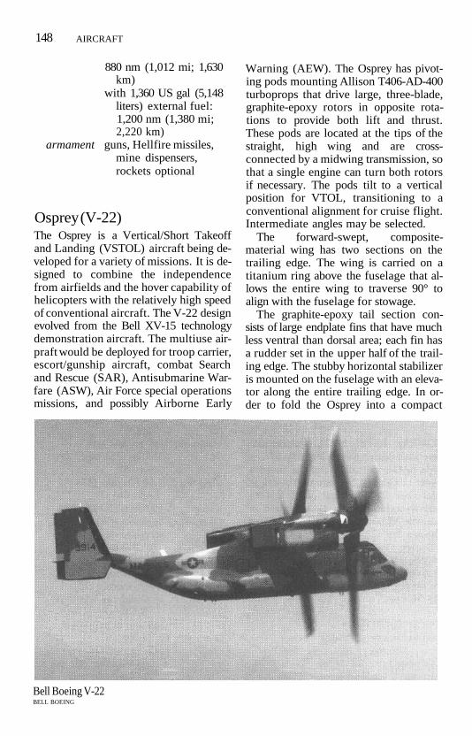
148 AIRCRAFT
880 nm (1,012 mi; 1,630km)
with 1,360 US gal (5,148liters) external fuel:1,200 nm (1,380 mi;2,220 km)
armament guns, Hellfire missiles,mine dispensers,rockets optional
Osprey (V-22)The Osprey is a Vertical/Short Takeoffand Landing (VSTOL) aircraft being de-veloped for a variety of missions. It is de-signed to combine the independencefrom airfields and the hover capability ofhelicopters with the relatively high speedof conventional aircraft. The V-22 designevolved from the Bell XV-15 technologydemonstration aircraft. The multiuse air-praft would be deployed for troop carrier,escort/gunship aircraft, combat Searchand Rescue (SAR), Antisubmarine War-fare (ASW), Air Force special operationsmissions, and possibly Airborne Early
Warning (AEW). The Osprey has pivot-ing pods mounting Allison T406-AD-400turboprops that drive large, three-blade,graphite-epoxy rotors in opposite rota-tions to provide both lift and thrust.These pods are located at the tips of thestraight, high wing and are cross-connected by a midwing transmission, sothat a single engine can turn both rotorsif necessary. The pods tilt to a verticalposition for VTOL, transitioning to aconventional alignment for cruise flight.Intermediate angles may be selected.
The forward-swept, composite-material wing has two sections on thetrailing edge. The wing is carried on atitanium ring above the fuselage that al-lows the entire wing to traverse 90° toalign with the fuselage for stowage.
The graphite-epoxy tail section con-sists of large endplate fins that have muchless ventral than dorsal area; each fin hasa rudder set in the upper half of the trail-ing edge. The stubby horizontal stabilizeris mounted on the fuselage with an eleva-tor along the entire trailing edge. In or-der to fold the Osprey into a compact
Bell Boeing V-22BELL BOEING

AIRCRAFT 149
package smaller than the SH-3 Sea King,the horizontal surfaces are reduced by25%-30% and controlled by a GE tripleredundant, digital Fly-by-Wire (FEW)flight control system that has triple Pri-mary Flight Control System (PFCS) pro-cessors for the control surfaces and tripleAutomatic FCS (AFCS) processors forstability augmentation.
The Allison turboprops have intakescreens and Infrared (IR) suppressors onthe exhausts, and rotor brakes. They areequipped with full-authority digital elec-tronic control. The fuselage is relativelyconventional in layout but is made almostentirely of graphite-epoxy composites. Itis designed to be crashworthy, althoughweight-reduction measures have reducedthe level of protection. The flight deckwill be protected against Nuclear, Biolog-ical, and Chemical (NBC) warfare effectsthrough a slight internal overpressure.
The Osprey features a flight deck withside-by-side seating forward of an unob-structed, square-section main cabin. Acabin door is located forward, on the star-board side. The rear ramp is fitted in twosections and forms the bottom of the an-gled, "beavertail" rear fuselage. Cargocan be slung from one or two externalhooks. The short, two-wheel main-landing-gear struts retract into the spon-sons; the two-wheel nose gear folds to therear under the cockpit.
The FCS, avionics, and displays arelinked through triple redundant MIL-STD-1553B databuses; the aircraft has abuilt-in Vibration, Structural Life, andEngine Diagnostic (VSLED) system. Theflight deck is integrated through a Cock-pit Management System (CMS) that in-cludes two AN/AYK-14 fully redundantmission computers, four Bendix Multi-function Displays (MFD), and two Con-trol Display Units (CDU). The controlsconsist of a thrust/power lever, a cycliclever, and the rudder pedals.
The radar is the Texas InstrumentsAN/APQ-168 terrain-avoidance/terrain-following radar; a Forward-Looking In-
frared (FLIR) turret is fitted under thechin. The MFD can display a digital mov-ing map system. The pilots will wear anintegrated helmet display system that in-cludes Night Vision Goggles (NVG) simi-lar to a Head-Up Display (HUD), andFLIR output; the NVG, FLIR, and a gunturret would be slaved through the hel-met. Electronic Support Measures (ESM)include the Honeywell AN/AAR-47missile-warning system. The V-22 can bearmed with a single, integral multibarrelgun and can carry a variety of weaponsexternally on sponson attachment points.
DEVELOPMENT • The Osprey is one ofseveral controversial weapons systems ofthe early 1990s whose ultimate produc-tion is more dependent on politicalrather than military considerations. TheV-22 is under development; the first pro-totype rolled out in late May 1988. Its firstflight (hover mode only) was on March19,1989, after a nine-month delay, and itsfirst full-conversion flight was on Septem-ber 14, 1989. Four out of five prototypeswere flying by the end of 1990; the fifthcrashed during its maiden flight on June11,1991. The aircraft began rocking afterhovering for about one minute; althoughthe two crew members were not seriouslyinjured, the aircraft was heavily damaged.
Flight testing stopped while the causeof the erratic flight and crash was investi-gated, eventually being attributed to in-correct wiring during manufacturing ofthe 120-wire wiring bundle for the cock-pit interfaces, resulting in false informa-tion being fed to the flight controlcomputers. Subsequently, the other fourwere grounded after more than 1,000takeoffs and landings and 536 flighthours. Test-flying resumed on September10, 1991. Bell Helicopter Textron is re-sponsible for the design and fabricationof the wings, engine pods, and prop ro-tors. Boeing Helicopter Co. is responsiblefor the fuselage, including the avionicsand cockpit design. Grumman Corp. de-signed the tail group as subcontractor.

150 AIRCRAFT
In April 1989, the Bush administrationeliminated all procurement funding forthe V-22 in the FY1990-91 Biennial Bud-get. Before the cancellation, the MarineCorps had planned to acquire 552 air-craft. In addition, the aircraft's other po-tential roles were thought to bring therequirement to a total of 900-1,200 air-craft. Altogether, plans included 55 forAir Force use, 552 for Marine Corps use,and 50 for the Navy combat SAR roleplus possibly 200-300 for other Navyroles.
The US Army vacillated on its procure-ment plans for the Osprey, eventuallyabandoning plans for 231 aircraft whenthe LHX scout helicopter was placed at ahigher priority.
Supporters in Congress managed to se-cure $255 million in Research and Devel-opment (R&D) funding for FY1990. ForFY1991, funding consisted of $237 millionin R&D and $165 million in advance pro-curement funds for production-level air-craft that are used in operational testing.In June 1991, the Navy awarded a $36.5-million contract to Allison to improve itsT406 engine and $163 million in two con-tracts to Bell-Boeing, including $88 mil-lion that had been rescinded in earlieractions.
An argument to continue developingthe aircraft has been to exploit a techno-logical area that the United States clearlyleads. Persistent congressional supportand the aging of the CH-46 led to furtherfunding for low-rate production.
Japan included in its FY1991-95 five-year plan a request for two V-22s inFY1994 and two in FY1995 (SAR variant)if the aircraft is procured by US services.But funding cutbacks and delays meantno V-22s were procured under that five-year plan.
VARIANTS • JVX (developmental), EV-22 (US Army Special Electronic Mis-sions) , HV-22 (USN SAR), CV-22 (USAF),MV-22 (USMC), SV-22 (USN ASW),WV-22 (USNAEW).
SPECIFICATIONS •MANUFACTURER
Bell Helicopter TextronBoeing Helicopter
CREW 3 (2 pilots, crewman) + 24troops
ENGINES 2 Allison T406-AD-400 turbo-propmax power 6,150 shp eachinternal fuel capacity
standard: 13,650 Ib(6,192 kg)
with auxiliary: 29,650 Ib(13,449 kg)
WEIGHTSempty 31,772 Ib (14,411 kg)max internal load
10,000 Ib (4,536 kg)max sling load
2 hooks combined:15,000 Ib (6,804 kg)
2 separate hooks:10,000 Ib (4,536 kg)each
max takeoff 47,500 Ib (21,546 kg)VTOL
55,000 Ib (24,947 kg)STOL
DIMENSIONS
rotor diam 38 ft (11.58 m)-length 56 ft 10 in (17.33m)height 17 ft 4 in (5.28 m)total disc area
2,268.2 ft2 (210.7 m*)PERFORMANCE
dash speed 315 kts (363 mph; 584km/h)
cruise speed 275 kts (317 mph; 510km/h)
ceiling 30,000 ft (9,144 m)hovering ceiling out of ground effect at
91.^F (3fC) at 44,980 Ib (20,403 kg)3,000 ft (914 m)
combat radiusHV-22 SAR, with 880-lb
(400-kg) payload: 460nm (530 mi; 852 km)
MV-22, VTOL weight of44,980 Ib (20,403 kg)

AIRCRAFT 151
range
with 8,300-lb (3,765-kg)payload: 220 nm (253mi; 408 km); with 24troops or 6,000-lb(2,722-kg) payload: 430nm (495 mi; 797 km)
MV-22, STOL weight of55,000 Ib (24,948 kg)with 12,000-lb (5,444kg) payload: 1,085 nm(1,249 mi; 2,011km)
2,100 nm (2,417 mi;3,889 km) ferry
Comanche (RAH-66)The Comanche program is designed toreplace the US Army's aging fleet of heli-copters, particularly the OH-58 andAH-1. After some cutting back of thenumber of aircraft ultimately to be built,the program was delayed until at least thelate 1990s, with funding directed for re-search and development.
A team composed of Boeing Helicop-ters and Sikorsky Aircraft, along with Ger-many's Messerschmitt-Bolkow-BlohmGmbH (MBB) and a team made up ofBell Helicopters Textron and McDonnellDouglas Helicopters won the contract forthe helicopter.
The design calls for a sharklike air-frame with a five-blade bearingless mainrotor with a high hinge offset to greatlyimprove maneuverability. In September1990, MBB was selected to design andproduce the Comanche's main rotor, adesign based on a prototype system thathas a relatively high 9.5% hinge offset. Asplit torque transmission was adopted toreduce complexity. Also, the rotor headdesign was changed from a one-piecePentaflex design to a type that has modu-lar fittings for each rotor blade, permit-ting a much easier removal of a singleblade in case of damage. The Comanchedesign also has an eight-blade fan-in-fin(also known as a Fantail) antitorque ro-tor and a T-tail.
To power the Comanche, the Armyfunded an effort in July 1985 to develop a1,200-shp, advanced-technology engine(to be used in pairs in the LHX). Follow-ing a competition, a design by the LightHelicopter Turbine Engine Company(LHTEC), a joint venture of Allison andGarrett, was chosen. The T800-LHT-T800 powerplant is a dual-centrifugal-compressor design. Following initial de-sign, the engine's output was raised by12% (to 1,350 shp) to compensate for anincrease in empty weight.
Infrared (IR) signature suppression isaccomplished by mixing the engine ex-haust with cool air drawn through grillesbehind the engine.
The Boeing Aerospace/HamiltonStandard Fly-by-Wire (FEW) flight systemhas two modes: Automatic Flight ControlSystem (AFCS), an altitude-prioritymode in which the flight system holds thelast-selected altitude even during pilotmaneuvering, as in Nap of the Earth(NOE) flight, and Velocity Stabilization(VelStab), a ground- or airspeed-prioritymode. Development of other automaticmodes was deferred in 1992. Antitorquepedals have been eliminated, the yawcontrol being provided by twisting theright-hand sidestick controller.
A distinctive feature of the Co-manche's airframe design is a composite-material internal box beam backbonethat allows many more access doors to becut in the skin than usual. The manufac-turers claim that more than 50% of thesurface area can be moved for access. Mis-sile rails are stowed in bays enclosed byretractable doors that are strong enoughto serve as work stands.
Avionics will be grouped into a MissionEquipment Package (MEP) featuringVery High Speed Integrated Circuitry(VHSIC). The MEP is expected to ac-count for about 50%-60% of the unitflyaway cost of each unit and is consid-ered as the most difficult element in theoverall design.
The Comanche's standard self-defense

152 AIRCRAFT
is primarily passive. This includes stealthfuselage shaping, a cockpit sealedagainst Nuclear, Biological, and Chemi-cal (NBC) warfare effects, and the Infra-red (IR) suppressors fitted on theengines. Many other elements were to beinstalled only on aircraft flying in high-threat areas.
Missile configuration ultimately re-sulted in a maximum of either:
• six AGM-114 Hellfire antitank andtwo FIM-92 Stinger antiair missiles
• four Hellfires and four Stingers• two Hellfires and eight Stingers
A 20-mm three-barrel General Elec-tric/GIAT Vulcan II Catling gun turret ismounted under the cockpit.
DEVELOPMENT • The US Army an-nounced on April 15, 1991, the designa-tion of RAH-66 (for Reconnaissance-Attack Helicopter) and the name Co-manche for the Boeing-Sikorsky LH. TheArmy explained that Comanche Indianswere renowned for their skill as scoutsand their fierceness as fighters. The ini-tial operational capability for the Co-manche is planned for the early 21stcentury. The award of the prototype con-tract to Boeing/Sikorsky was made onApril 6, 1991.
The LHX competition entered itsDemonstration/Validation (Dem/Val)phase in October 1988. In early 1990, the"X" was dropped from the designationto indicate the impending selection ofthe Full-Scale Engineering Development(FSED) team. In September 1990, how-ever, the Defense Department (DoD) re-introduced a prototype phase in theaircraft's development, postponing FSEDuntil the fall of 1994. Six prototype (fourflying) aircraft were to be built at theSikorsky plant.
Operation Desert Storm showed theArmy that aircraft would have little op-portunity to be fitted with sensor and sur-vivability systems once fighting starts and
therefore needed to be carried on everyflight. Thus, the basic survivability kit wasupgraded to include floor armor and aradio-frequency interferometer as well asweight reservation for the IR Counter-measures (IRCM) and active radar jam-mer. As a result, an additional 144 Ib (65kg) was added for aircraft survivabilityupgrades and 130 Ib (59 kg) for IRCMand the radar jammer.
At that time, the first prototype flightwas planned for August 1994 and firstdelivery for FSED aircraft in October1995, beginning low-rate initial produc-tion in October 1996 and initial deliv-eries in February 1998. Subsequentdecisions by the DoD have pushed pro-duction back until the next century.
In September 1993, Army officialswarned that the Comanche program maysuffer the loss of some of its key features,such as its Longbow radar and stealthproperties, because of cuts in the Army'sbudget.
SPECIFICATIONS •MANUFACTURERS
Boeing Helicopters, Sikorsky Aircraft,and Messerschmitt-Bolkow-BlohmGmbH
Bell Helicopter Textron and McDon-nell Douglas
WEIGHTSempty original target: 7,055-
7,500 Ib (3,200-3,400kg)
revised target: 8,224 Ib(3,750 kg)
mission 11,000 Ib (4,990 kg)ENGINES 2 LHTEC T800-LHT-800 tur-
boshaftmax power 1,200 shp each (increase
to 1,479 shp planned)DIMENSIONS
rotor diam 39 ft 1A in (11.9m)length overall: 47 ft 6 in (14.48
m)fuselage: 43 ft 4 '/a in
(13.22m)height 11 ft 1/4 in (3.36m)

AIRCRAFT 153
disc area 1,197ft2 (11.2 m2)PERFORMANCE
minimum dash speedIVOkts (196mph;315
km/h)rate of climb at 4,000 ft (1,219 m) and
95°F(3?C)minimum: 500 ft/min
(152 m/min)max (with uprated
LHTEC engines): 1,130ft/min (344 m/min)
ferry range with 2 450-US gal (1,703-liter) external tanks
l,260nm (1,451 mi;2,335 km)
armament 1 20-mm 3-barrel GeneralElectric/GIAT Catlingcannon
AGM-114Hellfireantitank missiles
AIM-92 Stinger ATAS air-to-air missiles
TANKERSExtender (KC-10)The KC-10 Extender is a military versionof the McDonnell Douglas DC-10-30CF"wide body" civil air freighter. The air-craft is configured for use as a tankerand cargo aircraft, and it differs fromthe civil versions mainly in the communi-cations and avionics suite, plus the re-
fueling equipment. The KC-10 has thegreatest transferable fuel capacity of anyoperational tanker as well as a cargo pay-load that was second only to the C-5AGalaxy among US military transports un-til the C-17 entered operational servicein 1993.
KC-10U.S. GOVERNMENT DEPARTMENT OF DEFENSE

154 AIRCRAFT
The low wing has a 35° quarter-chordsweep, incidence that washes out towardthe tip, and two-stage dihedral in whichthe angle is greater inboard of the en-gines than outboard. The leading edge islined with nine sections of slats, two in-board and seven outboard of the engine.The crescent-shaped trailing edge hastwo sections of double-slotted flaps flank-ing the cruise aileron; the outboardaileron operates at low speeds (i.e., onlywhen the slats are deployed). Five sec-tions of spoilers are mounted on the up-per surface ahead of the outboardaileron; they are used both for roll con-trol and for lift-dumping.
The swept fin and two-section rudderare mounted on top of the center enginenacelle, which is located on a short stubon the aft fuselage. The variable-incidence tailplanes are mounted on thefuselage below the engine; they havesome dihedral and elevators with inboardand outboard sections. Controls, brakes,and high-lift surfaces are actuated bythree fully independent hydraulic sys-tems.
The wide-body fuselage has a constant,circular cross section aft of the pointednose. The nose slopes up sharply to anearly stepless flight-deck windshield.The main cargo hold is longitudinally di-vided with a cargo deck above and fuelcells below. An 11-ft 8-in (3.56-m) wide,8-ft 6-in (2.59-m) high upper-deck cargodoor is located to port and forward. Alter-native upper-deck payloads include 75passengers and 17 standard 463L cargopallets, 20 passengers and 23 pallets, or atotal of 27 pallets. (The C-5A has a maxcapacity of 36 pallets.) Cargo stores areshifted using powered floor rollers andwinches.
Fuel is stored in seven bladders on thelower deck, and there is a refueling sta-tion well aft with three positions for theboom operator, instructor (for training),and observer. The refueling boom is lo-cated under the centerline of the aft fu-selage. It is longer than that of the
KC-135, has a maximum fuel transfer rateof 1,500 US gal (5,678 liter)/min, and ismaneuvered through Sperry Flight Sys-tems active Fly-by-Wire (FEW) controls.For aircraft equipped with refuelingprobes, a hose and drogue system with an80-ft (24.4-m) long hose is fitted next tothe flying boom station on the starboardside; it has a transfer rate of 600 US gal(2,271 liters)/min.
A General Electric turbofan engine ishoused in a nacelle mounted on a pylonsuspended from each wing. As notedabove, the third engine is unusually lo-cated in a nacelle that stands proud of theaft fuselage. The main landing gear con-sists of two four-wheel bogies that retractinward into wing root bays and a cen-terline, two-wheel assembly that is in linewith the outboard bogies and retracts for-ward. The two-wheel nose gear retractsforward.
The Bendix RDR-1FB (AN/APS-133)color weather radar is located in the noseradome. Three inertial navigation sys-tems are provided, along with an Identi-fication Friend or Foe (IFF) transponderand Tactical Air Navigation (TACAN) re-ceiver.
DEVELOPMENT • The KC-10's initialoperational capability was in 1981; its firstflight was on July 12, 1980. The Air Forceprocured 60 aircraft under a multiyearprocurement contract. The first KC-10was delivered on March 17, 1981, and thelast in April 1990. Since they entered ser-vice, KC-lOs have sustained fully-mission-capable and mission-completion successrates of over 99%.
COMBAT EXPERIENCE • KC-lOs deliv-ered cargo and passengers to Saudi Ar-abia during Operations Desert Shield/Desert Storm. From August 7, 1990, toApril 2, 1991, KC-lOs flew more than 380missions carrying over 1,000 passengersand 12,400 tons of cargo. All of these fig-ures were less than 2 Va% of the airlifttotal.

AIRCRAFT 155
However, KC-lOs proved invaluable astankers, especially on the long hauls be-tween the United States and the PersianGulf.
SPECIFICATIONS •MANUFACTURER McDonnell DouglasCREW 3-6 (pilot, copilot, flight engi-
neer + 3 refueling crew)ENGINES 3 General Electric CF6-50C2
turbofanmax power 52,500 Ib (23,814 kg)
static thrustinternal fuel capacity
basic: 36,500 US gal(138,165 liters)
lower-deck fuel bladders:18,125 US gal (68,610liters)
WEIGHTSempty 241,027 Ib (109,328 kg)maxpayload cargo: 169,409 Ib (76,843
kg)fuel: 356,065 Ib (161,508
kg)max takeoff 590,000 Ib (267,620 kg)
DIMENSIONSwingspan 165 ft 4 in (50.4 m)length 181 ft 7 in (55.35 m)height 58 ft 1 in (17.7 m)wing area 3,958 ft* (367.7 m2)
PERFORMANCEmax speed 530 kts (610 mph; 982
km/h)cruise speed
490 kts (564 mph; 908km/h)
ceiling 33,400 ft (10,180 m)range max cargo: 3,797 nm
(4,370 mi; 7,032 km)with payload of 100,000
Ib (45,359 kg): approx6,000 nm (6,909 mi;11,118km)
refueling radius with fuel transferof 200,000 Ib (90,718kg):
1,910 nm (2,200 mi;3,540 km)
of 100,000 Ib (45,359kg):
approx 3,250 nm(3,742 mi; 6,022 km)
ferry range 9,993 nm (11,500 mi;18,507 km)
takeoff run 10,250 ft (3,124 m)landing run 5,350 ft (1,630 m)
Stratotanker (KC-135)The C-135 family of aircraft features amultitude of variants adapted to a varietyof missions. This series is primarily usedfor in-flight refueling operations but hasalso been adapted for use as a cargo air-craft and in a variety of research andspecial-purpose electronics configura-tions. These aircraft are related to theBoeing 707 commercial airliner series,which evolved from the same design pro-gram.
The C-135 family has a conventionalplanform with low, swept wings swept 35°at the leading edge. Along the straighttrailing edge are two sections of double-slotted flaps that flank the midspan flightaileron. The larger, low-speed aileron isoutboard of the outer set of flaps. From1975 to 1988, all KC-135s had their lowerwing skins replaced to extend fatigue lifeto 27,000 hours.
The tall, slightly swept fin has an an-tenna extending forward from the tip,and a large, powered rudder. The swepttailplanes have inset elevators.
The four turbojet or turbofan enginesare mounted on wing pylons. MostKC-135s have been refitted with CFM In-ternational F108-CF-100 engines, whichgive the aircraft a much needed 60% in-crease in takeoff thrust even as pounds offuel burned per hour decreases. Othershave received JT3D turbofan engines.
The KC-135 carries 31,300 US gal(118,471 liters) of transferable fuel that ispassed to receiving aircraft through aBoeing-designed "flying boom." Theboom is controlled by an operator lyingprone in a compartment under the fu-selage near the tail. An assessment of

156 AIRCRAFT
KC-135U.S. GOVERNMENT DEPARTMENT OF DEFENSE
KC-135 operations during OperationsDesert Shield and Desert Storm in 1990-91 concluded that the KC-135E andKC-135R fleets require wing-mountedprobe-and-drogue-type refueling pods.
DEVELOPMENT • The Stratotanker'sinitial operational capability was in 1957;its first flight was in July 1954. A total of732 were completed before productionceased in 1966.
Accidents that occurred in Septemberand October 1989 may have involvedproblems with the fuselage wiring andfuel cells. In the September accident, theaircraft crew was performing a finalchecklist after landing at Eielson AFB,Alaska, following a refueling flight whenit exploded, killing two crewmen. In Oc-tober, a KC-135 exploded in midair nearthe US-Canadian border in New Bruns-wick; four crew members were killed.
The first delivery of the KC-135E was onJuly 26, 1982, and the last of 186 conver-sion was in the summer of 1991. The
KC-135R's first flight was on August 4,1982, and deliveries began in 1984. Mostof them are expected to serve well intothe 21st century.
The USAF's tanker force had been un-der the operational control of the Strate-gic Air Command since the command'sinception. However, in the extensive re-organization of the Air Force effectiveJune 1992, the tanker force was trans-ferred to the new Air MobilityCommand.
In addition to the United States,France also operates the tanker.
VARIANTS • KC-135A, KC-135E (up-graded tanker), KC-135R, C-135FR(French KC-135R).
COMBAT EXPERIENCE • Hundreds ofUS KC-135A/E/Rs supported the airlift toSaudi Arabia that initiated Desert Shieldin August 1990. During Desert Storm,KC-135s and French C-135FRs refueledstrike aircraft from several countries.

AIRCRAFT 157
SPECIFICATIONS •MANUFACTURER Boeing Military Air-
planeCREW 4 (pilot, copilot, navigator,
boom operator)3 (pilot, copilot, navigator) + 126
troops (C-135)ENGINES
KC-135A: 4 Pratt & Whitney J57-59Wor -43W turbojet
KC-135E: 4 Pratt & Whitney JT3D tur-bofan
KC-135R: 4 CFM International F108-CF-100 turbofan
max power J57: 13,750 Ib (6,233 kg)static thrust each
JT3D: 18,000 Ib (8,165kg) static thrust each
F108-CF-100: 22,000 Ib(9,979 kg) static thrusteach
WEIGHTSempty 98,466 Ib (44,664 kg)maxpayload 89,000 Ib (40,370 kg)max fuel load
KC-135A: 189,702 Ib(86,047 kg)
KC-135R: 203,288 Ib(92,210 kg)
max takeoff KC-135A: 301,600 Ib(136,800 kg)
KC-135R: 322,500 Ib(146,285 kg)
DIMENSIONSwingspan 130 ft 10 in (39.88 m)length 134 ft 6 in (40.99 m)height 38 ft 4 in (11.68m)wing area 2,433 ft2 (226 m2)
PERFORMANCEcruise speed
461 kts (530 mph; 853km/h)
max speed 508 kts (585 mph; 941km/h)
climb rate at sea level, KC-135A4 engines: 1,290 ft/min
(393 m/min)3 engines: 580 ft/min
(177 m/min)max climb rate, KC-135E
4,900 ft/min (1,494m/min)
time to 30,500ft (9,300 m)27 minutes
ceiling 36,000 ft (10,900 m)radius with transfer
of 120,000 Ib (54,432kg)fuel: 1,000 nm (1,150mi; 1,853 km)
of 24,000 Ib (10,886kg)fuel: 2,998 nm (3,450mi; 5,552 km)
ferry range 7,989 nm (9,200 mi;14,806 km)

ARTILLERY/GUNS
AIRCRAFT GUNSSeveral US automatic cannon are manu-factured by Martin Marietta and operateon the Galling principle. Three or more20-, 25-, or 30-mm barrels are mountedon a geared rotor that is driven by anelectric motor. As the rotor turns, thecam follower on the bolt of each rotatingbarrel follows a fixed cam path in the gunhousing, opening and closing the boltonce per revolution. Firing only once perrevolution reduces each barrel's rate offire to below that of most single-barrelrevolver cannon. Martin Marietta claimsthat this continuous rotary motion elimi-nates the impact loads on gun compo-nents and that sharing the thermal dutycycle among three barrels "significantly"increases barrel life. The use of externalpower eliminates jamming due to a mis-fired round.
The unusual mechanism of McDonnellDouglas Helicopters' externally powered"Chain Gun" consists of an endless rollerchain riding in a "racetrack" around onedriven and three idling sprockets. A chaindrive slider mounted on the master linktravels back and forth in a transverse sloton the underside of the bolt carrier. Thisreciprocal action opens and closes thebreech on the single barrel. This design issaid to be simpler and more reliable thanother external-power mechanisms.
GECAL .50-Cal Catling gunThe GECAL Catling gun is a .50-cal 3- or6-barrel weapon firing standard NATO.50-cal (12.7-mm) ammunition. Origi-
nally developed for the V-22 Osprey, theweapon requirement for that plane wasdropped in 1985. The loss of nine heli-copters in the 1983 Grenada invasionprompted the continued development ofthe GECAL as a means to upgun US util-ity helicopters.
Power can be obtained from externalelectric, hydraulic, or pneumatic sources.A self-starting gas drive and 4-ft 3-in(1.295-m) barrels weighing 10.4 Ib (4.7kg) each are also available.
The GECAL fires linkless ammunition.A delinking feeder can be installed tohandle standard, linked ammunition.
No range for the GECAL is available,but comparable weapons have maximumranges of about 7,330 yd (6,700 m).
DEVELOPMENT • Under developmentby Martin Marietta, Burlington, Ver-mont.
SPECIFICATIONS •EMPTY WEIGHT 3-barrel 68 Ib (30 kg);
6-barrel 96 Ib (43.6 kg)barrel 7.9 Ib (3.6 kg) each
DIMENSIONS length overall 3 ft lOVa in(1.18 m), barrel length 3 ft (0.91 m),width (6-barrel) 8 in (203 mm)
MAX RANGE est. 7,330 yd (6,700 m);tracer burnout 1,750 yd (1,600 m)
MUZZLE VELOCITY 2,900 fps (884 mps)RATE OF FIRE 3-barrel 4,000 rounds/
min; 6-barrel 8,000 rounds/mintime to reach max rate of fire:0.3 sec

ARTILLERY/GUNS 159
M61 Vulcan 20-mmCatling gun
The 6-barrel M61A1 Vulcan 20-mm Gat-ling gun has been the standard self-defense gun armament on most US com-bat aircraft for over 30 years. (The self-powered GAU 4 is virtually identical.) Al-though used primarily as an air-to-airweapon, the Vulcan is effective againstsome types of ground targets. In addi-tion, the gun has served as the basis forseveral land-based towed and tracked airdefense weapons (M163 and M167) aswell as shipboard Sea Vulcan and Pha-lanx close-in weapons.
Vulcans are very reliable weapons withlong-lived barrels. Although the cannon'srate of fire is a very high 6,000 rounds/min, each barrel fires fewer rounds dur-ing an engagement than a high-speed re-volver cannon. On the other hand, therevolver achieves its high rate of fire vir-tually instantaneously, while the Vulcan
has to "spin up," which takes 0.3-0.5 sec-onds. This spin-up reduces practical rateof fire to around 2,000 rounds/min aswell as limiting accuracy during the firsthalf second.
At first, most fighters carried the M61in a SUU-16 or SUU-23 externallymounted pod, their designs providing lit-tle internal room. After experience inVietnam showed that pod vibrations dis-persed the gun's fire too widely, however,room was found within such aircraft asthe F-4. Later aircraft were designed forinternal cannon from the start.
The M61A1 internally mounted gun isdriven by external electrical or hydraulicpower; the GAU 4 is self-driven by gunexhaust gases. In most installations, theM56 armor-piercing ammunition is con-veyed by a linkless feed from a 1,020-1,200-round storage drum.
In aircraft with the double-ended, hy-draulically driven linkless feed system,rounds stored along longitudinal railswithin the drum are moved to the gun
Vulcan Gun SystemGENERAL ELECTRIC

160 ARTILLERY/GUNS
end by a helix; the helix is made of Fiber-Reinforced Plastic (FRP) in the F/A-18.A rotating scoop disc assembly transfersthe rounds to a rotating retaining ring.The rounds travel partway around thering to the exit unit, which puts therounds into the chute that feeds the gun.Empty cases are returned to the drum forstorage.
DEVELOPMENT • Originally devel-oped under Project Vulcan by GeneralElectric in Burlington, Vermont, achiev-ing initial operational capability on theF-105 Thunderchief in 1958. In produc-tion and in service with all US armedforces branches and with several foreignair forces as well.
The M61 gun is in widespread use bythe United States and many other nationson the following aircraft (aircraft are lis-ted by the country of manufacture):
USA: A-7 Corsair, AC-130 Spectre, F-4Phantom, F-14 Tomcat, F-15 Eagle,F-16 Fighting Falcon, F-18 Hornet,F-lll "Aardvark"
Brazil/Italy: AMX attackItaly: Aeritalia F-104S ASA StarfighterJapan: F-l, T-2, SX-3 (FSX)Many other aircraft can accept the M61
in the SUU-16 or SUU-23 externallymounted pods.
VARIANTS • Lightweight M61A1 haslinear linkless feed system, AIM-GUNSfire control software changes that expandthe effective gun envelope, and PGU-28/B Semi-Armor-Piercing High-ExplosiveIncendiary (SAPHEI) projectiles.
SPECIFICATIONS •WEIGHT
SUU-16/A pod w/1,200 rounds: 1,719Ib (780 kg)
SUU-23/A pod w/1,200 rounds: 1,730Ib (785 kg)
GAU 4: 275 Ib (125 kg)M61A1 gun weight
standard: 252 Ib (114kg)lightweight: 205 Ib (93
kg)DIMENSIONS
SUU-16/A, 23/A2: pod length 16 ft 7in (5.05 m), diameter 22 in (560mm)
M61A1: cannon length 6 ft 1.4 in(1.86 m), diameter 1 ft P/a in (343mm)
MUZZLE VELOCITY M56 projectile 3,380fps (1,030 mps); PGU-28/B 3,450 fps(1,052 mps)
RATE OF FIRE 6,000 rounds/min
Ml97 20-mm Gatling gunThis 3-barrel cannon is essentially half ofan M61 Vulcan Gatling gun. It can bemounted in an M97 turret, an M197 pin-tle, or installed in the GPU-2/A Light-weight Gun Pod. The turret and pintlevariants have linked-belt feed systems. Inthe GPU-2/A, ammunition is fed from a300-round storage drum behind the gun;the feed is linkless.
DEVELOPMENT • Produced by MartinMarietta, Burlington, Vermont, with ini-tial operational capability in 1969. Plat-forms include the AH-1 Cobra/TOWseries, the AH-1J/T/W SeaCobra/SuperCobra series, and the OV-10DBronco observation aircraft. Still in pro-duction to equip new AH-1W WhiskeyCobras.
SPECIFICATIONS •FIRING WEIGHT GPU-2/A 595 Ib
(270.0 kg)gun 132 Ib (59.9 kg)
DIMENSIONS
GPU-2/A: pod length 10 ft 8 in (3.25m), diameter 19 in (483 mm)
M197 gun: overall length 6 ft (1.83m), barrel 5 ft (1.52 m), diameter10.8 in (274 mm)
MUZZLE VELOCITY M197 with 6-in (152-mm) barrels 3,380 fps (1,030 mps)

ARTILLERY/GUNS 161
M197 20-mm Gading GunMARTIN MARIETTA
RATE OF FIRE
linked feed M97 turret: 750 rounds/min
M197 pintle: 350 or 700rounds/min
linklessfeed 750 or 1,500 rounds/min
GAU-12/U EqualizerThe 5-barrel GAU-12/U 25-mm Catlinggun is the principal gun armament ofthe AV-8B Harrier II. It is carried in apod under the Harrier's belly; a linklesslinear feed brings the round from theadjacent 300-round storage pod. A SeaVulcan 25 variant was developed to pro-tect small surface ships but has not en-tered service.
Compared to the M61 Vulcan 20-mmGading cannon, the GAU-12 weighsslightly more, has a lower maximum rateof fire, but fires a heavier round. Re-liability was an important consideration,and the GAU-12's goals are a mainte-
nance cycle of 15,000 rounds and meanrounds between failure of more than100,000 rounds.
At maximum rate of fire, the GAU-12delivers 33 Ib (15 kg) of armor-piercingprojectiles per second. In 1985, the USNavy told Congress, in response to itsquestions, that the GAU-12's 25-mm am-munition was able to penetrate the ar-mor of US M47 Patton and Soviet T-62main batde tanks.
The gun fires High-Explosive Incendi-ary (HEI), HEI with Tracer (HEI-T),Armor-Piercing Incendiary (API), APDiscarding Sabot with Tracer (APDS-T),and Target Practice (TP) projectiles.
DEVELOPMENT • In production bythe Aircraft Equipment Division, MartinMarietta, achieving initial operationalcapability in AV-8B in 1985. In service inUS Marine Corps, Italian, and SpanishNavy AV-8Bs. (British Royal Air ForceGR 5/7s have the Aden 25-mm revolvercannon.)

162 ARTILLERY/GUNS
VARIANTS • Blazer 25 combinesGAU-12/U gun (500 rounds ammuni-tion) and eight Stinger SAMs, AN/VSG-2Forward-Looking Infrared (FLIR) sensoras well as a digital fire control system.Selected for further development as ar-mament for the eight-wheel LAV-AD vari-ant in 1992.
COMBAT EXPERIENCE • The GAU-12was the largest-caliber airborne gun inMarine Corps service during OperationDesert Storm, during which Harriers ex-pended 83,373 rounds of 25-mm ammu-nition.
MU7ZLE VELOCITY APDS-T M791 4,412fps (1,345 mps); HEI PGU-25 3,610fps (1,100 mps); API PGU-20/U 3,281fps (1,000 mps)
RATE OF FIRE 3,600-4,200 shots/minPROJECTILE WEIGHT
API PGU-20/U (round) 18.8 oz (533g), (projectile) 7.6 oz (215 g)
HEI PGU-22/M792 (M758 fuze) andPGU-25/Mk 210 (M505 fuze)(round) 17.7 oz (502 g) (projec-tile) 6.4 oz (184 g)
APDS-T M791 (round) 16.0 oz (457g) (projectile) 4.7 oz (134 g)
SPECIFICATIONS •FIRING WEIGHT
system 1,231 Ib (558 kg)gun 2701b(123kg)
DIMENSIONS length overall 6 ft 11 in(2.11 m), diameter 11 in (279 mm)
GAU-8/A AvengerThe GAU-8/A 7-barrel 30-mm Catlingcannon is the internal gun armament ofthe A-10 Thunderbolt II ("Warthog")ground-attack aircraft. It is the largest,
GAU-8/A 30-mm Galling GunMARTIN MARIETTA

ARTILLERY/GUNS 163
heaviest, most powerful aircraft gun inservice.
The gun's great size and weight pre-vent it from being adapted to a gun pod,and no other aircraft has been built toaccommodate it. The high rate of fireand weight of projectiles, however, haveled to its adoption as the gun armamentin the Goalkeeper shipboard Close-inWeapons System (CIWS).
The GAU-8/A was developed as an air-borne "tank buster." Its success in thatrole depends on a high rate of fire andheavy ammunition with significant pene-trating power. The gun is properlythought of as part of a system that in-cludes Depleted Uranium (DU) ammu-nition and the A-10 attack aircraft, whichwas designed around the gun.
The GAU-8's 1,174 rounds weigh1,800-2,000 Ib (816-908 kg) dependingon the mixture of Armor-Piercing Incen-diary (API) and High-Explosive Incendi-ary (HEI) round types. Operating atmaximum rate of fire (4,200 rounds/min), the GAU-8 can put approximately65 Ib (29.5 kg) of Kinetic Energy Projec-tiles (KEP) on a target every second. DUis pyrophoric as well, throwing off sparksas it penetrates armor and creating sec-ondary incendiary effects.
Reliability goals include a maintenancecycle every 25,000 rounds.
DEVELOPMENT • Both candidates inthe 1970 A-X competition—the North-rop A-9 and Fairchild Republic A-10—were designed around the Avenger. TheA-10 was selected in 1973, and the aircraft(and gun) achieved initial operationalcapability in 1977. Produced by MartinMarietta. The GAU-8 is no longer in pro-duction as an airborne weapon but is be-ing supplied as the gun used in theGoalkeeper shipboard CIWS.
COMBAT EXPERIENCE • The GAU-8was effective against a variety of targetsduring Operation Desert Storm. SeeA-10 Warthog entry.
SPECIFICATIONS •FIRING WEIGHT 3,798 Ib (1,723 kg)
gun 620 Ib (281.2kg)DIMENSIONS length overall 21 ft (6.4
m), gun 9 ft 6 in (2.9 m), diameter 14in (356 mm)
MUZZLE VELOCITY 3,215-3,375 fps(980-1,030 mps)
RATE or FIRE 1,800-4,200 shots/minAMMUNITION WEIGHT
API round: 25.3-26.4 oz (717-748 g),projectile 13.8-15.2 oz (390-430 g)
HEI round: 23.4 oz (662 g), projectile12.7 oz (360 g)
GAU-13/A 30-mmCatling gunThe US 4-barrel 30-mm GAU-13/A Catl-ing gun is a derivative of the 7-barrelGAU-8/A. It is usually mounted in thePave Claw GPU-5/A external pod. It hasalso been developed as a vehicle-mounted weapon but is not in service inthat configuration.
Deployment of the GPU-5/A on 18F-16As during Operation Desert Stormshowed some limitations in the installa-tion similar to those exposed in the pod-mounted Vulcan during thq VietnamWar. At the time, the F-16's computercouldn't provide the Continuously Com-puted Impact Point (CCIP) becausethere is no more room in the Fire ControlSystem (FCS). Pilots resorted to less accu-rate manual techniques. Moreover, thegun's maximum 1.9-mi (3.05-km) stand-off range would have been too short hadthe Iraqis been able to use their short-range air defense missiles.
The gun can fire Armor-Piercing In-cendiary (API), High-Explosive Incendi-ary (HEI), and Target Practice (TP)projectiles. These are conveyed to thebreech by a linkless feed from double-layer helical tracks (353 rounds total)around the concentric aluminum innertube housing the gun.

164 ARTILLERY/GUNS
DEVELOPMENT • Built by the AircraftEquipment Division, Martin Marietta,achieving initial operational capability in1982.
COMBAT EXPERIENCE • When theDesert Storm ground war began, the138th TFS (New York ANG) used theGPU-5/A during the first day of the of-fensive. In the absence of a CCIP, pilotsguessed at the compensation for cross-winds and aimed by bullet impact, kick-ing the rudder to "stir" the stream. Afterone day's use, the pod was replaced byRockeye cluster bombs, which appearedto be as effective and could be deliveredfrom higher altitudes.
SPECIFICATIONS •WEIGHT loaded pod 1,900 Ib (862 kg)DIMENSIONS pod length 14 ft 2 in
(4.32 m), gun length 9 ft 2 in (2.79m), diameter 24 in (610 mm)
MUZZLE VELOCITY
HEI PGU-13/B: 3,350 fps (1,021 mps)API PGU-14/B: 3,225 fps (983 nips)
RATE OF FIRE 2,400 rounds/min;GPU-5/A pod 3,000 rounds/min,max
PROJECTILE WEIGHT API PGU-14/B15.0 oz (425 g); HEI PGU-13/B 12.6oz (360 g)
M230 30-mm aircraft cannonOne of a series of "Chain Guns," theMcDonnell Douglas Helicopters M230 isthe main gun armament of the AH-64Apache attack helicopter. It fires a signifi-cantly lighter projectile than the A-10'sGAU-8 Galling gun at a lower muzzle ve-locity. On the AH-64, the M230 is aimedwith the Target Acquisition DesignationSight/Pilot Night Vision Sensor (TADS/PNVS).
This design is claimed to be simplerand more reliable than other external-power mechanisms, although vibrationsfrom the M230 have caused circuit
breakers to pop in Apaches, and the gunhas fallen short of reliability standards.During a five-day exercise in January1989, the principal cause of Apachegroundings was the Chain Gun, whichrepeatedly jammed or broke down alto-gether; vibrations from the cannon weresaid to have tripped circuit breakers,shutting down the targeting systems.
Despite good reports from OperationDesert Storm about the gun's destructivepower and general reliability, the GeneralAccounting Office (GAO) reported inOctober 1991 and April 1992 that prob-lems with the ammunition feed systemstill had not been resolved. In particular,carrier drive links, which take the ammu-nition from the box to the gun, bend orbreak, jamming the gun. In addition, theflex chute broke several times during re-liability testing in December 1990-August 1991. GAO's report also statedthat the gun had still not reached firstarticle test levels of accuracy, even thoughthe gun had been in production for sev-eral years.
The GAO noted some "work-arounds"used in Operation Desert Storm that ap-peared to reduce failure rates. These in-cluded selecting a burst length andholding the trigger until all rounds in theburst had been fired, reducing the am-munition load to 600-800 rounds, orusing a different, commercially availablelubricant.
Planned upgrades to the M230 hopeto improve accuracy and reduce vibra-tion. The Integrated Air-to-Air Weapons(INTAAW) program includes refinementsto the turret, gun, and Apache sensors. In-tegrated Systems Inc. and HR Textronwere funded under the subsidiary Preci-sion Aircraft Armament Control Experi-ment (PAACE) to develop an active recoilattenuation system (HR Textron) and anall-digital turret control system (ISI).
HR Textron's design uses actuators topush the barrel in the direction of firingjust before ignition with a force that re-duces vibration, while retaining enough

ARTILLERY/GUNS 165
rearward force to return the gun to firingposition.
The gun fires High-Explosive Dual-Purpose (HEDP) and Target Practice(TP) projectiles. Ammunition more suit-able for air-to-air engagements is underdevelopment.
DEVELOPMENT • Hughes Helicopter(later acquired by McDonnell Douglas)tested its A-model prototype in July 1973,an improved B model following in 1974.Development of the gun and the helicop-ter was protracted, the system achievinginitial operational capability in 1986. Inproduction by McDonnell Douglas Heli-copters Co. in Mesa, Arizona.
COMBAT EXPERIENCE • Eight Apa-ches struck two critical Iraqi early warn-ing radars to open the air assault ofOperation Desert Storm. In addition tothe 27 AGM-114 Hellfire missiles and 100Hydra 70 rockets, the AH-64s fired morethan 4,000 rounds of 30-mm ammunitionin the raid. In a more general comment,XVIII Airborne Corps officers found thatthe M230 was "excellent against all artil-lery pieces." Over 98,000 rounds were
expended altogether, including one thatpierced the rear of a T-72 tank turret andthousands that devastated "soft-skinned"vehicles and other targets.
But the gun was very unreliable. Inquestioning 95 pilots and 82 maintainersfor its April 1992 report, the GAO foundthat 56 pilots (59%) and 72 maintainers(88%) had encountered problems withthe gun. Several battalion commandersreported breakdowns of over half of theguns during missions; in one case, all 18guns suffered failures during the samemission.
SPECIFICATIONS •TOTAL GUN SYSTEM WEIGHT 123 lb
(55.9 kg)receiver 63 lb (28.6 kg)barrel 35 lb (15.9 kg)
DIMENSIONS length overall 5 ft 4 in(1.64 m), width 10 in (254 mm),height 11 Vain (292mm)
MUZZLE VELOCITY 2,641 fps (805 mps)RATE OF FERE 625 (+/~25) rounds/
min, cyclicAMMUNITION WEIGHT
round 12.3 oz (351 g)projectile 8.3 oz (236 g)
MORTARSM224 60-mm mortarThe M224 60-mm smoothbore mortar isone of the family of mortars developed toreplace equivalent World War II-eraweapons. The M224 benefits from US ex-perience in the Vietnam War, which indi-cated the need for a reliable, lightweightweapon at the infantry company level. Itcan be fired from the standard baseplateand mount or handheld from a smallerbaseplate. The mortar can weigh as littleas 18 lb (8.2 kg) and be carried by oneman.
The weapon can be either drop-firedor trigger-fired. Both the M64 optical
sight and the range indicator used forhandheld firing are tritium-filled, givinggood night-ranging visibility.
The M720 High-Explosive (HE) car-tridge has four propellant incrementsthat can be broken off to achieve the de-sired range. Other rounds include theM721 illuminating, M722 smoke, M723White Phosphorus (WP) as well as twopractice rounds. Handheld firing is re-stricted to a single-increment charge,which yields a 900-m range. The M734fuze can be set for Proximity Burst(PRX), Near Surface Burst (NSB),

166 ARTILLERY/GUNS
Impact Burst (IMP), or a half-second De-lay After Impact (DLY) for ground pene-tration.
DEVELOPMENT • Begun in 1970 by theWatervliet Arsenal, Watervliet, New York,with design approval in 1973. Type classi-fication came in 1977, the first unit equip-ping in 1981. The US Army procured atotal of 1,590 M224s, with the MarineCorps purchasing an additional 698.
SPECIFICATIONS •WEIGHT conventional 46.5 Ib (21.1
kg), handheld 18.0 Ib (8.2 kg)DIMENSIONS bore 60 mm, barrel
length 3 ft 4 in (1.02m)RATE OF FIRE max 30 rounds/mm for
4 min; sustained 20 rounds/minELEVATION +45°/ + 85° (800/1,511
mils), traverse 7° (125 mils) to eachside
RANGE (M?20 HE ROUND) conventional3,817 yd (3,490 m); handheld 984 yd(1,340 m); minimum 76 yd (70 m)
SIGHTS M64 with 17° (300-mil) field ofview and 1.5-power magnification
M252 81-mm mortarThe M252 Improved 81-mm mortar is an"off-the-shelf" purchase of the BritishLI 6 mortar. The smoothbore, muzzle-loaded weapon replaced the M29 as thestandard battalion-level mortar in the USArmy and US Marine Corps.
The M252 combines the British barreland bipod with a US-designed and -builtM3A1 circular baseplate and M64A1 opti-cal sight. The barrel has a distinctiveflared blast attenuator; the lower half isfinned to dissipate heat and reduceweight. Compared to the M29, the M252is more stable and accurate and fires im-proved ammunition to a greater range.
Ammunition for the M252 includesnot only all of the M29 projectiles but alsothe M821 High-Explosive (HE) bombwith the M734 multioption fuze and 49-yd (45-m) lethal radius, the M819 smoke
and M853 600,000-candlepower illumina-tion projectiles. To gain a one-shot, non-line-of-sight antitank capability, the USArmy tested the Royal Ordnance (in part-nership with Alliant Techsystems) Merlin81-mm terminal homing round begin-ning in 1991.
50 USMC LAV-25 light armored vehi-cles carry the M252 mortar mounted inthe rear compartment and firing throughroof hatches. The vehicle carries 90 mor-tar rounds. The first was delivered in July1987.
DEVELOPMENT • US testing began in1977 and led to type classification in 1984and initial operational capability in 1987.Manufactured by Royal Ordnance, GreatBritain, and Watervliet Arsenal, Water-vliet, New York. The US Army procurednearly 1,100 M252s, while the Marinespurchased 800.
COMBAT EXPERIENCE • LAV-Ms ofthe 1st Marine Expeditionary Force sup-ported Marine Corps and Gulf State in-fantry units on their drive toward KuwaitCity in February 1991.
SPECIFICATIONS •CREW 5
WEIGHT 91 Ib (41.3 kg)DIMENSIONS bore 81 mm, barrel
length 4 ft 6 in (1.37m)RATE OF FIRE sustained 15 rounds/
min; max 33 rounds/minELEVATION +457 + 85° (800/1,511
mils), traverse 7° (125 mils) to eitherside
RANGE M29 ammunition 6,124 yd(5,600 m); M821 or M889 HE 6,151yd (5,625 m); M835A1 5,960 yd(5,450 m); M819 5,577 yd (5,100 m);practice 437 yd (400 m)
Ml20/121 120-mm mortarThe M120 (towed) and M121 (mountedin the Ml064 armored personnel carriervariant) mortars are "off-the-shelf" pur-

ARTILLERY/GUNS 167
chases (Nondevelopment Item/NDI) ofSoltam of Israel's K6 and TT6 mortars.(The Israeli mortars were in turn derivedfrom the Finnish Tampella designs.) Thesmoothbore, muzzle-loaded weapon re-places the rifled 4.2-in (107-mm) M30that dates back to World War II.
Like the 81-mm M252 program, NDIselection strove to cut the deploymenttime for a new heavy mortar. Unfor-tunately, initial Army dissatisfaction withthe three NDI candidates and fundingcutbacks delayed procurement for sev-eral years.
The M120's smoothbore steel-alloytube rests its breech on a circular base-plate and meets a broad-legged bipodabout three-quarters up the barrel. Boththe towed Ml20 and carrier-mountedM121 use many of the same components,the principal difference being a fully tra-versable base in the mortar carrier.
Ammunition consists of M933 High-Explosive (HE) set off by the M745 point-detonating fuze, M934 HE using the mul-tioptional M734 fuze that is common toall new US mortars, M929 smoke, andM930 illuminating rounds. Probablerange error amounts to 1% (80 yards atmaximum range) while azimuth deflec-tion is 0.45%. The Swedish Strix terminalhoming antiarmor mortar round is beingstudied for possible use in the M120/M121.
Ml 20 is the towed version mounted ona thick, 137-lb (62.1-kg) baseplate. It canbe towed using the two-wheel, torsion-bar-sprung M286 trailer that also carriessix rounds of ammunition. Ml21 ismounted in a modified M106A2 mortarcarrier (part of the Ml 13 family), which isupgraded to M113A3 standards. TheM121 replaces the M30, while 69 120-mmrounds replace 88 107-mm rounds. Con-version plans envision 1,530 M106A1/A2s being converted to Ml 064 in FY1993-98.
DEVELOPMENT • Because most of theworld's heavy mortars use 120-mm am-munition, the US Army elected to re-place the 107-mm M30 with a 120-mmNDI weapon in September 1984. USArniy testing began in 1986 of NDI sub-missions from three teams: Spain's Es-peranza y Cia, SA, and General DefenseCorp.; France's Thomson Brandt andHoneywell Defense Systems; and SoltamInternational with Martin Marietta. Testresults in 1986 showed that none of thethree weapons met the Army's criteriaand forced a delay of almost two years.
The Army chose the Soltam-MartinMarietta weapon in April 1988. Water-vliet Arsenal, Watervliet, New York, buildsthe mortar under license while MartinMarietta supplies the ammunition. The199th Infantry Brigade (Motorized),later the 2nd Armored Cavalry Regiment(Light), deployed the towed M120 inSeptember 1991. An original goal of2,606 mortars dropped to 1,725 with adecline in the force structure.
COMBAT EXPERIENCE • Israel hasused its 120-mm mortars extensively incombat during the Arab-Israeli wars aswell as in Lebanon.
SPECIFICATIONS •CREW 4
WEIGHT total of towed version 709 Ib(322 kg) including 390-lb (177-kg)M286 trailer; mortar 319 Ib (145 kg)
DIMENSIONS bore 120 mm, barrellength 5 ft 9 in (1.76m)
RATE OF FIRE sustained 4-5 rounds/min; max 19-20 rounds/min
ELEVATION +40°/+85° (711/1,511mils), traverse 360° (6,400 mils) inMl 064 vehicle
RANGE max 7,918 yd (7,240 m); mini-mum 197yd (180m)

168 ARTILLERY/GUNS
NAVAL GUNSMk 15 20-mm PhalanxCatling single mountThe Phalanx Mk 15 Close-in WeaponsSystem (CIWS) provides shipboard auto-matic defense against antiship cruise mis-siles. Virtually all US combatant andamphibious ships (as well as many auxilia-ries) are fitted with the Phalanx. In addi-tion, many foreign combatants are fittedwith one or more Phalanx mounts.
The installation of Phalanx CIWS fol-lowed deployment of similar, larger-caliber rapid-fire gun systems in SovietNavy surface warships; the Sovietweapons didn't have the colocated radar-spotting system, however. Most foreignCIWS designs include 25-mm or 30-mmrapid-fire guns rather than the smaller 20-mm cannon of the Phalanx.
Only one Mk 15 CIWS is installed pership and consists of one or more Mk 16Weapon Groups, the same number of Mk339 local-control panels, and one Mk 340remote-control panel. Thus, if a ship hasa Mk 15 Mod 4 CIWS, she has four gunmounts.
The Mk 16 Weapon Group has a mod-ified M61 Vulcan 6-barrel Galling cannonassembly on a mount and train drive as-sembly, the search and J-band pulse-Doppler fire control radars housed in adomed cylinder located above the gun,barbette assembly containing themount's digital computer, and theWeapon Group electronics enclosure.The basic mount does not require deckpenetration and can be fitted to a widerange of ships.
The Mk 16's computer classifies threatsdetected by the search radar and lays themount on the target azimuth. The J-bandtracking radar follows both the target andthe M61's bullet stream. The computeruses a closed-loop spotting technique to
reduce the difference between the radarline of sight and the projectile trajectoryto zero. The mount ceases fire when thetarget is out of range or destroyed.
Until the early 1990s, the only projec-tile was the dense Mk 149 subcaliber(12.75-mm) Depleted Uranium (DU)penetrator. A tungsten penetrator re-placed the DU version, which loweredcosts and simplified storage and hand-ling.
Phalanx can be used against surfacetargets by using conventional optical tar-get designators, although it is rare todo so.
DEVELOPMENT • Testing of closed-loop concept began in 1970; trials of op-erational suitability model began in 1976in USS Bigelow (DD 942), achieving initialoperational capability in 1980. In produc-tion by Pomona Division, Hughes Corp.(formerly General Dynamics Corp.),Pomona, California.
Besides the widespread distributionwithin the US Navy, ships of the followingnavies are also fitted with the Phalanx:Australia, Brazil, Canada, China, GreatBritain, Greece, Israel, Japan, South Ko-rea, Pakistan, Portugal, Saudi Arabia, andTaiwan.
VARIANTS • Block I, Mod 11 to Mod 14,replaces the parabolic search radar withfour-plate back-to-back search radar arrayfor better high-elevation coverage. Themount has greater ammunition stowage,higher rate of fire, and enhanced relia-bility and maintainability. In full produc-tion by October 1987, with all Block 0 to beupgraded to Block I standards by 1997.

ARTILLERY/GUNS 169
COMBAT EXPERIENCE • In its onlycombat test, the CIWS on the USS Stark(FFG 31) did not engage the French-builtExocet AM-39 air-to-surface missileslaunched against the ship by an Iraqi air-craft on May 17, 1987. The CIWS was notactivated at the time for fear that a non-hostile ship might inadvertently triggerthe system's automatic response. By thetime the threat became apparent, notime remained to turn the system on.
SPECIFICATIONS •CREW unmannedLOADED WEIGHT 13,629 lb (6,182 kg)
Mk 16 Block 1ARMAMENT bore 20 mm/76 calMUZZLE VELOCITY
Block 0: 3,280 fps (1,000 mps)Block 1: 3,600+ fps (1,097+ mps)
RATE OF FIRE (theoretical maximum)Block 0: 3,000 rounds/min, Block 1:4,500 rounds/mm
ELEVATION Block 0: -10°/+70°; Block1: -25°/+80° at 92°/sec
TRAVERSE Block 1: +155° at 126°/secRANGE 1,625 yd (1,486 m)MAGAZINE CAPACITY Block 0: 980
rounds; Block 1: 1,562 roundsFIRE CONTROL VPS-2 pulse-Doppler,
J-band search and track radar withclosed-loop spotting, high-speed digi-tal computer; 60-second reactiontime from being switched on to beingoperational, 2 seconds from threatdetection
30-mm Emerlec twin mountThe Emerlec mount, fitted with twoOerlikon 30-mm/75-cal rifled automaticcannon, is a US-built antiaircraft gunmount in service in several classes of non-US ships.
The gyro-stabilized mount puts thegunner's position between the two can-non, which are mounted on a trunnionthat passes through the cabin behind thegunner. The two barrels elevate and tra-
verse together. The front-entry cabin hasa controlled environment and a daylightreflex sight or a image-intensifying nightsight; the mount can also be operatedunder remote control.
The Oerlikon gas-operated cannon hasa muzzle brake and fires from the openbreech position, using propellant gas tounlock the bolt and breech during thefiring cycle. It can be clip-fed or belt-fed,the belt feeds being set up from eitherthe left or the right side.
The Oerlikon KCB fires High-Explosive Incendiary (HEI), HEI withTracer (HEI-T), Semi-Armor-PiercingHEI (SAPHEI), and Target Practice (TPand TP-T) rounds. A below-decks maga-zine holds up to 1,970 rounds of ammuni-tion.
DEVELOPMENT • The Emerlec 30 be-gan as the EX-74 Mod 0, a mount devel-oped for the US Navy's Coastal Patrol andInterdiction Craft (CPIC) program in theearly 1970s. Land testing began in 1972with General Electric EX 28 30-mm ma-chine guns, which were replaced by theOerlikons. Tests in the prototype CPICbegan in 1975; neither was procured bythe USN, but the mount design was ex-ported to several navies.
Produced by Emerson Electric, Gov-ernment and Defense Group (laterESCO) in St. Louis, Missouri.
In service with ships in the Ecuadorian,Greek, South Korean, Malaysian, Niger-ian, Philippine, and Qatari navies.
SPECIFICATIONS •CREW 1MOUNT WEIGHT 4,200 lb (1,905 kg),
gun with feed mechanism 348 lb (158kg)
DIMENSIONS barrel length 7 ft 8 in(2.35 m), gun width 8.6 in (218 mm)
MUZZLE VELOCITY 3,543 fps (1,080mps)
RATE OF FIRE 600-650 rounds/min perbarrel
ELEVATION -15°/+80°, traverse 360°

170 ARTILLERY/GUNS
RANGE
max altitude11,483ft (3,500m)
max surface 10,936 yd (10,000m)
AMMUNITION WEIGHTround 1.9 Ib (0.87 kg)projectile 0.8 Ib (0.36 kg)
Mk 75 76-mm/62-cal dual-purpose single mountThe Mk 75 dual-purpose, rapid-fire 76-mm gun is a license-built version of theItalian OTO Melara 76-mm/62 Compactgun. It has been installed in smaller USnaval combatants and Coast Guard cut-ters.
The remotely controlled mount is nor-mally unmanned, although local controlthrough a stabilized optical sight is possi-ble. Enclosing the mount is a lightweight,watertight, fiberglass-domed shield thatprovides protection against Nuclear, Bio-logical, and Chemical (NBC) warfare ef-fects. The 76-mm gun is water-cooled, hasa fume extractor halfway along the barreland a perforated muzzle brake. Be-
low the gun is a 70-round magazine with10 additional rounds stored in the feederdrum and hoist.
DEVELOPMENT • The 76-mm Com-pact gun entered Italian service in 1964and is in widespread use around theworld; the first US Mk 75s, produced byFMC's Northern Ordnance Division,FMC Corp., Minneapolis, Minnesota,equipped Oliver Hazard Perry (FFG 7)class beginning in 1977. Some Perryshave the Italian-built gun.
Mk 75s also equip Pegasus (PHM 1)patrol hydrofoils and the US CoastGuard's Hamilton (WHEC 715) and Bear-class (WMEC 901) cutters. Two Saudi Ar-abian patrol craft classes built in USyards have the Mk 75—the .Badr-classcorvettes and the As-Siddiq-c\ass missileboats.
SPECIFICATIONS •CREW none in turret, 4 below decksMOUNT WEIGHT 13,680 Ib (6,205 kg)DIMENSIONS bore 76 mm, barrel
length 62 cal or 15 ft 5 in (6.95 m),rifling 13 ft 3.5 in (4.05 m)
MUZZLE VELOCITY 3,000 fps (914 mps)RATE OF FIRE 75-85 rounds/minELEVATION -15°/+85° at 35°/sec, tra-
verse unlimited at 60°/secRANGE
max antiair 39,000 ft (11,888 m)approx at +85°
max surface 21,000 yd (19,202 m)approx at +45°
typical antiair18,991 ft (5,788 m)
typical surface17,391 yd (15,902 m)
AMMUNITION WEIGHT
compkte round27.8 Ib (12.6 kg)
projectile 14.0 Ib (6.4 kg)FIRE CONTROL Mk 92 track-while-scan
Gunfire Control System
Gun Mount Mk 75FMC CORPORATION

ARTILLERY/GUNS 171
Mk 42 5-in/54-cal (127-mm)dual-purpose single mount
The US Mk 42 was the principal post-World War II 5-in (127-mm)/54-calmount in surface combatants and aircraftcarriers. It was replaced in new ships bythe lighter Mk 45. Most mods have only asurface-fire capability.
DEVELOPMENT • Built by FMC Corp.in Minneapolis, Minnesota, achieving itsinitial operational capability in 1952 inUSSMitscher(DL2).
No longer in production. In service indeclining numbers in the Belknap (CG26) class. The Mk 42 is fitted in ships ofseveral other navies, some of which oper-ate former Adams-class guided-missile de-stroyers and Knox-class frigates. Thesenavies include those of Australia, Ger-many, Greece, Japan, Spain, Taiwan, andTurkey.
VARIANTS • Earlier variants are longout of service.
The Mod 7 was the principal modelinstalled on new construction in the1950s and 1960s; the Mod 8 added aGunar Mk 3 radar antenna to the right ofthe gun.
The Mod 7's mount weight varies from146,400 Ib (66,407 kg) to 183,630 Ib(83,294 kg). Mod 8 weights range from144,900 Ib (65,726 kg) to 201,195 Ib(91,261kg).
51 lighter-weight Mod 9 variants for theKnox (FF 1052)-class frigates have solid-state electronics for the ammunition han-dling system. Mount weight is 129,411 Ib(58,700kg).
Above-decks components built byNorthern Ordnance Division, FMCCorp., Minneapolis, Minnesota, andbelow-decks equipment built at the USNavy's Naval Ordnance Station atLouisville, Kentucky.
Mod 10 designates conversions ofMods 7 and 8 that incorporate reliability
and maintainability upgrades of Mod 9.Most US ships equipped with Mk 42mounts received Mod 10 upgrades.
COMBAT EXPERIENCE • FourBelknap-class guided-missile cruisers, three Adams-class and three Cbonfe-class guided-missiledestroyers, and 11 Kno3c-cla.ss frigates fit-ted with the Mk 42 as main gun armamentwere deployed in the Persian Gulf areaduring all or part of Operations DesertShield and Desert Storm. A total of only750 5-in/54-cal rounds from both Mk 42and Mk 45 guns during Desert Storm, in-cluding practice rounds. The low expend-iture indicates that the relatively smallprojectile and short range of the 5-in gunrelegated medium-caliber surface-shipgunfire support to near invisibility com-pared to other weapons. By contrast, thetwo /ozwz-class battleships fired more than1,000 rounds of 16-in ammunition inthree weeks.
In addition, the Australian Perf/z-classdestroyer Brisbane, fitted with Mk 42mounts, took part in Operation DesertShield beginning in December 1990.
SPECIFICATIONS •CREW 12-14 depending on Mod; Mod
10 has 12WEIGHT
mount 139,000 Ib (63,050 kg)Mod 10
gun 5,508 Ib (2,498 kg) Mods7-8
DIMENSIONS bore 5 in (127 mm), borelength 54 cal or 22 ft 6 in (6.86 m),rifling 19 ft 1 in (5.82 m)
MUZZLE VELOCITY 2,650 fps (808 mps)RATE OF FIRE practical 20 rounds/min,
max 40 rounds/minELEVATION - 7°/+85° at 25°/sec, tra-
verse 360° at 40°/secRANGE
maxantiair 47,247ft (14,401 m)max surface 23,936 yd (21,887 m)max with Rocket-Assisted Projectile (FLAP)
weighing 62 Ib (29 kg)31,913yd (29,181m)

172 ARTILLERY/GUNS
AMMUNITION
40 rounds in two ready service drumswith dual-feed automatic loader
weight: case 34.5 Ib (16.8 kg), projec-tile 70.0 Ib (31.75kg)
FIRE CONTROL Mk 68 Gun Fire Con-trol System with SPG-53 radar (GFCSand radar subtypes vary with modnumber and modernizations)
Mk 45 5-in/54-cal dual-purpose single mountThe Mk 45 is a lightweight developmentof the basic post-World War II Mk 42 5-in(127-mm)/54-cal single-barrel, dual-purpose mount. It is the main gun arma-ment of all recent US cruisers and de-stroyers as well as the Tarawa class ofhelicopter carriers. It is also the largest-caliber naval gun mount in productionand in service on US ships.
Compared to the older Mk 42, the Mk45 mount is 62% lighter. To achieve thissubstantial reduction in weight (andcrew), the design accepted a 20° lowermaximum elevation as well as slower ele-vation and traverse speeds. Maximumrate of fire is cut in half, although typicalrates of fire for both mounts are nearlyidentical. In addition, the conical gunhouse has been sneeringly described as"an upside-down Dixie cup."
On the other hand, the barrel hasmore than twice the firing lifetime (7,000rounds vs. 3,070). Moreover, instead ofthe 12-14 crew of the Mk 42, the re-motely operated Mk 45 has six crew in-cluding the four ammunition handlersbelow decks.
The Mk 19 Mod 0 or Mod 2 gun canfire any existing 5-in/54-cal round in-cluding the High-Capacity (HC), illu-mination, starshell, White Phosphorus(WP), and a lighter Rocket-Assisted Pro-jectile (RAP). Two types of guided proj-ectiles—the Deadeye Semiactive Laser-Guided Projectile (SALGP) and an
Infrared (IR) guided projectile—werecanceled before development was com-plete.
DEVELOPMENT • Manufactured byNaval Systems Division, FMC Corp., Min-neapolis, Minnesota. (General Electric'sOrdnance Systems Division of Pittsfield,Massachusetts, was a second source dur-ing the 1970s.) Achieved initial opera-tional capability in USS California (CGN36) in 1974. Other US ship classes in-clude Virginia (CGN 38), Ticonderoga (CG47), Spruance (DD 963), Kidd (DDG 993),Arleigh Burke (DDG 51), and Tarawa(LHA1).
Other navies using the Mk 45 includethose of Australia, Greece, and Turkey.
VARIANTS • Mk 45 Mod 1 entered pro-duction in 1983 with a fire control systemthat automatically selects projectiles, setsfuzes electronically or mechanically,varies the firing rate to suit the projectile,and clears misfires. Drum holds 20 con-ventional rounds or 10 guided projectilesor a mixture of the two types. Other im-provements included a fault-isolation sys-tem and solid-state optical system.
COMBAT EXPERIENCE • US cruisersand destroyers used the Mk 45 to bom-bard Lebanese targets several times fromlate 1983 to early 1984. In 1987-88, Iran-ian oil platforms were shelled by US de-stroyers firing Mk 45s. One of these ab-sorbed 1,000 rounds in onebombardment, an expenditure thatmany argued showed the need for largershipboard guns.
Many US warships deployed to thePersian Gulf in 1990 under OperationDesert Shield were fitted with the Mk45 mount as the main gun. Altogether, 12different Ticonderoga-, one California-,and three Vtrgmza-class cruisers, oneKidd-cluss guided-missile destroyer, 13Spruance-class destroyers, and two Tarawa-class amphibious assault ships operatedin the area during part or all of Desert

ARTILLERY/GUNS 173
Shield and Desert Storm. A total of 7505-in/54 rounds were fired from both Mk 42and Mk 45 guns during Desert Storm, in-cluding practice rounds. (See additionalcomments in die Mk 42 entry.)
SPECIFICATIONS •CREW none in mount; gun captain and
1 panel operator below decks plus 4handlers in ammunition handlingroom
MOUNT WEIGHT 49,000 lb (22,226 kg)DIMENSIONS bore 5 in (127 mm), bore
length 54 cal or 22 ft 6 in (6.86 m),rifling 19 ft 1 in (5.82 m)
MUZZLE VELOCITY 2,500 fps (762 raps)RATE OF FIRE 16-20 rounds/minELEVATION -15°/+65° at 20%ec, tra-
verse 170° to either side of centerlineat 30°/sec
RANGEantiair 47,245 ft (14,400 m)surface 23,936 yd (21,887 m)RAP 31,913yd (29,181m)
AMMUNITION WEIGHTstandard projectile weight 70.0 lb
(31.75 kg), RAP 62.0 lb (28.12 kg)20 rounds in ready service drum in
mount; drum can be refilled duringfiring
FERE CONTROL Mk 86 digital Gun FireControl System (GFCS) with SPQ-9search and SPG-60 tracking radars;EP-2 operator's station; DDG-51s haveMk 160 using data from SPS-67 orSPY-ID radars
SELF-PROPELLED GUNS AND HOWITZERSM44 155-mm howitzerThe M44 155-mm self-propelled howitzerbegan development immediately afterWorld War II to incorporate lessonslearned in that conflict. It uses several ofthe same chassis and automotive compo-nents as the M41 light tank and the M52105-mm self-propelled howitzer, whichwere also developed shordy after die war.
The engine of the M44 is located inthe front of the vehicle, with the open-top gun/crew compartment at the rear.The driver is seated on the left side, withthe commander, who also acts as the an-tiaircraft gunner, directly behind him.When firing, the spade at the rear of thehull is lowered and the back of the guncompartment is folded down to form aplatform for the crew to operate diegun.
The M45 23-cal howitzer has a Welinstepped-thread interrupted-screw breechand fires a variety of ammunition includ-ing High-Explosive (HE) M107 and
M449, illuminating Ml 18, and smokeWhite Phosphorus (WP) Ml 10.
DEVELOPMENT • Began in 1947 asT99; adoption of M41 chassis led to its re-designation as T99E1. The first 250 builtas T99E1 did not meet requirements andwere modified as T194, which was latertype-classified as M44 in 1953. 358 T194swere built, achieving initial operationalcapability in the early 1950s. A total of 608T99El/T194s (later designated as M44)were manufactured by Massey Harris.
No US M44s were substantially mod-ified before they were replaced by Ml09sbeginning in 1962, but Turkish M44s aregetting diesel engines and a longer how-itzer barrel.
VARIANTS • The M44A1, powered by aContinental AOSI-895-5 fuel-injectedgasoline engine, entered service in 1956.Most M44s were later refitted withAOSI-895-5 engines.

174 ARTILLERY/GUNS
M44T is a German-developed upgradelocally produced in Turkey that includesa 450-hp V-6 diesel engine and fuel capac-ity raised to 206 US gal (780 liters); cruis-ing range is increased more than fivefoldto 385 mi (620 km). The longer Rhein-metall 39-cal howitzer barrel can fire astandard HE projectile to 26,246 yd(24,000 m) and an extended-range pro-
jectile to 32,808 yd (30,000 m).
SPECIFICATIONS •CREW 5
COMBAT WEIGHT 62,500 lb (28,350
kg)ground pressure
9.40 lb/in2 (0.66 kg/cm2)
DIMENSIONS
length 20 ft 2 in (6.16 m)width 10 ft 8 in (3.24 m)height 10 ft 2 in (3.11 m)length of track on ground
12 ft 6 in (3.8 m)ground clearance
19 in (483 mm)track width 25 in (635 mm)
MAIN ARMAMENT M45 155-mm/23-calrifled howitzer with 24 roundselevation -5°/+65° (-89
mils/1,156 mils),traverse 30° (533mils) to eitherside
muzzle velocityl,850fps(564mps)
rate of fire1 round/min
max range 15,967 yd (14,600 m)projectile weight
M118 101.0 lb (46.26kg);Ml 10 97.0 lb (44.40kg);M44994.21b(43.09 kg); M107 94.1lb (42.91 kg)
SECONDARY ARMAMENT 12.7-mm anti-aircraft machine gun with 900 rounds
ARMOR 12.7 mmPOWERPLANT Continental AOS-895-3
or AOSI-895-5 500-hp air-cooled, 6-
cylinder gasoline engine, manual Al-lison CD-500-3 cross-drive transmis-sion with 4 forward/2 reverse gearspower-to-weight ratio
17.63 hp/metric tonSUSPENSION (EACH SIDE) torsion bar,
6 road wheels, front drive, sixthwheel acting as idler, 4 returnrollers
SPEED 35 mph (56 km/h), range 76 mi(122km)
OBSTACLE CLEARANCE vertical 2 ft6 in (0.76 m), gradient 60%, trench6 ft (1.83 m), fording 3 ft 4 in(1.01 m)
Ml09 Paladin 155-mmhowitzerThe widely used M109 carries a 155-mmhowitzer and has been the principal self-propelled artillery support for US Armydivisions since the early 1960s. In addi-tion, 30 other national armies operateone or more variants. It is a large, trackedvehicle with a fully traversable turret andprominent bustle. Early variants had ashort, 23-cal barrel with a D-shaped fumeextractor and single-baffle muzzle brake;later versions, including the M109A6 Pal-adin, have a 39-cal barrel with cylindricalfume extractor.
The M109A6 Paladin arises from theHowitzer Improvement Program (HIP)in which A2 hulls are refurbished andmated with a new turret being built byUnited Defense. The first armamentmodification phase substitutes the M284gun for the A2/A3's M185 andstrengthens the gun mount to preventbarrel rotation with maximum charge.Later armament options include theXM283, which has the same interior bal-listics as the M284, but is more reliable,and the XM282, a 58-cal cannon capableof firing M864 base-bleed projectiles to28 mi (45km).
Paladin's Automatic Fire Control Sys-

ARTILLERY/GUNS 175
Ml09 Paladin 155-mm Self-Propelled HowitzerU.S. GOVERNMENT DEPARTMENT OF DEFENSE
tem (AFCS) permits 0.6 mi (1 km) sep-aration between vehicles, improvingbattery survivability while still coordinat-ing fires. At first, the AFCS was plaguedby software problems and random com-puter lockups that could be solved only byshutting down the entire system and re-booting.
Du Pont Kevlar and rolled homoge-neous steel armor were added and thesuspension strengthened. Upgrades tocooling, electrical, and hydraulic sys-tems as well as fire suppression andanti-NBC improve reliability and protec-tion.
The gun fires rounds weighing be-tween 94.6 and 103.2 Ib (42.9 to 46.8 kg).These include High-Explosive (HE),M692/M731 HE Area Denial ArtilleryMunition (ADAM), M718/M741 Anti-tank Remote Antiarmor Mine System(AT-RAAMS), M549A1 Rocket-AssistedHE (HERA), M864 Dual-Purpose Im-proved Conventional Munitions(DPICM) carrying submunitions, Cop-
perhead Cannon-Launched Guided Pro-jectiles (CLGP), nuclear, XM867Artillery-Delivered Expendable Commu-nications Jammer (ADEXJAM) submuni-tions, chemical, smoke, and illuminationrounds.
DEVELOPMENT • The first M109s en-tered service in 1963. More than 2,000were manufactured by three automobilecompanies. M109A1 and later variantshave been built by BMY Combat Systems(formerly Bowen-McLaughlin-York) ofYork, Pennsylvania. Samsung Shipbuild-ing and Heavy Industries (SHI) is assem-bling up to 1,000 M109A2 howitzers.German, Italian, Norwegian, and SwissM109s have been subjected to modifica-tion programs as well.
VARIANTS • M109A1 (1970) withlonger Ml 85 155-mm gun and elevation,traversing, and suspension improve-

176 ARTILLERY/ GUNS
merits; M109A2 (1978) features many de-tail improvements including larger turretbustle that carries 36 rounds; M109A3(1980) has improved M178 mounting;designation also applies to retrofittedmodels; M109A4 737 US Reserve Compo-nent howitzers refitted under the NBCand Reliability, Availability, and Main-tainability (RAM) program completed inFY1992; M109A5 further upgrade ofM109A4 completed in FY1993 to bringthe cannon and gun mount up to A6 stan-dard.
COMBAT EXPERIENCE • Ml 09s haveseen service in many conflicts. Israeliforces have operated Ml 09s in severalMiddle East wars, and Iranian and Iraqiforces (the latter through capture) bat-tled each other in the 1980s. US opera-tions include virtually the entire VietnamWar as well as Operations Desert Shield/Desert Storm.
Over 500 US and British Ml 09s (in-cluding 24 Marine Corps vehicles) wereemployed in Desert Shield/DesertStorm. US forces found that the Ml85howitzer's relatively short range put theIraqi artillery out of reach of all but full-charge or rocket-assisted projectiles dur-ing the pre-ground war bombardmentphase.
The range mismatch proved to be in-consequential once the land offensivebegan, however, as the Iraqi artillery wasunable to maneuver under the coali-tion's air assault. The 155-mm M864DPICM munitions were widely used andproved very effective against Iraqi artil-lery, especially when fired together withMultiple-Launch Rocket System (MLRS)batteries. The relatively few (90) Cop-perhead projectiles fired reflected theM901 Fire Support Vehicle's (FSV) diffi-culties in keeping up with the ad-vance.
British 155-mm howitzers (most or allof them Ml09s) fired approximately10,000 rounds during preparations forthe ground war and the ground war itself.
In addition, Saudi M109s supported theUS Marine Corps—Saudi offensive intoeastern Kuwait.
SPECIFICATIONS •CREW 6 (commander, gunner, 3 am-
munition servers, driver)COMBAT WEIGHT
M109A2/A3: 55,000 Ib (24,948 kg)Paladin: 63,300 Ib (28,712 kg)
DIMENSIONShull length 20 ft 4 in (6.19 m); with
gun forward A2/A3 29ft 11 in (9.12m),Paladin 32 ft 2 in (9.8m)
width 10 ft 4 in (3.15m)height with Air Defense Machine Gun
(ADMG)A2/A3 10 ft 9 in (3.28
m), Paladin 10 ft 7 in(3.24 m)
length of track on ground13 ft (3.96 m)
ground clearance18 in (457 mm)
track width 15 in (381 mm)MAIN ARMAMENT
A2/A3: 155-mm/39-cal M185 rifledhowitzer with 22 "long wheelbase,"12 conventional, 2 Copperheadrounds
A6: 155-mm/39-cal M284 rifled how-itzer with 39 rounds
elevation -3°/ + 75° (-53/ + 1.333mils), traverse 360°(6,400 mils)
muzzle velocity2,244 fps (684 mps)
rate of fire (max)A3: 4/min in first 3
minPaladin: 3 rounds in 15
sec, 6 rounds/minrange A2/A3 (full charge):
15,951yd (14,586m),max 19,400 yd (17,740m); with M864 base-bleed 24,059 yd(22,000 m)

ARTILLERY/GUNS 177
Paladin: max 26,247 yd(24,000m); with M86424,168yd (22,100m);with M549A1 HERA32,808 yd (30,000 m)
FIRE CONTROL AFCS with ballisticcomputer/weapon controller, powerconditioner, and an Inertial Refer-ence Navigation Systems/DynamicReference Unit (IRNS/DRU)
ARMOR light alloy, 20 mm maxPOWERPLANT General Motors 8V-71T
405-hp liquid-cooled, turbocharged2-stroke V-8 enginepower-to-weight ratio
A2/A3 16.23 hp/metricton; Paladin 14.11 hp/metric ton
SPEED 35 mph (56 km/h), range 214-220 mi (344-354 km)
OBSTACLE CLEARANCE vertical 1 ft 9 in(0.53 m), gradient 60%, trench 6 ft 0in (1.83 m), fording 3 ft 3 in (1.0 m)without preparation, amphibious withairbags
Ml07 175-mm gunThe 175-mm M107 was the largest self-propelled gun (as opposed to howitzer)ever to be adopted by the US Army. TheMl 13 gun's barrel extends for 60 calibers(i.e., a length 60 times the diameter), thehighest of any mobile artillery piece everdeployed in significant numbers.
Changes in US artillery doctrine ledto standardization on the 155-mm how-itzer. Although many MHO 8-in how-itzers remained in service, the M107 hadleft US service by the early 1980s be-cause of differing logistical requirementsand rapid barrel wear caused by thehigh-velocity rounds. On the other hand,several non-US armies still field theM107.
The Ml07 shares a common chassiswith the 203-mm MHO self-propelledhowitzer and the M578 armored recovery
vehicle. The M113 gun's long, slenderbarrel extends well forward of the hull.Only the driver sits in the hull; his posi-tion is forward and to the left of the en-gine. The other crew members sitexposed around the breech of the how-itzer. A hydraulically operated recoilspade can be lowered from the rear tobrace the vehicle before firing the how-itzer.
The Ml 13 gun has a Welin step-threadinterrupted-screw breech. It fires two vari-ants of High-Explosive (HE) projectiles.The M437A1 has 30 Ib (13.6 kg) of TNT,while the M437A2 has 31 Ib (14.06 kg) ofComposition B explosive. Two roundstravel with the gun; reload vehicles supplythe rest.
DEVELOPMENT • First built by PacificCar and Foundry (Renton, Washington),achieving initial operational capability in1963. Later contracts were awarded toFMC (San Jose, California) and Bowen-McLaughlin-York (York, Pennsylvania).BMY alone built 524 between 1965 and1980. The US Army and Marine Corpscompleted converting their M107s toMl 10s in 1981. Several countries, amongthem Israel, South Korea, and Turkey,still field the M107.
COMBAT EXPERIENCE • M107s servedin several units during the US involve-ment in the Vietnam War, where theirrange and accuracy were especiallyprized for hitting targets in Laos and theDemilitarized Zone from within SouthVietnam. M107/M110 commonality al-lowed some US artillery commanders inVietnam to tailor their fire support bychanging gun tubes on their mountsfrom one day to the next.
The Ml 07 was the largest artillerypiece in Israeli service during the 1973Arab-Israeli war and saw action on bothfronts. It has often fired in cross-borderbombardments against Arab forces inLebanon.

178 ARTILLERY/GUNS
SPECIFICATIONS •CREW 5 (commander, 3 gunners,
driver), with up to 8 moreCOMBAT WEIGHT 62,100 lb (28,168 kg)
ground pressure11.51 lb/in2 (0.81 kg/
cm2)DIMENSIONS
hull length 18 ft 9 in (5.72 m), withgun forward 36 ft 11 in(11.26m)
barrel length34 ft 6 in (10.5m)
width 10 ft 4 in (3.15m)height to top of mount
9 ft 3 in (2.81m),traveling 12 ft 1 in(3.68 m) to top ofbarrel
length of track on ground12 ft 11 in (3.94m)
ground clearance18 in (457 mm)
track width 18 in (457 mm)MAIN ARMAMENT Ml 13 l75-mm/60-cal
rifled gun with 2 roundselevation -2°/ + 65°
(-35.5/ + 1,156 mils),traverse 30° (533 mils)to each side
max muzzle velocity3,028 fps (923 mps)
rate of fire1 round/2 min normal, 2
rounds/min intensemax range Charge 1 (1,672 fps/509
mps): 16,951 yd(15,500m)
Charge 2 (2,303 fps/702mps): 24,169 yd(22,100 m)
Charge 3 (2,992 fps/912mps): 35,761yd(32,700 m)
ammunition weight147.2 lb (66.78 kg)
SENSORS AND FIRE CONTROL Ml 15panoramic sight, infrared night visiondevices
ARMOR 20 mm for the driver only
POWERPIANT Detroit Diesel 8V-71T405-hp liquid-cooled, 2-stroke, turbo-charged V-8 diesel engine, DetroitDiesel Allison XTG-411-2A powershiftcrossdrive with 4 forward/2 reversepower-to-weight ratio
14.37 hp/metric tonSUSPENSION (EACH SIDE) torsion bar, 5
road wheels, front drive, last roadwheel as idler, hydraulic cylinders asshock absorbers on each wheel, no re-turn rollers, suspension lockout whenfiring, rear-mounted hydraulic spadelowered when firing
SPEED 35 mph (56 km/h), range 450mi (725 km)
OBSTACLE CLEARANCE vertical 3 ft 4 in(1.02 m), gradient 60%, side slope30%, trench 7 ft 9 in (2.36 m), ford-ing 3 ft 6 in (1.07m)
M110A2 203-mm howitzerThe MHO 8-in (203-mm) self-propelledhowitzer is the heaviest field artillerypiece in the US Army and Marine Corps.(It is not deployed in a towed version.) Itis a large and mobile weapon but has noballistic protection for its crew. Its num-bers are declining because the US basesits artillery doctrine around the fasterand more versatile 155-mm howitzer. TheMllO's partisans note that the 203-mmhowitzer has a longer range, higher accu-racy, and a more powerful warhead aswell as being capable of firing anenhanced-radiation ("neutron") nu-clear warhead. But its lower priorityscrubbed needed fire control andballistic-protection updates.
The MHO chassis is identical to that ofthe Ml 07 175-mm self-propelled gun. Inits M110A2 form, the vehicle is domi-nated by the long, thick barrel extendingwell forward of the hull. Only the driversits in the hull; his position is forward andto the left of the engine. The other crewmembers sit exposed around the breechof the howitzer. A hydraulically operated

ARTILLERY/GUNS 179
recoil spade digs into the ground behindthe vehicle.
The M201 howitzer has an interrupted-screw breech. Ammunition weighs 200-206 Ib (90.72-93.66 kg) and includesM106 High-Explosive (HE), M404 Im-proved Conventional Munition (ICM)and the M509 Dual-Purpose ICM(DPICM), M650 Rocket-Assisted HE(HERA), M426 GB or VX chemical, andM422 and M753 nuclear rounds. TheM404 ICM carries 104 M43A1 antiper-sonnel grenades; the M509 DPICM car-ries 180 M42 dual-purpose grenades.NATO nations began deleting nuclearwarheads from the MHO arsenal in 1987(Britain). Then-President Bush orderedthe stand-down of all artillery-fired nu-clear warheads in September 1991.
DEVELOPMENT • Prototypes were firsttested in 1958, and first production unitsbegan in 1962. Built by Pacific Car andFoundry in Renton, Washington, FMC inSan Jose, California (MHO only), andBowen-McLaughlin-York in York, Pennsyl-vania (MHO and M110A1/A2 new con-struction and conversions). The Ml 10achieved its initial operational capabilityin 1963, with the Ml 10A1 in 1977.
Construction of about 750 Ml 10s end-ed in the late 1960s; the new M110A1/A2s were completed in the early 1980s.License production of 201 M110A2s inmid-1980s by Komatsu (vehicle) and Ja-pan Steel Works (gun mount). Approx-imately 2,000 MHO series were builtin all.
Although it is being phased out of USservice, 15 other countries continue tooperate the Ml 10.
VARIANTS • Ml 10 was the original pro-duction variant's howitzer with a shorter,25-cal barrel and lower muzzle velocityand range. None remains in service.
M110A1/A2 has a 40-cal barrel withdouble-slotted muzzle brake and the abil-ity to fire a Zone 9 charge for greaterrange than the Zone 8 charge of the Al.
Cost for converting each vehicle was$100,000.
COMBAT EXPERIENCE • The com-monality of the MHO and M107 mountsand vehicles allowed some US artillerycommanders in Vietnam to'tailor theirfire support by changing gun tubes ontheir mounts from one day to the next.Because they had no overhead protec-tion, Ml 10 crews usually created mobilefoxholes on their vehicles with sandbagsand fired from bunkered positions.
96 US Army and 12 Marine CorpsMl 10 howitzers began shelling Iraqi posi-tions in Kuwait soon after Operation De-sert Storm began on January 17, 1991.The M509 DPICM round proved effec-tive against Iraqi artillery and troop con-centrations, often being fired incombination with the Multiple-LaunchRocket System (MLRS).
The Iraqi inability to locate coalitionartillery and a lack of aggressiveness (asseen by US artillery personnel) out-weighed the difficulties posed by a dis-tinct range disadvantage and theprepared Iraqi fire positions. Massed USand British artillery barrages accountedfor a high percentage of Iraqi artillerydestroyed during the war. US 8-in ammu-nition expenditure has not been re-leased; British Ml 10s fired 2,500 roundsof 8-in projectiles.
US Marine Corps Ml 10s were used incross-border raids, a practice that initiallydiscomfited the commander of the 5thBattalion, Hth Marines. He noted, how-ever, that the 8-in DPICM had greaterrange and capacity than the 155-mmDPICM fired by other coalition howitzers,which made up for the longer emplace-ment time and slower rate of fire. Thelack of any concerted Iraqi response re-duced the risk.
SPECIFICATIONS •CREW 5 (commander, driver, 3 gun-
ners) -I- 8 in the associated M548 am-munition carrier

180 ARTILLERY/GUNS
COMBAT WEIGHT 62,500 lb (28,350 kg)ground pressure
10.8 Ib/in2 (0.76 kg/cm2)
DIMENSIONShull length 18 ft 9 in (5.72 m), with
gun forward 35 ft 2 in(10.73 m)
barrel length27 ft Va in (8.24 m)
width 10 ft 4 in (3.15 m)height 10 ft 4 in (3.15 m) to top
of barrellength of track on ground
12 ft 11 in (3.94m)ground clearance
15.4 in (393 mm)track width 18 in (457 mm)
MAIN ARMAMENT M201 203-mm/40-cal rifled howitzer with 2 roundscarriedelevation -2°/+65° (-36/4-1,156
mils), traverse 30° (533mils) to each side
muzzle velocity2,333 fps (71 Imps)
rate of fire 1 round/2 min normal,2+ rounds/min max
range M650 HERA: 32,808 yd(30,000 m)
M509 DPICM: 24,606 yd(22,500 m) normal,26,247 yd (24,000 m)max charge
M106 HE, M404 HE,M426 CHEM: 23,293 yd(21,300m)
SENSORS AND FIRE CONTROL infrarednight vision equipment
ARMOR 20 mm max (est)POWERPIANT Detroit Diesel 8V-71T 405-
hp liquid-cooled, 2-stroke, turbo-charged V-8 diesel engine, Detroit Die-sel Allison XTG-411-2A powershiftcrossdrive with 4 forward/2 reversegearspower-to-weight ratio
14.28 hp/metric tonSUSPENSION (EACH SIDE) torsion bar, 5
road wheels, front drive, last roadwheel acts as rear idler, shock ab-sorber on each road wheel, no returnrollers
SPEED on paved roads 34 mph (55.0km/h), cross-country 9 mph (14.5km/h); range 325 mi (523 km)
OBSTACLE CLEARANCES vertical 3 ft 4 in(1.02 m), gradient 60%, side slope30%, trench 6 ft 3 in (1.90 m), ford-ing 3 ft 6 in (1.06m)
TOWED GUNS AND HOWITZERSMl67 20-mm Vulcan Gatlingantiaircraft mountThe Ml67 Vulcan Air Defense System(VADS) is a US towed, antiaircraft systemconsisting of an M168 6-barrel 20-mmGatling cannon with its own M61A1 firecontrol system mounted in a turret.M167A2 PIVADS (Product-ImprovedVADS) have a range-only radar, stabilizeddirector-type gunsight, digital micro-processor, and improved elevation andtraversing ability to reduce backlash.(Lockheed Electronics was awarded a
contract for 285 kits in 1982.) The systemis carried on the M42 one-axle trailer andis powered by two 24-volt Nickel-Cadmium (NiCad) batteries (one for thegun, one for the turret and radar).
The gun fires High-Explosive Incendi-ary (HEI), HEI with Tracer (HEI-T), andArmor-Piercing with Tracer (APT).
DEVELOPMENT • Original variantachieved its initial operational capability

ARTILLERY/GUNS 181
in 1967; the PIVADS entered service in1987. Manufactured by Martin Marietta;some also built by Daewoo Heavy Indus-tries, Inchon, South Korea. Although ithas left US service, the Ml 67 serves inmany other countries.
VARIANTS • Basic Vulcan has no range-rate radar, using a lead-computing gun-sight and range update computer. Manyof these were exported.
SPECIFICATIONS •CREW 1 (gunner in turret)FIRING WEIGHT 3,450 lb (1,565 kg)DIMENSIONS 6 X 20-mm barrels
grouped on a geared rotor mountingwith 500 linked ready roundslength traveling 16 ft 1 in (4.91
m), barrel 5 ft (1.52m)width 6 ft 6 in (1.98m)height firing 5 ft 5 in (1.65 m);
traveling 6 ft 8 in (2.04m)
MUZZLE VELOCITY 3,379 ft/min (1,030m/min)
RATE OF FIRE antiair 3,000 rounds/min; ground target 1,000 rounds/min
SENSORS AND FIRE CONTROL visualtracking and lead-computing gun-sight, VPS-2 radar supplies range andrange rate in M167A2
ELEVATION -5°/+80° (-89/+1,422mils), traverse 360° deg
RANGE antiair 3,937 ft (1,200 m);ground 2,406 yd (2,200 m)
PROJECTILE WEIGHT APT 3.5 OZ (100g); HEI 3.52 oz (103 g); HEI-T 3.3 oz(94 g)
MIDI 105-mm howitzerThe Ml01 105-mm towed howitzer exem-plifies the staying power of competentand reliable weapons. As the Ml, this 105-mm howitzer was first designed in the1920s but not produced in large numbersuntil World War II, under the designationM2. After World War II, the weapon was
redesignated M101 and remained theprincipal 105-mm howitzer for severaldecades in the US Army and MarineCorps. The M101 has been replaced inUS service by the Ml 19 Light Gun.
The M2A1 or M2A2 barrel's riflingtwists at a constant 1 in 20 rate and has 36grooves. A horizontal sliding wedge sealsthe breech. Firing life is 7,500 EffectiveFull Charge (EFC) rounds.
Ammunition weighs between 38.25and 46.40 lb (17.35-21.06 kg). Types ofammunition include High-Explosive(HE), antipersonnel grenades (RE-APERS) , APERS with Tracer (APERS-T),Rocket-Assisted HE (HERA), smoke,chemical, illumination, leaflet, and prac-tice projectiles. The M546 APERS-Tsprays 8,000 flechettes. The M413 Im-proved Conventional Munition (ICM)carries 18 M35 antipersonnel grenades;the M444 ICM carries 18 M39 grenades.
DEVELOPMENT • Originally recom-mended by the Westervelt Board of 1919,the Ml was ordered in 1928, modifiedand redesignated M2 in 1935, began tri-als in 1938, entered production in 1940,and achieved initial operational capa-bility in 1941. Production at the Rock Is-land Arsenal ended in 1953 after 10,202weapons were built. Production to fill fur-ther foreign orders, however, did not enduntil November 1983. Very widely used byforeign military forces.
VARIANTS • The M101 original pro-duction model had the M2A1 carriageand the M2A1 model gun, which had astraight barrel.
M101A1 has an M2A2 carriage, whichdiffers from the M2A1 chiefly in theamount of shielding, and the M2A2 gunwith a thickened muzzle.
West German Ml01 modification fea-tured a longer barrel with single-bafflemuzzle brake, new breech ring, and newsights. Maximum range was extended3,085yd (2,821 m) to 15,420yd (14,100m).

182 ARTILLERY/GUNS
COMBAT EXPERIENCE • The M101saw extensive service in World War II andin numerous postwar conflicts includingthe Vietnam War. Eight MIOls were de-ployed with Marine Corps units aboardamphibious ships in the Persian Gulf dur-ing Operation Desert Storm.
SPECIFICATIONS •CREW 8WEIGHT 4,980 Ib (2,258 kg)DIMENSIONS
bore 105 mm/24.5 callength overall 19 ft 8 in (5.99
m), barrel 8 ft 5 in(2.57m), rifling 6 ft 6in (1.98 m)
width firing 12 ft (3.66 m),traveling 7 ft 1 in (2.16m)
height firing 10 ft 3 in (3.12, m),traveling 5 ft 2 in (1.57m)
ground clearance14 in (356 mm)
MUZZLE VELOCITY M546 APERS-T
1,801 fps (549 mps); M548 HERA1,798 fps (548 mps); HE, GB, HD, WP,HC, ILLUM 1,550 fps (472.4 mps)
RATE OF FIRE sustained 3 rounds/min;max 10 rounds/min
ELEVATION -5°/ + 66° (-89/ + 1.156
mils), traverse 23° (409 mils) to eachside
RANGE M548 HERA 15,967 yd (14,600m); M546 APERS-T 12,686yd (11,600m); HE, GB, HD, WP, HC, ILLUM12,325yd (11,270m)
Ml02 105-mm lightweighthowitzerThe M102 105-mm towed howitzer is alightweight weapon used by US airmobileand airborne divisions. It replaced theMl 01 in those units.
The M102 features several improve-ments over the Ml01, such as longerrange, lighter weight, prominent under-
M102 105-mm Lightweight HowitzerU.S. GOVERNMENT DEPARTMENT OF DEFENSE

ARTILLERY/GUNS 183
slung equilabrators, and a deep-sectionaluminum box trail that is joined at therear. A roller at the rear of the trail allowsunlimited traverse. In the firing position,the crew raises the two-wheel carriage,lowers a circular baseplate, and stakes itinto the ground.
A vertical sliding wedge seals thebreech. Ml 37 barrel life is estimated at5,000 Effective Full Charge (EFC)rounds.
Projectiles weigh between 38 and 42 Ib(17.35-19.05 kg). Types of ammunitioninclude High-Explosive (HE), Rocket-Assisted HE (HERA), Antipersonnel withTracer (APERS-T) round with 8,000flechettes, M413 or M444 submunitioncarrier with 18 M35 or M39 antiperson-nel grenades, chemical, illuminating,smoke, and leaflet rounds.
DEVELOPMENT • The M102 achievedinitial operational capability in 1965.Rock Island Arsenal produced more than1,200 M102s from 1965 to 1971. 22 morewere built for foreign armies in 1980;these services also fielded many surplusM102s.
COMBAT EXPERIENCE • US Army di-visions, South Vietnamese, and Cam-bodian forces all used the M102 duringthe Indo-China wars. US artillerymenoften broke up Viet Cong and NorthVietnamese attacks with the devas-tating M546 APERS-T round, which wasalso known as the beehive for the furi-ous humming created by 8,000 fle-chettes.
82nd Airborne and 101st Airborne (AirAssault) Divisions deployed 108 M102sduring Operations Desert Shield and De-sert Storm. To support the 101st groundcampaign in February 1991, the division'sartillery commanders used CH-47 Chi-nook helicopters to airlift the howitzersand 900 rounds of ammunition per bat-tery. The CH-47s acted as prime moversand stayed with the battery. The fast paceof the ground attack meant that the air as-
sault leapfrogging occurred several times.(Obviously, the tactic succeeds best whenhostile air or antiair power is virtually niland ground defenses are in disarray.)
SPECIFICATIONS •CREW 8PEKING AND TRAVELING WEIGHT 3,400
Ib (1,542 kg)DIMENSIONS
bore 105-mm/32 callength traveling 17 ft (5.18 m),
barrel 11 ft 1 in (3.38m)
width 6 ft 5 in (1.96m)height 5 ft 3 in (1.59m)ground clearance
13 in (330 mm)MUZZLE VELOCITY APERS-T M546
1,801 fps (549 mps); HERA M5481,798 fps (548 mps); all other rounds1,620 fps (494 mps)rate of fire sustained 3 rounds/min;
max 10 rounds/min(for 3 min)
elevation -5°/+75° (-89/+l,333mils), traverse 360°(6,400 mils)
range HERA 16,514 yd (15,100m); HE 12,577 yd(11,500m)
Ml 19 105-mm howitzerThe US Army's Ml 19 105-mm howitzer isa license-built variant of the British LI 18Light Gun, which was developed to re-place the British Army's Italian-madeOTO Melara Model 56 105-mm packhowitzer. Airborne and light infantry divi-sions adopted it in place of the earlierM102, which in turn replaced the last ofthe Ml 01 howitzers.
It is a relatively lightweight gun thatoffers a stable platform and good cross-country towing speed. It traverses easily,the gunners rolling the carriage's twowheels along the perimeter of the firingplatform by lifting the tubular bow trail.

184 ARTILLERY/GUNS
Helicopters such as the UH-60 Blackhawk(one gun) and the CH-47 Chinook (twoguns and ammunition) can carry theMl 19 in slings. A C-130 Hercules cancarry three Ml 19s and drop them by con-ventional parachute or the Low-AltitudeParachute Extraction System (LAPES).
Supporters of Nondevelopmental Item(NDI) procurement, in which an existingsystem is bought "off-the-shelf" oftenpoint to the Ml 19 as an example of itsadvantages. The gun required relativelyfew modifications, and few problems sur-faced in testing. Time to field from con-cept definition was approximately fiveyears, considerably less than similar US-developed weapons.
Ml 19 differences from the LI 18 in-clude a prominent single-baffle muzzlebrake fitted to the muzzle of a shorterbarrel (the LI 18 has a double-bafflebrake). The ordnance is percussion-fired,the barrel has 36 grooves, and a twist in-creasing from 1 in 35 to 1 in 18 as theprojectile moves down the tube. (TheLI 18 has a constant twist, 28 grooves, andis fired electrically.) The breech is sealedby a vertical sliding wedge.
The Ml 19 fires projectiles weighing38.25-43.8 Ib (17.35-19.89 kg). Thestandard M101 family includes High-Explosive (HE), M913 Rocket-AssistedHE (HERA), M546 Antipersonnel withTracer (APERS-T), chemical, illuminat-ing, smoke, and leaflet as well as M413and M444 Improved Conventional Mu-nition (ICM) rounds. The M760 car-tridge is used to increase the basic HErange to 14,000 m. The XM915 Dual-Purpose Improved Conventional Muni-tion (DPICM) with M80 antitank/antipersonnel submunitions is under de-velopment.
DEVELOPMENT • In December 1985,the US Army type-classified the LI 19 vari-ant as the Ml 19. The Ml 19 achieved ini-tial operational capability in December1989. (Australia built a similar HAMELgun for Australian and New Zealand
forces, and South Korea manufacturesthe KH 178 using the LI 18 barrel.)
COMBAT EXPERIENCE • The Britishused the LI 18 during the Falklands Warof 1982, firing more than 15,000 rounds.The gun demonstrated a long range forits caliber and proved itself to be accurateand reliable.
The Ml 19 was not deployed to South-west Asia during Operations DesertShield and Desert Storm.
SPECIFICATIONS •CREW 10WEIGHT 4,100 Ib (1,860 kg)DIMENSIONS
bore 105 mm/30 callength gun over trail 16 ft (4.88
m), rifling length 9 ft 1in (2.78 m)
width 5 f t 11 in (1.78m)height gun over trail 4 ft 6 in
(1.37m)MUZZLE VELOCITY M546 APERS-T
1,801 fps (549 mps); M548 HERA1,798 fps (548 mps); HE, GB, HD,WP, HC 1,620 fps (494 mps)
RATE OF FIRE sustained 3 rounds/min;for 1 min 8 rounds/min; for 3 min 6rounds/min
ELEVATION -5.5°/+70° (-98/ + 1.244mils), traverse 5° (89 mils) to eitherside, 360° on firing platform
RANGE M913 HERA 21,325 yd (19,500m); HE 12,576 yd (11,500 m); withM760 charge 15,310 yd (14,000 m);minimum 2,734 yd (2,500 m)
Ml 14 155-mm howitzerThe Ml 14 155-mm towed howitzer wasoriginally built as the Ml in World War IIand redesignated Ml 14 after the war. Thegun was the US Army and Marine Corps'principal 155-mm howitzer until the in-troduction of the M198 in the early1980's and was exported to many othercountries as well. Although highly re-

ARTILLERY/GUNS 185
garded for its accuracy and robustness,the Ml 14 falls well short in range com-pared to later 155-mm howitzers withmuch longer barrels.
A stepped-thread, interrupted-screwmechanism seals the breech. Ml 14 am-munition weighs between 94.5 and 95 Ib(42.91-43.09 kg). The howitzer firesHigh-Explosive (HE), HE with Antiper-sonnel grenades (HE-APERS), nuclear,chemical, smoke, and illuminationrounds. President Bush ordered thestand-down of all artillery-fired nuclearwarheads in September 1991.
To bring the Ml 14 up to date, RDMupgraded more than 200 Ml 14s to anMl 14/39 standard in the late 1980s forthe Netherlands, Denmark, and Norway.Features include a longer barrel (39 cali-bers vs. 23) with increased rifling twist, athree-port muzzle brake, beefier equili-brators and recoil system, an increase inmaximum elevation, and a greater barrelchamber volume. The gun carriage hasalso been modified to handle the in-creased forces; as a result, the Ml 14/39is heavier than the US Army's M198. Un-fortunately, the greater stress producedcracks and the Netherlands decommis-sioned its guns in 1994.
The new gun fires modern ammuni-tion with improved ballistics at a highermuzzle velocity. For example, a Zone 9charge kicks the 114/39's extended-range, full-bore high-explosive round(ERFB HE) out to 26,903 yd (24,600 m).Add a Base Bleed (BB) drag-reducing tailand an ERFB BB travels out to 33,246 yd(30,400 m), more than double theM114's range.
DEVELOPMENT • In 1919, the Wester-velt Board recommended the develop-ment of a 155-mm howitzer. Unlike the105-mm howitzer, which saw desultorydevelopment for most of the next twodecades, the 155-mm howitzer only be-gan development in 1939 as a departurefrom World War I-era French-designedequipment. The Ml achieved initial oper-
ational capability in 1942, and more than6,000 were completed by the end ofWorld War II.
Post-World War II redesignationstransformed the Ml into the Ml 14. NoUS formations use the Ml 14 (having re-placed it with the M198), but, like thesmaller M101, it still serves in numerouscountries. Before Yugoslavia's breakup,its arsenals built a copy of the Ml 14known as the M65. RDM's 39-cal make-over is the most elaborate updating ofthis venerable design.
VARIANTS • The Ml 14 designationcovers the Ml or M1A1 howitzer, recoilmechanism (M6), and its carriage(M1A1). M114A2 is the standard M114fitted with the longer barrel of the newerM198.
COMBAT EXPERIENCE • Widely de-ployed in US divisions in World War II,the Ml gained a reputation for reliabilityand accuracy. Observers also commentedfavorably on the M114's accuracy duringKorean War bombardments.
SPECIFICATIONS •CREW 11WEIGHT
firing Ml 14: 12,787 Ib (5,800kg)
M114/39: 16,755 Ib(7,600 kg)
traveling Ml 1412,698 Ib (5,760 kg)DIMENSIONS
bore M114: 155 mm/23 calMl 14/39:155 mm/39 cal
length, travelingMl 14: 24 ft (7.32m)M114/39:32ft 10 in
(10.0m)barrel length
Ml 14: 12 ft 5 in (3.78m)Ml 14/39: 19ft (6.045m)
width 8 ft (2.44 m)height 5 ft 11 in (1.8 m)ground clearance
9 in (229 mm)

186 ARTILLERY/GUNS
MUZZLE VELOCITY
Ml 14: l,850fps (564 mps)Ml 14/39: 2,575 fps (785 mps)
RATE OF FIRE
2 rounds, 1st Vz min8 rounds, 1st 4 min16 rounds, 1st 10 min40 rounds/hr sustained
ELEVATION M114-2°/+63°(-36/+ 1,120 mils), M114/39 -2°/ + 70°(-36/4-1,244, mils), traverse 25° (445mils) right, 24° (427 mils) left
RANGE
M114: 15,914yd (14,600m)Ml 14/39 ERFB HE: 26,903 yd
(24,600 m)ERFB BB: 33,246 yd
(30,400 m)
Ml98 155-mm howitzerThe Ml98 155-mm howitzer replaced theMl 14 as the principal towed 155-mmhowitzer in the US Army and MarineCorps. Although the M198 has a leanerprofile than the Ml 14, it is 25% heavierand has a greater range. An interrupted-screw breech is fitted, as is a double-bafflemuzzle brake.
The top carriage, which holds the guntube and equilibrators, is anchored to thecradle's two curved arms; the equilibra-tors are secured to the top of the cradlearms. Twin, stalky elevating jacks are fas-tened to the bottom carriage and raisethe front of the top carriage. A split, box-section trail with recoil spades stabilizesthe gun.
The US Army Armament Munitionsand Chemical Command (AMCCOM) atRock Island Arsenal developed a SystemImprovement (SI) kit featuring 18 mod-ifications, mostly to the gun carriage. Be-ginning in FY1991, all active M198s wereretrofitted with these kits.
The gun fires rounds weighing be-tween 94.6 and 103.2 lb (42.9-46.8 kg).Principal types include Ml07 High-
Explosive (HE), M692/M731 HE AreaDenial Artillery Munition (ADAM),M718/M741 Antitank Remote Antiar-mor Mine System (AT-RAAMS), M549Rocket-Assisted HE (HERA), M864 Dual-Purpose Improved Conventional Muni-tion (DPICM) carrying submunitions,Copperhead Cannon-Launched GuidedProjectiles (CLGP), XM867 Artillery-Delivered Expendable CommunicationsJammer (ADEXJAM) submunitions, nu-clear, chemical, smoke, and illuminationrounds. The piece has a thermal warningsystem that monitors tube temperature; itis used to allow greater rates of fire ifneeded.
DEVELOPMENT • Development beganin 1968, and the first prototypes weretested in 1972; initial operational capa-bility came in 1979. In addition to USArmy and Marine Corps units, the M198has been deployed by Australia, Bahrain,Ecuador, Greece, Honduras, Lebanon,Pakistan, Saudi Arabia, Thailand, and Tu-nisia.
COMBAT EXPERIENCE • The M198'smost extensive operational use came withOperations Desert Shield and DesertStorm. The Marine Corps deployed 180Ml98 howitzers in Saudi Arabia and an-other 44 on landing ships in the northernPersian Gulf. 72 M198 howitzers servedwith the US Army's 18th Airborne Corpsartillery during their flank-protectiondrive north into Iraq. These weapons firstsupported the French 6th Light ArmoredDivision on the left flank, then shiftedacross the corps sector to support the US24th Mechanized Infantry Division oper-ations on the right flank. Operations en-tailed traveling 150 mi (241 km) cross-country in 36 hours.
As with self-propelled 155-mm and 8-inartillery units, the DPICM was the mosthighly valued round. Use of the Cop-perhead was limited by the poor mobilityof the M981 Fire Support Team Vehicles(FIST-V) that carry the Ground/Vehic-

ARTILLERY/GUNS 187
ular Laser Locator Designator (G/VLLD). In one instance, however, anIraqi unit attacked by DPICM took coverin a bunker that was hit almost imme-diately by a laser-guided Copperhead; thecombination inspired a rapid surrender.
SPECIFICATIONS •CREW 11FIRING AND TRAVELING WEIGHT 15,791
lb (7,163 kg)DIMENSIONS
bore 155 mm/39 callength traveling 40 ft 6 in (12.34
m), firing 36 ft 1 in(11.Om); barrel 20 ft(6.1 m)
width traveling 9 ft 2 in (2.79 m),firing 28 ft (8.53m)
height traveling 9 ft 6 in (2.9 m),firing 5 ft 11 in (1.8m)
ground clearance13 in (330mm)
MUZZLE VELOCITY HE 2,245 fps (684mps); HERA 2,710 fps (826 mps)
RATE OF FIRE max 3 rounds/30 sec, 4rounds/min during 1st 3 min, 2rounds/min sustained
ELEVATION - 5°/+72° (- 89/ +1,280mils), traverse 22.5° (400 mils) eachside
RANGE HE 19,029 yd (17,400 m);M864 DPICM 31,933 yd (29,200 m);M549A1 HERA 32,808 yd (30,000 m)
VEHICLE GUNSM242 Bushmaster 25-mmcannonThe M242 Bushmaster Chain Gun is theprincipal US light armored vehicle mainarmament. Although somewhat less pow-erful than the 30-40-mm cannon fittedin many light combat vehicles, the M242has proven to be reliable and potentagainst many types of targets.
The LAV-25 uses the Delco turret, andthe M2/M3 Bradley AFV series vehiclesuse the TBAT-II. Several other turret de-signs can accommodate the M242, in-cluding Creusot-Loire T.25 (France),SAMM TTB 125 (France), Helio FVT 925(Great Britain), Arrowpointe (South-field, Michigan), Cadillac Gage (Warren,Michigan), ESCO TAT-251 and TAT-252(St. Louis, Missouri), and the FMC two-man autocannon turret.
The gun can fire M792 High-ExplosiveIncendiary with Tracer (HEI-T) andM758 Point Detonating Self-Destruct(PDSD) fuze, M791 Armor-Piercing Dis-carding Sabot (APDS-T), M793 TargetPractice with Tracer (TP-T), and M910TPDS-T projectiles.
DEVELOPMENT • Contract awarded toHughes Helicopters (since acquired byMcDonnell Douglas) in February 1976,with the first prototype beginning tests inearly 1977. The gun achieved initial oper-ational capability in 1983.
VARIANTS • Mk 38 Sea Snake is anM242 carried in a Mk 88 gun mount andfitted in patrol craft and new-construction amphibious and auxiliaryships as general-purpose, short-range ar-mament.
Bushmaster II is a 30-mm cannon un-der development; 70% of the parts arefrom the original Bushmaster. It firesstandard GAU-8 ammunition, or RAR-DEN and KCB ammunition with mod-ification.
COMBAT EXPERIENCE • The Bush-master cannon was said to have been veryeffective against many types of soft andlight armored targets during Operation
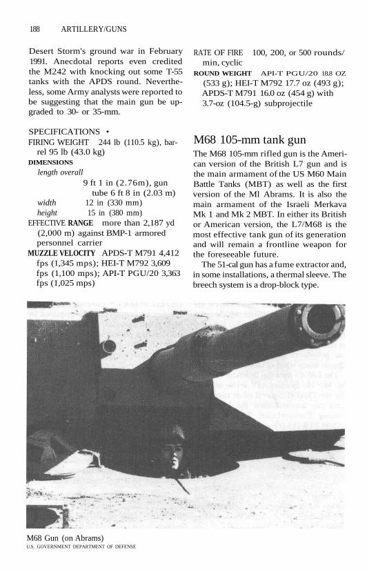
188 ARTILLERY/GUNS
Desert Storm's ground war in February1991. Anecdotal reports even creditedthe M242 with knocking out some T-55tanks with the APDS round. Neverthe-less, some Army analysts were reported tobe suggesting that the main gun be up-graded to 30- or 35-mm.
SPECIFICATIONS •FIRING WEIGHT 244 lb (110.5 kg), bar-
rel 95 lb (43.0 kg)DIMENSIONS
length overall9 ft 1 in (2.76m), gun
tube 6 ft 8 in (2.03 m)width 12 in (330 mm)height 15 in (380 mm)
EFFECTIVE RANGE more than 2,187 yd(2,000 m) against BMP-1 armoredpersonnel carrier
MUZZLE VELOCITY APDS-T M791 4,412fps (1,345 mps); HEI-T M792 3,609fps (1,100 mps); API-T PGU/20 3,363fps (1,025 mps)
RATE OF FIRE 100, 200, or 500 rounds/min, cyclic
ROUND WEIGHT API-T PGU/20 18.8 OZ
(533 g); HEI-T M792 17.7 oz (493 g);APDS-T M791 16.0 oz (454 g) with3.7-oz (104.5-g) subprojectile
M68 105-mm tank gunThe M68 105-mm rifled gun is the Ameri-can version of the British L7 gun and isthe main armament of the US M60 MainBattle Tanks (MBT) as well as the firstversion of the Ml Abrams. It is also themain armament of the Israeli MerkavaMk 1 and Mk 2 MBT. In either its Britishor American version, the L7/M68 is themost effective tank gun of its generationand will remain a frontline weapon forthe foreseeable future.
The 51-cal gun has a fume extractor and,in some installations, a thermal sleeve. Thebreech system is a drop-block type.
M68 Gun (on Abrams)U.S. GOVERNMENT DEPARTMENT OF DEFENSE

ARTILLERY/GUNS 189
The M68 fires M392 Armor-PiercingDiscarding Sabot with Tracer (APDS-T),M735 and M774 Fin-Stabilized APDS-T(APFSDS-T) with tungsten penetrators,M833 APFSDS-T with Depleted Uranium(DU) penetrator, M456 High-ExplosiveAntitank (HEAT), and M494 Antiperson-nel with Tracer (APERS-T) projectiles.Chamberlain Manufacturing Corp. hasalso developed an M900 APFSDS-Tround with a DU penetrator and theCMC 105 APFSDS-T with a tungsten pen-etrator (20:1 length/diameter ratio) forexport. Mecar's M1060 APFSDS withtungsten-nickel-iron (WNiFe) penetratorwas purchased by the Saudi Army.
DEVELOPMENT • The M68 achievedits initial operational capability in theM60 in 1962. It was produced at the Wa-tervliet Arsenal at Watervliet, New York,and in Israel.
VARIANTS • M68A1 was a low-recoilvariant developed for the FMC CloseCombat Vehicle-Light (CCV-L) and firstshown in 1985; the Benet XM35 was lateradopted for the production M8 ACS.
COMBAT EXPERIENCE • Like its Brit-ish progenitor, the M68 proved very ef-fective when used by Israeli M60 andMerkava tanks against Syrian T-72 tanksin 1982. APFSDS rounds sliced into thehull, hitting the carousel autoloader anddetonating the ammunition with devas-tating results.
During the ground phase of OperationDesert Storm, which began on February24, 1991, US Marine Corps M60Alsknocked out Iraqi T-55 and T-62 tanks inKuwait, often firing at close range. Sauditanks enjoyed particular success, withAPFSDS ammunition believed to be theM1060 round.
SPECIFICATIONS •FIRING WEIGHT 2,489 lb (1,128 kg),
barrel 1,662 lb (754kg)DIMENSIONS length, overall 18 ft 3 in
(5.55 m), tube 17 ft 7 in (5.35 m), re-coil 12 in (305mm)
EFFECTIVE RANGE APFSDS 90% hit
probability 2,187 yd (2,000 m)MUZZLE VELOCITY APFSDS 4,921-
4,955 fps (1,500-1,510 mps); APDS4,783 fps (1,458 mps); M456/A2HEAT-T 3,848 fps (1,173 mps); M494APERS-T 2,693 fps (821 mps)
RATE OF FIRE 9 rounds/min sustainedAMMUNITION ROUND WEIGHT
M494 APERS-T: 55 lb (24.94 kg)M456/A2 HEAT-T: 48 lb (21.78 kg)M392A2 APDS-T: 41 lb (18.6 kg)APFSDS rounds 37.8-39.7 lb (17.15-
18 kg), APFSDS projectiles 12.79-15 lb (5.8-6.83 kg) (M1060 carries7.3-lb/3.31-kg penetrator)
M256 120-mm tank gunThe Rheinmetall-designed 120-mm, 44-cal smoothbore tank gun is the main ar-mament for the German Leopard 2 andUS M1A1 Abrams Main Battle Tanks(MBT). The US Army's eventual adop-tion of the 120-mm gun reflected a be-lated concern that adversary tank armormight defeat the effective but smallerL7/M68 105-mm gun. Rheinmetallclaims a 60% improvement in ballisticperformance over the 105-mm.
The gun is the first heavy-calibersmoothbore gun in Western tanks, andits adoption (in preference to a rifledgun) was prompted by the desire toachieve high muzzle velocities without ex-cessively shortening barrel life. Highmuzzle velocity, coupled with a highercross-sectional loading (usually achievedby reducing the diameter of the KineticEnergy Penetrator/KEP while retainingor increasing its mass), is currently seenas the most effective means of counteringincreases in armor thickness and quality.
The gun has a cold-drawn, seamless,autofrettaged tube with a chromium in-ner lining that improves wear resistancewhile firing fin-stabilized ammunition.

190 ARTILLERY/GUNS
The gun tube's Effective Full Charge(EFC) life was originally set at 500rounds, but upgrades extended the life to750 and later 1,000 EFC rounds. Both thefume extractor and thermal sleeve aremade of glass-reinforced plastic. Thebreech type is a semiautomatic verticalsliding wedge.
There is little difference between theoriginal Rheinmetall gun and the Ameri-can M256 produced under license at theWatervliet Arsenal. The Ml turret mant-let and trunnion bearings were re-designed to accept the M256.
Ammunition for the 120-mm gun iscontained in semicombustible car-tridges; German and US ammunition issimilar. The M256 fires the M829 Armor-Piercing Fin-Stabilized Discarding Sabot(APFSDS-T) using a Depleted Uranium(DU) penetrator and the M830 High-Explosive Antitank, Multipurpose(HEAT-MP).
Olin Corp. developed the GDI20 Ki-netic Energy-Tungsten (KE-T) APFSDS-Tround for export; Alliant Techsystemsalso has a KE-T round.
DEVELOPMENT • Development of theRheinmetall gun began in 1964 at thesame time the Soviet T-62 introduced thefirst Soviet smoothbore 115-mm gun intoactive service. Testing of the German gunbegan in 1974, and production started in1979 for the Leopard tank. Testing in theM1E1 tank began in 1981, and produc-tion of the M1A1 tank was approved in
1984. First delivery of the M1A1 withthe 120-mm gun—designated M256—occurred in 1985.
In production by Rheinmetall in Diis-seldorf, Germany, and Watervliet Arse-nal, Watervliet, New York. The Rhein-metall design is also fitted in Israel'sMerkava 3, Japan's Type 90, and Korea'sType 88 tank.
COMBAT EXPERIENCE • The M256established a convincing superiority overany other vehicle-mounted weapon dur-ing Operation Desert Storm. See MlAbrams.
SPECIFICATIONS • Total systemweight 6,649 Ib (3,015 kg), gun 4,200 Ib(1,905 kg), barrel 2,590 Ib (1,175 kg)DIMENSIONS
length overall 18 ft 4 in (5.6 m),barrel 17 ft 5 in (5.3m)
width 2 ft 5 in (0.73 m)MAX EFFECTIVE RANGE (EXCEEDED IN
COMBAT)APFSDS-T: 3,281 yd (3,000 m)HEAT-MP: 2,734 yd (2,500 m)
MUZZLE VELOCITY
APFSDS-T: 5,545-5,616 fps (1,690-1,712 mps)
HEAT-MP M830: 3,740 fps (1,140mps)
AMMUNITION ROUND
HEAT-MP M830: 53.4 Ib (24.2 kg)with 29.8-lb (13.5-kg) projectile
APFSDS M829: 41.2 Ib (18.7 kg) with15.9-lb (7.2-kg) projectile

GROUND COMBAT VEHICLES
AIR DEFENSE VEHICLESAvengerThe US Avenger air defense system con-sists of an AM General High-Mobility Mul-tipurpose Wheeled Vehicle (HMMWVor Humvee) fitted with a BoeingAerospace/General Electric Pedestal-Mounted Stinger (PMS) system. ThePMS consists of a GE one-man electricallydriven, gyro-stabilized turret with a digi-tal fire control processor. The turretbears two four-round Stinger Surface-to-Air Missile (SAM) Standard VehicleMount Launchers (SVML) and an FNMSP .50-cal (12.7-mm) machine gun lo-cated under the right launcher. The gun-ner sits in a compartment between thelaunchers, tracking through a CAI driven-reticle optical sight.
Under the left launcher are the Magna-vox AN/VLR-1 Forward-Looking Infra-red (FOR) system and a TexasInstruments eye-safe CO2 laser range-finder. In the armored cab is a GeneralElectric Remote-Control Unit (RCU) thatcan be operated 55 yd (50 m) away fromthe vehicle.
The system is designed to function withsome or all of the subsystems inoperative.The Avenger can fire a second missile at atarget without losing the lock if the firstround misses.
The Avenger system can be airlifted byseveral types of aircraft.
DEVELOPMENT • The Boeing/GE en-try competed with the LTV CrossbowPMS (also mounted on a Humvee) forthe US Army's Line-of-Sight-Rear (LOS-R) component of the Forward Area AirDefense System (FAADS) program. In a
refreshing departure from the usual re-sults of FAADS development efforts, bothAvenger and Crossbow were reported tohave exceeded requirements during test-ing. Boeing's bid was said to have been asmuch as $50 million less than LTV's.
In production by Boeing Aerospace inHuntsville, Alabama, achieving initial op-erational capability in April 1989.
COMBAT EXPERIENCE • Avengerswere deployed with US Army units inSaudi Arabia as part of Operation DesertShield. Because of the rapid disablementof the Iraqi Air Force during the first fewdays of Operation Desert Storm, noAvenger units fired on Iraqi aircraft.
SPECIFICATIONS •CREW 3COMBAT WEIGHT 8,600 lb (3,901 kg)
DIMENSIONShull length 16 ft 3 in (4.95 m)width 7 ft 2 in (2.49 m)tactical height
8 ft 8 in (2.64 m)ground clearance
16 in (410 mm)wheelbase 10 ft 10 in (3.3 m)
MAIN ARMAMENT 8 Stinger SAM and 1X 12.7-mm MSP machine gun with200 12.7-mm roundselevation -10°/+70°, traverse 360°
SENSORS AND FIRE CONTROL Digital fire
control, FLIR, CO2 eye-safe laserrangefinder, driven-reticle opticalsight, remote-control unit operablefrom Humvee cab or away from vehicle
ARMOR supplemental armor on cab

192 GROUND COMBAT VEHICLES
POWERPLANT Detroit Diesel 135-hp air-cooled V-8 dieselpower-to-weight ratio
38.6 hp/metric tonSUSPENSION independent double
A-arm with coil spring on all wheels,front stabilizer bar
SPEED 60 mph (97 km/h), accelera-tion, 0-30 mph (48 km/h) 7 sec, 0-50 mph (80 km/h) 20 sec, range 300mi (483 km)
OBSTACLE CLEARANCE vertical obstacle1 ft 10 in (0.56 m), gradient 60%,fording without preparation 2 ft 6 in(0.76 m), with preparation 5 ft(1.52 m)
M48 ChaparralThe US Chaparral short-range Surface-to-Air Missile (SAM) system consists of anM54 launcher bearing four modifiedAIM-9 Sidewinder Infrared (IR)-homingmissiles that is mounted on the rear deckof a modified M548 tracked cargo carrierdesignated the M730 or M730A1. (It hasalso been deployed on a trailer and inships.)
The powertrain was updated in the1980s. Although newer vehicles were de-veloped (notably the Americanized Ro-land and ADATS systems), teethingproblems and cost prevented a successorfrom entering service.
The full-width cab has a permanentblast shield on the rear. To prepare forfiring, the crew folds down the wind-shield, side window frames, and roof, andcovers the lower armored portion with asix-piece blast shield. An auxiliary powerunit elevates and traverses the base andturret assembly.
Two vertically stacked missile rails arelocated on either side of the air-conditioned "gunner's" position. Thegunner slews his turret onto a target bear-ing provided by a remote target-locatingradar. Target acquisition and postlaunchtracking are by the missile's IR seeker,
conferring a "fire and forget" capabilityon the system.
The MIM-72 missiles have been up-graded several times; the current variantfeatures the AN/DAW-2 Rosette ScanSeeker (RSS) two-color spectral discrimi-nation detector that increases resistanceto IR countermeasures, improves spatialdiscrimination and expands field of viewwithout sacrificing sensor acuity.
VARIANTS • Night Chaparral (Chapar-ral FLIR) with forward-looking IR sight.
DEVELOPMENT • Installation of theMIM-72 missile (adapted from the AIM-7Sidewinder) in 1969 was originally in-tended as a stopgap measure after themore sophisticated Mauler missile wascanceled. The Regular Army achievedinitial operational capability in 1969; thefirst National Guard unit (New Mexico)became operational with the Chaparralin FY1984.
The chassis is supplied by FMC of SanJose, California, and the missile system ismanufactured by Loral's AeroneutronicsDivision of Newport Beach, California.
In addition to US service, Egypt,Greece, Israel, Morocco, Taiwan, and Tu-nisia operate the Chaparral.
COMBAT EXPERIENCE • AlthoughChaparrals were deployed with all majorUS Army units in Saudi Arabia duringOperations Desert Shield and DesertStorm, the early achievement of air su-premacy by the anti-Iraq coalition meantthat no Iraqi aircraft came within theM48's range during the conflict.
SPECIFICATIONS •CREW 4-5 (commander, driver, gun-
ner, 2 loaders)COMBAT WEIGHT 25,353 lb (11,500 kg)
ground pressure7.54 lb/in2 (0.53 kg/
cm2)DIMENSIONS
hull length 19 ft 11 in (6.06 m)

Chaparral Air Defense MissileU.S. GOVERNMENT DEPARTMENT OF DEFENSE

194 GROUND COMBAT VEHICLES
width 8 ft 11 in (2.69m)height 8 ft 10 in (2.68 m)ground clearance
16 in (400 ram)length of track on ground
9 ft 3 in (2.82 m)track width 15 in (380 mm)
MAIN ARMAMENT 4 X MIM-72 Chapar-ral SAM with 8 rounds in reserveelevation - 5°/+90°, traverse 360°max range 3.2 nm (3.7 mi; 6 km)max altitude
9,843 ft (3,000 m)minimum altitude
164 ft (50 m)rate of fire 4 rounds/min normal
SENSORS AND FIRE CONTROL launcherhas Forward-Looking Infrared (FLIR)thermal-imaging system with auto-matic target tracking and Identifica-tion Friend or Foe (IFF) interrogator;missile has passive IR homing with ra-dar proximity fuze
POWERPLANT Detroit Diesel 6V-53T275-hp water-cooled 2-stroke V-6 die-sel engine, X-200-4 fully automatic hy-drokinetic crossdrive transmissionwith 4 forward/1 reverse gearspower-to-weight ratio
23.9 hp/metric tonSUSPENSION (EACH SIDE) torsion bar, 5
road wheels, front drive, rear idler, notrack return rollers
SPEED 38 mph (61 km/h), 3.5 mph(5.5 kmh) in water with tracks whenfitted with flotation screen, range 313mi (504 km)
OBSTACLE CLEARANCE vertical 2 ft(0.62 m), gradient 60%, side slope30%, trench 5 ft 6 in (1.68 m), am-phibious
M42A1 Skys weeperThe M42A1 Skysweeper (usually knownas the Duster) twin 40-mm self-propelledantiaircraft vehicle is obsolete in its pri-mary role but remains useful againstground targets.
The Skysweeper has the same chassisas the M41 light tank and an open-topturret that houses four crew members.The driver of the M42 is located in thefront left of the hull with thecommander/radio operator seated tohis right. The engine is at the rear of thevehicle.
The M42 is armed with twin 40-mmcannon that are mounted between acurved, scooped shield. The cannon firea High-Explosive Tracer (HE-T) andArmor-Piercing Tracer (AP-T) round.
VARIANTS • Some Taiwanese M42shave been modified to carry and fire theTOW antitank guided missile.
DEVELOPMENT • Produced at CadillacMotor Car's Cleveland (Ohio) Tank Arse-nal from 1951 to 1956 and at ACF's Ber-wick, Pennsylvania, plant from 1952 to1953. It achieved its initial operationalcapability in 1953. Production totaled3,700 units. Not in service in active USunits, but still in use in several othercountries.
COMBAT EXPERIENCE • "Dusters"were often used by US forces in Vietnamagainst ground targets, in which the rela-tively heavy shell and high rate of fireproved effective. Very litde shielding pro-tected the crew, however, especiallyagainst threats from overhead.
SPECIFICATIONS: •CREW 6COMBAT WEIGHT 49,498 lb (22,452 kg)
ground pressure9.24 Ib/in2 (0.65 kg/
cm2)DIMENSIONS
hull length 19 ft 1 in (5.82 m), withguns forward 20 ft 10in (6.36 m)
width 10 ft 7 in (3.23 m)height 9 ft 4 in (2.85 m)

GROUND COMBAT VEHICLES 195
length of track on ground10 ft 8 in (3.25 m)
ground clearance17 in (440mm)
track width 21 in (530 mm)MAIN ARMAMENT 2 40-mm M2A1 auto-
matic cannon with 480 rounds in thevehicleelevation -3°/+85°, traverse 360°initial muzzle velocity
HE-T: 2,887 fps (880mps)
AP-T: 2,860 fps (872 mps)rate of fire 120 rounds/min per
barrel, practicalSECONDARY ARMAMENT 7.62-mm M60
with 1,750 roundsSENSORS AND FIRE CONTROL mechan-
ical computing sight, optical reflexsight
ARMOR HULL (GLACIS) 25.4 mm slopedat 45°, turret 9.52-15.87 mm
POWERPLANT Continental or LycomingAOSI-895-5 500-hp air-cooled 6-cylin-der supercharged fuel-injected gas-oline engine, Allison CD-500-3powershift, crossdrive transmissionwith 4 forward/2 reverse gearspower-to-weight ratio
22.26 hp/metric tonSUSPENSION (EACH SIDE) torsion bar, 5
road wheels, rear drive, front idler, 3shock absorbers, 3 return rollers
SPEED 45 mph (72 km/h), range 100miles (161 km)
OBSTACLE CLEARANCE vertical 2 ft 4 in(0.71 m), gradient 60%, side slope30%, trench 6 ft (1.83 m), fording 3 ft4 in (1.02m)
Ml63 Vulcan Air DefenseSystemThe Vulcan air defense system consists ofa modified Ml 13 armored personnel car-rier chassis (designated M741) mountinga turret fitted with a 6-barrel M61 VulcanCatling cannon and range-only radar.
The radar is similar to that used in the USNavy's Phalanx Close-In Weapons System(CIWS).
The 20-mm cannon fires Armor-Piercing with Tracer (AP-T) and High-Explosive Incendiary (HEI, HEI-T) pro-jectiles weighing 3.3-3.5 oz (94-100 g).An AP Discarding Sabot round was devel-oped for the Product Improved VulcanAir Defense System (PIVADS).
PIVADS consists of a stabilizeddirector-type gunsight, replacement ofthe analog computer with a digital mi-croprocessor, and improved elevationand traversing ability to reduce back-lash.
DEVELOPMENT • Like the Chaparralair defense vehicle, the M163 was an in-terim system, achieving initial opera-tional capability in 1968. Manufacturedby General Electric Co., Burlington, Ver-mont.
Cancellation of the Sergeant York Divi-sion Air Defense System (DIVADS) in1986 meant that these 1960s-vintage sys-tems remained in frontline service withthe US Army until the 1990s. At that time,US service in Operation Desert Stormexposed severe shortcoming, in mobility.In addition, the M163 showed steadily de-clining effectiveness against modern tar-gets and steadily increasing maintenancecosts. As a result, the Army retired itsM163s ahead of schedule, replacing themwith M2 Bradleys fitted with Stinger mis-siles.
In service with 12 other countries.
COMBAT EXPERIENCE • Israeli M163swere credited with several Syrian aircraftdestroyed during the 1982 Lebanese con-flict.
US Army Ml 63s deployed to Vietnamin the late 1960s encountered no NorthVietnamese aircraft, but the high firingrate and relatively heavy rounds were ef-fective against ground targets.
20 years later, Ml63s in Operations De-

196 GROUND COMBAT VEHICLES
sert Shield and Desert Storm likewisenever engaged Iraqi aircraft or helicop-ters. During the 100-hour ground war,however, the system's 20-mm cannonproved effective against light armored ve-hicles, trucks and other unarmored vehi-cles, and Iraqi bunkers.
SPECIFICATIONS •CREW 4 (commander, gunner, loader,
driver)COMBAT WEIGHT 27,478 lb (12,490
kg)ground pressure
8.68 Ib/in2 (0.61 kg/cm2)
DIMENSIONShull length 16 ft 2 in (4.93 m)width " 8 ft 9 3/4 in (2.69 m)height to turret top
8 ft 8 % in (2.64 m)length of track on ground
8 ft 9 in (2.67 m)ground clearance
16 in (406 mm)track width 15 in (381 mm)
MAIN ARMAMENT Ml68 gun system con-sisting of 6 X 20-mm barrels groupedon a geared rotor mountingelevation - 5°/+80° at 60°/sec,
traverse 360° at 75%ecmuzzle velocity
3,379 fps (1,030 raps)rate of fire antiair 3,000 rounds/min;
ground target 1,000rounds/min
magazine capacity1,100 ready rounds,
linkless feed; 1,000rounds more in hull
max range antiair 5,249 ft (1,600 m);ground 3,281 yd(3,000 m)
SENSORS AND EIRE CONTROL visualtracking and M61A1 (US Navy Mk 20Mod 0) lead-computing gunsight,AN/VPS-2 radar supplies range andrange rate, AN/TVS-2B night visionsight
PROTECTION 5083 aluminum hull (12-38 mm), antimine applique armor onthe bottom
POWERPIANT Detroit Diesel model6V-53 215-hp water-cooled 2-stroke V-6diesel engine, Allison TX-100 auto-matic transmission with 6 forward/1reverse gearspower-to-weight ratio
I7.47hp/metric tonSUSPENSION (EACH SIDE) torsion bar, 5
road wheels, rear drive, front idler, 3shock absorbers, no return rollers; sus-pension can be locked out during fir-ing
SPEED road 35 mph (56 km/h), cross-country 19 mph (30.6 km/h), acceler-ation 0-20 mph (0-32 km/h) 12 sec,3.6 mph (5.8 km/h) in water, range300 mi (483 km)
OBSTACLE CLEARANCE vertical 2 ft (0.61m), gradient 60%, side slope 30%,trench 5 ft 6 in (1.68 m), amphibious
ARMORED PERSONNEL CARRIERSAAV7A1 (formerly LVTP-7A1)The US Marine Corps AAV7A1 is a full-tracked, amphibian vehicle, providing anover-the-beach capability for landingtroops and material through surf up to 10feet high. The Marine Corps has oftenemployed the AAV7A1 as an armored
personnel carrier, although the vehiclehas a high silhouette for this role and wasnot originally intended to move far in-land from its assault beach.
Its mission dictates the AAV's bulk andunusual shape; the vehicle is taller and

GROUND COMBAT VEHICLES 197
AAV7A1FMC CORPORATION
wider than any other APC. The bow is anupturned snout extending well forwardof the tracks. Below the nose, die hullflares out in sponsons. This forward sec-tion of the hull houses the transmissionand engine. The driver and commanderare located to the left of the engine com-partment, the gunner to the right in aslightly elevated weapons station. Fartheraft, the crew compartment can hold 25troops in three rows; the compartment'supper sides are sloped toward the cen-terline.
Propulsion is by tracks on land, twinwater jets in the water. Afloat, the AAV issteered by a deflector's stream at the rearof each waterjet. Secondary track propul-sion can be reverted to if necessary.
VARIANTS • 90 AAVC7A1 command,61 AAVR7A1 recovery with crane.
DEVELOPMENT • The LVTP-7 wasbuilt by FMC Corp. (Ordnance Division)of San Jose, California, and achieved itsinitial operational capability in 1972. Pro-duction of the LVTP-7 ended in 1974 af-ter 942 had been built.
Conversion of LVTP-7s to LVTP-7Als(AAV7A1) came under a Service Life Ex-tension Program (SLEP) with an initialoperational capability for the LVTP-7A1in 1982. The SLEP saw the Detroit Dieselpowerplant replaced by the Cummins en-gine, a suspension upgrade, fully electricdrive for the weapons station, new ven-tilation system, built-in test equipment,better night vision devices, secure voiceradio equipment. The program was com-pleted in 1986 after a total of 984 vehicleswere modified. The production line waslater reopened to produce an additional333 new AAV7Als for the Maritime Prep-

198 GROUND COMBAT VEHICLES
positioning Ships (MPS); first deliverieswere made in October 1983.
Under a late-1980s Product Improve-ment Program (PIP), most AAWs havebeen refitted with an "upgunned"weapons station carrying a 40-mm auto-matic grenade launcher and a 12.7-mmin new, all-electric turret. Another im-provement is the Applique Armor Kit(AAK), consisting of two layers ofcorrosion-treated steel fastened to thehull sides. In addition, a bow plane hasbeen added to improve water speed andsafety, an Automatic Fire Sensing andSuppression System (AFSSS), and an im-proved transmission with double the re-liability of the current transmissionassembly.
Eight other countries operate theLVTP7 or AAV7. Many have been up-graded.
COMBAT EXPERIENCE • AAVVs landedMarines on Grenada in October 1983.
The AAVVs were among the first ar-mored vehicles to be landed in SaudiArabia after Iraq's August 1990 invasionand annexation of Kuwait. By the begin-ning of the Operation Desert Stormground war in February 1991, the 1stMarine Expeditionary Force (MEF) had225 AAV7s ashore. Another 115 were em-barked in 31 landing ships in the north-ern Persian Gulf. The shore-basedAAV7s served as one of two principaltypes of Marine Corps APCs (the LAV-25being the other) during the drive toKuwait City.
SPECIFICATIONS •CREW 3 (commander, gunner, driver)
+ 25 troopsCOMBAT WEIGHT 52,770 lb (23,936 kg)
ground pressure7.82 Ib/in* (0.55 kg/
cm2)DIMENSIONS
hull length 26 ft (7.94 m)width 10 ft 9 in (3.27 m)
height 10 ft 8 in (3.26 m)ground clearance
16 in (410mm)freeboard to driver's hatch
2 ft 3 in (0.85 m)length of track on ground
12 ft 11 in (3.94m)track width 21 in (530 mm)
MAIN ARMAMENT 40-mm grenadelauncher with 100 ready rounds, 12.7-mm machine gun with 200 roundselevation -8°/+45°, 360° traverse
SENSORS AND FIRE CONTROL infrareddriving lights, passive night drivingsystem, passive night firing system
ARMOR 30-45-mm hull armor, 6.72-12.7 mm on rear ramps
POWERPLANT Cummins VT-400 400-hpwater-cooled turbocharged 4-strokeV-8 diesel, FMC Corp. HS-400-3A1 hy-draulic lock-up torque converter with4 forward/2 reverse ratiospower-to-weight ratio
17.31 hp/metric tonSUSPENSION (EACH SIDE) tube-over-
torsion bar, 6 road wheels, front drive,rear idler, 2 shock absorbers, no re-turn rollers
SPEED road 45 mph (72.5 km/h),cruising speed 20-30 mph (12.5-18.6km/h), 8 mph (13 km/h) with 2 hy-drojets, 4.5 mph (7.2 km/h) track-driven, road range 300 miles (482km) at 25 mph (40 km/h), waterrange 7 hr
OBSTACLE CLEARANCE vertical 3 ft(0.91 m), gradient 60%, side slope40%, trench 8 ft (2.44 m)
LAV-25 Bison (in Canadianservice)Based on the Swiss MOWAG Piranha, the8 X 8-wheeled LAV-25 was developed spe-cifically for US Marine Corps use as anair-portable APC and reconnaissance ve-hicle. It has been built in several versions.
The LAV-25 has sloping hull sides and aseverely sloped glacis; the four wheels on

GROUND COMBAT VEHICLES 199
each side have no skirts or fenders. Thedriver sits at the front left of the hull withthe engine to his right. The troop com-partment is at the rear of the hull, withentry and exit through two rear doorsthat open outward. Two outward-openingroof hatches are located in the rear hull.The two-man, fully stabilized turret hasan M242 25-mm Chain Gun.
VARIANTS • Canadian LAV-APC Bison,96 LAV-AT Antitank with TOW, 50 LAV-MMortar Carrier, LAV-AD Air Defense Ve-hicle with FIM-92 Stingers and GAU/125-barrel 25-mm Catling cannon, LAV-AGAssault Gun Vehicle/LAV-105 with BenetEX-35 105-mm gun, 50 LAV-CC Com-mand and Control, 94 LAV-L Logisticsvehicles, 46 LAV-R Maintenance and Re-covery Vehicle, 20 USAF MARV MobileArmored Reconnaissance Vehicle, LAV-MEWSS (Mobile Electronic Warfare Sup-port System).
DEVELOPMENT • After a competition,contract awarded to General Motors ofCanada, Ltd., in London, Ontario, inSeptember 1982. The vehicle achievedinitial operational capability in 1984. Atotal of 758 were delivered to the USMC.
Other services using variants of theLAV-25 are the Australian Army, the Ca-nadian Force's Ground Command, andSaudi Arabia's Army and National Guard.
COMBAT EXPERIENCE • The LAV wasdeployed on European exercises for thefirst time during "Teamwork 88" innorthern Norway.
In operations in Panama beginning inMay 1989, the wheeled LAVs proved ver-satile enough to travel on roads whentracked vehicles would do too much dam-age to the pavement or in water, oftenswimming across the canal to evade Pan-ama Defense Force (PDF) surveillance.They also proved useful in breaking upbarricades, often by using the LAV-Ls topull them apart.
During the December 1989 Operation
Just Cause—the actual military ouster ofGeneral Noriega—Marine Corps LAVswere used to take several positions, in-cluding the headquarters of the PDF. Af-ter the military operation, the LAVs wereused to back up the successor govern-ment, often serving as a focal point for"nation-building" activities in smalltowns.
Marine Corps LAVs began landing inSaudi Arabia from Maritime Preposition-ing Ships (MPS) within days after the USdecision to begin Operation DesertShield in August 1990. By the start ofDesert Storm's ground war in February1991, 372 were in the theater (193LAV-25,54 LAV-AT, 30 LAV-CC, 47 LAV-L,26 LAV-M, and 22 LAV-R).
The LAV's strengths proved to be itsdependability and speed. (The DoD'sApril 1992 summary was "flexible, re-sponsive, and adaptable.") The vehicle'sspeed allowed units to flank fixed posi-tions and evade superior forces. Al-though several LAV crews did score TOWmissile hits on Iraqi tanks, the LAV didnot seek out enemy armor.
The LAV-25's inherent weakness is itslight armor. Ironically, the worst LAV ca-sualties came three weeks before theground war, when an Air Force A-10Thunderbolt accidentally fired anAGM-65 Maverick at an LAV, killing sevenof the eight men inside.
When the ground offensive began, theLAV's passive day/night sight proved in-adequate. It required too much ambientlight to be useful at night and was unableto penetrate the sand and oil-smoke fogthat shrouded much of the battlefield.
After Desert Storm, one LAV com-mander contended that light armored in-fantry units often were not fully exploitedbecause of a lack of understanding of theunit's reconnaissance capabilities. Healso suggested upgrades to the LAV-25including (among others) a thermal im-aging sight for the 25-mm gun, redesignof the machine gun mount, and a re-design of the internal communications

200 GROUND COMBAT VEHICLES
system in the basic vehicle to keep thescouts in the picture and in the C2 vehicleto permit staff-only conferences (to avoidconfusing the driver).
SPECIFICATIONS •CREW 3 (commander, gunner, driver)
+ 6 troopsCOMBAT WEIGHT 28,200 lb (12,791 kg)DIMENSIONS
hull length 21 ft (6.39 m)width 8 ft 2 in (2.5 m)height 8 ft 10 in (2.69 m)distance between axles
1st to 2nd 3 ft 7 in (1.1m), 2nd to 3rd 4 ft 5 in(1.35m), 3rd to 4th 3ft 5 in (1.04m)
ground clearance20 in (508 mm)
MAIN ARMAMENT 25-mm M242 ChainGun with 210 ready rounds, 420stowedelevation -10°/ + 60° at 25%ec,
traverse 360° at 25%ecSECONDARY WEAPONS 7.62-mm M240
coaxial machine gun, pintle mountfor 7.62-mm machine gun, 4,050stowed rounds of 5.56-mm rifle am-munition
SENSORS AND FIRE CONTROL M36E1day/passive night vision sight for com-mander and gunner
ARMOR ballistic protection againstsmall arms and shell fragments
POWERPLANT GM Detroit Diesel6V-53T 275-hp liquid-cooled 2-strokeV-6 turbocharged diesel engine, Al-lison MT-653 DR automatic transmis-sion with 5 for ward/1 reverse gearspower-to-weight ratio
21.5 hp/metric tonSUSPENSION (EACH SIDE)
8 X 8 (8-wheel drive, front 4 steer-ing) ; 4-wheel drive may be selected
fully independent coil springs, twinshock absorbers on front 2 axles,trailing arm torsion bar on rear 2axles
SPEED 62 mph (100 km/h), 6.2 mph
(10 km/h) in the water with 2 pro-pellers, range 410 mi (660 km)
OBSTACLE CLEARANCE vertical 1 ft 8 in(0.5 m), gradient 70%, trench 6 ft 9in (2.06 m)
V-300 CommandoThe Commando V-300 6 X 6-wheeled Ar-mored Personnel Carrier (APC) is a de-velopment of the earlier CommandoV-150 4 x 4 armored reconnaissance ve-hicle, but is a larger vehicle similar toseveral models produced in Europe. Afull glacis plate, second rear axle, and awider range of turret options (from 7.62-mm machine guns to 90-mm cannon) arethe principal changes. Despite its muchgreater gun power, the V-300 is still onlylightly armored and has less cross-country mobility than tracked APCs.
The V-300 has a sloping frontal glacisplate and sloping sides. The turret ismounted toward the rear of the vehicle.The troop compartment is also in therear; access is through two rear doors andtwo roof hatches.
Turret armaments range from 7.62- or12.7-mm machine guns, through 20- or25-mm automatic cannon, to the 76- or90-mm gun. A retractable TOW antitankmissile launcher with two missiles can alsobe fitted. The 90-mm Cockerill gun has atriple-baffle muzzle brake. A V-600, whichfeatured a Cadillac Gage turret mountingthe L7A1 105-mm/51-cal Low RecoilForce rifled tank gun ran trials but wasnot procured.
VARIANTS • APC, 81-mm mortar vehi-cle, recovery vehicle, ambulance.
DEVELOPMENT • Manufactured byCadillac Gage, Warren, Michigan, achiev-ing initial operational capability in 1983.Production has been limited, with Kuwaitand Panama being the only buyers untilearly 1993, when the Philippines con-tracted for 24 through Foreign MilitarySales. The Panamanian V-300 roster in-

GROUND COMBAT VEHICLES 201
eludes vehicles fitted with the BelgianCockerill Mk 3 90-mm gun, APCs withtwo 7.62-mm machine guns, and ar-mored recovery vehicles.
COMBAT EXPERIENCE • When Iraqinvaded Kuwait in August 1990, very fewof Kuwait's V-300s appear to have es-caped.
SPECIFICATIONS •CREW 3 (commander, gunner, driver)
+ 9-10 troopsCOMBAT WEIGHT 32,000 lb (14,515 kg)DIMENSIONS
hull length 21 ft (6.4 m)width 8 ft 4 in (2.54 m)height 6 ft 6 in (1.98m)distance between axles
1st to 2nd 7 ft 3 in (2.21m), 2nd to 3rd 5 ft(1.52m)
ground clearance14 in (356 mm)
MAIN ARMAMENT Cockerill Mk 3 90-mm/36-cal rifled gun with 39 roundsof ammunitionelevation - 8°/ + 28°, traverse 360°
SECONDARY WEAPONS 7.62-mm coaxialmachine gun with 400 rounds, 7.62-mm antiaircraft machine gun with200 rounds
SENSORS AND FIRE CONTROL 8-pOWCrmonocular sight and 1-power peri-scope for gunner, 3 vision blocks forcommander
ARMOR CADLOY ballistic steel plate,proof against 7.62-mm ball ammuni-tion (vision blocks and periscopeshardened to same level)
POWERPLANT Cummins VT-504 270-hpliquid-cooled turbocharged V-8 dieselengine, Allison MT-643 automatictransmission with 4 forward/1 reversegearspower-to-weight ratio
18.60 hp/metric tonSUSPENSION
6 x 6 ( 6 wheels driving, 2 wheelssteering)
front axle has solid beam on trailingarms; coil springs, 2 telescopingshock absorbers, and antisway barson each wheel
rear axles have independent trailingarm with coil springs and 1 shockabsorber
SPEED 92 mph (57 km/h), water 3mph (5 km/h) driven by wheels,range 435 mi (700 km)
OBSTACLE CLEARANCE vertical 2 ft(0.61 m), gradient 60%, side slope30%, amphibious
M113The US Ml 13 Armored Personnel Car-rier (APC) is the most widely used of allnon-Soviet APCs. Its hull and powertrainhave been the basis for a great variety ofbattlefield vehicles, some modificationsrepresenting functional changes andothers differences in locally availableweapons, powerplants, or sensors.
In configuration, the Ml 13 is aslimmed-down version of the earlier M59.The boxy hull is welded aluminum with asteeply sloped glacis and flat top. Al-though there is a roof hatch, troops enterthe compartment on a lowered rearramp. There are no firing ports or visionblocks.
In February 1987, the General Ac-counting Office contended that anMl 13A3 would be as mobile as the newerM2 Bradley and would be less likely toexplode because of the less volatile am-munition it carries. Rebuttals to the re-port noted that the Ml 13 was not as wellarmed or as easy for infantry to dismountfrom as the Bradley. US experience inOperation Desert Storm suggests that theBradley's thermal sights and 25-mmChain Gun, which the M113A3 does nothave, were critical elements in the M2'ssuccess.
VARIANTS • Ml 13 gasoline-poweredAPC derived from T113E1, M113A1

202 GROUND COMBAT VEHICLES
diesel-powered production model(25,459 produced), M113A2 (1978),M113A3 (1987).
M106 (107-mm), M125 (81-mm),M1064 (120-mm) mortar carriers.
Canadian M113A2s fitted with the AirDefense, Antitank System (ADATS) mis-sile launcher.
M548 cargo carrier, M577 series com-mand post, Ml068 Standard IntegratedCommand Post Systems (SICPS).
M901 Improved TOW Vehicle (ITV)with two TOW antitank missiles.
M981 Fire Support Vehicle (FSV) withlaser designator in erectable "ham-merhead" mount.
Ml 015 Electronic Warfare (EW) sys-tems carrier.
Ml 059 Smoke Generator Carrier.
DEVELOPMENT • Production began in1959, with the Ml 13 achieving initial op-erational capability in 1959, M113A1 in1965. More than 78,000 were producedfor over 50 countries by FMC Corp. of SanJose, California, with license productionby OTO Melara of Italy and Thyssen-Henschel of Germany, with Pakistan as-sembly of 775 M113A2s beginning in1990.
Known as the Zelda in Israeli service.
COMBAT EXPERIENCE • Ml 13s werewidely deployed in several versions, in-cluding the basic APC, with US, Viet-namese, Australian, and South Koreanunits in Vietnam. Experiments with cam-ouflage and firing ports (to allow firingunder cover) were short-lived and unsuc-cessful. A bridgelayer conversion, on theother hand, improved unit mobility in themarshes and defiles. Ml 13s have alsoseen extensive service in several Israeli-Arab conflicts.
M901 ITVs, M981 FIST-Vs, and M577command vehicles were deployed in USArmy units in Saudi Arabia during Opera-tions Desert Shield and Desert Storm.The M577s and the M981 FSVs were
slowed down by the sand and proved tobe the vehicles that most limited thetracked artillery's speed of maneuver andprevented greater use of Copperheadlaser-guided projectiles. (The most effec-tive laser platform was the OH-58DKiowa AHIP helicopter.)
In fact, the M981 was the most se-verely criticized of all US military sys-tems for its sluggishness in the sand, theneed to be stationary to operate its"hammerhead," and its inferior optics,which often didn't see targets being en-gaged by M1A1 Abrams tank and M2/M3 Bradley fighting vehicles. In addi-tion, having to orient the FIST-V's NSGadded eight to 10 minutes to the timeneeded to provide targeting informa-tion, which was far too long in a fluidbattlefield.
Saudi Arabian, Kuwaiti, and EgyptianMl 13s also participated in the groundwar. None of the 50 M901 ITVs capturedin Kuwait by the Iraqi Army took any partin the ground war.
A US M577 was accidentally struck byan AGM-114 Hellfire missile a week be-fore the ground war began; several sol-diers were wounded.
SPECIFICATIONS •CREW 2 (commander, driver) + 11
troopsWEIGHT
M113A2: 24,986 Ib (11,334 kg)M113A3: 27,180 Ib (12,339 kg)ground pressure
M113A2:7.961b/in2(0.56 kg/cm2)
M113A3:8.571b/in2(0.60 kg/cm2)
DIMENSIONS
hull length M113A2: 15 ft 11 in (4.86m)
M113A3: 17 ft 5 in (5.30m)
width 8 ft 10 in (2.69 m)height with air defense machine gun
8 ft 3 in (2.52 m)

GROUND COMBAT VEHICLES 203
M113A3FMC CORPORATION
length of track on ground8 ft 9 in (2.67 m)
ground clearance17 in (430 mm)
track width 15 in (380 mm)MAIN ARMAMENT 12.7-mm M2 HB ma-
chine gun with 2,000 rounds pintle-mounted at commander's hatch(M113A3 has armored gunshield)elevation -217+53°, traverse 360°
ARMOR 5083 aluminum hull (12-38mm), antimine applique armor onthe bottom
POWERPLANT Detroit Diesel model6V53 215-hp (M113A2) or 6V53T 275-hp (M113A3) water-cooled 2-strokeV-6 diesel engine; M113A2 AllisonTX-100-1 crossdrive transmission with3 forward/1 reverse gears; M113A3
TX-200-4 hydrokinetic crossdrivetransmission with 4 forward/1 reversegearspower-to-weight ratio at combat weight
M113A2 18.51 hp/metricton; Ml 13A3 22.45 hp/metric ton
SUSPENSION (EACH SIDE) torsion bar,5 road wheels, front drive, rearidler, 2 shock absorbers, no returnrollers
SPEED road M113A2 38 mph (61 km/h), M113A3 41 mph (65 km/h),cross-country (at 26,500 lb/12,020kg), M113A1/A2 16.8 mph (27 km/h), M113A3 22 mph (35.4 km/h);3.6 mph (5.8 km/h) in water, accel-eration 0-20 mph (0-32 km/h) at26,500 lb (12,020 kg) M113A1/A2 11sec, M113A3 9 sec

204 GROUND COMBAT VEHICLES
RANGE Ml 13A2 300 mi (483 km);M113A3309mi (497km)
OBSTACLE CLEARANCE vertical 2 ft(0.61 m), gradient 60%, side slope30%, trench 5 ft 6 in (1.68 m), am-phibious Mil 3A2
M2 BradleyThe Bradley Mechanized Infantry Fight-ing Vehicle (MICV) supplements and willeventually replace the Ml 13 ArmoredPersonnel Carrier (APC). The Bradleyreflects the 1970s worldwide move awayfrom a troop "battle taxi" to a more flex-ible vehicle with better self-defense capa-bilities. The M3 Cavalry Fighting Vehicle(CFV) variant is virtually identical, exceptfor the lack of firing ports and visionblocks in the hull and more stowed TOWantitank missile rounds.
The Bradley has been a controversialdesign, criticized at first for being vulner-
able to small-arms fire and liable to catchfire. It was also said to be less mobile thanthe Ml 13. In Operation Desert Storm,however, Bradleys proved very reliableand were far better at keeping up withand actively supporting the Ml Abramstank during the ground war of 1991 's Op-eration Desert Storm than were vehiclesbased on the M113.
Viewed from above, the Bradley revealsits asymmetrical hull layout; the left sideof the hull has a continuous in-slopingupper section while the right is broken bythe engine compartment and ventilatorgrille. Before the M2A2 variant, the hullwas shielded by spaced laminate armor;the M2A2 has steel armor. The engine islocated in the front of the vehicle. Thedriver's position is to the engine's leftand is covered by a low domed hatch withvision ports.
Behind the engine and driver is theTOW-Bushmaster Armored Turret(TBAT-II), which mounts a 25-mm M242
M2 Bradley Fighting VehicleFMC CORPORATION

GROUND COMBAT VEHICLES 205
Chain Gun and a twin TOW antitankmissile launcher. The gunner (on theleft) has an integrated day/night sightwith 4- and 12-power magnification and athermal Imaging Infrared (IIR) device;the station also has a 5-power auxiliarysight with a 10° field of view. The com-mander (on the right) has a direct opticalrelay from the gunner's sight. Six troopsride in the rear compartment.
Some M2s are fitted with Stinger short-range SAMs to replace the elderly Ml63Vulcan Catling gun vehicles.
VARIANTS • M2 (2,300 produced),M2A1 (1,400 vehicles) with TOW 2 mis-siles, M2A2 with improved protection,suspension, more powerful engine. FM2was ad hoc fire support vehicle createdduring Operation Desert Storm. M2A3projected for 1990s but not produced.Ml070 Electronic Fighting Vehicle Sys-tem (EFVS).
DEVELOPMENT • An operational re-quirement (OR) for an Ml 13 replace-ment was issued in 1964, but trials wereunsatisfactory. 1970 OR led to 1973 selec-tion of FMC, trials in 1975. Produced byFMC Ground Systems Division (laterUnited Defense) in San Jose, California,the M2 achieving initial operational capa-bility in 1983.
In April 1990, the Army reduced itsrequirement for 8,811 Bradleys to 6,882,with last delivery in December 1994.
COMBAT EXPERIENCE • Approx-imately 2,200 Bradleys were deployed toSaudi Arabia in the vehicle's first combattest. By the beginning of the ground warin February 1991, 33% of the force wereAls, 48%wereA2s.
When the ground war began, theBradleys proved reliable, effective, andhighly mobile, according to Army re-ports. Vehicle commanders were pleasedwith the effect of the 600-hp engine onperformance and welcomed the steel ap-
plique armor. Crewmen felt that theBradley needed a faster reverse gear tostay with the Abrams in all-azimuth fire-fights. In addition, the 25-mm ChainGun, TOW launcher, and thermal sightswere invaluable to the success of theBradley/MlAl Abrams armored sweeps.
The Bushmaster cannon was very effec-tive against many types of soft and light ar-mored targets. Nevertheless, some Armyanalysts suggested that the main gun beupgraded to 30- or 35-mm. The gunner'sthermal sighting system was effective innear-zero visibility and permitted TOWmissile firings at targets only the Bradleygunner could see. Only three Bradleyswere reported destroyed by hostile fire; 17more were destroyed by "friendly fire."According to the Army, the antispall linersand applique armor limited secondarydamage and injury even when the vehiclewas hit by a tank gun round. A Bradley wasstopped when a 12.7-mm machine-gunround penetrated the hull and damagedthe front transmission.
SPECIFICATIONS (M2A2) •CREW 3 (commander, gunner, driver)
+ 6 (2 in M3 CFV) troopsWEIGHT M2A2 with armor kit 66,000 Ib
(29,937 kg)ground pressure
10.20 lb/in2 (0.72 kg/cm2)
DIMENSIONShull length 21 ft 6 in (6.55 m)width ' l i f t 10 in (3.61 m)height 9 ft 9 in (2.97 m)length of track on ground
12 ft 10 in (3.91 m)ground clearance
18 in (457 mm)track width 21 in (533 mm)
MAIN ARMAMENT 25-mm/81.3-cal M242Chain Gun with 300 ready rounds,600 (1,200 in M3 CFV) reserveroundselevation -10°/+60°, traverse 360°antitank missile
2 X TOW antitank

206 GROUND COMBAT VEHICLES
missile launchers, 5missiles in reserve (10in M3 CFV)
elevation -20°/+30°, traverseswith turret
SECONDARY WEAPONS 7.62-mm M240Ccoaxial machine gun with 800 readyrounds, 1,400 (3,400 in M3 CFV) re-serve rounds
SENSORS AND FIRE CONTROL Integratedthermal imaging day/night sight withscan at 4-power, aiming at 12-power,AN/WS-2 driver's night vision viewerwith 38° X 45° field of view
ARMOR 5083 series aluminum coveredby homogeneous steel plating to resist30-mm ammunition, Du Pont Kevlarspall liner, attachment points for reac-tive armor tiles
POWERPLANT Cummins VTA-903T 600-hp liquid-cooled 4-stroke turbo-charged V-8 diesel engine, GeneralMotors HMPT-500 hydromechanicaltransmission with 3 forward/1 reverserangespower-to-weight ratio
without armor kit 22.04hp/metric ton, witharmor kit 20.04 hp/metric ton
SUSPENSION (EACH SIDE) torsion bar, 6road wheels, front drive, rear idler, 4shock absorbers (14-in/365-mm wheeltravel), 3 return rollers
SPEED 42 mph (68 km/h), 5 mph (7.2km/h) in water with tracks, range 300mi (483 km)
OBSTACLE CLEARANCE vertical 3 ft(0.91 m), gradient 60%, side slope40%, trench 8 ft 4 in (2.54 m), am-phibious
YPR765 Armored InfantryFighting Vehicle (AIFV)The Armored Infantry Fighting Vehicle(AIFV) is a modified Ml 13 Armored Per-sonnel Carrier (APC). The AIFV is alsothe basis for the 1,700-vehicle Turkish Ar-
mored Combat Vehicle (ACV) program.The design has been praised for its com-bination of effective gun armament,proven Ml 13 components, and goodcross-country mobility.
Principal differences from the Ml 13are the shape of the after hull, hull con-struction, and main armament. Spacedlaminate steel armor is bolted over thestandard aluminum hull sides and rearand forms the collars for the gunner'shatch and turret.
Main armament varies; several hun-dred of the Dutch AIFVs (and 75 of theTurkish ACVs) carry an Oerlikon 25-mmKBA automatic cannon in a boxy turretdesigned by FMC. The KBA 25-mm gunfires High-Explosive Incendiary withTracer (HEI-T) and Armor-Piercing Dis-carding Sabot with Tracer (APDS-T) pro-jectiles. After a Swiss-imposed embargoon supplying the KBA to Turkey, the re-maining 575 ACVs have been fitted withthe GIAT DRAGAR turret—60 with theMcDonnell Douglas M242 25-mm ChainGun, 515 with GIAT's M811 25-mmcannon.
VARIANTS •Several Dutch YPR765 variants—cargocarriers, command vehicles, mortar car-riers, radar carrier, recovery vehicle,TOW antitank missile carrier—are fittedwith the standard Ml 13 cupola mountinga 12.7-mm M2 HB machine gun. The am-bulance is unarmed. Belgian variants aresimilar.
Turkish ACV family includes IFV, TOW2, and mortar carriers.
DEVELOPMENT • Although failing tomeet Army's 1970 Mechanized InfantryCombat Vehicle (MICV) requirement,other countries procured the AIFV, andover 2,000 have been built. Initial opera-tional capability achieved in the Nether-lands in 1978, Belgium in 1985. Dutchand Philippine vehicles manufactured byFMC Corp., San Jose, California; Bel-

GROUND COMBAT VEHICLES 207
gian vehicles (AIFV-B) manufactured un-der license by Belgium Mechanical Fabri-cation, Grace-Hollogne, Belgium.
Turkish Defence Industry Develop-ment and Support Administration(DIDA) contracted with FMC/Nurol In-saat to build 1,698 vehicles for the Turk-ish Army. Nurol's Golbasi factory begandelivering vehicles in 1991. Turret pro-duction manufactured in cooperationwith Makina ve Kimya Endustrisi Kurunu(MKEK) in Ankara.
SPECIFICATIONS •CREW 3 (commander, driver, gunner)
4- 7 troopsCOMBAT WEIGHT 30,174 lb (13,687 kg)
ground pressure9.53 lb/in2 (0.67 kg/
cm*)DIMENSIONS
hull length 17 ft 3 in (5.26 m)extreme width
9 ft 3 in (2.82 m)overall height
9 ft 2 in (2.79 m)length of track on ground
8 ft 9 in (2.67 m)ground clearance
17 in (432mm)track width 15 in (381 mm)
MAIN ARMAMENTYPR765/first 75 ACV: 25-mm
Oerlikon KBA-B02 cannon with 180ready rounds, 144 in reserve
elevation: -10°/+50°,traverse 360°
secondary weapon: 7.62coaxial machine gunwith 230 ready rounds,1,610 in reserve
Turkish ACV: 25 mm/86-cal GIATM811 with 220 rounds
elevation: -10°/+45°,traverse 360°
secondary weapon: 7.62-mm coaxial machinegun with 400 rounds; 5firing ports in hullsides and rear
SENSORS AND FIRE CONTROL telescopic
sights, optional integral night sight;Turkish IFVs have Cadillac Gage guncontrol equipment and Marconi Com-mand and Control Systems thermalimager vehicle sight; Texas Instru-ments thermal sights being suppliedto 650 vehicles
ARMOR aluminum alloy with spacedlaminate steel bolted to sides and rear
POWERPLANT Detroit Diesel Allison6V-53T 264-hp water-cooled turbo-charged 2-stroke V-6 diesel engine, Al-lison TX-100-1A automatic trans-mission with 3 forward/1 reversegearspower-to-weight ratio
19.29 hp/metric tonSUSPENSION (EACH SIDE) tube-over-
torsion bar, 5 road wheels, frontdriver, rear idler, 3 shock absorbers,no return rollers
SPEED 38 mph (61.2km/h),up 10%grade 17.5 mph (28.2 km/h), 4 mph(6.5 km/h) in water with tracks,range 305 mi (490 km)
OBSTACLE CLEARANCE vertical 2 ft 1 in(0.64 m), gradient 60%, side slope30%, trench 5 ft 4 in (1.63 m), am-phibious

208 GROUND COMBAT VEHICLES
ARMORED RECONNAISSANCE VEHICLESVI50 (M706) CommandoSeriesThe Commando series of light armoredvehicles has been produced in a variety ofconfigurations and is in widespread ser-vice. The basic Commando is a 4 X 4-wheeled vehicle with no vertical sur-faces and a low superstructure or turretring. Weapons fitted to the vehicle rangefrom 7.62-mm machine guns to 90-mmcannon.
VARIANTS •V-100 with Chrysler 191-hp gasoline en-gine; V-200 in several variants toSingapore; V-150 with gasoline or dieselengine, five-speed manual transmissionreplaced by two-speed automatic; V-150Swith 18-in (0.46-m) stretch and systemupgrades; Mexican-built DN-III/V Ca-ballo. Also command, recovery, air de-fense, internal security, air force basesecurity variants.
DEVELOPMENT • Manufactured byCadillac Gage Co., Warren, Michigan,achieving initial operational capability in1964. The original Commando was thegasoline-powered V-100 model. TheV-200 was sold only to Singapore.
Since 1971, the four-wheel productionmodel has been the V-150, a model with aloaded weight approximately halfway be-tween the V-100 and the V-200 and pow-ered by a diesel engine. In 1985, theV-150 was replaced in production by thelonger V-150S.
In limited US Air Force service, butoperated by more than 20 other coun-tries.
COMBAT EXPERIENCE • V-lOOs wereused by the United States Army and AirForce in the Vietnam War. Although trou-bled at first by rear-axle failure, theyproved handy as light security vehicles.The turret's ability to accept a variety ofweapons and the relatively high groundclearance were considered assets.
SPECIFICATIONS (V-150S) •CREW 3 (commander, gunner, driver)
+ 2 troopsCOMBAT WEIGHT V-150 21,800 lb
(9,888 kg); V-150S 24,000 lb (10,886kg)
DIMENSIONShull length V-100/150 18 ft 8 in (5.69
m);V-150S20ft2in(6.14m)
width 7 ft 5 in (2.26 m)height to hull top
6 ft 6 in (1.98m)wheelbase V-100/150 8 ft 9 in (2.67
m);V-150S10ft3in(3.12m)
ground clearancehull 25.5 in (650mm),
axles 15 in (380 mm)MAIN ARMAMENT (options fitted to
V-150/150S)

GROUND COMBAT VEHICLES 209
# AND CALIBER ELEVATION (DEC) ROUNDS OF AMMUNITION
27.62mm -13/+55212.7mm -10/+551 20-mm Oerlikon -S/+55125mm -8/+601 20-mm Vulcan1 30mm1 12.7-mm MG and 40-mm grenade
launcher -8/+4S1 76 mm190mm -8/+2S1 81-mm mortar +40/+85TOW antitank
800 ready, 3,000 in hull400 ready, 1,000 in hull200 ready, 200 in hull230 ready, 400 in hull1,300
100 (40 mm), 200 (12.7 mm)
8 ready, 31 in hull62 in hull7 missiles in hull
ARMOR Cadloy steel armor plate pro-tects against 7.62-mm fire
POWERPLANTChrysler 191-hp liquid-cooled V-8 gas-
oline engine; power-to-weight ratio20.23 hp/metric ton
or Cummins V-504 202-hp liquid-cooled V-8 automatic transmissionwith 4 forward/1 reverse gears;power-to-weight ratio V-150 20.43hp/metric ton, V-150S 18.56 hp/metric ton
SUSPENSION 4 X 4 (all wheels powered,front wheels steering), solid beamaxle, semi-elliptic multileaf springs,double-acting hydraulic shock ab-sorbers
SPEED 55 mph (89 km/h), 3.1 mph (5km/h) in water, road range 500 mi(800 km), cross-country range 400 mi(643 km)
OBSTACLE CLEARANCE vertical V-100/150 2 ft 0 in (0.61 m), V-150S 3 ft 0 in(0.91 m), gradient 60%, 30%, am-phibious
Commando ScoutThe Scout is a small 4 X 4 Armored Recon-naissance Vehicle (ARV) developed as aprivate venture by Cadillac Gage. It is de-signed primarily for reconnaissance andsecurity. No US units operate the Scout.
The Scout has a low silhouette with along, sloping glacis. Viewed from the
front, the hull's cross section is diamond-shaped, with both upper and lower hullhalves sloping inward. Compared toother ARVs, the engine, driver, and turretare set farther to the rear of the vehicle.The one- or two-man turret is sited overthe rear axle.
VARIANTS •Command car and antitank vehicle withretractable TOW antitank missilelauncher.
DEVELOPMENT • Manufactured byCadillac Gage, Warren, Michigan, achiev-ing initial operational capability in 1983.28 in service in Indonesia and 112 inEgypt.
SPECIFICATIONS •CREW 3 (driver, commander, gunner)COMBAT WEIGHT 16,000 lb (7,258 kg)DIMENSIONS
hull length 16 ft 5 in (5.0 m)width 6 ft 9 in (2.06 m)height 7 ft 4 in (2.24 m)wheettase 8 ft 10 in (2.74 m)
MAIN ARMAMENT 1-meter turret with 2gun stations for twin 7.62 or 12.7-mmmachine guns with 200 ready 7.62-mm rounds and 2,200 7.62-mmrounds stowed in hull; or 100 ready12.7-mm rounds and 1,000 12.7-mmrounds stowed in hull. Turret can also

210 GROUND COMBAT VEHICLES
bear combination of 7.62-mm ma-chine and 40-mm grenade launcherwith 100 7.62-mm rounds ready, 200stowed in hullelevation -107+55°, traverse 360°
at 45°/secSENSORS AND FIRE CONTROL 8 vision
blocks, M28C sight, 500,000-candlepower searchlight
ARMOR Cadloy steel armor proofagainst 7.62-mm ammunition
POWERPLANT Cummins 149-hp liquid-cooled V-6 diesel engine, Allison auto-matic transmission with 4 forward/1reverse gearspower-to-weight ratio
20.53 hp/metric tonSUSPENSION 4 X 4 (4 wheels driving,
2-wheel steering), coil springs on all 4wheels, front axle has solid swing arm,rear axle has independent swing arms
SPEED 60 mph (96 km/h), range 800mi (1,287km)
OBSTACLE CLEARANCE vertical 2 ft(0.61 m), gradient 60%, side slope30%, fording 3 ft 10 in (1.17 m)
M113C&RLynxThe M113C&R (Command and Recon-naissance) is a shorter, smaller variant ofthe basic Ml 13 tracked armored person-nel carrier in service in the Dutch andCanadian armies. (The name Lynx ap-plies only to Canadian vehicles.)
Although sharing many componentswith the Ml 13, the Lynx has one less roadwheel station per side. In place of theunbroken glacis of the Ml 13 is a steppedprofile that reduces the apparent size stillmore. Unlike the Ml 13, the engine ismounted in the rear.
As delivered, the C&R had an M2 12.7-mm machine gun mounted ahead of thecupola. In the late 1970s, the NetherlandsArmy retrofitted a larger 25-mmOerlikon KBA-B automatic cannon in aGDB-AOA turret; this gun fires High-Explosive (HE) and Armor-Piercing Dis-carding Sabot (APDS) rounds.
There are other, minor layout differ-ences between the Dutch and Canadianvehicles. For example, the radio operatorsits to the driver's right in the C&R; theLynx radio operator sits behind the driver,to the left and rear of the commander.
DEVELOPMENT • Begun by FMC Corp.as a private venture in 1963, theM113C&R was passed over by the USArmy in favor of the Ml 14 APC. Manufac-tured by FMC, San Jose, California,achieving initial operational capability inthe Netherlands (260 vehicles) in 1966,in Canada (174) in 1968.
SPECIFICATIONS •CREW 3 (commander, driver, radio op-
erator) ; radio operator is also gunnerinDutchM113C&R
COMBAT WEIGHT 19,345 lb (8,775 kg)ground pressure
6.83 Ib/in2 (0.48 kg/cm2)
DIMENSIONS
hull length 15 ft 1 in (4.6 m)extreme width
7 ft 11 in (2.41m)height to hull top
5 ft 9 in (1.75m)length of track on ground
7 ft 10 in (2.39 m)ground clearance
16 in (410 mm)track width 15 in (380 mm)
MAIN ARMAMENT
Lynx: 12.7-mm M2 HB machine gunin M26 turret with 1,155 rounds
elevation: -15°/+550,traverse 360°
secondary armament:7.62-mm machine gunwith 2,000 rounds
M113C&R: 25-mm Oerlikon KBA-Bautomatic cannon with 120 HE, 80APDS rounds
elevation: -127+52°,traverse 360°
SENSORS AND FIRE CONTROL M19 infra-red periscope

GROUND COMBAT VEHICLES 211
ARMOR all-welded aluminum armorPOWERPLANT CMC Detroit Diesel Al-
lison 6V-53 215-hp 2-stroke water-cooled V-6 diesel engine, AllisonTX100 transmission with torque con-verter and 3 forward/1 reverse gearspower-to-weight ratio
24.5 hp/metric tonSUSPENSION (EACH SIDE) torsion bar, 4
road wheels, front drive, rear idler, noreturn rollers
SPEED 44 mph (71 km/h), water speed3.5 mph (5.6 km/h) with tracks,range 325 mi (523 km)
OBSTACLE CLEARANCE vertical 2 ft(0.61 m), gradient 60%, trench 5 ft(1.52 m), amphibious
M551 SheridanThe M551 was developed to provideheavy firepower in a light, air-droppablearmored reconnaissance vehicle. Thealuminum-hulled Sheridan has an un-usual main armament consisting of theM81 152-mm gun/missile launcher. Theweapon fires conventional combustible-case ammunition and the MGM-51 Shil-lelagh antitank missile. The missile hasSemiactive Command to Line of Sight(SACLOS) guidance using a two-way In-frared (IR) link. Conventional ammuni-tion includes White Phosphorous (WP),canister, and High-Explosive Antitankwith Tracer (Multipurpose)—HEAT-T-MP—projectiles.
The gun-tube-launched, antitank mis-sile proved very troublesome and de-layed widespread deployment for severalyears. By the time most of the bugs hadbeen smoked out, the tube-launchedmissile had been supplanted by im-proved kinetic energy penetrators forconventional tank guns, and the Sher-idan's potential declined rapidly. Disap-pointment with the Sheridan led to aphaseout from active US Army units be-ginning in 1978.
However, the 82nd Airborne Division
retains these vehicles in active service;these will be replaced by M8 Assault GunSystem vehicles. 330 Sheridans were "vi-sually modified" to represent Soviettanks and other armored vehicles andserve at the Army's National TrainingCenter in Fort Irwin, California.
DEVELOPMENT • The M551 achievedinitial operational capability in 1968, al-though it was several years after that be-fore it was in regular service in largenumbers. A total of 1,562 were built bythe Allison Division of General Motorsfrom 1966 to 1970.
COMBAT EXPERIENCE • Althoughfast and apparently heavily armed, the 64Sheridans deployed to Vietnam in 1968-69 revealed many deficiencies, most re-quiring extensive redesign work to rec-tify.
12 Sheridans were used in the Decem-ber 1989 Operation Just Cause—the USouster of Panamanian General Nori-ega—where it was said to have per-formed well. Eight were delivered using aLow-Velocity Airdrop (LVAD) technique.The design's weight allowed it to overrunmakeshift street barricades, and the 152-mm bunker-busting rounds proved effec-tive against reinforced-concrete walls.The one armor-piercing RPG-7 antitankrocket directed against a Sheridanmissed its target.
In August 1990, Sheridans were de-ployed to Saudi Arabia with the 82nd Air-borne Division as part of OperationDesert Shield. They were initially sent asa stopgap quick-strike force to forestallany Iraqi moves into Saudi Arabia in thefirst few weeks.
Although it was later fitted with ther-mal imaging sights for night fighting, theSheridan's role in Operation DesertStorm was limited primarily to reconnais-sance by its age and light armor. Nev-ertheless, several Shillelagh missiles werefired at Iraqi bunkers.

212 GROUND COMBAT VEHICLES
SPECIFICATIONS •CREW 4 (commander, gunner, loader,
driver)COMBAT WEIGHT 34,900 lb (15,830 kg)
ground pressure6.97 Ib/in2 (0.49 kg/
cm2)DIMENSIONS
hull length 20 ft 8 in (6.3 m)width 9 ft 3 in (2.82 m)height 9 ft 8 in (2.95 m)length of track on ground
12 ft (3.66 m)ground clearance
19 in (483 mm)track width 17.5 in (444 mm)
MAIN ARMAMENT 152-mm M81 gun/
missile launcher with 20 HEAT-T-MProunds and 8 Shillelagh missile rounds
elevation -8°/ + 19.5°, traverse 360°SECONDARY WEAPONS 7.62-mm M73
machine gun with 3,080 rounds and12.7-mm M2 HB antiaircraft machinegun with 1,000 rounds
SENSORS AND FTRE CONTROL Ml 29gunner's telescope, magnification 8X,8° Field of View (FOV), M44 gunner'sIR night sight, magnification 9X, 6°FOV, IR SACLOS data link
ARMOR aluminum hull, steel turretPOWERPLANT Detroit Diesel 6V-53T
300-hp water-cooled turbocharged2-stroke V-6 diesel, Allison TG-250-2Apowershift crossdrive transmissionwith 4 forward/2 reverse gearspower-to-weight ratio
18.95 hp/metric tonSUSPENSION (EACH SIDE) torsion bar,
5 road wheels, rear drive, front idler,2 shock absorbers, no returnrollers
SPEED 45 mph (72 km/h), 3.6 mph(5.8 km/h) in water widi tracks,range 373 mi (600 km)
OBSTACLE CLEARANCE vertical 2 ft 9 in(0.84 m), gradient 60%, side slope40%, trench 8 ft 4 in (2.54 m), am-phibious
COMBAT SUPPORT AND SERVICE VEHICLESM9 Armored CombatEarthmover (ACE)The M9 ACE is a full-tracked, relativelyfast armored earthmover capable of con-structing weapons positions, building orclearing obstacles, and recovering othervehicles in combat areas.
The ACE is a combination of a bull-dozer and a front-end loader, with theblade forming the front of a large "bowl"that holds up to 237 ft2 (6.7 m2) of fill.The top corners of the dozer blade aremounted on heavy arms that lower theblade for dozing and raise it to exposethe bowl for loading. The vehicle's hydro-mechanical suspension can tilt fore andaft or 5° toward one corner of the blade;dozing leverage can be increased by plac-ing ballast in the bowl.
The engine is in the right rear with thedriver seat to its left. A heavy armoredcupola with vision blocks and a hatch pro-tects the driver under fire. When over-head protection isn't necessary, the hatchpivots up and back to allow the driver tosit up.
The M9 is fully amphibious in all butfast-running rivers and can be airlifted bythe C-130 Hercules and larger transportaircraft.
DEVELOPMENT • ACE began develop-ment in 1958 as All-Purpose BallastableCrawler (ABC). Actual prototyping as theUniversal Engineer Tractor (UET)started in 1962 with examples built by

GROUND COMBAT VEHICLES 213
Caterpillar Tractor and Universal Har-vester, the latter winning the 1963 devel-opment award. Operational require-ments kept changing, and at times twoprograms competed for attention.
PACCAR involvement began in 1975;testing of four prototypes ended in Au-gust 1976 with type classification to Stan-dard A approved in February 1977. Firstproduction did not begin, however, until1985, as funding was inadequate and theArmy demanded further improvementsand changes.
Finally, BMYof York, Pennsylvania, be-gan production, with the ACE achievinginitial operational capability in 1986. Al-though the Army originally planned toacquire 1,318 vehicles, ultimately 566 ve-hicles were to be purchased.
The US Marine Corps announced a re-quirement for 257 vehicles in 1986; laterrevisions reduced the number to 180.The first 41 were requested in the FY1993defense budget.
An undisclosed "Far Eastern" nationordered ISACEs.
COMBAT EXPERIENCE • 151 ACEswere deployed with US units in Saudi Ar-abia during Operation Desert Shield.Most were shipped during December andJanuary after being prepared by BMY, in-cluding 99 in a 10-day period in January1991. 30 were "loaned" to the US MarineCorps, 24 of these being used in Opera-tion Desert Storm.
M9s lived up to their job description,preparing US armor and artillery posi-tions and demolishing the barriers raisedby Iraqi forces. ACEs were praised as be-ing fast, mobile, and effective. In fact, the1st Infantry Division's technique forclearing Iraqi trenches centered on theACE. The M9 drove down the trench es-corted by M2 Bradley APCs on eachflank, leaving "a smooth place where thetrench had been." The ACE's only limita-tion is that the driver is effectively blindwhen under armor.
SPECIFICATIONS •CREW 1 (driver in armored cab)BALLASTED WEIGHT 54,000 lb (24,494 kg)
ground pressure, loaded14.51b/in (1.02 kg/cm)
DIMENSIONShull length 20 ft 6 in (6.25 m)width with dozer wings
10 ft 6 in (3.20m) .overtracks 8 ft 10 in (2.69m)
height to top of cupola9 ft 10 in (2.69 m)
freeboard when fording11 in (279mm) with
4,000-lb (1,814-kg) loadand armor partiallyremoved
ground clearance, sprungIS'/a in (343 mm)
length of track on ground8 ft 9 in (2.67 m)
track width 18 in (460 mm)ARMOR steel, aluminum, and Kevlar ar-
mor on engine, powertrain, and oper-ator's position
POWERPLANT Cummins V903C 295-hpliquid-cooled 4-stroke V-8 diesel en-gine, Clark Model 13.5 HR 3610-2torque-converter manual transmissionwith 6 forward/2 reverse gearspower-to-weight ratio, ballasted
12.04 hp/metric tonSUSPENSION (EACH SIDE) hydro-
pneumatic with rotary actuators,4 road wheels, rear drive, no frontidler or return rollers
SPEED road 30 mph (48.3 km/h), wa-ter 3 mph (4.8 km/h) with tracks,range 200 mi (322 km)
OBSTACLE CLEARANCE vertical 1 ft 6 in(0.46 m), ballasted gradient 60%, bal-lasted side 40% slope, trench 5 ft 2 in(1.57 m), fording 3 ft (0.91 m)
M88A1The M88 is the principal US medium Ar-mored Recovery Vehicle (ARV) and isbased on the M48 Patton Main BattleTank (MET). It is capable of recovering

214 GROUND COMBAT VEHICLES
and evacuating all US armored vehiclesexcept for some models of the M60 andthe Ml Abrams MET. Adoption of theImproved Recovery Vehicle (IRV) withan uprated engine in 1992 was un-enthusiastic, but made necessary by theincreasing weight of the Army's Abramstank. Two M88Als are needed to tow anMl tank, a limitation that showed to theMSB's disadvantage during OperationDesert Storm.
The hull is of cast and rolled armorwelded together. The crew compartmentis to the front, with the engine and trans-mission to the rear and doors on eitherside of the hull.
A blade mounted at the front is usedfor dozing operations and to stabilize thevehicle when using the winch or crane.The A-frame crane can hoist 12,000 Ib(5,443 kg) with the dozer blade up, up to40,000 Ib (18,143 kg) with suspensionlocked out, and 50,000 Ib (22,680 kg)with the blade down. The main winch hasa 90,000-lb (40,824-kg) pull.
A fording kit is available which allowsthe vehicle to ford water 8 ft 6 in (2.6 m)deep. An auxiliary fuel pump can trans-fer fuel to other vehicles at a rate of 25 USgal/min (95 liters/mm).
VARIANTS •M88 (1,075 delivered from 1961) withContinental AVSI-1790-6A 980-hp V-12gasoline engine, M88A1 (2,100 new, 875converted) with diesel engine, NBC col-lective protection kit, M88A1E1/M88A2Improved Recovery Vehicle (IRV) withnearly double crane and winch capacity.
DEVELOPMENT • M88 achieved its ini-tial operational capability in 1961;M88A1 conversions began in 1977. Man-ufactured by BMYCorp., York, Pennsylva-nia (later United Defense). Productionended in 1989 but resumed in 1990 afterthe assembly line layout was reoriented tosmall-batch orders.
The Army's dissatisfaction with IRV tri-als led to the project's cancellation inApril 1989, but lack of options led to de-
velopment funding in September 1992.Production started in 1993 on 186 vehi-cles planned, with First Unit Equipped(FUE) planned for FY1994.
In service with the US Army and Ma-rine Corps and over 20 other countries.
COMBAT EXPERIENCE • US units inVietnam depended heavily on the M88for recovery in the field, and the vehiclewas widely deployed.
Although it was again widely deployed,the M88's performance in Operation De-sert Storm earned unfavorable reviews.According to Defense News, 3rd ArmoredDivision M88s could not tow M1A1Abrams tanks and were said to have been"operational" only 60% of the time. TheGeneral Accounting Office reported in1992 that in one brigade of the 24th Infan-try Division (Mechanized), Abrams tanksmore often towed M88s than the otherway around. Moreover, a low towing speedof 5 mph (8 km/h) did not prevent en-gine and transmission breakdowns.
SPECIFICATIONS •CREW
M88A1: 4 (commander, mechanic,driver, co-driver)
IRV: 3 (commander, mechanic,driver)
COMBAT WEIGHTM88A1: 112,000 Ib (50,803 kg)IRV: 139,000 Ib (63,049 kg)ground pressure
M88A1: 10.86 Ib/in*(0.76 kg/cm*)
IRV: 13.40 Ib/in2 (0.94kg/cm2)
DIMENSIONShull length 27 ft 1 in (8.27 m)width 11 ft 3 in (3.43m)height with machine gun
10 ft 3 in (3.12m)length of track on ground
15 ft 1 in (4.61 m)ground clearance
17 in (430 mm)track width 28 in (710 mm)

GROUND COMBAT VEHICLES 215
ARMAMENT 12.7-mm M2 HB machinegun (1,500 rounds)
ARMOR 12.7-50-mm cast armor (IRVhas 30-mm overlay), ballistic armortrack skirts on IRV
POWERPLANT Teledyne-ContinentalAVDS-1790-2DR (M88A1) or -SDR(IRV), 750-hp (M88A1) or 1,050-hp(IRV) air-cooled supercharged fuel-injected V-12 diesel engine,XT-1410-4 (M88A1) or -5A (IRV)crossdrive transmission with 3 for-ward/1 reverse gearspower-to-weight ratio
M88A1 14.76 hp/metricton, IRV 16.65 hp/metric ton
SUSPENSION (EACH SIDE) torsion bar, 6road wheels, rear drive, front idler, 3shock absorbers, 3 return rollers
SPEED 27 mph (43.5 km/h), with towedload on level ground (M88A1) 18 mph(29 km/h) (IRV) 13-25 mph (21-40km/h), range 280 mi (450 km)
OBSTACLE CLEARANCE vertical 3 ft 6 in(1.07 m), gradient 60%, trench 8 ft 7in (2.62 m), fording 4 ft 8 in (1.42 m)
M548 Cargo CarrierThe M548 is a full-tracked chassis basedon the Ml 13 armored personnel carrierand is used for ammunition resupply andcargo carriage. Although the M548 hasproved valuable as an off-road resupplyvehicle, it is easily overmatched by highcargo loads. Other M548 modificationscarry missile systems and radar stations.
All vehicles in the M548 family havesuspensions that differ from the Ml 13 ar-mored personnel carrier only in a thickertorsion bar and different final drive gearratio. Physically, the M548 differs fromthe Ml 13 in having a built-up cab and alow cargo deck protected by detachablehollow aluminum panels on the sides anda nylon cover supported by six aluminumbows. An optional cargo beam and travel-ing hoist can lift up to 1,500 Ib (680 kg).
VARIANTS • M548 (4,970 deliveredfrom 1965) and M548A1 (278 new, 2,806upgrades) had engine cooling and sus-pension improvements.
Missile launcher variants include theM752 (launcher) and M688 (resupply)vehicles for the Lance short-rangetactical missile, the M730 Chaparralair defense vehicle. (The M727 HAWKmobile surface-to-air missile system vari-ant is out of service.) Israel's M548/LAR160 Multiple Rocket Launcher Systemcarries two 13-round pods or one 18-round pod of 160-mm bombardmentrockets.
M1015 communications vehicles carryradio and electronic countermeasuresequipment.
DEVELOPMENT • Initial operationalcapability in 1966. In production by FMCCorp., San Jose, California. In servicewith the US Army and more than 10 othercountries.
COMBAT EXPERIENCE • US units op-erating in Vietnam found the unarmoredM548s vulnerable to mines or artillery,but liked the vehicles' reliability, cross-country agility, and relative ease of hand-ling.
20 years later, M548s served most of theUS artillery units in Operations DesertShield and Desert Storm. During thebuildup, the M548 suffered at first fromrubber separating from the road wheelsand transmission case cracking. The con-sensus was that the vehicles had "excel-lent" cross-country mobility but that theengines tended to overheat.
After the February 1991 ground war,some Army units stressed two points: (1)the M548 performed its mission ade-quately after adjustments were made toaccommodate its limitations, but (2) theArmy needs to replace it. The 3rd Battal-ion, 41st Field Artillery of the 24th Mech-anized Infantry Division, encountered"severe maintenance problems" withtheir 24 fully loaded M548s (96 rounds—

216 GROUND COMBAT VEHICLES
12 pallets—of ammunition). Battalionofficers reduced the loads on each of the24 M548s to seven pallets (56 rounds),which kept all of them running duringthe 200-mi (370-km) assault.
On the other hand, the 1st InfantryDivision's action report singled out theM548 as "a piece of junk" when assert-ing the need to replace all but theM113A3. Other units found that mainte-nance personnel had to put too mucheffort into keeping the M548s running,which led to a call for more M985 HeavyExpanded Mobility Tactical Trucks(HEMTT).
SPECIFICATIONS •CREW 4WEIGHT
combat 28,400 Ib (12,882 kg)payload 12,000 Ib (5,443 kg)ground pressure
8.62 Ib/in* (0.61 kg/cm?)DIMENSIONS
hull length 18 ft lO'/s in (5.75 m)width, overall
8 ft 10 in (2.69 m)height without machine gun
8 ft 11 in (2.71m),reducible to 6 ft 4 in(2.24m)
ground clearance17 in (430 mm)
length of track on ground9 ft 3 in (2.82 m)
track width 15 in (380 mm)ARMAMENT fitted with ring mount for
7.62-mm machine gun (660 rounds)or 12.7-mm machine gun (300rounds)
POWERPLANT CMC Model 6V-53 215-hp liquid-cooled 2-stroke V-6 diesel,Allison TX-100-1 3-speed transmissionwith torque converter with 6 for-ward/2 reverse gearspower-to-weight ratio
16.69 hp/metric tonSUSPENSION (EACH SIDE) torsion bar, 5
road wheels, front drive, rear idler, 3shock absorbers, no return rollers
SPEED 40 mph (64 km/h), accelera-tion 0-20 mph (0-32 km/h) 14 sec-onds, range 285 mi (458 km)
OBSTACLE CLEARANCE vertical 2 ft(0.61 m), gradient 60%, side slope30%, trench 5 ft 6 in (1.68 m), ford-ing 3 ft 3 in (1.0 m) (non-US M548sare amphibious, being propelled inthe water by the tracks)
M578 Light ArmoredRecovery VehicleBased on the M107/M110 SPG chassis,the M578 is a light armored recovery ve-hicle used for recovering disabled vehi-cles as well as changing major subsystemsin the field (engines, transmissions, andguns). It is used primarily for light ar-mored vehicles and other support vehi-cles.
The hydraulic crane is housed in a tur-ret mounted at the rear of the chassis. Astabilizing spade hydraulically lowersfrom the rear. Turret traverse is 360°, andthe boom's capacity is 30,000 Ib (13,607kg). Towing winch capacity is 60,000 Ib(27,030 kg), and the hoist winch canmanage 20,500 Ib (9,299 kg). Relativelythin steel armor offers splinter protec-tion.
DEVELOPMENT • Designed and builtby FMC of San Jose, California, achiev-ing initial operational capability in 1963;826 delivered by 1969. Bowen-McLaughlin-York (York, Pennsylvania)reopened production in 1971 and built1,018 more by 1983. In service with theUS Army and more than 10 other coun-tries.
COMBAT EXPERIENCE • M578s werewidely deployed in Vietnam during theeight-year-long US involvement. M578ssupported US airborne, armored, and in-fantry units during Operation DesertStorm's ground war.

GROUND COMBAT VEHICLES 217
SPECIFICATIONS •CREW 3COMBAT WEIGHT 53,572 lb (24,300 kg),
air-portable 45,069 lb (20,443 kg)ground pressure
9.95 lb/in2 (0.70 kg/cm2)
DIMENSIONSlength hull 18 ft 4 in (5.59 m)
overall 21 ft 1 in (6.43m)
width 10 ft 4 in (3.15m)height to top of cupola
9 ft 7 in (2.92 m)length of track on ground
12 ft 4 in (3.76 m)ground clearance
16 in (0.44 m)track width 17 in (0.46 m)
ARMAMENT 12.7-mm M2 HB anti-aircraft machine gun with 500 rounds
POWERPLANT Detroit Diesel 8V71T425-hp liquid-cooled turbochargedV-8 diesel engine, Allison XTG-411-2Apowershift crossdrive transmissionwith 4 forward/2 reverse gearspower-to-weight ratio
17.49 hp/metric ton,loaded
SUSPENSION (EACH SIDE) torsion bar, 5road wheels, front drive, no idler, noreturn rollers
SPEED 34 mph (55 km/h), range 450mi (725 km)
OBSTACLE CLEARANCE vertical 3 ft 4 in(1.02 m), gradient 60%, trench 7 ft 9in (2.36 m), fording 3 ft 6 in (1.07 m)
M728 Combat EngineerVehicle (CEV)Based on the M60A1 main battle tank,the M728 CEV recovers disabled vehicles,clears and prepares obstructions, pre-pares firing positions for artillery, andbombards hostile strongpoints at point-blank range.
The hull is of cast sections welded to-
gether, with the engine, transmission,and fuel tanks in the rear of the hull. A25,000-lb (11,340-kg) capacity winch ismounted in the bow.
The turret is cast in one piece. Thecommander and gunner sit to the right ofthe stubby main, "bunker-busting" M135165-mm gun; the loader is to the left. Thisdemolition gun fires a 66-lb (30-kg)round to a maximum range of 1,093 yd(1,000 m). In addition to the gun, theturret can support an A-frame crane with35,000-lb (15,786-kg) capacity.
DEVELOPMENT • The Til8 prototypewas constructed in 1960; the M728 en-tered production in 1965. 300 producedat Chrysler Corp.'s Detroit Arsenal TankPlant, Warren, Michigan, with the M728achieving initial operational capability in1968. In addition to US Army service,M728s are found in Saudi Arabian andSingapore army service.
COMBAT EXPERIENCE • US ArmyCEVs were used for a variety of tasks dur-ing Operations Desert Shield and DesertStorm. During the ground war that beganon February 24,1991, they broke throughberms and used their Ml 35 demolitiongun against obstacles and bunkers. A CEVof the 6th Battalion, 6th Regiment, 1stArmored Division, fired 21 165-mmrounds into the stubbornly defendedtown of Al Busayyah: "That totally de-stroyed all the resistance in the town,"according to the battalion commander.
After the cease-fire, CEV guns wereused to break up coke piles that hadformed around approximately 20% ofthe burning oil wells in Kuwait. Accord-ing to the US Army, the guns reduced thetime to break up coke formation from aslong as two days to 15 minutes.
SPECIFICATIONS •CREW 4 (commander, gunner, loader,
driver)COMBAT WEIGHT 117,286 lb (53,200
kg)

218 GROUND COMBAT VEHICLES
ground pressure12.661b/in2 (0.89kg/
cm2)DIMENSIONS
hull length 29 ft 3 in (8.91 m)width with blade
12 ft 2 in (3.7 m)height 10 ft 8 in (3.26 m)length of track on ground
13 ft 11 in (4.24m)ground clearance
15 in (381 mm)track width 28 in (711 mm)
MAIN GUN 165-mm Ml35 demolitiongun with 30 roundselevation -10°/ + 20°, traverse 360°secondary coaxial
7.62-mm M219 or M240machine gun and 12.7-mm M85 antiaircraftmachine gun
ARMOR
hull: 120 mm glacis, 76 mm sides, 44mm rear, 57 mm top, 13 mm floor
turret: 120 mm front, 50 mm rear, 25mm top
POWERPLANT ContinentalAVDS-1790-2A or -2D 750-hp air-cooled 4-stroke V-12 diesel engine, Al-lison CD-850-6A powershift crossdrivetransmission with 2 forward/1 reverserangespower-to-weight ratio
14.38 hp/metric tonSUSPENSION torsion bar, 6 road wheels,
rear drive, front idler, 3 shock ab-sorbers, 3 return rollers
SPEED 30 mph (48 km/h), range 280mi (450 km)
OBSTACLE CLEARANCE vertical obstacle2 ft 6 in (0.76 m), gradient 60%,trench 8 ft 3 in (2.51 m), fording 4 ft(1.22 m), with fording kit 8 ft (2.44m)
M977 Heavy ExpandedMobility Tactical Truck(HEMTT)The M977 HEMTT (pronounced "hem-met") is the base vehicle for a series of 10-US ton 8 by 8 trucks that proved versatile,rugged, and reliable during OperationsDesert Shield and Desert Storm. The cabseats two and is of heavy-duty, welded-steel construction. The spare wheel ismounted to the right rear of the cab. Thecargo area is 17 ft 9 in (5.4 m) long andhas drop sides to assist in loading/unloading.
A light-duty crane (capacity of 47,500 ftlb/6,567 kg m) is mounted on the rear ofthe truck for loading operations. All vari-ants can be equipped with an optional20,000-lb (9,072-kg) capacity self-recovery winch.
VARIANTS •M978 2,500-US gal (9,500-liter) tanker,M983 tractor used with M989 Heavy Ex-panded Mobility Ammunition Trailer(HEMAT), M984A1 wrecker, M985 cargowith crane.
DEVELOPMENT • In production byOshkosh Truck Corp., Oshkosh, Wiscon-sin, achieving initial operational capa-bility in 1983. The original plan for 7,490trucks was superseded by purchases thatextended procurement to almost 13,000vehicles.
COMBAT EXPERIENCE • Few of theUS systems used in Operations DesertShield and Desert Storm received suchunconditional praise from their users asdid the HEMTT. At the beginning of Op-eration Desert Storm in January 1991,the US Army had 11,177 HEMTTs in itsinventory. 4,410 HEMTTs were deployedin Saudi Arabia, including 1,700 thatwere described as indispensable to theVII Corps sweep around the Iraqi rightduring Operation Desert Storm's ground

GROUND COMBAT VEHICLES 219
war in February 1991. The HEMTTs werethe only large cargo vehicles that couldkeep up with the advance.
A postwar review by officers of the 18thField Artillery Brigade (Airborne) stated:"This vehicle was an outstanding asset. Itcould travel through all types of terrain—deep sand, mud, and rocks—with a fullload. We loaded HEMTTs to their maxi-mum gross weight capability. They nevergot stuck and didn't break down."
The commander of 1st Armored Divi-sion Artillery recommended that "alltrucks that operate forward of a division'srear are either from the HMMWV [HighMobility Multipurpose Wheeled Vehicle]or HEMTT family of trucks." SomeHEMTTs were converted to carry the ar-tillery's Tactical Fire Direction System(TACFIRE) shelter.
The soft sand caused some problems atfirst for the HEMTTs of the 27th FieldArtillery of the 42nd Field Artillery Bri-gade, however. When the support ele-ments jumped off with the 3rd ArmoredDivision, M985 HEMTTs with M989 HE-MAT ammunition trailers each carryingfour six-rocket MLRS pods struggled tokeep pace with the M270 launcher vehi-cles. Within the first few hours, five drive-shafts had snapped under the strain. Achange in driving method to account forthe unpredictable traction eliminatedthe problem.
SPECIFICATIONS •CREW 2GROSS VEHICLE WEIGHT RATINGS (GVWR)
62,000 Ib (28,123 kg) except M984A195,000 Ib (43,091 kg) and M98568,000 Ib (30,844 kg)
payload 22,000 Ib (9,979 kg)DIMENSIONS
length 33 ft 4 1A in (10.17 m)except M983 29 ft 2 Vain (8.9 m) and M984A132 ft 9 in (9.98 m)
overall width8 ft (2.44 m)
cab height 8 ft 5 in (2.57 m)
distance between equalizer pivots17 ft 6 in (5.33 m) except
M983 15 ft 1 in (4.6 m)andM98415ft l l in(4.85 m)
POWERPLANT Detroit Diesel 8V-92TA445-hp liquid-cooled 2-stroke V-8 die-sel, Allison HT740D automatic trans-mission with torque converter, 4for ward/1 reverse gearspower-to-weight ratio
M977, M978, M983: 16.18hp/metric ton
M984A1: 10.33 hp/metricton
M985: 14.43 hp/metricton
SUSPENSION 8 X 8 (8 wheels driving,4-wheel steering), Hendrickson leafspring with steel saddle, equalizingbeams, and 10-in (254-mm) verticaltravel on front and rear
SPEED 55 mph (88 km/h), range withfull payload at 33.5 mph (54 km/h)300 mi (483 km)
OBSTACLE CLEARANCE gradient 60%
M992 Field ArtilleryAmmunition Support Vehicle(FAASV)The FAASV (Fas-Vee) is a resupply vehiclebased on the chassis of the Ml09 155-mmself-propelled howitzer. A covered super-structure protected by 32 mm of alumi-num armor holds ammunition storageracks and a power-operated conveyor belt.
The FAASV carries 93 projectiles, 99charges, and 104 fuzes in honeycombstorage racks. The on-board AmmunitionHandling Equipment (AHE) uses a pow-ered X-Y (Cartesian) stacker to pullrounds from the racks. After assemblyand fuzing, the rounds travel to the Ml 09along a hydraulic conveyor at 6 rounds/min. An Auxiliary Power Unit (APU)powers the conveyor, stacker, and vehicleelectrical system.

220 GROUND COMBAT VEHICLES
The driver of the M992 is located onthe left front of the hull with the engineto his right. At the forward part of thesuperstructure is a three-part resupplyhatch behind which is the commander'scupola. The FAASV has an armored reardoor that swings upward and outward toprovide overhead protection between theFAASV and the howitzer during loadingoperations.
FAASVs in service with Egypt are fittedwith a 1,500-lb (680-kg) capacity crane atthe front of the hull.
VARIANTS •Command post vehicle sold to Egypt(72), Greece (41), and Taiwan (six).
M1050 developed to support the MHO203-mm self-propelled howitzer but notfunded.
DEVELOPMENT • Manufactured byBMYin York, Pennsylvania, and achievedits initial operational capability in 1985.Original US Army requirement was forone FAASV for each M109 (960 total ve-hicles), but budget limitations cutprocurement to 675. Also in service inSaudi Arabia (60), Egypt (51), and Spain(six).
COMBAT EXPERIENCE • FAASVs ac-companied several US artillery unitsduring Operation Desert Storm. Thecommander of the XVIII AirborneCorps artillery commented that the onebrigade with FAASVs didn't encounterthe mobility problems that affected theothers, which were supported by older,slower, unprotected M548 ammunitioncarriers.
Among the lessons learned was theneed for better fire-extinguishing equip-ment in FAASVs. Although the Halon fireextinguishers operated properly whenfire broke out in two vehicles after theground war, the vehicles were destroyedwhen the fire reignited and reached theammunition supply.
SPECIFICATIONS •CREW 2 (commander and driver) + 6
troopsLOADED WEIGHT 58,500 lb (26,535 kg)DIMENSIONS
length 22 ft 3 in (6.78 m)width 10 ft 4 in (3.15 m)height 10 ft 6 in (3.2 m)ground clearance
Ml/a in (368 mm)length of track on ground
13 ft (3.96 m)track width 15 in (381 mm)
ARMOR 32 mm of alloy platePOWERPLANT Detroit Diesel 8V-71T
405-hp liquid-cooled turbocharged2-stroke V-8 diesel engine, AllisonXTG-411-2A crossdrive transmissionwith 4 forward/2 reverse gearspower-to-weight ratio
15.49 hp/metric tonSUSPENSION (EACH SIDE) torsion bar, 7
road wheels, front drive, rear idler, noreturn rollers
SPEED road 35 mph (56.3 km/h), up20% slope 12.5 mph (20 km/h),range 217 mi (350 km)
OBSTACLE CLEARANCE vertical 1 ft 9 in(0.53 m), gradient 60%, side slope40%, trench 6 ft (1.83 m), fording 3 ft6 in (1.07m)
M998 High-MobilityMultipurpose WheeledVehicle (HMMWV)The US M998 "Humvee" is a 4 X 4-wheeled tactical vehicle being procuredin large numbers to replace several olderlight trucks and cargo carriers in the USArmy, Air Force, and Marine Corps. Likethe earlier jeep, the Humvee is reliable,sturdy, capable of operating in all types ofterrain, and readily adaptable to a varietyof missions. Significant improvementsover the Jeep include a better power-to-weight ratio, twice the payload, automatictransmission and power steering, and

GROUND COMBAT VEHICLES 221
HMMWV with TowU.S. GOVERNMENT DEPARTMENT OF DEFENSE
better ground clearance. The Humvee isalso far less likely to roll over in a sharpturn than was the jeep.
The basic vehicle is a boxy truck usingmany commercial drivetrain compo-nents. Depending on its role, the HM-MWV has a two- or 4-door cab with eithera soft canvas top or a hard roof. In itsbasic configuration, the HMMWV is un-armored and unprotected against NBCwarfare. The Humvee is large enough tocarry several types of weapons systems,and its speed and cross-country mobilityhave led to its use as a reconnaissancevehicle.
The common chassis serves as aweapons carrier as well as utility vehicle,ambulance, squad carrier, shelter carrier,TOW antitank guided-missile carrier,and Pedestal-Mounted Stinger (PMS)surface-to-air missile system carrier. AC-130 Hercules cargo aircraft can carrythree HMMWVs, a C-141B Starlifter
holds six, and a C-5 Galaxy can trans-port 15.
VARIANTS • M966/M1036/M1045/Ml046 TOW missile carrier, M996/M997/M1035 ambulance, M998/M1038cargo troop carrier, M1025/M1026/M1043/M1044 armament carrier, M1028AN/TRQ-32 Teammate Comint system,M1037/M1042 shelter carrier, M1069light artillery prime mover, M1097"Heavy Hummer" with uprated chassis.
DEVELOPMENT •competition, the
After an early 1980sfirst AM General
Humvee was delivered in 1985. Morethan 90,000 had been delivered by 1993,with production continuing. Latervariants include the M1097 "HeavyHummer" with an uprated Humveechassis permitting a Gross Vehicle Weight(GVW) raised to 10,001 Ib (4,356 kg) and

222 GROUND COMBAT VEHICLES
payload increase for shelter carriers to4,400 Ib (1,996 kg). AM General alsotested the Cab-Over Cargo Truck(COCT) with Heavy Hummer chassisadapted to lightweight, high-payload-capacity truck having a GVW of 12,000 Ib(5,443 kg) and 5,000 Ib (2,268-kg) pay-load.
Several other national armies and po-lice forces operate Humvees, includingDjibouti, Israel, Kuwait, Luxembourg,the Philippines, Saudi Arabia, and theUnited Arab Emirates. Civilian versionshave been sold to the Chinese Ministry ofPetroleum and the US Border Patrol, anda $40,000 commercial version becameavailable in 1992.
COMBAT EXPERIENCE • More than20,000 Humvees were deployed to SaudiArabia in 1990 under Operation DesertShield, where they lived up to their bill-ing as the new jeep. The problems thatcropped up were relatively minor, al-though annoying; these included steer-ing gear box seals leakage, brokengenerator mounting bolts, and failureof a plastic speedometer gear in thetransmission. Flat tires were a problembecause the HMMWV doesn't have aspare wheel and tire as standard equip-ment.
After Operation Desert Storm began,"up-armored" Humvee scout cars wereused by the US Army and Marine Corpsto probe Iraqi positions. Many werearmed with TOW antitank missiles and12.7-mm machine guns; their passengersalso had laser designators to support co-alition air attacks. Marine Combined An-titank (CAT) teams consisted of sixHumvees with TOW launchers.
When the ground war began, 50Humvees of the 101st Airborne Divisionwere airlifted by helicopter to establisha forward base in Iraq. Humvees of alldescriptions accompanied the northernrush into Iraq and Kuwait, often takingthe surrender of Iraqi units on theirown.
SPECIFICATIONS •CREW 1 (driver) + 3-7 troops or casu-
altiesWEIGHT (lightest and heaviest of M998
series)curb basic cargo/troop carrier:
5,200 Ib (2,359 kg)shelter carrier: 5,424 Ib
(2,460 kg)payload basic cargo/troop carrier:
2,500 Ib (1,134 kg)shelter carrier: 3,176 Ib
(1,441 kg)gross vehicle basic cargo/troop carrier:
7,700 Ib (3,493 kg)shelter carrier: 8,600 Ib
(3,901 kg)DIMENSIONS
hull length 15 ft (4.57 m) exceptambulance 16 ft 9 in(5.11m), shelter 15 ft 8in (4.78 m)
width 7 ft 1 in (2.16m)height (depending on role)
5 ft 9 in (1.75m) to 8 ft 8in (2.64 m)
ground clearance16 in (406 mm)
wheelbase 10 ft 10 in (3.3 m)PROTECTION Armament, TOW, and
PMS carriers have supplemental ar-mor
POWERPLANT Detroit Diesel 150-hp air-cooled V-8 diesel, automatic transmis-sion with 3 forward/1 reverse gears
SUSPENSION independent doubleA-arm with coil spring on all wheels,front stabilizer bar
SPEED 65 mph (105 km/h), range 300mi (483 km)
OBSTACLE CLEARANCE vertical 2 ft 6 in(0.76 m), gradient 60%, side slope40%, fording 2 ft 6 in (0.76 m) with-out preparation, 5 ft (1.52 m) withpreparation
GROUND COMBAT VEHICLES 223
M1075 Palletized LoadSystemThe Palletized Load System (PLS) wasdeveloped to simplify the handling ofbulk resupply from rear areas to near thebattlefield. The tractor vehicle is basedon the Heavy Expanded Mobility TacticalTransport (HEMTT) and can carry onedemountable cargo bed called a flatrackwhile towing an M1076 or M1077 trailerloaded with a second.
The all-wheel-drive truck has two axlesjust behind the cab and three more un-der the bed. The forward two axles andthe rearmost axle are steerable, which im-proves maneuverability. A Central TireInflation System can be set to four presetlevels—Highway (highest pressure),Cross-Country, Mud-Sand-Snow, andEmergency.
The key to the PLS is the multilifthoist located on the truck bed. Pairs ofhydraulic rams extend the upper andlower arms back and down to positionthe fixed hook under the lift barmounted on the forward edge of the flat-rack. Once it has hooked the flatrack,the lower arm travels up and forwardthrough a nearly 180° arc, pulling theflatrack onto the truck bed. Up to 24pallets of ammunition and other heavycargo can be loaded in one movement.As part of further development, the flat-rack design was upgraded to allow use asan International Standards Organiza-tion (ISO) container, which simplifiestransportation aboard train, truck, orship. A 3,900-lb (1,769-kg) lifting capac-ity crane is also fitted.
DEVELOPMENT • Oshkosh TruckCorp. (Oshkosh, Wisconsin) is thebuilder, the PLS achieving initial opera-tional capability in 1993. Developmentbegan in the early 1980s with first testfunding requested in 1985; competitionbetween Oshkosh, GM, and PACCAR.Originally decided in favor of the PAC-
CAR entry, later retrials resulted in theaward to Oshkosh in July 1990.
Army goals in 1992 set at 3,400 trucks,1,521 trailers, and 63,418 flatracks, butlikely to be reduced.
SPECIFICATIONS •WEIGHT gross vehicle 86,595 Ib (39,290
kg), gross combination 136,970 Ib(62,135 kg)
DIMENSIONStruck without flatrack
length: 24 ft (7.34 m)overall width: 8 ft (2.44
m)height, cab: 9 ft 6 in (2.89
m)truck/trailer combination length, extended
62 ft 1 in (18.943m)wheelbase 18 ft 9 in (5.705 m)ground clearance
151/2 in (394 mm)POWERPLANT Detroit Diesel 8V-92TA
500-hp liquid-cooled 2-stroke V-8 die-sel, Allison CLT-755 ATEC automatictransmission with torque converterand 5 forward/1 reverse gears
SUSPENSION
1 0 X 1 0 (first, second, and fifth axlessteer)
front tandem: Hendrickson RT-340walking beam
third axle: Hendrickson Turner airride
rear tandem: Hendrickson RT-400walking beam
SPEED 55 mph (90 km/h), range 336mi (541 km)
OBSTACLE CLEARANCE angle of ap-proach 42°, angle of departure 62°,turning circle 96 ft (29.3 m), fordingdepth 4 ft (1.22m)
Ml078 Family of MediumTactical VehiclesThe Family of Medium Tactical Vehicles(FMTV) is a series of 4 X 4 (Light Me-dium Tactical Vehicle/LMTV) and 6 x 6
224^ GROUND COMBAT VEHICLES
(Medium Tactical Vehicle/MTV) trucksdeveloped to replace aging 21/2-ton("deuce-and-a-half") and 5-ton trucks.
To reduce costs and speed up acquisi-tion, bidders were required to use asmany commercially available compo-nents as possible. The vehicle needed toshow good cross-country and adverse-weather mobility, to share at least 75% ofits components among variants, to be op-erated by both large male and small fe-male drivers, and to be easily maintainedand repaired.
The basis of Stewart & Stevenson's win-ning entry is the Austrian Steyr-Daimler-Puch 12M21 4 X 4 already in service inthe Austrian Army. Given the extensivetruck-building experience of its two com-petitors, the choice of Stewart & Steven-son surprised many observers. The size ofthe program was much larger than anyother single effort the company had un-dertaken before. Stewart & Stevenson of-ficials noted in rebuttal that the companyhas built many types of specialized vehi-cles and that the baseline FMTV truckwas already in service.
In adapting the 12 M 21, Stewart &Stevenson sharply reduced the foreigncontent in the design by using US compo-nents, including the Allison MD-D7seven-speed automatic transmission withintegral transfer case in place of the nine-speed manual used by Austrian trucks.
The cab is designed to take three pas-sengers. It has power-assist steering, foreand aft adjustable seat, tilt and telescop-ing steering wheel, and a Central TireInflation System (CTIS), which can re-motely adjust tire pressure to one of fivesettings according to road conditions. A12.7-mm machine-gun mount is fitted tothe reinforced cab roof.
Some variants can be delivered to alanding area using the Low-AltitudeParachute Extraction System/Airdrop(LAPES/AD).
VARIANTS • LMTV4 X 4 types includethe M1078 cargo, M1079 van, M1081
LAPES-capable cargo, and M1080 chassisfor other bodies.
FMTV 6 X 6 types include the M1083cargo, M1084 cargo with crane, M1085long-bed cargo, M1086 long-bed cargowith crane, M1087 expansible van,M1088 tractor, M1089 wrecker, M1090dump truck, M1091 fuel tanker, M1092chassis, M1093 cargo-LAPES/AD, andM1094 dump-LAPES/AD.
DEVELOPMENT • The FMTV programbegan in 1987 with prototype contractsawarded in October 1988 to BMYTacticalTruck Corp. of Marysville, Ohio, Stewart& Stevenson of Sealy, Texas, and Tele-dyne Continental Motors of Muskegon,Michigan. Stewart & Stevenson won thecompetition in October 1991, with theFirst Unit Equipped (FUE) in 1993.
Program goals originally set at 112,000MTVs procured over a 30-year period. AJune 1991 decision scaled the plan downto 89,000 trucks, with first five-year planreduced from 19,000 to 14,000 and laterto 11,000 trucks.
SPECIFICATIONS •CREW 3
PAYLOAD 4 x 4 , 5,000 Ib (2,268 kg);6 X 6 , 10,000 Ib (4,536 kg)
DIMENSIONSoverall length
LMTV: 21 ft 2 in to 21 ft11 in (6.461-6.682 m)
MTV: 22 ft 10 in (6.961m) (M1093) to 31 ft 9in (9.689 m) (M1086)
width 8 ft (2.44 m)height, max to top of cab
9 ft 1 in (2.76 m)wheelbase 4 X 4: 12 ft 9J/2 in (3.9 m)
6 x 6 : ranges from 13 ft 5in (4.10m) (M1083,M1090, M1093) to 18 ftVz in (5.5 m) (M1086)
ground clearance22 in (559 mm)
ANTIAIRCRAFT ARMAMENT 12.7-mm ma-chine gun mount over cab
GROUND COMBAT VEHICLES 225
POWERPLANT Caterpillar 3116 ATAAC225-hp (LMTV), 290-hp (MTV) liquid-cooled turbocharged aftercooled in-line 6-cylinder diesel engine, AllisonMD-D7 automatic transmission with 7forward/1 reverse gearspower-to-weight ratio
18.9-23.7 hp/metric tonSUSPENSION (EACH SIDE)
front: longitudinal leaf with shock ab-sorbers
rear: longitudinal leaf with shocks(LMTV), bogie with leaf springover walking beam (MTV)
SPEED 55 mph (88 km/h), range morethan 400 mi (644 km) (LMTV), morethan 300 mi (483 km) (MTV)
OBSTACLE CLEARANCE approach angle40°, departure angle 40° (LMTV), 63°(basic MTV), gradient 60%, sideslope 30%, fording basic 3 ft (0.91m), with preparation 5 ft (1.52 m)
Mk 48 Logistic VehicleSystem (LVS)The 8 X 8 Mk 48 LVS is an articulatedcargo transporter that consists of the Mk48 tractor and four types of Rear BodyUnits (RBU). Such a design permits muchtighter turns (e.g., a turning radius up to30% less than a conventional fixed-wheel-base truck) and better off-road mobility.
The tractor consists of a two-person cabahead of the engine and is of heavy-duty,welded-steel construction. The pow-ertrain is identical to that of the M977Heavy Expanded Mobility Tactical Truck(HEMTT) series.
The tractor and RBU are linkedthrough an articulated joint that trans-mits power to the rear two axles. The jointis also hydraulically driven to provide 32°of steering (yaw) motion to each side and6° of roll freedom. The RBUs are quicklyinterchangeable among the platform,wrecker/recovery, tractor (i.e., fifthwheel), drop-side cargo with crane, andpivoting frame variants.
VARIANTS •RBUs include 1,451 Mk 14 logistics plat-forms for cargo containers, 97 Mk 15wrecker/recovery with crane and winch,249 Mk 16 semi tractors with standardfifth wheel, 277 Mk 17 cargo bodies withdrop-down sides, and 530 Mk 18 tilting-bed platforms converted from Mk 14.
DEVELOPMENT • Marine Corps trialsbegan in 1981. Production by OshkoshTruck Corp., Oshkosh, Wisconsin, ranfrom July 1985 to September 1989, theLVS achieving initial operational capa-bility in 1986. 1,682 Mk 48 front halvesdelivered. A total of 2,074 RBUs were de-livered.
COMBAT EXPERIENCE • Between 800and 1,000 Marine Corps LVSs were sentto Saudi Arabia in 1990 for OperationsDesert Shield and Desert Storm. All vari-ants except for the Mk 18 were used andperformed well.
SPECIFICATIONS •CREW 2
GROSS VEHICLE COMBINATION WEIGHTRATINGS (GVCWR)
on road Mk 14: 150,000 Ib (68,039kg)
Mk 15 and 17: 153,971 Ib(69,840 kg)
Mk 16: 188,000 Ib (85,275kg)
off road, all versions105,000 Ib (47,627 kg)
off-road payloadMk 14, Mk 18: 25,000 Ib
(11,340kg)Mk 17: 20,000 Ib (9,072
kg)DIMENSIONS
Mkl4, Mk 17: 38 ft(11.58m)
Mk 15: 37 ft (11.28m)Mk 16: 33 ft 1 in (10.09
m)Mk 18: 35 ft 9 in (10.9 m)
226 GROUND COMBAT VEHICLES
overall width 8ft (2.44 m)cab height 8 ft 6 in (2.59 m)distance between axles
1st to 2nd and 3rd to 4th:all models 5 ft (1.52m)
2nd to 3rd: 21 ft 7 in(6.58m) except Mk 1619 ft 1 in (5.82 m)
POWERPLANT Detroit Diesel 8V-92TA445-hp liquid-cooled 2-stroke V-8 die-sel engine, Allison HT740D automatictransmission with torque converter, 4forward/1 reverse gears
SUSPENSION 8 X 8 (8 wheels driving,front axle and articulated-joint steer-ing) , Hendrickson leaf spring withsteel saddle, 6 torque rods and 14-in(356-mm) vertical travel on front andrear
SPEED 52 mph (84 km/h), range 300mi (483 km)
OBSTACLE CLEARANCE gradient 60%,side slope 30%, angle of approach45°, angle of departure Mk 14 45°, Mk15 48°, Mk 16 65°, Mk 17 40°
LIGHT AND MAIN BATTLE TANKSM1A1 AbramsThe Ml Abrams is the principal Main Bat-tle Tank (MET) of the US Army and Ma-rine Corps. Originally developed as astopgap until a more advanced tankcould be fielded, the Ml struggled foracceptance from its first trials in 1976. Itwas criticized for high cost, high fuel con-sumption, and, especially, main-tainability problems. Further criticismfocused on the 105-mm M68 gun, whichwas initially chosen over the Rheinmetall120-mm gun.
Many of the early problems have beenremedied, and, at its best, the M1A1armed with the Rheinmetall-designed120-mm smoothbore gun is possibly thebest combination of firepower, mobility,and protection of any tank in service. Itsperformance in Operation Desert Stormdemonstrated a convincing superiorityover the Soviet-designed T-72 (admittedlyan export variant) as well as relativelyhigh reliability and mobility.
The smoothbore gun (also fitted to theGerman Leopard 2 and several otherMBTs) fires a broad range of projectilesincluding two types of Armor-PiercingFin-Stabilized Discarding Sabot
(APFSDS) rounds. With upgrades, thegun tube's Effective Full Charge (EFC)life has risen from 500 to 1,000 rounds.
Fire control is sophisticated, relativelysimple to use, and a major contributor tothe tank's cost. In the M1A2, electroniccomplexity and integration has become"vetronics" (vehicle electronics), withmany of the systems linked through aTexas Instruments MIL-STD-1553B digi-tal databus. One of the most importantenhancements in the M1A2 is the Com-mander's Independent Thermal Viewer(CITV), which permits the commanderto search and independently select newtargets.
The Mi's relatively high mobility isachieved through a high power-to-weightratio conferred on the tank by its 1,500-hp gas turbine powerplant that is com-pact, starts more readily, and requires lessmaintenance than a comparable dieselbut is noted for its poor fuel mileage. Theproblem is significandy exacerbated bythe lack of an Auxiliary Power Unit(APU) that would provide power to thetank's electronics when stationary. (Intanks produced after mid-1990, an Allied-

GROUND COMBAT VEHICLES 227
Bendix digital electronic fuel control sys-tem is claimed to reduce fuel consump-tion by 18%-20%.)
The suspension permits relatively highcross-country speeds. The Mi's highweight (57-63 metric tons) limits thenumber of bridges it may cross and re-stricts its airportability to the LockheedC-5 Galaxy (which can carry only onetank). Low mileage between track re-placement also reduces the Mi's mobility,although newer FMC-Goodyear T158tracks have a claimed lifetime of 2,113 mi(3,400km).
Protection is afforded by the spaced,laminate "Chobham" armor also foundon the Leopard 2 and British ChallengerMBTs as well as by the Abrams' low silhou-ette. The frontal armor is described as asemimobile matrix of aluminum, plas-tics, and glues in pockets that can beopened for improved combinations suchas a steel-encased depicted-uraniummesh, which is said to produce an almostimpenetrable carapace at the cost of anincrease in weight.
Passive protection includes stowage ofthe main gun's ammunition in a bustleseparated from the rest of the turret byfast-closing access doors and covered withblow out panels. The fire-suppression sys-tem has also proved effective.
VARIANTS • Ml (2,374 produced) with105-mm/51-cal M68E1 rifled gun and 55rounds. Improved Ml (IPM1) (894 pro-duced) with cast trunnions for later refitwith 120-mm gun.
M1A1 Block I introduced the 120-mmM256 gun, updated fire control system,collective overpressure NBC protection,stronger transmission and suspension.
M1A2 (M1A1 Block II) with vetronicsintegrated through MIL-STD-1553Bdatabuses; Fire Control Electronics Unit(FCEU) coordinates CITV stabilization,primary sight, and gun turret drive.
DEVELOPMENT • The Ml with the 105-mm gun and weighing about 60 short
tons achieved initial operational capa-bility in 1983. Produced by the Land Sys-tems Division of General Dynamics at theLima Army Tank Plant in Lima, Ohio,and the Detroit Arsenal Tank Plant inWarren, Michigan. The original 1972plan to procure 3,312 tanks was super-seded several times until more than 8,131had been delivered. 2,374 "basic" Misand 894 Improved Mis (IPMls) capableof being refitted with the 120-mm gunwere produced by 1986.
Production then switched to the M1A1Block I, which introduced the 120-mmmain gun. 4,680 (221 for the MarineCorps) MlAls were produced. TheM1A2, which emphasized vetronics, wasto be produced in large numbers, butproduction was curtailed to 62 by de-fense spending reductions. Many Mis arebeing upgraded to M1A1 standards.
Egypt is coproducing 555 MlAls, whileSaudi Arabia and Kuwait have procuredseveral hundred MlAls each. In 1993-94, Congress added funds to upgrade210 Ml and M1A1 models to M1A2 stan-dards. Plans called for nearly 800 moreupgrades.
COMBAT EXPERIENCE • When Oper-ation Desert Storm's ground war beganon February 24, 1991, approximately1,650 MlAls (and another 300 Mis with105-mm guns) were in Saudi Arabia; 60 ofthese were "loaned" to the MarineCorps, who used them effectively despitelittle time to prepare. Admittedly, assess-ments of the Abrams' performance musttake account of unusually favorable con-ditions; thus, results were unusually posi-tive. Still, the Abrams, handled by well-trained Army and Marine Corps crews,performed superbly in the battle it wasasked to conduct.
During the tank battles, the Ml's sight-ing and targeting systems performed wellin haze, fog, and swirling sand. Unfor-tunately, lack of a means to identify tar-gets positively led to the destruction ofseveral "friendly" armored vehicles.

228 GROUND COMBAT VEHICLES
In tank-to-tank duels, Mis often beatT-72 tank crews to the first shot, and thatshot often scored a fatal hit. (Many Iraqitank turrets blew clear away from thechassis or flipped upside down.) More-over, the 120-mm gun's much greater ef-fective range kept the Ml well out of the125-mm gun's killing range. Armor pro-tection proved even more effective thanexpected, allowing few penetrating hitsand no crew fatalities.
Concerns about mobility and re-liability were met with a conservative re-fueling policy (every three to five hours)and high scheduled maintenance rates.As a result, the Mis set the pace duringthe advance into Iraq and Kuwait. One120-mile (193-km) night move of severalhundred Abramses ended successfullywithout a single mechanical casualty.Clearly, the success of the Left Hookowed much to the Abrams's good perfor-mance.
SPECIFICATIONS •CREW 4 (commander, gunner, loader,
driver)COMBAT WEIGHT
M1A1: 126,000 Ib (57,154 kg)M1A2 with depicted-uranium armor:
139,080 Ib (63,086 kg)ground pressure
M1A1: 13.70 Ib/in2 (0.96kg/cm2)
M1A2: 15.40 Ib/in2 (1.08kg/cm2)
DIMENSIONS
length 26 ft (7.92 m), gunforward 32 ft 3 in (9.83m)
width 12 ft (3.65 m) with skirtsheight 9 ft 6 in (2.89 m) to top
of cupolalength of track on ground
15 ft 3 in (4.65 m)ground clearance
19 in (480 mm) center,17 in (430 mm) sides
track width 25 in (635 mm)
MAIN GUN 120-mm/46-cal M256smoothbore gun with 40 roundselevation -10°/+20°, traverse 360°
SECONDARY WEAPONS 7.62-mm M240coaxial machine gun, 7.62-mm M240machine gun for loader, 12.7-mm M2machine gun for commander
SENSORS AND FTRE CONTROLM1A1: 12-kilobyte digital ballistic
computer, primary stabilized sightwith 3- and 10-power day optics,unity vision with 18° field of view,integrated Nd-YAG laser range-finder, night vision/sight with ther-mal imaging
M1A2: CITV, Driver's ThermalViewer, SINCGARS radio, eye-safeCO2 laser rangefinder, position/navigation system, intervehicularinformation system
ARMOR Chobham-type armor on glacisand turret and armored bulkheadsbetween turret and engine, depicted-uranium armor in production in 1988
POWERPLANT Avco-Lycoming AGT-15001,500-shp 2-spool free-shaft multifuelturbine, Detroit Diesel X-1100-3B hy-drokinetic transmission with 4 for-ward/2 reverse gearspower-to-weight ratio
M1A1: 26.24 hp/metricton
M1A2: 23.78 hp/metricton
SUSPENSION (EACH SIDE) torsion bar, 7road wheels with 15-in (381-mm)travel, rear drive, front idler, 3 inter-nal rotary shock absorbers, 2 returnrollers
SPEED road 41.5 mph (66 km/h),cross-country 30 mph (48 km/h), ac-celeration, 0-20 mph (32 km/h) 6.8-7.2 sec, range (M1A1) 289 miles (465km) (M1A2) 243 miles (391 km)
OBSTACLE CLEARANCE vertical 3 ft 6 in(1.07 m), gradient 60%, trench 9 ft(2.74 m), fording 4 ft (1.22 m) with-out preparation, 6 ft 6 in (1.98 m)with preparation

GROUND COMBAT VEHICLES 229
XM8 Armored Gun SystemThe FMC XM8 Armored Gun System(AGS) is designed to incorporate tank-level firepower in a compact, mobile, andairportable vehicle. The controversialAGS concept originated in the early1980s as a means to provide more power-ful direct support to rapidly deployableforces such as the US Army's light, moun-tain, and airborne divisions. Doubts re-main about its ability to avoid engagingheavy forces while usefully supporting of-fensive action.
The M8's profile resembles a conven-tional tank, and the vehicle has a typicaltank layout. The high engine compart-ment aft limits gun depression to a 270°arc. The large electrohydraulic, two-axisstabilized turret is asymmetrically laid outwith the gun left of center in the mantletand the turret slightly to the right of thecenterline in the hull. (The combinationof asymmetries repositions the gun onthe vehicle centerline.)
The XMS's main armament is the 105-mm XM35 tank gun, a modified M68 thatwas turned upside down by Rheinmetallof Germany and fitted with a soft-recoilsystem that doubles the recoil length andbuffers it through a rifled, multislottedmuzzle brake that is 35% efficient. Afume extractor is fitted halfway up thebarrel. When the gun is depressed, itsbreech recoils through hydraulically op-erated doors in the turret roof.
FMC Naval Systems Division suppliesthe 21-projectile autoloader; nine morerounds are stowed forward near thedriver. The AGS can fire a full range of105-mm ammunition, including Armor-Piercing Fin-Stabilized Discarding Sabot(APFSDS) rounds.
Fire control equipment includes theComputing Devices Corp. digital firecontrol system with 32-bit micro-processors and MIL-STD-1553B digitaldatabus. The gunner's primary sensor isthe Hughes Aircraft Co. day/night ther-mal sight and integrated laser range-
finder in a two-axis stabilized mount onthe right side of the turret. A relayed pic-ture of the gunner's sight image can ap-pear in the commander's sight.
To balance the contradictory demandsimposed by airportability and the needfor some level of protection, the AGS canbe fitted with four levels of protection:none, Level 1 against splinters, Level 2against armor-piercing small-arms andsmall-cannon fire, and Level 3 againstcannon up to 30-mm. The crew compart-ment is sealed against Nuclear, Biolog-ical, and Chemical (NBC) warfare effects,even when the gun's recoil doors areopen.
Vehicle mobility is aided by a relativelyhigh power-to-weight ratio and relativelylow ground pressure. Maintainability isenhanced by a powerpack that can berolled out through a drop-down reardoor for repair or replacement. An essen-tial feature of the M8's design is its airpor-tability: three can be loaded into a C-5 orC-17 transport, two into a C-141, and onein a C-130. The C-130 can deliver the"stripped" M8—lacking any armor andthe commander's cupola—in a Low-Velocity Airdrop (LVAD).
DEVELOPMENT • In its earlier trialsform, the M8 was known as the CloseCombat Vehicle Light (CCVL). Develop-ment of the predecessor CCVL began in1983, with prototype rollout on August30, 1985. Interest in the AGS waxed andwaned throughout the 1980s for manyreasons; requirements were difficult toreconcile—the Army and Marine Corpshad differing ideas.
After several changes and delays, a$27.7-million contract for Phase I wasawarded on June 4, 1992, to FMC Corp.Defense Systems Group of San Jose, Cali-fornia (now United Defense); full Phase Icontract amount was $119.6 million. Ap-proximately 300 vehicles are planned,with an initial operational capability in1996-97.
In September 1993, United Defense

230 GROUND COMBAT VEHICLES
and Taiwan's Hwa Fong Industries an-nounced plans to build several hundredM8s for Taiwanese service.
COMBAT EXPERIENCE • None.
SPECIFICATIONS •CREW 3 (commander, gunner, driver)COMBAT WEIGHT ranges from 36,900 Ib
(16,738 kg) (airdrop) to Level 3 ar-mor 52,000 Ib (23,587 kg)ground pressure
12.161b/in2 (0.86kg/cm2)DIMENSIONS
hull length 20 ft (6.1 m), with gunforward 30 ft IVa in(9.18m)
extreme width8 ft 10 in (2.69 m)
height to top of turret7 ft 9M> in (2.37 m)
ground clearance16 in (406 mm)
length of track on ground11 ft 10 in (3.61m)
track width 15 in (381 mm)MAIN ARMAMENT Rheinmetall/
Watervliet 105-mm/51-cal rifled gunwith 21 ready rounds in autoloaderand 9 stowed in hullelevation -10°/+20°, traverse 360°weapons 7.62 coaxial machine gun
and 12.7-mm M2HBantiaircraft machinegun
SENSORS AND FERE CONTROL digital firecontrol computer, stabilized day/night thermal sight and laser range-finder for gunner, 8 periscopes forcommander, 5 periscopes for driverwith image intensifier in center
ARMOR aluminum hull with steel ar-mor modules
POWERPLANT Detroit Diesel 6V-921A550-hp liquid-cooled turbocharged2-stroke V-6 diesel engine, GeneralElectric HMPT-500-3EC hydro-mechanical, infinitely variable trans-mission with 3 forward/1 reverseranges
power-to-weight ratio30.47 hp/metric ton
(Level 1) down to23.32 hp/metric ton(Level 3)
SUSPENSION (EACH SIDE) independenttrailing arm torsion bar, 6 roadwheels, rear drive, front idler, 5 linearshock absorbers, 10-in (254-mm)wheel travel, no return rollers
SPEED 43.5 mph (70 km/h), accelera-tion 0-20 mph (0-32 km/h) at Level 3weight 6.5 sec, range 300 mi (483 km)
OBSTACLE CLEARANCE vertical 2 ft 6 in(0.76 m), gradient 60%, side slope40%, trench 7 ft (2.13 m), fording 3 ft4 in (1.02m)
M41 Walker BulldogThe M41 is a light tank developed by theUS Army in the late 1940s for reconnais-sance and tank destroyer missions. Its ar-mor is much heavier than contemporarylight tanks such as the AMX-13 and thePT-76; the design of the latter two vehi-cles, however, more accurately presaged apostwar trend toward emphasizing fire-power and mobility in a vehicle smallerthan theM41.
The M41 has proved to be reliable andsturdy—except for its gasoline engine. Itremains in service in several countries,although it was phased out of service inthe US in the 1960s.
Upgrade programs concentrate on re-placing the gasoline engine with a dieselengine (to achieve much greater range)and providing modern fire control equip-ment, such as a laser rangefinder, andmore powerful ammunition. Amongthese are the Danish M41 DK-1, Tai-wanese Yung Hu, and several dozen Bra-zilian M41s. Brazilian and Uruguayantanks are armed with 90-mm guns.
The M41 hull and suspension were alsoused to mount twin 40-mm antiaircraftguns (M42 Skysweeper) and were built upinto the M75 armored personnel carrier.
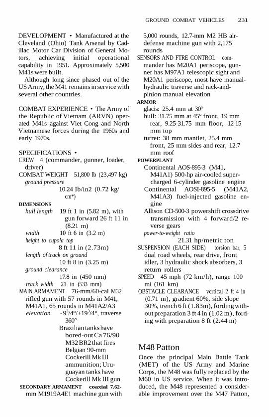
GROUND COMBAT VEHICLES 231
DEVELOPMENT • Manufactured at theCleveland (Ohio) Tank Arsenal by Cad-illac Motor Car Division of General Mo-tors, achieving initial operationalcapability in 1951. Approximately 5,500M41s were built.
Although long since phased out of theUS Army, the M41 remains in service withseveral other countries.
COMBAT EXPERIENCE • The Army ofthe Republic of Vietnam (ARVN) oper-ated M41s against Viet Cong and NorthVietnamese forces during the 1960s andearly 1970s.
SPECIFICATIONS •CREW 4 (commander, gunner, loader,
driver)COMBAT WEIGHT 51,800 lb (23,497 kg)
ground pressure10.24 Ib/in2 (0.72 kg/
cm*)DIMENSIONS
hull length 19 ft 1 in (5.82 m), withgun forward 26 ft 11 in(8.21 m)
width 10 ft 6 in (3.2 m)height to cupola top
8 ft 11 in (2.73m)length of track on ground
10 ft 8 in (3.25 m)ground clearance
17.8 in (450 mm)track width 21 in (533 mm)
MAIN ARMAMENT 76-mm/60-cal M32rifled gun with 57 rounds in M41,M41A1, 65 rounds in M41A2/A3elevation - 93/4°/+193/4°, traverse
360°Brazilian tanks have
bored-out Ca 76/90M32 BR2 that firesBelgian 90-mmCockerill Mk IIIammunition; Uru-guayan tanks haveCockerill Mk III gun
SECONDARY ARMAMENT coaxial 7.62-mm M1919A4E1 machine gun with
5,000 rounds, 12.7-mm M2 HB air-defense machine gun with 2,175rounds
SENSORS AND FTRE CONTROL com-mander has M20A1 periscope, gun-ner has M97A1 telescopic sight andM20A1 periscope, most have manual-hydraulic traverse and rack-and-pinion manual elevation
ARMORglacis: 25.4 mm at 30°hull: 31.75 mm at 45° front, 19 mm
rear, 9.25-31.75 mm floor, 12-15mm top
turret: 38 mm mantlet, 25.4 mmfront, 25 mm sides and rear, 12.7mm roof
POWERPLANT
Continental AOS-895-3 (M41,M41A1) 500-hp air-cooled super-charged 6-cylinder gasoline engine
Continental AOSI-895-5 (M41A2,M41A3) fuel-injected gasoline en-gine
Allison CD-500-3 powershift crossdrivetransmission with 4 forward/2 re-verse gears
power-to-weight ratio21.31 hp/metric ton
SUSPENSION (EACH SIDE) torsion bar, 5dual road wheels, rear drive, frontidler, 3 hydraulic shock absorbers, 3return rollers
SPEED 45 mph (72 km/h), range 100mi (161 km)
OBSTACLE CLEARANCE vertical 2 ft 4 in(0.71 m), gradient 60%, side slope30%, trench 6 ft (1.83m), fording with-out preparation 3 ft 4 in (1.02 m), ford-ing with preparation 8 ft (2.44 m)
M48 PattonOnce the principal Main Battle Tank(MET) of the US Army and MarineCorps, the M48 was fully replaced by theM60 in US service. When it was intro-duced, the M48 represented a consider-able improvement over the M47 Patton,

232 GROUND COMBAT VEHICLES
having a better turret shape and less com-plicated sighting system but still having arelatively high profile and limitedmobility. M48s have been the subject ofseveral fire control update programs, andmany now have laser rangefinders andthermal sights.
The M48A5 version is quite differentfrom the original M48. As designed in thelate 1940s, the M48 had a 90-mm M41rifled tank gun and a ContinentalAV-1790 gasoline engine. The tank's mo-bility was severely limited by low fuel mile-age, and, beginning with the M48A3, adiesel engine based on the AV-1790 wasinstalled. The tank's power-to-weight ra-tio dropped, but its road range nearlyquadrupled.
Raising firepower also proved possiblewith the retrofitting of the ubiquitousL7A3 (license-built as M68) 105-mmrifled tank gun to existing turrets. Fewerrounds can be stowed, but the increasesin range and accuracy more than out-weigh the loss of magazine capacity.
The conversion of earlier M48s to theM48A5 standard has proved to be a goodsolution to the need in many armies for abetter tank at considerably less than thecost of a new one. The TurkishM48A5T1/T2 is the best M48 variant inservice. Tl has a Turkish-built 105-mmgun and saw its first deliveries in Septem-ber 1983. The T2 adds a laser range-finder, Texas Instruments thermal sightsfor commander and gunner, ControlData Corp. solid-state ballistic computer,and Cadillac Gage Textron gun stabiliza-tion. Serial production began in 1987.
VARIANTS • M48 with 810-hp AV-1790gasoline engine, 90-mm M41 rifled gun,and 60 rounds of ammunition.
M48A2 had higher-powered 825-hpgasoline engine, larger fuel tanks, fullyautomatic transmission, and suspensionsystem modifications.
M48A3 rebuilt M48A1 and A2 withContinental AVDS-1790 diesel engine,fire control system updates, fuel capacity
increase. First examples introduced in1964 with further large programs under-taken in 1967 and 1975.
M48A5 are M48A1 and M48A3 with the105-mm M68 rifled gun and manychanges to the fire control systems, en-gine air-cleaning system, and most otherrelated systems. First deliveries 1975, lastof 2,064 delivered in 1979.
M48 AVLB (Armored VehicleLaunched Bridge) that spans a 60-foot(18.29 m) gap.
(M67 series were flamethrower tanksused in Vietnam but no longer fielded.)
DEVELOPMENT • Production began atChrysler Corp.'s Newark, Delaware, plantin 1950, the tank achieving initial opera-tional capability in 1953 (M48).
11,703 M48 series tanks were pro-duced, 6,000 by Chrysler, the others byAmerican Locomotive Co. (Alco) inSchenectady, New York, and by GeneralMotors at the Detroit Tank Plant in War-ren, Michigan. More than 15 countriesstill operate the M48.
COMBAT EXPERIENCE • TheM48wasthe only medium-to-heavy tank to oper-ate with US forces during the VietnamWar. It proved to be reliable and relativelyrugged. Israeli M48s (many with dieselengines and 105-mm guns) met with con-siderable success against Arab tanks inthe 1967 Six-Day War. On the other hand,Israeli gasoline-powered M48s acquiredthe nickname of Ronson, because theycaught fire so easily after being hit.
SPECIFICATIONS (M48A5) •CREW 4 (commander, gunner, loader,
driver)COMBAT WEIGHT 107,997 lb (48,987
kg)ground pressure
12.51 Ib/in2 (0.88 kg/cm2)
DIMENSIONS
hull length 21 ft (6.42 m), with gunforward 30 ft 6 in(9.31 m)

GROUND COMBAT VEHICLES 233
width 11 ft 11 in(3.63 m)
height 10 ft 1 in(3.09 m)
length of track on ground13 ft 1 in (4.0 m)
ground clearance16 in (406 mm)
track width 28 in (711 mm)MAIN ARMAMENT 105-mm/51-cal M68
rifled gun with 54 roundselevation -9°/ +19°, traverse 360°
SECONDARY ARMAMENT Coaxial 7.62-mm M73 machine gun, antiaircraft7.62-mm M60D machine gun with10,000 7.62-mm rounds total
SENSORS AND FIRE CONTROLM13 electromechanical ballistic com-
puter, coincidence rangefmder, in-frared driving lights andsearchlights
Taiwanese and Turkish M48s fittedwith AN/VSG-2 Tank ThermalSights (TTS) that have laser range-finder and Mercury-Cadmium-
Telluride (HgCdTe) IR detector forpassive night and dust vision
ARMORhull: 101/120 mm front, 76 mm sides
(max), 44 mm rear, 57 mm topturret: 110 mm front, 50 mm rear, 25
mm topPOWERPLANT Teledyne Continental
AVDS-1790-2D 750-hp air-cooled V-12diesel, Allison CD-850 series auto-matic planetary transmission with 2forward/1 reverse gearspower-to-weight ratio
15.89 hp/metric tonSUSPENSION (EACH SIDE) torsion bar, 6
road wheels, rear drive, front idler, 3hydraulic shock absorbers, 5 returnrollers (M48A3 has 3 return rollers)
SPEED 30 mph (48.2 km/h), range 309mi (499 km)
OBSTACLE CLEARANCE vertical 3 ft(0.92 m), gradient 60%, trench 8 ft 6in (2.59 m), fording 4 ft (1.22 m)without preparation, 8 ft (2.44 m)with preparation
M60 TankU.S. GOVERNMENT DEPARTMENT OF DEFENSE

234 GROUND COMBAT VEHICLES
M60 main battle tankThe M60 is in US service only in NationalGuard and Reserve units, but was theprincipal US Main Battle Tank (MET) fortwo decades. It was developed from theearlier M48 Patton series. Although crit-icized for its high silhouette and limitedcross-country mobility, the M60 is arugged and reliable tank that has provedamenable to many updates over a longcareer; the M60A3 with the Tank Ther-mal Sight (TTS) is considered a frontlinetank in most scenarios.
Firepower was increased over the M48by adoption of the British-designed L7105-mm/51-cal rifled gun with thermalsleeve and fume extractor in a reshapedturret. The turret permits high elevationand depression angles (-10V+200) butcontributes to the high silhouette. TheM60A3 TTS has a hybrid solid-state ballis-tic computer, laser rangefinder, tankthermal sight, and turret stabilizationsystem.
Mobility and range were increasedover that of the M48 by installing a dieselengine, but, compared to other contem-porary tank designs, the M60 power-to-weight ratio is still relatively low and itsground pressure relatively high. Armorprotection is considered quite good com-pared to its contemporaries.
VARIANTS •M60A1 was the principal production
version for 17 years.M60A2 with 152-mm Shillelagh gun/
missile system; 13 missiles and 33 conven-tional 152-mm combustible charge.
M60 AVLB (Armored VehicleLaunched Bridge) spans a 60-ft (18.29 m)gaP-
M728 Combat Engineer Vehicle(CEV).SeeM728.
DEVELOPMENT • Over 15,000 werebuilt from 1960 to 1987 by Chrysler atNewark, Delaware, and Detroit TankPlant in Warren, Michigan, with the De-
troit plant building the great majority.The M60 achieved initial operational ca-pability in 1961, M60A1 in 1963, M60A2in 1974, and M60A3 in 1979.
M60A1 production (for the US MarineCorps) ended in 1980. M60A3 produc-tion for the US Army ended in 1983, andthe last Foreign Military Sales (FMS) ve-hicles rolled out in late 1987. Conversionof 5,400 older models to M60A3 TTS end-ed in FY1990.
At its peak, the US Army's M60 inven-tory totaled 8,887 tanks, the first reduc-tions coming in 1990 as part of thedisposal of older US tanks in anticipationof a Conventional Forces in Europe(CFE) arms limitation. Also in service inmore than 15 other countries.
COMBAT EXPERIENCE • TheM60wasused extensively by Israeli forces in the1973 Yom Kippur War in tank battlesboth in the Sinai and, more critically, inthe Golan Heights.
210 M60Als were fielded by the 1st Ma-rine Expeditionary Force (MEF) duringOperation Desert Storm in February1991; another 39 were embarked on someof the 31 landing ships deployed in thenorthern Persian Gulf. The lstMEFM60s,some equipped with mine-clearing rakes,supported the Saudi-Marine drive intoeastern Kuwait that ended in Kuwait City.
As expected, the 105-mm gun provedeffective against the Iraqis' Soviet-builtT-55 and T-62 tanks. In addition, the com-manding general of the 1st Marine Divi-sion stated that even T-72s had beendestroyed by the M60A1. Most shots werefired from relatively short range (500 m),with at least one APFSDS round boringits way through a T-72's frontal armor andemerging from the rear engine compart-ment.
Given the M60's performance in De-sert Storm, arguments against replacingit with the expensive M1A1 gained somestrength. Despite these sentiments, how-ever, all M60s were out of active MarineCorps service by the end of 1991.

GROUND COMBAT VEHICLES 235
SPECIFICATIONS (M60A3) •CREW 4 (commander, gunner, loader,
driver)COMBAT WEIGHT 116,000 lb (52,617
kg)ground pressure
12.37 lb/in2 (0.87 kg/cm2)
DIMENSIONS
length 22 ft 9 in (6.95 m) hull,30 ft 11 in (9.44m)gun forward
width 11 ft 11 in (3.63m)height 10 ft 9 in (3.27 m)ground clearance
18 in (457 mm)length of track on ground
13 ft 7 in (4.24 m)track width 28 in (711 mm)
MAIN GUN 105-mm/51-cal M68 rifledgun with 63 roundsequation -10°/+20°, traverse 360°
SECONDARY WEAPONS 7.62-mm M240coaxial machine gun with 5,950rounds, 12.7-mm M85 antiaircraft gunwith 900 rounds
SENSORS AND FIRE CONTROL M21 Solid-state analog ballistic computer, AN/WG-2 ruby laser rangefinder usableby both commander and gunner,AN/VSG-2 Tank Thermal Sights(TTS) with laser rangefinder andMercury-Cadmium-Telluride(HgCdTe) IR detector for passivenight and dust vision
POWERPLANT Continental AVDS-1790-2C 750-hp air-cooled 4-stroke V-12multifuel engine, Allison CD-850-6/6A powershift crossdrive trans-mission with 2 forward/1 reversegearspower-to-weight ratio
14.24 hp/metric tonSUSPENSION (EACH SIDE) torsion bar, 6
road wheels, rear drive, front idler, 3shock absorbers, 3 track return rollers
SPEED 30 mph (48.3 km/h), range 298mi (480 km)
OBSTACLE CLEARANCE vertical 3 ft(0.91 m), 60% gradient. 30% side
slope, trench 8 ft 6 in (2.59 m), ford-ing 4 ft (1.22 m) without preparation,7 ft 10 in (2.4 m) with preparation
StingrayThe design goals for this light tank wereto incorporate tank-level firepower in acompact, mobile, and airportable vehi-cle. Given the vehicle's small size and rel-atively low weight, a premium has beenplaced on firepower and mobility at theexpense of protection (and perhapssome degree of ruggedness).
The Stingray's main armament is a low-recoil development (known as the Low-Recoil Force or LRF gun) of the widelyused Royal Ordnance L7A3 105-mmrifled tank gun in a Cadillac Gage three-man turret. The LRF has a multislottedmuzzle brake, concentric fume extractor,and thermal sleeve; it can fire a full rangeof 105-mm ammunition, includingArmor-Piercing Fin-Stabilized DiscardingSabot (APFSDS) rounds.
A relatively high power-to-weight ratioand relatively low ground pressure con-tribute to mobility. The Stingray is trans-portable by C-130 Hercules transportaircraft.
For protection, the Stingray dependson Cadloy armor, ballistic shaping, smallsilhouette, and mobility. The low turrethas many oblique angles that make aflush impact virtually impossible and alsosimplify adding more armor if needed.Soon after Stingrays entered service inThailand, modifications began to add ar-mor to the frontal arc, which increasesthe weight by approximately 4,400 lb(2,000 kg). Such reinforcement (and re-portedly an exuberant driving style) ledto the discovery of cracks in the hull thatwere repaired by FMC in 1993.
DEVELOPMENT • The first CadillacGage turret was tested in June 1984, andthe first hull in August 1984. The com-plete vehicle began testing in 1985. A

236 GROUND COMBAT VEHICLES
candidate for the US Army's XM4 Ar-mored Gun System (AGS) light tank pro-gram, which was canceled, it lost to theFMC entry in the later XM8 program.
SPECIFICATIONS •CREW 4 (commander, gunner, loader,
driver)COMBAT WEIGHT 44,500 lb (20,185 kg)
ground pressure9.81 Ib/in2 (0.69 kg/
cm2)DIMENSIONS
hull length 20 ft 8 in (6.3 m), withgun forward 30 ft 5 in(9.27m)
width 8 ft 10'/2 in (2.71 m)overall height
8 ft 4 in (2.55m),reducible to 7 ft 10 in(2.4m)
length of track on ground11 ft 11 in (3.63m)
ground clearance18 in (457 mm)
track width 15 in (381 mm)MAIN ARMAMENT L7A3 LRF 105-mm
rifled gun with 8 ready rounds, 24stowed in hullelevation -7.5°/+20° at 8%ec
(unstabilized), 40°/sec(stabilized), traverse360° at 25°/sec(unstabilized), 30°/sec(stabilized)
SECONDARY WEAPONS 7.62 coaxial ma-chine gun with 400 ready rounds, 2,000
stowed; 7.62-mm air defense machinegun with 200 ready, 2,000 stowedrounds (or 12.7-mm air defense ma-chine gun with 100 ready, 1,000 stowedrounds)
SENSORS AND FIRE CONTROL Optic-Electronic Corp. M36E1 SIRE day/night sight with laser rangefinder forgunner and optional thermal sight, 7periscopes for commander with op-tional NV52 day/night sight, optionalMarconi digital fire control system,optional 2-axis turret stabilization
ARMOR Cadloy steel armor; turret ar-mor is reported to defeat 14.5-mmrounds over the frontal arc and 7.62-mm rounds from any angle
POWERPLANT Detroit Diesel Allison8V-92TA 535-hp liquid-cooled turbo-charged 2-stroke V-8 diesel engine, Al-lison XTG-411-2A automatictransmissionpower-to-weight ratio
26.5 hp/metric tonSUSPENSION (EACH SIDE) independent
trailing arm torsion bar, 6 roadwheels, rear drive, front idler, 3 shockabsorbers, 3 return rollers
SPEED level road 42 mph (68 km/h),10% slope 18 mph (29 km/h), 60%slope 3.7 mph (6 km/h), acceleration0-20 mph (0-32 km/h) 7 seconds,range 300 mi (483 km)
OBSTACLE CLEARANCE vertical 2 ft 6 in(0.76 m), gradient 60%, side slope40%, trench 7 ft (2.13 m), fording 3 ft6 in (1.07m)

ANTIAIRAMRAAM (AIM- 120)The AMRAAM (Advanced Medium-Range Air-to-Air Missile) was developedjointly by the US Air Force and Navy as afollow-on to the AIM-7 Sparrow III AAM.The core of AMRAAM’s performancespecification is a high kill probability atshort and long range under all weatherconditions while subjected to heavy Elec-tronic Countermeasures (ECM) and clut-ter. It is a “look-down, shoot-down”missile and can be launched at any air-craft speed or target angle. Although AM-RAAM is to be more capable than theAIM-7, it is lighter and thinner and has asmaller warhead.
Unlike the AIM-7, whose target mustbe illuminated by the launch aircraft’s ra-dar, the AMRAAM is fitted with an activeradar seeker whose 5-in (127-mm) an-tenna is energized by a small Traveling-Wave Tube (TWT) transmitter. To oper-ate the missile most effectively, the launchaircraft needs a track-while-scan radarand the ability to assign targets simul-taneously to more than one missile. Theactive monopulse seeker uses a pulse-Doppler programmable waveform to’penetrate clutter and precipitation.Rapid automatic gain control and digitalsignal processing contribute to theseeker’s Electronic Counter-Counter-measures (ECCM) capabilities.
After launch, the missile can operate au-tonomously, turning on its active seeker ata preset time or distance. Alternatively,AMRAAM can receive midcourse guid-ance updates to refine its terminal hom-ing track. When presentedwith more thanone target, AMRAAM will choose a partic-
ular target and ignore the others. Thecontinuous-rod warhead of the AIM-7 hasbeen replaced by a blast-fragmentationwarhead with a “smart” fuze.
DEVELOPMENT l Full-scale develop-ment of the AMRAAM began in 1981,and its initial operational capability wasin 1991. Flight tests began in 1985. Theinitial series production of 105 missilesbegan in October 1987. The Air Forcereceived the first production AMRAAMsfrom Hughes and Raytheon in January1989. The AMRAAM was originally in-tended for US and NATO service.AMRAAM is one of the US/Europeanfamily of weapons first proposed in 1978.A 1980 Memorandum of Understanding(MoU) among the United States, GreatBritain, and West Germany agreed thatthe medium-range missile would also beproduced in Europe. Norway signed theMoU in 1989, and France has observerstatus within the European group. TheUS AMRAAM requirement had been24,320 missiles, but later reviews reducedthe total to 15,500 missiles.
The EURAAM joint venture was estab-lished in Britain in July 1987 to overseeEuropean production of the AMRAAM.EURAAM consisted of AEG, British Aero-space, Marconi Defence Systems, andMBB. Responsibility for European pro-duction was reallocated to Germany inAugust 1988. In exchange, British Aero-space was named prime contractor onthe ASRAAM-Advanced Short-RangeAir-to-Air Missile.
In 1989, the AMRAAM’s rel iabi l i ty was
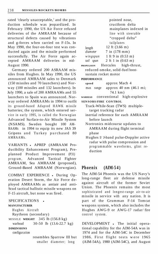
2 3 8 MISSILES/ROCKETS/BOMBS
rated ‘clearly unacceptable,’ and the pro-duction schedule was jeopardized. InFebruary 1990, the US Air Force refuseddeliveries of the AMRAAM because ofstructural defects caused by vibrationsand g-forces when carried on F-15s. InMay 1990, the four-on-four test was con-ducted again and the missile performedsuccessfully. The Air Force again ac-cepted AMRAAM deliveries in mid-August 1990.
Germany ordered 200 ASRAAM mis-siles from Hughes. In May 1990, the USannounced AMRAAM sales to Denmark(150 missiles and 70 launchers) and Nor-way (100 missiles and 132 launchers). InJuly 1990, a sale of 200 AMRAAMs and 55launchers to Spain was announced. Nor-way ordered AMRAAMs in 1994 to outfitits ground-based Adapted HAWK missilebatteries; the system, which entered ser-vice in early 1995, is called the NorwegianAdvanced Surface-to-Air Missile System(NSAMS). Sweden bought 100 AM-RAAMs in 1994 to equip its new JAS 39Gripens and Turkey purchased 80AMRAAMs.
VARIANTS l APREP (AMRAAM Pro-ducibility Enhancement Program), Pre-planned Product Improvement (P31)program, Advanced Tactical FighterAMRAAM, Sea AMRAAM (proposed),Ground-Based AMRAAM (Norwegian).
COMBAT EXPERIENCE l During Op-eration Desert Storm, the Air Force de-ployed AMRAAMs as antiair and anti-Scud tactical ballistic missile weapons onF-15 aircraft, but none was fired.
SPECIFICATIONS l
MANUFACTURERHughes AircraftRaytheon (secondary)
MISSILE WEIGHT 345 lb (156.8 kg)warhead 30-50 lb (13.6-22.7 kg)
DIMENSIONSconfiguration
resembles Sparrow III butsmaller diameter; long
pointed nose,cruciform deltamainplanes indexed inline with steerable“cropped delta”tailplanes
length 12 ft (3.66 m)diameter 7 in (178 mm)wingspan 1 ft 9 in (0.53 m)tail span 2 ft 1 in (0.63 m)
PROPULSION Hercules high-thrust,reduced-smoke, solid-fuel boost-sustain rocket motor
PERFORMANCEspeed approx Mach 4max range approx 40 nm (46.1 mi;
74.1 km)WARHEAD conventional high-explosiveSENSORS/FIRE CONTROL
Track-While-Scan (TWS) multiple-target tracking radar
inertial reference for each AMRAAMbefore launch
Nortronics midcourse updates toAMRAAM during flight terminalphase
Hughes I/J-band pulse-Doppler activeradar with pulse compression andprogrammable waveforms, glint re-duction
Phoenix (AIM-54)The AIM-54 Phoenix was the US Navy’slong-range fleet air defense missileagainst aircraft of the former SovietUnion. The Phoenix remains the mostsophisticated and longest-range air-to-airmissile in service with any nation. It ispart of the Grumman F-14 Tomcatweapons system, which also includes theHughes AWG-9 or AWG-17 radar/firecontrol system.
DEVELOPMENT l The initial opera-tional capability for the AIM-54A was in1974 and for the AIM-54C in December1986. First f l ight tests were 1965(AIM-54A), 1980 (AIM-54C), and August
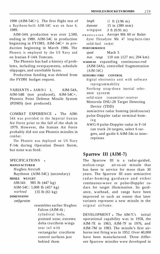
MISSILES/ROCKETS/BOMBS 2 3 9
1990 (AIM-54C+). The first flight test ofa Raytheon-built AIM-54C was on June 6,1989.
AIM-54A production was over 2,500,ending in 1980. AIM-54C in productionbeginning in FY1983, AIM-54C+ in pro-duction beginning in March 1986. ThePhoenix is employed by the US Navy andon Iranian F-14A Tomcats.
The Phoenix has had a history of prob-lems, including overpayments, scheduleslippages, and unreliable fuzes.
Production funding was deleted fromthe FY1991 budget request.
VARIANTS l AAM-N-1 1, AIM-54A,AIM-54B (not produced), AIM-54C+,Phoenix Point Defense Missile System(PDMS) (not produced).
COMBAT EXPERIENCE l The AIM-54A was provided to the Imperial IranianAir Force prior to the fall of the shah in1979. However, the Iranian Air Forceprobably did not use Phoenix missiles incombat.
The Phoenix was deployed on US NavyF-14s during Operation Desert Storm,but none was fired.
SPECIFICATIONS l
MANUFACTURER
Hughes AircraftRaytheon (AIM-54C) (secondary)
MISSILE W E I G H TAIM-54A: 985 lb (447 kg)AIM-54C: 1,008 lb (457 kg)warhead 135 lb (61 kg)
DIMENSIONS
configurationresembles earlier Hughes
Falcon (AIM-4) ;cylindrical body,pointed nose; extremedelta cruciform wingsnear tai l withrectangular cruciformcontrol surfaces justbehind them
length 13 ft (3.96 m)diameter 15 in (380 mm)wingspan 3 ft (0.91 m)
P R O P U L S I O N Aerojet Mk 60 or Rocket-dyne Flexadyne Mk 47 long-burn-timesolid-fuel rocket
PERFORMANCE
speed Mach 5max range 110 nm (127 mi; 204 km)
WARHEAD expanding continuous-rod(AIM-54A), controlled fragmentation(AIM-54C)
SENSORS/FIRE CONTROL
digital electronics unit with softwarereprogrammability
Northrop strap-down inertial refer-ence systemsolid-state transmitter/receiverMotorola DSU-28 Target Detecting
Device (TDD)semiactive radar homing (midcourse)pulse-Doppler radar terminal hom-
i n gAWG-9 pulse-Doppler radar in F-14
can track 24 targets, select 6 tar-gets, and guide 6 AIM-54s to inter-ceptions
Sparrow III (AIM-7)The Sparrow III is a radar-guided,medium-range air-to-air missile thathas been in service for more than 30years. The Sparrow III uses semiactiveradar-homing guidance and eithercontinuous-wave or pulse-Doppler ra-dars for target illumination. Its guid-ance, warhead, and range have beenimproved to such an extent that latervariants represent a new missile in theoriginal airframe.
DEVELOPMENT l The AIM-7C’s initialoperational capability was in 1958, theAIM-7E in 1963, AIM-7F in 1976, andAIM-7M in 1983. The missile’s first air-borne test firing was in 1952. Over 40,000have been manufactured. Three differ-ent Sparrow missiles were developed in

2 4 0 MISSILES/ROCKETS/BOMBS
the early 1950s, with Sparrow III by farthe most massively produced.
AIM-7M production ended in 1990while the AIM-7P was in development. InMarch 1990, Japanese license productionof the AIM-7M was approved; MitsubishiElectric Corp. (MELCO) is prime con-tractor. A Kuwaiti order for 200 AIM-7Fswas approved in August 1988.
In addition to the US Air Force, Navyand Marines, Sparrow missiles are oper-ated by about 15 other nations in Europe,Asia, and the Middle East, along withCanada and Australia.
Although the US Navy requested noAIM-7 missiles in the Amended FYl988-89 Biennial Budget, delays in the Ad-vanced Medium-Range Air-to-Air Missile(AMRAAM) program, which is plannedto replace the Sparrow, resulted in theappropriation of $52.3 million in FYI989to purchase 450 missiles.
VARIANTS l (Designation note: Thefirst designation predated the 1962 tri-service redesignation scheme repre-sented by the second.) AAM-N-2/AIM-7ASparrow I, AAM-N-6/AIM-7B Sparrow II,AAM-N-6/AIM-7C Sparrow III, AAM-N-6B/AIM-7E, AIM-7F, AIM-7H, AIM-7M, AIM-‘/N, AIM-7P, (Missile HomingImprovement Program/MHIP), AIM-7R(proposed).
COMBAT EXPERIENCE l While theSparrow saw combat experience in Viet-nam, its experiences demonstrated thelimitation of the AIM-7E and promptedthe development of the -7E2 and -7F ver-sions. The Sparrow has not been a gooddogfighting missile, being much more ef-fective in nonmaneuvering intercep-tions. In engagements against Libyanaircraft in 1981 and 1989 and an August1987 interception of an Iranian F-4 wellwithin the missile’s stated range, five outof six Sparrows missed their targets for avariety of reasons. In the 1987 F-4 engage-ment, the first missile’s motor failed tofire and the other was launched at nearly
its minimum range and missed the evad-ing target. In January 1989, two F-14sfrom the aircraft carrier John F. Kennedy(CV 67) engaged two Libyan MiG-23Floggers off the coast of Libya. The leadF-14 fired two Sparrows that failed to holdlock-on and missed the MiGs. The secondF-14 downed one of the MiGs with a Spar-row. The other MiG was downed by aSidewinder AIM-9.
In Operation Desert Storm, unlike itsprevious lack of success in combat, theSparrow performed well. 23 Iraqi combataircraft were shot down by AIM-7s duringthe seven-week war, 69% of the total Iraqiaircraft losses. Reports suggested that themissile operated reliably, due in part tobetter pilot training and solid-state elec-tronics.
SPECIFICATIONS lMANUFACTURER
RaytheonGeneral Dynamics (since 1977)
MISSILE WEIGHT 510 lb (231 kg)warhead 86 lb (39 kg)
DIMENSIONS
configurationlong cylinder with
pointed nose, 2 sets ofcruciform delta wingsindexed in line, thesteerable foreplanes atmidbody, another fixedset at the tail
length 11 ft 10 in (3.6 m)diameter 8 in (203 mm)wingspan 3 ft 4 in (1.02 m)tail span 2 ft 8 in (0.81.m)
P R O P U L S I O N Hercules Mk 58 or Aero-jet General Mk 65 boost-sustainedsolid-fuel rocket
PERFORMANCE
speed Mach 4+max range approx 30 nm (34.5 mi;
56 km)WARHEAD Mk 71 controlled fragmenta-
tion high-explosiveSENSORS/FIRE CONTROL
inverse monopulse semiactive radar-

MISSILES/ROCKETS/BOMBS 241
homing seeker with digital signalprocessor, improved autopilot andfuze (which can work as contact orproximity type)
upgrades provide better electroniccountermeasures resistance, im-proved look-down, shoot-down per-formance
Sidewinder (AIM-9)The Sidewinder is a simple, effectiveinfrared-homing, widely used Air-to-AirMissile (AAM), with over 110,000 pro-duced. Its unique “rolleron” stabiliza-tion system consists of air-driven wheelsfitted in the rear outside corner of therear fins. The spinning wheels gyro-scopically stabilize the missile effectivelywith few moving parts and at low cost.
The Sidewinder is used by a variety ofWestern fixed-wing combat aircraft andhelicopters. As the Chaparral missile, ithas been adopted for a surface-to-air mis-sion.
DEVELOPMENT l The Sidewinder’sinitial operational capability as theAIM-9B was in 1956, the AIM-SE in 1967,the AIM-9H in 1973, the AIM-9J in 1977,the AIM-9L/P in 1978, and the AIM-9Min 1983. Development of the missile be-gan in 1949 at the Naval Weapons Centerin China Lake, California. Its first flightwas on September 11, 1953.
The Sidewinder is operated through-out the world by 36 countries in SouthAmerica, Europe, Asia, the Middle East,and Africa.
VARIANTS l XAAM-N-7 (prototype),SW-l (production), AAM-N-7 (USN),
GAR-8 (USAF), AIM-9 (assigned to allSidewinders, 1962), AIM-S/A/B, AIM-SF,AIM-SC/D, AIM-SE, AIM-9G/H, AIM-9H(USN/USAF), AIM-9J/N, AIM-9L/M(third generation), AIM-9P, AIM-9QAIM-9R, AIM-9S, AIM-9X (USN/USAFSidewinder successor), Box Office/
Improved Sidewinder, Boa, Helicopter-Launched Sidewinder, MIM72 (Chapar-ral) .
COMBAT EXPERIENCE l The Side-winder’s first combat was in October1958, when Taiwanese in F-86s launchedthem against Chinese MiG-17s, claimingas many as 14 shot down in one day.AIM-9s scored most of the air-to-air killsmade by US Navy and Air Force aircraft inthe Vietnam War, and by the Israeli AirForce in the 1967 and 1973 wars in theMiddle East.
During the 1982 air engagements overLebanon’s Bekaa Valley, 51 out of the 55Syrian-flown MiGs shot down were hit bySidewinders.
In the 1982 conflict in the FalklandIslands, between Great Britain and Ar-gentina, British Sea Harriers usedAIM-9L Sidewinders for 16 confirmedkills and one probable against Argentineaircraft (of a total 20 air-to-air kills).
Ironically, the Sidewinder was used rel-atively little during Operation DesertStorm’s air assault against Iraqi targets.However, Sidewinders fired by USAFF-15C Eagle jets downed six Iraqi combataircraft. Two more Su-22 Fitters were shotdown by AIM-9s three weeks after thecease-fire. A Saudi F-15 pilot downed twoFrench-built Iraqi Mirage Fls with Side-winders in a single attack. Two F/A-18Hornets and an F-14 Tomcat scored withAIM-9s, the Hornets shooting downMiG-21 Fishbeds and the Tomcat down-ing a helicopter.
SPECIFICATIONS lMANUFACTURER
Loral AeronutronicsRaytheonBodenseewerk Geratetechnik consor-, tium (Germany-Britain-Italy-
Norway)Mitsubishi Industries (Japan)
MISSILE WEIGHTAIM-9H: 186 lb (84.4 kg)AIM-9L/M: 191 lb (86.5 kg)

242 MISSILES/ROCKETS/BOMBS
warhead AIM-9B/E/J/N/P: 10 lb(4.5 kg)
AIM-SD/G/H: 22.4 lb(10.2 kg)
AIM-9L/M: 20.8 lb (9.4kg)
DIMENSIONS
configurationsimple thin cylinder, 4
cruciform “croppeddelta” wings withstabil izing “rollerons”on the trailing edges,steerable cruciformforeplanes
length (AIM-9L/M)9 ft 6 in (2.85 m)
diameter 5 in (127 mm)wingspan 2 ft 1 in (635 mm)
PROPULSION
solid-fuel rocket by Aerojet, Hercules,Rockwell, or Thiokol
Mk 17 on B/E/J/N/PMk 36 with flexadyne propellant on
H/L/MPERFORMANCE
speed Mach 2+max range 10 nm (11.5 mi; 18.5 km)
WARHEAD (AIM-9L/M) annular blastfragmentation wrapped in a sheath ofpreformed rods
SENSORS/FIRE CONTROL
except for AIM-SC, all versions haveused infrared homing
AIM-9L/M is the first with all-aspectseeker analog roll-control autopilot
Stinger (FIM-92A)The FIM-92 Stinger is a lightweight, short-range surface-to-air missile that was ini-tially deployed as a portable weapon bythe US Army as the successor to theFIM-43 Redeye missile. It has also beendeployed on several aircraft, includingthe AH-64 Apache and the OH-58DKiowa Warr ior .
The Stinger system consists of a re-usable battery pack and gripstock with
sight. The launch tube is a “woodenround” requiring no field maintenance.The missile is a “fire and forget” weaponwith a relatively simple firing sequence.After an Identification Friend or Foe(IFF) query confirms the target is hostile,the gunner cools the passive, all-aspectInfrared (IR) seeker and fires the missilewhen the seeker’s “growl” tells him it haslocked onto the target.
Most Stinger launchers have a simpleplastic sight akin to the fixed “ring andbead” of older antiaircraft guns.
A gas generator pops the missile out ofthe tube; when it is a few yards away fromthe launcher, the dual-thrust main motorignites and accelerates the missile to su-personic speed. Tail fins roll-stabilize theStinger and an on-board processor usestwist-and-steer commands on two of thefour canard surfaces. Proportional navi-gation with lead bias predicts an inter-cept point and guides the missile over theshortest path to that point. The missilehas impact fuzing only.
DEVELOPMENT l The Stinger’s initial‘operational capability was in 1981. It be-gan advanced development in 1967, andengineering development began in 1972.Over 16,000 Stinger missiles have beenproduced.
In October 1988, the United Statesawarded a license to the Stinger ProjectGroup (SPG) to produce missiles in Eu-rope. SPG was formed following a 1983Memorandum of Understanding (MoU)concluded among West Germany,Greece, the Netherlands, and Turkey.SPG’s lead company is Dornier GmbH ofGermany; subcontractors from the otherMoU countries will also be involved. Man-ufacture of approximately 12,500 missileswas planned for the SPG countries, withlow-rate production beginning in 1992;the license does not permit SPG to sell tonon-SPG countries.
The Stinger is in service with the USArmy, Navy, and Marine Corps and over20 other countries and groups. When

MISSILES/ROCKETS/BOMBS 2 4 3
needed, Stingers are deployed on boardUS Navy ships, as in the August 1990 de-ployments for Operation Desert Storm.
In September 1988, Switzerland se-lected the Stinger over the French Mistralafter a two-year evaluation, for approx-imately 2,500 to 3,000 missiles.
Iran and Qatar are known to haveStingers that they obtained through di-versions from other users. The Stingerhas also been used by Afghan Mujahi-deen rebels, UNITA antigovernmentforces in Angola, and various factions inLebanon. In the early to middle 1990s,the US attempted to recover the remain-ing Stingers held by the Afghan rebels.
In May 1990, two alleged Colombiandrug dealers were charged with attempt-ing to purchase Stingers for use againstColombian government aircraft.
VARIANTS l FIM-92C Stinger-POST(Passive Optical Seeker Technique),FIM-92C Stinger-POST RMP (Repro-grammable Microprocessor), FIM-92Stinger Plus, Stinger Night Sight,A v e n g e r P e d e s t a l - M o u n t e d(PMS) , Setter, Air-to-Air Stinger (ATAS).
COMBAT EXPERIENCE l Afghan re-bels received approximately 900 Stingersand used them effectively against Soviethelicopters, transports, and attack air-craft. The introduction of the Stinger inOctober 1986 had a significant effect onSoviet air tactics.
During the 1982 Falkland Islands con-flict, the British Royal Marines’ SpecialBoat Squadron employed Stinger missilesthat were credited with destroying an Ar-gentine aircraft.
Stingers were deployed on board USwarships in the Persian Gulf in 1987-88as a last-resort missile defense. However,the missile’s lack of design for shipboardstowage or handling influenced the Navyto curtail its procurement in April 1988.
In April 1988, Israel reported thatsome Palestinian militia groups inLebanon had obtained Stingers from Af-
ghanistan or Iran and may have firedthem at Israeli aircraft.
Although Stingers were deployed withboth the ground and naval forces duringDesert Storm, none was fired in combat,since no enemy aircraft came withinrange. Some Special Operations forces inDesert Storm were fitted with WASP-equipped Stingers.
SPECIFICATIONS lMANUFACTURER
H u g h e sRaytheon (second source, 1987)
WEIGHTSsystem 34.5 lb (15.2 kg)missile 22.0 lb (10.0 kg)
DIMENSIONS
configurationlong cylinder with blunt
nose, pop-outcruciform rectangularforeplanes, taperedexhaust with full-diameter nozzle,cruciform tailfins
length 5 ft (1.52 m)diameter 2% in (70 mm)
P R O P U L S I O N Atlantic Research Mk 27dual-thrust solid-fuel rocket
PERFORMANCE
speed 2,297 ft/sec (700 m/sec)or Mach 1+
max range 3 mi (4.8 km)max altitude
9,840 ft (3,000 m)WARHEAD 2.2 lb (1.0 kg) penetrating
high-explosiveSENSORS/FIRE CONTROL
proportional navigation with lead biasall-aspect automatic passive infrared
h o m i n gIdentification Friend or Foe (IFF) in-
terrogatorMagnavox M934 impact fuze

244 MISSILES/ROCKETS/BOMBS
Patriot (MIM-104)The Patriot is a US medium-to-high-altitude surface-to-air missile system de-veloped as an area defense weapon toreplace Nike-Hercules missile batteries inEurope. The Patriot gained widespreadnotoriety for its reported successes afterbeing deployed in the early 1990s toSaudi Arabia, Israel, and Turkey as a de-fense against Iraqi-launched tactical bal-listic missiles. A Patriot battery or fireunit consists of a phased-array radar, anEngagement Control Station (ECS), andelectric generators (two 150-kW genera-tors). Up to eight M901 trailer-mounted,four-tube launchers will be deployed;each tube is sealed at the factory and themissile requires no field maintenance.
The AN/MSQ-104 ECS includes theweapons control computer, and Identi-
Patriot MissileU.S. GOVERNMENT DEPARTMENT OF DEFENSE
fication Friend or Foe (IFF) is performedby the colocated AN/TPX-46(V)7. Theelectronically steered phased-array radaris the trailer-mounted, G-band (4-6GHz) AN/MPQ-53, which performs tar-get acquisition, tracking, and missileguidance. The system can track morethan 100 targets, interrogate, and assignpriorities to those identified as hostile.
Patriots based in Saudi Arabia and Is-rael were linked to Defense Support Pro-gram (DSP) missile-warning satellites forlaunch warnings, increasing warningtimes to as much as five minutes.
Raytheon’s upgrade to the ECS in-cludes developing Very-High-Speed Inte-grated Circuit (VHSIC) technology toreplace 200 modules in the ECS com-puter with 13 modules in a much smallervolume.
The Patriot system has the ability toguide several missiles simultaneouslywhile tracking other targets, and also hasa limited Anti-Tactical Ballistic Missile(ATBM) defense capability. In a 1986 testof its potential, a Patriot missile inter-cepted and destroyed a Lance tacticalball ist ic missi le .
The Patriot’s accuracy is due to itsTrack via Missile (TVM) terminal guid-ance method. Targets are selected by thesystem and illuminated by the GCSphased-array radars. Tracking “gates” inthe software permit the radar to concen-trate on a relatively small sector in whichthe missile is likely to appear next, whichimproves the precision of the tracking.
When the missile is launched, it ma-neuvers using tail control, with indepen-dently activated fins that move the afterend of the body. Body lift generated bythe missile’s shape and speed steers themissile in the desired direction.
Typically, two missiles are automat-ically fired against a target missile in a“shoot-shoot” sequence to ensure inter-ception. Later development could resultin an earl ier “shoot-look-shoot” se-quence that allows counteraction at agreater distance from the target.

MISSILES/ROCKETS/BOMBS 2 4 5
The missile’s on-board semiactivehoming monopulse seeker senses the re-flected energy from the target, estab-lishes its position relative to the target,and relays that information to theground-based AN/MSQ-104 ECSthrough a radio data link. At the sametime, smaller ground-based radars aretracking the target. High-speed com-puters in the ECS compare the positionsreported by the missile and the groundradars and calculate course correctionsthat direct the missile to fly the most effi-cient intercept course. If the ground-based system is jammed by ElectronicCountermeasures (ECM), the TVM chan-nel gives the system an alternate trackingm o d e .
The missile’s warhead is designed tospray an aircraft with high-velocity frag-ments that are likely to hit vital systems.When used against a missile, the blast atleast diverts the incoming missile andprevents the warhead from exploding; itis not usually massive enough to obliter-ate a missile.
DEVELOPMENT l The Patriot’s initialoperational capability was in 1985. Pa-triot development began as the FieldArmy Ballistic Missile Defense System(FABMDS) and Army Air Defense Systemof the 1970s (AADS-70) programs, whichwere combined into the SAM-D programin August 1965.
First flight tests began in 1970. Full-scale development began in 1972 but wasdelayed by a 1974 decision to incorporatea TVM ability into the system. In 1976(the US bicentennial year), the name Pa-triot was selected and said to be an acro-nym for Phased-Array Tracking toIntercept of Target.
Limited production was authorized inAugust 1980, with first deliveries in 1982.The original plan was to procure 104 fireunits but was later revised by budgetaryconstraints to 60 fire units planned.
In March 1988, Italy signed an air de-fense agreement that includes the pur-
chase and coproduction of 20 Patriotmissile batteries with 160 launchers and1,000 missiles. A new consortium-Italmissile-composed of Selenia, BPD,and OTO Melara would coordinate Ital-ian industrial participation and manufac-ture the missiles and launchers.
Japan signed a license-productionagreement for 26 batteries (130launchers and 1,300 missiles) in 1985;prime contractor is Mitsubishi Heavy In-dustries. Japan’s first three fire units weredeclared operational in April 1990 withthe 3rd Air Defense Missile Group(ADMG) .
Siemens is prime contractor for Ger-man production. 36 fire units in sixwings. 12 squadrons are owned and oper-ated by the German Air Force. 12 will beowned by the US Army for 10 years andthen turned over to the GAF, which hasoperated the batteries from the start. Thelast 12 are owned by the US Army but willbe operated by the GAF until the year2000. Four other squadrons (two “float-ing” and two training) are being fielded.
The Patriot is operational with the USArmy and six other nations.
VARIANTS l PAC-1, PAC-2, quick-reaction upgrade, PAC-3/Advanced Tac-tical (AT) Patriot/Patriot Growth Missile(US/German), Launcher ImprovementProgram.
COMBAT EXPERIENCE l In August1990, Patriot missile batteries were de-ployed to Saudi Arabia as part of Opera-tion Desert Storm. Israeli Patriotbatteries were delivered in early January1991 and launched their first missiles onJanuary 22.
A total of 158 Patriots from some of themore than 90 launchers deployed werefired at 47 TBM in both theaters; another39 TBM were aimed at targets outside ofthe Patriot batteries’ envelope.
In Saudi Arabia, the US Army claimedthat more than 80% of the missiles thatentered the Patriot’s “coverage zone”

2 4 6 MISSILES/ROCKETS/BOMBS
were successfully engaged. This claim washotly challenged by critics.
SPECIFICATIONS lMANUFACTURFX
Raytheon (prime)Siemens (prime German contractor)Japan (license producer)
WEIGHTSmissile 1,534 lb (700 kg)zuarhead 198 lb (90 kg)
DIMENSIONS
configurationlong cylinder with
cruciform “croppeddelta” tailfins andogival nose
length 17 ft 5 in (5.31 m)diameter 16 in (406 mm)fin span 3 ft (914 mm)
P R O P ULS I O N Thiokol TX-486 single-stage solid-fuel rocket burns for 11seconds
PERFORMANCE
s p e e d more than 1,722 kts
(1,983 mph; 3,191 km/h) or Mach 3 (sourcesreport Mach 4 or 5)
range max more than 43 nm(50 mi; 80 km)
min approx 1.6 nm (1.9mi; 3 km)
WARHEAD conventional blast fragmen-tation
SENSORS/FIRE CONTROL
AN/MPQ-53 phased-array radarAN/TPX-46(V) 7 IFFAN/MSQ-104 ECSTrack via Missile (TVM) terminal
guidanceM818E2 dual-beam fuze in PAC-2 vari-
ant
HAWK (MIM-23)The HAWK and Improved HAWK (I-HAWK) are the primary US low-to-medium-altitude ground-based surface-to-air missile systems. It is carried on a
Launch of HAWK Air Defense MissileU S GOVERNMENT DEPARTMENT OF DEFENSE
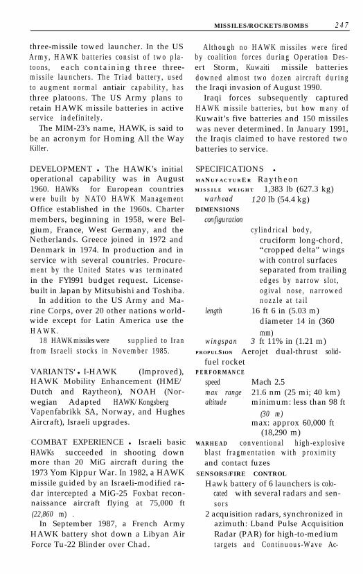
MISSILES/ROCKETS/BOMBS 2 4 7
three-missile towed launcher. In the USArmy, HAWK batteries consist of two pla-toons, each containing three three-missile launchers. The Triad battery, usedto augment normal antiair capability, hasthree platoons. The US Army plans toretain HAWK missile batteries in activeservice indefinitely.
The MIM-23’s name, HAWK, is said tobe an acronym for Homing All the WayKiller.
DEVELOPMENT l The HAWK’s initialoperational capability was in August1960. HAWKs for European countrieswere built by NATO HAWK ManagementOffice established in the 1960s. Chartermembers, beginning in 1958, were Bel-gium, France, West Germany, and theNetherlands. Greece joined in 1972 andDenmark in 1974. In production and inservice with several countries. Procure-ment by the United States was terminatedin the FYl991 budget request. License-built in Japan by Mitsubishi and Toshiba.
In addition to the US Army and Ma-rine Corps, over 20 other nations world-wide except for Latin America use theH A W K .
18 HAWK missiles were supplied to Iranfrom Israeli stocks in November 1985.
VARIANTS‘ l I-HAWK (Improved),HAWK Mobility Enhancement (HME/Dutch and Raytheon), NOAH (Nor-wegian Adapted HAWK/KongsbergVapenfabrikk SA, Norway, and HughesAircraft), Israeli upgrades.
COMBAT EXPERIENCE l Israeli basicHAWKs succeeded in shooting downmore than 20 MiG aircraft during the1973 Yom Kippur War. In 1982, a HAWKmissile guided by an Israeli-modified ra-dar intercepted a MiG-25 Foxbat recon-naissance aircraft flying at 75,000 ft(22,860 m) .
In September 1987, a French ArmyHAWK battery shot down a Libyan AirForce Tu-22 Blinder over Chad.
Although no HAWK missiles were firedby coalition forces during Operation Des-ert Storm, Kuwaiti missile batteriesdowned almost two dozen aircraft duringthe Iraqi invasion of August 1990.
Iraqi forces subsequently capturedHAWK missile batteries, but how many ofKuwait’s five batteries and 150 missileswas never determined. In January 1991,the Iraqis claimed to have restored twobatteries to service.
SPECIFICATIONS l
MANUFACTURE R RaytheonM I S S I L E WEIGHT 1,383 lb (627.3 kg)
warhead 120 lb (54.4 kg)DIMENSIONS
configurationcylindrical body,
cruciform long-chord,“cropped delta” wingswith control surfacesseparated from trailingedges by narrow slot,ogival nose, narrowednozzle at tai l
length 16 ft 6 in (5.03 m)diameter 14 in (360mm)
wingspan 3 ft 11% in (1.21 m)PROPULSION Aerojet dual-thrust solid-
fuel rocketPERFORMANCE
speed Mach 2.5max range 21.6 nm (25 mi; 40 km)altitude minimum: less than 98 ft
(30 m)max: approx 60,000 ft
(18,290 m)WARHEAD conventional high-explosive
blast fragmentation with proximityand contact fuzes
SENSORS/FIRE CONTROL
Hawk battery of 6 launchers is colo-cated with several radars and sen-sors
2 acquisition radars, synchronized inazimuth: Lband Pulse AcquisitionRadar (PAR) for high-to-mediumtargets and Continuous-Wave Ac-

248 MISSILES/ROCKETS/BOMBS
quisition Radar (CWAR) for low-altitude detection through heavyclutter
2 High-Power Illuminators (HPI) op-erating in X band illuminate targetfor missi le
K-band Range-Only Radar (ROR) usedwhen other radars are jammed
Tracking Adjunct System (TAS) pas-sive electro-optical tracker
missile has proportional navigationguidance coupled with CW andsemiactive terminal homing
Sea Sparrow (RIM-7)The Sea Sparrow naval Surface-to-AirMissile (SAM) system was originally de-veloped in the late 1960s as an interimBasic Point Defense Missile System(BPDMS) against Soviet antiship missiles.Later versions\ include the ImprovedBPDMS and the NATO Sea Sparrow Sur-face Missile System (NSSMS). All usemodified Sparrow III Air-to-Air Missiles(AAM) in an eight-cell launcher that canbe fitted in a variety of ships.
The Mk 48 Sea Sparrow VerticalLaunch System (VLS) was first tested onthe Canadian destroyer Huron in April1981. The system is designed to be assem-bled in groups of two vertical canistersand can be set either in the deck, exhaust-ing vertically (Mod 0), on a bulkheadwith overboard exhausting (Mod 1), or ina superstructure mount with vertical ex-haust (Mod 2). The missile is fitted withJet Vane Control (JVC) to quickly pitchthe missile into cruise attitude from itsvertical takeoff. Maximum missile turn-ing rate during boost is 283deg/sec.
The Mk 41 VLS, in US service on someTiconderoga (CG 47)-class cruisers andSpruance-class destroyers, can also launchVL Sea Sparrows. Four Evolved Sea Spar-rows (ESS) could fit in each Mk 41 VLScel l .
DEVELOPMENT l The BPDMS withRIM-7E initial operational capability was
in 1969, NSSMS with RIM-7H around1977, RIM-7M in 1983. International pro-gram was established by July 1968 Mem-orandum of Understanding (MoU)between Denmark, Italy, Norway, and theUnited States. Later, Belgium and theNetherlands in 1970, West Germany in1977, Canada and Greece in 1982, andTurkey in 1986 signed.
The Sea Sparrow is mounted in severaltypes of US Navy surface combatants, am-phibious ships, and underway replenish-ment ships, fired from either the NATOSea Sparrow Mk 29 launcher or the BPDMSMk 25 launcher. Both launchers have eightcells, although some Mk 29 launchers willbe refitted to fire RAM (RIM-l 16) missilesfrom two of the eight cells.
In production and in service with USNavy and other navies. In non-US naviesthe Sea Sparrow is mounted in Mk 29launchers in destroyer and frigate classesexcept for Mk 48 VLS in new-constructionships. A launch system and 21 RIM-7M SeaSparrow missiles will be fitted to the leadship of the South Korean Destroyer Exper-imental (KDX) class, scheduled for ser-vice entry in 1995. Over a dozen othernations in Europe, Asia, and Canada havethe Sea Sparrow system deployed on theirdestroyers and frigates.
VARIANTS l Basic Point Defense Mis-sile System (BPDMS), NATO Sea Spar-row Surface Missile System (NSSMS),Guided Missile Vertical Launch System(GMVLS) , RIM-7P, RIM-7R/MissileHoming Improvement Program (MHIP),Evolved Sea Sparrow (ESS) .
COMBAT EXPERIENCE l AlthoughSea Sparrow launchers were the mostwidely deployed naval weapons system inDesert Storm, no missiles were firedagainst Iraqi aircraft or missi les .
SPECIFICATIONS l
MANUFACTURERRaytheon (primary)Hughes (secondary)

MISSILES/ROCKETS/BOMBS 2 4 9
SUBCONTRACTORS
Belgium Manufacture Belge deLampes et de Materiel (MBLE)
Canada EBCORaytheon CanadaDenmark DISANEA-LindbergGermany Motorenwerk Bremerhaven
GmBHItaly SeleniaNetherlands Bronswerk Fokker-VFWNorway Norsk Forsvarsteknologi
(NFT)Turkey Aselsan Military ElectronicsUS Ball Aerospace
WEIGHTS
system BPDMS 39,000 lb (17,690kg)
NSSMS 28,479 lb (12,918kg)
Mk 48 VLS (16 missiles)Mod 0above decks: 32,480 lb
(14,896 kg)below decks: 1,793 lb
(814 kg)Mod 1above decks: 29,960 lb
(12,256 kg)below decks: 1,793 lb
(814 kg)missile RIM-7H: 450 lb (205 kg)
RIM-7M: 510 lb (231 kg)warhead: 88 lb (40 kg)
DIMENSIONS
configurationlong cylinder with ogival
nose, cruciform,folding “croppeddelta” mainplanes,clipped tail fins, JVCpack on tail of VLSvariant
length 12 ft (3.66 m)diameter 8 in (203 mm)wingspan 3 ft 4 in (1.02 m)tail span 2 ft (0.61 m)
P R O P U L S I O N Hercules Mk 58 single-stage solid-fuel rocket (Mk 58 Mod 4in RIM-7M)
PERFORMANCE
speed Mach 2.5max range 8 nm (9.2 mi; 14.8 km)
WARHEAD
RIM-7H: high-explosive continuousr o d
RIM-7M: WAU-17/B high-explosiveblast fragmentation
SENSORS/FIRE CONTROL
BPDMS Continuous Wave (CW)illumination from Mk51 radar
Mk 115 manuallyoperated fire controlsystem
Semiactive Radar (SAR)homing in RIM-7E
NSSMS Mk 91 fire control system;Mod 0 has singledirector, Mod 1 hasdual directors
Ball Mk 6 Mod 0 LLLTVsystem
Hughes Mk 23 TargetAcquisition System(TAS) update
RIM-7M introduced inverse mono-pulse seeker, reprogrammabledigital Missile-Borne Computer(MBC)
Rolling Airframe Missile-RAM (RIM- 116)The RAM (Rolling Airframe Missile) isbeing developed to provide a rapid-reaction, short-range Surface-to-Air Mis-sile (SAM) for shipboard defense using“off-the-shelf” components. RAM hasthe Infrared (IR) seeker from the StingerSAM and the rocket motor, fuze, and war-head from the Sidewinder Air-to-Air Mis-sile (AAM).
The RAM is the first US Navy ship-board “fire and forget” missile and theonly Navy missile that rolls during flight(i.e., is not aerodynamically stabilized).

2 5 0 MISSILES/ROCKETS/BOMBS
In the initial flight phase, the missile usespassive Radio Frequency (RF) to homeon target emissions to point its IR seekerat the target. RAM switches to IR homingduring the terminal phase of flight. Theguidance system measures the IR signal-to-noise ratio and determines when it isappropriate to switch to terminal IR hom-ing. If the IR seeker cannot acquire thetarget, the missile continues on to targetusing the RF guidance.
There are three types of launchers. Theproduction RAM Mk 31 launcher has 21cells. Some NATO Sea Sparrow Mk 29launchers will be modified so two of theeight cells would each launch five mis-siles. The RAM Alternative LaunchingSystem (RALS), a lighter, eight-roundlauncher for small combatants, is underdevelopment by TransLant Inc., a jointventure of General Dynamics and Ger-man RAM System.
DEVELOPMENT l The RAM’s initialoperating capability was original lyplanned for 1992-93. Funding for devel-opment was initially shared by the US,West Germany, and Denmark on a49% 49% 2% basis. Denmark withdrew fi-nancial support from the project but par-ticipates on an ad hoc basis.
Although the RAM did not have imme-diate test success, with seven of 15launched in an early 1985 series failing,later trials aboard the US destroyer DavidR. Ray (DD 971) from December 1986 toFebruary 1987 resulted in 11 successesout of 13 attempts.
The US Navy established a require-ment for 30 launchers and 4,900 missiles;the first allotment of 240 missiles is sched-uled for the mid-1990s. Germany’s re-quirement is for 55 launchers and 2,000missiles.
The RAM will be deployed on US am-phibious, command, and landing shipsand frigates, German destroyers, frigates,and small combatants, and Danish frig-ates and small combatants.
Hughes and RAM System are working
separately to develop an improved seekerfor the RAM. The new seeker would re-tain the dual RF/IR capability, but the IRseeker would use an image scanning con-cept to improve its field of view. The im-provement will a u g m e n t RAM’scapability against antiship missiles usinginertial guidance and IR homing.
SPECIFICATIONS lMANUFACTURER
Hughes (primary)RAM System (German consortium)
MISSILE WEIGHT 162 lb (73.5 kg)warhead 25 lb (11.3 kg)
DIMENSIONS
configurationlong, thin cylinder with
blunt nose, 2 foldingsteerable foreplanes,small cruciform foldingtailfins; EX-8 sealedcanister round impartsa spin to the RAM asthe missile is launched
length 9 ft 3 in (2.82 m)diameter 5 in (127 mm)
PROPULSION Mk 36 Mod 8 solid-propellant rocket
SPEED supersonicWARHEAD conventional high-explosiveSENSORS/FIRE CONTROL passive dual-
mode RF/IR acquisitionMODIFTED MK 29 SEA SPARROW LAUNCHER
capacity 10 RAM, 6 Sea SparrowMK 31 RAM STANDARD LAUNCHER
weight above decks: 11,424 lb(5,182 kg) with missiles
below decks: 2,105 lb(955 kg)
elevation -25deg/+80degtraverse 360degcapacity 21 rounds
RALSweight above decks: less than
6,500 lb (2,950 kg) withmissiles
below decks: 1,600 lb(726 kg)

MISSILES/ROCKETS/BOMBS 251
elevationtraverse
capacity
-25deg/+80deg175” to either side of
centerline8 rounds
Standard SM-1 MR (RIM-66B)The Standard Surface-to-Air Missile(SAM) series was, developed as a replace-ment for the three “T” missiles, thetrouble-plagued Talos, Terrier, and Tar-tar. The Standard missile family was theresult of an improvement program thatbegan in the late 1950s. The SM-1 MR(Medium Range) is the oldest Standardtype remaining in service, being a rela-tively short-range weapon with single-stage rocket propulsion.
The update program’s emphasis wason the achievement of greater range andreliability than Tartar and Terrier. Amore powerful dual-thrust rocket motorboosted intercept altitude by 25% andrange by 45%. Reliability was enhancedby replacing vacuum-tube electronicsand hydraulic controls with solid-state cir-cuitry and electronically powered con-trols. Warm-up time was reduced from 26seconds for the Improved Tartar to onesecond for the SM-1.
DEVELOPMENT l The SM-l’s initialoperational capability was in 1970. It is nolonger in production but in service ondestroyers and frigates in the US Navyand the navies of Australia, France, Ger-many, Italy, Japan, Netherlands, andSpain.
VARIANTS l RIM-66B, RIM-66E, RGM-66D Standard ARM, RGM-66E, RGM-66F, AGM-78 (air-launched ARM, see sep-arate listing), RIM-67A, RIM-67B,RIM-67C, RIM-67D (rail-launched).
COMBAT EXPERIENCE l Although 13Perry-class frigates participated in Opera-tion Desert Storm, none fired its Stan-dard missiles.
SPECIFICATIONS lMANUFACTURER HughesMISSILE WEIGHT 1,100 lb (499 kg)DIMENSIONS
configurationslim cylinder with pointed
nose, cruciform narrowlong-chord mainplanesindexed in line withsteerable tailplanes
length 14 ft 8 in (4.47 m)diameter 13% in (342 mm)wingspan 3 ft 6 in (1.07 m)
P R O P ULS I O N Mk 56 Mod 0 dual-thrustsingle-stage rocket motor
PERFORMANCE
speed Mach 2+max range 25 nm (28.8 mi; 46.3 km)max altitude
60,000 ft (18,288 m)minimum altitude
150 ft (46 m)WARHEAD conventional expanding,
continuous rodSENSORS/FIRE CONTROL
missile guidanceconical scan Semiactive Radar (SAR)
h o m i n gsingle sideband receiverall-electric control surface actuationadaptive autopilotMotorola Mk 45 Target Detecting De-
vice (TDD) proximity and contactfuze
Standard SM-2 MR (RIM-66C)The SM-2 MR (Medium Range) has in-creased range over the SM-1 MR (aboutequal to the range of the SM-2 ER) as wellas the addition of midcourse guidanceand enhanced resistance to ElectronicCountermeasures (ECM).
The SM-2 MR is being procured in sev-eral versions and Blocks, which has re-sulted in a proliferation of type designa-tions. Block II and Block III variants areseparated into three subtypes, each with adifferent letter suffix depending on

252 MISSILES/ROCKETS/BOMBS
SM-2 MR
MISSILES/ROCKETS/BOMBS 2 5 3
whether the missile is intended for theAegis missile system, a Vertical LaunchSystem (VLS), or a Tartar guided-missileship.
DEVELOPMENT l Init ial operationalcapability was in 1981. Production byH u g h e s .
In service with US Navy Ticonderoga-,California-, and Virginia-class cruisers andKidd- and Burke-class destroyers, Cana-dian Iroquois-class destroyers, and Japa-nese Kongo-class destroyers.
COMBAT EXPERIENCE l The first op-erational use of SM-2 missiles occurredon July 3, 1988, when two missiles werefired from the USS Vicennes (CG 49) at atarget believed to be an Iranian F-14Tomcat fighter. One or both missilesstruck the aircraft, which was a civilianIran Air Airbus 300 airliner carrying 290passengers. All aboard were killed.
A total of 43 US, four Australian, twoNetherlands, and two Spanish ships fittedwith Standard SAM launchers deployedto the Persian Gulf during Operation De-sert Storm. Because of the rapid destruc-tion of Iraq’s antiship weapons (princi-pally the Mirage Fl-EQ attack aircraftcarrying Exocet missiles and the ground-launched Silkworm antiship missile), noStandards were launched during the de-ployments.
SPECIFICATIONS lMANUFACTURER HughesRaytheon (secondary, Block II and III)MISSILE WEIGHT
Block I: 1,350 lb (613 kg)Block II/III: 1,556 lb (706 kg)
DIMENSIONS
configuration
length
cylinder with cruciformlong-chord mainplanes,cruciform steerable tailfins, ogival nose
Block I: 14 ft 7 in (4.44 m)Block II/III: 15 ft 6 in
(4.72 m)
diameter 13% in (342 mm)wingspan 3 ft 6 in (1.07 m)
PROPULSION single-stage dual-thrustAerojet Mk 56 Mod 2 (Block I) orMorton Thiokol Mk 104 (Block II/III) solid-fuel rocket
PERFORMANCE
speed Mach 2+max range Block I: approx 40 nm
(46 mi; 74 km)Block II: approx 90 nm
(104 mi; 167 km)WARHEAD high-velocity controlled frag-
mentation conventional high explo-sive
SENSORS/FIRE CONTROL
inertial navigation with P-way commu-nication link for midcourse guid-ance from warship
digital guidance computermonopulse Semiactive Radar (SAR)
h o m i n gMotorola Mk 45 Target Detecting De-
vice (TDD) proximity and contactfuzes
Standard SM-2 ER (RIM-67A/Band 67C/D)The SM-2 ER (Extended Range) versionhas extended range, midcourse guid-ance, an inertial reference system, andimproved resistance to Electronic Coun-termeasures (ECM) compared to earliermissiles. The SM-2 ER is a two-stage mis-sile that can reach an altitude of about80,000 feet.
DEVELOPMENT l Init ial operationalcapability was in 1981. The RIM-67A/Bwas deployed on the US Navy’s Bainbridge,Truxtun, and Long Beach-class cruisers,and Coon&class destroyers, and theRIM-67C/D was deployed on Leahy andBelknap-class cruisers.
COMBAT EXPERIENCE - Three Leahyclass and four Belknap-class cruisers fittedwith RIM-67C/D and three Farragut-class

2 5 4 MISSILES/ROCKETS/BOMBS
destroyers armed with RIM-67B missilesdeployed during Operation DesertStorm, but no Standards were launched,
SPECIFICATIONS lMANUFACTURER General DynamicsMISSILE W E I G H T 2,920 lb (1,324 kg)DIMENSIONS
configurationcylindrical booster with
cruciform steerable“cropped delta”tailplanes, necked topfor mating to missile;cylindrical missile withcruciform long-chordmainplanes, cruciformsteerable tailplanes,ogival nose
length 27 ft (8.23 m)diameter booster: 18 in (460 mm)
missile: 13% in (342 mm)wingspan booster: 5 ft 3 in (1.6 m)
missile: 3 ft 6 in (1.06 m)PROPULSION
two-stage solid fuel rocketMk 70 booster in SM-2 ERMk 56 or IO4 sustainer
PERFORMANCE
speed Mach 2+max range 75-90 nm (86-104 mi;
139-167 km)max altitude
approx 80,000 ft(24,384 m)
WARHEAD conventional high-explosivecontrolled fragmentation
SENSORS/FIRE CONTROL
inertial navigation with two-way com-munication link for midcourseguidance from warship
digital guidance computermonopulse Semiactive Radar (SAR)
h o m i n gMotorola Mk 45 Target Detecting De-
vice (TDD) proximity and contactfuze
Standard SM-2 AER (RIM-67B)The latest Standard variant is the AegisExtended Range, which is considerablychanged from earlier Standard missiles.Aegis ER launches from the Mk 41 Verti-cal Launching System on Ticonderoga andArleigh Burke classes. The basic airframeresembles earlier Standards, althoughthe dorsal fins have been enlarged.
The guidance, ECM equipment, andairframe improvements derived from sev-eral other Raytheon missile programs.Aegis ER’s digital autopilot is based onRaytheon’s AIM-120 AMRAAM Air-to-AirMissile (AAM) update design. The digitalsignal processor techniques are takenfrom AMRAAM and AIM-7 SparrowAAMs and the ground-based MIM-104Patriot SAM. Sparrow ElectronicCounter-Countermeasures ( E C C M )from Sparrow AAM. To cope with theheating imposed by a longer period ofhigh-speed flight, the fused-silica radomedeveloped for the Patriot has beenadopted.
DEVELOPMENT l The SM-2 AER’s ini-tial operational capability was in 1992.This is the first Standard missile designfor which Raytheon is prime contractor;all previous variants were led by GeneralDynamics. The missile is deployed on theUS Navy Ticonderoga-class cruisers and Ar-leigh Burke-class destroyers.
SPECIFICATIONS lMANUFACTURER RaytheonMISSILE WEIGHT 3,200 lb (1,451 kg)DIMENSIONS
configurationcylindrical booster with
necked top for matingto missile; cylindricalmissile with cruciformlong-chord mainplanes,cruciform steerabletailplanes, ogival nose
length missile only: 16 ft(4.88 m)

MISSILES/ROCKETS/BOMBS 255
with booster: 21 ft 6 in(6.55 m)
diameter booster: 21 in (533 mm)missile: 13.7 in (348 mm)missile wingspan: 3 ft 6 in
(1.06 m)PROPULSION
service, the Nike is in service in severalEuropean and Asian countries.
VARIANTS l MIM-14C (1981 modifica-’tion) .
two-stage solid-fuel rocketEX-72 boosterMk 104 dual-thrust rocket motor sus-
tainerPERFORMANCE larger envelope than
Block II/Block IIIWARHEAD conventional high-explosive
controlled fragmentationSENSORS/FIRE CONTROL
inertial navigation with two-way com-munication link for midcourseguidance from warship
digital guidance computermonopulse Semiactive Radar (SAR)
h o m i n g
Nike Hercules (MIM-14)The Nike Hercules Surface-to-Air Missile(SAM) system is one of the oldest US-designed SAMs still in active service. It iscapable of interceptions at relatively highaltitudes and long ranges but is not suit-able for low-altitude defense. It can alsoperform in a Surface-to-Surface Missile(SSM) role. The fixed batteries thatformed part of the North American airdefense system have been dismantled;mobile Nike batteries are still in servicein several other countries.
When targets are detected by the sys-tem’s tracking radar, the Nike launcher iselevated to 85” and the missile is fired.After the boosters are spent and jet-tisoned, the missile-tracking radar guidesthe missile to the target. Detonation ofthe high-explosive or nuclear warhead isby radio command.
SPECIFICATIONS lMANUFACTURER
Western Electric (prime)Douglas Aircraft (missile)Mitsubishi (Japanese license)AT&T (upgrade prime)
MISSILE W E I G H T 10,710 lb (4,858 kg)DIMENSIONS
configuration2-stage missile, 4 booster
cluster, each booster withcroppeddelta stabilizer,tapered cylinder, smallcruciform deltanoseplanes indexed inline with extremely sweptdelta mainplanes,control surfacesjoinedto mainplanes byactuators
length 39 ft 8 in (12.1 m)diameter 2 ft 7% in (.8 m)wingspan 6 ft 2 in (1.88 m)
PROPULSION
Hercules 4motor solid-propellantbooster cluster
Thiokol solid-propellant sustainerPERFORMANCE
speed Mach 3.65max range more than 75 nm (87 mi;
140 km)max altitude
more than 24.3 nm (28mi; 45 km)
WARHEAD conventional high-explosiveor nuclear
SENSORS/FIRE CONTROL
guidance MIM-14A command andcontrol by WesternElectric
MIM-14C has NordenDCS, General ElectricAN/MPQ-43 HIPAR
DEVELOPMENT l The Nike’s initial op-erational capability was in 1958. Al-though no longer in production or US

2 5 6 MISSILES/ROCKETS/BOMBS
Super Falcon (AIM-4)The Super Falcon is the final generationof one of the earliest Air-to-Air Missiles(AAM) in the US inventory. The AIM-4Ghas an all-aspect homing capability. TheAIM-4D has only a tail engagement capa-bility but has greater maneuverabilityand was designed as an antifighterweapon.
DEVELOPMENT l The Super Falcon’sinitial operational capability as the AIM-4was in 1956, the AIM-4E in 1958,AIM-4F/G in 1960, and AIM-4D in 1963.Over 56,000 AIM-4series missiles werebuilt, most of which were AIM-4A/B/Cvariants. It is no longer in production butis still in service with the US Air Force andAir National Guard.
The Falcon’s success was based on alight airframe containing a generousamount of Glass-Reinforced Plastics(GRP) and the best miniaturized elec-tronics then available.
All Falcons were originally designatedGAR (Guided Air Rockets) the AIM des-ignation and revised numbering were in-stituted in 1962.
Super Falcons are operated by the airforces of Finland, Japan, Sweden, Switzer-land, Turkey, and Taiwan.
VARIANTS l GAR-1/1D (AIM-4/4A),G A R - 2 /2A (AIM-4B/4C), GAR-3/3A(AIM-4E/4F), GAR-4A (AIM-4G),GAR-2B (AIM-4D), XAIM-4H (test),XGAR-11 /GAR-1 1 / 11A (XAIM-26/AIM-26A/26B), G A R - 9 (AIM-47A),RB-27 (AIM-26B) and RB-28 (AIM-4D)(Swedish license-built).
SPECIFICATIONS lMANUFACTURER
Hughes AircraftSaab-Scania (Sweden)
MISSILE WEIGHT
AIM-4D: 135 lb (61 kg)AIM-4F: 150 lb (68 kg)AIM-4G: 145 lb (66 kg)
warhead 40 lb (18.14 kg)DIMENSIONS
configurationcylindrical body with
blunt nose (opaque forSemiactive Radar/SAR,clear for Infrared/IRseeker), four smallaerial “ears” onforebody (AIM-4F/Gonly), extreme deltacruciform wings withlarge control servicesattached at trailingedge; AIM-4D has 4fixed, semicircularcanards near the nose,AIM-4F/G have longleading-edgeextensions
length AIM-4D: 6 ft 8 in (2.02 m)AIM-4F: 7 ft 2 in (2.18 m)AIM-4G: 6 ft 9 in (2.06
m)diameter AIM-4D: 6% in (165 mm)
AIM-4F/G: 6.6 in (168mm)
wingspan AIM-4D: 1 ft 8 in (0.51m)
AIM-4F/G: 2 ft (0.61m)
PROPULSION Thiokol M46 two-stagesolid-fuel motor with first-stagethrust rating of 6,000 lb (26.7 kN)static thrust; second stage has lowerrating for sustaining speed
PERFORMANCE
speed Mach 3max range 7 mi (11.3 km)
WARHEAD conventional high explo-sive
SENSORS/FIRE CONTROL
AIM-4D has an Infrared (IR) seekerAIM-4F has a Hughes semiactive
radar-homing seekerAIM-4G has an all-aspect IR seeker

MISSILES/ROCKETS/BOMBS 257
ANTIRADAR MISSILES
HARM(AGM-88)The AGM-88 HARM missile was devel-oped as a replacement for the AGM-45Shrike and AGM-78 Standard Antiradia-tion Radar Missiles (ARM). It is an expen-sive missile, but one with a broadcapability against ground- and ship-basedradars.
The HARM can be fired in severalmodes: As a long-range standoff missileagainst preselected targets, HARM candelay acquisition of target until afterlaunch. The all-aspect passive radar-homing seeker can be used to search fortargets of opportunity; the missile is thenfired manually. The missile can belaunched in “range-known” and “range-unknown” and can home on back andsidelobe radiation. It can also be used as aself-defense missile in concert with air-craft Electronic Support Measures(ESM) equipment.
HARM has a digital autopilot andstrap-down inertial navigation, a low-smoke solid-propellant rocket, and digi-tal processing in both the missile and thelaunch aircraft, which allows the HARMto attack a broad frequency spectrum(four-octave bandwidth from 0.5 to 20GHz) of hostile radars.
The high-explosive warhead is prefrag-mented into thousands of small steelcubes designed specifically to damage ra-dar antenna and other fragile equip-m e n t .
DEVELOPMENT l The missi le’s init ialoperational capability was in 1984. It wasdeveloped by the Naval Weapons Centerat China Lake, California; Texas Instru-ments began participation in 1974. A to-tal of 14,000 were planned for the USservices. West Germany ordered 1,000HARMS in 1986 and took its f irst delivery
in November 1987. The 10,000th HARMwas delivered in 1990.
In an attempt to increase the numberof firms capable of producing antiradia-tion seekers, the Navy began developingthe Low-Cost Seeker (LCS) program in1984. While Texas Instruments contin-ued developing the Block IV seeker, FordAerospace and Raytheon Corp. offered acompeting LCS, with the Navy choosingthe Ford design in 1988. (Ford Aerospacewas later acquired by Loral Corp.)
Texas Instruments received a $459-million contract in February 1989 for theproduction of 2,449 missiles. Deliveriesbegan in late 1990, to be completed bylate 1991; the contract covers 1,319 mis-siles for the Navy, 950 for the Air Force,and 180 for Germany. In 1990, Spain or-dered 200 HARMS for carriage by EF-18Hornet aircraft.
The HARM has frequently been crit-icized for high cost, and in early 1986, theNavy briefly stopped accepting the mis-sile because of quality control problems.Its future as the principal air-launchedantiradar missile was assured, however, byits competent performance during the1986 US naval air strikes against Libya.
Platforms for the HARM includefighters, electronic aircraft and attack(US), attack and electronic aircraft (Ger-many), and electronic (Spain).
VARIANTS l AGM-88A, AGM-88B,AGM-88C.
COMBAT EXPERIENCE l US Navycarrier-based aircraft launched 40HARMS against Libyan surface-to-air mis-sile radars, primarily SA-5s, in March-April 1986 air str ikes against Libya.
When Operation Desert Storm’s air

258 MISSILES/ROCKETS/BOMBS
war began in January 1991, HARMS werea heavy contributor to the collapse of theIraqi air defense radar network. Most ofthe more than 1,000 HARMS fired (661by US Navy aircraft, 233 more by the USMarine Corps) were launched during thefirst half of the campaign.
SPECIFICATIONS lMANUFACTURER (see Development)MISSILE WEIGHT 796-807 lb (361-
366 kg)warhead 145 lb (66 kg)
DIMENSIONS
configurationlong cylinder with ogival
nose, cruciformsteerable double-deltaforeplanes indexed inline with stubby fins attail
length 13 ft 8% in (4.17 m)diameter 10 in (254 mm)wingspan 3 ft 8% in (1.13 m)
PROPULSION Thiokol YSR-113-TC-1dual-thrust reduced-smoke solid-
fuel rocket (Hercules is secondsource)
PERFORMANCE
speed Mach 2+range 10 nm (11.5 mi; 18.5
km)WARHEAD conventional high explosive
with prefragmented steel-cube war-head
SENSORS/FIRE CONTROL
all-aspect passive radar homingMotorola DSU-19 active optical fuzing
system
Shrike (AGM-45)The AGM-45 is the first missile built spe-cifically for the antiradar mission to entermass production in the United States. Itis based, in part, on the AIM-7 Sparrowair-to-air missile, which it resembles. Itconsists of four sections: a guidance sys-tem, the warhead, the control system, andthe rocket motor.

MISSILES/ROCKETS/BOMBS 2 5 9
The Shrike has had many subvariants.all of which differ principally in theirseeker. It is gradually being replaced bythe AGM-88 HARM missile.
DEVELOPMENT l The Shrike’s initialoperational capability was in 1963, and itsfirst test flights were in 1962. Over 20,000had been produced before productionceased.
The Shrike is deployed on US Air ForceF-4Gs and F-16Cs and Ds, US Navy A-6Es,A-7Es, and F/A-18s, and Israeli F-4s andKfirs.
The Shrike had several major limita-tions that reduce its effectiveness: it mustbe pointing at the target at the momentof launch and the target radar must beradiating throughout the missile’s flight.Although upgrades have improved theShrike’s performance, the lack of areadily reprogrammable seeker remainsan intrinsic l imitation.
VARIANTS l AGM-45-9A Shrike G-Biasupgrade.
COMBAT EXPERIENCE l Shrikes werefirst used in combat in Vietnam in 1966.They were used extensively as a penetra-tion aid by the US Air Force and Navy, butthe missile’s limitations-including aneed for the target to continue radiatingduring the entire flight-led to manymodifications.
The Israelis used the Shrike during the1973 Yom Kippur War with successagainst SA-2 and SA-3 missiles, but inef-fectively against the SA-6. It was also usedby Israeli aircraft in the 1982 Lebaneseconflict.
It was used ineffectively by British Vul-can bombers in the 1982 Falklands Warand launched by the US Navy against Libyan radars in the 1986 US raid.
Although the AGM-88 HARM was usedmuch more extensively in Operation De-sert Storm, the US Air Force, Navy, andMarine Corps also launched Shrikesagainst Iraqi radars. Fewer than 100 were
fired, however, and very little was saidabout their success rate.
SPECIFICATIONS lMANUFACTURER
Texas InstrumentsSperry Rand/Univac
MISSILE WEIGHT 390 lb (176.9 kg),varies with subtypewarhead 145 lb (65.8 kg)
DIMENSIONS
configurationresembles Sparrow AAM
(AIM-7) long cylinder,ogival nose, cruciformdelta steerableforeplanes at midbody,stubby tailfins
length 10 ft (3.05 m)diameter 8 in (203 mm)wingspan 3 ft (0.91 m)
P R O P ULS I O N Rocketdyne Mk 39 orAerojet Mk 53 polybutadiene solid-fuel rocket; Aerojet Mk 78 poly-urethane dual-thrust solid-fuel rocketfor AGM-45B
PERFORMANCE
speed Mach 2max range approx 10 nm (11.5 mi;
18.5 km)up to 25 nm (28.8 mi;
40.2 km) reported forimproved rocket motor
WARHEAD conventional highexplosive/fragmentation
SENSORS/FIRE CONTROL
at least 18 variations, with over 13variations on the seeker; other vari-ations include increased range andsafety features; AGM-45-9 and -10have the widest range of coverage
fuzing is proximity and contact
Sidearm (AGM- 122)The Sidearm is a short-range, antiradarmissile developed to counter air defenseweapons. It is an inexpensive selfdefense

260 MISSILES/ROCKETS/BOMBS
missile for Marine Corps fixed-wing andhelicopter aircraft.
The missile uses components from theAIM-SC Sidewinder, which has been instorage since the 1970s. The AIM-SC wasa relatively unsuccessful Semiactive Ra-dar (SAR)-homing variant of the Side-winder; all other Sidewinders a r eInfrared (IR)-homing missiles.
The Naval Weapons Center at ChinaLake, California, modified the AIM-SC’snarrowband semiactive seeker, creating abroadband passive seeker. The seekerachieves a conical scan by mounting theantenna off center on a spinning gyro-scope wheel. The DSU-15A/B Target De-tection Device (TDD) flown in theAIM-9L has also been modified for air-to-ground use.
Sidearm is intended primarily for low-altitude use, and the AIM-SC control sys-tem has been modified to cause the mis-sile to pitch up soon after launch. Thischange allows aircraft to launch Sidearmswhile flying Nap of the Earth (NOE) pro-files.
Former Soviet J-band tracking radarssuch as the Flap Wheel and Gun Dishwere the principal targets.
DEVELOPMENT l Approximately 1,000AIM-9Cs were converted to the Sidearmconfiguration before funding ended inFYI988 with the purchase of 276 units.The last was delivered in late 1990. Themissile is deployable by any aircraft quali-fied to fire the Sidewinder.
The Marines have used the missile onits Harrier and Bronco planes and theCobra helicopter.
SPECIFICATIONS l
MANUFACTURER MotorolaMISSILE WEIGHT 200 lb (90.7 kg)
warhead 22.4 lb (10.15 kg)DIMENSIONS
configurationthin cylinder with
cruciform steerabledelta foreplanes,
trapezoidal mainplanesat rear, hemisphericalradome on nose
length 10 ft (3.0 m)diameter 5 in (127 mm)
PROPULSION Mk 36 Mod 9 or Mod 12solid-fuel rocket
PERFORMANCE
speed Mach 2.5max range 9.6 nm (11 mi; 17.7 km)
WARHEAD continuous rod, conven-tional high explosive
SENSORS/FIRE CONTROL passive radarhoming with broadband seeker
Standard Antiradar Missile(ARM) (AGM-78)The US Standard Antiradar Missile(ARM) is a large, air-launched weaponbased on the shipboard RIM-66A Stan-dard SM-1 surface-to-air missile. It was de-veloped to supplement the AGM-45Shrike, which had shown range, seeker,and warhead-size limitations during earlyUS use in Vietnam.
The first Standard ARM (AGM-78A)variant used the Texas Instrumentsseeker from the Shrike, which was pre-tuned to a given frequency band beforefitting it to the aircraft. Later variants(from AGM-78B) used a Maxson Elec-tronics wideband, gimballed seeker. Thisseeker does not require pretuning, cantrack a radar emitter from a wider rangeof attack angles, and has an on-boardmemory that allows it to continue attackson shut-down radars. The Target Identi-fication and Acquisition System (TIAS)on the launch aircraft provides targetingdata to the Standard ARM before launch.When the missile hits, a smoke cloud re-veals the impact point.
DEVELOPMENT l The missile’s initialoperational capability was in 1968, and itsflight tests were conducted in 1967-68. Itis no longer in production. It was retired

MISSILES/ROCKETS/BOMBS 261
from US Air Force service in 1984 withthe last F-105 Thunderchief. In serviceonly with the Israeli Air Force.
VARIANTS l AGM-78A, AGM-78B,AGM-78C, AGM-78D, Purple Fist (Israelidevelopment).
COMBAT EXPERIENCE l Used by USAir Force and Navy aircraft against NorthVietnamese radars. Purple Fist missiles(Standard ARMs with improved war-heads) were launched by Israeli pilotsagainst Syrian air defense radars in theBekaa Valley during the 1982 Peace inGalilee invasion of Lebanon.
SPECIFICATIONS l
MANUFACTURER General DynamicsMISSILE WEIGHT 1,799 lb (816 kg)
warhead 215 lb (97.5 kg)
DIMENSIONSconfiguration
thin cylinder with pointednose, cruciform long-chord ultra-low aspectratio l ift ing strakesindexed in line withtrapezoidal steerabletailplanes
length 15 ft (4.57 m)diameter 13% in (343 mm)tail span 3ft 7in (1.09m)
PROPULS I O N Aerojet General Mk 27Mod 4 dual-thrust solid-propellantrocket motor
PERFORMANCEspeed Mach 2.5maximum range
16-30 nm (18.4-34.8 mi;30-56 km)
WARHEAD high-explosive blast/frag-mentation
SENSORS/FlRE CONTROL
guidance: passive radar homingdirect and proximity fuzes
ANTISHIP MISSILESHarpoon (AGM-84/RGM-84/UGM-84)The series of AGM/RGM/UGM-84 Har-poons are long-range sea-skimming, anti-ship missiles that are the mostwidely usedantiship missiles in the West. The ship-launched version of the Harpoon wasoriginally conceived as an air-to-surfacemissile to attack surfaced Soviet Echo-class cruise missile submarines. The mis-sile is deployed in surface ships and sub-marines, in land-based coastal defensepositions, and on aircraft for a broad anti-ship role. All Harpoons in US servicehave been upgraded to AGM/RGM/UGM-84D (Block 1C) level.
All Harpoons through Block 1C have
the same missile body; different launchsystems will use different body wings andfins, and restraint shoes. Harpoonslaunched from surface ships, submarines,or coastal defense platforms require abooster that is the same for all applica-tions. Air-launched Harpoons do not re-quire a booster and have pylon-attach-ment lugs instead of shoes. The Block 1D(AGM/RGM-84F) has a 23.2-in (592-mm)plug for more fuel capacity, relocatedwings, and a Missile Guidance Unit(MGU) based on the AGM-84E SLAM.
Like the French Exocet missile, theHarpoon is a “fire and forget” weapon.
262 MISSILES/ROCKETS/BOMBS
Target information is developed in differ-ent ways depending on the platform. Sur-face ships use the Harpoon ShipboardCommand and Launch Control Set(HSCLCS, pronounced “Sickles”).Larger aircraft-P-3, F27 Maritime,B-52G, and Nimrod-are fitted with the“stand-alone” Aircraft Command andLaunch Control Set (HACLCS or“Hackles”). Others-S-3 Viking and theAustralian F-1 11C Pig-have a hybrid sys-tem that depends in part on the aircraft’sweapons control system.
The F-16’s Harpoon Interface AdapterKit (HIAK) is a hybrid variant having soft-ware changes and a control box fitted inthe underwing stores pylon. Full integra-tion is also found on US, British RoyalNavy, Australian, and Netherlands Navysubmarines. Other non-US submarinesare fitted with the Encapsulated HarpoonCommand and Launch Control Set(EHCLS or “Eckles”).
The MGU uses a Northrop or SmithsIndustries (formerly Lear-Siegler) strap-down, three-axis Attitude Reference As-sembly (ARA) to monitor the missile’srelation to its launch platform (ratherthan in relation to the earth, as in inertialguidance). If terrain or nonhostile tar-gets need to be avoided, a high-altitudeflyout is preferred. A stealthier approachis to drop down to a presearch sea-skimming altitude.
The starting point for a circular searchis offset from the target in the directionthat offers the best chance of acquiringthe intended target. The Bearing OnlyLaunch (BOL) is used when the range tothe target is not known or when targetbearing or range is imprecisely known.
In the Block 1C, the missile has im-proved Electronic Counter- Countermea-sures (ECCM) as part of the missile up-grade.
Surface-ship-launched Harpoons areloaded into one of three types of reusablelaunch canisters at the factory or at aweapons station. The Harpoon can befired from Mk 11 twin-rail and Mk 13
single-rail Surface-to-Air Missile (SAM)launchers, or from four cells (two outeron each end) of the eight-cell Mk 16 Anti-submarine Rocket (ASROC) launcher.
Submarine-launched Harpoons arecarried in a buoyant capsule that islaunched from a standard 21-in (533-mm) torpedo tube.
DEVELOPMENT l The missile’s initialoperational capability was in 1977 for sur-face ships and submarines, in 1979 inP-3C antisubmarine patrol aircraft, and1981 in A-6E attack aircraft. Initial opera-tional capability for AGM/RGM-84D wasin 1984.
First air-launched tests were in 1972.Over 6,400 Harpoons and SLAMs hadbeen ordered by the end of 1991. Themissile is intended to continue in US ser-vice well into the 21st century.
The Harpoon has been deployed onUS Air Force B-52G bombers and severalUS Navy aircraft. The missile is also de-ployed in the aircraft of eight Europeanand Asian nations, as well as on boardseveral classes of US Navy cruisers, de-stroyers, frigates, and small combatants,and the surface warships of 19 other na-tions. The UGM-84 is deployed in subma-rines of the US Navy and nine othernavies.
The land-launched coastal defensemissile variant of the Harpoon was or-dered by South Korea (three batteries),Denmark, and Norway. This missile wasidentical to the production version, withquad canister and launched from a buyer-supplied vehicle.
VARIANTS l AGM/RGM-84A, UGM-84B (S&Harpoon, UK), RGM-84C, AGM/RGM-/UGM-84D, AGM/RGM-84F.
COMBAT EXPERIENCE l The firstcombat use of the Harpoon was by USnaval forces against Libyan missile cor-vettes in the Gulf of Sidra in March 1986.During three separate incidents, at leasttwo, and possibly an unconfirmed third,

MISSILES/ROCKETS/BOMBS 263
missile craft were destroyed by US NavyA-6E Intruders.
On April 18, 1988, US Navy frigateBagley (FF 1069) launched a singleRGM-84D Harpoon missile at the Iranianmissile craft Joshan as she fired anRGM-84A Harpoon at US ships. Har-poons were fired on several occasionsduring the expanded US ship operationsagainst Iraq that year.
During Operation Desert Storm, USNavy ships had very few chances for usingHarpoons, as most Iraqi naval ships andcraft were sunk by air-launched bombsand rockets. In late January 1991, theSaudis reported that one of their missilecraft sank an Iraqi ship with a Harpoon.
SPECIFICATIONS l
MANUFACTURER McDonnell DouglasMISSILE WEIGHT
AGM-84D: 1,172 lb (531.6 kg)RGM-84D
Mk 11/13: 1,527 lb (692.6 kg)Mk 16: 1,466 lb (665.0 kg)canister/capsule: 1,530 lb (694.0kg)
AGM-84F: 1,390 lb (630.5 kg)RGM-84F: 1,757 lb (797.0 kg)
DIMENSIONS
configurationthick cylinder with
pointed nose,cruciform trapezoidalwings at midbody,cruciform in-line swept“cropped delta”control fins at tail;wings and controlsurfaces fold forstorage, pop out afterlaunch; engine hasnearly flush ventral airintake; surface-launchversion has shortbooster section withcruciform fins
length AGM-84D: 12 ft 7% in(3.898 m)
RGM/UGM-84D/coastal:15 ft 2% in (4.635 m)
AGM-84F: 14 ft 7 in(4.445 m)
RGM-84F: 17 ft 2 in(5.232 m)
diameter 13% in (340 mm)wingspan 3 ft (0.914 m)
PROPULSION
booster (surface-/coastal-/submarine-launch) : Aerojet or Thiokol solid-fuel rocket (avg 12,000 lb/5,444 kgstatic thrust)
Teledyne Continental CAE-J402-CA-400 turbojet sustainer develop-ing 600 lb (273 kg) static thrust;100 lb (45.4 kg) fuel (JP-10 inBlock 1C/ 1D missiles)
PERFORMANCE
speed Mach 0.85max range AGM-84D: 75-80 nm
(86.3-92.1 mi; 139-148km)
AGM-84F: approx 150 nm(173 mi; 278 km)
WARHEAD 500 lb (227 kg) conventionalhigh explosive with some penetrationcapability
SENSORS/FIRE CONTROL
HCLS provides targeting data; no up-dates once missile is launched
on-board Midcourse Guidance Unit(MGU): IBM digital computer,Smiths Industries 3-axis ARA, andHoneywell AN/APN-194 short-pulse radar or Kollsman Frequency-Modulated Continuous Wave(FMCW) altimeter
Texas Instruments PR-53/DSQ-28monopulse frequency-agile, jitteredPulse Repetition Frequency (PRF)active radar-homing seekerswitched on at preplanned point
Skipper II (AGM-123)The Skipper is a laser-guided standoff an-tiship missile originally based on existingmissile and bomb components. The

2 6 4 MISSILES/ROCKETS/BOMBS
“body” is a standard Mk 83 1,000-lb (454kg) bomb. The rocket motor is derivedfrom the Shrike antiradar missi le(AGM-45). The seeker, based on thePaveway II laser-guided bomb series,homes on a remotely designated laser re-flected from the target.
DEVELOPMENT l The missile’s initialoperational capability was in 1985. Inservice with the US Navy on A-6E In-truder aircraft. The Skipper II was devel-oped by the Naval Weapons Center atChina Lake, California. Although themissile is comparatively low in costand composed of already tested compo-nents, its deployment was delayedthrough a lack of strong support by theNavy.
The FOGS (Fiber-Optic Guided Skip-per) is a variation of the Skipper usingUS Army-developed fiber-optic datalink for Non Line of Sight (NLOS)launch. After discouraging testing andother technical problems, the Navy aban-doned the program in March 1991, andreprogrammed funding to support de-velopment of the Advanced InterdictionWeapons System (AIWS), which itselfwas later cancelled.
COMBAT EXPERIENCE l On April 18,1988, a US Navy A-6 Intruder struck theIranian frigate Sahand with an AGM-123after the ship engaged US Navy warshipsin the Strait of Hormuz. The Sahand alsosustained hits from an air-launchedAGM-84 Harpoon and an RGM-84
launched by the USS Joseph Strauss (DDG16) and sank later that night.
Three Skippers were launched by USMarine Corps aircraft in January-Febru-ary 1991 during Operation Desert Storm.
SPECIFICATIONS lMANUFACTURFX
Aerojet General (rocket motor)Emerson Electric (guidance)
MISSILE WEIGHT 1,283 lb (582 kg)warhead 1,000 lb (454 kg)
DIMENSIONS
configurationMk 83 bomb has tapered
body; guidance sectionpivots on nose, hascruciform fixed“cropped delta” fins,ringed tip; boostersection at tail hascruciform, pop-outswept wings
length 14 ft (4.27 m)wingspan’ 5 ft 3 in (1.6 m)
PROPULSION Aerojet General solid-fuelbooster
PERFORMANCE
speed 500 kts (575 mph; 926km/h)
range approx 5.2 nm (6 mi; 9.7km) at 500 kts and 300ft (91.4 m) launchaltitude
WARHEAD conventional high explosivewith FMU-376 fuze
SENSORS/FIRE CONTROL guidance: la-ser homing from remote designator

MISSILES/ROCKETS/BOMBS 265
ANTITANK MISSILESCopperhead (M712)The M712 Copperhead Cannon-Launched Guided Projectile (CLGP) is ahighly accurate, laser-guided projectilefired from standard 155-mm howitzers.
The projectile’s semiactive laser seekersearches for a target illuminated by a for-ward ground- or aircraft-based observerusing a coded laser. Copperhead aerody-namically adjusts its flight path to hit thetarget. The impact “footprint” is approx-imately 1,100 yd (1,000 m) from the nom-inal aim point. The Copperhead is biasedto hit slightly above the aim point, theturret ring in the case of a tank, to ensurea hit. In one test at maximum range, theround dropped down the open hatch of amoving tank.
The warhead can penetrate every tanknow in service. The standard CLGP hasbeen modified with a time-delay fuze,which permits the warhead to penetratereactive armor without detonating it.
The Copperhead can be fired usingshallow flight path angles when cloudcover is below 3,000 ft (914 m). This in-creases guidance time below clouds, andconsequently acquisition range is in-creased. The Copperhead can be firedfrom most US 155-mm towed and self-propelled howitzers, French GCT self-propelled gun, International FH-70, andJapanese Type 75 self-propelled howitzer.
DEVELOPMENT l The missile’s initialoperational capabil i ty was in 1982 follow-ing over 12 years in development. Its firsttests were in 1974 between Martin Mar-ietta and Texas Instruments prototypes,which ended with the selection of MartinMarietta. Full production began withFYl984 funding.
The Copperhead is operated by the USArmy and Marine Corps and by Egypt.
VARIANTS l None operational.
COMBAT EXPERIENCE l During Op-eration Desert Storm, the VII Corps andXVIII Airborne Corps fired approx-imately 90 Copperheads against a varietyof targets with “a high success rate.” Theprincipal constraint on Copperhead usecame from the limited speed and mo-bility of the M981 FSV tracked vehiclesused to designate targets; these vehiclesoften could not range far enough aheadof the artillery during the rapid maneu-vers that characterized the ground war.
The commander of the 24th Mecha-nized Infantry Division’s artillery claimedthat every Copperhead fired during De-sert Shield training had scored a hit.
SPECIFICATIONS lMANUFACTURER Martin MariettaCOMBAT WEIGHT 137.0 lb (63.0 kg)
warhead 49.5 lb (22.5 kg)filler 14.0 lb (6.4 kg)
Composition BDIMENSIONS
configurationkept in storage container
until use; cylindricalbody with rounded-cone nose; pop-outcruciform midwings;tail-mounted cruciformguidance fins
length 4 ft 6 in (1.37 m)width 6 in (152 mm)
P R O P ULS I O N launched by 155-mm how-itzer
PERFORMANCE
max range 17,498 yd (16,000 m)minimum range
3,281 yd (3,000 m)WARHEAD 49.6 lb (22.5 kg) High-

2 6 6 MISSILES/ROCKETS/BOMBS
Explosive Antitank (HEAT), 14.1 lb(6.4 kg) explosive weight
SENSORS/FIRE CONTROL semiactivehoming on laser designator
Dragon (M47)The US M47 Dragon is a shoulder-fired,lightweight, antitank guided missile origi-nally known as the Medium AssaultWeapon (MAW). It is a short-rangeweapon needing only one soldier to fire.
The weapon consists of a tracker as-sembly and a discardable “packaged”missile. The missile has an unusual pro-pulsion system consisting of 60 smallrockets. The rockets are paired, with fivesuch pairs making up a single longitudi-nal array along the missile’s midbody. Atotal of six arrays are distributed evenlyaround the circumference of the mid-body. These rockets provide thrust andstabilization, the latter in combinationwith three pop-out tailfins.
The missile uses Semiautomatic Com-mand to Line of Sight (SACLOS) guid-ance with a Kollsman Infrared (IR)tracker following a flare in the missile’stail and bringing it to the gunner’s line ofsight. The original Dragon shaped-chargewarhead was slimmer than the rocket sec-tion. Dragon Generation II has a full-diameter warhead.
DEVELOPMENT l The Dragon’s initialoperational capability was in 1971. Its se-ries production ended in 1980. In Janu-ary 1992, the US Army selected theDragon II to serve as its interim short-range antitank missile until the Javelin(formerly the Advanced AntitankWeapons System-Medium/AAWS-M) isfielded in the late 1990s.
The Dragon is operated by the USArmy and Marine Corps along with 10other countries. Iraq is believed to havecaptured Dragons from Iran.
A major limitation of the Dragon is theSACLOS guidance. A Dragon gunner
must remain exposed for approximately16 seconds to obtain a hit. A 1990 Con-gressional Research Service report esti-mated that 33% of Dragon gunners wouldbecome casualties in a high-intensity war,This problem is not corrected in any of theimproved versions. The Dragon has alsobeen criticized for its inaccuracy.
The greatest limitation on Dragon IIIuse, besides its still-modest maximumrange, is its total weight of approximately50 lb (22.5 kg). In practical use, the sys-tem’s weight would prevent the operatorfrom carrying any other equipment.
VARIANTS l B/B-77 (Swiss-made),Generation II Dragon, Generation IIIDragon (USMC),
COMBAT EXPERIENCE l Althoughthe Dragon was fielded with US Army andMarine Corps units in Operation DesertStorm, the rapid pace of the ground of-fensive in February 1991 meant that fewDragons were fired in combat. Some wereused as “bunker busters” during attackson machine-gun emplacements.
SPECIFICATIONS l
MANUFACTURERMcDonnell Douglas (original source)Raytheon (second source)Federal Aircraft Factory (Swiss license)
COMBAT WEIGHT 31 lb (14.1 kg)round 25 lb (11.3 kg)warhead 6 lb (2.72 kg)
DIMENSIONSconfiguration
packaged ready-roundfiberglass tubecontaining missile withcylindrical body, 3curved pop-out fins, 60small sustainer rocketswhich both propel andcontrol the missile
length tube: 3 ft 8 in (1.12 m)rocket: 2 ft 5 in (0.74 m)
warhead diameter4 in (101.6 mm)
MISSILES/ROCKETS/BOMBS 2 6 7
PROPULSION
Hercules motor2 stages: gas generator expels missile
from tube; 60 small rockets, firingin pairs, propel and control themissile in fl ight
PERFORMANCE
speed launch: 260 fps (79 mps)flight: 328 fps (100 mps)
max range 1,094 yd (1,000 m)minimum range
warhead71 yd (65 m)conical shaped-charge
SENSORS/FIRE CONTROL guidance:Semiautomatic Command to Line ofSight (SACLOS) with Kollsman Infra-red (IR) tracker following flare inmissi le tai l
Hellfire (AGM- 114)The Hellfire air-to-ground missile is theprimary armament of several US attack/gunship helicopters. Although fielded asa laser-guided weapon, Hellfire acceptsother guidance packages, including anImaging Infrared (IIR) seeker, a RadioFrequency/IR (RF/IR) seeker, and amillimeter-wave seeker under develop-ment by Marconi Defense Systems.
The Hellfire can be launched in severalmodes. The Lock-On Before Launch(LOBL) has two modes. The first is ripplefire, in which several missiles arelaunched at one-second intervals at tar-gets marked by different designators.The other LOBL mode-rapid fire-canbe as fast as every eight seconds as thesingle designator shifts targets. BeforeOperation Desert Storm, this was themost common Hellfire sequence.
The missile can also be launched be-fore its seeker locks onto a target. In thisLock-On After Launch (LOAL) mode,the missile will clear high or low obstacles(LOALH and LOAL-L) while seekingthe coded laser designation, lock onto it,and dive on the target. Rockwell devel-oped a hardened seeker that is more re-
sistant to being misled by beam attenua-tion due to dust, smoke, and haze or byactive countermeasures; productionsince 1991 included this seeker.
The missile is capable of 13-g turns atsupersonic speeds.
DEVELOPMENT l The Hellfire evolvedfrom Rockwell International’s earlierHornet missile program. The name Hell-f ire is a nickname derived from“helicopter-launched fire and forget.”The missile’s initial operational capa-bility was in 1986. The US services plan topurchase at least 60,000 missiles over thelife of the program.
The Hellfire is deployed on US ArmyApache, Blackhawk, Kiowa Warrior, andDefender helicopters, US Marine Cobras,and Israel i Apaches. Additionally,Sweden began receiving a total of 700antiship Hellfires in June 1987 to be oper-ated as a portable coastal defense systemmounted on a Swedish-built, single-railtripod launcher. The Swedish RBS-17weighs 108.5 lb (49.3 kg) and has a rangeof 5.4 nm (6.2 mi; 10 km). The Boforsdelayed-action warhead penetrates thesuperstructure or hull of a ship beforeexploding. The system was successfullytested in October 1989, when a targetboat 3.1 mi (5 km) offshore was hit fourtimes out of four launches.
In October 1989, Rockwell received a$500,000, 16-month contract to study themissile’s ability to shoot down helicoptersand slow-moving (less than 100 mph, 160km/h) targets. The missile would be car-ried by the RAH-66 Comanche (formerlyLH) helicopter, complementing or re-placing the Stinger missile. A proximityfuze would be developed for the AAH.The system was first tested in air-to-airfirings in July 1990 with direct hits againstaerial drone targets traveling 60 kts (69mph; 111 km/h) at 600 ft (183 m) .
VARIANTS l AGM-114B (USN/USMC),AGM-114C (US Army), AGM-114D/F(US Army), AGM-114E/G (US Navy),

268 MISSILES/ROCKETS/BOMBS
RBS-17 (Swedish coastal variant), Brim-stone (proposed RAF), Ground-LaunchedHellfire-Heavy (GLH-H) , Ground-Launched Hellfire-Light (GLH-L) , Sea-Launched Hellfire, Longbow Hellfire.
COMBAT EXPERIENCE l In Decem-ber 1989, 11 Apaches flew 200 hours ofmissions in support of the US militaryoperation Just Cause to remove Panama-nian leader General Noriega. The Armyreported that seven Hellfire missiles wereused against fixed targets, including Gen-eral Noriega’s headquarters, and all wereaccurate and effective.
Eight Apaches were used to attackearly-warning radar sites in western Iraqon a round-trip of 950 nm (1,094 mi;1,759 km) that opened Operation Des-ert Storm’s air war. The mission, whichcleared an attack lane for precisionstrikes, achieved complete surpriseand within two minutes had scored 15hits with Hellfire missiles. Hellfireswere launched at one-to-two second in-tervals from as far off as 3.8 nm (4.3 mi;7 km), the pilot switching his laser desig-nator from one target to the next.Apaches fired an estimated 5,000 Hell-fires and destroyed an estimated 500tanks.
During the attacks against Iraqi Re-publican Guard formations that pre-pared the way for the ground war, oneAH-64 hit and destroyed seven tankswith seven Hellfires. The 4th Battalionof the 229th Aviation Brigade was cred-ited with 50 tanks in a single battle.Army OH-58Ds carried Hellfires duringtheir antiship patrols; at least one Silk-worm antiship missile launcher was de-stroyed by a Hellfire.
Marine Corps AH-1T and -lW Sea-cobra gunships fired 159 Hellfires duringDesert Storm against tanks and observa-tion and command posts.
Hellfires were also involved in acciden-tal hits on friendly light armored vehiclesand resulted in several US and Britishdeaths. Subsequent improved recogni-
tion techniques reduced the risk of re-peating such accidents.
SPECIFICATIONS l
MANUFACTURER
Rockwell International (primary)Martin Marietta (secondary)
MISSILE WRIGHT
Laser variant100.9 lb (45.7 kg)
RF/IR, IIR 105.6 lb (47.9 kg)warhead approx 18 lb (8 kg)
DIMENSIONS
configurationthick cylinder, blunt nose
with laser seekerwindow, smallcruciform steerableforeplanes, low-aspect-ratio mainplanes at therear
length laser variant: 5 ft 4 in(1.63 m)
RF/IR: 5 ft 8 in (1.73 m)IIR: 5 ft 10 in (1.78 m)
diameter 7 in (178 mm)wingspan 1 ft 0.8 in (0.326 m)
P R O P ULS I O N Thiokol TX-657 reduced-smoke solid-fuel rocket (Navy designa-tion is T773-3, Army motors desig-nated M120E1)
PERFORMANCE
speed Mach 1.1max range approx 4.3 nm (5 mi; 8
km)WARHEAD high-explosive shaped-chargeSENSORS/FIRE CONTROL
missile Laser seeker hasCassegrain telescope inhemispherical glassnose, giving the missilebroad window coverageand enhancing itsautonomous searchcapability
Analog autopilot inp r o d u c t i o n v e r s i o n ;digital autopilot ind e v e l o p m e n t

MISSILES/ROCKETS/BOMBS 2 6 9
target designationTADS in AH-64 used by
copilot to designatetarget itself or detectother designations andlock-on
AN/TVQ-l (G/VLLD)has range of 5,468 yd(5,000 m) againststationary target, 3,827yd (3,500 m) againstmoving targets;designator weight is 28lb (12.7 kg), totalsystem weight is 51 lb(23.2 kg)
AN/PAQ-3 MULE usesAN/PAQ-1 laser anddesignator and AN/GSV5 rangefindercomponents; systemweight is 37.5 lb (17kg)
Javelin (AAWS-M)The Javelin Advanced Antitank WeaponsSystem-Medium (AAWS-M) is a man-portable antitank missile intended as areplacement for the M47 Dragon. Unlikethe optically guided Dragon, the AAWS-Mis an Infrared (IR) “fire and forget” sys-tem. It is a shoulder-fired missile comingin two parts: the disposable tube, whichholds the missile, and the reusable Com-mand Launch Unit (CLU) .
The missile is designed to attack thetop of tanks where the armor is thinner.The missile climbs 330-660 ft (100-200m) after launch. As the missile ap-proaches the target, it dives at a 45” angle.If the target is protected from above, theoperator has the option of selecting adirect-flight mode.
The warhead is a tandem shaped-charge for penetrating reactive armor.The first charge detonates the armor andthe second penetrates the vehicle.
The AAWS-M is guided by an imaging
Long-Wave IR (LWIR) seeker in the mis-sile’s nose using a staring focal-plane ar-ray. The array is a 64 X 64 configurationcontaining 4,096 IR detectors. A scan-ning focal-plane array with 240 detectorsis used in the CLU; both arrays are madeof mercury-cadmium-telluride (mer-cad). The CLU’s Field of View (FOV)varies according to type of sight andmagnification. Day sight FOV at fourpower is 3” X 4”. The thermal sight’sFOV at four power is 4” X 6”; at eightpower it is 2” X 3”.
The missile has a two-stage propulsionsystem. The first low-power motor ejectsthe missile from the tube. The missileglides for 15-20 ft (4-6 m) and then themain motor ignites. This allows theAAWS-M to be fired from inside a build-ing or from a prone stance.
DEVELOPMENT l The Javelin’s initialoperational capability was originallyplanned for 1994 but was later put offuntil later in the decade, probably 1996 atthe earliest. The first guided test firingwas at Huntsville, Alabama, in April 1991.
In mid-1990, Martin Marietta selectedHughes Aircraft Co. as the secondsource for the IR focal-plane arrays. Theoriginal $169.7-million developmentcontract was in 1989, but an Army reviewin March 1991 raised cost ceiling to $370million.
Both the US Army and Marine Corpsare scheduled to receive the missile.
In February 1989, the TI/Martin Mar-ietta design was selected over two otherdesigns, one by Hughes/Honeywell andone by Ford Aerospace.
SPECIFICATIONS lMANUFACTURER Texas Instruments
Martin MariettaCOMBAT WEIGHT 41.9 lb (19.0 kg)
tube with missile32.0 lb (14.5 kg)
missile 27.0 lb (12.2 kg)CLU 9.9 lb (4.5 kg)
270 MISSILES/ROCKETS/BOMBS
DIMENSIONS
configurationcylinder with 4 folding
control fins aft and 8folding wings atmidpoint
PROPULSION
Atlantic Research 2-stage motor sys-t e m
lst, low-power, motor ejects missilefrom tube at 164 fps (50 mps)
2nd, main, engine then ignites for4.5-5 sec and boosts missile to1,804 fps (550 mps)
MAX RANGE approx 2,871 yd (2,000 m)WARHEAD tandem, shaped-chargeSENSORS/FIRE CONTROL focal-plane-
array IR guidance
TOW (BGM-71)The US BGM-71 TOW (Tube-Launched,Optically Tracked, Wire-Guided) is themost widely distributed antitank guidedmissile in the world. It is fired from tri-pods, ground-combat vehicles, and heli-copters.
Six variants have been fielded. The Ba-sic TOW has a 5-in (127-mm) diameterwarhead, analog computer, and a 3,281-yd (3,000-m) range. Improved TOW(ITOW) added a telescoping standoffdetonation probe. At launch, the two-section probe springs forward to providethe optimum distance between the ar-mor and the exploding High-ExplosiveArmor-Piercing (HEAP) warhead. TheTOW 2 has a three-section probe, amore powerful motor, and a 6-in (152-mm) diameter warhead. TOW 2A is simi-lar to the TOW 2 except that it incorpo-rates a tandem warhead to increase itseffectiveness against reactive armor. Theprecursor warhead in the missile probedetonates the reactive armor, allowingthe primary warhead to penetrate thetank.
The TOW 2B, a top-attack version, en-tered service in late 1992.
DEVELOPMENT l The initial opera-tional capability for the TOW/BGM-71Awas in 1970, ITOW/BGM-71C in 1982,TOW 2/BGM-71D in 1984, TOW 2A/BGM-71E in 1987, and TOW 2B/BGM-71F in 1992 (First Unit Equipped).Emerson Electric Co. builds the launcher,and Texas Instruments, digital guidanceand the AN/TAS-4A night sight for TOW2 retrofit. Over 500,000 TOWs have beenbuilt and are in service.
In January 1992, the Spanish joint-venture firm Guiado y Control (com-posed of Hughes and INISEL) won theSpanish Defense Ministry’s $130-millioncontract to manufacture TOWs; addi-tional orders were expected into the late1990s.
In addition to the US Army and Ma-rine Corps, over 36 other countries usethe TOW missile. Although Brazil andColombia are the only Latin Americancountries to receive the TOW, the missileis deployed extensively in countries in Eu-rope, Asia, and the Middle East.
Many Western helicopters have beenmodified to fire TOWs. The Bell AH-1J,AH-1S, AH-1T, and AH-1W can carryTOWs as well as several versions of theMcDonnell Douglas (formerly Hughes)500MD, the MBB BO 105, Westland-Aerospatiale Lynx, Aerospatiale AS 350Ecureuil, Agusta 109 Hirundo, and Al29Mangusta.
ISSUES l The controversial arms sales toIran disclosed in late 1986 included over500 TOW missiles from Israeli stocks. Themissiles were reportedly Basic TOWS. ANovember 1987 report claimed that a fur-ther 20,000 TOWs contracted for in late1984 were not delivered when the $264million letter of credit disappeared withthe Iranian contact. In July 1991, the Fi-nancial Times of London reported thatLondon branches of the troubled Bank ofCredit and Commerce International(BCCI) were used to bankroll the clandes-tine sale of 1,250 TOW missiles worth$9.375 million to Iran in 1985.

MISSILES/ROCKETS/BOMBS 271
No TOW motors were produced at theHercules-managed Radford, Virginia,plant between May and December 1986,because of problems in cold-weather fir-ing and crumbling propellant. The delayaffected almost 11,000 TOW missilebodies. Full production capacity wasreached again in mid-1987.
Two TOW missile explosions in Sep-tember 1986 were unrelated to the Her-cules propellant problem, havingoccurred because of stress corrosion inthe motor cases of TOWs produced be-fore 1986. A plastic coating on new mo-tor cases was recommended as apreventative measure.
Soon after the TOW 2A was an-nounced in 1987, evidence suggestedthat some Soviet tanks have stacked reac-tive armor, the first layer of which deto-nates the probe, leaving the inner layer todeflect the HEAT warhead. Another ar-mor option would be a light layer of lami-nate armor over the reactive armor. TheTOW 2B is expected to be able to defeatsuch measures by virtue of its depressedangle of attack from above.
VARIANTS l Basic TOW, ImprovedT O W , T O W 2 , T O W 2A, T O W 2B,Further Improved TOW (FITOW) (Brit-ish MoD funded), MAPATS (LaserTOW) (Israeli), H u g h e s wirelessTOW.
Major airborne TOW system-variantsare the M65 Airborne TOW, M65L Laser-Augmented Airborne TOW (LAAT),TOW Roof Sight (TRS), C-NITE (Cobra-NITE), HELITOW (for Danish and Ital-ian helicopters).
COMBAT EXPERIENCE l The TOWmissile was first used in May 1972 nearHue, South Vietnam, by US Army andMarine Corps infantry and airborneunits. The success rate for helicopter gun-ship launches was claimed to be 65 directhits out of 81 launches (80%).
Israeli forces fired TOWs in the 1973Yom Kippur War and the 1982 invasion of
Lebanon. The Moroccan Air Force hasused TOWs against Polisario units in theWestern Sahara. Iranian forces usedTOWs against Iraqi tanks during the1980-88 Gulf War.
In 1987, Pakistan used TOW 2s againstIndian forces in the conflict over the gla-cier region.
In Operation Desert Storm, beginningJanuary 17, 1991, TOWs were deployedby the US Army and Marine Corps as wellas by the British, Royal Saudi, Egyptian,and Kuwaiti armies in far greater num-bers than any other ground- or vehicle-based antitank missile. In the MarineCorps alone, 5 8 2 M220E4 T O Wlaunchers were deployed with the 1st Ma-rine Expeditionary Force (MEF) in SaudiArabia. Another 96 launchers remainedwith troops embarked on landing ships inthe northern Persian Gulf.
During preparations for the groundwar, TOW-equipped Marine CorpsLAV-25s were used for reconnaissance ofIraqi border positions, using the missilesas “bunker busters” as well as against ar-mored vehicles. At the battle of Khafji,January 30-31, Saudi TOW-equippedM113s engaged tanks as well as hittingbunkers.
Marine Corps Cobras also figuredprominently in the Marine-Saudi drive onKuwait City. Four Cobras attackedthrough breaks in the oily murk and de-stroyed several tanks with TOWS. Alto-gether, 250 TOWs were fired by MarineCorps units.
SPECIFICATIONS l
MANUFACTURERHughes Aircraft (prime)McDonnell Douglas (secondary)
WEIGHTSon tripod launcher
Basic TOW: 173 lb (78.5kg)
Basic with AN/TAS-4night sight: 193 lb (87.5kg)
TOW 2: 205 lb (93 kg)

272 MISSILES/ROCKETS/BOMBS
weight in containerBasic TOW: 56.3 lb (25.5
kg)ITOW: 56.6 lb (25.7 kg)TOW 2: 62.0 lb (28.1 kg)
missile weightBasic TOW: 41.7 lb (18.9
kg)ITOW: 42.0 lb (19.1 kg)TOW 2: 47.4 lb (21.5 kg)
WARHEAD
BGM-71A: 8.6 lb (3.9 kg)TOW 2/-71D: 13.0 lb (5.9 kg)
DIMENSIONS
configuration
diameter
factory-sealed tubecontains a cylindricalmissile body; pop-outcruciform wingsindexed 45” off linefrom cruciformrudders; 2 rocketexhausts at midbody; 2guidance wire spools intail
prelaunch: 3 ft 10 in(1.17 m)
TOW 2, probe out: 4 ft 7in (1.4 m)
missile: 6 in (152 mm)warhead Basic TOW,
ITOW: 5 in (127mm)
TOW 2: 6 in (152 mm)PROPULSION
2 Hercules solid-fuel rocket motors1st motor has short burn to allow
TOW to clear tube2nd motor sustains TOW flight until
impactTOW 2 motor provides 30% greater
impulse than Basic TOWPERFORMANCE
speed Mach OS-O.9range (BGM-71D)
max: 4,100 yd (3,750 m)minimum: 71 yd (65 m)
WARHEAD High-Explosive Armor-Piercing (HEAP) shaped-charge;ITOW and TOW 2 have extendable
probes to enhance the hollowcharge effect
ITOW probe length:5 in (127 mm); standoff distance 15
in (381 mm)TOW 2 probe length: 6 in (152 mm);standoff distance 21 .25 in (540 mm)penetration classified but TOW 2 is
intended to penetrateany 1990s tank
rate of fire3 launches in 90 sec
SENSORS/FIRE CONTROL
guidance: Semiautomatic Commandto Line of Sight (SACLOS) wireguidance
automatic Infrared (IR) tracking ofxenon or thermal beacon in missiletail
analog computer in Basic TOWTexas Instruments dual digital pro-
grammable microprocessors inTOW 2
Texas Instruments AN/TAS-4 thermalnight sight
Kollsman AN/UAS-12C thermal im-ager and missile guidance systemfor TOW 2
dual Thorn/EM1 optical/magneticproximity sensor for TOW 2B
C R E W 4
Maverick (AGM-65)The Maverick is a precision-guided, air-to-ground missile configured primarilyfor the antitank and antiship roles. Sixmodels of Mavericks have been devel-oped. The AGM-65A/B/D variants have ashaped-charge warhead and are used asantitank weapons; these dive on the tankat an angle to hit the more vulnerable toparmor. The AGM-65E/F variants have alarger blast/penetration warhead andare used in the land-attack and antishiprole; the -65F’s terminal attack aims at thewaterline of a ship.
In addition to the types of targets thatcan be engaged, the Maverick employs

MISSILES/ROCKETS/BOMBS 2 7 3
Maverick AGM-65U.S. GCvERNMENT DEPARTMENT OF DEFENSE
several different guidance methods. TheAGM-65A/Bs are television-guided; theAGM-65C is laser-guided; the AGM-65Duses an Imaging Infrared (IIR) guidancesystem; the AGM-65E is the improved Cmodel; and the AGM-65F combines theIIR seeker of the D model with the war-head and propulsion sections of theAGM-65E.
The Maverick is launched from a vari-ety of fixed-wing aircraft and helicopters;the launch envelope varies slightly de-pending on warhead size.
DEVELOPMENT l The Maverick’s ini-tial operational capabil i ty was in 1972 forthe AGM-65A, 1983 (AGM-65D), and1985 (AGM-65E). The first test flightswere in 1969. The AGM-65G completedits last test launch in October 1988. InAugust-September 1990, Hughes accel-erated testing of the AGM-65D for launchfrom the AH-1W attack helicopter in re-
sponse to the August 1990 Iraqi invasionof Kuwait. Final manufacture and deliv-ery of missile (5,225 AGM-65Gs and 36AGM-65Fs to the US Navy) was in April1994.
In addition to the Maverick beingdeployed on various US Air Force andNavy fixed-wing planes and helicopters,the missile is used by 19 other countriesin Europe, Asia, and the Middle East.
VARIANTS l AGM-65A (TV), AGM-65B, AGM-65C, AGM-65D, AGM-65E,AGM-65F, AGM-65G, Rapid Fire.
COMBAT EXPERIENCE l The firstcombat use of the Maverick was in Viet-nam in January-February 1973, wheretargets were hit in 13 of 18 launches.
During the 1973 Yom Kippur War, Isra-eli aircraft fired 50 AGM-65s and scored

274 MISSILES/ROCKETS/BOMBS
42 hits and five deliberate near misses (todisable, not destroy). Later Israeli com-bat use (up through March 1983) experi-enced 20 missiles hit for 20 targetsengaged.
In a June 1975 border clash, Iranianaircraft fired 12 missiles, all of which hitIraqi tanks.
More than 5,100 Mavericks were firedduring Operation Desert Storm, makingthe missile the Air Force’s principal tank-killing missile’ during the conflict (al-though GBU-12 laser-guided bombs mayhave accounted for more armored vehi-cles) .
An April 1992 official report on theconduct of the Persian Gulf War claimedan SO%-90% success rate (launch andguidance to target) for the TV and IIRMavericks, and approximately 60% forthe laser-guided variants.
SPECIFICATIONS l
MANUFACTURER
Hughes Aircraft (prime)Raytheon (secondary)Alenia (Italy, AGM-65D/G)
MISSILE WEIGHT
AGM-65A/B/D: 462 lb (210 kg)65E/F: 637 lb (289 kg)warhead AGM-65A/B/D: 125 lb
(56.7 kg)AGM-65E/F/G: 300 lb
(136.1 kg)DIMENSIONS
configurationResembles an enlarged
Falcon AAM (AIM-4) thick cylinder withrounded nose,cruciform extremedelta wings withrectangular controlsurfaces immediatelybehind
length 8 ft 2 in (2.49 m)diameter 12 in (305 mm)wingspan 2 ft 4.5 in (0.72 m)
PROPULSION
Thiokol TX-481 or TX-633 Z-stagesolid-fuel rocket; Aerojet is secondsource
(Defense Department designation isSR-109-TC-1)
PERFORMANCE
speed between Mach 1 and 2range (launch aircraft speed of
Mach 0.9)at upprox 3, 0 0 0 f t (914 m)
launch altitudeminimum; 2,000 ft (610
m)
max: 9 nm (10.4 mi; 16.8km)
at 10,000ft (3,048 m)launch altitude
minimum: 5,000 ft (1,524m)
max: 12 nm (13.8 mi;22.2 km)
at 30,000ft (9,143 m)launch altitude
minimum: 3.5 nm (4.0mi; 6.4 km)
max: 12.0 nm (13.8 mi;22.2 km)
max with 300-lb (135-kg)warhead: 13.5 nm (15.5mi; 24.4 km)
warhead typeconventional high-
explosiveAGM-65A/B/D: shaped-
chargeAGM-65E/F/G: blast/
penetrationSENSORS/FIRE CONTROL varies by
m o d e l

MISSILES/ROCKETS/BOMBS 275
LAND-ATTACK MISSILESAGM-130The AGM-130 is a powered version of theUS GBU-15 precision-guided modularglide bomb, which in turn evolved fromthe Mk 84 2,000-lb (907-kg) bomb. Com-monality between the two weapons in-cludes the TV seeker, body, and short-chord wings. Warheads for the GBU-15are the Mk 84, a submunitions dispenser(SUU-54), o r t h e m o r e p o w e r f u lBLU-109 (I-2000) unitary warhead.
In addition to its rocket motor, theAGM-130 differs from the GBU-15 in theprovision of a digital autopilot and radaraltimeter. The rocket motor extends therange of the AGM-130 up to three timesfarther than the GBU-15 under similarlaunch conditions.
The AGM-130 can be launched fromlow altitudes against high-value fixed tar-gets. Its flight profile consists of a glidephase, a powered phase (after which therocket separates from the missile), and afinal glide phase. Midcourse correctionsare passed through a jam-resistant datalink that is an improvement over theGBU-15’s AXQ-14. Targeting optionscan be Lock-On Before Launch (LOBL)or After Launch (LOAL), which pro-vides for automatic tracking, or throughjoystick control by the weapons systemoperator on board the launch aircraft.The weapons systems officer can also up-date a locked-on AGM-130 during theflight.
GBU-15s have either a television (TV)(GBU-15 (V) l/B) or Imaging Infrared(IIR) (GBU-15(V)2/B) seeker; the IIRseeker has 90% commonality with theAGM-65D Maverick IIR air-to-surfacemissile.
The AGM-130 serves as a standoffw e a p o n f o r t h e F-4E, F-15E, a n dF-111F.
DEVELOPMENT l The initial opera-tional capability of the GBU-15 (TV) wasin 1983, the GBU-15 (IIR) in 1987. AirForce conducted nine initial operationaltest and evaluation launches, beginningin June 1989 and ending in January 1990.Eight of the nine launches were success-ful, with six scoring direct hits.
COMBAT EXPERIENCE l The GBU-15was used effectively against Iraqi targetsduring Operation Desert Storm.
SPECIFICATIONS lMANUFACTURER Rockwell International
(prime)MISSILE WEIGHT
GBU-15: 2,617 lb (1,187 kg)AGM-130: 2,980 lb (1,352 kg)warhead 2,000 lb (907 kg)
DIMENSIONS
configuration
length
thick cylinders, with smallcruciform foreplanes,and large rectangularmainplanes at the tail;AGM-130 has a strap-onventral rocket
GBU-15: 12 ft 10.5 in(3.92 m)
AGM-130: 12 ft 11 in(3.94 m)
diameter (both)1 ft 6 in (460 mm)
wingspan (both)4ft 11in(1.50m)
PROPULSION Hercules solid-fuelbooster weighing 480 lb (218 kg) with9 in (0.27 m) diameter
PERFORMANCE
max range GBU-15: 4.3 nm (5 mi; 8km)
AGM-130: 26 nm (30 mi;48 km)

276 MISSILES/ROCKETS/BOMBS
WARHEAD Mk-84 conventional high ex-plosive or SUU-54 explosive submuni-tions
SENSORS/FIRE CONTROL guidance:manual command through 2-way datalink or automatic TV or IIR guidancethrough pre- or postlaunch lock-on
Army Tactical MissileSystem (ATACMS)The US Army Tactical Missile System(ATACMS) is a long-range tactical missilefor deployment in modified M270 Ar-mored Vehicle-Multiple RocketLaunchers (AVMRL), which are alreadyused for the Multiple-Launch Rocket Sys-tem (MLRS) . The MLRS AVMRL is mod-ified by changing the pods from two six-round to two M39 Missile/Launch PodAssemblies (M/LPA) single-round unitsand updating the fire control software toVersion 6. The Improved StabilizationReference Platform (ISRP) providesmore precise pointing, the Program In-terface Module (PIM) allows thelauncher and the missile to exchangemore data, and the Improved ElectronicsUnit (IEU) gives better flexibility for pro-cessing types of munitions.
ATACMS is a semiballistic missile, withinertial guidance provided by a Honey-well H700-3A ring laser gyroscope sys-tem. Launch can be as much as 30” offaxis, and the missile is steered aerody-namically by electrically actuated controlfins during the descent, modifying theflight path from a ballistic parabola, Off-setting the launch angle and descendingsemiballistically complicates the enemy’sability to trace trajectory back to thelaunch vehicle. Its disadvantage is thataccuracy is less precise than a straightfor-ward flight path would achieve.
The missile was deployed with an M74warhead that dispensesAntipersonnel/Antimateriel
9 5 0 M 4 2(APAM)
submunitions that are cast forward at a45” angle over the target area, producinga 600-ft̂ 2 (183-m^2) footprint. Effectively,18 ATACMS would equal the impact of792 155-mm artillery rounds.
DEVELOPMENT l The Desert Stormconflict resulted in rushing the opera-tional test battery, being deployed toSaudi Arabia in late 1990. The original,tightly scheduled development contractwas awarded in late March 1986. The firstflight test was on April 26, 1988. The de-velopment test phase ended in December1989 after 26 missiles had been fired. Theoperational test phase ran from March toJune 1990.
Delivery of the first production missileto the US Army was in June 1990. A $66.4million contract for the low-rate initialproduction of 104 missiles was awardedin February 1990. The $126.3-millioncontract for full-scale production of 318missiles was awarded in November 1990.First delivery from this lot occurred inJune 1991. F u r t h e r $30.5-million-contract modification in June 1991added 55 missiles and some LPAs.
When the development test phaseended in December 1989, only 26 of 35planned test launches had been con-ducted. South Korea, Japan, Saudi ArabiaFrance, Turkey, Italy, and Great Britain’may purchase the ATACMS. Italy andFrance will participate in producingBlock II warheads for the missile.ATACMS will also carry the bril l iant anti-tank (BAT) missile as a submunition.
VARIANTS l Block II (follow-on war-head), Terminal Guided Warhead/TGW(US/German/French/British consor-tium), SADARM (Sense and Destroy Ar-mor) submunition, Brilliant Antitank(BAT) submunition, AGM-137/MGM-137/TSSAM (Tri-Service Standoff AttackMissile) .
COMBAT EXPERIENCE l The AT-ACMS was successful in Saudi Arabia dur-

MISSILES/ROCKETS/BOMBS 2 7 7
ing Desert Storm. More than 30 ATACMSmissiles were launched against Iraqi fixedtargets, mostly Russian-made SA-2 Guide-line and SA-3 Goa missile launchers.
In at least one instance, 200 un-armored vehicles attempting to cross abridge were also destroyed. According toofficial reports, all missiles hit, anddestroyed or rendered inoperable, theirtargets, some of which were more than54 nm (62 mi; 100 km) from the launchsite.
SPECIFICATIONS lMANUFACTURER Loral VoughtWEIGHT WITH BLOCK 1 WARHEAD 3,687
lb (1,672 kg)DIMENSIONS
length 13 ft (3.96 m)diameter 24 in (610 mm)
PROPULSION Atlantic Research 40,000-lb (18,144kg) static thrust solid-propellant rocket
MAX RANGE 81 nm (93.2 mi; 150 km)W A R H E A D M74 containing approx 950
M42 bombletsSENSORS/FIRE CONTROL missile guided
by Honeywell H700-3A ring lasergyro; overall ATACMS command andcontrol managed by DEC MicroVAXcomputers
Multiple Launch RocketSystem (MLRS)The MLRS is a 227-mm system withtracked, self-propelled, launcher loader,disposable pods, and fire control equip-ment. The M270 Armored Vehicle-Mounted Rocket Launcher (AVMRL)consists of an M269 Launcher LoaderModule (LLM) with two six-cell rocketLaunch Pods/Containers (LP/C)mounted on an M993 carrier vehicle. Itsmission is to bombard enemy field artil-lery and air defense systems as far as 20mi (32 km) away. A full salvo of 12 227-mm ripple-fired rockets with the M77submunition warhead will saturate a 60-acre (24hectare) area with 7,728 antiper-sonnel bomblets in less than one minute.Other warheads include the AT2 antitank
A Multiple Launch Rocket System (MLRS)U.S. GOVERNMENT DEPARTMENT OF DEFENSE

278 MISSILES/ROCKETS/BOMBS
mine dispenser and a Terminally GuidedWarhead (TGW) .
The M993 vehicle is a modified M2Bradley armored personnel carrier.Above the tracks, the superstructure hasan armored cab forward and the bulkytraversable launcher behind. When trav-eling, the cab and launcher roofs form aflat roofline. The M269 LLM has a twin-boom crane for reloading the six-roundLP/C that requires no personnel otherthan the three-man crew. (One crewmember can serve the launcher from em-placement to departure if necessary.)
US MLRS batteries are served by threeammunition sections, each of which hassix Heavy Expanded Mobility TacticalTrucks (HEMTT) towing a Heavy Ex-panded Mobility Ammunition Trailer(HEMAT); total capacity is 108 LP/Cs.British MLRS reloads come on ReynoldsBroughton two-axle trailers carrying spe-cially adapted flatracks.
The entire fire mission can be con-ducted from within the cab. The Nordenfire control system can be programmedwith three different fire missions, eachwith 12 aim points. The maximum rect-angular target size for each aim point is2,187yd X 1,094yd (2,000m X l,000m),square target is 1,094 yd (1,000 m)square, and maximum circular target ra-dius is 547 yd (500 m) .
The Fire Control System’s (FCS) ballis-tic computer calculates the necessary tra-jectories. Operation is semiautomatic,the FCS leading the crew through the se-quence and automatically reaiming thesystem during ripple fire. The rrew ranalso designate targets manually. The FCScan also accept inputs from other battle-field surveillance radars and sensors. TheFCS also controls the loading and unload-ing of launch pods.
Version 9 fire control software was in-troduced in 1990 for the battery’s FireDirection System (FDS) that links thelaunchers to the Tactical Fire DirectionSystem (TACFIRE) . Version 9 permits anMLRS fire direction specialist to control
launching in a Lance missile battery or tomix Lance and MLRS launchers. The FDSis now fielded at the platoon level, increas-ing flexibility and redundancy. In addi-tion, the system can store four fire planswith up to 78 total targets and interactwith the Airborne Target Handoff System(ATHS) on the OH-58D Kiowa and theAutomatic Fire Control System (AFCS)developed for the M109A6 Paladin 155-mm self-propelled gun. Version 9 allowsup to six firing units-platoons and bat-teries (depending on the size of the organ-ization) -to mass their fires on a target.
DEVELOPMENT l The system’s initialoperational capability was in 1983, and itentered service in 1988. A year later, theArmy awarded a five-year contract to theformer LTV for the supply of 235launchers and 127,000 rockets through1995. The US Marines begin receivingtheir AVMRLs in 1995.
In December 1986, the Netherlandssigned a $190-million agreement with theUS government for 22 launchers, rockets,and spare parts. Its first units became op-erational in 1990.
In December 1987, the US governmentannounced a 12-system sale to Turkey for$60 million. LTV (51%), EHY (34%),and MVKEK (15%) are shareholders in aprogram to produce 168 systems and55,000 rockets over a lo-year period in afactory near Burda, Turkey.
A European Production Group (EPG)was established in 1981 with headquartersin Munich, Germany. The group was toproduce MLRS systems for the nations inthe consortium, Aerospatiale (France),RTG (Germany), Hunting Engineering(Great Britain), and SNIA BPD SpA (Italy).The first production contract was let onMay 27, 1986. Aerospatiale began MLRSproduction for the EPG in October 1988;Wigmann is assembling German vehicles.
MLRS International Corp. (MIC),headquartered in London, England, isthe marketing entity for all internationalsales. Vought Corp. (formerly LTV) owns

MISSILES/ROCKETS/BOMBS 2 7 9
70% of the enterprise, with the EPG hold-ing the other 30%.
The British (72 launchers), French (48launchers), and Italian (22 launchers)armies have deployed their MLRS at thecorps level. German MLRS is fielded in anine-launcher battery composed of afour-launcher and a five-launcher pla-toon, two of which are assigned to each ofeight division-level rocket artillery battal-ions. A US Army MLRS battery consists ofnine AVMRLs.
Funding for Japanese production be-gan in FYl991. As many as 150 launchersmay be manufactured in Japan.
In addition to the US Army and Ma-rine Corps, Bahrain, Japan, Netherlands,Saudi Arabia, and Turkey are or will beoperating the US-produced MLRS
VARIANTS l XR-M77 Extended Range,AT2 (Germany warhead), TerminalGuided Warhead (TGW) , XM-135 BinaryChemical Warhead, SADARM (Senseand Destroy Armor) submunition, ABRS(shipboard).
COMBAT EXPERIENCE l Althoughthe manufacturer claimed higher num-bers, the official report on the conduct ofthe Persian Gulf War stated that 189SPLLs had fired 9,660 rockets.
Most of the launchers were with USArmy forces; the first US combat usecame in mid-February as part of thepreparation for the ground campaign.Generally, reports on the effectiveness ofthe weapon were very favorable, with alarge percentage of Iraqi targets de-stroyed.
According to some reports, the rate offire was described as “steel rain,” al-legedly coined by Iraqi soldiers to de-scribe MLRS bombardments.
12 British MLRS launchers. fired over2,500 rockets during Desert Storm. Asevidence of the system’s destructivepower, the British noted an Iraqi brigadethat began with 80 artillery pieces andlost only 20 to air attacks over a period of
weeks. After the MLRS barrages, onlyseven pieces remained operable.
SPECIFICATIONS lMANUFACTURER
FMC (AVMRL chassis)Loral Vought (MLRS)European Production Group (EPG)
(see above)Nissan Motors (Japan)
R O C K E T ARMAMENTnumber of cells
1 2launcher elevation
+60deg (+1,067 mils); rate0.9” (15.5 mils)/sec
traverse +/-194” each side ofcenterline; rate 5deg/sec
rocket caliber227 mm
weight rocketPhase I: 677 lb (307 kg)AT2: 568 lb (257.5 kg)warheadPhase I: 339.5 lb (154 kg)AT2: 236 lb (107 kg)
rocket lengthPhase I: 12 ft 11 in (3.93 m)
diameter 9 in (227 mm)max range Phase I: 19.9 mi (32 km)
AT2: 24.8 mi (40 km)rate ofjire
less than 1 min for 12missiles
L A U N C H V E H I C L Eweight combat: 55,536 lb (25,191
kg)unloaded: 44,509 lb
(20,189 kg)launch pod: 5,004 lb
(2,270 kg)dimensions hull length: 22 ft 10 in
(6.97 m)width: 9 ft 9 in (2.97 m)height: 19 ft 5 in (5.93 m)
elevated, 8 ft 7 in (2.62m) traveling
length of track onground: 14 ft 2 in (4.33m)

280 MISSILES/ROCKETS/BOMBS
track width: 21 .in (530mm)
ground clearance: 17 in(430 mm)
p r o p u l s i o n Cummins VTA-903 903-ins (14.8-liter) liquid-cooled 4stroketurbocharged V-8 diesele n g i n e
General ElectricI IMPT-500hydromechanicaltransmission; 3forward/l reverseranges (variablerat ios)
max power: 500 hp at2400 rpm
power-to-weight ratio19.85 hp/metric ton
performance speed: 40 mph (64 km/h)
range: 300 mi (483 km)fuel capacity: 163 US gal
(517 liters)obstacle clearance:
vertical 3 ft 3 in (1 . 0 m) ,trench 7 ft 6 in (2.29 m) ,fording 3ft 7in (1.1 m),gradient 60%
Sensors/Fire ControlNorden FCSBendix stabilization
reference package/position determiningsystem (SRP/PDS)
C r e w 3 (section chief, gunner,driver) ; crew can fire
entire load from caband can reload MLRSwithout other help
Suspens ion torsion bar, 6 dual roadwheels, front drive, rearidler, 2 shockabsorbers, 4 returnrollers
Vehicle protectionarmor against small-arms
fire on cab and louverson windows
overpressure protectionagainst Nuclear,Biological, andChemical (NBC)warfare
electronics hardenedagainst anElectromagnetic Pulse(EMP)
SLAM (AGM-84E- 1)The Standoff Land-Attack Missile(SLAM) is an Imaging Infrared(IIR) seeker, man-in-the-loop-terminallyguided missile that is a derivative of theAGM-84A Harpoon antiship missile.SLAM is launched from aircraft and sur-face ships against high-value targetswhile maintaining collateral damageand risk to the launch aircraft andaircrew. The SLAM was developed by in-tegrating the existing assets of theAGM-84 Harpoon, the Hughes MaverickIIR seeker, the Collins Global Position-ing System (GPS), and the Walleye datalink.
SLAM is capable of two modes of at-tack: Preplanned (PP) missions againsthigh-value fixed or relocatable land tar-gets and Target of Opportunity (TOO)missions against ships at sea.
The SLAM shares common control,warhead, and sustainer sections with theHarpoon. Its navigational heart isthe 12.5-lb (5.67-kg) Rockwell-Collinssingle-channel GPS receiver/processorthat determines the missile’s three-dimensional location within 52 ft (16 m)and its velocity within 0.65 fps (0.2mps)
In addition t o u s i n g Harpoon-common components, SLAM adopts theIIR seeker of the AGM-65 Maverick andthe AN/AWW-9 (later replaced by themore reliable AN/AWW-13) data link ofthe AGM-62 Walleye. The full-duplex

MISSILES/ROCKETS/BOMBS 281
SLAM
datalinkoperates on one of eight transmit-and-receive frequency pairs, with the fre-quencies being widely separated.
Four missions (typically three PP andone TOO) can be loaded into the missile’sElectronically Erasable ProgrammableRead-Only Memory (EEPROM) beforetakeoff, using a portable Prelaunch DataMemory Loader (PDML) . The PDML canstore up to 16 sets of mission data (64 mis-sions) for an eight-hour period beforeself-purge occurs. Transfer of missionplanning data to the missile takes aboutfive minutes. At the same time, the mis-sile’s GPS clock data is updated. Thepilot/weapons controller chooses one ofthe four missions before launch.
After launch, the SLAM flies autono-mously to the area of the target via itsGPS-aided inertial system. At a pre-programmed point approximately oneminute before impact, the seeker turnson and, because of GPS-aided navigation
accuracy, should be looking directly atthe target. The controller views the targetscene and selects an aim point for theterminal phase via the SLAM’s data link,and the missile flies autonomously to thatpoint.
The missile can also be controlled froman aircraft other than the firing platform.Additionally, the SLAM provides the ca-pability to attack targets of opportunityselected by scanning the missile’s seekerat 4deg/sec.
The combination of an A-6E launching aSLAM and an A-7 pilot performing thelocking-on was used during its first opera-tional flights against Iraqi targets in Janu-ary 1991. F/A-18 Hornets have also suc-cessfully launched and guided the SLAM.
The SLAM incorporates a fuze-wiringmodification into the same warhead usedin the Harpoon to allow for instantaneousdetonation (for certain land targets) anddelayed detonation (for ship targets).
282 MISSILES/ROCKETS/BOMBS
DEVELOPMENT l The SLAM’s initialoperational capability was in 1990. Its firsttest flight was in June 1989 launched froman A-6E Intruder. First production mis-sile was delivered in November 1988.
160 missiles were funded in FY1991.After success in Desert Storm, FYl993funding was appropriated by Congressbut not authorized.
The missile is used on A-6E Intruder,F/A-18 Hornet, F-16 Fighting Falcon, P-3Orion, and B-52 Stratofortress.
The first ship-launched SLAM test wasconducted in June 1990 from the USSLake Champlain (CG 57). Target lock-onwas commanded by an air tactical officerflying in the ship’s SH-GOB SeahawkLAMPS III helicopter, which also servedas data link for the ship’s Combat Infor-mation Center (CIC).
VARIANTS l Ship Launch SLAM (SLS/cruise missile), SLAM-ER.
COMBAT EXPERIENCE l SLAMs wereused during Desert Storm against Iraqitargets. Defense Department videosshowed two SLAM strikes on a building,the second entering the hole made by thefirst. The SLAMs were launched fromA-6E Intruders, but given midcourse cor-rections by A-7E Corsair pilots throughthe Walleye data link. Overall, sevenSLAM missileswere successfully fired dur-ing the Persian Gulf conflict, even thoughthe AWW-9 data link was very unreliableand required considerable maintenance.
SPECIFICATIONS lMANUFACTURER Douglas Missile Sys-
temsCOMBAT WEIGHT 1,366 lb (619.5 kg)
warhead section500 lb (226.8 kg)
DIMENSIONS
configurationthick cylinder with
rounded nose,cruciform trapezoidalwings at midbody,
cruciform in-line swept“cropped delta”control fins at tail;engine has nearly flushventral air intake
length 14 ft 8 in (4.47 m)diameter 13% in (343 mm)
PROPULSION Teledyne Continental660-lb (299-kg) static thrust CAE-J402-CA400 turbojet sustainer burningJP-10 fuel
PERFORMANCE
speed Mach 0.85 (highsubsonic)
range 60+ nm (69+ mi; 111+km)
midcourse accuracy52 ft (16 m)
WARHEAD DESTEX blast/fragmenta-tion high explosive with preselectedinstantaneous or delay fuzing
DATA L INK AN/AWW-9, -13 Walleyedatalink pods
SENSORS/FIRE CONTROL
on-board midcourse guidance unitRockwell Collins (R-2387/DSQ-51)
Global Positioning System (GPS)receiver
IBM digital computerSmith’s or Northrop 3-axis attitude
reference assemblyHoneywell AN/APN-194 short-pulse
radar or Kollsman Frequency-Modulated Continuous Wave(FMCW) altimeter
terminal homing through AGM-65FMaverick Imaging Infrared (IIR)seeker (using -65G centroid-biasedsoftware developed to attack largetargets) and Harris Corp. AGM-62Walleye data link (RT-1608/DSQ-51)
Tomahawk (BGM-109)The Tomahawk is a long-range cruise mis-sile for both surface and submarinelaunch against both surface-ship andland targets. It was subsequently adapted

MISSILES/ROCKETS/BOMBS 2 8 3
for land launch as the US GryphonGround-Launch Cruise Missile (GLCM)as part of the US Intermediate-Range Nu-clear Forces (INF) that were deployed inWestern Europe.
Initially known as the Sea-LaunchedCruise Missile (SLCM), the Tomahawk’sprincipal roles are antiship (TASM) , landattack with a conventional warhead(TLAM-C), and land attack with a nu-clear warhead (TLAM-N). All versionsoperate at very low altitudes and have aradar cross section of approximately10.76 ft̂ 2 (1 m 2̂). The missile is sealed inits launch canister at the factory and canbe treated as a “wooden round.”
Both TLAM versions have an inertialguidance phase using a Litton P-1000 in-ertial platform and Litton LC-45/16/Ccomputer, after which the missile’s accu-racy is updated using the McDonnellDouglas Electronics A N / D P W - 2 3Terrain-Contour Matching (TERCOM).TERCOM measures actual land contourswith its on-board radar altimeter andcompares them to stored digitized pro-files. The profile’s land area shrinks asthe missile nears its target. TERCOM isalso used to update the TERCOM-AidedInertial Navigation System (TAINS) .
While TLAM-N uses inertial and TER-COM guidance alone, TLAM-C uses aLoral Digital Scene-Mapping Area Cor-relator (DSMAC) as it nears the targetfor still greater accuracy. DSMAC corre-lates the optical view of the target area-obtained with a Fairchild WestonSchlumberger Charge-Coupled Device(CCD) sensor-with digitized targetmaps, refining the missile’s terminalflight. For night flights, the DSMAC canflash a strobe light when needed.
Target map updating involves rela-tively simple DSMAC reprogramming.Either Tomahawk version can fly pre-programmed evasive flight paths be-tween guidance updates; a “Flex-Targeting” upgrade, which permits re-targeting during flight, has been tested.
The antiship Tomahawk is fitted with a
modified Harpoon active radar seeker.The missile flies a preprogrammed pro-file at sea-skimming height for most of itsflight. When the missile nears the target’sestimated position, the active radarseeker takes over. The latest antiship vari-ant is reported to have a reattack mode.
The missile’s great versatility andadaptability are based largely on havingbeen constrained to the size of the stan-dard 21-inch (533-mm) submarine tor-pedo tube. Later US submarines have 12vertical-launch tubes for Tomahawks. Thesubmarine-launch canister is made ofstainless steel .
On board US Navy surface ships, theTomahawk is launched from the four-missile Mk 143 Armored Box Launcher(ABL) or from the Mk 41 61-cell Vertical-Launch System (VLS). The ABL is deck-mounted and elevates hydraulically to 35”in 35 seconds to fire. As in the submarine-launched versions, a TRW Thrust VectorControl (TVC) system steers the missileduring the first 15 seconds of flight.
The VLS combines weapons launcherand magazine and occupies the samebelow-decks volume as the 44missilemagazine of the older twin-rail missilelaunchers. In 1984, the Navy reported incongressional testimony that the nominal“load-outs” were 26 Tomahawks (6TLAM-N) in the Bunker Hill (CG 52) andAegis cruisers and 45 (two TLAM-N) inthe Spruance-class destroyer VLS. Toma-hawk load-outs for Operation DesertStorm were believed to be much higherin some ships.
DEVELOPMENT l The missile achievedinitial operational capability in 1982 forTASM in surface ships, 1983 for TASM insubmarines, 1984 for TLAM in surfaceships, and 1987 for TLAM-N. On Septem-ber 27, 1991, President Bush announcedthat all tactical nuclear weapons wouldbe removed from US Navy surface shipsand attack submarines. The order in-cluded all TLAM-Ns, which were placedin storage.

2 8 4 MISSILES/ROCKETS/BOMBS
The 1,000th Tomahawk was deliveredto the Navy by McDonnell Douglas onJuly 10, 1991. The missile is deployed onUS Navy submarines, cruisers, and de-stroyers. Hughes became sole-source pro-ducer in 1994.
VARIANTS l BGM-109A/TLAM, BGM-109B/TASM, BGM-109C/TLAM B l o c kI I A , BGM-109D/TLAM B l o c k I I B ,BGM-109E/TASM, BGM-109F/TLAM,BGM-109G/GLCM, B l o c k III/TLAM,Block IV.
COMBAT EXPERIENCE l During Des-ert Storm, 264 BGM-109Cs (unitary war-head) and 27 BGM-109Ds (clusterbombs) were launched from the battle-ships Missouri and Wisconsin, severalcruisers and destroyers, and at least twosubmarines, mostly in the early days ofthe war.
An analysis of Tomahawk results sug-gested that 85% of the 242 target aimpoints were hit. The United States sug-gested that two missiles may have beenshot down.
Tomahawks attacked Iraqi targetstwice more in 1993. The January attackdirected 45 missiles against nuclear facili-ties (one hit a hotel instead). In June, 20of 23 launched hit the Iraqi intelligenceheadquarters; three others landed in aresidential area.
SPECIFICATIONS l
MANUFACTURER
‘Hughes (prime)McDonnell Douglas Missiles (second-
ary)WEIGHTS
VLS, loaded: approx 255.7 short tons(232 metric tons)
VLS, empty: approx 129 short tons(117 metric tons)
ABL: 55,000 lb (24,948 kg)missile 2,650 lb (1,202 kg)booster 550 lb (249 kg)capsule 1,000 lb (454 kg) for
submarine launch
warhead 1,000 lb (454 kg) TASMDIMENSIONS
configurationtorpedo-shaped fuselage
with ventral pop-outturbofan intake, pop-out wings and tailsurfaces
missile: 18 ft 2 in(5.54 m)
booster: 2 ft (0.61 m)diameter 21 in (533 mm)wingspan 8 ft 8 in (2.64 m)
PROPULSION
Atlantic Research 6,000-lb (2,722-kg)static thrust solid-fuel booster thatburns for 12 sec
Williams Research F107-WR-400 600-lb (272-kg) static thrust turbofansustainer
PERFORMANCE
speed 331-496 kts (381-571mph; 613-919 km/h)or Mach 0.50-0.75
cruise altitude50-100 ft (15-30 m)
max range BGM-109B: more than250 nm (288 mi; 464km)
BGM-109C/D: approx‘700 nm (806 mi; 1,297km)
BGM-109A: approx 1,350nm (1,555 mi; 2,500km)
WARHEAD conventional high-explosivein TASM; nuclear 5-150-kiloton W80in TLAM-N
ACCURACY
Circular Error Probable (CEP)TERCOM: less than 100 ft (30.5 m)TERCOM + DSMAC: approx 33 ft
(10.0 m)GUIDANCE
Ships with Mk 143 ABL have AN/SWG-2 weapons control system
Ships with Mk 41 VLS have AN/SWG-3 weapons control system
Submarines have Mk 117 fire controlsystem

MISSILES/ROCKETS/BOMBS 285
TASM: inertial; terminal is active ra-dar homing (similar to Harpoon)
TALM-C: inertial; terminal is TerrainContour Matching (TERCOM) withDigital Scene-Mapping Area Cor-relator (DSMAC); Block IIA has apreselectable pop-up terminal ma-n e u v e r
TLAM-N: inertial and TERCOM
Paveway Bomb Series (GBU-)The Paveway II and III unpoweredPrecision-Guided Munitions (PGM) arebased on the Mk 80 series low-draggeneral-purpose unguided bombs origi-nally developed in the 1950s. The Mk 82500-lb (227-kg) is the smallest of thethree, followed by the l,000-lb (454kg)Mk 83 and the 2,000-lb (907-kg) Mk 84.This bomb series also formed the basisfor the Destructor air-dropped bottomsea mines used extensively during theVietnam War.
The first of the Paveway series of Laser-Guided Bombs (LGB) were originallygiven KMU designations but were laterredesignated GBU. Paveways increasedthe standoff distance for attacking air-craft while improving bombing accuracy,which was unacceptably low. Using a spotseeker tuned to the 1.064-micron wave-length of the widely deployed Neo-dymium: Yttrium-Aluminum-Garnet(Nd:YAG) laser, Paveways entered servicein Vietnam in the late 1960s. (25,000Paveways were dropped for 18,000 targetsclaimed destroyed.)
In fundamental configuration and op-eration, these bombs have changed littlesince Vietnam. Each Paveway has severalelements; from nose to tail they are: de-tector assembly, computer section, con-trol section, the bomb itself, and the pop-out wing assembly. All are designatedGBU-, the designation changing depend-ing on bomb size and Paveway genera-tion:
Paveway IIITEXAS INSTRUMENTS
286 MISSILES/ROCKETS/BOMBS
Paveway IIGBU-10E/B Mk 84GBU-12E/B Mk 82GBU-16C/B Mk 83
(British l,OOO-lb Mk 13/18 bombs aresimilar to the GBU-16.)
Paveway II detector assemblies have asmall seeker that swivels on a universaljoint and has an annular ring that aligns itin the slipstream; it does not scan inde-pendently. The optical silicon detectorstaring array behaves analogously to amonopulse semiactive radar-homingseeker. The array is subdivided into fourparts that receive reflected laser energy.A computer analyzes the relative reflec-tion strengths and sends steering com-mands to the Airfoil Control Groupsystem to the control fins. The fins oper-ate on a full-on, full-off (“bang-bang”)gas-operated system, adjusting thebomb’s flight path until the reflectionsare equal in all four quadrants, thus refin-ing its descent on the target. The pop-outrear wings stabilize the bomb and extendits range.
Paveway IIIGBU-24A/B Mk 84
GBU-27
I-2000 steel-encased pene-trator
steel-case 2,000-lb bombdelivered by the F-l 17
Paveway III GBU-24 Low-Level LGB(LLLGB) 2,000-lb bombs expand thelaunch envelope with a lower minimumaltitude and greater standoff range.’ Inaddition, the more sensitive seeker has awider field of view and several scanmodes that move the seeker on gimbalsin a search for the laser spot. The guid-ance electronics have a more powerfulmicroprocessor that allows for deliverymode (level, loft, or dive) and trajectoryshaping (to achieve the best terminalangle).
The midcourse autopilot is gyro-referenced (to establish its position rela-
tive to “up” and “level”) and uses baro-metric sensors to determine the rate ofdescent. Texas Instruments claims that inthe dive mode, the pilot only has to“place the target in the windscreen and“ ‘pickle.’ ” The control system intro-duced proportional control with infinitefin-angle positioning in place of thebang-bang method. At the tail, muchlarger wings confer a glide ratio of 5:l onthe bomb.
GBU-24A/B Penetrators are theLLLGB with the BLU-109/B I-2000 war-head that has a hardened case and de-layed fuze to great ly increaseeffectiveness against concrete bunkersand hardened aircraft shelters. In tests,the I-2000 penetrated up to 3 in (76 mm)of steel plates and 6 ft (1.83 m) of con-crete.
GBU-27/B is a 2,000-lb penetrator withsmaller wings and radar-absorbing mate-rials delivered by the F-1 17A, and guidedby a specially modified Paveway III guid-ance kit that ensured its accuracy. Ac-cording to press reports, the kit hasdoubled the price of each bomb. 60% ofGBU-27s in the inventory were used dur-ing Operation Desert Storm.
In January 1991, the GBU-28 didn’teven exist. This is significant because dur-ing Desert Storm, the GBU-28 was devel-oped, tested, shipped, and dropped bythe time of the cease-fire at the end ofFebruary. The remarkable 17-day ad hoceffort combined the Air Force SystemsCommand, Watervliet Arsenal in NewYork, Lockheed Aeronautical and SpaceSystems, Texas Instruments, and LTV(now Vought).
At the suggestion of Lockheed engi-neers, who had been contemplating suchan idea for approximately a year, Water-vliet remachined surplus 8-in artillerypiece tubes, boring them to 10 in (254mm) and reshaping the outside.
As the casing took shape, Texas Instru-ments modified its GBU-27 Paveway IIIlaser-guided-bomb guidance kit to ac-count for the altered ballistics of the

MISSILES/ROCKETS/BOMBS 287
more cylindrical shape and greaterweight of 4,700 lb (2,132 kg). Testsshowed that the bomb could penetrate100 ft (30.5 m) of earth or more than 22ft (6.71 m) of concrete. (In the concretetest, the sled-driven bomb crashedthrough the 22-ft-thick slab and contin-ued for another half mile before stop-ping.)
The bombs were then rushed to EglinAFB, Florida, to be filled with 650 lb (295kg) of explosive, a process so compressedthat the bombs hadn’t completely cooledbefore they were flown to Saudi Arabia. Atotal of 30 GBU-28s were made.
DEVELOPMENT l Initial operationalcapability for Paveway I was in the late1960s. Paveway II went into production in1977; Paveway III entered service in 1987.
In FY1988, the unit cost of a 2,000-lbhard target bomb was $12,686; in FYI992the cost had dropped to $11,608. As of1991, a standard “dumb” bomb costroughly $2 per pound. A Paveway II costsbetween $10,000 and $15,000 dependingon the length of the production run.Paveway 111s cost approximately $40,000-$50,000.
VARIANTS l In addition to the variantslisted above, three other members of thePaveway III family were proposed but notproduced: GBU-21 (2,000-lb weapon),GBU-22 (500-lb, began development butnot produced), GBU-23 (l,OOO-lb USNdevelopment variant).
COMBAT EXPERIENCE l During De-sert Storm, 7,400 tons of precision-guided munitions were dropped on Iraqitargets. Most of the unpowered weaponswere Paveways. In the official conduct ofthe Persian Gulf War report issued inApril 1992, the totals were given as:
more than 2,500 GBU-10more than 4,500 GBU-12more than 200 GBU-16 (virtually all by
USN aircraft)
almost 2,000 GBU-24/-27; 1,600 werepenetrators
The US Air Force described how F-1 11susing GBU-12s destroyed 150 armoredvehicles per night. Most of the large LGBswere GBU-10s although hardened tar-gets were reserved for the GBU-24 withthe I-2000 warhead, the GBU-27, whichwas delivered solely by the F-l 17 Stealthfighter, and GBU-28. 60% of GBU-27s inthe inventory were used.
Two GBU-28s were dropped by twoF-1 11F Aardvarks on a command andcontrol bunker in Baghdad only days be-fore the cease-fire. One missed its mark(because of faulty laser spotting); theother penetrated, destroying the bunkerand reportedly killing several Iraqi mili-tary leaders.
The US Navy reported delivering 202GBU-1 OS, 2 1 6 GBU-12s a n d 2 0 5GBU-16s. An additional 611 LGB kitswere fitted to other bombs. The BritishRoyal Air Force reported dropping 1,000LGBs.
SPECIFICATIONS l
DIMENSIONSlength GBU-10: 14 ft 2 in (4.31
m)GBU-12: 10 ft 11 in (3.33
m)GBU-28: 18 ft 9 in (8.42
m)bomb diameter
GBU-10: 1 ft 6 in (457mm)
GBLJ-12: 10 3/4 in (273mm)
GBU-28: 1 ft 4 1/2 in (368mm)
control fin spanGBU-10: 2 ft 7 1/4 in (794
mm)GBU-12: 1 ft 5 2/3 in (448
mm)wingspan GBU-10: 5 ft 5 in (1.67
m)GBU-12: 4ft 4in (1.32m)

288 MISSILES/ROCKETS/BOMBS
AIRBORNE TARGETING PODS
AN/AAS-33TRAM A-6E Intruder
AN/AAS-37 IRdetection set OV-1 OD Bronco
AN/AAS-38 laserdesignating F/A-18 Hornet
AN/ASQ-153 PaveSpike British Buccaneers
AN,‘AVQ-14LANTIRN F-15E Eagle
F-16A/C FightingFalcon
AN/AVQ-26 PaveTack F-l 11 Aardvark
Mast-MountedSight OH-58D Kiowa
WarriorTADS/PNVS AH-64 ApacheATLIS French JaguarsTIALD British Tornados
GROUND-BASED DESIGNATORS
AN/PAQ-1 handheld laser target des-ignator
AN/PAQ-3 Modular Universal LaserEquipment (MULE)
AN/TVQ-2 Ground/Vehicular LaserLocator Designator (G/VLLD)
Other aircraft such as the AV-8B Harrier,the A-10 Warthog, and the British Jaguarthat did not have-laser designators usedtheir laser spot seekers to deliver LGBsagainst remotely marked targets.
GBU-15The GBU-15 precision-guided modularglide bomb is based on the original PaveStrike GBU-8, which was used to greateffect in the latter part of the VietnamWar. The weapon comprises a television(TV) or Imaging Infrared (IIR) seeker,warhead adapter section, warhead, fuzeadapter, short-chord wings, and data link.Warheads for the GBU-15 are the Mk 84,a submunitions dispenser (SUU-54), or
the more powerful BLU-109 (I-2000) uni-tary warhead. Midcourse corrections arepassed through a jam-resistant AN/AXQ-14 data link.
Targeting options can be Lock-On Be-fore Launch (LOBL) or After Launch(LOAL), which provides for automatictracking, or through joystick control bythe weapons system operator on boardthe launch aircraft. GBU-15s have either aT V (GBU-15(V)1/B) o r I I R (GBU-15(V)2/B) seeker; the IIR seeker has90% commonality with the AGM-65DMaverick IIR air-to-surface missile.
DEVELOPMENT l The initial opera-tional capability for the GBU-15 (TV) wasin 1983 and for the GBU-15 (IIR), 1987.In April 1989, the General AccountingOffice criticized Rockwell for overstatingprices on 13 material items by almost $5.6million under a $114 million contractawarded in January 1984. Rockwell de-nied the criticism, arguing that althoughit had inadvertently failed to disclosesome data, the contracting officer hadnot relied on Rockwell’s information, anallegation denied by the contracting offi-cer .
VARIANTS l GBU-15-I (with BLU-109I-2000 penetrator warhead), AGM-130.
COMBAT EXPERIENCE l GBU-15swere delivered to F-15Es and F-11 1s dur-ing Operation Desert Storm, primarily touse against targets that were likely to beheavily defended or offering good con-trasts to permit effective lock-on by theTV or IIR seekers. A typical GBU-15 pay-load was two weapons and a data linkpod. A typical strike was flown at nightusing the IIR seeker, with a launch alti-tude between 10,000 and 23,000 ft(3,048-7,010 m).
To counter low visibility caused by badweather, GBU-15s were dropped abovethe clouds but only locked onto their tar-gets after they glided below the clouddeck.

The GBU-15s were effective againstbridges, chemical plants, building com-plexes, command facilities, mine en-trances, and bunkers and were also usedto destroy the opened oil valves that wereletting oil flow into the Persian Gulf. Inthe oil-manifold closure mission, one air-craft launched the missile, but a secondone controlled it until impact.
SPECIFICATIONS l
MANUFACTURER Rockwell InternationalMISSILE WEIGHT 2,617 lb (1,187 kg)
warhead 2,000 lb (907 kg)DIMENSIONS
configurationthick cylinder, small
cruciform foreplanes,
MISSILES/ROCKETS/BOMBS 289
large rectangularmainplanes at the tail
length 12 ft 10% in (3.92 m)diameter 1 ft 6 in (460 mm)wingspan 4ft 11 in (1.5 m)
PROPULSION GBU-15 is unpoweredPERFORMANCE
max range 4.3-22.6 nm (5-24.9 mi;8-40 km), depending
on launch altitudeWARHEAD Mk-84 conventional high
explosive or SUU-54 explosive sub-munitions
SENSORS/FIRE CONTROL guidance:manual command through HughesAN/AQX-14 P-way data link or auto-matic TV or IIR guidance throughpre- or postlaunch lock-on

NAVAL MINES AND TORPEDOES
NAVAL MINES
The US Navy lays mines principally fromaircraft and submarines. There are no sur-face minelaying ships in the fleet, and veryfew ships are fitted for minelaying. At-tempts to replace the mines described be-low have met with little success. Severalprograms begun in the 1980s and early1990s, the most promising a joint effortwith Great Britain, were canceled whenfunding fell short and mines sank to theirusual low priority. Remote Control(RECO) by acoustic signal has been devel-oped for Captor and Quickstrike mines.
Mk 52The Mk 52 is a modified 1 ,OOO-lb (454kg)aircraft bomb deployed as an aircraft-laidbottom mine. Mods vary principally intheir firing mechanism; in fact, most com-binations of pressure, acoustic, and mag-netic triggers were deployed: Mod 0pressure, Mod 1 acoustic, Mod 2 mag-netic, Mod 3 pressure-acoustic, Mod 4pressure-magnetic, Mod 5 magnetic-acoustic, M o d 6 pressure-acoustic-magnetic, and Mod 11 seismic-magnetic.
It was rated as capable of detecting asubmarine moving at three knots. Arm-ing delays ran from one hour to 90 daysand the mine could count up to30 ships before detonating. It could alsoturn itself off between ship passages andself-sterilize at the end of its useful life.
weapon didn’t achieve initial operationalcapability, however, until 1961. Germanproduction followed. Some may still be inservice, although it is known that Mods 1and 4 have been withdrawn.
COMBAT EXPERIENCE l Mk 52s werelaid by US aircraft in North Vietnamesewaterways as part of the late-1972“Christmas offensive” mounted to per-suade the government to return to end-of-war negotiations.
SPECIFICATIONS l
WEIGHT 1,130 (Mod 1) to 1,235 lb(Mod 6) (513-561 kg)warhead 595 lb (270 kg) of
conventional HBX-1DIMENSIONS
length 5 ft 1 in (1.55 m)diameter 19 in (477 mm), 2 ft 9 in
(0.84 m) over finsMAX DEPTH 150 ft (45.7 m) (Mods 1, 3,
5, 6); 600 ft (183 m) (Mod 2)SENSORS AND DETONATORS
Mod 1 acousticMod 2 magneticMod 3 pressure-magneticMod 5 acoustic-magneticMod 6 acoustic-magnetic/pressureMod 7 dual-channel magneticMod 11 magnetic-seismic
Mk 55DEVELOPMENT l The US Long-Range The Mk 55 is the 2,000-lb bomb analogueMine Program began in 1948, with pro- to the Mk 52 and functionally resemblesduction of the Mk 52 getting under way it. Many of the components were inter-in 1954 and testing starting in 1956. The changeable.

NAVAL MINES AND TORPEDOES 291
DEVELOPMENT l Initial operationalcapability was in 1961. Probably still inservice.
SPECIFICATIONS l
W E I G H T 2,039-2,128 lb (925-965kg)warhead 1,269 lb (576 kg) of
HBX-1DIMENSIONS
length 6 ft 7 in (2.09 m)diameter 23.4 in (594 mm)
M A X DEP T H 150 ft (45.7 m) (Mods 3, 5,6), 600 ft (183 m) (Mods 2, 7)
SENSORS AND DETONATORS
Mod 1 acoustic influenceMod 2 magnetic influenceMod 3 pressure-magneticMod 5 acoustic-magneticMod 6 acoustic-magnetic/pressureMod 7 dual-channel magneticMod 11 magnetic-seismic
Mk 56/Mk 57The Mk 56 is an aircraft-laid, moored USmine which was specifically designed foruse against high-speed, deep-operatingsubmarines. The Mk 56 has a nonmagne-tic, stainless-steel case and is fitted with amagnetic firing mechanism. The Mk 57,launched by submarines, has a fiberglasscasing.
DEVELOPMENT l Mk 57 achieved ini-tial operational capability in 1964, the Mk56 following in 1966.
SPECIFICATIONS l
WEIGHT 2,135 lb (968 kg); Mk 57 2,059lb (934 kg)warhead 357 lb (162 kg) of HBX-3;
Mk 57 340 lb (154 kg)DIMENSIONS
length Mk 56: 9 ft 5 in (2.87 m)Mk 57: 10 ft 8 in (3.25 m)
diameter Mk 56: 23.4 in (594 mm)b o d y
Mk 57: 21 in (533 mm)
MAX DEPTH 1,200 ft (366 m) , also ad-justable from 30-480 ft
SENSORS AND DETONATOR magneticdual-channel using total field magne-tometer as detector
Mk 60 Captor (encapsulatedtorpedo)The Mk 60 Captor is the US Navy’s princi-pal antisubmarine mine. Each Captormine consists of a container that containsa threat analyzer and acoustic signaturelibrary, a Mk 46 Mod 4 AntisubmarineWarfare (ASW) torpedo, and an anchor.Captors are laid in a barrier pattern indeep water by aircraft or submarines; pre-ferred drop points are straits and other“chokepoints.”
As the container descends, it pays outthe anchor, which drops to the seafloor.The container finds its preset surveillancedepth and “floats” vertically at the upperend of its tether. Using a passive acousticsensor, the Captor detects moving subma-rines while ignoring surface ships.
When the mine has established the sub-marine target’s bearing, Captor beginsactive tracking using Reliable AcousticPath (RAP) sound propagation. As thetarget comes within range of the tor-pedo’s seeker, the container fills with wa-ter. The flooding is controlled in a waythat tilts the canister to an angle 30” fromthe vertical. The torpedo is released,finds its own search depth, and searcheswith its passive acoustic homing seeker.
Despite its ability to be remotely acti-vated and its “fire and forget” search andattack system, the Captor’s punch is rela-tively light. This lack of explosive powerconcerned many in the US Navy duringthe days of Soviet submarine growth. ACaptor would probably succeed in dis-abling or destroying most likely subma-rine targets, however.
DEVELOPMENT l Development of theCaptor concept began in 1961; produc-

292 NAVAL MINES AND TORPEDOES
tion started in March 1976 after severalyears of trials. The weapon achieved ini-tial operational capability in 1979.
Produced by Goodyear Aerospace(now a division of Loral, Inc.), Akron,Ohio. Last authorization came in FY1986at a unit cost of $377,000. Budget con-straints cut Captor procurement inFY1985-87 from a planned 1,568 to 450.Total procurement fell short of the 4,109originally stated as a requirement.
A modification program was plannedbut has not been funded.
SPECIFICATIONS l
WEIGHT 2,321 lb (1,053 kg)warhead 98 lb (44 kg) high
explosiveDIMENSIONS
length 12 ft 1 in (3.68 m)diameter 21 in (533 mm) mine,
12 .4 in (324 mm) Mk46 torpedo
MAX DEPTH 3,000 ft (914 m)MAX DETECTION RANGE 3,281 ft
(1,000 m)SENSORS AND DETONATOR passive
acoustic monitoring switching to ac-tive once target is identified as sub-marine; monitoring is not continuousbut turns on and off according toprogrammed schedule
Mk 62 QuickstrikeQuickstrike aircraft-laid bottom mineswere converted from Mk 80 series bombs.They succeeded the Destructor series ofconversions that were used to mineNorth Vietnamese harbors and rivers.
A Quickstrike conversion includes in-stallation of a modular arming kit con-taining an arming device, fitting anexplosive booster, and Mk 57 magnetic-seismic or Mk 58 magnetic-seismic-pressure Target Detection Devices(TDD). (Mk 70 and Mk 71 TDDs re-placed Mk 57/Mk 58s in production inthe mid-1980s.)
The Mk 62 is a modified Mk 82 500-lb(227-kg) bomb.
DEVELOPMENT l Began i n t h emid-1970s to replace the Mk 36 Destruc-tor, achieving initial operational capa-bility in 1980. Plans called for productionof almost 40,000 TDDs, but only a smallfraction was actually funded.
SPECIFICATIONS l
W E I G H T
fixed conical tail531 lb (241 kg)
low-drag tail570 lb (259 kg)
warhead 192 lb (87 kg) of H-6explosive
DIMENSIONS
length 7 ft 5 in (2.25 m)diameter 10.8 in (274 mm)
MAX DEPTH 300 ft (91.4 m)SENSORS AND DETONATOR Target De-
tection Device TDD Mk 57/58 orTDD Mk 70/Mk 71, magnetic-seismicor magnetic-seismic-pressure firingmechanism
Mk 63 QuickstrikeSuccessor to Mk 40 Destructor series con-version of 1,000-lb (454kg) bomb. Few ofthese seem to have been procured.
SPECIFICATIONS l
W E I G H T
fixed conical tail985 lb (447 kg)
low-drag tail1,105 lb (501 kg)
warhead 450 lb (204 kg) of H-6explosive
DIMENSIONS
length 9 ft 5 in (2.86 m)diameter 14 in (356 mm)
Mk 64 QuickstrikeSuccessor to the Mk 41 Destructor, amodified Mk 84 2,000-lb (907-kg) bomb.

NAVAL MINES AND TORPEDOES 293
SPECIFICATIONS l
WEIGHT 2,000 lb (907 kg)DIMENSIONS
length 12 ft 8 in (3.83 m)diameter 18 in (457 mm)
Mk 65 QuickstrikeAlthough considered part of the Quick-strike series of bomb-to-mine conver-sions, the Mk 65 aircraft-laid bottommine is substantially different from theMk 84 2,000-lb (907-kg) bomb that is thebasis of the Mk 64 and 65. The Mk 65 hasa thin-walled mine-type case and severalmodifications to the arming mechanism,nose, and tail.
DEVELOPMENT l Production contractawarded to Aerojet Tech Systems, Sacra-mento, Cali fornia, in April 1982.Achieved initial operational capability in1983. 4,479 were produced underFY1983-86, FY1988-89 funding, veryclose to the 4,500 originally planned.
SPECIFICATIONS l
W E I G H T 2,390 lb (1,083 kg) includingwarhead with HBX explosive
DIMENSIONS
length 9 ft 2 in (2.8 m)diameter body 20.9 in (530 mm),
across fins 29 in (734mm)
MAX DEPTH 300 ft (91.4 m)SENSORS AND DETONATOR Target De-
tection Device TDD Mk 58/Mk 71combination sensor, variable influ-ence (magnetic-seismic-pressure)
Mk 67 SLMMThe Submarine-Launched Mobile Mine(SLMM) adapts a Mk 37 heavy torpedo toa self-propelled torpedolike mine that
submarines can launch covertly into inac-cessible waters. SLMM can also operate asa shallow-water bottom mine against sur-face ships.
The SLMM consists of a modified Mk37 Mod 2 electrically powered torpedowith the wire guidance equipment re-moved and warhead replaced by a mine.The electronics are similar to those of theQuickstrike series. Honeywell Marine Sys-tems proposed an Extended SLMM in-corporating the NT-37E torpedo, but thiswas not developed.
DEVELOPMENT l Development beganin 1977-78 with plans to produce 1,729mines by the mid- to late 1980s. Delays indevelopment and chronic funding prob-lems pushed the service introductiondate to 1992. By then only 889 had beenproduced under SLMM funding, al-though others may have been convertedusing torpedo refurbishment dollars.The prime contractor is Dewey Elec-tronics of Oakland, New Jersey.
SPECIFICATIONS l
W E I G H T
overall 1,759 lb (798 kg)warhead 529 lb (240 kg) of Mk 13
explosiveDIMENSIONS
length 13 ft 5 in (4.08 m)diameter 21 in (533 mm)
MAX DEPTH approx 328 ft (100 m)SENSORS AND DETONATOR Target De-
tection Device TDD Mk 71 combina-tion sensor, variable influence(magnetic-seismic-pressure)

294 NAVAL MINES AND TORPEDOES
TORPEDOESNT-37The NT-37 medium-weight torpedo is anextensively reworked Mk 37 torpedo thatis in service with several navies. It can belaunched from surface ships or subma-rines. Alliant has offered several versionsof the NT-37, including the digitalNT-37E and the analog NT-37F.
The NT-37E proved to be too expen-sive for most prospective retrofit candi-dates. The costly strap-down guidancesystem provides more precision than thetorpedo needs to get close enough for itsterminal homing system. Therefore, Alli-ant claims that the NT-37F, which up-grades the analog system with gimballedgyros, achieves nearly the same perfor-mance and is more reliable than earlierMk 37s while avoiding the expense of thedigital system.
VARIANTS l NT-37C was developed inthe early 1970s as an upgrade of the olderMk 37 torpedo. An Otto-fuel piston mo-tor like that of the Mk 46 replaced the Mk37’s electric motor and battery. NT-37Dused the NT-37C motor and replacedvacuum-tube acoustic technology with asolid-state acoustic processor system de-signed to improve antiship capability aswell as doubling acoustic performanceagainst submarine targets.
NT-37E replaces vacuum-tube analogguidance and control with strap-downsolid-state digital equipment using Xylogprocessors and inertial navigation. Fittedwith two-way communications linkthrough the guidance wire. Improve-ments doubled the active detection rangeand nearly doubled the passive range. Re-liability and logistical support also up-graded.
NT-37F was introduced in 1990 as a lessexpensive retrofit of Mk 37s. Original
control system replaced by upgraded an-alog system controlled by computer hav-ing Intel 80186 processors; senses drift ofless than one knot. After launch and im-mediately before turning on its homingsensor, the NT-37F takes backgroundnoise readings of itself and surroundingmedium and can adjust seeker sensitivityaccordingly.
The designation NT-37F is trademark-protected.
DEVELOPMENT l NT-37C/D kits de-veloped and manufactured by NorthropCorp. from 1968 to 1980, achieving initialoperational capability in 1974. TheNT-37E/F developed by Honeywell Ma-rine Systems (later Alliant Techsystems)in Everett, Washington. The NT-37Eseeker was first tested in 1980, full kittested in 1982-83.
Not in service in US ships but has re-placed Mk 37 in several other navies. Can-ada, Norway, Peru, and Taiwan operatedearlier NT-37 torpedoes; Israel (in 1986),Netherlands, and Taiwan also procuredNT-37Es. Egypt (1991) was the first cus-tomer for the NT-37F.
SPECIFICATIONS l
WEIGHT wire-guided 1,653 lb (750 kg),free-running 1,415 lb (642 kg)warhead 331 lb (150 kg)
DIMENSIONS
length wire-guided 14 ft 9 in(4.5 1 m) , free-running12 ft 7 in (3.85 m)
diameter 19 in (485 mm)WARHEAD conventional high explosiveGUIDANCE solid-state acoustics de-
signed to improve anti-surface-shipcapability; solid-state, computer-driven guidance and control (NT-37E

NAVAL MINES AND TORPEDOES 2 9 5
is strap-down digital, NT-37F is analogwith gimballed gyros); three search -patterns: straight run (antiship),straight run with acoustic reattack,snake and circle, active for ASW, pas-sive for antiship
POWERPLANT 90-hp thermochemicalrotary piston cam motor using liquidmonopropellant (Otto) fuel
SPEED 2 speeds selectable, max range9.7 nm (11.2 mi; 18 km)
Mk 46 lightweight torpedoThe Mk 46 is the most widely deployed12.75-in (324mm) lightweight torpedofor use against submarines by helicop-ters, aircraft, and surface ships; it is alsofitted in the Captor deep-water mine.
Development of the Mk 46 in the late1950s as a successor to the Mk 44 ad-dressed a design goal of a lightweight tor-pedo to counter nuclear-propelled sub-marines. Speed and range demands ledto the substitution of a chemical-fuel mo-tor in place of the Mk 44’s battery-pow-ered electric propulsion. The solid-fuelmotor in the Mk 46 Mod 0 was not suc-cessful. The much more numerous Mod 1(6,608 produced) is driven by a motorfueled by a liquid monopropellant.
A NEARTIP (Near-Term ImprovementProgram) and Mod 6 refit program be-gan in the early 1980s to counter the lossin acquisition range due to introductionof anechoic hull coatings and to improveshallow-water capability. NEARTIP fea-tures an improved sonar transducer anda digital guidance and control systemwith correlation channel and secondgyro; engine improvements included aslower search speed for greater rangeand lower self-generated noise.
Compared to the Mk 44, the Mk 46 isfaster, dives deeper, and has approx-imately twice the range.
VARIANTS l Mk 46 Mod 2 (3,344 pro-duced for Foreign Military Sales/FMS
customers) had improved ElectronicCounter-Countermeasures ( E C C M )logic.
Mk 46 Mod 4 is used in the Captor mine,which is laid in geographic chokepointsand lies dormant until activated. Operat-ing autonomously, the torpedo’s seekertracks ship noises and leaves the specialcapsule when a target is within range.
NEARTIP total of 4,922 kits was pro-cured for the US Navy; refitted torpedoeswere designated Mk 46 Mod 6. FMS pro-duction totaled 311.
Mk 46 Mod 5 are new-manufacture tor-pedoes with NEARTIP features that werefirst authorized for US Navy in the late1970s as an interim measure (575 pro-duced). As development of the Mk 50 Ad-vanced Lightweight Torpedo (ALWT) hitdelays, an additional 4,205 Mk 46 Mod 5were authorized from FY1983 to FY1987.1,278 were produced for FMS sales.
DEVELOPMENT l Aerojet Electra Sys-tems Co. of Azusa, California, developedand produced both the Mod 0 and Mod 1.The Mk 46 achieved initial operational ca-pabilityin 1966 for the Mod 0 and 1967forthe Mod 1. Honeywell Defense and Ma-rine Systems of Everett, Washington(which became Alliant Techsystems, Inc.,in September 1990), captured the laterproduction contracts, completing the lastMod 1 in 1971 and the last of 23,000 Mk46s in the mid-1990s. License productionby Mitsubishi in Japan began in 1982.
Alliant also produced the Mk 46 Mod 2,Mod 5, and NEARTIP update kits. Thelast US Navy funding was authorized inFY1987, but FMS continued for almostanother decade.
A list of aircraft and surface-ship classesthat do not carry the Mk 46 would be farshorter than the list of those that do.
SPECIFICATIONS lWEIGHT 508 lb (230 kg)
warhead 95 lb (43 kg)DIMENSIONS
length 8 ft 6 in (2.59 m)

296 NAVAL MINES AND TORPEDOES
diameter 12 3/4 in (324 mm)WARHEAD conventional PBXN-103 high
explosiveGUIDANCE active/passive acoustic hom-
ing; capable of repeated attacks using“snake-search” method
POWERPLANT 5-cylinder cam enginewith Otto liquid monopropellant fuel;contra-rotating propellers
SPEED 45 kts; max range 5.9 nm (6.8mi; 11 km); max depth classified(greater than 984 ft/300 m)
Mk 48 heavyweight torpedoThe Mk 48 is a heavy, wire-guided, long-range, antisubmarine and anti-surface-ship torpedo that succeeded the Mk 37.The Mk 48 is generally considered themost advanced torpedo in Western navalinventories. Still, in the late 1970s ad-vances in Soviet submarine capabilitiesreduced its margin, leading the Navy tobegin the Advanced Capability (ADCAP)program led by Hughes.
The Mk 48 is divided into five compo-nent groups. The nose group containsthe sonar and homing equipment; nextare the warhead, control (with gyro, com-mand, and power units), and fuel tankgroups. The fuel tank also holds the com-mand wire dispenser. The afterbody/tail-cone group consists of the engine andsteering surfaces. The all-digital Mk 48Advanced Capability (ADCAP) is vir-tually a new torpedo, possessing muchgreater “intelligence,” speed, and range.
Following launch, the submarine per-forms a wire-clearance maneuver and thetorpedo heads to a preselected “enablepoint.” At the enable point, the acousticsearch program guides the torpedo in aprogrammed search for the target. Oncethe target is acquired by the torpedo’ssonar, the Mk 48 maneuvers to lock-onand accelerates to intercept.
The ADCAP effort suffered costgrowth and delays during the first few
years due in part to Hughes’ inex-perience in developing torpedo sensorsas well as a continuing, and increasinglypessimistic, reassessment of the Sovietnuclear submarine threat. Each reassess-ment resulted in demands for more ofevery parameter.
For example, the Mk 48 Mod 4 interimADCAP variant entered production at anaccelerated rate in 1978 to take advantageof improvements in performance, activeand passive acoustic search range, anti-surface-ship capability, and ease of opera-tion studied. The later “Near-Term” Mod5 ADCAP upgrades existing torpedoes toMod 4 with a Hughes Aircraft electron-ically steered, higher-powered active so-nar and a larger fuel supply.
Meanwhile, the “Full-Up” ADCAPcontinued development, spurred by con-tinuing improvements in Soviet subma-rines. Further expansion of the operatingenvelope, higher fuel delivery rates andgreater fuel capacity, further improve-ments in acoustics and electronics,thicker shell, speed increased to morethan sixty knots were the result. TheHughes Guidance and Control subsystemhas two computers, signal processor,digital-based, electronically steered ac-tive sonar, and Inertial MeasurementUnit (IMU). It is capable of acoustic hom-ing on fast-moving targets in shallow wa-ter and strong thermal gradients.Unfortunately, program delays contin-ued as the Navy and Hughes played catch-up while tests to existing versions hit theirinevitable snags.
US Navy apprehensions about thegrowing quality of Soviet submarines per-sisted right up to the moment of the So-viet Union’s collapse. Almost overnight,that collapse alleviated the urgency ofADCAP development, and productionwithered.
VARIANTS l Mk 48 Mod 1 was the prod-uct of Gould (formerly Clevite Corp. andlater Westinghouse) and Naval SurfaceWarfare Center at White Oak, Maryland,

NAVAL MINES AND TORPEDOES 2 9 7
which began work on this variant in 1967.Propelled by a piston (swashplate) en-gine with a different acoustic homing sys-tem from the Mod 2. Mod 1 enteredproduction in 1972.
Mk 48 Mod 3 was provided with TELE-COM (Telecommunications) two-waycommunications link that transmits 14torpedo parameters once per secondthrough the wire guidance path Majorproduction variant.
Closed-Cycle Advanced Capability Pro-pulsion System (CCACPS) was a ProductImprovement to the ADCAP torpedowith a propulsion system based on the Mk50’s Stored Chemical Energy PropulsionSystem (SCEPS). Full-Scale Development(FSD) was planned to start in March 1989but was delayed several times and eventu-ally canceled.
DEVELOPMENT l Development beganin the early 1960s. The Ex-10 RETORC(Research Torpedo Configuration)turbine-propelled torpedo was the jointexperimental project of PennsylvaniaState University Applied Research Labo-ratory and Westinghouse Electric thatbegan in the early 1960s. This led to theMk 48 Mod 0/2 turbine-propelled vari-ants; the Mod 2 lost in competition withClevite’s Mk 48 Mod 1, with the latterachieving initial operational capability in1972. Production versions built by West-inghouse (formerly Gould, Inc.) NavalSystems Division in Cleveland, Ohio, andHughes Aircraft Company in Forest, Mis-sissippi.
Plans for 320 ADCAP torpedoes peryear fell afoul of program problems aswell as the diminution of the Soviet sub-marine threat. Until FY1992, productionfeatured firm-fixed-price competition be-tween Westinghouse and Hughes AircraftCo.‘s Undersea Weapons Division inBuena Park, California.
Beginning in FY1992, the productionrate was reduced to minimum sustain-able level for just one manufacturer.Hughes emerged the victor of a “winner
take all” competition to produce 324 tor-pedos over a five-year period.
All US submarines (SSN/SSBN) carrythe Mk 48 torpedo.
SPECIFICATIONS l
WEIGHT 3,450 lb (1,565 kg)warhead 650 lb (295 kg)
DIMENSIONSlength 19 ft 2 in (5.84 m)diameter 21 in (533 mm)
WARHEAD conventional high explosive(PBXN-3)
GUIDANCE can be launched as free-running or wire-guided free-running;active or passive acoustic search andterminal homing
POWERPLANT 500-hp axial-flow, gas-piston (swashplate) pump-jet usingOtto II monopropellant (nitrogen es-ter and Hydroxylamine Perchlorate/HAP oxidant) liquid fuel
SPEED 55 kts max; max range at 55 kts,20 nm (23 mi; 37 km); range at 40kts, 27 nm (31 mi; 50 km); max depth2,500 ft (760 m)
Mk 50 lightweight torpedoThe Mk 50, formerly known as the Ad-vanced Lightweight Torpedo (ALWT) , isthe successor to the Mk 46 for use byfixed-wing Antisubmarine Warfare(ASW) aircraft, helicopters, and surfaceships. The Mk 50 is constrained by theneed to stay within the Mk 46’s weightand dimensions as well as having to fitwithin the length and width of the S-3AViking’s weapons bay. In addition, the Mk50 will be carried in the Vertical LaunchASROC antisubmarine rocket launcher.(It was also to have been the conventionalpayload for the canceled Sea Lance ASWmissile.)
Compared to the Mk 46, the Mk 50 isfaster and will dive to a greater maximumdepth. Its passive/active seeker can gen-erate multiple, selectable transmit-and-receive beams and home on its target

298 NAVAL MINES AND TORPEDOES
Mk 50 Advanced Lightweight ASW TorpedoALLIANT TECH SYSTEMS
from twice as far away as the Mk 46. TheAN/AYK-14 on-board, programmable,digital computer analyzes signal returnsin real time and provides mission control,navigation, and target detection andtracking.
The larger warhead was designed bythe Naval Surface Warfare Center. Thepropulsion system is a closed, Rankine-cycle engine that uses a lithium-sulfurhexaflouride reaction to generate steam.The Mk 50 also has better counter-measures resistance and lower radiatednoise than the Mk 46.
An earlier version of the ALWT wasknown as the Barracuda; the current Mk50 logo shows the fish, but the name isnot often used and is not official.
The Mk 50’s size and weight constraintsworried many late-1980s Western analystswho regarded the improving Soviet nu-clear submarine fleet with increasingtrepidation. Despite the real improve-ments in speed and operating depths, theMk 50’s warhead seemed too small tothreaten the double hulls of Soviet boats.Use of a directed-energy warhead similarto the shaped charge found in antitankmissiles would enhance performance,and development was believed to be un-der way.
VARIANTS l Mk 51 was the McDonnellDouglas/Raytheon entry in the 1979
“swim-off” w i t h Honeywell/Garrett.(Gould/Hughes, Westinghouse offered athird contestant, but theirs was not se-lected for the swim-off.) Powered bysilver-oxide electric battery (GeneralElectric) and fitted with Raytheon side-looking l inear or f lank arrays.
DEVELOPMENT l Development beganin August 1975. Alliant Techsystems (for-merly Honeywell Underseas Systems Divi-sion) in Hopkins, Minnesota, is primecontractor. Westinghouse in Baltimore,Maryland, was selected as second sourcein May 1987; Martin Marietta supplies thecommand-and-control system for West-inghouse team.
Alliant and Westinghouse both re-ceived initial production contracts, butfunding slipped in later years.
The Mk 50 was to replace the Mk 46 inmany Western navies, but its cost seemslikely to limit foreign sales.
SPECIFICATIONS l
WEIGHT 800 lb (363 kg)warhead approx 100 lb (45.4 kg)
DIMENSIONS
length 9 ft 6 in (2.9 m)diameter 12 3/4 in (324 mm)
WARHEAD conventional warhead; adirected-energy (shaped-charge) war-head has been considered

NAVAL MINES AND TORPEDOES 299
G U I D A N C E active and passive acoustichoming with multiple selectable
terns Stored Chemical Energy Propul-
transmit/receive beams; directed bysion System (SCEPS) using a closed
AKY-14 programmable digital com-cycle steam turbine driving a pumpjet
puter SPEEDPOWERPLANT Garret Pneumatic Sys-
50+ kts; max depth more than1,968 ft (600 m)

SENSORS ANDELECTRONIC WARFARE
AIRBORNE RADARSAAQ-13/AAQ-14 LANTIRNThe LANTIRN (Low-Altitude Navigationand Targeting Infrared System for Night)is a two-pod system fitted to F-15 Eagleand F-16 Fighting Falcon aircraft. It canalso be operated by any aircraft that has aMIL-STD-1553B digital databus/multi-plexer.
LANTIRN permits an aircraft to fly atvery low levels at night or in limited-visibility conditions and conduct attackswith no external targeting data provided.Single-pilot operation is possible becauseof the high degree of automation and theintegrated symbology. The pods are fittedunder the engine intakes in both the F-15and F-16.
The AAQ-13 is the navigation pod. It isfitted with a Texas Instruments J-bandTerrain-Following Radar (TFR) that canbe set in any one of five radar modes: man-ual TFR flight at preset altitudes from1,000 ft (305 m) to 100 ft (30.5 m); VeryLow Clearance (VLC) mode; weathermode permitting TFR flight in rain orothervisible moisture; the Low Probabilityof Intercept (LPI) mode, designed to re-duce detectability; and Electronic Coun-ter-Countermeasures (ECCM) mode,which emphasizes immunity to ECM.
The navigational Forward-Looking In-frared (FLIR) has a selectable Field ofView (FOV), using a wide, 6° FOV or thenarrow, more precise 1.7° FOV. The FLIRcan look into a turn or have its FOV offset11° to either side for a "snap-look."
The AAQ-14 is the targeting pod and is
also fitted with its own ECU (ElectronicControl Unit) and pod control com-puter. The nose section rolls to allowtargeting by the gimballed FLIR and Lit-ton Laser Systems Laser DesignatorRangefinder (LDR) in a wide range offlight attitudes. The FLIR has a select-able FOV and is capable of precisionpointing and automatic tracking of des-ignated targets; space and weight provi-sions have been made for an automatictarget recognition capability.
A typical night-attack mission uses thetargeting pod first by displaying a wideFOV image on the pilot's Head-DownDisplay (HDD). He switches to a narrowFOV for magnification and activates onthe LDR. A Hughes missile boresight cor-relator allows the pod's targeting data tobe handed off automatically to the Maver-ick's seeker. The LDR is also used as atarget marker for LGB and as a range-finder for unguided, free-fall ordnance.
VARIANTS • Sharpshooter is the target-ing pod without the IR missile boresightcorrelator that is used with the MaverickIR missile.
Pathfinder is the simplified FLIR podfor close-air support missions in night oradverse weather conditions. Main com-ponent is the steerable, navigationalFLIR from LANTIRN with dual FOV. Itcan be integrated with any aircraftequipped with MIL-STD-1553B digitaldatabus and stroke/raster HUD.

SENSORS AND ELECTRONIC WARFARE 301
DEVELOPMENT • Development beganin 1980 by Martin Marietta in Orlando,Florida. US Air Force flight tests began in1983 and totaled over 2,800 hours by theend of 1988. Development of the target-ing pods experienced delays due to in-ability to meet AF performancerequirements. As a result, the targetingpods began production at a slower ratethan the navigational pods.
The first production navigation podwas delivered in April 1987; delivery ofthe first production targeting pod wasdelayed until June 1988.
Sharpshooter pods have been ex-ported to Israel and Pathfinders to Egypt.Full LANTIRN outfits have been sold tothe Turkish and South Korean air forces.
LANTIRN II is an upgraded version ofthe LANTIRN in development since late1989. LANTIRN II is designed to be lo-cated in the nose of the aircraft. The sys-tem's dual-aperture design combines thenavigation and targeting capabilities,and the system is guided by a head-steered helmet-mounted display.
COMBAT EXPERIENCE • LANTIRNswere deployed with the two squadrons ofF-15Es that flew against Iraqi targets dur-ing Operation Desert Storm and wereconsidered a great success. The combina-tion of the aircraft's APG-70 radar, thenavigation and targeting pods, andPaveway-series LGBs resulted in very pre-cise strikes against bridges, command-and-control links, road networks, ar-mored formations, airfields, and fixedand mobile Scud Tactical Ballistic Missile(TBM) sites by two-aircraft teams.
These teams consisted of one aircraftflying with both the navigation and tar-geting pod and the other carrying onlythe navigation pod (because of targetingpod shortages). Each aircraft carriedeight GBU-12 500-lb (227-kg) LGBs; insome attacks, all 16 bombs were put ontheir targets, according to the Air Force.
72 F-16s carried only the navigationpod, which was credited with significantly
expanding the aircraft's night andadverse-weather capability. According tothe US Air Force, LANTIRN reliability onthese aircraft was over 98%.
SPECIFICATIONS •LENGTH
navigation pod6 ft 6.2 in (1.99m)
targeting pod8 ft 2'/2 in (2.5 m)
DIAMETERnavigation pod
12 in (305 mm)targeting pod
15 in (381 mm)
APG-63The AN/APG-63 multimode radar wasdeveloped for the F-15 Eagle fighter. Thepulse-Doppler system uses a planar-arrayantenna and can operate on several se-lectable frequencies. The reliability goalof a 60-hour Mean Time Between Failures(MTBF) has proved elusive. In recentyears, the average MTBF was 30—35hours.
Four air-to-air modes include a searchmode and three air-combat modes. Su-persearch is the least discriminating,locking onto the first target to enter theF-15's Head-Up Display (HUD) field ofview and marking it for the pilot. Verticalscan searches the vertical axis ahead ofthe aircraft. In the boresight mode, theantenna looks straight ahead and the ra-dar notes any target coming into thatcone.
The air-to-ground modes are groundmapping, an Inertial Navigation System(INS) velocity update mode, and an auto-matic bomb-release mode. The systemalso has Identification Friend or Foe(IFF) capability and automatic target ac-quisition out to lOnm (11.5 mi; 18.5km).
Hughes introduced a programmablesignal processor with 96 kilobytes ofmemory in 1979 to improve ground map-

302 SENSORS AND ELECTRONIC WARFARE
ping and close formation target discrimi-nation capabilities. Further software up-dates provide Track-While-Scan (TWS)and compatibility with the AIM-120 Ad-vanced Medium-Range Air-to-Air Missile(AMRAAM).
The APG-63 also flies in US CustomsService P-3A Orion maritime patrol craftfor use against drug smugglers.
VARIANTS • APG-63 MSIP includedmore memory and a programmable sig-nal processor as part of the F-15 Multi-staged Improvement Program (MSIP).
APG-70 is the production version of agreatly enhanced APG-63 design; seeAPG-70 entry.
DEVELOPMENT • Production began inthe early 1970s and ended in September1986; manufactured by Hughes AircraftCo.'s Radar Systems Group, Los Angeles,California. In service in US, Israeli, Japa-nese, and Saudi Arabian F-15s and in USCustoms Service P-3s.
SPECIFICATIONS •BAND I/J
APG-65The AN/APG-65 is the digital multimoderadar in the US Navy's F/A-18 Hornetstrike fighter. It can be used with the Spar-row and Sidewinder missiles and the 20-mm gun for air-to-air combat, and a vari-ety of conventional and guided weaponsfor ground attack.
The system consists of five Line-Replaceable Units (LRU) including anelliptical, flat-plate, electrically drivenplanar-array antenna that has low side-lobes for better Electronic Counter-measures (ECM) resistance.
Two of the LRUs are a liquid-cooled,gridded Traveling Wave Tube (TWT)transmitter and a Receiver/Exciter thathouses the analog-to-digital converterand uses Field-Effect Transistors (FET).
A general-purpose Radar Data Processor(RDP) has a 250,000-word 16-bit bulkstorage memory. The digital Programm-able Signal Processor (PSP) operates at7.2 million operations per second.
The radar has a large variety of air-to-air and air-to-surface modes. In the air-to-air mode, the APG-65 presents a cleandisplay in both look-up and look-downconditions and has all-aspect target de-tection. The radar can perform velocitysearch, Range-While-Search (RWS),monopulse single-target tracking, Track-While-Scan (TWS) of up to 10 targetssimultaneously, raid assessment to distin-guish among closely spaced targets andgun director using pulse-to-pulse fre-quency agility for short-range sighting forthe 20-mm cannon. The short-range Air-Combat Maneuvering (ACM) target ac-quisition modes are displaying a target inthe Head-Up Display (HUD) and verticaland boresight acquisition.
Surface-attack modes include real-beam ground mapping, Doppler beamsharpening, terrain avoidance, precisionvelocity update for the Inertial Naviga-tion System (INS), sea surface search, air-to-surface ranging, fixed or moving tar-get tracking, and a synthetic aperturemode.
DEVELOPMENT • Testing began in themid-1970s, with the radar achievinginitial operational capability in 1981.Manufactured by Hughes Aircraft Co.,Radar Systems Group, El Segundo, Cali-fornia.
In addition to equipping mostF/A-18s, the APG-65 replaced the AN/APQ-120 radar in German F-4F Phan-toms under the Improved Combat Effec-tiveness (ICE) program. AV-8Bs of the USMarine Corps and the Spanish and Ital-ian air forces are being fitted with a mod-ified APG-65 with a smaller antenna; thefirst of these was delivered in the summerof 1993.
Extensive updates have resulted in theAPG-73.

SENSORS AND ELECTRONIC WARFARE 303
SPECIFICATIONS •BAND I/J
WEIGHT 450 Ibs (204 kg)VOLUME OCCUPIED less than 14.8 ft3
(0.42 m3)
APG-66The AN/APG-66 is a pulse-Doppler radardesigned specifically for the F-l 6 FightingFalcon fighter aircraft. It was developedfrom Westinghouse's WX-200 radar andis designed for operation with the Spar-row and AMRAAM medium-range andthe Sidewinder short-range missiles. It isless capable than the F/A-18's APG-65radar but weighs less, occupies less space,and is less expensive to acquire.
APG-66 uses a slotted planar-array an-tenna located in the aircraft's nose andhas four operating frequencies within theI/J band. The modular system consists ofthe antenna, transmitter, low-power Ra-dio Frequency (RF) unit, digital signalprocessor, computer, and control panel.
The system has 10 operating modes,which are divided into air-to-air, air-to-surface display, and submodes. The air-to-air modes are search (with Track-While-Scan/TWS) and engagement,each mode having several variations. Sixair-to-surface display modes include real-beam ground map, expanded real-beamground map, Doppler beam sharpening,beacon, and sea. APG-66 also has engage-ment and freeze submodes. Antenna sizevaries from the pocket version in NewZealand's upgraded A-4s to the larger-than-average APG-66J antenna in Japa-nese F-4EJs.
The system's displays include the con-trol panel, Head-Up Display (HUD), andradar display, with all combat-critical con-trols integrated into the throttle grip andsidestick controller.
Line-Replaceable Unit (LRU) mod-ularity allows for shortened Mean Timeto Repair (MTTR), since they can simplybe replaced, involving no special tools or
equipment. Westinghouse claims a 115-hour Mean Time Between Failure(MTBF), although the service average is97 hours in service.
DEVELOPMENT • First design work be-gan in the late 1960s, progressing to theWWX-200 in 1972. Development of theAPG-66 began in 1975, with the radarachieving initial operational capability in1979 in the F-16.
Besides the F-16, the A-4 Skyhawk(APG-66NZ), Japanese F-4EJ Phantom(APG-66J), and the British single-seatHawk 200 carry the APG-66. Antidrug-patrolling aircraft such as the US Cus-toms Service Cessna Citation Us (six)and Piper Cheyenne (eight) as well as theCoast Guard's modified HU-25A Guard-ian aircraft. The APG-66 is the primarysensor of the Small Aerostat SurveillanceSystem (SASS) as well, but the antenna isa solid banana-peel reflector.
SPECIFICATIONS •BAND I/J
RANGE
downlook 26 nm (30 mi; 48 km)uplook 39 nm (45 mi; 72 km)
PEAK POWER INPUT 3.58 kW
SYSTEM WEIGHT 296 lb (134.3 kg)
SYSTEM VOLUME 3.6 ft3 (0.102 m3)
ANTENNA BEAMWIDTH 3.2° X 4.8°
ANTENNA DIMENSIONS
length 2 ft 5 in (0.74 m)width 1 ft 7 in (0.48 m)
MAX SCAN IN AZIMUTH 60° either sideof vertical centerline
MAX SCAN IN ELEVATION 60° above orbelow horizontal centerline
APG-66(V)The AN/APG-66(V) is a variant of theAPG-66 pulse-Doppler radar with a Line-Replaceable Unit (LRU) containing theSignal Data Processor (SDP) that re-placed the APG-66's computer and digi-tal signal processor. The SDP performs

304 SENSORS AND ELECTRONIC WARFARE
their combined functions with increasedmemory, throughput capacity, and pro-cessing speed. APG-66(V)'s detectionrange is 20% greater than that of theAPG-66.
The system has all of APG-66's opera-tional modes and includes an additional12 modes: Track-While-Scan (TWS),dual-target situational awareness, inter-leaved map, weather avoidance, ad-vanced situation awareness, highaccuracy track, Ground Moving TargetIndication (GMTI), Ground Moving Tar-get Track (GMTT), maritime targettrack, multitarget attack/reattack, High-Resolution Map Along Track (HRMAT),and Doppler Beam Sharpening (DBS).
DEVELOPMENT • Manufactured byWestinghouse Electronic Systems Group,Baltimore, Maryland. Intended primarilyfor export.
*SPECIFICATIONS •BAND I/JPEAK INPUT POWER 2.204 kWSYSTEM WEIGHT 240 lb (108.9 kg)SYSTEM VOLUME 2.91 ft3 (0.08 m3)
GD-53 (APG-67) GoldenDragonThe AN/APG-67(V) multimode radar isa relatively lightweight and short-rangesystem that fits into a small volume. De-spite its merits, the APG-67 series hasbeen unsuccessful in F-5A/E refit compe-titions. Only a derivative of theAPG-67(C), which shares 90% common-ality with the -67 (F), met with success,being developed for the Taiwanese ChingKuo Indigenous Defense Fighter (IDF)as the GD-53 Golden Dragon.
The APG-67 is a coherent pulse-Doppler system that uses a flat-plate, ver-tically polarized, slotted array antenna ona direct-drive, two-axis balanced-gimbalmount. The transmitter has variable out-
put power, pulse widths, and Pulse Repe-tition Frequencies (PRF).
The radar data computer contains twoMIL-STD-1750A central processing unitsthat can execute 256-point Fast FourierTransform (FFT) coherent integration. Itcan be integrated into an avionics systemthrough an MIL-STD-1553B digitaldatabus interface and has Built-in Test(BIT) capability.
Air-to-air modes include Range-While-Search (RWS), Velocity Search (VS),Adaptive Search Mode (ASM), air-combat (four submodes) Single-Target-Track (STT), Situational AwarenessMode (SAM), and Track-While-Scan(TWS).
Air-to-ground modes include Real-Beam Ground Mapping (RBGM), Dop-pler Beam Sharpening (DBS), and sur-face moving target indication.
VARIANTS • APG-67 (E/F) is theexport-oriented variant with lowerweight, smaller antenna for the F-5E/F.
Golden Dragon GD-53 is Extended-Range Radar (ERR) APG-67 (C) variantfor operation in Taiwanese Ching KuoIDF.
DEVELOPMENT • Development of theAPG-67 began in the late 1970s for theNorthrop F-20 Tigershark (formerlyF-5G) aircraft, using technology derivedfrom the Modular Survivable Radar(MSR) program. After the F-20's can-cellation, GE developed the APG-67 (E)and (F) for retrofit to non-US F-5 Free-dom Fighter/Tiger aircraft. The only pro-duction version, however, is the GD-53fitted in Taiwan's IDF.
SPECIFICATIONS •BAND I/JPEAKPOWER -67(E)/(F) 3.5 kWTRANSMIT POWER -67 (V) 200 watts;
-67(E)/(F) 160 wattsRANGE, APG-67 (F)
RWS, look-up: 27-31 nm (31.1-35.7mi; 50-57.4 km)
SENSORS AND ELECTRONIC WARFARE 305
RWS, look-down: 17-21 nm (19.6-24.2 mi; 31.5-39.9 km)
Air Combat: 10 nm (11.5 mi; 18.5km)
SMTI, patrol craft, sea state 4: 26 nm(29.9 mi; 48.2 km); tank 19 nm(21.9 mi; 35.2 km)
WEIGHT, -67(F) 189 Ib (86 kg)SYSTEM VOLUME 2.1 ft3 (0.060 m3)ANTENNA SIZE, -67(F)
height 11 in (279 mm)width 17 in (432 mm)
APG-68The AN/APG-68 radar is derived fromthe AN/APG-66 but is substantially im-proved, making it capable of supportingthe AIM-120 Advanced Medium-RangeAir-to-Air Missile (AMRAAM). It sup-ports the expansion of the F-16's missionfrom day fighter to multirole aircraft. Per-formance improvements include in-creased range; sharper resolution,especially in the ground-mapping modes;and the addition of several modes.
Other improvements include a grid-ded, multiple peak power Traveling WaveTube (TWT) transmitter and program-mable signal processor possessing ablock-oriented, random-access 386K-word nonvolatile memory.
In the air-to-air mode, the APG-68 canperform velocity search, look-up search,Range-While-Search (RWS), Track-While-Scan (TWS) up to 10 targets simul-taneously, raid assessment, and gun di-rector, and three short-range Air-CombatManeuvering (ACM) target acquisitionmodes including displaying a target inthe Head-Up Display (HUD) as well asvertical and boresight acquisition.
Surface-attack modes include real-beam ground mapping with scan freeze,Doppler beam sharpening, terrain avoid-ance, terrain following, sea surfacesearch, air-to-surface ranging, fixed andmoving target tracking, and beacon hom-ing.
The APG-68 also has improved Elec-tronic Counter-Countermeasures(ECCM) including reduced sidelobes.
DEVELOPMENT • Upgrading of APG-66 design began in 1978, with the radarachieving initial operational capability in1985. Manufactured by WestinghouseElectric Corp., Baltimore, Maryland. Fit-ted only to the F-16C/D Fighting Falcon;however, the APG-66(V) uses many of thesame components and is intended for ex-port. See APG-66 (V).
SPECIFICATIONS •BAND I/J
APG-70The AN/APG-70 is an improved versionof the AN/APG-63 attack radar designedfor the F-15E Eagle fighter aircraft. Thesystem has improved software and hard-ware, with all hardware conforming toMIL-STD-1750A architecture. APG-70also has growth provisions for increasedmemory capacity, processing speed, andmode enhancements.
Air-to-ground modes include precisionvelocity update and air-to-ground rang-ing. The APG-70 permits the crew, flyingat a low altitude, to pick out targets fromdistances over 73 nm (80 mi; 135 km). Itcan freeze images of a particular area,allowing the radar to be turned off so theaircraft can close in on the target withoutbeing detected through its radar emis-sions. The APG-70's air-to-groundweapons delivery and high-resolutionmapping modes can only be accessed bythose F-15C/D and F-15E aircraft thathave dual-role capability.
The system uses Synthetic Aperture Ra-dar (SAR) imagery for better resolutionin the real-beam ground mapping andhigh-resolution ground mapping modes.The original resolution specification of8.5 ft (2.6 m) resolution at 20 nm (23 mi;37 km) range was met and may have beensurpassed.

306 SENSORS AND ELECTRONIC WARFARE
The APG-70's search modes in the air-to-air role are Range-While-Scan (RWS)and velocity search. Three RWS modesuse high, medium, or interleaved PulseRepetition Frequency (PRF). TheAPG-70's Track-While-Scan (TWS) modeis accessed once targets are sorted. Othermodes in the air-to-air role are single-target track, raid-assessment track, verti-cal search, super search, boresight, andauto-gun target acquisition modes.
VARIANTS • AN/APG-80 is the mod-ified version of the APG-70 for the AirForce's AC-130U Spectre special-operations aircraft by Hughes Aircraft.Five additional operational modes: fixedtarget track, ground moving target indi-cation and tracking, projectile impactpoint position, beacon track, and aweather mode for firing in poor visibility.Upgrades also include a digital scan con-verter and modifications to the APG-70signal processor and antenna.
DEVELOPMENT • Initial operationalcapability in 1986, with flight tests begin-ning in 1986 and continuing throughmid-1988. The first production systemwas delivered in December 1986, andthe first production APG-70-equippedF-15C/D was delivered in June 1987.
APG-70 is part of the MultistagedImprovement Program (MSIP) for theF-15, replacing the AN/APG-63 alreadyinstalled in the aircraft. Retrofit-ted into approximately 39 F-15C/D andapproximately 392 F-15E aircraft. Manu-factured by Hughes Radar SystemsGroup, El Segundo, California, with acoproduction agreement with Mitsubishiin Japan.
COMBAT EXPERIENCE • During Op-eration Desert Storm, the APG-70 provedas effective as had been hoped, withmany observers calling the F-15E/APG-70 combination the best strike air-craft in the world. As an air-to-groundradar, its resolution was said to be excel-
lent over a long range. The radar was alsoreported to be very reliable.
SPECIFICATIONSBAND I/J
APG-71The AN/APG-71 fire control radar is anupgrade of the AWG-9 weapons controlsystem used in the US Navy F-14 Tomcat.It also shares 86% of the Shop-Replaceable Assemblies (SRA) with theAPG-70 flown in the F-15C/E. TheAPG-71 is basically a digital version of theAWG-9 but represents a reworking of vir-tually every part of the system; only thetransmitter, power supply, and aft cockpittactical information display are retainedfrom the AWG-9. Detection and trackingranges increase by 40%, while reliabilityis expected to double in hours betweenfailures.
A new broadband radar master oscilla-tor contributes to improved ElectronicCounter-Countermeasures (ECCM) ca-pabilities. The analog-to-digital converteris claimed by Hughes to be state-of-the-art. The antenna control allows for moreflexible search patterns than those of theAWG-9.
The fully programmable, four-unit sig-nal processor and improved radar dataprocessor permit greater simultaneouscoverage of opening (target movingaway) and closing (target heading towardaircraft) speeds. Additional modes per-mit Beyond Visual Range (BVR) targetidentification, raid assessment with high-resolution Doppler techniques to distin-guish among closely spaced targets,monopulse angle tracking to predict thefuture position of a single target duringhigh-speed maneuvers, and distortion-less sector ground mapping of bothocean and land areas.
The APG-71 can also be linked to In-frared Search and Tracking (IRST) forpassive, long-range search making little

SENSORS AND ELECTRONIC WARFARE 307
use of the active radar. Digital scan con-trol and improved frequency agility arealso part of the upgrade.
The advanced low-sidelobe antenna ismore difficult to jam. Its mount is differ-ent, but the antenna retains the gimbalsystem used in the AWG-9.
Further improvements planned or pro-posed for the APG-71 cover virtuallyevery operational facet. Budget stringen-cies battle with the newly enhanced air-to-ground role envisioned for the F-14 todetermine which shall be funded. Theyinclude:
• adding a medium Pulse RepetitionFrequency (PRF) capability for aircombat maneuvering
• interleaving high- and low-PRF wave-forms for improved detection atgreater range
• modifying the frequency modulationof the ranging Doppler to operateover a greater range
• improving ground clutter definitionand ground moving-target indica-tion and tracking
• manual terrain avoidance and clear-ance
• improved look-down, shoot-down ca-pability over land
• adding high-resolution synthetic ap-erture and inverse synthetic aperturemodes
DEVELOPMENT • The APG-71achieved initial operational capability in1991. Manufactured by Hughes Aircraft,Radar Systems Group, in Los Angeles,California.
SPECIFICATIONS •BAND I/J
net's APG-65 radar by retaining thetransmitter and antenna, but updatingthe Receiver/Exciter and developingnew components that replace thegeneral-purpose Radar Data Processor(RDP) and digital Programmable SignalProcessor (PSP). Better resolution,added modes, and better ECCM are someof the benefits.
Processing speed and power increasesare considerable. The PSP's speed jumpsfrom 7.1 million complex operations persecond to 60 million; spare capacity al-lows a later increase to 80 million. Mem-ory capacity expands to one megawordin the PSP and two megawords in theRDP. RDP speed increases to 2 millioninstructions per second. Analog-to-digital converters also speed up severaltimes.
A later phase upgrades Synthetic Aper-ture Radar (SAR) mode processing anda motion sensor subsystem that counter-acts distortions from airframe bendingthat degrade accuracy in the current in-ertial reference unit. A third phasewould introduce the active array an-tenna.
DEVELOPMENT • A $65.7-million Full-Scale Engineering Development (FSED)contract was awarded to McDonnellDouglas Aircraft (Hughes Aircraft is ma-jor subcontractor) in May 1990; laterawards raised the value to $223 million.Five engineering development proto-types and the first 15 production setswere contracted for in 1991. Testing be-gan in 1993, with first production deliv-ery in June 1994.
All F/A-18s built for the US Navy after1989 are to operate APG-73s as well asseveral foreign air force customers.
APG-73The AN/APG-73 is a US-Canadian pro-gram to greatly improve the F/A-18 Hor-
SPECIFICATIONS •BAND I/J
WEIGHT approx 450 Ibs (204 kg)VOLUME OCCUPIED less than 14.8 ft3
(0.42 m3)

308 SENSORS AND ELECTRONIC WARFARE
APQ-122(V)The AN/APQ-122 (V) dual-frequency ra-dar is part of the Adverse-Weather AerialDelivery System (AWADS) used in theC-130 transport aircraft. The radar'sfunctions include long-range navigation,weather avoidance, and ground map-ping.
In the (V)8 version, separate I-bandand K-band receiver/transmitters feed acommon solid parabolic antenna; theI-band transmitter can also energize a cir-cular antenna used in TerrainAvoidance/Terrain Following (TA/TF)flight. (An additional "cross-scan" modeinterleaves TA and TF in a time-sharingpattern.)
I-band is used for weather plotting,ground mapping, and ground beacon in-terrogation. K-band permits high-resolution ground mapping in adverseweather. APQ-122s received a Systems Re-search Laboratories scan converter in thelate 1980s that converts radar range andbearing returns into signals suitable forhigh-resolution (1,024 X 810 pixels),raster-scan Cathode-Ray Tube (CRT) dis-plays.
VARIANTS • APQ-122 (V)l was fitted inC-130Es, APQ-122 (V) 5 was an I-band-only radar that replaced the AN/APN-59in the C-130 and E-4B, and APQ-122 (V) 7is used in navigation training in theT-43 aircraft, but is otherwise similar to(V)5.
DEVELOPMENT • Approximately 250units produced, 150 exported in C-130s.Being replaced by the ESCO AN/APQ-175. Manufactured by Texas Instru-ments in Dallas, Texas.
SPECIFICATIONS •BAND I and KRANGE
ground mapping: 200 nm (230 mi;371 km)
weather information: 150 nm (173mi; 278 km)
beacon interrogation: 240 nm (276mi; 444 km)
APQ-153The AN/APQ-153 is a lightweight air-borne fire control radar used in the F-5Eaircraft. Its principal operational modesare search, boresight missile, and air-to-air gunnery.
In search mode, target detection rangeis 20 nm (23 mi; 37 km) and the searchpattern is space-stabilized to counter air-craft pitch and roll to prevent loss of tar-get. In the boresight missile mode, thepilot can acquire targets out to ten nauti-cal miles for the AIM-9 Sidewinder mis-sile.
The two heads-up air-to-air gunnerymodes, one of which is for use in dog-fights, automatically acquire the first tar-get encountered and provide range andrange-rate information to the sight for alltargets.
DEVELOPMENT • Achieved initial op-erational capability in the early 1970s.Currently in use in the F-5E aircraft inseveral countries.
SPECIFICATIONS •BAND I
APQ-156The AN/APQ-156 is a multimode air-borne radar that combines into a singleradar the A-6A Intruder's AN/APQ-92search and terrain-following radar andAN/APQ-112 target tracking and rang-ing radar.
The main antenna has an overhanginghorn feed that generates a narrow beamwith a cosecant-squared profile, reducingdetectability and eliminating the needfor the radar to scan in elevation. Modes

SENSORS AND ELECTRONIC WARFARE 309
include Track-While-Scan (TWS) andAirborne Moving Target Indicator(AMTI) processing, ground mapping,and beacon detection and tracking.
The APQ-156 radar added a For-ward-Looking Infrared (FLIR) /laser Tar-get Recognition Attack Multisensor(TRAM) system to the A-6E aircraft. Aninterferometer under the main parabolicreflector aids in terrain avoidance. In anantenna that is slaved to the main an-tenna in azimuth, 64 horns in two rowsdetect elevation changes along the air-craft's route by comparing the differ-ences in phase delays between the upperand lower rows.
Plans to upgrade the system met withprogram redirection and budgetary cut-backs.
VARIANTS • AN/APQ-148 was the firstversion of the APQ-156. The AN/APS-130 is similar but is fitted in theEA-6B Prowler EW aircraft.
DEVELOPMENT • The APQ-148 wasdelivered in 1971, and the APQ-156 fol-lowed in 1981. Some were used for retro-fit into the A-6A. APQ-148 systems inolder A-6Es were upgraded to APQ-156standard. Manufactured by Norden Sys-tems, Norwalk, Connecticut.
SPECIFICATIONS •BAND J
APQ-159(V)The AN/APQ-159(V) series is a family offorward-looking multimode pulse radars.Used in the search mode, theAPQ-159(V) series has a range of up to40 nm (74 km). For shorter searchranges, the system conducts a space-stabilized two-bar scan of the planar-arrayantenna using an 8°-wide beam.
In the missile boresight mode, usedwith the Infrared (IR)-seeking AIM-9Sidewinder air-to-air missile, the radar
locks onto the target and provides steer-ing information to bring the aircraftwithin the missile seeker's boresight en-velope. Off-boresight expands the radar'starget search envelope at longer ranges.For gunnery, the array locks into bore-sight and searches through a range gateof 500-6,000 ft (152-1,830 m) at the rateof 22,000 ft/sec (6,706 m/sec), automat-ically locking onto the first target it sees.
In the Electro-Optical (E-O) mode, thesystem operates the AGM-65 Maverickmissile, relaying the image from the mis-sile's E-O seeker to the cockpit display.
A few of these radars were installed inMiG-21 Fishbed aircraft that the US ac-quired for evaluation.
VARIANTS • APQ-159 (V) 1 - (V) 4 arevariants, with differences in the numberof controls and video indicators.APQ-159(V)5 is described as having a100% increase in the maximum track/acquisition range and a 100% increase inreliability. Used in "Red Flag" aggressor-squadron F-5Es.
DEVELOPMENT • Manufactured byEmerson Electric (later ESCO), St. Louis,Missouri. In February 1991, CESELSA,the Spanish electronics company, an-nounced that it would be fitting SpanishAir Force Mirage HID and IIIE with theAPQ-159; this raised export hopes, butthat program was later canceled for bud-getary reasons.
SPECIFICATIONS •BAND I/J
APQ-164The AN/APQ-164 multimode, dual-channel, coherent pulse-Doppler radar isthe Offensive Radar Subsystem (ORS) ofthe AN/ASQ-184 Offensive WeaponsControl System of the B-l bomber. Unlikemany of the other B-l systems, the

310 SENSORS AND ELECTRONIC WARFARE
APQ-164 has encountered few serviceproblems, possibly because it was derivedfrom the proven AN/APG-68 radar flownin the F-16C/D Fighting Falcon.
Each channel of the APQ-164 has itsown independent set of Line-Replaceable Units (LRU), which canback up the other set. The LRUs includea gridded, multiple peak power TravelingWave Tube (TWT) transmitter, radarreceiver/transmitter, and programmablesignal processor, all originally developedfor the APG-68, as well as a radar videosignal processor.
The phased-array antenna has 1,526phase control modules that can bescanned electronically in both axes to+/—60°. The dish can be locked into oneof three positions (looking ahead or 45°to either side). When side-looking, theradar's field of view extends up to 105° aftof straight ahead.
The radar's four basic functions arenavigation and weather detection, pene-tration through low-level terrainfollowing/terrain avoidance, weaponsdelivery, and rendezvous for air-to-air re-fueling.
Navigation uses the synthetic aperturemapping mode with real-beam groundmapping for high-resolution images aswell as strip mapping when the radar isslewed to one side or the other.
Terrain avoidance is manual, but ter-rain following is automatic. In velocityupdate, the radar emits a narrow "flash-light" beam periodically (the periodicitydepending on selection of a given clear-ance altitude out of 11, ride levels, andnature of terrain).
Moving Target Indicator (MTI) pro-cessing allows detection of moving tar-gets within ground clutter, and MovingTarget Track (MTT) establishes a trackfile. Other modes can provide updates tothe bomb delivery system's altimeter aswell as target survey.
Air-to-air modes chiefly concern ren-dezvous for refueling, weather detection,and beaconing.
DEVELOPMENT • Derived from theAPG-68 and EAR series. Developmentbegan in 1981. Achieved initial opera-tional capability in 1986. Manufacturedby Westinghouse Electric, Baltimore,Maryland.
SPECIFICATIONS •BAND I/JSYSTEM WEIGHT 1,257 lb (570 kg)ANTENNA DIMENSIONS
width 3 ft 8 in (1.12m)height 1 ft 10 in (0.56 m)
APQ-169The APQ-169 is the latest of a series offorward-looking multimode attack radarsflown in US Air Force F-l 11 strike aircraft.The system has been updated severaltimes and has had several designators.
The air-to-air mode provides automaticrange search, target acquisition and track-ing, and plots angle tracks in a Track-While-Scan (TWS) mode. Air-to-air use islimited to the Infrared (IR)-guided AIM-9Sidewinder missile, as the radar does nothave a semiactive mode. The air-to-ground mode can be used for all-weatherweapons delivery, navigational positionfixing, and air-to-ground ranging.
The APQ-169 introduced pulse com-pression for better range resolution, a0.25 pulse width, and a television raster-scan display. More important is the exten-sive reliability and maintenance upgradethat raised the mean time between fail-ures substantially.
VARIANTS • APQ-113 (F-111A/E andRAAF F-111C), APQ-114 (FB-111A),APQ-144 (F-l 1 IF), APQ-161 (supportswith AN/AVQ-26 Pave Tack electro-optical target designator system),APQ-163 (modified APQ-144 used in theB-1A bomber prototype program),APQ-165 (RAAF F-111C radar with PaveTack and Harpoon antiship compati-bility) .

SENSORS AND ELECTRONIC WARFARE 311
DEVELOPMENT • Began in themid-1960s for the APQ-113/114. TheAPQ-169 achieved initial operational ca-pability in the mid-1980s. Manufacturedby GE in Utica, New York.
SPECIFICATIONS •BAND J
PULSE WIDTHS 0.2, 0.25, 0.4, 1.2, or 2.4microsec
PRF 337-4,044 Hz
RANGEI/J-band at 250 ft (76 m) above
ground level, 20 nm (23 mi; 37km); in 0.4-in (10-mm)/hr rainfall,14 nm (16 mi; 26 km)
J-band can see coastlines at 50 nm (58mi; 93 km), towers at 5 nm (5.8 mi;9.3km)
J-band radar beacon detection: 240nm (276 mi; 444 km)
J-band, severe-weather cell: 150 nm(173 mi; 278 km)
APQ-170The AN/APQ-170 was developed for theMC-130H Combat Talon II to supportlow-level, adverse-weather Special Opera-tions Command missions. It is actually acombination of two radars: a flat, circularI/J-band (old X band) antenna and back-to-back, solid truncated paraboloidJ-band (old Ku band) reflectors. Themount is fitted in the MC-130H's nose.
The I/J-band radar swivels througharcs of 90° horizontally, 75° vertically forterrain avoidance, terrain following, andbeacon location. The J-band antennas ro-tate at up to 30 rpm for weather detec-tion, ground mapping, and beaconlocation. If the J-band radars fail, the I/J-band system can take over weather detec-tion and ground mapping.
Both radars are designed to seethrough rainfall, although at a reduceddistance.
Software problems slowed acceptanceof the APQ-170.
DEVELOPMENT • The APQ-170achieved initial operational capability in1993. Manufactured by ESCO in St.Louis, Missouri.
SPECIFICATIONS •BAND
terrain avoidance/terrain following
I/Jweather J
APQ-171The AN/APQ-171 is the latest version of aseries of dual-channel, multimode,forward-looking radars fitted in the F-l 11deep-strike aircraft. Earlier models of theAPQ-171 were the APQ-110 for theF-111A/C/E, APQ-128 for the F-111D,the APQ-146 in the F-l 1 IF, and theAPQ-134 for the FB-111. The APQ-171 issimilar in function to the earlier versionsbut is more reliable and more easilymaintained. Compared to the original ra-dar, the APQ-171 is a 75% redesign, withreliability improving sixfold.
Each version has a pair of multimode,forward-looking radars using identicalantennas. The Terrain-Following Radar(TFR) automatically keeps the aircraft ata preset ground clearance by signalingthe flight control system. Other TFRmodes are terrain avoidance, groundmapping, and situation.
If the AN/APQ-169 attack radar shouldfail, the weapons control system can usethe APQ-171 as a backup ground-mapping system by using its transmitter todrive the APQ-169's antenna. For air-to-ground ranging, the antennas are slavedto the lead-computing optical sight in ele-vation; their azimuth is corrected to thedrift angle generated by the sight.
DEVELOPMENT • The APQ-110 en-tered service in the F-111A in 1967. Aftermodifications to increase reliability and
312 SENSORS AND ELECTRONIC WARFARE
maintainability are completed, all earlierradars in the series are redesignated AN/APQ-171. Manufactured by Texas Instru-ments in Dallas, Texas.
SPECIFICATIONS •BAND J
APQ-174The AN/APQ-174 Multimode Radar(MMR) was developed for the SpecialOperations Command MH-47E andMH-60K covert operation helicopters. Itis based on the terrain-following radarfound in the AAQ-13 navigation pod ofthe LANTIRN system. The small antennameans a relatively short range and lowerresolution, but the APQ-174's compact-ness and low weight suit it well forvolume-limited aircraft such as theMH-60.
Like the LANTIRN radar, the MMRmodes include manual Terrain-FollowingRadar (TFR) flight, Very Low Clearance(VLC), weather, Low Probability of Inter-cept (LPI), and Electronic Counter-Countermeasures (ECCM). In addition,the APQ-174 offers Terrain Avoidance(TA), Ground Mapping (GM), and air-to-air ranging. Also, the APQ-174 can inter-leave the TF and TA modes as well as theTF and GM modes.
DEVELOPMENT • First funding camein 1990, with production contracts beingawarded in 1992. Initial operational ca-pability was achieved in 1994.
SPECIFICATIONS •BAND J
APQ-175The AN/APQ-175 is the successor to theAPQ-122 Adverse-Weather Aerial Deliv-ery System (AWADS) radar set fitted in
many C-130s. Like the AN/APQ-170, alsoproduced by ESCO, the system combinestwo radars: an I/J-band (old X band) an-tenna for weather detection and long-range ground mapping and a K-band(old Ka band) for shorter-range precisionground mapping. The system also fea-tures dual independent high-resolutiondisplays.
Both radars are designed to seethrough rainfall, although at a reduceddistance.
DEVELOPMENT • First contractsawarded in mid-1980s for delivery of thefirst 50 production units beginning in1990. The APQ-175 achieved initial oper-ational capability in 1993. Manufacturedby Electronics and Space Corp. (ESCO)in St. Louis, Missouri.
SPECIFICATIONS •BAND
long-range ground mapping and weather
I/Jprecision ground mapping
KRANGE I/J band long-range ground
mapping: 175 nm (202 mi; 324 km)
APQ-181The B-2'sAN/APQ-181 radar emphasizesLow Probability of Intercept (LPI) designand operation and features 21 pulsed orpulse-Doppler search, detection, andtrack modes as well as penetration andnavigation Synthetic Aperture Radar(SAR) modes.
Each B-2 has two fully redundant ra-dar systems, each with five Line-Replaceable Units (LRU) and a MIL-STD-1553 digital databus. All LRUs ex-cept the antenna can function for bothradars if necessary. Each system has aliquid-cooled, gridded Traveling WaveTube (TWT) transmitter, air-cooled re-ceiver that performs pulse compression

SENSORS AND ELECTRONIC WARFARE 313
and generates RF waveforms, fully pro-grammable Radar Signal Processor(RSP), and Radar Data Processor (RDP)that develops the beam-steering com-mands used by the antennas' beam-steering computers.
The two liquid-cooled electronicallyscanned antennas are buried in the for-ward fuselage sides, each about 8 ft (2.44m) from the aircraft's centerline and justbehind the nose-gear compartment(which holds the other LRUs). Using amonopulse feed and steered in two axes,the radar achieves fractional beamwidthangular resolution. SAR operation re-quires correction for antenna move-ment, achieved through a SmithsIndustries modified strap-down inertialplatform.
DEVELOPMENT • Some modules werederived from the APG-70 and APG-71fighter aircraft radars. The APQ-181 wasfirst tested in the KC-135 Avionics FlightTest Bed (AFTB) in January 1987, amass-ing over 1,600 hours of operation—including more than 1,000 hours in 172flights devoted to radar testing—up toJanuary 1991.
Although the APQ-181 was tested onthe first Air Vehicle (AV-1) to fly, thethird, AV-3, is the avionics test bed. Theradar is manufactured by Hughes Air-craft, Torrance, California.
SPECIFICATIONS •BAND J (12.5-18 GHz)WEIGHT
system 2,100 Ib (953 kg)antennas 575 Ib (261 kg)
VOLUME 52.5 ft3 (1.49 m3)
APS-115The APS-115 is an airborne search radarused primarily for maritime patrol andAntisubmarine Warfare (ASW) opera-tions. The system uses two antennas, one
in the nose and one in the tail of the P-3COrion aircraft. The antennas scan 45° sec-tors and can be tilted through a-207+ 10° arc.
Also part of the system are twotransmitter/receivers, an antenna posi-tion programmer, dual set controls, and acommon antenna control unit. Longpulses at relatively low scan rates andPulse Repetition Frequencies (PRF) aidlong-range search. For target classifica-tion at shorter ranges, the radar switchesto a short-pulse, higher-scan, higher-PRFmode.
DEVELOPMENT • Achieved initial op-erational capability in 1969 in early P-3Caircraft. Manufactured by Texas Instru-ments.
SPECIFICATIONS •BAND IPEAK POWER 143 kWPULSE WIDTH 0.5 or 2.5 microsecPRF 1,600 or 400 HzSCAN RATE 12 or 6 rpmSYSTEM WEIGHT 523 Ib (237 kg)ANTENNA BEAMWIDTH 2.4° X 3.6°
APS-116APS-137The AN/APS-116 is a coherent, pulse-Doppler Antisubmarine Warfare (ASW)search radar designed to detect subma-rine periscopes and antennas in roughseas. It has been developed further as theexport-oriented AN/APS-134 and thesucceeding AN/APS-137(V), which hasan added Inverse Synthetic Aperture Ra-dar (ISAR) mode. The system's scanner ismounted in a nose radome, and the radaris integrated with the aircraft's datasystems.
In its periscope-detection mode inhigh sea states, the radar uses high peakpower, high scan rates (300 rpm) for highresolution, short pulse widths (2.5

314 SENSORS AND ELECTRONIC WARFARE
nanoseconds), high Pulse RepetitionFrequencies/PRF (2,000 Hz), pulse com-pression, and Moving Target Indicator(MTI) processing.
For navigation and surface search, theoperator can select either a lower scanrate and low PRF with pulse compressionfor high resolution of maritime targets orTrack-While-Scan (TWS) processing. Arelatively slow scan rate, low PRF, and fre-quency agility serve for long-range searchand navigation.
The APS-137 adds Inverse SyntheticAperture Radar (ISAR) processing inwhich the radar acts as a searchlight,"staring" at a given point on a target.Processing the Doppler shifts of otherparts of the target due to roll and pitchmotion generates a two-dimensional im-age. Range resolution is nominally 6 ft(1.8 m) but can be reduced to 1.5 ft (0.46m). Up to 32 ships can be tracked simul-taneously. Subvariants includeAPS-137(V)1 (S-3), APS-137 (V) 2 (P-3CUpdate III aircraft), APS-137(V)3 (P-3CUpdate IV), APS-137(V)4 (Coast GuardHC-130 Search and Rescue/SAR air-craft), APS-137(H) (helicopter-basedsystem).
DEVELOPMENT • APS-116 achieved itsinitial operational capability in 1974.Manufactured by Texas Instruments,Dallas, Texas. APS-137 (V) is in produc-tion for P-3, S-3B.
SPECIFICATIONS •BAND I (9.5-10 GHz)WEIGHT 472 Ib (214 kg)
APS-124The AN/APS-124 radar is fitted in the USNavy's SH-60B Seahawk helicopter as partof the LAMPS III shipboard surveillancesystem. Designed primarily to detect sub-marine periscopes and masts, theAPS-124 also searches for and acquirestargets for antiship cruise missiles. It is
not fitted in the SH-60F variant of thishelicopter, which is the carrier-basedmodel fitted with active dipping sonar, orother navalized SH-60 variants.
The APS-124 was configured for a"flat" radome that could be positionedunder the forward fuselage of the SH-60.It is linked to other systems through itsMIL-STD-1553 digital databus. Theplanar-array antenna rotates up to 120rpm. Images can be displayed in the heli-copter while in flight as well as beingdata-linked to surface-ship displays.
Three data modes using differentpulse widths and Pulse Repetition Fre-quencies (PRF) provide for long- andmedium-range search as well as fast-scansurveillance. An OU-103/A digital scanconverter performs scan-to-scan integra-tion of the returns, helping to screen outclutter.
DEVELOPMENT • The APS-124achieved initial operational capability inthe SH-60B in 1983. Manufactured byTexas Instruments, Equipment Group,Dallas, Texas. All SH-60 operators use theAPS-124.
SPECIFICATIONS •WEIGHT 210 Ibs (95 kg)BAND I/J
RANGE TO DETECT A 10.8-FT2 (1-M2) TAR-GET 16 nm (18 mi; 30 km)
PEAK POWER 350 kW
PULSE WIDTH
long range: 2 microsecmedium range: 1 microsecfast scan: 0.5 microsec
PRF
long range: 470 Hzmedium range: 940 Hzfast scan: 1,880 Hz
ANTENNA BEAMWIDTH 1.2° X 20°
ANTENNA DIMENSIONSwidth 6 ft (1.83m)height 1 ft (0.31 m)

SENSORS AND ELECTRONIC WARFARE 315
APS-125APS-138APS-139This series of radars is the principal sen-sor for the E-2C shipboard Airborne EarlyWarning (AEW) aircraft. It can track 300targets simultaneously at ranges of about250 nm (288 mi; 463 km). The system ismounted in later E-2C Hawkeye aircraftand has a 24-ft (7.93-m) diameter ro-todome mounted above the fuselage.
Some observers have contended thatthe APS-125 series radar system's rangeand processing capability, while impres-sive in the 1970s when the earlier variantswere introduced, lagged behind thethreat in the 1980s and 1990s. In many sce-narios, the E-2 has come to rely on the ra-dars of the scouting interceptors it wasdesigned to support for initial detectionof the enemy. During Operations DesertShield and Desert Storm, moreover, thesystem proved relatively limited and in-flexible, especially in comparison to theE-3 AWACS and Aegis ship-based sensorsystems.
The APS-125 evolved from the APS-120system found in the earlier E-2 aircraftbut added the digital Advanced Radar-Processing Subsystem (ARPS) thatcoaxes targets out of clutter.
The APS-138 has an improved over-land/water capability through aRandtron Total Radiation Aperture Con-trol Antenna (TRAC-A) that features lowsidelobes. Using a Loral array track pro-cessor, the aircraft can simultaneouslytrack more than 600 air targets and con-trol up to 40 interceptions.
The APS-139, which was fitted to E-2Csdelivered from 1988 on, has an upgradedprocessor that allows tracking of morethan 2,000 targets. In addition, the sys-tem has better Electronic Counter-Countermeasures (ECCM).
The rotodome revolves freely in the air-stream at the rate of 6 rpm. It providessufficient lift to offset its own weight in
flight and can be lowered to facilitatehandling the aircraft aboard ship. Tomake the most effective use of the radar,the E-2 cruises with a 10° flap setting,which gives the rotodome the desired 3°of incidence for scanning.
DEVELOPMENT • The APS-125achieved initial operational capability in1976, followed by the APS-138 in 1983and the APS-139 in 1988. Manufacturedby General Electric in Utica, New York.Four Customs Service P-3 anti-drug-smuggling surveillance aircraft useAPS-138 systems.
SPECIFICATIONS •BAND B/C (UHF)RANGE 250 nm (288 mi; 463 km)NUMBER OF TARGETS more than 300
APS-127This search radar was built for use on the41 US Coast Guard HU-25A Guardiansurveillance aircraft; it also equips someaircraft in the Netherlands Air Force. Itcan be used in all weather conditions forsearch-and-rescue efforts as well as druginterdiction missions and enforcement oflaws and treaties.
The APS-127 resembles the AN/APS-124 used on the SH-60B in that it hasa lightweight, fast-scanning planar-arrayantenna, with scan-to-scan integrationand direct-view displays for the pilot andsurveillance system operator.
DEVELOPMENT • Achieved initial op-erational capability in 1982; produceduntil 1984. Manufactured by Texas In-struments, Fort Worth, Texas.
SPECIFICATIONS •BAND I/J
RANGE AGAINST 10.8 FT2 (1 M2) TAR-GET 18 nm (20.7 mi; 33.3 km)
PEAK POWER 200 kWPULSE WIDTH 0.5 or 2.0 microsecPRF 1,600 or 400 HzSYSTEM WEIGHT 295 lb (134 kg)

316 SENSORS AND ELECTRONIC WARFARE
ANTENNA BEAMWIDTH 5° X 6°
ANTENNA DIMENSIONS
width 2 ft (0.62 m)height 2 ft 6 in (0.76 m)
APS-133(V)The AN/APS-133(V) is one of the mostwidely used color weather radars in USmilitary service. Based on the commer-cial RDR-1F radar, the APS-133(V) is fit-ted to most US Air Force transports aswell as several Marine Corps aircraft.
The stabilized parabolic antenna canemit either a pencil or fan beam and hasvarying scan angle. In the Type 2, thesector scan control panel allows adjust-ment of the scan angle from 15° to 75° toeach side of the centerline, and the cen-terline can vary up to 75° to the right orleft of the aircraft's longitudinal axis.
The receiver/transmitter uses a solid-state modulator that transmits on threedifferent pulse widths depending on itsmode and has two Pulse Repetition Fre-quencies (PRFs).
DEVELOPMENT • First entered mili-tary service as part of C-141B upgrade inthe 1970s. Installed on C-5, C-18, C-130,E-3, E-4, E-6, KC-10, and VC-25 (Air ForceOne) aircraft. The US Marine Corps in-troduced the later Type 2 in its aircraft in1984.
SPECIFICATIONS •BAND I (9.375 GHz)TRANSMIT POWER 65 kWRANGE
weather: 300 nm (345 mi; 556 km)mapping or beacon: more than 250
nm (288 mi; 463 km)skin painting/air-to-air: 30 nm (34.5
mi; 55.6 km)PRF 200 or 800 HzPULSE WIDTH 0.4, 2-35, or 5.0 microsecSYSTEM WEIGHT 104.4 lb (46.4 kg)ANTENNA BEAM WIDTH 2.9° (30-in an-
tenna), 4.4° (22-in antenna)ANTENNA SCAN RATE 45°/SCC
APS-134The AN/APS-134 is a coherent, pulse-Doppler Antisubmarine Warfare (ASW)search radar derived from the AN/APS-116 radar for international sales. It isdesigned to detect submarine periscopesand antennas in rough seas. The system'sscanner is mounted in a nose radome,and the radar is integrated with the air-craft's data systems.
In its periscope-detection mode inhigh sea states, the radar uses high peakpower of 500 kW, high scan rates (150rpm) with scan-to-scan processing forhigh resolution, short pulse widths, highPulse Repetition Frequencies (PRF),pulse compression, and Moving TargetIndicator (MTI) processing. Resolutionis 1.5 ft (0.46m).
For navigation and surface search, theoperator can select a high scan rate, highPRF, and pulse compression for high res-olution of maritime targets; Track-While-Scan (TWS) is also available. A relativelyslow scan rate, low PRF, and frequencyagility are used for long-range search andnavigation. The system can also apply In-verse Synthetic Aperture Radar (ISAR)processing to identify surface-ship tar-gets.
The antenna is a vertically polarized,heart-shaped parabolic dish with feedhorn and pressurized waveguide.
DEVELOPMENT • In production; man-ufactured by Texas Instruments. Fitted inupdated New Zealand P-3B Orion, Ger-man Atlantic, and US Coast GuardHC-130 aircraft as well as new PakistaniP-3Cs.
SPECIFICATIONS •WEIGHT 522 lb (237 kg)BAND I (9.5-10 GHz)POWER
Peak 500 kWaverage 500 W

SENSORS AND ELECTRONIC WARFARE 317
PULSE WIDTHSperiscope detection
2.5 nanosecPRF
periscope detection2,000 Hz
long-range, high-resolution or surveillance500 Hz
ANTENNA BEAMWIDTH 2.4° X 4°SCAN RATE
periscope detection150 rpm
navigation/surface search40 rpm
long-range search and navigation6 rpm
APS-144The APS-144 is one of the sensors devel-oped for the US Army's Airborne Recon-naissance Low/ARL (formerly GrislyHunter) program. ARL is being deployedin converted DHC-7 transports to aid inborder surveillance. The small, low-power pulse-Doppler APS-144 should beable to detect small, slow-moving targetsfrom the air. The usual benchmark isgiven as "a man leading a pack animal."
The radar was tested under the chin ofa UH-60 helicopter, in a DHC-6 Twin Ot-ter transport, and on board an AmberUnmanned Air Vehicle (UAV). Early ver-sions had a 15.7-in (0.45-m) diameter an-tenna and an 8.1-nm (9.3-mi; 15-km)range.
DEVELOPMENT • First trials began inthe late 1980s. Flight tests with the UH-60occurred in 1991. Deployment of theARL began in 1995-96. In production byAIL Systems.
SPECIFICATIONS •WEIGHT less than 100 Ib (45 kg)DIAMETER 2 ft S'/a in (0.7 m)SEARCH RANGE 10.8 nm (12.4 mi; 20
km)RESOLUTION BSf "SPOTLIGHT" MODE 50
ft (15 m)
APS-145The AN/APS-145 is an upgraded versionof the AN/APS-125 surveillance radar fit-ted in US-built E-2C Hawkeye AirborneEarly Warning (AEW) aircraft. It is likelyto be the last of the series, with later ship-board AEW aircraft mounting conformal,or fixed, phased-array antennas.
The APS-145 introduced a lower PulseRepetition Frequency (PRF) and ro-todome rotation rate to extend the ra-dar's range. Improvements in processingcapability offset the coarsened velocityresolution that results from the lowerPRF and rotation rate.
It also features "environmental pro-cessing" to screen out ground clutter.The search area is broken down intocells, each of which is assessed for clutterand target density. Sensitivity to clutter(both natural and man-made) can be ad-
justed by cell, which refines the system'sElectronic Counter-Countermeasures(ECCM). Automatic scan-to-scan check-ing of the 10 available transmission chan-nels avoids jamming.
The rotodome revolves freely in the air-stream at the rate of 5 rpm.
DEVELOPMENT • Initial operationalcapability was achieved in 1991. Manufac-tured by Lockheed Martin Electronics Di-vision, Utica, New York.
SPECIFICATIONS •BAND B/CRANGE 350 nm (400 mi; 644 km)
APY-l/APY-2 AWACSThe APY-1 is the primary radar for theE-3A Airborne Warning and Control Sys-tem (AWACS) aircraft.
The AWACS antenna is mechanicallyscanned in azimuth and electronicallyscanned in elevation. While in flight, butnot in operation, the saucer- shaped, 30-ft

318 SENSORS AND ELECTRONIC WARFARE
(9.14-m) diameter rotodome rotates at 1Arpm to lubricate the bearings. Rotationspeed climbs to 6 rpm during operation.The antenna is electronically scanned inelevation.
Most operational AWACS aircraft usean IBM CC-2 computer with a 665,360-word memory that is three times as fast asthe earlier CC-1. Operating in theF-band, the radar uses pulse and pulse-Doppler modes as well as a high PulseRepetition Frequency (PRF) for betterlook-down performance and higher reso-lution of targets with small Radar CrossSections (RCS). The system can chooseamong several pulse widths dependingon mode, and the antenna has low side-lobes, which reduces its sensitivity to jam-ming. Moveover, the radar's azimuthalscan can be broken into 24 sectors, someof which can be "blanked" (not scanned)to permit more detailed processing ofother sectors.
Under the Radar System ImprovementProgram (RSIP), the system receives anew CC-2E system computer, new pro-gramming, a new surveillance radar com-puter, pulse compression, and the use ofFast Fourier Transform (FFT) processingto extract targets.
DEVELOPMENT • Development beganin 1962, with the brassboard version en-tering test in 1971. Production began in1975, and the first version achieved initialoperational capability in 1978.
SPECIFICATIONS •BAND FMAX RANGE
bomber: 300 nm (345 mi; 556 km)fighter with 75.3-ft2 (7-m2) radar cross
section: 200 nm (230 mi; 370 km)
AWG-9The AN/AWG-9 is the F-14 Tomcat'sweapons control system that can simul-taneously track up to 24 targets and
guide missiles to six of them. Developedto control the AIM-54 Phoenix air-to-airmissile, the AWG-9 can be used withAIM-7 Sparrow, AIM-9 Sidewinder, andAIM-120 AMRAAM, as well as for theF-14's M61 20-mm Catling gun.
Although the AWG-9 has an impressivepotential for fleet defense, the Phoenixhas never been used in combat, and theF-14's success rate with Sparrows againsthostile targets in the 1980s (four Libyanand one Iranian aircraft) was one out ofsix. In fact, three of four Libyan aircraftshot down by F-14s were hit by IR-guidedSidewinders at close range.
The slotted planar-array antenna has a36-in (914-mm) diameter and two rows ofsix dipole arrays for the IdentificationFriend or Foe (IFF) system. It is raster-scanned in "bars." The AWG-9 radar candetect targets as low as 50 ft (15 m) and ashigh as 80,000 ft (24,384 m) at rangesover 115 nm (132 mi; 213 km), and acrossa front more than 150 nm (173 mi; 278km) wide.
Its Traveling Wave Tube (TWT) trans-mitters can generate Continuous Wave(CW), pulse, and pulse-Doppler beams.One TWT provides CW illumination of atarget for the Sparrow's Semiactive Radar(SAR) homing seeker. The other TWTprovides either conventional pulse orpulse-Doppler beams and can operate inone of several modes.
Pulse modes include Search (PS) andSingle-Target Track (PSTT). Pulse-Doppler modes include Search (PDS) forrange rate and bearing, Range-While-Scan (RWS) that generates a range aswell as range rate and bearing, Single-Target Track (PDSTT), and Track-While-Scan (TWS) for Phoenix missile target-ing of up to 24 targets simultaneously.Time-sharing techniques permit simul-taneous midcourse guidance of six Phoe-nixes at once against six different targets.
Other modes include a Vertical ScanLock-on (VSL) with a lower threshold be-tween 15° below the aircraft axis (endingat 25° above) and 15° above (ending at

SENSORS AND ELECTRONIC WARFARE 319
55° above). Pilot Rapid Location (PRL) iseffectively a boresight mode using a 2.3°-wide beam.
Both conventional and pulse-Dopplermodes can be slaved to an InfraredSearch and Tracking (IRST) system inwhich the IRST passively acquires a targetand the radar illuminates the target at theappropriate time.
DEVELOPMENT • Development beganin the mid-1960s as part of the abortiveF-111B fleet defense aircraft program.Production of complete AWG-9 systemsbegan in the early 1970s and ended inAugust 1988; spares manufacture endedin 1989. Manufactured by Hughes Air-craft Co. Radar Systems Group, ElSegundo, California.
SPECIFICATIONS •BAND I/JMAX RANGE
pulse search: 63 nm (73 mi; 117 km)PSTT: 49 nm (56 mi; 91 km)PDS of 53.8-ft2 (5-m2) target: 115 nm
(132 mi; 213 km)RWS, TWS: 90 nm (104 mi; 167 km)VSL, PRL: 5 nm (6 mi; 9 km)CW illumination for Sparrow: 38 nm
(44 mi; 70 km)PEAK POWER 10 kW (7 kW in pulse-
Doppler, 500 W in pulse)PULSE WIDTH 0.4 and 50 microsec in
pulse; 0.4, 1.3, 2.0, or 2.7 in pulse-Doppler
SYSTEM WEIGHT 1,300 lb (590 kg)SYSTEM VOLUME 28 ft3 (0.79 m3)
GROUND RADARSMPQ-53The AN/MPQ-53 is the multipurpose as-sembly of radars that is part of the PatriotSurface-to-Air Missile (SAM) system. Em-phasis is on real-time response, the abilityto operate in a heavy Electronic Counter-measures (ECM) environment, and theflexibility to adapt to changing threats.During Patriot engagements in Saudi Ara-bia and Israel during Operation DesertStorm, the operators claimed that the ra-dar was detecting targets at more than 54nm (62 mi; 100 km). Upgrades will permitgreater flexibility in launcher deploy-ments and for a range increase. Later ra-dars will have a dual Traveling Wave Tube(TWT) transmitter and low-noise exciter.
The upper half of the rectangular an-tenna mount is dominated by a large,G-band phased-array antenna that per-forms both surveillance and tracking.The roughly circular array consists ofmore than 5,000 phase-shifting elements.Below and to the outside of the lower arc
of the large array are two smaller arrays,each with more than 50 phase shifters.Above and to the outside of the upper arcare two covered antennas.
Dividing the rectangular mount in halfis a row of 18 rectangular boxes. Belowthe row are access panels and four moreplanar arrays. Three are similar in size tothe two sited below the large array. Theyare located at the bottom of the mount. Alarger array of approximately 250 phaseshifters is mounted just below the row ofboxes. At least one array is the HazeltineAN/TPX-46(V) 7 Interrogation Friend orFoe (IFF) interrogator. The other planarantennas provide command guidanceand receive signals from the missile.
The radars and missile launch controlsare commanded by a computer housedin the trailer.
DEVELOPMENT • Raytheon began de-velopment of the radar in the SAM-D pro-gram of the late 1960s, achieving initial

320 SENSORS AND ELECTRONIC WARFARE
operational capability in 1985. In produc-tion by Raytheon Company, Andover,Massachusetts. In service in the US Armyand several other countries.
SPECIFICATIONS •BAND G
MPQ-54/MPA-49/TPQ-32FAARThe Forward Area Alerting Radar (FAAR)is a family of air defense radars designedto provide early warning to air defenseweapons systems such as the Vulcan,Chaparral, and Redeye. They are mobile,pulse-Doppler systems designed to detectlow-flying aircraft in high-clutter environ-ments. Specific FAAR systems are the AN/TPQ-32 (cabin- and trailer-mounted),AN/MPQ-54 (trailer-mounted), and theAN/MPA-49 (truck-mounted).
The FAAR system includes a primaryopen-mesh truncated paraboloid reflec-tor and secondary Identification Friendor Foe (IFF) radar antenna assembly on afour-section telescoping mast. The opera-tions shelter contains radar data extrac-tion and processing units, operator'sconsole, and VHF voice and data links.
DEVELOPMENT • Prototypes enteredtests in 1968, with the system achievinginitial operational capability in the early1970s. Manufactured by Sanders Associ-ates, Nashua, New Hampshire andUnisys, Great Neck, New York.
(CW) correlation techniques and coher-ent Doppler pulse modulation.
Detection logic uses both velocity andrange gates. The "all-range" channelsearches for moving targets, while the"discrete-range" channel (or range gate)detects a target moving into that range.When a target is found within the gate,the operator hears a rising tone and seesa lighted display.
DEVELOPMENT • Entered service in1975. Manufactured by Amex Systems ofHawthorne, California (a subsidiary ofGeneral Dynamics). More than 1,650 hadbeen sold before production ended. Alater PPS-15B Model 386 had twice themaximum range, seven range gates,pseudo-random CW code modulation,and adjustable sector scan. It was notadopted for service, however.
COMBAT EXPERIENCE • PPS-15 ra-dars were used by the US FBI for surveil-lance of the Lake Placid, New York, sitesduring the 1980 Winter Olympics. (So faras is known, they encountered no com-bat.)
SPECIFICATIONS •BAND JRANGE
vehicles 3,281 yd (3,000 m)personnel 1,640 yd (1,500 m)
SYSTEM WEIGHT 23.6 lb (10.7 kg)
PPS-15The AN/PPS-15 is a lightweight, porta-ble, short-range perimeter surveillanceradar that can be remotely operated. ThePPS-15 can be mounted on a tripod orvehicle and is battery-powered.
Its rectangular antenna can be set forautomatic sector scan on a given bearingwith a selectable scan azimuth width. ThePPS-15 transceiver uses Continuous Wave
P-STARThe Portable Search and Target Recogni-tion Radar (P-STAR) is a lightweight sur-veillance radar for light infantry units. Itis designed to detect both low-flying air-craft and helicopters.
The P-STAR's rectangular planar-arrayantenna has an integral IdentificationFriend or Foe (IFF) transponder and issheathed in fiberglass. The Liquid-Crystal

SENSORS AND ELECTRONIC WARFARE 321
Diode (LCD) display may be remotely lo-cated up to 109 yd (100 m) from the radaritself. The relatively powerful transmitterhas 19 channels and Pulse Repetition Fre-quencies (PRF). The receiver's 60-dB sub-clutter visibility increases the range atwhich aircraft can be detected.
Signal processing places a premium onearly target alerting and cuing to affordas much reaction time as possible. A pri-mary channel detects both aircraft andhelicopters; a secondary channel is de-signed to look for the peculiar Dopplerreturns from rotating helicopter blades.
To counter Electronic Counter-measures (ECM), the P-STAR employsfrequency agility, sector blanking, strobe-on-jam, automatic search for a channelclear of jamming, and two sidelobe can-celers to block sidelobe jamming.
DEVELOPMENT • Development beganin 1988; production prototype tested inMay 1990, achieving initial operationalcapability in 1993. Manufactured bySanders Associates Inc., a division ofLockheed, in Nashua, New Hampshire.
SPECIFICATIONS •BAND DRANGE 11.9 nm (13.7 mi; 22 km)HEIGHT COVERAGE 0-10,000 ft
(3,054 m)ACCURACY
azimuth +/-3°RMSrange +/-345 yd (300 m)
POWERpeak 1,OOOWaverage 50 W
SYSTEM WEIGHT approx 300 Ib (137kg)
ANTENNA SCAN RATE 10 rpmBEAM ELEVATION —5°/ +30°, adjustable
over — 5°/+5° range
TPQ-36 FirefinderThe AN/TPQ-36 is a member of the Fire-finder family of mortar-locating radars,the other system being the longer-range
and less mobile AN/TPQ-37. The short-range TPQ-36 replaced the AN/MPQ-4mortar-locating radar, but it also locatesrocket and artillery. The system can alsobe used to correct "friendly fire." A de-veloped version is being produced as theAN/MPQ-64 Ground-Based Sensor(GBS).
This Three-Dimensional (3D), range-gated pulse-Doppler, vehicle-mountedsystem performs automatic scanning of a90° sector of the horizon several times asecond and can be expanded for 360°coverage when needed. Frequency shiftselevate the pencil beam, phase shiftingsteers it horizontally. The resulting beam-width is 2° in azimuth, 1.8° in elevation. Aseparate track channel for each projectilepermits simultaneous tracking and mea-surement. This technique also allows theradar to designate another channel foruninterrupted scanning of the horizon.The TPQ-36 is effective in high-clutterenvironments.
The beams form a "fence" along thetopographic horizon and "tag" every re-turn. The system's processor calculatesthe projectile's origin by extrapolation ofits trajectory and displays the firingweapon's coordinates and altitude on agrid. This data is stored, and subsequentprojectiles fired from weapons that havebeen located are ignored. The data canbe fed directly to artillery fire controlcenters.
The TPQ-36 is vehicle- and trailer-mounted, typically using the 2V2-tontruck and more recendy variants of dieHigh-Mobility Multipurpose Wheeled Ve-hicle (HMMWV).
VARIANTS • AN/TPQ-36 (A) is theLow-Altitude Surveillance Radar (LASR)that uses about 70% of the same compo-nents as the TPQ-36 from which itevolved. LASR, however, is a 3D, vehicle-mounted, air defense surveillance radarthat detects and tracks helicopters andlow-flying targets. First entered produc-tion for the US Army in 1987. NOAH is

322 SENSORS AND ELECTRONIC WARFARE
the LASR selected for the NorwegianAdapted HAWK (NOAH) surface-to-airmissile program directed by a Norwegianfire control system.
DEVELOPMENT • Hughes AircraftGround Systems Group, Fullerton, Cali-fornia, won a full-scale, three-year con-tract from the US Army for developmentof the TPQ-36 in August 1978. TPQ-36went into US Army service in 1981, withthe US Marine Corps following; theNetherlands was the first foreign buyer in1982, followed by 13 other countries.
The MPQ-64 Ground-Based Sensor(GBS) is based on the TPQ-36A and wasselected in 1992 by the US Army as anondevelopmental GBS for the Army'sForward Area Air Defense System(FAADS). 154 had been planned by 2001,but this number was later scaled back to117, then to 85.
COMBAT EXPERIENCE • The TPQ-36was used by the US Marine Corps peace-keeping force in Lebanon in 1983 and1984. Thailand used the Firefinder dur-ing border disputes with Laos in the late1980s and was reportedly dissatisfied withits performance.
TPQ-36s were deployed with US unitsin Saudi Arabia as part of Operation De-sert Shield. Both Firefinder types re-ceived urgent software modifications thatenabled them to plot launch points forTactical Ballistic Missiles (TBM). 20 Armyand Marine Corps Firefinders were mod-ified on the day before the ground warbegan.
The "Q-36" became the "mainstay" ofthe XVIII Airborne Corps' artillery coun-terfire preparation when none of thelarger TPQ37s were able to complete thecross-country move because of "severemobility problems." Accounts from sev-eral artillery units indicated that they re-garded the system as indispensable.
On the other hand, the Q-36 often de-tected phantom targets. Conjecture sug-gested that the radar was picking up
fragment trajectories and tracking thoseas well as real projectiles because the soft-ware was too sensitive. Further analysisadded the possibility of a hitherto un-suspected bug in the system's software.Another explanation was that users hadcome to expect the radar to be more dis-criminating than was possible.
SPECIFICATIONS •BAND I/J
RANGE 16.2 nm (18.6 mi; 30 km)ACCURACY 0.2° X 0.17° (3.6 X 3 mils)OPERATIONS CABIN WEIGHT 2,500 lb
(1,136kg)SETUP TIME 20 min
TPQ-37 FirefinderThe AN/TPQ-37 and the shorter-rangeand more mobile AN/TPQ-36 make upthe US Firefinder system of artillery-,rocket-, and mortar-locating radars. TheTPQ-37 differs from the TPQ-36 in beingcapable of locating artillery and rocketlaunchers at their normal ranges.
The TPQ-37 was developed from theTPQ-36 and has an improved antenna,signal processor, and computer. It uses aphased-array antenna with Track-While-Scan (TWS) and simultaneous trackingcapabilities using a separate track chan-nel for each projectile.
The radar is generally deployed in con-junction with the TPQ-36, with threeTPQ-36 and two TPQ-37 systems per divi-sion sector. The TPQ-36 is usually de-ployed 3.2-4.3 nm (3.7-5 mi; 6-8 km)from the Forward Edge of the Battle Area(FEBA), and the TPQ-37s at 4.3-5.4 nm(5-6.2 mi; 8-10 km).
The TPQ-37 is said to be reliable andcapable of operating at a wide range oftemperatures. Kevlar armor plating in-creases protection of the system from theenvironment.
DEVELOPMENT • Production of 72 sys-tems was ordered in 1977 from Hughes

SENSORS AND ELECTRONIC WARFARE 323
Aircraft, Ground Systems Group, Fuller-ton, California. In service in both the USArmy and Marine Corps.
In 1981, a moratorium was placed onsales of the TPQ-37 to foreign buyers dueto concerns regarding potential transferand compromise of high technology. Themoratorium was lifted and sales to for-eign customers was authorized in 1983after a study suggested that the risk wasrelatively small. As many as seven othercountries may operate the TPQ-37.
COMBAT EXPERIENCE • US TPQ-37swere deployed to Saudi Arabia as part ofOperation Desert Shield. Both Firefindertypes received urgent software modifica-tions that enabled them to plot launchpoints for Tactical Ballistic Missiles(TBM). 20 Army and Marine Corps Fire-finders were modified on the day beforethe ground war began.
The commander of the 1st ArmoredDivision Artillery said that the TPQ-37"had no significant faults and was an ex-tremely reliable source of enemy target-ing information. It provided many moreenemy artillery acquisitions during ourcounterfire battle than the [TPJQ-36did." On the other hand, an officer of theXVIII Airborne Corps' artillery head-quarters stated that the Q-37 "experi-enced severe mobility problems in cross-country movement. No Q37 [sic] radarplayed a significant role in the XVIII Air-borne Corps eastern sector. All six radarswere unable to complete the cross-country trek—the trailer must be re-placed."
SPECIFICATIONS •BAND I/J
RANGE 27 nm (31.1 mi; 50 km)
TPS-32/TPS-64The AN/TPS-32 is a mobile, long-range,tactical, Three-Dimensional (3D) air de-fense radar used in the Marine Tactical
Data System (MTDS). It is mounted inthree shelters, with the antenna collaps-ible onto three pallets for movement.
The tall, narrow, horizontally polarizedplanar-array antenna rotates at 6 rpm.Subdividing a long pulse into five sub-pulses of differing frequencies createsfive overlapping elevation beams that arestep-scanned as a group through a — 1° to+ 18° range. Returns are taken by fiveindividual receivers, each of which istuned to one of the five subpulses. Thetransmitter can vary the interpulse pe-riod and peak power to better illuminatetargets at long ranges and lower eleva-tions.
The receiver applies double-cancelingMoving Target Indicator (MTI) process-ing for clutter rejection, automatic 3Dtarget detection, automatic correlationof Identification Friend or Foe (IFF) andradar returns, and clutter censoring. Anine-channel video processor is also pro-vided.
DEVELOPMENT • The TPS-32 began asthe TPS-32 (XN-1) in 1958 and achievedinitial operational capability in the USMarine Corps in 1969. Manufactured byITT Gilfillan of Van Nuys, California; stillin service. Turkey's sets were adapted foruse within the NATO Air DefenseGround Environment (NADGE) systemand designated AN/TPS-64.
COMBAT EXPERIENCE • The twoKuwaiti TPS-32 installations were de-stroyed during the Iraqi invasion in Au-gust 1990. As part of the US MarineCorps' mobilization during OperationDesert Shield, TPS-32s were deployed inSaudi Arabia.
SPECIFICATIONS •BAND E/F (2.905-3.080 GHz)RANGE 300 nm (345 mi; 556 km)ACCURACY
azimuth 0.5°height, at 100 nm (115 mi; 185 km)
1,200ft (336m)
324 SENSORS AND ELECTRONIC WARFARE
height, at 300 nm (345 mi; 556 km)3,000 ft (914 m)
range 750 ft (229 m)PEAK POWER 2.2 MWPULSE WIDTH 30 microsecondsINTERPULSE PERIOD 1,090-3,772 mi-
crosecANTENNA GAIN at least 41 dBANTENNA siDELOBE at least 25 dB be-
low peak of main beam
TPS-43EThe AN/TPS-43E is a three-dimensional,long-range, high-power, air defense radarthat operates in the same frequencies asthe Marine Corps' TPS-32. It is used aspart of a ground-based air defense inter-ceptor or missile system. The radar is pal-letized for ease of air or road movement.
The open-mesh, truncated paraboloidantenna has a stripline matrix array tocreate multiple height-finding beams. Aseparate Hazeltine AN/UPX-23 Identi-fication Friend or Foe (IFF) interrogatorwith Interrogate Sidelobe Suppression(ISLS) sum/difference antenna is alsomounted.
The linear-beam klystron transmitterwith solid state creates the pulses. Elec-tronic Counter-Countermeasures(ECCM) features include pulse-to-pulsefrequency agility, staggered Pulse Repeti-tion Frequencies (PRF), and sidelobeblanking. To reduce clutter and furtherenhance ECCM, the six-channelreceiver/processor also applies digital co-herent Moving Target Indication(DMTI) processing, Coded Pulse Anti-clutter System (CPACS), and JammingAnalysis and Transmission Selection(JATS) that uses a small printed-circuitradar-sidelobe reference antenna.
DEVELOPMENT • More than 170TPS-43 series radars produced for USand more than 20 other countries. Manu-factured by the Westinghouse Defenseand Electronics Center of Baltimore,
Maryland. US TPS-43s were modified asTPS-43E ULSA (Ultra-Low Sidelobe An-tenna) radars (later redesignatedTPS-75).
SPECIFICATIONS •BAND E/F (2.9-3.1 GHz)RANGE 240 nm (276 mi; 445 km)ACCURACY
azimuth 0.35°height +/-1,500 ft (457 m)range 350 ft (107 m)
PEAK POWER 4.0 MW, average 6.7 kWPULSE WIDTH 6.5 microsecANTENNA BEAMWIDTH 1.1° X 0° to 20°ANTENNA SCAN RATE 6 rpmANTENNA GAIN
transmitting 36 dBreceiving 40 dB
ANTENNA ELEVATION ANGLE 0°-20°MEAN TIME BETWEEN FAILURES (MTBF)
600 hrMEAN TIME TO REPAIR (MTTR) 30 min
TPS-44 AlertThe AN/TPS-44 is a solid-state, air-transportable air surveillance radar usedas the sensor component of the US AirForce's 407L forward air traffic controlsystem.
Selection of a given Pulse RepetitionFrequency (PRF) determines many of itsperformance attributes, including pulsewidth and average power.
Housed in a single operations shelterwith large open-mesh truncated parab-oloid antenna, the TPS-44 can be set upin about 40 minutes by a team of fourpersons.
DEVELOPMENT • Entered service inthe 1970s. Manufactured by ISC CardionElectronics of Woodbury, New York.
SPECIFICATIONS •BAND D (1.25-1.35 GHz)

SENSORS AND ELECTRONIC WARFARE 325
ACCURACY
azimuthrange
+/-1°628ft (191 m) at 533 and
800 Hz, 0.5 nm (0.6 mi;0.9 km) at 400 Hz PRF
POWER
peakaverage
more than 1 MW745 W at 533 Hz PRF,
1.12 kW at 267 or 800Hz PRF
PULSE WIDTH 4.2 (267 Hz PRF), 2.8(400 Hz PRF), 1.4 (533 or 800 HzPRF) microsec
ANTENNA BEAMW1DTH 3.8° X 8° (COSC-cant squaring from 7° to 27° in eleva-tion)
TPS-59The AN/TPS-59 is a three-dimensional,long-range, D-band air defense surveil-lance radar. The TPS-59 active phased-array antenna is broken into two halvesfor travel on trailers; the wing sections ofeach row fold over the center section.Setup time is about one hour.
The radar scans electronically in eleva-tion while rotating in azimuth. TheTPS-59 antenna has 54 row feeds andthree column feeds; each row power as-sembly feeds two rows. The smallerTPS-59M/34 has 34 row feeds. Above theplanar-array antenna is the IdentificationFriend or Foe (IFF) antenna.
The transmitters have pulse-to-pulsefrequency agility over 14% of the band-width, being able to choose in a quasi-random manner. The transmitters arealso capable of initiating psuedo-randomPulse Repetition Frequency (PRF) andpseudo-random beam positioning.
TPS-59 is transported on three trucksor trailers; the antenna does not have tobe separated for travel.
DEVELOPMENT • General Electric be-gan development in 1972. Marine Corpsacceptance trials came in 1976-77. 15TPS-59s were built under a contract with
the US Marine Corps; four of these weretransferred to Egypt. Egypt later directlypurchased an additional TPS-59. "Morethan one" TPS-59M/34 were purchasedby Egypt in 1991. Manufactured by Mar-tin Marietta (formerly General ElectricCo.) of Syracuse, New York.
SPECIFICATIONS •BAND D (1.215-1.4 GHz)COVERAGE
azimuth 360°height 100,000 ft (30,480 m)range 4-300 nm (4.6-345 mi;
7.4-556 km)ACCURACY
azimuth 3 millirad (0.05°)height 1,000 ft (3,048 m)range 100 ft (30.5 m)
RESOLUTIONazimuth 3.4° (-59), 2.5° (-59M/34)height 1.7° (-59), 2.7° (-59M/34)range 140 ft (42.7 m)
PROBABILITY OF DETECTION OF 10.76-FT2
(1-M2) RADAR CROSS SECTION morethan 90% within 200 nm (230 mi; 371km); more than 70% at more than200 nm
POWERpeak 46kW(-59),28kW
(-59M/34)average 8.3 kW (-59), 5 kW
(-59M/34)prime power required
90 kWCLUTTER REDUCTION ground 53 dB;
weather 33 dBANTENNA BEAMWIDTH
-59 3.4° X 1.7° (monopulse) or 1.4°(low-angle)
-59M/34 3.4° X 2.7° (monopulse) or2.2° (low-angle)
ANTENNA DIMENSIONSwidth 15 ft (4.57 m)height -5930ft (9.14m),
-59M/34 19 ft (5.79 m)ANTENNA SCAN RATE 6 Or 12 rpmANTENNA SIDELOBE REDUCTION 55 dBBEAM ELEVATION RANGE -1°/ + 18° (de-
pression angle through software)

326 SENSORS AND ELECTRONIC WARFARE
MEAN TIME BETWEEN FAILURES (MTBF)more than 1,000 hr
MEAN TIME TO REPAIR (MTTR) less than40 min
TPS-63The AN/TPS-63 is a low-level, tactical airdefense radar available in transportableor stationary configurations. The sec-tional antenna is stored in the opera-tions shelter for movement and can beset up in about one hour. The originaltransmitter is a Traveling-Wave-Tube/Cross-Field Amplifier (TWT/CFA), A100% solid-state transmitter is also avail-able.
Most TPS-63s have a concave rectangu-lar antenna that is taller than it is wideand has a central vertical feed. A Second-ary Surveillance Radar (SSR) provides in-tegral Identification Friend or Foe (IFF)interrogation. Also available is a Low-Sidelobe Antenna (LSA) that retains thecentral feed, but has 32 vertical columnsin a reflector that is considerably widerthan it is tall.
The operator is allowed 21 possiblefrequency-pair selections with dual diver-sity. Jamming effects are also reduced byseveral forms of frequency agility, includ-ing pulse-to-pulse, burst, and sector. Theradar also uses a full array of clutter-reduction processing techniques andcan initiate up to 600 targets automat-ically.
The Low-Altitude Surveillance Radar(LASS) system is a TPS-63 installed on atethered balloon platform to provide sta-tionary airborne surveillance for ex-tended periods of time. It was originallydeveloped by Westinghouse, but mostLASS production came from TCOM. It isemployed by the Saudi Arabian Air Forceas a supplementary airborne early-warning radar.
DEVELOPMENT • More than 100 are inservice in the US Army and Marine Corps
as well as in 10 other countries. Manufac-tured by Westinghouse Defense and Elec-tronics Center in Baltimore, Maryland.Benha Company for Electronics Industryin Egypt began coproduction of 34 sets,with Benha assuming 90% productionfor any additional orders.
COMBAT EXPERIENCE • A LASS oper-ated for the Kuwait Air Force by the UScompany TCOM detected the first surgeof Iraqi armor that began the August1990 invasion of Kuwait. The early warn-ing is given credit for allowing the emirto escape to Saudi Arabia before Kuwaitfell.
SPECIFICATIONS •BAND D (1.25-1.35 GHz)RANGE 80-160 nm (92-184 mi; 148-
296 km)detection range of 10.76-ft2 (1-m2) tar-
get, 90% probability and false-alarmprobability of less than 1 in 10 mil-lion: 112 nm (129 mi; 207km)
HEIGHT COVERAGE 0-40,000 ft (0-12,192 m), to 40° elevation angle
ACCURACYazimuth 0.35°range 492 ft (150m)
RESOLUTIONazimuth 2.7°range 1,200 ft (366 m)
POWERpeak 100 kWmean 3 kW
PULSEWIDTH 39 microsec, dual-fre-quency selectable from 21 frequen-cies
PRF 774, fixed or staggeredRECEIVER DYNAMIC RANGE 123 dBMOVING TARGET INDICATOR (MTl) IM-
PROVEMENT FACTOR 60 dBSYSTEM WEIGHT 7,480 lb (3,400 kg)
ANTENNA GAIN 32.5 dBANTENNA SCAN RATE 6, 12, or 15 rpmANTENNA DIMENSIONS
width 18 ft (5.5 m)length 16 ft (4.9 m)

SENSORS AND ELECTRONIC WARFARE 327
TPS-65The AN/TPS-65 is a variable-range air-search radar similar in characteristics tothe earlier AN/TPS-63. The TPS-65 wasdeveloped as a military air traffic controlradar featuring dual diversity within 51channels with manual or automatic selec-tion. The system is compatible with var-ious subsystems designed for commercialair traffic control purposes.
The Moving Target Indicator (MTI)operates on a variable four-pulse trans-mission to eliminate ground clutter whilemaximizing moving aircraft detection.Dual-channel reception allows the addi-tion of a secondary three-pulse transmit-ter to enhance capabilities in inclementweather. The system also features con-stant false-alarm rate generation andbuilt-in test equipment.
DEVELOPMENT • In service with theMarine Corps as part of the US Air TrafficControl and Landing System and withseveral commercial users. Produced byWestinghouse Defense and ElectronicsCenter, Baltimore, Maryland.
SPECIFICATIONS •BAND D
RANGE COVERAGE 80-160 nm (92-184
mi; 148-296 km)POWER
peak 100 kWmean 3 kW
SYSTEM WEIGHT 13,669 lb (6,200 kg)ANTENNA GAIN 32.5 dBANTENNA SCAN RATE variable to 15 rpmANTENNA DIMENSIONS
width 18 ft (5.5 m)length 16 ft (4.9)
TPS-70The AN/TPS-70 is a long-range tacticalsurveillance radar; it is also being studiedas an Anti-Tactical Ballistic Missile(ATBM) radar. The highly mobile three-
dimensional system consists of a planar-array antenna and an operations cabin.
The antenna has 36 waveguides with 96slots each. The system produces very lowsidelobes, reducing probability of detec-tion by hostile sensors and minimizingvulnerability to antiradiation missiles.Moreover, the antenna radiates a lowertemperature than most, reducing its heatsignature. Other ECCM techniques in-clude pulse coding, random and auto-matic frequency agility, and staggeredPulse Repetition Frequencies (PRF).
The TPS-70 uses six receive beams,each with its own receiver, to illuminate atarget at a given elevation several timesduring a single antenna scan. A DigitalTarget Extractor (DTE) system providesautomatic clutter mapping and filteringusing four-pulse Moving Target Indicator(MTI) processing, radar plot extraction,Identification Friend or FOE (IFF)decoding/plot extraction, and radar/IFFcorrelation. MTI processing yields an im-provement factor of 50 dB. The plot canmaintain 500 tracks simultaneously.
DEVELOPMENT • The TPS-70 is in ser-vice in the US Army and Air Force. It isalso the base for the US Caribbean BasinRadar Network (CBRN), which consistsof eight radar sites.
Manufactured by Westinghouse De-fense Electronics Center, Baltimore,Maryland. Westinghouse produces theTPS-70 in lots of four to six systems, whichallows for the quick delivery of orderedsystems. More than 10 other countries op-erate the TPS-70. Not all users have beenidentified.
SPECIFICATIONS •BAND EF (2.9-3.1 GHz)RANGE 240 nm (276 mi; 440 km)
detection of target of 21.5-ft2 (2.0-m2)cross section, probability of detec-tion 75%, probability of false alarmless than 1 in 1 million: 175 nm(202 mi; 324 km)

328 SENSORS AND ELECTRONIC WARFARE
ACCURACYazimuth 0.25°height at 180 nm (207 mi; 333 km)
+/-1,500 ft (457m)range 350 ft (107 m)
RESOLUTION (50% probability for 21.5-ftV2-m2 target)azimuth 2.4°range 1,600 ft (488 m)
POWERpeak 3.5 MWaverage 6.2 kW
PULSE LENGTH 6.5 microsecPRF (AVERAGE) 250/275 pulses per secANTENNA BEAMWIDTH azimuth 1.5°; ele-
vation, transmit 0°-20°, receive 2.3°-6.0°
ANTENNA SCAN RATE 6 rpmANTENNA SCAN LIMITS azimuth 360°, el-
evation angle 0°-200, altitude 99,500ft (30,333 m)
ANTENNA DIMENSIONSwidth 18 ft 2 in (5.55 m)height 8 ft 4 in (2.54 m)
MEAN TIME BETWEEN FAILURES (MTBF)600 hr
MEAN TIME TO REPAIR (MTTR) 0.5 hr
TPS-73The AN/TPS-73 is a long-range tacticalair traffic control radar that can also beused for gap-filling and surveillance du-ties. It is said to be the only E-band radarwith a solid-state transmitter, which im-proves reliability. The system can betransported by a CH-53 helicopter orC-130 transport and can be set up withintwo hours.
The Alenia-built open-mesh, truncatedparaboloid antenna is illuminated bydual E-band beams for better clutter per-formance.
The low-noise receiver applies Adap-tive Moving-Target Detection (AMTD)and high-resolution ground-clutter mapsto suppress clutter and range/azimuthadaptive threshholding of the Dopplerfilters to sharpen the radar's sensitivity
to targets. The autotracker can maintain600 known tracks or 300 tentative trackssimultaneously. To resist ElectronicCountermeasures (ECM), the radar ap-plies pulse-to-pulse or burst-to-burst fre-quency agility as well as automaticselection of an unjammed frequency.
DEVELOPMENT • The TPS-73 was pur-chased by the Marine Corps in 1990.Manufactured by Paramax (a Unisys com-pany) in Great Neck, New York, and Al-enia SpA of Rome, Italy.
SPECIFICATIONS •BAND E, F (2.7-2.9 GHz)RANGE 60 nm (69 mi; 111 km)
detection of target of 10.8-ft2 (1.0-m2)cross section, probability of detec-tion 90%, probability of false alarmless than 1 in 1 million: 60 nm (69mi; 111 km)
ACCURACY (RMS)azimuth 0.18°range 350 ft (60 m)
RESOLUTION (98% probability for 210.8-ftVl-m2 targets)azimuth 3.5°range 760 ft (230 m)
POWERpeak 10 kWaverage 1.1 kW
ANTENNA BEAMWIDTH azimuth 1.45°,elevation 5°
ANTENNA SCAN RATE 12 or 15 rpmMEAN TIME BETWEEN FAILURES (MTBF)
5,000 hrMEAN TIME TO REPAIR (MTTR) 1.4hr
TPS-75The AN/TPS-75 is a three-dimensional,long-range, high-power, air defense radarthat grew out of earlier updates of theTPS-43. It is used as part of a ground-based air defense interceptor or missilesystem. After the TPS-43's E-squared(-43E Enhanced) program began by im-

SENSORS AND ELECTRONIC WARFARE 329
proving signal processing, a secondeffort—Seek Screen—that developedthe planar-array Ultra-Low Sidelobe An-tenna (ULSA) was merged with it and theresult redesignated the TPS-75. In turn,the smaller TPS-70 was developed asTPS-75's export variant. A physical differ-ence between the -70 and -75 is the creasein the TPS-75's antenna, showing where itfolds for transport.
The ULSA antenna uses a linear beamklystron transmitter and produces verylow sidelobes, reducing probability of de-tection by hostile sensors. The low side-lobes also minimize the effect of signaljamming and reduce the ability of Anti-radiation Missiles (ARM) to lock on, ex-cept at very short ranges where theywould have already been detected andother defense systems activated. More-over, the antenna radiates a lower tem-perature than most, reducing its heatsignature. Other Electronic Counter-Countermeasures (ECCM) techniquesinclude pulse coding, random and auto-matic frequency agility that steps through12 frequencies, and staggered Pulse Rep-etition Frequencies (PRF).
A platform supports the antenna, andthe whole unit may be mounted at fixedinstallations. A second antenna, for theIdentification Friend or Foe (IFF)system, is located on top of the mainarray.
Like the TPS-70, the TPS-75 uses sixreceive beams, each with its own receiver,to illuminate a target at a given elevationseveral times during a single antennascan. Data from the multiple beams areused for more accurate measurement oftarget elevation. Compared to theTPS-70, the TPS-75 has finer range andazimuth resolution.
A Digital Target Extractor (DTE) sys-tem provides automatic clutter mappingand filtering using four-pulse MovingTarget Indicator (MTI) processing, radarplot extraction, IFF decoding/plot ex-traction, and radar/IFF correlation. TheMTI improvement factor is 30 dB. As part
of the processing system, Litton Data Sys-tems' AN/GYQ-51 Advanced TrackingSystem (ATS) operates at the rate of 50million instructions per second.
The radar is palletized for ease of air orroad movement. Under the Seek Screenprogram, ITT began development of sur-vivable decoys, with the first productionexamples being delivered in September1992.
DEVELOPMENT • Initial operationalcapability in 1990. Manufactured by theWestinghouse Defense and ElectronicsCenter of Baltimore, Maryland. 51 con-versions from TPS-43E to TPS-75 fundedthrough FY1991, with 12 in service by theend of 1991.
SPECIFICATIONS •BAND E/F (2.9-3.1 GHz)RANGE 240 nm (276 mi; 440 km)
detection of target of 18.3-ft2 (1.7-m2)cross section, probability of detec-tion 80%, probability of false alarmless than 1 in 1 million: 165 nm(190 mi; 306 km)
ACCURACY
azimuth 0.35°range 350 ft (107m)height +7-1,500 ft (457 m)
RESOLUTIONazimuth 1.6°range 1,060 ft (323 m)
COVERAGE
elevation 0°-20°azimuth 360°
POWERpeak 4.0 MWaverage 6.7 kW
PULSE LENGTH 6.5 microsecANTENNA GAIN
transmit 36 dBreceive 40 dB
BEAMWIDTHazimuth 1.1°
MEAN TIME BETWEEN FAILURES (MTBF)600 hr
MEAN TIME TO REPAIR (MTTR) 0.5 hr

330 SENSORS AND ELECTRONIC WARFARE
TRACKSTARThe Target Acquisition Radar System, orTrackstar, works with short-range air de-fense systems such as the Blowpipe, Chap-arral, Stinger, and Vulcan. It is similar tothe AN/MPQ-54 FAAR, but has many up-grades including an armored, self-contained, integrated radar/command-and-control system.
A folding antenna erects from the roofof the M577 command post carrier thathouses the system electronics. Although atwo- or three-person crew is required tooperate Trackstar, erection, leveling, andstowage are automated.
Each Trackstar can operate in a net-work with three odier systems, sharingtargets through data links, which reducesthe exposure of an individual radar tocountermeasures. An individual radarcan track up to 64 targets. The systemrejects fixed clutter, ground traffic,weather and chaff using Digital MovingTarget Indicator (DMTI) and Dopplerprocessing while automatically transmit-ting target track cuing, allowing the sys-tem to operate in high-clutterenvironments. The digital signal pro-cessor can identify and classify rotary-wing aircraft even while homing in on thetarget at ranges up to 30 km.
DEVELOPMENT • First sale was toEgypt in 1990. Manufactured by SandersAssociates, Nashua, New Hampshire, andin service in Egypt.
SPECIFICATIONS •BAND DRANGE 32.4 nm (37.3 mi; 60 km)
UPS-3 SentryThe AN/UPS-3 Sentry Tactical DefenseAlert Radar (TDAR) is a tactical, low-levelair defense surveillance radar derivedfrom the Israeli EL/M-2106H radar. Itfeatures a quadrapod-mounted antenna
unit, remote-control operation, andremote-display unit.
The antenna has four slotted wave-guides and has two rotation rates; GECintroduced a reduced sidelobe upgrade(-38 dB below main lobe) in 1988. TheUPS-3's Track-While-Scan (TWS) modecan follow 40 targets simultaneously. Adigital signal processor can apply MovingTarget Indicator (MTI) processing to re-turns, improving the signal-to-noise ratioby 55 dB.
Early displays used Light-Emitting Di-odes (LED) to indicate range andazimuth and if the target is fixed-wing(steady glow) or helicopter (flashing).Later displays use a more conventionalPlan Position Indicator (PPI) screen. Asingle radar can cue as many as four dis-plays.
DEVELOPMENT • First US buys camein 1990 by the US Marine Corps; laterpurchases supplied US Army light andairborne divisions. Manufactured by GEC(formerly Lear-Siegler) Astronics ofSanta Monica, California; in production.
COMBAT EXPERIENCE • UPS-3 radarswere deployed with the Marine Corpsand the 82nd Airborne during Opera-tions Desert Shield and Desert Storm in1990-91.
SPECIFICATIONS •BAND DRANGE 16.7 nm (19.3 mi; 31 km)ACCURACY
azimuth 2°range 656 ft (200 m)velocity 10 kts (11.5 mph; 18.5
km/h)POWER
peak 210 Waverage 18 W
SYSTEM WEIGHT 171 lb (77.6kg)SYSTEM GAIN at least 22 dBANTENNA BEAMWIDTH 8° X 17°ANTENNA SCAN RATE 10 or 15 rpmANTENNA ELEVATION - 3°/ +10°

SENSORS AND ELECTRONIC WARFARE 331
VigilantThe Vigilant is a fully automated, mobile,three-dimensional, low-level air defenseradar system. It is transportable by twovehicles or by aircraft and can be set up inabout 30 minutes. The system is designedto operate as part of an air defense sensornetwork and can be remote-controlled.
The Vigilant features a planar array an-tenna with 36 slotted waveguides and lowsidelobes. It generates seven stackedbeams for height-finding and can trackup to 1,000 targets simultaneously. Thesystem has "look-down" capability and avariable data rate of three to six secondsfor mountain deployment. To counterElectronic Countermeasures (ECM), Vig-ilant can apply pulse coding, staggeredPulse Repetition Frequencies (PRF), andrandom and programmed frequencyagility. Moving Target Indicator (MTI)processing that results in a 48-dB im-
provement factor further weeds outclutter.
DEVELOPMENT • Manufactured by theWestinghouse Defense Electronics Cen-ter of Baltimore, Maryland. Switzerlandprocured five radars, the first being deliv-ered in 1987.
SPECIFICATIONS •BAND E/F (2.9-3.1 GHz)RANGE 60 nm (69 mi; 110 km)ACCURACY
azimuth 0.40°height +/-902 ft (275 m)range 130 ft (45 m)
RESOLUTIONazimuth 1.6°range 739 ft (225 m)
PEAK POWER 90 kWELEVATION COVERAGE -3°/ + 20°
NAVAL RADARSBPS-15/BPS-16This is a low-power, surface search andnavigation radar fitted in US nuclear-propelled submarines. The antenna is ahorn array with a 40-in (1.02-m) aper-ture.
An update that improved the mechani-cal reliability of the radar mast resulted inthe BPS-16.
DEVELOPMENT • Initial operationalcapability in the early 1960s. Manufac-tured by Unisys, Great Neck, New York.
The contract was awarded to SperryRand (later Unisys) after protest. TheBPS-16 is currently in production for theLos Angeles (SSN 688)- , Seawolf-, andOhio-class submarines as well as alreadyoperating in Sturgeon (SSN 637)-classsubmarines.
SPECIFICATIONS •BAND I-JPEAK POWER 35 kWBEAMWIDTH 3° X 13°PULSE LENGTH 0.1 or 0.5 microsecPRF 1,500 or 750 HzSYSTEM GAIN 25 dBRANGE RESOLUTION
short-range mode90 ft (27.4 m)
long-range mode300ft (91.4m)
SCAN RATE up to 9.5 rpm
MK 23 Target AcquisitionSystem (TAS)The Mk 23 is a Two-Dimensional (2D),pulse-Doppler weapons direction radar

332 SENSORS AND ELECTRONIC WARFARE
for the NATO Sea Sparrow missile. It in-terfaces with the AN/SLQ-32 ElectronicCountermeasures (ECM) system andwith the Mk 68 gunfire control system.
The Mk 23 automatically reacts to in-coming sea-skimming, high-angle, orpop-up missiles launched from surfaceships, high-altitude aircraft, or subma-rines. It is designed to operate in severejamming and high-clutter environments,using digital signal and Moving TargetIndicator (MTI) processing. A TravelingWave Tube (TWT) is used to turn theradar on and off rapidly, increasing itsECM resistance. The system can track 54missiles simultaneously.
Its linear-array antenna is mountedback-to-back with an IdentificationFriend or Foe (IFF) antenna on a roll-stabilized platform, which rotates for a360° scan in azimuth. The main reflectoris fed by 26 flared feed horns. Additionalsidelobe-blanking and sidelobe-can-cellation horns complete the array.
The Mk 23 has normal, medium-range,mixed, and emission control operationalmodes. The normal, or point defensemode, has a two-second data rate (30rpm). Slowing the radar scan to 15 rpmallows for radar surveillance and aircraftcontrol. These two modes are combinedin the mixed mode for a high data rateproviding rapid response and air controlover a large area.
Emission control consists of severalmodes that are divided into the fully quietmodes or modes that narrow the sector tobe scanned to a few degrees.
Although designed for total automaticoperations, the Mk 23 has operator inter-face controls in the display unit for man-ual initiation of automation levels,override, and control. Only two crewmembers operate the Mk 23, one for firecontrol and the other for the improvedpoint defense missile system.
TAS(I) is an improved 2D/3D systemwith a rotating phased-array (six-dipole)antenna fed by diode phase shifters thatcan steer two or more 11° beams simul-
taneously and much more powerful sig-nal processing. Development began in1986, but deployment was delayed byfunding cutbacks and program reorienta-tions.
VARIANTS •Mod 0 had a Mk 158 computer and wasthe development model in the frigateDowries (FF 1070).
Mod 1 introduced the UYK-20 com-puter and is integrated into the NavalTactical Data System (NTDS) in theSpruance class. Mod 3 is modified Mod 1with AN/UYQ-21 display. Mod 5 is Mod 1with AN/UYK-44 computer for Spruanceclass. Mod 7 is Mod 1 with UYK-44.
Mod 2 is a stand-alone model with AN/UYA-4 console (without NTDS); for ma-jor replenishment ships. Mod 4 is Mod 2with UYQ-21 display. Mod 6 is Mod 2 withUYK-44. Mod 8 is Mod 2 with UYK-44 andUYQ-21 display.
DEVELOPMENT • Five different sys-tems—Mk 20 through Mk 24—wereevaluated, each succeeding Mk represen-tating greater sophistication in somearea. The Mk 23 was evaluated in theDowries (FF 1070) from 1975 to 1983, withthe system achieving initial operationalcapability in 1980. Manufactured byHughes Aircraft Co., Fullerton, Califor-nia.
In service in all active aircraft carriers,Spruance (DDG 963)-class destroyers,Wasp (LHD l)-class amphibious assaultships, and the Sacramento (AOE 1)-, Sup-ply (AOE 6)-, and Wichita (AOR 1)-classauxiliary ships.
SPECIFICATIONS •BAND DRANGE 30 rpm 20 nm (23 mi; 37 km);
15 rpm 90 nm (104 mi; 167 km)PEAK POWER 200 kWPRF normal 4,000 Hz; medium-range
900 HzSYSTEM GAIN 21 dB

SENSORS AND ELECTRONIC WARFARE 333
MTI CLUTTER REDUCTION more than50 dB
SYSTEM WEIGHTtopside 2,000 Ibs (907 kg)total 10,000 Ibs (4,536 kg)
ANTENNA DIMENSIONSwidth 19 ft 3 in (5.87 m)height 10 ft 9 in (3.28 m)
ANTENNA BEAMWIDTH 3.3° X 75°
SPECIFICATIONS •BAND I/J
PEAK POWER 2 kW average, continuous-wave mode
ANTENNA DIAMETER 3 ft 3 in (1.0 m)
ANTENNA MOUNT DIMENSIONS 8 ft 4 in(2.54 m) X 8 ft (2.44 m)
ANTENNA WEIGHT 3,315 lb (1,504 kg)
Mk91This continuous-wave fire control radar isassociated with the short-range NATOSea Sparrow Missile System (NSSMS).Side-by-side Mk 95 parabolic transmittingand Cassegrain lens receiving I-band an-tennas ride on a single pedestal mountednear the eight-cell launcher. The trans-mitter's radome is convex, the receiver'sis concave.
To expand the tracker's field of view,the Mk 95 uses a wide-beam illuminatorthat allows the missile (a modified Spar-row III AAM) to use proportional naviga-tion. An electro-optical tracker fittedbetween the Mk 95s provides an alternatetracking method in high-ECCM condi-tions.
VARIANTS •Few ships use the single Mod 0. The dualMod 1 equips ships in the Danish, Italian,Japanese, Norwegian, and US navies.
A "Netherlands" form uses the Mk 73fire control transmitter linked with theDutch M25 fire control system; Belgian,German, Netherlands Navy, and Spanishships use the Netherlands version.
DEVELOPMENT • Entered service inthe 1970s. Manufactured by Raytheon,Wayland, Massachusetts. Used on manysurface combatants as well as some am-phibious and auxiliary ships of the USNavy. Also used in the Belgian, Danish,German, Italian, Japanese, Norwegian,and Spanish navies.
MK92The Mk 92 is a gun and missile fire con-trol system that performs tracking andillumination functions using two an-tennas in a Combined Antenna System(CAS) mounted above and below a sup-porting arm inside a distinctive egg-shaped dome. It is based on the DutchWM28 fire control system and is pro-duced in the United States under licensefrom Hollandse Signaalapparaten.
The upper, inverted Cassegrain lensantenna uses monopulse tracking andContinuous-Wave Injection (CWI) forthree-dimensional target acquisition andillumination. The lower, truncated para-boloid antenna uses a high scan rate (60rpm) for search and includes a limitedheight-finding capability by shifting thebeam in a spiral elevation pattern. Thesearch radar also has 10 IdentificationFriend or Foe (IFF) dipoles across itsface. Each antenna is capable of Track-While-Scan (TWS) processing, trackingtwo targets while scanning for others.
A Mk 106 Weapons Control Console(WCC) has a Plan Position Indicator(PPI) and two track displays. The Mod 2variant adds the Separate Target Illu-mination Radar's (STIR) Mk 107 WCCwith its own PPI.
In the late 1980s, Unisys developed aCoherent Receive/Transmit (CORT) kitto upgrade Perry-class Mod 2 radars. April1989 tests showed that CORT provided a"significant improvement in clutter rejec-tion" and showed increased resistance tojamming. In addition, the Mk 92 Mod 6detected targets with much smaller radar

334 SENSORS AND ELECTRONIC WARFARE
cross sections at similar ranges, doubledthe detection and tracking ranges of theMod 2, and showed an improved abilityto track and hold lock on targets as wellas decreasing reaction times.
The Ingraham (FFG 61) was the onlyP^ry-class ship completed with theCORT. Others are being upgraded, withsix kits ordered in 1988 and seven moreordered in October 1990.
Mk 94 was a prototype fitted in thehydrofoil missile patrol boat Pegasus.
VARIANTS •Mk 92 Mod 0 is the baseline variant that iscapable of gun and missile control usingone air-engagement channel and twosurface-search, TWS channels.
Mk 92 Mod 1/5 are for gun controlonly. Mod 1 is fitted in the Bear-class cut-ters, the Pegasus (PHM 1) class (exceptfor the lead ship Pegasus, which was fittedwith the Mk 94 prototype), and modern-ized Hamilton-class cutters.
Mod 5 is fitted in Saudi Navy Badr andAl-Siddiq small combatant classes.
Mk 92 Mod 2 is combined in PCTTji-classfrigates with the STIR radar (Mk 39 an-tenna on an SPG-60 pedestal) to providea second missile guidance channel forengaging air targets. Also has two TWS,surface-engagement channels. The STIRsystem is fitted with the monopulse feedand CWI horns, making it similar to thetargeting radar in the CAS radome.
DEVELOPMENT • Original DutchWM20 series entered service in the 1960s;Mk 92 achieved initial operational capa-bility in 1977. Mod 6 CORT upgrade cur-rently in production. Manufactured byUnisys, Great Neck, New York.
SPECIFICATIONS •BAND I/JWEIGHTS
above decks: Mod 0/1 1,905 Ib (865kg); Mod 2 6,318 Ib (2,866 kg)
below decks: Mod 0 9,086 Ib (4,121 kg);Mod 1 5,637 Ib (2,557 kg); Mod 2
15,848 Ib (7,189 kg); Mod 5 7,835Ib (3,554 kg); Mod 6 24,000 Ib(10,886 kg)
SPG-51The AN/SPG-51 is a target tracking andillumination radar used with the Tartar/Standard-MR Surface-to-Air Missile(SAM), in conjunction with the Mk 74gun and missile fire control system. It wasthe first operational pulse-Doppler track-ing radar.
The antenna is a parabolic dish reflec-tor with offset horn feed. The Mk 74 usestwo SPG-51 radar antennas per missilelauncher; the antennas are stepped downfrom the air-search radar that first detectsthe target. Data goes from the air searchradar to the Mk 74 digital fire controlcomputer, which assigns a search patternto the SPG-51 until the target is acquired.
The radar tracks the target, providingangle and range information to the mis-sile launchers through the fire controlcomputer; the operator can override an-gle and range tracking computation. Tar-get tracking uses the differences inDoppler shifts in target returns, allowingexperienced operators to hear as well assee the target picture.
Embedded I-band antennas in theSPG-51's reflector illuminate the targetfor the semiactive radar-homing seekersin the Standard missile.
VARIANTS •SPG-51A replaced SPG-51's 2-kW illu-minator with 5-kW module, whileSPG-51B added velocity tracking using anarrowband Doppler filter.
SPG-51C added automatic acquisitionand tracking, surface acquisition andtrack, horizon-search modes, and im-proved multiple-target resolution, clutterrejection, and electronic counter-countermeasures. Peak power is up to 30kW. Updates replaced several vacuum-tube components with solid-state ele-

SENSORS AND ELECTRONIC WARFARE 335
merits and substituted faster-acting, morereliable mount drives. Both the Charles F.Adams (DDG 2) and Brooke (FFG 1)classes operated this variant.
SPG-51D uses a more powerful, dual-channel, frequency agile (four changesper second) transmitter, more effectiveantenna with five times the gain, instan-taneous electronic emission control oncommand.
DEVELOPMENT • After development,the SPG-51 achieved its initial opera-tional capability in 1960. Raytheon Co.,Wayland, Massachusetts, manufacturedthe SPG-51. In addition to Standard-armed guided missile destroyers in theUS Navy, Standard-bearing ships in sevenother navies use one or two SPG-51 pairs.
SPECIFICATIONS •BAND G (tracking), I (illumination)PEAK POWER tracking 81 kW; illumina-
tion 5 kWPULSE WIDTH 2.1-3.2 microsecPRF surface mode 4,100 Hz; air mode
9,500-17,700 HzSYSTEM GAIN tracking 39.5 dB; illu-
mination 45 dBANTENNA BEAMWIDTH tracking 1.9°
conical scan; illumination 0.9°ELEVATION -30°-83°
SPG-53The AN/SPG-53 is a fire control radar forthe Mk 68 gunfire control system for usewith Mk 42 5-in (127-mm) dual-purposeguns.
The SPG-53 uses a nutating feed in thecenter of a solid parabolic reflector forconical scanning. After acquiring a targetusing a 12° spiral scan, the radar switchesto a 3° conical scan for target tracking;the transition between scanning modestakes approximately five seconds. Latervariants of this radar provide monopulsetracking and clutter cancellation to allowlow-elevation angle tracking.
VARIANTS •SPG-35A operated in Farragut- andAdams-class missile ships. A 1970s pro-gram added Radar Signal ProcessingEquipment (RSPE) that eliminated twoof the three operators while speedingup target acquisition and tracking.SPG-53E/F introduced monopulse track-ing. The -53E wasn't deployed becausethe -53F also offered simulated ECM fortraining. Many SPG-53As were upgradedto this standard.
SPG-35B equipped four mid-1960s Tar-tar SAM destroyer conversions, SPG-53Chas CWI and is fitted in the Spanish NavyBaleares-class guided-missile escorts,SPG-53D was similar to the -53C and wasused in five US Navy Knox-class frigatesfitted with Standard SAM missiles.
DEVELOPMENT • Prototypes devel-oped in the early 1950s, with the first ra-dars going into service in the ForrestSherman class of all-gun destroyers in1955. Manufactured by Western Electric.
Few active US ships still carry theSPG-53, but foreign navies operating for-mer Adams-class destroyers and Knox-class frigates have it.
SPECIFICATIONS •BAND I/JRANGE 59.2 nm (68.2 mi; 110 km)ACCURACY 30 ft (9.1 m)RESOLUTION 240 ft (73.1 m)PEAK POWER 250 kWPULSE WIDTH 0.25 microsecPRF 1,000 HzSYSTEM GAIN 39 dBSYSTEM WEIGHT 5,000 lb (2,268 kg)ANTENNA DIAMETER 5 ft (1.52 m)ANTENNA WEIGHT 163 lb (74 kg)
SPG-55The AN/SPG-55 "searchlight" illumina-tion and guidance radar is fitted in shipsarmed with the Terrier/Standard-ER,surface-to-air missile, one radar unit permissile rail. These large, heavy assemblies

336 SENSORS AND ELECTRONIC WARFARE
succeeded the AN/SPQ-5 radars. The Mk76 missile fire control system has pro-gressed through several mods and is de-ployed in Mod 9 and Mod 10 variants.
The current variant tracks and illumi-nates targets for the Semiactive Radar(SAR) homing seeker on the Standard-ER. The radar uses a G/H-band pulsetracking radar and I/J-band Continuous-Wave Illuminator (CWI). The radars aremounted as pairs; both reflectors can beenergized by the same transmitter,should the other fail.
The 96-in (2.44-m) diameter Cas-segrain antenna has two parabolic reflec-tors, one in front of the other, thedistance between them being spanned bya casing that acts as a hyperbolic reflec-tor. Pulse emissions from the G/H-bandfour-horn feed in the center of the rear(main) antenna strike the rear of thefront antenna, reflect back onto the mainantenna, and radiate out through thefront reflector, which is polarized to be-come "invisible" to the beams.
The front dish serves as the parabolicreflector for the Continuous Wave (CW)I/J-band illuminator; at the same time, abroader beam radiates forward from thesame feed horn to provide a rear refer-ence signal for the missile's computer. Anauxiliary Custer horn pillbox antenna onthe side of the stabilized main antennamount is used for tracking low, short-range targets such as antiship missiles.
The radar can operate in the presenceof heavy jamming using a coast mode orrange-rate prediction. The last of thebeam-riding Terrier missiles, which re-quired a conical scan with nutating feed,were retired in the late 1980s.
Refits and upgrades that replaced vac-uum tubes with digital solid-state circuitsgreatly improved the SPG-55's reliabilityand its resistance and response to ECMand expanded its envelope to includesurface targets and low-flying aircraft andmissiles. Many passive techniques, includ-ing sidelobe canceling, passive angletracking, and a radar silence mode that
features dummy loading of the transmit-ter's signal, counter the jamming target.The latest SPG-55 OrdAlts (field mod-ification kits) permitted Continuous-Wave Angle Tracking (CWAT) that burnsthrough jammers. To counteract thehorizon-level targets, SPG-55s can searchthe horizon or a given sector, suppressclutter, and track a surface target contin-uously.
The last principal variants in servicewere the SPG-55C in the US Bainbridgeand Leahy "double-ender" missilecruisers as well as the Italian Vittorio Venetoand Andrea Doria classes. Long Beach andthe nine Belknaps, had the -55D NewThreat Upgrade (NTU) variant. (The re-cently retired .Farrago-class guided-missile destroyers have -55Bs.)
DEVELOPMENT • Prototypes fielded inthe late 1950s, with production begin-ning at Sperry Rand (later Unisys) inGreat Neck, New York. Updates andOrdAlts began in the mid-1960s.
SPECIFICATIONS •BAND G/H (tracking) and I/J (CWI)RANGE 148 nm (172 mi; 276 km); 49.3
nm (56.8 mi; 91.4 km) against 10.8-ft2
(l-m2),Mach 2 targetPOWER
peak 1 MW in G/H bandaverage 5 kW in I/J band
PULSE WIDTHtarget acquisition and tracking
26 or 1.6 microsectracking 0.1 microsec
(uncompressed orcompressed from 12.7microsec)
PRF
target acquisition and tracking203-225 Hz
tracking 427 HzSYSTEM GAIN 39 dB (G/H), 47 dB
(CWI)ANTENNA BEAMWIDTH
G/H band: 1.6°I/J band: 0.8°

SENSORS AND ELECTRONIC WARFARE 337
ANTENNA WEIGHT 12,970 lb (5,883 kg)
DIMENSIONS
mount 14 ft 7 in X 23 ft 5 in(4.44m X 7.14m);
antenna 8 ft (2.44 m)
SPG-60The AN/SPG-60 is an automatic, scan-to-acquire, shipboard air target tracking ra-dar that operates with the SPQ-9 in theMk 86 fire control system and is usedprimarily to lay the ship's 5-in (127-mm)guns. It has a relatively high gain and ahigh Pulse Repetition Frequency (PRF)for precise velocity measurement.
Once a shipboard 2D or 3D search ra-dar (e.g., the SPS-40 or the SPQ-9) desig-nates the target area for the pulse-Doppler monopulse SPG-60 radar, itscans for, acquires, and tracks the target.Although primarily used against air tar-gets, the SPG-60 can also operate in ahorizon-search mode. To reduce the in-herent range ambiguities of a pulse-Doppler radar, the Mk 86 computervaries the transmitter's pulse width andvery high PRF. The radar can handlerange rates of up to Mach 3.
When used for Sea Sparrow orStandard-MR SAM, the SPG-60 transmitsa separate continuous-wave injectionchannel to illuminate the target. Aclosed-circuit television boresightedthrough the antenna allows passive track-ing; it has a continuously adjustable fieldof view ranging from 2.1 to 21°. A sepa-rate optical sight provides visual fire con-trol and damage assessment.
The SPG-60 is not used with theSPQ-9A and Mk 86 fire control system forthe 5-in guns on Ticonderoga (CG 47)-classcruisers (antiair capability on those shipsis provided by the Aegis AN/SPY-1 ra-dars). The SPG-60's antenna mount car-ries the Separate Target IlluminationRadar (STIR) and is fitted in the OliverHazard Perry (FFG 7) class to provide two
missile control channels for the Mk 92Mod 2 fire control system.
DEVELOPMENT • Development beganin the late 1960s, with the first prototypesof the Mk 86 delivered to the US Navy inMarch 1970. Manufactured by LockheedElectronics Co., Plainfield, New Jersey. Inservice in several US cruiser and de-stroyer classes as well as in US Adams- and.FVrry-design ships operating in the Aus-tralian, German, and Spanish navies.
SPECIFICATIONS •BAND I/J
RANGE
instrumented: 49.3 nm (56.8 mi; 91.4km)
detection of 10.8-ft2 (1.0-m2) target:41.9 nm (48.3 mi; 77.7 km)
CW illumination of 10.8-ft2 (1.0-m2)target: 9.9 nm (11.4 mi; 18.3 km)
PEAK POWER 5.5 kW
PULSE WIDTH 0.27, 1, or 6 microsecPRF 25,000-30,000 HzSYSTEM GAIN 41.5 dB
ANTENNA WEIGHT 4,015 lb (1,821 kg)
ANTENNA DIAMETER 13 ft 4 in (4.06 m)
ANTENNA BEAMWIDTH 1.2° X 1.2°
SPG-62The AN/SPG-62 is a continuous wave, il-lumination radar for the Standard SM-2missile in the Aegis air defense missilesystem. Three (DDG 51) or four (CG 47)Mk 99 missile control directors triggerthe SPG-62's illumination signal as theStandard missile nears its target, bathingthe target in a coded signal that the mis-sile's semiactive homing seeker tracks un-til the missile explodes or hits the target.
DEVELOPMENT • Manufactured byRaytheon in Wayland, Massachusetts,and achieved initial operational capa-bility in 1983 with the Ticonderoga (CG47). Also fitted in Arleigh Burke (DDG 51)-class destroyers.

338 SENSORS AND ELECTRONIC WARFARE
SPECIFICATIONS •BAND I/JAVERAGE POWER 10 kWANTENNA DIAMETER 7 ft 6 in (2.29 m)
SPQ-9AThe AN/SPQ-9A is a multipurpose USnaval radar, operating with the AN/SPG-60 radar as part of the Mk 86 firecontrol system. This combination pro-vides surface-search and low-level air cov-erage (up to 2,000 feet). The radarsupports defenses against high-speed (upto Mach 3), low-flying missiles or aircraft,as well as tracking helicopters.
The SPQ-9 radar operates in a high-resolution, pulse-Doppler, track-while-scan mode. The Mk 86 FCS can handleup to 120 targets in the track-while-scanmode, handling two or three surface orlow-flying target engagements simul-taneously. The system can be integratedwith the Naval Tactical Data System(NTDS).
A high scan rate of 60 rpm provides aone-second "data rate" to detect andmore accurately track incoming missilesas well as surface targets. 167:1 opticalpulse compression extends detectionrange. The basic SPQ-9 system provideslow-altitude air-search (2,000 ft/610 m)and surface-search functions, and is en-closed by a radome; the other adds Iden-tification Friend or Foe (IFF) andextends air coverage to an elevation of25°.
The SPQ-9A provides pulse-to-pulsefrequency agility in a choice of five fre-quencies to counter jamming and naturalclutter, and to allow several radars to op-erate in a cluster without interfering withone another. Digital Moving Target Indi-cator (DMTI) processing added under amid-1980s upgrade removes stationaryobjects from the target screen, reducingclutter. In addition, the upgrade intro-duced a Low-Noise Front End (LNFE),which increases effective system gain.
The SPQ-9A includes a separate radarbeacon transmitter/receiver for accuratenavigation during indirect shore bom-bardment, when the target is out of viewof both the radar and optical sightingsystems.
DEVELOPMENT • Prototypes tested be-ginning in 1967, with the first prototypesof the entire Mk 86 system being deliv-ered to the US Navy in March 1970. Man-ufactured by Lockheed Electronics,Plainfield, New Jersey. In service on a va-riety of US surface combatants, theTarawa-class amphibious assault ships,and Australian and German Adams-design destroyers.
SPECIFICATIONS •BAND I/JRANGE 20 nm (23 mi; 37 km) max; 450
ft (137m) minPEAK POWER 1.2 kWPULSE WIDTH 0.3-16 microsecPRF 3,000 HzSYSTEM GAIN 37 dBANTENNA WEIGHT 1,185 lb (537.5 kg)
with radomeANTENNA DIMENSIONS 7 ft 8>/2 in (2.35
m) wide X 2 ft 6 in (0.762 m)ANTENNA BEAMWIDTH 1.35° X 3°
SPS-10For decades, the AN/SPS-10 was the stan-dard US Navy surface-search radar. Al-though considered a horizon-rangenavigation radar, it routinely detects tar-gets at much greater ranges. ExistingSPS-lOs are being replaced by the solid-state SPS-67 that use the SPS-10's para-bolic cylinder open-mesh antenna.
The original SPS-10 emitted 190-285-kW pulses. The next three versions used amore powerful 500-kW transmitter.SPS-10E/F versions offer a broader beam-width of 1.9° X 16°.
DEVELOPMENT • Began in the early1950s, with first deliveries in 1953, and

SENSORS AND ELECTRONIC WARFARE 339
achieved initial operational capability in1955. Manufactured by Raytheon andGTE. Although long out of production,SPS-10 radars remain in widespread use.
SPECIFICATIONS •BAND G (5.45-5.825 GHz)PEAK POWER 500 kWPULSE WIDTH 0.25 or 1.3 microsecPRF 625-650 HzSYSTEM GAIN 30 dBANTENNA BEAMWIDTH 1.5° X 16°ANTENNA SCAN RATE 15 rpmANTENNA WEIGHT 442 lb (200 kg)ANTENNA DIMENSIONS
width 10 ft 6 in (3.2 m)height 6 ft 4 in (1.93 m)
SPS-40The AN/SPS-40 is a family of long-rangeair-search and shipboard surveillance ra-dars developed from the AN/SPS-31 andhave been in US service since 1961. Al-though the SPS-40 was developed for useon destroyers, it is now the standard light-weight air-search system for the US Navy.It replaced the AN/SPS-6 and AN/SPS-29, and delayed the AN/SPS-49's in-troduction into service.
The Lockheed-developed family wasreplaced by an improved version, desig-nated the SPS-40A, which in turn was re-placed by the SPS-40B. Most SPS-40systems now in use are the SPS-40D, anupgraded -40A that is fully solid-state.
The original SPS-40 had excellentrange resolution, using a short transmit-ted pulse. The system uses a feed hornoverslung on an open-mesh parabolic re-flector antenna. Radar signals were origi-nally emitted in the Ultra-High Frequency(UHF) band, using pulse compression forvery long detection ranges.
Developments that resulted in theSPS-40A included a new broadbandtransmitter and solid-state receiverchanges. Scan rate was a relatively low 6rpm. Both the SPS-40 and -40A were un-
reliable and had a low Mean Time Be-tween Failure (MTBF) rate. These vari-ants had difficulty spotting air targetscloser than the radar's horizons (e.g., 300ft/91.4 m to 18 nm/21 mi/33 km) whenthey flew at less than 50,000 ft (15,240 m).
The SPS-40B included an AIMS Identi-fication Friend or Foe (IFF) system, 10Radio Frequency (RF) operation chan-nels, and a Low Flyer Detection Mode(LFDM). Some versions included a Mini-mum Range Modification (MRM) systemthat provided range and bearing data onlow-flying aircraft in the SPS-40 and-40A's blind spot.
Modifications to the LFDM were in-cluded in the SPS-40C system that wentinto service in the early 1970s. TheSPS-40C and its improved version, theSPS-40D, are solid-state systems with a40% increase in reliability and main-tainability over the previous SPS-40 ver-sions. In addition, the Two-Dimensional(2D) SPS-40D has automatic target detec-tion capability for use in a shipboardcombat system, Digital Moving Target In-dicator (DMTI).
DEVELOPMENT • Derived from theSPS-31, the SPS-40 was first delivered inJune 1961. Older SPS-40s were upgradedto the C/D configurations, which usesolid-state electronics to increase re-liability from about 80 hours MTBF toabout 200 hours. SPS-40E used a Westing-house SSTx solid-state transmitter thatpowers up quickly and is much more reli-able. Although envisioned for retrofittinginto existing SPS-40 ships, the SPS-40Efailed to attractfunding and was canceled.
Manufactured by Lockheed Elec-tronics, Plainfield, New Jersey. In servicein many US ships as well as former USNavy ships transferred to other countries.
SPECIFICATIONS •BAND B (400-450 MHz)PEAK POWER 225 kW; pulse-
compressed 200 kW

340 SENSORS AND ELECTRONIC WARFARE
PULSE WIDTH 3 or 60 microsec, com-pressed to 1 microsec (or 0.6 micro-sec) in some variants
PRF 278 or 300 HzSYSTEM GAIN 21 dB
ANTENNA BEAMWIDTH 11° X 19°
ANTENNA SIDELOBES
horizontal 27 dBvertical 10 dB
ANTENNA SCAN RATE 7.5 or 15 rpm
WEIGHT
antenna 1,728 Ib (784 kg)below-decks equipment
3,474 Ib (1,576kg)
SPS-48The AN/SPS-48 is a Three-Dimensional(3D) FRESCAN (Frequency Scanning)radar used for long-range air search andfor providing data to the Standard SM-2series of medium- and long-range SAMs.The SPS-48 design eliminated the earlierSPS-39/42's mechanical stabilizer base,which was a principal source of weight,bulk, and equipment complexity.
The FRESCAN technique gives the sys-tem increased range and a high data ratethat improve the probability of detectinga target. Using changes in frequency tosteer the beam in elevation, the radaremits nine pulses of three microsecondseach for a 6° elevation coverage. Eachsuccessive pulse stream shifts upward,providing coverage (in the earlier vari-ants) from 0° to 45°. An antijammingmode transmits the signal in a singlebeam for 27 microseconds; processingcompresses the return to three micro-seconds.
When the SPS-48 and SPS-48Awere up-graded with Automatic Detection andTracking (ADT) features and a MovingTarget Indicator (MTI) capability, theywere redesignated the SPS-48C. TheSPS-48E encompasses elevation coverageof 0°—65°, has fewer components, lowersidelobes for greater ECM resistance, andbetter small-target performance.
DEVELOPMENT • Development beganin 1959 with the radar achieving initialoperational capabilities in 1962 (SPS-48),1968 (SPS-48A), 1974 (SPS-48C), and1983 (SPS-48E). The first SPS-48A pro-duction set was deployed on the cruiserWarden (CG 18) in March 1965; the Biddle(CG 34) was first with the -48E, complet-ing installation in July 1987.
Under the New Threat Upgrade(NTU) program, the SPS-48E was fittedto all cruisers in the Leahy, Belknap, Cali-fornia, and Virginia classes as well as thecruiser Long Beach and the Kidd-c\a.ssguided-missile destroyers. Manufacturedby ITT Gilfillan in Van Nuys, California.
Plans in the 1980s to retrofit 12 aircraftcarriers with the SPS-48E ran afoul of the$75 million per carrier cost ($12 millionfor the radar itself), and only the KittyHawk (CV 63) and Constellation (CV 64)actually received them.
SPECIFICATIONS •BAND E/F (2.9-3.1 GHz)RANGE 220 nm (253 mi; 408 km); low
angle 230 nm (265 mi; 426 km)accuracy 690 ft (210 m)
ELEVATION COVERAGE
SPS-48C: +07+45°SPS-48E: +0°/+65°
MAXIMUM ALTITUDE 100,000 ft
(30,480 m)ELEVATION ACCURACY !/6°
RESOLUTION IN RANGE 1,500 ft
(457 m), in elevation 2°POWER
peak 2.2 MWaverage SPS-48C: 15 kW
SPS-48E: 35 kWPULSE WIDTH 3 microsecPRF 1,250-2,000 HzSYSTEM GAIN 38.5 dB
WEIGHT (SPS-48C)
total system 22,000 Ib (9,979 kg)antenna 4,500 Ib (2,041 kg)
ANTENNA BEAMWIDTH 1.5° X 1.6°
ANTENNA SIDELOBES
SPS-48C: -23 dBSPS-48E: -33 dB
SENSORS AND ELECTRONIC WARFARE 341
ANTENNA SCAN RATE 7.5 Or 15 rpm
ANTENNA WIDTH
SPS-48C: 16 ft 2 in (4.93 m)SPS-48E: 18 ft (5.49 m)
ANTENNA HEIGHT
SPS-48C: 17 ft 6 in (5.33m)SPS-48E: 18 ft (5.49 m)
SPS-49The AN/SPS-49 is said to be the mosteffective rotating, Two-Dimensional(2D) search radar in US Navy service.Although developed in the 1960s, it didnot enter service until the first Oliver Haz-ard P«?rry-class frigate was commissionedin 1977. In the next 15 years, the SPS-49became the Navy's principal 2D air-search radar and has been produced inseveral variations.
An underslung, fan-shaped horn feedsthe open-mesh, orange-peel parabolicantenna. A klystron amplifier maintainspulse-to-pulse stability of signal ampli-fication while mechanical stabilizationsteadies the antenna.
A significant update entered service asthe SPS-49 (V) 5. Improvement includesAutomatic Detection Tracking (ADT),digital pulse-Doppler processing, Con-stant False-Alarm Rate (GEAR) process-ing, and clutter mapping. The system alsouses frequency agility, four-loop Coher-ent Sidelobe Canceler (CLSC), an anti-chaff mode, and up-spotting (elevatingthe main beam) for better ElectronicCounter-Countermeasures (ECCM) ca-pability. In its (V)5 form, the radar'sMean Time Between Failure (MTBF) is arelatively healthy 600 hours.
VARIANTS • SPS-49 (V)l designatesPerry-class ship installations.
SPS-49 (V) 2 replaces earlier 2D air-search radars in New Threat Upgrade(NTU) refit of cruisers and destroyers.
SPS-49 (V) 3 fitted in Canadian shipsand has embedded ADT system.
SPS-49 (V) 6 designates installations inTiconderoga-class cruisers.
DEVELOPMENT • The SPS-49 was eval-uated in 1965 on board the experimentaldestroyer Gyatt (DDG 1/DD 712) but firstbecame operational only in 1977. It is theprincipal 2D search radar in US service.Australian and Spanish Perry-design frig-ates also operate the SPS-49. Manufac-tured by Raytheon, Wayland, Massachu-setts.
In 1990, the Navy canceled the SPS-49SSTx with solid-state transmitter then un-der development by Westinghouse.
SPECIFICATIONS •BAND C (851-942 MHz)POWER
peak 280 kW (V) 1, 360 kW(V)5
average 10 kW (V) 1 -4, 13 kW(V)5 ,
PULSE WIDTH 125 microsec (with 83:1compression) or 2 microsec
PRF 280, 800, or 1,000 HzSYSTEM GAIN 29 dB
RANGE ACCURACY 0.03 nmAZIMUTH ACCURACY 0.5°
SYSTEM WEIGHT BELOW DECKS
SPS-49(V): 13,791 Ib (6,255 kg)SPS-49(V)5: 14,004 Ib (6,325 kg)
ANTENNA BEAMWIDTH 3.4° X 30° COSC-
cant2
ANTENNA WEIGHT
SPS-49 (V)l: 3,210 Ib (1,456 kg)SPS-49(V)5: 3,165 Ib (1,425 kg)
ANTENNA DIMENSIONSwidth 24 ft (7.3m)height 14 ft 3 in (4.3 m)
SPS-52The AN/SPS-52 is a US three-dimensional air-search radar with elec-tronic Frequency Scanning (FRESCAN)in elevation and mechanical rotation ofthe antenna in azimuth. It is an improvedAN/SPS-39 (the first FRESCAN radar)

342 SENSORS AND ELECTRONIC WARFARE
that uses a similar klystron transmitter, aplanar-array antenna, digital beam stabi-lization, parametric amplifier, and has alonger range. It is smaller and less capa-ble than the AN/SPS-48.
For short-range tracking, a high-data-rate mode (15 rpm scan rate) supplies ahigh-PRF signal. The radar also uses high-angle, medium-range detection andtracking and long-range tracking; the-52B and C also have a Moving TargetIndicator (MTI) mode that ignores clut-ter. Maximum range is 60 nm (111 km)against small, high-speed targets, and outto much greater distances against large,high-flying aircraft. Maximum viewing el-evation is 42° with limited angles of 13° inthe short and medium ranges, 4.5° in thelong range.
The antenna is the AN/SPA-72B planararray, tilted back at an angle of 25° fromthe vertical, allowing coverage to a highangle of elevation. 60 stacked linear ar-rays, each with 98 radiating slots, makeup the antenna and are energized by adeep serpentine feed along one verticaledge.
The SPS-52B introduced MTI clutterrejection for better low-altitude perfor-mance and the AN/UYK-15 computer.Peak power is 900 kW, low power level is14.4 kW. The SPS-52C added AutomaticTarget Detection (ATD) that allows oper-ation with a computerized combat systemand an increase in claimed MTBF to 216hours.
DEVELOPMENT • Development beganin 1963 for the SPS-52 and 1973 for theSPS-52C, with the SPS-52C entering ser-vice in the late 1970s. Manufactured byHughes Aircraft Co., Fullerton, Califor-nia. The SPS-52 has been installed in sev-eral US warship classes (primarily theAdams-class destroyers and the Tarawaand Wasp amphibious assault ships). Aus-tralian and German Adams-design shipsalso use the SPS-52 as well as several Ital-ian, Japanese, and Spanish ship classes.
The sets in the older ships are being
modified to the current SPS-52C configu-ration to improve reliability and perfor-mance.
SPECIFICATIONS •BAND E/F (2.91-3.1005 GHz)RANGE
short, high-data-rate60 nm (69 mi; 111 km)
high-angle 160 nm (184 mi; 296 km)long 240-245 nm (276-282
mi; 444-454 km)PEAK POWER 1 MW
LOW POWER MODE 16 kW
PULSE WIDTH 2.5, 4.6, or 10 microsecSCAN RATE 15, 10, or 7.5 rpmSYSTEM GAIN 39.5 dB
WEIGHT
below-decks equipmentSPS-52B: 15,934 Ib (7,228
kg);SPS-52C: 14,040 Ib (6,368
kg)ANTENNA WEIGHT 3,200 Ib (1,451 kg)
ANTENNA DIMENSIONS
width 13 ft 9 in (4.19m)13 ft 11 in (4.24m)
SPS-53/SPS-60This high-resolution surface search andnavigation radar uses a 5-ft (1.5-m) slot-ted array antenna. The earlier SPS-53 hasvacuum tubes, the SPS-60 solid-state cir-cuitry. The chief difference among vari-ants is the width (5 ft or 8 ft/1.52 m or2.44 m) and height of the antenna.
The SPS-60 has solid-state componentsand uses a standard 8-ft (2.44-m) an-tenna.
DEVELOPMENT • Development beganin the early 1960s, with the radar achiev-ing initial operational capability in 1967.In some ships, it replaced the SPS-5. Man-ufactured by Sperry Rand (later Unisys),Great Neck, New York. Remains in ser-vice on auxiliaries such as the Sacramentoand Wichita fast support ships.
SENSORS AND ELECTRONIC WARFARE 343
SPECIFICATIONS •BAND I/JPEAK POWER 40 kWPULSE WIDTH 0.5 or 1.0 microsecPRF 750 or 1,500 HzBEAMWIDTH 1.6° X 20°SCAN RATE 15 rpm
SPS-55This I-band surface search and naviga-tion radar replaces the widely usedC-band SPS-10. Because it operates in theI-band, the SPS-55 avoids interfering withC-band missile target trackers. It alsotracks low-flying aircraft and helicopters.
The antenna has two end-fed slottedwaveguide arrays arranged back-to-backand squint-compensated. Antenna polar-ization can be either linear or circular,the latter to screen out rain echoes. Side-lobes are approximately the same regard-less of polarization. It is fed by a coaxialmagnetron that generates two differentpulse widths. At the longer (1.0 microse-cond) pulse width, signals fainter than-102 dB below output can be detected.
The receiver is an image-suppressionmixer preamplifier that has AutomaticFrequency Control (AFC), Fast TimeControl (FTC), Sensitivity Time Control(STC), and logarithmic/ linear-loga-rithmic detection processing. Sectorwidth can range between 10° and 180°,and coverage can start at any pointaround the horizon.
All components except the magnetronare solid-state, which contributes tohigher Mean Time Between Failures(MTBF) and lower Mean Time to Repair(MTTR). Required MTBF was 500 hours;test results showed an MTBF of 1,200hours.
VARIANTS • SPS-502 is a Canadian-built variant 95% compatible with SPS-55,but operating in the G-band and usingthe SPS-10B antenna truncated para-boloid antenna. The receiver has low-
noise GAS Field-Effect Transistor (FET)RF amplifier ahead of the mixer preamp.Most characteristics are identical except:vertical antenna beamwidth is 12.5°, andnoise figure is less than 5 dB.
DEVELOPMENT • Developed by Ray-theon, but produced by Cardion Elec-tronics (part of Ferranti International) inWoodbury, New York. The first produc-tion contract was placed in 1971. Severalrecent surface combatant classes as wellas the Avenger-c\ass minesweepers oper-ate the SPS-55.
SPECIFICATIONS •BAND I (9.05-10 GHz)PEAK POWER 130 kWFULSEWIDTHS l.Omicrosec ( + /—0.1
microsec) or 0.12 microsec (+/—0.03microsec)
PRF 750 or 2,250 HzMINIMUM RANGE long pulse 900 ft (274
m); short pulse 150 ft (46 m)RESOLUTION long pulse 650 ft (198
m); short pulse 75 ft (23 m)RECEIVER BANDWIDTH long pulse 1.2
MHz (+/-0.25 MHz); short pulse10.0 MHz (+/-1.0MHz)
RECEIVER NOISE FIGURE 10.5 dB maxi-mum
ANTENNA SCAN RATE 16 rpmANTENNA GAIN
linear polarization30 dB minimum at 9.5
GHzcircular polarization
no more than 4 dB lessthan linear
ANTENNA BEAMWIDTH 1.5° X 20°ANTENNA SIDELOBES
linear polarization-26° within 10°, -30°
outsidecircular polarization
-25.5° within 10°, -30°outside

344 SENSORS AND ELECTRONIC WARFARE
SPS-59 (LN-66)AN/SPS-59 is the US Navy designation forthe LN-66 short-range navigation radarthat is usually fitted in surface ships as asecondary, close-range navigation radar.
DEVELOPMENT • Manufactured byMarconi of Canada. In service in manyUS Navy ships as well as in the SH-2FLAMPS I ASW helicopter.
SPECIFICATIONS •BAND I/JPEAK POWER 10 kWPULSE WIDTH 0.05 or 0.5 microsec
SPS-63The AN/SPS-63 is a US license-built ver-sion of the Italian 3RM-20N surface-search radar. The antenna is a horizon-tally polarized slotted waveguide that pro-duces a vertical beam pattern of 26°,shaped to 40°. The 20-kW transmitter hasfour Pulse Repetition Frequencies (PRF)and four pulse lengths.
DEVELOPMENT • Manufactured by theUS firm Dynell Electronics under licensefrom the Italian company SMA of Flor-ence, Italy, to fit in the Pegasus-class patrolhydrofoil craft.
SPECIFICATIONS •BAND I {9.375 GHz)RANGE 40 nm (46 mi; 74 km) instru-
mented, 60 ft (18.3 m) minimumBEARING ACCURACY 1°; resolution 1.2°PEAK POWER 20 kWPULSE WIDTH 0.05, 0.15, 0.5, or 1.5 mi-
crosecPRF 6,000, 3,000, 1,500, or 750 HzSYSTEM WEIGHT 217 lb (98 kg)SCAN RATE 25 rpm
SPS-64(V)The AN/SPS-64(V) is a modular surfacesearch and navigation radar that can
operate in either F- or I-band. Dependingon the variant, an SPS-64 set will combineelements of four I-band and one F-bandslotted-waveguide antennas as well asthree transmitter power levels emitting ineither band.
In the F-band, the range is approx-imately 50 nm (92.6 km), and the radarcan automatically track 20 targets simul-taneously. I-band sets are used for naviga-tion and feature higher resolution at ashorter range. RAYPATH, which plotsand displays surface tracks, and RAYCAS,which tracks air targets, are also part ofthe system.
The commercial name for this radar isPathfinder, and Raytheon designationsinclude RM 1220 and RM 1620.
VARIANTS •SPS-64(V) 1/7/8/9: One 20-kW I-bandtransmitter, 6-ft (1.83-m) I-band antenna;Coast Guard; SPS-64 (V) 5 is similar to(V)l for US Army ships; SPS-64 (V) 11 is(V) 1 with RAYPATH; Coast Guard.
SPS-64(V)2: As (V)l, but with two 20-kW I-band transmitters and three dis-plays; SPS-64 (V) 3 has two displays;SPS-64(V)10 has two 6-ft (1.83-m) I-bandantennas.
SPS-64 (V) 4: One each of 20-kW I-band,60-kW F-band transmitter, 6-ft (1.83-m)I-band, and 12-ft (3.66-m) F-band an-tenna; SPS-64(V)6 has 50-kW I-bandtransmitter and RAYCAS; Coast Guard(US Navy version is (V)15). SPS-64(V)16is (V)6 with RAYPATH; US Army.SPS-64(V)18 is (V)15 with 9-ft (2.74-m)antenna.
SPS-64(V) 12/13/14: As (V)5, but with10-kW transmitter, (V)14 in radome; USArmy.
SPS-64 (V) 17: 60-kW F-band transmit-ter, 12-ft (3.66-m) antenna, RAYPATH;US Army
DEVELOPMENT • Manufactured byRaytheon Co., Wayland, Massachusetts.Introduced in the early 1980s in US Navyships and is the standard Coast Guard

SENSORS AND ELECTRONIC WARFARE 345
surface-search/navigation radar. SomeUS Army ships and craft also operate theradar, as do an assortment of foreign na-val ships.
SPECIFICATIONS •BAND F (3.025-3.075 GHz) and/or I
(9.345-9.405 GHz)PEAK POWER F band 60 kW; I band 20
or 50 kWPULSE WIDTHS 0.06, 0.5, or 1.0 micro-
secondsPRF 3,600, 1,800, or 900 HzANTENNA SCAN RATE 33 rpmANTENNA BEAMW1DTH (HORIZONTAL X
VERTICAL)F band: 2° x 25°I band: 0.7°, 0.9°, 1.25°, or 1.9° x 22°
ANTENNA WEIGHT 6-ft 140 lb (63.5 kg);12-ft 332 Ib (150.6 kg)
SYSTEM GAIN 28 dB
SPS-58/SPS-65(V)The AN/SPS-58/65 is a pulse-Dopplerradar specifically adopted to detect anti-ship cruise missiles and for target acquisi-tion for the Sea Sparrow point defensemissile system.
Early variants had a 16-foot ellipticalantenna, but later radars use an AN/SPS-10 antenna that had its original feedhorn replaced by a dual-feed waveguidehorn. The SPS-58 stands alone and, insome versions, has its own display; it usesa klystron transmitter. Taiwan Navy shipsuse the SPS-58 as the missile detector forthe H930 combat system. Can apply bothAutomatic Target Detection (ATD) for adirect link to the H930 and Moving Tar-get Indicator (MTI) processing to screenout clutter.
SPS-65 versions have a solid-state trans-mitter and feed their data into the ship'sNaval Tactical Data System (NTDS),which combines the information withother sensor data and puts it up on inte-grated displays.
SPS-65 (V) 1 was designed as a detectorrather than an engagement radar.SPS-65 (V) 2 adds autotracking (but oper-ator must key it), a Fire Control InterfaceGroup (FCIG), track history, target cen-troids (several previous recorded targetpositions rationalized into one), NTDSsymbology, and output suitable for eithergun or missile systems. SPS-65 (V)ER op-erates in three modes using a more pow-erful transmitter, improved signalprocessing that includes digital MTI,stretch-pulsed transmission and pulsecompression, and burst-to-burst fre-quency agility. The SPS-65 (V) 1 has a spec-ified Mean Time Between Failure(MTBF) of 400 hours.
DEVELOPMENT • Development beganin early 1967 after studies showed thatexisting radars would not detect low-flying missiles quickly enough. The sink-ing of the Israeli destroyer Eilat in Decem-ber 1967 by an antiship missile gave anextra impetus to the project. Six differentideas or designs were considered beforethe Navy chose the Siemens MPDR-45 tobe developed into the SPS-58 by Westing-house Electric Corp., Baltimore, Mary-land.
Those US ships fitted with SPS-58s sawthem replaced by SPS-65 (V) sets in the1980s. In service in US aircraft carriersand command ships as well as in Tai-wanese destroyers and ex-US Knox-clzssfrigates in other navies.
SPECIFICATIONS •BAND D (1.215-1.365 GHz)RANGE (detection of 10.8-ft2/l-m2 tar-
get)-65(V) 1/2: 23 nm (26.5 mi; 42.6 km)-65(V)ER: 61 nm (70.2 mi; 113 km)
RANGE ACCURACY
-65 (V) 1/2: 1,500ft (457m)-65(V)ER:608ft (185m)
RANGE RESOLUTION 3,000 ft (914 m)ELEVATION COVERAGE
-65(V)l/2: 16°-65(V)ER:30°

346 SENSORS AND ELECTRONIC WARFARE
AZIMUTH ACCURACY 0.5°AZIMUTH RESOLUTION
-65{V)172:5.8°-65(V)ER: 3.5°
PEAK POWER
-65 (V) 1/2: 12 kW-65(V)ER: 25 kW
AVERAGE POWER
-65 (V) 1/2: 260 W-65(V)ER: 1.200W
PULSE WIDTH 7 microsecPRF -65 (V) 1/2 2,315 or 3,064 Hz, plus
300-625 Hz in-65 (V)ERSYSTEM GAIN 23 dBMTI IMPROVEMENT FACTOR 60 dBSYSTEM WEIGHT, SPS-65 1,594 lb (723
kg)ANTENNA WEIGHT, SPS-65 439 lb (199
kg)ANTENNA BEAMWIDTH 3°SCAN RATE 20 rpm (plus 10 rpm in
(V)ER)
SPS-67(V)The AN/SPS-67 naval surface search andnavigation radar was developed as a suc-cessor to the long-serving AN/SPS-10 ra-dar. Using the SPS-10 antenna, theSPS-67(V) replaces the vacuum-tube elec-tronics with solid-state Standard/Electronic Modules (SEM) vacuum tubetechnology to simplify repair and mainte-nance.
A digital noise suppressor and a veryshort-pulse mode improve performance,especially resolution of small targets atclose range. This is in addition to thetwo existing SPS-10 modes. The (V)2 re-places the open-mesh, truncated para-boloid antenna with a linear array. The(V)3 has an add-on unit that provides forintegration with the SYS-1 integrated au-tomatic detection and tracking system,as well as providing automatic target de-tection and digital moving target indica-tion.
DEVELOPMENT • Prototyping beganin the 1970s, the SPS-67 achieving initialoperational capability in 1982. Manufac-tured by Norden Systems, United Tech-nologies Corp. The new antenna system,also built by Norden, was first tested in1983.
Several surface combatant classes havebeen refitted with the SPS-67; the ArleighBurke-class destroyers are receiving themduring construction. In addition, laterNimitz-c\a.$s carriers use the SPS-67, as donew amphibious and auxiliary ships.
SPECIFICATIONS *BAND CPULSE WIDTHS 1, 0.25, or 0.10 microsecPRF 750, 1,200, or 2,400 HzSCAN RATE 15 or 30 rpm
SPY-1 AegisThe AN/SPY-1 multifunction, phased-array radar serves the Aegis Antiair War-fare (AAW) weapons system, which iscomposed of the SPY-1, a Command andDecision (C&D) element, fire control sys-tem, consoles and large-screen displays,air-search and fire control radars, missilelaunchers, and the RIM-66 Standard-MRand -ER antiaircraft missiles.
Aegis is certainly the most expensiveshipboard sensor suite ever installed, andit has been criticized for its expense andfor perceived shortcomings in service.Moreover, it is an electromagnetic bea-con of prodigious size, beckoning anti-radar weapons launched from far-offplatforms.
Nevertheless, as a fleet defense hub,the system provides far more capabilitythan any other combination of systems.Moreover, the system has such signal pro-cessing power and range that it is beingdeveloped as a mobile Anti-Tactical Bal-listic Missile (ATBM) system.
Most visible of all of these elementsare the four octagonal fixed-array an-

SENSORS AND ELECTRONIC WARFARE 347
tennas mounted on superstructurefaces, each measuring 12 ft 6 in (3.81 m)across. Each antenna is subdivided into140 array modules of 32 radiating ele-ments each; actual number of transmit-ting elements is 4,096 and receivingelements, 4,352. Each antenna covers a110° arc to provide full ,360° coveragewith some overlap.
Aegis system computers process targettrack information and provide beamsteering. Hundreds of targets can be ac-quired and identified simultaneously outto ranges of some 250 nm (288 mi; 463km). The system provides terminal guid-ance for up to 20 missiles at one timethrough the associated Raytheon Mk 99Standard SM-1/2 missile directors.
The Mk 1 C&D element can be pro-grammed to select an appropriate andautomatic response to any threat by anyweapons system; these are called doctrinestatements and are placed in a file untilcalled by a ship's officer. During intenseengagements, the combat system willhandle most of the interceptions or otherresponses automatically. As we note be-low under Combat Experience, this is notimmune to disastrous misuse.
Later Aegis ships fitted with the SPY-IBBaseline 4 have AN/UYK-43 computersand use the Advanced Combat DirectionSystem (ACDS). The computers also runmuch faster and can maintain manymore track files simultaneously.
Four Hughes AN/UYA-4 or -21 Large-Screen Displays (LSD), each measuring 3ft 6 in (1.07 m) square, project processedinformation. The four LSDs can displayASW, AAW, and ASuW (Antisurface[ship] Warfare) information. Two sets ofconsoles face the LSD and five Auto-mated Status Boards (ASTAB) perchabove each pair of LSDs.
The SPY-l's ability to defeat ECM in-cludes frequency diversity and jammingdetection, which leads it to shift to fre-quencies that show less interference. Dig-ital signal processing techniques counteror suppress jamming as well as sea clutter,
allowing the system to spot sea-skimmingmissiles more easily.
VARIANTS • SPY-IB is a production ver-sion built for Princeton (CG 59) and laterships with upgraded antennae, improvedtransmitter with double-duty cycle andsignal processor for increased effective-ness against low-flying and small radar-cross-section missiles, and enhancedECM resistance including reduction ofsidelobes by 15 dB.
SPY-ID is the single-deckhouse versionin the Arleigh Burke class with two UY21displays, three illuminators.
DEVELOPMENT • Development of theAegis SPY-1 began in the late 1960s as asuccessor to the canceled Typhon sys-tem. The SPY-1 (one radar "face") be-gan operation at the RCA developmentfacility in Moorestown, New Jersey, in1973, followed a year later by a single"face" being installed in the missile testship Norton Sound (AVM 1). LockheedMartin's Electronics Division at Moores-town produces the Aegis system, whichachieved initial operational capability inTiconderoga (CG 47) in 1983. LM (for-merly GE) is prime contractor for theAegis weapons system and "designagent'' for the more comprehensiveAegis combat system.
A Unisys-Westinghouse team qualifiedin 1986 as the second source for theSPY-ID single-deckhouse version fittedin the Arleigh Burke-class destroyers,but fell victim to a March 1990 cancella-tion of plans to procure from two con-tractors.
US support of the Japanese Aegis de-stroyer program aroused significant criti-cism in Congress as well as in Japan.Concerns focused on the transfer of sen-sitive technology as well as the great cost.Despite the opposition, the program pro-ceeded, and the first of four JapaneseKongou~c\a.ss Aegis ships entered servicein March 1993.

348 SENSORS AND ELECTRONIC WARFARE
COMBAT EXPERIENCE • While pro-viding gunfire support for the US Ma-rines stationed in Beirut in 1983, theUSS Ticonderoga (CG 47) used the SPY-1radar to guard against suicide aircraft orsmall craft. Although most observerscontended that the coverage was com-plete, a destroyer skipper claimed thatthe Aegis radar failed to pick up aCessna light aircraft that was headed forthe task force. The destroyer Tatnall'screw tracked the plane visually until itcame within range of the destroyer'sguns, while the Aegis radar allegedlynever "saw" it.
On July 3, 1988, the Vincennes' (CG 49)SPY-1A detected a target that had justtaken off from Bandar Abbas airfield inIran. The Vincennes' captain, relying onSPY-1A data as well as IFF and unsuccess-ful attempts to communicate with the air-craft, launched 2 Standard-MR SM-2missiles at the target. One destroyed theaircraft, killing the 290 passengers andcrew on board the misidentified AirbusA300 commercial airliner.
11 different Ticonderoga-class cruiserswere deployed in Operations DesertShield/Desert Storm in 1990-91.
SPECIFICATIONS •BAND F (3.1-3.5 GHz)POWER
peak 4-6 MWaverage 58 kW
PULSE WIDTH 6.4, 12.7, 25.4, or 51 mi-cros ec
PULSE COMPRESSION RATIO 128:1
BANDWIDTH sustained coherent 10MHz; instantaneous 40 MHz
SYSTEM SCAN RATE 12 rpm air cover-age; 1 rpm at the horizon
SYSTEM GAIN 42 dB
WEIGHT
above decks, per face: SPY-1A 13,030Ib (5,910 kg); SPY-IB 7,900 Ib(3,583 kg)
below decks: SPY-1A 131,584 Ib(59,686 kg)
ANTENNA BEAM WIDTH 1.7° X 1.7°
VPS-2The AN/VPS-2 is a coherent pulse-Doppler range-only radar built into theSpanish Meroka naval Close-in WeaponsSystem (CIWS) and the US Army'sM163A2 self-propelled and M167A2-towed Vulcan Air Defense Guns (VADS).The VPS-2 antenna is mounted on theturret and moves with the barrel andsight mounts. The optical sight can belaid independently.
The radar operates autonomously toprovide tracking of targets and the angu-lar tracking rate. Moving Target Indica-tor (MTI) processing eliminates clutter.An automatic search and lock-on modeplaces the optical sight on the target forthe gunner. Computation of the radar-measured range and range rate predictsfuture target position and adjusts the gunaccordingly.
The Meroka CIWS uses the VPS-2matched with the Alenia RAN-12L/Xsearch radar through the Alenia PDS-10tactical-data console.
DEVELOPMENT • Initial operationalcapability in the late 1960s. Manufac-tured by Lockheed Electronics Co., Plain-field, New Jersey. Shipboard use is con-fined to the Spanish Perry-design frigatesto support the Meroka.
SPECIFICATIONS •BAND I (9,200-9,500 MHz; 6 crystal-
controlled frequencies)SEARCH RANGE 2.7 nm (3.1 mi; 5 km)TARGET TRACKING 49-1,017 ft/sec
(15-310 m/sec)PEAK POWER 1.4 kW (average 10 watts)ANTENNA BEAMWiDTH 4° conical beamSUBCLUTTER VISIBILITY 40 dB or better

SENSORS AND ELECTRONIC WARFARE 349
STRATEGIC WARNING RADARSThe United States Air Force Space Com-mand (AFSPACECOM) is tasked withproviding warning of strategic and tacti-cal ballistic missile warning. Although thethreat of such a missile attack is moreremote than ever, many missiles still re-main in various stages of operational ca-pability throughout the world.
Therefore, USAF continues to operateradar and satellite systems to provideearly warning and transmit critical datato senior decision makers in the NationalCommand Authority (NCA). The sensorsemployed to provide warning are:
• Defense Support Program (DSP):This space-based system consists ofsatellites positioned about 22,300miles above the equator. The satel-lites monitor areas known to haveballistic-missile launch capabilityalong with large ocean areas. Satel-lite sensors detect the heat generatedfrom a missile launch and transmitthe data to ground stations that re-ceive and provide analysis of the in-formation. First launch of a DSPsatellite was in the early 1970s.
• BMEWS: This radar system consistsof 1950s-technology radars consist-ing of three large detection radarsand a tracking radar located at threenorthern sites.
• Pave Paws: This system was devel-oped in the mid-1970s to providewarning of a sea-launched ballisticmissile threat. The system consists ofa series of four sites located on theperiphery of the continental UnitedStates.
• PARCS: PARCS (Perimeter Acquisi-tion Radar Attack CharacterizationSystem) consists of a single radar lo-cated at Cavalier Air Force Station,North Dakota. This single-faced,
phased-array radar provides warningand data on ICBM and SLBM at-tacks. It entered its present role in1976 when the radar was transferredfrom the US Army.
• Cobra Dane: A single-faced, phased-array radar located at Shemya AFB,Alaska. It collects data on ballisticmissile launches to the Northwestand over the Pacific.
' Conventional Radars: Two conven-tional radars are located at PirinclikAir Station, Turkey, to collect spaceand missile activity data and providelimited warning. One radar providestracking data and the other providesdetection.
Ballistic Missile Early-Warning System/BMEWS(AN/FPS-49)The BMEWS consists of three radar in-stallations located at Fylingdales Moor,England; Thule, Greenland; and Clear,Alaska. Each site has radars used to de-tect land-based ballistic missile attacksagainst the United States, to track objectsin orbit, and to monitor other Russianrocket launchings.
Each BMEWS site has different radarequipment. Fylingdales Moor has an AN/FPS-49 surveillance and tracking radar.Clear has an AN/FPS-92 tracking radar,an update of the FPS-49, as well as threelarge AN/FPS-50 surveillance radars. Allthree sites had their data processing andtactical control capabilities updated inthe early 1980s.
Fylingdales is under the command andcontrol of the Royal Air Force; the othertwo sites are under the US Air Force

350 SENSORS AND ELECTRONIC WARFARE
BMEWSU.S. OOVKUNMl-'.NT DKl'AKl M U N I OF IJKFLNSI'1.
Space Command. All three are linked fordata transfer between them.
The FPS-49 tracking radar has an 82-ft(25-m) parabolic dish housed in a 141-ft(43-m) diameter radome. Maximumrange is approximately 2,700 nm (3,110mi; 5,000 km), and the radar operates inthe B/C (UHF) band. The radar wasmanufactured by RCA Corp.
The FPS-50 has a distinctive fixedparabolic-torus reflector that is 400 ft(122 m) wide and 165 ft (50 m) high. Itoperates in the B-band (425 MHz) at apeak power of 5 MW. Maximum range is2,650 nm (3,052 mi; 4,910 km), and itcovers an arc of 160° and has an elevationof +3.5° to +7°. The radar was built byGeneral Electric Co.
Thule had four FPS-50s and oneFPS-49A that were recently replaced witha solid-state, phased-array system builtby Raytheon Corp., which is similar tothe AN/FPS-115 PAVE PAWS installa-tion. The radar began operations in July
1987, and the older antennas were dis-mantled.
The more recent Thule radar has twophased-array faces, each covering 120°, ina structure that stands 92 ft (28 m) high.Its maximum range is approximately2,850 nm (3,280 mi; 5,280 km), and itsbeams can be elevated electronicallyfrom +3° to +85°.
DEVELOPMENT • The initial opera-tional capability of the FPS-49/50 was in1962; Thule's phased array was in 1987.The BMEWS is operated by the US AirForce Space Command.
The Fylingdales FPS-49 was replaced bya phased-array system in the early 1990sthat became operational on October 1,1992. Raytheon won the US Air Force$166.8-million contract for full system up-grade at Fylingdales in June 1988. Unlikethe Thule system, the Fylingdales radarhas three faces and offers full 360° cover-

SENSORS AND ELECTRONIC WARFARE 351
age. Each face of the array consists of2,560 active elements and is capable oftracking up to 800 objects simul-taneously. Since becoming operational,the new radar averaged tracking about6,000 satellite tracks a week, compared to2,000 a week with the older system.
The Alaskan BMEWS site was up-graded in the early 1990s to a dual-faced,phased array.
The former Soviet Union had arguedthat the Thule and Fylingdales Moor ra-dars violated the 1972 Anti-Ballistic Mis-sile (ABM) agreement's provisionsforbidding installation of ABM radars be-yond a signatory's national borders. TheReagan administration countered thatthe Thule radar can be upgraded becausethe modifications are based on technol-ogy not understood in 1972. When theSoviets admitted that their Phased-ArrayRadar (PAR) at Krasnoyarsk violated theABM treaty, they also contended the twoUS radars were in similar violation.
PAVE PAWS (AN/FPS-115)
The AN/FPS-115 Precision AcquisitionVehicle Entry Phased Array Warning Sys-tem (PAVE PAWS) radar is a large, solid-state-technology, phased-array radar sys-tem with the primary role of detectingand tracking Submarine-Launched Ballis-tic Missiles (SLBM). It is a part of theNorth American Air Defense Command(NORAD) early-warning system as well as.the Worldwide Military Command andControl System (WMCCS). These radarsreplaced the older FPS-85 and FSS-7SLBM warning radars.
The four PAVE PAWS installations arelocated near the US coastlines. The firstPAVE PAWS was erected at the formerOtis AFB (now Cape Cod Air Force Sta-tion) , Massachusetts, and covers most ofthe Atlantic Ocean area. The second, atBeale AFB in California, watches the Pa-cific Ocean. The third and fourth—atRobins AFB, Georgia, and Eldorado AFS,
PAVE PAWSU.S. GOVERNMENT DEPARTMENT' OF DEFENSE

352 SENSORS AND ELECTRONIC WARFARE
Texas—cover the southern US coast.Some overlap in coverage occurs with thefour sites.
Each radar installation is a 10-storybuilding covering 76,732 ft* (7,129 m*)with three faces that tilt 20° from the ver-tical. Triangular segments fill in the sidessuch that the base is six-sided and the topis triangular. Two adjacent faces containflat, octagonal, phased-array antennasmeasuring 102 ft {31.1 m) across.
Each electronically scanned andsteered antenna has the capacity to holdapproximately 5,400 individual elements.The Otis AFB installation has 1,792 activeelements in each face, and Beale 3,584after an update. Robins and Eldoradocan use all 5,354 elements. Two com-puters direct each of the PAVE PAWS andare housed in the same structures.
An often-cited measure of the radar'scapability is its ability to track abasketball-size object at distances up to1,050 nm (1,200 mi; 1,931 km). Thisproves useful in its primary anti-Sea-Launched Ballistic Missile (SLBM) mis-sion as well as in supporting the AirForce's Spacetrack satellite tracking sys-tem.
DEVELOPMENT • Initial operationalcapability at Otis AFB in 1979, Beale AFBin 1980, Robins AFB in 1986, and El-dorado Air Force Station in 1987. In Feb-ruary 1989, sources reported that thePAVE PAWS near Robins AFB had to beshut down periodically to eliminate therisk of detonating explosives on militaryaircraft that land at the base.
VARIANTS • PARCS (Perimeter Acqui-sition Radar Characterization System):Not a variant of PAVE PAWS but a prede-cessor that operates in the same band.Built to support the never-completedSafeguard anti-ballistic missile system in-stallation at Grand Forks, North Dakota.Has one phased-array radar face with110° coverage pointing northward andremains in service to supplement PAVE
PAWS. Compared to the PAVE PAWS,PARCS has a larger antenna (10,602.4ft2/985 m2), a shorter pulse width (400-550 microseconds), slightly wider eleva-tion arc (1°-90°), and a longer operatingcycle (20-50%).
COMBAT EXPERIENCE • None.
SPECIFICATIONS •MANUFACTURER RaytheonANTENNA AREA 8,126.7 ft2 (755 m2)
BAND B (420-450 MHz)COVERAGE
azimuth 240°elevation +3°/+85°
RANGE approx 3,000 nm (3,455 mi;5,560 km)
PEAK POWER PER ELEMENT 322 WAVERAGE POWER 64-290 kWPULSE WIDTH 300-5,000 microsecBEAMWIDTH
transmitting 2°receiving 2.2°
OPERATING CYCLE ll%-25%
Cobra DaneThe Cobra Dane is a large US phased-array radar located at Shemya AFB onShemya Island in the Aleutian chain. It isused primarily for tracking objects inspace and was formerly used to track So-viet missile test flights. In the flight-testtracking mode, Cobra Dane can follow100 targets at once. As part of the early-warning network, the radar can providetracking data on 200 targets, althoughthis is not a major function. The com-puter, processing, and "back-end" radarequipment are being upgraded or re-placed under a contract awarded in April1990.
The single, circular, phased-array radarface is approximately 98 ft (30 m) in di-ameter and has about 35,000 elements, ofwhich 15,000 are active. The radar facessouthwest and covers an arc of 120°. The

SENSORS AND ELECTRONIC WARFARE 353
Cobra DaneU.S. GOVERNMENT DEPARTMENT Ol'1 DEFENSK
Cobra Dane's Control Data Corp. Cyber74-18 computer operates at 1 Million In-structions per Second (MIPS) and has a131,000-word core memory. As part ofthe upgrade program, two Digital Equip-ment Corp. Vax 6000 series computerswill replace the Cyber 74-18, one backingup the other. The DEC machines operateat 12 MIPS and have a main memory of64 megabytes.
When upgrades were completed, thesystem improved its ability to catalogspace objects from 5,000 separate objectsto 12,000 initially and 15,000 if a growthoption is exercised.
The Cobra Dane's range for spacetracking is 25,000 nm (28,788 mi; 46,325km). It is operated by the US Air ForceSpace Command.
DEVELOPMENT • The Cobra Dane'sinitial operational capability was in 1977.It was manufactured by Raytheon Co.
In April 1990, the Air Force awarded a
contract worth up to $83.3 million to Ray-theon to upgrade the digital signal anddata processing. Raytheon is responsiblefor systems engineering and integration aswell as developing radar-related software.TRW developed the application softwarefor real-time mission operations, test andtraining simulation, and off-line data anal-ysis. Control Data is responsible for techni-cal support services development,operating systems, and applications.
Over-the-Horizon BackscatterRadar (AN/FPS-118)The AN/FPS-118 radar system consists ofa transmitter and a receiver located ap-proximately 100 miles (161 km) apart.The OTH-B uses emissions bounced offthe ionosphere to acquire targets up to2,000 nm (2,303 mi; 3706 km) away; itsdependence on atmospheric conditionshas been a source of concern, but the

354 SENSORS AND ELECTRONIC WARFARE
OTH-B is the only ground-based systemwith such a range. Minimum range is ap-proximately 500 nm (576 mi; 927 km);the radar is blind to targets less than 500nm away.
The first installation in Maine is a trialversion (known as the Experimental Ra-dar System/ERS) constructed by GeneralElectric and, although a part of the oper-ational system, it is less capable thanthose that had been planned for theNorth Central and West Coast. It is inlimited operational use and has been re-named the East Coast Radar System(ECRS); the three sectors together covera 180° arc from 16H° to 196V&0, relative totrue north.
There are 12 100-kW ContinentalElectronics/Varian elemental transmit-ters per 60° sector. The antennas cantransmit in several different modes forsurveillance and tracking. The emissionsare received and processed by a 4,980-ft(1,518-m) receiver array at ColumbiaFalls.
DEVELOPMENT • The Maine site wasaccepted by the Air Force OperationalTest and Evaluation Center in April 1990;the West Coast site was transferred to theAir Force in December 1990. Subse-quently, USAF decided to shut down theWest Coast system but maintain the sitewith a skeleton crew and reduce opera-tions to 40 hours per week at the EastCoast site, saving an estimated $37 mil-lion per year.
The Alaskan site was planned for com-pletion in 1995. The first contract for theNorth Central site was planned for award-ing in 1991. Both systems were canceledin late 1990.
VARIANTS • Preplanned Product Im-provement (P3I) program began inFY1988 for the central US and Alaska sys-tems, involving an upgrade of the systemsensitivity. Hardware changes were alsopart of the program. The P3I was can-celed when the OTH-B was cut back.
COMBAT EXPERIENCE • In late 1987the Maine OTH-B radar had its first suc-cessful operational use when it picked uptwo Soviet Tu-142 Bear long-range anti-submarine aircraft at a range of 912 nm(1,050 mi; 1,690 km).
SPECIFICATIONS •MANUFACTURER General ElectricFREQUENCY 5-28 MHz
RANGEmax 1,800 nm (2,073 mi;
3,335 km)minimum 500 nm (576 mi; 927 km)
EFFECTIVE RADIATED POWER 100 MWBEAMWIDTH 7.5°
EAST COAST SITE
OPERATIONS CENTER
size 32,500 ft2 (3,019 m2)air-conditioning equipment
180 US tons (163 metrictons)
office 30 US tons (27metric tons)
power normal: 2,000 kWstandby: l,200kWUPS for 15 min: 465 KV
ampereconsoles 30 Aydin displaysoperators officers: 37
enlisted: 337civilian: 13support: 89
SOUNDER ANTENNAS
tower heightsector 1:130 ft (40m)sectors 2-3: 148 ft (45m)
pole height sector 1: 34 ft (10 m)sectors 2-3: 42 ft (13m)
foundations sector 1: 2,430 ft3 (69in3)
sectors 2-3: 1,161ft2
(33 m2)TRANSMITTERS
power 100 kW each
Transmitter Antenna BandsA 5.00-6.74 MHzB 6.74-9.09 MHzC 9.09-12.25 MHz

SENSORS AND ELECTRONIC WARFARE 355
D 12.25-16.50 MHzE 16.50-22.25 MHzF 22.25-28.00 MHz
RECEIVE ANTENNAS (MAIN ANTENNA)tower height
sectors 1-3 65 ft(20m)
length sectors 1-3 4,980 ft(1,518m)
number of elementssectors 1-3 246
Seek Igloo (FPS-117/124)Seek Igloo is a program to lower the oper-ations and maintenance costs of the Alas-kan early-warning radar network. TheFPS-117 is part of the North Warning Sys-tem (NWS) to replace the existing Dis-tant Early Warning (DEW) Line, a seriesof bomber warning radars located alongCanada's northern border, 15 FPS-117 ra-dars replaced 31 AN/FPS-19 and AN/FPS-30 radars.
The FPS-117s have been mounted onexisting DEW towers in Canada andAlaska, except for those at Baffin Islandand two sites on the northeast coast ofLabrador. The FPS-117 is a solid-state,three-dimensional, planar phased-arrayradar developed from the GE 592, anexport-oriented, transportable variant ofthe AN/TPS-59 ground radar. TheFPS-117 operates in the D-band and has afrequency bandwidth of 185 MHz. Theradar scans electronically in elevationwhile rotating in azimuth. The radar re-quires no on-site personnel; maintenanceis performed by three radar technicianswho visit the site as necessary.
Unlike most radars, the FPS-117 has adistributed, redundant network of trans-ceivers and power supplies connected di-rectly to the antenna. Each transceiverrequires relatively little power. Using dis-tributed redundancy, the manufacturerclaims higher reliability while retainingaccuracy, range, and the ability to operateeffectively in spite of heavy Electronic
Countermeasures (ECM) and environ-mental clutter. 44 row feeds and four col-umn feeds constitute the surface of theantenna. Each row feed forms mono-pulse pencil beams with a linear,frequency-modulated waveform. Behindeach row feed are the transistorizedpower generators, power modules (100-watt amplifiers), and receivers.
The transmitters have pulse-to-pulsefrequency agility, being able to chooseamong 20 frequencies in a quasi-randommanner. The transmitters are also capa-ble of initiating pseudo-random PulseRepetition Frequency (PRF) and pseudo-random beam positioning.
The receiver offers Moving Target Indi-cator (MTI) processing, Constant False-Alarm Rate (CFAR) processing, pulsecompression, low sidelobes and sidelobeblanking, Doppler filtering for "look-down" situations, and automatic environ-ment clutter rejection.
The FPS-124 is a cylindrical phased-array radar that is approximately 12 ft(3.66m) tall. It is cooled by 11 fans, whichare the only moving parts in the system.FPS-124 is designed to be unattended,being monitored by a two-way link to sat-ellites and having a mean time betweencritical failures of 4,000 hours (over 166days). It will provide warning againstsmall targets out to approximately 70 nm(81 mi; 130 km); coverage is 360°. TheUnited States and Canada shared the ap-proximately $640-million cost in a 60/40ratio. Maintenance of the FPS-117 is con-tracted out to civilian firms.
DEVELOPMENT • The Seek Igloo's ini-tial operational capability was in 1987.FPS-117 and FPS-124 developed byUnisys Defense Systems, McLean, Vir-ginia. The 11 FPS-117s emplaced in Can-ada and four in Alaska are operational;four more were ordered in July 1991 forinstallation in Newfoundland, NovaScotia, and British Columbia. The UnisysFPS-124 radar began Initial OperationalTest and Evaluation (IOT&E) in the

356 SENSORS AND ELECTRONIC WARFARE
summer of 1988; further testing tookplace in June 1989. A $326.5-million con-tract for 37 production FPS-124s wasawarded to Unisys in October 1990. InMay 1991, the NORAD agreement wasrenewed for five years.
Three FPS-117s are also used by Ger-many in the NATO air defense network,and the US Air Force installed twoFPS-117s in the northern part of Iceland.
Two FPS-117s were ordered by SaudiArabia as part of the Peace Shield pro-gram, and a total of 17 FPS-ll7s areplanned. Two FPS-117 systems are partof the $207-million Royal Thai Air De-fense System (RTAD). RTAD, consistingof sensor systems and 31 microwave sta-tions, was designed, developed, andtested over four years by Unisys. The $43-million cost of the FPS-117s is part of theUS Military Assistance Program (MAP)to Thailand. The RTAD became opera-tional in January 1990.
South Korea and Italy announced inFebruary 1990 that they had orderedseven FPS-117 systems at a total cost of$130 million. South Korea ordered threesystems, bringing the number of FPS-117sto eight. Italy ordered four systems, mak-ing them the seventh NATO nation touse the FPS-117.
Turkey signed a $15-million contract inOctober 1991 for one FPS^117 and anoption for two more systems. Other oper-ators of the system include Great Britain,Belgium, and Canada.
SPECIFICATIONS •MANUFACTURER General ElectricWEIGHTS
total 37,100 Ib (16,828kg)transceiver group
30,000 Ib (13,608kg)process and control
5,700 Ib (2,585 kg)operation control
1,400 Ib (635kg)DIMENSIONS
height 24 ft (7.32 m)width 24 ft (7.32m)
BAND D
POWEReffective radiated
125 MWtotal system use
70 kW maxpeak 24.75 kWduty factor 16%
RANGEmax 200 nm (230 mi; 371 km)minimum 5 nm (5.8 mi; 9.3 km)
MAX ALTITUDE 100,000 ft (30,480 m)ELEVATION -6°/ + 20°
PULSE WIDTH
short range 51.2 microseccompressed to
0.8 microseclong range 409.6 microseccompressed to
1.6 microsecAZIMUTH 360°ACCURACY
range at 200 nm0.25 nm (465 m)
azimuth 0.18°altitude at 100 nm
less than 3,000 ft (914m)elevation at 160 nm
less than 6,000 ft(1,829m)
MEAN TIME BETWEEN FAILURE (MTBF)
l,076hrMEAN TIME TO REPAIR 30 min
PERIODIC MAINTENANCE TIME PER
YEAR 35 hours
Relocatable Over-the-Horizon Radar (ROTHR/TPS-71)The AN/TPS-71 ROTHR is a tactical ion-ospheric backscatter radar system in de-velopment for the US Navy and similar inconcept to the US Air Force AN/FPS-118Over-the-Horizon-Backscatter (OTH-B)strategic early-warning radar system.
The ROTHR system consists of thetransmitter and receiver sites. The trans-mitter installation uses two antenna

SENSORS AND ELECTRONIC WARFARE 357
arrays and a power generator. Each of thelog periodic antennas uses 16 radiatingelements. Each element or "curtain"consists of a series of dipole radiating ele-ments hung at different lengths on a cat-enary (i.e., a wire suspended from atower). Each dipole element is tuned to aspecific frequency. The antennas trans-mit on a selected frequency using the ar-rays, which radiate throughout either thelow or high band.
Power for the ROTHR is provided bygenerators housed in 10 shelters. Eachgenerator uses four 5-kW amplifiers, pro-ducing up to 20 kW of power each. Theamplifiers allow the generators to pro-vide power for specific antenna elements.Power is fed unevenly to the antenna,with the outer elements receiving lesspower than the central elements, whichreceive the full 20-kW capacity. The an-tenna produces low sidelobes because ofthis gradual reduction of power. The low-ered sidelobes reduce backscatter clutter,enhancing target detection. The receiv-ing unit uses a single high-gain antennawith 372 dual monopole elements ar-ranged in two rows that are 14 ft (4.27 m)apart. Each element pair uses a receiverto digitize incoming signals. The signalsare then passed to a processor via a fiber-optic link. The processor forms the signalinto a narrow receiving beam using digi-tal beam-forming techniques. Targets aredistinguished from clutter by their move-ment. Four computers are used to trackdetected targets. The system uses DigitalEquipment Corp. Vax 8600 computers,which were to be replaced by newer Digi-tal 6400 computers. Data is displayed inthe Operations Control Center (OCC).ROTHR uses six interactive color work-stations. Each workstation uses two rasterdisplays and plasmas-touch screen con-trols. Frequencies available for use andlocked-out frequencies can be displayedon a management spectral display system.
ROTHR differs from the strategicearly-warning OTH-B system in that it hasa tactical mission. The system is used to
detect ships and aircraft beyond the hori-zon, supplementing surveillance by E-2CHawkeye and E-3 AWACS airborne early-warning aircraft. The ROTHR enabledthe Navy to detect former Soviet Unionnaval bombers and surface ships at arange up to 1,302 nm (1,500 mi; 2414km). The total area that the ROTHR canmonitor is 1.23 million nm2 (1.63 millionmi2; 4.22 million km2). This area isscanned in 176 sectors called Dwell Infor-mation Regions (DIR). DIRs are not uni-form in size but vary according todistance from transmitter site. The sys-tem can concentrate on a specific DIR, orscan all DIRs, returning to specific onesas needed. The system may be moved butis not truly mobile. A system may remainat a site for periods of over one year. AROTHR site may be prepared ahead ofdeployment and needs little mainte-nance. All antennas, operations controlequipment, transmitters, and powersources can be moved to a site if required.The ROTHR is bistatic; its transmittingand receiving sites are separated by 50-100 nm (58-115 mi; 93-185 km), withthe OCC colocated with the receivingsite.
DEVELOPMENT • A prototype ROTHRwas tested in Virginia and was moved toAmchitka Island in Alaska in 1989 to bethe first operational ROTHR system.While in Virginia, the system fully tracked24 of 25 ships in one region and partiallytracked the 25th ship. It also demon-strated a 95% availability rate over a con-tinuous two-week test period. Thesystem's accuracy is classified, but theWide Area Surveillance Systems programmanager reported late in 1989 that thesystem had tracked an aircraft from flightthrough landing and only lost track as theaircraft entered a hangar. At least eightsites have been planned, including threeon Guam, one in Hawaii, one in Virginia,and one in Europe.
The system's initial operational ca-pability was in 1989. An engineering
358 SENSORS AND ELECTRONIC WARFARE
prototype was introduced in April 1984and the operational evaluation in April1989. Raytheon won a $273.7-millioncontract for the first three ROTHR sys-tems in January 1990. The contract in-cludes an option for another system andsupport equipment,
SPECIFICATIONS •MANUFACTURER RaytheonANTENNA ARRAY
transmitting antennalength: 1,200 ft (365.8m)
receiving antennalength: 8,400 ft (2,560 m)height, monopole
element: 19ft (5.79m)range max: 2,000 nm (2,303 mi;
3,706 km)minimum: approx 500
nm (576 mi; 927 km)AZIMUTH COVERAGE 60°TRANSMITTING ANTENNA FREQUENCY
low band 5-12 MHzhigh band 10-28 MHz
MAX POWER 20 kW per generatorAMPLIFIER POWER 5 kW each
Cobra Judy (SPQ-11)The US AN/SPQ-11 Cobra Judy is a solid-state, phased-array radar fitted in theUSNS Observation Island (T-AGM 23) op-erated in the Pacific. The operation mon-itors the exo- and endo-atmosphericportions of Russian and Chinese ballistic
missile test flights. Cobra Judy comple-ments the Cobra Dane radar installed onShemya Island in the Aleutians.
The Cobra Judy radar installation is a250-ton, mechanically rotated, four-story-high structure on the afterdeck of theObservation Island. It has one octagonalradar face that measures 22 ft 6 in (6.86m) across and contains approximately12,000 elements. Detection and trackingare controlled by a Control Data Corp.CYBER 175-112 computer.
As originally designed, Cobra Judy op-erated only in the S (E/F) band. A recentmodernization program added a para-bolic dish antenna abaft the ObservationIsland's funnel. This second radar oper-ates in the X (I/J) band to gather higher-resolution data from the terminal phaseof missile tests.
DEVELOPMENT • The Cobra Judy's ini-tial operational capability was in 1981.The radar is operated by US Air Forceand the ship operated by a civilian crew ofthe US Navy's Military Sealift Command(MSC).
SPECIFICATIONS •MANUFACTURER RaytheonBAND
phased-arrayS
parabolic dishX
SONARSALPSThe Airborne Low-Frequency System(ALFS) is a dipping sonar designed toreplace the AN/AQS-13F on the SH-60Fcarrier-borne helicopters. It will also beinstalled on the SH-60B Seahawks thatare part of the surface combatant Light
Airborne Multipurpose System III(LAMPS III). Its active low-frequency so-nar is said to defeat the anechoic coatingsthat were applied to many submarines inthe 1980s.
After a long competition that faced

SENSORS AND ELECTRONIC WARFARE 359
cancellation several times, a Hughes Air-craft Ground Systems/Thomson Sintraentry won in December 1991. The prin-cipal elements are the expandable sonararray and reeling winch originally devel-oped by Thomson for their joint ventureFLASH (Folding Light Acoustic System).FLASH operates in four low-frequencybands at considerable depths, the arrayarms extending on long arms at depthand retracting for insertion and re-trieval.
The Hughes sonar processing systemuses the controversial AT&T AN/UYS-2Enhanced Modular Signal Processor(EMSP) whose development met delaysand concerns that it would be incapableof performing some of the requirements.Congress mandated use of the UYS-2 in1991 in an attempt to standardize signalprocessors. ALFS's UYS-2 variant has aninput/output processor, three high-speed arithmetic processors, and twoglobal memories. A 1553B digital databuslinks the processor to displays similar tothose in service as well as a sonobuoyprocessor. A separate console controlsthe high-speed reeling mechanism.
DEVELOPMENT • In response to therapidly improving Soviet submarine forcethat deployed in the 1980s, developmentof the AQS-13F's successor began in themid-1980s. In addition to debates aboutthe need within the Navy, the question ofwhether funding would come from theaviation or surface combatant budgetsled Congress to delay funding altogether.When the SH-60B was added to the plat-forms that would carry the ALPS, futurebudget requirements grew at the sametime that skeptics worried about the im-pact of the system's weight on SH-60Bperformance.
The December 1991 award funds fiveyears of engineering development andhas options for up to 50 production sys-tems. At least 343 systems (185 for theSH-60B and 158 for the SH-60F) areplanned at a cost of more than $1 billion.
AQS-13/AQS-18The AN/AQS-13 active "dipping" sonaris fitted in the US Navy's SH-3H Sea KingAntisubmarine Warfare (ASW) helicop-ters. These aircraft lower the transducerinto the water to get below the zoneswhere ship-generated noises are high(e.g., near a carrier battle group), andpassive sonar or sonobuoy effectiveness islimited. Data gathered by the sonar in-cludes bathythermal (depth vs. tempera-ture) information, passive acousticmonitoring, and active echo determina-tion of range and bearing.
The AQS-13F used on the SH-60Freaches much greater operating depths(up to 1,450 feet) using a high-speedcable-lowering system.
The AN/AQS-18 developed from theAN/AQS-13 and is a helicopter-borne,long-range, active, dipping sonar. Amongthe system features is a false-alarm filterto eliminate misleading indicators fromthe display screen. Target range, bearing,and identification data is provided at.ranges up to 20,000 yards.
DEVELOPMENT • After developmentbegan in the mid-1960s, the AQS-13 cameinto widespread use on Sea Kings in theUS Navy and several other countries.Manufactured by Bendix Oceanics Divi-sion of Sylmar, California. AQS-18 is inservice in the German Navy.
SPECIFICATIONS •FREQUENCY 9.23, 10, or 10.77 kHzWEIGHT 30 lb (13.3 kg) sonar onlyCABLE LENGTH 1,083 ft (330 m)
AQS-14The AN/AQS-14 is an active, helicopter-towed mine-hunting sonar, initially devel-oped for retrofit in the RH-53D Sea Stal-lion helicopter. Searching for minesrequires a multibeam, side-looking sonarwith electronic beam forming, all-range

360 SENSORS AND ELECTRONIC WARFARE
focusing, and an adaptive processor. Thesystem uses a stabilized underwater vehi-cle to carry the transducer, an electro-mechanical tow cable, and an airborneelectronic console.
The underwater vehicle cruises at afixed point above the seafloor or belowthe surface, and the thin, coaxial cable isarmored and nonmagnetic. Sonar dataappears on the display as two continuous-moving televisionlike pictures.
DEVELOPMENT • The AQS-14achieved its initial operational capabilityin 1984 in the RH-53D Sea Stallion. Inproduction by Westinghouse ElectricCorp., Annapolis, Maryland. Westing-house, together with EDO and ARINC,are developing the AQS-20 to replace theAQS-14.
COMBAT EXPERIENCE • RH-53Dsfirst used the AQS-14 to clear mines fromthe Suez Canal in 1984. It was widely usedin the Arabian Gulf to clear mines afterthe 1991 Operation Desert Storm. In thatsame year, an RH-53 used an AQS-14 tofind four pesticide containers that hadfallen off a barge at the mouth of Dela-ware Bay in stormy weather, the first non-military use of this sonar.
BQQ-5The AN/BQQ-5 multifunction, active/passive digital sonar system integrates theAN/BQS-11, -12, or -13 bow-mountedspherical transducer array, the conformal(hull-mounted) array, and the towed ar-ray. A computer-driven signal processorselects the hydrophones and steers thebeams. Only computer capacity limits thenumber of beams that can be formedwith this method.
The digital BQQ-5 suffers far less frominternal noises than the AN/BQQ-2 thatit replaced (which has manual switch-ing) . The BQQ5 uses Digital MultibeamSteering (DIMUS) to enhance the detec-
tion of weaker acoustic signals. TheBQQ5 digital computer's processing alsoallowed a reduction in the number ofoperators compared to the BQQ-2.
Variants reflect continuing upgrades tothe sonars or processing. Among the up-grades are the Steerable Hull-ArrayBeamformer (SHAB), first deployed inDallas (SSN 700). BQQ-5C sets have Di-rectional Frequency Analysis and Record-ing (DIFAR) reception using three AN/UYK-44 computers. First deploymentcame in the Salt Lake City (SSN 716); -5Aand -5B sets in operation were upgradedto the -5C configuration.
Later additions include an integratedlong-aperture, thin-line towed array andan improved handling system. All systemsare now -5Es with an upgraded TB-12Xthin-line array that emphasizes better lo-calization.
DEVELOPMENT • The system achievedinitial operational capability in 1976. Thesystem was built into all Los Angeles (SSN688)-class submarines through SSN 750(the SSN 751 and later units being fittedwith the AN/BSY-1 combat system thatincludes the BQQ-5C/D/E). Backfittedin the Permit (SSN 594) and Sturgeon (SSN637) classes during overhauls. Manufac-tured by IBM Federal Systems, Owego,New York.
BQQ-6The AN/BQQ-6 hull-mounted, passivesonar system was adapted from the AN/BQQ-5 passive/active sonar system to usein strategic missile submarines of the Ohio(SSBN 726) class. Given the Ohio's lowself-noise, this system is likely to be a veryeffective self-defense sonar. It has 944 hy-drophone transducers mounted on asphere.
DEVELOPMENT * BQQ6 achieved ini-tial operational capability in 1981 withthe commissioning of the Ohio. Manufac-tured by IBM, Bethesda, Maryland.

SENSORS AND ELECTRONIC WARFARE 361
BQQ-9The AN/BQQ-9 is a thin-line, towed-array sonar and signal processing systemfor Ohio (SSBN 726)-class ballistic missilesubmarines. The system processes signalsreceived from the AN/BQR-15 passivetowed array originally used in Lafayette(SSBN 616)-class submarines.
DEVELOPMENT • BQQr9 achieved itsinitial operational capability in 1981 withthe commissioning of the Ohio. Manufac-tured by Rockwell International, Colum-bus, Ohio.
BQR-15The AN/BQR-15 passive detection sys-tem for submarines includes a towed ar-ray and the AN/BQR-23 signal processor.The array cable is 2,640 ft (800 m) longwith a diameter of 0.5 in (12 mm) andcan be streamed, retrieved, or adjustedthrough a hydraulic winch while the sub-marine is submerged.
DEVELOPMENT • Entered service inLafayette (SSBN 616)-class submarines in1974. Manufactured by Western Electric,Winston-Salem, North Carolina. TheBQR-15A is fitted in some Ohio (SSBN726)-class submarines.
BQR-19The AN/BQR-19 is a mast-mounted ac-tive, short-range, rapid-scanning subma-rine sonar for collision avoidance,navigation, and other special applica-tions, including upward-looking ice de-tection.
DEVELOPMENT • First entered servicein 1970 in Lafayette (SSBN 616)-class sub-marines. Manufactured by Raytheon Sub-marine Signal Division, Portsmouth,Rhode Island.
BQR-21The AN/BQR-21 is a hull-mounted pas-sive detection and tracking sonar used inthe Lafayette (SSBN 616)-class ballisticmissile submarines. The transducers arearranged on a hull-mounted conformalarray.
The BQR-21 uses DIMUS (Digital Mul-tibeam Steering) in conjunction with theAN/BQR-24 signal processor. The systememploys both analog and digital process-ing techniques and can detect targets atdistances up to 87 nm (100 mi; 161 km),tracking as many as five at once.
DEVELOPMENT • Retrofitted in Lafay-ette beginning in 1977. No longer in seriesproduction. Manufactured by Honey-well, West Covina, California.
BQS-ll/12/13These are active detection, bow-mountedsonars for the AN/BQQ-5 system; theyoperate at the relatively low frequency of3.5 kHz. The BQS-11 and -12 were up-graded as part of the program that retro-fitted the BQQ-5 multi-sonar suite intoolder submarines such as the Sturgeon(SSN 637) class beginning in themid-1980s. The BQS-13 is the active sonarused in later BQQ-5 variants found in LosAngeles (SSN 688)-class submarines.
DEVELOPMENT • BQS-11 first de-ployed in Permit (SSN 594)-class subma-rines in the mid-1980s. BQS-12 refitted tomost Sturgeons, except for the last two,which received BQS-13s. Manufacturedby Raytheon Submarine Signal Division,Portsmouth, Rhode Island.
BQS-15The AN/BQS-15 is an under-ice/mineavoidance, and target detection andtracking sonar developed for the Los

362 SENSORS AND ELECTRONIC WARFARE
Angeles (SSN 688) class to allow safe navi-gation in heavily mined waters. It wasintegrated with the AN/BQQ-5 passive/active sonar system as a system upgrade.
DEVELOPMENT • Manufactured byAmetek Straza.
BSY-1The AN/BSY-1 is an advanced US sonar/fire control system developed for the LosAngeles (SSN 688)-class submarines be-ginning with the San Juan (SSN 751). Asdesigned, the system employs advancedcomputer hardware and software to ex-ploit state-of-the-art acoustic sensors,such as Wide-Aperture Arrays (WAA), toanalyze acoustic detection data, identifytargets, and make fire control calcula-tions. Altogether, the system software re-quires 4 million lines of code.
Originally there were to be three ver-sions: the Basic version for SSN 751-759,the B version for SSN 760 (FY1986) andlater Los Angeles-class submarines, and theB-prime for the SSN 21 class. Unfor-tunately for IBM and the Navy, theplanned optical database (using fiber-optic technology) encountered diffi-culties, prompting a redesign effort toemploy more conventional technology.There were subsequent difficulties inproducing the multilayer computer cir-cuit boards and other technical prob-lems. The program was also sharplycriticized for poor management, includ-ing lack of coordination that resulted inthe inability to fit the system's cablinginto the San Juan's already cramped inte-rior.
The BSY-1 employs several sonars:The Submarine Active Detection
System (SADS) includes a Medium-Frequency Active Capability (MFAC)spherical-array sonar mounted in the bowand a High-Frequency Active Capability(HFAC) mounted in the sail. The MFAClong-range panoramic sonar has a passive
listening mode. The HFAC providesclose-in, high-resolution detection ofsmall targets including mines.
Two passive towed arrays supplementthe active arrays: The TB-16 is a heavierarray that is stored in a sheath along thesubmarine's hull. TB-23 is a thin-line ar-ray that can be reeled into the ship's mainballast tanks.
Beginning with the Columbia (SSN771), the BSY-1 has the Lockheed MartinAN/BQG-5 Stand-Alone Wide-ApertureArray (SWAA); this system may also bebackfitted into earlier BSY-1 level 688-class boats.
The Raytheon CCS Mk 2 upgrade in-cludes an AN/UVK-43 computer in placeof the AN/UYK-7, a Unisys AN/UYK-44computer and Loral ASPRO high-speedparallel processor for tracking OTH con-tacts, and a single design for thegraphics/display terminals in place of the30 designs typically found on an SSN 688boat.
DEVELOPMENT • The BSY systemswere known as Submarine AdvancedCombat System (SUBACS) until changedto the BSY series. Early development wasplagued by severe technical and manage-ment problems, which delayed schedules,increased costs, and reduced the origi-nally planned capability of the system.
In 1985, the Navy restructured theSUBACS program, breaking out theBSY-1 for the SSN 751 and later LosAngeles-class submarines. BSY-1 achievedlimited initial operational capability in1988. Several Los Angetes boats were de-layed by the configuration problemsmentioned above.
BSY-2The BSY-2 (formerly FY1989 system in theSubmarine Advanced Combat System/SUBACS program) is a more advancedversion of the BSY-1 that operates in LosAngeles (SSN 688)-class submarines. It is

SENSORS AND ELECTRONIC WARFARE 363
being installed in Seawolf (SSN 21)-classsubmarines.
The BSY-2 emphasizes a distributedprocessing architecture integrating datafrom several sensors. These sensors in-clude a BQG-5 Wide-Angle Array (WAA),sail-mounted BQS-24 Mine-Detectionand Avoidance Sonar (MIDAS) activehigh-frequency sonar, active Large Spher-ical Array (LSA) and low-frequency arrayin the bow dome, and TB-16D and TB-29towed arrays. Also supporting the systemare a tactical situation plotter, 11 libra-scope combat system display consoles,transmit group, and librascope weaponlaunch system.
A 1989 General Accounting Office(GAO) report contended that develop-ing software for the system would require900 programmers to generate 3.2 millionlines of Ada-language code. In October1990, the Navy announced that it wouldpurchase commercially developed, Mo-torola 68000-series microprocessors pro-grammable in Ada as a means of cuttingcost.
Like the troubled BSY-1 program, theBSY-2 has had problems. In December1988, Newport News Shipbuilding com-plained to the Navy that integration ofthe BSY-2 into the Seawolf design was be-ing hampered by delays in BSY-2 design.Newport News began its work using a ge-neric combat system design until GeneralElectric's design was selected. GE's de-sign was significantly different and putthe two programs out of phase by morethan a year. Newport News also con-tended that direct interfaces betweenGE and itself were not permitted, whichprevented coordination of design ef-forts.
DEVELOPMENT • In January 1988,General Electric/RCA {later Martin Mar-ietta) was awarded a $13.6-million con-tract to develop and produce the BSY-2.GE/RCA competed with IBM for the con-tract. In October 1988, GE/RGA wasawarded a contract to produce the BSY-2
for the SSN 21. Dramatic cutbacks in theSeawolf program will limit the number ofBSY-2s to a handful.
OWE 610The CWE 610 is an active, long-range,low-frequency, hull-mounted scanningsonar. This US-built sonar was designedfor export and was fitted in several classesin the early 1970s.
Searches cover three 120° sectors. Sig-nal processing allows the sonar to over-come the effects of heavy signalreverberation in shallow water. Searchand tracking data can be displayed simul-taneously, and a passive bearing-time dis-play updates the operator.
DEVELOPMENT • The system achievedits initial operational capability in 1970.Manufactured by EDO Corp., Govern-ment Products Division, College Point,New York. Italian Audace-c\a.$s and DutchTromp-cla$s destroyers and Brazilian andIndonesian frigates use this sonar.
DEI 160The DE 1160 series of hull-mounted so-nars is a commercial version of the USNavy's AN/SQS-56 hull-mounted sonar.The active/passive, multifunction, digi-tal sonar provides active echo rangingand passive panoramic surveillance (360°azimuth). The active array can search,track, classify, and give target informa-tion on several targets while the passivearray maintains torpedo surveillance viaa Digital Multibeam Steering (DIMUS)surveillance system. Most of the system'ssignal processing is accomplished usingNavy's Standard Electronic Module Pro-gram (SEMP) components.
Several versions exist of the DE 1160:DE 11 GOB, DE 1160C, DE 11 GOLF, DE1160LF/VDS, DE 1164, and DE 1167.
The DE 1160B is the standard active/passive sonar version of the system. It has

364 SENSORS AND ELECTRONIC WARFARE
a power output of 12 kW. The DE 1160Cis identical to the DE 1160B except it isslightly larger and has a power output of36 kW.
The DE 1160 is known as the DE 1164when configured as a Variable-Depth So-nar (YDS). As a YDS, the sonar can de-scend to 656 ft (200 m) and be towed atspeeds up to 20 knots.
The DE 1160 is capable of convergencezone performance when equipped withthree additional transmitter cabinets (fora total of eight) and a larger, low-frequency transducer array. This configu-ration, which is fitted to the Italian air-craft carrier Giuseppi Garibaldi, is knownas the DE 1160LF. The DE 1160LF/VDScombines the capabilities of the 1160LFwith the VDS ability to adapt to the envi-ronment of the DE 1164.
The 1167 is smaller and less expensive.The sonar can be fitted in a hull dome ordeployed as a VDS, or as an integratedhull dome and VDS. The VDS transmitsat 12 kHz and the 36-stave circular, hull-mounted array transmits at either 12 or7.5 kHz.
DEVELOPMENT • This system achievedits initial operational capability in 1977,with the 1167 following in 1984. Manufac-tured by Raytheon Co., Submarine SignalDivision, Portsmouth, Rhode Island. Inservice in several export designs, includ-ing Spanish-built Descubierta-cl'&'&s frigatesin Spanish service as well as those ex-ported to Morocco.
Italian De La Penne-class destroyers andMaestrale-class frigates use the 1164 VDS.Egyptian El Swa-class frigates have the DE1167 integrated 7.5-kHz hull-mountedand VDS version. Italian Minervarcfasscorvettes have the 7.5-kHz hull-mountedsystem only.
SPECIFICATIONS •FREQUENCY 7.5 kHz, except DE 1160LF
and 1160LF/VDS 3.75 kHz, and DE116712 kHz (some installations)
SYSTEM WEIGHT
DE 1160B: 7,780 Ib (3,536 kg)DE 1160C: 9,037 Ib (4,108 kg)DE 1164: 63,604 Ib (28,911 kg)DE 1160LF: 31,359 ib (14,254 kg)DE 1160LF/VDS: 85,926 Ib
(39,057 kg)
SQQ-14/SQQ-30The AN/SQQ-14 is an obsolete dual-frequency, mine-detection and classifica-tion sonar used by minesweepers in shal-low water against bottom mines.
The sonar is lowered from under thehull by a flexible cable that consists of 18-inch sections, connected by universaljoints. This cable configuration allows thesonar to flex in any vertical plane, butprevents twisting.
The SQQ-30 is a digital descendant ofthe SQQ-14 that consists of an egg-shapedvehicle housing two sonars: a search so-nar for mine detection and a high-frequency, high-resolution sonar formine classification (each sonar has itsown on-board display console). Becauseit was too limited to use against modernmines, the SQQ-30 was replaced by theSQQ:32.
DEVELOPMENT • The SQQ14 was firstdeployed in 1960, the SQQ-30 followingin 1983 in the Avenger (MCM 1). Manu-factured by General Electric (later Mar-tin Marietta), Syracuse, New York.Manufactured under license in Italy asthe SQQ-14IT.
SPECIFICATIONS •FREQUENCY 80 and 350 kHz
SQQ-23 PAIRThe AN/SQQ-23 Performance and Inte-gration Retrofit (PAIR) is an upgrade ofthe AN/SQS-23 active/passive detectionwith improved passive detection. Each of
SENSORS AND ELECTRONIC WARFARE 365
the system's 48 staves has a single channel(versus two in the SQS-23).
The baseline SQQ-23A configurationused two sonar domes instead of one,with the second dome housing the pas-sive transducer. All of the ships in thisconfiguration—four Charles F. Adams(DDG 2)-class and two Farragat (DDG37)-class destroyers—have been retired.The Long Beach (CGN 9), Bainbridge(CGN 25), and ships of the Leahy (CG16)class had the SQQ-23B in a single dome.
A measure of the shrinkage in systemweight and volume shows in the replace-ment of the 21 vacuum-tube cabinets and10 motor generators of the SQS-23'stransmission system with the three solid-state shipboard cabinets in the SQQ-23.
DEVELOPMENT • Retrofitted in shipsbeginning in 1972. Manufactured bySperry (later Unisys).
SPECIFICATIONS •FREQUENCY 4.3-5.7 kHzPEAK POWER Omni-Directional Trans-
mission (ODT) 160 kW for 160 micro-sec
SQQ-32The AN/SQQ-32 is a mine-detection and-classification Variable-Depth Sonar(YDS) installed in the Osprey (MHC 51)-and Avenger (MCM l)-class mine-sweepers. It replaces the less capable AN/SQQ-30 YDS in the Avenger mine-sweepers.
The SQQ32 has improved discrimina-tion between genuine mines and otherobjects, displays objects with near-picturequality, and has increased vertical cover-age. The system uses a lower operatingfrequency for increased detection range.Like the earlier sonars, the SQQ-32 con-sists of two sonars: a search sonar formine detection and a high-frequency,high-resolution sonar for mine classifica-tion. Each sonar has its own on-board dis-
play console as well as variable-depthtransducers. The consoles can displaydata from either of the two sonars.
The search sonar detects and displaysthe location of objects that are potentialtargets. The detected targets or their so-nar shadows are then displayed by theclassification sonar. The echo mode,which displays images of the detected tar-get, is more effective for objects that areclear of the bottom. The shadow mode issuitable for objects on the bottom wherethere is interference from reverbera-tions. A computer is used to help classifythe targets, reducing operator workload.
DEVELOPMENT • Initial developmentbegan in 1982. Raytheon won the initialproduction contract in early 1989. Al-though originally intended to enter ser-vice with the first Osprey, deployment onthe Avenger class was accelerated becauseof the increasing mine threat.
The detection sonar, computer system,and both consoles are manufactured byRaytheon Co., Portsmouth, Rhode Is-land, which is responsible for the overallsystem integration. The classification so-nar is manufactured by Thomson CSF,Brest Cedex, France. The towed vehicle,cable, and towing winch were designed byCharles Stark Draper Lab, Cambridge,Massachusetts.
COMBAT EXPERIENCE • SQQ:32s de-ployed on the Avenger and on older Ag-gressive (MSO 421) minesweepers in thePersian Gulf during Operations DesertShield and Desert Storm proved quiteeffective.
SQQ-89(V)The AN/SQQ-89(V) combines sensorsand weapons control systems with sophis-ticated data processing and display in thefirst integrated surface-ship ASW system.Known as the Squeak 89, the system cor-relates and manages acoustic sensor

366 SENSORS AND ELECTRONIC WARFARE
input from hull-mounted sonar andtowed arrays to provide track data to theship's combat direction center.
The large, AN/SQS-53B/C hull-mounted sonars in cruisers and de-stroyers are integrated into the SQQ89.Ticonderoga (CG 47)-class cruisers andSpruance (DD 963)-class destroyers havethe SQS-53B, and the Burke (DDG 51)-class destroyers the SQS-53C.
All of the variants have the AN/SQR-19towed arrays, the AN/SQQ-28 shipboardacoustic processing component of theLAMPS III helicopter system, the Mk 116ASW weapons control system (Perry-classfrigates use their Weapon AlternateProcessors/WAP), AN/UYQ-21 displays,and the AN/UYQ-25 Sonar in Situ ModeAssessment System (SIMAS), which pre-dicts acoustic environmental noise.
The limited-capability AN/SQS-56 so-nar in frigates, however, is not integratedwith the SQQ-89. The SQQ-89(V)2 is be-ing installed in both active and Naval Re-serve Force frigates of the Perry (FFG 7)class, the latter with the LAMPS I helicop-ter system.
The SQQ89{V)6 features integrationof AT&T's AN/UYS-2 Enhanced Modu-lar Signal Processor (EMSP) andDiagnostic/Retrieval Systems CY-8571(service designation AN/UYQ-21) Ad-vanced Video Processor (AVP) color,raster-scan display system.
Development of the SQY-1, which be-gan as the SQQ-89 Improvement (Q-89Ior SQQ-89 (V) 10) program in 1986, envis-aged using UYS-2 ESMP technology. Pro-gram slippage amounted to at least sixyears. Frequent changes in threat anal-ysis, platform definitions, system specifi-cations, and technical problems,particularly with the ESMP, created con-siderable turbulence, and the programwas canceled in 1992.
DEVELOPMENT • SQQ89 first de-ployed in the destroyer Moosbrugger (DD980) in 1985. Navy plans call for 130 shipsto be fitted with the SQQ-89 by 1995.
Manufactured by General Electric(later Lockheed Martin), Syracuse, NewYork and Westinghouse Electric, Bal-timore, Maryland.
SQR-18AThe AN/SQR-18 series began with theSQR-18 Interim Escort Towed-Array Sur-veillance System (IETASS) that was devel-oped to be a simpler version of the AN/SQR-14/15 long-range towed arrays forfrigates and minesweepers. During tests,the SQR-18 towed array generated excessnoise, which contributed to its unre-liability in the first convergence zone.
The SQR-18A addressed these prob-lems. It is a low-noise array with an im-proved tracker and an interferencetracker. The (V)l improves on the -18Awith use of a noise cancellation feature toremove ship-radiated noise by subtract-ing measured self-noise of the towingship from total noise output recorded bythe array.
The (V)2 array does not require a VDSsonar fish for towing and is towed from acable. It has its own towing and handlingcapability, enabling it to be streamedfrom ships without a VDS. The (V) 2 arrayhas 32 vibration-isolated hydrophones di-vided into eight hydrophone sections.
Both the (V) 1 and (V)2 systems can beintegrated with the AN/SQS-26 hull-mounled sonar and the AN/SQR-17sonobuoy processor. They can also usethe Advanced Modular Signal Processor(AMSP), which is a programmable systemwith interactive software.
DEVELOPMENT • Development on theSQR-18 began in FY1968. A Patterson Ex-perimental Array (PEA) prototype of theSQR-18 was purchased by the US Navy inFY1972. An operational requirement forthe system was placed in FY1973. TwolETASSs (SQR-18) were ordered in a con-tract awarded in August 1974. The EscortTowed-Array Sensor (ETAS) program

SENSORS AND ELECTRONIC WARFARE 367
was established in FY1975 after theIETASS had been tested on Knox-cl&ssfrigates and a minesweeper. In turn, theTactical Towed-Array Sonar (TACTAS)programs were developed from theETAS. ETAS program established inFY1975. Production of SQR-18A began inspring 1978 and an improvement pro-gram in April 1981.
Developed and produced by EDO, Col-lege Point, New York. Also manufacturedby Gould Electronics, Cupertino, Califor-nia. Deployed on Belknap (CG 26)-classcruisers, Spruance (DD 963)-class de-stroyers, and Oliver Hazard Perry (FFG 7)-and Knox (FF 1052)-class frigates. Alsofitted in Japanese destroyers and Indone-sian Ahmed i^zm-class frigates.
SQR-19 TACTASThe Tactical Towed-Array Sonar(TACTAS) was developed as a compo-nent subsystem of the AN/SQQ-89 sur-face antisubmarine warfare combatsystem. It is also specifically intended foruse with the LAMPS III airborne ASWsystem that features the SH-60B Seahawkhelicopter. The towed array or "tail" con-sists of vibration-isolation modules; a te-lemetry drive module; heading, depth,and temperature units; and 16 acousticmodules comprising eight Very Low Fre-quency (VLF), four Low Frequency (LF),two Medium Frequency (MF), and twoHigh Frequency (HF) modules. Themodular constt'uction of the array per-mits individual replacement of hydro-phone components that fail or aredamaged
The SQR-19 array can be effective at arelatively high ship's speed and in seastates up to four. Data storage (SQR-19A)and computing capacity (SQR-19B) havebeen improved.
DEVELOPMENT • The first productiondelivery occurred in July 1985, followedby the first SQR-19B in January 1991. In
service on some Ticonderoga (CG 47)-cIasscruisers, Spruance (DD 963)- and Burke(DDG 51)-class destroyers, and Perry(FFG 7)-class frigates. Installation in Kidd(DDG 993)-class destroyers is being con-sidered,
Also in service in Canada's upgradedIroquois-class destroyers and Halifax-classfrigates, Japan's Abukuma-class frigates,and Spain's Pm^design Santa Mariaclass.
Manufactured by Gould Electronicsand Lockheed Martin (formerly GeneralElectric).
SQS-23The AN/SQS-23 is a direct-path, activesonar with a range of some 10,000 yardsthat was intended to be compatible withthe Antisubmarine Rocket (ASROC)weapon. It was fitted to a variety of shipclasses, from World War II-era Gearing-class destroyers retrofitted under the1959-65 Fleet Rehabilitation and Main-tenance (FRAM) program to new-construction cruisers and destroyers.Most ships had sonar domes fitted underthe hull, but several US destroyers hadbow sonar mounts.
To generate a signal, a commutatormechanically scans two transducers oneach of 48 staves at 150 cycles per second.Base frequencies can be varied by up to380 Hz to reduce intership interference.The beam can be depressed electron-ically when closing a target. In a "light-house" Rotationally Directed Transmis-sion (RDT) mode, a 60-kWbeam is trans-mitted for 4.3 seconds. {This is obviouslynot a stealthy technique.)
The SQS-23 has been updated often,and a solid-state upgrade is offered forexport as the DE 1190/DE 1191. In fact,the solid-state transmitter has been retro-fitted into US ships, often in the success-ful SQQ-23 PAIR configuration.
Upgrades have added pulse variationsand reliability improvements including
368 SENSORS AND ELECTRONIC WARFARE
the installation of assemblies of 1-kWsolid-state transmitters, usually groupedin twelves. Designator series have run upto SQS-23H, DE 1190 has been exportedin 12-, 24-, 36-, 48-, 72-, and 96-transmittersizes. DE 1191 includes the DE 1190 SSTand a slightly modified DE 1167 Receiverand Display.
DEVELOPMENT • The first SQS-23achieved its initial operational capabilityin 1958. SQS-23 was manufactured bySangamo and is no longer in production.The DE 1190/DE 1191 series is producedby Raytheon's Submarine Signal Divisionin Portsmouth, Rhode Island.
SQS-23 and DE 1190/1191 upgradesare widely deployed on former FRAM-type destroyers still serving in several na-vies. In addition, several warship classesbuilt in Australia, Italy, Germany, and Ja-pan in the 1960s are still fitted with theSQS-23.
SPECIFICATIONS •BASE FREQUENCIES
SQS-23: 4.5, 5, and 5.5 kHzPAIR, DE 1190: 4.3-5.7 kHz
PULSE LENGTHS
SQS-23: 2, 30, and 120 millisec (2-millisec pulse later increased to 5)
PEAK POWER
PAIR: 160 kW for 160 millisec inOmni-Directional Transmission(ODT) mode
DEI 190: 28-56 kWDE 1191: 120 kW
SQS-26The AN/SQS-26 is a high-power, active/passive sonar for surface warships andwas the first major bow-mounted sonar inUS ships. Delays in delivery and technicalproblems delayed approval for serviceuse until November 1968. These short-comings carried potentially embarrass-ing consequences. The more than 20ships that carried the sonar had no long-
range sensor capability until the systemwas ready.
When solid-state electronics replacedvacuum tubes, the Navy designated theresult AN/SQS-5S.
DEVELOPMENT • Development beganin the late 1950s and the first ship (Bron-stein FF 1037) commissioned in 1962. 12SQS-26AX sets and all examples of thelater SQS-26CX were manufactured byGeneral Electric, Syracuse, New York. 18SQS-26BX sets were manufactured byEDO. Three nuclear-propelled cruisers(Truxtun, California, and South Carolina),eight of nine Belknap-class cruisers, andthe Bronstein-, Garcia-, and Knox-class frig-ates all carried SQS-26s.
SPECIFICATIONS (CX VARIANT) •FREQUENCY
active mode 3—4 kHzpassive mode
1.5kHzRANGE
directpath 9.9 nm (18.3 km)convergence zone or bottom bounce
34.6 nm (64 km)PEAK POWER 100 kWTRANSDUCER WEIGHT 60,000 lb
(27,215 kg)
SQS-38The AN/SQS-38 is a keel-mounted, high-frequency sonar derived from the AN/SQS-35 Independent Variable-Depth So-nar (IVDS). Using more reliable solid-state technology, the SQS-38 replaced thevacuum-tube AN/SQS-36 keel-mountedsonar in the Hamilton-class Coast Guardcutters. This is the only sonar fitted in USCoast Guard cutters; conversely only theHamiltons use the SQS-38.
The active/passive sonar operates inthree frequencies.
DEVELOPMENT • 14 SQS-38 sets weremanufactured for the 12-ship Hamilton

SENSORS AND ELECTRONIC WARFARE 369
class. The first set achieved initial opera-tional capability in 1967. Manufacturedby EDO Corp., College Point, New York.
SPECIFICATIONS •FREQUENCY 11.9, 13, or 14 kHz
SQS-53The AN/SQS-53 is a large active/passivesubmarine-detection sonar for surfacewarships. It is an improved version of theAN/SQS-26CX sonar and is housed in abow dome.
The principal difference between theSQS-26CX and SQS-53 is the latter's digi-tal computer interface with the ship-board Mk 116 Antisubmarine Warfare(ASW) weapons control system. The -53Bextends the capability with the AN/UYS-1 acoustic signal processor, AN/UYK-44(V) digital computers in additionto the earlier AN/UYK-ls, and digitalcontrols and displays that allow integra-tion into the SQQ89 system. The digitalcomponents allow less system degrada-tion due to drift of calibration and align-ment compared to analog; the systemmonitors itself to detect performance de-creases. The system features multiple-target capability, automatic target track-ing, and a higher systems availability(2,000 hours mean time between fail-ure).
Continuing the line is the SQS-53C,which has shipboard electronics that are50% smaller and lighter than theSQS-53B. The, transducers have beenmodified to provide higher power andwider bandwidth, and the AN/UYH-1mass memory was added.
DEVELOPMENT • The -53A achievedinitial operational capability in 1975.Manufactured by General Electric (laterLockheed Martin) and Hughes.
The SQS-53A is fitted in the earlyTiconderogfrdass cruisers (CG 47 to 55).The SQS-53B was fitted in the later
Ticonderogordass cruisers (CG 56 and on)as part of the AN/SQQ89 ASW combatsystem, and is being backfilled in theSpruance-class destroyers. Arleigh Burke-class deslroyers (DDG51) introduced iheSQS-53C. The firsl engineering develop-ment model of the SQS-53C was fitted inthe Spruance-class destroyer Stump (DD978) in late 1986.
SQS-56The AN/SQS-56 is an active/passive,medium-frequency, hull-mounted sub-marine-detection sonar with limited ca-pabilities. Its installation in the Oliver-Hazard Perry (FFG 7)-class frigates repre-sents an electronic example of AdmiralElmo Zumwalt's high-low mix policy ofthe early 1970s. Like the Perrys, the sonaris far less capable than the AN/SQS-26and AN/SQS-53 sonars carried in severalother classes of cruisers, destroyers, andfrigates.
Use of the SQS-56 saved perhaps 600tons of displacement in the FFG 7 andreduced electrical power requirments byalmost half. The cost is effective range,however, with the SQS-56 being capableof detection only on the order of 5 nm(5.75 mi; 9.3 km)—far too little for effec-tive use of ship-based AntisubmarineWarfare (ASW) helicopters. In fact, thePerrys lowed-array sonar and LAMPS IIISH-60B Seahawk helicopter will oftenmake the first contact.
The sonar provides active panoramicecho ranging and passive Digital Multi-beam Steering (DIMUS) surveillance.Most of the syslem's signal processing isaccomplished via the Navy's StandardElectronic Module Program (SEMP). Aminicomputer provides system control,timing, and interface communication.
The display system is a single-operatorCathode-Ray Tube (CRT) console withboth alphanumeric and symbol display. Aremote display and loudspeaker/inlercom system are optional features.

370 SENSORS AND ELECTRONIC WARFARE
DEVELOPMENT • The SQS-56 achievedinitial operational capability in 1977.Manufactured by Raytheon's SubmarineSignal Division, Portsmouth Rhode Is-land. In addition to the 51 US Navy Perry-class ships, the SQS-56 equips locally builtAustralian, Spanish, and Taiwanese Perry-design ships as well as frigates and cor-vettes in the Greek, Saudi, and Turkishnavies.
SPECIFICATIONS •FREQUENCY 5.6, 7.5, and 8.4 kHz
UQQ-2 SURTASSThe Surveillance Towed-Array Sonar Sys-tem (SURTASS) is an area surveillancesystem towed at slow speeds (about threeknots) by civilian-crewed T-AGOS ships.The array is a flexible, tubelike structureabout 2,600 feet long containing nu-merous passive hydrophones at the endof a 6,000-foot-long towing cable. Typicalarray towing depths are 500 to 1,500 feet.
Data from the hydrophone array isgenerated at a very high rate, pre-processed on the T-AGOS and sent at Viothe data rate by satellite to shore pro-cessors.
DEVELOPMENT • The first Stalwart-class T-AGOS ship entered service in1984. The full 18-ship class was active foronly a short time before the decline inthe submarine threat led to the decom-missioning or reassignment of most ofthe class. Several Victorious class SWATH(Small Waterplane, Twin Hull) T-AGOSships also operate SURTASS.
Japan's Hibikirclass T-AGOS-type shipshave ajapanese array.
sosusThe US Navy operates several seafloorSound Surveillance Systems (SOSUS) invarious parts of the Atlantic and Pacific
oceans, as well as across the Strait of Gi-braltar and off the North Cape north ofNorway. (The locations of US SOSUS ar-rays have been identified in Soviet maga-zines.)
SOSUS is a series of passive arrays usedto detect transiting submarines and, inwartime, would be used to direct air, sur-face, and submarine ASW forces to sus-pected submarine contacts.
Initially, a number of Naval Facilities(NAVFAC) were established as the shoreterminals for SOSUS, with NAVFACs be-ing located along both US coasts, in theCaribbean, Iceland, and Japan and atother overseas locations. Subsequently,more capable arrays and computers weredeveloped, and NAVFACs in the UnitedStates and the Caribbean were consoli-dated.
SOSUS information is provided at sev-eral levels—to tactical as well as theaterand national commanders—and fortechnical evaluation. Acoustic data fromthe NAVFACs and Regional EvaluationCenters (REG) is provided through theOcean Surveillance Information System(OSIS) to the Atlantic, Pacific, and Euro-pean area Fleet Command Centers(FCC), to the Naval Ocean SurveillanceInformation Center (NOSIC) in Suit-land, Maryland, near Washington, DC,and to the National Command Authori-ties (NCA).
Published sources cite detectionranges of "hundreds" of miles by SOSUS,with arrays reported in the Atlantic andPacific areas as well as in some regionalseas. Several update programs have beenannounced, especially related to com-puter capability that can provide datamore rapidly with an improved signal-to-noise ratio.
DEVELOPMENT • Immediately afterWorld War II, the US Navy began devel-opment of deep-ocean arrays. By 1948,arrays were being tested at sea, and by1951, the first SOSUS arrays were im-planted.

SENSORS AND ELECTRONIC WARFARE 371
Also termed Project Caesar, the first setof operational hydrophones was installedat Sandy Hook, south of Manhattan, fol-lowed in 1952 by a deep-water (1,200feet) installation off Eleuthra in theBahamas. That year the Chief of NavalOperations directed the establishment ofsix arrays in the Western Atlantic, all to beready by the end of 1956. The first arraysin the Pacific were operational in 1958.
TABLE OF SONOBUOYS
After the collapse of the Soviet Unionand the related decline in the submarinethreat, the Navy began using SOSUS tosupport civilian scientific research. Inone project, a blue whale was tracked for42 days. In another application, pinpoint-ing the sounds of an erupting underseavolcano led to observations that hadnever been made before.
DESIGNATION MANUFACTURER USE
SSQ-36 Sparton, Aircraft-launched expendable BathythermographPlessey (AXBT). Transmits temperature data from the surface
to 1,000 ft (3,048 m) to sonobuoy processors.
SSQ-41B Sparton, Omnidirectional passive detection. Emits on 31 or 99Jezebel Magnavox VHF RF channels. -41B in service in 1964, -41B produc-
tion between 1975 and 1982.
880:47 Sparton Active, nondirectional using continuous-wave keying.Short, 30-min life, 12 RF-channel, 6 sonic channel capac-ity. Production from 1965 to 1982, some later exported.
SSQ-53 Sparton, Active Directional Frequency Analysis and RecordingMagnavox (DIFAR). -53A had 31 RF channels, -53B/C have 99. Sev-
eral hundred thousand produced from 1968 to 1993.
SSQ-57 Sparton Passive, "special purpose" with 31 channels; mechan-ically similar to the SSQ-41. Production began in 1968;last procured in FY1989.
SSQ-62 Sparton, Directional Command-Activated Sonar SystemMagnavox (DICASS), passively determines bearing and range. 31
channels. Production began in 1978, last procured inFY1991.
SS(>71 Sparton Air-Transportable Acoustic Communication (ATAC) foraircraft-friendly submarine contact. Replaced bySSQ-86.
SS(V75 Bunker Ramo Expendable Reliable Acoustic Path Sonobuoy (ERAPS)(for develop- for deep-depth (down to 16,000 ft) detection. Develop-ment) merit began in 1974, problems delayed deployment.
SS(>77 Sparton, Vertical Line Array DIFAR (VLAD) with 11 omnidirec-Magnavox, tional, 2 DIFAR hydrophones for bottom-bounceSippican (one returns; -77B has convergence-zone capability. 99 RFyear only) channels. Production began in 1978, continued into
mid-1990s.
SSQ-86 Sparton One-way communications link to friendly submarine.Coded message of 4 groups of 3 digits.

372 SENSORS AND ELECTRONIC WARFARE
TABLE OF SONOBUOYS (continued)DESIGNATION MANUFACTURER USE
SSQ-103
SSQ-110
Litton
Sparton,Magnavox
Active Electronic Buoy (AEB) to decoy antiship mis-siles.
Air-Deployed Active Receiver Tactical Surveillance So-nar (ADARTSS). Detects targets illuminated by othersonars.
Low-cost sonobuoy. Canceled in early 1990s because ofcost overruns.
Classified program. First contracts to Magnavox (6,000units), Sparton (18,000 units).
TABLE OF ELECTRONIC WARFARE SYSTEMSAIRBORNE ELECTRONIC WARFARE SYSTEMS
DESIGNATION MANUFACTURER PLATFORMS NOTES
AAR-34
AAR-44
AAR-44FX
AAR-47
CincinnatiElectronics
CincinnatiElectronics
CincinnatiElectronics
CincinnatiElectronics
ALE-38/41 Tracor
ALE-39 Tracor, Loral
ALE-40 Tracor
F-lll
C-l 30, MC-130 CombatTalon, MH-53 Pave Low
fighters
C-130, OV-10,AH-1T,CH-46, CH-53 series,MH-60, SH-2, SH-60,UH-1
ALE-29 Loral, Tracor A-6, F-14
pod-mounted
A-6, AV-8B, F-14, F/A-18,CH-46, CH-53, AH-1,SH-2, SH-60, UH-1
A-10,AMX, C-l 30, Mi-rage, F-5E, F-16
Tail-mounted IR sensor todetect air-to-air missiles; in-terfaces with ALR-62.
Lower-hemisphere IRwarner to detect SAMs, trig-ger chaff or flare response.
Entrant in USAF Missile Ap-proach Warning System(MAWS) trials.
Passive MAWS operating inultraviolet band with 4 star-ing electro-optical receivers,processor to trigger coun-termeasures.
2 30-cell chaff/flare/jammer dispensers, pro-grammer.
Dispensers that cut chaff tolength for corridor clear-ance.
Derived from ALE-29 withgreater flexibility in patternand type of counter-measure.
Modular chaff/flare dis-pensers. 30 chaff cells, 15flare cells per unit.

SENSORS AND ELECTRONIC WARFARE 373
DESIGNATION MANUFACTURER PLATFORMS NOTES
ALE-45 Tracer F-15
ALE-47 Tracer, Loral 22 different aircraft
ALE-50 Raytheon A-6
ALQ;99 Eaton-AIL EA-6B, EF-111
ALCM08 Magnavox C-2, E-2C, EP-3E, S-3
ALQ-119 Westinghouse A-10, F-lll, F-15
ALQrl22 Motorola B-52
ALQ-126 LockheedSanders
A-6, F-14, F/A-18
ALQ-128 Magnavox F-15
ALQ-130 Eaton-AIL A-6, EA-6B
ALCM31 Westinghouse A-10, AC-130, F-4, F-15,F-16, F-lll
ALQ-133 United OV-1D, RV-1DQuick Look Technologies
Microprocessor-controlledchaff/flare dispensers usedwith ALQ4 35 TEWS.
Updated ALE-40 withsoftware-controlled dispens-ing patterns. Also exportedas TACDS.
Advanced Airborne Expen-dable Decoy (AAED);towed jammer streamedfrom aircraft.
Tactical Jamming System(TJS) with processor con-trol, 10 jamming bands inpods (A-6) or convertedweapons bay (EF-111).
Pod-mounted IFF jammer.
First dual-mode (noise anddeception) jammer. Up-graded several times, last asALQ-184.
Power-managed multiplefalse-target generator.
Threat identification, prior-ity setting, responsethrough variety of jammingmethods.
H-J-band threat-warningreceiver; part of ALQ-135TEWS.
Tactical communicationsjammer.
Pod- or internally mountedprocessor-controlled jam-mer using threat library,covers B-J radar bands. Ex-ported to several countries.
A-J-band passive locator,identifier of radars; relaysinformation to ground sta-tions.

374 SENSORS AND ELECTRONIC WARFARE
AIRBORNE ELECTRONIC WARFARE SYSTEMS (continued)
DESIGNATION MANUFACTURER PLATFORMS
ALQ-135 Northrop F-15
ALQ-136 ITT
ALQ;137 LockheedSanders
ALQ-142 Raytheon
AIXM44
ALQ-147
ALQ-149
LockheedSanders
LockheedSanders
LockheedSanders
ALQ-150 GTECefire Tiger
AH-l,AH-64
EF-111A
SH-60B
AH-l,AH-64, SH-2,SH-60, UH-1,UH-60
OV-1, RV-1
EA-6B*r
RU-21
ALQ-151 ESL, Tracer EH-1, EH-60Quick Fix
ALQ-153 Westinghouse B-52
ALQ-155 Northrop B-52
Threat Evaluation andWarning System (TEWS).Receiver and jammer upthrough J band. Coordi-nates with ALE-45, ALR-56.
Detects, analyzes, and jamsSAM radars in I/J band.
Power-managed, E-J-bandjammer using severalmodes. Operates withALR-62.
E-K-band intercept, direc-tion finder of submarineradars.
Infrared Countermeasures(IRCM) system uses heatedceramic radiator to spoofheat-seaking missiles.
Fuel-heated IRCM for air-craft with limited electricalsupply.
Communications, low-band(A/B) radar receiver, ana-lyzer; complements ALQ-99jammer.
Communications intercept,jammer. Each of 3 bandscovered in a different air-craft.
Communications intercept(HF/VHF), VHF directionfinding, VHF jamming.
Active pulse-Doppler radarMAWS that detects, classi-fies threats, automaticallylaunches chaff/flares. Cho-sen over AIL's ALQ-154.
Receivers for ALT-28 noisejammer, power manager.Also links with ALR-46.
NOTES

SENSORS AND ELECTRONIC WARFARE 375
DESIGNATION MANUFACTURER PLATFORMS NOTES
ALQ-156/-156A
ALQ-157
ALQ-158
ALQ:161
ALQ-162Shadowbox
ALQ-164
ALQ-165ASPJ
ALQ-178Rapport
LockheedSanders
Loral
Hazeltine
Eaton-AIL
Northrop
LockheedSanders
ITT-Westinghouse
ALQ472 ITT
ALQ-176 Hercules
Loral
A-6, CH-47, EH-1, EH-60,OV-l/RV-1, P-3C, RO12,RU-21
CH-46, CH-53, C-130
P-3C
B-l
AV-8B, CF-18, Draken,EH-1, EH-60, EF-18,F-16, OV/RV-1D, RC-12,RF-4B, RU-21
AV-8B
A-6,AV-8B, EA-6B, F-14,F/A-18
B-52,AC-130U,MO130E/H CombatTalon
F-16, Mirage III
Active pulse-Doppler radarMAWS. Automatically trig-gers ECM and IRCM. Canbe used at high and low al-titudes.
Jams IR-homing missiles;uses 1 of 5 preset routines.
Electronic Support Mea-sures system with phased-array antenna.
A-K-band integrated air-borne defensive avionicssystem. Severely troubled bytechnical glitches, threatchanges; not fully opera-tional.
Continuous-wave jammerdeveloped to counterSoviet-designed SAM sys-tems. Can identify and setthreat priorities. Also ex-ported to Canada (CF-18),Denmark (Draken), andSpain (EF-18).
Pulse and continuous-wavejammer developed fromALQ-126.
Advanced C-J pulsed andCW jammer with micro-processor control. Canceledin 1991-92 but could be re-vived.
ALQ-117 I/J-bandjammerupgrade with phased-arrayantennas (in (V)2), powermanagement, software up-dating.
Pod-mounted C-J-bandjammer for training, com-bat evaluation.
Integrated radar warnerand jammer fitted in exportaircraft.
various

376 SENSORS AND ELECTRONIC WARFARE
AIRBORNE ELECTRONIC WARFARE SYSTEMS (continued)
DESIGNATION MANUFACTURER PLATFORMS NOTES
ALQ-184 Raytheon A-10, F-lll, F-4G, F-15,F-16
ALQ;187
ALQ-191
ALQ-192
ALQ-199
Raytheon
Perkin-Elmer
Cartwright
Loral
ALR-45/-45F Litton
ALR-46 Litton
ALR-53 Litton
ALR-56A Loral
ALR-56C Loral
F-16
development
proposed for F/A-18
trials
US Navy aircraft
A-10, B-52;C-130, RF-4
ALR-52 Argo Systems EP-3E
F-15A
F-15C
ALR-56M Loral, Litton F-16C
ALR-58 Lockheed P-3BSanders
ALR-59(V) Litton E-2C
Repeater, transponder,noise^jammer upgrade ofALQ-119. Uses Rotmanlens antennas for receiving,jamming.Active jamming pod for ex-port.
Laser warning receiver; 8-12-micron wavelength.Threat Missile DetectionSystem (TMDS) MAWS.Active pulse-DopplerMAWS based on Israeli EL/M-2160 system.Radar-Warning Receiver(RWR) with crystal-videoreceivers, software-programmable ATAC pro-cessor.
E-J-band RWR that identi-fies up to 16 emitters(including frequency-agile)simultaneously.C-J-band InstantaneousFrequency Measurement(IFM) receiver, emitteranalysis by digital com-puter.
Long-range homing re-ceiver.
RWR with low-, high-bandreceivers; part of TEWS.Upgrade of-56A; E-J-band,dual-conversion, wideband,agile scanning, super-heterodyne RWR.ALR-56C reduced by 40%;replaces ALR-69 in earlierF-16s, to be fitted in B-1B.Electronic Support Mea-sures (ESM) set.C-J-band, 4-antenna radarreceiver; replaced byALR-73.
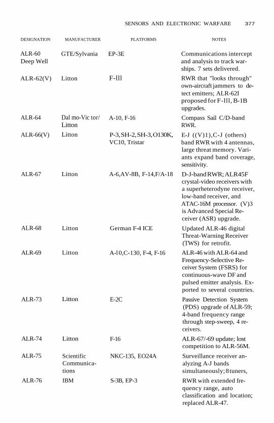
SENSORS AND ELECTRONIC WARFARE 377
DESIGNATION MANUFACTURER PLATFORMS NOTES
ALR-60Deep Well
ALR-64
ALR-66(V)
ALR-67
ALR-68
ALR-69
ALR-73
ALR-74
ALR-75
ALR-76
GTE/Sylvania EP-3E
ALR-62(V) Litton F-lll
Dal mo-Vic tor/Litton
Litton
Litton
A-10, F-16
P-3, SH-2, SH-3, O130K,VC10, Tristar
A-6,AV-8B, F-14,F/A-18
Litton
Litton
German F-4 ICE
A-l 0,C-130, F-4, F-16
Litton E-2C
Litton
ScientificCommunica-tions
IBM
F-16
NKC-135, EO24A
S-3B, EP-3
Communications interceptand analysis to track war-ships. 7 sets delivered.
RWR that "looks through"own-aircraft jammers to de-tect emitters; ALR-62Iproposed for F-lll, B-1Bupgrades.
Compass Sail C/D-bandRWR.
E-J ((V)1),C-J (others)band RWR with 4 antennas,large threat memory. Vari-ants expand band coverage,sensitivity.
D-J-band RWR; ALR45Fcrystal-video receivers witha superheterodyne receiver,low-band receiver, andATAC-16M processor. (V)3is Advanced Special Re-ceiver (ASR) upgrade.
Updated ALR-46 digitalThreat-Warning Receiver(TWS) for retrofit.
ALR-46 with ALR-64 andFrequency-Selective Re-ceiver System (FSRS) forcontinuous-wave DF andpulsed emitter analysis. Ex-ported to several countries.
Passive Detection System(PDS) upgrade of ALR-59;4-band frequency rangethrough step-sweep, 4 re-ceivers.
ALR-67/-69 update; lostcompetition to ALR-56M.
Surveillance receiver an-alyzing A-J bandssimultaneously; 8 tuners,
RWR with extended fre-quency range, autoclassification and location;replaced ALR-47.

378 SENSORS AND ELECTRONIC WARFARE
AIRBORNE ELECTRONIC WARFARE SYSTEMS (continued)DESIGNATION MANUFACTURER PLATFORMS
ALR-77 Eaton-AIL
ALR-80(V) Litton
ALR-85(V) Litton
ALR-91 Litton
ALR-93
APR-38
APR-39
APR-39A
Litton
McDonnellDouglas
E-Sy stems,Loral
Litton
APR-43 Loral, AEL
APR-44 AEL
P-3C
C-101 Aviojet, F-5E,CN-235
C-130, L-1011
F-16
export
F-4G
OV-/RV-1D, most UShelicopters, Lynx, Ga-zelle, BO-105, patrolcraft
C-l 30, OV-10, SEMA air-craft, AH-l,AH-64,UH-60, Hirundo
US Navy
OH-58, UH-1N
ESM with IFM, DF, narrow-band analysis; replacedALQ-78.
Export-oriented digital,fully programmableALR-66(V)3 upgrade.
Modular RWR for trans-ports.
Replacement RWR forALR-46 ({V)3),ALR-69((V) 4) with 32-bit pro-cessor, all-band "staring"surveillance.
32-bit processor, super-heterodyne, IFM receiverscan be added.
Emitter Location System(ELS) with 52 antennas.Planned upgrade to APR-47canceled because of re-ceiver problems, but muchimproved Weasel AttackSignal Processor (WASP)added to basic APR-38.
E-I-band RWR for helicop-ters with signal sorting,emitter identification, bear-ing computation.
Expands APR-39 coverageto millimeter-wave bands(L, M). (V) 3 adds crystal-video receivers for contin-uous coverage. Also servesas controller for AVR-2 la-ser warner, AAR-47.
RWR for C/D pulse, CWmissile systems. Works withALR-45/67, ALCM26/-162.
Lightweight RWR that de-tects (in (V)3 version) H-J-band CW signals.
NOTES

SENSORS AND ELECTRONIC WARFARE 379
DESIGNATION MANUFACTURER PLATFORMS NOTES
APR-46(V) Watkins-Johnson
APR-50
ASS-2
ASS-24
ATRJ
ATIRCM
IBM
ITT
Special-operations air-craft
B-2
UH-1
OV-1
development
Lockheed developmentSanders, Loral,Northrop
AVR-2
P-MAWS2000
USA-4
transports
Westinghouse development
OV-1
Wideband microwave re-ceiver (30 MHz to 18 GHz)applicable to special-operations forces aircraft.
ESM/Threat Warning suiteusing Very Large Scale Inte-grated (VLSI) and GalliumArsenide (GaAs) circuitry.
Infrared (IR) surveillancesystem.
IR surveillance system.
Advanced Threat RadarJammer suite for theAH-64.
(Advanced Tactical Infra-red Countermeasures)Directed IRCM systemusing laser to jam IRseekers. Sanders uses coher-ent laser, Loralnoncoherent, Northropboth.
Laser-warning system.
3rd-generation ultraviolet-band Missile Attack Warn-ing System.
IR surveillance system.
GROUND-BASED ELECTRONIC WARFARE SYSTEMS
DESIGNATION MANUFACTURER PLATFORMS NOTES
GLQ-3
MLQ-33
MLQ-34Tacjam
FairchildWeston
GTE
GTE, AEL
truck
M1015 tracked carrier
VHF (20-230 MHz) tacticalvoice and data communica-tions intercept and ECMsystem.
Jams ground-to-air VHF/UHF communications.
Jams most types of modu-lated signals in A-C bands;can direct 2,000 watts ateach of 3 emitters simul-taneously. Often deployedwithTSQ:112.

380 SENSORS AND ELECTRONIC WARFARE
GROUND-BASED ELECTRONIC WARFARE SYSTEMS (continued)DESIGNATION MANUFACTURER PLATFORMS
MSQ-103Teampack
PRO-10
PRD-12LMRDFS
TLQ-15
TLQ17Traffic JamQuickfix
Emerson truck (-103B) orM1015(-103A/C)
TRQ-30
TRQ32Teammate
TSC-109Agtclis
TSQ112Tacelis
TSQ-114Trailblazer
TSQ152Trackwolf
LAV MEWSS
truckWatkins-Johnson
AEL
Loral Fairchild truck (-17A), EH-1,EH-160 Quickfix helo
manpack
truck
Bunker Ramo truck
GTE
ESL
truck
M1015
tracked
Detects and provides Lineof Bearing (LOB) on radarsin C-K bands (0.5-40 GHz).Colocated with TSQ-114COMINT system.
SIGINT system.
Intercept, DF of hostileHF/VHF/UHF communi-cations.
2,000-watt jammer and"look-through" communi-cations system.
Jamming/monitoring ofHF/VHF systems. Can oper-ate on up to 255 presetfrequencies simultaneously.Sandcrab jammer devel-oped for Operation DesertStorm.
HF/VHF intercept andLOB. Known as Turkey 30.
HF/VHF intercept andLOB. Known as Turkey 32.Replaced by TSQ-112.
C-J-band SIGINT DF (Di-rection Finding) systemusing 3 remote, 1 controlstations; 1° RMS accuracy at16 nm (30km).
HF/VHF COMINT DF sys-tem; 2 remote master, 4remote slave stations; de-ployed with MLQ-34.
HF/VHF/UHF search, in-tercept, and report sytern.Interopcrates with Quickfixfor DF in 20-80 MHz.
HF COMINT and auto DF,collection, processing.
various
NOTES

SENSORS AND ELECTRONIC WARFARE 381
DESIGNATION MANUFACTURER PLATFORMS NOTES
TSQ-IEWCS Electrospace M2 tracked carrier, HM-WWV 5/4-ton truck
ULQ-19 Racal
USD-9 ESL
mobile, helicopter
RC-12
Intelligence and ElectronicWarfare Common Sensor(COMINT/ECM/EUNT/ESM functions combined)to detect single channeland Low Probability of In-tercept signals. Fielded inGBCS-Heavy (M2) andGBCS-Light variants. Re-places MLQ;34, MSCM03,TLQ-17, TRQ-32, TS(>114.
16-channel 100-watt com-munications jammercovering 20-80 MHz.
Airborne SIGINT system;with ELINT added, be-comes Guardrail commonsensor, works with TSQ-112.
NAVAL ELECTRONIC WARFARE SYSTEMS
DESIGNATION MANUFACTURER PLATFORMS NOTES
BLD-1
BLQ-3
BLQr4
BLCW
BLQ:6
BLQ-8
BLR 1-10
BLR-13
BLR-14
BLR-15
Litton/Amecon submarines (SSNSSN21)
GE
GE
submarines
submarines
GE submarines
GE submarines
Bendix, Aerojet submarines
several
Kollmorgen
Unisys
submarines
submarines
submarines
BRD-6/7 LockheedSanders
Kollmorgen submarines
submarines
Passive intercept and pre-cise Direction Finding (DF)using phase interferometer.
Low-Frequency (LF) acous-tic jammer.
High-Frequency (HF)acoustic jammer.
LF acoustic repeater.
HF acoustic repeater.
Acoustic Countermeasures(CM).
Radar-Warning Receivers(RWR).
ECM receiver.
Basic Submarine AcousticWarfare System (BSAWS)against torpedoes. Warns,analyzes, and launches CM.
Electronic Support Mea-sures {ESM) receiver.
RDF, SIGINT receiver.
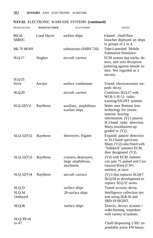
382 SENSORS AND ELECTRONIC WARFARE
NAVAL ELECTRONIC WARFARE SYSTEMS (continued)
DESIGNATION MANUFACTURER PLATFORMS NOTES
Mk36SRBOC
Loral Hycor surface ships
Mk 70 MOSS
SLQ-17 Hughes
SLQ-25Nixie
SLQ:29
Aerojet
SLQ-32(V)1 Raytheon
SLQ-32(V)2 Raytheon
SLQ-32(V)3 Raytheon
SLQ-32(V)4 Raytheon
SLQ-33SLQ-34Outboard
SLQ:36
SLQ-39/-41to-47
submarines (SSBN 726)
aircraft carriers
surface combatants
aircraft carriers
auxiliary, amphibiouswarfare ships
destroyers, frigates
cruisers, destroyers,large amphibious,auxiliaries
aircraft carriers
surface ships28 surface ships
surface ships
6-barrel chaff/flarelauncher deployed on shipsin groups of 2 or 4.Tube-Launched MobileSubmarine Simulator.ECM system that tracks, de-tects, and uses deceptionjamming against missile ra-dars. Not regarded as asuccess.
Towed, electroacoustic tor-pedo decoy.Combines SLQ-17 withWLR-1/-8/-11 radar-warning/SIGINT systemsSeries uses Rotman lenstechnology for instan-taneous bearinginformation. (V) 1 passiveH-J-band radar detection.Many installations up-graded to (V)2.Expands passive detectionto D-J-band spectrum.Many (V)2s also fitted with"Sidekick" jammer ECM,then designated (V)5.(V)2 with ECM. Jammercan jam 75 pulsed and Con-tinuous Wave (CW)emitters at once.(V) 3 that replaces SLQ4 7.SLQ-54 in development toreplace SLQ-32 series.Towed acoustic decoy.Intelligence collection sys-tem using SLR-16 andSRD-19 SIGINT.Detects, decoys acoustic-/wake-homing torpedoeswith variety of systems.
Chaff-dispensing (-39) / ex-pendable active EW buoys.

SENSORS AND ELECTRONIC WARFARE 383
DESIGNATION MANUFACTURER PLATFORMS NOTES
SLQ-49
SLR-16
Irvin
SLQ-50 E-SystemsBGPHES
LockheedSanders
SLR-21 E-Systems
SLR-22SLR-23
SLR-24
SLT-5, 8SRD-19Diamond
SRS-1
SSQ-72/-74 ITT/-108 ClassicOutboard
SSQ:82 MuteULQ-6 General
InstrumentURD-9(V)URD-27WLQ4 Sea GTENymph
WLR-1H
surface ships or aircraft
surface ship with aircraft
surface ships
PHM 1 hydrofoils
aircraft carrierssurface ships
surface ships
surface shipssurface ships
surface ships
surface ships
surface shipsdestroyers, frigates
surface shipssurface shipssubmarines (SSN 637)
ST Research surface ships
"Rubber duck" inflatableradar decoy. Developed inGreat Britain.Batde Group Passive Hori-zon Extension System(pronounced "bigfeez")-Intercept antenna are air-borne, info data-linked toshipboard processors.HF SIGINT using SRD-19antennas. Part of SLQr34/88(^72 Classic Outboardsystems.E-J-band radar interceptand DF.Deception system.J-band radar intercept, DF;used with WLR-1, SLQ-32,On-board processor usestowed torpedo-detectionarray.Communications jammers.SIGINT in LF/MF/VHFbands; uses several types ofantennas. Part of SSQ-72Classic Outboard.Antiship missile radar de-tection emphasizing lowercost. Cost overruns re-ported.DF suite; -74 on 1 ship, -108is most elaborate; usesSLR-16, SRD-19.Emission control monitor.Deception repeater jammerin older ships.A-B-band radar DF.B-J-band SIGINT DF.ESM detector/analyzer ofradar, communications sig-nals; -4(V) 1 for use inSeawolf.HF to low-J-band RWR inearly variants; 1H in H-J-band, has threat library,control of CM.

384 SENSORS AND ELECTRONIC WARFARE
NAVAL ELECTRONIC WARFARE SYSTEMS (continued)
DESIGNATION
WLR-9
WLR-11
MANUFACTURER PLATFORMS
Norden
ARGO
WLR-12 Norden
WLR-13
WLR-17 Norden
submarines
aircraft carriers
submarines
surface ships
submarines
NOTES
WLR-3 Jetonics
WLR-4
WLR-5
WLR-6Waterboy
WLR-8(V) GTE
surface ships,submarines
surface ships,submarines
surface ships,submarines
surface ships,submarines
aircraft carriers,submarines
RWR, SIGINT system.
ESM receiver.
Acoustic intercept receiver.
Signal collection for recon-naissance.
HF to J-band (except (V)2C-J-band) signal surveil-lance and analysis with 7superheterodyne tunersand 2 digital computers.
Acoustic Intercept Receiver(AIR); has 2 hydrophones,receiver processor for sonarintercept and analysis.
H-J-band InstantaneousFrequency Measurement(IFM) to detect antishipmissile radars. Used withWLR-1,
AIR with extended fre-quency coverage.
Infrared, electro-opticalwarning receiver.
AIR derived from WLR-9.

SHIPS/SUBMARINES
AIRCRAFT CARRIERSEnterprise (CVN 65)The Enterprise was the world's secondnuclear-powered surface warship and wasthe world's largest and most expensivewarship when she entered service in1961. The Enterprise was built to a mod-ified Kitty Hawk design and features afully angled deck with two C13 steam cat-apults, two more catapults at the bow,three elevators to starboard (two aheadof the island and one abaft it), and oneelevator on the port quarter. Each eleva-tor measures 85 x 52 ft (25.9 X 15.9 m).
The big difference from the Kitty Hawkwas the machinery layout, with no fewerthan eight reactors generating steam forfour steam turbines. No other ship hadeven half as many nuclear reactors. Rela-tively small reactors and the immense sizeof the ship led to the complex arrange-ment.
In her original configuration, Enterprisewas readily recognizable through the dis-tinctive arrangement of "billboard"planar-array radar antennas and EW"beehive" on her island; these were re-moved in the late 1970s. Her flight deckhas the greatest area of any aircraft car-rier, her hangar is the largest and longest,she carries 8,500 tons of aviation fuel(approximately 2.72 million US gal/10,295,200 liters), and she has an ord-nance capacity of 2,520 tons.
DEVELOPMENT • Enterprise was au-thorized in FY1958 and ordered fromNewport News Shipbuilding in Novem-ber 1957, completing in September 1960.Estimated construction cost was $444
million (contemporary conventional air-craft carrier construction costs in same-year dollars were estimated at $265 mil-lion) . Hopes for five more in the class ranafoul of the high cost and complex reac-tor layout.
In January 1991, the Enterprise began aRefueling and Complex Overhaul(RCOH) at Newport News that includednew reactor cores, overhauled propulsionplant, and modernization of the naviga-tion, communications, and aviation sup-port systems. Cost is estimated at between$1.5 and $2 billion to gain another 20years. Enterprise was recommissioned inSeptember 1994.
COMBAT EXPERIENCE • The Enter-prise began flying air strikes against NorthVietnam in November 1965, becomingthe first nuclear-propelled ship to entercombat. She served two more tours offVietnam but suffered a serious fire in Jan-uary 1969 on her way out to a fourth tour.
In April 1988, A-6 and A-7 aircraft fromthe Enterprise attacked several IranianNavy ships and craft in the Persian Gulf,sinking the frigate Sahandand several Bo-gharnmar fast attack craft and severelydamaging the frigate Sabalan. (The Enter-prise did not actually enter the gulf.)
SPECIFICATIONS •DISPLACEMENT 90,970 tons full loadDIMENSIONS
length 1,101 ft 3 in (335.8 m)overall
beam 133ft (40.5m)

386 SHIPS / SUBMARINES
draft 39ft (11.9m)flight deck width
257 ft 2 in (78.4m) max,area 4.94 acres (2hectares)
hangar deck length 860 ft (262.1 m),width 107ft (32.6m),height 25 ft (7.6 m)
MACHINERY 8 Westinghouse A2Wpressurized-water reactors, 4 Westing-house steam turbines, 280,000 shp on4 shafts=30+ kts, electric power40,000 kW
CREW 3,208 + air wing 2,092WEAPONS
2 8-tube NATO Sea Sparrowlaunchers Mk 29
3 20-mm Mk 15 Phalanx Gatling-typeCIWS
AIRCRAFT 85
SENSORSSPS-48 3D air-search radarSPS-49 2D air-search radarSPS-64 surface-search radarSPS-65 threat-warning radar2 Mk 91 missile fire control systemsSLQr32(V)3 active/passive EW system
ForresfaJ (CV 59, AVT 59)These four ships were the world's firstaircraft carriers to be built from the keelup after World War II, construction be-ginning in the early 1950s. The Forrestalintroduced the basic supercarrier con-cept of four elevators and four catapults,avast, 8° angled flight deck, "hurricane"bow for better seakeeping, a powerfulpropulsion plant, and great increases infuel and ordnance storage capacity. Twolongitudinal bulkheads run from stem tostern and extend from keel to waterline;transverse bulkheads are placed approx-imately every 33 ft (10 m). This subdivi-sion results in 1,200 watertight compart-ments under an armored flight deck.
The elevator layout is the weakest pointof the design in that one is positioned atthe forward end of the angled deck, limit-
ing its use during flight operations. Eachelevator measures 62 ft x 52 ft 4 in (18.9x 15.98 m). The island is midships in thecarrier's silhouette with one elevatorahead and two astern along the starboardside. The Forrestal has two inboard four-blade propellers, two outboard five-bladepropellers, and three rudders.
DEVELOPMENT • Newport News Ship-building was the lead yard and con-structed the Forrestal and Ranger from1952 to 1957 while the Brooklyn NavyYard built the Saratoga and Independencefrom 1952 to 1959.
The 1980s Service Life Extension Pro-gram (SLEP) updates include rehabilita-tion of the ship's hull, propulsion,auxiliary machinery, and piping systems,with improved radars, communicationsequipment, and aircraft launch and re-covery systems provided. Kevlar armorwas added to vital spaces, and more pow-erful C13 catapults, the Phalanx Mk 15Mod 3 Close-in Weapons System (CIWS),Mk 23 TAS radar, and Mk 29 Sea Sparrowshort-range Surface-to-Air Missile (SAM)launchers were fitted.
The Saratoga-was first to enter the SLEP(October 1980-February 1983), then theForrestal (March 1983-May 1985), and In-dependence (April 1985-February 1988).The Ranger did not enter the SLEP pro-gram, getting instead a 1984-85 overhaulthat included many of the self-defensesensor and weapons upgrades, an im-proved fire-fighting system, and im-proved evaporators.
The Forrestal replaced Lexington (AVT16) as the Navy's training carrier in Feb-ruary 1992. Her start in the new role wasdelayed by her six-month deployment tothe Mediterranean in mid-1991. Latercutbacks led to her being decommis-sioned in FY1994.
The Independence shifted home ports toYokosuka, Japan, in September 1991, re-lieving the USS Midway (CV 41). TheRanger was decommissioned in 1993, theSaratoga in 1994.

SHIPS / SUBMARINES 387
COMBAT EXPERIENCE • All four shipslaunched raids against North Vietnam intours conducted from 1964 to 1975. TheForrestal, Saratoga, and Independence eachhad one tour; the Forrestal lost 134 crewdead to a fire in July 1967. The Rangermade four tours.
In August 1990, the Independencemoved first to the northern Arabian Seain response to Iraq's invasion of Kuwaitand later (October 1990) became thefirst US carrier to enter the Persian Gulfsince 1974. She was relieved by the carrierMidway in November.
The Saratoga arrived in the DesertShield operating area in late August 1990and remained in the Red Sea throughoutOperations Desert Shield and DesertStorm. Her air wing flew 12,500 sortiesduring the deployment, more than 4,000of them in Desert Storm, in which 2,025tons of ordnance were delivered.
The Ranger reached the gulf a few daysbefore Operation Desert Storm began,Her air wing delivered 2,110 tons ofbombs and missiles.
SPECIFICATIONS •DISPLACEMENT 78,200 tons full load
(Forrestal); 79,200 tons full load(others)
DIMENSIONSlength 1,039 ft (316.7 m) overall
(firsts); 1,046 ft 6 in(319.0m) overall(Independence)
beam 130ft (39.6m)draft 37ft (11.3m)/light deck width
250 ft 3 in (76.3 m) (first2); 270 ft (82.3m) (last2)
hangar deck length 740 ft (225.6 m),width 101 ft (30.8m),height 25 ft (7.6 m)
MACHINERY 8 Babcock & Wilcoxboilers, 4 Westinghouse steam tur-bines, 260,000 shp (in Forrestafy,280,000 shp (others) on 4 shafts=33
kts (in Forrestal), 34 kts (others),range 12,000 nm at 20 kts
CREW 2,793-2,958 + air wing 3,400WEAPONS
3 8-cell NATO Sea Sparrow launchersMk 29 in Saratoga and Independence,2 launchers in Ranger
3 20-mm Mk 15 Mod 3 PhalanxGatling-type CIWS
AIRCRAFT 85SENSORS
SPS-48C (except SPS-49E in Saratoga)3D air-search radar
SPS-49 2D air-search radarSPS-10 surface-search radar3 Mk 91 missile fire control systemsSLQ:29 (SLQ-17 jammer and
WLR-8(V)4 radar-warning system)
John F. Kennedy (CV 67)Officially a one-ship class that followedthe three Kitty Hawks (CV 63), this shiphas a distinctive single stack canted out-board. Her underwater protection layoutalso is different from earlier carriers.Otherwise, she resembles the Kitty Hawks,having the island set well aft and the fourelevators at the deck edges. Three eleva-tors are located on the starboard side,two ahead of the island and one abaft ofit; the portside elevator is fitted on theport quarter. The elevators measure 85 x52ft (25.9 X 15.9m).
The Kennedy was completed with a bowsonar dome, but, unlike the America,never had the SQS-23 sonar installed.The Kennedy originally had three SeaSparrow Mk 25 launchers and Mk 115PCS; she was later refitted with Mk 29launchers.
DEVELOPMENT • The Kennedy wasbuilt by Newport News Shipbuilding andentered service in 1968; her constructionwas delayed by lengthy debates overwhether the ship should have nuclear or

388 SHIPS / SUBMARINES
conventional propulsion. (All subse-quent large carriers built for the US Navyhave been nuclear-powered.)
Her Service Life Extension Program(SLEP) refit was canceled in the FY1992budget submitted in February 1991. A$400-million Complex Overhaul (COH)—a less elaborate refit—at Philadelphiawas approved in the Operation DesertStorm supplemental funding bill passedin April 1991, with work beginning in1993.
COMBAT EXPERIENCE • The Kennedywas deployed to the Sixth Fleet in August1990 to replace the Eisenhower (CVN 69)and to support US forces in the PersianGulf as part of Operation Desert Shield.The Kennedy was the only one of the sixcarriers not to embark F/A-18 Hornetdual-role fighters. Instead, she deployedthe last A-7E Corsairs on active duty. HerCAW-3 air wing delivered 1,750 tons, in-cluding the only AGM-84E SLAMs usedin the conflict. Altogether, more than11,000 sorties left her deck during herdeployment.
SPECIFICATIONS *DISPLACEMENT 80,940 tons full loadDIMENSIONS
length 1,050 ft 9 in (320.3 m)beam 128 ft 6 in (39.2m)draft 36 ft 6 in (11.1 m)flight deck width
266 ft 11 in (81.4m)hangar deck length 688 ft (209.75 m),
width 106 ft (32.3m),height 25 ft (7.6 m)
MACHINERY 8 Foster Wheeler boilers, 4Westinghouse steam turbines, 280,000shp on 4 shafts=30+ kts, range 12,000nm at 20 kts, electric power 17,000 kW
CREW 3,045 + air wing 2,500WEAPONS
3 8-cell NATO Sea Sparrow launchersMk29
3 20-mm Mk 15 Phalanx Gatling-typeCIWS
AIRCRAFT 85
SENSORS
SPS-48 3D air-search radarSPS-49 2D air-search radarSPS-10 surface-search radar3 Mk 91 missile fire control systemsMk 23 Target Acquisition System (TAS)SLQ-17 jammer and SLQ-26 EW sys-
tems
Kitty Hawk (CV 63)These three ships have a modified Forres-tal (CV 59) configuration, with improvedelevator and flight deck arrangements,that would be the standard for all laterNavy carriers. The island was moved far-ther aft; the new elevator layout placed allfour at the deck edges. Three elevatorsare located on the starboard side, twoahead of the island and one abaft of it;the portside elevator is fitted on the portquarter. The elevators measure 85 X 52 ft(25.9 X 15.9m).
The America has a bow sonar dome tohouse the SQS-23 sonar. She was the onlypostwar US carrier so fitted at the time;the set was removed in late 1981.
These ships were built with Terriersurface-to-air missile launchers (Mk 10Mod 3 on starboard quarter and Mk 10Mod 4 on port quarter) and SPQ-55Bmissile control "searchlight" radars thathave been removed.
DEVELOPMENT • Delivery of the KittyHawfcwas delayed because of problems atNew York Shipbuilding; her condition ondelivery in 1961 was severly criticized bythe Navy. The Constellation was delayedbecause of a fire on board while underconstruction at the Brooklyn Navy Yard,also completing in 1961. The America,built by Newport News Shipbuilding, en-tered service in 1965. (The John F. Ken-nedy, although similar, is considered aseparate class; see the John F. Kennedyentry.)
The Kitty Hawk and Constellation SLEPs(Service Life Extension Program) at the
SHIPS / SUBMARINES 389
Philadelphia Naval Shipyard included re-habilitation of the ship's hull, propul-sion, auxiliary machinery, electrical, andpiping systems. Improved radars, com-munications equipment, and aircraftlaunch and recovery systems—includingnew blast deflectors, three-wire Mk 7Mod 3 arresting gear, and new catapultrotary engines—were fitted as well as theAdvanced Combat Direction System(ACDS).
Kitty Hawk's SLEP began in January1988 with her first post-SLEP deploymentcoming in November 1992. The Constella-tions SLEP began in July 1990, with herfirst post-SLEP deployment coming at theend of 1993.
The America's SLEP, planned forFY1995, was canceled as a part of forcelevel cutbacks.
COMBAT EXPERIENCE • All threeships operated off the Vietnam coastfrom 1964 to 1975. America and KittyHawk served 3 tours each, while the Con-stellation saw duty on Yankee Station sixtimes, the most of any supercarrier.
Aircraft from the America raided fiveLibyan airfields and other targets in1986.
When Iraq invaded Kuwait in August1990, both Kitty Hawk and Constellationwere undergoing SLEPs. The Americasailed from the West Coast in December,arriving in her launch area a few daysbefore Operation Desert Storm began.Her CAW-1 flew more than 3,000 sortiesduring the air war and delivered 2,000tons of ordnance.
In January 1993, aircraft from the KittyHawk struck at SAM sites in three raidsintended to enforce a "no-fly" zone oversouthern Iraq.
SPECIFICATIONS •DISPLACEMENT 80,800 tons full loadDIMENSIONS
length 1,045 ft 8 in (318.8m)
(first 2); 1,047 ft 2 in(319.25m) (America]
beam 129 ft 11 in (39.6m)draft 37ft (11.3m)flight deck width
251 ft 11 in (76.8m)hangar deck length 740 ft (225.6 m),
width 101 ft (30.8m),height 25 ft (7.6 m)
MACHINERY 8 Foster Wheeler boilers, 4Westinghouse steam turbines, 280,000shp on 4 shafts=30+ kts, range 12,000nm at 20 kts, electric power 15,000kW (first 2), 18,000 kW (America)
CREW 2,773-3,017 + air wing 2,500WEAPONS
3 8-cell NATO Sea Sparrow launchersMk29
3 20-mm Mk 15 Phalanx Gatling-typeCIWS
AIRCRAFT 85SENSORS
SPS-48E 3D air-search radar (exceptSPS-48C in America)
SPS-49(V) 2D air-search radarSPS-10 surface-search radarMk 23 Target Acquisition System
(TAS)SLQ-32(V)3 active/passive EW system
Nimitz (CVN 68)These ships are the largest warships everbuilt and are the definitive supercarrierdesign. Construction of this class willcover more than 30 years, a record for asingle class in the steam and steel age. Thegeneral arrangement of these ships is sim-ilar to the previous Kitty Hawk (CV 63)class with respect to flight deck, elevators(three to starboard, one on the port quar-ter), and island structure. Each elevatormeasures 85 X 52 ft (25.9 X 15.85 m).
The Nimitz was completed with two bri-dle retrieval horns extending forwardfrom the bow catapults. Later ships in theclass have only the starboard horn, asmost Navy aircraft no longer require awire bridle for launching. The number of

390 SHIPS / SUBMARINES
arresting wires is being reduced fromfour to three during refit; the gear is cur-rently produced by the Dutch firm Hy-draudyne Systems and Engineering.
The flight deck and hull are con-structed from high-tensile steel. Protec-tion includes 2 Va-in (63-mm) side armor,Kevlar armor over the magazines and en-gine rooms. 23 watertight transversebulkheads and longitudinal bulkheads di-vide the hull into 2,000 watertight com-partments. Payload includes up to 2,970tons of aviation ordnance and 2.7 millionUS gal (10,219,500 liters) of aviation fuel.
These carriers have only two reactorscompared to the eight in the first nuclearcarrier, the Enterprise (CVN 65). The ini-tial fuel cores in the Mmz'fe-class ships areestimated to have a service life of at least13years (800,000-1 million nm).
As designed, these ships can operateabout 85 fighter, attack, antisubmarine,and airborne early-warning aircraft andhelicopters. Beginning in 1993, US carrierssailed in some deployments as the flagshipof a Joint Task Group of surface combat-ants and amphibious ships. Some of thenormal aircraft were sent ashore to makeroom for a 600-person Marine Corps unitaccompanied by six CH-53 transport andfour UH-1N utility helicopters.
DEVELOPMENT • Six ships are in ser-vice, two more are under construction,and initial funding for a ninth wasrequested in the FY1993 budget. Thefirst three (CVN 68-70) were delayedby shipyard problems and the fourth(CVN 71) by conflicts between the Con-gress and the Carter administration. Thenext four (CVN 72-75) were ordered inpairs in 1983 and 1988. CVN 76 was or-dered in large part to maintain a UScapability to build nuclear-powered sur-face ships.
COMBAT EXPERIENCE ' In August1981, Ata'fe-based F-14 Tomcat fightersshot down two Libyan Su-22 aircraft dur-ing operations in the Gulf of Sidra.
In August 1990, the Dwight D. Eisen-hower, which was nearing the end of ascheduled six-month deployment in theMediterranean, entered the Red Sea aspart of the US response to the Iraqi inva-sion and annexation of Kuwait. She wasrelieved in late September by the John F,Kennedy (CV67).
The Theodore Roosevelt entered the RedSea on January 15, 1991, and launchedaircraft against Iraqi targets on January17 as part of Operation Desert Storm, theonly nuclear-powered carrier to partici-pate in the air war. Her aircraft deliveredapproximately 1,615 tons of ordnanceduring the air war.
SPECIFICATIONS •DISPLACEMENT 91,700 tons full load
(first 3); 96,300-96,700 tons full load(later ships)
DIMENSIONS
length 1,089 ft (332.1 m) overallbeam 134 ft (40.85 m)draft 37 ft (11.3 m) (first 3); 38
ft 5 in (11.7m) (laterships)
flight deck width252 ft 11 in (77.1 m)
(first 3); 257 ft(78.3 m) (later ships)
HANGAR DECK length 684 ft (208.5 m),width 108 ft (32.9 m), height 26 ft 5in (9.5 m)
MACHINERY 2 Westinghouse pressur-ized-water reactors, 4 steam turbines,260,000+ shp on 4 shafts=30+ kts,electric power 64,000 kW
CREW 3,000-3,200 + air wing 2,865WEAPONS
3 8-cell NATO Sea Sparrow Mk 29launchers
20-mm Mk 15 Mod 3 Phalanx Gatling-type CIWS 3 mounts in CVN 68 andCVN 69, 4 in later ships
AIRCRAFT 85 including 20 F-14 Tomcat,20 F/A-18 Hornet, 16 A-6E Intruder,5 EA-6B Prowler, 5 E-2C Hawkeye, 8S-3 Viking, 6 SH-3 Sea King or SH-60FCV-Helo

SHIPS / SUBMARINES 391
CVN71U.S. GOVERNMENT DEPARTMENT OF DEFENSE

392 SHIPS / SUBMARINES
SENSORSSPS-48B 3D air-search radar in CVN
68-70SPS-48C in CVN 71-73 (to be replaced
by SPS-48E)SPS-49 2D air-search radarSPS-10F surface-search radar in CVN
68-70SPS-67(V) surface-search radar in
CVN 71-73
SPS-64 surface-search radar in CVN71 and later ships
SPS-65 threat-detection radar inCVN-71 and later ships
4 Mk 91 missile fire control systemsSLQ-29 (SLQ-17 jammer + WLR-8
radar-warning receiver)WLR-1H radar-warning receiver4 Mk 36 SRBOC 6-barrel chaff/flare
launchers

SHIPS / SUBMARINES 393
AMPHIBIOUS SHIPSAnchorage (LSD 36)These five Dock Landing Ships (LSD)were part of the large amphibious shipconstruction program of the early 1960s.They resemble the earlier Thomaston-c\3.ss(LSD 28) but have a prominent knuckleforward, a more rectangular superstruc-ture profile, greater freeboard, and amore substantial helicopter landing areaaft.
The docking well is 430 ft (131.1 m)long and 50 ft (15.24 m) wide; it wasdesigned to accommodate four LCAC aircushion landing craft or three LCU util-ity landing craft or nine LCM-8 mecha-nized landing craft or 52 AAV amphibiantractors. Another 15 tractors can bestowed on a "mezzanine" deck, whichwhen fitted allows only three LCAC aircushion assault craft to be embarked. Aremovable helicopter deck is fitted overthe docking well, but the ships have nohangar or helicopter maintenance capa-bility. Total vehicle storage space is15,800ft2 (1,468m*).
As built, these ships had eight 3-in gunsin twin mounts; one amidships mountand the Mk 56 and Mk 63 gunfire controlsystems were removed in the late 1970s.One additional 3-in twin gun mount wasdeleted with installation of the two Pha-lanx Close-In Weapons Systems (CIWS)in the 1980s.
DEVELOPMENT • Anchorage was builtby Litton's Ingalls yard at Pascagoula,Mississippi, from 1967 to 1969; the otherfour were constructed at General Dy-namics' Quincy, Massachusetts, yardfrom 1967 to 1972.
COMBAT EXPERIENCE • Anchorage,Portland, Pensacola, and Mount Vernon alldeployed to the Persian Gulf as part of
Operation Desert Shield. Portland andPensacola sailed with Amphibious Group2, arriving in the theater in early Septem-ber (Portland on the 3rd, Pensacola on the6th). Anchorage and Mount Vernon werepart of Amphibious Group 3, which en-tered the theater on January 12, 1991.
The threat of a large invasion forcelying in the gulf east of Kuwait City wassaid to have been an important part ofthe deception that significantly reducedIraqi armed forces' ability to react to thearmored left hook that began theground war in late February. All re-mained in the gulf as part of a potentialinvasion force until after the March 1cease-fire.
SPECIFICATIONS •DISPLACEMENT 14,000 tons full loadDIMENSIONS
length 553 ft 6 in (168.7m)overall
beam 85 ft (25.9 m)draft 18 ft 5 in (5.6m)
MACHINERY 2 Foster Wheeler boilers(except Combustion Engineering inAnchorage), 2 De Laval steam turbines,24,000 shp on 2 shafts=22 kts (20 ktssustained)
CREW 358 + 330 troopsWEAPONS
6 3-in (76-mm)/50-cal Mk 33 AA intwin mounts (4 guns in ships withPhalanx CIWS)
2 20-mm Mk 15 Phalanx Catling-typeCIWS
HELICOPTERS removable flight deckSENSORS
SPS-40 air-search radarSPS-10 surface-search radarlocal fire control only for 3-in gunsSLQ-32(V)1 passive EW system

394 SHIPS / SUBMARINES
Austin (LPD 3)These 12 ships are enlarged versions ofthe earlier three-ship Raleighrdass LPDs.They resemble dock landing ships buthave a relatively smaller docking well andadditional space for troop berthing andvehicle parks.
The LPD 7-13 are configured as am-phibious squadron flagships and have anadditional bridge level. All have a dock-ing well that is 168 feet long and 50 feetwide; landing craft stowage in the wellcan be either two LCACs, one LCU withthree LCM-6s or four LCM-8s, or 24 AAV7amphibious assault vehicles. Two moreLCM-6 or four LCVP or LCPL landingcraft can be carried on the helicopterdeck. Below decks is about 12,000 ft2
(1,115 m2) of vehicle storage space and40,000ft3 (1,133m3) of bulk cargo space.
These ships have a fixed flight deckabove the docking well with two landingspots. All except the Austin are fitted witha helicopter hangar; an extension ex-pands to provide a length of approx-imately 80 feet. As many as four CH-46s orCH-53s can be embarked at a time, butthis can only be done with a helicoptercarrier in company to provide sustainedmaintenance and support. As built, theseships had eight 3-in guns in twin mounts.The number was reduced in the late1970s, and the associated Mk 56 and Mk63 Gun Fire Control Systems (GFCS)were removed. Most have been fitted withtwo Phalanx Close-in Weapons Systems(CIWS).
DEVELOPMENT • Brooklyn Navy Yardbuilt the first three, Litton's Ingalls yardin Pascagoula, Mississippi, the next two,and Lockheed Shipbuilding the lastseven. Deliveries came between 1965 and1971; LPD-16 was authorized, but notbuilt. Plans in the 1980s for a Service LifeExtension Program (SLEP) for this classwere not funded by Congress. The .firstships of this class began decommission-ing in FY1993.
The Coronado (LPD 11) of this class wasmodified for use as a flagship in late 1980and reclassified AGF 11. The LPD-17follow-on class is planned for first orderin FY1996. These 12 much bigger shipswill displace 25,300 tons, measure 684feet {208.4 m) long overall and have a105-ft (31.9 m) beam. Each will carry 700troops, two Landing Craft Air Cushion(LCAC), and have a hangar for helicop-ters or the MV-22 Osprey.
COMBAT EXPERIENCE • As with mostof the US Navy's amphibious ships, theseunits frequently assist in disaster or hu-manitarian relief or evacuation of depen-dents. Six of the class participated inOperations Desert Shield/Desert Storm.The Ogden embarked part of the 13th Ma-rine Expeditionary Unit (Special Opera-tions Capable). The Dubuquewas part of asmall task force (ARG Bravo) that de-ployed to the Desert Storm theater for 35days between September 9 and October13, 1990.
Shreveport and Trenton lifted elementsof the 4th Marine Expeditionary Brigade(MEB), reaching the theater of opera-tions on September 3, 1990. Denver andJuneau, as part of Amphibious Group 3,transported the 5th MEB, arriving in thetheater in mid-January 1991. All exceptDubuque remained in the theater untilwell after the cease-fire.
SPECIFICATIONS •DISPLACEMENT 16,900 tons full loadDIMENSIONS
length 568 ft 9 in (173.4m)overall
beam 84ft (25.6m)draft 23 ft (7.0 m)well deck length 393 ft 8 in (120.0
m), width 52 ft 3 in(15.2m), flight deckarea 15,000 ft2 (1,394m2)
MACHINERY 2 boilers (Foster Wheelerexcept Babcock & Wilcox in Duluthand Shreveport), 2 De Laval steam tur-

SHIPS / SUBMARINES 395
bines, 24,000 shp on 2 shafts= 20 kts,range 7,700 nm at 20 kts
CREW 425 + 930 troops in 5 ships; 840troops + 90 flag in 6 ships
WEAPONS
4 3-in (76-mm)/50-caI Mk 33 AA intwin mounts
2 20-mm Mk 15 Mod 2 PhalanxGatling-type CIWS in four ships
HELICOPTERS flight deck with 2 land-ing spots and hangar
SENSORS
SPS-40C air-search radarSPS-10F or SPS-67 surface-search radarLN-66 navigation radarlocal gunfire control onlySLQ-32(V) 1 passive EW system
Charleston (LKA 113)These five ships carry heavy equipmentand supplies to unload into landing craftand onto helicopters for opposed land-ings. Although they were the first US classto be built expressly for the attack trans-port role, they resemble conventionalbreak-bulk freighters. But their prodi-gious hoisting capacity includes two 78-ton-capacity cranes and two 40-toncranes; eight more 15-ton-capacity boomsare also rigged.
These ships have a helicopter landingarea aft, but no hangar or maintenance fa-cilities. The landing area measures 6,082ft2 (565 my). The Charlestons have approx-imately 33,000 ft2 (3,065 m*) of vehiclestorage space and almost 70,000 ft3 (1,982m3) of bulk cargo space. Usual landingcraft stowage includes four LCM-8s, fiveLCM-6s, two LCVPs, and two LCPs.
Two Phalanx Close-in Weapons Sys-tems (CIWS) were fitted in the Charlestonand El Paso.
DEVELOPMENT • Newport News Ship-building constructed all five ships, com-pleting them from 1968 to 1970. TheCharleston was decommissioned inFY1992 and the other four in FY1994.
COMBAT EXPERIENCE * To supportOperations Desert Shield and DesertStorm, the Durham carried elements ofthe 13th Marine Expeditionary Unit(Special Operations Capable) fromOkinawa to the Persian Gulf, arriving onSeptember 7,1990. The Mobile sailed withAmphibious Group 3, which arrived inthe gulf on January 12, 1991 and re-mained until the cease-fire.
SPECIFICATIONS •DISPLACEMENT 18,600 tons full loadDIMENSIONS
length 576 ft (175.6 m) overallbeam 62ft (18.9m)draft 25 ft 6 in (7.8 m)
MACHINERY 2 Combustion Engineeringboilers, 1 Westinghouse steam turbine,22,000 shp on 1 shaft- 20+ kts
CREW 360 -I- 225 troopsWEAPONS
6 3-in (76-mm)/50-cal Mk 33 AA intwin mounts except 4 in Charleston,El Paso
2 20-mm Mk 15 Phalanx Gatling-typeCIWS
HELICOPTERS landing areaSENSORS
SPS-10 surface-search radarLN-66 navigation radar (except
CRP-2900 in Charleston]local gunfire control onlySLQ-32(V) 1 passive EW system2 Mk 36 SRBOC 6-barrel chaff/flare
launchers
Jwo/ima(LPH2)These seven ships were the first of anynavy to be constructed specifically to op-erate helicopters. Unlike the Royal Navy'scommando carriers of the 1960s and1970s, and the later Tarawa/Wasp classes,however, these LPHs do not carry land-ing craft (except for the LCVP davits inthe Inchon).
These ships represent an improvedWorld War II-type escort carrier design

396 SHIPS / SUBMARINES
with accommodations for a Marine bat-talion and supporting helicopter squad-ron. Up to seven CH-46 Sea Knight orfour CH-53 Sea Stallion helicopters canoperate from their flight decks. No cata-pults or arresting gear are fitted. Thehangar deck, which is 229 ft 8 in (70 m)long, can accommodate 19 Sea Knightsor 11 Sea Stallions or various mixes ofthese and other aircraft. The two deck-edge elevators measure 50 X 34 ft (15.2X 10.4m).
Below the flight deck, vehicle spaceamounts to 5,563 ft2 (517 m*), and40,000 ft3 (1,133 m3) of space is availablefor bulk cargo. These ships have exten-sive medical facilities with a 300-bed sickbay.
Between 1970 and 1974, all ships hadtwo 3-in gun mounts replaced by SeaSparrow missile launchers (one forwardof the island and one on the port quar-ter). Still later, all ships were refitted withtwo Phalanx CIWS. The Okinawa had herforward Sea Sparrow launcher replacedby a Phalanx mount. The other six shipshave one Phalanx on a sponson on thestarboard side, forward of the Sea Spar-row launcher, a second Phalanx fitted ona sponson on the port side, aft. All gun-fire control systems have been removedand only local control is now available forthe 3-in guns.
Building on the Tripoli's experiencein Operation Desert Storm, the Inchonbegan testing a mine countermeasuressupport ship conversion in 1994. Successin these trials led to a $29-miIlionconversion contract to Ingalls in Decem-ber 1994. Inchon's new designation isMCS-1.
DEVELOPMENT • Five of the class werebuilt in naval shipyards (one at PugetSound, four at Philadelphia) from 1961to 1968; two were constructed at Litton'sIngalls yard in Pascagoula, Mississippi,and delivered in 1966 and 1970. Iwojimaand Okinawa decommissioned in FY1993,Guadalcanal in FY1994.
COMBAT EXPERIENCE • These shipsoperated CH-53 helicopters in minecountermeasures operations off NorthVietnam in 1973, in the Suez Canal in thelate 1970s, and in the Persian Gulf in sup-port of US Navy convoy operations dur-ing the 1980-88 Iran-Iraq war. They havealso frequently participated in monitor-ing operations such as the Adriatic Seapatrol in 1992 and several evacuations.
The Iwojima, Okinawa, Guam, Tripoli,and New Orleanswere deployed to the Per-sian Gulf region as part of Operation De-sert Shield. The Okinawa was the first toarrive, on September 5, bringing a part ofthe 13th Marine Expeditionary Unit(Special Operations Capable). The Iwo
Jima and the Guam lifted parts of the 4thMarine Expeditionary Brigade (MEB),arriving in the theater on September 8,1990, and remaining until March 23,1991. The Tripoli and the New Orleanswere part of Amphibious Group 3, whichreached the theater on January 12, 1991.
The Tripoli was named command shipof the Mine Countermeasures Group onJanuary 17. On February 18, 1991, shestruck a mine in the northern PersianGulf, sustaining a 16 by 20-ft (4.88 by6.1-m) hole 10 ft (3.05 m) below the wa-terline, but remained operational. Shecontinued as flagship of the MCM forceuntil June 18, when she was relieved bythe cruiser Texas (CGN 39).
Cargo and utility helicopters flew 4,980sorties from the Tripoli's flight deck insupport of Operation Restore Hope inSomalia in 1993.
SPECIFICATIONS •DISPLACEMENT 18,300 tons full loadDIMENSIONS
length 602 ft 3 in (183.6m)overall
beam 83 ft 8 in (25.5 m)waterline, extremewidth 104 ft (31.7m)
draft 26 ft (7.9 m)MACHINERY 2 boilers (Combustion En-
gineering except Babcock & Wilcox in

SHIPS / SUBMARINES 397
Guam), 1 Westinghouse steam turbine,22,000 shp on 1 shaft=22 kts (21 kts sus-tained, range 16,600 nm at 11.5 kts,10,000 nm at 20 ktsCREW 685 + 2,000 troopsWEAPONS
2 8-cell Mk 25 Sea Sparrow missilelaunchers (except Okinawa)
4 3-in (76-mm)/50-cal Mk 33 AA intwin mounts
2 20-mm Mk 15 Phalanx Gatling-typeCIWS
HELICOPTERS 25 helicopters (class hasoperated AV-8B Harrier VSTOLaircraftbut does not regularly embark them)
SENSORSSPS-40 air-search radarSPS-10 surface-search radarLN-66 navigation radar (except
CRP-1900B in Guam)2 Mk 115 missile fire control systemsSLQ:32(V)2 EW system (except
WLR-1 in Tripoli)
Landing Craft Air Cushion(LCAC 1)These 84 craft are the only US Navy aircushion landing craft in service. (The for-mer Soviet Navy deployed several de-signs, many larger than the LCACs.) Theyare designed to transport troops andequipment from ships to over-the-shoreduring amphibious operations. Using theair cushion gives the LGAC the ability tocarry approximately the same payload asan LCM-8-type landing craft at more thanfour times the speed and to travel inlandover flat ground or marshes; they canclear land obstacles up to 4 ft (1.22 m)high.
The LCAC has more in common with ahelicopter than with a landing craft. It isconned by a "craftmaster" using ayokelike control wheel (and earning"flight time") from a pilothouse on thestarboard side; the navigator and craftengineer sit next to the operator in side-
by-side seats. A fourth seat is provided forthe group commander, who rides in oneof three LCACs in a detachment. All fiveLCAC crew members are enlisted person-nel, the craftmaster being most senior.
Typical payload is 60 tons (54.4 metrictons) of cargo, an Ml Abrams main battletank (65 tons), or five light armored vehi-cles, or two M198 towed 155-mm how-itzers and their prime movers, plus 24combat-ready troops. Eight Marines ridebelow the pilothouse and 16 more sit in adeckhouse on the port side forward. Theloadmaster rides in the port deckhouseand a deck hand/assistant engineer sitsabove. (During Operation Desert Storm,as many as 41 Marines were embarked.)
The cargo deck is 27 ft (8.23 m) wideand has an area of 1,809 ft* (168.1 m*};maximum cargo overload is 75 tons (68metric tons). Along each side of the cargodeck are the crew and troop quarters(forward) and tandem engine units.
The craft are girdled with a "bag andfinger" skirt that is inflated by the for-ward engine unit on each side. The Tex-tron Lycoming gas turbines drive four liftfans through offset fan drive gearboxes.When the skirt is deflated, both bow andstern ramps can be used for loading andunloading.
The after engines on each side propelthe craft with four-blade, reversible, 11-ft9-in (3.58-m) diameter propellersthrough offset propeller drive gear-boxes. Each propeller is housed in adeep-chord shroud that has five statorsabaft the propellers and twin rudders.The engines also operate two bow thrus-ters that are used for propulsion andmaneuvering.
DEVELOPMENT • LCAC 1 was deliv-ered by Bell Textron in December 1984.The first operational deployment of theLCACs took place in August 1987 in USSGermantown (LSD 42). 107 had beenplanned, but only 84 were authorized, thelast being ordered in 1992. The LCACsare evenly divided between Assault Craft

398 SHIPS / SUBMARINES
Unit 4 (ACU-4) of the Atlantic Fleet andACU-5 in the Pacific. Japan ordered twoLCACsinlate 1993.
COMBAT EXPERIENCE • In August1990,17 LCACswere deployed to the Per-sian Gulf in several landing ships as partof Operation Desert Shield. Although aNovember 1990 landing rehearsal im-plied that LCACs might be limited byhigh waves, actual performance duringDesert Storm was more gratifying. In a24-hour period beginning on February24, LCACs battled heavy seas and pre-vailing 40-knot winds to make 55 runsand carry more than 2,369 tons of vehi-cles and an entire MEB (7,-300 men), anaverage of 43 tons and 132 men per run.
In May 1991, Amphibious Group 3, ledby USS Tarawa (LHA 1), provided emer-gency aid to Bangladesh's cyclone victimsas part of Operation Sea Angel. LCACsproved well suited for ship-to-shore trans-fers in the flooded and devastated riverdeltas.
SPECIFICATIONS •WEIGHT 200 tons loadedDIMENSIONS
length 87 ft 11 in (26.8m)overall on cushion
beam 47 ft 0 in (14.3 m) oncushion
draft 0 ftMACHINERY 4 Textron Lycoming TF-
40B gas turbines (2 for propulsion, 2for lift), 31,640 ship- 50 kts max, 40kts with payload, range 200 nm at 40kts with payload
CREW 5 + 24 troopsSENSORS 1 navigation radar
Newport (LSI 1179)These 20 ships were the last large am-phibious ships built for the US Navy thatcould beach themselves for unloading.The design has bow and stern ramps for
unloading tanks and other vehicles. Thebow ramp is 112 ft (34.14 m) long and ishandled over the bow by twin, fixed der-rick arms that are a distinctive feature ofthis class. Only the upper half of the bowhas clamshell doors; the lower half has araked stem to permit sustained speeds of20 knots.
The block superstructure is amidshipsand is pierced by a vehicle passage con-necting the main deck forward and aft.Abaft the superstructure is a broad stackon the port side and a smaller stack far-ther aft on the starboard side.
The ships have 17,300 ft2 (1,607 m*) ofvehicle storage space. The tank deck isserved by a 75-ton capacity turntable ateach end; alternative loads include 412 '/a-ton trucks, 29 M48-size tanks, or 23AAV-7s. Four LCVPs (Landing Craft, Ve-hicle and Personnel) are carried in amid-ship davits.
These ships carry 2,000 tons when op-erated as a cargo ship, 500 tons of vehi-cles when beaching. Vehicle fuel capacityis 141,600 US gal (535,956 liters). Vehi-cles have 19,000 ft2 (1,765 sq m2) of maindeck parking area; the helicopter landingarea measures an additional 2,605 ft2
(242 m2). Two 10-ton cranes serve themain deck aft.
Replacement of the 3-in guns by two20-mm Phalanx Gatling-type Close-InWeapons Systems (CIWS) was limited toless than half the class. Plans to fit allships with two Phalanx CIWS were abbre-viated by retirement of the class begin-ning in FY1992.
DEVELOPMENT • The first three shipswere built by the Philadelphia Navy Yardand delivered in 1969-70. The other 17ships were awarded as a block to NationalSteel and Shipbuilding in July 1966. Thiswas the first naval ship construction blockaward to a US yard in the post-World WarII era and presaged a pattern of largeawards to single yards. The 17 ships weredelivered in 1969-72.
Decommissioning these ships in the

SHIPS / SUBMARINES 399
early 1990s led to new careers for many ofthem in other navies. Argentina (1), Bra-zil (1), Chile (2), Malaysia (1), Morocco(1), Spain (2), Taiwan (3), and Venezuela(2) leased ex-Newports. Australia pur-chased 2 more for conversion to helicop-ter support ships.
COMBAT EXPERIENCE • The Mani-towoc, Peoria, Frederick, Schenectady, Cayuga,Saginaw, San Bernardino, SpartanburgCounty, La Moure County, and HarbourCounty were among the amphibious shipsthat transported US Marines to the Per-sian Gulf area as part of Operation De-sert Shield. Several remained in theregion throughout Operation DesertStorm, although they never attempted toland troops in Kuwait.
Several ships were transferred to theNaval Reserve Force (NRF) beginning in1980 with Boulder. Eight Newports (includ-ing the name ship) were decommis-sioned by FY1994.
SPECIFICATIONS •DISPLACEMENT 8,450 tons full loadDIMENSIONS
length 561 ft 10 in (171.3 m)over derrick arms
beam 69 ft 6 in (21.2m)draft 17 ft 6 in (5.3m)
MACHINERY 6 diesels (Alco 16-251 infirst 3, General Motors 16-645-E5 inrest), 16,500 bhp on 2 shafts withcontrollable-pitch propellers=22 kts
CREW 253 + 400 troopsWEAPONS
4 3-in 76-mm/50-cal Mk 32 AA in twinmounts in some ships
1 20-mm Mk 15 Mod 1 PhalanxGatling-type CIWS in some ships
SENSORS SPS-10F surface-search radar
Tarawa (LHA 1)These five amphibious assault ships com-bine the capabilities of several types ofamphibious ships in a single hull. In addi-
tion, they are larger than virtually all non-US aircraft carriers and can operateAV-8B Harrier VSTOL aircraft, transporthelicopters such as the CH-53 series, andgunships such as the AH-1 Supercobra.The first of a modified design—Wasp(LHD 1)—entered service in 1989.
In addition to a spacious flight deck,the design has 30,000 ft2 (2,787 m?) ofvehicle storage decks connected byramps to the flight deck and dockingwell, five cargo elevators that move equip-ment between the holds and flight deck,and approximately 110,000 ft3 (3,115m3) of space for bulk cargo. Extensivecommand and communications facilitiesare provided for an amphibious forcecommander.
The stern docking well is 268 ft (81.7m) long and 78 ft (23.8 m) wide and canaccommodate four LCU 1610 landingcraft or two LCUs plus three LCM-8s or17 LCM-6s or 45 AAV/LVTP-7 amphibiantractors. Yet the docking well can acceptonly one LCAC air cushion landing craftbecause of the arrangement of the dock-ing well.
A 900-horsepower through-tunnelthruster is fitted in the forward part ofthe hull. Other special features includean 18-foot section of the mast that ishinged to permit passage under bridgesand a 5,000-ft2 (464.5-m2) training andacclimatization room to permit troops toexercise in a controlled environment. Ex-tensive medical facilities include threeoperating rooms and bed space for 300patients.
These are the only US amphibiousships currently armed with 5-in guns. Thefirst ships fitted with the Phalanx were theSaipan and Nassau. The Saipan has a Pha-lanx mount replacing the Sea Sparrowlaunchers forward of the bridge; the Nas-sau has the Phalanx installed on a smalldeckhouse forward of the bridge struc-ture and forward Sea Sparrow launcher.
DEVELOPMENT • Litton's Ingalls yardin Pascagoula, Mississippi, built all five

400 SHIPS / SUBMARINES
ships. Nine were planned, but seriousstart-up problems and unanticipated in-flation in the early 1970s resulted in costoverruns (the Total Package Procure-ment acquisition program was deemedthe major culprit) and delays. Thus, fund-ing authorized for nine ships could onlypay for five. The Tarawa was completed in1976. The others followed in 1976 to1980.
COMBAT EXPERIENCE • These shipshave participated in most of the majorpresence, combat, and humanitarian-aidoperations the US Navy has mounted.
The Nassauwzis flagship of AmphibiousGroup 3 that operated in the Persian Gulfand northern Arabian Sea from Septem-ber 7,1990, until March 23, 1991, as partof Operation Desert Shield/DesertStorm. The Tarawa headed up Amphib-ious Group 2, which operated in the thea-ter of operations from January 12 to lateApril 1991.
Like her sister ship's task force, the Tar-awa's group practiced amphibious land-ings and supported Marine Corps airoperations during the Desert Storm airwar. (Both Tarawa and Nassau served asaircraft carriers for AV-8B Harrier II andhelicopter gunships.)
SPECIFICATIONS •DISPLACEMENT 39,400 tons full loadDIMENSIONS
length 834 ft (254.2 m) overallbeam 105 ft 8 in (32.2 m)
waterline, extremewidth 131 ft 10 in(40.2 m)
draft 25 ft 11 in (7.9m)flight deck length 820 ft (249.9 m),
width 118ftl in (36.0m)
MACHINERY 2 Combustion Engineer-ing boilers, 2 Westinghouse steam tur-bines, 70,000 shp on 2 shafts=24 kts(22 kts sustained), range 10,000 nmat 20 kts, electric power 14,600 kW
CREW 940 + 1,900 troops
WEAPONS
2 8-cell Sea Sparrow missile launchersMk 25 except 1 in Saipan
3 single 5-in (127-mm)/54-cal Mk 45dual-purpose
1 20-mm Mk 15 Phalanx Gatling-typeCIWS
6 single 20-mm AA Mk 67AIRCRAFT 35 Harrier VSTOL and heli-
coptersSENSORS
SPS-52 3D air-search radarSPS-40 2D air-search radarSPS-53 surface-search radarMk 86 gunfire control system with
SPG-60 and SPQ-9 radarsSLQ-32(V)3 active/passive EW system
Wasp (LHD 1)These amphibious assault ships and theearlier Tarawa (LHA 1) class are theworld's largest amphibious ships, andthey dwarf all other conventional andVSTOL (Vertical/Short Takeoff andLanding) aircraft carriers save the Rus-sian Kiev- and Kuznetsov (ex-Tbilisi)-c\a.ssships and the US Navy's supercarriers. Asthreats change and budgets decline,these ships increasingly are standing infor conventional aircraft carriers in for-ward deployments.
The design's primary role is to supportMarine Corps amphibious operationsand thus they are equipped with exten-sive Command, Control, Communica-tions, and Intelligence (C3I) equipment.If deployed as the flagship of a surfaceaction group, up to 20 AV-8B Harrierscan be embarked as well as four to sixSH-60B LAMPS III helicopters.
Differences from the Tarawa design re-flect operational practice and growingacceptance of the AV-8B Harrier. TheCombat Information Center (CIC) wasrelocated below the flight deck, permit-ting the island to be reduced in height bytwo decks. The island is also longer andnarrower than that in the Tarawas. The

SHIPS / SUBMARINES 401
hull retains the "clipper" bow and full-section after half, but the bow thrusterhas been deleted in favor of a bulbousforefoot.
The flight deck is constructed of high-strength HY-100 steel. It does not have aski-jump ramp to assist VSTOL opera-tions because the size of the flight deck isconsidered sufficiently large to enablerolling takeoffs for heavily laden VSTOLaircraft. (Despite the Wasp's roominess,the Marine Corps has tested portable ski-jump assemblies.)
Helicopters use nine landing spots, sixto port and three fore and aft of the is-land. The stern elevator has been movedto the starboard quarter, and the capacityof both deck elevators has been in-creased to 34 tons each. There are alsosix cargo and ammunition elevators.
The Wasp class has less vehicle storagespace and bulk cargo space than the Tar-awas, but carries more aircraft. The 270-ft(82.3-m) long docking well is narrower(having been reduced to a 50-ft/15.24-mwidth), but the removal of a longitudinalpartition yields a greater unobstructedwidth, enabling the Wasp to embark threeair cushion landing craft (LCAC). Medi-cal facilities are double those of the LHA1 class, with six operating rooms and fa-cilities for 600 bed patients.
The self-defense armament has beenmodified by replacing the two 5-in (127-mm) guns with three Phalanx 20-mmGatling-type Close-in Weapons Systems(CWIS). Two eight-cell NATO Sea Spar-row short-range surface-to-air missilelaunchers are also fitted; plans to fitvertical-launch Sea Sparrow were can-celed.
Beginning with the Essex (LHD 2),these ships have composite armor builtinto the deckhouse to protect from small-caliber bullets and fire damage.
The Navy considered replacing thesteam turbine propulsion plant with fourgas turbines to increase the ships' speedto 25 knots and allow a longer range.Although the Navy estimated that gas tur-
bines would be cheaper to install, oper-ate, and maintain, the reengining wascanceled when it appeared that the Waspclass would be limited to five ships.
DEVELOPMENT • The Wasp commis-sioned in July 1989. Although defensecutbacks were to limit procurement tofive, later program revisions saw a sixthauthorized in FY1993. Litton's Ingallsyard at Pascagoula, Mississippi, builds allLHDs.
COMBAT EXPERIENCE • The Wasp'sfirst deployment was in support of Opera-tion Provide Comfort and Provide Com-fort II in Turkey in June 1991. In a 1993deployment, her AV-8B Harriers pro-vided cover for UN forces operating inMogadishu, Somalia, during 1992-93'sOperation Restore Hope.
SPECIFICATIONS •DISPLACEMENT 40,530 tons full loadDIMENSIONS
length 844ft (257.3m)beam 106 ft (32.3 m) waterline,
extreme width 140 ft(42.7 m)
draft 26 ft 1 in (8.0m)MACHINERY 2 Combustion Engineer-
ing boilers, 2 Westinghouse steam tur-bines, 71,000 shp on 2 shafts=22+kts, range 9,500 nm at 20 kts, electricpower 16,500 kW
CREW 1,081 + 1,875 MarinesWEAPONS
2 8-cell Mk 29 launchers for NATOSea Sparrow SAM
3 20-mm Mk 15 Phalanx Gatling-typeCIWS
AIRCRAFT 40 Harrier VSTOL and heli-copters
SENSORS
SPS-48 3D air-search radar (SPS-52 inWasp)
SPS-49 2D air-search radarSPS-64 surface-search radar2 Mk 91 fire control systems

402 SHIPS / SUBMARINES
Mk 23 Target Acquisition System(TAS)
SLQ-32(V)3 active/passive EW system
Whidbey Island (LSD 41)The Whidbey Island-class amphibious shipshave replaced the 1950s-era Thomaston(LSD 28) class. The Whidbey Islands, aresimilar to the earlier Anchorage class (LSD36). However, the Whidbey Island designhas a much larger, blockier superstruc-ture; faired, rectangular-section diesel-engine stacks; a stump lattice foremast;and bulkier cranes amidships.
The docking well is 440 ft (134.1 m)long and 50 ft (15.2 m) wide and canaccommodate 4 LCACs or 21 LCM-6landing craft. There is approximately12,500 ft2 (1,161.7 in*) of vehicle storagespace and 5,000 ft3 (141.6 m3) of spacefor bulk cargo. Cargo handling is aidedby one 60-ton (54,432-kg) capacity andone 20-ton (18,144-kg) capacity crane.
The modified LSD 41CV (Cargo Vari-ant) is similar to the Whidbey Island butemphasizes internal capacity at the ex-pense of docking well room. Thus, bulkcargo space is increased eightfold to40,000 ft' (1,132.7 m3), while LCAC ca-pacity in the well is cut in half to two.
DEVELOPMENT • Lockheed Ship-building at Seattle, Washington built thefirst three ships in the class, completingthe first in February 1985. Avondale ofWestwego, Louisiana, constructed all ofthe ships from the Gunston Hall on.
The number of big-well ships in Navy
planning oscillated from nine to 10 up to12 and back to eight. LSD 41CV construc-tion began with the Harpers Ferry in April1991. Five CVs were funded throughFY1993.
COMBAT EXPERIENCE • In supportof Operation Desert Shield, FortMcHenryarrived in the Gulf of Oman on Septem-ber 7. Gunston Hall, which operated withAmphibious Group 2, entered the gulffour days later. Germantown, which oper-ated with Amphibious Group 3, enteredthe gulf in mid-January 1991. All stoodready to launch invasion forces until afterthe cease-fire.
SPECIFICATIONS •DISPLACEMENT 15,704 tons full load
(LSD 41); 16,695 tons full load (LSD41CV)
DIMENSIONSlength 609 ft 5 in (185.8m)
overallbeam 84 ft (25.6 m)draft 20 ft (6.1 m) (LSD 41)
MACHINERY 4 Colt-Pielstick 16PC 2.5V400 diesels, 33,600 bhp on 2shafts=20 kts (21.6 kts for LSD41CV), electric power 9,200 kW
CREW 342 + 500 troops with 64-manassault craft unit (LSD 41), 400 + 400troops (LSD 41CV)
WEAPONS 2 20-mm Mk 15 PhalanxGatling-type CIWS
HELICOPTERS landing areaSENSORS
SPS-49 2D air-search radarSPS-67 surface-search radarSLQ-32(V)1 passive EW system

SHIPS / SUBMARINES 403
AUXILIARY SHIPSEdenton (ATS 1)These British-built ships are the onlyoceangoing tugs in active Navy commis-sion. The design features a long fore-castle that breaks abaft the super-structure, little sheer, a shallow knuckleforward, large open work spaces forwardand aft, and a transom stern. The clipperbow curves up to a prominent sheave,which has a 272-ton dead-lift capacity. Atall vertical bridge face supports a 10-ton-capacity boom. Abaft the stack is the 20-ton crane.
The ships carry four mooring buoys toassist in four-point moors for diving andsalvage activities. The ships have com-pressed air diving equipment and athrough-bow thruster for precise maneu-vering and station keeping.
DEVELOPMENT • The Edenton wasfunded in FY1966, the other two inFY1967, despite congressional opposi-tion to procuring foreign-built ships.They were built at Brooke Marine in Low-estoft, England, from 1967 to 1972. Twomore in the class were canceled in 1973because of their high cost.
COMBAT EXPERIENCE • The Beaufortleft Sasebo for the Persian Gulf on Janu-ary 5, 1991, as part of Operation DesertShield, arriving in the area on January 29.After the Princeton (CG 58) struck twomines in the northern gulf on February18, the US minesweeper Adroit (MSO509) led the Beaufort to the scene. Edentonsupplied Navy divers to assess the damageand assisted the Princeton out of the area.Although the Princeton could steam, theBeaufort helped the cruiser to maneuverup the channel swept by the Adroit. Thetense journey took all night and part ofthe next day.
The Beaufort remained in the area untilmid-June, when she returned to Sasebo.
SPECIFICATIONS •DISPLACEMENT 3,200 tons full loadDIMENSIONS
length 282 ft 8 in (86.2 m)overall
beam 50ft f 15.25m)draft 15 ft 2 in (4.6m)
MACHINERY 4 Paxman 12 YLCM die-sels, 6,000 bhp on 2 shafts withEscher-Wyss controllable-pitch pro-pellers=16 kts, range 10,000 nm at 13kts, electric power 1,200 kW
CREW 115
WEAPONS2 twin Mk 24 20-mm cannon mounts
in ATS 12 single Mk 68 20-mm cannon in ATS
2,3SENSORS
SPS-53 surface-search radarSPS-64(V) navigation radar
Emory S. Land (AS 39)These three ships are improved versionsof the L. Y. Spear<\a$s tenders that wereexpressly designed to support up to fourLos Angeles-class nuclear-powered attacksubmarines simultaneously. These ships,the Spears, and the Samuel Gompers-classdestroyer tenders are virtually identical indimensions and propulsion machinery.
DEVELOPMENT • Lockheed Ship-building of Seattle built all three ships,laying down the Land in March 1976 anddelivering the Mckee'm August 1981.
SPECIFICATIONS •DISPLACEMENT 22,650 tons full load

404 SHIPS / SUBMARINES
DIMENSIONS
length 645 ft 8 in (196.9m)overall
beam 85 ft (25.9 m)draft 25 ft (7.6 m)
MACHINERY 2 Combustion Engineer-ing boilers, 1 De Laval steam turbine,20,000 shp on 1 shaft=20 kts, range10,000 nm at 12 kts
CREW 620HELICOPTERS VERTREP areaWEAPONS
4 20-mm Mk 67 in single mounts2 40-mm Mk 19 grenade launchers in
single mountsSENSORS
SPS-10 surface-search radarnavigation radar
Hunley (AS 31)The Hunley and Hollandvfere the first ten-ders designed specifically to service FleetBallistic Missile (FBM) submarines. Eachship can service three SBBNs alongsidesimultaneously. Amidships are verticaltubes for 20 Poseidon submarine-launched ballistic missiles. 30-ton-capacity cranes move the missiles be-tween submarine and tender.
The original armament for these shipswas four 3-inch/50-cal antiair guns intwin mounts.
DEVELOPMENT • The Hunley was builtby Newport News Shipbuilding from1960 to 1962; the Holland came from Lit-ton's Ingalls yard in 1963. Hunley washomeported at Holy Loch, Scotland, formany years until replaced by the SimonLake. Hunley was decomissioned inFY1994.
SPECIFICATIONS •DISPLACEMENT 19,819 tons full loadDIMENSIONS
length 599 ft (182.7 m) overallbeam 83 ft (25.3 m)draft 24 ft (7.3 m)
MACHINERY 10 Fair ban ks-Morse dieselsturning electric motors; 15,000 bhpon 1 shaft=19 kts, range 10,000 nm at12 kts
CREW 612-659HELICOPTERS VERTREP areaWEAPONS 4 20-mm Mk 67 in single
mountsSENSORS
SPS-10 surface-search radarnavigation radar
Impeccable (T-AGOS 23)These ships were to have been the thirdgeneration of T-AGOS ships, an im-proved version of the Victorious (T-AGOS19)-class SWATH (Small WaterplaneArea Twin-Hull) ocean surveillanceships. Like the T-AGOS 19 class, theT-AGOS 23 class was to operate the USNavy's AN/UQQ-2 Surveillance Towed-Array Sonar System (SURTASS).
The T-AGOS 23 was based on the Victo-rious design. The design was to have twin,fully submerged hulls that resemble longtorpedoes; these were to provide buoy-ancy, carry fuel, and have electric-drivepropellers. The propeller was to be pro-tected by a ring supported by four arms.Forward of the propulsion set were to befins on the inboard sides of the hulls thathelp to control pitching. Rising up fromeach hull a thin side wall that broadensabove the waterline to support the maindeck and superstructure was planned.Above the waterline, the boxy hull was tohave a broad bridge forward, abaft ofwhich was to be the single, tapered en-gine stack. The SURTASS winch would siton the fantail with a lattice cable boomextending aft from the stern.
The new design extended the originalenvelope of the SURTASS operationsinto higher-latitude sea states than theearlier class. And the addition of a sec-ond acoustic system resulted in greatlyexpanded acoustic collection capa-bilities.

SHIPS / SUBMARINES 405
The T-AGOS 23 was to displace 60%more than the older design and was in-tended to have an electric-drive propul-sion plant. Steering was to be throughangled canard surfaces well forward andangled rudders aft as well as twoazimuthing thrusters forward.
DEVELOPMENT • The first ship was re-quested in the FY1990 budget, with theconstruction contract to be awarded inFY1990. The actual award of the lead ship(with options for up to five more) went toAmerican Shipbuilding's Tampa Ship-yards Division on March 28, 1991.
The delay in ordering the lead ship anda general cutback in planned defenseprocurement caused the elimination oftwo ships in the FY1992 and FY1993 bud-gets, leaving just one ship to be requestedin FY1993. That ship was later moved for-ward to FY1992.
Contract problems led to this ship'scancellation in 1994.
SPECIFICATIONS •DISPLACEMENT 5,370 tons full loadDIMENSIONS
length 281 ft 6 in (85.8m)overall
beam 95 ft 9 in (29.2 m)draft 26 ft (7.9 m)
MACHINERY diesel-clectric drive, 5,000shp on 2 shafts=12 kts, range 3,000nm, endurance 60 days
CREW 45SENSORS
navigation radar1 UQQ-2 SURTASS sonar
John McDonnell (T-AGS 51)These burly ships collect hydrographicdata in coastal and near-coastal areas forthe US Navy's Oceanography Command.They are outfitted for shallow-water datacollection in depths of 5.35 to 328fathoms (10 to 600 m) and deep-water
data collection down to 2,187 fathoms(4,000m).
One hydraulic crane stands on theforecastle ahead of the superstructure. Asecond hydraulic crane is mounted onthe after deckhouse. The design has atotal of 1,500 ft* (139.4 m2) of workingdeck area. Laboratory work space is 700ft2 (65 m2) and includes a wet lab, facili-ties for survey control, and space forelectronic maintenance. Scientific stor-age amounts to 2,000 ft3 (56.6 m3). Heli-copter facilities are limited to a hover-only resupply capability during daylighthours.
The extensive shipboard sonar surveysystems include a shallow-water echosounder operating at either 40 or 200KHz, a 12-KHz deep-water echo sounder,a multibeam hydrographic survey systemsounding at 95 KHz, and a towed side-scan sonar operating at 105 KHz. The 34-ft (10.3-m) survey launches also use theshallow-water sounder and the towedside-scan sonar.
Navigation and communicationsequipment include Global PositioningSystem (GPS) for mission-related loca-tion, short-range positioning (Microfix)for harbor surveying, and SatNav andLoran-C receivers.
DEVELOPMENT • Trinity MarineGroup began building the first in theclass. Original 1990 delivery datesslipped because of the contractor's termi-nation of engineering drawing sub-contractor services. Trials of the JohnMcdonnell began in August 1991 with de-livery following in December; Littlehaleswas delivered one month later.
SPECIFICATIONS •DISPLACEMENT 2,000 tons full loadDIMENSIONS
length 208 ft 2 in (63.45 m)overall
beam 45ft (13.72m)draft 22 ft 6 in (6.86 m)
MACHINERY 2 diesels, 2,000 bhp on 1

406 SHIPS / SUBMARINES
shaft= 12-16 kts sustained speed, 3-12 kts survey speed, range 13,800 nm
CREW 22 civilian + 11 survey partySENSORS 1 navigation radar
LY. Spear (AS 36)These were the Navy's first submarinetenders designed specifically to supportSSNs; they can support four submarinesalongside at one time.
As built, these ships each had two5-inch/38-cal dual-purpose guns thatwere later deleted in favor of the minimal20-mm gun armament.
DEVELOPMENT • Both ships in theclass were built at General Dynamics'Quincy, Massachusetts, yard from 1966 to1971. The AS 38 of this design was autho-rized in the FY1969 budget, but was notbuilt because of funding shortages inother ship programs. Dixon (A537) is thefirst to decommission, leaving the fleet inFY1995.
SPECIFICATIONS •DISPLACEMENT 23,493 tons full loadDIMENSIONS
length 645 ft 8 in (196.9m)overall
beam 85 ft (25.9 m)draft 24 ft 8 in (7.5 m)
MACHINERY 2 Foster Wheeler boilers, 1General Electric steam turbine,20,000 shp on 1 shaft=18 kts, range7,600 nm at 18 kts, 10,000 nm at 12kts
CREW 532HELICOPTERS VERTREP areaWEAPONS 4 20-mm Mk 67 cannon in
single mountsSENSORS
SPS-10 surface-search radarnavigation radar
Mercy (T-AH 19)These former San Clement&cl&ss tankerswere fully converted to hospital ships tosupport the US maritime prepositioningand intervention (amphibious) forces.They are the largest ships ever to be dedi-cated to hospital functions, which equalthose of a very large city medical center.
Most of the visible changes have beenmade at the main deck level and above.The forward superstructure has muchgreater volume, its several-deck blockoverhanging the hull sides. Abaft the for-ward block is the large helicopter pad, anarrow superstructure section extendingaft to a tall superstructure block and asingle tapered stack. As hospital shipsthey have 12 operating rooms, four X-rayrooms, and an 80-bed intensive-care facil-ity, with a bed care casualty capacity ofabout 1,000 patients; up to 1,000 morepatients can be accommodated for lim-ited care. The ships are intended to ac-commodate a peak admission rate of 300patients in 24 hours with surgery re-quired by 60% of the admissions and anaverage patient stay of five days.
The ships are designed to take aboardcasualties primarily by helicopter; there isa limited capability for taking on casu-alties from boats on the port side.
DEVELOPMENT • Both ships were con-verted at the National Steel and Ship-building yard in San Diego; the T-AH 19conversion was authorized in FY1983 (be-gun July 1984) and the T-AH 20 in FY1984(begun April 1985). The Mercy operatesout of Oakland, California, and the Com-fort out of Baltimore, Maryland.
COMBAT EXPERIENCE • The Mercywas deployed to the Philippines in 1987as soon as she was operational, carryingmedical personnel from each of the USmilitary services as well as from civilianorganizations. The ship operated in thePhilippines as a hospital facility fromMarch to June 1987, after which the ship

SHIPS / SUBMARINES 407
visited several South Pacific islands be-fore returning to the United States in July1987.
The Mercy and Comfort sailed for thePersian Gulf in August 1990 as part ofOperations Desert Shield/Desert Storm.The Comfort, sailing from Baltimore, en-tered the theater on August 31; the Mercyfollowed two weeks later after a minorbreakdown delayed her departure by aday. The two ships remained in the Per-sian Gulf until mid-March 1991.
Projections of thousands of casualtiesduring a ground war against Iraqprompted fears that the two ships mightbe overwhelmed by the demand. Therapid course of Operation DesertStorm's ground war in February 1991yielded unprecedentedly low casualties,however, which meant that the medicalfacilities were barely used.
SPECIFICATIONS •DISPLACEMENT 69,360 tons full load
(44,578 tons Mercy, 44,762 tons Com-fort deadweight)
DIMENSIONS
length 894 ft (272.6 m) overallbeam 105 ft 9 in (32.3m)draft 32 ft 10 in (10.0m)
MACHINERY 2 boilers, 1 General Elec-tric steam turbine, 24,500 shp on 1shaft=17.5 kts, range 13,400 nm at17.5 kts, electric power 9,250 kW (in-cluding a 750-kW emergency dieselgenerator)
CREW 76 civilian -I- 1,083 Navy; pa-tients 1,000 beds
HELICOPTERS landing areaSENSORS 2 navigation radars
institution, usually an oceanographic re-search institution. The T-AGS 60s oper-ate under Military Sealift Command(MSC) direction.
The MSC mission statement gives anoverview of the purpose of these ships:
"Conduct general-purpose ocean-ographic surveys and research world-wide and year-round in coastal anddeep ocean areas.
—physical, chemical, and biologicaloceanography,
—multi-discipline environmental in-vestigations,
—ocean engineering and marineacoustics,
—marine geology and geophysics,—surveys (bathymetry, gravimetry,
and magnetometry)."
The superstructure is centered in theprofile, with the bridge level being con-siderably smaller than the upper deck,and bridge glazing affords a 360° view.Machinery consists of two steerable pro-pellers aft (Z-drives) and a 1,140-horsepower bow thruster.
DEVELOPMENT • Halter Marine wonthe contract for the first two ships in Janu-ary 1991; the option for the third wasexercised in May 1992.
The Pathfinder replaced the Lynch (T-AGOR 7); the Sumnerreplaced the De Stei-guer (T-AGOR 12); both ships operate inthe Atlantic. The T-AGS 62 will relieve theBartlett (T-AGOR 13). Benson (T-AGS-63)was ordered in 1994.
Pathfinder (T-AGS 60)Known as the T-AGS (Ocean) type, theseoceanographic survey and research shipsare similar in design to the Thomas GThompson (AGOR 23). The principal dif-ference is in who operates them. AnAGOR is operated by a private academic
SPECIFICATIONS •DISPLACEMENT 4,762 tons full loadDIMENSIONS
length 328 ft (100.0 m) overallbeam 58 ft (17.7 m)draft 19 ft (5.8 m)
MACHINERY dicsel-electric, 8,000 shpwith 2 Azimuth propellers=16 kts,

408 SHIPS / SUBMARINES
range 12,000 nm at 12 kts, endurancemore than 29 days
CREW 30
Safeguard (ARS 50)These ships replaced the Bolster (ARS 38)class in the salvage and towing role. Theyare fitted for towing and heavy lift, with alimited diving support capability. Tallmasts fore and aft bear crane booms, theafter crane having the greater capacity.Bow and stern sheaves allow for towing.Maneuvering in restricted waters is aidedby a 500-horsepower bow thruster
DEVELOPMENT • All 4 ships were builtby Peterson Builders of Sturgeon Bay,Wisconsin from 1982 to 1986. One addi-tional ship had been planned for theFY1990 program but was never re-quested.
SPECIFICATIONS •DISPLACEMENT 2,880 tons full loadDIMENSIONS
length 255 ft (77.8 m) overallbeam 51 ft (15.5 m)draft 15 ft 5 in (4.7m)
MACHINERY 4 Caterpillar geared die-sels, 4,200 bhp on 2 shafts=13.5 kts,range 8,000 nm at 12 kts
CREW 90
WEAPONS 2 .50-cal machine guns insingle mounts
SENSORS SPS-55 surface-search radar
Samuel Gompers (AD 37)These six ships were the Navy's first post-World War II destroyer tenders and weredesigned to support ships with nuclearand gas turbine propulsion. They are sim-ilar to the L. Y. Spear (AS 36)-class subma-rine tenders.
All ships have two 30-ton-capacitycranes and two 6.5-ton cranes. 65 store-rooms occupying a total volume of 63,400
ft3 (1,795.3 m3) carry 60,000 differenttypes of parts.
As built, the AD 37 and 38 had a single5-in/38-cal dual-purpose gun forwardwith a Mk 56 gunfire control system; thisarmament was removed. Plans to installNATO Sea Sparrow missile launchers inthese ships were dropped in the late1980s.
DEVELOPMENT * Although groupedas a single class, the third ship was laiddown nine years after the second wascompleted. Puget Sound Navy Yard builtthe first two ships in 1965-68. AD 39,authorized in FY1969, and AD 40, fundedin 1973, were canceled before construc-tion began.
National Steel and Shipbuilding con-structed the remaining four from 1978 to1983, delivering the Shenandoah in De-cember 1983. An AD 45 was planned forthe FY1980 program but was not fundedand additional ships were dropped fromNavy planning. The AD 41 and later shipsare generally referred to as the Yellowstoneclass. The Acadia (AD 42) decommis-sioned in FY1995, the first of the class todo so.
COMBAT EXPERIENCE • The PugetSound, Yellowstone, and Acadia were de-ployed to the Persian Gulf region as partof Operation Desert Shield.
The Yellowstone-WAS in the theater fromSeptember 25 to October 13, 1990, andJanuary 8 to February 27, 1991; she re-turned to Norfolk on March 23. The Aca-dia left for the theater on September 5,1990, arriving on October 18; she left thearea on March 12, 1991, and returned toOakland on April 26. The Puget Soundarrived in the theater on February 18; sheleft the theater in May and returned toNorfolk on June 28.
SPECIFICATIONS •DISPLACEMENT 20,500 tons full load (AD
37,38); 20,225 tons full load (others)
SHIPS / SUBMARINES 409
DIMENSIONSlength 643 ft 4 in (196.1 m)
overallbeam 85 ft (25.9 m)draft 22 ft 8 in (6.9m)
MACHINERY 2 Combustion Engineer-ing boilers, 1 De Laval steam turbine,20,000 shp on 1 shaft=20 kts (18 ktssustained), electric power 12,000 kW
CREW 1,367HELICOPTERS landing areaWEAPONS
2 40-mm Mk 19 grenade launchers insingle mounts
4 20-mm Mk 67 AA in single mountson first 2, 2 20-mm in others
SENSORSSPS-10 surface-search radarLN-66 navigation radar
Simon Lake (AS 33)These two large, high-freeboard tendersare designed to service simultaneouslyup to three Fleet Ballistic Missile (FBM)submarines moored alongside. In addi-tion to regular AS (submarine tender)capabilities, FBM submarine tenders alsostore ballistic missiles.
These ships have side-by-side 30-toncranes over 16 vertical cells that hold themissiles. Originally these were PolarisFBMs, but the Simon Za&^was modified in1970-71 and the Canopus in 1969-70 tosupport the Poseidon missile. At the endof the 1970s, the Simon Lake was againmodified, this time to deal with the Tri-dent C-4 missile; Canopus received her re-fit in 1984-85.
Note that the 3-in guns have been re-tained. Two Mk 63 directors for the 3-inguns were removed, leaving local guncontrol only.
DEVELOPMENT • Simon Lake was builtby the Puget Sound Navy Yard in 1963-64. Litton's Ingalls yard constructed theCanopus in 1964-65. AS 35 of this designwas authorized in FY1965, but construc-
tion was deferred and the ship was notbuilt.
The Simon Lake left her home port atHoly Loch, Scotland, in March 1992 asthe last overseas ballistic missile subma-rine base closed. The shrinking numbersof US Posiedon-launching SSBNs wasgiven as the reason. Canopus (AS 34) wasthe first in the class to decommission,going into mothballs in FY1995.
SPECIFICATIONS •DISPLACEMENT 19,934 tons full load
(AS 33); 21,089 tons full load (AS 34)DIMENSIONS
length 643 ft 9 in (196.3m)overall
beam 85 ft (25.9 m)draft 24 ft 6 in (7.5m)
MACHINERY 2 Combustion Engineer-ing boilers, 1 De Laval steam turbine,20,000 shp on 1 shaft=18 kts, range7,600 nm at 18 kts, electric powerll,OOOkW
CREW 915 (AS 33), 660 (AS 34)HELICOPTERS VERTREP areaWEAPONS 4 3-in (76-mm)/50-cal Mk 33
AA in twin mountsSENSORS
SPS-10 surface-search radarLN-66 navigation radar
Stalwart (T-AGOS 1)These 18 Surveillance Towed-Array So-nar System (SURTASS) ships were devel-oped to patrol vast regions providingpassive surveillance of Soviet submarineforces. Early Navy planning envisioned90-day patrol periods and eight days intransit, resulting in more than 300 days atsea per year. MSC rejected so intense aschedule as impractical and unrealistic.Actual patrol durations amounted to 60to 74 days.
The decline of the naval threat afterthe collapse of the Soviet Union led to
410 SHIPS / SUBMARINES
shrinkage in the active fleet and reassign-ment to several nonmilitary posts.
The hull is similar to that of the Pow~hatan (T-ATF 166) class; it is bluff with ahigh bow, short forecastle broken at thebridge, tall side-by-side stacks, and a re-versed tripod mast with a WSC-6 Satcomlink radome at top. The low fantail has alarge winch drum for the AN/UQQ-2SURTASS. Mothballed ships do not haveeither the UQQ-2 SURTASS or the WSC-6Satcom link.
The civilian crew members enjoy a highdegree of habitability, including singlestaterooms for all crewmen, with threesingle and four double staterooms fortechnicians.
A bow thruster powered by a 550-horsepower electric motor aids in stationkeeping. Special features reduce self-radiated machinery noise.
DEVELOPMENT • The lead ship, theStalwart, was laid down in November1982. The program suffered from signifi-cant cost increases over original esti-mates and equipment failures, resultingin a three-year delay over the originalschedule. In particular, the Tacoma yardsought reorganization under bankruptcylaws, and some observers believed thatthe yard would not be able to complete itsremaining two ships (T-AGOS 11 and12). However, the Navy officially reor-dered these ships from Tacoma in Sep-tember 1987, and the completion dateswere pushed back one year to 1989 and1990 respectively.
Halter's Moss Point, Mississippi, yardfinished up the class, delivering T-AGOS13 through T-AGOS 18 in 1988-90.
The T-AGOS fleet completed its 100thsurveillance mission in October 1988.
Beginning with the Tenacious in April1992, MSC began mothballing or trans-ferring Stalwarts out of the MSC to otheroperations. Adventurous went to the Na-tional Oceanic and Atmospheric Admin-istration (NOAA), Contender to the USMerchant Marine Academy at King's
Point. By the end of FY1994, ten more ofthe class had been laid up.
SPECIFICATIONS •DISPLACEMENT 2,285 tons full loadDIMENSIONS
length 224 ft (68.3 m) overallbeam 43 ft (13.1 m)draft 15 ft (4.6 m)
MACHINERY 4 Caterpillar D-348B dieselgenerators with 3,200 bhp total turn-ing 2 General Electric electric motorson 2 shafts=ll kts (array towing speed3 kts), range 6,000 nm at 11 kts
CREW 21 civilian + 7 techniciansSENSORS
2 Raytheon navigation radarsUQQ-2 SURTASS
Victorious (T-AGOS 19)These four craft are the world's first oper-ational military ships with the Small Wa-terplane Area Twin-Hull (SWATH)design. Their mission is to stream theAN/UQQ-2 Surveillance Towed-ArraySonar System (SURTASS) in operationsin high-latitude areas and in heavyweather. The SWATH design offers ahigh degree of stability and a large deckworking area in comparison wilhconventional-hull designs. For example,a Victorious- class ship can maintain opera-tions in all headings in sea state 6 and inthe "best" heading in sea state 7.
Twin, fully submerged hulls resemblelong torpedoes and provide buoyancy,carry fuel, and have electric-drive pro-pellers. Forward of the propulsion set arefins on the inboard sides of the hulls thathelp to control pitching. Farther forwardare canard surfaces and azimuthingthrusters.
Thin side walls support the main deckand boxy superstructure that has a broadbridge and side-by-side engine stacks.The SURTASS system's winch is mountedon the fantail with a lattice cable boomextending aft from the stern.

SHIPS / SUBMARINES 411
DEVELOPMENT • McDermott won inOctober 1986 for Victorious' detailed de-sign and construction. She and her threesisters entered service in 1991-93. Fivemore were cut from the program in favorof the larger Impeccable-class ships.
SPECIFICATIONS •DISPLACEMENT 3,384 tons full loadDIMENSIONS
length 234 ft 6 in (71.4m)overall
beam max 93 ft 6 in (28.5 m);of box at waterline 80 ft(24.4 m)
draft 24 ft 11 in (7.6m)MACHINERY 4 Caterpillar 3512-TA die-
sel engines with a total of 4,800 bhpturning 4 Kato alternators (3,320 kWtotal) of which 2 drive propellers=9,6kts, range 3,000 nm at 8.5 kts, electricpower 1,970 kW
CREW 25SENSORS
navigation radarUQQ-2 SURTASS
Wafers (T-AGS 45)This built-for-the-purpose ocean surveyship replaces the outdated Mizar (T-AGOR11). The T-AGS 45 conducts deep-ocean hydrographic, magnetic, and grav-ity surveys in support of strategic pro-grams.
The T-AGS 45's environmental surveycomponents will include the ability to:
' tow up to three acoustic projectors• perform bathymetric, hydrographic,
or oceanographic surveys• launch, control, and recover a Re-
motely Operated Vehicle (ROV)
She is built to ABS/US Coast Guardstandards and is ice-strengthened to ABSclass C. Davits for Rigid Inflatable Boats(RIB) flank the narrowed forward super-structure abaft the bridge. Farther aft,
the after superstructure block is toppedby a square-section, slightly raked stack.Well aft, handling gear for undersea sur-veillance gear and a ROV are mountedon the fantail.
DEVELOPMENT • Avondale Shipbuild-ing of Westwego, Louisiana, won the con-tract in April 1990 and delivered the shipin 1993. She operates in the Pacific.
SPECIFICATIONS •DISPLACEMENT 12,208 tons full loadDIMENSIONS
length 442 ft (135.6 m) overallbeam 69ft (21.0m)draft 21 ft 2 in (6.45m)
MACHINERY 5 GM 12-645-F3B dieselengines turning electric motors, 7,400bhp on 2 shafts=13.2 kts
CREW 95
SENSORS 2 navigation radars
WrightRoll-On/Roll-Off (RO/RO)-containermerchant ships provide maintenanceand logistic support for Marine aircraftin forward areas. They retain their RO/RO ability; vehicle storage space is168,000 ft2 (15,608 m2). In addition,they also pack 300 standard containerswhen deployed as maintenance ships. Tospeed setup on shore, many of the unit'sfacilities make up from standardcontainer-size modules. These have ac-cess ladders, scaffolding, and shipboardelectrical power and other services,which allow the unit to begin operationbefore disembarkation.
Some 300 of the troops embarked inthe AVB are associated with the mainte-nance unit; the others serve in communi-cations and other support capacities.Troop berthing and mess are installedabove the number 7 hold.
Seven cargo holds are served by 10 30-ton-capacity booms (which can be joinedfor 60-ton lifts); a single 70-ton Stuelcken

412 SHIPS / SUBMARINES
boom is also installed. Once the mainte-nance unit is disembarked, the Wrightscan carry 684 standard containers.
The conversion included fitting a heli-copter deck above the two forward holds;the deck can be removed to permit fullaccess to the holds with the use of off-board cranes.
DEVELOPMENT • Both ships were con-verted at Todd Shipyards in Galveston,Texas. The Wright began conversion inJune 1984, finishing in May 1986, and theCurtiss converted between December1985 and March 1987. When not acti-vated, the Curtiss is laid up in the ReadyReserve Force fleet at Suisun Bay, Califor-nia; Wright is in the RRF fleet at JamesRiver, Virginia.
COMBAT EXPERIENCE • In August1990, both ships were activated and sentto the Persian Gulf in support of MarineCorps aviation as part of Operation De-sert Shield. Soon after she sailed on Au-gust 19, 1990, the Curtiss suffered a boilerfailure; she put into Adak, Alaska, for re-pairs and arrived on September 10.
Once there, the two AVBs performed
"magnificently," according to a Marinegeneral, judging the ships' AVB conceptas "right on target." The Wright wasbased at Bahrain and supported A-6 In-truders and F/A-18 Hornets. The Curtisssupported primarily AV-8B Harriers andhelicopters from her post atjubayl, SaudiArabia.
The Wright was returned to Marad con-trol for layup on December 11,1991, Cur-tiss joining her on December 17.
SPECIFICATIONS •DISPLACEMENT 23,872 tons full load
(15,694 tons deadweight)DIMENSIONS
length 602 ft (183.49 m) overallbeam 90 ft (27.43 m)draft 34 ft (10.36m) (to
summer freeboard)MACHINERY 2 Combustion Engineer-
ing boilers, 2 General Electric steamturbines, 30,000 shp on 1 shaft=23.6kts, range 9,000 nm at 23 kts, electricpower 3,000 kW
CREW 41 civilianHELICOPTERS landing areaSENSORS 2 navigation radars
BATTLESHIPSIowa (BB 61)The US Iowa-class ships were the world'slast surviving battleships in naval service,having been returned to active commis-sion in the 1980s. They were estimated tohave a remaining service life of 10-15years, and their main armament was con-ceded to have unmatched power withinits range. On the other hand, they re-mained expensive to operate even with aslimmed-down crew. Moreover, the shipsrequired unique knowledge, the lack ofwhich could be fatal, as the turret explo-
sion in the Iowa showed. The four shipswere stricken in 1995, forestalling any re-turn to service.
These are the longest battleships evercompleted, much of the length forwardadopted to raise the maximum hull speedwhile retaining a broad beam across thecitadel. Two of the three massive, three-gun turrets are superimposed ahead ofthe bridge; the third is in the main deckaft. They were by far the most heavily ar-mored ships in any navy in the 1980s,

SHIPS / SUBMARINES 413
having 12-in (305-mm) belt armor and19.7-in (500-mra) armor on the turretface.
When reactivated in the 1980s, theseships underwent a limited moderniza-tion, including receiving updated com-munications and radars, sewage holdingtanks, and habitability features. The Pha-lanx CIWS defensive system as well asHarpoon antiship and Tomahawk land-attack missiles were fitted. In 1987, theIowa was trials ship for the Pioneer Un-manned Air Vehicle (UAV) system. TheMissouri and Wisconsin subsequently em-ployed Pioneer UAVs for gunfire spottingin Operation Desert Storm.
DEVELOPMENT • The New Jersey and•Missouriwere modernized and recommis-sioned at the Long Beach Naval Shipyard;the Iowa and Wisconsin were modernizedat the Avondale and Litton/Ingalls ship-yards. New Jersey recommissioned inDecember 1982; the last ship to re-commission was the Wisconsin, in Octo-ber 1988.
COMBAT EXPERIENCE • The New Jer-sey fired her 16-in guns against shore tar-gets near Beirut for the first time onDecember 14, 1983. She was also the firstUS battleship to enter the Persian Gulf(December 1989).
The Wisconsin entered the Persian Gulfin August 1990 as part of Operation Des-ert Shield. Her main armament was theonly artillery that could outrange theSouth African-de signed G5 155-mmhowitzers then deployed in Iraqi service.
When Operation Desert Storm beganon January 17, 1991, the Missourilaunched 28 Tomahawk cruise missiles attargets in Baghdad and other points; theWisconsin launched 24 missiles. On Febru-ary 4, the Missouri fifed its guns in earnestfor the first time since 1953, the Wisconsinjoining on February 7.
During the next 3!/2 weeks, the two bat-tleships fired 1,083 rounds of 16-in am-munition; the total included practice
rounds. The Missouri fired 759 rounds in41 Naval Gunfire Support Missions(NGFS), including 112 rounds in eightfire support missions in the first 48 hours.The Wisconsin undertook 34 NGFS andfired 324 projectiles.
Targets in Kuwait included bunkers,troop concentrations, artillery positions,SAM missile batteries, radar sites, and theKhawr al-Mufattah Marina {15 boatssunk). The Navy's batde damage assess-ment of 41 NGFS concluded that 32% ofthe 68 targets were destroyed, 10% neu-tralized, 26% heavily damaged, and 32%lightly to moderately damaged.
The bombardments represented thefirst combat use of the Pioneer UAVs forreal-time targeting and damage assess-ment; just over half (52%) of the NGFSwere "spotted" by the battleships' ownUAVs. The small aircraft were claimed tohave greatly improved the accuracy andeffect of the 16-in guns. (Before long,Iraqi soldiers began showing surrenderflags to the Pioneer's camera.)
The Iowa was decommissioned on Oc-tober 26, 1990, with the New Jersey follow-ing on February 9, 1991, Wisconsin onSeptember 30, 1991, and the Missouri onMarch 31, 1992.
SPECIFICATIONS •DISPLACEMENT 57,350 tons full loadDIMENSIONS
length 887 ft 3 in (270.6 m)overall except New Jersey887 ft 7 in (270.7 m)
beam 108 ft 2 in (33.0m)draft 38 ft (11.6m)
MACHINERY 8 Babcock & Wilcoxboilers, 4 steam turbines (GeneralElectric except Westinghouse in NewJersey), 212,000 shp on 4 shafts=33 kts,range 15,000 nm at 15 kts, electricpower 10,500 kW
CREW 1,570WEAPONS
16 Harpoon SSM in 4 quad canisters32 Tomahawk TASM/TLAM in 8
quadMk!43ABL

414 SHIPS / SUBMARINES
9 16-in (406-mm)/50-cal Mk 7 guns intriple turrets
12 5-in (127-mm)/38-cal Mk 28 dual-purpose in twin turrets
4 20-mm Mk 15 Phalanx Gatling-typeCIWS
HELICOPTERS landing areaSENSORS
SPS-49 2D air-search radar
SPS-67 surface-search radar (exceptSPS-lOFin New Jersey)
7 gunfire control systems (4 Mk 37with Mk 25 radar, 2 Mk 38 with Mk13 radar, and 1 Mk 40 with Mk 27radar)
SLQr32(V)3 active/passive EWsystem
COAST GUARD SHIPSBear (WMEC 901)These 12 multipurpose cutters were de-signed to perform 14-day law enforce-ment patrols in areas out to 400 milesfrom base. Maximum normal at-sea en-durance is 21 days. They have been crit-icized for being slow (although theymatch speeds with the similar-sizeReliance-class cutters) and, despite finstabilization, for riding poorly in heavyseas. According to one skipper, "A[Bear] is a tender ship" for winter Alas-kan patrols.
The telescoping helicopter hangar andbroad landing deck permit these cuttersto handle any of the Coast Guard's heli-copters as well as the Navy's SH-2FLAMPS I. In wartime, an SH-2F would beassigned to each ship for convoy escort.The Recovery Assistance and TraversingSystem (RAST) is fitted to facilitate heli-copter operations in rough seas.
The Integrated Cutter Electronic Sys-tems (ICES) includes the Command Dis-play and Control (COMDAC) that isdesigned to integrate navigation, pilot-ing, internal communications, and trackand coordinate Search and Rescue(SAR) operations. The system sufferedfrom teething troubles.
In wartime, these ships could be fittedwith some combination of the followingsystems:
SH-2F LAMPS I antisubmarine heli-copter
2 Harpoon antiship quad missile canis-ters
1 20-mm Phalanx Gatling-type CIWSTactical Towed-Array Sonar (TACTAS)chaff launchers
DEVELOPMENT • The first four shipswere ordered from Tacoma Boatbuild-ing. The remainder were planned forprocurement also from the Tacoma yard;however, the Coast Guard was forced intocompetitive bidding. The subsequentships were then awarded to the Derecktoryard of Middletown, Rhode Island. TheBear, originally scheduled for delivery inDecember 1980, was not delivered to theCoast Guard until February 1983; the lastof the class completed in 1990.
COMBAT EXPERIENCE • Several ofthis class have operated in the Caribbeanon anti-drug-smuggling and immigrationcontrol missions.
SPECIFICATIONS •DISPLACEMENT 1,780 tons full loadDIMENSIONS
length 270 ft (82.3 m) overallbeam 38ft (11.6m)draft 14 ft (4.3m)

SHIPS / SUBMARINES 415
MACHINERY 2 Alco 18V-251 dlesels,7,000 bhp on 2 shafts=19.5 kts, range3,850 nm at 19.5 kts, 10,250 nm at 12kts, electric power 1,350 kW
CREW 109WEAPONS
1 76-mm/62-caI Mk 75 dual-purposegun
4 .50-cal (12.7-mm) machine gunsHELICOPTERS 1 light with hangarSENSORS
SPS-64 (V) navigation/surface-searchradar
Mk 92 weapons control systemSLQ-32{V)1 passive EW system
Hamilton (WHEC 715)These 12 cutters are the largest vessels inCoast Guard service except for the Polar(WAGB 10)-class icebreakers. They wereamong the first ships in any service to bedriven by gas turbines, which operated ina Combined Diesel or Gas (CODOG)powerplant. For their peacetime, CoastGuard missions, the ships have ocean-ographic and meteorological facilities.One Coast Guard skipper has referred tothem as "our Cadillac in terms of sea-keeping capability and on-scene en-durance. . . . A 378 [Hamilton] can sprinton its turbines to a hot area and thenremain on the scene and do great workfor an extended period of time."
The narrow helicopter hangars wereused as balloon shelters before the class'smodernization.
A late 1980s Fleet Rehabilitation andModernization (FRAM) program ad-dressed the imbalance between theirhandy size and capacity for operating ahelicopter and their relatively dated com-bat systems. Under the FRAM, the Com-bat Information Center (CIC) has beenrelocated into the hull; the 5-in/38-calmain gun was replaced; communica-tions, radar, sonar, and EW systems weremodernized, and the flight deck wasstrengthened to handle the Coast
Guard's HH-65 Dolphin or a Navy SH-2FLAMPS I ASW helicopter. In addition,several ships were fitted with Harpoonantiship missiles, and space and weightwere reserved for the Phalanx Gatling-type Close-in Weapons System (CIWS).
DEVELOPMENT • 36 cutters of thisclass were planned in the 1960s, but only12 were funded. All were built by Avon-dale of Westwego, Louisiana, completingin 1967-72. Planning for additional unitswas deferred in favor of retaining olderships and then was dropped with con-struction of the smaller Bear (WMEC901)-class cutters.
FRAM work began in October 1985.Four East coast ships (Hamilton, Dallas,Chase, and Gallatin) frammed at the BathIron Works, Maine, the other eight shipsat the Todd Pacific yard in Seattle, Wash-ington. Delays hit the program and deliv-eries were spread out from November1988 to April 1992.
SPECIFICATIONS •DISPLACEMENT 3,050 tons full loadDIMENSIONS
length 378 ft (115.2 m) overallbeam 42 ft 8 in (13.0m)draft 20 ft (6.1 m)
MACHINERY CODOG (2 Pratt &Whitney FT4-A6 gas turbines, 28,000shp and 2 Fairbanks Morse 38TD81/8 diesels, 7,200 bhp) on 2 shaftswith controllable-pitch propellers=29kts, range 14,000 nm at 11 kts, 2,400nm at 29 kts
CREW 148-165WEAPONS
8 Harpoon missiles in 2 quad-canistermounts
1 76-mm/62-cal OTO Melara dual-purpose gun
2 40-mm Mk 19 grenade launchers insingle mounts
2 20-mm Mk 67 cannon in singlemounts
4 .50-cal machine guns in singlemounts

416 SHIPS / SUBMARINES
6 12.75-in (324-mm) Mk 46 torpedosin triple mounts
HELICOPTERS extendable helicopterhangar for SH-2F or HH-65
SENSORS
Lockheed SPS-40B air-search radarSPS-64 with RAYCAS surface-search
radarSQS-38 keel-mounted sonarMk 92 gun/missile with fire control
systemWLR-1C with Band 10 EW systemSLQ-32(V)2 active/passive EW system2 Mk 36 SRBOC 6-barrel chaff/flare
launchers
Healy (WAGE 20)Construction of the Healy, a long-awaitedreplacement for several older ice-breakers, was delayed by lack of CoastGuard funds. She's one of the largest ice-breakers to be built.
The design resembles that of the Polarclass but is 60 feet longer and has only asingle stack. The hull form has been crit-icized for failing to take advantage of re-cent developments in icebreakingtechnologies. Instead of the Poland gasturbine propulsion, the Healy is driven bylarge medium-speed diesels, which meansa lower top speed but greater range. Shecan break 4-ft 8-in (1.4-m) ice at threeknots or 8 ft (2.4m) of ice by backing andramming. Her hangar accommodatesone or two helicopters and she has over4,000 ft2 (377 m2) of scientific labs.
DEVELOPMENT • The Coast Guard'schronic procurement penury delayedthis ship for several years. Eventually,Congress voted $274.8 million in theNavy's FY1990 authorization. When thisproved insufficient to attract bids, an-other $62 million was added two yearslater. The first round of bids was canceledin March 1992 because no contestantwould come within available funds. A sec-ond round ended with the selection of
Avondale Shipyard in Westwego, Louisi-ana, in July 1993 for completion in 1996.
SPECIFICATIONS •DISPLACEMENT 17,710 tons full loadDIMENSIONS
length 459 ft 5 in (140.1 m)overall
beam 89 ft (26.85 m) waterline,94 ft 6 in (28.8 m)extreme
draft 32 ft (9.75 m)MACHINERY 4 Colt-Pielstick diesels,
40,000 bhp turning 4 10,000 kVa gen-erators driving 2 shafts withcontrollable-pitch propellers=12.5 kts(cruising), range 34,000 nm at 12.5kts, 37,000 nm at 9.25 kts, endurance80 days, electric power 1,500 kW
CREW 133 ( + accommodation for 49more)
WEAPONS 2 12.7-mm machine guns insingle mounts
SENSORS
navigation radarhydrographic mapping sonar
Island (WPB 1301)The Coast Guard originally procured thisclass of 49 craft primarily for drug inter-diction in south Florida and the Carib-bean. The urgent need to replace 95-footCape- and 82-foot JPomtelass cutters, how-ever, led to more general use. Secondarymissions are offshore surveillance andsearch-and-rescue operations.
The 20-year-old design (based onVosper Thornycroft 110-foot patrolboats) has a flush-deck, round-bilge hullwith active fin stabilizers. The boats havea steel hull with aluminum deck and su-perstructure. They are expected to haveonly a 15-year life span because of thethinness of their hull plating.
Critics of the design note that thesecraft have a high minimum control speedof nine knots, making small-boat towingdifficult. Also, early operational experi-

SHIPS / SUBMARINES 417
ence revealed hull problems—cracks de-veloping in heavy seas. From the Attu(WPB 1317) on, the craft have heavierbow plating to correct the hull-crackingproblem, and changes in operating pro-cedures are claimed by the Coast Guardto reduce stress on the hull.
DEVELOPMENT • The Farallon (WPB1301) was delivered for sea trials fromBellinger Machine Shop and Shipyard(Lockport, Louisiana) on November 15,1985. WPB 1317 to WPB 1337 were or-dered in two groups in February 1987:the first 16 were funded under the CoastDefense Augmentation Act, the last fiveunder the Drug Omnibus Act. 12 morewere ordered in December 1989, with thelast being completed in 1992.
SPECIFICATIONS •DISPLACEMENT 165 tons full loadDIMENSIONS
length 109 ft (33.2 m) overallbeam 21 ft (6.4 m)draft 7 ft 4 in (2.2m)
MACHINERY 2 Alco-Paxman Valenta 16RP200 diesels, 6,200 bhp on 2shafts=26kts
CREW 16WEAPONS
1 20-mm Mk 16 cannon2 7.62-mm M60 machine guns in sin-
gle mountsSENSORS SPS-64(V) surface search ra-
dar
Mackinaw (WAGE 83)The Mackinaw is the only icebreaker op-erating on the US-Canadian Great Lakes.The ship is homeported in Sheboygan,Michigan.
In designing the Mackinaw for GreatLakes service, many of the features of theearlier and more numerous Wind classwere adopted. Compared to those ocean-going ships, however, she is longer andbeamier but draws less. She can break 2 ft
(0.76 m) of ice continuously, and 11 ft(3.3 m) by backing and ramming.
DEVELOPMENT • Originally to benamed Manitowoc, the Mackinaw was laiddown in 1943 and completed at the endof 1944 by the Toledo Shipbuilding Corp.of Toledo, Ohio. She received a $100-million refit in 1982 but was put in "care-taker status" in 1988 because of a lack ofoperating funds. She was restored to ser-vice in 1989 and underwent another refitin 1991.
SPECIFICATIONS •DISPLACEMENT 5,252 tons full loadDIMENSIONS
length 290 ft (88.4 m) overallbeam 75 ft (22.9 m)draft 19 ft (5.8m)
MACHINERY 6 Fairbanks Morse38D81/8 X 12 diesels turning West-inghouse electric motors generating10,000 shp aft + 3,000 slip forwarddriving 2 shafts aft + 1 shaft for-ward=18.8 kts, range 10,000 nm at18.7 kts, 41,000 nm at 9 kts, electricpower 1,260 kW
CREW 127
SENSORS 2 SPS-64(V) surface searchradar
Polar Star (WAGE 10)Other than some icebreakers operated bythe Russian Navy, these two ships are thelargest icebreakers now in service.They've proved disappointing in some re-spects, particularly in the reliability oftheir cross-connected propulsion plants.Also, the ship has never achieved her de-sign speed of 21 knots. Her great cruisingrange, however, is an asset.
One of the two ships deploys to theAntarctic each year, where they can breakthrough six feet of ice while cruising atthree knots and smash 21 feet of ice byriding up onto it.

418 SHIPS / SUBMARINES
The Healey (WAGB 20), a newer design,is under construction.
DEVELOPMENT • The Polar Star was or-dered from Lockheed Shipbuilding inSeattle, Washington, in the early 1970sand delivered in 1976. The Polar Sea fol-lowed in 1978.
SPECIFICATIONS •DISPLACEMENT 13,190 tons full loadDIMENSIONS
length 399 ft (121.6 m) overallbeam 83 ft 6 in (25.5 m)draft 33 ft 6 in (10.2m)
MACHINERY CODOG: 6 Alco diesels,18,000 bhp; 3 Pratt & Whitney gas tur-bines, 60,000 shp on 3 shafts=18 kts,range 28,000 nm at 13 kts, 16,000 nmat 18 kts
CREW 139WEAPONS
4 20-mm cannon in single mounts2 40-mm Mk 19 grenade launchers in
single mountsHELICOPTERS 2 HH-65 DolphinSENSORS 2 SPS-64(V) surface search
radars
Heliance (WMEC 615)These 16 medium-size patrol and search-and-rescue cutters have proven very use-ful since they entered service in the1960s. They have a high bridge withnearly 360° visibility well forward and along helicopter landing platform aft.
The first five cutters were completedwith a Combined Diesel and Gas(CODAG) propulsion plant, but wereconverted to all-diesel propulsion in thelate 1980s during their Major Mainte-nance Availability (MMA). All 16 cuttersare being modified during their MMAs,an 18-21-month refit that reduces thehelicopter deck space in favor of a ta-pered stack and enlarged superstructure,lessens topweight, increases at-sea endur-
ance by increasing provision storage, andupgrades the ship's fire-fighting capa-bility.
The A&riwas fitted with the Canadian-developed "Beartrap" helicopter haul-down system. No Antisubmarine Warfare(ASW) armament is provided.
DEVELOPMENT • The Reliance classprovided one of the few opportunities forsmaller yards to build combatants. Ameri-can Shipbuilding in Lorain, Ohio, con-structed eight ships, the Coast Guardyard at Curtis Bay, Maryland, built four,Todd Shipbuilding in Houston, Texas,constructed three, and Christy Corp. inSturgeon Bay, Wisconsin, delivered one.All were commissioned between 1964and 1969.
Curtis Bay conducted MMAs on the firstfive cutters to receive them. Colonna'sShipyard in Norfolk, Virginia, won thecontract to refit the remaining 11. Theprogram was originally scheduled to endin December 1990, but funding cutsforced a stretch-out to November 1996.
SPECIFICATIONS •DISPLACEMENT 1,110 tons full load
(615-619); 1,129 tons full load(others)
DIMENSIONS
length 210 ft 7 in (64.2 m)overall
beam 34ft 1 in (10.4m)draft 10 ft 6 in (3.2m)
MACHINERY 2 Alco 25IB turbochargeddiesels, 5,000 shp on 2 shafts withcontrollable-pitch propellers=18 kts,range 6,100 nm at 14 kts, 2,700 nm at18 kts, endurance 30 days, electricpower 500 kW
CREW 62-82WEAPONS
1 3-in (76-mm)/50-cal Mk 22 gun2 40-mm Mk 19 grenade launchers4 .50-cal machine guns
HELICOPTERS landing areaSENSORS 2 SPS-64(V)1 surface-search
radars

SHIPS / SUBMARINES 419
Sea Bird (WSES 2)These Surface Effect Ships (SES) operatein the Caribbean as effective counter-drug-smuggling craft. In the mid-1980s,their annual usage averaged 3,000 hoursunder way. Trials with the earlier Dorado(WSES 1 or SES-200) proved convincingenough to prompt procurement of thesethree craft. The Dorado returned to navalcontrol.
The SES is a mixture of catamaran andair cushion vehicle design ideas. Therigid side walls and flexible bow and sternseals contain the pressurized air cushioncreated by the two lift engines. Claims forthe SES design include stability at highspeeds because of their low (2.8:1)length-to-beam ratio, smooth ride in seastates lower than the freeboard, topspeed of more than 40 knots, maneu-verability, and shallow draft.
DEVELOPMENT • All three orderedfrom Bell Halter Marine, New Orleans,Louisiana, in 1981, delivered in 1982-83.
SPECIFICATIONS •DISPLACEMENT 150 tons full loadDIMENSIONS
length 110 ft (33.5 m) overallbeam 39 ft (11.9m)draft 5 ft 6 in (1.7 m) on
cushion, 8 ft 3 in (2.5m) off cushion
MACHINERY 2 General Motors 16V149TIB diesels, 3,600 bhp on 2 shafts,2 General Motors 8V 92TIB diesels,1,800 bhp driving 2 fans for lift, elec-tric power 55 kW (2 GM diesels)speed on cushion 33 kts in sea
state 0, 30 kts in seastate 3; off cushion 19kts in sea state 0, 15 ktsin sea state 3; "besteconomical" 26 kts
range 1,100 nm on cushion insea state 3 at 25 kts,mission endurance 7 to10 days
CREW 17
WEAPONS 2 .50-cal machine gunsSENSORS 1 commercial navigation ra-
dar
COMMAND SHIPSBlue Ridge (LCC 19)These two large command ships are theonly ships to be designed from the outsetspecifically for the amphibious commandship role. Both ships are now employed asfleet flagships.
The hull and propulsion machineryare similar to that of the Iwojima (LPH 2)-class helicopter carriers. Along each sideof the hull, however, are long sponsonsfor landing craft and the ship's boats. Theships have large open deck areas resem-bling the Iwojima & flight deck to providefor optimum antenna placement. A talllattice antenna is stepped ahead of thebridge, a thick pedestal is placed farther
aft. The superstructure "island" is amid-ships (both transversely and longi-tudinally) .
Antiaircraft protection includes 76-mm twin gun mounts ahead of the islandon each deck edge and Sea Sparrow octu-ple point-defense missile launchers abaftthe island port and starboard. Both shipsreceived two Mk 15 Phalanx Gatling-typeClose-in Weapons Systems (CIWS) in themid-1980s, one mounted forward on asmall deckhouse fitted on the main deck,the other on a sponson at the stern (in-creasing length approximately 16 feet).
A helicopter landing area aft has no

420 SHIPS / SUBMARINES
hangar, {A small vehicle hangar is ser-viced by an elevator.) Davits provide stow-age for five LCP/LCVP-type personnelcraft plus a ship's launch.
DEVELOPMENT • Blue Ridge was builtat the Philadelphia Navy Yard, MountWhitney at Newport News Shipbuilding;completion came in 1970-71. Blue Ridgeserves in Yokosuka, Japan, as flagship ofthe Seventh Fleet; Mount Whitney headsup the Second Fleet in Norfolk.
COMBAT EXPERIENCE • Blue Ridgewas sent to the Persian Gulf under Opera-tion Desert Shield. She served as the flag-ship for the commander of the US NavalForces Central Command (NAVCENT)as well as the amphibious warfare com-mand ship. She remained in the gulf untilApril 24, 1991, in the longest continuousdeployment of any US ship in OperationsDesert Shield/Desert Storm,
SPECIFICATIONS •DISPLACEMENT 19,290 tons full loadDIMENSIONS
length 636 ft 5 in (194.0 rn)overall
beam 82 ft (25.0 m), extremewidth 108 ft (32.9 m)
draft 27 ft (8.2 m)MACHINERY 2 Foster Wheeler boilers, 1
General Electric steam turbine,22,000 shp on 1 shaft=21.5 kts, range13,500nmatl6kts
CREW 777-799 + 170-191 flagship staffWEAPONS
2 8-cell Mk 25 Sea Sparrow BPDMSlaunchers
4 3-inch {76-mm)/50-cal Mk 33 AA intwin mounts
2 20-mm Mk 15 Phalanx CIWSHELICOPTERS landing areaSENSORS
SPS-48C 3D air-search radarSPS-40C 2D air-search radarSPS-65 threat-detection radarMarconi LN-66 navigation radar2 Mk 115 missile fire control systemsSLQr32(V)3 active/passive EW system
Coroncrdo(AGFll)The Coronado is an Austin-class amphib-ious transport dock (LPD) modified foruse as a fleet flagship. The conversion in-volved fitting the ship with command andcommunications facilities, a helicopterhangar, and additional air-conditioning.
Vice Admiral Jerry Tuttle, lamentingthe Coronado's absence from OperationsDesert Shield and Desert Storm, spoke in1991 of the ship's Command, Control,Communications, and Intelligence (C3I)facilities: "In my estimation, it is the fin-est system in the world. It has Inmarsat,SHF [Super High Frequency], UHF, andthe first operational EHF [ExtremelyHigh Frequency]."
The Coronado's hangar is 57 ft 9 in longand 20 ft 8 in wide. Phalanx Gatling-typeClose-in Weapons System (CIWS) mountsstand on a "bridge wing" to starboard andjust forward of the hangar to port.
DEVELOPMENT • Coronado replacedthe destroyer tender Puget Sound (AD 38)as Sixth Fleet flagship and was home-ported in Gaeta, Italy, in October 1985. InJuly 1986 the Belknap became Sixth Fleetflagship and the Coronado shifted to thePacific to become flagship for Comman-der, Third Fleet (based at Pearl Harbor).
SPECIFICATIONS •DISPLACEMENT 17,000 tons full loadDIMENSIONS
length 570 ft 2 in (173.8 m)overall
beam 84 ft (25.6 m)draft 23ft (7 .0m)
MACHINERY 2 Babcock & Wilcoxboilers, 2 De Laval steam turbines,24,000 shp on 2 shafts-20 kts, range7,700 nm at 20 kts
CREW 516WEAPONS
4 3-in (76-mm)/50-cal Mk 33 AA intwin mounts
2 20-mm Mk 15 Mod 2 PhalanxGatling-type CIWS

SHIPS / SUBMARINES 421
HELICOPTERS 1 SH-3 Sea KingSENSORS
SPS-40 air-search radarSPS-10 surface-search radarMarconi LN-66 navigation radarlocal gunfire control onlySLQ-32(V)2 radar intercept and jam-
merWLR-1H ESM4 Mk 36 SRBOC 6-barrel chaff/flare
launchers
La Salle (AGF 3)The La Salle was converted from one ofthree Raleigh (LPD l)-class amphibioustransport docks specifically to serve asflagship for the Commander, US MiddleEast Force (MEF).
Conversion came in 1972 and fea-tured command and communicationsfacilities, a helicopter hangar, and addi-tional air-conditioning. The amidshipshangar is 47 ft 5 in long and 19 ft 4 inwide.
Two Mk 15 Mod 2 Phalanx Close-inWeapons Systems (CIWS) have been in-stalled amidships, port and starboard.
The La Salle is painted white with blacknumerals to reflect some of the PersianGulf sun, giving rise to the nickname theGreat White Ghost.
DEVELOPMENT • La Salle was origi-nally built by the Brooklyn Navy Yard asthe third in the Raleigh class of LPDs,completing in February 1964. Her con-version to AGF came in 1972. In Novem-ber 1994, she became flagship of the U.S.Sixth Fleet at Gaeta, Italy.
COMBAT EXPERIENCE • The La Salleoperated in the Persian Gulf/IndianOcean area from 1972 to 1980, when sheunderwent an extensive overhaul at thePhiladelphia Naval Shipyard from De-
cember 1980 to September 1982, return-ing to her flagship duties in June 1983.
Her post as flagship of the MEF inevita-bly meant involvement in several epi-sodes during the Iran-Iraq war (1980-88). The La Sallewzs one of the first shipsto respond when the USS Stark (FFG 31}was severely damaged by an Iraqi-firedExocet antiship missile in May 1987. TheLa Salle $ crew provided damage control,emergency repairs, and berthing facili-ties for Stark crew members.
US interdiction of Iranian minelayingships in September 1987 and an attack onan oil platform a month later were coor-dinated by the Commander, MEF, aboardthe La Salle.
After the start of Operation DesertShield, La Salle was soon joined by thecommand ship Blue Ridge (LCC 19),which has more extensive communica-tions facilities.
SPECIFICATIONS •DISPLACEMENT 14,650 tons full loadDIMENSIONS
length 521 ft 9 in (159.1 m)overall
beam 84 ft (25.6 m)draft 21ft (6.4m)
MACHINERY 2 Babcock & Wilcoxboilers, 2 De Laval steam turbines,24,000 shp on 2 shafts=21.6 kts,range 9,600 nm at 16 kts, 16,500 nmat 10 kts, electric power 4,600 kW
CREW 487 + 44 flagWEAPONS
4 3-iii (76-mm)/50-cal Mk 33 AA intwin mounts
2 20-mm Mk 15 Mod 2 PhalanxGatling-type CIWS
HELICOPTER 1 SH-3 Sea KingSENSORS
SPS-40 air-search radarSPS-10 surface-search radarlocal gunfire control onlySLQ-32(V) 2 EW system

422 SHIPS / SUBMARINES
CRUISERSBainbridge (CGN 25)This was the US Navy's third nuclear-powered surface ship after the Enterprise(CVN 65) and the Long Beach (CGN 9).She differs from the later Truxtun (CGN35) in being a "double-end" missile shipand in not having a 5-in gun andhelicopter-support capability.
Her long-forecastle hull breaks justahead of the aft twin-rail Surface-to-AirMissile (SAM) launcher. A split super-structure set well aft has short latticemasts carrying large radar antenna, andtransom stern. Ahead of the superstruc-ture is the forward SAM launcher andsloping reload house. Abaft the reloadhouse is the eight-cell AntisubmarineRocket (ASROC) box; no reloads are pro-vided. Above the bridge are two SPG-55missile guidance radar pedestals; twomore SPG-55 pedestals are located abaftthe mainmast.
The ship has a helicopter landing areaon the fantail, but no hangar.
DEVELOPMENT " The Bainfmdge wasbuilt by Bethlehem Steel in Quincy, Mas-sachusetts, and commissioned in 1962.Her sensors were upgraded in 1983-85and Phalanx Close-in Weapons Systems(CIWS) mounts were installed high inthe after superstructure ahead of themainmast at the same time. She was de-commissioned in FY1994.
SPECIFICATIONS •DISPLACEMENT 8,580 tons full loadDIMENSIONS
length 565 ft (172.3 m) overallbeam 58 ft (17.7m)draft 29 ft (8.8 m)
MACHINERY 2 General Electric D2Gpressurized-water reactors, 2 steam tur-bines, 60,000 shp on 2 shafts^ 30 kts,
range 90,000 nm at 20 kts, electricpower 14,500 kW
CREW 558WEAPONS
2 twin Mk 10 Mod 5/6 launchers forTerrier/Standard-ER SAM (80 mis-siles)
8 Harpoon SSM Mk 141 (2 quad can-isters)
2 20-mm Mk 15 Mod 2 PhalanxGatHng-type CIWS
1 8-cell Mk 16 ASROC launcher6 12.75-in (324-mm) Mk 32 torpedo
tubes in triple mountsHELICOPTERS landing areaSENSORS
SPS-48C 3D air-search radarSPS-49 2D air-search radarSPS-67 surface-search radarSQQ-23 bow-mounted active medium-
frequency sonar4 Mk 76 missile fire control systems
with 4 SPG-55B target-illuminatingradars
SLQ-32(V)3 active/passive EW system4 Mk 36 SRBOC 6-barrel chaff/flare
launchers
Belknap (CG 26)These nine "single-end" guided-missilecruisers were built to screen aircraft car-riers. They were built to an improvedLeahy (CG 16)-class design with a 5-in gunsubstituted for the after Surface-to-AirMissile (SAM) launcher. Like the Leahys,the Belknaps have a long-forecastle hullwith a cut-down fantail and transom stern.The Mk 10 Mod 7 twin-rail SAM launcheris mounted on the forecastle ahead of thebridge. A sloping reload deckhouse abaftthe launchers leads to three 20-round

SHIPS / SUBMARINES 423
magazine "rings" (one more "ring" thanthe earlier Leahys to compensate for thereduction in launchers).
The superstructure is dominated bythe superimposed SPG-55D target-illuminating radars, the combined maststack ("mack") abaft the bridge bearingthe SPS-48 planar-array antenna, and ashort main mack topped by the SPS-49truncated paraboloid antenna.
The helicopter hangar in these shipsvaries in size. Abaft the hangar is the flightdeck, which extends the forecastle decklevel aft of the hull plating break. On thefantail is the 5-in (127-mm) gun mount.
From 1986 to 1991, all Belknaps exceptthe lead ship received the New ThreatUpgrade (NTU), which greatly improvesthe ships' Antiair Warfare (AAW) capa-bility to go with the Standard SM-2 ERBlock II missile. In addition to upgradedradars, command and control as well asmissile control systems were modernized.
The Belknapwas modified to serve as anumbered fleet flagship in 1986. She hasmore superstructure and represents aseparate class.
DEVELOPMENT • Five of the nine shipswere built by Bath Iron Works; Todd'sSan Pedro yard built one, San FranciscoNavy Yard built one, and Puget SoundNavy Yard constructed two. All were com-pleted between 1964 and 1967. Wain-wright and Biddle were the first of the classto be earmarked for decommissioning,their day coming in FY1994. The rest fol-lowed in 1994 and 1995.
COMBAT EXPERIENCE • In April1988, Wainwrigh,t helped to sink the Ira-nian missile boat Joshan with StandardSAMs.
During Operations Desert Shield andDesert Storm, \hejouett, Home, and Biddleoperated in the Persian Gulf region. TheJouett escorted the carrier Independence (CV62) from June to November 1990. The Bid-die escorted the Saratoga (CV 60) from Au-gust 1990 to March 1991. The Home served
in the gulf-based Middle East Force fromDecember 1990 to April 1991.
SPECIFICATIONS •DISPLACEMENT 7,930 tons full loadDIMENSIONS
length 547 ft (166.7 m) overallbeam 55 ft (16.7 m)draft 28 ft 10 in (8.8m)
MACHINERY 4 boilers (Babcock & Wil-cox in all but CG 29-31 and 33,which have Combustion Engineer-ing) , 2 steam turbines (GE in all butCG 29-31 and 33, which have De La-val), 85,000 shp on 2 shafts=33 kts,2,500 nm at 30 kts, 8,000 nm at 14 kts,electric power 6,800 kW
CREW 492WEAPONS
1 twin Mk 10 Mod 7 launcher forRIM-67C Standard SM-2 ER SAM(60 missiles)
8 Harpoon SSM (2 quad canisters Mk141)
1 5-in (127-mm)/54-cal Mk 42 dual-purpose gun
20-mm Mk 15 Mod 2 Phalanx Gatling-typeCIWS
ASROC ASW missiles launched fromMk 10 missile launcher
6 12.75-in (324-mm) Mk 32 torpedotubes in triple mounts
HELICOPTERS 1 SH-2F/G LAMPS ISENSORS
SPS-48E 3D air-search radarSPS-49 (V) 3 2D air-search radarSPS-67 surface-search radarMk 68 gunfire control system with
SPG-53F radar2 SPG-55B illuminating radarSQS-53A bow-mounted active sonar in
BelknapSQS-26AXR bow-mounted active so-
nar in Josephus DanielsSQS-26BX bow-mounted active sonar
in remaining shipsSLQ-32(V)3 passive/active EW systemSLQ-34 Outboard jammer in 6 ships4 Mk 36 SRBOC 6-barrel chaff/flare
launchers

424 SHIPS / SUBMARINES
California (CGN 36)These two ships—California and SouthCarolina—represented the US Navy'shope that experimentation with nuclearpower in surface ships could be sup-planted by series production. It was a vainhope, partly because of their cost and be-cause of steady changes in weaponry andthreats to the fleet. This class is fitted withsingle-rail Mk 13 launchers for the Stan-dard SM-1 MR missile system, rather thanthe twin-rail Mk 26 found on most UScruisers. Refits and modifications havebeen limited; for example, these ships donot carry Tomahawk land-attack cruisemissiles.
The low, split superstructure is set rela-tively far aft. Each superstructure block istopped by a conically tapered, platedmast. These ships have a large helicopterlanding area aft, but no hangar or main-tenance facilities. They have separate AS-ROC (Antisubmarine Rocket) "box"launchers because their Mk 13 launcherscannot accommodate the AntisubmarineWarfare (ASW) weapons.
In addition to the two single 5-in/54-cal Mk 45 gun mounts, Mk 15 Mod 2Phalanx Close-in Weapons System(CIWS) multibarrel mounts were fittedahead and outboard of the mainmast.
DEVELOPMENT • Both ships were orig-inally classified as guided-missile frigates(DLGN) but were changed to CGN on
June 30, 1975. They were built by New-port News Shipbuilding and delivered in1974 and 1975. The construction of addi-tional units was deferred in favor of themore capable Virginia class.
COMBAT EXPERIENCE • The SouthCarolina sailed to the Mediterranean inSeptember 1990, accompanying the car-rier Saratogas (CV 60) battle group in theDesert Shield theater of operations fromOctober 23 to December 11. Then, asflagship of Cruiser-Destroyer Squadron24 (CruDesRon 24), the South Carolina
coordinated antiair warfare operations inthe Mediterranean to forestall interven-tion from states allied with Iraq.
SPECIFICATIONS •DISPLACEMENT 10,530 tons full loadDIMENSIONS
length 596 ft 6 in (181.8m)overall
beam 61 ft (18.6m)draft 31 ft 6 in (9.6 m)
MACHINERY 2 General Electric D2Gpressurized-water reactors, 2 steam tur-bines, 60,000 shp on 2 shafts=30+ kts
CREW 595-603WEAPONS
2 single Mk 13 Mod 3 launchers forRIM-66C/E Standard SM-1 MRSAM (80 missiles)
8 Harpoon SSM (2 quad canisters Mk141)
2 single 5-in (127-mm)/54-cal Mk 45dual-purpose guns
2 20-mm Mk 15 Mod 2 PhalanxGatling-type CIWS
1 8-tube ASROC launcher and 4 fixed12.75-in (324-mm) Mk 32 torpedotubes
HELICOPTERS landing areaSENSORS
SPS-48 3D air-search radarSPS-49 2D air-search radarSPS-67 surface-search radar2 SPG-51D missile control radarsMk 86 gunfire control system with
SPG-60 and SPQ-9 radarsSQS-26 series bow-mounted active so-
narSLQ-32(V)3 active/passive EW system
Leahy (CG 16)These nine cruisers are "double-enders," having twin-rail Surface-to-AirMissile (SAM) launchers fore and aftand no gun armament larger than a 20-mm Mk 15 Phalanx Gatling-type Close-in Weapons System (CIWS). Their lackof gun armament and the relatively low-

SHIPS / SUBMARINES 425
powered sonar underscore their princi-pal role as Antiair Warfare (AAW) fleetescorts. In tonnage and length, they arethe smallest US Navy ships currently clas-sified as cruisers.
This class introduced the "mack" su-perstructure (combination masts and ex-haust stacks) to US warships. A splitsuperstructure, each with its own mack,long-forecasde hull, and missilelaunchers with sloping reload housesmark the design. Each launcher has two20-missile "rings" below. The forwardblack-capped mack has the SPS-48Eplanar-array antenna stepped forwardand a tall topmast abaft the mack. Theshort main mack is topped by the SPS-49truncated paraboloid antenna; the top-mast is stepped ahead of the exhaust up-take. Above the bridge are two SPG-55missile guidance radar pedestals; twomore SPG-55 pedestals are located abaftthe mainmast. Some ships have been fit-ted with the Hughes Aircraft Naval Mast-Mounted Sight (NMMS).
As built, all ships of this class had two3-in/50-cal twin antiaircraft mountsamidships. These were removed and Har-poon missile canisters were fitted in theirplace. The Leahys also received the NewThreat Upgrade (NTU), which greatlyimproves the ships' AAW capability to gowith the Standard SM-2 ER Block II mis-sile. In addition to upgraded radars, com-mand and control as well as missilecontrol systems were modernized.
DEVELOPMENT • All nine ships werebuilt as DLGs (guided-missile destroyerleaders), being reclassified as cruisers in1975. Bath Iron Works of Bath, Maine,built three, New York Shipbuilding ofCamden, New Jersey, two; Puget SoundShipbuilding (later Lockheed), Todd'sSan Pedro, California, yard, and the navyyards at San Francisco and Puget Soundall had one. Completions came betweenAugust 1962 and May 1964.
First retirements in the class were theLeahy, Harry E. Yarnell, Warden, and Reeves
in FY1994. Richmond K. Tunwrwas the lastinFY1995.
COMBAT EXPERIENCE • The Warden,Richmond K. Turner, and Engtandwere de-ployed to the Persian Gulf region duringOperations Desert Shield and DesertStorm. The England operated with theGulf-based Middle East Force from Juneto 3 November 1990, and was succeededby the Warden. Turner sortied as part ofthe Theodore Roosevelt's (CVN 71) battlegroup in December 1990, arriving in thetheater on January 14.
SPECIFICATIONS •DISPLACEMENT 8,200 tons full loadDIMENSIONS
length 533 ft (162.5 m) overallbeam 55ft (16.8m)draft 25 ft (7.6 m)
MACHINERY 4 boilers (Babcock &Wilcox in CG 16-18, Foster Wheelerin CG 19-24), 2 steam turbines (Gen-eral Electric in CG 16-18, De Laval inCG 19-22, Allis-Chalmers in CG 23-24), 85,000 shp on 2 shafts=32 kts,range 8,000 nm at 20 kts, electricpower 6,800 kW
CREW 423WEAPONS
2 twin Mk 10 Mod 5/6 launchers forRIM-67C Standard-ER SAM (80missiles)
8 Harpoon SSM in 2 quad canisters2 20-mm Mk 15 Mod 2 Gatling-type
CIWS1 8-cell ASROC launcher6 12.75-in (324-mm) Mk 32 torpedo
tubes in triple mountsSENSORS
SPS-48E 3D air-search radarSPS-49 (V) 3 2D air-search radar4 Mk 76 missile fire control systems4 SPG-55B target-illumination radarsSPS-10F or Norden SPS-67 surface-
search radarCRP-1900 ND navigation radar (CG
16), LN-66 navigation radar (CG 17,

426 SHIPS / SUBMARINES
21, 23), CRP-2900 navigation radar(CG 22, 24)
SQS-23 bow mounted active medium-frequency sonar except SQQ-23BPAIR in CGI 7
NMMS in some shipsSLQ-32(V)3 active/passive EW system4 Mk 36 SRBOC 6-barrel chaff/flare
launchers
Long Beach (CGN 9)The Long Beach was the world's firstnuclear-powered surface warship. Al-though originally intended to be the firstof the nuclear "frigates" (e.g., what waseventually realized in the Bainbridge), shebecame instead the nuclear-poweredequivalent of a traditional heavy cruiser.The design kept growing as more andmore systems were added. In the end, likean all-gun heavy cruiser in the battleshipera, the missile-laden Long Beach was de-signed to support aircraft carriers whilebeing capable of operating on her own.Her cost, however, as well as the limita-tions of the Surface-to-Air Missiles (SAM)then in service made her a one-of-a-kindship.
As completed, Long Beach had a long-range Talos twin-rail launcher aft andstepped twin-rail Terrier launchers for-ward. In the late 1970s, Congress pro-posed fitting the Long Beach with theAegis phased-array radar and weaponssystem; the FY1978 budget provided $371million to begin Aegis conversion. Navyfears that such a conversion would im-peril construction of new nuclear-propelled cruisers, combined with a Car-ter administration reluctance to take onthe expense of this one-ship program,killed the plan.
She retained her original weapons andelectronics until 1979, when the Talos sys-tem (launcher and radars) was removed,the space later being filled by two quadArmored Box Launchers (ABL) for Tom-ahawk cruise missiles. A year later came
the dismantling of the "billboard" an-tennas for the electronically scannedAN/SPS-32/33 3D radars that gave thebridge superstructure its unusual (andquite unstealthy) profile; the plating isnow protected by 1.75 in {45 mm) of ar-mor. Forward of the bridge are thestepped pedestals for two SPG-55 missileguidance radars, a twin-rail Standard-ERSAM launcher on the 01 level, and, wellforward, another twin-rail launcher onthe main deck. Two more SPG-55s aremounted on stepped pedestals on thebridge roof.
Between the block bridge and thequadrapod lattice mainmast are the AS-ROC eight-cell box launcher and side-by-side 5-in (127-mm) single gun mounts;the 5-in guns addressed the embarrassinglack of close-in defense against smallcraft. As part of the major refit in the1980s, Harpoon quad canister launchergroups to port and starboard of the main-mast and stepped Phalanx Gatling-typeClose-In Weapons System (CIWS)mounts were added aft.
DEVELOPMENT • Long Beach was or-dered from Bethlehem Steel's Quincy,Massachusetts, yard in October 1956 andcompleted in September 1961. The LongBeach had been scheduled for a NewThreat Upgrade beginning in FY1993,but this was later canceled. She was in-stead earmarked for retirement inFY1994.
SPECIFICATIONS •DISPLACEMENT 17,100 tons full loadDIMENSIONS
length 721 ft. 9 in (220.0m)overall
beam 73 ft 2 in (22.3 m)draft 28 ft 10 in (8.8m)
MACHINERY 2 Westinghouse C1Wpressurized-water, 4 General Electricsteam turbines, approx 80,000 shp on2 shafts=30+ kts, range approx90,000 nm at 30 kts, 360,000 nm at 20kts, electric power 17,000 kW

SHIPS / SUBMARINES 427
CREW 958WEAPONS
8 Tomahawk land-attack in 2 quadABL
8 Harpoon antiship missiles in 2 quadcanisters
2 twin Mk 10 Mod 1/2 launchers forTerrier/Standard-ER SAM (120missiles)
2 5-in (127-mm)/38-cal Mk 30 dual-purpose guns in single mounts
2 20-mm Mk 15 Phalanx Gatling-typeCIWS
6 12.75-in (324-mm) Mk 32 torpedotubes in 2 triple mounts
1 8-cell ASROC launcherHELICOPTER landing areaSENSORS
SPS-48C 3D air-search radarSPS-49 2D air-search radarSPS-67 surface-search radar4 Mk 76 missile fire control systems
with SPG-55B target-illuminationradars
2 Mk 56 gunfire control systems withMk 35 radar
LN-66 navigation radarSQQ-23 PAIR keel-mounted sonarSLQr32(V)3 active/passive EW system
Ticonderogcr (CG 47)These 27 ships are the most complex andcapable surface combatants the US Navyhas deployed. In effect, they summarizeUS Navy developments in Antiair andAntisubmarine Warfare (AAW/ASW)over the past three decades. In additionto the Aegis air defense radar and com-mand and control system, the design alsofeatures 122 Vertical Launch System(VLS) cells (except in the first five ships,which have two twin-rail Surface-to-AirMissile/SAM launchers). A VLS ship canlaunch Standard SM-2 MR or ER SAM,Tomahawk land-attack cruise missiles,and ASROC ASW missiles. Otherweapons and sensors include a powerfulbow sonar, Harpoon antiship missiles,
two 5-in (127-mm) guns, two Light Air-borne Multipurpose System (LAMPS) IIIhelicopters (SH-60B), and antisub-marine torpedo tubes.
All of these weapons are deployed in ahull and propulsion system derived fromthe Spruance (DD 963)-class destroyer de-sign. Changes included a bow bulwark toreduce wetness forward and higher ex-haust stacks. The superstructure hasbeen enlarged to accommodate theAegis/SPY-1 system, with two fixedphased-array radar antennas on the for-ward deckhouse facing forward and tostarboard, and two on the after deck-house, facing aft and to port. Internalchanges include limited armor platingfor the magazine and critical electronicspaces, increases in the ship's three ser-vice generators from 2,000 kW to 2,500kW, additional accommodations, and ad-ditional fuel tanks.
The size and duration of the Aegiscruiser program has resulted in the sub-division of the class into five blocks or"baselines," representing points at whichupgrades were introduced into new con-struction. Baseline 0 covered the first twoships. Baseline I (CG 49) introducedLAMPS HI, improved SAMs, and betterdisplays. Baseline II (CG 52) has VLS,better sonars, Baseline III (CG 59) animproved (SPY-IB) radar and displays,and Baseline IV (CG 64) faster, more ca-pable computers.
The LAMPS III ships have the Recov-ery Assist Secure and Traversing (RAST)helicopter-hauldown system, which im-proves capability to operate helicoptersin rough seas.
DEVELOPMENT • Begun as conven-tionally powered guided-missile de-stroyer counterparts (DDG 47) to aprojected series of nuclear-poweredstrike cruisers, the Ticonderogas replacedthe strike cruisers in force planning aftercosts spiraled unacceptably. Litton's In-galls yard at Pascagoula, Mississippi, wasthe lead yard, winning the order in Sep-

428 SHIPS / SUBMARINES
CG52U.S. GOVERNMENT DEPARTMENT OF DF.J-KNSK
tember 1978 and completing the ship inJanuary 1983. Ingalls then built 18 moreships. Bath Iron Works completed its firstship (CG 51) in August 1987 and builtseven more.
COMBAT EXPERIENCE • First combataction for the class came in April 1986,when Yorktown (CG 48) fired two Har-poons at a Libyan missile boat, damagingor possibly sinking it. The Vincennes (CG49) incurred notoriety in July 1988 whenher crew mistook an Iranian airliner for ahostile combat aircraft and shot it downwith Standard missiles, killing 290 pas-sengers and crew.
At the start of Operation DesertStorm in January 1991, seven VLS-equipped Ticonderogas launched Toma-hawks against Iraqi targets. They were:Bunker Hill (28 missiles), Mobile Bay (22with one failure), Leyte Gulf (2), San An-tonio (14 with one failure), Philippine Sea(10), Princeton (3), and Normandy (26).
Princeton later struck a mine, which se-verely damaged her hull; nevertheless,the Navy claimed her AAW systems wereback in service within hours.
In January 1993, Cowpens launchedTomahawks against an Iraqi nuclear re-search facility, and Chancellorsville firednine TLAM (one more failed to launch)against Iraq's military intelligence head-quarters in June 1993.
SPECIFICATIONS •DISPLACEMENT 9,400-9,530 tons full
loadDIMENSIONS
length 565 ft 10 in (172.5 m)overall
beam 55 ft (16.8 m)draft 31 ft 6 in (9.6m)
MACHINERY 4 General Electric LM2500 gas turbines, 80,000 shp on 2shafts with controllable-pitch pro-pellers=30 + kts, range 6,000 nm at20 kts, electric power 7,500 kW
SHIPS / SUBMARINES 429
CREW 364WEAPONS
2 twin Mk 26 Mod 1 launchers forStandard SM-2 MR SAM, ASROC(88 missiles) in CG 47-51
2 61-cell Mk-41 VLS for StandardSAM, Tomahawk land-attack, andVertical-Launch ASROC (VLA) inCG-52 and later ships
8 Harpoon antiship missiles in 2 quadcanisters
2 5-in (127-mm)/54-cal Mk 45 dual-purpose in single mounts
2 20-mm Mk 15 Phalanx Gatling-typeCIWS
6 12.75-in (324-mm) Mk 32 torpedotubes in triple mounts (36 torpe-does)
HELICOPTERS 2 LAMPS I (SH-2F) inCG 47-48, 2 LAMPS III (SH-60B Sea-hawk) in CG 49 and later ships
SENSORS
4 Aegis multifunction phased-array(SPY-1A in CG 47-58, SPY-IB in CG59-73)
SPS-49(V)6 2D air-search radarSPS-55 surface-search radar in CG
47-48SPS-64 surface-search radar in CG
49-734 Mk 99 missile directors with SPG-62
radar1 Mk 86 gunfire control system with
SPQ-9A radarSQS-53A bow-mounted active sonar in
CG 47-55SQQ~89(V)3 in CG 56-73 includes:
SQS-53B in CG 56-68,SQS-53C in CG 69-73
SQR-19 TACTAS towed-array sonar
SQQr28 Shipboard SonarProcessing System forLAMPS III
Sonar in Situ ModeAssessment System(SIMAS) with UYQ-25data processing system
SLQ-32(V)3 active/passive EW systemSLQ-25 Nixie torpedo decoy
Truxtun (CGN 35)The Truxtun was the fourth nuclear-powered surface combatant built for theUS Navy. Like the Long Beach (CGN 9)and Bainfmdge (DLGN 25, later CGN 25),Truxtun reflected an inability (for manyreasons) to stabilize nuclear-propelledsurface combatant design. She was a stop-gap while development continued on thelong-range Typhoon missile system,which used an early version of the Aegisradar; that program was later canceled.
Truxtunwas built to a modified Belknap(CGN 26)-class design with the gun andmissile launcher positions reversed (gunforward, missiles aft) to accommodatethe SQS-26 sonar in a bow dome. Theship's distinctive appearance comes fromfour-legged lattice masts that faintly re-semble the "cage" masts of early US bat-tleships.
The Truxtun has a long-forecastle hullwith raked bow, little sheer, forecastlebreak abaft the helicopter platform andabreast of the twin-rail Surface-to-Air Mis-sile (SAM) launcher, and transom stern.Ahead of the superstructure is the single5-in/54-cal Mk 42 gun mount and a lowdeckhouse. Above the bridge is the pedes-tal for the SPG-53 gunfire control radar.
The tall lattice foremast has a shortpole topmast; the large planar-array an-tenna serves the AN/SPS-48E system.The lattice mainmast (equal in height tothe foremast and also fitted with a poletopmast) is stepped into the after super-structure block; the truncated parabolicantenna is part of the AN/SPS-49 radarsystem. The Truxtun is also fitted with theHughes Aircraft Naval Mast-MountedSight (NMMS) electro-optical surveil-lance system that has TV, Forward-Looking Infrared (FLIR), and laser des-ignator in a traversable ball.
Abaft the mainmast are the hangar and

430 SHIPS / SUBMARINES
flight deck for the SH-2F Seasprite(LAMPS I) helicopter.
Harpoon missile canisters were em-placed in the positions originally occu-pied by two 3-in/50-cal AA single gunmounts. Two Phalanx Gatling-type Close-in Weapons Systems (CIWS) are forwardof the bridge.
DEVELOPMENT • Truxtun was built byNew York Ship and commissioned in1967. She was decommissioned in FY1995.
SPECIFICATIONS •DISPLACEMENT 8,800 tons full loadDIMENSIONS
length 564 ft (172.0 m) overallbeam 58ft (17.7m)draft 31 ft (9.5 m)
MACHINERY 2 General Electric D2Gpressurized-water nuclear reactors, 2steam turbines, approx 60,000 shp on 2shafts =30+ kts, electric power 14,500 kW
CREW 591 (39 Off + 552 Enl)WEAPONS
1 twin Mk 10 Mod 8 launcher forTerrier/Standard-ER SAM andASROC ASW missiles (60 missiles)
8 Harpoon antiship missiles in 2 quadcanisters
1 5-inch (127-mm)/54-cal Mk 42 dual-purpose gun
2 20-mm Mk 15 Phalanx Gatling-typeCIWS
4 fixed 12.75-in (324-mm) Mk 32 tor-pedo tubes
HELICOPTER 1 LAMPS I (SH-2F)
SENSORS
SPS48C 3D air-search radarSPS-49 2D air-search radarSPS-67 surface-search radar2 Mk 76 missile fire control systems
with 2 SPG-55B target-illuminationradars
1 Mk 68 gunfire control system withSPG-53F radar
SQS-26BX bow-mounted active sonarNMMS electro-optical surveillance sys-
temSLQ-32(V)3 active/passive EW system
Virginia (CGN 38)These four nuclear-powered ships arebased on the previous California (CGN36)-class cruisers, but with the ASROClauncher deleted, Mk 26 twin-rail missilelaunchers, and provision for a helicopterhangar and elevator in the stern. Theyconstituted the largest class of nuclear-propelled surface combatants, but arelikely to be the last nuclear-propelled sur-face ships (other than aircraft carriers) tobe built by the US Navy.
As in the Californias, the flush-deck de-sign has a split superstructure set rela-tively far aft with each block topped by atapered, plated mast. As originally built,the ships had a stern hangar with a fold-ing hatch cover and elevator arrange-ment to accommodate a single SH-2FLAMPS (Light Airborne MultipurposeSystem) helicopter.
After encountering problems with theelevators, and in keeping the hangars wa-tertight, the Navy deleted the helicoptersin the early 1980s in favor of two Toma-hawk Armored Box Launchers (ABL) onthe fantail, aft of the second Mk 26launcher. Earlier proposals to provide aVertical Launch System (VLS) for Toma-hawk missiles in place of the hangar weredropped. Side-by-side Phalanx Close-inWeapons System (CIWS) mounts wereadded abaft the tower foremast duringrefits.
DEVELOPMENT • CGN 38-40 wereoriginally classified as "frigates" (DLGN38-40); they were changed to cruisers onJune 30, 1975. The Arkansas was orderedas CGN 41. All were built at Newport NewsShipbuilding and entered service from1976 to 1980. Virginia and Texas were thefirst to decommission in 1994, less than 20years after they entered service.
COMBAT EXPERIENCE • The Virginiaand Mississippi were deployed to the Med-iterranean and Southwest Asia in late1990 as part of Operation Desert Shield.

SHIPS / SUBMARINES 431
The Virginia launched two Tomahawks atIraqi targets from the Mediterranean.The Mississippi operated with the John F.Kennedy's (CV 67) task force from Sep-tember 14, 1990 to March 13, 1991.
The Texas arrived in the Persian Gulfwith the Nimitz (CVN 68) in June 1991,replacing the Tripoli (LPH 10) as flagshipof the multinational mine counter-measures task force that swept the north-ern Persian Gulf after the cease-fire.
SPECIFICATIONS •DISPLACEMENT 11,300 tons full loadDIMENSIONS
length 585 ft (178.4 m) overallbeam 63ft (19.2m)draft 29 ft 6 in (9.0 m)
MACHINERY 2 General Electric D2Gpressurized-water reactors, 2 steamturbines, 60,000 shaft hp on 2shafts=30+ knots
CREW 562-613WEAPONS
2 twin Mk 26 Mod 0/1 launchers forRIM-66D/J Standard SM-2 MRSAM (68 missiles)
8 Tomahawk TASM/TLAM (2 quadABL Mk 143)
8 Harpoon SSM (2 quad canisters Mk141)
2 single 5-in (127-mm)/54-cal Mk 45dual-purpose
2 20-mm Mk 15 Mod 2 PhalanxGatling-type CIWS
ASROC ASW missiles fired from for-ward Mk 26 launcher
6 12.75-in (324-mm) Mk 32 torpedotubes in triple mounts
SENSORS
SPS-48 3D air-search radarSPS-49 2D air-search radarSPS-55 surface-search radar4 SPG-51D missile control radarsMk 86 gunfire control system with
SPG-60 and SPQ-9 radarsSQS-53 series bow-mounted active so-
narSLQ-32(V)3 active/passive EW systemNaval Mast-Mounted Sight (NMMS)
electro-optical surveillance systemin Arkansas
DESTROYERSArleigh Burke (DDG 51)These complex destroyers (28 authorizedby the end of FY1994) were designedfrom the outset to be smaller and lessexpensive (by 25%) than the Ticonderoga(DDG/CG 47) design. Even so, they rep-resent a significant investment and showan unmatched flexibility in their seakeep-ing and weapons layout. The design's oneweakness is the lack of helicopter capa-bility in the original design, which is be-ing remedied in later ships.
The Burke's design is unlike previousUS destroyer construction, especially inits broad waterplane hull, which is beam-
ier than any other US destroyer design,its phased-array radar, and its VerticalLaunching System (VLS). In addition,these are the first US destroyers in 50 yearsconstructed of steel, which provides in-creased blast, fire, and fragment re-sistance as well as protection from Elec-tromagnetic Pulse (EMP). The Burke has130 tons of Kevlar armor plating to pro-tect vital spaces, and for the first time in aUS warship design, a Nuclear, Biological,and Chemical (NBC) Collective Protec-tive System (CPS) is fitted from the outset.
Each angled bridge face bears a fixed

432 SHIPS / SUBMARINES
antenna for the Martin Marietta (for-merly General Electric/RCA) AN/SPY-ID Aegis radar. The after corners ofthe forward superstructure also haveSPY-ID antennas. Beginning with TheSul-livans (DDG 68), a Track Initiation Pro-cessor (TIP) permits better tracking,especially of slow-moving targets, and re-duced clutter. A 29-cell VLS is fitted in thedeck forward of the bridge, a 61-cell VLSis well aft.
A helicopter landing deck and limitedsupport capability are provided, but nohangar. Instead of providing a full LightAirborne Multipurpose System (LAMPSIII/SH-60B) helicopter capability tothese ships, as Congress at one point di-rected, funding limitations inspired amodest $10-million package that wasadded to the DDG 52 and later shipswhile under construction.
Flight II (beginning with DDG 72 Ber-nard L, Austin), is fitted with the Joint.Tactical Information Distribution System(JTIDS) command-and-control pro-cessor, Tactical Information ExchangeSystem (TADIX), Tactical Data Informa-tion Link (TADIL J), Combat DirectionFinding, the Aegis Extended-Range Stan-dard SAM, and AN/SLQ-32(V)3 ESM.
Flight IIA (formerly Flight III) ships(beginning with DDG 79) will have fullhelicopter facilities including a hangarfor two LAMPS III helicopters, blast-hardened transverse bulkheads, and theKingfisher mine-detection module forthe SQS-53C sonar. The Phalanx systemwill be beached in favor of Evolved SeaSparrow SAMs fired from VLS cells. Tocompensate, the Harpoon missiles andSQR-19 towed-array sonar will be re-moved and less expensive commercialcolor displays fitted.
DEVELOPMENT • Studies for a smallerAegis ship began in 1979. Planned num-bers in the class have ranged from 29 to63 ships, with at least the minimum cer-tain to be built.
Bath Iron Works of Bath, Maine, is the
lead yard, being awarded the contract forthe Arleigh Burke in April 1985. The Burkewas commissioned on July 4, 1991 andbegan her first operational deploymentin February 1993. Litton's Ingalls yard inPascagoula, Mississippi, received its firstcontract (for the Barry) in May 1987; theBarry commissioned in December 1992.In the shrinking defense budgets of the1990s, the Burkes were likely to be the onlysurface combatants funded for severalyears.
SPECIFICATIONS •DISPLACEMENT 8,315 tons full loadDIMENSIONS
length 504 ft 6 in (153.8m)overall
beam 59 ft (18.0m)draft 30 ft 7 in (9.3 m)
MACHINERY 4 General Electric LM 2500gas turbines, 100,000 shp on 2 shaftswith controllable-pitch propel-lers=30 + kts, range 4,400 nrn at 20 kts
CREW 340WEAPONS
90-cell VLS for Standard-MR/Tomahawk/Vertical Launch ASROC
8 McDonnell Douglas Harpoon SSM(2 quad canisters Mk 141)
1 5-in (127-mm)/54-cal Mk 45 dual-purpose
2 20-mm Mk 15 Phalanx Catling-typeCIWS
6 12.75-in (324-mm) Mk 32 torpedotubes in triple mounts
HELICOPTERS flight deck aft throughDDG 78, hangar for 2 SH-60B LAMPSIII in DDG 79 and later
SENSORS
4 SPY-ID multifunction radar antennaSPS-67(V) surface-search radarSPS-64 navigation radar3 Mk 99 illuminators with SPG-62 radarSQS-53C bow-mounted active sonarSQR-19 TACTAS towed-array sonarSLQ-32(V)2 active/passive EW systemSLQr25 Nixie towed torpedo decoy4 Mk 36 SRBOC 6-barrel chaff/flare
launchers

SHIPS / SUBMARINES 433
Kidd (DDG 993)Also known colloquially as the Ayatollahclass, these fourguided-rnissile destroyerswere part of a six-ship order by the Impe-rial Iranian Navy in the 1970s; they werepurchased for the US Navy after the fall ofthe shah of Iran. Until the commissioningof the Arleigh Burke (DDG 51) in July1991, these were the most capable de-stroyers in US service, having excellentAiitiair Warfare (AAW) and Antisub-marine Warfare (ASW) capabilities.
The Kidds are based on the Spruance(DD 963)-class ASW destroyers, whichwere designed from the beginning tohave a SAM-capable variant (DXG).These ships have a considerably higherdisplacement than do the Spruances andhave more aluminum-alloy and Kevlar ar-mor.
The superstructure is composed oflarge, unstealthy blocks dominated byheavy lattice fore- and mainmasts and twogas turbine stacks arranged in echelon(the forward stack to port, after stack tostarboard). Abaft the after stack are theside-by-side helicopter hangars and land-ing platform.
The machinery is quiet and has provedto be very reliable, with a Mean TimeBetween Overhauls (MTBO) for the LM2500 of 9,000 hours. These ships are re-ported to be very quiet during ASW oper-ations, a condition achieved in partthrough use of the Prairie-Masker bub-bler system. Iranian government require-ments that these ships be provided withincreased air-conditioning capacity anddust separators for their engine air in-takes have been welcome by their USNavy operators.
These ships were completed with theLight Airborne Multipurpose System(LAMPS) I, which uses the SH-2F Sea-sprite helicopter. Two larger SH-60BLAMPS III helicopters could also be em-barked.
All ships have received the New ThreatUpgrade (NTU), the foremast being fit-
ted with an additional platform over theSPQ-9A radome for the SPS-49(V)2 two-dimensional search antenna. In addition,command-and-control as well as missilecontrol systems were modernized. TheKidd was fitted with the Naval Mast-Mounted Sight (NMMS) electro-opticalsurveillance system that has TV, Forward-Looking Infrared (FLIR), and laser des-ignator in a traversable ball.
DEVELOPMENT • Six of this designwere ordered by the shah's navy in 1973-74. Delays in contract signing and risingcost had cut the buy to four, which hadbarely begun production when theshah's empire fell. After a congression-ally mandated purchase in July 1979, Lit-ton's Ingalls yard in Pascagoula,Mississippi, built all four ships, commis-sioning them between July 1981 andMarch 1982.
COMBAT EXPERIENCE • The Scott waspart of the Dwight D. Eisenhowers (CVN69) carrier battle group that sailed in theRed Sea from August 8 to 24 as part of theinitial US response to Iraq's invasion andannexation of Kuwait.
The Kidd arrived in the Operation De-sert Storm theater on February 1, 1991,as part of a regular rotation of ships forthe permanently based Middle EastForce; she remained until mid-June.
SPECIFICATIONS •DISPLACEMENT 9,574 tons full loadDIMENSIONS
length 563 ft 8 in (171.8m)overall
beam 55 ft 1 in (16.8 m)draft (including sonar dome)
33 ft (10.1m)MACHINERY 4 General Electric LM 2500
gas turbines, 80,000 shp on 2 shaftswith controllable-pitch propellers =30+ kts, range 6,000 nm at 20 kts,3,300 nm at 30 kts, electric power6,000 kW
CREW 339

434 SHIPS / SUBMARINES
WEAPONS2 twin Mk 26 Mod 3/4 launchers for
Standard SM-2 MR SAM (52 mis-siles)
8 Harpoon SSM (2 quad canisters Mk141)
2 5-in (127-mm)/54-cal Mk 45 dual-purpose guns in single mounts
2 Mk 15 Mod 2 Phalanx Gatling-typeCIWS
6 12.75-in (324-mm) torpedo tubes in2 triple mounts
ASROC ASW missile fired from for-ward Mk 26 launcher (16 missiles)
HELICOPTERS 1 SH-2F LAMPS ISENSORS
SPS-48E 3D air-search radarSPS-49(V)2 2D air-search radarSPS-64(4) surface-search radarSPS-55 surface-search radar2 Mk 74 missile fire control systems
with SPG-55D illuminating radars1 Mk 86 Mod 5 gunfire control system
with SPG-60 and SPQ-9A radarsSQS-53A bow-mounted active sonarNMMS electro-optical surveillance sys-
temSLQ;25 Nixie towed torpedo decoySLQ-32(V)2 radar intercept and jam-
mer EW system4 Mk 36 SRBOC 6-barrel chaff/flare
launchers
Spruance (DD 963)These 31 large destroyers were originallybuilt as specialized Antisubmarine War-fare (ASW) ships with only point-defensemissiles for the Antiair Warfare (AAW)role. Although their AAW capability re-mains limited, the Spruance § surface war-fare punch was greatly enhanced byadding Harpoon antiship and Tomahawkland-attack missiles. Their great assetsare their considerable size, quietness,and modular weapons layout.
As a class, they are the most numerousWestern destroyer class completed sinceWorld War II. Moreover, the basic hull
and powerplant have been used in fourKidd-c\a$s AAW destroyers and the 27ships of the Ticonderoga-class Aegis missilecruiser class. (Hayler, the 31st ship, wasoriginally authorized as a helicopter-capable destroyer with enlarged hangarand flight deck, but completed to theSpruance design.)
The ship's profile has large superstruc-ture blocks dominated by heavy latticefore- and mainmasts and two stacks ar-ranged in echelon (the forward stack toport, after stack to starboard). Farther aftare side-by-side helicopter hangars andlanding platform. Although bulky, theSpruance*$ interior volume is considerableand her bunkerage gives her a goodrange at cruising speed.
The four General Electric LM 2500gas turbines are connected in pairs toshafts that drive controllable-pitch pro-pellers. The quiet machinery has provedto be very reliable, showing a Mean TimeBetween Overhauls (MTBO) for the LM2500 of 9,000 hours. Use of the Prairie-Masker bubbler system decreases theship's already low acoustic signa-ture.
Armament includes Harpoon antishipmissiles, two 5-in guns, an ASROC "pep-perbox" ASW launcher, and Sea SparrowSAM launcher. The ASROC launcher isautomatically reloaded from a verticalmagazine providing 16 reloads. A total of24 Sea Sparrow missiles are normally car-ried.
Seven ships carry two Tomahawk Ar-mored Box Launchers (ABL); these willbe replaced by the 61-cell Mk 41 VerticalLaunch System (VLS) that is being fittedin the other 24 ships. Merrill was thefirst Spruance fitted with the ABL in Oc-tober 1982; Spruance completed the firstVLS installation in June 1987. Refittingthe other ships (including those withABLs) will take until the turn of the cen-tury.
These ships were completed with theLight Airborne Multipurpose System(LAMPS) I but have been upgraded to
SHIPS / SUBMARINES 435
LAMPS III level, which uses the SH-60BSeahawk.
All Spruances are being fitted with theSQQ-89 integrated ASW system, which in-cludes several other systems such as theSQR-19 Tactical Towed-Array Sonar(TACTAS).
Several Spruancts, including Elliott,David R. Ray, O'Brien, and Leftwich, haveHughes Aircraft Naval Mast-MountedSight (NMMS) electro-optical surveil-lance system that has TV, Forward-Looking Infrared (FLIR), and laser des-ignator in a traversable ball.
DEVELOPMENT • All 31 ships werebuilt at Litton's Ingalls yard at Pas-cagoula, Mississippi. Under the TotalPackage Procurement policy adopted inthe late 1960s, Litton was awarded all 30ships at once (although funding wasspaced out over several years). Far fromachieving the hoped-for economies ofscale, the program hit rapid cost growthand serious delays. Nevertheless, averageconstruction time was a creditable threeyears, with the first ship completing inSeptember 1975 and the Fletcher (DD992) in July 1980. The Hayler, procuredseparately, was commissioned in March1983.
COMBAT EXPERIENCE • Throughoutthe 1980s, Spruance-class destroyers sup-ported US naval action in Lebanon, Gre-nada, the Persian Gulf in 1987-88, and inOperations Desert Shield and DesertStorm. In most of these deployments, theSpruances, used their 5-in guns againstshore targets or oil platforms.
A total of 11 Spruances supported De-sert Shield, and five of them launchedTomahawks against Iraqi targets in Janu-ary 1991; Fife launched 60 (59 successes),Foster sent up 40 (38 successes). Almostexactly two years later, Caron (which hadlaunched two TLAMs in January 1991)and Stump launched Tomahawks againstan Iraqi nuclear research facility, fol-lowed in June 1993 by the Peterson's 14-
missile contribution to the attack on theheadquarters of Iraqi military intel-ligence.
SPECIFICATIONS •DISPLACEMENT 8,040 tons full loadDIMENSIONS
length 563 ft 4 in (171.8m)overall
beam 55ft (16.8m)draft 29 ft (8.8 m)
MACHINERY 4 General Electric LM2500 gas turbines, 80,000 shp on 2shafts with controllable-pitch pro-pellers=32.5 kts, range 6,000+ nm at20 kts, 3,300 nm at 30 kts, electricpower 6,000 kW
CREW 334WEAPONS
8 Tomahawk TASM/TLAM (2 quadABL Mk 143) in DD 974, 976, 979,983, 984, 989, 990
61-cell Mk 41 Mod 0 VLS forTomahawk/VLA being fitted inother 24 ships
8 Harpoon SSM in 2 quad canisters1 8-cell NATO Sea Sparrow launcher
Mk292 5-in (127-mm)/54-cal Mk 45 dual-
purpose in single mounts2 20-mm Mk 15 Mod 2 or Mod 12
Phalanx Gatling-type CIWS1 8-cell ASROC launcher Mk 16 (be-
ing removed from ships receivingVLS) (24 missiles)
6 12.75-in (324-mm) Mk 32 torpedotubes in triple mounts
HELICOPTERS 2 SH-60B SeahawkLAMPS III
SENSORS
SPS-40B/C/D 2D air-search radar ex-cept SPS-49 in DD 997
SPS-55 surface-search radarMk 86 gunfire control system with
SPG-60 and SPQ-9A radarsMk 91 missile fire control system for
Sea SparrowMk 23 antiship missile Target Acquis-
tion System (TAS)SPS-53 or LN-66 navigation radar
436 SHIPS / SUBMARINES
SQS-53 series bow-mounted sonarSQQ-89(V) ASW combat systemNMMS electro-optical surveillance sys-
temSLQ-25 Nixie torpedo decoy
SLQ-32(V)3 active/passive EW system4 Mk 36 SRBOC 6-barrel chaff/flare
launchersWLR-1 in DD 971, 975
FRIGATES/CORVETTESKnox (FF 1052)These 46 large antisubmarine frigatesconstituted the most numerous class ofsurface combatants built in the Westsince World War II until the advent of theOliver Hazard Perry (FFG 7) class. Whenthe Knoxes entered service, they were crit-icized for their relatively low speed, singlescrew, and light armament. Over their op-erational lifetime, however, most re-ceived new weapons systems and were notnotably unreliable.
The superstructure is topped by a dis-tinctive cylindrical "mack" that com-bines mast and stacks. The hull designproved wet forward, so the Navy fittedbulwarks and bow strakes in the 1970s.The helicopter deck aft, originally in-tended for Drone Antisubmarine Heli-copters (DASH), was strengthened tooperate the manned SH-2 Light AirborneMultipurpose System (LAMPS) I.
Evidence of the class's ASW orienta-tion lies in the emphasis on ASW sensorsand weapons and the fitting of such sys-tems as the Prairie-Masker bubbling sys-tem that reduces self-generated noise.The ASROC eight-cell box launcher canlaunch ASROC ASW rockets or Harpoonantiship missiles; a 16-round reload mag-azine replenishes the system.
DEVELOPMENT • The first 26 shipswere ordered in August 1964 from fouryards: lead yard Todd Shipyard in Seattle,Washington (six ships), Todd in SanPedro, California (eight ships), Lock-
heed in Seattle (five ships), and Avondalein Westwego, Louisiana (seven ships).This traditional pattern of dividing an or-der among several yards (a traditionwithin US naval shipbuilding) was bro-ken with the August 1966 follow-on bulkorder of the last 20 ships from Avondale.
All yards suffered delays, strikes, mate-rials shortages, and price inflation, lead-ing to a marked cost and scheduleoverrun. The first delivery came in April1969, the last in November 1974.
COMBAT EXPERIENCE • 10 Xnewclassfrigates were deployed to the PersianGulf in 1990-91's Operations DesertShield/Desert Storm as escorts to carrierbattle groups or ships assigned to thegulf-based Middle East Force (MEF).They were:
Reasoner (Independence Battle Group/BG)
Stein (Eisenhower BG)Marvin Shields (MEF)Francis Hammond (Ranger BG)Vredand (Theodore Roosevelt BG)Paul (Eisenhower BG)Elmer Montgomery (John F. Kennedy BG)Brewton (Independence BG)Barbey (MEF)Thomas C. Harl (Saratoga BG)
The class's high-pressure boilers andsteam turbines doomed them to early re-tirement from a navy that was increas-ingly powered by gas turbines. Knox-das$

SHIPS / SUBMARINES 437
frigates have been leased to the RoyalHellenic (Connote, Vreeland, and Trippe),Taiwanese (Robert E. Peary, Brewton, andKirk), and Turkish (Capodanno, Fanning,Reasoner, Thomas C. Hart) navies. All of theother ships were due to be decommis-sioned by FY1995. Eight ships, redesig-nated FFT, were to remain active withcadre crews, but they too were moth-balled under the FY1994 budget.
SPECIFICATIONS •DISPLACEMENT 4,250 tons full loadDIMENSIONS
length 438 ft (133.6 m) overall(439 ft 8 in/134.0 mwith bulwarks)
beam 46 ft 9 in (14.3m)draft 24 ft 9 in (7.5m)
MACHINERY 2 Combustion Engineer-ing boilers, 1 Westinghouse steam tur-bine, 35,000 shp on 1 shaft=27+ kts,range 4,500 nm at 20 kts
CREW 282WEAPONS
Harpoon antiship missiles fired fromASROC launcher
1 5-in (127-mm)/5^cal Mk 42 dual-purpose gun
1 20-mm Mk 15 Phalanx Gatling-typecrws
4 fixed 12.75-in (324-mm) Mk 32 tor-pedo tubes
1 8-tube ASROC launcher Mk 116HELICOPTER 1 SH-2F Seasprite
(LAMPS I)SENSORS
SPS-40B air-search radarSPS-58 threat-warning radar in some
shipsSPS-67 surface-search radar1 Mk 68 gunfire control system with
SPG-53A/D/F radarMk 23 Target Acquisition System
(TAS) in DownesSQS-26CX bow-mounted active sonarSQS-35 variable-depth sonar or
SQR-18A(V)1 TACTAS towed-arraysonar
SLQ-32 (V) 1 or SLQ-32 (V) 2 EW system
2 Mk 36 SRBOC 6-barreI chaff/flarelaunchers
Oliver Hazard Perry (FFG 7)The 51 ships in this class constitute themost numerous class of major surfacewarships built in the West since WorldWar II; only the Soviet Skoryy destroyerclass was larger. First designed as austeresea control ships with a single screw, rela-tively low-powered sonar, and little pro-tection in the early 1970s, the Perrysacquired a Surface-to-Air Missile (SAM)launcher at congressional insistence. ThePerrys proved versatile and suprisinglyhardy ships, their modular constructionmaking repairs from severe combat dam-age a practical proposition.
Although considered a single class,these ships were built in "flights," whichallowed for upgrades to the design dur-ing the run of the program. Many of theupdates raised the design's ASW andlong-range surveillance capabilities.Some of the updates were refitted toships of a given flight during their Post-Shakedown Availability (PSA) periods;ships of the next flight had these up-grades included during construction.
After the lead ship, Flight 1 was thebasic production configuration and cov-ered FFG 8 through FFG 18. The first twoFlights were equipped with SH-2F Sea-sprite helicopters as part of the Light Air-borne Multipurpose System (LAMPS) I.
Flight 2 (FFG 19 to FFG 35) saw theintroduction of the SLQ:32(V)2 EW sys-tem, the 20-mm Gatling-type PhalanxClose-in Weapons System (CIWS), andthe SRBOC chaff/flare launchers.
Flight 3 (FFG 36 to FFG 49) repre-sented a considerable augmentationwhen the LAMPS III suite with twoSH-60B Seahawk helicopters were em-barked after a PSA retrofit. Fin stabilizerswere fitted after completion, and the Re-covery Assist Secure and Traversing(RAST) helicopter handling system was

438 SHIPS / SUBMARINES
installed on a lengthened flight deck thatresulted in a raked stern. Link 11 tacticaldata transfer system was also fitted duringconstruction.
Flight 4 (FFG 50 to FFG 61) wasequipped with LAMPS III, RAST, and finstabilizers during construction (exceptFFG 52, which received LAMPS III andRAST during her PSA). AN/SQR-19TACTAS towed-array sonar was fitted dur-ing PSAs for FFG 55-FFG 58; FFG 59-FFG61 received TACTAS during construction.
Only the FFG 61 (Ingraham) receivedthe Mk 92 Mod 6 CORT (CoherentReceiver/Transmitter) fire control sys-tem that offers improved capabilities inbad weather and improved reliability. 11other ships (Taylor, Gary, Underwood, Reu-ben James, Vandegrift, Nicholas, Hawes, Ford,Elrod, Kauffman, and Carr) will have re-ceived similar upgrades by 1995. In addi-tion, 10 more ships will get a moremodest "CANDO" (Commercially Off-the-Shelf Affordable Near-TermDeficiency-Correcting Ordalts) up-grades.
DEVELOPMENT • Perry was built as aprototype by Bath Iron Works, beingcommissioned in December 1977. The 50that followed were built by three yards:Bath (23 ships), Todd's San Pedro, Cali-fornia, yard (18 ships), and Todd's Seat-tle yard (nine ships). The last shipcommissioned in August 1989.
Todd Seattle constructed four moreships of the same design for the RoyalAustralian Navy (RAN) as the Adelaideclass. Two more Australian, six Spanish,and at least eight Taiwanese Navy Perry-design ships have been built in those re-spective countries.
Most of the Flight I and II Perrys havebeen shifted to the Naval Reserve Force(NRF).
COMBAT EXPERIENCE • Two ships—Stark (FFG 31) and Samuel P. Roberts (FFG58)—were severely damaged by hostileaction in the Persian Gulf. Starkwas hit by
Exocet antiship missiles in May 1987; Rob-erts triggered a mine in April 1988. Bothwere nearly lost, but both rejoined thefleet after repairs. (The Roberts repair in-volved modular hull replacement for thefirst time.)
13 US, three Australian, and two Span-ish Perry-class ships were deployed to thePersian Gulf region at some time duringOperations Desert Shield and DesertStorm in 1990-91. They conducted mar-itime sanction patrols and operated lightUS Army helicopters as well as their Sea-hawks. Most often cited in dispatches wasthe Nicholas, which raided Iraqi oil plat-forms on January 18, taking 23 Iraqisprisoners; she later escorted first the Mis-souri (BB 63), then the Wisconsin (BB 64),to their bombardment missions offKuwait.
SPECIFICATIONS •DISPLACEMENT 3,658 tons full load
(FFG 7, FFG 9-FFG 35); 3,900-4,100tons full load (FFG 8, FFG 36, andlater)
DIMENSIONS
length 445 ft (135.6 m) overallexcept 453 ft (138.2m)overall for ships withLAMPS IIImodification
beam 45ft (13.7m)draft 24 ft 6 in (7.5 m)
MACHINERY 2 General Electric LM2500 gas turbines, 40,000 shp on 1shaft with controllable-pitch pro-peller=28+ kts sustained, 4,500 nmat 20 kts (2 electrically driven APU;650 hp for restricted area maneuver-ing), electric power 3,000 kW
CREW 206 in active ships, 114 active +76 reservists in NRF ships
WEAPONS
1 Mk 13 Mod 4 single launcher forStandard SM-1 MR SAM andRGM-84 Harpoon antiship missiles(40 with typical missile loadout of36 SM-1 MR and 4 Harpoon)
1 76-mm/62-cal AA Mk 75 gun

SHIPS / SUBMARINES 439
1 20-mm Mk 15 Phalanx Gatling-typeCIWS
6 12.75-in (324-mm) Mk 32 torpedotubes in triple mounts for Mk 46torpedoes (14 torpedoes)
HELICOPTER 1 or 2 SH-2F LAMPS IASW in NRF ships, 2 SH-60B LAMPSIII Seahawk ASW in active ships
SENSORSSPS-49(V)2 2D air-search radar
(-49(V)5inFFG61)
SPS-55 surface-search radarMk 92 Mod 4 weapons fire control sys-
tem (Mod6inFFG61)STIR targeting radarSQR-18A towed array in NRF shipsSQR-19 towed array in active shipsSQS-56 keel-mounted sonarNaval Mast-Mounted Sight (NMMS)
electro-optical system in 19 shipsSLQ-32 (V) 2 EW system2 Mk 36 chaff/flare launchers
MINE WARFARE SHIPSAvenger (MCM 1)These 14 relatively large Mine Counter-measures (MCM) ships locate and de-stroy mines that cannot be countered byconventional minesweeping techniquesor minesweeping helicopters. The basicMCM design is similar to previous MSO(Ocean Minesweeper) classes. The long-forecastle hull has a low magnetic signa-ture, being constructed of fiberglass-sheathed wood (laminated oak framing,Douglas fir planking, and deck sheathingwith reinforced fiberglass covering). Adegaussing system further reduces thesignature.
One or two Honeywell AN/SLQ-48Mine Neutralization System (MNS) vehi-cles are carried in addition to conven-tional sweep gear.
The ships are fitted with MagnavoxAN/SSN-2(V) Precise Integrated Naviga-tion System (PINS). The MCMs were ini-tially fitted with the AN/SQQ.-30 variable-depth sonar. This equipment was suc-ceeded in later ships by the AN/SQQ-32.Influence mines are swept by the AN/SLQ-37(V)2 magnetic/acoustic sweepequipment; the mechanical sweep is theOropesa Type 0 Size 1.
All ships have four very-low-magnetic
diesel engines for propulsion; the origi-nal engine design had several defects.Electrical power for minesweeping gear isprovided by gas turbines.
DEVELOPMENT • When laid down in1983, the Avenger-was the first large mine-sweeper under construction for the USNavy since the Assurance (MSO 521) wascompleted 25 years earlier; she enteredservice in 1987. Peterson of SturgeonBay, Wisconsin, built all but three of theclass; Marinette constructed the Defender,Champion, and Patriot. The program suf-fered delays (especially due to engineproblems) and the last of 14 wasn 't due tocommission until 1995.
COMBAT EXPERIENCE • The Avengercleared traffic lanes near the Kuwaiticoast for combatants during OperationsDesert Shield/Desert Storm, especiallythe battleships Missouri and Wisconsin. Af-ter the cease-fire, she and a large interna-tional minesweeping flotilla clearedmore than 1,200 mines. She was relievedin June 1991 by the Guardian, which re-mained in the Persian Gulf until Febru-ary 1992.

440 SHIPS / SUBMARINES
SPECIFICATIONS •DISPLACEMENT 1,312 tons full loadDIMENSIONS
length 224 ft 4 in (68.4 m)overall
beam 39ft (11.9m)draft 11 ft 6 in (3.5 m)
MACHINERY 4 diesels, Waukesha L-16162,600 bhp (first 2 ships), Isotta-Fraschini ID36 SS^6V AM 2,720 bhp(remaining ships), 2 shafts withcontrollable-pitch propellers=13.5kts, (max minehunting speed is 5kts), low-speed maneuvering by 2 220-hp electric motors turning propellers,1 350-hp bow thruster, electric power1,125 kW
CREW 72
SENSORSSPS-55 surface-search radarSQQ-30 mine-detecting sonar in first 9SQQ-32 mine-detecting sonar in last 5
Osprey (MHC 51)These 12 coastal minehunters are basedon the Italian-designed Lena-class coastalminehunter design. After the expensivefailure of the Cardinal (MSH 1) surface-effect minehunter in the mid-1980s, theseships were procured virtually as a Non-developmental Item (NDI) to shore upthe Navy's weak mine warfare capability.
Ospreys have a Glass-Reinforced Plastic(GRP) monohull single-skin structureand operate the remotely operated un-derwater vehicle known as the AN/SLQ-48 Mine Neutralizing System(MNS). Mechanical and influence min-esweeping systems are being developedindependently. The ships are capable ofcoastal mine clearance operations of up
to five days without replenishment. In thetranslation of the Italian design to USrequirements, full-load displacementclimbed to almost 900 tons.
DEVELOPMENT • The contract foradapting the Lerici design was awarded inAugust 1986 to Interrnarine USA (estab-lished by Interrnarine Sarzana of Italy,builders of the original Lerici design),which was chosen in May 1987 to con-struct the lead ship of this class. The firstship was laid down in May 1988 and wasscheduled for delivery in April 1991. Al-most immediately (and inevitably) delayscrept into the schedule and none of theoriginal target dates was met. Inter-marine contracted for eight of the 12craft, and Avondale of Westwego, Louisi-ana, received contracts for the other four.
SPECIFICATIONS •DISPLACEMENT 895 tons full loadDIMENSIONS
length 187 ft 10 in (57.25 m)overall
beam 35 ft 11 in (10.95m)draft 9 ft 6 in (2.9 m)
MACHINERY 2 Isotta-Fraschini ID 36 SS6V-AM diesels, 1,160 bhp driving 2Voith-Schneider vertical cycloidal pro-pellers = 12 kts, range 2,500 nm at 12kts (2 180-bhp hydraulic motors forminehunting, 1 180-hp bow thruster),electric power 600 kW
CREW 51
WEAPONS1 30-mm or 40-rnm gunSENSORS
SPS-64(V)9 surface-search radarSQQ-32 mine-detection sonarSLQ-48 (V) MNS

SHIPS / SUBMARINES 441
SEALIFT AND PREPOSITIONED SHIPSNew-Construction SealiftShipsDesert Shield mobilization experience andthe likelihood that US forces would have tobuild up rapidly at remote locations in thefuture led to a considerable expansion ofthe US sealift fleet. In addition to the con-version of five commercial Roll-On/Roll-Off (RO/RO) ships byNewportNewsShip-building and NASSCO, 12 new ships (BobHope class) were ordered in September1993. An award for six (one confirmed plusfive options) went to Avondale, followed bya similar award to NASSCO.
The design resembles that of the Algolclass, having about the same length andbeam. It is slower, however, with a maxi-mum speed of 26 knots. {Experience withthe Algols shows that the extra six to eightknots requires expensive, fuel-inefficient,and unreliable machinery.)
DEVELOPMENT • The Avondale andNASSCO contracts require delivery ofthe first ships in October 1997 and thelast ships by April 2001.
Algol (T-AKR 287)These eight Fast Sealift Ships were built inWest Germany and the Netherlands forthe US Sea-Land Services, Inc., of PortElizabeth, New Jersey, as commercial con-tainer ships. Originally delivered in theearly 1970s, they are the fastest commer-cial cargo ships ever built. The penaltiesfor such high-speed capability are heavyfuel consumption even at slower cruisingspeeds and machinery unreliability.
The relatively quick and simple conver-sion to Fast Sealift Ships included the ad-dition of a RO/RO ramp forward and aft,andaLO/LO (Load-On/Load-Off) capa-
bility aft for containers. Paired 35-toncranes and twin 50-ton cranes serve theholds.
Each ship has a RO/RO capacity of185,000 ft2 (17,187 m2), and a LO/LOcapacity of 26,000 ft2 (2,415 m*) for con-tainers or vehicles containerized in flat-racks. A 35,000-ft2 (3,252-m?) helicopterflight deck strong enough for the heaviestUS military helicopters is located be-tween the forward and after deckhouse.Four cargo decks beneath the flight deckare connected by ramps and can accom-modate helicopters as well as vehicles, thefirst deck with a height of 19 ft 6 in (5.94m) and the others 13 ft 6 in (4.11 m).
DEVELOPMENT • The US Navy pur-chased the eight ships in 1981-82 for atotal of $272 million, including procure-ment of 400 containers and 800 containerchassis and spare parts. Each ship cost ap-proximately $60 million (FY1982 dollars)to convert to RO/RO vehicle cargo shipsfor use by the Military Sealift Command's(MSC) Rapid Deployment Force (RDF).NASSCO of San Diego, California, con-verted three, as did Avondale of West-wego, Louisiana. Penn Ship of Chester,Pennsylvania, handled the other two.
These ships are maintained at EastCoast and Gulf Coast layberths, ready forrapid loading of Army or Marine equip-ment and sailing to crisis/war areas.
COMBAT EXPERIENCE • All eightships left US ports in August 1990 to sup-port Operation Desert Shield. Antaresbroke down in the Atlantic and had to betowed to Spain. Seven arrived in SaudiArabia, taking an average of two weeks forthe 8,800-mn voyage.

442 SHIPS / SUBMARINES
Altogether the seven ships made 32"lifts" to the region by the end of April1991, delivering 321,940 short tons of drycargo. The value of their great size andspeed is best seen in a comparison withthe smaller, slower ships of the Ready Re-serve Force, which averaged less than twotrips per vessel and carried 45% lesscargo per lift.
In December 1992, Altair, Bellatrix, Ca-pella, Denebola, and Pollux were activatedto support the movement of supplies toSomalia as part of the Restore Hope hu-manitarian relief operation.
SPECIFICATIONS •DISPLACEMENT 55,350 tons full load
(22,279-25,915 tons deadweight)DIMENSIONS
length 946 ft 6 in (288.5 m)overall
beam 105 ft 8 in (32.2m)draft 36 ft 9 in (11.2m)
MACHINERY 2 Foster Wheeler boilers, 2General Electric steam turbines,120,000 shp on 2 shafts=33 kts, range14,000 nm at 33 kts (unloaded),12,200 nm at 27 kts (loaded), electricpower 8,000 kW
CREW 45 civilian + 56 troopsHELICOPTERS flight deckSENSOR navigation radar
2nd It. John P. BoboThese five ships are part of the MaritimePrepositioning Squadron (MPS) force.Three MPSs are stationed in areas wellaway from the United States where sup-port of US intervention may be requiredquickly. Each ship carries about a quarterof the equipment and supplies needed tosupport a 15,000-Marine force (known in1990 as a Marine Expeditionary Brigade)in a forward area for 30 days. Four of theBobo class form MPS 3, based in Guam,while the name ship is grouped withthree Kocak-c\zs$ ships in MPS 1 in theeastern Atlantic. Although built specifi-
cally for the MPS role, the Bobo& areowned by private interests and are under25-year-term charter to American Over-seas Marine. They are the only class builtexpressly for MPS service.
These ships have an immense storagecapacity: 150,000 ft* (13,935 m*) of vehi-cle deck; storage space for 522 standard20-ft (6.1-m) and 41 refrigerated con-tainers; almost 300,000 ft3 (8,495 m3) ofdry storage capacity for ammunition,general cargo, standard military rations,and refrigerated storage, and over 1.5million gallons of liquid storage.
All cargo can be unloaded onto a pierin three days; from a four-point mooring,discharge takes five days. On deck arefour powered causeways, six unpoweredcauseways, two LCM-8 landing craft, oneside-loading warping tug, and three hosereels. A Navire stern ramp is fitted forunloading vehicles into landing craft andonto piers. Five 40-ton capacity cranes arefitted ahead of the bridge on three pedes-tals (one single boom, two doublebooms). A 1,000-horsepower bow thrus-ter is fitted to permit maneuveringalongside a pier without the aid of tugs.
Crisis Action Modules (CAM) and De-terrence Force Modules (DFM) are alter-native loading packages, developedbeginning in 1989, that can be loadedand unloaded quickly to tailor an individ-ual ship or a partial squadron for dif-ferent requirements ranging from a con-tingency Marine air ground task force toa full 15,000-man force. The Lummuswzsfitted with a CAM after her initial deploy-ment to Saudi Arabia during OperationDesert Shield.
All MPS ships have berths for a Marine"surge team"—known as the Off-LoadPreparation Party (OPP)—that preparesvehicles and other materiel for unloadingwhile the ships move from their bases tothe disembarkation port.
DEVELOPMENT • Bobo and Williamswere ordered in August 1982, the othersin January 1983. All were built at General

SHIPS / SUBMARINES 443
Dynamics' Quincy, Massachusetts, yardand delivered in 1985-86. They are alsoknown as the Braintree class, connotingthe shipyard's actual location in Massa-chusetts.
COMBAT EXPERIENCE • These shipssupported the Marine Corps buildupashore as part of Operation DesertShield. MPS 3 off-loading in Saudi Arabiawas complete by September 4, 1990. MPS1, which included Bobo, arrived in Decem-ber and finished off-loading in four days.
Once the MPS deployment was com-plete, Button and Williams were retainedas sea-based logistics ships that providedenvironmentally controlled storagespace, Lopez was put in service in "com-mon user status," and Lummuswas "re-constituted" with a CAM prepositioningloadout sufficient to support a Special-Operations-Capable Marine Expedition-ary Unit/MEU(SOC) or an air contin-gency battalion. Bobo provided AssaultFollow-On Echelon (AFOE) support tothe 5th Marine Expeditionary Brigade(MEB). All MPS ships were restored topeacetime condition by November 1991.
Lummuswas also used to support reliefefforts in Bangladesh after a May 1991typhoon and in the Philippines in Juneafter the eruption of Mount Pinatubo.Lummus also landed equipment for theMarine force that deployed to Somalia inDecember 1992.
SPECIFICATIONS •DISPLACEMENT 40,846 tons full load
(26,523 tons deadweight)DIMENSIONS
length 671 ft 2 in (204.6 m)overall
beam 105 ft 6 in (32.2 m)draft 29 ft 6 in (9.0 m)
MACHINERY 2 Stork Werkspoor18TM410V diesels, 26,040 bhp on 1shaft=18 kts, range 12,840 nm at 18kts, electric power 7,850 kW
CREW 30 civilian + 25 maintenance per-sonnel (flagship also has 7 Navy-civilian
and 8 Navy communications person-nel)
HELICOPTERS landing areaSENSORS 2 navigation radars
CpJ. Louis /. Hcriige, Jr.These five ships are former Maersk Linecombination container and Roll-On/Roll-Off (RO/RO) vehicle cargo shipsthat were acquired by the US governmentspecifically for conversion to the Mar-itime Prepositioning Squadron (MPS)role. Each ship transports one-fifth of theequipment and supplies needed to sup-port a Marine Expeditionary Brigade(MEB).
During conversion, a new 157 Vz-ft (48-m) midsection was added to each ship.The result was 120,080 ft2 (11,156 m2) ofvehicle storage space and three vehicleparking decks. Each ship can carry up to413 standard 20-ft (6.1-m) freight con-tainers subdivided into 280 ammunition,86 general cargo, 23 fuel-drum, and 24refrigerated containers. Nearly 1.3 mil-lion US gal (mostly bulk fuels) is carried,and dry cargo capacity is 524,000 ft3
(14,838 m3). The Navire slewing ramp,two 36-ton and four 30-ton cranes servingeight hatches provide a limited self-unloading capability.
(For more information about the MPSprogram, see the 2nd Lt John P. Boboclass.)
DEVELOPMENT • The first three shipswere ordered in August 1982, the lattertwo in January 1983. The Hauge, Ander-son, and Phillips were converted at theBethlehem Steel yard at Sparrows Point,Maryland; the Baugh and Bonnyman at theBethlehem Steel yard in Beaumont,Texas. They are owned by private inter-ests and operated by the Maersk Line.The five ships form MPS 2, based in Di-ego Garcia in the Indian Ocean.

444 SHIPS / SUBMARINES
COMBAT EXPERIENCE • Two and ahalf weeks after Iraq invaded Kuwait inAugust 1990, Hauge, Anderson, and Bonny-man were unloading equipment in SaudiArabia as part of Operation DesertShield. (The other two ships were under-going MPS Maintenance Cycle/MMC re-fits in the United States.) The Off-LoadPreparation Parties (OPP) were creditedwith having the equipment at a 99.9%readiness rate when it was disembarked.The Fisher (later renamed Franklin S. Phil-lips) arrived on August 24 and the Baughon September 7. Altogether, the nineships of MPS 2 and MPS 3 (see the Boboclass) delivered equipment and stores tosupport 33,000 Marines in combat for 30days.
SPECIFICATIONS •DISPLACEMENT 46,552 tons full load
(20,718-23,138) tons deadweight)DIMENSIONS
length 755 ft 6 in (230.3 m)overall
beam 90 ft 1 in (27.5 m)draft 32 ft 1 in (9.8 m)
MACHINERY 1 Sulzer 7RND 76M diesel,16,800 bhp on 1 shaft=l7.5 kts, range10,800 nm at 17.5 kts, electric power4,250 kW
CREW 30 civilian + 20 civilian mainte-nance personnel (7 Navy-civilian + 8Navy communications in Bonnyman)
HELICOPTERS landing areaSENSORS 2 navigation radars
Sgf. Mate; KocakThese three ships were acquired for con-version to MPS ships soon after theircompletion for the Waterman Lines; theynever entered commercial service. Theyare civilian-crewed and -operated undercontract by Waterman Steamship Co.(For more on the MPS program, see 2ndLt. John P. Bobo class.)
As part of their conversion, a 126-ft
(38.4-m) midbody section was added pri-marily for hospital and troop spaces.Each ship carries one-fourth of the equip-ment and supplies needed to support a15,000-Marine landing force.
The ships were reconfigured for152,524 ft2 (14,170 m*) of vehicle cargospace, 682,000 ft3 (19,312 m3) of drycargo storage space, and 540 standardcargo containers, and they carry morethan 1.6 million US gal of liquids, mostlybulk fuels.
To aid unloading, the ships are fittedwith vehicle ramps including a jackknife-style stern ramp. Ahead of the bridge areback-to-back 30-ton cranes on the afterpedestal, back-to-back 50-ton cranes far-ther forward, and a full-beam travelinggantry for hoisting containers; the gantryhas a 30-ton capacity.
DEVELOPMENT • All three ships wereconverted to the MPS role by the Na-tional Steel and Shipbuilding Co.(NASSCO) in San Diego, California. Thecontract for the first two was awarded onAugust 17,1982; conversion of the CharlesCarroll (renamed Major Stephen W. Pless)was ordered on January 14, 1983.
This class and the Bobo form the MPS 1based in Norfolk, Virginia. All 13 MPSships are named for US Marine CorpsMedal of Honor winners.
COMBAT EXPERIENCE • All threeKocak-cl'dss ships and the Bobo arrived inSaudi Arabia on December 13, 1990. ThePless and Kocak were then reassigned to"common user status" for the US Trans-portation Command, while the Obregonjoined the Bobo as on-station repositoriesof Assault Follow-On Echelon (AFOE)equipment to support the 5th Marine Ex-peditionary Brigade (MEB).
SPECIFICATIONS •DISPLACEMENT 48,754 tons full load
(21,189-23,653 tons deadweight)DIMENSIONS
length 821 ft (250.3 m) overall
SHIPS / SUBMARINES 445
beam 105 ft 6 in 32.2 m)draft 32 ft 4 in (9.9 m)
MACHINERY 2 boilers, 2 General Elec-tric steam turbines, 30,000 shp on 1shaft=20 kts, range 13,000 nm at 20kts
CREW 39 civilian + 25 civilian mainte-nance personnel (plus 7 Navy-civilian+ 8 Navy communications in 1 ship)
HELICOPTERS landing areaSENSORS 2 navigation radars
SMALL COMBATANTSCyclone (PC 1)These 13 fast patrol craft are the first oftheir kind to be built for the US Navysince the Vietnam War and are amongthe largest ever procured for that service.They are based on the British-built Egyp-tian Navy Ramadan-c\as$ missile boats,but are gun-armed craft intended to pa-trol US coastlines as well as covertly de-ploying US Navy Sea-Air-Land (SEAL)teams.
The stern is cut away to form a boat-landing dock for Rigid Inflatable Boats(RIB). Below decks are four Paxman Val-enta diesels, each driving a fixed-pitchpropeller through Reintjes reverse-reduction gearboxes; the gearboxes havea trolling valve for slow speeds and loiter.
A RIM-92 Stinger short-range surface-to-air missile system is mounted in a Sta-bilized Weapons Platform System(SWPS) on the fantail. Additionalweapons include two Mk 88 mounts bear-ing Mk 38 Sea Snake 25-mm Chain Guns,two Mk 19 40-mm grenade machineguns, and two 12.7-mm and two 7.62-mmmachine guns.
DEVELOPMENT • The Patrol BoatCoastal (PBC) program was funded inFY1989 at the insistence of Congress as aconsiderably larger successor to thefailed Sea Viking program. Delays in theselection of engine and hull builderspostponed the first lay-down to June 22,1991. Bollinger Machine Shop and Ship-
yard of Lockport, Louisiana, built 13PBCs (16 were originally planned).
SPECIFICATIONS •DISPLACEMENT 315 tons full loadDIMENSIONS
length 170 ft 7 in (52.0m)beam 25 ft (7.6 m)
MACHINERY 4 Paxman Valenta diesels,13,400 bhp on 4 shafts=35 kts, range2,000 nm at 12 kts, endurance 10 days
CREW 28 + 9 SEALsWEAPONS
2 Stinger SAM in twin mount2 25-mm Mk 88 Sea Snake cannon in
single mounts2 40-mm Mk 19 grenade machine
guns in single mounts2 12.7-mm machine guns in single
mounts2 7.62-mm machine guns in single
mountsSENSORS
RASCAR surface-search radarWesmar side-scanning sonar
Pegasus (PHM 1)These six high-speed, heavily armed hy-drofoil missile craft were originally builtto trail and attack hostile warships in"chokepoints" or other restricted areas;they were to have been based in the Medi-terranean. They saw their most extensive

446 SHIPS / SUBMARINES
service, however, as part of the US druginterdiction effort in the Caribbean.
These are speedy and highly maneu-verable craft, capable of more than 50knots and able to turn more than 8°/sec.All foils are fully submerged foils (as op-posed to surface-piercing). A broad deltabow foil providing one-third the total liftis carried on a single strut on the cen-terline; this strut swings 90° forward forhullborne operations. The rectangularfoil is carried by two struts, one on eachstern quarter; these pivot back 90°. Trimtabs on the foils aid lift.
Propulsion comes from three water jetsdriven by a Combined Diesel or Gas(CODOG) set of two diesels and one gasturbine. The gas turbine uses reductiongears to drive a single water jet pumpingup to 141,000 US gal (533,685 liters) ofwater per minute. Off-foil, the dieselseach drive 30,000-gal/min (113,550liter/min) water jets. A through-bowthruster is provided for low-speed ma-neuvering.
Harpoon antiship missiles provide themain punch; up to eight can be carried.Main gun armament is a 76-mm gunmount forward. No antisubmarine war-fare capability and no secondary gun bat-tery are provided. The PHM designprovides for two 20-mm Mk 20 single gunmounts to be fitted abaft the mast.
DEVELOPMENT • Originally orderedin the early 1970s, these craft were to be apart of a trinational (US, Italy, and WestGermany) program; the US was to supplyfive six-craft squadrons. Cost growth, de-lays, and a high degree of skepticismabout their mission soon drove the other
navies out. After a change of administra-tions, the Hercules and following craftwere canceled in April 1977. Congressinsisted on their being built and they en-tered service in 1981-83 after their con-struction by Boeing Marine of Seattle,Washington.
All six craft were based at Key West,Florida, in PHM Squadron 2. Fleet reduc-tions that began in the early 1990s led todecommissioning all the PHMs on July30, 1993.
SPECIFICATIONS •DISPLACEMENT 265 tons full loadDIMENSIONS
length 147 ft 4 in (44.9m)overall (foils retracted),131 ft 7 in (40.1 m)overall (foils extended)
beam 28 ft 2 in (8.6 m)draft 6 ft 4 in (1.9m) (foils
retracted), 23 ft 3 in(7.1 m) (foilsextended)
MACHINERY CODOG (1 General Elec-tric LM 2500 gas turbine, 16,767 shpand 2 MTU 8V331 diesels, 1,630bhp), 2 water jets hullborne = 12 kts, 1waterjet foilborne=50 kts, range1,225 nm at 11 kts hullborne, 600+nm at 40+ kts foilborne
CREW 25
WEAPONS8 Harpoon antiship missiles in 2 quad
canisters1 3-in (76-mm)/62-cal Mk 75 AA gun
SENSORSSPS-63 surface-search radarMk 92 gunfire control systemSLR-20 EW system

SHIPS / SUBMARINES 447
ATTACK SUBMARINESLos Angeles (SSN 688)The 62 boats in this class represent thelargest class of nuclear-powered subma-rines to have been built to a single basicdesign. Initially developed in the late1960s to counter the Soviet Vz'ctor-classfast attack submarines, production car-ried on far longer than originally ex-pected, setting a construction durationrecord for submarines of any type.
As built, the Los Angeles class subs wereabout five knots faster than the earlier USSturgeon (SSN 637) class. Like all US sub-marines, the LA is a single-hulled design,which is quieter than a comparabledouble-hull boat, but also more vulner-able to ASW weapons. The speed advan-tage was later diminished by upgrades inweaponry, sonars, and survivability.Those upgrades have also eliminated a250-ton reserve designed into the class.The LAs were significantly quieter thanSoviet submarines until improved Sovietdesign (and propeller-milling machineryfrom Norway and Japan) helped to nar-row the gap in the mid-1980s.
One of the most apparent changes isthe 12-tube Tomahawk Vertical LaunchSystem (VLS) in the bow introduced inProvidence (SSN 719). The troubled BSY-1advanced sonar and fire control systemwas potentially so great an advance thatboats so equipped—San Juan (SSN 751)
and later—are described as a subclass—Improved 688 or ISSN 688. Other ISSN688 features include modifications topermit minelaying and an under-ice ca-pability with retractable bow planes. (Vir-tually all other US submarines had divingplanes on the sail.)
In addition to the large BQQ-5 seriesbow sonar, a large towed-array passive so-nar is carried in a sheathlike housing fittedto the upper starboard side of the hull.Later boats have the BSY-1 sonar system.
DEVELOPMENT • As with most USshipbuilding programs begun in the late1960s, the Los Angeles class had a rockystart with cost overruns, material priceinflation, and rancorous fault-finding be-tween the Navy and the builders. New-port News Shipbuilding was lead yardand was awarded 29 boats. General Dy-namics' Electric Boats contracted for 32submarines. The Los Angeles was commis-sioned in November 1976.
Problems with integrating the BSY-1system were so nearly intractable that av-erage building times stretched out con-siderably. Incorrect engineeringdrawings, delays by the sonar's contrac-tor, and Navy changes were blamed. Thelast boat—Greeneville (SSN 773)—willcomplete in late 1996.
Los Angeles SubmarineU.S. GOVERNMENT DEPARTMENT OK DEFENSE

448 SHIPS / SUBMARINES
Meanwhile, defense cutbacks causedthe Navy to begin retiring Los Angeles classsubmarines early. The Baton Rouge, duefor an expensive refueling, was "inacti-vated" instead in September 1993, 16years after her commissioning.
COMB AT EXPERIENCE • In November1986, as the Augusta operated submerged(playing "cat and mouse") in the Atlanticin October 1986, she collided with an ap-parently undetected Soviet attack subma-rine while evading another. Bothsubmarines survived the collision with nopersonnel losses. The Augusta returned toGroton, Connecticut, where her damage(external ballast tank and bow sonar cap)cost about $2.7 million to repair. Othersuch collisions may have contributed tothe loss of one or more Soviet submarines.
The first known operational use ofsubmarine-launched Tomahawks was thelaunch by Louisville (SSN 720) during Op-eration Desert Storm; approximately 12were fired by submarines. The Pittsburghwas later revealed to have launched Tom-ahawks from the Mediterranean. ThePhiladelphia, Chicago, and Neivport Newswere also reported by the Navy as havingsupported Desert Shield. Altogether 13submarines, most or all of them Los An-geles-c\a.ss ships, were reported to havebeen deployed to the region.
The Topeka was the first US submarineto enter the Persian Gulf, visiting SaudiArabia in January 1993 in response to thedelivery of the first Russian-built Kilo-class attack submarine to Iran.
SPECIFICATIONS •DISPLACEMENT 6,080 tons standard,
6,927 tons submergedDIMENSIONS
length 360 ft (109.7 m) overallbeam 33 ft (10.1 m)draft 32 ft (9.8 m)
MACHINERY 1 General Electric S6Gpressurized-water nuclear reactor, 2steam turbines, approx 30,000 shp on1 shaft=30+ kts submerged
CREW 133WEAPONS
4 21-in (533-mm) Mk 67 torpedo tubesamidships for Mk 48 torpedoes (to-tal stowage 26 torpedoes/missiles)
Harpoon anti-ship and Tomahawkland-attack launched from torpedotubes
12 vertical launch tubes for Tomahawkin SSN 719 and later submarines
SENSORS
BPS-15A surface-search radarBQQ-5A/B/C/D multifunction bow-
mounted low-frequency sonar (be-ing upgraded to BQQ-5E)
BSY-1 multifunction sonar in SSN 751and later submarines
TB-16 or TB-23 towed-array sonarBQS-15 under-ice/mine-detection
high-frequency sonarMine and Ice Detection System
(MIDAS) in SSN 751 and later sub-marines
BRD-7 direction finderWLR-8(V) radar-warning receiverWLR-9 sonar receiverWLR-12ESM receiver
Seawo/f(SSN21)This attack submarine design was in-tended to succeed the Los Angeles (SSN688) class. Reflecting increased concernover the quieter Soviet submarines, theemphasis in this class lay on improvedmachinery, quieting (especially in ma-chine isolation from the hull), and im-proved combat systems, both sensors andadditional weapons.
The result was a large, plump boat witha relatively low length-to-beam ratio thatwas the largest attack submarine to bebuilt outside of the Soviet Union. Despiteits size, the most powerful US submarinenuclear reactor propels the submarine ata maximum speed slightly faster than theLos Angeles (SSN 688) class (making it thefastest US submarine design).
One Navy design goal was a high maxi-

SHIPS / SUBMARINES 449
mum "acoustic speed" of more than 20knots (i.e., the speed at which the subma-rine can transit while maintaining a suffi-ciently low noise level to employ passivesonar; 1980s-era Soviet submarines had amaximum acoustic speed of six to eightknots). The pump jet propulsors, de-signed in Great Britain, are the same asthose used in the very quiet BritishTrafalgar-class SSNs.
Bow-mounted diving planes retractinto the bow for under-ice operations.The forward edge of the sail-hull joint iscovered by a "cusp," or fairing, that issimilar in appearance to the dorsal filleton an airplane. It distributes the stressesimposed by surfacing through the ice.
Installation of Seawolf& BSY-2 sonar/fire control system was delayed by a vari-ety of technical and programmatic prob-lems. In addition, construction delaysand early problems with the propulsorplayed their parts in raising the cost toover $1 billion per boat.
Armament has more torpedo tubesand internally stowed weapons than inexisting subs, but no external TomahawkVertical Launch System (VLS) tubes likethose in the later units of the Los Angelesclass. 30-in (762-mm) diameter tubes al-low a quiet, "swim-out" torpedo launch.
The Seawolfs place as the core of the21st-century Navy's nuclear-powered at-tack submarine force eroded during con-tinuing, at times acrimonious, debateover its design and increasing resistanceto its cost. Further weakening the casewas the collapse of the Soviet Union andthe apparent diminution of the suc-cessors' submarine fleet.
Critics strongly disagreed with the em-phasis on size and weapons load, arguingthat the cost per boat would make it impos-sible to respond to the high building ratesestablished for Soviet Akula and Sierra nu-clear attack boats as well as the very compe-tent Kilo-class diesel-e lee trie design.
DEVELOPMENT • Despite the debateover its size and cost, Seawolf began con-
struction at Electric Boat in Groton, Con-necticut, in 1990. Delivery fell behind bymore than a year when inspectors discov-ered cracks in many of the Seazuolfs hullwelds; all welds had to be inspected andmany redone.
Attempts by Newport News Shipbuild-ing to share construction were frustratedby a sharply declining building rate. By themid-1990s, the program had been scaleddown from a 30-boat force to fewer thanfive (probably no more than three), andstudies had already begun of a smaller, lessexpensive design known as the Centurion.
Seawolf, which had been canceled by theBush administration in FY1992, was re-vived in the election year of 1992, primar-ily as an industrial-base preservationprogram. Naming the SSN 22 Connecticuthonored the sub's home state even as itignored a recent policy directive that re-established the names offish as proper forsubmarines.
SPECIFICATIONS •DISPLACEMENT 9,150 tons submergedDIMENSIONS
length 350 ft (106.7 m) overallbeam 40ft (12.2m)draft 35 ft 11 in (10.9m)
MACHINERY 1 pressurized-water nuclearreactor, 2 steam turbines, approx 60,000shp on 1 propulsor= 35 kts submerged,diving depth over 1,500 ft (460 m)
CREW approx 130WEAPONS
8 30-in (762-mm) torpedo tubes am-idships (50 weapons)
Harpoon antiship and Tomahawkland-attack missiles launched fromtorpedo tubes
Mk 48 torpedoesSENSORS
surface-search radarBSY-2 suite with bow-mounted trans-
ducers, wide-aperture array, andtowed-array sonar
TB-16 towed-array sonarTB-23 towed-array sonarWLQ-4{V) 1 passive EW system

450 SHIPS / SUBMARINES
Sturgeon (SSN 637)These 37 submarines are improved ver-sions of the Permit (SSN 594) class, with ataller sail structure, an improved elec-tronics suite, under-ice operational capa-bility, and low-mounted sail planes forbetter depth-keeping when near the sur-face. They are slower than the Permits be-cause the same propulsion machinerydrives a bigger, heavier hull. This is accen-tuated in the last nine boats, which are 10ft (3 m) longer than the others.
Interest in Arctic Ocean operations isreflected by the attention given to operat-ing under the ice. Both the sail and rud-der were reinforced, the sail planes canbe rotated 90° to slice upward, and up-ward- and forward-looking navigationalsonars allow safer operations between theseafloor and the jumbled blocks of ice.
Many, if not all, of these submarineshave an acoustic device known as GNATfittedjustforward of the upper rudder fin.
Many Sturgeons have been modified fora variety of purposes. Some have beenmodified to carry the the Deep Sub-mergence Rescue Vehicle (DSRV).Others, including the Cavalla, were al-tered to support covert swimmer-deliveryconcepts and equipment such as a remov-able Dry Deck Shelter (DOS) hangar thatpermits loading and deployment of agroup of free-swimming divers or a Swim-mer Delivery Vehicle (SDV) while fully orpartially submerged.
DEVELOPMENT • The Sturgeon was or-dered in November 1961 and delivered inMarch 1967; the last in the class was com-pleted by Newport News Shipbuilding inAugust 1975. Sharing the yards with thehigher-priority Lafayette-class ballistic mis-sile boats slowed the pace. Electric Boatin Groton, Connecticut, built 13 alto-gether. Other yards included NewportNews (10), General Dynamics' Bethle-hem yard at Quincy, Massachusetts (two),Litton's Ingalls yard at Pascagoula, Missis-sippi (five plus one begun by New York
Shipbuilding), Mare Island Navy Yard(five), and Portsmouth Navy Yard (two).
COMBAT EXPERIENCE • The Whalebecame the first of the class to operateunder the Arctic ice pack for more than abrief period. In late 1989 and early 1990,the Silversides (SSN 679) became the firstship since the Nautilus (SSN 571) to cir-cumnavigate the North American conti-nent. The trip took 89 days and includedsurfacing at the North Pole.
Several Sturgeon-class submarines werereported to have supported US navalforces during Operations Desert Shieldand Desert Storm in 1990-91. In March1993, the Grayling collided with a CIS(Commonwealth of Independent States)Navy Delta Ill-class ballistic missile sub-marine in the Barents Sea. Although suchmeetings are thought to have occurredoften, very few were publicized before thecollapse of the Soviet Union.
The Qiieenfish was the first of the classto be decommissioned (October 1990),followed by nine more by the end ofFY1994.
SPECIFICATIONS •DISPLACEMENT 4,250 tons standard ex-
cept SSN 678-687 4,460 tons; 4,780tons submerged except SSN 678-6874,960 tons
DIMENSIONS
length 292 ft 0 in (89.0m)overall (except SSN678-687 302 ft (92.1m))
beam 31 ft 8 in (9.7 m)draft 28 ft 10 in (8.8 m)
MACHINERY 1 Westinghouse S5Wpressurized-water nuclear reactor, 2 DeLaval or General Electric steam tur-bines, 15,000 shp on 1 shaft, approx 15kts surface, approx 30 kts submerged
CREW 129
WEAPONS
4 21-in (533-mm) Mk 63 torpedotubes amidships
Mk 48 wire-guided torpedoes

SHIPS / SUBMARINES 451
Harpoon antiship and Tomahawkland-attack missiles launched fromtorpedo tubes
SENSORSBPS-14/15 surface-search radarBQQ-5 multifunction bow-mounted
BQS-14 mine-avoidance/under-ice so-nar
TB-16 or TB-23 towed-array sonarWLR-9 sonar receiver
STRATEGIC SUBMARINESLafayette (SSBN 616)These 31 submarines were the definitiveproduction launch platforms for the Po-laris Submarine-Launched Ballistic Mis-sile (SLBM) design. The program isnearly unique in its success in getting somany complex ships in service in so shorta time.
These submarines are enlarged andimproved versions of the previous EthanAllen (SSBN 608) class. Their main arma-ment upon completion was the PolarisA-2 and A-3 SLBMs. From 1970 to 1978,all 31 boats were converted to firethe Poseidon C3, which was fitted withMultiple Independently Targetable Re-entry Vehicles (MIRV). James Madison(SSBN 627) deployed on the first Po-seidon patrol in March 1971. In a sec-ond upgrade, 12 submarines wereupgraded to fire the longer-range Tri-dent C-4 missile from 1979 to 1982.Francis Scott Key (SSBN 657) was the firstto deploy Tridents in October 1979, theGeorge Bancroft (SSBN 643) the last of the12 in June 1989.
As in the Ethan Allen class, the pres-sure hulls are constructed of HY-80 steel.The Lafayett&cl&ss operating depth isprobably deeper than that of the laterOhio (SSBN 726) class. The last 12 sub-marines of this class had quieter machin-ery installations and other minordifferences and were officially desig-nated as the Benjamin Franklin class.(The Daniel Wfefeter/SSBN 626 had bow-mounted diving planes instead of sailplanes as in all other US SSBNs; she was
retrofitted with sail planes before her de-commissioning.)
Lafayettes navigated through two Mk 2Mod 6 Ship's Inertial Navigation Systems(SINS), which were augmented by anElectrostatically Supported Gyro Moni-tor (ESGM) fitted first to the Tridentboats and later to the 19 Poseidon craft.
DEVELOPMENT • An indication of theurgency with which they were procured isthe furious building rale, with the firstbeing ordered in July 1960 (completionin April 1963) and the 31st finishing upless than seven years later, in April 1967.Four shipyards participated in the pro-gram: General Dynamics' Electric Boat inGroton, Connecticut (13 boats), New-port News Shipbuilding (10), Mare Is-land Navy Yard (six), and PortsmouthNavy Yard (two),
Designed originally for a 20-year ser-vice life, most of the class was retired wellbefore their 30th birthday.
The Mariano Vallejo (SSBN 658) wascredited with completing the 2,500thSSBN patrol on April 4, 1987. Decommis-sioning of this class began in 1986 withthe Nathan Hale (SSBN 623) andNathanael Greene (SSBN 626). The lastwent into mothballs in 1994.
SPECIFICATIONS •DISPLACEMENT surfaced 7,310-7,350
tons; submerged 8,260 tons (SSBN616-626), 8,240 tons (627-639),8,250 tons (640-659)

452 SHIPS / SUBMARINES
DIMENSIONS
length 425 ft (129.6 m) overallbeam 33ft (10.1 m)draft 31 ft 6 in (9.6 m)
MACHINERY 1 Westinghouse S5Wpressurized-water reactor, 2 steam tur-bines, 15,000 shp on 1 shaft=20 kts(surfaced), 25 kts (submerged)
CREW 140-146WEAPONS
16 tubes for Poseidon C-3/TridentC-4 SLBM
4 21-in (533-mm) Mk 65 bow torpedotubes with Mk 48 torpedoes
SENSORS
BPS-11 /11A or BPS-15 surface-searchradar
BQR-7 passive sonarBQR-15 towed-array sonarBQR-19 navigation sonarBQR-21 passive array sonarBQS-4 active/passive detection sonarWLR-8 passive intercept EW system
Ohio (SSBN 726)These 18 launch platforms for TridentSubmarine-Launched Ballistic Missiles(SLBM) are the largest submarines builtin the United States, although the SovietTyphoon SSBNs are almost half again aslarge. The Ohios have four more missilelaunch tubes than the Typhoons, but, un-like the Russian boats, are of an evolu-tionary, rather than radically new, design.For example, they retain the bow sonardome and amidships torpedo tubes oflater attack submarines (SSN).
The first eight Ohios are armed with theTrident C-4 missile, which was also de-ployed on 12 Lafayett&cl&ss SSBNs. TheTennessee (SSBN 734) and later boats havethe Trident D-5 missile, which was to befitted into the earlier craft during subse-quent overhauls. Those refits were can-celed due to the decline in the nucleardeterrent posture as well as the cessationof the D-5's W88 warhead production be-cause of safety problems at the RockyFlats plant. In fact, only 400 W88 war-
heads were completed, not enough tooutfit all D-5s being built.
The first eight boats have two Mk 2Mod 7 Ship's Inertial Navigation Systems(SINS) with the Electrostatically Sup-ported Gyro Monitor (ESGM). Begin-ning with the Tennessee, the heart of thenavigation system is the ElectrostaticallySupported Gyro Navigator (ESGN). TheNavigation Sonar System (NSS), also fit-ted to these boats, has a better ability tomeasure velocity than earlier systems.
Reportedly, the Ohiois significantly qui-eter than the ship's design goals for self-quieting. At low speeds, when using natu-ral convection rather than pumps for thecirculation of pressurized water in theprimary loop, the Ohio may be the qui-etest nuclear submarine yet constructed.As the nuclear threat waned, this attri-bute, and the class's relative youth, led toa suggestion that some of the earlierboats be retired or rearmed as Tomahawkcruise missile carriers.
DEVELOPMENT • A force of 20 Ohio-class Trident submarines was originallyplanned. Because of budget cuts and theuncertainty of SSBN force requirementsin light of ongoing arms control talks, thenumber of submarines was cut to 18. TheOhio was ordered in January 1974 butwasn't commissioned until April 1981 be-cause of design changes, program mis-management, and problems at theElectric Boat shipyard in Groton, Con-necticut. A late-1980s Navy attempt toforce competition between Electric Boatand Newport News Shipbuilding failedwhen EB's edge as lead yard proved toogreat to overcome.
The first squadron of Ohios (Subma-rine Squadron 17) operates in the Pa-cific, based at Bangor, Washington, andestablished on January 5, 1981. The sec-ond 0/Mo-class submarine squadron wasformed in the Atlantic, based at KingsBay, Georgia; the Tennessee (SSBN 734)was the first submarine to be assignedthere. These submarines conduct 70-day

SHIPS / SUBMARINES 453
patrols interrupted by 25-day overhaul/replenishment periods, during whichtime the blue/gold crews change over.Under this schedule the submarines un-dergo a lengthy overhaul and reactor re-fueling every 10 years.
SPECIFICATIONS •DISPLACEMENT 16,764 tons standard,
18,750 tons submergedDIMENSIONS
length 560 ft (170.7 m) overallbeam 42 ft (12.8 m)draft 36 ft 5 in ( l l . lm)
MACHINERY 1 General Electric S8Gpressurized-water reactor, 2 GeneralElectric steam turbines, 60,000 shp on1 shaft=18 kts surface, 30 kts sub-merged
CREW 155
WEAPONS
24 tubes for Trident C-4 SLBM inSSBN 726-733
24 tubes for Trident D-5 SLBM inlater units
4 21-in (533-mm) Mk 68 torpedotubes amidships for Mk 48 torpe-does
SENSORS
BPS-15A surface-search radar (beingreplaced by Sperry BPS-16)
BQQ-6 bow-mounted sonarBQR-19 navigation sonarBQS-13 active detection sonarBQS-15 under-ice sonarTB-16 or TB-29 towed-array sonarWLR-8 (V)5 radar-warning system
UNDERWAY-REPLENISHMENT SHIPSCimarron (AO 177)These five fleet oilers are designed toprovide two complete refuelings to aconventional aircraft carrier and six toeight accompanying escort ships. Ascompleted, they proved too small andwere stretched 108 ft (32.9 m) to in-crease petroleum product capacity by50%. After their "jumboizing," the Cim-arrons carry 183,000 barrels of petro-leum products—F76 (DFM) marine fueland F44 (JP-5) gas turbine fuel. FiveStandard Tensioned ReplenishmentAlongside Method (STREAM) fuel deliv-ery rigs are arranged in pairs at the fore-castle break and near the superstructureface; a third portside STREAM rig wasadded during the jumboization. Thestretched Cimarrons can transfer up to9,000 US gal/min (34,065 liters/min) ofJP-5 and 15,000 US gal/min (56,775liters/min) of DFM.
Original Navy manning was to be ap-proximately 135; it was increased to pro-
vide improved maintenance self-sufficiency for prolonged deployments.
Avondale also fitted AN/SLQ-32(V)1and AN/SLQ-32 Nixie Electronic War-fare (EW) systems in the ships during thejumboizing.
DEVELOPMENT • These ships werebuilt by Avondale Shipyards of Westwego,Louisiana, from 1978 to 1983. In 1988,the same yard began stretching the five-ship class, delivering the last one (Platte)in December 1992.
COMBAT EXPERIENCE • Cimarron op-erated with the Independence's (CV 62)battle group (AO 177) from the begin-ning of Operation Desert Shield untilNovember 1990, when the battle groupwas relieved by that of the Midway (CV41). Platte supported the Theodore Roose-velt's (CVN 71) battle group from Januaryto April 1991.

454 SHIPS / SUBMARINES
SPECIFICATIONS •DISPLACEMENT 37,866 tons full loadDIMENSIONS
length 708 ft 6 in (215.95 m)beam 88 ft (26.8 m)draft 33 ft 6 in (10.2m)
MACHINERY 2 Combustion Engineer-ing boilers, 1 steam turbine, 24,000shp on 1 shaft-19.4 kts, electric power8,250 kW
CREW 212HELICOPTERS landing platformWEAPONS
2 20-mm Mk 15 Phalanx Gatling-typeCIWS in AO 178-180, 186
SENSORSSPS-10B or SPS-55 surface-search radar1 navigation radarSLQ-32(V)1 passive EW systemSLQ-25 torpedo decoy
Henry/, Kaiser (T-AO 187)These fleet oilers are based on the earlierCimarron (AO 177) design but are beingbuilt to civilian specifications and are in-tended for civilian (Maritime SealiftCommand/MSC) manning. Comparedto the Cimarrons, the Kaisers are longerand beamier and are propelled by dieselsinstead of a single steam turbine. In addi-tion, Kaiser-class ships have outside singlestaterooms for all permanent crew mem-bers; the crew also have a gymnasium,hobby shop, and library.
These are midsize petroleum carrierswith a 180,000-barreI cargo capacity, di-vided between F76 marine distillate(DFM) and F44 jet fuel (JP-5). A 60%DFM/40% JP-5 load proportion is typi-cal, but tankage can be converted to amaximum of 70% DFM or a maximum of52% jet fuel. These ships have five Stan-dard Tensioned Replenishment Along-side Method (STREAM) fuel deliveryrigs with a delivery capacity of 9,000 USgal/min (34,065 liters/min) of JP-5 and15,000 US gal/min (56,775 liters/min)of DFM.
Water tankage includes 88,000 US gal(333,080 liters) of feed water and 105,000US gal (397,425 liters) of potable water aswell as 25,000 US gal (94,625 liters) oflube oil.
These ships have a limited UnderwayReplenishment (UNREP) capacity fordry stores as well as fuels, using a pair ofCargo STREAM 10-ton-capacity rigs. Aslead ship in the class, the T-AO 187 suf-fered from several problems that were re-solved during shakedown trials. Vibrationlevels were excessive at higher speeds,and general vibration levels were unsat-isfactory as well. Reduction gears andtheir bearings suffered from alignment,problems and backlash. PTO bearingswore quickly, fuel oil injectors and pumpsdid not work properly, and several itemsof underway replenishment, equipmentwere not acceptable.
Space and weight are reserved for theAN/SLQ-25 Nixie torpedo counter-measures, and 20-mm Phalanx Close-inWeapons System (CIWS) mounts couldbe fitted for wartime service.
DEVELOPMENT • The lead ship waslaid down by Avondale on August 29,1984, and delivered in 1987. Avondalebuilt all but four of the 18 ships in theclass. Pennsylvania Shipbuilding had woncontracts for the others but proved un-able to complete any of them. Avondalefinished the John Ericsson and Kanawha,while Tampa Ship took over constructionof the Benjamin Isherwood and HenryEckford. In September 1993, however, theNavy canceled its contract with TampaShip because of the yard's lack of prog-ress and financial problems, and theships were left incomplete.
The Kaiser and the Higgins were tick-eted for inactivation in FY1995 as part ofthe scaling-down of the US fleet.
COMBAT EXPERIENCE • Five Kaiw-class oilers supported Operations DesertShield/Desert Storm. The Henry J. Kaiser,Joshua Humphreys, and John Lenthall re-

SHIPS / SUBMARINES 455
fueled ships in the Mediterranean andRed Sea; the Kaiser conducted 188 under-way refuelings altogether. The Humphreysoperated in the Desert Shield theater ofoperations from January 15, 1991, toApril 23. The AndrewJ. Higgins supportedthe Independence's (CV 62) battle groupfrom September to November 1990 andconducted many other subsequent re-fuelings. The Walter S. Diehl sailed withthe Midway's (CV 41) battle group.
SPECIFICATIONS •DISPLACEMENT 40,700 tons full load
(27,761 tons deadweight)DIMENSIONS
length 677 ft 6 in (206.6 m)overall
beam 97 ft 6 in (29.7 m)draft 35ft (10.7m)
MACHINERY 2 Colt-Pielstick 10P C4.2Vdiesels, 32,000 blip on 2 shafts=20kts, range 6,000 nm at 20 kts, electricpower 10,600 kW
CREW 98 civilian + 21 NavyHELICOPTERS landing areaSENSORS 2 navigation radars
Kilauea (AE 26)These high-capability ammunition-resupply ships are especially tailored forunderway replenishment. The Kilaueadesign provides for the ship's main cargospaces forward of the superstructure witha helicopter landing area aft. Sixconstant-tension replenishment stationsstand in a kingpost frame forward, side-by-side rigs farther aft, and staggered rigsnear the superstructure. Some stationshave been deactivated to permit a reduc-tion in crew.
The after superstructure holds a heli-copter hangar for two UH-46 Vertical Re-plenishment (VERTREP) helicopters.Cargo capacity is approximately 6,500tons.
As built, the ships had eight 3-in guns
in twin mounts with two Mk 56 gunfirecontrol systems. Kilauea. lost her gunswhen she transferred to the Military Sea-lift Command (MSC). The others saw thearmament cut in half; the last four thenreceived two Phalanx Close-in WeaponsSystem (CIWS) mounts each.
DEVELOPMENT • These ships werefunded over four fiscal years (1965-68)in groups of two. Bethlehem in Quincy,Massachusetts, built the first two; Bethle-hem, Sparrows Point, Maryland, the sec-ond pair, and Litton's Ingalls yard inPascagoula, Mississippi, constructed thelast four. They entered service from 1968to 1972.
Kilauea was transferred to the MilitarySealift Command in October 1980. She isofficially a United States Naval Ship(USNS) and has a civilian crew.
COMBAT EXPERIENCE • Six of theclass were deployed to the Persian Gulfregion as part of Operations DesertShield and Desert Storm. The Flint wasalready in the Indian Ocean with the car-rier Independence's (CV 62) battle groupwhen the Iraqi invasion occurred. She en-tered what was later designated as theDesert Shield/Storm Theater of Opera-tions on August 5, 1990, remaining onstation until November 4. After a rapidturnaround on the West Coast, the Flintreentered the theater on January 21,1991, and operated in the area until mid-March.
The Kiska operated with the Midway's(CV 41) battle group in the Desert Stormtheater from November 2,1990, to March14, 1991. The Shasta sailed from the WestCoast with the Ranger's (CV 61) battlegroup in December 1990, arriving in thetheater on January 13, 1991, not leavinguntil April 29.
The Santa Barbaras tour with the The-odore Roosevelt $ (CVN 71) battle groupincluded service in the Persian Gulf andMediterranean from mid-January 1991to the beginning of June.

456 SHIPS / SUBMARINES
The Mount Hood was not attached to aparticular battle group. She arrived in thetheater on February 1, 1991, and de-parted on March 13.
The Kilauea operated in a shuttle be-tween the Persian Gulf and the northernArabian Sea from September 3, 1990, toMarch 8, 1991.
SPECIFICATIONS •DISPLACEMENT 19,937 tons full load
(8,593 tons deadweight)DIMENSIONS
length 564 ft (172.0 m) overallbeam 81 ft (24.7 m)draft 25 ft 9 in (7.8m)
MACHINERY 3 600-psi Foster "Wheelerboilers, 1 General Electric steam tur-bine, 22,000 shp on 1 shaft=22 kts(20 kts sustained), range 18,000 nmat 11 kts, 10,000 nm at 20 kts, electricpower 5,500 kW
CREW navy ships 385; Kilauea 123 civil-ian + 37 Navy
WEAPONS
4 Mk 33 3-in (76-mm)/50-cal guns intwin mounts (except none inKilauea}
2 20-mm Mk 15 Phalanx CIWS in AE32-35
2 12.7-mm machine guns in KilaueaHELICOPTERS 2 UH-46 Sea KnightSENSORS
1 SPS-10 surface-search radarSLQ-32(V) 1 passive/active EW system2 6-barrel Mk 36 SRBOC chaff
launchers
Mars (AFS 1)These seven large, built-for-the-purposeunderway-replenishment ships combinethe capabilities of store ships (AF),stores-issue ships (AKS), and aviationstore ships (AVS). They were among thefirst to be ordered of the large fleet ofunderway-replenishment ships procuredduring the 1960s. Five cargo holds (onerefrigerated) have a 7,000-ton cargo ca-pacity and a total volume of 586,118 ft3
(16,597 m3). Fore to aft, the holds con-tain: (1) spare parts, (2) aviation parts, (3and 4) provisions, and (5) spare parts.40,000 bins and racks carry up to 25,000types of spare parts. The holds are servedby five M-shaped cargo masts (three for-ward, two aft) with constant-tension gear.Ahead of the large helicopter deck overthe fantail is the hangar for two utilityhelicopters.
These ships entered service armed withfour 3-in twin gun mounts. Half of thesemounts were deleted from all ships but theWhite Plains during the late 1970s; all shipslost their Mk 56 gunfire control system aswell as their SPS-40 air-search radar. In themid-1980s, the White Plains beached two ofher mounts in favor of two Phalanx Close-in Weapons Systems (CIWS).
DEVELOPMENT • Construction of theclass lasted from 1962 to 1970 at NationalSteel and Shipbuilding in San Diego.NASSCO won the order for the Mars inJuly 1961; the other six ships followed atthe rate of one per fiscal year (exceptFY1963).
The Niagara Falls, White Plains, and San/#$£ are homeported in Guam.
Three additional ships originallyplanned for the FY1977-78 shipbuildingprograms were not requested.
In FY1993, ships of this class begantransferring to Military Sealift Command(MSC) control, where they would havecivilian crews. The Mars, Sylvania, SanDiego, and Concord were the first to bereassigned.
COMBAT EXPERIENCE • The San Josewas the first ship to assist the Samuel B.Roberts (FFG 58) after she struck a minein the Persian Gulf in 1988.
All but one of the Mars ships deployedto the Desert Storm theater at some pointduring Operations Desert Shield and De-sert Storm. The White Plains operatedwith the Independences (CV 62) carrierbattle group from August 17 to October15, 1990, The San Jose served the longest
SHIPS / SUBMARINES 457
period in the theater, arriving September24, 1990, and leaving March 13, 1991.
The Sylvania had two tours—October8-13, 1990, and Januarys-February 17,1991—during which her crew delivered20,500 tons of supplies f in effect, threefull shiploads), once resupplying fourships simultaneously, and filled morethan 30,000 requisitions. Her helicopterstransferred another 5,000 tons of sup-plies.
The Mars operated in the region fromDecember 21, 1990, to March 22, 1991,the Niagara Falls: from January 15, 1991,to the end of March, and the San Diegofrom January 14, 1991, to April 6.
SPECIFICATIONS •DISPLACEMENT 16,070 tons full loadDIMENSIONS
length 581 ft 3 in (177.3m)overall
beam 79ft (24.1 m),draft 24 ft (7.3 m)
MACHINERY 3 Babcock & Wilcoxboilers, 1 steam turbine (De Laval ex-cept Westinghouse in AFS 6), 22,000shp on 1 shaft=21 kts, range 18,000nm at 11 kts, 10,000 nm at 20 kts,electric power 4,800 kW
CREW 435WEAPONS
2 twin Mk 33 3-in (76-mm)/50-cal AAgun mounts
2 20-mm Mk 15 Phalanx CatlingCIWS mounts in AFS 4
HELICOPTERS 2 UH-46 Sea Knight heli-copters
SENSORS
1 SPS-10 surface-search radarSLQ-32(V) 1 passive EW system
Scrcrcrmenfo (AOE 1)These are the world's largest UnderwayReplenishment (UNREP) ships, de-signed to provide a carrier battle groupwith full fuels, munitions, dry and frozenprovisions, and other supplies. They are
also among the fastest naval auxiliaries incommission.
These ships can carry 194,000 barrelsof fuels (more than the Kaiser- andCimorrow-class oilers) ,2,100 tons of muni-tions and 250 tons each of dry and refrig-erated stores. Between the super-structure blocks is a forest of cargo trans-fer rigs, alternating between long-armedfuel hose rigs and shorter stores and am-munition derricks. All are constant-tension devices.
A large helicopter deck extends aft of athree-bay hangar for UH-46 Vertical Re-plenishment (VERTREP) helicopters.
The canceled /ou/o-class battleship Ken-tucky (BB 66) supplied propulsion ma-chinery for the first two ships, while herbarely started sister Illinois (BB 65) pro-duced machinery for AOE 3 and 4.
The octuple Sea Sparrow short-rangeSurface-to-Air Missile (SAM) launcher isforward of the bridge. The 2 PhalanxClose-In Weapons System (CIWS)mounts are fitted up in the after super-structure, abaft and outboard of thestack.
DEVELOPMENT * Puget Sound NavyYard built all but the Seattle, which wasdelivered by New York Shipbuilding inCamden, New Jersey. The Seattle, deliv-ered in 1968, was the last ship completedby New York Ship, and the Detroit, deliv-ered in 1970, represents the last new con-struction by Puget Sound Navy Yard.
A fifth ship of this design was originallyplanned for the FY1968 shipbuilding pro-gram and subsequently for the FY1980shipbuilding program, but the ship wasnever built. Instead, the smaller and lessexpensive Wichita (AOR 1) design was de-veloped.
The later Supply class (AOE 6) is some-what smaller and powered by gas turbineengines.
COMBAT EXPERIENCE • Three of thefour ships in the class supported US andcoalition navy fleets during Operations

458 SHIPS / SUBMARINES
Desert Shield and Desert Storm. The Sac-ramento sailed with the battleship Mis-sour? s (BB 63) surface action group,arriving in the region on January 1,1991,and leaving on March 24. The Seattle sup-ported the carrier battle group headed bythe John F. Kennedy (CV 67); she arrivedon September 14, 1990, and departedMarch 11,1991. The Detroit operated withthe Saratoga (CV 60) and her battlegroup, which deployed in the regionthree separate times: August 24-September 21, 1990, November 7-December 16, 1990, and January 6—March 6, 1991.
The Camden supported the carrier Nim-itz (CVN 68) and her battle group, whichrelieved forces in the Persian Gulf inApril 1991.
SPECIFICATIONS •DISPLACEMENT 53,600 tons full loadDIMENSIONS
length 794 ft 9 in (242.4 m)overall
beam 107 ft (32.6m)draft 39 ft 4 in (12.0m)
MACHINERY 4 Combustion Engineer-ing boilers, 2 General Electric steamturbines, 100,000 shp on 2 shafts^27.5 kts (26 kts sustained), range10,000 nm at 17 kts, 6,000 nm at 26kts
CREW 594-612WEAPONS
8-tube NATO Sea Sparrow launcherMk29
2 Mk 15 Phalanx Gatling-type CIWSHELICOPTERS 2 UH-46 Sea KnightSENSORS
SPS-40 air-search radar in AOE 1, 2SPS-53 surface-search radarMk 91 Sea-Sparrow missile fire con-
trol systemMk 23 Target Acquisition System
(TAS) Mod 2 in SeattleSPS-10 surface-search radarSLQ-32(V)3 active/passive EW system
Supply (AOE 6)These are large Underway Replenish-ment (UNREP) ships designed to pro-vide a carrier battle group with fuels,munitions, provisions, and other sup-plies. They are based on the design of theslightly larger Sacramento (AOE 1)-classfast combat support ships but have gasturbine propulsion instead of steam tur-bine.
The profile is of a flush-deck hull with asplit superstructure. A large helicopterdeck extends aft of a large three-bayhangar for UH-46 Sea Knight Vertical Re-plenishment (VERTREP) helicopters.
These ships can carry 156,000 barrelsof fuels, 1,800 tons of munitions, 250 tonsof dry stores, and 400 tons of refrigeratedstores. They have highly automatedcargo-handling equipment.
The first name for the AOE 7 was laterseen as more properly belonging to a de-stroyer (DDG 60), and Rainierwas substi-tuted. Considering the names of the firstthree ships, the naming pattern for thisclass is inscrutable.
DEVELOPMENT • The Navy hadplanned the construction of at leastseven AOEs of this class, but rising costs,serious delays, and construction prob-lems, as well as a declining active fleet,seem likely to abbreviate the program atthe four authorized by 1994. NationalSteel won the AOE 6 contract in 1987with an option for three additional ships.The Navy exercised options on AOE 7and AOE 8 in 1988 and 1989.
NASSCO had difficulty completingthe first two ships, with some reportsclaiming that the company underbid theships and could not make a profit. InSeptember 1991, the General Account-ing Office (GAO) noted that planneddelivery dates had slipped by almost twoyears in the case of the Supply, 13 monthsfor the Rainier, and 10 months for theArctic. The delay stemmed primarilyfrom problems with the reversing reduc-

SHIPS / SUBMARINES 459
tion gears, which were a new design be-ing manufactured by Cincinnati GearCo.
When funding for the AOE 9 was with-drawn from the FY1992 budget,NASSCO's option expired. As often hap-pens with canceled hull numbers, theNavy skipped to AOE 10 for the FY1993ship (effectively the FY1992 ship delayeda year) rather than reusing the canceledhull number.
SPECIFICATIONS •DISPLACEMENT 48,800 tons full loadDIMENSIONS
Length 755 ft (230.1 m) overallbeam 107 ft (32.6 m)draft 39ft (11.9m)
MACHINERY 4 General Electric LM2500 gas turbines, 100,000 shp on 2shafts=26 kts, electric power 12,500kW
CREW 660WEAPONS
1 8-cell Mk 29 launcher for NATO SeaSparrow SAM
2 20-mm Mk 15 Phalanx Gatling-typeCIWS
2 25-mm Mk 88 Chain Gun AA intwin mount
HELICOPTERS 3 UH-46 Sea KnightSENSORS
SPS-67 air/surface-search radarSPS-64(V)9 navigation radarMk 91 missile fire control systemMk 23 Target Acquisition SystemSLQ-32(V)3 passive/active EW system4 6-barrel Mk 36 SRBOC chaff/flare
launchers
SuriJbcrchi(AE21)These ships were the first to be designedspecifically for underway replenishmentof munitions. Cargo capacity is 7,500 tonsand is handled by three large kingpostmasts (two forward, one aft). The profilehas an almost straight stem, short fore-castle, single block superstructure with a
slender tapered stack amidships, canoe-shaped stern, and long helicopter plat-form.
All five ships were extensively modern-ized during the 1960s. They were fitted tocarry and transfer guided missiles; theirafter 3-in gun mounts were removed and ahelicopter deck installed. The three laterships are also referred to as the Nitro class.
DEVELOPMENT • These were amongthe first post-World War II auxiliaries tobe authorized, the Suribachi and MaunaKea being ordered from Bethlehem'sSparrows Point, Maryland, yard in 1954.Nitro and Pyro followed in 1957 and Hale-akalain 1958. Deliveries came in 1957-59.
Pyro was the first to be decommis-sioned, leaving the active fleet in FY1994.The Haleakalawds homeported in Guam.
COMBAT EXPERIENCE • The Sur-ibachi, Nitro, and Haleakala deployed tothe Persian Gulf region as part of Opera-tion Desert Shield. The Suribachi movedwith the carrier Eisenhower's (CVN 69)battle group from the Mediterranean tothe Red Sea in August 1990.
Nitro sailed with the carrier America's(CV 66) battle group in December 1990,arriving in the theater on January 10,1991. She operated with the battle groupuntil it left the theater on April 10, 1991.
The Haleakala was independently de-ployed from Guam on January 22, 1991,and arrived in the theater on February 9.She resupplied ships in the region untilMarch 14.
SPECIFICATIONS •DISPLACEMENT 17,500 tons full load
(AE 21, 22); 17,450 tons full load (AE23-25)
DIMENSIONS
length 512 ft (156.1 m) overallbeam 72 ft (22-0 m)draft 29 ft (8.8 m)
MACHINERY 2 Combustion Engineeringboilers, 1 steam turbine supplied by thebuilder, 16,000 shp on 1 shaft-20.6 kts,

460 SHIPS / SUBMARINES
range 12,000 nm at 15 kts, 10,000 nmat 20 kts
CREW 348WEAPONS4 3-inch (76-mm)/50-cal Mk 33 AA in
twin mountsHELICOPTERS landing area onlySENSORS
SPS-10 surface-search radarSLQ-32(V)1 passive EW system in
some ships
Wichita (AOR 1)These are large combination petroleum-munitions Underway Replenishment(UNREP) ships, smaller and slower thanthe Sacramento (AOE 1) class, but stilllarger than any foreign ship other thanthe Soviet replenishment oiler Berezina.
They resemble the Sacramentos, havingthe same split-superstructure layout, heli-copter flight deck aft, and array of trans-fer rigs amidships. There are many detaildifferences, however. The ships cansteam at 18 knots on two boilers while thethird is being maintained.
These ships can carry 160,000 barrelsof petroleum, 600 tons of munitions, 200tons of dry stores, and 100 tons of refrig-erated stores. Except for the forward sta-tion, which is a single liquid-storesderrick extending to port, all stationsserve both sides. An upright solid-storesframe with port and starboard stations isfollowed by two liquid-stores frames(long arms joined by truss girder), an-other solid stores frame, and a finalliquid-stores station structure.
All ships except the Roanokewere builtwith helicopter decks but withouthangars; all later received two-bayhangars. Installation of the hangars ledto striking the two twin 3-in/50-cal twinantiaircraft gun mounts aft and the Mk 56gunfire control system. Several ships re-ceived the 20-mm Phalanx Gatling-typeClose-in Weapons System (CIWS).
DEVELOPMENT • Bethlehem's Quincy,Massachusetts, yard built the first sixships, receiving contracts in 1965-67 andcompleting the orders in 1969-73.NASSCO began the Roanokein 1974 anddelivered her in 1976.
The Wichita and Milwaukee were thefirst to be mothballed, being decommis-sioned in FY1993; the Wabash followed inFY1994.
COMBAT EXPERIENCE • Three of theclass supported US and coalition navy op-erations during the 1990-91 OperationsDesert Shield and Desert Storm. TheKansas City sailed with the carrier Ranger's(CV 61) battle group, operating in theDesert Storm theater from January 13,1991, to April 19. The Savannah's visit tothe region lasted only from October 8 to13, 1990. The Kalamazoo supported thecarrier America's (CV 66) battle groupfrom January 15, 1991, to March 30.
SPECIFICATIONS •DISPLACEMENT 41,350 tons full loadDIMENSIONS
length 659 ft (201.0 m) overallbeam 96 ft (29.3 m)draft 33 ft 4 in (10.2m)
MACHINERY 3 Foster Wheeler boilers, 2General Electric steam turbines,32,000 shp on 2 shafts=20 kts, range10,000 nm at 17 kts, 6,500 nm at 20kts, electric power 8,000 kW
CREW approx 450WEAPONS
1 NATO Sea Sparrow launcher Mk 29except in Wichita
20-mm Mk 15 Phalanx Gatling-typeCIWS except in Wichita
HELICOPTERS 2 UH-46 Sea KnightSENSORS
SPS-10 surface-search radarLN-66 or SPS-53 surface-search radarMk 91 missile fire control system ex-
cept in WichitaMk 23 Mod 2 TAS in KalamazooSLQ-32(V)3 passive/active EW system

APPENDIX I
STRATEGIC MISSILESArmed with powerful nuclear warheadsand poised to attack strategic targets inthe Soviet homeland, these weapons werein many ways the symbols of the Cold War,and they often stimulated the greatestcontroversy. But unlike many of the otherweapons and weapons systems describedin this book, their use ultimately provedunthinkable. Moreover, in the span of afew years, strategic missiles have gonefrom being the most urgent, ready-to-go-to-war weapons to a dormancy matchedby few other systems. Although modestupgrades go on, there is a real possibilitythat strategic nuclear weapons will fadeout of the U.S. inventory sometime earlyin the next century. Therefore, we've in-cluded six strategic systems still in theinventory as of early 1995 as an appendix,rather than as an integral part of the USmilitary weapons system complex.
ADVANCED CRUISE MISSILE(AGM-129)The AGM-129 Advanced Cruise Missile(ACM) is a low-observable ("stealth")missile intended for launching by strate-gic bomber aircraft. Fewer than one-quarter of those originally planned weredelivered; these would be carried byB-52H Stratofortresses, but are not usu-ally mounted on the bombers' pylons.
The ACM uses both composite mate-rials and design characteristics to lessenits radar signature. Forward-swept, pop-
out wings are fitted just aft of midbody,high on the fuselage. Three control sur-faces are visible: two downward-foldingelevators that have no dihedral when ex-tended, and a folding ventral rudder thatis offset to one side to place it clear of theexhaust. Like the exhaust, the inlet is un-derneath the missile and of flush design.The exhaust exits through a slot under-neath the tail.
The stealth features are concentratedon the forward and top aspects, which isfrom where the missile is most likely tobe detected. The lower half of the nose isboatlike, having a broad "stem" sweep-ing up from the flat bottom to a sharpchine line at midheight. (The flat bot-tom provides additional lift.) The upperhalf of the nose is also divided intotwo planes. The inlet, exhaust, and rud-der are shielded by the afterbody. Theradar cross-section from the side is prob-ably large, but ground clutter wouldshield the missile from detection at thisangle.
The Northrop guidance system is prob-ably similar to that in the AGM-86 AirLaunched Cruise Missile, only with alarger memory, a radar altimeter with alow-probability of intercept, a Kearfott In-ertial Navigation System (INS), and aHughes Aircraft laser Doppler velocime-ter ranging system for navigation and tar-geting. A 1991 Krasnaya Zvezda (SovietArmy newspaper) reported estimates ofthe ACM's accuracy as 5 meters (16 ft),Circular Error Probable (CEP).

462 APPENDIX I
VARIANTS • AGM-129B was officiallydescribed as "AGM-129A modified withstructural and software changes and analternate nuclear warhead for accom-plishing a classified cruise missile mis-sion."
Development began in 1988. First flightplanned for December 1992, but the pro-gram was cancelled in November 1991.
DEVELOPMENT • Originally plannedto total approximately 2,000, this pro-gram's total cost was estimated at $7 bil-lion before cutbacks announced in 1991-1992. But ACM production was repeat-edly cut back both because of quality con-trol problems as well as changes in forceplanning. At one point {November 1987)a USAF lieutenant general described theoverall status of the program as "verypoor." Although later Air Force reportswere more reassuring, the General Ac-counting Office (GAO) singled out the"sensor, guidance set, forward and aftavionics units, actuators, altimeter, anddeployment system" as presenting "sig-nificant reliability concerns." The missilealso suffered from fuel leaks, and severalsubsystems were reportedly hard to reachfor maintenance. The Air Force agreedthat reliability was below the plannedlevel, but that all of the problems hadbeen identified, and most rectified. A 26-flight schedule of Full-Scale Development(FSD) testing ended in September 1990.The first operational AGM-129 was deliv-ered to the US Air Force on January 29,1991.
As with all strategic weapons, debateover the cost and use of the ACM seemedirrelevant as the dissolution of the SovietUnion became irrevocable. Developmentof the AGM-129B was cancelled in No-vember 1991 and only 461 AGM-129Aswere delivered.
SPECIFICATIONS •MANUFACTURER General Dynamics
Convair Division, San Diego, Calif.MISSILE WEIGHT 3,709 lb (1,682 kg)
DIMENSIONS
length 20 ft 10 in {6.35 m)depth of lower fuselage
2 ft 1 in (639 mm)radius of upper half of fuselage
14.45 in (367 mm)wingspan 10 ft 4 in (3.16 m)
PROPULSION Williams InternationalF112-WR-100turbofan
CRUISING SPEED Mach 0.9MAX RANGE approx 2,000 nm (2,300
mi; 3,700 km)WARHEAD W80 nuclear, 5-150 kilotonSENSORS/FIRE CONTROL TERCOM
(Terrain Contour Matching) with ter-minal active radar or laser-assistedguidance
ALCM (AGM-86)The AGM-86 ALCM (Air-LaunchedCruise Missile) is a long range, air-to-ground cruise missile originally designedto be launched by manned bombers andattack strategic targets. The ALCM (pro-nounced Al-kum) has many of theattributes of the earlier Hound Dogcruise missile but is slower, longer range,and much more accurate. Flying at a verylow altitude, ALCM relies on its small ra-dar signature and surrounding groundclutter to defeat enemy air defenses. Aconventional version using Global Posi-tioning System (GPS) navigation was se-cretly developed in the mid-1980s andused in Operation Desert Storm in 1991.
The missile's fuselage is a welded as-sembly of four segments, each machinedfrom a cast aluminum block, that servesas a virtually leak-proof fuel tank. Theslender wings are swept at 25 deg; addi-tional lift is generated by the "belugawhale" nose. Flight surfaces and the dor-sal air intake pop out at launch, the in-take being first, elevons and vertical tailnext, followed by engine start, and de-ployment of the wings. Unlike the origi-nal ALCM-A, the ALCM-B is too long tofit in standard B-52 or B-l weapons bays,
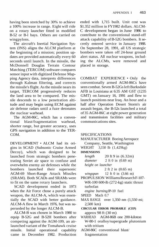
APPENDIX I 463
having been stretched by 30% to achievea 100% increase in range. Eight will rideon a rotary launcher fitted in modifiedB-52 or B-l bays. Others are carried onwing pylons.
The aircraft's Inertial Navigation Sys-tem (INS) aligns the ALCM platform atthe beginning of a mission; position up-dates are provided automatically every 60seconds until launch. In the missile, theMcDonnell Douglas Terrain ContourMatching (TERCOM) software comparessensor input with digitized Defense Map-ping Agency data, interprets differencesthrough Kalman filtering, and correctsthe missile's flight. As the missile nears itstarget, TERCOM progressively reducesthe land area to be compared. The mis-sile descends to a low penetration alti-tude and may begin using ECM againstair defense radars until a fuze detonatesthe nuclear warhead.
The AGM-86C, which has a conven-tional blast/fragmentation warhead,shorter range, but greater accuracy, usesGPS navigation in addition to the TER-COM.
DEVELOPMENT • ALCM had its ori-gins in SCAD (Subsonic Cruise ArmedDecoy), which was designed to belaunched from strategic bombers pene-trating Soviet air space to confuse andoverwhelm enemy air defenses while thebombers launched their supersonicAGM-69 Short-Range Attack Missiles(SRAM). Both SCADs and SRAMs wereto fit on the same rotary launchers.
SCAD development ended in 1973when the Air Force chose a purely attackweapon, the ALCM-A, which was essen-tially the SCAD with better guidance.ALCM-A flew in March 1976, but was su-perseded by the longer ALCM-B.
ALCM-B was chosen in March 1980 toequip B-52G and B-52H bombers aftercompeting against the AGM-109, an air-launched variant of the Tomahawk cruisemissile. Initial operational capabilitycame in December 1982. Production
ended with 1,715 built. Unit cost was$1.352 million in FY1982 dollars. ALCM-C development began in June 1986 tocontribute to the conventional stand-offattack capability of B-52G bombers. It se-cretly entered service in January 1988.On September 28, 1991, all US strategicbombers were taken off 24-hour groundalert status. All nuclear weapons, includ-ing the ALCMs, were removed andplaced in storage.
COMBAT EXPERIENCE • Only theconventionally armed AGM-86Cs haveseen combat. Seven B-52Gs left BarksdaleAFB in Louisiana at 6:35 AM GST (1235GMT) on January 16, 1991 and flew tolaunch positions near Iraq. An hour and ahalf after Operation Desert Storm's airassault began, the B-52s launched a totalof 35 AGM-86C at eight power generationand transmission facilities and militarycommunications sites.
SPECIFICATIONSMANUFACTURER Boeing Aerospace
Company, Seattle, WashingtonWEIGHT 3,150 Ib (1,429kg)DIMENSIONS
length 20 ft 9 in (6.32m)diameter 2 ft 0 in (0.69 m)height on launcher
2 ft 2 in (0.65 m)wingspan 12 ft 0 in (3.66 m)
PROPULSION Williams Research F-107-WR-100 600-lb (272-kg) static thrustturbofanengine burning JP-10 fuel
SPEED Mach 0.7MAX RANGE over 1,350 nm (1,550 mi;
2,500 km)CIRCULAR ERROR PROBABLE (CEP)
approx 98 ft (30 m)WARHEAD AGM-86B one 200-kiloton
W-80-1 oralloy/supergrade plutoniumwith tritium
AGM-86C conventional blast/fragmentation

464 APPENDIX I
SENSORS/FIRE CONTROL AGM-86B INS
with TERCOMAGM-86C INS with TERCOM, GPS
MINUTEMAN (LGM-30)The Minuteman III (LGM-30G) ICBM isthe most numerous US land-based strate-gic missile with 500 missiles currently de-ployed in fixed silos that are hardened towithstand 2,000 psi (140 bar) of blastoverpressure. Minuteman was the firstsolid-fuel rocket ICBM and the first withMultiple Independently targetable Re-entry Vehicles (MIRVs). Development ofthe MIRV in the late 1960s was criticizedas accelerating the US-Soviet arms race,while supporters noted the greater num-bers of Soviet missiles and a similar drivefor greater accuracy.
The third stage solid-propellant rocketuses fluid-injection thrust vector controlfor greater range and accuracy. The post-boost vehicle, which holds the MIRVs,uses eleven small rockets for post-boostcontrol. Of the 500 Minuteman Ills, the300 fitted with the highly accurate Mk12A MIRVs are the most modern of thedeployed Minuteman force. These intro-duced remote retargeting throiigh theCommand Data Buffer System (CDBS),which allows the missiles to be remotelyretargeted before launch in less than ahalf hour.
In the late 1980s, the Air Force beganthe REACT (Rapid Execution and Com-bat Targeting) upgrade program to sup-port rapid message processing and missileretargeting; establish commonalityamong Minuteman III, fixed and rail-mobile Peacekeeper, and small ICBMlaunch control systems; provide a logis-tically supportable system past the turn ofthe century, and improve crew effective-ness and crew environment. Other life-extension efforts included clean-out andrepouring of second-stage motors, the re-manufacture of third-stage motors, andthe development of new penetration aids.
DEVELOPMENT • Minuteman I (LGM-30A/B) saw its Initial Operational Capa-bility (IOC) in 1963. Minuteman II(LGM-30F) with a 1.2-megaton warheadfollowed in 1966. Minuteman Ill's IOCcame in 1970; the first Mk 12A MIRVsachieved IOC in 1979. Production endedin 1977.
The 450 Minuteman II missiles werescheduled to be deactivated and dis-mantled over a seven-year period underthe terms of the 1991 Strategic Arms Re-duction Treaty (START) once the treatywas ratified.
Minuteman Ills are at four bases(Malmstrom, Grand Forks, Minot, andF.E. Warren) in Montana, North Dakota,and Wyoming.
VARIANTS • The earliest version wasthe single-warhead Minuteman I, none ofwhich remain in service. 450 single-warhead Minuteman Us were decommis-sioned as part of President Bush's mas-sive scaledown of the US nucleardeterrent in September 1991.
SPECIFICATIONS •MANUFACTURER Boeing Aerospace,
Seattle, WashingtonWEIGHT
missile 78,000 Ib (35,380 kg)throwweight 2,400 Ib (1,089 kg)
DIMENSIONS
length 59 ft 10 in (18.21 m)diameter at first interstage
5 ft 6 in (1.68m)PROPULSION
1st stage Thiokol M-55 210,000 Ib(95,255 kg) staticthrust
2nd stage Aerojet-General SR-19-AJ-1 60,300 Ib (27,352kg) st
3rd stage Thiokol SR73-AJ-1, 34,400Ib (15,604kg) st
MAX RANGE more than 6,950 nm(8,000 mi; 12,875km)
CIRCULAR ERROR PROBABLE (CEP) 605ft (185m)

APPENDIX I 465
WARHEADS 3 General Electric (GE) Mk12 MIRVs with W62 170-kiloton war-heads or 3 GE Mk 12A MIRVs withW78 330-kiloton warheads
SENSORS/FIRE CONTROL RockwellNS-20 inertial guidance GE1 MIRVusing Bell Aerospace post-boost con-trol system; penetration aids includedecoys and chaff
PEACEKEEPER (LGM-118)The LGM-118 Peacekeeper was devel-oped to replace the LGM-30 Minutemanas the US land-based ICBM. Betterknown under its development name MX,the Peacekeeper is a large and very accu-rate missile that reflected 20 years of USICBM design practice with the most sig-nificant improvements coming in guid-ance and warhead technology.
A big change was the adoption of acold-launch technique. A small gas gener-ator pops the missile out of its silo afterwhich the first stage ignites. This tech-nique, never before used to launch a USICBM, was developed to enable the MXto be deployed as a mobile system.
The solid-propellant missile has threeboost stages and a powered Post-BoostVehicle (PBV). All 3 motor cases aremade of wound Kevlar aramid fibers.
The PBV can carry up to ten MultipleIndependently targetable Reentry Vehi-cles (MIRVs). Achieving unprecedentedaccuracy was the role of the Rockwell Au-tonetics Missile Guidance and ControlSet (MCGS), of which the Northrop Ad-vanced Inertial Reference Sphere (AIRS)Inertial Measurement Unit (IMU) is aprominent component. The IMU is asphere that floats in fluorocarbon 77 andcontains approximately 14,000 compo-nents, including three gyroscopes andthree sophisticated accelerometersknown as Specific Force Integrating Re-ceivers (SFIR), which update an onboarddigital computer.
Of equal importance in the programwere the efforts to protect the MX frompreemptive attack by moving the missilearound. As originally proposed duringthe Carter Administration, the MX pro-gram called for 200 missiles, each to bedeployed in one of several hardened shel-ters located on large tracts of land in re-mote western areas. At random intervals,special carriers would move from oneshelter to another.
By the early 80s, procurement planshad been scaled back to 100 missiles, butthe basing issue persisted in vexing DoD,the Air Force, and Congress. Proposalsfor a "dense pack" silo plan, deep silos,and finally a rail garrison mode encoun-tered criticisms over cost, feasibility, andtheir chilling effects on arms-control ne-gotiations. Proponents of the programpointed to the large Soviet SS-24 ScalpelICBMs, which began their rail-based de-ployments at this time, as well as deploy-ment of the smaller, but even moremobile SS-25 Sickles.
With a further, Congress-mandatedlimit of 50 deployed missiles being im-posed, Rail Garrison MX gained momen-tum. Twenty-five, nine-car trains wereplanned, one for every two missiles. Onword of a high alert status, the trainswould move from their protective "ig-loos" onto the US rail network to "hide"from Soviet ICBMs, The trains were to becapable of independent operations forone month before requiring resupplyand crew relief.
Basing 50 Peacekeepers in modifiedMinuteman silos at F. E. Warren Air ForceBase in Wyoming was to be a temporarymeasure. But the basing discussion wasovertaken by events, as the threat of So-viet missile attacks against the UnitedStates declined rapidly in 1989-1991 dueto the demise of the Warsaw Pact and thesubsequent dissolution of the SovietUnion itself. President Bush's September1991 cancellation of rail garrison devel-opment reflected the declining threat ofa surprise Soviet nuclear weapons strike

466 APPENDIX I
against the United States as well as lack ofCongressional support.
DEVELOPMENT • Full scale develop-ment began in 1979 with the first testflight coming on June 17, 1983. Testingwas greatly delayed by problems with theIMU, reduced funding for missile pro-curement, and Congressionally imposeddelays on testing until the basing modequestion was satisfactorily addressed. Ini-tial operational capability came in De-cember 1986, with all fifty missiles inplace by December 1988. START II arms-control limitations call for the gradualremoval of MX from the silos, beginningin the year 2000 and ending in 2004.
SPECIFICATIONS •MANUFACTURER Martin MariettaTOTAL MISSILE WEIGHT 195,000 lb
(88,450 kg)post-boost vehicle
3,000 lb (1,361 kg)throwweight 8,000 lb (3,629 kg)
DIMENSIONS
overall length71ft (21.64m)
PBV 4 f t (1.22m)diameter 7 ft 8 in (2.34 m)
PROPULSION first 3 stages are solid-propellant rockets (Morton-Thiokol,Aerojet, Hercules); fourth stage is aRocketdyne storable-liquid rocket
MAX RANGE more than 6,000 nm(6,909 mi; 11,118km)
CIRCULAR ERROR PROBABLE (CEP) 394
ft (120m)WARHEADS 10 Avco Mk 21 MIRV, each
armed with one W87 300-475 kilotonnuclear warhead
SENSORS/FERE CONTROL Northrop
AIRS IMU, PBV has guidance andcontrol section to deploy MIRVs onballistic trajectories
TRIDENT I (UGM-96)The US Navy's Trident I (CM)Submarine-Launched Ballistic Missile(SLBM) succeeded the Poseidon (C-3)SLBM in Lafayette and Ohio-class ballisticmissile submarines. In fact, the originaldesign criteria for the Trident was primar-ily to obtain an increase in range over thePoseidon while remaining compatiblewith existing Poseidon submarine launchtubes.
The Trident's Multiple Independentlytargetable Reentry Vehicles (MIRV) havetwice the yield and twice the accuracy ofthose of the Poseidon. The Trident C-4was designed to alternatively carry theMk 500 Evader Maneuvering Reentry Ve-hicle (MaRV) warhead. This was de-signed to overcome ballistic-missiledefenses; it was not deployed. Tridentwas the first US SLBM to be able to hittargets in the Soviet Union while itslaunch boat operated near US waters.
DEVELOPMENT • Development beganin the early 1970s with the missile achiev-ing initial operational capability in Octo-ber 1979. The last Lafayette-class Tridentboat was decommissioned in 1994. Theeight Ohio-class boats were to have beenretrofitted with the larger Trident D5, butthis program was curtailed.
SPECIFICATIONSMANUFACTURER Lockheed Missiles and
Space Company, Inc, Sunnyvale, Calif.WEIGHT
missile 65,000 lb (29,484 kg)throw-weight more than 3,000 lb (1,361
kg)DIMENSIONS
length 34 ft 0 in (10.36m)diameter 6 ft 2 in (1.88 m)
PROPULSION 3-stage solid-propellantrocket
MAX RANGE approx 4,000 nm (4,606mi; 7,412 km)

APPENDIX I 467
CIRCULAR ERROR PROBABLE (CEP)approx 0.25 nm (460 m)
WARHEADS eight Mk 4 MIRV, each car-rying a W76 100-kiloton nuclear war-head
SENSORS/FIRE CONTROL stellar inertialguidance
TRIDENT II D-5 (UGM-133A)The Trident II D-5 SLBM is a significantlymore capable version of the Trident I C-4and was the first SLBM to have a "hardtarget" (e.g., an ICBM missile silo) killcapability. It is estimated that a D-5 W88warhead has an 88% probability of killagainst a target, hardened to 7,200 psi(506 kg/sq cm). In addition to outfittinglater US Ohio-class missile boats, TridentII missiles carrying a British warhead willarm the Royal Navy's class of four 16-tubeVanguard ballistic missile submarines.
Although it is more accurate and car-ries a larger MIRV warhead than any pre-vious SLBM, Trident II shares some of thelimitations of its predecessors. Reactiontime suffers from the difficulty of subma-rine communications and the dormantguidance system of the missile, whichtakes several minutes to activate. Also,Trident II's missile footprint is threetimes smaller than the MX Peacekeeper'sfootprint, which is the target area intowhich a Multiple Independently target-able Reentry Vehicle (MIRV) can beguided. This creates limitations on theTrident force when planning targets. Thesmaller footprint is a result of the solid-fueled Post. Boost Vehicle (PBV) in theTrident. (MX has a liquid-fueled PBV.)
Trident II's range depends on the typeand number of warheads carried; typicalrange is 4,000 nm (4,606 mi; 7,412 km)and the maximum range with a reducedpayload is 6,000 nm (6,909 mi; 11,118km). Plans to test a D-5 with 12 Mk 4MIRVs each carrying a W76 100 kilotonnuclear warhead ran afoul of arms-control counting rules.
DEVELOPMENT • Prior to the first sub-marine test launch, the D-5 was reportedto be within schedule and cost projec-tions parameters. For example, the firstD-5 test launch on January 17, 1987 waswithin two hours of the target date setfour years earlier.
However, a February 1989 DOD auditfound that more than $11 billion of ex-pected costs had been excluded fromNavy estimates given to the Defense Ac-quisition Board (DAB) during its March1987 production review. The $11 billionincluded $6.9 billion in Trident subma-rine modifications and $4.1 billion in re-search and development costs needed todeploy the system.
Compared to the land-based test se-ries, the first of nine scheduled subma-rine launches (held on March 21, 1989)had a less auspicious conclusion. Afterejection from the launch tube of the USSTennessee (SSBN-734), the Tridentbroke the water's surface as planned, buta malfunction during the first stage ofpowered flight caused the missile to veeroff course, pinwheel, and self-destruct af-ter four seconds of flight. Other test prob-lems led to fixes that slightly delayed theInitial Operating Capability (IOC) toMarch 1990.
Plans to outfit eighteen Ohio-classboats, a total of 432 Trident II missiles(with a potential for 3,456 warheads)changed rapidly for two reasons. One wasthe September 1991 decision to scaleback US nuclear weapon deployments inresponse to reduced threats. This in-cluded a decision to "download" TridentII missiles. British Prime Minister Major'sgovernment announced similar plans in1992.
Such restraint may have been inevita-ble. Serious production and environmen-tal problems at the Rocky Flats, CO,plutonium processing plant led to itsclosing in November 1989. As the scopeof the cleanup at Rocky Flats becameclearer, its reopening prospects dimmedappreciably. As a result, only about 400

468 APPENDIX I
W88 warheads had been manufactured.Similarly, management problems andstaff shortages delayed completion of thenew Aldermaston warhead facility in En-gland.
SPECIFICATIONS •MANUFACTURER Lockheed Missiles and
Space Company, Sunnyvale, Calif.WEIGHT
missile 130,000 Ib (58,967 kg)throwweight 6,170 Ib (2,800 kg)
DIMENSIONS
length 44 ft 0 in (13.40 m)diameter 6 ft 11 in (2.11 m)
PROPULSION 3-stage solid-fuel rocket;1st and 2nd stage, each with 65-secburn time, are manufactured by Her-cules or Morton Thiokol; 3rd stage,with burn time of 40 seconds, comesfrom United Technologies
MAX RANGE more than 6,000 nm(6,909 mi; 11,118km)
CIRCULAR ERROR PROBABLE (CEP)
295-395 ft (90-120m)WARHEADS 8 W88 300-475 kiloton
MIRVs in a solid-fuel Mk 5 PBVSENSORS/FIRE CONTROL dormant stel-
lar inertial guidance

APPENDIX II
REGISTER OF SHIPSAIRCRAFT CARRIERSSHIP NAME
FORRESTALFORRESTAL— SLEPSARATOGASARATOGA— SLEPRANGERINDEPENDENCEINDEPENDENCE—
SLEP
KITTY HAWKKITTY HAWK—
SLEPCONSTELLATIONCONSTELLATION—
SLEPENTERPRISEENTERPRISE—
RCOHAMERICA
JOHN F. KENNEDY
NIMITZDWIGHT D.
EISENHOWERCARL VINSONTHEODORE
ROOSEVELTABRAHAM
LINCOLNGEORGE
WASHINGTONJOHN C. STENNISHARRYS TRUMANRONALD REAGAN
TYPE
cvcvcvcvcvcv
cv
cv
cvcv
cvCVN
CVNcv
cv
CVN
CVNCVN
CVN
CVN
CVNCVNCVNCVN
HULL BUILDER
59 Newport News59 Phila NY60 Brooklyn NY60 Phila NY61 Newport News62 Brooklyn NY
62 Phila NY
63 NYSB, Camden
63 Phila NY64 Brooklyn NY
64 Phila NY65 Newport News
65 Newport News66 Newport News
67 Newport News
68 Newport News
69 Newport News70 Newport News
71 Newport News
72 Newport News
73 Newport News74 Newport News75 Newport News76 Newport News
LAID DOWN
D M Y
14 07 5221 01 8316125201 10 8002 07 5401 07 55
18 04 85
27 12 56
28 01 8814 09 57
02 07 9004 02 58
08 01 9109 01 61
22 11 64
22 06 68
14087011 1075
31 1081
0311 84
25 08 8613039103 08 92
LAUNCHED
D M Y
11 1254
08 10 55
29 09 5606 06 58
21 05 60
08 10 60
24 09 60
01 02 64
27 05 67
13 05 72
11 1075150380
27 10 84
13 02 88
21 07 9026 03 94160396
COMPLETED
D M Y
01 10 5519 05 8514 04 5601 02 8310 08 57100159
16 05 88
29 04 61
02 08 91271061
05 03 93251161
27 09 9423 01 65
07 09 68
03 05 75
18107713 03 82
25 10 86
11 1189
04 07 92
SLEP: Service Life Extension Project.RCOH: Refueling and Complex Overhaul.

470 APPENDIX II
AMPHIBIOUS SHIPS
SHIP NAME
TARAWASAIPANBELLEAU WOODNASSAUPELELIU
WASPESSEXKEARSARGEBOXERBATAANBONHOMME
RICHARD
CHARLESTONDURHAMMOBILEST. LOUISEL PASO
RALEIGHVANCOUVERLA SALLE
AUSTINOGDENDULUTHCLEVELANDDUBUQUEDENVERJUNEAU
CORONADO
SHREVEPORT
NASHVILLE
TRENTON
PONCE
IWOJIMAOKINAWAGUADALCANAL
TYPE
LHALHALHALHALHA
LHDLHDLHDLHDLHD
LHD
LKALKALKALKALKA
LPDLPDLPD
LPDLPDLPDLPDLPDLPDLPD
LPD
LPD
LPD
LPD
LPD
LPHLPHLPH
HULL BUILDER
1 Litton/Ingalls2 Litton/Ingalls3 Litton/Ingalls4 Litton/Ingalls5 Litton/Ingalls
1 Litton/Ingalls2 Litton/Ingalls3 Litton/Ingalls4 Litton/Ingalls5 Litton/Ingalls
6 Litton/Ingalls
113 Newport News114 Newport News115 Newport News116 Newport News117 Newport News
1 Brooklyn NY2 Brooklyn NY3 Brooklyn NY
4 Brooklyn NY5 Brooklyn NY6 Brooklyn NY7 Litton/Ingalls8 Litton/Ingalls9 Lockheed, Seattle10 Lockheed,
Seattle11 Lockheed,
Seattle12 Lockheed,
Seattle13 Lockheed,
Seattle14 Lockheed,
Seattle15 Lockheed,
Seattle
2 Puget NY3 Phila NY7 Phila NY
LAID DOWN
D M Y
15 11 7121 07 7205 03 7313 08 731211 76
30 05 8520 03 8906 02 9001 049125 04 94
05 12 6610076715 01 6803 04 6822 10 68
23 06 601911 6002 04 62
04 02 6304 02 6318 12 633011 6425 01 6507 02 64
23 01 65
03 05 65
271265
14 03 66
08 08 66
31 10 66
02 04 5901 04 6001 09 61
LAUNCHED
D M Y
01 12 7318077411047728 01 7806 01 79
04 08 8702 03 9126 03 9228 08 93
02 12 6729 03 6819 10 6804 01 69170569
17036215 09 6203 08 63
27 06 6427 06 6414 08 6507 05 6606 08 6623 01 65
12 02 66
30 07 66
25 10 66
07 10 67
03 08 68
30 05 70
17096014 08 61160363
COMPLETED
D M Y
29 05 7615 107723 09 7828 07 7903 05 80
29 07 8917109224 09 9310 06 94
1296
14 12 6824 05 6920 09 6922 11691701 70
08 09 6211056322 02 64
06 02 6519 06 6518126521 04 6701 09 67261068
12 07 69
23 05 70
12 1270
14 02 70
06 03 71
10 07 71
26 08 6114046220 07 63

APPENDIX II 471
SHIP NAME
GUAMTRIPOLINEW ORLEANSINCHON
ANCHORAGEPORTLAND
PENSACOLA
MOUNT VERNON
FORT FISHER
WHIDBEY ISLAND
GERMANTOWN
FORT McHENRY
GUNSTON HALLCOMSTOCKTORTUGARUSHMOREASHLANDHARPERS FERRYCARTER HALLOAK HILLPEARL HARBOR
NEWPORTMANITOWOCSUMTERFRESNOPEORIAFREDERICKSCHENECTADYCAYUGATUSCALOOSASAGINAWSAN BERNARDINOBOULDERRACINE
TYPE
LPH
LPHLPHLPH
LSDLSD
LSD
LSD
LSD
LSD
LSD
LSD
LSDLSDLSDLSDLSDLSDLSDLSDLSDLSDLSD
LSTLSTLSTLSTLSTLSTLSTLSTLSTLSTLSTLSTLST
HULL BUILDER
9 Phila NYlOLitton/Ingalls11 Phila NY12 Litton/Ingalls
36 Litton/Ingalls37 GD/Beth,
Quincy38 GD/Beth,
Quincy39 GD/Beth,
Quincy40 GD/Belh,
Quincy
41 Lockheed,Seattle
42 Lockheed,Seattle
43 Lockheed,Seattle
44 Avondale45 Avondale46 Avondale47 Avondale48 Avondale49 Avondale50 Avondale51 Avondale52 Avondale5354
11 79 Phila NY11 80 Phila NY1181 Phila NY1182 National Steel11 83 National Steel1184 National Steel11 85 National Steel1186 National Steel11 87 National Steel1188 National Steel11 89 National Steel11 90 National Steel1191 National Steel
LAID DOWN
D M Y
15 11 6215 06 6401 03 6608 04 68
13 03 67
21 09 67
12 03 69
29 01 70
150770
04 08 81
05 08 82
10 06 8326 05 8627 10 8623 03 870911 8704 04 8815049108 11 9121 11 92
01 11 6601 02 671411 6716126722 02 6813 04 6802 08 6828 09 6823 11 6824 05 6912 07 6906 09 6913 12 69
LAUNCHED
D M Y
22 08 6431 07 6503 02 6824 05 69
05 05 68
20 1269
11 0770
170471
22 04 72
10 06 83
29 06 84
01 02 8627 06 871601 8815 09 8806 05 8911 11 8916 01 9323 11 93
03 02 6804 06 6913 126920 09 682311 6808 03 6924 05 6912076906 09 6907 02 7026 03 7022 05 7015 08 70
COMPLETED
D M Y
1601 6506 08 6616116820 07 70
15 03 69
03 10 70
27 03 71
130572
09 12 72
09 02 85
08 02 86
08 08 8722 04 8903 02 9017 119001 06 9109 05 92
15 01 95
07 06 6924 01 7020 06 7022116921 02 7011 047013067008 08 7024 10 7023 01 7127 03 7104 06 7109 07 71

472 APPENDIX II
AMPHIBIOUS SHIPS
SHIP NAME
SPARTANBURGCOUNTY
FAIRFAX COUNTYLA MOURE
COUNTYHARBOUR COUNTYHARLAN COUNTYBARNSTABLE
COUNTYBRISTOL COUNTY
AUXILIARY SHIPS
SHIP NAME
SAMUEL GOMPERS
PUGET SOUND
YELLOWSTONEACADIACAPE CODSHENANDOAHSAFEGUARDGRASPSALVORGRAPPLEHUNLEYHOLLANDSIMON LAKECANOPUS
L. Y SPEAR
DIXON
EMORY S. LAND
FRANK CABLE
McKEE
EDENTONBEAUFORTBRUNSWICKSTALWART
(confirmed)
TYPE HULL BUILDER
LSTLST
LSTLSTLST
LSTLST
TYPE
AD
AD
ADADADADARSARSARSARSASASASAS
AS
AS
AS
AS
AS
ATSATSATST-AGOS
1192 National Steel1193 National Steel
1194 National Steel1195 National Steel1196 National Steel
1197 National Steel1198 National Steel
HULL BUILDER
37 Puget SoundNY
38 Puget SoundNY
41 National Steel42 National Steel43 National Steel44 National Steel51 Peterson52 Peterson53 Peterson54 Peterson31 Newport News32 Litton/Ingalls33 Puget Navy34 Litton/Ingalls
36 GD/Beth,Quincy
37 GD/Beth,Quincy
39 Lockheed,Seattle
40 Lockheed,Seattle
41 Lockheed,Seattle
1 Brooke Marine2 Brooke Marine3 Brooke Marine1 Tacoma Boat
LAID DOWN
D M Y
07 02 7028 03 70
22 05 7015 08 700711 70
19 1270130271
LAID DOWN
D M Y
09 07 64
15026527 06 7714 02 7827 01 7902 08 8002 11 8230 03 8324108325 04 8428 11 6005 03 6207 01 6302 03 64
05 05 66
07 09 67
02 03 76
02 03 76
1401 78
01 04 6719 02 6805 06 6803 05 82
LAUNCHED
D M Y
11 11 7019 1270
13027115 05 7124 07 71
02 10 7104 12 71
LAUNCHED
D M Y
14 05 66
16 09 6621 01 7928 07 7902 08 8006 02 8212118321 04 8428 07 8408 12 8428 09 6119 01 6308 02 64120265
07 09 67
20 06 70
04 05 77
14 01 78
160280
15 05 68201268141169121183
COMPLETED
D M Y
01 09 71161071
18127112 02 7208 04 72
27 05 7205 08 72
COMPLETED
D M Y
01 07 67
27 04 6828 06 8006 06 8117048217 128317088514128512 08 8615118616066207 09 630711 640411 65
28 02 70
07 08 71
07 07 79
05 02 80
15 08 81
2301 7122 01 7219 12 7209 04 84

APPENDIX II 473
SHIP NAME
CONTENDERVINDICATORTRIUMPHASSURANCEPERSISTENCEINDOMITABLEPREVAILASSERTIVEINVINCIBLEAUDACIOUSBOLDADVENTUROUSWORTHYTITANCAPABLEINTREPIDRELENTLESS
VICTORIOUSABLEEFFECTIVELOYAL
IMPECCABLEINTEGRITY
WATERS
MCDONNELLUTTLEHALESPATHFINDERSUMNERBOWDITCHHENSON
MERCYCOMFORT
WRIGHT
CURTISS
TYPE
T-AGOST-AGOST-AGOST-AGOST-AGOST-AGOST-AGOST-AGOST-AGOST-AGOST-AGOST-AGOST-AGOST-AGOST-AGOST-AGOST-AGOS
T-AGOST-AGOST-AGOST-AGOS
T-AGOST-AGOS
T-AGS
T-AGST-AGST-AGST-AGST-AGST-AGS
T-AHT-AH
T-AVB
T-AVB
HULL BUILDER
2 Tacoma Boat3 Tacoma Boat4 Tacoma Boat5 Tacoma Boat6 Tacoma Boat7 Tacoma Boat8 Tacoma Boat9 Tacoma Boat10 Tacoma Boat11 Tacoma Boat12 Tacoma Boat13 Halter14 Halter15 Halter16 Halter17 Halter18 Halter
19 McDermott20 McDermott21 McDermott22 McDermott
23 Tampa Ship24 Tampa Ship
45 Avondale
51 Halter52 Halter60 Halter61 Halter62 Halter63 Halter
19 National Steel20 National Steel
3 Todd,Galveston
4 Todd,Galveston
LAID DOWN
D M Y
10 01 8314 04 8313078316048422 10 842601 8513 05 8530 07 850811 8529 02 8813 06 8819 128503 04 8630 10 8617 108726 02 8822 04 88
12048823 05 90160291021091
01 02 9301 02 93
160591
03 08 89251089180892181192170693
20 07 8402 04 85
141284
071285
LAUNCHED
D M Y
20 128301 06 8407 09 841201 8506 04 8516078507 12 8520 06 8611 118628 01 8922 05 8923 09 8706 02 8818 06 8802 10 8817 02 8912 05 89
02 05 9016029126 09 9118 09 92
COMPLETED
D M Y
29 07 8420 11 8419 02 8501 05 8514 08 8501 128528 02 8612098630 01 8712 06 8929 09 8919088816128808 03 8909 06 8929 09 89120190
13089124 03 9228 01 9301 07 93
CANCELLEDCANCELLED
06 06 92
13 129014029107 10 9319 05 94
05 07 94
19 03 93
15119110 01 9231 109430 04 95
30 1195
08118624 09 87
14 05 86
0387

474 APPENDIX II
BATTLESHIPS
SHIP NAME
IOWAIOWA— updateNEW JERSEYNEW JERSEY—
updateMISSOURIMISSOURI— update
WISCONSINWISCONSIN—
update
COAST GUARDSHIP NAME
MACKINAW
POLAR STARPOLAR SEA
HEALY
HAMILTONDALLASMELLONCHASEBOUTWELLSHERMANGALLATINMORGENTHAURUSHMUNROJARVISMIDGETT
RELIANCE
DILIGENCE
VIGILANT
ACTIVECONFIDENCERESOLUTE
TYPE
BBBBBB
BBBBBB
BB
BB
TYPE
WAGE
WAGBWAGB
WAGB
WHECWHECWHECWHECWHECWHECWHECWHECWHECWHECWHECWHEC
WMEC
WMEC
WMEC
WMECWMECWMEC
HULL BUILDER
61 Brooklyn NY61 Avon/Ingalls62 Phila NY62 Long Beach
NY63 Brooklyn NY63 Long Beach
NY64 Phila NY
64 Avon/Ingalls
HULL BUILDER
4 Toledo SB
10 Lockheed11 Lockheed
20 Avondale
715 Avondale716 Avondale717 Avondale718 Avondale719 Avondale720 Avondale721 Avondale722 Avondale723 Avondale724 Avondale725 Avondale726 Avondale
615Todd,Houston
616 Todd,Houston
61 7 Todd,Houston
618 Christy619 Curtis Bay SY620 Amship,
Lorain
LAID DOWN
D M Y
27 06 4001 108207 12 40
01 10810601 41
01 10 8425 01 41
15 08 86
LAID DOWN
D M Y
20 03 43
15 05 722711 73
220491
15 01 6507 02 6625 07 6627 10 6605 12 6623 01 6727 02 6717076723 10 6718 02 7009 09 7005 04 71
25 09 62
12 12 62
25 09 6229 07 6315 01 63
09 12 63
LAUNCHED
D M Y
27 08 42
071242
29 01 44
07 12 43
LAUNCHED
D M Y
04 03 44
17117324 06 75
25 07 92
18 126501 10 6611 026720 05 6717 06 6723 09 6718 11 6710 02 6816116805 12 7024 04 7104 09 71
25 05 63
20 07 63
24 12 6331 07 6508 05 65
30 04 66
COMPLETED
D M Y
22 02 4313 02 8423 05 43
28 12 8204 06 44
10 05 8616 04 44
21 1088
COMPLETED
D M Y
20 12 44
19017623 02 78
18 09 93
20 02 6701 106722 12 6701 03 6814 06 6823 08 6820 12 6814 02 6903 07 6910 09 7130 12 71170372
20 06 64
26 08 64
03 10 6417096619 02 66
081266

APPENDIX II 475
SHIP NAME
VALIANT
COURAGEOUS
STEADFAST
DAUNTLESS
VENTUROUSDEPENDABLE
VIGOROUS
DURABLEDECISIVEALERT
BEARTAMPAHARRIET LANENORTHLAND •SPENCERSENECAESCANABATAHOMACAMPBELLTHETISFORWARDLEGAREMOHAWKFARALLONMANITOUMATAGORDAMAUIMONHEGANNUNIVAKORACOKEVASHONAQUIDNECKMUSTANGNAUSHONSANIBELEDISTOSAPELOMATINICUSNANTUCKET
TYPE
WMEC
WMEC
WMEC
WMEC
WMECWMEC
WMEC
WMECWMECWMEC
WMECWMECWMECWMECWMECWMECWMECWMECWMECWMECWMECWMECWMECWPBWPBWPBWPBWPBWPBWPBWPBWPBWPBWPBWPBWPBWPBWPBWPB
HULL BUILDER
621 Amship,Lorain
622 Amship,Lorain
623 Amship,Lorain
624 Amship,Lorain
625 Curtis Bay SY626 Amship,
Lorain627 Amship,
Lorain628 Curtis Bay SY629 Curtis Bay SY630 Amship,
Lorain
901 Tacoma Boat902 Tacoma Boat903 Tacoma Boat904 Tacoma Boat905 Dcrecktor906 Derecktor907 Derecktor908 Derecktor909 Derecktor910 Derecktor911 Derecktor912 Derecktor913 Derecktor1301 Bellinger1302 Bollinger1303 Bollinger1304Bollinger1305 Bollinger1306 Bellinger1307 Bollinger1 308 Bollinger1309 Bollinger1310 Bollinger1311 Bollinger1312 Bollinger1313 Bollinger1314 Bollinger1315 Bollinger1316 Bollinger
LAID DOWN
D M Y
21 01 80
191081
20 10 82
14 04 8331 08 84
11 01 84
06 06 8415 11 8418 03 85
24 07 85
23 08 7902 04 8015108009 04 8126 06 8216098201 04 8328 06 8310 08 8424 08 8411 078611 078615 03 87
LAUNCHED
D M Y
1401 67
180567
24 06 67
21 10 6711 1167
160368
04 05 6829 04 6714 12 67
19 10 68
25 09 8019 03 8106 02 8207 05 8217048417 04 8406 02 8506 02 8529 04 8629 04 8622 08 8722 08 8718 05 8827 08 8509 10 8515 12 8513 01 8615 02 8615 03 8612048610 05 8614 06 8611 078622 08 8603 10 8621 11 8608 01 8726 02 87170487
COMPLETED
D M Y
28 10 67
10 04 68
25 09 68
10 06 6816 08 68
2711 68
02 05 6908 12 6723 08 68
04 08 69
04 02 8316038420 09 8417128423 128509 05 8703 02 8701 09 8703 01 8829 06 8801 05 8901 12 8904 05 9021 02 8628 02 8625 04 8609 05 8616068604 07 8604 08 8615 08 8626 09 8629 08 8603 10 8614118607 01 8724 02 8716 04 8704 06 87

476 APPENDIX II
COAST GUARD (continued)SHIP NAME
ATTUBARANOFCHANDELEURCHINCOTEAGUEGUSHINGCUTTYHUNKDRUMMONDKEY LARGOMETOMKINMONOMOYORGASPADRESITKINAKTYBEEWASHINGTONWRANGELLADAKLIBERTYANACAPAKISKAASSATEAGUEGRAND ISLEKEYBISCAYNEJEFFERSON ISLANDKODIAK ISLANDLONG ISLANDBAINBRIDGE
ISLANDBLOCK ISLANDSTATEN ISLANDROANOKE ISLANDPEA ISLANDKNIGHT ISLANDGALVESTON
ISLAND
TYPE
WPBWPBWPBWPBWPBWPBWPBWPBWPBWPBWPBWPBWPBWPBWPBWPBWPBWPBWPBWPBWPBWPBWPBWPBWPBWPB
WPBWPBWPBWPBWPBWPB
WPB
HULL BUILDER
131 7 Bellinger1318 Bellinger1319 Bollinger1320 Bellinger1321 Bellinger1322 Bollinger1323 Bellinger1324 Bollinger1325 Bollinger1326 Bollinger1327 Bellinger1328 Bollinger1329 Bollinger1330 Bollinger1331 Bollinger1332 Bollinger1333 Bollinger1334 Bollinger1335 Bollinger1 336 Bollinger1337 Bollinger1338 Bollinger1339 Bollinger1340 Bollinger1341 Bollinger1342 Bellinger
1343 Bollinger1344 Bollinger1345 Bollinger1346 Bollinger1347 Bollinger1348 Bollinger
1349 Bollinger
LAID DOWN
D M Y
04 12 8708 06 8713 07 8717088721 09 8726 10 8723 11 8701 01 8801 02 8821 03 8825 04 8830 03 8804 07 8808 08 8812098817108825118826 12 8830 01 8906 03 8910048918 06 9016079020 08 9024 09 9029 10 90
03 12 9014019118 02 9125 03 9129 04 9103 10 91
08 07 91
LAUNCHED
D M Y
04 12 8715 01 8819 02 8825 03 8829 04 8803 06 8808 07 8812 08 8816 09 8821 10 8825 11 8806 01 8910 02 8917038921 04 8926 05 8930 06 8904 08 8908 09 8913 10 8917 11 89
08 02 9119 03 91
190491
15 11 91
COMPLETED
D M Y
09 05 8820 05 8808 06 8808 08 8808 08 8815108819 10 8824 12 8812 01 8916 12 8814 04 8924 02 8931 03 8909 05 8900 00 8924 06 891711 8922 09 8913019001 12 89*01 01 90*141290*27 04 9117049121069127 08 91
140691*190791*23 08 91*27 09 91*01 1191*061291*
170192*
^Delivery date from yard; commissioning date was later.

APPENDIX II 477
COMMAND SHIPSSHIP NAME
BLUE RIDGEMOUNT WHITNEY
LA SALLE
CORONADO
CRUISERSSHIP NAME
LEAHYHARRY E.YARNELLWORDENDALE
RICHMOND KTURNER
GRIDLEY
ENGLAND
HALSEY
REEVES
BELKNAPJOSEPHUS
DANIELSWAINWRIGHTJOUETT
HORNE
STERRETT
WILLIAM H.STANDLEY
FOX
BIDDLE
TICONDEROGAYORKTOWN
TYPE
LCCLCC
AGF
AGE
TYPE
CGCGCGCG
CGCG
CG
CG
CG
CG
CGCGCG
CG
CG
CGCG
CG
CGCG
HULL BUILDER
19 Phila NY20 Newport News
3 Brooklyn NY
11 Lockheed,Seattle
HULL BUILDER
16 Bath IW17 Bath IW18 Bath IW19 NYSB,
Camden20 NYSB,
Camden21 Lockheed,
Seattle22 Todd, San
Pedro23 San Francisco
NY24 Puget Sound
NY
26 Bath IW
27 Bath IW28 Bath IW29 Puget Sound
NY30 San Francisco
NY31 Puget Sound
NY
32 Bath IW33 Todd, San
Pedro34 Bath IW
47 Litton/Ingalls48 Litton/Ingalls
LAID DOWN
D M Y
27 02 6708 01 69
02 04 62
03 05 65
LAID DOWN
D M Y
03 12 5931 05 6019 09 60
06 09 60
09 01 61
15 07 60
041060
28 08 60
01 07 60
05 02 62
23 04 6202 07 62
25 09 62
121262
25 09 62
29 07 63
1501 6309 12 63
21 01 80191081
LAUNCHED
D M Y
04 01 6908 01 70
03 08 63
30 07 66
LAUNCHED
D M Y
01 076109 12 6102 06 62
28 07 62
06 04 63
31 07 61
06 03 62
15 01 62
120562
20 07 63
02126325 04 64
30 06 64
30 10 64
30 06 64
191264
21 11 6402 07 65
25 04 8117 01 83
COMPLETED
D M Y
1411 70160171
22 02 64
23 05 70
COMPLETED
D M Y
04 08 6202 02 6303 08 63
23 11 63
130664
25 05 63
07 12 63
20 07 63
150564
0711 64
08 05 6508 01 66
031266
150467
08 04 67
09 07 66
28 05 6621 01 67
22 01 8304 07 84

478 APPENDIX II
CRUISERS (continued)SHIP NAME
VINCENNESVALLEY FORGETHOMAS G. GATESBUNKER HILLMOBILE BAYANTIETAMLEYTE GULFSANJACINTOLAKE CHAMPLAINPHILIPPINE SEAPRINCETONNORMANDYMONTEREYCHANCELLORS-VILLECOWPENSGETTYSBURGCHOSINHUE CITYSHILOHANZIOVICKSBURGLAKE ERIECAPE ST. GEORGEVELLA GULFPORT ROYAL
LONG BEACH
BAINBRIDGE
TRUXTUN
CALIFORNIASOUTH CAROLINA
VIRGINIATEXASMISSISSIPPIARKANSAS
TYPE
CGCGCGCGCGCGCGCGCGCGCGCGCG
CGCGCGCGCGCGCGCGCGCGCGCG
CGN
CGN
CGN
CGNCGN
CGNCGNCGNCGN
HULL BUILDER
49 Litton/Ingalls50 Litton/Ingalls51 Bath IW52 Litton/Ingalls53 Litton/Ingalls54 Litton/Ingalls55 Litton/Ingalls56 Litton/Ingalls57 Litton/Ingalls58 Bath IW59 Litton/Ingalls60 Bath IW61 Bath IW
62 Litton/Ingalls63 Bath IW64 Bath IW65 Litton/Ingalls66 Litton/Ingalls67 Bath IW68 Litton/Ingalls69 Litton/Ingalls70 Bath IW71 Litton/Ingalls72 Litton/Ingalls73 Litton/Ingalls
9 GD/Beth,Quincy
25 GD/Beth,Quincy
35 NYSB,Camden
36 Newport News37 Newport News
38 Newport News39 Newport News40 Newport News41 Newport News
LAID DOWN
D M Y
20 10 8214048331 08 8411 01 8406 06 8415 11 8418 03 8524 07 8503 03 8611 058615 108607 04 8719 08 87
24 06 8723 12 8717088822 07 8820 02 8901 08 8921 08 8930 05 9006 03 9019 11 90220491141091
021257
15 05 59
170663
23 01 7001 12 70
19 08 7218087322 02 751701 77
LAUNCHED
D M Y
1401 8423 06 8414128511 038522 08 8514 02 8620 06 861411 8603 04 8712 07 8702 10 8719 03 8823 1088
15 07 8811 038922 07 8914 10 8921 07 9008 09 9002 119012 109113079111 049225 07 9220 1192
14 07 59
15 04 61
19 1264
22 09 7101 07 72
14127409 08 7531 07 7621 1078
COMPLETED
D M Y
06 07 851801 8622 08 8720 09 8613 02 8706 06 8726 09 8723 01 8808 08 8818038911 028909 12 8916 06 90
04118909 03 9122 06 9110 05 9114099118 07 9202 05 9214119224 07 9312 06 9318 09 9309 07 94
09 09 61
06 10 62
27 05 67
16027425 01 75
11097610097705 08 7813 1080

APPENDIX II 479
DESTROYERS
SHIP NAME
SPRUANCE
PAUL F. FOSTER
KINKAID
HEWITT
ELLIOT
ARTHUR W.RADFORD
PETERSON
CARON
DAVID R. RAY
OLDENDORF
JOHN YOUNG
COMTE DE GRASSE
O'BRIEN
MERRILL
BRISCOE
STUMP
CONOLLY
MOOSBRUGGER
JOHN HANCOCK
NICHOLSON
JOHN RODGERS
LEFTWICH
TYPE
DD
DD
DD
DD
DD
DDDD
DD
DD
DD
DD
DD
DD
DD
DD
DD
DD
DD
DD
DD
DD
DD
HULL BUILDER
963 Litton/Ingalls
964 Litton/Ingalls
965 Litton/Ingalls
966 Litton/Ingalls
967 Litton/Ingalls
968 Litton/Ingalls
969 Litton/Ingalls
970 Litton/Ingalls
971 Litton/Ingalls
972 Litton/Ingalls
973 Litton/Ingalls
0974 Litton/Ingalls
975 Litton/Ingalls
976 Litton/Ingalls
977 Litton/Ingalls
978 Litton/Ingalls
979 Litton/Ingalls
980 Litton/Ingalls
981 Litton/Ingalls
982 Litton/Ingalls
983 Litton/Ingalls
984 Litton/Ingalls
LAID DOWN
D M Y
01 1172
06 02 73
190473
23 07 73
15 10 73
140174
29 04 74
01 07 74
23 09 74
27 12 74
170275
04 04 75
09 05 75
160675
21 07 75
22 08 75
29 09 75
03 11 75
1601 76
20 02 76
12 08 76
121176
LAUNCHED
D M Y
10 11 73
23 02 74
25 05 74
24 08 74
19 1274
01 03 75
21 06 75
24 06 75
23 08 75
21 10 75
07 02 76
26 03 76
08 07 76
01 09 76
08 01 77
30 04 77
25 06 77
20 08 77
29 10 77
28 01 78
25 02 78
08 04 78
COMPLETED
D M Y
20 09 75
21 02 76
100776
25 09 76
2201 77
09 04 77
09 07 77
01 10 77
19 11 77
04 03 78
20 05 78
05 08 78
03 12 77
11 0378
03 06 78
19 08 78
14 10 78
16 12 78
100379
120579
140779
25 08 79
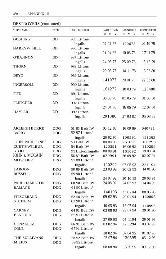
480 APPENDIX II
DESTROYERS (continued)SHIP NAME
GUSHING
HARRYW. HILL
O'BANNON
THORN
DEYO
INGERSOLL
FIFE
FLETCHER
HAYLER
ARLEIGH BURKEBARRY
JOHN PAUL JONESCURTIS WILBURSTOUTJOHN s. MCCAINMITSCHER
LABOONRUSSELL
PAUL HAMILTONRAMAGE
FITZGERALDSTETHEM
CARNEYBENFOLD
GONZALEZCOLE
THE SULLIVANSMILIUS
TYPE
DD
OD
DD
DD
DD
DD
DD
DD
DD
DDGDDG
DDGDDGDDGDDGDDG
DDGDDG
DDGDDG
DDGDDG
DDGDDG
DDGDDG
DDGDDG
HULL BUILDER
985 Litton/Ingalls
986 Litton/Ingalls
987 Litton/Ingalls
988 Litton/Ingalls
989 Litton/Ingalls
990 Litton/Ingalls
991 Litton/Ingalls
992 Litton/Ingalls
997 Litton/Ingalls
51 85 Bath IW52 87 Litton/
Ingalls53 Bath IW54 Bath IW55 Litton/Ingalls56 89 Bath IW57 89 Litton/
Ingalls58 89 Bath IW59 90 Litton/
Ingalls60 90 Bath IW61 90 Litton/
Ingalls62 90 Bath IW63 90 Litton/
Ingalls64 91 Bath IW65 91 Litton/
Ingalls66 91 Bath IW6791 Litton/
Ingalls68 92 Bath IW69 92 Litton/
Ingalls
LAID DOWN
D M Y
02 02 77
01 04 77
24 06 77
29 08 77
141077
161277
06 03 78
24 04 78
20 1080
06 12 88
26 02 9008 08 9012039108 08 91030991
12029223 03 92
24 07 9224 08 92
14019309 02 93
10 05 9303 08 93
27 09 9303 02 94
28 02 9403 07 94
08 08 94
LAUNCHED
D M Y
170678
10 08 78
25 09 78
14 11 78
20 01 79
10 03 79
01 05 79
16 06 79
27 03 82
16 09 89
10059126109116 06 9216109226 09 92
07 05 9320 02 93
20 10 9324 07 93
11029429 01 94
16 07 9423 07 94
05 119417 1294
07 04 95130595
16 09 95
COMPLETED
D M Y
20 10 79
1711 79
15 12 79
16 02 80
22 03 80
120480
31 05 80
12 07 80
05 03 83
040791
12129218129311029419 08 9402 07 94
28119414 01 95
20 03 9514 04 95
08 05 95160895
11 099529 01 96
29 01 9603 07 96
01 07 9605 12 96
09 12 96

APPENDIX II 481
SHIP NAME
HOPPERROSSMAHAN (ex-
BERNARD L.AUSTIN)
DECATURMCFAUL
DONALD COOKHIGGINSO'KANEPORTEROSCAR AUSTIN
KIDD
CALLAGHAN
SCOTT
CHANDLER
FRIGATES
SHIP NAME
KNOX
ROARK
GRAY
HEPBURN
CONNOLERATHBURNE
MEYERKORD
W. S. SIMS
TYPE
DDGDDG
DDGDDGDDG
DDGDDGDDGDDGDDGDDGDDGDDG
DDG
DDG
DDG
DDG
TYPE
FF
FF
FF
FF
FFFF
FF
FF
HULL BUILDER
70 Bath IW71 Litton/Ingalls
72 92 Bath IW73 93 Bath IW74 93 Litton/
Ingalls75 93 Bath IW76 93 Bath IW779478947995809581 9582 95
993 Litton/Ingalls
994 Litton/Ingalls
995 Litton/Ingalls
996 Litton/Ingalls
HULL BUILDER
1052 Todd,Seattle
1053 Todd,Seattle
1054 Todd,Seattle
1055 Todd,. SanPedro
1056 Avondale1057 Lockheed,
Seatde1058 Todd, San
Pedro1059 Avondale
LAID DOWN
D M Y
25 12 9409 01 95
04069501 1095
04129510 03 9611 0896
26 06 78
23 10 78
120279
120579
LAID DOWN
D M Y
05 1065
02 02 66
19 11 66
01 06 6623 03 67
08 01 68
01 09 66100467
LAUNCHED
D M Y
1811 95170296
04 05 9631 08 96
25 01 9625 01 9721 06 97
13 10 79
19 OT 80
29 03 80
24 05 80
LAUNCHED
D M Y
1911 66
24 04 67
0311 67
25 03 6720 07 68
02 05 69
1507670401 69
COMPLETED
D M Y
02 06 9719 05 97
30 109704 03 98
07 05 9831 07 9829 1 1 98
270781
29 08 81
24 1081
13 03 82
COMPLETED
D M Y
120469
22 11 69
04 04 70
03 07 6930 08 69
160570
2811 6903 01 70

482 APPENDIX II
FRIGATES (continued)SHIP NAME
LANG
PATTERSONWHIPPLE
REASONER
LOCKWOOD
STEIN
MARVIN SHIELDS
FRANCISHAMMOND
VREELANDBAGLEY
DOWNES
BADGER
BLAKELYROBERT E. PEARY
HAROLD E. HOLT
TRIPPEFANNING
OUELLETJOSEPH HEWESBOWENPAULAYLWINELMER
MONTGOMERYCOOKMcCANDLESSDONALD B. BEARYBREWTONKIRKBARBEYJESSE L. BROWNAINSWORTHMILLER
TYPE
FF
FFFF
FF
FF
FF
FF
FFFFFF
FF
FF
FFFF
FF
FFFF
FFFFFFFFFF
FFFFFFFFFFFFFFFFFFFF
HULL BUILDER
1060 Todd, SanPedro
106] Avondale1062 Todd, San
Pedro1063 Lockheed,
Seattle1064 Todd,
Seattle1065 Lockheed,
Seattle1066 Todd,
Seattle1067 Todd, San
Pedro1068 Avondale1069 Lockheed,
Seattle1070 Todd,
Seattle1071 Todd, San
Pedro1072 Avondale1073 Lockheed,
Seattle1074 Todd, San
Pedro1075 Avondale1076 Todd, San
Pedro1077 Avondale1078 Avondale1079 Avondale1080 Avondale1081 Avondale
1082 Avondale1083 Avondale1084 Avondale1085 Avondale1086 Avondale1087 Avondale1088 Avondale1089 Avondale1090 Avondale1091 Avondale
LAID DOWN
D M Y
25 03 6712 1067
24 04 67
06 01 69
0311 67
01 06 70
120468
15 07 6720 03 68
22 09 70
05 09 68
17026803 06 68
20 12 70
1 1 05 6829 07 68
0712681501 6915 05 6911 076912096913 11 69
23 01 7020 03 7004 06 7024 07 7002 10 7004 12 7005 02 7108 04 71110671060871
LAUNCHED
D M Y
17026803 05 69
12 04 68
01 08 70
05 09 68
19 1270
23 10 69
11 056814 06 69
240471
13 12 69
07 12 6823 08 69
23 06 71
03 05 6901 11 69
24 01 701701 7007 03 7002 05 7020 06 7029 08 70
21 11 7023 01 7120 03 7122 05 7124 07 7125 09 7104 12 7118037215047203 06 72
COMPLETED
D M Y
28 03 7014 03 70
22 07 70
31 07 71
05 12 70
08 01 72
10 04 71
25 07 70130670
09 05 72
28 08 71
01 12 7018 07 70
23 09 72
26 03 7119 09 70
23 07 7112 12 7027 02 7122 05 7114087118 09 71
30 10 7118 12 7118 03 7222 07 7208 07 7209 09 7211 117217027331 03 7330 06 73

APPENDIX II 483
SHIP NAME
THOMAS C. HARTCAPODANNOPHARRISTRUETTVALDEZMOINESTER
OLIVER HAZARDPERRY
McINERNEYWADSWORTH
DUNCANCLARKGEORGE PHILIP
SAMUEL ELIOTMORISON
SIDES
ESTOCINCLIFTON SPRAGUEJOHN A. MOORE
ANTRIMFLATLEYFAHRIONLEWIS B. PULLER
JACK WILLIAMSCOPELAND
GALLERYMAHLON S.
TISDALEBOONESTEPHEN W.
GROVESREID
STARKJOHN L. HALLJARRETT
AUBREY FITCHUNDERWOODCROMMELIN
TYPE
FFFFFFFFFFFF
FFGFFGFFG
FFGFFGFFG
FFGFFG
FFGFFGFFG
FFGFFGFFGFFG
FFGFFG
FFG
FFGFFG
FFGFFG
FFGFFGFFG
FFGFFGFFG
HULL BUILDER
1092 Avondale1093 Avondale1094 Avondale1095 Avondale1096 Avondale1097 Avondale
7 Bath IW8 Bath IW9 Todd, San
Pedro10 Todd, Seattle11 BathlW12 Todd, San
Pedro
13 Bath IW14 Todd, San
Pedro15 Bath IW16 Bath IW19 Todd, San
Pedro20 Todd, Seattle21 Bath IW22 Todd, Seattle23 Todd, San
Pedro24 Bath IW25 Todd, San
Pedro26 Bath IW27 Todd, San
Pedro28 Todd, Seattle
29 Bath IW30 Todd, San
Pedro31 Todd, Seattle32 Bath IW33 Todd, San
Pedro34 Bath IW36 Bath IW37 Todd, Seattle
LAID DOWN
D M Y
08107110127111 027227 04 7230 06 7225 08 72
12 06 751601 78
13 07 7729 04 77170778
141277
04 12 78
07 08 7802 04 7930 07 79
19 127821 06 781311 7901 12 78
23 05 7925 02 80
24 10 79170580
19 03 8027 03 79
16 09 80
08 10 8024 08 7905 01 81
11 028110 04 8103 08 8130 05 80
LAUNCHED
D M Y
12087221 10 7216127203 02 7324 03 7312 05 73
25 09 7604 1 1 78
29 07 7801 03 7824 03 79
161278
140779
19 05 79031179160280
20 10 7927 03 7915 05 8024 08 79
15038030 08 80
26 07 8020 12 80
0702811601 80
040481
27 06 8130 05 8024 07 81
17108117108106 02 82010781
COMPLETED
D M Y
28 07 731711 7326 01 7401 06 7427 07 7402 11 74
17127715 1279
02 04 8024 05 8017 05 80
15 1180
11 1080
30 05 8110018121 03 81
1411 8126 09 8120 06 8116 01 82
17048219 09 81
07 08 82051281
13 11 82131182
170482
19 02 8323108226 06 82
02 07 8309 10 82290183180683

484 APPENDIX II
FRIGATES (continued)
SHIP NAME
CURTS
DOYLEHALYBURTONMcCLUSKEY
KLAKRINGTHACH
DE WERTRENTZ
NICHOLSVANDEGRIFTROBERT G.
BRADLEYTAYLORGARY
CARRHAWESFORD
ELRODSIMPSONREUBEN JAMES
SAMUEL B,ROBERTS
KAUFFMAN
TYPE
FFG
FFGFFGFFG
FFGFFG
FFGFFG
FFGFFG
FFGFFGFFG
FFGFFGFFG
FFGFFGFFG
FFGFFG
RODNEY M. DAVIS FFG
INGRAHAM
MINE WARFARE
SHIP NAME
AVENGERDEFENDERSENTRYCHAMPIONGUARDIANDEVASTATORPATRIOT
FFG
SHIPSTYPE
MCMMCMMCMMCMMCMMCMMCM
HULL BUILDER
38 Todd, SanPedro
39 Bath IW40 Todd, Seattle41 Todd, San
Pedro42 Bath IW43 Todd, San
Pedro45 Bath IW46 Todd, San
Pedro47 Bath IW48 Todd, Seattle
49 Bath IW50 Bath IW51 Todd, San
Pedro52 Todd, Seattle53 Bath IW54 Todd, San
Pedro55 Bath IW56 Bath IW57 Todd, San
Pedro
58 Bath IW59 Bath IW60 Todd, San
Pedro61 Todd, San
Pedro
HULL BUILDER
1 Peterson2 Marinette3 Peterson4 Marinette5 Peterson6 Peterson7 Marinette
LAID DOWN
D M Y
01 078123 10 8126 09 80
21 108119 02 82
06 03 8214 06 82
18098227 09 82131081
28128205 05 83
18128226 03 8222 08 83
16 07 8314118327 02 84
1911 83
21 05 8408 04 85
08 02 85
30 03 87
LAID DOWN
D M Y
03 06 8301 12 8308108428 06 8408 05 8509 02 8731 03 87
LAUNCHED
D M Y
06 03 82
22 05 82131081
18 09 8218 09 82
18 12 82181282
16 07 8323 04 8315 1082
13 08 8305 11 83
1911 8326 02 83170284
23 06 8412 05 8431 08 84
08 02 85
08 12 8429 03 86
11 01 86
25 06 88
LAUNCHED
D M Y
15068504 04 8720 09 8615 04 8920 06 8711068815 05 90
COMPLETED
D M Y
08 10 8321 05 8307 01 84
12108320 08 83
17 03 8419 11 83
30 06 8410 03 8424 1 1 84
11 088401 12 84
17118427 07 8502 09 85
29 06 8506 07 850911 85
22 03 86
12 04 8628 02 87
09 05 87
05 08 89
COMPLETED
D M Y
12098730 09 8902 09 8908 02 9116128906 10 90181091
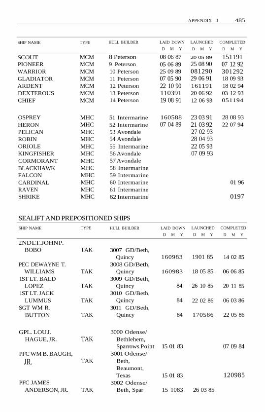
APPENDIX II 485
SHIP NAME
SCOUTPIONEERWARRIORGLADIATORARDENTDEXTEROUSCHIEF
OSPREYHERONPELICANROBINORIOLEKINGFISHERCORMORANTBLACKHAWKFALCONCARDINALRAVENSHRIKE
TYPE
MCMMCMMCMMCMMCMMCMMCM
MHCMHCMHCMHCMHCMHCMHCMHCMHCMHCMHCMHC
HULL BUILDER
8 Peterson9 Peterson10 Peterson11 Peterson12 Peterson13 Peterson14 Peterson
51 Intermarine52 Intermarine53 Avondale54 Avondale55 Intermarine56 Avondale57 Avondale58 Intermarine59 Intermarine60 Intermarine61 Intermarine62 Intermarine
LAID DOWN
D M Y
08 06 8705 06 8925 09 8907 05 9022 10 9011039119 08 91
16058807 04 89
LAUNCHED
D M Y
20 05 89
25 08 9008129029 06 9116119120 06 9212 06 93
23 03 9121 03 9227 02 9328 04 9322 05 9307 09 93
COMPLETED
D M Y
15119107 12 9230129218 09 9318 02 9403 12 93051194
28 08 9322 07 94
01 96
0197
SEALIFT AND PREPOSITIONED SHIPS
SHIP NAME
2ND LT. JOHN P.BOBO
PEC DEWAYNE T.WILLIAMS
1ST LT. BALDLOPEZ
1ST LT. JACKLUMMUS
SGT WM R.BUTTON
GPL. LOU J.HAGUE, JR.
PFC WM B. BAUGH,
JR.
PFC JAMESANDERSON, JR.
TYPE
TAK
TAK
TAK
TAK
TAK
TAK
TAK
TAK
HULL BUILDER
3007 GD/Beth,Quincy
3008 GD/Beth,Quincy
3009 GD/Beth,Quincy
3010 GD/Beth,Quincy
3011 GD/Beth,Quincy
3000 Odense/Bethlehem,Sparrows Point
3001 Odense/Beth,Beaumont,Texas
3002 Odense/Beth, Spar
LAID DOWN
D M Y
160983
160983
84
84
84
15 01 83
15 01 83
15 1083
LAUNCHED
D M Y
1901 85
18 05 85
26 10 85
22 02 86
170586
26 03 85
COMPLETED
D M Y
14 02 85
06 06 85
20 11 85
06 03 86
22 05 86
07 09 84
120985

486 APPENDIX II
SEALIFT AND PREPOSITIONED SHIPS (continued)
SHIP NAME
1ST IT. ALEXBONNYMANJR.
PVT. HARRY FISHER
SOT. MATEJ KOCAK
PFC EUGENE A.OBREGON
MAJ. STEPHEN W.PLESS
ALGOL
BELLATRIX
DENEBOLA
POLLUX
ALTAIR
REGULUS
CAPELLA
ANTARES
BOB HOPE (sealift)
(option)(option)(option)(option)(option)(sealift)
(option)(option)(option)(option)(option)
TYPE
TAKTAK
TAK
TAK
TAK
TAKR
TAKR
TAKR
TAKR
TAKR
TAKR
TAKR
TAKR
TAKR
TAKTAKTAKTAKTAKTAK
TAKTAKTAKTAKTAK
HULL BUILDER
3003 Odense/Beth, Beau
3004 Odense/Beth, Spar
3005 Sun/National
3006 Sun/National
3007 Sun/National
287 Rotterdam/Nat'l
288 Rheinsthl/Nat'l
289 Rotterdam/Penn
290 Weser/Avondale
291 Rheinsthl/Avondale
292 Weser/National
293 Rotterdam/Penn
294 Weser/Avondale
300 Avondale(ordered Sep.1, 1993)
X AvondaleX AvondaleX AvondaleX AvondaleX AvondaleX NASSCO
(Ordered Sep.16, 1993)
X NASSCOX NASSCOX NASSCOX NASSCOX NASSCO
LAID DOWN
D M Y
15 01 84
150484
15 08 83
1501 83
15 05 84
13 1082
22 10 82
04 05 84
21 05 84
01 02 84
29 06 84
22 10 82
06 10 82
LAUNCHED COMPLETED
D M Y D M Y
30 10 84
24 09 85
051084
15 01 85
01 05 85
190684
100984
100985
31 03 86
1311 85
28 08 85
01 0784
120784

APPENDIX II 487
SMALL COMBATANTS
SHIP NAME
PEGASUSHERCULESTAURUSAQUILAARIESGEMINI
CYCLONETEMPESTHURRICANEMONSOONTYPHOONSIROCCOSQUALLZEPHYRCHINOOKFIREBOLTWHIRLWINDTHUNDERBOLTSHAMAL
TYPE
PHM
PHMPHMPHMPHMPHM
PCPCPCPCPCPCPCPCPCPCPCPCPC
HULL BUILDER
1 Boeing, Seattle2 Boeing, Seattle3 Boeing, Seattle4 Boeing, Seattle5 Boeing, Seattle6 Boeing, Seattle
1 Bellinger2 Bollinger3 Bollinger4 Bollinger5 Bollinger6 Bollinger7 Bollinger8 Bollinger9 Bollinger10 Bollinger11 Bollinger12 Bollinger13 Bollinger
LAID DOWN
D M Y
10 05 7312 09 8030 01 7910 07 790701 80130580
22 06 9130 09 91201191150292
LAUNCHED
D M Y
0911 7413048208 05 8116098105 11 81170282
15 02 9220 06 9206 03 9306 03 9320 02 9318 09 9318 09 9312 03 9412 03 9424 09 9424 09 94
COMPLETED
D M Y
09 07 7712038307108116 10 8218 09 82131182
19 12 9213019331 07 9326 09 9312029405 05 9423 06 9415 1094
ATTACK SUBMARINES
SHIP NAME
STURGEON
WHALE
TAUTOG
GRAYLING
POGY
ASPRO
SUNFISH
PARGO
QUEENFISH
PUFFER
TYPE
SSN
SSN
SSN
SSN
SSN
SSN
SSN
SSN
SSN
SSN
HULL BUILDER
637 GD/EB,Groton
638 GD/Beth,Quincy
639 Litton/Ingalls
646 PortsmouthNY
647 Litton/Ingalls
648 Litton/Ingalls
649 GD/Beth,Quincy
650 GD/EB,Groton
651 NewportNews
652 Litton/Ingalls
LAID DOWN
D M Y
10 08 63
27 05 64
2701 64
12 05 64
04 05 64
2311 64
1501 65
03 06 64
11 0564
08 02 65
LAUNCHED
D M Y
26 02 66
141066
15 04 67
22 06 67
03 06 67
2911 67
141066
17 09 66
25 02 66
30 03 68
COMPLETED
D M Y
03 03 67
121068
170868
11 1069
15 05 71
20 02 69
150369
05 01 68
06 12 66
09 08 69

APPENDIX II
ATTACK SUBMARINES (continued)
SHIP NAME
RAY
SAND LANCE
LAPON
GURNARD
HAMMERHEAD
SEA DEVIL
GUITARRO
HAWKBILL
BERGALL
SPADEFISH
SEAHORSE
FINBACK
NARWHAL
PINTADO
FLYING FISH
TREPANG
BLUEFISH
BILLFISH
DRUM
ARCHERFISH
SILVERSIDES
WILLIAM H. BATES
BATFISH
TYPE
SSN
SSN
SSN
SSN
SSN
SSN
SSN
SSN
SSN
SSN
SSN
SSN
SSN
SSN
SSN
SSN
SSN
SSN
SSN
SSN
SSN
SSN
SSN
HULL BUILDER
653 NewportNews
660 PortsmouthNY
661 NewportNews
662 Mare IslandNY
663 NewportNews
664 NewportNews
665 Mare IslandNY
666 Marc IslandNY
667 GD/EB,Groton
668 NewportNews
669 GD/EB,Groton
670 NewportNews
671 GD/EB,Groton
672 Mare IslandNY
673 GD/EB,Groton
674 GD/EB,Groton
675 GD/EB,Groton
676 GD/EB,Groton
677 Mare IslandNY
678 GD/EB,Groton
679 GD/EB,Groton
680 Litton/Ingalls
681 GD/EB,Groton
LAID DOWN
D M Y
01 04 65
15 01 65
26 07 65
22 12 64
2911 65
120466
09 12 65
121266
16 04 66
21 12 66
130866
26 06 67
17 01 66
27 10 67
30 06 67
28 10 67
130368
20 09 68
20 08 68
19 06 69
131069
04 08 69
09 02 70
LAUNCHED
D M Y
21 06 66
11 11 69
16 12 66
20 05 67
14 04 67
05 10 67
27 07 68
12 04 69
170268
15 05 68
15 06 68
07 12 68
09 09 67
160869
170569
27 09 69
10 01 70
01 05 70
23 05 70
1601 71
04 06 71
11 1271
09 10 71
COMPLETED
D M Y
120467
25 09 71
141267
061268
28 06 68
30 01 69
09 09 72
04 02 71
130669
140869
19 09 69
04 02 70
120769
29 04 71
29 04 70
14 08 70
080171
12 03 71
15 04 72
171271
05 05 72
05 05 73
01 09 72
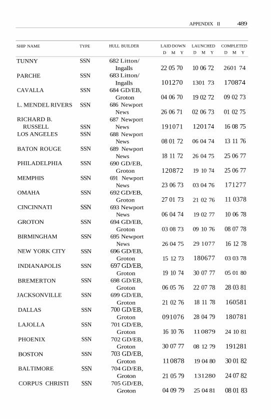
APPENDIX II 489
SHIP NAME
TUNNY
PARCHE
CAVALLA
L. MENDEL RIVERS
RICHARD B.RUSSELL
LOS ANGELES
BATON ROUGE
PHILADELPHIA
MEMPHIS
OMAHA
CINCINNATI
GROTON
BIRMINGHAM
NEW YORK CITY
INDIANAPOLIS
BREMERTON
JACKSONVILLE
DALLAS
LAJOLLA
PHOENIX
BOSTON
BALTIMORE
CORPUS CHRISTI
TYPE
SSN
SSN
SSN
SSN
SSNSSN
SSN
SSN
SSN
SSN
SSN
SSN
SSN
SSN
SSN
SSN
SSN
SSN
SSN
SSN
SSN
SSN
SSN
HULL BUILDER
682 Litton/Ingalls
683 Litton/Ingalls
684 GD/EB,Groton
686 NewportNews
687 NewportNews
688 NewportNews
689 NewportNews
690 GD/EB,Groton
691 NewportNews
692 GD/EB,Groton
693 NewportNews
694 GD/EB,Groton
695 NewportNews
696 GD/EB,Groton
697 GD/EB,Groton
698 GD/EB,Groton
699 GD/EB,Groton
700 GD/EB,Groton
701 GD/EB,Groton
702 GD/EB,Groton
703 GD/EB,Groton
704 GD/EB,Groton
705 GD/EB,Groton
LAID DOWN
D M Y
22 05 70
101270
04 06 70
26 06 71
191071
08 01 72
18 11 72
120872
23 06 73
27 01 73
06 04 74
03 08 73
26 04 75
15 12 73
19 10 74
06 05 76
21 02 76
091076
16 10 76
30 07 77
11 0878
21 05 79
04 09 79
LAUNCHED
D M Y
10 06 72
1301 73
19 02 72
02 06 73
1201 74
06 04 74
26 04 75
19 10 74
03 04 76
21 02 76
19 02 77
09 10 76
29 1077
180677
30 07 77
22 07 78
18 11 78
28 04 79
11 0879
08 12 79
19 04 80
131280
25 04 81
COMPLETED
D M Y
2601 74
170874
09 02 73
01 02 75
16 08 75
13 11 76
25 06 77
25 06 77
171277
11 0378
10 06 78
08 07 78
16 12 78
03 03 78
05 01 80
28 03 81
160581
180781
24 10 81
191281
30 01 82
24 07 82
08 01 83

490 APPENDIX II
ATTACK SUBMARINES (continued]
SHIP NAME
ALBUQUERQUE
PORTSMOUTH
MINNEAPOLIS-ST. PAUL
HYMAN G.RICKOVER
AUGUSTA
SAN FRANCISCO
ATLANTA
HOUSTON
NORFOLK
BUFFALO
SALT LAKE CITY
OLYMPIA
HONOLULU
PROVIDENCE
PITTSBURGH
CHICAGO
KEY WEST
OKLAHOMA CITY
LOUISVILLE
HELENA
NEWPORT NEWS
SAN JUAN
PASADENA
TYPE
SSN
SSN
SSN
SSNSSN
SSN
SSN
SSN
SSN
SSN
SSN
SSN
SSN
SSN
SSN
SSN
SSN
SSN
SSN
SSN
SSN
SSN
SSN
HULL BUILDER
706 GD/EB,Groton
707 GD/EB,Groton
708 GD/EB,Groton
709 GD/EB,Groton
710 GD/EB,Groton
711 NewportNews
712 NewportNews
713 NewportNews
71 4 NewportNews
715 NewportNews
71 6 NewportNews
71 7 NewportNews
718 NewportNews
719 GD/EB,Groton
720 GD/EB,Groton
721 NewportNews
722 NewportNews
723 NewportNews
724 GD/EB,Groton
725 GD/EB,Groton
750 NewportNews
751 GD/EB,Groton
752 GD/EB,Groton
LAID DOWN
D M Y
27 12 79
08 05 80
2001 81
24 07 81
01 04 82
26577
170878
29 01 79
01 08 79
25 01 80
26 08 80
31 03 81
1011 81
141082
150483
05 01 83
06 07 83
04 01 84
160984
28 03 85
03 03 84
160885
201285
LAUNCHED
D M Y
13 03 82
18 09 82
19 03 83
170883
21 01 84
27 10 79
16 08 80
21 03 81
31 1081
08 05 82
161082
30 04 83
24 09 83
04 08 84
08 1284
13 1084
20 07 85
02 11 85
141285
28 06 86
15 03 86
061286
12 09 87
COMPLETED
D M Y
21 05 83
01 1083
170384
08 09 84
19 01 85
24 04 81
06 03 82
25 09 82
21 05 83
05 1183
12 05 84
17 11 84
06 07 85
27 07 85
231185
27 09 86
12 09 87
03 07 88
081186
110787
03 06 89
07 08 88
280189

APPENDIX II 491
SHIP NAME
ALBANY
TOPEKA
MIAMI
SCRANTON
ALEXANDRIA
ASHEVILLE
JEFFERSON CITY
ANNAPOLIS
SPRINGFIELD
COLUMBUS
SANTA FE
BOISE
MONTPELIER
CHARLOTTE
HAMPTON
HARTFORD
TOLEDO
TUCSON
COLUMBIA
GREENEVILLE
CHEYENNE
SEAWOLF
CONNECTICUT
TYPE
SSN
SSN
SSN
SSN
SSN
SSN
SSN
SSN
SSN
SSN
SSN
SSN
SSN
SSN
SSN
SSN
SSN
SSN
SSN
SSN
SSN
SSN
SSN
HULL BUILDER
753 NewportNews
754 GD/EB,Groton
755 GD/EB,Groton
756 NewportNews
757 GD/EB,Groton
758 NewportNews
759 NewportNews
760 GD/EB,Groton
761 GD/EB,Groton
762 GD/EB,Groton
763 GD/EB,Groton
764 NewportNews
765 NewportNews
766 NewportNews
767 NewportNews
768 GD/EB,Groton
769 NewportNews
770 NewportNews
771 GD/EB,Groton
772 NewportNews
773 NewportNews
21 GD/EB,Groton
22 GD/EB,Groton
LAID DOWN
D M Y
22 04 85
13 05 86
24 10 86
27 06 86
19 06 87
140187
19 10 87
150688
29 01 90
09 01 91
25 05 91
25 08 88
19 05 89
31 07 90
02 03 90
22 02 92
08 04 91
150891
15 08 92
31 01 92
31 0892
LAUNCHED
D M Y
130687
23 01 88
12 11 88
15 04 89
25 06 90
10 02 90
15 03 90
18 05 91
04 01 92
20 06 92
12 1292
23 03 91
06 04 91
03 10 92
28 09 92
04 12 93
28 08 93
190394
24 09 94
170994
01 04 94
COMPLETED
D M Y
07 04 90
21 10 89
30 06 90
26 01 91
29 06 91
280991
29 02 92
11 0492
09 01 93
24 07 93
11 1293
0711 92
130393
16 09 94
1 1 06 93
15 1294
28 08 94

492 APPENDIX II
STRATEGIC SUBMARINES
SHIP NAME
LAFAYETTE
ALEXANDERHAMILTON
THOMASJEFFERSON
ANDREW JACKSON
JOHN ADAMS
JAMES MONROE
NATHAN HALE
WOODROWWILSON
HENRY CLAY
DANIEL WEBSTER
JAMES MADISON
TECUMSEH
DANIEL BOONE
JOHN C. CALHOUN
ULYSSES S. GRANT
VON STEUBEN
CASIMIR PULASKI
STONEWALLJACKSON
SAM RAYBURN
NATHANAELGREENE
BENJAMINFRANKLIN
SIMON BOLIVAR
KAMEHAMEHA
TYPE
SSBN
SSBN
SSBNSSBN
SSBN
SSBN
SSBN
SSBNSSBN
SSBN
SSBN
SSBN
SSBN
SSBN
SSBN
SSBN
SSBN
SSBNSSBN
SSBN
SSBNSSBN
SSBN
HULL BUILDER
616 GD/EB,Groton
61 7 GD/EB,Groton
618 NewportNews
619 Mare IslandNY
620 PortsmouthNY
622 NewportNews
623 GD/EB,Groton
624 Mare IslandNY
625 NewportNews
626 GD/EB,Groton
627 NewportNews
628 GD/EB,Groton
629 Mare IslandNY
630 NewportNews
631 GD/EB,Groton
632 NewportNews
633 GD/EB,Groton
634 Mare IslandNY
635 NewportNews
636 PortsmouthNY
640 GD/EB,Groton
641 NewportNews
642 Mare IslandNY
LAID DOWN
D M Y
170161
26 06 61
03 02 61
26 04 61
19 05 61
31 07 61
02 10 61
130961
23 10 61
231261
05 03 62
01 06 62
06 02 62
04 06 62
18 08 62
04 09 62
12 01 63
04 07 62
03 12 62
21 05 62
25 05 63
170463
02 05 63
LAUNCHED
D M Y
08 05 62
18 08 62
24 02 62
15 09 62
12 01 63
04 08 62
1201 63
22 02 63
3011 62
27 04 63
15 03 63
22 06 63
22 06 63
22 06 63
02 11 63
18 10 63
01 02 64
3011 63
20 12 63
12 05 64
05 1264
22 08 64
16 01 65
COMPLETED
D M Y
23 04 63
27 06 63
04 01 63
03 07 63
12 05 64
071263
23 1163
27 12 63
20 02 64
09 04 64
28 07 64
29 05 64
23 04 64
15 09 64
17 07 64
30 09 64
140864
26 08 64
02 12 64
19 12 64
22 10 65
29 10 65
101265

APPENDIX II 493
SHIP NAME
GEORGEBANCROFT
LEWIS AND CLARK
JAMES K. POLK
GEORGE C.MARSHALL
HENRY L.STIMSON
GEORGEWASHINGTONCARVER
FRANCIS SCOTTKEY
MARIANO G.VALLEJO
WILL ROGERS
OHIO
MICHIGAN
FLORIDA
GEORGIA
HENRY M.JACKSON
ALABAMA
ALASKA
NEVADA
TENNESSEE
PENNSYLVANIA
WEST VIRGINIA
KENTUCKY
MARYLAND
TYPE
SSBNSSBN
SSBN
SSBNSSBN
SSBN
SSBN
SSBNSSBN
SSBN
SSBN
SSBN
SSBN
SSBN
SSBN
SSBN
SSBN
SSBN
SSBN
SSBN
SBBN
SBBN
HULL BUILDER
643 GD/EB,Groton
644 NewportNews
645 GD/EB,Groton
654 NewportNews
655 GD/EB,Groton
656 NewportNews
657 GD/EB,Groton
658 Mare IslandNY
659 GD/EB,Groton
726 GD/EB,Groton
727 GD/EB,Groton
728 GD/EB,Groton
729 GD/EB,Groton
730 GD/EB,Groton
731 GD/EB,Groton
732 GD/EB,Groton
733 GD/EB,Groton
734 GD/EB,Groton
735 GD/EB,Groton
736 GD/EB,Groton
737 GD/EB,Groton
738 GD/EB,Groton
LAID DOWN
D M y
24 08 63
29 07 63
23 11 63
02 03 64
04 04 64
24 08 64
05 12 64
07 07 64
20 03 65
10 04 76
04 04 77
09 06 77
07 04 79
1901 81
27 08 81
09 03 83
08 08 83
09 06 86
02 03 87
181287
181287
18 12 87
LAUNCHED
D M Y
20 03 65
21 11 64
22 05 65
21 05 65
13 11 65
14 08 65
23 04 66
23 10 65
21 07 66
07 04 79
26 04 80
1411 81
0611 82
15 1083
19 05 84
1201 85
14 09 85
131286
23 04 88
14 10 89
11 0890
10 08 91
COMPLETED
D M Y
22 01 66
22 12 65
16 04 66
29 04 66
20 08 66
15 06 66
03 12 66
161266
01 04 67
11 11 81
1 1 09 82
18 06 83
110284
061084
25 05 85
25 01 86
160886
31 1288
09 09 89
20 1090
13 07 91
130692

494 APPENDIX II
STRATEGIC SUBMARINES (continued)SHIP NAME
NEBRASKA
RHODE ISLAND
MAINE
WYOMING
LOUISIANA
TYPE
SBBN
SSBN
SBBN
SBBN
SSBN
UNDERWAY-REPLENISHMENT
SHIP NAME
SURIBACHI
MAUNA KEA
NITRO
PYRO
HALEAKALA
KILAUEA
BUTTE
SANTA BARBARA
MOUNT HOOD
FLINTSHASTAMOUNT BAKERKISKAMARSSYLVANIANIAGARA FALLSWHITE PLAINSCONCORDSAN DIEGOSAN JOSE
TYPE
AE
AE
AE
AE
AE
T-AE
AE
AE
AE
AEAEAEAEAFSAFSAFSAFST-AFST-AFST-AFS
HULL BUILDER
739 GD/EB,Groton
740 GD/EB,Groton
741 GD/EB,Groton
742 GD/EB,Groton
743 GD/EB,Groton
SHIPSHULL BUILDER
21 Beth,Sparrows
22 Beth,Sparrows
23 Beth,Sparrows
24 Beth,Sparrows
25 Beth,Sparrows
26 GD/Beth,Quincy
27 GD/Beth,Quincy
28 Beth,Sparrows
29 Beth,Sparrows
32 Litton/Ingalls33 Litton/Ingalls34 Litton/Ingalls35 Litton/Ingalls1 National Steel2 National Steel3 National Steel4 National Steel5 National Steel6 National Steel7 National Steel
LAID DOWN
D M Y
181287
23 04 88
04 04 89
270190
150591
LAID DOWN
D M Y
160555
31 01 55
20 05 57
21 1057
10 03 58
100366
21 0766
20 12 66
08 05 6704 08 691011 6910057004 08 7105 05 6218086222 05 6502 10 6526 03 6611036708 03 69
LAUNCHED
D M Y
15 08 92
170793
16 07 94
22 07 95
27 07 96
LAUNCHED
D M Y
03 05 56
0211 55
26 06 58
05 1 1 58
170259
90 08 67
09 08 67
23 01 68
17 07 680911 7003 04 7123 10 7111 037215 06 6315086326 03 6623 07 6617126613 04 6812 12 69
COMPLETED
D M Y
100793
09 07 94
COMPLETED
D M Y
20 03 57
171156
01 05 59
24 07 59
031159
10 08 68
291168
11 0770
01 05 712011 7126 02 7222 07 7216 12 7221 126311076429 04 672311 682711 6824 05 6923 10 70

APPENDIX II 495
SHIP NAME
CIMARRONCIMARRON
(Jumbo)MONONGAHELAMONONGAHELA
(Jumbo)MERRIMACKMERRIMACK
(Jumbo)WILLAMETTEWILLAMETTE
(Jumbo)PLATTEPLATTE (Jumbo)SACRAMENTOCAMDENSEATTLEDETROIT
SUPPLYRAINIERARCTICCONECUHBRIDGE
WICHITA
MILWAUKEE
KANSAS CITY
SAVANNAH
WABASH
KALAMAZOO
ROANOKE
TYPE
AO
AOAO
AOAO
AOAO
AOAOAOAOEAOEAOEAOE
AOEAOEAOEAOEAOE
AOR
AOR
AOR
AOR
AOR
AOR
AOR
HULL BUILDER
177 Avondale
177 Avondale178 Avondale
178 Avondale179 Avondale
179 Avondale180 Avondale
180 Avondale1 86 Avondale186 Avondale1 Puget Navy2 Puget Navy3 NYSB, Camden4 Puget Navy
6 National Steel7 National Steel8 National Steel9 Deferred10 National Steel
1 GD/Beth,Quincy
2 GD/Beth,Quincy
3 GD/Beth,Quincy
4 GD/Beth,Quincy
5 GD/Beth,Quincy
6 GD/Beth,Quincy
7 National Steel
LAID DOWN
D M Y
15 05 78
25 06 9015 08 78
29 01 90160779
06 03 8904 08 80
30 10 8902 02 8126119030 06 6117026401 10 652911 66
28 11 8831 05 90021291
180666
29 11 66
20 04 68
22 01 69
21 01 70
28 10 7019 01 74
LAUNCHED
D M Y
28 04 79
04 08 79
17 05 80
180781
06 02 82
14 09 6329 05 6502 03 6821 06 69
06109028 09 91
18 03 68
1701 69
28 06 69
25 04 70
06 02 71
11 11 7207 12 74
COMPLETED
D M Y
10 01 81
08 05 9208 08 81
1412911411 81
11 02 9126 09 82
07 07 9116 04 8316129214 03 6401 04 6705 04 6928 03 70
07 06 69
01 11 69
06 06 70
05 12 70
2011 71
11 087330 10 76
Jumbo: Lengthening of ship.

496 APPENDIX II
AUXILIARY
SHIP NAME
HENRY J. KAISERJOSHUA
HUMPHREYSJOHN LENTHALLANDREWJ.
HIGGINSBENJAMIN
ISHERWOOD
HENRY ECKFORD
WALTER S. DIEHLJOHN ERICSSONLEROY GRUMMANKANAWHAPECOSBIG HORNTIPPECANOEGUADALUPEPATUXENT
YUKONLARAMIE
RAPPAHANNOCK
TYPE
T-AO
T-AOT-AO
T-AO
T-AO
T-AO
T-AOT-AOT-AOT-AOT-AOT-AOT-AOT-AOT-AO
(D)T-AOT-AO
(D)T-AO
(D)
HULLNUM
187
188189
190191
192
193194195196197198199200
201202
203
204
FY
82
8384
8485
85
8586868787888889
8989
89
89
BUILDER
Avon dale
AvondaleAvon dale
AvondalePenn
Ship/Tampa
PennShip/Tampa
AvondaleAvondaleAvondaleAvondaleAvondaleAvondaleAvondaleAvondale
AvondaleAvondale
Avondale
Avondale
LAID DOWN
D M Y
22 08 84
171284150785
21 11 85
12 07 86
19 01 8707 08 8613038906 07 8717078915 02 8809 10 8919 11 9009 07 90
16 10 91130591
100194
29 06 92
LAUNCHED
D M Y
05 10 85
05 02 8609 08 86
12 01 87
15 08 88
22 07 8902 10 8725 04 9003 12 8822 09 9023 09 8902 02 9116 05 9215 1091
23 07 9406 02 93
27 05 95
101294
COMPLETE:D M Y
191286
03 04 8725 06 87
22 10 87
Cancelled
Cancelled13098818 03 9102 08 8906 12 9106 07 9001 07 9208 02 9326 10 92
07 06 9525 03 94
05 04 96
07 11 95

Timothy M. Laur, Lt. Colonel, USAF (Ret.), is editorial directorof Periscope's USNI Military Database and Electronic "EarlyBird" News Service. With more than twenty years of militaryintelligence experience, he helped launch the Military Databasein 1986. Former director of the Military Aircraft CommandIndications and Warning Center, and a former professor anddepartment head with the U.S. Defense Intelligence College,Colonel Laur is the author of The Handbook of InternationalTerrorism and Political Violence, Strategic Air Command, and U.S.Military Airlift.
Steven L. Llanso has explored several aspects of weapons tech-nology and broader defense issues during his master's degreeprograms at the University of Delaware and Tufts University'sFletcher School of Law and Diplomacy. With Norman Polmarand Tim Laur, he helped launch the Military Database, and issenior editor of the Weapons/Systems/Platforms portion. Hehas coauthored Periscope's Desert Storm weapons performancespecial reports, including the weapons entries in the bookDesert Score, and served as editorial consultant for Brute Force, adocumentary history of weapons at war.
Walter J. Boyne, USAF (Ret.), is the bestselling author ofWeapons of Desert Storm, Silver Wings, Clash of Wings, and manyother award-winning works of fiction and nonfiction. A careerAir Force officer, he has also served as consultant to publishers,television, museums, and several aerospace firms. He wasdirector of the Air and Space Museum of the SmithsonianInstitute and founder of the magazine Air & Space. He wasawarded the Cliff Henderson Trophy for lifetime achievementin aviation by the National Aviation Club.

MILITARY REFERENCE
"The Encyclopedia of Modern U.S. Military Weapons is such avaluable contribution to the literature, for the weapons it describeswill be relied upon by the American armed forces and their allies
for the foreseeable future. The book is the most comprehensive andcomplete reference available on U.S. military equipment, and will
satisfy the requirements of anyone from novice to expert."
—FROM THE FOREWORD BYCOLONEL WALTER J. BOYNE, USAF (Ret.)
The Encyclopedia of Modern U.S. Military Weapons covers,in one exhaustively researched volume, the weapons, vehicles,
equipment and systems that have served our nation in the past andpresent. Each listing includes a collective description of the weapon
system, its evolution, development, variants, combat experience, andspecifications. These systems are divided into seven categories:
Aircraft, Artillery/Guns, Ground Combat Vehicles, Missiles/Rockets,Naval Mines/Torpedoes, Sensors/Electronic Warfare Systems, and
Ships/Submarines, including a complete register of ships.
Perhaps the greatest contribution of this definitive reference bookis the sharp historical perspective it provides for each weapon system.Since World War II, changing times and technology have dramaticallyaltered the military's assessment of equipment. With rising costs and
defense budget reductions, more effort has been placed in extending theuseful lives of weapons already in existence. The Encyclopedia of Modern
U.S. Military Weapons is a powerful information source for the futureof the American armed forces and their allies as well as a fascinating
reference guide for military historians, buffs, and collectors.


![[Ian v. Hogg] Encyclopedia of Modern Small Arms(BookZZ.org)](https://img.pdfslide.net/doc/110x75/55cf940c550346f57b9f445e/ian-v-hogg-encyclopedia-of-modern-small-armsbookzzorg.jpg)