Embed Size (px)
Citation preview
Geometric Modelling
Learning objectives
• To understand the functions and requirements of geometric modelling in manufacturing
• To study the different types of geometric modelling techniques
• To recognize the different types geometric entities and its mathematical representations

Geometric Modelling
Geometric modelling is the representation of
physical objects on computers , allowing both
interactive and automatic analysis of design,
and the expression of design in a form
suitable for manufacturing.

Functions of Geometric Modelling
• Design Analysis• Evaluation of areas and volumes• Evaluation of inertia properties• Interference checking and assemblies• Analysis of tolerance build‐up in assemblies• Analysis of kinematics – machines, robotics• Automatic mesh generation for FEA

Functions of Geometric Modelling
• Drafting• Automatic planar cross sectioning• Automatic hidden line and surface removal• Automatic production of shaded images• Automatic dimensioning• Automatic creation of exploded views for technical illustrations
• Manufacturing• Parts classification• Process planning• Numerical control data generation and verification
• Robot program generation
Functions of Geometric Modelling
Functions of Geometric Modelling
• Production Engineering• Bill of materials• Material requirement• Manufacturing resource requirement• Scheduling
• Inspection and Quality Control• Program generation for inspection machines• Comparison of produced part with design
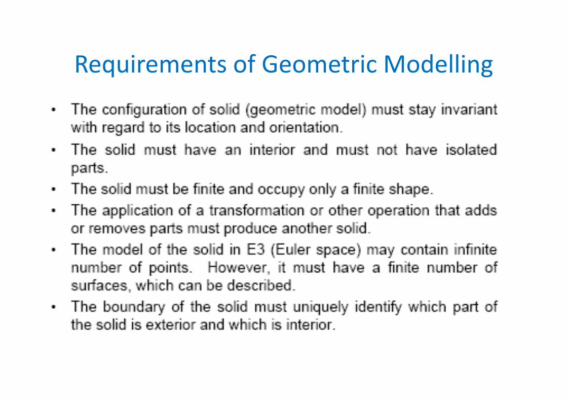
Requirements of Geometric Modelling
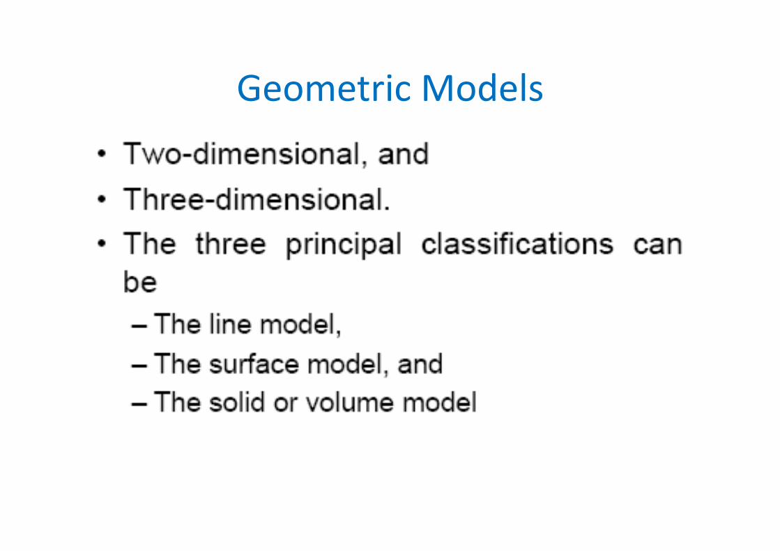
Geometric Models
Wireframe Modelling
• Advantages• Simple in construction• Less computer time and memory• For simple NC tool path generation and interference detection
• Limitations• Lack of visual coherence• Can’t be used for FEA
Surface Modelling• Advantages
• Less ambiguous• Support hidden line and surface removal algorithms
• Utilized for mass property calculations, creation of FE meshes, NC tool path generation and checking interferences between mating parts
• Limitations• Higher computer time and memory• Don’t specify the topology of objects
Solid Modelling• Advantages
• Represents complete, valid and unambiguous objects
• Contains both geometrical and topological information
• Utilized for mass property calculations, FEA, NC tool path generation and verification, process planning and checking interferences between mating parts.
• Limitations• Higher computer time and memory
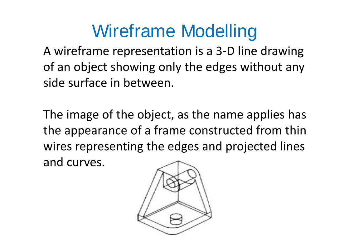
Wireframe ModellingA wireframe representation is a 3‐D line drawing of an object showing only the edges without any side surface in between.
The image of the object, as the name applies has the appearance of a frame constructed from thin wires representing the edges and projected lines and curves.

Wireframe ModellingA computer representation of a wire‐framestructure consists essentially of two types ofinformation:• The first is termed metric or geometric data
which relate to the 3D coordinate positions ofthe wire‐frame node points in space.
• The second is concerned with theconnectivity or topological data, which relatepairs of points together as edges.
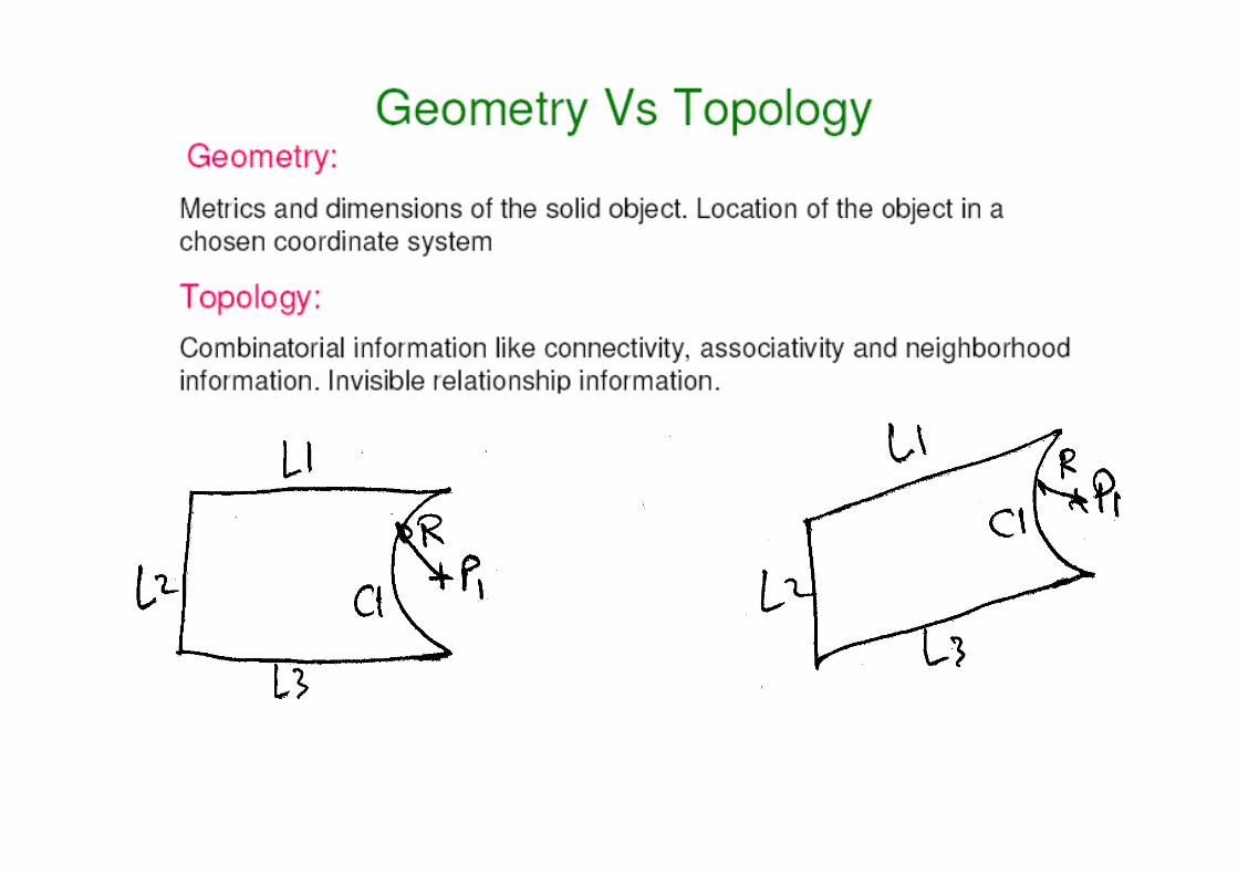

Classification of Wireframe EntitiesCurve entities are divided into two categories.
1. Analytical curves
Points, lines, arcs, fillets, chamfers, and conics(ellipses, parabolas, and hyperbolas)
2. Synthetic curves
Includes various types of spline; Hermite cubicspline, Bezier and B‐spline
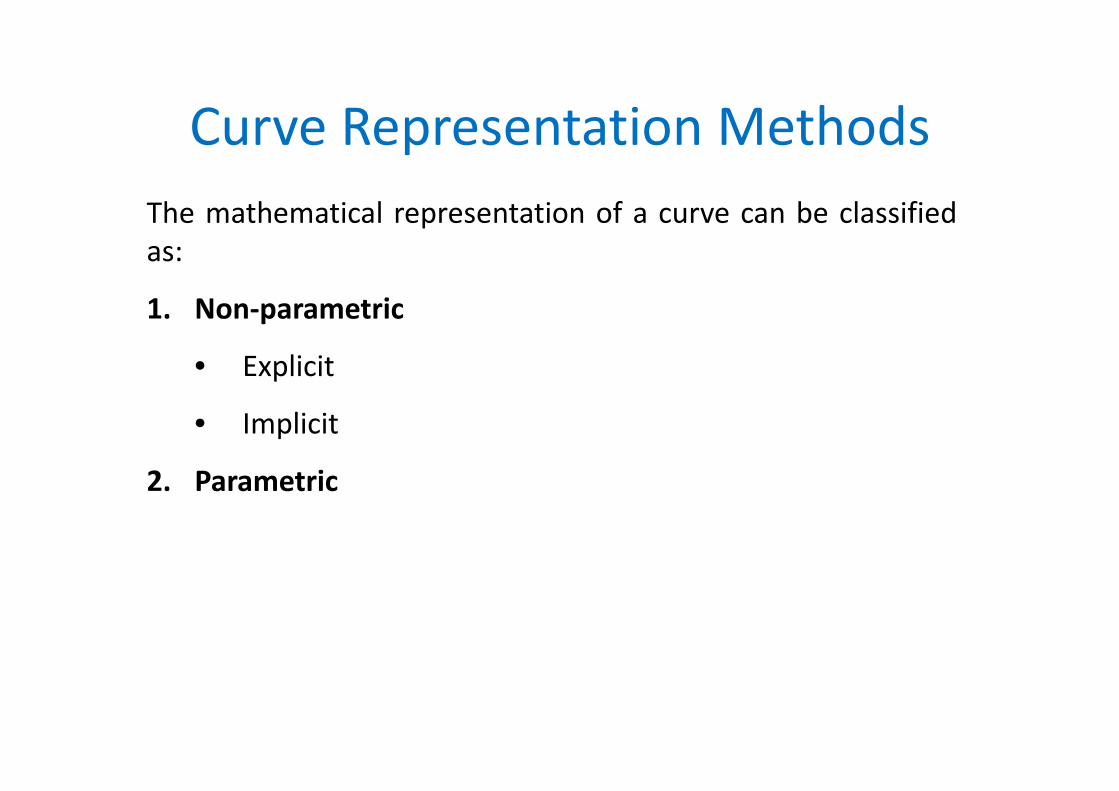
Curve Representation MethodsThe mathematical representation of a curve can be classifiedas:
1. Non‐parametric
• Explicit
• Implicit
2. Parametric
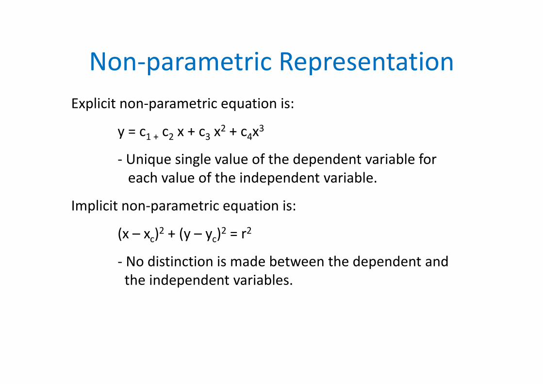
Non‐parametric RepresentationExplicit non‐parametric equation is:
y = c1 + c2 x + c3 x2 + c4x3
‐ Unique single value of the dependent variable for each value of the independent variable.
Implicit non‐parametric equation is:
(x – xc)2 + (y – yc)2 = r2
‐ No distinction is made between the dependent and the independent variables.
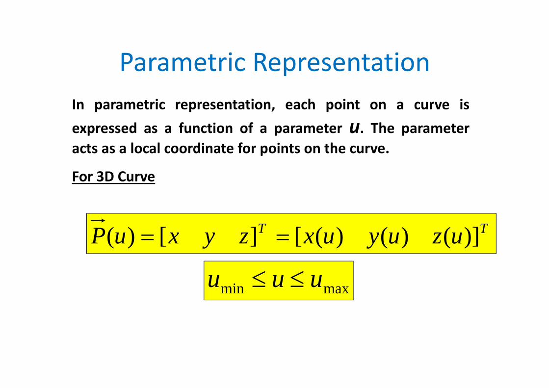
Parametric RepresentationIn parametric representation, each point on a curve isexpressed as a function of a parameter u. The parameteracts as a local coordinate for points on the curve.
For 3D Curve
TT uzuyuxzyxuP )]()()([][)(
maxmin uuu
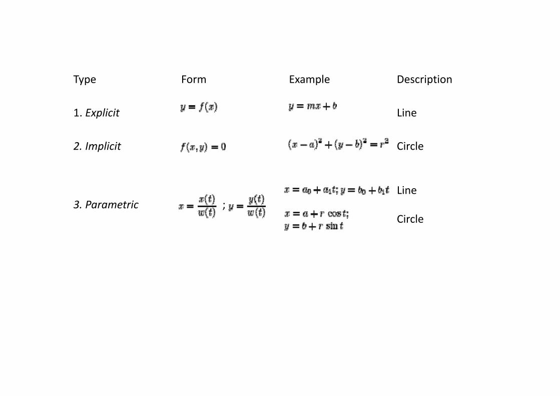
Type Form Example Description
1. Explicit Line
2. Implicit Circle
3. Parametric ; Line
Circle

Parametric Representation of Analytic Curves
)(10)(
)(
10)(
121
121
121
121
zzuzzuyyuyy
xxuxx
uPPuPP
Vector form
The above equation defines a line bounded by the endpoints P1 and P2 whose associated parametric value are 0 and 1
. LINE1
Scalar form

Parametric Representation of Analytic Curves. CIRCLE2
• The basic parametric equation of a circle can be written as
c
c
c
zzuuRyy
uRxx
20sin
cos
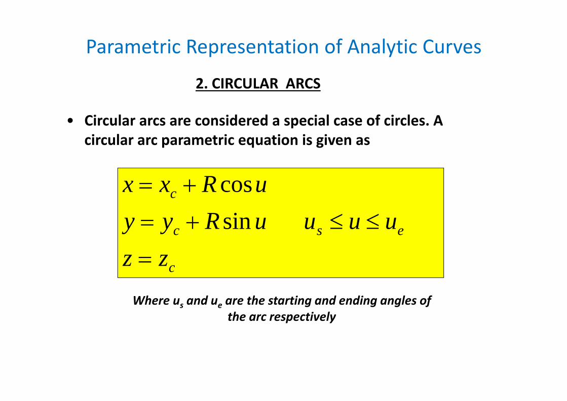
Parametric Representation of Analytic Curves
• Circular arcs are considered a special case of circles. A circular arc parametric equation is given as
c
esc
c
zzuuuuRyy
uRxx
sincos
. CIRCULAR ARCS2
Where us and ue are the starting and ending angles of the arc respectively
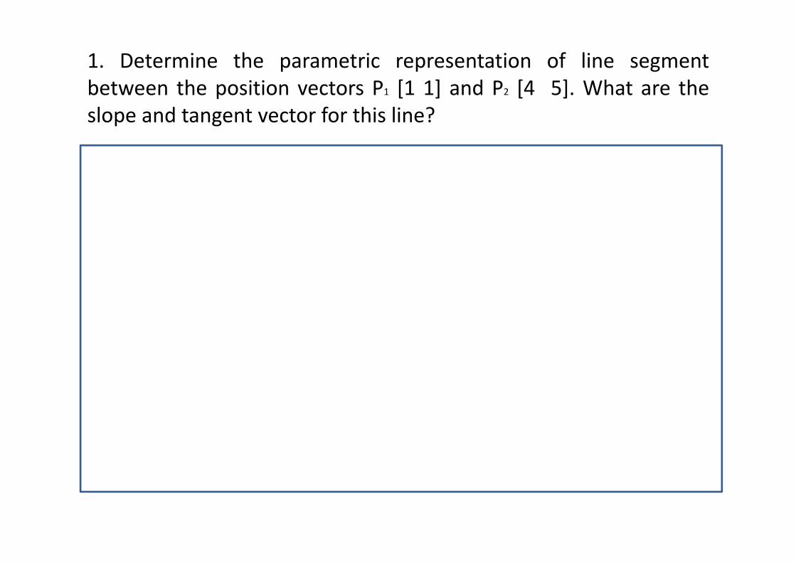
1. Determine the parametric representation of line segmentbetween the position vectors P1 [1 1] and P2 [4 5]. What are theslope and tangent vector for this line?
A parametric representation isP(u) = P1 + (P2‐P1)u = [ 1 1] + ([4 5]‐[1 1])u P(u) = [1 1] + [ 3 4]u
Parametric representation of x and y components arex(u) = x1 + (x2‐x1) u = 1 + (4‐1) u = 1 + 3uy(u) = y1+(y2‐y1)u = 1+(5‐1) u = 1+4u
Tangent vector is obtained by differentiating P(u)P’(u) = [x’(u) Y’(u)] = [ 3 4] (or)
3i + 4j where i,j are unit vectors in the x,y directions
Slope (dy/dx)= y’/x’ = 4/3