Embed Size (px)
Citation preview
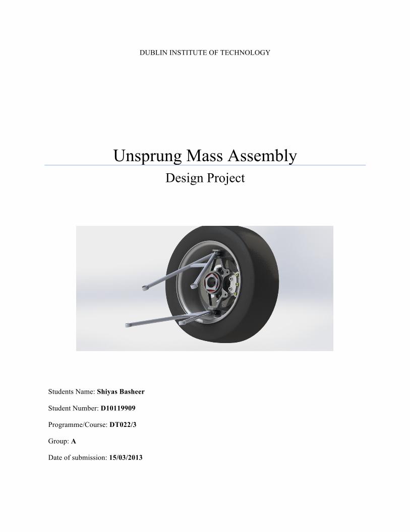
DUBLIN INSTITUTE OF TECHNOLOGY
Unsprung Mass Assembly Design Project
Students Name: Shiyas Basheer
Student Number: D10119909
Programme/Course: DT022/3
Group: A
Date of submission: 15/03/2013
1 | P a g e
Table of Contents ABSTRACT ............................................................................................................................................ 3
1. INTRODUCTION ................................................................................................................................ 4
2. LITERATURE REVIEW ........................................................................................................................ 5 2.1 SCRUB RADIUS ....................................................................................................................................... 6 2.2 KINGPIN INCLINATION (KPI) ..................................................................................................................... 7 2.3 CASTER ................................................................................................................................................. 7 2.4 CAMBER ............................................................................................................................................... 8 2.5 UNDERSTEER AND OVERSTEER .................................................................................................................. 8 2.6 WHEELBASE .......................................................................................................................................... 9 2.7 TRACK WIDTH ........................................................................................................................................ 9
3. DESIGN SUMMARY ........................................................................................................................... 9
4. DESIGN CALCULATIONS .................................................................................................................. 13 4.1 BRAKING FORCE AND TORQUE ................................................................................................................ 13 4.2 BEARINGS ........................................................................................................................................... 14
4.2.1 Bearing Selection ...................................................................................................................... 15 4.2.2 Bearing Life ............................................................................................................................... 15 4.2.3 Tubular Bar ............................................................................................................................... 17 4.2.4 Bearing Interference/ tolerance ................................................................................................ 19
5. DESIGN ANALYSIS ........................................................................................................................... 21
6. SUSTAINABILITY ............................................................................................................................. 23 6.1 BRAKE DISC FOR CARBON STEEL MILLED .................................................................................................... 23 6.2 BRAKE DISC FOR CAST IRON .................................................................................................................... 24 6.3 UPRIGHT DIE CASTED ............................................................................................................................ 25 6.4 UPRIGHT MILLED ................................................................................................................................. 26
7. COMMENTS AND CONCLUSIONS .................................................................................................... 26
8. REFERENCES ................................................................................................................................... 28
APPENDIX .......................................................................................................................................... 29
Figure 1 ........................................................................................................................................................ 6 Figure 2 ........................................................................................................................................................ 7 Figure 3 ........................................................................................................................................................ 9 Figure 4 Brake Disc .................................................................................................................................... 10 Figure 5 Hub .............................................................................................................................................. 11 Figure 6 Upright ......................................................................................................................................... 12 Figure 7 Assembly ...................................................................................................................................... 13 Figure 8 ...................................................................................................................................................... 15
2 | P a g e
Figure 9 ...................................................................................................................................................... 19 Figure 10 .................................................................................................................................................... 20 Figure 11 .................................................................................................................................................... 21 Figure 12 .................................................................................................................................................... 22 Figure 13 .................................................................................................................................................... 22 Figure 14 -‐ Sustainability Brake Disc (Carbon Steel) .................................................................................. 23 Figure 15 -‐ Sustainability Brake Disc (Gray cast iron) ................................................................................ 24 Figure 16-‐ Sustainability Upright (Die Casted) ........................................................................................... 25 Figure 17-‐ Sustainability Upright (Milled) .................................................................................................. 26 Figure 18-‐ Exploded View .......................................................................................................................... 27
3 | P a g e
Abstract Formula SAE is a student designed competition, organized by SAE International to take students
out of the classroom and allows them to apply the textbook theories to the real work experiences.
This project is to study and design the suspension system for Formula SAE racecar. The
designed suspension system must follow all the Formula SAE rules and regulations thus
compete with other racecar around the world. All the required steps in designing the suspension
system are conducted in this project in order to produce a racecar with optimum handling and
cornering performance. At the end of this project, the designed suspension system must be
competitive enough which can be used for further development.
4 | P a g e
Unsprung Mass Assembly
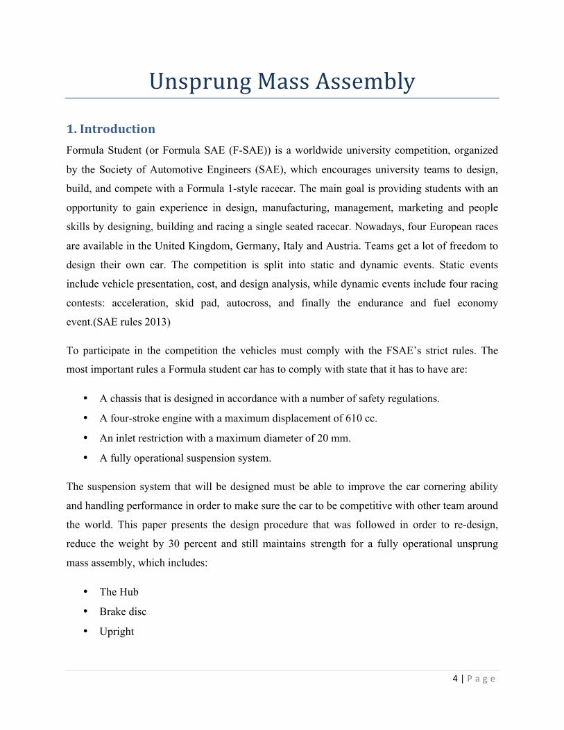
1. Introduction Formula Student (or Formula SAE (F-SAE)) is a worldwide university competition, organized
by the Society of Automotive Engineers (SAE), which encourages university teams to design,
build, and compete with a Formula 1-style racecar. The main goal is providing students with an
opportunity to gain experience in design, manufacturing, management, marketing and people
skills by designing, building and racing a single seated racecar. Nowadays, four European races
are available in the United Kingdom, Germany, Italy and Austria. Teams get a lot of freedom to
design their own car. The competition is split into static and dynamic events. Static events
include vehicle presentation, cost, and design analysis, while dynamic events include four racing
contests: acceleration, skid pad, autocross, and finally the endurance and fuel economy
event.(SAE rules 2013)
To participate in the competition the vehicles must comply with the FSAE’s strict rules. The
most important rules a Formula student car has to comply with state that it has to have are:
• A chassis that is designed in accordance with a number of safety regulations.
• A four-stroke engine with a maximum displacement of 610 cc.
• An inlet restriction with a maximum diameter of 20 mm.
• A fully operational suspension system.
The suspension system that will be designed must be able to improve the car cornering ability
and handling performance in order to make sure the car to be competitive with other team around
the world. This paper presents the design procedure that was followed in order to re-design,
reduce the weight by 30 percent and still maintains strength for a fully operational unsprung
mass assembly, which includes:
• The Hub
• Brake disc
• Upright
5 | P a g e
The main objectives of the project were as follows:
• To re-design the unsprung mass assembly for DIT Formula SAE race car.
• To reduce the weight by 30 percent and still maintain strength to withstand all braking
and cornering loads.
• Replace the existing brake calipers with AP motorbike calipers-CP4227-2SO.
• Redesign the hub so that there is no need for the stub axle, which will reduce the need for
one component and reduce the weight.
• To understand the concept of upright, brake disc and the hub and its applications, in this
case it is specific to the Formula SAE racecar application.
• To select appropriate bearing for the redesigned brake disc.
• The application of self-technical knowledge, Solid works and FEA analysis, understand
related high-tech material and its production process, and the application and the
advantage of the designed item.
• To understand the sustainability of the selected materials.
2. Literature Review The suspension design was mainly focused on the constraints of the competition. First, the
design parameters were set and then using the old upright, designed previous year as a template,
a new upright was designed keeping the same camper angle and king pin offset. Before the
modeling began the ball joint locations were set using the old upright. A new hub was designed
and an appropriate bearing was selected using the NSK catalogue provided and an new brake
disc was designed fitted with a given brake caliper. The main design requirement put forward for
the design of the unspring mass assembly was that it should have the ability to have many
adjustments, since different races often require alternative setups, and in this case it was decided
that the upright design should include the following adjustments:
• Camber angles
• Under steer and over steer
• Roll angle
• King pin angle
6 | P a g e
• Caster roll stiffness
• Spring rate
• King pin offset
• Squat
• Wheel base and
• Track
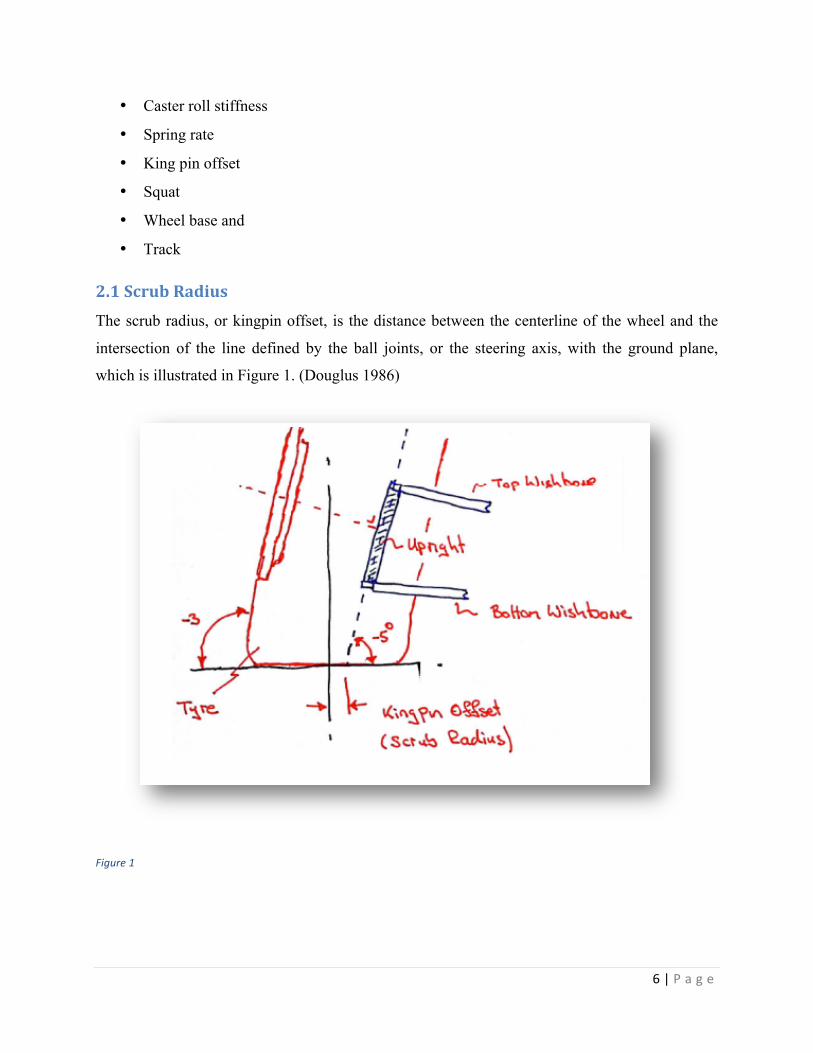
2.1 Scrub Radius
The scrub radius, or kingpin offset, is the distance between the centerline of the wheel and the
intersection of the line defined by the ball joints, or the steering axis, with the ground plane,
which is illustrated in Figure 1. (Douglus 1986)
Figure 1
7 | P a g e
Scrub radius is considered positive when the steering axis intersects the ground to the inside of
the wheel centerline. But here it was considered negative. The amount of scrub radius should be
kept small since it can cause excessive steering forces.
2.2 Kingpin inclination (KPI)
It is viewed from the front of the vehicle and is the angle between the steering axis and the wheel
centerline. To reduce scrub radius, KPI can be incorporated into the suspension design if
packaging of the ball joints near the centerline of the wheel is not feasible. Scrub radius can be
reduced with KPI by designing the steering axis so that it will intersect the ground plane closer to
the wheel centerline. The drawback of excessive KPI, however, is that the outside wheel, when
turned, cambers positively thereby pulling part of the tire off of the ground.
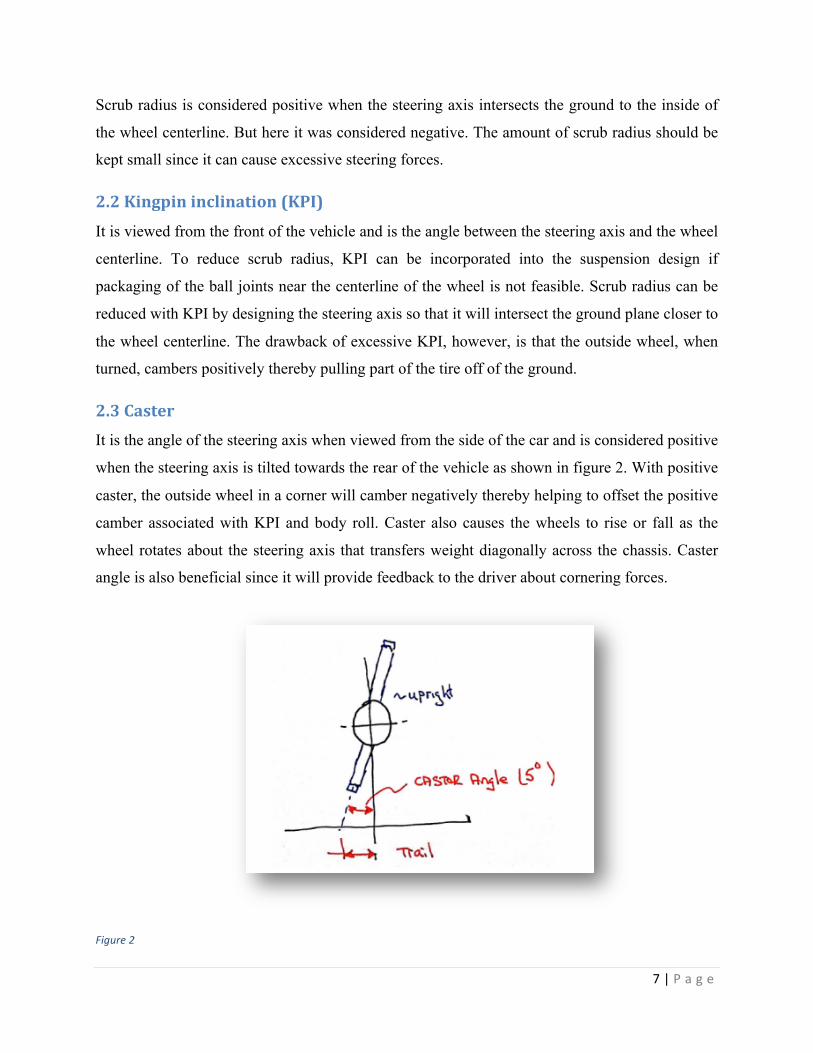
2.3 Caster
It is the angle of the steering axis when viewed from the side of the car and is considered positive
when the steering axis is tilted towards the rear of the vehicle as shown in figure 2. With positive
caster, the outside wheel in a corner will camber negatively thereby helping to offset the positive
camber associated with KPI and body roll. Caster also causes the wheels to rise or fall as the
wheel rotates about the steering axis that transfers weight diagonally across the chassis. Caster
angle is also beneficial since it will provide feedback to the driver about cornering forces.
Figure 2
8 | P a g e
2.4 Camber
Camber is the angle of the wheel plane from the vertical and is considered to be a negative angle
when the top of the wheel is tilted towards the centerline of the vehicle. Camber is adjusted by
tilting the steering axis from the vertical, which is usually done by adjusting the ball joint
locations. Because the amount of tire on the ground is affected by camber angle, camber should
be easily adjustable so that the suspension can be tuned for maximum cornering. For example,
the amount of camber needed for the small skid pad might not be the same for the sweeping
corners in the endurance event. The maximum cornering force that the tire can produce will
occur at some negative camber angle. However, camber angle can change as the wheel moves
through suspension travel and as the wheel turns about the steering axis. Because of this change,
the suspension system must be designed to compensate or complement the camber angle change
associated with chassis and wheel movements so that maximum cornering forces are produced.
Static camber can be added to compensate for body roll; however, the added camber might be
detrimental to other aspects of handling. For example, too much static camber can reduce the
amount of tire on the ground, thereby affecting straight line braking and accelerating. Similarly,
too much camber gain during suspension travel can cause part of the tire to loose contact with
the ground.
2.5 Understeer and oversteer
They are driving characteristics that involve sliding of either the front or rears tires. Excessive
understeer and oversteer can result in an out-of-control car. A car’s tendency to understeer or
oversteer is most commonly attributed to whether it’s front- or rear-wheel drive. Front-wheel-
drive cars characteristically understeer, while rear-wheel-drive cars tend to oversteer. Both front-
and rear-wheel-drive cars, though, can experience both understeer and oversteer in the right
conditions. The more power a car has, the more likely understeer or oversteer will show their
faces.(Driving Fast 2013)
Understeer happens when the front wheels start to plow straight even if you have the steering
wheel turned. Front-wheel-drive cars are susceptible to understeer because power is being sent to
the same wheels that steer the car, and when the tires start spinning there’s no grip to steer.
Oversteer is the tendency for the rear end to slide out or fishtail.
9 | P a g e
2.6 Wheelbase
It is defined as the distance between the front and rear axle centerlines. It also influences weight
transfer, but in the longitudinal direction. Except for anti-dive and anti-squat characteristics, the
wheelbase relative to the CG location does not have a large effect on the kinematics of the
suspension system. However, the wheelbase should be determined early in the design process
since the wheelbase has a large influence on the packaging of components.
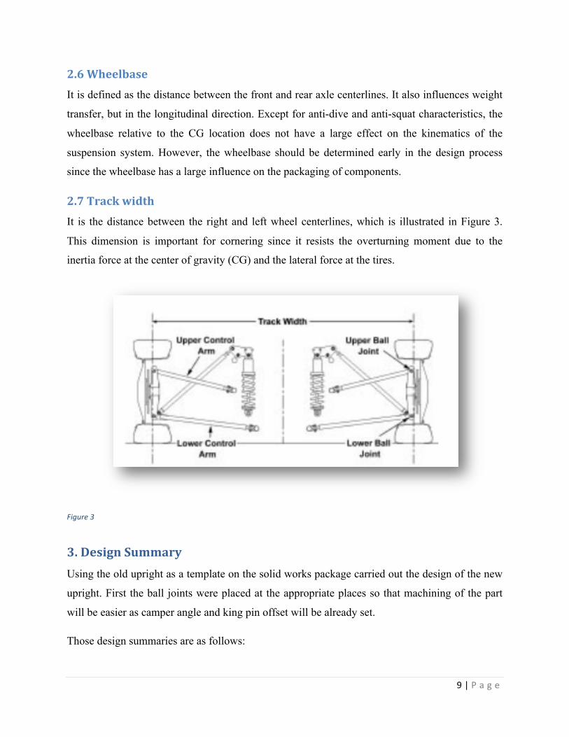
2.7 Track width
It is the distance between the right and left wheel centerlines, which is illustrated in Figure 3.
This dimension is important for cornering since it resists the overturning moment due to the
inertia force at the center of gravity (CG) and the lateral force at the tires.
Figure 3
3. Design Summary Using the old upright as a template on the solid works package carried out the design of the new
upright. First the ball joints were placed at the appropriate places so that machining of the part
will be easier as camper angle and king pin offset will be already set.
Those design summaries are as follows:
10 | P a g e
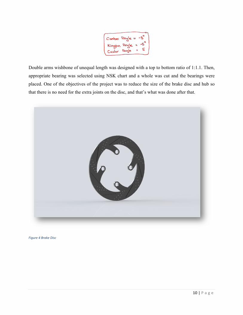
Double arms wishbone of unequal length was designed with a top to bottom ratio of 1:1.1. Then,
appropriate bearing was selected using NSK chart and a whole was cut and the bearings were
placed. One of the objectives of the project was to reduce the size of the brake disc and hub so
that there is no need for the extra joints on the disc, and that’s what was done after that.
Figure 4 Brake Disc
11 | P a g e
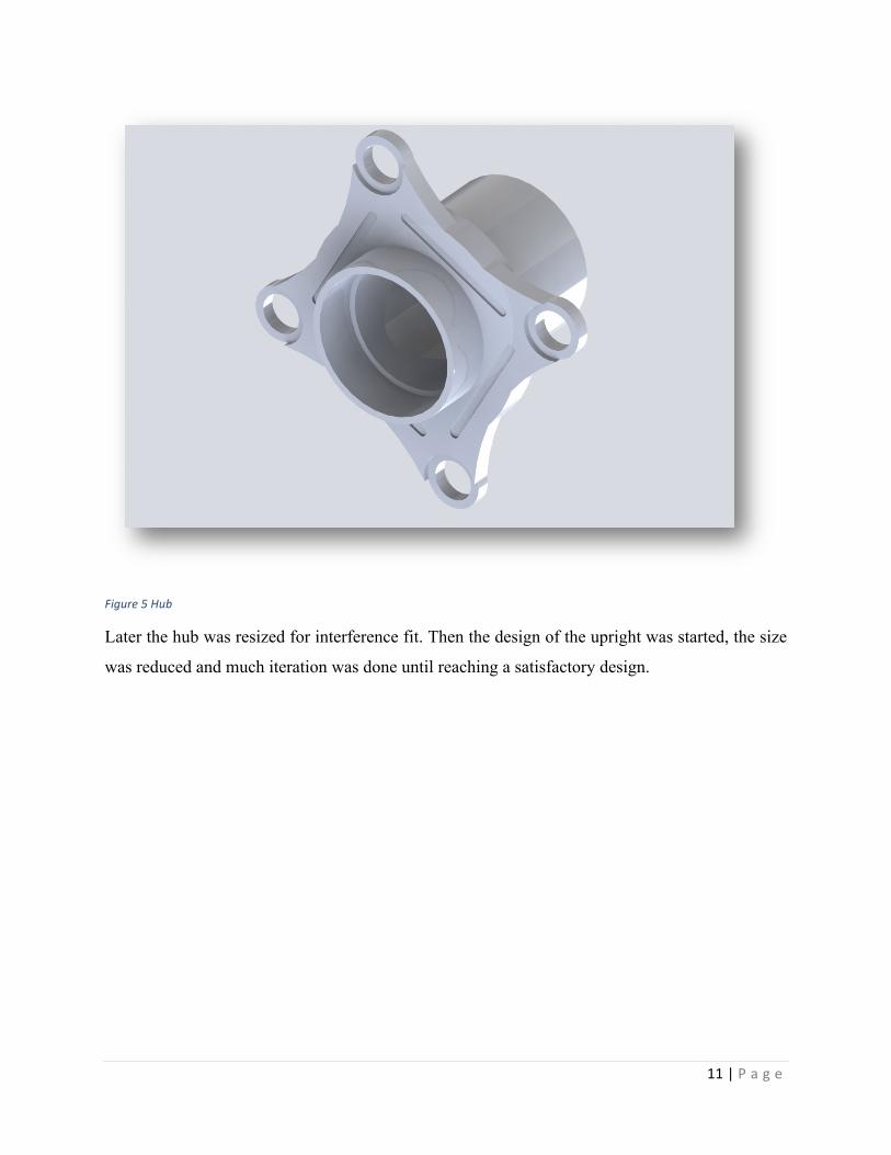
Figure 5 Hub
Later the hub was resized for interference fit. Then the design of the upright was started, the size
was reduced and much iteration was done until reaching a satisfactory design.
12 | P a g e
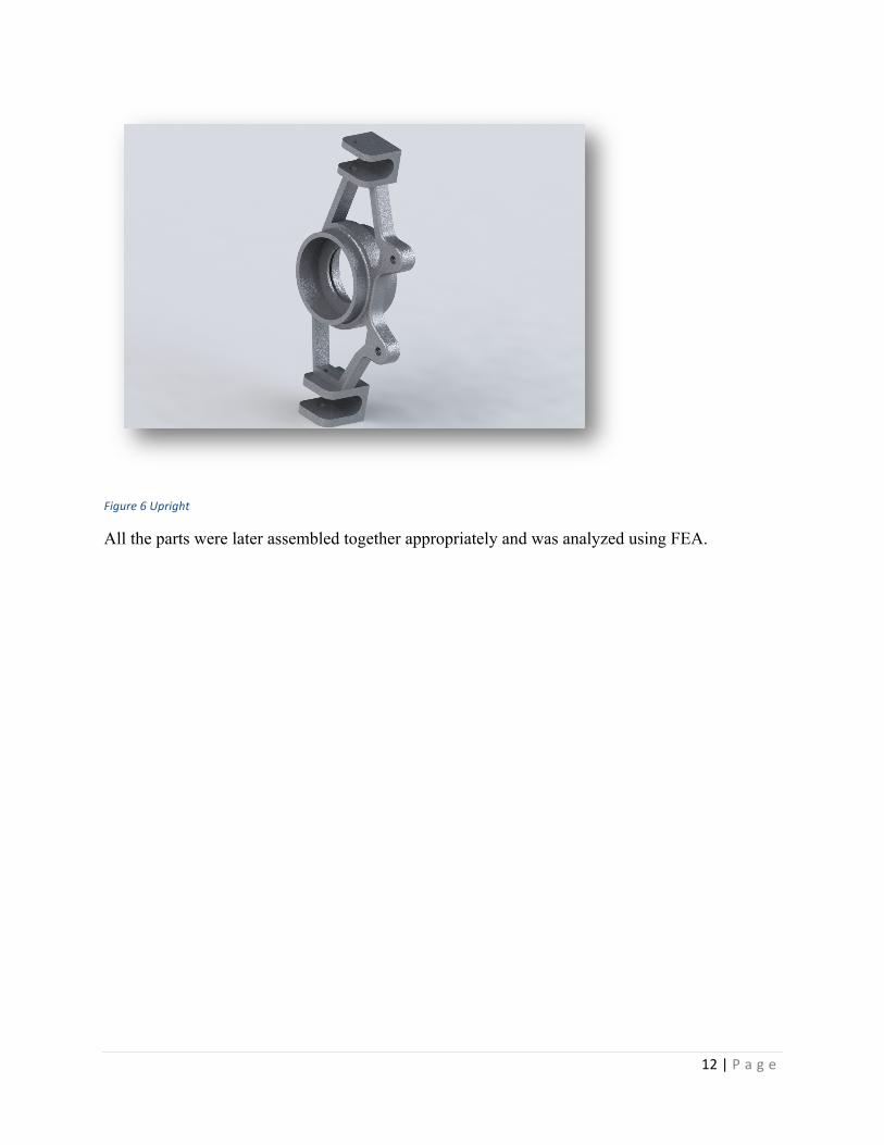
Figure 6 Upright
All the parts were later assembled together appropriately and was analyzed using FEA.
13 | P a g e
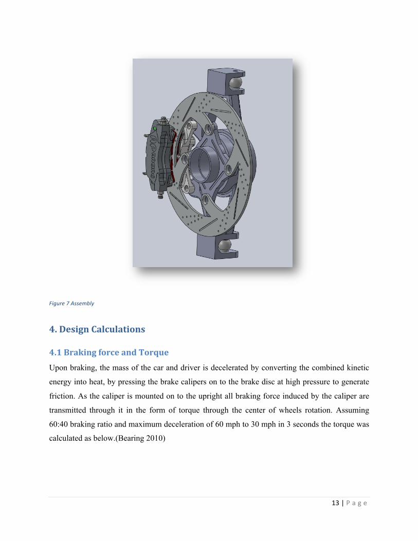
Figure 7 Assembly
4. Design Calculations
4.1 Braking force and Torque
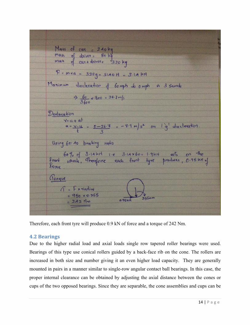
Upon braking, the mass of the car and driver is decelerated by converting the combined kinetic
energy into heat, by pressing the brake calipers on to the brake disc at high pressure to generate
friction. As the caliper is mounted on to the upright all braking force induced by the caliper are
transmitted through it in the form of torque through the center of wheels rotation. Assuming
60:40 braking ratio and maximum deceleration of 60 mph to 30 mph in 3 seconds the torque was
calculated as below.(Bearing 2010)
14 | P a g e
Therefore, each front tyre will produce 0.9 kN of force and a torque of 242 Nm.
4.2 Bearings Due to the higher radial load and axial loads single row tapered roller bearings were used.
Bearings of this type use conical rollers guided by a back-face rib on the cone. The rollers are
increased in both size and number giving it an even higher load capacity. They are generally
mounted in pairs in a manner similar to single-row angular contact ball bearings. In this case, the
proper internal clearance can be obtained by adjusting the axial distance between the cones or
cups of the two opposed bearings. Since they are separable, the cone assemblies and cups can be
15 | P a g e
mounted independently. Depending upon the contact angle, tapered roller bearings are divided
into three types called the normal angle, medium angle, and steep angle. (Bearing 2010)
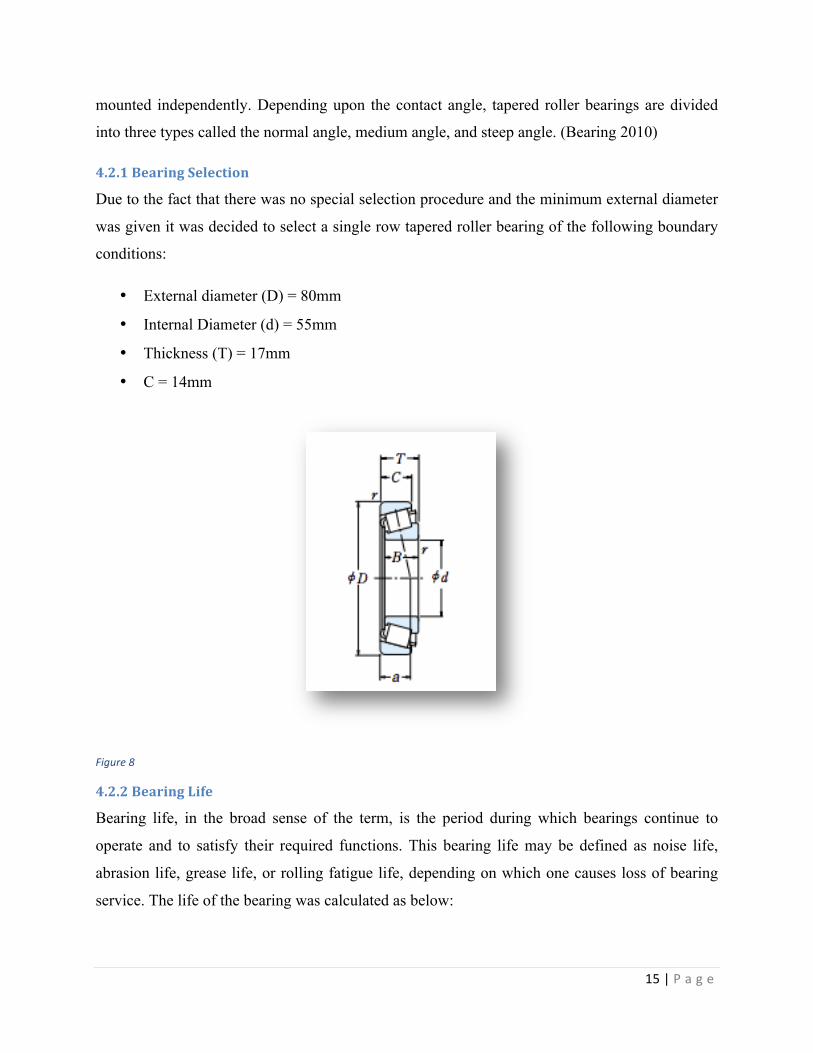
4.2.1 Bearing Selection
Due to the fact that there was no special selection procedure and the minimum external diameter
was given it was decided to select a single row tapered roller bearing of the following boundary
conditions:
• External diameter (D) = 80mm
• Internal Diameter (d) = 55mm
• Thickness (T) = 17mm
• C = 14mm
Figure 8
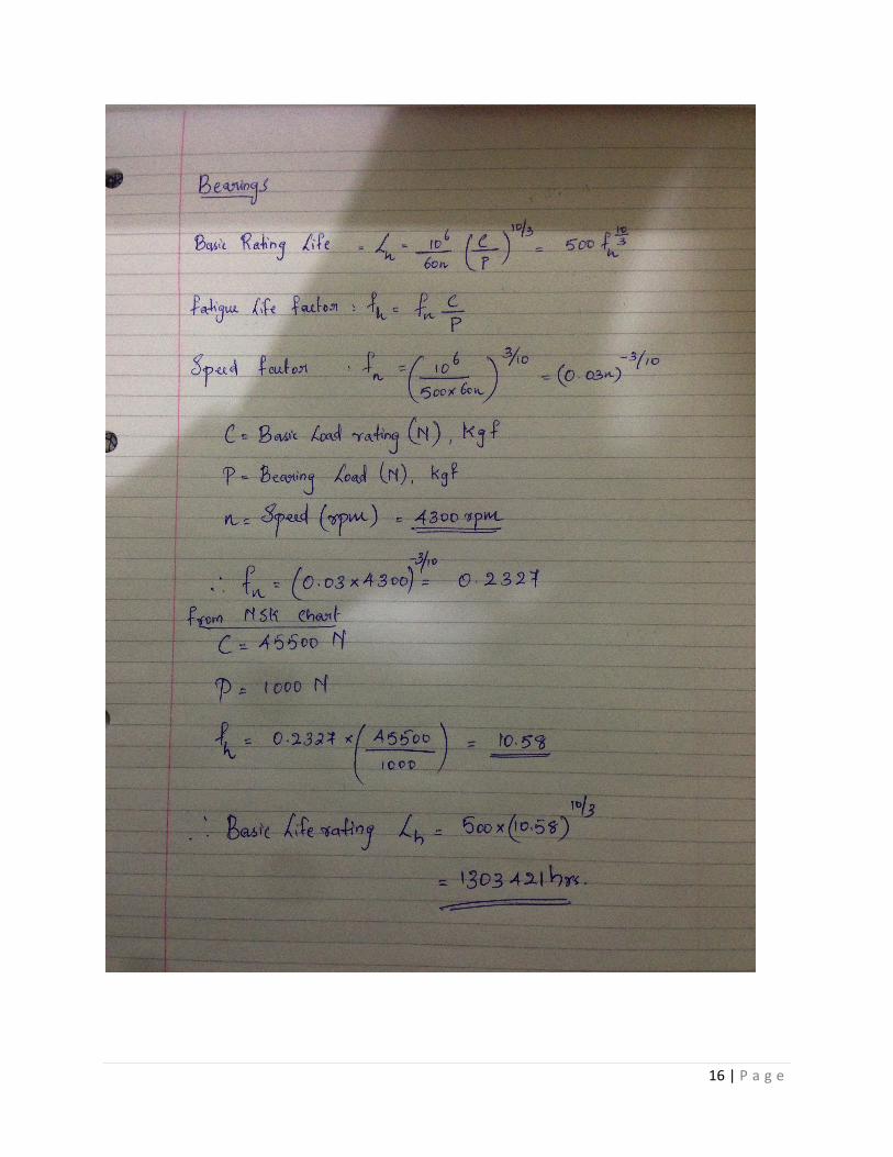
4.2.2 Bearing Life
Bearing life, in the broad sense of the term, is the period during which bearings continue to
operate and to satisfy their required functions. This bearing life may be defined as noise life,
abrasion life, grease life, or rolling fatigue life, depending on which one causes loss of bearing
service. The life of the bearing was calculated as below:
16 | P a g e
17 | P a g e
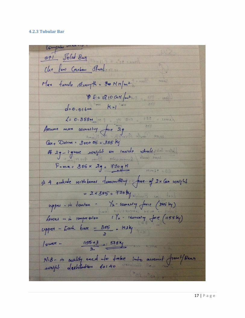
4.2.3 Tubular Bar
18 | P a g e
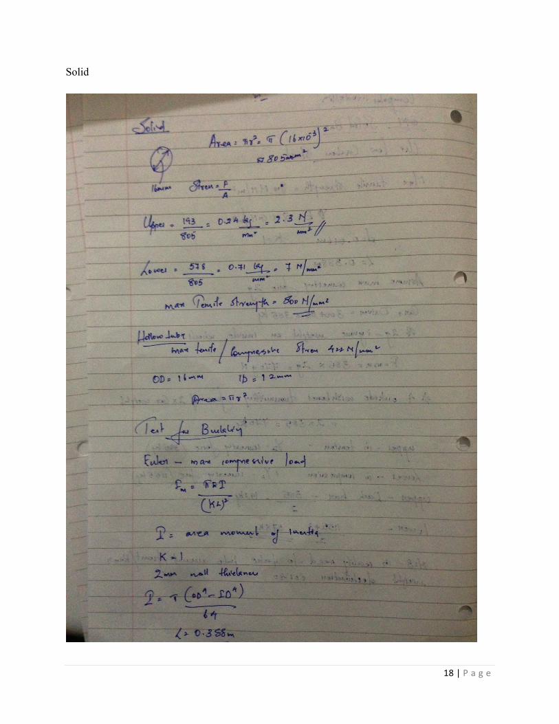
Solid
19 | P a g e
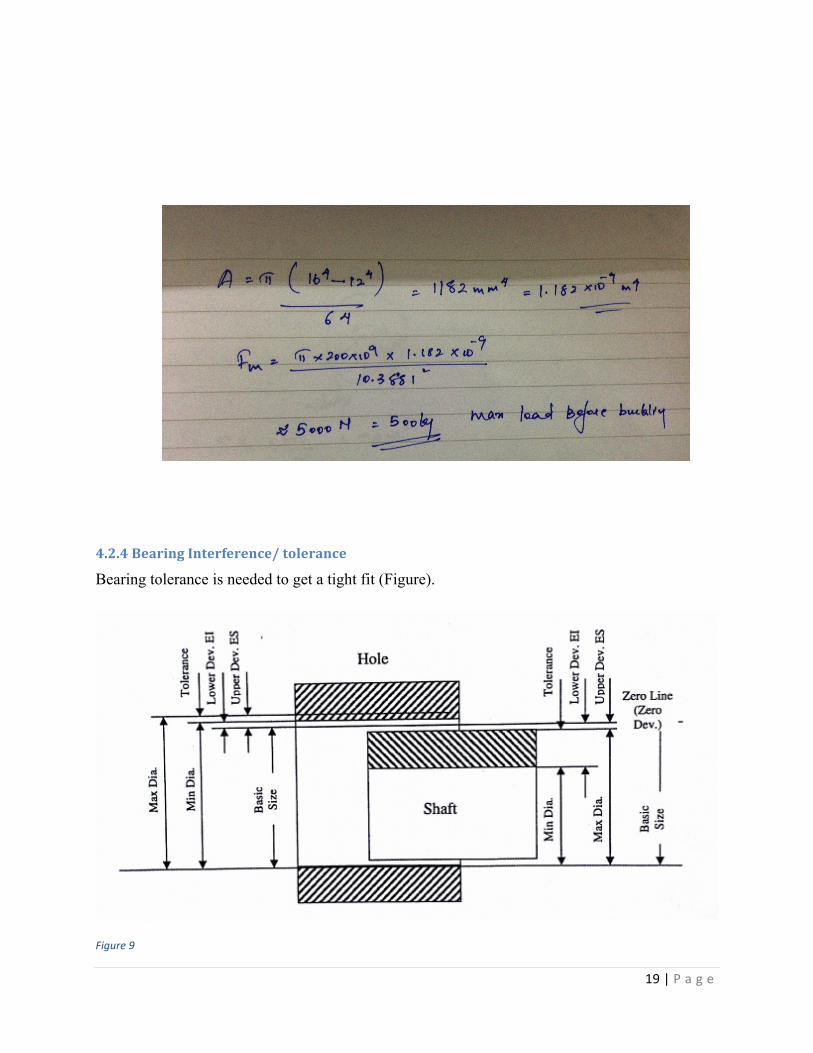
4.2.4 Bearing Interference/ tolerance
Bearing tolerance is needed to get a tight fit (Figure).
Figure 9
20 | P a g e
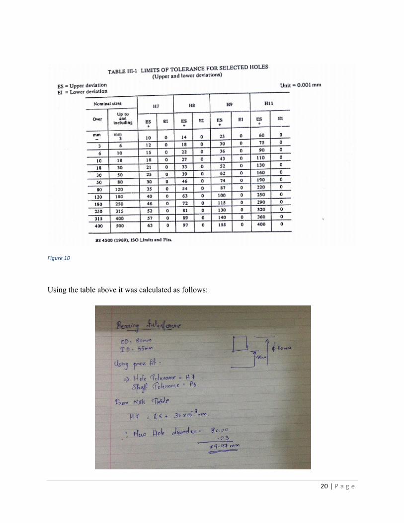
Figure 10
Using the table above it was calculated as follows:
21 | P a g e
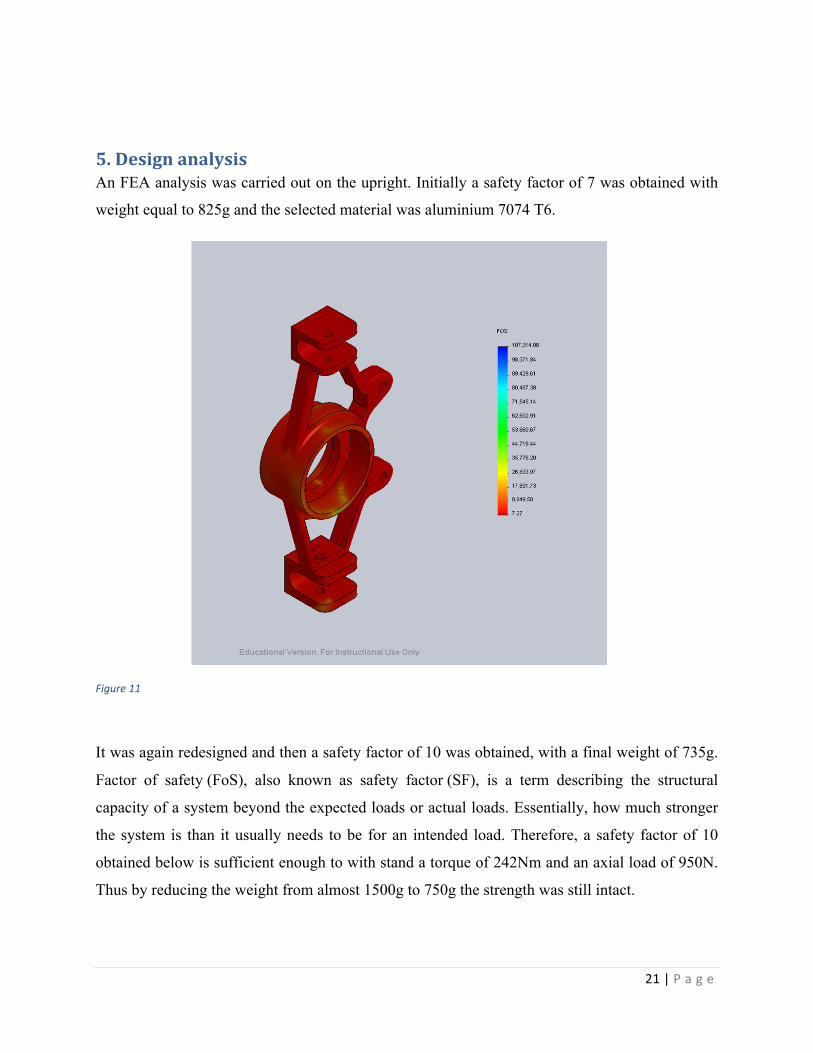
5. Design analysis An FEA analysis was carried out on the upright. Initially a safety factor of 7 was obtained with
weight equal to 825g and the selected material was aluminium 7074 T6.
Figure 11
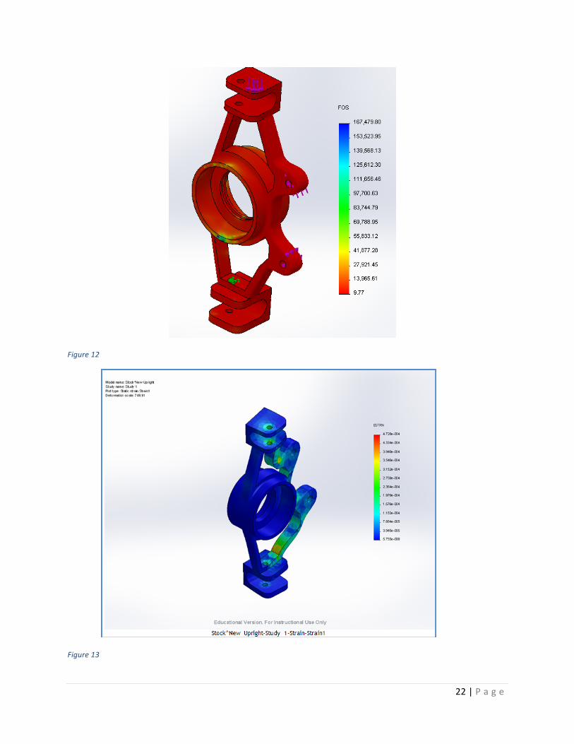
It was again redesigned and then a safety factor of 10 was obtained, with a final weight of 735g.
Factor of safety (FoS), also known as safety factor (SF), is a term describing the structural
capacity of a system beyond the expected loads or actual loads. Essentially, how much stronger
the system is than it usually needs to be for an intended load. Therefore, a safety factor of 10
obtained below is sufficient enough to with stand a torque of 242Nm and an axial load of 950N.
Thus by reducing the weight from almost 1500g to 750g the strength was still intact.
22 | P a g e
Figure 12
Figure 13
23 | P a g e
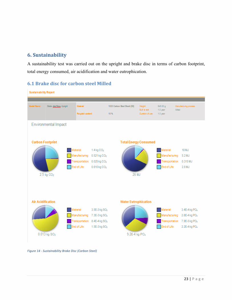
6. Sustainability A sustainability test was carried out on the upright and brake disc in terms of carbon footprint,
total energy consumed, air acidification and water eutrophication.
6.1 Brake disc for carbon steel Milled
Figure 14 -‐ Sustainability Brake Disc (Carbon Steel)
24 | P a g e
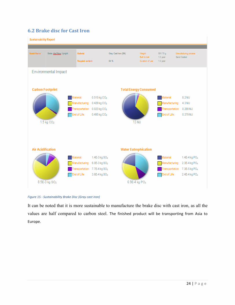
6.2 Brake disc for Cast Iron
Figure 15 -‐ Sustainability Brake Disc (Gray cast iron)
It can be noted that it is more sustainable to manufacture the brake disc with cast iron, as all the
values are half compared to carbon steel. The finished product will be transporting from Asia to
Europe.
25 | P a g e
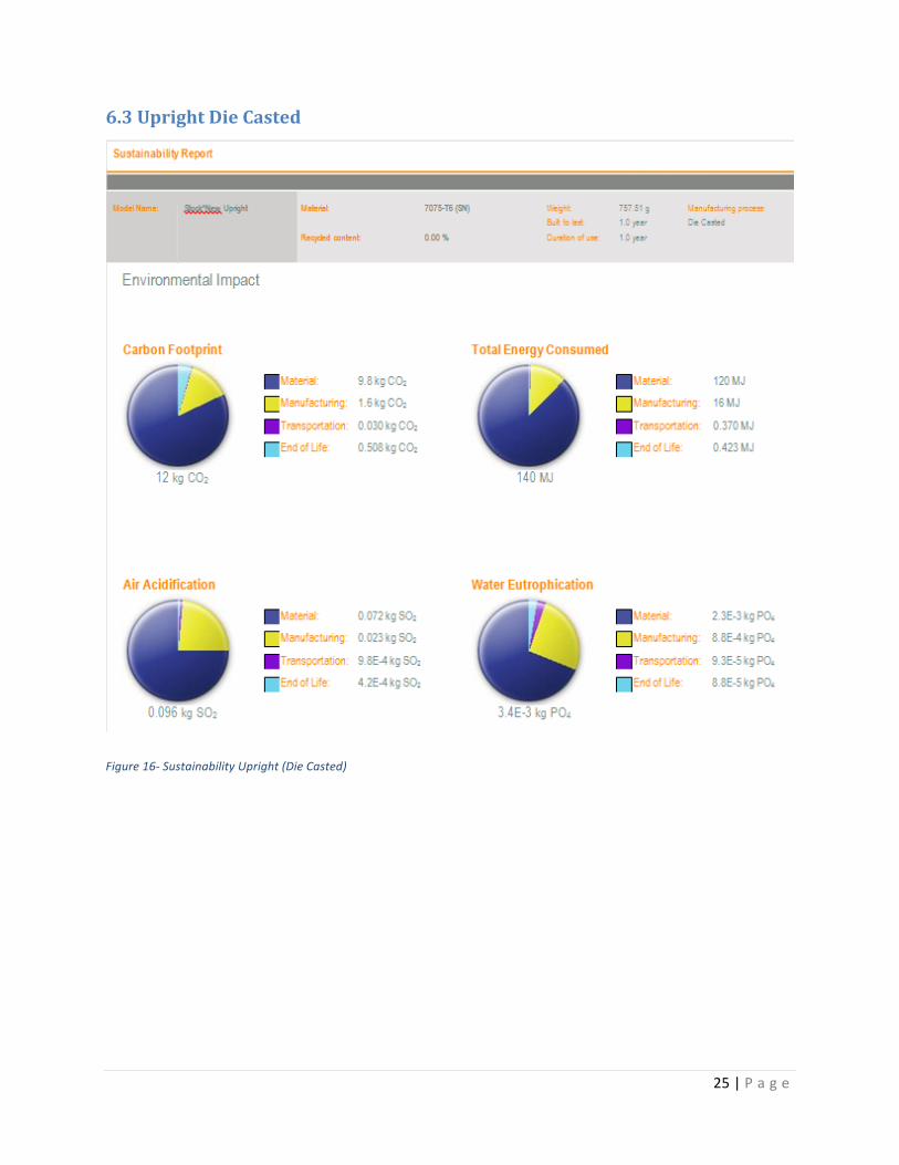
6.3 Upright Die Casted
Figure 16-‐ Sustainability Upright (Die Casted)
26 | P a g e
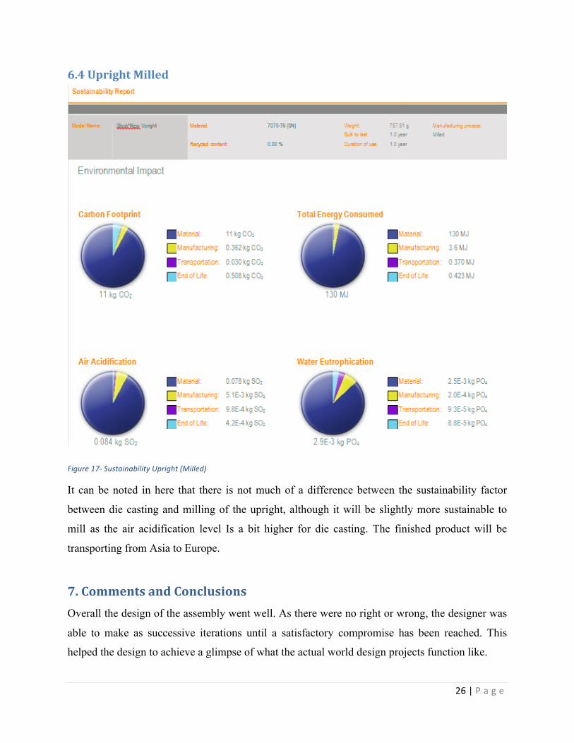
6.4 Upright Milled
Figure 17-‐ Sustainability Upright (Milled)
It can be noted in here that there is not much of a difference between the sustainability factor
between die casting and milling of the upright, although it will be slightly more sustainable to
mill as the air acidification level Is a bit higher for die casting. The finished product will be
transporting from Asia to Europe.
7. Comments and Conclusions Overall the design of the assembly went well. As there were no right or wrong, the designer was
able to make as successive iterations until a satisfactory compromise has been reached. This
helped the design to achieve a glimpse of what the actual world design projects function like.
27 | P a g e
During the design process the designer was able to achieve all the objectives so that the overall
weight of the car could be reduce but still maintaining it strength. The timeline of six weeks
along with the rigorous schedule of college did some limitation on the number of design
iterations. However it was understood that many iterations would take to converge on to a
satisfactory design.
Overall it was challenging and at the same time interesting.
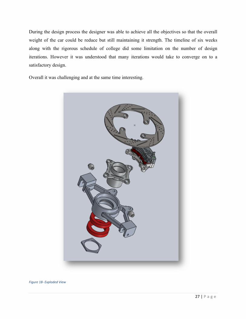
Figure 18-‐ Exploded View
28 | P a g e
8. References Bearing, N., 2010. NSK Bearing Catalogue.
Douglus, Mi., 1986. Race car vehicle dynamics, S.E International.
Driving Fast, 2013. Understeer. Available at: http://www.drivingfast.net/car-control/understeer.htm#.UUeDsVTviQs [Accessed March 18, 2013].
SAE rules, F., 2013. Formula SAE rules.

29 | P a g e
Appendix