Embed Size (px)
Citation preview
MINOR PROJECT (I)
On
GAS DETECTION AND ALERT SYSTEM
Under the guidance of
Dr. Malti Bansal
Assistant Professor, Department of Electronics and Communication
Delhi Technological University
BY-
Arpit Bhateley (2K12/EC/036)
Anngad Singh (2K12/EC/030)
Apaar Singhal (2K12/EC/034)
Angad Singh (2K12/EC/026)
B. Tech. (Electronics and Communication Engineering), DTU
Department of Electronics and Communication Engineering,
Delhi Technological University
2
CERTIFICATE
This is to certify that the report entitled “Gas Detection And Alert System” is a
bonafide record of Minor Project (I) Report submitted by
Arpit Bhateley(2K12/EC/036)
Anngad Singh (2K12/EC/030)
Apaar Singhal(2K12/EC/034)
Angad Singh (2K12/EC/026)
as the record study undertaken by them under my guidance. It is being accepted in
partial fulfillment of the requirements for the award of degree of fifth semester
Minor Project (I) course of Bachelor of Technology in Electronics and
Communication Engineering, Delhi Technological University, Delhi.
Mentor
Dr. Malti Bansal
Assistant Professor
Department of ECE
Delhi Technological University

3
ACKNOWLEDGEMENT
We express our deepest gratitude to our mentor, Dr. Malti Bansal,
Department of Electronics and Communication Engineering, Delhi
Technological University, whose encouragement, guidance and support
enabled us to undertake this Minor Project successfully and to get the
maximum output of understanding from the subject.
We also take this opportunity to thank my friends, who encouraged us
and cleared our doubts during the course of my Minor Project. We
extend my gratitude to our families whose efforts were crucial in the
successful completion of this project.
4
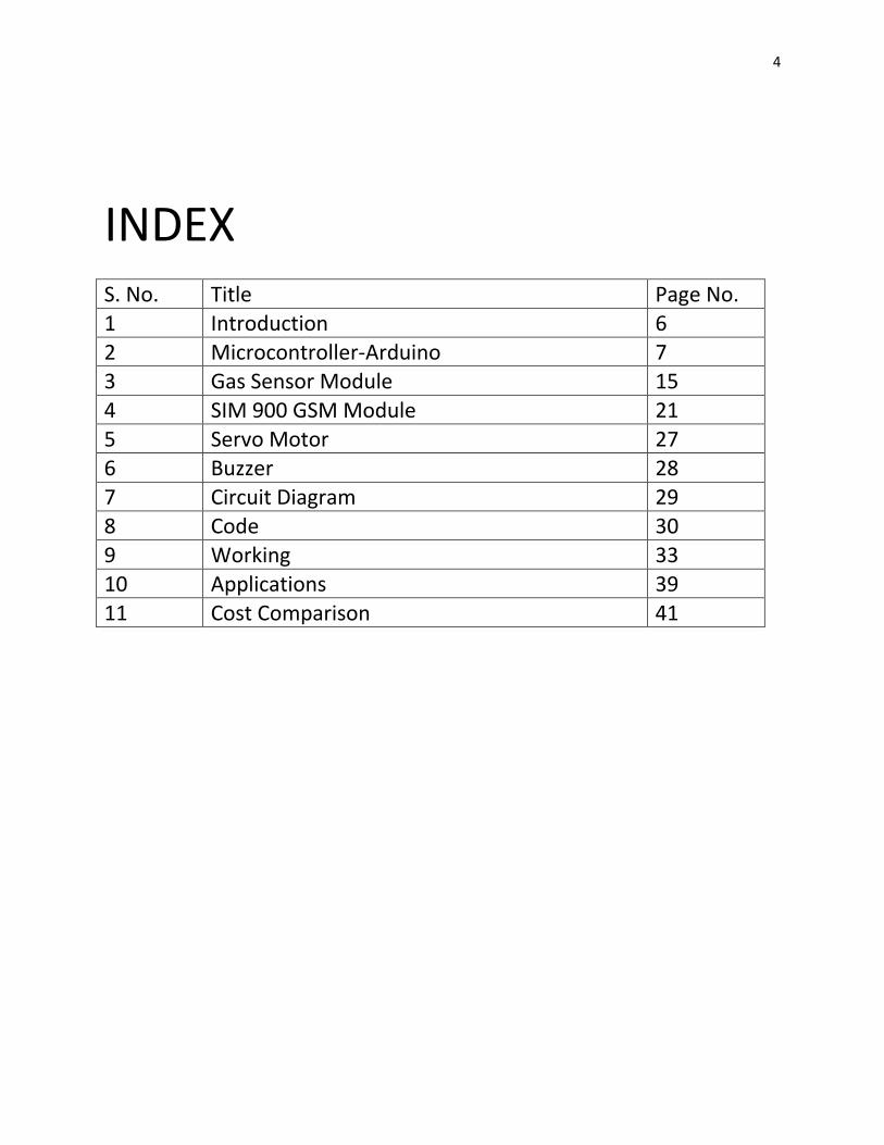
INDEX S. No. Title Page No.
1 Introduction 6
2 Microcontroller-Arduino 7
3 Gas Sensor Module 15
4 SIM 900 GSM Module 21
5 Servo Motor 27 6 Buzzer 28
7 Circuit Diagram 29
8 Code 30
9 Working 33
10 Applications 39
11 Cost Comparison 41
5
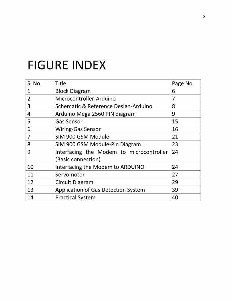
FIGURE INDEX S. No. Title Page No.
1 Block Diagram 6
2 Microcontroller-Arduino 7
3 Schematic & Reference Design-Arduino 8
4 Arduino Mega 2560 PIN diagram 9
5 Gas Sensor 15
6 Wiring-Gas Sensor 16 7 SIM 900 GSM Module 21
8 SIM 900 GSM Module-Pin Diagram 23
9 Interfacing the Modem to microcontroller (Basic connection)
24
10 Interfacing the Modem to ARDUINO 24
11 Servomotor 27
12 Circuit Diagram 29
13 Application of Gas Detection System 39
14 Practical System 40
6
Servo
Motor
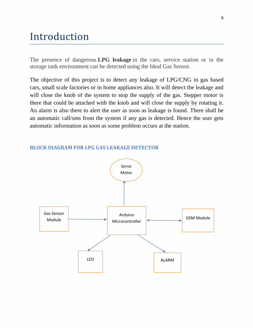
Introduction
The presence of dangerous LPG leakage in the cars, service station or in the
storage tank environment can be detected using the Ideal Gas Sensor.
The objective of this project is to detect any leakage of LPG/CNG in gas based
cars, small scale factories or in home appliances also. It will detect the leakage and
will close the knob of the system to stop the supply of the gas. Stepper motor is
there that could be attached with the knob and will close the supply by rotating it.
An alarm is also there to alert the user as soon as leakage is found. There shall be
an automatic call/sms from the system if any gas is detected. Hence the user gets
automatic information as soon as some problem occurs at the station.
BLOCK DIAGRAM FOR LPG GAS LEAKAGE DETECTOR
Arduino
Microcontroller
Gas Sensor
Module GSM Module
LED ALARM
7
BLOCK DIAGRAM DESCRIPTION
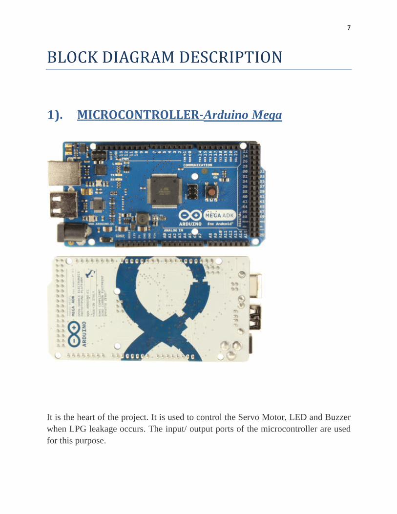
1). MICROCONTROLLER-Arduino Mega
It is the heart of the project. It is used to control the Servo Motor, LED and Buzzer
when LPG leakage occurs. The input/ output ports of the microcontroller are used
for this purpose.
8
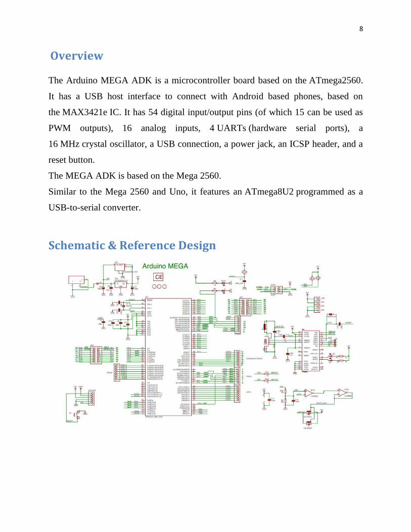
Overview
The Arduino MEGA ADK is a microcontroller board based on the ATmega2560.
It has a USB host interface to connect with Android based phones, based on
the MAX3421e IC. It has 54 digital input/output pins (of which 15 can be used as
PWM outputs), 16 analog inputs, 4 UARTs (hardware serial ports), a
16 MHz crystal oscillator, a USB connection, a power jack, an ICSP header, and a
reset button.
The MEGA ADK is based on the Mega 2560.
Similar to the Mega 2560 and Uno, it features an ATmega8U2 programmed as a
USB-to-serial converter.
Schematic & Reference Design
9
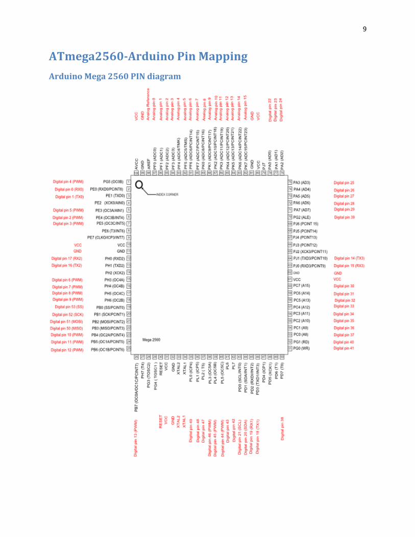
ATmega2560-Arduino Pin Mapping
Arduino Mega 2560 PIN diagram
10
Summary
Microcontroller
ATmega2560
Operating Voltage 5V
Input Voltage (recommended) 7-12V
Input Voltage (limits) 6-20V
Digital I/O Pins 54 (of which 15 provide PWM output)
Analog Input Pins 16
DC Current per I/O Pin 40 mA
DC Current for 3.3V Pin 50 mA
Flash Memory 256 KB of which 8 KB used by bootloader
SRAM 8 KB
EEPROM 4 KB
Clock Speed 16 MHz
USB Host Chip MAX3421E

11
Power
The Arduino MEGA ADK can be powered via the USB connection or with an
external power supply. The power source is selected automatically.
External (non-USB) power can come either from an AC-to-DC adapter (wall-wart)
or battery. The adapter can be connected by plugging a 2.1mm center-positive plug
into the board's power jack. Leads from a battery can be inserted in the Gnd and
Vin pin headers of the POWER connector.
The board can operate on an external supply of 5.5 to 16 volts. If supplied with less
than 7V, however, the 5V pin may supply less than five volts and the board may be
unstable. If using more than 12V, the voltage regulator may overheat and damage
the board. The recommended range is 7 to 12 volts.
The power pins are as follows:
VIN. The input voltage to the Arduino board when it's using an external power
source (as opposed to 5 volts from the USB connection or other regulated power
source). You can supply voltage through this pin, or, if supplying voltage via the
power jack, access it through this pin.
5V. This pin outputs a regulated 5V from the regulator on the board. The board can
be supplied with power either from the DC power jack (7 - 12V), the USB
connector (5V), or the VIN pin of the board (7-12V). Supplying voltage via the 5V
or 3.3V pins bypasses the regulator, and can damage your board. We don't advise
it.
3V3. A 3.3 volt supply generated by the on-board regulator. Maximum current
draw is 50 mA.
GND. Ground pins.
IOREF. This pin on the Arduino board provides the voltage reference with which
the microcontroller operates. A properly configured shield can read the IOREF pin
voltage and select the appropriate power source or enable voltage translators on the
outputs for working with the 5V or 3.3V.
12
Memory
The MEGA ADK has 256 KB of flash memory for storing code (of which 8 KB is
used for the bootloader), 8 KB of SRAM and 4 KB of EEPROM (which can be
read and written with the EEPROM library).
Input and Output
Each of the 50 digital pins on the MEGA ADK can be used as an input or output,
using pinMode(), digitalWrite(), anddigitalRead() functions. They operate at 5
volts. Each pin can provide or receive a maximum of 40 mA and has an internal
pull-up resistor (disconnected by default) of 20-50 kOhms. In addition, some pins
have specialized functions:
Serial: 0 (RX) and 1 (TX); Serial 1: 19 (RX) and 18 (TX); Serial 2: 17 (RX)
and 16 (TX); Serial 3: 15 (RX) and 14 (TX). Used to receive (RX) and transmit
(TX) TTL serial data. Pins 0 and 1 are also connected to the corresponding pins of
the ATmega8U2 USB-to-TTL Serial chip.
External Interrupts: 2 (interrupt 0), 3 (interrupt 1), 18 (interrupt 5), 19
(interrupt 4), 20 (interrupt 3), and 21 (interrupt 2). These pins can be
configured to trigger an interrupt on a low value, a rising or falling edge, or a
change in value.
PWM: 2 to 13 and 44 to 46. Provide 8-bit PWM output with
the analogWrite() function.
SPI: 50 (MISO), 51 (MOSI), 52 (SCK), 53 (SS). These pins support SPI
communication using the SPI library. The SPI pins are also broken out on the ICSP
header, which is physically compatible with the Uno, Duemilanove and Diecimila.
USB Host: MAX3421E. The MAX3421E comunicate with Arduino with the SPI
bus. So it uses the following pins:
o Digital: 7 (RST), 50 (MISO), 51 (MOSI), 52 (SCK). NB:Please do not use Digital pin 7 as input or output because is used in the
comunication with MAX3421E
o Non broken out on headers: PJ3 (GP_MAX), PJ6 (INT_MAX), PH7 (SS).
13
LED: 13. There is a built-in LED connected to digital pin 13. When the pin is
HIGH value, the LED is on, when the pin is LOW, it's off.
TWI: 20 (SDA) and 21 (SCL). Support TWI communication using the Wire
library. Note that these pins are not in the same location as the TWI pins on the
Duemilanove or Diecimila.
The MEGA ADK has 16 analog inputs, each of which provide 10 bits of resolution
(i.e. 1024 different values). By default they measure from ground to 5 volts, though
is it possible to change the upper end of their range using the AREF pin and
analogReference() function.
There are a couple of other pins on the board:
AREF. Reference voltage for the analog inputs. Used with analogReference().
Reset. Bring this line LOW to reset the microcontroller. Typically used to add a
reset button to shields which block the one on the board.
Communication
The Arduino MEGA ADK has a number of facilities for communicating with a
computer, another Arduino, or other microcontrollers. The ATmega2560 provides
four hardware UARTs for TTL (5V) serial communication. An ATmega8U2 on
the board channels one of these over USB and provides a virtual com port to
software on the computer (Windows machines will need a .inf file, but OSX and
Linux machines will recognize the board as a COM port automatically. The
Arduino software includes a serial monitor which allows simple textual data to be
sent to and from the board. The RX and TX LEDs on the board will flash when
data is being transmitted via the ATmega8U2/16U2 chip and USB connection to
the computer (but not for serial communication on pins 0 and 1).
A SoftwareSerial library allows for serial communication on any of the MEGA
ADK's digital pins.

14
The ATmega2560 also supports TWI and SPI communication. The Arduino
software includes a Wire library to simplify use of the TWI bus; see the Wire
library for details. For SPI communication, use the SPI library.
The USB host interface given by MAX3421E IC allows the Arduino MEGA ADK
to connect and interact to any type of device that have a USB port. For example,
allows you to interact with many types of phones, controlling Canon cameras,
interfacing with keyboard, mouse and games controllers as Wiimote and PS3.
Physical Characteristics and Shield Compatibility
The maximum length and width of the MEGA ADK PCB are 4 and 2.1 inches
respectively, with the USB connector and power jack extending beyond the former
dimension. Three screw holes allow the board to be attached to a surface or case.
Note that the distance between digital pins 7 and 8 is 160 mil (0.16"), not an even
multiple of the 100 mil spacing of the other pins.
The MEGA ADK is designed to be compatible with most shields designed for the
Uno, Diecimila or Duemilanove. Digital pins 0 to 13 (and the adjacent AREF and
GND pins), analog inputs 0 to 5, the power header, and ICSP header are all in
equivalent locations. Further the main UART (serial port) is located on the same
pins (0 and 1), as are external interrupts 0 and 1 (pins 2 and 3 respectively). SPI is
available through the ICSP header on both the MEGA ADK and Duemilanove /
Diecimila.

15
2). Gas Sensor Module
This sensor is used to sense the leakage of LPG. In normal conditions the output of
this sensor is ‘high’ and it goes ‘low’, when the LPG is sensed.
Introduction
The MQ series of gas sensors use a small heater inside with an electro-chemical
sensor. They are sensitive for a range of gasses and are used indoors at room
temperature.
They can be calibrated more or less (see the section about "Load-resistor" and
"Burn-in") but a know concentration of the measured gas or gasses is needed for
that.
The output is an analog signal and can be read with an analog input of the Arduino.
16
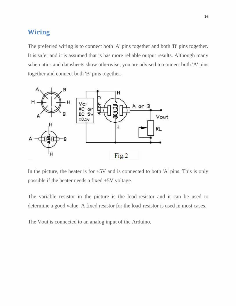
Wiring
The preferred wiring is to connect both 'A' pins together and both 'B' pins together.
It is safer and it is assumed that is has more reliable output results. Although many
schematics and datasheets show otherwise, you are advised to connect both 'A' pins
together and connect both 'B' pins together.
In the picture, the heater is for +5V and is connected to both 'A' pins. This is only
possible if the heater needs a fixed +5V voltage.
The variable resistor in the picture is the load-resistor and it can be used to
determine a good value. A fixed resistor for the load-resistor is used in most cases.
The Vout is connected to an analog input of the Arduino.

17
The Heater
The voltage for the internal heater is very important.
Some sensors use 5V for the heater, others need 2V. The 2V can be created with a
PWM signal, using analogWrite() and a transistor or logic-level mosfet.
The heater may not be connected directly to an output-pin of the Arduino, since it
uses too much current for that.
Some sensors need a few steps for the heater. This can be programmed with an
analogWrite() function and delays. A transistor or logic-level mosfet should also in
this situation be used for the heater.
If it is used in a battery operated device, a transistor or logic-level mosfet could
also be used to switch the heater on and off.
The sensors that use 5V or 6V for the internal heater do get warm. They can easily
get 50 or 60 degrees Celcius.
After the "burn-in time", the heater needs to be on for about 3 minutes (tested with
MQ-2) before the readings become stable.
18
Load-resistor
The sensor needs a load-resistor at the output to ground. It's value could be from
2kOhm to 47kOhm. The lower the value, the less sensitive. The higher the value,
the less accurate for higher concentrations of gas.
If only one specific gas is measured, the load-resistor can be calibrated by applying
a know concentration of that gas. If the sensor is used to measure any gas (like in a
air quality detector) the load-resistor could be set for a value of about 1V output
with clean air.
Burn-in
Some datasheets use the term "preheat", but it is the time to burn-in the sensor.
This is meant to make the sensor readings more consistent. A time of 12 or 24
hours is usually used for the burn-in time.
The Burn-in is achieved by applying normal power to the sensor (to the heater and
with the 'A' and 'B' pins connected, and with a load-resistor). In some special cases
a specific burn-in is needed. See the datasheet if the sensor needs such a specific
burn-in.
19
List of sensors
MQ-2
Sensitive for Methane, Butane, LPG, smoke.
This sensor is sensitive for flamable and combustible gasses.
The heater uses 5V.
MQ-3
Sensitive for Alcohol, Ethanol, smoke
The heater uses 5V
MQ-4
Sensitive for Methane, CNG Gas
The heater uses 5V.
MQ-5
Sensitive for Natural gas, LPG
The heater uses 5V.
20
MQ-6
Sensitive for LPG, butane gas
The heater uses 5V.
MQ-7
Sensitive for Carbon Monoxide
The heater uses an alternating voltage of 5V and 1.4V.
MQ-8
Sensitive for Hydrogen Gas
The heater uses 5V.
MQ-9
Sensitive for Carbon Monoxide, flammable gasses.
The heater uses an alternating voltage of 5V and 1.5V. It depends on the gases how
to use that alternating voltage. If only Carbon Monoxide is tested, the heater can be
set at 1.5V.
21
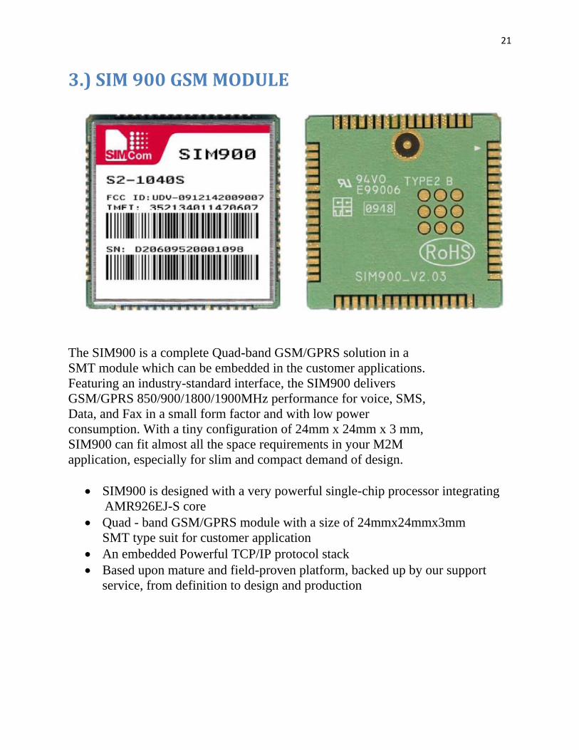
3.) SIM 900 GSM MODULE
The SIM900 is a complete Quad-band GSM/GPRS solution in a
SMT module which can be embedded in the customer applications.
Featuring an industry-standard interface, the SIM900 delivers
GSM/GPRS 850/900/1800/1900MHz performance for voice, SMS,
Data, and Fax in a small form factor and with low power
consumption. With a tiny configuration of 24mm x 24mm x 3 mm,
SIM900 can fit almost all the space requirements in your M2M
application, especially for slim and compact demand of design.
SIM900 is designed with a very powerful single-chip processor integrating
AMR926EJ-S core
Quad - band GSM/GPRS module with a size of 24mmx24mmx3mm
SMT type suit for customer application
An embedded Powerful TCP/IP protocol stack
Based upon mature and field-proven platform, backed up by our support
service, from definition to design and production
22
General features
Quad-Band 850/ 900/ 1800/ 1900 MHz
GPRS multi-slot class 10/8
GPRS mobile station class B
Compliant to GSM phase 2/2+
– Class 4 (2 W @850/ 900 MHz)
– Class 1 (1 W @ 1800/1900MHz)
Dimensions: 24* 24 * 3 mm
Weight: 3.4g
Control via AT commands (GSM
07.07 ,07.05 and SIMCOM enhanced AT
Commands)
SIM application toolkit
Supply voltage range 3.4 ... 4.5 V
Low power consumption
Operation temperature:
-30 °C to +80 °C
Specifications for SMS via GSM/GPRS
Point-to-point MO and MT
SMS cell broadcast
Text and PDU mode
Drivers
MUX Driver
Interfaces
Interface to external SIM 3V/ 1.8V
analog audio interface
RTC backup
SPI interface
Serial interface
Antenna pad
I2C
23
GPIO
PWM
ADC
Compatibility
AT cellular command interface
Approvals in planning
CE
FCC
ROHS
PTCRB
GCF
AT&T
IC
TA
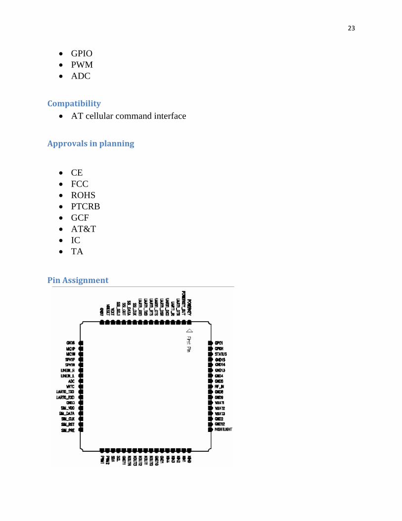
Pin Assignment

24
INTERFACING THE GSM MODEM
Interfacing the Modem to microcontroller (Basic connection)
GSM Modem Interfacing with Microcontroller
The Modem can be directly interface with 5V microcontrollers like PIC,AVR,
8051 Derivatives, Arduinos and 3V3 Microcontrollers like ARM ,ARM Cortex
XX etc. Make ensure V_INTERFACE pin is supplied with same voltage level as
the microcontroller VCC. As per the Fig there is only 2 connections are required to
use the modem. Connect RX pin of the modem to the TX pin of the
Microcontroller and TX pin of the modem to microcontroller’s RX pin. The
connected power supply (4.2v to 12v dc) should be capable of handling current up
to 1 A.
Interfacing the Modem to ARDUINO
25
GETTING STARTED
1) Insert SIM card. Open the SIM cardholder by sliding it as per the arrow mark
and lift up. Insert the SIM card , so as to align the chamfered corner suits in card
holder .After inserting the SIM card, lock the holder by sliding it to theopposite
direction of arrow mark.
2) Connect the antenna.Fix the supplied RF antenna to the SMA Antennae
connector and tighten it by rotating the nut
3) Connect the pins connect the GSM modem as per the circuit diagram provided
4) Power the modem power the modem from suitable power supply, which is
having enough current capacity (>1A).
5) Check the Status of the LEDs
PWR LED - Red LED will lit immediately
STS LED - Green LED will lit after 1-2 seconds
NET LED -Blue LED will starts to blink in fast for few seconds(Searching For
Network) and becomes slow blinking once the Modem registers with the Network.
6) Network LED
The Network LED indicates the various status of GSM module eg. Power on,
Network registration & GPRS connectivity. When the modem is powered up, the
status LED will blink every second. After the modem registers in the network
(takes between 10-60 seconds), LED will blink in step of 3 seconds. At
this stage you can start using Modem for your application.
7) Baud rate
The Baud rate supported by the modem is between 9600 and 115200. Make sure
the host system is set to the supported baud rate. The modem automatically sets to
the baud rate of the first command sent by the host system after it is powered up.
User must first send “A” to synchronize the baud rate. It is recommended to wait 2
to 3 seconds before sending “AT” character. After receiving the “OK” response,
Your Device and GSM Modemare correctly synchronized. So there is no need for
setting the baud rate using commands. Before You Start using the modem, please
make sure that the SIM card you inserted support the needed features and there is
enough balance in SIM.
26
Testing GSM module with arduino using AT commands
AT commands are instructions used to control a modem. AT is the abbreviation of ATtention.
Every command line starts with "AT" or "at". That's why modem commands are called AT
commands. Many of the commands that are used to control wired dial-up modems, such as ATD
(Dial), ATA (Answer), ATH (Hook control) and ATO (Return to online data state), are also
supported by GSM/GPRS modems and mobile phones. Besides this common AT command set,
GSM/GPRS modems and mobile phones support an AT command set that is specific to the GSM
technology, which includes SMS-related commands like AT+CMGS (Send SMS message),
AT+CMSS (Send SMS message from storage), AT+CMGL (List SMS messages) and
AT+CMGR (Read SMS messages).
Note that the starting "AT" is the prefix that informs the modem about the start of a command
line. It is not part of the AT command name. For example, D is the actual AT command name in
ATD and +CMGS is the actual AT command name in AT+CMGS. However, some books and
web sites use them interchangeably as the name of an AT command.
There are two types of AT commands: basic commands and extended commands.
Basic commands are AT commands that do not start with "+". For example, D (Dial), A
(Answer), H (Hook control) and O (Return to online data state) are basic commands.
Extended commands are AT commands that start with "+". All GSM AT commands are
extended commands. For example, +CMGS (Send SMS message), +CMSS (Send SMS message
from storage), +CMGL (List SMS messages) and +CMGR (Read SMS messages) are extended
commands.

27
4.) Servomotor
A servomotor is a rotary actuator that allows for
precise control of angular position, velocity and
acceleration. It consists of a suitable motor
coupled to a sensor for position feedback. It also
requires a relatively sophisticated controller,
often a dedicated module designed specifically
for use with servomotors.
Servomotors are used in applications such
as robotics, CNC machinery or automated
manufacturing.
Here we are using the servomotor to close the
knob of the gas cylinder in case of any leakage.
Mechanism
Servo motors have three wires: power, ground, and signal. The power wire is
typically red, and should be connected to the 5V pin on the Arduino board. The
ground wire is typically black or brown and should be connected to a ground pin
on the Arduino board. The signal pin is typically yellow, orange or white and
should be connected to a digital pin on the Arduino board. Note that servos draw
considerable power, so if you need to drive more than one or two, you'll probably
need to power them from a separate supply (i.e. not the +5V pin on your Arduino).
Be sure to connect the grounds of the Arduino and external power supply together.

28
5.) BUZZER
A buzzer or beeper is an audio signalling device,which may be mechanical,
electromechanical, or piezoelectric. Typical uses of buzzers and beepers
include alarm devices, timers and confirmation of user input such as a mouse click
or keystroke.
Here we are using the buzzer to detect the
leakage of LPG. It is 12 V DC operated buzzer
which sounds an alarm as soon as it detects
LPG leakage.
29
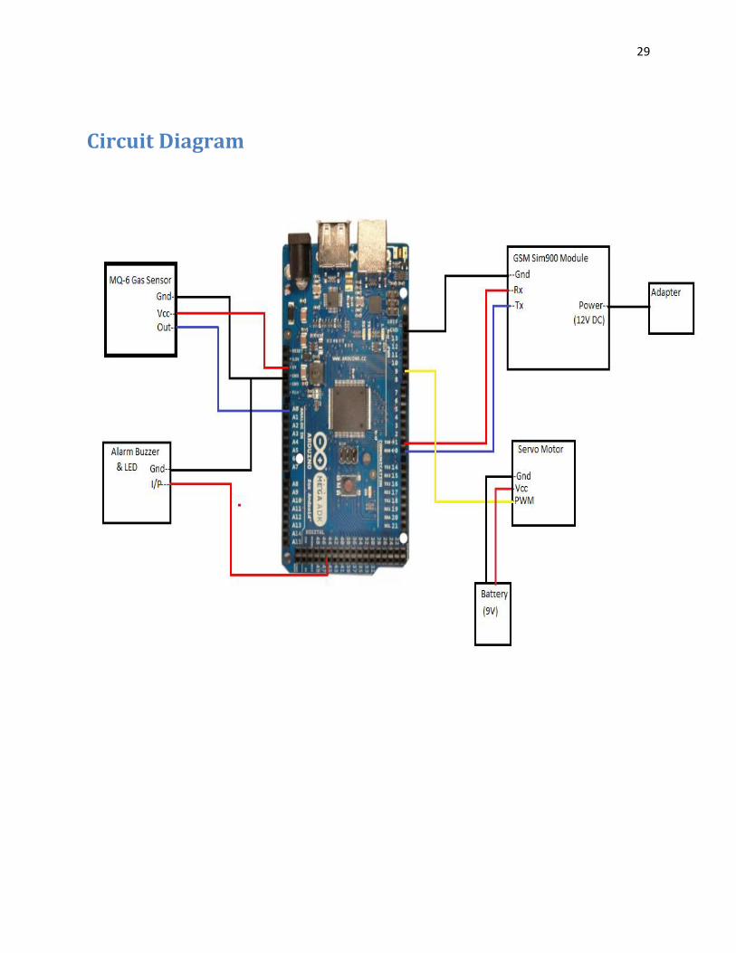
Circuit Diagram
30
Code
#include <Servo.h> // Header File
Servo myservo; // create servo object to control a servo
/*--------------Variables-------------------------------*/
int gas=0;
int pos = 0;
const int analogInPin = A0; // Analog input pin that the gas sensor is attached to
int sensorValue = 0; // value read from the gas sensor
int timestosend=1;
int count=0;
char phone[]="9716946367"; // registered phone number
/*--------------------------------------------------------*/
void setup()
{
Serial.begin(9600); // initialize serial communications at 9600 bps:
myservo.attach(9); // Servo attached to PWM pin 9
Serial.println("AT+CMGF=1");
delay(200);
31
}
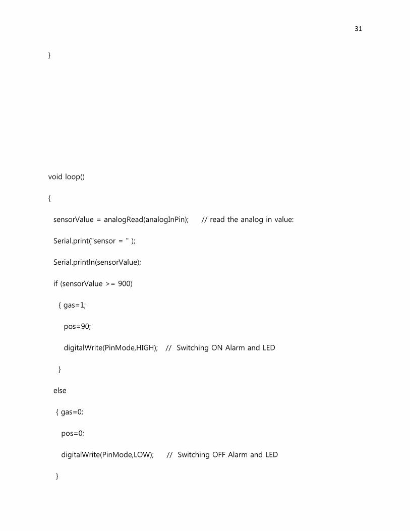
void loop()
{
sensorValue = analogRead(analogInPin); // read the analog in value:
Serial.print("sensor = " );
Serial.println(sensorValue);
if (sensorValue >= 900)
{ gas=1;
pos=90;
digitalWrite(PinMode,HIGH); // Switching ON Alarm and LED
}
else
{ gas=0;
pos=0;
digitalWrite(PinMode,LOW); // Switching OFF Alarm and LED
}
32
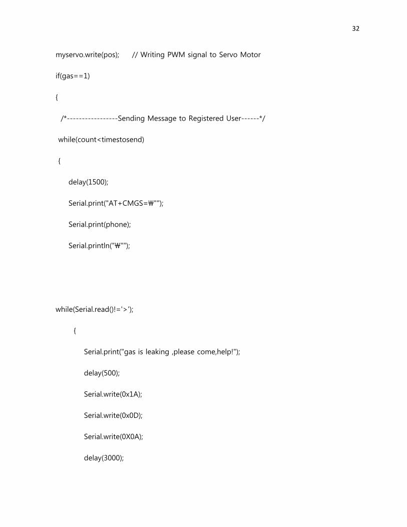
myservo.write(pos); // Writing PWM signal to Servo Motor
if(gas==1)
{
/*-----------------Sending Message to Registered User------*/
while(count<timestosend)
{
delay(1500);
Serial.print("AT+CMGS=\"");
Serial.print(phone);
Serial.println("\"");
while(Serial.read()!='>');
{
Serial.print("gas is leaking ,please come,help!");
delay(500);
Serial.write(0x1A);
Serial.write(0x0D);
Serial.write(0X0A);
delay(3000);
33
}
count++;
}
}
else
count=0;
delay(10);
}
WORKING
Input Section:
MQ6 gas sensor: The sensor is capable of detecting different type
flammable gases on calibrated sensitivity. In this that is Lighter Gas.
This sensor can be calibrated using the two potentiometers fitted in the
breakout board of MQ6 Sensor. The sensor gives an analog output. The
value of this output is decided as follows-
34
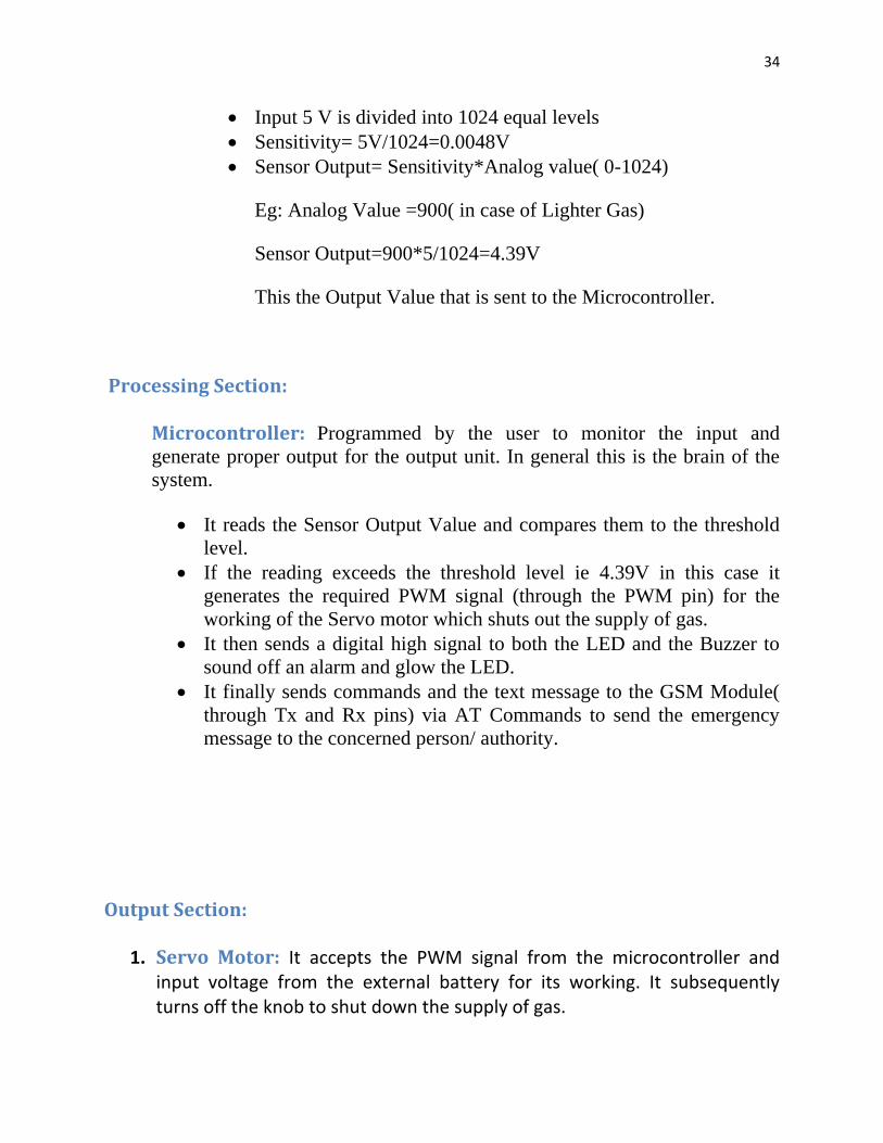
Input 5 V is divided into 1024 equal levels
Sensitivity= 5V/1024=0.0048V
Sensor Output= Sensitivity*Analog value( 0-1024)
Eg: Analog Value =900( in case of Lighter Gas)
Sensor Output=900*5/1024=4.39V
This the Output Value that is sent to the Microcontroller.
Processing Section:
Microcontroller: Programmed by the user to monitor the input and
generate proper output for the output unit. In general this is the brain of the
system.
It reads the Sensor Output Value and compares them to the threshold
level.
If the reading exceeds the threshold level ie 4.39V in this case it
generates the required PWM signal (through the PWM pin) for the
working of the Servo motor which shuts out the supply of gas.
It then sends a digital high signal to both the LED and the Buzzer to
sound off an alarm and glow the LED.
It finally sends commands and the text message to the GSM Module(
through Tx and Rx pins) via AT Commands to send the emergency
message to the concerned person/ authority.
Output Section:
1. Servo Motor: It accepts the PWM signal from the microcontroller and input voltage from the external battery for its working. It subsequently turns off the knob to shut down the supply of gas.
35
2. Buzzer: It accepts the digital high signal from the microcontroller to sound
off the alarm. 3. LED: It accepts the digital high signal from the microcontroller to glow the
LED in case of any leakage. 4. GSM Module: It receives the required message ( through Tx and Rx pins)
from the microcontroller. Then it send the emergency message in case of any
leakage.
Code Description:
#include <Servo.h>- Header file of Servo Library which contains all the
functions necessary for the control and operation of the Motor. It has the following
2 functions-
1. Myservo.attach(pin)-This function tells the microcontroller that the given
pin is attached to the input of the motor. In our case it is the PWM 9 pin.
2. Myservo.write(value)-This function is used for writing the PWM signal on
the Motor. Value ranges from 0-180 degrees.
3. Servo myservo- Create servo object to control the servo
int gas=0-signifies no leakage of gas
int pos = 0-signifies the position of the Motor
const int analogInPin = A0- Analog input pin that the gas sensor is attached to
int sensorValue = 0- value read from the gas sensor
int timestosend=1-Number of times the message is to be sent
int count=0-flag variable
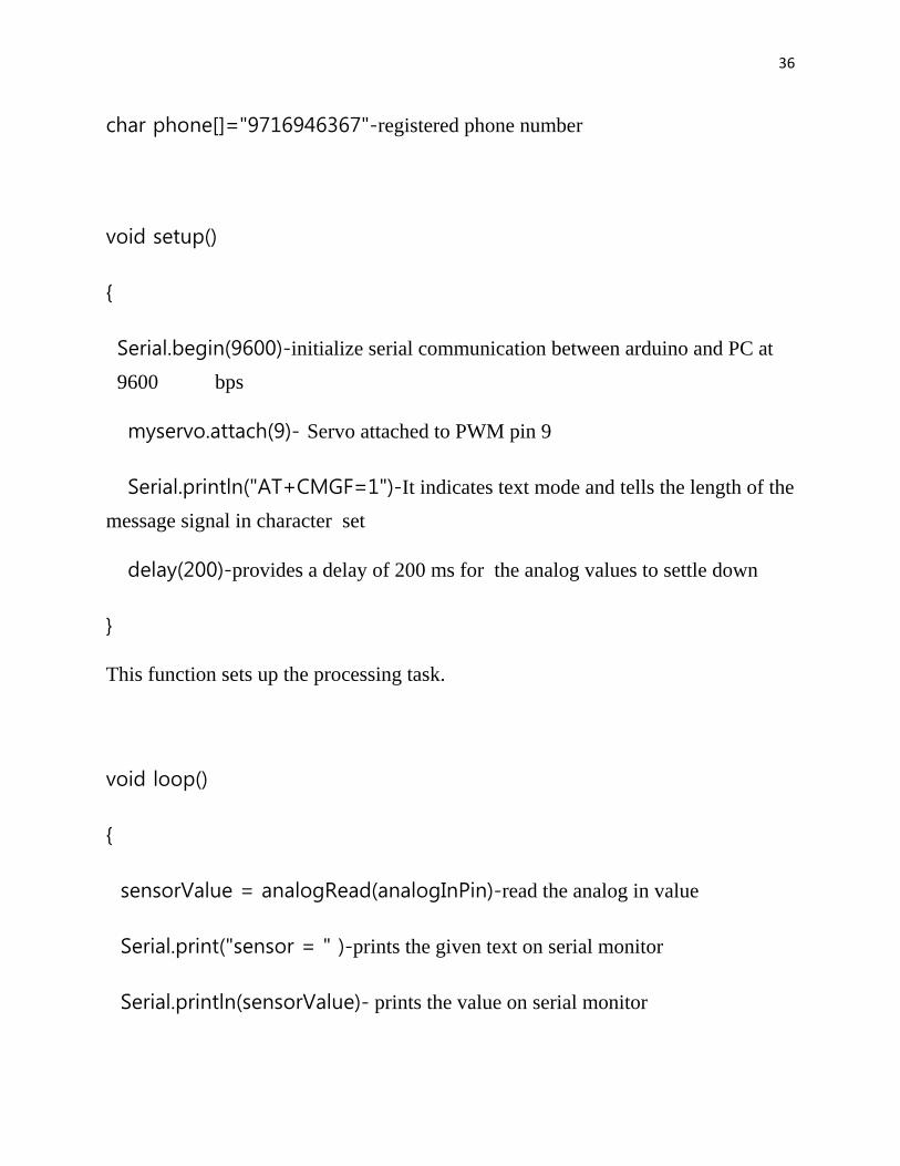
36
char phone[]="9716946367"-registered phone number
void setup()
{
Serial.begin(9600)-initialize serial communication between arduino and PC at
9600 bps
myservo.attach(9)- Servo attached to PWM pin 9
Serial.println("AT+CMGF=1")-It indicates text mode and tells the length of the
message signal in character set
delay(200)-provides a delay of 200 ms for the analog values to settle down
}
This function sets up the processing task.
void loop()
{
sensorValue = analogRead(analogInPin)-read the analog in value
Serial.print("sensor = " )-prints the given text on serial monitor
Serial.println(sensorValue)- prints the value on serial monitor
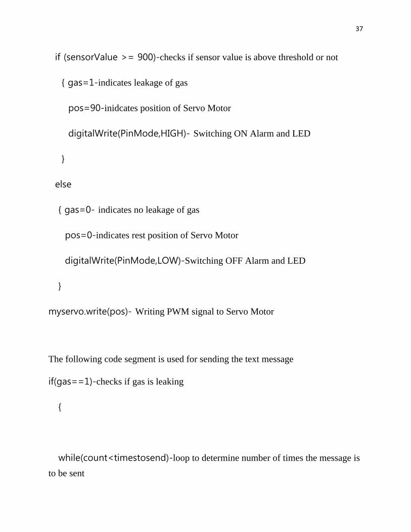
37
if (sensorValue >= 900)-checks if sensor value is above threshold or not
{ gas=1-indicates leakage of gas
pos=90-inidcates position of Servo Motor
digitalWrite(PinMode,HIGH)- Switching ON Alarm and LED
}
else
{ gas=0- indicates no leakage of gas
pos=0-indicates rest position of Servo Motor
digitalWrite(PinMode,LOW)-Switching OFF Alarm and LED
}
myservo.write(pos)- Writing PWM signal to Servo Motor
The following code segment is used for sending the text message
if(gas==1)-checks if gas is leaking
{
while(count<timestosend)-loop to determine number of times the message is
to be sent
38
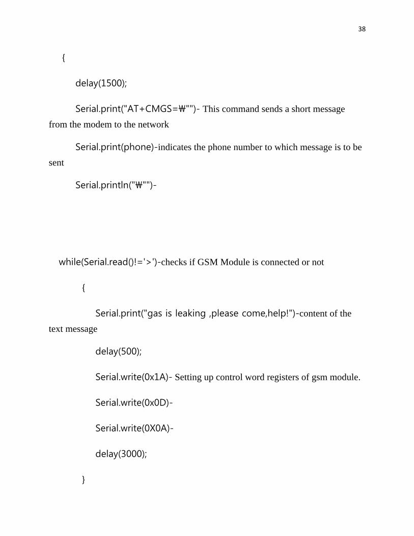
{
delay(1500);
Serial.print("AT+CMGS=\"")- This command sends a short message
from the modem to the network
Serial.print(phone)-indicates the phone number to which message is to be
sent
Serial.println("\"")-
while(Serial.read()!='>')-checks if GSM Module is connected or not
{
Serial.print("gas is leaking ,please come,help!")-content of the
text message
delay(500);
Serial.write(0x1A)- Setting up control word registers of gsm module.
Serial.write(0x0D)-
Serial.write(0X0A)-
delay(3000);
}

39
count++-Increments flag counter
}
}

40

41
APPLICATIONS
Safety plays a major role in today’s world and it is necessary that good safety
systems are to be implemented in places of education and work. The LPG or
propane which is flammable mixture of hydrocarbon gases used as fuel in many
applications like homes, hostels, industries, automobiles, vehicles because of its
desirable properties which include high calorific
value, which produce the less smoke, produces
less soot, and does not cause much harm to the
environment. Natural gas is another widely used
fuel in homes. Both gases burns to produce clean
energy, however there is a serious problem about
their leakage in the air. The gases being heavier
than air do not disperse easily and may lead to
suffocation when inhaled also when gas leakage
into the air may lead to explosion. Due to the
explosion of LPG gas the number of deaths has
been increased in recent years. To avoid this
problem there is a need for a system to detect and also prevent leakage of LPG.
Gas leak detection is the process of identifying potentially hazardous gas leaks by
means of various sensors. The advantage of this automated detection and alerting
system over the manual method is that it offers quick response time and accurate
detection of an emergency and in turn leading faster diffusion of the critical
situation.
The gas detection and alert system that we have designed is a very cost effective
system to detect leakage of any gas. It not only detects leakage of gas, it also
sounds an alarm and has a motor attached to it that can be used to close the knob of
the leaking cylinder. It has its applications in various fields like
Schools, Colleges, Universities
Homes
Industries
It is especially useful in the case when leakage takes place when there is no one
around. In this case the motor installed would close the source of the leakage and
the concerned person would get an alert by SMS.

42
One of the incidents that everyone can closely relate to is the Bhopal Gas tragedy.
With this system in place not only would a timely alert been useful for evacuation,
but the source of gas leakage could also have been stopped and a lot of lives would
have been saved.
ADVANTAGE
It is used in house as LPG leakage detection.
It also detects alcohol so it is used as liquor tester.
The sensor has excellent sensitivity combined with a quick response time.
DISADVANTAGES
It is little sensitive to smoke, then in kitchen it is not perfectly response for
LPG gas leakage.
It works only when at 5V power supply is given.
Its sensitivity depends on Humidity and temperature.
43
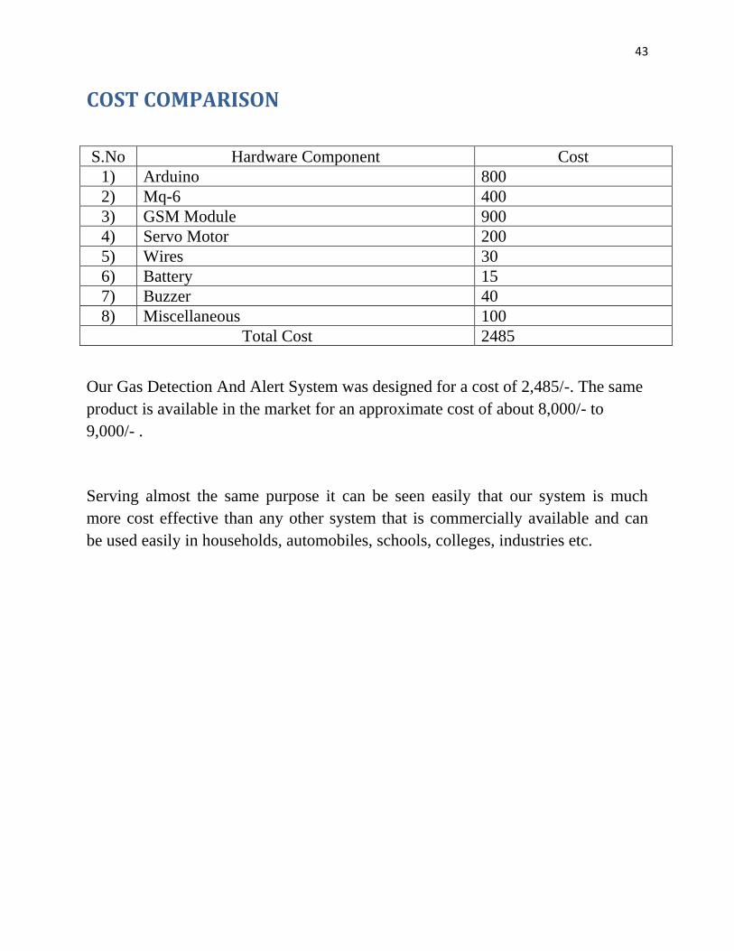
COST COMPARISON
S.No Hardware Component Cost
1) Arduino 800
2) Mq-6 400
3) GSM Module 900
4) Servo Motor 200
5) Wires 30
6) Battery 15
7) Buzzer 40
8) Miscellaneous 100
Total Cost 2485
Our Gas Detection And Alert System was designed for a cost of 2,485/-. The same
product is available in the market for an approximate cost of about 8,000/- to
9,000/- .
Serving almost the same purpose it can be seen easily that our system is much
more cost effective than any other system that is commercially available and can
be used easily in households, automobiles, schools, colleges, industries etc.