Embed Size (px)
Citation preview

SFAE
1
西门子常用驱动产品概况西门子常用驱动产品概况
SFAE

SFAE
2
SIMOVERT MASTERDRIVES VC
矢量控制

SFAE
3
SIMOVERT MASTERDRIVES 系列
Compact PLUS紧凑加强型
Compact紧凑型
Chassis机架式
0.5 - 18.5 kW 2.2 - 37 kW 45 - 2300 kW
MC (运动控制) 750kW
Cabinet柜体
45 - 6000 kW
VC (矢量控制)
其应用包括定位、同步操作以及凸轮轴驱动等。
应用于绕线机、拉丝机、造纸及薄膜工业、升降机等。
新产品

SFAE
4
6SE70系列变频器产品的一般情况(1)
MASTER DRIVES 6SE70变频调速器系列产品是西门子在低压领域推出的中、高档
变频调速产品。从90年代初期推出后,历经10多年的发展,性能优良,品种齐
全,用户遍及世界。
6SE70系列变频调速器采用电压源型交-直-交的主回路结构,拥有变频器、逆
变器与单/四象限整流器等几大类产品。
单台装置具有交-直-交结构主回路的为变频器,其交-直结构仅适合于单象限
运行如要运行于四象限方式,在直流母线端子上需配接具有足够耗散功率的制动
单元与制动电阻。6SE70系列产品也拥有相配套的制动单元与制动电阻产品系列。
单台装置仅具有直-交环节主回路结构的为逆变器,输出拖动电机,它必须连接
到电压等级一致,功率容量足够的直流母线上运行。逆变器自身具有四象限(在
电机侧)运行能力。适用于组成共用直流母线的多传动变频器系统。6SE70的逆变
器具有相同规格的产品可以实现几台并联的结构(需定购选件),用以扩大功率
容量。

SFAE
5
6SE70系列变频器产品的一般情况(2)
单台装置仅具有交-直环节主回路结构的为整流单元(网侧单象限运行)或整流/回馈(网
侧四象限运行)单元,在6SE70系列产品中有两类:
- 以可控硅作为功率器件的装置,简称为整流单元(RU)与整流/回馈(RRU)单元;
- 以IGBT作为功率器件的装置,简称为AFE变流单元。
交-直环节的装置用于形成共用的直流母线,可以搭载多台逆变器构成多传动拖动系
统。根据采用装置的不同,交-直环节分为单象限运行与四象限运行。制动单元与制动电阻
也可以用于共直流母线的系统。交-直环节也可以采用几台同类、同容量装置并联的结构,
以扩大直流母线容量。
变频/逆变器适合于拖动哪一类电机,在6SE70产品系列中取决于采用何种控制方式的主控制
模块(CU)。被拖动电机一般可分成两大类:一类是三相交流异步感应电机,可采用具有
F/V=C或异步机矢量控制方式的逆变器系统拖动。在6SE70中,称为VC系列产品;另一类是三
相交流同步伺服电动机,可由专门设计用于控制这类电机的逆变器系统(采用自控式同步机
矢量控制方式)拖动,在6SE70中,称为MC系列产品。

SFAE
6
6SE70系列变频器产品的一般情况(3)
在同框架结构,同电压等级,同容量的这两类6SE70不同的变频器系统中,除主控
制模块不同外,系统的其余部分结构与部件是完全相同的,了解这一特点,对于维修
很重要。
6SE70系列的变频器系统有采用多种不同供电电压的产品子系列
变频器与整流器产品有四种:
AC 三相 200V~230V 供用电压代码C,有书本型与装机装柜型
AC 三相 380V~480V 供用电压代码E,有书本型、增强书本型与装机装柜
型
AC 三相 500V~600V 供用电压代码F,有书本型与装机装柜型
AC 三相 660V~690V 供用电压代码H,仅有装机装柜型
逆变器产品也有四种:
DC 270V~310V 供电电压代码R,有书本型、装机装柜型
DC 510V~650V 供电电压代码T,有书本型、装机装柜型与增强书本型
DC 675V~810V 供电电压代码U,有书本型、装机装柜型
DC 890V~930V 供电电压代码W,仅有装机装柜型

SFAE
7
书本型变频器/逆变器的外观

SFAE
8
装机装柜型变频器/逆变器的外观

SFAE
9
增强书本型变频器/逆变器的外观

SFAE
10
6SE706SE70整流整流//回馈单元回馈单元(RRU)(RRU)的四种结构尺寸的四种结构尺寸--C/E/H/KC/E/H/K

SFAE
11
采用AFE整流器的变频柜

SFAE
12
MASTERDRIVES 系统 – 测试及试运行超过300,000 次
适用于定时, 高动态响应的机械设备
定位, 角同步, 凸轮盘, 电子齿轮, 虚拟主轴, 自动程序....
工艺软件包 F01
同步和异步电机
功率范围从0.55 kW 到250 kW
适用于连续工作的要求
连续进给,拉丝, 卷绕 及牵引....
异步电机
功率范围从0.55 kW到6,000 kW
MASTERDRIVES 运动控制 (MC)
MASTERDRIVES 矢量控制 (VC)

SFAE
13
VC与MC之间的主要区别
MCVC功率 / kW 2.2 - 6000 0.5 – 750
是否有Compact Plus形式 有 有
编码器种类 脉冲编码器
电机种类 ASM, SIMOSYN SYN - Servo, ASM - Servo
弱磁范围 1 : 5 1 : 2
使用 T300, T400 软件 F01
输出电压 0 - 100% V_Mains 0 - 86% V_Mains
矢量控制 带/不带编码器 带编码器
速度提升时间/ms ≅ 20 <= 2.5 (at 5kHz)
扭矩提升时间+死区时间/ms ≅ 2.5 + approx. 2 <= 0.4 + 0.4 (at 5kHz)
输入电压 / V 200–230, 380– 480, 500–575, 660– 690 380 - 480

SFAE
14
可以在世界范围内使用
IEC3 AC 380 - 415 V 50 Hz3 AC 500 V 50 Hz3 AC 660 - 690 V 50 Hz IEC / NEMA
3 AC 380 - 460 V 50/60 Hz
IEC / NEMA3 AC 380 - 460 V 50/60 Hz
IEC3 AC 380 - 440 V 50/50 Hz3 AC 500 - 550 V 50/50 Hz
IEC3 AC 415 - 440 V 50 Hz
适用于所有的电源频率和所有的应用标准
DeviceNET
PROFIBUS DP
CC Link
CAN

SFAE
15
≈1.0
1.5
1.691 % 基本负载
0 % 基本负载50 % 基本负载
IIn
In = 装置额定电流
60 s 180 s120 s tmax
30 s 270 s
1,6
0,91 90%基本负载时的典型过载周期>250KW时, 过载为1.36倍
t
IIn
30 s
0.9
1.36
变频器的过载能力

SFAE
16
6SE70系列产品的变频器、逆变器与AFE的定货号解读
6SE70 37 – 0TE 60– Z
P=书本增强型A~D= 书本型E,F,G,(H),J,KL(R),M(Q),N(S)= 架装型(Chassis)
MASTER DRIVES6SE70系列产品
0 = 无安全停车功
能1 = 有安全停车功
能
额定输出电流基本值( 两位数字)
1 = CU1 (FC); 2 = CU2 (VC);3 = CU3 (SC);
5 = CUMC/CUCP;6 = CUVC/CUVP;7 = CUPM/CUMP; 8 = CUSA (AFE);
进线电压:变频器 C = 200 ... 230V AC变频器 E = 380 ... 480V AC变频器 F = 500 ... 600V AC变频器 H = 660 ... 690V AC逆变器 R = 270 ... 310 V DC逆变器 T = 510 ... 650 V DC逆变器 U = 675 ... 810 V DC逆变器 W = 890 ... 930 V DC
有选件
额定输出电流
基本值的倍率:1 = X 0.1;2 = X 1;3 = X 10;4 = X 100;

SFAE
17
6SE70系列产品的整流器RU与RRU的定货号解读
6SE70 41– 0HH 85 –1AA0– Z
P=书本增强型
B,C= 书本型
E,H, K= 装机装柜型(Chassis)
MASTER DRIVES6SE70系列产品
0 = 整流单元1 =整流/回馈单元
额定输出电流基本值( 两位数字)
A = 基本单元
D = 并联连接的单元
整流器进线电压:E = 380 ... 480V ACF = 500 ... 600V ACH = 660 ... 690V
AC
有选件
额定输出电流
基本值的倍率:1 = X 0.1;2 = X 1;3 = X 10;4 = X 100;

SFAE
18
6SE70系列变频器系统中的主控制模板(1)
6SE70系列变频器系统的主控制模板相对来说属于变频/逆变器中的通用模板。基本上可以分
为二代.
第一代用于变频器/逆变器主控板:
CU1(FC)――频率控制功能的主板,处理器采用一块SAB80C167。主要完成f/v=c方式的变频
器控制功能,适用于泵和风机类负载及其它可采用频率控制的一般性负载的拖动。
CU2(VC)――矢量控制功能的主板,可实现异步感应电机的带或不带编码器的矢量控制。也
可完成f/v=c的控制方式,用于需要高性能的恒转矩特性负载的拖动需求。
CU3(SC)――伺服控制功能的主板,可实现三相交流同步伺服电机的矢量控制,主要应用于
西门子的各伺服电机系列的拖动,二者结合可以取得非常好的拖动特性,主要用于运动控制领
域。
第一代主控板用于整流器的主控板有:
CUR――用于H、K结构尺寸整流单元与全系列整流/回馈单元的主控板,其主回路结构为可控
硅单整流反并联形式的整流/回馈双桥结构,所采用的微处理器为SAB80C166。
CUA――用于采用IGBT为功率元件的四象限整流器的控制,是现阶段采用CUSA主板的AFE产品的
前身。

SFAE
19
6SE70系列变频器系统中的主控制模板(2)
第二代用于变频器与逆变器主控板
CUVC――主要用于控制交流异步感应电动机的控制主板,可实现带或不带速度反馈的高性能矢量
控制方式,也可实现F/V=C的各种控制及三相同步电动机的他控式调速,为CU1与CU2的升级换代产
品。主处理器为2块SAB 80C165。推出以来,系统软件(Firmware)不断更新升级,目前版本为
V3.42。此主板可用于6SE70定货号控制方式位为6的书本型和装机、装柜型的变频器和逆变器。
CUVP――增强书本型所用的异步电机的矢量控制方式主控制板,其软、硬件功能等与CUVC类似。
CUMC――主要用于控制三相交流同步伺服电动机的主控制板,可使系统取得高性能的伺服控制特
性,用于运动控制,所使用的策处理器为一块SAB 80C167与一块DSP TMS320C32。此主板可用于
6SE70系列定货号中控制方式位为“5”的书本型和装机装柜型与柜装型的变频器与逆变器。
Firmware版本从推出时的V1.0到目前为止已更新到V1.66。
CUPM――三相交流同步伺服电机用主板是CUMC主板的高性能(Perfomance2)版本,与CUMC相比
具有两倍的主处理器计算能力,两倍的存储器容量与4倍的DSP计算能力。处理器为SAB 80C167与
DSP TM320C33。它是6SE70系列定货号中控制方式位数字为“7”的变频器与逆变器(书本型和装
机装柜型)的控制主板。Firmware版本从推出时的V2.0到已更新到目前V2.41。

SFAE
20
6SE70系列变频器系统中的主控制模板(3)
CUCP――增强书本型的伺服控制主板。其软、硬件结构与功能等与CUMC模板类似。
CUMP――CUPM的增强书本型专用版本。其软、硬件结构与功能等与CUPM模板类似。
第二代主板用于整流器的有:
CUR――CUR在第二代主板的整流器中仍然沿用,只是软、硬件版本均有更新,某些
功能,例如对OCP的支持只有到达一定的硬件版本(V1.3)与软件版本(V4.5)状态
后方才支持。
CUSA――CUA主板在第二代6SE70产品中的升级版本。支持正弦型的脉宽调制方式
(SPWM)并具有了更强的处理和接口能力。
不同的主控板具有不同的控制对象、控制方式与控制特性,这一点对于选型
与调试变频器而言,无疑是非常重要的。变频器与逆变器系统在拔去主板以后,其剩
下的装置本体结构都是一样的,即:它们可以通过更换主控板改变自己的类型。但对
于整流器,这一点是不成立的,CUR与CUSA绝对不可互换使用,二者工作原理完全不
同 。增强书本型的主控板也不可与书本型和架装、柜装型的互换使用,但这主要是
因为装不上。

SFAE
21
特性 优点
操作控制可视化兼容Motion Control运动控制器与DC
MASTER直流驱动器
BICO 技术
Flash EPROM存储器
自由功能模块
装配插槽CUVC主板上设有装配插槽,用
于安装选件功能模板
选件模板MASTERDRIVES驱动器与 DC MASTER直流驱动器具有相同的选件模板
调试参数既可以快速设定,也可以精确配置
OP1S操作面板
所有单元的人机接口操作都是一样的 (具有相同的外观和风格)
系统中的逻辑功能和控制功能可以轻松实现
无需更换 EPROM 存储器就可以进行软件更新
高度的灵活性,可以解决用户各种各样的
驱动问题
较低的培训要求
软件工具可以应用于所有单元
具有若干可选件模板
简单而快速的启动
通过OP1 S操作面板,所有参数可以上装/与下载
通过OP1 S操作面板,可以保存所有参数
矢量控制驱动器的主板:CUVC控制板

SFAE
22
功能 优点
动能缓冲 (KIP)负载的动能可以被利用
向感应电机中输入一个直流电流实现直流制动
电源故障之后的自动重启 (WEA)
捕捉再启动:驱动控制器的输出与旋转的电机直接相联
两台驱动器的电压、频率和相位角是实现同步 (TSY)
电机自动识别程序
具有自动优化功能
运动跟踪功能,多达8个通道
在短暂的电网干扰下,仍能保持很高的生产能力
非常经济的停机形式
是电源故障后重新启动的简单方法
生产过程很快恢复
通过两台驱动器之间负载的相互转移取得高度的控制灵活性
快速而简便的启动过程
降低了调试过程中对测量设备的要求。比如示波器就是不需要的。
矢量控制驱动器的主板:CUVC控制板 一般功能
SFAE
23
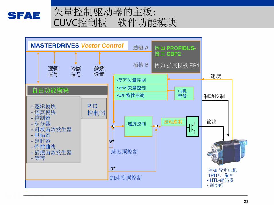
PID控制器
自由功能模块
- 逻辑模块- 运算模块- 控制器- 积分器- 斜坡函数发生器- 限幅器- 定时器- 特性曲线- 摇摆函数发生器- 等等
制动控制
输出
速度
速度控制
a*
v*
速度预控制
•闭环矢量控制
•开环矢量控制
•U/f-特性曲线
加速度预控制
扭矩控制.
电机型号
例如 PROFIBUS-接口 CBP2
例如 扩展模板 EB1
插槽 A
插槽 B逻辑信号
诊断信号
MASTERDRIVES Vector Control
参数设置
例如 异步电机1PH7,带有
- HTL-编码器- 制动闸
矢量控制驱动器的主板:CUVC控制板 软件功能模块

SFAE
24
approx. 240 的全部自由功能模块包括:
... approx. 80 运算与控制功能模块(除法器、加法器、限幅器、特性模块、极限值监控等)
... approx. 80 逻辑模块(与 / 或门、触发器、定时器等)
... approx. 5 综合模块(很好的斜坡函数发生器、工艺控制器、摇摆函数发生器等)
... approx. 50 管理模块(故障监控、固定设定点、数据格式转换等)
驱动器中的PLC 功能驱动器中的PLC 功能
.01
.02
U111 (1)KK
x1 100%x2
yx2x1
*
K471
&
U221 (0)BBB
.01
.03
.02 B601
Acceleration time0.00...100.00s
U383.01 (10.00)
x yU380 (0)
K K577
U381 (0)B
Set ramp-function generator
Setting value of ramp-function gen.U382 (0)
K
Deceleration time0.00...100.00s
U383.02 (10.00)
U062 (0)B 1 = "Fault F149"
矢量控制驱动器的主板:CUVC控制板 BICO 技术

SFAE
25
根据实际的技术要求,直接运用自由功能模块和BICO技术来解决。
Maneuvering
Vset
boost
FactM
Fset 1
Power sectionSpeed controller Currentcontroller
Friction torque
dn/dt
Dactnact
Diametercalculator
Fact
Gain-adaption
J
Gain-adaption
Dact
Taper tension characteristic
Jog setpoint
Vconst n+M+F
Tension control
Dact
Inertia characteristic
2 3 4 5 6 7 8
F
E
D
C
B
m
Hr. Mustermann
24.06.02 5
winder conception, basic drive VC Datei
Seitetaper tension curve / tension set value Bez. Zeichenblatt-1
U951.04 = 4U961.04 = 1765
K0467K0577
U107 (0).01
yK0525
.02
x1x2100 %⋅
x1x2
200%
-200%
K0577
K0541
Fset [%] x y
U381 (0)B
Set ramp-function generator
U380 (0)K0406
Deceleration time0,00...100,00U383.02 (0,5)
Acceleration time0,00...100,00U383.01 (0,5)
U382 (0)K
Setting value of ramp-function gen
U951.87 = 4U961.87 = 1755
Y-WerteU192.01 bis .10 (0)
K0501U190 (0)
U951.07 = 4U961.07 = 1070
x
y1
x
y
+200%
x10
x1
1
2 34
65
78
9
10y10
-200% y
U191.01 bis .10 (0)X-Werte
max. distancebetween neighbouringX- or Y-valuesis 199,99%
.01
U174 (0)
U951.76 = 4U961.76 = 1760
K0525
K0001U175 (0)
B0425
.02K0541
0
1
Abwickler: 0Aufwickler: 1
K0001
fixed con.100%
100,0 %
Fset_taper [%]
Ktaper [%]
to [15.A1]
values
values
unwinder: 0winder: 1
BICO技术应用实例
SFAE
26
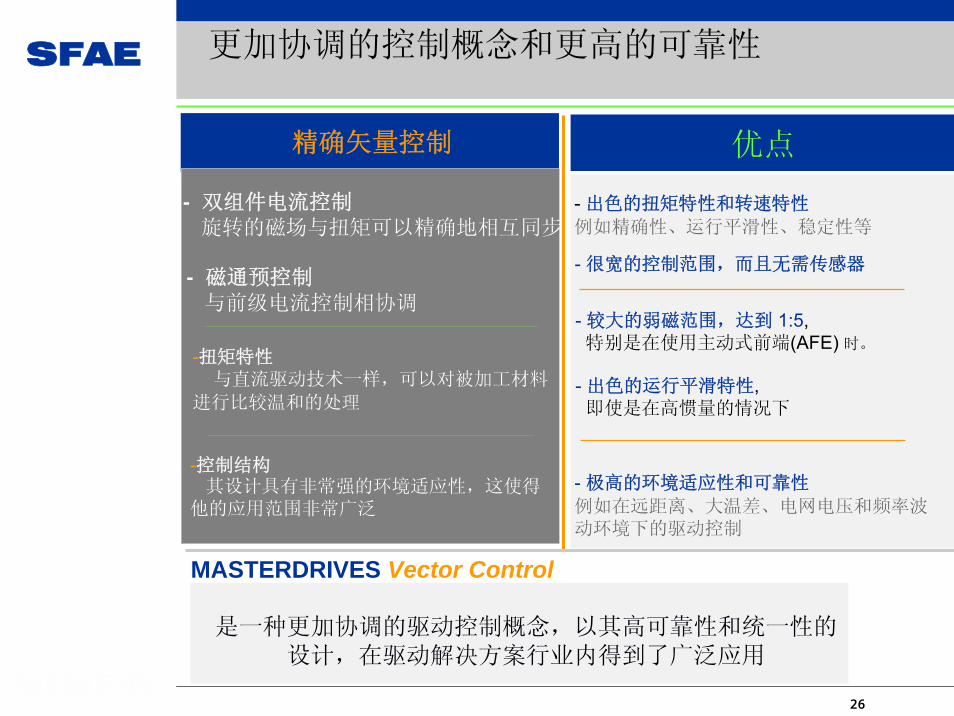
- 双组件电流控制旋转的磁场与扭矩可以精确地相互同步
- 磁通预控制与前级电流控制相协调
-扭矩特性与直流驱动技术一样,可以对被加工材料
进行比较温和的处理
-控制结构其设计具有非常强的环境适应性,这使得
他的应用范围非常广泛
优点
- 很宽的控制范围,而且无需传感器
- 较大的弱磁范围,达到 1:5, 特别是在使用主动式前端(AFE) 时。
- 出色的扭矩特性和转速特性
例如精确性、运行平滑性、稳定性等
- 极高的环境适应性和可靠性
例如在远距离、大温差、电网电压和频率波动环境下的驱动控制
MASTERDRIVES Vector Control
精确矢量控制
- 出色的运行平滑特性, 即使是在高惯量的情况下
是一种更加协调的驱动控制概念,以其高可靠性和统一性的设计,在驱动解决方案行业内得到了广泛应用
更加协调的控制概念和更高的可靠性

SFAE
27
消磁范围 (矢量控制模式下)
定位/同步( 使用工艺模板T300 / T400 )
输出电压
控制形式
(不考虑由电机、机械或其它局限性引起的转速波动 )
调制方式正弦调制,双曲正弦调制
同步系统
U/f特征曲线及用于纺织的U/f控制
频率控制转速控制扭矩控制
位置传感器
电机型号 ASM, SIMOSYN
脉冲编码器
电机识别、自动调节、跟踪监控等
更多丰富的功能
软件功能
捕捉再启动、自动再启动、直流制动、矢量制动、动能缓冲
动态性能 (仅限于矢量控制)磁通控制任务扭矩上升时间 (不包括反应时间)
快反应时间带有编码器/传感器情况下的转速上升时间
0,4 ms2,5 ms2,5 ms20 / 25 ms
精确性 (仅限于矢量控制)扭矩( 在摩擦补偿和无第三方电机情况下的平均值 )
转速 编码器 / 传感器情况下
+/- 2% T rat.
0,05 U/min /+/- 0,2% N rat.
消磁情况下的转速控制范围 /f-max 用于纺织工业的U/f控制
频率控制转速控制扭矩控制
1 : 25 / 500Hz1 : 100 / 300Hz1 : 1000/ 300Hz1 : 1000/ 300Hz
1 : 5
高可达100 %线电压
MASTERDRIVES Vector Control满足高要求的驱动控制

SFAE
28
CUVC/CUMC/CUPM与CUVP/CUCP/CUMP的接口

SFAE
29
D尺寸变频器的电结构示意

SFAE
30
D尺寸逆变器的电结构示意

SFAE
31
E尺寸变频器的结构示意
直流母线的
电容器组件
进线端及直流母线端在盖板内
电子板箱
PSU
风机变压器
逆变器的输出端与电流互感器
风机组件
PCU
IVI及ABO
IGD及IGBT在电容器组件后面
PCC

SFAE
32
E尺寸变频器的电结构示意(1)

SFAE
33
E尺寸变频器的电结构示意(2)

SFAE
34
K尺寸逆变器的结构示意
直流母线的
电容器组件
直流母线的熔断器
电子板箱
PSU及滑
出机构
风机接线端
逆变器的输出端与电流互感器
风机组件
直流母线室
IVI及ABO(电子板箱后部)
IGD及IGBT在电容器组件后面

SFAE
35
L尺寸逆变器的电结构示意(1)

SFAE
36
L尺寸逆变器的电结构示意(2)

SFAE
37
L尺寸逆变器的电结构示意(3)

SFAE
38
增强书本型装置 (1)
增强书本型MCP(运动控制型)或VCP (矢量控制型)是
MASTER DRIVES 6SE70在约1998年以后出现的一类新的结构型
式的变频器系统,国内用户中以MCP机型居多。
增强书本型的特点是结构紧凑,相对来说,功率范围
也小些(从0.75kw~18.5kw),在定货号上的特征是在尺寸结构位
上为“P”;供电电压为交流380V~480V(交-直-交方式的变频
器),或直流550V~650V(直-交方式的逆变器),在定货号上,
供电电压位上的字母分别是“E”或“T”;其控制方式也分为
两大类:一类是主要用于交流异步电机的矢量控制型,其定货
号方式位上的数字是“6”,其主控模块为CUVP,功能和CUVC模
块相似,使用的微处理器也是2块SAB 80C165。例如:
6SE7021-4EP60,这是一款5.5kw的矢量控制型变频器。

SFAE
39
增强书本型变频器与逆变器的示意图

SFAE
40
增强书本型装置 (2)
另一类是主要用于控制交流同步伺服电机的运动控制型,由于具有两种
控制特性的主控模块,故形成了两个产品系列:
一种是在其定货号方式位上的数字“5”,其主控模块为CVCP02/03,
功能和CUMC模块相似,其软件版本为MCP的1.x系列,使用的处理器为一块
SAB80C167与一块DSP(TMS320C32)。例如,6SE7012-6TP50,这是一台0.75kw的运
动控制型逆变器;
另一种则在其定货号方式位上的数字是“7”,其主控模块为CUMP ,
功能和MC具有控制特性2的主控模块CUPM相似,其软件版本为MCP的2.X系列,使用
的处理器为SAB80C167与DSP(TMS320C33),其处理速度要快于前一种。例如,
6SE7022-7EP70,这是一种11kw的具有控制特性2的运动控制型变频器。

SFAE
41
采用增强书本型整流器直流母线供电的实例

SFAE
42
例: 6SE7013-0EP50变频器(MCP)的结构
模块,
CUCP02模块
逆变器部分
PBI04.13模块,
风机
整流部分
扁平电缆CUCP到PBI04.13

SFAE
43
整 流 回 馈 单 元
性 能 用 户 受 益
带 反 向 并 联 桥 路可 回 馈 电 能
导 通 角 可 以 到 零αG = 0
与 电 网 电 压 及 功率 的 匹 配 由 自 耦变 压 器 完 成
操 作 单 元 与 变 频 器类 似
系 统 总 效 率 高, 谐 波幅 值 低
一 种 简 单 的 再 生 能 量解 决 方 案

SFAE
44
整流器 (1)
MASTERDRIVES 6SE70的整流单元是以二极管或可控硅为功率元件的单象限交-直
环节,共有5种结构尺寸:B、C、E、H、K。
B与C尺寸为书本式的整流单元其功率部分为二极管桥式整流电路,,需配合由继电
器与预充电电阻组成的预充电回路。由一块控制板-A23模块做启、停及保护控制。其
启、停控制由端子外接启、停按钮实现。预充电控制、前端主接触器控制,冷却风机
供电,装置过热检测等也均由A23模块完成。A23模块检测主回路进线的交流电压及直
流母线的电压作为控制的实际值依据,装置前端需要有快速熔断器以及进线电抗器保
护。
E尺寸整流单元的部分为可控硅整流桥。可控硅整流桥在装置接通后,经固定的延
时,将可控硅整流电路的触发角由 小开到 大,从而完成逆变器直流母线上电容器
组的预充电,其控制原理与方式类同与B和C尺寸控制模块也是-A23单元。
B、C与E三种整流单元,其控制板-A23的控制原理大同小异,均没有采用数字化显
示,但它们均可以通过选件A50辅助电源与PSR接口板接入选件电子箱,电子箱中可以
搭载SCB接口扩展板,CBP2通讯板,甚至是T400工艺板等。

SFAE
45
整流器 (2)
H与K尺寸的整流器,其功率部分采用模块化的平板可控硅元件组件,其主控板
采用与整流/回馈单元相同的CUR控制模板,它是由微处理控制的具有直流母线
电流调节器为内环、直流母线电压调节器为外环的双闭环调节器控制的整流系
统。但直流母线电压不可自由设定,而是设定为跟踪进线电压的方式。系统的
控制和显示实现了数字化,可由PMU单元或DI、DOAO端子进行控制与显示。电子
箱的形式与6SE70系列标准模式相一致,可以安装主控板,也可安装选件模块。
可以实现PROFIBUS DP通讯A23模块完成CUR控制模块与主回路元件之间的控制接
口与各种控制电源变换,以及实现对系统的主回路方面的各种保护与实际值检
测。

SFAE
46
H/K尺寸的整流器的电气结构及使用控制示意图

SFAE
47
H 尺寸的整流器的主回路电气示意图

SFAE
48
H/K尺寸的整流器的结构示意图

SFAE
49
K尺寸的整流器的结构

SFAE
50
并联装置的并联连接,规格K

SFAE
51
并联装置的并联连接,规格K

SFAE
52
并联装置的并联连接,规格K

SFAE
53
整流器的12-脉冲运行

SFAE
54
用于与SST2 进行装置-对-装置连接的RS485 接口电缆

SFAE
55
整流器的12-脉冲运行
SFAE
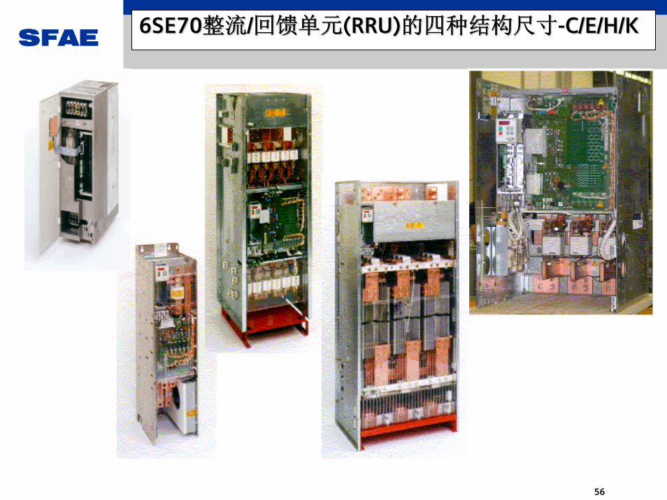
56
6SE706SE70整流整流//回馈单元回馈单元(RRU)(RRU)的四种结构尺寸的四种结构尺寸--C/E/H/KC/E/H/K

SFAE
57
RRU整流/回馈装置的特点 (1)
RRU装置的主回路为两组晶闸管采用无环流反并联的连接方式
在馈入工作状态下,直流回路电流由正向桥I提供;
在回馈工作状态(发电制动)下,直流回路电流将按反方向流动,流经反向桥
II,这时的移相角会设定在有源逆变所需要的角度上(α>90°),从而将能量回
馈电网。
RRU装置只有在主回路总可以保证其电压不低于90%额定值的这样一个较高质量
的交流电源下,变流器才能安全地进行回馈(再生运行)。电源的短路功率必须
相当于所连接的RRU装置的总视在功率的约100倍。在回馈其间,若电源电压有
故障或者电源被切断,则有源逆变器的上、下桥臂就会迅速直通,造成逆变颠
覆。
为了保证有源逆变器稳定地工作在发电制动状态,直流回路电压被减小到大约
为额定电压的85%,这也就是为什么在逆变桥侧未加自耦变压器的情况下,需设
置参数(P318与P571)来降低直流回路电压。因而,为保证直流母线能够全压工
作,逆变桥侧需通过一个升压的自耦变压器供电。

SFAE
58
RRU整流/回馈装置的特点与维修(2)
应该注意,只有在不易发生故障的稳定电网电压下,才可以采用RRU装置。在发电
制动运行时,如果电网电压故障时间大于2ms,则可能发生换相失败,从而导致逆变
颠覆,轻则烧坏熔断器,重则损坏可控硅元件。因此电网质量不能保证时,建议采
用RU加制动单元与电阻或是AFE变流器,而对于工厂中的滑触线供电方式,一般不能
采用RRU单元供电。
RRU单元在深控时,功率因数低、谐波含量高、换相重叠角将引起电网电压波形的
畸变。
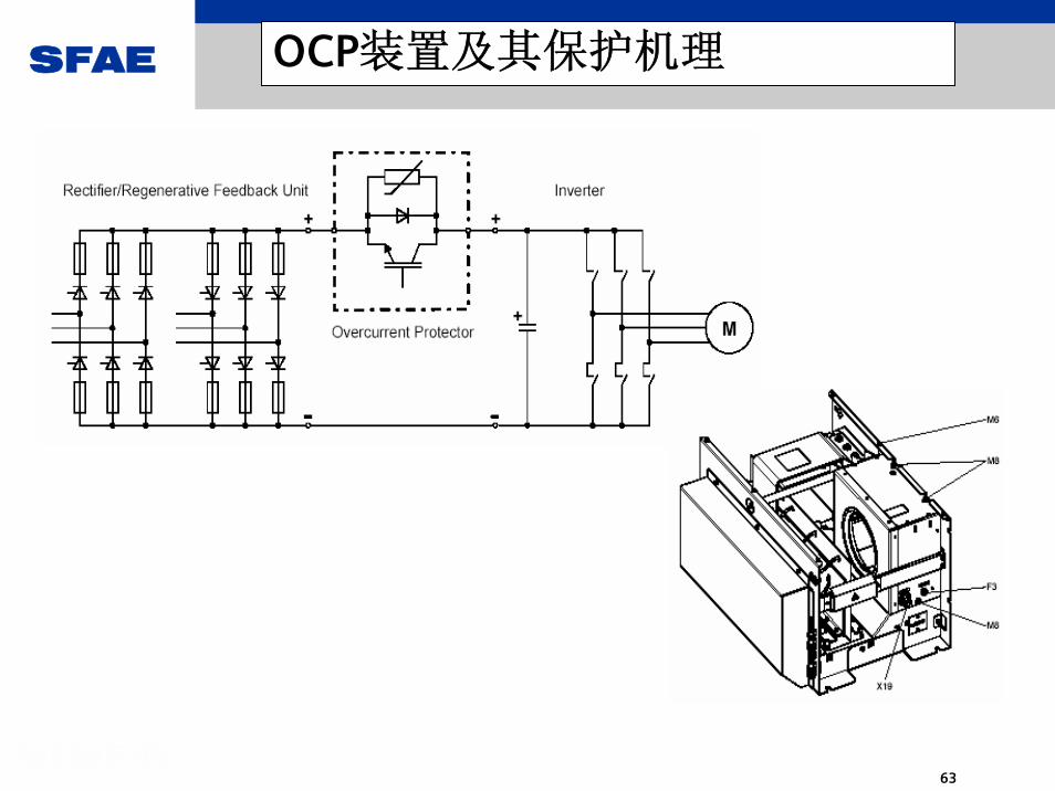
为了防止RRU装置在有源逆变的过程中发生逆变颠覆,西门子提供一种称为OCP
(Over Current Protection )的装置,这是一个附加装置,接在RRU与逆变器之间
的直流中间回路的正端上,该装置具有中间回路2倍额定电流的能力及DC510V~650V
与DC650V~930V两种电压等级的产品。
这是一个以IGBT为开关器件的直流母线反向阻断装置。它的主要作用是侦测出
RRU装置的逆变颠覆的倾向,适时地防止逆变颠覆的发生。它的加入可以有效地防止
RRU单元烧毁的可能性,减少了设备的故障停产时间。

SFAE
59
RRU整流/回馈装置闭环控制(1)
SFAE
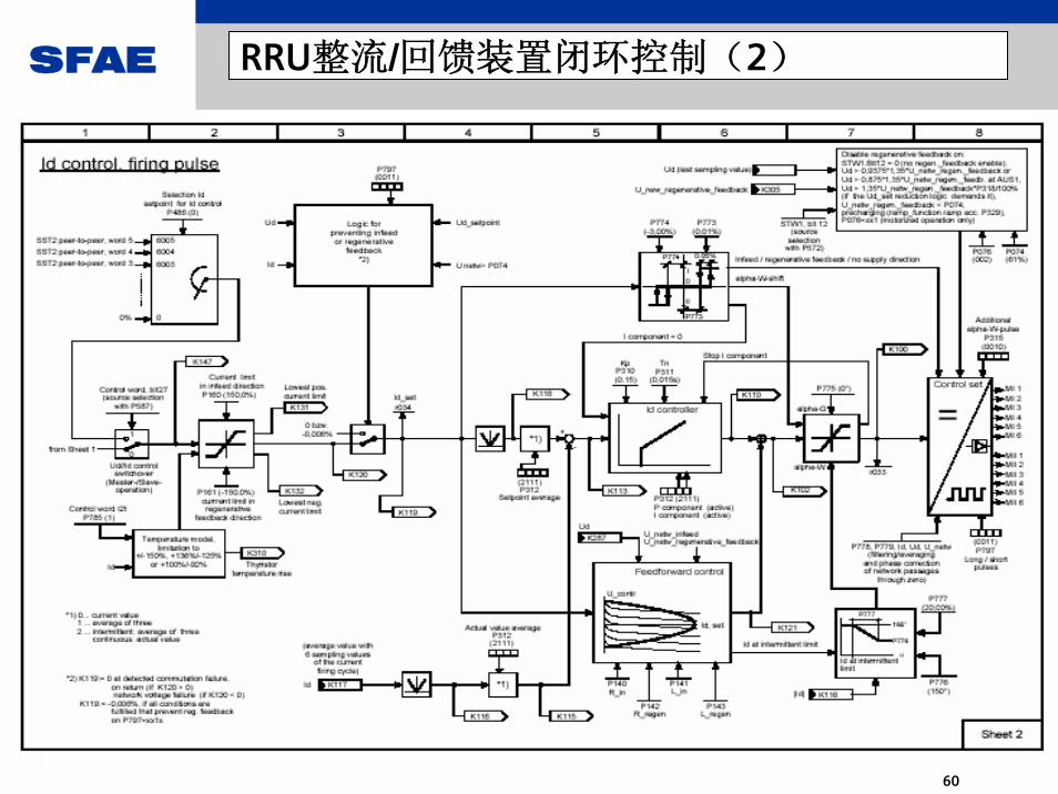
60
RRU整流/回馈装置闭环控制(2)

SFAE
61
K尺寸装置的主回路及-A23模块

SFAE
62
H与K尺寸装置的功率模块布局
SFAE
63
OCP装置及其保护机理

SFAE
64
OCP装置主回路及控制连接

SFAE
65
AFE电源模块
清洁电源滤波器
带AFE的逆变器
标准逆变器
矢量控制的 佳电源管理那就是: 主动式前端 (AFE)
不论电源质量如何, MASTERDRIVES 主动式前端 始终给驱动器提供一个稳定的
直流电源,保护驱动器不受电源质量影
响。
Vac in重要的好处有:
电源回馈功能 (四象限运行)当电网出现故障时,驱动系统的整
流与换向等工作不会出现错误电网电压波动补偿抑制谐波回馈电网可以设定的功率因数高速的驱动动态响应多轴驱动系统的理想解决方案
M~
M~
为了满足更高的生产力要求:主动式前端技术 ( AFE )

SFAE
66
AFE变流器的特点 (1)
AFE变流器是随着全控式开关器件(例如IGBT)的实用化而发展起来的斩控式
可逆变流器。系统的交-直环节与直-交环节的结构完全相同,均采用正弦脉
宽调制模式(SPWM)。其控制结构包括直流母线电压的电压调节器;提供变频
器系统输入电流瞬时值指令模式信号的功率因数调节器;与电流模式信号成正
比的控制输入电流的调节器;以及对变流器交流输入电压进行斩波控制的SPMW
控制器。
- AFE变流器能使直流母线电压保持恒定。
- 电源侧的4象限运行。在电机侧的制动能量通过逆变器返回而使直流母线
电压升高 时,可以使交流输入电流的相位与电源电压相位相反,实现再生发电
运行,并将再生功率回馈到交流电网去,这时整流器工作在有源逆变状态。
- 由于采用了自关断器件IGBT,通过恰当的SPWM模式,可对交流电流的大小
和相位进 行控制,并通过前端的各滤波、储能环节使交流输入电流接近正弦
波。
- 功率因数以1为中点而正负可调。

SFAE
67
AFE整流/逆变器为新一代交-直流环节。它采用自关断器件IGBT作为功率器
件,并且采用正弦波的脉宽调制技术。从而避免了可控硅类功率元件的整流/回
馈单元,由于电网侧故障而容易发生的逆变颠覆的弊端,使AC-DC环节的可靠性
大幅度提高。
由于AFE整流/逆变器前端的电压与电流波形均已滤波成正弦波形,电压与电流
正弦波形间的相位差角可以按需要在一定范围内设定,因此功率因数可调。它甚
至可以对供电系统进行有源的功率因数补偿。
由于直流母线电压可在一定范围内设定,设定值即为稳压值,故AFE整流器抵
抗电源电压偏低的能力很强,特别适合于供电电压长期偏低的情况作用。
AFE整流/逆变器前端部分的开关与滤波、储能元件安装要求较高,一般均采用
西门子公司供货的总成,其前端集成了正弦波的电压/电流滤波器。但需注意,
AFE前端模块的接地结构对IT电网与TT/TN电网而言是不同的,错用会引起问题。
AFE变流器的特点 (2)

SFAE
68
VSB模块是AFE整流/逆变器的重要部件,它实时检测AFE整流器前端的进线电压
相位信号,其工作原理类似于编码器测量电机轴的角位移,作为控制的基本依
据之一。
AFE为四象限运行的整流/回馈单元,由于采用SPWM方式,与可控硅的整流/回
馈单元的工作原理完全不同。它在回馈运行时不必有自耦变压器配合。
AFE整流/逆变器除去主控板CUSA后的部分与一台同功率容量的逆变器的硬件结
构完全相同,只是主回路输入与输出端倒过来用,因此检测与维修一台AFE整流
/逆变器可以完全采用与前述的逆变器的修理与检测相同的办法。6SE70的测试
盒也完全可以用于AFE整流/逆变器。甚至可先把AFE本体部分作为逆变器进行测
试(只需将CUSA换成一块CUVC,并按逆变器方式接线)。
AFE变流器的特点 (3)

SFAE
69
由AFE整流/逆变器做前端的变频器示意图
control section
6
LCF
LF
-K1
-K2R
230Vac
Control voltage transformersfor all auxiliary supplies,control circuits, cooling fans etc。
pre-charging
circuit
L-C filter
clean power filter AFE inverter
motor inverterAFE unit
-S1
-F
motor
Complete AFE inverter
M~

SFAE
70
使用 AFE 做为AC/DC环节的变频器系统(630kW )
AFE inverterAFE inductor
L-C filter
isolatingswitch
fuses
contactors
motor inverter

SFAE
71
AFE整流/逆变器的前端部件

SFAE
72
AFE – Basic principle Step up converter
CVdc
S1V
L
I1 I2
Initially C charges to voltage V (pre-charging), I2.
S1 (IGBT) closes and current I1 increases. L stores energy. (0.5LI2)
S1 opens, the energy in L is transferred to C by the current I2. due to the inductive voltage effect Vdc =V+VL
By controlling the switching of S1 the voltage Vdc is kept constant, independent of the voltage V or the load.The faster the switching of S1 the better the control of Vdcand the smoother I becomes.
I DC link

SFAE
73
AFE – Basic principle Step down converter
CVdc
S2
V
L
I1 I2
Capacitor C is charged above the supply voltageS2 closes and current I2 flows back to the supplyS2 opens, and current continues to flow in input inductor I1. By controlling the switching of S2 the flow of current is controlled.
In a step up converter, the energy is stored in the inductor, in a step down converter, the energy is stored in the capacitor
I DC link

SFAE
74
AFE整流/逆变器的前端部件总成
SFAE
75
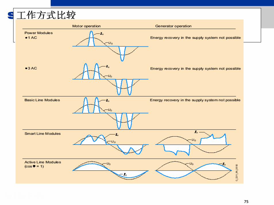
工作方式比较

SFAE
76
AFE整流/逆变器的控制结构

SFAE
77
制 动 单 元
性 能 用 户 受 益
外 配 制 动 单 元
可 通 过 并 联 扩 大制 动 功 率
含 20 kW 内 部 制动 电 阻
可 外 接 制 动 电 阻以 增 大 制 动 功 率。外 接 制 动 电 阻 带有 稳 定 监 控 功 能。
过 载 电 气 保 护
实 现 4 象 限 运 行 的经 济 方 案
如 将 来 需 要, 可 以扩 容

SFAE
78
“安全停机” 功能已经通过了德国贸易协会的鉴定,并写进了EN 954-1 Category 3中。
- 降低成本电机侧无需开关,这降低了配
线成本,而且节省了空间
-节省时间使机械设备更容易被BG (德国
贸易协会)承认,因为这种电路理论
已经通过了鉴定
-工程可靠通过了鉴定的电路理论与成功
实例使工程更加可靠
U1V1W1
U2V2W2
P24
P15
ASICmit
Ansteuerlogik
uPController unit
D C
M3~
X101
X53312
43
DE
DE ... DigitaleingangS1 ... Schließer zur Aufhebung der Funktion "Sicherer Halt"
(anlagenseitig)K1 Sicherheitsrelais
S1 K1
2
1
2
1 AnsteuerverstärkerOptokoppler oder Lichtwellenleiter
MASTERDRIVES Vector Control矢量控制系统的安全性由一个内置的继电保护装置来完成,这称作“安全停机“功能。这一装置还
带来了更多的好处:
确保功能的安全性——集成式安全装置

SFAE
79
MASTERDRIVES Vector Control驱动器拥有IP65防护等级,可以安装在相应的柜体中.
重要的好处有:
高防护等级使系统的运行不受周围环境的影响
低噪音由于功率损失而产生的热量可以非
常容易而可靠地分散掉
冷却系统
MASTERDRIVES Vector Control水冷型功率范围从2,2kW 到 6000kW
水冷型确保您生产过程中的冷却

SFAE
80
1
1
1
1
6个装配插槽,用于安装选件模板
传感器模板
用于检测设定点- SBP脉冲编码器(TTL/HTL)
通讯模板- CBP2 PROFIBUS DP (12 MBaud)
快速数据传输(内部)- SLB SIMOLINK
输入输出模板(扩展模板)- EB1 3 DI, 4 DI/DO
1 AI (±13 Bit,) 2 AO (±11 Bit)-EB2 2 DI, 4 继电器输出
1 AI (±11 Bit), 1 AO (±9 Bit)
电子箱中有两个装配位置用于复杂工艺功能使用以下模板:
- T4001
A
B
F
GC
D
E
A
功能范围广泛的模板: 无约束 – 不论是何种应用

SFAE
81
选 件: 抗 无 线 干 扰 滤 波 器
性 能 用 户 受 益
208V 至440V,2.2kW至 37 kW 的 装 置 加滤 波 器 后 RFI 等 级可 达 B1 级
380V 至440V,45kW至 200 kW 的 装 置 加滤 波 器 后 RFI 等 级可 达 A1 级
适 用 于 接 地 电 网
需 与 输 入 电 抗 器一 起 使 用 才 可 达所 述 RFI 等 级
可 运 行 于 办 公/ 商 业 环 境
可 运 行 于 工 业 环 境
可 以 很 简 便 获 得CE 标 志
B1 级: 办 公/ 商 业 环 境
A1 级: 工 业 环 境

SFAE
82
选 件: 正 弦 波 滤 波 器
性 能 用 户 受 益
为 电 机 输 出 一正 弦 波 电 压
不 会 超 出 根 据PTB 规 则 所 限定 的 高 电 压
380 至 460 V 电 压输 入 时, 大 频率 fAmax = 200 -400 Hz
500 至 690V 电 压输 入 时, 大 频率 fAmax = 200 Hz
可 以 使 用 标 准 的EExd 电 机
电 机 噪 音 维 持 在正 弦 波 输 入 时 的噪 音 水 平
电 机 损 耗 维 持 在正 弦 波 输 入 时 的损 耗 值
可 以 配 接 非 西 门 子电 机 而 无 需 降 额

SFAE
83
选 件:dv / dt 滤 波 器
性 能 用 户 受 益
限 制 电 机 电 压 的变 化 率 (dv/dt)
限 制 大 电 压 尖峰
可 大 程 度 地 利 用电 机 效 率, 同 时 体 现IGBT 的 优 越 性
电 缆 长 度 可 达 300 m
降 低 电 机 运 行 噪 音

SFAE
84
选 件: 输 出 电 抗 器
性 能 用 户 受 益
3 相 铁 芯 电 抗 器,
大 频 率 fAmax = 120 Hz
3 相 铁 氧 体 电 抗 器
大 频 率 fAmax = 600 Hz
抑 制 电 机 的 电 压 变 化 率
(dv / dt)
抑 制 电 缆 中 的 充 电 电 容
可 以 容 许 接 更 长 的 电 缆
可 根 据 电 机 大 频 率 选 择
相 应 的 电 抗 器

SFAE
85
功能性 / 智能性SIMATIC
S7
1
基本的电子技术基于逻辑与控制的驱动器自动调整全面的系统诊断位变量联接技术
通讯PROFIBUS DPSIMOLINK 点到点通讯符合USS协议的通讯
MASTERDRIVES Vector Control矢量控制的处理技术和控制功能对自动控制系统产生了巨大影响,极大地推动
了自动控制技术的发展
它使设备的配置和维护简单化.
从而也使系统造价和工程成本大大降低.
分布式智能内核:针对各种任务的功能模块

SFAE
86
SIMOVERT MASTERDRIVES Motion Control运动控制
(MC)

SFAE
87
对机器的快速响应控制是伺服驱动系统的标准功能
适用于循环式高动态响应机械
DA65.10
Compact PLUS
MASTERDRIVES 运动控制 ( MC )

SFAE
88
Chassis机架式
包含在每个单元之中
适用各软件版本
F01作为选件订货 (MLFB: 6SE7... Z=F01),在发货时F01已被激活
可以随时升级和更新
带有PIN码保护锁
为了维修、测试和演示等目的,特设一个有效时间为500小时的PIN码(U977.1 = 0727, U977.2 = 0101)
工艺软件 F01
Compact PLUS紧凑加强型
F01
工艺软件
锁定角同步;
凸轮;
定位;
自动控制等
Compact紧凑型
SFAE
89
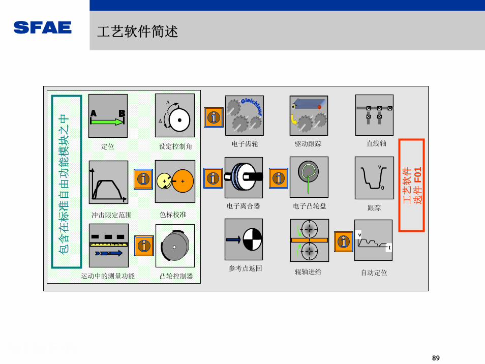
电子齿轮
电子离合器 电子凸轮盘
直线轴驱动跟踪
参考点返回
t
v
自动定位辊轴进给
跟踪
v
0
工艺
软件
选件
F01
工艺软件简述
定位
运动中的测量功能
色标校准冲击限定范围
设定控制角
Δ
Δ
包含
在标
准自
由功
能模
块之
中
凸轮控制器

SFAE
90
速度控制器
t
速度 (v)
距离 (s)
t
加速度 (a)
t
PROFIBUS接口
旋转变压器
Slot A
Slot B
Slot C
控制信号l 诊断信号 参数设定
位置控制器
扭矩控制器
速度,位置控制
制动控制
输出
示例:1FK6型伺服电机带有-内置旋转变压器-制动闸
a*
加速度预控制
v*速度预控制
自由功能模块
SIMOVERT MASTERDRIVES MC
软件功能模块
s*
工艺软件 F01
- 逻辑- 计算- 工艺控制器- 积分运算器- 斜坡函数发生器- 限幅器- 监视器- 计时器- 特征曲线发生器- 多路复合开关- 摇摆发生器- 凸轮序列发生器- 等等
简单定位
RDRU
v_soll
SETUP / POS
V , S
A
Up
Down
SV

SFAE
91
大约有240自由功能模块,包括大约有240自由功能模块,包括
...大约有80 运算模块和控制环模块(乘法器、除法器、加法器、减法器、限幅器、特征曲线模块、积分运算器、限幅监视器、滤波单元等等)
...大约有80逻辑模块(与/或单元、存储单元、定时单元等等)
... 复杂模块(简单而且友好的斜坡函数发生器、工艺控制器、扫描信号发生器、软件计数器等等)
...大约有50管理模块(故障监控、固定设定点、数据传输等等)
BICO系统:自由功能模块
变频器内部的PLC功能变频器内部的PLC功能
U952.63 = __ (20)U065 (0)
B 1 = "Warnung A061"
U221 (1)U950.78 = __ (20)
&B
B0601BB
.01
.02
.03
U951.04 = __ (20)
K0467KU107 (0) .01 y
K .02
x1x2100 %⋅
x1x2
200%
-200%

SFAE
92
BICO工艺软件示例
* 通过模拟量输入端子或PROFIBUS设定速度给定值
* 通过端子来选择 (数字输入6)
.01
U176 (0) U950.86 = __ (20)
KK0526KKU177 (0)
B
.02KK
0
1
B0020Digitalinput 6
KK0011Analoginput
P224.B (0)KK
Q.1 n(Set-val)
KK3032PROFIBUS +
+– –
Nominall value analog signal switch Speedregulator2.
3.
4.
5.
1.
参数设置: 从应用对象出发,哪里有要求就在哪里进行参数设置。
1. P224.1 = 526 使用模拟信号开关进行附加速度值的设定操作2. U950.86 = 4 将模拟信号切换模块设为执行周期(3,2 ms)3. U176 = 20 通过输入端子6控制4. U177.1 = 11 输入1,模拟信号从输入端子来5. U177.2 = 3032 输入2 ,模拟信号从 Profibus KK3032来

SFAE
93
BICO系统:速度控制器功能图
Band-stop filter
Droop
DT1 element

SFAE
94
电机自动识别
菜单引导,快速启动
便利的制动控制
V/f特性
摆动信号发生器
用户界面友好的斜坡函数发生器
用户界面友好的工艺控制器
摩擦特性曲线
高扭矩和高加速度下的kT估算 / Tr 匹配
用户菜单
通过开启/锁定功能实现对用户参数的保护
自动识别选件模板
速度过滤器
编码器变化或用非西门子电动机时能自动进行位置检测
PRBS噪声发生器,辅助机电控制设计
附加软件功能
Chassis机架式
Compact紧凑型
Compact PLUS

SFAE
95
简单定位器
无额外费用
非常容易与PLC联接
用户可以快速熟悉和控制它
可以实现所有的典型应用
用 户 收 益
绝对位置和相对位置控制
带有电机编码器或机器编码器
组装和参考功能
不同模式之间的快速转换
使用 过程数据(PZD)进行设定点的快速改变
软件限位开关
运转补偿
功 能
RDRU
v_set
SETUP / POS
V , S
A
Up
Down
SV
定位

SFAE
96
现在,90%的应用可以用MASTERDRIVES MC现有的功能来实现。而针对那些特殊的应用包括:
预控制 (例如印刷机械中的引导控制 )凸轮控制的快速处理 (例如包装机械)
我们需要采用“特殊功能2”。
速度控制环,频率转换计算部分DSP => 在控制器后加入速度控制器T1.
高脉冲频率 8kHz
时间计算,工艺模块、自由功能模块,主处理器同步/定位/偶合等操作,采样时间 3.2 msec
存储功能DSP内部RAM (DSP变量=> 全部)主处理器RAM (变量=> 全部)
CUMC / CUCP / CUMP / CUPM
MC 特殊功能2(CUMC and CUPM)

SFAE
97
C167
DSP
FLASH1MB
RAM64kB
RAM64kB
E2
Osc20MHz
Osc60 MHz
总线控制器ASIC
脉冲控制器ASIC
功率层
Osc40MHz 1/2
SRAM1MB
2倍速度C167
两倍的主处理器计算能力
FLASH2MB
两倍(可能)的存储容量
DSPTMS320C33
四倍的单一处理器计算能力
MC特殊功能2 (CUPM/CUMP)MASTERDRIVES MC 的硬件结构

SFAE
98
优点:对动态响应的重大改进
(例如在T0中,电流与速度控制器的计算在200微秒之内完成)工艺软件和自由功能模块的计算更加快速 (例如在 F01 中,该操作可以在1.6
毫秒之内完成)附加功能存储器(自由功能模块)与SIMOTION 的联接达到了8kHz 1,5 毫秒(3轴系统)功率扩展:200kW 到 750kW
兼容性:接线器的设计保持不变
特殊功能2是向下兼容的。例如所有的 DNL 和脚本文档都可以被执行。现有的项目也可以被利用。
MC特殊功能2 (CUPM/CUMP)MASTERDRIVES MC 的硬件结构

SFAE
99
SIMODRIVE 611 U通用型驱动器

SFAE
100
SIMODRIVE ® 611 uSIMODRIVE 611驱动系统中的
独立的、全数字的插入式控制模块
SIMODRIVE,作为机械工业领域中的
广泛应用的驱动控制系统,已经
经历过上百万次考验了!
用于高动态响应的多轴联动控制
SIMODRIVE 611 通用型驱动模块
SFAE
101
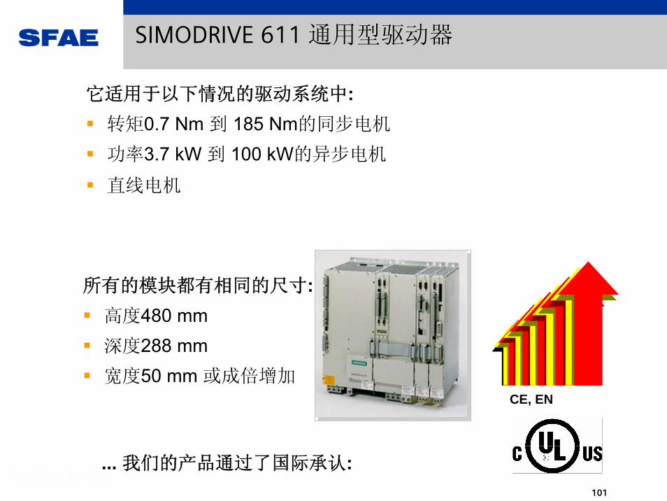
它适用于以下情况的驱动系统中:转矩0.7 Nm 到 185 Nm的同步电机
功率3.7 kW 到 100 kW的异步电机
直线电机
所有的模块都有相同的尺寸:高度480 mm深度288 mm宽度50 mm 或成倍增加
CE, EN
... 我们的产品通过了国际承认:
SIMODRIVE 611 通用型驱动器

SFAE
102
SIMODRIVE 611通用型驱动器
同步电机: - 1FK7, 1FK6, 1FT6, 1FE., 1FN..异步电机: - 1PH..,1LA...非西门子电机: - xxy
异步电机也可以在没有编码器的情况下
进行操作控制
所用编码器包括: -旋转变压器, -峰-峰值为1Vpp的正弦/余弦信号编码器 ,-使用 EnDat 接口的绝对编码器

SFAE
103
SIMODRIVE 611通用型驱动器
电源模块:
无反馈电源模块
再生反馈电源模块
适用于单轴或多轴驱动器
功率模块,包含
插入式控制单元

SFAE
104
SIMODRIVE 611通用型驱动器
611D 模块611A模块 611U 通用型模块
插入式控制单元 功率模块
功率模块由什么组成 ?

SFAE
105
SIMODRIVE 611通用型驱动器
双轴EnDat接口的
sin/cos 1Vpp编码器
单轴旋转变压器
双轴旋转变压器
针对各种应用设计的不同插入式控制单元,客户可选择购买不同模块得到真正需要的功能
转速/扭矩控制
定位/位置控制
或

SFAE
106
插入式控制单元的可选组件
端子扩展可以为驱动器A和
驱动器B提供8路输入和8路输出
- PROFIBUS DP通过PROFIBUS DP进行运动控制
系统程序件模块硬件 + 用户数据
安全可靠地与无压插槽联接在一起
系统程序件模块硬件 + 用户数据
安全可靠地与无压插槽联接在一起
突出特点更换模块的简易性
突出特点更换模块的简易性

SFAE
107
适用于所有应用领域的紧凑式双轴驱动系统
特点:
这一双轴驱动模块
非常便于用户安装
功率模块宽度仅为
50 mm
例如:
5 kW 电源模块
加两块双轴
功率模块
可以驱动四台电机
,而宽度仅150mm

SFAE
108
工艺软件已经集成到驱动器之中所以其智能化控制已经渗透到了每一个细节!
定位
参考点返回
t
v
自动定位
冲击限幅
通过PROFIBUS-DP的控制实现同步
凸轮控制器
直线轴或旋转轴
Teach-in操作软件
固定停车点

SFAE
109
定位功能:直线轴,旋转轴
直线轴
定义运动范围
硬件或软件限位开关
0 x m输送车
360°/0°
转盘
旋转轴
无限制的旋转运动
设定位置和实际位置在一定模数
范围内变化。例如范围为0至360度由 短路径或由指定的方向运动到
设定点
直线轴和旋转轴可以使用增量编码器(如旋变编码器)或绝对值编码器来进行位置检测。用绝对编码器就可以省去回参考点的动作了

SFAE
110
产品特点 --调试软件 SimoCom U
SimoCom U是一种用于设定参数和启动系统的工具,在其不断的
升级中,我们一直将重点放在了其易用性和功能性上!
菜单指引式启动过程
服务信息
在线帮助
我们的运动控制系统SIMODRIVE 611 Universal提供了超强的可用性;而我们的调试软件 SimoCom U
则成为竞争对手追随的标准!

SFAE
111
SimoCom U中的频域分析功能(波特图)

SFAE
112
经过了上百万次考验的SIMODRIVE驱动系统!
经过了考验的技术支持,全球化的服务体系
结合SimoCom U 达到 佳的运行状态
节省工程、启动和维护时间
无需PC或PG就可以更换模块,从而进行维修只需更换带系统程序和用户数据的系统固件大大减少维修时间和停工期
功率高达 120 kW 的单个功率模块更少的备件库存减少配置时间
使用双轴驱动模块就可以组成紧凑的多轴驱动模块降低了控制柜的要求使用双轴驱动系统达到 佳性价比
工艺软件直接集成在驱动器之中,如定位和同步功能等

SFAE
113
SIMODRIVE 611U 与 MASTERDRIVES MC之间的主要区别
MC611U
电机种类 SYN和ASM 伺服电机SYN和ASM伺服电机, 直线电机
电机弱磁范围 ASM 1 : 2ASM 1:16
输出电压 0 ... 86% V_mains0 ... 430 V (with 600 Vdc)
转矩/Nm 0.5 ... 9000.7 ... 140
电网电压 380 - 480 TN,IT,TT400, 415, 480 TN
编码器脉冲编码器,旋转变压器,
绝对值编码器
矢量控制 带编码器带 / 不带编码器
旋转变压器, 编码器,绝对值编码器
定位 / 同步操作 速度设定、转矩设定,定位功能 可选工艺软件 F01
PROFIBUS运动控制
横向通讯,时钟同步横向通讯,时钟同步
加速时间 /ms <= 2.5 (at 5 kHz)
转矩提升+死区时间 <= 0.4 + 0.4 (at 5 kHz)<= 0.4 + 0.4 (at 5 kHz)
<= 1.3 (at 5 kHz)

SFAE
114
MASTERDRIVES MC 与 SIMODRIVE的应用环境和应用条件
SIMOVERT MASTERDRIVES MC 的应用环境
SIMOVERT/SIMOREG 系统集成环境
300 mm规格的控制柜
大输出功率 250 kW5.5 kW以上的需要水冷系统
自由功能块
可选工艺软件F01具有价格优势的单轴驱动系统使用 AC 模块
三倍的过载能力 (指Compact PLUS)编码器、总线系统、输入/输出系统的更高的灵活
性
可与电网直接相联
SIMODRIVE 的应用环境
低的空间要求 (双轴模块)单个模块功率高达120kW表面冷却(风冷)具有价格优势的由双轴驱动模块构成的多轴驱动
系统
磁场削弱范围1:16输出频率高达 1,400 Hz带自动优化功能的速度控制器
无需 PG/PC即可进行模块更换 (如固件卡)适用于直线电机
与SimoCom U 相配合,达到 佳的可用性

SFAE
115
SIMODRIVE 611 U 与 MASTERDRIVES MC之比较工艺软件
使用PROFIBUS DP进行同步操作
电子离合 电子凸轮 凸轮控制器 直线轴
主值匹配 定位
参考点返回
运动中测量
t
v
自动定位印刷 / 机械标记同步 辊轴进给冲击限幅
跟踪
v
0
设置偏斜角
Δ
Δ

SFAE
116
SIMODRIVE 611 universal v. MASTERDRIVES MC
SIMODRIVE® 611 universal
是一种用于易于使用的驱动系统,适合于 那些要求简单定位的客户使用.
SIMOVERT® MASTERDRIVES Motion Control
是一种用于 复杂运动 的驱动系统,适合于
那些具有丰富驱动技术经验的客户使用,因为其高 灵活性和复杂的功能可以实现用户设备的独创性。
SFAE
117
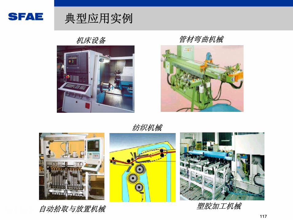
典型应用实例
管材弯曲机械机床设备
自动拾取与放置机械
纺织机械
塑胶加工机械

SFAE
118
操作模式 带编码器的速度控制
设定点分辨率-数字模式-模拟模式(标准模式)
(EB1选项)
带编码器的扭矩控制
15 bit + sign11 bit + sign13 bit + sign
31 bit + sign11 bit + sign13 bit + sign
提升时间 (5kHz) 2ms 转速 0.5ms 扭矩
设定范围- 数字模式- 模拟模式
采样时间(5kHz)频率上限
1 : 20001 : 2000
0.4ms250Hz
0.2ms600Hz
带编码器的位置控制
31 bit + sign11 bit + sign13 bit + sign
6.4ms 位置
> 1 : 100001 : 2000 / 8000
1.6ms---
> 1 : 100001 : 2000 / 8000
控制特性

SFAE
119
Positioning/ MotorsDas Keyvisual bittehier im Folienmastereinfügen
*) because of the missing safe separation of the PTC resistor analysis
**) only without encoder
MasterdrivesMC
Motors SIMODRIVE611U
POSMO CAPOSMO CD
1FT51FT61FK6 1FK7
noyesyesyes
noyesyesyes
noyesyesyes
nono *)
on request
noyes
on request
noon requeston request
1FN11FN3
Torque
noyes
on request
noyes **)
on request
yesyes **)
on request
1FE1LA
third party motors
yesyesno
yesyesyes
yesyesyes
1PH41PH71PL6

SFAE
120
Positioning ResolutionDas Keyvisual bittehier im Folienmastereinfügen
encoder typeResolution with
MASTERDRIVES MC
Resolution withSIMODRIVE
611U, POSMO SI/CD/CA POSMO A
Referencing Motor type
1. Incremental encoder TTL, HTL (e.g. 1024 Pulse / revolution)
pulse x 41024 x 4
--- 204 x 4 (75 W)1024 x 4 (300 W)
yes ASM
2. Resolver 2-pole 4.096 4.096 --- yes ASM+SYNResolver 4-pole 4096 x 2 4096 x 2 --- yes ASM+SYNResolver 6-pole 4096 x 3 4096 x 3 --- yes ASM+SYNResolver 8-pole 4096 x 4 4096 x 4 --- yes ASM+SYN
3. sin/cos 1Vpp encoder (e.g. ERN 1387)
4.194.304 262.144 4.194.304 ---yes ASM+SYN
4. Absolute encoder EnDat(e.g. EQN 1325) Absolute turns
4.194.304
4096
262.144 4.194.304
4096
---
no ASM+SYN
5. Simple absoluteencoder EQI1325Absolute turns
4096(32x128)
4096
4096(32x128)
4096
---
no1FK61FK7
Attention:The resolution must always be at least higher around the factor 4 to 10 than the required positioning accuracy
Attention:The resolution must always be at least higher around the factor 4 to 10 than the required positioning accuracy
example: 2-pole resolver (related to motor shaft)resolution: 4096 =^ 0,088°Positioning accuracy : Factor 4 0,35°
example: 2-pole resolver (related to motor shaft)resolution: 4096 =^ 0,088°Positioning accuracy : Factor 4 0,35°
Resolutionwith

SFAE
121
Positioning- Motor encoderDas Keyvisual bittehier im Folienmastereinfügen
*) only for induction motors **) only for 1FK6/1FK7 ***) only for linear motors
MasterdrivesMC
Motor encoder SIMODRIVE611U
POSMO CAPOSMO CD
60 ... 20.000 pul./rev.ROD431, 1XP8001
2-poleMotor pole pair num.
ERN1387ERN1381 *)ROD486 *)ECN1313 (EnDat)
EQN1325EQI1325 **)
EQN1324ROQ424
LC181(EnDat) LC184 (EnDat)
Pulse encoder *)(HTL, TTL)
Resolver
sin/cos 1Vpp
Absolute encoder EnDat
Absolute encoder SSI
Linear encoder ***)
---
2-poleMotor pole pair num.
ERN1387ERN1381 *)
EQN1325EQI1325 **)
---
LC181(EnDat) LC184 (EnDat)
---
---
ERN1387ERN1381 *)
EQN1325EQI1325 **)
---
---

SFAE
122
Incremental Encoder with Rectangular Signals: 2 Application Cases
E
Currentcontroller
Powersection
M
Standard asyn-chronous motor
Actual currentvalue acquisition
- Iact
Iset
Speedcontroller
Actual speed value
- nact
nset
E
Currentcontroller
Powersection
M
Servo motor withintegratedencoder/
tachometer
Actual currentvalue acquisition
- Iact
Iset
Speedcontroller
- nact
nset
Position controller
- xact
xsetE
Actual speed value
Actual position value
1. Acquisition: of actual speed value
2. Acquisition: of actual position value

SFAE
123
Reference Point Approach
Example: MASTERDRIVES MC installation and startup screen

SFAE
124
SIMOREG: 成 功 的 直 流 传 动 品 牌
SIMOREGStill leading the field -after years of success
INNOVATION with Tradition

SFAE
125
SIMOREG 产品系列回顾及改造替代问题
西门子直流调速系统SIMOREG系列:
全模拟的系统:6RA21与6RA22(模拟版),有单相电源供电的机型;6RA25;6RA26(DV V50-V57,MV V30-V34);另:6RB20/6RB21
第一代数字化产品: 6RA22(数字版);派生产品6RA27(主轴驱动);
第二代数字化产品: 6RA23; 6RA28 (低端产品);
第三代数字化产品: 6RA24
第四代数字化产品: 6RA70 (可替代前述各产品,但不可单相电源供电)
特点:主回路-单/四象限驱动;六脉动SCR全控桥式(B6C)/反并联的六脉动全控桥式(B6A/B6C)可控硅逻辑控制无环流主回路;近30年中,无大变化.控制回路- 转速/电流双闭环的基本结构;数字技术取代模拟技术.
样本: DA21

SFAE
126
产品的铭牌
装置的定货号 :
我们通过它可以确定此系统是哪个系列的整流器,额
定电流多少,是工作在什么样的进线电压下的装置,以及其
结构尺寸是哪一种,这是我们报修和订购备件的 基本的信
息。
出厂系列号 :
从这里我们能够判断装置为何年、何月、何日出厂
的,是否还在保修期内。一般情况下,保修期是从装置出厂
之日起18个月之内。
硬件版本状态 :
这一信息对于我们采购正确的备件非常重要。采购备
件,通常需要报出装置的定货号与硬件版本状态,某个特定
型号的系统具有唯一的定货号,但在发展过程中可能存在多
个版本状态,其硬件的结构形态或电性能是会存在某种差异
的,因此如没有硬件版本状态信息,而只通过系统定货号去
订备件,备件订购部门也不一定能够为你提供正确的备件。
SFAE
127
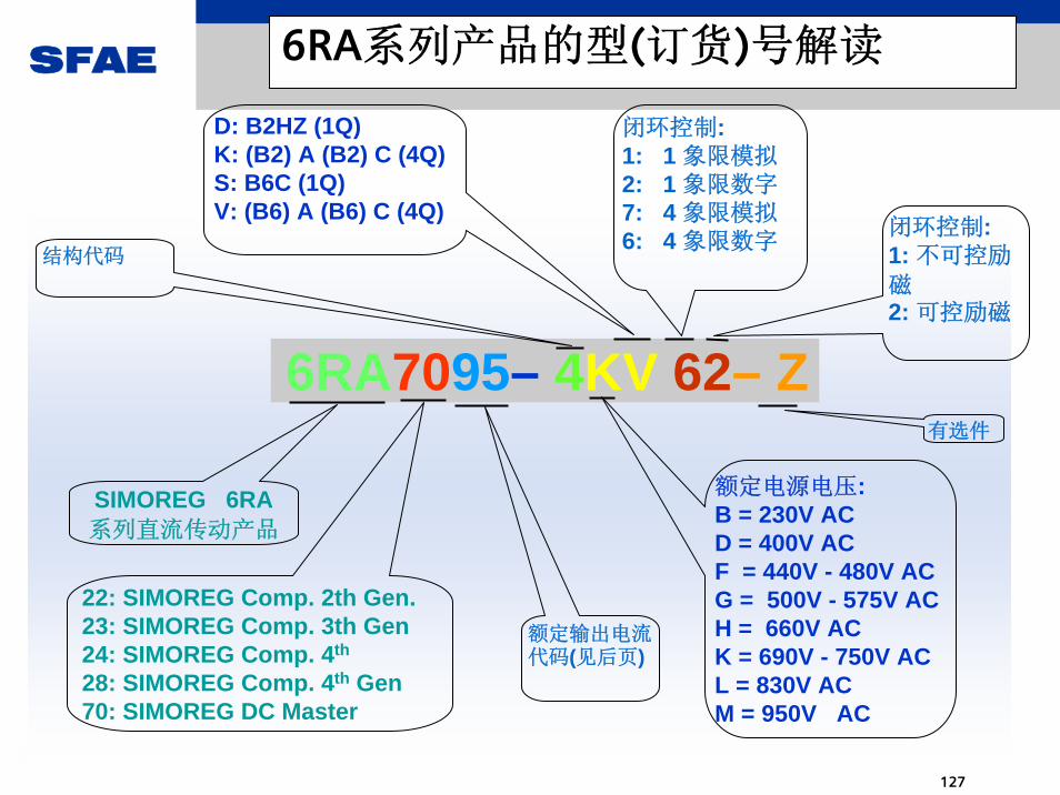
6RA系列产品的型(订货)号解读
6RA7095– 4KV 62– Z
D: B2HZ (1Q)K: (B2) A (B2) C (4Q)S: B6C (1Q)V: (B6) A (B6) C (4Q)
SIMOREG 6RA系列直流传动产品
闭环控制:1: 不可控励
磁2: 可控励磁
22: SIMOREG Comp. 2th Gen.23: SIMOREG Comp. 3th Gen24: SIMOREG Comp. 4th
28: SIMOREG Comp. 4th Gen70: SIMOREG DC Master
额定电源电压:B = 230V ACD = 400V ACF = 440V - 480V ACG = 500V - 575V ACH = 660V ACK = 690V - 750V ACL = 830V ACM = 950V AC
有选件
结构代码
闭环控制:1: 1 象限模拟2: 1 象限数字7: 4 象限模拟6: 4 象限数字
额定输出电流代码(见后页)

SFAE
128
额定输出电流代码

SFAE
129
DC Master 6RA70 系列直流全数字调速产品

SFAE
130
DC Master 6RA70 系列直流全数字调速产品
SIMOREG DC Master 6RA70 系列直流全数字调速产品,在6RA24 产品的基础上更具有以下特
点:
1. 6RA70 SIMOREG DC MASTER 系列整流器为全数字紧凑型整流器,输入为三相电源,可向变速
直流驱动用的电枢和励磁供电,额定电枢电流从15A 至3000A。紧凑型整流器可以并联使用,提
供高至12000A 的电流,励磁电路可以提供 大85A 的电流(此电流取决于电枢额定电流)。
2. 输入电压分为6 个等级: 400V/460V/575V/690V/830V/950V。
3. 强大的通讯能力。有SIMOLINK 高速直接的装置-装置通讯,还可支持PROFIBUS、CAN-BUS、
DeviceNet、USS 协议等。
4. 所有工艺板,通讯板及OP1S 操作面板都可与新一代的SIMOVERT MASTERDRIVES 矢量控制交
流调速产品通用。
5. 所有的开环和闭环驱动控制及通讯功能由两台功能强大的微处理器实现,驱动控制功能可以通
过参数,将软件所提供的程序块“连接”来实现。
6. 铭牌上规定的额定直流电流(连续直流电流),在负载等级I,可以过载到180%,过载允许的持续
时间由各个整流器而定。微处理器周期地计算功率部份电流的I2t 值,以确保晶闸管在过载运行时
不被损坏。7. 整流器可自动适应电源频率范围为45Hz~65Hz(电枢和励磁互不相关)。8. 工作在扩大的频率范围23Hz~110Hz 需询问。
SIMOREG DC Master 软件版本可从参数r060 和r065 读出。
新软件版本请访问以下Internet 网址:
http://www4.ad.siemens.de/view/cs/en/8479576

SFAE
131
6RA70的一般情况
6RA24系列的换代产品;但操作风格靠拢MASTERDRIVE6SE70;6个供电电压子系列:3~AC –400V/460V/575V
/690V/830V/950V
与 SIMOTRAS HD 6SG70系列及6RA70 CM产品孪生;从软件版本V1.5开始CUD1的firmware集成了HD的功能,从软件版本V1.6开始CUD1的firmware集成了CM的功能.
三种产品的主控制板与直流调速产品完全相同---CUD1;更换CUD1, 不必重新加载参数。
种产品的系统软件相同并同步升级---当前版本V2.25;
直接拖动对像:他励式的直流电动机;亦可变通用于其它类型的直流电机(串励,并励,永磁)或其它装置.

SFAE
132
6RA70控制结构总览
SFAE
133
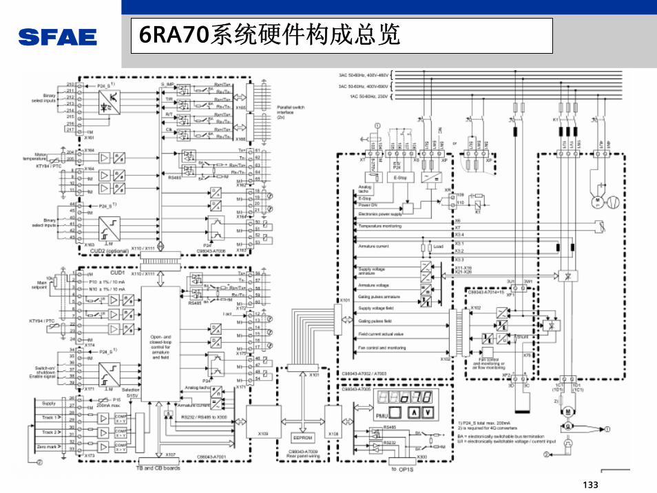
6RA70系统硬件构成总览

SFAE
134
SIMOREG 6RA70 的基本硬件结构
主控部分: 电子箱内安装--- CUD1(A7001); CUD2(A7006); 以及其它选件板;
A7009--CUD1的系统软件(Firmware)同时具备6RA70、6SG70与 6RA70CM三种产品的控制功能。 具体控制哪种产品由MLFBLOAD软件写入定货号到A7009模块上的存贮器的特定存储单元上 决定,这需要在F069故障状态下进行。此特定的单元存储正常情况下,只能写入一次,之后即被封
锁。
电源与接口部分:A7002/A7003
励磁部分:A7014/A7015
吸收回路部分:A7011
操作部分:A7005
功率部件部分:散热器底座;SCR模块;NTC 测温元件;散热风机

SFAE
135
SIMOREG 6RA70 的基本硬件构成(以6RA7085 - 6DV62 – 0为例)

SFAE
136
6RA70的并联扩容(可多至6台并联)

SFAE
137
SIMOREG 6RA70 的选件
在CUD1上可以扩展CUD2,使接口规模扩大一倍.
但在CUD1上不能直接搭载其它的选件模块.
电子箱内可使用与6SE70类似的扩展方法安装
选件模块, (用LBA/ADB)
通讯模块:CBP/CBP2,CBC, CBD, SLB
端子扩展:EB1,EB2,SCB1/SCI1/SCI2
速度反馈接口:SBP,DTI;但不支持
SBR,SBM/SBM2
工艺板:T300,T400等
操作面板:OP1S
进线电抗器与半导体保护级速熔必须设置
自由功能块必需购买才能使用(以PIN号的形式提供)
SFAE
138
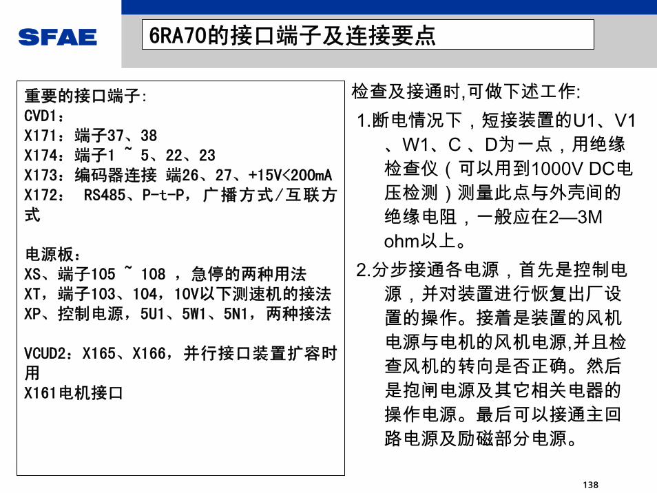
6RA70的接口端子及连接要点
重要的接口端子:CVD1:X171:端子37、38X174:端子1 ~ 5、22、23X173:编码器连接 端26、27、+15V<200mAX172: RS485、P-t-P,广播方式/互联方式
电源板:XS、端子105 ~ 108 ,急停的两种用法XT,端子103、104,10V以下测速机的接法XP、控制电源,5U1、5W1、5N1,两种接法
VCUD2:X165、X166,并行接口装置扩容时用X161电机接口
检查及接通时,可做下述工作:1.断电情况下,短接装置的U1、V1
、W1、C 、D为一点,用绝缘检查仪(可以用到1000V DC电压检测)测量此点与外壳间的绝缘电阻,一般应在2—3M ohm以上。
2.分步接通各电源,首先是控制电源,并对装置进行恢复出厂设置的操作。接着是装置的风机电源与电机的风机电源,并且检查风机的转向是否正确。然后是抱闸电源及其它相关电器的操作电源。最后可以接通主回路电源及励磁部分电源。

SFAE
139
6RA70的资料阅读方法
基本资料:直流调速样本DA21; 6RA70的使用手册 目前中/英文均已到13版.
1. 浏览样本及6RA70说明书前5章了解基本信息.
2. 硬件规划,安装指导(EMC规则等),连接端子说明等均在第6章.应仔细阅读.
3.软件规划设计需精读第8章(功能图),辅以第9章的功能说明及第11章的参数数明.
4. 接通调试见第7章,调试中出现一般故障及报警查阅第10章.
5.调试中出现硬件损坏,记清定货号及出厂编号与故障描述并r947/r949报服务部.
工具软件: DRIVEMONITOR (当前V5.4.1.2).已不再支持PCIN.

SFAE
140
6RA70的参数设置过程
所谓6RA70的参数设置过程(规划设计与优化)实质上就是用 合理的方法与步骤
形
成一份参数文件,建议用下面的步聚进行:
首先恢复出厂设置;
做接通优化,生成基本参数;
根据硬件设计与一系列功能的规化划等利用DRIVEMONITOR的空参数表功
能,生成一系列的数据补丁文件,在调试过程中逐个导入,边调试边确认;
特性优化 :对于与特性有关的参数要借助示波器、记录仪、 PDA或DRIVEMONITOR的 TRACE功能在运行中进行整定;
用DRIVEMONITOR做好两种形式的数据备份;

SFAE
141
直流传动6RA70的接通调整步骤(1)
1. 按设计图纸完成与6RA70传动相关的全部接线,查线完成并无误。
2. 将端子X171与X174拨去,另接为测试盒,或:端子34(+24V)与端子37、38之
间各 接一个钮子开关,作为合闸与使能的临时操作。
3. 首先接通6RA70的控制电源,设P51=21,按P键,恢复出厂设置。
4. 设P51=40、P830=3,然后接通电枢主回路电源,操作端子37上的开关闭合
主接触器,在口3的状态显示下,装置进行SCR检测,完成后37端子的开关扳回。
5. P51=40、P52=3。
6. 调整装置的电流设置,设P076..001与P076.002.
7. 调整装置的进线电压设置,设P078.001与P078.002。

SFAE
142
直流传动6RA70的接通调整步骤(2)
8. 根据电机铭牌设置P100、P101、P102、P114,必要时亦可设置P104 ~ P109的
保护生效。
9. 正确设置速度反馈方式,P083 。
10.正确设置速度反馈方式,P082与P081。
11.正确设置电流与力矩极限,P171、P172与P180、181,并将P303与P304设为数秒。
12.确认此时电机是否可以带负载自由转动?否则要求脱开电机轴的机械联接。
13.确认此时6RA70为07.0 状态。
14. 根据控制需要,执行电机的自动检测与优化步骤P51 = 25-- 29 。
15. 优化后将电机正、反运行到 高速,并调整速度匹配与零漂。

SFAE
143
6RA70的调试小工具

SFAE
144
1. 对于所有的使用,P51=25的优化要尽量设法做成,因为在这个过程中系统要
自动检测电机参数及进行励磁与预控制的基本设定。一般情况下,电机不转。但永磁电机或高剩磁电机必须采用抱闸等手段防止其转动。
2.在使用弱磁调节的方式时,P51=27必须进行。
3.对优化结果可以进一步手动调整,这点对P51=26的优化结果尤为重要。
4. P51=28的优化,一般需要带上实际负载方才有意义。
5. P51=29的优化,由于特定为摆动运行方式,无此工况时不要做。
6. 由于所有的自动优化,在执行过程中相对不可控,故在执行前一定要考虑优化过程对设备的安全性。必要时可以手动优化参数。
6RA70与自动优化相关的几个问题

SFAE
145
6RA70常用控制方式及控制字和电机参数组
常用控制方式:
速度控制方式: 速度给定的接入-- P644
力矩(电流)控制方式 : 力矩给定的接入-- P607/P500 或:电流给定的接入-P601
速度调节器饱和状态下的力矩控制方式:速度给定的接入-- P644/力矩限定的链接: P605/P606
控制字: P648=9对CW1、P649=9对CW2的设置使得控制字的通过P654-P691定义,
若二者不设为9,则需直接用通讯字的位方式处理,例如装置并联。
电机参数组: 用P676与P677选择; 用P055拷贝后修改;
控制参数组: 用P690选择; 用P057拷贝后修改;

SFAE
146
6RA70的自由功能块选件(S00)
1.如无S00选件,功能图B部分的连接关系全部无效;
2. 自由功能块在追加定购时必须写明所使用装置的定货号与系列号;
3.将定购来的PIN号写入U977,n978 = 2000 时,S00永久生效;临时使用可设确U977=1500,n978 =1XXX,XXX = 所余小时数;
4. 注意所有的自由功能块有扫描时间的定义,在U950.01-U952.100 之间定义,每号定义一个块,号见功能图的椭圆圈内,建议每个应用设计均应对此进行处理。可选:1、2、4、*(T0)、10(20ms)、20(块无效),其中:T0 =3.33ms(50Hz);T0=2.78ms(60Hz) ;
5.必要时可以用U960 -U962与U969调整自由功能块的执行顺序;

SFAE
147
如何提高系统的控制特性
影响稳态速度控制精度的原因及对策:1. 由线路引入的干扰--- 按EMC规则进行布线连接.
2. 输入(给定与实际值)信号干扰大--- 可考虑进行数字滤波.
3. 负载波动大---机械修整; 电流环精调;装置选型不合理.
4. 速度反馈元件品质或状态不佳---更换或处理.
5.速度匹配的调整不正确.
影响动态特性的原因及对策:1. 优化调整完成不佳---必要时应在自动优化的基础上手动进一步优化.
2. 如果低速段特性要求高---速度环特性采用分段自适应方式.
3. 摩擦与转动惯量的优化.

SFAE
148
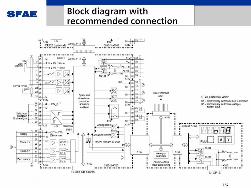
基 本 装 置 的 控 制 端 子 CUD1
脉 冲 编 码 器 接 口, 2 路 脉 冲 + 零 信 号
4 路 开 关 量 输 入, 其 中 2 路 功 能 可 设 定
2 路 开 关 量 输 出, 功 能 可 设 定 (100 mA 短 路 保 护)
2 路 模 拟 量 输 入,14 位 通 过 差 分 放 大 器,0 -±10 V 或 0 -20 mA 或 4 - 20 mA
2 路 模 拟 量 输 出, 功 能 可 设 定,11 位, 0 -±10 V
1 路 实 时 输 出, 模 拟 量 0-±10 V , 电 流 实 际 值
内 部 电 源 P10, N10 (10 mA)
1 个 RS232 / RS485 接 口
1 个 RS485 接 口
1 路 电 机 温 度 检 测 接 口 KTY 84 或 PTC
OP1 S 前 面 板 接 口

SFAE
149
动 态 过 载 能 力
IN: 装 置 的 DC 额 定 电 流 ( 输 出 电 流 = 额 定 连 续 电 流)无 过 载 能 力 的 传 动 装 置 可 持 续 利 用 的 电 流
IG: 基 本 负 载 电 流, 装 置 IN 的 %传 动 装 置 可 过 载 大 1.5 IN 的 电 流
I: 装 置 大 1,5 IN ( 一 次) 的 动 态 过 载 电 流. 过 载 时 间 取 决 于 基 本 负 载 电 流IG 的 值. 负 载 周 期 为 小 300 sI 取 决 于 IG.
IG
I
IN
I [%]
IG
150 %
100 %
300 t [s]
80 %
50 %
IG = 80 %IG = 50 %
IG = 0 %

SFAE
150
功 能 扩展
性 能
工 艺 控 制 器
基 本 的 斜 坡 函 数 发 生 器
转 速 及 速 度 计 算
开 关 量 信 号处 理逻 辑 功 能 (AND, NAND,OR, XOR, 切 换 开 关, 存 储,binector / connector 转 换,定 时 器)
算 术 运 算 功 能( 加 法, 减 法, 除 法乘 法, 取 绝 对 值)
模 拟 量 信 号 处 理( 幅 值 发 生 器, 存 储, 限 幅 器, 切 换 开 关, 小 值/ 大 值 采 样)
二 次 特 性 曲 线, 死 区
T100,T300,T400 工艺功能扩展
客 户 受 益
基 本 装 置 的 软 件 既 可 实现 工 艺 控 制 功 能, 不 必 额外 的 硬 件 投 资
软 件 模 块 只 需 通 过 参 数使 能 即 可, 无 需 编 程
在 很 多 情 况 下 可 省 去PLC, 从 而 节 省 资 金
-1
-1
1
2
3
0
P332 (0)K K0123
P333 (0)
P334 (0)0...10000ms
SiebzeitSiebzeitSiebzeitSiebzeitSiebzeit
yx
23
x
y
1
10
+200%
-200%
x10
x1
y1
y10
P565 (0)K K0655
P566.01 bis .10 (0)
P567.01 bis .10 (0)
Y-Werte
X-Werte

SFAE
151
开 创 软 件 功 能 新 标 准
软 件 结 构
2 个 功 能 强 大 的 处 理 器(80C163 及 80C167) 处 理 所 有闭 环 控 制 及 电 枢 和 励 磁 回 路的 传 动 功 能
控 制 功 能 可 通 过 各 功 能 模 块实 现, 功 能 模 块 可 通 过 参 数连 接
控 制 相 关 的 所 有 重 要 点 均 可由 BICO 访 问
BICO BICO 技技 术术

SFAE
152
BICO 使 用 举 例 (转 矩 限 幅)

SFAE
153
BICO 使 用 举 例( 开 关 量 输 出 )

SFAE
154
成 柜 装 置, 即 接 即 用
SIMATIC ( 可 选 )
操 作 面 板
辅 助 接 触 器
SIMOREG 6RA70快 熔电 源 进 线 / 电 枢
主 接 触 器
主 开 关
控 制 电 缆
电 缆 端 子
进 线 电 抗 器

SFAE
155
6RA70CM(Control module)
When these installations are converted or upgraded, the motor, mechanical and power sections
are left in the installation and the trigger and control section replaced by a 6RA70 control module.
The result is a modern DC drive at an extremely low price, with the full functional scope of the
tried
and tested fully digital devices of the SIMOREG DC MASTER 6RA70 range.
The configuration of the existing components is adapted by simple parameterization.
The 6RA70 control module contains a power section for the field supply with a rated current of up
to 40A.
The main application of the SIMOREG CM converter is conversion and modernization of DC drives in existing installations.In DC technology, many installations exist that are older than 5 - 10
years and still use analog technology.

SFAE
156
6RA70CM(Control module)
The OP1S optional converter operator panel can be mounted either in the converter door orexternally, e.g. in the cubicle door. For this purpose, it can be connected up by means of a 5 m
long cable. Cables of up to 200 m in length can be used if a separate 5 V supply is available. The OP1S is connected to the SIMOREG CM via connector X300.
The OP1S can be installed as an economic alternative to control cubicle measuring instruments which display physical measured quantities.
The OP1S features an LCD with 4 x 16 characters for displaying parameter names in plaintext.
German, English, French, Spanish and Italian can be selected as the display languages.
The OP1S can store parameter sets for easy downloading to other devices.
The converter can also be parameterized on a standard PC with appropriate software connected to the serial interface on the basic unit. This PC interface is used during start-up, for maintenance during shutdown and for diagnosis in operation. Furthermore, converter software upgrades can be loaded via this interface for storage in a Flash memory.
SFAE
157
Block diagram with recommended connection

SFAE
158
Block diagram with recommended connection

SFAE
159
Block diagram with recommended connection(with electronics power supply option, 24 V DC)

SFAE
160
6RA70CM(Control module)
1) The commutating reactor in the field circuit is dimensioned for the rated motor field current.2) The commutating reactor in the armature circuit is dimensioned for the rated motor current in thearmature. The line current equals DC current x 0.82.3) The radio interference suppression filter for the armature circuit is dimensioned for the rated motorcurrent in the armature. The line current equals DC current x 0.82.4) The radio interference suppression filter for the field circuit and the electronics power supply (if 380 to460 V) is designed for the rated current of the motor of plus 1 A (see description terminal XP).5) The radio interference suppression filter for the electronics power supply (if 190 to 230 V) is designed for 2 A (see description for terminal XP).

SFAE
161
Control of SITOR SCR set 6QG12
SFAE
162
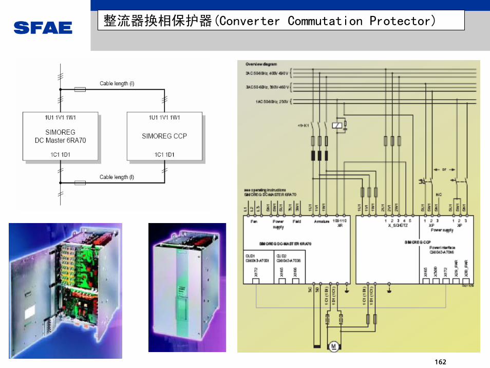
整流器换相保护器(Converter Commutation Protector)

SFAE
163
整流器换相保护器(Converter Commutation Protector)

SFAE
164
换相失败示意

SFAE
165
CCP保护机理

SFAE
166
Overview diagram

SFAE
167
Recommended connection

SFAE
168
The transformer is disconnected
under no-load conditions
The plant is shut down for operational reasonsThe no-load current of the transformer is interruptedThe overvoltage protection must absorb the transformer magnetization energy
It makes sense to use over-voltage protection here if theconverter is not isolated fromthe transformer!
7VV3002

SFAE
169
The transformer is dis-connected under load
Shutdown under load is generally caused by a fault!Faults during the commissioning phase !
Cause:
The interruption current of the circuit-breakerMedium-voltage line faultMedium-voltage line fuse rupturedEmergency Stop
7VV3002
SFAE
170
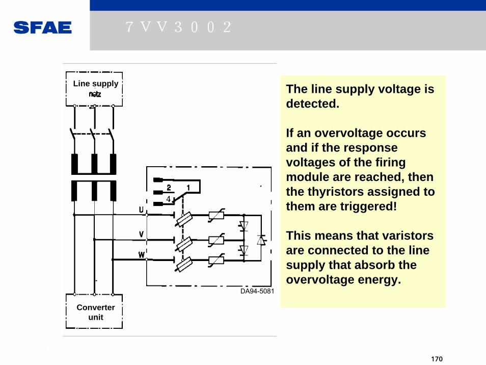
Line supply
Converter unit
DA94-5081
The line supply voltage is detected.
If an overvoltage occurs and if the response voltages of the firing module are reached, then the thyristors assigned to them are triggered!
This means that varistorsare connected to the line supply that absorb the overvoltage energy.
7VV3002

SFAE
171
Order No. [MLFB]Overvoltage protection
VRRM
(V)
VAN
(V)
VN
(V)
VV
(V)
7VV3002-3CD20
7VV3002-3AD207VV3002-3BD207VV3002-3GD207VV3002-3DD207VV3002-3ED207VV3002-3JD207VV3002-3KD207VV3002-3LD20
120014001600180022002500280032003500
110013001500170021002400260030003200
400420500540725850900
10901150
720720865865
12401480148018701870
7VV3002

SFAE
172
Order No. [MLFB]Overvoltage protection
UAN
(V)MLFB Simoreg
DC Master
7VV3002-3CD20
7VV3002-3AD207VV3002-3BD207VV3002-3GD207VV3002-3DD207VV3002-3ED207VV3002-3JD207VV3002-3KD207VV3002-3LD20
11001300150017002100240026003000
3200
6RA70..-.D...
6RA70..-.G...
Usupply
(V)
400
5756RA70..-.K...6906RA70..-.L...830
460 6RA70..-.F...420
900 6RA70..-.M...
7VV3002

SFAE
173
7VV 3002
The practical protection against subsequent damagecaused by line-side faulttrips.
7VV3002

SFAE
174
Load-side option (1-1)
2
L
1
3
4
7VV3003
C1
C
DD1
Rv5
6
7
XEW1
SICROWBAR DC is used to specifically dischargecapacitances or inductances and to protect theconverter against overvoltages(e.g. for excitation equipment for synchronousmotors fed through sliprings
SICROWBAR DC: 7VV3003 DC overvoltage protection
1…Line supply2...Converter3...Inductance as load4...Alternatively DC link capacitor as loadRv...de-excitation / discharge resistorC / D... thyristor switch connection5...Firing circuit6...Voltage sensing forde-excitation / discharge resistor7...Option G11, fast de-excitation
Circuit diagram of the application:

SFAE
175
Load-side option (1-2)SICROWBAR DC: 7VV3003 DC overvoltage protection
Order No. Firingvoltage [V]
Max. current[kA]
7VV3003-5AG32 800 2.57VV3003-5BG32 1200 2.57VV3003-5CD32 1600 2.57VV3003-5DG32 2200 2.57VV3003-5EG32 1600 5.87VV3003-5FG32 2200 5.87VV3003-5GG32 2600 5.87VV3003-5HG32 3000 5.87VV3003-5J7VV3003-57VV3003-5
G32 1600 10.5KG32 2200 10.5LG32 2600 10.5
7VV3003-5MG32 3000 10.5
The overvoltage protection function is connected in parallel to the loadInductive load: When the supply voltage fails,a voltage spike occurs at the load inductancewith opposite polarity to the voltage that was previously applied. When the firing voltage isreached, the protection thyristor is triggeredand reduces the load current according to adecaying exponential function. Resistance Rvreduces the time constant of the current decay.Capacitive load: Resistor Rv is always requiredto limit the maximum current.Alternatively, the protection thyristor can also be fired using option G11 (fast discharge).Suitable for both current directions: 1Q and 4QThe blocking voltage of the converter powersemiconductors must be >= the firing voltageof the 7VV3003
Type range:

SFAE
176
6RA23/286RA23/28系列直流调速系统系列直流调速系统

SFAE
177
6RA23/286RA23/28系列直流调速系统系列直流调速系统
6RA23/ 6RA28 SIMOREG K 整流器是用于直流调速的全数字控制的紧凑型整流
器,其结构紧凑,用于直流电机电枢供电完成调速任务。接入三相电源为直流变速
传动提供电枢和励磁电源,额定输出电流达30A~600A。并带有不可控的整流桥,
用于励磁回路供电。
根据不同的应用场合,可选择单象限或四象限工作的装置。装置本身带有参数设
定单元,不需其它任何附加设备便可完成参数的设定。所有的控制、调节、监控及
附加功能都由微处理器来实现,可选择给定值和反馈值为数字量或模拟量。
电枢回路为三相桥式整流电路:
单象限工作装置的功率电路为三相全控桥B6C。
四象限工作装置的功率电路为反并联三相全控桥(B6)A(B6)C,工作方式
为无环流。
所有的开环和闭环传动控制功能和通信由一个功能强大的16 位微处理器实现。
SIMOREG K 整流器是极其紧凑的。由于各个单体部件容易得到,所以为这种
30A~600A 的整流器的模块化设计提供了方便的服务。电子箱既适应于基本电子
板,也适应于任何其他的附加线 路板,并可被方便地打开或取出。

SFAE
178
6RA23/286RA23/28系列直流调速系统系列直流调速系统
外部信号(开关量输入/输出,模拟量输入/输出,脉冲
编码器等)与基本电子板相连接。
可以有二路模拟量输入,三路模拟量输出,四路开关
量输入和一路开关量输出。
SIMOREG 整流器可用装于电子板上一个简单的操作员
控制板上的三个键和三个7 段显示器来设置参数。整流
器也可用一台常用的PC 机及其相应的软件通过电子板上
的RS232 串行接口来设置参数。该PC 机接口用于启动、
关机时的维修服务或运行过程中的故障检测,这样它就
成了一个服务性接口。
对于额定电流为30A~600A 的整流器,电枢和
励磁的功率部分采用绝缘的晶闸管模块,这样其散热器
就是电绝缘的。强电联接部分的屏蔽罩子和端子盖防止
在整流器附近工作时的意外触碰。所有的接线端子都可
从前部接入。

SFAE
179
6RA286RA28系列直流调速系统系列直流调速系统

SFAE
180
6RA23/ 6RA286RA23/ 6RA28的框图的框图

SFAE
181
6RA23/ 6RA286RA23/ 6RA28的控制结构的控制结构

SFAE
182
6RA23/ 6RA286RA23/ 6RA28控制板间连接控制板间连接

SFAE
183
6RA23/ 6RA286RA23/ 6RA28的励磁回路的励磁回路

SFAE
184
30A-250A单象限整流器的主回路

SFAE
185
晶闸管模块的布局

SFAE
186
例: 6RA2331-6DS21-0的部件表

SFAE
187
400A与600A四象限整流器的主回路

SFAE
188
晶闸管模块的布局

SFAE
189
例:6RA2385-6DV61-0的部件表

SFAE
190
6RA23/ 6RA286RA23/ 6RA28各规格示意图各规格示意图

SFAE
191
6RA23/ 6RA286RA23/ 6RA28恢复出厂设置
恢复出厂设置:
若改变整流器软件,就必须执行“建立工厂设置”。若建立了定义的基本设置,例如为进行完全的新的启动,就可实施“恢复到缺省”状态。
1) 接通电子设备电源5U1,5V1,5W12) 设置P51=203) 设P87=3x。这样下列参数设定也可保存在EEPROM 中4) 手动设置下列参数到所需要的值(参见9.2 节“参数说明”)P93:额定电源电压/功率(铭牌)P98:电子设备电源的电压匹配
E00:配备的选件
5) 选择P52,转入值模式,并按上升键或下降键
6) 关掉电子设备的电源5U1,5V1,5W1 至少二秒,然后再合上。
出现运行状态o7电子设备电源必须至少保持15 秒,以便正确地完成“建立工厂设置”的功能。只有那样
参数值
才能被储存于EEPROM 中。键参数P51 重新为0 值。在这种状态下参数不可能改变了。
下列预先设置的参数不是由“建立工厂设置”来改变的:P93,P98 和E00

SFAE
192
用PCIN软件传输数据用的电缆
6RA28 整流器(X501)与PC 上带9 针SUBMIN D 连接器的串行接口的连接6RA28 整流器既不能进行硬件信息交换(CTS/RTS),也不能进行软件信息交换(XON/XOFF)。通电后,RTS 控制信号在RS232 上保持低电平(+10V),未计算CTS 控制信号。传送时PCIN 数据传送程序要求连接CTS 与DSR 控制信号。

SFAE
193
6RA23/ 6RA286RA23/ 6RA28用用PCINPCIN传送数据传送数据
1.连接6RA23/ 6RA28 整流器与
PC(PG);2.在PC(PG)上启动PCIN 程序;3.在PC(PG)上设置串口数据传送格式与波特率,功能键〈F5〉……安装,功能键〈F3〉…接口,6RA23/ 6RA28
整流器为标准设定(P97=015)时,PCIN 按如下配置:
波特率-9600;奇偶检验-偶;数据位-7;停止位-1;
4. 设置PC/PG 接收按功能键〈F8〉两次…返回主
菜单;功能键〈F3〉…文件功能,功能键〈F4〉…选择接收,定义文件名
和文件类型(文件名允许8 个字符,文件类型3 个字符)
按〈RETURN〉键后,PC/PG 准备接
收。
5. .用P51 选择需要的功能(在PC(PG)上输出参数
) P51=31
6. 按6RA23 /6RA28 上的方式键开始文件传送。
操作控制面板显示:
“III”自右向左跳动,表示正在输出显示的参数
。
终止数据传送接到终止标志符“40x〈ZERO〉”时,PC/(PG)准备接收状态自动停止,完整的传动
参数表保存在规定的文件名和文件类型下。
如果手动终止数据传送,按下PC/PG 上的〈F8〉
键,存储目前为止所接收的传动参数。
7. 按6RA23 /6RA28 上的下降键,自动终止数据
传送。如果在“读出”过程中产生故障信息,数据
传送立即终止。数据传送结束时, 6RA23
/6RA28 整流器处于现有运行状态。
8 .完成后P51 自动设置为零。
SFAE
194
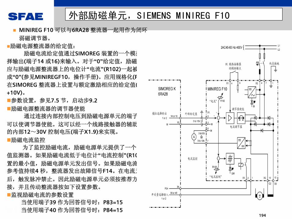
外部励磁单元,SIEMENS MINIREG F10
MINIREG F10 可以与6RA28 整流器一起用作为闭环
弱磁调节器。
励磁电源整流器的给定值:
励磁电流给定值通过SIMOREG 装置的一个模拟选
择输出(端子14 或16)来输入。对于“0”给定值,励磁电流
应与励磁电源整流器上的电位计“电流”(R102)一起被设置
成“0”(参见MINIREGF10,操作手册)。应用规格化(P76)在SIMOREG 整流器上设置与额定激励相应的给定值(0~+10V)。参数设置,参见7.5 节,启动步9.2
励磁电源整流器的调节器使能
通过连接内部控制电压到励磁电源单元的端子X1.4
可以使调节器使能。这可以经一个线路接触器的辅助触点
的内部12~30V 控制电压(端子X1.9)来实现。
励磁电流监控
为了监控励磁电流,励磁电源单元提供了一个限幅
值监测器。如果励磁电流低于电位计“电流控制”(R106)设
置的 小值,励磁电源单元发出信号。如果励磁电流低于
参考值持续4 秒,整流器发出故障信号F14。在电流为0
后,触发脉冲禁止。因此励磁电源单元必须按推荐方法联
接,并且传动整流器按如下设置参数。
监视励磁电流的参数设置
当使用端子39 作为回答信号时:P83=15当使用端子40 作为回答信号时:P84=15

SFAE
195
SIEMENS MINIREG F33 外部励磁电源整流器
MINIREG F33 可以与6RA28 整流器一起用作为闭环弱磁
控制。
励磁电源整流器的给定值励磁电流给定值经一模拟选择输出(端子14 或16)从
SIMOREG 整流器送入。在给定值为“0”时,励磁电流应被
励磁电源整流器上的R120 设置成“0”。应用规格化(P76),和/或用励磁电源整流器上的R121,在SIMOREG 整流器上
设置与额定励磁相应的给定值(0 到+10V)(参见
MINIREGF33,操作手册)。参数设置,参见7.5 节,启动步9.2励磁电源整流器的调节器使能用励磁电源整流器的端子X1.4 处的内部控制电压使调节
器使能。为此,例如可以经一线路接触器的辅助触点来使用
内部P24 控制电压(端子X1.5)。励磁电流监控
为了监控励磁电流,励磁电源单元提供了一个限幅值
监测器。如果励磁电流低于电位计“电流控制”(R106)设置的
小值,励磁电源单元发出信号。如果励磁电流低于参考值
持续4 秒,整流器发出故障信号F14。在电流为0 后,触发
脉冲禁止。因此励磁电源单元必须按推荐方法联接,并且传
动整流器按如下设置参数。
监视励磁电流的参数设置
当使用端子39 作为回答信号:P83=15;当使用端子40 作为回答信号:P84=15;

SFAE
196
数字化的定子调压调速系统数字化的定子调压调速系统
SIMOTRAS HDSIMOTRAS HD

SFAE
197
数字化使传统的定子调压驱动技术焕发新的生机

SFAE
198
产 品 概 况
西门子维也纳工厂生产; 1999年左右推出
SIMOTRAS HE(6GA4625)系列的后继产品
系列名称: SIMOTRAS HD 6SG70
独特的开发方式---与SIMOREG6RA70系列产品孪生
独特的开发方式使它具有了独特的生命力
主控制板与直流调速产品完全相同---CUD1/CUD2
从软件版本V1.5开始CUD1的firmware集成了HD功能
系统软件与直流调速产品同步升级---当前版本V2.14

SFAE
199
SIMOTRAS HD –结构概览

SFAE
200
SIMOTRAS HE(6GA4625)系列

SFAE
201
概念回顾 ---绕线转子异步电动机
结构特点:转子为与定子绕组类似的绕组结构;具有集电环和碳刷结构;
性能特点:起动电流小(可通过转子外接电阻限制—减
小 冲击电流与冲击转矩);起动转矩大,可以等于临界转矩;控制特性软;
典型应用对象:起重设备的起升/俯仰机构—位能性负载的
驱动;起重设备的平移/回转机构—磨擦性负载的
驱动;典型产品:•西门子– 1LT3;1LT6; 1LT8;1LT9;
1LV3;1LW4等系列;•国产– YR; YZR等系列;

SFAE
202
西门子1LT8绕线转子滑环异步电动机
n0

SFAE
203
概念回顾 ---交流绕线转子异步电动电机的调速
由
转子串电阻的调速属于调S方式
特点:特性软;调速范围受转矩影
响,轻载时调速范围小;转差功率变成热
能消耗在转子回路上。
定子回路的调压调速
不属于上述三种方式。开环时,调速
范围很小,与直流电机的调电枢电压的调
速特性不可同日而语,故无实用价值。但
在加入测速元件,形成转速闭环以后,则
调速范围和特性硬度均得到改善,调速比达1:10-20,可适用于起重设备的要
求。
串级调速
转差功率可回馈电压,但功率回数很
低,已不代表发展方向。
pfn 60
0 =)1(60 s
pfn −=
0
0
nnns −
=

SFAE
204
概念回顾 ---转子串电阻的起动及调速特性及电阻
SFAE
205
概念回顾 ---转子反转的反接制动
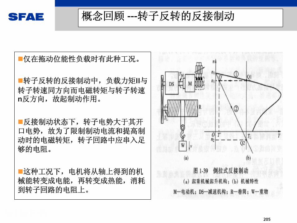
仅在拖动位能性负载时有此种工况。
转子反转的反接制动中,负载力矩II与转子转速同方向而电磁转矩与转子转速n反方向,故起制动作用。
反接制动状态下,转子电势大于其开口电势,故为了限制制动电流和提高制动时的电磁转矩,转子回路中应串入足够的电阻。
这种工况下,电机将从轴上得到的机械能转变成电能,再转变成热能,消耗到转子回路的电阻上。
SFAE
206
概念回顾 ---定子反接的反接制动
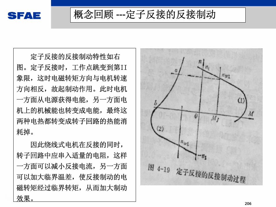
定子反接的反接制动特性如右
图。定子反接时,工作点跳变到第II
象限,这时电磁转矩方向与电机转速
方向相反,故起制动作用。此时电机
一方面从电源获得电能,另一方面电
机上的机械能也转变成电能,最终这
两种电热都转变成转子回路的热能消
耗掉。
因此绕线式电机在反接的同时,
转子回路中应串入适量的电阻,这样
一方面可以减小反接电流,另一方面
可以加大临界温差,使反接制动的电
磁转矩经过临界转矩,从而加大制动
效果。

SFAE
207
概念回顾 --- 磨擦性负载的四象限运行

SFAE
208
概念回顾 --- 位能性负载的四象限运行

SFAE
209
SIMOTRAS HD –起升控制特性与走行控制特性

SFAE
210
SIMOTRAS HD涉及的技术基础
综合上述回顾的概念,定子调压调
速系统在工作中涉及下列工况:
具有转速闭环的定子调压调速
转子串电阻的启动制动与调速
转速反向的反接制动(位能性负载
时)
定子反接的反接制动
上述这些工况结合以后,所得到
的控制方式,大大地改善了低速段的
工作特性,使得除能耗以外的技术性
能接近直流调速与交流变频技术。

SFAE
211
SIMOTRAS HD – 一般介绍 (1)
数字式三相控制装置,用于转子滑环电机的控制, 以SIMOREG DC-MASTER 为基础开发.与 SIMOVERT MASTERDRIVES 和SIMOREG DC-MASTER 具有相同的操作控制及通讯方式。
速度/电流双闭环控制系统
五组SCR反并联的主回路结构(含反接回路)动力电源电压范围:3-ph. 110 V AC to 500 V AC (+/- 10%)电流范围: 60 A to 900 A调试和基本的诊断可通过操作面板完成,可以不需要其它的仪器和设备.
左图: SIMOTRAS HD, 额定电流 142 A

SFAE
212
SIMOTRAS HD -一般介绍 (2)
OP1S-操作面板 (选件),具有文本显示功能,
用于起动过程主要参数的显示和装置设置参数的
管理及传输。
可通过DRIVEMONITOR软件进行参数设置,起
动,参数备份和调试。
多种通讯功能。
左图: SIMOTRAS HD, 额定电流 525 A带有 OP1 S

SFAE
213
SIMOTRAS HD -一般介绍 (3)
隔离输入(1-ph. 230 V AC ),具有 LED 状态显示。
继电器隔离输出,具有 LED 状态显示。
200% 过载能力,20 s,载荷周期:150 s装置运行的环境温度:--普通型: 0 - 40 °C;(装置 ≤ 78 A: 45 °C)。--高温型: 0 - 65 °C。
左图:电子箱和电源部分, 525 A

SFAE
214
SIMOTRAS HD - 主要特点 (1)
在额定速度的+/- 60 % 范围内,可实现与负载无关的连续闭环速度控制;额定速度的60 % - 100 %的范围是开环控制区, 通过切出转子电阻实现加速。
动力电源通过电子式换相实现四象限驱动。
多可通过继电器隔离输出控制四级转子电阻。
转子接触器无电流通/断。
开环与闭环控制范围之间的转换平稳。
起动脉冲,避免了起升和下降过程中的负载‘溜钩’现象。
给定输入可通过:模拟速度给定, 多级主令开关, 或PROFIBUS DP可分别设定斜坡函数发生器的上升和下降过程,用以调整加速和减速时间。

SFAE
215
SIMOTRAS HD - 主要特点 (2)
完善的制动控制功能。
多种状态, 报警及故障信息,比如:过热,断相以及速度给定-实际值监控.所有的,重要的控制量,比如: 电流实际值, 速度等可以通过模拟量输出,或通过接口接到 PC上.可实现开环主/从控制(两台装置并联). 数据传输通过装置上的串行接口完成。
模拟测速机,或脉冲编码器作为测速元件。 (脉冲编码器的15 V 电压可来自装置。
用于电动机的KTY 84 或 PTC 温度元件可与装置连接,用以监控电动机的发热。
所有的主令信号通过端子或通过PROFIBUS DP输入。
自由功能块用于算术运算,闭环及逻辑操作。

SFAE
216
SIMOTRAS HD - 主要特点 (3)
高动态性能的速度及转矩闭环控制保证了起重机的稳定运行和高生产率。
调试可通过操作面板OP1S或PC+DRIVEMONITOR程序完成. BICO 技术使装置的应用更灵活:- 装置的端子, - 通讯接口的信号,- 端子括展模板, - 自由功能块的使用。
可采用端子括展模板CUD2, EB1 或 EB2。可采用T100, T300 或 T400 工艺板。

SFAE
217
SIMOTRAS HD –主回路结构

SFAE
218
SIMOTRAS HD –接线举例

SFAE
219

SFAE
220
SIMOTRAS HD 装置 - 大到 40 °C
装置型号 额定 冷却 外形尺寸 重量电流 方式 ( mm) ( kg)
6SG7050-0EB60-0 60 S 385 x 265 x 283 166SG7052-0EB60-0 78 S 385 x 265 x 283 166SG7055-0EB60-0 98 L 385 x 265 x 283 166SG7060-0EB60-0 112 L 385 x 265 x 283 166SG7062-0EB60-0 142 L 385 x 265 x 283 176SG7065-0EB60-0 180 L 385 x 265 x 283 176SG7070-0EB60-0 225 L 625 x 268 x 318 306SG7072-0EB60-0 285 L 625 x 268 x 318 306SG7076-0EB60-0 360 L 625 x 268 x 318 306SG7080-0EB60-0 525 L 700 x 268 x 362 456SG7082-0EB60-0 680 L 780 x 406 x 362 856SG7085-0EB60-0 900 L 880 x 450 x 500 137
装置运行环境温度从 0°C 到 40°C (45°C)

SFAE
221
SIMOTRAS HD 装置 - 大到 65 °C
装置型号 额定 冷却 外形尺寸 重量电流 方式 ( mm)( kg)
6SG7050-0EB60-0-Z 42 S 385 x 265 x 283 166SG7052-0EB60-0-Z 55 S 385 x 265 x 283 166SG7055-0EB60-0-Z 70 L 385 x 265 x 283 166SG7060-0EB60-0-Z 80 L 385 x 265 x 283 166SG7062-0EB60-0-Z 100 L 385 x 265 x 283 176SG7065-0EB60-0-Z 125 L 385 x 265 x 283 176SG7070-0EB60-0-Z 150 L 625 x 268 x 318 306SG7072-0EB60-0-Z 200 L 625 x 268 x 318 306SG7076-0EB60-0-Z 250 L 625 x 268 x 318 306SG7080-0EB60-0-Z 365 L 700 x 268 x 362 456SG7082-0EB60-0-Z 475 L 780 x 406 x 362 856SG7085-0EB60-0-Z 700 L 880 x 450 x 500 137
装置运行的环境温度从 0°C 到 65°C
Z =78

SFAE
222
SIMOTRAS HD 主/从结构可 多6台并联使用,电流容量可括展到>5000A

SFAE
223
SIMOTRAS HD –基本控制接口(位于电源板)

SFAE
224
SIMOTRAS HD - 外部接口概况
8 数字可选择输入, 控制电压 1-ph. 230 V AC,具有 LED 状态显示。
8 继电器可选择输出, 250 V, 2 A AC, LED 状态显示。
4, 24 V 数字输入, 其中 3 个 作为可选择输入。
2, 24 V 数字可选择输出, 大 100 mA, 防短路。
2 差动模拟可选择输入, 可在 0/ 4 to 20 mA 与 +/- 10 V 之间转换, 分辨率 +/- 14 字。
2 模拟可选择输出, +/- 10 V, 小分辨率 +/- 11 字。
模拟输出, +/- 5 V 与装置的额定电流相对应。
可连接脉冲编码器或DC 测速机。
24 V, 200 mA 用于数字信号;15 V, 200 mA 用于脉冲编码器。
+10 V, -10V, 10 mA 参考电压源,防短路。
2 串行接口用于 USS (比如,连接 SIMOVIS-PC)和 装置 到 装置 (比如,用于两台装置在主--从结构下的闭环转矩控制的指令信
号的传输。
SFAE
225
SIMOTRAS HD –通讯功能
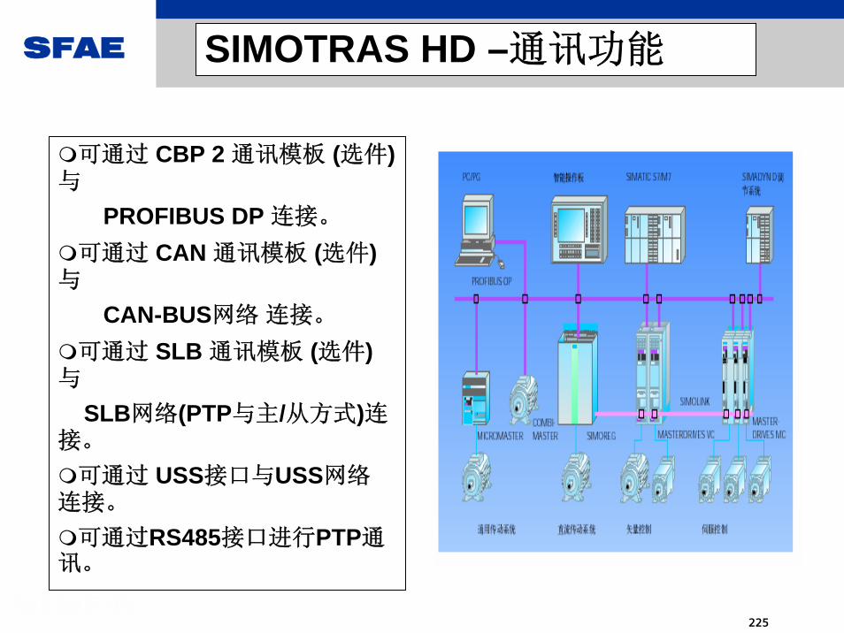
可通过 CBP 2 通讯模板 (选件)与
PROFIBUS DP 连接。
可通过 CAN 通讯模板 (选件)与
CAN-BUS网络 连接。
可通过 SLB 通讯模板 (选件)与
SLB网络(PTP与主/从方式)连接。
可通过 USS接口与USS网络连接。
可通过RS485接口进行PTP通讯。

SFAE
226
驱动设备相连的 PROFIBUS 净数据块结构
TYP 1
TYP 2
TYP 3
TYP 5
TYP 4
PPO PKE IND PWE PZD1 PZD2 PZD3 PZD4 PZD5 PZD6 PZD7 PZD8 PZD9 PZD10
PKE: Parameter IDIND: Index (3rd byte),PWE: Parameter value
参 数 码 区 过 程 数 据 区
PZD: Process dataSTW: Control wordZSW: Status wordHSW: Main setpointHIW : Main actual value
PPO: Parameter Process data Object

SFAE
227
SIMOLINK 通讯
装置间的高速点对点通讯
与主设备的高速点对点通讯
塑料光纤闭合环网
适用于高要求的主/从连
接
抗干扰的高质量通讯

SFAE
228
6SG70与6RA70的主要共同点
主控制电子模块CUD1与CUD2采用相同的硬件及接口
双闭环控制结构与参数基本相同
装置的功率单元定义方式相同,用户参数的存贮相同,因为具有相同的A7009模块
通讯接口方式相同PROFIBUS SLB USS P-t-P等
参数的修改方式相同
有相当一部分定义及参数号亦相同
外型相同(主回路端子除外)
自由功能块相同

SFAE
229
6SG70与6RA70的主要不同点
主回路结构及连接对象完全不同
电源板上的接口大多不同--限位开关接口 转子电阻切换接口
基本功能即包括S00选件不必另购
6SG70无励磁回路
出厂状态不同:6RA70_基本上是运行准备好状态6SG70_基本上是运行限制状态(开机F024)
根本差异在于:6SG70具有K部分控制逻辑连接
6SG70不具备SCR测试功能
6SG70不具备闭环控制结构的自优化功能

SFAE
230
SIMOTRAS HD测试性运行的可能性(1)
由于SINOTRAS HD主要应用对象为起重设备,其出厂设置使用自由功能
块功能进行了一些必要的控制关系连接,例如:斜升功能与给定使能的控
制;报闸控制;终端限位对运行的限制等关系使得出厂状态的系统基本处
于保护性控制状态,在外围条件不具备时,似乎很难使它进入工作状态,但
这是可改变的.
一般说来,如欲正常地启动系统,需要外围电路进行配合,这包括:
电机应是一台绕线式异步机
转子部分有电阻切换回路
有抱闸回路,且有返回信号
给定的加入应按起重设备习惯
具有响应终端开关信号
必须有速度反馈元件

SFAE
231
SIMOTRAS HD的测试性运行的可能性(2)
在简化条件下运行:
可以使用一台笼型异步机+测速元件的结构进行测试性运行.但需注意
理论上讲,定子调压设备是不能用于笼型异步机的,因转差功率的耗散会
使转子部分异常发热,所以,整个实验过程必须人为加以限制
需要考虑:抱闸监控;给定连锁;终端开关状态;模拟给定等
这种情况下,要正常地进行转子电阻的有级切换不可能,但可检查切换
电阻的动作

SFAE
232
SIMOTRAS HD - 改造旧起重机的优点
装置的输入端接动力电源,输出端接转子滑环电动机的定子。
保留所有的必要开关元件,包括电动机和转子电阻。
起重机的运行特性将得到显著的提高。改造费用低;同时,起重机的机械
部件会得到有效的保护。
起重机的生产率将得到极大的提高。
SIMOTRAS HD 适宜旧起重机的改造,因为输入和输出的电源是 单相
230V。
SIMOTRAS HD 可与 PROFIBUS DP 连接. 控制信号既可以通过
PROFIBUS DP 输入,也可以通过端子输入。
SIMOTRAS HE 很容易由 SIMOTRAS HD取代, 因为 SIMOTRAS HD 通过
参数设定可具有所有的SIMOTRAS HE功能。

SFAE
233
SIMOTRAS HD –启动与调试步骤
1 . 内部和外围的连接检查无误后,接通装置电源。
2.恢复出厂设置。
3.基本参数设置(电机,接口,反馈方式,电流与速度限制等)。
4. 用调试控制的方式接通装置,进行电流环的调试,确定电流环的
Kp与Tn 等。
5. 速度环调试:
确定主/从结构时各电机的旋转方向;
主方式装置的速度反馈校正;
速度环的Kp与Tn,斜坡给定等的确定,初步的速度环优化;
转子电阻切除的档位的切换动作验证;
全程调速性能的检验。

SFAE
234
SIMOTRAS HD –启动与调试步骤(续)
6. 空载调试结束,起升机构可穿绳,走行机构可连接机械负载。
7.带载后根据运行特性的要求进一步施行优化(电流环与速度环)
调整 ,从而确定动态与静态的 佳运行特性。
这一步需借助示波器或DRIVEMONITOR软件的波形显示功能完成。
8. 调试完成,用DRIVEMONITOR软件或OP1S 进行参数的备份。
总的来说,数字化的SIMOTRAS HD 的调试较之模拟装置而言方
便了许多,也更安全。

SFAE
235
MICROMASTER 4MICROMASTER 4标标 准准 型型 变变 频频
器器
MICROMASTER 4MICROMASTER 4标标 准准 型型 变变 频频 器器

SFAE
236
MicorMaster 4系列变频器
MicroMasterMicroMaster 420420 经济通用型经济通用型
MicroMasterMicroMaster 430430 风机水泵专用型风机水泵专用型
Micro Master 440Micro Master 440 适用于一切传动装置适用于一切传动装置
功率范围: 0.12-250kW输入电压: 1AC 200 ~ 240V
3AC 200 ~ 240V3AC 380 ~ 480V3AC 500 ~ 600V
功率范围: 0.12-11kW输入电压: 1AC 200 ~ 240V
3AC 200 ~ 240V3AC 380 ~ 480V
功率范围: 7.5-250kW输入电压: 3AC 380 ~ 480V

SFAE
237
功率范围 : 120W - 750W
供电电压 : 115V or 230V 单相, 230V 3相
多种安装方式, 无风扇
控制模式: V/F, FCC
端子: 3DI, 1DI, 1AI, RS485
过载能力: 150%, 60S
参数码及用户界面与 M420 和 MM440兼 容
接触器式变频器, 适用于简单速度控制
•Mitsubishi: S500 •Telemecanique: ATV08•Yaskawa: VS-mini J7•Lenze (former ACTech): 8200 •Hitachi: L100•ABB: ACS100•SEW: Movitrac 07
MICROMASTER 410 ---低成本变频器

SFAE
238
MICROMASTER 411--- 电机/变频器一体化
主要应用场合:
※ 现场安装空间有限
※ 应用环境较恶劣
※ 有EMC干扰设备的场合
※ 要求能连到ASI总线
主要特点:
※ 与MM420/440 兼容的参数及外围选件
※ 0.12 – 7.5KW
※ 可连PROFIBUS,AS-I 通讯总线
※ IP66高防护等级,适用任何恶劣环境
※ 高性能的集成马达

SFAE
239
MICROMASTER 420420 - 经济通用型变频器
输入电源:230V单相/三相,380V三相
输出功率:0.12kW~11kW
控制接口:
3个带隔离的数字输入,
1个模拟输入(0-10V或0-20mA)
1个继电器输出
1个模拟输出(0-20mA)
V/f, V2/f,可编程的V/f,FCC 四种控制模式

SFAE
240
I/O 功能更强大,可以自定义
直流制动和复合制动功能
PI控制可在线切换到常规的频率控制
频率设定源可灵活的叠加,切换
PROFIBUS通讯可集成到高层自动化系统中
二套斜坡加减速可在线切换
优化的马达模型使变频器的保护特性更精确
BICO技术的采用使软件功能更强大
参数加密功能确保数据不会更改
MICROMASTER 420420的功能特点

SFAE
241
380-480V AC ± 10% 三相交流
功 率 范 围: 7.5kW~250kW (VT)控制接口
6个 数字输入 (可 PNP/NPN 切 换)
2个 模拟输入
3个 数字输出(继电器输出)
2个 模拟输出)控 制 方 式 : V/f, V2/f, 多 点 V/f, FCC丰富的风机水泵专用的功能
MICROMASTER 430430 – 风机水泵专用型
SFAE
242
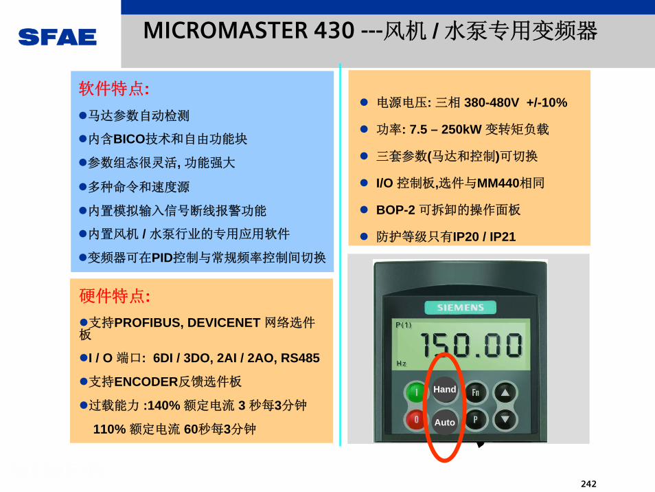
电源电压: 三相 380-480V +/-10%
功率: 7.5 – 250kW 变转矩负载
三套参数(马达和控制)可切换
I/O 控制板,选件与MM440相同
BOP-2 可拆卸的操作面板
防护等级只有IP20 / IP21
MICROMASTER 430 ---风机 / 水泵专用变频器
硬件特点:支持PROFIBUS, DEVICENET 网络选件
板
I / O 端口: 6DI / 3DO, 2AI / 2AO, RS485
支持ENCODER反馈选件板
过载能力 :140% 额定电流 3 秒每3分钟
110% 额定电流 60秒每3分钟
软件特点:马达参数自动检测
内含BICO技术和自由功能块
参数组态很灵活, 功能强大
多种命令和速度源
内置模拟输入信号断线报警功能
内置风机 / 水泵行业的专用应用软件
变频器可在PID控制与常规频率控制间切换
Hand
Auto

SFAE
243
Mains
Inverter Motor StartersPressure Sensor
To Inverter PID Input
MICROMASTER 430 – 分段控制
马达分段控制:> 变频器依据PID的信号自动控制其它泵/风机的 起/ 停
> 一台变频器只能控制 多3台附加泵/风机
> 主要应用:冷却塔,恒压供水,潜水泵,空调系统等

SFAE
244
MICROMASTER 430 –节能应用
节能控制:> 变频器依据一些条件控制马达的起动与停止
> 一台变频器只能对一台马达进行节能控制
> 主要应用:工艺控制要求不高但要求节能的场合如送风机

SFAE
245
针对风机水泵的特殊功能
断带检测 (MM4)通过设置力矩区域,可以检测力矩异常适用于:水泵缺水 、传输带断裂
多泵循环起动在PID控制信号作用下,通过接触
器,多可控制三台辅助电机
节能功能(睡眠功能)在规定时间内,没有负载可自动断开电机
旁路功能将电机切换到直接用电网供电运行接触器需要有机械互锁
本地/远程切换
T
f
MM430
Hand Auto

SFAE
246
MICROMASTER 430430 性能指标
固 定 频 率 15 个跳 转 频 率 4 个
内 置 串 行 通 讯 接 口内 部 互 连 采 用 BiCo技 术
集 成 的 / 带 辅 助 底 板 的 滤 波 器 (A, B)便 于 接 线 和 用 颜 色 编 码 的 接 线 端 子
防 护 等 级 IP20 / NEMA 1通 过 了 CE, UL, CUL和 c-tick 的 认 证
专 用 的 风 机 和 泵 类 控 制 软 件
直 流 制 动 和 复 合 制 动 功 能
具 有 完 善 的 故 障 检 测 和 保 护 功 能

SFAE
247
电源电压: 380~480V ±10%,三相交流
500---600V ±10%, 三相交流
200---230V ±10% 单相/三相交流
功率范围: 0.12 KW — 250 KW
数字量输入:6个(可编程且可PNP/NPN切换)
+2个 (模拟输入作为数字输入)
继电器输出:3个可编程
30V DC/5A (电阻性负载)
250V AC/2A(电感性负载)
MICROMASTER 440440 - 技术性能概要

SFAE
248
MICROMASTER 440
• 控制板上的3个继电输出230VAC 或 24VDC 输出
• 2 个模拟输入0-10V 电压或0-20MA电流
• 6个数字输入全部隔离. 另外2个模拟输入可以组态为第7,8个数字输入
• 内置集成制动控制单元允许直接连接制动电阻构成外部制动
• 2 个模拟输出0 to 20mA.输出可被编程来输
出多种变量
• PTC 和 KTY84 输入实现温度监测和报警
• 过载能力过载能力:1.5:1.5倍倍6060S/5S/5分分, 2, 2倍倍33S/1S/1
分分
• 丰富的选件
硬件特征:
• 更快的响应时间 - 6ms +/- 1/2ms
• 无测速机矢量控制模式
• 转矩控制模式
• 三套参数选择, 切换
• 多种固定频率模式选择
• 恒转矩和变转矩选择
• 速度控制模式 - 带或不带脉冲编码
器
• 自动调整的PID控制器
• 可连同步电机
• 直流制动,动力制动,DC电压控制器
• 支持PROFIBUS 等现场总线
• BICO 技术 和自由功能块
软件特征:

SFAE
249
MICROMASTER 440440的性能特性
高性能的PID控制器,两种控制模式,参数自动整定
内置直流注入制动
复合制动,改善了制动的性能
动态缓冲
定为控制
快速电流限制功能,预防运行中不应有的跳闸
恒转矩和变转矩选择 (P0205, P0500)
三套参数选择 (电机,命令和设定值)
自由功能模块
线性V/f,FCC的V/f,抛物线的V/f,特性可编辑的V/f控制
有/无传感器的矢量,有/无传感器的转矩控制等

SFAE
250
自动化系统 通讯 接口
可以通过选配的各种通讯接口选件,灵活的与各种上一级自动化系统的通讯,实现对MM4变频器的远程控制
PFIRBUS 速度可达 12Mbps 也可以使用外接的24V电源
DeviceNet 在美洲市场广泛采用, 高速度为500kbps.
CANopen 支持1Mbps的速率
RS-485 / RS-232 支持开放的USS协议,无须选件即可使用485接口连接总线
支持TIA、SIMOTION。理想的自动化系统的驱动选择

SFAE
251
MM440选件:编码器模块
光电编码器,是一种通过光电转换将输出轴上的机械几何位移量转换成脉冲或数字量的传感器。
与 所 以 MM440 变 频 器 匹 配操 作 在 矢 量 模 式 下。
功能电机在零速时允许满负载运行高精度的速度控制提高速度和转矩控制动态响应特性
安装和使用可以直接安装在I/O模板上PROFIBUS和BOP/AOP也可以同时使用。支持TTL/HTL两种类型支持 5V,18V供电。

SFAE
252
AC 输 入 电 抗 器
( 用 于 低 阻 抗 电 网)
输 出 电 抗 器
( 确 保 变 频 器 长 电 缆 运 行)
MM4的公共选件:电抗器和滤波器
A级背板式滤波器(仅针对400VFSA变频器)
附加B级滤波器(可加到已配有滤波器的变频器上)
低漏感B级滤波器(可加到未配有滤波器变频器上)
防止变频器对电网的干
扰,符合欧洲
EMC标准

SFAE
253
� PID PID 控制的设定源控制的设定源, , 反馈源选择反馈源选择, , 控制模式控制模式
MICROMASTER 4 – 强大的 PID 功能

SFAE
254
MICROMASTER 4 – PROFIBUS 通讯功能
A&D SD 20.06.02 254/02A&D SD 20.06.02 254/02
F1
F3
F5
F7
F9
F11
F2
F4
F6
F8
F10
F12
F14 F15 F16 F17 F18 F19 F20
K3 K4 K5 K6 K7 K8
K11 K12 K13 K14 K15 K16
K1 K2
K10K9
0258
369
.147
++-*/
A Z
DELINS
A C E GB D F H
I K M OJ L N P
Q S U WR T V X
Y : = (Z \ , )
TAB
ALT
CTRL
S HIFT
A-Z
K H
F13
1
6 71
SIMATICS7
SIMATICM7
PROFIBUS-DP
STEP7 V5.1Drive ES
Basic V5.1Drive ES
PCS7 V5.1Drive ES
SIMATIC V5.1

SFAE
255
MICROMASTER 4 - USS通讯功能
USS 通讯 方案:
> S7-200 PLC ,S7-300C (PTP) , S7-300/400 PLC+CP340/441
> PC + VB / VC + RS232/RS485 转换器
> HHK + AOP + RS232/RS485 转换卡
MM420PLC
MM420
MM440
1415
2930
1415
Other controls and sensors
MM4 变频器内带RS485口,支持USS通讯:

SFAE
256
重要参数设置:
•P1000 = 3 用固定频率•P701 = 17: Dig In1•P0702 = 17 Dig In 2•P0703 = 17 Dig In 3•P1001-7 FF1 - FF7
•Din 3 Din 2 Din 1Result •0 0 0 Off•0 0 1 FF1 (P1001) •0 1 0 FF2 (P1002) •0 1 1 FF3 (P1003) •1 0 0 FF4 (P1004) •1 0 1 FF5 (P1005) •1 1 0 FF6 (P1006)
•1 1 1 FF7 (P1007)
MM420DIN2 6
DIN3 7
24V 8
DIN1 5
MICROMASTER 4 - 固定频率功能
多种固定频率选择模式 :> 直接选择
> 直接选择加ON命令
> 二进制编码选择
> BICO 技术选择
用固定频率时,客户受益处:> 多段速度选择 , 多达15种
> 应按用BICO,选择方式灵活
> 频率和命令一同选择,可节省
I / O 端子

SFAE
257
MM440
Braking Resistor
重要参数设置:
P1215-7 机械抱闸参数P1300 = 20 使用无速度传感器矢量控制P1237 = 5 设定动力制动率P1130-4 设定加减速曲线
马达参数必须正确设定
MICROMASTER 4 - 制动控制功能
多种制动控制模式 :
> DC 制动
> 直接电压控制器
> 复合制动
> 动力制动
用制动时,客户受益处:
> 在制动不频繁时可节省成本
> 已內置制动单元
> 避免过电压跳闸
> 可应用于简单定位

SFAE
258
MICROMASTER 440
Torque SlavesMaster
Speed control Torque control Torque control
转矩控制模式 :
> 变频器工作: 主 / 从控制( 从站可工作为速度或转矩模式)
> 要求 PROFIBUS 通讯, 矢量控制模式
转矩控制模式主要应用 :
> 速度同步, 负荷分配控制要求如线缆开卷,收卷等
闭环力矩控制,允许实现主从方式的变频器控制

SFAE
259
MICROMASTER 430/440 –应用软件
P2186Lower torque threshold 1
P2185Upper torque threshold 1
P2188Lower torque threshold 2
P2187Upper torque threshold 2
P2190Lower torque threshold 3
P2189Upper torque threshold 3
P2182Threshold frequency 1
P2183Threshold frequency 2 P2184
Threshold frequency 3
Torque [Nm]
Frequency [Hz]
机械故障监测:> 变频器依据力矩与速度信号监测机械故障,以减少设备的损害
> 必须十分了解机械的这种工作保护特性
> 主要应用:水泵是否空,皮带是否断等信号监测要求的场合

SFAE
260
编码器板技术参数:>数字式编码器(HTL/TTL)
> 大脉冲频率300KHZ
>编码器: 60-5000个脉冲/ 转
>编码器电源: DC 5V, 15V, 24V
编码器闭环控制具有以下优点 :
>低速时仍然具有额定转矩的负载能力
>速度控制和转矩控制的动态性
能得到改善
>速度控制的精度高
编码器闭环控制方式典型应用场合 :
>造纸机械,印刷机械
>纺织,印染机械,
> 皮带传输
> 提升机械
MICROMASTER 440 – 编码器反馈功能
编码器闭环控制:>简单的参数设定, 0.2%控制精度
>可实现闭环转矩控制

SFAE
261
MICROMASTER 4 - BICO应用
使用BICO 来选择PID 使能信号
使用BICO 来启动 / 停止变频器
使用BICO 来连接频率设定信号
使用BICO 来使能继电器输出
使用BICO 来远程监视变频器或马达温度
使用BICO 来改变通讯控制字
参数设定:1. 设 P809[0]=0, P809[1]=1 , P809[2]=1. 拷贝参数
2. 设 P703[0]=99, P703[1]=99
3. 设 P1000[0]=2, P1000[1]=7
4. 设 P810=722.2 AIN2
AIN1
MM440
switch
Start/stop
正常速度由模拟输入1决定, 端子3接速度由模拟输入2决定
例子: 模拟输入1 / 模拟输入2切换

SFAE
262
MICROMASTER 4 – 柜门安装选件
适用于单台变频器的柜门安装选件
BOP 或 AOP可用
设定P700=4, P1000=4
3 米标准电缆 ( UP TO 20 M)
RS232 接口( 共4 线: 24V DC. 2根数据线)
适用于多台变频器的柜门安装选件
AOP选件,要求24V DC
设定P700=5, P1000=1
有RS232 和 RS485接口, RS485 连接多台变频器 , RS232连接PC

SFAE
263
Drive Monitor / Starter—方便的调试工具
其它软件工具:>选型软件--- SELECTOR
>费用节省计算软件--- MASTERSAVE
>谐波含量计算与标准软件--- HARMAC
>变频器连接到PROFIBUS网络的软件---DRIVE ES

SFAE
264
MICROMASTER 440也是用于驱动方案业务的驱动系统,它同样是
一种杰出的驱动系统,具有以下优点:
极高水平的标准化这主要体现在所有的MICROMASTER 4 系列驱动器具有相同的
参数结构。而这种结构同样是SINAMICS 这一全新 A&D 驱动概念的基础
可扩展性和高度的灵活性这一点由其模块化设计决定
模块化设计也意味着MICROMASTER 4 系列驱动器的零件可以创新。它还使我们能对市场需求做出快速反应,同时保护我们的投资。
这种创新观念使我们的产品系列可以适用于许多应用,同时,这种不断创新和前进的观念也增加了我们的市场潜能
卓越的性能价格比
MICROMASTER 4MICROMASTER 4标标 准准 型型 变变 频频 器器

SFAE
265
MM4功能:电机过热和过载保护
可通过PTC,KTY温度传感器,以及无传感器观测的方式获取电机温度
数据。
断线检测
电机热学模型
≥ xx℃
KTY
PTC
+
报警 自动降容
报错F0011
设定过温应对措施
电机温度检测
电机过温保护

SFAE
266
MM4停车与制动
OFF1—斜坡停车OFF2—惯性自由
停车OFF3—快速停车
直流制动
抱闸制动
耗能制动
复合制动
根据斜坡设定
f
t
f
t根据负载惯量
MM440(75kW及以下)
内置制动单元
根据Vmax限定
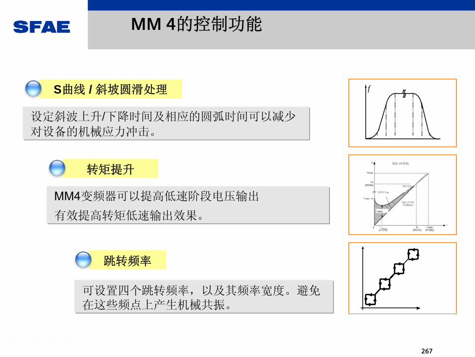
SFAE
267
设定斜波上升/下降时间及相应的圆弧时间可以减少
对设备的机械应力冲击。
f
MM 4的控制功能
MM4变频器可以提高低速阶段电压输出
有效提高转矩低速输出效果。
可设置四个跳转频率,以及其频率宽度。避免在这些频点上产生机械共振。
跳转频率
S曲线 / 斜坡圆滑处理
转矩提升

SFAE
268
自动应对各种状况
电机减速
变频器自动检测到电机当前转速
从当前速度按斜坡速率调节转速
断电
供电恢复
直流母线电压恢复
Vdc-min控制器被激活
保存能量
自动确认,恢复运行
自动再起动
动态缓冲
捕捉再起动
电网不稳定?
手动确认故障

SFAE
269
自动应对各种状况
按斜坡速率刹车
Vdc-max 控制器被激活
自动减少斜坡斜率
斜坡时间设置不当
可能造成过电压!
Vmax
过载
自动降容运行
过温
继续过载则报错
Imax
电机 变频器
错误纪录

SFAE
270
MICROMASTER4 参数
1. 标准2. 扩展3. 专家4. 维修
2
3
4
5
7
810
12
13
20
2122
PID控制报
警
通讯
电机控制
装置特点
通道,斜坡发生器
模拟
I/O
命令与数字
I/O
工艺应用
速度传感器电动机变频器
P0003 访问级别
P0004 参数过滤
……
分级过滤
三组参数
控制方式驱动设备
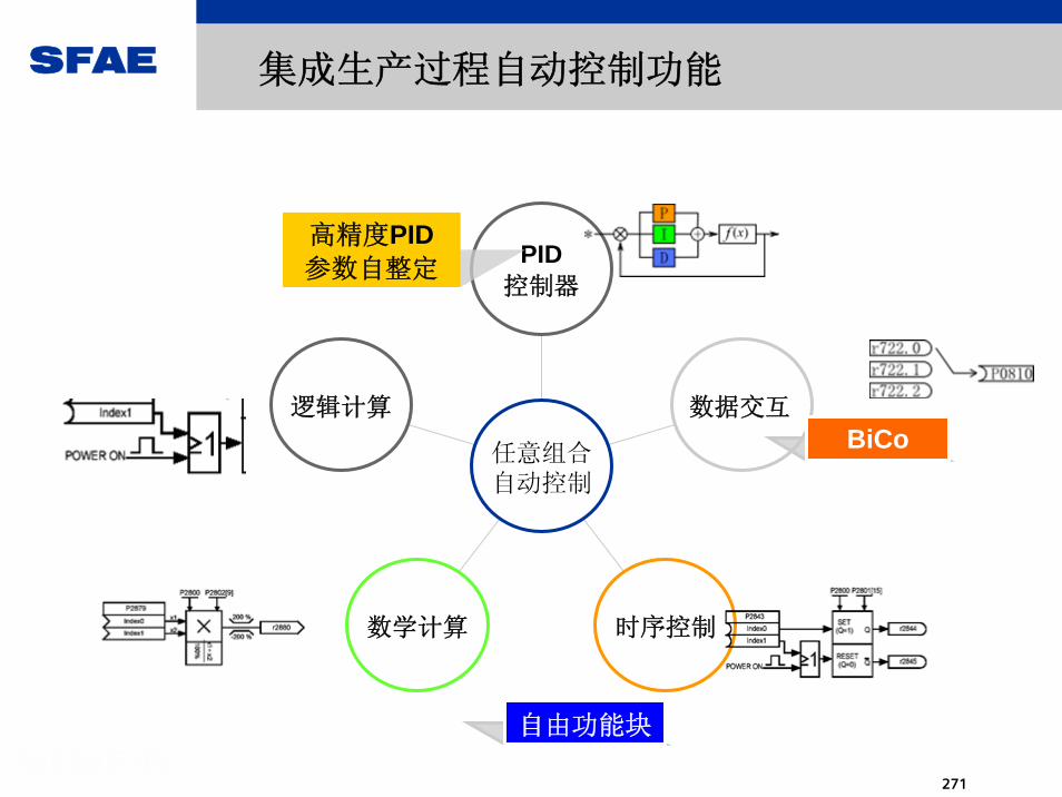
SFAE
271
逻辑计算
数学计算 时序控制
数据交互
PID控制器
任意组合自动控制
集成生产过程自动控制功能
BiCo
自由功能块
高精度PID参数自整定

SFAE
272
PROFIBUS
Operator panel setting AOP operator control
Setpoint channel
Analog input
Fixed setpoints
Setpointselection
Speed limiting
Ramp-functiongenerator
电 动 电 位 计
模 拟 量
4固 定 频 率
USS/PROFIBUS联 网 控 制
BOP/AOP
渠道
设定
MM4的设定值通道-多种设定渠道
通过灵活的参数设置方式和BiCo功能,用户可以灵活的设定变频
器设定值和反馈值渠道。

SFAE
273
MM440
APPROVED
MM 440的特殊功能:PID-Trim功能

SFAE
274
SINAMICS的介绍
SINAMICS

SFAE
275
MICROMASTER/MIDIMASTER标准传动(MM4/MM3)
SIMODRIVE 611Servo drive system for machine tools
SIMOVERT MASTERDRIVES VC6SE70 工程型变频器(CUVC)
SIMOVERT MASTERDRIVES MCServo-drive system for production machines (with the exception of machine tools)
当前的交流传动产品

SFAE
276
标准的模块化设计
标准的工程设计
运动控制由自动化系统完成
通用性和稳定性提高
终将取代MASTERDRIVES 和SIMODRIVE
新一代传动SINAMICS的特点

SFAE
277
Expert name
SINAMICS将传动产品统一为一个家族
SIMODRIVEMICROMASTER MASTERDRIVES SIMOVERT MV
SD MC LD
SINAMICS
611D611UPosmo
MC, VCMM3, MM4Combimaster
SINAMICS S120SINAMICS S120
SINAMICS G110SINAMICS G120SINAMICS G110SINAMICS G120
SINAMICS S150SINAMICS S150
SINAMICS G130SINAMICS G130 SINAMICS G150SINAMICS G150SINAMICS G
SINAMICS S

SFAE
278
SINAMICS的型谱
G 110 G 120 G 150
G 130
S 120
ET200S FC
S 150

SFAE
279
产品型号的含义
1 - 1.Generation10 - 模块型
20 - 模块型&书本型,装机装柜型
30 - 装机装柜型
50 - 柜机
SINAMICS G xxx for General requirements
SINAMICS S xxx for High requirements

SFAE
280
Family
G110
G130
G150
S120-Vector
S120-Servo
S150
ET200S FC
-
7/03
6/04
3/03
12/04
4/04
6/04
10/04
-
D11.1
D11
D11
D21.1
D21.2
D21.3
IK PI
-
i.V.
-
-
-
10/04
-*)
Tran
s-pa
renc
ies
Brie
f de
scrip
tion
Adv
ertis
ing
broc
hure
-
-
-
-
-
cataloge
Shortcut
Start of
delivery Me-dium
avai-lable
-
-
-
3/05
10/04
-
i.V.
LANGUAGE
SINAMICS 各种产品发布的时间表
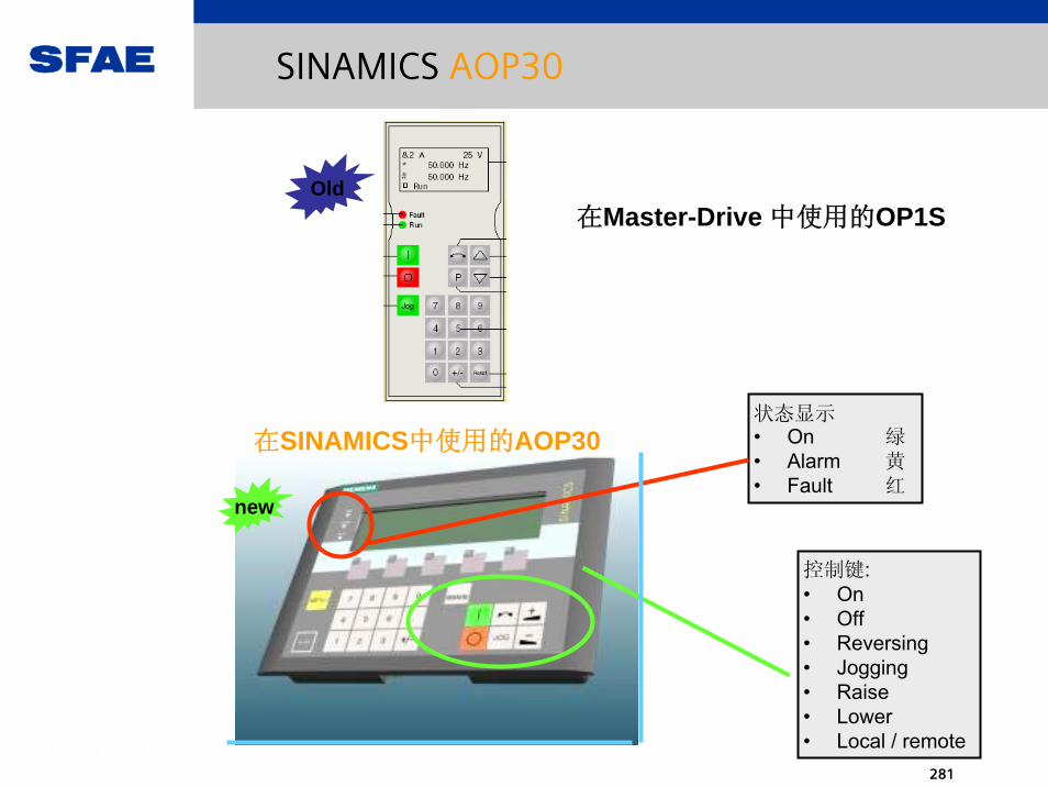
SFAE
281
SINAMICS AOP30
控制键:• On• Off• Reversing• Jogging• Raise• Lower • Local / remote
状态显示• On 绿• Alarm 黄• Fault 红
在SINAMICS中使用的AOP30
在Master-Drive 中使用的OP1SOld
new

SFAE
282
SINAMICS BOP20
设置参数
读出报警和故障
可用在所有的CU上
BOP20
PMU
设置参数
读出报警和故障
固定在一个CU上
new
Old

SFAE
283
文本显示
功能键
Drive control
控制本地 / 远程
指示灯:运行报警故障
数字键
禁止键
菜单键
SINAMICS AOP30的简介

SFAE
284
AOP30
CU320
7
4
1
MENU
SIN
AMIC
S
FAULT
ALARM
F1 F5F2 F3 F4
8
5
2
9
6
3
0
.
LOCALREMOTE
JOG
RUN
PPI (RS232)
AOP30通过PPI 与CU320连接
AOP30在柜机中使用
SINAMICS AOP30的接线和使用

SFAE
285
Start mask
Generateconfiguration
Displayconfiguration
First start-upWizard
Country selection
Motor parameters
Basic start-up
Data save
Operating maskMain menu
Parameterization
Fault memory *)Alarm memory *)
UploadDownload
Time control(ON/OFF timer)
Settings
Define operating mask
Display settings
Date/time
Language toggling
Load databases
Actual faults *)
Actual alarms *)
*) Help texts can becalled for allalarms and faults
Basic start-up
All parameters
Parameter groups
( ) If a new electronics module is insertedwith new software card
Safetysettings
Key inhibit
Key inhibit / password
Access stages
MENU
菜单的树形结构
SINAMICS AOP30的菜单结构

SFAE
286
• 可显示10个变量或3个模拟条
• 显示运行状态和时间
• 报警时黄色指示灯闪烁
• 故障时红色指示灯闪烁
• AOP30上可显示报警/故障代码
及故障原因
SINAMICS AOP30的功能

SFAE
287
用AOP30进行快速调试
SINAMICS AOP30的功能

SFAE
288
PROFIBUS
Customerinterface
P0700
LocalAOP30内部控制
REMOTE
“Local“ 模式, 可用端子或PROFIBUS控制.柜内监控和紧急停车的功能保持不变.
LOCAL“Local“ 模式, 可用 AOP30 或 STARTER PC-Tool控制.
LOCAL
REMOTE
PPI
DRIVE-CLiQ
PROFIBUS DP
STARTER
柜内监控
SINAMICS AOP30的功能

SFAE
289
安全设置
键盘禁止
键盘禁止 /密码
访问等级
禁止类型 在AOP30右上角的显示
无禁止
禁止运行+禁止修改参数
禁止运行
禁止修改参数
SINAMICS AOP30的功能

SFAE
290
new
CU320CUVC,选件及电子箱
Old
SINAMICS CU320

SFAE
291
The Control Unit has all of the interfaces necessary for connecting periphery and higher-level components
数字量输入/输出8 DI8 DI/DO bidirectional, 4 of which are fast inputs
Space forBasic Operator Panel
DC 24 V 电源
CompactFlash card slot
4x DRIVE-CLiQfor connecting
Line ModulesMotor ModulesTerminal Modulesdirect measuring systems
1 选件槽
端子或通讯板(e.g. TB30 or CBC10)
RS232/485 interface
4 diagnostic LEDs
4 measuring sockets
new
new
SINAMICS CU320

SFAE
292
CU320
TB30
CBC10
端子扩展板 TB30
Fast digital I/O: 4 DI, 4 DO
2 AI, 2 AO, e.g. as analogsetpoint interface
通讯板 CBC10CAN bus interface withCAN protocol acc. toCANopen drive profile
SINAMICS CU320的选件
CU320只有一个选件槽
可选的选件有:

SFAE
293
DRIVE-CLiQ采用100 Mbit/s以态网的技术. RJ45 的连接包括Ethernet 信号和24 V DC电源. 标准化和数字化的接口模块化的设计,自由灵活的组合CU中含有 “electronic rating plates“的数据库 :运行时, 通过DRIVE-CLiQ连接的设备可被CU自动识别,不需要手动输入.
DRIVE-CLiQ
“Drive Component Link with Intelligence Quotient“
Signal name
Reserved, do not useReserved, do not use
Reserved, do not useReserved, do not use
Note:Terminals A and B are only used to supply the measuring system evaluation. These terminals are continually short-circuit proof.
Signal name
CU 320
TM 31
PM
SINAMICS DRIVE-CLiQ

SFAE
294
TM 31
Terminal Module TM31
通过DRIVE-CLiQ 与CU(Control Unit )连接
8 digital inputs, 4 bidirectionaldigital inputs/outputs
2 analog inputs, 2 analog outputs
2 relay outputs with CO contact
1 temperature sensor input (KTY/PTC)
在柜机中使用
防护等级IP20
导轨安装

SFAE
295
SMC20
SMC30
SMC20 for connecting
Sin/cos 1Vpp incremental encoders or
EnDat absolute value encoders
SMC30 for connecting
TTL encoders or
HTL encoders
For installation in cabinets
IP20 degree of protection
For mounting on a mounting rail
SMC30
Encoder sensor Module

SFAE
296
SMC20 SMC30
Motor withDRIVE-CLiQinterface*)
Motor withoutDRIVE-CLiQinterface
DRIVE-CLiQencoder
Conventionalencoder
数字量/模拟量的连接
All drive-related components are connected to SINAMICS via DRIVE-CLiQ
SINAMICS DRIVE-CLiQ的使用

SFAE
297
SINAMICS G130 Comprises two autonomous Components: Power Modules and Control Unit CU320
TM31
-X9
u1, v1, w1
u2, v2, w2
CIB
Power Block
RS 232DRIVE -CLiQ
DR
IVE
-CLi
Q
Cus
tom
erTe
rmin
al b
lockExternal
24VDC
Alim
enta
tion
24V
DC
M
NetControl Unit CU320with Profibus
CU320
CFC
AOP 30
Alim
enta
tion
24V
DC
Alim
enta
tion
24V
DC
CIBTM31
DRIVE-CLiQ
CU320Option/extern
SINAMICS DRIVE-CLiQ的使用

SFAE
298
SINAMICS的Electronic Rating Plates
Electronic rating plates enable auto-parameterization and help avoid errors
Active Line ModuleOrder number,unique ID,rated power,...
Motor Module 1Order noumber,unique ID, rated current, ...
Terminal Module 1Order number,unique ID... Control Unit
Order number,unique ID,...
Motor Module 2Order number,unique IDrated current,...
Motor 2Order number,unique IDrated current,rated torque,...
Motor 1Order number,unique IDrated current,rated torque,...

SFAE
299
Pre-
Sale
sPo
st-S
ales
SIZER
WorkbencH
SAP-VSRCA01Mall
Stückliste
Proj
ekt
in SCOUT, STEP7 oderDrive ES
STARTERintegriert
STARTERStand alone
and
设计和调试

SFAE
300
设计工具 SIZER

SFAE
301
SIZER 的使用环境
PG or PC with Pentium II 333 MHz128 MB RAMMin. 75 MB free hard disk for the toolAdditional 100 MB free hard disk on the Windows system drive for the databaseWindows NT 4.0 SP5 or Windows 2000 SP2MS Internet Explorer 5.5 SP2Power Point Viewer for Guided Tour 4280K and MS Excel for data export to SAP

SFAE
302
选型与配置软件SIZER

SFAE
303
SIZER 的用户界面使用德语和英语。 驱动配置作为一个项目被创建。 在该项目中,以树形图方式显示与其布置对应的所使用的组件和功能。 选型视图可实现对驱动系统的选型设计以及对已设计的驱动进行复制/添加/修改。
SIZER 支持工作流程中的所有设计步骤:● 电源供电选择● 作为负载设计的电机设计选型● 驱动组件的计算● 所需配件的组合装配● 电源侧和电机侧功率选件的选择在用 SIZER 进行选型时,着重于高可用性,并关注于驱动任务的整体性和功能性。通过使用该工具,可
简化诸多用户控制过程。状态信息总是显示设计步骤。选型设计的结果是:● 一份所需组件的零件清单● 技术参数● 特性曲线● 电源反作用的说明● 结构图纸和尺寸图这些结果将显示为结果文件树并可作为资料用作它用。 为支持用户,提供技术在线帮助,包括:
● 详细的技术参数● 驱动系统及其组件的信息● 用于选择组件的关键标准
SIZER 的用户界面使用德语和英语。 驱动配置作为一个项目被创建。 在该项目中,以树形图方式显示
与其布置对应的所使用的组件和功能。 选型视图可实现对驱动系统的选型设计以及对已设计的驱动进行复制/添加/修改。
设计工具 SIZER

SFAE
304
驱动软件/调试软件 STARTER

SFAE
305
驱动软件/调试软件 STARTER
SINAMICS传动系统的调试软件为STARTER,这是西门子公司提供给SINAMICS传动系统用户
的大型免费调试软件,具有强劲的功能与友好的操作界面。它支持SINAMICS系列产品的调试与
组态,也支持对Micro Mater 4XX系列产品的调试。要注意的是以往西门子传动产品调试中使用
的Drive Monitor软件是不支持SINAMICS系列产品调试的。不能用在这里。
操作简便的驱动/调试软件 STARTER 提供了:
● 开机调试,
● 优化和
● 诊断
该软件既可以作为独立的计算机应用软件,也可以集成在工程系统 SCOUT(对于
SIMOTION)中或集成在 STEP 7 (借助 Drive ES Basic)中运行。 与基本功能和处理无关。
在 新的 STARTER 版本中除了 SINAMICS 驱动系统以外,还支持:
MICROMASTER 4 设备和用于分散外设 SIMATIC ET 200S FC 的变频器。
用设计辅助工具设定设计树中的驱动系统。

SFAE
306
工程系统Drive ES
v Drive ES 是一种工程系统,通过该系统可将西门子驱动技术以简便、省时和经济高效的方式集成在 SIMATIC 自动化系统中,包括通信、设计和数据维护。 这里的基础是 STEP 7 管理器的操作界面。

SFAE
307
Drive ES Basic
用于进入全集成自动化系统领域且可以不受网络路线限制及使用SIMATIC 远程服务。
Drive ES Basic 是在线和离线参数化所有驱动系统的基础软件。通过 Drive ES Basic 在 SIMATIC 管理器操作界面上处理自动化和驱动
系统。 Drive ES Basic是整个设计中用于数据存档的输出点,用于利用SIMATIC 远程服务,也用于驱动系统。
Drive ES Basic 提供用于新的运动控制系统功能交叉连接、等距和带有PROFIBUS DP 的周期同步的设计工具。

SFAE
308
Drive ES SIMATIC
STEP 7 通信程序简单的参数化代替编程。Drive ES SIMATIC 是安装 STEP 7 的前提条件。 随附有一个 SIMATIC 模块库,
为此可以在SIMATIC-CPU 中进行一个简单而又可靠的 PROFIBUS 接口编程,以用于驱动系
统。避免了 SIMATIC-CPU 和驱动之间独立、费时的数据交换编程。对于 Drive ES 用户根据以下指令:复制 – 匹配 – 装载 – 完成。在自己的设计中采用库中的已确定、合适的功能模块 。
经常需要的功能已完全编程:● 自动从驱动系统中读取整个诊断存储器中的信息● 自动将整个参数组从 SIMATIC CPU 装载到驱动系统中,例如在更换装置时● 自动将部分参数组(例如修理更换或者产品更换)从 SIMATIC-CPU 装载到驱
动系统中● 将整个参数化或者部分参数组从驱动系统读入至 SIMATIC-CPU 中,也就是进
行更新。

SFAE
309
工程系统 Drive ES 的选型和订货数据

SFAE
310
Drive ES PCS 7
将带有 PROFIBUS 接口的驱动系统连接到过程控制系统 SIMATIC PCS 7 中。
Drive ES PCS 7 是安装过程控制系统 SIMATIC PCS 7(自版本 5.2 起)的前提条件。 DriveES PCS 7 提供一个带有功能模块的模块库用于驱动系统和附属的操作站面板。 因此,可以由过程控制系统 PCS 7 操作驱动系统。
其它信息,可浏览网址:http://www.siemens.com/drivesolutions

SFAE
311
Drive Design with SIZER
传动系统的设计,包括选件和附件
简单实用
包括所有的技术数据
自动生成报表
SAP interface for quick ordering

SFAE
312
Line supply
Motor
Drive converter
Output options
Input options
The drive is engineering step-by-step:• A project is first generated. • This is followed by a prompted drive engineering phase,
which is orientated to the so-called workflow. • Extensive engineering support functions support this
process.
Project
Workflow
Results
Engineering support
- Voltage- Frequency- Phase number
- Motor type- Reduction (de-rating)
- ambient temperature- installation altitude- temperature rise class
- Motor- load- output data- drive system- overload capability- pole number- basic data - motor selection
- Output reactor and filter
- Drive converter system- Reduction (de-rating)
- ambient temperature- installation altitude
- Increased degree of protection- Drive converter- Options
- degree of protection- braking unit- Emergency Off- ...
- Filter- Incoming reactor- Fuse- Shield connecting plate- Circuit-breaker
SINAMICS SIZER 的流程图

SFAE
313
STARTER的使用环境
STARTERPG or PC with Pentium II 333 MHz128 MB RAMApprox. 210 MB free hard disk Windows NT 4.0 SP5 or Windows 2000 SP2

SFAE
314
Drive Commissiong with STARTER
Automatic basic configuringGuided commissioning with thehelp of assistantsGraphical masks for standardapplications or expert listsTest and diagnostic functions
SFAE
315
sinamics G110

SFAE
316
SINAMICS G110
The frequency converter for drive applications with variable speeds
can be used flexiblywith V/f controlfor the lower power and performance range of 0.12 - 3 kWfor single-phase supplies (200 –240 V)for industrial and public networks
Featureslow stress on mechanicslow noise levelsrobustsimple installation, parameterization and commissioning

SFAE
317
SINAMICS G110产品的功率范围
SINAMICS G110
Power supply: 1AC 200V - 240VAnalogInput USS Analog
Input USS
unfiltered filtered
0.12 - 0.75 kW 0.12 - 0.75 kWFS A
0.12 - 0.75 kW 0.12 - 0.75 kWFS A flat plate1.1 - 1.5 kW 1.1 - 1.5 kWFS B
2.2 - 3.0 kW 2.2 - 3.0 kWFS CFS: Frame Size
FS C FS B FS A

SFAE
318
sinamics G120

SFAE
319
SINAMICS 各种产品的功率范围
SINAMICS G120
solution forsingle drives up to 250 kW

SFAE
320
F3E (Fundamental Frequency Front End)
Standard Converter OperationThe Input IGBTs are not used. The diodes supply current like a standard rectifer, so the DC link voltage is below the peak of the input.RegenerationWhen energy returns from the motor, the DC link voltage rises, and the input IGBTs turn on to return energy to the supply

SFAE
321
F3E (Fundamental Frequency Front End)
MotoringThe low DC link capacitance means low input currents
GeneratingNow the current is in antiphase to the supply voltage; energy returns to the supply.

SFAE
322
Active Front End AFE
Active Front End operationWhen the drive is motoring, energy is supplied through the input IGBTs which operate like a step up power supply. (see later)The AFE is usually programmed to draw a sinusoidal current from the supply, so a filter capacitor is still required. The DC link voltage will be higher than the peak of the supply (e.g.1.45 x supply)The AFE input choke is a necessary part of the switching actionWhen the drive regenerates, the input IGBTs continue to control the DC link voltage, but current flow is reversed, the IGBTs operate like a step down power supply, so energy returns to the supply.
Active Front End operation.

SFAE
323
sinamics G120D

SFAE
324
SINAMICS G120D
Innovative Converter in high protection class
Optimized for conveyor technology applications that need a decentral converter on PROFIBUS
Focus: Automobile industry. Also adequate for high-performance applications for airports, food & beverage (dry part) and for overhead monorail
V/f control, vector control with/without encoder
Power range: 750W bis 7,5kW (380V-500V) with 3-phase power supply
Features
Perfect mechanics through very flat design and identical footpring for all power ranges
Safety Integrated inside the converter for innovative and cost effective safety applications
Innovative energy recovery generates a variety of cost saving
High mechanical and electrical robustness

SFAE
325
sinamics G130

SFAE
326
SINAMICS 各种产品的功率范围
SINAMICS G130315 kW to 800 kW
0 400200
315 kW to 560 kW
100 300380 .. 480 V
500
0 400 600200 800100 300 500 700
0 400200100 300 500
660 .. 690 V
500 .. 600 V 03.2005315 kW to 560 kW

SFAE
327
SINAMICS G130
The universal drive solution for high-rating single-motor drives as chassis unit
V/f control, vector control with/without encoderFor the power range from 315 – 800 kWFor variable-drives with square-law load torque (M ~ n²) and constant (M = Const) load characteristic with average performance requirements, without regenerative feedback into the line supplyFeatures
Quiet and compactModular designOperator-friendly Simple installation,parameterization andcommissioning

SFAE
328
sinamics G150

SFAE
329
SINAMICS 各种产品的功率范围
SINAMICS G15075 kW to 800 kW
0 400200
110 kW to 560 kW
100 300 500
0 200 400 600 800100 300 500 700
0 400200100 300 500
660 .. 690 V
500 .. 600 V ( 03.05.04) - Types: 132 / 200 / 400 / 560 kW
Up to 1500 kW Parallel Connection (06.05)
600 800700
13001000
Up to 1000 kW Parallel Connection (06.05)380 .. 480 V
660 .. 690 V
900 1000
15001100 1200 1400

SFAE
330
G150 – SINAMICS 家族的先锋
G150是SINAMICS家族的先锋产品, 为柜体形式的
低压交流变频
调速装置.
主要适用于
单机传动要求
的各种应用
及众多工业领域.

SFAE
331
•德国原装SINAMICS G150变频调速柜
•德国RITTAL机柜
•标准保护等级IP20•标准配置操作面板AOP30•标准配置输入电抗器(500KW以下)•进线主开关及快熔保险 (A型交钥匙柜)•整流环节
•直流环节
•逆变环节
•冷却风扇
•电源输入端子
•电机输出端子
•主控板CU320•标准配置PROFIBUS 接口
•RS232接口 (已连接操作面板AOP30)•程序存储卡 (CF卡)•模拟量/数字量输入输出端子接口板TM31
G150 - 基本配置(A型交钥匙柜)

SFAE
332
G150 - 功率范围
输入电压 额定功率
3AC 380 – 480V 110kW – 560 (~800kW)*
(3AC 500 – 575V 110kW – 800kW)*
3AC 660 – 690V 75kW – 800 (~1200kW)*
*自2005年4月起

SFAE
333
输入电压和输出范围 3 相交流 380 V - 480 V,± 10 %(-15% < 1 min) 110 ... 800 kW 3 相交流 660 V - 690 V,± 10 %(-15% < 1 min) 75 ... 1200 kW
输入频率 47 - 63 Hz 输出频率 0 Hz - 83 Hz 输入电源功率因子 > 0.98 变频器效率 >98 % 控制技术 V/F 曲线 ,无测速机开环矢量控制 ,闭环矢量控制 固定频率 4,可参数化 可抑制频率范围 4,可参数化 设定点分辨率 0.01 Hz 连续,0.01 Hz 数字 (通过操作员面板 ),12 位模拟 制动 通过制动单元,可选 (正在准备 ) 电磁兼容性 作为选件,可提供电磁干扰抑制滤波器,符合标准 EN 55 011,Class A 电磁干扰抑制 符合变速驱动系统用电磁兼容产品标准 EN61800-3 冷却类型 强制空冷 (参见技术数据和尺寸图 ) 噪声 大 72 dB(A)(对于 50 Hz 输入电源频率 ) 防护等级 IP20(防护等级可达 IP54,可选 ) 冲击保护 BGV A2 变频调速柜 Rittal TS 8,双锁门 喷漆 室内用 RAL 7035 环境条件: 标准 运行 IEC60721-3-3 贮存 IEC60721-3-1 运输 IEC60721-3-2 等级 温度 空气湿度
禁止冷凝 (3K3) 0 - +40 °C
到 +50 °C(额定值降低 ) 5 - 95 %
安装高度 2000 m 以
下,无额定值
降低
(1K4) -25 - +55 °C 5 - 95 %
运输 IEC60721-3-2 (2K3) -25 °C - +70 °C -40 °C 以下,24 小时
5 - 95%,40 °C 时
G150 – 技术概述

SFAE
334
100 %
150 %
110 %
10 s
60 s300 s变
频器
电流
t
对于一般性能应用,使用自适应过载,可增加可用性!
S1 负
荷:
连续
= 10
0%
过载
极限
过载短时电流
订货号 400V时的
输出功率[kW]
额定输出电流IN
[A]
基本负载电流IG
[A]
额定输入电流
[A]
205 2396SL3 710 -1GE32-1 110 210
210 A205 A
315 A
231 A
G150 – 过载

SFAE
335
G150 - 生产制造
包括功率及控制部件,操作板,低压配电和
柜体,G150整体在德国
纽伦堡工厂生产,测试.

SFAE
336
1. 输入电抗器
2. PROFIBUS 连接
3. 主接触器
4. 带有熔断器的主控制开关
5. 客户端子板
6. 电机连接
7. 电源连接
1
2
3
4
5
6
7
G150特性 – 柜体设计

SFAE
337
G150特性 – 柜体设计 (A 型 – 交钥匙柜)
突破传统的柜体设计,突出体现结构的
紧凑,节省占地空间,且充分考虑了
良好的散热及降噪,堪称 安静的变频器.
A型柜体拥有
充足的空间,可安装多种选件
及用户自行设计
的系统配置器件.

SFAE
338
380V, 110kWA型交钥匙柜
占地面积仅为:800mm X 600mm

SFAE
339
G150特性 – 柜体设计 (C 型 – 半交钥匙柜)
突破传统的柜体设计,突出体现结构的
紧凑,节省占地空间,且充分考虑了
良好的散热及降噪,堪称 安静的变频器.
独有的C型柜体设计,比传统柜体节省占地达70%,堪称 小的变频器柜体.

SFAE
340
380V, 110kWC型半交钥匙柜
占地面积仅为:400mm X 600mm

SFAE
341
电源连接
主控制开关
熔断器
主接触器
输入电抗器
整流器
DC 链路
逆变器
电机连接
A 型变频器柜C 型变频器柜A 型变频器柜 C 型变频器柜
G150特性 – 柜体设计

SFAE
342
G150全部采用德国RITTAL机柜
保证板材的强度,厚度,高工艺水准的结构件,密封,门锁等
优异的喷漆
G150特性 – 机柜

SFAE
343
输入电抗器 接触器 熔断器
SITOP电源 保险 端子排
G150特性 – 西门子品牌低压元件
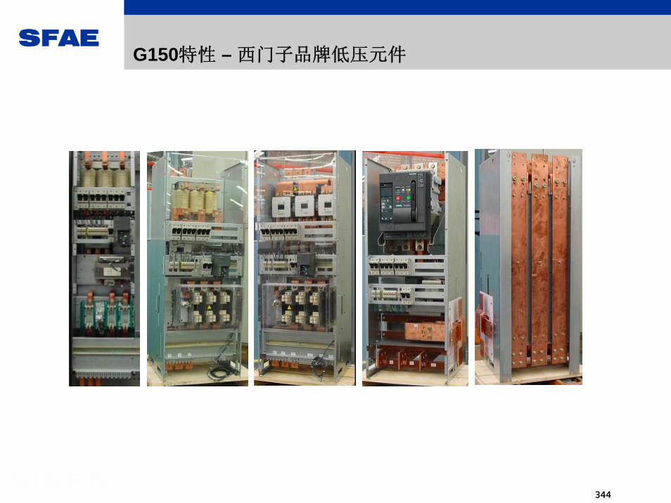
SFAE
344
G150特性 – 西门子品牌低压元件

SFAE
345
安装导轨
热敏电阻电机保护(选件)
PT100 评价单元(选件)
TM31 客户接口
紧急关机组合装置(选件)
客户端子板
G150特性 – 西门子品牌低压元件
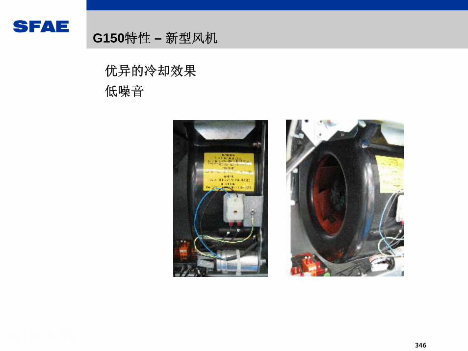
SFAE
346
优异的冷却效果
低噪音
G150特性 – 新型风机

SFAE
347
G150特性 – 柜内强电保护设计

SFAE
348
G150特性 – 操作面板
G150标准配备了
功能超强的
操作面板AOP30,用于变频器的调试,参数设定,运行监控
及故障诊断.
在保留传统功能的
基础上,增加了如:条码显示,时钟设置,按键测定,背光调节
等多种智能型功能, 堪称功能 强大的操作面板.

SFAE
349
显示屏
功能键
运行控制键盘锁定
控制等级调整
本地 / 远程控制切换
数码管显示
运行报警故障
数字键
方便快捷的软件升级过程
G150特性 – 操作面板

SFAE
350
G150特性 – 操作面板
2005年中文操作面板推出,现有系统可实现升级

SFAE
351
G150特性 – 控制方式
G150可依据不同的应用,实现以下控制方式:
•V/F曲线控制方式
•开环矢量控制方式
•闭环矢量控制方式

SFAE
352
RFG
nset
- Iact
Imax
Current actual value sensing
Frequency
Voltage
Currentlimiting
Slipcompensation
I * Rcompensation
V/f
f
V
Vd maxcorrection
IxR Slip
n
f
V
f
- +
+++
+ +
-
f>fs f<fs
M
G150特性 – V/F曲线控制

SFAE
353
Speedcontroller
Current controller,active current
- nact
- Iact,d
nset Coordinatetransformation
P
KCurrent controller,field current
- Iact, q
Iset, q
Fieldcontroller
Iset, d set
act
M
n
Rotoractive current
Statorfield current
Motor model
Stator current isTorque-gen. current iqFlux-generating current id
Vset
Phi
IUVW
G150特性 – 无测速机开环矢量控制
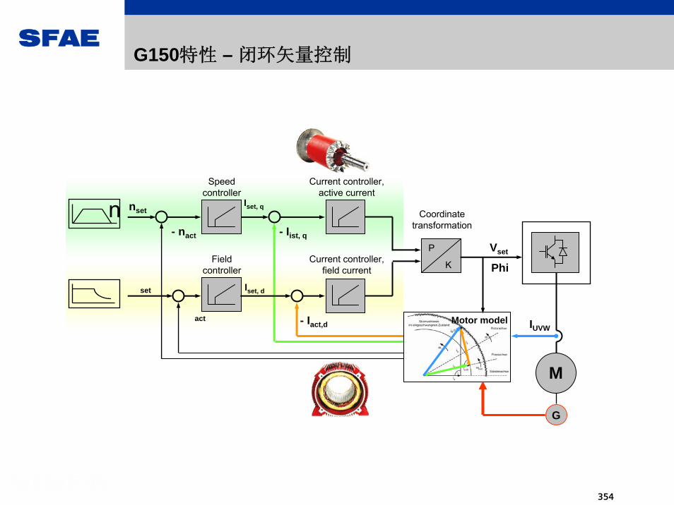
SFAE
354
Speedcontroller
Current controller,active current
- nact
- Iact,d
nset Coordinatetransformation
P
KCurrent controller,field current
- Iist, q
Iset, q
Fieldcontroller
Iset, d set
act
n
Motor model
Vset
Phi
IUVW
G
M
G150特性 – 闭环矢量控制

SFAE
355
•8 点数字量输入
•4 点双向输入/输出
•2 点模拟量输入(差分)
•2 点模拟量输出
•2 点继电器输出(切换触点)
•KTY84 温度传感器或 PTC 热敏电阻输入
•±10 V 辅助电压输出,用于模拟设定点输入
•±24 V 辅助电压输出,用于数字量输入
G150特性 – 标准配置的输入输出端子TM31
TM31标准配置
TM31额外附加

SFAE
356
G150特性 – 功能完善的选件
G150提供功能完善的选件,配置 佳的交流传动系统.主要包括:•无线电抗干扰滤波器
•输出电抗器
•紧急停机
•电机热保护接口
•提高保护等级
•电源顶部进线
•电机顶部出线
•制动电阻
•特殊喷漆
•防冷凝加热器
•柜内照明

SFAE
357
G150特性 – 便捷的软件工具
G150免费提供齐全的软件工具,运行于WIN98/2000/XP环境,极易安装,使用便捷,快速.
•G150选型软件 – SINAMICS SIZER
•G150备件选型软件
•G150节能计算软件 – SINASAVE
•G150在线调试软件 – STARTER
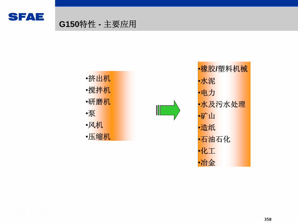
SFAE
358
G150特性 - 主要应用
•挤出机
•搅拌机
•研磨机
•泵•风机
•压缩机
•橡胶/塑料机械
•水泥
•电力
•水及污水处理
•矿山
•造纸
•石油石化
•化工
•冶金

SFAE
359
G150为您创造遐意生活
G150
•易于选型
•易于安装
•易于调试
•易于运行

SFAE
360
G150为您
•省钱
•节省空间
•节省时间
G150为您创造遐意生活

SFAE
361
sinamics S110

SFAE
362
Core message – SINAMICS S110
SINAMICS S110:
Optimized for basic single-axis servo tasks
Power [kW]1,2000.12 90
Vectordrive
Torque,linearmotors
Servodrive
SINAMICS S110 –the tailored system
SINAMICS S120 - “The universal drive”A
pplic
atio
ns

SFAE
363
Basic servo for positioning tasks
Performance/FunctionalityV/f
General Purpose Performance
General Purpose Vector
Basic Performance
Servo
High PerformanceServo/Vector
Motion Control
G110 G120 S120 D410
S110
Lower dynamic performance,Fewer free function blocks,Fewer motor types,Lower price

SFAE
364
The Basic Performance Servo market segmentDefinition
High Performance Servo:
Higher dynamic performanceMore extensive technological functions.Also vector control and V/fAlso direct drives
S120S110
Basic Performance Servo:
Only closed-loop servo control for Synchronous, induction motorsLower priceSimpler handling
For sophisticated & demanding single and multi-axis applications (universal)
Optimized for basic single-axis servo tasks
(tailored)

SFAE
365
Typical uses / applications
Basic pick & place tasks
Basic high-bay racking units
Rotary cycle tables
Healthcare systems (beds for patients etc.)
Feeders for post-press applications
Tool positioning in machining stations
Injection moulding technology (ejector)
Blow moulding systems (positioning blanks)
Basic handling tasks (CD, DVD)
Actuating tasks in wind turbine and solar systems

SFAE
366
Price example for an application:Basic application for a rotary cycle table
Station 1
Station 3
4 (clamping/releasing)
12
3Station 2
Comparable K prices (customer prices) for drive system:Siemens solution (as shown): 1,262 € (= L price minus 10%)Comparable SEW solution: approx. 1,250 €Comparable KEB solution: approx. 1,350 €
SINAMICS S110IN = 1,7AIncl. accessories (cables, etc.)
1FK7 synchronous motorsMN =1.1 NmWith resolver and Drive-CLiQ

SFAE
367
Competitors
MR-J3+ Frame size+ Real Time Auto Tuning+ Platform concept A/B/CL- Power range (-7kW)- No third-party motors- No fieldbus- No safety
F5A Servo+ Positioning (16)+ Various fieldbuses via the
option card+ Ready-to-connect packages- Power range (1.5 kW)- No third-party motors- No safety
Movidrive MDX60B/61B+ Positioning in the basic unit+ Various fieldbuses via the
option card+ Free blocks with PLC motion- Ext. safety only with supplementary
card- C/Ass knowledge required for IPOS- No mot ID- Frame size
Competitors are already serving this market with the appropriateproducts:

SFAE
368
The components of a SINAMICS S110 drive system
Power Module PM340from FSA to FSF, 0.12-90 kW
Basic Operator Panel BOP (optional)
DRIVE-CLiQ encoder cable
Servomotor (synchronous or induction), e.g. 1FK7 with DRIVE-CLiQ interface
STARTER for commissioning
Power cable
Control Unit CU305, 3 versions: CU305 DP, CU305 CAN, CU305 PN (being prepared) (optional memory card)
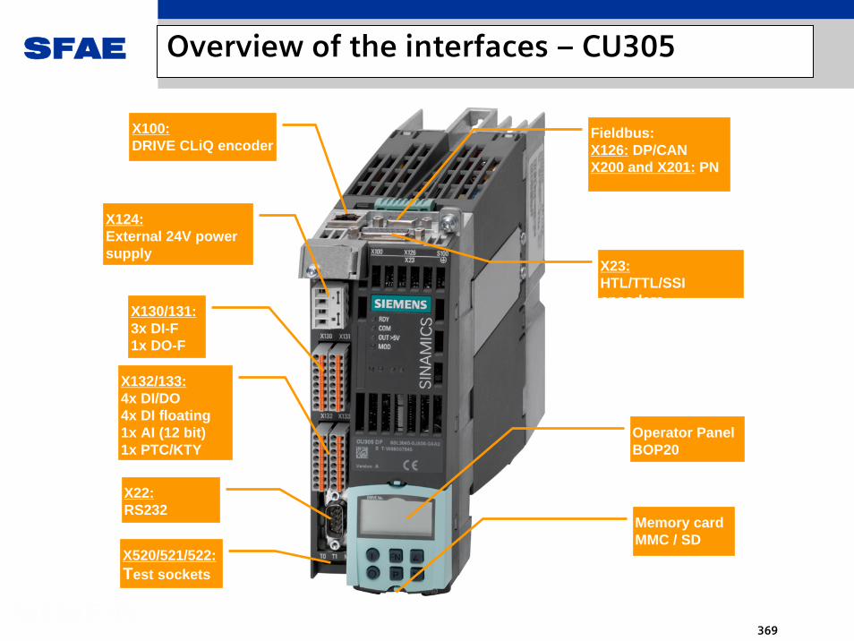
SFAE
369
Overview of the interfaces – CU305
Memory cardMMC / SD
X22:RS232
X130/131:3x DI-F1x DO-F
X23:HTL/TTL/SSI encoders
Fieldbus:X126: DP/CAN X200 and X201: PN
X100:DRIVE CLiQ encoder
X124:External 24V power supply
X132/133:4x DI/DO4x DI floating1x AI (12 bit)1x PTC/KTY
Operator PanelBOP20
X520/521/522:Test sockets

SFAE
370
Functionality and performance data
Servo controlSynchronous, induction motors, third-party motorse.g. 1FK, 1PH, 1LA
Current/speed/position controller/EPos: 250/250/1ms/4ms
Positioning (EPos), max. 16 traversing blocksFree function blocks via the parameter list (free blocks), later, screen forms in STARTER (no DCC)
STO, SS1, SS2, SBC, SOS, SLS, SSM functions Controlled via onboard terminals or PROFIsafe
One DRIVE-CLiQ for encodersBus: Optional, PROFIBUS, PROFiNET or CAN
Internal ROM, with data save to / loading from MMC-Card
Basic Operator Panel BOP
What can the SINAMICS S110 do?
Motors and closed-loop control:
Performance:
Motion and technology:
Safety functions:
Interfaces:
FW and user memory:
Operator control:

SFAE
371
Demarcation to S120 single axis drives
What can SINAMICS S120(CU310) additionally do?Motors and control:
Performance:
Motion and technology:
Safety functions:Interfaces:
What can SINAMICS S110 do, that S120(CU310) cannot do ?Terminals:FW and user memory:Interfaces:
Vector and V/f controlLinear and torque motorsSignificantly better performance:Current/speed/position control/EPos:62.5µs/62.5µs/1ms/2msMax. 64 traversing blocks for EPosExtended closed-loop torque control, friction characteristicGraphic configuring with DCC for the extended scope of free function blocks (DCB)Controlled via TM54FTopology with Terminal Module and encoder can be established via DRIVE-CLiQ. (2 encoders are also possible)
S110 has more digital I/O onboard S110 only requires a memory card for Extended Safety S110 has a +/-10V analog inputS110 has a CAN interface (CAN port)S110 will have a pulse-direction interface (this is being prepared)

SFAE
372
Overview of the differentiating features S110/S120 in tabular form
Positionieren mitLageregler 4 ms
Servo
Asynchron, Synchron
Basic FunctionsExtended Functions
Onboard-Klemmen oderProfisafe
Reduzierte Bausteine,reduz. Technologiefkt.
Paametrierung
DRIVE-CLiQ nur fürMotorgeber
Profibus u. CAN Profinet (i.V.)
Positionieren
Regelung
Motortypen
Safety-FunktionenundAnsteuerung
Bausteine,Technologie,Parametrierung
DRIVE-CLiQ
Bus-Anschluß
Functions S110 S120 (CU310)Closed-loop control Servo Servo, vector, V/f
Motor types Induction, servo Induction, synchronouslinear, torque
PerformanceCurrent/speed/position/positioning
Servo250μs/250μs/1ms/4ms
Servo62.5μs/62.5μs/1ms/2ms
Vector250μs/250μs/1ms/2ms
EPos # traversing blocks 16 64
Technology functions - Technology controller- Technology controller
- kt estimator- Friction characteristic
Free blocks Free Blocks Drive Control Chart (DCC)
Safety
- Basic Functions- Extended Functions
via onboard terminals or PROFIsafe
- Basic Functions - Extended Functions
via TM54F or PROFIsafe
System interfaces- DRIVE CLiQ
only for one encoder- RS232 for Starter
- DRIVE CLiQfor encoder and TM's- RS232 for Starter
Bus interfaces- PROFIBUS
- CAN- PROFINET (being prep.)
- PROFIBUS- PROFINET
Encoder evaluation
- DRIVE CLiQ motors- Resolver : SMC10- sin/cos/EnDat : SMC20- TTL/HTL/SSI* : on board- TTL/HTL/SSI : SMC30* SSI with incremental tracks only via SMC30
- DRIVE CLiQ motors- Resolver : SMC10- sin/cos/EnDat : SMx20- HTL/TTL/SSI : SMC30

SFAE
373
Free blocks
Type Abbrev. Name of the function block Type No.
AND AND function block BOOL 4
OR OR function block BOOL 4
XOR XOR function block BOOL 4 NOT Inverter BOOL 4
ADD Adder REAL 2
SUB Subtractor REAL 2
MUL Multiplier REAL 2
DIV Divider REAL 2 AVA Absolute value generator with sign evaluation REAL 2
MFP Pulse generator BOOL 2
PCL Pulse shortener BOOL 2
PDE Switch-on delay BOOL 2
PDF Switch-out delay BOOL 2 PST Pulse extender BOOL 2
RSR RS flip-flop, reset dominant BOOL 2 DFR D flip-flop, reset dominant BOOL 2
BSW Binary changeover switch BOOL 2 NSW Numerical changeover switch REAL 2
LIM Limiter REAL 2
PT1 Smoothing element REAL 2
INT Integrator REAL 1 DIF Differentiating element REAL 1
Complex LVM Double-sided limit value monitor with hysteresis BOOL 2
Switch
Control
Logic
Arithmetic
Timer
Memory

SFAE
374
Order Nos. and list prices CU305
343,- 343,-
149,-
CU305CAN
CU305 DP
+
Safety license“Motion
Monitoring”
6SL3040-0JA00-0AA0
6SL3040-0JA02-0AA0
MMC cardempty
45,-6SL3054-4AG00-0AA0
6SL3074-0AA10-0AA0
MMC card+FW
60,-V4.1:6SL3054-4EB00-0AA0current:6SL3054-4AA00-0AA0
Release11/2008
Optional

SFAE
375
sinamics S120

SFAE
376
SINAMICS S120 – different design optimized for single and multiple axis applications
Deliberate ways to combine the different variants and complete uniformity in means of functionality and handling
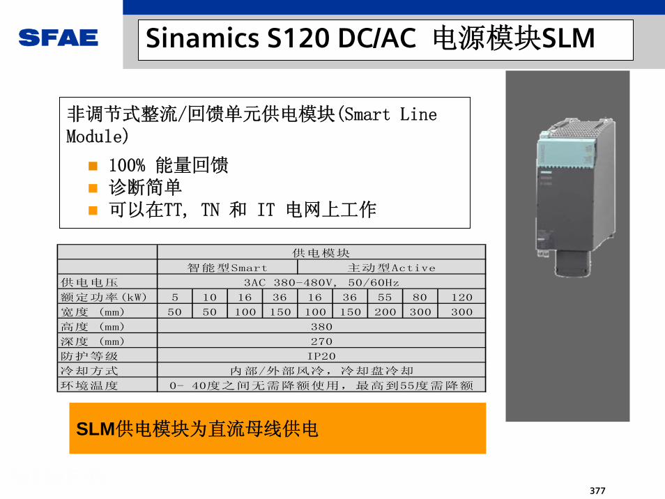
SFAE
377
SLM供电模块为直流母线供电
Sinamics S120 DC/AC 电源模块SLM
非调节式整流/回馈单元供电模块(Smart Line Module)
100% 能量回馈诊断简单可以在TT, TN 和 IT 电网上工作
供电电压
额定功率(kW) 5 10 16 36 16 36 55 80 120
宽度 (mm) 50 50 100 150 100 150 200 300 300
高度 (mm)
深度 (mm)
防护等级
冷却方式
环境温度
270
IP20
0- 40度之间无需降额使用,最高到55度需降额
3AC 380-480V, 50/60Hz
内部/外部风冷,冷却盘冷却
供电模块
智能型Smart 主动型Active
380

SFAE
378
Sinamics S120 DC/AC 电源模块ALM
带闭环控制整流/回馈的主动型供电模块(Active Line Module)
自动补偿电网的波动,增强了工作的可靠性和安全性直流母线电压的稳定也进一步保证了电机运行的稳定性较高的直流母线电压,提高了电机的利用率
供电模块提高了工作的可靠性和效率

SFAE
379
电机模块从直流母线取电,驱动电机
供电电压
额定电流 (A) 3 5 9 18 30 45 60 85 132 200 3 5 9 18
最大输出电流 (A) 6 10 18 36 56 85 113 141 212 282 6 10 18 36
宽度 (mm) 50 50 50 50 100 150 150 200 300 300 50 50 50 100
高度 (mm)
深度 (mm)
防护等级
冷却方式
环境温度
内部或外部风冷,冷却盘
0-40度之间无需降额使用,最高55度需要降额
单轴 双轴
DC 510-720V
380
270
IP20
Sinamics S120 DC/AC 电机模块
单轴模块额定电流最高达到200 A
双轴模块双电机驱动节省空间额定电流最高达到18 A

SFAE
380
Single Motor Modules
For output currents up to 200A
Double Motor ModulesSpace-saving version for 2 motorsFor output currents up to 18A
100 mm50 mm 150 mm 200 mm 300 mmModule width
Supply voltageRated output current (A) 3 5 9 18 30 45 60 85 132 200 3 5 9 18Maximum output current (A) 6 10 18 36 56 85 113 141 212 282 6 10 18 36Width (mm) 50 50 50 50 100 150 150 200 300 300 50 50 50 100Height (mm)Depth (mm)Degree of protectionCoolingAmbient temperature
Internal/external air cooling, Cold Plate cooling0-40°C without derating, up to 55°C with derating
Motor ModulesSingle Double
510-720V DC
380270IP20
S120 - Motor Module: Booksize versions

SFAE
381
Sinamics S120 DC/AC 母线安装
简单而可靠的插入式连接器
简单的直流连接母线排
电源模块
电机模块
24 V端子
直流连接桥
24 V跳线
24 V直流母线
电机模块
直流母线
由于这种设计,SINAMICS S120 的安装非常简单。

SFAE
382
Sinamics S120 DC/AC 整流母线多排连接
直流回路的适配器提高母线的配置的灵活性
直流回路的适配器
2DC
3AC
Motor Modules
Motor Modules
LineModule
Motor Modules
2DC
用于多排结构 直接供电

SFAE
383
SMC20 SMC30
集成了DRIVE-CLiQ接口的电机
未集成DRIVE-CLiQ接口的电机
DRIVE-CLiQ接口编码器
常规编码器数字量/模拟量外设
Sinamics S120 DC/AC DRIVE-CLiQ 节点
通过DRIVE-CLiQ ,所有与驱动器有关的组件都能与SINAMICS S120 进行数据交换

SFAE
384
Motors
Cabinet modules
3-ph. AC
line supply
Line modules:
ALM, SLM, BLM
Line-side components
Power supply
DC link components
Control units
Motor modules
SINAMICS S120 chassis and system components
System overview SINAMICS S120 chassis and cabinet modules

SFAE
385
Three different line modules
Basic line modules: The favorably-priced 1Q infeed
Basic line modules (“infeed unit”)
The rugged 1Q infeed
Extremely compact and favorably-priced
Main components included:- line thyristors- DC link capacitors - pre-charging cirucit- RFI suppression filter accord. EN 61800-3 category C3
VDC link ≈ 1.35*V line supply

SFAE
386
SINAMICS S120 basic line modulesNon-regulated infeed unit using thyristors (B6 circuit configuration).Mainly used to supply DC busbar drives without any regenerative feedback into the line supply Replaces the MASTERDRIVES infeed units
SINAMICS S120 basic line modules
Components included:Thyristors module + thyristors gating moduleDC link capacitorsHeat sink Fan + fan transformerElectronics module with power supply and CIB

SFAE
387
“Must“ rules for DRIVE-CLiQ connections (additionally for Chassis)
- Active Line Module and drives on different ports in operating types “Vector“ or “mixed“- Within a DRIVE-CLiQ branch only one current controller cycle time rsp. an integer multiple- Voltage Sensing Module on port X402 of the Active Line Module
250 µs (400 µs)400 µs
250 µs
ControlUnit
ControlUnit
X100
X101
X102
X103
Active LineModule
X400
X401
X402
ActiveLine
Module
X400
X401
X402
SingleMotor
Module
Drive 1 Drive 2
X400
X401
X402
SingleMotor
Module
X500
VoltageSensingModule
M3~
SensorModule
X500
M3~
SensorModule
X500
ChassisFS F or G
ChassisFS H or J
ActiveInterfaceModule
Drive 3
X400
X401
X402
SingleMotor
Module
M3~
SensorModule
X500
ChassisFS H or J
400 µs
( S120 comm. manual 2-33ff)
S150 S120 Chassis

SFAE
388
SINAMICS S120 Smsrt line modules
Smart line modules: The rugged infeed/regenerative feedback
VDC link ≈ 1.35*V line supply
Smart line modules (“Infeed/regenerative feedback unit”)
4Q infeed avoiding inverter commutation faults by usingIBGTs during line faults, fuses no longer blown
An autotransformer is no longer required
Compact and favorably priced
Main components included:- IGBT modules- DC link capacitors - Line voltage sensing- RFI suppression filter accord. EN 61800-3 category C3

SFAE
389
T1 T2 T3
T4 T5 T6
D2D1 D3
D4 D5 D6
Cd
EM
C basi
c no
ise
supp
ress
ion
filte
r
LN
LN
LN
Line supply Smart Line Module
SINAMICS S120 MegaMaster LV Smart Infeed
(c) SIEMENS AG, 11/2004, F. Baumann
3 AC380-690V50/60Hz
DC+
DC-
u1
u2
u3
LN
LN
LN
Line supplyconnection
(forbypass contactor,pre-charging circuit,
line reactor,fusing)
SINAMICS S120 smart line modulesNon-regulated infeed / regenerative feedback unit utilizing IGBT technology Insensitive to line voltage dips (fuses do not blow)Mainly used to supply DC busbar drives with regenerative energy fed back into the line supply Replaces the MASTERDRIVES infeed/regenerative feedback units
Components included:IGBT module + IGBT gating moduleDC link capacitorsHeatsinkFan + fan transformerElectronics module with power supply and CIB
SINAMICS S120 smart line modules

SFAE
390
Spare parts:Powerblock (1 - 3 units)Fan (1 - 3 units)CIB modulePower supply PSB
Difference:The line voltage sensing VTB and the EMC filter, Category C3 are located at the slot for the DRIVE-CLiQ fuses (ALM/MM)
The SLM design principally corresponds to that of the ALM
FS GX FS JX
Design SLM frame sizes GX, JX

SFAE
391
S120 Cabinet Modules:Basics - cabinet
Rittal TS8 cabinet system, 2200 mm highIP20 degree of protectionPE rail (nickel-coated)RAL 7035 paint finishBase (floor) panel (3-section)Air entry through the doorNo side panels
Without DC busbar (mandatoryoption)Without CU320 Control UnitAuxiliary busbar system (6 phase) - lower cabinet sectionEvery Cabinet Module is individually supplied (individual order)Order-specific customer documentation

SFAE
392
SINAMICS S120 Cabinet Modules
Typical plant/ configuration
Line
Con
nect
ion
Mod
ule
Line
Infe
ed
Aux
iliar
y Po
wer
Su
pply
Mod
ule
Mot
or M
odul
es-C
hass
is-B
ooks
ize
Mot
or M
odul
es-C
hass
is-B
ooks
ize
Out
put s
witc
hC
entr
al B
raki
ng
Mod
ule
CU
320
/ Sim
otio
nce
ntra
lly a
rran
ged
Can be variably combined just as the plant/system demands it

SFAE
393
S120 Cabinet Modules - infeed: Basic Line Module (BLM)
Order No. Frame size
Rated infeed power
Rated DC link current-
Rated infeed current
IN
Weight, standard version
Dimensions IP20 2)
W x D x H kW A A kg mm Supply voltage 380–480V
6SL3730-1TE34-2AA0 FB 200 420 365 166 400 x 600 x 2200
6SL3730-1TE35-3AA0 FB 250 530 460 166 400 x 600 x 2200
6SL3730-1TE38-2AA0 FB 400 820 710 166 400 x 600 x 2200
6SL3730-1TE41-2AA0 GB 560 1200 1010 320 400 x 600 x 2200
6SL3730-1TE41-2BA0 GB 560 1200 1010 440 600 x 600 x 2200
6SL3730-1TE41-2BC0 GB 560 1200 1010 480 600 x 600 x 2200
6SL3730-1TE41-5AA0 GB 710 1500 1265 320 400 x 600 x 2200
6SL3730-1TE41-5BA0 GB 710 1500 1265 440 600 x 600 x 2200
6SL3730-1TE41-5BC0 GB 710 1500 1265 480 600 x 600 x 2200
6SL3730-1TE41-8AA0 GD 900 1880 1630 320 400 x 600 x 2200
6SL3730-1TE41-8BA0 GD 900 1880 1630 440 600 x 600 x 2200
6SL3730-1TE41-8BC0 GD 900 1880 1630 480 600 x 600 x 2200
Supply voltage 660 – 690 V
6SL3730-1TH33-0AA0 FB 250 300 260 166 400 x 600 x 2200
6SL3730-1TH34-3AA0 FB 355 430 375 166 400 x 600 x 2200
6SL3730-1TH36-8AA0 FB 500 680 575 166 400 x 600 x 2200
6SL3730-1TH41-1AA0 GB 900 1100 925 320 400 x 600 x 2200
6SL3730-1TH41-1BA0 GB 900 1100 925 440 600 x 600 x 2200
6SL3730-1TH41-1BC0 GB 900 1100 925 480 600 x 600 x 2200
6SL3730-1TH41-4AA0 GB 1100 1400 1180 320 400 x 600 x 2200
6SL3730-1TH41-4BA0 GB 1100 1400 1180 440 600 x 600 x 2200
6SL3730-1TH41-4BC0 GB 1100 1400 1180 480 600 x 600 x 2200
6SL3730-1TH41-8AA0 GD 1500 1880 1580 320 400 x 600 x 2200
6SL3730-1TH41-8BA0 GD 1500 1880 1580 440 600 x 600 x 2200
6SL3730-1TH41-8BC0 GD 1500 1880 1580 480 600 x 600 x 2200
Provided for parallel circuit configuration

SFAE
394
Order No. Fram e size
Rated power
Rated DC link current Line current
W eight, standard version
Dim ensions IP20 2)
W x D x H [kW ] [A] [A] [kg] [m m ] Supply voltage 380–480V
6SL3730-6TE35-3AA0 GX 250 550 463 270 400 x 600 x 2200
6SL3730-6TE37-3AA0 GX 355 735 614 270 400 x 600 x 2200
6SL3730-6TE41-1AA0 HX 500 1050 883 490 600 x 600 x 2200
6SL3730-6TE41-1BA0 HX 500 1050 883 490 600 x 600 x 2200
6SL3730-6TE41-1BC0 HX 500 1050 883 490 600 x 600 x 2200
6SL3730-6TE41-3AA0 JX 630 1300 1093 775 800 x 600 x 2200
6SL3730-6TE41-3BA0 JX 630 1300 1093 775 800 x 600 x 2200
6SL3730-6TE41-3BC0 JX 630 1300 1093 775 800 x 600 x 2200
6SL3730-6TE41-7AA0 JX 800 1700 1430 775 800 x 600 x 2200
6SL3730-6TE41-7BA0 JX 800 1700 1430 775 800 x 600 x 2200
6SL3730-6TE41-7BC0 JX 800 1700 1430 775 800 x 600 x 2200
Supply voltage 660 – 690 V
6SL3730-6TG35-5AA0 GX 450 550 463 270 400 x 600 x 2200
6SL3730-6TG38-8AA0 HX 710 900 757 550 600 x 600 x 2200
6SL3730-6TG38-8BA0 HX 710 900 757 550 600 x 600 x 2200
6SL3730-6TG38-8BC0 HX 710 900 757 550 600 x 600 x 2200
6SL3730-6TG41-2AA0 JX 1000 1200 1009 795 800 x 600 x 2200
6SL3730-6TG41-2BA0 JX 1000 1200 1009 795 800 x 600 x 2200
6SL3730-6TG41-2BC0 JX 1000 1200 1009 795 800 x 600 x 2200
6SL3730-6TG41-7AA0 JX 1400 1700 1430 795 800 x 600 x 2200
6SL3730-6TG41-7BA0 JX 1400 1700 1430 795 800 x 600 x 2200
6SL3730-6TG41-7BC0 JX 1400 1700 1430 795 800 x 600 x 2200
Provided for parallel circuit configuration
S120 Cabinet Modules - infeed: Smart Line Module (SLM)

SFAE
395
S120 Cabinet Modules - Infeed: Active Line Module + Active Interface Module (ALM)
Dimensions IP20
Order No. Frame size
Rated infeed/regenerative feedback power
Rated DC link current Rated infeed/regenerative feedback current
IN
Weight, standard version W x D x H
kW A A kg mm Supply voltage 380 – 480 V
6SL3730-7TE32-1BA0 FX+FI 132 235 210 500 800 x 600 x 2200
6SL3730-7TE32-6BA0 FX+FI 160 291 260 500 800 x 600 x 2200
6SL3730-7TE33-8BA0 GX+GI 235 425 380 640 800 x 600 x 2200
6SL3730-7TE35-0BA0 GX+GI 300 549 490 640 800 x 600 x 2200
6SL3730-7TE36-1BA0 HX+HI 380 678 605 930 1000 x 600 x 2200
6SL3730-7TE38-4BA0 HX+HI 500 940 840 930 1000 x 600 x 2200
6SL3730-7TE41-0BA0 JX+JI 630 1103 985 1360 1400 x 600 x 2200
6SL3730-7TE41-0BC0 JX+JI 630 1103 985 1360 1400 x 600 x 2200
6SL3730-7TE41-4BA0 JX+JI 900 1574 1405 1360 1400 x 600 x 2200
6SL3730-7TE41-4BC0 JX+JI 900 1574 1405 1360 1400 x 600 x 2200
Supply voltage 660 – 690 V
6SL3730-7TH35-8BA0 HX+HI 560 644 575 930 1000 x 600 x 2200
6SL3730-7TH37-4BA0 JX+JI 800 823 735 1360 1400 x 600 x 2200
6SL3730-7TH37-4BC0 JX+JI 800 823 735 1360 1400 x 600 x 2200
6SL3730-7TH41-0BA0 JX+JI 1100 1148 1025 1360 1400 x 600 x 2200
6SL3730-7TH41-0BC0 JX+JI 1100 1148 1025 1360 1400 x 600 x 2200
6SL3730-7TH41-3BA0 JX+JI 1400 1422 1270 1360 1400 x 600 x 2200
6SL3730-7TH41-3BC0 JX+JI 1400 1422 1270 1360 1400 x 600 x 2200
Intended for parallel circuit configuration (with mirrored design)

SFAE
396
S120 Cabinet Modules - Motor Module: Chassis format
Order No. Frame size
Rated power
Rated DC link current
Rated output current
IN
Base load current
IL
Power to IH
Basic load current
IH
Weight Dimensions IP20 WxDxH
kW A A A kW A Supply voltage 380 – 480 V
6SL3720-1TE32-1AA0 FX 110 252 210 205 90 178 145 400 x 600 x 2200 6SL3720-1TE32-6AA0 FX 132 312 260 250 110 233 145 400 x 600 x 2200 6SL3720-1TE33-1AA0 GX 160 372 310 302 132 277 286 400 x 600 x 2200 6SL3720-1TE33-8AA0 GX 200 456 380 370 160 340 286 400 x 600 x 2200 6SL3720-1TE35-0AA0 GX 250 588 490 477 200 438 286 400 x 600 x 2200 6SL3720-1TE36-1AA0 HX 315 726 605 590 250 460 490 600 x 600 x 2200 6SL3720-1TE37-5AA0 HX 400 894 745 725 315 570 490 600 x 600 x 2200 6SL3720-1TE38-4AA0 HX 450 1008 840 820 400 700 490 600 x 600 x 2200 6SL3720-1TE41-0AA0 JX 560 1182 985 960 450 860 700 800 x 600 x 2200 6SL3720-1TE41-2AA0 JX 720 1512 1260 1230 560 1127 700 800 x 600 x 2200 6SL3720-1TE41-4AA0 JX 800 1686 1405 1370 720 1257 700 800 x 600 x 2200 Supply voltage 660 – 690 V
6SL3720-1TH28-5AA0 FX 75 102 85 80 55 76 145 400 x 600 x 2200 6SL3720-1TH31-0AA0 FX 90 120 100 95 75 89 145 400 x 600 x 2200 6SL3720-1TH31-2AA0 FX 110 144 120 115 90 107 145 400 x 600 x 2200 6SL3720-1TH31-5AA0 FX 132 180 150 142 110 134 145 400 x 600 x 2200 6SL3720-1TH31-8AA0 GX 160 210 175 171 132 157 286 400 x 600 x 2200 6SL3720-1TH32-2AA0 GX 200 258 215 208 160 192 286 400 x 600 x 2200 6SL3720-1TH32-6AA0 GX 250 312 260 250 200 233 286 400 x 600 x 2200 6SL3720-1TH33-3AA0 GX 315 396 330 320 250 280 286 400 x 600 x 2200 6SL3720-1TH34-1AA0 HX 400 492 410 400 315 367 490 600 x 600 x 2200 6SL3720-1TH34-7AA0 HX 450 558 465 452 400 416 490 600 x 600 x 2200 6SL3720-1TH35-8AA0 HX 560 690 575 560 450 514 490 600 x 600 x 2200 6SL3720-1TH37-4AA0 JX 710 882 735 720 560 657 700 800 x 600 x 2200 6SL3720-1TH38-1AA0 JX 800 972 810 790 720 724 700 800 x 600 x 2200 6SL3720-1TH38-8AA0 JX 900 1092 910 880 800 814 700 800 x 600 x 2200 6SL3720-1TH41-0AA0 JX 1000 1230 1025 1000 900 917 700 800 x 600 x 2200 6SL3720-1TH41-3AA0 JX 1200 1524 1270 1230 1000 1136 700 800 x 600 x 2200

SFAE
397
sinamics S120 AC/ACS120 AC/AC装置装置((单轴模块单轴模块))

SFAE
398
Sinamics S120 AC/AC 模块化设计理念
一个单轴控制器由两部分组成:功率模块+控制模块
PM 340
CUA31
CU310 DP (Profibus)CU310 PN (PROFINET)
控制单元和功率单元间的任意组合,具有极高的灵活性

SFAE
399
Sinamics S120 AC/AC 产品一览
F55-90kW
D18,5-30kW E
37-45kW
FX110-132kW
GX160-250kW
A230:
0,12-0,75kW400V:
0,37-1,5kW
B2,2-4kW
C7,5-
15kW
宽的功率范围从“0.12kw到250kw”

SFAE
400
Sinamics S120 AC/AC 模块式功率模块
主要特征适用于TN、 IT 和 TT电网
3AC400输入电压:功率从0.37到90 kW1AC230输入电压:功率从0.12到0.75 kW不可控的二极管整流
集成的制动单元, 可以外接制动电阻实现快速制动
集成式的安全功能 “安全扭矩停车”可选择的集成式的电源滤波器 (C2 acc. EN61800-3)
功率模块PM340
功率模块 PM340:电源模块+电机模块

SFAE
401
Sinamics S120 AC/AC 机架式功率模块
机架式功率模块
机架式功率模块 :电源模块+电机模块
主要特征适用于TN、 IT 和 TT电网
3AC400输入电压:功率从110KW到250 kW不可控的二极管整流
集成的制动单元(选件), 可以外接制动电阻实现快速制动
集成式的安全功能 “安全扭矩停车”

SFAE
402
Sinamics S120 AC/AC控制单元
CU310 DP:6SL3040-0LA00-0AA0
CU310 PN:6SL3040-0LA01-0AA0
主要特征
伺服、矢量、V/F控制
定位功能(相对、绝对定位)
集成式了Profibus或Profinet
编码器接口:集成的Drive CLiQ或HTL/TTL接口
数字量输入和输出
存储器卡存储系统和用户数据
基本操作模板(BOP)选件用于诊断和改变参数
一个控制单元完成所有的控制任务:从速度控制到位置控制

SFAE
403
Sinamics S120 AC/AC控制单元CU310接口
诊断灯- RDY: 准备-Communication: 通讯-- Out > 5V: 输出大于5V
X22- RS232X21
Profibus插口或Profinet: 2x RJ45
存储卡: 存储系统和用户数据
T0, T1, T23 个测试口
X23HTL/TTL 接口
基本操作模板BOP(选件)
X12424V 供电电源
X120- KTY/PTC
- 1 个输入 “安全停车“
X121- 4 个开关量输入- 4 个可编程输入/输出
X100DRIVE-CLIQ 插口

SFAE
404
Sinamics S120 AC/AC控制单元适配器CUA31
控制单元 适配器 (CUA31)容易作为轴的扩展
3 个DRIVE-CLiQ 插口来连接 CU320或SIMOTION D4x
编码器的DRIVE-CLiQ接口
外接24V(选件)维持通讯的正常,即使主电源断电
1个温控KTY/PTC接口
通过DRIVE-CLiQ接口连接扩展单元
1个诊断显示灯(准备)
6SL3040-0PA00-0AA0
与CU320和Simotion D 一起容易扩展成多轴控制

SFAE
405
Sinamics S120 AC/AC控制单元CUA310接口
1 个诊断灯- RDY: 准备
X200-X2023 DRIVE-CLiQ插口
X181- KTY/PTC
-1个输入 “安全停车“
X12424V供电电源

SFAE
406
Sinamics S120 单轴应用- CU310DP
SIMATIC S7TP 170
FSD 带CU310DP FSB 带CU310DP FSGX 带CU310DP

SFAE
407
Sinamics S120 综合应用
FSA with CUA31D4xx/NCU7xx + LM + MM

SFAE
408
Sinamics S120紧凑型配置
C 230
5 x A with CUA31
CU320

SFAE
409
Simotion D

SFAE
410
Motion Control with SINAMICS S120 and SIMOTION C or P
SINAMICS S120 in SIMOTION D435SINAMICS S120 with SIMOTION C or P
Ethernet
oder
The modular platform principle extends into the fusion of Drive and Motion Control functionality (SINAMICS S120 and SIMOTION) into one single component (D425, D435, D445).

SFAE
411
SIMOTION D

SFAE
412
SIMOTION D435 / 445 and Control Extension 32
2 Ethernet connections (not ProfiNET)2 Ethernet connections (not ProfiNET)
Battery / FanBattery / Fan
4 “3-coloured“ status LEDs4 “3-coloured“ status LEDs
3 measuring sockets to observe signal values3 measuring sockets to observe signal values
Compact Flash Card for software and for parameter settingsCompact Flash Card for software and for parameter settings
4 DRIVE-CLiQ ports for communication with further drive components4 DRIVE-CLiQ ports for communication with further drive components
Switch and display for operating modes under the cover; BOP20 in preparationSwitch and display for operating modes under the cover; BOP20 in preparation
RS232/PPI interfaceRS232/PPI interface
Option slot for interface extension (TB30, CBP10, CBC10, CBE30)Option slot for interface extension (TB30, CBP10, CBC10, CBE30)
8 digital inputs8 bidirectional DI/DO (4 of which as fast DI)8 digital inputs8 bidirectional DI/DO (4 of which as fast DI)
24VDC input for electronic power supply24VDC input for electronic power supply
PROFIBUS DP Interface: DP1, MPI/DP2PROFIBUS DP Interface: DP1, MPI/DP2
2 USB interfaces (SOLUTION LINE)2 USB interfaces (SOLUTION LINE)
only 4 + 4
only in conjunction with SIMOTION 445;NX10, NX15 in conjunction with NCU 720, 730

SFAE
413
SIMOTION D - 驱动器平台
SIMOTION D 可用于不同性能变量。 这在 大程度上确保了分级
能力和灵活性。 这些不同型号如 SIMOTION D425、SIMOTIOND435 及 SIMOTION D445 具有以下不同特征:
• 轴数量 大值
- SIMOTION D425: 16- SIMOTION D435: 32- SIMOTION D445: 64• DRIVE-CLiQ 接口
- SIMOTION D425: 4- SIMOTION D435: 4- SIMOTION D445: 6• 风扇/ 电池模块
- SIMOTION D425: 可选
- SIMOTION D435: 可选
- SIMOTION D445: 必备
该集成驱动控件 多可配有6 个伺服驱动器。
SINAMICS S120 系列的其它驱动器可以与 SINAMICS CU320 一起
运行用于 D4xx,或者与 CX32 直接在 DRIVE-CLiQ 上运行用于
D435 及 D445。 作为伺服控件的备选,速度控件可采用矢量或V/f控件进行操作。

SFAE
414
Combination of SIMOTION and SINAMICS S120
3
1. SIMOTION D435for max. 32SIMOTION axes
SINAMICS S120with CU320; eachfor typically 6 axes
2. SIMOTION D435
for max. 16 SIMOTION axes
SINAMICS integratedtyp. 6 axes
CX32each fortyp. 6 axes
SINAMICS integratedtyp. 6 axes
SIMOTION D445for max. 64SIMOTION axes
4 5 3
DRIVE-CLiQ
SIMOTION C230for max. 16 SIMOTION axes
SINAMICS S120with CU320; eachfor typically 6 axes
4 5
3

SFAE
415
Control Units of the “SINAMICS-integrated“ family
D 425 Simotion Runtime
+ Drive
Simotion RuntimeD 435
NCU 710 NC-Kernel /HMI / PLC
Drive basedSINUMERIK(Solution Line):
D 445 Drive basedSIMOTION D:
DriveDriv
e
802DSL
Simotion RuntimeDrive
CX32
Drive
Drive
CX32
Drive
CX32
Drive
CX32
NCU 730 NC-Kernel /HMI / PLC
Drive
Drive
NX10
Drive
NX10
Drive
NX10
Drive
NX10
Drive
NX10
Drive
NX10
NCU 720 NC-Kernel /HMI / PLC
Drive
Drive
NX10
Drive
NX10
BOP20under
preparation
6 DRIVE-CLiQ 8 DRIVE-CLiQ
Panel basedSINUMERIK(Solution Line): Driv
e
840DISL
MCI 2 CU320CU320 CU320
Technologymax. 31 axes
Drivei.e. 6 axes
(Medium / Servo)

SFAE
416
SIMOTION D extension module CX32
Extension module forSimotion D for up to 64 axes
Fixed Profibus addressesFixed Profibus addresses
4 DRIVE-CLiQ ports for communication with other drive components such as:motor-module; terminal-, sensor-modules
4 DRIVE-CLiQ ports for communication with other drive components such as:motor-module; terminal-, sensor-modules

SFAE
417
SIMOTION控制系统的调试软件是SCOUT,这是一种商业化的专用调
试工具软件,需要购买与授权。SCOUT软件的功能广泛而强大,它可以
配置、组态SIMOTION控制系统,也可以用多种编程方式编制
SIMOTION 与SINAMICS系统的各种应用控制程序。还可以用于它们的
在线调试与诊断等。而STARTER软件实际上可以看作是SCOUT软件用于
处理传动装置方面的组态调试一个子项功能集合。因为在处理单独传动
方面的项目时,二者具有完全相同的操作界面和操作方法。
配合使用SCOUT软件,SIMOTION控制系统具有多种编程方式,这包
括:程序语言ST编程;运动控制连续功能图的MCC编程;驱动控制连续
功能图DCC;梯形图与流程图(LAD/FBD);凸轮编程软件包与凸轮编辑
器等。
SIMOTION 的工具软件SCOUT

SFAE
418
SIMOTION 的SCOUT工具软件的一些功能
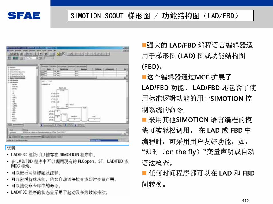
SFAE
419
SIMOTION SCOUT 梯形图 / 功能结构图(LAD/FBD)
强大的 LAD/FBD 编程语言编辑器适
用于梯形图 (LAD) 图或功能结构图
(FBD)。
这个编辑器通过MCC 扩展了
LAD/FBD 功能。 LAD/FBD 还包含了使
用标准逻辑功能的用于SIMOTION 控
制系统的命令。
采用其他SIMOTION 语言编程的模
块可被轻松调用。 在 LAD 或 FBD 中
编程时,可采用用户友好功能,如:
“即时(on the fly)”变量声明或自动
语法检查。
任何时间程序都可以在 LAD 和 FBD
间转换。

SFAE
420
运动控制图 (MCC)
运动控制图 (MCC) 可以用简单合理的工具通过
图形化的形式描述机器的流程。 可以用一个或多
个流程图表示各独立动作的顺序。首先,MCC 借助其强大的运动控制命令可以很
简便的描述带有多轴的机器的运动顺序(例如,
原点轴,定位轴,同步或非同步凸轮,等)
各种命令均可以用于机器顺序的控制,例如,等待条件满足的命令,扫描或设置 I/O 信号,方
程式的计算;各种控制结构,如条件(IF),分支
(CASE) 和循环 (WHILE, REPEAT UNTIL) 等。
可以建立多个 MCC 程序来描述不同的过程状
态。 例如,用户可以建立一个 MCC 程序以在打
开电源后使机器进入起始状态。另一个MCC 用于正常生产,第三个 MCC 用于在出错
时机器的反应。所有的命令均装在工具条中 - 按功能分类 -
用鼠标选择后会自动找到所在流程图中的位置。
点击各独立单元可以打开附加参数设定窗口。 当
然,还可以在文件顺序中加入注释。

SFAE
421
高级结构文本语言 (ST)
高级结构文本语言 (ST) 提供了所有的控制命令。
可以用于建立结
构化的应用程序。
满足所有要求的基本命令:
• 数据管理
• 计算功能
• 控制结构
• I/O 操作
附加运动控制技术软件包提供了强大的,扩大的控
制命令的范围,高度灵活的运动控制命令 ( 如:
_pos(...) 用于轴的定位)。
ST 源文件基本上是以连续的文本构成。 文本可以
划分成段,由此表达 ST 源文件的逻辑单元。
这些单元包括:
• 程序分配给某个实时任务层
• 带有专署的数据块的功能块
• 不带专署数据块的功能
功能及功能块可以不被分配给某个实时任务层, 它
们由程序来调。

SFAE
422
SIMOTION SCOUT 创建简单凸轮(基本)
凸轮用于定义引导轴(主轴)的运动与跟随轴(从轴)之间的关
系。 凸轮也可采用变速曲线、压力特征值或液压轴
阀门特征修正值。 凸轮技术软件包可以将凸轮以插补表或多项式
的形式表示出来。SCOUT 的基本范围包括在表格中以文本形式创建简单
凸轮或借助组态支持以图形形式创建多项式的编辑器。
在建立凸轮技术目标时可以确定使用“插补表”或“多项式”。
插补表:主轴与从轴的位置可以输入一个两列的表格中。插补表也可以从其它来源获得(ASCII 文件,Excel 表)。
•多项式:多项式描述了符合 VDI 2143 标准的运动的原理。SIMOTION 支持多至六阶多项式。处于多项式模式时,凸轮被描述成一系列连续的多项式。 输入设定是以多项式表格的形式实现的。 用户可以使用多项式对话框和/ 或者 VDI 助手。
输入的结果以曲线的形式显示在窗口的右半部分。另外,可以设置补充参数,例如插补点间插补的类型。
SIMOTION CamTool 选项包可以用来显示和优化图形
化凸轮。
优势
• 简单凸轮编辑器已经包含在 SCOUT 的基本配
置中
• 图形化的凸轮显示可以快速甄别错误输入
• 插补表格的显示可以选择由其他来源输入
(ASCII, EXCEL)• 多至六阶多项式描述,由多项式对话框及 VDI 提示提供帮助

SFAE
423
SIMOTION SCOUT图形化凸轮编辑器
SIMOTION CamTool 时一种有效的图形化编辑器,用于凸轮的建立及优化。SIMOTION CamTool 作为 SIMOTION SCOUT
的扩展软件包使用,它可以完全集成在SIMOTION SCOUT 的工程环境中。• 曲线以图形方式及 X-Y 图形(主轴及从动轴位置)。 通过插入固定点、线、及插补点来描述曲线轮廓。 可以使用直线,Sine线及反 Sine 线。
SIMOTION CamTool 将这些元素自动连成曲线。 确保各独立曲线单元间的连接尽可能的和谐。
用鼠标移动曲线单元进行曲线的优化。 曲线的轮廓将按要求改变。
另外,SIMOTION CamTool 可以显示速度及加速度特性,以及主轴运动导致的从动轴的蠕动。
SCOUT 可用于将采用凸轮编辑 (CamEdit) 创建的凸轮转换为凸轮工具 (CamTool) 可以使用的格式,反之亦然。
优势• 准确,图形化显示• 通过插入曲线单元可以快速方便地输入曲线• 通过"dragging the profile" 快速方便的优化曲线• 同时显示位置、速度及加速度。发生蠕动时可及时
指示出对大速度,所需电机扭矩及机械负荷的影响• 曲线可以针对速度,加速度及蠕动进行优化• 基本运动原理符合VDI 2143

SFAE
424
SIMOTION SCOUT测试及调试诊断工具
优势• SCOUT 中集成了大量便
于使用且信息丰富的诊断工具• 为过程优化及故障排除
提供有效支持• 所有信息均可以屏幕显
SCOUT 中集成了一系列的诊断和调试工具,大
大方便了测试及调试工作:• 任务状态,系统负荷及存储器资源可以由装置
诊断来显示。• 诊断缓存区用于出错记录。 以下信息被输入到
缓存区中SIMOTION 程序:- 所有系统状态切换(RUN, STOP 等)- 带日期及时间的系统中断• 所有技术目标所提供的出错信息(例如,轴出
错)均以数值及•文本形式显示在 SCOUT 故障窗口中。当 SIMOTION 在线时可以刷新及监视所有的SIMOTION 系统变量。• 所有编程错误的位置及原因• 程序中的状态显示通过可能的停止点 (ST) 和同步追踪 (MCC) 来帮助用户调试软件。• 监视窗口可以用来排列和显示重要变量。• 调试时可以借助 SIMOTION SCOUT 中机器控制面板改变及优化轴的运动。 使用机器控制面板的功能无需 IMOTION 用户程序。
SFAE
425
sinamics S150

SFAE
426
SINAMICS 各种产品的功率范围
SINAMICS S1500 600200 400 800100 300 500 700
660 .. 690 V900 1000 1100 1200
Oct.2004
0 200 400
110 kW to 250 kW
100 300
380 .. 480 V500 600 800700
Oct. 2004
75 kW to 315 kW

SFAE
427
System overview - SINAMICS S150Core statement
SINAMICS S150 cabinet unitsare designed for variable-speed drives in machine and plant construction.
They are especially suitable for the following applications
• for variable-speed drives with high dynamic requirements
• frequent braking cycles with high energy levels when braking
• and 4-quadrant operation.
SINAMICS S150 offers a high-performance closed-loop speed control with high precision and dynamic response.
The drive converter cabinet units are available in the power range from 75 kW to 1200 kW.
General brochure

SFAE
428
System overview - SINAMICS S150 Core statement
Regenerative feedback into the line supply asstandardHigh precision line supply infeed that has a high dynamic responseHarmonics fed back into the line supply canalmost be neglected when using the innovatedClean Power FilterReactive power can be compensatedModular RITTAL/TS8 cabinet systemwith standard dimensions (HxDxB = 2000x600x dependent on the power, in a 200 mm grid)Low fan noiseProfibus connection and AOP30 as standardFootprint has been reduced by approx. 20 % with respect to Masterdrives AFEWide range of optionsDrive documentation specifically drawn-up for a particular contract

SFAE
429
System overview - SINAMICS S150 Technical data
400 (380 .. 480) V
Power ranges, voltages
The Active Line Module stabilizes the DC link voltage to an adjustable value of 1,5 x of the rated line supply voltage.
Vline supply VDC link =1.5 x Vlinesupply
400 V 600 V
690 V 1035 V
Fig.: 380..480 V 200..250 kW
0 200 400100 300 500
0 200 400 600 800100 300 500 700 900 1000 1100 1200
600 800700
75 ..
110 ..
.. 1200 kW
.. 800 kW
690 (660 .. 690) V

SFAE
430
System overview - SINAMICS S150 Interface to control the drive
CU320Control Unit
MotorModule
TM31Option
TM31Standard
TM31 customer interface: 8 digital inputs4 bi-directional inputs/outputs2 analog inputs2 analog outputs2 relay outputs (changeover contact)1 input for a temperature sensor
Interface as standard for connecting to the customer’s control. This is automatically pre-assigned during the commissioning phase.The customer interface can be expanded, e.g. using a 2nd TM31Internal interface to the motor module, main contactor control, fan, ... .Separate wiring of the internal cabinet options to the Control Unit. This is automatically pre-assigned during the commissioning phase by selecting the appropriate options.All interfaces are connected to the Control Unit via DRIVE-CLiQ.
Digital I/Os for internal cabinet optionssuch as EMERGENCY STOP, PT100,..
DRIVE-CLiQ
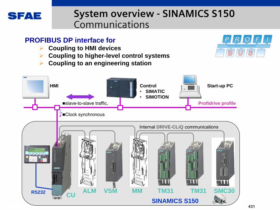
SFAE
431
System overview - SINAMICS S150 Communications
CU ALM TM31 SMC30TM31VSM MM
HMI Control• SIMATIC• SIMOTION
Profidrive profile
PROFIBUS DP interface forCoupling to HMI devicesCoupling to higher-level control systemsCoupling to an engineering station
Start-up PC
slave-to-slave traffic,
Clock synchronous
SINAMICS S150
Internal DRIVE-CLiQ communications
RS232

SFAE
432
75 kW90 kW
110 kW132 kW
400 kW450 kW560 kW
710 kW800 kW900 kW
1000 kW1200 kW
160 kW200 kW250 kW315 kW
110 kW132 kW
200 kW250 kW
315 kW400 kW450 kW
560 kW710 kW800 kW
160 kW
400 + 1200 600 + 1200 600 + 400 + 600 + 600
Technical data Modular cabinet system from RITTAL
B = 400 + 1000 600 + 600 + 800 + 800
Frame size for Active Interface Module / Active Line Module and Motor ModulesFI/FX GI/GX GI/GX HI/HX JI/JX
Wide range of power ratings in a modular cabinet system.
Rated power at 690 V : 75 .. 1200 kW
Rated power at 400 V : 110 .. 800 kW
H =
200
0, T
= 6
00

SFAE
433
Examples Masterdrives 6SE71..-5BA0 SINAMICS S150
400V / 400 kW
690V / 1200 kW
Technical data Comparison to Masterdrives
B = 3000 B = 2200
B = 3600 B = 2800
The cabinet width and weight have been able to be significantly reduced with SINAMICS S150.Distributed over the product range, the average reduction is as follows:Width: approx. 79 % (SINAMICS S150 to Masterdrives)Weight: approx. 91 %Current consumption: approx. 98 %
Fig.:400V, 250kW

SFAE
434
Technical data Overload currents
SINAMICS S150 provide an overload reserve in order, for example, to overcome breakaway torques. If higher surge loads occur, then this must be taken into account when engineering the particular drive.For drives with overload requirements, then the appropriate base load current must be used as basis for the load demanded.
Load duty cycle over 300 sec:
Depending on the application, a lower or higher overload can be selected – but it can also vary within these limits.
ohne IL_kurz IL_lang IH_kurz IH_langÜberlast 150% 110% 160% 150%
I_G, A 330 320 320 280 280Zeit_2, s 300 290 240 290 240I_Max, A 0 480 352 448 420Zeit_1, s 0 10 60 10 60
I_N, A 330 327 327 287 313ohne G1_kurz G1_lang G2_kurz G2_langÜberlast 150% 110% 170% 150%
I_G, A 330 320 320 280 280Zeit_2, s 300 290 240 290 240I_Max, A 0 480 352 476 420Zeit_1, s 0 10 60 10 60
I_N, A 330 327 327 289 313
(300A)
(400A)
(500A)
10 60 3000 10 60 3000 T, sec.
I L*110%
I L*150%
I H
I N_eff
I H*150%
I H*160%
I L
High overload, for base load current IH160 % for 10 sec and 150 % for 60 sec
Low overload, for base load current IL150 % for 10 sec and 110 % for 60 sec
300 s 300 s
Example:

SFAE
435
SINAMICS SINAMICS GM150GM150
0.6–10 MVAmax. 28 MVA
Medium Voltage2.3 kV / 3.3 kV / 4.16 kV / 6 kV /6.6 kV / 7.2 kV
Air-/Water-cooled
3-level NPCVoltage Source
Inverter
HV-IGBTIGCT
SINAMICS SINAMICS SM150SM150
5–10 MVAmax. 28 MVA
Water-cooled
Medium Voltage3.3 kV
3-level NPCVoltage Source
Inverter
IGCT
SINAMICS SINAMICS GL150GL150
2.5–70 MVAmax. 140 MVA
Medium Voltage1.8 – 13.4 kV
Air-/Water-cooled
LoadCommutated
Inverter
Thyristor
SIMOVERT SIMOVERT DD
3–25 MVA
Air-/Water-cooled
Medium Voltage1 - 4 kV
CycloConverter
Thyristor
RobiconRobiconPerfect Perfect
HarmonyHarmony0.15–35 MVAmax. 140 MVA
Medium Voltage2.3 – 14.4 kV
Air-/Water-cooled
Multi CellVoltage Source
Inverter
LV-IGBT
Product overview - LD Medium Voltage Drives

SFAE
436
sinamics GM150

SFAE
437
System overviewThe medium-voltage drives in the SINAMICS family
SINAMICS GM150
Single-motor applications with• Variable and constant torque
characteristic• No regenerative feedback
Typical Applications are:• Pumps and fans• Compressors• Extruders and mixers• Mills
SINAMICS SM150
Demanding single- and multi-motor applications with
• High dynamics• Operation at low frequency• Regenerative feedback
Typical Applications are:• Rolling mill drives• Mine hoists• Test beds
IGBT
IGCT

SFAE
438
System overviewProduct features
Feature SINAMICS GM150 SINAMICS SM150
Power section technology IGBT IGCT IGCT Line Module (Line-side rectifier) Basic Line Module, 12-pulse Standard No
Optional Basic Line Module, 24-pulse (Standard for 6.0 – 7.2 kV
and converters with parallel connection)
(Standard for converters
with parallel connection)
No
Active Line Module (regenerative) No Standard
Motor Module (Motor-side inverter) Voltage range 2.3 – 7.2 kV 3.3 kV 3.3 kV Power range 600 kVA - 10 MVA 10 – 28 MVA 5 – 28 MVA Control for
• Induction motor • Separately excited synchronous motor • Permanently excited synchronous motor
Standard Optional
No
Standard Optional Optional
Standard Optional Optional
DC bus configuration with multiple Motor Modules connected to a common DC bus
No No Standard
Sine-wave filter Optional No No Cooling • Air-cooling • Water-cooling
Standard Standard
No
Standard
No
Standard

SFAE
439
• 600 kVA ... 10 MVA• Air-cooling and water-cooling• 3AC, 50/60Hz,
2.3 / 3.3 / 4.16 / 6.0 / 6.6 / 7.2 kV • Output frequency up to 250 Hz • Power factor > 0.96• Efficiency 98.5% (typical)
• 12- und 24-pulse infeed• Operation of converter motors as
well as standard motors• Control for IM and SYM• Easy operation with standardized
operator panel• Integrated Maintenance Functions• Degree of protection up to IP54• Compact• Inexpensive• Low noise design• UL Listing
System overviewSINAMICS GM150 (IGBT): Main features
Market leader inHV-IGBT Technology
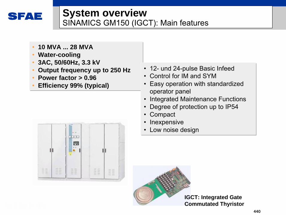
SFAE
440
System overviewSINAMICS GM150 (IGCT): Main features
• 10 MVA ... 28 MVA• Water-cooling• 3AC, 50/60Hz, 3.3 kV • Output frequency up to 250 Hz • Power factor > 0.96• Efficiency 99% (typical)
• 12- und 24-pulse Basic Infeed• Control for IM and SYM• Easy operation with standardized
operator panel• Integrated Maintenance Functions• Degree of protection up to IP54• Compact• Inexpensive• Low noise design
IGCT: Integrated Gate Commutated Thyristor
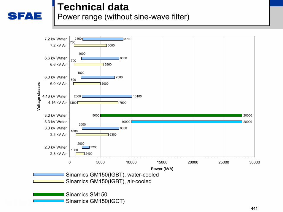
SFAE
441
Technical dataPower range (without sine-wave filter)
Sinamics GM150(IGBT), water-cooledSinamics GM150(IGBT), air-cooled
Sinamics SM150Sinamics GM150(IGCT)
10000
5000
1300
2000
2400
3200
6300
8000
28000
28000
7900
10100
5000
7300
5500
8000
6000
87002100700
1900
700
600
1800
2000
1000
1000
2000
0 5000 10000 15000 20000 25000 30000
2.3 kV Air
2.3 kV Water
3.3 kV Air
3.3 kV Water
3.3 kV Water
3.3 kV Water
4.16 kV Air
4.16 kV Water
6.0 kV Air
6.0 kV Water
6.6 kV Air
6.6 kV Water
7.2 kV Air
7.2 kV WaterVo
ltage
cla
sses
Power (kVA)

SFAE
442
Technical dataPower range (with sine-wave filter)
Sinamics GM150(IGBT), air-cooledSinamics GM150(IGBT), water-cooled
2000
2400
5400
6100
6600
7900
4000
5800
4200
6400
4300
70001700500
1600
500
1400
500
1600
1100
1500
900
1500
800
0 5000 10000 15000 20000 25000 30000
2.3 kV Air
2.3 kV Water
3.3 kV Air
3.3 kV Water
4.16 kV Air
4.16 kV Water
6.0 kV Air
6.0 kV Water
6.6 kV Air
6.6 kV Water
7.2 kV Air
7.2 kV Water
Volta
ge c
lass
es
Power (kVA)

SFAE
443
Technical dataStandards and certifications
• The system has been developed according to the standards:
• The system fulfills the applicable Standards regarding the Machine and EMV Directives
• The SINAMICS GM150(IGBT), air-cooled,2.3 – 4.16 kV are cULus approved (tested by UL according to the UL and CSA Standard)
• In the following industry sectors:• - Chemical industry: NAMUR• - Marine certification
EN 61800-3, EN 61800-4,EN 61800-5-1, EN 60146-1-1,EN 50178, EN 60204-11

SFAE
444
Power sectionFeatures, customer benefits
Features Customer benefitsThe cooling system can be freely selected (IGBT)
• Air-cooling: Costs associated with the water supply are eliminated
• Water-cooling: Reduces the power loss dissipated into the electrical room, lower noise levels, especially suitable for difficult ambient conditions
Optionally with or without sine-wave filter (GM150 IGBT only)
• Without filter: very compact, highest dynamics• With filter: Optimal for standard motors
Simple power semiconductors:HV-IGBT and IGCT
• Highest reliability for powers up to 10 MVA (IGBT) and above (IGCT)
Self-healing DC link capacitors • High reliability• Life time more than 22 years
The type and mounting location of the transformer can be freely selected
• Outdoor mounting: saves up to 30% space and reduces the power loss in the electrical room by up to 50%
• Indoor mounting: less cabling

SFAE
445
Circuit breaker
Converter transformer
Basic Line Module(diode rectifier)
Motor Module(3-level NPC inverter)with HV-IGBT
Motor-side pts and cts
DC link withdry-type capacitors
MV motor
2,3...36 kV 3~ 50 / 60 Hz
=
~3
=
~3
Power sectionPower section topology SINAMICS GM150 (IGBT)
=

SFAE
446
Circuit breaker
Converter transformer
Basic Line Module(diode rectifier)
Motor Module(3-level NPC inverter)with IGCT
Motor-side pts and cts
DC link withdry-type capacitors
MV motor
Power sectionPower section topology SINAMICS GM150 (IGCT)
2,3...36 kV 3~ 50 / 60 Hz
=
~3
=
~3
=

SFAE
447
Power sectionPower section configurations SINAMICS GM150
• Base unit• 12-pulse infeed• Base unit• 12-pulse infeed
• Option N15• 24-pulse infeed
through series connection of two Basic Infeed
• Standard for 6.0 / 6.6 and 7.2 kV
• Option N15• 24-pulse infeed
through series connection of two Basic Infeed
• Standard for 6.0 / 6.6 and 7.2 kV
=
~3
=
~3
=
~3
=
~3
=
~3
• Option L08• Output reactor for long
motor cables
• Option L08• Output reactor for long
motor cables

SFAE
448
Power sectionPower section configurations SINAMICS GM150(IGBT)
• Power increase through parallel connection of Basic Infeed and Motor Module on a common DC bus
• Voltages 2.3 / 3.3 und 4.16 kV• 24-pulse infeed as standard
• Power increase through parallel connection of Basic Infeed and Motor Module on a common DC bus
• Voltages 2.3 / 3.3 und 4.16 kV• 24-pulse infeed as standard
Requires motors with two separate winding systems.With output reactor (L08) also suitable for motors with only one winding system.
=
~3
=
~3
=
~3
=
~3
=
~3
=
~3
=
~3
=
~3
• Power increase through series connection of Basic Infeed and Motor Module on a common DC bus
• Voltages 6.0 / 6.6 und 7.2 kV• 24-pulse infeed as standard
• Power increase through series connection of Basic Infeed and Motor Module on a common DC bus
• Voltages 6.0 / 6.6 und 7.2 kV• 24-pulse infeed as standard

SFAE
449
Power sectionPower section configurations SINAMICS GM150(IGBT)
=
~3
=
~3
=
~3
=
~3
=
~3
=
~3
• Option Y15• Sine-wave filter for operation of standard motors• For applications with variable torque
characteristic (Pumps, fans, etc.)
• Option Y15• Sine-wave filter for operation of standard motors• For applications with variable torque
characteristic (Pumps, fans, etc.)
Sine-wave filter

SFAE
450
Power sectionPower section configurations SINAMICS GM150 (IGCT)
=
~3
=
~3
=
~3
=
~3
=
~3
=
~3
=
~3
=
~3
=
~3
=
~3
• Power increase through parallel connection of two complete converter units
• 24-pulse infeed possible
• Power increase through parallel connection of two complete converter units
• 24-pulse infeed possible
• Power increase through parallel connection of three complete converter units
• 36-pulse infeed possible
• Power increase through parallel connection of three complete converter units
• 36-pulse infeed possible
Requires motors with two separate winding systems.

SFAE
451
Power sectionDesign SINAMICS GM150 (IGBT)
Air- and water-cooling for the complete range
HV-IGBT Power Cards
SINAMICScontrol
Motor Module
Basic Line Module
air cooling
water cooling
Powercard

SFAE
452
Power sectionDesign SINAMICS GM150 (IGBT)
SINAMICSRegelung
Motor Module
Basic Line Module
Powercard Door interlocks
Connections from top and
bottom
Excellent connectability
Diodes and HV-IGBT on Powercards
Low noise fan design
CU320
Voltage and current transducers
Integrated DC link
grounding switch

SFAE
453
Power sectionHV-IGBT Powercards SINAMICS GM150 (IGBT)
Plug-in type HV-IGBT Powercards:• Modular and compact design• Quick and simple replacement
(less than 15 min)• Light-weight for easy handling
Plug-in type HV-IGBT Powercards:• Modular and compact design• Quick and simple replacement
(less than 15 min)• Light-weight for easy handling
• 3.3 kV HV-IGBT for output voltages 2.3 kV / 3.3 kV / 4.16 kV
• NEW 6.5 kV HV-IGBT for output voltages 6 kV / 6.6 kV / 7.2 kV
• 3.3 kV HV-IGBT for output voltages 2.3 kV / 3.3 kV / 4.16 kV
• NEW 6.5 kV HV-IGBT for output voltages 6 kV / 6.6 kV / 7.2 kV

SFAE
454
Power sectionDesign of a 10 MVA base unit SINAMICS GM150 (IGCT)
IGCT phase moduleCU320
PSA
Motor ModuleBasic Line Module
SINAMICScontrol
Diode modules for 12-pulse or 24-pulse
infeed
Supplementary fans
IGCT
Supplementary fans

SFAE
455
Power sectionIGCT phase modules SINAMICS GM150 (IGCT)
IGCT with driver circuit
di/dt reactor (toroidal)
Cooling water connection
IGCT stackFree-wheeling
diode stack
Stack for other elements

SFAE
456
Features Customer benefitsPre-assigned interfaces • Simplified engineering and commissioning
Variable BICO wiring • Flexible for individual solutions
Block diagram • Clear transparent overview to connect-up the interfaces, options and drive components
Parameters to select the command sources and setpoint sources
• Interfaces can be simply, quickly and safely changed – also after the first commissioning
Local - remote changeover • Local control can be simply selectedCommand data sets that can be toggled between
• Control is accessible from various locations
Operation, visualization,
controlCentral customer interface
Control and interfacesFeatures, customer benefits
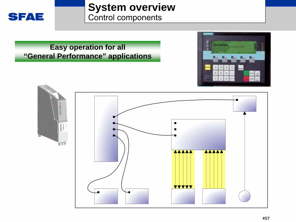
SFAE
457
System overviewControl components
Easy operation for all“General Performance” applications

SFAE
458
Features Customer benefitsThe performance of the closed-loop control can be scaled
• V/f control (open-loop) for group drives• Vector control for high dynamic speed response and torque
accuracy up to the limiting areas• Encoder interface for the highest speed accuracy
User-friendly basic commissioning
• The closed-loop control can be very easily and transparently configured using AOP30 or the STARTER tool
Setpoint channel with • Variable setpoint sources• Suppression (skip) frequencies against machine resonances• Extensive n, f, I limits to protect the motor• User-friendly ramp-function generator for optimized adaptation to
the processExtensive functions for induction motors
• Energy functions (V-DC link (min / max) controller)• Temperature monitoring functions
Maintenance functions • High degree of plant availability• Cost-savings because non-scheduled plant downtimes can be
avoided
Closed-loop controlFeatures, customer benefits

SFAE
459
Closed-loop control• Closed-loop Vector and torque control with and without encoder• V/f control with various characteristics• Automatic restart function (this function is being prepared)• Flying restart• Vdc max controller• Kinetic buffering
Setpoint channel• Setpoints that can be toggled between from all interfaces selected
via control commands• Internal: 15 fixed setpoints, motorized potentiometer and jog
setpoint• External: PROFIBUS DP and analog/digital customer interface
• Four suppression bands for resonant frequencies • Minimum and maximum limits, direction of rotation reversal• Ramp-function generator with ramp-up/ramp-down times that can be
separately set as well as rounding-off and additional fast stop ramp.
Closed-loop controlClosed-loop control functions

SFAE
460
Automatic restart (WEA)• This allows an automatic start after power failure and/or fault
within just a few seconds.
Flying restart• This allows a drive controller to be connected to a motor
that is still spinning
Starting functions for increased availability and a higher degree of user-friendliness.
Closed-loop controlStarting and energy functions
Energy functions increase the availability and reliability.
Vdc max control• The braking ramp is automatically flattened to avoid
overvoltage conditions in the DC link – this increases the availability
• In conjunction with an Active Infeed – generally only required for power failure (emergency retraction concept).
Kinetic buffering (KIP), Vdc min control• Vdc-min control to buffer brief line supply failures in the ms
range – useful for unstable line supplies

SFAE
461
Even when the power limits are exceeded and a series of circuit faults occur at the motor, the motor and drive converter are still protected.
Closed-loop controlProtective functions
Temperature monitoring to protect the motor• The motor temperature is evaluated and Imax is reduced• Motor temperature detection with PTC or PT100
Motor anti-stall protection• A stalled motor is protected against thermal overload by a fault
trip.
Drive converter temperature protection• A temperature model and temperature sensors in the power
section can trip the drive converter when threshold values are exceeded – or can reduce the thermal load.
Ground-fault monitoring• Insulation faults are detected by an insulation monitor.
Electronic short-circuit protection at the output• Three-stage protection against short-circuit in the motor or
motor cables (the current is limited by the closed-loop control, hardware threshold, UCE monitoring)

SFAE
462
Closed-loop controlMaintenance functions
• Operating time counters for fans of air-cooled.• Differential pressure monitor determines the amount of dust in
the air-inlet filter.• Conductivity measurement continuously checks the ion
exchange performance of the ion exchanger.• Counter for switching operations of the circuit breaker with and
without load.
Customer benefits:Prevention of non-scheduled downtimes with loss of production and costly repair service calls.
Maintenance functions continuously monitor components subject to wear, e.g. fans and indicate when service is required. This allows procurement and replacement of such components before they actually fail.

SFAE
463
Features Customer benefitsTotally Integrated Automation • Integrated engineering, data management and
communicationsIntegrated PROFIBUS interface • Without any additional price, connection to
PROFIBUS partnerThe drive is automatically parameterized for standard telegram 1
• The drive is simply, quickly and reliably integrated into a higher-level control
Teleservice • Shorter service times through the possibility of support from the central customer service
Can be expanded using option cards • Prepared for CAN bus, Ethernet and other bus systems
CommunicationsFeatures, customer benefits
GM150
GM150

SFAE
464
OptionsFeatures, customer benefits
Features Customer benefitsComprehensive range of options • Flexible customization to customer needs
• Easy plant integration• A separate auxiliary control cubicle is
unnecessary in most cases
All options can be ordered with a short-code
• Short delivery times due to a simplified automatic ordering procedure and processing with a configurator
Standardized options • Simplified engineering due to clear definition of interfaces
3
3
3
3 P
0
M
M

SFAE
465
OptionsSystem overview

SFAE
466
System overview... for a broad spectrum of motors
HH--compactcompactIECIEC
200 - 3000 kW
2 - 11 kV2 - 12 pole
Squirrel cage
Cast iron housingwith cooling ribs
IP55
HH--modynmodynIEC, ANEMAIEC, ANEMA
7000 - 50000 kW9390 – 67000HP
6 - 13.2 kV2 - 12 pole
Squirrel cageSynchronous
Base frame,Water cooling
IP55, WP II
Series Series 1R.5/S.51R.5/S.5
IECIEC7000 - 10000 kW
3.3 - 13.2 kV4 - 24 pole
Squirrel cageslip ring rotorSynchronous
Cast iron-/ Steel housing,
cooler assemblyIP55, WP II
HH--compactcompactPLUSPLUS
IEC, ANEMAIEC, ANEMA1000 - 7000 kW1340 – 9390 HP
3.3 - 13.2 kV2 - 12 pole
Squirrel cage
Cast iron-/ Steel housing,
cooler assemblyIP23, IP55, WP II
SpecialSpecialmotorsmotors
2000 - 65000 kW
690 V - 13.2 kV
Squirrel cagesynchronous
Example:Highspeed
compressordrive
ANEMAANEMA150 - 2500 HP
0.2 – 11 kV2 - 16 pole
Squirrel cage
Cast iron housingwith cooling ribs
IP55/TEFC
200 - 10000 HP
0.2 - 13.8 kV2 - 16 pole
Squirrel cage
Cast iron housing
cooler assembly
ODP, WP I, WP II, TEAAC/TEWAC
ANEMAANEMA
RetrofitRetrofit
• Existing motors with standard windings
• May be operated with sine-wave filter (GM150(IGBT) only)
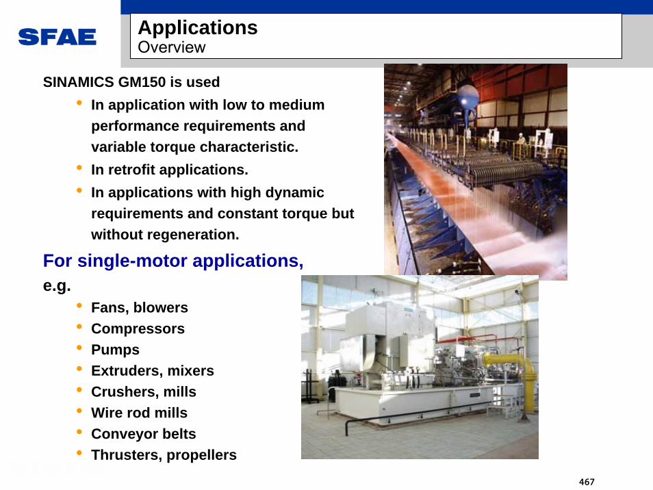
SFAE
467
SINAMICS GM150 is used• In application with low to medium
performance requirements and variable torque characteristic.
• In retrofit applications.• In applications with high dynamic
requirements and constant torque but without regeneration.
For single-motor applications,e.g.
• Fans, blowers• Compressors• Pumps• Extruders, mixers• Crushers, mills• Wire rod mills• Conveyor belts• Thrusters, propellers
ApplicationsOverview

SFAE
468
Paper
Oil & Gas
Chemical
PowerShipbuilding
Mining
Water &Waste water
Cement
SINAMICS GM150
Fans
PumpsCompressors
ApplicationsOne product for all applications

SFAE
469
sinamics GL150

SFAE
470
Power range: 2.5 – 70 MVA
Voltage range: 2 – 12 kV
Motor: Synchronous motor
Operation: 4 Q
Output frequency: 0 ... 105 Hz, 6300 RPM
Topology: LCI (Load Commutated Inverter)
Technology: Thyristor
Cooling: Air or water cooling
Closed-loop control: TRANSVEKTOR® closed-loop control
Options: Starting converter, redundant thyristors,Tele-Service, complete project planning….
Features: Cost effective, extremely high power rating, highest degree of reliability
Applications: Oil & gas: all compressor typesMarine: main marine drives, booster
drives, shaft generatorsPower: boiler feed pumps, starting
generators Steel: starting blast furnaces, wire rod
mills Others: Extruders, all types of pumps
Overview

SFAE
471
Air-cooling: 2.8 MVA – 19.4 MVA3AC, 50/60Hz, 1.8 – 5 kVWater-cooling: 6.0 MVA – 74 MVA3AC, 50/60Hz, 2.6 – 12 kVOutput frequency up to 125 Hz Power factor = 1 @ rated speedEfficiency 99% (typical)
Load Commutated Inverter (LCI)4Q-operation standard6-pulse, 12-pulse and 24-pulseControl of synchronous motorsEasy operation with standardized operator panelStarting converter (air-cooled)Redundant thyristorsHighest power densityHighest degree of reliability
ProvenThyristor technology
Main features

SFAE
472
*synchronous motor drive MW = MVA
0 10 20 30 40 50 60 70 80
1.8 kV 6 pulse, air
1.8 kV 12 pulse, air
2.6 kV 6 pulse, air
2.6 kV 12 pulse, air
3.3 kV 6 pulse, air
3.3 kV 12 pulse, air
5.0 kV 6 pulse, air
5.0 kV 12 pulse, air
2.6 kV 12 pulse, water
5.2 kV 12 pulse, water
7.8 kV 12 pulse, water
10.4 kV 12 pulse, water
12 kV 12 pulse, water
Power [MW]
Power ranges
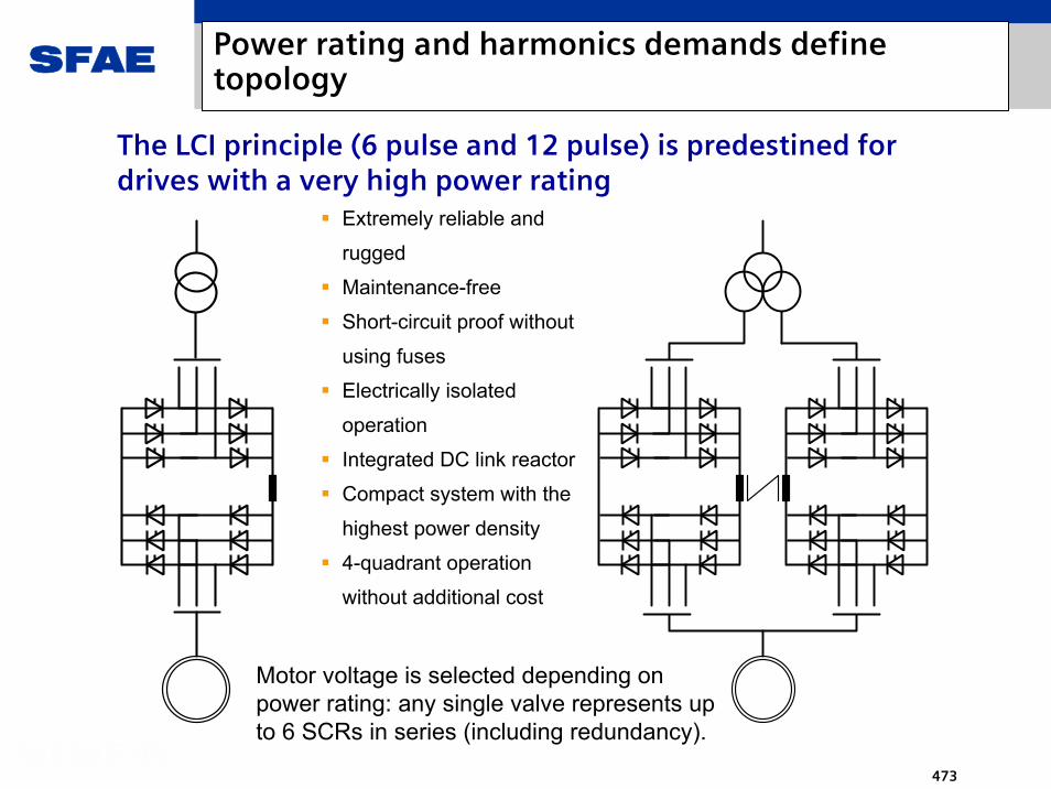
SFAE
473
The LCI principle (6 pulse and 12 pulse) is predestined for drives with a very high power rating
Extremely reliable and
rugged
Maintenance-free
Short-circuit proof without
using fuses
Electrically isolated
operation
Integrated DC link reactor
Compact system with the
highest power density
4-quadrant operation
without additional cost
Motor voltage is selected depending on power rating: any single valve represents up to 6 SCRs in series (including redundancy).
Power rating and harmonics demands define topology

SFAE
474
3500 5500 7000
N1
N2
M1
M2
N1
N2
M1
M2
2.6 kV6.0 – 16 MW
5.2 kV21 – 32 MW
7.8 kV31.5 – 48 MW
9000 9000
N1
N2
M1
M2
N1
N2
M1
M2
N1
N2
M1
M2
N1
N2
M1
M2
10.4 kV50 – 64 MW
12 kV58 – 74 MW
Dimensions, water cooling

SFAE
475
600036003600
6 pulse1.8 –2.6 kV2.8 – 6.2 MW
6 pulse3.3 – 5.0 kV5.7 – 9.7 MW
12 pulse1.8 – 2.6 kV5.7 – 12.4 MW
12 pulse3.3– 5.0 kV10.7 – 19.4 MW
SIMOVERT S: Dimensions, air cooling

SFAE
476
Features Customer benefits
Wide power range:Air cooled 2.8-19.4 MWWater cooled 6 -74 MW
Uniform design of water cooled resp. air cooled power stacks
Lower training costs for OEMs and system integratorsLow training costs for end customer personnelLimitation of the number of suppliersLimitation of the parts variety
Namur & ship certifications Lower training costs for OEMs and system integrators
Compactness in volume and footprint through highest power density
1.06 .. 2.5 MW/m3
Saves space and costs for the electrical room
Highlights
Customer benefits

SFAE
477
When compared to voltage-source DC link converters, SINAMICS GL150 has some characteristic advantages in its particular power range:
As a result of the circuit principle (LCI=converter motor), there are a minimum of power semiconductorsAs a result of its overload capability, the thyristor is extremely ruggedExtremely high efficiency due to the minimum number of power semiconductorsSimple topology : no turn-off circuit required Fault tolerant as a result of a patented arrangement of the DC link reactor The maximum power rating is not limited (>100MW)The motor winding is not stressed by dv/dt as a result of the LCI principleContinues to operate after the power fails (ride-through) and automatic restart functionality are characteristic features of LCI topology – no additional costs/equipment required
Last but not least:
Proven reliablility: 35 years of experience with LCI drives
Highlights

SFAE
478
A SIMOREG DC MASTER DC controller is used for synchronous motors with slip-ring excitation.
1 Fused disconnector 4 Circuit-breker2 Line filter and power supply 5 Sliprings3 Grond fault monitorig 6 Main excitation (field) winding
main motor
5
432
1
EEW
AC
DC
Excitation curent setpointfrom the flux controller of
the transvector control
DC current excitation - SIMOREG

SFAE
479
Excitation machine with rotating rectifiers,fed using the SIMOTRAS three-phase controller
1 fuse disconnector 5 ac voltage controller2 transformer and line filter for 6 stator of the exciter machine ac control power supply 7 rotor with diode wheel3 ground fault monitor 8 main motor rotor4 contactor
rotating part
main motorexciter machine
8
7
6
5432
1
EEW
Brushless excitation – SIMOTRAS (1)

SFAE
480
Rotor of the excitation machine with rotating rectifier
Brushless excitation – SIMOTRAS (2)

SFAE
481
Features Customer benefitsPre-assigned interfaces Simplified engineering and commissioning
Variable BICO wiring Flexible for individual solutions
Block diagram Clear transparent overview to connect-up the interfaces, options and drive components
Parameters to select the command sources and setpoint sources
Interfaces can be simply, quickly and safely changed – also after the first commissioning
Local - remote changeover Local control can be simply selected
Command data sets that can be toggled between
Control is accessible from various locations
Operation, visualization,
controlCentral customer interface
Control: features, customer benefits

SFAE
482
Easy operation for all“General Performance” applications
Control system / regulation
Control components

SFAE
483
Every SINAMICS cabinet unit has a graphics LCD display with the following features:
User-friendly menu for simple prompted (navigated) drive commissioningPlain text display and bar-type graphics to monitor/visualize process quantities in a user-friendly fashionLEDs to display the operating statesExtensive help functions with a description of the causes and help to resolve faults and alarms.The drive is controlled from the AOP using LOCAL-REMOTE changeover2-stage safety conceptMulti-lingual
Drive controlLocal / remote On, offReversingJog, up, down
LED to displayvarious states
On greenAlarm yellowFault red
ConditionsLocal/Remote key LocalControl authority inhibited, p0806=1
ConditionsLocal/Remote key LocalControl authority inhibited, p0806=1
In the “Local” mode, the control authority is either assigned to the AOP30 or the STARTER start-up tool. Changeover to local in the “Run” state can be enabled at the AOP.
Operator control with the AOP30

SFAE
484
Retaining lugRetaining lug
RS232/PPI interface for AOP30RS232/PPI interface for AOP30
4 2-color status LEDs4 2-color status LEDs
3 test sockets to monitor drive values 3 test sockets to monitor drive values
CompactFlash Cardfor the software and selected parameters
CompactFlash Cardfor the software and selected parameters
Integrated lateral holdersIntegrated lateral holders
Option slot to expand the interfaces (CBC10)Option slot to expand the interfaces (CBC10)
4 DRIVE-CLiQ ports for communication with additional drive components:Active Line / Motor Modules, Terminal / Sensor Modules)
4 DRIVE-CLiQ ports for communication with additional drive components:Active Line / Motor Modules, Terminal / Sensor Modules)
8 digital inputs8 bi-directional DI/DO (of
which, 4 are fast DI)
8 digital inputs8 bi-directional DI/DO (of
which, 4 are fast DI)
24 V DC connection, electronics power supply24 V DC connection, electronics power supply
PROFIBUS address switch under the dummy cover
PROFIBUS address switch under the dummy cover
PROFIBUS-DP interfacePROFIBUS-DP interface
The CU320 Control Unit contains the internal interfaces to the other drive components (DRIVE-CLiQ, RS232, DI/O), the link to the external open-loop control (PROFIBUS) as well as the software and drive program (CompactFlash-Card).
CoverCover
Control unit CU320

SFAE
485
Powerstack Adaptor (PSA)
Interface between the control components and power stack
Fiber-optic interface to gate drive units
Actual value signal interface
Analog and digital inputs and outputs
Actual Value Transmitter (AVT-C)
Signal level adaptation
Sigma-delta A/D-conversion
Manchester coding
Fiber-optic interface to Powerstack Adaptor
Interface to power section

SFAE
486
Standard ComponentsControl Cabinet
Voltage SensingModule VSM10(synchronization.)
SensorModule SMC30
TerminalModulesTM15,TM31
Power Stack
PSA
CU320
PSA
TerminalModulesTM15,TM31
PSAPSA
additional PSA accordingto power rating
Optional Components
Drive topology

SFAE
487
Features Customer benefitsThe performance of the closed-loop control can be scaled
V/f control (open-loop) for commissioningVector control for high dynamic speed responseEncoder interface for the highest speed accuracy
User-friendly basic commissioning
The closed-loop control can be very easily and transparently configured using AOP30 or the STARTER tool
Setpoint channel with Variable setpoint sourcesSuppression (skip) frequencies against machine resonancesExtensive n, f, I limits to protect the motorUser-friendly ramp-function generator for optimized adaptation to the process
Control: features and benefits

SFAE
488
Features Customer benefitsTotally Integrated Automation Integrated engineering, data management and
communications
Integrated PROFIBUS interface Without any additional price, connection to PROFIBUS partner
The drive is automatically parameterized for standard telegram 1
The drive is simply, quickly and reliably integrated into a higher-level control
Teleservice Shorter service times through the possibility of support from the central customer service
Can be expanded using option cards Prepared for CAN bus, Ethernet and other bus systems
GM150
GL150
• Connection to HMI devices• Connection to higher-level controls• Connection to an engineering station
Communication: features and benefits
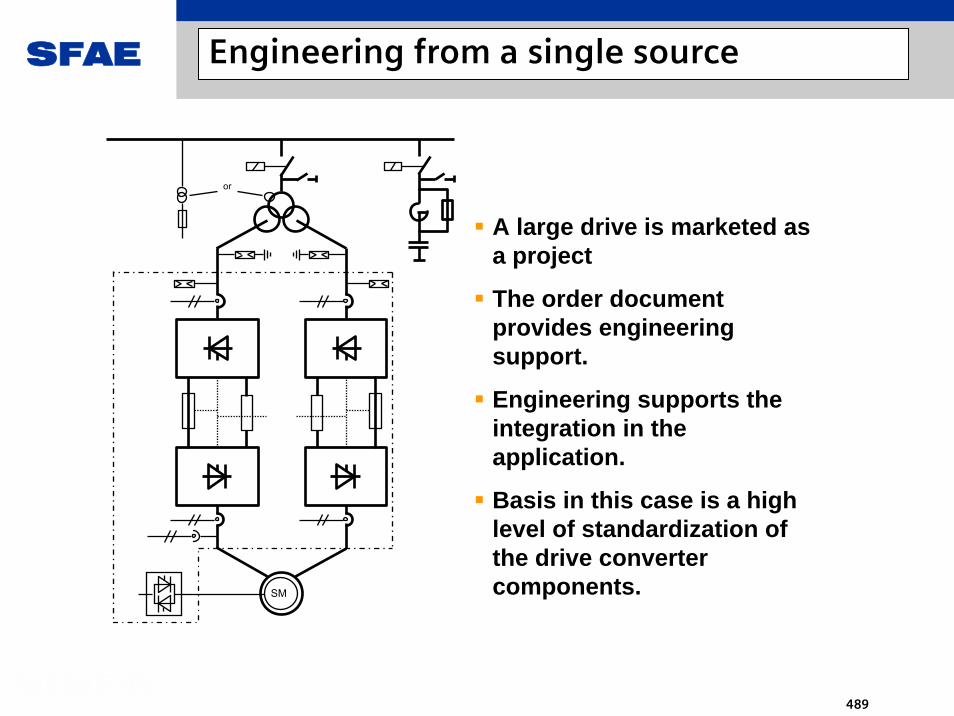
SFAE
489
or
SM
A large drive is marketed as a project
The order document provides engineering support.
Engineering supports the integration in the application.
Basis in this case is a high level of standardization of the drive converter components.
Engineering from a single source

SFAE
490
Features Customer benefitsRugged components High degree of availability and long lifetime
Remote diagnostics / maintenance Global support through Teleservice
Service-friendly mechanical design Fast serviceability
Few power components Simple designEfficient spare parts stocking for customers
Modem
Modem
LocalOperatingPanel
Service &Diagnostic PC
Manufacturer‘s Teleservice Center
ClientInstallation
Power bus
ConverterTransformer
Rectifier
DC link
Inverter
RotatingString
Controlsystem
Serviceability

SFAE
491
HH--modynmodynIEC, ANEMAIEC, ANEMA7000 - 50000 kW
9390 – 67000HP
6 – 13.2 kV2 - 12 pole
Synchronous
Steel frame,water cooling
IP55, WP II
SpecialSpecialmotorsmotors2000 - 65000 kW
690 V – 13.2 kV
Synchronous
Example:High-speed
compressor drive
The motor must be designed for operation as converter motor:
The motor voltage is adapted
Sub-transient reactance may not exceed certain limits
excitation is required: brushless or via slip-ring
Advantages of the LCI: the motor winding is not subject to dV/dt stresses
Taking all known requirements into account leads to an optimum drive solution:
Motor and drive converter are optimally designed corresponding to the system requirements.
For the retrofit business, motor / transformer / line data of the existing installation are important to achieve the desired system performance
Motors

SFAE
492
SE
parallelingunitPSG
Simadyn Dfor
soft-starterSD AUR
Simadyn Dfor
processcontrol
communi-cationSD AK
SErr
SNSA
SErr
SNSA
SM 2SM 1
Using the starting converter, the synchronous motor is accelerated to a speed corresponding to the line frequency and then transferred to the line supply.
Application: starting converter

SFAE
493
Compressor drives for gas storage facilities
Compressor drive for the Trans-Canada Pipeline
Main drives for cruise ships
Starting converter for blast furnaces Boiler-feed
pump drives
Application examples

SFAE
494
sinamics SM150

SFAE
495
System overviewMain features
IGCT: Integrated Gate Commutated Thyristor
• 5 MVA ... 28 MVA• Water-cooling• 3AC, 50/60Hz, 3.3 kV • Output frequency up to 250 Hz • Adjustable line power factor• Efficiency 99% (typical)
• Active Infeed• Common DC bus for multi-motor applications
• Control for IM and SYM• Convenient operation with high-end operator panel
• Integrated Maintenance Functions
• Degree of protection up to IP54
• Compact• Inexpensive• Low noise design

SFAE
496
Technical dataPower range (without sine-wave filter)
Sinamics GM150(IGBT), water-cooledSinamics GM150(IGBT), air-cooled
Sinamics SM150Sinamics GM150(IGCT)
10000
5000
1300
2000
2400
3200
6300
8000
28000
28000
7900
10100
5000
7300
5500
8000
6000
87002100700
1900
700
600
1800
2000
1000
1000
2000
0 5 0 0 0 1 0 0 0 0 1 5 0 0 0 2 0 0 0 0 2 5 0 0 0 3 0 0 0 0
2 .3 kV A ir
2 .3 kV W a te r
3 .3 kV A ir
3 .3 kV W a te r
3 .3 kV W a te r
3 .3 kV W a te r
4 .1 6 kV A ir
4 .1 6 kV W a te r
6 .0 kV A ir
6 .0 kV W a te r
6 .6 kV A ir
6 .6 kV W a te r
7 .2 kV A ir
7 .2 kV W a te r
Volta
ge c
lass
es
P o w e r (k V A)

SFAE
497
Circuit breaker
Converter transformer
Active Line Module(3-level NPC inverter)with IGCT
Motor Module(3-level NPC inverter)with IGCT
Motor-side pts and cts
DC link withdry-type capacitors
MV motor
Power sectionPower section topology SINAMICS SM150
2,3...36 kV 3~ 50 / 60 Hz
=
~3
=
~3
Line-side cts
Line-side pts
=

SFAE
498
Power sectionPower section configurations SINAMICS SM150
=
~3
=
~3
=
~3
=
~3
=
~3
=
~3
=
~3
=
~3
=
~3
=
~3
=
~3
=
~3
• Power increase through parallel connection of two complete converter units
• Power increase through parallel connection of two complete converter units
• Power increase through parallel connection of three complete converter units
• Power increase through parallel connection of three complete converter units
Base unitBase unit

SFAE
499
Power sectionPower section configurations SINAMICS SM150
=
~3
=
~3
=
~3
Configurationen for multiple motors on one DC bus
• DC bus configuration with two motors fed from a common DC bus
• DC bus configuration with two motors fed from a common DC bus
• DC bus configuration with three motors fed from a common DC bus
• DC bus configuration with three motors fed from a common DC bus
• Smaller line side converter
• Less energy consumption
• Smaller transformer
• Smaller line side converter
• Less energy consumption
• Smaller transformer

SFAE
500
Power sectionDesign of a 10 MVA base unit SINAMICS SM150
SINAMICScontrol
IGCT phase module
Motor ModuleActive Line Module
PSAShort-circuiting
device
D445CX32
DC link grounding
switch
IGCT
Supplementary fans
Supplementary fans

SFAE
501
System overviewControl components
D445
Convenient operation for all„High Performance“ applications
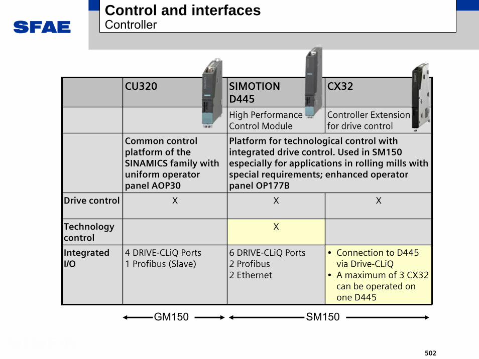
SFAE
502
Control and interfacesController
CU320 SIMOTIOND445
CX32
High Performance Control Module
Controller Extensionfor drive control
Drive control X X X
IntegratedI/O
4 DRIVE-CLiQ Ports1 Profibus (Slave)
6 DRIVE-CLiQ Ports2 Profibus2 Ethernet
• Connection to D445 via Drive-CLiQ
• A maximum of 3 CX32 can be operated on one D445
Common control platform of the SINAMICS family with uniform operator panel AOP30
Platform for technological control with integrated drive control. Used in SM150 especially for applications in rolling mills with special requirements; enhanced operator panel OP177B
Technology control
X
GM150 SM150
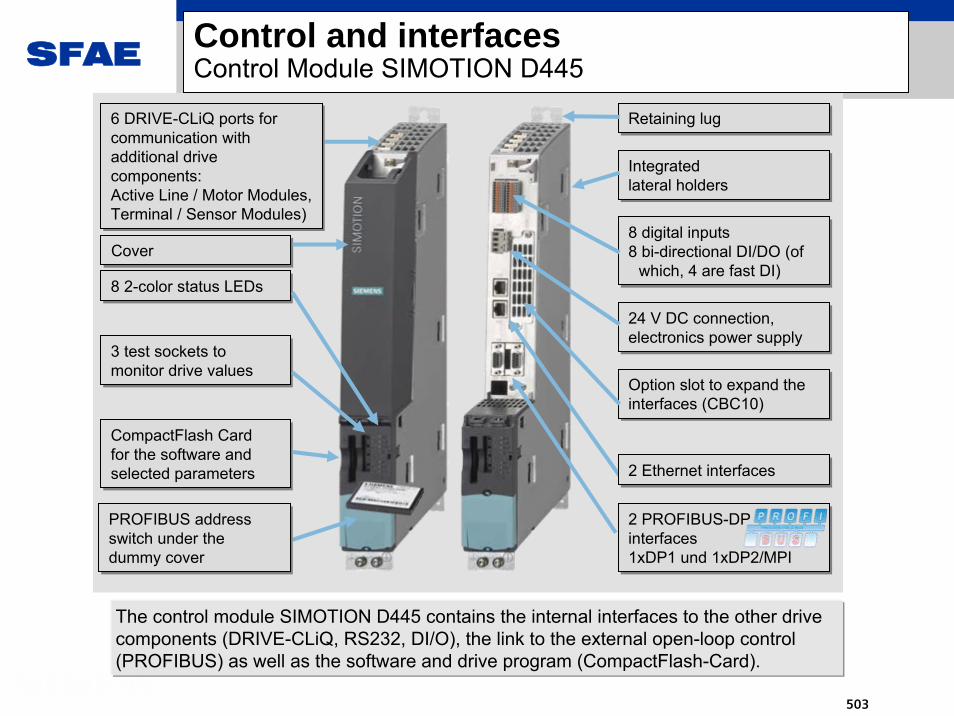
SFAE
503
Control and interfacesControl Module SIMOTION D445
6 DRIVE-CLiQ ports for communication with additional drive components:Active Line / Motor Modules, Terminal / Sensor Modules)
6 DRIVE-CLiQ ports for communication with additional drive components:Active Line / Motor Modules, Terminal / Sensor Modules)
CoverCover
CompactFlash Cardfor the software and selected parameters
CompactFlash Cardfor the software and selected parameters
3 test sockets to monitor drive values3 test sockets to monitor drive values
2 PROFIBUS-DP interfaces1xDP1 und 1xDP2/MPI
2 PROFIBUS-DP interfaces1xDP1 und 1xDP2/MPI
24 V DC connection, electronics power supply24 V DC connection, electronics power supply
8 digital inputs8 bi-directional DI/DO (of
which, 4 are fast DI)
8 digital inputs8 bi-directional DI/DO (of
which, 4 are fast DI)8 2-color status LEDs8 2-color status LEDs
PROFIBUS address switch under the dummy cover
PROFIBUS address switch under the dummy cover
Option slot to expand the interfaces (CBC10)Option slot to expand the interfaces (CBC10)
Retaining lugRetaining lug
Integrated lateral holdersIntegrated lateral holders
2 Ethernet interfaces2 Ethernet interfaces
The control module SIMOTION D445 contains the internal interfaces to the other drive components (DRIVE-CLiQ, RS232, DI/O), the link to the external open-loop control (PROFIBUS) as well as the software and drive program (CompactFlash-Card).

SFAE
504
Control and interfacesDrive topology SM150
• Up to three PSA(motor-side inverters)
• Up to three CX32(one for each ALM)
• Profibus interface to the excitation unit
• Profibus interface to the ET200• Ethernet interface to the
Simatic OP• Profibus interface to the higher-
level automation system

SFAE
505
Closed-loop controlLine-side reactive power control SINAMICS SM150
Customer benefits:
Contribution to plant profitability due to the possibility to provide reactive power for other consumers if the converter is selected accordingly.
With the Active Infeed it is possible to flexibly adjust the line-side reactive power. This makes it possible to compensate the reactive power consumption of other consumers/drives.By continuously providing a variable set point value, reaction to changing load situations on the line is possible.

SFAE
506
System overview... for motors for special applications
Rolling mill motors
Solid pole synchronous machines
Power range: 500 kW ... 12 MW
Speed range: 50 ... 900 rpm
Slipring excitation
Hoist motors
Salient pole synchronous machines with external rotor
Power range: 500 kW ... 8 MW
Speed range: 40 ... 100 rpm

SFAE
507
System overviewThe product for high-performance applications
Metals
SINAMICS SM150
Mine hoists
Rolling mills
Mining
Test beds

SFAE
508
美国罗宾康完美无谐波高压变频器SIEMENS LD-R ROBICON
西门子上海电气传动设备有限公司大型传动-罗宾康部

SFAE
509
高压变频器的应用的目的
1. 节能
2. 满足工艺要求
3. 创建和谐社会,提高生产力和效益
输出电压为2.3kv以上的变频器称为中压变频器,
与低压变频器相对而言

SFAE
510
WHY USE ADJUSTABLE SPEED DRIVE CONTROL为什么要采用变频器
ENERGY SAVINGS 节能需要
Centrifugal loads 离心式负载
Pumps 泵
Fans 风机
目前80%的能量是被离心式风机和水泵和压缩机消耗的
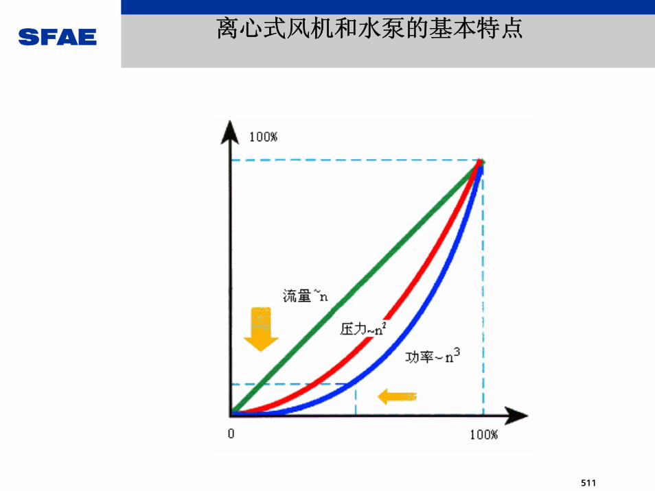
SFAE
511
离心式风机和水泵的基本特点

SFAE
512
Constant Speed Operation Constant Speed Operation 水泵常速运行特点水泵常速运行特点

SFAE
513
ENERGY SAVINGS BASICS
0
20
40
60
80
100
120
140
160
180
1 2 3 4 5 6 7 8 9 10 11

SFAE
514
VariableSpeed drive
Driven
LoadSupply
NetworkMotor
No harmonicvoltage or
current distortion
Near unitypower factor
No harmonicheating
No insulationstress
No additionalbearing current
No rotationaltorque
oscillations
Fault tolerantenabling operation
with failures
Small footprint
Easy repair
High efficiency
Ideal Variable Speed Drive System 理想的整套系统

SFAE
515
美国罗宾康高压变频器的基本特点
正弦波输入,无需滤波器,输入谐波优于IEEE519-1992标准和国家标准
GB/T14549-93
输入功率因数0.95以上,无需功率因数补偿器
高压直接输出,高-高结构,没有升压变压器
单元串联多电平PWM专利技术,完美正弦输出波形(无需输出滤波器),
适用国产普通电机
内部干式变压器和功率单元模块化设计,维护方便
矢量控制技术, 恒转矩特性
97% 系统总体效率(包含变频器和变压器部分)
体积 小的高压变频器
可靠性极高
全球范围内超过3000台销售业绩,国内超过500台,业绩处于第一

SFAE
516

SFAE
517

SFAE
518

SFAE
519

SFAE
520

SFAE
521

SFAE
522

SFAE
523

SFAE
524
基 本 选 件
功率单元旁路功能
控制电源UPS及双路电源切换装置
常速/全压旁路
同步切换,用于一台变频带多台电机
高性能闭环矢量控制
通讯接口
8通道电机温度监控仪
热备用通风风扇
中文触摸屏
Y/Delta柜(用于10kv电机)

SFAE
525
控 制 特 点采用开环或闭环矢量控制,恒转矩特性
数字化调制技术(载波频率可调)
输入电能质量监控
控制参数自动优化(电机参数自动优化)
具有同步切换功能
支持高速电机(0-330Hz),超过180Hz以后降额
整套控制系统可以冗余设计
可以设置8套不同的电机和保护参数
多台变频器并联运行
升步/降步功能(可设置步长)
内置IPD
转矩限制模式
主从方式(多电机同步运行,适合于多台皮带机电机传动)
双频制动功能(专利)

SFAE
526
ROBICON 电 力 应 用
1. 火电厂各种辅机场合: 凝结水泵, 送风机,引风机
,一次风机,给水泵,循环水泵,取水泵,渣浆泵
2. 机组:
100MW,135MW,150MW,200MW,300MW,350MW,600MW,9
00MW
3. 五大发电集团和各地方电力系统
4. 电力总量超过200台以上

SFAE
527
新海电厂2*1400kw/6kv 凝结水泵
一拖二方式
节电率达30%以上,非常可观

SFAE
528
山西阳城电厂2*2300kw水源地取水泵
每天节电和水费费达1万元以上,非常可观
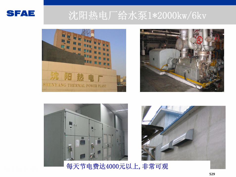
SFAE
529
沈阳热电厂给水泵1*2000kw/6kv
每天节电费达4000元以上,非常可观

SFAE
530
2 x 4200kWLiquid Cooled System

SFAE
531
PHILLIPS BOHAI BAY PL19-3A platform (23sets)

SFAE
532
上海高桥炼油厂 2800kw/6kv 变频器-高速压缩机(11000rpm)
节电率达30%以上,非常可观,2年内收回投资

SFAE
533
Perfect Harmony ConceptReliability - The proof
Reliability - the proof!
3.7MW wet gas compressor
Refinery duty
5 years guaranteed tripfree operation
Started end of 2000
Three year payback oninvestment
5 year maintenanceperiod extended to6 years

SFAE
534
Integrated System DeliveryLiquid Cooled System

SFAE
535
Crude oil pump drives for pipeline
String test of 6MWdrive with pump
Installation in Scotland

SFAE
536
String test at compressor factory
Apache Forties platform
2MW artificial gas lift compressors, 15 ESP drives3 Water injection pumps

SFAE
537
Motors and drives for MOL pumps in Qatar
String test at pump factory

SFAE
538
Enclosures for drive systems
Motor pipeline compressors
8MW compressor drives for gas pipeline - England

SFAE
539
Amoco Orient, South China Sea, ESP-3KM Shell Gannet, North Sea, ESP-14KMPetrobras Brazil, Campos Basin, ESP-3KMMarathon Oil, Gabon West Africa, ESP-3KMTexaco Captain, North Sea, ESPTFE, North Sea, Otter ESP-23kMPhillips China Bohai Bay, 4KM ESPBP, UK, ESP-10kM
ESP-Electric Submersible Pump24-1000HP ESP’s on one Platform
Petrobras Brazil, Campos Basin, FPSOMobil Oil, Gulf Of Mexico, Texaco, Gulf Of Mexico, FPSO
FPSO - Floating Production Storage & Offloading
Amoco Orient
Over 200,000HP of deep water production & storage.

SFAE
540
15km
Perfect Harmony4 Years Operation at 15km

SFAE
541
23.3km
1500HPESP drives operating
on a step-outof 23km.

SFAE
542
14 ESP Drives + 2 Booster Pump Drives
Santos Mutineer FPSO Australia
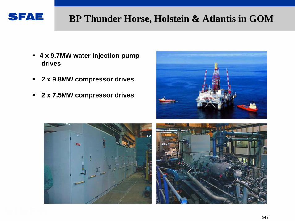
SFAE
543
4 x 9.7MW water injection pumpdrives
2 x 9.8MW compressor drives
2 x 7.5MW compressor drives
BP Thunder Horse, Holstein & Atlantis in GOM

SFAE
544
15 Drives 250kW - 4.4MW crude oil pump drives for Kuwait.

SFAE
545
5.4MW high speed compressor drives for gas storage

SFAE
546
宝钢集团高炉除尘风机 1000KW/6KV 1台
柳钢焦化厂除尘风机 630KW/6KV 2台
通化钢铁厂除尘风机 800KW/6KV 1台
邢钢炼钢厂除尘风机 800KW/6KV 1台
包钢二炼钢除尘风机 2500HP/6KV 1台同步机
包钢水厂 1600KW/6KV 1台同步机
南京钢铁集团公司 3500kw/7.2kv 2台除鳞泵
武钢集团能源部 500kw/6kv 1台鼓风机
武钢集团八万立方米柜 500kw/6kv 1台风机
宝钢能源部 300kw/3.3kV 1台水泵
首钢焦化厂除尘风机 1000KW/6KV 1台
邢钢炼钢厂除尘风机 800KW/6KV 2台(续购)
鞍钢集团燃气厂 630kw/6kv 3台煤气压缩机(同步切换)
首钢矿业 3200kw/10kv 除尘风机1台(同步机)
攀钢集团高炉除尘风机 1800kw/6kv 1台
石家庄钢铁公司炼铁厂 1400kw/6kv 1台除尘风机(拆除原液力偶合器)
攀钢集团煤气化工程 2300kw/6kv 1台风机
邯郸钢铁公司炼铁厂 1600kw/6kv 1台除尘风机
涟钢焦化厂除尘风机 2000kw/6kv 1台
鞍钢集团燃气厂 900kw/6kv 1台风机
重钢动力厂 4500kw/6kv 1台
ROBICON 钢铁行业应用

SFAE
547
南京钢铁公司2*3500kw/7.2kv 除鳞水泵
Profibus通讯方式
冷却风扇在背后

SFAE
548
ROBICON 国内市政行业应用
Kw 输出电压 kv 数量
上海大场水厂 1400 6 2
上海合流污水二期工程SB泵站 1600 6 2
上海合流污水二期工程M2泵站 1000 6 2
上海合流污水二期工程SA泵站 1000 6 2
苏州新加坡工业园区取水泵站 680 3.3 2
北京第九水厂扩建工程 2550 6 2
北京第九水厂扩建工程 1150 6 1
四川宜宾五粮液水厂 250 6 1
上海临江水厂 1000 6 1
东莞上江城水厂 1250 4.16 1
包钢给水厂3#泵站 1600 6 1
苏州工业园区清源水业公司 630 6 1
呼和浩特引黄工程 315 6 2
呼和浩特引黄工程 560 6 2
上海化学工业区自来水有限公司 450 6 1
上海化学工业区自来水有限公司 630 6 1
温州珊溪水利枢纽新状元水厂 500 6 1
温州珊溪水利枢纽供水新状元水厂 800 6 1
东莞市第五水厂供水工程二期 1690 4.16 3
苏州水厂 1250 6 1
重庆唐家沱污水处理厂一期工程 750 6 2
杭丰水厂 355 6 1

SFAE
549
• 风洞测试 (CLVC)
哈尔滨风洞 9 5 0 0 kw/6kv, 配套电机为上海电机厂
300rpm,20p,9500kw,6kv
• 测试台(CLVC)
哈飞直升机螺旋浆测试台, 2000kw,6kv,208rpm, 配套电机
为哈电,1500kw,20.8Hz,208rpm
• 重型燃机启动辅助装置
• 高炉煤气联合发电 (CCPP)
• 皮带机
• 挤出机
ROBICON 国内特殊应用

SFAE
550
重钢高炉煤气联合发电 (CCPP)
电机为上电出品,异步电机17000kw/10kv
压缩机为沈鼓制造
变频启动装置为ROBICON提供,规格为
6500KW/10KV

SFAE
551
甘肃省平凉煤矿 皮带机 750kw/6kv

SFAE
552
Automation Control System Conveyor TR 15
Ethernet TCP-IP (optical link – future)
VFD VFD VFD
M1900 HP4160V1200 RPM
Existing PLCLoad Sharing sw
DeviceNet network
I/O
M4900 HP4160V1200 RPM
M3900 HP4160V1200 RPM
M2900 HP4160V1200 RPM
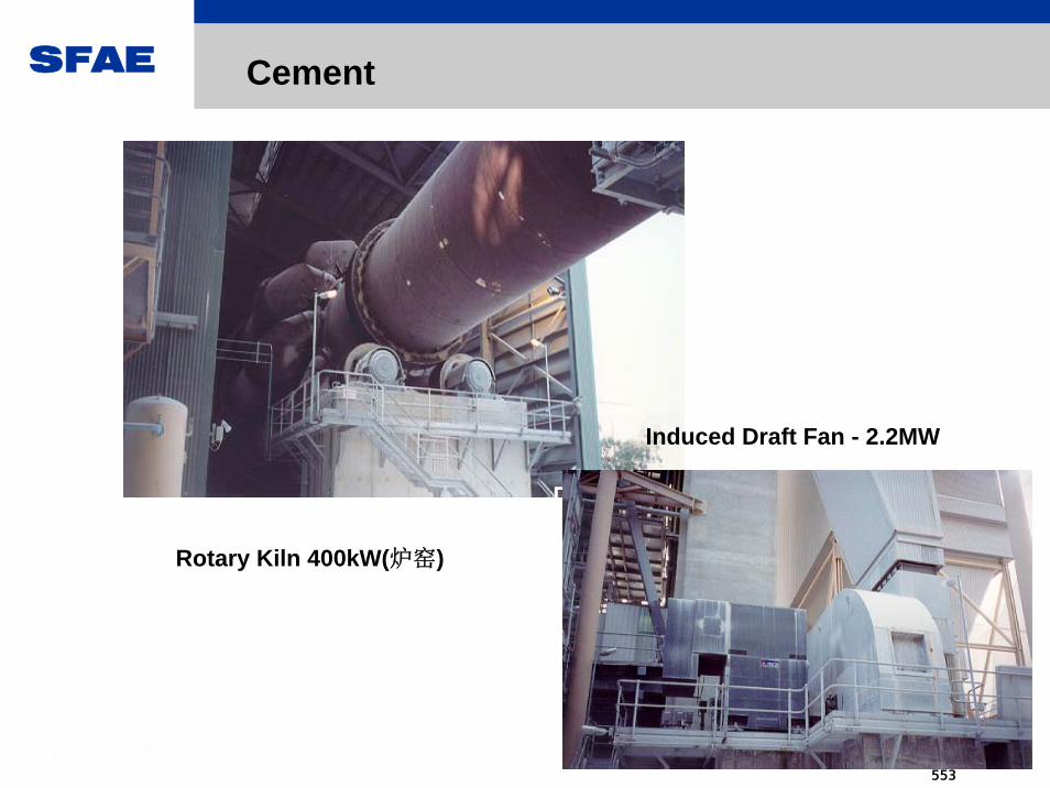
SFAE
553
Electric Submersible PumpRotary Kiln 400kW(炉窑)
Induced Draft Fan - 2.2MW
Cement

SFAE
554
A group of Norwegian and international companies are already well underway with the construction of Ormen Lange
The world’s longest subseaexport pipeline
The gas will be transported approximately 1200 kilometers from Nyhamna via Sleipner in the North Sea
Sub-sea Variable Speed Drives
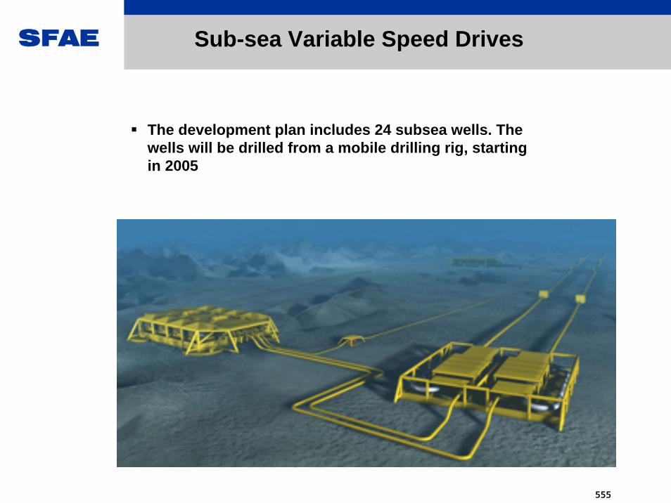
SFAE
555
The development plan includes 24 subsea wells. The wells will be drilled from a mobile drilling rig, starting in 2005
Sub-sea Variable Speed Drives


