Embed Size (px)
Citation preview

1
Thermally Drawn Biodegradable Fibres with Tailored Topography for Biomedical
Applications
Syamak Farajikhah1,* , Antoine F. J. Runge1, Badwi B. Boumelhem2, Ivan D. Rukhlenko1,
Alessio Stefani1,3, Sepidar Sayyar4, Peter C. Innis4,5, Stuart T. Fraser2,6, Simon Fleming1,6, and
Maryanne C. J. Large1*
1The University of Sydney, Institute of Photonics and Optical Sciences (IPOS), School of Physics,
Camperdown 2006, NSW, Australia
2The University of Sydney, Discipline of Physiology, School of Medical Sciences, Camperdown
2006, NSW, Australia
3DTU Fotonik, Department of Photonics Engineering, Technical University of Denmark, DK-2800
Kgs. Lyngby, Denmark
4Australian National Fabrication Facility – Materials Node, Innovation Campus, University of
Wollongong NSW 2500, Australia
5ARC Centre of Excellence for Electromaterials Science (ACES), AIIM Facility, Intelligent Polymer
Research Institute (IPRI), Innovation Campus, University of Wollongong NSW 2500, Australia
6The University of Sydney, Sydney Nano Institute, 2006, NSW, Australia

2
Abstract: There is growing demand for polymer fibre scaffolds for biomedical applications and
tissue engineering. Biodegradable polymers such as polycaprolactone have attracted particular
attention due to their applicability to tissue engineering and optical neural interfacing. Here we report
on a scalable and inexpensive fibre fabrication technique which enables the drawing of PCL fibres
in a single process without the use of auxiliary cladding. We demonstrate the possibility of drawing
PCL fibres of different geometries and cross-sections, including solid-core, hollow-core and grooved
fibres. The solid-core fibres of different geometries are shown to support cell growth, through
successful MCF-7 breast cancer cell attachment and proliferation. We also show that the hollow-
core fibres exhibit a relatively stable optical propagation loss after submersion into a biological fluid
for up to 21 days with potential to be used as waveguides in optical neural interfacing. The capacity
to tailor the surface morphology of biodegradable PCL fibres and their non-cytotoxicity make the
proposed approach an attractive platform for biomedical applications and tissue engineering.
Keywords: PCL fibres, thermally drawn fibres, tailored cross-section, biodegradable fibres, cell
cultures, PCL capillary waveguides
1. Introduction
Over the last decade, natural and synthetic polymer fibres and scaffolds have emerged as an
alternative to biological grafts in tissue engineering1,2. Scaffolds for tissue engineering require
characteristics specific to the application and the tissue of interest. Properties such as
biocompatibility, biodegradability, porosity, tissue-like mechanical properties and appropriate
surface morphology are essential for an ideal scaffold3,4. Additionally, the quality of tissue
regeneration strongly depends upon the mechanical properties of the scaffold3. Scaffolds should be
strong enough to support tissue regeneration and satisfactorily maintain their integrity during cell

3
growth but not so rigid as to cause adverse tissue response5,6. The mechanical properties of the
scaffolds should also mimic the mechanical strength of the native tissue5.
Ceramics, naturally derived polymeric structures, and synthetic polymers are the most commonly
used materials in scaffolds for tissue engineering3. The brittle nature of ceramic materials, such as
those based on calcium phosphate and magnesium phosphate, limits their application in tissue
engineering. Scaffolds made from naturally derived materials such as collagen, chitosan and
hyaluronic acid demonstrate good biocompatibility, hydrophilicity and cell affinity, but lack
mechanical strength3,7. Hence, synthetic polymer scaffolds with the desired mechanical strength and
tunable structure such as poly(ε-caprolactone) (PCL), polylactic acid (PLA) and poly(lactic-co-
glycolic) acid (PLGA) have emerged7. PCL is one of the most commonly used biodegradable
materials in biomedical applications and tissue engineering, due to its low inflammatory response,
biocompatibility, ease of synthesis, low melting point, suitable mechanical properties and
processability8–10.
The key to successful tissue engineering and regenerative therapy with functional synthetic
biomaterials like PCL is the development of novel structures that are biocompatible and have useful
architecture and surface features4,11. Cell–scaffold interactions, cell differentiation and self-renewal
ability can be modulated by tuning biophysical (surface topography) and mechanical (stiffness and
elasticity) properties of biomaterials. Scaffolds mimicking the native physical and physicochemical
properties of the extracellular matrix (ECM) support cellular functions such as migration,
differentiation, proliferation and tissue regeneration11. The topography of polymer scaffolds has been
modified to include grooves or pores to mimic the structural features of the extracellular landscape
and control the cell shape in vitro. Abagnale et al. reported that intracellular responses, such as
proliferation and directed differentiation, are triggered by forces resulting from the interaction of

4
cells with surface topography11. They found that the spreading of human embryonic stem cells
(ESCs) can be tuned by surface roughness, and lineage-specific differentiation of ESCs can be
achieved using a defined structure. Koppes et al.12 also reported that surface features, such as grooves
in polymer and fibre scaffolds, accelerate Schwann cell migration and enhance neurite growth and
alignment.
In recent decades, fibre-based PCL structures have been widely developed for biomedical
applications and tissue engineering using different techniques. Malikmammadov et al. reported the
fabrication of wet-spun composite tricalcium phosphate/PCL fibres as a good candidate for bone
tissue engineering applications13. In the wet spinning method, fibre morphology and cross-section
shape greatly depend on the mass transfer rate difference between the solvent and coagulant14.
However, the requirement for a non-solvent can make this method costly15. Xue et al. used melt
spinning to develop processable PCL and nano-hydroxyapatite/PCL composite fibres as a potential
substrate for tissue engineering16. Kelnar et al. reported fabrication of melt-spun PCL-based
composite fibres as another potential substrate for tissue engineering17. Although fibres with
different geometries and cross-sections are spinnable with the melt spinning technique, complex
extrusion mould designs with hundreds of microns resolutions and multistep protocols or complex
spinning setups are required.
Electrospinning has also been used to fabricate PCL fibrous scaffolds. Rafiei et al. developed 3D
tablet-like PCL scaffolds for protein delivery using the electrospinning technique18. In another study,
Lian and Meng developed curcumin-loaded PCL fibres using melt and solution electrospinning as a
potential for drug delivery applications19. Johnson et al. also proposed to use electrospun co-axial
PCL/gelatin nanofibers as vascular graft implants20. The high surface area to volume ratio of
electrospun fibrous architectures and their porous structure are desirable for tissue engineering21.

5
There is a very limited number of reports on fabrication of continuous long electrospun fibres, due
to the technical complexity of the process.
Very recently, Grena et al22. utilised the well-established fibre drawing technique, involving drawing
in a furnace from a macroscale preform, to fabricate solid-core PCL fibres. The fibre drawing
technique is a suitable method for low cost mass production of fibres with desired miniaturized
features difficult to fabricate at scale with traditional techniques12,23. However, a post-processing
chemical etching step was required to remove the cladding material used to sleeve PCL.
Implantable optical waveguides have attracted attention in important applications in biomedical
fields such as optogenetic stimulation24, fluorescence photometry25, laser surgery, and
phototherapy26. Conventional silica-based fibres are standard tools for optical implants24,25.
Although these fibres have advantages, their stiffness27 and non-biodegradability make them
incompatible with biological systems (especially for application in soft brain tissues). Recently,
biodegradable polymer waveguides and fibres have been used in deep-tissue photomedicine28 and
optical neural interfaces27. Such waveguides can be absorbed in biological tissues eliminating the
risks associated with their removal and offering great potential for biomedical applications and
clinical use.
Here we use hollow-core PCL fibres as waveguides, which guide by the grazing incidence reflection
inside the fibre. One end of the fibre is sealed, with negligible ingress of solution into the hollow-
core waveguide. The waveguides exhibit a relatively stable loss after immersion into a biological
fluid for up to three weeks.
With the increasing interest in using fibrous structures for biomedical applications2 and building on
our previous work on drawing soft polymer fibre materials29, for the first time we develop a one-step

6
method for direct drawing of both solid-core and hollow-core PCL fibres with tailored cross sections
and topography.
2. Materials and methods
2.1. Materials
PCL polymer with four different molecular weights, 25K, 37K, 50K and 80K from Polysciences,
Inc., were used as supplied.
2.2. Material characterisation
Differential Scanning Calorimetry (DSC) was performed to determine the melting temperature of
the PCL samples using a TA instrument Q1000. Samples were sealed in hermetic aluminium pans
then placed in the instrument. The heat/cool/heat method (with temperatures between -80°C and
150°C) was used to remove the thermal history of the polymer in the first heat/cool cycle and to
accurately measure the melting point.
Thermal Gravimetric Analysis (TGA) on the PCL samples was performed on a TA instruments
Q5000 under 90 mL/min nitrogen flow using platinum pans. To measure the mass loss of samples
with temperature, the samples were heated up to 650°C with a 10°C/min heating rate, and the mass
loss was recorded.
Dynamic Mechanical Analysis (DMA) was performed using NETZSCH DMA 242 E to evaluate
the mechanical properties of different PCL samples at elevated temperatures. Storage modulus and
tan delta (also known as damping factor) were measured in a dynamic mode at constant strain (0.1
%) and frequency (1 Hz). Strain variation vs temperature was also measured using the TMA mode
of the instrument. Each sample was analysed for at least three times using DMA.

7
Thermal conductivity of the PCL samples were measured using a C-therm TCi thermal conductivity
analyser (C-Therm Technologies Ltd., Canada) as described elsewhere30, using disk samples (Ø ~
30 mm) with 7 mm thickness. A computer-controlled Peltier thermoelectric heater/cooler system
was used to perform heat transfer measurements. Thermal conductivities were measured at room
temperature.
Rheology tests on the PCL samples were performed using a rheometer (Anton Paar MCR 301) at
60°C. Parallel plate geometry of a quartz plate and metallic plate with a diameter of 25 mm and a
0.2-mm-thick gap were used to perform viscosity tests.
The molecular weight profiles, relative to polystyrene standards (PS), of the PCL were confirmed
by GPC (Shimadzu) using a Styragel HR4 (Waters) column in a THF mobile phase at 1.0 mL/min
with an injection volume of 10 µL of 1 mg/mL PCL.
2.3. Fibre fabrication
PCL preforms of 120 mm length were fabricated by melting PCL pellets inside polypropylene and
Teflon moulds of circular, 3-leaf, and 4-leaf cross sectional shapes (all inscribed into a 15-mm
diameter circle) at 80°C for 17 hours. PCL fibres were drawn using a fibre draw tower31, shown in
Figure 1a. The drop-off temperature was set to 90°C (the hot zone temperature inside the furnace
was measured to be approximately 52°C) while the subsequent drawing was performed at 85°C (hot
zone temperature about 48°C). The preform was fed downwards into a furnace at a constant rate of
2 mm/min, and fibres were drawn with a capstan wheel at rates between 0.5 and 1.5 m/min.
2.4. Mechanical properties of fibre
The mechanical properties of the drawn PCL fibres were assessed using an Instron BioPuls
mechanical tester. The fibres were initially mounted into paper frames and then transferred to the
Instron to ensure that they were held vertically between the clamps. The frame sides were cut after

8
mounting and before testing. Fibres of 50 mm length were fixed vertically between two pneumatic
clamps and stretched at a 50 mm/min rate. Young’s modulus was determined as the slope of the
initial linear stress–strain region. Five PCL fibre samples were analysed using Instron BioPuls
mechanical tester and the average value for Young’s modulus was reported.
2.5. Cell culture
Solid PCL fibres with approximately similar diameters were cleaned by submerging in ethanol
(EtOH) overnight. They were then coated with 0.1% (w/v) gelatin solution (Merck-Millipore),
sterilised with UV-C light and placed into a 48 well-plate culture dish. Each PCL fibre was seeded
with 100,000 MCF-7 breast cancer cells (ATCC) in culture media containing Dulbecco’s Modified
Eagle Medium (Sigma), 10% (v/v) foetal calf serum (Bovogen), 1% (v/v) penicillin/streptomycin
(Gibco) and 1x insulin-transferrin-selenium solution (Sigma). To remove cells that had not attached
to the fibres after 24 hours and to monitor cell attachment and proliferation on the PCL fibres, the
fibres were transferred to a new culture dish containing MCF-7 culture media. MCF-7 cell cultures
were maintained in an incubator set to 37°C and 5% CO2 with media replenished every other day.
Duplicate cultures were set up 24 and 48 hours after the initial experiment.
2.6. Cell imaging
After 7 days of culture, MCF-7 cells cultured on PCL fibres were fixed for 15 minutes in 4%
paraformaldehyde (PFA) solution in PBS, washed three times with PBS and then stained with
Phalloidin Atto-565 (Sigma) diluted in PBS containing 0.05% (v/v) Triton X-100 (PBS-T) overnight
at 4°C. Samples were then washed three times in PBS-T and once in PBS alone. A reservoir was
formed on a glass slide using silicone sealant and the fibre transferred to the reservoir which was
then filled with Vectashield with DAPI (Vector Labs) and sealed with a glass coverslip. High
resolution images were taken using a ZEISS LSM 800 confocal microscope coupled with the Zen
9
Blue software package (Advanced Microscopy Facility, Bosch Institute, University of Sydney).
Images were taken using a 20x objective. Phalloidin Atto-565 was excited at 565 nm while DAPI
was excited at 408 nm. Bright-field images were taken with a Zeiss Axiovert35 microscope coupled
with the Zen Blue software package.
2.7. Measurement of optical loss
Single-mode silica fibres (SMFs) were stripped and cleaved at one end, which was inserted into 7 cm
lengths of PCL capillary fibres with 200 µm internal diameter. Silicone sealant was used to fix and
seal the SMF and capillary connection. The fibre capillary sections were then vertically immersed in
PBS solution for periods of 3, 7, 14 and 21 days, and their optical quality was assessed by measuring
the linear propagation loss using a standard cutback technique. The SMF was connected to a 635 nm
laser as shown in Figure 1c. Cutback measurements were performed by repeatedly cutting off
approximately 5 mm sections of the PCL capillary samples and measuring the output power as a
function of the length. The cutback measurements were repeated for three nominally identical
samples for each period of immersion.
3. Results
3.1. Material Characterisation
According to the GPS analysis, all PCL samples were found to have a consistent polydispersity index
(PDI 1.5) indicative of a consistent molecular weight profile between the samples. Molecular
weights relative to PS were found to be 25K PCL (Mn 36.1 KDa, PDI 1.49), 35K PCL (Mn 46.1
KDa, PDI 1.46), 50K PCL (Mn 53.4 KDa, PDI 1.55) and 80K PCL (Mn 120.8, PDI 1.53). Relative
molecular weights were found to be slightly higher than reported by the supplier. The molecular
weight offsets were likely a result of the structural differences between the PS reference and PCL
and the fact that the supplier had no published molecular weight characterisation available for the

10
PCL and inferred a molecular weight value. However, the 80 KDa PCL had a significantly higher
molecular weight profile than reported by the supplier. According to the DSC and TGA spectra
shown in Figures 2a and 2b, the PCL melting point was approximately 55°C while the decomposition
of PCL started at 300°C. The viscosities of different molecular weights of PCL shown in Figure 2c
decreased with the shear rate due to the phenomenon known as shear thinning14,32. DMA analysis
was utilised to further investigate the properties of different PCL samples. To simulate the draw
condition, PCL samples were drawn using a stress sweep test at 50°C using DMA, Figure 3a. Figures
3b and 3c show storage modulus and Tan delta measured in the dynamic mode at constant strain and
frequency.
3.2. Fibre Fabrication
PCL fibres were then successfully drawn from these preforms using the well-established fibre
drawing technique used for making optical fibres. Figure 4 shows that internal and external features
of the preforms were successfully preserved and scaled down in the respective drawn PCL fibres
without either pressurising the hollow preforms over the draw process or using a cladding material.
The outer diameters of the solid, 3-leaf and 4-leaf fibres are 701.7 ± 12 µm, 704.6 ± 15 µm and
692 ± 8 µm, respectively.
3.3. Mechanical properties of fibre
The average Young’s modulus of solid-core PCL fibres was calculated to be 2.14 ± 0.23 MPa.
3.4. Cell culture
For the purpose of investigating the compatibility of the drawn PCL fibres with cell growth in vitro
and determining if there was any dependence on the topology, only the solid fibres were used for
cell culture experiments. MCF-7 breast cancer epithelial cells were chosen as a model system for

11
assessing cell attachment. MCF-7 cells are a highly proliferative cell line of breast epithelial origin.
MCF-7 cells express a broad range of cell adhesion molecules including integrins which are
capable of binding to a range of substrates33 and cadherins which help with cell-cell attachment.
MCF-7 cells also have abundant F-actin fibres which help to form the cytoskeleton and helped
with assessment of cell shape and attachment. MCF-7 cells are routinely used in studies examining
cell attachment and cytoskeleton re-arrangement such as the example given by Nassef and
colleagues34 where MCF-7 cells were used to monitor the effects of gravity on cell attachment. In
order to determine whether our PCL fibres are compatible with cell survival and growth, MCF-7
human breast cancer cells were added to wells of 48-well culture plates containing solid-core fibres
with circular, 3-leaf and 4-leaf cross-sections. As PCL is hydrophobic, the drawn fibres were
incubated with 0.1% (w/v) gelatin prior to incubation with the cells. After 24 hours, MCF-7 cells
were observed (using bright-field microscopy) attached to the surfaces of all three fibres. MCF-7
cells survived and expanded in number over 7 days of culture indicating that the fibres are compatible
with cell attachment and growth (Figure 5a). The fibres with the 3-leaf geometry supported the
largest number of cells in culture with many cells clustering in the grooves of the fibre after 48 hours
(Figure 5b) and expanded further after 6 days of culture (Figure 5c).
To assess cell attachment and growth in detail, confocal imaging of fixed, phalloidin- and DAPI-
stained fibre MCF-7 cultures was performed. Phalloidin staining (red) indicates the F-actin
cytoskeleton of the attached MCF-7 cells whereas DAPI is a fluorescent DNA-binding dye which
stains the nucleus (blue) (Figures 5d and 5e). Again, the fibres with the 3-leaf geometry showed the
most cell attachment (Figure 5d). Phalloidin staining showed F-actin present at the interface between
the MCF-7 cells and the PCL fibre. Strong phalloidin staining was apparent at the cell junctions of

12
cells within the grooves of the 3-leaf fibres (3-leaf geometry in Figure 5d). To confirm that the fibre
geometries were not affected by the culture media, optical micrographs of cross-sections of solid
PCL fibres were taken before and after 7 days of incubation in the culture media (without any cells).
Figure 6 shows that the fibres did not swell in the culture media for over a week and their cross-
sectional shapes remained intact. Supplementary videos S1, S2 and S3 show 3D volume rendering
of the z-stacks of these cultures, demonstrating the three-dimensionality of the cultures surrounding
the circular fibre (video S1) and within the grooves of the 3-leaf (video S2) and 4-leaf cultures (video
S3). To determine whether cells could attach to the fibres without gelatin, MCF-7 cells were
incubated on non-gelatinised fibres and cultured. Cells were found to attach to the fibres without any
prior gelatinisation, with strong attachment indicated by phalloidin staining at the cell–fibre
boundary (Figure 5e). More cells were observed on the gelatinised 3-leaf fibre than on the untreated
3-leaf fibre, yet the hydrophobicity of the PCL did not preclude cell binding directly to the fibre. The
percentage of the fibre surface covered with cells after 24 hours of culture (see Figure S1) was
calculated and shown in Figure 5f.
3.5. Measurement of optical loss
The results of the cutback measurements of the PCL capillaries are shown in Figure 7.
4. Discussion
4.1. Characterisation and fabrication
The 80K PCL sample, due to its higher melt viscosity compared to the PCLs of other molecular
weights (shown in Fig 2c), can facilitate transmitting an applied tensile force within the sample and
exhibit a ductile behaviour35. This characteristic is beneficial in the fibre drawing process where a
shear force is applied to the preform to make fibres

13
As shown in Figure 3a, the elongation at break increases with the molecular weight of PCL. The
80K PCL sample had the lowest initial modulus indicating a more ductile less brittle material suitable
for drawing.
As shown in Figures 3b and 3c, in all the samples, increasing the temperature resulted in a decrease
in the storage modulus and an increase in Tan delta, which is typical in thermoplastic polymers36,
indicating that less force is required to deform the polymer as its temperature approaches the melting
point.
Generally, the storage modulus increases with molecular weight. However, 80K PCL has a storage
modulus smaller than the other samples, which might be attributed to its lower crystallinity as
compared to other samples of lower molecular weights9. The less steep decrease of the storage
modulus with temperature for 80K PCL indicates that this sample can retain its stiffness in this
temperature range better than the other samples.
Tan delta in 80K PCL increases at a lower rate than in the other samples as shown in Figure 3c. This
could also be attributed to higher amorphicity of the 80K PCL sample as compared to the other
samples. Due to the lower crystallinity of 80K PCL compared to the other PCL samples, it has lower
thermal diffusivity37 and also, due to higher molecular weight, it takes longer to deform compared
to the other samples, so it is more resistant to rapid deformation at elevated temperatures.
The variation of strain with temperature, measured using the TMA mode of the instrument, is shown
in Figure 3d. 80K PCL demonstrates the lowest rate of increase in strain due to temperature. This
can be attributed to its higher molecular weight and lower crystallinity compared to the other
samples, which decrease thermal diffusivity rate resulting in a strain at a lower rate.
To confirm the hypothesis of lower crystallinity of 80K PCL compared to the other molecular
weights, the degree of crystallinity was determined by DSC and thermal conductivity analysis. The

14
melt enthalpies of different PCL samples were obtained from DSC thermograms and the degree of
crystallinity was calculated based upon 139.5 J/g for the enthalpy per unit mass of a pure 100%
crystalline PCL sample38. As shown in Figure 3e, the thermal conductivity and the degree of
crystallinity decrease with the molecular weight, confirming the hypothesis and consistent with a
more ductile less brittle material with respect to the lower molecular weight PCL samples
(Figure 3a).
From this mechanical and thermal characterisation of the PCL samples confirms that the 80K PCL
will be the most readily drawable polymer and the more suited to the intended application.
The successful continuous fabrication of PCL fibres with different topographies demonstrates two
important advantages of our technique as compared to the existing methods of drawing
biodegradable fibres. The scalability of our technique and that it allows fabrication of fibres with
complex tailored topographies. This is in sharp contrast with the limited scalability and poor control
over the fibre topography provided by manual drawing. This is evidenced, for example, by fibres
fabricated via dipping a glass capillary into biodegradable PLA and PLGA melts by Fu et al27 for
implantable optical neural interfaces. The second advantage the capacity to provide direct drawing
of unsleeved PCL fibres. This significantly simplifies the drawing process by eliminating the need
to find an appropriate sleeving material and perform an additional step to chemically remove it,
which are essential in the method proposed by Grena et al.22 and Shahriari et al.6 It also allows
fabrication of PCL fibres with more complex features with hollow cores and other internal features
(grooves, channels, etc.).
4.2. Cell attachment to drawn PCL fibres
The successful attachment and proliferation of MCF-7 cells on solid-core PCL fibres with different
cross-sections indicates that these fibres are non-cytotoxic and are suitable for biomedical

15
applications. The different adhesions of MCF-7 cells to different fibre geometries, that we observed,
suggests our technique as a useful tool for fabricating various fibre topographies for simple
modulation of cell growth.
4.3. Measurement of optical loss
In order to estimate the ingress of liquid into the sealed PCL capillary when its open end is immersed
in PBS, we assume that the air trapped in the capillary is an isothermally compressed ideal gas and
use the Laplace equation for the difference of pressures above and below the spherical meniscus at
the air/PBS interface, Δ𝑃 𝑃 𝑃 . Because PCL is a hydrophobic polymer, PBS can only enter
the capillary provided this pressure difference is equal to or greater than the negative capillary
pressure Δ𝑃 4 𝛾/𝑑 cos𝜗, where 𝛾 is the surface tension at the air/PBS interface, 𝜗 is the contact
angle, and 𝑑 is the internal diameter of the capillary.
It is seen from Figure 7a that 𝑃 𝑃 𝑙/ 𝑙 ℎ and 𝑃 𝑃 𝜌𝑔𝑥, where 𝑃 is the atmospheric
pressure, 𝑙 and ℎ are the lengths of the capillary and its part occupied by the PBS (of density 𝜌), and
𝑥 is the height of PBS above the meniscus. By denoting ℎ the height of a column of PBS that can
be supported by 𝑃 , it is found from the Laplace equation that
ℎ𝑙
1 ℎ / 𝑥 𝑥𝐻 𝑥 𝑥 ,
where 𝑥 4𝛾|cos𝜗|/ 𝜌𝑔𝑑 is the maximal depth of the capillary’s immersion without PBS
penetration and 𝐻 𝑥 is the Heaviside step function. The density of PBS is close to that of water, so
that ℎ 10 m. Because our capillaries are much shorter than ℎ and are not immersed into the PBS
much deeper than their length, the fraction in the denominator of the above equation is much larger
16
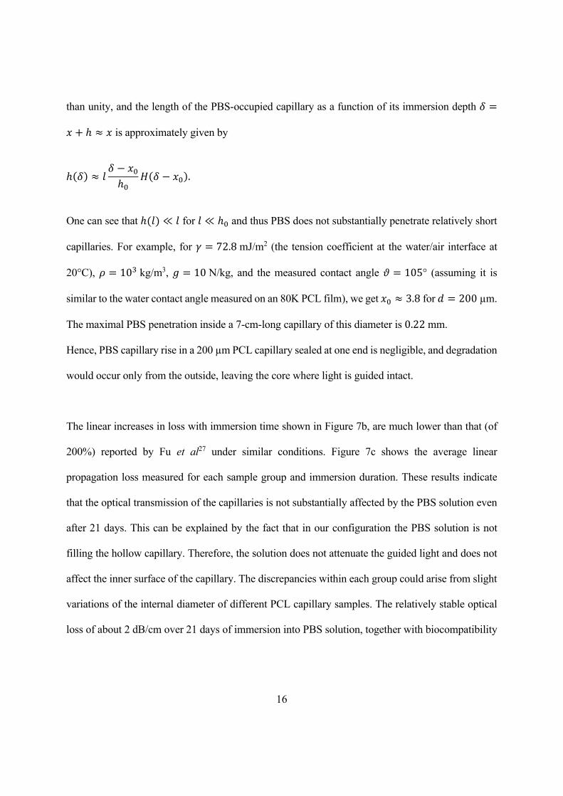
than unity, and the length of the PBS-occupied capillary as a function of its immersion depth 𝛿
𝑥 ℎ 𝑥 is approximately given by
ℎ 𝛿 𝑙𝛿 𝑥ℎ
𝐻 𝛿 𝑥 .
One can see that ℎ 𝑙 ≪ 𝑙 for 𝑙 ≪ ℎ and thus PBS does not substantially penetrate relatively short
capillaries. For example, for 𝛾 72.8 mJ/m2 (the tension coefficient at the water/air interface at
20°C), 𝜌 10 kg/m3, 𝑔 10 N/kg, and the measured contact angle 𝜗 105° (assuming it is
similar to the water contact angle measured on an 80K PCL film), we get 𝑥 3.8 for 𝑑 200 µm.
The maximal PBS penetration inside a 7-cm-long capillary of this diameter is 0.22 mm.
Hence, PBS capillary rise in a 200 µm PCL capillary sealed at one end is negligible, and degradation
would occur only from the outside, leaving the core where light is guided intact.
The linear increases in loss with immersion time shown in Figure 7b, are much lower than that (of
200%) reported by Fu et al27 under similar conditions. Figure 7c shows the average linear
propagation loss measured for each sample group and immersion duration. These results indicate
that the optical transmission of the capillaries is not substantially affected by the PBS solution even
after 21 days. This can be explained by the fact that in our configuration the PBS solution is not
filling the hollow capillary. Therefore, the solution does not attenuate the guided light and does not
affect the inner surface of the capillary. The discrepancies within each group could arise from slight
variations of the internal diameter of different PCL capillary samples. The relatively stable optical
loss of about 2 dB/cm over 21 days of immersion into PBS solution, together with biocompatibility

17
and biodegradability, makes these PCL fibres good candidates as waveguides for biomedical
applications.
4. Conclusion
Due to an ever increasing demand for biodegradable polymer fibre scaffolds with different surface
features in tissue engineering, we have developed a simple one-step method for drawing
submillimetre biodegradable PCL polymer fibres, with desired internal and external features, using
a well-established fibre drawing technique. This technique does not require pressurising the preforms
or using an etchable cladding. Following thorough characterisation of PCL polymers, different fibre
topographies, with microgrooves and channels inside or outside of the fibres, were successfully
drawn.
The drawn fibres were demonstrated to be compatible with cell attachment and growth in vitro.
MCF-7 breast cancer cells were cultured on different PCL fibre geometries for seven days. Cells
successfully attached to and proliferated on PCL fibres confirming that PCL fibres are noncytotoxic
and could be considered for biomedical applications.
We also demonstrated that hollow-core fibres can serve as and flexible optical waveguides, with a
relatively stable optical propagation loss after submersion into a biological fluid for up to 21 days.
These fibres are highly flexible, biocompatible, biodegradable, and easy to handle. These
characteristics make them a promising material for various biomedical applications, including tissue
engineering, nerve regrowth and implantable biomedical devices.
Acknowledgments
We acknowledge funding from the Australian Research Council Discovery Project DP170103537,
CE 140100012, the Marie Sklodowska-Curie grant of the European Union’s Horizon 2020 research
and innovation programme (708860) and Sydney Nano Institute Kickstarter Award. Technical

18
support was provided by the Research & Prototype Foundry Core Research Facility at the University
of Sydney, the Materials Node of the Australian National Fabrication Facility, and Bosch Institute
Advanced Microscopy Facility. We thank Peter Henry, Prof. Jun Chen, Dr. Sina Naficy, Dr Patricia
Hayes and A/Prof. Wojciech Chrzanowski for assistance and/or discussions.
References
[1] Diaz-Gomez, L., García-González, C. A., Wang, J., Yang, F., Aznar-Cervantes, S., Cenis, J. L., Reyes, R., Delgado, A., Évora, C., Concheiro, A. and Alvarez-Lorenzo, C., “Biodegradable PCL/fibroin/hydroxyapatite porous scaffolds prepared by supercritical foaming for bone regeneration,” Int. J. Pharm. 527(1–2), 115–125 (2017).
[2] Farajikhah, S., Cabot, J. M., Innis, P. C., Paull, B. and Wallace, G., “Life-Saving Threads: Advances in Textile-Based Analytical Devices,” ACS Comb. Sci. 21(4), 229–240 (2019).
[3] Wang, X., Han, C., Hu, X., Sun, H., You, C., Gao, C. and Haiyang, Y., “Applications of knitted mesh fabrication techniques to scaffolds for tissue engineering and regenerative medicine.,” J. Mech. Behav. Biomed. Mater. 4(7), 922–932 (2011).
[4] Abdal-hay, A., Abdelrazek Khalil, K., Al-Jassir, F. F. and Gamal-Eldeen, A. M., “Biocompatibility properties of polyamide 6/PCL blends composite textile scaffold using EA.hy926 human endothelial cells,” Biomed. Mater. 12(3), 035002 (2017).
[5] Mansouri, N., Al-Sarawi, S. F., Mazumdar, J. and Losic, D., “Advancing fabrication and properties of three-dimensional graphene–alginate scaffolds for application in neural tissue engineering,” RSC Adv. 9(63), 36838–36848 (2019).
[6] Shahriari, D., Loke, G., Tafel, I., Park, S., Chiang, P., Fink, Y. and Anikeeva, P., “Scalable Fabrication of Porous Microchannel Nerve Guidance Scaffolds with Complex Geometries,” Adv. Mater. 31(30), 1902021 (2019).
[7] Gajendiran, M., Choi, J., Kim, S.-J., Kim, K., Shin, H., Koo, H.-J. and Kim, K., “Conductive biomaterials for tissue engineering applications,” J. Ind. Eng. Chem. 51, 12–26 (2017).
[8] Torres, E., Fombuena, V., Vallés-Lluch, A. and Ellingham, T., “Improvement of mechanical and biological properties of Polycaprolactone loaded with Hydroxyapatite and Halloysite nanotubes,” Mater. Sci. Eng. C 75, 418–424 (2017).
[9] Liu, Q., Yuan, S., Guo, Y., Narayanan, A., Peng, C., Wang, S., Miyoshi, T. and Joy, A., “Modulating the crystallinity, mechanical properties, and degradability of poly(ε-caprolactone) derived polyesters by statistical and alternating copolymerization,” Polym. Chem. 10(20), 2579–2588 (2019).
[10] Chang, S. H., Lee, H. J., Park, S., Kim, Y. and Jeong, B., “Fast Degradable Polycaprolactone for Drug Delivery,” research-article, Biomacromolecules 19(6), 2302–2307 (2018).
[11] Abagnale, G., Sechi, A., Steger, M., Zhou, Q., Kuo, C.-C., Aydin, G., Schalla, C., Müller-Newen, G., Zenke, M., Costa, I. G., van Rijn, P., Gillner, A. and Wagner, W., “Surface Topography Guides Morphology and Spatial Patterning of Induced Pluripotent Stem Cell Colonies,” Stem Cell Reports 9(2), 654–666 (2017).
[12] Koppes, R. A., Park, S., Hood, T., Jia, X., Abdolrahim Poorheravi, N., Achyuta, A. H., Fink, Y. and Anikeeva, P., “Thermally drawn fibers as nerve guidance scaffolds,” Biomaterials 81, 27–35 (2016).
[13] Malikmammadov, E., Tanir, T. E., Kiziltay, A., Hasirci, V. and Hasirci, N., “PCL-TCP wet spun scaffolds carrying antibiotic-loaded microspheres for bone tissue engineering,” J. Biomater. Sci. Polym. Ed. 29(7–9), 805–824 (2018).
[14] Farajikhah, S., Amber, R., Sayyar, S., Shafei, S., Fay, C. D., Beirne, S., Javadi, M., Wang, X., Innis, P. C., Paull, B. and Wallace, G. G., “Processable Thermally Conductive Polyurethane Composite Fibers,” Macromol. Mater. Eng. 304(3), 1800542 (2019).
[15] Farajikhah, S., “Electroactive Fibre Sensor Systems for Fluidics,” Univ. Wollongong Thesis Collect. 2017+ (2018). [16] Xue, W., Chen, P., Wang, F. and Wang, L., “Melt spinning of nano-hydroxyapatite and polycaprolactone composite fibers for bone
scaffold application,” J. Mater. Sci. 54(11), 8602–8612 (2019). [17] Kelnar, I., Zhigunov, A., Kaprálková, L., Fortelný, I., Dybal, J., Kratochvíl, J., Nevoralová, M., Hricová, M. and Khunová, V., “Facile
preparation of biocompatible poly (lactic acid)-reinforced poly(ε-caprolactone) fibers via graphite nanoplatelets -aided melt spinning,” J. Mech. Behav. Biomed. Mater. 84(February), 108–115 (2018).
[18] Rafiei, M., Jooybar, E., Abdekhodaie, M. J. and Alvi, M., “Construction of 3D fibrous PCL scaffolds by coaxial electrospinning for protein delivery,” Mater. Sci. Eng. C, 110913 (2020).
[19] Lian, H. and Meng, Z., “Melt electrospinning vs. solution electrospinning: A comparative study of drug-loaded poly (ε-caprolactone) fibres,” Mater. Sci. Eng. C 74, 117–123 (2017).
[20] Johnson, R., Ding, Y., Nagiah, N., Monnet, E. and Tan, W., “Coaxially-structured fibres with tailored material properties for vascular graft implant,” Mater. Sci. Eng. C 97(December 2017), 1–11 (2019).
[21] Mouthuy, P. A., Zargar, N., Hakimi, O., Lostis, E. and Carr, A., “Fabrication of continuous electrospun filaments with potential for use as medical fibres,” Biofabrication 7(2), 1–13 (2015).
[22] Grena, B., Alayrac, J.-B., Levy, E., Stolyarov, A. M., Joannopoulos, J. D. and Fink, Y., “Thermally-drawn fibers with spatially-selective porous domains,” Nat. Commun. 8(1), 364 (2017).
[23] Rukhlenko, I. D., Farajikhah, S., Lilley, C., Georgis, A., Large, M. and Fleming, S., “Performance Optimization of Polymer Fibre Actuators for Soft Robotics,” Polymers (Basel). 12(2), 454 (2020).
[24] Warden, M. R., Cardin, J. A. and Deisseroth, K., “Optical Neural Interfaces,” Annu. Rev. Biomed. Eng. 16(1), 103–129 (2014). [25] Gunaydin, L. A., Grosenick, L., Finkelstein, J. C., Kauvar, I. V., Fenno, L. E., Adhikari, A., Lammel, S., Mirzabekov, J. J., Airan, R. D.,
Zalocusky, K. A., Tye, K. M., Anikeeva, P., Malenka, R. C. and Deisseroth, K., “Natural Neural Projection Dynamics Underlying Social Behavior,” Cell 157(7), 1535–1551 (2014).
19
[26] Yun, S. H. and Kwok, S. J. J., “Light in diagnosis, therapy and surgery,” Nat. Biomed. Eng. 1(1), 0008 (2017). [27] Fu, R., Luo, W., Nazempour, R., Tan, D., Ding, H., Zhang, K., Yin, L., Guan, J. and Sheng, X., “Implantable and Biodegradable Poly(L
-lactic acid) Fibers for Optical Neural Interfaces,” Adv. Opt. Mater. 6(3), 1700941 (2018). [28] Nizamoglu, S., Gather, M. C., Humar, M., Choi, M., Kim, S., Kim, K. S., Hahn, S. K., Scarcelli, G., Randolph, M., Redmond, R. W. and
Yun, S. H., “Bioabsorbable polymer optical waveguides for deep-tissue photomedicine,” Nat. Commun. 7(1), 10374 (2016). [29] Kaysir, M. R., Stefani, A., Lwin, R. and Fleming, S., “Flexible optical fiber sensor based on polyurethane,” 2017 Conf. Lasers Electro-
Optics Pacific Rim, CLEO-PR 2017 170103537(708860), 1–2 (2017). [30] Waheed, S., Cabot, J. M., Macdonald, N. P., Kalsoom, U., Farajikhah, S., Innis, P. C., Nesterenko, P. N., Lewis, T. W., Breadmore, M.
C. and Paull, B., “Enhanced physicochemical properties of polydimethylsiloxane based microfluidic devices and thin films by incorporating synthetic micro-diamond,” Sci. Rep. 7(1) (2017).
[31] Farajikhah, S., Rukhlenko, I. D., Stefani, A., Large, M., Chrzanowski, W. and Fleming, S., “Thermally drawn polycaprolactone fibres with customised cross sections,” AOS Aust. Conf. Opt. Fibre Technol. Aust. Conf. Opt. Lasers, Spectrosc. 2019 1120039(December 2019), A. Mitchell and H. Rubinsztein-Dunlop, Eds., 103, SPIE (2019).
[32] Um, I. C., Ki, C. S., Kweon, H., Lee, K. G., Ihm, D. W. and Park, Y. H., “Wet spinning of silk polymer: II. Effect of drawing on the structural characteristics and properties of filament,” Int. J. Biol. Macromol. 34(1–2), 107–119 (2004).
[33] Taherian, A., Li, X., Liu, Y. and Haas, T. A., “Differences in integrin expression and signaling within human breast cancer cells,” BMC Cancer 11(1), 293 (2011).
[34] Nassef, M. Z., Kopp, S., Wehland, M., Melnik, D., Sahana, J., Krüger, M., Corydon, T. J., Oltmann, H., Schmitz, B., Schütte, A., Bauer, T. J., Infanger, M. and Grimm, D., “Real Microgravity Influences the Cytoskeleton and Focal Adhesions in Human Breast Cancer Cells,” Int. J. Mol. Sci. 20(13), 3156 (2019).
[35] Nakae, M., Uehara, H., Kanamoto, T., Ohama, T. and Porter, R. S., “Melt drawing of ultra-high molecular weight polyethylene: Comparison of Ziegler- and metallocene-catalyzed reactor powders,” J. Polym. Sci. Part B Polym. Phys. 37(15), 1921–1930 (1999).
[36] Lozano-Sánchez, L., Bagudanch, I., Sustaita, A., Iturbe-Ek, J., Elizalde, L., Garcia-Romeu, M. and Elías-Zúñiga, A., “Single-Point Incremental Forming of Two Biocompatible Polymers: An Insight into Their Thermal and Structural Properties,” Polymers (Basel). 10(4), 391 (2018).
[37] Bai, L., Zhao, X., Bao, R.-Y., Liu, Z.-Y., Yang, M.-B. and Yang, W., “Effect of temperature, crystallinity and molecular chain orientation on the thermal conductivity of polymers: a case study of PLLA,” J. Mater. Sci. 53(14), 10543–10553 (2018).
[38] Wang, X., Zhao, H., Turng, L.-S. and Li, Q., “Crystalline Morphology of Electrospun Poly(ε-caprolactone) (PCL) Nanofibers,” Ind. Eng. Chem. Res. 52(13), 4939–4949 (2013).

20
Figure legends Figure 1. Schematics of (a) fibre drawing process, (b) PCL capillary fibre immersion in PBS solution (Inset: schematic
of coupling a silica fibre into a PCL capillary) and (c) cutback measurement setup.
Figure 2. Repetitive data for (a) DSC and (b) TGA spectra of PCLs of different molecular weights showing their
melting and decomposition temperatures and (c) viscosities of different PCL samples at 60°C at different shear rates.
Figure 3. Repetitive graphs of (a) Stress–strain curve, (b) storage modulus and (c) Tan delta of different PCL samples
at an elevated temperature, (d) strain variation vs temperature for different PCL samples and (e) degree of crystallinity
and thermal conductivity of PCL samples as functions of molecular weight.
Figure 4. (a) Schematics of PCL preforms and (b) optical micrographs of the respective thermally drawn submillimeter
fibres (the scale bars are 200 µm).
Figure 5. Representative bright-field images of MCF-7 cells (105 cells) plated on a 3-leaf PCL fibre. Images were
taken using a Zeiss Axiovert35 microscope at (a) 5x magnification (the scale bar is 50 μm) after 24 hours of culture,
(b) 20x (the scale bar is 20 μm) after 48 hours of culture and (c) 20x (the scale bar is 20 μm) after 6 days of culture;
red arrows show cells and blue arrow shows the fibre. (d) Confocal microscopy images of MCF-7 breast cancer cells
plated on PCL fibres of different geometrical profiles: circular, 3-leaf and 4-leaf; white dash-dotted lines indicate the
locations of microgrooves on fibres. (e) Confocal microscopy images of MCF-7 breast cancer cells plated on 3-leaf
PCL fibres without gelatin coating. Images were taken using a Zeiss LSM 800 confocal microscope. A z-stack of at
least 70 μm was compiled for each PCL fibre geometry. Images were taken with a 20x objective and visualized using
Phalloidin staining (red) for F-actin cytoskeleton and DAPI (blue) for the nucleus. The scale bars in (d) and (e) are
200 μm. (f) Surface coverage of fibre with cells after 24 hours of culture.
Figure 6. Optical micrographs of solid PCL fibres with round, 3leaf and 4leaf geometries (a) before and (b) after 7 days
of incubation in MCF 7 culture media (the scale bars are 300 µm)
Figure 7. (a) Schematic of a sealed capillary submerged in a liquid, (b) optical attenuation of PCL capillaries before and
after submersion in PBS for 3, 7, 14 and 21 days (dashed lines are linear fits) and (c) optical loss of PCL capillaries as a
function of submersion time.
Videos S1 to S3 are 3D animated of cells for solid, 3-leaf and 4-leaf PCL fibres, respectively.


