Embed Size (px)
Citation preview
Develop Nova Scotia Old Red Store, Historic Properties Suite 301 – 1875 Upper Water St. Halifax, NS B3J 1S9
Date: Friday, March 05, 2021
ADDENDUM #02 for DNS-2021-0106 Peggys Cove Public Washroom Request for Quotation
Sponsored by: Develop Nova Scotia
1.0 Clarifications:
1.1 Geotechnical Conditions
Please see report attached below for auger pit and test bit data in the project area.
2.0 CHANGES
2.1. Refer to Specification 05 50 00 Metal Fabrications and Drawing A3-02 North and South Deck Elevation
Remove: HSS SS 25mm X 76mm X 6mm
Replace with: HSS SS 25mm X 76mm X 4.8mm (grade 304)
This change is based on supplier availability of the architectural railing system discussed in the project documents.
2.2. Refer to Specification 05 50 00 Metal Fabrications and Drawing A3-02 North and South Deck Elevation
Remove: 51mm Handrail Grade 316
Replace with: 42mm X 4.8mm Grade 316 for Vertical Posts; 42mm X 3.2mm Grade 316 for Horizontal Posts
This change is based on supplier availability of the architectural railing system discussed in the project documents.

This addendum WILL NOT require a revision to the Closing Date and Time, or other dates given in the Request for Proposal document. The closing date will remain 2:00 pm AT on March 11th, 2021.
In accordance with Section C.7 of Appendix C – Submission Pricing Form, Proponents are deemed to have read and taken into account all addenda issued by Develop Nova Scotia.
For further information prospective Proponents should contact Tim Jordan, Project Manager at [email protected]
Geotechnical Investigation Peggy’s Cove Infrastructure Development
Peggy’s Cove, Halifax County, NS File No: 213024
Prepared for:
Develop Nova Scotia 1875 Upper Water St. Suite 301 Halifax, NS B3J 1S5
Prepared by:
Harbourside Geotechnical Consultants 219 Waverley Rd., Suite 200 Dartmouth, NS B2X 2C3
March 1, 2021 (Revision 1)
ii
TABLE OF CONTENTS 1.0 INTRODUCTION ............................................................................................................. 1
2.0 SITE DESCRIPTION ....................................................................................................... 2
3.0 INVESTIGATIVE PROCEDURES ................................................................................... 3
4.0 SUBSURFACE CONDITIONS ........................................................................................ 4
4.1 Surficial Layer .............................................................................................................. 5
4.2 Fill ................................................................................................................................ 5
4.3 Rootmat and Topsoil .................................................................................................... 5
4.4 Bedrock ....................................................................................................................... 6
5.0 CLOSURE ....................................................................................................................... 6
iii
LIST OF TABLES Table 1 Summary of Subsurface Conditions ......................................................................... 4
Table 2 Grain-Size Analyses - Fill ......................................................................................... 5
LIST OF APPENDICES Appendix A Symbols and Terms Used on Borehole and Test Pit Records
Auger Probe and Test Pit Records BH-AP-01 to BH-AP-15 and TP16 to TP18
Appendix B Laboratory Testing Results Appendix C Sketch SK-1 – Borehole Location Plan
FILE NO: 213024
1
1.0 INTRODUCTION Acting at the request of Develop Nova Scotia, Harbourside Geotechnical Consultants (HGC) have completed a series of auger probes and test pits to inform the proposed infrastructure development at Peggy’s Cove, in Halifax County, Nova Scotia including:
• Upgrades to the Peggy’s Point Road Driving Loop, south of the Sou’ Wester Gift & Restaurant Company (the Sou-Wester Restaurant), and
• Construction of a new washroom facility south of the Sou’ Wester Restaurant.
The scope of work completed includes site reconnaissance and a field investigation comprised of a series of fifteen auger probes and three test pits.
FILE NO: 213024
2
2.0 SITE DESCRIPTION Peggy’s Point Road is currently a two-lane road connecting Peggy’s Cove Road to the Peggy’s
Cove Lighthouse which is a tourist destination in Peggy’s Cove, NS. The existing driving loop is located south of the Sou’Wester Restaurant and has large outcrops of granite bedrock at the center of the loop. The driving loop currently serves as the main entrance to the back parking lot that services the restaurant and lighthouse tourist area. The road slopes relatively gently to the south, towards the ocean. The location of the proposed washroom facilities is east of the Sou’Wester Restaurant, in the existing parking lot which slopes gently to the north.
Geological mapping indicates the principal overburden materials are a thin discontinuous veneer of till comprised of sand, gravel, and silt. Bedrock is mapped as granite of the Liscomb Complex.

FILE NO: 213024
3
3.0 INVESTIGATIVE PROCEDURES The field work for the investigations was carried out on February 24th and 25th, and March 4th, 2021. Fifteen auger probes were put down using a truck mounted CME 45 drill on February 24th and 25th, 2021. The auger probes were put down at regular intervals around the driving circle, south of the restaurant, and within the proposed location of the washroom facilities. The auger probes were carried out using 114-mm standard flight augers to depths of 5.16 m, or until practical refusal on/in bedrock was attained based on auger performance. Grab samples of the soils and rock encountered were taken from the augers during drilling. Three additional test pits were excavated at the proposed location of the new washrooms, south of the restaurant, on March 4th, 2021. Test pits were advanced to depths of 1.3 to 2.3 m.
All soil samples recovered were stored in moisture tight containers and delivered to our Dartmouth laboratory for final classification and testing. Testing on select soil samples included water content determinations (ASTM D2216 Standard Test Methods for Laboratory Determination of Water
Content of Soil and Rock by Mass), and particle-size analyses (ASTM D6913 Standard Test
Method for Particle-Size Distribution of Soils Using Sieve Analysis). A summary of the testing performed is presented on the borehole records in Appendix A and separate figures in Appendix B. Soil descriptions used throughout this report are in general accordance with the Unified Soil Classification System (ASTM D2487 Standard Practice for Classification of Soils for Engineering
purposes / ASTM D2488 Standard Practice for Description and Identification of Soils). Samples remaining after testing will be stored until July 2021, six months hence, at which time they will be discarded unless further arrangements are made.
The location and ground surface elevation of all auger probes and test pits were surveyed by Harbourside personnel with construction-grade GPS equipment. Auger probe coordinates are provided in UTM Zone 20N. Elevations are referenced to the Canadian Geodetic Vertical Datum of 2013 (CGVD2013).
FILE NO: 213024
4
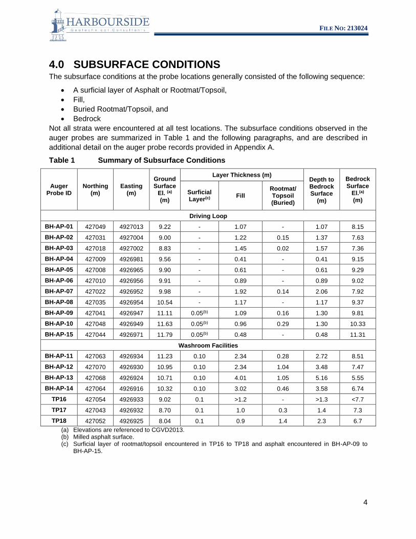
4.0 SUBSURFACE CONDITIONS The subsurface conditions at the probe locations generally consisted of the following sequence:
• A surficial layer of Asphalt or Rootmat/Topsoil, • Fill, • Buried Rootmat/Topsoil, and • Bedrock
Not all strata were encountered at all test locations. The subsurface conditions observed in the auger probes are summarized in Table 1 and the following paragraphs, and are described in additional detail on the auger probe records provided in Appendix A.
Table 1 Summary of Subsurface Conditions
Auger Probe ID
Northing (m)
Easting (m)
Ground Surface
El. (a)
(m)
Layer Thickness (m) Depth to Bedrock Surface
(m)
Bedrock Surface
El.(a)
(m) Surficial Layer(c) Fill
Rootmat/ Topsoil (Buried)
Driving Loop BH-AP-01 427049 4927013 9.22 - 1.07 - 1.07 8.15
BH-AP-02 427031 4927004 9.00 - 1.22 0.15 1.37 7.63 BH-AP-03 427018 4927002 8.83 - 1.45 0.02 1.57 7.36
BH-AP-04 427009 4926981 9.56 - 0.41 - 0.41 9.15
BH-AP-05 427008 4926965 9.90 - 0.61 - 0.61 9.29
BH-AP-06 427010 4926956 9.91 - 0.89 - 0.89 9.02
BH-AP-07 427022 4926952 9.98 - 1.92 0.14 2.06 7.92
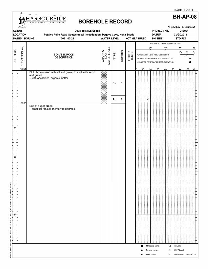
BH-AP-08 427035 4926954 10.54 - 1.17 - 1.17 9.37
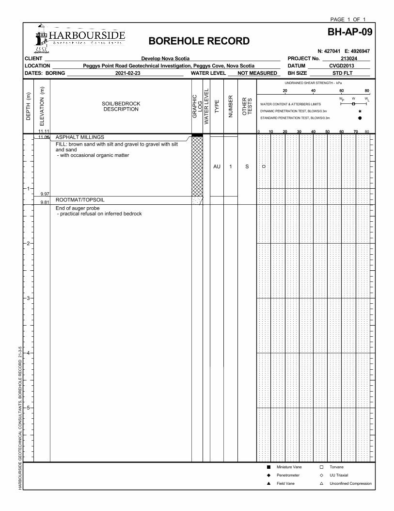
BH-AP-09 427041 4926947 11.11 0.05(b) 1.09 0.16 1.30 9.81
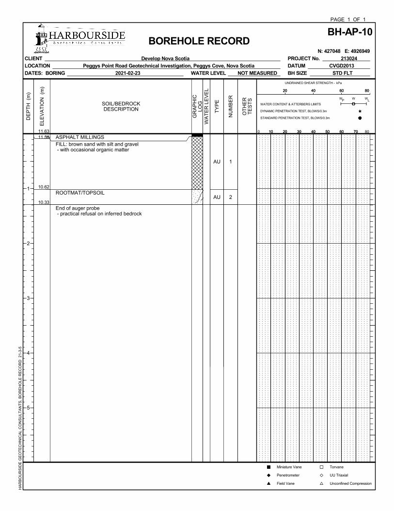
BH-AP-10 427048 4926949 11.63 0.05(b) 0.96 0.29 1.30 10.33
BH-AP-15 427044 4926971 11.79 0.05(b) 0.48 - 0.48 11.31
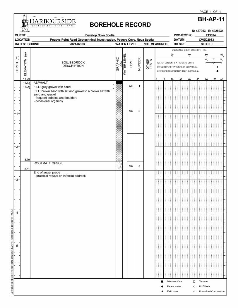
Washroom Facilities BH-AP-11 427063 4926934 11.23 0.10 2.34 0.28 2.72 8.51
BH-AP-12 427070 4926930 10.95 0.10 2.34 1.04 3.48 7.47
BH-AP-13 427068 4926924 10.71 0.10 4.01 1.05 5.16 5.55 BH-AP-14 427064 4926916 10.32 0.10 3.02 0.46 3.58 6.74
TP16 427054 4926933 9.02 0.1 >1.2 - >1.3 <7.7
TP17 427043 4926932 8.70 0.1 1.0 0.3 1.4 7.3
TP18 427052 4926925 8.04 0.1 0.9 1.4 2.3 6.7 (a) Elevations are referenced to CGVD2013. (b) Milled asphalt surface. (c) Surficial layer of rootmat/topsoil encountered in TP16 to TP18 and asphalt encountered in BH-AP-09 to
BH-AP-15.
FILE NO: 213024
5
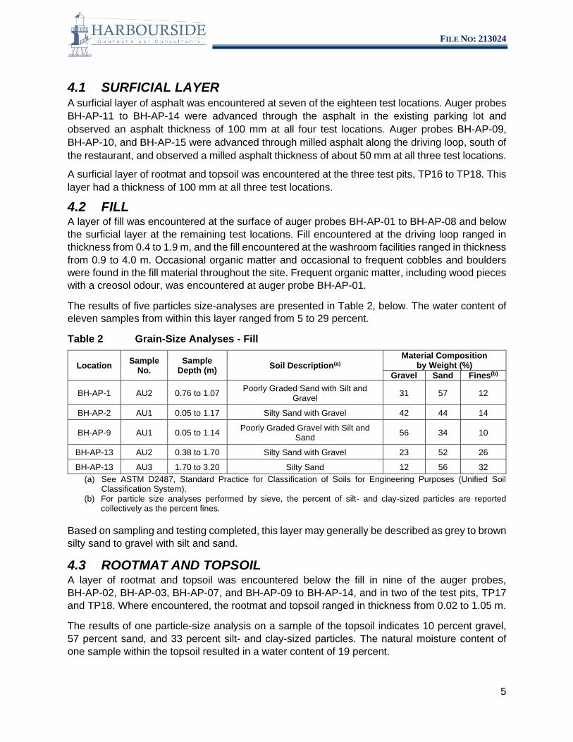
4.1 SURFICIAL LAYER A surficial layer of asphalt was encountered at seven of the eighteen test locations. Auger probes BH-AP-11 to BH-AP-14 were advanced through the asphalt in the existing parking lot and observed an asphalt thickness of 100 mm at all four test locations. Auger probes BH-AP-09, BH-AP-10, and BH-AP-15 were advanced through milled asphalt along the driving loop, south of the restaurant, and observed a milled asphalt thickness of about 50 mm at all three test locations.
A surficial layer of rootmat and topsoil was encountered at the three test pits, TP16 to TP18. This layer had a thickness of 100 mm at all three test locations.
4.2 FILL A layer of fill was encountered at the surface of auger probes BH-AP-01 to BH-AP-08 and below the surficial layer at the remaining test locations. Fill encountered at the driving loop ranged in thickness from 0.4 to 1.9 m, and the fill encountered at the washroom facilities ranged in thickness from 0.9 to 4.0 m. Occasional organic matter and occasional to frequent cobbles and boulders were found in the fill material throughout the site. Frequent organic matter, including wood pieces with a creosol odour, was encountered at auger probe BH-AP-01.
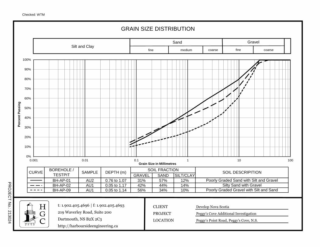
The results of five particles size-analyses are presented in Table 2, below. The water content of eleven samples from within this layer ranged from 5 to 29 percent.
Table 2 Grain-Size Analyses - Fill
Location Sample No.
Sample Depth (m) Soil Description(a)
Material Composition by Weight (%)
Gravel Sand Fines(b)
BH-AP-1 AU2 0.76 to 1.07 Poorly Graded Sand with Silt and Gravel 31 57 12
BH-AP-2 AU1 0.05 to 1.17 Silty Sand with Gravel 42 44 14
BH-AP-9 AU1 0.05 to 1.14 Poorly Graded Gravel with Silt and Sand 56 34 10
BH-AP-13 AU2 0.38 to 1.70 Silty Sand with Gravel 23 52 26
BH-AP-13 AU3 1.70 to 3.20 Silty Sand 12 56 32 (a) See ASTM D2487, Standard Practice for Classification of Soils for Engineering Purposes (Unified Soil
Classification System). (b) For particle size analyses performed by sieve, the percent of silt- and clay-sized particles are reported
collectively as the percent fines.
Based on sampling and testing completed, this layer may generally be described as grey to brown silty sand to gravel with silt and sand.
4.3 ROOTMAT AND TOPSOIL A layer of rootmat and topsoil was encountered below the fill in nine of the auger probes, BH-AP-02, BH-AP-03, BH-AP-07, and BH-AP-09 to BH-AP-14, and in two of the test pits, TP17 and TP18. Where encountered, the rootmat and topsoil ranged in thickness from 0.02 to 1.05 m.
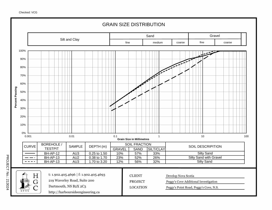
The results of one particle-size analysis on a sample of the topsoil indicates 10 percent gravel, 57 percent sand, and 33 percent silt- and clay-sized particles. The natural moisture content of one sample within the topsoil resulted in a water content of 19 percent.
FILE NO: 213024
6
4.4 BEDROCK Bedrock was inferred at all test locations, except test pit TP16, based on practical refusal of the auger or excavator. Type 1 gravel was encountered directly below the fill layer in test pit TP16, indicating potential buried services. TP16 was terminated at a depth of 1.3 m below the ground surface, before bedrock could be inferred. The depth to the surface of inferred bedrock at the remaining test locations ranged from 0.4 to 5.2 m below the ground surface.
5.0 CLOSURE This report has been prepared for the sole benefit of Develop Nova Scotia and their agents. Any use which a third party makes of this report is the responsibility of such third party.
This report is based on the site conditions encountered by Harbourside Geotechnical Consultants at the time of the work at the specific sampling locations and can only be extrapolated to a limited extent around these locations.
If you have any questions or require any additional information, please do not hesitate to contact the undersigned at your convenience.
H a r b o u r s i d e Geotechnical Consultants
Vince C. Goreham, Ph.D., P.Eng. Geotechnical Engineer, Principal Office: (902) 405 - 4696 [email protected]
APPENDIX A Symbols and Terms Used on Borehole and Test Pit Records
Auger Probe Records BH-AP-01 and BH-AP-15
Test Pit Records TP1 to TP18
Page 1 of 5
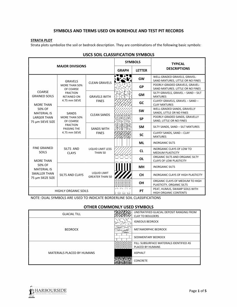
SYMBOLS AND TERMS USED ON BOREHOLE AND TEST PIT RECORDS
STRATA PLOT Strata plots symbolize the soil or bedrock description. They are combinations of the following basic symbols:
USCS SOIL CLASSIFICATION SYMBOLS
MAJOR DIVISIONS SYMBOLS TYPICAL
DESCRIPTIONS GRAPH LETTER
COARSE GRAINED SOILS
MORE THAN
50% OF MATERIAL IS
LARGER THAN 75 µm SIEVE SIZE
GRAVELS MORE THAN 50%
OF COARSE FRACTION
RETAINED ON 4.75 mm SIEVE
CLEAN GRAVELS
GW WELL-GRADED GRAVELS, GRAVEL-SAND MIXTURES, LITTLE OR NO FINES
GP POORLY-GRADED GRAVELS, GRAVEL-SAND MIXTURES. LITTLE OR NO FINES
GRAVELS WITH FINES
GM SILTY GRAVELS, GRAVEL – SAND – SILT MIXTURES
GC CLAYEY GRAVELS, GRAVEL – SAND – CLAY MIXTURES
SANDS MORE THAN 50%
OF COARSE FRACTION
PASSING THE 4.75 mm SIEVE
CLEAN SANDS
SW WELL-GRADED SANDS, GRAVELLY SANDS, LITTLE OR NO FINES
SP POORLY-GRADED SANDS, GRAVELLY SAND, LITTLE OR NO FINES
SANDS WITH FINES
SM SILTY SANDS, SAND – SILT MIXTURES
SC CLAYEY SANDS, SAND – CLAY MIXTURES
FINE GRAINED SOILS
MORE THAN
50% OF MATERIAL IS
SMALLER THAN 75 µm SIEZE SIZE
SILTS AND CLAYS
LIQUID LIMIT LESS THAN 50
ML INORGANIC SILTS
CL INORGANIC CLAYS OF LOW TO MEDIUM PLASTICITY
OL ORGANIC SILTS AND ORGANIC SILTY CLAYS OF LOW PLASTICITY
SILTS AND CLAYS LIQUID LIMIT
GREATER THAN 50
MH INORGANIC SILTS
CH INORGANIC CLAYS OF HIGH PLASTICITY
OH ORGANIC CLAYS OF MEDIUM TO HIGH PLASTICITY, ORGANIC SILTS
HIGHLY ORGANIC SOILS PT PEAT, HUMUS, SWAMP SOILS WITH HIGH ORGANIC CONTENTS
NOTE: DUAL SYMBOLS ARE USED TO INDICATE BORDERLINE SOIL CLASSIFICATIONS
OTHER COMMONLY USED SYMBOLS
GLACIAL TILL UNSTRATIFIED GLACIAL DEPOSIT RANGING FROM CLAY TO BOULDERS
BEDROCK
IGNEOUS BEDROCK
METAMORPHIC BEDROCK
SEDIMENTARY BEDROCK
MATERIALS PLACED BY HUMANS
FILL: SUBSURFACE MATERIALS IDENTIFIED AS PLACED BY HUMANS
ASPHALT
CONCRETE
Page 2 of 5
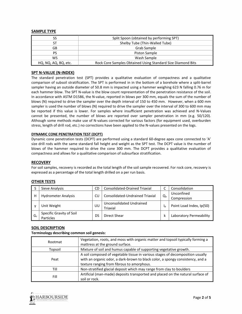
SAMPLE TYPE
SS Split Spoon (obtained by performing SPT)
ST Shelby Tube (Thin-Walled Tube)
GB Grab Sample
PS Piston Sample WS Wash Sample
HQ, NQ, AQ, BQ, etc. Rock Core Samples Obtained Using Standard Size Diamond Bits
SPT N-VALUE (N-INDEX) The standard penetration test (SPT) provides a qualitative evaluation of compactness and a qualitative comparison of subsoil stratification. The SPT is performed in in the bottom of a borehole where a split-barrel sampler having an outside diameter of 50.8 mm is impacted using a hammer weighing 623 N falling 0.76 m for each hammer blow. The SPT N-value is the blow count representation of the penetration resistance of the soil. In accordance with ASTM D1586, the N-value, reported in blows per 300 mm, equals the sum of the number of blows (N) required to drive the sampler over the depth interval of 150 to 450 mm. However, when a 600 mm sampler is used the number of blows (N) required to drive the sampler over the interval of 300 to 600 mm may be reported if this value is lower. For samples where insufficient penetration was achieved and N-Values cannot be presented, the number of blows are reported over sampler penetration in mm (e.g. 50/120). Although some methods make use of N-values corrected for various factors (for equipment used, overburden stress, length of drill rod, etc.) no corrections have been applied to the N-values presented on the logs. DYNAMIC CONE PENETRATION TEST (DCPT) Dynamic cone penetration tests (DCPT) are performed using a standard 60-degree apex cone connected to ‘A’ size drill rods with the same standard fall height and weight as the SPT test. The DCPT value is the number of blows of the hammer required to drive the cone 300 mm. The DCPT provides a qualitative evaluation of compactness and allows for a qualitative comparison of subsurface stratification. RECOVERY For soil samples, recovery is recorded as the total length of the soil sample recovered. For rock core, recovery is expressed as a percentage of the total length drilled on a per run basis. OTHER TESTS
S Sieve Analysis CD Consolidated-Drained Triaxial C Consolidation
H Hydrometer Analysis CU Consolidated-Undrained Triaxial Qu Unconfined Compression
γ Unit Weight UU Unconsolidated Undrained Triaxial
Ip Point Load Index, Ip(50)
Gs Specific Gravity of Soil Particles
DS Direct Shear k Laboratory Permeability
SOIL DESCRIPTION Terminology describing common soil genesis:
Rootmat Vegetation, roots, and moss with organic matter and topsoil typically forming a mattress at the ground surface.
Topsoil Mixture of soil and humus capable of supporting vegetative growth.
Peat A soil composed of vegetable tissue in various stages of decomposition usually with an organic odor, a dark-brown to black color, a spongy consistency, and a texture ranging from fibrous to amorphous.
Till Non-stratified glacial deposit which may range from clay to boulders
Fill Artificial (man-made) deposits transported and placed on the natural surface of soil or rock.
Page 3 of 5
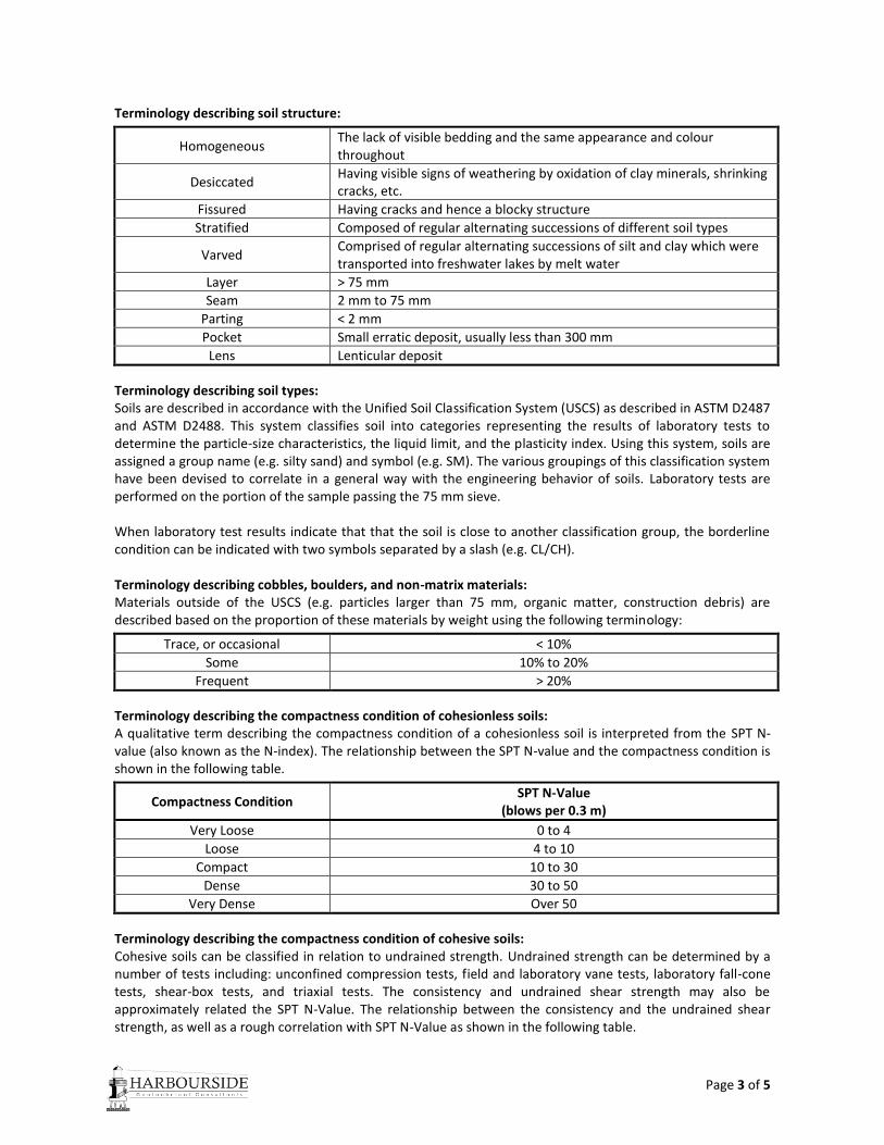
Terminology describing soil structure:
Homogeneous The lack of visible bedding and the same appearance and colour throughout
Desiccated Having visible signs of weathering by oxidation of clay minerals, shrinking cracks, etc.
Fissured Having cracks and hence a blocky structure
Stratified Composed of regular alternating successions of different soil types
Varved Comprised of regular alternating successions of silt and clay which were transported into freshwater lakes by melt water
Layer > 75 mm
Seam 2 mm to 75 mm
Parting < 2 mm
Pocket Small erratic deposit, usually less than 300 mm
Lens Lenticular deposit
Terminology describing soil types: Soils are described in accordance with the Unified Soil Classification System (USCS) as described in ASTM D2487 and ASTM D2488. This system classifies soil into categories representing the results of laboratory tests to determine the particle-size characteristics, the liquid limit, and the plasticity index. Using this system, soils are assigned a group name (e.g. silty sand) and symbol (e.g. SM). The various groupings of this classification system have been devised to correlate in a general way with the engineering behavior of soils. Laboratory tests are performed on the portion of the sample passing the 75 mm sieve. When laboratory test results indicate that that the soil is close to another classification group, the borderline condition can be indicated with two symbols separated by a slash (e.g. CL/CH). Terminology describing cobbles, boulders, and non-matrix materials: Materials outside of the USCS (e.g. particles larger than 75 mm, organic matter, construction debris) are described based on the proportion of these materials by weight using the following terminology:
Trace, or occasional < 10%
Some 10% to 20%
Frequent > 20%
Terminology describing the compactness condition of cohesionless soils: A qualitative term describing the compactness condition of a cohesionless soil is interpreted from the SPT N-value (also known as the N-index). The relationship between the SPT N-value and the compactness condition is shown in the following table.
Compactness Condition SPT N-Value
(blows per 0.3 m)
Very Loose 0 to 4
Loose 4 to 10
Compact 10 to 30
Dense 30 to 50
Very Dense Over 50
Terminology describing the compactness condition of cohesive soils: Cohesive soils can be classified in relation to undrained strength. Undrained strength can be determined by a number of tests including: unconfined compression tests, field and laboratory vane tests, laboratory fall-cone tests, shear-box tests, and triaxial tests. The consistency and undrained shear strength may also be approximately related the SPT N-Value. The relationship between the consistency and the undrained shear strength, as well as a rough correlation with SPT N-Value as shown in the following table.
Page 4 of 5
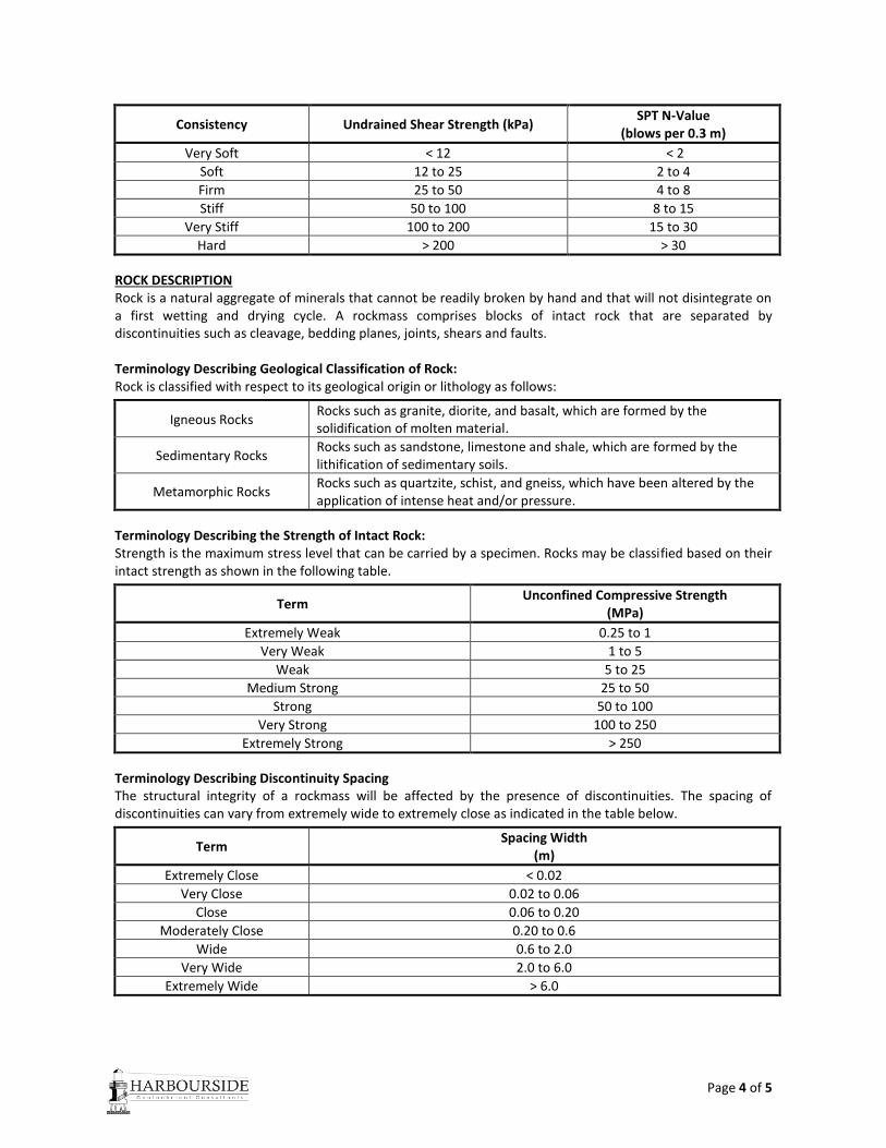
Consistency Undrained Shear Strength (kPa) SPT N-Value
(blows per 0.3 m)
Very Soft < 12 < 2
Soft 12 to 25 2 to 4
Firm 25 to 50 4 to 8
Stiff 50 to 100 8 to 15
Very Stiff 100 to 200 15 to 30
Hard > 200 > 30
ROCK DESCRIPTION Rock is a natural aggregate of minerals that cannot be readily broken by hand and that will not disintegrate on a first wetting and drying cycle. A rockmass comprises blocks of intact rock that are separated by discontinuities such as cleavage, bedding planes, joints, shears and faults. Terminology Describing Geological Classification of Rock: Rock is classified with respect to its geological origin or lithology as follows:
Igneous Rocks Rocks such as granite, diorite, and basalt, which are formed by the solidification of molten material.
Sedimentary Rocks Rocks such as sandstone, limestone and shale, which are formed by the lithification of sedimentary soils.
Metamorphic Rocks Rocks such as quartzite, schist, and gneiss, which have been altered by the application of intense heat and/or pressure.
Terminology Describing the Strength of Intact Rock: Strength is the maximum stress level that can be carried by a specimen. Rocks may be classified based on their intact strength as shown in the following table.
Term Unconfined Compressive Strength
(MPa)
Extremely Weak 0.25 to 1
Very Weak 1 to 5
Weak 5 to 25
Medium Strong 25 to 50
Strong 50 to 100
Very Strong 100 to 250
Extremely Strong > 250
Terminology Describing Discontinuity Spacing The structural integrity of a rockmass will be affected by the presence of discontinuities. The spacing of discontinuities can vary from extremely wide to extremely close as indicated in the table below.
Term Spacing Width
(m)
Extremely Close < 0.02
Very Close 0.02 to 0.06
Close 0.06 to 0.20
Moderately Close 0.20 to 0.6
Wide 0.6 to 2.0
Very Wide 2.0 to 6.0
Extremely Wide > 6.0
Page 5 of 5
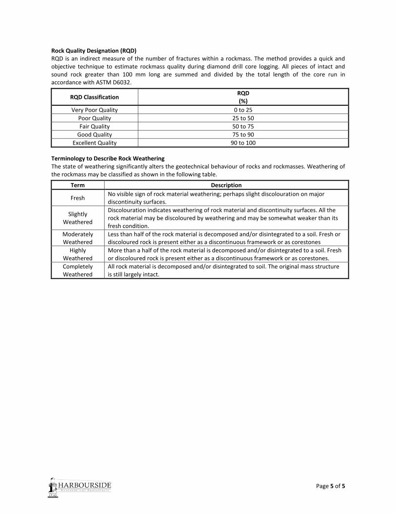
Rock Quality Designation (RQD) RQD is an indirect measure of the number of fractures within a rockmass. The method provides a quick and objective technique to estimate rockmass quality during diamond drill core logging. All pieces of intact and sound rock greater than 100 mm long are summed and divided by the total length of the core run in accordance with ASTM D6032.
RQD Classification RQD (%)
Very Poor Quality 0 to 25
Poor Quality 25 to 50
Fair Quality 50 to 75
Good Quality 75 to 90
Excellent Quality 90 to 100
Terminology to Describe Rock Weathering The state of weathering significantly alters the geotechnical behaviour of rocks and rockmasses. Weathering of the rockmass may be classified as shown in the following table.
Term Description
Fresh No visible sign of rock material weathering; perhaps slight discolouration on major discontinuity surfaces.
Slightly Weathered
Discolouration indicates weathering of rock material and discontinuity surfaces. All the rock material may be discoloured by weathering and may be somewhat weaker than its fresh condition.
Moderately Weathered
Less than half of the rock material is decomposed and/or disintegrated to a soil. Fresh or discoloured rock is present either as a discontinuous framework or as corestones
Highly Weathered
More than a half of the rock material is decomposed and/or disintegrated to a soil. Fresh or discoloured rock is present either as a discontinuous framework or as corestones.
Completely Weathered
All rock material is decomposed and/or disintegrated to soil. The original mass structure is still largely intact.
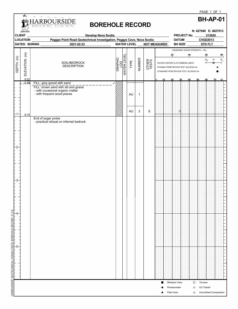
9.17
8.15
FILL: grey gravel with sandFILL: brown sand with silt and gravel - with occasional organic matter - with frequent wood pieces
End of auger probe - practical refusal on inferred bedrock
AU
AU
1
2 S
ELE
VA
TIO
N (
m)
DE
PT
H (
m)
1
2
3
4
5
9.22
BH-AP-01PAGE 1 OF 1
BOREHOLE RECORD N: 427049 E: 4927013
CLIENT Develop Nova Scotia
LOCATION Peggys Point Road Geotechnical Investigation, Peggys Cove, Nova Scotia
DATES: BORING 2021-02-23
PROJECT No. 213024
DATUM CVGD2013
BH SIZE STD FLTWATER LEVEL NOT MEASURED
HA
RB
OU
RS
IDE
GE
OT
EC
HN
ICA
L C
ON
SU
LTA
NT
S,
BO
RE
HO
LE R
EC
OR
D
21-3
-5
GR
AP
HIC
LOGSOIL/BEDROCK
DESCRIPTION
WA
TE
R L
EV
EL
TY
PE
NU
MB
ER
OT
HE
RT
ES
TS
UNDRAINED SHEAR STRENGTH - kPa
10 20 30 40 50 60 700 8010 20 30 40 50 60 70
PW W
L
20 40 60 8020 40 60 80
Torvane
UU Triaxial
Unconfined Compression
WATER CONTENT & ATTERBERG LIMITS
DYNAMIC PENETRATION TEST, BLOWS/0.3m
STANDARD PENETRATION TEST, BLOWS/0.3m
W
Miniature Vane
Penetrometer
Field Vane
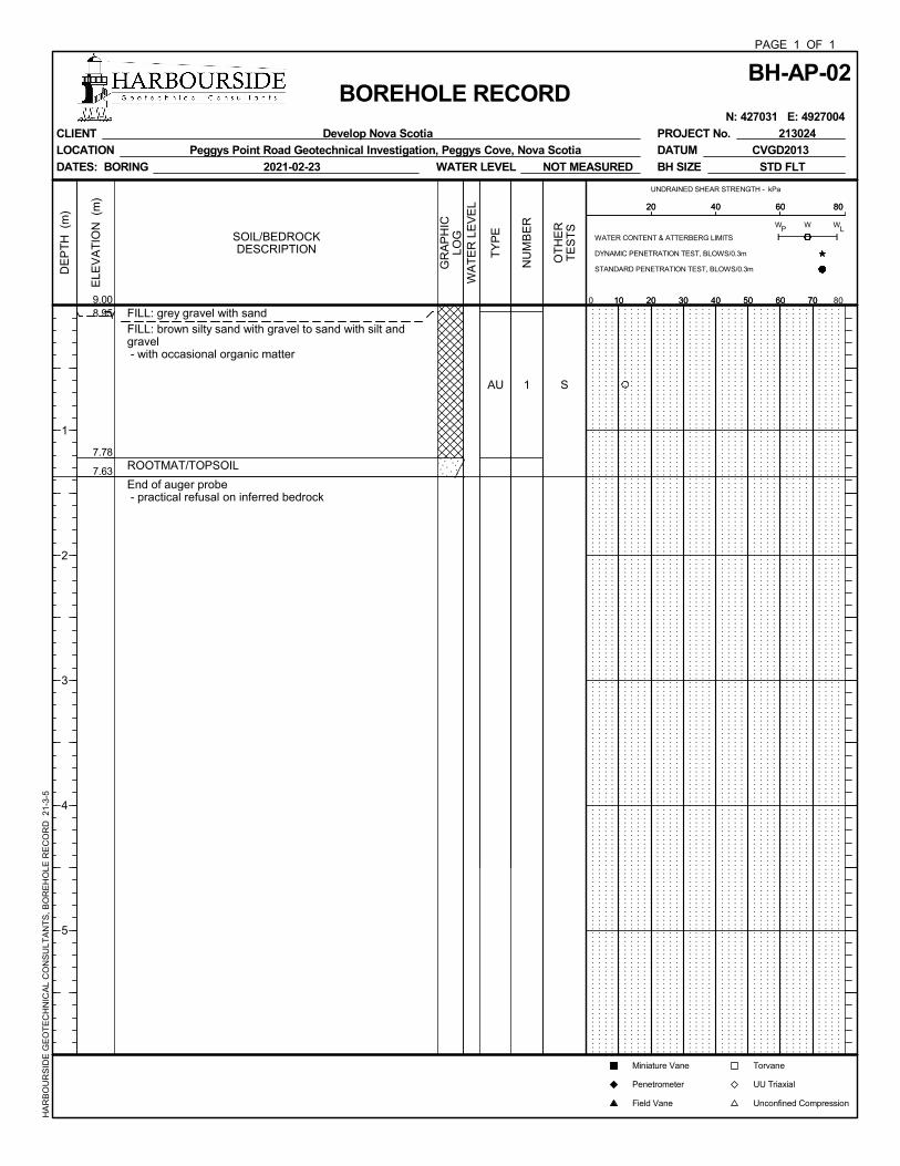
8.95
7.78
7.63
FILL: grey gravel with sandFILL: brown silty sand with gravel to sand with silt andgravel - with occasional organic matter
ROOTMAT/TOPSOIL
End of auger probe - practical refusal on inferred bedrock
AU 1 S
ELE
VA
TIO
N (
m)
DE
PT
H (
m)
1
2
3
4
5
9.00
BH-AP-02PAGE 1 OF 1
BOREHOLE RECORD N: 427031 E: 4927004
CLIENT Develop Nova Scotia
LOCATION Peggys Point Road Geotechnical Investigation, Peggys Cove, Nova Scotia
DATES: BORING 2021-02-23
PROJECT No. 213024
DATUM CVGD2013
BH SIZE STD FLTWATER LEVEL NOT MEASURED
HA
RB
OU
RS
IDE
GE
OT
EC
HN
ICA
L C
ON
SU
LTA
NT
S,
BO
RE
HO
LE R
EC
OR
D
21-3
-5
GR
AP
HIC
LOGSOIL/BEDROCK
DESCRIPTION
WA
TE
R L
EV
EL
TY
PE
NU
MB
ER
OT
HE
RT
ES
TS
UNDRAINED SHEAR STRENGTH - kPa
10 20 30 40 50 60 700 8010 20 30 40 50 60 70
PW W
L
20 40 60 8020 40 60 80
Torvane
UU Triaxial
Unconfined Compression
WATER CONTENT & ATTERBERG LIMITS
DYNAMIC PENETRATION TEST, BLOWS/0.3m
STANDARD PENETRATION TEST, BLOWS/0.3m
W
Miniature Vane
Penetrometer
Field Vane
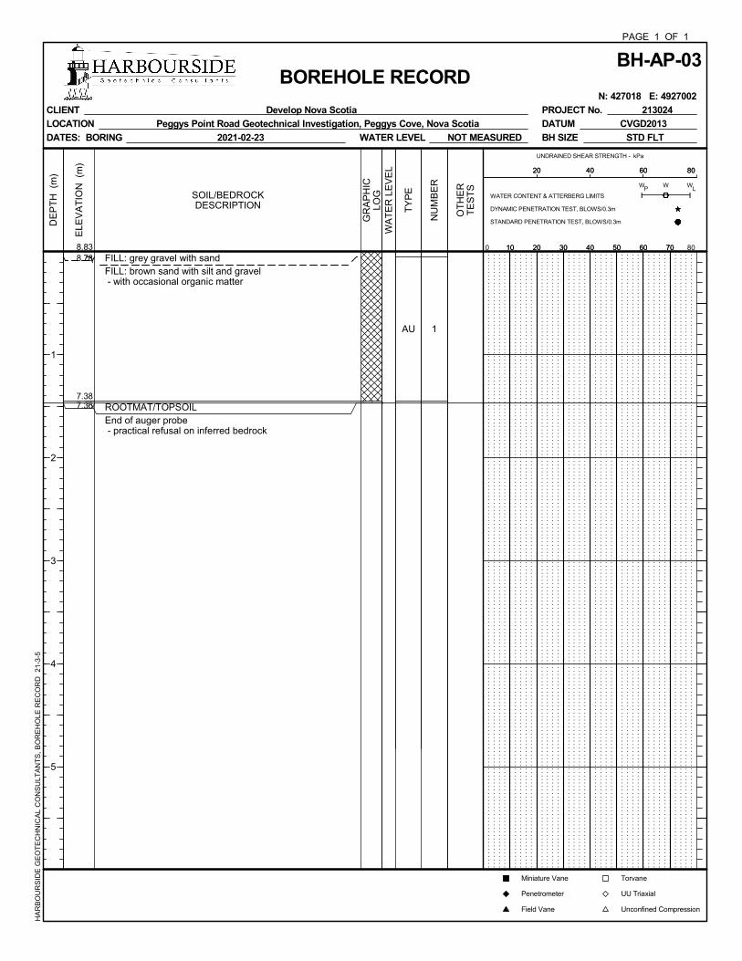
8.78
7.387.36
FILL: grey gravel with sandFILL: brown sand with silt and gravel - with occasional organic matter
ROOTMAT/TOPSOILEnd of auger probe - practical refusal on inferred bedrock
AU 1
ELE
VA
TIO
N (
m)
DE
PT
H (
m)
1
2
3
4
5
8.83
BH-AP-03PAGE 1 OF 1
BOREHOLE RECORD N: 427018 E: 4927002
CLIENT Develop Nova Scotia
LOCATION Peggys Point Road Geotechnical Investigation, Peggys Cove, Nova Scotia
DATES: BORING 2021-02-23
PROJECT No. 213024
DATUM CVGD2013
BH SIZE STD FLTWATER LEVEL NOT MEASURED
HA
RB
OU
RS
IDE
GE
OT
EC
HN
ICA
L C
ON
SU
LTA
NT
S,
BO
RE
HO
LE R
EC
OR
D
21-3
-5
GR
AP
HIC
LOGSOIL/BEDROCK
DESCRIPTION
WA
TE
R L
EV
EL
TY
PE
NU
MB
ER
OT
HE
RT
ES
TS
Torvane
UU Triaxial
Unconfined Compression
WATER CONTENT & ATTERBERG LIMITS
DYNAMIC PENETRATION TEST, BLOWS/0.3m
STANDARD PENETRATION TEST, BLOWS/0.3m
W
Miniature Vane
Penetrometer
Field Vane
UNDRAINED SHEAR STRENGTH - kPa
10 20 30 40 50 60 700 8010 20 30 40 50 60 70
PW W
L
20 40 60 8020 40 60 80
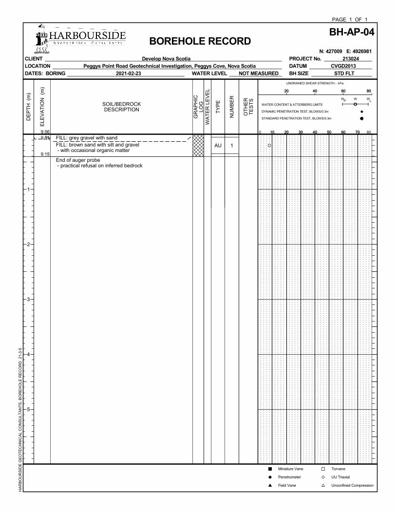
9.51
9.15
FILL: grey gravel with sandFILL: brown sand with silt and gravel - with occasional organic matter
End of auger probe - practical refusal on inferred bedrock
AU 1
ELE
VA
TIO
N (
m)
DE
PT
H (
m)
1
2
3
4
5
9.56
BH-AP-04PAGE 1 OF 1
BOREHOLE RECORD N: 427009 E: 4926981
CLIENT Develop Nova Scotia
LOCATION Peggys Point Road Geotechnical Investigation, Peggys Cove, Nova Scotia
DATES: BORING 2021-02-23
PROJECT No. 213024
DATUM CVGD2013
BH SIZE STD FLTWATER LEVEL NOT MEASURED
HA
RB
OU
RS
IDE
GE
OT
EC
HN
ICA
L C
ON
SU
LTA
NT
S,
BO
RE
HO
LE R
EC
OR
D
21-3
-5
GR
AP
HIC
LOGSOIL/BEDROCK
DESCRIPTION
WA
TE
R L
EV
EL
TY
PE
NU
MB
ER
OT
HE
RT
ES
TS
UNDRAINED SHEAR STRENGTH - kPa
10 20 30 40 50 60 700 8010 20 30 40 50 60 70
PW W
L
20 40 60 8020 40 60 80
Torvane
UU Triaxial
Unconfined Compression
WATER CONTENT & ATTERBERG LIMITS
DYNAMIC PENETRATION TEST, BLOWS/0.3m
STANDARD PENETRATION TEST, BLOWS/0.3m
W
Miniature Vane
Penetrometer
Field Vane

9.85
9.29
FILL: grey gravel with sandFILL: brown sand with silt and gravel - with occasional organic matter
End of auger probe - practical refusal on inferred bedrock
AU 1
ELE
VA
TIO
N (
m)
DE
PT
H (
m)
1
2
3
4
5
9.90
BH-AP-05PAGE 1 OF 1
BOREHOLE RECORD N: 427008 E: 4926965
CLIENT Develop Nova Scotia
LOCATION Peggys Point Road Geotechnical Investigation, Peggys Cove, Nova Scotia
DATES: BORING 2021-02-23
PROJECT No. 213024
DATUM CVGD2013
BH SIZE STD FLTWATER LEVEL NOT MEASURED
HA
RB
OU
RS
IDE
GE
OT
EC
HN
ICA
L C
ON
SU
LTA
NT
S,
BO
RE
HO
LE R
EC
OR
D
21-3
-5
GR
AP
HIC
LOGSOIL/BEDROCK
DESCRIPTION
WA
TE
R L
EV
EL
TY
PE
NU
MB
ER
OT
HE
RT
ES
TS
UNDRAINED SHEAR STRENGTH - kPa
10 20 30 40 50 60 700 8010 20 30 40 50 60 70
PW W
L
20 40 60 8020 40 60 80
Torvane
UU Triaxial
Unconfined Compression
WATER CONTENT & ATTERBERG LIMITS
DYNAMIC PENETRATION TEST, BLOWS/0.3m
STANDARD PENETRATION TEST, BLOWS/0.3m
W
Miniature Vane
Penetrometer
Field Vane

9.86
9.02
FILL: grey gravel with sandFILL: brown sand with silt and gravel - with occasional organic matter
End of auger probe - practical refusal on inferred bedrock
AU 1
ELE
VA
TIO
N (
m)
DE
PT
H (
m)
1
2
3
4
5
9.91
BH-AP-06PAGE 1 OF 1
BOREHOLE RECORD N: 427010 E: 4926956
CLIENT Develop Nova Scotia
LOCATION Peggys Point Road Geotechnical Investigation, Peggys Cove, Nova Scotia
DATES: BORING 2021-02-23
PROJECT No. 213024
DATUM CVGD2013
BH SIZE STD FLTWATER LEVEL NOT MEASURED
HA
RB
OU
RS
IDE
GE
OT
EC
HN
ICA
L C
ON
SU
LTA
NT
S,
BO
RE
HO
LE R
EC
OR
D
21-3
-5
GR
AP
HIC
LOGSOIL/BEDROCK
DESCRIPTION
WA
TE
R L
EV
EL
TY
PE
NU
MB
ER
OT
HE
RT
ES
TS
UNDRAINED SHEAR STRENGTH - kPa
10 20 30 40 50 60 700 8010 20 30 40 50 60 70
PW W
L
20 40 60 8020 40 60 80
Torvane
UU Triaxial
Unconfined Compression
WATER CONTENT & ATTERBERG LIMITS
DYNAMIC PENETRATION TEST, BLOWS/0.3m
STANDARD PENETRATION TEST, BLOWS/0.3m
W
Miniature Vane
Penetrometer
Field Vane
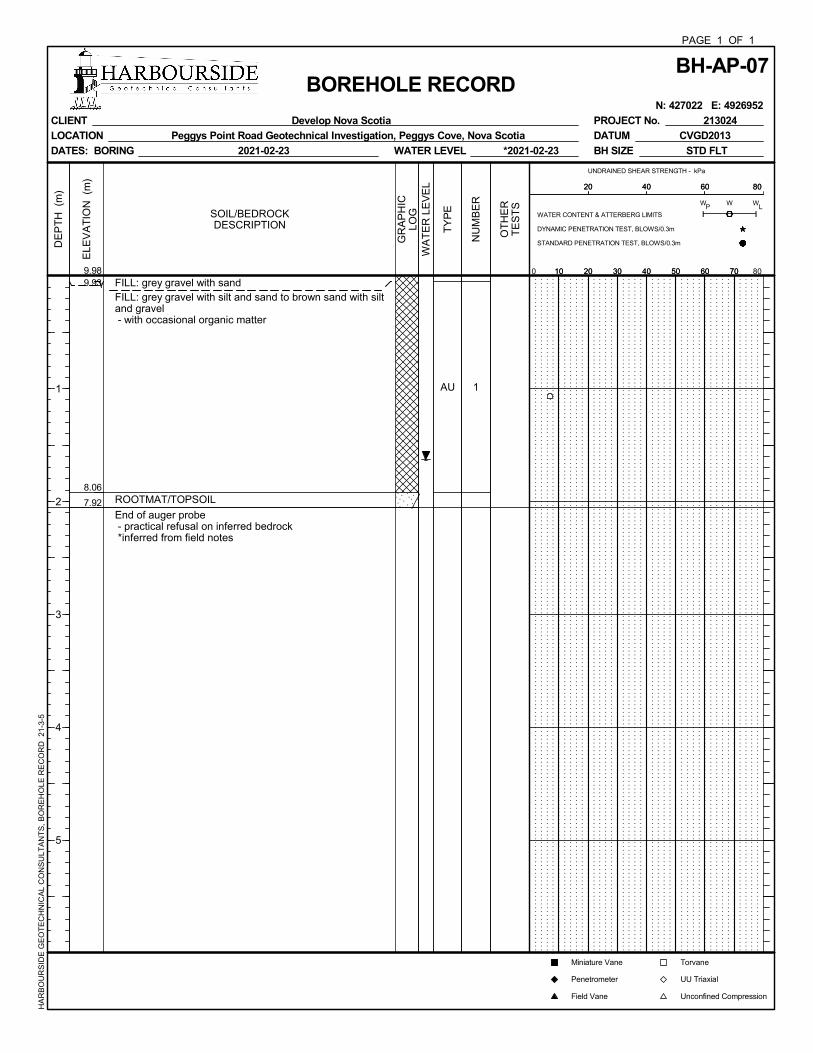
9.93
8.06
7.92
FILL: grey gravel with sandFILL: grey gravel with silt and sand to brown sand with siltand gravel - with occasional organic matter
ROOTMAT/TOPSOIL
End of auger probe - practical refusal on inferred bedrock *inferred from field notes
AU 1
ELE
VA
TIO
N (
m)
DE
PT
H (
m)
1
2
3
4
5
9.98
BH-AP-07PAGE 1 OF 1
BOREHOLE RECORD N: 427022 E: 4926952
CLIENT Develop Nova Scotia
LOCATION Peggys Point Road Geotechnical Investigation, Peggys Cove, Nova Scotia
DATES: BORING 2021-02-23
PROJECT No. 213024
DATUM CVGD2013
BH SIZE STD FLTWATER LEVEL *2021-02-23
HA
RB
OU
RS
IDE
GE
OT
EC
HN
ICA
L C
ON
SU
LTA
NT
S,
BO
RE
HO
LE R
EC
OR
D
21-3
-5
GR
AP
HIC
LOGSOIL/BEDROCK
DESCRIPTION
WA
TE
R L
EV
EL
TY
PE
NU
MB
ER
OT
HE
RT
ES
TS
UNDRAINED SHEAR STRENGTH - kPa
10 20 30 40 50 60 700 8010 20 30 40 50 60 70
PW W
L
20 40 60 8020 40 60 80
Torvane
UU Triaxial
Unconfined Compression
WATER CONTENT & ATTERBERG LIMITS
DYNAMIC PENETRATION TEST, BLOWS/0.3m
STANDARD PENETRATION TEST, BLOWS/0.3m
W
Miniature Vane
Penetrometer
Field Vane
9.37
FILL: brown sand with silt and gravel to a silt with sandand gravel - with occasional organic matter
End of auger probe - practical refusal on inferred bedrock
AU
AU
1
2
ELE
VA
TIO
N (
m)
DE
PT
H (
m)
1
2
3
4
5
10.54
BH-AP-08PAGE 1 OF 1
BOREHOLE RECORD N: 427035 E: 4926954
CLIENT Develop Nova Scotia
LOCATION Peggys Point Road Geotechnical Investigation, Peggys Cove, Nova Scotia
DATES: BORING 2021-02-23
PROJECT No. 213024
DATUM CVGD2013
BH SIZE STD FLTWATER LEVEL NOT MEASURED
HA
RB
OU
RS
IDE
GE
OT
EC
HN
ICA
L C
ON
SU
LTA
NT
S,
BO
RE
HO
LE R
EC
OR
D
21-3
-5
GR
AP
HIC
LOGSOIL/BEDROCK
DESCRIPTION
WA
TE
R L
EV
EL
TY
PE
NU
MB
ER
OT
HE
RT
ES
TS
UNDRAINED SHEAR STRENGTH - kPa
10 20 30 40 50 60 700 8010 20 30 40 50 60 70
PW W
L
20 40 60 8020 40 60 80
Torvane
UU Triaxial
Unconfined Compression
WATER CONTENT & ATTERBERG LIMITS
DYNAMIC PENETRATION TEST, BLOWS/0.3m
STANDARD PENETRATION TEST, BLOWS/0.3m
W
Miniature Vane
Penetrometer
Field Vane
11.06
9.97
9.81
ASPHALT MILLINGSFILL: brown sand with silt and gravel to gravel with siltand sand - with occasional organic matter
ROOTMAT/TOPSOIL
End of auger probe - practical refusal on inferred bedrock
AU 1 S
ELE
VA
TIO
N (
m)
DE
PT
H (
m)
1
2
3
4
5
11.11
BH-AP-09PAGE 1 OF 1
BOREHOLE RECORD N: 427041 E: 4926947
CLIENT Develop Nova Scotia
LOCATION Peggys Point Road Geotechnical Investigation, Peggys Cove, Nova Scotia
DATES: BORING 2021-02-23
PROJECT No. 213024
DATUM CVGD2013
BH SIZE STD FLTWATER LEVEL NOT MEASURED
HA
RB
OU
RS
IDE
GE
OT
EC
HN
ICA
L C
ON
SU
LTA
NT
S,
BO
RE
HO
LE R
EC
OR
D
21-3
-5
GR
AP
HIC
LOGSOIL/BEDROCK
DESCRIPTION
WA
TE
R L
EV
EL
TY
PE
NU
MB
ER
OT
HE
RT
ES
TS
UNDRAINED SHEAR STRENGTH - kPa
10 20 30 40 50 60 700 8010 20 30 40 50 60 70
PW W
L
20 40 60 8020 40 60 80
Torvane
UU Triaxial
Unconfined Compression
WATER CONTENT & ATTERBERG LIMITS
DYNAMIC PENETRATION TEST, BLOWS/0.3m
STANDARD PENETRATION TEST, BLOWS/0.3m
W
Miniature Vane
Penetrometer
Field Vane
11.58
10.62
10.33
ASPHALT MILLINGSFILL: brown sand with silt and gravel - with occasional organic matter
ROOTMAT/TOPSOIL
End of auger probe - practical refusal on inferred bedrock
AU
AU
1
2
ELE
VA
TIO
N (
m)
DE
PT
H (
m)
1
2
3
4
5
11.63
BH-AP-10PAGE 1 OF 1
BOREHOLE RECORD N: 427048 E: 4926949
CLIENT Develop Nova Scotia
LOCATION Peggys Point Road Geotechnical Investigation, Peggys Cove, Nova Scotia
DATES: BORING 2021-02-23
PROJECT No. 213024
DATUM CVGD2013
BH SIZE STD FLTWATER LEVEL NOT MEASURED
HA
RB
OU
RS
IDE
GE
OT
EC
HN
ICA
L C
ON
SU
LTA
NT
S,
BO
RE
HO
LE R
EC
OR
D
21-3
-5
GR
AP
HIC
LOGSOIL/BEDROCK
DESCRIPTION
WA
TE
R L
EV
EL
TY
PE
NU
MB
ER
OT
HE
RT
ES
TS
UNDRAINED SHEAR STRENGTH - kPa
10 20 30 40 50 60 700 8010 20 30 40 50 60 70
PW W
L
20 40 60 8020 40 60 80
Torvane
UU Triaxial
Unconfined Compression
WATER CONTENT & ATTERBERG LIMITS
DYNAMIC PENETRATION TEST, BLOWS/0.3m
STANDARD PENETRATION TEST, BLOWS/0.3m
W
Miniature Vane
Penetrometer
Field Vane
11.13
11.00
8.79
8.51
ASPHALTFILL: grey gravel with sandFILL: brown sand with silt and gravel to a brown silt withsand and gravel- frequent cobbles and boulders- occasional organics
ROOTMAT/TOPSOIL
End of auger probe - practical refusal on inferred bedrock
AU
AU
AU
1
2
3
ELE
VA
TIO
N (
m)
DE
PT
H (
m)
1
2
3
4
5
11.23
BH-AP-11PAGE 1 OF 1
BOREHOLE RECORD N: 427063 E: 4926934
CLIENT Develop Nova Scotia
LOCATION Peggys Point Road Geotechnical Investigation, Peggys Cove, Nova Scotia
DATES: BORING 2021-02-23
PROJECT No. 213024
DATUM CVGD2013
BH SIZE STD FLTWATER LEVEL NOT MEASURED
HA
RB
OU
RS
IDE
GE
OT
EC
HN
ICA
L C
ON
SU
LTA
NT
S,
BO
RE
HO
LE R
EC
OR
D
21-3
-5
GR
AP
HIC
LOGSOIL/BEDROCK
DESCRIPTION
WA
TE
R L
EV
EL
TY
PE
NU
MB
ER
OT
HE
RT
ES
TS
UNDRAINED SHEAR STRENGTH - kPa
10 20 30 40 50 60 700 8010 20 30 40 50 60 70
PW W
L
20 40 60 8020 40 60 80
Torvane
UU Triaxial
Unconfined Compression
WATER CONTENT & ATTERBERG LIMITS
DYNAMIC PENETRATION TEST, BLOWS/0.3m
STANDARD PENETRATION TEST, BLOWS/0.3m
W
Miniature Vane
Penetrometer
Field Vane
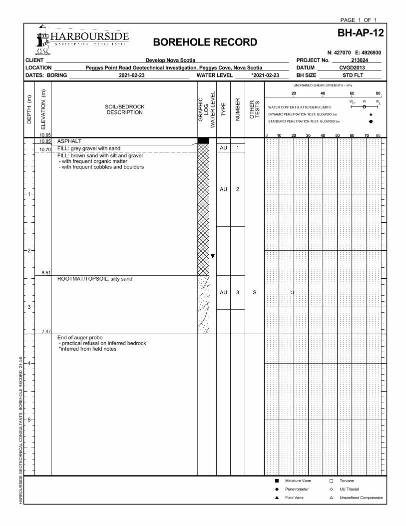
10.85
10.70
8.51
7.47
ASPHALTFILL: grey gravel with sandFILL: brown sand with silt and gravel - with frequent organic matter - with frequent cobbles and boulders
ROOTMAT/TOPSOIL: silty sand
End of auger probe - practical refusal on inferred bedrock *inferred from field notes
AU
AU
AU
1
2
3 S
ELE
VA
TIO
N (
m)
DE
PT
H (
m)
1
2
3
4
5
10.95
BH-AP-12PAGE 1 OF 1
BOREHOLE RECORD N: 427070 E: 4926930
CLIENT Develop Nova Scotia
LOCATION Peggys Point Road Geotechnical Investigation, Peggys Cove, Nova Scotia
DATES: BORING 2021-02-23
PROJECT No. 213024
DATUM CVGD2013
BH SIZE STD FLTWATER LEVEL *2021-02-23
HA
RB
OU
RS
IDE
GE
OT
EC
HN
ICA
L C
ON
SU
LTA
NT
S,
BO
RE
HO
LE R
EC
OR
D
21-3
-5
GR
AP
HIC
LOGSOIL/BEDROCK
DESCRIPTION
WA
TE
R L
EV
EL
TY
PE
NU
MB
ER
OT
HE
RT
ES
TS
UNDRAINED SHEAR STRENGTH - kPa
10 20 30 40 50 60 700 8010 20 30 40 50 60 70
PW W
L
20 40 60 8020 40 60 80
Torvane
UU Triaxial
Unconfined Compression
WATER CONTENT & ATTERBERG LIMITS
DYNAMIC PENETRATION TEST, BLOWS/0.3m
STANDARD PENETRATION TEST, BLOWS/0.3m
W
Miniature Vane
Penetrometer
Field Vane
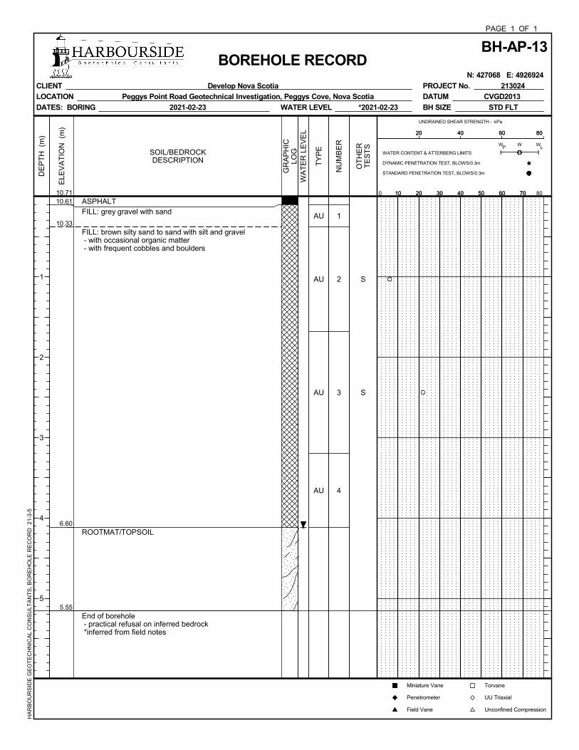
10.61
10.33
6.60
5.55
ASPHALTFILL: grey gravel with sand
FILL: brown silty sand to sand with silt and gravel - with occasional organic matter - with frequent cobbles and boulders
ROOTMAT/TOPSOIL
End of borehole - practical refusal on inferred bedrock *inferred from field notes
AU
AU
AU
AU
1
2
3
4
S
S
ELE
VA
TIO
N (
m)
DE
PT
H (
m)
1
2
3
4
5
10.71
BH-AP-13PAGE 1 OF 1
BOREHOLE RECORD N: 427068 E: 4926924
CLIENT Develop Nova Scotia
LOCATION Peggys Point Road Geotechnical Investigation, Peggys Cove, Nova Scotia
DATES: BORING 2021-02-23
PROJECT No. 213024
DATUM CVGD2013
BH SIZE STD FLTWATER LEVEL *2021-02-23
HA
RB
OU
RS
IDE
GE
OT
EC
HN
ICA
L C
ON
SU
LTA
NT
S,
BO
RE
HO
LE R
EC
OR
D
21-3
-5
GR
AP
HIC
LOGSOIL/BEDROCK
DESCRIPTION
WA
TE
R L
EV
EL
TY
PE
NU
MB
ER
OT
HE
RT
ES
TS
UNDRAINED SHEAR STRENGTH - kPa
10 20 30 40 50 60 700 8010 20 30 40 50 60 70
WATER CONTENT & ATTERBERG LIMITS
DYNAMIC PENETRATION TEST, BLOWS/0.3m
STANDARD PENETRATION TEST, BLOWS/0.3m
W
Miniature Vane
Penetrometer
Field Vane
PW W
L
20 40 60 8020 40 60 80
Torvane
UU Triaxial
Unconfined Compression
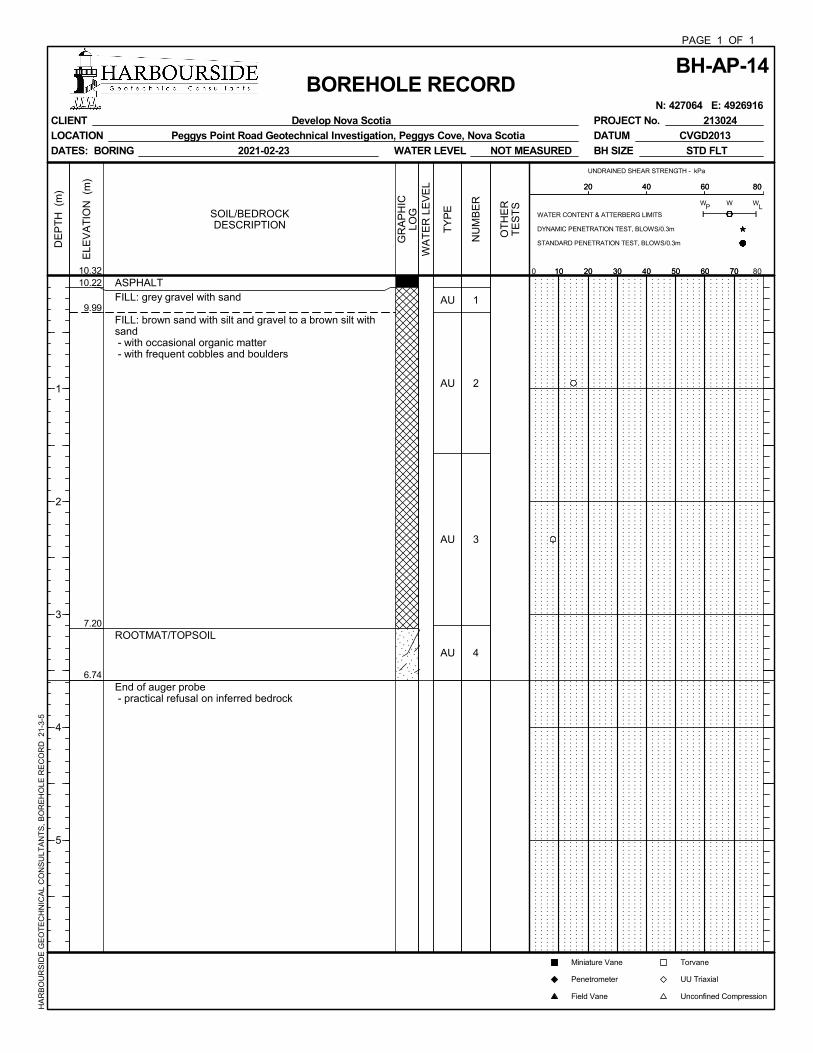
10.22
9.99
7.20
6.74
ASPHALTFILL: grey gravel with sand
FILL: brown sand with silt and gravel to a brown silt withsand - with occasional organic matter - with frequent cobbles and boulders
ROOTMAT/TOPSOIL
End of auger probe - practical refusal on inferred bedrock
AU
AU
AU
AU
1
2
3
4
ELE
VA
TIO
N (
m)
DE
PT
H (
m)
1
2
3
4
5
10.32
BH-AP-14PAGE 1 OF 1
BOREHOLE RECORD N: 427064 E: 4926916
CLIENT Develop Nova Scotia
LOCATION Peggys Point Road Geotechnical Investigation, Peggys Cove, Nova Scotia
DATES: BORING 2021-02-23
PROJECT No. 213024
DATUM CVGD2013
BH SIZE STD FLTWATER LEVEL NOT MEASURED
HA
RB
OU
RS
IDE
GE
OT
EC
HN
ICA
L C
ON
SU
LTA
NT
S,
BO
RE
HO
LE R
EC
OR
D
21-3
-5
GR
AP
HIC
LOGSOIL/BEDROCK
DESCRIPTION
WA
TE
R L
EV
EL
TY
PE
NU
MB
ER
OT
HE
RT
ES
TS
UNDRAINED SHEAR STRENGTH - kPa
10 20 30 40 50 60 700 8010 20 30 40 50 60 70
PW W
L
20 40 60 8020 40 60 80
Torvane
UU Triaxial
Unconfined Compression
WATER CONTENT & ATTERBERG LIMITS
DYNAMIC PENETRATION TEST, BLOWS/0.3m
STANDARD PENETRATION TEST, BLOWS/0.3m
W
Miniature Vane
Penetrometer
Field Vane
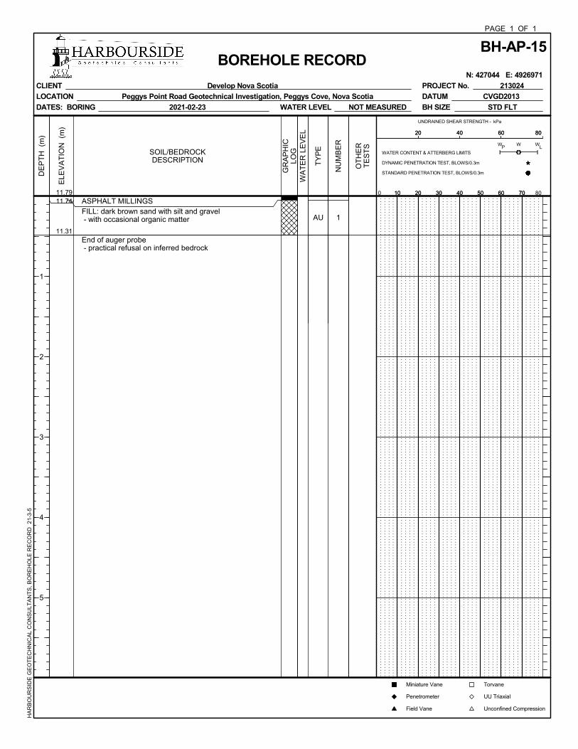
11.74
11.31
ASPHALT MILLINGSFILL: dark brown sand with silt and gravel - with occasional organic matter
End of auger probe - practical refusal on inferred bedrock
AU 1
ELE
VA
TIO
N (
m)
DE
PT
H (
m)
1
2
3
4
5
11.79
BH-AP-15PAGE 1 OF 1
BOREHOLE RECORD N: 427044 E: 4926971
CLIENT Develop Nova Scotia
LOCATION Peggys Point Road Geotechnical Investigation, Peggys Cove, Nova Scotia
DATES: BORING 2021-02-23
PROJECT No. 213024
DATUM CVGD2013
BH SIZE STD FLTWATER LEVEL NOT MEASURED
HA
RB
OU
RS
IDE
GE
OT
EC
HN
ICA
L C
ON
SU
LTA
NT
S,
BO
RE
HO
LE R
EC
OR
D
21-3
-5
GR
AP
HIC
LOGSOIL/BEDROCK
DESCRIPTION
WA
TE
R L
EV
EL
TY
PE
NU
MB
ER
OT
HE
RT
ES
TS
UNDRAINED SHEAR STRENGTH - kPa
10 20 30 40 50 60 700 8010 20 30 40 50 60 70
PW W
L
20 40 60 8020 40 60 80
Torvane
UU Triaxial
Unconfined Compression
WATER CONTENT & ATTERBERG LIMITS
DYNAMIC PENETRATION TEST, BLOWS/0.3m
STANDARD PENETRATION TEST, BLOWS/0.3m
W
Miniature Vane
Penetrometer
Field Vane
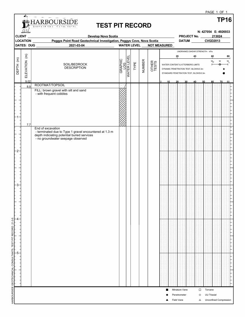
8.9
7.7
ROOTMAT/TOPSOIL
FILL: brown gravel with silt and sand - with frequent cobbles
End of excavation - terminated due to Type 1 gravel encountered at 1.3 mdepth indiciating potential buried services - no groundwater seepage observed
ELE
VA
TIO
N (
m)
DE
PT
H (
m)
1
2
3
4
5
9.02
TP16PAGE 1 OF 1
TEST PIT RECORD N: 427054 E: 4926933
CLIENT Develop Nova Scotia
LOCATION Peggys Point Road Geotechnical Investigation, Peggys Cove, Nova Scotia
DATES: DUG 2021-03-04
PROJECT No. 213024
DATUM CVGD2013
WATER LEVEL NOT MEASURED
HA
RB
OU
RS
IDE
GE
OT
EC
HN
ICA
L C
ON
SU
LTA
NT
S,
TE
ST
PIT
RE
CO
RD
21
-3-5
GR
AP
HIC
LOGSOIL/BEDROCK
DESCRIPTION
WA
TE
R L
EV
EL
TY
PE
NU
MB
ER
OT
HE
RT
ES
TS
UNDRAINED SHEAR STRENGTH - kPa
10 20 30 40 50 60 700 8010 20 30 40 50 60 70
PW W
L
20 40 60 8020 40 60 80
Torvane
UU Triaxial
Unconfined Compression
WATER CONTENT & ATTERBERG LIMITS
DYNAMIC PENETRATION TEST, BLOWS/0.3m
STANDARD PENETRATION TEST, BLOWS/0.3m
W
Miniature Vane
Penetrometer
Field Vane
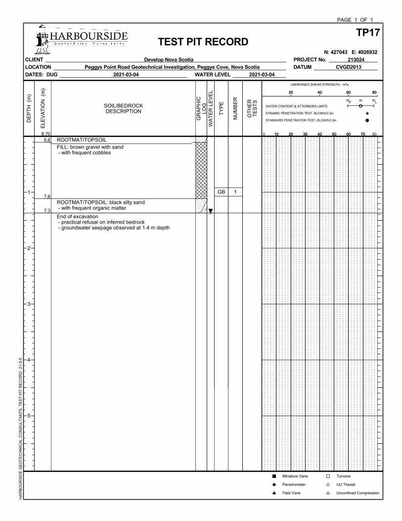
8.6
7.6
7.3
ROOTMAT/TOPSOILFILL: brown gravel with sand - with frequent cobbles
ROOTMAT/TOPSOIL: black silty sand - with frequent organic matter
End of excavation - practical refusal on inferred bedrock - groundwater seepage observed at 1.4 m depth
GB 1
ELE
VA
TIO
N (
m)
DE
PT
H (
m)
1
2
3
4
5
8.70
TP17PAGE 1 OF 1
TEST PIT RECORD N: 427043 E: 4926932
CLIENT Develop Nova Scotia
LOCATION Peggys Point Road Geotechnical Investigation, Peggys Cove, Nova Scotia
DATES: DUG 2021-03-04
PROJECT No. 213024
DATUM CVGD2013
WATER LEVEL 2021-03-04
HA
RB
OU
RS
IDE
GE
OT
EC
HN
ICA
L C
ON
SU
LTA
NT
S,
TE
ST
PIT
RE
CO
RD
21
-3-5
GR
AP
HIC
LOGSOIL/BEDROCK
DESCRIPTION
WA
TE
R L
EV
EL
TY
PE
NU
MB
ER
OT
HE
RT
ES
TS
UNDRAINED SHEAR STRENGTH - kPa
10 20 30 40 50 60 700 8010 20 30 40 50 60 70
PW W
L
20 40 60 8020 40 60 80
Torvane
UU Triaxial
Unconfined Compression
WATER CONTENT & ATTERBERG LIMITS
DYNAMIC PENETRATION TEST, BLOWS/0.3m
STANDARD PENETRATION TEST, BLOWS/0.3m
W
Miniature Vane
Penetrometer
Field Vane
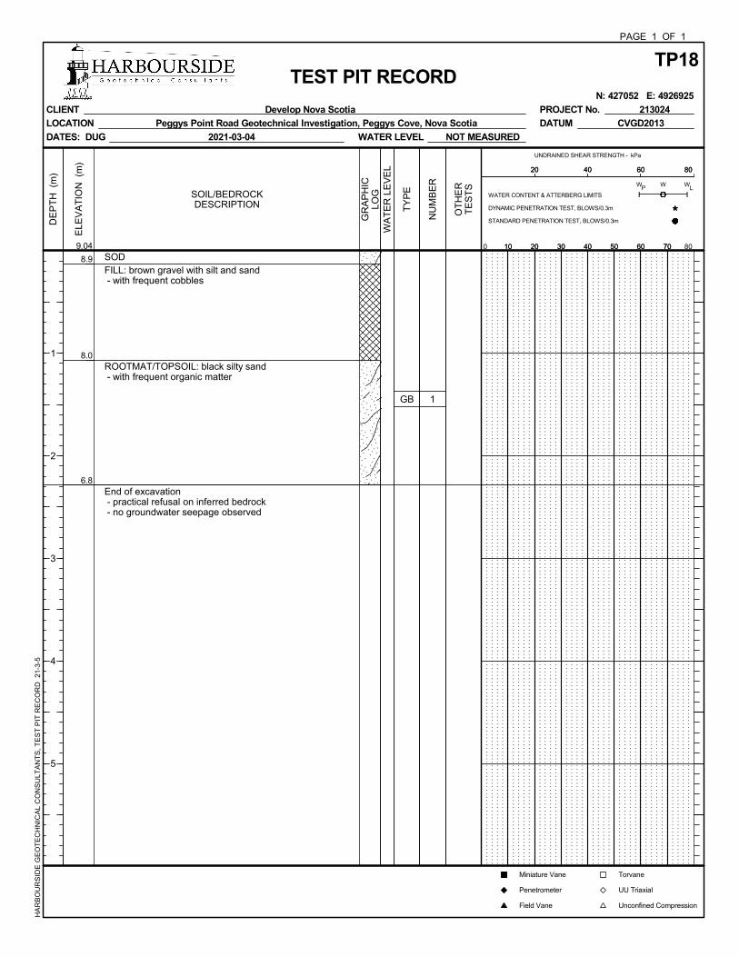
8.9
8.0
6.8
SODFILL: brown gravel with silt and sand - with frequent cobbles
ROOTMAT/TOPSOIL: black silty sand - with frequent organic matter
End of excavation - practical refusal on inferred bedrock - no groundwater seepage observed
GB 1
ELE
VA
TIO
N (
m)
DE
PT
H (
m)
1
2
3
4
5
9.04
TP18PAGE 1 OF 1
TEST PIT RECORD N: 427052 E: 4926925
CLIENT Develop Nova Scotia
LOCATION Peggys Point Road Geotechnical Investigation, Peggys Cove, Nova Scotia
DATES: DUG 2021-03-04
PROJECT No. 213024
DATUM CVGD2013
WATER LEVEL NOT MEASURED
HA
RB
OU
RS
IDE
GE
OT
EC
HN
ICA
L C
ON
SU
LTA
NT
S,
TE
ST
PIT
RE
CO
RD
21
-3-5
GR
AP
HIC
LOGSOIL/BEDROCK
DESCRIPTION
WA
TE
R L
EV
EL
TY
PE
NU
MB
ER
OT
HE
RT
ES
TS
UNDRAINED SHEAR STRENGTH - kPa
10 20 30 40 50 60 700 8010 20 30 40 50 60 70
PW W
L
20 40 60 8020 40 60 80
Torvane
UU Triaxial
Unconfined Compression
WATER CONTENT & ATTERBERG LIMITS
DYNAMIC PENETRATION TEST, BLOWS/0.3m
STANDARD PENETRATION TEST, BLOWS/0.3m
W
Miniature Vane
Penetrometer
Field Vane

APPENDIX B Laboratory Testing
Checked: WTM
GRAVEL SAND SILT/CLAYBH-AP-01 AU2 0.76 to 1.07 31% 57% 12%BH-AP-02 AU1 0.05 to 1.17 42% 44% 14%BH-AP-09 AU1 0.05 to 1.14 56% 34% 10%
CLIENT
PROJECT
LOCATION
Poorly Graded Sand with Silt and Gravel
Peggy's Point Road, Peggy's Cove, N.S.
Peggy's Cove Additional Investigation
Develop Nova Scotia
SOIL DESCRIPITION
GRAIN SIZE DISTRIBUTION
PRO
JECT N
o.: 213024
CURVE BOREHOLE / TESTPIT SAMPLE DEPTH (m) SOIL FRACTION
Silty Sand with GravelPoorly Graded Gravel with Silt and Sand
t: 1.902.405.4696 | f: 1.902.405.4693
219 Waverley Road, Suite 200
Dartmouth, NS B2X 2C3
http://harboursideengineering.ca
0%
10%
20%
30%
40%
50%
60%
70%
80%
90%
100%
0.001 0.01 0.1 1 10 100
Perc
ent P
assi
ng
Grain Size in Millimetres
GravelSandSilt and Clay
coarsecoarse finefine medium
Checked: VCG
GRAVEL SAND SILT/CLAYBH-AP-12 AU3 0.25 to 1.50 10% 57% 33%BH-AP-13 AU2 0.38 to 1.70 23% 52% 26%BH-AP-13 AU3 1.70 to 3.20 12% 56% 32%
CLIENT
PROJECT
LOCATION
SOIL DESCRIPITION
GRAIN SIZE DISTRIBUTION
PRO
JECT N
o.: 213024
CURVE BOREHOLE / TESTPIT SAMPLE DEPTH (m) SOIL FRACTION
Silty Sand with GravelSilty Sand
Silty Sand
Peggy's Point Road, Peggy's Cove, N.S.
Peggy's Cove Additional Investigation
Develop Nova Scotiat: 1.902.405.4696 | f: 1.902.405.4693
219 Waverley Road, Suite 200
Dartmouth, NS B2X 2C3
http://harboursideengineering.ca
0%
10%
20%
30%
40%
50%
60%
70%
80%
90%
100%
0.001 0.01 0.1 1 10 100
Perc
ent P
assi
ng
Grain Size in Millimetres
GravelSandSilt and Clay
coarsecoarse finefine medium

APPENDIX C Sketch SK - 1 - Borehole Location Plan

0 20 4010 m
0 70 14035 ft
KEY PLAN
LEGEND
DATA SOURCES: IMAGERY OBTAINED FROM ESRI
PEGGYS POINT RDGEOTECHNICAL INVESTIGATION
TEST PIT (TP)
U
Y BOREHOLE (BH)
BOREHOLE AND TEST PITLOCATION PLAN
U
YU
YU
Y
U
YU
Y
U
Y
U
Y
U
Y
U
Y
U
Y
U
Y
U
Y
U
Y
U
Y
U
Y
BH-AP-01 427049 4927014 9.22
BH-AP-02 427032 4927004 9.00
BH-AP-03 427018 4927002 8.83
BH-AP-04 427010 4926981 9.56
BH-AP-05 427009 4926965 9.90
BH-AP-06 427010 4926956 9.91
BH-AP-07 427023 4926953 9.98
BH-AP-08 427035 4926954 10.54
BH-AP-09 427041 4926947 11.11
BH-AP-10 427049 4926949 11.63
BH-AP-11 427064 4926934 11.23
BH-AP-12 427070 4926930 10.95
BH-AP-13 427069 4926925 10.71
BH-AP-14 427065 4926917 10.32
BH-AP-15 427045 4926971 11.78
BOREHOLE (BH) EASTING NORTHING ELEVATION
COORDINATES ARE IN REFERENCE TONAD83 UTM ZONE 20N
ELEVATIONS ARE IN REFERENCE TOCGVD2013
DD-MM-YYYY: 04-03-2021
PROJECT No. 213024
BH-AP-01
BH-AP-02
BH-AP-03
BH-AP-04
BH-AP-05
BH-AP-06BH-AP-07
BH-AP-08
BH-AP-09
BH-AP-10
BH-AP-11
BH-AP-12
BH-AP-13
BH-AP-14
BH-AP-15
TP16
TP17
TP18
TP16 427054 4926932 9.02
TP17 427043 4926932 8.70
TP18 427051 4926924 9.04
TEST PIT (TP) EASTING NORTHING ELEVATION
Develop Nova Scotia Old Red Store, Historic Properties Suite 301 – 1875 Upper Water St. Halifax, NS B3J 1S9
Date: Friday, February 26, 2021
ADDENDUM #01 for DNS-2021-0106 Peggys Cove Public Washroom
Request for Quotation Sponsored by:
Develop Nova Scotia 1.0 Clarifications:
1.1 Project Signage There are numerous references to sign locations in the tender drawings. Please note that the locations are noted on the drawings, as well as rough-ins for future power/communication requirements. The signs, however, are not part of the project at this time. 1.2 Approved Alternates – Plumbing Components The following plumbing alternates are approved for use in this project:
- Beeco (Mifab Backflow) – ½” to 2” reduced pressure back flow; - Air Gap ½” thru 1”; Air Gap 1-1/4” thru 2” - Mifab Electronic Trap Primer
o MI-100-5-AD 1-5 opening ports copper waterway with cabinet with bolt on cover
o Water Hammer Arrestors – Brass Piston Type ½” to 1-1/4” Connection o Hub Drain – c/w primer conn 2-3-4” NH o Lav-1 Carrier – MC-31
Please note that faucets specified in drawings are to be assumed for bidding purposes. 2.0 CHANGES 2.1. Refer to Specifications Remove: Specifications Replace with: ADDENDUM #1 – Revised Specifications (attached below).
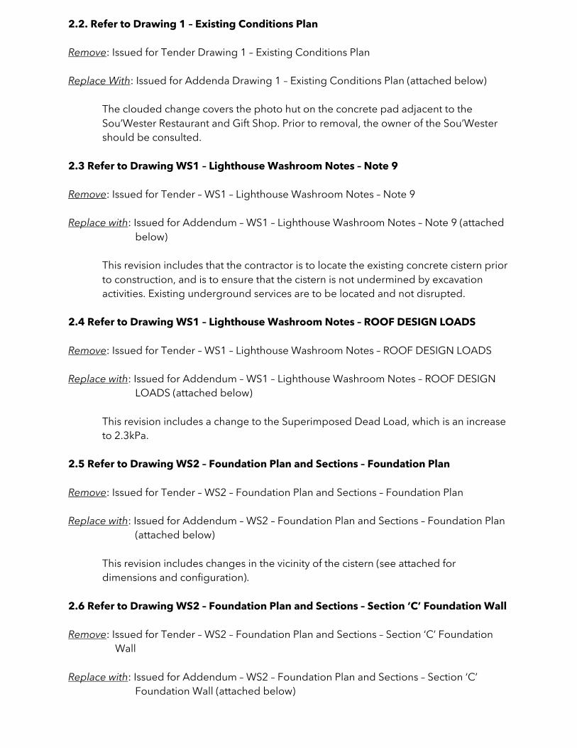
2.2. Refer to Drawing 1 – Existing Conditions Plan Remove: Issued for Tender Drawing 1 – Existing Conditions Plan Replace With: Issued for Addenda Drawing 1 – Existing Conditions Plan (attached below)
The clouded change covers the photo hut on the concrete pad adjacent to the Sou’Wester Restaurant and Gift Shop. Prior to removal, the owner of the Sou’Wester should be consulted.
2.3 Refer to Drawing WS1 – Lighthouse Washroom Notes – Note 9 Remove: Issued for Tender – WS1 – Lighthouse Washroom Notes – Note 9 Replace with: Issued for Addendum – WS1 – Lighthouse Washroom Notes – Note 9 (attached
below)
This revision includes that the contractor is to locate the existing concrete cistern prior to construction, and is to ensure that the cistern is not undermined by excavation activities. Existing underground services are to be located and not disrupted.
2.4 Refer to Drawing WS1 – Lighthouse Washroom Notes – ROOF DESIGN LOADS Remove: Issued for Tender – WS1 – Lighthouse Washroom Notes – ROOF DESIGN LOADS Replace with: Issued for Addendum – WS1 – Lighthouse Washroom Notes – ROOF DESIGN
LOADS (attached below)
This revision includes a change to the Superimposed Dead Load, which is an increase to 2.3kPa.
2.5 Refer to Drawing WS2 – Foundation Plan and Sections – Foundation Plan Remove: Issued for Tender – WS2 – Foundation Plan and Sections – Foundation Plan Replace with: Issued for Addendum – WS2 – Foundation Plan and Sections – Foundation Plan
(attached below)
This revision includes changes in the vicinity of the cistern (see attached for dimensions and configuration).
2.6 Refer to Drawing WS2 – Foundation Plan and Sections – Section ‘C’ Foundation Wall Remove: Issued for Tender – WS2 – Foundation Plan and Sections – Section ‘C’ Foundation
Wall Replace with: Issued for Addendum – WS2 – Foundation Plan and Sections – Section ‘C’
Foundation Wall (attached below)
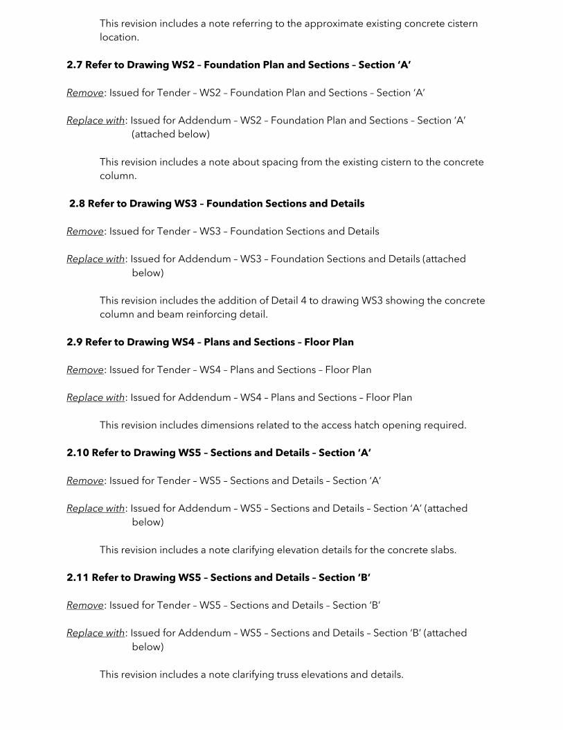
This revision includes a note referring to the approximate existing concrete cistern location.
2.7 Refer to Drawing WS2 – Foundation Plan and Sections – Section ‘A’ Remove: Issued for Tender – WS2 – Foundation Plan and Sections – Section ‘A’ Replace with: Issued for Addendum – WS2 – Foundation Plan and Sections – Section ‘A’
(attached below)
This revision includes a note about spacing from the existing cistern to the concrete column.
2.8 Refer to Drawing WS3 – Foundation Sections and Details Remove: Issued for Tender – WS3 – Foundation Sections and Details Replace with: Issued for Addendum – WS3 – Foundation Sections and Details (attached
below)
This revision includes the addition of Detail 4 to drawing WS3 showing the concrete column and beam reinforcing detail.
2.9 Refer to Drawing WS4 – Plans and Sections – Floor Plan Remove: Issued for Tender – WS4 – Plans and Sections – Floor Plan Replace with: Issued for Addendum – WS4 – Plans and Sections – Floor Plan
This revision includes dimensions related to the access hatch opening required. 2.10 Refer to Drawing WS5 – Sections and Details – Section ‘A’ Remove: Issued for Tender – WS5 – Sections and Details – Section ‘A’ Replace with: Issued for Addendum – WS5 – Sections and Details – Section ‘A’ (attached
below)
This revision includes a note clarifying elevation details for the concrete slabs. 2.11 Refer to Drawing WS5 – Sections and Details – Section ‘B’ Remove: Issued for Tender – WS5 – Sections and Details – Section ‘B’ Replace with: Issued for Addendum – WS5 – Sections and Details – Section ‘B’ (attached
below)
This revision includes a note clarifying truss elevations and details.
2.12 Refer to Drawing WS5 – Sections and Details – Detail ‘1’ Overhang Remove: Issued for Tender – WS5 – Sections and Details – Detail ‘1’ Overhang Replace with: Issued for Addendum – WS5 – Sections and Details – Detail ‘1’ Overhang
(attached below)
This revision includes a note clarifying the use of microlam and a change to a Simpson Strong Tie ST18.
2.13 Refer to Drawing WS5 – Sections and Details – Detail ‘2’ Overhang Remove: Issued for Tender – WS5 – Sections and Details – Detail ‘2’ Overhang Replace with: Issued for Addendum – WS5 – Sections and Details – Detail ‘2’ Overhang
(attached below)
This revision includes a note clarifying the use of microlam, blocking adjustment and underside of truss elevations.
2.14 Refer to Drawing WS6 – Deck Plan – Deck Plan Remove: Issued for Tender – WS6 – Deck Plan – Deck Plan Replace with: Issued for Addendum – WS6 – Deck Plan – Deck Plan (attached below)
This revision includes a revision to the deck plan orientation and the addition of numerous details and measurements.
2.15 Refer to Drawing WS7 – Deck Sections – Section ‘A’ Remove: Issued for Tender – WS7 – Deck Sections – Section ‘A’ Replace with: Issued for Addendum – WS7 – Deck Sections – Section ‘A’ (attached below)
This revision includes dimensions for timber decking, connection clarification and additional information.
2.16 Refer to Drawing WS7 – Deck Sections – Section ‘B’ Remove: Issued for Tender – WS7 – Deck Sections – Section ‘B’ Replace with: Issued for Addendum – WS7 – Deck Sections – Section ‘B’ (attached below)
This revision includes dimensions for the ramp, support information and elevations. 2.17 Refer to Drawing WS7 – Deck Sections – Section ‘C’ Remove: Issued for Tender – WS7 – Deck Sections – Section ‘C’
Replace with: Issued for Addendum – WS7 – Deck Sections – Section ‘C’ (attached below)
This revision includes dimensions for timber beam. 2.18 Refer to Drawing WS7 – Deck Sections – Section ‘D’ Remove: Issued for Tender – WS7 – Deck Sections – Section ‘D’ Replace with: Issued for Addendum – WS7 – Deck Sections – Section ‘D’ (attached below)
This revision includes details on the concrete wall thickness, gasket, ground clearance dimension between deck and grade, and gridline dimensions.
2.19 Refer to Drawing WS8 – Deck Details – Section ‘A’ Remove: Issued for Tender – WS8 – Deck Details Replace with: Issued for Addendum – WS8 – Deck Details – Section ‘A’ (attached below)
This revision includes the addition of Section ‘A’ for additional details. 2.20 Refer to Drawing WS8 – Deck Details – Section ‘B’ Remove: Issued for Tender – WS8 – Deck Details Replace with: Issued for Addendum – WS8 – Deck Details – Section ‘B’ (attached below)
This revision includes Section ‘B’ replacing Detail ‘3’ in the IFT set. This detail shows dimensions and data for the cast-in-place stairs.
2.21 Refer to Drawing WS8 – Deck Details – Detail ‘1’ Remove: Issued for Tender – WS8 – Deck Details – Detail ‘1’ Replace with: Issued for Addendum – WS8 – Deck Details – Detail ‘1’ (attached below)
This revision includes detail of the PVC scupper for the cast-in-place retaining wall. 2.22 Refer to Drawing WS8 – Deck Details – Detail ‘2’ Remove: Issued for Tender – WS8 – Deck Details – Detail ‘2’ Replace with: Issued for Addendum – WS8 – Deck Details – Detail ‘2’ (attached below)
This revision provides a new detail including the PVC scupper for the cast-in-place retaining wall (medium).
2.23 Refer to Drawing WS8 – Deck Details – Detail ‘3’
Remove: Issued for Tender – WS8 – Deck Details – Detail ‘3’ Replace with: Issued for Addendum – WS8 – Deck Details – Detail ‘3’ (attached below)
This revision provides a new detail including the PVC scupper for the cast-in-place retaining wall (small).
2.24 Refer to Drawing WS8 – Deck Details – Detail ‘4’ Remove: Issued for Tender – WS8 – Deck Details – Detail ‘4’ Replace with: Issued for Addendum – WS8 – Deck Details – Detail ‘4’ (attached below)
This revision provides a new detail with information on the baseplate. 2.25 Refer to Drawing WS8 – Deck Details – Detail ‘5’ Remove: Issued for Tender – WS8 – Deck Details Replace with: Issued for Addendum – WS8 – Deck Details – Detail ‘5’ (new detail attached
below)
This revision provides a new detail with information on the baseplate. 2.26 Refer to Structural Drawings Add: Issued for Addendum – WS9 – Deck Details (attached below)
This revision provides a new drawing with details for footings and sidewalk. 2.27 Refer to Drawing M1 – Mechanical Plans and Legend – Detail ‘1’ Mechanical Plan –
Basement Level Remove: Issued for Tender – M1 – Mechanical Plans and Legend – Detail ‘1’ Mechanical Plan –
Basement Level Replace With: Issued for Addendum – M1 – Mechanical Plans and Legend – Detail ‘1’
Mechanical Plan – Basement Level
This revision provides piping, compost liquid storage tank capacity, and gray water storage tank capacity updates.
2.28 Refer to Drawing M1 – Mechanical Plans and Legend – Detail ‘2’ Mechanical Plan –
Main Level Remove: Issued for Tender – M1 – Mechanical Plans and Legend – Detail ‘1’ Mechanical Plan –
Main Level
Replace With: Issued for Addendum – M1 – Mechanical Plans and Legend – Detail ‘1’ Mechanical Plan – Main Level
This revision provides a capped shut-off valve and rough-in for a water fountain, addition of cistern cam lock, and cistern overflow infrastructure.
2.29 Refer to Drawing A0-03 – Assemblies Remove: Drawing A0-03 – Issued for Tender - Assemblies Replace with: Drawing A0-03 – Issued for Addendum 1 - Assemblies This change addresses revisions to the roof and soffit assemblies. 2.30 Refer to Drawing A1-01 – Accessible Viewing Deck and Pathways Remove: Drawing A1-01 – Issued for Tender – Accessible Viewing Deck and Pathways Replace with: Drawing A1-01 – Issued for Addendum 1 – Accessible Viewing Deck and
Pathways This change addresses revisions to the tactile and visual indicators at ramps and stairs; revisions to the access ramp & stair from the parking lot; revisions to the bicycle racks; and revisions & additions to guardrails at the Accessible Viewing Platform access ramp. 2.31 Refer to Drawing A2-01 – Level 0 Plan & Roof Plan Remove: Drawing A2-01 – Issued for Tender – Level 0 Plan & Roof Plan Replace with: Drawing A2-01 – Issued for Addendum 1 – Level 0 Plan & Roof Plan This change addresses revisions to the cistern. 2.32 Refer to Drawing A2-02 – Level 1 Plan Remove: Drawing A2-02 – Issued for Tender – Level 1 Plan Replace with: Drawing A2-02 – Issued for Addendum 1 – Level 1 Plan This change addresses a revision to the safety room. 2.33 Refer to Drawing A2-10 – Reflected Ceiling & Soffit Plan Level 0 and Level 1 Remove: Drawing A2-10 – Issued for Tender – Reflected Ceiling & Soffit Plan Level 0 and
Level 1 Replace with: Drawing A2-10 – Issued for Addendum 1 – Reflected Ceiling & Soffit Plan Level
0 and Level 1
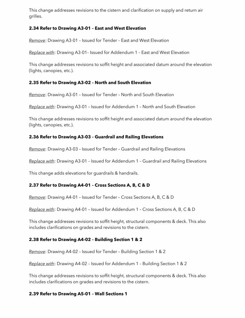
This change addresses revisions to the cistern and clarification on supply and return air grilles. 2.34 Refer to Drawing A3-01 – East and West Elevation Remove: Drawing A3-01 – Issued for Tender – East and West Elevation Replace with: Drawing A3-01– Issued for Addendum 1 – East and West Elevation This change addresses revisions to soffit height and associated datum around the elevation (lights, canopies, etc.). 2.35 Refer to Drawing A3-02 – North and South Elevation Remove: Drawing A3-01 – Issued for Tender – North and South Elevation Replace with: Drawing A3-01 – Issued for Addendum 1 – North and South Elevation This change addresses revisions to soffit height and associated datum around the elevation (lights, canopies, etc.). 2.36 Refer to Drawing A3-03 – Guardrail and Railing Elevations Remove: Drawing A3-03 – Issued for Tender – Guardrail and Railing Elevations Replace with: Drawing A3-01 – Issued for Addendum 1 – Guardrail and Railing Elevations This change adds elevations for guardrails & handrails. 2.37 Refer to Drawing A4-01 – Cross Sections A, B, C & D Remove: Drawing A4-01 – Issued for Tender – Cross Sections A, B, C & D Replace with: Drawing A4-01 – Issued for Addendum 1 – Cross Sections A, B, C & D This change addresses revisions to soffit height, structural components & deck. This also includes clarifications on grades and revisions to the cistern. 2.38 Refer to Drawing A4-02 – Building Section 1 & 2 Remove: Drawing A4-02 – Issued for Tender – Building Section 1 & 2 Replace with: Drawing A4-02 – Issued for Addendum 1 – Building Section 1 & 2 This change addresses revisions to soffit height, structural components & deck. This also includes clarifications on grades and revisions to the cistern. 2.39 Refer to Drawing A5-01 – Wall Sections 1

Remove: Drawing A5-01 – Issued for Tender – Wall Sections 1 Replace with: Drawing A5-01 – Issued for Addendum 1 – Wall Sections 1 This change addresses revisions to coordinate with new structural information (soffit, deck & cistern) and provides clarification on grades. 2.40 Refer to Drawing A5-03 – Wall Sections III Remove: Drawing A5-03 – Issued for Tender – Wall Sections III Replace with: Drawing A5-03 – Issued for Addendum 1 – Wall Sections III This change addresses revisions to coordinate with new structural information (soffit, deck & cistern) and provides clarification on grades. 2.41 Refer to Drawing A6-02 – Interior Finishes II Remove: Drawing A6-02 – Issued for Tender – Interior Finishes II Replace with: Drawing A6-02 – Issued for Addendum 1 – Interior Finishes II This change adjusted the heights/locations & descriptions of accessories. 2.42 Refer to Drawing A6-03 – Interior Finishes III Remove: Drawing A6-03 – Issued for Tender – Interior Finishes III Replace with: Drawing A6-03 – Issued for Addendum 1 – Interior Finishes III This change adjusted the heights/locations & descriptions of accessories. 2.43 Window and Door Schedule Add: Drawing A8-01 – Issued for Addendum 1 – Window and Door Schedule This change added a door schedule. This addendum WILL require a revision to the Closing Date and Time, or other dates given in the Request for Proposal document. The closing date and time will CHANGE TO 2:00 pm AT on March 11th, 2021.
In accordance with Section C.7 of Appendix C – Submission Pricing Form, Proponents are deemed to have read and taken into account all addenda issued by Develop Nova Scotia. For further information prospective Proponents should contact Tim Jordan, Project Manager at [email protected]
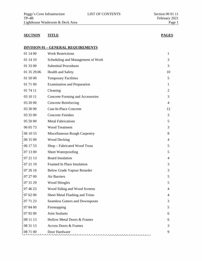
Peggy’s Cove Infrastructure LIST OF CONTENTS Section 00 01 11 TP-4B February 2021 Lighthouse Washroom & Deck Area Page 1
SECTION TITLE PAGES
DIVISION 01 – GENERAL REQUIREMENTS
01 14 00 Work Restrictions 1
01 14 10 Scheduling and Management of Work 3
01 33 00 Submittal Procedures 3
01 35 29.06 Health and Safety 10
01 50 00 Temporary Facilities 5
01 71 00 Examination and Preparation 1
01 74 11 Cleaning 2
03 10 11 Concrete Forming and Accessories 3
03 20 00 Concrete Reinforcing 4
03 30 00 Cast-In-Place Concrete 12
03 35 00 Concrete Finishes 3
05 50 00 Metal Fabrications 5
06 05 73 Wood Treatment 3
06 10 53 Miscellaneous Rough Carpentry 8
06 15 00 Wood Decking 4
06 17 53 Shop – Fabricated Wood Truss 5
07 13 00 Sheet Waterproofing 5
07 21 13 Board Insulation 4
07 21 19 Foamed In Place Insulation 3
07 26 16 Below Grade Vapour Retarder 3
07 27 00 Air Barriers 5
07 31 29 Wood Shingles 5
07 46 23 Wood Siding and Wood Screens 4
07 62 00 Sheet Metal Flashing and Trims 4
07 71 23 Seamless Gutters and Downspouts 3
07 84 00 Firestopping 5
07 92 00 Joint Sealants 6
08 11 13 Hollow Metal Doors & Frames 6
08 31 13 Access Doors & Frames 3
08 71 00 Door Hardware 9
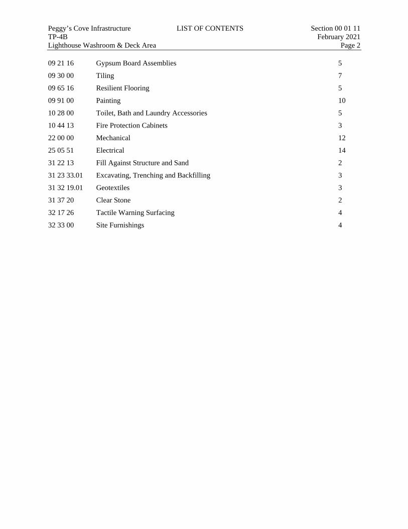
Peggy’s Cove Infrastructure LIST OF CONTENTS Section 00 01 11 TP-4B February 2021 Lighthouse Washroom & Deck Area Page 2 09 21 16 Gypsum Board Assemblies 5
09 30 00 Tiling 7
09 65 16 Resilient Flooring 5
09 91 00 Painting 10
10 28 00 Toilet, Bath and Laundry Accessories 5
10 44 13 Fire Protection Cabinets 3
22 00 00 Mechanical 12
25 05 51 Electrical 14
31 22 13 Fill Against Structure and Sand 2
31 23 33.01 Excavating, Trenching and Backfilling 3
31 32 19.01 Geotextiles 3
31 37 20 Clear Stone 2
32 17 26 Tactile Warning Surfacing 4
32 33 00 Site Furnishings 4

Peggy’s Cove Infrastructure WORK RESTRICTIONS Section 01 14 00 TP-4B February 2021 Lighthouse Washroom & Deck Area Page 1
Part 1 General
1.1 ACCESS AND EGRESS
.1 Design, construct and maintain temporary "access to" and "egress from" work areas, in accordance with relevant municipal, provincial and other regulations.
1.2 USE OF SITE AND FACILITIES
.1 Execute work with least possible interference or disturbance to normal use of premises. Make arrangements with Develop NS to facilitate work as stated.
.2 Provide for personnel and vehicle access.
.3 Where safety and/or security is reduced by the work, provide temporary means to maintain safety and/or security.
1.3 ALTERATIONS, ADDITIONS OR REPAIRS
.1 Execute work with least possible interference or disturbance to public and normal use of private premises. Arrange with Develop NS to facilitate execution of work.
1.4 EXISTING SERVICES
.1 Notify Develop NS and utility companies of intended interruption of services and obtain required permission.
.2 Provide services for personnel, pedestrian and vehicular traffic where such services have been interrupted due to construction.
1.5 SPECIAL REQUIREMENTS
.1 Maintenance to vehicles and equipment is prohibited.
.2 Blasting is not permitted.
.3 Ensure Contractor's personnel employed on site become familiar with and obey regulations including safety, fire, traffic and security regulations.
.4 Keep within limits of work and avenues of ingress and egress.
.5 Contractor is to coordinate work with all other contractors on-site in Peggy’s Cove and notify Develop NS if conflicts arise.
END OF SECTION
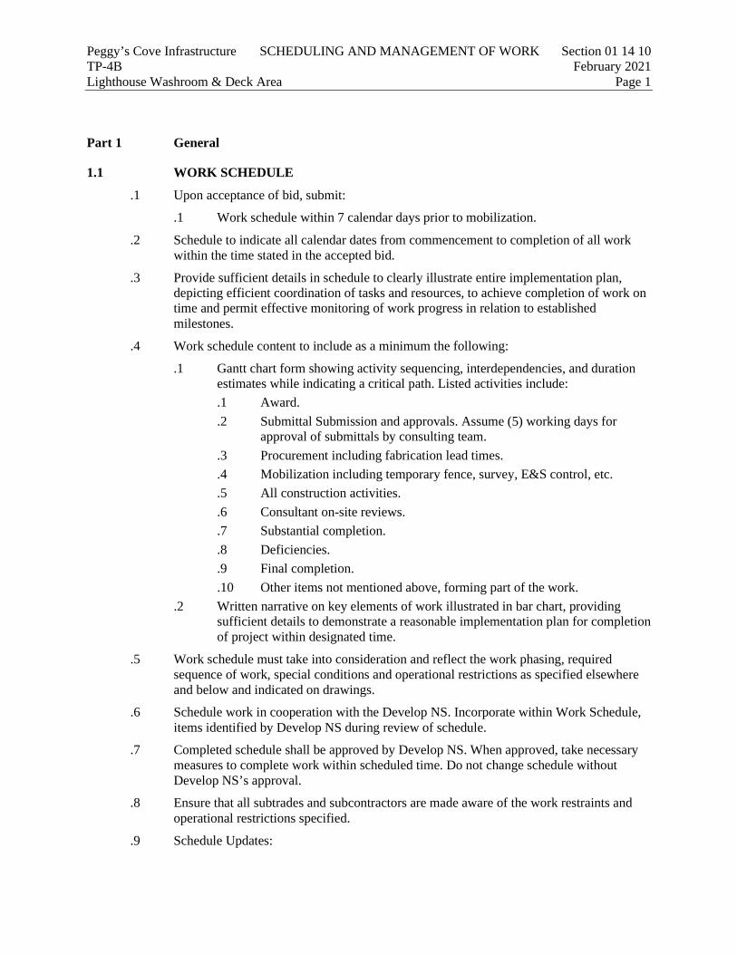
Peggy’s Cove Infrastructure SCHEDULING AND MANAGEMENT OF WORK Section 01 14 10 TP-4B February 2021 Lighthouse Washroom & Deck Area Page 1
Part 1 General
1.1 WORK SCHEDULE
.1 Upon acceptance of bid, submit:
.1 Work schedule within 7 calendar days prior to mobilization.
.2 Schedule to indicate all calendar dates from commencement to completion of all work within the time stated in the accepted bid.
.3 Provide sufficient details in schedule to clearly illustrate entire implementation plan, depicting efficient coordination of tasks and resources, to achieve completion of work on time and permit effective monitoring of work progress in relation to established milestones.
.4 Work schedule content to include as a minimum the following:
.1 Gantt chart form showing activity sequencing, interdependencies, and duration estimates while indicating a critical path. Listed activities include: .1 Award. .2 Submittal Submission and approvals. Assume (5) working days for
approval of submittals by consulting team. .3 Procurement including fabrication lead times. .4 Mobilization including temporary fence, survey, E&S control, etc. .5 All construction activities. .6 Consultant on-site reviews. .7 Substantial completion. .8 Deficiencies. .9 Final completion. .10 Other items not mentioned above, forming part of the work.
.2 Written narrative on key elements of work illustrated in bar chart, providing sufficient details to demonstrate a reasonable implementation plan for completion of project within designated time.
.5 Work schedule must take into consideration and reflect the work phasing, required sequence of work, special conditions and operational restrictions as specified elsewhere and below and indicated on drawings.
.6 Schedule work in cooperation with the Develop NS. Incorporate within Work Schedule, items identified by Develop NS during review of schedule.
.7 Completed schedule shall be approved by Develop NS. When approved, take necessary measures to complete work within scheduled time. Do not change schedule without Develop NS’s approval.
.8 Ensure that all subtrades and subcontractors are made aware of the work restraints and operational restrictions specified.
.9 Schedule Updates:
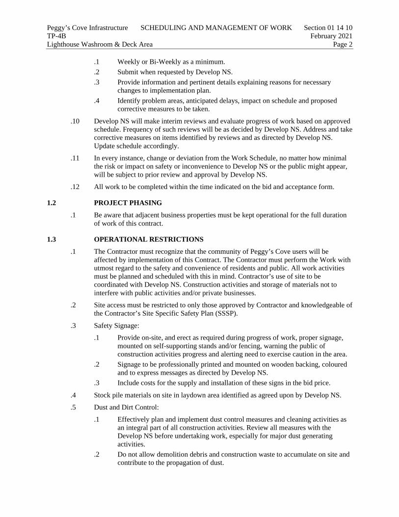
Peggy’s Cove Infrastructure SCHEDULING AND MANAGEMENT OF WORK Section 01 14 10 TP-4B February 2021 Lighthouse Washroom & Deck Area Page 2
.1 Weekly or Bi-Weekly as a minimum.
.2 Submit when requested by Develop NS.
.3 Provide information and pertinent details explaining reasons for necessary changes to implementation plan.
.4 Identify problem areas, anticipated delays, impact on schedule and proposed corrective measures to be taken.
.10 Develop NS will make interim reviews and evaluate progress of work based on approved schedule. Frequency of such reviews will be as decided by Develop NS. Address and take corrective measures on items identified by reviews and as directed by Develop NS. Update schedule accordingly.
.11 In every instance, change or deviation from the Work Schedule, no matter how minimal the risk or impact on safety or inconvenience to Develop NS or the public might appear, will be subject to prior review and approval by Develop NS.
.12 All work to be completed within the time indicated on the bid and acceptance form.
1.2 PROJECT PHASING
.1 Be aware that adjacent business properties must be kept operational for the full duration of work of this contract.
1.3 OPERATIONAL RESTRICTIONS
.1 The Contractor must recognize that the community of Peggy’s Cove users will be affected by implementation of this Contract. The Contractor must perform the Work with utmost regard to the safety and convenience of residents and public. All work activities must be planned and scheduled with this in mind. Contractor’s use of site to be coordinated with Develop NS. Construction activities and storage of materials not to interfere with public activities and/or private businesses.
.2 Site access must be restricted to only those approved by Contractor and knowledgeable of the Contractor’s Site Specific Safety Plan (SSSP).
.3 Safety Signage:
.1 Provide on-site, and erect as required during progress of work, proper signage, mounted on self-supporting stands and/or fencing, warning the public of construction activities progress and alerting need to exercise caution in the area.
.2 Signage to be professionally printed and mounted on wooden backing, coloured and to express messages as directed by Develop NS.
.3 Include costs for the supply and installation of these signs in the bid price.
.4 Stock pile materials on site in laydown area identified as agreed upon by Develop NS.
.5 Dust and Dirt Control:
.1 Effectively plan and implement dust control measures and cleaning activities as an integral part of all construction activities. Review all measures with the Develop NS before undertaking work, especially for major dust generating activities.
.2 Do not allow demolition debris and construction waste to accumulate on site and contribute to the propagation of dust.
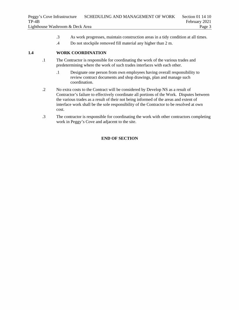
Peggy’s Cove Infrastructure SCHEDULING AND MANAGEMENT OF WORK Section 01 14 10 TP-4B February 2021 Lighthouse Washroom & Deck Area Page 3
.3 As work progresses, maintain construction areas in a tidy condition at all times.
.4 Do not stockpile removed fill material any higher than 2 m.
1.4 WORK COORDINATION
.1 The Contractor is responsible for coordinating the work of the various trades and predetermining where the work of such trades interfaces with each other.
.1 Designate one person from own employees having overall responsibility to review contract documents and shop drawings, plan and manage such coordination.
.2 No extra costs to the Contract will be considered by Develop NS as a result of Contractor’s failure to effectively coordinate all portions of the Work. Disputes between the various trades as a result of their not being informed of the areas and extent of interface work shall be the sole responsibility of the Contractor to be resolved at own cost.
.3 The contractor is responsible for coordinating the work with other contractors completing work in Peggy’s Cove and adjacent to the site.
END OF SECTION
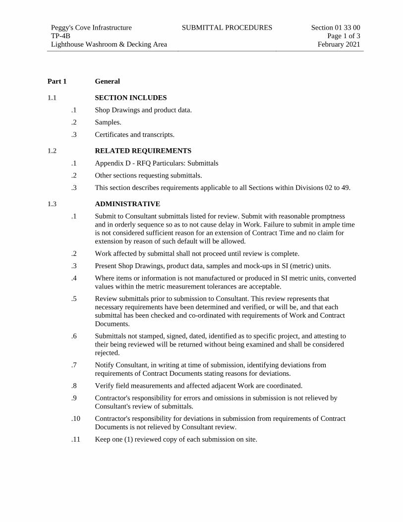
Peggy's Cove Infrastructure TP-4B Lighthouse Washroom & Decking Area
SUBMITTAL PROCEDURES Section 01 33 00 Page 1 of 3
February 2021
SEC TION 01 33 00 Submittal procedures
Part 1 General
1.1 SECTION INCLUDES
.1 Shop Drawings and product data.
.2 Samples.
.3 Certificates and transcripts.
1.2 RELATED REQUIREMENTS
.1 Appendix D - RFQ Particulars: Submittals
.2 Other sections requesting submittals.
.3 This section describes requirements applicable to all Sections within Divisions 02 to 49.
1.3 ADMINISTRATIVE
.1 Submit to Consultant submittals listed for review. Submit with reasonable promptness and in orderly sequence so as to not cause delay in Work. Failure to submit in ample time is not considered sufficient reason for an extension of Contract Time and no claim for extension by reason of such default will be allowed.
.2 Work affected by submittal shall not proceed until review is complete.
.3 Present Shop Drawings, product data, samples and mock-ups in SI (metric) units.
.4 Where items or information is not manufactured or produced in SI metric units, converted values within the metric measurement tolerances are acceptable.
.5 Review submittals prior to submission to Consultant. This review represents that necessary requirements have been determined and verified, or will be, and that each submittal has been checked and co-ordinated with requirements of Work and Contract Documents.
.6 Submittals not stamped, signed, dated, identified as to specific project, and attesting to their being reviewed will be returned without being examined and shall be considered rejected.
.7 Notify Consultant, in writing at time of submission, identifying deviations from requirements of Contract Documents stating reasons for deviations.
.8 Verify field measurements and affected adjacent Work are coordinated.
.9 Contractor's responsibility for errors and omissions in submission is not relieved by Consultant's review of submittals.
.10 Contractor's responsibility for deviations in submission from requirements of Contract Documents is not relieved by Consultant review.
.11 Keep one (1) reviewed copy of each submission on site.
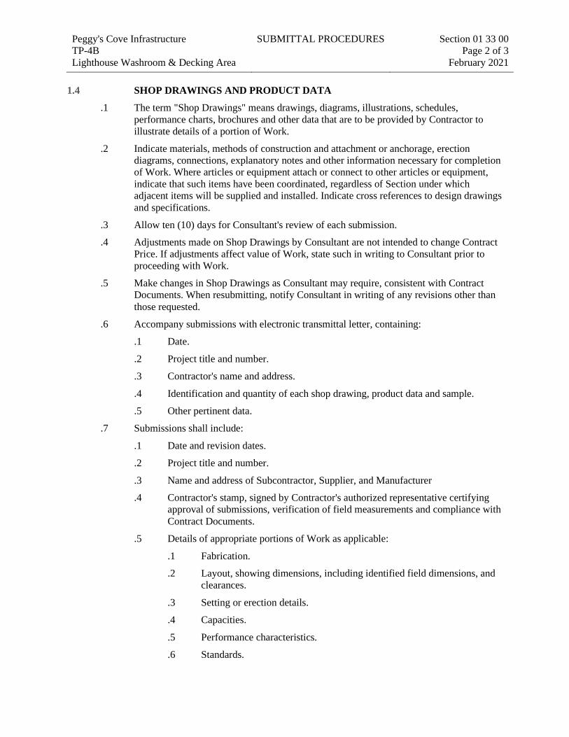
Peggy's Cove Infrastructure TP-4B Lighthouse Washroom & Decking Area
SUBMITTAL PROCEDURES Section 01 33 00 Page 2 of 3
February 2021 1.4 SHOP DRAWINGS AND PRODUCT DATA
.1 The term "Shop Drawings" means drawings, diagrams, illustrations, schedules, performance charts, brochures and other data that are to be provided by Contractor to illustrate details of a portion of Work.
.2 Indicate materials, methods of construction and attachment or anchorage, erection diagrams, connections, explanatory notes and other information necessary for completion of Work. Where articles or equipment attach or connect to other articles or equipment, indicate that such items have been coordinated, regardless of Section under which adjacent items will be supplied and installed. Indicate cross references to design drawings and specifications.
.3 Allow ten (10) days for Consultant's review of each submission.
.4 Adjustments made on Shop Drawings by Consultant are not intended to change Contract Price. If adjustments affect value of Work, state such in writing to Consultant prior to proceeding with Work.
.5 Make changes in Shop Drawings as Consultant may require, consistent with Contract Documents. When resubmitting, notify Consultant in writing of any revisions other than those requested.
.6 Accompany submissions with electronic transmittal letter, containing:
.1 Date.
.2 Project title and number.
.3 Contractor's name and address.
.4 Identification and quantity of each shop drawing, product data and sample.
.5 Other pertinent data.
.7 Submissions shall include:
.1 Date and revision dates.
.2 Project title and number.
.3 Name and address of Subcontractor, Supplier, and Manufacturer
.4 Contractor's stamp, signed by Contractor's authorized representative certifying approval of submissions, verification of field measurements and compliance with Contract Documents.
.5 Details of appropriate portions of Work as applicable:
.1 Fabrication.
.2 Layout, showing dimensions, including identified field dimensions, and clearances.
.3 Setting or erection details.
.4 Capacities.
.5 Performance characteristics.
.6 Standards.
Peggy's Cove Infrastructure TP-4B Lighthouse Washroom & Decking Area
SUBMITTAL PROCEDURES Section 01 33 00 Page 3 of 3
February 2021
.7 Operating weight.
.8 Wiring diagrams.
.9 Single line and schematic diagrams.
.10 Relationship to other parts of the Work.
.8 After Consultant's review, distribute copies.
.9 Submit electronic copy of Shop Drawings for each requirement requested in specification Sections and as consultant may reasonably request.
.10 Submit electronic copy of product data sheets or brochures for requirements requested in specification sections and as requested by Consultant where Shop Drawings will not be prepared due to standardized manufacture of product.
.11 Delete information not applicable to project.
.12 Supplement standard information to provide details applicable to project.
.13 If upon review by Consultant, no errors or omissions are discovered or if only minor corrections are made, electronic copy will be returned and fabrication and installation of Work may proceed. If Shop Drawings are rejected, noted copy will be returned and re-submission of corrected Shop Drawings, through same procedure indicated above, must be performed before fabrication and installation of Work may proceed.
1.5 SAMPLES
.1 Submit for review samples in duplicate as requested in respective specification Sections. Label samples with origin and intended use.
.2 Deliver samples prepaid to Consultant's business address.
.3 Notify Consultant in writing, at time of submission of deviations in samples from requirements of Contract Documents.
.4 Where colour, pattern or texture is criterion, submit full range of samples.
.5 Adjustments made on samples by Consultant are not intended to change Contract Price. If adjustments affect value of Work, state such in writing to Consultant prior to proceeding with Work.
.6 Make changes in samples that Consultant may require, consistent with Contract Documents.
.7 Reviewed and accepted samples will become standard of workmanship and material against which installed Work will be verified.
1.6 CERTIFICATES AND TRANSCRIPTS
.1 Immediately after award of Contract, submit Workers' Compensation Board status.
.2 Submit transcription of insurance immediately after award of Contract.
END OF SECTION

Peggy’s Cove Infrastructure HEALTH AND SAFETY Section 01 35 29.06 TP-4B February 2021 Lighthouse Washroom & Deck Area Page 1
Part 1 General
1.1 REFERENCES
.1 Health Canada / Workplace Hazardous Materials Information System (WHMIS)
.1 Material Safety Data Sheets (MSDS)
.2 Government of Canada
.1 Canada Labour Code – Part II (entitled Occupational Health and Safety)
.2 Canada Occupational Health and Safety Regulations (COHS)
.3 Province of Nova Scotia
.1 Occupational Health and Safety Act
.2 Occupational Health and Safety Regulations made pursuant to the Act
.4 Part 8 of the National Building Code
.5 Municipal by-laws and ordinances.
1.2 DEFINITIONS
.1 Competent Person: means a person who is:
.1 Qualified by virtue of personal knowledge, training and experience to perform assigned work in a manner that will ensure the health and safety of persons in the workplace;
.2 Knowledgeable about the provisions of occupational health and safety statues and regulations that apply to the Work; and
.3 Knowledgeable about potential or actual danger to health and safety associated with the Work.
.2 Medical Aid Injury: any minor injury for which medical treatment was provided and the cost of which is covered by the Workers’ Compensation Board of the province in which the injury incurred.
.3 Work site: where used in this section shall mean areas, located at the premises where Work is undertaken, used by Contractor to perform all of the activities associated with the performance of the Work.
.4 COSH: Canada Occupational Health and Safety Regulations made under Part II of the Canada Labour Code.
.5 PPE: personal protective equipment
1.3 SUBMITTALS
.1 Submit site specific Health and Safety Plan (including site specific hazard assessment): within 10 days of notification of Bid Acceptance and prior to commencement of work.
.2 Develop NS will review Contractor’s site-specific Health and Safety Plan and provide comments. Revise plan as appropriate and resubmit within ten (10) working days after receipt of comments.
Peggy’s Cove Infrastructure HEALTH AND SAFETY Section 01 35 29.06 TP-4B February 2021 Lighthouse Washroom & Deck Area Page 2
.3 Develop NS’s review and comments made of the Plan shall not be construed as an endorsement, approval or implied warranty of any kind by Canada and does not reduce Contractor's overall responsibility for Occupational Health and Safety of the Work.
.4 Submit revisions and updates made to the Contractor’s Health and Safety plan during the course of the Work.
.5 Submit name of designated Health & Safety Site Representative and support documentation specified in the Safety Plan.
.6 Submit records of Contractor’s Health and Safety meetings when requested.
.7 Submit Construction Safety Checklists after completion.
.8 Submit copies of reports of directions issued by Federal, Provincial and Territorial health and safety inspectors.
.9 Submit copies of incident and accident reports.
.10 Submit WHMIS MSDS – Material Safety Data Sheets.
.11 Submit proof of Workers’ Compensation Coverage through submission of Letter of Good Standing. Contractor must maintain good standing throughout the duration of the contract.
.12 Submit Certificate of Recognition or Letter of Good Standing issued jointly by the Workers` Compensation Board of Nova Scotia and an occupational health and safety organization approved by the Workers` Compensation Board of Nova Scotia.
.13 Contractor’s responsibility for Health and Safety is not relieved in any way by the Develop NS’s review or lack of review of these submittals.
1.4 COMPLIANCE REQUIREMENTS
.1 Comply with the Occupational Health and Safety Act for the Province of Nova Scotia and the Regulations made pursuant to the Act.
.2 Comply with Canada Labour Code Part II, and the Canada Occupational Safety and Health Regulations made under Part II of the Canada Labour Code.
.3 Observe and enforce construction safety measures required by:
.1 2015 National Building Code of Canada, Part 8;
.2 Provincial Worker’s Compensation Board;
.3 Municipal by-laws and ordinances.
.4 In event of conflict between any provisions of above authorities the most stringent provision will apply. Should a dispute arise in determining the most stringent requirement, Develop NS will advise on the course of action to be followed.
.5 Maintain Workers Compensation Coverage for duration of Contract. Submit Letter of Good Standing to Departmental Representative upon request.
.6 Medical Surveillance: Where prescribed by legislation or regulations, obtain and maintain worker medical surveillance documentation.
Peggy’s Cove Infrastructure HEALTH AND SAFETY Section 01 35 29.06 TP-4B February 2021 Lighthouse Washroom & Deck Area Page 3 1.5 RESPONSIBILITY
.1 Be responsible for health and safety of persons on site, safety of property on site and for protection of persons and environment adjacent to the site to the extent that they may be affected by the conduct of Work.
.2 Comply with and enforce compliance by all workers, sub-contractors and other persons granted access to work site with safety requirements of Contract Documents, applicable federal, provincial, and local statues, regulations, and ordinances, and with site-specific Health and Safety Plan.
1.6 SITE CONTROL AND ACCESS
.1 Control work site and entry points. Grant and allow entry to only workers and other persons so authorized. Immediately stop non-authorized persons from circulating within construction areas and remove from site. Develop NS will provide names of those persons authorized by Develop NS to enter onto Work Site and will ensure that such authorized persons have the required knowledge and training on Health and Safety pertinent to their reason for being at the site, however, Contractor remains responsible for the health and safety of authorized persons while at the Work Site
.2 Do not operate any mobile equipment (cranes, excavators, trucks, pile driving equipment, etc.) on any private property without written permission from Develop NS.
.3 Implement procedures for granting permission to enter onto work site to all persons who require access. Procedures to include the provision of a site safety orientation session.
.4 Delineate and isolate construction areas from other areas of site by use of appropriate means. Erect barricades, fences, boarding and temporary lighting as required. See Section 01 56 00 – Temporary Barriers and Enclosures for minimum type of barriers acceptable.
.5 Erect signage at entry points and at other strategic locations indicating restricted access and conditions of access. Signage must be professionally made in both official languages or by use of well understood graphic symbols.
.6 Secure work site against entry when inactive or unoccupied and to protect persons against harm. Provide security guard as deemed necessary to protect site against entry.
.7 Ensure persons granted access is fitted and wear appropriate personnel protective equipment (PPE). Be responsible for the provision of such PPE to persons who require access to conduct work or perform inspections.
.8 Provide safety orientation session to persons granted access to Work Site. Advise of hazards and safety rules to be observed while on site.
1.7 PROTECTION
.1 Provide temporary facilities for protection and safe passage of pedestrian and vehicular traffic around and adjacent to work site.
.2 Provide safety barricades, lights and signage on work site as required to provide a safe working environment for workers.
.3 Carry out work placing emphasis on health and safety of public, site personnel and protection of the environment over cost and schedule consideration for work.
Peggy’s Cove Infrastructure HEALTH AND SAFETY Section 01 35 29.06 TP-4B February 2021 Lighthouse Washroom & Deck Area Page 4
.4 Should unforeseen or peculiar safety related hazard or condition become evident during performance of work, immediately take measures to rectify the situation and prevent damage or harm. Advise Develop NS verbally and in writing.
1.8 FILING OF NOTICE
.1 File Notice of Project and other Notices with Provincial authorities prior to commencement of work.
1.9 PERMITS
.1 Obtain permits, licenses and compliance certificates, at appropriate times and frequency as stipulated by authorities having jurisdiction.
.2 Where particular permit or compliance certificate cannot be obtained at the required stage of work, notify Develop NS in writing and obtain Develop NS’s approval to proceed prior to carrying out that portion of work.
.3 Post all permits, licenses and compliance certificates on site. Submit copies to Develop NS.
1.10 HAZARD ASSESSMENTS
.1 Implement and carry out a health and safety hazard assessment program as part of the work. Program to include:
.1 Initial hazard assessment carried out immediately upon notification of contract award and prior to commencement of work.
.2 On-going hazard assessments performed during the progress of work identifying new or potential health risks and safety hazards not previously known. As a minimum hazard assessments shall be carried out when: .1 New sub-trade work, new subcontractor(s) or new workers arrive at the
site to commence another portion of the work. .2 The scope of work has been changed by Change Order. .3 Potential hazard or weakness in current health and safety practices are
identified by Develop NS or by an authorized safety representative. .3 Hazard assessments to be project and site-specific, based on review of contract
documents, site and weather conditions. .4 Each hazard assessment to be made in writing. Keep copies of all assessments on
site for duration of work. Upon request, make available Develop NS for inspection.
1.11 PROJECT/SITE CONDITIONS
.1 The following are known or potential project related safety hazards at site:
.1 Tidal water.
.2 Working over water.
.3 Wet and Slippery Conditions.
.4 Inclement Weather.
.5 Buried services.
Peggy’s Cove Infrastructure HEALTH AND SAFETY Section 01 35 29.06 TP-4B February 2021 Lighthouse Washroom & Deck Area Page 5
.6 Overhead electrical lines.
.7 Vehicle, pedestrian and other commercial traffic.
.8 Heavy equipment.
.9 Working overhead and heavy lifts.
.10 Cutting tools and other construction tools.
.11 Possible night-time work under artificial lighting.
.2 Above lists shall not be construed as being complete and inclusive of safety and health hazards encountered as a result of Contractor’s operations during the course of work.
.3 Include above items into the hazard assessment program specified herein.
1.12 SAFETY MEETINGS
.1 Prior to commencement of work attend health and safety meeting conducted by Departmental Representative. Develop NS will advise of time and location. Ensure attendance of:
.1 Superintendent of Work.
.2 Designated Health and Safety Site Representative
.3 Subcontractors.
.2 Conduct regularly scheduled tool box and safety meetings during the Work in conformance with Occupational Health and Safety regulations.
.3 Keep documents on site.
1.13 HEALTH AND SAFETY PLAN
.1 Develop written site-specific Project Health and Safety Plan, based on hazard assessments, prior to commencement of work. Submit plan to Develop NS within 10 calendar days of Contract Award date.
.2 Health and Safety Plan shall contain the following components:
.1 List of health risks and safety hazards identified by hazard assessments.
.2 Control measures used to mitigate risks and hazards identified.
.3 On-site Contingency and Emergency Response Plan as specified below.
.4 On-site Communications Plan as specified below.
.5 Name of Contractor’s designated Health and Safety Site Representative and information showing proof of their competence and reporting relationship in Contractor’s company.
.6 Names, competence and reporting relationship of other supervisory personnel used in the Work for occupational health and safety purposes.
.7 On-site Contingency and Emergency Response Plan shall include: .1 Operational procedures, evacuation measures and communication
process to be implemented in the event of an emergency. .2 Evacuation plan: site layouts showing escape routes, marshalling areas.
Details of alarm notification methods, fire drills, location of firefighting equipment and other related data.
Peggy’s Cove Infrastructure HEALTH AND SAFETY Section 01 35 29.06 TP-4B February 2021 Lighthouse Washroom & Deck Area Page 6
.3 Name, duties and responsibilities of persons designated as Emergency Warden(s) and deputies.
.4 Emergency Contacts: name and telephone number of officials from Contractor, Sub-Contractors, federal and provincial departments having jurisdiction, local emergency resource organization.
.5 Harmonize plan with Develop NS’s Emergency Response and Evacuation Plan.
.8 On-site Communications Plan: .1 Procedures for sharing of work related safety information to workers and
Sub-Contractors, including emergency and evacuation measures. .2 List of critical work activities shall be communicated with the Develop
NS which have a risk of endangering health and safety of end users. .9 Address all activities of the Work including those of Sub-Contractors. .10 Prepare Health and Safety Plan in a three-column format, addressing the three
parts specified above, as follows:
Column 1 Column 2 Column 3 Part 1 Part 2 Part 3a/3b Identified Safety Emergency Response Hazards Measures Site Communications
.11 Implement and enforce compliance with requirements of Plan for full duration of
work to final completion and demobilization from site. .12 As work progresses, review and update Plan. Address additional health risks and
safety hazards identified by on-going hazard assessments. .13 Review and update Health and Safety Plan regularly during the Work. Update as
conditions warrant addressing additional health risks and safety hazards, such as whenever new trade or Sub-Contractors arrive at Work site.
.14 Develop NS will respond in writing, where deficiencies or concerns are noted and may request re-submission of the Health and Safety Plan with correction of deficiencies or concerns.
.15 Post copy of the Health and Safety Plan, and updates, prominently at Work site.
1.14 SAFETY SUPERVISION AND INSPECTIONS
.1 Designate Health and Safety Site Representative to be present on site at all times during work, responsible for supervising health and safety and conducting safety inspections of work site.
.2 Health and Safety Representative shall be recently trained in First Aid.
.3 Health and Safety Representative may be the Superintendent of the Work or other person designated by Contractor and shall be assigned the responsibility and authority to:
Peggy’s Cove Infrastructure HEALTH AND SAFETY Section 01 35 29.06 TP-4B February 2021 Lighthouse Washroom & Deck Area Page 7
.1 Implement, monitor and enforce daily compliance with health and safety requirements of the Work.
.2 Conduct site safety orientation session to persons granted access to the Work site.
.3 Ensure that persons allowed site access are knowledgeable and trained in health and safety pertinent to their activities at the site or are escorted by a competent person while on the Work site.
.4 Authority to stop and start work as deemed necessary for reasons of health and safety.
.4 Conduct regularly scheduled safety inspections of work site as follows:
.1 Informal Inspections: carry out a minimum bi-weekly basis. Note deficiencies and remedial action taken in a log book or diary.
.2 Formal Inspections: carry out on a minimum monthly basis. Use standardized safety checklist forms. Prepare written report for each formal inspection. Document deficiencies, remedial action needed and assign responsibility for rectification to appropriate subcontractor or worker.
.5 Health & Safety Site Representative must:
.1 Be qualified and competent person in occupational health and safety. .2 Have site-related working experience specific to activities of the Work. .3 Be on Work Site at all times during execution of the Work.
.6 Cooperate with Develop NS’s Site Coordinator responsible for the entire site or facility, should one be designated by Develop NS.
.7 Maintain safety inspection documentation on site
1.15 TRAINING
.1 Ensure that workers, subcontractors and other authorized persons granted access to site are effectively trained in occupational health and safety and practices pertinent to their assigned tasks.
.2 Maintain employee records and evidence of training received.
.3 Make training records readily available for review by Develop NS upon request.
.4 Should any unforeseen or peculiar safety-related factor, hazard or condition become evident during performance of Work immediately stop work and advise Develop NS verbally and in writing.
.5 Follow procedures in place for Employee’s Right to Refuse Work in accordance with Acts and Regulations of Province having jurisdiction and advise Develop NS.
1.16 MINIMUM SITE SAFETY RULES
.1 Notwithstanding the requirement to abide by federal and provincial health and safety regulations, the following safety rules shall be considered minimum requirements at the work site and obeyed by all persons granted access:
.1 Wear personal protective equipment (PPE) appropriate to function and task on site; the minimum requirements being hard hat, reflective vest, personal flotation
Peggy’s Cove Infrastructure HEALTH AND SAFETY Section 01 35 29.06 TP-4B February 2021 Lighthouse Washroom & Deck Area Page 8
device if working near or over water, safety footwear and eye protection where appropriate.
.2 Immediately report unsafe activities, conditions, near-miss accidents, injuries and damages.
.3 Maintain site and storage areas in tidy condition free of hazards causing injury.
.4 Obey warning signs and safety tags.
.2 Brief workers on site safety rules, and on the disciplinary measures to be taken for violation or non-compliance of such rules. Post such information on site.
.3 The following actions or conduct by Contractor, workers and sub-contractors will be considered as non-conformance with the health and safety requirements of the contract for which a non-compliance Notification will be issued to the General Contractor by Develop NS:
.1 Failure to follow the minimum Site safety rules specified above.
.2 Negligence resulting in serious injury or major property damage.
.3 Deliberate non-compliance with Federal and Provincial Acts and Regulations.
.4 Falsification of information in Workers Compensation Reports, safety reports and other health and safety related documents submitted to Develop NS or to Authority having jurisdiction.
.5 Possession of firearms on site.
.6 Possession of non-prescriptive illegal drugs or alcohol.
.7 Action, or lack thereof, resulting in the issuance of Warnings, Fines or Stop Work Orders from a Provincial Authority having jurisdiction.
.8 Violation of other specified health and safety rules and requirements as determined by Develop NS.
.4 See elsewhere in this section for details on Non-Compliance Notifications and resulting disciplinary measures.
1.17 CORRECTION OF NON-COMPLIANCE
.1 Immediately address health and safety non-compliance issues identified by authority having jurisdiction of by Develop NS.
.2 Provide Develop NS with written report of action taken to correct non-compliance of health and safety issues identified.
.3 Develop NS will stop Work if non-compliance of health and safety regulations is not corrected in a timely manner.
1.18 INCIDENT REPORTING
.1 Investigate and immediately report to Develop NS incidents that:
.1 Are Near Misses.
.2 Require reporting to Provincial Department of Occupational Safety and Health, Workers’ Compensation Board or to other regulatory agency.
.3 Medical aid injuries.
.4 Cause property damage,
Peggy’s Cove Infrastructure HEALTH AND SAFETY Section 01 35 29.06 TP-4B February 2021 Lighthouse Washroom & Deck Area Page 9
.5 Cause interruption to Facility operations that were unforeseen and were not planned for,
.6 Required notification to Workers Compensation Board or other regulatory agencies as stipulated by applicable regulations.
.2 Submit report in writing.
1.19 TOOLS AND EQUIPMENT SAFETY
.1 Routinely check and maintain tools, equipment and machinery for safe operation.
.2 Conduct checks as part of site safety inspections. When requested, submit proof that checks and maintenance have been carried out.
.3 Tag and immediately remove from site items found faulty or defective.
1.20 HAZARDOUS PRODUCTS
.1 Comply with requirements of Workplace Hazardous Materials Information Systems (WHMIS).
.2 Keep MSDS data sheets on site. Provide copies of all data sheets to Departmental Representative upon receipt of materials on site.
.3 Post all MSDS data sheets on site, in a common area, visible to workers.
1.21 BLASTING
.1 Blasting or other use of explosives is not permitted.
1.22 POWDER ACTUATED DEVICES
.1 Use powder actuated fastening devices only after receipt of written permission from Develop NS.
1.23 POSTING OF DOCUMENTS
.1 Post documents indicated herein and as required by Authority having jurisdiction.
1.24 RECORDS ON SITE
.1 Ensure applicable items, articles, notices and orders are posted in conspicuous location on Work site in accordance with Acts and Regulations of Province having jurisdiction.
.2 Post other documents as specified herein, including:
.1 Site specific Health and Safety Plan.
.2 WHMIS data sheets.
.3 Incident reports.
.4 Tool box and safety meeting minutes.
.3 Make available to Develop NS, or authorized safety representative, for inspection upon request.

Peggy’s Cove Infrastructure HEALTH AND SAFETY Section 01 35 29.06 TP-4B February 2021 Lighthouse Washroom & Deck Area Page 10
.4 Maintain on Work Site copy of safety related documentation and reports stipulated to be produced in compliance with Acts and Regulations of authorities having jurisdiction and of those documents specified herein.
END OF SECTION
Peggy’s Cove Infrastructure TEMPORARY FACILITIES Section 01 50 00 TP-4B February 2021 Lighthouse Washroom & Deck Area Page 1
Part 1 General
1.1 REFERENCES
.1 Canadian General Standards Board (CGSB)
.1 CAN/CGSB 1.189-00, Exterior Alkyd Primer for Wood.
.2 CGSB 1.59-97, Alkyd Exterior Gloss Enamel.
.2 Canadian Standards Association (CSA International)
.1 CSA-A23.1/A23.2-04, Concrete Materials and Methods of Concrete Construction/Methods of Test and Standard Practices for Concrete.
.2 CSA-0121-M1978 (R2003), Douglas Fir Plywood.
.3 CAN/CSA-S269.2-M1987 (R2003), Access Scaffolding for Construction Purposes.
.4 CAN/CSA-Z321-96 (R2001), Signs and Symbols for the Occupational Environment.
.3 Nova Scotia Department of Transportation and Infrastructure Renewal (NSTIR)
.1 Nova Scotia Temporary Workplace Traffic Control Manual (TWTCM)
1.2 ACTION AND INFORMATIONAL SUBMITTALS
.1 Submit shop drawings for all temporary structures which are required to be engineered. Shop drawings submitted to bear signature and stamp of qualified professional engineer registered or licensed in Province of Nova Scotia, Canada.
.2 Confirm site topography, conditions and property extents prior to arriving on-site and commencing work.
1.3 INSTALLATION AND REMOVAL
.1 Prepare site plan indicating proposed location and dimensions of area to be fenced and used by Contractor, number of trailers to be used, avenues of ingress/egress to fenced area and details of fence installation.
.2 Identify areas which have to be gravelled to prevent tracking of mud.
.3 Indicate use of supplemental or other staging area.
.4 Provide construction facilities in order to execute work expeditiously.
.5 Provide temporary controls in order to execute Work expeditiously.
.6 Remove from site all such work after use.
1.4 SCAFFOLDING
.1 Scaffolding in accordance with CAN/CSA-S269.2.
.2 Provide and maintain scaffolding, ramps, ladders, swing staging, platforms and temporary stairs as required.
Peggy’s Cove Infrastructure TEMPORARY FACILITIES Section 01 50 00 TP-4B February 2021 Lighthouse Washroom & Deck Area Page 2 1.5 GUARD RAILS AND BARRICADES
.1 Provide secure, rigid guard rails and barricades around excavations, and open edges of structures or as indicated in Contract Documents. Provide as required by governing authorities and as indicated.
1.6 WEATHER ENCLOSURES
.1 Provide weather tight closures where and when required to facilitate construction operations.
.2 Design enclosures to withstand wind pressure and snow loading.
1.7 HOISTING
.1 Provide, operate and maintain hoists required for moving of workers, materials and equipment. Make financial arrangements with Subcontractors for their use of hoists.
.2 Hoists and cranes to be operated by qualified operator. Cranes must be certified and inspected on a regular basis.
1.8 SITE STORAGE/LOADING
.1 Confine work and operations of employees to an area agreed to by Develop NS. Do not unreasonably encumber premises with products.
.2 Material storage space on site is limited. Coordinate delivery to minimize storage period on site before being needed for incorporation into work.
.3 Do not load or permit to load existing structures or any part of Work with weight or force that will endanger existing structures or the new Work.
.4 The capacity of existing structure is unknown.
1.9 SITE ACCESS AND PARKING
.1 Contractor's access to project site as well as parking facilities for equipment and workers will be by arrangement with Develop NS.
.2 Parking facilities at site are limited. Make arrangements elsewhere for Contractor's vehicles including those of subcontractors and workers by consultation with Develop NS.
.3 Build and maintain temporary access roads as required and provide snow removal and dust control during period of work.
.4 Maintain existing roads and parking areas at site, where used by Contractor, for duration of contract.
.1 Keep clean and free of mud and dirt by washing on a regular basis.
.2 Provide snow removal in areas located within construction site or enclosed by work.
.3 Make good and repair damage resulting from Contractor's use of existing roads, asphalted areas and lawns on site. This will be strictly enforced.
Peggy’s Cove Infrastructure TEMPORARY FACILITIES Section 01 50 00 TP-4B February 2021 Lighthouse Washroom & Deck Area Page 3 1.10 SECURITY
.1 If deemed necessary by the contractor, provide and pay for responsible security personnel to guard site and contents of site after working hours and during holidays.
1.11 SITE ENCLOSURES
.1 Provide temporary fence to enclose various construction areas of work site.
.2 Erect plastic mesh fence constructed as follows:
.1 1200 mm height, constructed of high density polyethylene mesh fence fabric, orange in color.
.2 Supported by steel T-bar posts or other similar framing, of sufficient quantity, adequate spacing and set firmly in ground to secure fence against sags.
.3 Inspect fence regularly, repairing sags and damaged sections.
.4 Incorporate within fence one operable truck gate and one pedestrian gate.
.3 Make all gates lockable and provide keyed padlocks.
.4 Obtain Develop NS’s approval beforehand of location and layout of all temporary fence enclosures.
.5 Provide battery powered lanterns around the perimeter of the site enclosure to clearly mark its location at night.
.6 Provide warning signs affixed to all fenced areas, identifying those enclosed areas as "Construction Zones" with access restricted to only those persons so authorized by General Contractor.
1.12 FIRE ROUTES
.1 Maintain access to property including overhead clearances for use by emergency response vehicles.
1.13 PROTECTION FOR OFF-SITE AND PUBLIC PROPERTY
.1 Protect surrounding private and public property from damage during performance of Work.
.2 Be responsible for damage incurred.
1.14 OFFICES
.1 Provide office heated to 22 degrees C, lighted 750 lx and ventilated, of sufficient size to accommodate site meetings and furnished with drawing laydown table.
.2 Provide marked and fully stocked first-aid case in a readily available location.
.3 Subcontractors shall provide their own offices as necessary. Offices must be located within the laydown area identified on the drawings.
Peggy’s Cove Infrastructure TEMPORARY FACILITIES Section 01 50 00 TP-4B February 2021 Lighthouse Washroom & Deck Area Page 4
1.15 EQUIPMENT, TOOL AND MATERIALS STORAGE
.1 Provide and maintain, in clean and orderly condition, lockable weatherproof sheds for storage of tools, equipment and materials.
.2 Locate materials not required to be stored in weatherproof sheds on site in the laydown area.
1.16 SANITARY FACILITIES
.1 Provide sanitary facilities for work force in accordance with governing regulations and ordinances.
.2 Post notices and take precautions as required by local health authorities. Keep area and premises in sanitary condition.
1.17 POWER AND LIGHTING
.1 Power supply for temporary facilities may be available on-site. Contractor to investigate available power sources to determine if temporary power supply is available or if temporary generators are required.
.1 Contractor is responsible for temporary power hook-up, generators and all cost associated with temporary power.
.2 Connect to existing power supply in accordance with Canadian Electrical Code.
.2 Provide and maintain temporary lighting to conduct work. Temporary lighting shall be considered incidental to the work.
.3 Power used for heating, temporary lighting and hoarding will require self-contained power supply units supplied by the contractor. No connection will be available from Develop NS for this power requirement.
1.18 WATER SUPPLY
.1 Water supply will not be available on site and must be provided by the contractor for construction usage.
1.19 CONSTRUCTION SIGNS AND NOTICES
.1 Contractor or subcontractor advertisement signboards are not permitted on site.
.2 Safety and Instruction Signs and Notices:
.1 Signs and notices for safety and instruction shall be in both official languages or commonly understood graphic symbols conforming to CAN3-Z321-96(R2006).
.3 Maintenance and Disposal of Site Signs:
.1 Maintain approved signs and notices in good condition for duration of project and dispose of offsite upon completion of project or earlier if directed by Develop NS.
Peggy’s Cove Infrastructure TEMPORARY FACILITIES Section 01 50 00 TP-4B February 2021 Lighthouse Washroom & Deck Area Page 5 1.20 CLEAN-UP
.1 Remove construction debris, waste materials, packaging material from work site daily.
.2 Clean dirt or mud tracked onto paved or surfaced roadways.
.3 Make good any road surfaces as good or better than their original condition upon completion of the work.
.4 Store materials resulting from demolition activities that are salvageable.
.5 Stack stored new or salvaged material not in construction facilities.
Part 2 Products
Not Used.
Part 3 Execution
3.1 GENERAL
.1 Construct and maintain construction facilities in accordance with applicable Sections contained in these specifications.
3.2 WASTE MANAGEMENT AND DISPOSAL
.1 Separate waste materials in accordance with Section 01 74 21 - Construction/Demolition Waste Management and Disposal.
3.3 REMOVAL OF TEMPORARY FACILITIES
.1 Remove temporary facilities from site when directed by Develop NS.
END OF SECTION
Peggy’s Cove Infrastructure EXAMINATION AND PREPARATION Section 01 71 00 TP-4B February 2021 Lighthouse Washroom & Deck Area Page 1
Part 1 General
1.1 REFERENCES
.1 Owner's identification of existing survey control points and property limits.
1.2 SURVEY REFERENCE POINTS
.1 Locate, confirm and protect working/datum points prior to starting site work.
.2 Make no changes or relocations without prior written notice to Develop NS.
.3 Report to Develop NS when reference point is lost or destroyed, or requires relocation because of necessary changes in grades or locations.
1.3 SURVEY REQUIREMENTS
.1 Establish lines and levels, locate and lay out, by instrumentation.
.2 Establish tip elevations for rock anchors, as installed.
.3 Assume full responsibility for and execute complete layout of work to locations, lines and elevations indicated or directed by Develop NS.
.4 Supply such devices needed to layout and construct work.
.5 Supply stores and other survey markers required to layout work.
.6 Supply devices such as straight edges and templates required to facilitate Develop NS inspection of work.
.7 Locate and mark property boundaries on-site prior to commencing work.
1.4 EXISTING SERVICES
.1 Before commencing work, establish location and extent of active (or previously abandoned) service lines in area of Work and notify Develop NS of findings.
1.5 ACTION AND INFORMATIONAL SUBMITTALS
.1 Submit name and address of Surveyor to Develop NS for approval.
.2 Contractor to visit site and become familiar with site conditions and topography during the bidding phase of the project.
END OF SECTION
Peggy’s Cove Infrastructure CLEANING Section 01 74 11 TP-4B February 2021 Lighthouse Washroom & Deck Area Page 1
Part 1 General
1.1 PROJECT CLEANLINESS
.1 Maintain Work in tidy condition, free from accumulation of waste products and debris, including that caused by other Contractors.
.2 Remove waste materials from site at daily regularly scheduled times or dispose of as directed by Develop NS. Do not burn waste materials on site.
.3 Clear snow and ice from access to site, bank/pile snow in designated areas only.
.4 Make arrangements with and obtain permits from authorities having jurisdiction for disposal of waste and debris.
.5 Provide on-site containers for collection of waste materials and debris.
.6 Provide and use marked separate bins for recycling.
.7 Dispose of waste materials and debris off site.
.8 Store volatile waste in covered metal containers, and remove from premises at end of each working day.
.9 Provide adequate ventilation during use of volatile or noxious substances.
.10 On a daily basis maintain site free from debris and waste materials.
1.2 FINAL CLEANING
.1 When Work is Substantially Performed remove surplus products, tools, construction machinery and equipment not required for performance of remaining Work.
.2 Prior to final review remove surplus products, tools, construction machinery and equipment.
.3 Remove waste products and debris including that caused by other Contractors, and leave Work clean and suitable for occupancy.
.4 Remove waste materials from site at regularly scheduled times or dispose of as directed by Develop NS. Do not burn waste materials on site.
.5 Inspect finishes and ensure specified workmanship and operation.
.6 Broom clean and wash exterior walks, steps and surfaces; rake clean other surfaces of grounds.
.7 Use only cleaning materials recommended by manufacturer for surface to be cleaned.
.8 Remove dirt and other disfiguration from exterior surfaces.
.9 Sweep and wash clean finished paved and concreted areas within the work site.
.10 Clean drainage systems.
.11 Remove debris and surplus materials from site.
.12 Remove snow and ice from access to site.

Peggy’s Cove Infrastructure CLEANING Section 01 74 11 TP-4B February 2021 Lighthouse Washroom & Deck Area Page 2
1.3 WASTE MANAGEMENT AND DISPOSAL
.1 Separate waste materials for reuse and recycling.
END OF SECTION
Peggy’s Cove Infrastructure CONCRETE FORMING AND ACCESSORIES Section 03 10 00
TP-4B February 2021
Lighthouse Washroom & Deck Area Page 1
Part 1 General
1.1 RELATED SECTIONS
.1 Section 03 20 00 – Concrete Reinforcing
.2 Section 03 30 00 – Cast-in-Place Concrete
1.2 REFERENCES
.1 Canadian Standards Association (CSA International)
.1 CSA-A23.1-14/A23.2-14, Concrete Materials and Methods of Concrete
Construction/Methods of Test and Standard Practices for Concrete.
.2 CSA A23.4, Precast Concrete – Materials and Construction
.3 CSA-O86-14, Engineering Design in Wood.
.4 CSA O121-08(R2013), Douglas Fir Plywood.
.5 CSA O151-09 (R2014), Canadian Softwood Plywood.
.6 CSA O153-13, Poplar Plywood.
.7 CAN/CSA-O325-07(R2012), Construction Sheathing.
.8 CSA O437 Series-93(R2011), Standards for OSB and Waferboard.
.9 CAN/CSA-S269.1-1975 (R2003), Falsework for Construction Purposes
.10 CAN/CSA-S269.3-M92(R2013), Concrete Formwork, National Standard of
Canada
1.3 ACTION AND INFORMATIONAL SUBMITTALS
.1 Submittals in accordance with Contract Documents.
.2 Indicate method and schedule of construction, shoring, stripping and re-shoring
procedures, materials, arrangement of joints, special architectural exposed finishes, ties,
liners, and locations of temporary embedded parts. Comply with CAN/CSA-S269.3 for
formwork drawings.
.3 Indicate formwork design data: permissible rate of concrete placement, and temperature
of concrete, in forms.
.4 Indicate sequence of erection and removal of formwork/falsework as directed by
formwork Engineer.
1.4 DELIVERY, STORAGE AND HANDLING
.1 Store and manage hazardous materials in accordance with jurisdictional requirements.
.2 Deliver, handle and store formwork materials to prevent weathering, warping or damage
detrimental to the strength of the materials or to the surface to be formed.
.3 Ensure that formwork surfaces which will be in contact with concrete are not
contaminated by foreign material. Handle and erect the fabricated formwork so as to
prevent damage.
.4 Waste Management and Disposal:
Peggy’s Cove Infrastructure CONCRETE FORMING AND ACCESSORIES Section 03 10 00
TP-4B February 2021
Lighthouse Washroom & Deck Area Page 2
.1 Separate waste materials for reuse and recycling.
.2 Place materials defined as hazardous or toxic waste in designated containers.
.3 Ensure emptied containers are sealed and stored safely for disposal away from
children.
.4 Use sealers, form release and stripping agents that are non-toxic, biodegradable
and have zero or low volatile organic compounds (VOC’s).
1.5 MEASUREMENT FOR PAYMENT
.1 Refer to Contract Documents.
Part 2 Products
2.1 MATERIALS
.1 Formwork materials:
.1 Use wood and wood product formwork materials to CAN/CSA O121,
CAN/CSA-O86.
.2 Formwork shall be constructed from lumber devoid of warped defects in order to
achieve a face alignment free of distortion. This shall apply to all panel forms
including prefabricated boards, plywood and steel panels.
.3 Formwork on exposed concrete surfaces shall be new or like new to achieve a
quality aesthetically pleasing finish.
.2 Form ties:
.1 Use removable or snap-off metal ties, fixed or adjustable length, free of devices
leaving holes larger than 25 mm diameter in concrete surface. Holes to be filled
with non-shrink grout with a minimum compressive strength at 28 days of 45
MPa.
.2 Cone form tie components which remain embedded in concrete are to be
galvanized or non-metallic. Dissimilar metals which are in contact must be
separated by denso tape barrier. Spacing of ties shall be 305mm in both
directions.
.3 Form release agent: non-toxic, biodegradable, low VOC. Form release agents must be
compatible with waterproofing systems where applicable.
.4 Falsework materials: to CSA-S269.1.
Part 3 Execution
3.1 FABRICATION AND ERECTION
.1 Verify lines, levels and centres before proceeding with formwork/falsework and ensure
dimensions agree with Contract Drawings.
.2 Fabricate and erect falsework in accordance with CSA S269.1.
.3 Do not place shores and mud sills on frozen ground.
Peggy’s Cove Infrastructure CONCRETE FORMING AND ACCESSORIES Section 03 10 00
TP-4B February 2021
Lighthouse Washroom & Deck Area Page 3
.4 Provide site drainage to prevent washout of soil supporting mud sills and shores.
.5 Fabricate and erect formwork in accordance with CAN/CSA-S269.3 to produce finished
concrete conforming to shape, dimensions, locations and levels indicated within
tolerances required by CSA-A23.1/A23.2.
.6 Align form joints and make watertight.
.1 Keep form joints to minimum.
.7 Use 25 mm chamfer strips on external corners and/or 25 mm fillets at interior corners,
joints, unless specified otherwise.
.8 Form chases, slots, openings, drips, recesses, expansion and control joints as indicated.
.9 Built in anchors, sleeves, and other inserts required to accommodate Work specified in
other sections.
.1 Ensure that anchors and inserts will not protrude beyond surfaces designated to
receive applied finishes, including concrete texturing.
.2 Anchors and inserts cast into the concrete shall be non-metallic or galvanized
metal and either be isolated from dissimilar metals by either a 30 mm clear
spacing or ‘Denso’ tape barrier on the formwork anchors / inserts.
.10 Clean formwork in accordance with CSA-A23.1/A23.2, before placing concrete.
3.2 REMOVAL AND RESHORING
.1 Notify Develop NS Representative prior to form removal.
.2 Form removal times are dependent on proper curing in accordance with CAN/CSA-
A23.1 and CAN/CSA-S269.3. Provide written evidence of concrete strength to the
Develop NS Representative 24 hours prior to form removal to show the suitable strength
has been achieved. Contractor shall pay for the concrete cylinder strength tests to
demonstrate concrete strength prior to form removal.
.3 Remove formwork when concrete has reached 70% of its design strength and replace
immediately with adequate reshoring (if required). No vehicle loading or backfilling shall
take place until concrete reaches design strength, unless otherwise approved in writing by
Develop NS Representative.
.4 If formwork is used to aid curing, it shall not be removed until seven days after the
concrete placement.
.5 Re-use formwork and falsework subject to requirements of CSA-A23.1/A23.2.
END OF SECTION
Peggy’s Cove Infrastructure CONCRETE REINFORCING Section 03 20 00
TP-4B February 2021
Lighthouse Washroom & Deck Area Page 1
Part 1 General
1.1 RELATED SECTIONS
.1 Section 03 10 00 – Concrete Forming and Accessories
.2 Section 03 30 00 – Cast-in-Place Concrete
1.2 REFERENCES
.1 American Concrete Institute (ACI)
.1 SP-66-04, ACI Detailing Manual 2004.
.1 ACI 315-99, Details and Detailing of Concrete Reinforcement.
.2 ACI 315R-04, Manual of Engineering and Placing Drawings for
Reinforced Concrete Structures.
.2 Canadian Standards Association (CSA International)
.1 CSA-A23.1-14/A23.2-14, Concrete Materials and Methods of Concrete
Construction/Test Methods and Standard Practices for Concrete.
.2 CSA-A23.3-14, Design of Concrete Structures.
.3 CSA-A23.4, Precast Concrete – Materials and Construction
.4 CAN/CSA-G30.18-09, Carbon Steel Bars for Concrete Reinforcement, A
National Standard of Canada.
.5 CSA-G40.20-13/G40.21-13, General Requirements for Rolled or Welded
Structural Quality Steel/Structural Quality Steel.
.6 CSA W186-M1990 (R2012), Welding of Reinforcing Bars in Reinforced
Concrete Construction.
.7 CSA-G164-M92
.3 Reinforcing Steel Institute of Canada (RSIC)
.1 RSIC-2004, Reinforcing Steel Manual of Standard Practice.
1.3 ACTION AND INFORMATIONAL SUBMITTALS
.1 Submit in accordance with Contract Documents.
.2 Prepare reinforcement drawings in accordance with RSIC Manual of Standard Practice
and ACI 315, except as noted herein. Shop drawings are to be submitted at least four (4)
weeks prior to commencing fabrication for review and approval. The Contractor retains
responsibility for correctly detailing reinforcement, but the shop drawings must be
approved for conformity with the design. Fabrication shall not proceed until the final
approval of shop drawings. Shop drawings shall be stamped by a Professional Engineer
licensed to practice in the Province of Nova Scotia.
.3 Submit shop drawings for all reinforcing steel and welded wire mesh including placing of
reinforcement and indicate:
.1 Bar bending schedules.
.2 Quantities of reinforcement.
Peggy’s Cove Infrastructure CONCRETE REINFORCING Section 03 20 00
TP-4B February 2021
Lighthouse Washroom & Deck Area Page 2
.3 Sizes, spacings, locations of reinforcement and mechanical splices as specified /
if approved by Develop NS Representative, with identifying code marks to
permit correct placement without reference to structural drawings.
.4 Indicate sizes, spacings and locations of chairs, spacers and hangers.
.4 Detail lap lengths and bar development lengths to CSA-S23.3, unless otherwise indicated.
.1 Provide Class B tension lap splices unless otherwise indicated.
1.4 QUALITY ASSURANCE
.1 Submit in accordance with Contract Documents and as described in PART 2.3 -
SOURCE QUALITY CONTROL.
.1 Mill Test Report: provide Departmental Representative with certified copy of
mill test report of reinforcing steel, minimum 4 weeks prior to beginning
reinforcing work.
.2 Submit in writing to Departmental Representative proposed source of
reinforcement material to be supplied.
1.5 DELIVERY, STORAGE AND HANDLING
.1 Deliver, store and handle materials in accordance with manufacturer's written
instructions.
.2 Delivery and Acceptance Requirements: deliver materials to site in original factory
packaging, labelled with manufacturer's name and address.
.3 Storage and Handling Requirements:
.1 Store materials off ground and in accordance with manufacturer's
recommendations in clean, dry, well-ventilated area.
.2 Replace defective or damaged materials with new.
1.6 MEASUREMENT FOR PAYMENT
.1 Refer to Contract Documents for measurement for payment.
Part 2 Products
2.1 MATERIALS
.1 Substitute different size bars only if permitted in writing by Departmental Representative.
.2 Reinforcing steel: billet steel, grade 400W (weldable), deformed bars to CAN/CSA-
G30.18, unless indicated otherwise.
.3 Chairs, bolsters, bar supports, spacers: to CSA-A23.1/A23.2.
.4 Mechanical splices:
.1 The use of mechanical rebar splices shall be subject to approval of Develop NS
Representative.
.5 Wire ties: to CSA G30.3 plain, cold drawn annealed steel wire.
Peggy’s Cove Infrastructure CONCRETE REINFORCING Section 03 20 00
TP-4B February 2021
Lighthouse Washroom & Deck Area Page 3
2.2 FABRICATION
.1 Fabricate reinforcing steel in accordance with CSA-A23.1/A23.2, ACI 315 and
Reinforcing Steel Manual of Standard Practice by the Reinforcing Steel Institute of
Canada, except as noted herein.
.2 Obtain Develop NS Representative's approval for locations of reinforcement splices other
than those shown on shop drawings.
.3 Upon approval of Develop NS Representative, weld reinforcement in accordance with
CSA W186.
.4 Ship bundles of bar reinforcement, clearly identified in accordance with bar bending
details and lists.
.5 Do not weld reinforcing steel.
2.3 SOURCE QUALITY CONTROL
.1 Upon request, provide Develop NS Representative with certified copy of mill test report
of reinforcing steel, showing physical and chemical analysis, minimum 4 weeks prior to
beginning reinforcing work.
.2 Upon request inform Develop NS Representative of proposed source of material to be
supplied.
Part 3 Execution
3.1 PREPARATION
.1 All steel reinforcing bars shall have the necessary net sectional area, and shall be cut to
the exact lengths, and bent cold to the exact forms and dimensions, shown on the
approved plans, or otherwise required, before being placed in position. Bending shall be
accurately done, in a bending machine and no welding or heating of any bars shall be
allowed, except with written approval from the Develop NS Representative. All stirrups
and hoops shall accurately fit the rods, and all bends shall be taken out of bars to be used
as straight members.
3.2 FIELD BENDING
.1 Do not field bend or field weld reinforcement except where indicated or authorized by
Develop NS.
.2 When field bending is authorized, bend without heat, applying slow and steady pressure.
.3 Replace bars which develop cracks or splits.
3.3 CLEANING
.1 Clean reinforcing before placement.
3.4 PLACING REINFORCEMENT
.1 Place reinforcing steel as indicated on placing drawings.
Peggy’s Cove Infrastructure CONCRETE REINFORCING Section 03 20 00
TP-4B February 2021
Lighthouse Washroom & Deck Area Page 4
.2 Prior to placing concrete, obtain Develop NS Representative’s approval of reinforcing
material and placement.
.3 Ensure cover to reinforcement is maintained during concrete placement.
.4 All reinforcing bars shall be placed and held rigidly in the exact positions in the forms as
shown on the approved plans, or otherwise required, and there shall be no displacement
of the same by the placing and tamping of the concrete. Adjusting or moving the bars,
while the concrete is being placed, shall not be permitted, unless specified on the plans.
Concrete protection required for reinforcing steel shall be in accordance with the Contract
Documents, or as directed by the Develop NS Representative. All bars shall be tied and
properly braced to prevent displacement. No concrete shall be placed until the
reinforcement, after being cleaned and placed in position, has been examined and
approved by the Develop NS Representative.
3.5 SURFACE CONDITION
.1 Reinforcement (at time concrete is placed) to be free from mud, oil or other nonmetallic
coatings that adversely affect bonding capacity.
.2 Reinforcement with rust, mill scale, or combination of both to be considered as
satisfactory provided minimum dimensions, including height of deformations, and mass
of hand wire brushed test specimen are not less than specified requirements in applicable
CSA Standards.
END OF SECTION
Peggy’s Cove Infrastructure CAST-IN-PLACE CONCRETE Section 03 30 00 TP-4B February 2021 Lighthouse Washroom & Decking Area Page 1
Part 1 General
1.1 RELATED SECTIONS
.1 Section 03 10 00 – Concrete Forming and Accessories
.2 Section 03 20 00 – Concrete Reinforcing
1.2 REFERENCES
.1 ANSI/ACI 117-06, Specifications for Tolerances for Concrete Construction and Materials and Commentary.
.2 American Society for Testing and Materials International (ASTM)
.1 ASTM C260/C260M-10a, Standard Specification for Air-Entraining Admixtures for Concrete.
.2 ASTM C309-11, Standard Specification for Liquid Membrane-Forming Compounds for Curing Concrete.
.3 ASTM C457-08, Standard Test Method for Microscopical Determination of Parameters of the Air-Void System in Hardened Concrete.
.4 ASTM C494/C 494M-13, Standard Specification for Chemical Admixtures for Concrete.
.5 ASTM C1017/C 1017M-13, Standard Specification for Chemical Admixtures for Use in Producing Flowing Concrete.
.6 ASTM C1202-07, Standard Test Method for Electrical Indication of Concrete’s Ability to Resist Chloride Ion Penetration.
.3 Canadian Standards Association (CSA International)
.1 CSA-A23.1-14/A23.2-14, Concrete Materials and Methods of Concrete Construction/Methods of Test and Standard Practices for Concrete.
.2 CSA A23.5, Supplementary Cementing Materials
.3 CSA A283-00(R2003), Qualification Code for Concrete Testing Laboratories.
.4 CSA S269.3-M92(R2008), Concrete Formwork.
.5 CAN/CSA-A3000-13, Cementitious Materials Compendium. .1 CSA-A3001-13, Cementitious Materials for Use in Concrete.
1.3 DESIGN REQUIREMENTS
.1 All mixture designs to be in accordance with CSA-A23.1/A23.2, and as described in MIXES of PART 2 – PRODUCTS.
.1 Concrete mixture designs shall be proportioned as normal density concrete in accordance with CSA-A23.1 latest edition and the contractor shall accept responsibility for the concrete mixture and its properties. Concrete shall be proportioned using Portland cement, Type SF silica fume, fly ash, fine and coarse aggregates, air entraining, water reducing,
Peggy’s Cove Infrastructure CAST-IN-PLACE CONCRETE Section 03 30 00 TP-4B February 2021 Lighthouse Washroom & Decking Area Page 2
and superplasticizing and / or set retarding admixtures. Other supplementary cementing materials may include Class F fly ash. Set retarding admixtures may be used as ambient and site conditions warrant.
.2 Concrete encasing the cistern is required to have a minimum 28 day compressive strength of 25MPa. Concrete mixtures shall be designed to meet the following:
• Minimum cementing materials = 390 kg/m3 • Maximum water cementing materials ratio = 0.55 • Nominal size coarse aggregate = 20 mm • Maximum slump = 80 +/- 20 • Air content = 4 -7 % • Required admixture: Xypex crystalline waterproofing additive or
equivalent, water reducer, air entrainment. .3 All concrete is required to have a minimum 28 day compressive strength
of 25MPa. Concrete mixtures shall be designed to meet the following: • Minimum cementing materials = 390 kg/m3 • Maximum water cementing materials ratio = 0.55 • Nominal size coarse aggregate = 20 mm • Maximum slump = 80 +/- 20 • Air content = 4 -7 % • Required admixture: water reducer, air entrainment.
1.4 SUBMITTALS
.1 Submittals in accordance with Section 01 33 00 – Submittal Procedures.
.2 Submit the following at least four (4) weeks prior to the commencing concrete work:
.1 Certification from the qualified independent inspection and testing company that plant, equipment and materials to be used in the concrete comply with requirements of CSA-A23.1/A23.2.
.2 Manufacturer’s test data and certification by qualified independent inspection and testing laboratory that the following materials will meet specified requirements:
.1 Portland cement
.2 Blended hydraulic cement
.3 Supplementary cementing materials
.4 Admixtures
.5 Water
.6 Aggregates .3 Mix designs for concrete, mix proportions and aggregate sources, which
will produce concrete of quality, yield and strength as specified in concrete mixes, and will comply with CSA-A23.1/A23.2, and that mix design is adjusted to prevent alkali aggregate reactivity problems.
Peggy’s Cove Infrastructure CAST-IN-PLACE CONCRETE Section 03 30 00 TP-4B February 2021 Lighthouse Washroom & Decking Area Page 3
.4 Certification for the concrete supplier from the Atlantic Provinces Ready Mixed Concrete Association – APRMCA Concrete Production Facilities Certification Program.
.3 Include in the submission of the mix designs, test results for each mix containing the following information:
.1 Plastic Concrete Tests
.2 Slump (CSA A23.2-5C)
.3 Air Content of Plastic Concrete by Pressure Method (CSA A23.2-4C)
.4 Mass Density and Yield (CSA A23.2-6C)
.5 Compressive Strength Testing (CSA A23.2-9C)
.6 2 cylinders to be tested at 28 days
.7 Air Void Analysis on Hardened Concrete (ASTM C457) tested at 7 days
.8 Alkali Reactivity Test Results
.4 Submit four (4) weeks in advance of concrete placement, relevant test data for all aggregate materials indicating conformance to the requirements of CSA-A23.1 and this specification. The test results required, but not be limited to, shall include:
.1 Sieve Analysis of Fine and Coarse aggregate
.2 Amount of Material Finer than 80 µm in Aggregate
.3 Bulk Relative Density and Absorption of Fine and Coarse Aggregate (SSD basis)
.4 Fineness Modulus of Fine Aggregate
.5 Clay Lumps and Light Weight Pieces
.6 Test for Organic Impurities in Fine Aggregate
.7 Flat and Elongated Particles in Coarse Aggregates
.8 Petrographic Analysis of Coarse Aggregate (PN-NSTIR Test Method-2)
.9 Resistance to Degradation of Coarse Aggregate by Abrasion and Impact in the Los Angeles machine
.10 Micro-Deval test for Coarse and Fine Aggregate
.11 Soundness of Coarse and Fine Aggregate by Use of Magnesium Sulphate
.12 Test for Detection of Alkali-Aggregate Reactivity (AAR) on Coarse and Fine Aggregate
.13 Unconfined Freeze and Thaw test
.5 Submit two (2) weeks prior to commencement of the project adequate details of all equipment to be used. Equipment shall include that required for transporting, handling, placement and curing of all concrete.
.6 Concrete pours: submit accurate records of poured concrete items indicating date and location of pour, quality, air temperature and test samples taken as described in PART 3 – FIELD QUALITY CONTROL.
1.5 QUALITY ASSURANCE
.1 Submit to Develop NS Representative, minimum of four weeks prior to starting concrete work, valid and recognized certificate from plant delivering concrete.
Peggy’s Cove Infrastructure CAST-IN-PLACE CONCRETE Section 03 30 00 TP-4B February 2021 Lighthouse Washroom & Decking Area Page 4
.1 When plant does not hold valid certification, provide test data and certification by qualified independent inspection and testing laboratory that materials used in concrete mixture will meet specified requirements.
.2 Minimum four weeks prior to starting concrete work, submit proposed quality assurance procedures for review by the Develop NS Representative on the following items:
.1 Falsework erection
.2 Hot weather concrete
.3 Cold weather concrete .1 Departmental Representative can provide expected provisions for cold
weather concreting prior to submitting a procedure. .4 Placement method(s) .5 Curing .6 Finishes .7 Formwork Removal
.3 Quality Control Plan: submit written report to Develop NS verifying compliance that concrete in place meets performance requirements of concrete as established in PART 2 – PRODUCTS.
.4 Health and Safety Requirements: undertake occupational health and safety in accordance with Section 01 35 29.06 – Health and Safety Requirements.
1.6 DELIVERY, STORAGE AND HANDLING
.1 Concrete hauling time: maximum allowable time for concrete to be delivered to site of Work and discharged not to exceed 120 minutes after batching.
.1 Modifications to maximum time limit must be agreed to by Develop NS and concrete producer as described in CSA A23.1/A23.2.
.2 Deviations to be submitted for review by Develop NS.
.2 The concrete materials shall be mixed and transported in a manner which will not segregate or damage the mix in any fashion. Concrete shall be mixed using stationary or truck mixers. The mixer shall carry the Manufacturer’s rating plate in a prominent position that indicates the following:
.1 The gross volume of the mixer
.2 The rated maximum mixing capacity
.3 The minimum and maximum speeds for mixing and agitating of the mixer
.3 The mixer shall be capable of combining the concrete ingredients into a thoroughly mixed and uniform mass and shall not exceed the capabilities of the mixer.
.4 Concrete delivery: ensure continuous concrete delivery from plant meets CSA A23.1/A23.2.
.5 Where ready mix trucks are used to transport the concrete, Develop NS reserves the right to subject any truck suspected of poor mixing to a uniformity test as outlined in CSA A23. If the truck fails the test, then the concrete and the truck shall be rejected at the sole cost of the Contractor unless otherwise directed by Develop NS.
Peggy’s Cove Infrastructure CAST-IN-PLACE CONCRETE Section 03 30 00 TP-4B February 2021 Lighthouse Washroom & Decking Area Page 5
.6 Waste Management and Disposal:
.1 Separate waste materials for reuse and recycling.
.2 Use trigger operated spray nozzles for water hoses.
.3 Carefully coordinate the specified concrete work with weather conditions.
.4 Divert unused concrete materials from landfill to local facility approved by Develop NS.
.5 Prevent admixtures and additive materials from entering drinking water supplies or streams. Using appropriate safety precautions collect liquid or solidify liquid with inert, non-combustible material and remove for disposal. Dispose of waste in accordance with applicable local, provincial and national regulations.
.6 Choose least harmful, appropriate cleaning method which will perform adequately.
1.7 MEASUREMENT FOR PAYMENT
.1 Refer to Contract Documents for measurement for payment.
.2 Costs associated with cold and/or hot weather concreting shall be considered incidental to the work.
Part 2 Products
2.1 MATERIALS
.1 All cementing materials to CSA A3001.
.2 Portland Cement: to CSA A5, normal type Gub.
.3 Water: to CSA A23.1 and to be free from injurious amounts of oil, acid, alkali soluble chloride, organic matter, sedimentation and other deleterious substances.
.4 Aggregates: to CSA A23.1/A23.2 for Class C-1 exposure, with a minimum 28 day compressive strength of 35 mPa.
.5 Coarse aggregates shall consist of washed crushed stone having a nominal size of 20 mm.
.6 Fine aggregate shall be washed and classified for conform to the gradation limits specified in CSA A23.1.
.7 The use of Alkali-Silica Reactive Aggregates shall not be permitted.
.8 Curing compound: to ASTM C309, Type 2.
.9 Joint sealants to Section 07 92 00 – Joint Sealants.
.10 Silane Sealer: self-penetrating, 100% silane, clear, breathable. Hydrozo 100 or equal. Vocomp 25 by WR Meadows or equivalent to be used within cistern.
.11 Waterstops: bentonite or extruded PVC .
.1 Tensile strength: to ASTM D412, method A, Die "C".
.2 Elongation: to ASTM D412, method A, Die "C", minimum 150%.
Peggy’s Cove Infrastructure CAST-IN-PLACE CONCRETE Section 03 30 00 TP-4B February 2021 Lighthouse Washroom & Decking Area Page 6
.3 Tear resistance: to ASTM D624, method A, Die "B", minimum 35 kN/m.
2.2 MIXES
.1 Prior to starting concrete work, submit to Develop NS the proposed mix design(s) for approval. Mix design(s) to be in accordance with CSA A23.1-14 (or latest edition). Comply with additional requirements of CSA A23.1-14 (or latest edition), Section 4 for concrete placed near sea water.
.2 Do not use calcium chloride or compounds containing calcium chloride.
.3 Weigh aggregates, cement, water and admixtures separately when batching. Inspect and test scales for accuracy as directed. Accuracy to be such that successive quantities can be measured to within one percent of desired amounts. Test certificates to be submitted to Develop NS upon request.
.4 Where seven day strength is less than 70% of specified 28 day strength, provide additional protection curing and make changes to mix proportions to the satisfactions of Develop NS.
.5 Provide certification that plant, equipment and all materials to be used in concrete comply with the requirements of CSA A23.1-14 (or latest edition).
.6 Provide certification from independent testing and inspection company that mix proportions selected will produce concrete of specified quality and can be effectively placed and finished for all work under this contract.
.7 Provide certification from independent testing, for concrete containing Xypex or equivalent admixture, that treated samples exhibit a reduction in permeability coefficient of at least 80% when compared to control concrete. Control samples must have a depth of penetration of at least 50 mm and shall be exposed to water with a pressure of 0.5 MPa for 72 hours. Or that required of equivalent admixture.
2.3 FINISHES
.1 Provide uniform light broom finish on top surface of concrete.
.2 Waterstops:
.1 Install waterstops to provide continuous water seal.
.2 Do not distort or pierce waterstop in way as to hamper performance.
.3 Do not displace reinforcement when installing waterstops.
.4 Use equipment to manufacturer's requirements to field splice waterstops.
.5 Tie waterstops rigidly in place.
.6 Use only straight heat sealed butt joints in field.
Part 3 Execution
3.1 PREPARATION
.1 Obtain Develop NS’s written approval before placing concrete. Provide 24 hours minimum notice prior to placing concrete.
.2 Place concrete reinforcing in accordance with Section 03 20 00 - Concrete Reinforcing.
Peggy’s Cove Infrastructure CAST-IN-PLACE CONCRETE Section 03 30 00 TP-4B February 2021 Lighthouse Washroom & Decking Area Page 7
.3 During concreting operations:
.1 Development of cold joints not allowed.
.2 Ensure concrete delivery and handling facilitates placing with minimum of re-handling, and without damage to existing structure or Work.
.4 Pumping of concrete is permitted only after review of equipment and mix by Develop NS.
.5 Ensure reinforcement and inserts are not disturbed during concrete placement.
.6 Prior to placing of concrete obtain Develop NS’s approval of proposed method for protection of concrete during placing and curing.
.7 Protect previous Work from staining.
.8 Clean and remove stains prior to application of concrete finishes.
.9 Maintain accurate records of poured concrete items to indicate date, location of pour, quality, air temperature and test samples taken.
.10 Remove all debris including sawdust, chips and any other deleterious materials from the interior of the forms.
.11 Do not place load upon new concrete until authorized by Develop NS.
3.2 CONSTRUCTION
.1 Perform cast-in-place concrete work to CSA A23.1/A23.2.
.2 Concrete shall not be placed when the air temperature exceeds 25oC or is likely predicted to rise above this temperature during placement. The temperature of the formwork, reinforcing steel or other material on which the concrete is placed shall not exceed 25oC.
.3 When there is a probability of the air temperature falling below 5 °C within 24 h of placing (as forecast by the nearest official meteorological office), all materials and equipment needed for adequate protection and curing shall be on hand and ready for use before concrete placement is started. If the temperature of the concrete is expected to drop below 5 °C then protection is required. All snow and ice shall be removed before concrete is deposited on any surface. Calcium chloride or other de-icing salts shall not be used as a de-icing agent in the forms.
.4 Sleeves and inserts:
.1 Do not permit penetrations, sleeves, ducts, pipes or other openings to pass through structural members, except where indicated or approved by the Engineer.
.2 Place electrical conduits and conduit expansion joints at indicated locations. Ensure conduit expansion joints are cast in such a way that they are free to move longitudinally after the slabs on each side of the expansion joint are cast.
.3 Where approved by the Engineer, set sleeves, ties, pipe hangers and other inserts and openings as indicated or specified elsewhere.
.4 Sleeves and openings greater than 100 x 100 mm not indicated must be reviewed by the Engineer.
.5 Do not eliminate or displace reinforcement to accommodate hardware. If inserts cannot be located as specified, obtain written approval of modifications from Develop NS before placing of concrete.
Peggy’s Cove Infrastructure CAST-IN-PLACE CONCRETE Section 03 30 00 TP-4B February 2021 Lighthouse Washroom & Decking Area Page 8
.6 Check locations and sizes of sleeves and openings shown on drawings.
.7 Set special inserts for strength testing as indicated and as required by non-destructive method of testing concrete.
.5 Anchor bolts:
.1 Set anchor bolts to templates under supervision of appropriate trade prior to placing concrete.
.2 When setting anchor bolts, care shall be taken to not only ensure that the anchor bolts are set in the correct position and orientation, but also that sufficient thread extension is provided to facilitate bolting the assembly to the concrete, complete with compatible nuts and washers (plate washers where specified), as per the detailed on the Contract Drawings.
.6 Placing of concrete:
.1 Contractor is responsible for the placing method used.
.2 Concrete shall be delivered to the point of final deposit in a manner satisfactory to Develop NS using means and equipment which will prevent segregation or loss of materials.
.3 The size of section to be placed in one continuous operation shall be as detailed on the drawings or as directed by the Engineer.
.4 Unless otherwise authorized by Develop NS, forms shall be kept dry during the placing of the concrete until the concrete has reached initial set.
.5 Concrete shall be deposited in the forms in maximum lifts of 500 mm and in layers that are approximately horizontal and as close as practicable to its final position.
.6 Concrete form ties shall be cast in place integral insulation connector systems: Thermomass CIP system using either Thermomass TL or Thermomass SL fibre composite connectors c/w retaining plates and all accessories. Space connectors at 305 mm o/c typical.
.7 Concrete shall not be moved horizontally with vibrators or by other methods which could cause segregation.
.8 Under adverse weather conditions the Contractor shall be prepared to provide suitable protection in order to prevent damage to concrete.
.9 Consolidation: .1 All methods of consolidation shall be subject to the approval of the
Engineer. .2 Concrete shall be consolidated thoroughly and uniformly by means of
hand tamping, vibrators or finishing machines to obtain a dense, homogeneous structure, free from cold joints, voids and honeycomb.
.3 A sufficient number of vibrators shall be employed to adequately handle the anticipated rate of placement. The size and frequency of vibrators shall be as specified in CSA A23.1. A stand-by vibrator shall be available on the site at all times.
Peggy’s Cove Infrastructure CAST-IN-PLACE CONCRETE Section 03 30 00 TP-4B February 2021 Lighthouse Washroom & Decking Area Page 9
.4 Internal vibrators shall be used wherever practicable. External type vibrators may be used where surfaces cannot be properly consolidated with the internal type alone.
.5 Insertion of internal vibrators shall be made systematically at intervals such that the zones of influence of the vibrator overlap.
.6 Extreme care shall be taken to ensure that the internal type vibrators do not displace the reinforcing steel or the forms. Vibrators shall have rubber or non-metallic vibrating heads.
.10 Curing concrete: .1 Concrete shall be protected from freezing, premature drying, high
temperature and moisture loss for a period of time necessary to develop the desired properties of the concrete.
.2 Curing shall be applied to concrete as soon as possible without damaging or marring the surface.
.3 Curing compounds shall conform to ASTM C309 Type 2.
.4 All fresh placed and consolidated concrete shall be suitably protected from the elements and from defacement due to construction activities, traffic and vandals. The effects of direct sunshine, drying winds, cold, excessive heat and running water are particularly harmful. The concrete shall be protected by the use of adequate tarpaulins or other suitable material to completely cover, or enclose, all freshly finished surfaces.
.5 The curing time and methods shall be as indicated in CSA A23.1.
.6 Hot Weather Concreting (if approved by Develop NS): .1 When the air temperature is at or above 25˚C, or is likely to rise
above 25˚C within 24 hours, special measures, as detailed in CSA A23.1 shall be taken by the Contractor to protect the concrete from the effects of hot and /or drying weather conditions.
.2 The temperature of the formwork, reinforcing steel or the material on which the concrete is to be placed, shall not exceed 25˚C. Concrete temperatures shall not exceed those specified in CSA A23.1, Table 16.
.7 Cold Weather Concreting: .1 When the mean air temperature is at or below 5˚C or when the
temperature is likely to fall below 5˚C within 24 hours, the Contractor shall place, cure and protect concrete in accordance with CSA 23.1 and this specification.
.2 Concrete shall not be placed on or against any surface which is at a temperature less than 5˚C. Snow and ice shall be removed before concrete is deposited on any surface.
.3 Calcium chloride or other de-icing chemicals shall not be used as a de-icing agent in the forms.
Peggy’s Cove Infrastructure CAST-IN-PLACE CONCRETE Section 03 30 00 TP-4B February 2021 Lighthouse Washroom & Decking Area Page 10
.4 If heating of the mix water and/or aggregates is approved for use, the charging cycle shall be altered to prevent flash setting of the concrete.
.5 Aggregates and water shall not be heated above 80˚C. Water and/or aggregates heated to a temperature in excess of 40˚C, prior to the addition of the cementing materials shall be approved by Develop NS.
.6 All frozen lumps of aggregate shall be excluded from the mix. .11 Protection:
.1 Protection and curing depends upon the outside temperature, the wind velocity, and the size of the concrete section.
.2 Under normal circumstances the following methods of protection may be required to maintain the protection necessary for the conditions described.
.3 Heating of the mixing water and/or aggregates shall be required for all classes of protection.
.4 When the outside temperature during placing or during the protection period may fall below 5˚C, adequate covering of all surfaces with tarpaulins or polyethylene sheets shall be provided.
.5 When the outside temperature during placing or during the protection period may fall below 0˚C, all surfaces shall be covered with an approved insulating material, over which tarpaulins or polyethylene sheets are placed.
.6 When the outside temperature during placing or during the protection period may fall below -5˚C, a complete housing of the concrete, together with supplementary heat, shall be provided. The Contractor shall ensure that heat is supplied uniformly around the concrete.
.7 For mass concrete, defined as minimum section dimension in excess of 2 m, the temperature gradient shall not exceed 20˚C/m from the interior of the element to the exterior face.
.8 In thin sections, less than 2 m, the temperature differential from the interior to the exterior shall not exceed 20˚C.
.12 Finishing of Concrete: .1 Horizontal concrete surfaces shall be textured by means of a burlap drag,
light broom finish or approved alternate. .2 Basic Treatment:
.1 Upon removal of the forms, all cavities, honeycomb, and other deficiencies shall be patched with sand cement mortar of the same composition as that used in the concrete.
.2 Mortar shall be composed of cement, fine aggregate and water, proportioned and mixed as specified.
.3 When the proportioning of cement and fine aggregate is not specified, the mortar shall consist of one (1) part by volume of cement and two (2) parts of fine aggregate.
Peggy’s Cove Infrastructure CAST-IN-PLACE CONCRETE Section 03 30 00 TP-4B February 2021 Lighthouse Washroom & Decking Area Page 11
.4 The quantity of water used in mixing the mortar shall be sufficient to make it capable of being freely spread with the trowel.
.5 Mortar shall be mixed in quantities which can be utilized within 60 minutes.
.6 Mortar shall not be re-tempered or re-mixed with water after initial set.
.7 All bolts, ties, nails, or other metal not specifically required for construction purposes, shall be removed or cut back to a depth of 25 mm from the surface of the concrete unless otherwise directed by the Departmental Representative.
.8 The cavity shall be kept saturated for 60 minutes prior to the application of latex bonding agent or neat cement paste.
.9 The mortar shall be pressed or packed into the depressions so as to completely fill the cavity and then finished to match the adjacent surface.
.10 Fins, unsightly ridges, or other imperfections shall be chipped or rubbed off flush with the surface.
.11 Mortar patches in excess of 25 mm shall be applied in layers not exceeding 25 mm with a 30 minute interval between the placing of layers.
.12 The surface of the patch shall be textured equivalent to the adjacent concrete.
.13 Honeycomb areas or cavities over 25 mm in diameter shall not be repaired until inspected by Develop NS.
.14 Where honeycombing has occurred in non-structural elements, the affected area shall be removed and filled with mortar as previously described.
.15 Where honeycombing has occurred in structural elements, the corrective method of treatment shall be carried out as directed by the Engineer.
.16 All concrete and mortar shall be cured and protected in accordance with CSA A23.1.
.3 Seal all concrete surfaces with a silane sealer. .13 Concrete thickness and surface tolerances to be in accordance with CSA-
A23.1/A23.2.
3.3 CRACKS
.1 Repair all cracks greater than 0.25 mm in width with an epoxy injection grout. Repair methods and materials to be submitted to Develop NS for approval.
3.4 FIELD QUALITY CONTROL
.1 Site tests: conduct tests as follows in accordance with Section 01 45 00 - Quality Control and Section 1.6, Quality Assurance, of this Section and submit report as described in PART 1 - SUBMITTALS.
Peggy’s Cove Infrastructure CAST-IN-PLACE CONCRETE Section 03 30 00 TP-4B February 2021 Lighthouse Washroom & Decking Area Page 12
.1 Inspection and testing of concrete and concrete materials will be carried out by testing laboratory designated by Develop NS for review to CSA A23.1/A23.2.
.2 Carry out tests for slump, air content, compressive strength and temperature in conformance with CAN/CSA A23.1 and CAN/CSA A23.2
.3 Frequency of testing as follows: .1 Air, Slump and Temperature: one test for each load of concrete until
satisfactory control is established daily and rate of placement > 35 m3 per hour; then one (1) test for each three (3) loads of concrete. Satisfactory control is considered to have been established when tests on five consecutive loads or batches or concrete are within specification requirements.
.2 Concrete shall be tested for slump, air content and temperature prior to and after the addition of superplasticizer (if added on site). Testing shall be carried out at the point of discharge from the truck and as close as possible to the final deposit into the forms. Sufficient superplasticizer shall be added to produce the desired consistency and if added on site, the superplasticizer shall be mixed into the load a minimum of five minutes prior to retesting.
.3 For compressive strength testing of concrete, a minimum of 3 – 6 x 12 cylinders are required for:
• Each day’s pour • Each change of supplier • Each 20 m3 or fraction thereof for rock anchors • Each 30 m3 or fraction thereof for cast-in-place concrete • Additional test specimens shall be taken whenever requested be
Develop NS to verify concrete quality. .4 The responsibility for casting any additional cylinders required for
interim testing lies with the Contractor. .5 Ensure there is no accelerated curing of concrete cylinders
.2 Develop NS shall have the right to sample and test all materials used in the mixture design and given access to the production facilities of the ready mix supplier. Materials failing to meet requirements to be immediately rejected.
.3 Ensure test results are distributed to all parties.
.4 Develop NS may take additional test cylinders as required. Cure cylinders on job site under same conditions as concrete which they represent.
.5 Non-Destructive Methods for Testing Concrete: to CSA A23.1/A23.2.
.6 Inspection or testing by Develop NS will not relieve Contractor of their contractual responsibility.
END OF SECTION
Peggy’s Cove Infrastructure CONCRETE FINISHES 03 35 00 TP-4B Page 1 Lighthouse Washroom & Decking Area February 2021
PART 1 GENERAL
1.1 RELATED SECTIONS
.1 Section 03 10 00 – Concrete Formwork.
.2 Section 03 30 00 - Cast-in-Place Concrete.
1.2 REFERENCES
.1 Canadian Standards Association (CSA)
.1 CSA-A23.1/A23.2, Concrete Materials and Methods of Concrete Construction/Methods of Test and Standard Practices for Concrete.
1.3 PERFORMANCE REQUIREMENTS
.1 Submit written declaration that components used are compatible and will not adversely affect areas of exposed concrete and installation adhesives.
1.4 PRODUCT DATA
.1 Submit WHMIS MSDS - Material Safety Data Sheets. WHMIS MSDS acceptable to Labour Canada and Health and Welfare Canada for concrete floor treatment materials. Indicate VOC content.
.2 Include application instructions for treatment of exposed concrete curbs.
1.5 ENVIRONMENTAL REQUIREMENTS
.1 Temporary lighting:
.1 Minimum 1200 W light source, placed 2.5 m above floor surface, for each 40 sq m of floor being treated.
.2 Electrical power:
.1 Provide sufficient electrical power to operate equipment normally used during construction.
.3 Work area:
.1 Make the work area water tight protected against rain and detrimental weather conditions.
Peggy’s Cove Infrastructure CONCRETE FINISHES 03 35 00 TP-4B Page 2 Lighthouse Washroom & Decking Area February 2021
.4 Temperature:
.1 Maintain ambient temperature of not less than 10°C from 7 days before installation to at least 48 hours after completion of work and maintain relative humidity not higher than 40% during same period.
.5 Safety:
.1 Comply with requirements of Workplace Hazardous Materials Information System (WHMIS) regarding use, handling, storage, and disposal of hazardous materials.
.6 Ventilation:
.1 Ventilate area of work as directed by Owner’s Representative by use of approved portable supply and exhaust fans.
.2 Provide continuous ventilation during and after coatings application if any risk of exposure to hazardous fumes is deemed to exist.
PART 2 PRODUCTS
2.1 CHEMICAL HARDENERS
.1 Type 1- Sodium silicate.
.2 Water: potable.
2.2 SEALING COMPOUNDS
.1 Surface sealer: to CAN/CGSB-25.20, Type 2 - water based, Vocomp 25 by WR Meadows or equivalent.
.2 Surface sealers may not be manufactured or formulated with aromatic solvents formaldehyde halogenated solvents mercury lead cadmium hexavelant chromium and their compounds.
2.3 WET CURE
.1 Clear polyethylene film to ASTM C171, minimum thickness 0.15 mm.
2.4 MIXES
.1 Mixing, ratios and application in accordance with manufacturer’s instructions.
2.5 JOINT SEALANT
.1 Joint sealants to Section 07 92 00 – Joint Sealants.
Peggy’s Cove Infrastructure CONCRETE FINISHES 03 35 00 TP-4B Page 3 Lighthouse Washroom & Decking Area February 2021
PART 3 EXECUTION
3.1 EXAMINATION
.1 Verify with the Consultant that concrete surfaces are ready to receive work and are as indicated on drawings.
END OF SECTION
Peggy’s Cove Infrastructure METAL FABRICATIONS SECTION 05 50 00 TP-4B Page 1 Lighthouse Washroom & Decking Area February 2021
Part 1 General
1.1 SECTION INCLUDES
.1 Shop fabricated interior and exterior metal items.
1.2 RELATED SECTIONS
.1 Appendix D – RFQ Particulars
.2 Section 01 33 00 – Submittal Procedures
.3 Section 03 30 00 - Cast-in-place Concrete: Placement of metal fabrications in concrete.
.4 Section 06 05 73 – Wood Treatment
.5 Section 06 10 53 – Miscellaneous Rough Carpentry
.6 Section 06 15 00 – Wood Decking
.7 Section 07 71 23 – Gutters and Downspouts
.8 Section 32 33 00 – Site Furnishings
1.3 REFERENCES
.1 ASTM A53/A53M-10 - Standard Specification for Pipe, Steel, Black and Hot-Dipped, Zinc-Coated, Welded and Seamless.
.1 ASTM A153/A153M-16a - Standard Specification for Zinc Coating (Hot-Dip) on Iron and Steel Hardware.
.2 ASTM A269 / A269M - 15a(2019) Standard Specification for Seamless and Welded Austenitic Stainless Steel Tubing for General Service
.3 ASTM A276/A276M-17 - Standard Specification for Stainless Steel Bar and Shapes
.2 ASTM A307-14e1 - Standard Specification for Carbon Steel Bolts and Studs, 60 000 PSI Tensile Strength.
.3 ASTM A500/A500M-18 - Standard Specification for Cold-Formed Welded and Seamless Carbon Steel Structural Tubing in Rounds and Shapes.
.4 ASTM A501/A501M-14 - Standard Specification for Hot-Formed Welded and Seamless Carbon Steel Structural Tubing.
.4 ASTM A666 – 15 Standard Specification for Annealed or Cold-Worked Austenitic Stainless Steel Sheet, Strip, Plate, and Flat Bar
.5 ASTM B209M-14 - Aluminum and Aluminum-Alloy Sheet and Plate
.6 ASTM B221M-13 - Aluminum and Aluminum-Alloy Extruded Bars, Rods, Wire, Profiles, and Tubes
.7 ASTM F3125/F3125M-19, Standard Specification for High Strength Structural Bolts, Steel and Alloy Steel, Heat Treated, 120 ksi (830 MPa) and 150 ksi (1040 MPa) Minimum Tensile Strength, Inch and Metric Dimensions.
.8 ASTM F593-17, Standard Specification for Stainless Steel Bolts, Hex Cap Screws, and Studs.
.9 CAN/CSA G164-18, Hot Dip Galvanizing of Irregularly Shaped Articles
Peggy’s Cove Infrastructure METAL FABRICATIONS SECTION 05 50 00 TP-4B Page 2 Lighthouse Washroom & Decking Area February 2021
.10 CAN/CSA-G40.20-13/G40.21-13 (R2018) - General Requirements for Rolled or Welded Structural Quality Steel/Structural Quality Steel.
.11 CSA W47.1-19, Certification of Companies for Fusion Welding of Steel.
.5 CSA-W48-18 - Filler Metals and Allied Materials for Metal Arc Welding.
.12 CSA W59-18 - Welded Steel Construction (Metal Arc Welding).
.13 MPI (Master Painters Institute) – Architectural Painting Specifications Manual and Maintenance Repainting Manual.
.14 SSPC (The Society for Protective Coatings) - Steel Structures Painting Manual.
1.4 SUBMITTALS FOR REVIEW
.1 Appendix D – RFQ Particulars
.2 Section 01 33 00 – Submittal Procedures
.3 Shop Drawings:
.1 Indicate profiles, sizes, connection attachments, reinforcing, anchorage, size and type of fasteners, and accessories. Include erection drawings, elevations, and details where applicable.
.2 Indicate welded connections using standard welding symbols. Indicate net weld lengths.
.3 Submit drawings stamped and signed by professional engineer registered or licensed in Nova Scotia, Canada.
1.5 QUALITY ASSURANCE
.1 Test Reports: Certified test reports showing compliance with specified performance characteristics and physical properties.
.2 Certificates: Submit product certificates signed by manufacturer certifying materials comply with specified performance characteristics and criteria and physical requirements. Welded Steel Construction: CSA-W59.
.3 Welded Aluminum Construction: CSA-W59.2.
.4 Prepare Shop Drawings under direct supervision of a Professional Structural Engineer experienced in design of this work and licensed at the place where the Project is located.
1.6 DELIVERY, STORAGE AND HANDLING
.1 Deliver, store and handle materials in accordance with manufacturer’s written instructions.
.2 Delivery and Acceptance Requirements: deliver materials to site in original factory packaging, labelled with manufacturer’s name and address.
.3 Store materials in accordance with manufacturer’s recommendations and in clean, dry, well-ventilated area.
.4 Replace defective or damaged materials with new.
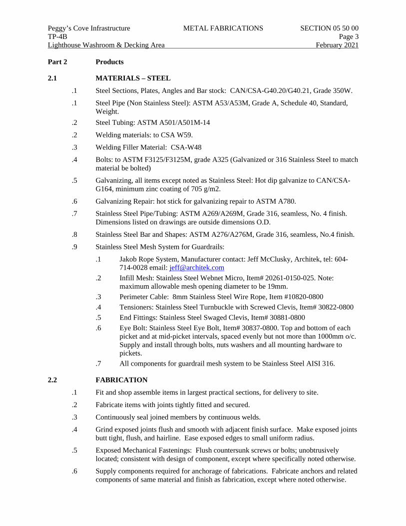
Peggy’s Cove Infrastructure METAL FABRICATIONS SECTION 05 50 00 TP-4B Page 3 Lighthouse Washroom & Decking Area February 2021 Part 2 Products
2.1 MATERIALS – STEEL
.1 Steel Sections, Plates, Angles and Bar stock: CAN/CSA-G40.20/G40.21, Grade 350W.
.1 Steel Pipe (Non Stainless Steel): ASTM A53/A53M, Grade A, Schedule 40, Standard, Weight.
.2 Steel Tubing: ASTM A501/A501M-14
.2 Welding materials: to CSA W59.
.3 Welding Filler Material: CSA-W48
.4 Bolts: to ASTM F3125/F3125M, grade A325 (Galvanized or 316 Stainless Steel to match material be bolted)
.5 Galvanizing, all items except noted as Stainless Steel: Hot dip galvanize to CAN/CSA-G164, minimum zinc coating of 705 g/m2.
.6 Galvanizing Repair: hot stick for galvanizing repair to ASTM A780.
.7 Stainless Steel Pipe/Tubing: ASTM A269/A269M, Grade 316, seamless, No. 4 finish. Dimensions listed on drawings are outside dimensions O.D.
.8 Stainless Steel Bar and Shapes: ASTM A276/A276M, Grade 316, seamless, No.4 finish.
.9 Stainless Steel Mesh System for Guardrails:
.1 Jakob Rope System, Manufacturer contact: Jeff McClusky, Architek, tel: 604-714-0028 email: [email protected]
.2 Infill Mesh: Stainless Steel Webnet Micro, Item# 20261-0150-025. Note: maximum allowable mesh opening diameter to be 19mm.
.3 Perimeter Cable: 8mm Stainless Steel Wire Rope, Item #10820-0800
.4 Tensioners: Stainless Steel Turnbuckle with Screwed Clevis, Item# 30822-0800
.5 End Fittings: Stainless Steel Swaged Clevis, Item# 30881-0800
.6 Eye Bolt: Stainless Steel Eye Bolt, Item# 30837-0800. Top and bottom of each picket and at mid-picket intervals, spaced evenly but not more than 1000mm o/c. Supply and install through bolts, nuts washers and all mounting hardware to pickets.
.7 All components for guardrail mesh system to be Stainless Steel AISI 316.
2.2 FABRICATION
.1 Fit and shop assemble items in largest practical sections, for delivery to site.
.2 Fabricate items with joints tightly fitted and secured.
.3 Continuously seal joined members by continuous welds.
.4 Grind exposed joints flush and smooth with adjacent finish surface. Make exposed joints butt tight, flush, and hairline. Ease exposed edges to small uniform radius.
.5 Exposed Mechanical Fastenings: Flush countersunk screws or bolts; unobtrusively located; consistent with design of component, except where specifically noted otherwise.
.6 Supply components required for anchorage of fabrications. Fabricate anchors and related components of same material and finish as fabrication, except where noted otherwise.
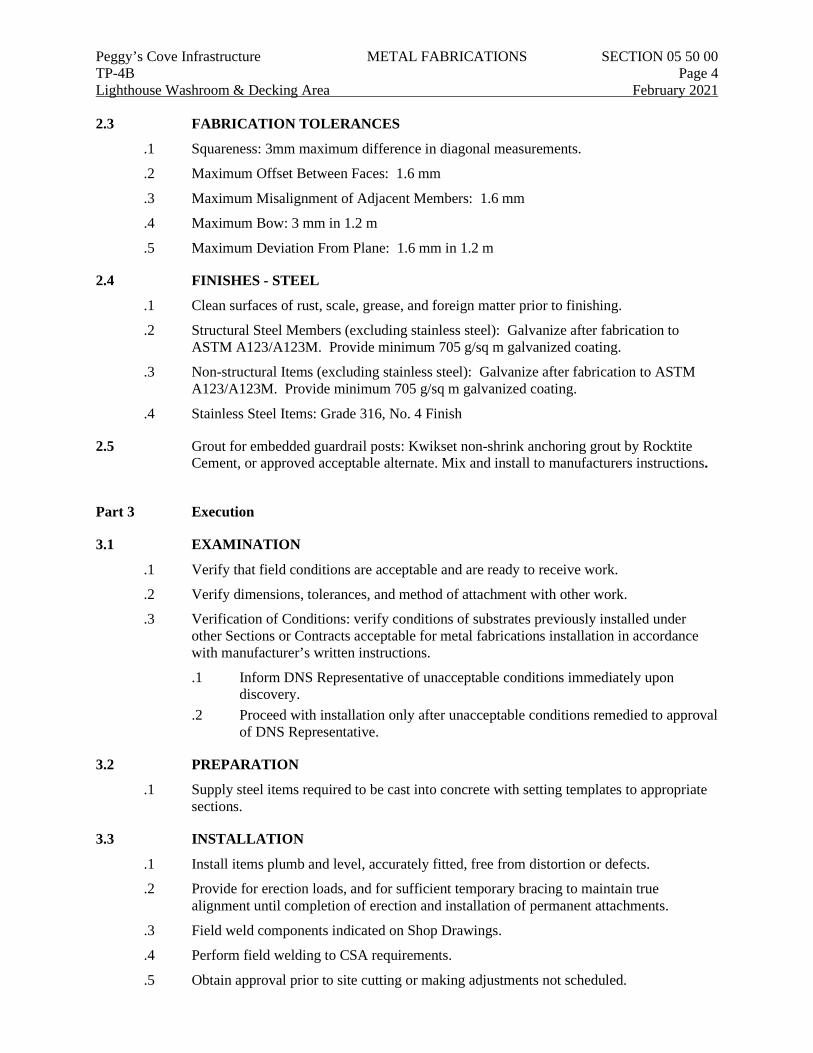
Peggy’s Cove Infrastructure METAL FABRICATIONS SECTION 05 50 00 TP-4B Page 4 Lighthouse Washroom & Decking Area February 2021 2.3 FABRICATION TOLERANCES
.1 Squareness: 3mm maximum difference in diagonal measurements.
.2 Maximum Offset Between Faces: 1.6 mm
.3 Maximum Misalignment of Adjacent Members: 1.6 mm
.4 Maximum Bow: 3 mm in 1.2 m
.5 Maximum Deviation From Plane: 1.6 mm in 1.2 m
2.4 FINISHES - STEEL
.1 Clean surfaces of rust, scale, grease, and foreign matter prior to finishing.
.2 Structural Steel Members (excluding stainless steel): Galvanize after fabrication to ASTM A123/A123M. Provide minimum 705 g/sq m galvanized coating.
.3 Non-structural Items (excluding stainless steel): Galvanize after fabrication to ASTM A123/A123M. Provide minimum 705 g/sq m galvanized coating.
.4 Stainless Steel Items: Grade 316, No. 4 Finish
2.5 Grout for embedded guardrail posts: Kwikset non-shrink anchoring grout by Rocktite Cement, or approved acceptable alternate. Mix and install to manufacturers instructions.
Part 3 Execution
3.1 EXAMINATION
.1 Verify that field conditions are acceptable and are ready to receive work.
.2 Verify dimensions, tolerances, and method of attachment with other work.
.3 Verification of Conditions: verify conditions of substrates previously installed under other Sections or Contracts acceptable for metal fabrications installation in accordance with manufacturer’s written instructions.
.1 Inform DNS Representative of unacceptable conditions immediately upon discovery.
.2 Proceed with installation only after unacceptable conditions remedied to approval of DNS Representative.
3.2 PREPARATION
.1 Supply steel items required to be cast into concrete with setting templates to appropriate sections.
3.3 INSTALLATION
.1 Install items plumb and level, accurately fitted, free from distortion or defects.
.2 Provide for erection loads, and for sufficient temporary bracing to maintain true alignment until completion of erection and installation of permanent attachments.
.3 Field weld components indicated on Shop Drawings.
.4 Perform field welding to CSA requirements.
.5 Obtain approval prior to site cutting or making adjustments not scheduled.
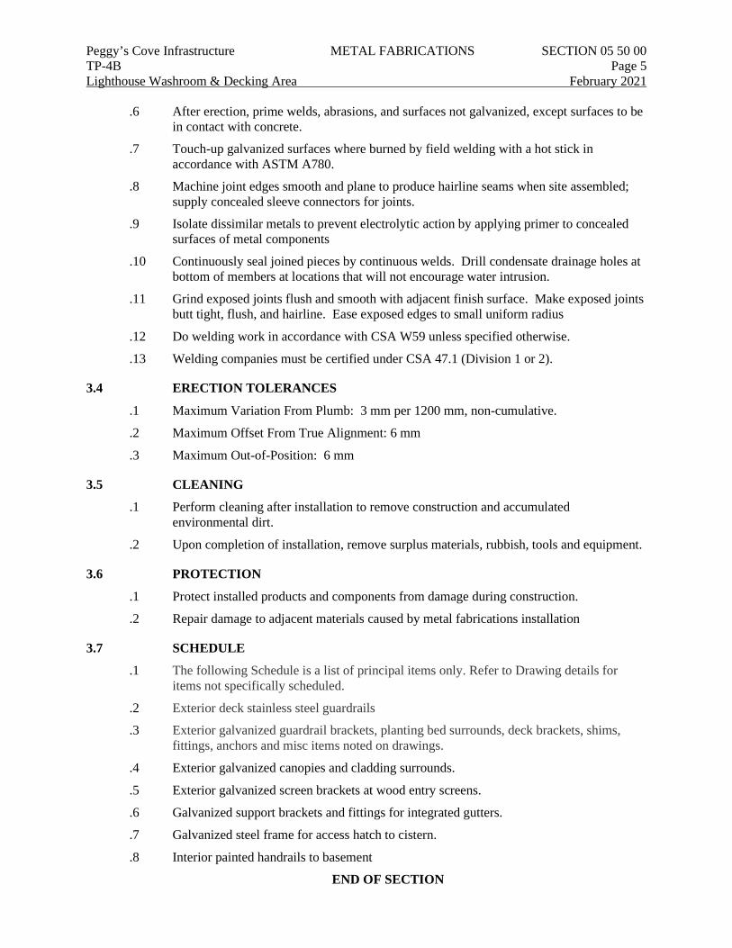
Peggy’s Cove Infrastructure METAL FABRICATIONS SECTION 05 50 00 TP-4B Page 5 Lighthouse Washroom & Decking Area February 2021
.6 After erection, prime welds, abrasions, and surfaces not galvanized, except surfaces to be in contact with concrete.
.7 Touch-up galvanized surfaces where burned by field welding with a hot stick in accordance with ASTM A780.
.8 Machine joint edges smooth and plane to produce hairline seams when site assembled; supply concealed sleeve connectors for joints.
.9 Isolate dissimilar metals to prevent electrolytic action by applying primer to concealed surfaces of metal components
.10 Continuously seal joined pieces by continuous welds. Drill condensate drainage holes at bottom of members at locations that will not encourage water intrusion.
.11 Grind exposed joints flush and smooth with adjacent finish surface. Make exposed joints butt tight, flush, and hairline. Ease exposed edges to small uniform radius
.12 Do welding work in accordance with CSA W59 unless specified otherwise.
.13 Welding companies must be certified under CSA 47.1 (Division 1 or 2).
3.4 ERECTION TOLERANCES
.1 Maximum Variation From Plumb: 3 mm per 1200 mm, non-cumulative.
.2 Maximum Offset From True Alignment: 6 mm
.3 Maximum Out-of-Position: 6 mm
3.5 CLEANING
.1 Perform cleaning after installation to remove construction and accumulated environmental dirt.
.2 Upon completion of installation, remove surplus materials, rubbish, tools and equipment.
3.6 PROTECTION
.1 Protect installed products and components from damage during construction.
.2 Repair damage to adjacent materials caused by metal fabrications installation
3.7 SCHEDULE
.1 The following Schedule is a list of principal items only. Refer to Drawing details for items not specifically scheduled.
.2 Exterior deck stainless steel guardrails
.3 Exterior galvanized guardrail brackets, planting bed surrounds, deck brackets, shims, fittings, anchors and misc items noted on drawings.
.4 Exterior galvanized canopies and cladding surrounds.
.5 Exterior galvanized screen brackets at wood entry screens.
.6 Galvanized support brackets and fittings for integrated gutters.
.7 Galvanized steel frame for access hatch to cistern.
.8 Interior painted handrails to basement
END OF SECTION
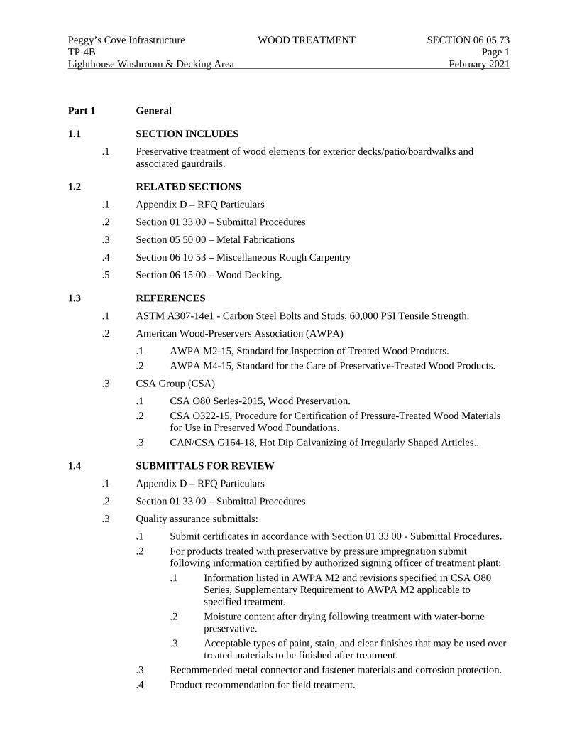
Peggy’s Cove Infrastructure WOOD TREATMENT SECTION 06 05 73 TP-4B Page 1 Lighthouse Washroom & Decking Area February 2021
Part 1 General
1.1 SECTION INCLUDES
.1 Preservative treatment of wood elements for exterior decks/patio/boardwalks and associated gaurdrails.
1.2 RELATED SECTIONS
.1 Appendix D – RFQ Particulars
.2 Section 01 33 00 – Submittal Procedures
.3 Section 05 50 00 – Metal Fabrications
.4 Section 06 10 53 – Miscellaneous Rough Carpentry
.5 Section 06 15 00 – Wood Decking.
1.3 REFERENCES
.1 ASTM A307-14e1 - Carbon Steel Bolts and Studs, 60,000 PSI Tensile Strength.
.2 American Wood-Preservers Association (AWPA)
.1 AWPA M2-15, Standard for Inspection of Treated Wood Products.
.2 AWPA M4-15, Standard for the Care of Preservative-Treated Wood Products.
.3 CSA Group (CSA)
.1 CSA O80 Series-2015, Wood Preservation.
.2 CSA O322-15, Procedure for Certification of Pressure-Treated Wood Materials for Use in Preserved Wood Foundations.
.3 CAN/CSA G164-18, Hot Dip Galvanizing of Irregularly Shaped Articles..
1.4 SUBMITTALS FOR REVIEW
.1 Appendix D – RFQ Particulars
.2 Section 01 33 00 – Submittal Procedures
.3 Quality assurance submittals:
.1 Submit certificates in accordance with Section 01 33 00 - Submittal Procedures.
.2 For products treated with preservative by pressure impregnation submit following information certified by authorized signing officer of treatment plant: .1 Information listed in AWPA M2 and revisions specified in CSA O80
Series, Supplementary Requirement to AWPA M2 applicable to specified treatment.
.2 Moisture content after drying following treatment with water-borne preservative.
.3 Acceptable types of paint, stain, and clear finishes that may be used over treated materials to be finished after treatment.
.3 Recommended metal connector and fastener materials and corrosion protection.
.4 Product recommendation for field treatment.
Peggy’s Cove Infrastructure WOOD TREATMENT SECTION 06 05 73 TP-4B Page 2 Lighthouse Washroom & Decking Area February 2021 1.5 QUALITY ASSURANCE
.1 Inspection and testing of heavy timbers may be carried out by a Testing Laboratory designated by DNS Representative.
1.6 DELIVERY, STORAGE AND HANDLING
.1 Deliver, store and handle materials in accordance with AWPA M4 and with manufacturer’s written instructions.
.2 Delivery and Acceptance Requirements: deliver materials to site in original factory packaging, labelled with product category, manufacturer’s name and address.
.3 Waste Management and Disposal:
.1 Do not dispose of preservative treated wood through incineration.
.2 Do not dispose of preservative treated wood with other materials destined for recycling or reuse.
.3 Dispose of treated wood, end pieces, wood scraps and sawdust at sanitary landfill Products
.4 Do not dispose of unused preservative materials into sewer system, into streams, lakes, ocean, onto ground or in other location where it will pose health or environmental hazard
1.7 HEALTH AND SAFETY
.1 Health and Safety Requirements: do construction occupational health and safety in accordance with Appendix D – RFQ Particulars
.2 Worker protection:
.1 Workers must wear gloves, dust masks, long sleeved clothing and eye protection when handling, drilling, sawing, cutting or sanding preservative treated wood and applying preservative materials.
.2 Workers must not eat, drink or smoke while applying preservative material.
.3 Clean up spills of preservative materials immediately with absorbent material. Safely discard of adsorbent material to sanitary landfill
Part 2 Products
2.1 SUSTAINABLE REQUIREMENTS
.1 Wood preservation plants: certified by Canadian Wood Preservation Authority (CWPCA) to Environment Canada Technical Recommendation Document for the Design and Operation of Wood Preservation Facilities.
2.2 PRESERVATIVE TREATED WOOD MATERIALS AND APPLICATION
.1 Type 1 PT:
.1 Uses: Guardrail & Curb Subframing & Nailers between metal substructure and finished wood. Wood materials noted as Pressure Treated in Washroom Building.
.2 Lumber to be pressure treated using Chromated Copper Arsenate (CCA) in accordance with the requirements of CSA O80, Use Category UC3A. Prior to treatment, wood shall be incised to achieve net retention as specified.
Peggy’s Cove Infrastructure WOOD TREATMENT SECTION 06 05 73 TP-4B Page 3 Lighthouse Washroom & Decking Area February 2021
.3 Minimum CCA net retention shall be 10 kg/m3
.2 Type 2 PT:
.1 Use: Decking, Deck Sleepers, Deck Subframing and Solid Blocking below surface elements.
.2 Lumber to be pressure treated using Chromated Copper Arsenate (CCA) in accordance with the requirements of CSA O80, Use Category UC5A. Prior to treatment, wood shall be incised to achieve net retention as specified.
.3 Minimum CCA net retention shall be 24 kg/m3
2.3 CORROSION PROTECTION FOR FASTENERS FOR USE WITH TREATED WOOD
.1 Bolts: to ASTM A307, Galvanized
.2 Lag screws: ASTM A307, Galvanized or 316 Stainless Steel where noted.
.3 Finishes: Hot dipped galvanizing with zinc coating 705 g/m2to CAN/CSA-G164 or 316 Stainless Steel where noted.
2.4 PRESERVATIVE FOR FIELD TREATMENT
.1 Type recommended by manufacturer to suit specified pressure treated products.
Part 3 Execution
3.1 CONSTRUCTION
.1 Use connectors and fasteners with specified corrosion protection in all construction with treated wood products
3.2 FIELD TREATMENT
.1 Comply with AWPA M4 and revisions specified in CSA O80 Series, Supplementary Requirements to AWPA M2.
.2 Handle treated material without damaging original treatment. Replace treated timber with major damage to original treatment.
.3 Field treatment: apply and saturate cuts, minor surface damage, abrasions, and bolt, nail and spike holes with preservative to CAN/CSA-O80 Series.
.4 Remove chemical deposits from surfaces of treated wood to receive applied finish
END OF SECTION
Peggy’s Cove Infrastructure MISCELLANEOUS ROUGH CARPENTRY SECTION 06 10 53 TP-4B Page 1 Lighthouse Washroom & Decking Area February 2021
Part 1 General
1.1 SECTION INCLUDES
.1 Labour, equipment and materials for the supply, fabrication and installation of Washroom building rough carpentry & framing.
.2 Labour, equipment and materials for the supply, fabrication and installation exterior wood deck/patio/boardwalk areas including wood subframing, wood guardrail cladding, and installation of wood decking. Sleepers and subframing specified in Section 06 05 73.
1.2 RELATED SECTIONS
.1 Appendix D – RFQ Particulars
.2 Section 01 33 00 – Submittal Procedures
.3 Section 05 50 00 – Metal Fabrications
.4 Section 06 05 73 – Wood Treatment
.5 Section 06 15 00 – Wood Decking
.6 Section 08 11 13 – Hollow Metal Doors and Frames.
.7 Section 32 33 00 – Site Furnishings
1.3 REFERENCES
.1 ASTM A307-14e1 - Carbon Steel Bolts and Studs, 60,000 PSI Tensile Strength.
.2 ASTM A123/A123M-17 - Standard Specification for Zinc (Hot-Dip Galvanized) Coatings on Iron and Steel Products.
.3 ASTM A153/A153M-16a - Standard Specification for Zinc Coating (Hot-Dip) on Iron and Steel Hardware.
.4 ASTM A653/A653M-19a - Standard Specification for Steel Sheet, Zinc-Coated (Galvanized) or Zinc-Iron Alloy-Coated (Galvannealed) by the Hot-Dip Process.
.5 CANPLY (Canadian Plywood Association) - Canadian Plywood Handbook.
.6 CAN/CSA-O80 Series-15 - Wood Preservation.
.7 Canadian Wood Council
.1 Wood Design Manual 2017
.2 Engineering Guide for Wood Frame Construction 2014 (updated 2018)
.8 CSA Group (CSA)
.1 CSA B111-1974 (R2003), Wire Nails, Spikes and Staples.
.2 CSA O86-14 Engineered Design in Wood
.3 CAN/CSA G164-18, Hot Dip Galvanizing of Irregularly Shaped Articles.
.4 CSA-O121-17 - Douglas Fir Plywood.
.5 CSA-O151-17 - Canadian Softwood Plywood.
.6 CSA-O153-19 - Poplar Plywood.
.7 CSA-O437 Series-93 (R2011) (Withdrawn) - Standards on OSB and Waferboard
Peggy’s Cove Infrastructure MISCELLANEOUS ROUGH CARPENTRY SECTION 06 10 53 TP-4B Page 2 Lighthouse Washroom & Decking Area February 2021
.9 NLGA (National Lumber Grades Authority) - Standard Grading Rules for Canadian Lumber, 2017 Edition.
1.4 SUBMITTALS FOR REVIEW
.1 Appendix D – RFQ Particulars
.2 Section 01 33 00 – Submittal Procedures
.3 Product Data:
.1 Submit manufacturer’s instructions, printed product literature and data sheets for wood elements and include product characteristics, performance criteria, physical size, finish and limitations.
.2 Submit copy of WHMIS SDS for each type.
.3 Certifications: submit certificates signed by manufacturer certifying materials comply with specified performance characteristics and physical properties.
1.5 QUALITY ASSURANCE
.1 Perform Work in accordance with the following agencies:
.1 Lumber Grading Agency: Certified by NLGA Grading Rules.
.2 Plywood Grading Agency: Certified by CANPLY.
.3 Wood Based Panel Products: Marked with a recognized, visible grade stamp showing Grade or span rating as required.
.2 Pressure Preservative Treated Wood: Marked with certification mark authorized by the Canadian Wood Preservers Bureau (CWPB) indicating producer, preservative type, retention and Use Category (UC).
.3 Inspection and testing of wood decking may be carried out by a Testing Laboratory designated by DNS Representative.
1.6 DELIVERY, STORAGE AND HANDLING
.1 Deliver, store and handle pressure treated materials in accordance with AWPA M4 and with manufacturer’s written instructions.
.2 Delivery and Acceptance Requirements: deliver materials to site in original factory packaging, labelled with product category, manufacturer’s name and address.
.3 Store plywood panels flat and level.
.4 Keep finish faces inward and cover stacks to protect from bumping and abrasion.
.5 Protect tongue and groove plywood panel edges and corners.
.6 Protect panels from sunlight, water or excessive humidity.
.7 Store materials [off the ground, covered with weatherproof tarps] [indoors in dry, well-ventilated area].
.8 Waste Management and Disposal:
.1 Do not dispose of preservative treated wood through incineration.
.2 Do not dispose of preservative treated wood with other materials destined for recycling or reuse.
Peggy’s Cove Infrastructure MISCELLANEOUS ROUGH CARPENTRY SECTION 06 10 53 TP-4B Page 3 Lighthouse Washroom & Decking Area February 2021
.3 Dispose of treated wood, end pieces, wood scraps and sawdust at sanitary landfill Products
.4 Do not dispose of unused preservative materials into sewer system, into streams, lakes, ocean, onto ground or in other location where it will pose health or environmental hazard
1.7 HEALTH AND SAFETY
.1 Health and Safety Requirements: do construction occupational health and safety in accordance with Appendix D – RFQ Particulars.
.2 Worker protection:
.1 Workers must wear gloves, dust masks, long sleeved clothing and eye protection when handling, drilling, sawing, cutting or sanding preservative treated wood and applying preservative materials.
.2 Workers must not eat, drink or smoke while applying preservative material.
.3 Clean up spills of preservative materials immediately with absorbent material. Safely discard of adsorbent material to sanitary landfill
Part 2 Products
2.1 MATERIALS
.1 Lumber to be graded and stamped in accordance with applicable grading rules and standards of associations or agencies approved to grade lumber by Canadian Lumber Standards Accreditation Board of CSA.
2.2 MATERIALS – WASHROOM BUILDING
.1 Dimension Lumber
.1 CSA-O141, softwood lumber unless indicated otherwise, S4S, maximum moisture content 19%; graded to NLGA Grading Rules Standard Grading Rules for Lumber. Finger jointed lumber not acceptable.
.2 Panel materials
.1 Plywood: CSA-O121, CSA-O151, CSA-O153 certified and graded by CANPLY, meeting the requirements of CSA-O325.
.2 OSB: Oriented strands set with waterproof resin binder, meeting the requirements of CSA-O437
.3 Particleboard: NPA A208.1, cellulosic composite panel bonded together with a synthetic resin, Grade A; 19mm thickness.
.4 Medium Density Fibreboard (MDF): NPA A208.2, heat and pressure bonded cellulosic fibres, MD Grade, 19mm thickness.
.3 Fasteners and anchors
.1 Screws and Nails: Galvanized steel; type and size suitable for application.
.2 Anchors: Galvanized steel, expansion shield and lag bolt type for anchorage to solid masonry or concrete
.3 Finishes .1 Galvanized Coatings for Untreated Wood:
Peggy’s Cove Infrastructure MISCELLANEOUS ROUGH CARPENTRY SECTION 06 10 53 TP-4B Page 4 Lighthouse Washroom & Decking Area February 2021
.1 Connectors: Hot dip galvanized to ASTM A653/A653M, Z275 zinc coating designation.
.2 Bearing Plates and Angles: Hot dip galvanized after fabrication to ASTM A123/A123M.
.3 Fasteners and Anchors: Hot dip galvanized to ASTM A153/A153M.
.2 Galvanized Coating for Use with Treated Wood and High Humidity Areas: .1 Connectors: Hot dip galvanized to ASTM A653/A653M, Z550
zinc coating designation. .2 Bearing Plates and Angles: Hot dip galvanized after fabrication
to ASTM A123/A123M. .3 Fasteners and Anchors: Hot dip galvanized to ASTM
A153/A153M.
.4 Miscellaneous accessories
.1 Adhesives: Waterproof adhesive, approved for use with type of construction panel indicated by manufacturers of both adhesives and panels. .1 Product: PL Premium, manufactured by Lepage. .2 Polyethylene: Sheet polyethylene, 6mil thick.
.5 Preservative treatment
.1 Wood Preservative (Pressure Treatment): CAN/CSA-O80, and in accordance with Table 2 - Use Categories for Specific Products, Uses, and Exposures. .1 UC2: Interior construction, above-ground and potentially damp
applications; use waterborne alkali-based, type CA. .2 UC3.1: Exterior construction, protected, above-ground applications
(coated millwork, cants, siding, trim); use waterborne alkali-based, type CA.
.1 Wood Preservative (Surface Application): CAN/CSA-O80, copper naphthenate.
.2 Fire Retardant (FRT): CAN/CSA-O80, chemically treated and pressure impregnated; capable of providing a maximum flame spread/smoke development rating of CAN/ULC-S102, to 25 or less.
2.3 MATERIALS – EXTERIOR DECK/PATIO/BOARDWALK
.1 Exterior Wood Decking, Sleepers and Deck Subframing: Refer to Section 06 15 00
.2 Exterior Wood Guardrail & Curb Subframing & Nailers between metal substructure and finished wood cladding.
.1 CAN/CSA-O141, No.2 Grade Softwood SPF species.
.2 Kiln Dried to 19% maximum moisture content
.3 Wood Treatment: Type 1 PT as specified in Section 06 05 73
.4 Fasteners: .1 Bolts: ASTM A307, Galvanized .2 Nails/Spikes/Drift pins: to CSA B111, Galvanized .3 Lag screws: ASTM A307, Galvanized .4 Finishes: Hot dipped galvanizing with zinc coating 705 g/m2 to
CAN/CSA-G164
Peggy’s Cove Infrastructure MISCELLANEOUS ROUGH CARPENTRY SECTION 06 10 53 TP-4B Page 5 Lighthouse Washroom & Decking Area February 2021
.3 Exterior Wood Guardrail Cladding & Cap, Wood Curb Cladding & Cap, Wood Caps for Metal Railings.
.1 CAN/CSA-O141 No.1 Grade or Grade A Eastern White Cedar (species), Milled to profiles and sizes as indicated on drawings.
.2 Kiln Dried to 12%-16% Moisture Content.
.3 Brushed or semi-rough wood finish, mill scale/mill glaze to be completely removed prior to application of finish.
.4 Finish: Cabot Bleaching Stain # 10241. Pre-coat all sides of siding boards prior to installation. Coordinate surface finish of wood with finish manufacturer's requirements for adhesion.
.5 Fasteners: .1 Concealed Bolts: ASTM A307, Galvanized .2 Concealed Nails/Spikes/Drift pins: to CSA B111, Galvanized .3 Concealed Lag screws: ASTM A307, Galvanized .4 Finishes, for Concealed Fasteners: Hot dipped galvanizing with zinc
coating 705 g/m2 to CAN/CSA-G164 .5 Exposed Face Fasteners for Cladding Boards: 316 Stainless Steel ring
shank nails with textured heads (hammer installed), 11-13GA, minimum penetration into substrate of 32mm (1 1/4").
Part 3 Execution
3.1 EXAMINATION
.1 Verification of Conditions: verify conditions of substrates previously installed under other Sections or Contracts are acceptable for wood installation in accordance with manufacturer’s written instructions.
.1 Visually inspect substrate in presence of DNS Representative.
.2 Inform DNS Representative of unacceptable conditions immediately upon discovery.
.3 Proceed with installation only after unacceptable conditions have been remedied and after receipt of written approval to proceed from DNS Representative.
3.2 INSTALLATION – WASHROOM BUILDING
.1 Framing
.1 Set structural members level and plumb, in correct position.
.2 Make provisions for erection loads, and for sufficient temporary bracing to maintain structure safe, plumb, and in true alignment until completion of erection and installation of permanent bracing.
.3 Place horizontal members, crown side up.
.4 Construct load bearing framing and curb members full length without splices.
.5 Double members at openings over 610mm wide. Space short studs over and under opening to stud spacing.
.6 Construct double joist headers at floor and ceiling openings and under wall stud partitions that are parallel to floor joists. Frame rigidly into joists.
Peggy’s Cove Infrastructure MISCELLANEOUS ROUGH CARPENTRY SECTION 06 10 53 TP-4B Page 6 Lighthouse Washroom & Decking Area February 2021
.7 Bridge joists in excess of 2.3 m span as detailed. Fit solid blocking at ends of members.
.8 Place sill gasket directly on cementitious foundation. Puncture gasket clean and fit tight to protruding foundation anchor bolts.
.9 Coordinate installation of prefabricated wood trusses.
.10 Curb roof openings except where prefabricated curbs are provided. Form corners by alternating lapping side members.
.11 Coordinate curb installation with installation of decking and support of deck openings.
.2 Sheathing
.1 Secure roof sheathing with longer edge perpendicular to framing members and with ends staggered and sheet ends over bearing.
.2 Fully engage tongue and groove edges.
.3 Secure wall sheathing with long dimension perpendicular to wall studs, with ends over firm bearing and staggered.
.4 Secure subfloor sheathing with longer edge perpendicular to floor framing and with end joints staggered and sheet ends over bearing. Attach with subfloor glue and construction screws.
.3 Site applied wood treatment
.1 Apply preservative treatment to manufacturer's written instructions.
.2 Brush apply two (2) coats of preservative treatment on wood requiring cutting or drilling after treatment and on wood in contact with cementitious materials.
.3 Allow preservative to dry prior to erecting members
3.3 INSTALLATION – EXTERIOR WOOD DECKING, SLEEPERS AND DECK SUBFRAMING
.1 Refer to Section 06 15 00 Wood Decking for materials.
.2 Do wood deck work to CSA O86 except where specified otherwise.
.3 Install decking to CSA O86, continuous over two span patterns.
.4 Supply minimum of 2 bearing support for each plank except extend cantilevers over three supports.
.5 Anchor sleepers to concrete at 600mm o/c and ends. Shim sleepers at each anchor with galvanize metal shims, refer to Section 06 15 00.
.6 Fasten deck members at each sleeper with two 152mm (6”) long Construction Screws (specified in Section 2.1). Minimum 25mm edge distance. Predrill hole at each screw in accordance with manufacturer’s specifications. Countersink fastener head. Align fasteners along each support.
.7 Stagger end joints in adjacent planks minimum of 0.6 m.
.1 Separate joints in same area by at least 2 intervening courses.
.2 Avoid joints in first fifth of end spans.
.3 Minimize joints in middle third of span.
.4 Apply preservative to end cuts of pressure treated lumber.
.8 Solidly block wood decking under surface mounted concrete elements.
Peggy’s Cove Infrastructure MISCELLANEOUS ROUGH CARPENTRY SECTION 06 10 53 TP-4B Page 7 Lighthouse Washroom & Decking Area February 2021 3.4 INSTALLATION – EXTERIOR WOOD GUARDRAILS & CURBS
.1 Do wood deck work to CSA O86 except where specified otherwise.
.2 Install members true to line, levels and elevations, square and plumb. Construct continuous members from pieces of longest practical length.
.3 Install spanning members with crown-edge up.
.4 Select exposed framing & finish pieces for appearance. Install materials so that grade-marks and other defacing marks are concealed or are removed by sanding where materials are left exposed before any pressure treatment is applied.
.5 Frame, anchor, fasten, tie and brace members to provide necessary strength and rigidity.
.6 Countersink bolts where necessary to provide clearance for other work Supply minimum of 2 bearing support for each plank except extend cantilevers over three supports.
.7 Pre-coat all sides of cladding boards with finish, prior to installation. Apply finish to cut ends during installation.
.8 Space cladding boards with 3mm (1/8")- 6mm (1/4") movement gap between boards, confirm with Architect at time of installation. Nail boards with 2 fasteners at maximum 400mm (16") o/c and minimum 25mm (1") from ends. Align fasteners over entire surface. Space fasteners 19mm (3/4") from edge. Bevel all end joints between adjoining boards and nail at an angle. Stagger joints a minimum of 400mm (16”) in succeeding courses.
.9 Fasten finished top caps from underside. No exposed fasteners on top face.
.10 Apply preservative to end cuts of pressure treated lumber.
3.5 FIELD QUALITY CONTROL
.1 Testing:
.1 Testing moisture content of delivered material will be performed by testing laboratory designated by DNS Representative.
.2 Consultant DNS Representative will pay for costs of testing.
.3 Testing moisture content of delivered material will be by moisture metre with adjustments for species and temperature.
3.6 ERECTION TOLERANCES .1 Framing Members: 6 mm from true position, maximum. .2 Surface Flatness of Floor: 2 mm in 1 m maximum, and 6 mm in 9 m maximum.
3.7 CLEANING
.1 Leave Work area clean at end of each day.
.2 Final Cleaning: upon completion remove surplus materials, rubbish, tools and equipment Waste Management: separate waste materials for recycling.
3.8 WASTE MANAGEMENT
.1 Separate waste materials for recycling.
.2 Re-use scrap lumber to the greatest extent possible. Separate scrap lumber for use on site as accessory components, including shims, bracing, and blocking.
.3 Do not leave any wood, shavings, sawdust, etc. on the ground or buried in fill.
Peggy’s Cove Infrastructure MISCELLANEOUS ROUGH CARPENTRY SECTION 06 10 53 TP-4B Page 8 Lighthouse Washroom & Decking Area February 2021
.4 Prevent saw dust and wood shavings from entering the storm or sewer drainage system, or any waterways or ocean.
.5 Do not send lumber treated with pentachlorophenol, CCA, or ACA to co-generation facilities or “waste-to-energy” facilities.
.6 Dispose of treated wood as recommended by manufacturer.
3.9 PROTECTION
.1 Protect installed products and components from damage during construction.
.2 Repair damage to adjacent materials caused by rough carpentry installation.
END OF SECTION
.
Peggy’s Cove Infrastructure WOOD DECKING SECTION 06 15 00 TP-4B Page 1 Lighthouse Washroom & Decking Area February 2021
Part 1 General
1.1 SECTION INCLUDES
.1 Exterior Wood Decking
.2 Exterior Wood Sleepers & Misc Sub Framing Supporting Decking & Surface Elements
.3 Fasteners, shims and accessories.
1.2 RELATED SECTIONS
.1 Appendix D – RFQ Particulars
.2 Section 01 33 00 – Submittal Procedures
.3 Section 05 50 00 – Metal Fabrications
.4 Section 06 10 53 – Miscellaneous Rough Carpentry
.5 Section 06 05 73 – Wood Treatment.
1.3 REFERENCES
.1 ASTM A307-14e1 - Carbon Steel Bolts and Studs, 60,000 PSI Tensile Strength.
.2 Canadian Wood Council
.1 Wood Design Manual 2017
.2 Engineering Guide for Wood Frame Construction 2014 (updated 2018)
.3 CSA Group (CSA)
.1 CSA B111-1974 (R2003), Wire Nails, Spikes and Staples.
.2 CSA O86-14 Engineered Design in Wood
.3 CAN/CSA G164-18, Hot Dip Galvanizing of Irregularly Shaped Articles.
.4 National Lumber Grades Authority (NLGA)
.1 Standard Grading Rules for Canadian Lumber 2010
1.4 SUBMITTALS FOR REVIEW
.1 Appendix D – RFQ Particulars
.2 Section 01 33 00 – Submittal Procedures
.3 Product Data:
.1 Submit manufacturer’s instructions, printed product literature and data sheets for wood decking and include product characteristics, performance criteria, physical size, finish and limitations.
.2 Submit copy of WHMIS SDS.
.3 Shop Drawings: .1 Submit layout of decking showing direction, general lengths, splices,
method and location of fasteners. .4 Certifications: submit certificates signed by manufacturer certifying materials
comply with specified performance characteristics and physical properties.
Peggy’s Cove Infrastructure WOOD DECKING SECTION 06 15 00 TP-4B Page 2 Lighthouse Washroom & Decking Area February 2021 1.5 QUALITY ASSURANCE
.1 Lumber identification: by grade stamp of an agency certified by Canadian Lumber Standards Accreditation Board.
.2 Inspection and testing of wood decking may be carried out by a Testing Laboratory designated by DNS Representative.
1.6 DELIVERY, STORAGE AND HANDLING
.1 Deliver, store and handle materials in accordance with AWPA M4 and with manufacturer’s written instructions.
.2 Delivery and Acceptance Requirements: deliver materials to site in original factory packaging, labelled with product category, manufacturer’s name and address.
.3 Waste Management and Disposal:
.1 Do not dispose of preservative treated wood through incineration.
.2 Do not dispose of preservative treated wood with other materials destined for recycling or reuse.
.3 Dispose of treated wood, end pieces, wood scraps and sawdust at sanitary landfill Products
.4 Do not dispose of unused preservative materials into sewer system, into streams, lakes, ocean, onto ground or in other location where it will pose health or environmental hazard
1.7 HEALTH AND SAFETY
.1 Health and Safety Requirements: do construction occupational health and safety in accordance with Section 01 35 30 - Health and Safety Requirements.
.2 Worker protection:
.1 Workers must wear gloves, dust masks, long sleeved clothing and eye protection when handling, drilling, sawing, cutting or sanding preservative treated wood and applying preservative materials.
.2 Workers must not eat, drink or smoke while applying preservative material.
.3 Clean up spills of preservative materials immediately with absorbent material. Safely discard of adsorbent material to sanitary landfill
Part 2 Products
2.1 MATERIALS
.1 Wood decking, sleepers, and miscellaneous framing elements supporting decking: #1 Hemlock or #1 Douglas Fir, dressed all sides to sizes on drawings. Kiln dry lumber to 15% maximum moisture content.
.2 Lumber sizes shown on drawings are actual finished sizes (thickness & width) unless noted otherwise
.3 Decking lengths: 1.8 to 6 m or longer with a minimum of 90% planks exceeding 3 m. Square end trimmed. For single spans shorter than 3 m use decking of same length as span.
.4 Fasteners:
Peggy’s Cove Infrastructure WOOD DECKING SECTION 06 15 00 TP-4B Page 3 Lighthouse Washroom & Decking Area February 2021
.1 Wood Decking: 8mm (5/16”) diameter, 152mm (6”) long, 316 stainless steel Construction ScrewTM manufactured by U2 Fasteners.
.2 Wood Sleepers: 16mm (5/8”) diameter Epoxy Resin embedded galvanized threaded anchor rods at 600mm o/c and 150mm from end. Epoxy Resin to be compatible with marine environment. Min. 125mm embedment into concrete subbase.
.3 Metal Shims: Min. 100mm x 100mm plate pre-drilled shims @ each anchor, but not less than 610mm o/c. Minimum shim space of 6mm for each sleeper, thickness and number of shims to suit to achieve level. Hot dip galvanize to CAN/CSA-G164, minimum zinc coating of 705 g/m2.
.5 Wood Decking, Sleepers & Misc Wood Framing to receive Wood Treatment Type 2 PT according to Section 06 05 73 – Wood Treatment.
Part 3 Execution
3.1 EXAMINATION
.1 Verification of Conditions: verify conditions of substrates previously installed under other Sections or Contracts are acceptable for wood decking installation in accordance with manufacturer’s written instructions.
.1 Visually inspect substrate in presence of DNS Representative.
.2 Inform DNS Representative of unacceptable conditions immediately upon discovery.
.3 Proceed with installation only after unacceptable conditions have been remedied and after receipt of written approval to proceed from DNS Representative.
3.2 INSTALLATION
.1 Refer to Section 06 10 53 Miscellaneous Rough Carpentry for Wood Decking, Sleepers and Deck Subframing Installation.
3.3 FIELD QUALITY CONTROL
.1 Testing:
.1 Testing moisture content of delivered material will be performed by testing laboratory designated by DNS Representative.
.2 Consultant DNS Representative will pay for costs of testing.
.3 Testing moisture content of delivered material will be by moisture metre with adjustments for species and temperature.
3.4 CLEANING
.1 Leave Work area clean at end of each day.
.2 Final Cleaning: upon completion remove surplus materials, rubbish, tools and equipment Waste Management: separate waste materials for recycling.
3.5 WASTE MANAGEMENT
.1 Separate waste materials for recycling.
.2 Re-use scrap lumber to the greatest extent possible. Separate scrap lumber for use on site as accessory components, including shims, bracing, and blocking.
Peggy’s Cove Infrastructure WOOD DECKING SECTION 06 15 00 TP-4B Page 4 Lighthouse Washroom & Decking Area February 2021
.3 Do not leave any wood, shavings, sawdust, etc. on the ground or buried in fill.
.4 Prevent saw dust and wood shavings from entering the storm or sewer drainage system, or any waterways or ocean.
.5 Do not send lumber treated with pentachlorophenol, CCA, or ACA to co-generation facilities or “waste-to-energy” facilities.
.6 Dispose of treated wood as recommended by manufacturer.
3.6 PROTECTION
.1 Protect installed products and components from damage during construction.
.2 Repair damage to adjacent materials caused by rough carpentry installation.
END OF SECTION
Peggy’s Cove Infrastructure SHOP - FABRICATED WOOD TRUSSES Section 06 17 53
TP-4B February 2021
Lighthouse Washroom & Decking Area Page 1
Part 1 General
1.1 RELATED REQUIREMENTS
.1 05 50 00 Metal fabrications
1.2 REFERENCES
.1 CSA International
.1 CAN/CSA O80 Series-08, Wood Preservation.
.2 CSA O86 -14, Engineering Design in Wood.
.3 CSA O141-05(R2014), Softwood Lumber.
.4 CSA S307-M1980(R2006), Load Test Procedure for Wood Roof Trusses for
Houses and Small Buildings.
.5 CSA S347-99(R2014) Method of Test for Evaluation of Truss Plates Used in
Lumber Joints.
.6 CSA W47.1-19, Certification of Companies for Fusion Welding of Steel.
.2 National Lumber Grades Authority (NLGA)
.1 Standard Grading Rules for Canadian Lumber 2010.
.3 Truss Plate Institute of Canada (TPIC)
.1 TPIC - 2007, Truss Design Procedures and Specifications for Light Metal Plate
Connected Wood Trusses (Limit States Design).
1.3 ACTION AND INFORMATIONAL SUBMITTALS
.1 Submit in accordance with Section 01 33 00 - Submittal Procedures.
.2 Product Data:
.1 Submit manufacturer's instructions, printed product literature and data sheets for
wood trusses and include product characteristics, performance criteria, physical
size, finish and limitations.
.3 Shop Drawings:
.1 Submit drawings stamped and signed by professional engineer registered or
licensed in Province of Nova Scotia, Canada.
.2 Include on drawings:
.1 Each shop drawing submission showing connection details.
.2 Indicate special structural application and specification as according to
local authorities having jurisdiction.
.3 Indicate TPIC Truss Design Procedure and CSA O86 Engineering
Design in Wood and specific CCMC Product Registry number of the
truss plates
.4 Indicate species, sizes, and stress grades of lumber used as truss
members. Show pitch, span, camber, configuration and spacing of
Peggy’s Cove Infrastructure SHOP - FABRICATED WOOD TRUSSES Section 06 17 53
TP-4B February 2021
Lighthouse Washroom & Decking Area Page 2
trusses. Indicate connector types, thicknesses, sizes, locations and design
value. Show bearing details. Indicate design load for members.
.5 Submit stress diagram or print-out of computer design indicating design
load for truss members. Indicate allowable load and stress increase.
.6 Provide certification that trusses meet requirements of CSA S307 and
CSA S347. Do load testing on representative trusses selected by DNS
Representative.
.7 Indicate arrangement of webs or other members to accommodate ducts
and other specialties.
.8 Show location of lateral bracing for compression members.
.9 Test reports: submit certified test reports for prefabricated wood trusses
from approved independent testing laboratories, indicating compliance
with specifications for specified performance characteristics and physical
properties.
.10 Certificates: submit certificates signed by manufacturer certifying that
materials comply with specified performance characteristics and physical
properties.
.11 Instructions: submit manufacturer's installation instructions.
1.4 QUALITY ASSURANCE
.1 Qualifications:
.1 Fabricator for trusses to show evidence of quality control program such as
provided by regional wood truss associations, or equivalent.
.2 Fabricator for welded steel connections to be certified in accordance with CSA
W47.1.
1.5 DELIVERY, STORAGE AND HANDLING
.1 Deliver, store and handle materials in accordance with AWPA M4 and with
manufacturer’s written instructions.
.2 Delivery and Acceptance Requirements: deliver materials to site in original factory
packaging, labelled with product category, manufacturer’s name and address.
.3 Waste Management and Disposal:
.1 Do not dispose of preservative treated wood through incineration.
.2 Do not dispose of preservative treated wood with other materials destined for
recycling or reuse.
.3 Dispose of treated wood, end pieces, wood scraps and sawdust at sanitary landfill
Products
.4 Do not dispose of unused preservative materials into sewer system, into streams,
lakes, ocean, onto ground or in other location where it will pose health or
environmental hazard
1.6 HEALTH AND SAFETY
.1 Health and Safety Requirements: do construction occupational health and safety in
accordance with Section 01 35 30 - Health and Safety Requirements.
Peggy’s Cove Infrastructure SHOP - FABRICATED WOOD TRUSSES Section 06 17 53
TP-4B February 2021
Lighthouse Washroom & Decking Area Page 3
.2 Worker protection:
.1 Workers must wear gloves, dust masks, long sleeved clothing and eye protection
when handling, drilling, sawing, cutting or sanding preservative treated wood and
applying preservative materials.
.2 Workers must not eat, drink or smoke while applying preservative material.
.3 Clean up spills of preservative materials immediately with absorbent material.
Safely discard of adsorbent material to sanitary landfill.
Part 2 Products
2.1 DESIGN REQUIREMENTS
.1 Design light metal plate connected wood trusses in accordance with TPIC truss design
procedures for wood truss chords and webs in accordance with engineering properties in
CSA O86.
.2 Design light metal plate connected wood trusses in accordance with TPIC truss design
procedures for truss joint designs to test engineering properties in accordance with CSA
S347 and listed in CCMC Registry of Product Evaluations.
.3 Design trusses, bracing and bridging in accordance with CSA O86.1 for loads indicated
and for building locality as ascertained by NBC, Climatic Information for Building
Design in Canada as well as minimum uniform and minimum concentrated loadings
stipulated in NBC commentary.
.4 Limit live load deflection to 1/360th of span.
.5 Provide camber for trusses as indicated.
2.2 MATERIALS
.1 Lumber: SPF species, no 1/2 grade, Kiln dry lumber to 15% maximum moisture content
and to following standards:
.1 CSA O141.
.2 NLGA (National Lumber Grading Association), Standard Grading Rules for
Canadian Lumber.
.3 CAN/CSA-Z809 or FSC or SFI certified.
.2 Fastenings: to CSA O86.
2.3 FABRICATION
.1 Fabricate wood trusses in accordance with approved shop drawings.
.2 Provide for design camber and roof slopes when positioning truss members.
.3 Connect members using metal connector plates.
Peggy’s Cove Infrastructure SHOP - FABRICATED WOOD TRUSSES Section 06 17 53
TP-4B February 2021
Lighthouse Washroom & Decking Area Page 4
2.4 SOURCE QUALITY CONTROL
.1 Identify lumber by grade stamp of an agency certified by Canadian Lumber Standards
Administration Board.
Part 3 Execution
3.1 EXAMINATION
.1 Verification of Conditions: verify conditions of substrates previously installed under
other Sections or Contracts are acceptable for product installation in accordance with
manufacturer's written instructions.
.1 Visually inspect substrate in presence of DNS Representative.
.2 Inform DNS Representative of unacceptable conditions immediately upon
discovery.
.3 Proceed with installation only after unacceptable conditions have been remedied
and after receipt of written approval to proceed from DNS Representative.
3.2 MANUFACTURER'S INSTRUCTIONS
.1 Compliance: comply with manufacturer's written recommendations or specifications,
including product technical bulletins, handling, storage and installation instructions, and
datasheet.
3.3 ERECTION
.1 Erect wood trusses in accordance with approved shop drawings.
.2 Handling, installation, erection, bracing and lifting in accordance with manufacturers
instructions.
.3 Make adequate provisions for handling and erection stresses.
.4 Exercise care to prevent out-of-plane bending of trusses.
.5 Install temporary horizontal and cross bracing to hold trusses plumb and in safe condition
until permanent bracing and decking are installed.
.6 Install permanent bracing in accordance with approved shop drawings, prior to
application of loads to trusses.
.7 Do not cut or remove any truss material without approval of DNS Representative.
.8 Remove chemical and other surface deposits on treated wood, in preparation for applied
finishes.
3.4 FIELD QUALITY CONTROL
.1 Manufacturer's Field Services:
.1 Have manufacturer of products supplied under this Section review work involved
in handling, installation/application, protection and cleaning of its products, and
submit written reports, in acceptable format, to verify compliance of work with
Contract.
Peggy’s Cove Infrastructure SHOP - FABRICATED WOOD TRUSSES Section 06 17 53
TP-4B February 2021
Lighthouse Washroom & Decking Area Page 5
.2 Manufacturer's field services: provide manufacturer's field services, consisting of
product use recommendations and periodic site visits for inspection of product
installation, in accordance with manufacturer's instructions.
.2 Upon completion of work, after cleaning is carried out.
3.5 CLEANING
.1 Leave Work area clean at end of each day.
.2 Final Cleaning: upon completion remove surplus materials, rubbish, tools and equipment
Waste Management: separate waste materials for recycling.
3.6 WASTE MANAGEMENT
.1 Separate waste materials for recycling.
.2 Re-use scrap lumber to the greatest extent possible. Separate scrap lumber for use on site
as accessory components, including shims, bracing, and blocking.
.3 Do not leave any wood, shavings, sawdust, etc. on the ground or buried in fill.
.4 Prevent saw dust and wood shavings from entering the storm or sewer drainage system,
or any waterways or ocean.
END OF SECTION
Peggy's Cove Infrastructure TP-4B Lighthouse Washroom & Decking Area
SHEET WATERPROOFING SECTION 07 13 00 Page 1 of 5
February 2021
SEC TION 07 13 00 Sheet waterproofing
Part 1 General
1.1 SECTION INCLUDES
.1 Self adhesive sheet membrane waterproofing.
.2 Dimpled drainage membranes.
1.2 RELATED REQUIREMENTS
.1 Section 03 30 00 – Cast-In-Place Concrete: Concrete substrate.
.2 Section 07 21 13 - Board Insulation: Perimeter and horizontal insulation protective cover.
.3 Section 07 62 00 - Sheet Metal Flashing and Trim: Metal flashing work.
.4 Section 07 92 00 - Joint Sealants.
1.3 REFERENCE STANDARDS
.1 ASTM D412-16 - Standard Test Methods for Vulcanized Rubber and Thermoplastic Elastomers - Tension.
.2 ASTM D449/D449M-03(2014)e1 - Standard Specification for Asphalt Used in Dampproofing and Waterproofing.
.3 ASTM D4068-17 - Standard Specification for Chlorinated Polyethylene (CPE) Sheeting for Concealed Water-Containment Membrane.
.4 ASTM D4551-17 - Standard Specification for Poly(Vinyl Chloride) (PVC) Plastic Flexible Concealed Water-Containment Membrane.
.5 ASTM D6134-07(2019)e1 - Standard Specification for Vulcanized Rubber Sheets Used in Waterproofing Systems.
.6 ASTM E96/E96M-16 - Standard Test Methods for Water Vapor Transmission of Materials.
.7 CGSB 37-GP-56M-85 (Withdrawn) - Membrane, Modified, Bituminous, Prefabricated, and Reinforced for Roofing.
.8 NRCA (National Roofing Contractors Association - USA) - Roofing Manual.
1.4 ADMINISTRATIVE REQUIREMENTS
.1 Coordination:
.1 Coordinate with other work having a direct bearing on work of this section.
.2 Coordinate the Work of this section and directly related sections, with installation of surrounding opening.
.2 Pre-installation Meetings: Convene one (1) week before starting work of this section.
1.5 ACTION SUBMITTALS
.1 Appendix D - RFQ Particulars
Peggy's Cove Infrastructure TP-4B Lighthouse Washroom & Decking Area
SHEET WATERPROOFING SECTION 07 13 00 Page 2 of 5
February 2021
.2 Section 01 33 00: Submission procedures.
.3 Product Data: Provide data for surface conditioner, flexible flashings, joint cover sheet, and joint and crack sealants, with temperature range for application of waterproofing membrane.
.4 Shop Drawings: Indicate special joint or termination conditions and conditions of interface with other materials.
1.6 INFORMATIONAL SUBMITTALS
.1 Appendix D - RFQ Particulars
.2 Section 01 33 00: Submission procedures.
.3 Certificate: Certify that Products meet or exceed specified requirements.
.4 Installation Data: Manufacturer's special installation requirements, indicating special procedures and perimeter conditions requiring special attention.
1.7 CLOSEOUT SUBMITTALS
.1 Warranty Documentation: Submit manufacturer warranty and ensure forms have been completed in Owner's name and registered with manufacturer.
1.8 QUALITY ASSURANCE
.1 Products of This Section: Manufactured to ISO 14000 certification requirements.
.2 Perform Work in accordance with NRCA.
.3 Test material samples to ASTM D449/D449M.
.4 Manufacturer Qualifications: Company specializing in manufacturing the Products specified in this section with minimum three (3) years documented experience.
.5 Applicator Qualifications: Company specializing in performing the work of this section with minimum three (3) years documented experience and approved by the manufacturer.
1.9 DELIVERY, STORAGE, AND HANDLING
.1 Transport, handle, store, and protect products to manufacturer's reccomendations.
1.10 SITE CONDITIONS
.1 Ambient Conditions:
.1 Maintain ambient temperatures above 5 degrees C for twenty-four (24) hours before and during application and until liquid or mastic accessories have cured.
1.11 WARRANTY
.1 Provide a five (5) year warranty to include coverage for failure to meet specified requirements.
.2 Provide five (5) year manufacturer warranty for waterproofing failing to resist penetration of water, except where such failures are the result of structural failures of building. Hairline cracking of concrete due to temperature change or shrinkage is not considered a structural failure.
Peggy's Cove Infrastructure TP-4B Lighthouse Washroom & Decking Area
SHEET WATERPROOFING SECTION 07 13 00 Page 3 of 5
February 2021
.3 Provide five (5) year manufacturer warranty for waterproofing failing to resist penetration of water.
.4 For warranty repair work, remove and replace materials concealing waterproofing.
Part 2 Products
2.1 MANUFACTURERS
.1 Henry; Product: Blueskin WP 200.
.2 Other acceptable manufacturers offering functionally equivalent products.
.1 Soprema; Product: Colphene 3000.
.2 WR Meadows; Product: Mel-Rol.
.3 Substitutions: Refer to Appendix D - RFQ Particulars.
2.2 MEMBRANE MATERIALS
.1 Modified Bituminous Membrane: CGSB 37-GP-56M, asphalt and polymer modifiers of styrene-butadiene-styrene (SBS) type, reinforced with cross laminated polyethlene film; smooth surfaced; 1.5mm (60mils) thick; 915 mm wide roll, conforming to the following criteria::
.1 Tensile Strength: ASTM D412
.2 Elongation: ASTM D412
.3 Moisture Vapour Transmission: ASTM E96/E96M
.4 Puncture Resistance: ASTM E154
.5 Elongation: ASTM D142
2.3 ADHESIVE MATERIALS - PRIMER
.1 Primer: Polymer emulstion based adhsive as recommended by membrane manufacturer and compatible with sheet membrane. Water Based.
.2 Thinner and Cleaner: As recommended by adhesive manufacturer, compatible with sheet membrane.
2.4 ACCESSORIES
.1 Sealant: As recommended by membrane manufacturer.
.2 Protection Board: Rigid insulation specified in Section 07 21 13.
.3 Dimpled Drainage Membrane: Min. 8mm thick HDPE Dimpled drain membrane
.1 Products:
.1 Dorken; Product: Delta MS
.2 Soprema; Product: Sopradrain 10-G
.3 WR Meadows; Product: Mel-Drain
Peggy's Cove Infrastructure TP-4B Lighthouse Washroom & Decking Area
SHEET WATERPROOFING SECTION 07 13 00 Page 4 of 5
February 2021
.2 Attachment accessories including plate fasteners and termination bars as recommended by manufacturer for concrete substrate.
Part 3 Execution
3.1 EXAMINATION
.1 Verify substrate surfaces are durable; free of matter detrimental to adhesion or application of waterproofing system.
.2 Verify items that penetrate surfaces to receive waterproofing are securely installed.
3.2 PREPARATION
.1 Protect adjacent surfaces not designated to receive waterproofing.
.2 Clean and prepare surfaces to receive waterproofing in accordance with manufacturer's written instructions. Vacuum substrate clean.
.3 Do not apply waterproofing to surfaces unacceptable to manufacturer.
.4 Seal cracks and joints with sealant materials using depth to width ratio as recommended by sealant manufacturer.
3.3 INSTALLATION - SELF ADHERED SHEET WATERPROOFING MEMBRANE
.1 Install membrane waterproofing to manufacturer's instructions.
.2 Prime all surfaces and install membrane waterproofing to manufacturer's instructions.
.3 Roll out membrane. Minimize wrinkles and bubbles.
.4 Remove release paper layer. Roll out on substrate with a mechanical roller to encourage full contact bond.
.5 Lap sides and ends to membrane manufacturer's written instructions.
.6 Reinforce membrane with multiple thickness of membrane material over joints, whether joints are static or dynamic.
.7 Weather lap joints on sloped substrate in direction of drainage. Seal joints and seams.
.8 Install flexible flashings. Seal watertight to membrane.
.9 Seal membrane and flashings to adjoining surfaces.
.10 Extend membrane over cants and up intersecting surfaces at membrane perimeter minimum 150 mm above horizontal surface for first ply and 150mm at subsequent plies laid in shingle fashion.
.11 Seal items protruding to or penetrating through membrane and install counter flashing membrane material.
.12 Protect membrane with Board insulation specified in Section 07 21 13.
3.4 INSTALLATION - DIMPLED DRAINAGE MEMBRANE
.1 Install to manufacturer's instructions.
Peggy's Cove Infrastructure TP-4B Lighthouse Washroom & Decking Area
SHEET WATERPROOFING SECTION 07 13 00 Page 5 of 5
February 2021
.2 At top, install with flat edge secured with termination bar. Fasten at not more than 203mm (8") on centre
.3 At all joints, apply continuous bead of sealant between layers and fasten through both layers with specified fasteners with dimpled washers.
.4 At vertical joints, overlap sheets at least 152mm (6") and interlock dimples, making full contact with sealant.
.5 At horizontal joints, apply continuous sealant bead between wall and top flange of lower sheet and fasten lower sheet along top edge; overlap upper sheet over flat flange of lower sheet and fasten through both sheets at lower edge of upper sheet at 915mm (36") on center.
.6 At interruptions and penetrations, apply continuous bead of sealant between sheet and substrate, fasten sheet around entire opening at not more than 203mm (8") on center, and cover cut edge with flashing strip sealed to wall and fastened at not more than 203mm (8") on center.
.7 At inside and outside corners, install sheet as close to substrate as possible without breaking and fasten along both sides entire length of corner, not closer than 125mm (5") to corner.
.8 At bottom of walls, extend a single sheet from wall over footing to drainage pipe.
.9 Take care when backfilling to avoid damage to membrane; replace membrane damaged during backfilling.
3.5 PROTECTION
.1 Do not permit traffic over unprotected or uncovered membrane.
.2 Protect membrane from damage by adhering protection board applied with mastic over membrane surface. Scribe and cut boards around projections and interruptions.
Ω END OF SECTION
Peggy's Cove Infrastructure TP-4B Lighthouse Washroom & Decking Area
BOARD INSULATION SECTION 07 21 13 Page 1 of 4
February 2021
SECTION 07 21 13 Board insulation
Part 1 General
1.1 SECTION INCLUDES
.1 Extruded Polystyrene Board Insulation - Underslab and vertical foundation walls (integral sandwich panel and exterior applied)
.2 Mineral Fiber Board Insulation - Above Grade Walls and Roof Exterior Insulation
1.2 RELATED REQUIREMENTS
.1 Section 03 30 00 - Cast in Place Concrete.
.2 Section 07 13 00 - Sheet Waterproofing.
.3 Section 07 26 16 - Below Grade Vapour Retarders
.4 Section 07 27 00 - Air Barriers: Air seal materials to adjacent insulation.
1.3 REFERENCE STANDARDS
.1 ASTM C578-19 - Standard Specification for Rigid, Cellular Polystyrene Thermal Insulation.
.2 ASTM C612-14(2019) - Standard Specification for Mineral Fiber Block and Board Insulation.
.3 ASTM E84-20 - Standard Test Method for Surface Burning Characteristics of Building Materials.
.4 ASTM E96/E96M-16 - Standard Test Methods for Water Vapor Transmission of Materials.
.5 CAN/ULC-S102-18 - Standard Method of Test for Surface Burning Characteristics of Building Materials and Assemblies.
.6 CAN/ULC-S701.1-2017 - Standard for Thermal Insulation, Polystyrene Boards.
.7 CAN/ULC-S702-14 - Standard for Mineral Fibre Thermal Insulation for Buildings.
1.4 ADMINISTRATIVE REQUIREMENTS
.1 Coordination:.
.1 Coordinate with other work having a direct bearing on work of this section.
.2 Coordinate the work with Section 07 13 00 for installation of sheet waterproofing and Section 07 27 00 for air seal materials.
1.5 ACTION SUBMITTALS
.1 Appendix D - RFQ Particulars
.2 Section 01 33 00: Submission procedures.
.3 Product Data: Provide data on product characteristics, performance criteria, and limitations.
Peggy's Cove Infrastructure TP-4B Lighthouse Washroom & Decking Area
BOARD INSULATION SECTION 07 21 13 Page 2 of 4
February 2021 1.6 INFORMATIONAL SUBMITTALS
.1 Appendix D - RFQ Particulars
.2 Section 01 33 00: Submission procedures.
.3 Installation Data: Indicate special environmental conditions required for installation and installation techniques.
.4 Manufacturer's Certificate: Certify that Products meet or exceed specified requirements.
1.7 CLOSEOUT SUBMITTALS
.1 Appendix D - RFQ Particulars
1.8 MOCK-UPS
.1 Provide mock-up of materials of this section and wall cladding materials of Sections 07 31 29 and Section 07 46 23.
.2 Locate where directed by Consultant.
.3 Approved mock-up may remain as part of the Work.
1.9 SITE CONDITIONS
.1 Ambient Conditions:
.1 Do not install insulation adhesives when temperature or weather conditions are detrimental to successful installation.
Part 2 Products
2.1 INSULATION MATERIALS
.1 Extruded Polystyrene Insulation (XPS): CAN/ULC-S701, Type 4; cellular type, conforming to the following:
.1 Compressive Strength - Underslab: 275 kPa (40 psi).
.2 Compressive Strength - Vertical Foundation Walls: 210 kPa (30 psi).
.3 Thermal Resistance: RSI-0.87.
.4 Water Absorption: 0.1 - 0.3% by volume maximum.
.5 Board Thickness: as indicated on drawings.
.6 Board Edges: Square.
.7 Flame/Smoke Properties: Conform to CAN/ULC-S102.
.8 Product - Underslab:
.1 Styrofoam Highload 40, manufactured by Dupont
.2 Foamular 400, manufactured by Owens Corning
.9 Product - Vertical Foundation Walls:
.1 Styrofoam SM, manufactured by Dupont
Peggy's Cove Infrastructure TP-4B Lighthouse Washroom & Decking Area
BOARD INSULATION SECTION 07 21 13 Page 3 of 4
February 2021
.2 Foamular, manufactured by Owens Corning
.2 Mineral Fibre Insulation: ASTM C612, Type IVB, stone wool fibre, rigid board, with the following characteristics:
.1 Board Density: 176kg/m3 (11lb/ft3)
.2 Thermal Resistance: RSI-0.70.
.3 Board Size: 610mm x 1220mm.
.4 Board Thickness: as indicated on drawings
.5 Facing: Standard.
.6 Board Edges: Square.
.7 Flame/Smoke Properties: Conform to CAN/ULC-S102.
.8 Product: Above Grade Walls & Roof
.1 Comfortboard 110, manufactured by Rockwool
.2 ThermaFiber RainBarrier CI HS Plus 110, manufactured by Owens Corning
2.2 ACCESSORIES
.1 Insulation Fasteners: Impaling clip of galvanized steel with washer retainer and clips, to be mechanically fastened to surface to receive board insulation, length to suit insulation thickness and substrate, capable of securely and rigidly fastening insulation in place.
.1 Product: As recommended by insulation manufacturer.
Part 3 Execution
3.1 EXAMINATION
.1 Verify that substrate, adjacent materials, and insulation boards are dry and ready to receive insulation and adhesive.
.2 Verify substrate surface is flat, free of irregularities.
3.2 INSTALLATION - FOUNDATION PERIMETER
.1 Install boards on foundation wall perimeter, vertically.
.1 Place boards in a method to maximize contact bedding.
.2 Stagger end joints.
.3 Butt edges and ends tight to adjacent board and to protrusions.
.2 Extend boards over control joints, unbonded to foundation 150mm on one (1) side of joint.
.3 Cut and fit insulation tight to protrusions or interruptions to the insulation plane.
.4 Fasten boards with manufacturer's recommended fasteners or adhesives, at required spacing.
Peggy's Cove Infrastructure TP-4B Lighthouse Washroom & Decking Area
BOARD INSULATION SECTION 07 21 13 Page 4 of 4
February 2021 3.3 INSTALLATION - ABOVE GRADE WALLS AND ROOF
.1 Secure impale fasteners to substrate at a frequency of six (6) per insulation board.
.2 Install boards perpendicular to roof and wall strapping.
.3 Place boards in a method to maximize contact bedding. Stagger end joints. Butt edges and ends tight to adjacent board and no protrusions. Place impale fastener locking discs.
.4 Cut and fit insulation tight to protrusions or interruptions to the insulation plane.
3.4 INSTALLATION - UNDER CONCRETE SLABS
.1 Place insulation under slabs on grade after base for slab has been compacted.
.2 Cut and fit insulation tight to protrusions or interruptions to the insulation plane.
.3 Prevent insulation from being displaced or damaged while placing vapour retarder and slab.
3.5 PROTECTION
.1 Do not permit work to be damaged prior to covering insulation.
Ω END OF SECTION
Peggy's Cove Infrastructure TP-4B Lighthouse Washroom & Decking Area
FOAMED IN PLACE INSULATION
SECTION 07 21 19 Page 1 of 3
February 2021
SEC TION 07 21 19 Foamed-in- place insulation
Part 1 General
1.1 SECTION INCLUDES
.1 Foamed-in-place insulation Rim Joists, roof/wall junctions, headers and miscellaneous locations indicated on drawings requiring a thermal seal.
1.2 RELATED REQUIREMENTS
.1 Section 07 21 13 - Board Insulation
.2 Section 07 27 00 - Air Barriers: Materials continuing the air barrier seal.
1.3 REFERENCE STANDARDS
.1 ASTM C1029-15 - Standard Specification for Spray-Applied Rigid Cellular Polyurethane Thermal Insulation.
.2 ASTM E84-20 - Standard Test Method for Surface Burning Characteristics of Building Materials.
.3 CAN/ULC-S102-18 - Standard Method of Test for Surface Burning Characteristics of Building Materials and Assemblies.
.4 CAN/ULC-S705.1-18 - Standard for Thermal Insulation - Spray Applied Rigid Polyurethane Foam, Medium Density - Material - Specification (Includes Amendments 1 and 2, 2005).
.5 CAN/ULC-S705.2-05 (R2016) - Standard for Thermal Insulation - Spray Applied Rigid Polyurethane Foam, Medium Density - Application.
.6 CUFCA (The Canadian Urethane Foam Contractors Association).
1.4 ADMINISTRATIVE REQUIREMENTS
.1 Coordination:
.1 Coordinate with other work having a direct bearing on work of this section.
.2 Coordinate work to ensure timely placement of insulation within construction spaces.
1.5 ACTION SUBMITTALS
.1 Appendix D - RFQ Particulars
.2 Section 01 33 00: Submission procedures.
.3 Product Data: Provide product description, insulation properties, and preparation requirements.
1.6 INFORMATIONAL SUBMITTALS
.1 Appendix D - RFQ Particulars
.2 Section 01 33 00: Submission procedures.
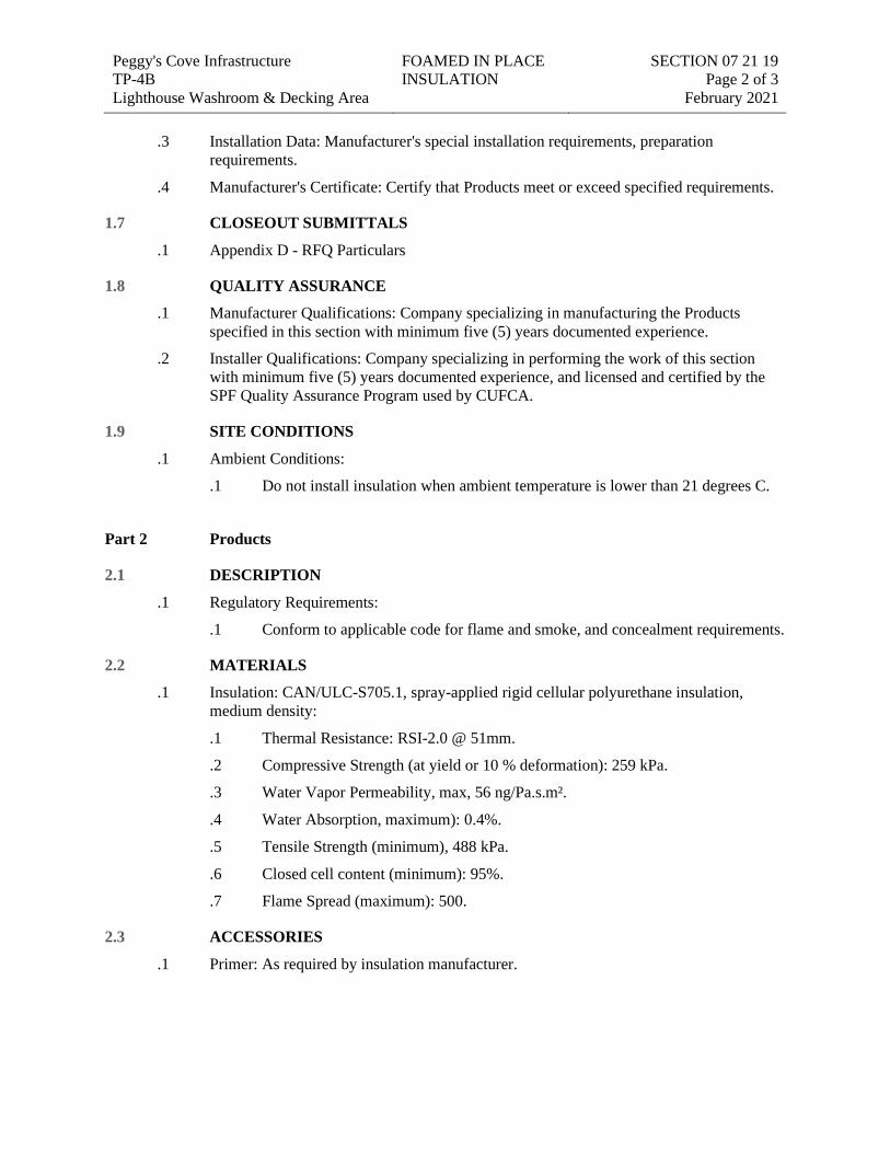
Peggy's Cove Infrastructure TP-4B Lighthouse Washroom & Decking Area
FOAMED IN PLACE INSULATION
SECTION 07 21 19 Page 2 of 3
February 2021
.3 Installation Data: Manufacturer's special installation requirements, preparation requirements.
.4 Manufacturer's Certificate: Certify that Products meet or exceed specified requirements.
1.7 CLOSEOUT SUBMITTALS
.1 Appendix D - RFQ Particulars
1.8 QUALITY ASSURANCE
.1 Manufacturer Qualifications: Company specializing in manufacturing the Products specified in this section with minimum five (5) years documented experience.
.2 Installer Qualifications: Company specializing in performing the work of this section with minimum five (5) years documented experience, and licensed and certified by the SPF Quality Assurance Program used by CUFCA.
1.9 SITE CONDITIONS
.1 Ambient Conditions:
.1 Do not install insulation when ambient temperature is lower than 21 degrees C.
Part 2 Products
2.1 DESCRIPTION
.1 Regulatory Requirements:
.1 Conform to applicable code for flame and smoke, and concealment requirements.
2.2 MATERIALS
.1 Insulation: CAN/ULC-S705.1, spray-applied rigid cellular polyurethane insulation, medium density:
.1 Thermal Resistance: RSI-2.0 @ 51mm.
.2 Compressive Strength (at yield or 10 % deformation): 259 kPa.
.3 Water Vapor Permeability, max, 56 ng/Pa.s.m².
.4 Water Absorption, maximum): 0.4%.
.5 Tensile Strength (minimum), 488 kPa.
.6 Closed cell content (minimum): 95%.
.7 Flame Spread (maximum): 500.
2.3 ACCESSORIES
.1 Primer: As required by insulation manufacturer.

Peggy's Cove Infrastructure TP-4B Lighthouse Washroom & Decking Area
FOAMED IN PLACE INSULATION
SECTION 07 21 19 Page 3 of 3
February 2021 Part 3 Execution
3.1 EXAMINATION
.1 Verify work within construction spaces or crevices is complete prior to insulation application.
.2 Verify that surfaces are clean, dry, and free of matter that may inhibit insulation or overcoat adhesion.
.3 Verify that wood surfaces are of a sufficiently low moisture content of 8%-12% to accept foamed in place insulation. Do not proceed with installation if moisture content exceeds range.
3.2 PREPARATION
.1 Mask and protect adjacent surfaces from over spray or dusting.
.2 Apply primer in accordance with manufacturer's written instructions.
3.3 INSTALLATION
.1 Apply insulation to CAN/ULC-S705.2 and manufacturer's written instructions.
.2 Apply insulation by spray method, to a uniform monolithic density without voids.
.3 Apply to a minimum cured thickness of 50 mm (2").
.4 Apply in a maximum thickness per each pass of 50 mm (2”). Wait until first layer cools before applying a second layer/lift over the initial layer/lift.
.5 Apply to achieve a thermal resistance RSI-4.2.
.6 Coordinate installation of protective covering specified in Section 09 21 16, to achieve fire rating required.
.7 Patch damaged areas.
3.4 FIELD QUALITY CONTROL
.1 Inspection and Testing:
.1 Inspection will include verification of insulation and overcoat thickness and density.
3.5 PROTECTION
.1 Do not permit subsequent construction work to disturb applied insulation.
Ω END OF SECTION
Peggy's Cove Infrastructure TP-4B Lighthouse Washroom & Decking Area
BELOW GRADE VAPOUR RETARDERS
SECTION 07 26 16 Page 1 of 3
February 2021
SEC TION 07 26 16 Below-grade vapor retarders
Part 1 General
1.1 SECTION INCLUDES
.1 Underslab Vapour and gas retarder/barrier membrane.
1.2 RELATED REQUIREMENTS
.1 Section 03 30 00 - Cast-in-Place Concrete: Concrete substrate.
.2 Section 07 27 00 - Air Barriers: Above-grade air barrier membrane.
.3 Section 07 21 13 - Board Insulation: Perimeter and horizontal insulation protective cover.
1.3 REFERENCE STANDARDS
.1 ACI 302.1R-15 - Guide for Concrete Floor and Slab Construction.
.2 ASTM D1709-16ae1 - Standard Test Methods for Impact Resistance of Plastic Film by the Free-Falling Dart Method.
.3 ASTM E154/E154M-08a(2019) - Standard Test Methods for Water Vapor Retarders Used in Contact with Earth Under Concrete Slabs, on Walls, or as Ground Cover.
.4 ASTM E1643-11(2017) - Standard Practice for Selection, Design, Installation, and Inspection of Water Vapor Retarders Used in Contact with Earth or Granular Fill Under Concrete Slabs.
.5 ASTM E1745-17 - Standard Specification for Water Vapor Retarders Used in Contact with Soil or Granular Fill under Concrete Slabs.
.6 ASTM E1993/E1993M-98(2020) - Standard Speci?cation for Bituminous Water Vapor Retarders Used in Contact with Soil or Granular Fill Under Concrete Slabs.
1.4 ADMINISTRATIVE REQUIREMENTS
.1 Coordination: Coordinate with other work having a direct bearing on work of this section.
1.5 ACTION SUBMITTALS
.1 Appendix D - RFQ Particulars
.2 Section 01 33 00: Submission procedures.
.3 Product Data: Provide data for membrane and joint seals, with temperature range for application of membrane.
.4 Shop Drawings: Indicate special joint, perimeter termination and sealing details.
1.6 INFORMATIONAL SUBMITTALS
.1 Appendix D - RFQ Particulars
.2 Section 01 33 00: Submission procedures.
.3 Certificates: Certify that Products meet or exceed specified requirements.
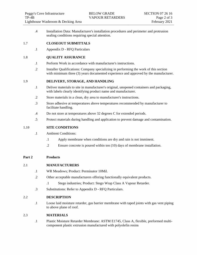
Peggy's Cove Infrastructure TP-4B Lighthouse Washroom & Decking Area
BELOW GRADE VAPOUR RETARDERS
SECTION 07 26 16 Page 2 of 3
February 2021
.4 Installation Data: Manufacturer's installation procedures and perimeter and protrusion sealing conditions requiring special attention.
1.7 CLOSEOUT SUBMITTALS
.1 Appendix D - RFQ Particulars
1.8 QUALITY ASSURANCE
.1 Perform Work in accordance with manufacturer's instructions.
.2 Installer Qualifications: Company specializing in performing the work of this section with minimum three (3) years documented experience and approved by the manufacturer.
1.9 DELIVERY, STORAGE, AND HANDLING
.1 Deliver materials to site in manufacturer's original, unopened containers and packaging, with labels clearly identifying product name and manufacturer.
.2 Store materials in a clean, dry area to manufacturer's instructions.
.3 Store adhesive at temperatures above temperatures recommended by manufacturer to facilitate handling.
.4 Do not store at temperatures above 32 degrees C for extended periods.
.5 Protect materials during handling and application to prevent damage and contamination.
1.10 SITE CONDITIONS
.1 Ambient Conditions:
.1 Apply membrane when conditions are dry and rain is not imminent.
.2 Ensure concrete is poured within ten (10) days of membrane installation.
Part 2 Products
2.1 MANUFACTURERS
.1 WR Meadows; Product: Perminator 10Mil.
.2 Other acceptable manufacturers offering functionally equivalent products.
.1 Stego industries; Product: Stego Wrap Class A Vapour Retarder.
.3 Substitutions: Refer to Appendix D - RFQ Particulars.
2.2 DESCRIPTION
.1 Loose laid moisture retarder, gas barrier membrane with taped joints with gas vent piping to above plane of roof.
2.3 MATERIALS
.1 Plastic Moisture Retarder Membrane: ASTM E1745, Class A, flexible, preformed multi-component plastic extrusion manufactured with polyolefin resins
Peggy's Cove Infrastructure TP-4B Lighthouse Washroom & Decking Area
BELOW GRADE VAPOUR RETARDERS
SECTION 07 26 16 Page 3 of 3
February 2021
.1 Thickness: 10 mil.
.2 Tensile Strength: 9.12 kN/m, tested to ASTM E154/E154M.
.3 Puncture Resistance: 3500 g, tested to ASTM D1709.
.4 Water Vapour Permeance: 0.018 perms, tested to ASTM E154/E154M.
.2 Joint and Lap Sealer: Manufacturers standard tape.
.3 Adhesives, Thinner and Cleaner: As recommended by membrane manufacturer, compatible with membrane.
Part 3 Execution
3.1 EXAMINATION
.1 Verify substrate surfaces are durable; free of matter detrimental to adhesion or application of membrane and related components.
3.2 PREPARATION
.1 Clean and prepare surfaces to receive membrane to manufacturer's written instructions.
.2 Do not apply membrane or related components to surfaces unacceptable to manufacturer.
3.3 INSTALLATION - MEMBRANE
.1 Install membrane and accessories to manufacturer's written instructions and ASTM E1643.
.2 Level, tamp, or roll earth or granular material beneath the slab base. Ensure insulation base is level and secure with no voids in sub base below prior to installation of vapour barrier.
.3 Roll out membrane. Minimize wrinkles and bubbles.
.4 Seal overlaps and joints with manufacturer's recommended tape.
.5 Seal around protrusions, permanently airtight and waterproof.
3.4 PROTECTION
.1 Do not permit damage to membrane prior to pouring concrete.
.2 Protect membrane from damage with protection boards. Scribe and cut boards around projections and interruptions.
END OF SECTION
Peggy's Cove Infrastructure TP-4B Lighthouse Washroom & Decking Area
AIR BARRIERS SECTION 07 27 00 Page 1 of 5
February 2021
SEC TION 07 27 00 Air barriers
Part 1 General
1.1 SECTION INCLUDES
.1 Air leakage criteria for primary air seal building enclosure materials and assemblies.
.2 Materials and installation methods supplementing primary air seal materials and assemblies.
.3 Air seal materials to connect and seal openings, joints, and junctions between other air seal materials and assemblies.
1.2 RELATED REQUIREMENTS
.1 Section 03 30 00 - Cast-in-place Concrete: Concrete components functioning as an air seal.
.2 Section 07 13 00 - Sheet Waterproofing: Below grade waterproofing membrane functioning as an air seal.
.3 Section 07 21 13 - Board Insulation: Insulation and insulation facing directly adjacent to the air seal.
.4 Section 07 21 19 - Spray Insulation: Insulation and insulation facing directly adjacent to the air seal.
.5 Section 07 26 16 - Below-grade Vapour Retarder: Coordinate underslab vapour seal criteria with air barrier requirements.
.6 Section 07 84 00 - Firestopping: Fire stopping materials.
.7 Section 07 92 00 - Joint Sealants: Sealant materials and installation techniques.
.8 Section 08 11 13 - Hollow Metal Doors and Frames
1.3 REFERENCE STANDARDS
.1 ASCE/SEI 7-16 - Minimum Design Loads and Associated Criteria for Buildings and Other Structures.
.2 ASTM C920-18 - Standard Specification for Elastomeric Joint Sealants.
.3 ASTM E283/E283M-19 - Standard Test Method for Determining Rate of Air Leakage Through Exterior Windows, Curtain Walls, and Doors Under Specified Pressure Differences Across the Specimen.
.4 ASTM E330/E330M-14 - Standard Test Method for Structural Performance of Exterior Windows, Doors, Skylights and Curtain Walls by Uniform Static Air Pressure Difference.
.5 NABA (National Air Barrier Association) - Air Barrier Quality Assurance Program (QAP).
.6 SWRI (Sealant, Waterproofing and Restoration Institute) - Sealant and Caulking Guide Specification.
Peggy's Cove Infrastructure TP-4B Lighthouse Washroom & Decking Area
AIR BARRIERS SECTION 07 27 00 Page 2 of 5
February 2021 1.4 DEFINITIONS
.1 Air Barrier: A continuous network of materials and joints providing air tightness, with adequate strength and stiffness to not deflect excessively under air pressure differences, to which it will be subjected in service. It can be comprised of a single material or a combination of materials to achieve the performance requirements.
1.5 ADMINISTRATIVE REQUIREMENTS
.1 Coordination:
.1 Coordinate with other work having a direct bearing on work of this section.
.2 Coordinate the work of this section with all sections referencing this section.
.2 Sequencing: Sequence work to permit installation of materials in conjunction with related materials and seals.
1.6 ACTION SUBMITTALS
.1 Appendix D - RFQ Particulars
.2 Section 01 33 00: Submission procedures.
.3 Product Data: Provide data on material characteristics, performance criteria, and limitations.
.4 Shop Drawings: Provide Drawings of special joint conditions.
1.7 INFORMATIONAL SUBMITTALS
.1 Appendix D - RFQ Particulars
.2 Section 01 33 00: Submission procedures.
.3 Installation Data: Manufacturer's special installation requirements, including preparation, installation requirements and techniques, product storage and handling criteria.
1.8 CLOSEOUT SUBMITTALS
.1 Appendix D - RFQ Particulars
1.9 QUALITY ASSURANCE
.1 Perform Work to SWRI sealant and caulking guide requirements for installation.
.2 Perform Work in accordance with the NABA Air Barrier Quality Assurance Program.
.3 Maintain one (1) copy of document on site.
.4 Contractor Qualifications: Company specializing in manufacturing the Products specified in this section with minimum three (3) years documented experience.
.5 Applicator Qualifications: Company specializing in performing the work of this section with minimum three (3) years documented experience.
1.10 MOCK-UPS
.1 Provide mock-up of air barrier system, which is comprised of a variety of materials.
Peggy's Cove Infrastructure TP-4B Lighthouse Washroom & Decking Area
AIR BARRIERS SECTION 07 27 00 Page 3 of 5
February 2021
.2 Construct typical exterior wall panel, three(1) m long by one(1)m wide, incorporating door frame and sill, insulation, building corner condition and junction with roof membrane air seal; illustrating materials interface and seals.
.3 Locate where directed by Consultant.
.4 Approved mock-up may remain as part of the Work.
1.11 SITE CONDITIONS
.1 Ambient Conditions:
.1 Maintain temperature and humidity recommended by the materials manufacturers before, during and after installation.
1.12 WARRANTY
.1 Provide a three (3) year warranty to include coverage for failure to meet specified requirements.
.2 Warranty: Include coverage of installed sheet materials that fail to achieve airtight seal, exhibit loss of adhesion or cohesion, or do not cure.
Part 2 Products
2.1 SHEET MATERIALS
.1 Self Adhered Air Barrier: Self-adhesive rubberized asphalt bonded to sheet polyethylene, regular or low (if required) temperature, nominal total thickness of 1.0 mm.
.1 Product: Blueskin SA or SALT, manufactured by Henry.
.2 Product: Sopraseal Stick 1100T, manufactured by Soprema
.3 Product: Air Shield, manufactured by WR Meadows.
.4 Use low temperature versions of all products listed if outside air temperature dictates at time of installation. Confirm limits with product manufacturer.
.2 Foam-In-Place Seal (At openings and gaps): Maximum 25% expansion, spray-applied polyurethane foam insulation.
.1 Product: Great Stuff Pro Series Window and Door, manufactured by Dupont.
.3 Membrane Flashing: Self Adhered waterproof air barrier strip format for sealing wall air barrier to doors & misc. mechanical/electrical openings.
.1 Product: Strip format, same material as sheet seal air barrier
.2 Product: 3M All Weather Tape, Manufactured by 3M
.4 Liquid Applied Flashing Sealant: Waterproof Sealant as recommended by Air Barrier manufacturer
2.2 ADHESIVES
.1 Mastic Adhesive: As recommended by, and compatible with sheet seal material, thick mastic of uniform knife grade consistency.
Peggy's Cove Infrastructure TP-4B Lighthouse Washroom & Decking Area
AIR BARRIERS SECTION 07 27 00 Page 4 of 5
February 2021
.2 Adhesive, Primers & Sealants: As recommended by, and compatible with sheet seal material, permanently non-curing.
Part 3 Execution
3.1 EXAMINATION
.1 Verify that surfaces and conditions are ready to accept the Work of this section.
3.2 PREPARATION
.1 Remove loose or foreign matter that might impair adhesion of materials.
.2 Clean and prime substrate surfaces to receive membranes and sealants to manufacturers written instructions.
3.3 INSTALLATION
.1 Install materials to manufacturer's written instructions.
.2 Self Adhered Air Barrier Over Solid Substrate: Secure flexible air barrier membrane to plywood sheathing material. Caulk to ensure complete air seal. Position lap seal over firm bearing.
.3 Roll out membranes. Minimize wrinkles and bubbles. Remove release paper layer. Roll out on substrate with a mechanical roller to encourage full contact bond. Correct fishmouths per manufacturer's instructions.
.4 Lap sides and ends per membrane manufacturer's written instructions and distances. Weather lap joints on sloped substrate in direction of drainage. Seal membrane to adjoining surfaces.
.5 Seal items protruding to or penetrating through membrane and install counter flashing membrane material.
.6 Air Seal for Wall/Roof Junction: Lap roof sheet air barrier over wall sheet air barrier. Caulk to ensure complete air seal. Position lap seal over firm bearing.
.7 Install self adhered air barrier between door frames and adjacent wall; seal materials. Caulk to ensure complete air seal. Position lap seal over firm bearing.
.8 Install membrane flashing between door frames and adjacent wall; seal RO gap with low expansion foam. Caulk to ensure complete air seal. Position lap seal over firm bearing.
.9 Install steel sheet bridging over cracks and joints exceeding 6 mm; seal with membrane. Secure with flat head screws.
.10 Apply sealant within recommended application temperature ranges. Consult manufacturer when sealant cannot be applied within these temperature ranges.
.11 Maintain ambient temperatures above 5 degrees C for twenty-four (24) hours before and during application and until liquid or mastic accessories have cured.
3.4 FIELD QUALITY CONTROL
.1 Inspection and Testing:

Peggy's Cove Infrastructure TP-4B Lighthouse Washroom & Decking Area
AIR BARRIERS SECTION 07 27 00 Page 5 of 5
February 2021
.1 Refer to Appendix D - RFQ Particulars
3.5 PROTECTION
.1 Do not permit adjacent work to damage work of this section.
END OF SECTION
Peggy's Cove Infrastructure TP-4B Lighthouse Washroom & Decking Area
WOOD SHINGLES SECTION 07 31 29 Page 1 of 5
February 2021
SEC TION 07 31 29 Wood Shingles
Part 1 General
1.1 SECTION INCLUDES
.1 Wood Shingle roofing.
.2 Wood Shingle siding.
.3 Ice dam protection, moisture shedding roof underlayment, eave, valley, and ridge protection.
.4 Associated metal flashings and accessories.
1.2 RELATED REQUIREMENTS
.1 Section 06 10 53 - Miscellaneous Rough Carpentry
.2 Section 07 21 13 - Board Insulation: Semi-Rigid Mineral Fiber Insulation.
.3 Section 07 27 00 - Air Barriers: Continuation of wall air barrier system.
.4 Section 07 46 23 - Wood Siding and wood screens.
.5 Section 07 62 00 - Sheet Metal Flashing : Edge and cap flashings.
.6 Section 07 71 23 - Manufactured Gutters And Downspouts.
1.3 REFERENCE STANDARDS
.1 ASTM B209M-14 - Standard Specification for Aluminum and Aluminum-Alloy Sheet and Plate.
.2 CAN/ULC-S107-19 - Standard Methods of Fire Tests of Roof Coverings.
.3 CGSB 37-GP-56M-85 (Withdrawn) - Membrane, Modified, Bituminous, Prefabricated, and Reinforced for Roofing.
.4 CSA O118.2-08 - Eastern White Cedar Shingles.
.5 CRCA (Canadian Roofing Contractors' Association) - CRCA Roofing Specifications Manual.
.6 CSSB (Cedar Shake and Shingle Bureau).
.7 Province of Nova Scotia Roofing Contractors Association - Roofing Specifications Manual.
.8 UL 580-2006 - Standard for Tests for Uplift Resistance of Roof Assemblies (5th Edition).
.9 UL 790-2004 - Standard for Standard Test Methods for Fire Tests of Roof Coverings (8th Edition).
1.4 ACTION SUBMITTALS
.1 Appendix D - RFQ Particulars
.2 Section 01 33 00: Submission procedures.
.3 Product Data: Provide data indicating material characteristics.
Peggy's Cove Infrastructure TP-4B Lighthouse Washroom & Decking Area
WOOD SHINGLES SECTION 07 31 29 Page 2 of 5
February 2021
.4 Shop Drawings: Indicate specially configured metal flashings, jointing methods and locations, fastening methods and locations, and installation details.
1.5 INFORMATIONAL SUBMITTALS
.1 Appendix D - RFQ Particulars
.2 Section 01 33 00: Submission procedures.
.3 Installation Data: Manufacturer's special installation requirements and procedures.
.4 Manufacturer's Certificate: Certify that Products meet or exceed specified requirements.
1.6 CLOSEOUT SUBMITTALS
.1 Appendix D - RFQ Particulars
1.7 MAINTENANCE MATERIAL SUBMITTALS
.1 Extra Stock Materials: Provide 4 bundles of extra pre-finished shingles.
1.8 QUALITY ASSURANCE
.1 Perform Work in accordance with the following roofing manual. Maintain one (1) copy of document on site.
.1 CRCA Roofing Specifications Manual.
.2 NRCA Steep Roofing Manual.
1.9 MOCK-UPS
.1 Provide mock-up of 2 sq m, including eave protection, underlayment, shake installation, and associated flashings.
.2 Locate where directed by Consultant.
.3 Approved mock-up may remain as part of the Work.
1.10 SITE CONDITIONS
.1 Ambient Conditions:
.1 Do not install eave edge protection or bitumen sheet products when ambient air temperatures are below 7 degrees C.
Part 2 Products
2.1 WOOD SHINGLES
.1 Eastern White Cedar Shingles: CSA O118.2-08, sized and graded, No. 1 (Blue Label); Re-Butt and Re-Squared; 92mm to 280mm wide, 400mm to 450mm long. Kiln Dried to 12%-16% Moisture Content.
.2 Hips and Ridge Caps: Prefabricated ridge cap shingle.
.3 Treatment: Shop preservative treat with water based clear preservative to improve moisture resistance.
Peggy's Cove Infrastructure TP-4B Lighthouse Washroom & Decking Area
WOOD SHINGLES SECTION 07 31 29 Page 3 of 5
February 2021
.1 Product: Bleaching Stain #10241, manufactured by Cabot.
2.2 SHEET MATERIALS
.1 Eave Protection: CGSB 37-GP-56M, Sheet barrier of rubberized asphalt bonded to sheet polyethylene, 1 mm total thickness, with strippable treated release paper.
.1 Product: Refer to Section 07 27 00
.2 Roof Underlayment Membrane: Mechanically attached, spun-bonded polypropylene, water resistive, vapour permeable membrane.
.1 Products:
.1 WrapShield IT Integrated Tape, manufactured by Vaproshield
.2 DELTA®-VENT S, manufactured by Dörken Systems Inc.
2.3 ACCESSORIES
.1 Staples: 316 Stainless Steel Roofing Staples, 15-17GA, 12mm (7/16") Crown, 32mm (1 1/4") -38mm (1 1/2") long, minimum penetration to strapping of 16mm (5/8")
2.4 FLASHING MATERIALS
.1 Sheet Flashings and Trims: Refer to Section 07 62 00.
.2 Flashing Nails: Standard round wire roofing type, 316 Stainless Steell; of sufficient length to penetrate through sheathing or strapping.
2.5 FLASHING FABRICATION
.1 Form flashings to profiles indicated on Drawings to protect materials from physical damage and shed water.
.2 Form sections square and accurate to profile, in maximum possible lengths, free from distortion or defects detrimental to appearance or performance.
.3 Hem exposed edges of flashings minimum 6 mm on underside.
Part 3 Execution
3.1 EXAMINATION
.1 Verify that plumbing stacks and roof penetrations are in place and flashed to deck surface.
.2 Verify roof openings are correctly framed.
.3 Verify deck surfaces are dry, free of ridges, warps, or voids.
.4 Verify wood substrate and fully secured and stable, and rain barrier membrane is free of tears and holes.
3.2 PREPARATION
.1 Store wood materials in dry location shielded from sun exposure prior to pre-finish application and installation.
Peggy's Cove Infrastructure TP-4B Lighthouse Washroom & Decking Area
WOOD SHINGLES SECTION 07 31 29 Page 4 of 5
February 2021
.2 Coordinate roof strapping placement to accommodate specified 102mm (4") to the weather shingle exposure.
.3 Ensure base strapping is straight, true and plumb for walls and equally spaced off of roof sheathing over entire area.
.4 Proceed with Shingle installation only when substrate is dry. Do not install shingles over wet strapping.
.5 Coordinate installation of shingles with flashing and other adjoining work to ensure proper sequencing.
.6 Clean all surfaces.
.7 Pre-finish all sides of shingle and allow to fully dry before installing.
3.3 INSTALLATION - ROOF PROTECTIVE UNDERLAYMENT
.1 Place one ply of roof underlayment below roof shingle nailing strips as indicated on drawings, with ends and edges weather lapped minimum 150mm. Install perpendicular to roof slope. Stagger end laps of each consecutive layer. Staple in place.
.2 Weather lap and seal watertight with manufacturer recommended sealant at items projecting through or mounted on roof.
3.4 INSTALLATION - METAL FLASHING AND ACCESSORIES
.1 Install flashings to CSSB requirements.
.2 Weather lap joints minimum 50 mm and seal weather tight with plastic cement.
.3 Secure in place with nails at 203 mm on centre. Conceal fastenings.
.4 Flash and seal work weather tight, projecting through or mounted on roofing with plastic cement.
3.5 INSTALLATION - SHINGLES
.1 Unless otherwise noted, install wood shingles in accordance with details and recommendations of the Wood Shingle section of Canadian Roofing Contractors Association (CRCA) reference manual, and the shingle manufacturer's instructions.
.2 Lay butt ends straight along entire length of roof.
.3 Install shingles, beginning at lower end with a double layer starter course, projecting shingles 25mm (1”) beyond flashing. Space adjoining shingles 6mm (¼”) to 12.7mm (½”) apart, fastening each shingle with two staples, spaced 19mm (¾”) from edge of shingle and minimum 25mm (1”) above butt line of subsequent courses. Stagger edge joints a minimum of 38mm (1-1/2”) in succeeding courses. Install shingles to provide 102mm (4") weather exposure. Cut and fit shingles at ridges and edges to provide maximum weather protection..
.4 Adjust exposure if necessary when about midway between eave and ridge so that coursing will appear uniform at ridge. Coursing to vary no more than 12.7mm (1/2") from specified exposure over entire roof or wall areas and no more than 1.6mm (1/16") between successive courses.
Peggy's Cove Infrastructure TP-4B Lighthouse Washroom & Decking Area
WOOD SHINGLES SECTION 07 31 29 Page 5 of 5
February 2021
.5 Build ridges with pre-assembled butted shingles approximately 152mm (6") wide, double starters, and lap from alternate sides. Tack straight edges on roof, 125mm (5") from centerline of ridge, one on each side to ensure a neat installation.
3.6 SITE CUT TREATMENT
.1 End cut/side cut treatment: Treat cut faces of wood in the field with specified prefinished stain preservative by brush application, to manufacturer's written instructions.
3.7 PROTECTION
.1 Do not permit traffic over finished roof surface.
END OF SECTION
Peggy's Cove Infrastructure TP-4B Lighthouse Washroom & Decking Area
WOOD SIDING AND WOOD SCREENS
SECTION 07 46 23 Page 1 of 4
February 2021
SEC TION 07 46 23 Wood siding and wood screens
Part 1 General
1.1 SECTION INCLUDES
.1 Shiplap wood siding for walls.
.2 Tongue and Groove wood boards for soffits.
.3 Square Edge lumber for entrance screens.
.4 Related trim, flashings, accessories, and fastenings.
1.2 RELATED REQUIREMENTS
.1 Section 06 10 53 - Miscellaneous Rough Carpentry
.2 Section 07 31 29 - Wood Shingles
.3 Section 07 62 00 - Sheet Metal Flashing and Trim: Supply of metal flashings and trim associated with wood siding for placement by this section.
.4 Section 07 92 00 - Joint Sealants: Sealant at perimeter, openings & dissimilar materials.
1.3 REFERENCE STANDARDS
.1 NPA A208.1-2016 - Particleboard.
.2 CAN/CSA-O80 Series-15 - Wood Preservation.
.3 CANPLY (Canadian Plywood Association) - Canadian Plywood Handbook.
.4 APA (The Engineered Wood Association).
.5 NLGA (National Lumber Grades Authority) - Standard Grading Rules for Canadian Lumber, 2017 Edition.
.6 RIS (Redwood Inspection Service) - Standard Specifications for Grades of California Redwood Lumber.
.7 WCLIB (West Coast Lumber Inspection Bureau) - Standard 17 - Grading Rules for West Coast Lumber - 2018.
.8 WWPA - Western Wood Products Association.
1.4 ACTION SUBMITTALS
.1 Appendix D - RFQ Particulars
.2 Section 01 33 00: Submission procedures.
.3 Product Data: Provide data indicating materials, component profiles, fastening methods, jointing details, sizes, surface texture, finishes and accessories.
.4 Samples: Submit two (2) samples, 300mm long in size illustrating surface texture.
1.5 INFORMATIONAL SUBMITTALS
.1 Appendix D - RFQ Particulars
Peggy's Cove Infrastructure TP-4B Lighthouse Washroom & Decking Area
WOOD SIDING AND WOOD SCREENS
SECTION 07 46 23 Page 2 of 4
February 2021
.2 Section 01 33 00: Submission procedures.
.3 Installation Data: Manufacturer's special installation requirements.
1.6 CLOSEOUT SUBMITTALS
.1 Appendix D - RFQ Particulars
1.7 QUALITY ASSURANCE
.1 Grade materials in accordance with the following:
.1 Lumber Grading: Certified by NLGA Grading Rules.
.2 Maintain one (1) copy of document on site.
1.8 DELIVERY, STORAGE, AND HANDLING
.1 Store in ventilated areas with constant minimum temperature of 16 degrees C and maximum relative humidity of 55%.
1.9 WARRANTY
.1 Provide a five (5) year warranty to include coverage for failure to meet specified requirements.
.2 Warranty: Include degradation of colour or deterioration of finish.
Part 2 Products
2.1 MATERIALS
.1 Wood Siding, Soffit & Wood for Screens: No.1 Grade or Grade A Eastern White Cedar. Custom milled to profiles and sizes indicated. Kiln Dried to 12%-16% Moisture Content.
2.2 ACCESSORIES
.1 Siding Board Exposed Face Fasteners: 316 Stainless Steel ring shank nails with textured heads (hammer installed), 11-13GA, minimum penetration into substrate of 32mm (1 1/4").
.2 Soffit Board Blind Fasteners: 316 Stainless Steel nails or staples (hammer or gun/actuator installed), 11-13GA, minimum penetration into substrate of 32mm (1 1/4") or 316 Stainless steel trim head screws.
.3 Flashing: Refer to Section 07 62 00 Sheet Metal Flashing & Trims
.4 Accessory Components: Starter strips, trims, and fascias, of same material and finish as siding.
2.3 FABRICATION - SIDING BOARD
.1 Board Size: 19mm thick, 64mm wide (actual dressed size) board with 16 mm lap.
.2 Board Profile: Ship lap.
.3 Surface Texture: Brushed or Semi-Rough.
Peggy's Cove Infrastructure TP-4B Lighthouse Washroom & Decking Area
WOOD SIDING AND WOOD SCREENS
SECTION 07 46 23 Page 3 of 4
February 2021 2.4 FABRICATION - SOFFIT BOARD
.1 Board Size: 19mm thick, 64mm wide (actual dressed size) board with 16 mm lap.
.2 Board Profile: Tongue and groove.
.3 Surface Texture: Brushed or Semi-Rough.
2.5 FABRICATION - SCREEN BOARD
.1 Board Size: 51mm thick, 203mm wide (actual dressed size) board.
.2 Board Profile: Square Edged.
.3 Surface Texture: Brushed or Semi-Rough.
2.6 FINISHES
.1 Pre-finish Colour: Cabot Bleaching Stain # 10241. Pre-coat all sides of boards prior to installation. *Note: Siding, soffit, & screen and board finish to match wood shingle finish. Coordinate surface finish of wood with manufacturer's requirements.
.2 Mill scale/mill glaze to be completely removed prior to application of finish.
Part 3 Execution
3.1 EXAMINATION
.1 Verify that framing & substrate surfaces are ready to receive work.
3.2 PREPARATION - SITE TREATMENT OF WOOD MATERIALS
.1 Verify materials do not exceed the specified percent moisture content before applying wood preservative treatment.
.2 Pre-finish all sides of boards with two (2) coats of brush applied finish to siding, soffit and screen boards, and related trim.
.3 Treat site-sawn ends. Allow finish to cure prior to erecting materials.
.4 Prime paint surfaces in contact with cementitious materials.
3.3 INSTALLATION - BOARDS
.1 Install board siding and soffits with 3mm (1/8in) to 6mm (1/4in) space for expansion and contraction between adjacent boards. Confirm amount with consultant at time of installation.
.2 Siding Board Installation: Face Nail boards with 2 fasteners at maximum 400mm (16") o/c and minimum 25mm (1") from ends. Space fasteners 16mm (5/8") from edge. Install boards to full height lengths, no butt joints over visible length of board. Slightly bevel top end of board to drain. Cut and fit boards at penetrations and edges to provide maximum weather protection. Fasten siding in place level and plumb. Nail to aligned pattern.
.3 Soffit Board Installation: Blind fasten boards with 2 fasteners at maximum 400mm (16") o/c in tongue. Face nail edge boards where required. Install boards to full lengths, no butt joints over visible length of board. Cut and fit boards at penetrations and edges to provide
Peggy's Cove Infrastructure TP-4B Lighthouse Washroom & Decking Area
WOOD SIDING AND WOOD SCREENS
SECTION 07 46 23 Page 4 of 4
February 2021
maximum weather protection. Fasten soffit board in place level and plumb. Fasten to aligned pattern where exposed.
.4 Screen Board Installation: Bolt boards in place to metal brackets at spacing and locations indicated on drawings with 13mm dia. galvanized bolts, nuts and washers. Countersink ends. Install boards to full lengths, no butt joints over visible length of board. Fasten screen board in place level and plumb.
.5 Mitre vertical external corner joints at 45 degrees.
.6 Install siding for natural shed of water.
.7 Position cut ends over bearing surfaces. Sand cut edges smooth and clean and apply finish to cut ends
.8 Install metal flashings at as indicated on drawings.
.9 Touch-up prefinished stain surfaces that are disfigured. Unsightly touch-up will require removal and replacement of affected siding.
3.4 ERECTION TOLERANCES
.1 Maximum Variation From Plumb: 3 mm in 3 m.
.2 Maximum Offset From Joint Alignment: 1.6 mm.
END OF SECTION
Peggy's Cove Infrastructure TP-4B Lighthouse Washroom & Decking Area
SHEET METAL FLASHING AND TRIMS
SECTION 07 62 00 Page 1 of 4
February 2021
SEC TION 07 62 00 Sheet Metal Flashing & Trims
Part 1 General
1.1 SECTION INCLUDES
.1 Metal cap, sill, lintel, & miscellaenous flashings.
.2 Metal cladding trims
.3 Metal counterflashings.
1.2 RELATED REQUIREMENTS
.1 Section 06 10 53 - Miscellaneous Rough Carpentry
.2 Section 07 31 29 - Wood Shingles
.3 Section 07 46 23 - Wood Siding and Wood Screens
.4 Section 07 71 23 - Manufactured Gutters and Downspouts.
.5 Section 07 92 00 - Joint Sealants.
.6 Section 08 11 13 - Hollow Metal Doors and Frames.
.7 Section 09 91 00 - Painting: Prime and finish painting.
.8 Division 23 – Heating, Ventilating, and Air-Conditioning (HVAC): Prefabricated curb for mechanical equipment.
.9 Division 26 - Electrical: Flashing sleeves and collars for electrical items protruding through roofing membrane.
1.3 REFERENCE STANDARDS
.1 ASTM A167-99(2009) (Withdrawn) - Standard Specification for Stainless and Heat-Resisting Chromium-Nickel Steel Plate, Sheet, and Strip.
.2 ASTM A653/A653M-19a - Standard Specification for Steel Sheet, Zinc-Coated (Galvanized) or Zinc-Iron Alloy-Coated (Galvannealed) by the Hot-Dip Process.
.3 ASTM B32-08(2014) - Standard Specification for Solder Metal.
.4 ASTM B209M-14 - Standard Specification for Aluminum and Aluminum-Alloy Sheet and Plate.
.5 ASTM D4586/D4586-07(2018) - Standard Specification for Asphalt Roof Cement, Asbestos-Free.
.6 Province of Nova Scotia Roofing Contractors Association - Roofing Specifications Manual.
.7 NRCA (National Roofing Contractors Association - USA) - Roofing Manual.
.8 SMACNA 1120-2012 - Architectural Sheet Metal Manual, 7th Edition.
1.4 ADMINISTRATIVE REQUIREMENTS
.1 Coordination:
Peggy's Cove Infrastructure TP-4B Lighthouse Washroom & Decking Area
SHEET METAL FLASHING AND TRIMS
SECTION 07 62 00 Page 2 of 4
February 2021
.1 Coordinate with other work having a direct bearing on work of this section.
1.5 ACTION SUBMITTALS
.1 Appendix D - RFQ Particulars
.2 Section 01 33 00: Submission procedures.
.3 Shop Drawings: Indicate material profile, jointing pattern, jointing details, fastening methods, flashings, terminations, and installation details.
.4 Samples:
.1 Submit two (2) samples, 300 mm in size illustrating typical flashing material and finish.
1.6 INFORMATIONAL SUBMITTALS
.1 Appendix D - RFQ Particulars
.2 Section 01 33 00: Submission procedures.
.3 Installation Data: Manufacturer's special installation requirements.
1.7 CLOSEOUT SUBMITTALS
.1 Appendix D - RFQ Particulars
1.8 QUALITY ASSURANCE
.1 Perform Work to SMACNA 1120 for standard details and requirements. Maintain a copy of document on site.
.2 Fabricator Qualifications: Company specializing in manufacturing the Products specified in this section with minimum three (3) years documented experience.
.3 Installer Qualifications: Company specializing in performing the work of this section with minimum three (3) years documented experience and approved by the manufacturer.
1.9 DELIVERY, STORAGE, AND HANDLING
.1 Stack material to prevent twisting, bending, or abrasion, and to provide ventilation. Slope metal sheets to ensure drainage.
.2 Prevent contact with materials which may cause discolouration or staining.
Part 2 Products
2.1 SHEET MATERIALS
.1 Zinc/Aluminum Alloy Coated Steel: ASTM A792/A792M, Galvalume, AZM210 Coating; 0.6mm (24Ga) core steel.
2.2 ACCESSORIES
.1 Fasteners: Galvanized steel, with soft neoprene washers.
.2 Underlayment: Membrane flashing as specified in Section 07 27 00.
Peggy's Cove Infrastructure TP-4B Lighthouse Washroom & Decking Area
SHEET METAL FLASHING AND TRIMS
SECTION 07 62 00 Page 3 of 4
February 2021
.3 Sealant: Polyurethane type, specified in Section 07 92 00.
.4 Bedding Compound: Butyl type.
.5 Reglets: Surface mounted type, galvanized steel; face and ends covered with plastic tape.
2.3 FABRICATION
.1 Form sections true to shape, accurate in size, square, and free from distortion or defects.
.2 Fabricate cleats of same material as sheet, minimum 50m wide, interlockable with sheet.
.3 Form pieces in single length sheets.
.4 Hem exposed edges on underside 13 mm; mitre and seam corners.
.5 Form material with flat lock seams.
.6 Fabricate corners from one piece with minimum 450 mm long legs; seam for rigidity, seal with sealant.
.7 Fabricate vertical faces with bottom edge formed outward 6 mm and hemmed to form drip.
.8 Fabricate flashings to allow toe to extend 25mm over roofing edges. Return and brake edges.
Part 3 Execution
3.1 EXAMINATION
.1 Verify roof openings, curbs, pipes, sleeves, ducts, or vents through roof are solidly set, reglets in place, and nailing strips located.
.2 Verify roofing termination and base flashings are in place, sealed, and secure.
3.2 PREPARATION
.1 Install starter and edge strips, and cleats before starting installation.
.2 Install surface mounted reglets true to lines and levels. Seal top of reglets with sealant.
3.3 INSTALLATION
.1 Conform to Drawing details generally included in the SMACNA 1120 manual.
.2 Secure flashings in place using concealed fasteners. Use exposed fasteners only where permitted.
.3 Apply plastic cement compound between metal flashings and felt flashings.
.4 Fit flashings tight in place. Make corners square, surfaces true and straight in planes, and lines accurate to profiles.
.5 Seal metal joints watertight.
3.4 FIELD QUALITY CONTROL
.1 Inspection and Testing:

Peggy's Cove Infrastructure TP-4B Lighthouse Washroom & Decking Area
SHEET METAL FLASHING AND TRIMS
SECTION 07 62 00 Page 4 of 4
February 2021
.1 Inspection will involve surveillance of work during installation to ascertain compliance with specified requirements.
END OF SECTION
Peggy's Cove Infrastructure TP-4B Lighthouse Washroom & Decking Area
SEAMLESS GUTTERS AND DOWNSPOUTS
SECTION 07 71 23 Page 1 of 3
February 2021
SEC TION 07 71 23 Seamless Gutters and Dow nspouts
Part 1 General
1.1 SECTION INCLUDES
.1 Seamless Gutters.
.2 Seamless Downspouts.
1.2 RELATED REQUIREMENTS
.1 Section 07 27 00 - Air Barriers.
.2 Section 07 31 29 - Wood Shingles
.3 Section 07 62 00 - Sheet Metal Flashing And Trim.
1.3 REFERENCE STANDARDS
.1 ASTM A167-99(2009) (Withdrawn) - Standard Specification for Stainless and Heat-Resisting Chromium-Nickel Steel Plate, Sheet, and Strip.
.2 ASTM A653/A653M-19a - Standard Specification for Steel Sheet, Zinc-Coated (Galvanized) or Zinc-Iron Alloy-Coated (Galvannealed) by the Hot-Dip Process.
.3 ASTM B32-08(2014) - Standard Specification for Solder Metal.
.4 ASTM B209M-14 - Standard Specification for Aluminum and Aluminum-Alloy Sheet and Plate.
.5 ASTM B209-14 - Standard Specification for Aluminum and Aluminum-Alloy Sheet and Plate.
.6 SMACNA 1120-2012 - Architectural Sheet Metal Manual, 7th Edition.
1.4 ADMINISTRATIVE REQUIREMENTS
.1 Coordination:
.1 Coordinate with other work having a direct bearing on work of this section.
.2 Coordinate the work with downspout discharge pipe inlet.
1.5 ACTION SUBMITTALS
.1 Appendix D - RFQ Particulars
.2 Section 01 33 00: Submission procedures.
.3 Product Data: Provide data on prefabricated components.
.4 Shop Drawings: Indicate locations, configurations, jointing methods, fastening methods, locations, and installation details.
.5 Samples: Submit two (2) samples, 300 mm long illustrating component design, finish, colour, and configuration.
Peggy's Cove Infrastructure TP-4B Lighthouse Washroom & Decking Area
SEAMLESS GUTTERS AND DOWNSPOUTS
SECTION 07 71 23 Page 2 of 3
February 2021 1.6 INFORMATIONAL SUBMITTALS
.1 Appendix D - RFQ Particulars
.2 Section 01 33 00: Submission procedures.
.3 Installation Data: Manufacturer's special installation requirements.
1.7 CLOSEOUT SUBMITTALS
.1 Appendix D - RFQ Particulars
1.8 QUALITY ASSURANCE
.1 Perform Work to 1 in 100 years for sizing components for rainfall intensity determined by a storm occurrence of SMACNA 1120. Maintain a copy of document on site.
1.9 DELIVERY, STORAGE, AND HANDLING
.1 Stack preformed prefinished material to prevent twisting, bending, or abrasion, and to provide ventilation. Slope to drain.
.2 Prevent contact with materials during storage which may cause discolouration, staining, or damage.
Part 2 Products
2.1 DESCRIPTION
.1 Seamless Built-in Gutters, Downspouts and Accessories
.2 Regulatory Requirements:
.1 Conform to applicable code for size and method of rain water discharge.
2.2 MATERIALS
.1 Aluminum Sheet: ASTM B209M, confirm alloy and temper; 0.6mm thick; plain finish. Shop pre-coated with PVDF coating; colour as selected.
2.3 COMPONENTS
.1 Gutters: SMACNA, Profile as detailed. Seamless construction.
.2 Downspouts: SMACNA,Round profile.
.3 Accessories: Profiled to suit gutters and downspouts.
2.4 ACCESSORIES
.1 Anchorage Devices: SMACNA requirements.
.2 Gutter Supports: Galvanized brackets as detailed on drawings.
.3 Downspout Supports: Straps.
.4 Fasteners: Galvanized steel, with soft neoprene washers. Finish exposed fasteners same as flashing metal.
Peggy's Cove Infrastructure TP-4B Lighthouse Washroom & Decking Area
SEAMLESS GUTTERS AND DOWNSPOUTS
SECTION 07 71 23 Page 3 of 3
February 2021
.5 Primer: Zinc chromate type.
.6 Protective Backing Paint: Zinc chromate alkyd.
.7 Protective Back Coating: Bituminous.
2.5 FABRICATION
.1 Form gutters and downspouts in Seamless fabrication of profiles and size indicated.
.2 Fabricate with required connection pieces.
.3 Form sections square, true, and accurate in size, in maximum possible lengths, free of distortion or defects detrimental to appearance or performance. Allow for expansion at joints.
.4 Hem exposed edges of metal.
.5 Fabricate gutter and downspout accessories; seal watertight.
2.6 FINISHES
.1 Apply bituminous protective backing on surfaces in contact with dissimilar materials.
Part 3 Execution
3.1 EXAMINATION
.1 Verify that surfaces are ready to receive work.
3.2 INSTALLATION
.1 Install gutters, downspouts, and accessories to manufacturer instructions.
.2 Gutters to be seamless in full lengths. Flash and seal gutters to downspouts and accessories.
.3 Slope gutters 2% minimum.
.4 Seal metal joints watertight.
.5 Seal metal joints permanantly watertight.
END OF SECTION
Peggy's Cove Infrastructure TP-4B Lighthouse Washroom & Decking Area
FIRESTOPPING SECTION 07 84 00 Page 1 of 5
February 2021
SEC TION 07 84 00 Firestopping
Part 1 General
1.1 SECTION INCLUDES
.1 Tested and listed firestopping systems.
1.2 RELATED REQUIREMENTS
.1 Section 07 27 00 - Air Barriers: Air barrier materials to adjacent insulation.
.2 Section 07 21 19: Spray applied fireproofing.
.3 Section 09 21 16 - Gypsum Board Assemblies: Gypsum wallboard fireproofing.
.4 Division 23 – Heating, Ventilating, and Air-Conditioning (HVAC): Mechanical work requiring firestopping.
.5 Section 26 - Electrical: Electrical work requiring firestopping.
1.3 REFERENCE STANDARDS
.1 ASTM E84-20 - Standard Test Method for Surface Burning Characteristics of Building Materials.
.2 ASTM E119-19 - Standard Test Methods for Fire Tests of Building Construction and Materials.
.3 ASTM E814-13a (2017) - Standard Test Method for Fire Tests of Penetration Firestop Systems.
.4 ASTM E1966-15(2019) - Standard Test Method for Fire-Resistive Joint Systems.
.5 CAN/ULC-S101-14 - Standard Methods of Fire Endurance Tests of Building Construction and Materials.
.6 CAN/ULC-S102-18 - Standard Method of Test for Surface Burning Characteristics of Building Materials and Assemblies.
.7 CAN/ULC-S102.2-18 - Standard Method of Test for Surface Burning Characteristics of Flooring, Floor Coverings and Miscellaneous Materials and Assemblies.
.8 CAN/ULC-S115-18 - Standard Method of Fire Tests of Firestop Systems.
.9 FM (Factory Mutual) - FM 4991-2013 - Approval Standard for Firestop Contractors.
.10 FCIA (Firestop Contractors International Association) - Manual of Practice.
.11 NFPA 251 - Standard Methods of Tests of Fire Endurance of Building Construction and Materials, 2006 edition.
.12 OPL (Omega Point Laboratories).
.13 UL 263-2011 - Standard for Fire Tests of Building Construction and Materials (14th Edition).
.14 UL 1479-2015 - Standard for Fire Tests of Through-Penetration Firestops (4th Edition).
Peggy's Cove Infrastructure TP-4B Lighthouse Washroom & Decking Area
FIRESTOPPING SECTION 07 84 00 Page 2 of 5
February 2021
.15 UL 1709-2017 - Standard for Rapid Rise Fire Tests of Protection Materials for Structural Steel (5th Edition).
.16 UL 2079-2015 - Standard for Tests for Fire Resistance of Building Joint Systems (5th Edition).
.17 ULC-FR-17 - Fire Resistance Directory (2017 Edition).
.18 WHI (Intertek/Warnock Hershey).
1.4 ADMINISTRATIVE REQUIREMENTS
.1 Appendix D - RFQ Particulars
.2 Section 01 31 00: Project management and coordination procedures.
.3 Coordination: Coordinate with other work having a direct bearing on work of this section.
.4 Pre-Installation Meeting: Convene one (1) week before starting work of this section.
.5 Sequencing: Coordinate and sequence firestopping installation with all affected trades.
1.5 ACTION SUBMITTALS
.1 Appendix D - RFQ Particulars
.2 Section 01 33 00: Submission procedures.
.3 Product Data: Provide manufacturer's written data on product characteristics, performance, limitation criteria.
.4 System Design Listings: Submit system design listings including illustrations from a qualified nationally recognized testing and inspection agency applicable to each firestop configuration.
.5 Unlisted Firestopping Systems: Obtain an Engineering Judgment (EJ) or Equivalent Fire Resistance Rated Assembly (EFRRA) from firestop manufacturer where no specific third party tested, listed and classified firestop system is available for a particular firestop configuration.
1.6 INFORMATIONAL SUBMITTALS
.1 Appendix D - RFQ Particulars
.2 Section 01 33 00: Submission procedures.
.3 Installation Data: Manufacturer's written special preparation and installation requirements and tested and listed firestop systems designs.
.4 Contractor's Certificates:
.1 Provide FCIA Member in Good Standing letter or certificate for the current year, on FCIA letterhead.
.2 Current ULC Qualified Firestop Contractor Certificate and individual Designated Responsible Individual Certificate.
.5 Manufacturer's Certificate: Certify that Products meet or exceed specified requirements.
Peggy's Cove Infrastructure TP-4B Lighthouse Washroom & Decking Area
FIRESTOPPING SECTION 07 84 00 Page 3 of 5
February 2021 1.7 CLOSEOUT SUBMITTALS
.1 Appendix D - RFQ Particulars.
1.8 QUALITY ASSURANCE
.1 Manufacturer Qualifications: Company specializing in manufacturing the Products specified in this section with minimum three (3) years documented experience and FCIA Manufacturer Member in good standing.
.2 Contractor Qualifications: Company specializing in performing the work of this section and as follows:
.1 FCIA Member in good standing.
.2 Minimum one (1) person employed at the firm who has passed the ULC Firestop Exam.
.3 ULC Qualified Firestop Contractor Program.
.4 FM approved in accordance with FM standard 4991 - Approval of Firestop Contractors.
.5 FCIA Member in good standing.
.6 Licensed by the province or local authority where applicable.
.7 Completed not less than five (5) comparable scale projects.
.3 Single Source Responsibility: Obtain firestop systems for each type of penetration and construction situation from a single primary firestop systems manufacturer. Obtain firestop systems for complete project, from a single primary firestop systems manufacturer, to the greatest extent possible.
1.9 DELIVERY, STORAGE, AND HANDLING
.1 Deliver firestopping products in original, unopened containers with labels intact and legible, identifying product and manufacturer.
.2 Store and handle firestopping materials to manufacturer's instructions.
1.10 SITE CONDITIONS
.1 Ambient Conditions:
.1 Do not apply materials when temperature of substrate material and ambient air is below 15 degrees C.
.2 Maintain this minimum temperature before, during, and for three (3) days after installation of materials.
.3 Provide ventilation to manufacturer's instructions in areas to receive solvent cured materials.
Peggy's Cove Infrastructure TP-4B Lighthouse Washroom & Decking Area
FIRESTOPPING SECTION 07 84 00 Page 4 of 5
February 2021 Part 2 Products
2.1 MANUFACTURERS
.1 Acceptable Manufacturers:
.1 3M Fire Protection Products.
.2 BALCO, Inc.
.3 HILTI, Inc.
.4 Specified Technologies, Inc
.5 Thermal Ceramics, Inc.
.6 Thermafiber, Inc.
.2 Substitutions: Refer to Appendix D - RFQ Particulars.
2.2 DESCRIPTION
.1 System Description:
.2 Tested and listed firestopping systems consisting of a material or materials, the wall or floor assembly, and penetrating items or gaps, assembled or placed in spaces, gaps, joints and building perimeters, to restore the fire resistance rating and or smoke resistant properties of a fire resistance rated assembly or smoke resistant assembly.
.3 Regulatory Requirements:
.1 Conform to applicable code for fire resistance ratings and surface burning characteristics.
.2 Provide certificate of compliance from authority having jurisdiction indicating approval of materials, tested and listed systems or engineering judgments used.
2.3 PERFORMANCE / DESIGN CRITERIA
.1 Materials, accessories and application procedures listed by ULC, or tested to CAN/ULC-S115 to comply with applicable building code requirements.
.2 Firestopping Materials: CAN/ULC-S101, to achieve a fire rating as noted on Drawings.
.3 Surface Burning Characteristics: CAN/ULC-S102 or CAN/ULC-S102.2, as applicable.
.4 Smoke Resistance: For areas where smoke resistance is required, provide firestop systems with L-ratings of maximum 25.4l/sec/sq m opening area.
.5 Environmental Resistance: Systems to be resistant to environmental conditions they will be exposed to, as apparent at design stage.
2.4 MATERIALS
.1 Fire Stopping Systems and Materials: Tested and listed by ULC, and conforming to construction type, penetrant type, annular space requirements and fire rating involved in each separate instance.
Peggy's Cove Infrastructure TP-4B Lighthouse Washroom & Decking Area
FIRESTOPPING SECTION 07 84 00 Page 5 of 5
February 2021 2.5 ACCESSORIES
.1 Primer: Type recommended by firestopping manufacturer for specific substrate surfaces.
.2 Forming/Packing Material: Permanent type, suitable for application.
.3 Installation Accessories: Clips, collars, fasteners, temporary stops or dams, and other devices required to position and retain materials in place.
Part 3 Execution
3.1 EXAMINATION
.1 Verify opening configurations, penetrating items, substrates, and other conditions affecting performance of firestopping are ready to receive the work of this section.
.2 Verify tested and listed systems selected are applicable to the conditions encountered.
.3 Do not proceed with installation until unsatisfactory conditions have been corrected.
3.2 PREPARATION
.1 Clean substrate surfaces as recommended in manufacturer's written instructions, of dirt, dust, grease, oil, loose material, or other matter which may affect bond of firestopping material and performance of firestop system for fire or smoke resistant situations.
.2 Remove incompatible materials which may affect bond.
.3 Install damming materials to arrest liquid material leakage.
3.3 APPLICATION
.1 Apply primer and firestopping materials to manufacturer's written instructions.
.2 Install material at walls or partition openings which contain penetrating sleeves, piping, ductwork, conduit and other items, requiring firestopping to tested and listed system or engineering judgment.
.3 Apply firestopping material, thickness sufficient to achieve rating, to uniform density and texture.
.4 Compress fibred material to achieve a density of 40% of its uncompressed density.
.5 Place intumescent coating in sufficient coats to achieve rating required.
.6 Dam Material: Dam material to remain.
3.4 CLEANING
.1 Clean adjacent surfaces of firestopping materials.
3.5 PROTECTION
.1 Protect adjacent surfaces from damage by material installation.
END OF SECTION
Peggy's Cove Infrastructure TP-4B Lighthouse Washroom & Decking Area
JOINT SEALANTS SECTION 07 92 00 Page 1 of 6
February 2021
SEC TION 07 92 00 Joint sea lants
Part 1 General
1.1 SECTION INCLUDES
.1 Preparing substrate surfaces.
.2 Sealant and joint backing.
1.2 RELATED REQUIREMENTS
.1 Section 03 30 00 - Cast-in-Place Concrete: Sealants required in conjunction with cast-in-place concrete.
.2 Section 07 13 00 - Sheet Membrane Waterproofing: Sealants required in conjunction with waterproofing.
.3 Section 07 27 00 - Air Barriers: Sealants required in conjunction with air barrier.
.4 Section 07 84 00 - Firestopping: Sealants required in conjunction with firestopping.
.5 Section 07 62 00 - Sheet Metal Flashing And Trim: Sealants required in conjunction with metal flashings.
.6 Section 08 11 13 - Metal Doors and Frames: Sealants required in conjunction with door frames.
.7 Section 09 21 16 - Gypsum Board Assemblies.
.8 Section 09 91 00 - Painting.
1.3 REFERENCE STANDARDS
.1 ASTM C834-17 - Standard Specification for Latex Sealants.
.2 ASTM C919-19 - Standard Practice for Use of Sealants in Acoustical Applications.
.3 ASTM C920-18 - Standard Specification for Elastomeric Joint Sealants.
.4 ASTM C1184-18e1 - Standard Specification for Structural Silicone Sealants.
.5 ASTM C1193-16 - Standard Guide for Use of Joint Sealants.
.6 ASTM C1311-14 - Standard Specification for Solvent Release Sealants.
.7 ASTM C1330-18 - Standard Specification for Cylindrical Sealant Backing for Use with Cold Liquid Applied Sealants.
.8 ASTM E330/E330M-14 - Standard Test Method for Structural Performance of Exterior Windows, Doors, Skylights and Curtain Walls by Uniform Static Air Pressure Difference.
1.4 ADMINISTRATIVE REQUIREMENTS
.1 Coordination:
.1 Coordinate with other work having a direct bearing on work of this section.
.2 Coordinate the work with all sections referencing this section.
Peggy's Cove Infrastructure TP-4B Lighthouse Washroom & Decking Area
JOINT SEALANTS SECTION 07 92 00 Page 2 of 6
February 2021 1.5 ACTION SUBMITTALS
.1 Appendix D - RFQ Particulars
.2 Section 01 33 00: Submission procedures.
.3 Product Data: Provide data indicating sealant chemical characteristics, performance criteria, substrate preparation, limitations and colour availability.
.4 Shop Drawings: Indicate sealant joints and dimensions, materials, structural bite, glueline thickness, joint profile, and support framing.
1.6 INFORMATIONAL SUBMITTALS
.1 Appendix D - RFQ Particulars
.2 Section 01 33 00: Submission procedures.
.3 Installation Data: Manufacturer's special installation requirements.
.1 Indicate special procedures, surface preparation, perimeter conditions requiring special attention.
1.7 CLOSEOUT SUBMITTALS
.1 Appendix D - RFQ Particulars
1.8 QUALITY ASSURANCE
.1 Perform sealant application work to ASTM C1193.
.2 Perform acoustical sealant application work to ASTM C919.
.3 Manufacturer Qualifications: Company specializing in manufacturing the Products specified in this section with minimum three (3) years documented experience.
.4 Applicator Qualifications: Company specializing in performing the work of this section with minimum three (3) years documented experience and approved by the manufacturer.
1.9 SITE CONDITIONS
.1 Ambient Conditions:
.1 Maintain temperature and humidity recommended by the sealant manufacturer during and after installation.
1.10 WARRANTY
.1 Warranty: Provide a five (5) year warranty for failure to meet specified requirements including coverage for installed sealants and accessories which fail to achieve air tight or water tight seal, exhibit loss of adhesion or cohesion, or do not cure.
.2 Manufacturer's Warranty: Provide manufacturer's twenty (20) year material warranty for installed silicone sealant.
Peggy's Cove Infrastructure TP-4B Lighthouse Washroom & Decking Area
JOINT SEALANTS SECTION 07 92 00 Page 3 of 6
February 2021 Part 2 Products
2.1 PERFORMANCE / DESIGN CRITERIA
.1 Sealant Design: Design structural sealant to withstand specified loads without breakage, loss, failure of seals, product deterioration, and other defects.
.2 Design installed sealant to withstand:
.1 Loads: Design and size to withstand dead and live loads caused by positive and negative wind pressure acting normal to plane of panel:
.1 As calculated in accordance with applicable code.
.2 As measured in accordance with ASTM E330/E330M.
.2 Seismic loads and sway displacement as calculated in accordance with applicable code.
.3 Movement from ambient temperature range of 49 degrees C.
.4 Movement and deflection of structural support framing.
.5 Water and air penetration.
2.2 SEALANTS
.1 Siliconized Acrylic Latex (Type E): ASTM C834; Type C and OP, Grade -18C; single component, non-sagging, non-staining, non-bleeding, paintable; colour: as selected
.1 Elongation Capability 25%.
.2 Service Temperature Range -54 to 82 degrees C.
.3 Shore A Hardness Range 15 to 25.
.4 Product: Tremflex 854, manufactured by Tremco.
.2 Butyl Sealant (Type F): ASTM C1311, single component, solvent release, non-skinning, non-sagging, black colour.
.1 Elongation Capability 7.5%.
.2 Service Temperature Range -28 to 82 degrees C.
.3 Shore A Hardness Range 10 to 30.
.4 Product: Tremco Butyl Seanlant, manufactured by Tremco.
.3 Acoustic Sealant (Type G): ASTM C1311, Acoustic grade, single component, solvent release, non-skinning, non-sagging, Grey colour.
.1 Elongation Capability 7.5%.
.2 Service Temperature Range -28 to 82 degrees C.
.3 Shore A Hardness Range 10 to 30.
.4 Product: Tremflex 854, manufactured by Tremco.
.4 Polyurethane Sealant (Type I): ASTM C920, Grade NS, Class 50, Use NT, T, M, A, O, I; single component, chemical curing, non-staining, non-bleeding, non-sagging type; colour as selected.
Peggy's Cove Infrastructure TP-4B Lighthouse Washroom & Decking Area
JOINT SEALANTS SECTION 07 92 00 Page 4 of 6
February 2021
.1 Elongation Capability 25%.
.2 Service Temperature Range -40 to 82 degrees C.
.3 Shore A Hardness Range 20 to 35.
.4 Product: Dymonic 100, manufactured by Tremco.
.5 Silicone Sealant (Type L): ASTM C920, Grade NS, Class 50, Use NT, M, G, A, O; single component, moisture curing, non-sagging, non-staining, non-bleeding, fungus resistant; colour as selected.
.1 Elongation Capability 25%.
.2 Service Temperature Range -54 to 82 degrees C .
.3 Shore A Hardness Range 15 to 35.
.4 Product: Spectrem 1, manufactured by Tremco.
.6 Sanitary Silicone Sealant (Type N): ASTM C920, Grade NS, Class 25, Use NT; single component, acetoxy curing, non-sagging, non-staining, mildew resistant; colour as selected.
.1 Elongation Capability 25%.
.2 Service Temperature Range -54 to 82 degrees C.
.3 Shore A Hardness Range 15 to 35.
.4 Product: Tremsil 200, manufactured by Tremco.
2.3 ACCESSORIES
.1 Primer: Non-staining type, as recommended by sealant manufacturer to suit application.
.2 Joint Cleaner: Non-corrosive and non-staining type, recommended by sealant manufacturer; compatible with joint forming materials.
.3 Joint Backing: ASTM C1330, round, closed cell; polyethylene foam rod, oversized 30% to 50% larger than joint width.
.4 Bond Breaker: Pressure sensitive tape recommended by sealant manufacturer to suit application.
.5 Masking tape: Non-staining, non-absorbent type compatible with sealant and adjacent surfaces.
.6 Setting Blocks and Spacers: Compatible with silicone sealant and recommended by sealant manufacturer.
Part 3 Execution
3.1 EXAMINATION
.1 Verify that substrate surfaces and joint openings are clean, dry, and free of frost and ready to receive work.
.2 Verify that joint backing and release tapes are compatible with sealant and substrate.
Peggy's Cove Infrastructure TP-4B Lighthouse Washroom & Decking Area
JOINT SEALANTS SECTION 07 92 00 Page 5 of 6
February 2021 3.2 PREPARATION
.1 Remove loose materials and foreign matter which might impair adhesion of sealant.
.2 Clean and prime joints to sealant manufacturer's written instructions.
.3 Perform preparation to sealant manufacturer's written instructions.
.4 Protect elements surrounding the work of this section from damage or disfiguration.
3.3 INSTALLATION
.1 Perform installation in accordance with ASTM C1193 for solvent release and latex base sealants and ASTM C919 for acoustical sealants.
.2 Install sealant to sealant manufacturer's written instructions.
.3 Measure joint dimensions and size materials to achieve required width/depth ratios.
.4 Install joint backing to achieve a neck dimension no greater than 1/3 of the joint width.
.5 Install bond breaker where joint backing is not used.
.6 Install sealant free of air pockets, foreign embedded matter, ridges, and sags.
.7 Apply sealant within recommended application temperature ranges. Consult manufacturer when sealant cannot be applied within these temperature ranges.
.8 Tool joints concave.
3.4 FIELD QUALITY CONTROL
.1 Inspection and Testing:
.1 Joint Sealants: Perform adhesion tests to manufacturer's written instructions and ASTM C1193, Method A - Field-Applied Sealant Joint Hand Pull Tab.
.1 Perform test seven (7) days after installation at a rate of one test every 300 m of installed sealant.
.2 Remove sealants failing adhesion test, clean substrates, reinstall sealants and perform retesting.
.3 Maintain test log and submit report to Consultant indicating tests, locations, dates, results, and remedial actions.
.2 Manufacturer's Services:
.1 Monitor and report installation procedures and unacceptable conditions.
3.5 CLEANING
.1 Clean adjacent soiled surfaces.
3.6 PROTECTION
.1 Remove masking tape and excess sealant.
.2 Protect sealants until cured, remove temporary glass supports.
Peggy's Cove Infrastructure TP-4B Lighthouse Washroom & Decking Area
JOINT SEALANTS SECTION 07 92 00 Page 6 of 6
February 2021 3.7 SCHEDULE
.1 Exterior Opening perimeter: Type I
.2 Metal flashing: Type I, to match metal colour.
.3 Wood siding: Type I, to match siding colour.
.4 Interior Door frame/walls/trim: Type E, Grey.
.5 Gypsum Board / Vapour barrier: Type G, White.
.6 Under thresholds: Type F, Black.
.7 Plumbing fixtures / ceramic tile: Type N, clear.
END OF SECTION
Peggy's Cove Infrastructure TP-4B Lighthouse Washroom & Decking Area
HOLLOW METAL DOORS & FRAMES
SECTION 08 11 13 Page 1 of 6
February 2021
SEC TION 08 11 13 Hollow metal doors and frames
Part 1 General
1.1 SECTION INCLUDES
.1 Hollow metal steel frames, thermally broken and non thermally broken
.2 Pressed steel doors, insulated and non-insulated
.3 Exterior glazed light frames; glass and glazing.
.4 Louvres.
1.2 RELATED REQUIREMENTS
.1 Section 08 71 00 - Door Hardware
.2 Section 06 10 53 - Miscellaneous Rough Carpentry
.3 Section 09 91 00 - Painting: Field painting of doors.
.4 Division 23 - Heating, Ventilation and Air Conditioning.
1.3 REFERENCE STNADARDS
.1 ASTM A653/A653M-19a - Standard Specification for Steel Sheet, Zinc-Coated (Galvanized) or Zinc-Iron Alloy-Coated (Galvannealed) by the Hot-Dip Process.
.2 ASTM B29-19 - Standard Specification for Refined Lead.
.3 ASTM B749-14 - Standard Specification for Lead and Lead Alloy Strip, Sheet, and Plate Products.
.4 ASTM C578-19 - Standard Specification for Rigid, Cellular Polystyrene Thermal Insulation.
.5 ASTM C591-19a - Standard Specification for Unfaced Preformed Rigid Cellular Polyisocyanurate Thermal Insulation.
.6 ASTM C1289-19 - Standard Specification for Faced Rigid Cellular Polyisocyanurate Thermal Insulation Board.
.7 ASTM E90-09(2016) - Standard Test Method for Laboratory Measurement of Airborne Sound Transmission Loss of Building Partitions and Elements.
.8 ASTM E413-16 - Classification for Rating of Sound Insulation.
.9 CAN/ULC-S104-15 - Standard Method for Fire Tests of Door Assemblies.
.10 CAN/ULC-S105-16 - Standard Specification for Fire Door Frames Meeting the Performance Required by CAN/ULC-S104.
.11 CAN/ULC-S701.1-2017 - Standard for Thermal Insulation, Polystyrene Boards.
.12 CAN/ULC-S702-14 - Standard for Mineral Fibre Thermal Insulation for Buildings.
.13 CAN/ULC-S704.1-2017 - Standard for Thermal Insulation, Polyurethane and Polyisocyanurate Boards, Faced.
Peggy's Cove Infrastructure TP-4B Lighthouse Washroom & Decking Area
HOLLOW METAL DOORS & FRAMES
SECTION 08 11 13 Page 2 of 6
February 2021
.14 CSA-G40.20-13/G40.21-13 (R2018) - General Requirements for Rolled or Welded Structural Quality Steel/ Structural Quality Steel.
.15 CSA-W59-18 - Welded Steel Construction (Metal Arc Welding).
.16 FM (Factory Mutual).
.17 CSDMA (Canadian Steel Door Manufacturers Association).
.1 Recommended Dimensional Standards for Commercial Steel Doors and Frames, 2009.
.2 Recommended Selection and Usage Guide for Commercial Steel Doors and Frame Products, 2009.
.18 NFPA 80 - Standard for Fire Doors and Other Opening Protectives, 2019 Edition.
.19 NFPA 252 - Fire Tests of Door Assemblies, 2017 Edition.
.20 ULC-FR-17 - Fire Resistance Directory (2017 Edition).
.21 UL - Fire Resistance Directory.
1.4 ADMINISTRATIVE REQUIREMENTS
.1 Coordination:
.1 Coordinate with other work having a direct bearing on work of this section.
.2 Coordinate the work with frame opening construction, door, and hardware installation.
.2 Sequencing: Sequence installation to ensure wire connections are achieved in an orderly and expeditious manner.
1.5 ACTION SUBMITTALS
.1 Appendix D - RFQ Particulars
.2 Section 01 33 00: Submission procedures.
.3 Product Data: Indicate door and frame configurations and finishes, location of cut-outs for hardware reinforcement.
.4 Shop Drawings:
.1 Indicate frame elevations, reinforcement, anchor types and spacing, location of cut-outs for hardware, and finish.
.2 Indicate door elevations, internal reinforcement, closure method, and cut-outs for louvres and/or glazing.
1.6 INFORMATIONAL SUBMITTALS
.1 Appendix D - RFQ Particulars
.2 Section 01 33 00: Submission procedures.
.3 Installation Data: Manufacturer's special installation requirements.
.4 Manufacturer's Certificate: Certify that Products meet or exceed specified requirements.
Peggy's Cove Infrastructure TP-4B Lighthouse Washroom & Decking Area
HOLLOW METAL DOORS & FRAMES
SECTION 08 11 13 Page 3 of 6
February 2021 1.7 CLOSEOUT SUBMITTALS
.1 Appendix D - RFQ Particulars
1.8 QUALITY ASSURANCE
.1 Conform to requirements of CSDMA. Maintain one (1) of document on site.
.2 Manufacturer Qualifications: Company specializing in manufacturing the Products specified in this section with minimum three (3) years documented experience.
1.9 DELIVERY, STORAGE, AND HANDLING
.1 Remove doors and frames from wrappings or coverings upon receipt on site and inspect for damage.
.2 Store in vertical position, spaced with blocking to permit air circulation between components.
.3 Store materials on planks or dunnage, out of water and covered to protect from damage.
.4 Clean and touch up scratches or disfigurement caused by shipping or handling with zinc-rich primer.
Part 2 Products
2.1 DESCRIPTION
.1 Regulatory Requirements:
.1 Fire Rated Door and Frame Construction: Labelled and listed to CAN/ULC-S104.
.2 Fire Rated Door Construction: Rate of rise of 250 C degrees across door thickness.
.3 Installed Door and Frame Assembly: Conform to NFPA 80 for fire rated class as indicated.
2.2 MATERIALS
.1 Sheet Steel: Galvanized steel to ASTM A653/A653M, commercial grade (CS), Type B.
.1 Exterior Doors: Coating designation ZF180.
.2 Interior Doors: Coating designation ZF120.
.2 Reinforcement Channel: CSA-G40.20/G40.21, Type 44W, ZF75 coating designation to ASTM A653/A653M.
2.3 DOOR CORE MATERIALS
.1 Honeycomb Core: Structural small cell 25.4 mm maximum kraft paper honeycomb; weight 36.3 kg per ream minimum, density 16.5 kg/cu m minimum, sanded to required thickness.
.2 Polystyrene Core: ASTM C578, Type 1, rigid extruded fire retardant, closed cell board, density 16 to 32 kg/cu m, thermal values R-6.0 minimum.
Peggy's Cove Infrastructure TP-4B Lighthouse Washroom & Decking Area
HOLLOW METAL DOORS & FRAMES
SECTION 08 11 13 Page 4 of 6
February 2021
.3 Temperature Rise Rated (TRR): Core composition to provide fire-protection rating and limit temperature rise on unexposed side of door to 250 degrees C at 30 or 60 minutes, as determined by governing code requirements, core tested as part of a complete door and frame assembly, to CAN/ULC-S104, and listed by a nationally recognized testing agency having a factory inspection service.
2.4 ADHESIVES
.1 Cores and Steel Components: Heat resistant, structural reinforced epoxy, resin based adhesive.
.2 Lock Seam: Reinforced epoxy resin, high viscosity, thicksotroptic sealant.
2.5 PRIMERS
.1 Primer: Rust inhibitive touch-up only.
2.6 ACCESSORIES
.1 Door Silencers: Single stud rubber/neoprene.
.2 Exterior Top Caps: Rigid polyvinylchloride (PVC) extrusion.
.3 Frame Thermal Breaks: Rigid polyvinylchloride (PVC) extrusion.
.4 Removable Glazing Stops: Formed galvanized steel channel, minimum 16 mm high, accurately fitted, butted at corners and fastened to frame sections with counter-sunk tamper proof sheet metal screws.
.5 Bituminous Coating: Fibred asphalt emulsion.
.6 Weatherstripping: Resilient rubber set in aluminum frame.
.7 Weatherstripping: Specified in Section 08 71 00.
.8 Louvres:
.1 Material and Finish: Extruded aluminum; precoated.
.1 Colour: As selected.
.2 Louver Blade: Inverted V blade, sight proof.
.3 Louver Blade: Inverted V blade, sight proof; fire rated to 1 hours; fusible link design to ULC requirements.
.4 Louver Free Area: Coordinate with mechanical.
.5 Frame: Narrow style with tamper proof fasteners.
.9 Glass: Sealed insulated glazing unit consisting of 2 layers 3mm tempered glazing with argon filled airspace, Low E coating, and warm edge spaced.
2.7 FABRICATION - DOORS
.1 Exterior Doors: Laminated core construction.
.2 Interior Doors: Laminated core construction.
.3 Longitudinal Edges: Mechanically interlocked, tack welded with no visible edge seams.
Peggy's Cove Infrastructure TP-4B Lighthouse Washroom & Decking Area
HOLLOW METAL DOORS & FRAMES
SECTION 08 11 13 Page 5 of 6
February 2021
.4 Mortised, blanked, reinforced, drilled and tapped for templated hardware, in accordance with templates provided by hardware supplier.
.5 Reinforce for surface mounted hardware, anchor hinges, thrust pivots, pivot reinforced hinges, or non-templated hardware.
.6 Top and Bottom Channels: Inverted, recessed, welded steel channels.
.7 Exterior Door: Flush PVC top caps.
.8 Provide factory-applied touch-up primer at areas where zinc coating has been removed during fabrication.
.9 Sound Rated Door after Fabrication: STC of 40, measured to ASTM E413.
2.8 LAMINATED CORE CONSTRUCTION
.1 Exterior Doors: Both face sheets 2.0 mm 1.6 mm steel, with polystyrene core, laminated under pressure to face sheets.
.2 Interior Doors: Both face sheets 1.6 mm steel with honeycomb core and temperature rise rated core where scheduled, laminated under pressure to face sheets.
2.9 FABRICATION - FRAMES
.1 Exterior Frames: 2.0 mm thick base metal thickness.
.1 Frames: Welded type construction, thermally broken.
.2 Transom Frames, Sidelight and Window Assemblies: Welded type construction, thermally broken.
.2 Interior Frames: 1.6 mm thick base metal thickness.
.1 Door Frames and Window Assemblies: Welded type construction.
.2 Transom Frames: Welded type construction.
.3 Sidelight Assemblies: Welded type construction.
.3 Mullions for Double Doors: Removable type, of same profiles as jambs.
.4 Transom Bars for Glazed Lights: Fixed type, of same profiles as jamb and head.
.5 Mortised, blanked, reinforced, drilled and tapped for templated hardware, in accordance with templates provided by hardware supplier. Provide mortar guard boxes.
.6 Reinforce frames wider than 1 200 mm with roll formed steel channels fitted tightly into frame head, flush with top.
.7 Prepare frames for silencers. Provide three (3) single silencers for single doors and mullions of double doors on strike side. Provide two (2) single silencers on frame head at double doors without mullions.
.8 Configure exterior frames with special profile to receive recessed weatherstripping.
.9 Attach fire rated label to each fire rated door unit.
Peggy's Cove Infrastructure TP-4B Lighthouse Washroom & Decking Area
HOLLOW METAL DOORS & FRAMES
SECTION 08 11 13 Page 6 of 6
February 2021 Part 3 Execution
3.1 EXAMINATION
.1 Verify that opening sizes and tolerances are acceptable; check floor area within path of door swing for flatness.
.2 Verify doors and frames are correct size, swing, rating and opening number.
.3 Remove temporary shipping spreaders.
3.2 INSTALLATION
.1 Install doors and frames to CSDMA.
.2 Install fire-rated doors and frames in accordance with NFPA 80, and local authority having jurisdiction.
.3 Coordinate with gypsum board wall construction for anchor placement.
.4 Coordinate installation of glass and glazing.
.5 Coordinate installation of doors and frames with installation of hardware specified in Section 08 71 00.
.6 Set frames plumb, square, level and at correct elevation.
.7 Secure anchorages and connections to adjacent construction.
.8 Brace frames rigidly in position while building-in. Install wood spreaders at third points of frame rebate height to maintain frame width. Provide vertical support at centre of head for openings exceeding 1 200 mm in width.
.9 Remove wood spreaders after frames have been built-in.
.10 Make allowance for deflection to ensure structural loads are not transmitted to frame product.
.11 Install doors, and hardware in accordance with hardware templates and manufacturer's instructions.
.12 Adjust operable parts for correct clearances and function.
.13 Install louvers, glazing and door silencers.
.14 Finish paint as specified in Section 09 91 00.
.15 Install roll formed steel reinforcement channels between two abutting frames. Anchor to structure and floor.
3.3 ERECTION TOLERANCES
.1 Maximum Diagonal Distortion: 1.5 mm measured with straight edges, crossed corner to corner.
END OF SECTION
Peggy's Cove Infrastructure TP-4B Lighthouse Washroom & Decking Area
ACCESS DOORS & FRAMES
SECTION 08 31 13 Page 1 of 3
February 2021
SEC TION 08 31 13 Access doors and frames
Part 1 General
1.1 SECTION INCLUDES
.1 Access door and frame units.
1.2 RELATED REQUIREMENTS
.1 Appendix D - RFQ Particulars
.2 Section 01 33 00 - Submittal Procedures
.3 Section 03 30 00 - Cast-in-Place Concrete: Openings in concrete.
.4 Section 09 21 16 - Gypsum Board Assemblies: Openings in partitions.
.5 Section 09 91 00 - Painting: Field paint finish.
.6 Division 23 - Heating, Ventilating, and Air-Conditioning (HVAC): ……….
.7 Division 28 – Electronic Safety and Security: Electrical components requiring access ……….
1.3 REFERENCE STANDARDS
.1 UL - Fire Resistance Directory.
.2 ULC-FR-17 - Fire Resistance Directory (2017 Edition).
1.4 ADMINISTRATIVE REQUIREMENTS
.1 Coordination: Coordinate with other work having a direct bearing on work of this section.
.1 Coordinate the work with other work requiring access doors.
1.5 ACTION SUBMITTALS
.1 Section 01 33 00: Submission procedures.
.2 Appendix D - RFQ Particulars.
.3 Product Data: Provide sizes, types, finishes, hardware, scheduled locations, and details of adjoining work.
.4 Shop Drawings: Indicate exact position of all access door units.
1.6 CLOSEOUT SUBMITTALS
.1 Appendix D - RFQ Particulars
.2 Record Documentation: Record actual locations of all access units.
1.7 QUALITY ASSURANCE
.1 Perform Work in accordance with ULC Assembly Design. Maintain one (1) copy of document on site.
Peggy's Cove Infrastructure TP-4B Lighthouse Washroom & Decking Area
ACCESS DOORS & FRAMES
SECTION 08 31 13 Page 2 of 3
February 2021 Part 2 Products
2.1 PERFORMANCE / DESIGN CRITERIA
.1 Fabricate floor access assemblies to support live load of 4.7 kPa with deflection not to exceed 1/240 of span.
2.2 ACCESS UNITS - GYPSUM BOARD WALLS AND CEILINGS
.1 Fire Rated Door and Frame Unit: Formed steel, finish; ULC, 45min fire rating:
.1 Product - Ceiling Access: Model MFRU2436 MFRU uninsulated Fire Rated Access Door, manufactured by Mifab
.2 Product - Wall and Ceiling Typical access for mechanical/electrical : Model MFRU uninsulated Fire Rated Access Door, manufactured by Mifab. Size to suit.
.3 Alternate manufacturers: Acudor, Nystrom NT Series; Zurn Nailor; Controlled Air; SMS William Brothers
.4 Substitutions: Refer to Appendix D - RFQ Particulars
2.3 ACCESS UNITS - FLOORS
.1 Fire Rated Hatch and Frame Unit: Formed steel, finish; 2hr fire rating:
.1 In Concrete Floors, ULC Rated: Bilco Type FR Fire Rated Door
.2 Substitutions: Refer to Appendix D- RFQ Particulars
2.4 FABRICATION - WALL AND CEILING UNITS
.1 Fabricate frames and flanges of 1.5 mm stainless steel.
.2 Fabricate door panels of 1.8 mm steel double sheet with integral non-combustible insulation filler.
.3 Weld, fill, and grind joints to ensure flush and square unit.
.4 Hardware:
.1 Hinge: concealed constant force closure spring type.
.2 Lock: Screw driver slot for quarter turn cam lock .
2.5 FABRICATION - FLOOR UNITS
.1 Fabricate frames and anchors of mill finish aluminum, 6mm thickness.
.2 Fabricate hatches of 6mm aluminum plate reinforced for 732 kg/m2 live load with integral intumescent fire coating; 25mm infill concrete top, finish with specified floor finish in room.
.3 Weld, fill, and grind joints to assure flush and square unit.
.4 Hardware:
.1 Hinge: Continuous heavy-duty type 316 stainless steel hinge.
.2 Latch: Pneumatic self closing system that automatically closes the door in the event of a fire when heat parts a UL-listed 165°F (74°C) fusible link
Peggy's Cove Infrastructure TP-4B Lighthouse Washroom & Decking Area
ACCESS DOORS & FRAMES
SECTION 08 31 13 Page 3 of 3
February 2021
.3 Lift Assistance: Compression spring operators enclosed in telescopic tubes. Mechanical hold-open system with release button automatically holds the cover in the open position
Part 3 Execution
3.1 EXAMINATION
.1 Verify that rough openings for door and frame are correctly sized and located.
3.2 INSTALLATION
.1 Install units to manufacturer's written instructions.
.2 Install frames plumb and level in opening. Secure rigidly in place.
.3 Position unit to provide convenient access to concealed work requiring access.
END OF SECTION
Peggy's Cove Infrastructure TP-4B Lighthouse Washroom & Decking Area
DOOR HARDWARE
SECTION 08 71 00 Page 1 of 9
February 2021
SEC TION 08 71 00 Door hardware
Part 1 General
1.1 SECTION INCLUDES
.1 Hardware for doors.
.2 Barrier Free Actuators
.3 Thresholds.
.4 Weatherstripping, seals, and door gaskets.
1.2 RELATED REQUIREMENTS
.1 Section 08 11 11 - Hollow Metal Doors and Frames.
.2 Division 26: Power supply to electric hardware devices barrier free actuators.
1.3 REFERENCE STANDARDS
.1 Standard hardware location dimensions in accordance with the Canadian Metric Guide for Steel Doors and Frames (Modular Construction) prepared by Canadian Steel Door and Frame Manufacturers Association
.2 CAN/ULC-S104-15 - Standard Method for Fire Tests of Door Assemblies.
.3 CAN/ULC-S132-16 - Standard for Emergency Exit and Emergency Fire Exit Hardware.
.4 CSDMA (Canadian Steel Door Manufacturers Association).
.5 DHI (Door and Hardware Institute Canada) - AHC and EHC certification programs.
.6 DHI (Door Hardware Institute) - A115 series.
.7 BHMA (Builders Hardware Manufacturers Association) - A156 Series Standards.
.8 NFPA 80 - Standard for Fire Doors and Other Opening Protectives, 2019 Edition.
.9 NFPA 252 - Fire Tests of Door Assemblies, 2017 Edition.
.10 UL 10B-2008 - Fire Tests of Door Assemblies (10th Edition).
.11 UL 305-2012 - Standard for Panic Hardware (6th Edition).
.12 ANSI/BHMA A156.1-2016, Butts and Hinges.
.13 ANSI/BHMA A156.2-2017, Bored & Preassembled Locks and Latches.
.14 ANSI/BHMA A156.3-2014, Exit Devices.
.15 ANSI/BHMA A156.4-2013, Door Controls - Closers.
.16 ANSI/BHMA A156.5-2014, Cylinders and Input Devices for Locks.
.17 ANSI/BHMA A156.6-2010, Architectural Door Trim.
.18 ANSI/BHMA A156.7-2014, Template Hinge Dimensions.
.19 ANSI/BHMA A156.8-2010, Door Controls – Overhead Stops & Holders.
.20 ANSI/BHMA A156.13-2017, Mortise Locks and Latches.
Peggy's Cove Infrastructure TP-4B Lighthouse Washroom & Decking Area
DOOR HARDWARE
SECTION 08 71 00 Page 2 of 9
February 2021
.21 ANSI/BHMA A156.15-2015, Release Devices – Closer Holder, Electromagnetic.
.22 ANSI/BHMA A156.16-2013, Auxiliary Hardware.
.23 ANSI/BHMA A156.18-2016, Materials and Finishes.
.24 ANSI/BHMA A156.19-2013, Power Assist & Low Energy Power Operated Doors.
.25 ANSI/BHMA A156.26-2017, Continuous Hinges
.26 ANSI/BHMA A156.21-2014, American National Standards for Thresholds.
.27 ANSI/BHMA A156.22-2017, Door Gasketing and Edge Seal Systems
.28 ANSI/BHMA A156.25-2013, Electrified Locking Devices.
.29 ANSI/BHMA A156.24-2012, Delayed Egress Locks.
.30 ANSI/BHMA A156.29-2017, Exit Locks, Exit Alarms, Alarms for Exits Devices.
.31 ANSI/BHMA A156.31-2013, Electric Strikes and Frame Mounted Actuators.
1.4 ADMINISTRATIVE REQUIREMENTS
.1 Coordination: Coordinate with other work having a direct bearing on work of this section.
.1 Coordinate the work with other directly affected sections involving manufacture or fabrication of internal reinforcement for door hardware and recessed items.
.2 Coordinate Owner's keying requirements during the course of the Work.
.2 Sequencing: Sequence installation to ensure utility connections are achieved in an orderly and expeditious manner.
1.5 ACTION SUBMITTALS
.1 Appendix D - RFQ Particulars
.2 Section 01 33 00: Submission procedures.
.3 Shop Drawings:
.1 Indicate locations and mounting heights of each type of hardware, schedules, catalogue cuts, electrical characteristics and connection requirements.
.2 Submit manufacturer's parts lists and templates.
1.6 INFORMATIONAL SUBMITTALS
.1 Appendix D - RFQ Particulars
.2 Section 01 33 00: Submission procedures.
.3 Installation Data: Manufacturer's special installation requirements.
1.7 CLOSEOUT SUBMITTALS
.1 Appendix D - RFQ Particulars
.2 Operation and Maintenance Data: Include data on operating hardware, lubrication requirements, and inspection procedures related to preventative maintenance.
Peggy's Cove Infrastructure TP-4B Lighthouse Washroom & Decking Area
DOOR HARDWARE
SECTION 08 71 00 Page 3 of 9
February 2021
.3 Warranty Documentation: Submit manufacturer warranty and ensure forms have been completed in Owner's name and registered with manufacturer.
.4 Record Documentation:
.1 Record actual locations of installed cylinders and their master key code.
.2 Keys: Deliver with identifying tags to Owner by security shipment direct from hardware supplier.
1.8 MAINTENANCE MATERIAL SUBMITTALS
.1 Extra Stock Materials:
.1 Provide ten (10) extra key lock cylinders for each master keyed group.
.2 Tools:
.1 Provide special wrenches and tools applicable to each different or special hardware component.
.2 Provide maintenance tools and accessories supplied by hardware component manufacturer.
1.9 QUALITY ASSURANCE
.1 Perform Work to the following requirements:
.1 BHMA A156 series.
.2 DHI A115 series.
.3 DHI WDHS-3.
.4 CSDMA.
.5 NFPA 80.
.6 NFPA 252.
.7 UL 10B .
.8 UL 305.
.9 CAN/ULC-S132.
.10 CAN/ULC-S104.
.11 Maintain one (1) copy of each document on site.
.2 Manufacturer Qualifications: Company specializing in manufacturing the Products specified in this section with minimum three (3) years documented experience.
.3 Installer Qualifications: Company specializing in performing the work of this section with minimum three (3) years documented experience and approved by the manufacturer.
.4 Hardware Supplier Personnel: Employ an Architectural Hardware Consultant (AHC) to assist in the work of this section.
Peggy's Cove Infrastructure TP-4B Lighthouse Washroom & Decking Area
DOOR HARDWARE
SECTION 08 71 00 Page 4 of 9
February 2021 1.10 DELIVERY, STORAGE, AND HANDLING
.1 Package hardware items individually; label and identify each package with door opening code to match hardware schedule.
1.11 WARRANTY
.1 Appendix D - RFQ Particulars
.2 Provide five (5) year manufacturer warranty for door closers.
Part 2 Products
2.1 DESCRIPTION
.1 Regulatory Requirements:
.1 Conform to applicable code for Products requiring electrical connection. Listed and classified by CSA as suitable for the purpose specified and indicated.
.2 Use a single manufacturer’s products for similar product groups.
2.2 ACCEPTABLE MANUFACTURERS
.1 Full Mortise Hinges:
.1 Base: McKinney; Symbol: MK; Alternative: Ives
.2 Lockset, Deadlock:
.1 Base: Schlage / Falcon; Symbol: SC/FA; Alternative: Sargent
.3 Swing Operator:
.1 Base: Entramatic; Symbol: EN; Alternative: LCN
.4 Activation Device:
.1 Base: Candem Controls; Symbol: CC; Alternative: DormaKaba
.5 Push, Pull and Kick Plate:
.1 Base: Gallery; Symbol: GA; Alternative: CBH
.6 Astragal:
.1 Base: Frontline Defence; Symbol: FL; Alternative: Pemko
.7 Gasketing:
.1 Base: Pemko; Symbol: PE; Alternative: KN Crowder
2.3 SUBSTITUTIONS
.1 Other manufacturer’s products will be considered provided they meet or exceed the performance, grade, quality, function, weight, design, and finish of the specified product and approved in writing by the architect prior to commencement of the work
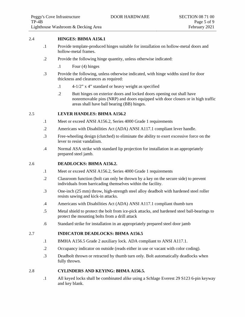
Peggy's Cove Infrastructure TP-4B Lighthouse Washroom & Decking Area
DOOR HARDWARE
SECTION 08 71 00 Page 5 of 9
February 2021 2.4 HINGES: BHMA A156.1
.1 Provide template-produced hinges suitable for installation on hollow-metal doors and hollow-metal frames.
.2 Provide the following hinge quantity, unless otherwise indicated:
.1 Four (4) hinges
.3 Provide the following, unless otherwise indicated, with hinge widths sized for door thickness and clearances as required:
.1 4-1/2” x 4” standard or heavy weight as specified
.2 Butt hinges on exterior doors and locked doors opening out shall have nonremovable pins (NRP) and doors equipped with door closers or in high traffic areas shall have ball bearing (BB) hinges.
2.5 LEVER HANDLES: BHMA A156.2
.1 Meet or exceed ANSI A156.2, Series 4000 Grade 1 requirements
.2 Americans with Disabilities Act (ADA) ANSI A117.1 compliant lever handle.
.3 Free-wheeling design (clutched) to eliminate the ability to exert excessive force on the lever to resist vandalism.
.4 Normal ASA strike with standard lip projection for installation in an appropriately prepared steel jamb.
2.6 DEADLOCKS: BHMA A156.2.
.1 Meet or exceed ANSI A156.2, Series 4000 Grade 1 requirements
.2 Classroom function (bolt can only be thrown by a key on the secure side) to prevent individuals from barricading themselves within the facility.
.3 One-inch (25 mm) throw, high-strength steel alloy deadbolt with hardened steel roller resists sawing and kick-in attacks.
.4 Americans with Disabilities Act (ADA) ANSI A117.1 compliant thumb turn
.5 Metal shield to protect the bolt from ice-pick attacks, and hardened steel ball-bearings to protect the mounting bolts from a drill attack
.6 Standard strike for installation in an appropriately prepared steel door jamb
2.7 INDICATOR DEADLOCKS: BHMA A156.5
.1 BMHA A156.5 Grade 2 auxiliary lock. ADA compliant to ANSI A117.1.
.2 Occupancy indicator on outside (reads either in use or vacant with color coding).
.3 Deadbolt thrown or retracted by thumb turn only. Bolt automatically deadlocks when fully thrown.
2.8 CYLINDERS AND KEYING: BHMA A156.5.
.1 All keyed locks shall be combinated alike using a Schlage Everest 29 S123 6-pin keyway and key blank.
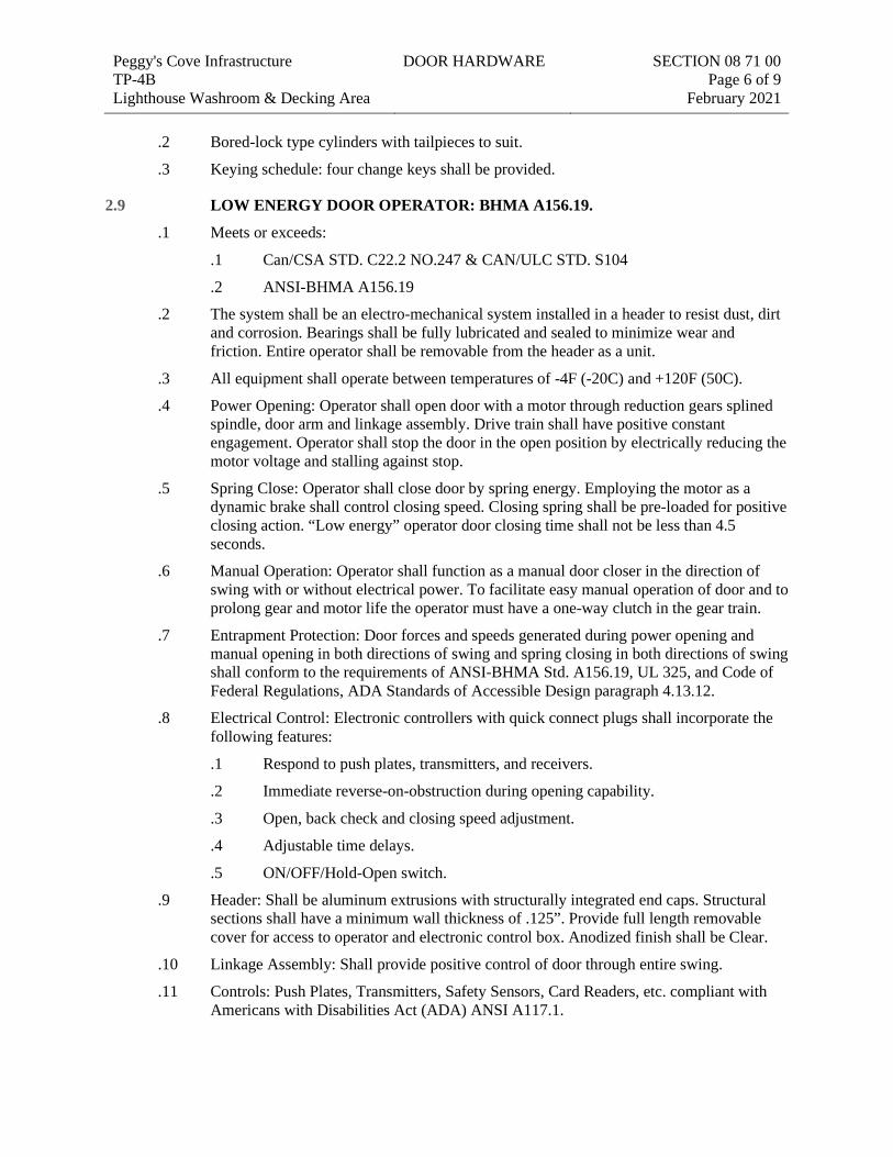
Peggy's Cove Infrastructure TP-4B Lighthouse Washroom & Decking Area
DOOR HARDWARE
SECTION 08 71 00 Page 6 of 9
February 2021
.2 Bored-lock type cylinders with tailpieces to suit.
.3 Keying schedule: four change keys shall be provided.
2.9 LOW ENERGY DOOR OPERATOR: BHMA A156.19.
.1 Meets or exceeds:
.1 Can/CSA STD. C22.2 NO.247 & CAN/ULC STD. S104
.2 ANSI-BHMA A156.19
.2 The system shall be an electro-mechanical system installed in a header to resist dust, dirt and corrosion. Bearings shall be fully lubricated and sealed to minimize wear and friction. Entire operator shall be removable from the header as a unit.
.3 All equipment shall operate between temperatures of -4F (-20C) and +120F (50C).
.4 Power Opening: Operator shall open door with a motor through reduction gears splined spindle, door arm and linkage assembly. Drive train shall have positive constant engagement. Operator shall stop the door in the open position by electrically reducing the motor voltage and stalling against stop.
.5 Spring Close: Operator shall close door by spring energy. Employing the motor as a dynamic brake shall control closing speed. Closing spring shall be pre-loaded for positive closing action. “Low energy” operator door closing time shall not be less than 4.5 seconds.
.6 Manual Operation: Operator shall function as a manual door closer in the direction of swing with or without electrical power. To facilitate easy manual operation of door and to prolong gear and motor life the operator must have a one-way clutch in the gear train.
.7 Entrapment Protection: Door forces and speeds generated during power opening and manual opening in both directions of swing and spring closing in both directions of swing shall conform to the requirements of ANSI-BHMA Std. A156.19, UL 325, and Code of Federal Regulations, ADA Standards of Accessible Design paragraph 4.13.12.
.8 Electrical Control: Electronic controllers with quick connect plugs shall incorporate the following features:
.1 Respond to push plates, transmitters, and receivers.
.2 Immediate reverse-on-obstruction during opening capability.
.3 Open, back check and closing speed adjustment.
.4 Adjustable time delays.
.5 ON/OFF/Hold-Open switch.
.9 Header: Shall be aluminum extrusions with structurally integrated end caps. Structural sections shall have a minimum wall thickness of .125”. Provide full length removable cover for access to operator and electronic control box. Anodized finish shall be Clear.
.10 Linkage Assembly: Shall provide positive control of door through entire swing.
.11 Controls: Push Plates, Transmitters, Safety Sensors, Card Readers, etc. compliant with Americans with Disabilities Act (ADA) ANSI A117.1.
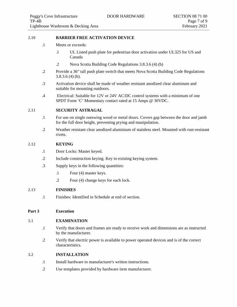
Peggy's Cove Infrastructure TP-4B Lighthouse Washroom & Decking Area
DOOR HARDWARE
SECTION 08 71 00 Page 7 of 9
February 2021 2.10 BARRIER FREE ACTIVATION DEVICE
.1 Meets or exceeds:
.1 UL Listed push plate for pedestrian door activation under UL325 for US and Canada
.2 Nova Scotia Building Code Regulations 3.8.3.6 (4) (b)
.2 Provide a 36” tall push plate switch that meets Nova Scotia Building Code Regulations 3.8.3.6 (4) (b).
.3 Activation device shall be made of weather resistant anodized clear aluminum and suitable for mounting outdoors.
.4 Electrical: Suitable for 12V or 24V AC/DC control systems with a minimum of one SPDT Form ‘C’ Momentary contact rated at 15 Amps @ 30VDC.
2.11 SECURITY ASTRAGAL
.1 For use on single outswing wood or metal doors. Covers gap between the door and jamb for the full door height, preventing prying and manipulation.
.2 Weather resistant clear anodized aluminium of stainless steel. Mounted with rust-resistant rivets.
2.12 KEYING
.1 Door Locks: Master keyed.
.2 Include construction keying. Key to existing keying system.
.3 Supply keys in the following quantities:
.1 Four (4) master keys.
.2 Four (4) change keys for each lock.
2.13 FINISHES
.1 Finishes: Identified in Schedule at end of section.
Part 3 Execution
3.1 EXAMINATION
.1 Verify that doors and frames are ready to receive work and dimensions are as instructed by the manufacturer.
.2 Verify that electric power is available to power operated devices and is of the correct characteristics.
3.2 INSTALLATION
.1 Install hardware to manufacturer's written instructions.
.2 Use templates provided by hardware item manufacturer.
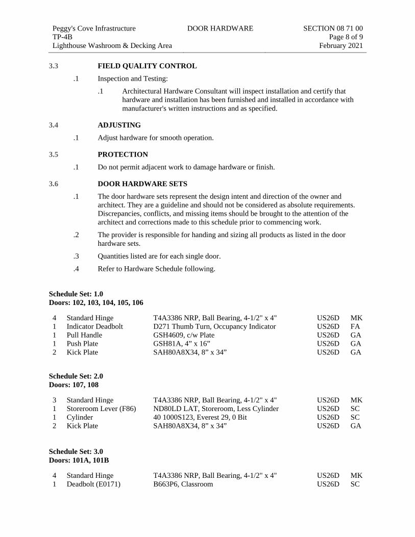
Peggy's Cove Infrastructure TP-4B Lighthouse Washroom & Decking Area
DOOR HARDWARE
SECTION 08 71 00 Page 8 of 9
February 2021 3.3 FIELD QUALITY CONTROL
.1 Inspection and Testing:
.1 Architectural Hardware Consultant will inspect installation and certify that hardware and installation has been furnished and installed in accordance with manufacturer's written instructions and as specified.
3.4 ADJUSTING
.1 Adjust hardware for smooth operation.
3.5 PROTECTION
.1 Do not permit adjacent work to damage hardware or finish.
3.6 DOOR HARDWARE SETS
.1 The door hardware sets represent the design intent and direction of the owner and architect. They are a guideline and should not be considered as absolute requirements. Discrepancies, conflicts, and missing items should be brought to the attention of the architect and corrections made to this schedule prior to commencing work.
.2 The provider is responsible for handing and sizing all products as listed in the door hardware sets.
.3 Quantities listed are for each single door.
.4 Refer to Hardware Schedule following.
Schedule Set: 1.0 Doors: 102, 103, 104, 105, 106
4 Standard Hinge T4A3386 NRP, Ball Bearing, 4-1/2" x 4" US26D MK 1 Indicator Deadbolt D271 Thumb Turn, Occupancy Indicator US26D FA 1 Pull Handle GSH4609, c/w Plate US26D GA 1 Push Plate GSH81A, 4” x 16” US26D GA 2 Kick Plate SAH80A8X34, 8” x 34” US26D GA
Schedule Set: 2.0 Doors: 107, 108
3 Standard Hinge T4A3386 NRP, Ball Bearing, 4-1/2" x 4" US26D MK 1 Storeroom Lever (F86) ND80LD LAT, Storeroom, Less Cylinder US26D SC 1 Cylinder 40 1000S123, Everest 29, 0 Bit US26D SC 2 Kick Plate SAH80A8X34, 8” x 34” US26D GA
Schedule Set: 3.0 Doors: 101A, 101B
4 Standard Hinge T4A3386 NRP, Ball Bearing, 4-1/2" x 4" US26D MK 1 Deadbolt (E0171) B663P6, Classroom US26D SC
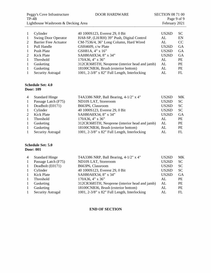
Peggy's Cove Infrastructure TP-4B Lighthouse Washroom & Decking Area
DOOR HARDWARE
SECTION 08 71 00 Page 9 of 9
February 2021 1 Cylinder 40 1000S123, Everest 29, 0 Bit US26D SC 1 Swing Door Operator HA8-SP, (LH/RH) 39” Push, Digital Control AL EN 2 Barrier Free Actuator CM-7536/4, 36" Long Column, Hard Wired AL CC 1 Pull Handle GSH4609, c/w Plate US26D GA 1 Push Plate GSH81A, 4” x 16” US26D GA 2 Kick Plate SAH80A8X34, 8” x 34” US26D GA 1 Threshold 170A36, 4” x 36” AL PE 1 Gasketing 312CR3685TH, Neoprene (interior head and jamb) AL PE 1 Gasketing 18100CNB36, Brush (exterior bottom) AL PE 1 Security Astragal 1001, 2-3/8” x 82” Full Length, Interlocking AL FL
Schedule Set: 4.0 Door: 109
4 Standard Hinge T4A3386 NRP, Ball Bearing, 4-1/2" x 4" US26D MK 1 Passage Latch (F75) ND10S LAT, Storeroom US26D SC 1 Deadbolt (E0171) B663P6, Classroom US26D SC 1 Cylinder 40 1000S123, Everest 29, 0 Bit US26D SC 2 Kick Plate SAH80A8X34, 8” x 34” US26D GA 1 Threshold 170A36, 4” x 36” AL PE 1 Gasketing 312CR3685TH, Neoprene (interior head and jamb) AL PE 1 Gasketing 18100CNB36, Brush (exterior bottom) AL PE 1 Security Astragal 1001, 2-3/8” x 82” Full Length, Interlocking AL FL
Schedule Set: 5.0 Door: 001
4 Standard Hinge T4A3386 NRP, Ball Bearing, 4-1/2" x 4" US26D MK 1 Passage Latch (F75) ND10S LAT, Storeroom US26D SC 1 Deadbolt (E0171) B663P6, Classroom US26D SC 1 Cylinder 40 1000S123, Everest 29, 0 Bit US26D SC 1 Kick Plate SAH80A8X34, 8” x 34” US26D GA 1 Threshold 170A36, 4” x 36” AL PE 1 Gasketing 312CR3685TH, Neoprene (interior head and jamb) AL PE 1 Gasketing 18100CNB36, Brush (exterior bottom) AL PE 1 Security Astragal 1001, 2-3/8” x 82” Full Length, Interlocking AL FL
END OF SECTION
Peggy's Cove Infrastructure TP-4B Lighthouse Washroom & Decking Area
GYPSUM BOARD ASSEMBLIES
SECTION 09 21 16 Page 1 of 5
February 2021
SEC TION 09 21 16 Gypsum board assem blies
Part 1 General
1.1 SECTION INCLUDES
.1 Gypsum board.
.2 Cementitious backer board. For all wall tile locations.
.3 Acoustic insulation.
.4 Metal channel ceiling framing.
1.2 RELATED REQUIREMENTS
.1 Section 06 10 53 - Miscellaneous Rough Carpentry: Building wood framing system; wood blocking for support of Interior Finish.
.2 Section 07 84 00 - Firestopping.
.3 Section 08 31 13 - Access Doors and Frames: Metal access panels and frames.
1.3 REFERENCE STANDARDS
.1 ANSI A118.9 - Specifications for Test Methods and Specifications for Cementitious Backer Units.
.2 ASTM C475/C475M-17 - Standard Specification for Joint Compound and Joint Tape for Finishing Gypsum Board.
.3 ASTM C514-04(2020) - Standard Specification for Nails for the Application of Gypsum Board.
.4 ASTM C557-03(2017) - Standard Specification for Adhesives for Fastening Gypsum Wallboard to Wood Framing.
.5 ASTM C665-17 - Standard Specification for Mineral-Fiber Blanket Thermal Insulation for Light Frame Construction and Manufactured Housing.
.6 ASTM C840-19b - Standard Specification for Application and Finishing of Gypsum Board.
.7 ASTM C1047-19 - Standard Specification for Accessories for Gypsum Wallboard and Gypsum Veneer Base.
.8 ASTM C1325-19 - Standard Specification for Non-Asbestos Fiber-Mat Reinforced Cementitious Backer Units.
.9 ASTM C1396/C1396M-17 - Standard Specification for Gypsum Board.
.10 CAN/ULC-S101-14 - Standard Methods of Fire Endurance Tests of Building Construction and Materials.
.11 CAN/ULC-S102-18 - Standard Method of Test for Surface Burning Characteristics of Building Materials and Assemblies.
.12 CAN/ULC-S702-14 - Standard for Mineral Fibre Thermal Insulation for Buildings.
.13 Gypsum Association GA-214-2017 - Recommended Levels of Gypsum Board Finish.
Peggy's Cove Infrastructure TP-4B Lighthouse Washroom & Decking Area
GYPSUM BOARD ASSEMBLIES
SECTION 09 21 16 Page 2 of 5
February 2021
.14 Gypsum Association GA-216-2016 - Application and Finishing of Gypsum Panel Products.
.15 Gypsum Association GA-600-2015 - Gypsum Fire Resistance Design Manual.
.16 Gypsum Association GA-801-2017 - Handling and Storage of Gypsum Panel Products.
.17 UL - Fire Resistance Directory.
.18 ULC-FR-17 - Fire Resistance Directory (2017 Edition).
1.4 ACTION SUBMITTALS
.1 Appendix D - RFQ Particulars
.2 Section 01 33 00: Submission procedures.
.3 Product Data:
.1 Provide data on : gypsum board, cementitious backer board, joint tape, trims, accessories.
1.5 INFORMATIONAL SUBMITTALS
.1 Appendix D - RFQ Particulars
.2 Section 01 33 00: Submission procedures.
.3 Installation Data: Manufacturer's special installation requirements.
1.6 CLOSEOUT SUBMITTALS
.1 Appendix D - RFQ Particulars.
1.7 QUALITY ASSURANCE
.1 Perform Work in accordance with GA-216. Maintain one (1) copy of document on site.
.2 Installer Qualifications: Company specializing in performing the work of this section with minimum three (3) three (3) years documented experience and approved by the manufacturer.
.3 Handling Gypsum Board: Comply with GA-801.
Part 2 Products
2.1 MANUFACTURERS
.1 CGC
.2 CertainTeed
.3 Cabot Gypsum Company
2.2 GYPSUM BOARD MATERIALS
.1 Flexible Gypsum Board: ASTM C1396/C1396M, paper-faced, regular core, 6 mm thick, 1220 mm wide, maximum available length in place; ends square cut, tapered edges.
Peggy's Cove Infrastructure TP-4B Lighthouse Washroom & Decking Area
GYPSUM BOARD ASSEMBLIES
SECTION 09 21 16 Page 3 of 5
February 2021
.2 Moisture Resistant Gypsum Board: ASTM C1396/C1396M, paper-faced, maximum available length in place; tapered edges, ends square cut.
.1 Regular core, 16 mm thick.
.2 Fire rated core, 16 mm thick.
.3 Cementitious Backer Board: ASTM C1325, high density, fibre reinforced cementitious board, 16 mm thick; maximum available size in place; smoothed edges, ends square cut.
.1 Product: Durock Brand Cement Board, manufactured by CGC.
.2 Product: DiamondBack Tile Backer, manufactured by CertainTeed.
2.3 ACCESSORIES
.1 Acoustic Insulation: CAN/ULC-S702; preformed mineral wool fibre, friction fit type, unfaced, thickness as noted.
.1 Product: Rockwool AFB, manufactured by Rockwool.
.2 Product: Thermafibre SAFB, manufactured by Owens Corning.
.2 Acoustic Sealant: Non-hardening, non-skinning, for use in conjunction with gypsum board.
.1 Product: Acoustical sealant, manufactured by Tremco.
.3 Corner Beads: GA-216 ASTM C1047, metal corner bead.
.4 Edge Trim: GA-216, ASTM C1047; Type L bead, Control joint.
.5 Joint Materials: GA-216, ASTM C475/C475M.
.1 Reinforcing tape, adhesive, and water.
.2 Joint compound: Asbestos-free dust-controlled.
.6 Gypsum Board Fasteners: ASTM C1002, TypeS or Type W to suit substrate.
.7 Cementitious Board Fasteners: Board manufacturer's purpose made screws, corrosion resistant steel, self-drilling points, counter-sink heads to prevent strip-out, for wood substrate.
Part 3 Execution
3.1 EXAMINATION
.1 Verify that site conditions are ready to receive work and opening dimensions are as indicated on drawings.
3.2 WALL FURRING INSTALLATION
.1 Erect furring channels horizontally; space maximum 400 mm on centre, not more than 100 mm from floor and ceiling lines, & abutting walls. Secure in place on alternate channel flanges at maximum 600 mm on centre.
.2 Install thermal insulation directly attached to wood framed or metal furred walls to manufacturer's written instructions.
Peggy's Cove Infrastructure TP-4B Lighthouse Washroom & Decking Area
GYPSUM BOARD ASSEMBLIES
SECTION 09 21 16 Page 4 of 5
February 2021 3.3 FURRING FOR FIRE RATINGS
.1 Install furring as required for fire resistance ratings indicated and to GA-600 requirements.
3.4 CEILING FRAMING INSTALLATION
.1 Install to GA-216, ASTM C754.
.2 Install metal suspension system requiring seismic restraint to meet requirements of local code.
.3 Coordinate location of hangers with other work.
.4 Install ceiling framing independent of walls, columns, and above ceiling work.
.5 Reinforce openings in ceiling suspension system which interrupt main carrying channels or furring channels, with lateral channel bracing. Extend bracing minimum 600 mm past each end of openings.
.6 Laterally brace entire suspension system.
3.5 ACOUSTIC ACCESSORIES INSTALLATION
.1 Install resilient channels at maximum 600 mm on centre. Locate joints over framing members Locate joints over framing members.
.2 Place acoustic insulation in partitions tight within spaces, around cut openings, behind and around electrical and mechanical items within or behind partitions, and tight to items passing through partitions.
.3 Install acoustic sealant within partitions in accordance with manufacturer's written instructions.
.4 Install acoustic sealant at gypsum board perimeter at:
.1 Metal Framing: One (1) beads.
.2 Base Layer.
.3 Face Layer.
.4 Caulk all penetrations of partitions by conduit, pipe, duct work, rough-in boxes, and miscellaneous projections.
3.6 GYPSUM BOARD INSTALLATION
.1 Install gypsum board to GA-216, ASTM C840.
.2 Erect single layer gypsum board horizontal, with ends and edges occurring over firm bearing.
.3 Erect single layer fire rated gypsum board vertically, with edges and ends occurring over firm bearing.
.4 Use screws when fastening gypsum board to metal furring or framing.
.5 Use screws when fastening gypsum board to wood furring or framing. Staples may only be used when securing the first layer of double layer applications.
Peggy's Cove Infrastructure TP-4B Lighthouse Washroom & Decking Area
GYPSUM BOARD ASSEMBLIES
SECTION 09 21 16 Page 5 of 5
February 2021
.6 Double Layer Applications: Use gypsum backing board for first layer, placed perpendicular to framing or furring members. Use fire rated gypsum backing board for fire rated partitions and ceilings.
.7 Double Layer Applications: Secure second layer to first with fasteners. Apply adhesive to manufacturer's written instructions.
.8 Offset joints of second layer from joints of first layer.
.9 Treat cut edges and holes in moisture resistant gypsum board with sealant.
.10 Place control joints consistent with lines of building spaces at no more than 6000mm o/c.
.11 Place corner beads at external corners as indicated. Use longest practical length. Place edge trim where gypsum board abuts dissimilar materials as indicated.
.12 Install backing board over framing to manufacturer's written instructions.
.13 Apply gypsum board to curved walls in accordance with GA-216.
.14 Use cementitious backer board at all wall tile areas indicated on drawings. Install to manufacturers instructions.
3.7 JOINT TREATMENT
.1 Finish to GA-214, Level 5.
.2 Tape, fill, and sand exposed joints, edges, and corners to produce smooth surface ready to receive finishes.
.3 Feather coats on to adjoining surfaces so that camber is maximum 0.8 mm.
.4 Fill and finish joints and corners of cementitious backing board.
3.8 TOLERANCES
.1 Maximum Variation of Finished Gypsum Board Surface from True Flatness: 3 mm in 3 m in any direction.
END OF SECTION
Peggy's Cove Infrastructure TP-4B Lighthouse Washroom & Decking Area
TILING SECTION 09 30 00 Page 1 of 7
February 2021
SEC TION 09 30 00 Til ing
Part 1 General
1.1 SECTION INCLUDES
.1 Ceramic tiling.
.2 Uncoupling membrane.
.3 Tile accessories.
.4 Mortar and Grout.
.5 Floor levelling.
1.2 RELATED REQUIREMENTS
.1 Section 07 92 00 - Joint Sealants: Mildew resistant sealant.
.2 Section 09 21 16 - Gypsum Board Assemblies: Gypsum board wall substrate.
1.3 REFERENCE STANDARDS
.1 ANSI A108/A118/A136-2017 - North American Standard Specifications for the Installation of Ceramic Tile.
.2 ANSI A137.1-2019 - Standard Specifications for Ceramic Tile.
.3 DIN 51130 - 2014 - Testing of Floorcoverings, Determination of Slip Properties, Ramp Method.
.4 ISO 10545 Series - Ceramic Tiles, Standards for Testing.
.5 ISO 13006-2018 - Ceramic Tiles, Definitions, Classifications, Characteristics and Marking.
.6 TCNA Handbook for Ceramic, Glass, and Stone Tile Installation (2019).
.7 TTMAC - Specification Guide 09 30 00, Tile Installation Manual 2019-2021.
1.4 ADMINISTRATIVE REQUIREMENTS
.1 Coordination:
.1 Coordinate with other work having a direct bearing on work of this section.
.2 Coordinate requirements for floor recesses, accounting for mortar bed, bond coat and tile thickness where finished tile surfaces are installed flush with adjacent floor finishes.
1.5 ACTION SUBMITTALS
.1 Appendix D - RFQ Particulars
.2 Section 01 33 00: Submission procedures.
.3 Product Data: Submit manufacturer's product data for each type of product specified.
Peggy's Cove Infrastructure TP-4B Lighthouse Washroom & Decking Area
TILING SECTION 09 30 00 Page 2 of 7
February 2021
.4 Samples for Verification: Submit the following samples for final verification, including full range of colour and texture variations expected.
.1 Tiles: Submit two (2) pieces of each tile selected.
.2 Trims: Submit full size units of each type of trim and accessory in each colour required for installation; minimum 75 mm lengths.
1.6 INFORMATIONAL SUBMITTALS
.1 Appendix D - RFQ Particulars
.2 Section 01 33 00: Submission procedures.
.3 Manufacturer's Certificate: Certify that Products meet or exceed the requirements of ANSI A137.1.
.4 Installation Data:
.1 Manufacturer's recommended and special installation requirements.
.2 Written instructions for using adhesives and grouts.
1.7 CLOSEOUT SUBMITTALS
.1 Appendix D - RFQ Particulars
.2 Operation and Maintenance Data: Submit one (1) copies of TTMAC Maintenance Guide and additional information as follows.
.1 Manufacturer’s maintenance data sheets for floor sealers and other non-tile maintenance materials and accessories.
.2 Warning of maintenance practices or materials that may damage or disfigure finished Work.
1.8 MAINTENANCE MATERIAL SUBMITTALS
.1 Extra Stock Materials: Provide 2% of each size, colour, and surface finish of tile specified.
.1 Store in original containers, clearly marked to identify the following:
.1 Manufacturer, supplier and distributor’s name.
.2 Material series name and stocking number.
.3 Material description, including colour and pattern.
1.9 QUALITY ASSURANCE
.1 Conform to TTMAC Tile Installation Manual, ANSI A108/A118/A136.
.2 Maintain one (1) copy of document on site.
.3 Manufacturer Qualifications: Company specializing in manufacturing the Products specified in this section with minimum three (3) years documented experience.
.4 Installer Qualifications: Company specializing in performing the work of this section with minimum three (3) years documented experience and having completed tile
Peggy's Cove Infrastructure TP-4B Lighthouse Washroom & Decking Area
TILING SECTION 09 30 00 Page 3 of 7
February 2021
installations similar in material, design and extent to this Project and be a member in good standing with TTMAC at time of bidding.
1.10 DELIVERY, STORAGE, AND HANDLING
.1 Deliver and store packaged materials in original containers with seals unbroken and labels intact.
.2 Store materials to prevent damage or contamination to materials by water, freezing, foreign matter, and other causes; store cementitious materials in a dry area, and raised off floor and ground surfaces.
1.11 SITE CONDITIONS
.1 Ambient Conditions:
.1 Apply tile after completion of Work by other sections, to dry, clean, firm, level and plumb surfaces, free from oil or wax or any other material detrimental to tile adhesion.
.2 Maintain tile materials and substrate temperature between TTMAC & manufacturer's recommended minimum and maximum temperature range.
.3 Maintain temperature range for minimum forty-eight (48) hours before and during installation and until materials are fully set and cured to manufacturer’s recommendations.
.4 Maintain adequate ventilation where Work generates toxic gases or where there is a risk of raising relative humidity to levels detrimental to building finishes and assemblies.
Part 2 Products
2.1 MANUFACTURERS
.1 Ceramic Tile - Floors:
.1 Ceragres; Product: Built Collection 600mmx600mm (23.625in x 23.625in), Colour: Path
.2 Olympia Tile; Product: Uptown Series 600mmx600mm (23.625in x 23.625in), Colour: Sugar Hill (White)
.2 Ceramic Tile - Walls
.1 Centura; Product: Urban Max 100mmx300mm (4inx12in), Colour: White - Glossy
.2 Elegant Flooring; Product: Arquitectura Series. 100mmx300mm (4inx12in), Colour: Blanco - Glossy
.3 Olympia Tile; Product: Colour and Dimension Collection. 100mmx300mm (4inx12in), Colour: Arctic White - Bright
Peggy's Cove Infrastructure TP-4B Lighthouse Washroom & Decking Area
TILING SECTION 09 30 00 Page 4 of 7
February 2021 2.2 DESCRIPTION
.1 System Description:
.1 Ceramic tile, installed on floors, walls, including base and using thinset application method.
2.3 TRIMS AND EDGING
.1 Trims: Shapes and profiles to match colour and finish of adjoining field tile; coordinate with size and coursing of adjoining flat tile where applicable.
.1 Floor Trim @ Wall Base: Schluter Dilex-KSA, aluminum. Height to suit tile, with integral anchoring leg.
.2 Edge Trims & Top of Wall Base: Schluter Jolly, aluminum. At all outside corners, exposed top edges, and at perimeter of doors and windows. Height to suit tile installation, with integral anchoring leg.
.3 Transition Trim: Schluter Reno-U, aluminum. At transitions between floor materials Height to suit tile installation, with integral anchoring leg.
.4 Movement Profile: Schluter Dilex BWS, PVC. At joints between substrate materials and spaced over field to TTMAC standards. Height to suit tile installation, with integral anchoring leg.
2.4 MORTAR AND GROUT MATERIALS
.1 Self-Levelling Underlayment: Latex-modified, portland cement-based, as recommended by tile-setting manufacturer.
.1 Product: Novoplan Easy Plus, manufacturer by Maipei
.2 Product: NXT Skim, manufacturer by Laticrete
.3 Product: Level Set 500HF, manufacturer by Tec
.2 Wall Tile Mortar: ANSI A108/A118/A136.
.1 Latex-Portland Cement (exterior thin set): Fast-setting, non-sagging frost-resistant mortar with bond enhancing latex/polymer additives.
.1 Product: Ultraflex 1, manufactured by Maipei.
.2 Product: 254 Platinum, manufactured by Latticrete.
.3 Product: Super Flex™ Ultra-Premium manufactured by Tec.
.3 Floor Tile Mortar: ANSI A108/A118/A136.
.1 Latex-Portland Cement (interior thin set): Fast-setting mortar with bond enhancing latex/polymer additives, rated for floor traffic load bearing performance as indicated.
.1 Product: Ultraflex 1, manufactured by Maipei.
.2 Product: 254 Platinum, manufactured by Laticrete.
.3 Product: Super Flex™ Ultra-Premium manufactured by Tec..
.4 Tile Grout: ANSI A108/A118/A136.
Peggy's Cove Infrastructure TP-4B Lighthouse Washroom & Decking Area
TILING SECTION 09 30 00 Page 5 of 7
February 2021
.1 Epoxy Grout: Water cleanable, chemical resistant, factory blended modified portland cement compound with epoxy additives and hardeners.
.1 Colour: As selected from manufacturer’s range .
.2 Product: Kerapoxy, manufactured by Maipei.
.3 Product: Spectralock Pro, manufactured by Latticrete.
.4 Product: AccuColour EFX Epoxy Special Effects Grout, manufactured by Tec..
2.5 ACCESSORIES
.1 Uncoupling Membrane: ANSI A108/A118/A136, corrugated polyethylene membrane with anchoring webbing system, thickness as recommended by manufacturer to accommodate in-plane substrate movement.
.1 Product: Ditra, manufactured by Schluter.
.2 Joint Sealant: As specified in Section 07 92 00.
.3 Sealer: Meeting or exceeding requirements of CAN/CGSB 25.20, Type 1 or 2, as recommended by tile manufacturer.
2.6 CEMENTITIOUS MIXES
.1 Premanufactured Mortars and Grouts: Mix to manufacturers' written instructions.
.2 Site Mixed Mortar and Grout: Site mix proportioned mortar and grout materials to ANSI A108/A118/A136.
Part 3 Execution
3.1 EXAMINATION
.1 Verify existing conditions before starting work.
.2 Examine surfaces and verify that surfaces are ready to receive tile installation.
.1 Concrete substrates have cured minimum of ninety (90) days to TTMAC requirements.
.2 Substrates are dry; clean; free from oil, waxy films, and curing compounds; and within starting flatness tolerances as specified in TTMAC, and are ready for application of levelling materials.
.3 Grounds, anchors, recessed frames, electrical and mechanical units of Work in or behind tile have been installed.
.4 Joints and cracks in tile substrates are coordinated with tile joint locations.
.3 Verify tile subject to colour variations has been factory blended and packaged. If not factory blended, blend tiles at site before installing.
3.2 PREPARATION
.1 Protect surrounding work from damage or disfiguration.
Peggy's Cove Infrastructure TP-4B Lighthouse Washroom & Decking Area
TILING SECTION 09 30 00 Page 6 of 7
February 2021
.2 Vacuum clean surfaces and damp clean.
.3 Seal substrate surface cracks with filler. Level existing substrate surfaces to flatness tolerances specified.
.4 Confirm backing board is ready to accept tile.
3.3 INSTALLATION
.1 Install tile to TTMAC Tile Installation Manual and manufacturer's written instructions.
.2 Lay tile to pattern indicated. Do not interrupt tile pattern through openings.
.3 Extend tile work into recesses and under or behind equipment and fixtures to form a complete covering without interruptions:
.4 Cut and fit tile tight to penetrations through tile. Form corners neatly. Align base and wall joints with floor joints.
.5 Place tile joints uniform in width, subject to variance in tolerance allowed in tile size. Make joints watertight, without voids, cracks, excess mortar or grout.
.6 Adjust tile layout to minimize tile cutting. Maintain minimum tile width of one-third unit size unless indicated otherwise on Drawings.
.7 Form internal angles square and external angles square.
.8 Sound tile after setting. Replace hollow sounding units.
.9 Keep expansion joints joints free of adhesive or grout. Apply sealant to joints.
.10 Allow tile to set for a minimum of forty-eight (48) hours prior to grouting.
.11 Install grout to TTMAC Tile Installation Manual and manufacturer’s written instructions.
.12 Apply sealant to junction of tile and dissimilar materials and planes.
.13 Install prefabricated edge strips and movement joints at locations indicated or where exposed edge of floor tile meets different flooring materials and exposed substrates.
.14 Protect exposed edges of floor tile with properly sized transition strips; at uneven transitions between 6 mm and 13 mm, use sloped reducer strips.
3.4 INSTALLATION - ACCESSORIES
.1 Membranes:
.1 Install membrane to ANSI A108/A118/A136 and manufacturer's written instructions; lap and seal watertight edges and ends.
.2 Movement Joints: Install expansion or control joint trims where indicated on Drawings, at junctions between floor substrates, and to TTMAC Detail 301MJ-2012/2013; keep control and expansion joints free of setting and grouting materials.
3.5 FIELD QUALITY CONTROL
.1 Inspection and Testing:
.1 Provide inspection of the following:
Peggy's Cove Infrastructure TP-4B Lighthouse Washroom & Decking Area
TILING SECTION 09 30 00 Page 7 of 7
February 2021
.1 Tiles are set flush and level with adjacent tiles, meeting lippage requirements.
.2 Identify broken, cracked, damaged or hollow sounding tiles.
.3 Accessories are correctly installed.
.4 Grouting and sealant are correctly installed.
.5 Installation is complete to TTMAC.
3.6 CLEANING
.1 Clean tile and grout surfaces with manufacturer's recommended cleaning methods.
3.7 PROTECTION
.1 Protect finished areas from traffic until setting materials have sufficiently cured to TTMAC requirements.
.2 Protect finished floor areas from foot and wheel traffic from floors for a minimum of twenty-four (24) hours after completion of grouting.
END OF SECTION
Peggy’s Cove Infrastructure RESILIENT FLOORING SECTION 09 65 16 TP-4B Page 1 Lighthouse Washroom & Decking Area February 2021
Part 1 General
1.1 SECTION INCLUDES
.1 Resilient vinyl sheet flooring.
.2 Resilient rubber base.
.3 Resilient stair treads, risers and skirting.
1.2 RELATED SECTIONS
.1 Appendix D – RFQ Particulars
.2 Section 01 33 00 – Submittal Procedures
.3 Section 09 21 16 - Gypsum Board Assemblies: Wall materials to receive application of base.
.4 Section 06 10 53 – Miscellaneous Rough Carpentry
1.3 REFERENCES
.1 ASTM E84-09c - Test Method for Surface Burning Characteristics of Building Materials.
.2 ASTM F1861-08 - Resilient Wall Base.
.3 ASTM F1913-04(2010) - Vinyl Sheet Floor Covering Without Backing.
.4 ASTM F2169-02(2008) - Resilient Stair Treads.
.5 CAN/ULC-S102.2-07 - Surface Burning Characteristics of Flooring, Floor Covering and Miscellaneous Materials and Assemblies.
1.4 SUBMITTALS FOR REVIEW
.1 Appendix D – RFQ Particulars
.2 Section 01 33 00: Submission procedures.
.3 Product Data: Provide data on specified products, describing physical and performance characteristics; sizes, patterns and colours available.
.4 Shop Drawings: Indicate seaming plan.
.5 Samples:
.1 Submit two (2) samples, illustrating colour and pattern for each floor material for each colour specified.
.2 Submit two (2) 100 mm long samples of base and stair material for each colour specified.
Peggy’s Cove Infrastructure RESILIENT FLOORING SECTION 09 65 16 TP-4B Page 2 Lighthouse Washroom & Decking Area February 2021 1.5 CLOSEOUT SUBMITTALS
.1 Operation and Maintenance Data: Include maintenance procedures, recommended maintenance materials, and suggested schedule for cleaning, stripping, and re-waxing.
1.6 MAINTENANCE MATERIAL SUBMITTALS
.1 Extra Stock Materials: Provide 6 sq m of flooring, 4 lin mof base, and stair materials of each material specified.
1.7 QUALITY ASSURANCE
.1 Manufacturer Qualifications: Company specializing in manufacturing the Products specified in this section with minimum three (3) years documented experience.
.2 Installer Qualifications: Company specializing in performing the work of this section with minimum three (3) years documented experience and approved by the manufacturer.
1.8 REGULATORY REQUIREMENTS
.1 Conform to applicable code for flame/smoke rating requirements to CAN/ULC-S102.2.
1.9 DELIVERY, STORAGE, AND PROTECTION
.1 Appendix D – RFQ Particulars
.2 Protect roll materials from damage by storing per the manufacturers requirements.
1.10 ENVIRONMENTAL REQUIREMENTS
.1 Store materials for three days prior to installation in area of installation to achieve temperature stability.
.2 Maintain ambient temperature required by adhesive manufacturer three (3) days prior to, during, and twenty-four (24) hours after installation of materials.
Part 2 Products
2.1 MATERIALS - SHEET FLOORING
.1 Tarkett; Product: Standard Plus Homogeneous Sheet Vinyl Flooring.
.2 Other acceptable manufacturers offering functionally equivalent products.
.1 Armstrong; Product: Accolade Plus Homogeneous Sheet Vinyl Flooring.
.3 Substitutions: Refer to Appendix D – RFQ Particulars
.4 Vinyl Sheet without Backing: ASTM F1913:
.1 Colour and pattern through total thickness.
.2 Total Thickness: 2.0 mm
.3 Sheet Width: 1.83m to 2.0m
Peggy’s Cove Infrastructure RESILIENT FLOORING SECTION 09 65 16 TP-4B Page 3 Lighthouse Washroom & Decking Area February 2021 2.2 MATERIALS - STAIR COVERING
.1 Tarkett; Product: Angle Fit Rubber Stair Tread with Integrated Riser.
.2 Other acceptable manufacturers offering functionally equivalent products.
.1 Armstrong; Product: Integrated Stair Treads
.3 Substitutions: Refer to Appendix D – RFQ Particulars
.4 Stair Treads with Integrated Riser and Nosing: ASTM F2169.
.1 Full width and depth of stair tread in one piece; return down edge of tread
.2 Material: Rubber.
.3 Thickness: 3mm
.4 Pattern: Hammered
.5 Design: Serrated nosing
.5 Stair Skirting:
.1 Width: Maintain width sufficient to provide 100mm above stair nose, measured perpendicular to stair slope.
.2 Sheet Material: Rubber.
.3 Thickness: 3mm
.4 Pattern: Smooth
2.3 MATERIALS - BASE
.1 Manufacturers:
.1 Tarkett; Product: Baseworks Thermoset Rubber .
.2 Armstrong; Product: Coved Wall Base.
.3 Substitutions: Refer to Appendix D – RFQ Particulars
.2 Base: ASTM F1861, Thermoplastic rubber, top set coved; premoulded external corners:
.1 Height: 100 mm
.2 Thickness: 3 mm thick.
.3 Length: Roll.
.3 Base Accessories: Premoulded end stops and external corners, of same material, size, and colour as base.
2.4 ACCESSORIES
.1 Subfloor Filler: Type recommended by adhesive material manufacturer.
.2 Primers and Adhesives: Waterproof; types recommended by flooring manufacturer.
.3 Edge Strips: Flooring material
.4 Cant Strip: Plastic
.5 Sealer and Wax: Types recommended by flooring manufacturer.
Peggy’s Cove Infrastructure RESILIENT FLOORING SECTION 09 65 16 TP-4B Page 4 Lighthouse Washroom & Decking Area February 2021 Part 3 Execution
3.1 EXAMINATION
.1 Verify concrete floors are dry to a maximum moisture content of 7%, and exhibit negative alkalinity, carbonization, or dusting.
.2 Verify floor and lower wall surfaces are free of substances that may impair adhesion of new adhesive and finish materials.
3.2 PREPARATION
.1 Remove sub-floor ridges and bumps. Fill minor or local low spots, cracks, joints, holes, and other defects with sub-floor filler to achieve smooth, flat, hard surface.
.2 Prohibit traffic until filler is cured.
.3 Vacuum clean substrate.
.4 Apply primer to surfaces.
3.3 INSTALLATION - SHEET FLOORING
.1 Install sheet flooring to manufacturer's written instructions.
.2 Spread only enough adhesive to permit installation of materials before initial set.
.3 Set flooring in place, press with heavy roller to attain full adhesion.
.4 Lay flooring with joints and seams to produce minimum number of seams.
.5 Install sheet flooring parallel to width of room. Provide minimum of one third (1/3) full roll width. Double cut sheet; provide continuously heat welded seal.
.6 Terminate flooring at centreline of door openings where adjacent floor finish is dissimilar.
.7 Install edge strips at unprotected or exposed edges, and where flooring terminates. Secure resilient strips by adhesive.
.8 Scribe flooring to walls, columns, cabinets, floor outlets, and other appurtenances to produce tight joints.
.9 Install flooring in pan type floor access covers. Maintain floor pattern.
3.4 INSTALLATION - BASE
.1 Fit joints tight and vertical. Maintain minimum measurement of 450 mm joints.
.2 Mitre internal corners. At external corners, use premoulded units. At exposed ends, use premoulded units.
.3 Install base on solid backing. Bond tight to wall and floor surfaces.
Peggy’s Cove Infrastructure RESILIENT FLOORING SECTION 09 65 16 TP-4B Page 5 Lighthouse Washroom & Decking Area February 2021
.4 Scribe and fit to door frames and other interruptions.
3.5 INSTALLATION - STAIR COVERINGS
.1 Install stair nosing, stair treads, stair risers in one (1) piece for full width and depth of tread.
.2 Install stair skirting configured tight to stair and stringer profile.
.3 Adhere over entire surface. Fit accurately and securely.
3.6 CLEANING
.1 Remove access adhesive from floor, base, and wall surfaces without damage.
.2 Clean, seal, and wax floor and base surfaces in accordance with manufacturer's written instructions.
3.7 PROTECTION OF FINISHED WORK
.1 Prohibit traffic on floor finish for forty-eight (48) hours after installation.
3.8 SCHEDULES
.1 Storage Room, Electrical Room, Safety Room: Vinyl Sheet Flooring, Rubber Base.
.2 Stairwell and landing to Basement: Vinyl Sheet flooring at landing, Integrated Rubber Tread/Riser/Nosing and skirting.
END OF SECTION
Peggy's Cove Infrastructure TP-4B Lighthouse Washroom & Decking Area
PAINTING SECTION 09 91 00 Page 1 of 10
February 2021
SEC TION 09 91 00 Painting
Part 1 General
1.1 SECTION INCLUDES
.1 Surface preparation.
.2 Painting.
1.2 RELATED REQUIREMENTS
.1 Section 05 50 00 - Metal Fabrications: Shop primed items.
.2 Section 09 21 16 - Gypsum Board Assemblies
1.3 REFERENCE STANDARDS
.1 MPI (Master Painters Institute) – Architectural Painting Specifications Manual and Maintenance Repainting Manual.
1.4 ACTION SUBMITTALS
.1 Appendix D - RFQ Particulars
.2 Section 01 33 00: Submission procedures.
.3 Product Data:
.1 Submit Product data on all specified finishing products.
.2 Submit two (2) copies of WHMIS MSDS - Material Safety Data Sheets.
1.5 INFORMATIONAL SUBMITTALS
.1 Appendix D - RFQ Particulars
.2 Section 01 33 00: Submission procedures.
.3 Installation Data: Manufacturer's special installation requirements including special surface preparation procedures and substrate conditions requiring special attention.
.4 Schedule:
.1 If requested, submit Work schedule for various stages of Work when painting occupied areas for Consultant’s review and Owner’s approval.
.2 Submit schedule minimum of forty-eight (48) hours in advance of proposed operations.
.3 Obtain written authorization from Consultant for changes in Work schedule.
1.6 CLOSEOUT SUBMITTALS
.1 Appendix D - RFQ Particulars
.2 Record Documentation: Upon completion, provide itemized list of products used including the following:
.1 Manufacturer's name.
Peggy's Cove Infrastructure TP-4B Lighthouse Washroom & Decking Area
PAINTING SECTION 09 91 00 Page 2 of 10
February 2021
.2 Product name, type and use.
.3 Colour coding number.
.4 Manufacturer's Material Safety Data Sheets (MSDS).
1.7 MAINTENANCE MATERIAL SUBMITTALS
.1 Extra Stock Materials: Provide properly packaged maintenance material as follows.
.1 1 gal of each coating type and colour to Owner.
.2 Label each container with colour, type, texture and room locations in addition to manufacturer's label.
1.8 QUALITY ASSURANCE
.1 Manufacturer Qualifications: Company specializing in manufacturing the Products specified in this section with minimum five (5) years documented experience.
.2 Installer Qualifications: Qualified journeypersons or apprentices, provided they work under direct supervision of qualified journeyperson in accordance with trade regulations.
.3 Conform to MPI Painting Manual requirements for materials, preparation and workmanship.
.4 Paint Products: Paint manufacturers and paint Products listed under the Approved Product List section of the MPI Painting Manual.
1.9 DELIVERY, STORAGE, AND HANDLING
.1 Deliver products to site in sealed and labeled containers showing manufacturer's name, type of paint, brand name, lot number, brand code, coverage, surface preparation, drying time, cleanup requirements, colour designation, and written instructions for mixing and reducing.
.2 Store paint materials at minimum ambient temperature of 7 degrees C and a maximum of 32 degrees C, in dry, ventilated area and as required by manufacturer's written instructions.
1.10 SITE CONDITIONS
.1 Ambient Conditions:
.1 Do not perform painting or decorating Work when ambient air and substrate temperatures are below 10 degrees C for both interior and exterior work, or as required by paint product manufacturer.
.2 Do not perform painting or decorating Work when relative humidity is above 85% or when dew point is less than 3 degrees C variance between the air/surface temperature required by paint Product manufacturer.
.3 Provide suitable weatherproof covering and sufficient heating facilities to maintain minimum ambient air and substrate temperatures for twenty-four (24) hours before, during and after paint application.
.4 Do not perform painting and decorating Work when maximum moisture content of substrate exceeds:
Peggy's Cove Infrastructure TP-4B Lighthouse Washroom & Decking Area
PAINTING SECTION 09 91 00 Page 3 of 10
February 2021
.1 Wood: 15%.
.2 Plaster and Gypsum Wallboard: 12 %.
.3 Masonry, Concrete, and Concrete Unit Masonry: 12%.
.4 Concrete Floors: 8%.
.5 Conduct moisture tests using a properly calibrated electronic Moisture Meter, except test concrete floors for moisture using a simple cover patch test.
.6 Test concrete, masonry and plaster surfaces for alkalinity as required.
.7 Provide minimum lighting level of 323 lux is provided on surfaces to be painted or decorated.
1.11 WASTE MANAGEMENT AND DISPOSAL
.1 Dispose of waste materials in accordance with Local authorities having jurisdiction.
.2 Where paint recycling is available, collect waste paint by type and provide for delivery to recycling or collection facility.
.3 Place non-reusable materials defined as hazardous or toxic waste, including used sealant and adhesive tubes and containers, in containers or areas designated for hazardous waste.
.4 To reduce contaminants entering waterways, sanitary/storm drain systems or into the ground, adhere to the following procedures:
.1 Retain cleaning water for water-based materials to allow sediments to be filtered out. In no case shall equipment be cleaned using free draining water.
.2 Retain cleaners, thinners, solvents and excess paint and place in designated containers and ensure proper disposal.
.3 Return solvent and oil soaked rags used during painting operations for contaminant recovery, proper disposal, or appropriate cleaning and laundering.
.4 Dispose of contaminants in an approved legal manner in accordance with hazardous waste regulations.
.5 Dry out empty paint cans prior to disposal or recycling.
.6 Close and seal tightly partly used cans of materials including sealant and adhesive containers and store protected in well ventilated fire-safe area at moderate temperature.
.5 Set aside and protect surplus and uncontaminated finish materials and deliver or arrange collection for verifiable re-use or re-manufacturing.
1.12 WARRANTY
.1 Provide local 100% two (2) year Maintenance Bond warranting that Work has been performed in accordance with MPI Painting Manual.
Peggy's Cove Infrastructure TP-4B Lighthouse Washroom & Decking Area
PAINTING SECTION 09 91 00 Page 4 of 10
February 2021 Part 2 Products
2.1 DESCRIPTION
.1 Regulatory Requirements:
.1 Conform to applicable code for flame and smoke rating requirements for finishes, storage, mixing, application and disposal of paint and related waste materials.
2.2 MATERIALS
.1 Use only materials (primers, paints, coatings, varnishes, stains, lacquers, fillers) listed in the latest edition of the MPI Approved Product List (APL) on this project.
.2 Ancillary materials such as linseed oil, shellac, thinners, solvents to be of highest quality product and provided by an MPI listed manufacturer, and compatible with paint materials being used.
.3 Where required, use only materials having a minimum MPI "Environmentally Friendly" E2 rating based on VOC (EPA Method 24) content levels.
.4 Where indoor air quality (odour) is an issue, use only MPI listed materials having a minimum E2 rating.
.5 Where possible, all materials to be lead and mercury free with low VOC content.
.6 Provide all material for each system from a single manufacturer.
.7 Fire Hazard: Flame spread and smoke developed ratings in accordance with local authorities having jurisdiction.
.8 Patching Materials: Latex filler.
.9 Fastener Head Cover Materials: Latex filler.
2.3 MIXING AND TINTING
.1 Coatings: Ready-mixed and pre-tinted; re-mix all paint in containers prior to and during application to ensure break-up of lumps, complete dispersion of settled pigment, and colour and gloss uniformity.
.2 Paste, Powder or Catalyzed Paint: Mixed in accordance with manufacturer's written instructions.
.3 Accessory Materials: Linseed oil, shellac, turpentine, paint thinners and other materials not specifically indicated but required to achieve the finishes specified, of commercial quality.
.1 Do not exceed paint manufacturer's recommendations for addition of thinner. Do not use kerosene or any such organic solvents to thin water-based paints.
.2 Thin paint for spraying in accordance with paint manufacturer's instructions.
2.4 FINISH AND COLOUR
.1 Finish: To MPI Premium Grade finish requirements.
.2 Colours and Finishes: Refer to Finish Schedule to be provided after award of Contract.
Peggy's Cove Infrastructure TP-4B Lighthouse Washroom & Decking Area
PAINTING SECTION 09 91 00 Page 5 of 10
February 2021
.1 Exterior Colours: Based on two (2) base colours and one (1) accent colours with a maximum of one (1) deep or bright colour. No more than four (4) colours will be selected for entire project.
.2 Interior Colours: Based on two (2)) base colours and one (1) accent colours with a maximum of one (1) deep or bright colour. No more than four (2) colours will be selected for entire project and no more than two (2) colours will be selected in each area.
2.5 GLOSS/SHEEN RATINGS
.1 Paint gloss is defined as the sheen rating of applied paint with the following values:
.2
Gloss Level Description Gloss @ 60 degrees Sheen @ 85 degrees
G1 Matte Finish (flat) 0 to 5 10 max.
G2 Velvet-Like Finish 0 to 10 10 to 35
G3 Eggshell Finish 10 to 25 10 to 35
G4 Satin-Like Finish 20 to 35 35 min.
G5 Traditional Semi-Gloss Finish 35 to 70 ………
G6 Traditional Gloss 70 to 85 ………
G7 High Gloss Finish More than 85 ………
.3 Gloss level ratings of painted surfaces as noted on Finish Schedule.
2.6 MANUFACTURERS
.1 Paint Manufacturers:
.1 Benjamin Moore.
.2 ICI.
.3 PPG.
.4 Substitutions: Refer to Appendix D - RFQ Particulars.
2.7 INTERIOR PAINT SYSTEMS
.1 Paint interior surfaces in accordance with the following MPI Painting Manual requirements.
.2 Concrete Vertical Surfaces: (including horizontal soffits).
.1 INT 3.1C: High performance architectural latex, G3 finish.
.3 Concrete Horizontal Surfaces: (floors and stairs).
Peggy's Cove Infrastructure TP-4B Lighthouse Washroom & Decking Area
PAINTING SECTION 09 91 00 Page 6 of 10
February 2021
.1 INT 3.2G: Concrete floor sealer, water based finish.
.4 Structural Steel and Metal Fabrications: (columns, beams, joists, etc.).
.1 INT 5.1R: High performance architectural latex, G5 finish.
.5 Steel - High Heat: (boilers, furnaces, heat exchangers, breeching, pipes, flues, stacks, etc., with temperature range as noted).
.1 NT 5.2A: Heat resistant enamel finish, maximum 205 degrees C.
.2 INT 5.2D: High heat resistant coating, maximum 593 degrees C.
.6 Galvanized Metal: (doors, frames, railings, misc. steel, pipes, overhead decking, ducts, etc.).
.1 INT 5.3M: High performance architectural latex, G3 finish.
.7 Plaster and Gypsum Board: (gypsum wallboard and textured finishes).
.1 INT 9.2B: High performance architectural latex, G3 finish.
2.8 EXTERIOR PAINT SYSTEMS
.1 Structural Steel and Metal Fabrications:
.1 EXT 5.1F: Epoxy (over H.B. epoxy) finish.
.2 Steel - High Heat: (heat exchangers, breeching, pipes, flues, stacks, etc., with temperature range as noted).
.1 EXT 5.2A: Heat resistant enamel finish, maximum 205 degrees C.
.2 EXT 5.2D: High heat resistant coating, maximum 593 degrees C.
.3 Galvanized Metal: (not chromate passivated; for high contact/high traffic areas (doors, frames, railings, misc. steel, pipes, etc.) and low contact/low traffic areas (overhead decking, ducts, gutters, flashing, etc.).
.1 EXT 5.3C: Epoxy finish.
.4 Dimension Lumber: (columns, beams, exposed joists, underside of decking, siding, fencing, etc.).
.1 EXT 6.2H: Polyurethane, clear, 2 component finish.
.5 Dressed Lumber: (doors, door and window frames, casings, battens, smooth facias, etc.).
.1 EXT 6.3G: Polyurethane, clear, 2 component finish.
Part 3 Execution
3.1 EXAMINATION
.1 Verify that surfaces are ready to receive work as instructed by the product manufacturer.
.2 Examine surfaces scheduled to be finished prior to commencement of work. Report any condition that may potentially affect proper application.
.3 Test shop applied primer for compatibility with subsequent cover materials.
Peggy's Cove Infrastructure TP-4B Lighthouse Washroom & Decking Area
PAINTING SECTION 09 91 00 Page 7 of 10
February 2021
.1 Apply paint finish in areas where dust is no longer being generated by related construction operations or when wind or ventilation conditions are such that airborne particles will not affect quality of finished surface.
.2 Apply paint to adequately prepared surfaces and to surfaces within moisture limits.
.3 Apply paint when previous coat of paint is dry or adequately cured.
3.2 PREPARATION
.1 Prepare surfaces in accordance with MPI requirements.
.2 Remove and store or mask miscellaneous hardware and surface fittings such as electrical plates, hardware, light fixture trim, escutcheons, and fittings prior to painting. Clean and replace upon completion of painting Work in each area. Remove doors before painting to paint bottom and top edges and re-hung.
.3 Protect adjacent surfaces and areas, including rating and instruction labels on doors, frames, equipment, piping, from painting operations with drop cloths, shields, masking, templates, or other suitable protective means.
.4 Correct defects and clean surfaces which affect work of this section. Start of finish painting of defective surfaces indicates acceptance of substrate and making good defects will be at no cost to Owner.
.5 Confirm preparation and primer used with fabricator of steel items.
.6 Seal with shellac and seal marks which may bleed through surface finishes.
.7 Impervious Surfaces: Remove mildew by scrubbing with solution of tri-sodium phosphate and bleach. Rinse with clean water and allow surface to dry.
.8 Aluminum Surfaces Scheduled for Paint Finish: Remove surface contamination by steam or high pressure water. Remove oxidation with acid etch and solvent washing. Apply etching primer immediately following cleaning.
.9 Insulated Coverings: Remove dirt, grease, and oil from canvas and cotton.
.10 Concrete Floors: Remove contamination; acid etch, and rinse floors with clear water. Verify required acid-alkali balance is achieved. Allow to dry.
.11 Gypsum Board Surfaces: Fill minor defects with filler compound. Spot prime defects after repair.
.12 Galvanized Surfaces: Remove surface contamination and oils and wash with solvent. Apply coat of etching primer.
.13 Concrete and Unit Masonry Surfaces Scheduled to Receive Paint Finish: Remove dirt, loose mortar, scale, salt or alkali powder, and other foreign matter. Remove oil and grease with a solution of tri-sodium phosphate; rinse well and allow to dry. Remove stains caused by weathering of corroding metals with a solution of sodium metasilicate after thoroughly wetting with water. Allow to dry.
.14 Uncoated Steel and Iron Surfaces: Remove grease, mill scale, weld splatter, dirt, and rust. Where heavy coatings of scale are evident, remove by hand wire brushing or sandblasting; clean by washing with solvent. Apply a treatment of phosphoric acid
Peggy's Cove Infrastructure TP-4B Lighthouse Washroom & Decking Area
PAINTING SECTION 09 91 00 Page 8 of 10
February 2021
solution, ensuring weld joints, bolts, and nuts are similarly cleaned. Spot prime paint after repairs.
.15 Shop Primed Steel Surfaces: Sand and scrape to remove loose primer and rust. Feather edges to make touch-up patches inconspicuous. Clean surfaces with solvent. Prime bare steel surfaces. Prime metal items including shop primed items.
.16 Interior Wood Items Scheduled to Receive Paint Finish: Wipe off dust and grit prior to priming. Seal knots, pitch streaks, and sappy sections with sealer. Fill nail holes and cracks after primer has dried; sand between coats.
.17 Interior Wood Items Scheduled to Receive Transparent Finish: Wipe off dust and grit prior to sealing, seal knots, pitch streaks, and sappy sections with sealer. Fill nail holes and cracks after sealer has dried; sand lightly between coats.
.18 Exterior Wood Scheduled to Receive Paint Finish: Remove dust, grit, and foreign matter. Seal knots, pitch streaks, and sappy sections. Fill nail holes with tinted exterior calking compound after prime coat has been applied.
.19 Exterior Wood Scheduled to Receive Transparent Finish: Remove dust, grit, and foreign matter; seal knots, pitch streaks, and sappy sections with sealer. Fill nail holes with tinted exterior calking compound after sealer has been applied.
.20 Wood and Metal Doors Scheduled for Painting: Seal top and bottom edges with primer.
3.3 APPLICATION
.1 Apply paint or stain in accordance with MPI Painting Manual Premium Grade finish requirements.
.2 Apply products to adequately prepared surfaces, within moisture limits and acceptable environmental conditions.
.3 Apply paint finish in areas where dust is no longer being generated or when wind or ventilation conditions will not affect quality of finished surface.
.4 Apply each coat to uniform finish.
.5 Unless otherwise approved, apply a minimum of four (4) coats of paint where deep or bright colours are used to achieve satisfactory results.
.6 Sand and dust between each coat to provide an anchor for next coat and to remove defects visible from a distance up to 1000 mm.
.7 Vacuum clean surfaces free of loose particles. Use tack cloth just prior to applying next coat.
.8 Allow applied coat to dry before next coat is applied.
.9 Where clear finishes are required, tint fillers to match wood. Work fillers into the grain before set. Wipe excess from surface.
.10 Continue paint finish behind wall-mounted items such as washroom accessories, electrical devices & signage.
Peggy's Cove Infrastructure TP-4B Lighthouse Washroom & Decking Area
PAINTING SECTION 09 91 00 Page 9 of 10
February 2021 3.4 FINISHING MECHANICAL AND ELECTRICAL EQUIPMENT
.1 Refer to Division 23 and Division 26 for schedule of colour coding and identification banding of equipment, duct work, piping, and conduit.
.2 Unless otherwise specified, paint all unfinished conduits, piping, hangers, ductwork and other mechanical and electrical equipment with colour and texture to match adjacent surfaces in the following areas:
.1 Exposed-to-view exterior and interior areas.
.2 High humidity interior areas.
.3 Boiler room, mechanical and electrical rooms.
.3 In unfinished areas leave exposed conduits, piping, hangers, ductwork and other mechanical and electrical equipment in original finish; touch up scratches and marks.
.4 Touch up scratches and marks on factory painted finishes and equipment with paint as supplied by manufacturer of equipment.
.5 Do not paint over nameplates.
.6 Paint inside of ductwork and convector and baseboard heating cabinets where visible behind louvers, grilles and diffusers for a minimum of 460 mm or beyond sight line, whichever is greater, with primer and one (1) coat of matt black (non-reflecting) paint.
.7 Paint the inside of light valances gloss white.
.8 Paint disconnect switches for fire alarm system and exit light systems in red enamel.
.9 Paint red or band all fire protection piping and sprinkler lines in accordance with mechanical specification requirements. Keep sprinkler heads free of paint.
.10 Paint yellow or band all natural gas piping in accordance with mechanical specification requirements.
.11 Backprime and paint face and edges of plywood service panels for telephone and electrical equipment before installation gray, semi-gloss. Leave equipment in original finish except for touch-up as required, and paint conduits, mounting accessories and other unfinished items.
.12 Paint exterior steel electrical light standards. Do not paint outdoor transformers and substation equipment.
.13 Reinstall electrical cover plates, hardware, light fixture trim, escutcheons, and fittings that were removed prior to finishing.
3.5 FIELD QUALITY CONTROL
.1 Inspection and Testing:
.1 Acceptable Surfaces:
.1 No visible defects are evident on vertical surfaces when viewed at normal viewing angles from a distance of not less than 1000 mm.
.2 No visible defects are evident on horizontal surfaces when viewed at normal viewing angles from a distance of not less than 1000 mm.
Peggy's Cove Infrastructure TP-4B Lighthouse Washroom & Decking Area
PAINTING SECTION 09 91 00 Page 10 of 10
February 2021
.3 No visible defects are evident on ceiling, soffit and other overhead surfaces when viewed at normal viewing angles.
.4 Uniformity of colour, sheen, texture, and hiding across full surface area.
3.6 CLEANING
.1 Collect waste material which may constitute a fire hazard, place in closed metal containers and remove daily from site.
END OF SECTION
Peggy's Cove Infrastructure TP-4B Lighthouse Washroom & Decking Area
TOILET, BATH AND LAUNDRY ACCESSORIES
SECTION 10 28 00 Page 1 of 5
February 2021
SEC TION 10 28 00 Toilet, bath, and laundry accessories
Part 1 General
1.1 SECTION INCLUDES
.1 Toilet, washroom accessories.
.2 Grab bars.
.3 Attachment hardware.
.4 Electric Hand Dryers
1.2 RELATED REQUIREMENTS
.1 Appendix D - RFQ Particulars
.2 Section 01 33 00 - Submittal Procedures
.3 Section 05 50 00 - Metal Fabrications: In wall framing and plates for support of accessories.
.4 Section 06 15 53 - Misc Rough Carpentry: In wall framing and plates for support of accessories.
.5 Section 09 30 00 - Ceramic Wall Tiling: Ceramic accessories.
1.3 REFERENCE STANDARDS
.1 ASTM A123/A123M-17 - Standard Specification for Zinc (Hot-Dip Galvanized) Coatings on Iron and Steel Products.
.2 ASTM A167-99(2009) (Withdrawn) - Standard Specification for Stainless and Heat-Resisting Chromium-Nickel Steel Plate, Sheet, and Strip.
.3 ASTM A269/A269-15a(R2019) - Standard Specification for Seamless and Welded Austenitic Stainless Steel Tubing for General Service.
.4 ASTM A1018/A1018M-18 - Standard Specification for Steel, Sheet and Strip, Heavy-Thickness Coils, Hot-Rolled, Carbon, Commercial, Drawing, Structural, High-Strength Low-Alloy, High-Strength Low-Alloy with Improved Formability, and Ultra-High Strength.
.5 ASTM B456-17 - Standard Specification for Electrodeposited Coatings of Copper Plus Nickel Plus Chromium and Nickel Plus Chromium.
.6 CSA-B651-18 - Accessible Design for the Built Environment.
1.4 ADMINISTRATIVE REQUIREMENTS
.1 Coordination:
.1 Coordinate with other work having a direct bearing on work of this section.
.2 Coordinate the work with the placement of internal wall reinforcement to receive anchor attachments.
Peggy's Cove Infrastructure TP-4B Lighthouse Washroom & Decking Area
TOILET, BATH AND LAUNDRY ACCESSORIES
SECTION 10 28 00 Page 2 of 5
February 2021 1.5 ACTION SUBMITTALS
.1 Appendix D - RFQ Particulars
.2 Section 01 33 00: Submission procedures.
.3 Product Data: Provide data on accessories describing size, finish, details of function, attachment methods.
1.6 INFORMATIONAL SUBMITTALS
.1 Appendix D - RFQ Particulars
.2 Section 01 33 00: Submission procedures.
.3 Installation Data: Manufacturer's special installation requirements including perimeter conditions requiring special attention.
1.7 CLOSEOUT SUBMITTALS
.1 Appendix D - RFQ Particulars
Part 2 Products
2.1 MANUFACTURERS - TOILET ACCESSORIES
.1 Bobrick; Product: refer to schedule.
.2 Other acceptable manufacturers offering functionally and aesthetically equivalent products.
.1 Bradley; Product: refer to schedule.
.2 Watrous - ASI Group Canada; Product: refer to schedule.
.3 Substitutions: Appendix D - RFQ Particulars.
2.2 MANUFACTURERS - BABY CHANGE TABLE
.1 Koala; Product: refer to schedule.
.2 Substitutions: Appendix D - RFQ Particulars.
2.3 MANUFACTURERS - ELECTRIC HAND DRYERS
.1 Dyson; Product: refer to schedule.
.2 Substitutions: Appendix D - RFQ Particulars.
2.4 DESCRIPTION
.1 Regulatory Requirements:
.1 Conform to CSA-B651 and applicable codes for accessibility requirements for the handicapped.
2.5 MATERIALS
.1 Sheet Steel: ASTM A1008/A1008M.
Peggy's Cove Infrastructure TP-4B Lighthouse Washroom & Decking Area
TOILET, BATH AND LAUNDRY ACCESSORIES
SECTION 10 28 00 Page 3 of 5
February 2021
.2 Stainless Steel Sheet: ASTM A167, Types 304 & 316.
.3 Tubing: ASTM A269, stainless steel.
.4 Fasteners, Screws, and Bolts: Concealed screws and bolts hot dip galvanized, exposed fasteners to match face of unit.
.5 Expansion Shields: Fibre, lead, or rubber as recommended by accessory manufacturer for component and substrate.
2.6 FABRICATION
.1 Weld and grind joints of fabricated components, smooth.
.2 Form exposed surfaces from single sheet of stock, free of joints. Form surfaces flat without distortion. Maintain surfaces without scratches or dents.
.3 Fabricate grab bars of tubing, free of visible joints, return to wall with end attachment flanges. Form bar with min 38mm clear of wall surface. Knurl grip surfaces.
.4 Shop assemble components and package complete with anchors and fittings.
.5 Provide steel anchor plates, adapters, and anchor components for installation.
2.7 KEYING
.1 Supply three (3) keys for each keyed accessory to Owner.
.2 Master key all keyed accessories.
2.8 FINISHES
.1 Galvanizing: Hot-dip galvanized to appropriate grade for type and size of steel material indicated, coating thickness ASTM A123/A123M. Galvanize ferrous metal and fastening devices.
.2 Shop Primed Ferrous Metals: Pre-treat and clean, spray apply one coat primer and bake.
.3 Enamel: Pre-treat to clean condition, apply one (1) coat primer and minimum two (2) coats electrostatic baked enamel.
.4 Chrome/Nickel Plating: ASTM B456, Type SC 2, satin finish.
.5 Stainless Steel: No. 4 Satin finish.
.6 Back paint components where contact is made with building finishes to prevent electrolysis.
Part 3 Execution
3.1 EXAMINATION
.1 Verify that field measurements are as instructed by the manufacturer.
.2 Verify that site conditions are ready to receive work and dimensions are as instructed by the manufacturer.
.3 Verify exact location of accessories for installation.
Peggy's Cove Infrastructure TP-4B Lighthouse Washroom & Decking Area
TOILET, BATH AND LAUNDRY ACCESSORIES
SECTION 10 28 00 Page 4 of 5
February 2021 3.2 PREPARATION
.1 Deliver inserts and rough-in frames to site for timely installation.
.2 Provide templates and rough-in measurements as required.
3.3 INSTALLATION
.1 Install accessories to manufacturer's written instructions & CSA-B651.
.2 Install plumb and level, securely and rigidly anchored to substrate.
3.4 SCHEDULES
.1 Toilet Tissue Dispenser: Single roll type, surface mounted, stainless steel, capacity of 255mm (10in) roll, keyed.
.1 Manufacturer/Model:
.1 Bobrick: B-2890.
.2 Quantity: 1 per washroom/family washroom
.2 Soap Dispenser: Lather push-in valve, self-contained 1.2 L tank, stainless steel valve and assembly, tamper proof filler lock, surface mounted, stainless steel construction.
.1 Manufacturer/Model:
.1 Bobrick B-2111
.2 Quantity: 1 per washroom/family washroom
.3 Waste receptacle: Recessed waste receptacle, satin stainless steel, 45.5L capacity.
.1 Manufacturer/Model:
.1 Bobrick B-35643.
.2 Quantity: 1 per washroom/family washroom
.4 Sanitary Napkin Disposal: Stainless Steel, surface mounted, with lid, 3.8L capacity.
.1 Manufacturer/Model:
.1 Bobrick B-270.
.2 Quantity: 1 per washroom/family washroom
.5 Mirrors - Typical: 610mm x 915mm size, welded stainless steel frame, laminated mirror glass.
.1 Manufacturer/Model:
.1 Bobrick B-290 2436.
.2 Quantity: 1 per washroom
.6 Mirrors - Family Washroom: 610mm x 915mm size, fixed position tilt mirror, welded stainless steel frame, laminated mirror glass.
.1 Manufacturer/Model:
.1 Bobrick B-293 2436.
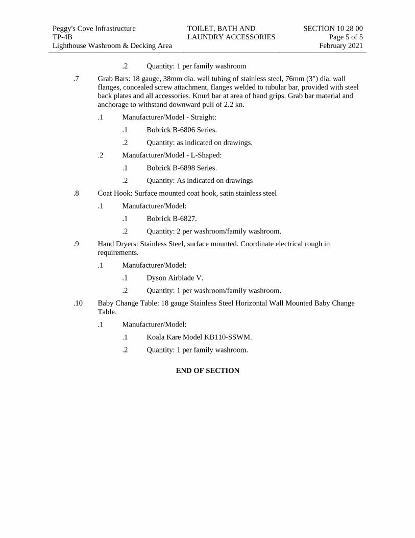
Peggy's Cove Infrastructure TP-4B Lighthouse Washroom & Decking Area
TOILET, BATH AND LAUNDRY ACCESSORIES
SECTION 10 28 00 Page 5 of 5
February 2021
.2 Quantity: 1 per family washroom
.7 Grab Bars: 18 gauge, 38mm dia. wall tubing of stainless steel, 76mm (3") dia. wall flanges, concealed screw attachment, flanges welded to tubular bar, provided with steel back plates and all accessories. Knurl bar at area of hand grips. Grab bar material and anchorage to withstand downward pull of 2.2 kn.
.1 Manufacturer/Model - Straight:
.1 Bobrick B-6806 Series.
.2 Quantity: as indicated on drawings.
.2 Manufacturer/Model - L-Shaped:
.1 Bobrick B-6898 Series.
.2 Quantity: As indicated on drawings
.8 Coat Hook: Surface mounted coat hook, satin stainless steel
.1 Manufacturer/Model:
.1 Bobrick B-6827.
.2 Quantity: 2 per washroom/family washroom.
.9 Hand Dryers: Stainless Steel, surface mounted. Coordinate electrical rough in requirements.
.1 Manufacturer/Model:
.1 Dyson Airblade V.
.2 Quantity: 1 per washroom/family washroom.
.10 Baby Change Table: 18 gauge Stainless Steel Horizontal Wall Mounted Baby Change Table.
.1 Manufacturer/Model:
.1 Koala Kare Model KB110-SSWM.
.2 Quantity: 1 per family washroom.
END OF SECTION
Peggy's Cove Infrastructure TP-4B Lighthouse Washroom & Decking Area
FIRE PROTECTION CABINETS
SECTION 10 44 13 Page 1 of 3
February 2021
SEC TION 10 44 13 Fire protection cabinets
Part 1 General
1.1 SECTION INCLUDES
.1 Fire extinguishers.
.2 Cabinets.
.3 Accessories.
1.2 RELATED REQUIREMENTS
.1 Section 06 10 53 - Miscellaneous Rough Carpentry: Wood blocking and shims.
.2 Section 09 21 16: Gypsum Board Assemblies.
.3 Section 09 91 00 - Painting: Field paint finish.
1.3 REFERENCE STANDARDS
.1 NFPA 10 - Portable Fire Extinguishers, 2018 Edition.
.2 CAN/ULC-S503-05 (R2018) - Standard for Carbon-Dioxide Fire Extinguishers.
.3 CAN/ULC-S504-12 (R2018) - Standard for Dry Chemical Fire Extinguishers.
.4 CAN/ULC-S507-05 (R2018) - Standard for Water Fire Extinguishers.
.5 CAN/ULC-S508-18 - Standard for the Rating and Fire Testing of Fire Extinguishers.
.6 CAN/ULC-S566-17 - Halocarbon Clean Agent Fire Extinguisher.
1.4 ACTION SUBMITTALS
.1 Appendix D - RFQ Particulars
.2 Section 01 33 00: Submission procedures.
.3 Product Data: Provide extinguisher operational features, colour and finish, anchorage details ……….
.4 Shop Drawings: Indicate cabinet physical dimensions, rough-in measurements for recessed cabinets or wall bracket mounted measurements.………
1.5 INFORMATIONAL SUBMITTALS
.1 Appendix D - RFQ Particulars
.2 Section 01 33 00: Submission procedures.
.3 Installation Data: Manufacturer's special installation requirements, including special criteria and wall opening coordination requirements.
.4 Manufacturer's Certificate: Certify that Products meet or exceed Products.specified requirements
Peggy's Cove Infrastructure TP-4B Lighthouse Washroom & Decking Area
FIRE PROTECTION CABINETS
SECTION 10 44 13 Page 2 of 3
February 2021 1.6 CLOSEOUT SUBMITTALS
.1 Operation and Maintenance Data: Include test, refill or recharge schedules and re-certification requirements.
1.7 QUALITY ASSURANCE
.1 Provide units to CAN/ULC-S508. Maintain one (1) copy of document on site.
1.8 SITE CONDITIONS
.1 Ambient Conditions:
.1 Do not install extinguishers when ambient temperature may cause freezing of extinguisher ingredients.
Part 2 Products
2.1 MANUFACTURERS
.1 Acceptable manufacturers
.1 Kidde
.2 Amerex
.3 Strike First
.2 Substitutions: Refer to Appendix D - RFQ Particulars.
2.2 DESCRIPTION
.1 Regulatory Requirements:
.1 Conform to NFPA 10 for requirements for extinguishers.
2.3 EXTINGUISHERS
.1 Dry Chemical Type: CAN/ULC-S504, Cast steel tank, with pressure gauge; Class A:B:C, Size 10lb.
.2 Extinguisher Finish:
.1 Steel, enamel, colour as selected.
2.4 CABINETS
.1 Cabinets: Formed sheet steel, recessed type, galvanized; 1.2 mm thick metal base.
.2 Trim Type: Flat, 25-50mm wide face.
.3 Door: 1.2 mm thick, reinforced for flatness and rigidity; lock with full glass access.
.4 Door Glazing:
.1 Glass, clear, 3 mm thick tempered.
.5 Cabinet Mounting Hardware: Appropriate to cabinet.
Peggy's Cove Infrastructure TP-4B Lighthouse Washroom & Decking Area
FIRE PROTECTION CABINETS
SECTION 10 44 13 Page 3 of 3
February 2021
.6 Form cabinet enclosure with right angle inside corners and seams. Form perimeter trim and door stiles.
.7 Pre-drill for anchors.
.8 Hinge doors for 180 degree opening with continuous piano hinge. Provide roller type catch.
.9 Weld, fill, and grind components smooth.
.10 Glaze doors with resilient channel gasket glazing.
.11 Finishing Cabinet Exterior Trim and Door: Red baked enamel; colour red.
2.5 ACCESSORIES
.1 Extinguisher Brackets: Formed steel, galvanized finish; colour from standard range.
.2 Extinguisher Theft Alarm: Battery operated alarm, with ten (10) second delay for disarming, activated by opening cabinet door.
Part 3 Execution
3.1 EXAMINATION
.1 Verify rough openings for cabinet are correctly sized and located.
3.2 INSTALLATION
.1 Install to manufacturer's instructions.
.2 Install cabinets plumb and level in wall openings, min 750mm from finished floor to inside bottom of cabinet.
.3 Secure rigidly in place.
.4 Place extinguishers and accessories in cabinet or on wall bracket where noted.
3.3 SCHEDULES
.1 Lobby (as indicated on plan) : One (1) Extinguisher mounted in recessed cabinet
.2 Basement (as indicated on plan) : One (1) Extinguisher mounted on wall bracket
.3 Safety Room (as indicated on plan) : One (1) Extinguisher mounted on wall bracket
END OF SECTION
Peggy’s Cove Infrastructure MECHANICAL Section 22 00 00 TP-4B February 2021 Lighthouse Washroom & Deck Area Page 1
Part 1 GENERAL SPECIFICATION
1.1 QUALITY OF WORK MATERIAL
.1 All work and material supplied under these specifications shall be new and shall comply with the latest edition of the codes and standards in use. The decision of the engineer as to the quality and suitability of material or work shall be final and binding. In all cases where work or apparatus of "approved type or equal" is specified, the engineer's approval thereof must be obtained in writing in an addendum before tenders close.
.2 Unless noted otherwise, all equipment and materials shall be provided as specified or alternate approved equal. The alternate equipment and materials shall be equivalent in size, performance and operating characteristics to the specified product, and all costs for larger starters, additional space, heavier supports, etc. Required for the alternate equipment and materials shall be borne by the contractor making the substitution. No substitution of equipment and materials are permitted unless approved by the owner and design engineer. Excessive costs incurred by the designer to review proposed alternates shall be billable at standard rates to the supplier and contractor requesting the alternate.
1.2 DRAWINGS AND SPECIFICATIONS
.1 Drawings and specifications are intended to complement each other, so that if anything is shown on the drawings but not mentioned in the specifications, or vice versa, it is to be furnished and built as though specifically set forth in both. If the drawings conflict with the specifications in any particular, the specifications shall govern. If any discrepancies are discovered in the drawings or specifications, the same shall be referred to the engineer before proceeding with the work. Figured dimensions on drawings shall have precedence in the event of any conflict.
.2 If obvious ambiguities or omissions are noticed when tendering refer same to the consultant for a ruling and obtain the ruling in writing in the form of an addendum. Claims for extra for ambiguities or omission of items brought to the attention of the consultant after the award of a contract which, due to the nature of the ambiguity or omission, should have been brought to the attention of the consultant during the tendering period, will not be allowed.
.3 The drawings are performance drawings and are diagrammatic to show locations for apparatus and materials. The drawing are intended to convey the scope of work and do not intend to show architectural and structural details. The locations of all services and equipment shown are approximate and may be altered when approved by the consultant to meet requirements of the material and/or apparatus or building conditions. Do not scale drawings.
1.3 AS-BUILTS
.1 Maintain at site one set of contract drawings and specifications to record actual as-built site conditions. Maintain up-to-date real time as-built drawings and specifications on good condition to make available for inspection by consultant upon request.
.2 Record changes in red ink. Submit paper copy to consultant prior to final inspection. Stamp all drawings with “as-built drawings”. Label and place contractors signature and
Peggy’s Cove Infrastructure MECHANICAL Section 22 00 00 TP-4B February 2021 Lighthouse Washroom & Deck Area Page 2
date. Contractor shall show all modifications, substitutions and deviations from what is shown on the contract drawings or in specifications.
.3 Contractor shall incorporate as-built drawings into maintenance manual prior to final submission.
1.4 STANDARD OF CARE
.1 In performing its services and obligations under the contract, the contractor shall exercise a standard of care, skill and diligence that would normally be provided by an experienced and prudent contractor supplying similar services for similar projects. The contractor acknowledges and agrees that, throughout the contract, the contractor's obligations, duties and responsibilities shall be interpreted in accordance with this standard. The contractor shall exercise the same standard of due care and diligence in respect of any products, personnel or procedures which it may recommend to the owner.
1.5 SHOP DRAWING SUBMISSION .1 Shop drawings shall be submitted electronically. Items shall be clearly labeled with
“tags” as referenced in the drawings. Items shall have the same unit of measurement as the construction documents. The following mechanical equipment items shall be included to the shop drawing review package.
.1 Plumbing items
.2 Composting toilet package, plumbing fixtures, trap primer, bfp, sump pit, pumps, tanks, piping & fittings, valves, pipe insulation and controllers. Exhaust fans.
1.6 COMMISSIONING
.1 This contractor shall provide a start-up/commissioning report prior to final inspection confirming that all major pieces of equipment have been started in accordance with manufacturer's instructions. Report shall list each piece of equipment and shall include the name of the inspection authority giving permission for equipment start-up where applicable. Report must be signed and dated.
1.7 TRAINING
.1 This contractor shall provide a maximum of 4 hours of training, or less, if user is comfortable with the new systems being installed, after final commissioning of all new systems has been completed and signed-off by engineer and owner. Owner's representative shall sign-off on acceptance of training once complete, and all training documentation shall be stored in the operations & maintenance manuals. Training shall include: operation of controls system as modified, sequence of operation explanation, composting unit maintenance, fan maintenance, pump maintenance, valve locations/identification, filter replacement, belt replacement, manual reset of equipment, etc.
1.8 SPARE PARTS
.1 This contractor shall provide spare parts, chemical, filters, media, etc. To be replaced a minimum of three times during construction, unless otherwise noted, additional times as recommended by manufacturer and as further outlined in this specification. All replaceable media in all equipment shall be replaced prior to and immediately after
Peggy’s Cove Infrastructure MECHANICAL Section 22 00 00 TP-4B February 2021 Lighthouse Washroom & Deck Area Page 3
commissioning. All strainers shall be cleaned and all start-up screens in strainers shall be removed before turnover. This contractor shall provide to owner enough spare parts, chemical replacement, changeable media and filters for a period of 12 months after construction is complete. Leave a minimum of two sets of filters per piece of equipment on site. Obtain written receipt from owner for spare filters.
1.9 OPERATIONS AND MAINENTANCE DATA
.1 This contractor shall provide three (3) copies of operations & maintenance manuals upon completion of project. Binders shall be submitted to engineer for approval prior to final inspection and prior to being finalized and forwarded to owner for record-keeping. Manual shall be in a 3-ring hard-covered binder with labeled section divisions and cover indicating job title, date, prime-consultant's job number, location and shall include at minimum the following: contractor, sub contractor and supplier contact information, warranty letter, engineer-stamped approved shop drawings, final air & water balancing reports, maintenance information for all new equipment (fans, pumps, etc.), colour-copies of contractor as-builts (to be added after engineer's approval).
1.10 WIRING
.1 All control wiring, devices, etc. 50 volts and below shall be by the mechanical contractor. All wiring, starters, etc. Above 50 volts shall be by electrical contractor. All wiring installed within spaces used as return plenum shall be rated as such (min ft-6 rating). All wiring installed outside of conduit shall be run neatly tied to structure parallel to building lines. Refer to mechanical control schematics on the drawings for additional details. At minimum, all wiring from wall-devices up to 2" above ceiling shall be installed in emt conduit (conduit and back-box by electrical - coordinate requirements with electrical contractor). All control wiring in mechanical & electrical rooms shall be installed in emt conduit.
1.11 ALTERNATE EQUIPMENT MANUFACTURERS
.1 Approval of equipment/material manufacturers different than those specified herein shall be requested in writing no less than 7 business days prior to tender close to prime consultant for consideration. Any requests made after this point are assumed to be dismissed. Alternate manufacturers equipment/material shall meet all specified construction/performance criteria as minimum, and shall bear all standard features/capabilities of specified products, specifically listed in contract documents or not. It is the responsibility of the purchasing contractor to ensure that alternate products meet or exceed expectations of original product. Any changes necessary to accommodate alternate product (changes in electrical, plumbing, ventilation infrastructure, clearances, space requirements, etc) shall be the responsibility of the purchasing contractor who shall bear all costs and responsibility of coordination. In addition to approved alternates listed within contract documents specifically, the following manufacturers are considered approved alternates for specified products, subject to the above conditions:
.2 Pumps (constant speed only): armstrong, bell & gossett/xylem, grundfos, taco.
.3 Fans: greenheck, cooke, twin city
Peggy’s Cove Infrastructure MECHANICAL Section 22 00 00 TP-4B February 2021 Lighthouse Washroom & Deck Area Page 4 1.12 MOTORS
.1 All motors used on this project must comply with csa-c390 article 4.10 and mnecb article 7.2.4.2.1.
1.13 ACCESS DOORS
.1 Supply access doors in all areas to concealed mechanical equipment for operating, inspecting, adjusting and servicing. Flush mounted 24"x 24" (600x600mm) for body entry and 12"x 12" (300x300mm) for hand entry unless otherwise noted. Doors to open 180 degree, have rounded safety corners, concealed hinges, screwdriver latches and anchor straps. Special areas such as tiled or marble surfaces and washrooms, use stainless steel with brushed satin or polished finish. Remaining areas use prime coated steel. Locate so that concealed items are accessible and hand/body entry is achieved. Use fire rated access doors in all fire rated assemblies.
1.14 LABELLING
.1 Installing trade contractor(s) shall be responsible for labeling of all installed services including but not limited to: piping, ductwork, equipment, and control panels. All equipment, device and panel labels shall be of lamacoid type, glued to equipment surface. All piping labeling shall be colour-coded stick-on type with flow direction and service type indicated. All ductwork labeling shall be black stencil-painted type with flow direction and service type indicated. Install labeling on piping/ductwork at 15' (4500mm) intervals, or closer as necessary for viewing through access panels/around equipment/etc. If power piping contractor and plumbing contractor are no the same, both contractors must use same labeling method and style for consistency.
Part 2 PLUMBING
2.1 PIPING
.1 Do all plumbing in accordance with 2010 canadian plumbing code.
.1 Drainage lines inside building above ground:
.2 Pvc to csa b181.2 will be accepted for sanitary piping.
.2 Vent lines above ground:
.1 Pvc to csa b181.2m.
.3 Domestic cold water and domestic hot/recirc water piping:
.1 Copper hard drawn type "l" to astm b42 above ground.
.2 Copper hard drawn type “k” below ground.
.3 Cpvc potable water piping to astm d1784.
.4 Pumped pressure pipe:
.1 Piping shall be pvc schedule 40 to csa b137.3.
.5 Exhaust ventilation piping:
.1 pvc with class cell of 12454 to astm d 1784 c/w solvent cemented fittings to astm d2564.
Peggy’s Cove Infrastructure MECHANICAL Section 22 00 00 TP-4B February 2021 Lighthouse Washroom & Deck Area Page 5 2.2 PIPE JOINTS
.1 Pvc joints
.1 Clean all joints with abs or pvc - cleaner. Use pvc solvent cement on both sides of joints. All work carried out to csa standard b181.1-m90 and b181.2-m90 recommended practice for the installation of pvc dwv pipe fittings.
.2 Threaded pipe joints:
.1 Make with approved pipe thread compound teflon tape pulverized lead paste. Apply to male threads only.
2.3 PIPE HANGERS
.1 General
.1 Ansi/asme b31.1 latest edition. Power piping (si edition). Ansi/mss-sp-58 latest edition, pipe hangers and supports - materials, design and manufacture. Fabricate hangers, supports and sway braces in accordance with ansi b31.1 and mss-sp-58.
.2 Upper attachment
.1 Concrete .1 Inserts for cast-in-place concrete: galvanized steel wedge to mss-sp-58,
type 18. Ulc listed for pipe 1/2" (13mm) through 8" (200mm). Acceptable manufacturer (or an approved equal): grinnell fig. 281, myatt, b-line. Carbon steel plate with clevis, for surface mount: malleable iron socket and expansion case and bolt. Minimum two expansion cases and bolts for each hanger. Acceptable manufacturer (or an approved equal): grinnell, plate fig. 49, eye nut fig. 290, expansion case fig. 117, myatt, b-line.
.2 Steel beam (bottom flange): .1 Piping nps 50 and under: malleable iron c clamp to mss-sp-58,
type 19. Ulc listed. Acceptable manufacturer (or an approved equal): grinnell fig. 229, myatt. Cold piping 2.5" (65mm) and larger and all hot piping: malleable iron beam clamp to mss-sp-58, type 28 or 29. Ulc listed. Acceptable manufacturer (or an approved equal): grinnell fig. 229, myatt, b-line.
.3 Steel beam (top): .1 Piping nps 50 and under: malleable iron “top of beam” c clamp
to mss-sp-58, type 19. Ulc listed. Acceptable manufacturer (or an approved equal): grinnell fig. 61, myatt, b-line. Cold piping 2.5" (65mm) and larger and all hot piping: steel jaw, hook rod with nut, spring washer and plain washer, to mss-sp-58, type 25. Ulc listed. Acceptable manufacturer (or an approved equal): grinnell fig. 227, myatt, b-line.
.4 Steel joist: .1 Piping 2" (50mm) and under: steel washer plate with double
locking nuts. Acceptable manufacturer (or an approved equal): grinnell fig. 60, myatt, b-line. Cold piping 2.5" (65mm) and larger and hot piping: steel washer plates with double locking
Peggy’s Cove Infrastructure MECHANICAL Section 22 00 00 TP-4B February 2021 Lighthouse Washroom & Deck Area Page 6
nut, carbon steel clevis and malleable iron socket. Acceptable manufacturer (or an approved equal): grinnell: washer plate, fig. 60; clevis, fig. 66; eye nut, fig. 290, myatt, b-line.
.5 Steel channel or angle (bottom): .1 Piping 2" (50mm) and under, malleable iron c clamp to mss-sp-
58, type 23. Ulc listed. Acceptable manufacturer (or an approved equal): grinnell fig. 86, myatt, b-line. Cold piping 2.5" (65mm) and larger and all hot piping; universal channel clamp. Ulc listed. Acceptable manufacturer (or an approved equal): grinnell fig. 226, myatt, b-line.
.6 Steel channel or angle (top): .1 Piping nps 50 and under; malleable iron “top of beam” c clamp
to mss-sp-58, type 19. Ulc listed. Acceptable manufacturer (or an approved equal): grinnell fig. 89x, myatt, b-line. Cold piping 2.5" (65mm) and larger and all hot piping: steel jaw, hook rod with nut, spring washer and plain washer, to mss-sp-58, type 25. Ulc listed. Acceptable manufacturer (or an approved equal): grinnell fig. 227, myatt, b-line.
.7 Wood joists (bottom): .1 Piping 2" (50mm) and under. Acceptable manufacturer (or an
approved equal): grinnell fig. 142, myatt, b-line.
.3 Middle attachment
.1 Carbon steel threaded rod black. Acceptable manufacturer (or an approved equal): grinnell fig. 146, myatt, b-line.
.4 Pipe attachment
.1 Cold piping, steel or cast iron: hot piping steel, with less than 1" (25mm) horizontal movement; hot piping, steel, with more than 300 mm middle attachment (rod) length: adjustable clevis to mss-sp-58, type 1. Ulc listed. Acceptable manufacturer (or an approved equal): grinnell fig. 260, myatt, b-line. Cold copper piping; hot copper piping with less than 1" (25mm) horizontal movement; hot copper piping with more than 300 mm middle attachment (rod) length: adjustable clevis to mss-sp-58, type 1. Copper plated. Acceptable manufacturer (or an approved equal): grinnell fig. Ct-65, myatt, b-line. Suspended hot piping, steel and copper, with horizontal movement in excess of 1" (25mm); hot steel piping with middle attachment (rod) 12" (300mm) or less; pipe roller to mss-sp-58, type 43. Acceptable manufacturer (or an approved equal): grinnell fig. 174, myatt, b-line. Bottom supported hot piping, steel and copper: pipe roller stand to mss-sp-58, type 45. Acceptable manufacturer (or an approved equal): grinnell fig. 271, myatt, b-line.
.5 Pipe insulation shields
.1 Domestic piping up to and including 1.5" (38mm): protection shield with high density insulation under shield with uninterrupted vapour barrier. Acceptable manufacturer: grinnell fig. 167, myatt, b-line.
Peggy’s Cove Infrastructure MECHANICAL Section 22 00 00 TP-4B February 2021 Lighthouse Washroom & Deck Area Page 7
.6 Hanger installation
.1 Spacing and middle attachment (rod) diameter as specified in paragraphs below or as in table below, whichever is more stringent. Plumbing piping: most stringent requirements of canadian plumbing code, provincial code, or authority having jurisdiction. Fire protection: to applicable fire code. Copper piping: up to 12" (300mm): every 60" (1500mm). Flexible joint roll groove pipe: in accordance with table below, but not less than one hanger at joints. Within 12" (300mm) of each horizontal elbow. Install hanger so that rod is vertical under operating conditions. Adjust hangers to equalize load. Support from top of structural members. Where structural bearing does not exist, or inserts are not in suitable locations, provide supplementary structural steel members.
Pipe size rod diameter: maximum spacing maximum spacing (mm): steel: copper: Up to 39 10 mm 2.1 m 1.8 m 40 10 mm 2.7 m 2.4 m 50 10 mm 3.0 m 2.7 m 63 10 mm 3.6 m 3.0 m 75 10 mm 3.6 m 3.0 m 100 16 mm 4.2 m 3.6 m
2.4 ESCUTCHEONS
.1 Provide chrome plated escutcheon plates on pipes passing through finished walls, partitions, floors and ceilings.
2.5 BALL VLAVES
.1 Crane 9202 or 9222, jenkins 901a or 902a, watts b-6000 or b-6001, red & white 5044a or 5049a, kitz 58 or 59, apollo 77c series and victaulic series 608 for use with grooved end copper pipe system.
2.6 PIPE INSULATION
.1 Use fibrous glass standard pipe insulation on all rigid hot, cold and hot water recirculation water pipes, humidifier steam piping, roof drain assemblies, horizontal rainwater leaders and on all plastic cold water pipes.
.2 Acceptable products: fiberglas with asj jacket to astm c547, thickness 1" (25mm). Use ½" (13mm) thick insulation on plastic pipes. On pex systems use flexible insulation. Insulation to have 25/50 flame spread/smoke developed ratings.
.3 Apply pvc jacket on insulation in exposed areas john manville zeston 2000 or equal.
2.7 WATER HAMMER ARRESTORS (SHOCK ABSORBERS)
.1 Provide arrestors on branch supplies to each fixture or group of fixtures. Acceptable product: watts no. 15m2 or equivalent from sioux chief, jr smith, zurn.
Peggy’s Cove Infrastructure MECHANICAL Section 22 00 00 TP-4B February 2021 Lighthouse Washroom & Deck Area Page 8 2.8 TRAP SEAL PRIMERS
.1 Provide priming device with r.p. type bfp watts series 009 or equivalent from wilkins c/w drain to nearest services in conjunction with electric trap primer unit. Trap primer unit shall consist of a 120 volt solenoid valve and copper manifold header for multiple pipes. System must be connected to nearest ½" dcw service with ball type service valve and strainer. System must introduce a regulated equal amount of water to each floor drain and shall be c/w a test switch, built-in timer and in-line replaceable fuse. Entire assembly must be contained within a cabinet with an access door by manufacturer. Strainer and bfp shall be mounted external to cabinet in a serviceable location. Acceptable product: p.p.p. prime time trap primer or approved equal. Site fabricated assemblies will not be accepted in lieu of unit specified. No exceptions.
2.9 BACKFLOW PREVENTER - FIXTURES
.1 R.p. type bfp watts series 009 c/w quarter turn ball valves, strainer and air gap drained to nearest service.
.2 Acceptable manufacturers: watts, apollo, zurn/wilkins
2.10 SUMP PUMP, PIT
.1 Pit shall be continuous filament wound fiberglass with anti-float ring without lid. Liberty or equal. Submersible sump capable of 57 lpm @ 4.5 m head when driven by a 1/3 hp/115v/1ph motor. Supply c/w quick disconnect power and switch cords and mechanical float. Pump shall be liberty or approved equal. Refer to sump pit detail on drawings for further information on these items and associated controls for this system.
2.11 FLOOR DRAINS
.1 Square 100mm floor grate shall come with a brushed stainless steel finish.
.2 Acceptable manufacturer: schluter-kerdi-drain kd4 grk e10
.3 Floor grate shall be furnished with a wide pvc flange c/w 75mm diameter outlet.
.4 Acceptable manufacturer: schluter-kerdi-drain kd3/pvc/fl
2.12 ELECTRIC HOT WATER HEATHER (DHWH – 1)
.1 184 l (40 gal). Heater shall be rated for 3000w at 240v. Tank dimensions: 560mm diameter and 1220mm high. Rating shall be 150 psi insulation sandwich between inside and outside steel casings shall be rigid polyurethane to mnec 6.2.2.1-2. Anode rod shall be heavy duty to provide cathodic protection. Tank shall be c/w junction box built in and shall have automatic adjustable temperature control with over temperature protector and ¾” relief valve.
.2 Standard of acceptance: giant 152b
2.13 THERMAL EXPANSION TANK
.1 8l tank shall be watts plt-5 or equivalent from wilkins, amtrol, armstrong, expanflex or taco with 40 psi precharge. 5l tank acceptance. Set expansion tank pressure 3 psi lower than system operating pressure. Contractor shall submit commissioning report verifying tank precharge pressure and system pressure, with pumps off, has been tested.
Peggy’s Cove Infrastructure MECHANICAL Section 22 00 00 TP-4B February 2021 Lighthouse Washroom & Deck Area Page 9 2.14 COMESTIC WATER PRESSURE BOOST SYSTEM (P – 1)
.1 Stainless steel construction shallow well self priming jet pump c/w end suction, top discharge arrangement, technopolymer impeller, built-in ejector complete with clean-out port to clear blockages from nozzle, ceramic-carbon bellows mechanical seal ensures trouble-free operation, high quality pressure switch. See schedule on drawings for performance specifications.
2.15 WALL HYDRANTS / HOSE BIBBS (NFHB)
.1 Zurn z-1300 or approval equal “anti-siphon” automatic drain, non-freeze type with integral backflow preventer, all bronze interior and casing with hinged cover and operating key.
.2 Acceptable manufacturers: watts, zurn, sioux chief, jr smith, mifab
2.16 COMPOSTING TOILETS AND UNITS
.1 Water closet "wc-1": foam flush toilet fixture c/w vitreous ceramic body & foam flush tank, abs toilet seat/lid, alcohol-based biodegradable neponol soap and 100mm drain pipe connection (pvc pipe only). Toilet dimensions: 445mm high, 380mm wide and 740mm long. Toilet shall be ada accessible. Toilet tank required 120v ac/ 4 watts power supply. Water consumption shall be 3 oz/flush. Four (4) such.
.2 Composting storage unit shall have a capacity of 6,626 l and daily usage capacity of 180 visits and an annual capacity of 65,000 visits at 18°c. Installed dimensions shall be 2616mm long, 1791mm wide and 2261mm high. Unit weight shall not exceed 363 kg. Unit enclosure shall be composed of rotationally molded high-density 9.5mm thick polyethylene walls to astm d1505 and asm d638. Unit system shall come with integral automatic moistening system with 120v solenoid valve and 115v, 5a liquid removal pump with a maximum pumping height capacity of 8 meters & 170l liquid separation tank. Five (5) such.
.3 Each composting unit system shall be furnished with a pre-programmed stand alone controller (120v power) that automatically regulates the functioning of compost moistening, liquid removal, ventilation and fire suppression devices. Controller housing shall be water resistant nema box, 250mm x 200mm x 150mm. Each controller shall have a high level audible tank alarm (horn at 82 decibels). Install all controllers in the electrical room. Five (5) such.
.4 Standard of acceptance: clivus multrum m35 to nsf standard 41.
2.17 COMPOSTING TOILET UNIT EXHAUST FAN:
.1 A centrifugal type exhaust fan specifically designed for moderate size ventilation applications. The fan can be mounted in any angle at any point along the duct work and straight-through air flow design allows easy installation. By using accessory fc type mounting clamps fan can easily be removed from duct work for service. Fans are constructed in accordance with standard dimensions for spiral duct eliminating the need for transition pieces. Fan motors are capable of operating in air stream temperatures up to 140 of. Motor bearings are permanently sealed, self lubricating ball type. All fans are 100% speed controllable through a decrease in the voltage by using a solid state or transformer type control. All fr series fans are backed by fantech's five year warranty.
Peggy’s Cove Infrastructure MECHANICAL Section 22 00 00 TP-4B February 2021 Lighthouse Washroom & Deck Area Page 10
.2 Guide specifications for model fr inline duct fans supply, exhaust or return air inline fans shall be of the centrifugal, direct driven type. Housing fan housing shall be constructed of uv resistant, flame retardant polycarbonate (pc) thermo plastic. Fan housing shall be a single piece casing formed by the joining of inlet and outlet pieces via a vibration welding process. The joining process shall not utilize mechanical fasteners, caulk or adhesive, and the seam where the pieces were joined shall be permanent and inherently leak free.
.3 Capacitor shall be provided and shall be located within the fan electrical terminal box for easy access. Electrical terminal box is water tight. Motorized impeller shall be an external rotor type, class b insulation, totally enclosed psc type for maximum efficiency. Motor shall be a permanently sealed self lubricating ball bearing type.
.4 Motor shall be equipped with automatic reset thermal overload protection.
.5 Motor shall be acceptable for continuous duty.
.6 Sufficient service factor shall be provided to ensure long maintenance free operation over maximum load conditions.
.7 Fan wheel shall be of the backward inclined centrifugal type with a well designed inlet venturi for maximum performance. Motorized impeller shall be both statically and dynamically balanced as one integral unit to provide for vibration free performance.
.8 Fan air flow performance shall be certified by hvi and licensed to bear the hvi tested/certified performance logo. Refer to schedule on drawings for performance requirements.
2.18 LIQUID STORAGE TANK
.1 Cylindrical liquid storage tanks shall be composed of high density polyethylene resin c/w top lid and bottom 50mm drain outlet connection. Sizing as per drawings.
2.19 PRESSURE TANK
.1 High strength steel heavy duty butyl vertical pressure tank c/w antimicrobial liner and 304l stainless steel connection, steel stand and projection welded air valve. Maximum working pressure of 10.3 bar (150 psig). Total tank volume of 121 l and minimum acceptance volume of 37 l at 30 / 50 psig pressure switch settings.
.2 Standard of acceptance: amtrol wellxtrol wx-203
2.20 2.20. CLEANOUTS
.1 Provide at base of all soil and waste stacks, and at such points shown or required installed by codes. Where possible install so access to cleanout is from walls rather than floors.
.2 Acceptable product: zurn
2.21 PIPE PRESSURE TESTING
.1 Pressure test all pipe in accordance with the canadian & new brunswick plumbing codes.
Peggy’s Cove Infrastructure MECHANICAL Section 22 00 00 TP-4B February 2021 Lighthouse Washroom & Deck Area Page 11 Part 3 VENTILATION
3.1 LOW PRESSURE GALVANIZED STELL DUCTWORK
.1 Ductwork to be constructed to withstand 1-1/2 times working static pressure with leakage rate of 1.5% maximum and designed for less than 2" s.p. operating pressure. Ducts: lock forming quality steel with g90 designation zinc coating to astm a653/653m. Gauge of ducts shall be in accordance with recommendation of ashrae. Fabrication: ducts and fittings configuration in accordance with recommendation of smacna and ashrae. Round ductwork shall be spiral type with flat seam. At completion of project dents in exposed ductwork will not be accepted. Dented ductwork will result in the entire length being replaced by this contractor.
3.2 DUCTWORK INSTALLATION
.1 Install steel duct in accordance with smacna standards. All duct joints to be sealed with duct sealant and porous tape imbedded in sealant. Duct tape will not be accepted. Do not insulate duct until sealant work is approved by engineer. Do not break continuity of insulation vapour barrier by hangers or rods. Install balancing dampers at all branch ducts and as indicated. Anchor all risers as indicated. Hangers shall be steel angles with supporting rods, locking nuts and washers.
3.3 DUCT INSULATION (ALL DUCTWORK WITHIN ATTIC SPACE)
.1 Insulation shall be 1.5" thick mineral fibre blanket to astm c 553 faced with factory applied vapour retarter jacket to cbsb 51-gp-52ma). Insulate all ductwork within attic space.
3.4 DUCT SEALANTS
.1 Seal all ductwork. Water soluble, flexible, non-toxic duct sealant with fiber reinforcement. Maximum flame spread rating 25, smoke development rating 50. Acceptable product: ductmate fiberseal or approved alternate. Solvent based sealant will not be accepted. Duct tape will not be accepted as the primary sealant. Sealant on all exposed ductwork shall be applied to ensure clean/crisp edge lines using taped lines.
3.5 BALANCING DAMPERS
.1 In rectangular/square duct mains provide multi-leaf opposed blade dampers designed to smacna details with locking quadrant. In round branch ducts provide single leaf blade with end bearing and locking quadrant.
3.6 AIR BALANCING
.1 Testing and balancing personnel shall be experienced in balancing mechanical systems in accordance with, and shall be members of, aabc. Submit three copies of the final air balancing report.
.2 Include following for air systems components: installation data, manufacturer and model size, arrangement discharge and class, motor type, hp, voltage, phase. Location and local identification data. Design data, total volume flow rate, static pressure, outside air flow rate. Recorded data, air flow rates, static pressure. System schematic with required and actual flow rates. Manufacturers catalogue identification and type, application factors,
Peggy’s Cove Infrastructure MECHANICAL Section 22 00 00 TP-4B February 2021 Lighthouse Washroom & Deck Area Page 12
designated area, design and recorded velocities, design and recorded air flow rates. Permissible air deviation from design air quantities shall be 10%.
3.7 ENERGY RECOVERY VENTILATION (ERV)
.1 Packaged air-to-air energy recovery ventilator complete with 0.5 hp 120v single phase ec motor powered fans, controllers, merv 8 filters, backdraft damper, sensors and controls and factory wiring. Wired for single point power connection. Erv shall utilize enthalpy type plate core with hydroscopic resin plates edge sealed and bonded to casing. Energy core shall allow both sensible and latent energy transfer. Core not to exceed 25 / 50 flame and smoke spread per nfpa 90a and b. Cross contamination is not permitted.
.2 No condensate shall be generated during operation down to -23°c. Occasional more extreme conditions shall not affect the usual function performance or durability of the core. No condensate drains will be allowed.
.3 Acceptable manufacturer: renewaire - ev450in
3.8 ELECTRIC DUCT HEATING SOIL (HC – 1)
.1 Cul approved slip in or collar type electric duct heater. Heater will come complete with flange for securing it to the duct. Mounting flange shall be independent of the terminal box so as to allow installation without opening the box or drilling into it. Heater shall be complete with fail safe, automatic reset disc-type thermal cut-out as required by csa.
.2 Duct heater shall be complete with disconnecting back-up magnetic contractors, 24 volt transformer, airflow sensor, scr control, load fuses, solid state relays, pilot lights and protect screens require to provide a consistent air temperature output.
.3 Size: 5.0 kw electric duct heater power at 240 volts single phase
3.9 FILLES & DIFFUSERS
.1 Grille frames shall be full perimeter gaskets with concealed fasterners. All grilles shsall come compelte with concealed manual volume control damper operators. All grilles shall be of aluminum construction.
Og-1 grille: eh price model: 300x300 620 dal/f/l/a Sg-1 grille: eh price model: 300x150 620 dal/f/l/a/b12 Eg-1 grille: eh price model: 300x300 630 dal/f/l/a Rg-1 grille: eh price model: 300x150 630 DAL/F/L/A/B12
Peggy’s Cove Infrastructure ELECTRICAL Section 25 05 51 TP-4B February 2021 Lighthouse Washroom & Deck Area Page 1
Part 1 General
1.1 SCOPE OF WORK
.1 The work covered by this specification will include the furnishing of all labour, materials, not listed as supplied by others, tools and services to construct and install a complete and working electrical system as shown on the accompanying drawings, specified herein, or both.
.2 Without in any way limiting the foregoing, the work in general will include the following: .1 Utility service, underground conduit, service entrance, wiring and conduit,
and power distribution hardware. .2 Lighting and associated electrical conduits and wiring of switches,
fixtures, and receptacles as indicated. .3 Power distribution for mechanical equipment and composting toilet
system. .4 Grounding and bonding.
1.2 CODES, PERMITS, CERTIFICATES, FEES & INSPECTION .1 The work will be tendered on and will be carried out in accordance with these
drawings and specifications and to requirements of the canadian electrical code c22.1-2018, national building code 2015, any special requirements of the provincial electric power commission and the provincial electrical inspection department and any other applicable codes. In no instance, however, will the standard established by the drawings and specifications be reduced by any of the codes referred to above. In no instance will a standard be accepted lower than that established by the electrical code.
.2 The electrical contractor will obtain and pay for all permits in order that the work herein specified will be carried out.
.3 On, or before the completion of this contract, this contractor will obtain, at his own expense, the necessary certificate of inspection from the electrical inspection department of the province of nova scotia and will forward same to the engineer.
.4 During "final" or "interim" inspections where the consultant obtains a list of 15 deficiencies, the consultant has the right to leave the site and the contractor will be responsible for a $500 fee. Where the inspection is located greater than 10km from the consultants office location mileage will be added to the fee at a rate of $0.45/km.
1.3 DRAWINGS .1 The electrical drawings, which constitute an integral part of this contract, will
serve as the working drawings. They indicate the general layout of the complete
Peggy’s Cove Infrastructure ELECTRICAL Section 25 05 51 TP-4B February 2021 Lighthouse Washroom & Deck Area Page 2
electrical system, arrangement of feeders, circuits, outlets, switches, controls, panel boards, service equipment, luminaires and other work.
.2 The field verification of scale dimensions on plans is directed since actual locations, distances and levels will be governed by actual field conditions.
.3 Electrical contractor shall totally review all architectural, structural and mechanical plans drawings and specifications to co-ordinate and determine work associated with work prior to submitting tender price. Also, review all addendums associated with all trades. After review of all documents associated with other trades, forward any questions and obtain answers prior to tender submission. Submission of tender by electrical contractor acknowledges coordination with other trades.
.4 Discrepancies shown on different drawings or between drawings and actual field conditions, or between drawings and specifications will promptly be brought to the attention of the engineer, for clarification.
.5 The drawings may be superseded by later revised or detailed drawings or specifications addenda provided by the engineer, and this contractor will conform to all reasonable changes without extra cost to the owner.
.6 All items not specifically mentioned in the specification or noted in the drawings but which are obviously necessary to make the complete working installation shall be included.
1.4 .1 The contractor shall review all other trades drawings and notify other trades of
conflicts on the finished ceiling. Lighting shall govern over ventilation, sprinkler, other ceiling mounted electrical equipment. No allowances will be made for equipment relocations as a result of the contractor failing to coordination with other trades.
1.5 .1 All submissions are to be made through the general contractor only; the electrical
contractor will, therefore, submit all information, drawings, inquiries, etc., to the general contractor for such submission.
1.6 .1 All systems and equipment covered by this specification will be thoroughly tested
in the presence of an authorized representative of the engineer before final acceptance of the work, such tests to be to the complete satisfaction of the engineer. All costs in connection with the tests are to be borne by this contractor, including the supplying of any equipment necessary for such testing as is required.
Peggy’s Cove Infrastructure ELECTRICAL Section 25 05 51 TP-4B February 2021 Lighthouse Washroom & Deck Area Page 3 1.7
.1 Be responsible for the complete and proper protection of all equipment, apparatus and luminaires during construction and will be turned over free from damage.
1.8
.1 For any extra electrical work that may be proposed, the electrical contractor will furnish to the engineer an estimate of the cost of such work. The electrical contractor will proceed only after receiving written permission from the engineer or his authorized representative, establishing the agreed price and describing the work to be done.
1.9 .1 Provide adequate supervision and direction to the work and keep a competent
foreman in charge until the job is completed.
1.10 .1 Any systems that have verification reports including but not limited to video and
data / telephone shall be supplied to the engineer and also included within the user manual.
1.11 .1 Remove from his work any foreman or workmen to whom the engineer or his
representative may object, on the ground of carelessness or incompetence.
1.12 .1 All workmanship will be of the best quality and subject to approval by the
engineer or his representative. Before final payment is made the electrical contractor will guarantee all materials and workmanship of this contract for a period of one (1) year from the date of acceptance by the engineer and will replace within that period of time, without extra cost to the owner, all materials or workmanship proven defective. He will before final payment is made, test and operate all equipment installed by him, and make all necessary adjustments and replacements and demonstrate to the engineer that all equipment is operating as intended.
1.13 .1 Co-operate with the other contractors doing work in the building and familiarize
with the drawings issued on the other trades and coordinate with the various foremen, so that work will not conflict, and that, it will not be necessary to move or change any piping, wiring, etc. When interference exists, notify the engineer before installing the work.
Peggy’s Cove Infrastructure ELECTRICAL Section 25 05 51 TP-4B February 2021 Lighthouse Washroom & Deck Area Page 4 1.14
.1 Provide sufficient, safe and proper facilities necessary for inspection of the work by the engineer, the owner, any legally authorized government, insurance or municipal inspector, and the representative of the manufacturer or suppliers of any special device or devices used. This contractor will give the engineer due and reasonable notice when the work is ready for inspection.
1.15 .1 Work is to be started as soon as conditions will permit and will be carried on
continuously as not to interfere or delay the work of other contractors or completion of the project.
1.16 .1 Remove any discarded electrical materials upon completion of the work and turn
over any spare parts to the owner.
1.17 .1 Upon completion of the contract, the electrical contractor will remove all debris
from the construction site created by his work, clean and polish all equipment and repair all damages to the work, in readiness to turn the building over to the owner.
1.18 .1 Grounding will be in accordance with the latest regulations of the canadian
electrical code and per the drawings and specifications.
1.19 .1 All equipment shall be rated for the environment in which it is located.
1.20 .1 All non-current-carrying metal parts, including raceways, cabinets, metal support
frames and other equipment where grounding is required, shall be completely grounded in an approved manner as prescribed by the utility service entrance standards and the canadian electrical code. All necessary conduit, conductors, clamps, connectors, etc. For the grounding system shall be furnished, installed and connected by the electrical contractor.
1.21 .1 Where manufacturers' names are used, it is for the purpose of establishing a
standard, and that equipment shall be used in preparing quotations. Permission to use alternatives shall be secured by means of written request no later than 5 days prior to tender closing. All equipment part numbers provided shall be verified by the electrical contractor for accuracy.
Peggy’s Cove Infrastructure ELECTRICAL Section 25 05 51 TP-4B February 2021 Lighthouse Washroom & Deck Area Page 5 1.22
.1 Verify all existing equipment loads and connections and make necessary revisions to existing circuitry, where applicable, to accommodate c.e.c. requirements.
1.23
.1 All redundant wire, cable, conduit, wiring devices, fixtures, etc, identifiable as not in use shall be removed. Remove conduit and wiring back to source of supply (electrical panel, data rack). No extra will be allowed for conditions identifiable during a non-invasive site inspection (removing ceiling tiles is not considered invasive). Provide new support for existing cabling to remain in ceiling space previously found unsupported.
1.24
.1 Where cables or conduits pass through floors and fire rated walls, pack space between wiring and sleeve full with asbestos-free fire stop. Where cables or conduits pass through acoustically-rated walls, floor and ceiling, pack space between wiring and conduit / sleeve full with asbestos-free soundproofing material.
1.25
.1 All materials and equipment removed under work of this section becomes the property of the contractor for disposal off of the property, unless directed for future use by owner.
1.26
.1 All electrical equipment determined to be environmentally hazardous shall be disposed of in accordance with n.s. department of environment instructions and guidelines. These guidelines must be stringently adhered to. Contractors must obtain and familiarize themselves with proper disposal methods.
1.27
.1 Cutting, patching and painting
.1 The contractor shall be responsible for all cutting required to complete the work shown on the drawing and described herein.
.2 All holes through concrete or masonry shall be made by core drilling. Care must be taken to contain dust and debris.
.3 Access doors shall be flush mounted 600 x 600 mm for body entry and 300 x 300 mm for hand entry unless otherwise noted. Doors shall open 180 degrees, have rounded safety corners, concealed hinges, screwdriver latches and anchor straps, steel shall be prime coated. Doors shall be of approved manufacturer with published literature door to have pre-punched holes so that drywall compound will conceal flange and only steel door is visible, acudor # dw-5040
.4 Seal all holes and opening using an approved non-shrink fire proof compound. 3m# ic-15wb
.5 The contractor shall neatly patch all surfaces cut or damaged as a result of this contract.
Peggy’s Cove Infrastructure ELECTRICAL Section 25 05 51 TP-4B February 2021 Lighthouse Washroom & Deck Area Page 6
.6 All patching shall be of matching material and carried out by tradesmen trained and skilled in the work to be done.
.7 The contractor shall re-paint all surfaces as required. All painting shall be carried out by skilled tradesmen.
.8 All patching, painting and sealing shall be to the satisfaction of the owner and engineer.
1.28
.1 Contractor to complete breaker coordination study and adjust breakers as required to allow the system to function as intended.
Part 2
2.1 SHOP DRAWINGS, MAINTENANCE MANUALS & AS-BUILTS
.1 Once tender has been awarded, contractor to provide shop drawings on all specified equipment prior to ordering equipment. Provide any additional shop drawings as requested by engineer.
.2 Preserve all operation, maintenance and installation instructions supplied with equipment and will secure further information about all or any of the equipment, if desired by the owners. The instructions will be neatly bound in a binder and presented to the owners at the time of substantial completion of the work. In addition, the electrical contractor will instruct the custodian or other owner's representative in the proper operation and maintenance of the various pieces of equipment installed by him.
.3 Provide one set of white prints and keep them on the job for the exclusive purpose of recording changes of the trenches, conduit, equipment and devices, etc. These drawings will be kept up to date and turned over to the engineer at the completion of the contract. Drawings shall be stamped with the contractors, signature and be labeled clearly as "as-builts".
Part 3
3.1 LABELLING
.1 All conduits, pull boxes and junction boxes shall be labelled with 25mm wide prime color and 20mm wide auxiliary color. Conduit and cable identificaiton shall be done where conduit or cable enters wall, ceiling or floor and at 15m intervals.
.1 Project color coding shall be as follows, confirm exact color coding requirements with user/building owner prior to commencing work. .1 Service prime color auxiliary color
50v to 249v normal green 50v to 249v emergency orange emergency lighting remote head redbrown telephone white data white yellow controls brown orange
Peggy’s Cove Infrastructure ELECTRICAL Section 25 05 51 TP-4B February 2021 Lighthouse Washroom & Deck Area Page 7
.2 Equipment shall be identified with plastic laminate lamacoid with white face, black core with 12mm high letters.
.3 Terminal cabinets and pull boxes: indicate system and voltage.
.4 Receptacles and switches shall be labelled with 6mm high letters, embossed plastic labels.
.5 Upon completion of project, contractor to relabel / update all lamicoid nameplates on all existing panelboards, disconnects, transformers, etc and new typed panel directories to reflect all changes.
Part 4 GENERAL MATERIALS
4.1 GROUNDING RODS/CONNECTIONS
.1 Ground rods shall be 19mm diameter, 3.0 meters long, and copper clad steel;
.2 Ground electrode plates are not to be used in lieu of ground rods unless approved by the engineer prior to installation.
.3 Grounding connections shall be inspected and approved by the engineer prior to burial or concealment; electrical contractor shall make engineer aware, 2 business days before being required on-site. Contractor shall provide photos of each connection.
.4 Grounding connections shall be made using 'cadweld' exothermic welds or compression connections using suitable hardware with matching die sets. Installation shall follow best practices per manufacturer's instructions;
.5 Acceptable manufacturers: t&b, burndy, or equivalent.
4.2 CONDUIT AND SHEATHED CABLE
.1 All wiring shall be installed in conduit unless otherwise noted.
.2 All conduits shall be installed with nylon bushings.
.3 Conceal conduit except in electrical and mechanical rooms and in unfinished areas.
.4 All data / telephone ports and mechanical heating system control items such as 24v sensors and thermostats shall have conduit installed from the device box up into the ceiling space.
.5 Use electrical metallic tubing (emt) for concealed conduit and for surface conduit above 1.2 meters not subject to mechanical injury.
.6 Use rigid galvanized steel conduit for surface conduit less than 1.2 meters above the floor and in basement.
.7 Use rigid pvc conduit in the floor slabs.
.8 Use rigid pvc conduit in trenches (concrete and direct buried).
.9 Use liquid tight flexible metal conduit for final connection to equipment such as pendant / chain mounted luminaire, motors and vibrating equipment where required.
Peggy’s Cove Infrastructure ELECTRICAL Section 25 05 51 TP-4B February 2021 Lighthouse Washroom & Deck Area Page 8
.10 Use steel rain-tight couplings and connectors for emt. Set-screw type are not acceptable.
.11 Run conduits parallel or perpendicular to building lines. Plan conduit routing for all circuits prior to installation.
.12 Support conduits in accordance with the requirements of the canadian electrical code. Do not use wire lashing or perforated strap to support or secure conduits.
.13 Install a green insulated bonding conductor in all conduits used for power with minimum ampacity per table 16a of the canadian electrical code.
.14 All empty conduit shall be complete with nylon pull string.
4.3 OUTLET BOXES
.1 Use surface mounted steel type fs / fd boxes with conduit hubs as required.
.2 Use coverplates specifically designed for fs/fd boxes.
.3 Use recessed type masonry boxes for concrete block wall as required.
.4 Use recessed electrical device boxes as required in all other areas.
.5 Support boxes independently of connecting conduits.
.6 Shall be recessed in wall, unless otherwise noted.
.7 Shall be one piece electro-galvanized construction.
.8 Single and multi gang flush device boxes for flush installation, minimum size 76 x 50 x 38mm or as indicated. 102mm square outlet boxes shall be used when more than one conduit enters one side with extension and plaster rings as required.
.9 Utility boxes for outlets connected to surface-mounted pvc conduit shall be no less than 102 x 54 x 48mm.
.10 102mm square or octagonal outlet boxes for lighting fixture outlets.
.11 Extension and plaster rings for flush mounting devices in finished gypsum walls.
.12 Contractor to fill boxes with sponges or foam or similar approved material to prevent entry of debris during construction, remove upon completion of work.
4.4 JUNCTION AND PULL BOXES
.1 Use boxes of welded steel construction with screw-on flat covers unless indicated otherwise.
.2 All junction boxes installed in wet location shall be rated nema 3r/4.
.3 Shall be recessed in wall, unless otherwise noted
.4 Support boxes independently of connecting conduits
Peggy’s Cove Infrastructure ELECTRICAL Section 25 05 51 TP-4B February 2021 Lighthouse Washroom & Deck Area Page 9 4.5 CONDUCTORS
.1 Use copper conductors with 600 v insulation of chemically cross-linked thermosetting polyethylene material rated rw90 xlpe for all wiring installed in conduit for power and lighting circuits.
.2 Nmd90 cable may be used for concealed wiring of lighting and power circuits installed in wood framed walls.
.3 Use ac90 for luminaire drops, not exceeding 3.0m.
.4 Use teck90 for exterior equipment connections.
.5 All conductors shall be sized as required for the ampacity of the branch circuit and in accordance with the canadian electrical code and per the following specifications.
.6 Use stranded conductors for 8 awg and larger.
.7 Use stranded conductors for 14 awg control wiring.
.8 Minimum size of conductors for lighting and power: 12 awg.
.9 Minimum size of conductors for heating: 10 awg
.10 Minimum size of conductors for control: 18awg stranded.
.11 Grounding conductor shall be stranded, soft drawn bare copper: 6 awg.
.12 Contractor shall assure that all conductors are sized for a maximum voltage drop of:
.1 Branch circuits - max. 2%
.2 Panel feeders - max. 2%
.3 Distribution - max. 1%
Part 5 POWER DISTRIBUTION MATERIALS
5.1 RECEPTACLES
.1 15a/20a, 125v, duplex receptacles with white face.
.2 Extra heavy duty specification grade.
.3 Smooth high impact steel wall plates for device boxes
.4 Unbreakable nylon coverplate: white finish.
.5 Install pvc weatherproof while in use covers with gasket over each receptacle for all indicated and outdoor receptacles.
.6 While in use cover plates shall be rated 'extra duty'.
.7 Isolated ground receptacles to be orange in color.
.8 Shall be recessed in wall, unless otherwise noted.
.9 Acceptable material: hubbel hbl5262w, hbl5362, or approved equal.
5.2 METER SOCKET
.1 As per utility power requirements.
Peggy’s Cove Infrastructure ELECTRICAL Section 25 05 51 TP-4B February 2021 Lighthouse Washroom & Deck Area Page 10
.2 Nema 1 heavy duty enclosure.
.3 Acceptable material: hydel, squared, micro electric or approved equal.
5.3 DISCONNECT SWITCHES
.1 Heavy duty side throw disconnect switch.
.2 Rated as indicated.
.3 Nema 1 enclosure.
.4 Nema 3r enclosure for wet locations.
.5 Acceptable material: eaton, schneider, siemens or approved equal.
5.4 PANELBOARDS
.1 Copper bus
.2 Main breaker required.
.3 Molded case branch circuit breakers with interrupting rating as indicated.
.4 Surface mounted nema 1 enclosure with space for designated branch circuits.
.5 Integral 100ka surge protection device with led status indication.
.6 Acceptable material: schneider, eaton or approved equal.
.7 Mount surface panelboards on plywood backboard, painted with fire retardant paint, with smooth edge, painted with 3 coats.
.8 Service entrance rated where indicated.
5.5 MAGNETIC STARTER
.1 Nema full voltage magnetic motor starter in nema 1/12 enclosure.
.2 Rating: nema size 1, 120 volt, 1 phase.
.3 Coil voltage: 120 volt.
.4 Manual reset bimetallic ambient compensated overload relay with external reset.
.5 Control circuit breaker: size as indicated.
.6 120v control relay with 1 no and nc contract.
.7 Green pilot light for run indication.
.8 Red pilot light for trip indication.
.9 Hand-off-auto selector switch.
.10 Acceptable material: eaton, schneider, or approved equal.
5.6 120V MOTOR RATED SWITCHES
.1 20a, 120vac, 2 pole toggle operated with brown nylon handle.
Peggy’s Cove Infrastructure ELECTRICAL Section 25 05 51 TP-4B February 2021 Lighthouse Washroom & Deck Area Page 11
.2 Industrial specification grade.
.3 Smooth high impact steel wall plates for device boxes.
.4 Acceptable material: hubbel 1222 series or approved equal.
5.7 LINE VOLTAGE THERMOSTAT
.1 Heavy-duty commercial grade specification.
.2 Rating: 120vac, 16afl.
.3 Temperature rating: 10°c to 27°c.
.4 Acceptable material: honeywell or approved equal.
5.8 HEATERS
.1 Linear type base board heater with built-in high heat limit protection.
.2 Rated for 240v, size as indicated
.3 Acceptable manufacturers: stelpro, honeywell, oullet.
Part 6 LIGHTING AND LIGHTING CONTROL MATERIALS
6.1 120V AC LIGHT SWITCHES
.1 15a, 120v ac, single pole, toggle operated with white nylon handle.
.2 Industrial specification grade.
.3 Smooth high impact steel wall plates for device boxes.
.4 Shall be recessed in wall, unless otherwise noted.
.5 Acceptable material: hubbel hbl1201w or approved equal.
6.2 SWITCH MOUNTED OCCUPANCY SENSOR
.1 Wall mounted, line voltage, 180 degrees, white finish.
.2 Push button programmable.
.3 Adjustable time relays and operating modules.
.4 1/4 hp load rated.
.5 Acceptable material: sensor switch wsx-wh or approved equal.
6.3 LUMINAIRES
.1 Polyester powdercoated steel housing.
.2 Diffused lensed led light engine.
.3 Low inrush, low emi electronic led driver.
Peggy’s Cove Infrastructure ELECTRICAL Section 25 05 51 TP-4B February 2021 Lighthouse Washroom & Deck Area Page 12
.4 Thermal heat management system to maintain optimal operating temperatures for long life leds.
.5 Maximum driver harmonic distortion shall be <20%thd
.6 0-10v or electronic line voltage dimming capable where indicated.
.7 Suspended luminaires shall be installed to form a straight continuous line.
.8 Downlights shall be supplied and installed with hanger bars and supported by one (1) safety chain.
.9 Aircraft cable and appropriate hardware may be substituted in lieu of safety chains for luminaire support.
.10 Luminaire construction and drivers noted above are to set a minimum standard, other minimum standard construction and control method may be specified in the luminaire schedule.
.11 Acceptable manufacturers as per luminaire schedule, alternates shall be submitted no later than 5 days prior to tender close.
6.4 EMERGENCY LIGHTING
.1 Emergency lighting equipment to csa c22.2 no.141.
.2 Supply voltage 120v ac, output voltage as indicated in luminaire schedule.
.3 Operating time of 30 minutes minimum.
.4 Battery is to be sealed and maintenance free
.5 Finish to be white powder coat
Part 7 EMERGENCY CALL SYSTEM KIT
7.1
.1 Emergency call system shall be designed to provide a washroom occupant with the ability to request emergency assistance, to receive visual and audible confirmation that their request has been made, and visual and audible notification to building occupancys outside the restroom of an emergency condition
.2 Product: emergency call systems for university & barrier free restrooms - cs-web10bk2 camdem door controls package (or consultant approved equivalent) including:
.1 Cm-af540so "press for emergency assistance" switch c/w led and sounder.
.2 Cm-af142so multi-color single gang led dome light with piezo sounder and printed "assistance required" text on lens.
.3 Cm-se21a sign to be located above activation switch "in the event of an emergency push button and audible and visual signal will activate".
.4 Cs-ps13 12/24v linear power supply and cx-trx-4024 40va transformer.
Peggy’s Cove Infrastructure ELECTRICAL Section 25 05 51 TP-4B February 2021 Lighthouse Washroom & Deck Area Page 13 Part 8 MOUNTING HEIGHTS, FROM FINISHED FLOOR TO CENTRE OF DEVICE,
UNLESS NOTED
8.1
.1 Receptacles - 16" (400 mm)
.2 Receptacles - 6" (150 mm) above desk / counter surfaces
.3 Switches - 47" (1200 mm)
.4 Emergency lighting - 12" (300mm) above door frame
.5 Thermostats - 47" (1200mm)
.6 Door operator push button - 47" (1200mm)
.7 Washroom emergency push button - 47" (1200mm)
Part 9 ELECTRICAL SUPPLY
9.1
.1 Characteristics of electrical system: the electrical energy supply will be provided by nova scotia power and will be installed as indicated.
.2 Electrical energy service: the electrical contractor will make the necessary arrangements with the owner and nova scotia power to have electrical energy supplied to the site in accordance with the intent of this specification and drawings. Any material, apparatus, equipments and labour not provided by nova scotia power for the work will be provided by the electrical contractor and must be to the complete satisfaction of nova scotia power.
Part 10 TRAINING
10.1
.1 Allow for two training sessions of one (1) hour each with the user. The first training session shall be at the completion of the project, the second training session shall be after a period of 3 months from the first training session. The contractor shall confirm with the user about the second training session. Instruct the user in the language requested (french or english). Provide copies of all supporting documentation. Training sessions shall be for systems such as lighting control.
.2
.3
.4
.1

Peggy’s Cove Infrastructure ELECTRICAL Section 25 05 51 TP-4B February 2021 Lighthouse Washroom & Deck Area Page 14
END OF SECTION
Peggy’s Cove Infrastructure FILL AGAINST STRUCTURE AND SAND TP-4BLighthouse Washroom & Deck Area
Section 31 22 13 February 2021
Page 1
Part 1 General
1.1 RELATED REQUIREMENTS
.1 Refer to Contract Documents for submittal requirements.
.2 Section 31 23 33.01 Excavating, Trenching and Backfilling
1.2 REFERENCES
.1 ASTM International
.1 ASTM D698-[07e1], Test Method for Laboratory Compaction Characteristics of Soil Using Standard Effort (600 kN-m/m3 ).
Part 2 Products
2.1 MATERIALS
.1 Select BackFill material: Select backfill material to be competent material suitable to support overlying aggregates, asphalt and vehicle loads. Acceptable materials include:
.1 Clear Stone in accordance with Section 31 37 20.
.2 Fill Against Structure as specified in NSTIR Standard Specification Specification Highway Construction & Maintenance (2011).
.3 Sand as specified under Fine Aggregate for Concrete in NSTIR Standard Specification Highway Construction & Maintenance (2011).
.2 Excavated or graded material existing on site suitable to use as fill for grading work if reviewed and approved by Develop NS.
Part 3 Execution
3.1 EXAMINATION
.1 Verification of Conditions: verify that conditions of substrate are acceptable for rough grading placement and compaction of backfill material.
.1 Visually inspect substrate in presence of Develop NS.
.2 Inform the Engineer of unacceptable conditions immediately upon discovery.
.3 Proceed with installation only after unacceptable conditions have been remedied and after receipt of written approval to proceed from the Engineer.
3.2 GRADING
.1 Rough grade to levels, profiles, and contours allowing for surface treatment as indicated on drawings.
.2 Slope rough grade away from existing or proposed buildings 1:50.
Peggy’s Cove Infrastructure FILL AGAINST STRUCTURE AND SAND TP-4BLighthouse Washroom & Deck Area
Section 31 22 13 February 2021
Page 2
.3 Prior to placing fill over existing ground, scarify surface to depth of 150 mm minimum before placing fill over existing ground. Maintain fill and existing surface at approximately same moisture content to facilitate bonding.
.4 Compact filled and disturbed areas to maximum dry density to ASTM D698, as follows:
.1 95% under paved and walk areas.
3.3 TESTING
.1 Inspection and testing of soil compaction will be carried out by testing laboratory designated by Develop NS.
.2 Submit testing procedure, frequency of tests, to Develop NS for review.
3.4 CLEANING
.1 Progress Cleaning:
.1 Leave Work area clean at end of each day.
3.5 PROTECTION
.1 Protect existing structures, pavement, surface or underground utility lines which are to remain as directed by Develop NS. If damaged, restore to original or better condition unless directed otherwise.
.2 Maintain access roads to prevent accumulation of construction related debris on roads.
END OF SECTION
Peggy’s Cove Infrastructure EXCAVATING, TRENCHING AND BACKFILLING Section 31 23 33.01 TP-4B February 2021 Lighthouse Washroom & Deck Area Page 1
Part 1 General
1.1 RELATED SECTIONS
.1 Section 31 22 13 – Select Backfill.
.2 Section 31 32 19.01 – Geotextiles.
.3 Section 31 37 20 – Clear Stone.
1.2 MEASUREMENT PROCEDURES
.1 Excavated materials will be measured in accordance with Contract Documents.
.2 Shoring, bracing, cofferdams, underpinning and de-watering of excavation will not be measured separately for payment.
.3 Backfilling to authorized excavation limits will be measured in accordance with Contract Documents.
1.3 REFERENCES
.1 American Society for Testing and Materials (ASTM)
.1 ASTM C 117-95, Standard Test Method for Material Finer Than 0.075 mm (No.200) Sieve in Mineral Aggregates by Washing.
.2 ASTM C 136-96a, Standard Test Method for Sieve Analysis of Fine and Coarse Aggregates.
.3 ASTM D 422-98, Standard Test Method for Particle-Size Analysis of Soils.
.4 ASTM D 698-00a, Standard Test Methods for Laboratory Compaction Characteristics of Soil Using Standard Effort (12,400 ft-lbf/ft ³ ) (600 kN-m/m ³).
.5 ASTM D 1557-00, Test Method for Laboratory Compaction Characteristics of Soil Using Modified Effort (56,000 ft-lbf/ft ³ ) (2,700 kN-m/m ³ ).
.6 ASTM D 4318-00, Standard Test Methods for Liquid Limit, Plastic Limit, and Plasticity Index of Soils.
.2 Canadian General Standards Board (CGSB)
.1 CAN/CGSB-8.1-88, Sieves, Testing, Woven Wire, Inch Series.
.2 CAN/CGSB-8.2-M88, Sieves, Testing, Woven Wire, Metric.
.3 Canadian Standards Association (CSA)
.1 CAN/CSA-A3000-98-A5-18, Portland Cement.
.2 CAN/CSA-A23.1-14, Concrete Materials and Methods of Concrete Construction.
1.4 SUBMITTALS
.1 Samples:
.1 Submit samples in accordance with Contract Documents.
.2 Inform Develop NS at least 4 weeks prior to commencing Work, of proposed source of fill materials and provide access for sampling.
Peggy’s Cove Infrastructure EXCAVATING, TRENCHING AND BACKFILLING Section 31 23 33.01 TP-4B February 2021 Lighthouse Washroom & Deck Area Page 2
.3 Upon Request, submit 70 kg samples of type of fill specified including representative samples of excavated material.
.4 Upon request, ship samples prepaid to an address specified by Develop NS in tightly closed containers to prevent contamination.
Part 2 Products
2.1 MATERIALS
.1 See Contract Drawings for material specifications.
2.2 GEOTEXTILES
.1 See Section 31 32 19.01 for geotextile specifications.
Part 3 Execution
3.1 SITE PREPARATION
.1 All excavation of native material is to be monitored by an archaeologist provided by Develop NS. Notice to be provided to Develop NS a minimum of 3 days prior to starting excavation for coordination purposes.
.2 Remove obstructions, ice and snow, from surfaces to be excavated within limits indicated.
3.2 STOCKPILING
.1 Stockpile fill materials in the laydown area. Stockpile granular materials in a manner to prevent segregation.
.2 Protect fill materials from contamination.
3.3 EXCAVATION
.1 Advise the Engineer at least 7 days in advance of excavation operations.
.2 Excavate to lines, grades, elevations and dimensions as indicated on the Contract Drawings.
.3 Remove concrete and other obstructions encountered during excavation.
.4 Excavation must not interfere with bearing capacity of adjacent foundations.
.5 Dispose of surplus and unsuitable excavated material in approved location.
.6 Do not obstruct flow of surface drainage or natural watercourses.
.7 Install geotextiles in accordance with Section 31 32 19.01 – Geotextiles.
.8 Solid Rock excavation, where required to achieve the finished grades shown on the Contract Drawings, shall consist of excavating and removing rock insitu and all boulders measuring 1 m3 or greater in volume. All sub-surface boulders 1 m3 or greater in volume are classified as Solid Rock. No undrained pockets shall be left in the rock surface. A material satisfactory to the Engineer shall be used to
Peggy’s Cove Infrastructure EXCAVATING, TRENCHING AND BACKFILLING Section 31 23 33.01 TP-4B February 2021 Lighthouse Washroom & Deck Area Page 3
backfill the areas within the site boundaries to the required elevation. All loose or shattered fragments of rock shall be removed. Excavated rock or waste from the excavation shall not be left outside the excavation.
.9 Excavation of existing soils and fill.
3.4 FILL TYPES AND COMPACTION
.1 All fill materials will be in accordance with Section 31 22 13 Select Backfill and 31 37 20 Clear Stone. Compaction densities are percentages of maximum densities obtained from ASTM D 698.
3.5 BACKFILLING
.1 Do not proceed with backfilling operations until Develop NS has inspected and approved installations.
.2 Areas to be backfilled to be free from debris, snow, ice, water and frozen ground.
.3 Do not use backfill material which is frozen or contains ice, snow or debris.
.4 Place backfill material in uniform layers not exceeding 300 mm compacted thickness up to grades indicated. Compact each layer before placing succeeding layer.
.5 Backfilling around installations.
.1 Place bedding and surround material as specified elsewhere.
.2 Do not backfill around or over cast-in-place concrete within 48 hours after placing of concrete.
.3 Place layers simultaneously on both sides of installed Work to equalize loading. Difference not to exceed 0.25 m.
.4 Where temporary unbalanced earth pressures are liable to develop on walls or other structures: .1 Permit concrete to cure for minimum 14 days or until it has sufficient
strength to withstand earth and compaction pressure and approval obtained from Develop NS.
.6 Install geotextiles in backfill in accordance with section 31 32 19.01 – Geotextiles.
END OF SECTION
GEOTEXTILES Peggy’s Cove Infrastructure TP-4B Lighthouse Washroom & Deck Area
Section 31 32 19.01 February 2021
Page 1
Part 1 General
1.1 SECTION INCLUDES
.1 Materials and installation of polymeric geotextiles purpose of which is to:
.1 Separate and prevent mixing of granular materials of different grading.
.2 The same geotextile material is to be used in a floating silt curtain.
1.2 RELATED SECTIONS
.1 Section 31 23 33.01 Excavating, Trenching & Backfilling.
1.3 MEASUREMENT PROCEDURES
.1 In accordance with Contract Documents.
1.4 REFERENCES
.1 American Society for Testing and Materials International, (ASTM)
.1 ASTM D4632. Grab Tensile strength test.
.2 ASTM D 4751, Standard Test Method for Determining Apparent Opening Size of a Geotextile.
.2 Canadian General Standards Board (CGSB)
.1 CAN/CGSB-4.2 No. 11.2-M89(April 1997), Textile Test Methods - Bursting Strength - Ball Burst Test (Extension of September 1989).
.2 CAN/CGSB-148.1, Methods of Testing Geotextiles and Complete Geomembranes. .1 No.7.3-92, Methods of Testing Geotextiles and Geomembranes - Grab
Tensile Test for Geotextiles.
1.5 SUBMITTALS
.1 Submit samples in accordance with Contract Documents.
.2 Submit to Develop NS following samples at least 2 weeks prior to beginning Work.
.1 Minimum length of 2 m of roll width of geotextile.
.2 Minimum of 1 m seam with at least 300 mm of geotextile on both sides of seam.
1.6 DELIVERY, STORAGE AND HANDLING
.1 During delivery and storage, protect geotextiles from direct sunlight, ultraviolet rays, excessive heat, mud, dirt, dust, debris and rodents. Store, handle and protect geotextile in accordance with manufacturer’s instructions and in such a manner that will not cause damage to the material.
GEOTEXTILES Peggy’s Cove Infrastructure TP-4B Lighthouse Washroom & Deck Area
Section 31 32 19.01 February 2021
Page 2
1.7 MEASUREMENT FOR PAYMENT
.1 Refer to Contract Documents for measurement for payment.
Part 2 Products
2.1 MATERIAL
.1 Geotextile: Non-Woven synthetic fiber fabric, supplied in rolls.
.1 Width: 3.5 m minimum.
.2 Length: 150 m minimum.
.2 Physical properties:
.1 Mass per unit area: to CAN/CGSB-148.1, No.2, minimum 540 g/m².
.2 Grab tensile strength (N) 1690
.3 Grab elongation 50%
.4 Tear Resistance (N) 644
.5 CBR puncture (N) 4820
.6 Rot proof, unaffected by action of oil or salt water and not subject to attack by marine life, insects or rodents.
.3 Hydraulic properties:
.1 Apparent opening size (AOS): to ASTM D 4751, 0.15 mm.
.2 Permittivity: to ASTM D 4491, 0.7 pers.
.4 Securing pins and washers: to CAN/CSA-G40.21, Grade 300W, hot-dipped galvanized with minimum zinc coating of 600 g/m² to CAN/CSA G164.
Part 3 Execution
3.1 INSTALLATION
.1 Place geotextile material by unrolling onto graded surface in orientation, manner and locations indicated and retain in position with pins and washers or weights.
.2 Place geotextile material smooth and free of tension stress, folds, wrinkles and creases.
.3 Overlap each successive strip of geotextile approximately 600 mm over previously laid strip.
.4 Pin successive strips of geotextile with securing pins or fasteners at 600 mm interval at mid-point of lap or as recommended by the manufacturer.
.5 Protect installed geotextile material from displacement, damage or deterioration before, during and after placement of material layers.
.6 After installation, cover with overlying layer within 4 h of placement
.7 Replace damaged or deteriorated geotextile to approval of Develop NS.
.8 Place and compact soil layers in accordance with Section 31 23 33.01 - Excavating Trenching and Backfilling.

GEOTEXTILES Peggy’s Cove Infrastructure TP-4B Lighthouse Washroom & Deck Area
Section 31 32 19.01 February 2021
Page 3
3.2 PROTECTION
.1 Traffic not permitted directly on geotextile.
END OF SECTION
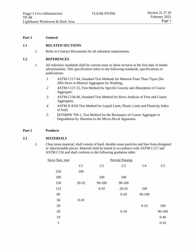
CLEAR STONEPeggy’s Cove Infrastructure TP-4B Lighthouse Washroom & Deck Area
Section 31 37 20 February 2021
Page 1
Part 1 General
1.1 RELATED SECTIONS
.1 Refer to Contract Documents for all submittal requirements.
1.2 REFERENCES
.1 All reference standards shall be current issue or latest revision at the first date of tender advertisement. This specification refers to the following standards, specifications or publications:
.1 ASTM C117-04, Standard Test Methods for Material Finer Than 75µm (No. 200) Sieve in Mineral Aggregates by Washing.
.2 ASTM C127-15, Test Method for Specific Gravity and Absorption of Coarse Aggregate.
.3 ASTM C136-06, Standard Test Method for Sieve Analysis of Fine and Coarse Aggregates.
.4 ASTM D 4318 Test Method for Liquid Limit, Plastic Limit and Plasticity Index of Soils
.5 DOT&PW TM-1, Test Method for the Resistance of Coarse Aggregate to Degradation by Abrasion in the Micro-Deval Apparatus.
Part 2 Products
2.1 MATERIALS
.1 Clear stone material: shall consist of hard, durable stone particles and free from elongated or objectionable pieces. Material shall be tested in accordance with ASTM C117 and ASTM C136 and shall conform to the following gradation table:
Sieve Size, mm Percent Passing C1 C2 C3 C4 C5
250 100 200 100 100 150 20-35 90-100 90-100 112 0-10 20-35 100 80 0-20 90-100 56 0-10 28 0-10 100 20 0-10 90-100 10 0-40 5 0-10
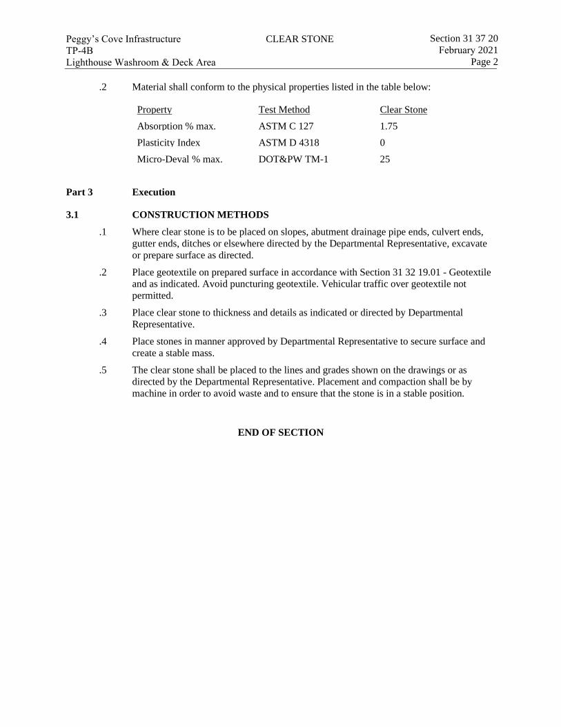
CLEAR STONEPeggy’s Cove Infrastructure TP-4B Lighthouse Washroom & Deck Area
Section 31 37 20 February 2021
Page 2
.2 Material shall conform to the physical properties listed in the table below:
Property Test Method Clear Stone Absorption % max. ASTM C 127 1.75 Plasticity Index ASTM D 4318 0 Micro-Deval % max. DOT&PW TM-1 25
Part 3 Execution
3.1 CONSTRUCTION METHODS
.1 Where clear stone is to be placed on slopes, abutment drainage pipe ends, culvert ends, gutter ends, ditches or elsewhere directed by the Departmental Representative, excavate or prepare surface as directed.
.2 Place geotextile on prepared surface in accordance with Section 31 32 19.01 - Geotextile and as indicated. Avoid puncturing geotextile. Vehicular traffic over geotextile not permitted.
.3 Place clear stone to thickness and details as indicated or directed by Departmental Representative.
.4 Place stones in manner approved by Departmental Representative to secure surface and create a stable mass.
.5 The clear stone shall be placed to the lines and grades shown on the drawings or as directed by the Departmental Representative. Placement and compaction shall be by machine in order to avoid waste and to ensure that the stone is in a stable position.
END OF SECTION
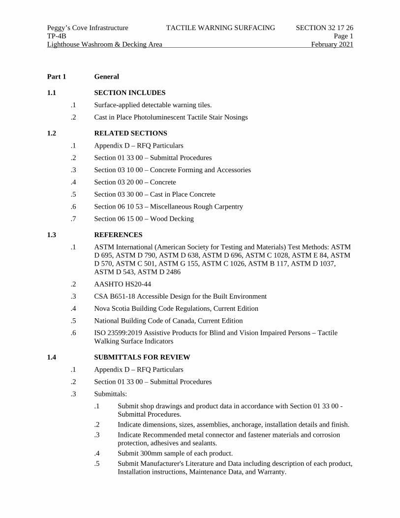
Peggy’s Cove Infrastructure TACTILE WARNING SURFACING SECTION 32 17 26 TP-4B Page 1 Lighthouse Washroom & Decking Area February 2021
Part 1 General
1.1 SECTION INCLUDES
.1 Surface-applied detectable warning tiles.
.2 Cast in Place Photoluminescent Tactile Stair Nosings
1.2 RELATED SECTIONS
.1 Appendix D – RFQ Particulars
.2 Section 01 33 00 – Submittal Procedures
.3 Section 03 10 00 – Concrete Forming and Accessories
.4 Section 03 20 00 – Concrete
.5 Section 03 30 00 – Cast in Place Concrete
.6 Section 06 10 53 – Miscellaneous Rough Carpentry
.7 Section 06 15 00 – Wood Decking
1.3 REFERENCES
.1 ASTM International (American Society for Testing and Materials) Test Methods: ASTM D 695, ASTM D 790, ASTM D 638, ASTM D 696, ASTM C 1028, ASTM E 84, ASTM D 570, ASTM C 501, ASTM G 155, ASTM C 1026, ASTM B 117, ASTM D 1037, ASTM D 543, ASTM D 2486
.2 AASHTO HS20-44
.3 CSA B651-18 Accessible Design for the Built Environment
.4 Nova Scotia Building Code Regulations, Current Edition
.5 National Building Code of Canada, Current Edition
.6 ISO 23599:2019 Assistive Products for Blind and Vision Impaired Persons – Tactile Walking Surface Indicators
1.4 SUBMITTALS FOR REVIEW
.1 Appendix D – RFQ Particulars
.2 Section 01 33 00 – Submittal Procedures
.3 Submittals:
.1 Submit shop drawings and product data in accordance with Section 01 33 00 - Submittal Procedures.
.2 Indicate dimensions, sizes, assemblies, anchorage, installation details and finish.
.3 Indicate Recommended metal connector and fastener materials and corrosion protection, adhesives and sealants.
.4 Submit 300mm sample of each product.
.5 Submit Manufacturer's Literature and Data including description of each product, Installation instructions, Maintenance Data, and Warranty.
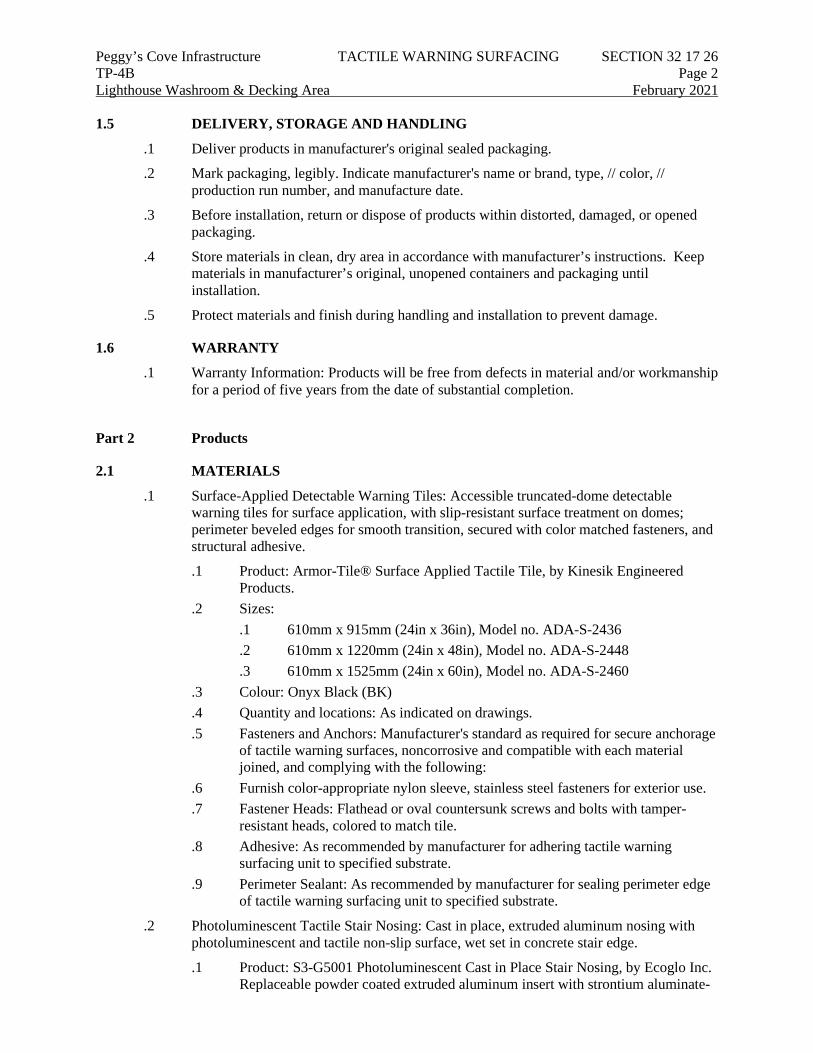
Peggy’s Cove Infrastructure TACTILE WARNING SURFACING SECTION 32 17 26 TP-4B Page 2 Lighthouse Washroom & Decking Area February 2021 1.5 DELIVERY, STORAGE AND HANDLING
.1 Deliver products in manufacturer's original sealed packaging.
.2 Mark packaging, legibly. Indicate manufacturer's name or brand, type, // color, // production run number, and manufacture date.
.3 Before installation, return or dispose of products within distorted, damaged, or opened packaging.
.4 Store materials in clean, dry area in accordance with manufacturer’s instructions. Keep materials in manufacturer’s original, unopened containers and packaging until installation.
.5 Protect materials and finish during handling and installation to prevent damage.
1.6 WARRANTY
.1 Warranty Information: Products will be free from defects in material and/or workmanship for a period of five years from the date of substantial completion.
Part 2 Products
2.1 MATERIALS
.1 Surface-Applied Detectable Warning Tiles: Accessible truncated-dome detectable warning tiles for surface application, with slip-resistant surface treatment on domes; perimeter beveled edges for smooth transition, secured with color matched fasteners, and structural adhesive.
.1 Product: Armor-Tile® Surface Applied Tactile Tile, by Kinesik Engineered Products.
.2 Sizes: .1 610mm x 915mm (24in x 36in), Model no. ADA-S-2436 .2 610mm x 1220mm (24in x 48in), Model no. ADA-S-2448 .3 610mm x 1525mm (24in x 60in), Model no. ADA-S-2460
.3 Colour: Onyx Black (BK)
.4 Quantity and locations: As indicated on drawings.
.5 Fasteners and Anchors: Manufacturer's standard as required for secure anchorage of tactile warning surfaces, noncorrosive and compatible with each material joined, and complying with the following:
.6 Furnish color-appropriate nylon sleeve, stainless steel fasteners for exterior use.
.7 Fastener Heads: Flathead or oval countersunk screws and bolts with tamper-resistant heads, colored to match tile.
.8 Adhesive: As recommended by manufacturer for adhering tactile warning surfacing unit to specified substrate.
.9 Perimeter Sealant: As recommended by manufacturer for sealing perimeter edge of tactile warning surfacing unit to specified substrate.
.2 Photoluminescent Tactile Stair Nosing: Cast in place, extruded aluminum nosing with photoluminescent and tactile non-slip surface, wet set in concrete stair edge.
.1 Product: S3-G5001 Photoluminescent Cast in Place Stair Nosing, by Ecoglo Inc. Replaceable powder coated extruded aluminum insert with strontium aluminate-
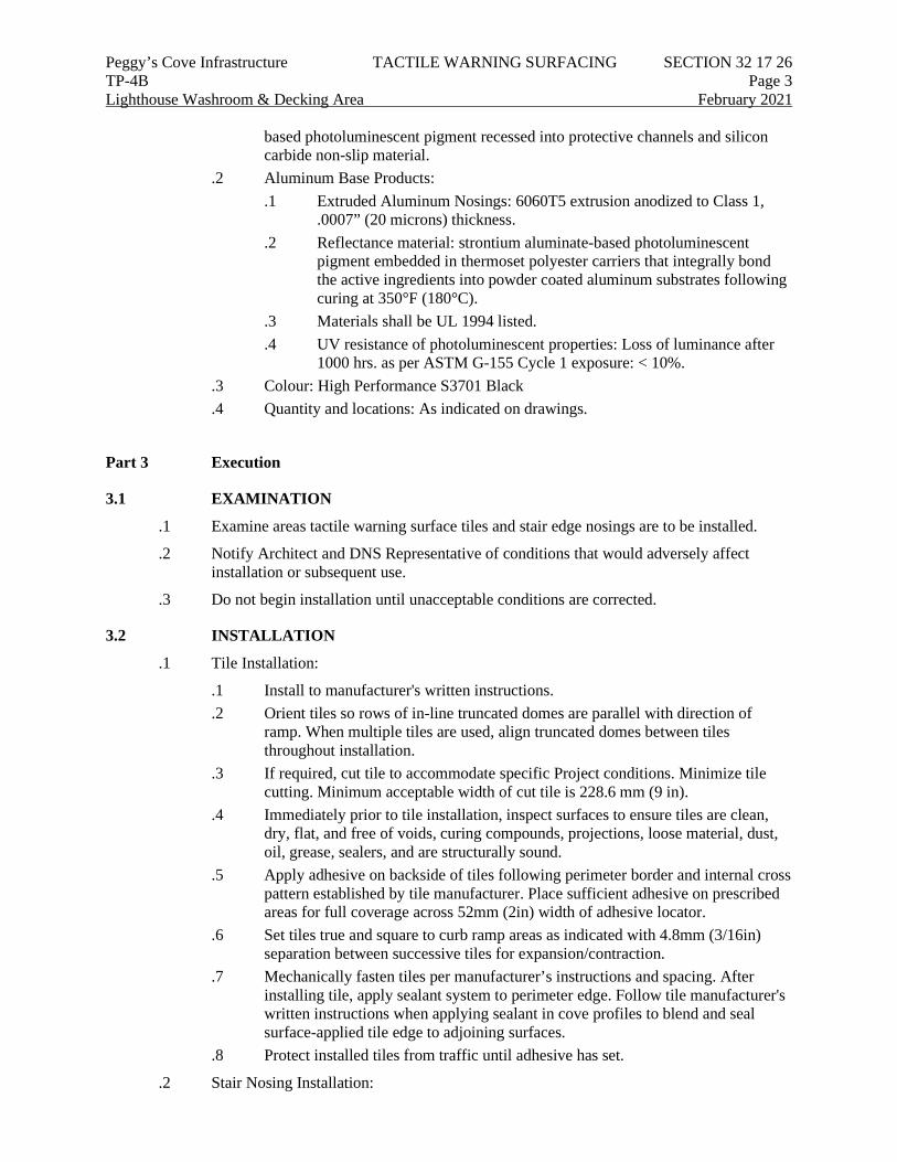
Peggy’s Cove Infrastructure TACTILE WARNING SURFACING SECTION 32 17 26 TP-4B Page 3 Lighthouse Washroom & Decking Area February 2021
based photoluminescent pigment recessed into protective channels and silicon carbide non-slip material.
.2 Aluminum Base Products: .1 Extruded Aluminum Nosings: 6060T5 extrusion anodized to Class 1,
.0007” (20 microns) thickness. .2 Reflectance material: strontium aluminate-based photoluminescent
pigment embedded in thermoset polyester carriers that integrally bond the active ingredients into powder coated aluminum substrates following curing at 350°F (180°C).
.3 Materials shall be UL 1994 listed.
.4 UV resistance of photoluminescent properties: Loss of luminance after 1000 hrs. as per ASTM G-155 Cycle 1 exposure: < 10%.
.3 Colour: High Performance S3701 Black
.4 Quantity and locations: As indicated on drawings.
Part 3 Execution
3.1 EXAMINATION
.1 Examine areas tactile warning surface tiles and stair edge nosings are to be installed.
.2 Notify Architect and DNS Representative of conditions that would adversely affect installation or subsequent use.
.3 Do not begin installation until unacceptable conditions are corrected.
3.2 INSTALLATION
.1 Tile Installation:
.1 Install to manufacturer's written instructions.
.2 Orient tiles so rows of in-line truncated domes are parallel with direction of ramp. When multiple tiles are used, align truncated domes between tiles throughout installation.
.3 If required, cut tile to accommodate specific Project conditions. Minimize tile cutting. Minimum acceptable width of cut tile is 228.6 mm (9 in).
.4 Immediately prior to tile installation, inspect surfaces to ensure tiles are clean, dry, flat, and free of voids, curing compounds, projections, loose material, dust, oil, grease, sealers, and are structurally sound.
.5 Apply adhesive on backside of tiles following perimeter border and internal cross pattern established by tile manufacturer. Place sufficient adhesive on prescribed areas for full coverage across 52mm (2in) width of adhesive locator.
.6 Set tiles true and square to curb ramp areas as indicated with 4.8mm (3/16in) separation between successive tiles for expansion/contraction.
.7 Mechanically fasten tiles per manufacturer’s instructions and spacing. After installing tile, apply sealant system to perimeter edge. Follow tile manufacturer's written instructions when applying sealant in cove profiles to blend and seal surface-applied tile edge to adjoining surfaces.
.8 Protect installed tiles from traffic until adhesive has set.
.2 Stair Nosing Installation:
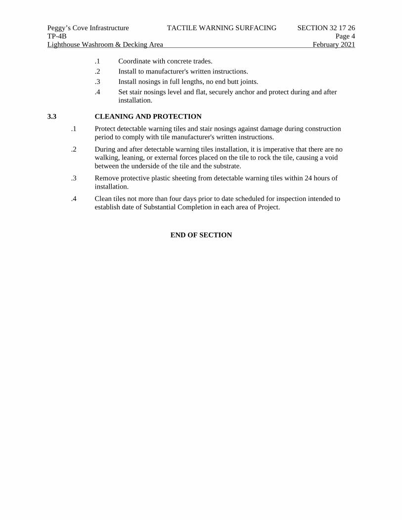
Peggy’s Cove Infrastructure TACTILE WARNING SURFACING SECTION 32 17 26 TP-4B Page 4 Lighthouse Washroom & Decking Area February 2021
.1 Coordinate with concrete trades.
.2 Install to manufacturer's written instructions.
.3 Install nosings in full lengths, no end butt joints.
.4 Set stair nosings level and flat, securely anchor and protect during and after installation.
3.3 CLEANING AND PROTECTION
.1 Protect detectable warning tiles and stair nosings against damage during construction period to comply with tile manufacturer's written instructions.
.2 During and after detectable warning tiles installation, it is imperative that there are no walking, leaning, or external forces placed on the tile to rock the tile, causing a void between the underside of the tile and the substrate.
.3 Remove protective plastic sheeting from detectable warning tiles within 24 hours of installation.
.4 Clean tiles not more than four days prior to date scheduled for inspection intended to establish date of Substantial Completion in each area of Project.
END OF SECTION
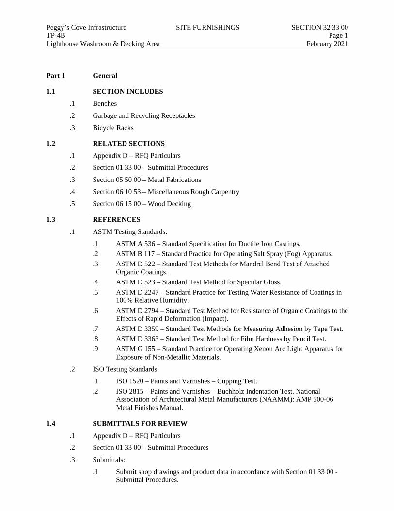
Peggy’s Cove Infrastructure SITE FURNISHINGS SECTION 32 33 00 TP-4B Page 1 Lighthouse Washroom & Decking Area February 2021
Part 1 General
1.1 SECTION INCLUDES
.1 Benches
.2 Garbage and Recycling Receptacles
.3 Bicycle Racks
1.2 RELATED SECTIONS
.1 Appendix D – RFQ Particulars
.2 Section 01 33 00 – Submittal Procedures
.3 Section 05 50 00 – Metal Fabrications
.4 Section 06 10 53 – Miscellaneous Rough Carpentry
.5 Section 06 15 00 – Wood Decking
1.3 REFERENCES
.1 ASTM Testing Standards:
.1 ASTM A 536 – Standard Specification for Ductile Iron Castings.
.2 ASTM B 117 – Standard Practice for Operating Salt Spray (Fog) Apparatus.
.3 ASTM D 522 – Standard Test Methods for Mandrel Bend Test of Attached Organic Coatings.
.4 ASTM D 523 – Standard Test Method for Specular Gloss.
.5 ASTM D 2247 – Standard Practice for Testing Water Resistance of Coatings in 100% Relative Humidity.
.6 ASTM D 2794 – Standard Test Method for Resistance of Organic Coatings to the Effects of Rapid Deformation (Impact).
.7 ASTM D 3359 – Standard Test Methods for Measuring Adhesion by Tape Test.
.8 ASTM D 3363 – Standard Test Method for Film Hardness by Pencil Test.
.9 ASTM G 155 – Standard Practice for Operating Xenon Arc Light Apparatus for Exposure of Non-Metallic Materials.
.2 ISO Testing Standards:
.1 ISO 1520 – Paints and Varnishes – Cupping Test.
.2 ISO 2815 – Paints and Varnishes – Buchholz Indentation Test. National Association of Architectural Metal Manufacturers (NAAMM): AMP 500-06 Metal Finishes Manual.
1.4 SUBMITTALS FOR REVIEW
.1 Appendix D – RFQ Particulars
.2 Section 01 33 00 – Submittal Procedures
.3 Submittals:
.1 Submit shop drawings and product data in accordance with Section 01 33 00 - Submittal Procedures.
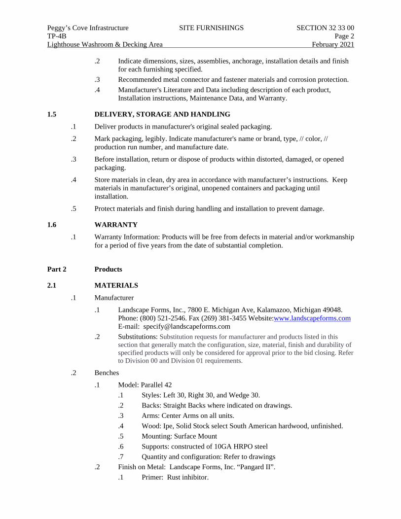
Peggy’s Cove Infrastructure SITE FURNISHINGS SECTION 32 33 00 TP-4B Page 2 Lighthouse Washroom & Decking Area February 2021
.2 Indicate dimensions, sizes, assemblies, anchorage, installation details and finish for each furnishing specified.
.3 Recommended metal connector and fastener materials and corrosion protection.
.4 Manufacturer's Literature and Data including description of each product, Installation instructions, Maintenance Data, and Warranty.
1.5 DELIVERY, STORAGE AND HANDLING
.1 Deliver products in manufacturer's original sealed packaging.
.2 Mark packaging, legibly. Indicate manufacturer's name or brand, type, // color, // production run number, and manufacture date.
.3 Before installation, return or dispose of products within distorted, damaged, or opened packaging.
.4 Store materials in clean, dry area in accordance with manufacturer’s instructions. Keep materials in manufacturer’s original, unopened containers and packaging until installation.
.5 Protect materials and finish during handling and installation to prevent damage.
1.6 WARRANTY
.1 Warranty Information: Products will be free from defects in material and/or workmanship for a period of five years from the date of substantial completion.
Part 2 Products
2.1 MATERIALS
.1 Manufacturer
.1 Landscape Forms, Inc., 7800 E. Michigan Ave, Kalamazoo, Michigan 49048. Phone: (800) 521-2546. Fax (269) 381-3455 Website:www.landscapeforms.com E-mail: [email protected]
.2 Substitutions: Substitution requests for manufacturer and products listed in this section that generally match the configuration, size, material, finish and durability of specified products will only be considered for approval prior to the bid closing. Refer to Division 00 and Division 01 requirements.
.2 Benches
.1 Model: Parallel 42 .1 Styles: Left 30, Right 30, and Wedge 30. .2 Backs: Straight Backs where indicated on drawings. .3 Arms: Center Arms on all units. .4 Wood: Ipe, Solid Stock select South American hardwood, unfinished. .5 Mounting: Surface Mount .6 Supports: constructed of 10GA HRPO steel .7 Quantity and configuration: Refer to drawings
.2 Finish on Metal: Landscape Forms, Inc. “Pangard II”. .1 Primer: Rust inhibitor.
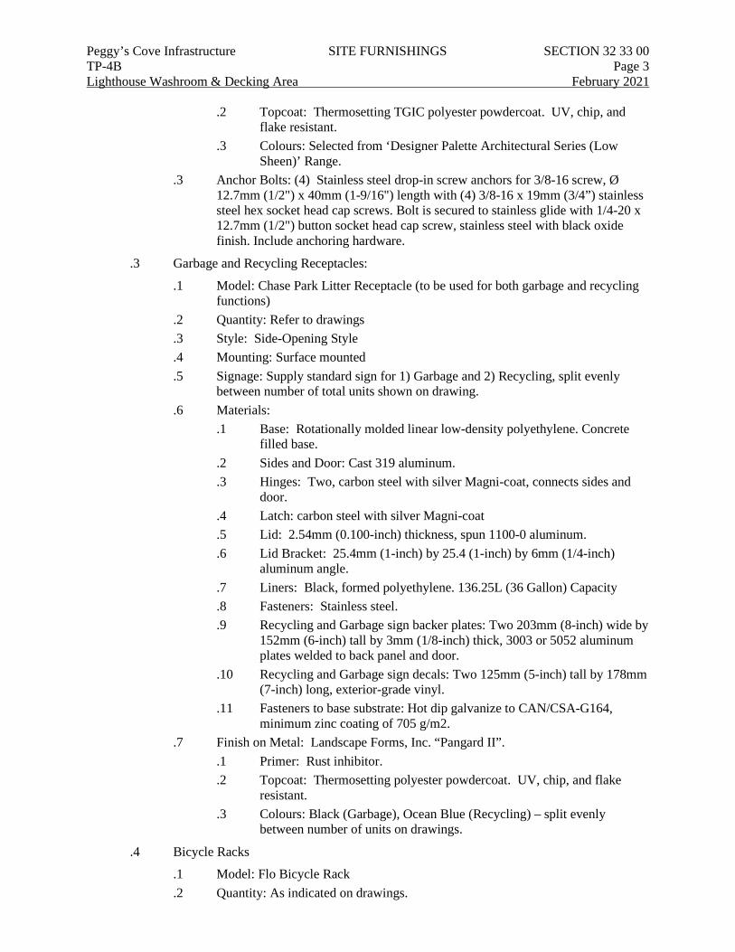
Peggy’s Cove Infrastructure SITE FURNISHINGS SECTION 32 33 00 TP-4B Page 3 Lighthouse Washroom & Decking Area February 2021
.2 Topcoat: Thermosetting TGIC polyester powdercoat. UV, chip, and flake resistant.
.3 Colours: Selected from ‘Designer Palette Architectural Series (Low Sheen)’ Range.
.3 Anchor Bolts: (4) Stainless steel drop-in screw anchors for 3/8-16 screw, Ø 12.7mm (1/2") x 40mm (1-9/16") length with (4) 3/8-16 x 19mm (3/4”) stainless steel hex socket head cap screws. Bolt is secured to stainless glide with 1/4-20 x 12.7mm (1/2") button socket head cap screw, stainless steel with black oxide finish. Include anchoring hardware.
.3 Garbage and Recycling Receptacles:
.1 Model: Chase Park Litter Receptacle (to be used for both garbage and recycling functions)
.2 Quantity: Refer to drawings
.3 Style: Side-Opening Style
.4 Mounting: Surface mounted
.5 Signage: Supply standard sign for 1) Garbage and 2) Recycling, split evenly between number of total units shown on drawing.
.6 Materials: .1 Base: Rotationally molded linear low-density polyethylene. Concrete
filled base. .2 Sides and Door: Cast 319 aluminum. .3 Hinges: Two, carbon steel with silver Magni-coat, connects sides and
door. .4 Latch: carbon steel with silver Magni-coat .5 Lid: 2.54mm (0.100-inch) thickness, spun 1100-0 aluminum. .6 Lid Bracket: 25.4mm (1-inch) by 25.4 (1-inch) by 6mm (1/4-inch)
aluminum angle. .7 Liners: Black, formed polyethylene. 136.25L (36 Gallon) Capacity .8 Fasteners: Stainless steel. .9 Recycling and Garbage sign backer plates: Two 203mm (8-inch) wide by
152mm (6-inch) tall by 3mm (1/8-inch) thick, 3003 or 5052 aluminum plates welded to back panel and door.
.10 Recycling and Garbage sign decals: Two 125mm (5-inch) tall by 178mm (7-inch) long, exterior-grade vinyl.
.11 Fasteners to base substrate: Hot dip galvanize to CAN/CSA-G164, minimum zinc coating of 705 g/m2.
.7 Finish on Metal: Landscape Forms, Inc. “Pangard II”. .1 Primer: Rust inhibitor. .2 Topcoat: Thermosetting polyester powdercoat. UV, chip, and flake
resistant. .3 Colours: Black (Garbage), Ocean Blue (Recycling) – split evenly
between number of units on drawings.
.4 Bicycle Racks
.1 Model: Flo Bicycle Rack
.2 Quantity: As indicated on drawings.
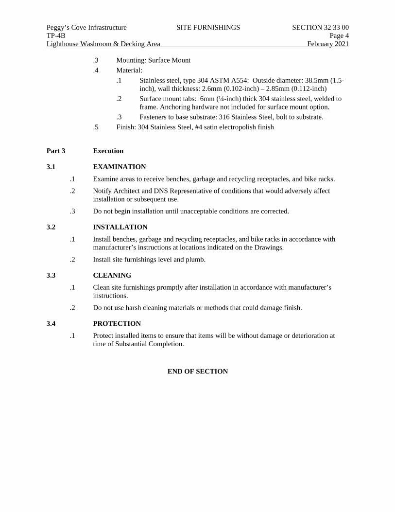
Peggy’s Cove Infrastructure SITE FURNISHINGS SECTION 32 33 00 TP-4B Page 4 Lighthouse Washroom & Decking Area February 2021
.3 Mounting: Surface Mount
.4 Material: .1 Stainless steel, type 304 ASTM A554: Outside diameter: 38.5mm (1.5-
inch), wall thickness: 2.6mm (0.102-inch) – 2.85mm (0.112-inch) .2 Surface mount tabs: 6mm (¼-inch) thick 304 stainless steel, welded to
frame. Anchoring hardware not included for surface mount option. .3 Fasteners to base substrate: 316 Stainless Steel, bolt to substrate.
.5 Finish: 304 Stainless Steel, #4 satin electropolish finish
Part 3 Execution
3.1 EXAMINATION
.1 Examine areas to receive benches, garbage and recycling receptacles, and bike racks.
.2 Notify Architect and DNS Representative of conditions that would adversely affect installation or subsequent use.
.3 Do not begin installation until unacceptable conditions are corrected.
3.2 INSTALLATION
.1 Install benches, garbage and recycling receptacles, and bike racks in accordance with manufacturer’s instructions at locations indicated on the Drawings.
.2 Install site furnishings level and plumb.
3.3 CLEANING
.1 Clean site furnishings promptly after installation in accordance with manufacturer’s instructions.
.2 Do not use harsh cleaning materials or methods that could damage finish.
3.4 PROTECTION
.1 Protect installed items to ensure that items will be without damage or deterioration at time of Substantial Completion.
END OF SECTION
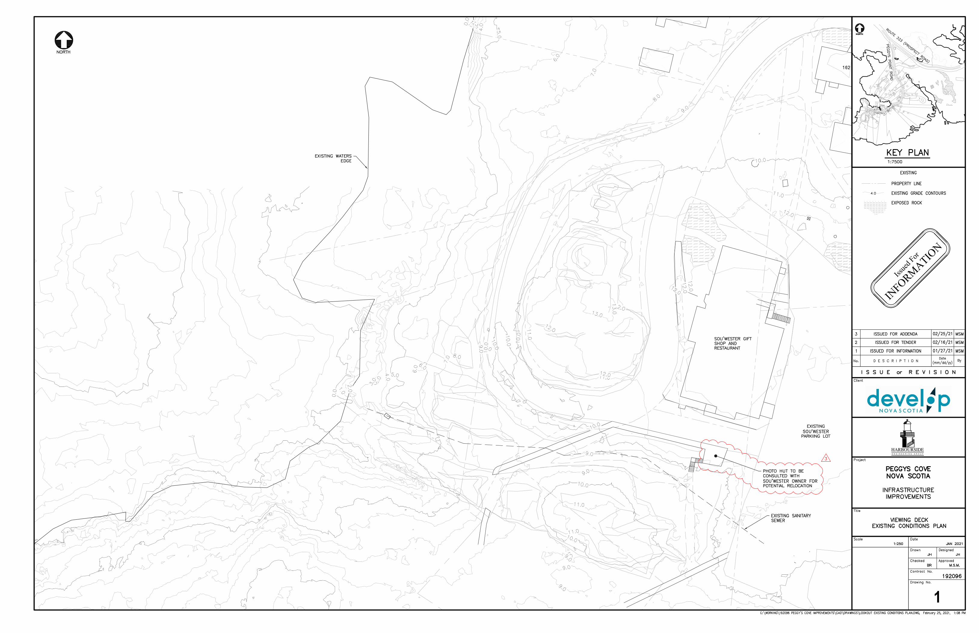
HARBOURSIDEE N G I N E E R I N G G R O U P
1
Issue
d For
INFORMATIO
N
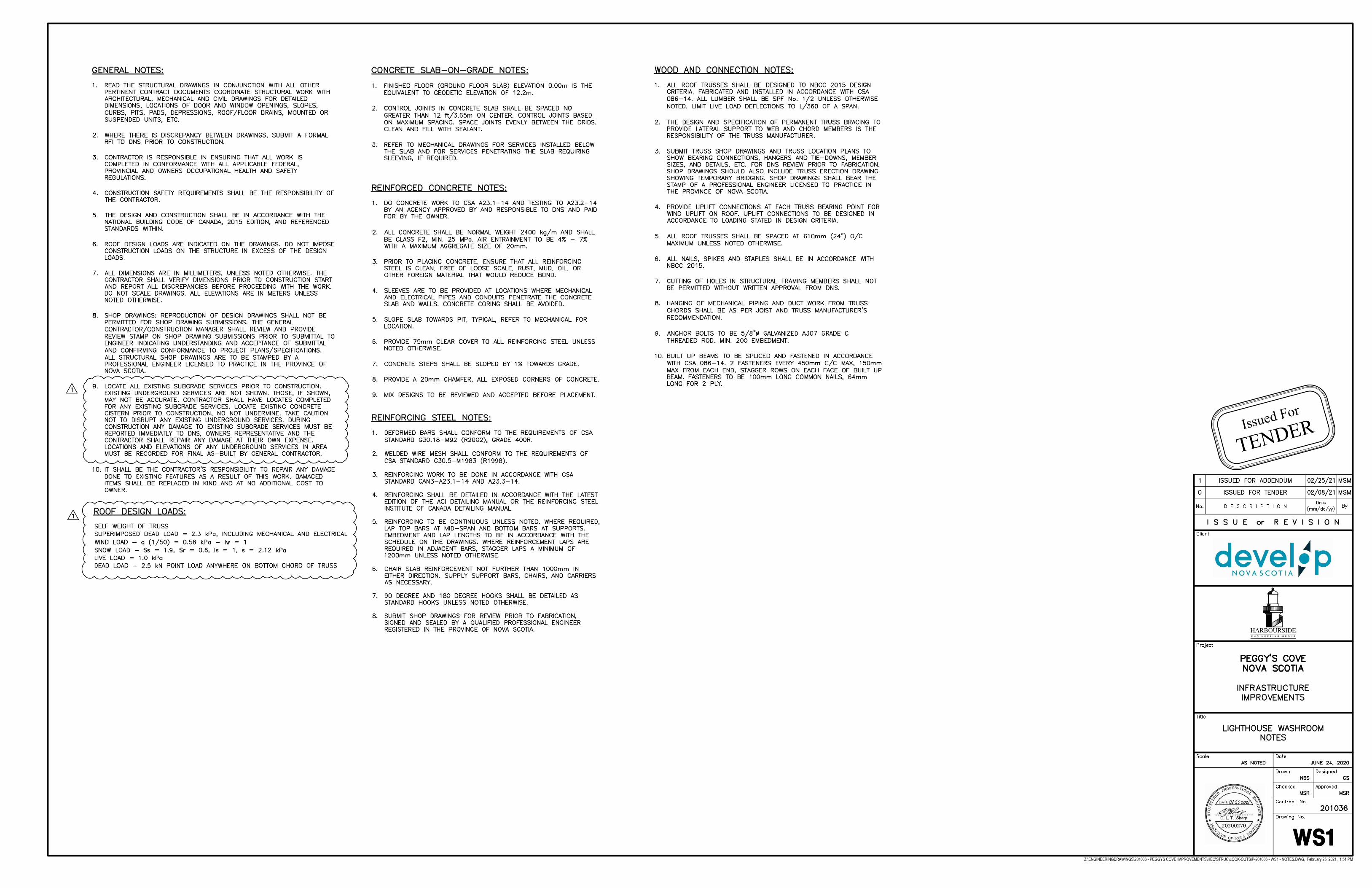
Z:\ENGINEERINGDRAWINGS\201036 - PEGGYS COVE IMPROVEMENTS\HEC\STRUC\LOOK-OUTS\P-201036 - WS1 - NOTES.DWG, February 25, 2021, 1:51 PM
HARBOURSIDEE N G I N E E R I N G G R O U P
Issued For
TENDER
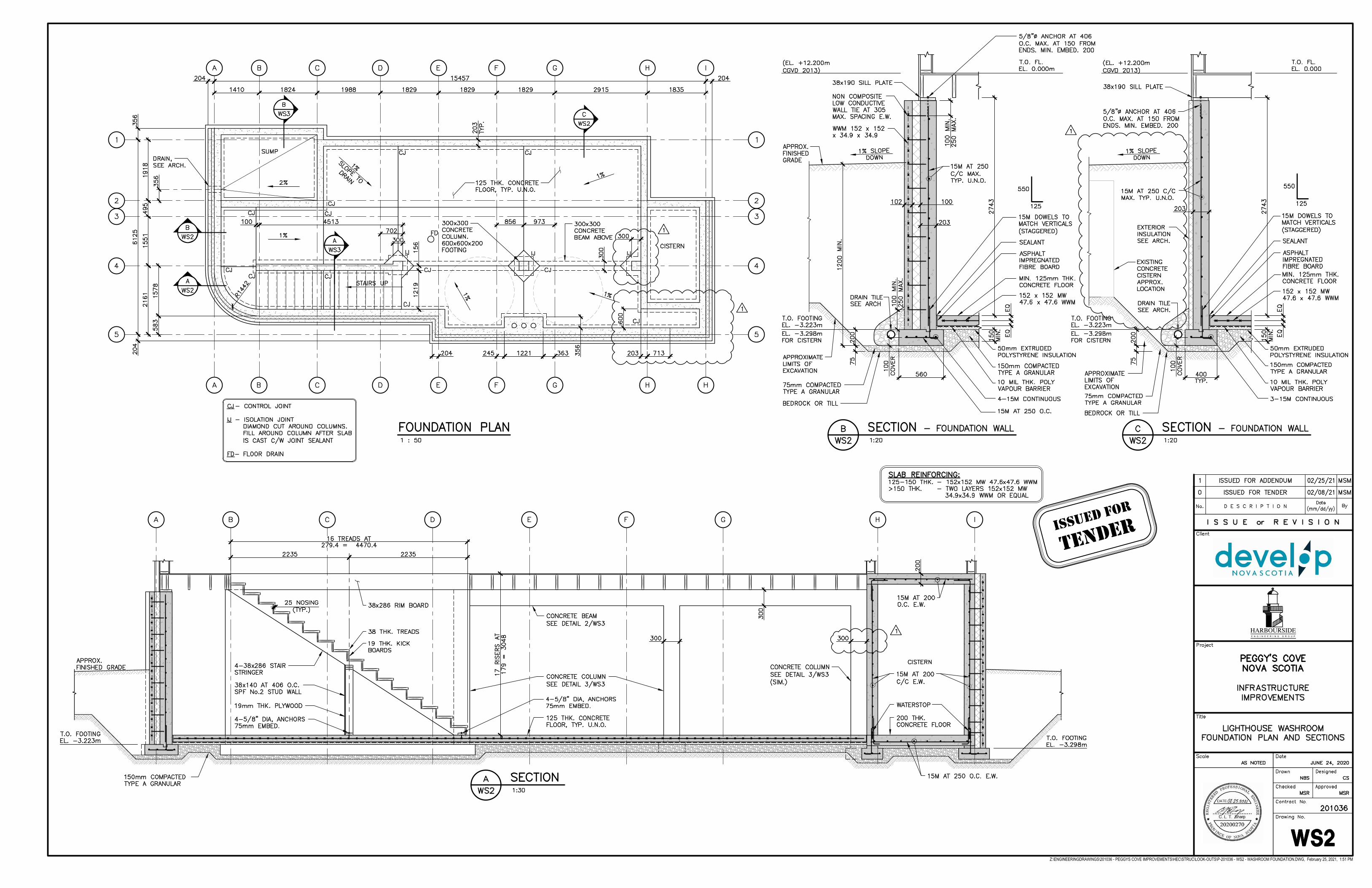
Issued For
TeNder
Z:\ENGINEERINGDRAWINGS\201036 - PEGGYS COVE IMPROVEMENTS\HEC\STRUC\LOOK-OUTS\P-201036 - WS2 - WASHROOM FOUNDATION.DWG, February 25, 2021, 1:51 PM
HARBOURSIDEE N G I N E E R I N G G R O U P
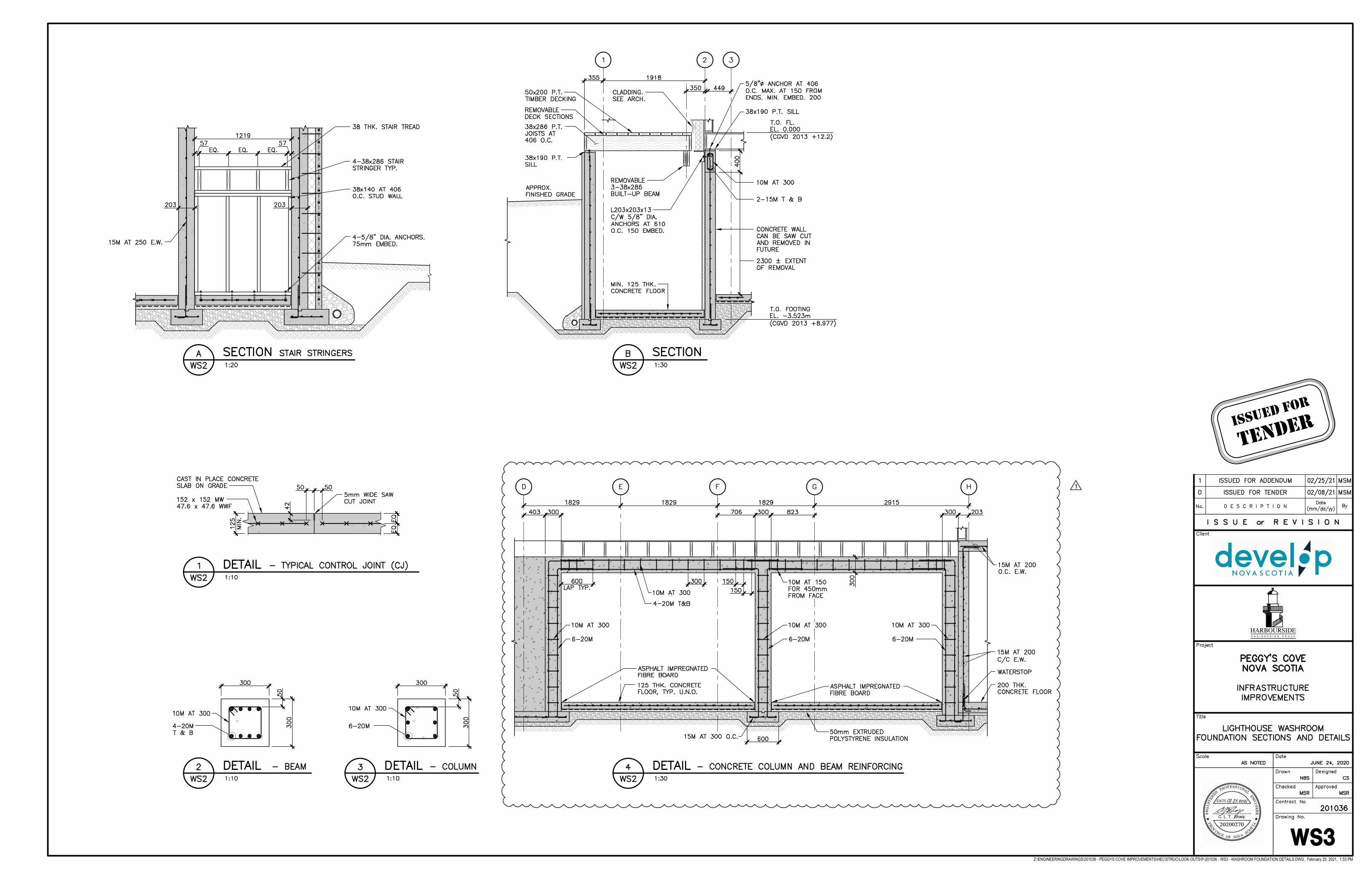
Z:\ENGINEERINGDRAWINGS\201036 - PEGGYS COVE IMPROVEMENTS\HEC\STRUC\LOOK-OUTS\P-201036 - WS3 - WASHROOM FOUNDATION DETAILS.DWG, February 25, 2021, 1:33 PM
HARBOURSIDEE N G I N E E R I N G G R O U P
Issued For
TeNder
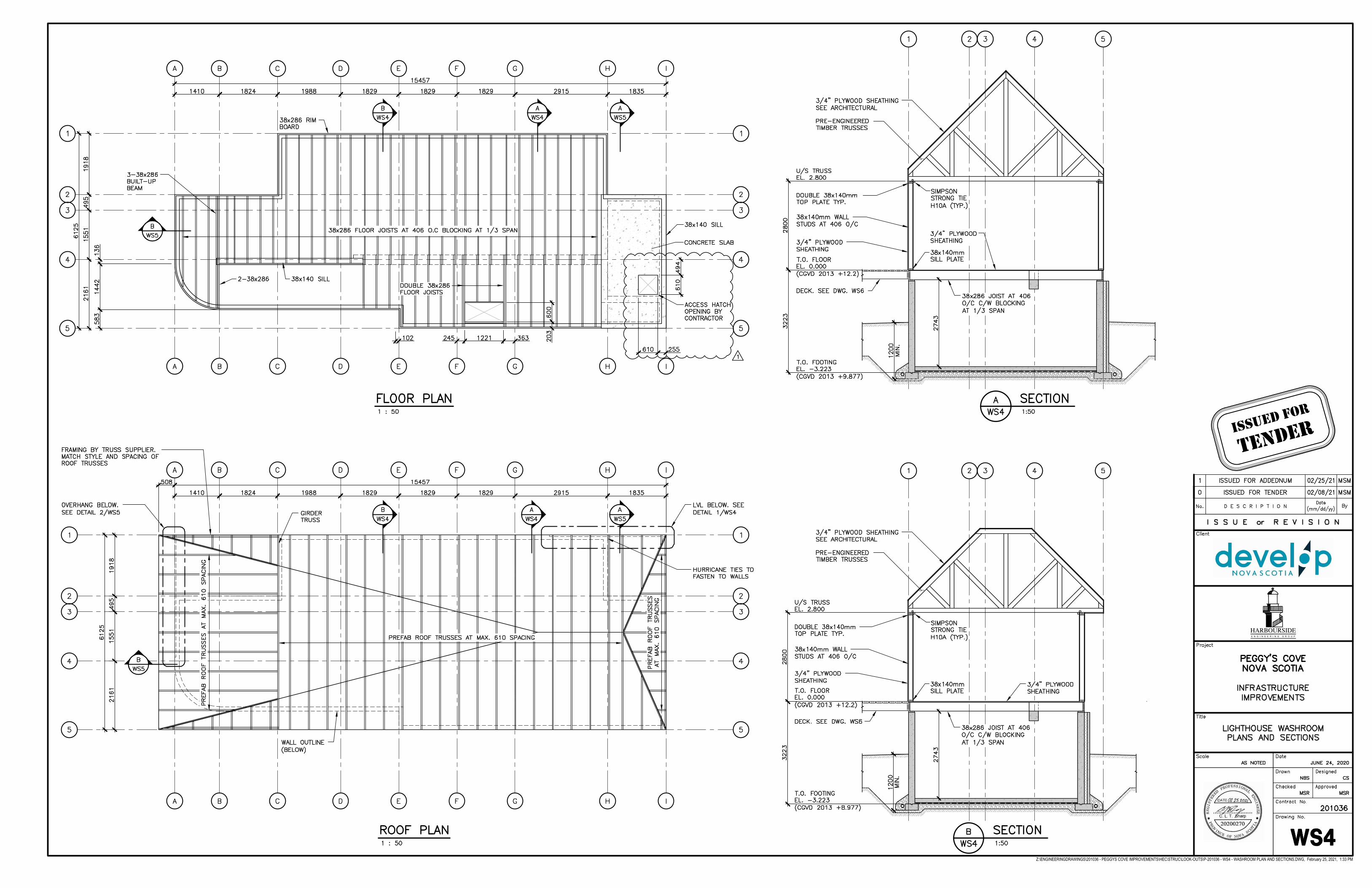
Z:\ENGINEERINGDRAWINGS\201036 - PEGGYS COVE IMPROVEMENTS\HEC\STRUC\LOOK-OUTS\P-201036 - WS4 - WASHROOM PLAN AND SECTIONS.DWG, February 25, 2021, 1:33 PM
HARBOURSIDEE N G I N E E R I N G G R O U P
Issued For
TeNder
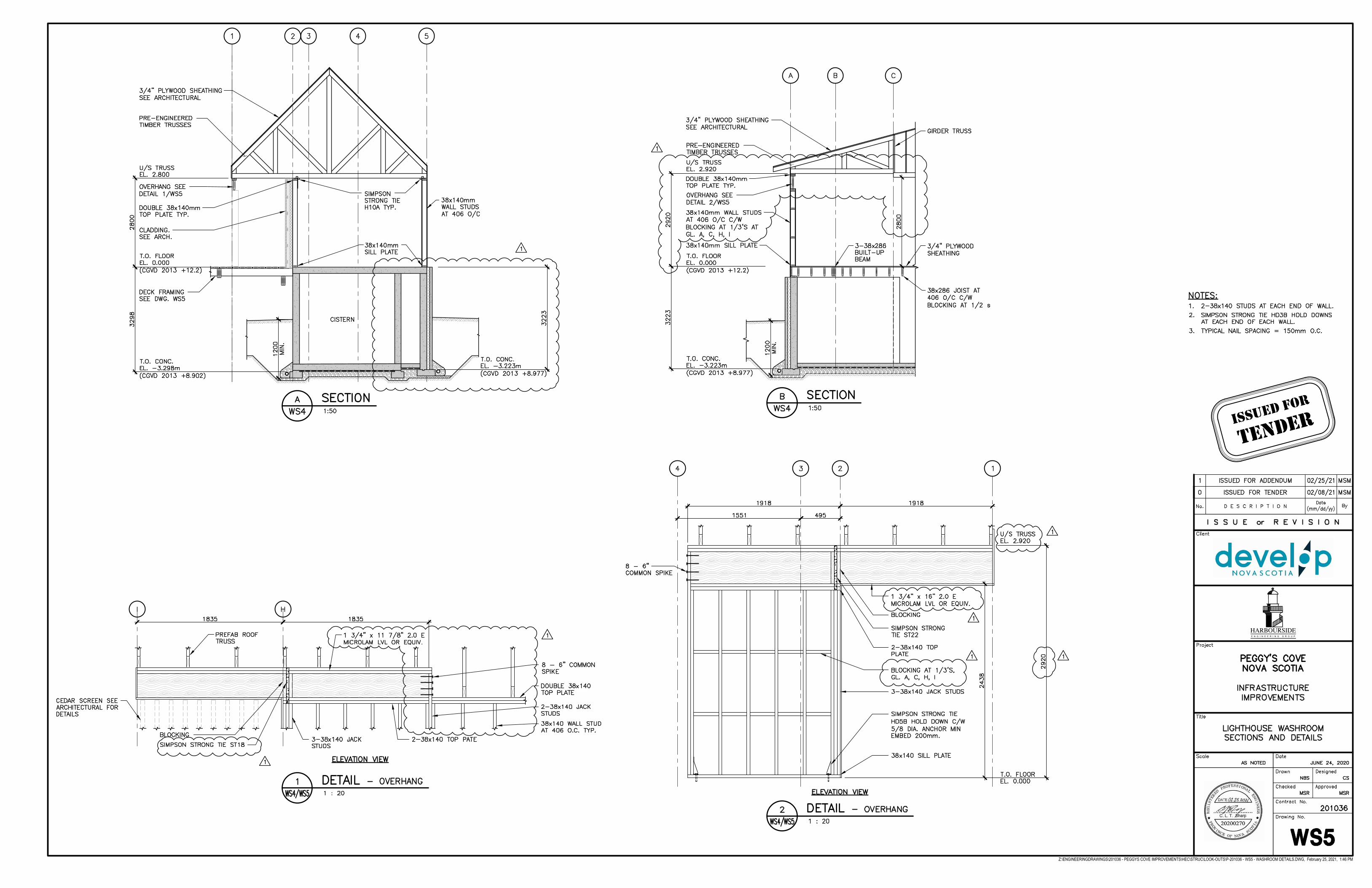
Z:\ENGINEERINGDRAWINGS\201036 - PEGGYS COVE IMPROVEMENTS\HEC\STRUC\LOOK-OUTS\P-201036 - WS5 - WASHROOM DETAILS.DWG, February 25, 2021, 1:46 PM
HARBOURSIDEE N G I N E E R I N G G R O U P
Issued For
TeNder
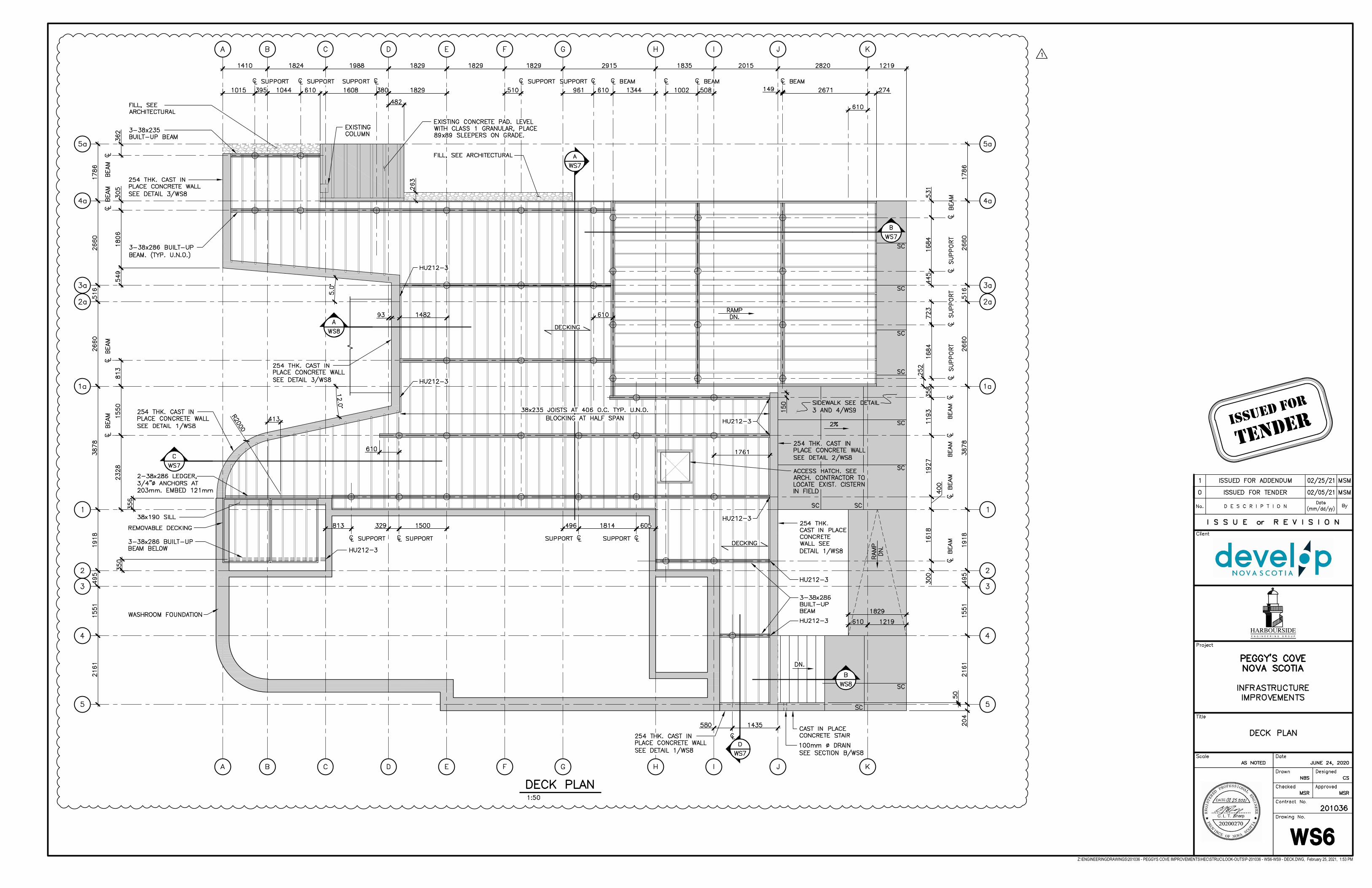
Z:\ENGINEERINGDRAWINGS\201036 - PEGGYS COVE IMPROVEMENTS\HEC\STRUC\LOOK-OUTS\P-201036 - WS6-WS9 - DECK.DWG, February 25, 2021, 1:53 PM
HARBOURSIDEE N G I N E E R I N G G R O U P
Issued For
TeNder
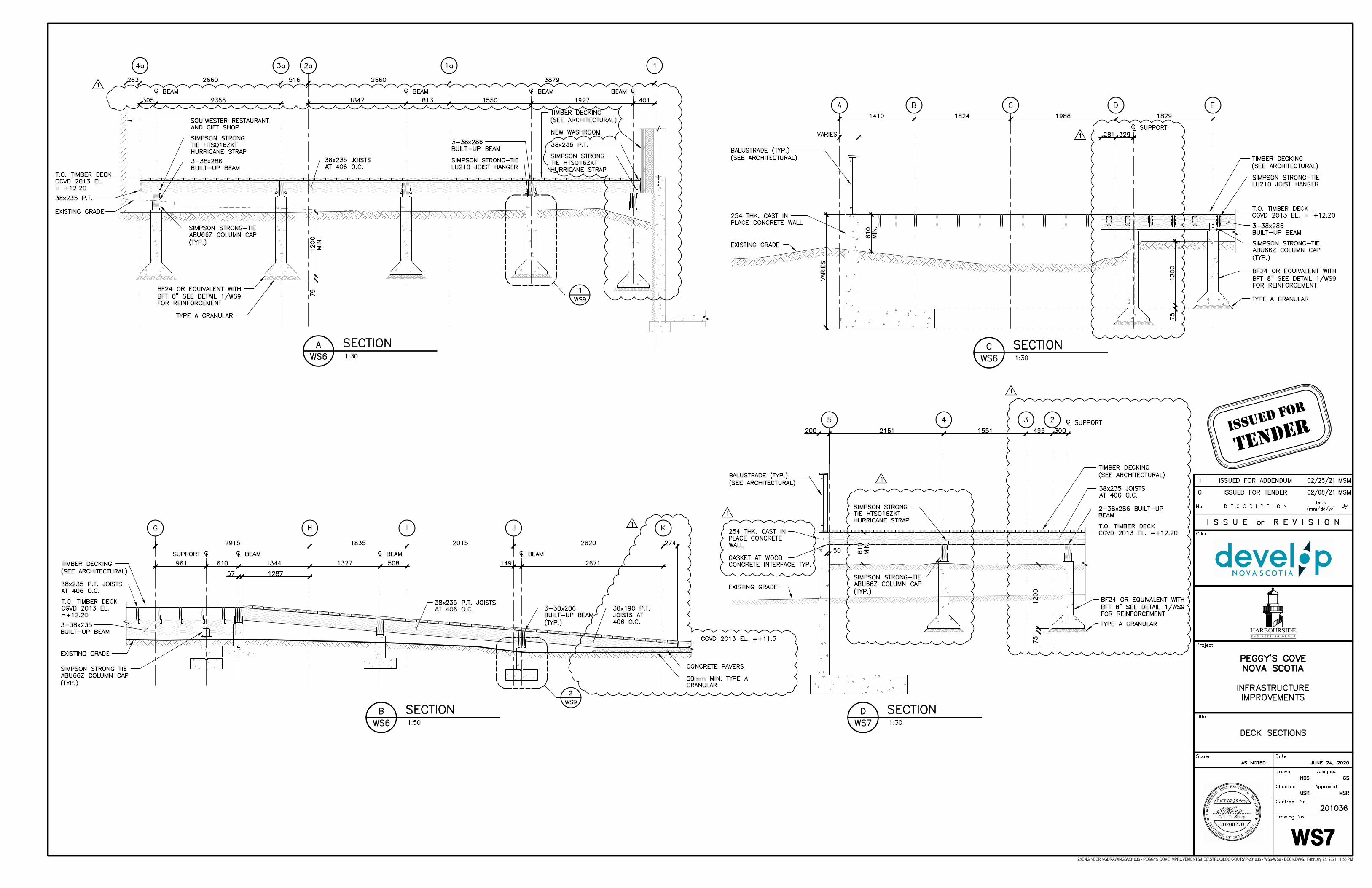
Z:\ENGINEERINGDRAWINGS\201036 - PEGGYS COVE IMPROVEMENTS\HEC\STRUC\LOOK-OUTS\P-201036 - WS6-WS9 - DECK.DWG, February 25, 2021, 1:53 PM
HARBOURSIDEE N G I N E E R I N G G R O U P
Issued For
TeNder
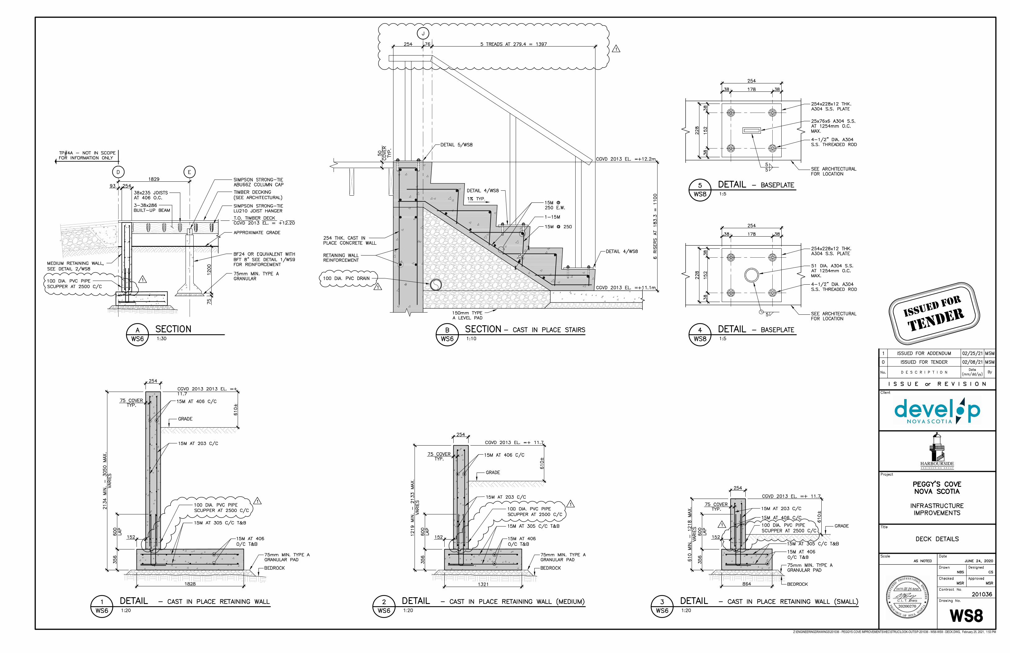
Z:\ENGINEERINGDRAWINGS\201036 - PEGGYS COVE IMPROVEMENTS\HEC\STRUC\LOOK-OUTS\P-201036 - WS6-WS9 - DECK.DWG, February 25, 2021, 1:53 PM
HARBOURSIDEE N G I N E E R I N G G R O U P
Issued For
TeNder
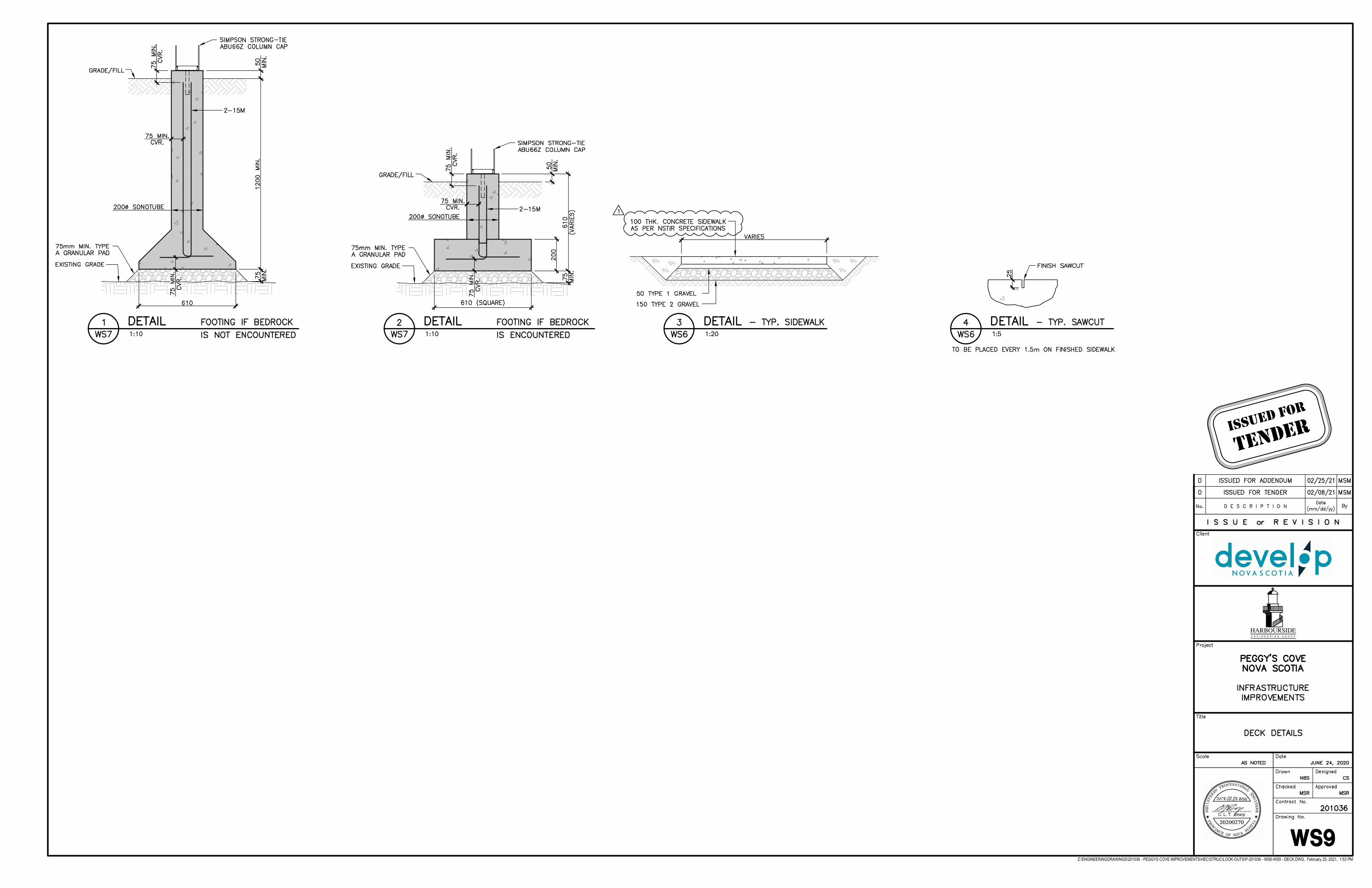
Z:\ENGINEERINGDRAWINGS\201036 - PEGGYS COVE IMPROVEMENTS\HEC\STRUC\LOOK-OUTS\P-201036 - WS6-WS9 - DECK.DWG, February 25, 2021, 1:53 PM
HARBOURSIDEE N G I N E E R I N G G R O U P
Issued For
TeNder
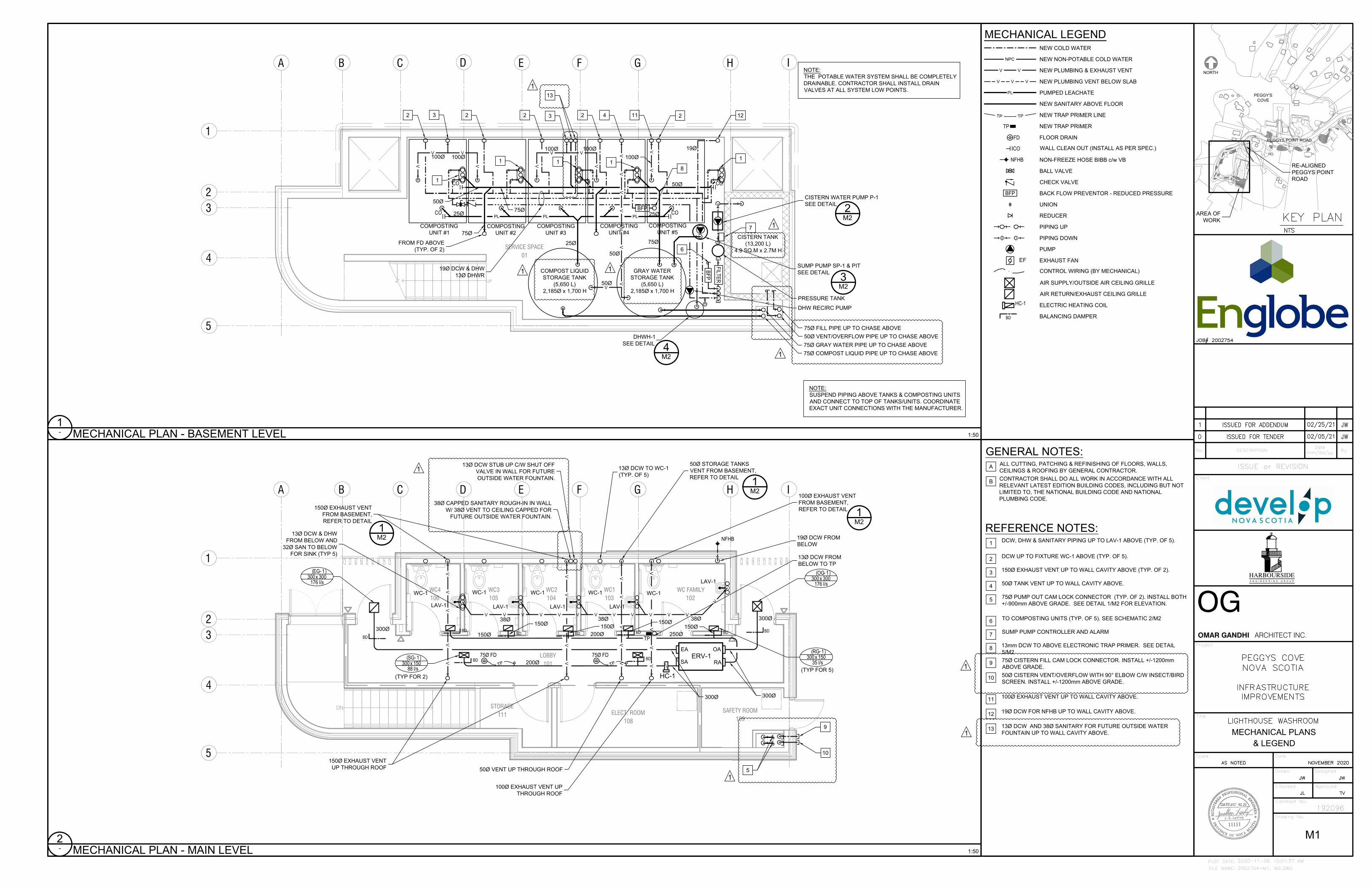
DN
1
4
B IC H
2
A
3
GFED
5
LOBBY101
ELECT. ROOM108
WC1103
WC2104
WC3105
WC FAMILY102
WC4106
SAFETY ROOM109
STORAGE111
VV
VV
V
VV
VV
VV
VV
VV
VV
V
LAV-1
LAV-1 LAV-1 LAV-1
LAV-1
WC-1
WC-1WC-1 WC-1
WC-1
100Ø EXHAUST VENT UP
THROUGH ROOF
50Ø VENT UP THROUGH ROOF
150Ø EXHAUST VENT
UP THROUGH ROOF
100Ø EXHAUST VENT
FROM BASEMENT,
REFER TO DETAIL
1
M2
150Ø EXHAUST VENT
FROM BASEMENT,
REFER TO DETAIL
1
M2
50Ø STORAGE TANKS
VENT FROM BASEMENT,
REFER TO DETAIL
1
M2
75Ø FD
T
P
75Ø FD
T
P
TP
13Ø DCW FROM
BELOW TO TP
13Ø DCW TO WC-1
(TYP. OF 5)
NFHB
5
9
10
V V V V V V V V V V V V
V
38Ø
38Ø38Ø
13Ø DCW & DHW
FROM BELOW AND
32Ø SAN TO BELOW
FOR SINK (TYP 5)
19Ø DCW FROM
BELOW
OA
RA
EA
ERV-1
SA
HC-1
( - )
l/s xOG 1
300 300176
300Ø
( - )
l/s xEG 1
300 300176
( - )
l/s xRG 1
300 15035
( - )
l/s xSG 1
300 15088
(TYP FOR 5)
300Ø
300Ø
300Ø
150Ø
200Ø 250Ø
200Ø
150Ø
BDBD BD BD BD BD BD
150Ø
150Ø
150Ø
BD BD
(TYP FOR 2)
13Ø DCW STUB UP C/W SHUT OFF
VALVE IN WALL FOR FUTURE
OUTSIDE WATER FOUNTAIN.
1
38Ø CAPPED SANITARY ROUGH-IN IN WALL
W/ 38Ø VENT TO CEILING CAPPED FOR
FUTURE OUTSIDE WATER FOUNTAIN.
1
TP
TP
V V
V V V
NEW COLD WATER
NEW PLUMBING & EXHAUST VENT
NEW PLUMBING VENT BELOW SLAB
PUMPED LEACHATE
NEW SANITARY ABOVE FLOOR
NEW TRAP PRIMER LINE
FLOOR DRAIN
WALL CLEAN OUT (INSTALL AS PER SPEC.)
NON-FREEZE HOSE BIBB c/w VB
BALL VALVE
CHECK VALVE
UNION
REDUCER
FD
NFHB
NEW TRAP PRIMER
CO
TP
NPC
NEW NON-POTABLE COLD WATER
MECHANICAL LEGEND
BACK FLOW PREVENTOR - REDUCED PRESSUREBFP
PIPING UP
PIPING DOWN
PL
EFEXHAUST FAN
PUMP
CONTROL WIRING (BY MECHANICAL)
BD
HC-1
AIR SUPPLY/OUTSIDE AIR CEILING GRILLE
AIR RETURN/EXHAUST CEILING GRILLE
ELECTRIC HEATING COIL
BALANCING DAMPER
UP
1
4
B IC H
2
A
3
GFED
5
SERVICE SPACE01
COMPOSTING
UNIT #1
COMPOSTING
UNIT #2
COMPOSTING
UNIT #3
COMPOSTING
UNIT #4
COMPOSTING
UNIT #5
COMPOST LIQUID
STORAGE TANK
(5,650 L)
2,185Ø x 1,700 H
GRAY WATER
STORAGE TANK
(5,650 L)
2,185Ø x 1,700 H
CISTERN TANK
(13,200 L)
4.9 SQ.M x 2.7M H
CO
CO
CO
FILT
ER
V
VV
V
V V V V
V V V
CO
1
2
3
3
CISTERN WATER PUMP P-1
SEE DETAIL
7
8
SUMP PUMP SP-1 & PIT
SEE DETAIL
FROM FD ABOVE
(TYP. OF 2)
PRESSURE TANK
DHW RECIRC PUMP
VV
VV
VV
VV
V
75Ø FILL PIPE UP TO CHASE ABOVE
50Ø VENT/OVERFLOW PIPE UP TO CHASE ABOVE
75Ø GRAY WATER PIPE UP TO CHASE ABOVE
75Ø COMPOST LIQUID PIPE UP TO CHASE ABOVE
DHWH-1
SEE DETAIL
50Ø
25Ø25Ø
25Ø
75Ø
1
1
1
1
2 2 2
2
100Ø100Ø
100Ø 100Ø
50Ø
50Ø
4
BF
P
BFP
1112
75Ø
50Ø
75Ø
100Ø
6
19Ø DCW & DHW
13Ø DHWR
3
M2
2
M2
4
M2
19Ø
PLPL PL
1
1
1
1
13
1
REFERENCE NOTES:
DCW, DHW & SANITARY PIPING UP TO LAV-1 ABOVE (TYP. OF 5).
DCW UP TO FIXTURE WC-1 ABOVE (TYP. OF 5).
150Ø EXHAUST VENT UP TO WALL CAVITY ABOVE (TYP. OF 2).
50Ø TANK VENT UP TO WALL CAVITY ABOVE.
75Ø PUMP OUT CAM LOCK CONNECTOR (TYP. OF 2). INSTALL BOTH
+/-900mm ABOVE GRADE. SEE DETAIL 1/M2 FOR ELEVATION.
TO COMPOSTING UNITS (TYP. OF 5). SEE SCHEMATIC 2/M2
SUMP PUMP CONTROLLER AND ALARM
13mm DCW TO ABOVE ELECTRONIC TRAP PRIMER. SEE DETAIL
5/M2
75Ø CISTERN FILL CAM LOCK CONNECTOR. INSTALL +/-1200mm
ABOVE GRADE.
50Ø CISTERN VENT/OVERFLOW WITH 90° ELBOW C/W INSECT/BIRD
SCREEN. INSTALL +/-1200mm ABOVE GRADE.
100Ø EXHAUST VENT UP TO WALL CAVITY ABOVE.
19Ø DCW FOR NFHB UP TO WALL CAVITY ABOVE.
13Ø DCW AND 38Ø SANITARY FOR FUTURE OUTSIDE WATER
FOUNTAIN UP TO WALL CAVITY ABOVE.
1
2
3
4
5
6
7
8
9
10
11
12
13
GENERAL NOTES:
ALL CUTTING, PATCHING & REFINISHING OF FLOORS, WALLS,
CEILINGS & ROOFING BY GENERAL CONTRACTOR.
CONTRACTOR SHALL DO ALL WORK IN ACCORDANCE WITH ALL
RELEVANT LATEST EDITION BUILDING CODES, INCLUDING BUT NOT
LIMITED TO, THE NATIONAL BUILDING CODE AND NATIONAL
PLUMBING CODE.
A
B
2
-
1:50
MECHANICAL PLAN - MAIN LEVEL
1
-
1:50
MECHANICAL PLAN - BASEMENT LEVEL
M1
MECHANICAL PLANS
& LEGEND
NOTE:
SUSPEND PIPING ABOVE TANKS & COMPOSTING UNITS
AND CONNECT TO TOP OF TANKS/UNITS. COORDINATE
EXACT UNIT CONNECTIONS WITH THE MANUFACTURER.
NOTE:
THE POTABLE WATER SYSTEM SHALL BE COMPLETELY
DRAINABLE. CONTRACTOR SHALL INSTALL DRAIN
VALVES AT ALL SYSTEM LOW POINTS.
HARBOURSIDEE N G I N E E R I N G G R O U P
2002754-M1, M2.DWG
PLOT DATE:
FILE NAME:
Client
Project
Title
Scale Date
Drawn Designed
Checked Approved
Contract No.
Drawing No.
192096
ISSUE or REVISION
No. DESCRIPTION By
Date
mm/dd/yy
OMAR GANDHI ARCHITECT INC.
OG
2020-11-06 10:01:37 AM
NORTH
SOU'WESTER GIFTSHOP AND
RESTAURANT
PEGGY'S POINT ROAD
AREA OF
WORK
PEGGY'S
COVE
RE-ALIGNED
PEGGYS POINT
ROAD
PEGGYS POINT ROAD
1
1
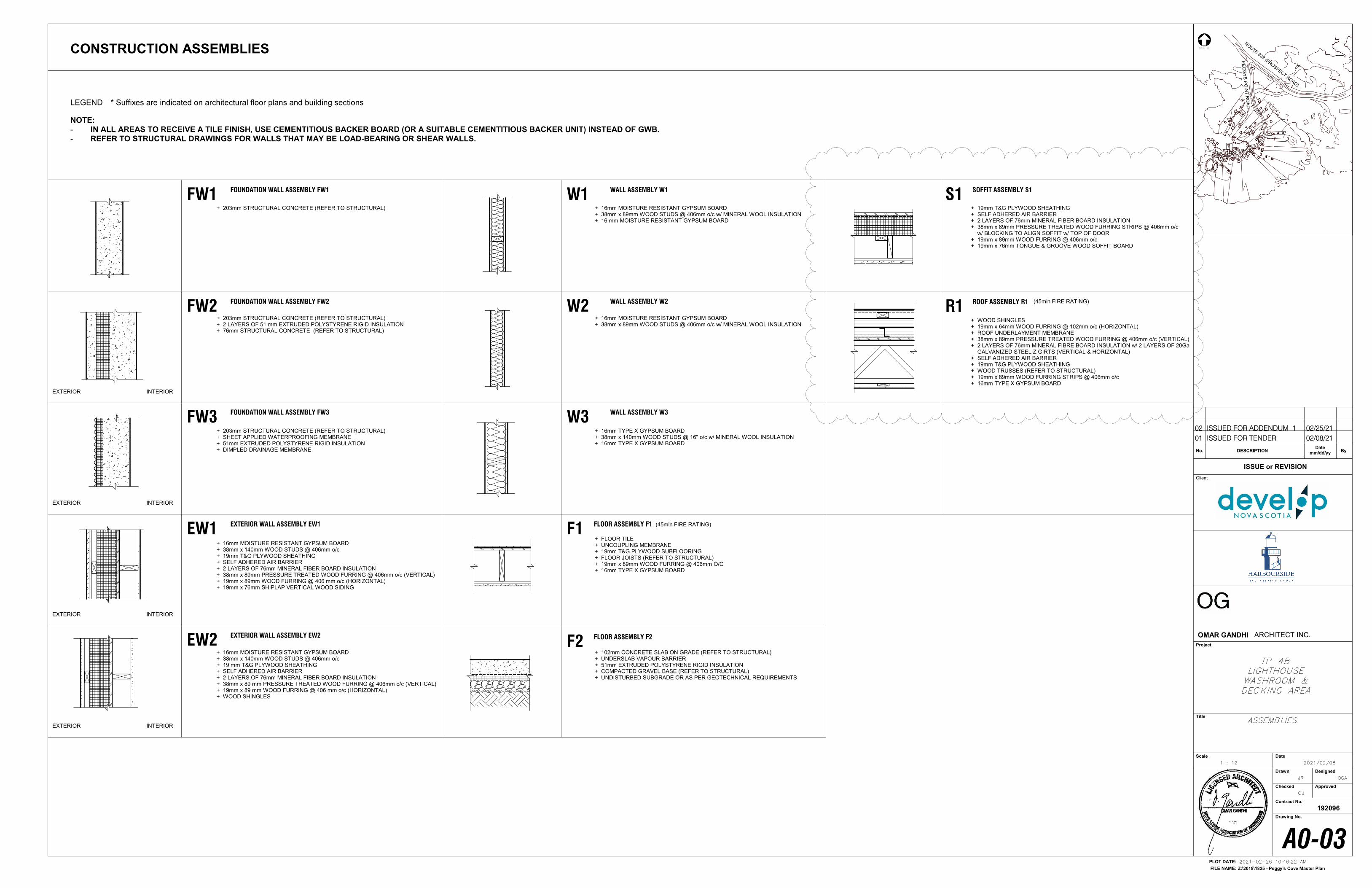
FW1 FOUNDATION WALL ASSEMBLY FW1 W1 WALL ASSEMBLY W1
F2 FLOOR ASSEMBLY F2
F1 FLOOR ASSEMBLY F1
EXTERIOR INTERIOR
FW3 FOUNDATION WALL ASSEMBLY FW3
R1 ROOF ASSEMBLY R1
S1 SOFFIT ASSEMBLY S1
+ 203mm STRUCTURAL CONCRETE (REFER TO STRUCTURAL)
+ 203mm STRUCTURAL CONCRETE (REFER TO STRUCTURAL)+ SHEET APPLIED WATERPROOFING MEMBRANE+ 51mm EXTRUDED POLYSTYRENE RIGID INSULATION+ DIMPLED DRAINAGE MEMBRANE
EXTERIOR INTERIOR
+ 203mm STRUCTURAL CONCRETE (REFER TO STRUCTURAL) + 2 LAYERS OF 51 mm EXTRUDED POLYSTYRENE RIGID INSULATION+ 76mm STRUCTURAL CONCRETE (REFER TO STRUCTURAL)
EXTERIOR INTERIOR
EXTERIOR INTERIOR
+ 16mm MOISTURE RESISTANT GYPSUM BOARD+ 38mm x 140mm WOOD STUDS @ 406mm o/c+ 19mm T&G PLYWOOD SHEATHING+ SELF ADHERED AIR BARRIER+ 2 LAYERS OF 76mm MINERAL FIBER BOARD INSULATION+ 38mm x 89mm PRESSURE TREATED WOOD FURRING @ 406mm o/c (VERTICAL)+ 19mm x 89mm WOOD FURRING @ 406 mm o/c (HORIZONTAL)+ 19mm x 76mm SHIPLAP VERTICAL WOOD SIDING
+ 16mm MOISTURE RESISTANT GYPSUM BOARD+ 38mm x 140mm WOOD STUDS @ 406mm o/c+ 19 mm T&G PLYWOOD SHEATHING+ SELF ADHERED AIR BARRIER+ 2 LAYERS OF 76mm MINERAL FIBER BOARD INSULATION+ 38mm x 89 mm PRESSURE TREATED WOOD FURRING @ 406mm o/c (VERTICAL)+ 19mm x 89 mm WOOD FURRING @ 406 mm o/c (HORIZONTAL)+ WOOD SHINGLES
+ 16mm MOISTURE RESISTANT GYPSUM BOARD+ 38mm x 89mm WOOD STUDS @ 406mm o/c w/ MINERAL WOOL INSULATION+ 16 mm MOISTURE RESISTANT GYPSUM BOARD
+ 16mm MOISTURE RESISTANT GYPSUM BOARD+ 38mm x 89mm WOOD STUDS @ 406mm o/c w/ MINERAL WOOL INSULATION
+ FLOOR TILE+ UNCOUPLING MEMBRANE+ 19mm T&G PLYWOOD SUBFLOORING+ FLOOR JOISTS (REFER TO STRUCTURAL)+ 19mm x 89mm WOOD FURRING @ 406mm O/C+ 16mm TYPE X GYPSUM BOARD
+ 102mm CONCRETE SLAB ON GRADE (REFER TO STRUCTURAL)+ UNDERSLAB VAPOUR BARRIER+ 51mm EXTRUDED POLYSTYRENE RIGID INSULATION+ COMPACTED GRAVEL BASE (REFER TO STRUCTURAL)+ UNDISTURBED SUBGRADE OR AS PER GEOTECHNICAL REQUIREMENTS
+ WOOD SHINGLES+ 19mm x 64mm WOOD FURRING @ 102mm o/c (HORIZONTAL)+ ROOF UNDERLAYMENT MEMBRANE+ 38mm x 89mm PRESSURE TREATED WOOD FURRING @ 406mm o/c (VERTICAL)+ 2 LAYERS OF 76mm MINERAL FIBRE BOARD INSULATION w/ 2 LAYERS OF 20Ga GALVANIZED STEEL Z GIRTS (VERTICAL & HORIZONTAL)+ SELF ADHERED AIR BARRIER+ 19mm T&G PLYWOOD SHEATHING+ WOOD TRUSSES (REFER TO STRUCTURAL)+ 19mm x 89mm WOOD FURRING STRIPS @ 406mm o/c+ 16mm TYPE X GYPSUM BOARD
+ 19mm T&G PLYWOOD SHEATHING+ SELF ADHERED AIR BARRIER+ 2 LAYERS OF 76mm MINERAL FIBER BOARD INSULATION+ 38mm x 89mm PRESSURE TREATED WOOD FURRING STRIPS @ 406mm o/c w/ BLOCKING TO ALIGN SOFFIT w/ TOP OF DOOR+ 19mm x 89mm WOOD FURRING @ 406mm o/c+ 19mm x 76mm TONGUE & GROOVE WOOD SOFFIT BOARD
W2 WALL ASSEMBLY W2
EW2 EXTERIOR WALL ASSEMBLY EW2
EW1 EXTERIOR WALL ASSEMBLY EW1
FW2 FOUNDATION WALL ASSEMBLY FW2
+ 16mm TYPE X GYPSUM BOARD+ 38mm x 140mm WOOD STUDS @ 16" o/c w/ MINERAL WOOL INSULATION+ 16mm TYPE X GYPSUM BOARD
W3 WALL ASSEMBLY W3
(45min FIRE RATING)
(45min FIRE RATING)
NORTH
Z:\2018\1825 - Peggy's Cove Master Plan
PLOT DATE:
FILE NAME:
Client
Project
Title
Scale Date
Drawn Designed
Checked Approved
Contract No.
Drawing No.
192096
ISSUE or REVISION
No. DESCRIPTION ByDate
mm/dd/yy
ROUTE 333 (PRO
SPECT ROAD)
PE
GG
YS
PO
INT
RO
AD
OMAR GANDHI ARCHITECT INC.
2021-02-26 10:46:22 AM
1 : 12
A0-03
JR
CJ
OGA
2021/02/08
ASSEMBLIES
TP 4BLIGHTHOUSEWASHROOM &DECKING AREA
CONSTRUCTION ASSEMBLIES
LEGEND * Suffixes are indicated on architectural floor plans and building sections
NOTE:
- IN ALL AREAS TO RECEIVE A TILE FINISH, USE CEMENTITIOUS BACKER BOARD (OR A SUITABLE CEMENTITIOUS BACKER UNIT) INSTEAD OF GWB.
- REFER TO STRUCTURAL DRAWINGS FOR WALLS THAT MAY BE LOAD-BEARING OR SHEAR WALLS.
01 ISSUED FOR TENDER 02/08/21
02 ISSUED FOR ADDENDUM 1 02/25/21
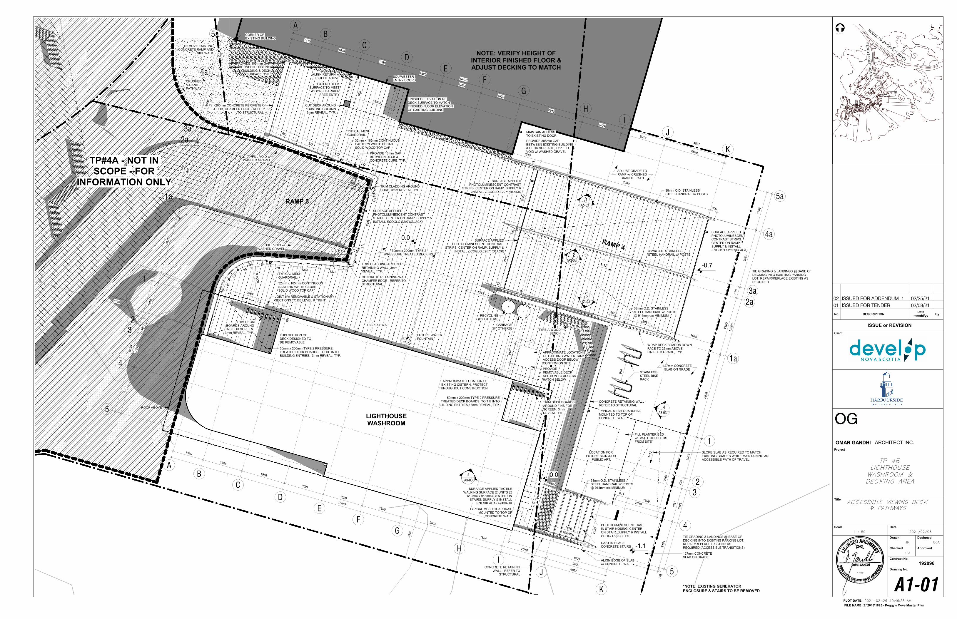
1
1
4
4
B
B
I
I
C
C
H
H
2
2
A
A
3
3
G
G
F
F
E
E
D
D
5
5
GARBAGE (BY OTHERS)
RECYCLING(BY OTHERS)
APPROXIMATE LOCATION OF EXISTING WATER TANK ACCESS DOOR BELOW -CONFIRM ON SITE
914
914
PROVIDE REMOVABLE DECK SECTION TO ACCESS HATCH BELOW
CONCRETE RETAINING WALL -REFER TO STRUCTURAL
PROVIDE 305mm GAP BETWEEN EXISTING BUILDING & DECK SURFACE, TYP. FILL VOID w/ WASHED GRAVEL
RAMP 3
CORNER OF EXISTING BUILDING
TRIM DECK BOARDS AROUND
FINS FOR SCREEN. 3mm REVEAL, TYP.
TRIM DECK BOARDS AROUND FINS FOR SCREEN. 3mm REVEAL, TYP.
TRIM CLADDING AROUND RETAINING WALL, 3mm REVEAL, TYP.
50mm x 200mm TYPE 2 PRESSURE TREATED DECK BOARDS, TO TIE INTO BUILDING ENTRIES,13mm REVEAL, TYP.
32mm x 165mm CONTINUOUS EASTERN WHITE CEDAR SOLID WOOD TOP CAP
TYPICAL MESH GUARDRAIL
FUTURE WATER FOUNTAIN
LIGHTHOUSE WASHROOM
50mm x 200mm TYPE 2 PRESSURE TREATED DECKING
EXTEND DECK SURFACE TO MEET
DOORS, BARRIER FREE ENTRY
*NOTE: EXISTING GENERATOR ENCLOSURE & STAIRS TO BE REMOVED
TIE GRADING & LANDINGS @ BASE OF DECKING INTO EXISTING PARKING LOT. REPAIR/REPLACE EXISTING AS REQUIRED (ACCESSIBLE TRANSITIONS)
RAMP 4
SURFACE APPLIED PHOTOLUMINESCENT CONTRAST
STRIPS. CENTER ON RAMP. SUPPLY & INSTALL ECOGLO E2071(BLACK)
127mm CONCRETE SLAB ON GRADE
127mm CONCRETE SLAB ON GRADE
FILL PLANTER BED w/ SMALL BOULDERS FROM SITE
ALIGN EDGE OF SLAB w/ CONCRETE WALL
TYPICAL MESH GUARDRAIL MOUNTED TO TOP OF
CONCRETE WALL
TYPICAL MESH GUARDRAIL MOUNTED TO TOP OF CONCRETE WALL
CRUSHED GRANITE
PATHWAY
200mm CONCRETE PERIMETER CURB, CHAMFER EDGE - REFER
TO STRUCTURAL
PROVIDE 13mm GAP BETWEEN DECK & CONCRETE CURB, TYP.
PHOTOLUMINESCENT CAST IN STAIR NOSING, CENTER ON STAIR. SUPPLY & INSTALL ECOGLO S3-G, TYP.
TP#4A - NOT IN SCOPE - FOR
INFORMATION ONLY
STAINLESS STEEL BIKE RACK
914
NOTE: VERIFY HEIGHT OF INTERIOR FINISHED FLOOR & ADJUST DECKING TO MATCH
FINISHED ELEVATION OF DECK SURFACE TO MATCH FINISHED FLOOR ELEVATION OF EXISTING BUILDING
REMOVE EXISTING CONCRETE RAMP AND
SIDEWALK
PROVIDE 305 mm GAP BETWEEN EXISTING
BUILDING & DECK SURFACE, TYP.
1:12
J
J
K
K
1a
1a
2a
2a
3a
3a
4a
4a
5a
5a
3878
2660
516
2660
1786
11500
6125
2161
1551
495
1918
15457
4837
1410
1824
1988
1829
1829
1830
2915
1834
2016
2820
6125
11500
2161
1551
495
1918
3878
2660
516
2660
1786
15457
4837
1410
1824
1988
1829
1829
1830
2915
1834
2016
2820
2310
178
611
1699
1:1
2
TIE GRADING & LANDINGS @ BASE OF DECKING INTO EXISTING PARKING LOT. REPAIR/REPLACE EXISTING AS REQUIRED
0.0
CUT DECK AROUND EXISTING COLUMN
13mm REVEAL, TYP.
305
DISPLAY WALL
TYPE A WOOD BENCH
RIGHT w/ BR
TRIM CLADDING AROUND CURB, 3mm REVEAL, TYP.
ALIGN RETURN w/ SOFFIT ABOVE
60°
255
WE
DG
E
1699
2821
2135
6 TREADS
1676
-1.1
0.0
3964
CONCRETE RETAINING WALL - REFER TO
STRUCTURAL
1312
MAINTAIN ACCESS TO EXISTING DOOR
ADJUST GRADE TO RAMP w/ CRUSHED
GRANITE PATH
WRAP DECK BOARDS DOWN FACE TO 25mm ABOVE FINISHED GRADE, TYP.
CAST IN PLACE CONCRETE STAIRS
FILL VOID w/ WASHED GRAVEL
FILL VOID w/ WASHED GRAVEL
CONCRETE RETAINING WALL, CHAMFER EDGE - REFER TO STRUCTURAL
406
2984
THIS SECTION OF DECK DESIGNED TO BE REMOVABLE
JOINT b/w REMOVABLE & STATIONARY SECTIONS TO BE LEVEL & TIGHT
50mm x 200mm TYPE 2 PRESSURE TREATED DECK BOARDS, TO TIE INTO
BUILDING ENTRIES,13mm REVEAL, TYP.ROOF ABOVE
2500
6371
7659
7130
-0.7
38mm O.D. STAINLESS STEEL HANDRAIL w/ POSTS
953
2382
SOU'WESTER ENTRY DOORS
621
12°
20°
20°
20°20° 1278
12781278
2743
113
124
2743
113
SURFACE APPLIED PHOTOLUMINESCENT CONTRAST
STRIPS. CENTER ON RAMP. SUPPLY & INSTALL ECOGLO E2071(BLACK)
SURFACE APPLIED PHOTOLUMINESCENT CONTRAST STRIPS. CENTER ON RAMP. SUPPLY & INSTALL ECOGLO E2071(BLACK)
SURFACE APPLIED PHOTOLUMINESCENT CONTRAST STRIPS. CENTER ON RAMP. SUPPLY & INSTALL ECOGLO E2071(BLACK)
LOCATION FOR FUTURE SIGN &/OR
PUBLIC ART
SLOPE SLAB AS REQUIRED TO MATCH EXISTING GRADES WHILE MAINTAINING AN ACCESSIBLE PATH OF TRAVEL
R 2
000
111
2438
111
5°
621
EQ
EQ
EQ
EQ
5103
TYPICAL MESH GUARDRAIL
32mm x 165mm CONTINUOUS EASTERN WHITE CEDAR SOLID WOOD TOP CAP
1315
7960
305
38mm O.D. STAINLESS STEEL HANDRAIL w/ POSTS
38mm O.D. STAINLESS STEEL HANDRAIL w/ POSTS @ 914mm o/c MINIMUM
38mm O.D. STAINLESS STEEL HANDRAIL w/ POSTS @ 914mm o/c MINIMUM
610
914
SURFACE APPLIED TACTILE WALKING SURFACE (2 UNITS @
610mm x 915mm) CENTER ON STAIRS. SUPPLY & INSTALL
KINESIK ADA-S-2436-BK
A3-03
1
A3-03
3
A3-03
2
A3-03
4
5
A3-03
APPROXIMATE LOCATION OF EXISTING CISTERN, PROTECT
THROUGHOUT CONSTRUCTION
NORTH
Z:\2018\1825 - Peggy's Cove Master Plan
PLOT DATE:
FILE NAME:
Client
Project
Title
Scale Date
Drawn Designed
Checked Approved
Contract No.
Drawing No.
192096
ISSUE or REVISION
No. DESCRIPTION ByDate
mm/dd/yy
ROUTE 333 (PRO
SPECT ROAD)
PE
GG
YS
PO
INT
RO
AD
OMAR GANDHI ARCHITECT INC.
2021-02-26 10:46:28 AM
1 : 50
A1-01
JR
CJ
OGA
2021/02/08
ACCESSIBLE VIEWING DECK& PATHWAYS
TP 4BLIGHTHOUSEWASHROOM &DECKING AREA
01 ISSUED FOR TENDER 02/08/21
02 ISSUED FOR ADDENDUM 1 02/25/21
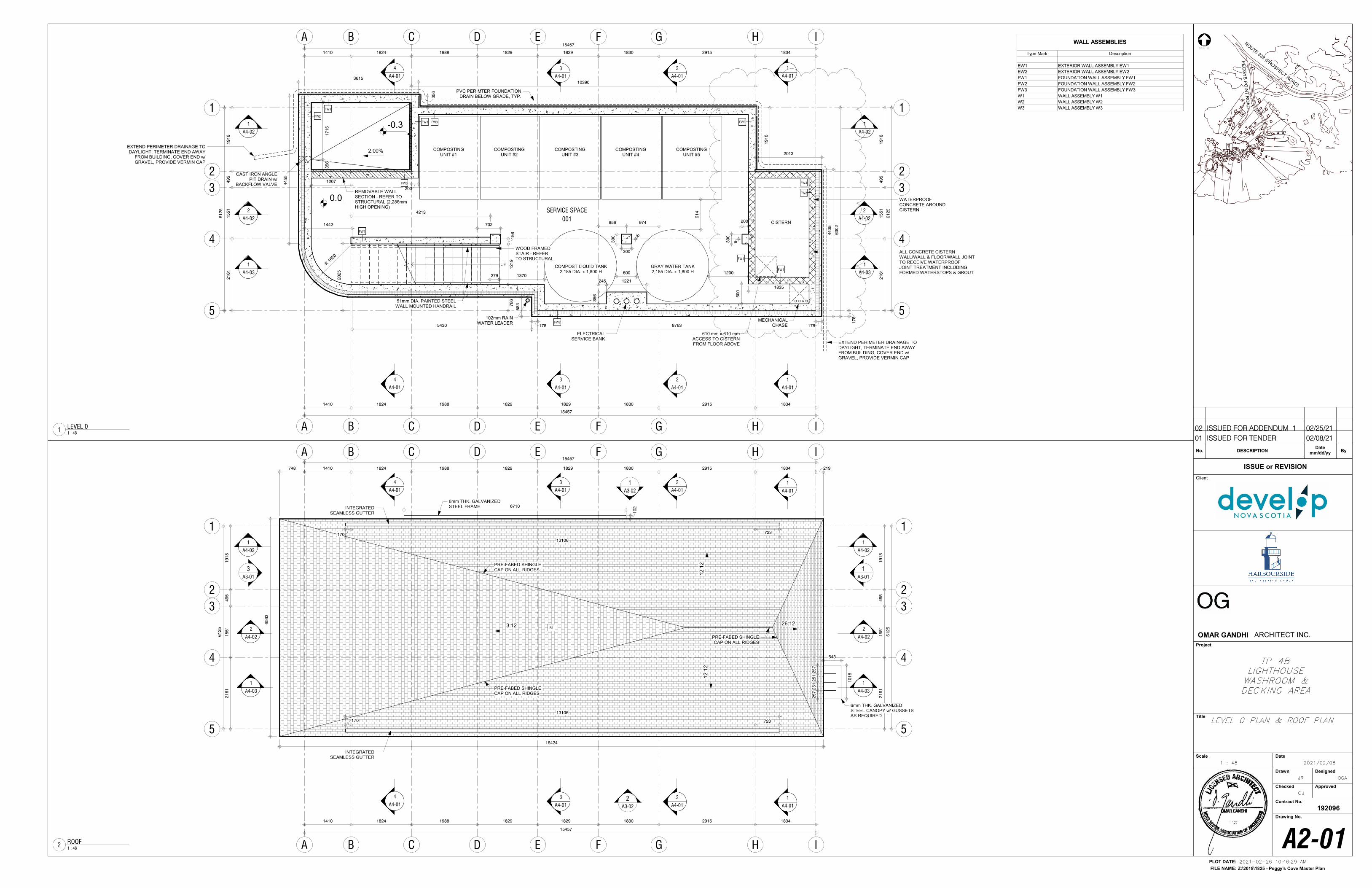
UP
2
A4-01
2
A4-01
11
44
B
B
I
I
2
A4-02
2
A4-02
1
A4-01
1
A4-01
1
A4-02
1
A4-02
SERVICE SPACE
001
C
C
H
H
22
A
A
4
A4-01
4
A4-01
FW3
33
G
G
F
F
E
E
D
D
1
A4-03
1
A4-03
55
3
A4-01
3
A4-01
21
61
15
51
49
51
91
8
15457
1410 1824 1988 1829 1829 1830 2915 1834
15457
1410 1824 1988 1829 1829 1830 2915 1834
44
35
63
02
21
61
15
51
49
51
91
8
203
17
8
178
CISTERN
12
19
702
4213
15
67
86
FW3
FW3
FW1
FW3
FW2
FW3
279
MECHANICAL CHASE
610 mm x 610 mm ACCESS TO CISTERN FROM FLOOR ABOVE
COMPOST LIQUID TANK2,185 DIA. x 1,800 H
GRAY WATER TANK2,185 DIA. x 1,800 H
COMPOSTING UNIT #1
COMPOSTING UNIT #2
COMPOSTING UNIT #3
COMPOSTING UNIT #4
COMPOSTING UNIT #5
PVC PERIMTER FOUNDATION DRAIN BELOW GRADE, TYP.
60
0
WATERPROOF CONCRETE AROUND CISTERN
ALL CONCRETE CISTERN WALL/WALL & FLOOR/WALL JOINT TO RECEIVE WATERPROOF JOINT TREATMENT INCLUDING FORMED WATERSTOPS & GROUT1200
91
4
FW2
61
25
1835
6001370
61
25
CAST IRON ANGLE PIT DRAIN w/
BACKFLOW VALVE
35
61
71
5
2.00%
FW3
EXTEND PERIMETER DRAINAGE TO DAYLIGHT, TERMINATE END AWAY
FROM BUILDING, COVER END w/ GRAVEL, PROVIDE VERMIN CAP
44
55
R 162
0
1442
20
25
5430
58
3
102mm RAIN WATER LEADER
8763178
2013
19
18
10390
35
6
3615
FW2
FW1
FW1
EXTEND PERIMETER DRAINAGE TO DAYLIGHT, TERMINATE END AWAY FROM BUILDING, COVER END w/ GRAVEL, PROVIDE VERMIN CAP
WOOD FRAMED STAIR - REFER TO STRUCTURAL
51mm DIA. PAINTED STEEL WALL MOUNTED HANDRAIL
-0.3
REMOVABLE WALL SECTION - REFER TO STRUCTURAL (2,286mm HIGH OPENING)
1207
0.0
856 974
6
30
0
300
200
30
0
6
ELECTRICAL SERVICE BANK
35
6
1221245
2
A4-01
2
A4-01
11
44
B
B
I
I
2
A4-02
2
A4-02
A3-02
1
A3-02
2
A3-01
1A3-01
3
1
A4-01
1
A4-01
1
A4-02
1
A4-02
C
C
H
H
22
A
A
4
A4-01
4
A4-01
INTEGRATED SEAMLESS GUTTER
33
G
G
F
F
E
E
D
D
15457
1410 1824 1988 1829 1829 1830 2915 1834
21
61
15
51
49
51
91
8
1
A4-03
1
A4-03
55
3
A4-01
3
A4-01
21
61
15
51
49
51
91
8
15457
1410 1824 1988 1829 1829 1830 2915 1834
INTEGRATED SEAMLESS GUTTER
26:123:12
12:1
212:1
2
61
25
61
25
PRE-FABED SHINGLE CAP ON ALL RIDGES
PRE-FABED SHINGLE CAP ON ALL RIDGES
6mm THK. GALVANIZED STEEL CANOPY w/ GUSSETS AS REQUIRED
25
72
51
25
12
57
543
10
16
6mm THK. GALVANIZED STEEL FRAME
PRE-FABED SHINGLE CAP ON ALL RIDGES
170
13106
723
219
10
26710
170
13106
723
R1
65
63
16424
748
1 : 48
LEVEL 01
WALL ASSEMBLIES
Type Mark Description
EW1 EXTERIOR WALL ASSEMBLY EW1
EW2 EXTERIOR WALL ASSEMBLY EW2
FW1 FOUNDATION WALL ASSEMBLY FW1
FW2 FOUNDATION WALL ASSEMBLY FW2
FW3 FOUNDATION WALL ASSEMBLY FW3
W1 WALL ASSEMBLY W1
W2 WALL ASSEMBLY W2
W3 WALL ASSEMBLY W3
1 : 48
ROOF2
NORTH
Z:\2018\1825 - Peggy's Cove Master Plan
PLOT DATE:
FILE NAME:
Client
Project
Title
Scale Date
Drawn Designed
Checked Approved
Contract No.
Drawing No.
192096
ISSUE or REVISION
No. DESCRIPTION ByDate
mm/dd/yy
ROUTE 333 (PRO
SPECT ROAD)
PE
GG
YS
PO
INT
RO
AD
OMAR GANDHI ARCHITECT INC.
2021-02-26 10:46:29 AM
1 : 48
A2-01
JR
CJ
OGA
2021/02/08
LEVEL 0 PLAN & ROOF PLAN
TP 4BLIGHTHOUSEWASHROOM &DECKING AREA
01 ISSUED FOR TENDER 02/08/21
02 ISSUED FOR ADDENDUM 1 02/25/21
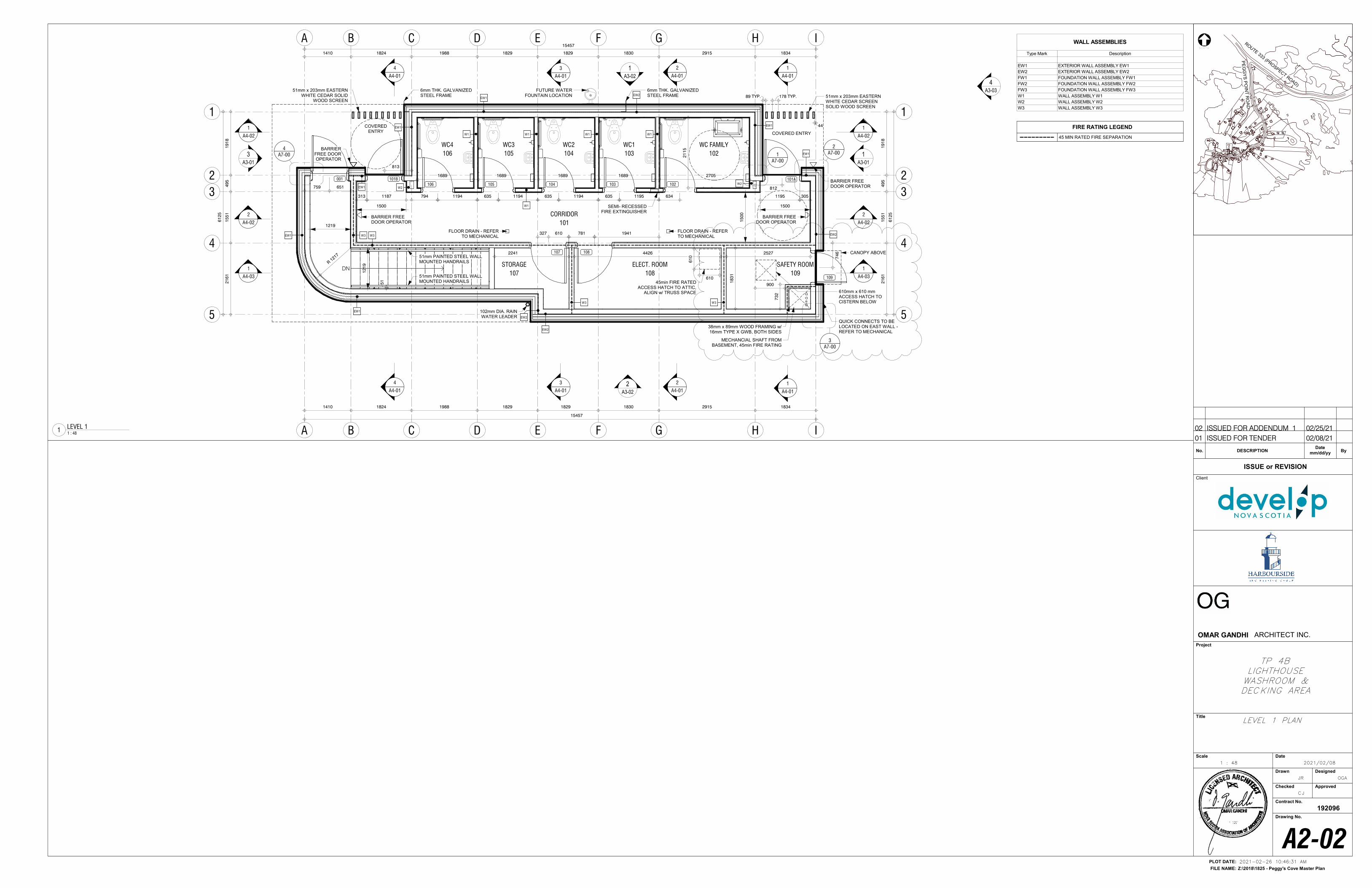
DN
2
A4-01
2
A4-01
11
44
B
B
I
I
2
A4-02
2
A4-02
A3-02
1
A3-02
2
A3-01
1A3-01
3
1
A4-01
1
A4-01
1
A4-02
1
A4-02
CORRIDOR
101
C
C
H
H
22
1410 1824 1988 1829 1829 1830 2915 1834
COVERED ENTRY
1689 1689 1689 2705
15001500
EW1
W3
W1
EW1
EW1
A
A
4
A4-01
4
A4-01
1689
ELECT. ROOM
108
A7-00
1 A7-00
2
A7-00
3
305 33
G
G
F
F
E
E
D
D
15457
21
61
15
51
49
51
91
8
WC1
103
103
WC2
104
104
WC3
105
105
WC FAMILY
102
102
15
00
101A
W1 W1 W1
W2
EW2
COVERED ENTRY
634635635635
812
1
A4-03
1
A4-03
89 TYP. 51mm x 203mm EASTERN WHITE CEDAR SCREEN SOLID WOOD SCREEN
44
51mm x 203mm EASTERN WHITE CEDAR SOLID
WOOD SCREEN
W1
178 TYP.
BARRIER FREE DOOR OPERATOR
BARRIER FREE DOOR OPERATOR
55
3
A4-01
3
A4-01
21
61
15
51
49
51
91
8
15457
1410 1824 1988 1829 1829 1830 2915 1834
1941
794
WC4
106
106
101B
109
108
001
A7-00
4
EW1
EW1
610mm x 610 mm ACCESS HATCH TO CISTERN BELOW
EW1
EW2
W3
QUICK CONNECTS TO BE LOCATED ON EAST WALL -REFER TO MECHANICAL
1194 1194 1194 11951187313
51mm PAINTED STEEL WALL MOUNTED HANDRAILS
BARRIER FREE DOOR OPERATOR
BARRIER FREE DOOR OPERATOR
781
SEMI- RECESSED FIRE EXTINGUISHER
45min FIRE RATED ACCESS HATCH TO ATTIC,
ALIGN w/ TRUSS SPACE
1219
SAFETY ROOM
109
4426
327 610
900
107
STORAGE
107
2241
R 121
7
W3
61
25
61
25
102mm DIA. RAIN WATER LEADER
EW2
EW2
MECHANCIAL SHAFT FROM BASEMENT, 45min FIRE RATING
38mm x 89mm WOOD FRAMING w/ 16mm TYPE X GWB, BOTH SIDES
73
2
51mm PAINTED STEEL WALL MOUNTED HANDRAILS5
1
W3
2527
18
31
CANOPY ABOVE
61
0
610
12
19
EW1
21
15
FUTURE WATER FOUNTAIN LOCATION
74
6
6mm THK. GALVANIZED STEEL FRAME
6mm THK. GALVANIZED STEEL FRAME
W2
813
1195
759 651
FLOOR DRAIN - REFER TO MECHANICAL
FLOOR DRAIN - REFER TO MECHANICAL
A3-03
4
NORTH
Z:\2018\1825 - Peggy's Cove Master Plan
PLOT DATE:
FILE NAME:
Client
Project
Title
Scale Date
Drawn Designed
Checked Approved
Contract No.
Drawing No.
192096
ISSUE or REVISION
No. DESCRIPTION ByDate
mm/dd/yy
ROUTE 333 (PRO
SPECT ROAD)
PE
GG
YS
PO
INT
RO
AD
OMAR GANDHI ARCHITECT INC.
2021-02-26 10:46:31 AM
1 : 48
A2-02
JR
CJ
OGA
2021/02/08
LEVEL 1 PLAN
TP 4BLIGHTHOUSEWASHROOM &DECKING AREA
1 : 48
LEVEL 11
WALL ASSEMBLIES
Type Mark Description
EW1 EXTERIOR WALL ASSEMBLY EW1
EW2 EXTERIOR WALL ASSEMBLY EW2
FW1 FOUNDATION WALL ASSEMBLY FW1
FW2 FOUNDATION WALL ASSEMBLY FW2
FW3 FOUNDATION WALL ASSEMBLY FW3
W1 WALL ASSEMBLY W1
W2 WALL ASSEMBLY W2
W3 WALL ASSEMBLY W3
FIRE RATING LEGEND
45 MIN RATED FIRE SEPARATION
01 ISSUED FOR TENDER 02/08/21
02 ISSUED FOR ADDENDUM 1 02/25/21
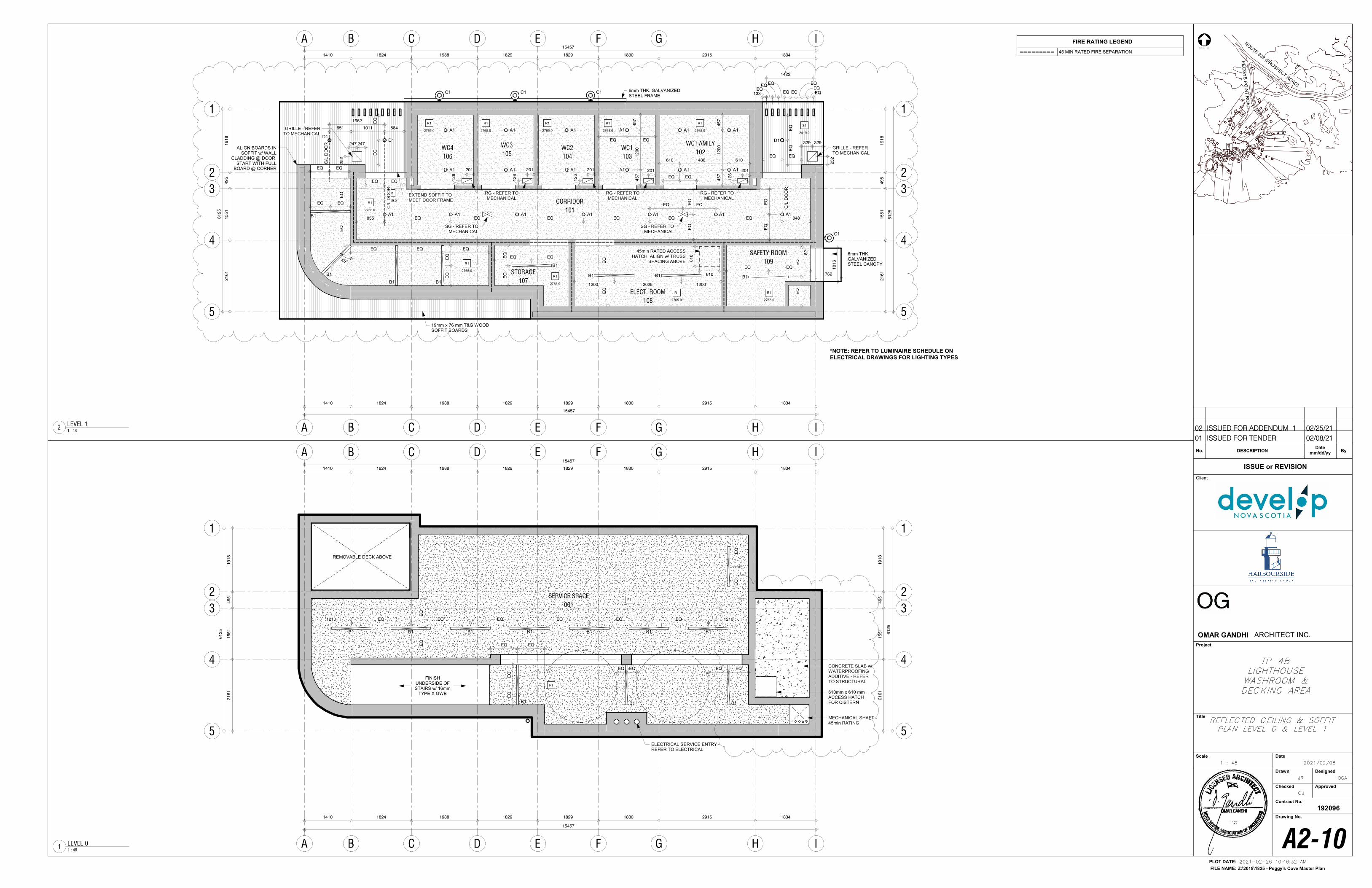
11
44
B
B
I
I
C
C
H
H
22
A
A
R1
2765.0
R1
2765.0
R1
2765.0
R1
2765.0
R1
2765.0
R1
2765.0
A1 A1 A1
A1
A1 A1
A1 A1 A1 A1 A1 A1 A1
D1 D1
33
G
G
F
F
E
E
D
D
15457
18342915183018291829198818241410
61
25
15
51
49
51
91
8
S1
2419.0
EQ
EQ
EQEQEQEQEQEQ855
EQEQ
EQ
EQEQ
EQEQEQ
133
5841011
45
71
20
0
EQEQ
45
71
20
04
57
A1
A1A1A1 A1 A1
6101486610
S1
2419.0 CORRIDOR
101
WC1
103
WC2
104
WC3
105
ELECT. ROOM
108
WC FAMILY
102
55
WC4
106
R1
2765.0
21
61
45
7
6mm THK. GALVANIZED STEEL CANOPY
D1
651
EQ
EQ
EQ
EQ
C/L
DO
OR
C/L
DO
OR
C/L
DO
OR
EQ EQ
EQ
EQ
EQ EQ EQ
B1
B1
B11200 2025 1200
EQ
EQ
EQ EQ
45min RATED ACCESS HATCH, ALIGN w/ TRUSS
SPACING ABOVE
R1
2765.0
R1
2765.0
EQ EQ
61
25
21
61
15
51
49
51
91
8
15457
1410 1824 1988 1829 1829 1830 2915 1834
STORAGE
107
R1
2765.0
EQ
EQ
61
0
610
SAFETY ROOM
109
EQ
EQ
82
762
10
16
19mm x 76 mm T&G WOOD SOFFIT BOARDS
EQ
EQ
45°
EQ EQ
848
EQ EQ
EQ EQ
1422
EQ EQ
*NOTE: REFER TO LUMINAIRE SCHEDULE ON ELECTRICAL DRAWINGS FOR LIGHTING TYPES
B1
B1
B1 B1
C1
C1C1C1 6mm THK. GALVANIZED STEEL FRAME
1662
ALIGN BOARDS IN SOFFIT w/ WALL
CLADDING @ DOOR, START WITH FULL
BOARD @ CORNER
EXTEND SOFFIT TO MEET DOOR FRAME
B1
EQ
EQ
EQ EQ
SG - REFER TO MECHANICAL
SG - REFER TO MECHANICAL
12
6
201
RG - REFER TO MECHANICAL
RG - REFER TO MECHANICAL
RG - REFER TO MECHANICAL
201
12
6
12
6
201201
12
6
201
329 329
25
2
GRILLE - REFER TO MECHANICAL
GRILLE - REFER TO MECHANICAL
25
2
247 247
11
44
B
B
I
I
C
C
H
H
22
A
A
33
G
G
F
F
E
E
D
D
18342915183018291829198818241410
15457
61
25
21
61
15
51
49
51
91
8
SERVICE SPACE
001
55
610mm x 610 mm ACCESS HATCH FOR CISTERN
REMOVABLE DECK ABOVE
CONCRETE SLAB w/ WATERPROOFING ADDITIVE - REFER TO STRUCTURAL
B1 B1 B1 B1 B1 B1 B1
B1 B1 B1
15457
1410 1824 1988 1829 1829 1830 2915 1834
EQ
EQ
EQ EQ EQ EQ EQ EQ 12101210
EQ EQ
EQ
EQ
61
25
21
61
15
51
49
51
91
8
EQ EQ EQ EQ
EQ
EQ
MECHANICAL SHAFT -45min RATING
F1
F1
FINISH UNDERSIDE OF STAIRS w/ 16mm
TYPE X GWB
ELECTRICAL SERVICE ENTRY -REFER TO ELECTRICAL
NORTH
Z:\2018\1825 - Peggy's Cove Master Plan
PLOT DATE:
FILE NAME:
Client
Project
Title
Scale Date
Drawn Designed
Checked Approved
Contract No.
Drawing No.
192096
ISSUE or REVISION
No. DESCRIPTION ByDate
mm/dd/yy
ROUTE 333 (PRO
SPECT ROAD)
PE
GG
YS
PO
INT
RO
AD
OMAR GANDHI ARCHITECT INC.
2021-02-26 10:46:32 AM
1 : 48
A2-10
JR
CJ
OGA
2021/02/08
REFLECTED CEILING & SOFFITPLAN LEVEL 0 & LEVEL 1
TP 4BLIGHTHOUSEWASHROOM &DECKING AREA
1 : 48
LEVEL 12
1 : 48
LEVEL 01
FIRE RATING LEGEND
45 MIN RATED FIRE SEPARATION
01 ISSUED FOR TENDER 02/08/21
02 ISSUED FOR ADDENDUM 1 02/25/21
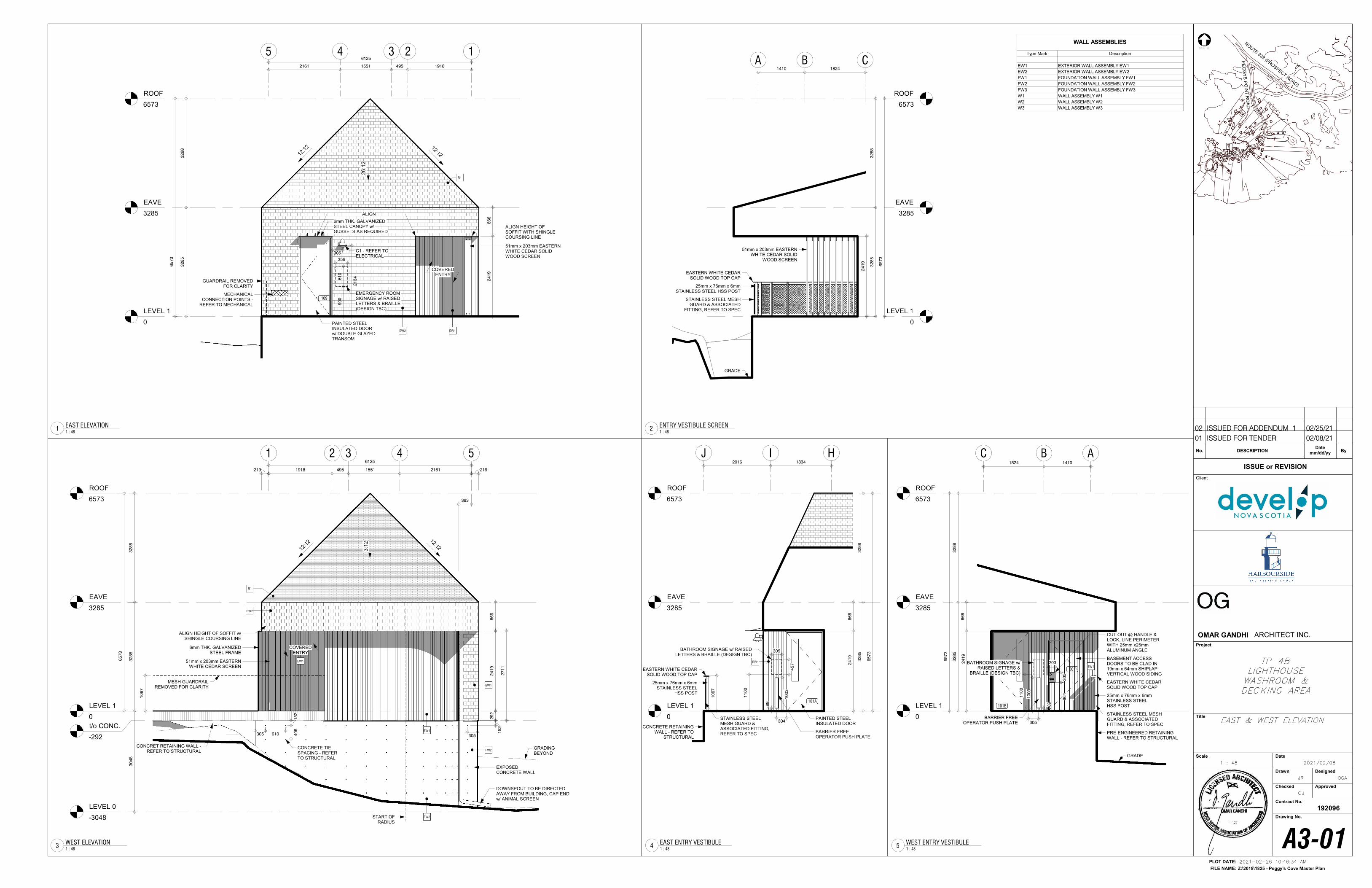
LEVEL 1
0
EAVE
3285
ROOF
6573
14 22161 1551 495 1918
32
88
32
85
ALIGN HEIGHT OF SOFFIT WITH SHINGLE COURSING LINE
EW1
3
51mm x 203mm EASTERN WHITE CEDAR SOLID WOOD SCREEN
COVERED ENTRY
C1 - REFER TO ELECTRICAL
65
73
5
86
62
41
9
6mm THK. GALVANIZED STEEL CANOPY w/ GUSSETS AS REQUIRED
EW2
6125
109
R1
PAINTED STEEL INSULATED DOOR w/ DOUBLE GLAZED TRANSOM
21
34
305
61
09
00
356
EMERGENCY ROOM SIGNAGE w/ RAISED LETTERS & BRAILLE (DESIGN TBC)
26:1
2
GUARDRAIL REMOVED FOR CLARITY
12:1212:1
2
ALIGN
MECHANICAL CONNECTION POINTS -
REFER TO MECHANICAL
LEVEL 1
0
EAVE
3285
ROOF
6573
1 4
LEVEL 0
-3048
2
1918 495 1551 2161
32
88
32
85
30
48
ALIGN HEIGHT OF SOFFIT w/ SHINGLE COURSING LINE
3
51mm x 203mm EASTERN WHITE CEDAR SCREEN
COVERED ENTRY
65
73
5
EW2
EW1
CONCRET RETAINING WALL -REFER TO STRUCTURAL
R1
FW2
EW1
FW2
6125
3:1
2
12:1212
:12
86
6
219
383
29
22
41
9
27
11
219
10
67
MESH GUARDRAIL REMOVED FOR CLARITY
DOWNSPOUT TO BE DIRECTED AWAY FROM BUILDING, CAP END w/ ANIMAL SCREEN
START OF RADIUS
15
2
305305 610
15
24
06
CONCRETE TIE SPACING - REFER TO STRUCTURAL
6mm THK. GALVANIZED STEEL FRAME
EW1
t/o CONC.
-292
GRADING BEYOND
EXPOSED CONCRETE WALL
LEVEL 1
0
EAVE
3285
ROOF
6573
BC A
32
85
32
88
BARRIER FREE OPERATOR PUSH PLATE
EW1
14101824
86
62
41
9
65
73
BASEMENT ACCESS DOORS TO BE CLAD IN 19mm x 64mm SHIPLAP VERTICAL WOOD SIDING
10
03
89
305
101B
001
30
58
64
203
CUT OUT @ HANDLE & LOCK, LINE PERIMETER WITH 25mm x25mm ALUMINUM ANGLE
25mm x 76mm x 6mm STAINLESS STEEL HSS POST
STAINLESS STEEL MESH GUARD & ASSOCIATED FITTING, REFER TO SPEC
EASTERN WHITE CEDAR SOLID WOOD TOP CAP
PRE-ENGINEERED RETAINING WALL - REFER TO STRUCTURAL
GRADE
BATHROOM SIGNAGE w/ RAISED LETTERS &
BRAILLE (DESIGN TBC)
11
00
LEVEL 1
0
EAVE
3285
ROOF
6573
B CA1410 1824
51mm x 203mm EASTERN WHITE CEDAR SOLID
WOOD SCREEN
32
85
32
88
65
73
25mm x 76mm x 6mm STAINLESS STEEL HSS POST
STAINLESS STEEL MESH GUARD & ASSOCIATED
FITTING, REFER TO SPEC
EASTERN WHITE CEDAR SOLID WOOD TOP CAP
GRADE
24
19
LEVEL 1
0
EAVE
3285
ROOF
6573
I H
101A
EW1
304
89
10
03
18342016
65
73
32
85
32
88
PAINTED STEEL INSULATED DOOR
BARRIER FREE OPERATOR PUSH PLATE
24
19
86
6
25mm x 76mm x 6mm STAINLESS STEEL
HSS POST
STAINLESS STEEL MESH GUARD & ASSOCIATED FITTING, REFER TO SPEC
EASTERN WHITE CEDAR SOLID WOOD TOP CAP
CONCRETE RETAINING WALL - REFER TO
STRUCTURAL
10
67
J
BATHROOM SIGNAGE w/ RAISED LETTERS & BRAILLE (DESIGN TBC)
11
00
45
7
305
NORTH
Z:\2018\1825 - Peggy's Cove Master Plan
PLOT DATE:
FILE NAME:
Client
Project
Title
Scale Date
Drawn Designed
Checked Approved
Contract No.
Drawing No.
192096
ISSUE or REVISION
No. DESCRIPTION ByDate
mm/dd/yy
ROUTE 333 (PRO
SPECT ROAD)
PE
GG
YS
PO
INT
RO
AD
OMAR GANDHI ARCHITECT INC.
2021-02-26 10:46:34 AM
1 : 48
A3-01
JR
CJ
OGA
2021/02/08
EAST & WEST ELEVATION
TP 4BLIGHTHOUSEWASHROOM &DECKING AREA
1 : 48
EAST ELEVATION1
1 : 48
WEST ELEVATION3
1 : 48
WEST ENTRY VESTIBULE5
1 : 48
ENTRY VESTIBULE SCREEN2
WALL ASSEMBLIES
Type Mark Description
EW1 EXTERIOR WALL ASSEMBLY EW1
EW2 EXTERIOR WALL ASSEMBLY EW2
FW1 FOUNDATION WALL ASSEMBLY FW1
FW2 FOUNDATION WALL ASSEMBLY FW2
FW3 FOUNDATION WALL ASSEMBLY FW3
W1 WALL ASSEMBLY W1
W2 WALL ASSEMBLY W2
W3 WALL ASSEMBLY W3
1 : 48
EAST ENTRY VESTIBULE4
01 ISSUED FOR TENDER 02/08/21
02 ISSUED FOR ADDENDUM 1 02/25/21
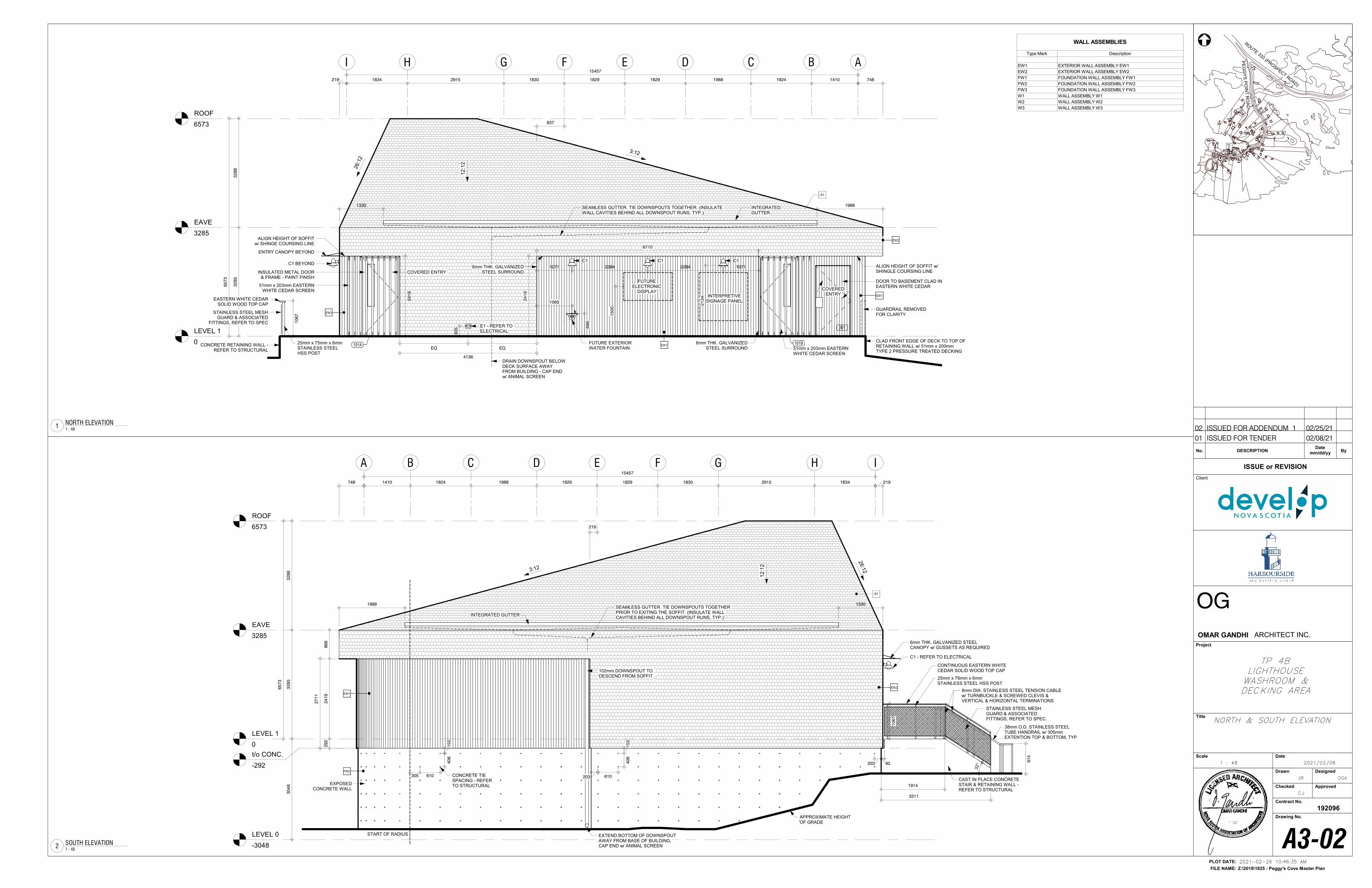
LEVEL 1
0
EAVE
3285
ROOF
6573
BI CH
14101824198818291829183029151834
32
85
32
88
A
INTEGRATED GUTTER
INSULATED METAL DOOR & FRAME - PAINT FINISH
ALIGN HEIGHT OF SOFFIT w/ SHINGE COURSING LINE
G F E D
65
73
15457
51mm x 203mm EASTERN WHITE CEDAR SCREEN
EW2
EW1
51mm x 203mm EASTERN WHITE CEDAR SCREEN
CLAD FRONT EDGE OF DECK TO TOP OF RETAINING WALL w/ 51mm x 200mm TYPE 2 PRESSURE TREATED DECKING
COVERED ENTRY
COVERED ENTRY
FUTURE ELECTRONIC
DISPLAY
E1 - REFER TO ELECTRICAL
GUARDRAIL REMOVED FOR CLARITY
DOOR TO BASEMENT CLAD IN EASTERN WHITE CEDAR
001
101B
748
ALIGN HEIGHT OF SOFFIT w/ SHINGLE COURSING LINE
6mm THK. GALVANIZED STEEL SURROUND
6mm THK. GALVANIZED STEEL SURROUND
24
19
6710
68
6
1065
FUTURE EXTERIOR WATER FOUNTAIN
837
15
00
219
12:1
2
26:1
2
3:12
21
34
1071 2284 2284 1071
INTERPRETIVE SIGNAGE PANEL
C1 C1 C1
30
5
EQ EQ
ENTRY CANOPY BEYOND
C1 BEYOND
4136
R1
EW1
EW2
CONCRETE RETAINING WALL -REFER TO STRUCTURAL
101A
STAINLESS STEEL MESH GUARD & ASSOCIATED
FITTINGS, REFER TO SPEC
25mm x 75mm x 6mm STAINLESS STEEL HSS POST
EASTERN WHITE CEDAR SOLID WOOD TOP CAP
10
67
24
19
SEAMLESS GUTTER. TIE DOWNSPOUTS TOGETHER. (INSULATE WALL CAVITIES BEHIND ALL DOWNSPOUT RUNS, TYP.)
DRAIN DOWNSPOUT BELOW DECK SURFACE AWAY FROM BUILDING - CAP END w/ ANIMAL SCREEN
1330 1988
LEVEL 1
0
EAVE
3285
ROOF
6573
B I
LEVEL 0
-3048
C H
1410 1824 1988 1829 1829 1830 2915 1834
A
INTEGRATED GUTTER
GFED15457
30
48
32
85
32
88
65
73
6mm THK. GALVANIZED STEEL CANOPY w/ GUSSETS AS REQUIRED
EW2
CONCRETE TIE SPACING - REFER TO STRUCTURAL
305 610
40
6
EW1
FW2
APPROXIMATE HEIGHT OF GRADE
748
START OF RADIUS
15
2
203 610
40
61
52
203
C1 - REFER TO ELECTRICAL
R1
219
3:12
26:1
2
12:1
2
86
62
41
92
92
27
11
CAST IN PLACE CONCRETE STAIR & RETAINING WALL -REFER TO STRUCTURAL
91
4
10
67
STAINLESS STEEL MESH GUARD & ASSOCIATED FITTINGS, REFER TO SPEC.
8mm DIA. STAINLESS STEEL TENSION CABLE w/ TURNBUCKLE & SCREWED CLEVIS & VERTICAL & HORIZONTAL TERMINATIONS
25mm x 76mm x 6mm STAINLESS STEEL HSS POST
CONTINUOUS EASTERN WHITE CEDAR SOLID WOOD TOP CAP
92
38mm O.D. STAINLESS STEEL TUBE HANDRAIL w/ 305mm EXTENTION TOP & BOTTOM, TYP
219
102mm DOWNSPOUT TO DESCEND FROM SOFFIT.
EXTEND BOTTOM OF DOWNSPOUT AWAY FROM BASE OF BUILDING, CAP END w/ ANIMAL SCREEN
SEAMLESS GUTTER. TIE DOWNSPOUTS TOGETHER PRIOR TO EXITING THE SOFFIT. (INSULATE WALL CAVITIES BEHIND ALL DOWNSPOUT RUNS, TYP.)
1988 1330
32°
3311
1914
t/o CONC.
-292
EXPOSED CONCRETE WALL
NORTH
Z:\2018\1825 - Peggy's Cove Master Plan
PLOT DATE:
FILE NAME:
Client
Project
Title
Scale Date
Drawn Designed
Checked Approved
Contract No.
Drawing No.
192096
ISSUE or REVISION
No. DESCRIPTION ByDate
mm/dd/yy
ROUTE 333 (PRO
SPECT ROAD)
PE
GG
YS
PO
INT
RO
AD
OMAR GANDHI ARCHITECT INC.
2021-02-26 10:46:35 AM
1 : 48
A3-02
JR
CJ
OGA
2021/02/08
NORTH & SOUTH ELEVATION
TP 4BLIGHTHOUSEWASHROOM &DECKING AREA
1 : 48
NORTH ELEVATION1
1 : 48
SOUTH ELEVATION2
WALL ASSEMBLIES
Type Mark Description
EW1 EXTERIOR WALL ASSEMBLY EW1
EW2 EXTERIOR WALL ASSEMBLY EW2
FW1 FOUNDATION WALL ASSEMBLY FW1
FW2 FOUNDATION WALL ASSEMBLY FW2
FW3 FOUNDATION WALL ASSEMBLY FW3
W1 WALL ASSEMBLY W1
W2 WALL ASSEMBLY W2
W3 WALL ASSEMBLY W3
01 ISSUED FOR TENDER 02/08/21
02 ISSUED FOR ADDENDUM 1 02/25/21
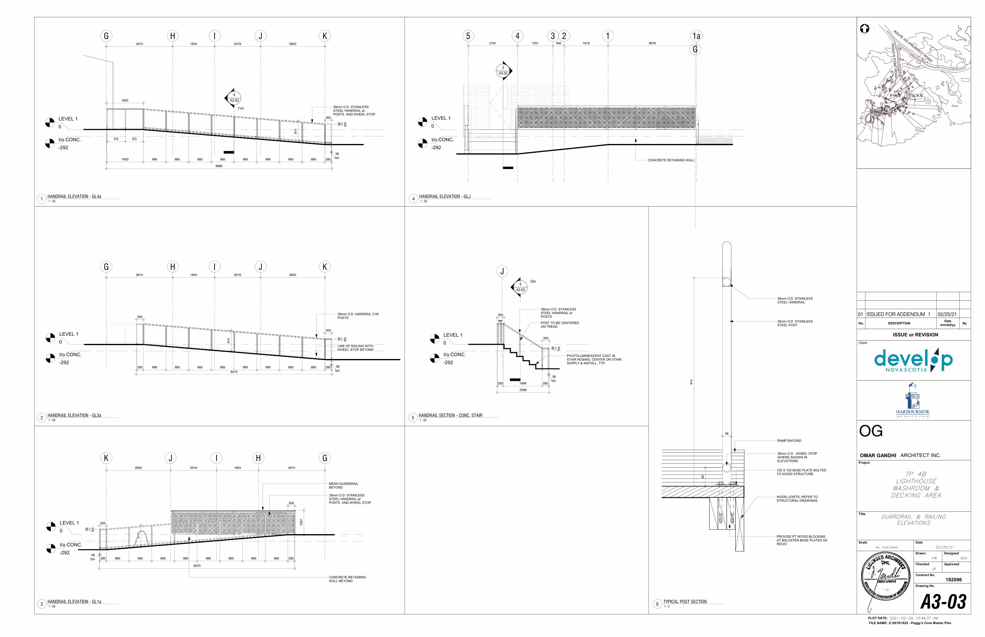
LEVEL 1
0
IHG J K
t/o CONC.
-292
91
4
2859959959959959959959959951600
305
typ
.
38
1620
38mm O.D. STAINLESS STEEL HANDRAIL w/ POSTS AND WHEEL STOP
2915 1834 2016 2820
EQ EQ
typ.
38
6
A3-03
TYP.
9885
LEVEL 1
0
IHG J K
t/o CONC.
-292285 995 995 995 995 995 995 995 995 285
typ
.
38
38mm O.D. HANDRAIL C/W POSTS
LINE OF RAILING WITH WHEEL STOP BEYOND
91
4
2915 1834 2016 2820
305
305
8570 typ.
38
LEVEL 1
0
I H GJK
t/o CONC.
-292
2915183420162820
285 995 995 995 995 995 995 995 995 285
305
305
91
4
typ
.
38
38mm O.D. STAINLESS STEEL HANDRAIL w/ POSTS AND WHEEL STOP
MESH GUARDRAIL BEYOND
8570
10
67
CONCRETE RETAINING WALL BEYOND
typ.
38
LEVEL 1
0
14 235
G
1a
t/o CONC.
-292
2161 1551 495 1918 3878
CONCRETE RETAINING WALL
5
A3-03
LEVEL 1
0
J
t/o CONC.
-292
265 1696 285
typ
.
38
38mm O.D. STAINLESS STEEL HANDRAIL w/ POSTS
POST TO BE CENTERED ON TREAD
6
A3-03
Sim
2286
typ.
38
PHOTOLUMINESCENT CAST IN STAIR NOSING, CENTER ON STAIR. SUPPLY & INSTALL, TYP.
305
305
WOOD JOISTS. REFER TO STRUCTURAL DRAWINGS
38
80
38mm O.D. WHEEL STOP WHERE SHOWN IN ELEVATIONS
38mm O.D. STAINLESS STEEL HANDRAIL
RAMP BAYOND
PROVIDE PT WOOD BLOCKING AT BALUSTER BASE PLATES AS REQ'D
102 X 102 BASE PLATE BOLTED TO WOOD STRUCTURE
91
4
38mm O.D. STAINLESS STEEL POST
NORTH
Z:\2018\1825 - Peggy's Cove Master Plan
PLOT DATE:
FILE NAME:
Client
Project
Title
Scale Date
Drawn Designed
Checked Approved
Contract No.
Drawing No.
192096
ISSUE or REVISION
No. DESCRIPTION ByDate
mm/dd/yy
ROUTE 333 (PRO
SPECT ROAD)
PE
GG
YS
PO
INT
RO
AD
OMAR GANDHI ARCHITECT INC.
2021-02-26 10:46:37 AM
As indicated
A3-03
KW
JR
OGA
02/25/21
GUARDRAIL & RAILINGELEVATIONS
TP 4BLIGHTHOUSEWASHROOM &DECKING AREA
1 : 50
HANDRAIL ELEVATION - GL4a1
1 : 50
HANDRAIL ELEVATION - GL3a2
1 : 50
HANDRAIL ELEVATION - GL1a3
1 : 50
HANDRAIL ELEVATION - GLJ4
1 : 50
HANDRAIL SECTION - CONC. STAIR5
1 : 5
TYPICAL POST SECTION6
01 ISSUED FOR ADDENDUM 1 02/25/21
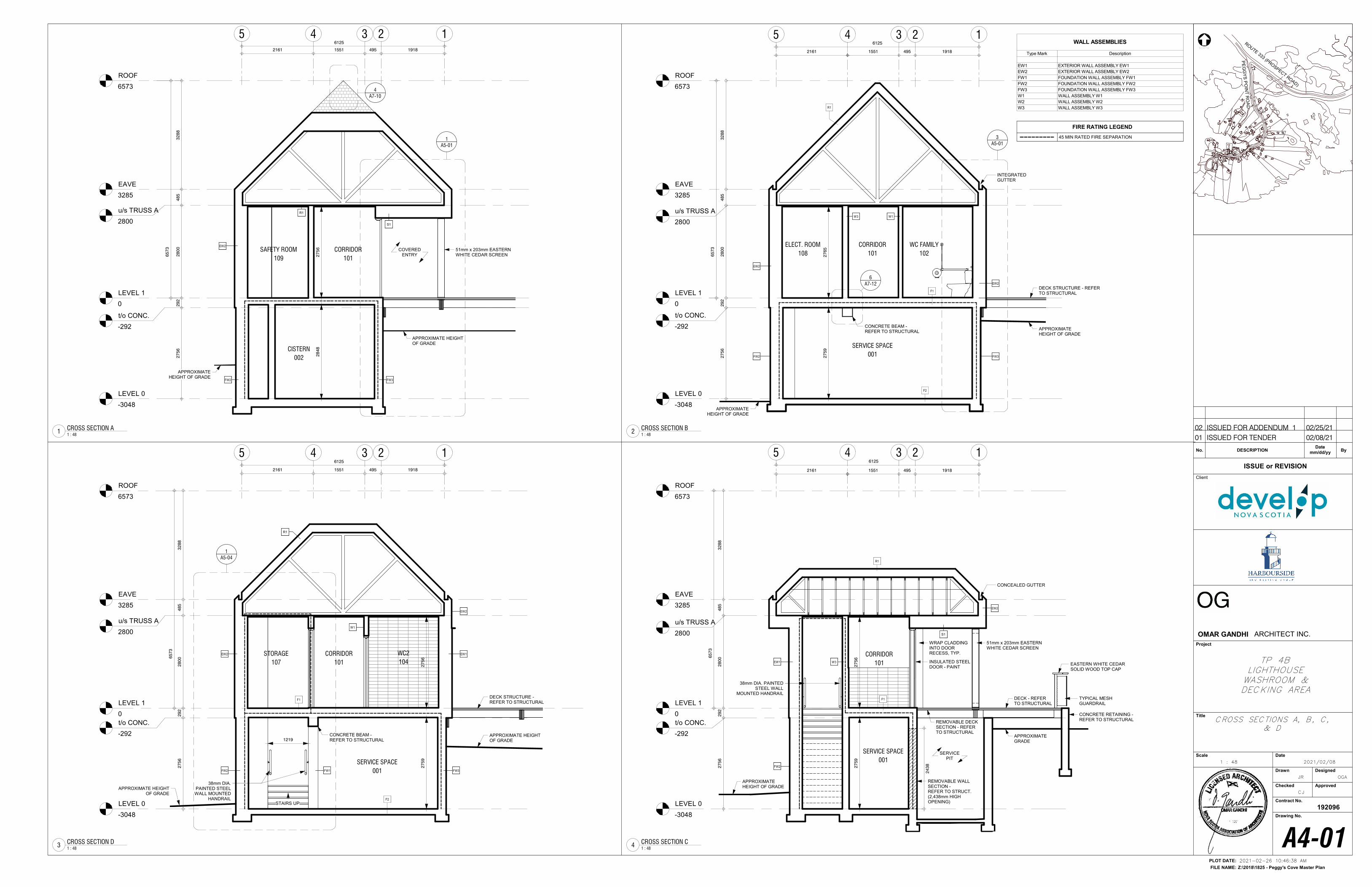
LEVEL 1
0
EAVE
3285
ROOF
6573
14
LEVEL 0
-3048
2
CORRIDOR
101
EW2
SERVICE SPACE
001
1551 495 1918
A5-01
3
A7-12
6
36125
W1
WC FAMILY
102
INTEGRATED GUTTER
32
88
48
52
80
02
92
27
56
65
73
5
2161
FW3
ELECT. ROOM
108
F2
F1
FW2
CONCRETE BEAM -REFER TO STRUCTURAL
EW2
R1
27
65
27
59
DECK STRUCTURE - REFER TO STRUCTURAL
u/s TRUSS A
2800
t/o CONC.
-292
W3
APPROXIMATE HEIGHT OF GRADE
APPROXIMATE HEIGHT OF GRADE
LEVEL 1
0
EAVE
3285
ROOF
6573
14
LEVEL 0
-3048
2
CORRIDOR
101
2161 1551 495 1918
A5-01
1
S1
36125
COVERED ENTRY
32
88
48
52
80
02
92
27
56
65
73
27
56
5
EW2
51mm x 203mm EASTERN WHITE CEDAR SCREEN
A7-10
4
FW2 FW3
SAFETY ROOM
109
28
48
R1u/s TRUSS A
2800
t/o CONC.
-292
CISTERN
002
APPROXIMATE HEIGHT OF GRADE
APPROXIMATE HEIGHT OF GRADE
LEVEL 1
0
EAVE
3285
ROOF
6573
14
LEVEL 0
-3048
236125
1551 495 1918
WRAP CLADDING INTO DOOR RECESS, TYP.
INSULATED STEEL DOOR - PAINT
SERVICE SPACE
001
CORRIDOR
101
32
88
48
52
80
02
92
27
56
65
73
CONCEALED GUTTER
5
2161
EW1
S1
EW2
W3
F1
FW2
R1
51mm x 203mm EASTERN WHITE CEDAR SCREEN
27
59
27
56
38mm DIA. PAINTED STEEL WALL
MOUNTED HANDRAIL
REMOVABLE WALL SECTION -REFER TO STRUCT. (2,438mm HIGH OPENING)
EASTERN WHITE CEDARSOLID WOOD TOP CAP
DECK - REFER TO STRUCTURAL
APPROXIMATE HEIGHT OF GRADE
u/s TRUSS A
2800
t/o CONC.
-292
REMOVABLE DECK SECTION - REFER TO STRUCTURAL
24
38
APPROXIMATE GRADE
CONCRETE RETAINING -REFER TO STRUCTURAL
TYPICAL MESH GUARDRAIL
SERVICE PIT
LEVEL 1
0
EAVE
3285
ROOF
6573
14
LEVEL 0
-3048
235
A5-04
1
CORRIDOR
101
WC2
104
SERVICE SPACE
001
EW1
EW2
W1
F2
F1DECK STRUCTURE -REFER TO STRUCTURAL
R1
FW1 FW3FW2
STORAGE
107
CONCRETE BEAM -REFER TO STRUCTURAL
EW2
38mm DIA. PAINTED STEELWALL MOUNTED
HANDRAIL
32
88
48
52
80
02
92
27
56
65
73
STAIRS UP
6125
2161 1551 495 1918
u/s TRUSS A
2800
t/o CONC.
-292
27
59
27
56
1219APPROXIMATE HEIGHT OF GRADE
APPROXIMATE HEIGHT OF GRADE
NORTH
Z:\2018\1825 - Peggy's Cove Master Plan
PLOT DATE:
FILE NAME:
Client
Project
Title
Scale Date
Drawn Designed
Checked Approved
Contract No.
Drawing No.
192096
ISSUE or REVISION
No. DESCRIPTION ByDate
mm/dd/yy
ROUTE 333 (PRO
SPECT ROAD)
PE
GG
YS
PO
INT
RO
AD
OMAR GANDHI ARCHITECT INC.
2021-02-26 10:46:38 AM
1 : 48
A4-01
JR
CJ
OGA
2021/02/08
CROSS SECTIONS A, B, C,& D
TP 4BLIGHTHOUSEWASHROOM &DECKING AREA
1 : 48
CROSS SECTION B2
1 : 48
CROSS SECTION A1
WALL ASSEMBLIES
Type Mark Description
EW1 EXTERIOR WALL ASSEMBLY EW1
EW2 EXTERIOR WALL ASSEMBLY EW2
FW1 FOUNDATION WALL ASSEMBLY FW1
FW2 FOUNDATION WALL ASSEMBLY FW2
FW3 FOUNDATION WALL ASSEMBLY FW3
W1 WALL ASSEMBLY W1
W2 WALL ASSEMBLY W2
W3 WALL ASSEMBLY W3
1 : 48
CROSS SECTION C4
1 : 48
CROSS SECTION D3
01 ISSUED FOR TENDER 02/08/21
02 ISSUED FOR ADDENDUM 1 02/25/21
FIRE RATING LEGEND
45 MIN RATED FIRE SEPARATION
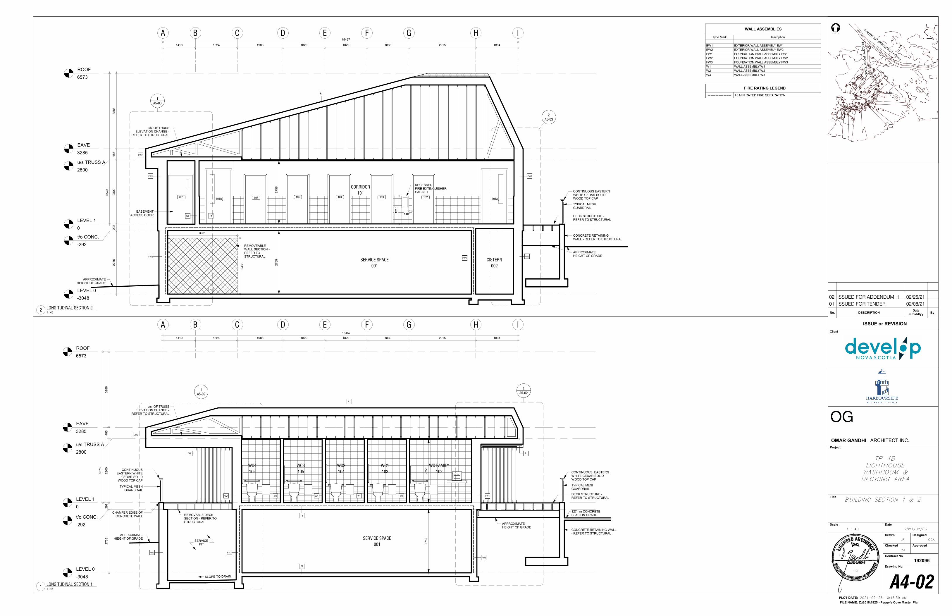
LEVEL 1
0
EAVE
3285
ROOF
6573
B I
LEVEL 0
-3048
C H
CORRIDOR
101
SERVICE SPACE
001
W3
1410 1824 1988 1829 1829 1830 2915 1834
F1
F2
A
27
59
A5-03
1
A5-03
2
GFED15457
BASEMENT ACCESS DOOR
27
56
29
22
80
04
85
32
88
65
73
EW1
CONCRETE RETAININGWALL - REFER TO STRUCTURAL
DECK STRUCTURE -REFER TO STRUCTURAL
EW2
FW2 FW2
R1
FW1
EW2
106 105 104 103 102001101B 101A
RECESSED FIRE EXTINGUISHER CABINET CONTINUOUS EASTERN
WHITE CEDAR SOLID WOOD TOP CAP
u/s TRUSS A
2800
t/o CONC.
-292
27
56
12
10
140
TYPICAL MESH GUARDRAIL
3031
24
38
REMOVEABLE WALL SECTION -REFER TO STRUCTURAL
CISTERN
002
APPROXIMATE HEIGHT OF GRADE
u/s OF TRUSS ELEVATION CHANGE -
REFER TO STRUCTURAL
APPROXIMATE HEIGHT OF GRADE
LEVEL 1
0
EAVE
3285
ROOF
6573
B I
LEVEL 0
-3048
C H
SERVICE SPACE
001
W1 W1 W1 EW1
1410 1824 1988 1829 1829 1830 2915 1834
A
27
59
A5-02
1A5-02
2
W1
F1
F2
GFED15457
EW1
S1 S1
WC3
105
WC2
104
WC1
103
WC FAMILY
102
27
56
29
22
80
04
85
32
88
65
73
WC4
106
CONCRETE RETAINING WALL- REFER TO STRUCTURAL
R1
FW3
FW3
CONTINUOUS EASTERN WHITE
CEDAR SOLID WOOD TOP CAP
CONTINUOUS EASTERN WHITE CEDAR SOLID WOOD TOP CAP
DECK STRUCTURE -REFER TO STRUCTURAL
u/s TRUSS A
2800
t/o CONC.
-292
FW2
27
56
APPROXIMATE HIEGHT OF GRADE
TYPICAL MESH GUARDRAIL
APPROXIMATE HEIGHT OF GRADE
EW2
SLOPE TO DRAIN
REMOVABLE DECK SECTION - REFER TO STRUCTURAL
TYPICAL MESH GUARDRAIL
127mm CONCRETE SLAB ON GRADE
CHAMFER EDGE OF CONCRETE WALL
SERVICE PIT
u/s OF TRUSS ELEVATION CHANGE -
REFER TO STRUCTURAL
NORTH
Z:\2018\1825 - Peggy's Cove Master Plan
PLOT DATE:
FILE NAME:
Client
Project
Title
Scale Date
Drawn Designed
Checked Approved
Contract No.
Drawing No.
192096
ISSUE or REVISION
No. DESCRIPTION ByDate
mm/dd/yy
ROUTE 333 (PRO
SPECT ROAD)
PE
GG
YS
PO
INT
RO
AD
OMAR GANDHI ARCHITECT INC.
2021-02-26 10:46:39 AM
1 : 48
A4-02
JR
CJ
OGA
2021/02/08
BUILDING SECTION 1 & 2
TP 4BLIGHTHOUSEWASHROOM &DECKING AREA
1 : 48
LONGITUDINAL SECTION 22
1 : 48
LONGITUDINAL SECTION 11
WALL ASSEMBLIES
Type Mark Description
EW1 EXTERIOR WALL ASSEMBLY EW1
EW2 EXTERIOR WALL ASSEMBLY EW2
FW1 FOUNDATION WALL ASSEMBLY FW1
FW2 FOUNDATION WALL ASSEMBLY FW2
FW3 FOUNDATION WALL ASSEMBLY FW3
W1 WALL ASSEMBLY W1
W2 WALL ASSEMBLY W2
W3 WALL ASSEMBLY W3
01 ISSUED FOR TENDER 02/08/21
02 ISSUED FOR ADDENDUM 1 02/25/21
FIRE RATING LEGEND
45 MIN RATED FIRE SEPARATION
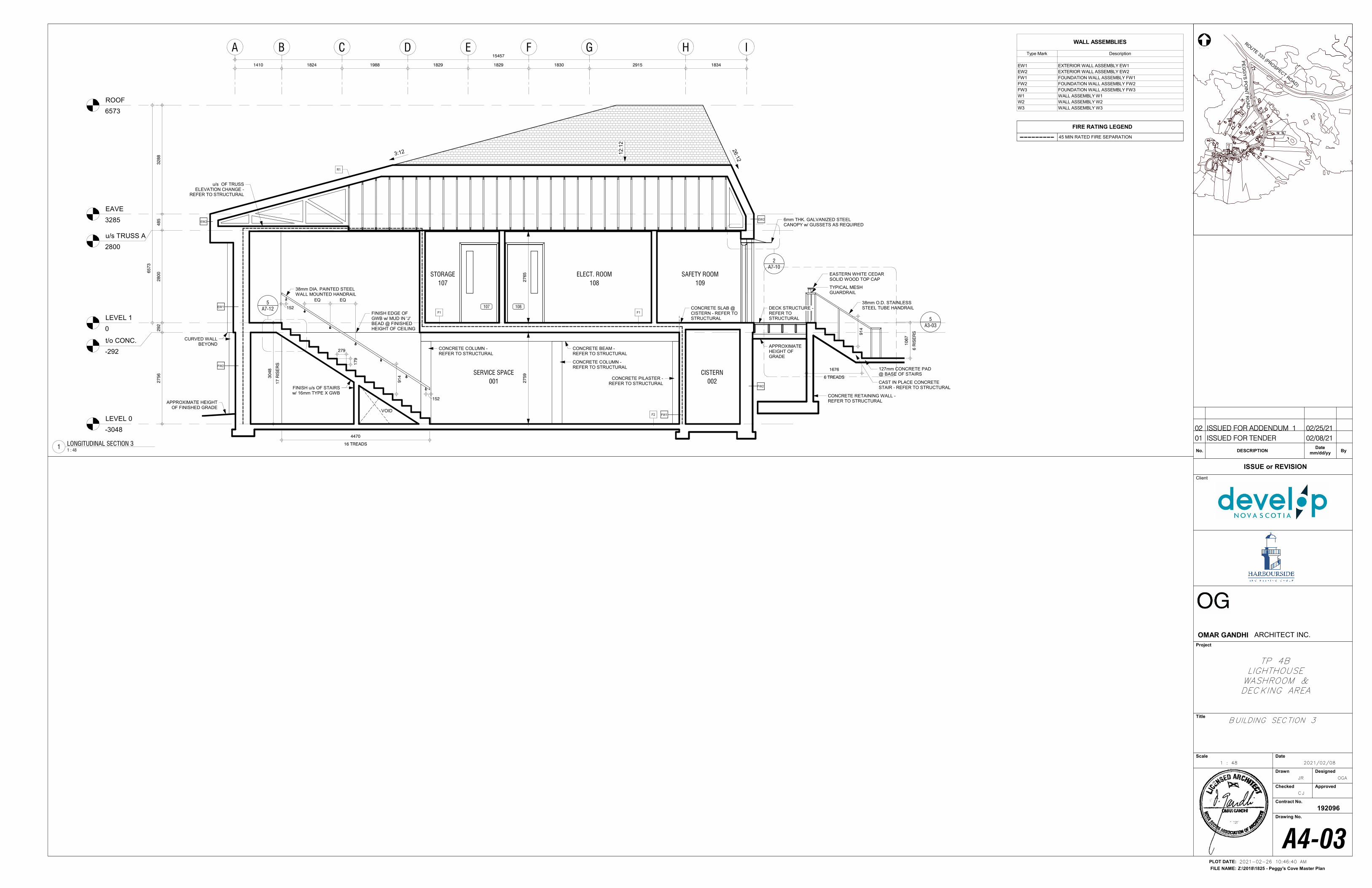
LEVEL 1
0
EAVE
3285
ROOF
6573
B I
LEVEL 0
-3048
C HA GFED
A7-10
2
ELECT. ROOM
108
SERVICE SPACE
001
F2
FW2
FW1
F1
EW2
APPROXIMATE HEIGHT OF FINISHED GRADE
2791
79
A7-12
5
38mm DIA. PAINTED STEEL WALL MOUNTED HANDRAIL
SAFETY ROOM
109
6mm THK. GALVANIZED STEELCANOPY w/ GUSSETS AS REQUIRED
CURVED WALL BEYOND
EASTERN WHITE CEDARSOLID WOOD TOP CAP
38mm O.D. STAINLESS STEEL TUBE HANDRAIL
CAST IN PLACE CONCRETESTAIR - REFER TO STRUCTURAL
CONCRETE BEAM -REFER TO STRUCTURAL
27
59
27
65
127mm CONCRETE PAD @ BASE OF STAIRS
27
56
29
22
80
04
85
32
88
65
73
FINISH u/s OF STAIRSw/ 16mm TYPE X GWB
108107
6 TREADS
1676
15457
1410 1824 1988 1829 1829 1830 2915 1834
u/s TRUSS A
2800
t/o CONC.
-292
CISTERN
002
CONCRETE COLUMN -REFER TO STRUCTURAL
CONCRETE PILASTER -REFER TO STRUCTURAL
CONCRETE COLUMN -REFER TO STRUCTURAL
STORAGE
107
F1
CONCRETE SLAB @ CISTERN - REFER TO STRUCTURAL
VOID
FINISH EDGE OF GWB w/ MUD IN 'J' BEAD @ FINISHED HEIGHT OF CEILING
17
RIS
ER
S
30
48
16 TREADS
4470
91
4
EQEQ
152
152CONCRETE RETAINING WALL -REFER TO STRUCTURAL
6 R
ISE
RS
10
67
91
4
TYPICAL MESH GUARDRAIL
EW1
FW2
EW2
3:12
26:1
2
12:1
2
APPROXIMATE HEIGHT OF GRADE
u/s OF TRUSS ELEVATION CHANGE -
REFER TO STRUCTURAL
R1
DECK STRUCTURE -REFER TO STRUCTURAL
A3-03
5
NORTH
Z:\2018\1825 - Peggy's Cove Master Plan
PLOT DATE:
FILE NAME:
Client
Project
Title
Scale Date
Drawn Designed
Checked Approved
Contract No.
Drawing No.
192096
ISSUE or REVISION
No. DESCRIPTION ByDate
mm/dd/yy
ROUTE 333 (PRO
SPECT ROAD)
PE
GG
YS
PO
INT
RO
AD
OMAR GANDHI ARCHITECT INC.
2021-02-26 10:46:40 AM
1 : 48
A4-03
JR
CJ
OGA
2021/02/08
BUILDING SECTION 3
TP 4BLIGHTHOUSEWASHROOM &DECKING AREA
1 : 48
LONGITUDINAL SECTION 31
WALL ASSEMBLIES
Type Mark Description
EW1 EXTERIOR WALL ASSEMBLY EW1
EW2 EXTERIOR WALL ASSEMBLY EW2
FW1 FOUNDATION WALL ASSEMBLY FW1
FW2 FOUNDATION WALL ASSEMBLY FW2
FW3 FOUNDATION WALL ASSEMBLY FW3
W1 WALL ASSEMBLY W1
W2 WALL ASSEMBLY W2
W3 WALL ASSEMBLY W3
01 ISSUED FOR TENDER 02/08/21
02 ISSUED FOR ADDENDUM 1 02/25/21
FIRE RATING LEGEND
45 MIN RATED FIRE SEPARATION
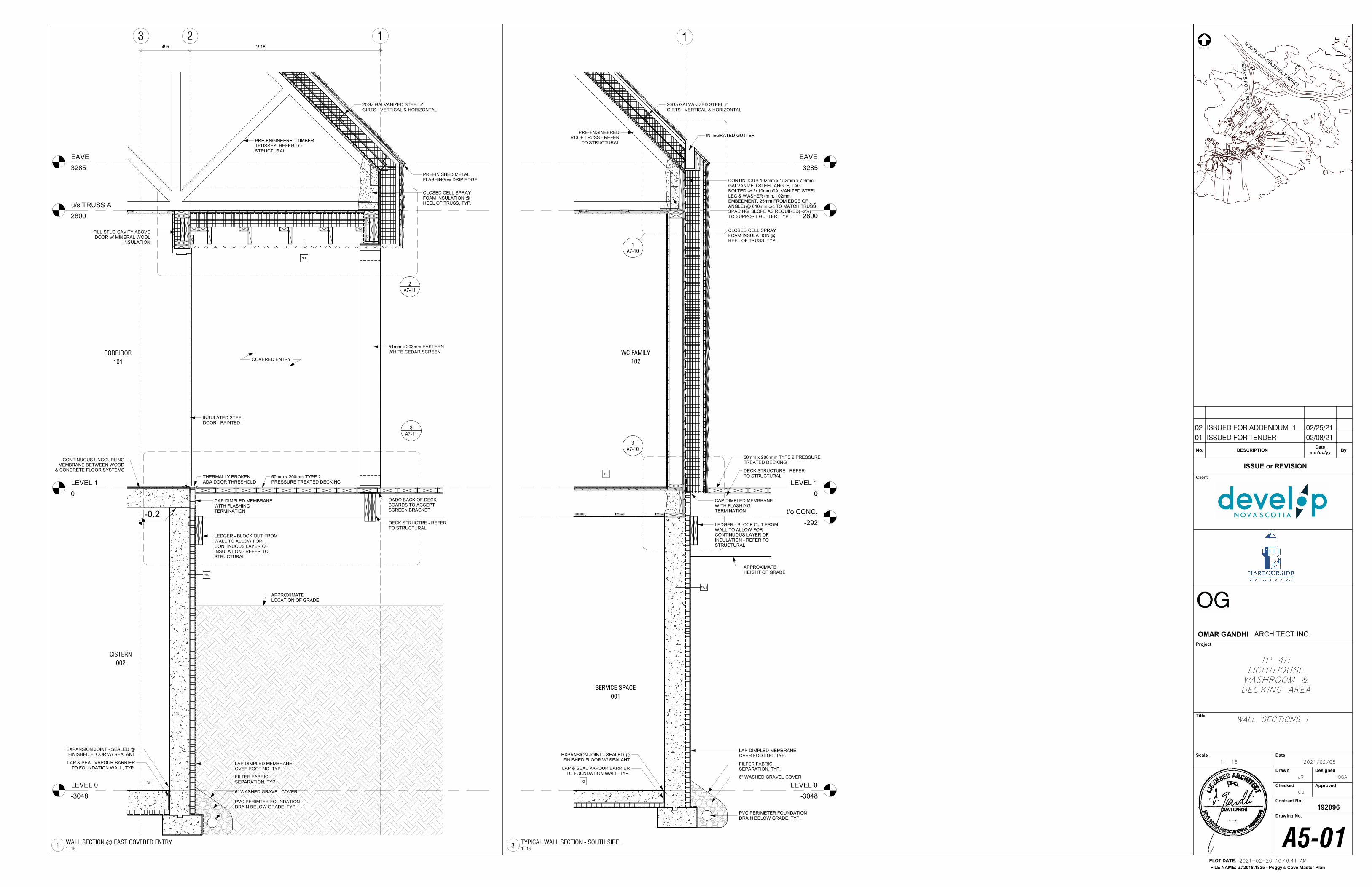
LEVEL 1
0
EAVE
3285
1
LEVEL 0
-3048
SERVICE SPACE
001
F2
A7-10
1
A7-10
3
WC FAMILY
102
F1
FILTER FABRIC SEPARATION, TYP.
6" WASHED GRAVEL COVER
PVC PERIMETER FOUNDATION DRAIN BELOW GRADE, TYP.
CLOSED CELL SPRAY FOAM INSULATION @ HEEL OF TRUSS, TYP.
LAP DIMPLED MEMBRANE OVER FOOTING, TYP.
APPROXIMATE HEIGHT OF GRADE
LAP & SEAL VAPOUR BARRIER TO FOUNDATION WALL, TYP.
EXPANSION JOINT - SEALED @ FINISHED FLOOR W/ SEALANT
50mm x 200 mm TYPE 2 PRESSURE TREATED DECKING
u/s TRUSS A
2800
t/o CONC.
-292
INTEGRATED GUTTER
CONTINUOUS 102mm x 152mm x 7.9mm GALVANIZED STEEL ANGLE, LAG BOLTED w/ 2x10mm GALVANIZED STEEL LEG & WASHER (min. 102mm EMBEDMENT, 25mm FROM EDGE OF ANGLE) @ 610mm o/c TO MATCH TRUSS SPACING. SLOPE AS REQUIRED(~2%) TO SUPPORT GUTTER, TYP.
FW3
LEDGER - BLOCK OUT FROM WALL TO ALLOW FOR CONTINUOUS LAYER OF INSULATION - REFER TO STRUCTURAL
CAP DIMPLED MEMBRANE WITH FLASHING TERMINATION
DECK STRUCTURE - REFER TO STRUCTURAL
PRE-ENGINEERED ROOF TRUSS - REFER
TO STRUCTURAL
20Ga GALVANIZED STEEL Z GIRTS - VERTICAL & HORIZONTAL
LEVEL 1
0
EAVE
3285
1
LEVEL 0
-3048
2
CORRIDOR
101
A7-11
2
3
A7-11
3
S1
FW3
CLOSED CELL SPRAY FOAM INSULATION @ HEEL OF TRUSS, TYP.
LAP DIMPLED MEMBRANE OVER FOOTING, TYP.
LAP & SEAL VAPOUR BARRIER TO FOUNDATION WALL, TYP.
EXPANSION JOINT - SEALED @ FINISHED FLOOR W/ SEALANT
FILL STUD CAVITY ABOVE DOOR w/ MINERAL WOOL
INSULATION
INSULATED STEEL DOOR - PAINTED
495 1918
COVERED ENTRY
51mm x 203mm EASTERN WHITE CEDAR SCREEN
APPROXIMATE LOCATION OF GRADE
FILTER FABRIC SEPARATION, TYP.
6" WASHED GRAVEL COVER
PVC PERIMTER FOUNDATION DRAIN BELOW GRADE, TYP.
F2
DECK STRUCTRE - REFER TO STRUCTURAL
u/s TRUSS A
2800
LEDGER - BLOCK OUT FROM WALL TO ALLOW FOR CONTINUOUS LAYER OF INSULATION - REFER TO STRUCTURAL
DADO BACK OF DECK BOARDS TO ACCEPT SCREEN BRACKET
50mm x 200mm TYPE 2 PRESSURE TREATED DECKING
THERMALLY BROKEN ADA DOOR THRESHOLD
-0.2
CAP DIMPLED MEMBRANE WITH FLASHING TERMINATION
CISTERN
002
CONTINUOUS UNCOUPLING MEMBRANE BETWEEN WOOD
& CONCRETE FLOOR SYSTEMS
PRE-ENGINEERED TIMBER TRUSSES, REFER TO STRUCTURAL
PREFINISHED METAL FLASHING w/ DRIP EDGE
20Ga GALVANIZED STEEL Z GIRTS - VERTICAL & HORIZONTAL
NORTH
Z:\2018\1825 - Peggy's Cove Master Plan
PLOT DATE:
FILE NAME:
Client
Project
Title
Scale Date
Drawn Designed
Checked Approved
Contract No.
Drawing No.
192096
ISSUE or REVISION
No. DESCRIPTION ByDate
mm/dd/yy
ROUTE 333 (PRO
SPECT ROAD)
PE
GG
YS
PO
INT
RO
AD
OMAR GANDHI ARCHITECT INC.
2021-02-26 10:46:41 AM
1 : 16
A5-01
JR
CJ
OGA
2021/02/08
WALL SECTIONS l
TP 4BLIGHTHOUSEWASHROOM &DECKING AREA
1 : 16
TYPICAL WALL SECTION - SOUTH SIDE3
1 : 16
WALL SECTION @ EAST COVERED ENTRY1
01 ISSUED FOR TENDER 02/08/21
02 ISSUED FOR ADDENDUM 1 02/25/21
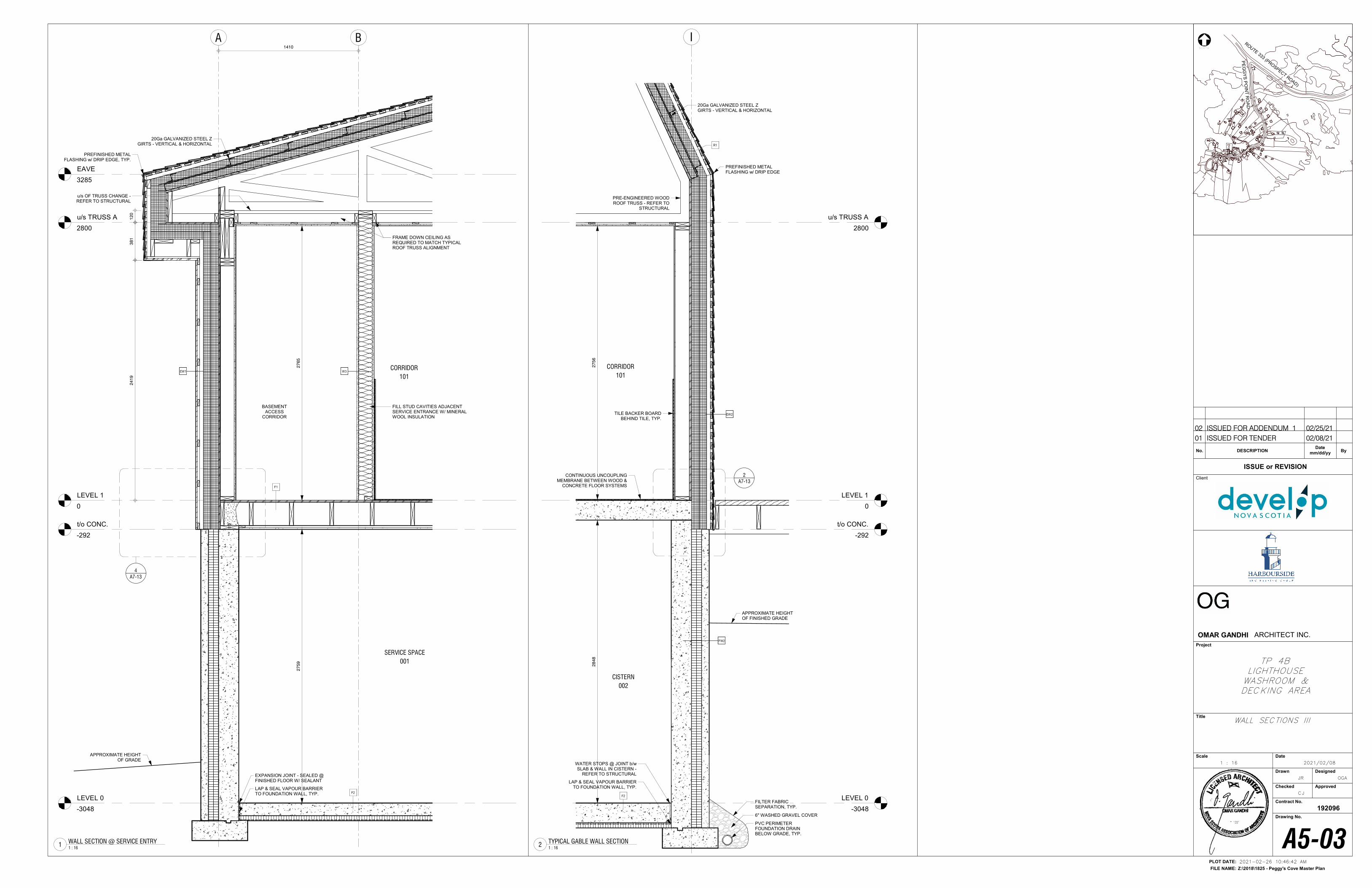
LEVEL 1
0
EAVE
3285
B
LEVEL 0
-3048
A
SERVICE SPACE
001
CORRIDOR
101
F2
A7-13
4
F1
LAP & SEAL VAPOUR BARRIER TO FOUNDATION WALL, TYP.
EXPANSION JOINT - SEALED @ FINISHED FLOOR W/ SEALANT
FILL STUD CAVITIES ADJACENT SERVICE ENTRANCE W/ MINERAL WOOL INSULATION
EW1 W3
27
65
27
59
1410
u/s TRUSS A
2800
t/o CONC.
-292
BASEMENT ACCESS
CORRIDOR
FRAME DOWN CEILING AS REQUIRED TO MATCH TYPICAL ROOF TRUSS ALIGNMENT
u/s OF TRUSS CHANGE -REFER TO STRUCTURAL
12
03
81
24
19
PREFINISHED METAL FLASHING w/ DRIP EDGE, TYP.
20Ga GALVANIZED STEEL Z GIRTS - VERTICAL & HORIZONTAL
APPROXIMATE HEIGHT OF GRADE
LEVEL 1
0
I
LEVEL 0
-3048
CORRIDOR
101
A7-13
2
F2
PVC PERIMETER FOUNDATION DRAIN BELOW GRADE, TYP.
6" WASHED GRAVEL COVER
APPROXIMATE HEIGHT OF FINISHED GRADE
LAP & SEAL VAPOUR BARRIER TO FOUNDATION WALL, TYP.
WATER STOPS @ JOINT b/w SLAB & WALL IN CISTERN -
REFER TO STRUCTURAL
FW2
FILTER FABRIC SEPARATION, TYP.
EW2
27
56
28
48
u/s TRUSS A
2800
t/o CONC.
-292
CISTERN
002
PREFINISHED METAL FLASHING w/ DRIP EDGE
R1
20Ga GALVANIZED STEEL Z GIRTS - VERTICAL & HORIZONTAL
PRE-ENGINEERED WOOD ROOF TRUSS - REFER TO
STRUCTURAL
TILE BACKER BOARD BEHIND TILE, TYP.
CONTINUOUS UNCOUPLING MEMBRANE BETWEEN WOOD &
CONCRETE FLOOR SYSTEMS
NORTH
Z:\2018\1825 - Peggy's Cove Master Plan
PLOT DATE:
FILE NAME:
Client
Project
Title
Scale Date
Drawn Designed
Checked Approved
Contract No.
Drawing No.
192096
ISSUE or REVISION
No. DESCRIPTION ByDate
mm/dd/yy
ROUTE 333 (PRO
SPECT ROAD)
PE
GG
YS
PO
INT
RO
AD
OMAR GANDHI ARCHITECT INC.
2021-02-26 10:46:42 AM
1 : 16
A5-03
JR
CJ
OGA
2021/02/08
WALL SECTIONS lll
TP 4BLIGHTHOUSEWASHROOM &DECKING AREA
1 : 16
WALL SECTION @ SERVICE ENTRY1
1 : 16
TYPICAL GABLE WALL SECTION2
01 ISSUED FOR TENDER 02/08/21
02 ISSUED FOR ADDENDUM 1 02/25/21
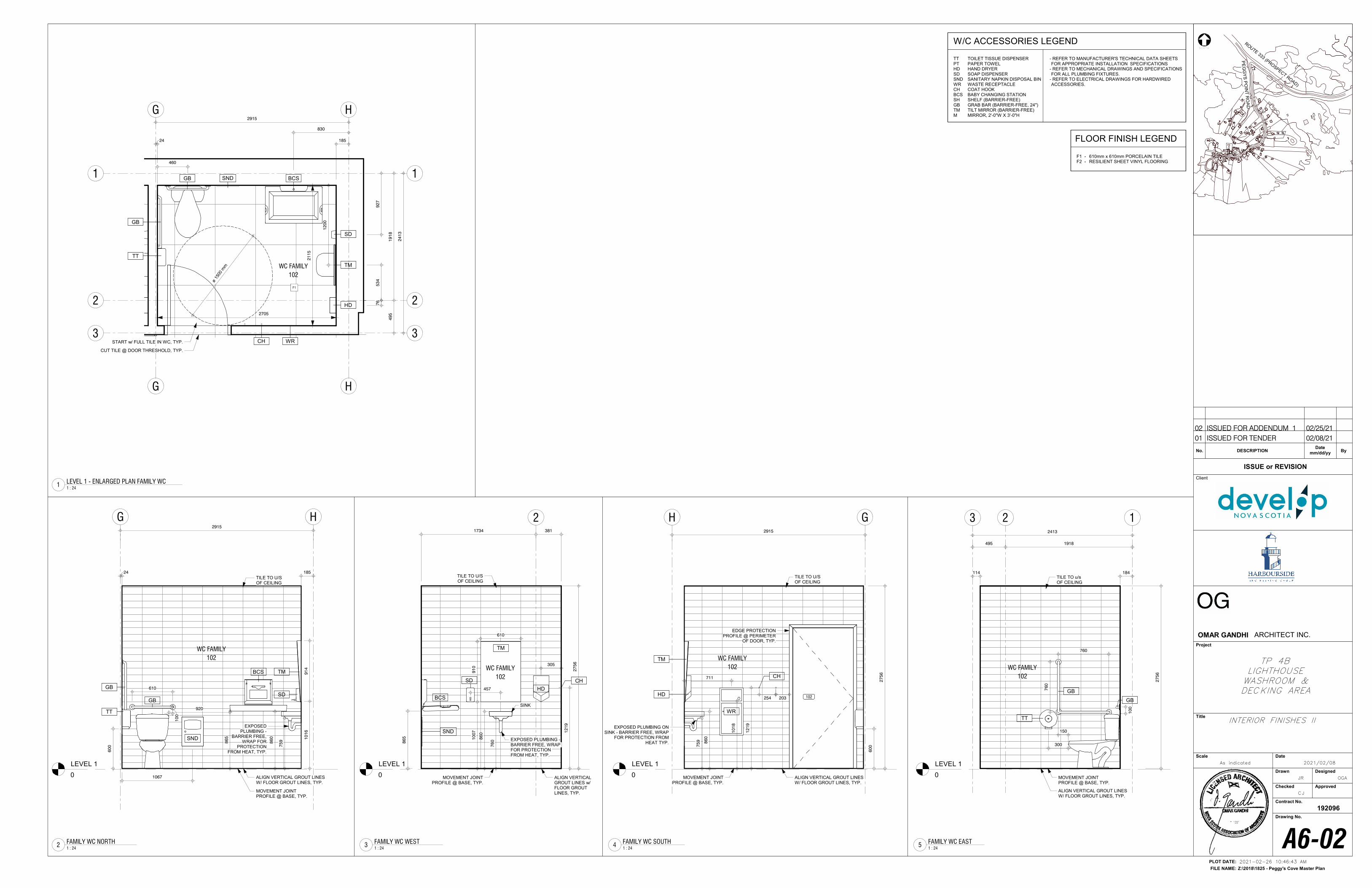
LEVEL 1
0
HG
TM
TT
GB
GB
WC FAMILY
102
10
16
91
4
86
0
60
0
SD
610
10
0
ALIGN VERTICAL GROUT LINES W/ FLOOR GROUT LINES, TYP.
TILE TO U/S OF CEILING
MOVEMENT JOINT PROFILE @ BASE, TYP.
2915
18524
86
5
BCS
EXPOSED PLUMBING -
BARRIER FREE, WRAP FOR
PROTECTION FROM HEAT, TYP.
920
SND
1067
75
9
TT TOILET TISSUE DISPENSERPT PAPER TOWELHD HAND DRYERSD SOAP DISPENSERSND SANITARY NAPKIN DISPOSAL BINWR WASTE RECEPTACLECH COAT HOOKBCS BABY CHANGING STATIONSH SHELF (BARRIER-FREE)GB GRAB BAR (BARRIER-FREE, 24")TM TILT MIRROR (BARRIER-FREE)M MIRROR, 2'-0"W X 3'-0"H
- REFER TO MANUFACTURER'S TECHNICAL DATA SHEETS FOR APPROPRIATE INSTALLATION SPECIFICATIONS
- REFER TO MECHANICAL DRAWINGS AND SPECIFICATIONS FOR ALL PLUMBING FIXTURES.
- REFER TO ELECTRICAL DRAWINGS FOR HARDWIRED ACCESSORIES.
W/C ACCESSORIES LEGEND
LEVEL 1
0
2
ALIGN VERTICAL GROUT LINES w/ FLOOR GROUT LINES, TYP.
TM
HD
91
01
00
7
610
CH
305
12
19
86
0
EXPOSED PLUMBING -BARRIER FREE, WRAP FOR PROTECTION FROM HEAT, TYP.
SINK
TILE TO U/S OF CEILING
MOVEMENT JOINT PROFILE @ BASE, TYP.
27
56
SD
457
WC FAMILY
102
BCS
86
5
1734 381
SND
76
0
LEVEL 1
0
H
EDGE PROTECTION PROFILE @ PERIMETER
OF DOOR, TYP.
G2915
ALIGN VERTICAL GROUT LINES W/ FLOOR GROUT LINES, TYP.
TILE TO U/S OF CEILING
MOVEMENT JOINT PROFILE @ BASE, TYP.
CH
TM
EXPOSED PLUMBING ON SINK - BARRIER FREE, WRAP
FOR PROTECTION FROM HEAT TYP.
12
19
27
56
102
WC FAMILY
102
WR
254 203
711
HD
60
0
10
18
86
0
75
9
LEVEL 1
0
12
27
56
3
WC FAMILY
102
495 1918
2413
TT
150
300
76
0
760
GB
10
0
GB
ALIGN VERTICAL GROUT LINES W/ FLOOR GROUT LINES, TYP.
TILE TO u/s OF CEILING
MOVEMENT JOINT PROFILE @ BASE, TYP.
184114
11
H
H
222
11
5
ø 15
00 m
m
33
G
G
2705
WC FAMILY
102
49
51
91
8
24
13
WRCH
SD
TM
HD
GB
GB
TT
460
12
00
F1
BCS
START w/ FULL TILE IN WC, TYP.
CUT TILE @ DOOR THRESHOLD, TYP.
2915
18524
830
92
77
65
34
SND
F1 - 610mm x 610mm PORCELAIN TILEF2 - RESILIENT SHEET VINYL FLOORING
FLOOR FINISH LEGEND
NORTH
Z:\2018\1825 - Peggy's Cove Master Plan
PLOT DATE:
FILE NAME:
Client
Project
Title
Scale Date
Drawn Designed
Checked Approved
Contract No.
Drawing No.
192096
ISSUE or REVISION
No. DESCRIPTION ByDate
mm/dd/yy
ROUTE 333 (PRO
SPECT ROAD)
PE
GG
YS
PO
INT
RO
AD
OMAR GANDHI ARCHITECT INC.
2021-02-26 10:46:43 AM
As indicated
A6-02
JR
CJ
OGA
2021/02/08
INTERIOR FINISHES II
TP 4BLIGHTHOUSEWASHROOM &DECKING AREA
1 : 24
FAMILY WC NORTH2
1 : 24
FAMILY WC WEST3
1 : 24
FAMILY WC SOUTH4
1 : 24
FAMILY WC EAST5
1 : 24
LEVEL 1 - ENLARGED PLAN FAMILY WC1
01 ISSUED FOR TENDER 02/08/21
02 ISSUED FOR ADDENDUM 1 02/25/21
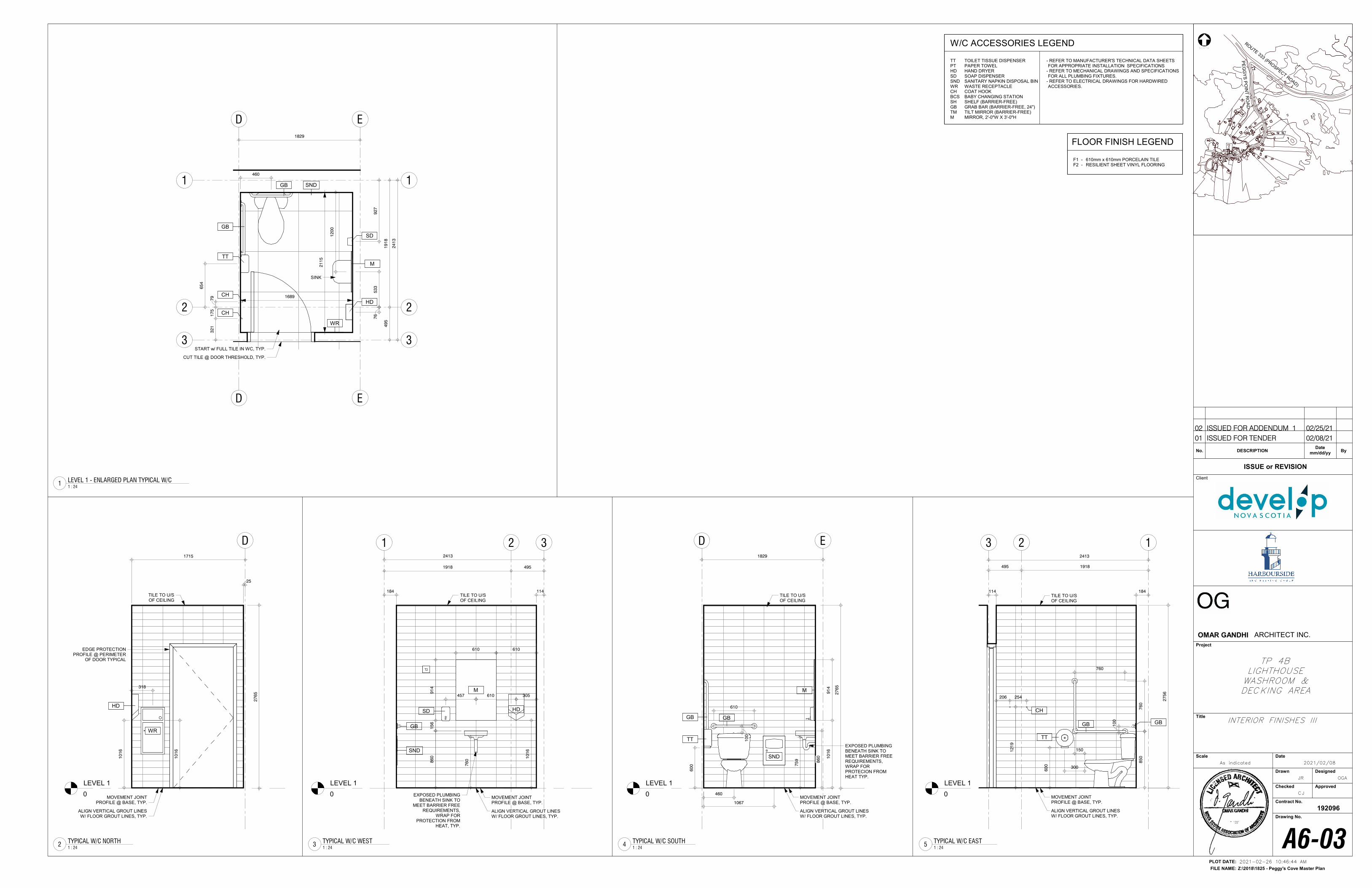
11
221689
33
E
E
D
D
21
15
460
TT
GB
GB
M
HD
WR
12
00
SD
CH
1829
49
51
91
8
24
13
CH
START w/ FULL TILE IN WC, TYP.
CUT TILE @ DOOR THRESHOLD, TYP.
92
75
33
76
SINK
32
11
75
79
65
4
SND
LEVEL 1
0
123
495 1918
2413
60
0
85
0
760
76
0
10
0 GBGB
150
300
TT
206 254
12
19
CH
MOVEMENT JOINT PROFILE @ BASE, TYP.
ALIGN VERTICAL GROUT LINES W/ FLOOR GROUT LINES, TYP.
TILE TO U/S OF CEILING
184114
27
56
LEVEL 1
0
ED1829
M
TT
GB GB
460
10
0
610
60
0
86
0
EXPOSED PLUMBING BENEATH SINK TO MEET BARRIER FREE REQUIREMENTS, WRAP FOR PROTECION FROM HEAT TYP.
10
16
91
4
27
65
TILE TO U/S OF CEILING
MOVEMENT JOINT PROFILE @ BASE, TYP.
ALIGN VERTICAL GROUT LINES W/ FLOOR GROUT LINES, TYP.
1067
SND
75
9
LEVEL 1
0
1 2 3
1918 495
2413
10
16
86
0
305
15
69
14
610
HD
M
GB
610
EXPOSED PLUMBING BENEATH SINK TO
MEET BARRIER FREE REQUIREMENTS,
WRAP FOR PROTECTION FROM
HEAT, TYP.
457 610
SD
T2
MOVEMENT JOINT PROFILE @ BASE, TYP.
ALIGN VERTICAL GROUT LINES W/ FLOOR GROUT LINES, TYP.
TILE TO U/S OF CEILING
114184
SND
76
0
LEVEL 1
0
D
HD
WR
10
16
27
65
10
16
318
EDGE PROTECTION PROFILE @ PERIMETER
OF DOOR TYPICAL
TILE TO U/S OF CEILING
MOVEMENT JOINT PROFILE @ BASE, TYP.
ALIGN VERTICAL GROUT LINES W/ FLOOR GROUT LINES, TYP.
25
1715
TT TOILET TISSUE DISPENSERPT PAPER TOWELHD HAND DRYERSD SOAP DISPENSERSND SANITARY NAPKIN DISPOSAL BINWR WASTE RECEPTACLECH COAT HOOKBCS BABY CHANGING STATIONSH SHELF (BARRIER-FREE)GB GRAB BAR (BARRIER-FREE, 24")TM TILT MIRROR (BARRIER-FREE)M MIRROR, 2'-0"W X 3'-0"H
- REFER TO MANUFACTURER'S TECHNICAL DATA SHEETS FOR APPROPRIATE INSTALLATION SPECIFICATIONS
- REFER TO MECHANICAL DRAWINGS AND SPECIFICATIONS FOR ALL PLUMBING FIXTURES.
- REFER TO ELECTRICAL DRAWINGS FOR HARDWIRED ACCESSORIES.
W/C ACCESSORIES LEGEND
F1 - 610mm x 610mm PORCELAIN TILEF2 - RESILIENT SHEET VINYL FLOORING
FLOOR FINISH LEGEND
NORTH
Z:\2018\1825 - Peggy's Cove Master Plan
PLOT DATE:
FILE NAME:
Client
Project
Title
Scale Date
Drawn Designed
Checked Approved
Contract No.
Drawing No.
192096
ISSUE or REVISION
No. DESCRIPTION ByDate
mm/dd/yy
ROUTE 333 (PRO
SPECT ROAD)
PE
GG
YS
PO
INT
RO
AD
OMAR GANDHI ARCHITECT INC.
2021-02-26 10:46:44 AM
As indicated
A6-03
JR
CJ
OGA
2021/02/08
INTERIOR FINISHES III
TP 4BLIGHTHOUSEWASHROOM &DECKING AREA
1 : 24
LEVEL 1 - ENLARGED PLAN TYPICAL W/C1
1 : 24
TYPICAL W/C EAST5
1 : 24
TYPICAL W/C SOUTH4
1 : 24
TYPICAL W/C WEST3
1 : 24
TYPICAL W/C NORTH2
01 ISSUED FOR TENDER 02/08/21
02 ISSUED FOR ADDENDUM 1 02/25/21
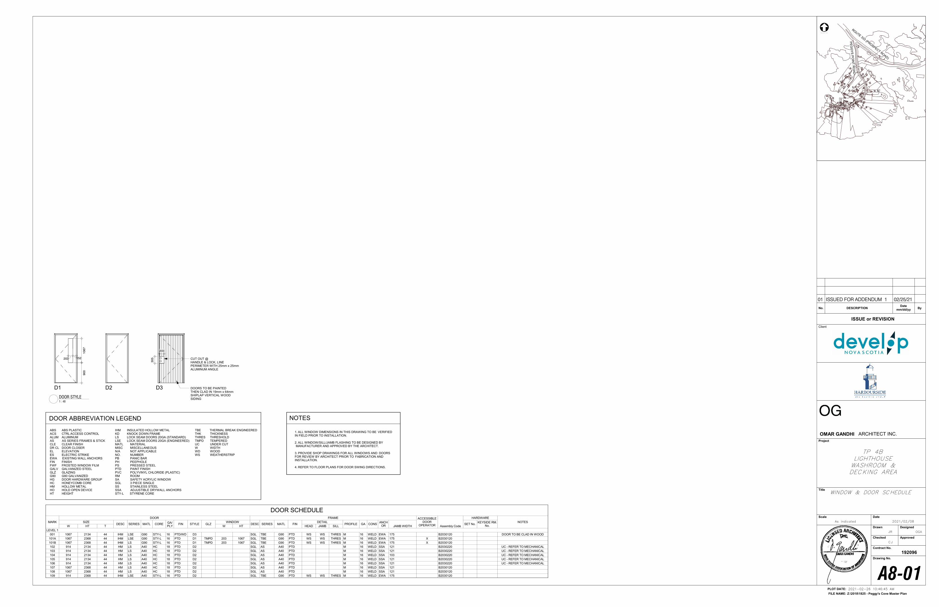
ABS ABS PLASTICACS CTRL ACCESS CONTROLALUM ALUMINUMAS AS SERIES FRAMES & STICKCLE CLEAR FINISHDR CL DOOR CLOSEREL ELEVATIONES ELECTRIC STRIKEEWA EXISTING WALL ANCHORSFIN FINISHFWF FROSTED WINDOW FILMGALV GALVANIZED STEEL GLZ GLAZINGG90 G90 GALVANIZEDHG DOOR HARDWARE GROUPHC HONEYCOMB COREHM HOLLOW METALHO HOLD OPEN DEVICEHT HEIGHT
TBE THERMAL BREAK ENGINEEREDTHK THICKNESSTHRES THRESHOLDTMPD TEMPEREDUC UNDER CUTW WIDTHWD WOODWS WEATHERSTRIP
DOOR ABBREVIATION LEGEND
IHM INSULATED HOLLOW METALKD KNOCK DOWN FRAMELS LOCK SEAM DOORS 20GA (STANDARD)LSE LOCK SEAM DOORS 20GA (ENGINEERED)MATL MATERIALMISC MISCELLANEOUSN/A NOT APPLICABLENO. NUMBERPB PANIC BARPH PEEPHOLEPS PRESSED STEELPTD PAINT FINISHPVC POLYVINYL CHLORIDE (PLASTIC)RM ROOMSA SAFETY ACRYLIC WINDOWSGL 3 PIECE SINGLESS STAINLESS STEELSSA ADJUSTIBLE DRYWALL ANCHORSSTY-L STYRENE CORE
1. ALL WINDOW DIMENSIONS IN THIS DRAWING TO BE VERIFIED IN FIELD PRIOR TO INSTALLATION.
2. ALL WINDOW/SILL/JAMB FLASHING TO BE DESIGNED BY MANUFACTURER AND APPROVED BY THE ARCHITECT.
3. PROVIDE SHOP DRAWINGS FOR ALL WINDOWS AND DOORS FOR REVIEW BY ARCHITECT PRIOR TO FABRICATION AND INSTALLATION.
4. REFER TO FLOOR PLANS FOR DOOR SWING DIRECTIONS.
NOTES
D1 D2
203 152
10
67
D3
90
0
203
30
5
DOORS TO BE PAINTEDTHEN CLAD IN 19mm x 64mm SHIPLAP VERTICAL WOODSIDING
CUT OUT @ HANDLE & LOCK, LINE PERIMETER WITH 25mm x 25mm ALUMINUM ANGLE
NORTH
Z:\2018\1825 - Peggy's Cove Master Plan
PLOT DATE:
FILE NAME:
Client
Project
Title
Scale Date
Drawn Designed
Checked Approved
Contract No.
Drawing No.
192096
ISSUE or REVISION
No. DESCRIPTION ByDate
mm/dd/yy
ROUTE 333 (PRO
SPECT ROAD)
PE
GG
YS
PO
INT
RO
AD
OMAR GANDHI ARCHITECT INC.
2021-02-26 10:46:45 AM
As indicated
A8-01
JR
CJ
OGA
2021/02/08
WINDOW & DOOR SCHEDULE
TP 4BLIGHTHOUSEWASHROOM &DECKING AREA
DOOR SCHEDULE
MARK
DOOR FRAME ACCESSIBLEDOOR
OPERATOR Assembly Code
HARDWARE
NOTESSIZEDESC SERIES MATL CORE GA/
PLYFIN STYLE GLZ
WINDOWDESC SERIES MATL FIN
DETAILPROFILE GA CONS
ANCHOR JAMB WIDTH
SET No.KEYSIDE RM.
No.W HT T W HT HEAD JAMB SILL
LEVEL 1
001 1067 2134 44 IHM LSE G90 STY-L 16 PTD/WD D3 SGL TBE G90 PTD WS WS THRES M 16 WELD EWA 175 B2030120 DOOR TO BE CLAD IN WOOD
101A 1067 2368 44 IHM LSE G90 STY-L 16 PTD D1 TMPD 203 1067 SGL TBE G90 PTD WS WS THRES M 16 WELD EWA 175 X B2030120
101B 1067 2368 44 IHM LS G90 STY-L 16 PTD D1 TMPD 203 1067 SGL TBE G90 PTD WS WS THRES M 16 WELD EWA 175 X B2030120
102 914 2134 44 HM LS A40 HC 18 PTD D2 SGL AS A40 PTD M 16 WELD SSA 121 B2030220 UC - REFER TO MECHANICAL
103 914 2134 44 HM LS A40 HC 18 PTD D2 SGL AS A40 PTD M 16 WELD SSA 121 B2030220 UC - REFER TO MECHANICAL
104 914 2134 44 HM LS A40 HC 18 PTD D2 SGL AS A40 PTD M 16 WELD SSA 103 B2030220 UC - REFER TO MECHANICAL
105 914 2134 44 HM LS A40 HC 18 PTD D2 SGL AS A40 PTD M 16 WELD SSA 121 B2030220 UC - REFER TO MECHANICAL
106 914 2134 44 HM LS A40 HC 18 PTD D2 SGL AS A40 PTD M 16 WELD SSA 121 B2030220 UC - REFER TO MECHANICAL
107 1067 2368 44 HM LS A40 HC 18 PTD D2 SGL AS A40 PTD M 16 WELD SSA 121 B2030120
108 1067 2368 44 HM LS A40 HC 18 PTD D2 SGL AS A40 PTD M 16 WELD SSA 121 B2030120
109 914 2368 44 IHM LSE A40 STY-L 16 PTD D2 SGL TBE G90 PTD WS WS THRES M 16 WELD EWA 175 B2030120
1 : 48
DOOR STYLE
01 ISSUED FOR ADDENDUM 1 02/25/21


