Embed Size (px)
Citation preview
11100 / 1105 / 1110 / 1120 / 1130 / 1200 / 1230 Variable-Frequency AC Drives
Guide to Installation, Troubleshooting,
and Maintenance
11/2 to 1,000 hp
(1.1 to 750 kW)
For revisions ECL 10 and above

Notices
Copyright © 2000-2013 by Unico, Incorporated. All rights reserved. No part of this publication may be copied, reproduced, or reduced to any electronic media or machine-readable format without the prior written permission of Unico, Inc. The information contained in this manual is considered accurate to the best knowledge of the supplier at the time of publication. The manufacturer, however, assumes no liability for errors that may exist. The supplier reserves the right to change data and specifications without notice. All trade designations are provided without reference to the rights of their respective owners. Printed in the United States of America.
110941 ECL 007 1000.40–07 6/13
Table of Contents
Table of Contents
Table of Contents ............................................................................................. 1-1
Safety Information ................................................................................................ i Overview .............................................................................................................................. i Conventions Used ................................................................................................................ i General Precautions ............................................................................................................ ii Installation Precautions ...................................................................................................... iii Application Precautions ..................................................................................................... iii Service Precautions ............................................................................................................ iv
1 About the Manual ....................................................................................... 1-1 1.1 Overview ................................................................................................................ 1-1 1.2 Contents ................................................................................................................. 1-1 1.2.1 Intended Audience ............................................................................................. 1-2
2 Product Overview ....................................................................................... 2-1 2.1 Overview ................................................................................................................ 2-1 2.2 Unpacking .............................................................................................................. 2-1 2.2.1 Lifting Instructions ............................................................................................ 2-1 2.2.2 Verify delivery ................................................................................................... 2-2 2.2.3 Inspect for damage ............................................................................................ 2-2 2.2.4 Storage/Transportation ...................................................................................... 2-2 2.2.5 Nameplate Identification ................................................................................... 2-2 2.3 Family Overview .................................................................................................... 2-3 2.3.1 Features .............................................................................................................. 2-3 2.3.2 Drive Architecture ............................................................................................. 2-6 2.4 Specifications ......................................................................................................... 2-9
3 Mechanical Installation .............................................................................. 3-1 3.1 Overview ................................................................................................................ 3-1 3.2 Forms ..................................................................................................................... 3-1 3.3 Installation Site Considerations ............................................................................. 3-1 3.3.1 Enclosure ........................................................................................................... 3-1 3.3.2 Operating Environment ..................................................................................... 3-2 3.3.3 Cooling .............................................................................................................. 3-2 3.4 Layout Considerations ........................................................................................... 3-3 3.4.1 Dimensions and Weights ................................................................................... 3-3 3.4.2 Space Requirements .......................................................................................... 3-3 3.4.3 Orientation ......................................................................................................... 3-3 3.4.4 Cable Routing .................................................................................................... 3-3 3.5 Installation Procedure ............................................................................................ 3-4 3.5.1 Foot Mounting ................................................................................................... 3-4 3.5.2 Flush Mounting (Form 22X) ............................................................................. 3-5 3.5.3 Flange Mounting ............................................................................................... 3-5 3.6 Mounting the I/O Fanning Strip ............................................................................. 3-5
1000 Series / Guide to Installation, Troubleshooting, and Maintenance
4 Electrical Installation ................................................................................. 4-1 4.1 Overview ................................................................................................................ 4-1 4.2 Wiring Requirements ............................................................................................. 4-1 4.2.1 Standards and Codes .......................................................................................... 4-1 4.2.2 Conductors ......................................................................................................... 4-1 4.2.3 Tightening Torque ............................................................................................. 4-1 4.3 Insulation Tests ...................................................................................................... 4-2 4.4 Ground Connections .............................................................................................. 4-2 4.4.1 Ground the drive ................................................................................................ 4-3 4.4.2 Ground the Power Supply ................................................................................. 4-3 4.4.3 Ground the Motor and Transducer .................................................................... 4-3 4.4.4 Connect the Control Grounds ............................................................................ 4-3 4.5 Input Power Supply ................................................................................................ 4-3 4.5.1 Power Source Conditioning ............................................................................... 4-4 4.5.2 Connect the Power Supply .............................................................................. 4-18 4.5.3 Input Protection ............................................................................................... 4-18 4.6 Connect the Motor ............................................................................................... 4-18 4.7 Connect the Dynamic Braking Resistor ............................................................... 4-19 4.8 Bus Connections .................................................................................................. 4-20 4.8.1 Common-Bus Operation .................................................................................. 4-20 4.9 Control Signal Connections ................................................................................. 4-47 4.9.1 Wiring Precautions .......................................................................................... 4-47 4.9.2 Digital I/O Connections (TB1) ........................................................................ 4-51 4.9.3 Analog I/O Connections (TB2, CON2) ........................................................... 4-52 4.9.4 Serial Connections (TB1, J1, J2, J3, J4, J6, J11, J12) ..................................... 4-52 4.9.5 Feedback Interface Connections ...................................................................... 4-53
5 Troubleshooting/Maintenance .................................................................. 5-1 5.1 Overview ................................................................................................................ 5-1 5.2 Troubleshooting ..................................................................................................... 5-1 5.2.1 Theory of Operation .......................................................................................... 5-1 5.2.2 Rectifier Checking Procedure .......................................................................... 5-17 5.2.3 Transistor Checking Procedure ....................................................................... 5-18 5.3 Maintenance ......................................................................................................... 5-20 5.3.1 Working Life ................................................................................................... 5-20 5.3.2 Battery Life ...................................................................................................... 5-20 5.3.3 Disposal ........................................................................................................... 5-20 5.4 Parts and Repairs .................................................................................................. 5-20 5.4.1 Parts ................................................................................................................. 5-20 5.4.2 Repairs ............................................................................................................. 5-21
Safety Information i
Safety Information
Overview This section states important safety information that must be followed when installing, operating, and servicing the drive. Study this information carefully before working on or with the unit. Failure to follow these instructions may lead to personal injury or death or to damage to the drive, motor, or driven equipment. Additional safety instructions specific to the application software can be found in the application documentation. Please study and follow those instructions as well. Conventions Used The following notation conventions are used throughout this manual to indicate information important to personal safety or machine hazards.
!
Attention Identifies information about practices or circumstances that can lead to personal injury or death, property damage, or economic loss.
ii 1000 Series / Guide to Installation, Troubleshooting, and Maintenance
General Precautions
!
Attention Only qualified personnel with the proper skills, instruction, and familiarity with the drive and its applications should install, start up, operate, troubleshoot, and maintain the drive. You must be familiar with the electrical and mechanical components of the system to perform the procedures outlined in this manual. Failure to comply may result in personal injury, death, and/or equipment damage.
!
Attention Failure to take proper precautions for electrical hazard could cause injury or death.
!
Attention Failure to follow industry safety standards and instructions in this manual could damage the drive and void the manufacturer’s warranty.
!
Attention The drive may be sensitive to electrostatic discharge. Static precautions are required when servicing or repairing the unit.
!
Attention If an aluminum electrolytic capacitor in the drive fails from a build-up of internal pressure, a safety vent will operate, spraying electrolyte vapor from the capacitor. If a capacitor vents, avoid contact with the liquid, avoid inhaling the vapors, and ventilate the area. If your skin comes in contact with the electrolyte, flush it immediately with cold water. If electrolyte gets in your eyes, immediately remove any contact lenses and flush the open eyes with plenty of clean water. If electrolyte is ingested, dilute it by drinking warm water and seek immediate medical attention.
!
Attention Drives are intended for fixed, permanent connection to earthed three-phase supply mains. Use of EMC filters along with the equipment will increase leakage current in the protective conductor and may affect compatibility with residual-current-operated protective devices.
!
Attention The drive provides solid-state motor overload protection. The level of protection is dependent upon the rating of the unit (given in Table 2-2) as well as the software overload specified by the user. Please refer to the application documentation for instructions on adjusting the overload.
Safety Information iii
Installation Precautions
!
Attention An incorrectly installed or operated drive can result in damage to the equipment it controls. Make certain installation and operating specifications are followed.
!
Attention To provide protection against electrical shock, drives must be mounted in an enclosure meeting at least the requirements of Protective Type IP20 (or NEMA equivalent) according to EN60529 and with top surfaces meeting at least the requirements of IP40 (or NEMA equivalent). It is recommended that a key or tool be required to open the enclosure and that enclosure doors be interlocked with the electrical supply disconnect.
!
Attention The drive and associated equipment must be properly earth grounded.
!
Attention Any site insulation tests must be performed before making electrical connections to the drive.
!
Attention The drive is not equipped with a supply-disconnecting device. An external supply-disconnecting device must be provided to isolate incoming electrical supplies during installation and maintenance work. This device should comply with the requirements of EN 60204-1 as well as all applicable national and local regulations.
Application Precautions
!
Attention Emergency stop devices shall be located at each operator control station and at other operating stations where emergency stop may be required. Control inputs and keypad motor-control functions do not generate an emergency stop of the motor and do not remove power that can cause hazardous conditions. Regardless of the operating state, the drive’s motor output terminals may be at dangerous voltage levels whenever input power is applied and the bus is charged.
iv 1000 Series / Guide to Installation, Troubleshooting, and Maintenance
!
Attention Drive functionality depends upon the application software installed. Some application software offers automatic restart functions that allow the unit to reset and resume operation after a fault. These functions must not be enabled when hazardous conditions might arise from such action. Certain features may present additional hazardous situations. Refer to the associated application documentation for further safety information.
Service Precautions
!
Attention Always disconnect and lock out all electrical supplies before working on the drive or associated equipment. Do this before touching any electrical or mechanical components associated with the drive application.
!
Attention High voltage may be present even when all electrical power supplies are disconnected. After switching off electrical power, wait at least 15 minutes for bus circuit capacitors to discharge before working on the drive or associated equipment. Use an appropriate voltmeter to further verify that capacitors are discharged before beginning work. Do not rely exclusively on the bus voltage indicator. Dangerous voltage levels may remain even when the indicator is off.
!
Attention High voltage may be present at the motor output terminals (U, V, W) whenever input power is applied, regardless of whether the motor is moving or not.
!
Attention Before energizing the motor, verify that there are no loose components associated with the drive train and that motor motion will not result in injury or damage to the equipment.
Safe Service Practices Follow industry-recognized safety procedures: • Use only one hand to hold test equipment probes • Wear approved eye protection • Stand on insulated material • Use an isolated oscilloscope • Keep unnecessary personnel out of the work area • Never leave a drive cabinet open or unattended
About the Manual 1-1
1 About the Manual
1.1 Overview This chapter describes the contents and intended audience of this document.
1.2 Contents The manual provides the instructions and technical information necessary to install and maintain the hardware of Unico’s 1000 family of AC drives. Specifically, the manual pertains to units listed in Table 1-1. The 1140 Variable-Voltage AC Drive is covered separately in publication 1140.40 (111-564).
Table 1-1—1000 Family
Drive Description
1100 Variable-Frequency AC Drive
1105 Variable-Frequency AC Drive
1110 Phase-Converting AC Drive
1120 Modular AC Drive
1130 Line-Regenerative AC Drive
1200 Variable-Frequency AC Drive
1230 Line-Regenerative AC Drive
What’s covered • Safety Instructions, discusses safety hazards and procedures important to anyone
working with the drive • Chapter 2, Product Overview, tells how to receive the drive and provides an
overview of its architecture, features, and specifications • Chapter 3, Mechanical Installation, provides instructions on physical installation
Chapter 4, Electrical Installation, explains the routine electrical connections • Chapter 5, Troubleshooting/Maintenance, discusses troubleshooting and
maintenance of the drive hardware
What’s not covered This manual does not address aspects of the drive that depend upon the application software. Please refer to the application documentation for the following: • Application-specific control signal wiring and definitions • Operator interface instructions • Start-up procedure • Detailed description of drive features and modes of operation • Parameter descriptions • Fault identification and troubleshooting
1-2 1000 Series / Guide to Installation, Troubleshooting, and Maintenance
This manual is not intended to provide in-depth service instructions. For service beyond that described in this manual, please contact Unico or your representative.
1.2.1 Intended Audience The manual is intended for anyone who will be installing and servicing the drive. Installation should be performed by qualified electrical personnel to ensure that correct electrical practices and applicable electrical codes are applied. The audience is expected to have a basic knowledge of physical and electrical fundamentals, electrical wiring practices and components, and electrical schematics. No prior experience with the drive is presumed or required. Follow instructions You can prevent injury and damage to the drive or equipment by carefully following the procedures outlined in this manual. Follow regulations All electrical work should conform to the National Electrical Code as well as all state and local government regulations. Please familiarize yourself with these regulations. Read both manuals first Read this manual and the application manual entirely before installing the drive.
Product Overview 2-1
2 Product Overview
2.1 Overview This chapter provides an overview of the 1000 family of drives. It gives instructions on unpacking, identifying, storing, and transporting a drive. It also familiarizes the user with the basic features, architecture, and specifications of the drives.
2.2 Unpacking After opening the package, you should verify delivery and inspect the drive before installing, storing, or transporting the unit.
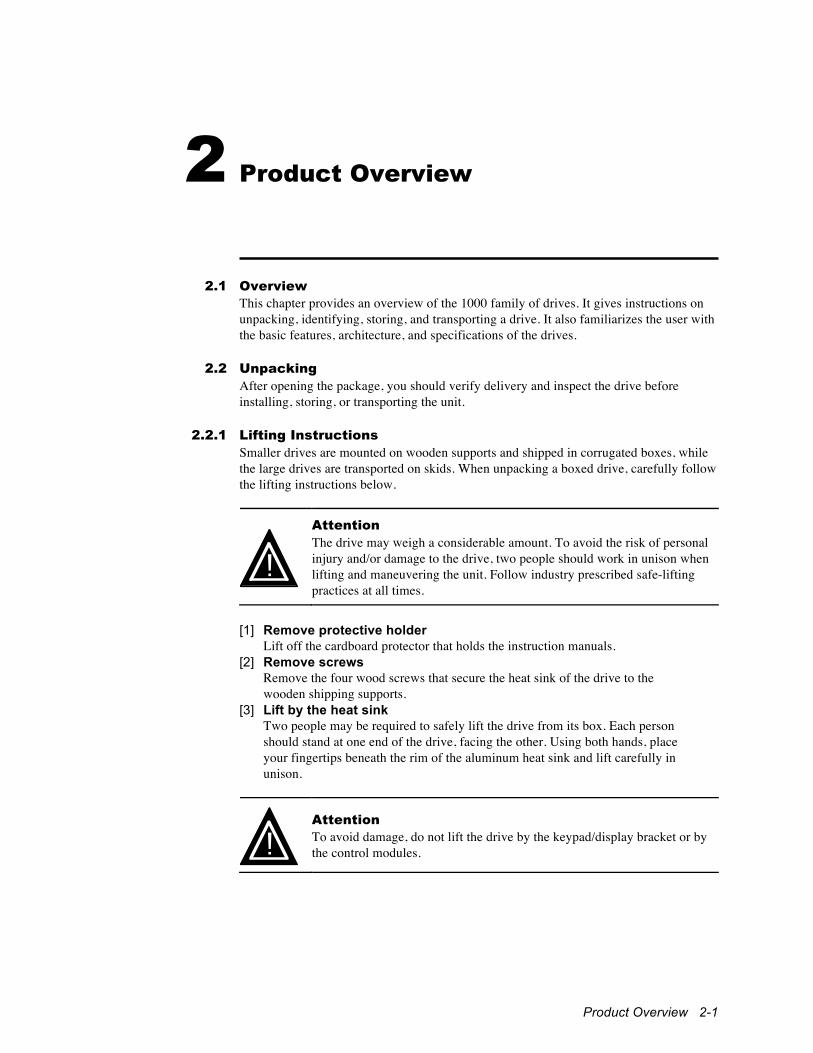
2.2.1 Lifting Instructions Smaller drives are mounted on wooden supports and shipped in corrugated boxes, while the large drives are transported on skids. When unpacking a boxed drive, carefully follow the lifting instructions below.
!
Attention The drive may weigh a considerable amount. To avoid the risk of personal injury and/or damage to the drive, two people should work in unison when lifting and maneuvering the unit. Follow industry prescribed safe-lifting practices at all times.
[1] Remove protective holder
Lift off the cardboard protector that holds the instruction manuals. [2] Remove screws
Remove the four wood screws that secure the heat sink of the drive to the wooden shipping supports.
[3] Lift by the heat sink Two people may be required to safely lift the drive from its box. Each person should stand at one end of the drive, facing the other. Using both hands, place your fingertips beneath the rim of the aluminum heat sink and lift carefully in unison.
!
Attention To avoid damage, do not lift the drive by the keypad/display bracket or by the control modules.
2-2 1000 Series / Guide to Installation, Troubleshooting, and Maintenance
2.2.2 Verify delivery Check that you received the drive that was ordered as well as any options or accessories. Minimally, you should have received a drive and two manuals (this installation guide and an application guide). Contact your supplier regarding any discrepancies.
2.2.3 Inspect for damage Inspect the drive for any damage that may have occurred during shipment. Remove the cover, if present, and visually examine the insides for obvious problems. If damage is found, do not operate the drive. Report the problem immediately to the supplier.
2.2.4 Storage/Transportation If the drive must be stored or transported to another location before installation, verify that the ambient conditions are acceptable according to the environmental specifications given in Table 2-3. Choose a storage location that is clean, dry, and noncorrosive. Repack and store the drive in its original packaging.
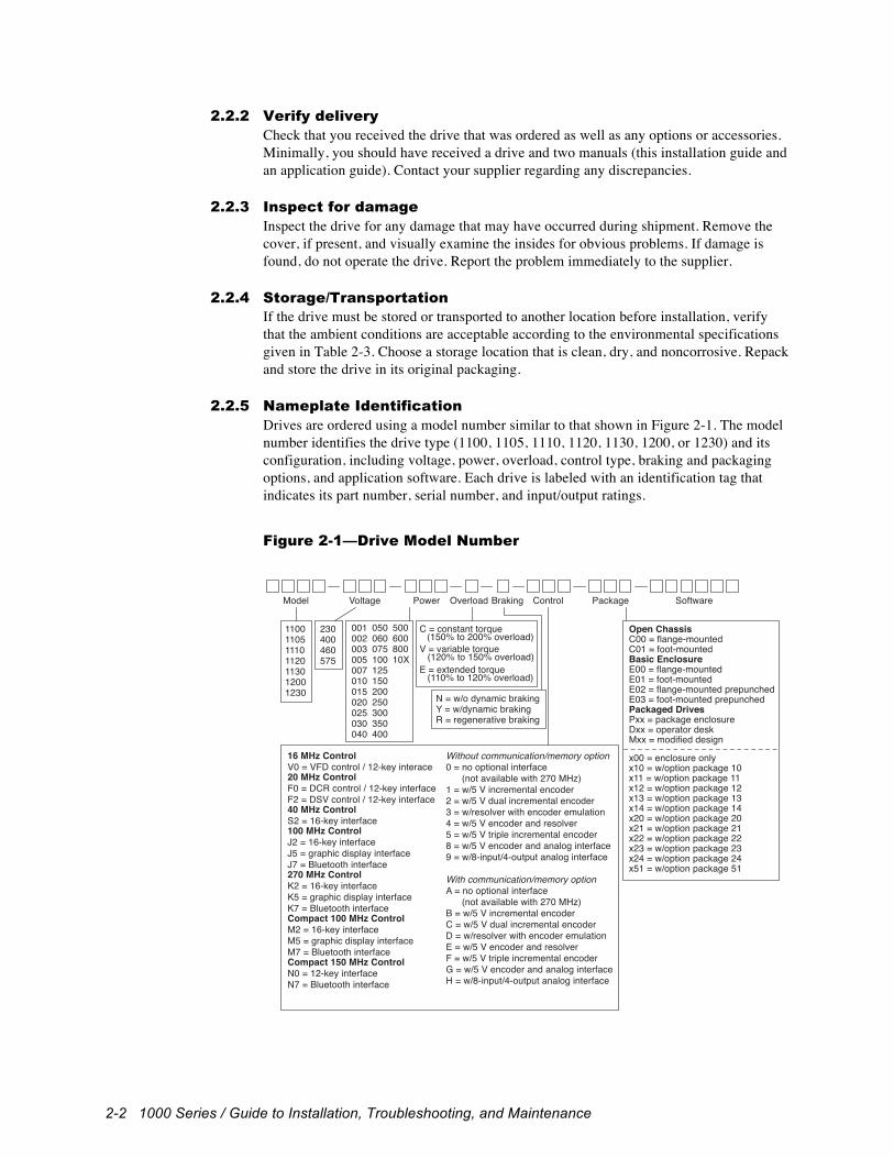
2.2.5 Nameplate Identification Drives are ordered using a model number similar to that shown in Figure 2-1. The model number identifies the drive type (1100, 1105, 1110, 1120, 1130, 1200, or 1230) and its configuration, including voltage, power, overload, control type, braking and packaging options, and application software. Each drive is labeled with an identification tag that indicates its part number, serial number, and input/output ratings.
Figure 2-1—Drive Model Number
Voltage Power Overload ControlBraking Package
001002003005007010015020025030040
050060075100125150200250300350400
50060080010X
C = constant torque (150% to 200% overload)V = variable torque
(120% to 150% overload)E = extended torque
(110% to 120% overload)
230400460575
1100110511101120113012001230 N = w/o dynamic braking
Y = w/dynamic brakingR = regenerative braking
SoftwareModel
Without communication/memory option0 = no optional interface (not available with 270 MHz)1 = w/5 V incremental encoder2 = w/5 V dual incremental encoder3 = w/resolver with encoder emulation4 = w/5 V encoder and resolver5 = w/5 V triple incremental encoder8 = w/5 V encoder and analog interface9 = w/8-input/4-output analog interface
With communication/memory optionA = no optional interface (not available with 270 MHz)B = w/5 V incremental encoderC = w/5 V dual incremental encoderD = w/resolver with encoder emulationE = w/5 V encoder and resolverF = w/5 V triple incremental encoderG = w/5 V encoder and analog interfaceH = w/8-input/4-output analog interface
16 MHz ControlV0 = VFD control / 12-key interace20 MHz ControlF0 = DCR control / 12-key interfaceF2 = DSV control / 12-key interface40 MHz ControlS2 = 16-key interface100 MHz ControlJ2 = 16-key interfaceJ5 = graphic display interfaceJ7 = Bluetooth interface270 MHz ControlK2 = 16-key interfaceK5 = graphic display interfaceK7 = Bluetooth interfaceCompact 100 MHz ControlM2 = 16-key interfaceM5 = graphic display interfaceM7 = Bluetooth interfaceCompact 150 MHz ControlN0 = 12-key interfaceN7 = Bluetooth interface
Open ChassisC00 = flange-mounted C01 = foot-mountedBasic EnclosureE00 = flange-mountedE01 = foot-mountedE02 = flange-mounted prepunchedE03 = foot-mounted prepunchedPackaged DrivesPxx = package enclosureDxx = operator deskMxx = modified design
x00 = enclosure onlyx10 = w/option package 10x11 = w/option package 11x12 = w/option package 12x13 = w/option package 13x14 = w/option package 14x20 = w/option package 20x21 = w/option package 21x22 = w/option package 22x23 = w/option package 23x24 = w/option package 24x51 = w/option package 51
Product Overview 2-3
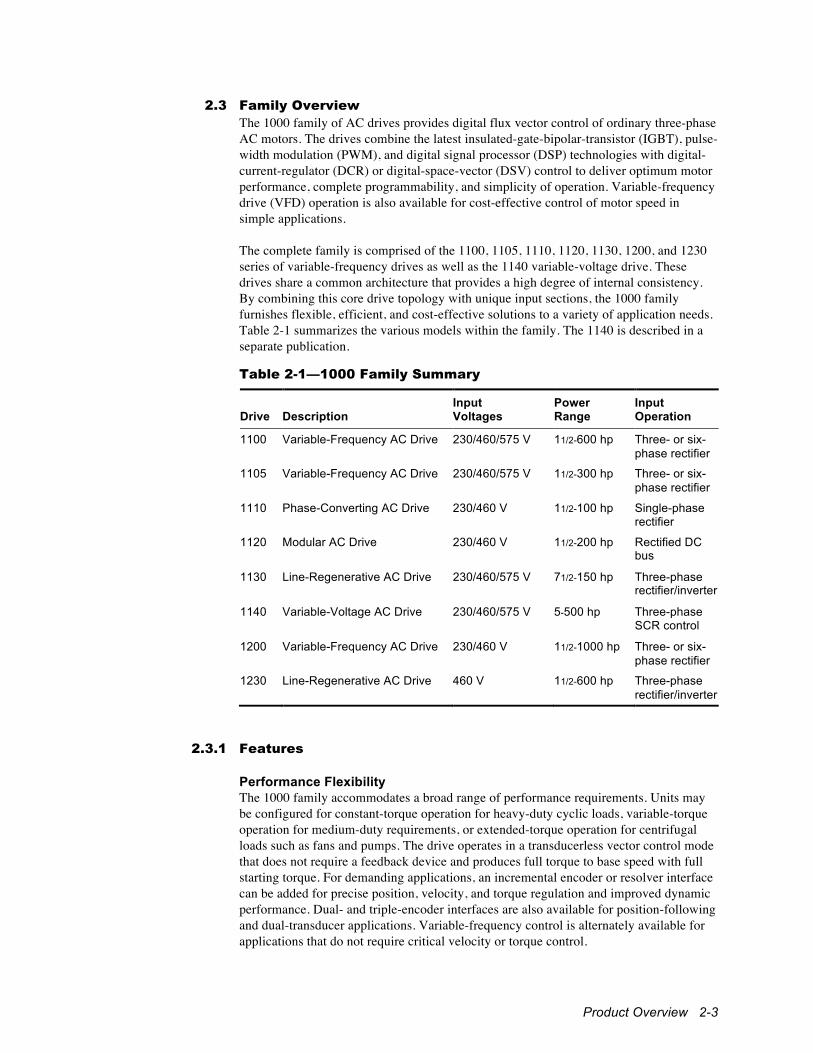
2.3 Family Overview The 1000 family of AC drives provides digital flux vector control of ordinary three-phase AC motors. The drives combine the latest insulated-gate-bipolar-transistor (IGBT), pulse-width modulation (PWM), and digital signal processor (DSP) technologies with digital-current-regulator (DCR) or digital-space-vector (DSV) control to deliver optimum motor performance, complete programmability, and simplicity of operation. Variable-frequency drive (VFD) operation is also available for cost-effective control of motor speed in simple applications. The complete family is comprised of the 1100, 1105, 1110, 1120, 1130, 1200, and 1230 series of variable-frequency drives as well as the 1140 variable-voltage drive. These drives share a common architecture that provides a high degree of internal consistency. By combining this core drive topology with unique input sections, the 1000 family furnishes flexible, efficient, and cost-effective solutions to a variety of application needs. Table 2-1 summarizes the various models within the family. The 1140 is described in a separate publication.
Table 2-1—1000 Family Summary
Drive
Description
Input Voltages
Power Range
Input Operation
1100 Variable-Frequency AC Drive 230/460/575 V 11/2-600 hp Three- or six-phase rectifier
1105 Variable-Frequency AC Drive 230/460/575 V 11/2-300 hp Three- or six-phase rectifier
1110 Phase-Converting AC Drive 230/460 V 11/2-100 hp Single-phase rectifier
1120 Modular AC Drive 230/460 V 11/2-200 hp Rectified DC bus
1130 Line-Regenerative AC Drive 230/460/575 V 71/2-150 hp Three-phase rectifier/inverter
1140 Variable-Voltage AC Drive 230/460/575 V 5-500 hp Three-phase SCR control
1200 Variable-Frequency AC Drive 230/460 V 11/2-1000 hp Three- or six-phase rectifier
1230 Line-Regenerative AC Drive 460 V 11/2-600 hp Three-phase rectifier/inverter
2.3.1 Features Performance Flexibility The 1000 family accommodates a broad range of performance requirements. Units may be configured for constant-torque operation for heavy-duty cyclic loads, variable-torque operation for medium-duty requirements, or extended-torque operation for centrifugal loads such as fans and pumps. The drive operates in a transducerless vector control mode that does not require a feedback device and produces full torque to base speed with full starting torque. For demanding applications, an incremental encoder or resolver interface can be added for precise position, velocity, and torque regulation and improved dynamic performance. Dual- and triple-encoder interfaces are also available for position-following and dual-transducer applications. Variable-frequency control is alternately available for applications that do not require critical velocity or torque control.

2-4 1000 Series / Guide to Installation, Troubleshooting, and Maintenance
Motor-Independent Design The 1000 family drives operate any standard- or inverter-duty AC induction or synchronous motor, making it ideal for retrofits and new applications alike. A unique, proprietary digital current regulator (DCR) tunes the drive continuously in real time, eliminating the usual current-loop tuning process required by conventional drives. Digital space vector (DSV) control can be selected for reduced motor noise and low current ripple. Auto Tuning Once routine electrical connections have been made, simple-to-use auto-tuning features adjust virtually all motor- and load-dependent parameters. No motor maps are required. Simply enter basic motor information from the nameplate, and the advanced setup routines do the rest. The drive is completely tuned within minutes. Control Options Numerous control and interface options are available. The 16 MHz control module provides variable-frequency drive (VFD) control for simple applications. The 20 MHz and 40 MHz control modules are available in digital-current-regulator (DCR) and digital-space-vector (DSV) versions. The 100 MHz, 270 MHz, and Compact 100 MHz control modules provide for VFD, DCR, and DSV control. The Compact 150 MHz control module provides VFD and DSV control. Each control module provides digital and analog inputs and outputs as well as asynchronous serial communication capabilities. The 20 MHz, 40 MHz, 100 MHz, 270 MHz, and Compact 100 MHz modules also provide synchronous serial communication capabilities. The 100 MHz and 270 MHz modules include provision for an optional Anybus®
module for communication using a variety of industry-standard protocols, while the 100 MHz, 270 MHz, and the Compact 100 MHz modules include provision(s) for a MaxStream™
module for wireless communication. Depending upon the control module, drives can accept motor and/or machine feedback with a single, dual, or triple incremental encoder interface, a resolver interface, or resolver and encoder interfaces. An optional analog interface module is also available for expanding the analog I/O capabilities of a drive. One of three keypad/display units is available, depending upon the application. Application Software A wide variety of software options is available to tailor a drive to its application, from a fully featured velocity/torque control for general purposes to a host of powerful programs pre-engineered for specific applications. Customization is possible with many programs using UEdit™, a Windows-based programming tool that allows users extend an application using IEC 1131 standard ladder diagrams and function blocks. Braking Options The 1000 family offers both dynamic and regenerative braking options. A dynamic braking IGBT allows motor braking energy to be dissipated in an external resistor. This dynamic braking control is included as standard on all 1120 drives and smaller 1105 and 1200 drives. It is optional on larger 1105 and 1200 drives and all 1100 and 1110 drives. Appropriately sized external braking resistors are required. The 1130 and 1230 line-regenerative drives provide true four-quadrant control without requiring dynamic braking. Energy generated by stopping the motor and load is put back onto the power grid rather than wasted as heat in a resistor.

Product Overview 2-5
Digital Setup, Easy Operation A keypad and liquid crystal display provide a simple interface for setting and viewing operating parameters and diagnostics. All controller settings are made digitally for precision and repeatability. Readouts and fault messages are displayed in readily understandable language. A graphical display option provides on-board oscilloscope-type viewing of drive and system parameters. Multiaxis Operation A built-in high-speed synchronous communication port allows the motion of multiple slave drives to be precisely coordinated. With optional master/slave software, the velocity ratio and position phasing of the drives can also be controlled. Multiple motors can be operated in parallel from a single drive using optional variable-frequency control. Power Quality A built-in link choke on the 1100, 1105, and 1110 drives and the unique low-capacitance design of the 1200 provides near-unity overall power factor and low harmonic line currents at all motor speeds. High-power 1100, 1105, and 1200 drives also offer a six-phase (twelve-pulse) configuration for further minimizing line harmonics in critical applications. The 1130 and 1230 line-regenerative drives provide near-unity power factor for both motoring- and braking-type loads by using an IGBT bridge to control the flow of power into and out of the drive. Protection and Advanced Diagnostics Drives monitor their operating conditions and provide a comprehensive set of overload, short circuit, and other electronic protective features to ensure safe, reliable operation. Faults indications are displayed in plain language. A log maintains a history of fault occurrences and externally triggered events. Serial Connectivity An RS-422/485 serial interface is provided for connecting a drive to a process controller, communication network, or programmable controller. A variety of popular communication protocols is available. The 100 MHz and 270 MHz modules also accept an Anybus® module with numerous industry-standard protocol options, and the 100 MHz, 270 MHz, and Compact 100 MHz modules accept MaxStream module(s) for wireless communications. An RS-232 connection is also provided on 40 MHz, 100 MHz, 270 MHz, Compact 100 MHz, and Compact 150 MHz controllers for connecting a personal computer. The Compact 150 MHz module also provides a USB 2.0 port for asynchronous communications. Windows-based PCs can set up, monitor, and control a network of drives using optional DriveLink™ or UEdit™ software. Drive Archive™ and Drive Chart™ for the Palm OS make it easy to save and restore setups and capture charts using a handheld computer. Packaging Compact and rugged, drives are available either enclosed or as an open chassis for mounting inside an enclosure. Both versions can be foot-mounted to a wall or subplate or flange-mounted through a cutout to dissipate heat outside an enclosure. Standard packaged systems are also available that incorporate additional components within an enclosure.
2-6 1000 Series / Guide to Installation, Troubleshooting, and Maintenance
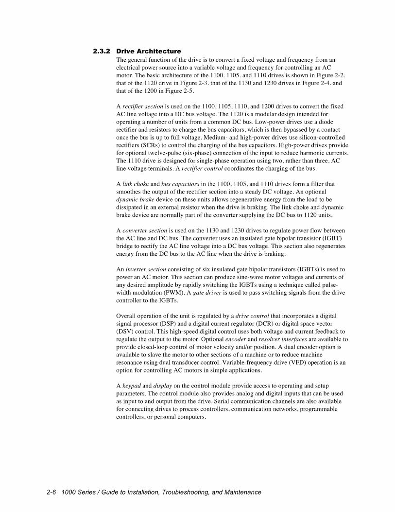
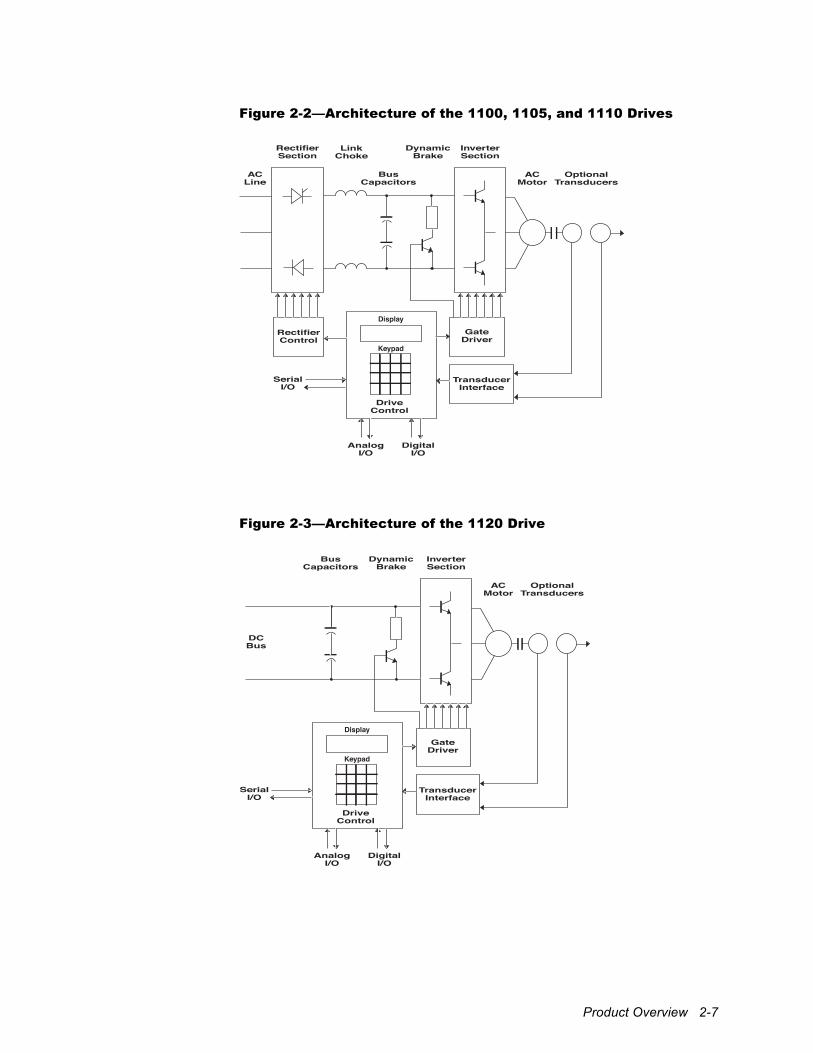
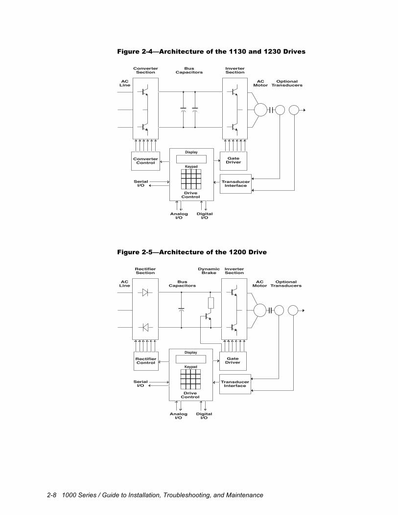
2.3.2 Drive Architecture The general function of the drive is to convert a fixed voltage and frequency from an electrical power source into a variable voltage and frequency for controlling an AC motor. The basic architecture of the 1100, 1105, and 1110 drives is shown in Figure 2-2, that of the 1120 drive in Figure 2-3, that of the 1130 and 1230 drives in Figure 2-4, and that of the 1200 in Figure 2-5. A rectifier section is used on the 1100, 1105, 1110, and 1200 drives to convert the fixed AC line voltage into a DC bus voltage. The 1120 is a modular design intended for operating a number of units from a common DC bus. Low-power drives use a diode rectifier and resistors to charge the bus capacitors, which is then bypassed by a contact once the bus is up to full voltage. Medium- and high-power drives use silicon-controlled rectifiers (SCRs) to control the charging of the bus capacitors. High-power drives provide for optional twelve-pulse (six-phase) connection of the input to reduce harmonic currents. The 1110 drive is designed for single-phase operation using two, rather than three, AC line voltage terminals. A rectifier control coordinates the charging of the bus. A link choke and bus capacitors in the 1100, 1105, and 1110 drives form a filter that smoothes the output of the rectifier section into a steady DC voltage. An optional dynamic brake device on these units allows regenerative energy from the load to be dissipated in an external resistor when the drive is braking. The link choke and dynamic brake device are normally part of the converter supplying the DC bus to 1120 units. A converter section is used on the 1130 and 1230 drives to regulate power flow between the AC line and DC bus. The converter uses an insulated gate bipolar transistor (IGBT) bridge to rectify the AC line voltage into a DC bus voltage. This section also regenerates energy from the DC bus to the AC line when the drive is braking. An inverter section consisting of six insulated gate bipolar transistors (IGBTs) is used to power an AC motor. This section can produce sine-wave motor voltages and currents of any desired amplitude by rapidly switching the IGBTs using a technique called pulse-width modulation (PWM). A gate driver is used to pass switching signals from the drive controller to the IGBTs. Overall operation of the unit is regulated by a drive control that incorporates a digital signal processor (DSP) and a digital current regulator (DCR) or digital space vector (DSV) control. This high-speed digital control uses both voltage and current feedback to regulate the output to the motor. Optional encoder and resolver interfaces are available to provide closed-loop control of motor velocity and/or position. A dual encoder option is available to slave the motor to other sections of a machine or to reduce machine resonance using dual transducer control. Variable-frequency drive (VFD) operation is an option for controlling AC motors in simple applications. A keypad and display on the control module provide access to operating and setup parameters. The control module also provides analog and digital inputs that can be used as input to and output from the drive. Serial communication channels are also available for connecting drives to process controllers, communication networks, programmable controllers, or personal computers.
Product Overview 2-7
Figure 2-2—Architecture of the 1100, 1105, and 1110 Drives
Rectifier Section
Rectifier Control
Drive Control
Serial I/O
Analog I/O
Digital I/O
Gate Driver
Transducer Interface
Link Choke
Dynamic Brake
Inverter Section
AC Motor
Optional Transducers
Bus Capacitors
AC Line
Display
Keypad
Figure 2-3—Architecture of the 1120 Drive
Drive Control
Serial I/O
Analog I/O
Digital I/O
Gate Driver
Transducer Interface
Bus Capacitors
Inverter Section
AC Motor
Optional Transducers
DC Bus
Display
Keypad
DynamicBrake
2-8 1000 Series / Guide to Installation, Troubleshooting, and Maintenance
Figure 2-4—Architecture of the 1130 and 1230 Drives
Converter Section
Converter Control
Drive Control
Serial I/O
Analog I/O
Digital I/O
Gate Driver
Transducer Interface
Bus Capacitors
Inverter Section
AC Motor
Optional Transducers
AC Line
Display
Keypad
Figure 2-5—Architecture of the 1200 Drive
RectifierSection
RectifierControl
DriveControl
SerialI/O
AnalogI/O
DigitalI/O
GateDriver
TransducerInterface
DynamicBrake
InverterSection
ACMotor
OptionalTransducers
BusCapacitors
ACLine
Display
Keypad
Product Overview 2-9
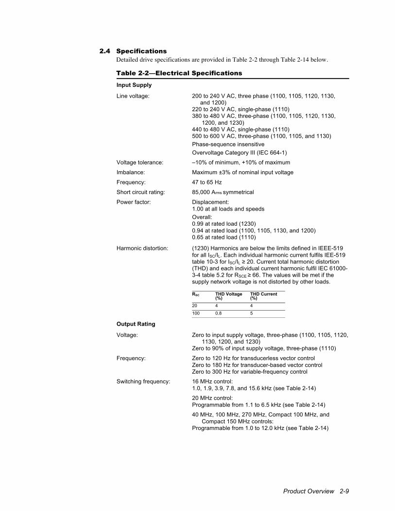
2.4 Specifications Detailed drive specifications are provided in Table 2-2 through Table 2-14 below.
Table 2-2—Electrical Specifications
Input Supply
Line voltage: 200 to 240 V AC, three phase (1100, 1105, 1120, 1130, and 1200) 220 to 240 V AC, single-phase (1110) 380 to 480 V AC, three-phase (1100, 1105, 1120, 1130, 1200, and 1230) 440 to 480 V AC, single-phase (1110) 500 to 600 V AC, three-phase (1100, 1105, and 1130) Phase-sequence insensitive Overvoltage Category III (IEC 664-1)
Voltage tolerance: –10% of minimum, +10% of maximum
Imbalance: Maximum ±3% of nominal input voltage
Frequency: 47 to 65 Hz
Short circuit rating: 85,000 Arms symmetrical
Power factor: Displacement: 1.00 at all loads and speeds Overall: 0.99 at rated load (1230) 0.94 at rated load (1100, 1105, 1130, and 1200) 0.65 at rated load (1110)
Harmonic distortion: (1230) Harmonics are below the limits defined in IEEE-519 for all ISC/IL. Each individual harmonic current fulfils IEE-519 table 10-3 for ISC/IL ≥ 20. Current total harmonic distortion (THD) and each individual current harmonic fulfil IEC 61000-3-4 table 5.2 for RSCE ≥ 66. The values will be met if the supply network voltage is not distorted by other loads.
RSC THD Voltage (%)
THD Current (%)
20 4 4
100 0.8 5
Output Rating
Voltage: Zero to input supply voltage, three-phase (1100, 1105, 1120, 1130, 1200, and 1230) Zero to 90% of input supply voltage, three-phase (1110)
Frequency: Zero to 120 Hz for transducerless vector control Zero to 180 Hz for transducer-based vector control Zero to 300 Hz for variable-frequency control
Switching frequency: 16 MHz control: 1.0, 1.9, 3.9, 7.8, and 15.6 kHz (see Table 2-14)
20 MHz control: Programmable from 1.1 to 6.5 kHz (see Table 2-14)
40 MHz, 100 MHz, 270 MHz, Compact 100 MHz, and Compact 150 MHz controls: Programmable from 1.0 to 12.0 kHz (see Table 2-14)
2-10 1000 Series / Guide to Installation, Troubleshooting, and Maintenance
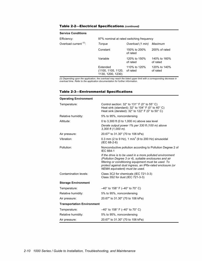
Table 2-2—Electrical Specifications (continued)
Service Conditions
Efficiency: 97% nominal at rated switching frequency
Overload current (†): Torque Overload (1 min) Maximum
Constant 150% to 200% of rated
200% of rated
Variable 120% to 150% of rated
140% to 160% of rated
Extended (1100, 1105, 1120, 1130, 1200, 1230)
110% to 120% of rated
120% to 140% of rated
(†) Depending upon the application, the overload may reach the listed upper limit with a corresponding decrease in overload time. Refer to the application documentation for further information.
Table 2-3—Environmental Specifications
Operating Environment
Temperature: Control section: 32° to 131° F (0° to 55° C) Heat sink (standard): 32° to 104° F (0° to 40° C) Heat sink (derated): 32° to 122° F (0° to 50° C)
Relative humidity: 5% to 95%, noncondensing
Altitude: 0 to 3,300 ft (0 to 1,000 m) above sea level Derate output power 1% per 330 ft (100 m) above 3,300 ft (1,000 m).
Air pressure: 20.67" to 31.30" (70 to 106 kPa)
Vibration: 0.3 mm (2 to 9 Hz), 1 m/s2 (9 to 200 Hz) sinusoidal (IEC 68-2-6)
Pollution: Nonconductive pollution according to Pollution Degree 2 of IEC 664-1 If the drive is to be used in a more polluted environment (Pollution Degree 3 or 4), suitable enclosures and air filtering or conditioning equipment must be used. To protect against dust ingress, an IP6x-rated enclosure (or NEMA equivalent) must be used.
Contamination levels: Class 3C2 for chemicals (IEC 721-3-3) Class 3S2 for dust (IEC 721-3-3)
Storage Environment
Temperature: –40° to 158° F (–40° to 70° C)
Relative humidity: 5% to 95%, noncondensing
Air pressure: 20.67" to 31.30" (70 to 106 kPa)
Transportation Environment
Temperature: –40° to 158° F (–40° to 70° C)
Relative humidity: 5% to 95%, noncondensing
Air pressure: 20.67" to 31.30" (70 to 106 kPa)

Product Overview 2-11
Table 2-4—Performance Specifications
Frequency Control (16 MHz control)
Range: Zero to base speed at full torque Base speed to 300 Hz at constant power
Resolution: 0.024% with analog input (12-bit) 0.1 Hz with digital input
Velocity Control (20, 40, 100, 270 MHz, Compact 100 MHz, and 150 MHz control)
Range: Zero to base speed at full torque Base speed to 180 Hz at constant power with transducer Base speed to 120 Hz at constant power without transducer
Regulation: ±0.001% of base speed, down to zero, with transducer ±0.5% of base speed, 2 Hz and above, without transducer
Torque Control (20, 40, 100, 270 MHz, Compact 100 MHz, and Compact 150 MHz control)
Starting torque: Constant torque: zero to 150% to 200% of rated Variable torque: zero to 120% to 150% of rated Extended torque: zero to 110% to 120% of rated (1100, 1105, 1120, 1130, 1200, and 1230)
Regulation: ±2.0% of maximum with transducer ±5.0% of maximum without transducer
2-12 1000 Series / Guide to Installation, Troubleshooting, and Maintenance
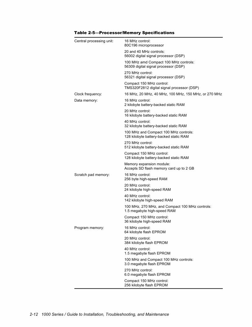
Table 2-5—Processor/Memory Specifications
Central processing unit: 16 MHz control: 80C196 microprocessor
20 and 40 MHz controls: 56002 digital signal processor (DSP)
100 MHz amd Compact 100 MHz controls: 56309 digital signal processor (DSP)
270 MHz control: 56321 digital signal processor (DSP)
Compact 150 MHz control: TMS320F2812 digital signal processor (DSP)
Clock frequency: 16 MHz, 20 MHz, 40 MHz, 100 MHz, 150 MHz, or 270 MHz
Data memory: 16 MHz control: 2 kilobyte battery-backed static RAM
20 MHz control: 16 kilobyte battery-backed static RAM
40 MHz control: 32 kilobyte battery-backed static RAM
100 MHz and Compact 100 MHz controls: 128 kilobyte battery-backed static RAM
270 MHz control: 512 kilobyte battery-backed static RAM
Compact 150 MHz control: 128 kilobyte battery-backed static RAM
Memory expansion module: Accepts SD flash memory card up to 2 GB
Scratch pad memory: 16 MHz control: 256 byte high-speed RAM
20 MHz control: 24 kilobyte high-speed RAM
40 MHz control: 142 kilobyte high-speed RAM
100 MHz, 270 MHz, and Compact 100 MHz controls: 1.5 megabyte high-speed RAM
Compact 150 MHz control: 36 kilobyte high-speed RAM
Program memory: 16 MHz control: 64 kilobyte flash EPROM
20 MHz control: 384 kilobyte flash EPROM
40 MHz control: 1.5 megabyte flash EPROM
100 MHz and Compact 100 MHz controls: 3.0 megabyte flash EPROM
270 MHz control: 6.0 megabyte flash EPROM
Compact 150 MHz control: 256 kilobyte flash EPROM
Product Overview 2-13
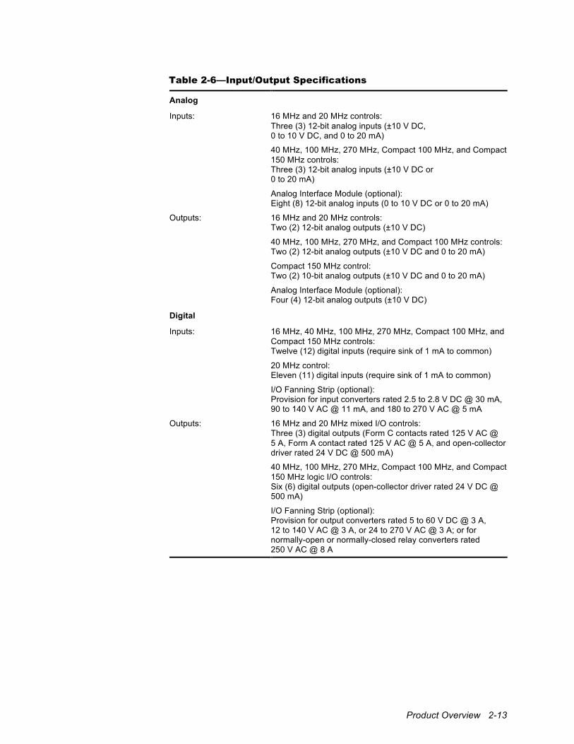
Table 2-6—Input/Output Specifications
Analog
Inputs: 16 MHz and 20 MHz controls: Three (3) 12-bit analog inputs (±10 V DC, 0 to 10 V DC, and 0 to 20 mA)
40 MHz, 100 MHz, 270 MHz, Compact 100 MHz, and Compact 150 MHz controls: Three (3) 12-bit analog inputs (±10 V DC or 0 to 20 mA)
Analog Interface Module (optional): Eight (8) 12-bit analog inputs (0 to 10 V DC or 0 to 20 mA)
Outputs: 16 MHz and 20 MHz controls: Two (2) 12-bit analog outputs (±10 V DC)
40 MHz, 100 MHz, 270 MHz, and Compact 100 MHz controls: Two (2) 12-bit analog outputs (±10 V DC and 0 to 20 mA)
Compact 150 MHz control: Two (2) 10-bit analog outputs (±10 V DC and 0 to 20 mA)
Analog Interface Module (optional): Four (4) 12-bit analog outputs (±10 V DC)
Digital
Inputs: 16 MHz, 40 MHz, 100 MHz, 270 MHz, Compact 100 MHz, and Compact 150 MHz controls: Twelve (12) digital inputs (require sink of 1 mA to common)
20 MHz control: Eleven (11) digital inputs (require sink of 1 mA to common)
I/O Fanning Strip (optional): Provision for input converters rated 2.5 to 2.8 V DC @ 30 mA, 90 to 140 V AC @ 11 mA, and 180 to 270 V AC @ 5 mA
Outputs: 16 MHz and 20 MHz mixed I/O controls: Three (3) digital outputs (Form C contacts rated 125 V AC @ 5 A, Form A contact rated 125 V AC @ 5 A, and open-collector driver rated 24 V DC @ 500 mA)
40 MHz, 100 MHz, 270 MHz, Compact 100 MHz, and Compact 150 MHz logic I/O controls: Six (6) digital outputs (open-collector driver rated 24 V DC @ 500 mA)
I/O Fanning Strip (optional): Provision for output converters rated 5 to 60 V DC @ 3 A, 12 to 140 V AC @ 3 A, or 24 to 270 V AC @ 3 A; or for normally-open or normally-closed relay converters rated 250 V AC @ 8 A
2-14 1000 Series / Guide to Installation, Troubleshooting, and Maintenance
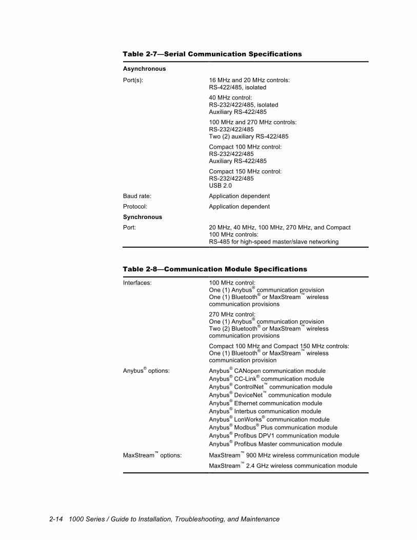
Table 2-7—Serial Communication Specifications
Asynchronous
Port(s): 16 MHz and 20 MHz controls: RS-422/485, isolated
40 MHz control: RS-232/422/485, isolated Auxiliary RS-422/485
100 MHz and 270 MHz controls: RS-232/422/485 Two (2) auxiliary RS-422/485
Compact 100 MHz control: RS-232/422/485 Auxiliary RS-422/485
Compact 150 MHz control: RS-232/422/485 USB 2.0
Baud rate: Application dependent
Protocol: Application dependent
Synchronous
Port: 20 MHz, 40 MHz, 100 MHz, 270 MHz, and Compact 100 MHz controls: RS-485 for high-speed master/slave networking
Table 2-8—Communication Module Specifications
Interfaces: 100 MHz control: One (1) Anybus® communication provision One (1) Bluetooth® or MaxStream™ wireless communication provisions
270 MHz control: One (1) Anybus® communication provision Two (2) Bluetooth® or MaxStream™ wireless communication provisions
Compact 100 MHz and Compact 150 MHz controls: One (1) Bluetooth® or MaxStream™ wireless communication provision
Anybus® options: Anybus® CANopen communication module Anybus® CC-Link® communication module Anybus® ControlNet™ communication module Anybus® DeviceNet™ communication module Anybus® Ethernet communication module Anybus® Interbus communication module Anybus® LonWorks® communication module Anybus® Modbus® Plus communication module Anybus® Profibus DPV1 communication module Anybus® Profibus Master communication module
MaxStream™ options: MaxStream™ 900 MHz wireless communication module
MaxStream™ 2.4 GHz wireless communication module
Product Overview 2-15
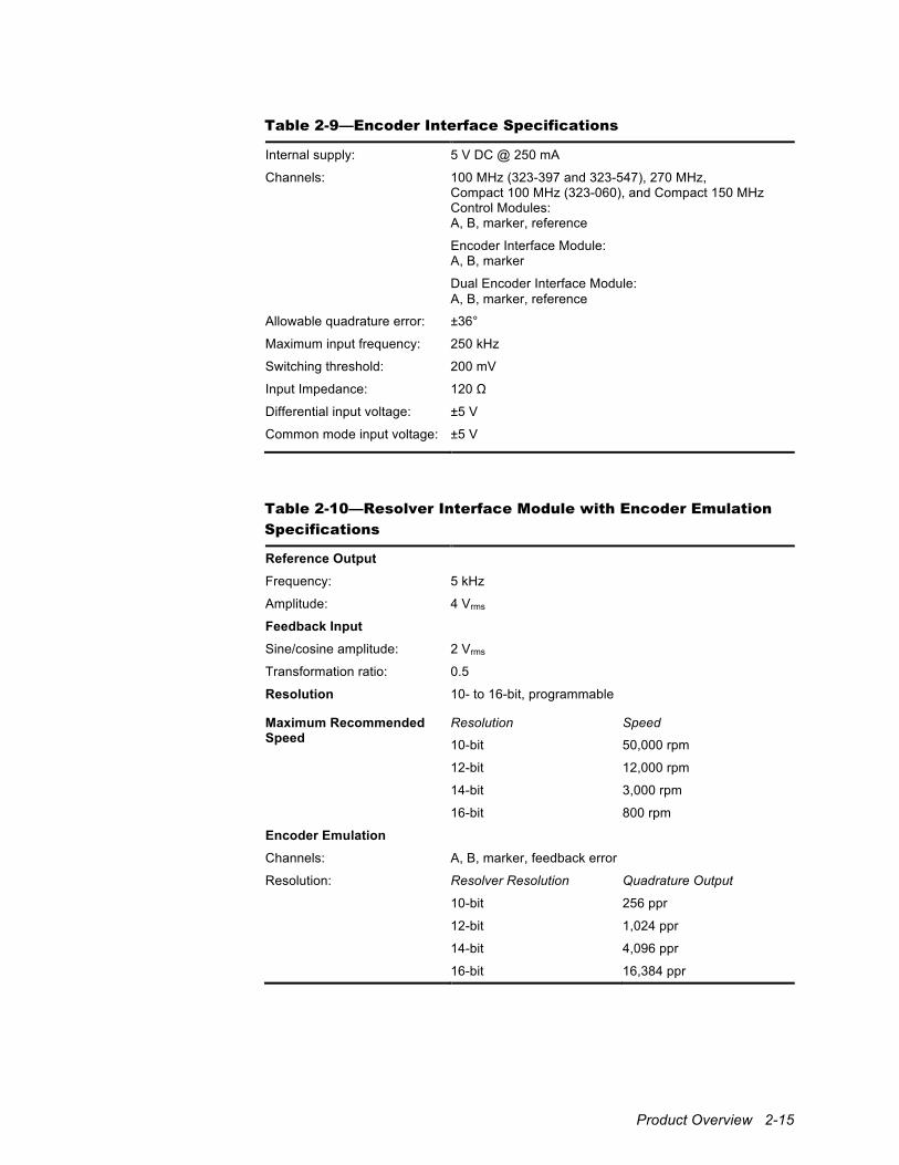
Table 2-9—Encoder Interface Specifications
Internal supply: 5 V DC @ 250 mA
Channels: 100 MHz (323-397 and 323-547), 270 MHz, Compact 100 MHz (323-060), and Compact 150 MHz Control Modules: A, B, marker, reference
Encoder Interface Module: A, B, marker
Dual Encoder Interface Module: A, B, marker, reference
Allowable quadrature error: ±36°
Maximum input frequency: 250 kHz
Switching threshold: 200 mV
Input Impedance: 120 Ω
Differential input voltage: ±5 V
Common mode input voltage: ±5 V
Table 2-10—Resolver Interface Module with Encoder Emulation
Specifications
Reference Output Frequency: 5 kHz
Amplitude: 4 Vrms
Feedback Input Sine/cosine amplitude: 2 Vrms
Transformation ratio: 0.5
Resolution 10- to 16-bit, programmable
Maximum Recommended Speed
Resolution Speed
10-bit 50,000 rpm
12-bit 12,000 rpm
14-bit 3,000 rpm
16-bit 800 rpm
Encoder Emulation Channels: A, B, marker, feedback error
Resolution: Resolver Resolution Quadrature Output
10-bit 256 ppr
12-bit 1,024 ppr
14-bit 4,096 ppr
16-bit 16,384 ppr
2-16 1000 Series / Guide to Installation, Troubleshooting, and Maintenance
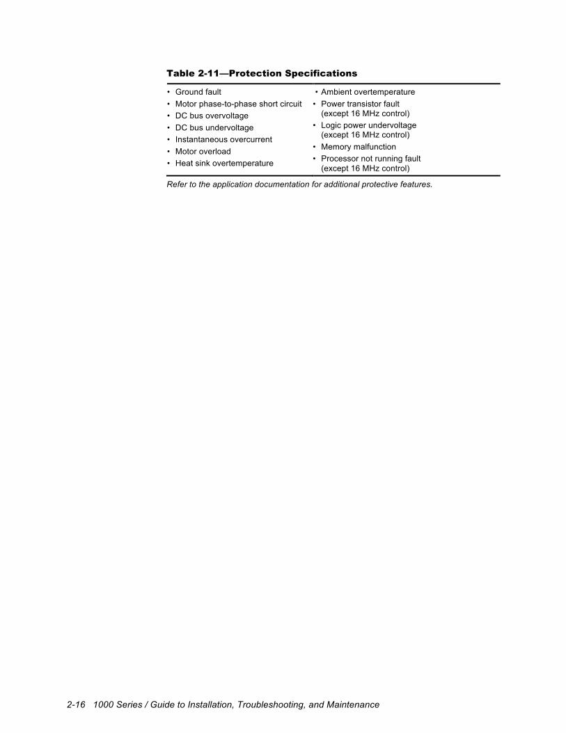
Table 2-11—Protection Specifications
• Ground fault • Motor phase-to-phase short circuit • DC bus overvoltage • DC bus undervoltage • Instantaneous overcurrent • Motor overload • Heat sink overtemperature
• Ambient overtemperature • Power transistor fault (except 16 MHz control) • Logic power undervoltage (except 16 MHz control) • Memory malfunction • Processor not running fault (except 16 MHz control)
Refer to the application documentation for additional protective features.
Product Overview 2-17
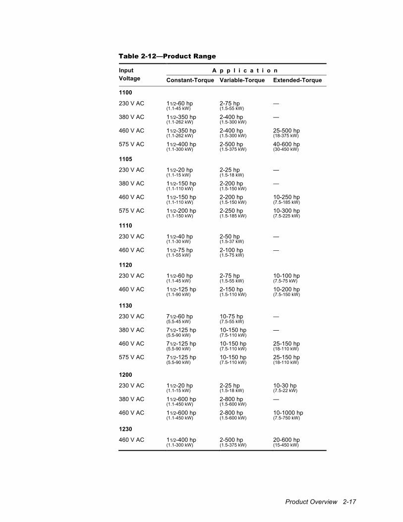
Table 2-12—Product Range
Input Voltage
A p p l i c a t i o n Constant-Torque Variable-Torque Extended-Torque
1100
230 V AC 11/2-60 hp 2-75 hp — (1.1-45 kW) (1.5-55 kW)
380 V AC 11/2-350 hp 2-400 hp — (1.1-262 kW) (1.5-300 kW)
460 V AC 11/2-350 hp 2-400 hp 25-500 hp (1.1-262 kW) (1.5-300 kW) (18-375 kW)
575 V AC 11/2-400 hp 2-500 hp 40-600 hp (1.1-300 kW) (1.5-375 kW) (30-450 kW)
1105
230 V AC 11/2-20 hp 2-25 hp — (1.1-15 kW) (1.5-18 kW)
380 V AC 11/2-150 hp 2-200 hp — (1.1-110 kW) (1.5-150 kW)
460 V AC 11/2-150 hp 2-200 hp 10-250 hp (1.1-110 kW) (1.5-150 kW) (7.5-185 kW)
575 V AC 11/2-200 hp 2-250 hp 10-300 hp (1.1-150 kW) (1.5-185 kW) (7.5-225 kW)
1110
230 V AC 11/2-40 hp 2-50 hp — (1.1-30 kW) (1.5-37 kW)
460 V AC 11/2-75 hp 2-100 hp — (1.1-55 kW) (1.5-75 kW)
1120
230 V AC 11/2-60 hp 2-75 hp 10-100 hp (1.1-45 kW) (1.5-55 kW) (7.5-75 kW)
460 V AC 11/2-125 hp 2-150 hp 10-200 hp (1.1-90 kW) (1.5-110 kW) (7.5-150 kW)
1130
230 V AC 71/2-60 hp 10-75 hp — (5.5-45 kW) (7.5-55 kW)
380 V AC 71/2-125 hp 10-150 hp — (5.5-90 kW) (7.5-110 kW)
460 V AC 71/2-125 hp 10-150 hp 25-150 hp (5.5-90 kW) (7.5-110 kW) (18-110 kW)
575 V AC 71/2-125 hp 10-150 hp 25-150 hp (5.5-90 kW) (7.5-110 kW) (18-110 kW)
1200
230 V AC 11/2-20 hp 2-25 hp 10-30 hp (1.1-15 kW) (1.5-18 kW) (7.5-22 kW)
380 V AC 11/2-600 hp 2-800 hp — (1.1-450 kW) (1.5-600 kW)
460 V AC 11/2-600 hp 2-800 hp 10-1000 hp (1.1-450 kW) (1.5-600 kW) (7.5-750 kW)
1230
460 V AC 11/2-400 hp 2-500 hp 20-600 hp (1.1-300 kW) (1.5-375 kW) (15-450 kW)
2-18 1000 Series / Guide to Installation, Troubleshooting, and Maintenance
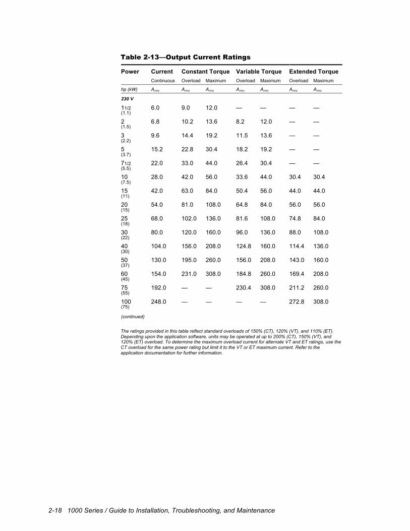
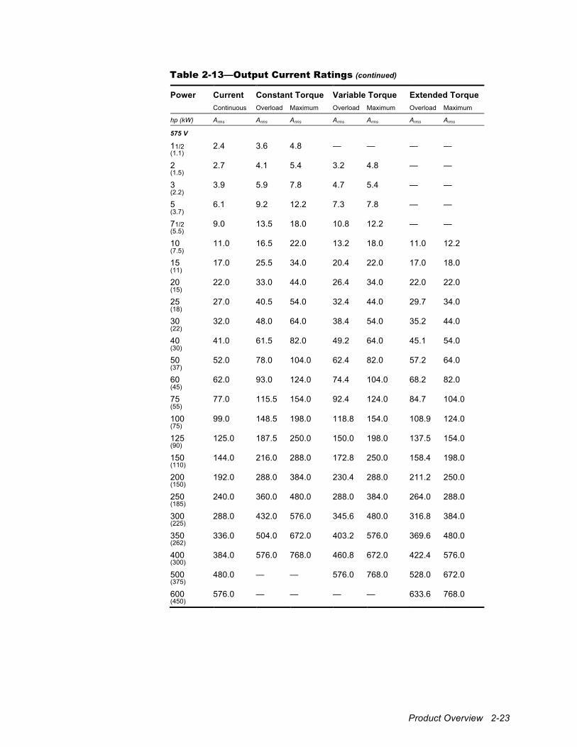
Table 2-13—Output Current Ratings
Power Current Constant Torque Variable Torque Extended Torque Continuous Overload Maximum Overload Maximum Overload Maximum
hp (kW) Arms Arms Arms Arms Arms Arms Arms
230 V
11/2 6.0 9.0 12.0 — — — — (1.1)
2 6.8 10.2 13.6 8.2 12.0 — — (1.5)
3 9.6 14.4 19.2 11.5 13.6 — — (2.2)
5 15.2 22.8 30.4 18.2 19.2 — — (3.7)
71/2 22.0 33.0 44.0 26.4 30.4 — — (5.5)
10 28.0 42.0 56.0 33.6 44.0 30.4 30.4 (7.5)
15 42.0 63.0 84.0 50.4 56.0 44.0 44.0 (11)
20 54.0 81.0 108.0 64.8 84.0 56.0 56.0 (15)
25 68.0 102.0 136.0 81.6 108.0 74.8 84.0 (18)
30 80.0 120.0 160.0 96.0 136.0 88.0 108.0 (22)
40 104.0 156.0 208.0 124.8 160.0 114.4 136.0 (30)
50 130.0 195.0 260.0 156.0 208.0 143.0 160.0 (37)
60 154.0 231.0 308.0 184.8 260.0 169.4 208.0 (45)
75 192.0 — — 230.4 308.0 211.2 260.0 (55)
100 248.0 — — — — 272.8 308.0 (75) (continued)
The ratings provided in this table reflect standard overloads of 150% (CT), 120% (VT), and 110% (ET). Depending upon the application software, units may be operated at up to 200% (CT), 150% (VT), and 120% (ET) overload. To determine the maximum overload current for alternate VT and ET ratings, use the CT overload for the same power rating but limit it to the VT or ET maximum current. Refer to the application documentation for further information.
Product Overview 2-19
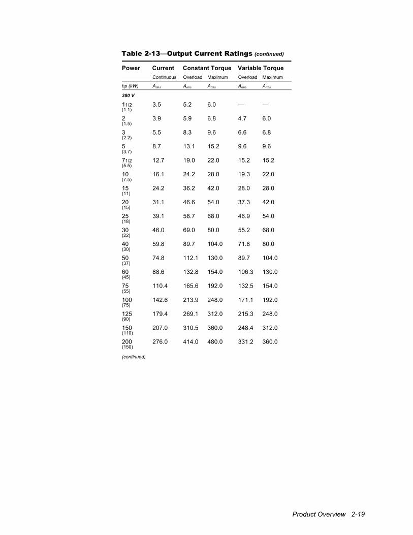
Table 2-13—Output Current Ratings (continued)
Power Current Constant Torque Variable Torque Continuous Overload Maximum Overload Maximum
hp (kW) Arms Arms Arms Arms Arms
380 V
11/2 3.5 5.2 6.0 — — (1.1)
2 3.9 5.9 6.8 4.7 6.0 (1.5)
3 5.5 8.3 9.6 6.6 6.8 (2.2)
5 8.7 13.1 15.2 9.6 9.6 (3.7)
71/2 12.7 19.0 22.0 15.2 15.2 (5.5)
10 16.1 24.2 28.0 19.3 22.0 (7.5)
15 24.2 36.2 42.0 28.0 28.0 (11)
20 31.1 46.6 54.0 37.3 42.0 (15)
25 39.1 58.7 68.0 46.9 54.0 (18)
30 46.0 69.0 80.0 55.2 68.0 (22)
40 59.8 89.7 104.0 71.8 80.0 (30)
50 74.8 112.1 130.0 89.7 104.0 (37)
60 88.6 132.8 154.0 106.3 130.0 (45)
75 110.4 165.6 192.0 132.5 154.0 (55)
100 142.6 213.9 248.0 171.1 192.0 (75)
125 179.4 269.1 312.0 215.3 248.0 (90)
150 207.0 310.5 360.0 248.4 312.0 (110)
200 276.0 414.0 480.0 331.2 360.0 (150) (continued)
2-20 1000 Series / Guide to Installation, Troubleshooting, and Maintenance
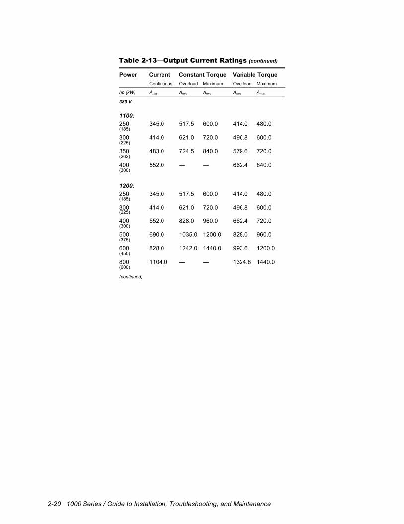
Table 2-13—Output Current Ratings (continued)
Power Current Constant Torque Variable Torque Continuous Overload Maximum Overload Maximum
hp (kW) Arms Arms Arms Arms Arms
380 V
1100:
250 345.0 517.5 600.0 414.0 480.0 (185)
300 414.0 621.0 720.0 496.8 600.0 (225)
350 483.0 724.5 840.0 579.6 720.0 (262)
400 552.0 — — 662.4 840.0 (300)
1200:
250 345.0 517.5 600.0 414.0 480.0 (185)
300 414.0 621.0 720.0 496.8 600.0 (225)
400 552.0 828.0 960.0 662.4 720.0 (300)
500 690.0 1035.0 1200.0 828.0 960.0 (375)
600 828.0 1242.0 1440.0 993.6 1200.0 (450)
800 1104.0 — — 1324.8 1440.0 (600) (continued)
Product Overview 2-21
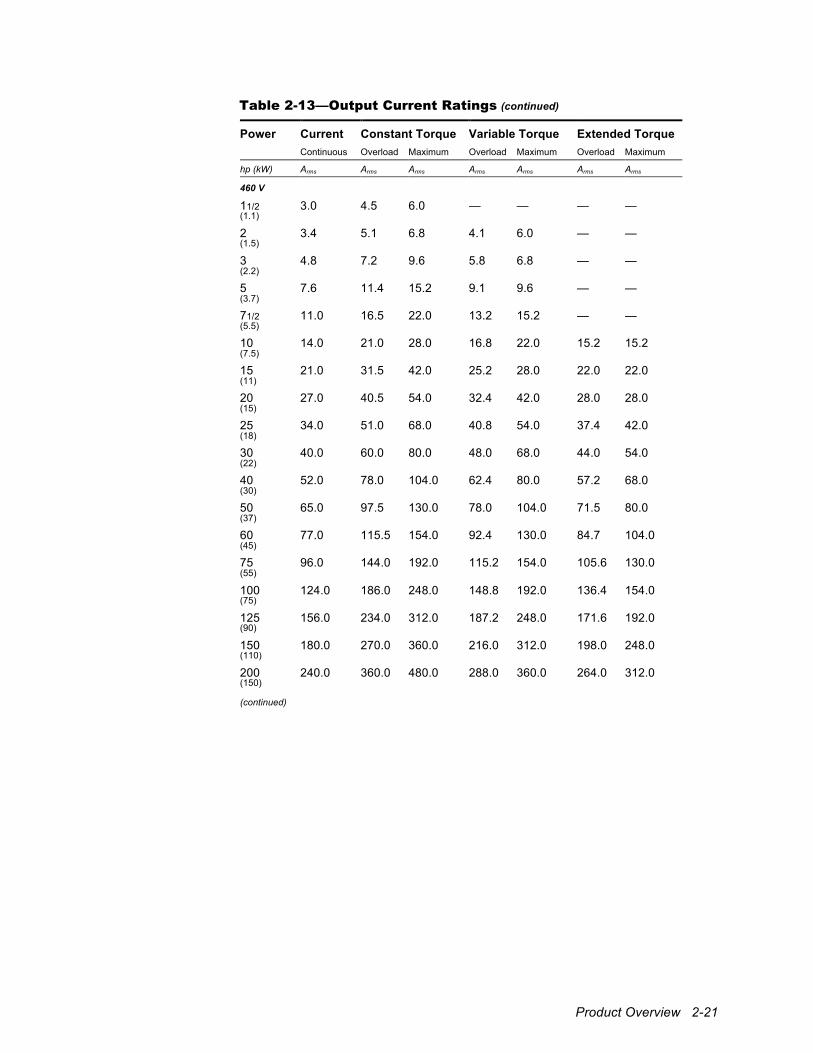
Table 2-13—Output Current Ratings (continued)
Power Current Constant Torque Variable Torque Extended Torque Continuous Overload Maximum Overload Maximum Overload Maximum
hp (kW) Arms Arms Arms Arms Arms Arms Arms
460 V
11/2 3.0 4.5 6.0 — — — — (1.1)
2 3.4 5.1 6.8 4.1 6.0 — — (1.5)
3 4.8 7.2 9.6 5.8 6.8 — — (2.2)
5 7.6 11.4 15.2 9.1 9.6 — — (3.7)
71/2 11.0 16.5 22.0 13.2 15.2 — — (5.5)
10 14.0 21.0 28.0 16.8 22.0 15.2 15.2 (7.5)
15 21.0 31.5 42.0 25.2 28.0 22.0 22.0 (11)
20 27.0 40.5 54.0 32.4 42.0 28.0 28.0 (15)
25 34.0 51.0 68.0 40.8 54.0 37.4 42.0 (18)
30 40.0 60.0 80.0 48.0 68.0 44.0 54.0 (22)
40 52.0 78.0 104.0 62.4 80.0 57.2 68.0 (30)
50 65.0 97.5 130.0 78.0 104.0 71.5 80.0 (37)
60 77.0 115.5 154.0 92.4 130.0 84.7 104.0 (45)
75 96.0 144.0 192.0 115.2 154.0 105.6 130.0 (55)
100 124.0 186.0 248.0 148.8 192.0 136.4 154.0 (75)
125 156.0 234.0 312.0 187.2 248.0 171.6 192.0 (90)
150 180.0 270.0 360.0 216.0 312.0 198.0 248.0 (110)
200 240.0 360.0 480.0 288.0 360.0 264.0 312.0 (150) (continued)
2-22 1000 Series / Guide to Installation, Troubleshooting, and Maintenance
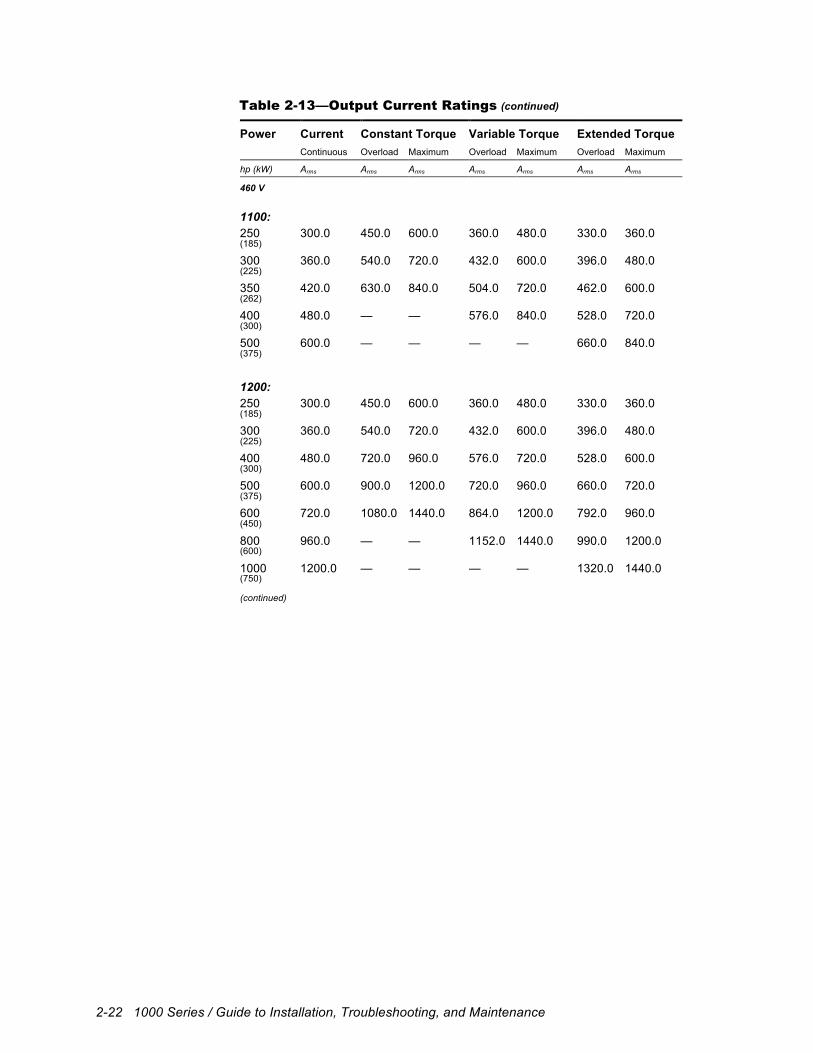
Table 2-13—Output Current Ratings (continued)
Power Current Constant Torque Variable Torque Extended Torque Continuous Overload Maximum Overload Maximum Overload Maximum
hp (kW) Arms Arms Arms Arms Arms Arms Arms
460 V
1100:
250 300.0 450.0 600.0 360.0 480.0 330.0 360.0 (185)
300 360.0 540.0 720.0 432.0 600.0 396.0 480.0 (225)
350 420.0 630.0 840.0 504.0 720.0 462.0 600.0 (262)
400 480.0 — — 576.0 840.0 528.0 720.0 (300)
500 600.0 — — — — 660.0 840.0 (375)
1200:
250 300.0 450.0 600.0 360.0 480.0 330.0 360.0 (185)
300 360.0 540.0 720.0 432.0 600.0 396.0 480.0 (225)
400 480.0 720.0 960.0 576.0 720.0 528.0 600.0 (300)
500 600.0 900.0 1200.0 720.0 960.0 660.0 720.0 (375)
600 720.0 1080.0 1440.0 864.0 1200.0 792.0 960.0 (450)
800 960.0 — — 1152.0 1440.0 990.0 1200.0 (600)
1000 1200.0 — — — — 1320.0 1440.0 (750) (continued)
Product Overview 2-23
Table 2-13—Output Current Ratings (continued)
Power Current Constant Torque Variable Torque Extended Torque Continuous Overload Maximum Overload Maximum Overload Maximum
hp (kW) Arms Arms Arms Arms Arms Arms Arms
575 V
11/2 2.4 3.6 4.8 — — — — (1.1)
2 2.7 4.1 5.4 3.2 4.8 — — (1.5)
3 3.9 5.9 7.8 4.7 5.4 — — (2.2)
5 6.1 9.2 12.2 7.3 7.8 — — (3.7)
71/2 9.0 13.5 18.0 10.8 12.2 — — (5.5)
10 11.0 16.5 22.0 13.2 18.0 11.0 12.2 (7.5)
15 17.0 25.5 34.0 20.4 22.0 17.0 18.0 (11)
20 22.0 33.0 44.0 26.4 34.0 22.0 22.0 (15)
25 27.0 40.5 54.0 32.4 44.0 29.7 34.0 (18)
30 32.0 48.0 64.0 38.4 54.0 35.2 44.0 (22)
40 41.0 61.5 82.0 49.2 64.0 45.1 54.0 (30)
50 52.0 78.0 104.0 62.4 82.0 57.2 64.0 (37)
60 62.0 93.0 124.0 74.4 104.0 68.2 82.0 (45)
75 77.0 115.5 154.0 92.4 124.0 84.7 104.0 (55)
100 99.0 148.5 198.0 118.8 154.0 108.9 124.0 (75)
125 125.0 187.5 250.0 150.0 198.0 137.5 154.0 (90)
150 144.0 216.0 288.0 172.8 250.0 158.4 198.0 (110)
200 192.0 288.0 384.0 230.4 288.0 211.2 250.0 (150)
250 240.0 360.0 480.0 288.0 384.0 264.0 288.0 (185)
300 288.0 432.0 576.0 345.6 480.0 316.8 384.0 (225)
350 336.0 504.0 672.0 403.2 576.0 369.6 480.0 (262)
400 384.0 576.0 768.0 460.8 672.0 422.4 576.0 (300)
500 480.0 — — 576.0 768.0 528.0 672.0 (375)
600 576.0 — — — — 633.6 768.0 (450)
2-24 1000 Series / Guide to Installation, Troubleshooting, and Maintenance
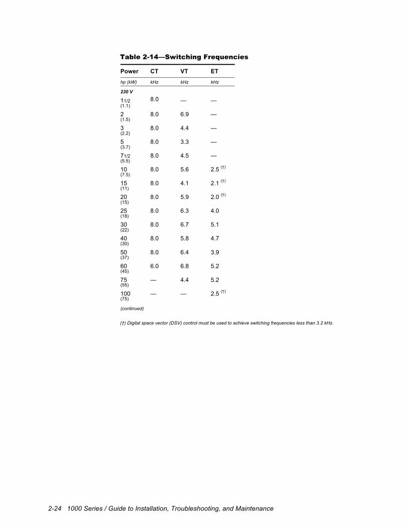
Table 2-14—Switching Frequencies
Power CT VT ET
hp (kW) kHz kHz kHz
230 V
11/2 8.0 — — (1.1)
2 8.0 6.9 — (1.5)
3 8.0 4.4 — (2.2)
5 8.0 3.3 — (3.7)
71/2 8.0 4.5 — (5.5)
10 8.0 5.6 2.5 (†) (7.5)
15 8.0 4.1 2.1 (†) (11)
20 8.0 5.9 2.0 (†) (15)
25 8.0 6.3 4.0 (18)
30 8.0 6.7 5.1 (22)
40 8.0 5.8 4.7 (30)
50 8.0 6.4 3.9 (37)
60 6.0 6.8 5.2 (45)
75 — 4.4 5.2 (55)
100 — — 2.5 (†) (75) (continued)
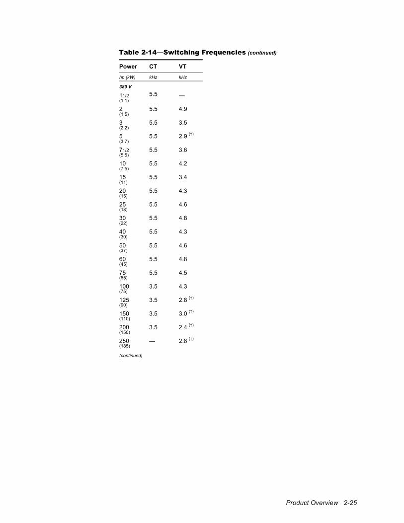
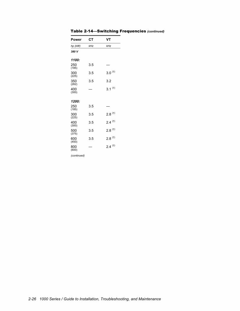
(†) Digital space vector (DSV) control must be used to achieve switching frequencies less than 3.2 kHz.
Product Overview 2-25
Table 2-14—Switching Frequencies (continued)
Power CT VT
hp (kW) kHz kHz
380 V
11/2 5.5 — (1.1)
2 5.5 4.9 (1.5)
3 5.5 3.5 (2.2)
5 5.5 2.9 (†) (3.7)
71/2 5.5 3.6 (5.5)
10 5.5 4.2 (7.5)
15 5.5 3.4 (11)
20 5.5 4.3 (15)
25 5.5 4.6 (18)
30 5.5 4.8 (22)
40 5.5 4.3 (30)
50 5.5 4.6 (37)
60 5.5 4.8 (45)
75 5.5 4.5 (55)
100 3.5 4.3 (75)
125 3.5 2.8 (†) (90)
150 3.5 3.0 (†) (110)
200 3.5 2.4 (†) (150)
250 — 2.8 (†) (185) (continued)
2-26 1000 Series / Guide to Installation, Troubleshooting, and Maintenance
Table 2-14—Switching Frequencies (continued)
Power CT VT
hp (kW) kHz kHz
380 V
1100:
250 3.5 — (185)
300 3.5 3.0 (†) (225)
350 3.5 3.2 (262)
400 — 3.1 (†) (300)
1200:
250 3.5 — (185)
300 3.5 2.8 (†) (225)
400 3.5 2.4 (†) (300)
500 3.5 2.8 (†) (375)
600 3.5 2.8 (†) (450)
800 — 2.4 (†) (600) (continued)
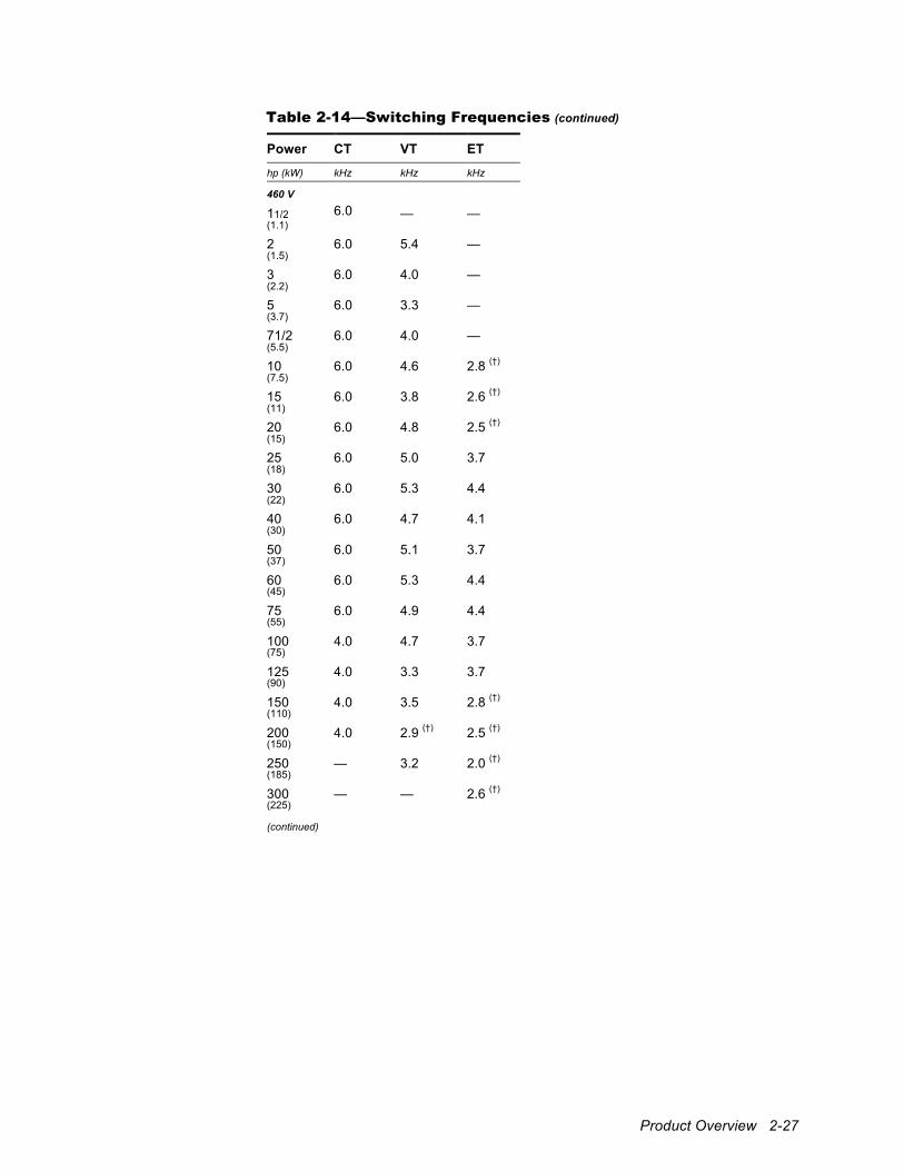
Product Overview 2-27
Table 2-14—Switching Frequencies (continued)
Power CT VT ET
hp (kW) kHz kHz kHz
460 V
11/2 6.0 — — (1.1)
2 6.0 5.4 — (1.5)
3 6.0 4.0 — (2.2)
5 6.0 3.3 — (3.7)
71/2 6.0 4.0 — (5.5)
10 6.0 4.6 2.8 (†) (7.5)
15 6.0 3.8 2.6 (†) (11)
20 6.0 4.8 2.5 (†) (15)
25 6.0 5.0 3.7 (18)
30 6.0 5.3 4.4 (22)
40 6.0 4.7 4.1 (30)
50 6.0 5.1 3.7 (37)
60 6.0 5.3 4.4 (45)
75 6.0 4.9 4.4 (55)
100 4.0 4.7 3.7 (75)
125 4.0 3.3 3.7 (90)
150 4.0 3.5 2.8 (†) (110)
200 4.0 2.9 (†) 2.5 (†) (150)
250 — 3.2 2.0 (†) (185)
300 — — 2.6 (†) (225) (continued)
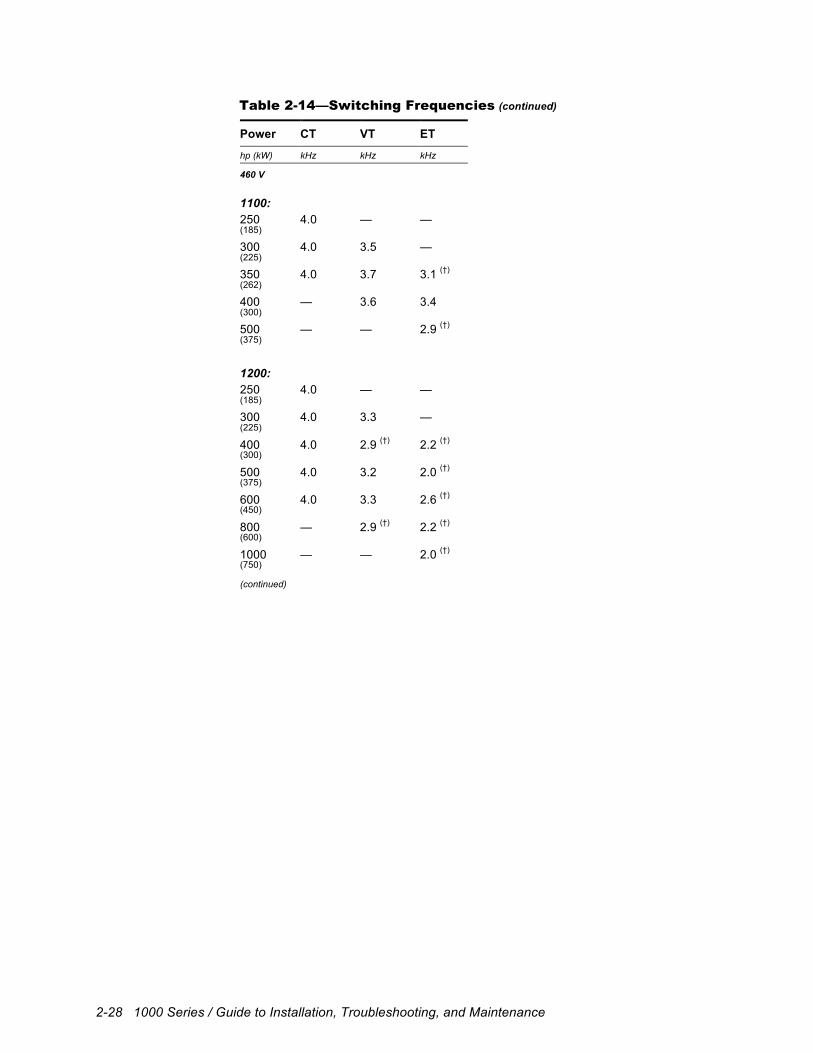
2-28 1000 Series / Guide to Installation, Troubleshooting, and Maintenance
Table 2-14—Switching Frequencies (continued)
Power CT VT ET
hp (kW) kHz kHz kHz
460 V
1100:
250 4.0 — — (185)
300 4.0 3.5 — (225)
350 4.0 3.7 3.1 (†) (262)
400 — 3.6 3.4 (300)
500 — — 2.9 (†) (375)
1200:
250 4.0 — — (185)
300 4.0 3.3 — (225)
400 4.0 2.9 (†) 2.2 (†) (300)
500 4.0 3.2 2.0 (†) (375)
600 4.0 3.3 2.6 (†) (450)
800 — 2.9 (†) 2.2 (†) (600)
1000 — — 2.0 (†) (750) (continued)

Product Overview 2-29
Table 2-14—Switching Frequencies (continued)
Power CT VT ET
hp (kW) kHz kHz kHz
575 V
11/2 4.0 — — (1.1)
2 4.0 3.6 — (1.5)
3 4.0 2.6 (†) — (2.2)
5 4.0 2.1 (†) — (3.7)
71/2 4.0 2.6 (†) — (5.5)
10 4.0 3.0 (†) 1.8 (†) (7.5)
15 4.0 2.4 (†) 1.6 (†) (11)
20 4.0 3.1 (†) 1.6 (†) (15)
25 4.0 3.3 2.4 (†) (18)
30 4.0 3.5 2.9 (†) (22)
40 4.0 3.1 (†) 2.7 (†) (30)
50 4.0 3.4 2.4 (†) (37)
60 4.0 3.5 2.9 (†) (45)
75 4.0 3.3 2.9 (†) (55)
100 3.0 (†) 3.1 (†) 2.4 (†) (75)
125 3.0 (†) 2.5 (†) 2.4 (†) (90)
150 3.0 (†) 2.7 (†) 2.1 (†) (110)
200 3.0 (†) 2.2 (†) 2.0 (†) (150)
250 3.0 (†) 2.5 (†) 1.7 (†) (185)
300 3.0 (†) 2.7 (†) 2.1 (†) (225)
350 3.0 (†) 2.8 (†) 2.4 (†) (262)
400 — 2.7 (†) 2.6 (†) (300)
500 — — 2.3 (†) (375)

2-30 1000 Series / Guide to Installation, Troubleshooting, and Maintenance
Mechanical Installation 3-1
3 Mechanical Installation
3.1 Overview Proper mechanical installation of the drive is essential for safe, reliable operation and to simplify electrical wiring and maintenance. This chapter provides information and instructions for determining the best mounting location, selecting an enclosure, planning a layout, and installing the unit.
3.2 Forms Drives are classified into twelve different forms according to their physical size and construction. These forms correspond, for the most part, to different heat sink sizes and sometimes to different box sizes or mounting methods. Refer to Table 3-3 through Table 3-8 near the end of this chapter to determine the form of a unit based upon its voltage, torque, and power ratings.
3.3 Installation Site Considerations It is important to chose a mounting location that protects the drive from harmful environmental conditions while, at the same time, safeguarding personnel from the dangerous voltages of the drive system.
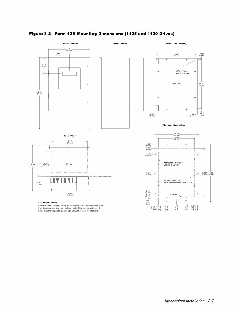
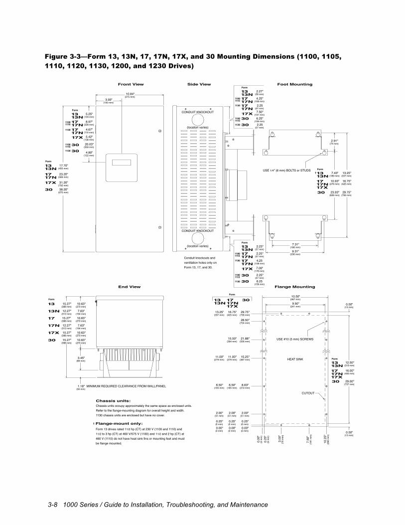
3.3.1 Enclosure A drive can be supplied either as an unmounted open chassis, an unmounted enclosed unit, or mounted within a larger enclosure as part of a packaged drive system incorporating additional components. Open-chassis (IP00) units must be mounted inside an enclosure for safety. The integral enclosures provided with Form 9N, 12N, 13N, 17N, and 17X drives provide NEMA 3R (IP23) protection and can be converted to NEMA 4 (IP66) using the solid gland plate provided with the enclosure. Form 13, 17, 22X, 30, 34, 34X, 48, and 48X enclosures provide NEMA 1 (IP20) protection. Both open-chassis and enclosed versions of all models may be either foot- or flange-mounted. Figure 3-1 through Figure 3-5 provide the physical dimensions and mechanical layouts of the drives. Refer to these figures when planning your layout. For simplicity, only the dimensions of enclosed drives are shown. Chassis units occupy approximately the same space.
!
Attention To provide protection against electrical shock, chassis units must be mounted in an enclosure meeting at least the requirements of Protective Type IP20 (or NEMA equivalent) according to EN60529 and with top surfaces meeting at least the requirements of IP40 (or NEMA equivalent). It is recommended that a key or tool be required to open the enclosure and that enclosure doors be interlocked with the electrical supply disconnect.
3-2 1000 Series / Guide to Installation, Troubleshooting, and Maintenance
3.3.2 Operating Environment The drive should be mounted in an environment that is free from corrosive and volatile vapors, dust and particles, mechanical shock, excessive vibration, water or excessive moisture, and temperature extremes. The required ambient operating conditions are specified in Table 2-3.
3.3.3 Cooling Thermal management techniques may be necessary to keep the drive operating within required temperature specifications, particularly when units are installed within confined spaces. Drives cool themselves using fans that circulate air across a heat sink. Air can be drawn from either inside the enclosure or outside, depending upon the mounting configuration. Some applications may require additional ventilating or cooling equipment.
3.3.3.1 Thermal Load If the drive is to be installed in a separate enclosure, its thermal load must be considered. The total power dissipated by each drive is given in Table 3-10 (1100, 1105, and 1130 drives), Table 3-11 (1110 drives), Table 3-12 (1120 drives), Table 3-13 (1200 drives), and Table 3-14 (1230 drives) at the end of this chapter. Dissipation figures are provided for the control section and heat sink independently since the heat sink can be mounted externally to the enclosure. Use this information, in conjunction with the enclosure manufacturer’s recommendations, to size the enclosure and to determine cooling airflow requirements. Power dissipation of units operating on 380 V power lines is the same as that listed for 460 V.
3.3.3.2 Air Circulation Air circulation can be controlled by selecting the mounting configuration. Foot-mounted drives stand away from the mounting surface and pull ambient air from behind the unit to cool the heat sink. Flange-mounted drives dissipate heat outside an enclosure by allowing the heat sink to protrude through a cutout in the enclosure wall. The smallest units, which do not have finned heat sinks, must be flush mounted. Refer to Section 3.5 for mounting instructions.
Mechanical Installation 3-3
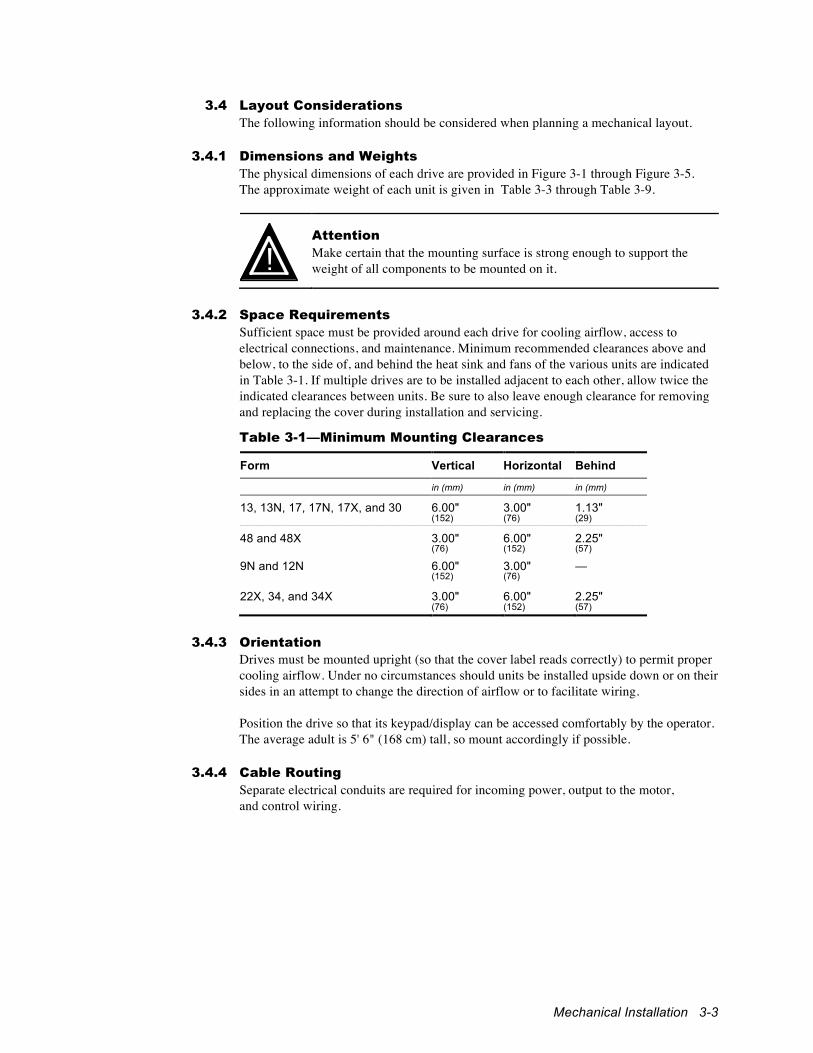
3.4 Layout Considerations The following information should be considered when planning a mechanical layout.
3.4.1 Dimensions and Weights The physical dimensions of each drive are provided in Figure 3-1 through Figure 3-5. The approximate weight of each unit is given in Table 3-3 through Table 3-9.
!
Attention Make certain that the mounting surface is strong enough to support the weight of all components to be mounted on it.
3.4.2 Space Requirements
Sufficient space must be provided around each drive for cooling airflow, access to electrical connections, and maintenance. Minimum recommended clearances above and below, to the side of, and behind the heat sink and fans of the various units are indicated in Table 3-1. If multiple drives are to be installed adjacent to each other, allow twice the indicated clearances between units. Be sure to also leave enough clearance for removing and replacing the cover during installation and servicing.
Table 3-1—Minimum Mounting Clearances
Form Vertical Horizontal Behind
in (mm) in (mm) in (mm)
13, 13N, 17, 17N, 17X, and 30 6.00" 3.00" 1.13" (152) (76) (29)
48 and 48X 3.00" 6.00" 2.25" (76) (152) (57)
9N and 12N 6.00" 3.00" — (152) (76)
22X, 34, and 34X 3.00" 6.00" 2.25" (76) (152) (57)
3.4.3 Orientation
Drives must be mounted upright (so that the cover label reads correctly) to permit proper cooling airflow. Under no circumstances should units be installed upside down or on their sides in an attempt to change the direction of airflow or to facilitate wiring. Position the drive so that its keypad/display can be accessed comfortably by the operator. The average adult is 5' 6" (168 cm) tall, so mount accordingly if possible.
3.4.4 Cable Routing Separate electrical conduits are required for incoming power, output to the motor, and control wiring.
3-4 1000 Series / Guide to Installation, Troubleshooting, and Maintenance
3.5 Installation Procedure Both chassis and enclosed drives can be either foot- or flange-mounted. Figure 3-1 through Figure 3-5 provide the physical dimensions and mechanical layouts of the units. Refer to these figures when planning your layout.
!
Attention Make certain that the mounting surface is secure before mounting the drive. Equipment damage could result from an improperly mounted unit.
!
Attention Exercise care during installation to prevent metal shavings, conduit knockouts, and other debris from falling into the unit(s). Personal injury and/or equipment damage could result.
!
Attention The drive may weigh a considerable amount. To avoid the risk of personal injury and/or damage to the drive, two or more people should work in unison when lifting and maneuvering a unit. Follow industry prescribed safe lifting practices at all times.
3.5.1 Foot Mounting A drive may be foot-mounted to a subpanel inside an enclosure or directly to an enclosure wall. Mounting feet are provided with Form 12N 1105 and 1120 drives and all Form 9N 1200 drives. Feet are available as a factory-installed option with Form 17N, 30, and 34 1105 drives, Form 17 1120 drives, Form 13N, 17X, and 48X 1230 drives, and all 1100, 1110, and 1130 drives. Optional foot-mounting brackets are available with Form 22X 1230 drives. Mounting feet and brackets keep the heat sink and fans, if so supplied, the proper distance from the mounting surface. Certain low-power Form 13 models do not have finned heat sinks and, therefore, cannot accept feet. These models must be mounted flush with the surface. Mount Form 13, 13N, 17, 17N, 17X, and 30 drives using four 1/4" (6 mm) bolts or studs with nuts. Mount Form 34, 34X, 48 and 48X drives using four 3/8" (10 mm) bolts or studs with nuts. Attach the top feet first to suspend the drive, then secure the bottom feet. Mount Form 9N and 12N drives using four #10 (5 mm) bolts or studs with nuts. Attach the bottom feet first, then secure the the top feet. Refer to the flange-mounting diagrams for hole locations. Form 22X drives may be foot-mounted to a subpanel inside an enclosure or directly to an enclosure wall using the optional 709-628 foot-mounting bracket kit. Attach the brackets first to the mounting surface using 5/16" (8 mm) bolts or studs, then mount the drive unit to the protruding 5/16"–18 x 3/4" studs.
Mechanical Installation 3-5
3.5.2 Flush Mounting (Form 22X) Form 22X drives may be flush mounted to a subpanel inside an enclosure or directly to an enclosure wall. The units require a cutout in the panel or enclosure wall to allow air to vent out the back. Allow clearance behind the cutout for airflow as recommended in Table 3-1. Mount the drives using at least six 5/16" (8 mm) bolts or studs. Rest the bottom mounting slots on the bolts or studs while securing the top.
3.5.3 Flange Mounting A drive may also be flange-mounted with its heat sink protruding through a cutout in the enclosure wall. This allows heat to be dissipated outside the enclosure. A mounting flange is provided with 1100, 1110, and 1130 drives, with Form 17N, 30, and 34 1105 drives, and with Form 17 1120 drives. It is available as a factory-installed option with Form 12N 1105 and 1120 drives and Form 9N 1200 drives. Factory-installed mounting adapters are also available for reusing existing cutouts when retrofitting certain units (see Table 3-2). Allow the recommended clearance behind the heat sink and fans for airflow (see Table 3-1). Certain low-power Form 13 models do not have finned heat sinks and must be mounted flush with the surface. Mount Form 9N, 12N, 13, 17, 17N, 17X, and 30 drives using #10 (5 mm) bolts or studs with nuts. The number of bolts or studs required varies with the size of the drive. Form 22X drives use sixteen #10 (5 mm) studs through the holes in the heat sink flange. The corner studs of each unit must pass through the console; others may be welded. Form 34, 34X, 48, and 48X drives have 1/4"-20 mounting studs protruding through both sides of the heat sink that require (12) 5/16" (8 mm) mounting holes. Secure the unit across the top and bottom using six additional 1/4" (6 mm) bolts with nuts. Refer to the flange-mounting diagrams for hole locations and cutout dimensions. Retrofit adapters use the same hole patterns as the drives they replace. Chassis units are designed to provide NEMA 4 (IP66) integrity when flange-mounted inside a suitable NEMA 4 enclosure using the gasket provided. Table 3-2—Flange-Mounting Retrofit Adapters
Form Part Number Description
9N 711-556 Adapter for mounting drive within cutout for Form 13 and 13N drives
9N 711-557 Adapter for mounting drive within cutout for Form 17, 17N, and 17X drives
12N 708-520 Adapter for mounting drive within cutout for Form 17, 17N, and 17X drives
17, 17N, and 17X 709-623 Adapter for mounting drive within cutout for Form 30 drive
3.6 Mounting the I/O Fanning Strip
The optional I/O fanning strip is generally mounted beneath the drive. Attach the strip from behind the mounting surface using nuts to secure the four #6-32 standoff screws.
3-6 1000 Series / Guide to Installation, Troubleshooting, and Maintenance
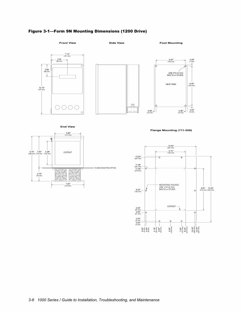
Figure 3-1—Form 9N Mounting Dimensions (1200 Drive)
Foot Mounting
Flange Mounting (711-556)
Side ViewFront View
End View
7.00"(178 mm)
2.75"(70 mm)
9.75"(248 mm)
7.00"(178 mm)
5.28"(134 mm)
CUTOUT
5.80"(147 mm)
10.75"(273 mm)
2.68(68 mm)
7.13"(181 mm)
3.50 (89 mm)
HEAT SINK
6.25"(159 mm)
8.49"(216 mm)
0.29"(7 mm)
0.22"(6 mm) 0.38"
(10 mm) 0.38"(10 mm)
USE #10 (5 mm)BOLTS or STUDS
FLANGE-MOUNTING OPTION
USE #10 (5 mm)BOLTS or STUDS
0.00"(0 mm)
0.25"(6 mm)
2.45"(62 mm)
11.00"(279 mm)
11.06"(281 mm)
2.00"(51 mm)
6.50"(165 mm)
13.25"(337 mm)
0.0
0"(0
mm
)
3.0
0"(7
6 m
m)
8.3
3"(2
12 m
m)
2.1
8"(5
5 m
m)
5.2
5"(1
33 m
m)
7.5
0"(1
91 m
m)
10.
50"
(267
mm
)
0.2
5"(6
mm
)
10.
25"
(260
mm
)
8.61"(219 mm)
13.50"(343 mm)
CUTOUT
6.15"(156 mm)
10.50"(267 mm)
Mechanical Installation 3-7
Figure 3-2—Form 12N Mounting Dimensions (1105 and 1120 Drives)
Foot Mounting
Flange Mounting
Side ViewFront View
End View
3.50"(89 mm)
9.50"(241 mm)
4.68"(119 mm)
16.30"(414 mm)
FLANGE-MOUNTING OPTION
3.25"(83 mm)
10.50"(267 mm)
7.25"(184 mm)
5.00"(127 mm)
9.50"(241 mm)
8.00"(203 mm)
CUTOUT
8.30"(211 mm)
0.25"(6 mm) 0.00"(0 mm)
1.10"(28 mm)
2.00"(51 mm)
6.50"(165 mm)
11.00"(279 mm)
12.40"(315 mm)
13.25"(337 mm)
10.
25"
(260
mm
)
7.5
0"(1
91 m
m)
?9.
40"
(239
mm
)
3.0
0"(7
6 m
m)
5.2
5"(1
33 m
m)
0.2
5"(6
mm
)
0.0
0"(0
mm
)
1.1
0"(2
8 m
m)
10.50"(267 mm)
11.30"(287 mm)
13.50"(343 mm)
MOUNTING HOLESUSE #10 (5 mm) BOLTS or STUDS
ATTACH TO HEAT SINKUSE #8-32 BOLTS
HEAT SINK
CUTOUT
9.00"(229 mm)
11.25"(286 mm)
0.25"(6 mm)
0.50"(13 mm)
USE #10 (5 mm)BOLTS or STUDS
0.25"(6 mm)
0.25"(6 mm)
Chassis units:Chassis units occupy approximately the same space as enclosed units. Refer to thefront view dimensions for overall height and width of foot-mounted units and to theflange-mounting diagram for overall height and width of flange-mounted units.
3-8 1000 Series / Guide to Installation, Troubleshooting, and Maintenance
Figure 3-3—Form 13, 13N, 17, 17N, 17X, and 30 Mounting Dimensions (1100, 1105,
1110, 1120, 1130, 1200, and 1230 Drives)
CONDUIT KNOCKOUT
(location varies)
CONDUIT KNOCKOUT
(location varies)
Conduit knockouts andvenitlation holes only onForm 13, 17, and 30.
USE 1/4" (6 mm) BOLTS or STUDS
CUTOUT
HEAT SINK
Foot Mounting
Flange MountingEnd View
Side ViewFront View
2.91"(74 mm)
9.50"(241 mm)
0.25"(6 mm)
2.00"(51 mm)
6.50"(165 mm)
11.00"(279 mm)
13.25"(337 mm)
0.25"(6 mm)
2.00"(51 mm)
8.63"(219 mm)
15.25"(387 mm)
28.50"(724 mm)
29.75"(756 mm)
0.25"(6 mm)
0.00"(0 mm)
0.00"(0 mm)
0.00"(0 mm)
2.00"(51 mm)
6.50"(165 mm)
11.00"(279 mm)
16.75"(425 mm)
10.
25"
(260
mm
)
7.50
"(1
91 m
m)
3.0
0"(7
6 m
m)
0.0
0"(0
mm
) 0
.25"
(6 m
m)
7.31"(186 mm) 9.31"
(236 mm)
10.84"(275 mm)
3.93"(100 mm)
21.88"(556 mm)
15.50"(394 mm)
10.50"(267 mm)
7.43"(189 mm)
10.93"(278 mm)
23.93"(608 mm)
13.25"(337 mm)
16.75"(425 mm)
29.75"(756 mm)
Form
17.70"(450 mm)
23.20"(589 mm)
38.20"(970 mm)
10.63"(270 mm)
10.63"(270 mm)
3.45"(88 mm)
15.27"(388 mm)
15.27"(388 mm)
10.63"(270 mm)
15.27"(388 mm)
Form
1130
11001110
5.25"(133 mm)
8.97"(228 mm)
4.67"(119 mm)2
1130
11001110
20.03"(509 mm)
4.80"(122 mm)
12.50"(318 mm)
0.50"(13 mm)
16.00"(406 mm)
29.00"(737 mm)
Form
2.27"(58 mm)
Form
Form
USE #10 (5 mm) SCREWS
1.18"(30 mm)
MINIMUM REQUIRED CLEARANCE FROM WALL/PANEL
Flange-mount only:Form 13 drives rated 11/2 hp (CT) at 230 V (1100 and 1110) and11/2 to 3 hp (CT) at 460 V/575 V (1100) and 11/2 and 2 hp (CT) at460 V (1110) do not have heat sink fins or mounting feet and mustbe flange mounted.
Chassis units:Chassis units occupy approximately the same space as enclosed units.Refer to the flange-mounting diagram for overall height and width.1130 chassis units are enclosed but have no cover.
†
0.50"(13 mm)
4.25"(108 mm)
2.25(57 mm)
6.25"(159 mm) 2.25
(57 mm)
2.23"(57 mm)
3 2.25"(57 mm)6.25
(159 mm)
2.25"(57 mm)
4.25(108 mm)
1313N
1313N
1717N
1717N
31.20"(792 mm)
17X
17
30
30
Form
13
7.63"(194 mm)
12.27"(312 mm)
13N
7.63"(194 mm)
12.27"(312 mm)
17N
10.63"(270 mm)
15.27"(388 mm)
17X
17
30
1313N
1313N
1717N17X
1717N17X
30
30
30
17N 5.42"
(138 mm)
7.50"(191 mm)
7.00"(178 mm)
17X
†
Form1313N1717N17X30
1130
11001110
2
1130
11001110
1313N1717N17
30
30
17N17X
Form
1130
11001110
2
1130
11001110
1313N1717N17
30
30
17N17X
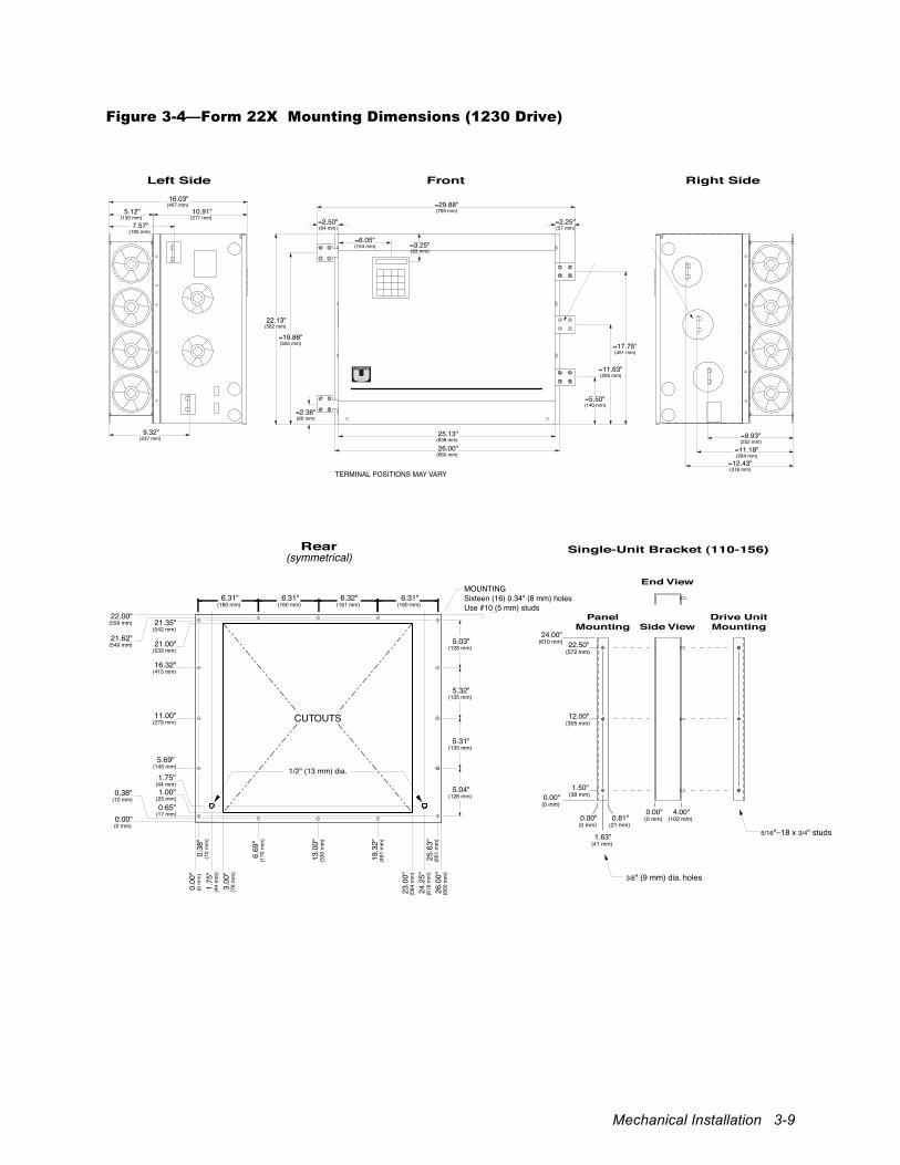
Mechanical Installation 3-9
Figure 3-4—Form 22X Mounting Dimensions (1230 Drive)
16.03" (407 mm)
10.91" (277 mm)
22.13" (562 mm)
19.88" (505 mm)
2.38" (60 mm)
22.13" (562 mm)
19.88" (505 mm)
2.38" (60 mm)
2.50" (64 mm)
6.05" (154 mm)
2.25" (57 mm)
3.25" (83 mm)
5.50" (140 mm)
9.50" (241 mm)9.93"
(252 mm)11.18"
(284 mm)12.43"
(316 mm)
9.93" (265 mm)11.18"
(291 mm)12.45"
(316 mm)
11.63" (295 mm)
17.75" (451 mm)
26.00" (660 mm)
25.13" (638 mm)
26.00" (660 mm)
25.13" (638 mm)
29.88" (759 mm)
2.50" (64 mm)
2.63" (67 mm)
2.00" (51 mm)
29.62" (752 mm) 12.38"
(314 mm)
5.12" (130 mm)
7.57" (192 mm)
Left Side Right SideFront
Left Side Right SideFront
2400 Inverter / 2450 Amplifier
2490 Converter
9.32" (237 mm)
9.32" (237 mm)
15.93" (405 mm)
10.81" (275 mm)
5.12" (130 mm)
7.57" (192 mm)
5.50" (140 mm)
11.75" (298 mm)
17.75" (451 mm)
TERMINAL POSITIONS MAY VARY
TERMINAL POSITIONS MAY VARY
ONLY ON 2400 UNITS
Unit #1
Unit #2
Unit #3
6.31" (160 mm)
67.50" (1715 mm)
45.88" (1165 mm)
22.00" (559 mm)
22.75" (578 mm)
44.75" (1137 mm)
45.50" (1156 mm)
61.82" (1570 mm)
66.85" (1698 mm)
56.50" (1435 mm)
51.19" (1300 mm)
46.15" (1172 mm)
39.07" (992 mm)
44.10" (1120 mm)
33.75" (857 mm)
28.44" (722 mm)
16.32" (415 mm)
21.35" (542 mm)
23.40" (594 mm)
23.13" (588 mm)
0.00" (0 mm)
0.38" (10 mm)
21.62" (549 mm)
44.37" (1127 mm)
67.12" (1705 mm)
23.75" (603 mm)
46.50" (1181 mm)
47.25" (1200 mm)
11.00" (279 mm)
5.69" (145 mm)
0.65" (17 mm)
1.00" (25 mm)
21.00" (533 mm)
43.75" (1111 mm)
66.50" (1689 mm)
6.31" (160 mm)
5.03" (128 mm)
5.04" (128 mm)
5.32" (135 mm)
5.31" (135 mm)
5.03" (128 mm)
0.75" (19 mm)
0.75" (19 mm)
5.04" (128 mm)
5.32" (135 mm)
5.31" (135 mm)
5.03" (128 mm)
5.04" (128 mm)
5.32" (135 mm)
5.31" (135 mm)
3.0
0"
(76
mm
)
6.6
9"
(170
mm
)
13.
00"
(330
mm
)
19.
32"
(491
mm
)
23.
00"
(584
mm
)
25.
63"
(651
mm
)
24.
25"
(616
mm
)
0.3
8"
(10
mm
) 1
.75"
(4
4 m
m)
0.0
0"
(0 m
m)
26.
00"
(660
mm
)
6.31" (160 mm)
6.32" (161 mm)
CUTOUTS
CUTOUTS
CUTOUTS
24.50" (622 mm)
1.75" (44 mm)
Rear (symmetrical)
1/2" (13 mm) dia.
MOUNTING Sixteen (16) 0.34" (8 mm) holes each unit Use #10 (5 mm) studs
1/2" (13 mm) dia.
1/2" (13 mm) dia.
24.00" (610 mm)
0.00" (0 mm)
0.00" (0 mm) 0.00"
(0 mm) 0.81" (21 mm)
1.63" (41 mm)
0.00" (0 mm)
0.81" (21 mm)
1.63" (41 mm)
0.00" (0 mm)
0.81" (21 mm)
1.63" (41 mm)
4.00" (102 mm)
0.00" (0 mm)
4.00" (102 mm)
22.50" (572 mm)
12.00" (305 mm)
1.50" (38 mm)
23.38" (594 mm)
24.25" (616 mm)
23.38" (572 mm)
34.75" (883 mm)
45.25" (1149 mm)
12.00" (305 mm)
1.50" (38 mm)
Side ViewDrive Unit Mounting
Panel Mounting
Side ViewDrive Unit Mounting
Panel Mounting
Side ViewDrive Unit Mounting
Panel Mounting
End View
End View
Double-Unit Bracket (110-145)
Single-Unit Bracket (110-156) Triple-Unit Bracket (110-188)
End View
3/8" (9 mm) dia. holes
3/8" (9 mm) dia. holes
5/16"–18 x 3/4" studs
5/16"–18 x 3/4" studs
3/8" (9 mm) dia. holes
5/16"–18 x 3/4" studs
0.00" (0 mm)
46.75" (1187 mm)
23.38" (594 mm)
34.75" (883 mm)
46.13" (1172 mm)
47.00" (1194 mm)
45.25" (1149 mm)
24.25" (616 mm)
22.50" (572 mm)
57.50" (1461 mm)
68.00" (1727 mm)
12.00" (305 mm)
1.50" (38 mm) 0.00"
(0 mm)
69.50" (1765 mm)
0.00" (0 mm)
4.00" (102 mm)
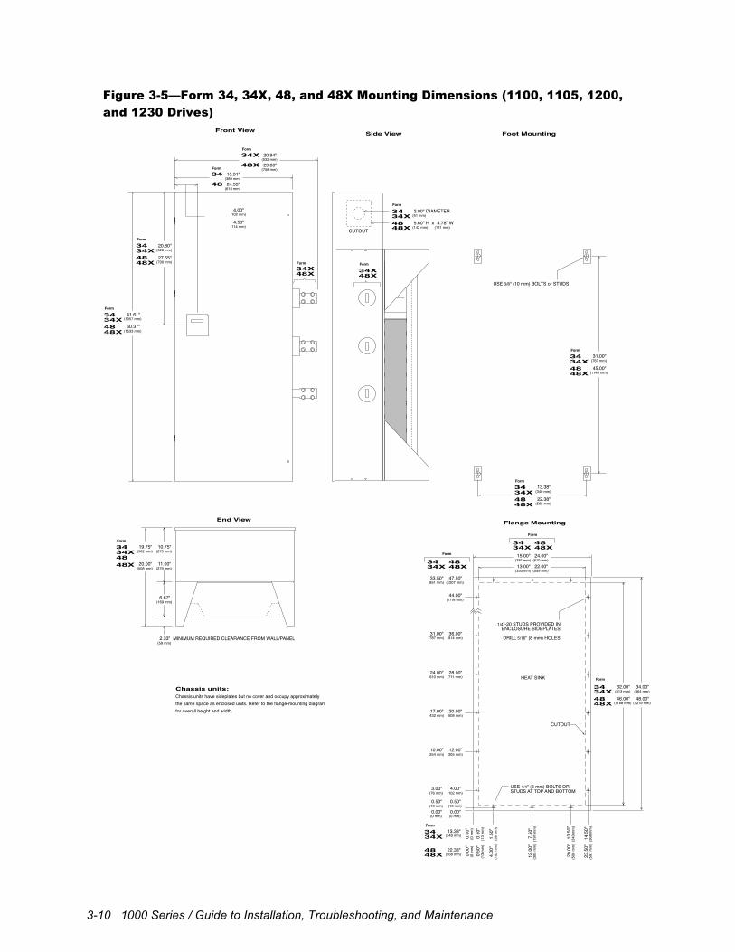
3-10 1000 Series / Guide to Installation, Troubleshooting, and Maintenance
Figure 3-5—Form 34, 34X, 48, and 48X Mounting Dimensions (1100, 1105, 1200,
and 1230 Drives)
2.33"(59 mm)
0.0
0"(0
mm
)
0.5
0"(1
3 m
m)
4.00
"(1
02 m
m)
12.
00"
(305
mm
)
20.
00"
(508
mm
)
23.
50"
(597
mm
)
0.0
0"(0
mm
)
0.5
0"(1
3 m
m)
1.50
"(3
8 m
m)
7.5
0"(1
91 m
m)
13.
50"
(343
mm
)
14.
50"
(368
mm
)
1/4"-20 STUDS PROVIDED INENCLOSURE SIDEPLATES
DRILL 5/16" (8 mm) HOLES
USE 1/4" (6 mm) BOLTS ORSTUDS AT TOP AND BOTTOM
CUTOUT
Foot Mounting
Flange MountingEnd ViewEnd View
Side ViewFront View
MINIMUM REQUIRED CLEARANCE FROM WALL/PANEL
USE 3/8" (10 mm) BOLTS or STUDS
HEAT SINK
End View
6.67"(169 mm)
Chassis units:Chassis units have sideplates but no cover and occupy approximatelythe same space as enclosed units. Refer to the flange-mounting diagramfor overall height and width.
60.37"(1533 mm)
41.61"(1057 mm)
4848X
3434X
10.75"(273 mm)
11.00"(279 mm)
Form
45.00"(1143 mm)
31.00"(787 mm)
4848X
3434X
Form
22.38"(568 mm)
13.38"(340 mm)
4848X
3434X
Form
4848X
3434X
Form
46.00"(1168 mm)
32.00"(813 mm)
48.00"(1219 mm)
34.00"(864 mm)
Form
31.00"(787 mm)
24.00"(610 mm)
17.00"(432 mm)
10.00"(254 mm)
3.00"(76 mm)
0.00"(0 mm)
0.50"(13 mm)
33.50"(851 mm)
44.00"(1118 mm)
36.00"(914 mm)
28.00"(711 mm)
20.00"(508 mm)
12.00"(305 mm)
4.00"(102 mm)
0.00"(0 mm)
0.50"(13 mm)
47.50"(1207 mm)
Form
22.38"(568 mm)
13.38"(340 mm)
24.00"(610 mm)
15.00"(381 mm)
22.00"(559 mm)
13.00"(330 mm)
27.55"(700 mm)
20.80"(528 mm)
48X34XForm
4.50"(114 mm)
4.00"(102 mm)
48
34Form
24.33"(618 mm)
15.31"(389 mm)
48X
34XForm
29.86"(758 mm)
20.94"(532 mm)
4848X
3434X
Form
34 4834X 48X
Form
34 4834X 48X
4848X
3434X
CUTOUT 5.60" H x (142 mm)
4.78" W (121 mm)
2.00" DIAMETER (51 mm)
48
3434X
48X
Form
20.00"(508 mm)
19.75"(502 mm)
4848X
3434X
Form
34X48X
Form
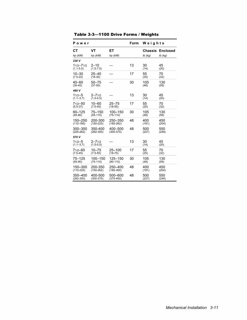
Mechanical Installation 3-11
Table 3-3—1100 Drive Forms / Weights
P o w e r Form W e i g h t s
CT VT ET Chassis Enclosed hp (kW) hp (kW) hp (kW) lb (kg) lb (kg)
230 V 11/2–71/2 2–10 — 13 30 45 (1.1-5.5) (1.5-7.5) (14) (20)
10–30 25–40 — 17 55 70 (7.5-22) (18-30) (25) (32)
40–60 50–75 — 30 105 130 (30-45) (37-55) (48) (59)
460 V 11/2–5 2–71/2 — 13 30 45 (1.1–3.7) (1.5-5.5) (14) (20)
71/2–50 10–60 25–75 17 55 70 (5.5-37) (7.5-45) (18-55) (25) (32)
60–125 75–150 100–150 30 105 130 (45-90) (55-110) (75-110) (48) (59)
150–250 200-300 250–350 48 400 450 (110-185) (150-225) (185-262) (181) (204)
300–350 350-400 400–500 48 500 550 (225-262) (262-300) (300-375) (227) (249)
575 V 11/2–5 2–71/2 — 13 30 45 (1.1–3.7) (1.5-5.5) (14) (20)
71/2–60 10–75 25–100 17 55 70 (7.5-45) (7.5-55) (18-75) (25) (32)
75–125 100–150 125–150 30 105 130 (55-90) (75-110) (90-110) (48) (59)
150–300 200-350 250–400 48 400 450 (110-225) (150-262) (185-300) (181) (204)
350–400 400-500 500–600 48 500 550 (262-300) (300-375) (375-450) (227) (249)
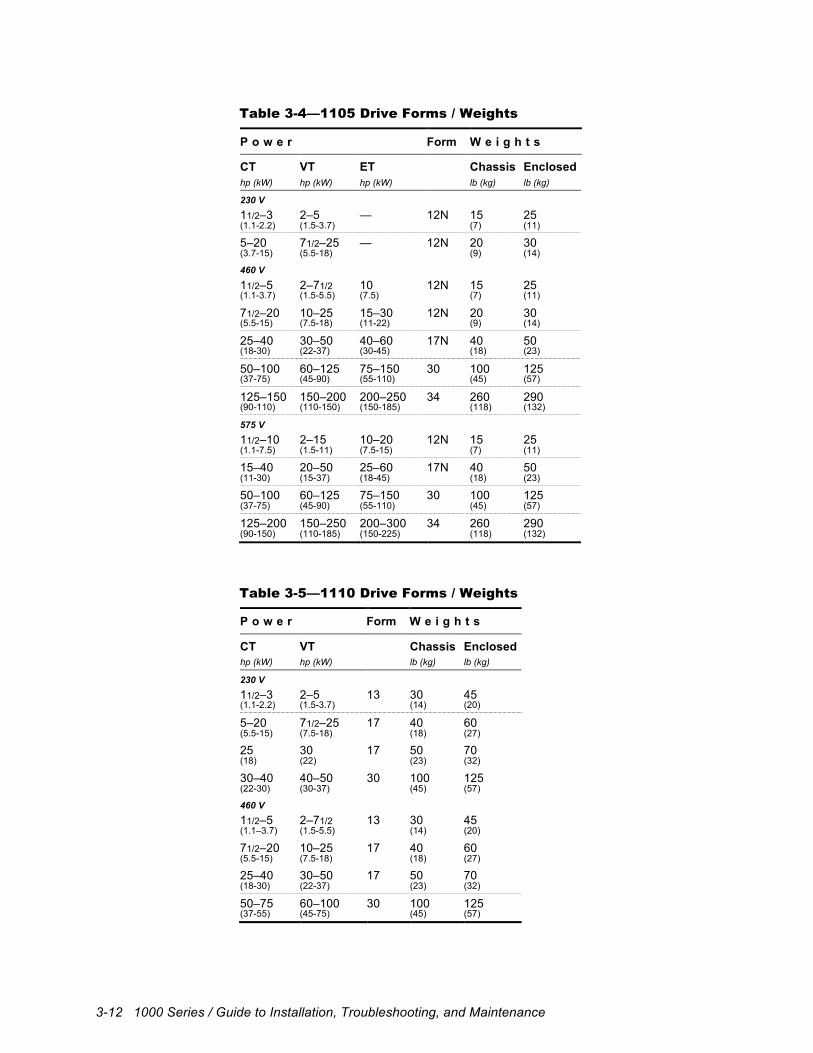
3-12 1000 Series / Guide to Installation, Troubleshooting, and Maintenance
Table 3-4—1105 Drive Forms / Weights
P o w e r Form W e i g h t s
CT VT ET Chassis Enclosed hp (kW) hp (kW) hp (kW) lb (kg) lb (kg)
230 V 11/2–3 2–5 — 12N 15 25 (1.1-2.2) (1.5-3.7) (7) (11)
5–20 71/2–25 — 12N 20 30 (3.7-15) (5.5-18) (9) (14)
460 V 11/2–5 2–71/2 10 12N 15 25 (1.1-3.7) (1.5-5.5) (7.5) (7) (11)
71/2–20 10–25 15–30 12N 20 30 (5.5-15) (7.5-18) (11-22) (9) (14)
25–40 30–50 40–60 17N 40 50 (18-30) (22-37) (30-45) (18) (23)
50–100 60–125 75–150 30 100 125 (37-75) (45-90) (55-110) (45) (57)
125–150 150–200 200–250 34 260 290 (90-110) (110-150) (150-185) (118) (132)
575 V 11/2–10 2–15 10–20 12N 15 25 (1.1-7.5) (1.5-11) (7.5-15) (7) (11)
15–40 20–50 25–60 17N 40 50 (11-30) (15-37) (18-45) (18) (23)
50–100 60–125 75–150 30 100 125 (37-75) (45-90) (55-110) (45) (57)
125–200 150–250 200–300 34 260 290 (90-150) (110-185) (150-225) (118) (132)
Table 3-5—1110 Drive Forms / Weights
P o w e r Form W e i g h t s
CT VT Chassis Enclosed hp (kW) hp (kW) lb (kg) lb (kg)
230 V 11/2–3 2–5 13 30 45 (1.1-2.2) (1.5-3.7) (14) (20)
5–20 71/2–25 17 40 60 (5.5-15) (7.5-18) (18) (27)
25 30 17 50 70 (18) (22) (23) (32)
30–40 40–50 30 100 125 (22-30) (30-37) (45) (57)
460 V 11/2–5 2–71/2 13 30 45 (1.1–3.7) (1.5-5.5) (14) (20)
71/2–20 10–25 17 40 60 (5.5-15) (7.5-18) (18) (27)
25–40 30–50 17 50 70 (18-30) (22-37) (23) (32)
50–75 60–100 30 100 125 (37-55) (45-75) (45) (57)
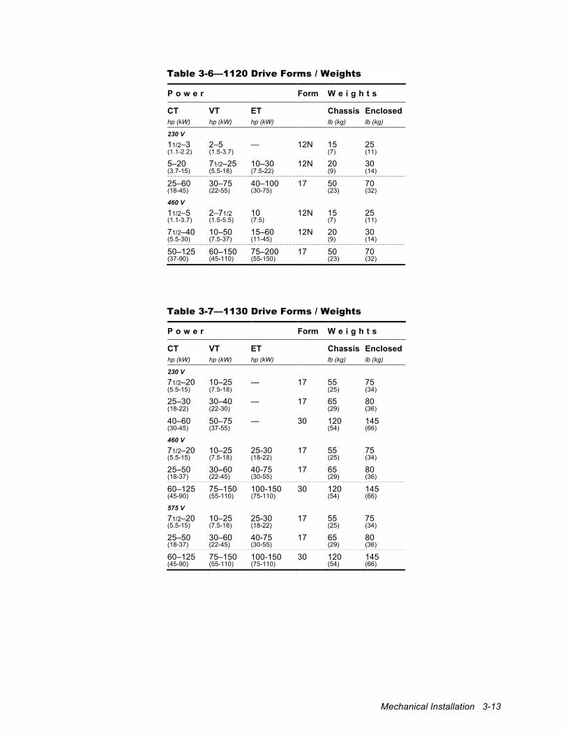
Mechanical Installation 3-13
Table 3-6—1120 Drive Forms / Weights
P o w e r Form W e i g h t s
CT VT ET Chassis Enclosed hp (kW) hp (kW) hp (kW) lb (kg) lb (kg)
230 V 11/2–3 2–5 — 12N 15 25 (1.1-2.2) (1.5-3.7) (7) (11)
5–20 71/2–25 10–30 12N 20 30 (3.7-15) (5.5-18) (7.5-22) (9) (14)
25–60 30–75 40–100 17 50 70 (18-45) (22-55) (30-75) (23) (32)
460 V 11/2–5 2–71/2 10 12N 15 25 (1.1-3.7) (1.5-5.5) (7.5) (7) (11)
71/2–40 10–50 15–60 12N 20 30 (5.5-30) (7.5-37) (11-45) (9) (14)
50–125 60–150 75–200 17 50 70 (37-90) (45-110) (55-150) (23) (32)
Table 3-7—1130 Drive Forms / Weights
P o w e r Form W e i g h t s
CT VT ET Chassis Enclosed hp (kW) hp (kW) hp (kW) lb (kg) lb (kg)
230 V 71/2–20 10–25 — 17 55 75 (5.5-15) (7.5-18) (25) (34)
25–30 30–40 — 17 65 80 (18-22) (22-30) (29) (36)
40–60 50–75 — 30 120 145 (30-45) (37-55) (54) (66)
460 V 71/2–20 10–25 25-30 17 55 75 (5.5-15) (7.5-18) (18-22) (25) (34)
25–50 30–60 40-75 17 65 80 (18-37) (22-45) (30-55) (29) (36)
60–125 75–150 100-150 30 120 145 (45-90) (55-110) (75-110) (54) (66)
575 V 71/2–20 10–25 25-30 17 55 75 (5.5-15) (7.5-18) (18-22) (25) (34)
25–50 30–60 40-75 17 65 80 (18-37) (22-45) (30-55) (29) (36)
60–125 75–150 100-150 30 120 145 (45-90) (55-110) (75-110) (54) (66)
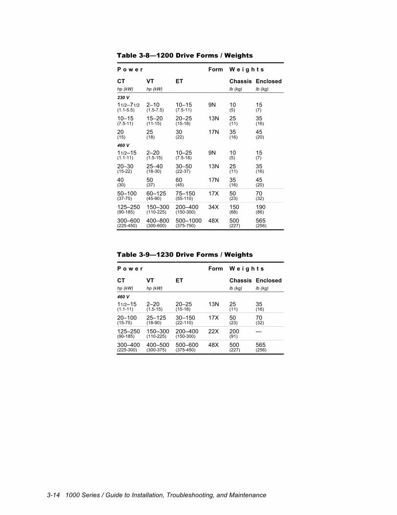
3-14 1000 Series / Guide to Installation, Troubleshooting, and Maintenance
Table 3-8—1200 Drive Forms / Weights
P o w e r Form W e i g h t s
CT VT ET Chassis Enclosed hp (kW) hp (kW) lb (kg) lb (kg)
230 V 11/2–71/2 2–10 10–15 9N 10 15 (1.1-5.5) (1.5-7.5) (7.5-11) (5) (7)
10–15 15–20 20–25 13N 25 35 (7.5-11) (11-15) (15-18) (11) (16)
20 25 30 17N 35 45 (15) (18) (22) (16) (20)
460 V 11/2–15 2–20 10–25 9N 10 15 (1.1-11) (1.5-15) (7.5-18) (5) (7)
20–30 25–40 30–50 13N 25 35 (15-22) (18-30) (22-37) (11) (16)
40 50 60 17N 35 45 (30) (37) (45) (16) (20)
50–100 60–125 75–150 17X 50 70 (37-75) (45-90) (55-110) (23) (32)
125–250 150–300 200–400 34X 150 190 (90-185) (110-225) (150-300) (68) (86)
300–600 400–800 500–1000 48X 500 565 (225-450) (300-600) (375-750) (227) (256)
Table 3-9—1230 Drive Forms / Weights
P o w e r Form W e i g h t s
CT VT ET Chassis Enclosed hp (kW) hp (kW) lb (kg) lb (kg)
460 V 11/2–15 2–20 20–25 13N 25 35 (1.1-11) (1.5-15) (15-18) (11) (16)
20–100 25–125 30–150 17X 50 70 (15-75) (18-90) (22-110) (23) (32)
125–250 150–300 200–400 22X 200 — (90-185) (110-225) (150-300) (91)
300–400 400–500 500–600 48X 500 565 (225-300) (300-375) (375-450) (227) (256)
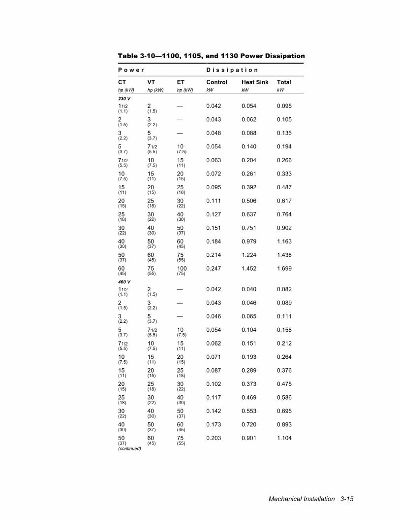
Mechanical Installation 3-15
Table 3-10—1100, 1105, and 1130 Power Dissipation
P o w e r D i s s i p a t i o n
CT VT ET Control Heat Sink Total hp (kW) hp (kW) hp (kW) kW kW kW
230 V 11/2 2 — 0.042 0.054 0.095 (1.1) (1.5)
2 3 — 0.043 0.062 0.105 (1.5) (2.2)
3 5 — 0.048 0.088 0.136 (2.2) (3.7)
5 71/2 10 0.054 0.140 0.194 (3.7) (5.5) (7.5)
71/2 10 15 0.063 0.204 0.266 (5.5) (7.5) (11)
10 15 20 0.072 0.261 0.333 (7.5) (11) (15)
15 20 25 0.095 0.392 0.487 (11) (15) (18)
20 25 30 0.111 0.506 0.617 (15) (18) (22)
25 30 40 0.127 0.637 0.764 (18) (22) (30)
30 40 50 0.151 0.751 0.902 (22) (30) (37)
40 50 60 0.184 0.979 1.163 (30) (37) (45)
50 60 75 0.214 1.224 1.438 (37) (45) (55)
60 75 100 0.247 1.452 1.699 (45) (55) (75)
460 V 11/2 2 — 0.042 0.040 0.082 (1.1) (1.5)
2 3 — 0.043 0.046 0.089 (1.5) (2.2)
3 5 — 0.046 0.065 0.111 (2.2) (3.7)
5 71/2 10 0.054 0.104 0.158 (3.7) (5.5) (7.5)
71/2 10 15 0.062 0.151 0.212 (5.5) (7.5) (11)
10 15 20 0.071 0.193 0.264 (7.5) (11) (15)
15 20 25 0.087 0.289 0.376 (11) (15) (18)
20 25 30 0.102 0.373 0.475 (15) (18) (22)
25 30 40 0.117 0.469 0.586 (18) (22) (30)
30 40 50 0.142 0.553 0.695 (22) (30) (37)
40 50 60 0.173 0.720 0.893 (30) (37) (45)
50 60 75 0.203 0.901 1.104 (37) (45) (55) (continued)
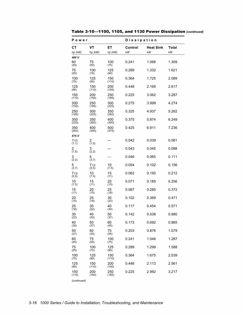
3-16 1000 Series / Guide to Installation, Troubleshooting, and Maintenance
Table 3-10—1100, 1105, and 1130 Power Dissipation (continued)
P o w e r D i s s i p a t i o n
CT VT ET Control Heat Sink Total hp (kW) hp (kW) hp (kW) kW kW kW
460 V 60 75 100 0.241 1.068 1.309 (45) (55) (75)
75 100 125 0.289 1.332 1.621 (55) (75) (90)
100 125 150 0.364 1.725 2.089 (75) (90) (110)
125 150 200 0.448 2.169 2.617 (90) (110) (150)
150 200 250 0.225 3.062 3.287 (110) (150) (185)
200 250 300 0.275 3.999 4.274 (150) (185) (225)
250 300 350 0.325 4.937 5.262 (185) (225) (262)
300 350 400 0.375 5.874 6.249 (225) (262) (300)
350 400 500 0.425 6.811 7.236 (262) (300) (375)
575 V 11/2 2 — 0.042 0.039 0.081 (1.1) (1.5)
2 3 — 0.043 0.045 0.088 (1.5) (2.2)
3 5 — 0.046 0.065 0.111 (2.2) (3.7)
5 71/2 10 0.054 0.102 0.156 (3.7) (5.5) (7.5)
71/2 10 15 0.062 0.150 0.212 (5.5) (7.5) (11)
10 15 20 0.071 0.185 0.256 (7.5) (11) (15)
15 20 25 0.087 0.285 0.372 (11) (15) (18)
20 25 30 0.102 0.369 0.471 (15) (18) (22)
25 30 40 0.117 0.454 0.571 (18) (22) (30)
30 40 50 0.142 0.538 0.680 (22) (30) (37)
40 50 60 0.173 0.692 0.865 (30) (37) (45)
50 60 75 0.203 0.876 1.079 (37) (35) (55)
60 75 100 0.241 1.046 1.287 (45) (55) (75)
75 100 125 0.289 1.299 1.588 (55) (75) (90)
100 125 150 0.364 1.675 2.039 (75) (90) (110)
125 150 200 0.448 2.113 2.561 (90) (110) (150)
150 200 250 0.225 2.992 3.217 (110) (150) (185) (continued)
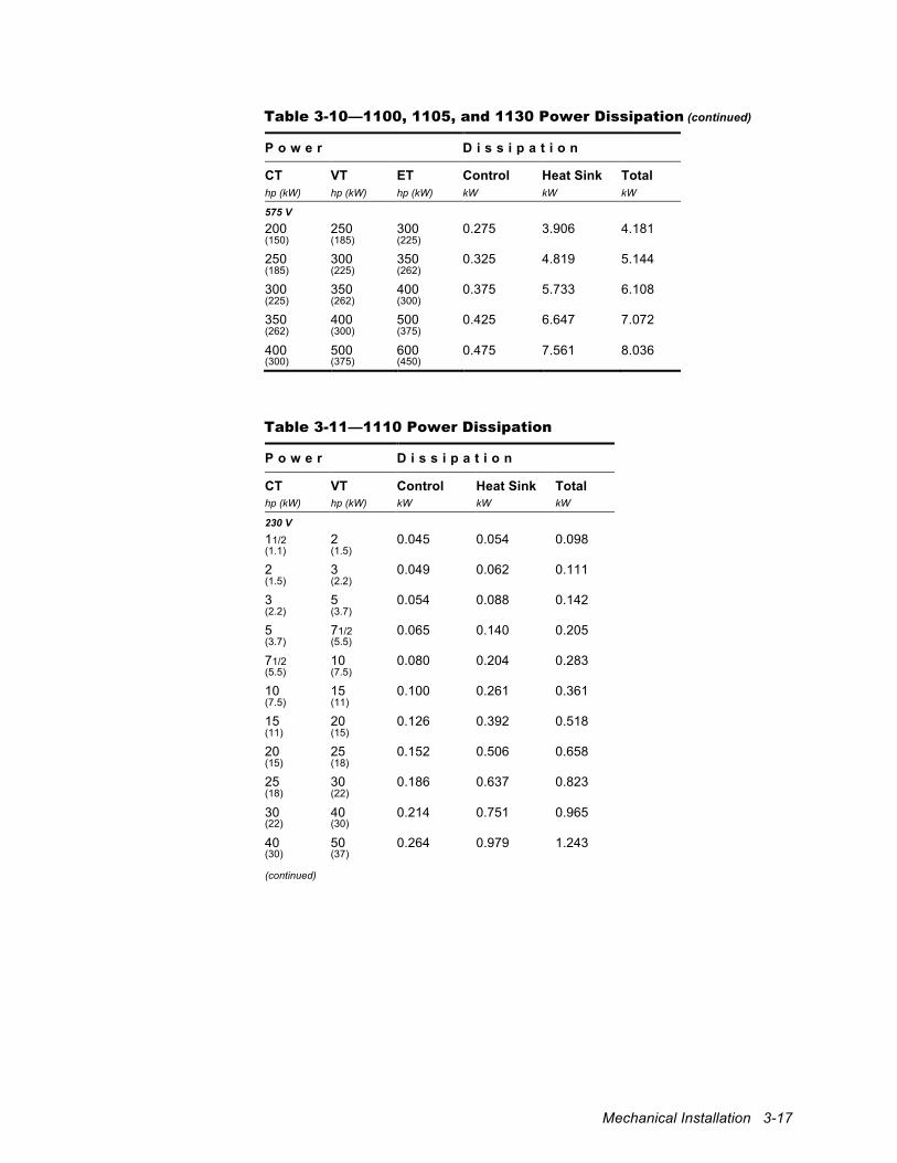
Mechanical Installation 3-17
Table 3-10—1100, 1105, and 1130 Power Dissipation (continued)
P o w e r D i s s i p a t i o n
CT VT ET Control Heat Sink Total hp (kW) hp (kW) hp (kW) kW kW kW
575 V 200 250 300 0.275 3.906 4.181 (150) (185) (225)
250 300 350 0.325 4.819 5.144 (185) (225) (262)
300 350 400 0.375 5.733 6.108 (225) (262) (300)
350 400 500 0.425 6.647 7.072 (262) (300) (375)
400 500 600 0.475 7.561 8.036 (300) (375) (450)
Table 3-11—1110 Power Dissipation
P o w e r D i s s i p a t i o n
CT VT Control Heat Sink Total hp (kW) hp (kW) kW kW kW
230 V 11/2 2 0.045 0.054 0.098 (1.1) (1.5)
2 3 0.049 0.062 0.111 (1.5) (2.2)
3 5 0.054 0.088 0.142 (2.2) (3.7)
5 71/2 0.065 0.140 0.205 (3.7) (5.5)
71/2 10 0.080 0.204 0.283 (5.5) (7.5)
10 15 0.100 0.261 0.361 (7.5) (11)
15 20 0.126 0.392 0.518 (11) (15)
20 25 0.152 0.506 0.658 (15) (18)
25 30 0.186 0.637 0.823 (18) (22)
30 40 0.214 0.751 0.965 (22) (30)
40 50 0.264 0.979 1.243 (30) (37) (continued)
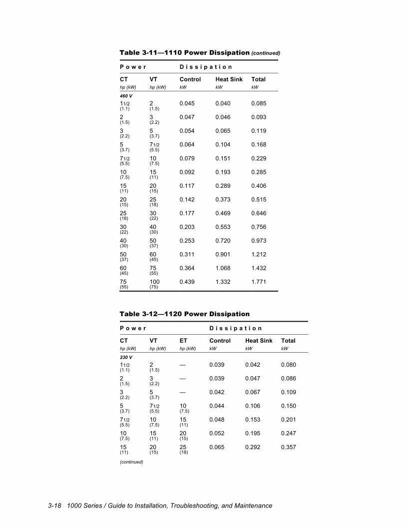
3-18 1000 Series / Guide to Installation, Troubleshooting, and Maintenance
Table 3-11—1110 Power Dissipation (continued)
P o w e r D i s s i p a t i o n
CT VT Control Heat Sink Total hp (kW) hp (kW) kW kW kW
460 V 11/2 2 0.045 0.040 0.085 (1.1) (1.5)
2 3 0.047 0.046 0.093 (1.5) (2.2)
3 5 0.054 0.065 0.119 (2.2) (3.7)
5 71/2 0.064 0.104 0.168 (3.7) (5.5)
71/2 10 0.079 0.151 0.229 (5.5) (7.5)
10 15 0.092 0.193 0.285 (7.5) (11)
15 20 0.117 0.289 0.406 (11) (15)
20 25 0.142 0.373 0.515 (15) (18)
25 30 0.177 0.469 0.646 (18) (22)
30 40 0.203 0.553 0.756 (22) (30)
40 50 0.253 0.720 0.973 (30) (37)
50 60 0.311 0.901 1.212 (37) (45)
60 75 0.364 1.068 1.432 (45) (55)
75 100 0.439 1.332 1.771 (55) (75)
Table 3-12—1120 Power Dissipation
P o w e r D i s s i p a t i o n
CT VT ET Control Heat Sink Total hp (kW) hp (kW) hp (kW) kW kW kW
230 V 11/2 2 — 0.039 0.042 0.080 (1.1) (1.5)
2 3 — 0.039 0.047 0.086 (1.5) (2.2)
3 5 — 0.042 0.067 0.109 (2.2) (3.7)
5 71/2 10 0.044 0.106 0.150 (3.7) (5.5) (7.5)
71/2 10 15 0.048 0.153 0.201 (5.5) (7.5) (11)
10 15 20 0.052 0.195 0.247 (7.5) (11) (15)
15 20 25 0.065 0.292 0.357 (11) (15) (18) (continued)
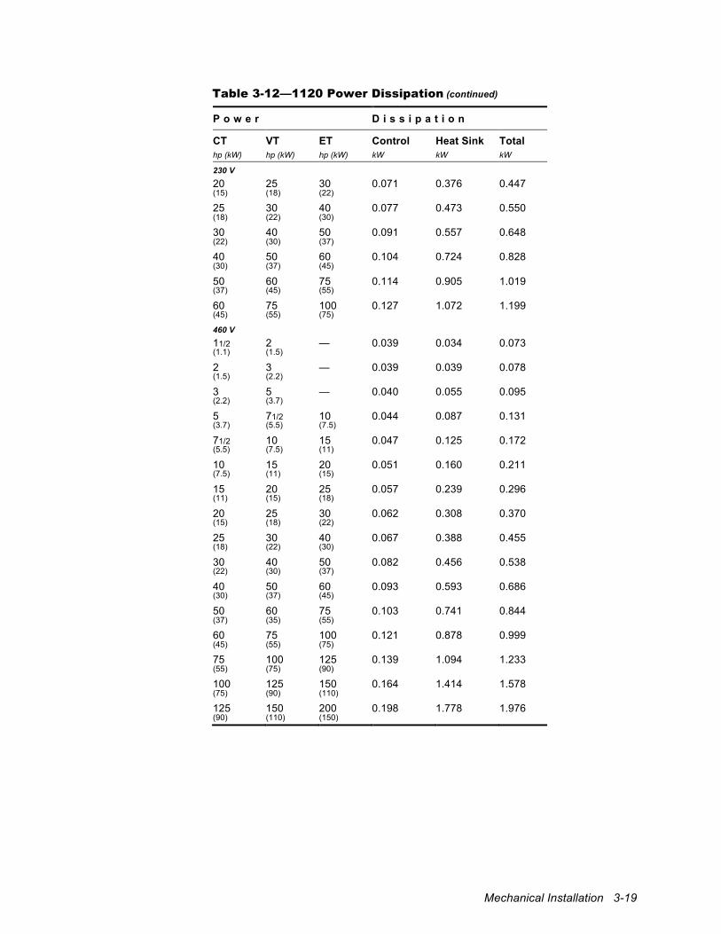
Mechanical Installation 3-19
Table 3-12—1120 Power Dissipation (continued)
P o w e r D i s s i p a t i o n
CT VT ET Control Heat Sink Total hp (kW) hp (kW) hp (kW) kW kW kW
230 V 20 25 30 0.071 0.376 0.447 (15) (18) (22)
25 30 40 0.077 0.473 0.550 (18) (22) (30)
30 40 50 0.091 0.557 0.648 (22) (30) (37)
40 50 60 0.104 0.724 0.828 (30) (37) (45)
50 60 75 0.114 0.905 1.019 (37) (45) (55)
60 75 100 0.127 1.072 1.199 (45) (55) (75)
460 V 11/2 2 — 0.039 0.034 0.073 (1.1) (1.5)
2 3 — 0.039 0.039 0.078 (1.5) (2.2)
3 5 — 0.040 0.055 0.095 (2.2) (3.7)
5 71/2 10 0.044 0.087 0.131 (3.7) (5.5) (7.5)
71/2 10 15 0.047 0.125 0.172 (5.5) (7.5) (11)
10 15 20 0.051 0.160 0.211 (7.5) (11) (15)
15 20 25 0.057 0.239 0.296 (11) (15) (18)
20 25 30 0.062 0.308 0.370 (15) (18) (22)
25 30 40 0.067 0.388 0.455 (18) (22) (30)
30 40 50 0.082 0.456 0.538 (22) (30) (37)
40 50 60 0.093 0.593 0.686 (30) (37) (45)
50 60 75 0.103 0.741 0.844 (37) (35) (55)
60 75 100 0.121 0.878 0.999 (45) (55) (75)
75 100 125 0.139 1.094 1.233 (55) (75) (90)
100 125 150 0.164 1.414 1.578 (75) (90) (110)
125 150 200 0.198 1.778 1.976 (90) (110) (150)
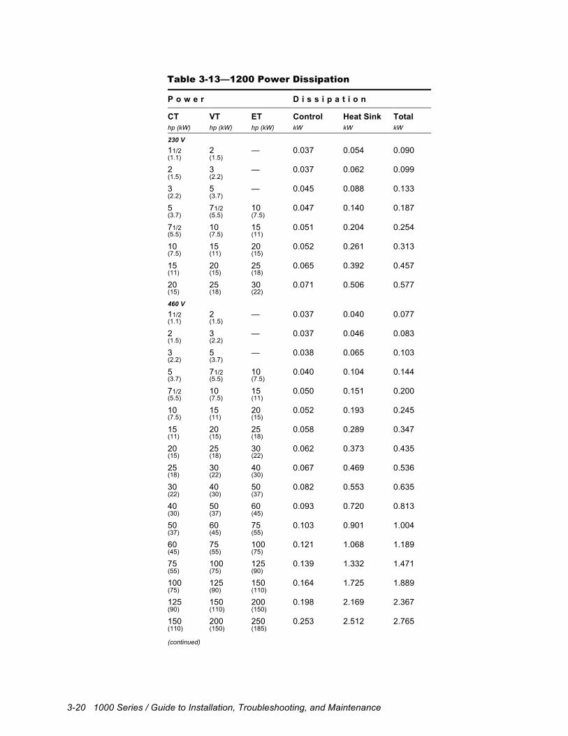
3-20 1000 Series / Guide to Installation, Troubleshooting, and Maintenance
Table 3-13—1200 Power Dissipation
P o w e r D i s s i p a t i o n
CT VT ET Control Heat Sink Total hp (kW) hp (kW) hp (kW) kW kW kW
230 V 11/2 2 — 0.037 0.054 0.090 (1.1) (1.5)
2 3 — 0.037 0.062 0.099 (1.5) (2.2)
3 5 — 0.045 0.088 0.133 (2.2) (3.7)
5 71/2 10 0.047 0.140 0.187 (3.7) (5.5) (7.5)
71/2 10 15 0.051 0.204 0.254 (5.5) (7.5) (11)
10 15 20 0.052 0.261 0.313 (7.5) (11) (15)
15 20 25 0.065 0.392 0.457 (11) (15) (18)
20 25 30 0.071 0.506 0.577 (15) (18) (22)
460 V 11/2 2 — 0.037 0.040 0.077 (1.1) (1.5)
2 3 — 0.037 0.046 0.083 (1.5) (2.2)
3 5 — 0.038 0.065 0.103 (2.2) (3.7)
5 71/2 10 0.040 0.104 0.144 (3.7) (5.5) (7.5)
71/2 10 15 0.050 0.151 0.200 (5.5) (7.5) (11)
10 15 20 0.052 0.193 0.245 (7.5) (11) (15)
15 20 25 0.058 0.289 0.347 (11) (15) (18)
20 25 30 0.062 0.373 0.435 (15) (18) (22)
25 30 40 0.067 0.469 0.536 (18) (22) (30)
30 40 50 0.082 0.553 0.635 (22) (30) (37)
40 50 60 0.093 0.720 0.813 (30) (37) (45)
50 60 75 0.103 0.901 1.004 (37) (45) (55)
60 75 100 0.121 1.068 1.189 (45) (55) (75)
75 100 125 0.139 1.332 1.471 (55) (75) (90)
100 125 150 0.164 1.725 1.889 (75) (90) (110)
125 150 200 0.198 2.169 2.367 (90) (110) (150)
150 200 250 0.253 2.512 2.765 (110) (150) (185) (continued)
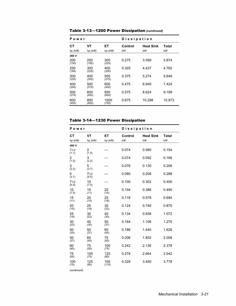
Mechanical Installation 3-21
Table 3-13—1200 Power Dissipation (continued)
P o w e r D i s s i p a t i o n
CT VT ET Control Heat Sink Total hp (kW) hp (kW) hp (kW) kW kW kW
460 V 200 250 300 0.275 3.599 3.874 (150) (185) (225)
250 300 400 0.325 4.437 4.762 (185) (225) (300)
300 400 500 0.375 5.274 5.649 (225) (300) (375)
400 500 600 0.475 6.949 7.424 (300) (375) (450)
500 600 800 0.575 8.624 9.199 (375) (450) (600)
600 800 1000 0.675 10.298 10.973 (450) (600) (750)
Table 3-14—1230 Power Dissipation
P o w e r D i s s i p a t i o n
CT VT ET Control Heat Sink Total hp (kW) hp (kW) hp (kW) kW kW kW
460 V 11/2 2 — 0.074 0.080 0.154 (1.1) (1.5)
2 3 — 0.074 0.092 0.166 (1.5) (2.2)
3 5 — 0.076 0.130 0.206 (2.2) (3.7)
5 71/2 — 0.080 0.208 0.288 (3.7) (5.5)
71/2 10 — 0.100 0.302 0.400 (5.5) (7.5)
10 15 20 0.104 0.386 0.490 (7.5) (11) (15)
15 20 25 0.116 0.578 0.694 (11) (15) (18)
20 25 30 0.124 0.746 0.870 (15) (18) (22)
25 30 40 0.134 0.938 1.072 (18) (22) (30)
30 40 50 0.164 1.106 1.270 (22) (30) (37)
40 50 60 0.186 1.440 1.626 (30) (37) (45)
50 60 75 0.206 1.802 2.008 (37) (45) (55)
60 75 100 0.242 2.136 2.378 (45) (55) (75)
75 100 125 0.278 2.664 2.942 (55) (75) (90)
100 125 150 0.328 3.450 3.778 (75) (90) (110) (continued)
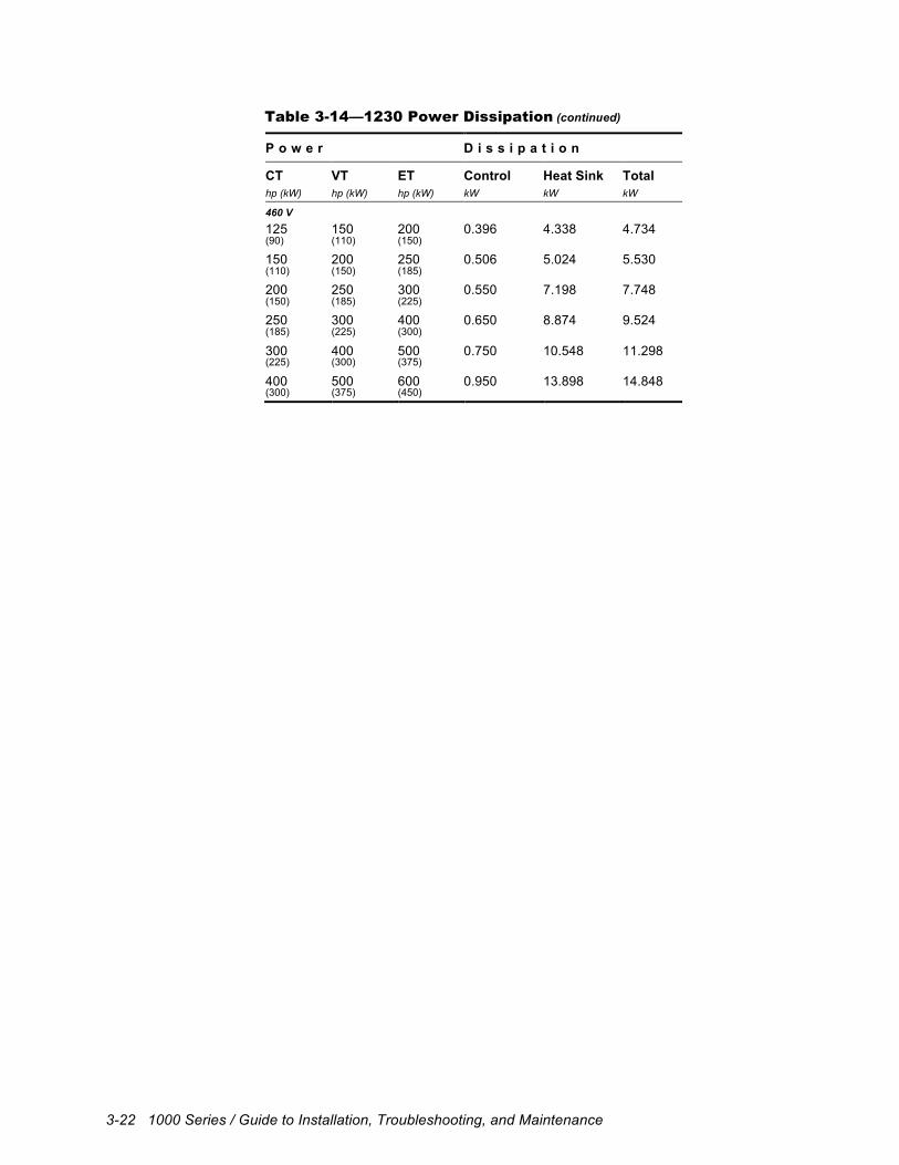
3-22 1000 Series / Guide to Installation, Troubleshooting, and Maintenance
Table 3-14—1230 Power Dissipation (continued)
P o w e r D i s s i p a t i o n
CT VT ET Control Heat Sink Total hp (kW) hp (kW) hp (kW) kW kW kW
460 V 125 150 200 0.396 4.338 4.734 (90) (110) (150)
150 200 250 0.506 5.024 5.530 (110) (150) (185)
200 250 300 0.550 7.198 7.748 (150) (185) (225)
250 300 400 0.650 8.874 9.524 (185) (225) (300)
300 400 500 0.750 10.548 11.298 (225) (300) (375)
400 500 600 0.950 13.898 14.848 (300) (375) (450)
Electrical Installation 4-1
4 Electrical Installation
4.1 Overview This chapter explains the electrical installation of the drive. It covers grounding, input power, motor output, dynamic braking, bus connections, and basic control connections. Since control signals vary from application to application, specific wiring instructions are discussed in the application documentation.
4.2 Wiring Requirements Follow the instructions below to ensure safe, reliable electrical connections.
4.2.1 Standards and Codes All wiring must conform to applicable local and national codes.
!
Attention The supplier cannot assume responsibility for compliance or noncompliance to any code governing the proper installation of this unit. The following information is intended only as a guide for proper installation. All wiring must conform to the National Electrical Code (NEC), described in publication NFPA No. 70. Local codes may overrule this information.
4.2.2 Conductors
Size conductors according to the National Electrical Code (NEC) based upon the required current-carrying capacity. All wires should be stranded copper with a rating of 167° F (75° C) or higher. Wires terminating in terminal blocks must meet the gauge limitations of the terminal as well. Acceptable wire sizes for ground and power connection terminals are specified in Table 4-4 through Table 4-9 and for control signal connection terminals in Table 4-19. Wires terminating at studs or bolts must use ring lugs to provide a solid connection. Use UL-approved lugs suitable for the currents required. For these connections, Table 4-4 through Table 4-9 list the stud or bolt size rather than the acceptable wire size.
4.2.3 Tightening Torque Tighten connections by applying the recommended tightening torque listed in Table 4-4 through Table 4-10 (for ground and power connections) and in Table 4-19 and (for control signal connections). Use a torque wrench to ensure that connections are properly tightened.
4-2 1000 Series / Guide to Installation, Troubleshooting, and Maintenance
4.3 Insulation Tests Any site insulation tests must be performed before making electrical connections to the drive. These tests should conform to all applicable national and local codes. A suggested procedure for checking installation insulation is outlined below.
!
Attention Before performing the insulation tests, make certain that the drive is disconnected from the input power (S, T or R, S, T or R1, R2, S1, S2, T1, T2). Also verify that the motor cable is disconnected from drive output terminals (U, V, W) and from the motor.
• Measure the insulation resistance of the motor between the phases and between
each phase and protective ground. The voltage range of the meter must be at least equal to the line voltage but not higher than 1,000 V. The insulation resistance must be greater than 1 MΩ.
• Measure the insulation resistance of the motor cable between the phases and between each phase and protective ground. The insulation resistance must be greater than 1 MΩ.
4.4 Ground Connections
Proper grounding procedures are essential to the safe, successful operation of the drive. Careful attention to these procedures can prevent electrical noise from disrupting drive operation. The drive, power supply, motor, and control circuits should all share a common earth ground. Refer to the appropriate connection diagram as listed in Table 4-1 below. Refer to Section 4.2 for wiring requirements. Ground connection terminal specifications for the various drives are provided in the tables summarized in Table 4-1.
PE
Ground terminal designation Ground terminals are designated by the IEC symbol at left, by PE (protective earth), or both. Such terminals are internally connected and tied to the chassis or enclosure. They are intended for connecting both the protective earth ground electrode as well as any external protective grounding conductors.
Table 4-1—Power/Ground Connection Tables
Drive Connection Diagram
Terminal Specifications
1100 Figure 4-1 Table 4-4
1105 Figure 4-2 Table 4-5
1110 Figure 4-4 Table 4-6
1120 Figure 4-5 Table 4-7
1130 Figure 4-6 Table 4-8
1200 Figure 4-7 Table 4-9
1230 Figure 4-8 Table 4-10
Electrical Installation 4-3
4.4.1 Ground the drive
The ground terminals (PE) of the drive should be connected to either a grounding electrode buried in the earth or a suitable plant ground with a solid connection to earth ground. The ground connector should be an electrode conductor or bonding jumper of sufficient capacity. Refer to Publication NFPA No. 70, Article 250, and to the IEEE “greenbook” for details on grounding and grounding electrodes.
4.4.2 Ground the Power Supply The incoming power supply must be earth grounded for ground fault protection.
4.4.3 Ground the Motor and Transducer The motor case and encoder or resolver case, if present, must also be earth grounded. To minimize electrical noise emissions, it is recommended that a ground lead from the motor case return with the motor stator leads to the drive ground terminals.
4.4.4 Connect the Control Grounds Connect the logic commons of the various low-voltage control circuits and any external control circuits to the drive ground.
4.5 Input Power Supply The 1100, 1105, 1110, 1130, 1200, and 1230 drives must be connected to the input power supply. Fuses or a circuit breaker must be used to protect the unit from short circuits. A line reactor or isolation transformer may also be necessary to condition the power source.
!
Attention • Do not supply input voltages higher than that specified. Higher input
voltages may damage the drive. • Input power (S, T or R, S, T or R1, R2, S1, S2, T1, T2) should be
able to supply at least 1.5 times the inverter capacity. • Do not connect supply input voltage (S, T or R, S, T or R1, R2, S1,
S2, T1, T2) to output terminals (U, V, W). • Do not use power factor correction capacitors on the input or the
output. • Do not run or stop the inverter by applying and removing power. Use
only the keypad, digital inputs, or serial commands to operate the drive.
• Do not perform the Megger test.
!
Attention The drive is not equipped with a supply-disconnecting device. An external supply-disconnecting device must be provided to isolate incoming electrical supplies during installation and maintenance work. This supply-disconnect-ing device should comply with all applicable national and local codes.
4-4 1000 Series / Guide to Installation, Troubleshooting, and Maintenance
!
Attention High voltage may be present even when all electrical power supplies are disconnected. After switching off electrical power, wait at least 15 minutes for bus circuit capacitors to discharge before working on the drive or associated equipment. Use an appropriate voltmeter to further verify that capacitors are discharged before beginning work. Do not rely exclusively on the bus voltage indicator. Dangerous voltage levels may remain even when the indicator is off.
4.5.1 Power Source Conditioning The use of an AC line reactor and/or isolation transformer is recommended under certain circumstances. The drive is designed for direct connection to AC lines of the correct voltage and impedance. Use the guidelines that follow to determine whether an isolation transformer or line reactor is required. Refer to Table 4-13 for isolation transformer sizing specifications and to Table 4-14 through Table 4-16 for line reactor sizing specifications for three-phase connections. When using a single-phase input, select a line reactor based upon the input current requirements of the 1110 drive as specified in Table 4-12. You may purchase isolation transformers and line reactors directly from Unico. Contact the factory for more information. Impedance mismatch Input lines must have a minimum impedance of 1% relative to the rated input kVA of the drive (assume the drive’s horsepower rating is approximately equal to its kVA rating). If the line has a lower impedance, a line reactor or isolation transformer must be added ahead of the drive to increase line impedance. If line impedance is too low, transient voltage spikes or interruptions can create excessive current spikes that may cause nuisance input fuse blowing and may damage the drive. Generally, if the kVA capacity of the AC line is greater than four times the rated power of the motor (in horsepower), an isolation transformer or AC line reactor should be used. No neutral or referenced phase If the AC input power system does not have a neutral or one phase referenced to ground, an isolation transformer with the neutral of the secondary grounded is highly recommended. If the line-to-ground voltages on any phase exceed 125% of the nominal line-to-line voltage, an isolation transformer with the neutral of the secondary grounded is always required. Transient power interruptions or voltage spikes If the AC line frequency experiences transient power interruptions or significant voltage spikes, an isolation transformer or AC line reactor must be installed. The drive can be damaged by extreme voltage and current spikes. Power factor correction capacitors If the AC line supplying the drive has power factor correction capacitors that are switched in and out, an isolation transformer or AC line reactor must be installed between the drive and the capacitors. The drive can be damaged by the extreme voltage and current spikes caused by capacitor switching. If the capacitors are permanently connected and not switched, the guideline for impedance mismatch applies.
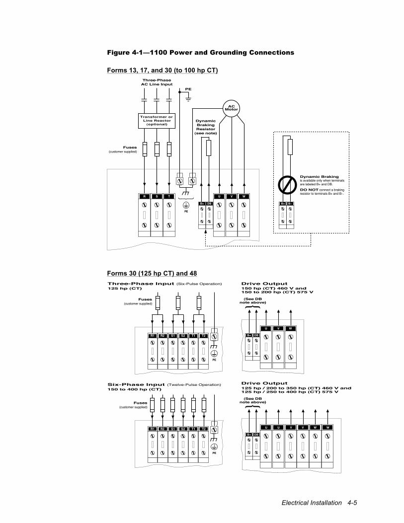
Electrical Installation 4-5
Figure 4-1—1100 Power and Grounding Connections
Forms 13, 17, and 30 (to 100 hp CT)
Three-PhaseAC Line Input
PE
DynamicBrakingResistor
(see note)
VU WSR T
ACMotor
Fuses(customer supplied)
B+ DB
(optional)
Transformer orLine Reactor
PE
Dynamic Braking is available only when terminals are labeled B+ and DB.
DO NOT connect a braking resistor to terminals B+ and B–.
B+ B–
Forms 30 (125 hp CT) and 48
150 to 400 hp (CT)
S2 T1 T2R1 R2 S1
Six-Phase Input (Twelve-Pulse Operation)
Fuses(customer supplied)
PE
125 hp (CT)
T2
Fuses(customer supplied)
S2 T1R1 R2 S1
Three-Phase Input (Six-Pulse Operation)
PE
U V W
150 hp (CT) 460 V and150 to 200 hp (CT) 575 V
U U V V W W
125 hp / 200 to 350 hp (CT) 460 V and125 hp / 250 to 400 hp (CT) 575 V
Drive Output
Drive Output
(See DBnote above)
B+ DB
B+ DB
(See DBnote above)
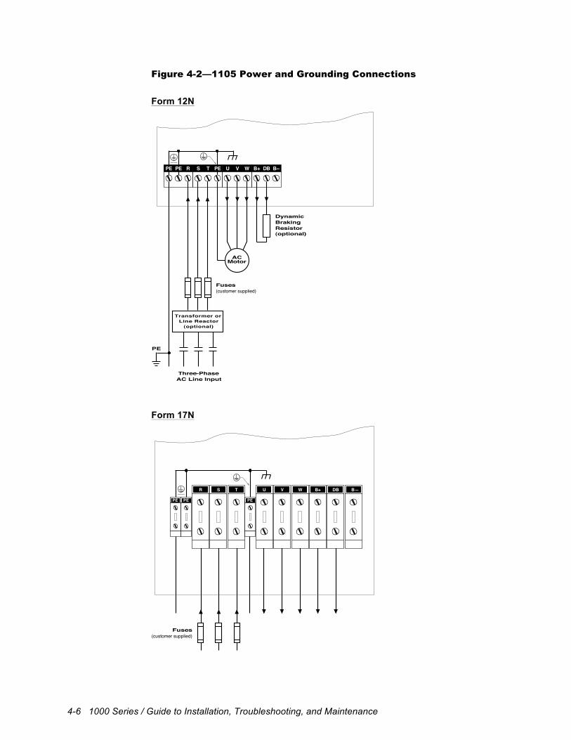
4-6 1000 Series / Guide to Installation, Troubleshooting, and Maintenance
Figure 4-2—1105 Power and Grounding Connections
Form 12N
Three-PhaseAC Line Input
DynamicBrakingResistor
Transformer orLine Reactor
(optional)
Fuses(customer supplied)
(optional)
ACMotor
PE
PE PE R S T PE U V W B+ DB B–
Form 17N
SR T VU W DBB+ B—
PE PEPE
Fuses(customer supplied)
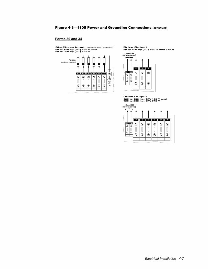
Electrical Installation 4-7
Figure 4-3—1105 Power and Grounding Connections (continued)
Forms 30 and 34
50 to 150 hp (CT) 460 V and50 to 200 hp (CT) 575 V
S2 T1 T2R1 R2 S1
Six-Phase Input (Twelve-Pulse Operation)
Fuses(customer supplied)
PE
U V W
50 to 100 hp (CT) 460 V and 575 V
U U V V W W
125 to 150 hp (CT) 460 V and125 to 200 hp (CT) 575 V
Drive Output
Drive Output
(See DBnote above)
B+ DB
B+ DB
(See DBnote above)
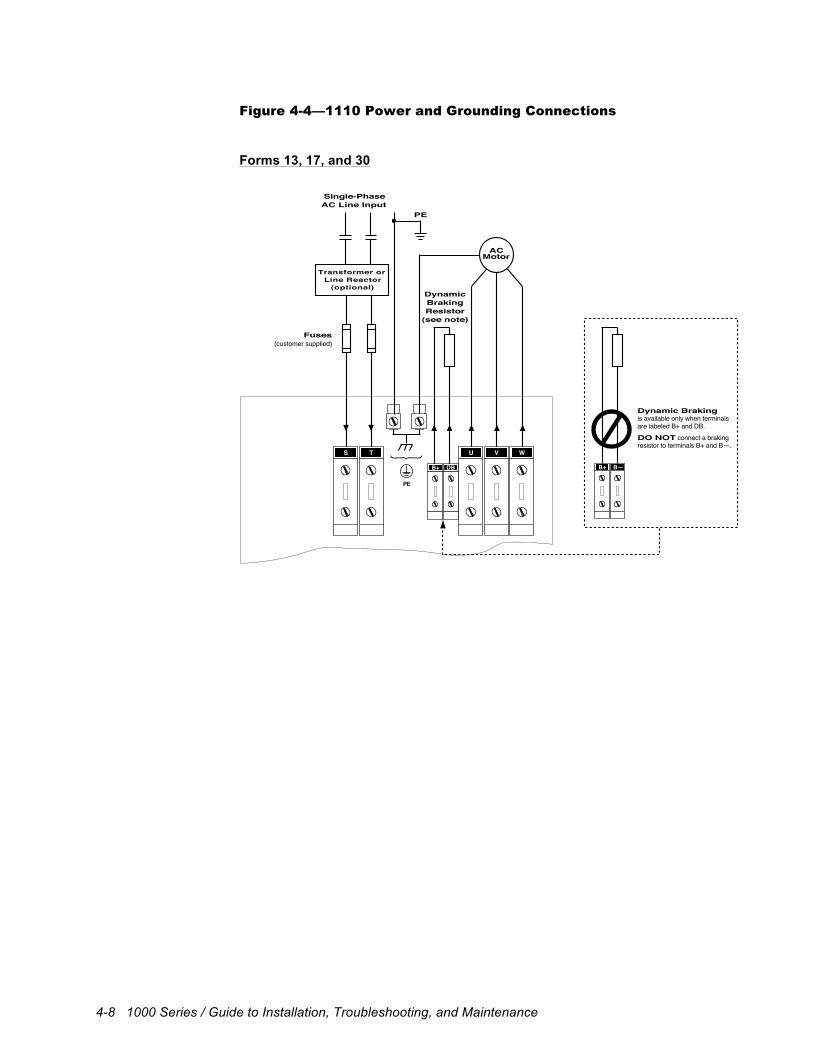
4-8 1000 Series / Guide to Installation, Troubleshooting, and Maintenance
Figure 4-4—1110 Power and Grounding Connections
Forms 13, 17, and 30
Single-PhaseAC Line Input
PE
DynamicBrakingResistor
(see note)
VU WS T
ACMotor
Fuses(customer supplied)
B+ DB
Transformer orLine Reactor
(optional)
PE
Dynamic Brakingis available only when terminalsare labeled B+ and DB.DO NOT connect a brakingresistor to terminals B+ and B—.
B+ B—
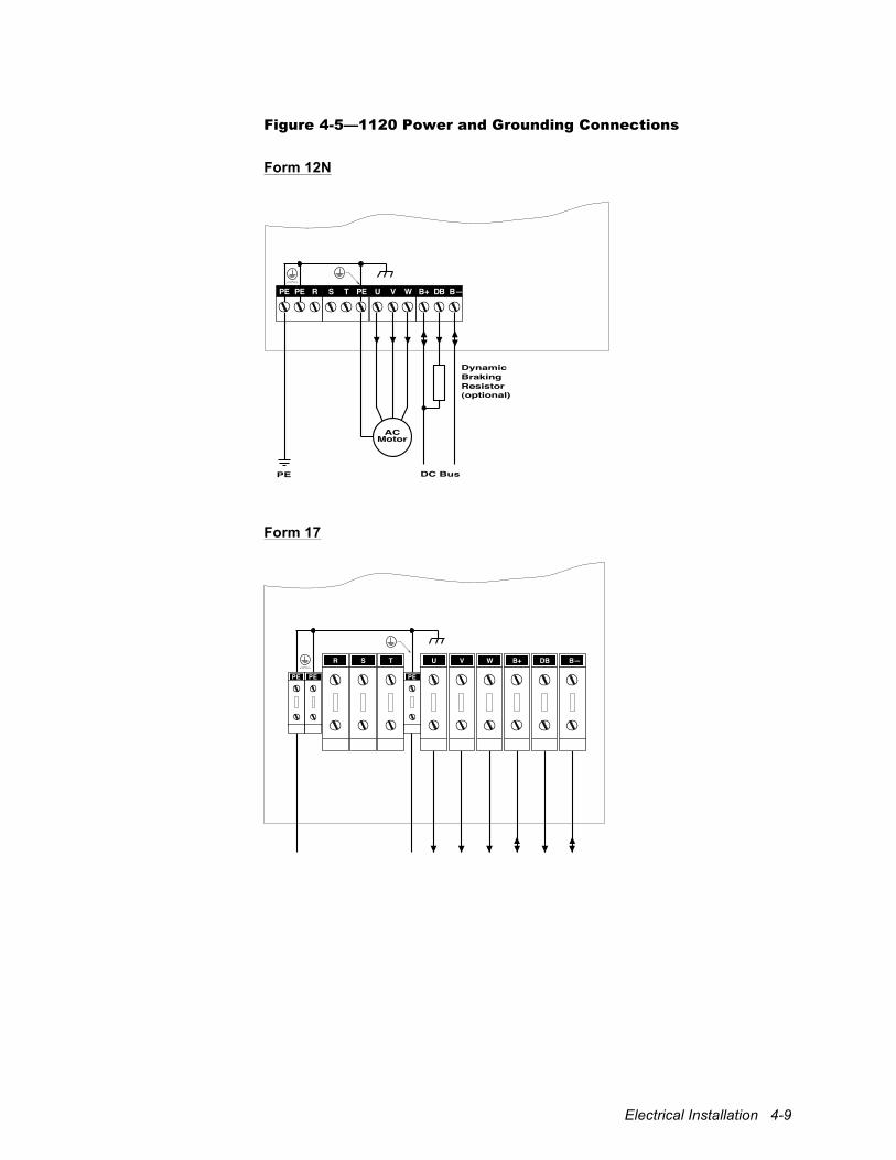
Electrical Installation 4-9
Figure 4-5—1120 Power and Grounding Connections
Form 12N
DynamicBrakingResistor(optional)
ACMotor
PE DC Bus
PE PE R S T PE U V W B+ DB B—
Form 17
SR T VU W DBB+ B—
PE PEPE
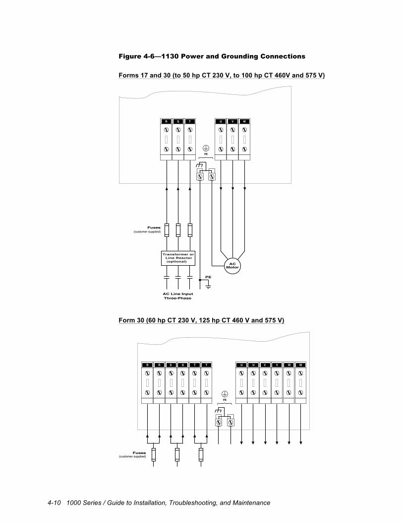
4-10 1000 Series / Guide to Installation, Troubleshooting, and Maintenance
Figure 4-6—1130 Power and Grounding Connections
Forms 17 and 30 (to 50 hp CT 230 V, to 100 hp CT 460V and 575 V)
PE
Three-PhaseAC Line Input
Transformer orLine Reactor(optional)
Fuses(customer supplied)
ACMotor
VU WSR T
PE
Form 30 (60 hp CT 230 V, 125 hp CT 460 V and 575 V)
Fuses(customer supplied)
UU V WV WTS TRR S
PE
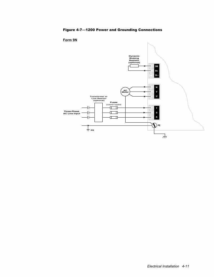
Electrical Installation 4-11
Figure 4-7—1200 Power and Grounding Connections
Form 9N
Three-PhaseAC Line Input
DynamicBrakingResistor
Transformer orLine Reactor
(optional)Fuses
(customer supplied)
(optional)
PE
DB
B+
B—
W
V
U
T
PE
S
R
ACMotor
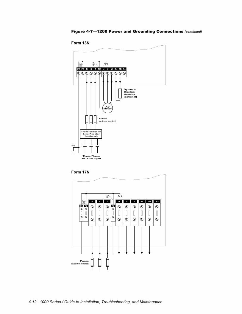
4-12 1000 Series / Guide to Installation, Troubleshooting, and Maintenance
Figure 4-7—1200 Power and Grounding Connections (continued)
Form 13N
Three-PhaseAC Line Input
DynamicBrakingResistor
Transformer orLine Reactor
(optional)
Fuses(customer supplied)
(optional)
ACMotor
PE
PE PE R S T PE U V W B+ DB B–
Form 17N
SR T VU W DBB+ B—
PE PEPE
Fuses(customer supplied)
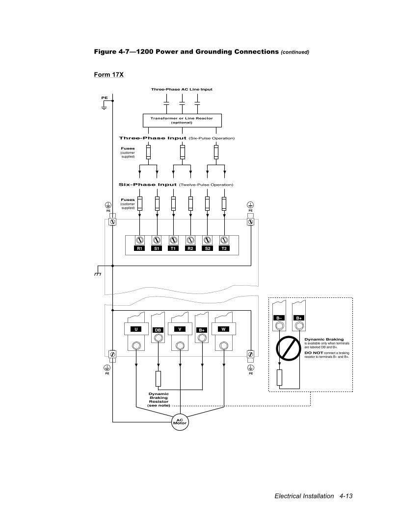
Electrical Installation 4-13
Figure 4-7—1200 Power and Grounding Connections (continued)
Form 17X
Three-Phase AC Line Input
Transformer or Line Reactor(optional)
PE
PE PE
PE
DynamicBrakingResistor
(see note)
ACMotor
Dynamic Brakingis available only when terminalsare labeled DB and B+.
DO NOT connect a brakingresistor to terminals B– and B+.
PE
T2R2 S2S1R1 T1
Fuses(customersupplied)
Fuses(customersupplied)
Six-Phase Input (Twelve-Pulse Operation)
Three-Phase Input (Six-Pulse Operation)
U VDB B+ W
B– B+
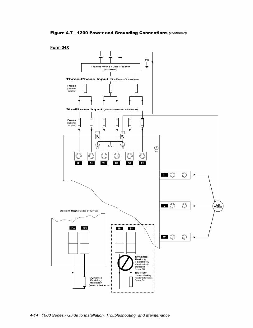
4-14 1000 Series / Guide to Installation, Troubleshooting, and Maintenance
Figure 4-7—1200 Power and Grounding Connections (continued)
Form 34X
Bottom Right Side of Drive
Transformer or Line Reactor(optional)
Fuses(customersupplied)
Fuses(customersupplied)
Six-Phase Input (Twelve-Pulse Operation)
Three-Phase Input (Six-Pulse Operation)
PE
PE
W
ACMotor
PEPE
DynamicBrakingis available onlywhen terminalsare labeledB+ and DB.
DO NOTconnect a brakingresistor to terminalsB+ and B–.
DynamicBrakingResistor
(see note)
T2
U
V
W
R2 S2S1R1
B+ DB B+ B–
T1
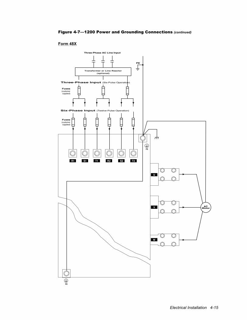
Electrical Installation 4-15
Figure 4-7—1200 Power and Grounding Connections (continued)
Form 48X
Three-Phase AC Line Input
Transformer or Line Reactor(optional)
Fuses(customersupplied)
Fuses(customersupplied)
Six-Phase Input (Twelve-Pulse Operation)
Three-Phase Input (Six-Pulse Operation)
PE
PE
PE
ACMotor
T2R2 S2S1R1 T1
U
V
W
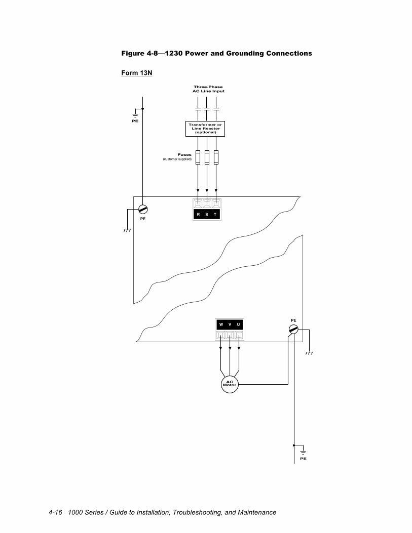
4-16 1000 Series / Guide to Installation, Troubleshooting, and Maintenance
Figure 4-8—1230 Power and Grounding Connections
Form 13N
PE
W V UPE
ACMotor
Three-PhaseAC Line Input
Transformer orLine Reactor
(optional)
Fuses(customer supplied)
PE
TSRPE
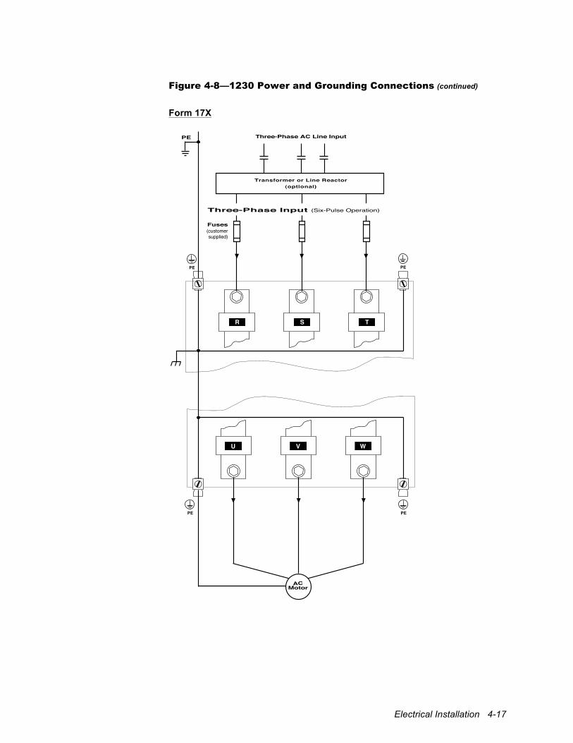
Electrical Installation 4-17
Figure 4-8—1230 Power and Grounding Connections (continued)
Form 17X
Three-Phase AC Line Input
PE
PE PE
PE
ACMotor
PE
Fuses(customer
supplied)
U V W
TSR
Three-Phase Input (Six-Pulse Operation)
Transformer or Line Reactor(optional)
4-18 1000 Series / Guide to Installation, Troubleshooting, and Maintenance
4.5.2 Connect the Power Supply Connect the line power supply leads to the 1100, 1105, 1110, 1130, 1200, and 1230 drives using the appropriate connection diagram as listed in Table 4-1. Depending upon the drive model and its power rating, the drive may accept either a single-phase (S, T), a three-phase (R, S, T), or a six-phase (R1, R2, S1, S2, T1, T2) input. If six-phase (12-pulse) operation is unnecessary, six-phase drives may also be configured for three-phase (six-pulse) operation. Refer to the appropriate connection diagram as listed in Table 4-1. Input connection terminal specifications for the various drives are provided in the tables summarized in Table 4-1. Large drives use double terminals (indicated by x2) to accommodate the maximum required currents. High-power drive sizes provide for optional six-phase (12-pulse) connection and, therefore, also have double terminals (indicated x2). Refer to Section 4.2 for wiring requirements. The inverter is phase-sequence insensitive, so the input leads may be connected in any order. Make certain that AC power inputs are routed separately from control signals.
4.5.3 Input Protection The 1100, 1105, 1110, 1130, 1200, and 1230 drives must be protected from short circuits using either a circuit breaker or fusing. Fuses are not supplied with the unit and must be provided externally. Fuse recommendations and specifications are provided in Table 4-11 (1100, 1105, 1130, 1200, and 1230 drives) and Table 4-12 (1110 drives). Select fuses according to the power of the application, not necessarily according to the drive rating. For example, a drive rated 40 hp CT can also be applied at 50 hp VT or 60 hp ET, depending upon the overload requirements of the application. The nominal ratings of the drive can be found on the rating label. Fuse recommendations differ for single-, three-, and six-phase configurations. The recommended fuse ratings for the six-phase (twelve-pulse) connections are 60% of those listed for the three-phase (six-pulse) connection in Table 4-11. Fuses from other manufacturers may be used as long as they meet the specifications given. Semiconductor fuses provide the highest level of protection and are recommended. UL-listed drives must use UL-recognized fuses under category JFHR2. For help in locating additional UL-recognized fuse manufacturers, please contact the factory. If a circuit breaker is to be used, refer to Table 4-11 (1100, 1105, 1130, 1200, and 1230 drives) or Table 4-12 (1110 drives) to determine the proper current rating using the input current and applying a margin of approximately 33%. You may purchase a circuit breaker directly from Unico. Contact the factory directly for more information.
4.6 Connect the Motor Connect the motor leads using the appropriate connection diagram as listed in Table 4-1. Motor output terminal specifications for the various drives are provided in the tables summarized in Table 4-1. High-power drives have two terminals per motor phase (indicated x2) to provide for convenient wire gauges. Refer to Section 4.2 for wiring requirements. Use of a metal-jacketed motor cable is recommended to minimize noise emissions. Refer to Table 2-13 to determine the output current rating of the drive. If the motor has a transducer, the motor leads may be connected in any order and the drive will determine the correct phasing accordingly. If the motor does not have a
Electrical Installation 4-19
transducer, you may have to rephase it during start-up. Refer to the application documentation for further information. High-frequency voltage switching on these connections necessitates care to minimize electrical noise interference. Make certain that motor outputs are routed separately from control signals and AC input power and that control signals are appropriately shielded.
4.7 Connect the Dynamic Braking Resistor Dynamic braking control for use with an external resistor is included on Form 12N and 17N 1105 drives, on all 1120 drives, and on Form 9N and 13N 1200 drives. It is optionally available on other 1105 drives, on Form 17X and 34X 1200 drives, and on all 1100 and 1110 drives. Drives with optional braking control have terminals labeled B+ and DB. Units having only B+ and B– with no DB terminal do not feature dynamic braking. Connect the braking resistor to the B+ and DB terminals using the appropriate connection diagram as listed in Table 4-1. Dynamic braking terminal specifications for the various drives are provided in the tables summarized in Table 4-1. Refer to Section 4.2 for wiring requirements. Dynamic braking resistors are available from the factory or you may supply your own. Resistors are sized to give a braking torque of either 100% of rated constant torque with integral control or 100%, 150%, or 200% of rated constant torque with optional control. Resistors with a capacity of 5%, 10%, or 20% of the associated drive constant-torque power rating. Consult the factory for other combinations. If providing your own resistor, size it according to Table 4-17, which lists recommended values for providing a braking torque of 100% of rated constant torque with integral braking control and 150% with optional braking control. Make certain braking resistors provide at least the minimum resistance specified in Table 4-18 to accommodate braking device current limitations. Consult the factory for sizing assistance.
!
Attention The braking resistor should be mounted in a well-ventilated area. Avoid placing it in a location where heat could cause injury or property damage. The resistor should be housed in a metal enclosure to shield neighboring equipment from electromagnetic emissions. If it is mounted outside of the enclosure, a guard should be constructed to prevent accidental contact.
!
Attention Do not connect any kind of power supply to the dynamic braking resistor terminals. Do not connect a resistor rated less than specified.
4-20 1000 Series / Guide to Installation, Troubleshooting, and Maintenance
4.8 Bus Connections The drive bus can be connected externally for sharing energy between units or for storing energy in a capacitor bank. Bus connections are available on 1100 and 1110 drives without optional braking control, on low-power 1105 drives and higher-power 1105 drives without braking control, and on all 1120, 1130 drives, and 1200 drives. Units having bus connections provide terminals labeled B+ and B–. Connect the B+ and B– terminals of the 1120 drive to the common DC bus using the appropriate connection diagram as listed in Table 4-1. Bus terminal specifications for the 1120 drive are provided in the tables summarized in Table 4-1. Use the bus current information listed in Table 4-3 to determine proper wire sizing. Nominal bus voltages are provided in Table 4-2. Refer to Section 4.2 for wiring requirements.
!
Attention High voltage may be present even when all electrical power supplies are disconnected. After switching off electrical power, wait at least 15 minutes for bus circuit capacitors to discharge before working on the drive or associated equipment. Use an appropriate voltmeter to further verify that capacitors are discharged before beginning work. Do not rely exclusively on the bus voltage indicator. Dangerous voltage levels may remain even when the indicator is off.
4.8.1 Common-Bus Operation The buses of multiple drives can be interconnected in certain applications to enable motoring and braking energies to circulate between units. The 1120 drive is intended for multidrive operation from a common bus. Consult the factory for assistance in using a common-bus connection with other drives. Table 4-2—Nominal Bus Voltages
Input Power Bus Voltage
230 V AC 311 V DC
380 V AC 513 V DC
460 V AC 621 V DC
575 V AC 776 V DC
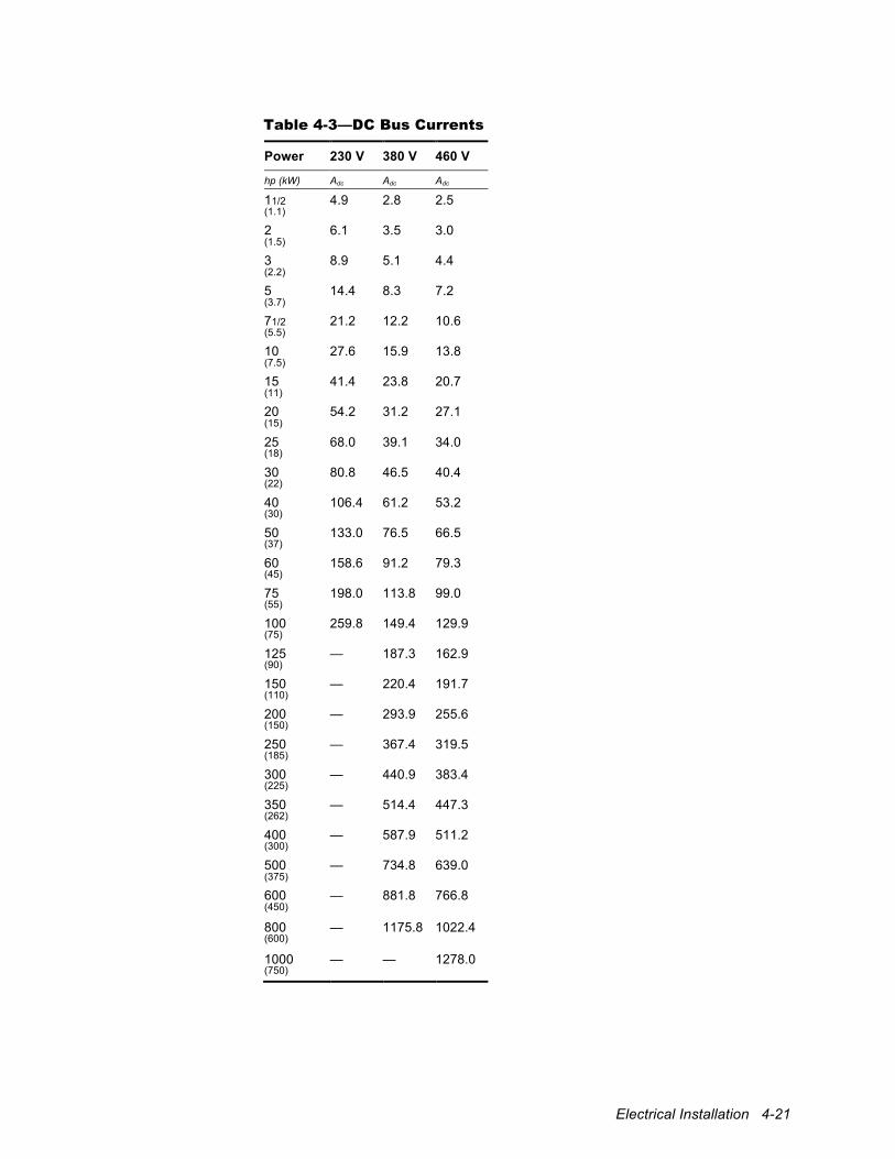
Electrical Installation 4-21
Table 4-3—DC Bus Currents
Power 230 V 380 V 460 V
hp (kW) Adc Adc Adc
11/2 4.9 2.8 2.5 (1.1)
2 6.1 3.5 3.0 (1.5)
3 8.9 5.1 4.4 (2.2)
5 14.4 8.3 7.2 (3.7)
71/2 21.2 12.2 10.6 (5.5)
10 27.6 15.9 13.8 (7.5)
15 41.4 23.8 20.7 (11)
20 54.2 31.2 27.1 (15)
25 68.0 39.1 34.0 (18)
30 80.8 46.5 40.4 (22)
40 106.4 61.2 53.2 (30)
50 133.0 76.5 66.5 (37)
60 158.6 91.2 79.3 (45)
75 198.0 113.8 99.0 (55)
100 259.8 149.4 129.9 (75)
125 — 187.3 162.9 (90)
150 — 220.4 191.7 (110)
200 — 293.9 255.6 (150)
250 — 367.4 319.5 (185)
300 — 440.9 383.4 (225)
350 — 514.4 447.3 (262)
400 — 587.9 511.2 (300)
500 — 734.8 639.0 (375)
600 — 881.8 766.8 (450)
800 — 1175.8 1022.4 (600)
1000 — — 1278.0 (750)
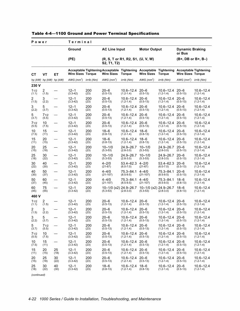
4-22 1000 Series / Guide to Installation, Troubleshooting, and Maintenance
Table 4-4—1100 Ground and Power Terminal Specifications
P o w e r T e r m i n a l
Ground AC Line Input Motor Output Dynamic Braking or Bus
(PE) (R, S, T or R1, R2, S1, S2, T1, T2)
(U, V, W) (B+, DB or B+, B–)
CT
VT
ET
Acceptable Wire Sizes
Tightening Torque
Acceptable Wire Sizes
Tightening Torque
Acceptable Wire Sizes
Tightening Torque
Acceptable Wire Sizes
Tightening Torque
hp (kW) hp (kW) hp (kW) AWG (mm2) in•lb (Nm) AWG (mm2) in•lb (Nm) AWG (mm2) in•lb (Nm) AWG (mm2) in•lb (Nm)
230 V 11/2 2 — 12–1 200 20–6 10.6–12.4 20–6 10.6–12.4 20–6 10.6–12.4 (1.1) (1.5) (3.3-42) (23) (0.5-13) (1.2-1.4) (0.5-13) (1.2-1.4) (0.5-13) (1.2-1.4)
2 3 — 12–1 200 20–6 10.6–12.4 20–6 10.6–12.4 20–6 10.6–12.4 (1.5) (2.2) (3.3-42) (23) (0.5-13) (1.2-1.4) (0.5-13) (1.2-1.4) (0.5-13) (1.2-1.4)
3 5 — 12–1 200 20–6 10.6–12.4 20–6 10.6–12.4 20–6 10.6–12.4 (2.2) (3.7) (3.3-42) (23) (0.5-13) (1.2-1.4) (0.5-13) (1.2-1.4) (0.5-13) (1.2-1.4)
5 71/2 — 12–1 200 20–6 10.6–12.4 20–6 10.6–12.4 20–6 10.6–12.4 (3.7) (5.5) (3.3-42) (23) (0.5-13) (1.2-1.4) (0.5-13) (1.2-1.4) (0.5-13) (1.2-1.4)
71/2 10 — 12–1 200 20–6 10.6–12.4 20–6 10.6–12.4 20–6 10.6–12.4 (5.5) (7.5) (3.3-42) (23) (0.5-13) (1.2-1.4) (0.5-13) (1.2-1.4) (0.5-13) (1.2-1.4)
10 15 — 12–1 200 18–6 10.6–12.4 18–6 10.6–12.4 20–6 10.6–12.4 (7.5) (11) (3.3-42) (23) (0.8-13) (1.2-1.4) (0.8-13) (1.2-1.4) (0.5-13) (1.2-1.4)
15 20 — 12–1 200 18–6 10.6–12.4 18–6 10.6–12.4 20–6 10.6–12.4 (11) (15) (3.3-42) (23) (0.8-13) (1.2-1.4) (0.8-13) (1.2-1.4) (0.5-13) (1.2-1.4)
20 25 — 12–1 200 10–1/0 24.9–26.7 10–1/0 24.9–26.7 20–6 10.6–12.4 (15) (18) (3.3-42) (23) (5.3-53) (2.8-3.0) (5.3-53) (2.8-3.0) (0.5-13) (1.2-1.4)
25 30 — 12–1 200 10–1/0 24.9–26.7 10–1/0 24.9–26.7 20–6 10.6–12.4 (18) (22) (3.3-42) (23) (5.3-53) (2.8-3.0) (5.3-53) (2.8-3.0) (0.5-13) (1.2-1.4)
30 40 — 12–1 200 4–2/0 53.4–62.3 4–2/0 53.4–62.3 20–6 10.6–12.4 (22) (30) (3.3-42) (23) (21-67) (6.0-7.0) (21-67) (6.0-7.0) (0.5-13) (1.2-1.4)
40 50 — 12–1 200 4–4/0 75.3–84.1 4–4/0 75.3–84.1 20–6 10.6–12.4 (30) (37) (3.3-42) (23) (21-107) (8.5-9.5) (21-107) (8.5-9.5) (0.5-13) (1.2-1.4)
50 60 — 12–1 200 4–4/0 75.3–84.1 4–4/0 75.3–84.1 18–6 10.6–12.4 (37) (45) (3.3-42) (23) (21-107) (8.5-9.5) (21-107) (8.5-9.5) (0.8-13) (1.2-1.4)
60 75 — 12–1 200 10–1/0 (x2) 24.9–26.7 10–1/0 (x2) 24.9–26.7 18–6 10.6–12.4 (45) (55) (3.3-42) (23) (5.3-53) (2.8-3.0) (5.3-53) (2.8-3.0) (0.8-13) (1.2-1.4)
460 V 11/2 2 — 12–1 200 20–6 10.6–12.4 20–6 10.6–12.4 20–6 10.6–12.4 (1.1) (1.5) (3.3-42) (23) (0.5-13) (1.2-1.4) (0.5-13) (1.2-1.4) (0.5-13) (1.2-1.4)
2 3 — 12–1 200 20–6 10.6–12.4 20–6 10.6–12.4 20–6 10.6–12.4 (1.5) (2.2) (3.3-42) (23) (0.5-13) (1.2-1.4) (0.5-13) (1.2-1.4) (0.5-13) (1.2-1.4)
3 5 — 12–1 200 20–6 10.6–12.4 20–6 10.6–12.4 20–6 10.6–12.4 (2.2) (3.7) (3.3-42) (23) (0.5-13) (1.2-1.4) (0.5-13) (1.2-1.4) (0.5-13) (1.2-1.4)
5 71/2 — 12–1 200 20–6 10.6–12.4 20–6 10.6–12.4 20–6 10.6–12.4 (3.7) (5.5) (3.3-42) (23) (0.5-13) (1.2-1.4) (0.5-13) (1.2-1.4) (0.5-13) (1.2-1.4)
71/2 10 — 12–1 200 20–6 10.6–12.4 20–6 10.6–12.4 20–6 10.6–12.4 (5.5) (7.5) (3.3-42) (23) (0.5-13) (1.2-1.4) (0.5-13) (1.2-1.4) (0.5-13) (1.2-1.4)
10 15 — 12–1 200 20–6 10.6–12.4 20–6 10.6–12.4 20–6 10.6–12.4 (7.5) (11) (3.3-42) (23) (0.5-13) (1.2-1.4) (0.5-13) (1.2-1.4) (0.5-13) (1.2-1.4)
15 20 25 12–1 200 20–6 10.6–12.4 20–6 10.6–12.4 20–6 10.6–12.4 (11) (15) (18) (3.3-42) (23) (0.5-13) (1.2-1.4) (0.5-13) (1.2-1.4) (0.5-13) (1.2-1.4)
20 25 30 12–1 200 20–6 10.6–12.4 20–6 10.6–12.4 20–6 10.6–12.4 (15) (18) (22) (3.3-42) (23) (0.5-13) (1.2-1.4) (0.5-13) (1.2-1.4) (0.5-13) (1.2-1.4)
25 30 40 12–1 200 18–6 10.6–12.4 18–6 10.6–12.4 20–6 10.6–12.4 (18) (22) (30) (3.3-42) (23) (0.8-13) (1.2-1.4) (0.8-13) (1.2-1.4) (0.5-13) (1.2-1.4) (continued)
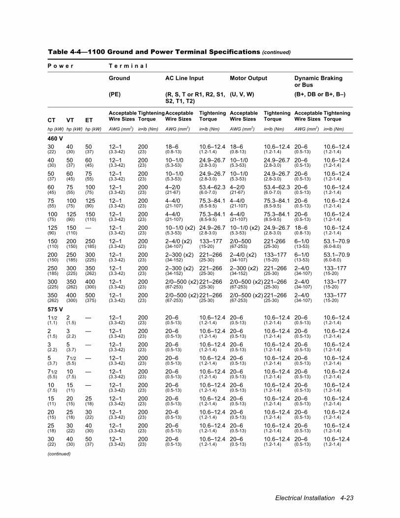
Electrical Installation 4-23
Table 4-4—1100 Ground and Power Terminal Specifications (continued)
P o w e r T e r m i n a l
Ground AC Line Input Motor Output Dynamic Braking or Bus
(PE) (R, S, T or R1, R2, S1, S2, T1, T2)
(U, V, W) (B+, DB or B+, B–)
CT
VT
ET
Acceptable Wire Sizes
Tightening Torque
Acceptable Wire Sizes
Tightening Torque
Acceptable Wire Sizes
Tightening Torque
Acceptable Wire Sizes
Tightening Torque
hp (kW) hp (kW) hp (kW) AWG (mm2) in•lb (Nm) AWG (mm2) in•lb (Nm) AWG (mm2) in•lb (Nm) AWG (mm2) in•lb (Nm)
460 V 30 40 50 12–1 200 18–6 10.6–12.4 18–6 10.6–12.4 20–6 10.6–12.4 (22) (30) (37) (3.3-42) (23) (0.8-13) (1.2-1.4) (0.8-13) (1.2-1.4) (0.5-13) (1.2-1.4)
40 50 60 12–1 200 10–1/0 24.9–26.7 10–1/0 24.9–26.7 20–6 10.6–12.4 (30) (37) (45) (3.3-42) (23) (5.3-53) (2.8-3.0) (5.3-53) (2.8-3.0) (0.5-13) (1.2-1.4)
50 60 75 12–1 200 10–1/0 24.9–26.7 10–1/0 24.9–26.7 20–6 10.6–12.4 (37) (45) (55) (3.3-42) (23) (5.3-53) (2.8-3.0) (5.3-53) (2.8-3.0) (0.5-13) (1.2-1.4)
60 75 100 12–1 200 4–2/0 53.4–62.3 4–2/0 53.4–62.3 20–6 10.6–12.4 (45) (55) (75) (3.3-42) (23) (21-67) (6.0-7.0) (21-67) (6.0-7.0) (0.5-13) (1.2-1.4)
75 100 125 12–1 200 4–4/0 75.3–84.1 4–4/0 75.3–84.1 20–6 10.6–12.4 (55) (75) (90) (3.3-42) (23) (21-107) (8.5-9.5) (21-107) (8.5-9.5) (0.5-13) (1.2-1.4)
100 125 150 12–1 200 4–4/0 75.3–84.1 4–4/0 75.3–84.1 20–6 10.6–12.4 (75) (90) (110) (3.3-42) (23) (21-107) (8.5-9.5) (21-107) (8.5-9.5) (0.5-13) (1.2-1.4)
125 150 — 12–1 200 10–1/0 (x2) 24.9–26.7 10–1/0 (x2) 24.9–26.7 18–6 10.6–12.4 (90) (110) (3.3-42) (23) (5.3-53) (2.8-3.0) (5.3-53) (2.8-3.0) (0.8-13) (1.2-1.4)
150 200 250 12–1 200 2–4/0 (x2) 133–177 2/0–500 221-266 6–1/0 53.1–70.9 (110) (150) (185) (3.3-42) (23) (34-107) (15-20) (67-253) (25-30) (13-53) (6.0-8.0)
200 250 300 12–1 200 2–300 (x2) 221–266 2–4/0 (x2) 133–177 6–1/0 53.1–70.9 (150) (185) (225) (3.3-42) (23) (34-152) (25-30) (34-107) (15-20) (13-53) (6.0-8.0)
250 300 350 12–1 200 2–300 (x2) 221–266 2–300 (x2) 221–266 2–4/0 133–177 (185) (225) (262) (3.3-42) (23) (34-152) (25-30) (34-152) (25-30) (34-107) (15-20)
300 350 400 12–1 200 2/0–500 (x2) 221–266 2/0–500 (x2) 221–266 2–4/0 133–177 (225) (262) (300) (3.3-42) (23) (67-253) (25-30) (67-253) (25-30) (34-107) (15-20)
350 400 500 12–1 200 2/0–500 (x2) 221–266 2/0–500 (x2) 221–266 2–4/0 133–177 (262) (300) (375) (3.3-42) (23) (67-253) (25-30) (67-253) (25-30) (34-107) (15-20)
575 V 11/2 2 — 12–1 200 20–6 10.6–12.4 20–6 10.6–12.4 20–6 10.6–12.4 (1.1) (1.5) (3.3-42) (23) (0.5-13) (1.2-1.4) (0.5-13) (1.2-1.4) (0.5-13) (1.2-1.4)
2 3 — 12–1 200 20–6 10.6–12.4 20–6 10.6–12.4 20–6 10.6–12.4 (1.5) (2.2) (3.3-42) (23) (0.5-13) (1.2-1.4) (0.5-13) (1.2-1.4) (0.5-13) (1.2-1.4)
3 5 — 12–1 200 20–6 10.6–12.4 20–6 10.6–12.4 20–6 10.6–12.4 (2.2) (3.7) (3.3-42) (23) (0.5-13) (1.2-1.4) (0.5-13) (1.2-1.4) (0.5-13) (1.2-1.4)
5 71/2 — 12–1 200 20–6 10.6–12.4 20–6 10.6–12.4 20–6 10.6–12.4 (3.7) (5.5) (3.3-42) (23) (0.5-13) (1.2-1.4) (0.5-13) (1.2-1.4) (0.5-13) (1.2-1.4)
71/2 10 — 12–1 200 20–6 10.6–12.4 20–6 10.6–12.4 20–6 10.6–12.4 (5.5) (7.5) (3.3-42) (23) (0.5-13) (1.2-1.4) (0.5-13) (1.2-1.4) (0.5-13) (1.2-1.4)
10 15 — 12–1 200 20–6 10.6–12.4 20–6 10.6–12.4 20–6 10.6–12.4 (7.5) (11) (3.3-42) (23) (0.5-13) (1.2-1.4) (0.5-13) (1.2-1.4) (0.5-13) (1.2-1.4)
15 20 25 12–1 200 20–6 10.6–12.4 20–6 10.6–12.4 20–6 10.6–12.4 (11) (15) (18) (3.3-42) (23) (0.5-13) (1.2-1.4) (0.5-13) (1.2-1.4) (0.5-13) (1.2-1.4)
20 25 30 12–1 200 20–6 10.6–12.4 20–6 10.6–12.4 20–6 10.6–12.4 (15) (18) (22) (3.3-42) (23) (0.5-13) (1.2-1.4) (0.5-13) (1.2-1.4) (0.5-13) (1.2-1.4)
25 30 40 12–1 200 20–6 10.6–12.4 20–6 10.6–12.4 20–6 10.6–12.4 (18) (22) (30) (3.3-42) (23) (0.5-13) (1.2-1.4) (0.5-13) (1.2-1.4) (0.5-13) (1.2-1.4)
30 40 50 12–1 200 20–6 10.6–12.4 20–6 10.6–12.4 20–6 10.6–12.4 (22) (30) (37) (3.3-42) (23) (0.5-13) (1.2-1.4) (0.5-13) (1.2-1.4) (0.5-13) (1.2-1.4) (continued)
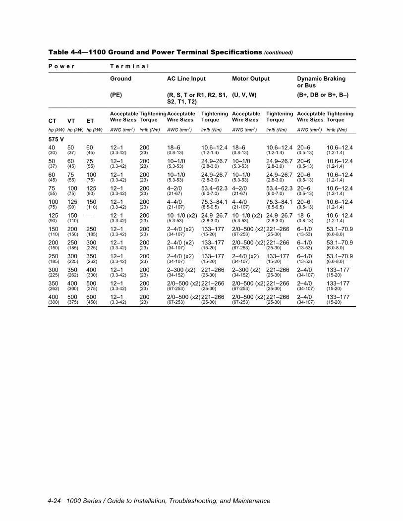
4-24 1000 Series / Guide to Installation, Troubleshooting, and Maintenance
Table 4-4—1100 Ground and Power Terminal Specifications (continued)
P o w e r T e r m i n a l
Ground AC Line Input Motor Output Dynamic Braking or Bus
(PE) (R, S, T or R1, R2, S1, S2, T1, T2)
(U, V, W) (B+, DB or B+, B–)
CT
VT
ET
Acceptable Wire Sizes
Tightening Torque
Acceptable Wire Sizes
Tightening Torque
Acceptable Wire Sizes
Tightening Torque
Acceptable Wire Sizes
Tightening Torque
hp (kW) hp (kW) hp (kW) AWG (mm2) in•lb (Nm) AWG (mm2) in•lb (Nm) AWG (mm2) in•lb (Nm) AWG (mm2) in•lb (Nm)
575 V 40 50 60 12–1 200 18–6 10.6–12.4 18–6 10.6–12.4 20–6 10.6–12.4 (30) (37) (45) (3.3-42) (23) (0.8-13) (1.2-1.4) (0.8-13) (1.2-1.4) (0.5-13) (1.2-1.4)
50 60 75 12–1 200 10–1/0 24.9–26.7 10–1/0 24.9–26.7 20–6 10.6–12.4 (37) (45) (55) (3.3-42) (23) (5.3-53) (2.8-3.0) (5.3-53) (2.8-3.0) (0.5-13) (1.2-1.4)
60 75 100 12–1 200 10–1/0 24.9–26.7 10–1/0 24.9–26.7 20–6 10.6–12.4 (45) (55) (75) (3.3-42) (23) (5.3-53) (2.8-3.0) (5.3-53) (2.8-3.0) (0.5-13) (1.2-1.4)
75 100 125 12–1 200 4–2/0 53.4–62.3 4–2/0 53.4–62.3 20–6 10.6–12.4 (55) (75) (90) (3.3-42) (23) (21-67) (6.0-7.0) (21-67) (6.0-7.0) (0.5-13) (1.2-1.4)
100 125 150 12–1 200 4–4/0 75.3–84.1 4–4/0 75.3–84.1 20–6 10.6–12.4 (75) (90) (110) (3.3-42) (23) (21-107) (8.5-9.5) (21-107) (8.5-9.5) (0.5-13) (1.2-1.4)
125 150 — 12–1 200 10–1/0 (x2) 24.9–26.7 10–1/0 (x2) 24.9–26.7 18–6 10.6–12.4 (90) (110) (3.3-42) (23) (5.3-53) (2.8-3.0) (5.3-53) (2.8-3.0) (0.8-13) (1.2-1.4)
150 200 250 12–1 200 2–4/0 (x2) 133–177 2/0–500 (x2) 221–266 6–1/0 53.1–70.9 (110) (150) (185) (3.3-42) (23) (34-107) (15-20) (67-253) (25-30) (13-53) (6.0-8.0)
200 250 300 12–1 200 2–4/0 (x2) 133–177 2/0–500 (x2) 221–266 6–1/0 53.1–70.9 (150) (185) (225) (3.3-42) (23) (34-107) (15-20) (67-253) (25-30) (13-53) (6.0-8.0)
250 300 350 12–1 200 2–4/0 (x2) 133–177 2–4/0 (x2) 133–177 6–1/0 53.1–70.9 (185) (225) (262) (3.3-42) (23) (34-107) (15-20) (34-107) (15-20) (13-53) (6.0-8.0)
300 350 400 12–1 200 2–300 (x2) 221–266 2–300 (x2) 221–266 2–4/0 133–177 (225) (262) (300) (3.3-42) (23) (34-152) (25-30) (34-152) (25-30) (34-107) (15-20)
350 400 500 12–1 200 2/0–500 (x2) 221–266 2/0–500 (x2) 221–266 2–4/0 133–177 (262) (300) (375) (3.3-42) (23) (67-253) (25-30) (67-253) (25-30) (34-107) (15-20)
400 500 600 12–1 200 2/0–500 (x2) 221–266 2/0–500 (x2) 221–266 2–4/0 133–177 (300) (375) (450) (3.3-42) (23) (67-253) (25-30) (67-253) (25-30) (34-107) (15-20)

Electrical Installation 4-25
Table 4-5—1105 Ground and Power Terminal Specifications
P o w e r T e r m i n a l
Ground AC Line Input Motor Output Dynamic Braking or Bus
(PE, SH) (R, S, T) (U, V, W) (B+, DB, B–)
CT
VT
ET
Acceptable Wire Sizes
Tightening Torque
Acceptable Wire Sizes
Tightening Torque
Acceptable Wire Sizes
Tightening Torque
Acceptable Wire Sizes
Tightening Torque
hp (kW) hp (kW) hp (kW) AWG (mm2) in•lb (Nm) AWG (mm2) in•lb (Nm) AWG (mm2) in•lb (Nm) AWG (mm2) in•lb (Nm)
230 V 11/2 2 — 24–10 4.4–5.3 24–10 4.4–5.3 24–10 4.4–5.3 24–10 4.4–5.3 (1.1) (1.5) (0.2-5.3) (0.5-0.6) (0.2-5.3) (0.5-0.6) (0.2-5.3) (0.5-0.6) (0.2-5.3) (0.5-0.6)
2 3 — 24–10 4.4–5.3 24–10 4.4–5.3 24–10 4.4–5.3 24–10 4.4–5.3 (1.5) (2.2) (0.2-5.3) (0.5-0.6) (0.2-5.3) (0.5-0.6) (0.2-5.3) (0.5-0.6) (0.2-5.3) (0.5-0.6)
3 5 — 24–10 4.4–5.3 24–10 4.4–5.3 24–10 4.4–5.3 24–10 4.4–5.3 (2.2) (3.7) (0.2-5.3) (0.5-0.6) (0.2-5.3) (0.5-0.6) (0.2-5.3) (0.5-0.6) (0.2-5.3) (0.5-0.6)
5 71/2 — 18–4 16 18–4 16 18–4 16 18–4 16 (3.7) (5.5) (0.8-21) (1.8) (0.8-21) (1.8) (0.8-21) (1.8) (0.8-21) (1.8)
71/2 10 — 18–4 16 18–4 16 18–4 16 18–4 16 (5.5) (7.5) (0.8-21) (1.8) (0.8-21) (1.8) (0.8-21) (1.8) (0.8-21) (1.8)
10 15 — 18–4 16 18–4 16 18–4 16 18–4 16 (7.5) (11) (0.8-21) (1.8) (0.8-21) (1.8) (0.8-21) (1.8) (0.8-21) (1.8)
15 20 — 18–4 16 18–4 16 18–4 16 18–4 16 (11) (15) (0.8-21) (1.8) (0.8-21) (1.8) (0.8-21) (1.8) (0.8-21) (1.8)
20 25 — 18–4 16 18–4 16 18–4 16 18–4 16 (15) (18) (0.8-21) (1.8) (0.8-21) (1.8) (0.8-21) (1.8) (0.8-21) (1.8)
460 V 11/2 2 — 24–10 4.4–5.3 24–10 4.4–5.3 24–10 4.4–5.3 24–10 4.4–5.3 (1.1) (1.5) (0.2-5.3) (0.5-0.6) (0.2-5.3) (0.5-0.6) (0.2-5.3) (0.5-0.6) (0.2-5.3) (0.5-0.6)
2 3 — 24–10 4.4–5.3 24–10 4.4–5.3 24–10 4.4–5.3 24–10 4.4–5.3 (1.5) (2.2) (0.2-5.3) (0.5-0.6) (0.2-5.3) (0.5-0.6) (0.2-5.3) (0.5-0.6) (0.2-5.3) (0.5-0.6)
3 5 — 24–10 4.4–5.3 24–10 4.4–5.3 24–10 4.4–5.3 24–10 4.4–5.3 (2.2) (3.7) (0.2-5.3) (0.5-0.6) (0.2-5.3) (0.5-0.6) (0.2-5.3) (0.5-0.6) (0.2-5.3) (0.5-0.6)
5 71/2 10 24–10 4.4–5.3 24–10 4.4–5.3 24–10 4.4–5.3 24–10 4.4–5.3 (3.7) (5.5) (7.5) (0.2-5.3) (0.5-0.6) (0.2-5.3) (0.5-0.6) (0.2-5.3) (0.5-0.6) (0.2-5.3) (0.5-0.6)
71/2 10 15 18–4 16 18–4 16 18–4 16 18–4 16 (5.5) (7.5) (11) (0.8-21) (1.8) (0.8-21) (1.8) (0.8-21) (1.8) (0.8-21) (1.8)
10 15 20 18–4 16 18–4 16 18–4 16 18–4 16 (7.5) (11) (15) (0.8-21) (1.8) (0.8-21) (1.8) (0.8-21) (1.8) (0.8-21) (1.8)
15 20 25 18–4 16 18–4 16 18–4 16 18–4 16 (11) (15) (18) (0.8-21) (1.8) (0.8-21) (1.8) (0.8-21) (1.8) (0.8-21) (1.8)
20 25 30 18–4 16 18–4 16 18–4 16 18–4 16 (15) (18) (22) (0.8-21) (1.8) (0.8-21) (1.8) (0.8-21) (1.8) (0.8-21) (1.8)
25 30 40 20–6 10.6–12.3 20–6 10.6–12.4 20–6 10.6–12.4 20–6 10.6–12.4 (18) (22) (30) (0.5-13) (1.4) (0.5-13) (1.4) (0.5-13) (1.4) (0.5-13) (1.4)
30 40 50 20–6 10.6–12.3 18–6 10.6–12.4 18–6 10.6–12.4 20–6 10.6–12.4 (22) (30) (37) (0.5-13) (1.4) (0.8-13) (1.2-1.4) (0.8-13) (1.2-1.4) (0.5-13) (1.4)
40 50 60 20–6 10.6–12.3 10–1/0 24.9–26.7 10–1/0 24.9–26.7 20–6 10.6–12.4 (30) (37) (45) (0.5-13) (1.4) (5.3-53) (2.8-3.0) (5.3-53) (2.8-3.0) (0.5-13) (1.4)
50 60 75 12–1 200 20–6 (x2) 10.6–12.4 10–1/0 24.9–26.7 20–6 10.6–12.4 (37) (45) (55) (3.3-42) (23) (0.5-13) (1.4) (5.3-53) (2.8-3.0) (0.5-13) (1.4)
60 75 100 12–1 200 18–6 (x2) 10.6–12.4 4–2/0 53.4–62.3 20–6 10.6–12.4 (45) (55) (75) (3.3-42) (23) (0.8-13) (1.2-1.4) (21-67) (6.0-7.0) (0.5-13) (1.4)
75 100 125 12–1 200 10–1/0 (x2) 24.9–26.7 4–4/0 75.3–84.1 20–6 10.6–12.4 (55) (75) (90) (3.3-42) (23) (5.3-53) (2.8-3.0) (21-107) (8.5-9.5) (0.5-13) (1.4) (continued)
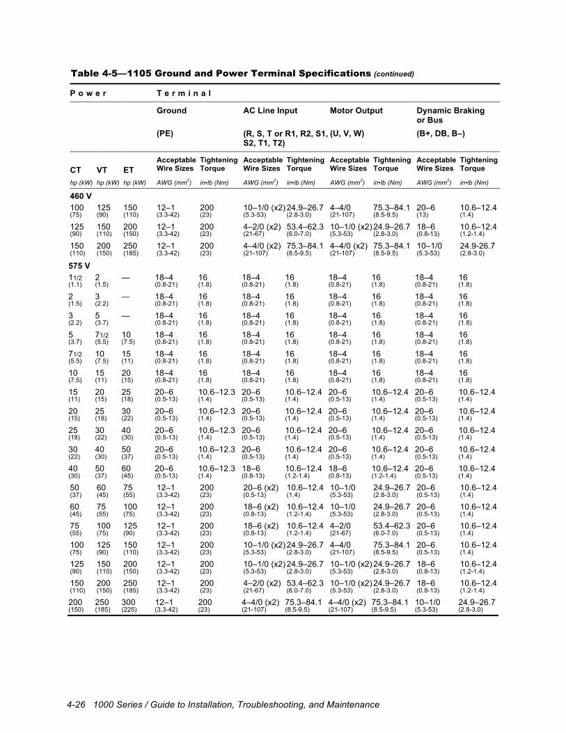
4-26 1000 Series / Guide to Installation, Troubleshooting, and Maintenance
Table 4-5—1105 Ground and Power Terminal Specifications (continued)
P o w e r T e r m i n a l
Ground AC Line Input Motor Output Dynamic Braking or Bus
(PE) (R, S, T or R1, R2, S1, S2, T1, T2)
(U, V, W) (B+, DB, B–)
CT
VT
ET
Acceptable Wire Sizes
Tightening Torque
Acceptable Wire Sizes
Tightening Torque
Acceptable Wire Sizes
Tightening Torque
Acceptable Wire Sizes
Tightening Torque
hp (kW) hp (kW) hp (kW) AWG (mm2) in•lb (Nm) AWG (mm2) in•lb (Nm) AWG (mm2) in•lb (Nm) AWG (mm2) in•lb (Nm)
460 V 100 125 150 12–1 200 10–1/0 (x2) 24.9–26.7 4–4/0 75.3–84.1 20–6 10.6–12.4 (75) (90) (110) (3.3-42) (23) (5.3-53) (2.8-3.0) (21-107) (8.5-9.5) (13) (1.4)
125 150 200 12–1 200 4–2/0 (x2) 53.4–62.3 10–1/0 (x2) 24.9–26.7 18–6 10.6–12.4 (90) (110) (150) (3.3-42) (23) (21-67) (6.0-7.0) (5.3-53) (2.8-3.0) (0.8-13) (1.2-1.4)
150 200 250 12–1 200 4–4/0 (x2) 75.3–84.1 4–4/0 (x2) 75.3–84.1 10–1/0 24.9-26.7 (110) (150) (185) (3.3-42) (23) (21-107) (8.5-9.5) (21-107) (8.5-9.5) (5.3-53) (2.8-3.0)
575 V 11/2 2 — 18–4 16 18–4 16 18–4 16 18–4 16 (1.1) (1.5) (0.8-21) (1.8) (0.8-21) (1.8) (0.8-21) (1.8) (0.8-21) (1.8)
2 3 — 18–4 16 18–4 16 18–4 16 18–4 16 (1.5) (2.2) (0.8-21) (1.8) (0.8-21) (1.8) (0.8-21) (1.8) (0.8-21) (1.8)
3 5 — 18–4 16 18–4 16 18–4 16 18–4 16 (2.2) (3.7) (0.8-21) (1.8) (0.8-21) (1.8) (0.8-21) (1.8) (0.8-21) (1.8)
5 71/2 10 18–4 16 18–4 16 18–4 16 18–4 16 (3.7) (5.5) (7.5) (0.8-21) (1.8) (0.8-21) (1.8) (0.8-21) (1.8) (0.8-21) (1.8)
71/2 10 15 18–4 16 18–4 16 18–4 16 18–4 16 (5.5) (7.5) (11) (0.8-21) (1.8) (0.8-21) (1.8) (0.8-21) (1.8) (0.8-21) (1.8)
10 15 20 18–4 16 18–4 16 18–4 16 18–4 16 (7.5) (11) (15) (0.8-21) (1.8) (0.8-21) (1.8) (0.8-21) (1.8) (0.8-21) (1.8)
15 20 25 20–6 10.6–12.3 20–6 10.6–12.4 20–6 10.6–12.4 20–6 10.6–12.4 (11) (15) (18) (0.5-13) (1.4) (0.5-13) (1.4) (0.5-13) (1.4) (0.5-13) (1.4)
20 25 30 20–6 10.6–12.3 20–6 10.6–12.4 20–6 10.6–12.4 20–6 10.6–12.4 (15) (18) (22) (0.5-13) (1.4) (0.5-13) (1.4) (0.5-13) (1.4) (0.5-13) (1.4)
25 30 40 20–6 10.6–12.3 20–6 10.6–12.4 20–6 10.6–12.4 20–6 10.6–12.4 (18) (22) (30) (0.5-13) (1.4) (0.5-13) (1.4) (0.5-13) (1.4) (0.5-13) (1.4)
30 40 50 20–6 10.6–12.3 20–6 10.6–12.4 20–6 10.6–12.4 20–6 10.6–12.4 (22) (30) (37) (0.5-13) (1.4) (0.5-13) (1.4) (0.5-13) (1.4) (0.5-13) (1.4)
40 50 60 20–6 10.6–12.3 18–6 10.6–12.4 18–6 10.6–12.4 20–6 10.6–12.4 (30) (37) (45) (0.5-13) (1.4) (0.8-13) (1.2-1.4) (0.8-13) (1.2-1.4) (0.5-13) (1.4)
50 60 75 12–1 200 20–6 (x2) 10.6–12.4 10–1/0 24.9–26.7 20–6 10.6–12.4 (37) (45) (55) (3.3-42) (23) (0.5-13) (1.4) (5.3-53) (2.8-3.0) (0.5-13) (1.4)
60 75 100 12–1 200 18–6 (x2) 10.6–12.4 10–1/0 24.9–26.7 20–6 10.6–12.4 (45) (55) (75) (3.3-42) (23) (0.8-13) (1.2-1.4) (5.3-53) (2.8-3.0) (0.5-13) (1.4)
75 100 125 12–1 200 18–6 (x2) 10.6–12.4 4–2/0 53.4–62.3 20–6 10.6–12.4 (55) (75) (90) (3.3-42) (23) (0.8-13) (1.2-1.4) (21-67) (6.0-7.0) (0.5-13) (1.4)
100 125 150 12–1 200 10–1/0 (x2) 24.9–26.7 4–4/0 75.3–84.1 20–6 10.6–12.4 (75) (90) (110) (3.3-42) (23) (5.3-53) (2.8-3.0) (21-107) (8.5-9.5) (0.5-13) (1.4)
125 150 200 12–1 200 10–1/0 (x2) 24.9–26.7 10–1/0 (x2) 24.9–26.7 18–6 10.6–12.4 (90) (110) (150) (3.3-42) (23) (5.3-53) (2.8-3.0) (5.3-53) (2.8-3.0) (0.8-13) (1.2-1.4)
150 200 250 12–1 200 4–2/0 (x2) 53.4–62.3 10–1/0 (x2) 24.9–26.7 18–6 10.6–12.4 (110) (150) (185) (3.3-42) (23) (21-67) (6.0-7.0) (5.3-53) (2.8-3.0) (0.8-13) (1.2-1.4)
200 250 300 12–1 200 4–4/0 (x2) 75.3–84.1 4–4/0 (x2) 75.3–84.1 10–1/0 24.9–26.7 (150) (185) (225) (3.3-42) (23) (21-107) (8.5-9.5) (21-107) (8.5-9.5) (5.3-53) (2.8-3.0)
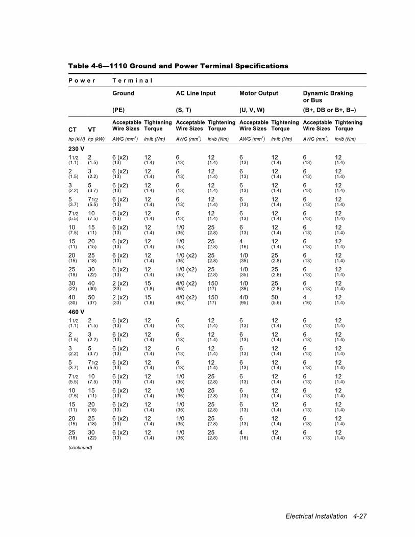
Electrical Installation 4-27
Table 4-6—1110 Ground and Power Terminal Specifications
P o w e r T e r m i n a l
Ground AC Line Input Motor Output Dynamic Braking or Bus
(PE) (S, T) (U, V, W) (B+, DB or B+, B–)
CT
VT
Acceptable Wire Sizes
Tightening Torque
Acceptable Wire Sizes
Tightening Torque
Acceptable Wire Sizes
Tightening Torque
Acceptable Wire Sizes
Tightening Torque
hp (kW) hp (kW) AWG (mm2) in•lb (Nm) AWG (mm2) in•lb (Nm) AWG (mm2) in•lb (Nm) AWG (mm2) in•lb (Nm)
230 V 11/2 2 6 (x2) 12 6 12 6 12 6 12 (1.1) (1.5) (13) (1.4) (13) (1.4) (13) (1.4) (13) (1.4)
2 3 6 (x2) 12 6 12 6 12 6 12 (1.5) (2.2) (13) (1.4) (13) (1.4) (13) (1.4) (13) (1.4)
3 5 6 (x2) 12 6 12 6 12 6 12 (2.2) (3.7) (13) (1.4) (13) (1.4) (13) (1.4) (13) (1.4)
5 71/2 6 (x2) 12 6 12 6 12 6 12 (3.7) (5.5) (13) (1.4) (13) (1.4) (13) (1.4) (13) (1.4)
71/2 10 6 (x2) 12 6 12 6 12 6 12 (5.5) (7.5) (13) (1.4) (13) (1.4) (13) (1.4) (13) (1.4)
10 15 6 (x2) 12 1/0 25 6 12 6 12 (7.5) (11) (13) (1.4) (35) (2.8) (13) (1.4) (13) (1.4)
15 20 6 (x2) 12 1/0 25 4 12 6 12 (11) (15) (13) (1.4) (35) (2.8) (16) (1.4) (13) (1.4)
20 25 6 (x2) 12 1/0 (x2) 25 1/0 25 6 12 (15) (18) (13) (1.4) (35) (2.8) (35) (2.8) (13) (1.4)
25 30 6 (x2) 12 1/0 (x2) 25 1/0 25 6 12 (18) (22) (13) (1.4) (35) (2.8) (35) (2.8) (13) (1.4)
30 40 2 (x2) 15 4/0 (x2) 150 1/0 25 6 12 (22) (30) (33) (1.8) (95) (17) (35) (2.8) (13) (1.4)
40 50 2 (x2) 15 4/0 (x2) 150 4/0 50 4 12 (30) (37) (33) (1.8) (95) (17) (95) (5.6) (16) (1.4)
460 V 11/2 2 6 (x2) 12 6 12 6 12 6 12 (1.1) (1.5) (13) (1.4) (13) (1.4) (13) (1.4) (13) (1.4)
2 3 6 (x2) 12 6 12 6 12 6 12 (1.5) (2.2) (13) (1.4) (13) (1.4) (13) (1.4) (13) (1.4)
3 5 6 (x2) 12 6 12 6 12 6 12 (2.2) (3.7) (13) (1.4) (13) (1.4) (13) (1.4) (13) (1.4)
5 71/2 6 (x2) 12 6 12 6 12 6 12 (3.7) (5.5) (13) (1.4) (13) (1.4) (13) (1.4) (13) (1.4)
71/2 10 6 (x2) 12 1/0 25 6 12 6 12 (5.5) (7.5) (13) (1.4) (35) (2.8) (13) (1.4) (13) (1.4)
10 15 6 (x2) 12 1/0 25 6 12 6 12 (7.5) (11) (13) (1.4) (35) (2.8) (13) (1.4) (13) (1.4)
15 20 6 (x2) 12 1/0 25 6 12 6 12 (11) (15) (13) (1.4) (35) (2.8) (13) (1.4) (13) (1.4)
20 25 6 (x2) 12 1/0 25 6 12 6 12 (15) (18) (13) (1.4) (35) (2.8) (13) (1.4) (13) (1.4)
25 30 6 (x2) 12 1/0 25 4 12 6 12 (18) (22) (13) (1.4) (35) (2.8) (16) (1.4) (13) (1.4) (continued)

4-28 1000 Series / Guide to Installation, Troubleshooting, and Maintenance
Table 4-6—1110 Ground and Power Terminal Specifications (continued)
P o w e r T e r m i n a l
Ground AC Line Input Motor Output Dynamic Braking or Bus
(PE) (S, T) (U, V, W) (B+, DB or B+, B–)
CT
VT
Acceptable Wire Sizes
Tightening Torque
Acceptable Wire Sizes
Tightening Torque
Acceptable Wire Sizes
Tightening Torque
Acceptable Wire Sizes
Tightening Torque
hp (kW) hp (kW) AWG (mm2) in•lb (Nm) AWG (mm2) in•lb (Nm) AWG (mm2) in•lb (Nm) AWG (mm2) in•lb (Nm)
460 V 30 40 6 (x2) 12 1/0 25 1/0 25 6 12 (22) (30) (13) (1.4) (35) (2.8) (35) (2.8) (13) (1.4)
40 50 6 (x2) 12 1/0 (x2) 25 1/0 25 6 12 (30) (37) (13) (1.4) (35) (2.8) (35) (2.8) (13) (1.4)
50 60 2 (x2) 15 4/0 150 1/0 25 6 12 (37) (45) (33) (1.8) (95) (17) (35) (2.8) (13) (1.4)
60 75 2 (x2) 15 4/0 (x2) 150 4/0 50 6 12 (45) (55) (33) (1.8) (95) (17) (95) (5.6) (13) (1.4)
75 100 2 (x2) 15 4/0 (x2) 150 4/0 50 6 12 (55) (75) (33) (1.8) (95) (17) (95) (5.6) (13) (1.4)
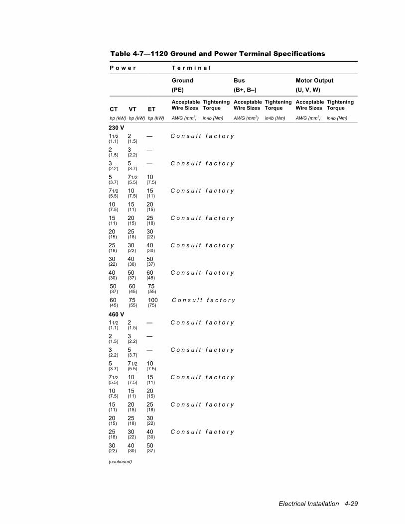
Electrical Installation 4-29
Table 4-7—1120 Ground and Power Terminal Specifications
P o w e r T e r m i n a l
Ground Bus Motor Output (PE) (B+, B–) (U, V, W)
CT
VT
ET
Acceptable Wire Sizes
Tightening Torque
Acceptable Wire Sizes
Tightening Torque
Acceptable Wire Sizes
Tightening Torque
hp (kW) hp (kW) hp (kW) AWG (mm2) in•lb (Nm) AWG (mm2) in•lb (Nm) AWG (mm2) in•lb (Nm)
230 V 11/2 2 — C o n s u l t f a c t o r y (1.1) (1.5)
2 3 — (1.5) (2.2)
3 5 — C o n s u l t f a c t o r y (2.2) (3.7)
5 71/2 10 (3.7) (5.5) (7.5)
71/2 10 15 C o n s u l t f a c t o r y (5.5) (7.5) (11)
10 15 20 (7.5) (11) (15)
15 20 25 C o n s u l t f a c t o r y (11) (15) (18)
20 25 30 (15) (18) (22)
25 30 40 C o n s u l t f a c t o r y (18) (22) (30)
30 40 50 (22) (30) (37)
40 50 60 C o n s u l t f a c t o r y (30) (37) (45)
50 60 75 (37) (45) (55)
60 75 100 C o n s u l t f a c t o r y (45) (55) (75)
460 V 11/2 2 — C o n s u l t f a c t o r y (1.1) (1.5)
2 3 — (1.5) (2.2)
3 5 — C o n s u l t f a c t o r y (2.2) (3.7)
5 71/2 10 (3.7) (5.5) (7.5)
71/2 10 15 C o n s u l t f a c t o r y (5.5) (7.5) (11)
10 15 20 (7.5) (11) (15)
15 20 25 C o n s u l t f a c t o r y (11) (15) (18)
20 25 30 (15) (18) (22)
25 30 40 C o n s u l t f a c t o r y (18) (22) (30)
30 40 50 (22) (30) (37) (continued)
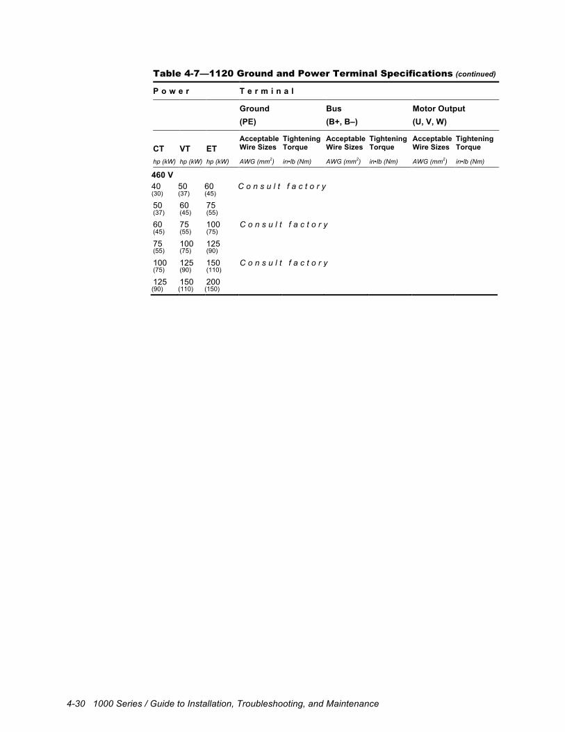
4-30 1000 Series / Guide to Installation, Troubleshooting, and Maintenance
Table 4-7—1120 Ground and Power Terminal Specifications (continued)
P o w e r T e r m i n a l
Ground Bus Motor Output (PE) (B+, B–) (U, V, W)
CT
VT
ET
Acceptable Wire Sizes
Tightening Torque
Acceptable Wire Sizes
Tightening Torque
Acceptable Wire Sizes
Tightening Torque
hp (kW) hp (kW) hp (kW) AWG (mm2) in•lb (Nm) AWG (mm2) in•lb (Nm) AWG (mm2) in•lb (Nm)
460 V 40 50 60 C o n s u l t f a c t o r y (30) (37) (45)
50 60 75 (37) (45) (55)
60 75 100 C o n s u l t f a c t o r y (45) (55) (75)
75 100 125 (55) (75) (90)
100 125 150 C o n s u l t f a c t o r y (75) (90) (110)
125 150 200 (90) (110) (150)
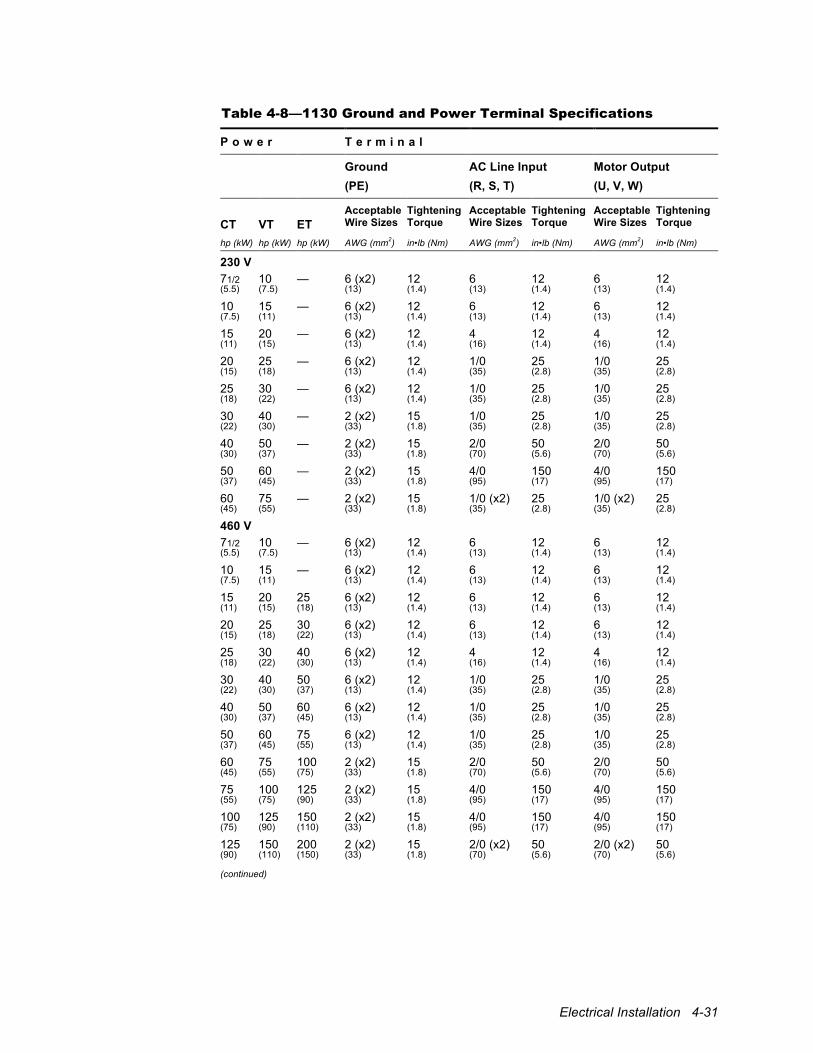
Electrical Installation 4-31
Table 4-8—1130 Ground and Power Terminal Specifications
P o w e r T e r m i n a l
Ground AC Line Input Motor Output (PE) (R, S, T) (U, V, W)
CT
VT
ET
Acceptable Wire Sizes
Tightening Torque
Acceptable Wire Sizes
Tightening Torque
Acceptable Wire Sizes
Tightening Torque
hp (kW) hp (kW) hp (kW) AWG (mm2) in•lb (Nm) AWG (mm2) in•lb (Nm) AWG (mm2) in•lb (Nm)
230 V 71/2 10 — 6 (x2) 12 6 12 6 12 (5.5) (7.5) (13) (1.4) (13) (1.4) (13) (1.4)
10 15 — 6 (x2) 12 6 12 6 12 (7.5) (11) (13) (1.4) (13) (1.4) (13) (1.4)
15 20 — 6 (x2) 12 4 12 4 12 (11) (15) (13) (1.4) (16) (1.4) (16) (1.4)
20 25 — 6 (x2) 12 1/0 25 1/0 25 (15) (18) (13) (1.4) (35) (2.8) (35) (2.8)
25 30 — 6 (x2) 12 1/0 25 1/0 25 (18) (22) (13) (1.4) (35) (2.8) (35) (2.8)
30 40 — 2 (x2) 15 1/0 25 1/0 25 (22) (30) (33) (1.8) (35) (2.8) (35) (2.8)
40 50 — 2 (x2) 15 2/0 50 2/0 50 (30) (37) (33) (1.8) (70) (5.6) (70) (5.6)
50 60 — 2 (x2) 15 4/0 150 4/0 150 (37) (45) (33) (1.8) (95) (17) (95) (17)
60 75 — 2 (x2) 15 1/0 (x2) 25 1/0 (x2) 25 (45) (55) (33) (1.8) (35) (2.8) (35) (2.8)
460 V 71/2 10 — 6 (x2) 12 6 12 6 12 (5.5) (7.5) (13) (1.4) (13) (1.4) (13) (1.4)
10 15 — 6 (x2) 12 6 12 6 12 (7.5) (11) (13) (1.4) (13) (1.4) (13) (1.4)
15 20 25 6 (x2) 12 6 12 6 12 (11) (15) (18) (13) (1.4) (13) (1.4) (13) (1.4)
20 25 30 6 (x2) 12 6 12 6 12 (15) (18) (22) (13) (1.4) (13) (1.4) (13) (1.4)
25 30 40 6 (x2) 12 4 12 4 12 (18) (22) (30) (13) (1.4) (16) (1.4) (16) (1.4)
30 40 50 6 (x2) 12 1/0 25 1/0 25 (22) (30) (37) (13) (1.4) (35) (2.8) (35) (2.8)
40 50 60 6 (x2) 12 1/0 25 1/0 25 (30) (37) (45) (13) (1.4) (35) (2.8) (35) (2.8)
50 60 75 6 (x2) 12 1/0 25 1/0 25 (37) (45) (55) (13) (1.4) (35) (2.8) (35) (2.8)
60 75 100 2 (x2) 15 2/0 50 2/0 50 (45) (55) (75) (33) (1.8) (70) (5.6) (70) (5.6)
75 100 125 2 (x2) 15 4/0 150 4/0 150 (55) (75) (90) (33) (1.8) (95) (17) (95) (17)
100 125 150 2 (x2) 15 4/0 150 4/0 150 (75) (90) (110) (33) (1.8) (95) (17) (95) (17)
125 150 200 2 (x2) 15 2/0 (x2) 50 2/0 (x2) 50 (90) (110) (150) (33) (1.8) (70) (5.6) (70) (5.6) (continued)

4-32 1000 Series / Guide to Installation, Troubleshooting, and Maintenance
Table 4-8—1130 Ground and Power Terminal Specifications (continued)
P o w e r T e r m i n a l
Ground AC Line Input Motor Output (PE) (R, S, T) (U, V, W)
CT
VT
ET
Acceptable Wire Sizes
Tightening Torque
Acceptable Wire Sizes
Tightening Torque
Acceptable Wire Sizes
Tightening Torque
hp (kW) hp (kW) hp (kW) AWG (mm2) in•lb (Nm) AWG (mm2) in•lb (Nm) AWG (mm2) in•lb (Nm)
575 V 71/2 10 — 6 (x2) 12 6 12 6 12 (5.5) (7.5) (13) (1.4) (13) (1.4) (13) (1.4)
10 15 — 6 (x2) 12 6 12 6 12 (7.5) (11) (13) (1.4) (13) (1.4) (13) (1.4)
15 20 25 6 (x2) 12 6 12 6 12 (11) (15) (18) (13) (1.4) (13) (1.4) (13) (1.4)
20 25 30 6 (x2) 12 6 12 6 12 (15) (18) (22) (13) (1.4) (13) (1.4) (13) (1.4)
25 30 40 6 (x2) 12 6 12 6 12 (18) (22) (30) (13) (1.4) (13) (1.4) (13) (1.4)
30 40 50 6 (x2) 12 4 12 4 12 (22) (30) (37) (13) (1.4) (16) (1.4) (21) (1.4)
40 50 60 6 (x2) 12 1/0 25 1/0 25 (30) (37) (45) (13) (1.4) (35) (2.8) (54) (2.8)
50 60 75 6 (x2) 12 1/0 25 1/0 25 (37) (45) (55) (13) (1.4) (35) (2.8) (54) (2.8)
60 75 100 2 (x2) 15 1/0 25 1/0 25 (45) (55) (75) (33) (1.8) (35) (2.8) (54) (2.8)
75 100 125 2 (x2) 15 2/0 50 2/0 50 (55) (75) (90) (33) (1.8) (70) (5.6) (67) (5.6)
100 125 150 2 (x2) 15 4/0 150 4/0 150 (75) (90) (110) (33) (1.8) (95) (17) (107) (17)
125 150 200 2 (x2) 15 1/0 (x2) 25 1/0 (x2) 25 (90) (110) (150) (33) (1.8) (35) (2.8) (54) (2.8)

Electrical Installation 4-33
Table 4-9—1200 Ground and Power Terminal Specifications
P o w e r T e r m i n a l
Ground AC Line Input Motor Output Dynamic Braking or Bus
(PE) (R, S, T or R1, R2, S1, S2, T1, T2)
(U, V, W) (B+, DB or B+, B–)
CT
VT
ET
Acceptable Wire Sizes
Tightening Torque
Acceptable Wire Sizes
Tightening Torque
Acceptable Wire Sizes
Tightening Torque
Acceptable Wire Sizes
Tightening Torque
hp (kW) hp (kW) hp (kW) AWG (mm2) in•lb (Nm) AWG (mm2) in•lb (Nm) AWG (mm2) in•lb (Nm) AWG (mm2) in•lb (Nm)
230 V 11/2 2 — 14–6 25 20–6 15–16 20–6 15–16 20–6 15–16 (1.1) (1.5) (2.1-13) (2.8) (0.5-13) (1.8-1.8) (0.5-13) (1.8-1.8) (0.5-13) (1.8-1.8)
2 3 — 14–6 25 20–6 15–16 20–6 15–16 20–6 15–16 (1.5) (2.2) (2.1-13) (2.8) (0.5-13) (1.8-1.8) (0.5-13) (1.8-1.8) (0.5-13) (1.8-1.8)
3 5 — 14–6 25 20–6 15–16 20–6 15–16 20–6 15–16 (2.2) (3.7) (2.1-13) (2.8) (0.5-13) (1.8-1.8) (0.5-13) (1.8-1.8) (0.5-13) (1.8-1.8)
5 71/2 10 14–6 25 20–6 15–16 20–6 15–16 20–6 15–16 (3.7) (5.5) (7.5) (2.1-13) (2.8) (0.5-13) (1.8-1.8) (0.5-13) (1.8-1.8) (0.5-13) (1.8-1.8)
71/2 10 15 14–6 25 20–6 15–16 20–6 15–16 20–6 15–16 (5.5) (7.5) (11) (2.1-13) (2.8) (0.5-13) (1.8-1.8) (0.5-13) (1.8-1.8) (0.5-13) (1.8-1.8)
10 15 20 14–4 20 14–4 20 14–4 20 14–4 20 (7.5) (11) (15) (2.1-16) (2.3) (2.1-16) (2.3) (2.1-16) (2.3) (2.1-16) (2.3)
15 20 25 14–4 20 14–4 20 14–4 20 14–4 20 (11) (15) (18) (2.1-16) (2.3) (2.1-16) (2.3) (2.1-16) (2.3) (2.1-16) (2.3)
20 25 30 14–6 10.5–12.4 10–1 24.9–26.7 10–1 24.9–26.7 10–1 24.9–26.7 (15) (18) (22) (2.1-13) (1.2-1.4) (5.3-42) (2.8-3.0) (5.3-42) (2.8-3.0) (5.3-42) (2.8-3.0)
460 V 11/2 2 — 14–6 25 20–6 15–16 20–6 15–16 20–6 15–16 (1.1) (1.5) (2.1-13) (2.8) (0.5-13) (1.8-1.8) (0.5-13) (1.8-1.8) (0.5-13) (1.8-1.8)
2 3 — 14–6 25 20–6 15–16 20–6 15–16 20–6 15–16 (1.5) (2.2) (2.1-13) (2.8) (0.5-13) (1.8-1.8) (0.5-13) (1.8-1.8) (0.5-13) (1.8-1.8)
3 5 — 14–6 25 20–6 15–16 20–6 15–16 20–6 15–16 (2.2) (3.7) (2.1-13) (2.8) (0.5-13) (1.8-1.8) (0.5-13) (1.8-1.8) (0.5-13) (1.8-1.8)
5 71/2 10 14–6 25 20–6 15–16 20–6 15–16 20–6 15–16 (3.7) (5.5) (7.5) (2.1-13) (2.8) (0.5-13) (1.8-1.8) (0.5-13) (1.8-1.8) (0.5-13) (1.8-1.8)
71/2 10 15 14–6 25 20–6 15–16 20–6 15–16 20–6 15–16 (5.5) (7.5) (11) (2.1-13) (2.8) (0.5-13) (1.8-1.8) (0.5-13) (1.8-1.8) (0.5-13) (1.8-1.8)
10 15 20 14–6 25 20–6 15–16 20–6 15–16 20–6 15–16 (7.5) (11) (15) (2.1-13) (2.8) (0.5-13) (1.8-1.8) (0.5-13) (1.8-1.8) (0.5-13) (1.8-1.8)
15 20 25 14–6 25 20–6 15–16 20–6 15–16 20–6 15–16 (11) (15) (18) (2.1-13) (2.8) (0.5-13) (1.8-1.8) (0.5-13) (1.8-1.8) (0.5-13) (1.8-1.8)
20 25 30 14–4 20 14–4 20 14–4 20 14–4 20 (15) (18) (22) (2.1-16) (2.3) (2.1-16) (2.3) (2.1-16) (2.3) (2.1-16) (2.3)
25 30 40 14–4 20 14–4 20 14–4 20 14–4 20 (18) (22) (30) (2.1-16) (2.3) (2.1-16) (2.3) (2.1-16) (2.3) (2.1-16) (2.3)
30 40 50 14–4 20 14–4 20 14–4 20 14–4 20 (22) (30) (37) (2.1-16) (2.3) (2.1-16) (2.3) (2.1-16) (2.3) (2.1-16) (2.3)
40 50 60 14–6 10.5–12.4 10–1 24.9–26.7 10–1 24.9–26.7 10–1 24.9–26.7 (30) (37) (45) (2.1-13) (1.2-1.4) (5.3-42) (2.8-3.0) (5.3-42) (2.8-3.0) (5.3-42) (2.8-3.0)
50 60 75 14–6 10.5–12.4 6–2/0 50 4–4/0 216 8–3/0 216 (37) (45) (55) (2.1-13) (1.2-1.4) (10-67) (5.6) (16-107) (24) (8.4-85) (24)
60 75 100 14–6 10.5–12.4 6–2/0 50 4–4/0 216 8–3/0 216 (45) (55) (75) (2.1-13) (1.2-1.4) (10-67) (5.6) (16-107) (24) (8.4-85) (24)
75 100 125 14–6 10.5–12.4 6–2/0 50 4–4/0 216 8–3/0 216 (55) (75) (90) (2.1-13) (1.2-1.4) (10-67) (5.6) (16-107) (24) (8.4-85) (24)
(continued)
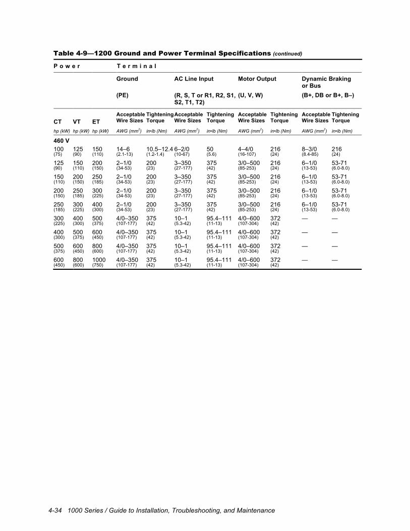
4-34 1000 Series / Guide to Installation, Troubleshooting, and Maintenance
Table 4-9—1200 Ground and Power Terminal Specifications (continued)
P o w e r T e r m i n a l
Ground AC Line Input Motor Output Dynamic Braking or Bus
(PE) (R, S, T or R1, R2, S1, S2, T1, T2)
(U, V, W) (B+, DB or B+, B–)
CT
VT
ET
Acceptable Wire Sizes
Tightening Torque
Acceptable Wire Sizes
Tightening Torque
Acceptable Wire Sizes
Tightening Torque
Acceptable Wire Sizes
Tightening Torque
hp (kW) hp (kW) hp (kW) AWG (mm2) in•lb (Nm) AWG (mm2) in•lb (Nm) AWG (mm2) in•lb (Nm) AWG (mm2) in•lb (Nm)
460 V 100 125 150 14–6 10.5–12.4 6–2/0 50 4–4/0 216 8–3/0 216 (75) (90) (110) (2.1-13) (1.2-1.4) (10-67) (5.6) (16-107) (24) (8.4-85) (24)
125 150 200 2–1/0 200 3–350 375 3/0–500 216 6–1/0 53-71 (90) (110) (150) (34-53) (23) (27-177) (42) (85-253) (24) (13-53) (6.0-8.0)
150 200 250 2–1/0 200 3–350 375 3/0–500 216 6–1/0 53-71 (110) (150) (185) (34-53) (23) (27-177) (42) (85-253) (24) (13-53) (6.0-8.0)
200 250 300 2–1/0 200 3–350 375 3/0–500 216 6–1/0 53-71 (150) (185) (225) (34-53) (23) (27-177) (42) (85-253) (24) (13-53) (6.0-8.0)
250 300 400 2–1/0 200 3–350 375 3/0–500 216 6–1/0 53-71 (185) (225) (300) (34-53) (23) (27-177) (42) (85-253) (24) (13-53) (6.0-8.0)
300 400 500 4/0–350 375 10–1 95.4–111 4/0–600 372 — — (225) (300) (375) (107-177) (42) (5.3-42) (11-13) (107-304) (42)
400 500 600 4/0–350 375 10–1 95.4–111 4/0–600 372 — — (300) (375) (450) (107-177) (42) (5.3-42) (11-13) (107-304) (42)
500 600 800 4/0–350 375 10–1 95.4–111 4/0–600 372 — — (375) (450) (600) (107-177) (42) (5.3-42) (11-13) (107-304) (42)
600 800 1000 4/0–350 375 10–1 95.4–111 4/0–600 372 — — (450) (600) (750) (107-177) (42) (5.3-42) (11-13) (107-304) (42)
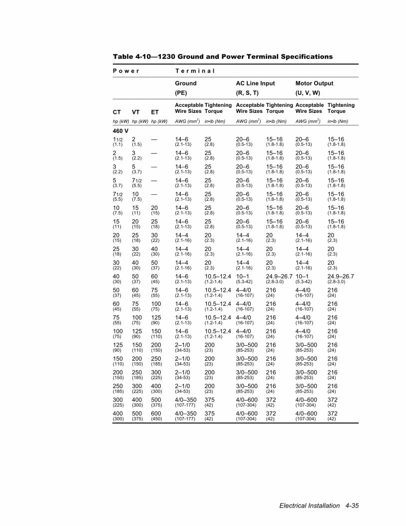
Electrical Installation 4-35
Table 4-10—1230 Ground and Power Terminal Specifications
P o w e r T e r m i n a l
Ground AC Line Input Motor Output (PE) (R, S, T) (U, V, W)
CT
VT
ET
Acceptable Wire Sizes
Tightening Torque
Acceptable Wire Sizes
Tightening Torque
Acceptable Wire Sizes
Tightening Torque
hp (kW) hp (kW) hp (kW) AWG (mm2) in•lb (Nm) AWG (mm2) in•lb (Nm) AWG (mm2) in•lb (Nm)
460 V 11/2 2 — 14–6 25 20–6 15–16 20–6 15–16 (1.1) (1.5) (2.1-13) (2.8) (0.5-13) (1.8-1.8) (0.5-13) (1.8-1.8)
2 3 — 14–6 25 20–6 15–16 20–6 15–16 (1.5) (2.2) (2.1-13) (2.8) (0.5-13) (1.8-1.8) (0.5-13) (1.8-1.8)
3 5 — 14–6 25 20–6 15–16 20–6 15–16 (2.2) (3.7) (2.1-13) (2.8) (0.5-13) (1.8-1.8) (0.5-13) (1.8-1.8)
5 71/2 — 14–6 25 20–6 15–16 20–6 15–16 (3.7) (5.5) (2.1-13) (2.8) (0.5-13) (1.8-1.8) (0.5-13) (1.8-1.8)
71/2 10 — 14–6 25 20–6 15–16 20–6 15–16 (5.5) (7.5) (2.1-13) (2.8) (0.5-13) (1.8-1.8) (0.5-13) (1.8-1.8)
10 15 20 14–6 25 20–6 15–16 20–6 15–16 (7.5) (11) (15) (2.1-13) (2.8) (0.5-13) (1.8-1.8) (0.5-13) (1.8-1.8)
15 20 25 14–6 25 20–6 15–16 20–6 15–16 (11) (15) (18) (2.1-13) (2.8) (0.5-13) (1.8-1.8) (0.5-13) (1.8-1.8)
20 25 30 14–4 20 14–4 20 14–4 20 (15) (18) (22) (2.1-16) (2.3) (2.1-16) (2.3) (2.1-16) (2.3)
25 30 40 14–4 20 14–4 20 14–4 20 (18) (22) (30) (2.1-16) (2.3) (2.1-16) (2.3) (2.1-16) (2.3)
30 40 50 14–4 20 14–4 20 14–4 20 (22) (30) (37) (2.1-16) (2.3) (2.1-16) (2.3) (2.1-16) (2.3)
40 50 60 14–6 10.5–12.4 10–1 24.9–26.7 10–1 24.9–26.7 (30) (37) (45) (2.1-13) (1.2-1.4) (5.3-42) (2.8-3.0) (5.3-42) (2.8-3.0)
50 60 75 14–6 10.5–12.4 4–4/0 216 4–4/0 216 (37) (45) (55) (2.1-13) (1.2-1.4) (16-107) (24) (16-107) (24)
60 75 100 14–6 10.5–12.4 4–4/0 216 4–4/0 216 (45) (55) (75) (2.1-13) (1.2-1.4) (16-107) (24) (16-107) (24)
75 100 125 14–6 10.5–12.4 4–4/0 216 4–4/0 216 (55) (75) (90) (2.1-13) (1.2-1.4) (16-107) (24) (16-107) (24)
100 125 150 14–6 10.5–12.4 4–4/0 216 4–4/0 216 (75) (90) (110) (2.1-13) (1.2-1.4) (16-107) (24) (16-107) (24)
125 150 200 2–1/0 200 3/0–500 216 3/0–500 216 (90) (110) (150) (34-53) (23) (85-253) (24) (85-253) (24)
150 200 250 2–1/0 200 3/0–500 216 3/0–500 216 (110) (150) (185) (34-53) (23) (85-253) (24) (85-253) (24)
200 250 300 2–1/0 200 3/0–500 216 3/0–500 216 (150) (185) (225) (34-53) (23) (85-253) (24) (85-253) (24)
250 300 400 2–1/0 200 3/0–500 216 3/0–500 216 (185) (225) (300) (34-53) (23) (85-253) (24) (85-253) (24)
300 400 500 4/0–350 375 4/0–600 372 4/0–600 372 (225) (300) (375) (107-177) (42) (107-304) (42) (107-304) (42)
400 500 600 4/0–350 375 4/0–600 372 4/0–600 372 (300) (375) (450) (107-177) (42) (107-304) (42) (107-304) (42)
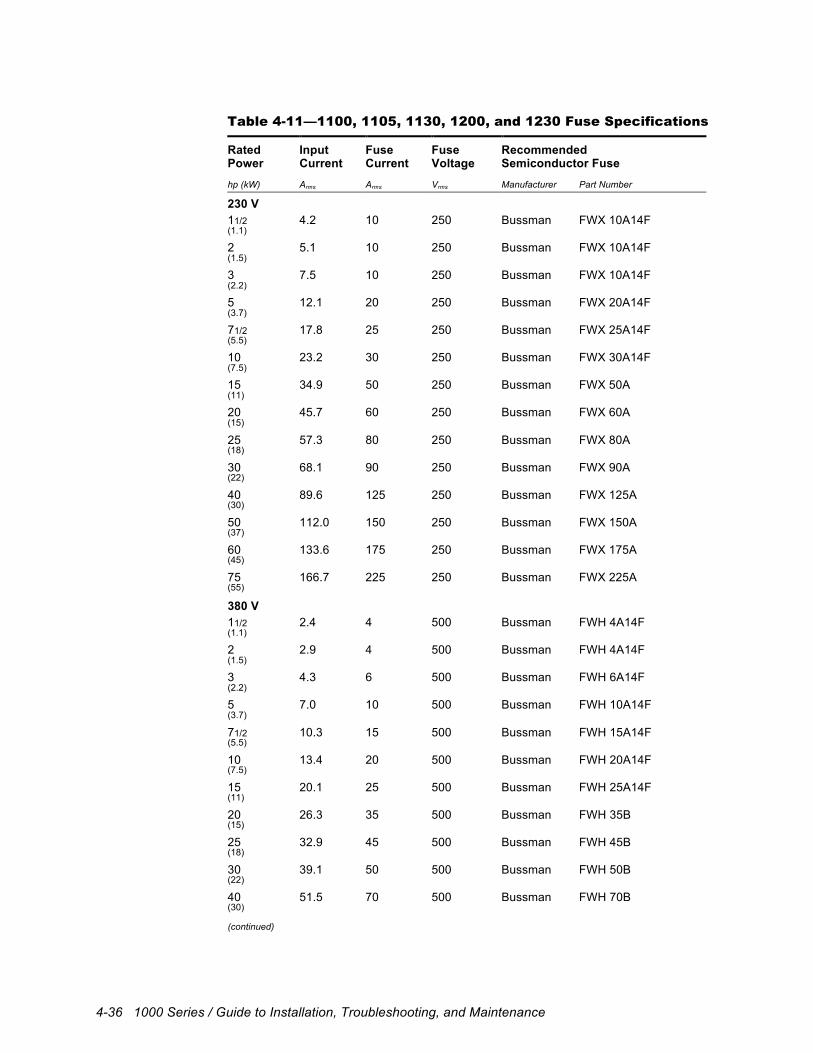
4-36 1000 Series / Guide to Installation, Troubleshooting, and Maintenance
Table 4-11—1100, 1105, 1130, 1200, and 1230 Fuse Specifications
Rated Power
Input Current
Fuse Current
Fuse Voltage
Recommended Semiconductor Fuse
hp (kW) Arms Arms Vrms Manufacturer Part Number
230 V 11/2 4.2 10 250 Bussman FWX 10A14F (1.1)
2 5.1 10 250 Bussman FWX 10A14F (1.5)
3 7.5 10 250 Bussman FWX 10A14F (2.2)
5 12.1 20 250 Bussman FWX 20A14F (3.7)
71/2 17.8 25 250 Bussman FWX 25A14F (5.5)
10 23.2 30 250 Bussman FWX 30A14F (7.5)
15 34.9 50 250 Bussman FWX 50A (11)
20 45.7 60 250 Bussman FWX 60A (15)
25 57.3 80 250 Bussman FWX 80A (18)
30 68.1 90 250 Bussman FWX 90A (22)
40 89.6 125 250 Bussman FWX 125A (30)
50 112.0 150 250 Bussman FWX 150A (37)
60 133.6 175 250 Bussman FWX 175A (45)
75 166.7 225 250 Bussman FWX 225A (55)
380 V 11/2 2.4 4 500 Bussman FWH 4A14F (1.1)
2 2.9 4 500 Bussman FWH 4A14F (1.5)
3 4.3 6 500 Bussman FWH 6A14F (2.2)
5 7.0 10 500 Bussman FWH 10A14F (3.7)
71/2 10.3 15 500 Bussman FWH 15A14F (5.5)
10 13.4 20 500 Bussman FWH 20A14F (7.5)
15 20.1 25 500 Bussman FWH 25A14F (11)
20 26.3 35 500 Bussman FWH 35B (15)
25 32.9 45 500 Bussman FWH 45B (18)
30 39.1 50 500 Bussman FWH 50B (22)
40 51.5 70 500 Bussman FWH 70B (30) (continued)
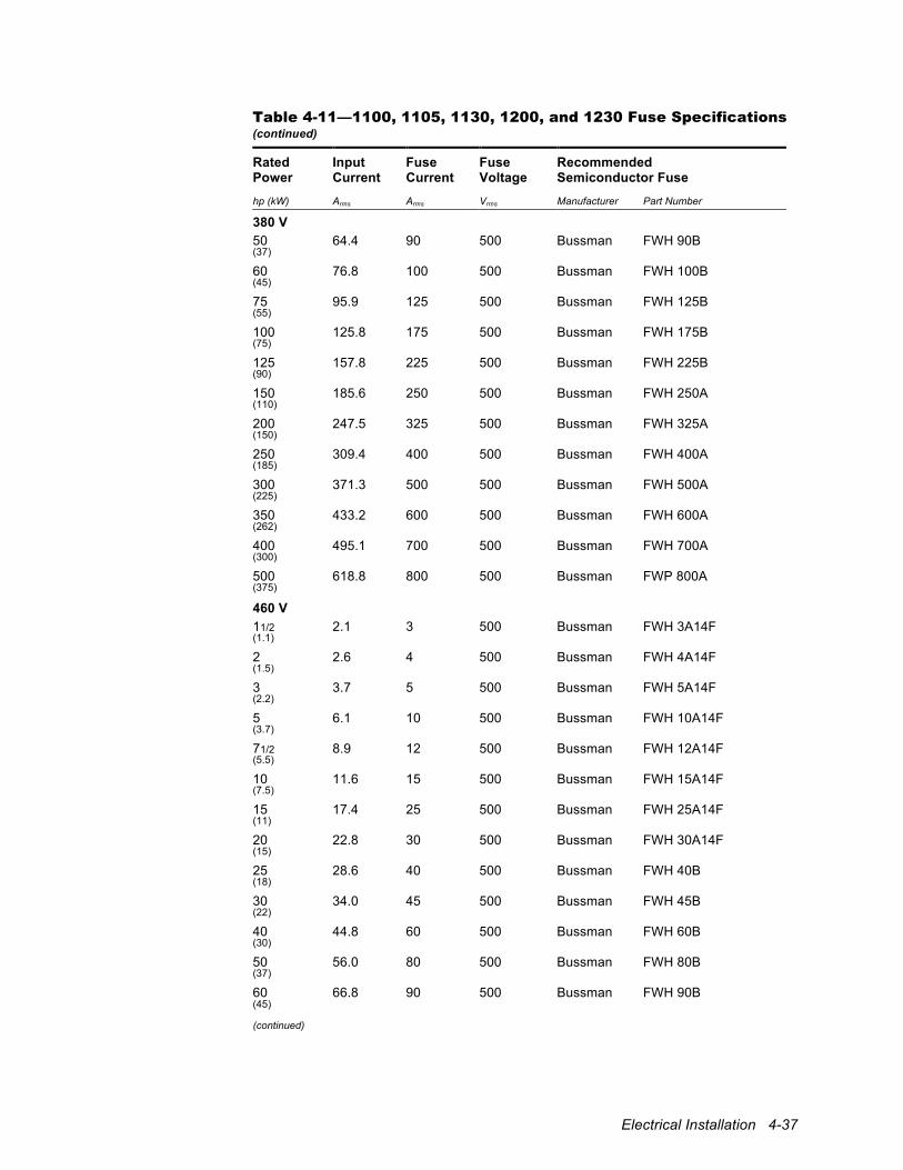
Electrical Installation 4-37
Table 4-11—1100, 1105, 1130, 1200, and 1230 Fuse Specifications (continued)
Rated Power
Input Current
Fuse Current
Fuse Voltage
Recommended Semiconductor Fuse
hp (kW) Arms Arms Vrms Manufacturer Part Number
380 V 50 64.4 90 500 Bussman FWH 90B (37)
60 76.8 100 500 Bussman FWH 100B (45)
75 95.9 125 500 Bussman FWH 125B (55)
100 125.8 175 500 Bussman FWH 175B (75)
125 157.8 225 500 Bussman FWH 225B (90)
150 185.6 250 500 Bussman FWH 250A (110)
200 247.5 325 500 Bussman FWH 325A (150)
250 309.4 400 500 Bussman FWH 400A (185)
300 371.3 500 500 Bussman FWH 500A (225)
350 433.2 600 500 Bussman FWH 600A (262)
400 495.1 700 500 Bussman FWH 700A (300)
500 618.8 800 500 Bussman FWP 800A (375)
460 V 11/2 2.1 3 500 Bussman FWH 3A14F (1.1)
2 2.6 4 500 Bussman FWH 4A14F (1.5)
3 3.7 5 500 Bussman FWH 5A14F (2.2)
5 6.1 10 500 Bussman FWH 10A14F (3.7)
71/2 8.9 12 500 Bussman FWH 12A14F (5.5)
10 11.6 15 500 Bussman FWH 15A14F (7.5)
15 17.4 25 500 Bussman FWH 25A14F (11)
20 22.8 30 500 Bussman FWH 30A14F (15)
25 28.6 40 500 Bussman FWH 40B (18)
30 34.0 45 500 Bussman FWH 45B (22)
40 44.8 60 500 Bussman FWH 60B (30)
50 56.0 80 500 Bussman FWH 80B (37)
60 66.8 90 500 Bussman FWH 90B (45) (continued)
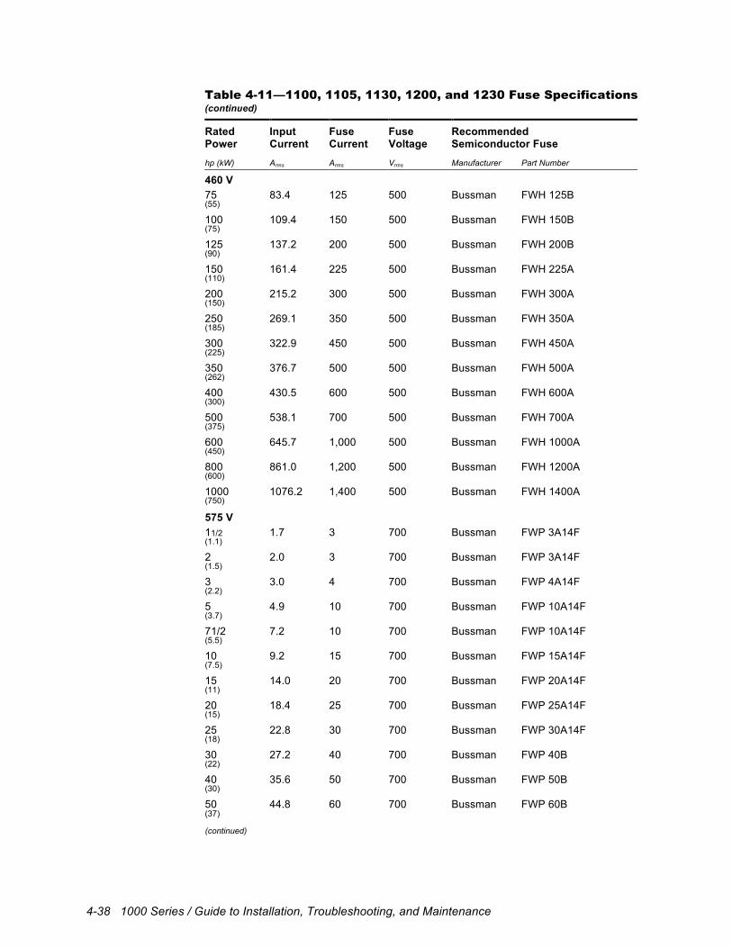
4-38 1000 Series / Guide to Installation, Troubleshooting, and Maintenance
Table 4-11—1100, 1105, 1130, 1200, and 1230 Fuse Specifications (continued)
Rated Power
Input Current
Fuse Current
Fuse Voltage
Recommended Semiconductor Fuse
hp (kW) Arms Arms Vrms Manufacturer Part Number
460 V 75 83.4 125 500 Bussman FWH 125B (55)
100 109.4 150 500 Bussman FWH 150B (75)
125 137.2 200 500 Bussman FWH 200B (90)
150 161.4 225 500 Bussman FWH 225A (110)
200 215.2 300 500 Bussman FWH 300A (150)
250 269.1 350 500 Bussman FWH 350A (185)
300 322.9 450 500 Bussman FWH 450A (225)
350 376.7 500 500 Bussman FWH 500A (262)
400 430.5 600 500 Bussman FWH 600A (300)
500 538.1 700 500 Bussman FWH 700A (375)
600 645.7 1,000 500 Bussman FWH 1000A (450)
800 861.0 1,200 500 Bussman FWH 1200A (600)
1000 1076.2 1,400 500 Bussman FWH 1400A (750)
575 V 11/2 1.7 3 700 Bussman FWP 3A14F (1.1)
2 2.0 3 700 Bussman FWP 3A14F (1.5)
3 3.0 4 700 Bussman FWP 4A14F (2.2)
5 4.9 10 700 Bussman FWP 10A14F (3.7)
71/2 7.2 10 700 Bussman FWP 10A14F (5.5)
10 9.2 15 700 Bussman FWP 15A14F (7.5)
15 14.0 20 700 Bussman FWP 20A14F (11)
20 18.4 25 700 Bussman FWP 25A14F (15)
25 22.8 30 700 Bussman FWP 30A14F (18)
30 27.2 40 700 Bussman FWP 40B (22)
40 35.6 50 700 Bussman FWP 50B (30)
50 44.8 60 700 Bussman FWP 60B (37) (continued)
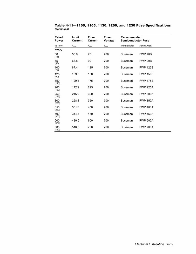
Electrical Installation 4-39
Table 4-11—1100, 1105, 1130, 1200, and 1230 Fuse Specifications (continued)
Rated Power
Input Current
Fuse Current
Fuse Voltage
Recommended Semiconductor Fuse
hp (kW) Arms Arms Vrms Manufacturer Part Number
575 V 60 53.6 70 700 Bussman FWP 70B (45)
75 66.8 90 700 Bussman FWP 90B (55)
100 87.4 125 700 Bussman FWP 125B (75)
125 109.8 150 700 Bussman FWP 150B (90)
150 129.1 175 700 Bussman FWP 175B (110)
200 172.2 225 700 Bussman FWP 225A (150)
250 215.2 300 700 Bussman FWP 300A (185)
300 258.3 350 700 Bussman FWP 350A (225)
350 301.3 400 700 Bussman FWP 400A (262)
400 344.4 450 700 Bussman FWP 450A (300)
500 430.5 600 700 Bussman FWP 600A (375)
600 516.6 700 700 Bussman FWP 700A (450)
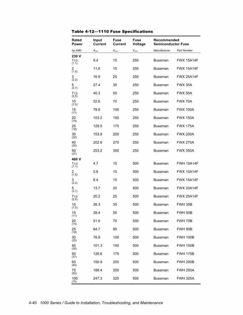
4-40 1000 Series / Guide to Installation, Troubleshooting, and Maintenance
Table 4-12—1110 Fuse Specifications
Rated Power
Input Current
Fuse Current
Fuse Voltage
Recommended Semiconductor Fuse
hp (kW) Arms Arms Vrms Manufacturer Part Number
230 V 11/2 9.4 15 250 Bussman FWX 15A14F (1.1)
2 11.6 15 250 Bussman FWX 15A14F (1.5)
3 16.9 25 250 Bussman FWX 25A14F (2.2)
5 27.4 35 250 Bussman FWX 35A (3.7)
71/2 40.3 50 250 Bussman FWX 50A (5.5)
10 52.6 70 250 Bussman FWX 70A (7.5)
15 78.8 100 250 Bussman FWX 100A (11)
20 103.2 150 250 Bussman FWX 150A (15)
25 129.5 175 250 Bussman FWX 175A (18)
30 153.9 200 250 Bussman FWX 200A (22)
40 202.6 275 250 Bussman FWX 275A (30)
50 253.2 350 250 Bussman FWX 350A (37)
460 V 11/2 4.7 10 500 Bussman FWH 10A14F (1.1)
2 5.8 10 500 Bussman FWX 10A14F (1.5)
3 8.4 15 500 Bussman FWX 15A14F (2.2)
5 13.7 20 500 Bussman FWX 20A14F (3.7)
71/2 20.2 25 500 Bussman FWX 25A14F (5.5)
10 26.3 35 500 Bussman FWH 35B (7.5)
15 39.4 50 500 Bussman FWH 50B (11)
20 51.6 70 500 Bussman FWH 70B (15)
25 64.7 90 500 Bussman FWH 90B (18)
30 76.9 100 500 Bussman FWH 100B (22)
40 101.3 150 500 Bussman FWH 150B (30)
50 126.6 175 500 Bussman FWH 175B (37)
60 150.9 200 500 Bussman FWH 200B (45)
75 188.4 250 500 Bussman FWH 250A (55)
100 247.3 325 500 Bussman FWH 325A (75)
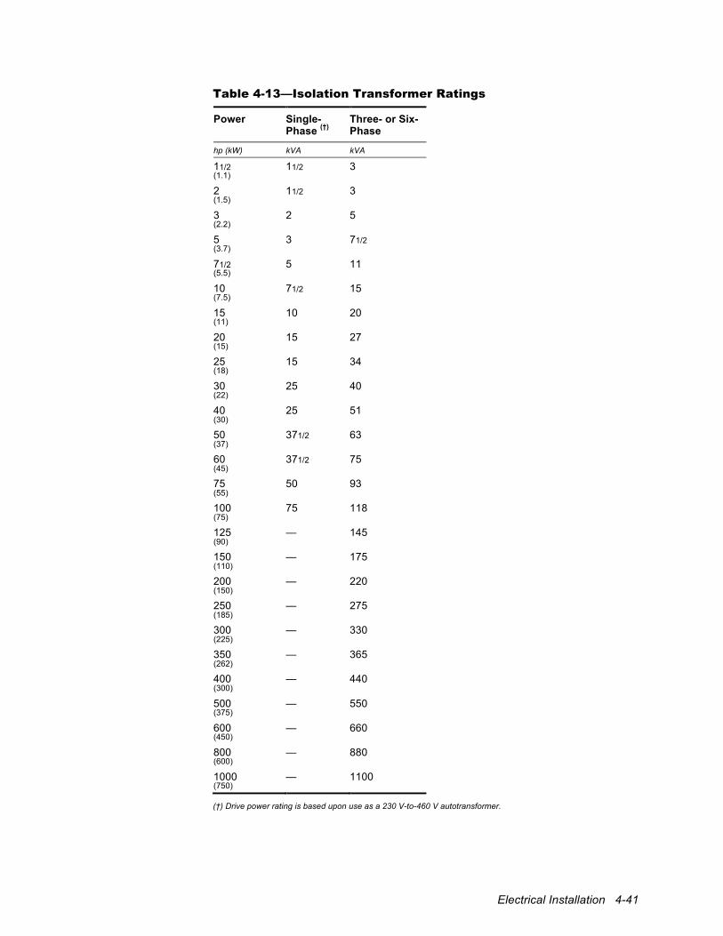
Electrical Installation 4-41
Table 4-13—Isolation Transformer Ratings
Power Single- Phase (†)
Three- or Six-Phase
hp (kW) kVA kVA
11/2 11/2 3 (1.1)
2 11/2 3 (1.5)
3 2 5 (2.2)
5 3 71/2 (3.7)
71/2 5 11 (5.5)
10 71/2 15 (7.5)
15 10 20 (11)
20 15 27 (15)
25 15 34 (18)
30 25 40 (22)
40 25 51 (30)
50 371/2 63 (37)
60 371/2 75 (45)
75 50 93 (55)
100 75 118 (75)
125 — 145 (90)
150 — 175 (110)
200 — 220 (150)
250 — 275 (185)
300 — 330 (225)
350 — 365 (262)
400 — 440 (300)
500 — 550 (375)
600 — 660 (450)
800 — 880 (600)
1000 — 1100 (750)
(†) Drive power rating is based upon use as a 230 V-to-460 V autotransformer.
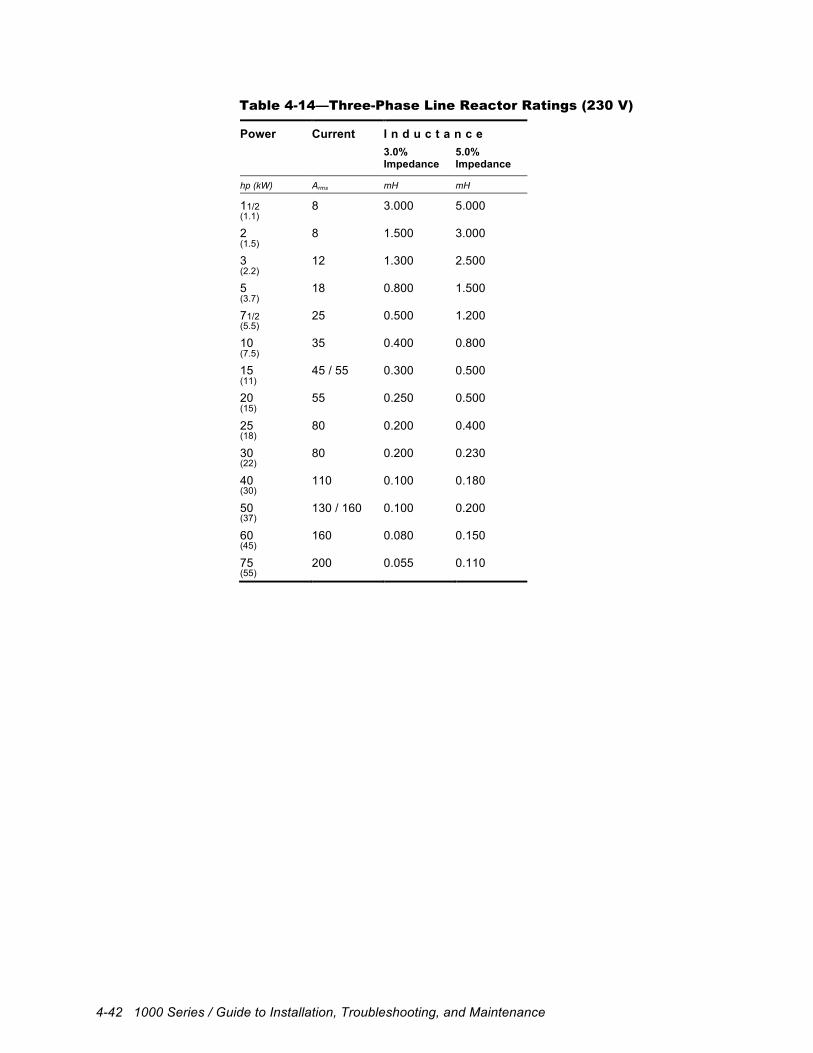
4-42 1000 Series / Guide to Installation, Troubleshooting, and Maintenance
Table 4-14—Three-Phase Line Reactor Ratings (230 V)
Power Current I n d u c t a n c e 3.0%
Impedance 5.0% Impedance
hp (kW) Arms mH mH
11/2 8 3.000 5.000 (1.1)
2 8 1.500 3.000 (1.5)
3 12 1.300 2.500 (2.2)
5 18 0.800 1.500 (3.7)
71/2 25 0.500 1.200 (5.5)
10 35 0.400 0.800 (7.5)
15 45 / 55 0.300 0.500 (11)
20 55 0.250 0.500 (15)
25 80 0.200 0.400 (18)
30 80 0.200 0.230 (22)
40 110 0.100 0.180 (30)
50 130 / 160 0.100 0.200 (37)
60 160 0.080 0.150 (45)
75 200 0.055 0.110 (55)
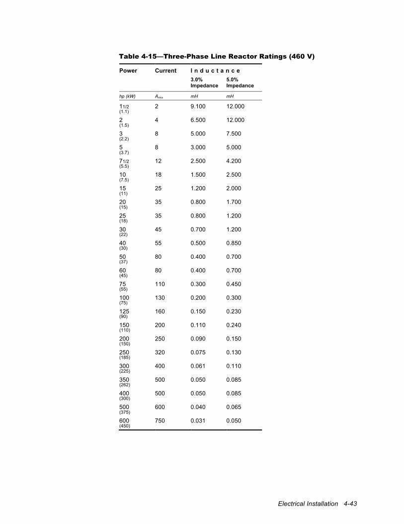
Electrical Installation 4-43
Table 4-15—Three-Phase Line Reactor Ratings (460 V)
Power Current I n d u c t a n c e 3.0%
Impedance 5.0% Impedance
hp (kW) Arms mH mH
11/2 2 9.100 12.000 (1.1)
2 4 6.500 12.000 (1.5)
3 8 5.000 7.500 (2.2)
5 8 3.000 5.000 (3.7)
71/2 12 2.500 4.200 (5.5)
10 18 1.500 2.500 (7.5)
15 25 1.200 2.000 (11)
20 35 0.800 1.700 (15)
25 35 0.800 1.200 (18)
30 45 0.700 1.200 (22)
40 55 0.500 0.850 (30)
50 80 0.400 0.700 (37)
60 80 0.400 0.700 (45)
75 110 0.300 0.450 (55)
100 130 0.200 0.300 (75)
125 160 0.150 0.230 (90)
150 200 0.110 0.240 (110)
200 250 0.090 0.150 (150)
250 320 0.075 0.130 (185)
300 400 0.061 0.110 (225)
350 500 0.050 0.085 (262)
400 500 0.050 0.085 (300)
500 600 0.040 0.065 (375)
600 750 0.031 0.050 (450)
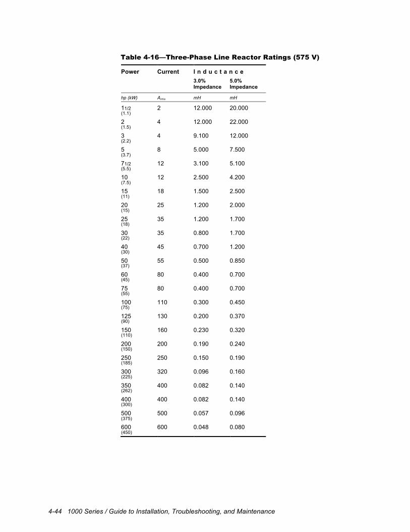
4-44 1000 Series / Guide to Installation, Troubleshooting, and Maintenance
Table 4-16—Three-Phase Line Reactor Ratings (575 V)
Power Current I n d u c t a n c e 3.0%
Impedance 5.0% Impedance
hp (kW) Arms mH mH
11/2 2 12.000 20.000 (1.1)
2 4 12.000 22.000 (1.5)
3 4 9.100 12.000 (2.2)
5 8 5.000 7.500 (3.7)
71/2 12 3.100 5.100 (5.5)
10 12 2.500 4.200 (7.5)
15 18 1.500 2.500 (11)
20 25 1.200 2.000 (15)
25 35 1.200 1.700 (18)
30 35 0.800 1.700 (22)
40 45 0.700 1.200 (30)
50 55 0.500 0.850 (37)
60 80 0.400 0.700 (45)
75 80 0.400 0.700 (55)
100 110 0.300 0.450 (75)
125 130 0.200 0.370 (90)
150 160 0.230 0.320 (110)
200 200 0.190 0.240 (150)
250 250 0.150 0.190 (185)
300 320 0.096 0.160 (225)
350 400 0.082 0.140 (262)
400 400 0.082 0.140 (300)
500 500 0.057 0.096 (375)
600 600 0.048 0.080 (450)
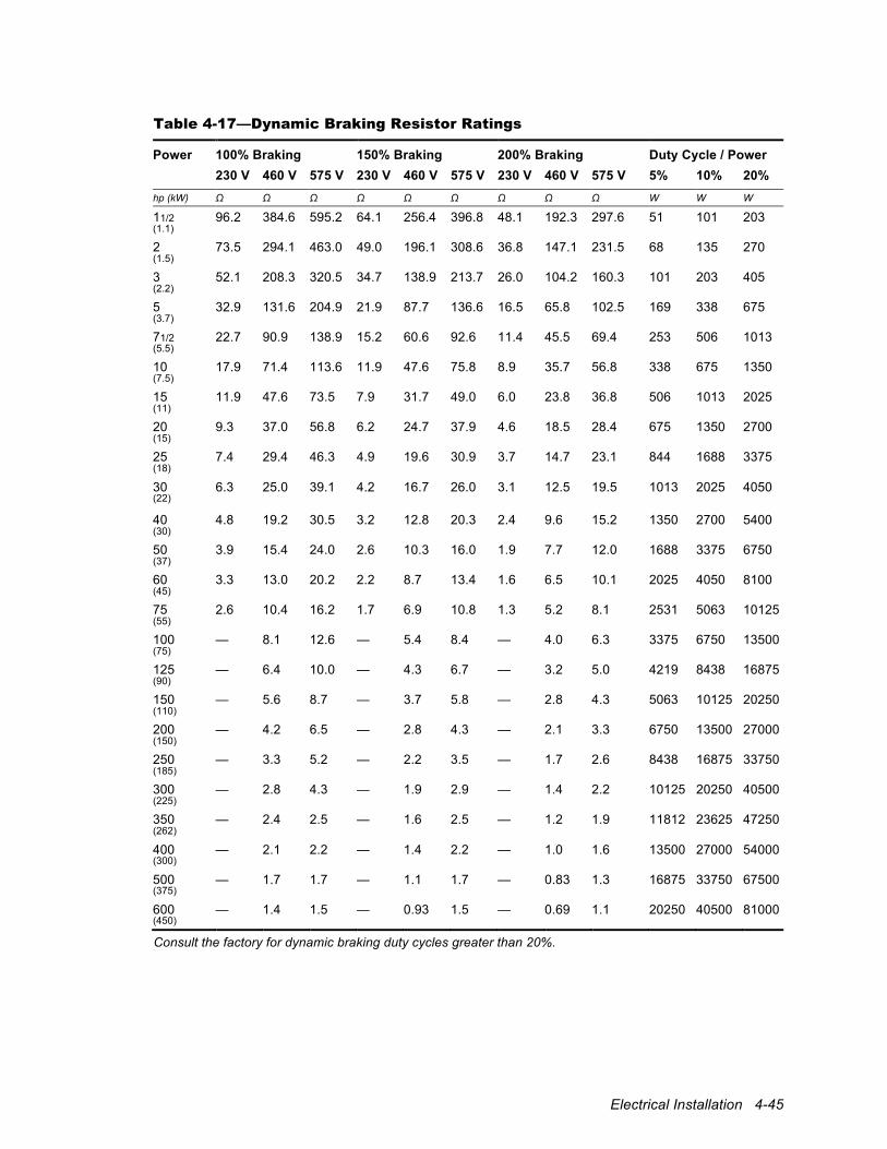
Electrical Installation 4-45
Table 4-17—Dynamic Braking Resistor Ratings
Power 100% Braking 150% Braking 200% Braking Duty Cycle / Power 230 V 460 V 575 V 230 V 460 V 575 V 230 V 460 V 575 V 5% 10% 20% hp (kW) Ω Ω Ω Ω Ω Ω Ω Ω Ω W W W
11/2 96.2 384.6 595.2 64.1 256.4 396.8 48.1 192.3 297.6 51 101 203 (1.1)
2 73.5 294.1 463.0 49.0 196.1 308.6 36.8 147.1 231.5 68 135 270 (1.5)
3 52.1 208.3 320.5 34.7 138.9 213.7 26.0 104.2 160.3 101 203 405 (2.2)
5 32.9 131.6 204.9 21.9 87.7 136.6 16.5 65.8 102.5 169 338 675 (3.7)
71/2 22.7 90.9 138.9 15.2 60.6 92.6 11.4 45.5 69.4 253 506 1013 (5.5)
10 17.9 71.4 113.6 11.9 47.6 75.8 8.9 35.7 56.8 338 675 1350 (7.5)
15 11.9 47.6 73.5 7.9 31.7 49.0 6.0 23.8 36.8 506 1013 2025 (11)
20 9.3 37.0 56.8 6.2 24.7 37.9 4.6 18.5 28.4 675 1350 2700 (15)
25 7.4 29.4 46.3 4.9 19.6 30.9 3.7 14.7 23.1 844 1688 3375 (18)
30 6.3 25.0 39.1 4.2 16.7 26.0 3.1 12.5 19.5 1013 2025 4050 (22)
40 4.8 19.2 30.5 3.2 12.8 20.3 2.4 9.6 15.2 1350 2700 5400 (30)
50 3.9 15.4 24.0 2.6 10.3 16.0 1.9 7.7 12.0 1688 3375 6750 (37)
60 3.3 13.0 20.2 2.2 8.7 13.4 1.6 6.5 10.1 2025 4050 8100 (45)
75 2.6 10.4 16.2 1.7 6.9 10.8 1.3 5.2 8.1 2531 5063 10125 (55)
100 — 8.1 12.6 — 5.4 8.4 — 4.0 6.3 3375 6750 13500 (75)
125 — 6.4 10.0 — 4.3 6.7 — 3.2 5.0 4219 8438 16875 (90)
150 — 5.6 8.7 — 3.7 5.8 — 2.8 4.3 5063 10125 20250 (110)
200 — 4.2 6.5 — 2.8 4.3 — 2.1 3.3 6750 13500 27000 (150)
250 — 3.3 5.2 — 2.2 3.5 — 1.7 2.6 8438 16875 33750 (185)
300 — 2.8 4.3 — 1.9 2.9 — 1.4 2.2 10125 20250 40500 (225)
350 — 2.4 2.5 — 1.6 2.5 — 1.2 1.9 11812 23625 47250 (262)
400 — 2.1 2.2 — 1.4 2.2 — 1.0 1.6 13500 27000 54000 (300)
500 — 1.7 1.7 — 1.1 1.7 — 0.83 1.3 16875 33750 67500 (375)
600 — 1.4 1.5 — 0.93 1.5 — 0.69 1.1 20250 40500 81000 (450)
Consult the factory for dynamic braking duty cycles greater than 20%.
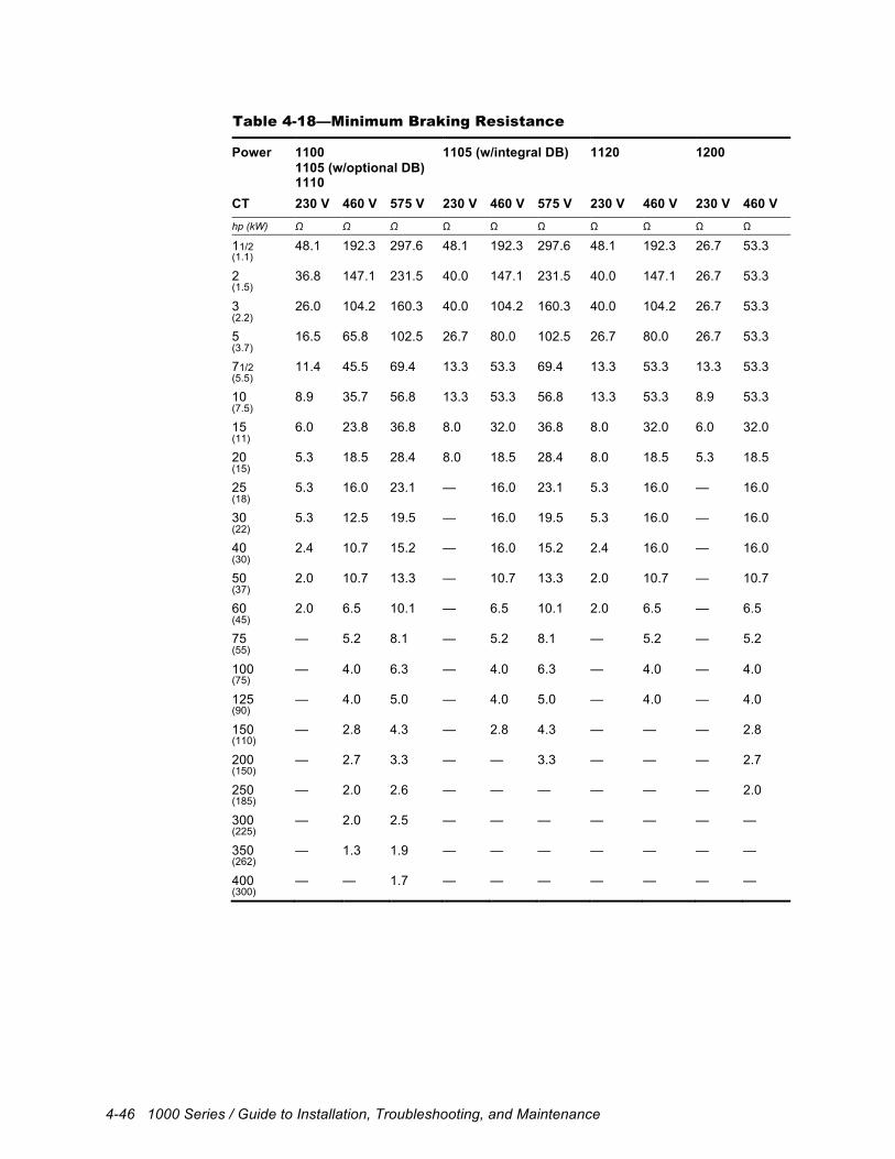
4-46 1000 Series / Guide to Installation, Troubleshooting, and Maintenance
Table 4-18—Minimum Braking Resistance
Power 1100 1105 (w/optional DB) 1110
1105 (w/integral DB) 1120 1200
CT 230 V 460 V 575 V 230 V 460 V 575 V 230 V 460 V 230 V 460 V hp (kW) Ω Ω Ω Ω Ω Ω Ω Ω Ω Ω
11/2 48.1 192.3 297.6 48.1 192.3 297.6 48.1 192.3 26.7 53.3 (1.1)
2 36.8 147.1 231.5 40.0 147.1 231.5 40.0 147.1 26.7 53.3 (1.5)
3 26.0 104.2 160.3 40.0 104.2 160.3 40.0 104.2 26.7 53.3 (2.2)
5 16.5 65.8 102.5 26.7 80.0 102.5 26.7 80.0 26.7 53.3 (3.7)
71/2 11.4 45.5 69.4 13.3 53.3 69.4 13.3 53.3 13.3 53.3 (5.5)
10 8.9 35.7 56.8 13.3 53.3 56.8 13.3 53.3 8.9 53.3 (7.5)
15 6.0 23.8 36.8 8.0 32.0 36.8 8.0 32.0 6.0 32.0 (11)
20 5.3 18.5 28.4 8.0 18.5 28.4 8.0 18.5 5.3 18.5 (15)
25 5.3 16.0 23.1 — 16.0 23.1 5.3 16.0 — 16.0 (18)
30 5.3 12.5 19.5 — 16.0 19.5 5.3 16.0 — 16.0 (22)
40 2.4 10.7 15.2 — 16.0 15.2 2.4 16.0 — 16.0 (30)
50 2.0 10.7 13.3 — 10.7 13.3 2.0 10.7 — 10.7 (37)
60 2.0 6.5 10.1 — 6.5 10.1 2.0 6.5 — 6.5 (45)
75 — 5.2 8.1 — 5.2 8.1 — 5.2 — 5.2 (55)
100 — 4.0 6.3 — 4.0 6.3 — 4.0 — 4.0 (75)
125 — 4.0 5.0 — 4.0 5.0 — 4.0 — 4.0 (90)
150 — 2.8 4.3 — 2.8 4.3 — — — 2.8 (110)
200 — 2.7 3.3 — — 3.3 — — — 2.7 (150)
250 — 2.0 2.6 — — — — — — 2.0 (185)
300 — 2.0 2.5 — — — — — — — (225)
350 — 1.3 1.9 — — — — — — — (262)
400 — — 1.7 — — — — — — — (300)
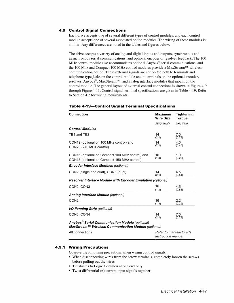
Electrical Installation 4-47
4.9 Control Signal Connections Each drive accepts one of several different types of control modules, and each control module accepts one of several associated option modules. The wiring of these modules is similar. Any differences are noted in the tables and figures below. The drive accepts a variety of analog and digital inputs and outputs, synchronous and aysnchronous serial communications, and optional encoder or resolver feedback. The 100 MHz control module also accommodates optional Anybus® serial communications, and the 100 Mhz and Compact 100 MHz control modules provide a MaxStream™ wireless communication option. These external signals are connected both to terminals and telephone-type jacks on the control module and to terminals on the optional encoder, resolver, Anybus®, MaxStream™, and analog interface modules that mount on the control module. The general layout of external control connections is shown in Figure 4-9 through Figure 4-11. Control signal terminal specifications are given in Table 4-19. Refer to Section 4.2 for wiring requirements.
Table 4-19—Control Signal Terminal Specifications
Connection Maximum Wire Size
Tightening Torque
AWG (mm2) in•lb (Nm)
Control Modules TB1 and TB2 14 7.0 (2.1) (0.79)
CON19 (optional on 100 MHz control) and 14 4.0 CON23 (270 MHz control) (2.1) (0.45)
CON16 (optional on Compact 100 MHz control) and 16 1.9 CON15 (optional on Compact 150 MHz control) (1.3)
(0.22)
Encoder Interface Modules (optional)
CON2 (single and dual), CON3 (dual) 14 4.5 (2.1) (0.51)
Resolver Interface Module with Encoder Emulation (optional)
CON2, CON3 16 4.5 (1.3) (0.51)
Analog Interface Module (optional)
CON2 16 2.2 (1.3) (0.25)
I/O Fanning Strip (optional)
CON3, CON4 14 7.0 (2.1) (0.79)
Anybus® Serial Communication Module (optional) MaxStream™ Wireless Communication Module (optional) All connections Refer to manufacturer’s
instruction manual
4.9.1 Wiring Precautions
Observe the following precautions when wiring control signals: • When disconnecting wires from the screw terminals, completely loosen the screws
before pulling out the wires • Tie shields to Logic Common at one end only • Twist differential (±) current input signals together
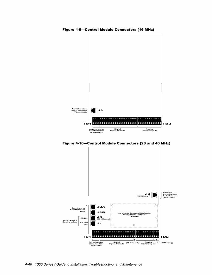
4-48 1000 Series / Guide to Installation, Troubleshooting, and Maintenance
Figure 4-9—Control Module Connectors (16 MHz)
1 2 3 4 5 6 7 8 9 10 11 12 131 2 3 4 5 6 7 8 9 10 11 12 13 14 15 16 17 18 19 20 21 22 23 24
TB1 TB2
J3Asynchronous Serial Interface
(RS-422/485)
Asynchronous Serial Interface
(RS-422/485)
DigitalInputs/Outputs
AnalogInputs/Outputs
Figure 4-10—Control Module Connectors (20 and 40 MHz)
1 2 3 4 5 6 7 8 9 10 11 12 131 2 3 4 5 6 7 8 9 10 11 12 13 14 15 16 17 18 19 20 21 22 23 24
TB1 TB2
J2A
J2B
J3(40 MHz only)
(40 MHz only)
J4(40 MHz only)
J1
Synchronous Serial Interface
(SSI)
Asynchronous Serial Interface
Auxiliary Asynchronous Serial Interface(RS-422/485)
Asynchronous Serial Interface
(RS-422/485)
Digital Inputs/Outputs
Analog Inputs/Outputs
RS-422/ 485
RS-232
(40 MHz only)
Incremental Encoder, Resolver, or Analog Interface Module
(optional)
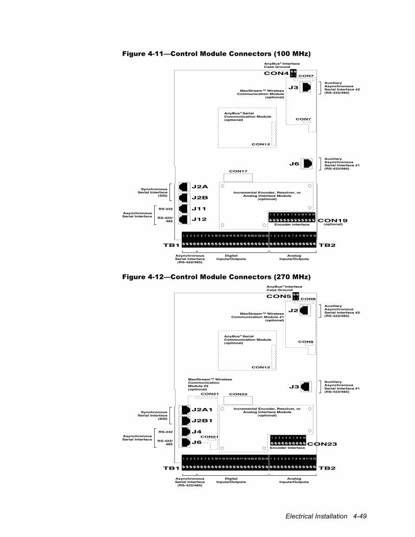
Electrical Installation 4-49
Figure 4-11—Control Module Connectors (100 MHz)
1 2 3 4 5 6 7 8 9 10 11 12 131 2 3 4 5 6 7 8 9 10 11 12 13 14 15 16 17 18 19 20 21 22 23 24
TB1 TB2
J2A
J2B
J11
J6
J12
Synchronous Serial Interface
(SSI)
Asynchronous Serial Interface
Incremental Encoder, Resolver, or Analog Interface Module
(optional)
Auxiliary Asynchronous Serial Interface #1(RS-422/485)
(optional)
AnyBus® Serial Communication Module (optional)
MaxStream™ Wireless Communication Module
(optional)
AnyBus® Interface Case Ground
Asynchronous Serial Interface
(RS-422/485)
Digital Inputs/Outputs
Analog Inputs/Outputs
RS-422/ 485
RS-232
J3
CON4
CON7
CON7
1 2 3 4 5 6 7 8 9 10 11 12 13
CON19
CON17
CON12
Auxiliary Asynchronous Serial Interface #2(RS-422/485)
Encoder Interface
2 1
Figure 4-12—Control Module Connectors (270 MHz)
1 2 3 4 5 6 7 8 9 10 11 12 131 2 3 4 5 6 7 8 9 10 11 12 13 14 15 16 17 18 19 20 21 22 23 24
TB1 TB2
J2A1
J2B1
J4
J3
J6
SynchronousSerial Interface
(SSI)
AsynchronousSerial Interface
Incremental Encoder, Resolver, orAnalog Interface Module
(optional)
AuxiliaryAsynchronousSerial Interface #1(RS-422/485)
AnyBus® SerialCommunication Module(optional)
MaxStream™ WirelessCommunicationModule #2(optional)
MaxStream™ WirelessCommunication Module #1
(optional)
AnyBus® InterfaceCase Ground
AsynchronousSerial Interface
(RS-422/485)
DigitalInputs/Outputs
AnalogInputs/Outputs
RS-422/485
RS-232
J2
CON5
CON8
CON8
CON23
CON22
CON12
AuxiliaryAsynchronousSerial Interface #2(RS-422/485)
Encoder Interface
2 1
CON21
CON21
1 2 3 4 5 6 7 8 9 10
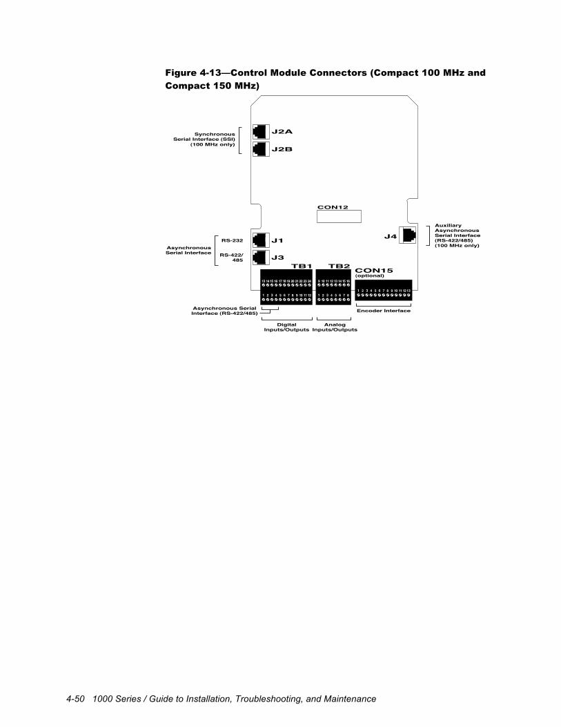
4-50 1000 Series / Guide to Installation, Troubleshooting, and Maintenance
Figure 4-13—Control Module Connectors (Compact 100 MHz and
Compact 150 MHz)
TB1 TB2CON15
CON12
1 2 3 4 5 6 7 8 1 2 3 4 5 6 7 89 10 11 12
9 10 11 1213 14 15 16 13 14 15 1617 18 19 20 21 22 23 24
1 2 3 4 5 6 7 8 9 10 11 1213
J2A
J2B
J1
J3
Synchronous Serial Interface (SSI)
Asynchronous Serial Interface RS-422/
485
RS-232J4
AuxiliaryAsynchronous Serial Interface(RS-422/485)
Asynchronous SerialInterface (RS-422/485)
DigitalInputs/Outputs
AnalogInputs/Outputs
Encoder Interface
(optional)
(100 MHz only)
(100 MHz only)
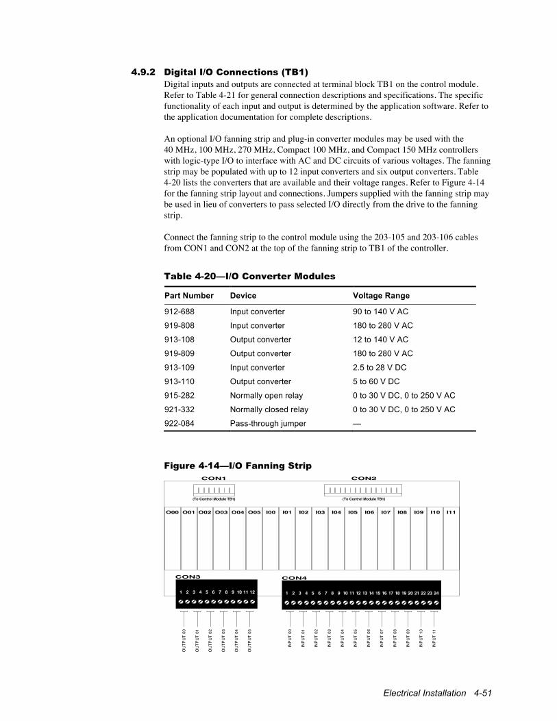
Electrical Installation 4-51
4.9.2 Digital I/O Connections (TB1) Digital inputs and outputs are connected at terminal block TB1 on the control module. Refer to Table 4-21 for general connection descriptions and specifications. The specific functionality of each input and output is determined by the application software. Refer to the application documentation for complete descriptions. An optional I/O fanning strip and plug-in converter modules may be used with the 40 MHz, 100 MHz, 270 MHz, Compact 100 MHz, and Compact 150 MHz controllers with logic-type I/O to interface with AC and DC circuits of various voltages. The fanning strip may be populated with up to 12 input converters and six output converters. Table 4-20 lists the converters that are available and their voltage ranges. Refer to Figure 4-14 for the fanning strip layout and connections. Jumpers supplied with the fanning strip may be used in lieu of converters to pass selected I/O directly from the drive to the fanning strip. Connect the fanning strip to the control module using the 203-105 and 203-106 cables from CON1 and CON2 at the top of the fanning strip to TB1 of the controller.
Table 4-20—I/O Converter Modules
Part Number Device Voltage Range
912-688 Input converter 90 to 140 V AC
919-808 Input converter 180 to 280 V AC
913-108 Output converter 12 to 140 V AC
919-809 Output converter 180 to 280 V AC
913-109 Input converter 2.5 to 28 V DC
913-110 Output converter 5 to 60 V DC
915-282 Normally open relay 0 to 30 V DC, 0 to 250 V AC
921-332 Normally closed relay 0 to 30 V DC, 0 to 250 V AC
922-084 Pass-through jumper —
Figure 4-14—I/O Fanning Strip
CON3
CON1 CON2
CON4
1 2 3 4 5 6 7 8 9 10 11 12 1 2 3 4 5 6 7 8 9 10 11 12 13 14 15 16 17 18 19 20 21 22 23 24
O01O00 O03O02 O05O04 I00 I01 I02 I03 I04 I05 I06 I07 I08 I09 I10 I11
(To Control Module TB1)(To Control Module TB1)
OU
TPU
T 00
OU
TPU
T 01
OU
TPU
T 02
OU
TPU
T 03
OU
TPU
T 04
OU
TPU
T 05
INPU
T 00
INPU
T 01
INPU
T 02
INPU
T 03
INPU
T 04
INPU
T 05
INPU
T 06
INPU
T 07
INPU
T 08
INPU
T 09
INPU
T 10
INPU
T 11
4-52 1000 Series / Guide to Installation, Troubleshooting, and Maintenance
4.9.3 Analog I/O Connections (TB2, CON2) Analog inputs and outputs are connected at terminal block TB2 on the control module. Refer to Table 4-22 for general connection descriptions and specifications. They may also be connected at terminal block CON2 on the optional Analog Interface Module (321-557). The Analog Interface Module mounts on the control module and provides eight additional inputs and four additional outputs. Analog Interface Module connections are shown in Figure 4-21 and Figure 4-22 and described in Table 4-30. Analog inputs and outputs are defined by the application. Refer to the application documentation for complete functional descriptions.
4.9.4 Serial Connections (TB1, J1, J2, J3, J4, J6, J11, J12) The drive provides both asynchronous and synchronous serial communication ports. The application software determines the functionality of these ports. Refer to the application documentation for any additional interconnection information specific to the application as well as a description of the communication protocol employed. For Anybus® and MaxStream™ communication modules, please refer to the module manufacturers’ instructions. Asynchronous serial signals (RS-422/485) are connected either to terminals at block TB1 on the control module (CON12 on the Compact 150 MHz control module) or to modular telephone-type jack J1 (40 MHz control module), J12 (100 MHz control module), J6 (270 MHz control module), and J3 (Compact 100 MHz and Compact 150 MHz control modules). Jacks J3 (40 MHz), J11 (100 MHz), J4 (270 MHz), and J1 (Compact 100 MHz and Compact 150 MHz) provide an RS-232 connection that parallels the signals of J1, J12, and J3. Jacks J4 (40 MHz and Compact 100 MHz), J3 and J6 (100 MHz), and J2 and J3 (270 MHz) provide auxiliary RS-422/485 connections independent from the other ports. Refer to Table 4-21 for TB1 terminal connections. Refer to Figure 4-15 and Table 4-23 for pinouts and descriptions of the modular telephone-type jack connectors. The Synchronous Serial Interface (SSI), available with all but the 16 MHz and Compact 150 MHz controllers, provides a means of slaving multiple drives together in real time. When supported by the application software, synchronous serial connections are made to jacks J2A and J2B (J2A1 and J2B1 on 270 MHz) using straight-through telephone cables. Refer to Figure 4-15 and Table 4-23 for pinouts and descriptions of the modular telephone-type jack connectors. Recommended synchronous serial cables are listed in Table 4-24. When networking two or more drives for either synchronous or asynchronous communications, remove the terminating resistors in all drives except the last one. With a synchronous network, this is the slave drive furthest from the master. When using the 20 MHz or 40 MHz control modules, remove both the data and clock terminating resistors for a synchronous network. Pull-up and pull-down resistors are generally required on the receive lines of the host computer to prevent the host from receiving garbage and to establish the ground reference for the serial port of the drive. The 16 MHz control module also provides pull-up and pull-down resistors on the transmit lines. In some networks, it may be necessary to remove the pull-up and pull-down resistors on the receive lines of the drive. Refer to the application documentation for any specific instructions. Pull-up, pull-down, and terminating resistor locations are shown in Figure 4-16 and described in Table 4-25.
Electrical Installation 4-53
4.9.5 Feedback Interface Connections The drive can operate with or without a transducer, depending upon the requirements of the application. It can accept feedback from one or more incremental encoders (pulse generators) and/or from a resolver, depending upon the control and interface modules selected. The 20 and 40 MHz control modules can accommodate either a single incremental encoder, dual incremental encoders, or a resolver by adding the appropriate transducer interface. The 100 MHz, 270 MHz, Compact 100 MHz (except 323-656), and Compact 150 MHz control modules have an on-board interface that accepts either an incremental encoder or an absolute/incremental encoder. The non-compact versions can also accommodate one or two additional incremental encoders or a resolver by adding the appropriate interface module.
4.9.5.1 Encoder Connections (CON2, CON3, CON16, CON19, CON23) The 100 MHz, 270 MHz, Compact 100 MHz (except 323-656), and Compact 150 MHz control modules accommodate one encoder with optional marker pulses and reference inputs. It can also operate with an absolute/incremental encoder. Connections for the on-board interface are shown in Figure 4-17 and described in Table 4-26. The CON19 and CON23 connections should be wired prior to installing the Dual Encoder, Resolver, or Analog interface modules since they will cover the terminal block. The pluggable connector can be removed to simplify wiring. The Encoder Interface Module (316-887) accommodates one encoder with optional marker pulses. Connections for the single encoder interface are shown in Figure 4-18 and described in Table 4-27. The Dual Encoder Interface Module (321-952) accommodates two encoders with optional marker pulses and reference inputs. Connections for the dual encoder interface are shown in and described in Table 4-28. Use of a Unico incremental encoder cable (105-619) is recommended. This cable consists of one twisted pair of 14 AWG wire (for isolated +5 V and isolated Common), three twisted pairs of 18 AWG wire, an overall shield, and a PCV jacket. The cable measures about 9/16" in diameter. At 0.250 A, the cable is good for a maximum of 175' (53 m). When wiring directly, be sure to use wire of sufficient gauge for the isolated +5 V and isolated Common connections to keep the voltage drop at the encoder at 0.25 V or less. The maximum encoder size that may be used with the interface module is dependent upon motor speed, as follows:
maximum encoder size = 12,000,000 / maximum motor speed (rpm) For example, the maximum encoder size for an 1,800 rpm motor is 6,666 ppr. The formula allows maximum motor speed to be exceeded safely by 25% without exceeding the rating of the interface module.
4-54 1000 Series / Guide to Installation, Troubleshooting, and Maintenance
4.9.5.2 Resolver Connections (CON2, CON3) The Resolver Interface Module with Encoder Emulation (322-096) accommodates feedback from a single resolver and echoes that feedback to another drive or device using encoder emulation. Connections for the resolver interface are shown in Figure 4-20 and described in Table 4-29. Use of a Unico resolver cable (908-368) is recommended. This cable consists of three twisted pairs of 18 AWG wire, individually shielded, and a PCV jacket. If encoder emulation is used, the 105-619 incremental encoder described in the previous section is recommended.
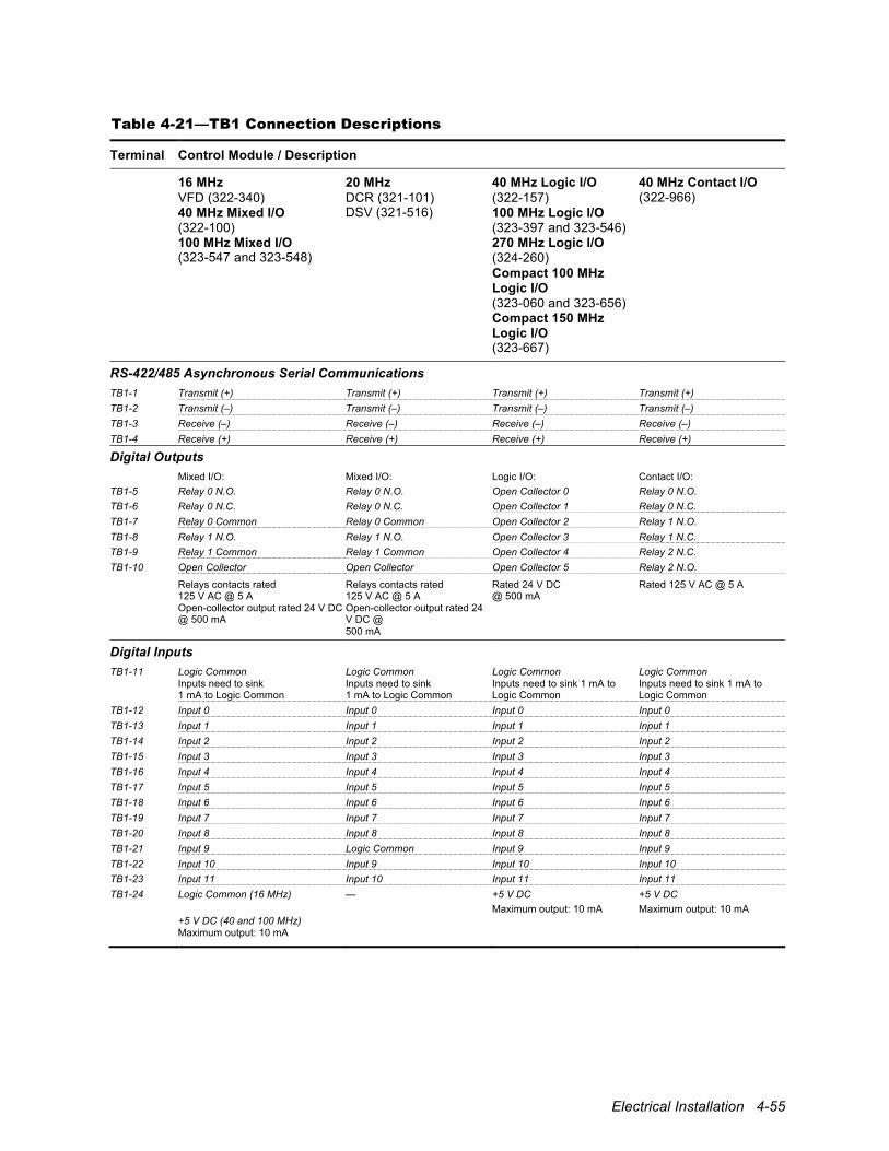
Electrical Installation 4-55
Table 4-21—TB1 Connection Descriptions
Terminal Control Module / Description
16 MHz VFD (322-340) 40 MHz Mixed I/O (322-100) 100 MHz Mixed I/O (323-547 and 323-548)
20 MHz DCR (321-101) DSV (321-516)
40 MHz Logic I/O (322-157) 100 MHz Logic I/O (323-397 and 323-546) 270 MHz Logic I/O (324-260) Compact 100 MHz Logic I/O (323-060 and 323-656) Compact 150 MHz Logic I/O (323-667)
40 MHz Contact I/O (322-966)
RS-422/485 Asynchronous Serial Communications TB1-1 Transmit (+) Transmit (+) Transmit (+) Transmit (+) TB1-2 Transmit (–) Transmit (–) Transmit (–) Transmit (–) TB1-3 Receive (–) Receive (–) Receive (–) Receive (–) TB1-4 Receive (+) Receive (+) Receive (+) Receive (+)
Digital Outputs Mixed I/O: Mixed I/O: Logic I/O: Contact I/O: TB1-5 Relay 0 N.O. Relay 0 N.O. Open Collector 0 Relay 0 N.O. TB1-6 Relay 0 N.C. Relay 0 N.C. Open Collector 1 Relay 0 N.C. TB1-7 Relay 0 Common Relay 0 Common Open Collector 2 Relay 1 N.O. TB1-8 Relay 1 N.O. Relay 1 N.O. Open Collector 3 Relay 1 N.C. TB1-9 Relay 1 Common Relay 1 Common Open Collector 4 Relay 2 N.C. TB1-10 Open Collector Open Collector Open Collector 5 Relay 2 N.O.
Relays contacts rated 125 V AC @ 5 A Open-collector output rated 24 V DC @ 500 mA
Relays contacts rated 125 V AC @ 5 A Open-collector output rated 24 V DC @ 500 mA
Rated 24 V DC @ 500 mA
Rated 125 V AC @ 5 A
Digital Inputs TB1-11 Logic Common
Inputs need to sink 1 mA to Logic Common
Logic Common Inputs need to sink 1 mA to Logic Common
Logic Common Inputs need to sink 1 mA to Logic Common
Logic Common Inputs need to sink 1 mA to Logic Common
TB1-12 Input 0 Input 0 Input 0 Input 0 TB1-13 Input 1 Input 1 Input 1 Input 1 TB1-14 Input 2 Input 2 Input 2 Input 2 TB1-15 Input 3 Input 3 Input 3 Input 3 TB1-16 Input 4 Input 4 Input 4 Input 4 TB1-17 Input 5 Input 5 Input 5 Input 5 TB1-18 Input 6 Input 6 Input 6 Input 6 TB1-19 Input 7 Input 7 Input 7 Input 7 TB1-20 Input 8 Input 8 Input 8 Input 8 TB1-21 Input 9 Logic Common Input 9 Input 9 TB1-22 Input 10 Input 9 Input 10 Input 10 TB1-23 Input 11 Input 10 Input 11 Input 11 TB1-24 Logic Common (16 MHz)
+5 V DC (40 and 100 MHz) Maximum output: 10 mA
— +5 V DC Maximum output: 10 mA
+5 V DC Maximum output: 10 mA
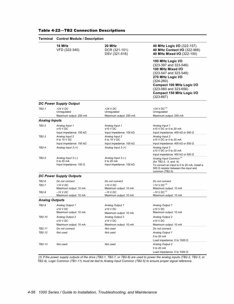
4-56 1000 Series / Guide to Installation, Troubleshooting, and Maintenance
Table 4-22—TB2 Connection Descriptions
Terminal Control Module / Description
16 MHz VFD (322-340)
20 MHz DCR (321-101) DSV (321-516)
40 MHz Logic I/O (322-157) 40 MHz Contact I/O (322-966) 40 MHz Mixed I/O (322-100)
100 MHz Logic I/O (323-397 and 323-546) 100 MHz Mixed I/O (323-547 and 323-548) 270 MHz Logic I/O (324-260) Compact 100 MHz Logic I/O (323-060 and 323-656) Compact 150 MHz Logic I/O (323-667)
DC Power Supply Output TB2-1 +24 V DC
Unregulated Maximum output: 250 mA
+24 V DC Unregulated Maximum output: 250 mA
+24 V DC (†) Unregulated Maximum output: 250 mA
Analog Inputs TB2-2 Analog Input 1
±10 V DC Input impedance: 100 kΩ
Analog Input 1 ±10 V DC Input impedance: 100 kΩ
Analog Input 1 ±10 V DC or 0 to 20 mA Input impedance: 400 kΩ or 500 Ω
TB2-3 Analog Input 2 0 to 10 V DC Input impedance: 100 kΩ
Analog Input 2 0 to 10 V DC Input impedance: 100 kΩ
Analog Input 2 ±10 V DC or 0 to 20 mA Input impedance: 400 kΩ or 500 Ω
TB2-4 Analog Input 3 (+) Analog Input 3 (+) Analog Input 3 ±10 V DC or 0 to 20 mA Input impedance: 400 kΩ or 500 Ω
TB2-5 Analog Input 3 (–) 0 to 20 mA Input impedance: 150 Ω
Analog Input 3 (–) 0 to 20 mA Input impedance: 150 kΩ
Analog Input Common (†) (for TB2-2, -3, and -4) To convert an input to 0 to 20 mA, install a 500 Ω resistor between the input and common (TB2-5)
DC Power Supply Outputs TB2-6 Do not connect Do not connect Do not connect TB2-7 +10 V DC
Maximum output: 10 mA +10 V DC Maximum output: 10 mA
+10 V DC (†) Maximum output: 10 mA
TB2-8 –10 V DC Maximum output: 10 mA
–10 V DC Maximum output: 10 mA
–10 V DC (†) Maximum output: 10 mA
Analog Outputs TB2-9 Analog Output 1
±10 V DC Maximum output: 10 mA
Analog Output 1 ±10 V DC Maximum output: 10 mA
Analog Output 1 ±10 V DC Maximum output: 10 mA
TB2-10 Analog Output 2 ±10 V DC Maximum output: 10 mA
Analog Output 2 ±10 V DC Maximum output: 10 mA
Analog Output 2 ±10 V DC Maximum output: 10 mA
TB2-11 Do not connect Not used Do not connect TB2-12 Not used Not used Analog Output 1
0 to 20 mA Load impedance: 0 to 1000 Ω
TB2-13 Not used Not used Analog Output 2 0 to 20 mA Load impedance: 0 to 1000 Ω
(†) If the power supply outputs of the drive (TB2-1, TB2-7, or TB2-8) are used to power the analog inputs (TB2-2, TB2-3, or TB2-4), Logic Common (TB1-11) must be tied to Analog Input Common (TB2-5) to ensure proper signal reference.
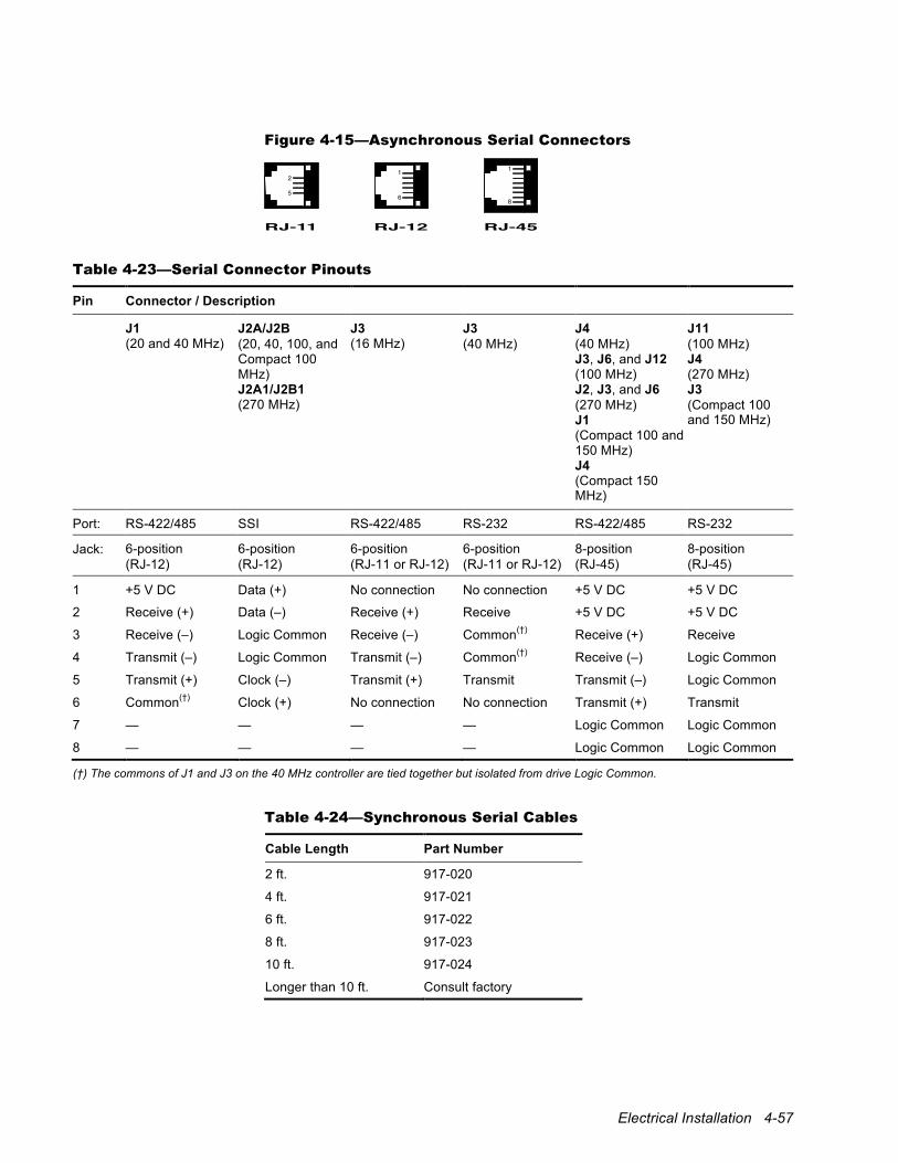
Electrical Installation 4-57
Figure 4-15—Asynchronous Serial Connectors
1
6
RJ-12
2
5
RJ-11
1
8
RJ-45
Table 4-23—Serial Connector Pinouts
Pin Connector / Description
J1 (20 and 40 MHz)
J2A/J2B (20, 40, 100, and Compact 100 MHz) J2A1/J2B1 (270 MHz)
J3 (16 MHz)
J3 (40 MHz)
J4 (40 MHz) J3, J6, and J12 (100 MHz) J2, J3, and J6 (270 MHz) J1 (Compact 100 and 150 MHz) J4 (Compact 150 MHz)
J11 (100 MHz) J4 (270 MHz) J3 (Compact 100 and 150 MHz)
Port: RS-422/485 SSI RS-422/485 RS-232 RS-422/485 RS-232
Jack: 6-position (RJ-12)
6-position (RJ-12)
6-position (RJ-11 or RJ-12)
6-position (RJ-11 or RJ-12)
8-position (RJ-45)
8-position (RJ-45)
1 +5 V DC Data (+) No connection No connection +5 V DC +5 V DC
2 Receive (+) Data (–) Receive (+) Receive +5 V DC +5 V DC
3 Receive (–) Logic Common Receive (–) Common(†) Receive (+) Receive
4 Transmit (–) Logic Common Transmit (–) Common(†) Receive (–) Logic Common
5 Transmit (+) Clock (–) Transmit (+) Transmit Transmit (–) Logic Common
6 Common(†) Clock (+) No connection No connection Transmit (+) Transmit
7 — — — — Logic Common Logic Common
8 — — — — Logic Common Logic Common
(†) The commons of J1 and J3 on the 40 MHz controller are tied together but isolated from drive Logic Common.
Table 4-24—Synchronous Serial Cables
Cable Length Part Number
2 ft. 917-020
4 ft. 917-021
6 ft. 917-022
8 ft. 917-023
10 ft. 917-024
Longer than 10 ft. Consult factory
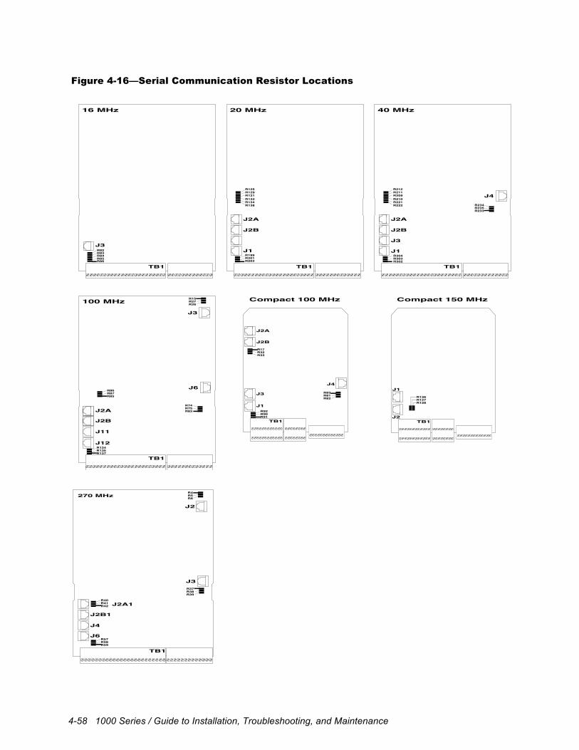
4-58 1000 Series / Guide to Installation, Troubleshooting, and Maintenance
Figure 4-16—Serial Communication Resistor Locations
R125R129R131
R199R201R203
R132R134R138
J2A
J2B
J1
TB1
20 MHz
100 MHz
J2A
J2B
J11
J12
J6
R134R135R137
J3
TB1
R86R87R85
R74R75R83
R15R27R26
R83R82
R85R86
R84
J3
TB1
16 MHz
R304R303R302
R212R211R209R210R221R222
J4
J2A
J2B
J3
J1
TB1
40 MHz
R234R235R233
Compact 100 MHz Compact 150 MHz
J2A
J2B
J1
J3
J4
R92R90R91
TB1
R17R32R33
R83R81R82
J2
J1
R126R127R128
TB1
TB1
J2A1
J2B1
J4
J3
J6
J2
270 MHz
R40R41R42
R57R58R59
R37R38R39
R4R5R6
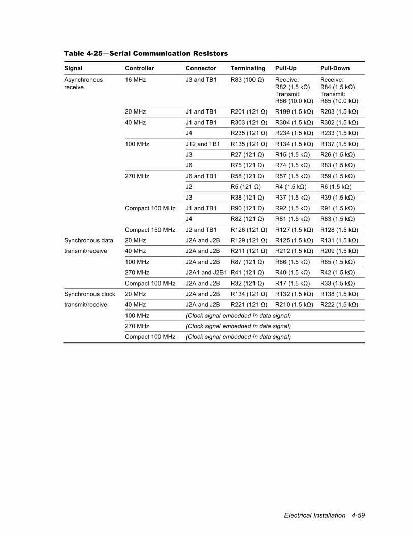
Electrical Installation 4-59
Table 4-25—Serial Communication Resistors
Signal Controller Connector Terminating Pull-Up Pull-Down
Asynchronous receive
16 MHz
J3 and TB1 R83 (100 Ω)
Receive: R82 (1.5 kΩ) Transmit: R86 (10.0 kΩ)
Receive: R84 (1.5 kΩ) Transmit: R85 (10.0 kΩ)
20 MHz J1 and TB1 R201 (121 Ω) R199 (1.5 kΩ) R203 (1.5 kΩ)
40 MHz J1 and TB1 R303 (121 Ω) R304 (1.5 kΩ) R302 (1.5 kΩ)
J4 R235 (121 Ω) R234 (1.5 kΩ) R233 (1.5 kΩ)
100 MHz J12 and TB1 R135 (121 Ω) R134 (1.5 kΩ) R137 (1.5 kΩ)
J3 R27 (121 Ω) R15 (1.5 kΩ) R26 (1.5 kΩ)
J6 R75 (121 Ω) R74 (1.5 kΩ) R83 (1.5 kΩ)
270 MHz J6 and TB1 R58 (121 Ω) R57 (1.5 kΩ) R59 (1.5 kΩ)
J2 R5 (121 Ω) R4 (1.5 kΩ) R6 (1.5 kΩ)
J3 R38 (121 Ω) R37 (1.5 kΩ) R39 (1.5 kΩ)
Compact 100 MHz J1 and TB1 R90 (121 Ω) R92 (1.5 kΩ) R91 (1.5 kΩ)
J4 R82 (121 Ω) R81 (1.5 kΩ) R83 (1.5 kΩ)
Compact 150 MHz J2 and TB1 R126 (121 Ω) R127 (1.5 kΩ) R128 (1.5 kΩ)
Synchronous data 20 MHz J2A and J2B R129 (121 Ω) R125 (1.5 kΩ) R131 (1.5 kΩ)
transmit/receive 40 MHz J2A and J2B R211 (121 Ω) R212 (1.5 kΩ) R209 (1.5 kΩ)
100 MHz J2A and J2B R87 (121 Ω) R86 (1.5 kΩ) R85 (1.5 kΩ)
270 MHz J2A1 and J2B1 R41 (121 Ω) R40 (1.5 kΩ) R42 (1.5 kΩ)
Compact 100 MHz J2A and J2B R32 (121 Ω) R17 (1.5 kΩ) R33 (1.5 kΩ)
Synchronous clock 20 MHz J2A and J2B R134 (121 Ω) R132 (1.5 kΩ) R138 (1.5 kΩ)
transmit/receive 40 MHz J2A and J2B R221 (121 Ω) R210 (1.5 kΩ) R222 (1.5 kΩ)
100 MHz (Clock signal embedded in data signal)
270 MHz (Clock signal embedded in data signal)
Compact 100 MHz (Clock signal embedded in data signal)
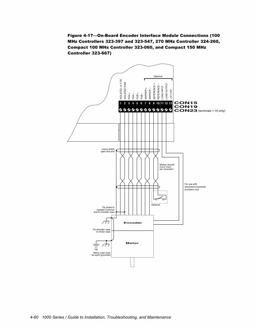
4-60 1000 Series / Guide to Installation, Troubleshooting, and Maintenance
Figure 4-17—On-Board Encoder Interface Module Connections (100
MHz Controllers 323-397 and 323-547, 270 MHz Controller 324-260,
Compact 100 MHz Controller 323-060, and Compact 150 MHz
Controller 323-667)
1 2 3 4 5 6 7 8 9 10 11 12 1310 11 12 13 14 15 16 1718 19 20 21 22 23 24
1 2 3 4 5 6 7 8 9 10 11 12 13CON19CON23 (terminals 1-10 only)
CON15
Marker should
For use withabsolute/incrementalencoders only
occur onceper revolution
Encoder
Motor
PEMotor case must
be earth grounded
Tie encoder caseto motor case
isolated CommonTie shield to
Optional
and to encoder case
open this endLeave shield
ISO
LATE
D +
5 V
DC
ISO
LATE
D C
OM
PGA
+
PGA
–
PGB
+
PGB
–
MAR
KER
+
MAR
KER
–
REF
EREN
CE
+
LOAD
INPU
T
LOAD
OU
TPU
T
+15
V D
C
REF
EREN
CE
–
Optional
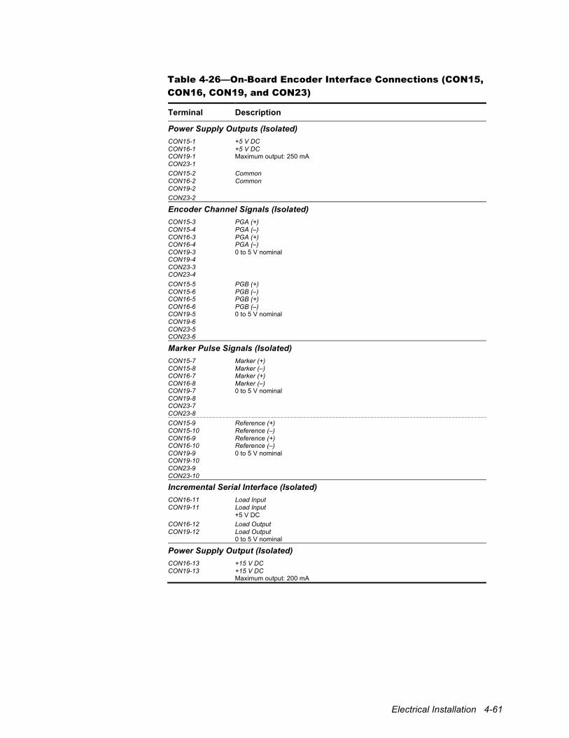
Electrical Installation 4-61
Table 4-26—On-Board Encoder Interface Connections (CON15,
CON16, CON19, and CON23)
Terminal Description
Power Supply Outputs (Isolated) CON15-1 CON16-1 CON19-1 CON23-1
+5 V DC +5 V DC Maximum output: 250 mA
CON15-2 CON16-2 CON19-2 CON23-2
Common Common
Encoder Channel Signals (Isolated) CON15-3 CON15-4 CON16-3 CON16-4 CON19-3 CON19-4 CON23-3 CON23-4
PGA (+) PGA (–) PGA (+) PGA (–) 0 to 5 V nominal
CON15-5 CON15-6 CON16-5 CON16-6 CON19-5 CON19-6 CON23-5 CON23-6
PGB (+) PGB (–) PGB (+) PGB (–) 0 to 5 V nominal
Marker Pulse Signals (Isolated) CON15-7 CON15-8 CON16-7 CON16-8 CON19-7 CON19-8 CON23-7 CON23-8
Marker (+) Marker (–) Marker (+) Marker (–) 0 to 5 V nominal
CON15-9 CON15-10 CON16-9 CON16-10 CON19-9 CON19-10 CON23-9 CON23-10
Reference (+) Reference (–) Reference (+) Reference (–) 0 to 5 V nominal
Incremental Serial Interface (Isolated) CON16-11 CON19-11
Load Input Load Input +5 V DC
CON16-12 CON19-12
Load Output Load Output 0 to 5 V nominal
Power Supply Output (Isolated) CON16-13 CON19-13
+15 V DC +15 V DC Maximum output: 200 mA
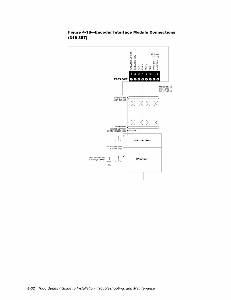
4-62 1000 Series / Guide to Installation, Troubleshooting, and Maintenance
Figure 4-18—Encoder Interface Module Connections
(316-887)
1 2 3 4 5 6 7 8
CON2
ISO
LATE
D +
5 V
DC
ISO
LATE
D C
OM
PGA
+
PGA
–
PGB
+
PGB
–
Optional
Marker shouldoccur onceper revolution
Encoder
Motor
PE
Motor case mustbe earth grounded
Tie encoder caseto motor case
isolated CommonTie shield to
and to encoder case
open this endLeave shield
MAR
KER
+
MAR
KER
–
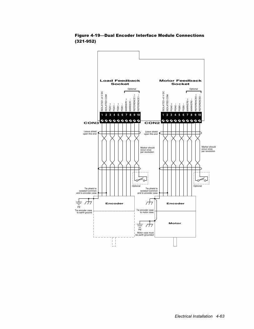
Electrical Installation 4-63
Figure 4-19—Dual Encoder Interface Module Connections
(321-952)
Marker shouldoccur onceper revolution
Encoder
Tie encoder caseto earth ground
isolated CommonTie shield to
and to encoder case
open this endLeave shield
Marker shouldoccur onceper revolution
Encoder
Motor
PE
PE
Motor case mustbe earth grounded
Tie encoder caseto motor case
isolated CommonTie shield to
Optional Optional
and to encoder case
open this endLeave shield
1 2 3 4 5 6 7 8 9 10
CON3
Load Feedback Socket
Motor Feedback Socket
CON2
ISO
LATE
D +
5 V
DC
ISO
LATE
D C
OM
PGA1
+
PGA1
–
PGB1
+
PGB1
–
MAR
KER
1 +
MAR
KER
1 –
ISO
LATE
D +
5 V
DC
ISO
LATE
D C
OM
PGA0
+
PGA0
–
PGB0
+
PGB0
–
MAR
KER
0 +
MAR
KER
0 –
REF
EREN
CE0
+
REF
EREN
CE0
–
1 2 3 4 5 6 7 8 9 10
REF
EREN
CE1
+
REF
EREN
CE1
–
Optional Optional
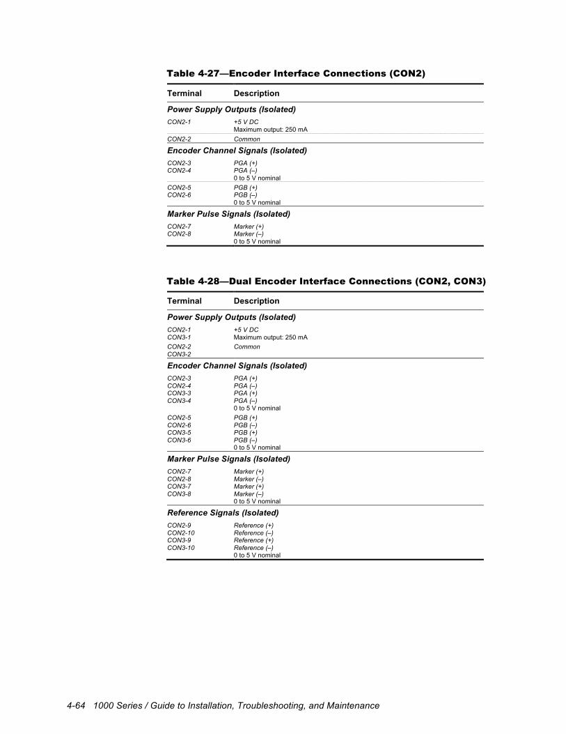
4-64 1000 Series / Guide to Installation, Troubleshooting, and Maintenance
Table 4-27—Encoder Interface Connections (CON2)
Terminal Description
Power Supply Outputs (Isolated) CON2-1 +5 V DC
Maximum output: 250 mA CON2-2 Common
Encoder Channel Signals (Isolated) CON2-3 CON2-4
PGA (+) PGA (–) 0 to 5 V nominal
CON2-5 CON2-6
PGB (+) PGB (–) 0 to 5 V nominal
Marker Pulse Signals (Isolated) CON2-7 CON2-8
Marker (+) Marker (–) 0 to 5 V nominal
Table 4-28—Dual Encoder Interface Connections (CON2, CON3)
Terminal Description
Power Supply Outputs (Isolated) CON2-1 CON3-1
+5 V DC Maximum output: 250 mA
CON2-2 CON3-2
Common
Encoder Channel Signals (Isolated) CON2-3 CON2-4 CON3-3 CON3-4
PGA (+) PGA (–) PGA (+) PGA (–) 0 to 5 V nominal
CON2-5 CON2-6 CON3-5 CON3-6
PGB (+) PGB (–) PGB (+) PGB (–) 0 to 5 V nominal
Marker Pulse Signals (Isolated) CON2-7 CON2-8 CON3-7 CON3-8
Marker (+) Marker (–) Marker (+) Marker (–) 0 to 5 V nominal
Reference Signals (Isolated) CON2-9 CON2-10 CON3-9 CON3-10
Reference (+) Reference (–) Reference (+) Reference (–) 0 to 5 V nominal
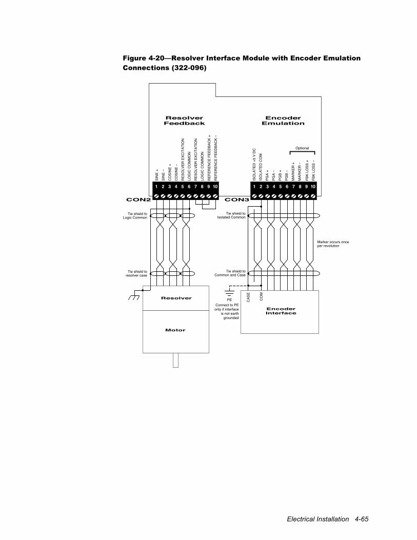
Electrical Installation 4-65
Figure 4-20—Resolver Interface Module with Encoder Emulation
Connections (322-096)
Marker occurs onceper revolution
Connect to PE only if interface
is not earth grounded
Isolated CommonTie shield to
Common and CaseTie shield to
Resolver
Motor
PE
resolver caseTie shield to
Logic CommonTie shield to
1 2 3 4 5 6 7 8
CON3
Encoder Emulation
Resolver Feedback
CON2
ISO
LATE
D +
5 V
DC
ISO
LATE
D C
OM
PGA
+
PGA
–
PGB
+
PGB
–
MAR
KER
+
MAR
KER
–
SIN
E +
SIN
E –
CO
SIN
E +
CO
SIN
E –
RES
OLV
ER E
XCIT
ATIO
N
LOG
IC C
OM
MO
N
RES
OLV
ER E
XCIT
ATIO
N
LOG
IC C
OM
MO
N
REF
EREN
CE
FEED
BAC
K +
REF
EREN
CE
FEED
BAC
K –
1 2 3 4 5 6 7 8 9 10
FBK
LOSS
+
FBK
LOSS
–
9 10
Optional
Encoder Interface
CAS
E
CO
M
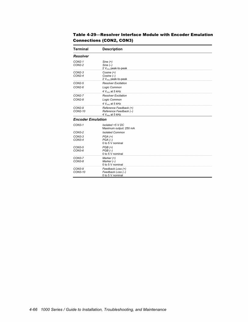
4-66 1000 Series / Guide to Installation, Troubleshooting, and Maintenance
Table 4-29—Resolver Interface Module with Encoder Emulation
Connections (CON2, CON3)
Terminal Description
Resolver CON2-1 CON2-2
Sine (+) Sine (–) 2 Vrms peak-to-peak
CON2-3 CON2-4
Cosine (+) Cosine (–) 2 Vrms peak-to-peak
CON2-5 Resolver Excitation CON2-6 Logic Common
4 Vrms at 5 kHz CON2-7 Resolver Excitation CON2-8 Logic Common
4 Vrms at 5 kHz CON2-9 CON2-10
Reference Feedback (+) Reference Feedback (–) 4 Vrms at 5 kHz
Encoder Emulation CON3-1 Isolated +5 V DC
Maximum output: 250 mA CON3-2 Isolated Common CON3-3 CON3-4
PGA (+) PGA (–) 0 to 5 V nominal
CON3-5 CON3-6
PGB (+) PGB (–) 0 to 5 V nominal
CON3-7 CON3-8
Marker (+) Marker (–) 0 to 5 V nominal
CON3-9 CON3-10
Feedback Loss (+) Feedback Loss (–) 0 to 5 V nominal
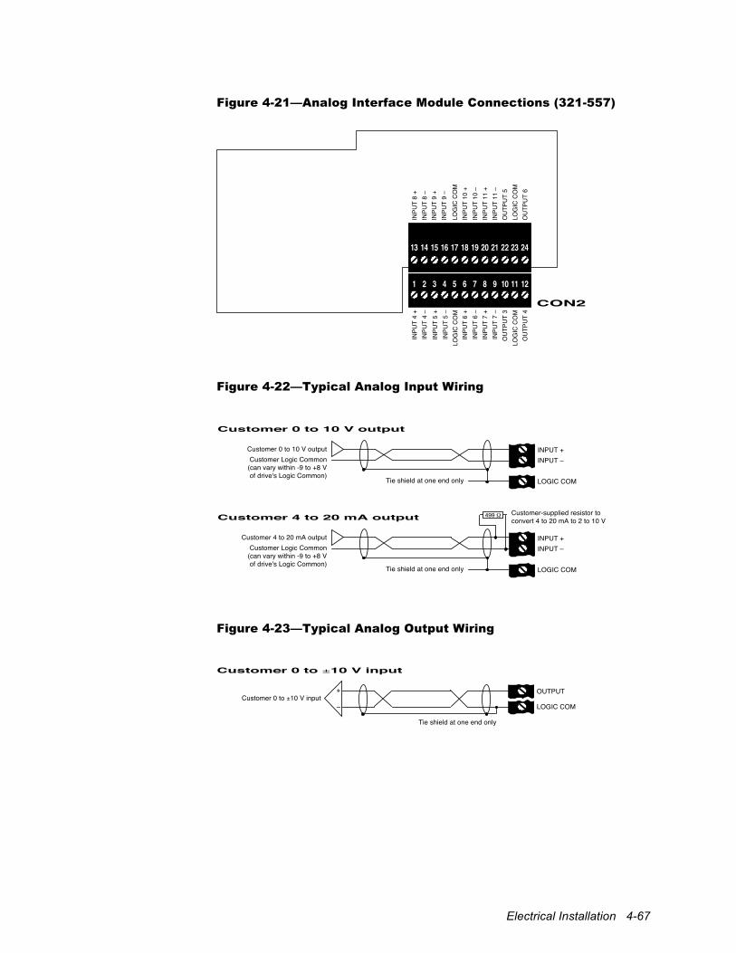
Electrical Installation 4-67
Figure 4-21—Analog Interface Module Connections (321-557)
13 14 15 16 17 18 19 20 21 22 23 24
1 2 3 4 5 6 7 8 9 10 11 12
CON2
INPU
T 4
+ IN
PUT
4 –
INPU
T 5
+ IN
PUT
5 –
LOG
IC C
OM
IN
PUT
6 +
INPU
T 6
– IN
PUT
7 +
INPU
T 7
– O
UTP
UT
3 LO
GIC
CO
M
OU
TPU
T 4
INPU
T 8
+ IN
PUT
8 –
INPU
T 9
+ IN
PUT
9 –
LOG
IC C
OM
IN
PUT
10 +
IN
PUT
10 –
IN
PUT
11 +
IN
PUT
11 –
O
UTP
UT
5 LO
GIC
CO
M
OU
TPU
T 6
Figure 4-22—Typical Analog Input Wiring
Customer 0 to 10 V output
INPUT +INPUT –
Customer 0 to 10 V outputCustomer Logic Common
(can vary within -9 to +8 V of drive's Logic Common)
LOGIC COM
Customer 4 to 20 mA output
INPUT +
Tie shield at one end only
Tie shield at one end only
INPUT – Customer 4 to 20 mA output
Customer Logic Common (can vary within -9 to +8 V of drive's Logic Common)
LOGIC COM
499 Customer-supplied resistor to convert 4 to 20 mA to 2 to 10 V
Figure 4-23—Typical Analog Output Wiring
Customer 0 to ±10 V input
OUTPUT
LOGIC COMCustomer 0 to ±10 V input
+
–
Tie shield at one end only
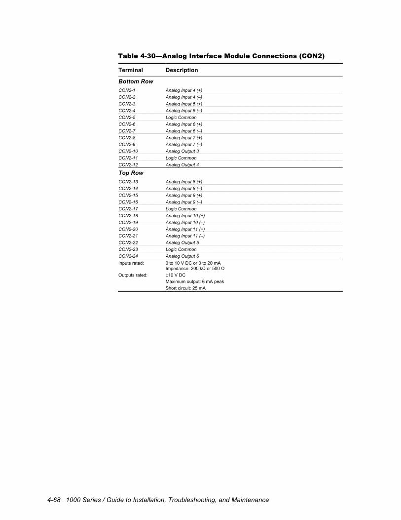
4-68 1000 Series / Guide to Installation, Troubleshooting, and Maintenance
Table 4-30—Analog Interface Module Connections (CON2)
Terminal Description
Bottom Row CON2-1 Analog Input 4 (+) CON2-2 Analog Input 4 (–) CON2-3 Analog Input 5 (+) CON2-4 Analog Input 5 (–) CON2-5 Logic Common CON2-6 Analog Input 6 (+) CON2-7 Analog Input 6 (–) CON2-8 Analog Input 7 (+) CON2-9 Analog Input 7 (–) CON2-10 Analog Output 3 CON2-11 Logic Common CON2-12 Analog Output 4
Top Row CON2-13 Analog Input 8 (+) CON2-14 Analog Input 8 (–) CON2-15 Analog Input 9 (+) CON2-16 Analog Input 9 (–) CON2-17 Logic Common CON2-18 Analog Input 10 (+) CON2-19 Analog Input 10 (–) CON2-20 Analog Input 11 (+) CON2-21 Analog Input 11 (–) CON2-22 Analog Output 5 CON2-23 Logic Common CON2-24 Analog Output 6 Inputs rated: 0 to 10 V DC or 0 to 20 mA
Impedance: 200 kΩ or 500 Ω Outputs rated: ±10 V DC
Maximum output: 6 mA peak Short circuit: 25 mA
Troubleshooting/Maintenance 5-1
5 Troubleshooting/Maintenance
5.1 Overview This chapter provides information useful in troubleshooting and maintaining the drive hardware. It presents the theory of operation, schematics, power electronics troubleshooting procedures, and general maintenance issues. It also provides a list of field-replaceable components.
5.2 Troubleshooting This manual is not intended to provide in-depth service instructions. For service beyond that described in this manual, please contact Unico or your representative.
!
Attention High voltage may be present even when all electrical power supplies are disconnected. After switching off electrical power, wait at least 15 minutes for bus circuit capacitors to discharge before working on the drive or associated equipment. Use an appropriate voltmeter to further verify that capacitors are discharged before beginning work. Do not rely exclusively on the bus voltage indicator. Dangerous voltage levels may remain even when the indicator is off.
5.2.1 Theory of Operation The general function of the drive is to convert a fixed voltage and frequency from an electrical power source into a variable voltage and frequency for controlling an AC motor. The block diagrams of the 1100, 1105, 1110, 1120, 1130, 1200, and 1230 drives are shown in Figure 5-1 through Figure 5-13. A rectifier section is used on the 1100, 1105, 1110, and 1200 drives to convert the fixed AC line voltage into a DC bus voltage. The 1120 is a modular design intended for operating a number of units from a common DC bus. Low-power drives use a diode rectifier and resistors to charge the bus capacitors, which is then bypassed by a contact once the bus is up to full voltage. Medium- and high-power drives use silicon-controlled rectifiers (SCRs) to control the charging of the bus capacitors. High-power drives provide for optional twelve-pulse (six-phase) connection of the input to reduce harmonic currents. The 1110 drive is designed for single-phase operation using two, rather than three, AC line voltage terminals. A rectifier control coordinates the charging of the bus. A link choke and bus capacitors in the 1100, 1105, and 1110 drives form a filter that smoothes the output of the rectifier section into a steady DC voltage. An optional dynamic brake device on these units allows regenerative energy from the load to be dissipated in an external resistor when the drive is braking. The dynamic braking device turns on when the bus voltage exceeds a preset value, causing the braking current to flow

5-2 1000 Series / Guide to Installation, Troubleshooting, and Maintenance
in the resistor. The link choke and dynamic brake device is normally part of the converter supplying the DC bus to 1120 units. A converter section is used on the 1130 and 1230 drives to regulate power flow between the AC line and DC bus. The converter uses an insulated gate bipolar transistor (IGBT) bridge to rectify the AC line voltage into a DC bus voltage. This section also regenerates energy from the DC bus to the AC line when the drive is braking. A regen control circuit turns on the input IGBTs in synchronism with the AC line to allow bidirectional power flow. An inverter section consisting of six insulated gate bipolar transistors (IGBTs) is used to power an AC motor. This section can produce sine-wave motor voltages and currents of any desired amplitude by rapidly switching the IGBTs using a technique called pulse-width modulation (PWM). A gate driver is used to pass switching signals from the drive controller to the IGBTs. Low-voltage power supplies provide the bias voltages for the control sections. Drives with constant-torque ratings up to 125 hp derive their control voltages from the DC bus using a bus-operated switching supply. Drives with constant-torque ratings greater than 125 hp use a step-down transformer and line-operated switching supply to generate the bias voltages. Overall operation of the unit is regulated by a drive control that incorporates a digital signal processor (DSP) and a digital current regulator (DCR) or digital space vector (DSV) control. This high-speed digital control uses both voltage and current feedback to regulate the output to the motor. Optional encoder and resolver interfaces are available to provide closed-loop control of motor velocity and/or position. A dual encoder option is available to slave the motor to other sections of a machine or to reduce machine resonance using dual transducer control. Variable-frequency drive (VFD) operation is an option for controlling AC motors in simple applications. A keypad and display on the control module provide access to operating and setup parameters. The control module also provides a number of analog and digital inputs that can be used as input to and output from the drive. Serial communication channels are also available for connecting drives to process controllers, communication networks, programmable controllers, or personal computers. Refer to the application manual for a detailed description of the operation of the control as well as the associated keypad and display.
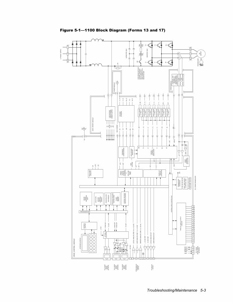
Troubleshooting/Maintenance 5-3
Figure 5-1—1100 Block Diagram (Forms 13 and 17)
ISO
LPW
R S
UPP
LY&
OPT
ICAL
ISO
L
TRAN
SDU
CER
INTE
RFA
CE
MV
IVF
IUF
POK
& W
DT
CIR
CU
ITS
TO /
FRO
M T
RAN
SDU
CER
TO /
FRO
M
ASYN
C S
ERIA
L N
ETW
OR
KRECV
XMITXMIT
RECV
DR
IVE
CO
NTR
OL
MO
DU
LE
+5 +15
-15
DIG
ITAL
SIG
NAL
PRO
CES
SOR
(DSP
)
KEYB
OAR
D &
DIS
PLAY
BUFF
ER &
CO
NTR
OL
REA
L TI
ME
CLO
CK
TIM
ER
SETU
P DA
TA
BATT
ERY
BAC
KUP
STAT
IC R
AMM
EMO
RY
OPE
RAT
ING
DAT
A
RAM
MEM
ORY
OPE
RAT
ING
PRO
GR
AMIN
STRU
CTI
ON
S
FLAS
HEE
PRO
MM
EMO
RY
CO
NTR
OL
DEC
OD
ER,
BUFF
ER &
CO
NTR
OL
OPT
ICAL
ISO
LATO
RS
SAM
PLE
& H
OLD
ANAL
OG
TO D
IGIT
ALC
ON
VERT
ER&
DIG
ITAL
TO
ANAL
OG
CO
NVE
RTER
FRO
M D
SP
TO D
SP
TO &
FRO
MAS
YNC
SER
IAL
NET
WO
RK
TO &
FRO
MSY
NC
HSE
RIA
LN
ETW
OR
K
FRO
M A
NAL
OG
CO
MM
AND
DEV
ICE
INTE
RN
AL D
ATA
& C
ON
TRO
L BU
SJU
MPE
RS
FO
RVO
LTAG
E &
HO
RSE
POW
ERID
ENTI
FIC
ATIO
N
BUS
VOLT
AGE
VU VV VW VB +
VB -
U +
E
V +
E
W +
E
B +
W- E
U +
V +
W +
U +
U -
IUF
IVF
IWF
OVE
RC
UR
REN
T D
ETEC
TOR
POC
+5 +8+8
ISO
+15
-15
+24
CR
3 P
HAS
E S
UPP
LY
RS
T
CR
U +
U -
V +
V -
W +
W -
VOLT
AGE
DIV
IDER
S
GAT
E D
RIV
E&
FAU
LT
V +
V -
W +
W -
IOC
DIG
ITAL
CU
RR
ENT
REG
ULA
TOR
GAT
E D
RIV
ER M
OD
ULE
GAT
E D
RIV
E&
FAU
LT
GAT
E D
RIV
E&
FAU
LT
GAT
E D
RIV
E&
FAU
LT
GAT
E D
RIV
E&
FAU
LT
GAT
E D
RIV
E&
FAU
LT
CAP
ACIT
OR
BU
S
INV
TSTS
VUF
VVF
FEED
BAC
KC
ON
DIT
ION
ING
IUC
IV C
TO A
NAL
OG
DEV
ICE
TO &
FRO
MSY
NC
HSE
RIA
LN
ETW
OR
K
FRO
M D
SP
FRO
M D
SP
TO D
SP
LC
1 2 3 4 5 6 7 8 9 10
sc
+24
VDC
LOC
AL A
NAL
OG
CM
D 0
to +
/-10
VDC
USE
R A
NAL
OG
CM
D 0
to
+10
VDC
REM
OTE
AN
ALO
G C
MD
0 t
o 2
0 m
A
+ 10
VD
C R
EF
- 10
VDC
REF
LOC
AL A
NAL
OG
OU
T
USE
R A
NAL
OG
OU
T
12
34
DB
DB
DB
GAT
E D
RIV
E&
FAU
LT
U -
V -
W -
BUS
VOLT
AGE
MO
NIT
OR
LOW
VO
LTAG
ESW
ITC
H M
OD
EPO
WER
SU
PPLY
MS0
-5
POW
ER M
OD
ULE
6PO
WER
MO
DU
LE
BUS
CH
ARG
E
+ 8
ISO
U L
EMSC
ALE
RES
ISTO
RS
V L
EMSC
ALE
RES
ISTO
RS
PAR
ALLE
L IN
PUT
& O
UTP
UT
CIR
CU
ITS
56
78
910
1112
1314
1516
1718
1920
2122
23
DB L
B+D
B
INVE
RTER
BU
SU
+U
-
V +
V -
W +
W -
UV
W
ACM
OTO
R
TRAN
SDU
CER
PROCESSOR BUS
FOR
DR
IVES
WIT
HO
UT
DYN
AMIC
BR
AKIN
G,
DB
IS L
ABEL
ED B
– AN
D C
ON
NEC
TS T
O
NEG
ATIV
E BU
S
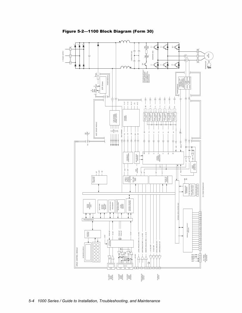
5-4 1000 Series / Guide to Installation, Troubleshooting, and Maintenance
Figure 5-2—1100 Block Diagram (Form 30)
ISO
LPW
R S
UPP
LY&
OPT
ICAL
ISO
L
TRAN
SDU
CER
INTE
RFA
CE
MV
IVF
IUF
POK
& W
DT
CIR
CU
ITS
DR
IVE
CO
NTR
OL
MO
DU
LE
+5 +15
-15
DIG
ITAL
SIG
NAL
PRO
CES
SOR
(DSP
)
KEYB
OAR
D &
DIS
PLAY
BUFF
ER &
CO
NTR
OL
REA
L TI
ME
CLO
CK
TIM
ER
SETU
P DA
TA
BATT
ERY
BAC
KUP
STAT
IC R
AMM
EMO
RY
OPE
RAT
ING
DAT
A
RAM
MEM
ORY
OPE
RAT
ING
PRO
GR
AMIN
STRU
CTI
ON
S
FLAS
HEE
PRO
MM
EMO
RY
CO
NTR
OL
DEC
OD
ER,
BUFF
ER &
CO
NTR
OL
OPT
ICAL
ISO
LATO
RS
SAM
PLE
& H
OLD
ANAL
OG
TO D
IGIT
ALC
ON
VERT
ER&
DIG
ITAL
TO
ANAL
OG
CO
NVE
RTER
FRO
M D
SP
TO D
SP
TO &
FRO
MAS
YNC
SER
IAL
NET
WO
RK
TO &
FRO
MSY
NC
HSE
RIA
LN
ETW
OR
K
FRO
M A
NAL
OG
CO
MM
AND
DEV
ICE
INTE
RN
AL D
ATA
& C
ON
TRO
L BU
SJU
MPE
RS
FO
RVO
LTAG
E &
HO
RSE
POW
ERID
ENTI
FIC
ATIO
N
BUS
VOLT
AGE
VU VV VW VB +
VB -
U +
E
V +
E
W +
E
B +
W- E
U +
V +
W +
U +
U -
IUF
IVF
IWF
OVE
RC
UR
REN
T D
ETEC
TOR
POC
+5 +8+8
ISO
+15
-15
+24
3 P
HAS
E S
UPP
LY
RS
T
U +
U -
V +
V -
W +
W -
VOLT
AGE
DIV
IDER
S
GAT
E D
RIV
E&
FAU
LT
V +
V -
W +
W -
IOC
DIG
ITAL
CU
RR
ENT
REG
ULA
TOR
GAT
E D
RIV
ER M
OD
ULE
GAT
E D
RIV
E&
FAU
LT
GAT
E D
RIV
E&
FAU
LT
GAT
E D
RIV
E&
FAU
LT
GAT
E D
RIV
E&
FAU
LT
GAT
E D
RIV
E&
FAU
LT
CAP
ACIT
OR
BU
S
INV
TSTS
VUF
VVF
FEED
BAC
KC
ON
DIT
ION
ING
IUC
IV C
TO A
NAL
OG
DEV
ICE
TO &
FRO
MSY
NC
HSE
RIA
LN
ETW
OR
K
FRO
M D
SP
FRO
M D
SP
TO D
SP
LC
1 2 3 4 5 6 7 8 9 10
sc
+24
VDC
LOC
AL A
NAL
OG
CM
D 0
to +
/-10
VDC
USE
R A
NAL
OG
CM
D 0
to
+10
VDC
REM
OTE
AN
ALO
G C
MD
0 t
o 2
0 m
A
+ 10
VD
C R
EF
- 10
VDC
REF
LOC
AL A
NAL
OG
OU
T
USE
R A
NAL
OG
OU
T
DB
DB
DB
GAT
E D
RIV
E&
FAU
LT
U -
V -
W -
BUS
VOLT
AGE
MO
NIT
OR
LOW
VO
LTAG
ESW
ITC
H M
OD
EPO
WER
SU
PPLY
MS0
-5
POW
ER M
OD
ULE
6PO
WER
MO
DU
LE
BUS
CH
ARG
E
+ 8
ISO
U L
EMSC
ALE
RES
ISTO
RS
V L
EMSC
ALE
RES
ISTO
RS
SCR
Driv
ers
3
Phas
e
3 SC
R G
ate
Driv
es
63
PAR
ALLE
L IN
PUT
& O
UTP
UT
CIR
CU
ITS
12
34
56
78
910
1112
1314
1516
1718
1920
2122
23
DB L
B+D
B
INVE
RTER
BU
SU
+U
-
V +
V -
W +
W -
UV
W
ACM
OTO
R
TRAN
SDU
CER
FOR
DR
IVES
WIT
HO
UT
DYN
AMIC
BR
AKIN
G,
DB
IS L
ABEL
ED B
– AN
D C
ON
NEC
TS T
O
NEG
ATIV
E BU
S
TO /
FRO
M T
RAN
SDU
CER
TO /
FRO
M
ASYN
C S
ERIA
L N
ETW
OR
KRECV
XMITXMIT
RECV
PROCESSOR BUS
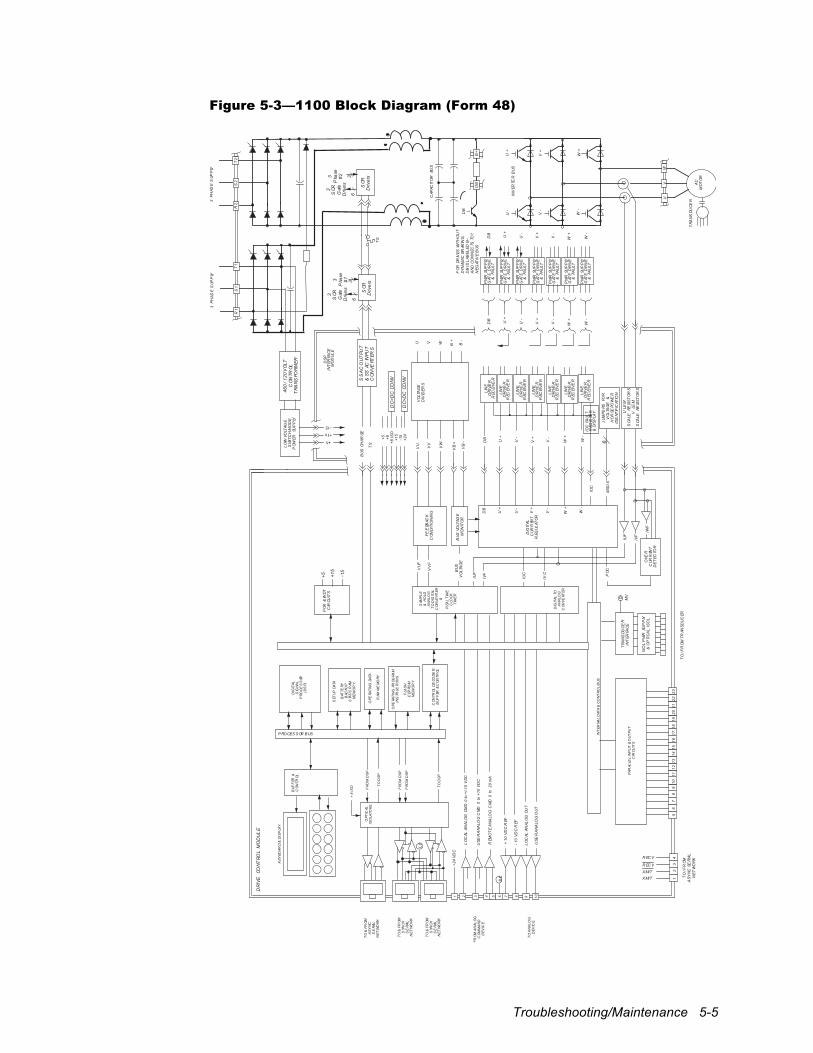
Troubleshooting/Maintenance 5-5
Figure 5-3—1100 Block Diagram (Form 48)
ISO
LP
WR
SUP
PLY
&O
PTI
CA
LIS
OL
TR
AN
SDU
CE
RIN
TER
FAC
EM
V
IVF
IUF
PO
K&
WD
TC
IRCU
ITS
TO
/FR
OMTR
ANS
DU
CER
DR
IVE
CON
TRO
LM
OD
UL
E
+5 +15
-15
DIG
ITAL
SIG
NAL
PRO
CE
SS
OR(D
SP)
KEY
BOAR
D&
DIS
PLA
Y
BU
FF
ER&
CO
NTR
OL
REA
LT
IME
CLO
CK
TIM
ER
SET
UP
DATA
BAT
TERY
BAC
KUP
STA
TIC
RAM
ME
MO
RY
OPE
RATI
NG
DATA
RAM
ME
MO
RY
OPE
RATI
NG
PROG
RAM
INS
TRUC
TIO
NS
FLA
SH
EEP
ROM
ME
MO
RY
CO
NTR
OL
DE
COD
ER,
BU
FF
ER&
CO
NTR
OL
OPT
ICAL
ISO
LATO
RS
SAM
PL
E&
HO
LDA
NA
LOG
TO
DIG
ITAL
CO
NV
ERT
ER&
DIG
ITAL
TOA
NA
LOG
CO
NV
ERT
ER
FRO
MD
SP
TO
DS
P
TO
&FR
OMA
SY
NC
SE
RIAL
NE
TW
OR
K
TO
&FR
OMS
YNC
HS
ER
IAL
NE
TW
OR
K
FR
OM
AN
ALO
GC
OM
MA
ND
DE
VIC
E
INT
ERNA
LD
ATA
&C
ON
TRO
LB
US
BU
SV
OLT
AG
E
VU VV
VW
VB
+
VB
-
U V W B+
U+
V+
W+
U+
U-
IUF
IVF
IWF
OVE
RC
URR
ENT
DE
TEC
TOR
PO
C
+5 +8+8
ISO
+15
-15
+24
3P
HAS
ES
UPP
LY
R2
S2
T2
DB L
B+
DB
INV
ERTE
RB
US
U+
U-
V+
V-
W+
W-
UV
W
AC
MO
TO
R
TR
AN
SDU
CE
R
U+
U-
V+
V-
W+
W-
VO
LTA
GE
DIV
IDE
RS
V+
V-
W+
W-
IOC
DIG
ITAL
CUR
REN
TR
EGUL
ATO
R
DS
PIN
TER
FAC
EM
OD
UL
E
CAP
ACIT
OR
BUS
TS
TS
VU
F
VV
FF
EE
DBAC
KC
ON
DIT
ION
ING
IUC
IVC
TO
AN
ALO
GD
EV
ICE
TO
&FR
OMS
YNC
HS
ER
IAL
NE
TW
OR
K
FRO
MD
SP
FRO
MD
SP
TO
DS
P
LC
1 2 3 4 5 6 7 8 9 10
sc
+24
VD
C
LO
CAL
ANA
LO
GCM
D0
to+/
-10
VD
C
USE
RA
NA
LOG
CM
D0
to+1
0V
DC
REM
OT
EA
NA
LOG
CM
D0
to20
mA
+10
VD
CR
EF
-10
VD
CR
EF
LO
CAL
ANA
LO
GO
UT
USE
RA
NA
LOG
OU
T
12
34
DB
DB
DB
LIN
ED
RIV
ER
REC
EIV
ER
U-
V-
W-
BU
SVO
LTAG
EM
ON
ITO
R
MS
0-5
6
BU
SCH
ARGE
+8
ISO
3P
HAS
ES
UPP
LY
R1
S1
T1
SCR
Driv
ers
3P
hase
#1
3P
hase
#2
3S
CRG
ate
Driv
es
63
JUM
PE
RSFO
RV
OLT
AG
E&
HO
RSE
POW
ER
IDE
NTIF
ICAT
ION
U+
U-
V+
V-
W+
W-
DB
PW
RSU
PP
LYG
ATE
DR
IVE
&FA
ULT
LIN
ED
RIV
ER
REC
EIV
ER
LIN
ED
RIV
ER
REC
EIV
ER
LIN
ED
RIV
ER
REC
EIV
ER
LIN
ED
RIV
ER
REC
EIV
ER
LIN
ED
RIV
ER
REC
EIV
ER
LIN
ED
RIV
ER
REC
EIV
ER
IOC
FAU
LTR
EGIS
TER
&D
ISP
LAY
B-
PW
RSU
PP
LYG
ATE
DR
IVE
&FA
ULT
PW
RSU
PP
LYG
ATE
DR
IVE
&FA
ULT
PW
RSU
PP
LYG
ATE
DR
IVE
&FA
ULT
PW
RSU
PP
LYG
ATE
DR
IVE
&FA
ULT
PW
RSU
PP
LYG
ATE
DR
IVE
&FA
ULT
PW
RSU
PP
LYG
ATE
DR
IVE
&FA
ULT
460
/120
VO
LTC
ON
TROL
TR
AN
SFO
RM
ER
DC
>DC
CON
V
DC
>DC
CON
V
SCR
Driv
ers
3S
CRG
ate
Driv
es
63
SS
AC
OU
TPU
T&
SS
ACIN
PU
TC
ON
VE
RTER
S
LO
WVO
LTAG
ES
WIT
CH
MO
DE
PO
WER
SUP
PLY
PAR
ALLE
LIN
PUT
&O
UT
PUT
CIR
CUIT
S
56
78
910
1112
1314
1516
1718
1920
2122
23
PROCES S OR BUS
TO
/FR
OM
AS
YN
CSE
RIA
L
NE
TW
OR
KR EC V
XMIT
XMIT
R EC V
FO
RDR
IVES
WIT
HO
UT
DY
NA
MIC
BRAK
ING
, D
BIS
LAB
ELED
B
AN
DC
ON
NEC
TSTO
?N
EG
ATIV
EB
US
ULE
MS
CALE
RESI
ST
OR
SV
LEM
SCA
LERE
SIS
TO
RS
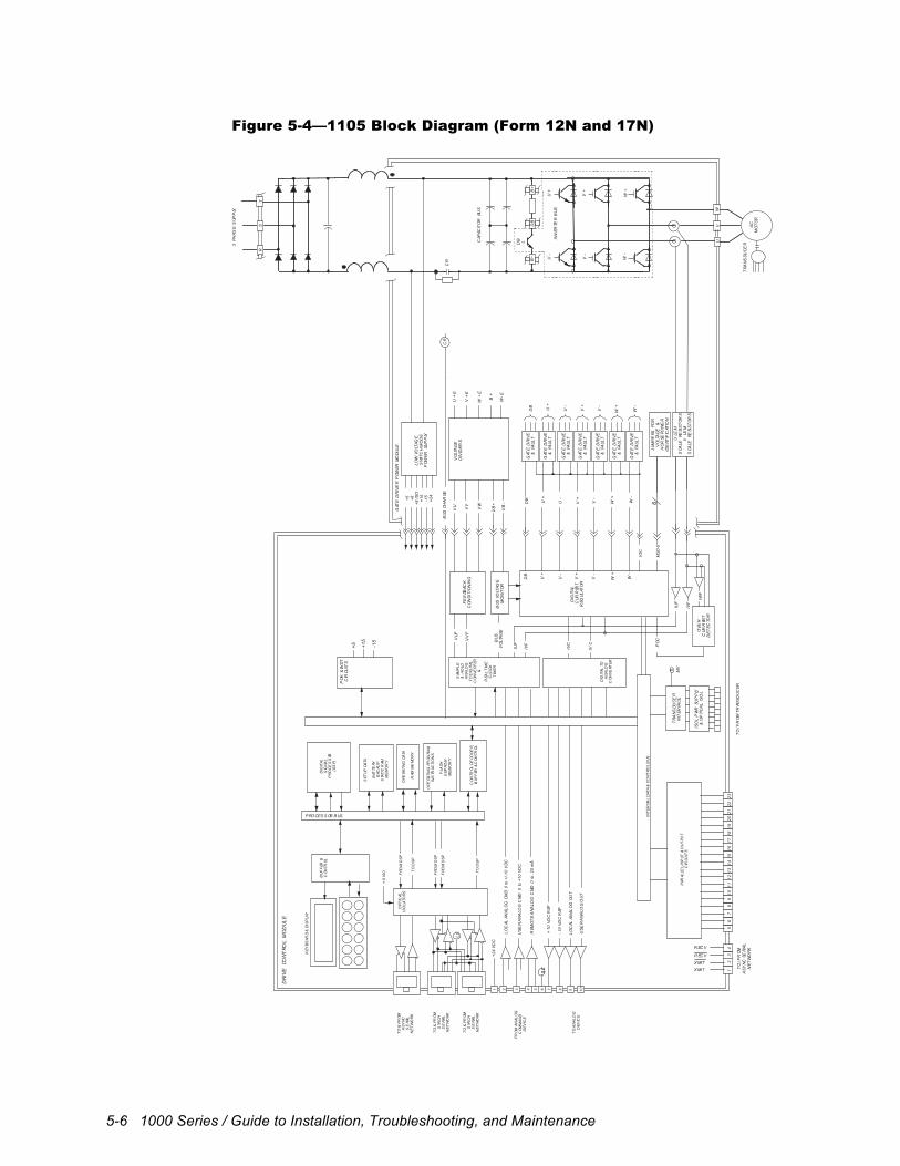
5-6 1000 Series / Guide to Installation, Troubleshooting, and Maintenance
Figure 5-4—1105 Block Diagram (Form 12N and 17N)
ISO
LP
WR
SUP
PLY
&O
PTI
CA
LIS
OL
TR
AN
SDU
CE
RIN
TER
FAC
EM
V
IVF
IUF
PO
K&
WD
TC
IRCU
ITS
TO
/FR
OMTR
ANS
DU
CER
DR
IVE
CON
TRO
LM
OD
UL
E
+5 +15
-15
DIG
ITAL
SIG
NAL
PRO
CE
SS
OR(D
SP)
KEY
BOAR
D&
DIS
PLA
Y
BU
FF
ER&
CO
NTR
OL
REA
LT
IME
CLO
CK
TIM
ER
SET
UP
DATA
BAT
TERY
BAC
KUP
STA
TIC
RAM
ME
MO
RY
OPE
RATI
NG
DATA
RAM
ME
MO
RY
OPE
RATI
NG
PROG
RAM
INS
TRUC
TIO
NS
FLA
SH
EEP
ROM
ME
MO
RY
CO
NTR
OL
DE
COD
ER,
BU
FF
ER&
CO
NTR
OL
OPT
ICAL
ISO
LATO
RS
SAM
PL
E&
HO
LDA
NA
LOG
TO
DIG
ITAL
CO
NV
ERT
ER&
DIG
ITAL
TOA
NA
LOG
CO
NV
ERT
ER
FRO
MD
SP
TO
DS
P
TO
&FR
OMA
SY
NC
SE
RIAL
NE
TW
OR
K
TO
&FR
OMS
YNC
HS
ER
IAL
NE
TW
OR
K
FR
OM
AN
ALO
GC
OM
MA
ND
DE
VIC
E
INT
ERNA
LD
ATA
&C
ON
TRO
LB
US
CR
BU
SV
OLT
AG
E
VU VV
VW
VB
+
VB
-
U+
E
V+
E
W+
E
B+
W-E
U+
V+
W+
U+
U-
IUF
IVF
IWF
OVE
RC
URR
ENT
DE
TEC
TOR
PO
C
+5 +8+8
ISO
+15
-15
+24
3P
HAS
ES
UPP
LY
RS
T
CR
U+
U-
V+
V-
W+
W-
VO
LTA
GE
DIV
IDE
RS
GAT
ED
RIV
E&
FAU
LT
V+
V-
W+
W-
IOC
DIG
ITAL
CUR
REN
TR
EGUL
ATO
R
GAT
ED
RIV
ER
PO
WER
MO
DU
LE
GAT
ED
RIV
E&
FAU
LT
GAT
ED
RIV
E&
FAU
LT
GAT
ED
RIV
E&
FAU
LT
GAT
ED
RIV
E&
FAU
LT
GAT
ED
RIV
E&
FAU
LT
CAP
ACIT
OR
BUS
VU
F
VV
FF
EE
DBAC
KC
ON
DIT
ION
ING
IUC
IVC
TO
AN
ALO
GD
EV
ICE
TO
&FR
OMS
YNC
HS
ER
IAL
NE
TW
OR
K
FRO
MD
SP
FRO
MD
SP
TO
DS
P
LC
1 2 3 4 5 6 7 8 9 10
sc
+24
VD
C
LO
CAL
ANA
LO
GCM
D0
to+/
-10
VD
C
USE
RA
NA
LOG
CM
D0
to+1
0V
DC
REM
OT
EA
NA
LOG
CM
D0
to20
mA
+10
VD
CR
EF
-10
VD
CR
EF
LO
CAL
ANA
LO
GO
UT
USE
RA
NA
LOG
OU
T
12
34
DB
DB
DB
GAT
ED
RIV
E&
FAU
LT
U-
V-
W-
BU
SVO
LTAG
EM
ON
ITO
R
LO
WVO
LTAG
ES
WIT
CH
MO
DE
PO
WER
SUP
PLY
MS
0-5
6
BU
SCH
ARGE
+8
ISO
PAR
ALLE
LIN
PUT
&O
UT
PUT
CIR
CUIT
S
56
78
910
1112
1314
1516
1718
1920
2122
23
JUM
PE
RSFO
RV
OLT
AG
E&
HO
RSE
POW
ER
IDE
NTIF
ICAT
ION
ULE
MS
CALE
RESI
ST
OR
SV
LEM
SCA
LERE
SIS
TO
RS
DB L
B+
DB
B
INV
ERTE
RB
US
U+
U-
V+
V-
W+
W-
UV
W
AC
MO
TO
R
TR
AN
SDU
CE
R
PROCES S OR BUS
TO
/FR
OM
AS
YN
CSE
RIA
L
NE
TW
OR
KR EC V
XMIT
XMIT
R EC V
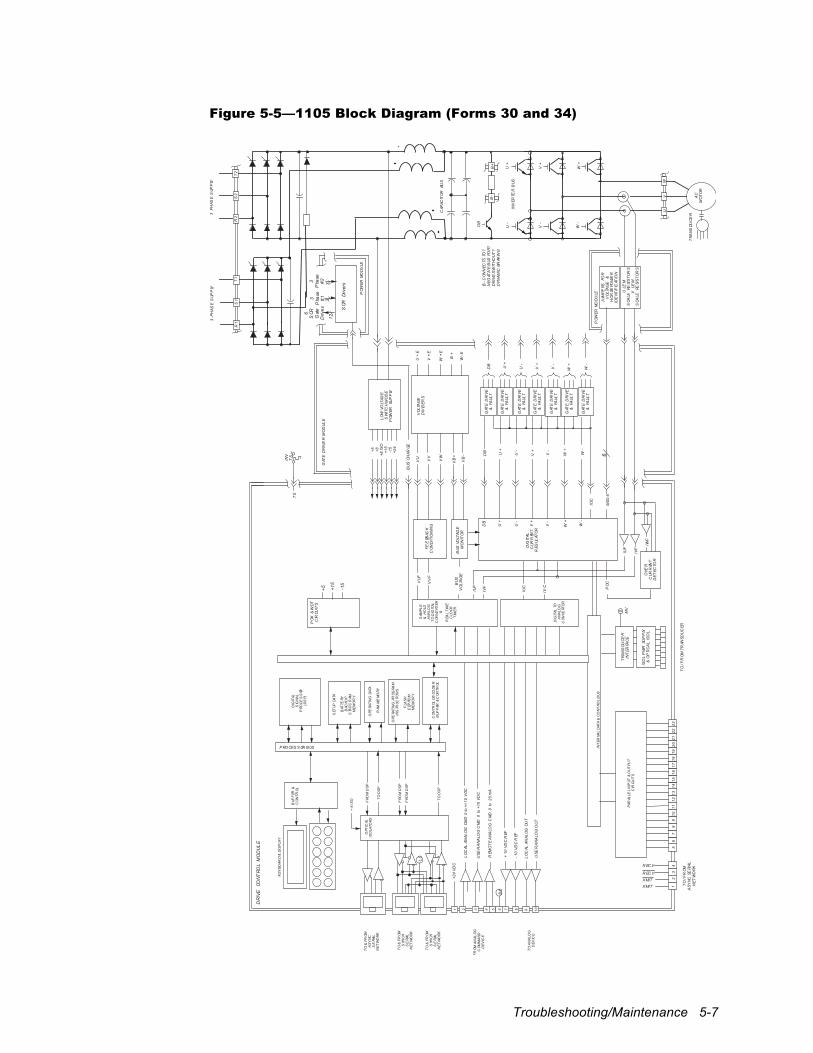
Troubleshooting/Maintenance 5-7
Figure 5-5—1105 Block Diagram (Forms 30 and 34)
ISO
LP
WR
SUP
PLY
&O
PTI
CA
LIS
OL
TR
AN
SDU
CE
RIN
TER
FAC
EM
V
IVF
IUF
PO
K&
WD
TC
IRCU
ITS
DR
IVE
CON
TRO
LM
OD
UL
E
+5 +15
-15
DIG
ITAL
SIG
NAL
PRO
CE
SS
OR(D
SP)
KEY
BOAR
D&
DIS
PLA
Y
BU
FF
ER&
CO
NTR
OL
REA
LT
IME
CLO
CK
TIM
ER
SET
UP
DATA
BAT
TERY
BAC
KUP
STA
TIC
RAM
ME
MO
RY
OPE
RATI
NG
DATA
RAM
ME
MO
RY
OPE
RATI
NG
PROG
RAM
INS
TRUC
TIO
NS
FLA
SH
EEP
ROM
ME
MO
RY
CO
NTR
OL
DE
COD
ER,
BU
FF
ER&
CO
NTR
OL
OPT
ICAL
ISO
LATO
RS
SAM
PL
E&
HO
LDA
NA
LOG
TO
DIG
ITAL
CO
NV
ERT
ER&
DIG
ITAL
TOA
NA
LOG
CO
NV
ERT
ER
FRO
MD
SP
TO
DS
P
TO
&FR
OMA
SY
NC
SE
RIAL
NE
TW
OR
K
TO
&FR
OMS
YNC
HS
ER
IAL
NE
TW
OR
K
FR
OM
AN
ALO
GC
OM
MA
ND
DE
VIC
E
INT
ERNA
LD
ATA
&C
ON
TRO
LB
US
JUM
PE
RSFO
RV
OLT
AG
E&
HO
RSE
POW
ER
IDE
NTIF
ICAT
ION
BU
SV
OLT
AG
E
VU VV
VW
VB
+
VB
-
U+
E
V+
E
W+
E
B+
W-E
U+
V+
W+
U+
U-
IUF
IVF
IWF
OVE
RC
URR
ENT
DE
TEC
TOR
PO
C
+5 +8+8
ISO
+15
-15
+24
3P
HAS
ES
UPP
LY
R2
S2
T2
U+
U-
V+
V-
W+
W-
VO
LTA
GE
DIV
IDE
RS
GAT
ED
RIV
E&
FAU
LT
V+
V-
W+
W-
IOC
DIG
ITAL
CUR
REN
TR
EGUL
ATO
R
GAT
ED
RIV
ER
MO
DU
LE
GAT
ED
RIV
E&
FAU
LT
GAT
ED
RIV
E&
FAU
LT
GAT
ED
RIV
E&
FAU
LT
GAT
ED
RIV
E&
FAU
LT
GAT
ED
RIV
E&
FAU
LT
CAP
ACIT
OR
BUS
INV
TS
TS
VU
F
VV
FF
EE
DBAC
KC
ON
DIT
ION
ING
IUC
IVC
TO
AN
ALO
GD
EV
ICE
TO
&FR
OMS
YNC
HS
ER
IAL
NE
TW
OR
K
FRO
MD
SP
FRO
MD
SP
TO
DS
P
LC
1 2 3 4 5 6 7 8 9 10
sc
+24
VD
C
LO
CAL
ANA
LO
GCM
D0
to+/
-10
VD
C
USE
RA
NA
LOG
CM
D0
to+1
0V
DC
REM
OT
EA
NA
LOG
CM
D0
to20
mA
+10
VD
CR
EF
-10
VD
CR
EF
LO
CAL
ANA
LO
GO
UT
USE
RA
NA
LOG
OU
T
DB
DB
DB
GAT
ED
RIV
E&
FAU
LT
U-
V-
W-
BU
SVO
LTAG
EM
ON
ITO
R
LO
WVO
LTAG
ES
WIT
CH
MO
DE
PO
WER
SUP
PLY
MS
0-5
PO
WER
MO
DU
LE
6
PO
WER
MO
DU
LE
BU
SCH
ARGE
+8
ISO
3P
HAS
ES
UPP
LY
R1
S1
T1
SCR
Driv
ers
3P
hase
#1
3P
hase
#2
6S
CRG
ate
Driv
es
123
3
PAR
ALLE
LIN
PUT
&O
UT
PUT
CIR
CUIT
S
12
34
56
78
910
1112
1314
1516
1718
1920
2122
23
DB L
B+
B-
INV
ERTE
RB
US
U+
U-
V+
V-
W+
W-
UV
W
AC
MO
TO
R
TR
AN
SDU
CE
R
BC
ON
NEC
TSTO
?N
EG
ATIV
EB
US
FOR
?D
RIV
ES
WIT
HO
UT
?D
YN
AM
ICBR
AKIN
G
TO
/FR
OMTR
ANS
DU
CER
TO
/FR
OM
AS
YN
CSE
RIA
L
NE
TW
OR
KR EC V
XMIT
XMIT
R EC V
PROCES S OR BUS
ULE
MS
CALE
RESI
ST
OR
SV
LEM
SCA
LERE
SIS
TO
RS
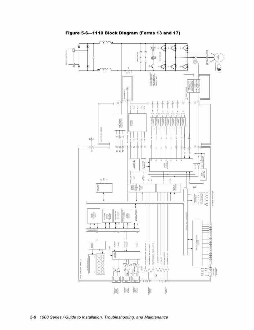
5-8 1000 Series / Guide to Installation, Troubleshooting, and Maintenance
Figure 5-6—1110 Block Diagram (Forms 13 and 17)
ISO
LPW
R S
UPP
LY&
OPT
ICAL
ISO
L
TRAN
SDU
CER
TO /
FRO
M T
RAN
SDU
CER
INTE
RFA
CE
MV
IVF
IUF
POK
& W
DT
CIR
CU
ITS
DR
IVE
CO
NTR
OL
MO
DU
LE
+5 +15
-15
DIG
ITAL
SIG
NAL
PRO
CES
SOR
(DSP
)
KEYB
OAR
D &
DIS
PLAY
BUFF
ER &
CO
NTR
OL
REA
L TI
ME
CLO
CK
TIM
ER
SETU
P DA
TA
BATT
ERY
BAC
KUP
STAT
IC R
AMM
EMO
RY
OPE
RAT
ING
DAT
A
RAM
MEM
ORY
OPE
RAT
ING
PRO
GR
AMIN
STRU
CTI
ON
S
FLAS
HEE
PRO
MM
EMO
RY
CO
NTR
OL
DEC
OD
ER,
BUFF
ER &
CO
NTR
OL
OPT
ICAL
ISO
LATO
RS
SAM
PLE
& H
OLD
ANAL
OG
TO D
IGIT
ALC
ON
VERT
ER&
DIG
ITAL
TO
ANAL
OG
CO
NVE
RTER
FRO
M D
SP
TO D
SP
TO &
FRO
MAS
YNC
SER
IAL
NET
WO
RK
TO &
FRO
MSY
NC
HSE
RIA
LN
ETW
OR
K
FRO
M A
NAL
OG
CO
MM
AND
DEV
ICE
INTE
RN
AL D
ATA
& C
ON
TRO
L BU
SJU
MPE
RS
FO
RVO
LTAG
E &
HO
RSE
POW
ERID
ENTI
FIC
ATIO
N
BUS
VOLT
AGE
VU VV VW VB +
VB -
U +
E
V +
E
W +
E
B +
W- E
U +
V +
W +
U +
U -
IUF
IVF
IWF
OVE
RC
UR
REN
T D
ETEC
TOR
POC
+5 +8+8
ISO
+15
-15
+24
CR
SIN
GLE
PH
ASE
SU
PPLY
ST
CR
U +
U -
V +
V -
W +
W -
VOLT
AGE
DIV
IDER
S
GAT
E D
RIV
E&
FAU
LT
V +
V -
W +
W -
IOC
DIG
ITAL
CU
RR
ENT
REG
ULA
TOR
GAT
E D
RIV
ER M
OD
ULE
GAT
E D
RIV
E&
FAU
LT
GAT
E D
RIV
E&
FAU
LT
GAT
E D
RIV
E&
FAU
LT
GAT
E D
RIV
E&
FAU
LT
GAT
E D
RIV
E&
FAU
LT
CAP
ACIT
OR
BU
S
INV
TSTS
VUF
VVF
FEED
BAC
KC
ON
DIT
ION
ING
IUC
IV C
TO A
NAL
OG
DEV
ICE
TO &
FRO
MSY
NC
HSE
RIA
LN
ETW
OR
K
FRO
M D
SP
FRO
M D
SP
TO D
SP
LC
1 2 3 4 5 6 7 8 9 10
sc
+24
VDC
LOC
AL A
NAL
OG
CM
D 0
to +
/-10
VDC
USE
R A
NAL
OG
CM
D 0
to
+10
VDC
REM
OTE
AN
ALO
G C
MD
0 t
o 2
0 m
A
+ 10
VD
C R
EF
- 10
VDC
REF
LOC
AL A
NAL
OG
OU
T
USE
R A
NAL
OG
OU
T
12
34
DB
DB
DB
GAT
E D
RIV
E&
FAU
LT
U -
V -
W -
BUS
VOLT
AGE
MO
NIT
OR
LOW
VO
LTAG
ESW
ITC
H M
OD
EPO
WER
SU
PPLY
MS0
-5
POW
ER M
OD
ULE
6PO
WER
MO
DU
LE
BUS
CH
ARG
E
+ 8
ISO
U L
EMSC
ALE
RES
ISTO
RS
V L
EMSC
ALE
RES
ISTO
RS
PAR
ALLE
L IN
PUT
& O
UTP
UT
CIR
CU
ITS
56
78
910
1112
1314
1516
1718
1920
2122
23
DB L
B+D
B
INVE
RTER
BU
SU
+U
-
V +
V -
W +
W -
UV
W
ACM
OTO
R
TRAN
SDU
CER
TO /
FRO
M
ASYN
C S
ERIA
L N
ETW
OR
KRECV
XMITXMIT
RECV
PROCESSOR BUS
FOR
DR
IVES
WIT
HO
UT
DYN
AMIC
BR
AKIN
G,
DB
IS L
ABEL
ED B
– AN
D C
ON
NEC
TS T
O
NEG
ATIV
E BU
S
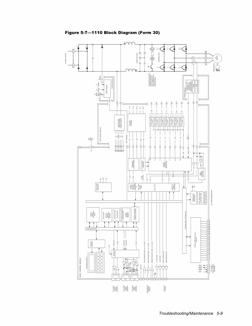
Troubleshooting/Maintenance 5-9
Figure 5-7—1110 Block Diagram (Form 30)
ISO
LPW
R S
UPP
LY&
OPT
ICAL
ISO
L
TRAN
SDU
CER
TO /
FRO
M T
RAN
SDU
CER
INTE
RFA
CE
MV
IVF
IUF
POK
& W
DT
CIR
CU
ITS
DR
IVE
CO
NTR
OL
MO
DU
LE
+5 +15
-15
DIG
ITAL
SIG
NAL
PRO
CES
SOR
(DSP
)
KEYB
OAR
D &
DIS
PLAY
BUFF
ER &
CO
NTR
OL
REA
L TI
ME
CLO
CK
TIM
ER
SETU
P DA
TA
BATT
ERY
BAC
KUP
STAT
IC R
AMM
EMO
RY
OPE
RAT
ING
DAT
A
RAM
MEM
ORY
OPE
RAT
ING
PRO
GR
AMIN
STRU
CTI
ON
S
FLAS
HEE
PRO
MM
EMO
RY
CO
NTR
OL
DEC
OD
ER,
BUFF
ER &
CO
NTR
OL
OPT
ICAL
ISO
LATO
RS
SAM
PLE
& H
OLD
ANAL
OG
TO D
IGIT
ALC
ON
VERT
ER&
DIG
ITAL
TO
ANAL
OG
CO
NVE
RTER
FRO
M D
SP
TO D
SP
TO &
FRO
MAS
YNC
SER
IAL
NET
WO
RK
TO &
FRO
MSY
NC
HSE
RIA
LN
ETW
OR
K
FRO
M A
NAL
OG
CO
MM
AND
DEV
ICE
INTE
RN
AL D
ATA
& C
ON
TRO
L BU
SJU
MPE
RS
FO
RVO
LTAG
E &
HO
RSE
POW
ERID
ENTI
FIC
ATIO
N
BUS
VOLT
AGE
VU VV VW VB +
VB -
U +
E
V +
E
W +
E
B +
W- E
U +
V +
W +
U +
U -
IUF
IVF
IWF
OVE
RC
UR
REN
T D
ETEC
TOR
POC
+5 +8+8
ISO
+15
-15
+24
3 P
HAS
E S
UPP
LY
ST
U +
U -
V +
V -
W +
W -
VOLT
AGE
DIV
IDER
S
GAT
E D
RIV
E&
FAU
LT
V +
V -
W +
W -
IOC
DIG
ITAL
CU
RR
ENT
REG
ULA
TOR
GAT
E D
RIV
ER M
OD
ULE
GAT
E D
RIV
E&
FAU
LT
GAT
E D
RIV
E&
FAU
LT
GAT
E D
RIV
E&
FAU
LT
GAT
E D
RIV
E&
FAU
LT
GAT
E D
RIV
E&
FAU
LT
CAP
ACIT
OR
BU
S
INV
TSTS
VUF
VVF
FEED
BAC
KC
ON
DIT
ION
ING
IUC
IV C
TO A
NAL
OG
DEV
ICE
TO &
FRO
MSY
NC
HSE
RIA
LN
ETW
OR
K
FRO
M D
SP
FRO
M D
SP
TO D
SP
LC
1 2 3 4 5 6 7 8 9 10
sc
+24
VDC
LOC
AL A
NAL
OG
CM
D 0
to +
/-10
VDC
USE
R A
NAL
OG
CM
D 0
to
+10
VDC
REM
OTE
AN
ALO
G C
MD
0 t
o 2
0 m
A
+ 10
VD
C R
EF
- 10
VDC
REF
LOC
AL A
NAL
OG
OU
T
USE
R A
NAL
OG
OU
T
DB
DB
DB
GAT
E D
RIV
E&
FAU
LT
U -
V -
W -
BUS
VOLT
AGE
MO
NIT
OR
LOW
VO
LTAG
ESW
ITC
H M
OD
EPO
WER
SU
PPLY
MS0
-5
POW
ER M
OD
ULE
6PO
WER
MO
DU
LE
BUS
CH
ARG
E
+ 8
ISO
U L
EMSC
ALE
RES
ISTO
RS
V L
EMSC
ALE
RES
ISTO
RS
SCR
Driv
ers
S
Phas
e
TPh
ase
2 SC
R G
ate
Driv
es
2
PAR
ALLE
L IN
PUT
& O
UTP
UT
CIR
CU
ITS
56
78
910
1112
1314
1516
1718
1920
2122
231
23
4
DB L
B+D
B
INVE
RTER
BU
SU
+U
-
V +
V -
W +
W -
UV
W
ACM
OTO
R
TRAN
SDU
CER
PROCESSOR BUS
TO /
FRO
M
ASYN
C S
ERIA
L N
ETW
OR
KRECV
XMITXMIT
RECV
FOR
DR
IVES
WIT
HO
UT
DYN
AMIC
BR
AKIN
G,
DB
IS L
ABEL
ED B
– AN
D C
ON
NEC
TS T
O
NEG
ATIV
E BU
S
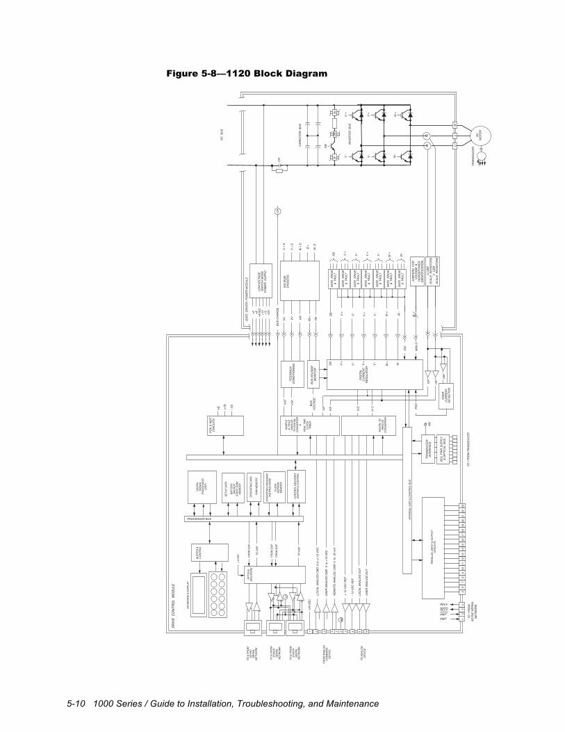
5-10 1000 Series / Guide to Installation, Troubleshooting, and Maintenance
Figure 5-8—1120 Block Diagram
ISO
LPW
R S
UPP
LY&
OPT
ICAL
ISO
L
TRAN
SDU
CER
INTE
RFA
CE
MV
IVF
IUF
POK
& W
DT
CIR
CU
ITS
TO /
FRO
M T
RAN
SDU
CER
DR
IVE
CO
NTR
OL
MO
DU
LE
+5 +15
-15
DIG
ITAL
SIG
NAL
PRO
CES
SOR
(DSP
)
KEYB
OAR
D &
DIS
PLAY
BUFF
ER &
CO
NTR
OL
REA
L TI
ME
CLO
CK
TIM
ER
SETU
P DA
TA
BATT
ERY
BAC
KUP
STAT
IC R
AMM
EMO
RY
OPE
RAT
ING
DAT
A
RAM
MEM
ORY
OPE
RAT
ING
PRO
GR
AMIN
STRU
CTI
ON
S
FLAS
HEE
PRO
MM
EMO
RY
CO
NTR
OL
DEC
OD
ER,
BUFF
ER &
CO
NTR
OL
OPT
ICAL
ISO
LATO
RS
SAM
PLE
& H
OLD
ANAL
OG
TO D
IGIT
ALC
ON
VERT
ER&
DIG
ITAL
TO
ANAL
OG
CO
NVE
RTER
FRO
M D
SP
TO D
SP
TO &
FRO
MAS
YNC
SER
IAL
NET
WO
RK
TO &
FRO
MSY
NC
HSE
RIA
LN
ETW
OR
K
FRO
M A
NAL
OG
CO
MM
AND
DEV
ICE
INTE
RN
AL D
ATA
& C
ON
TRO
L BU
S
CR
BUS
VOLT
AGE
VU VV VW VB +
VB -
U +
E
V +
E
W +
E
B +
W- E
U +
V +
W +
U +
U -
IUF
IVF
IWF
OVE
RC
UR
REN
T D
ETEC
TOR
POC
+5 +8+8
ISO
+15
-15
+24
DC
BU
S
CR
U +
U -
V +
V -
W +
W -
VOLT
AGE
DIV
IDER
S
GAT
E D
RIV
E&
FAU
LT
V +
V -
W +
W -
IOC
DIG
ITAL
CU
RR
ENT
REG
ULA
TOR
GAT
E D
RIV
ER P
OW
ER M
OD
ULE
GAT
E D
RIV
E&
FAU
LT
GAT
E D
RIV
E&
FAU
LT
GAT
E D
RIV
E&
FAU
LT
GAT
E D
RIV
E&
FAU
LT
GAT
E D
RIV
E&
FAU
LT
CAP
ACIT
OR
BU
S
VUF
VVF
FEED
BAC
KC
ON
DIT
ION
ING
IUC
IV C
TO A
NAL
OG
DEV
ICE
TO &
FRO
MSY
NC
HSE
RIA
LN
ETW
OR
K
FRO
M D
SP
FRO
M D
SP
TO D
SP
LC
1 2 3 4 5 6 7 8 9 10
sc
+24
VDC
LOC
AL A
NAL
OG
CM
D 0
to +
/-10
VDC
USE
R A
NAL
OG
CM
D 0
to
+10
VDC
REM
OTE
AN
ALO
G C
MD
0 t
o 2
0 m
A
+ 10
VD
C R
EF
- 10
VDC
REF
LOC
AL A
NAL
OG
OU
T
USE
R A
NAL
OG
OU
T
12
34
DB
DB
DB
GAT
E D
RIV
E&
FAU
LT
U -
V -
W -
BUS
VOLT
AGE
MO
NIT
OR
LOW
VO
LTAG
ESW
ITC
H M
OD
EPO
WER
SU
PPLY
MS0
-56
BUS
CH
ARG
E
+ 8
ISO
PAR
ALLE
L IN
PUT
& O
UTP
UT
CIR
CU
ITS
56
78
910
1112
1314
1516
1718
1920
2122
23
JUM
PER
S F
OR
VOLT
AGE
&H
OR
SEPO
WER
IDEN
TIFI
CAT
ION
U L
EMSC
ALE
RES
ISTO
RS
V L
EMSC
ALE
RES
ISTO
RS
DB L
B+D
BB–
INVE
RTER
BU
SU
+U
-
V +
V -
W +
W -
UV
W
ACM
OTO
R
TRAN
SDU
CER
PROCESSOR BUS
TO /
FRO
M
ASYN
C S
ERIA
L N
ETW
OR
KRECV
XMITXMIT
RECV
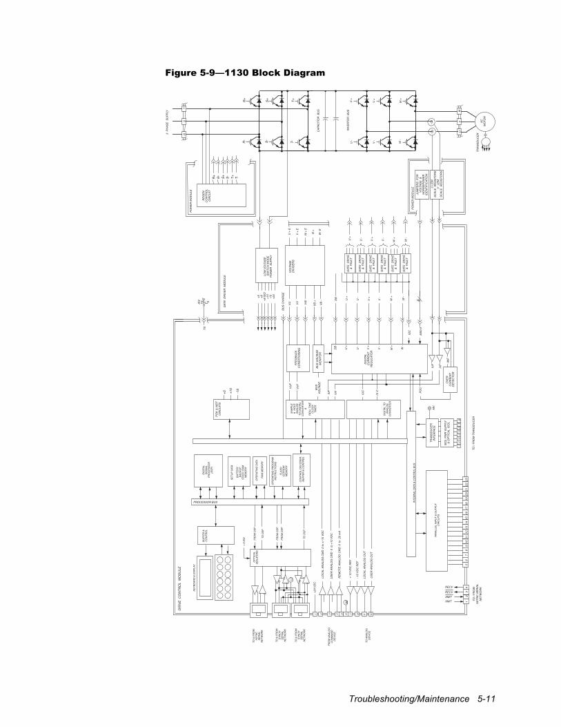
Troubleshooting/Maintenance 5-11
Figure 5-9—1130 Block Diagram
ISO
LPW
R S
UPP
LY&
OPT
ICAL
ISO
L
TRAN
SDU
CER
TO /
FRO
M T
RAN
SDU
CER
INTE
RFA
CE
MV
IVF
IUF
POK
& W
DT
CIR
CU
ITS
1
DR
IVE
CO
NTR
OL
MO
DU
LE
23
45
67
8
+5 +15
-15
DIG
ITAL
SIG
NAL
PRO
CES
SOR
(DSP
)
KEYB
OAR
D &
DIS
PLAY
BUFF
ER &
CO
NTR
OL
REA
L TI
ME
CLO
CK
TIM
ER
SETU
P DA
TA
BATT
ERY
BAC
KUP
STAT
IC R
AMM
EMO
RY
OPE
RAT
ING
DAT
A
RAM
MEM
ORY
OPE
RAT
ING
PRO
GR
AMIN
STRU
CTI
ON
S
FLAS
HEE
PRO
MM
EMO
RY
CO
NTR
OL
DEC
OD
ER,
BUFF
ER &
CO
NTR
OL
OPT
ICAL
ISO
LATO
RS
SAM
PLE
& H
OLD
ANAL
OG
TO D
IGIT
ALC
ON
VERT
ER&
DIG
ITAL
TO
ANAL
OG
CO
NVE
RTER
FRO
M D
SP
TO D
SP
TO &
FRO
MAS
YNC
SER
IAL
NET
WO
RK
TO &
FRO
MSY
NC
HSE
RIA
LN
ETW
OR
K
FRO
M A
NAL
OG
CO
MM
AND
DEV
ICE
INTE
RN
AL D
ATA
& C
ON
TRO
L BU
SJU
MPE
RS
FO
RVO
LTAG
E &
HO
RSE
POW
ERID
ENTI
FIC
ATIO
N
BUS
VOLT
AGE
VU VV VW VB +
VB -
U +
E
V +
E
W +
E
B +
W- E
U +
V +
W +
U +
U -
IUF
IVF
IWF
OVE
RC
UR
REN
T D
ETEC
TOR
POC
+5 +8+8
ISO
+15
-15
+24
R+
S+ T+
R- S- T-
3 P
HAS
E S
UPP
LY
ST
INVE
RTER
BU
SU
+U
-
V +
V -
W +
W -
UV
W
ACM
OTO
R
TRAN
SDU
CER
CAP
ACIT
OR
BU
S
R
U +
U -
V +
V -
W +
W -
VOLT
AGE
DIV
IDER
S
GAT
E D
RIV
E&
FAU
LT
V +
V -
W +
W -
IOC
DIG
ITAL
CU
RR
ENT
REG
ULA
TOR
GAT
E D
RIV
ER M
OD
ULE
GAT
E D
RIV
E&
FAU
LT
GAT
E D
RIV
E&
FAU
LT
GAT
E D
RIV
E&
FAU
LT
GAT
E D
RIV
E&
FAU
LT
GAT
E D
RIV
E&
FAU
LT
INV
TSTS
VUF
VVF
FEED
BAC
KC
ON
DIT
ION
ING
IUC
IV C
TO A
NAL
OG
DEV
ICE
TO &
FRO
MSY
NC
HSE
RIA
LN
ETW
OR
K
FRO
M D
SP
FRO
M D
SP
TO D
SP
LC
1 2 3 4 5 6 7 8 9 10
sc
+24
VDC
LOC
AL A
NAL
OG
CM
D 0
to +
/-10
VDC
USE
R A
NAL
OG
CM
D 0
to
+10
VDC
REM
OTE
AN
ALO
G C
MD
0 t
o 2
0 m
A
+ 10
VD
C R
EF
- 10
VDC
REF
LOC
AL A
NAL
OG
OU
T
USE
R A
NAL
OG
OU
T
12
34
DB
DB
U -
V -
W -
BUS
VOLT
AGE
MO
NIT
OR
LOW
VO
LTAG
ESW
ITC
H M
OD
EPO
WER
SU
PPLY
MS0
-5
POW
ER M
OD
ULE
REG
ENC
ON
TRO
LC
IRC
UIT
R+ R-
S+ S- T+ T-
6PO
WER
MO
DU
LE
BUS
CH
ARG
E
+ 8
ISO
U L
EMSC
ALE
RES
ISTO
RS
V L
EMSC
ALE
RES
ISTO
RS
PAR
ALLE
L IN
PUT
& O
UTP
UT
CIR
CU
ITS
56
78
910
1112
1314
1516
1718
1920
2122
23
TO /
FRO
M
ASYN
C S
ERIA
L N
ETW
OR
KRECV
XMITXMIT
RECV
PROCESSOR BUS
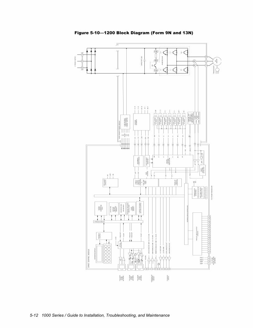
5-12 1000 Series / Guide to Installation, Troubleshooting, and Maintenance
Figure 5-10—1200 Block Diagram (Form 9N and 13N)
ISO
LP
WR
SUP
PLY
&O
PTI
CA
LIS
OL
TR
AN
SDU
CE
RIN
TER
FAC
EM
V
IVF
IUF
PO
K&
WD
TC
IRCU
ITS
TO
/FR
OMTR
ANS
DU
CER
DR
IVE
CON
TRO
LM
OD
UL
E
+5 +15
-15
DIG
ITAL
SIG
NAL
PRO
CE
SS
OR(D
SP)
KEY
BOAR
D&
DIS
PLA
Y
BU
FF
ER&
CO
NTR
OL
REA
LT
IME
CLO
CK
TIM
ER
SET
UP
DATA
BAT
TERY
BAC
KUP
STA
TIC
RAM
ME
MO
RY
OPE
RATI
NG
DATA
RAM
ME
MO
RY
OPE
RATI
NG
PROG
RAM
INS
TRUC
TIO
NS
FLA
SH
EEP
ROM
ME
MO
RY
CO
NTR
OL
DE
COD
ER,
BU
FF
ER&
CO
NTR
OL
OPT
ICAL
ISO
LATO
RS
SAM
PL
E&
HO
LDA
NA
LOG
TO
DIG
ITAL
CO
NV
ERT
ER&
DIG
ITAL
TOA
NA
LOG
CO
NV
ERT
ER
FRO
MD
SP
TO
DS
P
TO
&FR
OMA
SY
NC
SE
RIAL
NE
TW
OR
K
TO
&FR
OMS
YNC
HS
ER
IAL
NE
TW
OR
K
FR
OM
AN
ALO
GC
OM
MA
ND
DE
VIC
E
INT
ERNA
LD
ATA
&C
ON
TRO
LB
US
BU
SV
OLT
AG
E
VU VV
VW
VB
+
VB
-
U+
E
V+
E
W+
E
B+
W-E
U+
V+
W+
U+
U-
IUF
IVF
IWF
OVE
RC
URR
ENT
DE
TEC
TOR
PO
C
+5 +8+8
ISO
+15
-15
+24
3P
HAS
ES
UPP
LY
RS
T
U+
U-
V+
V-
W+
W-
VO
LTA
GE
DIV
IDE
RS
GAT
ED
RIV
E&
FAU
LT
V+
V-
W+
W-
IOC
DIG
ITAL
CUR
REN
TR
EGUL
ATO
R
GAT
ED
RIV
ER
PO
WER
MO
DU
LE
GAT
ED
RIV
E&
FAU
LT
GAT
ED
RIV
E&
FAU
LT
GAT
ED
RIV
E&
FAU
LT
GAT
ED
RIV
E&
FAU
LT
GAT
ED
RIV
E&
FAU
LT
CAP
ACIT
OR
BUS
VU
F
VV
FF
EE
DBAC
KC
ON
DIT
ION
ING
IUC
IVC
TO
AN
ALO
GD
EV
ICE
TO
&FR
OMS
YNC
HS
ER
IAL
NE
TW
OR
K
FRO
MD
SP
FRO
MD
SP
TO
DS
P
LC
1 2 3 4 5 6 7 8 9 10
sc
+24
VD
C
LO
CAL
ANA
LO
GCM
D0
to+/
-10
VD
C
USE
RA
NA
LOG
CM
D0
to+1
0V
DC
REM
OT
EA
NA
LOG
CM
D0
to2
0m
A
+10
VD
CR
EF
-10
VD
CR
EF
LO
CAL
ANA
LO
GO
UT
USE
RA
NA
LOG
OU
T
12
34
DB
DB
DB
GAT
ED
RIV
E&
FAU
LT
U-
V-
W-
BU
SVO
LTAG
EM
ON
ITO
R
LO
WVO
LTAG
ES
WIT
CH
MO
DE
PO
WER
SUP
PLY
MS
0-5
6
+8
ISO
PAR
ALLE
LIN
PUT
&O
UT
PUT
CIR
CUIT
S
56
78
91
01
11
21
31
41
51
61
71
81
92
02
12
22
3
JUM
PE
RSFO
RV
OLT
AG
E&
HO
RSE
POW
ER
IDE
NTIF
ICAT
ION
ULE
MS
CALE
RESI
ST
OR
SV
LEM
SCA
LERE
SIS
TO
RS
DB L
B+
DB
B
INV
ERTE
RB
US
U+
U-
V+
V-
W+
W-
UV
W
AC
MO
TO
R
TR
AN
SDU
CE
R
PROCES S OR BUS
TO
/FR
OM
AS
YN
CSE
RIA
L
NE
TW
OR
KR EC V
XMIT
XMIT
R EC V
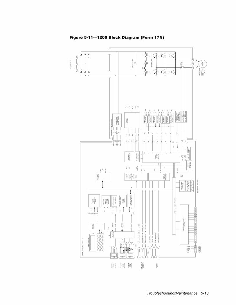
Troubleshooting/Maintenance 5-13
Figure 5-11—1200 Block Diagram (Form 17N)
ISO
LP
WR
SUP
PLY
&O
PTI
CA
LIS
OL
TR
AN
SDU
CE
RIN
TER
FAC
EM
V
IVF
IUF
PO
K&
WD
TC
IRCU
ITS
TO
/FR
OMTR
ANS
DU
CER
DR
IVE
CON
TRO
LM
OD
UL
E
+5 +15
-15
DIG
ITAL
SIG
NAL
PRO
CE
SS
OR(D
SP)
KEY
BOAR
D&
DIS
PLA
Y
BU
FF
ER&
CO
NTR
OL
REA
LT
IME
CLO
CK
TIM
ER
SET
UP
DATA
BAT
TERY
BAC
KUP
STA
TIC
RAM
ME
MO
RY
OPE
RATI
NG
DATA
RAM
ME
MO
RY
OPE
RATI
NG
PROG
RAM
INS
TRUC
TIO
NS
FLA
SH
EEP
ROM
ME
MO
RY
CO
NTR
OL
DE
COD
ER,
BU
FF
ER&
CO
NTR
OL
OPT
ICAL
ISO
LATO
RS
SAM
PL
E&
HO
LDA
NA
LOG
TO
DIG
ITAL
CO
NV
ERT
ER&
DIG
ITAL
TOA
NA
LOG
CO
NV
ERT
ER
FRO
MD
SP
TO
DS
P
TO
&FR
OMA
SY
NC
SE
RIAL
NE
TW
OR
K
TO
&FR
OMS
YNC
HS
ER
IAL
NE
TW
OR
K
FR
OM
AN
ALO
GC
OM
MA
ND
DE
VIC
E
INT
ERNA
LD
ATA
&C
ON
TRO
LB
US
BU
SV
OLT
AG
E
VU VV
VW
VB
+
VB
-
U+
E
V+
E
W+
E
B+
W-E
U+
V+
W+
U+
U-
IUF
IVF
IWF
OVE
RC
URR
ENT
DE
TEC
TOR
PO
C
+5 +8+8
ISO
+15
-15
+24
3P
HAS
ES
UPP
LY
RS
T
U+
U-
V+
V-
W+
W-
VO
LTA
GE
DIV
IDE
RS
GAT
ED
RIV
E&
FAU
LT
V+
V-
W+
W-
IOC
DIG
ITAL
CUR
REN
TR
EGUL
ATO
R
GAT
ED
RIV
ER
PO
WER
MO
DU
LE
GAT
ED
RIV
E&
FAU
LT
GAT
ED
RIV
E&
FAU
LT
GAT
ED
RIV
E&
FAU
LT
GAT
ED
RIV
E&
FAU
LT
GAT
ED
RIV
E&
FAU
LT
CAP
ACIT
OR
BUS
VU
F
VV
FF
EE
DBAC
KC
ON
DIT
ION
ING
IUC
IVC
TO
AN
ALO
GD
EV
ICE
TO
&FR
OMS
YNC
HS
ER
IAL
NE
TW
OR
K
FRO
MD
SP
FRO
MD
SP
TO
DS
P
LC
1 2 3 4 5 6 7 8 9 10
sc
+24
VD
C
LO
CAL
ANA
LO
GCM
D0
to+/
-10
VD
C
USE
RA
NA
LOG
CM
D0
to+1
0V
DC
REM
OT
EA
NA
LOG
CM
D0
to20
mA
+10
VD
CR
EF
-10
VD
CR
EF
LO
CAL
ANA
LO
GO
UT
USE
RA
NA
LOG
OU
T
12
34
DB
DB
DB
GAT
ED
RIV
E&
FAU
LT
U-
V-
W-
BU
SVO
LTAG
EM
ON
ITO
R
LO
WVO
LTAG
ES
WIT
CH
MO
DE
PO
WER
SUP
PLY
MS
0-5
6
+8
ISO
PAR
ALLE
LIN
PUT
&O
UT
PUT
CIR
CUIT
S
56
78
910
1112
1314
1516
1718
1920
2122
23
JUM
PE
RSFO
RV
OLT
AG
E&
HO
RSE
POW
ER
IDE
NTIF
ICAT
ION
ULE
MS
CALE
RESI
ST
OR
SV
LEM
SCA
LERE
SIS
TO
RS
DB L
B+
DB
B
INV
ERTE
RB
US
U+
U-
V+
V-
W+
W-
UV
W
AC
MO
TO
R
TR
AN
SDU
CE
R
PROCES S OR BUS
TO
/FR
OM
AS
YN
CSE
RIA
L
NE
TW
OR
KR EC V
XMIT
XMIT
R EC V
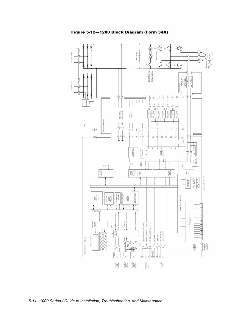
5-14 1000 Series / Guide to Installation, Troubleshooting, and Maintenance
Figure 5-12—1200 Block Diagram (Form 34X)
ISO
LP
WR
SUP
PLY
&O
PTI
CA
LIS
OL
TR
AN
SDU
CE
RIN
TER
FAC
EM
V
IVF
IUF
PO
K&
WD
TC
IRCU
ITS
DR
IVE
CON
TRO
LM
OD
UL
E
+5 +15
-15
DIG
ITAL
SIG
NAL
PRO
CE
SS
OR(D
SP)
KEY
BOAR
D&
DIS
PLA
Y
BU
FF
ER&
CO
NTR
OL
REA
LT
IME
CLO
CK
TIM
ER
SET
UP
DATA
BAT
TERY
BAC
KUP
STA
TIC
RAM
ME
MO
RY
OPE
RATI
NG
DATA
RAM
ME
MO
RY
OPE
RATI
NG
PROG
RAM
INS
TRUC
TIO
NS
FLA
SH
EEP
ROM
ME
MO
RY
CO
NTR
OL
DE
COD
ER,
BU
FF
ER&
CO
NTR
OL
OPT
ICAL
ISO
LATO
RS
SAM
PL
E&
HO
LDA
NA
LOG
TO
DIG
ITAL
CO
NV
ERT
ER&
DIG
ITAL
TOA
NA
LOG
CO
NV
ERT
ER
FRO
MD
SP
TO
DS
P
TO
&FR
OMA
SY
NC
SE
RIAL
NE
TW
OR
K
TO
&FR
OMS
YNC
HS
ER
IAL
NE
TW
OR
K
FR
OM
AN
ALO
GC
OM
MA
ND
DE
VIC
E
INT
ERNA
LD
ATA
&C
ON
TRO
LB
US
JUM
PE
RSFO
RV
OLT
AG
E&
HO
RSE
POW
ER
IDE
NTIF
ICAT
ION
BU
SV
OLT
AG
E
VU VV
VW
VB
+
VB
-
U+
E
V+
E
W+
E
B+
W-E
U+
V+
W+
U+
U-
IUF
IVF
IWF
OVE
RC
URR
ENT
DE
TEC
TOR
PO
C
+5 +8+8
ISO
+15
-15
+24
3P
HAS
ES
UPP
LY
R2
S2
T2
U+
U-
V+
V-
W+
W-
VO
LTA
GE
DIV
IDE
RS
GAT
ED
RIV
E&
FAU
LT
V+
V-
W+
W-
IOC
DIG
ITAL
CUR
REN
TR
EGUL
ATO
R
GAT
ED
RIV
ER
MO
DU
LE
GAT
ED
RIV
E&
FAU
LT
GAT
ED
RIV
E&
FAU
LT
GAT
ED
RIV
E&
FAU
LT
GAT
ED
RIV
E&
FAU
LT
GAT
ED
RIV
E&
FAU
LT
CAP
ACIT
OR
BUS
INV
TS
TS
VU
F
VV
FF
EE
DBAC
KC
ON
DIT
ION
ING
IUC
IVC
TO
AN
ALO
GD
EV
ICE
TO
&FR
OMS
YNC
HS
ER
IAL
NE
TW
OR
K
FRO
MD
SP
FRO
MD
SP
TO
DS
P
LC
1 2 3 4 5 6 7 8 9 10
sc
+24
VD
C
LO
CAL
ANA
LO
GCM
D0
to+/
-10
VD
C
USE
RA
NA
LOG
CM
D0
to+1
0V
DC
REM
OT
EA
NA
LOG
CM
D0
to20
mA
+10
VD
CR
EF
-10
VD
CR
EF
LO
CAL
ANA
LO
GO
UT
USE
RA
NA
LOG
OU
T
DB
DB
DB
GAT
ED
RIV
E&
FAU
LT
U-
V-
W-
BU
SVO
LTAG
EM
ON
ITO
R
LO
WVO
LTAG
ES
WIT
CH
MO
DE
PO
WER
SUP
PLY
MS
0-5
6
PO
WER
MO
DU
LE
+8
ISO
ULE
MS
CALE
RESI
ST
OR
SV
LEM
SCA
LERE
SIS
TO
RS
3P
HAS
ES
UPP
LY
R1
S1
T1
PAR
ALLE
LIN
PUT
&O
UT
PUT
CIR
CUIT
S
12
34
56
78
910
1112
1314
1516
1718
1920
2122
23
DB L
B+
B-
INV
ERTE
RB
US
U+
U-
V+
V-
W+
W-
UV
W
AC
MO
TO
R
TR
AN
SDU
CE
R
BC
ON
NEC
TSTO
?N
EG
ATIV
EB
US
FOR
?D
RIV
ES
WIT
HO
UT
?D
YN
AM
ICBR
AKIN
G
TO
/FR
OMTR
ANS
DU
CER
TO
/FR
OM
AS
YN
CSE
RIA
L
NE
TW
OR
KR EC V
XMIT
XMIT
R EC V
PROCES S OR BUS
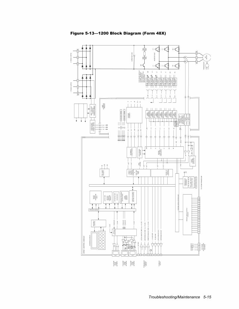
Troubleshooting/Maintenance 5-15
Figure 5-13—1200 Block Diagram (Form 48X)
ISO
LP
WR
SUP
PLY
&O
PTI
CA
LIS
OL
TR
AN
SDU
CE
RIN
TER
FAC
EM
V
IVF
IUF
PO
K&
WD
TC
IRCU
ITS
TO
/FR
OMTR
ANS
DU
CER
DR
IVE
CON
TRO
LM
OD
UL
E
+5 +15
-15
DIG
ITAL
SIG
NAL
PRO
CE
SS
OR(D
SP)
KEY
BOAR
D&
DIS
PLA
Y
BU
FF
ER&
CO
NTR
OL
REA
LT
IME
CLO
CK
TIM
ER
SET
UP
DATA
BAT
TERY
BAC
KUP
STA
TIC
RAM
ME
MO
RY
OPE
RATI
NG
DATA
RAM
ME
MO
RY
OPE
RATI
NG
PROG
RAM
INS
TRUC
TIO
NS
FLA
SH
EEP
ROM
ME
MO
RY
CO
NTR
OL
DE
COD
ER,
BU
FF
ER&
CO
NTR
OL
OPT
ICAL
ISO
LATO
RS
SAM
PL
E&
HO
LDA
NA
LOG
TO
DIG
ITAL
CO
NV
ERT
ER&
DIG
ITAL
TOA
NA
LOG
CO
NV
ERT
ER
FRO
MD
SP
TO
DS
P
TO
&FR
OMA
SY
NC
SE
RIAL
NE
TW
OR
K
TO
&FR
OMS
YNC
HS
ER
IAL
NE
TW
OR
K
FR
OM
AN
ALO
GC
OM
MA
ND
DE
VIC
E
INT
ERNA
LD
ATA
&C
ON
TRO
LB
US
BU
SV
OLT
AG
E
VU VV
VW
VB
+
VB
-
U V W B+
U+
V+
W+
U+
U-
IUF
IVF
IWF
OVE
RC
URR
ENT
DE
TEC
TOR
PO
C
+5 +8+8
ISO
+15
-15
+24
3P
HAS
ES
UPP
LY
R2
S2
T2
DB L
B+
DB
INV
ERTE
RB
US
U+
U-
V+
V-
W+
W-
UV
W
AC
MO
TO
R
TR
AN
SDU
CE
R
U+
U-
V+
V-
W+
W-
VO
LTA
GE
DIV
IDE
RS
V+
V-
W+
W-
IOC
DIG
ITAL
CUR
REN
TR
EGUL
ATO
R
DS
PIN
TER
FAC
EM
OD
UL
E
CAP
ACIT
OR
BUS
VU
F
VV
FF
EE
DBAC
KC
ON
DIT
ION
ING
IUC
IVC
TO
AN
ALO
GD
EV
ICE
TO
&FR
OMS
YNC
HS
ER
IAL
NE
TW
OR
K
FRO
MD
SP
FRO
MD
SP
TO
DS
P
LC
1 2 3 4 5 6 7 8 9 10
sc
+24
VD
C
LO
CAL
ANA
LO
GCM
D0
to+/
-10
VD
C
USE
RA
NA
LOG
CM
D0
to+1
0V
DC
REM
OT
EA
NA
LOG
CM
D0
to20
mA
+10
VD
CR
EF
-10
VD
CR
EF
LO
CAL
ANA
LO
GO
UT
USE
RA
NA
LOG
OU
T
12
34
DB
DB
DB
LIN
ED
RIV
ER
REC
EIV
ER
U-
V-
W-
BU
SVO
LTAG
EM
ON
ITO
R
MS
0-5
6
+8
ISO
3P
HAS
ES
UPP
LY
R1
S1
T1
JUM
PE
RSFO
RV
OLT
AG
E&
HO
RSE
POW
ER
IDE
NTIF
ICAT
ION
ULE
MS
CALE
RESI
ST
OR
SV
LEM
SCA
LERE
SIS
TO
RS
U+
U-
V+
V-
W+
W-
DB
PW
RSU
PP
LYG
ATE
DR
IVE
&FA
ULT
LIN
ED
RIV
ER
REC
EIV
ER
LIN
ED
RIV
ER
REC
EIV
ER
LIN
ED
RIV
ER
REC
EIV
ER
LIN
ED
RIV
ER
REC
EIV
ER
LIN
ED
RIV
ER
REC
EIV
ER
LIN
ED
RIV
ER
REC
EIV
ER
IOC
FAU
LTR
EGIS
TER
&D
ISP
LAY
B-
PW
RSU
PP
LYG
ATE
DR
IVE
&FA
ULT
PW
RSU
PP
LYG
ATE
DR
IVE
&FA
ULT
PW
RSU
PP
LYG
ATE
DR
IVE
&FA
ULT
PW
RSU
PP
LYG
ATE
DR
IVE
&FA
ULT
PW
RSU
PP
LYG
ATE
DR
IVE
&FA
ULT
PW
RSU
PP
LYG
ATE
DR
IVE
&FA
ULT
460
/120
VO
LTC
ON
TROL
TR
AN
SFO
RM
ER
DC
>DC
CON
V
DC
>DC
CON
V
LO
WVO
LTAG
ES
WIT
CH
MO
DE
PO
WER
SUP
PLY
PAR
ALLE
LIN
PUT
&O
UT
PUT
CIR
CUIT
S
56
78
910
1112
1314
1516
1718
1920
2122
23
PROCES S OR BUS
TO
/FR
OM
AS
YN
CSE
RIA
L
NE
TW
OR
KR EC V
XMIT
XMIT
R EC V
FO
RDR
IVES
WIT
HO
UT
DY
NA
MIC
BRAK
ING
, D
BIS
LAB
ELED
B
AN
DC
ON
NEC
TSTO
?N
EG
ATIV
EB
US
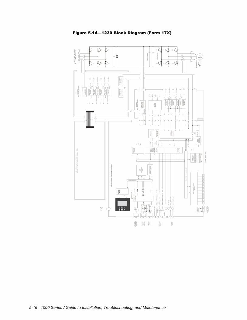
5-16 1000 Series / Guide to Installation, Troubleshooting, and Maintenance
Figure 5-14—1230 Block Diagram (Form 17X)
ISOL
PWR
SUPP
LY&
OPTI
CAL I
SOL
TRAN
SDUC
ERIN
TERF
ACE
MV
IVF
IUF
POK &
WDT
CIRC
UITS
INVE
RTER
DRI
VE C
ONTR
OL M
ODUL
E (D
SP)
+5 +15
-15
DIGI
TALSI
GNAL
PROC
ESSO
R(D
SP)
CONT
ROL D
ECOD
ER,
BUFF
ER &
CON
TROL
SAMP
LE
& H
OLD
ANAL
OG
TO D
IGIT
AL
CONV
ERTE
R &
REAL
TIM
E CL
OCK
DIGIT
AL TO
ANAL
OGCO
NVER
TER
TO &
FRO
MAS
YNC
SERI
ALNE
TWOR
K
TO &
FRO
MSY
NCH
SERI
ALNE
TWOR
K
FROM
ANA
LOG
COMM
AND
DEVI
CE
INTE
RNAL
DAT
A &
CONT
ROL B
US
VU VV VW VB+
VB-
U +
E
V +
E
W +
E
B +
W-E
U +
V +
W +
U +
U -
IUF
IVF
IWF
OVER
CURR
ENT
DET
ECTO
R
POC
+5
+8 IS
O+1
5-1
5+2
4
U +
U -
V + V -
W + W -
GATE
DRI
VE&
FAU
LT
V + V -
W + W -
IOC
DIGI
TAL
CURR
ENT
REGU
LATO
R
INVE
RTER
GA
TE D
RIVE
R M
ODUL
E
GATE
DRI
VE&
FAU
LT
GATE
DRI
VE&
FAU
LT
GATE
DRI
VE&
FAU
LT
GATE
DRI
VE&
FAU
LT
GATE
DRI
VE&
FAU
LT
CAPA
CITO
R B
US
INV TSTS
VUF
VVF
FEED
BACK
COND
ITIO
NING
IUC
IV C
TO A
NALO
GDE
VICE
TO &
FRO
MSY
NCH
SERI
ALNE
TWOR
K
1 2 3 4 8 9 10
sc
+24
VDC
LOCA
L AN
ALO
G CM
D 0
to +/-
10 V
DC
USER
ANAL
OG
CMD
0 t
o +10
VDC
REMO
TE A
NALO
G CM
D 0
to
20
mA
+ 10
VDC
REF
- 10
VDC
REF
LOCA
L AN
ALOG
OUT
USER
ANA
LOG
OUT
U -
V -
W -
BUS
VOLT
AGE
MONI
T
MS0-
56
PARA
LLEL
INPU
T &
OUTP
UTCI
RCUI
TS
12
34
56
78
910
1112
1314
1516
1718
1920
2122
23
INVE
RTER
BUS
U +
U -
V +
V -
W +
W -
UV
W
AC MOTOR
TRAN
SDUC
ER
TO / F
ROM
TRAN
SDUC
ERTO
/ FRO
MAS
YNC
SERI
ALNE
TWOR
KRECV
XMITXMIT
RECV
PROCESSOR BUS
5 6 7
+8LO
W V
OLTA
GE
SWIT
CH M
ODE
POW
ER S
UPPL
Y
VOLT
AGE
DIVI
DERS
BUS
VOLT
AGE
T + T -
T + T -
S + S -
R +
R -
GATE
DRI
VE&
FAU
LT
S + S -
R +
R -
GATE
DRI
VE&
FAU
LT
GATE
DRI
VE&
FAU
LT
GATE
DRI
VE&
FAU
LT
GATE
DRI
VE&
FAU
LT
GATE
DRI
VE&
FAU
LT
CONV
ERTE
R GA
TE D
RIVE
R M
ODUL
ECO
NVER
TER
DRIV
E C
ONTR
OL M
ODUL
E (D
SP)
Troubleshooting/Maintenance 5-17
5.2.2 Rectifier Checking Procedure The rectifier bridge diodes or SCRs can be checked using a multimeter on the diode range by following the procedure outlined below.
!
Attention To avoid an electrical shock hazard and possible damage to the equipment, follow all safety instructions listed in the front of this manual, beginning on page i.
[1] Remove power
Lock off the incoming power at the main machine disconnect switch. Use an appropriate meter to verify that all DC bus capacitor banks have been discharged to zero volts before proceeding. Set the meter to DC voltage and read across terminals B+ and B–. The reading should be 0 V before any attempt is made to work on the drive.
[2] Disconnect power board Disconnect all wires from terminals R, S, and T. Remove the three-phase fuses from the transformer or unplug the three-phase connector from the Power Board.
[3] Take readings Using a multimeter on the diode range, take each of the readings indicated in Table 5-1 at the bridge rectifier terminals and check for the appropriate meter reading.
[4] Reconnect power board Insert the three-phase fuses or plug in the three-phase connector on the Power Board.
[5] Take reading With the meter, check B+ to the R1 terminal. It should read 0.25 to 0.40 V with (+) lead to R1 and open with (+) lead to B+.
[6] Replacement Any meter reading other than that specified indicates a defective diode or SCR. Replace defective components or the entire drive.
[7] Reconnect Replace all wires to terminals R, S, and T.
5-18 1000 Series / Guide to Installation, Troubleshooting, and Maintenance
5.2.3 Transistor Checking Procedure The inverter IGBTs can be checked using a multimeter on the diode range by following the procedure outlined below.
!
Attention To avoid an electrical shock hazard and possible damage to the equipment, follow all safety instructions listed in the front of this manual, beginning on page i.
[8] Remove power
Lock off the incoming power at the main machine disconnect switch. Use an appropriate meter to verify that all DC bus capacitor banks have been discharged to zero volts before proceeding. Set the meter to DC voltage and read across terminals B+ and B–. The reading should be 0 V before any attempt is made to work on the inverter.
[9] Disconnect wires Disconnect all wires from terminals B+, B–, U, V, and W.
[10] Take readings Using a multimeter on the diode range, take each of the readings indicated in Table 5-2 and compare them with the proper values.
[11] Replacement Any meter reading other than that specified indicates a defective transistor or diode. Replace defective components or the entire drive.
[12] Reconnect Replace all wires to terminals B+, B–, U, V, and W.
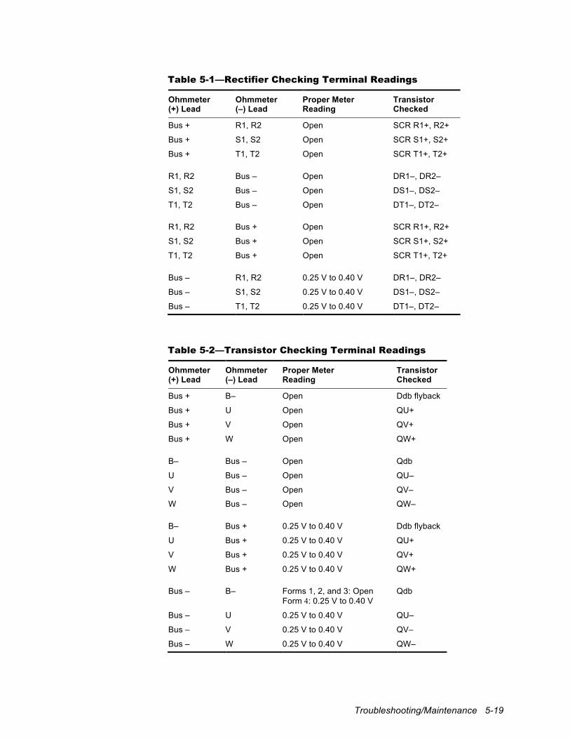
Troubleshooting/Maintenance 5-19
Table 5-1—Rectifier Checking Terminal Readings
Ohmmeter (+) Lead
Ohmmeter (–) Lead
Proper Meter Reading
Transistor Checked
Bus + R1, R2 Open SCR R1+, R2+
Bus + S1, S2 Open SCR S1+, S2+
Bus + T1, T2 Open SCR T1+, T2+
R1, R2 Bus – Open DR1–, DR2–
S1, S2 Bus – Open DS1–, DS2–
T1, T2 Bus – Open DT1–, DT2–
R1, R2 Bus + Open SCR R1+, R2+
S1, S2 Bus + Open SCR S1+, S2+
T1, T2 Bus + Open SCR T1+, T2+
Bus – R1, R2 0.25 V to 0.40 V DR1–, DR2–
Bus – S1, S2 0.25 V to 0.40 V DS1–, DS2–
Bus – T1, T2 0.25 V to 0.40 V DT1–, DT2–
Table 5-2—Transistor Checking Terminal Readings
Ohmmeter (+) Lead
Ohmmeter (–) Lead
Proper Meter Reading
Transistor Checked
Bus + B– Open Ddb flyback
Bus + U Open QU+
Bus + V Open QV+
Bus + W Open QW+
B– Bus – Open Qdb
U Bus – Open QU–
V Bus – Open QV–
W Bus – Open QW–
B– Bus + 0.25 V to 0.40 V Ddb flyback
U Bus + 0.25 V to 0.40 V QU+
V Bus + 0.25 V to 0.40 V QV+
W Bus + 0.25 V to 0.40 V QW+
Bus – B– Forms 1, 2, and 3: Open Form 4: 0.25 V to 0.40 V
Qdb
Bus – U 0.25 V to 0.40 V QU–
Bus – V 0.25 V to 0.40 V QV–
Bus – W 0.25 V to 0.40 V QW–
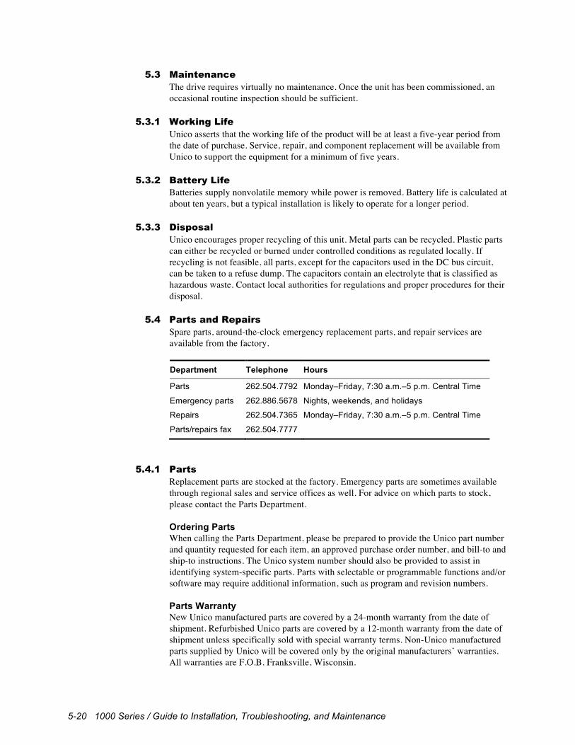
5-20 1000 Series / Guide to Installation, Troubleshooting, and Maintenance
5.3 Maintenance The drive requires virtually no maintenance. Once the unit has been commissioned, an occasional routine inspection should be sufficient.
5.3.1 Working Life Unico asserts that the working life of the product will be at least a five-year period from the date of purchase. Service, repair, and component replacement will be available from Unico to support the equipment for a minimum of five years.
5.3.2 Battery Life Batteries supply nonvolatile memory while power is removed. Battery life is calculated at about ten years, but a typical installation is likely to operate for a longer period.
5.3.3 Disposal Unico encourages proper recycling of this unit. Metal parts can be recycled. Plastic parts can either be recycled or burned under controlled conditions as regulated locally. If recycling is not feasible, all parts, except for the capacitors used in the DC bus circuit, can be taken to a refuse dump. The capacitors contain an electrolyte that is classified as hazardous waste. Contact local authorities for regulations and proper procedures for their disposal.
5.4 Parts and Repairs Spare parts, around-the-clock emergency replacement parts, and repair services are available from the factory. Department Telephone Hours
Parts 262.504.7792 Monday–Friday, 7:30 a.m.–5 p.m. Central Time
Emergency parts 262.886.5678 Nights, weekends, and holidays
Repairs 262.504.7365 Monday–Friday, 7:30 a.m.–5 p.m. Central Time
Parts/repairs fax 262.504.7777
5.4.1 Parts Replacement parts are stocked at the factory. Emergency parts are sometimes available through regional sales and service offices as well. For advice on which parts to stock, please contact the Parts Department. Ordering Parts When calling the Parts Department, please be prepared to provide the Unico part number and quantity requested for each item, an approved purchase order number, and bill-to and ship-to instructions. The Unico system number should also be provided to assist in identifying system-specific parts. Parts with selectable or programmable functions and/or software may require additional information, such as program and revision numbers. Parts Warranty New Unico manufactured parts are covered by a 24-month warranty from the date of shipment. Refurbished Unico parts are covered by a 12-month warranty from the date of shipment unless specifically sold with special warranty terms. Non-Unico manufactured parts supplied by Unico will be covered only by the original manufacturers’ warranties. All warranties are F.O.B. Franksville, Wisconsin.

Troubleshooting/Maintenance 5-21
Consignment Parts for Warranty Exchange In cases of a suspected warranty failure of a part within six months of the original sale, Unico will attempt to provide a replacement part for exchange if available. If you are sent a consignment exchange part, you will have 30 days to return the original failed part to Unico. Failure to return the exchanged parts for credit within the specified terms may result in a void of the credit. The consignment order number should be used as the return authorization number and be recorded on the shipment paperwork. Product failure information, such as symptoms or information pertaining to the failure, should also be provided for each part. When Unico receives the exchanged parts, they will be scheduled for repair. When the repair is completed, a credit will be issued to clear the consignment invoice; however, if the part is determined to be damaged in a manner not covered by warranty, you will be contacted and given an explanation of the charges.
5.4.2 Repairs Return Procedure All products returned to Unico must have prior authorization. Call the Repair Department to obtain a return material authorization (RMA) number. Be prepared to provide a purchase order number and, for each repair item, the Unico part and serial numbers and an explanation of the priority of the repair. Tag each part with the RMA number and a description of the failure, including any symptoms or other information that may help us determine the cause of the failure. Mark the RMA number clearly on the shipping carton and ship to: Unico, Inc., Repair Department, 3725 Nicholson Road, Franksville, WI 53126-0505. Packages will not be accepted without RMA numbers. Scheduling If your equipment is down, Unico can schedule an immediate rush repair of the part when it arrives. A 25% special handling fee will be added to the repair price for rush repair service unless the repair is covered by warranty. Regular repairs are scheduled in the master repair schedule and prioritized by date received. A two- to eight-week turnaround can be expected, depending upon departmental loading. Larger assemblies, motors, inactive or obsolete parts, and non-Unico manufactured items may take longer in order to secure repair components. Repaired parts are returned with a report that provides information on the repair and includes our finding on the suspected cause of the failure. Multiple-part repair orders are shipped complete unless we receive instructions to make multiple shipments. Repair Warranty Warranty repairs are performed only at the factory or, if approved, at authorized service centers. Unico-manufactured items repaired under warranty receive the balance of the original Unico warranty. Non-warranty repairs of active Unico-made products receive a 12-month parts-and-labor warranty from the date of the repair. Non-warranty repairs of inactive Unico-made products receive a 90-day parts-and-labor warranty on the module or assembly and a 12-month warranty on the parts and labor for components replaced during the repair. Repairs of obsolete Unico-made products are limited to a 90-day parts-and-labor warranty on components replaced during the repair and may be limited to a credit of the repair charges only.
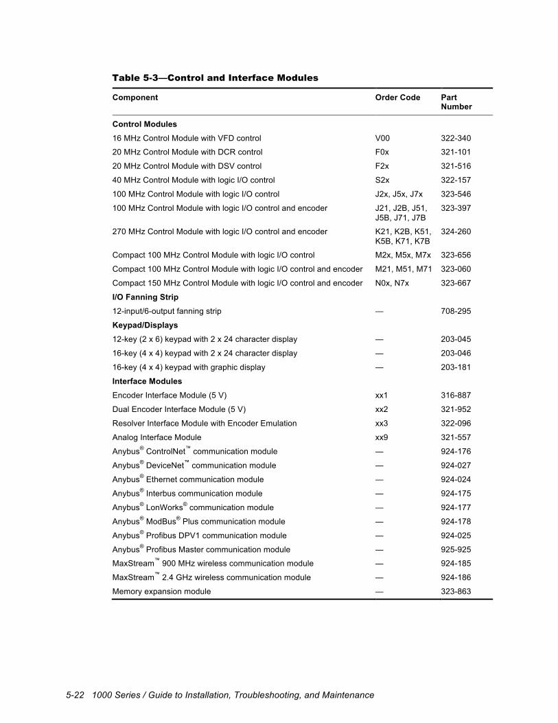
5-22 1000 Series / Guide to Installation, Troubleshooting, and Maintenance
Table 5-3—Control and Interface Modules
Component Order Code Part Number
Control Modules 16 MHz Control Module with VFD control V00 322-340
20 MHz Control Module with DCR control F0x 321-101
20 MHz Control Module with DSV control F2x 321-516
40 MHz Control Module with logic I/O control S2x 322-157
100 MHz Control Module with logic I/O control J2x, J5x, J7x 323-546
100 MHz Control Module with logic I/O control and encoder J21, J2B, J51, J5B, J71, J7B
323-397
270 MHz Control Module with logic I/O control and encoder K21, K2B, K51, K5B, K71, K7B
324-260
Compact 100 MHz Control Module with logic I/O control M2x, M5x, M7x 323-656
Compact 100 MHz Control Module with logic I/O control and encoder M21, M51, M71 323-060
Compact 150 MHz Control Module with logic I/O control and encoder N0x, N7x 323-667
I/O Fanning Strip 12-input/6-output fanning strip — 708-295
Keypad/Displays 12-key (2 x 6) keypad with 2 x 24 character display — 203-045
16-key (4 x 4) keypad with 2 x 24 character display — 203-046
16-key (4 x 4) keypad with graphic display — 203-181
Interface Modules Encoder Interface Module (5 V) xx1 316-887
Dual Encoder Interface Module (5 V) xx2 321-952
Resolver Interface Module with Encoder Emulation xx3 322-096
Analog Interface Module xx9 321-557
Anybus® ControlNet™ communication module — 924-176
Anybus® DeviceNet™ communication module — 924-027
Anybus® Ethernet communication module — 924-024
Anybus® Interbus communication module — 924-175
Anybus® LonWorks® communication module — 924-177
Anybus® ModBus® Plus communication module — 924-178
Anybus® Profibus DPV1 communication module — 924-025
Anybus® Profibus Master communication module — 925-925
MaxStream™ 900 MHz wireless communication module — 924-185
MaxStream™ 2.4 GHz wireless communication module — 924-186
Memory expansion module — 323-863
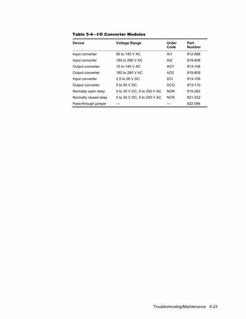
Troubleshooting/Maintenance 5-23
Table 5-4—I/O Converter Modules
Device Voltage Range Order Code
Part Number
Input converter 90 to 140 V AC AI1 912-688
Input converter 180 to 280 V AC AI2 919-808
Output converter 12 to 140 V AC AO1 913-108
Output converter 180 to 280 V AC AO2 919-809
Input converter 2.5 to 28 V DC DCI 913-109
Output converter 5 to 60 V DC DCO 913-110
Normally open relay 0 to 30 V DC, 0 to 250 V AC NOR 915-282
Normally closed relay 0 to 30 V DC, 0 to 250 V AC NCR 921-332
Pass-through jumper — — 922-084
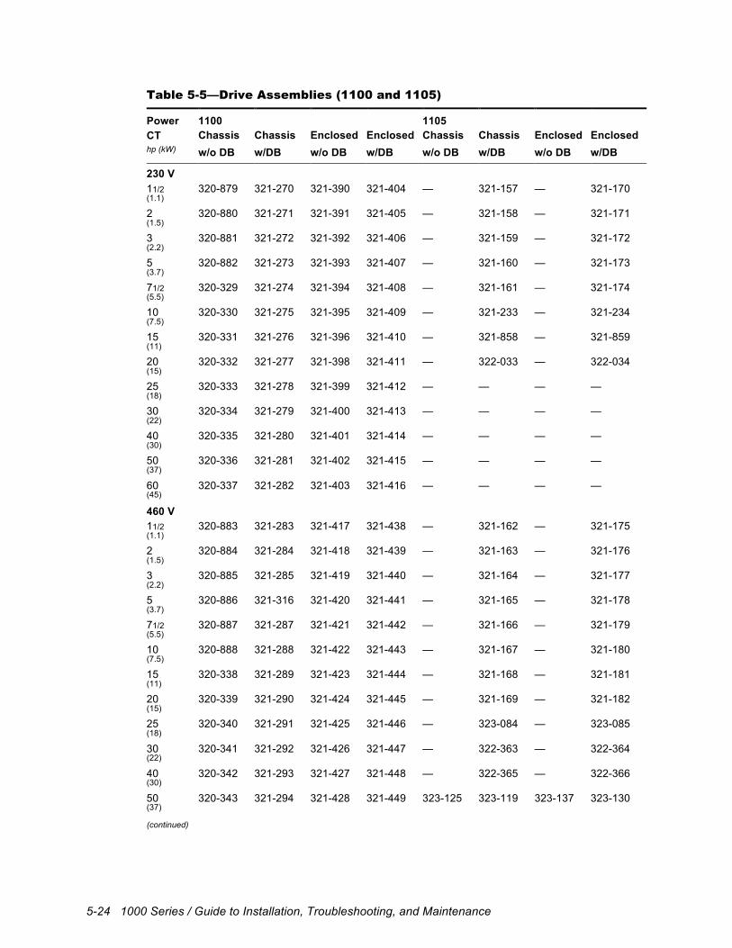
5-24 1000 Series / Guide to Installation, Troubleshooting, and Maintenance
Table 5-5—Drive Assemblies (1100 and 1105)
Power 1100 1105 CT Chassis Chassis Enclosed Enclosed Chassis Chassis Enclosed Enclosed hp (kW) w/o DB w/DB w/o DB w/DB w/o DB w/DB w/o DB w/DB
230 V 11/2 320-879 321-270 321-390 321-404 — 321-157 — 321-170 (1.1)
2 320-880 321-271 321-391 321-405 — 321-158 — 321-171 (1.5)
3 320-881 321-272 321-392 321-406 — 321-159 — 321-172 (2.2)
5 320-882 321-273 321-393 321-407 — 321-160 — 321-173 (3.7)
71/2 320-329 321-274 321-394 321-408 — 321-161 — 321-174 (5.5)
10 320-330 321-275 321-395 321-409 — 321-233 — 321-234 (7.5)
15 320-331 321-276 321-396 321-410 — 321-858 — 321-859 (11)
20 320-332 321-277 321-398 321-411 — 322-033 — 322-034 (15)
25 320-333 321-278 321-399 321-412 — — — — (18)
30 320-334 321-279 321-400 321-413 — — — — (22)
40 320-335 321-280 321-401 321-414 — — — — (30)
50 320-336 321-281 321-402 321-415 — — — — (37)
60 320-337 321-282 321-403 321-416 — — — — (45)
460 V 11/2 320-883 321-283 321-417 321-438 — 321-162 — 321-175 (1.1)
2 320-884 321-284 321-418 321-439 — 321-163 — 321-176 (1.5)
3 320-885 321-285 321-419 321-440 — 321-164 — 321-177 (2.2)
5 320-886 321-316 321-420 321-441 — 321-165 — 321-178 (3.7)
71/2 320-887 321-287 321-421 321-442 — 321-166 — 321-179 (5.5)
10 320-888 321-288 321-422 321-443 — 321-167 — 321-180 (7.5)
15 320-338 321-289 321-423 321-444 — 321-168 — 321-181 (11)
20 320-339 321-290 321-424 321-445 — 321-169 — 321-182 (15)
25 320-340 321-291 321-425 321-446 — 323-084 — 323-085 (18)
30 320-341 321-292 321-426 321-447 — 322-363 — 322-364 (22)
40 320-342 321-293 321-427 321-448 — 322-365 — 322-366 (30)
50 320-343 321-294 321-428 321-449 323-125 323-119 323-137 323-130 (37) (continued)
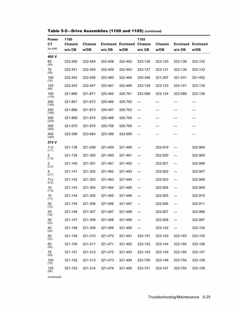
Troubleshooting/Maintenance 5-25
Table 5-5—Drive Assemblies (1100 and 1105) (continued)
Power 1100 1105 CT Chassis Chassis Enclosed Enclosed Chassis Chassis Enclosed Enclosed hp (kW) w/o DB w/DB w/o DB w/DB w/o DB w/DB w/o DB w/DB
460 V 60 322-450 322-454 322-458 322-462 323-126 323-120 323-138 323-132 (45)
75 322-451 322-455 322-459 322-463 323-127 323-121 323-139 323-133 (55)
100 322-452 322-456 322-460 322-464 320-346 321-297 321-431 321-452 (75)
125 322-453 322-457 322-461 322-465 323-129 323-123 323-141 323-135 (90)
150 321-866 321-871 320-465 320-761 323-588 323-124 323-589 323-136 (110)
200 321-867 321-872 320-466 320-762 — — — — (150)
250 321-868 321-873 320-467 320-763 — — — — (185)
300 321-869 321-874 320-468 320-764 — — — — (225)
350 321-870 321-875 320-758 320-765 — — — — (262)
400 323-398 323-684 323-399 323-685 — — — — (300)
575 V 11/2 321-138 321-299 321-459 321-480 — 322-919 — 322-904 (1.1)
2 321-139 321-300 321-460 321-481 — 322-920 — 322-905 (1.5)
3 321-140 321-301 321-461 321-482 — 322-921 — 322-906 (2.2)
5 321-141 321-302 321-462 321-483 — 322-922 — 322-907 (3.7)
71/2 321-142 321-303 321-463 321-484 — 322-923 — 322-908 (5.5)
10 321-143 321-304 321-464 321-485 — 322-924 — 322-909 (7.5)
15 321-144 321-305 321-465 321-486 — 322-925 — 322-910 (11)
20 321-145 321-306 321-466 321-487 — 322-926 — 322-911 (15)
25 321-146 321-307 321-467 321-488 — 322-927 — 322-996 (18)
30 321-147 321-308 321-468 321-489 — 322-928 — 322-997 (22)
40 321-148 321-309 321-469 321-490 — 323-142 — 323-154 (30)
50 321-149 321-310 321-470 321-491 323-151 323-143 323-163 323-155 (37)
60 321-150 321-311 321-471 321-492 323-152 323-144 323-164 323-156 (45)
75 321-151 321-312 321-472 321-493 323-153 323-145 323-165 323-157 (55)
100 321-152 321-313 321-473 321-494 323-750 323-146 323-754 323-158 (75)
125 321-153 321-314 321-474 321-495 323-751 323-147 323-755 323-159 (90) (continued)
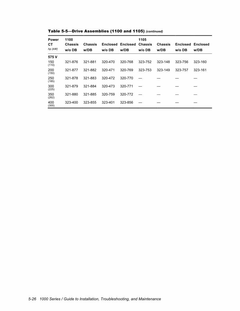
5-26 1000 Series / Guide to Installation, Troubleshooting, and Maintenance
Table 5-5—Drive Assemblies (1100 and 1105) (continued)
Power 1100 1105 CT Chassis Chassis Enclosed Enclosed Chassis Chassis Enclosed Enclosed hp (kW) w/o DB w/DB w/o DB w/DB w/o DB w/DB w/o DB w/DB
575 V 150 321-876 321-881 320-470 320-768 323-752 323-148 323-756 323-160 (110)
200 321-877 321-882 320-471 320-769 323-753 323-149 323-757 323-161 (150)
250 321-878 321-883 320-472 320-770 — — — — (185)
300 321-879 321-884 320-473 320-771 — — — — (225)
350 321-880 321-885 320-759 320-772 — — — — (262)
400 323-400 323-855 323-401 323-856 — — — — (300)
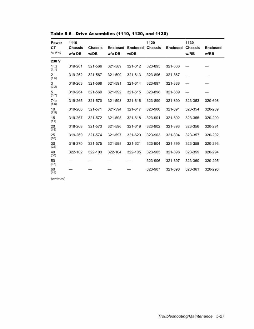
Troubleshooting/Maintenance 5-27
Table 5-6—Drive Assemblies (1110, 1120, and 1130)
Power 1110 1120 1130 CT Chassis Chassis Enclosed Enclosed Chassis Enclosed Chassis Enclosed hp (kW) w/o DB w/DB w/o DB w/DB w/RB w/RB
230 V 11/2 319-261 321-566 321-589 321-612 323-895 321-866 — — (1.1)
2 319-262 321-567 321-590 321-613 323-896 321-867 — — (1.5)
3 319-263 321-568 321-591 321-614 323-897 321-888 — — (2.2)
5 319-264 321-569 321-592 321-615 323-898 321-889 — — (3.7)
71/2 319-265 321-570 321-593 321-616 323-899 321-890 323-353 320-698 (5.5)
10 319-266 321-571 321-594 321-617 323-900 321-891 323-354 320-289 (7.5)
15 319-267 321-572 321-595 321-618 323-901 321-892 323-355 320-290 (11)
20 319-268 321-573 321-596 321-619 323-902 321-893 323-356 320-291 (15)
25 319-269 321-574 321-597 321-620 323-903 321-894 323-357 320-292 (18)
30 319-270 321-575 321-598 321-621 323-904 321-895 323-358 320-293 (22)
40 322-102 322-103 322-104 322-105 323-905 321-896 323-359 320-294 (30)
50 — — — — 323-906 321-897 323-360 320-295 (37)
60 — — — — 323-907 321-898 323-361 320-296 (45) (continued)
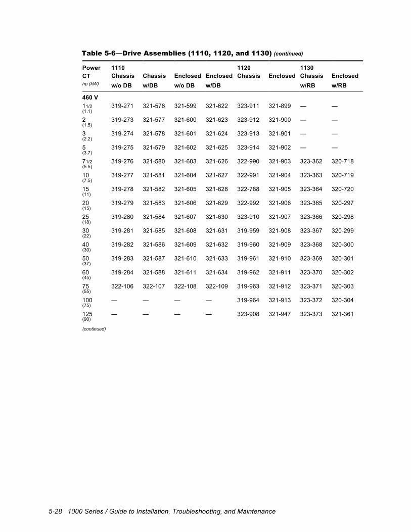
5-28 1000 Series / Guide to Installation, Troubleshooting, and Maintenance
Table 5-6—Drive Assemblies (1110, 1120, and 1130) (continued)
Power 1110 1120 1130 CT Chassis Chassis Enclosed Enclosed Chassis Enclosed Chassis Enclosed hp (kW) w/o DB w/DB w/o DB w/DB w/RB w/RB
460 V 11/2 319-271 321-576 321-599 321-622 323-911 321-899 — — (1.1)
2 319-273 321-577 321-600 321-623 323-912 321-900 — — (1.5)
3 319-274 321-578 321-601 321-624 323-913 321-901 — — (2.2)
5 319-275 321-579 321-602 321-625 323-914 321-902 — — (3.7)
71/2 319-276 321-580 321-603 321-626 322-990 321-903 323-362 320-718 (5.5)
10 319-277 321-581 321-604 321-627 322-991 321-904 323-363 320-719 (7.5)
15 319-278 321-582 321-605 321-628 322-788 321-905 323-364 320-720 (11)
20 319-279 321-583 321-606 321-629 322-992 321-906 323-365 320-297 (15)
25 319-280 321-584 321-607 321-630 323-910 321-907 323-366 320-298 (18)
30 319-281 321-585 321-608 321-631 319-959 321-908 323-367 320-299 (22)
40 319-282 321-586 321-609 321-632 319-960 321-909 323-368 320-300 (30)
50 319-283 321-587 321-610 321-633 319-961 321-910 323-369 320-301 (37)
60 319-284 321-588 321-611 321-634 319-962 321-911 323-370 320-302 (45)
75 322-106 322-107 322-108 322-109 319-963 321-912 323-371 320-303 (55)
100 — — — — 319-964 321-913 323-372 320-304 (75)
125 — — — — 323-908 321-947 323-373 321-361 (90) (continued)
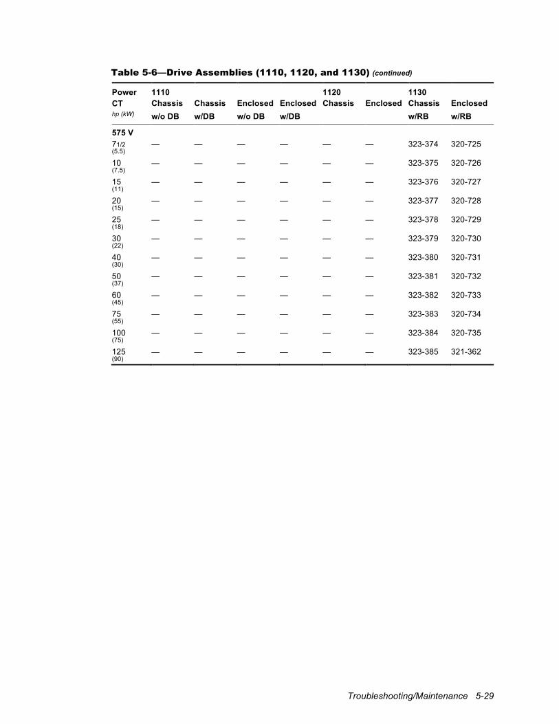
Troubleshooting/Maintenance 5-29
Table 5-6—Drive Assemblies (1110, 1120, and 1130) (continued)
Power 1110 1120 1130 CT Chassis Chassis Enclosed Enclosed Chassis Enclosed Chassis Enclosed hp (kW) w/o DB w/DB w/o DB w/DB w/RB w/RB
575 V 71/2 — — — — — — 323-374 320-725 (5.5)
10 — — — — — — 323-375 320-726 (7.5)
15 — — — — — — 323-376 320-727 (11)
20 — — — — — — 323-377 320-728 (15)
25 — — — — — — 323-378 320-729 (18)
30 — — — — — — 323-379 320-730 (22)
40 — — — — — — 323-380 320-731 (30)
50 — — — — — — 323-381 320-732 (37)
60 — — — — — — 323-382 320-733 (45)
75 — — — — — — 323-383 320-734 (55)
100 — — — — — — 323-384 320-735 (75)
125 — — — — — — 323-385 321-362 (90)
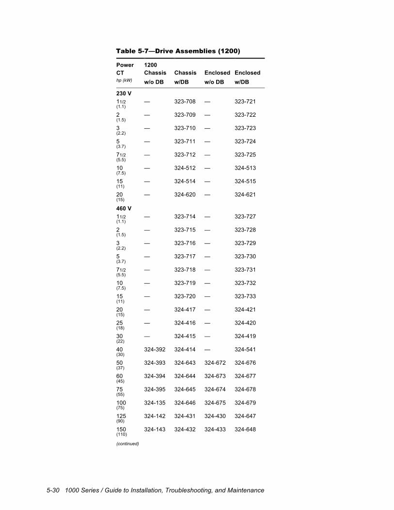
5-30 1000 Series / Guide to Installation, Troubleshooting, and Maintenance
Table 5-7—Drive Assemblies (1200)
Power 1200 CT Chassis Chassis Enclosed Enclosed hp (kW) w/o DB w/DB w/o DB w/DB
230 V 11/2 — 323-708 — 323-721 (1.1)
2 — 323-709 — 323-722 (1.5)
3 — 323-710 — 323-723 (2.2)
5 — 323-711 — 323-724 (3.7)
71/2 — 323-712 — 323-725 (5.5)
10 — 324-512 — 324-513 (7.5)
15 — 324-514 — 324-515 (11)
20 — 324-620 — 324-621 (15)
460 V 11/2 — 323-714 — 323-727 (1.1)
2 — 323-715 — 323-728 (1.5)
3 — 323-716 — 323-729 (2.2)
5 — 323-717 — 323-730 (3.7)
71/2 — 323-718 — 323-731 (5.5)
10 — 323-719 — 323-732 (7.5)
15 — 323-720 — 323-733 (11)
20 — 324-417 — 324-421 (15)
25 — 324-416 — 324-420 (18)
30 — 324-415 — 324-419 (22)
40 324-392 324-414 — 324-541 (30)
50 324-393 324-643 324-672 324-676 (37)
60 324-394 324-644 324-673 324-677 (45)
75 324-395 324-645 324-674 324-678 (55)
100 324-135 324-646 324-675 324-679 (75)
125 324-142 324-431 324-430 324-647 (90)
150 324-143 324-432 324-433 324-648 (110) (continued)
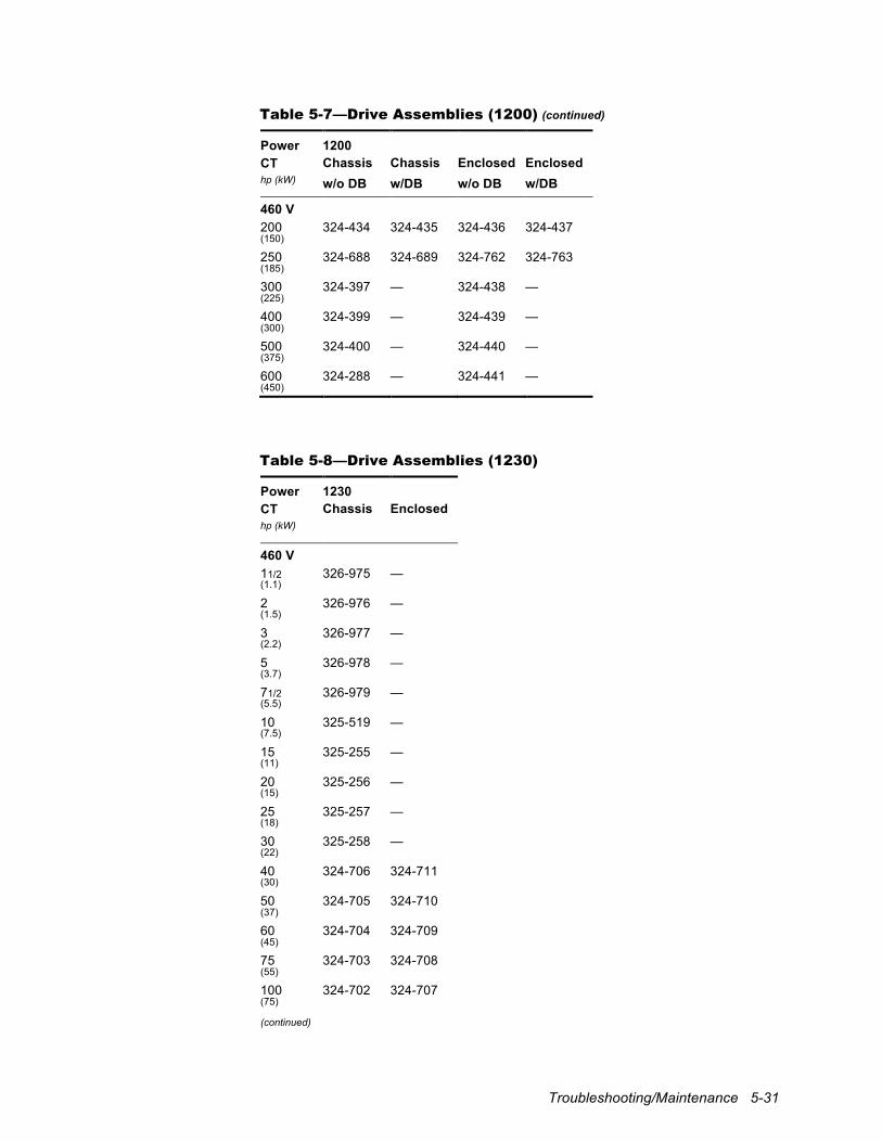
Troubleshooting/Maintenance 5-31
Table 5-7—Drive Assemblies (1200) (continued)
Power 1200 CT Chassis Chassis Enclosed Enclosed hp (kW) w/o DB w/DB w/o DB w/DB
460 V 200 324-434 324-435 324-436 324-437 (150)
250 324-688 324-689 324-762 324-763 (185)
300 324-397 — 324-438 — (225)
400 324-399 — 324-439 — (300)
500 324-400 — 324-440 — (375)
600 324-288 — 324-441 — (450)
Table 5-8—Drive Assemblies (1230)
Power 1230 CT Chassis Enclosed hp (kW)
460 V 11/2 326-975 — (1.1)
2 326-976 — (1.5)
3 326-977 — (2.2)
5 326-978 — (3.7)
71/2 326-979 — (5.5)
10 325-519 — (7.5)
15 325-255 — (11)
20 325-256 — (15)
25 325-257 — (18)
30 325-258 — (22)
40 324-706 324-711 (30)
50 324-705 324-710 (37)
60 324-704 324-709 (45)
75 324-703 324-708 (55)
100 324-702 324-707 (75) (continued)
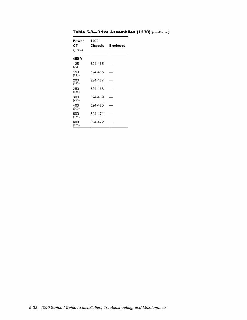
5-32 1000 Series / Guide to Installation, Troubleshooting, and Maintenance
Table 5-8—Drive Assemblies (1230) (continued)
Power 1200 CT Chassis Enclosed hp (kW)
460 V 125 324-465 — (90)
150 324-466 — (110)
200 324-467 — (150)
250 324-468 — (185)
300 324-469 — (225)
400 324-470 — (300)
500 324-471 — (375)
600 324-472 — (450)