Embed Size (px)
Citation preview
FCL: 14-54 DATE: 10/29/14
FLIGHT CREW LETTER
TO: ALL FLIGHT CREWMEMBERS
FROM: MIKE WOODFORD MANAGER OF FLIGHT STANDARDS AND TRAINING
SUBJECT: B767 AOM Rev 51
Rev 51 to the B767 AOM will be out in the 10/30/14 bag swap and online later that day. There are a few procedures and changes that you should take note of. Procedural changes; Shutdown Items and Airspeed Unreliable. Below are the Chapter highlights of the changes: Chapter 3, NORMAL PROCEDURES
• Added information to ensure seat is locked per a Boeing Service Letter. • Added guidance to reference the weight placards to ensure limits are not exceeded. • Removed procedures for Flight Crews to pull CBs on shutdown. • Added variable to flows for Packs on After Takeoff Flow.
Chapter 4, SUPPLEMENTAL NORMAL PROCEDURES
• Removed reference to printer on switching to APU power. • Added note concerning Flight Crew functions.
Chapter 5, STANDARD OPERATING PROCEDURES
• Corrected Stabilized Visual Approach limits to match FOM. • Removed reference to printer on switching to APU power. • Added new Electronic Device guidance to match FOM. • Corrected information concerning slides and the arming handle. • Added new information from Boeing on Landing Flare profile. • Added new information from Boeing on Directional Control and Braking on Landing
Roll. • Corrected information on Immediate Turns After Takeoff with and Engine Failure. • Added new information from Boeing on Airspeed Unreliable. (Change to QRH coming
soon). Note: The new pitch and power numbers will become an Immediate Action Item, committed to memory.
• Added new information from Boeing on Fuel Balance and Fuel Leak. • Added new information from Boeing on Upset Recovery Maneuvers. • Corrected Rejected Takeoff Profile to match verbiage. • Corrected and updated information in the Fuel Conservation Section.
145 Hunter Drive · Wilmington, Ohio 45177 · (937) 382 5591 · www.abxair.com
FCL: 14-54 DATE: 10/29/14
FLIGHT CREW LETTER Chapter 6, PERFORMANCE
• Added new PDX Engine Out Complex Special to cancel Flight Bulletin. • Added Recommended Brake Cooling performance for altitudes above 4000 feet. • Added performance information for above 8000 feet to 80A2 section. • Recommended Brake Cooling charts in 80A2 section changed to match 80A section.
Chapter 7, WEIGHT AND BALANCE
• Sable, additional guidance to reference the weight placard when doing crosschecks. • Corrected Corrections section in Sable to cancel Flight Bulletin. • Reworded use of Sable ACM and Fuel corrections for better understanding. • Added additional guidance to reference the weight placard when doing crosschecks. • PSTL, additional guidance to reference the weight placard when doing crosschecks. • PSTL, added new example/descriptor for Landing Weight and Fuel Burn added to
tape.
Please take some time to review these changes as some will be part of your next training event/PC.
As always if you have any questions regarding these changes contact Flight Standards.
145 Hunter Drive · Wilmington, Ohio 45177 · (937) 382 5591 · www.abxair.com
PAGE 1 OF 2
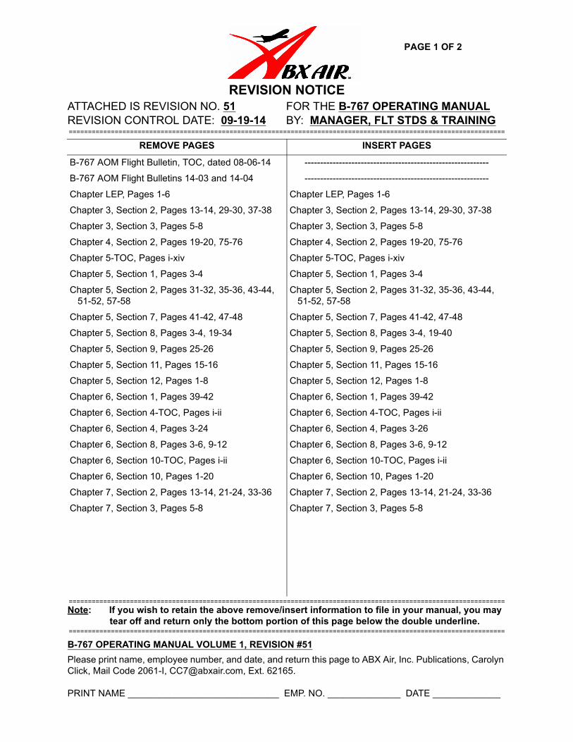
REVISION NOTICEATTACHED IS REVISION NO. 51 FOR THE B-767 OPERATING MANUALREVISION CONTROL DATE: 09-19-14 BY: MANAGER, FLT STDS & TRAINING==================================================================================================================
==================================================================================================================
Note: If you wish to retain the above remove/insert information to file in your manual, you may tear off and return only the bottom portion of this page below the double underline.
==================================================================================================================
B-767 OPERATING MANUAL VOLUME 1, REVISION #51
Please print name, employee number, and date, and return this page to ABX Air, Inc. Publications, Carolyn Click, Mail Code 2061-I, [email protected], Ext. 62165.
PRINT NAME _____________________________ EMP. NO. ______________ DATE _____________
REMOVE PAGES INSERT PAGES
B-767 AOM Flight Bulletin, TOC, dated 08-06-14 -----------------------------------------------------------
B-767 AOM Flight Bulletins 14-03 and 14-04 -----------------------------------------------------------
Chapter LEP, Pages 1-6 Chapter LEP, Pages 1-6
Chapter 3, Section 2, Pages 13-14, 29-30, 37-38 Chapter 3, Section 2, Pages 13-14, 29-30, 37-38
Chapter 3, Section 3, Pages 5-8 Chapter 3, Section 3, Pages 5-8
Chapter 4, Section 2, Pages 19-20, 75-76 Chapter 4, Section 2, Pages 19-20, 75-76
Chapter 5-TOC, Pages i-xiv Chapter 5-TOC, Pages i-xiv
Chapter 5, Section 1, Pages 3-4 Chapter 5, Section 1, Pages 3-4
Chapter 5, Section 2, Pages 31-32, 35-36, 43-44, Chapter 5, Section 2, Pages 31-32, 35-36, 43-44, 51-52, 57-58
Chapter 5, Section 7, Pages 41-42, 47-48
Chapter 5, Section 8, Pages 3-4, 19-34
Chapter 5, Section 9, Pages 25-26
Chapter 5, Section 11, Pages 15-16
Chapter 5, Section 12, Pages 1-8
Chapter 6, Section 1, Pages 39-42
Chapter 6, Section 4-TOC, Pages i-ii
Chapter 6, Section 4, Pages 3-24
Chapter 6, Section 8, Pages 3-6, 9-12
Chapter 6, Section 10-TOC, Pages i-ii
Chapter 6, Section 10, Pages 1-20
Chapter 7, Section 2, Pages 13-14, 21-24, 33-36
Chapter 7, Section 3, Pages 5-8
51-52, 57-58
Chapter 5, Section 7, Pages 41-42, 47-48
Chapter 5, Section 8, Pages 3-4, 19-40
Chapter 5, Section 9, Pages 25-26
Chapter 5, Section 11, Pages 15-16
Chapter 5, Section 12, Pages 1-8
Chapter 6, Section 1, Pages 39-42
Chapter 6, Section 4-TOC, Pages i-ii
Chapter 6, Section 4, Pages 3-26
Chapter 6, Section 8, Pages 3-6, 9-12
Chapter 6, Section 10-TOC, Pages i-ii
Chapter 6, Section 10, Pages 1-20
Chapter 7, Section 2, Pages 13-14, 21-24, 33-36
Chapter 7, Section 3, Pages 5-8

PAGE 2 OF 2
THIS PAGE INTENTIONALLY LEFT BLANK
CHAPTER: LEPSECTION:PAGE: 1
REV. NO.: 51DATE: 09-19-14
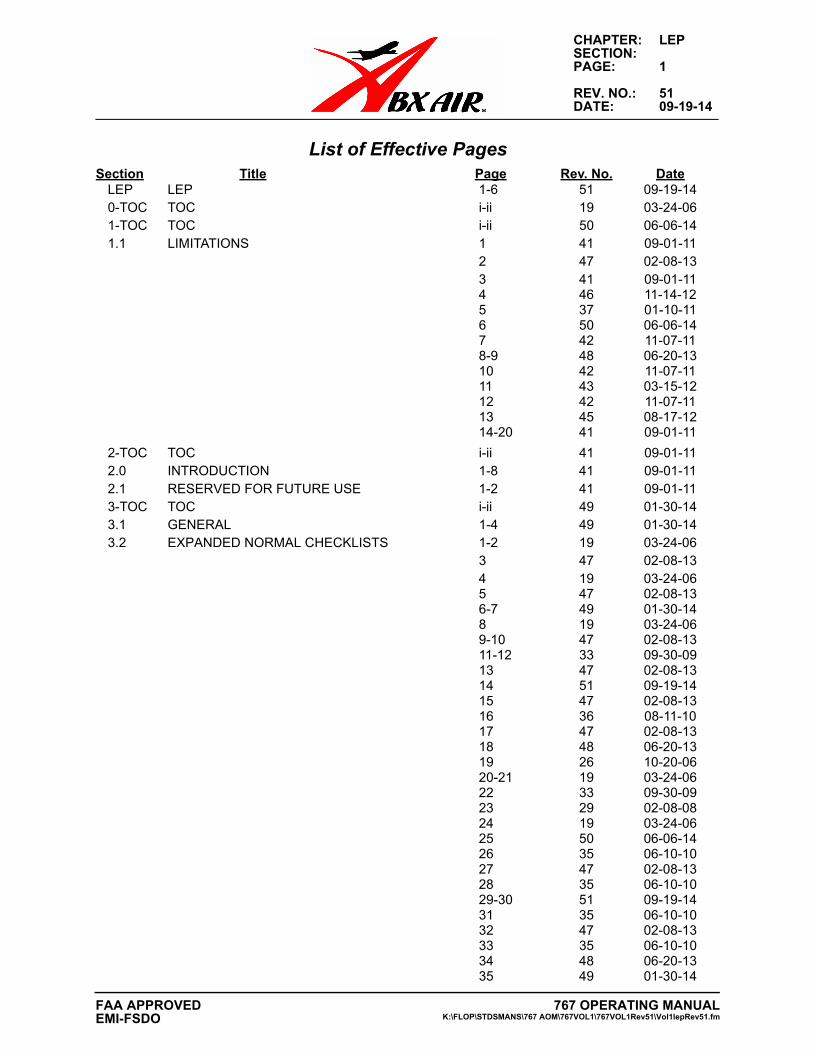
List of Effective PagesSection Title Page Rev. No. Date
LEP LEP 1-6 51 09-19-140-TOC TOC i-ii 19 03-24-061-TOC TOC i-ii 50 06-06-141.1 LIMITATIONS 1 41 09-01-11
2 47 02-08-133 41 09-01-114 46 11-14-125 37 01-10-116 50 06-06-147 42 11-07-118-9 48 06-20-1310 42 11-07-1111 43 03-15-1212 42 11-07-1113 45 08-17-1214-20 41 09-01-11
2-TOC TOC i-ii 41 09-01-112.0 INTRODUCTION 1-8 41 09-01-112.1 RESERVED FOR FUTURE USE 1-2 41 09-01-113-TOC TOC i-ii 49 01-30-143.1 GENERAL 1-4 49 01-30-143.2 EXPANDED NORMAL CHECKLISTS 1-2 19 03-24-06
3 47 02-08-134 19 03-24-065 47 02-08-136-7 49 01-30-148 19 03-24-069-10 47 02-08-1311-12 33 09-30-0913 47 02-08-1314 51 09-19-1415 47 02-08-1316 36 08-11-1017 47 02-08-1318 48 06-20-1319 26 10-20-0620-21 19 03-24-0622 33 09-30-0923 29 02-08-0824 19 03-24-0625 50 06-06-1426 35 06-10-1027 47 02-08-1328 35 06-10-1029-30 51 09-19-1431 35 06-10-1032 47 02-08-1333 35 06-10-1034 48 06-20-1335 49 01-30-14
767 OPERATING MANUALK:\FLOP\STDSMANS\767 AOM\767VOL1\767VOL1Rev51\Vol1lepRev51.fm
FAA APPROVEDEMI-FSDO
CHAPTER: LEPSECTION:PAGE: 2
REV. NO.: 51DATE: 09-19-14
36 41 09-01-1137-38 51 09-19-14
3.3 COCKPIT FLOWS 1 10 02-25-022 30 11-25-083 5 04-01-004 10 02-25-025 51 09-19-146 5 04-01-007 30 11-25-088 51 09-19-149-10 42 11-07-11
4-TOC TOC i-iv 50 06-06-144.1 SUPPLEMENTAL NORMAL PROCEDURES 1-2 43 03-15-124.2 SUPPLEMENTAL NORMAL CHECKLISTS 1-3 42 11-07-11
4-5 49 01-30-146 50 06-06-147-17 42 11-07-1118 47 02-08-1319 42 11-07-1120 51 09-19-1421-23 42 11-07-1124-39 48 06-20-1340-44 49 01-30-1445-47 50 06-06-1448-55 49 01-30-1456 50 06-06-1457-75 49 01-30-1476 51 09-19-1477-112 49 01-30-14
5-TOC TOC i-xiv 51 09-19-145.1 PROFICIENCY STANDARDS 1-2 40 06-30-11
3-4 51 09-19-145.2 GROUND OPERATIONS 1 46 11-14-12
2-3 33 09-30-094 46 11-14-125-11 33 09-30-0912 45 08-17-1213-27 33 09-30-0928 48 06-20-1329 34 01-27-1030 47 02-08-1331 51 09-19-1432 33 09-30-0933-35 47 02-08-1336 51 09-19-1437-40 47 02-08-1341-43 49 01-30-1444 51 09-19-1445-47 47 02-08-1348-50 49 01-30-1451 51 09-19-1452-54 47 02-08-1355-57 49 01-30-14
767 OPERATING MANUALK:\FLOP\STDSMANS\767 AOM\767VOL1\767VOL1Rev51\Vol1lepRev51.fm
FAA APPROVED EMI-FSDO
CHAPTER: LEPSECTION:PAGE: 3
REV. NO.: 51DATE: 09-19-14
58 51 09-19-1459-74 47 02-08-13
5.3 TAKEOFF 1 36 08-11-102 42 11-07-113 47 02-08-134-5 33 09-30-096 38 04-15-117 33 09-30-908 47 02-08-139 38 04-15-1110 47 02-08-1311 33 09-30-0912 47 02-08-1313-14 33 09-30-0915 49 01-30-1416-20 33 09-30-09
5.4 CLIMB 1 13 06-16-032 17 06-10-053-4 17 06-10-05
5.5 CRUISE 1-2 33 09-30-093 46 11-14-124-6 33 09-30-097 49 01-30-148 43 03-15-129-10 33 09-30-09
5.6 DESCENT 1-4 49 01-30-145.7 HOLDING, APPROACH, AND LANDING 1 33 09-30-09
2 49 01-30-143 36 08-11-104 33 09-30-095 48 06-20-136-19 33 09-30-0920 42 11-07-1121-22 33 09-30-0923 37 01-10-1124-26 48 06-20-1327 50 06-06-1428-31 48 06-20-1332-39 49 01-30-1440 50 06-06-1441-42 51 09-19-1443-46 50 06-06-1447 51 09-19-1448-60 50 06-06-14
5.8 EMERGENCY PROCEDURES 1 33 09-30-092 49 01-30-143 51 09-19-144-7 42 11-07-118-9 33 09-30-0910 47 02-08-1311 33 09-30-0912 36 08-11-1013-14 33 09-30-0915 49 01-30-1416-19 33 09-30-09
767 OPERATING MANUALK:\FLOP\STDSMANS\767 AOM\767VOL1\767VOL1Rev51\Vol1lepRev51.fm
FAA APPROVEDEMI-FSDO
CHAPTER: LEPSECTION:PAGE: 4
REV. NO.: 51DATE: 09-19-14
20-40 51 09-19-145.9 TRAINING MANUEVERS 1-5 33 09-30-09
6 43 03-15-127-19 42 11-07-1120 47 02-08-1321-24 42 11-07-1125 51 09-19-1426 42 11-07-11
5.10 ADVERSE WEATHER OPERATIONS 1-2 42 11-07-113-12 49 01-30-1413-14 42 11-07-1115 49 01-30-1416-19 42 11-07-1120 47 02-08-1321-22 42 11-07-11
5.11 STANDARD CALLOUTS AND PROFILES 1 42 11-07-112 49 01-30-143-4 42 11-07-115 47 02-08-136-10 42 11-07-1111 49 01-30-1412 47 02-08-1313-14 42 11-07-1115 49 01-30-1416 51 09-19-1417-18 42 11-07-1119 43 03-15-1220 42 11-07-1121 45 08-17-1222 46 11-14-1223 49 01-30-1424-29 33 09-30-0930-33 46 11-14-1234 42 11-07-1135-36 40 06-30-1137 48 06-20-1338 50 06-06-1439-41 48 06-20-1342 50 06-06-1443-45 48 06-20-1346-47 46 11-14-1248 40 06-30-1149-51 46 11-14-1252-58 40 06-30-11
5.12 1-8 51 09-19-146-TOC TOC i-ii 36 08-11-106.1 TOC TOC i-ii 49 01-30-146.1 GENERAL 1-2 42 11-07-11
3 49 01-30-144 42 11-07-15 46 11-14-126 42 11-07-11
767 OPERATING MANUALK:\FLOP\STDSMANS\767 AOM\767VOL1\767VOL1Rev51\Vol1lepRev51.fm
FAA APPROVED EMI-FSDO
CHAPTER: LEPSECTION:PAGE: 5
REV. NO.: 51DATE: 09-19-14
7-8 46 11-14-129-10 42 11-07-1111 46 11-14-1212 45 08-17-1213-14 48 06-20-1315 46 11-14-1216 42 11-07-1117 46 11-14-1218-22 42 11-07-1123 49 01-30-1424 48 06-20-1325 42 11-07-1126 43 03-15-1227 48 06-20-1328 49 01-30-1429 47 02-08-1330 42 11-07-1131 49 01-30-1432 45 08-17-1233-37 42 11-07-1138-39 49 01-30-1440-41 51 09-19-1442-50 47 02-08-13
6.2 TOC TOC i-ii 34 01-27-106.2 TAKEOFF AND LANDING B767-200 (CF6-80A) 1 38 04-15-11
2 34 01-27-103 46 11-14-124 38 04-15-115 46 11-14-126-8 38 04-15-119 46 11-14-1210 38 04-15-1111 43 03-15-1212 38 04-15-1113 48 06-20-1314-24 38 04-15-11
6.3 TOC TOC i-ii 31 02-02-096.3 ENROUTE (CF6-80A) 1-2 13 06-16-03
3-4 29 02-08-085-7 27 05-25-078-11 32 05-29-0912-13 27 05-25-0714 32 05-29-0915-30 31 02-02-09
6.4 TOC TOC i-ii 51 09-19-146.4 NON-NORMALS (CF6-80A) 1-2 46 11-14-12
3-26 51 09-19-146.5 RESERVED 1-2 36 08-11-106.6 RESERVED 1-2 36 08-11-106.7 RESERVED 1-2 36 08-11-106.8 TOC TOC i-ii 50 06-06-14
767 OPERATING MANUALK:\FLOP\STDSMANS\767 AOM\767VOL1\767VOL1Rev51\Vol1lepRev51.fm
FAA APPROVEDEMI-FSDO
CHAPTER: LEPSECTION:PAGE: 6
REV. NO.: 51DATE: 09-19-14
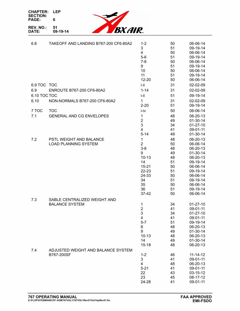
6.8 TAKEOFF AND LANDING B767-200 CF6-80A2 1-2 50 06-06-143 51 09-19-144 50 06-06-145-6 51 09-19-147-8 50 06-06-149 51 09-19-1410 50 06-06-1411 51 09-19-1412-20 50 06-06-14
6.9 TOC TOC i-ii 31 02-02-096.9 ENROUTE B767-200 CF6-80A2 1-14 31 02-02-096.10 TOC TOC i-ii 51 09-19-146.10 NON-NORMALS B767-200 CF6-80A2 1 31 02-02-09
2-20 51 09-19-147 TOC TOC i-iv 50 06-06-147.1 GENERAL AND CG ENVELOPES 1 48 06-20-13
2 49 01-30-143 34 01-27-104 41 09-01-115-14 49 01-30-14
7.2 PSTL WEIGHT AND BALANCE 1 48 06-20-13LOAD PLANNING SYSTEM 2 50 06-06-14
3-8 48 06-20-139 49 01-30-1410-13 48 06-20-1314 51 09-19-1415-21 50 06-06-1422-23 51 09-19-1424-33 50 06-06-1434 51 09-19-1435 50 06-06-1436 51 09-19-1437-42 50 06-06-14
7.3 SABLE CENTRALIZED WEIGHT AND BALANCE SYSTEM 1 34 01-27-10
2 41 09-01-113 34 01-27-104 41 09-01-115-7 51 09-19-148 48 06-20-139 49 01-30-1410-13 48 06-20-1314 49 01-30-1415-18 48 06-20-13
7.4 ADJUSTED WEIGHT AND BALANCE SYSTEMB767-200SF 1-2 46 11-14-12
3 41 09-01-114 48 06-20-135-21 41 09-01-1122 43 03-15-1223 45 08-17-1224-28 41 09-01-11
767 OPERATING MANUALK:\FLOP\STDSMANS\767 AOM\767VOL1\767VOL1Rev51\Vol1lepRev51.fm
FAA APPROVED EMI-FSDO
CHAPTER: 3SECTION: 2PAGE: 13
REV. NO.: 47DATE: 02-08-13
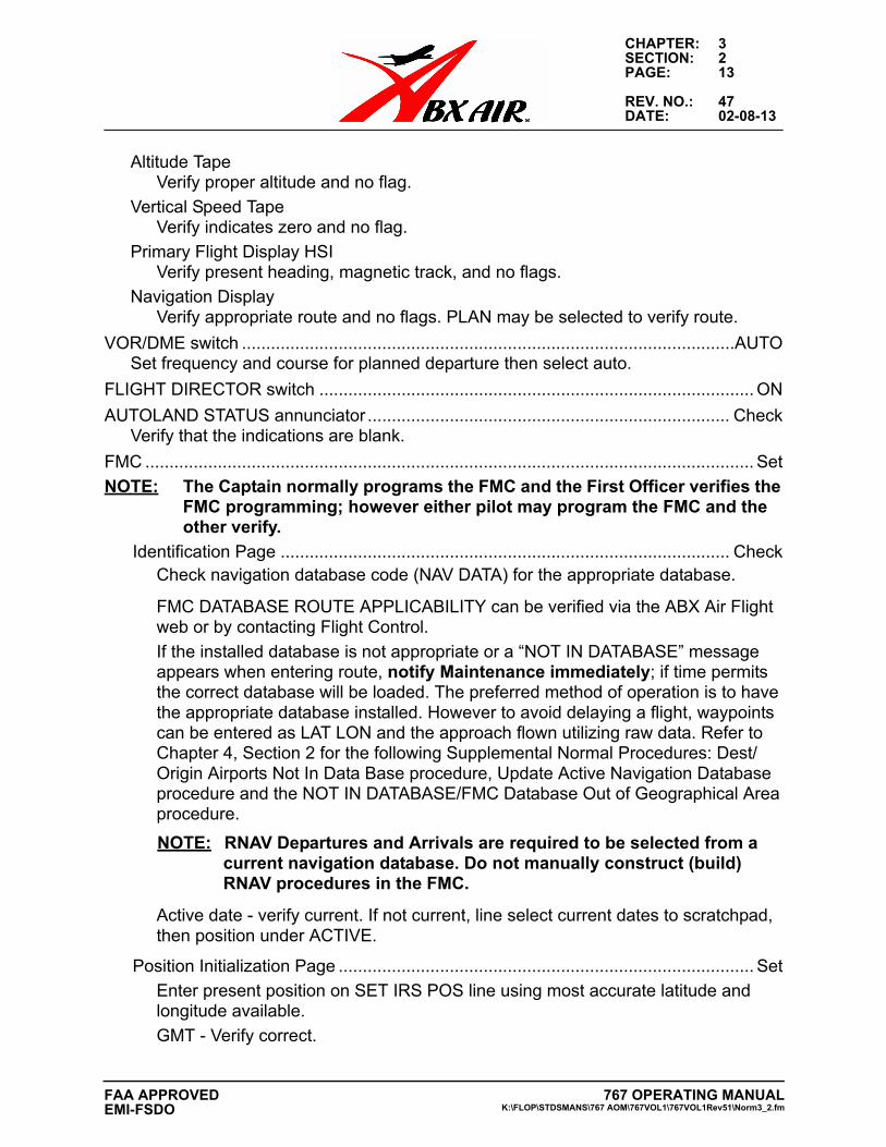
Altitude TapeVerify proper altitude and no flag.
Vertical Speed TapeVerify indicates zero and no flag.
Primary Flight Display HSIVerify present heading, magnetic track, and no flags.
Navigation DisplayVerify appropriate route and no flags. PLAN may be selected to verify route.
VOR/DME switch ......................................................................................................AUTOSet frequency and course for planned departure then select auto.
FLIGHT DIRECTOR switch .......................................................................................... ON
AUTOLAND STATUS annunciator ........................................................................... CheckVerify that the indications are blank.
FMC .............................................................................................................................. Set
NOTE: The Captain normally programs the FMC and the First Officer verifies the FMC programming; however either pilot may program the FMC and the other verify.
Identification Page ............................................................................................. CheckCheck navigation database code (NAV DATA) for the appropriate database.
FMC DATABASE ROUTE APPLICABILITY can be verified via the ABX Air Flight web or by contacting Flight Control.
If the installed database is not appropriate or a “NOT IN DATABASE” message appears when entering route, notify Maintenance immediately; if time permits the correct database will be loaded. The preferred method of operation is to have the appropriate database installed. However to avoid delaying a flight, waypoints can be entered as LAT LON and the approach flown utilizing raw data. Refer to Chapter 4, Section 2 for the following Supplemental Normal Procedures: Dest/Origin Airports Not In Data Base procedure, Update Active Navigation Database procedure and the NOT IN DATABASE/FMC Database Out of Geographical Area procedure.
NOTE: RNAV Departures and Arrivals are required to be selected from a current navigation database. Do not manually construct (build) RNAV procedures in the FMC.
Active date - verify current. If not current, line select current dates to scratchpad, then position under ACTIVE.
Position Initialization Page ...................................................................................... Set
Enter present position on SET IRS POS line using most accurate latitude and longitude available.
GMT - Verify correct.
767 OPERATING MANUALK:\FLOP\STDSMANS\767 AOM\767VOL1\767VOL1Rev51\Norm3_2.fm
FAA APPROVEDEMI-FSDO
CHAPTER: 3SECTION: 2PAGE: 14
REV. NO.: 51DATE: 09-19-14
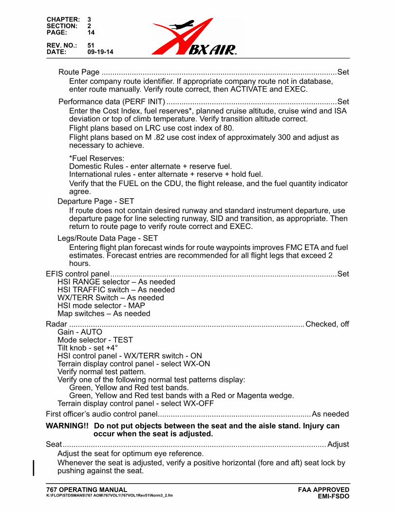
Route Page .............................................................................................................SetEnter company route identifier. If appropriate company route not in database, enter route manually. Verify route correct, then ACTIVATE and EXEC.
Performance data (PERF INIT) ...............................................................................SetEnter the Cost Index, fuel reserves*, planned cruise altitude, cruise wind and ISA deviation or top of climb temperature. Verify transition altitude correct.Flight plans based on LRC use cost index of 80.Flight plans based on M .82 use cost index of approximately 300 and adjust as necessary to achieve.
*Fuel Reserves:Domestic Rules - enter alternate + reserve fuel.International rules - enter alternate + reserve + hold fuel.Verify that the FUEL on the CDU, the flight release, and the fuel quantity indicator agree.
Departure Page - SETIf route does not contain desired runway and standard instrument departure, use departure page for line selecting runway, SID and transition, as appropriate. Then return to route page to verify route correct and EXEC.
Legs/Route Data Page - SETEntering flight plan forecast winds for route waypoints improves FMC ETA and fuel estimates. Forecast entries are recommended for all flight legs that exceed 2 hours.
EFIS control panel.........................................................................................................SetHSI RANGE selector – As neededHSI TRAFFIC switch – As neededWX/TERR Switch – As neededHSI mode selector - MAPMap switches – As needed
Radar .............................................................................................................Checked, offGain - AUTOMode selector - TESTTilt knob - set +4°HSI control panel - WX/TERR switch - ONTerrain display control panel - select WX-ONVerify normal test pattern.Verify one of the following normal test patterns display:
Green, Yellow and Red test bands.Green, Yellow and Red test bands with a Red or Magenta wedge.
Terrain display control panel - select WX-OFFFirst officer’s audio control panel.......................................................................As needed
WARNING!! Do not put objects between the seat and the aisle stand. Injury can occur when the seat is adjusted.
Seat.......................................................................................................................... AdjustAdjust the seat for optimum eye reference.Whenever the seat is adjusted, verify a positive horizontal (fore and aft) seat lock by pushing against the seat.
767 OPERATING MANUALK:\FLOP\STDSMANS\767 AOM\767VOL1\767VOL1Rev51\Norm3_2.fm
FAA APPROVED EMI-FSDO
CHAPTER: 3SECTION: 2PAGE: 29
REV. NO.: 51DATE: 09-19-14
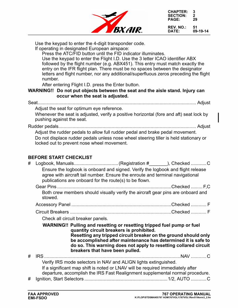
Use the keypad to enter the 4-digit transponder code.If operating in designated European airspace:
Press the ATC/FID button until the FID indicator illuminates.Use the keypad to enter the Flight I.D. Use the 3 letter ICAO identifier ABX followed by the flight number (e.g. ABX451). This entry must match exactly the entry on the IFR flight plan. There must be no spaces between the designator letters and flight number, nor any additional/superfluous zeros preceding the flight number.After entering Flight I.D. press the Enter button.
WARNING!! Do not put objects between the seat and the aisle stand. Injury can occur when the seat is adjusted.
Seat.......................................................................................................................... AdjustAdjust the seat for optimum eye reference.Whenever the seat is adjusted, verify a positive horizontal (fore and aft) seat lock by pushing against the seat.
Rudder pedals.......................................................................................................... AdjustAdjust the rudder pedals to allow full rudder pedal and brake pedal movement.Do not displace rudder pedals unless nose wheel steering tiller is held stationary or locked out to prevent nose wheel movement.
BEFORE START CHECKLIST# Logbook, Manuals.................................. (Registration #_______), Checked ............C
Ensure the logbook is onboard and signed. Verify the logbook and flight release agree with aircraft tail number. Ensure the enroute and terminal navigational publications are onboard for the route(s) to be flown.
Gear Pins ........................................................................................Checked ......... F,CBoth crew members should visually verify the aircraft gear pins are onboard and stowed.
Accessory Panel .............................................................................Checked ............ F
Circuit Breakers ..............................................................................Checked ............ F
Check all circuit breaker panels.
WARNING!! Pulling and resetting or resetting tripped fuel pump or fuel quantity circuit breakers is prohibited.Resetting any tripped circuit breaker on the ground should only be accomplished after maintenance has determined it is safe to do so. This warning does not apply to resetting collared circuit breakers that have been pulled.
# IRS .........................................................................................................NAV ............CVerify IRS mode selectors in NAV and ALIGN lights extinguished.If a significant map shift is noted or LNAV will be required immediately after departure, accomplish the IRS Fast Realignment supplemental normal procedure.
# Ignition, Start Selectors ................................................................1/2, AUTO ............C
767 OPERATING MANUALK:\FLOP\STDSMANS\767 AOM\767VOL1\767VOL1Rev51\Norm3_2.fm
FAA APPROVEDEMI-FSDO
CHAPTER: 3SECTION: 2PAGE: 30
REV. NO.: 51DATE: 09-19-14
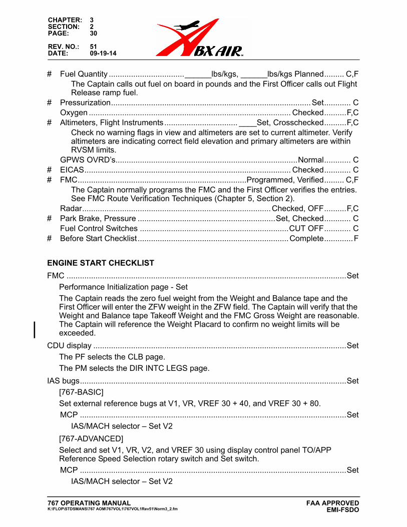
# Fuel Quantity ..................................______lbs/kgs, ______lbs/kgs Planned......... C,FThe Captain calls out fuel on board in pounds and the First Officer calls out Flight Release ramp fuel.
# Pressurization..........................................................................................Set............ COxygen ........................................................................................... Checked..........F,C
# Altimeters, Flight Instruments................................. ____Set, Crosschecked..........F,CCheck no warning flags in view and altimeters are set to current altimeter. Verify altimeters are indicating correct field elevation and primary altimeters are within RVSM limits.
GPWS OVRD’s..................................................................................Normal............ C# EICAS............................................................................................. Checked............ C# FMC............................................................................Programmed, Verified......... C,F
The Captain normally programs the FMC and the First Officer verifies the entries. See FMC Route Verification Techniques (Chapter 5, Section 2).
Radar.....................................................................................Checked, OFF..........F,C# Park Brake, Pressure ..............................................................Set, Checked............ C
Fuel Control Switches ...................................................................CUT OFF............ C# Before Start Checklist ....................................................................Complete.............F
ENGINE START CHECKLIST
FMC ..............................................................................................................................Set
Performance Initialization page - Set
The Captain reads the zero fuel weight from the Weight and Balance tape and the First Officer will enter the ZFW weight in the ZFW field. The Captain will verify that the Weight and Balance tape Takeoff Weight and the FMC Gross Weight are reasonable.The Captain will reference the Weight Placard to confirm no weight limits will be exceeded.
CDU display ..................................................................................................................Set
The PF selects the CLB page.
The PM selects the DIR INTC LEGS page.
IAS bugs........................................................................................................................Set
[767-BASIC]
Set external reference bugs at V1, VR, VREF 30 + 40, and VREF 30 + 80.
MCP ........................................................................................................................Set
IAS/MACH selector – Set V2
[767-ADVANCED]
Select and set V1, VR, V2, and VREF 30 using display control panel TO/APP Reference Speed Selection rotary switch and Set switch.
MCP ........................................................................................................................Set
IAS/MACH selector – Set V2
767 OPERATING MANUALK:\FLOP\STDSMANS\767 AOM\767VOL1\767VOL1Rev51\Norm3_2.fm
FAA APPROVED EMI-FSDO
CHAPTER: 3SECTION: 2PAGE: 37
REV. NO.: 51DATE: 09-19-14
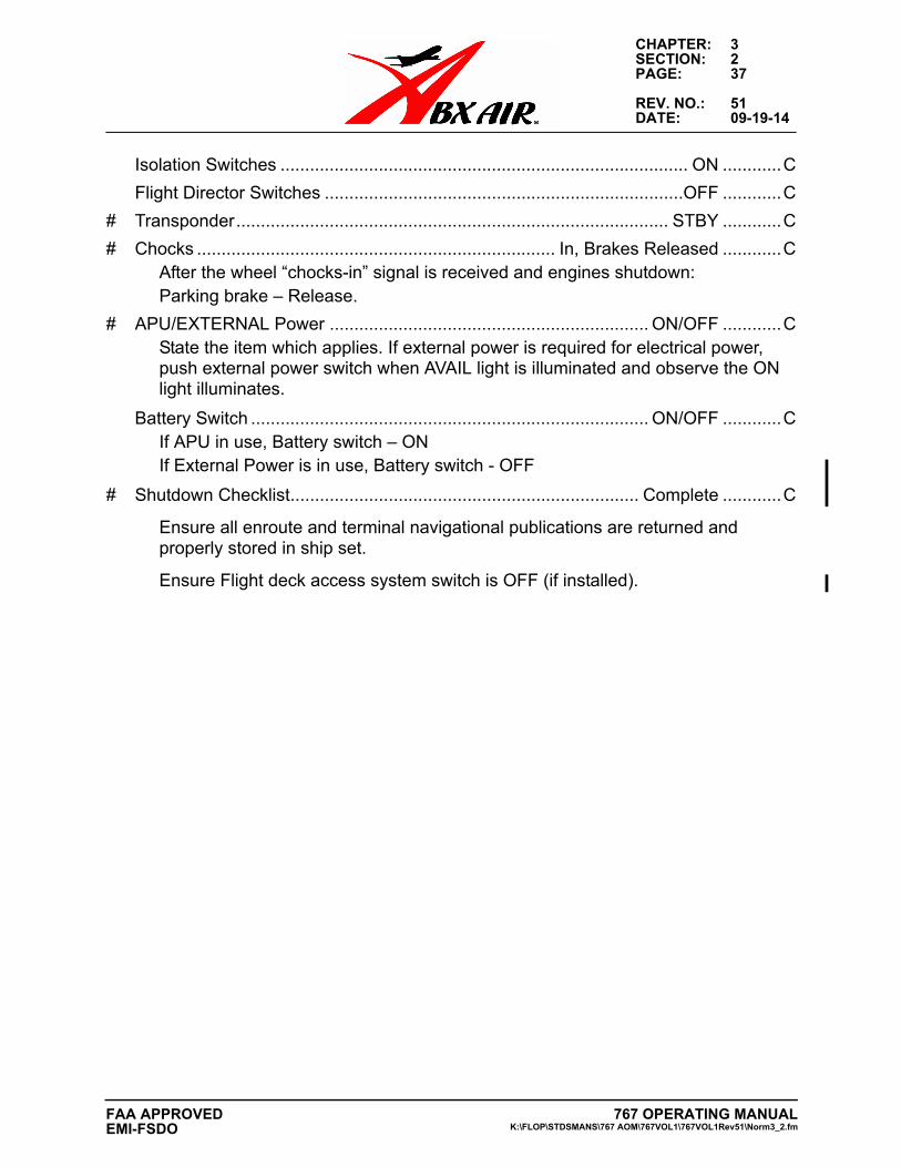
Isolation Switches ................................................................................... ON ............C
Flight Director Switches .........................................................................OFF ............C
# Transponder........................................................................................ STBY ............C
# Chocks ......................................................................... In, Brakes Released ............CAfter the wheel “chocks-in” signal is received and engines shutdown:Parking brake – Release.
# APU/EXTERNAL Power ................................................................. ON/OFF ............CState the item which applies. If external power is required for electrical power, push external power switch when AVAIL light is illuminated and observe the ON light illuminates.
Battery Switch ................................................................................. ON/OFF ............CIf APU in use, Battery switch – ONIf External Power is in use, Battery switch - OFF
# Shutdown Checklist....................................................................... Complete ............C
Ensure all enroute and terminal navigational publications are returned and properly stored in ship set.
Ensure Flight deck access system switch is OFF (if installed).
767 OPERATING MANUALK:\FLOP\STDSMANS\767 AOM\767VOL1\767VOL1Rev51\Norm3_2.fm
FAA APPROVEDEMI-FSDO

CHAPTER: 3SECTION: 2PAGE: 38
REV. NO.: 51DATE: 09-19-14
THIS PAGE INTENTIONALLY LEFT BLANK
767 OPERATING MANUALK:\FLOP\STDSMANS\767 AOM\767VOL1\767VOL1Rev51\Norm3_2.fm
FAA APPROVED EMI-FSDO
CHAPTER: 3SECTION: 3PAGE: 5
REV. NO.: 51DATE: 09-19-14
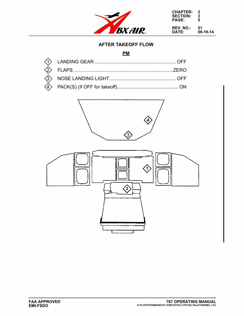
AFTER TAKEOFF FLOW
PM
1 LANDING GEAR ............................................................. OFF
2 FLAPS...........................................................................ZERO
3 NOSE LANDING LIGHT.................................................. OFF
4 PACK(S) (If OFF for takeoff).............................................. ON
767 OPERATING MANUALK:\FLOP\STDSMANS\767 AOM\767VOL1\767VOL1Rev51\NORM3_3.fm
FAA APPROVEDEMI-FSDO
CHAPTER: 3SECTION: 3PAGE: 6
REV. NO.: 5DATE: 04/01/00
767 OPERATING MANUALK:\FLOP\STDSMANS\767 AOM\767VOL1\767VOL1Rev51\NORM3_3.fm
FAA APPROVED EMI-FSDO
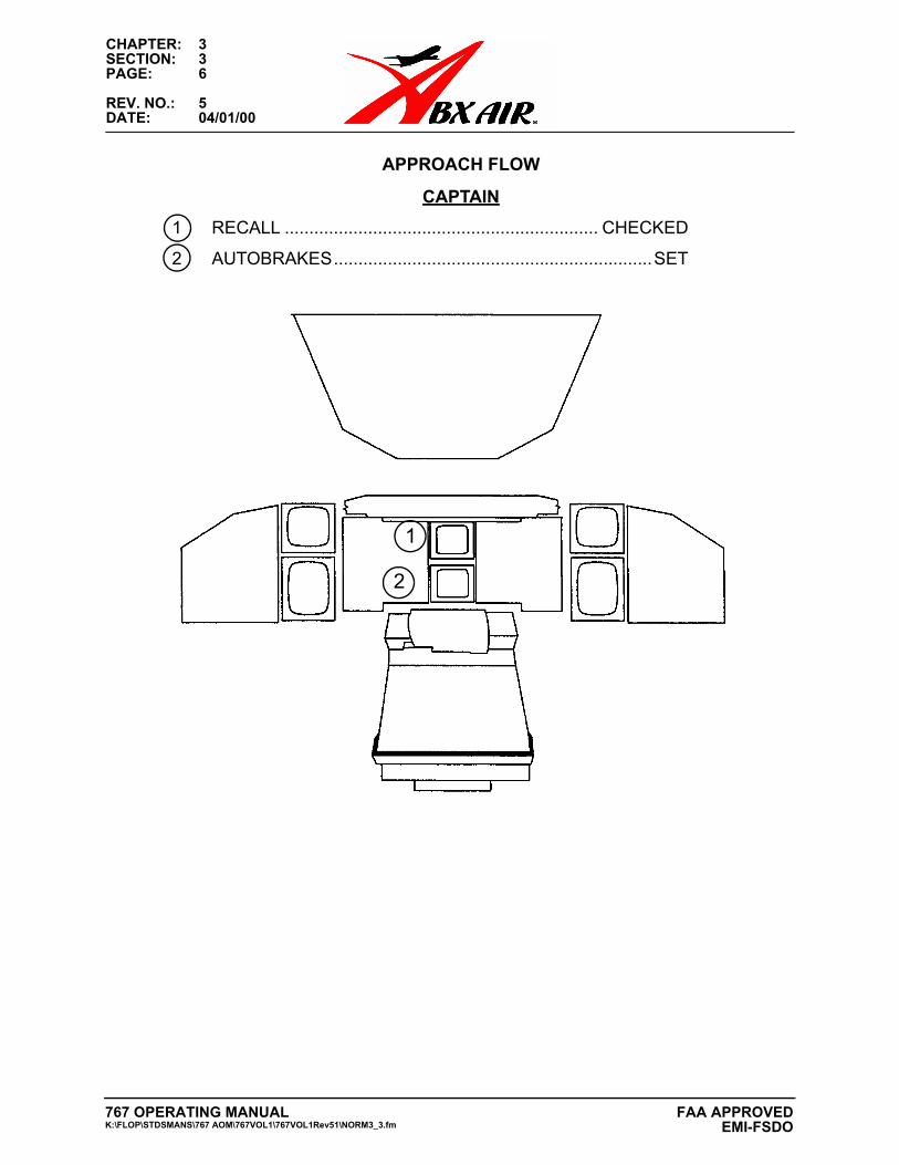
APPROACH FLOW
CAPTAIN
1 RECALL ................................................................ CHECKED
2 AUTOBRAKES.................................................................SET
1
2
CHAPTER: 3SECTION: 3PAGE: 7
REV. NO.: 30DATE: 11/25/08
767 OPERATING MANUALK:\FLOP\STDSMANS\767 AOM\767VOL1\767VOL1Rev51\NORM3_3.fm
FAA APPROVEDEMI-FSDO
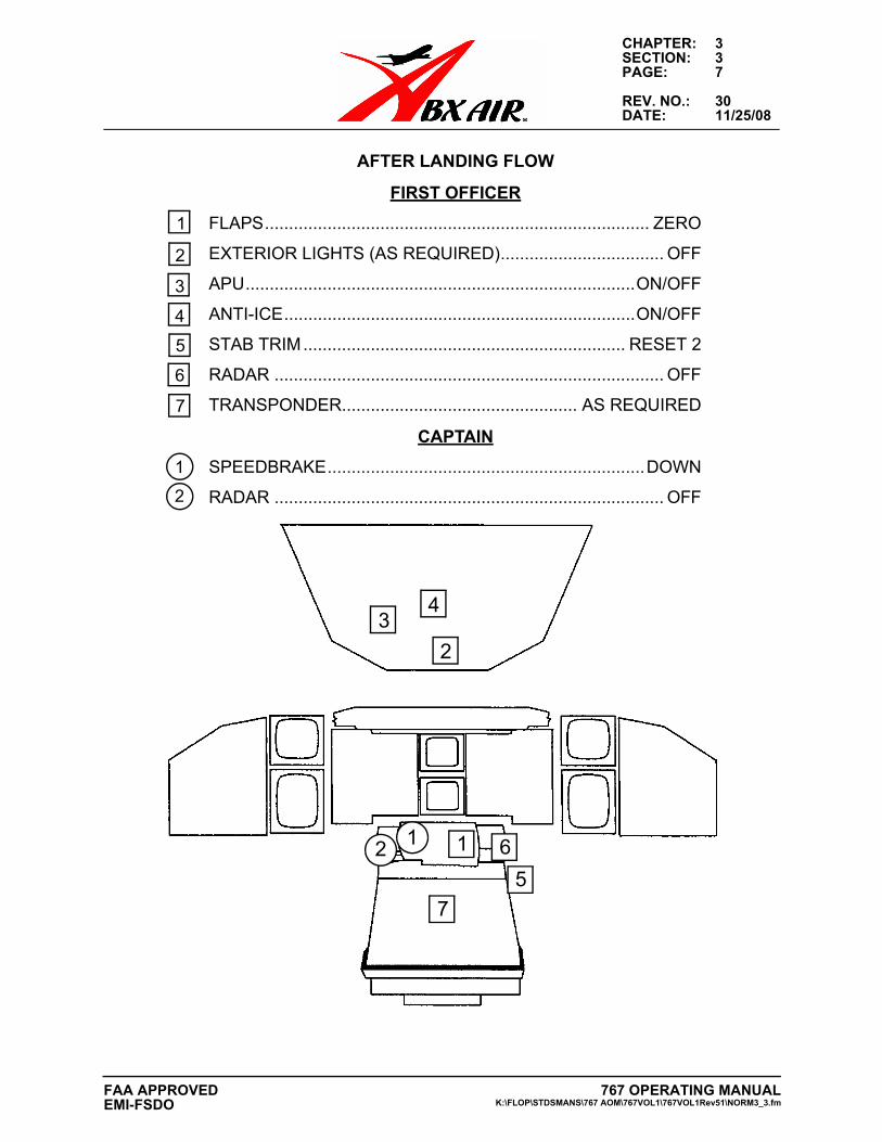
AFTER LANDING FLOW
FIRST OFFICER
FLAPS................................................................................ ZERO
EXTERIOR LIGHTS (AS REQUIRED).................................. OFF
APU.................................................................................ON/OFF
ANTI-ICE.........................................................................ON/OFF
STAB TRIM................................................................... RESET 2
RADAR ................................................................................. OFF
TRANSPONDER................................................. AS REQUIRED
CAPTAIN
SPEEDBRAKE..................................................................DOWN
RADAR ................................................................................. OFF
1
2
34
5
6
7
12
1
6
7
5
3
4
2
1
2
CHAPTER: 3SECTION: 3PAGE: 8
REV. NO.: 51DATE: 09-19-14
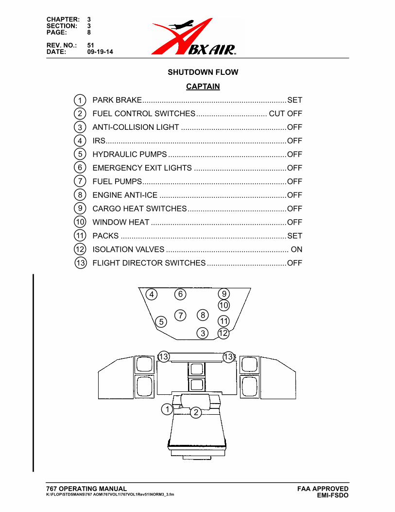
SHUTDOWN FLOW
CAPTAIN
PARK BRAKE...................................................................SET
FUEL CONTROL SWITCHES................................. CUT OFF
ANTI-COLLISION LIGHT .................................................OFF
IRS....................................................................................OFF
HYDRAULIC PUMPS.......................................................OFF
EMERGENCY EXIT LIGHTS ...........................................OFF
FUEL PUMPS...................................................................OFF
ENGINE ANTI-ICE ...........................................................OFF
CARGO HEAT SWITCHES..............................................OFF
WINDOW HEAT ...............................................................OFF
PACKS .............................................................................SET
ISOLATION VALVES ......................................................... ON
FLIGHT DIRECTOR SWITCHES.....................................OFF
1
3
4
2
57 8
6 9
11
13
10
13
12
13
1
6
7
5
3
4
2
8
12
10
11
9
767 OPERATING MANUALK:\FLOP\STDSMANS\767 AOM\767VOL1\767VOL1Rev51\NORM3_3.fm
FAA APPROVED EMI-FSDO
CHAPTER: 4SECTION: 2PAGE: 19
REV. NO.: 42DATE: 11-07-11
HF RADIO AND SELCAL CHECK PROCEDURE
HF Radios must be tested prior to any flight operation requiring their use.On the HF Radio Control Panel:Select USB modeSet Freq selector to a commercial LDOC station (refer to Jeppesen manual).RF SENS knob, turn to high (full clockwise) then turn the knob counter-clockwise until noise just ceases.Momentarily key the Microphone and listen for transmitter tuning (may last up to 1 second).Contact ARINC. Advise them of the frequency you are transmitting on as well as your call sign and location, i.e., “New York, ABX 38 on 11342, Ohio”.After station responds request radio and SELCAL check, i.e., “New York, ABX 38 request radio check, SELCAL WXYZ”. Once the radio/SELCAL check has been received, ask ARINC to standby for the second radio/SELCAL check.Note: HF radios should not be tuned to the same frequency.
HF radios should not be tested or used while refueling is in progress.SELCAL is not required for dispatch, however, where enroute operations require the use of HF, without SELCAL a listening watch must be maintained.
If unable to accomplish an HF check with ARINC, a simplified check can be accomplished as follows.
To Check the HF Receiver:
Tune radios to a WWV / WWVH frequency (2.5, 5, 10, 15, or 20 MHz) or a VOLMET frequency (refer to appropriate enroute chart) then listen for the time or weather information.
To Check the HF Transmitters:
Tune the HF radios to different “non-broadcast only” frequencies (WWV and VOLMET are broadcast only). Then momentarily key the transmitter one radio at a time. After the radio tunes, if the background noise returns, the transmitters check.
AUXILIARY POWER UNITAPU SELECTOR .........................................START, THEN TO ON
Hold selector in the START position for 3 to 5 seconds, then slowly release back to ON. Do not allow the APU selector to spring back to the ON position. (This step is to prevent failed starts due to Start Switch contact “bounce”.)Observe starter duty cycle of 3 start attempts within a 60-minute period.The APU should be started fifteen (15) minutes prior to scheduled departure to ensure that the aircraft systems will function/operate properly on ships power.
767 OPERATING MANUALK:\FLOP\STDSMANS\767 AOM\767VOL1\767VOL1Rev51\Norm4_2.fm
FAA APPROVEDEMI-FSDO
CHAPTER: 4SECTION: 2PAGE: 20
REV. NO.: 51DATE: 09-19-14
GENERALThe APU shall be used for all normal engine starts (Starts Before/During/After Pushback or Starts without a Pushback). The external pneumatic aircart shall be used only in the event the APU is deferred or for training situations by a company Check Airman.The APU may be started by Maintenance personnel prior to scheduled departure. In the event the APU is not running when the Flight Crew arrives, the Flight Crew shall start the APU no later than 15 minutes prior to departure. Once the APU is verified running, the Crew will confirm APU Pneumatics are available. If APU Pneumatics are not available, shut down the APU, then restart the APU and verify APU Pneumatics are available. If they are still not available, contact Maintenance Control.After the APU is supplying power to the aircraft, select EXT PWR switch to OFF.
The ground marshaller shall then be advised “CLEARED TO DISCONNECT EXTERNAL POWER”.
The APU should not be left running unattended by the Flight Crew without a qualified ABX maintenance person in the area of the aircraft.
USE OF THE APU IN FLIGHTUse of the APU in flight is determined by non-normal procedures and MEL requirements. In addition, the APU (if available) should be operating when conducting CAT 2/3 approaches in actual CAT 2/3 weather conditions.
USE OF THE APU WHEN ARRIVING AT STATIONS
Terminating flights:
If the flight terminates, APU usage should be minimized, if not eliminated, by prompt positioning of external power.
When parked:
Shut down the left engine.
Select external power when the AVAIL light is illuminated.
Shut down the right engine and resume normal cockpit duties.
Through flights:
For thru station times of less than 1 hour, start the APU when approaching the parking area and operate the APU during the ground time. If external power becomes available, leave the APU operating for engine start.
767 OPERATING MANUALK:\FLOP\STDSMANS\767 AOM\767VOL1\767VOL1Rev51\Norm4_2.fm
FAA APPROVEDEMI-FSDO
CHAPTER: 4SECTION: 2PAGE: 75
REV. NO.: 49DATE: 01-30-14
message does not erase or is redisplayed, enter the message in the logbook as a discrepancy requiring maintenance action or as a deferral of the affected system.
TAXI
If a STATUS prompt is observed during taxi, the STATUS message(s) should be reviewed. Crews should attempt to clear the message using the STATUS Message Clearing Procedure listed below. If the message does not clear, refer to the Flight Crew Deferral Procedures Section of the MEL preamble for the procedures to be followed for inoperative equipment.
AFTER TAKEOFF
If a STATUS Message is observed after takeoff, alert Maintenance/Flight Control when time permits. Any STATUS message that appears in flight requires an entry in the logbook. Do not erase a STATUS message that appears in flight.
AFTER LANDING
The STATUS page must also be reviewed after engine shutdown and STATUS messages must be entered in the logbook as a discrepancy with the appropriate Fault Reporting Manual (FRM) code. These messages affect the dispatchability of the next flight.
STATUS MESSAGE CLEARING PROCEDURE
1. Select STATUS page by pressing Status Button on the Control Stand ForwardElectronics Control Panel.
2. Note all status messages for possible logbook entry. If no messages appear otherthan the normal “Cargo Det Air”, without a bleed air source, no further stepsrequired.
3. If any status messages other than normal are displayed, press the ECS/MSGswitch on the EICAS maintenance panel. (Observe the ECS/MSG format appearson the lower EICAS display.)
4. Press the AUTO EVENT READ switch. (Observe that the words AUTO EVENTappear at the bottom of the display.)
5. Press and hold the ERASE switch for approximately 3 seconds. (This step erasesthe current page of displayed messages. Repeat for any additional pages.)
6. Reselect STATUS page by pressing Status Button on the Control Stand ForwardElectronics Control Panel.
Any status messages remaining after the above procedure indicate current conditions and must be reported to maintenance in addition to being recorded in the logbook as a discrepancy.
767 OPERATING MANUALK:\FLOP\STDSMANS\767 AOM\767VOL1\767VOL1Rev51\Norm4_2.fm
FAA APPROVEDEMI-FSDO
CHAPTER: 4SECTION: 2PAGE: 76
REV. NO.: 51DATE: 09-19-14
Note: Selecting ECS/MSG Switch displays status and maintenance level messages. Maintenance messages do not affect the airworthiness release of the aircraft, and do not require MEL consideration or maintenance action prior to dispatch. They are addressed within the standard maintenance program.
CAUTION: CIRCUIT BREAKERS SHOULD NEVER BE PULLED ON A POWERED OR OPERATING AIRCRAFT (ESPECIALLY ONE THAT IS IN FLIGHT) UNLESS IT IS PART OF AN APPROVED PROCEDURE, OR AS DIRECTED BY MAINTENANCE. BECAUSE OF THE COMPLEX INTERFACE BETWEEN SYSTEMS, PULLING CIRCUIT BREAKERS IN AN ATTEMPT TO ELIMINATE MESSAGES OR “FORCE” A SYSTEM INTO ACTIVITY MAY CAUSE ADDITIONAL MESSAGES; ADDITIONALLY, SUCH ACTIONS MAY CAUSE LOSS OF CONTROL OF EITHER THAT SYSTEM OR SOME OTHER RELATED SYSTEMS.
LANDING CONFIGURATION WARNING TEST
CONFIGURATION TEST SWITCH.................................................................... LDG
Observe CONFIG light illuminate and GEAR NOT DOWN message display.
Note: This test is not a normal Flight Crew function. The test is listed here for Flight Crew awareness or to be used, if directed, by Maintenance personnel.
EVENT RECORD (MANUAL)
EVENT RECORD SWITCH (FWD ELEC CONTROL PANEL) .................................................................PUSH
Use as directed by Flight Operations and maintenance analysis or at the discretion of the Captain to manually record parameters for a suspect condition.
767 OPERATING MANUALK:\FLOP\STDSMANS\767 AOM\767VOL1\767VOL1Rev51\Norm4_2.fm
FAA APPROVEDEMI-FSDO
CHAPTER: 5SECTION: TOCPAGE: i
REV. NO.: 51DATE: 09-19-14
TABLE OF CONTENTS
CHAPTER 5: STANDARD OPERATING METHODS
SECTION 1: PROFICIENCY STANDARDSGENERAL ...................................................................................................... 1
NORMAL TAKEOFF ................................................................................. 1ABORTED TAKEOFF ............................................................................... 1TAKEOFF WITH ENGINE FAILURE AT OR AFTER V1 .......................... 1CLIMBS, DESCENTS, AND TURNS ........................................................ 1APPROACH TO STALLS ......................................................................... 1RAPID DESCENT .................................................................................... 2INSTRUMENT HOLDING AND MANEUVERING (PROCEDURE TURN) PROCEDURES ................................................... 2ALL APPROACHES ................................................................................. 2PRECISION APPROACHES .................................................................... 2NONPRECISION APPROACH - FINAL SEGMENT ................................ 3NONPRECISION APPROACH - CIRCLING ............................................ 3VISUAL DESCENTS FROM MDA ............................................................ 3VISUAL PATTERNS AND LANDINGS ..................................................... 3
SECTION 2: GROUND OPERATIONSCREW COMMUNICATION AND COORDINATION ...................................................1
CREW RESOURCE MANAGEMENT (CRM) ................................................. 1COMMUNICATIONS CONDUCT ................................................................... 1
ATC CLEARANCES ................................................................................. 2USE OF BOOM MICROPHONES ............................................................ 2PILOT FLYING AND PILOT MONITORING ............................................. 2PILOT FLYING (PF) ................................................................................. 3PILOT MONITORING (PM) ...................................................................... 3FLIGHT PREPARATION .......................................................................... 4CHECKLIST USE ..................................................................................... 4PREFLIGHT ............................................................................................. 5EXTERIOR PREFLIGHT .......................................................................... 5INTERIOR PREFLIGHT ........................................................................... 5DEPARTURE PREPARATION ................................................................. 5CAPTAIN’S DUTIES ................................................................................. 5RUNWAY INCURSION PREVENTION .................................................... 6FLIGHT MANAGEMENT COMPUTER/CDUS ......................................... 6AIRCRAFT IDENTIFICATION .................................................................. 6INIT/REF INDEX ....................................................................................... 8POSITION INITIALIZATION ..................................................................... 9ROUTE SELECTION AND ACTIVATION .............................................. 12DUPLICATE WAYPOINTS ..................................................................... 15WAYPOINT DELETION ......................................................................... 16AIRWAY DELETION .............................................................................. 16ROUTE FULL ......................................................................................... 17PERFORMANCE INITIALIZATION ........................................................ 17TAKEOFF DATA ENTRY ....................................................................... 20
767 OPERATING MANUALK:\FLOP\STDSMANS\767 AOM\767VOL1\767VOL1Rev51\Som5.toc.fm
FAA APPROVEDEMI-FSDO
CHAPTER: 5SECTION: TOCPAGE: ii
REV. NO.: 51DATE: 09-19-14
DEPARTURE SELECTION .................................................................... 22SID AND DEPARTURE RUNWAY ENTRY ............................................ 23ROUTE DISCONTINUITY ...................................................................... 27FIRST OFFICER DUTIES ...................................................................... 28
AIRPORT ANALYSIS ................................................................................... 28FUEL SLIP ................................................................................................... 29FMC ROUTE VERIFICATION TECHNIQUES ............................................. 29AIRSPEED, ALTIMETER, AND STABILIZER SETTING ............................. 29DEPARTURE BRIEFING ............................................................................. 30PASSENGER/SUPERNUMERARY BRIEFING ........................................... 30REQUIRED PAPERS ................................................................................... 30APU START PROCEDURES ....................................................................... 31GROUND MARSHALLING ........................................................................... 31GROUND MARSHALLING HAND SIGNALS ............................................... 32B-767-200SF PASSENGER INFORMATION CARD
SUPERNUMERARY COMPARTMENT EXIT SEATING ......................... 33B-767 SAFETY BRIEFING CARD GUIDE PC2SF ....................................... 43B-767 SAFETY BRIEFING CARD GUIDE BCF/BDSF ................................. 50ENGINE STARTS ........................................................................................ 58
ENGINE START DURING PUSHBACK (WITH APU) ............................ 58ENGINE START AFTER PUSHBACK (WITH APU) .............................. 59ENGINE START NO PUSHBACK (WITH APU) ..................................... 60PNEUMATIC ENGINE START BEFORE/AFTER PUSHBACK ............. 60ENGINE START WITH PUSHBACK (WITH AIRSTART) ....................... 60
FLIGHT DECK PERSPECTIVE ................................................................... 62DEPARTING RAMP AREA .......................................................................... 62THRUST USE .............................................................................................. 63JET BLAST DATA ........................................................................................ 63TAXI SPEED AND BRAKES ........................................................................ 63NARROW TAXIWAYS ................................................................................. 64ANTI-SKID INOPERATIVE .......................................................................... 64TILLER/RUDDER PEDAL STEERING ......................................................... 64TURNING RADIUS ...................................................................................... 65VISUAL CUES AND TECHNIQUES FOR TURNING WHILE TAXIING ....... 66MINIMUM RADIUS 180 DEGREE TURNS .................................................. 66LOW VISIBILITY .......................................................................................... 67TAXI - ONE ENGINE .................................................................................... 67COMMUNICATION RADIO PROCEDURES ................................................ 68FLAP USAGE ............................................................................................... 69FLAP - SPEED SCHEDULE/MANEUVERING SPEEDS ............................. 69
FLAP MANEUVERING SPEED SCHEDULE ......................................... 69MANEUVER MARGINS TO STICK SHAKER .............................................. 70
MANEUVER MARGINS TO STICK SHAKER TAKEOFF ...................... 71MANEUVER MARGINS TO STICK SHAKER LANDING ....................... 71
FLAP OPERATION ...................................................................................... 72ACCELERATION HEIGHT ALL ENGINES ............................................ 72
767 OPERATING MANUALK:\FLOP\STDSMANS\767 AOM\767VOL1\767VOL1Rev51\Som5.toc.fm
FAA APPROVEDEMI-FSDO
CHAPTER: 5SECTION: TOCPAGE: iii
REV. NO.: 51DATE: 09-19-14
ACCELERATION HEIGHT ENGINE OUT .............................................. 72COMMAND SPEED ..................................................................................... 72
TAKEOFF ............................................................................................... 72CLIMB, CRUISE AND DESCENT .......................................................... 72APPROACH ........................................................................................... 72LANDING ................................................................................................ 72
NON-NORMAL CONDITIONS ..................................................................... 73
SECTION 3: TAKEOFFTHRUST MANAGEMENT .............................................................................. 1NORMAL TAKEOFF ...................................................................................... 1TAKEOFF (AFDS) - GENERAL ..................................................................... 2INITIATING TAKEOFF ROLL ......................................................................... 2ROTATION AND LIFTOFF ALL ENGINES .................................................... 4TYPICAL TAKEOFF TAIL CLEARANCE ....................................................... 5INITIAL CLIMB ............................................................................................... 6IMMEDIATE TURN AFTER TAKEOFF .......................................................... 7ROLL MODES ................................................................................................ 8TAKEOFF PITCH MODES ............................................................................. 8AUTOPILOT ENGAGEMENT ........................................................................ 8FLAP RETRACTION SCHEDULE ................................................................. 8CROSSWIND TAKEOFF ............................................................................... 9TAKEOFF CROSSWIND GUIDELINES ......................................................... 9DIRECTIONAL CONTROL ........................................................................... 10WIND CORRECTIONS ................................................................................ 10ROTATION AND TAKEOFF ......................................................................... 10GUSTY WIND AND STRONG CROSSWIND CONDITIONS........................ 10TAKEOFF WITH AFT CENTER-OF-GRAVITY (C.G.) ................................. 11REDUCED THRUST TAKEOFF .................................................................. 11
ASSUMED TEMPERATURE METHOD ................................................. 11FIXED DERATE (AS INSTALLED) ......................................................... 11
LOW VISIBILITY TAKEOFF.......................................................................... 12ADVERSE RUNWAY CONDITIONS ............................................................ 12EFFECTS OF DEICING/ANTI-ICING FLUIDS ON TAKEOFF ..................... 13FAR TAKEOFF FIELD LENGTH .................................................................. 13REJECTED TAKEOFF MANEUVER ........................................................... 14REJECTED TAKEOFF DECISION .............................................................. 15GO/STOP DECISION NEAR V1 .................................................................. 15RTO EXECUTION OPERATIONAL MARGINS ............................................ 17
SECTION 4: CLIMBCLIMB THRUST ............................................................................................. 1REDUCED THRUST FOR CLIMB .................................................................. 1CLIMB CONSTRAINTS .................................................................................. 1LOW ALTITUDE LEVEL OFF ........................................................................ 1TRANSITION TO CLIMB ................................................................................ 2PROCEDURES FOR IMMEDIATE ACCELERATION TO 250 KNOTS
767 OPERATING MANUALK:\FLOP\STDSMANS\767 AOM\767VOL1\767VOL1Rev51\Som5.toc.fm
FAA APPROVEDEMI-FSDO
CHAPTER: 5SECTION: TOCPAGE: iv
REV. NO.: 51DATE: 09-19-14
ON DEPARTURE............................................................................................ 2CLIMB SPEED DETERMINATION ................................................................ 2ECONOMY CLIMB ......................................................................................... 3
ECONOMY CLIMB SCHEDULE (FMC DATA UNAVAILABLE) .............. 3MAXIMUM RATE CLIMB ............................................................................... 3MAXIMUM ANGLE CLIMB ............................................................................. 3
SECTION 5: CRUISEMAXIMUM ALTITUDE .................................................................................... 1OPTIMUM ALTITUDE .................................................................................... 1LOW FUEL TEMPERATURE ......................................................................... 2CRUISE PERFORMANCE ECONOMY ......................................................... 4CRUISE SPEED ............................................................................................. 4STEP CLIMB FUEL ........................................................................................ 5HIGH ALTITUDE HIGH SPEED FLIGHT ....................................................... 5ENROUTE FUEL/TIME SCORING ................................................................ 5ENGINE READINGS ...................................................................................... 6FUEL CROSSFEED VALVE OPERATIONAL CHECK ................................... 6ARRIVAL PREPARATION ............................................................................. 7STANDARD ABX AIR, INC. ARRIVAL BRIEFING ......................................... 7AIRSPEEDS FOR APPROACH AND LANDING ............................................ 8ALTIMETERS FOR APPROACH AND LANDING .......................................... 9CAT 2/3 OPERATIONS .................................................................................. 9
SECTION 6: DESCENTDESCENT SPEED DETERMINATION .......................................................... 1DESCENT PATH ............................................................................................ 1DESCENT CONSTRAINTS ........................................................................... 1SPEED INTERVENTION ............................................................................... 1DESCENT PLANNING ................................................................................... 2SPEEDBRAKES ............................................................................................. 3FLAPS AND LANDING GEAR ....................................................................... 3SPEED RESTRICTIONS USA ....................................................................... 4MAXIMUM DESCENT RATES (not associated with an approach) ................. 4
SECTION 7: HOLDING, APPROACH, AND LANDINGHOLDING ....................................................................................................... 1
FAA HOLDING AIRSPEEDS (MAXIMUM) ............................................... 1APPROACH ................................................................................................... 1
INSTRUMENT APPROACHES ................................................................ 1APPROACH CATEGORY ........................................................................ 2APPROACH CLEARANCE ...................................................................... 2DME ARC ................................................................................................. 2PROCEDURE TURN ................................................................................ 3ESTABLISHED ON APPROACH CRITERIA (U.S. DOMESTIC) ............. 3
LANDING MINIMA ......................................................................................... 4RADIO ALTIMETER (RA) .............................................................................. 4
767 OPERATING MANUALK:\FLOP\STDSMANS\767 AOM\767VOL1\767VOL1Rev51\Som5.toc.fm
FAA APPROVEDEMI-FSDO
CHAPTER: 5SECTION: TOCPAGE: v
REV. NO.: 51DATE: 09-19-14
MISSED APPROACH POINTS (MAP) ........................................................... 4ILS ............................................................................................................ 4ASR .......................................................................................................... 4LOCALIZER .............................................................................................. 5OTHER NONPRECISION APPROACHES .............................................. 5
APPROACH - USE OF LNAV ........................................................................ 5ILS APPROACH ............................................................................................. 8
GENERAL ................................................................................................ 8PROCEDURE TURN ................................................................................ 8INITIAL APPROACH ................................................................................ 8APPROACH ............................................................................................. 8FINAL APPROACH ................................................................................ 10
DECISION ALTITUDE/HEIGHT DA(H) ........................................................ 11PILOT RESPONSE TO APPROACH, LANDING AND GO-AROUND ALERTS .......................................................................... 12
RAW DATA .................................................................................................. 12AFDS AUTOLAND CAPABILITIES .............................................................. 13
DEMONSTRATED CONDITIONS .......................................................... 13AUTOLAND ILS PERFORMANCE ......................................................... 13AUTOLANDS ON CONTAMINATED RUNWAYS .................................. 14
ILS APPROACH/LANDING GEOMETRY .................................................... 14ILS APPROACH/LANDING GEOMETRY .............................................. 15
LOW VISIBILITY APPROACHES ................................................................ 15CAT 2 OPERATIONS ............................................................................. 15CATEGORY 2 APPROACH AUTOPILOT .............................................. 15CATEGORY 2 APPROACH FLIGHT DIRECTOR .................................. 16CAT 3 OPERATIONS ............................................................................. 16CATEGORY 3A ...................................................................................... 16CATEGORY 3B ...................................................................................... 16
AFDS FAULTS ............................................................................................. 17PRIOR TO ALERT HEIGHT ................................................................... 17AT OR BELOW ALERT HEIGHT ........................................................... 18
AUTOPILOT PERFORMANCE CROSSCHECK .......................................... 18ILS- NON-NORMAL OPERATIONS ....................................................... 18
NONPRECISION APPROACH .................................................................... 19GENERAL .............................................................................................. 19
MAP DISPLAYS AND RAW DATA .............................................................. 19FIX OR VOR RADIAL DISPLAYS: ......................................................... 20
APPROACH ................................................................................................. 21AFDS PITCH MODES USED IN NONPRECISION APPROACHES ...... 21FLCH ...................................................................................................... 21VNAV ...................................................................................................... 22V/S .......................................................................................................... 22G/A ......................................................................................................... 22PROCEDURE TURN .............................................................................. 23INITIAL APPROACH .............................................................................. 23
767 OPERATING MANUALK:\FLOP\STDSMANS\767 AOM\767VOL1\767VOL1Rev51\Som5.toc.fm
FAA APPROVEDEMI-FSDO
CHAPTER: 5SECTION: TOCPAGE: vi
REV. NO.: 51DATE: 09-19-14
FINAL APPROACH ................................................................................ 23VISUAL SEGMENT ...................................................................................... 24MINIMUM DESCENT ALTITUDE (MDA) ..................................................... 24
SUGGESTED TECHNIQUES ................................................................ 25DERIVED DECISION ALTITUDE (DDA) ................................................ 25VERTICAL SPEED APPROACHES ....................................................... 25FINAL APPROACH USING V/S ............................................................. 26VNAV APPROACHES ............................................................................ 27SUMMARY ............................................................................................. 28
VISUAL DESCENT POINTS (VDP) .............................................................. 29MISSED APPROACH/GO-AROUND - ALL ENGINES OPERATING .......... 30CIRCLING APPROACHES .......................................................................... 31FAA EXPANDED CIRCLING MANEUVERING AIRSPACE RADIUS........... 32
EFFECT ON CHARTS ............................................................................ 32CIRCLING MISSED APPROACH ................................................................ 33VISUAL APPROACH ................................................................................... 33
GENERAL .............................................................................................. 33THRUST ................................................................................................. 33FLAP EXTENSION ................................................................................. 34DOWNWIND AND BASE LEG ............................................................... 34FINAL APPROACH ................................................................................ 34MCP ALTITUDE CONTROL ................................................................... 34DELAYED FLAP APPROACH (NOISE ABATEMENT) .......................... 35
LANDING AND GO-AROUND FLAPS AND SPEEDS ................................. 35WIND CORRECTIONS FINAL APPROACH ................................................ 36
AUTOTHROTTLE DISENGAGED .......................................................... 36AUTOTHROTTLE ENGAGED (AUTOLAND) ......................................... 36
RECOMMENDED LANDING FLAP SETTING ............................................. 37FLAPS 25 LANDINGS .................................................................................. 37MANEUVER MARGIN .................................................................................. 38VISUAL APPROACH SLOPE INDICATOR (VASI/ T-VASI) ......................... 38PRECISION APPROACH PATH INDICATOR (PAPI) .................................. 38PAPI LANDING GEOMETRY ....................................................................... 39LANDING GEOMETRY ................................................................................ 39
VISUAL AIM POINT ............................................................................... 39THRESHOLD HEIGHT ........................................................................... 39
TAIL STRIKE AVOIDANCE/AWARENESS................................................... 40FLARE AND TOUCHDOWN ........................................................................ 41LANDING FLARE PROFILE ........................................................................ 41BOUNCED LANDING RECOVERY ............................................................. 44
GROUND CLEARANCE ANGLES ......................................................... 45NORMAL LANDING ............................................................................... 45
PITCH AND ROLL LIMIT CONDITIONS ...................................................... 45AFTER TOUCHDOWN AND LANDING ROLL ............................................. 45SPEEDBRAKES ........................................................................................... 46
767 OPERATING MANUALK:\FLOP\STDSMANS\767 AOM\767VOL1\767VOL1Rev51\Som5.toc.fm
FAA APPROVEDEMI-FSDO
CHAPTER: 5SECTION: TOCPAGE: vii
REV. NO.: 51DATE: 09-19-14
DIRECTIONAL CONTROL AND BRAKING AFTER TOUCHDOWN ........... 46FACTORS AFFECTING LANDING DISTANCE ........................................... 47SLIPPERY RUNWAY LANDING PERFORMANCE ..................................... 47
FACTORS AFFECTING LANDING DISTANCE (TYPICAL) .................. 49WHEEL BRAKES ......................................................................................... 50MANUAL BRAKING (NOT UTILIZING AUTOBRAKES) .............................. 50AUTOMATIC BRAKES ................................................................................. 51BRAKING WITH ANTI-SKID INOPERATIVE ............................................... 52BRAKE COOLING ........................................................................................ 52MINIMUM BRAKE HEATING ....................................................................... 52REVERSE THRUST OPERATION .............................................................. 53REVERSE THRUST EEC INOPERATIVE ................................................... 55REVERSE THRUST - ENGINE INOPERATIVE ........................................... 56REVERSE THRUST AND CROSSWIND (ALL ENGINES) .......................... 56CROSSWIND LANDINGS ............................................................................ 56LANDING CROSSWIND GUIDELINES ....................................................... 56CROSSWIND LANDING TECHNIQUES ...................................................... 57
SIDESLIP (WING LOW) ......................................................................... 57DE-CRAB DURING FLARE .................................................................... 57TOUCHDOWN IN CRAB ........................................................................ 58
REJECTED LANDING ................................................................................. 58LANDING CLEARANCE ......................................................................... 59
SECTION 8: EMERGENCY PROCEDURESENGINE FAILURE ......................................................................................... 1
RUDDER AND LATERAL CONTROL ...................................................... 1TAKEOFF- ENGINE FAILURE ....................................................................... 2
GENERAL ................................................................................................ 2ENGINE FAILURE RECOGNITION ......................................................... 2ROTATION - ONE ENGINE INOPERATIVE ............................................ 2767 LIFTOFF PITCH ATTITUDE ONE ENGINE INOPERATIVE ............. 2INITIAL CLIMB - ONE ENGINE INOPERATIVE ...................................... 3
IMMEDIATE TURN AFTER TAKEOFF - ONE ENGINE INOPERATIVE ....... 3FLAP RETRACTION ALTITUDE - ONE ENGINE INOPERATIVE ................. 3AUTOTHROTTLE - ENGINE INOPERATIVE ................................................ 4
NOISE ABATEMENT ............................................................................... 4REDUCED THRUST - ONE ENGINE INOPERATIVE ............................. 4
ENGINE INOPERATIVE CLIMB .................................................................... 5ENGINE INOPERATIVE CRUISE/DRIFTDOWN ........................................... 5LOSS OF ENGINE THRUST CONTROL ....................................................... 7
GROUND-OPERATIONS ......................................................................... 7TAKEOFF ................................................................................................. 7CLIMB, CRUISE, DESCENT AND LANDING .......................................... 7
RAPID DESCENT .......................................................................................... 8AUTOPILOT ENTRY AND LEVEL OFF ................................................... 8FLIGHT LEVEL CHANGE (FLCH) ........................................................... 8
767 OPERATING MANUALK:\FLOP\STDSMANS\767 AOM\767VOL1\767VOL1Rev51\Som5.toc.fm
FAA APPROVEDEMI-FSDO
CHAPTER: 5SECTION: TOCPAGE: viii
REV. NO.: 51DATE: 09-19-14
VERTICAL SPEED MODE (V/S) .............................................................. 9MANUAL ENTRY AND LEVEL OFF ........................................................ 9AFTER LEVEL OFF ............................................................................... 10
ILS APPROACH - ONE ENGINE INOPERATIVE ........................................ 10MISSED APPROACH/GO-AROUND ONE-ENGINE INOPERATIVE .......... 11NONPRECISION APPROACH - ENGINE INOPERATIVE .......................... 12MISSED APPROACH NONPRECISION - ENGINE INOPERATIVE ............ 12ENGINE FAILURE ON FINAL APPROACH ................................................. 13ENGINE FAILURE DURING MISSED APPROACH/GO-AROUND ............. 13REVERSE THRUST - ENGINE INOPERATIVE ........................................... 14OVERWEIGHT LANDING ............................................................................ 14OVERWEIGHT AUTOLAND POLICY .......................................................... 15HARD LANDING .......................................................................................... 15LEADING EDGE SLAT ASYMMETRY ......................................................... 15TRAILING EDGE ASYMMETRY .................................................................. 16HYDRAULIC SYSTEM(S) INOPERATIVE - LANDING ................................ 16FLAPS UP LANDING ................................................................................... 16
APPROACH ........................................................................................... 17FINAL APPROACH ................................................................................ 17LANDING ................................................................................................ 17ADDITIONAL CONSIDERATIONS ......................................................... 18
NON-NORMAL LANDING DISTANCE ......................................................... 18LANDING ON A FLAT TIRE ......................................................................... 18PARTIAL OR GEAR UP LANDING .............................................................. 19
GENERAL .............................................................................................. 19LANDING RUNWAY ............................................................................... 19PRIOR TO APPROACH ......................................................................... 19LANDING TECHNIQUES ....................................................................... 19BOTH MAIN GEAR EXTENDED (NOSE GEAR UP) ............................. 20NOSE GEAR ONLY EXTENDED ........................................................... 20ALL GEAR UP OR PARTIALLY EXTENDED ......................................... 20ONE MAIN GEAR ONLY EXTENDED ................................................... 20ONE MAIN GEAR DOWN AND NOSE GEAR EXTENDED ................... 20AFTER STOP ......................................................................................... 20
AIRSPEED UNRELIABLE ............................................................................ 20DESCENT .............................................................................................. 22APPROACH ........................................................................................... 22LANDING ................................................................................................ 23PITCH AND THRUST REFERENCE FOR AIRSPEED UNRELIABLE .. 23
DITCHING .................................................................................................... 23ADVISE CREW AND PASSENGERS .................................................... 23FUEL BURN-OFF ................................................................................... 23DITCHING FINAL ................................................................................... 23INITIATE EVACUATION ........................................................................ 24
FUEL BALANCE .......................................................................................... 24FUEL LEAK .................................................................................................. 24
767 OPERATING MANUALK:\FLOP\STDSMANS\767 AOM\767VOL1\767VOL1Rev51\Som5.toc.fm
FAA APPROVEDEMI-FSDO
CHAPTER: 5SECTION: TOCPAGE: ix
REV. NO.: 51DATE: 09-19-14
LOW FUEL OPERATIONS .......................................................................... 26IN FLIGHT .............................................................................................. 26APPROACH AND LANDING .................................................................. 26GO-AROUND ......................................................................................... 26
APPROACH AND LANDING ON STANDBY POWER ................................. 26JAMMED STABILIZER ................................................................................. 27UNSCHEDULED STABILIZER TRIM ........................................................... 27WINDOW DAMAGE ..................................................................................... 27FLIGHT WITH THE SIDE WINDOW(S) OPEN ............................................ 27OVERSPEED ............................................................................................... 27COCKPIT EVACUATION ............................................................................. 28DUAL ENGINE FAILURE ............................................................................. 28WHEEL WELL FIRE..................................................................................... 28TAIL STRIKE ................................................................................................ 29
TAKEOFF RISK FACTORS ................................................................... 29MISTRIMMED STABILIZER ................................................................... 29ROTATION AT IMPROPER SPEED ...................................................... 29EXCESSIVE ROTATION RATE ............................................................. 29IMPROPER USE OF THE FLIGHT DIRECTOR .................................... 30LANDING RISK FACTORS .................................................................... 30UNSTABILIZED APPROACH ................................................................. 30HOLDING OFF IN THE FLARE .............................................................. 31TRIMMING IN THE FLARE .................................................................... 31MISHANDLING OF CROSSWINDS ....................................................... 31OVER-ROTATION DURING GO-AROUND ........................................... 31
JAMMED OR RESTRICTED FLIGHT CONTROLS ..................................... 32TRIM INPUTS ......................................................................................... 33APPROACH AND LANDING .................................................................. 33GO-AROUND PROCEDURE ................................................................. 33
ENGINE SEVERE DAMAGE ACCOMPANIED BY HIGH VIBRATION ........ 33STUCK “MIC” TRANSMIT SWITCH ............................................................. 34SITUATIONS BEYOND THE SCOPE OF NON-NORMAL PROCEDURES ............................................................................................ 34
BASIC AERODYNAMICS AND SYSTEMS KNOWLEDGE ................... 35FLIGHT PATH CONTROL ...................................................................... 36EMERGENCY CHECKLISTS/PROCEDURES ...................................... 36COMMUNICATIONS .............................................................................. 36DAMAGE ASSESSMENT AND AIRPLANE HANDLINGEVALUATION ......................................................................................... 37APPROACH AND LANDING .................................................................. 38
PILOT INCAPACITATION ............................................................................ 38CREW ACTION UPON CONFIRMING PILOT INCAPACITATION .............. 39LANDING AT THE NEAREST SUITABLE AIRPORT .................................. 39
SECTION 9: TRAINING MANEUVERSAFFECTS OF TRIM AND THRUST ............................................................... 1
767 OPERATING MANUALK:\FLOP\STDSMANS\767 AOM\767VOL1\767VOL1Rev51\Som5.toc.fm
FAA APPROVEDEMI-FSDO
CHAPTER: 5SECTION: TOCPAGE: x
REV. NO.: 51DATE: 09-19-14
TRIM ......................................................................................................... 1THRUST ................................................................................................... 1
RECOMMENDED RUDDER TRIM TECHNIQUE .......................................... 1DRAG FACTORS DUE TO TRIM TECHNIQUE ............................................ 1ALTERNATE TRIM TECHNIQUE .................................................................. 2MANEUVERS ................................................................................................. 2
HIGH ALTITUDE HIGH SPEED FLIGHT ................................................. 2HIGH ALTITUDE MANEUVERING, “G” BUFFET .................................... 2ACCELERATION TO AND DECELERATION FROM VMO ..................... 3DECELERATION TIME ............................................................................ 3
STEEP TURNS .............................................................................................. 3ENTRY ..................................................................................................... 4DURING TURN ........................................................................................ 4ATTITUDE DIRECTOR INDICATOR (ADI) .............................................. 6VERTICAL SPEED INDICATOR .............................................................. 6ALTIMETER ............................................................................................. 6AIRSPEED ............................................................................................... 6ROLLOUT ................................................................................................. 6APPROACH TO STALL OR STALL ......................................................... 6APPROACH TO STALL OR STALL RECOVERY ................................... 7APPROACH TO STALL OR STALL RECOVERY TRAINING ................. 8INITIAL CONDITIONS ............................................................................. 8INITIAL BUFFET-STICK SHAKER .......................................................... 8EFFECT OF FLAPS ................................................................................ 8EFFECT OF SPEEDBRAKES ................................................................. 9RECOVERY ............................................................................................ 9APPROACH TO STALL RECOVERY EXERCISES ................................ 9LEVEL OFF ............................................................................................. 9TURNING BASE .................................................................................... 10ILS FINAL APPROACH ......................................................................... 10COMPLETION OF THE RECOVERY ................................................... 10STALL - CLEAN ..................................................................................... 12STALL - DEPARTURE ........................................................................... 13STALL - LANDING ................................................................................. 14
RECOVERY FROM A FULLY DEVELOPED STALL ................................... 15GPWS “TERRAIN/PULL UP” ALERT RECOVERY TECHNIQUE ............... 16
CFIT RECOVERY MANEUVER ............................................................. 16ENHANCED GPWS ..................................................................................... 16RECOMMENDED OPERATION OF TERRAIN DISPLAY ........................... 18TRAFFIC ALERT AND COLLISION AVOIDANCE SYSTEM (TCAS) .......... 18
USE OF TA/RA, TA ONLY, AND TRANSPONDER ONLY MODES ...... 18TRAFFIC ADVISORY (TA) ..................................................................... 19RESOLUTION ADVISORY (RA) ............................................................ 19
RUDDER USAGE ........................................................................................ 20GENERAL .............................................................................................. 20RUDDER MANEUVERING CONSIDERATIONS ................................... 21
767 OPERATING MANUALK:\FLOP\STDSMANS\767 AOM\767VOL1\767VOL1Rev51\Som5.toc.fm
FAA APPROVEDEMI-FSDO
CHAPTER: 5SECTION: TOCPAGE: xi
REV. NO.: 51DATE: 09-19-14
ADVANCED MANEUVERS .......................................................................... 22UPSET RECOVERY .............................................................................. 22GENERAL .............................................................................................. 22STALL RECOVERY ............................................................................... 23NOSE HIGH, WINGS LEVEL ................................................................. 23NOSE LOW, WINGS LEVEL .................................................................. 24HIGH BANK ANGLES ............................................................................ 24NOSE HIGH, HIGH BANK ANGLES ...................................................... 25NOSE LOW, HIGH BANK ANGLES ....................................................... 25UPSET RECOVERY MANEUVERS ....................................................... 25NOSE HIGH RECOVERY ...................................................................... 26NOSE LOW RECOVERY ....................................................................... 26
SECTION 10: ADVERSE WEATHER OPERATIONSCOLD TEMPERATURE ALTITUDE CORRECTIONS ................................... 1OPERATING IN ICING CONDITIONS ........................................................... 1ICE CRYSTAL ICING ..................................................................................... 2TRAINING FLIGHTS ...................................................................................... 2PUSHBACK/TOWING - ADVERSE WEATHER ............................................. 3TAXI - ADVERSE WEATHER ........................................................................ 3
MODERATE TO HEAVY RAIN, HAIL, OR SLEET.................................... 3ENGINE ICING DURING CLIMB ................................................................... 4
ENGINE ICING DURING DESCENT ....................................................... 4APPROACHES IN ICING CONDITIONS ....................................................... 4WINDSHEAR ................................................................................................. 4
GENERAL ................................................................................................ 4AIRPLANE PERFORMANCE IN WINDSHEAR ....................................... 5AIRCRAFT OPERATION IN SUSPECTED/ACTUAL WINDSHEAR CONDITIONS .................................................................... 5ABX WINDSHEAR WARNING/GUIDANCE ........................................... 14WINDSHEAR WARNING ALERT (DECREASING PERFORMANCE) .. 14WINDSHEAR CAUTION ALERT (INCREASING PERFORMANCE) ..... 14AUTOFLIGHT WINDSHEAR GUIDANCE .............................................. 15WINDSHEAR RECOVERY PROCEDURE ............................................ 15MANUAL WINDSHEAR RECOVERY PROCEDURE (GUIDANCE INOPERATIVE) ................................................................. 17
FLIGHT OPERATIONS IN AREAS OF VOLCANIC ACTIVITY .................... 19TURBULENT AIR PENETRATION .............................................................. 20
SECTION 11: STANDARD CALLOUTS AND PROFILESGENERAL ...................................................................................................... 1
ALTITUDE/ALTIMETER AWARENESS ................................................... 1SETTING OF ALTITUDE .......................................................................... 1
STANDARD CALLOUTS ................................................................................ 3GENERAL ................................................................................................ 3STANDARD CALLOUTS FOR CLEARANCES ........................................ 3FLAP RECONFIGURATION CALLOUTS ................................................ 4
767 OPERATING MANUALK:\FLOP\STDSMANS\767 AOM\767VOL1\767VOL1Rev51\Som5.toc.fm
FAA APPROVEDEMI-FSDO
CHAPTER: 5SECTION: TOCPAGE: xii
REV. NO.: 51DATE: 09-19-14
ENGINE SECURING ................................................................................ 5AFTER V1: ............................................................................................... 5ENGINE START PROCEDURE ............................................................... 8
SELECTION OF EXTERIOR LIGHTS .......................................................... 11DEPARTURE BRIEFING ....................................................................... 11
NORMAL TAKEOFF .................................................................................... 12REJECTED TAKEOFF ................................................................................. 15 TAKEOFF- ENGINE FAILURE AFTER V1 ................................................. 17
TAKEOFF- ENGINE FAILURE AFTER V1 ............................................. 19ENROUTE TRANSFER OF CONTROL ................................................. 20ENROUTE CLIMB CRUISE AND DESCENT ......................................... 21
RAPID DESCENT ......................................................................................... 22GENERAL APPROACH CONSIDERATIONS .............................................. 23
ARRIVAL BRIEFING .............................................................................. 23PRECISION APPROACH (CAT 1) ......................................................... 24PRECISION APPROACH (CAT 2/3) ...................................................... 25PRECISION APPROACH DEVIATION CALLOUTS .............................. 29CAT 1/2/3 ILS VERTICAL SPEED/ AIRSPEED DEVIATION CALLOUTS ........................................................................ 29ILS - NORMAL ........................................................................................ 30ILS - ENGINE INOPERATIVE ................................................................ 32
AFDS NONPRECISION ............................................................................... 34RAW DATA MUST BE MONITORED. .................................................... 34LIMIT USE OF THE AUTOPILOT BELOW MDA. .................................. 36THE MISSED APPROACH POINT MUST BE IDENTIFIED. ................. 36MISSED APPROACH ............................................................................. 36NONPRECISION APPROACH AFDS VNAV PTH CALLOUTS ............. 37NONPRECISION APPROACH PROCEDURES- VNAV ........................ 39NONPRECISION APPROACH AFDS V/S CALLOUTS ......................... 41NONPRECISION APPROACH PROCEDURES - V/S ........................... 44NONPRECISION APPROACH DEVIATION CALLOUTS ...................... 45VISUAL APPROACH .............................................................................. 45VISUAL APPROACH DEVIATION CALLOUTS ..................................... 46DISCONNECTING AUTOPILOT ............................................................ 48MCP COMMANDS WHILE MANUALLY FLYING AIRCRAFT ............... 48FMC ROUTE MODIFICATIONS ............................................................. 48MISSED APPROACH - ONE OR TWO ENGINE ................................... 49MISSED APPROACH ............................................................................. 50LANDING ............................................................................................... 52LANDING ROLL PROCEDURE ............................................................. 53
GPWS WARNING ........................................................................................ 54EGPWS CAUTION ALERTS/WARNING ALERTS ....................................... 55TRAFFIC AVOIDANCE ................................................................................ 56
SECTION 12: FUEL CONSERVATION PROGRAMINTRODUCTION ...................................................................................... 1FLIGHT PLANNING ................................................................................. 1
767 OPERATING MANUALK:\FLOP\STDSMANS\767 AOM\767VOL1\767VOL1Rev51\Som5.toc.fm
FAA APPROVEDEMI-FSDO
CHAPTER: 5SECTION: TOCPAGE: xiii
REV. NO.: 51DATE: 09-19-14
WEATHER ....................................................................................... 1OPTIMUM ALTITUDE ..................................................................... 1ROUTE ............................................................................................ 2MEL/CDL DEFERRED ITEMS ........................................................ 2EXTRA FUEL ................................................................................... 2
TANKERING ............................................................................................. 3FMC COST INDEX ................................................................................... 3PREFLIGHT ............................................................................................. 3AIRCRAFT CG LOCATION ...................................................................... 3APU USAGE ............................................................................................. 4
WINTER ........................................................................................... 4SUMMER ......................................................................................... 4
ENGINE STARTS ..................................................................................... 4TAXI OUT & SINGLE ENGINE TAXI ........................................................ 4TAKEOFF ................................................................................................. 4CLIMB ....................................................................................................... 4CRUISE .................................................................................................... 5ALTITUDE SELECTION / ACTUAL OR EST WIND ................................. 5
TEMPERATURE............................................................................... 5WIND ................................................................................................ 5WEIGHT ........................................................................................... 5
TRIM ......................................................................................................... 6DESCENT ................................................................................................ 7HOLDING ................................................................................................. 7APPROACH AND LANDING .................................................................... 7TAXI IN ..................................................................................................... 7
WHAT YOU CAN DO TO SAVE FUEL............................................. 8
767 OPERATING MANUALK:\FLOP\STDSMANS\767 AOM\767VOL1\767VOL1Rev51\Som5.toc.fm
FAA APPROVEDEMI-FSDO

CHAPTER: 5SECTION: TOCPAGE: xiv
REV. NO.: 51DATE: 09-19-14
THIS PAGE INTENTIONALLY LEFT BLANK
767 OPERATING MANUALK:\FLOP\STDSMANS\767 AOM\767VOL1\767VOL1Rev51\Som5.toc.fm
FAA APPROVEDEMI-FSDO
CHAPTER: 5SECTION: 1PAGE: 3
REV. NO.: 51DATE: 09-19-14
NONPRECISION APPROACH - FINAL SEGMENT
Landing configuration.
Rate of descent: maximum 1000 FPM sustained rate.
Tracking: ±1 dot for VOR or LOC, ±5° for NDB.
VDP and MAP: ±10 seconds.
Altitude: +50 and -0 from MDA.(-50 is acceptable during a Go-Around provided an obstacle assessment has been accomplished.)
NONPRECISION APPROACH - CIRCLING
Airspeed: +10 to -5 knots of maneuvering speed during maneuvering segment.
Airspeed: VREF to VTGT +10 knots.
Altitude: +100 and -0 from MDA.
Bank angle for turns is limited to 30° when at or above maneuvering speed, 15° when below maneuvering speed.
VISUAL DESCENTS FROM MDA
Descent at or above the electronic or visual glide slope.
Airspeed: VREF to VTGT + 10 knots.
Engines spooled.
1,000 FPM maximum sustained rate of descent.
Maneuvering of the aircraft so as to land within the touchdown zone of the runway using normal maneuvering, speeds, and rates of descent consistent with ABX Air stabilized approach procedure.
VISUAL PATTERNS AND LANDINGS
Conformance to pattern altitude ±100 feet.
Airspeed; VREF to VTGT +10 knots when below 500 feet above TDZE.
Touchdown within the touchdown zone (target is 1,000 feet beyond threshold).
Rate of descent: maximum 1000 FPM when below 1000 feet above TDZE.
Approach stabilized by no lower than 500 feet above TDZE.
Abnormal slat/ flap approaches when VREF and VTGT are the same:
Maintain pattern altitude ±100 feet.
Airspeed: +10 to -5 knots of maneuvering speed during maneuvering segment.
Airspeed: VREF to VREF +10 knots during final segment.
Bank angle on final: maximum 15°.
767 OPERATING MANUALK:\FLOP\STDSMANS\767 AOM\767VOL1\767VOL1Rev51\Som5.1b.fm
FAA APPROVEDEMI-FSDO
CHAPTER: 5SECTION: 1PAGE: 4
REV. NO.: 51DATE: 09-19-14
THIS PAGE INTENTIONALLY LEFT BLANK
767 OPERATING MANUALK:\FLOP\STDSMANS\767 AOM\767VOL1\767VOL1Rev51\Som5.1b.fm
CHAPTER: 5SECTION: 2PAGE: 31
REV. NO.: 51DATE: 09-19-14
Weather: Sequence Reports, Forecasts, Winds aloft, Notams and Sigmets (if applicable)Load PlanHazardous Material NotificationGeneral Declaration (international flights)Custom Papers (international flights)
Manual Flight ReleaseShould a normal computer release be unavailable, the flight crew shall fill out the Manual Flight Release form.
APU START PROCEDURESAPU selector ................................................................................. START, release to ON
Hold selector in the START position for 3 to 5 seconds, then slowly release back to ON. Do not allow the APU selector to spring back to the ON position. (This step is to prevent failed starts due to Start Switch contact “bounce”.)
Observe starter duty cycle of 3 start attempts within a 60-minute period.
The APU should be started fifteen (15) minutes prior to scheduled departure to ensure that the aircraft systems will function/operate properly on ships power.
The APU shall be used for all normal engine starts (Starts Before/During/After Pushback or Starts without a Pushback). The external pneumatic aircart shall be used only in the event the APU is deferred or for training situations by a company Check Airman.
The APU may be started by Maintenance personnel prior to scheduled departure. In the event the APU is not running when the Flight Crew arrives, the Flight Crew shall start the APU no later than 15 minutes prior to departure. Once the APU is verified running, the Crew will confirm APU Pneumatics are available. If APU Pneumatics are not available, shut down the APU, then restart the APU and verify APU Pneumatics are available. If they are still not available, contact Maintenance Control.
After the APU is supplying power to the aircraft, select EXT PWR switch to OFF. The ground marshaller shall then be advised “CLEARED TO DISCONNECT EXTERNAL POWER”.
The APU should not be left running unattended by the Flight Crew without a qualified ABX maintenance person in the area of the aircraft.
GROUND MARSHALLINGStandard ground marshalling signals will be provided to the flight crew to direct the aircraft into and out of ramp locations. The Captain has final authority as to the safe operation of the aircraft. Should the Captain believe unsafe clearance exists from following marshalling instructions, aircraft movement will be stopped, until in the Captain’s judgment, adequate safety exists.
767 OPERATING MANUALK:\FLOP\STDSMANS\767 AOM\767VOL1\767VOL1Rev51\SOM5.2B.fm
FAA APPROVEDEMI-FSDO
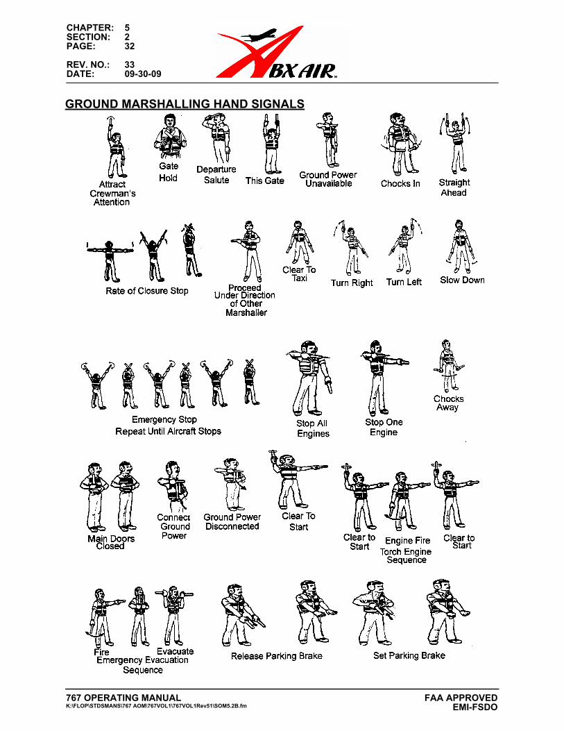
CHAPTER: 5SECTION: 2PAGE: 32
REV. NO.: 33DATE: 09-30-09
GROUND MARSHALLING HAND SIGNALS
767 OPERATING MANUALK:\FLOP\STDSMANS\767 AOM\767VOL1\767VOL1Rev51\SOM5.2B.fm
FAA APPROVED EMI-FSDO
CHAPTER: 5SECTION: 2PAGE: 35
REV. NO.: 47DATE: 02-08-13
RETURN TO SEAT INDICATION
An Emergency “Return to Seat” indication is provided in the following areas:
Supernumerary Compartment:
1. Flashing Overhead Lights.
2. Fasten Seat Belt Illuminated.
3. Aural chime.
Lavatory:
1. Flashing Overhead Light.
2. Red “Return to Seat” Sign illuminated.
3. Aural chime.
Main Deck Cargo Area:
1. Flashing Overhead Lights.
If any of the above signals are indicated, immediately return to your seat and fasten
your seat belt.
Access to the cargo area aft of the smoke barrier during flight is prohibited.
FIRST AID KIT:
Located at the rear of the cockpit, adjacent to the cockpit door.
LIFE VEST:
Located in the respective seat back pockets of the cockpit observer seats and under
the passenger seats in the supernumerary compartment. A demonstration/spare life
vest is stored in a stowage box near the L1 entry door. Life vests are put on by slip-
ping the vest over your head. To inflate the vest, pull the two cords on the front of the
vest after exiting the aircraft. For extended overwater operations (beyond 50 nm from
shore) a demonstration of the method of donning and inflating a life preserver shall be
complied with.
LIFE RAFTS:
Two (2), 7-man life rafts are located in a container below the galley, if required for over
water flight operations. The location shall be shown to any passenger/supernumerary
on flights that may require its use.
Rev. 02-08-13
767 OPERATING MANUALK:\FLOP\STDSMANS\767 AOM\767VOL1\767VOL1Rev51\SOM5.2B.fm
FAA APPROVEDEMI-FSDO
CHAPTER: 5SECTION: 2PAGE: 36
REV. NO.: 51DATE: 09-19-14
FIRE EXTINGUISHERS:
One is located on the left side of the cockpit behind the first observer’s seat. Another one is located in the supernumerary area aft of the galley mounted on the smoke barrier wall adjacent to the right entry door.
TALKING (STERILE COCKPIT):
If occupying a Cockpit Observers seat, talking is not permitted after engine start until climbing thru 10,000 feet. Talking is not permitted after descending thru 10,000 feet for landing until the aircraft is parked. Remember, these are critical phases of flight for crewmember communications.
TRASH:
Place all trash in the supernumerary compartment in the Galley Trash Receptacle. If seated in the cockpit, place all trash in the cockpit trash bag.
ELECTRONIC DEVICES:
With the exception of calculators and E-6B type flight computers or other company approved devices required to conduct the flight, inflight use of electronic devices for personal use by the operating flight crew while at their duty station is prohibited. Jumpseater personal electronic devices can be used above 10,000 ft. Cellular telephones or any device that transmits or receives an RF signal are not to be used in flight. All personal electronic devices must be turned off prior to takeoff and landing to prevent inadvertent chimes, bells or other potential noises that could be mistaken for aircraft warnings from distracting the Flight Crews.
U.S. Military RFID tags mounted on air pallets on CRAF flights are allowed. The RFID tags are normally dormant and have been tested for noninterference of aircraft avionics by ABX Air, Inc. Engineering.
1. Cargo Portable Electronic Devices (PED)
A. DEVICE - Sentry 400 FlightSafe
B. MANUFACTURER - SAVR Communications
C. Ground Handling Instructions
These approved PEDs may be carried only in the aircraft cargo compartments and the devices may not be charged on the aircraft. The loading agent must notify the Flight Crew when approved PEDs are carried on board the aircraft.
FIREARMS, ETC:
Except as authorized by the Flight Operations Manual, the Federal Aviation Administration (FAA) prohibits anyone from carrying a firearm, knife, mace product, or electronic protection device in any aircraft.
AIRCRAFT LOADING:
For your own safety; avoid the cargo compartment during loading and unloading operations. Rev. 09-19-14
767 OPERATING MANUALK:\FLOP\STDSMANS\767 AOM\767VOL1\767VOL1Rev51\SOM5.2B.fm
CHAPTER: 5SECTION: 2PAGE: 43
REV. NO.: 49DATE: 01-30-14
B-767 SAFETY BRIEFING CARD GUIDE PC2SF (FAR 121.583)NO SMOKING:
Smoking is strictly prohibited during ALL operations in and around all ABX Air aircraft. Smoking is prohibited in the aircraft lavatory.
SEAT BELTS AND SHOULDER HARNESS:Seat Belts and shoulder harnesses (if installed) shall be fastened at all times for taxi, takeoff, and landing. Once in flight, with the Captain’s permission and the Fasten Seat Belt Sign extinguished, you may move around the aircraft. If the Fasten Seat Belt Sign illuminates, return to your seat and fasten your seat belt. After landing, seat belts and shoulder harnesses (if installed) shall remain fastened until all engines are shut down.
RETURN TO SEAT INDICATIONAn Emergency “Return to Seat” indication is provided in the following areas:
Crew Service Area Compartment:1. Flashing Overhead Lights.2. Fasten Seat Belt Illuminated.3. Aural chime.
Lavatory:1. Flashing Overhead Light.2. Red “Return to Seat” Sign illuminated.3. Aural chime.
Main Deck Cargo Area:1. Flashing Overhead Lights.If any of the above signals are indicated, immediately return to your seat and fasten your seat belt and shoulder harness.Access to the cargo area aft of the smoke barrier during flight is prohibited.
FIRST AID KIT:Located at the rear of the cockpit, above the fire extinguisher and crash axe.
LIFE VEST:Life vests are provided at each seating location, in the respective seat back pockets of the forward cockpit seats and adjacent to the two rear seats. A demonstration/spare life vest is stored in a stowage box near the L1 entry door. Life vests are put on by slipping the vest over your head. To inflate the vest, pull the two cords on the front of the vest after exiting the aircraft. For extended overwater operations (beyond 50 nm from shore) a demonstration of the method of donning and inflating a life pre-server shall be complied with.
LIFE RAFTS:Two (2), 7-man life rafts are located in a container below the closet in the crew service area, if required for over water flight operations. The location shall be shown to any passenger/supernumerary on flights that may require its use.
FIRE EXTINGUISHERS:Both are located on the left side of the cockpit beside the first observer’s seat.
Rev. 02-08-13
767 OPERATING MANUALK:\FLOP\STDSMANS\767 AOM\767VOL1\767VOL1Rev51\SOM5.2B.fm
FAA APPROVEDEMI-FSDO
CHAPTER: 5SECTION: 2PAGE: 44
REV. NO.: 51DATE: 09-19-14
TALKING (STERILE COCKPIT):
If occupying a Cockpit Observers seat, talking is not permitted after engine start until climbing thru 10,000 feet. Talking is not permitted after descending thru 10,000 feet for landing until the aircraft is parked. Remember, these are critical phases of flight for crewmember communications.
TRASH:
Place all trash in the crew service area in the Galley Trash Receptacle. If seated in the cockpit, place all trash in the cockpit trash bag.
ELECTRONIC DEVICES:
With the exception of calculators and E-6B type flight computers or other company approved devices required to conduct the flight, inflight use of electronic devices for personal use by the operating flight crew while at their duty station is prohibited. Jumpseater personal electronic devices can be used above 10,000 ft. Cellular telephones or any device that transmits or receives an RF signal are not to be used in flight. All personal electronic devices must be turned off prior to takeoff and landing to prevent inadvertent chimes, bells or other potential noises that could be mistaken for aircraft warnings from distracting the Flight Crews.
U.S. Military RFID tags mounted on air pallets on CRAF flights are allowed. The RFID tags are normally dormant and have been tested for noninterference of aircraft avionics by ABX Air, Inc. Engineering.
1. Cargo Portable Electronic Devices (PED)
A. DEVICE - Sentry 400 FlightSafe
B. MANUFACTURER - SAVR Communications
C. Ground Handling Instructions
These approved PEDs may be carried only in the aircraft cargo compartments and the devices may not be charged on the aircraft. The loading agent must notify the Flight Crew when approved PEDs are carried on board the aircraft.
FIREARMS, ETC:
Except as authorized by the Flight Operations Manual, the Federal Aviation Administration (FAA) prohibits anyone from carrying a firearm, knife, mace product, or electronic protection device in any aircraft.
AIRCRAFT LOADING:
For your own safety; avoid the cargo compartment during loading and unloading operations.
Rev. 09-19-14
767 OPERATING MANUALK:\FLOP\STDSMANS\767 AOM\767VOL1\767VOL1Rev51\SOM5.2B.fm
FAA APPROVED EMI-FSDO
CHAPTER: 5SECTION: 2PAGE: 51
REV. NO.: 51DATE: 09-19-14
LIFE RAFTS:Two (2) 6-man rafts are located in the Life Raft Stowage Compartment along the left wall forward of the Main Entry Door. The location shall be shown to any passenger/supernumerary on flights that may require its use.
FIRE EXTINGUISHERS:Two (2) Halon fire extinguishers are located along the left wall forward of the Life Raft Stowage Compartment.
TALKING (STERILE COCKPIT):If occupying a Cockpit Observer’s Seat, talking is not permitted after engine start until climbing through 10,000 feet. Talking is not permitted after descending through 10,000 feet for landing until the aircraft is parked. Remember that these are critical phases of flight for crewmember communications.
TRASH:Place all trash in the Galley Trash Receptacle or in the trash bag located on the Aisle Stand.
ELECTRONIC DEVICES:
With the exception of calculators and E-6B type flight computers or other company approved devices required to conduct the flight, inflight use of electronic devices for personal use by the operating flight crew while at their duty station is prohibited. Jumpseater personal electronic devices can be used above 10,000 ft. Cellular telephones or any device that transmits or receives an RF signal are not to be used in flight. All personal electronic devices must be turned off prior to takeoff and landing to prevent inadvertent chimes, bells or other potential noises that could be mistaken for aircraft warnings from distracting the Flight Crews.
U.S. Military RFID tags mounted on air pallets on CRAF flights are allowed. The RFID tags are normally dormant and have been tested for noninterference of aircraft avionics by ABX Air, Inc. Engineering.
1. Cargo Portable Electronic Devices (PED)A. DEVICE - Sentry 400 FlightSafeB. MANUFACTURER - SAVR CommunicationsC. Ground Handling Instructions
These approved PEDs may be carried only in the aircraft cargo compartments and the devices may not be charged on the aircraft. The loading agent must notify the Flight Crew when approved PEDs are carried on board the aircraft.
FIREARMS, ETC:Except as authorized the Flight Operations Manual, the Federal Aviation Administration (FAA) prohibits anyone from carrying a firearm, knife, mace product, or electronic protection device in any aircraft.
AIRCRAFT LOADING:For your own safety, avoid the cargo compartment during loading and unloading operations. Rev. 09-19-14
767 OPERATING MANUALK:\FLOP\STDSMANS\767 AOM\767VOL1\767VOL1Rev51\SOM5.2B.fm
FAA APPROVEDEMI-FSDO
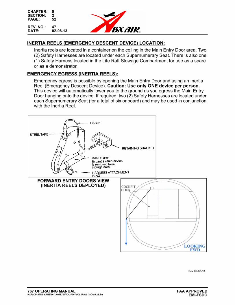
CHAPTER: 5SECTION: 2PAGE: 52
REV. NO.: 47DATE: 02-08-13
INERTIA REELS (EMERGENCY DESCENT DEVICE) LOCATION:
Inertia reels are located in a container on the ceiling in the Main Entry Door area. Two (2) Safety Harnesses are located under each Supernumerary Seat. There is also one (1) Safety Harness located in the Life Raft Stowage Compartment for use as a spare or as a demonstrator.
EMERGENCY EGRESS (INERTIA REELS):
Emergency egress is possible by opening the Main Entry Door and using an Inertia Reel (Emergency Descent Device). Caution: Use only ONE device per person. This device will automatically lower you to the ground as you egress the Main Entry Door hanging onto the device. If required, two (2) Safety Harnesses are located under each Supernumerary Seat (for a total of six onboard) and may be used in conjunction with the Inertia Reel.
Rev. 02-08-13
FORWARD ENTRY DOORS VIEW(INERTIA REELS DEPLOYED)
767 OPERATING MANUALK:\FLOP\STDSMANS\767 AOM\767VOL1\767VOL1Rev51\SOM5.2B.fm
FAA APPROVED EMI-FSDO
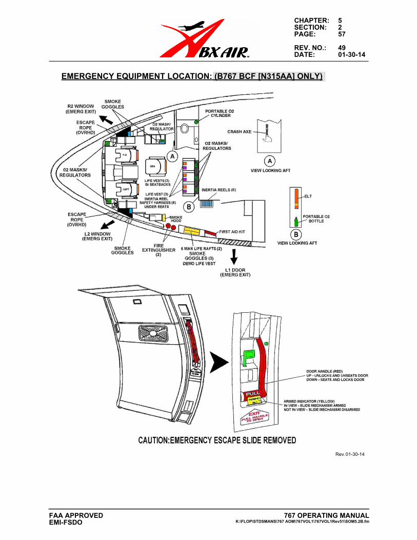
CHAPTER: 5SECTION: 2PAGE: 57
REV. NO.: 49DATE: 01-30-14
EMERGENCY EQUIPMENT LOCATION: (B767 BCF [N315AA] ONLY)
Rev. 01-30-14
767 OPERATING MANUALK:\FLOP\STDSMANS\767 AOM\767VOL1\767VOL1Rev51\SOM5.2B.fm
FAA APPROVEDEMI-FSDO
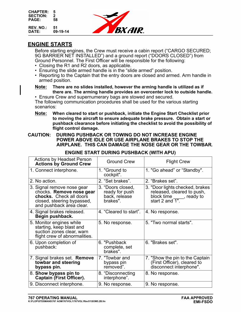
CHAPTER: 5SECTION: 2PAGE: 58
REV. NO.: 51DATE: 09-19-14
ENGINE STARTSBefore starting engines, the Crew must receive a cabin report (“CARGO SECURED; 9G BARRIER NET INSTALLED”) and a ground report (“DOORS CLOSED”) from Ground Personnel. The First Officer will be responsible for the following:• Closing the R1 and R2 doors, as applicable.• Ensuring the slide armed handle is in the “slide armed” position.• Reporting to the Captain that the entry doors are closed and armed. Arm handle in
armed position.Note: There are no slides installed, however the arming handle is utilized as if
there are. The arming handle provides an overcenter lock to outside handle.• Ensure Crew and supernumerary bags are stowed and secured.The following communication procedures shall be used for the various starting scenarios:Note: When cleared to start or pushback, initiate the Engine Start Checklist prior
to moving the aircraft to ensure adequate brake pressure. Obtain a start or pushback clearance before initiating the checklist to avoid the possibility of flight control damage.
CAUTION: DURING PUSHBACK OR TOWING DO NOT INCREASE ENGINE POWER ABOVE IDLE OR USE AIRPLANE BRAKES TO STOP THE AIRPLANE. THIS CAN DAMAGE THE NOSE GEAR OR THE TOWBAR.
ENGINE START DURING PUSHBACK (WITH APU)
Actions by Headset PersonActions by Ground Crew Ground Crew Flight Crew
1. Connect interphone. 1. "Ground tocockpit".
1. "Go ahead” or “Standby".
2. No action. 2. “Set brakes”. 2. “Brakes set”.3. Signal remove nose gear
chocks. Remove nose gearchocks. Check all doorsclosed, steering bypassed,and pushback area clear.
3. “Doors closed,ready for pushback, releasebrakes".
3. "Door lights checked, brakesreleased, cleared to push,block time ____, ready tostart 2 and 1".
4. Signal brakes released.Begin pushback.
4. “Cleared to start”. 4. No response.
5. Monitor engines whilestarting, keep blast andsuction zones clear, warnflight crew of abnormalities.
5. No response. 5. "Two normal starts".
6. Upon completion ofpushback:
6. "Pushbackcomplete, setbrakes".
6. "Brakes set".
7. Signal brakes set. Removetowbar and steeringbypass pin.
7. "Towbar andbypass pinremoved”.
7. "Show the pin to the Captain(First Officer), cleared todisconnect interphone".
8. Show bypass pin toCaptain (First Officer).
8. “Disconnectinginterphone”.
8. No response.
9. Disconnect interphone. 9. No response. 9. No response.
767 OPERATING MANUALK:\FLOP\STDSMANS\767 AOM\767VOL1\767VOL1Rev51\SOM5.2B.fm
FAA APPROVED EMI-FSDO
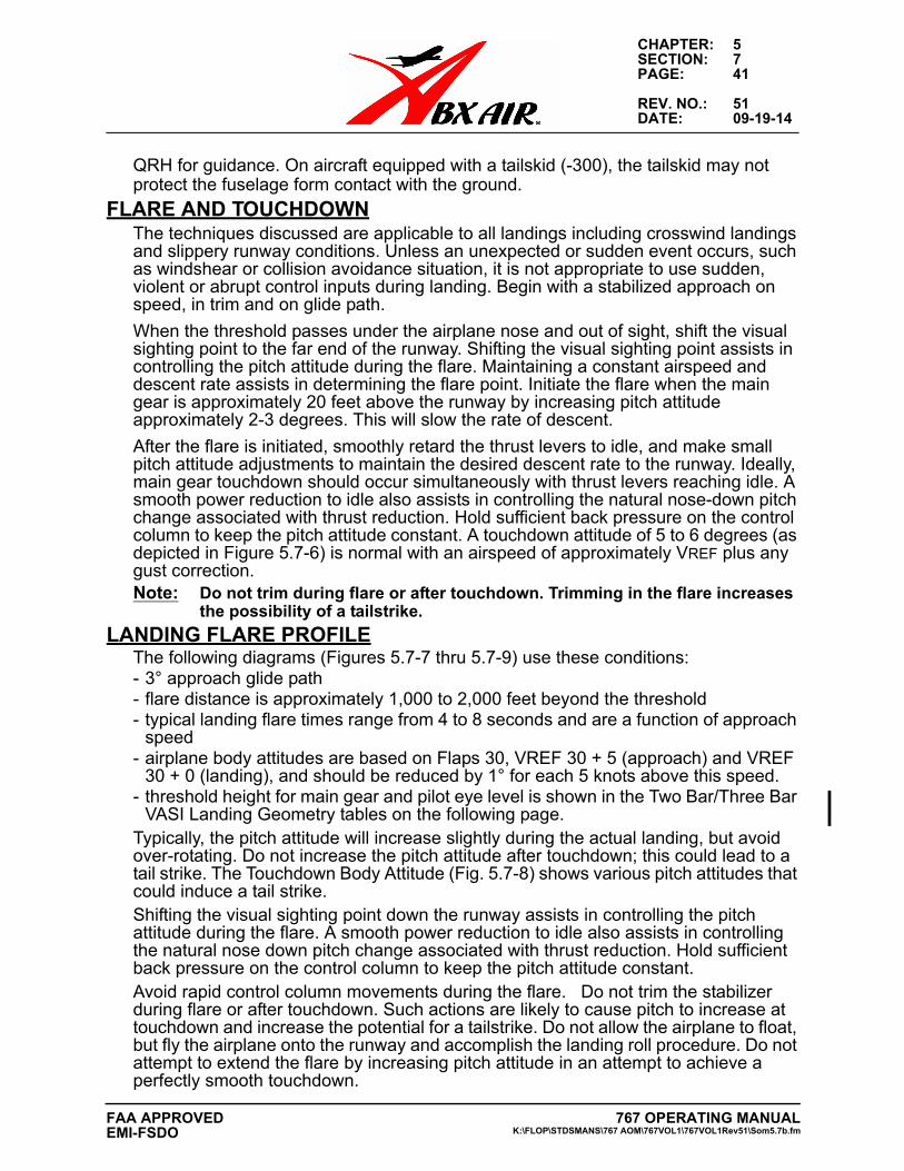
CHAPTER: 5SECTION: 7PAGE: 41
REV. NO.: 51DATE: 09-19-14
QRH for guidance. On aircraft equipped with a tailskid (-300), the tailskid may not protect the fuselage form contact with the ground.
FLARE AND TOUCHDOWNThe techniques discussed are applicable to all landings including crosswind landings and slippery runway conditions. Unless an unexpected or sudden event occurs, such as windshear or collision avoidance situation, it is not appropriate to use sudden, violent or abrupt control inputs during landing. Begin with a stabilized approach on speed, in trim and on glide path.
When the threshold passes under the airplane nose and out of sight, shift the visual sighting point to the far end of the runway. Shifting the visual sighting point assists in controlling the pitch attitude during the flare. Maintaining a constant airspeed and descent rate assists in determining the flare point. Initiate the flare when the main gear is approximately 20 feet above the runway by increasing pitch attitude approximately 2-3 degrees. This will slow the rate of descent.
After the flare is initiated, smoothly retard the thrust levers to idle, and make small pitch attitude adjustments to maintain the desired descent rate to the runway. Ideally, main gear touchdown should occur simultaneously with thrust levers reaching idle. A smooth power reduction to idle also assists in controlling the natural nose-down pitch change associated with thrust reduction. Hold sufficient back pressure on the control column to keep the pitch attitude constant. A touchdown attitude of 5 to 6 degrees (as depicted in Figure 5.7-6) is normal with an airspeed of approximately VREF plus any gust correction.Note: Do not trim during flare or after touchdown. Trimming in the flare increases
the possibility of a tailstrike.
LANDING FLARE PROFILEThe following diagrams (Figures 5.7-7 thru 5.7-9) use these conditions:- 3° approach glide path- flare distance is approximately 1,000 to 2,000 feet beyond the threshold- typical landing flare times range from 4 to 8 seconds and are a function of approach
speed- airplane body attitudes are based on Flaps 30, VREF 30 + 5 (approach) and VREF
30 + 0 (landing), and should be reduced by 1° for each 5 knots above this speed.- threshold height for main gear and pilot eye level is shown in the Two Bar/Three Bar
VASI Landing Geometry tables on the following page.Typically, the pitch attitude will increase slightly during the actual landing, but avoid over-rotating. Do not increase the pitch attitude after touchdown; this could lead to a tail strike. The Touchdown Body Attitude (Fig. 5.7-8) shows various pitch attitudes that could induce a tail strike.Shifting the visual sighting point down the runway assists in controlling the pitch attitude during the flare. A smooth power reduction to idle also assists in controlling the natural nose down pitch change associated with thrust reduction. Hold sufficient back pressure on the control column to keep the pitch attitude constant.Avoid rapid control column movements during the flare. Do not trim the stabilizer during flare or after touchdown. Such actions are likely to cause pitch to increase at touchdown and increase the potential for a tailstrike. Do not allow the airplane to float, but fly the airplane onto the runway and accomplish the landing roll procedure. Do not attempt to extend the flare by increasing pitch attitude in an attempt to achieve a perfectly smooth touchdown.
767 OPERATING MANUALK:\FLOP\STDSMANS\767 AOM\767VOL1\767VOL1Rev51\Som5.7b.fm
FAA APPROVEDEMI-FSDO
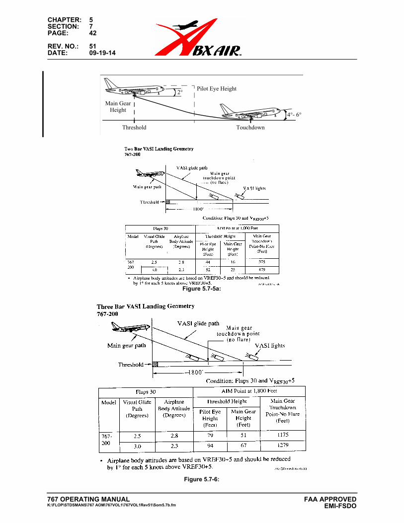
CHAPTER: 5SECTION: 7PAGE: 42
REV. NO.: 51DATE: 09-19-14
Figure 5.7-5a:
Figure 5.7-6:
2°
4°- 6°
Threshold Touchdown
Main Gear Height
Pilot Eye Height
767 OPERATING MANUALK:\FLOP\STDSMANS\767 AOM\767VOL1\767VOL1Rev51\Som5.7b.fm
FAA APPROVED EMI-FSDO
CHAPTER: 5SECTION: 7PAGE: 47
REV. NO.: 51DATE: 09-19-14
immediately after touchdown. Any delay will markedly increase the stopping distance.
Use a combination of rudder, differential braking, and control wheel input to maintain runway centerline during strong crosswinds, gusty wind conditions or other situations. Maintain these control input(s) until reaching taxi speeds.
Stopping distance varies with wind conditions and any deviation from recommended approach speeds.
FACTORS AFFECTING LANDING DISTANCEAdvisory information for Normal and Non-Normal Configuration landing distances is contained in the Performance Section of the AOM and QRH. Actual stopping distances for a maximum effort stop are approximately 60% of the dry runway field length requirement. Factors that affect stopping distance are: height and speed over the threshold, glide slope angle, lowering the nose to the runway after landing, use of reverse thrust, speed brakes and wheel brakes, and surface conditions of the runway.Note: Reverse thrust and speedbrake drag are most effective during the high
speed portion of the landing. Deploy the speedbrake lever and activate reverse thrust with as little time delay as possible.
Note: Speedbrakes fully deployed, in conjunction with maximum reverse thrust and maximum manual anti-skid braking provides the minimum stopping distance.
Floating above the runway before touchdown must be avoided because it uses a large portion of the available runway. The airplane should be landed as near the normal touchdown point as possible. Deceleration rate on the runway is about three times greater than in the air.
Height of the airplane over the runway threshold also has a significant effect on total landing distance. For example, on a 3 degree glide path, passing over the end of the runway at 100 feet altitude rather than 50 feet could increase the total landing distance by approximately 1000 feet. This is due to the length of runway used up before the airplane actually touches down. Glide path angle also affects total landing distance. As the approach path becomes flatter, even while maintaining proper height over the end of the runway, total landing distance is increased.
SLIPPERY RUNWAY LANDING PERFORMANCEWhen landing on slippery runways contaminated with ice, snow, slush or standing water, the reported braking action must be considered. Advisory information for reported braking actions of good, medium and poor is contained in the QRH and AOM. The performance level associated with good is representative of a wet runway. The performance level associated with poor is representative of a wet ice covered runway. Also provided in the QRH and AOM are stopping distances for the various autobrake settings and for non-normal configurations. Pilots should use extreme caution to ensure adequate runway length is available when poor braking action is reported.
Pilots should keep in mind slippery/contaminated runway advisory information is based on an assumption of uniform conditions over the entire runway. This means a uniform depth for slush/standing water for a contaminated runway or a fixed braking coefficient for a slippery runway. The data cannot cover all possible slippery/
767 OPERATING MANUALK:\FLOP\STDSMANS\767 AOM\767VOL1\767VOL1Rev51\Som5.7b.fm
FAA APPROVEDEMI-FSDO
CHAPTER: 5SECTION: 7PAGE: 48
REV. NO.: 50DATE: 06-06-14
contaminated runway combinations and does not consider factors such as rubber deposits or heavily painted surfaces near the end of most runways.
One of the commonly used runway descriptors is coefficient of friction. Ground friction measuring vehicles typically measure this coefficient of friction. Much work has been done in the aviation industry to correlate the friction reading from these ground friction measuring vehicles to airplane performance. Use of ground friction vehicles raises the following concerns:
- the measured coefficient of friction depends on the type of ground friction measuring vehicle used. There is not a method, accepted worldwide, for correlating the friction measurements from the different friction measuring vehicles to each other, or to the airplane’s braking capability.
- all testing to date, which compares ground friction vehicle performance to airplane performance, has been done at relatively low speeds (100 knots or less). The critical part of the airplane’s deceleration characteristics is typically at higher speeds (120 to 150 knots).
- ground friction vehicles often provide unreliable readings when measurements are taken with standing water, slush or snow on the runway. Ground friction vehicles might not hydroplane (aquaplane) when taking a measurement while the airplane may hydroplane (aquaplane). In this case, the ground friction vehicles would provide an optimistic reading of the runway’s friction capability. The other possibility is the ground friction vehicles might hydroplane (aquaplane) when the airplane would not, this would provide an overly pessimistic reading of the runway’s friction capability. Accordingly, friction readings from the ground friction vehicles may not be representative of the airplane’s capability in hydroplaning conditions.
- ground friction vehicles measure the friction of the runway at a specific time and location. The actual runway coefficient of friction may change with changing atmospheric conditions such as temperature variations, precipitation etc. Also, the runway condition changes as more operations are performed.
The friction readings from ground friction measuring vehicles do supply an additional piece of information for the pilot to evaluate when considering runway conditions for landing. Crews should evaluate these readings in conjunction with the PIREPS (pilot reports) and the physical description of the runway (snow, slush, ice, etc.) when planning the landing. Special care should be taken in evaluating all the information available when braking action is reported as POOR or if slush/standing water is present on the runway.
767 OPERATING MANUALK:\FLOP\STDSMANS\767 AOM\767VOL1\767VOL1Rev51\Som5.7b.fm
FAA APPROVED EMI-FSDO
CHAPTER: 5SECTION: 8PAGE: 3
REV. NO.: 51DATE: 09-19-14
center the control wheel. To center the control wheel, rudder will be required in the direction that the control wheel is displaced. This approximates a minimum drag configuration.
INITIAL CLIMB - ONE ENGINE INOPERATIVE
After lift-off use the flight director as the primary pitch reference, cross checking indicated airspeed and other flight instruments. If the flight director is not used, indicated airspeed and attitude become the primary pitch references.
The flight director pitch mode will command a minimum of V2, or the existing speed up to a maximum of V2 +15.
The flight director roll mode will command ground track after lift-off. If ground track is not consistent with desired flight path, use HDG SEL/ HDG HOLD to achieve the desired track.
Retract the landing gear after attaining a positive rate of climb is indicated on the altimeter. The initial climb attitude should be adjusted to maintain a minimum of V2. If an engine fails at an airspeed between V2 and V2 +15, climb at the airspeed which the failure occurred. If engine failure occurs above V2 +15, increase pitch to reduce airspeed to V2 + 15 and maintain until flap retraction altitude.
At 1,000’, accelerate and retract flaps on the normal flap/speed schedule. Begin a climb and set MCT. Once these conditions have been met, verify engine status, accomplish the Engine Failure or Engine Fire or Severe Damage or Separation Checklist and Immediate Action Items (if applicable). Complete Engine Failure or Engine Fire or Severe Damage or Separation Checklist (Chapter 5, Section 11; Takeoff-Engine Failure After V1).
IMMEDIATE TURN AFTER TAKEOFF - ONE ENGINE INOPERATIVE
Obstacle clearance or departure clearance may require an immediate turn after takeoff (Special Engine-Out Procedure). Climb performance is slightly reduced while turning, but is accounted for in the airport analysis. Initiate the turn at the appropriate altitude and maintain V2 to V2 +15 and takeoff flap setting while maneuvering. Engine failure initial heading or course is only listed if different than runway alignment. A turn to the specified heading shall be commenced at 50’ AFE or at engine failure above 50’ AFE.
Note: Limit bank angle to 15° until V2 + 15 knots. Bank angles up to 30° are permitted at V2 + 15 knots with takeoff flaps.
After completing the turn, and at or above flap retraction altitude, accelerate and retract flaps.
FLAP RETRACTION ALTITUDE - ONE ENGINE INOPERATIVE
Normally, flap retraction is initiated at 1,000 feet AGL, decrease pitch attitude to level flight. Select ALT HOLD on the MCP, accelerate, and retract the flaps on schedule.
767 OPERATING MANUALK:\FLOP\STDSMANS\767 AOM\767VOL1\767VOL1Rev51\Som5.8b.fm
FAA APPROVEDEMI-FSDO
CHAPTER: 5SECTION: 8PAGE: 4
REV. NO.: 42DATE: 11-07-11
At clean maneuvering speed, select the FLCH mode, and maximum continuous thrust (CON) set MCT and continue climb to desired altitude (not less than obstacle clearance altitude). Accomplish the ENGINE FAILURE OR ENGINE FIRE OR SEVERE DAMAGE OR SEPARATION CHECKLIST and AFTER TAKEOFF CHECKLIST. After level off, manually set thrust as required. Remain in the FLCH mode until all obstructions are cleared and select the engine out schedule from the CDU climb page (depending on the next course of action).
AUTOTHROTTLE - ENGINE INOPERATIVE
The autothrottle should not be used with an engine inoperative as proper system operation cannot be assured. System response is established for two engine operation and is not appropriate for the response requirements with one engine inoperative.
Disconnect the autothrottle when performing the engine failure procedure. The A/T arm switch should be selected to OFF to ensure the autothrottles will not inadvertently reengage when selecting FLCH or G/A.
Note: Prior to selecting the A/T ARM Switch OFF, disconnect the autothrottles to preclude an autothrottle disconnect caution.
NOISE ABATEMENT
When an engine failure occurs after takeoff, noise abatement is no longer a requirement.
REDUCED THRUST - ONE ENGINE INOPERATIVE
Takeoff thrust reduction is based on a minimum climb gradient that will clear all obstructions with an engine failure after V1. If reduced thrust is used and an engine failure occurs, based on performance, it is not necessary to set maximum thrust on the remaining engine. However, if maximum thrust is desired, thrust on the operating engine may be increased to go-around thrust to improve performance.
Note: Pushing the GA switch cancels the derate and provides a target thrust setting, but the autothrottle does not come out of the THR HOLD mode and manually advance the thrust.
For reduced thrust takeoffs, resetting the operating engine to full thrust provides additional performance margin. This additional performance margin is not a requirement of the reduced thrust takeoff certification and its use is at the discretion of the flight crew.
It should be noted the assumed temperature method of computing reduced thrust takeoff performance is always conservative and provides equal to or better than the performance obtained if actually operating at the assumed temperature.
767 OPERATING MANUALK:\FLOP\STDSMANS\767 AOM\767VOL1\767VOL1Rev51\Som5.8b.fm
FAA APPROVED EMI-FSDO
CHAPTER: 5SECTION: 8PAGE: 19
REV. NO.: 33DATE: 09-30-09
PARTIAL OR GEAR UP LANDING
GENERAL
Circumstances will influence the pilot's decision as to whether an all gear-up landing or partial gear-up landing should be made. If a choice of configuration is available, the decision will be determined by the amount of landing gear available, the conditions at the landing field, time of landing, available facilities, airplane load distribution and controllability. In all cases, reduce weight as much as practicable by burning off fuel to provide the slowest possible touchdown speed. Minimum damage will occur if the airplane is kept on a paved landing area.
Note: Absence of a green gear down light with no other light or message may be the result of a burned out light bulb.
Note: Land on all available gear. Recycling the landing gear in an attempt to extend the remaining gear is not recommended.
LANDING RUNWAY
Consideration should be given to landing at the most suitable airport with adequate runway and fire fighting capability. Foaming the runway is not necessary. Tests have shown that foaming provides minimal benefit and it takes approximately 30 minutes to replenish the fire trucks foam supply.
PRIOR TO APPROACH
Coordinate with all ground emergency facilities. For example, the fire trucks normally operate on a common VHF frequency with the airplane and can advise the crew of airplane condition during the landing.
Position the ground proximity configuration gear override switch to OVRD to prevent nuisance warnings when close to the ground with the gear retracted. Extend all available gear if desired. Turn pack control selectors off to depressurize the airplane. Select all fuel pump switches off to reduce the possibility of fire in the event of fuel line rupture.
LANDING TECHNIQUES
Plan a normal approach, extending maximum flaps with a normal landing and a normal rate of descent. Use the normal speeds plus headwind component and gust factor corrections.
Attempt to keep the aircraft on the runway in order to assist in evacuation and minimize damage.
767 OPERATING MANUALK:\FLOP\STDSMANS\767 AOM\767VOL1\767VOL1Rev51\Som5.8b.fm
FAA APPROVEDEMI-FSDO
CHAPTER: 5SECTION: 8PAGE: 20
REV. NO.: 51DATE: 09-19-14
BOTH MAIN GEAR EXTENDED (NOSE GEAR UP)
Establish approach speed early and maintain normal rate of descent. After touchdown at the normal 1,000 foot point, manually deploy the spoilers. Use normal reverse. Lower the nose gently before losing elevator effectiveness. Normal braking can be used to minimize structural damage.
NOSE GEAR ONLY EXTENDED
Establish a normal approach with maximum flaps. Use normal approach and flare attitude maintaining back pressure on the control column until ground contact. The engines will contact the ground prior to the nose gear. Move the speedbrake lever to up after touchdown.
ALL GEAR UP OR PARTIALLY EXTENDED
Use a normal approach and flare attitude. The engines will contact the ground first. After touchdown, move the speedbrake lever to up. There is adequate rudder available to maintain directional control during the initial ground slide.
ONE MAIN GEAR ONLY EXTENDED
Land the airplane on the side of the runway that corresponds to the extended gear down. At touchdown maintain wings level as long as possible. Use rudder and braking as required to keep the airplane rolling straight. Place the fuel control switch to CUTOFF prior to the corresponding engine contacting the ground.
ONE MAIN GEAR DOWN AND NOSE GEAR EXTENDED
Fly a normal approach and flare profile. The landing gear absorbs the initial shock and delays touchdown of the engine. At touchdown, extend spoilers, and use rudder and nose wheel steering for directional control. Braking on the side opposite the unsupported wing should be used as required to keep the airplane rolling straight. Maintain the wings level as long as possible.
AFTER STOP
Accomplish the Cockpit Evacuation Checklist.
AIRSPEED UNRELIABLE
Unreliable airspeed indications can result from blocking or freezing of the pitot/static system or a severely damaged or missing radome. When the ram air inlet to the pitot head is blocked, pressure in the probe is released through the drain holes and the airspeed slowly drops to zero. If the ram air inlet and the probe drain holes are both blocked, pressure trapped within the system reacts unpredictably. The pressure may increase through expansion, decrease through contraction, or remain constant. In all cases, the airspeed indications would be abnormal. This could mean increasing
767 OPERATING MANUALK:\FLOP\STDSMANS\767 AOM\767VOL1\767VOL1Rev51\Som5.8b.fm
FAA APPROVED EMI-FSDO
CHAPTER: 5SECTION: 8PAGE: 21
REV. NO.: 51DATE: 09-19-14
indicated airspeed in climb, decreasing indicated speed in descent or unpredictable indicated airspeed in cruise.
Increased reliance on automation has de-emphasized the practice of setting known pitch attitudes and thrust settings. However, should an airspeed unreliable incident occur, the flight crew should be familiar with the approximate pitch attitude and thrust setting for each phase of flight. This familiarity can be gained by noting the pitch attitude and thrust setting occasionally during normal flight. Any significant change in body attitude from the attitude normally required to maintain a particular airspeed or Mach number should alert the flight crew to a potential airspeed problem.
If abnormal airspeed is recognized, immediately set the target pitch attitude and thrust setting for the aircraft configuration from the Airspeed Unreliable memory items. When airplane control is established, accomplish the Airspeed Unreliable NNC. The crew should alert ATC if unable to maintain assigned altitude or if altitude indication are unreliable.
Memory items for target pitch and thrust must be accomplished as soon as it is suspected that airspeed indications are incorrect. The intent of having memorized pitch and thrust settings is to quickly put the airplane in a safe regime until the Airspeed Unreliable checklist can be referenced. The following assumptions and requirements were used in developing these memory items:
• The memorized settings are calculated to work for all model/engine combinations,at all weights and at all altitudes.
• The flaps up settings will be sufficient such that the actual airspeed remains abovestick shaker and below overspeed.
• The flaps extended settings will be sufficient such that the actual airspeed remainsabove stick shaker and below the flap placard limit.
• The settings are biased toward a higher airspeed as it is better to be at a highenergy state than a low energy state.
• These memorized settings are to allow time to stabilize the airplane, remain withinthe flight envelope without overspeed or stall, and then continue with reference tothe checklist.
• Settings are provided for flight with and without flaps extended. The crew shoulduse the setting for the condition they are in to keep the airplane safe whileaccessing the checklist.
In order to determine if a reliable source of indicated airspeed is available, the Airspeed Unreliable checklist says “When in trim and stabilized, cross check the Captain, First Officer and standby airspeed indicators.” The intent of this statement is for the pilot flying to set the pitch attitude and thrust setting from the PI-QRH Flight With Unreliable Airspeed table and allow the airplane to stabilize before comparing the airspeed indications to those shown in the table.
767 OPERATING MANUALK:\FLOP\STDSMANS\767 AOM\767VOL1\767VOL1Rev51\Som5.8b.fm
FAA APPROVEDEMI-FSDO
CHAPTER: 5SECTION: 8PAGE: 22
REV. NO.: 51DATE: 09-19-14
The airplane is considered stabilized when the thrust and pitch have been set, and the pitch is trimmed with no further trim movement needed to maintain the pitch setting. This is not an instantaneous process, and must be complete before comparing indicated and expected airspeeds for accurate results.
If it is determined that none of the airspeed indicators are reliable, the PI-QRH tables should be used for the remainder of the flight. Flight crews need to ensure they are using the table and values apprpriate for phase of flight and airplane configuration.
• When changing phase of flight or airplane configuration, make initial thrustchange, set pitch attitude, configure the airplane as needed, then recheck thrustand pitch, and trim as needed. Do not change configuration until the airplane istrimmed and stabilized at the current configuration.
Flap load relief can prevent the flaps from extending or remaining at the desired flap setting for landing. The flap load relief function uses indicated airspeed, which may be unreliable. The Airspeed Unreliable checklist procedures configure the airplane as necessary by using alternate flaps if needed to prevent unwanted flap load relief.
If the flight crew is aware of the problem, flight without the benefit of valid airspeed information can be safely conducted and should present little difficulty. Early recognition of erroneous airspeed indications requires familiarity with the interrelationship of attitude, thrust setting, and airspeed. A delay in recognition could result in loss of airplane control.
Ground speed information is available from the FMC and on the instrument displays. These indications can be used as a crosscheck. Many air traffic control radars can also measure ground speed.
DESCENT
Idle thrust descents to 10,000 feet can be made by flying body attitude and checking rate of descent in the QRH/PI tables. At 2,000 feet above the selected level off altitude, reduce rate of descent to 1,000 FPM. On reaching the selected altitude, establish pitch and thrust for the airplane configuration. If possible, allow the airplane to stabilize before changing configuration and altitude.
APPROACH
If available, accomplish an ILS approach. Establish landing configuration early on final approach. At glide slope intercept or beginning of descent, set thrust and attitude per the QRH tables and control the rate of descent with thrust.
767 OPERATING MANUALK:\FLOP\STDSMANS\767 AOM\767VOL1\767VOL1Rev51\Som5.8b.fm
FAA APPROVED EMI-FSDO
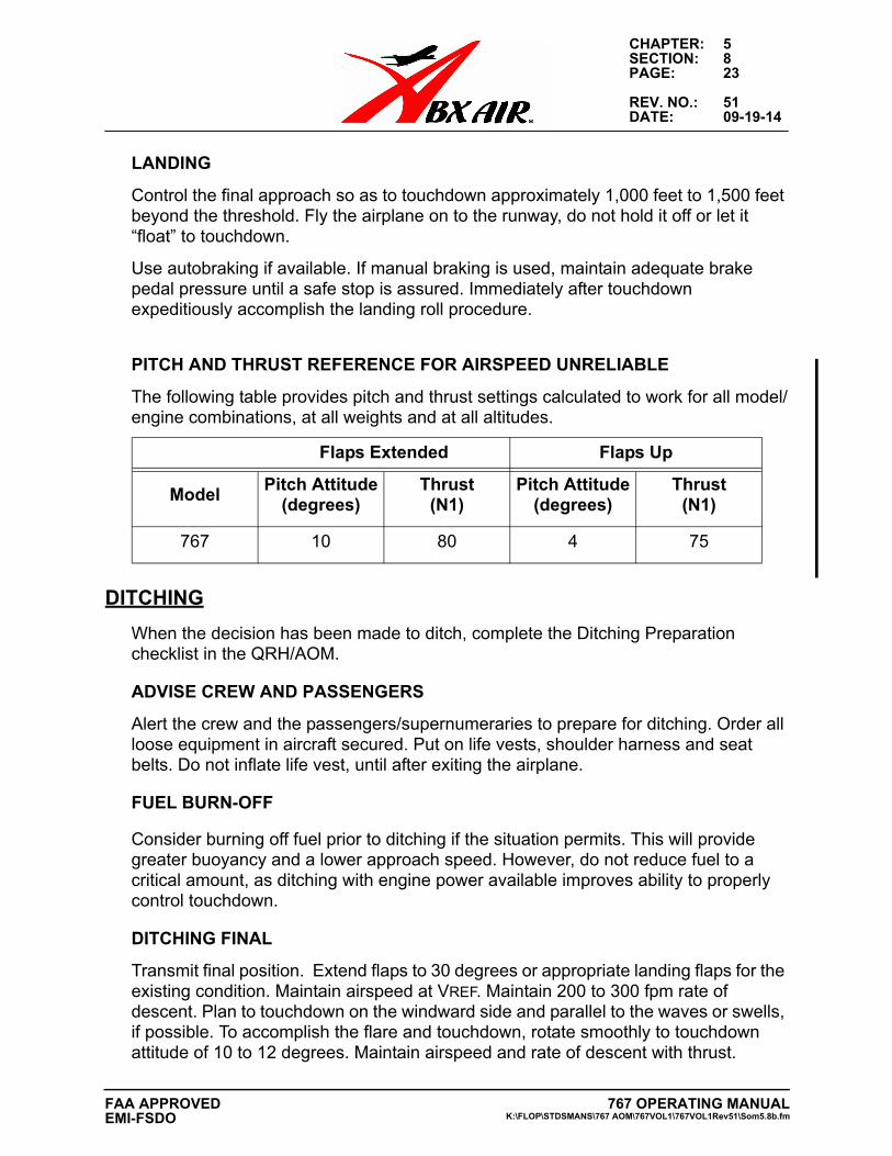
CHAPTER: 5SECTION: 8PAGE: 23
REV. NO.: 51DATE: 09-19-14
LANDING
Control the final approach so as to touchdown approximately 1,000 feet to 1,500 feet beyond the threshold. Fly the airplane on to the runway, do not hold it off or let it “float” to touchdown.
Use autobraking if available. If manual braking is used, maintain adequate brake pedal pressure until a safe stop is assured. Immediately after touchdown expeditiously accomplish the landing roll procedure.
PITCH AND THRUST REFERENCE FOR AIRSPEED UNRELIABLE
The following table provides pitch and thrust settings calculated to work for all model/engine combinations, at all weights and at all altitudes.
DITCHING
When the decision has been made to ditch, complete the Ditching Preparation checklist in the QRH/AOM.
ADVISE CREW AND PASSENGERS
Alert the crew and the passengers/supernumeraries to prepare for ditching. Order all loose equipment in aircraft secured. Put on life vests, shoulder harness and seat belts. Do not inflate life vest, until after exiting the airplane.
FUEL BURN-OFF
Consider burning off fuel prior to ditching if the situation permits. This will provide greater buoyancy and a lower approach speed. However, do not reduce fuel to a critical amount, as ditching with engine power available improves ability to properly control touchdown.
DITCHING FINAL
Transmit final position. Extend flaps to 30 degrees or appropriate landing flaps for the existing condition. Maintain airspeed at VREF. Maintain 200 to 300 fpm rate of descent. Plan to touchdown on the windward side and parallel to the waves or swells, if possible. To accomplish the flare and touchdown, rotate smoothly to touchdown attitude of 10 to 12 degrees. Maintain airspeed and rate of descent with thrust.
Flaps Extended Flaps Up
ModelPitch Attitude
(degrees)Thrust
(N1)Pitch Attitude
(degrees)Thrust
(N1)
767 10 80 4 75
767 OPERATING MANUALK:\FLOP\STDSMANS\767 AOM\767VOL1\767VOL1Rev51\Som5.8b.fm
FAA APPROVEDEMI-FSDO
CHAPTER: 5SECTION: 8PAGE: 24
REV. NO.: 51DATE: 09-19-14
INITIATE EVACUATION
After the airplane has come to rest, evacuate as soon as possible, assuring that all passengers/supernumeraries are out of the airplane.
FUEL BALANCE
The primary purpose for fuel balance limitations/alerts on Boeing airplanes is for structural life of the airframe and not due to controllability limitations. A reduction in structural life of the airframe or landing gear can be caused by frequently operating with out-of-limit fuel balance conditions. Lateral control is not significantly affected when operating with fuel beyond normal balance limits.
The primary purpose for fuel balance alerts is to inform the crew that imbalances beyond the current state may result in increased trim drag and higher fuel consumption. The FUEL CONFIGURATION NNC should be accomplished when the fuel balance alert is received.
There is a common misconception among flight crews that the fuel crossfeed valve should be opened immediately after an in-flight engine shutdown to prevent fuel imbalance. This practice is contrary to Boeing recommended procedures and could aggravate a fuel imbalance. This practice is especially significant if an engine failure occurs and a fuel leak is present. Arbitrarily opening the crossfeed valve and starting fuel balancing procedures without following the checklist can result in pumping usable fuel overboard.
The misconception may be further reinforced during simulator training. The fuel pumps in simulators are modeled with equal output pressure on all pumps so opening the crossfeed valve appears to maintain a fuel balance. However, the fuel pumps in the airplane have allowable variations in output pressure. If there is a sufficient difference in pump output pressures and the crossfeed valve is opened, fuel feeds to the operating engine from the fuel tank with the highest pump output pressure. This may result in fuel coming unexpectedly from the tank with the lowest quantity.
Note: It is not necessary to terminate fuel balancing on final approach.
FUEL LEAK
Any time an unexpected fuel quantity indication, FMC or EICAS fuel message, or imbalance condition is experienced, a fuel leak should be considered as a possible cause. Maintaining a fuel log and comparing actual fuel burn to the flight plan burn can help the pilot recognize a fuel leak.
Significant fuel leaks, although fairly rare, are difficult to detect. The Fuel Leak Non-Normal checklist includes steps for a leak that is between the front spar and the engine (an “engine fuel leak”) or a leak from the tank to the outside (a “tank leak”). An engine fuel leak is the most common type of fuel leak since fuel lines are exposed in the strut. Most other fuel lines, such as a crossfeed manifold are contained within the
767 OPERATING MANUALK:\FLOP\STDSMANS\767 AOM\767VOL1\767VOL1Rev51\Som5.8b.fm
FAA APPROVED EMI-FSDO
CHAPTER: 5SECTION: 8PAGE: 25
REV. NO.: 51DATE: 09-19-14
tanks. A significant fuel leak directly from a tank to the outside is very rare due to the substantial wing structure that forms the tanks.
There is no specific fuel leak annunciation on the flight deck. A fuel leak must be detected by changes or discrepancies in expected fuel consumption, or by some annunciation that occurs because of a fuel leak. Any unexpected and sustained change in fuel quantity or fuel balance should alert the crew to the possibility of a fuel leak.
Some fuel-related checklists (for example, FUEL CONFIGURATION) list reasons that a fuel leak should be suspected. This list is not exhaustive and, in all cases the flight crew should use their knowledge of the fuel system and current operating conditions to determine whether a fuel leak should be suspected. Some reasons are:
• The total fuel remaining on EICAS is less than the planned fuel remaining. Thetotal fuel can be less than planned fuel for a number of reasons, such as a fuelleak, unforecast headwinds, fuel sloshing (such as from high angles of pitch).Sloshing fuel would be a temporary effect. Flight crews should consider thesewhen deciding whether or not to suspect a fuel leak.
• An engine has excessive fuel flow. A faulty fuel flow meter or an engine fuel leakdownstream of the fuel flow meter will cause an excessive fuel flow indication.Total fuel remaining compared to planned fuel remaining should be consideredwhen deciding whether or not to suspect a fuel leak.
• One main tank is abnormally low compared to the other main tanks and theexpected fuel remaining in the tanks. One tank indicating abnormally low can becaused by a fuel leak, engine out or a crossfeed problem. With an engine out, ifthe totalizer and calculated values are tracking as expected, a fuel leak would notbe suspected. A fuel pump with higher pressure and a faulty crossfeed valve cancause one tank to provide fuel to more than one engine, causing one tank toindicate low. In this case, the fact that total fuel should still match planned fuel afuel leak would not be suspected.
• On PROGRESS page 2 the totalizer is less than the calculated fuel. TheTOTALIZER fuel is the sum of the individual tank quantities. The CALCULATEDfuel is the totalizer value at engine start minus fuel used. Fuel used is calculatedusing the engine fuel flow sensors. This can be caused by a fuel leak or a tank fuelquantity indicator failure. If a tank fuel quantity indicator has failed, the crew wouldnot suspect a fuel leak.
If a fuel leak is suspected, it is imperative to follow the Non-Normal Checklist.
The Non-Normal Checklist leads the crew through steps to determine if the fuel leak is from the strut or the engine area. If an engine fuel leak is confirmed, the NNC directs the crew to shutdown the affected engine. There are two reasons for the shutdown. The first is to close the spar valve, which stops the leak. This prevents the loss of fuel which could result in a low fuel state. The second reason is that the fire potential is increased when fuel is leaking around the engine. The risk of fire
767 OPERATING MANUALK:\FLOP\STDSMANS\767 AOM\767VOL1\767VOL1Rev51\Som5.8b.fm
FAA APPROVEDEMI-FSDO
CHAPTER: 5SECTION: 8PAGE: 26
REV. NO.: 51DATE: 09-19-14
increases further when the thrust reverser is used during landing. The thrust reverser significantly changes the flow of air around the engine which can disperse fuel over a wider area.
LOW FUEL OPERATIONS
IN FLIGHT
A low fuel condition exists when the FUEL CONFIG light illuminates and the EICAS message LOW FUEL is displayed. Expect an indicated fuel quantity of 2,200 pounds of fuel or less in either main tank. With this condition, open the crossfeed and turn on all fuel pump switches. Avoid sustained high nose-up attitudes and excessive acceleration to prevent uncovering of the fuel pumps.
APPROACH AND LANDING
With a low fuel quantity, the clean configuration should be maintained as long as possible during the descent and approach to conserve fuel. However, initiate configuration change early enough to provide a smooth, slow deceleration to final approach speed to prevent fuel running forward in the tanks.
A normal landing configuration and appropriate airspeed for the wind conditions are recommended.
Runway conditions permitting, heavy braking and high levels of reverse thrust should be avoided to prevent uncovering all fuel pumps and possible engine flameout during landing roll.
GO-AROUND
If a go-around is necessary, apply thrust slowly and smoothly and maintain the minimum nose-up body attitude required for a safe climb gradient. Avoid rapid acceleration of the airplane. If any wing tank fuel pump low pressure light illuminates, do not turn off fuel pump switches.
APPROACH AND LANDING ON STANDBY POWER
The probability of a total and unrecoverable AC power failure is extremely remote. Because of system design, a checklist for accomplishing an approach and landing on standby power is not required. During training, or in the unlikely event that a landing must be made on standby power, the following guidelines should be considered.
- Fly the approach on speed (excess speed is undesirable)
- Anti-skid is not available
- Thrust reversers are not available
- Auto speedbrakes are not available
767 OPERATING MANUALK:\FLOP\STDSMANS\767 AOM\767VOL1\767VOL1Rev51\Som5.8b.fm
FAA APPROVED EMI-FSDO
CHAPTER: 5SECTION: 8PAGE: 27
REV. NO.: 51DATE: 09-19-14
JAMMED STABILIZER
During flight test certification the worst case jammed stabilizer condition was evaluated. A satisfactory landing could be accomplished without the use of special configurations or speeds. Adequate flare capability was available at Flaps 30 and Flaps 20 using the appropriate VREF. Therefore, a special flight procedure is not considered necessary. Consideration should be given to aircraft configuration to maintain an improved aircraft trim condition.
UNSCHEDULED STABILIZER TRIM
Hold control column firmly to maintain desired pitch attitude. If uncommanded trim motion continues, the stabilizer trim commands are interrupted when the control column is displaced in the opposite direction.
WINDOW DAMAGE
If both forward windows delaminate or forward vision is unsatisfactory, accomplish an autoland if the ILS facility is satisfactory.
FLIGHT WITH THE SIDE WINDOW(S) OPEN
The inadvertent opening of an unlatched flight deck window by air loads during the takeoff roll is not considered an event that warrants a high speed RTO. Although the resulting noise levels may interfere with crew communications, the crew should consider continuing the takeoff and close the window after becoming airborne and the flight path is under control.
If required, the windows may be opened in-flight, at or below holding speeds, after depressurizing the airplane. It is recommended that the airplane be slowed since the noise levels increase at higher airspeed. Intentions should be briefed and ATC notified prior to opening the window as the noise level is high, even at slow speeds. Because of airplane design, there is an area of relatively calm air over the open window. Forward visibility can be maintained by looking out of the open window using care to stay clear of the airstream.
OVERSPEED
Vmo/Mmo is a maximum operating speed limit on the airplane and should not be exceeded. However, momentary exceedance sometimes occurs due to atmospheric effects and airplane anomalies. If encountered, smoothly reduce thrust and, if required, adjust attitude to reduce airspeed to less than Vmo/Mmo. This can be accomplished using the autoflight system or manual flight.
Note: If manual inputs are required, disconnect the autopilot.
Airplanes have been flight tested beyond Vmo/Mmo to ensure smooth pilot inputs will return the airplane safely to the normal flight envelope. Anytime Vmo/Mmo is exceeded, the maximum airspeed should be noted in the flight log.
767 OPERATING MANUALK:\FLOP\STDSMANS\767 AOM\767VOL1\767VOL1Rev51\Som5.8b.fm
FAA APPROVEDEMI-FSDO
CHAPTER: 5SECTION: 8PAGE: 28
REV. NO.: 51DATE: 09-19-14
COCKPIT EVACUATION
If the evacuation is planned, as in a partial or gear up landing, thorough briefing and preparation of the crew and passengers/supernumeraries is essential to a successful evacuation.
Availability of various exits will differ for each situation. Crewmembers on the scene must make the decision as to which exits are usable for the prevailing circumstances. Quick actions in a calm and methodical manner will assure a successful passenger/supernumerary evacuation.
DUAL ENGINE FAILUREDual engine failure is an emergency situation that demands prompt action regardless of altitude or airspeed. Accomplish the immediate action items and establish the appropriate airspeed to immediately attempt windmill relight. There is a higher probability that a windmill start will succeed if the restart attempt is made as early as possible (or immediately after recognizing engine failure) to take advantage of high engine RPM. Use of higher air speeds, and altitudes below 30,000 feet, will also improve probability of a relight. Loss of thrust at higher altitudes may require driftdown to lower altitude to improve windmill starting capability.
The inflight start envelope defines the region where windmill starts were demonstrated during certification. It should be noted that this envelope does not define the only areas where a windmill start may be successful. The dual engine failure procedure is written to ensure flight crews take advantage of the high RPM at engine failure regardless of altitude or airspeed. A subsequent APU start may be initiated as soon as practical for electrical power and starter assist start attempted if the rapid restart does not succeed. Initiate the Dual Engine Failure immediate action items before attempting an APU start for the reasons identified above.
If electrical power is restored, do not confuse the establishment of APU generator power with airplane engine generator power at idle RPM and advance the thrust lever prematurely. EGT during rapid restart may exceed the limit displayed by EICAS for one-engine starts. During relight attempts with both engines failed, use the Standby Engine Indicator takeoff EGT placard limit even if EICAS remains powered. A hung or stalled in-flight start is normally indicated by stagnant RPM and/or increasing EGT. During start, engines may accelerate to idle slowly but action should not be taken if RPM is increasing and EGT is not near or rapidly approaching the SEI limit.
WHEEL WELL FIRE
Prompt execution of the wheel well fire checklist following a wheel well fire warning is important for timely gear extension. Landing gear speed limitations should be considered during this procedure.
If airspeed is above 270 knots/.82 Mach, the airspeed must be reduced before extending the landing gear. A rapid way to reduce airspeed during climb or descent is to select FLCH to open the MCP command speed window, then set approximately
767 OPERATING MANUALK:\FLOP\STDSMANS\767 AOM\767VOL1\767VOL1Rev51\Som5.8b.fm
FAA APPROVED EMI-FSDO
CHAPTER: 5SECTION: 8PAGE: 29
REV. NO.: 51DATE: 09-19-14
250 knots. An alternate way to reduce airspeed during a climb or descent is to select altitude hold and select a lower speed. With the autothrottle in a speed mode, thrust levers may be reduced to idle and/or speedbrakes may be used to expedite deceleration.
Note: To avoid unintended deceleration below the new target airspeed, the autothrottles should remain engaged.
TAIL STRIKE
Tail strike occurs when the lower aft fuselage or tailskid (as installed) contacts the runway during takeoff or landing. A significant factor that appears to be common is the lack of flight crew experience with the model being flown. Understanding the factors that contribute to a tail strike can reduce the possibility of tail strike occurrence.
Note: Anytime fuselage contact is suspected or known to have occurred, accomplish the appropriate non-normal procedure.
TAKEOFF RISK FACTORS
Any one of the following takeoff risk factors may precede a tail strike:
MISTRIMMED STABILIZER
This usually results from using erroneous takeoff data, e.g., the wrong weights, or an incorrect center of gravity (CG). In addition, sometimes the information presented to the flight crew is accurate, but is entered incorrectly either in the flight management system (FMS) or set incorrectly on the stabilizer. The flight crew can prevent this type of error and correct the condition by challenging the reasonableness of the load sheet numbers. Comparing the load sheet numbers against past experience in the aircraft can assist in approximating numbers that are reasonable.
ROTATION AT IMPROPER SPEED
This situation can result in a tail strike and is usually caused by early rotation due to some unusual situation, or rotation at too low an airspeed for the weight and/or flap setting.
EXCESSIVE ROTATION RATE
Flight crews operating an airplane model that is new to them, especially when transitioning from an airplane with unpowered flight controls to one with hydraulic assistance, are most vulnerable to using excessive rotation rate. The amount of control input required to achieve the proper rotation rate varies from one model to another. When transitioning to a new model, flight crews may not consciously realize that it will not respond to pitch input in exactly the same way as their previous model.
767 OPERATING MANUALK:\FLOP\STDSMANS\767 AOM\767VOL1\767VOL1Rev51\Som5.8b.fm
FAA APPROVEDEMI-FSDO
CHAPTER: 5SECTION: 8PAGE: 30
REV. NO.: 51DATE: 09-19-14
IMPROPER USE OF THE FLIGHT DIRECTOR
The flight director is designed to provide accurate pitch guidance only after the airplane is airborne. With the proper rotation rate, the airplane reaches 35 feet with the desired pitch attitude of about 15 degrees. However, an aggressive rotation into the pitch bar at takeoff is not appropriate and may rotate the tail onto the ground.
LANDING RISK FACTORS
A tail strike on landing tends to cause more serious damage than the same event during takeoff and is more expensive and time consuming to repair. In the worst case, the tail can strike the runway before the landing gear touches down, thus absorbing large amounts of energy for which it is not designed. The aft pressure bulkhead is often damaged as a result.
Any one of these landing risk factors may precede a tail strike.
UNSTABILIZED APPROACH
An unstabilized approach appears in virtually every landing tail strike event. When an airplane turns on to final approach with excessive airspeed, excessive altitude, or both, the situation may not be under the control of the flight crew. The most common cause of this scenario is the sequencing of traffic in the terminal area as determined by air traffic control.
An unstabilized approach is the biggest single cause of tail strike. Flight crews should attempt to reach all the approach variables - on centerline, on approach path, on speed, and in the final landing configuration - by the time the airplane descends through 1,000 feet above ground level (AGL). This is not always possible. Under normal conditions, if the airplane descends through 1,000 feet AGL (IMC), or 500 feet AGL (VMC), with these approach variables not stabilized, a go-around should be considered.
Flight recorder data show that flight crews who continue with an unstabilized condition below 500 feet will never stabilize the approach. When the airplane arrives in the flare, it invariably has either excessive or insufficient airspeed. The result is a tendency toward large power and pitch corrections in the flare, often culminating in a vigorous pitch change at touchdown resulting in tail strike shortly thereafter. If the pitch is increased rapidly when touchdown occurs as ground spoilers deploy, the spoilers add additional nose up pitch force, reducing elevator authority, which increases the possibility of tail strike. Conversely, if the airplane is slow, increasing the pitch in the flare does not effectively reduce the sink rate and in some cases, may increase it.
A firm touchdown on the main gear is often preferable to a soft touchdown with the nose rising rapidly. In this case, the momentary addition of power may aid in preventing the tail strike. In addition unstabilized approaches can result in landing long or runway over run.
767 OPERATING MANUALK:\FLOP\STDSMANS\767 AOM\767VOL1\767VOL1Rev51\Som5.8b.fm
FAA APPROVED EMI-FSDO
CHAPTER: 5SECTION: 8PAGE: 31
REV. NO.: 51DATE: 09-19-14
HOLDING OFF IN THE FLARE
The second most common cause of a landing tail strike is an extended flare, with a loss in airspeed that results in a rapid loss of altitude, (a dropped-in touchdown). This condition is often precipitated by a desire to achieve an extremely smooth/soft landing. A very smooth/soft touchdown is not essential, nor even desired, particularly if the runway is wet.
TRIMMING IN THE FLARE
Trimming the stabilizer in the flare may contribute to a tail strike. The pilot flying may easily lose the feel of the elevator while the trim is running. Too much trim can raise the nose, even when this reaction is not desired. The pitch up can cause a balloon, followed either by dropping in or pitching over and landing in a three-point attitude. Flight crews should trim the airplane during the approach, but not in the flare.
MISHANDLING OF CROSSWINDS
When the airplane is placed in a forward slip attitude to compensate for the wind effects, this cross-control maneuver reduces lift, increases drag, and may increase the rate of descent. If the airplane then descends into a turbulent surface layer, particularly if the wind is shifting toward the tail, the stage is set for tail strike.
The combined effects of high closure rate, shifting winds with the potential for a quartering tail wind, can result in a sudden drop in wind velocity commonly found below 100 feet. Combining this with turbulence can make the timing of the flare very difficult. The pilot flying can best handle the situation by exercising the use of additional thrust, if required, and is combined with appropriate pitch change to keep the descent rate stable until initiation of the flare. Flight crews should clearly understand the criteria for initiating a go-around and plan to use this time-honored avoidance maneuver when needed.
OVER-ROTATION DURING GO-AROUND
Go-arounds initiated very late in the approach, such as during flare or after touching down, are a common cause of tail strike. When the go-around mode is initiated, the FD immediately commands a go-around pitch attitude. If the pilot flying abruptly rotates into the command bars, tail strike can occur before a change in the flight path is possible. Both pitch attitude and thrust are required for go-around. If pitch attitude increase is not used in conjunction with thrust, the thrust may not be adequate to support the effort, resulting in tail strike. A contributing factor may be a strong desire by the flight crew to avoid landing gear contact after initiating a late go-around when the airplane is still over the runway. In general, the concern is not warranted because a brief contact with the landing gear during a late go-around is acceptable. This has been demonstrated by airplane manufacturers during autoland and go-around certification programs.
767 OPERATING MANUALK:\FLOP\STDSMANS\767 AOM\767VOL1\767VOL1Rev51\Som5.8b.fm
FAA APPROVEDEMI-FSDO
CHAPTER: 5SECTION: 8PAGE: 32
REV. NO.: 51DATE: 09-19-14
JAMMED OR RESTRICTED FLIGHT CONTROLS
Although rare, jamming of the flight control system has occurred on commercial airplanes. A jammed flight control can result from ice accumulation due to water leaks onto cables or components, dirt accumulation, component failure such as cable break or worn parts, improper lubrication, or foreign objects.
A flight control jam may be difficult to recognize, especially in a properly trimmed airplane. A jam in the pitch axis may be more difficult to recognize than a jam in other axes. In the case of the elevator, the jammed control can be masked by trim. Some indications of a jam are:
• unexplained autopilot disconnect
• autopilot that will not engage
• undershoot or overshoot of an altitude during autopilot leveloff
• higher than normal control forces required during speed or configuration changes
If any jammed flight control condition exists, both pilots should apply force to try to either clear the jam or activate the override feature. There should be no concern about damaging the flight control mechanism by applying too much force to either clear a jammed flight control or activate an override feature. Maximum force may result in some flight control surface movement with a jammed flight control. If the jam clears, both pilot’s flight controls are available.
Note: If a control is jammed due to ice accumulation, the jam may clear when moving to a warmer temperature.
Some flight controls are linked together through override features. If the jam does not clear, activation of an override feature allows a flight control surface to be moved independently of the jammed control. Applying force to the non-jammed flight control activates the override feature. When enough force is supplied, the jammed control is overridden allowing the non-jammed control to operate. To identify the non-jammed flight control, apply force to each flight control individually. The flight control that results in the greatest aircraft control is the non-jammed control.
Note: The pilot of the non-jammed control should be the pilot flying for the remainder of the flight.
The non-jammed control will require a normal force, plus an additional override force to move the flight control surface. For example, if a force of 10 lbs (4 kg) is normally required to move the surface, and 50 lbs (23 kg) of force is required to activate the override, a total force of 60 lbs (27 kg) is required to move the control surface while in override. Response will be slower than normal with a jammed flight control; however, sufficient response is available for aircraft control and landing.
For those controls without override features, limited flight control surface deflection occurs when considerable force is applied to the flight control. This response is due to
767 OPERATING MANUALK:\FLOP\STDSMANS\767 AOM\767VOL1\767VOL1Rev51\Som5.8b.fm
FAA APPROVED EMI-FSDO
CHAPTER: 5SECTION: 8PAGE: 33
REV. NO.: 51DATE: 09-19-14
cable stretch and structural bending. This response may be sufficient for aircraft control and landing.
Note: There are override features for the aileron and elevator.
TRIM INPUTS
If a jammed flight control condition exists, use manual inputs from other control surfaces to counter pressures and maintain a neutral flight control condition. The following table provides trim inputs that may be used to counter jammed flight control conditions.
APPROACH AND LANDING
Attempt to select a runway with minimum crosswind. Complete approach preparations early. Recheck flight control surface operation prior to landing to determine if the malfunction still exists. Do not make abrupt thrust, speedbrake, or configuration changes. Make small bank angle changes. On final approach, do not reduce thrust to idle until after touchdown. Asymmetrical braking and asymmetrical thrust reverser deployment may aid directional control on the runway.
Note: In the event of an elevator jam, control forces will be significantly greater than normal and control response will be slower than normal to flare the airplane.
GO-AROUND PROCEDURE
If the elevator is known or suspected to be jammed, a go-around should be avoided if at all possible. To execute a go-around with a jammed elevator, smoothly advance throttles while maintaining pitch control with stabilizer and any available elevator. If a go-around is required, the go-around procedure is handled in the same manner as a normal go-around.
ENGINE SEVERE DAMAGE ACCOMPANIED BY HIGH VIBRATION
Certain engine failures, such as fan blade separation can cause high levels of airframe vibration. Although the airframe vibration may seem severe to the flight crew, it is extremely unlikely that the vibration will damage the airplane structure or critical systems. However, the vibration should be reduced as soon as possible by reducing
Jammed Control Surface Manual Trim Inputs
Elevator Stabilizer
Aileron Rudder *
Rudder Aileron *
* Asymmetric engine thrust may aid roll and directional control.
767 OPERATING MANUALK:\FLOP\STDSMANS\767 AOM\767VOL1\767VOL1Rev51\Som5.8b.fm
FAA APPROVEDEMI-FSDO
CHAPTER: 5SECTION: 8PAGE: 34
REV. NO.: 51DATE: 09-19-14
airspeed and descending. As altitude and airspeed change, the airplane may transition through various levels of vibration. In general, vibration levels will decrease as true airspeed decreases, however, at a given altitude vibration may temporarily increase or decrease as airspeed changes.
If vibration remains unacceptable, descending to a lower altitude (terrain permitting) will allow a lower sustained true airspeed and thus lower vibration levels. Vibration will likely become imperceptible as airspeed is further reduced during approach.
The impact of a vibrating environment on human performance is dependent on a number of factors, including the orientation of the vibration relative to the body. People working in a vibrating environment may find relief by leaning forward or backwards, standing, or otherwise changing their body position.
Once airframe vibration has been reduced to acceptable levels, the crew must evaluate the situation and determine a new course of action based on weather, fuel remaining and available airports.
STUCK “MIC” TRANSMIT SWITCH
If a stuck microphone transmit switch is suspected, all Flight Crew should immediately select the Flight Interphone (or Interphone) transmit position on their respective audio select panels. The Crewmember with the stuck mic transmit switch will be heard transmitting continuously; although in the stuck hand-microphone PTT switch case, the PTT signal may be active with no actual voice output. Once the affected audio select panel is identified and is in the Flight Interphone (or Interphone) transmit position, other Crewmembers may resume normal communications on all radios.
The affected audio select panel should remain in the Flight Interphone (or Interphone) transmit position until the microphone switch is no longer stuck in the transmit position.
SITUATIONS BEYOND THE SCOPE OF NON-NORMAL PROCEDURES
It is rare to encounter in-flight events which are beyond the scope of the Boeing recommended non-normal procedures. These events can arise as a result of unusual occurrences such as a midair collision, bomb explosion or other major malfunction. In these situations the flight crew may be required to accomplish multiple non-normal checklists, selected elements of several different checklists applied as necessary to fit the situation or be faced with little or no specific guidance except their own judgement and experience. Because of the highly infrequent nature of these occurrences, it is not practical or possible to create definitive flight crew procedures to cover all events.
The following guidelines may aid the flight crew in determining the proper course of action should an in-flight event of this type be encountered. Although these guidelines represent what might be called “conventional wisdom” circumstances will
767 OPERATING MANUALK:\FLOP\STDSMANS\767 AOM\767VOL1\767VOL1Rev51\Som5.8b.fm
FAA APPROVED EMI-FSDO
CHAPTER: 5SECTION: 8PAGE: 35
REV. NO.: 51DATE: 09-19-14
determine the course of action which the crew perceives will conclude the flight in the safest manner.
BASIC AERODYNAMICS AND SYSTEMS KNOWLEDGE
Knowledge of basic aerodynamic principles and airplane handling characteristics and a comprehensive understanding of airplane systems can be key factors in situations of this type.
Basic aerodynamic principles are known and understood by all pilots. Although not a complete and comprehensive list, following are a brief review of some basic aerodynamic principles and airplane systems information relevant to such situations:
1. If aileron control is affected, rudder inputs can assist in countering unwanted roll tendencies. The reverse is also true if rudder control is affected.
2. If both aileron and rudder control are affected, the use of asymmetrical engine thrust may aid roll and directional control.
3. If elevator control is affected, stabilizer trim, bank angle and thrust can be used to control pitch attitude. In order to do this effectively, engine thrust and airspeed must be coordinated with stabilizer trim inputs. The airplane will continue to pitch up if thrust is increased and positive corrective action is not taken by re-trimming the stabilizer. Flight crews should be aware of the airplane’s natural tendency to oscillate in the pitch axis if the stable pitch attitude is upset. These oscillations are normally self damping in Boeing airplanes, but to ensure proper control, it may be desirable to use thrust and/or stabilizer trim to hasten damping and return to a stable condition. Most current production Boeing airplanes have wing mounted engines and exhibit a pitch up when thrust is increased and a pitch down when thrust is decreased. Use caution when attempting to dampen pitch oscillations by use of engine thrust so that applications of thrust are timed correctly, and diverging pitch oscillations do not develop.
4. A flight control break-out feature is designed into all Boeing airplanes. If a jammed flight control exists, both pilots can apply force to either clear the jam or activate the break-out feature. There should be no concern about damaging the mechanism by applying too much force. In certain cases, clearing the jam may permit one of the control columns to operate the flight controls with portions of a control axis jammed. It may be necessary to apply break-out forces for the remainder of the flight on the affected control axis.
5. Stall margin decreases with angle of bank and increasing load factors. Therefore, it is prudent to limit bank angle to 15 degrees in the event maneuvering capability is in question. Increasing the normal flap/speed maneuvering schedule while staying within flap placard limits, will provide extra stall margin where greater bank angles are necessary.
6. All Boeing airplanes have the capability to land using any flap position, including flaps up. Use proper maneuvering and final approach speeds and ensure adequate runway is available to stop the airplane after landing.
767 OPERATING MANUALK:\FLOP\STDSMANS\767 AOM\767VOL1\767VOL1Rev51\Som5.8b.fm
FAA APPROVEDEMI-FSDO
CHAPTER: 5SECTION: 8PAGE: 36
REV. NO.: 51DATE: 09-19-14
FLIGHT PATH CONTROL
When encountering an event of the type described above, the flight crew’s first consideration should be to maintain or regain full control of the airplane and establish an acceptable flight path. This may require use of unusual techniques such as the application of full aileron or rudder or in an asymmetrical thrust situation, reduction of power on the operating engine(s) to regain lateral control. This may also require trading altitude for airspeed or vice versa. The objective is to take whatever action is necessary to control the airplane and maintain a safe flight path. Even in a worst case condition where it is not possible to keep the airplane flying and ground contact is imminent, a “controlled crash” is a far better alternative than uncontrolled flight into terrain.
If the operation of flaps is in doubt, leading and trailing edge flap position should not be changed unless it appears that airplane performance immediately requires such action. Consideration should be given to the possible effects of an asymmetrical flap condition on airplane control, if flap position is changed. If no flap damage exists, wing flaps should be operated as directed in the associated non-normal procedure. Anytime an increasing rolling moment is experienced during flap transition, (indicating a failure to automatically shutdown an asymmetric flap situation) return the flap handle to the previous position.
EMERGENCY CHECKLISTS/PROCEDURES
After flight path control has been established, accomplish the immediate action items of appropriate non-normal procedures. The emphasis at this point should be on containment of the problem. Execution of non-normal checklist actions commences when the airplane flight path and configuration are properly established. Examples of this type of checklist include “Engine Failure, Engine Fire or Severe Damage or Separation Checklists”, “Cabin Altitude or Rapid Depressurization Checklist”.
Accomplish all applicable non-normal procedures prior to commencing final approach. Exercise common sense and caution when accomplishing multiple procedures with differing direction. The intended course of action should be consistent with the damage assessment and handling evaluation.
COMMUNICATIONS
Establish flight deck communications as soon as possible. This may require use of the flight deck interphone system or, in extreme cases of high noise levels, hand signals and gestures in order to communicate effectively.
Declare an emergency with Air Traffic Control (ATC) to assure priority handling and emergency services upon landing. Formulate an initial plan of action and inform ATC. If possible, request a discrete radio frequency to minimize distractions and frequency changes. If unable to establish radio communication with ATC, squawk 7700 and proceed as circumstances dictate.
767 OPERATING MANUALK:\FLOP\STDSMANS\767 AOM\767VOL1\767VOL1Rev51\Som5.8b.fm
FAA APPROVED EMI-FSDO
CHAPTER: 5SECTION: 8PAGE: 37
REV. NO.: 51DATE: 09-19-14
Communications with company ground stations are important, but should be accomplished as time permits.
DAMAGE ASSESSMENT AND AIRPLANE HANDLING EVALUATION
Unless circumstances such as imminent airplane breakup or loss of control dictate otherwise, the Flight Crew should take time to assess the effects of the damage and/or conditions before attempting to land. Use caution when reducing airspeed in order to lower flaps. Make configuration and airspeed changes slowly until a damage and controllability assessment has been accomplished and it is certain that lower airspeeds can be safely utilized. In addition, limit bank angle to 15 degrees and avoid large or rapid changes in engine thrust and/or airspeed. If possible, conduct this assessment and handling evaluation at an altitude that will provide a safe margin for recovery should flight path control be inadvertently compromised. It is necessary for the flight crew to use good judgement in consideration of the existing conditions and circumstances to determine an appropriate altitude for this evaluation.
The assessment should start with an examination of flight deck indications to assess damage. Consideration should be given to the potential cumulative effect of the damage. A thorough understanding of airplane systems operation can greatly facilitate this task.
If structural damage is suspected, attempt to assess the magnitude of the damage by direct visual observation from the flight deck and/or main deck. While only a small portion of the airplane is visible to the flight crew from the flight deck, any visual observation data could be used to gain maximum knowledge of airplane configuration and status and could be valuable in determining subsequent actions.
The flight crew should consider contacting the company to both inform them of the situation and as a potential source of useful information. In addition to current and forecast weather, and airfield conditions, it may be possible to obtain technical information and recommendations from expert sources. These expert sources are available from within the company as well as from Boeing.
If controllability is in question consider performing a check of the airplane handling characteristics. The purpose of this check is to determine minimum safe speeds and appropriate configuration for landing. Limit bank to 15 degrees and avoid rapid thrust and airspeed changes which might adversely affect controllability. If flap damage has occurred, prior to accomplishing this check, consider the possible effects on airplane control should an asymmetrical condition occur if flap position is changed. Accomplish this check by slowly and methodically reducing speed and lowering the flaps; lower the gear only if available thrust permits.
As a starting point, use the flap/speed schedule as directed in the appropriate non-normal procedure. If stick shaker or initial stall buffet are encountered at or before reaching the associated flap speed, or if a rapid increase in wheel deflection and full rudder deflection are necessary to maintain wings level, increase speed to a safe level and consider this speed to be the minimum approach speed for the established configuration.
767 OPERATING MANUALK:\FLOP\STDSMANS\767 AOM\767VOL1\767VOL1Rev51\Som5.8b.fm
FAA APPROVEDEMI-FSDO
CHAPTER: 5SECTION: 8PAGE: 38
REV. NO.: 51DATE: 09-19-14
If airplane performance is a concern, use of the alternate flap or gear extension systems may dictate that the configuration portion of this check be accomplished in conjunction with the actual approach. Configuration changes made by the alternate systems may not be reversible. The Flight Crew must exercise extreme caution on final approach with special emphasis on minimum safe speeds and proper airplane configuration.
After the damage assessment and handling characteristics are evaluated, the crew should formulate a sequential plan for the completion of the flight.
APPROACH AND LANDINGThe following items should be considered when selecting an airport for landing
- Weather conditions (VMC preferred)- Enroute time- Length of runway available (longest possible runway preferred, wind permitting)- Emergency services available- Flight crew familiarity- Other factors dictated by the specific situation
Plan an extended straight-in approach with time allotted for the completion of any lengthy non-normal procedures such as the use of alternate flap or landing gear extension systems. Arm autobrakes and speedbrakes unless precluded by the checklist.If possible fly a normal approach profile, and attempt to land in the normal touchdown zone. If asymmetrical thrust is being used for roll control or pitch authority is limited, leave thrust on until touchdown. After landing, use available deceleration measures to bring the airplane to a complete stop on the runway. Circumstances will dictate the requirement for an airplane evacuation or if the airplane can be taxied off the runway.
PILOT INCAPACITATIONPilot incapacitation occurs frequently compared with other routinely trained non-normal conditions. It has occurred in all age groups and during all phases of flight. Incapacitation occurs in many forms ranging from sudden death to subtle, partial loss of mental or physical performance. Subtle incapacitations are the most dangerous and they occur the most frequently. Incapacitation effects can range from loss of function to unconsciousness or death.The key to early recognition of pilot incapacitation is the regular use of crew resource management concepts during flight deck operation. Proper crew coordination involves checks and crosschecks using verbal communications. Routine adherence to standard operating procedures and standard profiles can aid in detecting a problem. Suspicion of some degree of gross or subtle incapacitation should also be considered when a crewmember does not respond to any verbal communication associated with a significant deviation from a standard procedure or standard flight profile. Failure of any crewmember to respond to a third request or a checklist response is cause for investigation.
767 OPERATING MANUALK:\FLOP\STDSMANS\767 AOM\767VOL1\767VOL1Rev51\Som5.8b.fm
FAA APPROVED EMI-FSDO
CHAPTER: 5SECTION: 8PAGE: 39
REV. NO.: 51DATE: 09-19-14
If you do not feel well, let the other pilot know and let that pilot fly the airplane. During flight, crewmembers should also be alert for incapacitation of the other crewmember.
CREW ACTION UPON CONFIRMING PILOT INCAPACITATIONIf a pilot is confirmed to be incapacitated, the other pilot shall take over the controls and check the position of essential controls and switches.
• an emergency should be declared and the autopilot engaged to reduce workload
• after ensuring the airplane is under control, engage the autopilot. When practical, tryto restrain the incapacitated pilot and slide the seat to the full-aft position. Theshoulder harness lock (if installed) may be used to restrain the incapacitated pilot
• flight deck duties should be organized to prepare for landing
• consider using help from other pilots or crewmembers aboard the airplane.
LANDING AT THE NEAREST SUITABLE AIRPORT
“Plan to land at the nearest suitable airport” is a phrase used in the ABX 767 Aircraft Operating Manual. This section explains the basis for that statement and how it is applied.
In a non-normal situation, the pilot-in-command, having the authority and responsibility for operation and safety of the flight, must make the decision to continue the flight as planned or divert. In an emergency situation, this authority may include necessary deviations from any rule to meet the emergency. In all cases the pilot-in-command is expected to take a safe course of action.
Both the QRH and Non-Normal Procedures chapter assist flight crews in the decision making process by indicating in the Checklist Introduction Section or the individual checklist/non-normal procedures, situations where “landing at the nearest suitable airport” is required.
The rules regarding an engine failure are specific. The FARs specify that the pilot-in-command of a twin engine airplane that has an engine failure or engine shutdown shall land at the nearest suitable airport at which a safe landing can be made.
Note: If the pilot-in-command lands at an airport other than the nearest suitable airport, in point of time, the FARs require a written report from the airline stating the reasons for determining that the selection of an airport, other than the nearest airport, was as safe a course of action as landing at the nearest suitable airport.
A suitable airport is defined by the operating authority for the operator by guidance material, but in general must have adequate facilities and meet certain minimum weather and field conditions. If required to divert to the nearest suitable airport (twin engine airplane with engine failure), the guidance material also typically specifies the
767 OPERATING MANUALK:\FLOP\STDSMANS\767 AOM\767VOL1\767VOL1Rev51\Som5.8b.fm
FAA APPROVEDEMI-FSDO
CHAPTER: 5SECTION: 8PAGE: 40
REV. NO.: 51DATE: 09-19-14
pilot should select the nearest suitable airport “in point of time” or “in terms of time.” In selecting the nearest suitable airport, the pilot-in-command should consider the suitability of nearby airports in terms of facilities and weather and their proximity to the airplane position. The pilot-in-command may determine, based on the nature of the situation and an examination of the relevant factors, that the safest course of action is to divert to a more distant airport than the nearest airport. For example, there is not necessarily a requirement to spiral down to the airport nearest the airplane’s present position if, in the judgment of the pilot-in-command, it would require equal or less time to continue to another nearby airport.
For persistent smoke or a fire which cannot positively be confirmed to be completely extinguished, the safest course of action typically requires the earliest possible descent, landing and consideration of evacuation. This may dictate landing at the nearest airport appropriate for the airplane type, rather than the nearest suitable airport normally used for the route segment where the incident occurs.
767 OPERATING MANUALK:\FLOP\STDSMANS\767 AOM\767VOL1\767VOL1Rev51\Som5.8b.fm
FAA APPROVED EMI-FSDO
CHAPTER: 5SECTION: 9PAGE: 25
REV. NO.: 51DATE: 09-19-14
Only a small amount of rudder is needed. Too much rudder applied too quickly or held too long may result in loss of lateral and directional control or structural failure.
NOSE HIGH, HIGH BANK ANGLES
A nose high, high angle of bank upset requires deliberate flight control inputs. A large bank angle is helpful in reducing excessively high pitch attitudes. The pilot must apply nose-down elevator and adjust the bank angle to achieve the desired rate of pitch reduction while considering energy management. Once the pitch attitude has been reduced to the desired level, it is necessary only to reduce the bank angle, ensure that sufficient airspeed has been achieved, and return the airplane to level flight.
NOSE LOW, HIGH BANK ANGLES
The nose low, high angle of bank upset requires prompt action by the pilot as altitude is rapidly being exchanged for airspeed. Even if the airplane is at a high enough altitude that ground impact is not an immediate concern, airspeed can rapidly increase beyond airplane design limits. Simultaneous application of roll and adjustment of thrust may be necessary. It may be necessary to apply nose-down elevator to limit the amount of lift, which will be acting toward the ground if the bank angle exceeds 90 degrees. This will also reduce wing angle of attack to improve roll capability. Full aileron and spoiler input should be used if necessary to smoothly establish a recovery roll rate toward the nearest horizon. It is important to not increase g force or use nose-up elevator or stabilizer until approaching wings level. The pilot should also extend the speed brakes as necessary.
UPSET RECOVERY MANEUVERS
It is possible to consolidate and incorporate recovery techniques into two basic scenarios nose high and nose low and to acknowledge the potential for high bank angles in each scenario described above. Other crew actions such as recognizing the upset, reducing automation, and completing the recovery are included in these techniques. The recommended techniques provide a logical progression for recovering an airplane.
To recognize and confirm the situation the crew must assess the airplane attitude, airspeed, altitude and trend information through instrument crosscheck.
The ADI should be used as the primary reference in assessing airplane attitude. The pitch scales and color coding above/below the horizon (blue/brown) should be used when making the pitch assessment.
For any pitch attitude, the bank pointer stays perpendicular to the horizon. When completing the upset recovery maneuver, roll the shortest direction to wings level (toward the bank pointer).
767 OPERATING MANUALK:\FLOP\STDSMANS\767 AOM\767VOL1\767VOL1Rev51\SOM5.9b.fm
FAA APPROVEDEMI-FSDO
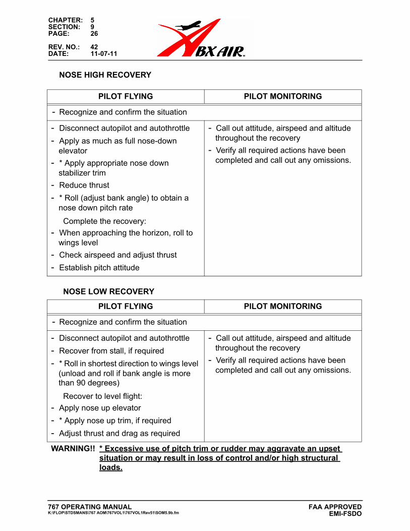
CHAPTER: 5SECTION: 9PAGE: 26
REV. NO.: 42DATE: 11-07-11
NOSE HIGH RECOVERY
PILOT FLYING PILOT MONITORING
- Recognize and confirm the situation
- Disconnect autopilot and autothrottle
- Apply as much as full nose-down elevator
- * Apply appropriate nose down stabilizer trim
- Reduce thrust
- * Roll (adjust bank angle) to obtain a nose down pitch rate
Complete the recovery:
- When approaching the horizon, roll to wings level
- Check airspeed and adjust thrust
- Establish pitch attitude
- Call out attitude, airspeed and altitude throughout the recovery
- Verify all required actions have been completed and call out any omissions.
NOSE LOW RECOVERY
PILOT FLYING PILOT MONITORING
- Recognize and confirm the situation
- Disconnect autopilot and autothrottle
- Recover from stall, if required
- * Roll in shortest direction to wings level (unload and roll if bank angle is more than 90 degrees)
Recover to level flight:
- Apply nose up elevator
- * Apply nose up trim, if required
- Adjust thrust and drag as required
- Call out attitude, airspeed and altitude throughout the recovery
- Verify all required actions have been completed and call out any omissions.
WARNING!! * Excessive use of pitch trim or rudder may aggravate an upset situation or may result in loss of control and/or high structural loads.
767 OPERATING MANUALK:\FLOP\STDSMANS\767 AOM\767VOL1\767VOL1Rev51\SOM5.9b.fm
FAA APPROVED EMI-FSDO
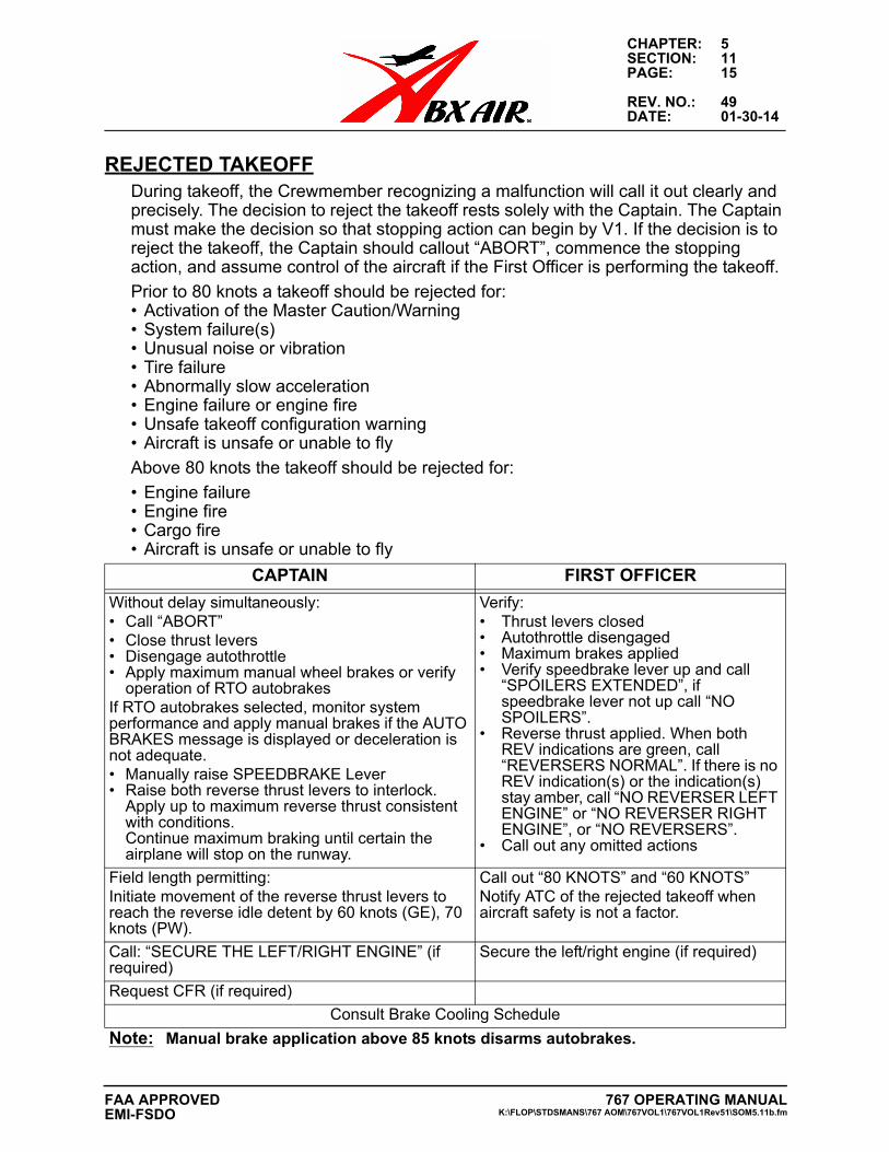
CHAPTER: 5SECTION: 11PAGE: 15
REV. NO.: 49DATE: 01-30-14
REJECTED TAKEOFFDuring takeoff, the Crewmember recognizing a malfunction will call it out clearly and precisely. The decision to reject the takeoff rests solely with the Captain. The Captain must make the decision so that stopping action can begin by V1. If the decision is to reject the takeoff, the Captain should callout “ABORT”, commence the stopping action, and assume control of the aircraft if the First Officer is performing the takeoff.
Prior to 80 knots a takeoff should be rejected for:• Activation of the Master Caution/Warning• System failure(s)• Unusual noise or vibration• Tire failure• Abnormally slow acceleration• Engine failure or engine fire• Unsafe takeoff configuration warning• Aircraft is unsafe or unable to fly
Above 80 knots the takeoff should be rejected for:
• Engine failure• Engine fire• Cargo fire• Aircraft is unsafe or unable to fly
CAPTAIN FIRST OFFICER
Without delay simultaneously:• Call “ABORT”• Close thrust levers• Disengage autothrottle• Apply maximum manual wheel brakes or verify
operation of RTO autobrakesIf RTO autobrakes selected, monitor system performance and apply manual brakes if the AUTO BRAKES message is displayed or deceleration is not adequate.• Manually raise SPEEDBRAKE Lever• Raise both reverse thrust levers to interlock.
Apply up to maximum reverse thrust consistentwith conditions.Continue maximum braking until certain theairplane will stop on the runway.
Verify:• Thrust levers closed• Autothrottle disengaged• Maximum brakes applied• Verify speedbrake lever up and call
“SPOILERS EXTENDED”, ifspeedbrake lever not up call “NOSPOILERS”.
• Reverse thrust applied. When bothREV indications are green, call“REVERSERS NORMAL”. If there is noREV indication(s) or the indication(s)stay amber, call “NO REVERSER LEFTENGINE” or “NO REVERSER RIGHTENGINE”, or “NO REVERSERS”.
• Call out any omitted actions
Field length permitting:Initiate movement of the reverse thrust levers to reach the reverse idle detent by 60 knots (GE), 70 knots (PW).
Call out “80 KNOTS” and “60 KNOTS” Notify ATC of the rejected takeoff when aircraft safety is not a factor.
Call: “SECURE THE LEFT/RIGHT ENGINE” (if required)
Secure the left/right engine (if required)
Request CFR (if required)
Consult Brake Cooling Schedule
Note: Manual brake application above 85 knots disarms autobrakes.
767 OPERATING MANUALK:\FLOP\STDSMANS\767 AOM\767VOL1\767VOL1Rev51\SOM5.11b.fm
FAA APPROVEDEMI-FSDO
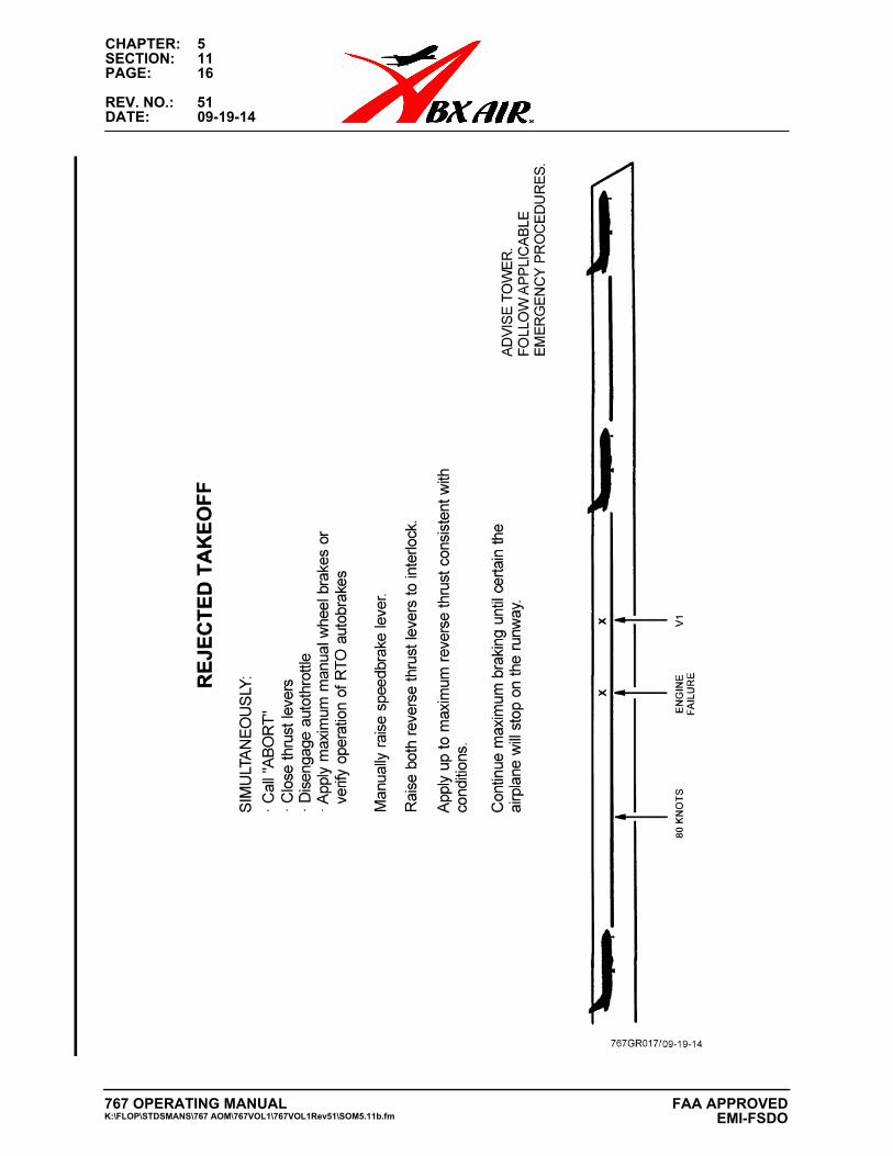
CHAPTER: 5SECTION: 11PAGE: 16
REV. NO.: 51DATE: 09-19-14
767 OPERATING MANUALK:\FLOP\STDSMANS\767 AOM\767VOL1\767VOL1Rev51\SOM5.11b.fm
FAA APPROVED EMI-FSDO
CHAPTER: 5SECTION: 12PAGE: 1
REV. NO.: 51DATE: 09-19-14
CHAPTER 5: STANDARD OPERATING METHODS
SECTION 12: FUEL CONSERVATION PROGRAM
INTRODUCTION
Jet fuel prices are at all time highs, because of this it is prudent to operate ABX equipment in the most efficient, cost-effective method. It is more important than ever that each and every one of us do our part to reduce our total fuel costs. The purpose of this section is to provide information to flight crews on fuel conservation and the most efficient methods to operate our aircraft and ground equipment.
ABX Air departments, Aircraft Maintenance & Engineering, Ground, Contingency, Aircraft Scheduling, Information Services and Flight Control work together to reach the common goal of – Reducing our overall fuel costs.
FLIGHT PLANNING
Become a Fuel Manager, not just a fuel user. A careful look at the flight plan may reveal areas that can considerably affect fuel savings. Some of these include the following:
Weather
Large deviations from ISA can affect the optimum climb/cruise speed schedule. Be aware that flying with engine and wing anti-ice on will increase your fuel consumption. Avoid areas of moderate and higher turbulence and icing conditions when practical.
Optimum Altitude
Review the planned takeoff weight. Optimum altitude is defined as the pressure altitude for a given weight and speed schedule that gives maximum mileage per unit of fuel. If the actual takeoff weight is considerably less, your optimum altitude will be higher than what is filed on the release. Be aware of the forecast winds at different flight levels along your route of flight. See the “Off Optimum Penalty Chart” below for the % Fuel Mileage Penalty.
767 OPERATING MANUALK:\FLOP\STDSMANS\767 AOM\767VOL1\767VOL1Rev51\SOM5.12.fm
FAA APPROVEDEMI-FSDO
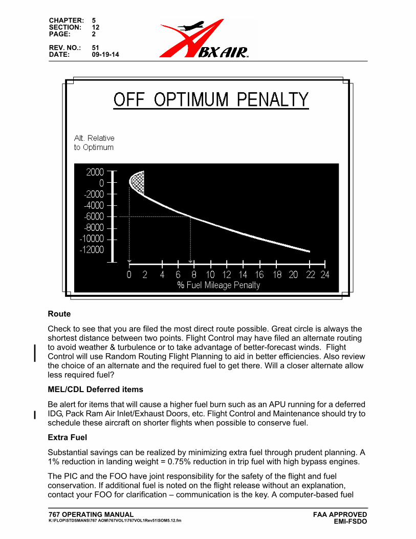
CHAPTER: 5SECTION: 12PAGE: 2
REV. NO.: 51DATE: 09-19-14
Route
Check to see that you are filed the most direct route possible. Great circle is always the shortest distance between two points. Flight Control may have filed an alternate routing to avoid weather & turbulence or to take advantage of better-forecast winds. Flight Control will use Random Routing Flight Planning to aid in better efficiencies. Also review the choice of an alternate and the required fuel to get there. Will a closer alternate allow less required fuel?
MEL/CDL Deferred items
Be alert for items that will cause a higher fuel burn such as an APU running for a deferred IDG, Pack Ram Air Inlet/Exhaust Doors, etc. Flight Control and Maintenance should try to schedule these aircraft on shorter flights when possible to conserve fuel.
Extra Fuel
Substantial savings can be realized by minimizing extra fuel through prudent planning. A 1% reduction in landing weight = 0.75% reduction in trip fuel with high bypass engines.
The PIC and the FOO have joint responsibility for the safety of the flight and fuel conservation. If additional fuel is noted on the flight release without an explanation, contact your FOO for clarification – communication is the key. A computer-based fuel
767 OPERATING MANUALK:\FLOP\STDSMANS\767 AOM\767VOL1\767VOL1Rev51\SOM5.12.fm
FAA APPROVED EMI-FSDO
CHAPTER: 5SECTION: 12PAGE: 3
REV. NO.: 51DATE: 09-19-14
burned tracking program is being developed. This program will track fuel burns by tail number allowing for improved flight planning and conservation improvements.
TANKERING
Based on fuel costs at various areas/countries it may be advantageous to tanker fuel. Contingency and the FOO decide when this is appropriate. Although it costs fuel to carry fuel, flight crews may be requested to carry extra fuel to lower the overall operating costs or to maintain scheduled departure or arrival times.
Note: Be aware of lower certificated landing weights on some aircraft with large amounts of fuel at landing. Reference Chapter 1 in AOM for landing weight limits.
FMC COST INDEX
Cost index is defined to be that speed which minimizes total cost (time + fuel). It is a ratio between time-related in-flight costs and fuel costs. A low Cost Index could mean high fuel costs or the need to save fuel. A high Cost Index means high time-related costs or a need to get there fast.
A cost index of 80 approximates LRC for the 767-200 @ 290K @ FL370, 260K @ FL390, 240K @ FL410, and 220K @ FL430
A Cost Index of zero (0) = Max Specific Range.
A Cost Index of 999 (Non PIP) = Minimum Time.
Note that with a Cost Index of 400 or more thrust limits or max speed limits will generally be encountered. Use caution during climb/descent when using a high Cost Index number to avoid a potential Vmo/Mmo exceedance in case you encounter turbulence. Attempted entries to change the cost index within 10 miles of the T/D point or during DES result in the INVALID ENTRY message.
In the future as the costs change in the day-to-day operation, a specific Cost Index Value will be added to the flight release. This will allow for improved fuel and fuel conservation program enhancements.
PREFLIGHT
As part of the aircraft maintenance programs, Maintenance checks the aircraft for chipped paint, dents, poorly fitted doors, protruding sealant, poorly faired surfaces, fluid leaks or any other items that increases aerodynamic drag. These seemingly small items can add up to significant drag and fuel penalties.
AIRCRAFT CG LOCATION
Crews should be aware of the effects of induced drag due to aircraft center of gravity. At an aft CG, the amount of aerodynamic force required on the horizontal stabilizer to maintain proper longitudinal trim is reduced. Consequently, the required lift provided by the wing is reduced and the airplane flies at a lower angle of attack. Accordingly, the stabilizer setting will be near zero and drag at a minimum.
767 OPERATING MANUALK:\FLOP\STDSMANS\767 AOM\767VOL1\767VOL1Rev51\SOM5.12.fm
FAA APPROVEDEMI-FSDO
CHAPTER: 5SECTION: 12PAGE: 4
REV. NO.: 51DATE: 09-19-14
APU USAGE
With respect to the APU for saving fuel, if you don’t need it, don’t use it. The typical APU consumes 35.5 gallons per hour on the ground. Conversely, a gasoline powered ground power unit burns about 5.5 gallons per hour and a diesel unit burns slightly more than 2 gallons per hour. A ground power unit can run for 20 minutes on what an APU uses per one minute. Obviously, waiting as long as possible before starting the APU on preflight could save a considerable amount of fuel. Maintenance will typically be starting the APU just prior to our arrival at the aircraft out base to assure proper operations and the possible need for an external air cart.
Winter
In the winter months, turning on the avionics, cockpit lights and windshield heat will warm a cockpit considerably. At temperatures above 25 degrees F, consider not using the APU for heat, especially if a Ground Power Unit is available.
Summer
During the summer months, Equipment cooling is a higher priority over APU fuel conservation. Crews can expect to see Maintenance utilizing the APU as necessary to cool aircraft equipment.
ENGINE STARTS
Plan the engine starts so there is a minimal amount of time between engine start and taxi. At idle power the B767 burns 2400 pounds per hour or 40 pounds per minute. It may be cost effective to delay the engine start.
TAXI OUT & SINGLE ENGINE TAXI
High Bypass engine manufacturers require a typical warm-up time of 10 minutes if the engine hasn’t been run in the previous 2 hours to minimize adverse engine wear.
Reference Single Engine Taxi procedures in Chapter 3 of AOM and Chapter 3 in -300 Differences.
TAKEOFF
Although a max power takeoff uses less fuel than a reduced power takeoff, the differences are slight. The saving with derate and reduced power takeoffs are used due to the long-term benefits realized by the increase in engine life and the resulting lower rate which specific fuel consumption deteriorates. Rolling takeoffs are standard operating procedure on the B767. They are more fuel-efficient than static takeoffs and minimize FOD potential. The aircraft should be “cleaned up” as soon as possible, consistent with the Standard Operating Methods. The drag reduction by the timely retraction of gear, flaps and slats will increase fuel economy.
CLIMBWhen departing on a heading away from the destination airport, the selection of climb speed becomes a judgment call. If departure control needs DISTANCE before they can
767 OPERATING MANUALK:\FLOP\STDSMANS\767 AOM\767VOL1\767VOL1Rev51\SOM5.12.fm
FAA APPROVED EMI-FSDO
CHAPTER: 5SECTION: 12PAGE: 5
REV. NO.: 51DATE: 09-19-14
turn you on course, complete the noise abatement profile and accelerate to 250 knots. If departure control needs ALTITUDE prior to the turn, maintain Vref+80 to that altitude. When within 45 degrees of the on course heading, begin accelerating to the normal 250-knot climb speed.
Contrary to popular beliefs, it is seldom fuel efficient to vary the climb speed due to differing weights or winds. The aircraft should be flown using the ECON speeds to arrive at optimum altitude as soon as possible.
CRUISEOptimum altitude is defined as the pressure altitude for a given weight and speed schedule that gives maximum mileage per unit of fuel over the route distance. OPT altitude increases approximately 100 feet per each 8 minutes at cruise.
ECON is based on lowest operating cost per nautical mile. LRC and SEL SPD minimize fuel used per nautical mile.
Request a direct routing from ATC when possible unless the flight plan shows a specific route to adjust for a jet stream or to avoid turbulence. Saving two minutes of cruise time on each flight segment will save fuel, and when multiplied by the number of flights each day, the dollars saved become significant.
ALTITUDE SELECTION / ACTUAL OR EST WINDThe computer flight plan selects the initial optimum altitude for a given stage length based on forecast winds, temperature, and weight. There are several conditions for which the computer flight plan inputs may prove different from those actually encountered.
Temperature:Significant deviations in temperature will affect the engine thrust limits and the ability of the aircraft to operate efficiently at the selected altitude.
Wind:Significant deviations in wind speed and direction will affect ground speed and fuel efficiency. Using the FMC, flight crews may be able to insert actual reported changes in the wind for other altitudes to find a more fuel-efficient altitude.
Weight:Actual weight may be much less than planned, thereby allowing an earlier climb than indicated on the flight plan. Conversely, a higher weight might dictate a later climb than on the flight plan to ensure adequate buffet protection.
Note: Remember to complete a proper FMC preflight including the insertion of flight plan winds into the Route Data page.
Remember that the flight plan altitude selection is usually based on data entered several hours before takeoff. Not flying the OPT altitude or ECON speed can result in excess fuel expenditures that are greater than those due to degraded aerodynamic cleanliness.
767 OPERATING MANUALK:\FLOP\STDSMANS\767 AOM\767VOL1\767VOL1Rev51\SOM5.12.fm
FAA APPROVEDEMI-FSDO
CHAPTER: 5SECTION: 12PAGE: 6
REV. NO.: 51DATE: 09-19-14
The STEP TO altitude field of the FMC can be used to review fuel economy trade-offs by possible step climb or descents. Select the entry above or below the present cruise altitude. Obtain the winds from traffic 30 minutes ahead at the STEP
TO altitude. If no reports are available, the next best thing is to use the winds tables you get with your flight plan. Enter these winds manually into the ACTUAL/EST wind field. The winds in this field are used by the FMC only for STEP TO computations. The predicted SAVINGS or PENALTY will be displayed for the climb or descent as compared to flying the current flight level to TOD. The most reliable indication of step climb/descent efficiency is determined from the progress page under DEST ETA and FUEL.
Note: Refer to specific sections for FMC non-Pip and Pegasus procedures in the B767 AOM.
Fly the ECON speeds and you’ll realize the best economy in a no wind situation. Your actual distance over the ground per pound of fuel decreases with each incremental increase of headwind. Current winds apply a strong bias to down-track fuel predictions in the FMC.
TRIM
Having minimum parasitic drag on the aircraft will allow it to maintain the desired speed with the minimum amount of power and therefore the minimum fuel flow. The more out of trim the aircraft is, the more fuel the engines burn to maintain a specific speed. Thousands of pounds of fuel are wasted fuel for a mere ½ degree of aileron mistrim and triple than amount for 1 degree of rudder mistrim.
To trim the aircraft, set and maintain a balanced thrust condition. Check fuel quantities for lateral balance.
With an autopilot engaged, allow the aircraft to stabilize on a constant heading. Trim the rudder in the direction of the down wing. Apply trim incrementally, allowing bank to stabilize after each trim input. When the bank is zero, rudder trim is correctly set. Proper aileron trim position will be held by the autopilot.
With the autopilot disengaged, hold the wings level with the control wheel using the EADI for reference. Use rudder to correct any heading drift. When the heading is stable with the wings level, trim out any rudder pedal force using rudder trim. Trim out any control wheel forces using aileron trim.
These techniques will result in minimum trim drag. The aircraft should be in trim for autoland approaches to assure autopilot authority limit is not degraded. Report to Maintenance any aircraft that requires more than 1.5 units of aileron trim or 3 units of rudder trim.
Note: Dissimilar thermal expansion and contraction of components of the rudder trim system on airplanes that have not been modified with a rudder trim compensator, may result in changes in trim requirements. The varying trim input required during climb, cruise and descent may be as much as five units left or right of center.
767 OPERATING MANUALK:\FLOP\STDSMANS\767 AOM\767VOL1\767VOL1Rev51\SOM5.12.fm
FAA APPROVED EMI-FSDO
CHAPTER: 5SECTION: 12PAGE: 7
REV. NO.: 51DATE: 09-19-14
DESCENT
The most important factor in the reduction of descent fuel is the use of idle thrust at a fixed speed. An idle power descent at the ECON speed properly planned as not to require a low altitude level off for an extended period, to a straight in approach to the landing runway yields the best fuel economy. This, however, may not be practical or permitted by ATC. The optimum top of descent point is affected by wind, ATC, speed restrictions, etc. If given an early descent, change the FMC cruise altitude so that a new top of descent point will be computed.
HOLDING
If informed of an long holding delay, it’s more fuel-efficient to begin slowing as soon as possible to the holding speed for the current weight than to remain at cruise speeds until 3 minutes prior to holding. Coordinate the early speed reduction with ATC. Because turns require more thrust and fuel than level flight, request longer DME legs to increase the size of the holding pattern and endurance.
For best fuel economy holding should be conducted in the clean configuration at the highest possible altitude with the FMC holding speed for the current weight (request approval from ATC to hold at the higher speed if necessary). Above FL 250 holding speed is Vref 30+100 knots to provide adequate buffet protection. This configuration provides a significant decrease in fuel consumption compared with a slats extended configuration. Avoid holding in icing conditions if possible as having the wing and engine anti-ice systems will increase fuel consumption due to required thrust settings.
APPROACH AND LANDING
Maintain a clean configuration as long as possible. Fuel flow in the landing configuration is 150% of the fuel flow in the clean configuration. Delay flap and gear extensions as long as practical and still achieve a stabilized approach. If you find that you no longer need the increased drag, retract the flaps to a lesser setting (or clean, if possible) until they are needed again. Remember, flaps move in both directions.
Although fuel savings can be realized during the approach phase by delaying flap and gear extension, it is essential that there be no compromise of the ABX Air stabilized approach philosophy. The need for a stabilized final approach overrides any fuel conservation considerations.
TAXI IN
Try to keep it rolling to avoid stopping during taxi. It takes more energy to start an aircraft from a full stop than to keep it rolling from even a very slow taxi speed. Reference Single Engine Taxi procedures in Chapter 3 of AOM and Chapter 3 in -300 Differences.
Ground should have the power cart running and ready to plug in as soon as the aircraft comes to a stop in the blocks. The difference in cost between running an aircraft engine and running a ground power cart is substantial. A B767 engine uses 80 times the amount of fuel per minute as a Ground Power Unit. Since each aircraft engine burns 20 pound
767 OPERATING MANUALK:\FLOP\STDSMANS\767 AOM\767VOL1\767VOL1Rev51\SOM5.12.fm
FAA APPROVEDEMI-FSDO
CHAPTER: 5SECTION: 12PAGE: 8
REV. NO.: 51DATE: 09-19-14
per minute and a ground power unit burns about ¼ pound per minute, every minute we run an engine waiting for a power cart costs an additional amount.
What YOU Can Do to Save Fuel:
Review your flight plan for routing and altitude selection and extra fuel loads.
Minimize aerodynamic drag. Keep the aircraft properly trimmed. Clean up the aircraft in a timely manner after takeoff and delay flap/slat and gear extension until necessary, consistent with a stabilized approach.
Wait as long as possible before starting the APU. Only use the APU for heating and cooling when truly necessary. Follow guidance in Supplemental Normals on APU usage.
Follow the climb, cruise and descent profiles that optimize fuel efficiency. As aircraft weight decreases, adjust your altitude accordingly.
Fly directly to the optimum altitude for the actual aircraft weight if able. If unable, step climb as weight decreases to the optimum altitude.
Make adjustments to your altitude to compensate for headwinds.
Request a direct routing whenever practical.
Stay at cruise altitude as long as possible, and then fly the profile descent. If given a descent clearance very early, request a “pilot’s discretion” descent.
Considering wind, traffic, runway length etc., request a landing runway for minimum taxi time.
Follow procedures for reporting excessive delays in shutting down engines while waiting for a ground power cart. Good and timely communication is necessary.
THINK ABOUT A SECURE FUTURE WITH A PROFITABLE AIRLINE.
THINK FUEL CONSERVATION.
767 OPERATING MANUALK:\FLOP\STDSMANS\767 AOM\767VOL1\767VOL1Rev51\SOM5.12.fm
FAA APPROVED EMI-FSDO
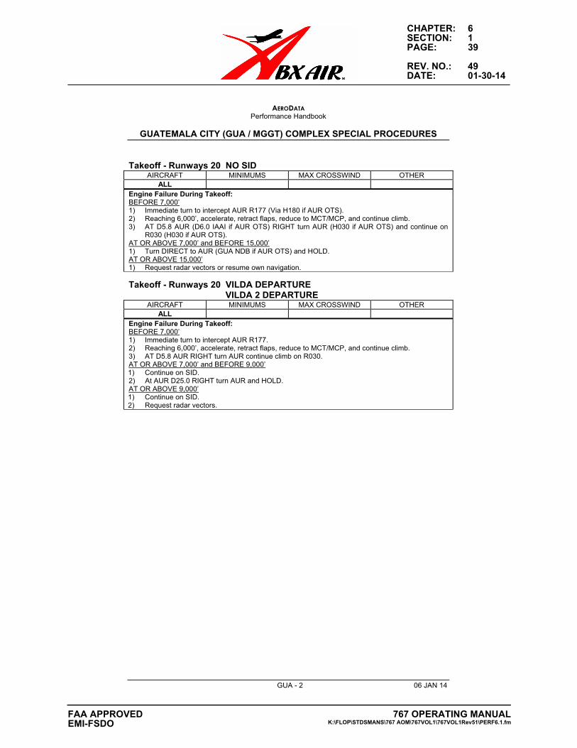
CHAPTER: 6SECTION: 1PAGE: 39
REV. NO.: 49DATE: 01-30-14
AERODATAPerformance Handbook
GUATEMALA CITY (GUA / MGGT) COMPLEX SPECIAL PROCEDURES
GUA - 2 06 JAN 14
Takeoff - Runways 20 NO SID AIRCRAFT MINIMUMS MAX CROSSWIND OTHER
ALLEngine Failure During Takeoff:BEFORE 7,000’1) Immediate turn to intercept AUR R177 (Via H180 if AUR OTS).2) Reaching 6,000’, accelerate, retract flaps, reduce to MCT/MCP, and continue climb.3) AT D5.8 AUR (D6.0 IAAI if AUR OTS) RIGHT turn AUR (H030 if AUR OTS) and continue on
R030 (H030 if AUR OTS).AT OR ABOVE 7,000’ and BEFORE 15,000’1) Turn DIRECT to AUR (GUA NDB if AUR OTS) and HOLD.AT OR ABOVE 15,000’1) Request radar vectors or resume own navigation.
Takeoff - Runways 20 VILDA DEPARTURE VILDA 2 DEPARTURE
AIRCRAFT MINIMUMS MAX CROSSWIND OTHERALL
Engine Failure During Takeoff:BEFORE 7,000’1) Immediate turn to intercept AUR R177.2) Reaching 6,000’, accelerate, retract flaps, reduce to MCT/MCP, and continue climb.3) AT D5.8 AUR RIGHT turn AUR continue climb on R030.AT OR ABOVE 7,000’ and BEFORE 9,000’1) Continue on SID.2) At AUR D25.0 RIGHT turn AUR and HOLD.AT OR ABOVE 9,000’1) Continue on SID.2) Request radar vectors.
767 OPERATING MANUALK:\FLOP\STDSMANS\767 AOM\767VOL1\767VOL1Rev51\PERF6.1.fm
FAA APPROVEDEMI-FSDO
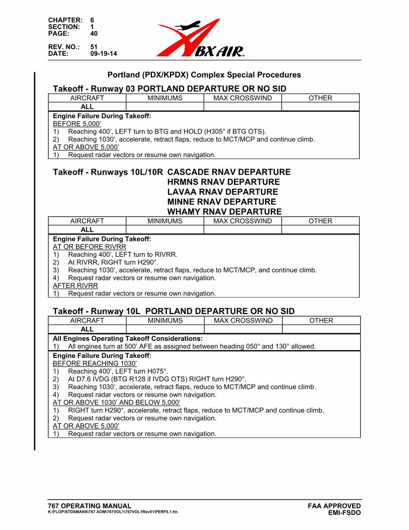
CHAPTER: 6SECTION: 1PAGE: 40
REV. NO.: 51DATE: 09-19-14
Portland (PDX/KPDX) Complex Special Procedures
Takeoff - Runway 03 PORTLAND DEPARTURE OR NO SIDAIRCRAFT MINIMUMS MAX CROSSWIND OTHER
ALLEngine Failure During Takeoff: BEFORE 5,000’ 1) Reaching 400’, LEFT turn to BTG and HOLD (H305° if BTG OTS).2) Reaching 1030’, accelerate, retract flaps, reduce to MCT/MCP and continue climb.AT OR ABOVE 5,000’ 1) Request radar vectors or resume own navigation.
Takeoff - Runways 10L/10R CASCADE RNAV DEPARTURE HRMNS RNAV DEPARTURE LAVAA RNAV DEPARTURE MINNE RNAV DEPARTURE WHAMY RNAV DEPARTURE
AIRCRAFT MINIMUMS MAX CROSSWIND OTHERALL
Engine Failure During Takeoff: AT OR BEFORE RIVRR 1) Reaching 400’, LEFT turn to RIVRR.2) At RIVRR, RIGHT turn H290°.3) Reaching 1030’, accelerate, retract flaps, reduce to MCT/MCP, and continue climb.4) Request radar vectors or resume own navigation.AFTER RIVRR 1) Request radar vectors or resume own navigation.
Takeoff - Runway 10L PORTLAND DEPARTURE OR NO SID AIRCRAFT MINIMUMS MAX CROSSWIND OTHER
ALLAll Engines Operating Takeoff Considerations: 1) All engines turn at 500’ AFE as assigned between heading 050° and 130° allowed.Engine Failure During Takeoff: BEFORE REACHING 1030’ 1) Reaching 400’, LEFT turn H075°.2) At D7.6 IVDG (BTG R128 if IVDG OTS) RIGHT turn H290°.3) Reaching 1030’, accelerate, retract flaps, reduce to MCT/MCP and continue climb.4) Request radar vectors or resume own navigation.AT OR ABOVE 1030’ AND BELOW 5,000’ 1) RIGHT turn H290°, accelerate, retract flaps, reduce to MCT/MCP and continue climb.2) Request radar vectors or resume own navigation.AT OR ABOVE 5,000’ 1) Request radar vectors or resume own navigation.
767 OPERATING MANUALK:\FLOP\STDSMANS\767 AOM\767VOL1\767VOL1Rev51\PERF6.1.fm
FAA APPROVED EMI-FSDO

CHAPTER: 6SECTION: 1PAGE: 41
REV. NO.: 51DATE: 09-19-14
Takeoff - Runway 10R PORTLAND DEPARTURE OR NO SID AIRCRAFT MINIMUMS MAX CROSSWIND OTHER
ALLAll Engines Operating Takeoff Considerations: 1) All engines turn at 500’ AFE as assigned between heading 050° and 130° allowed.Engine Failure During Takeoff: BEFORE REACHING 1030’ 1) Reaching 400’, RIGHT turn H110°.2) At D6.4 IPDX (BTG R135 if IPDX OTS) LEFT turn to H290°.3) Reaching 1030’, accelerate, retract flaps, reduce to MCT/MCP and continue climb.4) Request radar vectors or resume own navigation.AT OR ABOVE 1030’ AND BELOW 5,000’ 1) LEFT turn H290°, accelerate, retract flaps, reduce to MCT/MCP and continue climb.2) Request radar vectors or resume own navigation.AT OR ABOVE 5,000’ 1) Request radar vectors or resume own navigation.
767 OPERATING MANUALK:\FLOP\STDSMANS\767 AOM\767VOL1\767VOL1Rev51\PERF6.1.fm
FAA APPROVEDEMI-FSDO
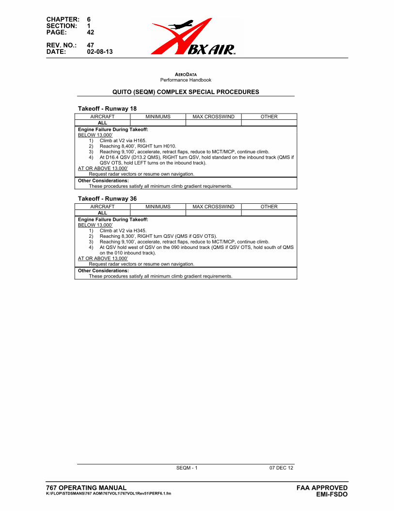
CHAPTER: 6SECTION: 1PAGE: 42
REV. NO.: 47DATE: 02-08-13
AERODATAPerformance Handbook
QUITO (SEQM) COMPLEX SPECIAL PROCEDURES
SEQM - 1 07 DEC 12
Takeoff - Runway 18 AIRCRAFT MINIMUMS MAX CROSSWIND OTHER
ALLEngine Failure During Takeoff:BELOW 13,000’
1) Climb at V2 via H165.2) Reaching 8,400’, RIGHT turn H010.3) Reaching 9,100’, accelerate, retract flaps, reduce to MCT/MCP, continue climb.4) At D16.4 QSV (D13.2 QMS), RIGHT turn QSV, hold standard on the inbound track (QMS if
QSV OTS, hold LEFT turns on the inbound track).AT OR ABOVE 13,000’
Request radar vectors or resume own navigation. Other Considerations:
These procedures satisfy all minimum climb gradient requirements.
Takeoff - Runway 36 AIRCRAFT MINIMUMS MAX CROSSWIND OTHER
ALLEngine Failure During Takeoff:BELOW 13,000’
1) Climb at V2 via H345.2) Reaching 8,300’, RIGHT turn QSV (QMS if QSV OTS).3) Reaching 9,100’, accelerate, retract flaps, reduce to MCT/MCP, continue climb.4) At QSV hold west of QSV on the 090 inbound track (QMS if QSV OTS, hold south of QMS
on the 010 inbound track).AT OR ABOVE 13,000’
Request radar vectors or resume own navigation. Other Considerations:
These procedures satisfy all minimum climb gradient requirements.
767 OPERATING MANUALK:\FLOP\STDSMANS\767 AOM\767VOL1\767VOL1Rev51\PERF6.1.fm
FAA APPROVED EMI-FSDO

CHAPTER: 6SECTION: 4-TOCPAGE: i
REV. NO.: 51DATE: 09-19-14
TABLE OF CONTENTS
CHAPTER 6: PERFORMANCE
SECTION 6.4: NON-NORMALS B767-200 CF6-80-A
EEC OFF
TAKEOFF SPEEDS ................................................................1MAX TAKEOFF %N1 ..............................................................1MAX GO-AROUND %N1 ........................................................1TO1 TAKEOFF SPEEDS ........................................................2TO1 TAKEOFF %N1 ...............................................................2TO2 TAKEOFF SPEEDS ........................................................2TO2 TAKEOFF %N1 ...............................................................2
RECOMMENDED BRAKE COOLING SCHEDULE(AIRPORT ELEVATION SL TO 4000 FEET) ...............................3RECOMMENDED BRAKE COOLING SCHEDULE(AIRPORT ELEVATION 6000 TO 8000 FEET) ............................4RECOMMENDED BRAKE COOLING SCHEDULECOOLING TIME CATEGORY "B" BRAKES..................................5
ENGINE INOP
INITIAL MAX CONTINUOUS %N1 .........................................6DRIFTDOWN SPEED/LEVEL OFF ALTITUDE MAX CONTINUOUS THRUST ................................................6LONG RANGE CRUISE ALTITUDE CAPABILITY MAX CONTINUOUS THRUST ................................................7LRC MACH SCHEDULE .........................................................7MAX CONTINUOUS %N1 37000 FT TO 27000 FT PRESSURE ALTITUDES .................8
%N1 ADJUSTMENTS FOR ENGINE BLEED ...................8
MAX CONTINUOUS %N1 25000 FT TO 16000 FT PRESSURE ALTITUDES .................9
%N1 ADJUSTMENTS FOR ENGINE BLEED ...................9
MAX CONTINUOUS %N1 14000 FT TO 5000 FT PRESSURE ALTITUDES .................10
%N1 ADJUSTMENTS FOR ENGINE BLEED .................10
LONG RANGE CRUISE TABLE MAX CRUISE THRUST30000 FT TO 25000 FT ........................................................11
MAX CONTINUOUS %N1 ...............................................11
767 OPERATING MANUALK:\FLOP\STDSMANS\767
AOM\767VOL1\767VOL1Rev51\PERF6_4TOC.fm
FAA APPROVEDEMI-FSDO
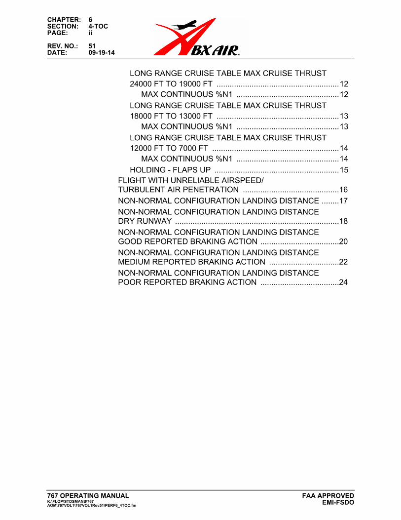
CHAPTER: 6SECTION: 4-TOCPAGE: ii
REV. NO.: 51DATE: 09-19-14
LONG RANGE CRUISE TABLE MAX CRUISE THRUST 24000 FT TO 19000 FT ........................................................12
MAX CONTINUOUS %N1 ...............................................12
LONG RANGE CRUISE TABLE MAX CRUISE THRUST 18000 FT TO 13000 FT ........................................................13
MAX CONTINUOUS %N1 ...............................................13
LONG RANGE CRUISE TABLE MAX CRUISE THRUST 12000 FT TO 7000 FT ..........................................................14
MAX CONTINUOUS %N1 ...............................................14
HOLDING - FLAPS UP .........................................................15FLIGHT WITH UNRELIABLE AIRSPEED/TURBULENT AIR PENETRATION ............................................16
NON-NORMAL CONFIGURATION LANDING DISTANCE ........17
NON-NORMAL CONFIGURATION LANDING DISTANCE DRY RUNWAY ...........................................................................18
NON-NORMAL CONFIGURATION LANDING DISTANCEGOOD REPORTED BRAKING ACTION ....................................20
NON-NORMAL CONFIGURATION LANDING DISTANCE MEDIUM REPORTED BRAKING ACTION ................................22
NON-NORMAL CONFIGURATION LANDING DISTANCE POOR REPORTED BRAKING ACTION ....................................24
767 OPERATING MANUALK:\FLOP\STDSMANS\767 AOM\767VOL1\767VOL1Rev51\PERF6_4TOC.fm
FAA APPROVEDEMI-FSDO
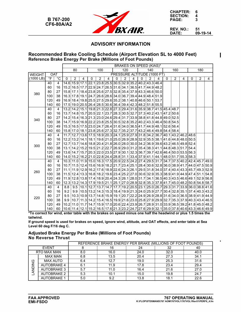
CHAPTER: 6SECTION: 4
B 767-200 PAGE: 3CF6-80A/A2
REV. NO.: 51DATE: 09-19-14
ADVISORY INFORMATION
Advisory InformationRecommended Brake Cooling Schedule (Airport Elevation SL to 4000 Feet)Reference Brake Energy Per Brake (Millions of Foot Pounds)
Adjusted Brake Energy Per Brake (Millions of Foot Pounds)No Reverse Thrust
BRAKES ON SPEED (KIAS)*80 100 120 140 160 180
WEIGHT (1000 LB)
OAT PRESSURE ALTITUDE (1000 FT) °F °C 0 2 4 0 2 4 0 2 4 0 2 4 0 2 4 0 2 4
380
40 4 14.6 15.9 17.1 22.1 23.8 25.5 30.5 32.9 35.2 40.2 43.3 46.460 16 15.2 16.5 17.7 22.9 24.7 26.5 31.6 34.1 36.5 41.7 44.9 48.280 27 15.8 17.1 18.4 23.8 25.6 27.5 32.8 35.4 37.9 43.3 46.6 50.0
100 38 16.3 17.8 19.1 24.7 26.6 28.6 34.0 36.7 39.4 44.9 48.4 51.9120 49 16.9 18.4 19.8 25.5 27.5 29.6 35.2 38.1 40.8 46.6 50.1 53.7140 60 17.5 19.0 20.5 26.4 28.5 30.6 36.4 39.4 42.3 48.2 51.8 55.5
340
40 4 13.2 14.2 15.1 19.8 21.3 22.8 27.3 29.4 31.6 35.9 38.7 41.5 45.4 48.760 16 13.7 14.8 15.7 20.5 22.1 23.7 28.3 30.5 32.7 37.3 40.2 43.1 47.2 50.680 27 14.2 15.4 16.3 21.3 23.0 24.6 29.4 31.7 33.9 38.8 41.8 44.8 49.0 52.5
100 38 14.7 15.9 16.9 22.2 23.8 25.5 30.5 32.8 35.2 40.2 43.3 46.4 50.8 54.5120 49 15.3 16.5 17.5 23.0 24.7 26.4 31.6 34.0 36.5 41.7 44.9 48.1 52.6 56.4140 60 15.8 17.0 18.1 23.8 25.6 27.3 32.7 35.2 37.7 43.2 46.4 49.8 54.4 58.4
300
40 4 11.7 12.7 13.6 17.5 18.9 20.3 24.1 25.9 27.9 31.8 34.2 36.7 40.1 43.2 46.2 48.660 16 12.2 13.2 14.1 18.1 19.6 21.0 25.0 26.9 28.9 32.9 35.5 38.1 41.6 44.8 48.0 50.580 27 12.7 13.7 14.6 18.8 20.4 21.8 26.0 28.0 30.0 34.2 36.9 39.6 43.2 46.5 49.8 52.4
100 38 13.1 14.2 15.2 19.5 21.2 22.7 26.9 29.0 31.2 35.4 38.3 41.1 44.8 48.3 51.7 54.4120 49 13.6 14.7 15.7 20.3 22.0 23.5 27.9 30.1 32.3 36.7 39.7 42.6 46.4 50.0 53.5 56.3140 60 14.0 15.2 16.2 21.0 22.8 24.4 28.8 31.1 33.4 37.9 41.1 44.1 48.0 51.7 55.3 58.3
260
40 4 10.3 11.0 11.9 15.0 16.3 17.5 20.9 22.5 24.2 27.4 29.5 31.7 34.7 37.5 40.2 42.4 45.7 49.060 16 10.7 11.5 12.4 15.6 16.9 18.2 21.7 23.4 25.1 28.4 30.6 32.8 36.0 38.9 41.7 44.0 47.5 50.980 27 11.1 11.9 12.9 16.2 17.6 18.9 22.6 24.3 26.1 29.5 31.8 34.0 37.4 40.4 43.3 45.7 49.3 52.9
100 38 11.5 12.4 13.3 16.8 18.2 19.6 23.4 25.2 27.0 30.6 32.9 35.3 38.9 41.9 44.9 47.4 51.1 54.8120 49 11.9 12.8 13.8 17.4 18.9 20.4 24.3 26.1 28.0 31.7 34.1 36.5 40.3 43.5 46.6 49.1 52.9 56.8140 60 12.3 13.2 14.3 17.9 19.5 21.1 25.1 27.0 28.9 32.8 35.3 37.8 41.7 45.0 48.2 50.8 54.8 58.7
220
40 4 8.8 9.5 10.1 12.7 13.7 14.7 17.7 19.2 20.5 23.1 25.0 26.7 29.3 31.7 33.9 36.0 38.8 41.660 16 9.2 9.9 10.5 13.2 14.3 15.3 18.4 19.9 21.3 24.0 25.9 27.7 30.4 32.8 35.1 37.4 40.3 43.280 27 9.5 10.3 10.9 13.7 14.8 15.9 19.1 20.7 22.2 24.9 26.9 28.8 31.6 34.0 36.5 38.9 41.9 44.9
100 38 9.9 10.7 11.3 14.2 15.4 16.5 19.9 21.6 23.0 25.8 27.9 29.9 32.7 35.3 37.9 40.3 43.4 46.5120 49 10.2 11.0 11.7 14.7 15.9 17.0 20.6 22.4 23.9 26.7 28.9 31.0 33.9 36.5 39.2 41.8 45.0 48.2140 60 10.6 11.4 12.1 15.2 16.5 17.6 21.3 23.2 24.7 27.6 29.9 32.1 35.0 37.8 40.6 43.3 46.6 49.9
*To correct for wind, enter table with the brakes on speed minus one half the headwind or plus 1.5 times the tailwind. If ground speed is used for brakes on speed, ignore wind, altitude, and OAT effects, and enter table at Sea Level 60 deg F/16 deg C.
REFERENCE BRAKE ENERGY PER BRAKE (MILLIONS OF FOOT POUNDS)EVENT 8 16 24 32 40
RTO MAX MAN 8.0 16.0 24.0 32.0 40.0
LA
ND
ING
MAX MAN 6.8 13.5 20.4 27.3 34.1MAX AUTO 6.4 12.7 19.0 25.3 31.6
AUTOBRAKE 4 6.1 11.9 17.8 23.4 29.4AUTOBRAKE 3 5.7 11.0 16.4 21.6 27.0AUTOBRAKE 2 5.3 10.1 15.0 19.8 24.7AUTOBRAKE 1 5.0 9.2 13.8 18.1 22.6
767 OPERATING MANUALK:\FLOP\STDSMANS\767 AOM\767VOL1\767VOL1Rev51\PERF6_4.fm
FAA APPROVEDEMI-FSDO
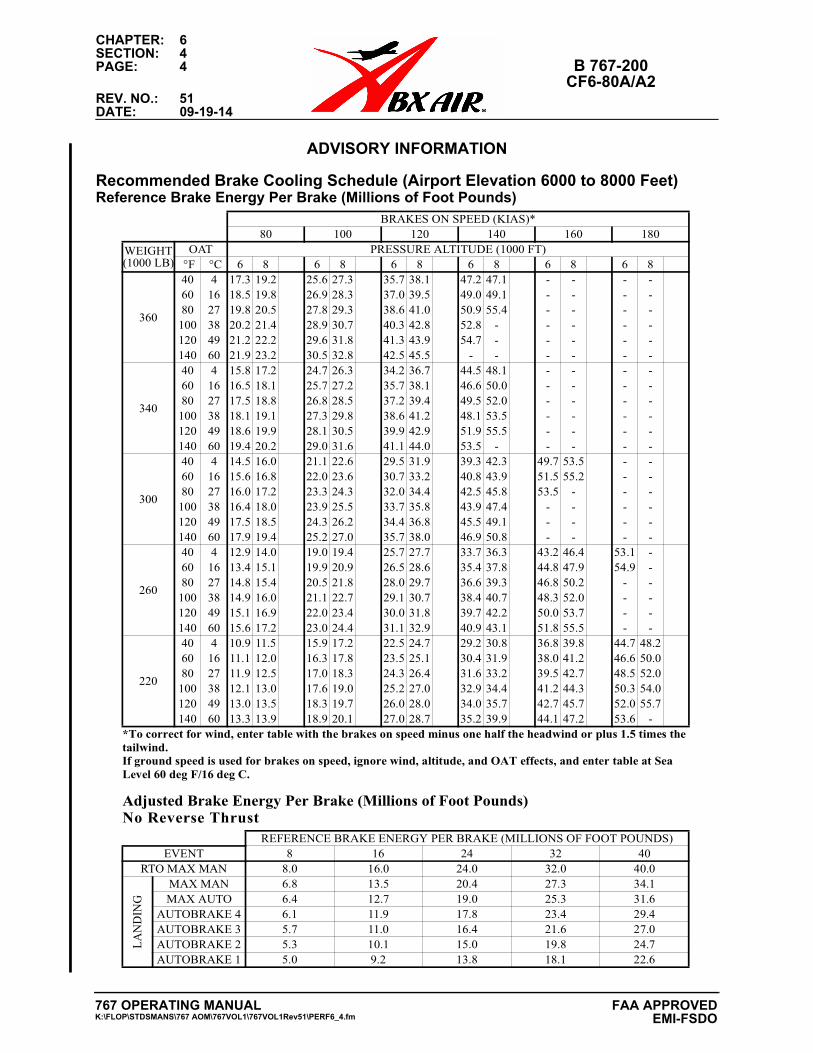
CHAPTER: 6SECTION: 4PAGE: 4 B 767-200
CF6-80A/A2REV. NO.: 51DATE: 09-19-14
ADVISORY INFORMATIONAdvisory Information
Recommended Brake Cooling Schedule (Airport Elevation 6000 to 8000 Feet)Reference Brake Energy Per Brake (Millions of Foot Pounds)
Adjusted Brake Energy Per Brake (Millions of Foot Pounds)No Reverse Thrust
BRAKES ON SPEED (KIAS)*80 100 120 140 160 180
WEIGHT (1000 LB)
OAT PRESSURE ALTITUDE (1000 FT) °F °C 6 8 6 8 6 8 6 8 6 8 6 8
360
40 4 17.3 19.2 25.6 27.3 35.7 38.1 47.2 47.1 - - - -60 16 18.5 19.8 26.9 28.3 37.0 39.5 49.0 49.1 - - - -80 27 19.8 20.5 27.8 29.3 38.6 41.0 50.9 55.4 - - - -
100 38 20.2 21.4 28.9 30.7 40.3 42.8 52.8 - - - - -120 49 21.2 22.2 29.6 31.8 41.3 43.9 54.7 - - - - -140 60 21.9 23.2 30.5 32.8 42.5 45.5 - - - - - -
340
40 4 15.8 17.2 24.7 26.3 34.2 36.7 44.5 48.1 - - - -60 16 16.5 18.1 25.7 27.2 35.7 38.1 46.6 50.0 - - - -80 27 17.5 18.8 26.8 28.5 37.2 39.4 49.5 52.0 - - - -
100 38 18.1 19.1 27.3 29.8 38.6 41.2 48.1 53.5 - - - -120 49 18.6 19.9 28.1 30.5 39.9 42.9 51.9 55.5 - - - -140 60 19.4 20.2 29.0 31.6 41.1 44.0 53.5 - - - - -
300
40 4 14.5 16.0 21.1 22.6 29.5 31.9 39.3 42.3 49.7 53.5 - -60 16 15.6 16.8 22.0 23.6 30.7 33.2 40.8 43.9 51.5 55.2 - -80 27 16.0 17.2 23.3 24.3 32.0 34.4 42.5 45.8 53.5 - - -
100 38 16.4 18.0 23.9 25.5 33.7 35.8 43.9 47.4 - - - -120 49 17.5 18.5 24.3 26.2 34.4 36.8 45.5 49.1 - - - -140 60 17.9 19.4 25.2 27.0 35.7 38.0 46.9 50.8 - - - -
260
40 4 12.9 14.0 19.0 19.4 25.7 27.7 33.7 36.3 43.2 46.4 53.1 -60 16 13.4 15.1 19.9 20.9 26.5 28.6 35.4 37.8 44.8 47.9 54.9 -80 27 14.8 15.4 20.5 21.8 28.0 29.7 36.6 39.3 46.8 50.2 - -
100 38 14.9 16.0 21.1 22.7 29.1 30.7 38.4 40.7 48.3 52.0 - -120 49 15.1 16.9 22.0 23.4 30.0 31.8 39.7 42.2 50.0 53.7 - -140 60 15.6 17.2 23.0 24.4 31.1 32.9 40.9 43.1 51.8 55.5 - -
220
40 4 10.9 11.5 15.9 17.2 22.5 24.7 29.2 30.8 36.8 39.8 44.7 48.260 16 11.1 12.0 16.3 17.8 23.5 25.1 30.4 31.9 38.0 41.2 46.6 50.080 27 11.9 12.5 17.0 18.3 24.3 26.4 31.6 33.2 39.5 42.7 48.5 52.0
100 38 12.1 13.0 17.6 19.0 25.2 27.0 32.9 34.4 41.2 44.3 50.3 54.0120 49 13.0 13.5 18.3 19.7 26.0 28.0 34.0 35.7 42.7 45.7 52.0 55.7140 60 13.3 13.9 18.9 20.1 27.0 28.7 35.2 39.9 44.1 47.2 53.6 -
*To correct for wind, enter table with the brakes on speed minus one half the headwind or plus 1.5 times thetailwind. If ground speed is used for brakes on speed, ignore wind, altitude, and OAT effects, and enter table at Sea Level 60 deg F/16 deg C.
REFERENCE BRAKE ENERGY PER BRAKE (MILLIONS OF FOOT POUNDS)EVENT 8 16 24 32 40
RTO MAX MAN 8.0 16.0 24.0 32.0 40.0
LAN
DIN
G
MAX MAN 6.8 13.5 20.4 27.3 34.1MAX AUTO 6.4 12.7 19.0 25.3 31.6
AUTOBRAKE 4 6.1 11.9 17.8 23.4 29.4AUTOBRAKE 3 5.7 11.0 16.4 21.6 27.0AUTOBRAKE 2 5.3 10.1 15.0 19.8 24.7AUTOBRAKE 1 5.0 9.2 13.8 18.1 22.6
767 OPERATING MANUALK:\FLOP\STDSMANS\767 AOM\767VOL1\767VOL1Rev51\PERF6_4.fm
FAA APPROVED EMI-FSDO
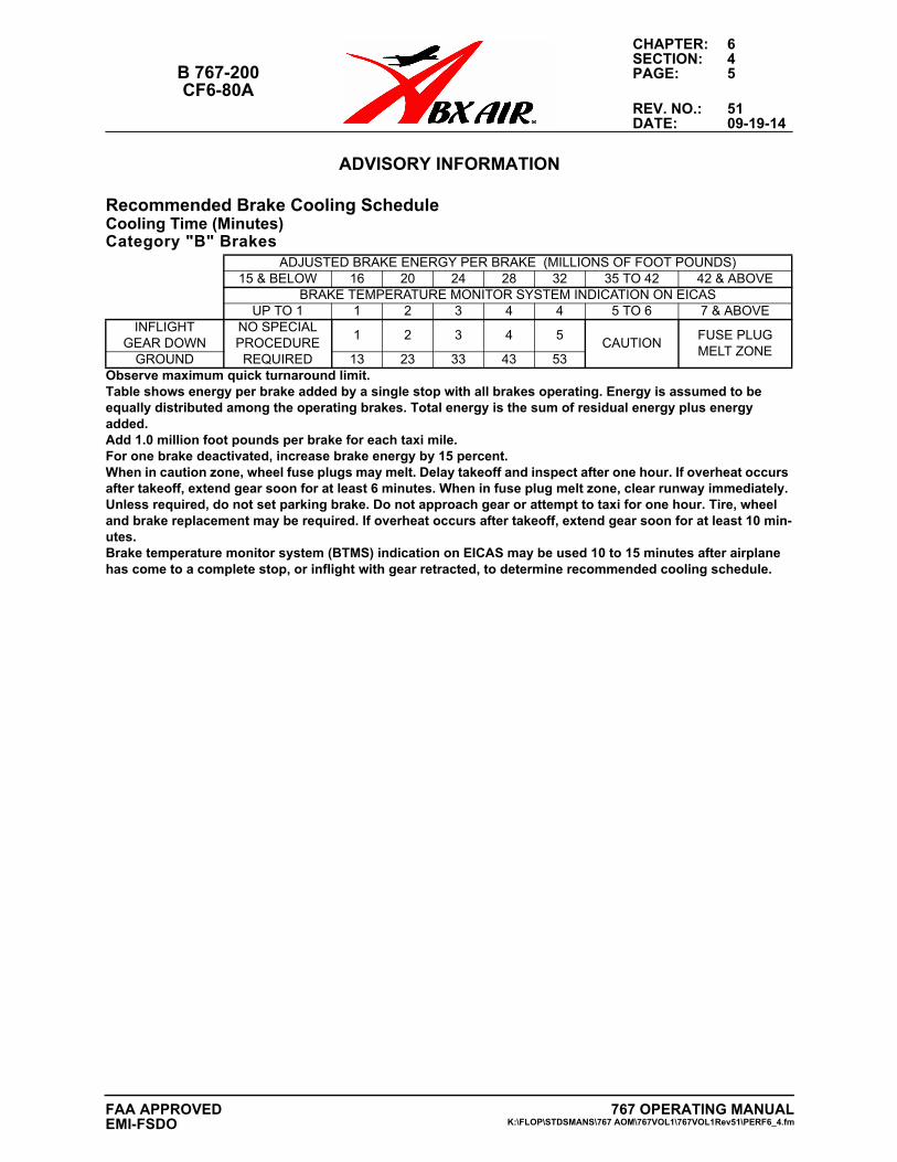
CHAPTER: 6SECTION: 4
B 767-200 PAGE: 5CF6-80A
REV. NO.: 51DATE: 09-19-14
ADVISORY INFORMATIONAdvisory Information
Recommended Brake Cooling ScheduleCooling Time (Minutes) Category "B" Brakes
ADJUSTED BRAKE ENERGY PER BRAKE (MILLIONS OF FOOT POUNDS)15 & BELOW 16 20 24 28 32 35 TO 42 42 & ABOVE
BRAKE TEMPERATURE MONITOR SYSTEM INDICATION ON EICASUP TO 1 1 2 3 4 4 5 TO 6 7 & ABOVE
INFLIGHT GEAR DOWN
NO SPECIAL PROCEDURE REQUIRED
1 2 3 4 5CAUTION
FUSE PLUG MELT ZONE
GROUND 13 23 33 43 53Observe maximum quick turnaround limit.Table shows energy per brake added by a single stop with all brakes operating. Energy is assumed to be equally distributed among the operating brakes. Total energy is the sum of residual energy plus energy added. Add 1.0 million foot pounds per brake for each taxi mile. For one brake deactivated, increase brake energy by 15 percent.When in caution zone, wheel fuse plugs may melt. Delay takeoff and inspect after one hour. If overheat occurs after takeoff, extend gear soon for at least 6 minutes. When in fuse plug melt zone, clear runway immediately. Unless required, do not set parking brake. Do not approach gear or attempt to taxi for one hour. Tire, wheel and brake replacement may be required. If overheat occurs after takeoff, extend gear soon for at least 10 min-utes. Brake temperature monitor system (BTMS) indication on EICAS may be used 10 to 15 minutes after airplane has come to a complete stop, or inflight with gear retracted, to determine recommended cooling schedule.
767 OPERATING MANUALK:\FLOP\STDSMANS\767 AOM\767VOL1\767VOL1Rev51\PERF6_4.fm
FAA APPROVEDEMI-FSDO
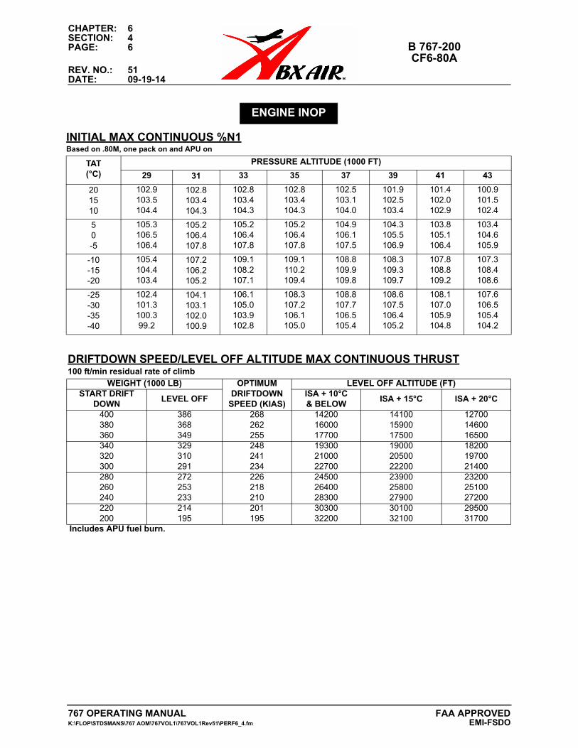
CHAPTER: 6SECTION: 4PAGE: 6 B 767-200
CF6-80AREV. NO.: 51DATE: 09-19-14
ENGINE INOP
INITIAL MAX CONTINUOUS %N1Based on .80M, one pack on and APU on
TAT(°C)
PRESSURE ALTITUDE (1000 FT)
29 31 33 35 37 39 41 43
201510
102.9103.5104.4
102.8103.4104.3
102.8103.4104.3
102.8103.4104.3
102.5103.1104.0
101.9102.5103.4
101.4102.0102.9
100.9101.5102.4
50-5
105.3106.5106.4
105.2106.4107.8
105.2106.4107.8
105.2106.4107.8
104.9106.1107.5
104.3105.5106.9
103.8105.1106.4
103.4104.6105.9
-10-15-20
105.4104.4103.4
107.2106.2105.2
109.1108.2107.1
109.1110.2109.4
108.8109.9109.8
108.3109.3109.7
107.8108.8109.2
107.3108.4108.6
-25-30-35-40
102.4101.3100.399.2
104.1103.1102.0100.9
106.1105.0103.9102.8
108.3107.2106.1105.0
108.8107.7106.5105.4
108.6107.5106.4105.2
108.1107.0105.9104.8
107.6106.5105.4104.2
DRIFTDOWN SPEED/LEVEL OFF ALTITUDE MAX CONTINUOUS THRUST100 ft/min residual rate of climb
WEIGHT (1000 LB) OPTIMUM DRIFTDOWN
SPEED (KIAS)
LEVEL OFF ALTITUDE (FT)START DRIFT
DOWNLEVEL OFF
ISA + 10°C& BELOW
ISA + 15°C ISA + 20°C
400380360
386368349
268262255
142001600017700
141001590017500
127001460016500
340320300
329310291
248241234
193002100022700
190002050022200
182001970021400
280260240
272253233
226218210
245002640028300
239002580027900
232002510027200
220200
214195
201195
3030032200
3010032100
2950031700
Includes APU fuel burn.
767 OPERATING MANUAL FAA APPROVEDK:\FLOP\STDSMANS\767 AOM\767VOL1\767VOL1Rev51\PERF6_4.fm EMI-FSDO
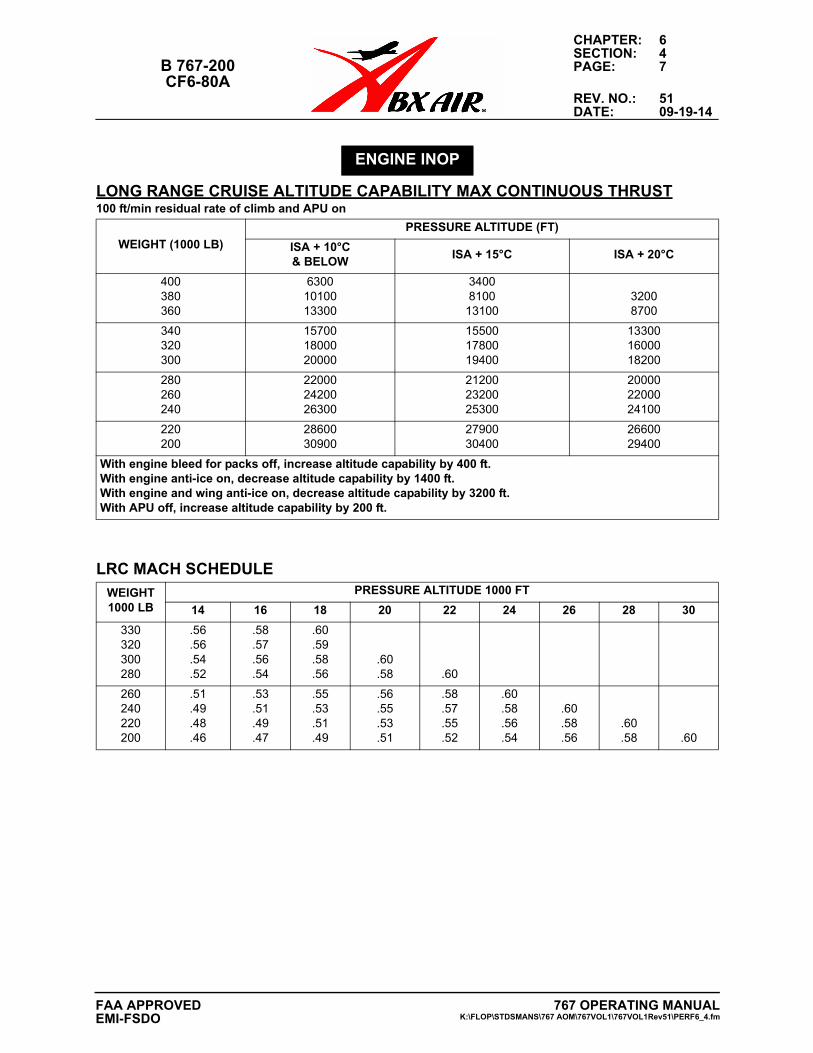
CHAPTER: 6SECTION: 4
B 767-200 PAGE: 7CF6-80A
REV. NO.: 51DATE: 09-19-14
ENGINE INOP
LONG RANGE CRUISE ALTITUDE CAPABILITY MAX CONTINUOUS THRUST100 ft/min residual rate of climb and APU on
WEIGHT (1000 LB)
PRESSURE ALTITUDE (FT)
ISA + 10°C& BELOW
ISA + 15°C ISA + 20°C
400380360
63001010013300
34008100
1310032008700
340320300
157001800020000
155001780019400
133001600018200
280260240
220002420026300
212002320025300
200002200024100
220200
2860030900
2790030400
2660029400
With engine bleed for packs off, increase altitude capability by 400 ft.With engine anti-ice on, decrease altitude capability by 1400 ft.With engine and wing anti-ice on, decrease altitude capability by 3200 ft.With APU off, increase altitude capability by 200 ft.
LRC MACH SCHEDULE
WEIGHT1000 LB
PRESSURE ALTITUDE 1000 FT
14 16 18 20 22 24 26 28 30
330320300280
.56
.56
.54
.52
.58
.57
.56
.54
.60
.59
.58
.56.60.58 .60
260240220200
.51
.49
.48
.46
.53
.51
.49
.47
.55
.53
.51
.49
.56
.55
.53
.51
.58
.57
.55
.52
.60
.58
.56
.54
.60
.58
.56.60.58 .60
767 OPERATING MANUALK:\FLOP\STDSMANS\767 AOM\767VOL1\767VOL1Rev51\PERF6_4.fm
FAA APPROVEDEMI-FSDO
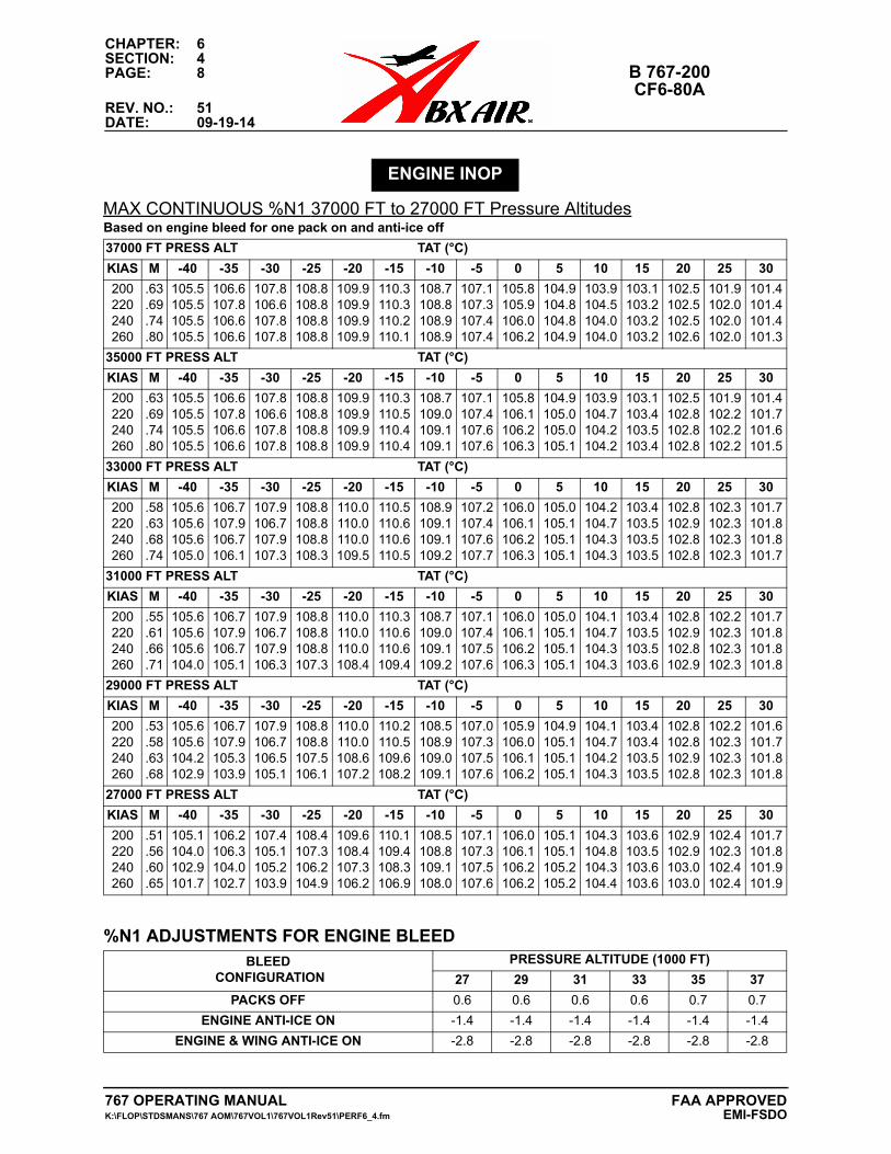
CHAPTER: 6SECTION: 4PAGE: 8 B 767-200
CF6-80AREV. NO.: 51DATE: 09-19-14
MAX CONTINUOUS %N1 37000 FT to 27000 FT Pressure Altitudes
ENGINE INOP
Based on engine bleed for one pack on and anti-ice off
37000 FT PRESS ALT TAT (°C)
KIAS M -40 -35 -30 -25 -20 -15 -10 -5 0 5 10 15 20 25 30
200220240260
.63
.69
.74
.80
105.5105.5105.5105.5
106.6107.8106.6106.6
107.8106.6107.8107.8
108.8108.8108.8108.8
109.9109.9109.9109.9
110.3110.3110.2110.1
108.7108.8108.9108.9
107.1107.3107.4107.4
105.8105.9106.0106.2
104.9104.8104.8104.9
103.9104.5104.0104.0
103.1103.2103.2103.2
102.5102.5102.5102.6
101.9102.0102.0102.0
101.4101.4101.4101.3
35000 FT PRESS ALT TAT (°C)
KIAS M -40 -35 -30 -25 -20 -15 -10 -5 0 5 10 15 20 25 30
200220240260
.63
.69
.74
.80
105.5105.5105.5105.5
106.6107.8106.6106.6
107.8106.6107.8107.8
108.8108.8108.8108.8
109.9109.9109.9109.9
110.3110.5110.4110.4
108.7109.0109.1109.1
107.1107.4107.6107.6
105.8106.1106.2106.3
104.9105.0105.0105.1
103.9104.7104.2104.2
103.1103.4103.5103.4
102.5102.8102.8102.8
101.9102.2102.2102.2
101.4101.7101.6101.5
33000 FT PRESS ALT TAT (°C)
KIAS M -40 -35 -30 -25 -20 -15 -10 -5 0 5 10 15 20 25 30
200220240260
.58
.63
.68
.74
105.6105.6105.6105.0
106.7107.9106.7106.1
107.9106.7107.9107.3
108.8108.8108.8108.3
110.0110.0110.0109.5
110.5110.6110.6110.5
108.9109.1109.1109.2
107.2107.4107.6107.7
106.0106.1106.2106.3
105.0105.1105.1105.1
104.2104.7104.3104.3
103.4103.5103.5103.5
102.8102.9102.8102.8
102.3102.3102.3102.3
101.7101.8101.8101.7
31000 FT PRESS ALT TAT (°C)
KIAS M -40 -35 -30 -25 -20 -15 -10 -5 0 5 10 15 20 25 30
200220240260
.55
.61
.66
.71
105.6105.6105.6104.0
106.7107.9106.7105.1
107.9106.7107.9106.3
108.8108.8108.8107.3
110.0110.0110.0108.4
110.3110.6110.6109.4
108.7109.0109.1109.2
107.1107.4107.5107.6
106.0106.1106.2106.3
105.0105.1105.1105.1
104.1104.7104.3104.3
103.4103.5103.5103.6
102.8102.9102.8102.9
102.2102.3102.3102.3
101.7101.8101.8101.8
29000 FT PRESS ALT TAT (°C)
KIAS M -40 -35 -30 -25 -20 -15 -10 -5 0 5 10 15 20 25 30
200220240260
.53
.58
.63
.68
105.6105.6104.2102.9
106.7107.9105.3103.9
107.9106.7106.5105.1
108.8108.8107.5106.1
110.0110.0108.6107.2
110.2110.5109.6108.2
108.5108.9109.0109.1
107.0107.3107.5107.6
105.9106.0106.1106.2
104.9105.1105.1105.1
104.1104.7104.2104.3
103.4103.4103.5103.5
102.8102.8102.9102.8
102.2102.3102.3102.3
101.6101.7101.8101.8
27000 FT PRESS ALT TAT (°C)
KIAS M -40 -35 -30 -25 -20 -15 -10 -5 0 5 10 15 20 25 30
200220240260
.51
.56
.60
.65
105.1104.0102.9101.7
106.2106.3104.0102.7
107.4105.1105.2103.9
108.4107.3106.2104.9
109.6108.4107.3106.2
110.1109.4108.3106.9
108.5108.8109.1108.0
107.1107.3107.5107.6
106.0106.1106.2106.2
105.1105.1105.2105.2
104.3104.8104.3104.4
103.6103.5103.6103.6
102.9102.9103.0103.0
102.4102.3102.4102.4
101.7101.8101.9101.9
%N1 ADJUSTMENTS FOR ENGINE BLEEDBLEED
CONFIGURATIONPRESSURE ALTITUDE (1000 FT)
27 29 31 33 35 37
PACKS OFF 0.6 0.6 0.6 0.6 0.7 0.7
ENGINE ANTI-ICE ON -1.4 -1.4 -1.4 -1.4 -1.4 -1.4
ENGINE & WING ANTI-ICE ON -2.8 -2.8 -2.8 -2.8 -2.8 -2.8
767 OPERATING MANUAL FAA APPROVEDK:\FLOP\STDSMANS\767 AOM\767VOL1\767VOL1Rev51\PERF6_4.fm EMI-FSDO
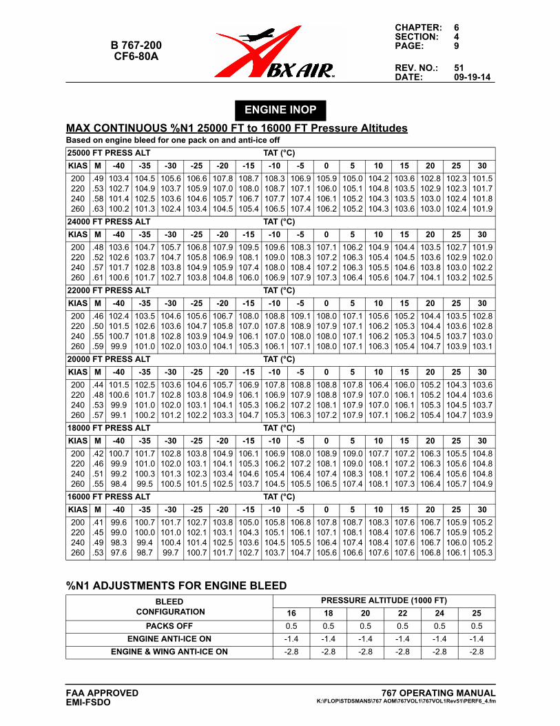
CHAPTER: 6SECTION: 4
B 767-200 PAGE: 9CF6-80A
REV. NO.: 51DATE: 09-19-14
MAX CONTINUOUS %N1 25000 FT to 16000 FT Pressure Altitudes
ENGINE INOP
Based on engine bleed for one pack on and anti-ice off
25000 FT PRESS ALT TAT (°C)
KIAS M -40 -35 -30 -25 -20 -15 -10 -5 0 5 10 15 20 25 30
200220240260
.49
.53
.58
.63
103.4102.7101.4100.2
104.5104.9102.5101.3
105.6103.7103.6102.4
106.6105.9104.6103.4
107.8107.0105.7104.5
108.7108.0106.7105.4
108.3108.7107.7106.5
106.9107.1107.4107.4
105.9106.0106.1106.2
105.0105.1105.2105.2
104.2104.8104.3104.3
103.6103.5103.5103.6
102.8102.9103.0103.0
102.3102.3102.4102.4
101.5101.7101.8101.9
24000 FT PRESS ALT TAT (°C)
KIAS M -40 -35 -30 -25 -20 -15 -10 -5 0 5 10 15 20 25 30
200220240260
.48
.52
.57
.61
103.6102.6101.7100.6
104.7103.7102.8101.7
105.7104.7103.8102.7
106.8105.8104.9103.8
107.9106.9105.9104.8
109.5108.1107.4106.0
109.6109.0108.0106.9
108.3108.3108.4107.9
107.1107.2107.2107.3
106.2106.3106.3106.4
104.9105.4105.5105.6
104.4104.5104.6104.7
103.5103.6103.8104.1
102.7102.9103.0103.2
101.9102.0102.2102.5
22000 FT PRESS ALT TAT (°C)
KIAS M -40 -35 -30 -25 -20 -15 -10 -5 0 5 10 15 20 25 30
200220240260
.46
.50
.55
.59
102.4101.5100.799.9
103.5102.6101.8101.0
104.6103.6102.8102.0
105.6104.7103.9103.0
106.7105.8104.9104.1
108.0107.0106.1105.3
108.8107.8107.0106.1
109.1108.9108.0107.1
108.0107.9108.0108.0
107.1107.1107.1107.1
105.6106.2106.2106.3
105.2105.3105.3105.4
104.4104.4104.5104.7
103.5103.6103.7103.9
102.8102.8103.0103.1
20000 FT PRESS ALT TAT (°C)
KIAS M -40 -35 -30 -25 -20 -15 -10 -5 0 5 10 15 20 25 30
200220240260
.44
.48
.53
.57
101.5100.699.999.1
102.5101.7101.0100.2
103.6102.8102.0101.2
104.6103.8103.1102.2
105.7104.9104.1103.3
106.9106.1105.3104.7
107.8106.9106.2105.3
108.8107.9107.2106.3
108.8108.8108.1107.2
107.8107.9107.9107.9
106.4107.0107.0107.1
106.0106.1106.1106.2
105.2105.2105.3105.4
104.3104.4104.5104.7
103.6103.6103.7103.9
18000 FT PRESS ALT TAT (°C)
KIAS M -40 -35 -30 -25 -20 -15 -10 -5 0 5 10 15 20 25 30
200220240260
.42
.46
.51
.55
100.799.999.298.4
101.7101.0100.399.5
102.8102.0101.3100.5
103.8103.1102.3101.5
104.9104.1103.4102.5
106.1105.3104.6103.7
106.9106.2105.4104.5
108.0107.2106.4105.5
108.9108.1107.4106.5
109.0109.0108.3107.4
107.7108.1108.1108.1
107.2107.2107.2107.3
106.3106.3106.4106.4
105.5105.6105.6105.7
104.8104.8104.8104.9
16000 FT PRESS ALT TAT (°C)
KIAS M -40 -35 -30 -25 -20 -15 -10 -5 0 5 10 15 20 25 30
200220240260
.41
.45
.49
.53
99.699.098.397.6
100.7100.099.498.7
101.7101.0100.499.7
102.7102.1101.4100.7
103.8103.1102.5101.7
105.0104.3103.6102.7
105.8105.1104.5103.7
106.8106.1105.5104.7
107.8107.1106.4105.6
108.7108.1107.4106.6
108.3108.4108.4107.6
107.6107.6107.6107.6
106.7106.7106.7106.8
105.9105.9106.0106.1
105.2105.2105.2105.3
%N1 ADJUSTMENTS FOR ENGINE BLEEDBLEED
CONFIGURATIONPRESSURE ALTITUDE (1000 FT)
16 18 20 22 24 25
PACKS OFF 0.5 0.5 0.5 0.5 0.5 0.5
ENGINE ANTI-ICE ON -1.4 -1.4 -1.4 -1.4 -1.4 -1.4
ENGINE & WING ANTI-ICE ON -2.8 -2.8 -2.8 -2.8 -2.8 -2.8
767 OPERATING MANUALK:\FLOP\STDSMANS\767 AOM\767VOL1\767VOL1Rev51\PERF6_4.fm
FAA APPROVEDEMI-FSDO
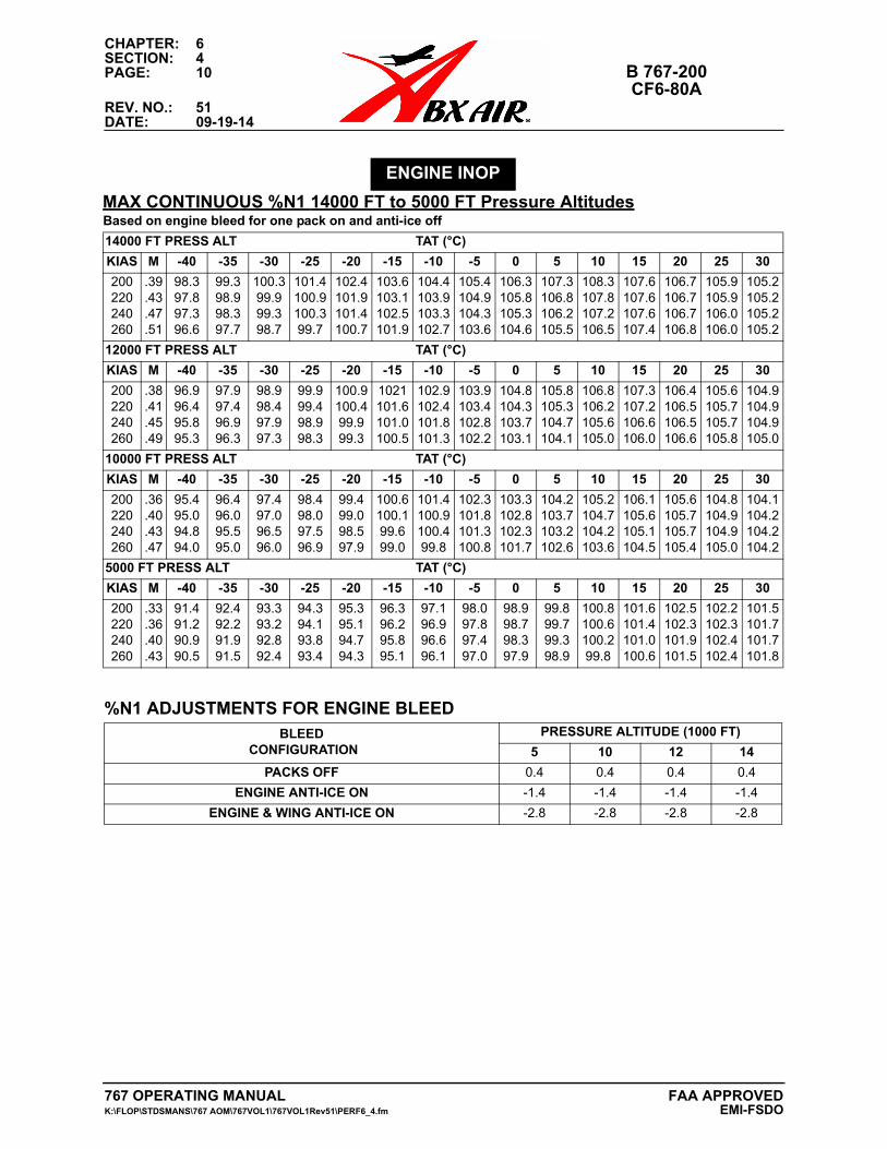
CHAPTER: 6SECTION: 4PAGE: 10 B 767-200
CF6-80AREV. NO.: 51DATE: 09-19-14
MAX CONTINUOUS %N1 14000 FT to 5000 FT Pressure Altitudes
ENGINE INOP
Based on engine bleed for one pack on and anti-ice off
14000 FT PRESS ALT TAT (°C)
KIAS M -40 -35 -30 -25 -20 -15 -10 -5 0 5 10 15 20 25 30
200220240260
.39
.43
.47
.51
98.397.897.396.6
99.398.998.397.7
100.399.999.398.7
101.4100.9100.399.7
102.4101.9101.4100.7
103.6103.1102.5101.9
104.4103.9103.3102.7
105.4104.9104.3103.6
106.3105.8105.3104.6
107.3106.8106.2105.5
108.3107.8107.2106.5
107.6107.6107.6107.4
106.7106.7106.7106.8
105.9105.9106.0106.0
105.2105.2105.2105.2
12000 FT PRESS ALT TAT (°C)
KIAS M -40 -35 -30 -25 -20 -15 -10 -5 0 5 10 15 20 25 30
200220240260
.38
.41
.45
.49
96.996.495.895.3
97.997.496.996.3
98.998.497.997.3
99.999.498.998.3
100.9100.499.999.3
1021101.6101.0100.5
102.9102.4101.8101.3
103.9103.4102.8102.2
104.8104.3103.7103.1
105.8105.3104.7104.1
106.8106.2105.6105.0
107.3107.2106.6106.0
106.4106.5106.5106.6
105.6105.7105.7105.8
104.9104.9104.9105.0
10000 FT PRESS ALT TAT (°C)
KIAS M -40 -35 -30 -25 -20 -15 -10 -5 0 5 10 15 20 25 30
200220240260
.36
.40
.43
.47
95.495.094.894.0
96.496.095.595.0
97.497.096.596.0
98.498.097.596.9
99.499.098.597.9
100.6100.199.699.0
101.4100.9100.499.8
102.3101.8101.3100.8
103.3102.8102.3101.7
104.2103.7103.2102.6
105.2104.7104.2103.6
106.1105.6105.1104.5
105.6105.7105.7105.4
104.8104.9104.9105.0
104.1104.2104.2104.2
5000 FT PRESS ALT TAT (°C)
KIAS M -40 -35 -30 -25 -20 -15 -10 -5 0 5 10 15 20 25 30
200220240260
.33
.36
.40
.43
91.491.290.990.5
92.492.291.991.5
93.393.292.892.4
94.394.193.893.4
95.395.194.794.3
96.396.295.895.1
97.196.996.696.1
98.097.897.497.0
98.998.798.397.9
99.899.799.398.9
100.8100.6100.299.8
101.6101.4101.0100.6
102.5102.3101.9101.5
102.2102.3102.4102.4
101.5101.7101.7101.8
%N1 ADJUSTMENTS FOR ENGINE BLEEDBLEED
CONFIGURATIONPRESSURE ALTITUDE (1000 FT)
5 10 12 14
PACKS OFF 0.4 0.4 0.4 0.4
ENGINE ANTI-ICE ON -1.4 -1.4 -1.4 -1.4
ENGINE & WING ANTI-ICE ON -2.8 -2.8 -2.8 -2.8
767 OPERATING MANUAL FAA APPROVEDK:\FLOP\STDSMANS\767 AOM\767VOL1\767VOL1Rev51\PERF6_4.fm EMI-FSDO

CHAPTER: 6SECTION: 4
B 767-200 PAGE: 11CF6-80A
REV. NO.: 51DATE: 09-19-14
ENGINE INOP
LONG RANGE CRUISE TABLE MAX CRUISE THRUST30000 FT TO 25000 FTPRESS ALT(1000 FT)(STD TAT)
WEIGHT (1000 LB)
400 380 360 340 320 300 280 260 240 220 200
30(-28)
%N1MAX TAT
KIASMACH
FE/ENGKTAS
100.8-2
224.6026871355
29(-26)
%N1MAX TAT
KIASMACH
FE/ENGKTAS
104.7-9
233.6137803363
99.24
225.5926805351
28(-24)
%N1MAX TAT
KIASMACH
FE/ENGKTAS
101.7-1
234.6047595359
97.9
226.5826771346
27(-22)
%N1MAX TAT
KIASMACH
FE/ENGKTAS
105.1-7
243.6128514365
100.15
235.5947518354
96.9
227.5736752342
26(-20)
%N1MAX TAT
KIASMACH
FE/ENGKTAS
102.30
245.6038307362
98.89
236.5847479350
96.0
228.5646752338
25(-18)
%N1MAX TAT
KIASMACH
FE/ENGKTAS
104.9-4
253.6119185368
100.76
246.5938226357
97.7
237.5747457346
95.0
228.5546747333
Max TAT not shown where %N1 can be set in ISA +30°C conditions.Increase/decrease %N1 required by 1% per 5°C above/below standard TAT.Increase/decrease fuel flow 3% per 10°C above/below standard TAT.Increase/decrease KTAS by 1 knot per 1°C above/below standard TAT.
MAX CONTINUOUS %N1PRESS ALT
(1000 FT)TAT (°C)
-55 -50 -45 -40 -35 -30 -25 -20 -15 -10 -5 0 5 10302928
102.2101.2100.5
103.3102.3101.6
104.4103.4102.7
105.6104.5103.8
106.7105.6104.9
107.8106.7106.0
108.9107.8107.1
109.9108.8108.1
110.0109.9109.2
108.8108.9108.9
107.2107.3107.4
106.0106.1106.2
105.0105.1105.2
104.1104.2104.3
272625
99.599.098.1
100.7100.199.2
101.8101.2100.3
102.8102.3101.4
103.9103.4102.4
105.0104.4103.5
106.0105.5104.5
107.1106.5105.6
108.1107.5106.6
108.9108.6107.6
107.6107.8107.9
106.4106.5106.7
105.4105.6105.7
104.5104.6104.8
With engine anti-ice on, decrease limit %N1 by 1.1.With engine and wing anti-ice on, decrease limit %N1 by 1.7.
767 OPERATING MANUALK:\FLOP\STDSMANS\767 AOM\767VOL1\767VOL1Rev51\PERF6_4.fm
FAA APPROVEDEMI-FSDO
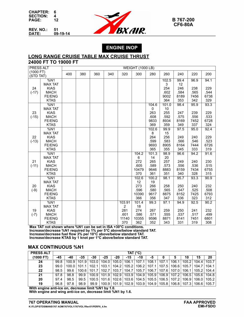
CHAPTER: 6SECTION: 4PAGE: 12 B 767-200
CF6-80AREV. NO.: 51DATE: 09-19-14
ENGINE INOP
LONG RANGE CRUISE TABLE MAX CRUISE THRUST24000 FT TO 19000 FTPRESS ALT(1000 FT)(STD TAT)
WEIGHT (1000 LB)
400 380 360 340 320 300 280 260 240 220 200
24(-17)
%N1MAX TAT
KIASMACH
FE/ENGKTAS
102.53
254.6029002364
99.412
246.5848189353
96.9
238.5657456342
94.1
229.5446738329
23(-15)
%N1MAX TAT
KIASMACH
FE/ENGKTAS
104.60
263.6089833369
101.010
255.5928934359
98.4
247.5758169349
95.9
239.5567452337
93.3
229.5336728324
22(-13)
%N1MAX TAT
KIASMACH
FE/ENGKTAS
102.68
264.5999693365
99.915
256.5838905355
97.5
249.5668164345
95.0
240.5467444333
92.4
229.5236726319
21(-11)
%N1MAX TAT
KIASMACH
FE/ENGKTAS
104.26
272.605
10479370
101.314
265.5899646361
98.920
257.5738883351
96.6
249.5568159340
94.2
240.5367434328
91.6
230.5156755315
20(-9)
%N1MAX TAT
KIASMACH
FE/ENGKTAS
102.612
273.596
10390366
100.219
266.5809617356
98.1
258.5658875347
95.7
250.5478152336
93.3
240.5257425323
90.9
232.5086793312
19(-7)
%N1MAX TAT
KIASMACH
FE/ENGKTAS
103.912
281.601
11140370
101.418
274.586
10355362
99.3
267.5719596352
97.1
259.5558871343
94.9
250.5378141331
92.5
241.5177451319
90.2
232.4996801308
Max TAT not shown where %N1 can be set in ISA +30°C conditions.Increase/decrease %N1 required by 1% per 5°C above/below standard TAT.Increase/decrease fuel flow 3% per 10°C above/below standard TAT.Increase/decrease KTAS by 1 knot per 1°C above/below standard TAT.
MAX CONTINUOUS %N1PRESS ALT
(1000 FT)TAT (°C)
-45 -40 -35 -30 -25 -20 -15 -10 -5 0 5 10 15 20242322
99.899.098.5
100.9100.099.6
101.9101.1100.6
103.0102.1101.7
104.0103.1102.7
105.0104.2103.7
106.1105.2104.7
107.1106.2105.7
108.1107.1106.7
107.1107.5107.6
106.1106.6107.0
105.2105.7106.1
104.4104.7105.2
103.7104.1104.4
212019
97.897.496.8
98.898.597.8
99.999.598.9
100.9100.599.9
101.9101.6100.9
102.9102.6101.9
103.9103.6102.9
104.9104.5103.9
105.9105.5104.9
106.9106.5105.8
107.2107.2106.8
106.5106.9107.3
105.6106.0106.6
104.8105.2105.7
With engine anti-ice on, decrease limit %N1 by 1.0.With engine and wing anti-ice on, decrease limit %N1 by 1.6.
767 OPERATING MANUAL FAA APPROVEDK:\FLOP\STDSMANS\767 AOM\767VOL1\767VOL1Rev51\PERF6_4.fm EMI-FSDO
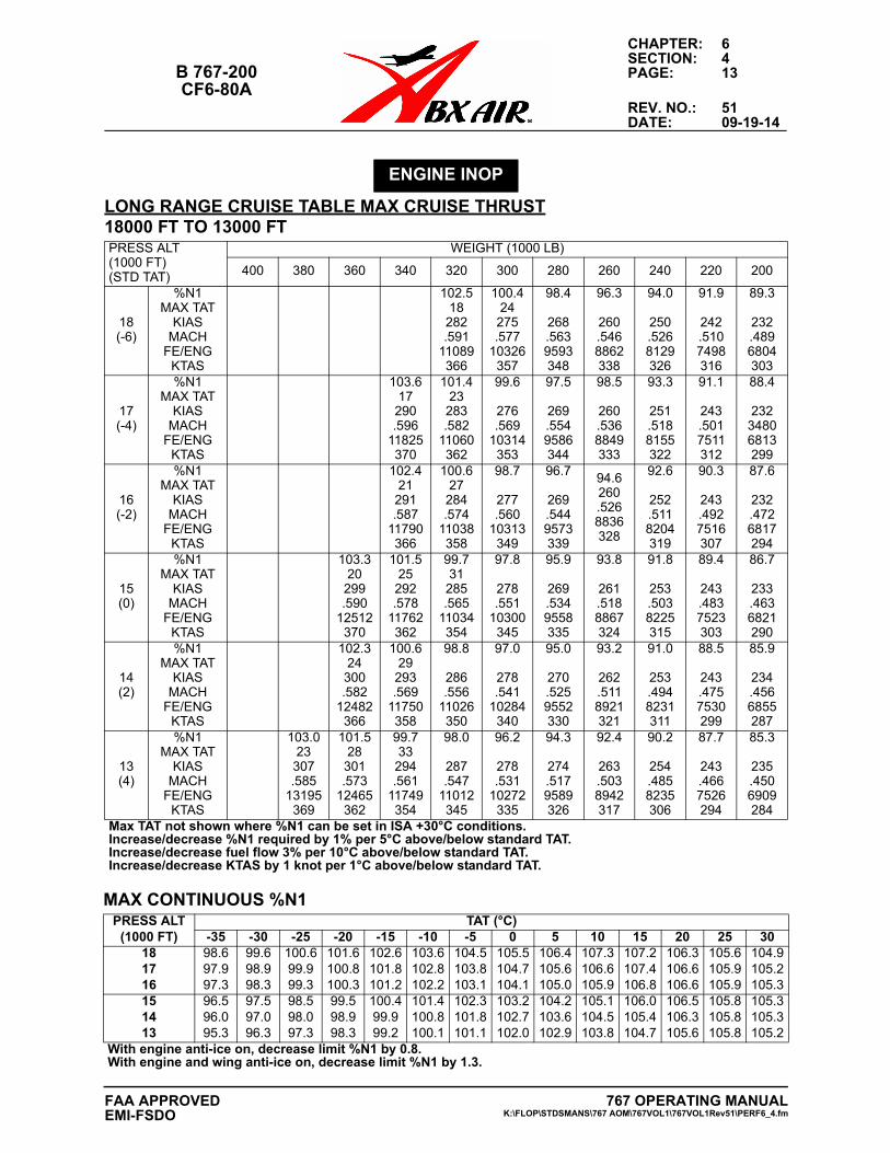
CHAPTER: 6SECTION: 4
B 767-200 PAGE: 13CF6-80A
REV. NO.: 51DATE: 09-19-14
ENGINE INOP
LONG RANGE CRUISE TABLE MAX CRUISE THRUST18000 FT TO 13000 FTPRESS ALT(1000 FT)(STD TAT)
WEIGHT (1000 LB)
400 380 360 340 320 300 280 260 240 220 200
18(-6)
%N1MAX TAT
KIASMACH
FE/ENGKTAS
102.518282.591
11089366
100.424275.577
10326357
98.4
268.5639593348
96.3
260.5468862338
94.0
250.5268129326
91.9
242.5107498316
89.3
232.4896804303
17(-4)
%N1MAX TAT
KIASMACH
FE/ENGKTAS
103.617290.596
11825370
101.423283.582
11060362
99.6
276.569
10314353
97.5
269.5549586344
98.5
260.5368849333
93.3
251.5188155322
91.1
243.5017511312
88.4
23234806813299
16(-2)
%N1MAX TAT
KIASMACH
FE/ENGKTAS
102.421291.587
11790366
100.627284.574
11038358
98.7
277.560
10313349
96.7
269.5449573339
94.6260.5268836328
92.6
252.5118204319
90.3
243.4927516307
87.6
232.4726817294
15(0)
%N1MAX TAT
KIASMACH
FE/ENGKTAS
103.320299.590
12512370
101.525292.578
11762362
99.731285.565
11034354
97.8
278.551
10300345
95.9
269.5349558335
93.8
261.5188867324
91.8
253.5038225315
89.4
243.4837523303
86.7
233.4636821290
14(2)
%N1MAX TAT
KIASMACH
FE/ENGKTAS
102.324300.582
12482366
100.629293.569
11750358
98.8
286.556
11026350
97.0
278.541
10284340
95.0
270.5259552330
93.2
262.5118921321
91.0
253.4948231311
88.5
243.4757530299
85.9
234.4566855287
13(4)
%N1MAX TAT
KIASMACH
FE/ENGKTAS
103.023307.585
13195369
101.528301.573
12465362
99.733294.561
11749354
98.0
287.547
11012345
96.2
278.531
10272335
94.3
274.5179589326
92.4
263.5038942317
90.2
254.4858235306
87.7
243.4667526294
85.3
235.4506909284
Max TAT not shown where %N1 can be set in ISA +30°C conditions.Increase/decrease %N1 required by 1% per 5°C above/below standard TAT.Increase/decrease fuel flow 3% per 10°C above/below standard TAT.Increase/decrease KTAS by 1 knot per 1°C above/below standard TAT.
MAX CONTINUOUS %N1PRESS ALT
(1000 FT)TAT (°C)
-35 -30 -25 -20 -15 -10 -5 0 5 10 15 20 25 30181716
98.697.997.3
99.698.998.3
100.699.999.3
101.6100.8100.3
102.6101.8101.2
103.6102.8102.2
104.5103.8103.1
105.5104.7104.1
106.4105.6105.0
107.3106.6105.9
107.2107.4106.8
106.3106.6106.6
105.6105.9105.9
104.9105.2105.3
151413
96.596.095.3
97.597.096.3
98.598.097.3
99.598.998.3
100.499.999.2
101.4100.8100.1
102.3101.8101.1
103.2102.7102.0
104.2103.6102.9
105.1104.5103.8
106.0105.4104.7
106.5106.3105.6
105.8105.8105.8
105.3105.3105.2
With engine anti-ice on, decrease limit %N1 by 0.8.With engine and wing anti-ice on, decrease limit %N1 by 1.3.
767 OPERATING MANUALK:\FLOP\STDSMANS\767 AOM\767VOL1\767VOL1Rev51\PERF6_4.fm
FAA APPROVEDEMI-FSDO
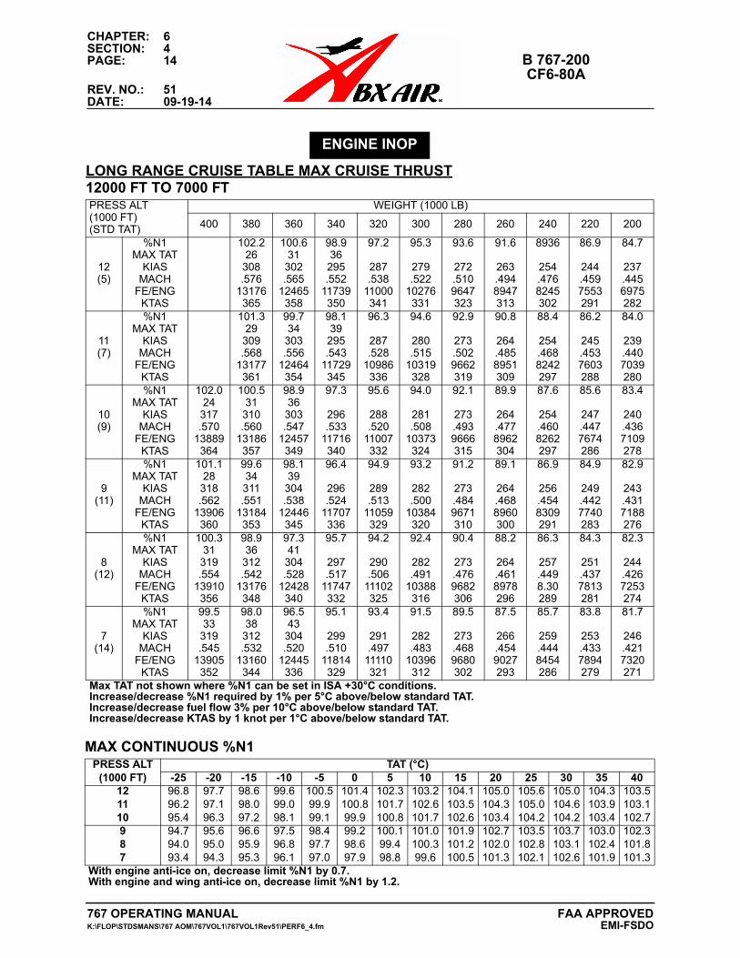
CHAPTER: 6SECTION: 4PAGE: 14 B 767-200
CF6-80AREV. NO.: 51DATE: 09-19-14
ENGINE INOP
LONG RANGE CRUISE TABLE MAX CRUISE THRUST12000 FT TO 7000 FTPRESS ALT(1000 FT)(STD TAT)
WEIGHT (1000 LB)
400 380 360 340 320 300 280 260 240 220 200
12(5)
%N1MAX TAT
KIASMACH
FE/ENGKTAS
102.226
308.576
13176365
100.631
302.565
12465358
98.936
295.552
11739350
97.2
287.538
11000341
95.3
279.522
10276331
93.6
272.5109647323
91.6
263.4948947313
8936
254.4768245302
86.9
244.4597553291
84.7
237.4456975282
11(7)
%N1MAX TAT
KIASMACH
FE/ENGKTAS
101.329
309.568
13177361
99.734
303.556
12464354
98.139
295.543
11729345
96.3
287.528
10986336
94.6
280.515
10319328
92.9
273.5029662319
90.8
264.4858951309
88.4
254.4688242297
86.2
245.4537603288
84.0
239.4407039280
10(9)
%N1MAX TAT
KIASMACH
FE/ENGKTAS
102.024
317.570
13889364
100.531
310.560
13186357
98.936
303.547
12457349
97.3
296.533
11716340
95.6
288.520
11007332
94.0
281.508
10373324
92.1
273.4939666315
89.9
264.4778962304
87.6
254.4608262297
85.6
247.4477674286
83.4
240.4367109278
9(11)
%N1MAX TAT
KIASMACH
FE/ENGKTAS
101.128
318.562
13906360
99.634311.551
13184353
98.139
304.538
12446345
96.4
296.524
11707336
94.9
289.513
11059329
93.2
282.500
10384320
91.2
273.4849671310
89.1
264.4688960300
86.9
256.4548309291
84.9
249.4427740283
82.9
243.4317188276
8(12)
%N1MAX TAT
KIASMACH
FE/ENGKTAS
100.331
319.554
13910356
98.936
312.542
13176348
97.341
304.528
12428340
95.7
297.517
11747332
94.2
290.506
11102325
92.4
282.491
10388316
90.4
273.4769682306
88.2
264.4618978296
86.3
257.4498.30289
84.3
251.4377813281
82.3
244.4267253274
7(14)
%N1MAX TAT
KIASMACH
FE/ENGKTAS
99.533
319.545
13905352
98.038
312.532
13160344
96.543
304.520
12445336
95.1
299.510
11814329
93.4
291.497
11110321
91.5
282.483
10396312
89.5
273.4689680302
87.5
266.4549027293
85.7
259.4448454286
83.8
253.4337894279
81.7
246.4217320271
Max TAT not shown where %N1 can be set in ISA +30°C conditions.Increase/decrease %N1 required by 1% per 5°C above/below standard TAT.Increase/decrease fuel flow 3% per 10°C above/below standard TAT.Increase/decrease KTAS by 1 knot per 1°C above/below standard TAT.
MAX CONTINUOUS %N1PRESS ALT
(1000 FT)TAT (°C)
-25 -20 -15 -10 -5 0 5 10 15 20 25 30 35 40121110
96.896.295.4
97.797.196.3
98.698.097.2
99.699.098.1
100.599.999.1
101.4100.899.9
102.3101.7100.8
103.2102.6101.7
104.1103.5102.6
105.0104.3103.4
105.6105.0104.2
105.0104.6104.2
104.3103.9103.4
103.5103.1102.7
987
94.794.093.4
95.695.094.3
96.695.995.3
97.596.896.1
98.497.797.0
99.298.697.9
100.199.498.8
101.0100.399.6
101.9101.2100.5
102.7102.0101.3
103.5102.8102.1
103.7103.1102.6
103.0102.4101.9
102.3101.8101.3
With engine anti-ice on, decrease limit %N1 by 0.7.With engine and wing anti-ice on, decrease limit %N1 by 1.2.
767 OPERATING MANUAL FAA APPROVEDK:\FLOP\STDSMANS\767 AOM\767VOL1\767VOL1Rev51\PERF6_4.fm EMI-FSDO
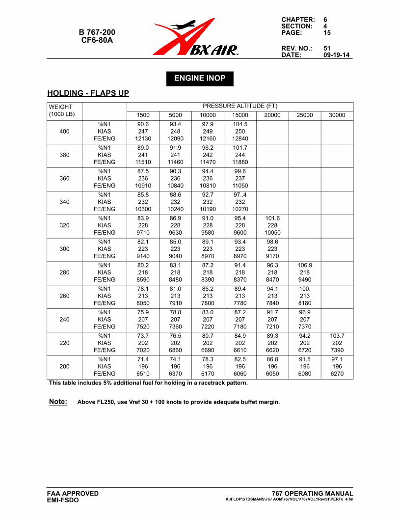
CHAPTER: 6SECTION: 4
B 767-200 PAGE: 15CF6-80A
REV. NO.: 51DATE: 09-19-14
HOLDING - FLAPS UP
ENGINE INOP
WEIGHT(1000 LB)
PRESSURE ALTITUDE (FT)
1500 5000 10000 15000 20000 25000 30000
400%N1KIAS
FE/ENG
90.6247
12130
93.4248
12090
97.9249
12160
104.5250
12840
380%N1KIAS
FE/ENG
89.0241
11510
91.9241
11460
96.2242
11470
101.7244
11880
360%N1KIAS
FE/ENG
87.5236
10910
90.3236
10840
94.4236
10810
99.6237
11050
340%N1KIAS
FE/ENG
85.8232
10300
88.6232
10240
92.7232
10190
97..4232
10270
320%N1KIAS
FE/ENG
83.9228
9710
86.9228
9630
91.0228
9580
95.4228
9600
101.6228
10050
300%N1KIAS
FE/ENG
82.1223
9140
85.0223
9040
89.1223
8970
93.4223
8970
98.6223
9170
280%N1KIAS
FE/ENG
80.2218
8590
83.1218
8480
87.2218
8390
91.4218
8370
96.3218
8470
106.9218
9490
260%N1KIAS
FE/ENG
78.1213
8050
81.0213
7910
85.2213
7800
89.4213
7780
94.1213
7840
100.213
8180
240%N1KIAS
FE/ENG
75.9207
7520
78.8207
7360
83.0207
7220
87.2207
7180
91.7207
7210
96.9207
7370
220%N1KIAS
FE/ENG
73.7202
7020
76.5202
6860
80.7202
6690
84.9202
6610
89.3202
6620
94.2202
6720
103.7202
7390
200%N1KIAS
FE/ENG
71.4196
6510
74.1196
6370
78.3196
6170
82.5196
6060
86.8196
6050
91.5196
6080
97.1196
6270
This table includes 5% additional fuel for holding in a racetrack pattern.
Note: Above FL250, use Vref 30 + 100 knots to provide adequate buffet margin.
767 OPERATING MANUALK:\FLOP\STDSMANS\767 AOM\767VOL1\767VOL1Rev51\PERF6_4.fm
FAA APPROVEDEMI-FSDO
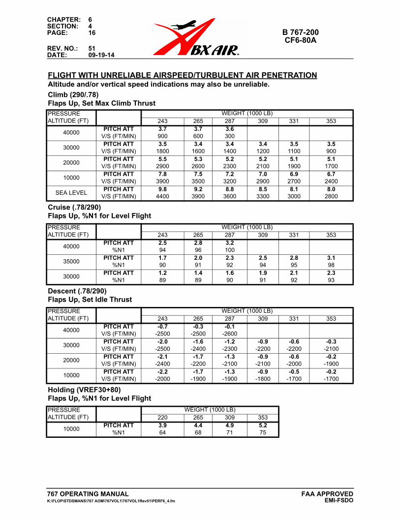
CHAPTER: 6SECTION: 4PAGE: 16 B 767-200
CF6-80AREV. NO.: 51DATE: 09-19-14
FLIGHT WITH UNRELIABLE AIRSPEED/TURBULENT AIR PENETRATIONAltitude and/or vertical speed indications may also be unreliable.
Climb (290/.78)Flaps Up, Set Max Climb ThrustPRESSUREALTITUDE (FT)
WEIGHT (1000 LB)243 265 287 309 331 353
40000PITCH ATT
V/S (FT/MIN)3.7900
3.7600
3.6300
30000PITCH ATT
V/S (FT/MIN)3.5
18003.4
16003.4
14003.4
12003.5
11003.5900
20000PITCH ATT
V/S (FT/MIN)5.5
29005.3
26005.2
23005.2
21005.1
19005.1
1700
10000PITCH ATT
V/S (FT/MIN)7.8
39007.5
35007.2
32007.0
29006.9
27006.7
2400
SEA LEVELPITCH ATT
V/S (FT/MIN)9.8
44009.2
39008.8
36008.5
33008.1
30008.0
2800
Cruise (.78/290)Flaps Up, %N1 for Level Flight
PRESSUREALTITUDE (FT)
WEIGHT (1000 LB)243 265 287 309 331 353
40000PITCH ATT
%N12.594
2.896
3.2100
35000PITCH ATT
%N11.790
2.091
2.392
2.594
2.895
3.198
30000PITCH ATT
%N11.289
1.489
1.690
1.991
2.192
2.393
Descent (.78/290)Flaps Up, Set Idle Thrust
PRESSUREALTITUDE (FT)
WEIGHT (1000 LB)243 265 287 309 331 353
40000PITCH ATT
V/S (FT/MIN)-0.7
-2500-0.3
-2500-0.1
-2600
30000PITCH ATT
V/S (FT/MIN)-2.0
-2500-1.6
-2400-1.2
-2300-0.9
-2200-0.6
-2200-0.3
-2100
20000PITCH ATT
V/S (FT/MIN)-2.1
-2400-1.7
-2200-1.3
-2100-0.9
-2100-0.6
-2000-0.2
-1900
10000PITCH ATT
V/S (FT/MIN)-2.2
-2000-1.7
-1900-1.3
-1900-0.9
-1800-0.5
-1700-0.2
-1700
Holding (VREF30+80)Flaps Up, %N1 for Level Flight
PRESSUREALTITUDE (FT)
WEIGHT (1000 LB)220 265 309 353
10000PITCH ATT
%N13.964
4.468
4.971
5.275
767 OPERATING MANUAL FAA APPROVEDK:\FLOP\STDSMANS\767 AOM\767VOL1\767VOL1Rev51\PERF6_4.fm EMI-FSDO
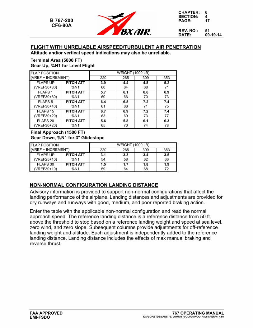
CHAPTER: 6SECTION: 4
B 767-200 PAGE: 17CF6-80A
REV. NO.: 51DATE: 09-19-14
NON-NORMAL CONFIGURATION LANDING DISTANCEAdvisory information is provided to support non-normal configurations that affect the landing performance of the airplane. Landing distances and adjustments are provided for dry runways and runways with good, medium, and poor reported braking action.
Enter the table with the applicable non-normal configuration and read the normal approach speed. The reference landing distance is a reference distance from 50 ft. above the threshold to stop based on a reference landing weight and speed at sea level, zero wind, and zero slope. Subsequent columns provide adjustments for off-reference landing weight and altitude. Each adjustment is independently added to the reference landing distance. Landing distance includes the effects of max manual braking and reverse thrust.
Terminal Area (5000 FT)Gear Up, %N1 for Level Flight
FLAP POSITION(VREF + INCREMENT)
WEIGHT (1000 LB)220 265 309 353
FLAPS UP(VREF30+80)
PITCH ATT%N1
3.960
4.464
4.868
5.271
FLAPS 1(VREF30+60)
PITCH ATT%N1
5.760
6.166
6.670
6.973
FLAPS 5(VREF30+40)
PITCH ATT%N1
6.461
6.866
7.271
7.475
FLAPS 15(VREF30+20)
PITCH ATT%N1
6.763
6.969
7.273
7.477
FLAPS 20(VREF30+20)
PITCH ATT%N1
5.665
5.870
6.174
6.378
Final Approach (1500 FT)Gear Down, %N1 for 3° Glideslope
FLAP POSITION(VREF + INCREMENT)
WEIGHT (1000 LB)220 265 309 353
FLAPS UP(VREF25+10)
PITCH ATT%N1
3.154
3.358
3.462
3.566
FLAPS 30(VREF30+10)
PITCH ATT%N1
1.559
1.764
1.868
1.972
FLIGHT WITH UNRELIABLE AIRSPEED/TURBULENT AIR PENETRATIONAltitude and/or vertical speed indications may also be unreliable.
767 OPERATING MANUALK:\FLOP\STDSMANS\767 AOM\767VOL1\767VOL1Rev51\PERF6_4.fm
FAA APPROVEDEMI-FSDO
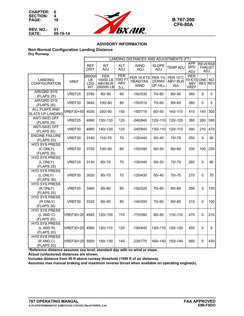
CHAPTER: 6SECTION: 4PAGE: 18 B 767-200
CF6-80AREV. NO.: 51DATE: 09-19-14
ADVISORY INFORMATIONAdvisory Information
Non-Normal Configuration Landing DistanceDry Runway
LANDING DISTANCES AND ADJUSTMENTS (FT)
REF DIST
WT ADJ
ALT ADJ
WIND ADJ
SLOPE ADJ TEMP ADJ
APP SPD ADJ
REVERSETHRUST
ADJ
LANDINGCONFIGURATION VREF
280000LB
LDGWT
PER 10000 LBABV/BLW 280000 LB
PER 1000 FT
ABV S.L.
PER 10 KTS HEAD/TAIL
WIND
PER 1% DOWN/UP HILL
PER 10°C ABV/ BLW
ISA
PER 10 KTS ABV VREF
ONE REV
NO REV
AIR/GRD SYS (FLAPS 25)
VREF25 3780 90/-90 80 -160/530 70/-60 90/-90 360 0 0
AIR/GRD SYS (FLAPS 30)
VREF30 3640 100/-80 80 -150/510 70/-60 80/-80 380 0 0
ALL FLAPS AND SLATS UP LANDING
VREF30+50 4030 330/-90 150 -150/710 60/-50 140/-110 410 140 300
ANTI-SKID OFF (FLAPS 25)
VREF25 4990 130/-130 120 -240/840 120/-110 120/-120 380 260 590
ANTI-SKID OFF (FLAPS 30)
VREF30 4880 140/-120 120 -240/840 130/-110 120/-110 390 210 470
ENGINE FAILURE (FLAPS 20)
VREF20 3140 110/-70 70 -130/440 50/-40 70/-70 250 0 90
HYD SYS PRESS (C ONLY)
(FLAPS 20)VREF20 3720 100/-90 80 -150/490 60/-50 80/-80 330 100 230
HYD SYS PRESS (L ONLY)
(FLAPS 25)VREF25 3130 80/-70 70 -130/440 50/-50 70/-70 260 0 90
HYD SYS PRESS (L ONLY)
(FLAPS 30)VREF30 3020 80/-70 70 -120/430 50/-40 70/-70 270 0 70
HYD SYS PRESS (R ONLY)
(FLAPS 25)VREF25 3460 90/-80 80 -150/520 70/-60 80/-80 290 0 130
HYD SYS PRESS (R ONLY) (FLAPS 30)
VREF30 3330 90/-80 80 -140/500 70/-60 80/-80 310 0 100
HYD SYS PRESS (L AND C) (FLAPS 20)
VREF30+20 4540 120/-100 110 -170/580 90/-80 110/-110 470 0 210
HYD SYS PRESS (L AND R) (FLAPS 20)
VREF30+20 4560 120/-110 120 -190/640 120/-110 120/-120 450 0 0
HYD SYS PRESS (R AND C) (FLAPS 20)
VREF30+20 5500 150/-130 140 -230/770 160/-140 150/-140 560 0 430
*Reference distance assumes sea level, standard day with no wind or slope.Actual (unfactored) distances are shown.Includes distance from 50 ft above runway threshold (1000 ft of air distance). Assumes max manual braking and maximum reverse thrust when available on operating engine(s).
767 OPERATING MANUAL FAA APPROVEDK:\FLOP\STDSMANS\767 AOM\767VOL1\767VOL1Rev51\PERF6_4.fm EMI-FSDO
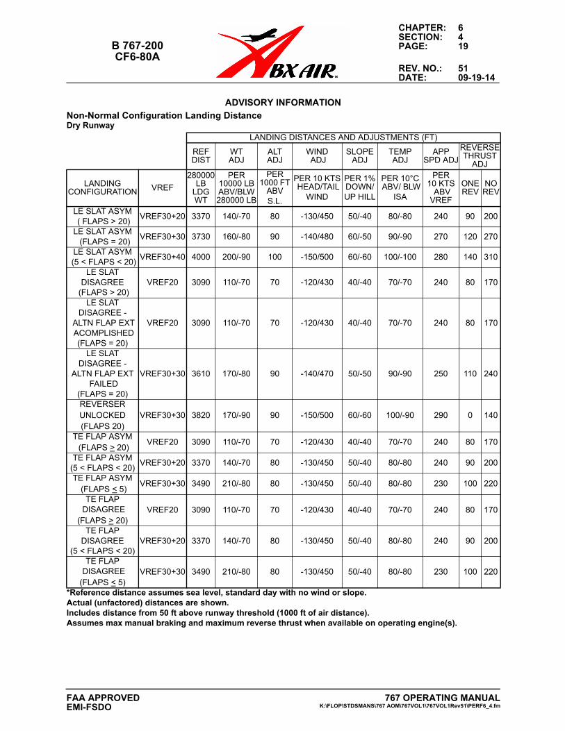
CHAPTER: 6SECTION: 4
B 767-200 PAGE: 19CF6-80A
REV. NO.: 51DATE: 09-19-14
ADVISORY INFORMATIONAdvisory Information
Non-Normal Configuration Landing DistanceDry Runway
LANDING DISTANCES AND ADJUSTMENTS (FT)
REF DIST
WT ADJ
ALT ADJ
WIND ADJ
SLOPE ADJ
TEMP ADJ
APP SPD ADJ
REVERSETHRUST
ADJ
LANDINGCONFIGURATION VREF
280000LB
LDGWT
PER 10000 LBABV/BLW 280000 LB
PER 1000 FT
ABV S.L.
PER 10 KTS HEAD/TAIL
WIND
PER 1% DOWN/UP HILL
PER 10°C ABV/ BLW
ISA
PER 10 KTS ABV VREF
ONE REV
NO REV
LE SLAT ASYM ( FLAPS > 20)
VREF30+20 3370 140/-70 80 -130/450 50/-40 80/-80 240 90 200
LE SLAT ASYM (FLAPS = 20)
VREF30+30 3730 160/-80 90 -140/480 60/-50 90/-90 270 120 270
LE SLAT ASYM (5 < FLAPS < 20)
VREF30+40 4000 200/-90 100 -150/500 60/-60 100/-100 280 140 310
LE SLAT DISAGREE
(FLAPS > 20)VREF20 3090 110/-70 70 -120/430 40/-40 70/-70 240 80 170
LE SLAT DISAGREE -
ALTN FLAP EXT ACOMPLISHED
(FLAPS = 20)
VREF20 3090 110/-70 70 -120/430 40/-40 70/-70 240 80 170
LE SLAT DISAGREE -
ALTN FLAP EXT FAILED
(FLAPS = 20)
VREF30+30 3610 170/-80 90 -140/470 50/-50 90/-90 250 110 240
REVERSER UNLOCKED (FLAPS 20)
VREF30+30 3820 170/-90 90 -150/500 60/-60 100/-90 290 0 140
TE FLAP ASYM (FLAPS > 20)
VREF20 3090 110/-70 70 -120/430 40/-40 70/-70 240 80 170
TE FLAP ASYM (5 < FLAPS < 20)
VREF30+20 3370 140/-70 80 -130/450 50/-40 80/-80 240 90 200
TE FLAP ASYM (FLAPS < 5)
VREF30+30 3490 210/-80 80 -130/450 50/-40 80/-80 230 100 220
TE FLAP DISAGREE
(FLAPS > 20)VREF20 3090 110/-70 70 -120/430 40/-40 70/-70 240 80 170
TE FLAP DISAGREE
(5 < FLAPS < 20)VREF30+20 3370 140/-70 80 -130/450 50/-40 80/-80 240 90 200
TE FLAP DISAGREE (FLAPS < 5)
VREF30+30 3490 210/-80 80 -130/450 50/-40 80/-80 230 100 220
*Reference distance assumes sea level, standard day with no wind or slope.Actual (unfactored) distances are shown.Includes distance from 50 ft above runway threshold (1000 ft of air distance). Assumes max manual braking and maximum reverse thrust when available on operating engine(s).
767 OPERATING MANUALK:\FLOP\STDSMANS\767 AOM\767VOL1\767VOL1Rev51\PERF6_4.fm
FAA APPROVEDEMI-FSDO
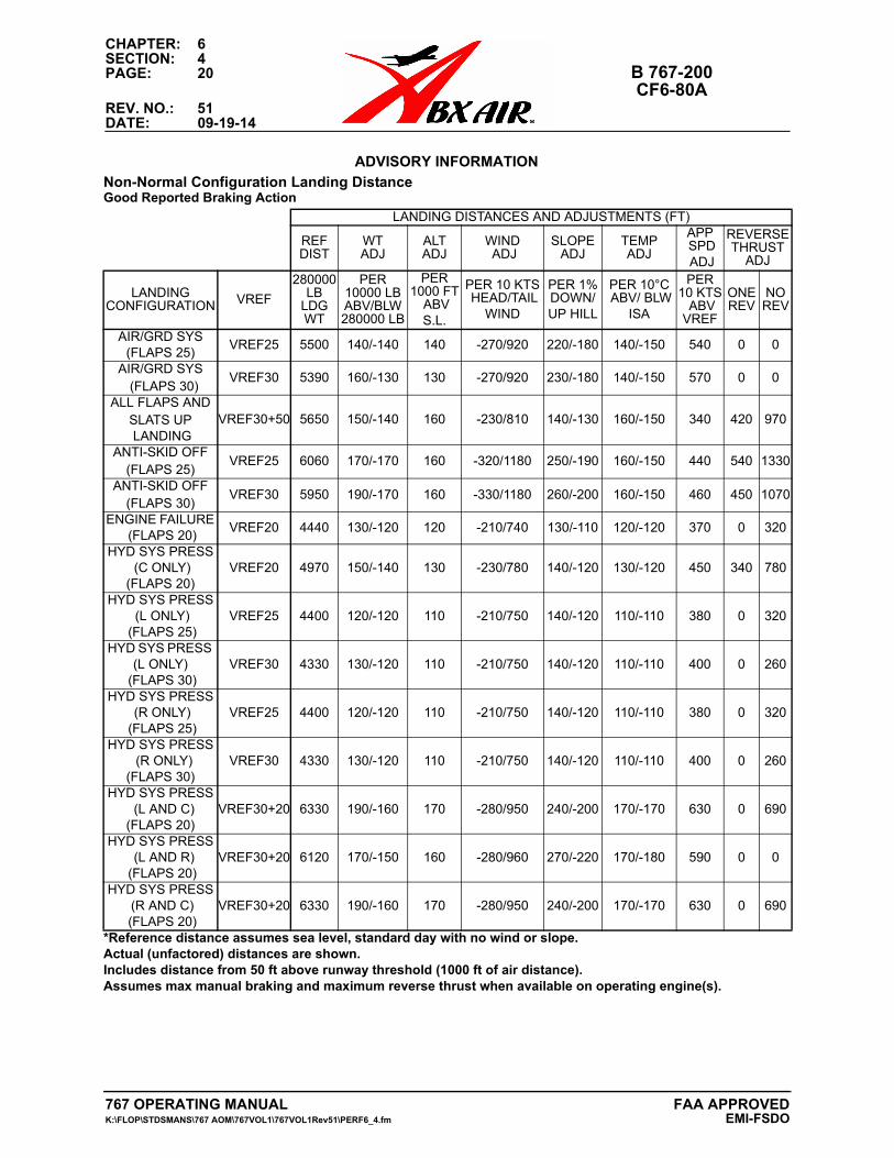
CHAPTER: 6SECTION: 4PAGE: 20 B 767-200
CF6-80AREV. NO.: 51DATE: 09-19-14
ADVISORY INFORMATIONAdvisory Information
Non-Normal Configuration Landing DistanceGood Reported Braking Action
LANDING DISTANCES AND ADJUSTMENTS (FT)
REF DIST
WT ADJ
ALT ADJ
WIND ADJ
SLOPE ADJ
TEMP ADJ
APP SPD ADJ
REVERSETHRUST
ADJ
LANDINGCONFIGURATION VREF
280000LB
LDGWT
PER 10000 LBABV/BLW 280000 LB
PER 1000 FT
ABV S.L.
PER 10 KTS HEAD/TAIL
WIND
PER 1% DOWN/UP HILL
PER 10°C ABV/ BLW
ISA
PER 10 KTS ABV VREF
ONE REV
NO REV
AIR/GRD SYS (FLAPS 25)
VREF25 5500 140/-140 140 -270/920 220/-180 140/-150 540 0 0
AIR/GRD SYS (FLAPS 30)
VREF30 5390 160/-130 130 -270/920 230/-180 140/-150 570 0 0
ALL FLAPS ANDSLATS UP LANDING
VREF30+50 5650 150/-140 160 -230/810 140/-130 160/-150 340 420 970
ANTI-SKID OFF(FLAPS 25)
VREF25 6060 170/-170 160 -320/1180 250/-190 160/-150 440 540 1330
ANTI-SKID OFF(FLAPS 30)
VREF30 5950 190/-170 160 -330/1180 260/-200 160/-150 460 450 1070
ENGINE FAILURE (FLAPS 20)
VREF20 4440 130/-120 120 -210/740 130/-110 120/-120 370 0 320
HYD SYS PRESS (C ONLY)
(FLAPS 20)VREF20 4970 150/-140 130 -230/780 140/-120 130/-120 450 340 780
HYD SYS PRESS (L ONLY)
(FLAPS 25)VREF25 4400 120/-120 110 -210/750 140/-120 110/-110 380 0 320
HYD SYS PRESS (L ONLY)
(FLAPS 30)VREF30 4330 130/-120 110 -210/750 140/-120 110/-110 400 0 260
HYD SYS PRESS (R ONLY)
(FLAPS 25)VREF25 4400 120/-120 110 -210/750 140/-120 110/-110 380 0 320
HYD SYS PRESS (R ONLY) (FLAPS 30)
VREF30 4330 130/-120 110 -210/750 140/-120 110/-110 400 0 260
HYD SYS PRESS (L AND C) (FLAPS 20)
VREF30+20 6330 190/-160 170 -280/950 240/-200 170/-170 630 0 690
HYD SYS PRESS (L AND R) (FLAPS 20)
VREF30+20 6120 170/-150 160 -280/960 270/-220 170/-180 590 0 0
HYD SYS PRESS (R AND C) (FLAPS 20)
VREF30+20 6330 190/-160 170 -280/950 240/-200 170/-170 630 0 690
*Reference distance assumes sea level, standard day with no wind or slope.Actual (unfactored) distances are shown.Includes distance from 50 ft above runway threshold (1000 ft of air distance). Assumes max manual braking and maximum reverse thrust when available on operating engine(s).
767 OPERATING MANUAL FAA APPROVEDK:\FLOP\STDSMANS\767 AOM\767VOL1\767VOL1Rev51\PERF6_4.fm EMI-FSDO
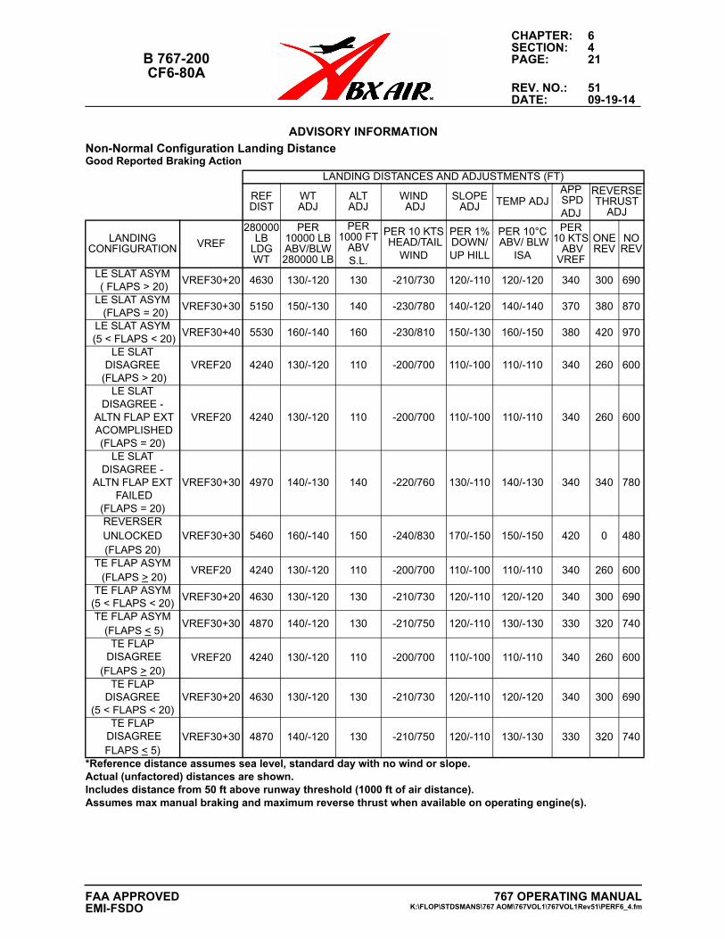
CHAPTER: 6SECTION: 4
B 767-200 PAGE: 21CF6-80A
REV. NO.: 51DATE: 09-19-14
ADVISORY INFORMATIONAdvisory Information
Non-Normal Configuration Landing DistanceGood Reported Braking Action
LANDING DISTANCES AND ADJUSTMENTS (FT)
REF DIST
WT ADJ
ALT ADJ
WIND ADJ
SLOPE ADJ TEMP ADJ
APP SPD ADJ
REVERSETHRUST
ADJ
LANDINGCONFIGURATION VREF
280000LB
LDGWT
PER 10000 LBABV/BLW 280000 LB
PER 1000 FT
ABV S.L.
PER 10 KTS HEAD/TAIL
WIND
PER 1% DOWN/UP HILL
PER 10°C ABV/ BLW
ISA
PER 10 KTS ABV VREF
ONE REV
NO REV
LE SLAT ASYM ( FLAPS > 20)
VREF30+20 4630 130/-120 130 -210/730 120/-110 120/-120 340 300 690
LE SLAT ASYM (FLAPS = 20)
VREF30+30 5150 150/-130 140 -230/780 140/-120 140/-140 370 380 870
LE SLAT ASYM (5 < FLAPS < 20)
VREF30+40 5530 160/-140 160 -230/810 150/-130 160/-150 380 420 970
LE SLAT DISAGREE
(FLAPS > 20)VREF20 4240 130/-120 110 -200/700 110/-100 110/-110 340 260 600
LE SLAT DISAGREE -
ALTN FLAP EXT ACOMPLISHED
(FLAPS = 20)
VREF20 4240 130/-120 110 -200/700 110/-100 110/-110 340 260 600
LE SLAT DISAGREE -
ALTN FLAP EXT FAILED
(FLAPS = 20)
VREF30+30 4970 140/-130 140 -220/760 130/-110 140/-130 340 340 780
REVERSER UNLOCKED (FLAPS 20)
VREF30+30 5460 160/-140 150 -240/830 170/-150 150/-150 420 0 480
TE FLAP ASYM (FLAPS > 20)
VREF20 4240 130/-120 110 -200/700 110/-100 110/-110 340 260 600
TE FLAP ASYM (5 < FLAPS < 20)
VREF30+20 4630 130/-120 130 -210/730 120/-110 120/-120 340 300 690
TE FLAP ASYM (FLAPS < 5)
VREF30+30 4870 140/-120 130 -210/750 120/-110 130/-130 330 320 740
TE FLAP DISAGREE
(FLAPS > 20)VREF20 4240 130/-120 110 -200/700 110/-100 110/-110 340 260 600
TE FLAP DISAGREE
(5 < FLAPS < 20)VREF30+20 4630 130/-120 130 -210/730 120/-110 120/-120 340 300 690
TE FLAP DISAGREE FLAPS < 5)
VREF30+30 4870 140/-120 130 -210/750 120/-110 130/-130 330 320 740
*Reference distance assumes sea level, standard day with no wind or slope.Actual (unfactored) distances are shown.Includes distance from 50 ft above runway threshold (1000 ft of air distance). Assumes max manual braking and maximum reverse thrust when available on operating engine(s).
767 OPERATING MANUALK:\FLOP\STDSMANS\767 AOM\767VOL1\767VOL1Rev51\PERF6_4.fm
FAA APPROVEDEMI-FSDO
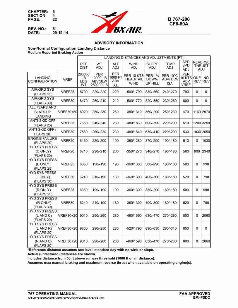
CHAPTER: 6SECTION: 4PAGE: 22 B 767-200
CF6-80AREV. NO.: 51DATE: 09-19-14
ADVISORY INFORMATIONAdvisory Information
Non-Normal Configuration Landing DistanceMedium Reported Braking Action
LANDING DISTANCES AND ADJUSTMENTS (FT)
REF DIST
WT ADJ
ALT ADJ
WIND ADJ
SLOPE ADJ
TEMP ADJ
APP SPD ADJ
REVERSETHRUST
ADJ
LANDINGCONFIGURATION VREF
280000LB
LDGWT
PER 10000 LBABV/BLW 280000 LB
PER 1000 FT
ABV S.L.
PER 10 KTS HEAD/TAIL
WIND
PER 1%DOWN/UP HILL
PER 10°C ABV/ BLW
ISA
PER 10 KTS ABV VREF
ONE REV
NO REV
AIR/GRD SYS (FLAPS 25)
VREF25 8790 220/-220 220 -500/1790 830/-560 240/-270 790 0 0
AIR/GRD SYS (FLAPS 30)
VREF30 8470 250/-210 210 -500/1770 820/-550 230/-260 800 0 0
ALL FLAPS AND SLATS UP LANDING
VREF30+50 8020 250/-230 260 -380/1340 360/-290 250/-230 470 1160 2970
ANTI-SKID OFF (FLAPS 25)
VREF25 7650 240/-240 230 -480/1830 600/-390 220/-200 510 1200 3250
ANTI-SKID OFF (FLAPS 30)
VREF30 7560 260/-230 230 -480/1840 630/-410 220/-200 530 1030 2650
ENGINE FAILURE (FLAPS 20)
VREF20 6460 220/-200 190 -360/1280 370/-290 190/-180 510 0 1030
HYD SYS PRESS (C ONLY)
(FLAPS 20)VREF20 6710 230/-210 200 -350/1270 340/-270 190/-180 560 900 2340
HYD SYS PRESS (L ONLY)
(FLAPS 25)VREF25 6350 190/-190 190 -360/1300 380/-290 180/-180 500 0 990
HYD SYS PRESS (L ONLY)
(FLAPS 30)VREF30 6240 210/-190 180 -360/1300 400/-300 180/-180 520 0 790
HYD SYS PRESS (R ONLY)
(FLAPS 25)VREF25 6350 190/-190 190 -360/1300 380/-290 180/-180 500 0 990
HYD SYS PRESS (R ONLY) (FLAPS 30)
VREF30 6240 210/-190 180 -360/1300 400/-300 180/-180 520 0 790
HYD SYS PRESS (L AND C) (FLAPS 20)
VREF30+20 9010 290/-260 280 -460/1590 630/-470 270/-260 800 0 2060
HYD SYS PRESS (L AND R) (FLAPS 20)
VREF30+20 9800 290/-250 280 -520/1790 890/-630 280/-310 850 0 0
HYD SYS PRESS (R AND C) (FLAPS 20)
VREF30+20 9010 290/-260 280 -460/1590 630/-470 270/-260 800 0 2060
*Reference distance assumes sea level, standard day with no wind or slope.Actual (unfactored) distances are shown.Includes distance from 50 ft above runway threshold (1000 ft of air distance). Assumes max manual braking and maximum reverse thrust when available on operating engine(s).
767 OPERATING MANUAL FAA APPROVEDK:\FLOP\STDSMANS\767 AOM\767VOL1\767VOL1Rev51\PERF6_4.fm EMI-FSDO

CHAPTER: 6SECTION: 4
B 767-200 PAGE: 23CF6-80A
REV. NO.: 51DATE: 09-19-14
ADVISORY INFORMATIONAdvisory Information
Non-Normal Configuration Landing DistanceMedium Reported Braking Action
LANDING DISTANCES AND ADJUSTMENTS (FT)
REF DIST
WT ADJ
ALT ADJ
WIND ADJ
SLOPE ADJ
TEMP ADJ
APP SPD ADJ
REVERSETHRUST
ADJ
LANDINGCONFIGURATION VREF
280000LB
LDGWT
PER 10000 LBABV/BLW 280000 LB
PER 1000 FT
ABV S.L.
PER 10 KTS HEAD/TAIL
WIND
PER 1% DOWN/UP HILL
PER 10°C ABV/ BLW
ISA
PER 10 KTS ABV VREF
ONE REV
NO REV
LE SLAT ASYM ( FLAPS > 20)
VREF30+20 6400 210/-190 200 -340/1210 300/-240 190/-180 440 810 2030
LE SLAT ASYM (FLAPS = 20)
VREF30+30 7100 230/-210 220 -360/1280 340/-270 220/-200 480 980 2470
LE SLAT ASYM (5 < FLAPS < 20)
VREF30+40 7640 250/-220 250 -370/1320 360/-290 240/-220 490 1110 2840
LE SLAT DISAGREE
(FLAPS > 20)VREF20 5880 200/-180 180 -320/1170 290/-230 170/-160 440 730 1820
LE SLAT DISAGREE -
ALTN FLAP EXT ACOMPLISHED
(FLAPS = 20)
VREF20 5880 200/-180 180 -320/1170 290/-230 170/-160 440 730 1820
LE SLAT DISAGREE -
ALTN FLAP EXT FAILED
(FLAPS = 20)
VREF30+30 6850 220/-200 210 -350/1250 320/-250 210/-190 440 880 2200
REVERSERUNLOCKED(FLAPS 20)
VREF30+30 7910 250/-230 250 -400/1410 460/-350 240/-230 560 0 1420
TE FLAP ASYM(FLAPS > 20)
VREF20 5880 200/-180 180 -320/1170 290/-230 170/-160 440 730 1820
TE FLAP ASYM (5 < FLAPS < 20)
VREF30+20 6420 210/-190 200 -340/1210 300/-240 190/-180 450 820 2070
TE FLAP ASYM(FLAPS < 5)
VREF30+30 6820 220/-200 210 -350/1240 310/-250 200/-190 440 890 2250
TE FLAP DISAGREE
(FLAPS > 20)VREF20 5880 200/-180 180 -320/1170 290/-230 170/-160 440 730 1820
TE FLAP DISAGREE
(5 < FLAPS < 20)VREF30+20 6420 210/-190 200 -340/1210 300/-240 190/-180 450 820 2070
TE FLAP DISAGREE(FLAPS < 5)
VREF30+30 6820 220/-200 210 -350/1240 310/-250 200/-190 440 890 2250
*Reference distance assumes sea level, standard day with no wind or slope.Actual (unfactored) distances are shown.Includes distance from 50 ft above runway threshold (1000 ft of air distance). Assumes max manual braking and maximum reverse thrust when available on operating engine(s).
767 OPERATING MANUALK:\FLOP\STDSMANS\767 AOM\767VOL1\767VOL1Rev51\PERF6_4.fm
FAA APPROVEDEMI-FSDO

CHAPTER: 6SECTION: 4PAGE: 24 B 767-200
CF6-80AREV. NO.: 51DATE: 09-19-14
ADVISORY INFORMATIONAdvisory Information
Non-Normal Configuration Landing DistancePoor Reported Braking Action
LANDING DISTANCES AND ADJUSTMENTS (FT)
REF DIST
WT ADJ
ALT ADJ
WIND ADJ
SLOPE ADJ
TEMP ADJ
APP SPD ADJ
REVERSETHRUST
ADJ
LANDINGCONFIGURATION VREF
280000LB
LDGWT
PER 10000 LBABV/BLW 280000 LB
PER 1000 FT
ABV S.L.
PER 10 KTS HEAD/TAIL
WIND
PER 1% DOWN/UP HILL
PER 10°C ABV/ BLW
ISA
PER 10 KTS ABV VREF
ONE REV
NO REV
AIR/GRD SYS (FLAPS 25)
VREF25 14590 320/-260 340 -1010/3820 4730/-1720 390/-480 1030 0 0
AIR/GRD SYS (FLAPS 30)
VREF30 13790 340/-240 310 -980/3730 4510/-1630 370/-450 1010 0 0
ALL FLAPS ANDSLATS UP LANDING
VREF30+50 10640 370/-340 370 -570/2100 850/-580 350/-310 580 2500 7300
ANTI-SKID OFF(FLAPS 25)
VREF25 10330 360/-340 340 -810/3540 3640/-940 310/-270 580 3300 12950
ANTI-SKID OFF(FLAPS 30)
VREF30 10290 390/-350 340 -820/3560 3610/-980 310/-280 600 2980 11130
ENGINE FAILURE (FLAPS 20)
VREF20 8940 330/-300 290 -560/2100 980/-620 280/-260 640 0 2590
HYD SYS PRESS (C ONLY)
(FLAPS 20)VREF20 8620 320/-290 290 -520/1970 780/-510 270/-240 650 1900 5620
HYD SYS PRESS (L ONLY)
(FLAPS 25)VREF25 8790 290/-280 270 -580/2210 1070/-630 260/-260 610 0 2480
HYD SYS PRESS (L ONLY)
(FLAPS 30)VREF30 8640 300/-270 270 -580/2210 1100/-650 260/-260 620 0 1980
HYD SYS PRESS (R ONLY)
(FLAPS 25)VREF25 8790 290/-280 270 -580/2210 1070/-630 260/-260 610 0 2480
HYD SYS PRESS (R ONLY) (FLAPS 30)
VREF30 8640 300/-270 270 -580/2210 1100/-650 260/-260 620 0 1980
HYD SYS PRESS (L AND C) (FLAPS 20)
VREF30+20 12290 430/-380 400 -720/2620 1620/-960 380/-370 930 0 5010
HYD SYS PRESS (L AND R) (FLAPS 20)
VREF30+20 15390 440/-390 430 -930/3370 3320/-1620 440/-510 1080 0 0
HYD SYS PRESS (R AND C) (FLAPS 20)
VREF30+20 12290 430/-380 400 -720/2620 1620/-960 380/-370 930 0 5010
*Reference distance assumes sea level, standard day with no wind or slope.Actual (unfactored) distances are shown.Includes distance from 50 ft above runway threshold (1000 ft of air distance). Assumes max manual braking and maximum reverse thrust when available on operating engine(s).
767 OPERATING MANUAL FAA APPROVEDK:\FLOP\STDSMANS\767 AOM\767VOL1\767VOL1Rev51\PERF6_4.fm EMI-FSDO
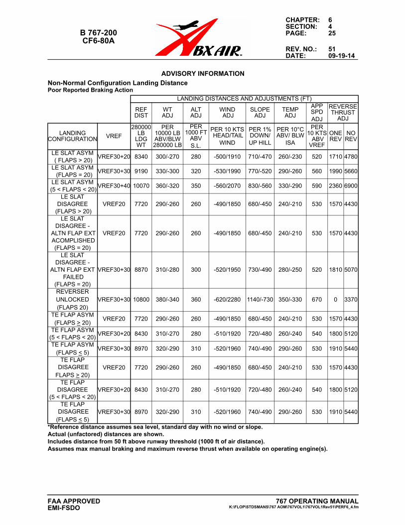
CHAPTER: 6SECTION: 4
B 767-200 PAGE: 25CF6-80A
REV. NO.: 51DATE: 09-19-14
ADVISORY INFORMATIONAdvisory Information
Non-Normal Configuration Landing DistancePoor Reported Braking Action
LANDING DISTANCES AND ADJUSTMENTS (FT)
REF DIST
WT ADJ
ALT ADJ
WIND ADJ
SLOPE ADJ
TEMP ADJ
APP SPD ADJ
REVERSETHRUST
ADJ
LANDINGCONFIGURATION VREF
280000LB
LDGWT
PER 10000 LBABV/BLW 280000 LB
PER 1000 FT
ABVS.L.
PER 10 KTS HEAD/TAIL
WIND
PER 1% DOWN/UP HILL
PER 10°C ABV/ BLW
ISA
PER 10 KTS ABV VREF
ONE REV
NO REV
LE SLAT ASYM ( FLAPS > 20)
VREF30+20 8340 300/-270 280 -500/1910 710/-470 260/-230 520 1710 4780
LE SLAT ASYM (FLAPS = 20)
VREF30+30 9190 330/-300 320 -530/1990 770/-520 290/-260 560 1990 5660
LE SLAT ASYM (5 < FLAPS < 20)
VREF30+40 10070 360/-320 350 -560/2070 830/-560 330/-290 590 2360 6900
LE SLAT DISAGREE
(FLAPS > 20)VREF20 7720 290/-260 260 -490/1850 680/-450 240/-210 530 1570 4430
LE SLAT DISAGREE -
ALTN FLAP EXT ACOMPLISHED
(FLAPS = 20)
VREF20 7720 290/-260 260 -490/1850 680/-450 240/-210 530 1570 4430
LE SLAT DISAGREE -
ALTN FLAP EXT FAILED
(FLAPS = 20)
VREF30+30 8870 310/-280 300 -520/1950 730/-490 280/-250 520 1810 5070
REVERSER UNLOCKED (FLAPS 20)
VREF30+30 10800 380/-340 360 -620/2280 1140/-730 350/-330 670 0 3370
TE FLAP ASYM (FLAPS > 20)
VREF20 7720 290/-260 260 -490/1850 680/-450 240/-210 530 1570 4430
TE FLAP ASYM (5 < FLAPS < 20)
VREF30+20 8430 310/-270 280 -510/1920 720/-480 260/-240 540 1800 5120
TE FLAP ASYM (FLAPS < 5)
VREF30+30 8970 320/-290 310 -520/1960 740/-490 290/-260 530 1910 5440
TE FLAP DISAGREEFLAPS > 20)
VREF20 7720 290/-260 260 -490/1850 680/-450 240/-210 530 1570 4430
TE FLAP DISAGREE
(5 < FLAPS < 20)VREF30+20 8430 310/-270 280 -510/1920 720/-480 260/-240 540 1800 5120
TE FLAP DISAGREE(FLAPS < 5)
VREF30+30 8970 320/-290 310 -520/1960 740/-490 290/-260 530 1910 5440
*Reference distance assumes sea level, standard day with no wind or slope.Actual (unfactored) distances are shown.Includes distance from 50 ft above runway threshold (1000 ft of air distance). Assumes max manual braking and maximum reverse thrust when available on operating engine(s).
767 OPERATING MANUALK:\FLOP\STDSMANS\767 AOM\767VOL1\767VOL1Rev51\PERF6_4.fm
FAA APPROVEDEMI-FSDO

CHAPTER: 6SECTION: 4PAGE: 26 B 767-200
CF6-80AREV. NO.: 51DATE: 09-19-14
THIS PAGE INTENTIONALLY LEFT BLANK
767 OPERATING MANUAL FAA APPROVEDK:\FLOP\STDSMANS\767 AOM\767VOL1\767VOL1Rev51\PERF6_4.fm EMI-FSDO
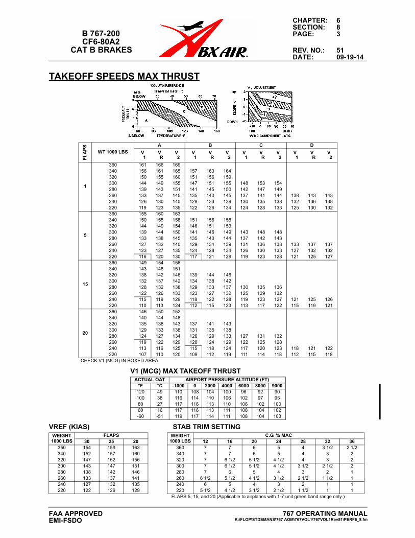
CHAPTER: 6SECTION: 8
B 767-200 PAGE: 3CF6-80A2
CAT B BRAKES REV. NO.: 51DATE: 09-19-14
TAKEOFF SPEEDS MAX THRUSTF
LA
PS
WT 1000 LBS
A B C D
V 1
V R
V 2
V 1
V R
V 2
V 1
V R
V 2
V 1
V R
V 2
1
360 161 166 169340 156 161 165 157 163 164320 150 155 160 151 156 159300 144 149 155 147 151 155 148 153 154280 139 143 151 141 145 150 142 147 149260 133 137 145 135 140 145 137 141 144 138 143 143240 126 130 140 128 133 139 130 135 138 132 136 138220 119 123 135 122 126 134 124 128 133 125 130 132
5
360 155 160 163340 150 155 158 151 156 158320 144 149 154 146 151 153300 139 144 150 141 146 149 143 148 148280 133 138 145 135 140 144 137 142 143260 127 132 140 129 134 139 131 136 138 133 137 137240 123 127 135 124 128 134 126 130 133 127 132 132220 116 120 130 117 121 129 119 123 128 121 125 127
15
360 149 154 156340 143 148 151320 138 142 146 139 144 146300 132 137 142 134 138 142280 128 132 138 129 133 137 130 135 136260 122 126 133 123 127 132 125 129 132240 115 119 129 118 122 128 119 123 127 121 125 126220 110 113 124 112 115 123 113 117 122 115 119 121
20
360 146 150 152340 140 144 148320 135 138 143 137 141 143300 129 133 138 131 135 138280 124 127 134 126 129 133 127 131 132260 119 122 129 120 124 129 122 125 128240 113 116 125 115 118 124 117 120 123 118 121 122220 107 110 120 109 112 119 111 114 118 112 115 118
CHECK V1 (MCG) IN BOXED AREA
V1 (MCG) MAX TAKEOFF THRUSTACTUAL OAT AIRPORT PRESSURE ALTITUDE (FT)
°F °C -1000 0 2000 4000 6000 8000 9000120 49 110 108 104 100 96 92 90100 38 116 114 110 106 102 97 9580 27 117 116 113 110 106 102 10060 16 117 116 113 111 108 104 102-60 -51 119 117 114 111 108 104 103
VREF (KIAS) STAB TRIM SETTINGWEIGHT1000 LBS
FLAPS WEIGHT1000 LBS
C.G. % MAC30 25 20 12 16 20 24 28 32 36
350 154 159 163 360 7 7 6 5 4 3 1/2 2 1/2340 152 157 160 340 7 7 6 5 4 3 2320 147 152 156 320 7 6 1/2 5 1/2 4 1/2 4 3 2300 143 147 151 300 7 6 1/2 5 1/2 4 1/2 3 1/2 2 1/2 2280 138 142 146 280 7 6 5 4 3 2 1260 133 137 141 260 6 1/2 5 1/2 4 1/2 3 1/2 2 1/2 1 1/2 1240 127 132 135 240 6 5 4 3 2 1 1220 122 126 129 220 5 1/2 4 1/2 3 1/2 2 1/2 1 1/2 1 1
FLAPS 5, 15, and 20 (Applicable to airplanes with 1-7 unit green band range only.)
767 OPERATING MANUALK:\FLOP\STDSMANS\767 AOM\767VOL1\767VOL1Rev51\PERF6_8.fm
FAA APPROVEDEMI-FSDO
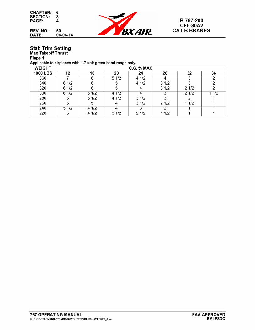
CHAPTER: 6SECTION: 8PAGE: 4 B 767-200
CF6-80A2REV. NO.: 50 CAT B BRAKESDATE: 06-06-14
Stab Trim SettingMax Takeoff ThrustFlaps 1Applicable to airplanes with 1-7 unit green band range only.
WEIGHT1000 LBS
C.G. % MAC12 16 20 24 28 32 36
360 7 6 5 1/2 4 1/2 4 3 2340 6 1/2 6 5 4 1/2 3 1/2 3 2320 6 1/2 6 5 4 3 1/2 2 1/2 2300 6 1/2 5 1/2 4 1/2 4 3 2 1/2 1 1/2280 6 5 1/2 4 1/2 3 1/2 3 2 1260 6 5 4 3 1/2 2 1/2 1 1/2 1240 5 1/2 4 1/2 4 3 2 1 1220 5 4 1/2 3 1/2 2 1/2 1 1/2 1 1
767 OPERATING MANUAL FAA APPROVEDK:\FLOP\STDSMANS\767 AOM\767VOL1\767VOL1Rev51\PERF6_8.fm EMI-FSDO
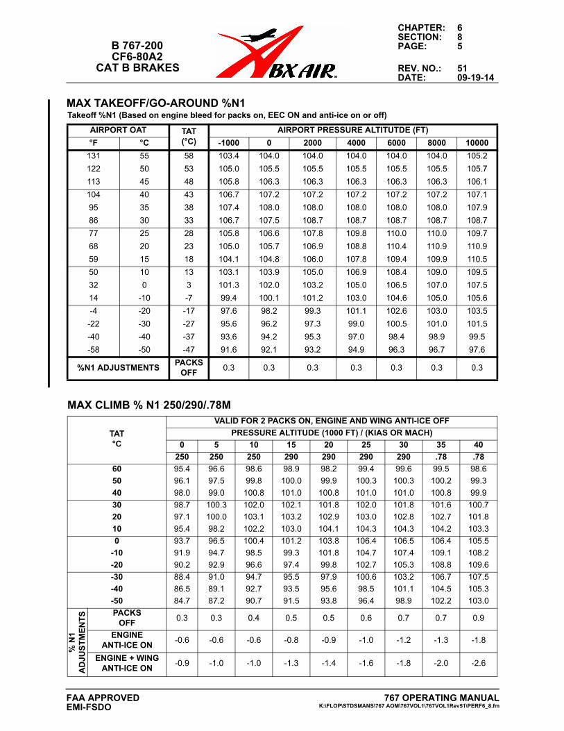
CHAPTER: 6SECTION: 8
B 767-200 PAGE: 5CF6-80A2
CAT B BRAKES REV. NO.: 51DATE: 09-19-14
MAX TAKEOFF/GO-AROUND %N1 Takeoff %N1 (Based on engine bleed for packs on, EEC ON and anti-ice on or off)
AIRPORT OAT TAT(°C)
AIRPORT PRESSURE ALTITUTDE (FT)
°F °C -1000 0 2000 4000 6000 8000 10000
131 55 58 103.4 104.0 104.0 104.0 104.0 104.0 105.2
122 50 53 105.0 105.5 105.5 105.5 105.5 105.5 105.7
113 45 48 105.8 106.3 106.3 106.3 106.3 106.3 106.1
104 40 43 106.7 107.2 107.2 107.2 107.2 107.2 107.1
95 35 38 107.4 108.0 108.0 108.0 108.0 108.0 107.9
86 30 33 106.7 107.5 108.7 108.7 108.7 108.7 108.7
77 25 28 105.8 106.6 107.8 109.8 110.0 110.0 109.7
68 20 23 105.0 105.7 106.9 108.8 110.4 110.9 110.9
59 15 18 104.1 104.8 106.0 107.8 109.4 109.9 110.5
50 10 13 103.1 103.9 105.0 106.9 108.4 109.0 109.5
32 0 3 101.3 102.0 103.2 105.0 106.5 107.0 107.5
14 -10 -7 99.4 100.1 101.2 103.0 104.6 105.0 105.6
-4 -20 -17 97.6 98.2 99.3 101.1 102.6 103.0 103.5
-22 -30 -27 95.6 96.2 97.3 99.0 100.5 101.0 101.5
-40 -40 -37 93.6 94.2 95.3 97.0 98.4 98.9 99.5
-58 -50 -47 91.6 92.1 93.2 94.9 96.3 96.7 97.6
%N1 ADJUSTMENTSPACKS
OFF0.3 0.3 0.3 0.3 0.3 0.3 0.3
MAX CLIMB % N1 250/290/.78M
TAT°C
VALID FOR 2 PACKS ON, ENGINE AND WING ANTI-ICE OFF
PRESSURE ALTITUDE (1000 FT) / (KIAS OR MACH)
0 5 10 15 20 25 30 35 40
250 250 250 290 290 290 290 .78 .78
60 95.4 96.6 98.6 98.9 98.2 99.4 99.6 99.5 98.6
50 96.1 97.5 99.8 100.0 99.9 100.3 100.3 100.2 99.3
40 98.0 99.0 100.8 101.0 100.8 101.0 101.0 100.8 99.9
30 98.7 100.3 102.0 102.1 101.8 102.0 101.8 101.6 100.7
20 97.1 100.0 103.1 103.2 102.9 103.0 102.8 102.7 101.8
10 95.4 98.2 102.2 103.0 104.1 104.3 104.3 104.2 103.3
0 93.7 96.5 100.4 101.2 103.8 106.4 106.5 106.4 105.5
-10 91.9 94.7 98.5 99.3 101.8 104.7 107.4 109.1 108.2
-20 90.2 92.9 96.6 97.4 99.8 102.7 105.3 108.8 109.6
-30 88.4 91.0 94.7 95.5 97.9 100.6 103.2 106.7 107.5
-40 86.5 89.1 92.7 93.5 95.6 98.5 101.1 104.5 105.3
-50 84.7 87.2 90.7 91.5 93.8 96.4 98.9 102.2 103.0
% N
1A
DJ
US
TM
EN
TS PACKS
OFF0.3 0.3 0.4 0.5 0.5 0.6 0.7 0.7 0.9
ENGINEANTI-ICE ON
-0.6 -0.6 -0.6 -0.8 -0.9 -1.0 -1.2 -1.3 -1.8
ENGINE + WINGANTI-ICE ON
-0.9 -1.0 -1.0 -1.3 -1.4 -1.6 -1.8 -2.0 -2.6
767 OPERATING MANUALK:\FLOP\STDSMANS\767 AOM\767VOL1\767VOL1Rev51\PERF6_8.fm
FAA APPROVEDEMI-FSDO
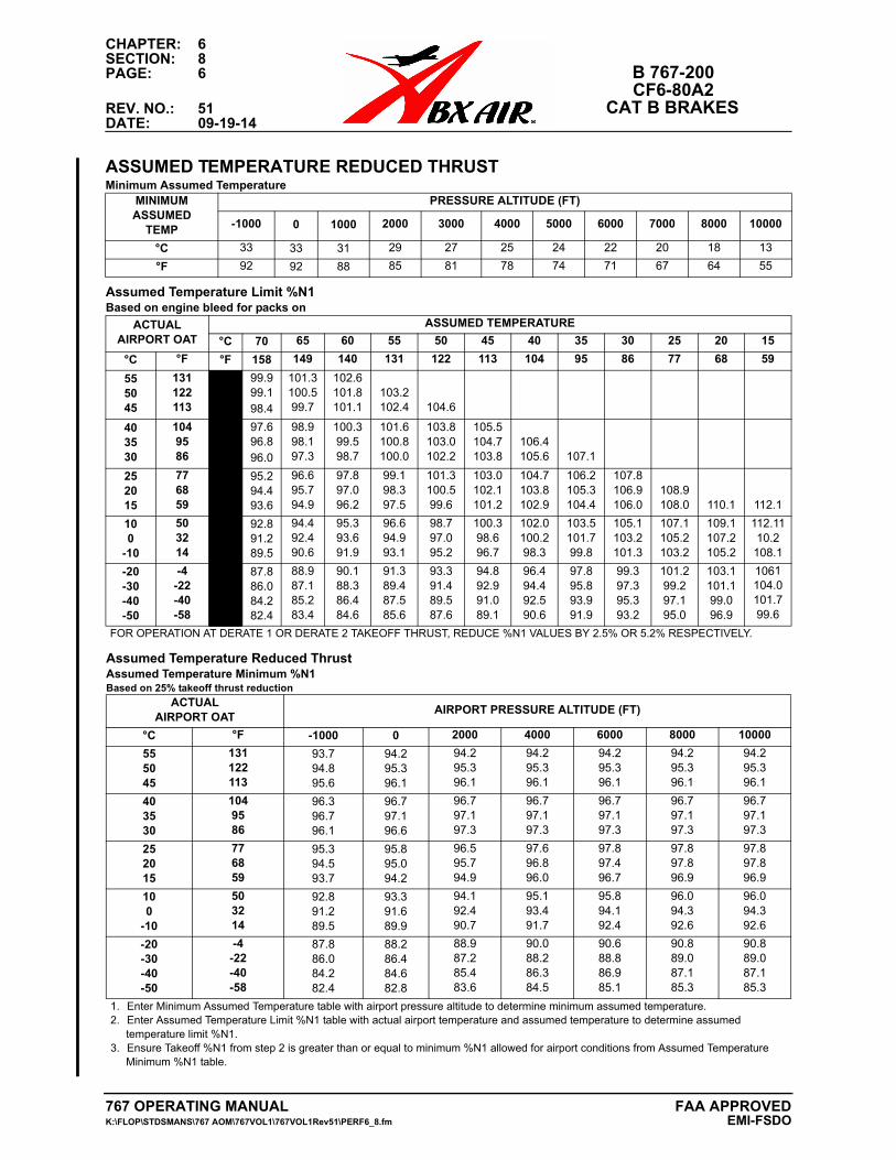
CHAPTER: 6SECTION: 8PAGE: 6 B 767-200
CF6-80A2REV. NO.: 51 CAT B BRAKESDATE: 09-19-14
ASSUMED TEMPERATURE REDUCED THRUSTMinimum Assumed Temperature
MINIMUMASSUMED
TEMP
PRESSURE ALTITUDE (FT)
-1000 0 1000 2000 3000 4000 5000 6000 7000 8000 10000
°C 33 33 31 29 27 25 24 22 20 18 13
°F 92 92 88 85 81 78 74 71 67 64 55
Assumed Temperature Limit %N1Based on engine bleed for packs on
ACTUALAIRPORT OAT
ASSUMED TEMPERATURE
°C 70 65 60 55 50 45 40 35 30 25 20 15
°C °F °F 158 149 140 131 122 113 104 95 86 77 68 59
555045
131122113
99.999.198.4
101.3100.599.7
102.6101.8101.1
103.2102.4 104.6
403530
1049586
97.696.896.0
98.998.197.3
100.399.598.7
101.6100.8100.0
103.8103.0102.2
105.5104.7103.8
106.4105.6 107.1
252015
776859
95.294.493.6
96.695.794.9
97.897.096.2
99.198.397.5
101.3100.599.6
103.0102.1101.2
104.7103.8102.9
106.2105.3104.4
107.8106.9106.0
108.9108.0 110.1 112.1
100
-10
503214
92.891.289.5
94.492.490.6
95.393.691.9
96.694.993.1
98.797.095.2
100.398.696.7
102.0100.298.3
103.5101.799.8
105.1103.2101.3
107.1105.2103.2
109.1107.2105.2
112.1110.2
108.1
-20-30-40-50
-4-22-40-58
87.886.084.282.4
88.987.185.283.4
90.188.386.484.6
91.389.487.585.6
93.391.489.587.6
94.892.991.089.1
96.494.492.590.6
97.895.893.991.9
99.397.395.393.2
101.299.297.195.0
103.1101.199.096.9
1061104.0101.799.6
FOR OPERATION AT DERATE 1 OR DERATE 2 TAKEOFF THRUST, REDUCE %N1 VALUES BY 2.5% OR 5.2% RESPECTIVELY.
Assumed Temperature Reduced ThrustAssumed Temperature Minimum %N1Based on 25% takeoff thrust reduction
ACTUALAIRPORT OAT
AIRPORT PRESSURE ALTITUDE (FT)
°C °F -1000 0 2000 4000 6000 8000 10000
555045
131122113
93.794.895.6
94.295.396.1
94.295.396.1
94.295.396.1
94.295.396.1
94.295.396.1
94.295.396.1
403530
1049586
96.396.796.1
96.797.196.6
96.797.197.3
96.797.197.3
96.797.197.3
96.797.197.3
96.797.197.3
252015
776859
95.394.593.7
95.895.094.2
96.595.794.9
97.696.896.0
97.897.496.7
97.897.896.9
97.897.896.9
100
-10
503214
92.891.289.5
93.391.689.9
94.192.490.7
95.193.491.7
95.894.192.4
96.094.392.6
96.094.392.6
-20-30-40-50
-4-22-40-58
87.886.084.282.4
88.286.484.682.8
88.987.285.483.6
90.088.286.384.5
90.688.886.985.1
90.889.087.185.3
90.889.087.185.3
1. Enter Minimum Assumed Temperature table with airport pressure altitude to determine minimum assumed temperature.2. Enter Assumed Temperature Limit %N1 table with actual airport temperature and assumed temperature to determine assumed
temperature limit %N1.3. Ensure Takeoff %N1 from step 2 is greater than or equal to minimum %N1 allowed for airport conditions from Assumed Temperature
Minimum %N1 table.
767 OPERATING MANUAL FAA APPROVEDK:\FLOP\STDSMANS\767 AOM\767VOL1\767VOL1Rev51\PERF6_8.fm EMI-FSDO
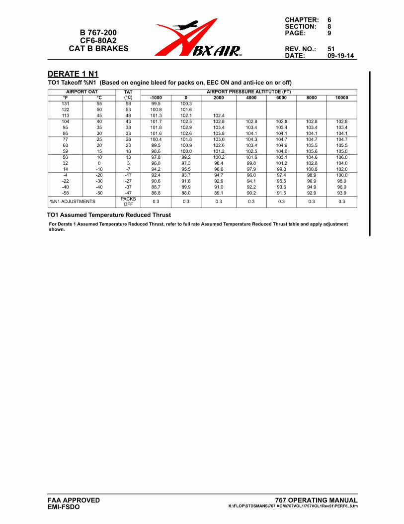
CHAPTER: 6SECTION: 8
B 767-200 PAGE: 9CF6-80A2
CAT B BRAKES REV. NO.: 51DATE: 09-19-14
DERATE 1 N1
TO1 Takeoff %N1 (Based on engine bleed for packs on, EEC ON and anti-ice on or off)
AIRPORT OAT TAT(°C)
AIRPORT PRESSURE ALTITUTDE (FT)°F °C -1000 0 2000 4000 6000 8000 10000
131 55 58 99.5 100.3122 50 53 100.8 101.6113 45 48 101.3 102.1 102.4104 40 43 101.7 102.5 102.8 102.8 102.8 102.8 102.895 35 38 101.8 102.9 103.4 103.4 103.4 103.4 103.486 30 33 101.6 102.6 103.8 104.1 104.1 104.1 104.177 25 28 100.4 101.8 103.0 104.3 104.7 104.7 104.768 20 23 99.5 100.9 102.0 103.4 104.9 105.5 105.559 15 18 98.6 100.0 101.2 102.5 104.0 105.6 105.050 10 13 97.8 99.2 100.2 101.6 103.1 104.6 106.032 0 3 96.0 97.3 98.4 99.8 101.2 102.8 104.014 -10 -7 94.2 95.5 96.6 97.9 99.3 100.8 102.0-4 -20 -17 92.4 93.7 94.7 96.0 97.4 98.9 100.0-22 -30 -27 90.6 91.8 92.9 94.1 95.5 96.9 98.0-40 -40 -37 88.7 89.9 91.0 92.2 93.5 94.9 96.0-58 -50 -47 86.8 88.0 89.1 90.2 91.5 92.9 93.9
%N1 ADJUSTMENTSPACKS
OFF0.3 0.3 0.3 0.3 0.3 0.3 0.3
TO1 Assumed Temperature Reduced Thrust
For Derate 1 Assumed Temperature Reduced Thrust, refer to full rate Assumed Temperature Reduced Thrust table and apply adjustment shown.
767 OPERATING MANUALK:\FLOP\STDSMANS\767 AOM\767VOL1\767VOL1Rev51\PERF6_8.fm
FAA APPROVEDEMI-FSDO
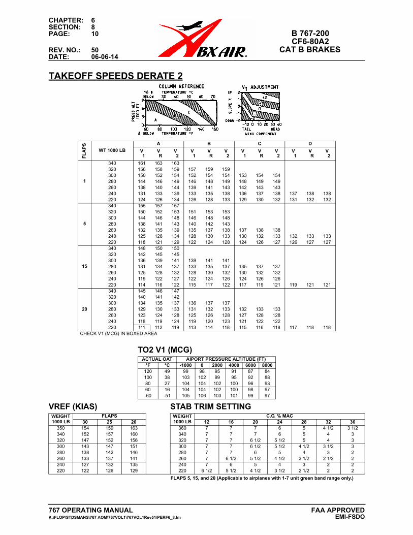
CHAPTER: 6SECTION: 8PAGE: 10 B 767-200
CF6-80A2REV. NO.: 50 CAT B BRAKESDATE: 06-06-14
TAKEOFF SPEEDS DERATE 2F
LA
PS
WT 1000 LB
A B C D
V 1
V R
V 2
V 1
V R
V 2
V 1
V R
V 2
V 1
V R
V 2
1
340 161 163 163320 156 158 159 157 159 159300 150 152 154 152 154 154 153 154 154280 144 146 149 146 148 149 148 149 149260 138 140 144 139 141 143 142 143 143240 131 133 139 133 135 138 136 137 138 137 138 138220 124 126 134 126 128 133 129 130 132 131 132 132
5
340 155 157 157320 150 152 153 151 153 153300 144 146 148 146 148 148280 138 141 143 140 142 143260 132 135 139 135 137 138 137 138 138240 125 128 134 128 130 133 130 132 133 132 133 133220 118 121 129 122 124 128 124 126 127 126 127 127
15
340 148 150 150320 142 145 145300 136 139 141 139 141 141280 131 134 137 133 135 137 135 137 137260 125 128 132 128 130 132 130 132 132240 119 122 127 122 124 126 124 126 126220 114 116 122 115 117 122 117 119 121 119 121 121
20
340 145 146 147320 140 141 142300 134 135 137 136 137 137280 129 130 133 131 132 133 132 133 133260 123 124 128 125 126 128 127 128 128240 118 119 124 119 120 123 121 122 122220 111 112 119 113 114 118 115 116 118 117 118 118
CHECK V1 (MCG) IN BOXED AREA
TO2 V1 (MCG)ACTUAL OAT AIPORT PRESSURE ALTITUDE (FT)
°F °C -1000 0 2000 4000 6000 8000120 49 99 98 95 91 87 84100 38 103 102 99 95 92 8880 27 104 104 102 100 96 9360 16 104 104 102 100 98 97-60 -51 105 106 103 101 99 97
VREF (KIAS) STAB TRIM SETTINGWEIGHT1000 LB
FLAPS WEIGHT1000 LB
C.G. % MAC30 25 20 12 16 20 24 28 32 36
350 154 159 163 360 7 7 7 6 5 4 1/2 3 1/2340 152 157 160 340 7 7 7 6 5 4 3320 147 152 156 320 7 7 6 1/2 5 1/2 5 4 3300 143 147 151 300 7 7 6 1/2 5 1/2 4 1/2 3 1/2 3280 138 142 146 280 7 7 6 5 4 3 2260 133 137 141 260 7 6 1/2 5 1/2 4 1/2 3 1/2 2 1/2 2240 127 132 135 240 7 6 5 4 3 2 2220 122 126 129 220 6 1/2 5 1/2 4 1/2 3 1/2 2 1/2 2 2
FLAPS 5, 15, and 20 (Applicable to airplanes with 1-7 unit green band range only.)
767 OPERATING MANUAL FAA APPROVEDK:\FLOP\STDSMANS\767 AOM\767VOL1\767VOL1Rev51\PERF6_8.fm EMI-FSDO
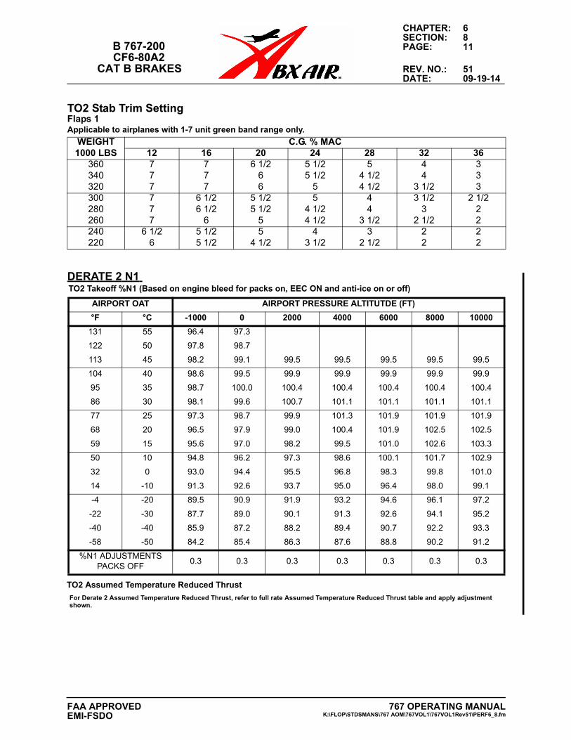
CHAPTER: 6SECTION: 8
B 767-200 PAGE: 11CF6-80A2
CAT B BRAKES REV. NO.: 51DATE: 09-19-14
DERATE 2 N1
TO2 Stab Trim SettingFlaps 1Applicable to airplanes with 1-7 unit green band range only.
WEIGHT 1000 LBS
C.G. % MAC12 16 20 24 28 32 36
360 7 7 6 1/2 5 1/2 5 4 3340 7 7 6 5 1/2 4 1/2 4 3320 7 7 6 5 4 1/2 3 1/2 3300 7 6 1/2 5 1/2 5 4 3 1/2 2 1/2280 7 6 1/2 5 1/2 4 1/2 4 3 2260 7 6 5 4 1/2 3 1/2 2 1/2 2240 6 1/2 5 1/2 5 4 3 2 2220 6 5 1/2 4 1/2 3 1/2 2 1/2 2 2
TO2 Takeoff %N1 (Based on engine bleed for packs on, EEC ON and anti-ice on or off)
AIRPORT OAT AIRPORT PRESSURE ALTITUTDE (FT)
°F °C -1000 0 2000 4000 6000 8000 10000
131 55 96.4 97.3
122 50 97.8 98.7
113 45 98.2 99.1 99.5 99.5 99.5 99.5 99.5
104 40 98.6 99.5 99.9 99.9 99.9 99.9 99.9
95 35 98.7 100.0 100.4 100.4 100.4 100.4 100.4
86 30 98.1 99.6 100.7 101.1 101.1 101.1 101.1
77 25 97.3 98.7 99.9 101.3 101.9 101.9 101.9
68 20 96.5 97.9 99.0 100.4 101.9 102.5 102.5
59 15 95.6 97.0 98.2 99.5 101.0 102.6 103.3
50 10 94.8 96.2 97.3 98.6 100.1 101.7 102.9
32 0 93.0 94.4 95.5 96.8 98.3 99.8 101.0
14 -10 91.3 92.6 93.7 95.0 96.4 98.0 99.1
-4 -20 89.5 90.9 91.9 93.2 94.6 96.1 97.2
-22 -30 87.7 89.0 90.1 91.3 92.6 94.1 95.2
-40 -40 85.9 87.2 88.2 89.4 90.7 92.2 93.3
-58 -50 84.2 85.4 86.3 87.6 88.8 90.2 91.2
%N1 ADJUSTMENTSPACKS OFF
0.3 0.3 0.3 0.3 0.3 0.3 0.3
TO2 Assumed Temperature Reduced Thrust
For Derate 2 Assumed Temperature Reduced Thrust, refer to full rate Assumed Temperature Reduced Thrust table and apply adjustment shown.
767 OPERATING MANUALK:\FLOP\STDSMANS\767 AOM\767VOL1\767VOL1Rev51\PERF6_8.fm
FAA APPROVEDEMI-FSDO
CHAPTER: 6SECTION: 8PAGE: 12 B 767-200
CF6-80A2REV. NO.: 50 CAT B BRAKESDATE: 06-06-14
MAXIMUM ALLOWABLE LANDING WEIGHT CALCULATIONS
The maximum allowable landing weight is the lower of the following:
Structural Landing Limit Weight
Climb Limited Landing Weight
Runway Field Length Limited Weight
The Maximum Allowable Landing Weight Determination chart, located in this section, may be used to assist in the determination of the maximum landing weight.
LANDING FIELD LENGTH TABLES
FAR landing field length performance is presented in two tables.
Flaps 30/25 Landing Weight Table:
Allowable landing weight based on a known runway length. This information is included in the AeroData TLR and is to be used for normal flight planning.
Landing Field Length Table:
Required field length based on an estimated landing weight. This format may be more useful during an in-flight diversion or beginning an approach with RVR less than 4000.
767 OPERATING MANUAL FAA APPROVEDK:\FLOP\STDSMANS\767 AOM\767VOL1\767VOL1Rev51\PERF6_8.fm EMI-FSDO
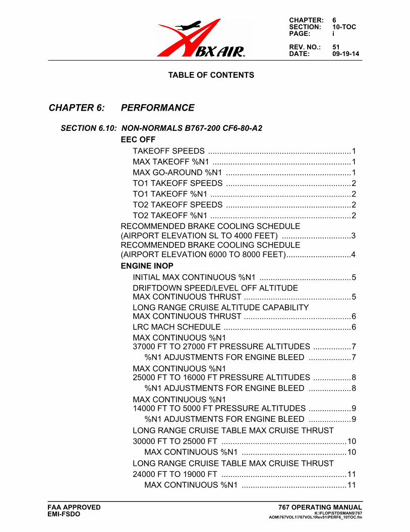
CHAPTER: 6SECTION: 10-TOCPAGE: i
REV. NO.: 51DATE: 09-19-14
TABLE OF CONTENTS
CHAPTER 6: PERFORMANCE
SECTION 6.10: NON-NORMALS B767-200 CF6-80-A2
EEC OFF
TAKEOFF SPEEDS ................................................................1MAX TAKEOFF %N1 ..............................................................1MAX GO-AROUND %N1 ........................................................1TO1 TAKEOFF SPEEDS ........................................................2TO1 TAKEOFF %N1 ...............................................................2TO2 TAKEOFF SPEEDS ........................................................2TO2 TAKEOFF %N1 ...............................................................2
RECOMMENDED BRAKE COOLING SCHEDULE(AIRPORT ELEVATION SL TO 4000 FEET) ...............................3RECOMMENDED BRAKE COOLING SCHEDULE(AIRPORT ELEVATION 6000 TO 8000 FEET).............................4
ENGINE INOP
INITIAL MAX CONTINUOUS %N1 .........................................5DRIFTDOWN SPEED/LEVEL OFF ALTITUDEMAX CONTINUOUS THRUST ................................................5LONG RANGE CRUISE ALTITUDE CAPABILITY MAX CONTINUOUS THRUST ................................................6LRC MACH SCHEDULE .........................................................6MAX CONTINUOUS %N1 37000 FT TO 27000 FT PRESSURE ALTITUDES .................7
%N1 ADJUSTMENTS FOR ENGINE BLEED ...................7
MAX CONTINUOUS %N1 25000 FT TO 16000 FT PRESSURE ALTITUDES .................8
%N1 ADJUSTMENTS FOR ENGINE BLEED ...................8
MAX CONTINUOUS %N1 14000 FT TO 5000 FT PRESSURE ALTITUDES ...................9
%N1 ADJUSTMENTS FOR ENGINE BLEED ...................9
LONG RANGE CRUISE TABLE MAX CRUISE THRUST30000 FT TO 25000 FT ........................................................10
MAX CONTINUOUS %N1 ...............................................10
LONG RANGE CRUISE TABLE MAX CRUISE THRUST 24000 FT TO 19000 FT ........................................................11
MAX CONTINUOUS %N1 ...............................................11
767 OPERATING MANUALK:\FLOP\STDSMANS\767
AOM\767VOL1\767VOL1Rev51\PERF6_10TOC.fm
FAA APPROVEDEMI-FSDO
CHAPTER: 6SECTION: 10-TOCPAGE: ii
REV. NO.: 51DATE: 09-19-14
LONG RANGE CRUISE TABLE MAX CRUISE THRUST18000 FT TO 13000 FT ........................................................12
MAX CONTINUOUS %N1 ...............................................12
LONG RANGE CRUISE TABLE MAX CRUISE THRUST12000 FT TO 7000 FT ..........................................................13
MAX CONTINUOUS %N1 ...............................................13
HOLDING - FLAPS UP, MAX CONTINUOUS THRUST .......14FLIGHT WITH UNRELIABLE AIRSPEED/TURBULENT AIR PENETRATION ............................................15
NON-NORMAL CONFIGURATION LANDING DISTANCE ........16
NON-NORMAL CONFIGURATION LANDING DISTANCE DRY RUNWAY ...........................................................................17
NON-NORMAL CONFIGURATION LANDING DISTANCE GOOD REPORTED BRAKING ACTION.....................................18
NON-NORMAL CONFIGURATION LANDING DISTANCE MEDIUM REPORTED BRAKING ACTION .................................19
NON-NORMAL CONFIGURATION LANDING DISTANCE POOR REPORTED BRAKING ACTION ....................................20
767 OPERATING MANUALK:\FLOP\STDSMANS\767 AOM\767VOL1\767VOL1Rev51\PERF6_10TOC.fm
FAA APPROVEDEMI-FSDO
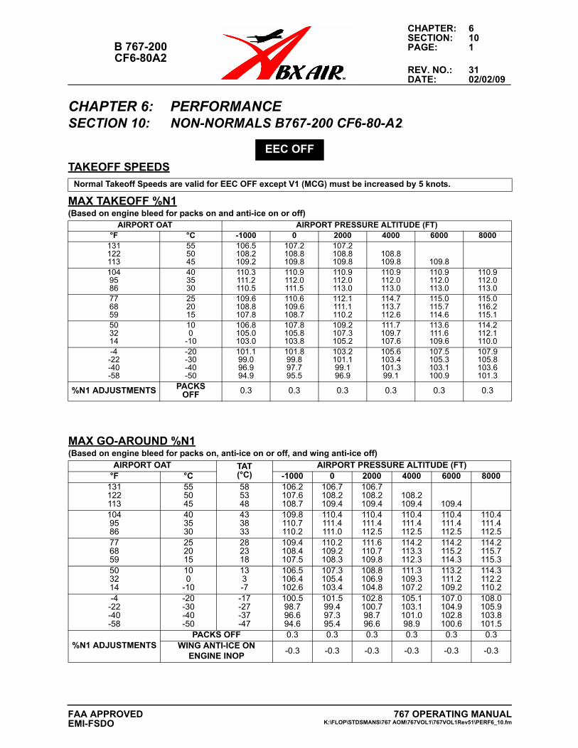
CHAPTER: 6SECTION: 10
B 767-200 PAGE: 1CF6-80A2
REV. NO.: 31DATE: 02/02/09
CHAPTER 6: PERFORMANCESECTION 10: NON-NORMALS B767-200 CF6-80-A22
TAKEOFF SPEEDS
EEC OFF
Normal Takeoff Speeds are valid for EEC OFF except V1 (MCG) must be increased by 5 knots.
MAX TAKEOFF %N1(Based on engine bleed for packs on and anti-ice on or off)
AIRPORT OAT AIRPORT PRESSURE ALTITUDE (FT)°F °C -1000 0 2000 4000 6000 8000
131122113
555045
106.5108.2109.2
107.2108.8109.8
107.2108.8109.8
108.8109.8 109.8
1049586
403530
110.3111.2110.5
110.9112.0111.5
110.9112.0113.0
110.9112.0113.0
110.9112.0113.0
110.9112.0113.0
776859
252015
109.6108.8107.8
110.6109.6108.7
112.1111.1110.2
114.7113.7112.6
115.0115.7114.6
115.0116.2115.1
503214
100
-10
106.8105.0103.0
107.8105.8103.8
109.2107.3105.2
111.7109.7107.6
113.6111.6109.6
114.2112.1110.0
-4-22-40-58
-20-30-40-50
101.199.096.994.9
101.899.897.795.5
103.2101.199.196.9
105.6103.4101.399.1
107.5105.3103.1100.9
107.9105.8103.6101.3
%N1 ADJUSTMENTS PACKSOFF 0.3 0.3 0.3 0.3 0.3 0.3
MAX GO-AROUND %N1(Based on engine bleed for packs on, anti-ice on or off, and wing anti-ice off)
AIRPORT OAT TAT(°C)
AIRPORT PRESSURE ALTITUDE (FT)°F °C -1000 0 2000 4000 6000 8000
131122113
555045
585348
106.2107.6108.7
106.7108.2109.4
106.7108.2109.4
108.2109.4 109.4
1049586
403530
433833
109.8110.7110.2
110.4111.4111.0
110.4111.4112.5
110.4111.4112.5
110.4111.4112.5
110.4111.4112.5
776859
252015
282318
109.4108.4107.5
110.2109.2108.3
111.6110.7109.8
114.2113.3112.3
114.2115.2114.3
114.2115.7115.3
503214
100
-10
133-7
106.5106.4102.6
107.3105.4103.4
108.8106.9104.8
111.3109.3107.2
113.2111.2109.2
114.3112.2110.2
-4-22-40-58
-20-30-40-50
-17-27-37-47
100.598.796.694.6
101.599.497.395.4
102.8100.798.796.6
105.1103.1101.098.9
107.0104.9102.8100.6
108.0105.9103.8101.5
%N1 ADJUSTMENTSPACKS OFF 0.3 0.3 0.3 0.3 0.3 0.3
WING ANTI-ICE ONENGINE INOP
-0.3 -0.3 -0.3 -0.3 -0.3 -0.3
767 OPERATING MANUALK:\FLOP\STDSMANS\767 AOM\767VOL1\767VOL1Rev51\PERF6_10.fm
FAA APPROVEDEMI-FSDO
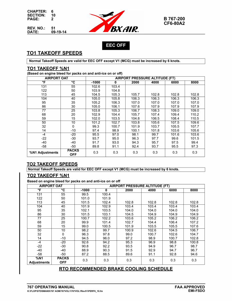
CHAPTER: 6SECTION: 10PAGE: 2 B 767-200
CF6-80A2REV. NO.: 51DATE: 09-19-14
TO1 TAKEOFF SPEEDS
RTO RECOMMENDED BRAKE COOLING SCHEDULEdvisory Information
EEC OFF
Normal Takeoff Speeds are valid for EEC OFF except V1 (MCG) must be increased by 6 knots.
TO1 TAKEOFF %N1(Based on engine bleed for packs on and anti-ice on or off)
AIRPORT OAT AIRPORT PRESSURE ALTITUDE (FT)°F °C -1000 0 2000 4000 6000 8000
131 55 102.6 103.4122 50 103.9 104.8113 45 104.5 105.3 105.7 102.8 102.8 102.8104 40 105.0 105.8 106.3 106.3 106.3 106.395 35 105.2 106.3 107.0 107.0 107.0 107.086 30 105.0 106.1 107.6 107.9 107.9 107.977 25 103.8 105.3 106.7 108.3 109.0 109.068 20 102.9 104.4 105.7 107.4 109.4 110.259 15 102.0 103.5 104.8 106.5 108.4 110.550 10 101.2 102.7 103.8 105.6 107.5 109.632 0 99.3 100.7 101.9 103.7 105.5 107.714 -10 97.4 98.9 100.1 101.8 103.6 105.6-4 -20 95.5 97.0 98.1 99.7 101.6 103.6-22 -30 93.7 95.0 96.3 97.7 99.6 101.5-40 -40 91.7 93.0 94.3 95.7 97.5 99.4-58 -50 89.8 91.1 92.4 93.7 95.5 97.3
%N1 AdjustmentsPACKS
OFF0.3 0.3 0.3 0.3 0.3 0.3
TO2 TAKEOFF SPEEDSNormal Takeoff Speeds are valid for EEC OFF except V1 (MCG) must be increased by 6 knots.
TO2 TAKEOFF %N1Based on engine bleed for packs on and anti-ice on or off
AIRPORT OAT AIRPORT PRESSURE ALTITUDE (FT)°F °C -1000 0 2000 4000 6000 8000
131 55 99.5 100.4122 50 101.0 101.9113 45 101.5 102.4 102.8 102.8 102.8 102.8104 40 101.9 102.9 103.4 103.4 103.4 103.495 35 102.1 103.5 104.0 104.0 104.0 104.086 30 101.5 103.1 104.5 104.9 104.9 104.977 25 100.7 102.2 103.6 105.2 106.2 106.268 20 99.9 101.4 102.7 104.4 106.4 107.259 15 99.0 100.5 101.9 103.5 105.5 107.650 10 98.2 99.7 100.9 102.6 104.5 106.732 0 96.3 97.8 99.0 100.7 102.6 104.714 -10 94.5 96.0 97.2 98.9 100.7 102.8-4 -20 92.6 94.2 95.3 96.9 98.8 100.8
-22 -30 90.8 92.2 93.5 94.9 96.7 98.7-40 -40 88.9 90.3 91.5 92.9 94.7 96.7-58 -50 87.2 88.5 89.6 91.1 92.8 94.6
%N1 Adjustments
PACKSOFF
0.3 0.3 0.3 0.3 0.3 0.3
767 OPERATING MANUAL FAA APPROVEDK:\FLOP\STDSMANS\767 AOM\767VOL1\767VOL1Rev51\PERF6_10.fm EMI-FSDO
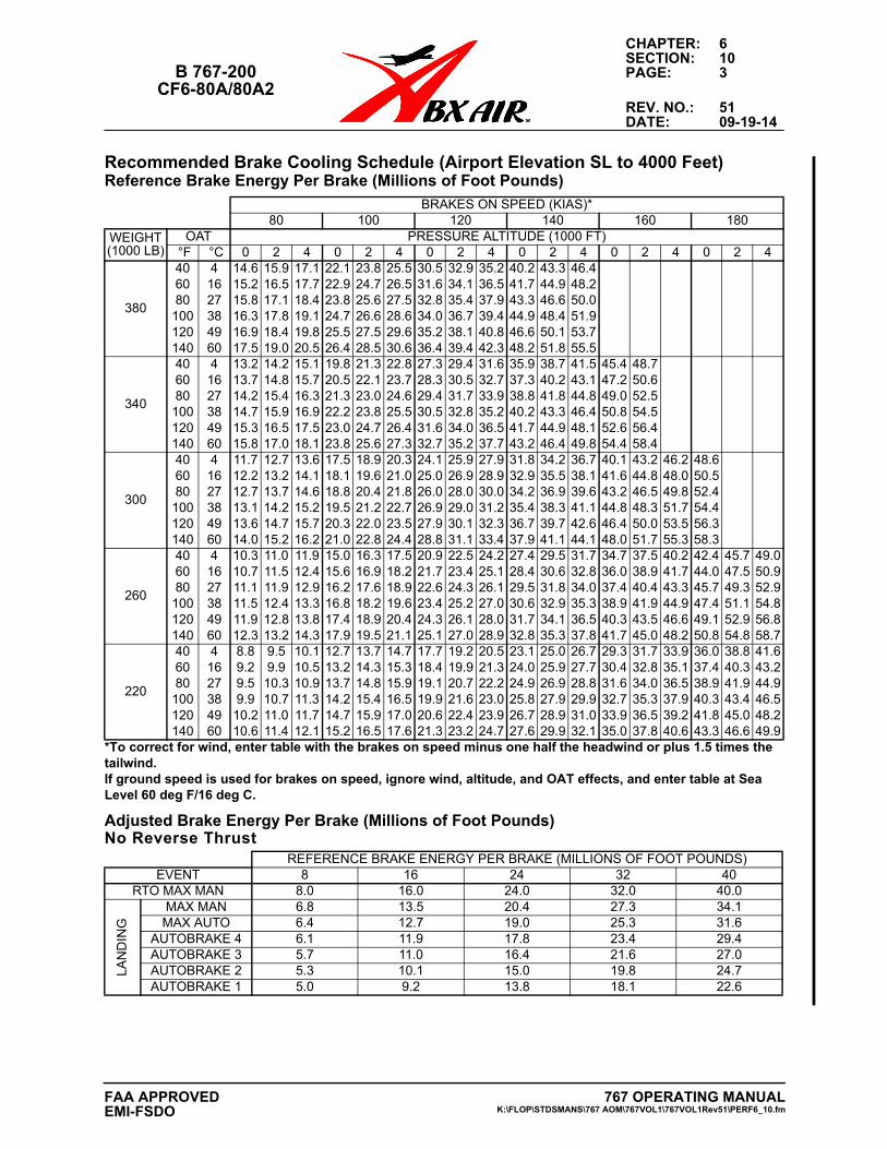
CHAPTER: 6SECTION: 10
B 767-200 PAGE: 3CF6-80A/80A2
REV. NO.: 51DATE: 09-19-14
Recommended Brake Cooling Schedule (Airport Elevation SL to 4000 Feet)Reference Brake Energy Per Brake (Millions of Foot Pounds)
Adjusted Brake Energy Per Brake (Millions of Foot Pounds)No Reverse Thrust
BRAKES ON SPEED (KIAS)*80 100 120 140 160 180
WEIGHT (1000 LB)
OAT PRESSURE ALTITUDE (1000 FT) °F °C 0 2 4 0 2 4 0 2 4 0 2 4 0 2 4 0 2 4
380
40 4 14.6 15.9 17.1 22.1 23.8 25.5 30.5 32.9 35.2 40.2 43.3 46.460 16 15.2 16.5 17.7 22.9 24.7 26.5 31.6 34.1 36.5 41.7 44.9 48.280 27 15.8 17.1 18.4 23.8 25.6 27.5 32.8 35.4 37.9 43.3 46.6 50.0
100 38 16.3 17.8 19.1 24.7 26.6 28.6 34.0 36.7 39.4 44.9 48.4 51.9120 49 16.9 18.4 19.8 25.5 27.5 29.6 35.2 38.1 40.8 46.6 50.1 53.7140 60 17.5 19.0 20.5 26.4 28.5 30.6 36.4 39.4 42.3 48.2 51.8 55.5
340
40 4 13.2 14.2 15.1 19.8 21.3 22.8 27.3 29.4 31.6 35.9 38.7 41.5 45.4 48.760 16 13.7 14.8 15.7 20.5 22.1 23.7 28.3 30.5 32.7 37.3 40.2 43.1 47.2 50.680 27 14.2 15.4 16.3 21.3 23.0 24.6 29.4 31.7 33.9 38.8 41.8 44.8 49.0 52.5
100 38 14.7 15.9 16.9 22.2 23.8 25.5 30.5 32.8 35.2 40.2 43.3 46.4 50.8 54.5120 49 15.3 16.5 17.5 23.0 24.7 26.4 31.6 34.0 36.5 41.7 44.9 48.1 52.6 56.4140 60 15.8 17.0 18.1 23.8 25.6 27.3 32.7 35.2 37.7 43.2 46.4 49.8 54.4 58.4
300
40 4 11.7 12.7 13.6 17.5 18.9 20.3 24.1 25.9 27.9 31.8 34.2 36.7 40.1 43.2 46.2 48.660 16 12.2 13.2 14.1 18.1 19.6 21.0 25.0 26.9 28.9 32.9 35.5 38.1 41.6 44.8 48.0 50.580 27 12.7 13.7 14.6 18.8 20.4 21.8 26.0 28.0 30.0 34.2 36.9 39.6 43.2 46.5 49.8 52.4
100 38 13.1 14.2 15.2 19.5 21.2 22.7 26.9 29.0 31.2 35.4 38.3 41.1 44.8 48.3 51.7 54.4120 49 13.6 14.7 15.7 20.3 22.0 23.5 27.9 30.1 32.3 36.7 39.7 42.6 46.4 50.0 53.5 56.3140 60 14.0 15.2 16.2 21.0 22.8 24.4 28.8 31.1 33.4 37.9 41.1 44.1 48.0 51.7 55.3 58.3
260
40 4 10.3 11.0 11.9 15.0 16.3 17.5 20.9 22.5 24.2 27.4 29.5 31.7 34.7 37.5 40.2 42.4 45.7 49.060 16 10.7 11.5 12.4 15.6 16.9 18.2 21.7 23.4 25.1 28.4 30.6 32.8 36.0 38.9 41.7 44.0 47.5 50.980 27 11.1 11.9 12.9 16.2 17.6 18.9 22.6 24.3 26.1 29.5 31.8 34.0 37.4 40.4 43.3 45.7 49.3 52.9
100 38 11.5 12.4 13.3 16.8 18.2 19.6 23.4 25.2 27.0 30.6 32.9 35.3 38.9 41.9 44.9 47.4 51.1 54.8120 49 11.9 12.8 13.8 17.4 18.9 20.4 24.3 26.1 28.0 31.7 34.1 36.5 40.3 43.5 46.6 49.1 52.9 56.8140 60 12.3 13.2 14.3 17.9 19.5 21.1 25.1 27.0 28.9 32.8 35.3 37.8 41.7 45.0 48.2 50.8 54.8 58.7
220
40 4 8.8 9.5 10.1 12.7 13.7 14.7 17.7 19.2 20.5 23.1 25.0 26.7 29.3 31.7 33.9 36.0 38.8 41.660 16 9.2 9.9 10.5 13.2 14.3 15.3 18.4 19.9 21.3 24.0 25.9 27.7 30.4 32.8 35.1 37.4 40.3 43.280 27 9.5 10.3 10.9 13.7 14.8 15.9 19.1 20.7 22.2 24.9 26.9 28.8 31.6 34.0 36.5 38.9 41.9 44.9
100 38 9.9 10.7 11.3 14.2 15.4 16.5 19.9 21.6 23.0 25.8 27.9 29.9 32.7 35.3 37.9 40.3 43.4 46.5120 49 10.2 11.0 11.7 14.7 15.9 17.0 20.6 22.4 23.9 26.7 28.9 31.0 33.9 36.5 39.2 41.8 45.0 48.2140 60 10.6 11.4 12.1 15.2 16.5 17.6 21.3 23.2 24.7 27.6 29.9 32.1 35.0 37.8 40.6 43.3 46.6 49.9
*To correct for wind, enter table with the brakes on speed minus one half the headwind or plus 1.5 times thetailwind. If ground speed is used for brakes on speed, ignore wind, altitude, and OAT effects, and enter table at Sea Level 60 deg F/16 deg C.
REFERENCE BRAKE ENERGY PER BRAKE (MILLIONS OF FOOT POUNDS)EVENT 8 16 24 32 40
RTO MAX MAN 8.0 16.0 24.0 32.0 40.0
LAN
DIN
G
MAX MAN 6.8 13.5 20.4 27.3 34.1MAX AUTO 6.4 12.7 19.0 25.3 31.6
AUTOBRAKE 4 6.1 11.9 17.8 23.4 29.4AUTOBRAKE 3 5.7 11.0 16.4 21.6 27.0AUTOBRAKE 2 5.3 10.1 15.0 19.8 24.7AUTOBRAKE 1 5.0 9.2 13.8 18.1 22.6
767 OPERATING MANUALK:\FLOP\STDSMANS\767 AOM\767VOL1\767VOL1Rev51\PERF6_10.fm
FAA APPROVEDEMI-FSDO
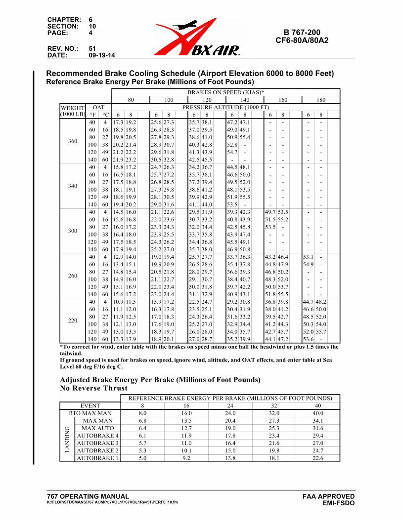
CHAPTER: 6SECTION: 10PAGE: 4 B 767-200
CF6-80A/80A2REV. NO.: 51DATE: 09-19-14
Recommended Brake Cooling Schedule (Airport Elevation 6000 to 8000 Feet)Reference Brake Energy Per Brake (Millions of Foot Pounds)
Adjusted Brake Energy Per Brake (Millions of Foot Pounds)No Reverse Thrust
BRAKES ON SPEED (KIAS)*80 100 120 140 160 180
WEIGHT (1000 LB)
OAT PRESSURE ALTITUDE (1000 FT) °F °C 6 8 6 8 6 8 6 8 6 8 6 8
360
40 4 17.3 19.2 25.6 27.3 35.7 38.1 47.2 47.1 - - - -60 16 18.5 19.8 26.9 28.3 37.0 39.5 49.0 49.1 - - - -80 27 19.8 20.5 27.8 29.3 38.6 41.0 50.9 55.4 - - - -
100 38 20.2 21.4 28.9 30.7 40.3 42.8 52.8 - - - - -120 49 21.2 22.2 29.6 31.8 41.3 43.9 54.7 - - - - -140 60 21.9 23.2 30.5 32.8 42.5 45.5 - - - - - -
340
40 4 15.8 17.2 24.7 26.3 34.2 36.7 44.5 48.1 - - - -60 16 16.5 18.1 25.7 27.2 35.7 38.1 46.6 50.0 - - - -80 27 17.5 18.8 26.8 28.5 37.2 39.4 49.5 52.0 - - - -
100 38 18.1 19.1 27.3 29.8 38.6 41.2 48.1 53.5 - - - -120 49 18.6 19.9 28.1 30.5 39.9 42.9 51.9 55.5 - - - -140 60 19.4 20.2 29.0 31.6 41.1 44.0 53.5 - - - - -
300
40 4 14.5 16.0 21.1 22.6 29.5 31.9 39.3 42.3 49.7 53.5 - -60 16 15.6 16.8 22.0 23.6 30.7 33.2 40.8 43.9 51.5 55.2 - -80 27 16.0 17.2 23.3 24.3 32.0 34.4 42.5 45.8 53.5 - - -
100 38 16.4 18.0 23.9 25.5 33.7 35.8 43.9 47.4 - - - -120 49 17.5 18.5 24.3 26.2 34.4 36.8 45.5 49.1 - - - -140 60 17.9 19.4 25.2 27.0 35.7 38.0 46.9 50.8 - - - -
260
40 4 12.9 14.0 19.0 19.4 25.7 27.7 33.7 36.3 43.2 46.4 53.1 -60 16 13.4 15.1 19.9 20.9 26.5 28.6 35.4 37.8 44.8 47.9 54.9 -80 27 14.8 15.4 20.5 21.8 28.0 29.7 36.6 39.3 46.8 50.2 - -
100 38 14.9 16.0 21.1 22.7 29.1 30.7 38.4 40.7 48.3 52.0 - -120 49 15.1 16.9 22.0 23.4 30.0 31.8 39.7 42.2 50.0 53.7 - -140 60 15.6 17.2 23.0 24.4 31.1 32.9 40.9 43.1 51.8 55.5 - -
220
40 4 10.9 11.5 15.9 17.2 22.5 24.7 29.2 30.8 36.8 39.8 44.7 48.260 16 11.1 12.0 16.3 17.8 23.5 25.1 30.4 31.9 38.0 41.2 46.6 50.080 27 11.9 12.5 17.0 18.3 24.3 26.4 31.6 33.2 39.5 42.7 48.5 52.0
100 38 12.1 13.0 17.6 19.0 25.2 27.0 32.9 34.4 41.2 44.3 50.3 54.0120 49 13.0 13.5 18.3 19.7 26.0 28.0 34.0 35.7 42.7 45.7 52.0 55.7140 60 13.3 13.9 18.9 20.1 27.0 28.7 35.2 39.9 44.1 47.2 53.6 -
*To correct for wind, enter table with the brakes on speed minus one half the headwind or plus 1.5 times thetailwind. If ground speed is used for brakes on speed, ignore wind, altitude, and OAT effects, and enter table at Sea Level 60 deg F/16 deg C.
REFERENCE BRAKE ENERGY PER BRAKE (MILLIONS OF FOOT POUNDS)EVENT 8 16 24 32 40
RTO MAX MAN 8.0 16.0 24.0 32.0 40.0
LAN
DIN
G
MAX MAN 6.8 13.5 20.4 27.3 34.1MAX AUTO 6.4 12.7 19.0 25.3 31.6
AUTOBRAKE 4 6.1 11.9 17.8 23.4 29.4AUTOBRAKE 3 5.7 11.0 16.4 21.6 27.0AUTOBRAKE 2 5.3 10.1 15.0 19.8 24.7AUTOBRAKE 1 5.0 9.2 13.8 18.1 22.6
767 OPERATING MANUALK:\FLOP\STDSMANS\767 AOM\767VOL1\767VOL1Rev51\PERF6_10.fm
FAA APPROVED EMI-FSDO
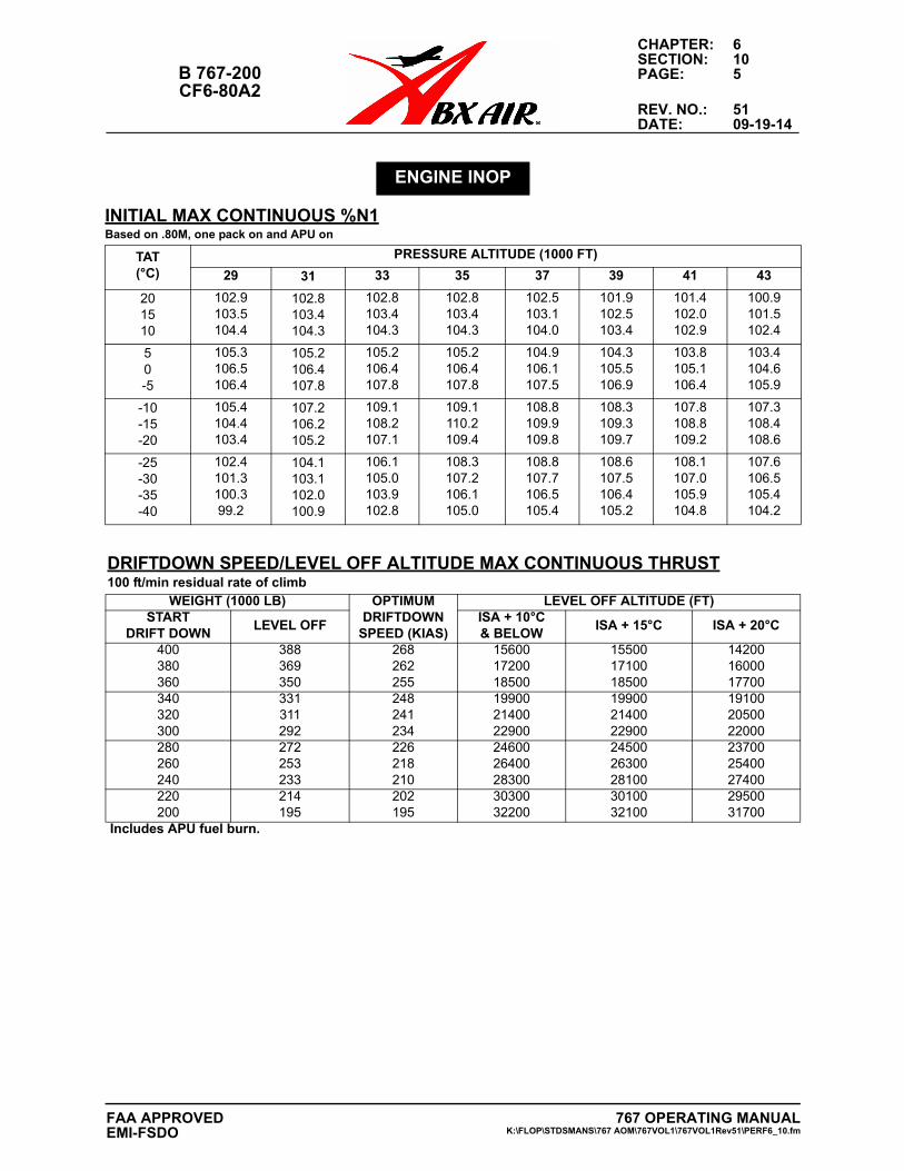
CHAPTER: 6SECTION: 10
B 767-200 PAGE: 5CF6-80A2
REV. NO.: 51DATE: 09-19-14
ENGINE INOP
INITIAL MAX CONTINUOUS %N1Based on .80M, one pack on and APU on
TAT(°C)
PRESSURE ALTITUDE (1000 FT)
29 31 33 35 37 39 41 43
201510
102.9103.5104.4
102.8103.4104.3
102.8103.4104.3
102.8103.4104.3
102.5103.1104.0
101.9102.5103.4
101.4102.0102.9
100.9101.5102.4
50-5
105.3106.5106.4
105.2106.4107.8
105.2106.4107.8
105.2106.4107.8
104.9106.1107.5
104.3105.5106.9
103.8105.1106.4
103.4104.6105.9
-10-15-20
105.4104.4103.4
107.2106.2105.2
109.1108.2107.1
109.1110.2109.4
108.8109.9109.8
108.3109.3109.7
107.8108.8109.2
107.3108.4108.6
-25-30-35-40
102.4101.3100.399.2
104.1103.1102.0100.9
106.1105.0103.9102.8
108.3107.2106.1105.0
108.8107.7106.5105.4
108.6107.5106.4105.2
108.1107.0105.9104.8
107.6106.5105.4104.2
DRIFTDOWN SPEED/LEVEL OFF ALTITUDE MAX CONTINUOUS THRUST100 ft/min residual rate of climb
WEIGHT (1000 LB) OPTIMUM DRIFTDOWN
SPEED (KIAS)
LEVEL OFF ALTITUDE (FT)START
DRIFT DOWNLEVEL OFF
ISA + 10°C& BELOW
ISA + 15°C ISA + 20°C
400380360
388369350
268262255
156001720018500
155001710018500
142001600017700
340320300
331311292
248241234
199002140022900
199002140022900
191002050022000
280260240
272253233
226218210
246002640028300
245002630028100
237002540027400
220200
214195
202195
3030032200
3010032100
2950031700
Includes APU fuel burn.
767 OPERATING MANUALK:\FLOP\STDSMANS\767 AOM\767VOL1\767VOL1Rev51\PERF6_10.fm
FAA APPROVEDEMI-FSDO
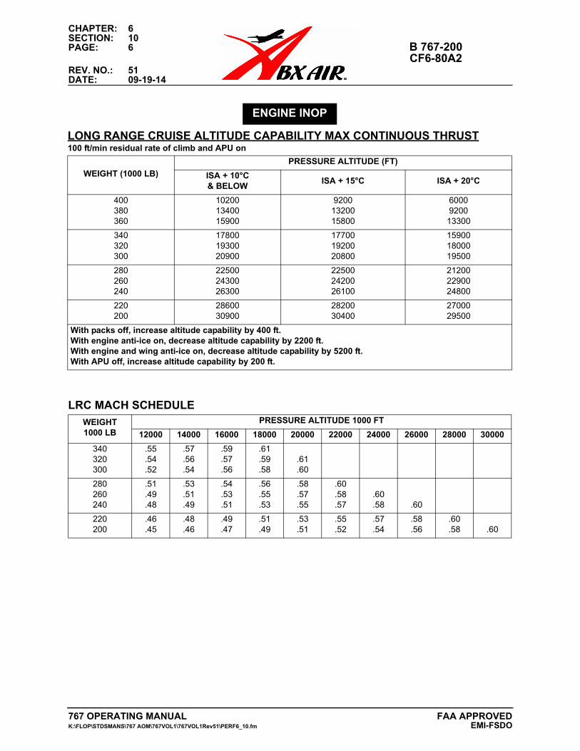
CHAPTER: 6SECTION: 10PAGE: 6 B 767-200
CF6-80A2REV. NO.: 51DATE: 09-19-14
ENGINE INOP
LONG RANGE CRUISE ALTITUDE CAPABILITY MAX CONTINUOUS THRUST100 ft/min residual rate of climb and APU on
WEIGHT (1000 LB)
PRESSURE ALTITUDE (FT)
ISA + 10°C& BELOW
ISA + 15°C ISA + 20°C
400380360
102001340015900
92001320015800
6000920013300
340320300
178001930020900
177001920020800
159001800019500
280260240
225002430026300
225002420026100
212002290024800
220200
2860030900
2820030400
2700029500
With packs off, increase altitude capability by 400 ft.With engine anti-ice on, decrease altitude capability by 2200 ft.With engine and wing anti-ice on, decrease altitude capability by 5200 ft.With APU off, increase altitude capability by 200 ft.
LRC MACH SCHEDULE
WEIGHT1000 LB
PRESSURE ALTITUDE 1000 FT
12000 14000 16000 18000 20000 22000 24000 26000 28000 30000
340320300
.55
.54
.52
.57
.56
.54
.59
.57
.56
.61
.59
.58.61.60
280260240
.51
.49
.48
.53
.51
.49
.54
.53
.51
.56
.55
.53
.58
.57
.55
.60
.58
.57.60.58 .60
220200
.46
.45.48.46
.49
.47.51.49
.53
.51.55.52
.57
.54.58.56
.60
.58 .60
767 OPERATING MANUAL FAA APPROVEDK:\FLOP\STDSMANS\767 AOM\767VOL1\767VOL1Rev51\PERF6_10.fm EMI-FSDO
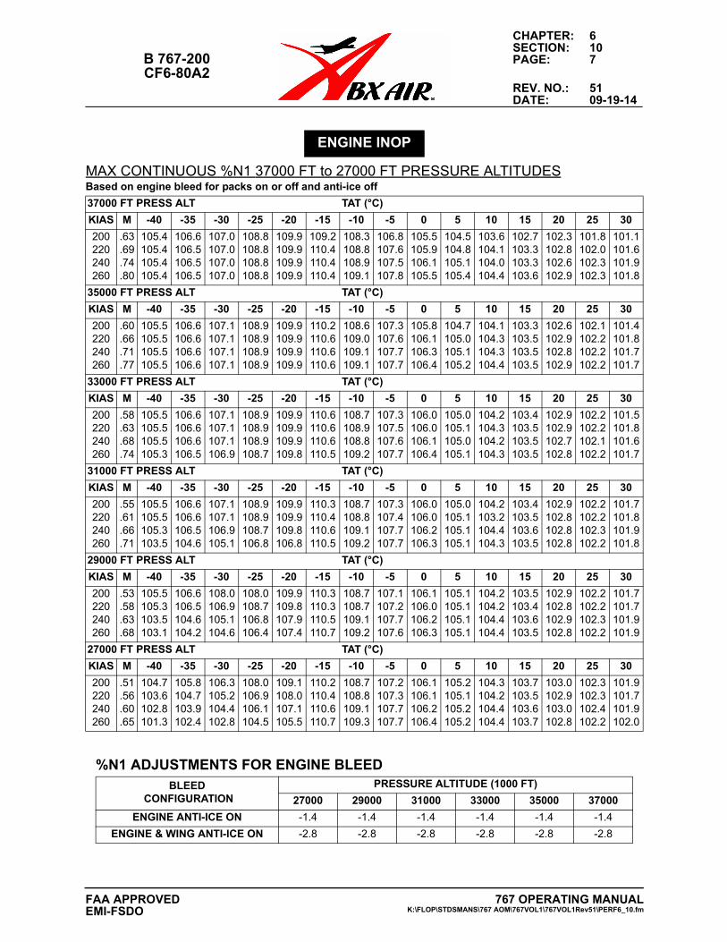
CHAPTER: 6SECTION: 10
B 767-200 PAGE: 7CF6-80A2
REV. NO.: 51DATE: 09-19-14
MAX CONTINUOUS %N1 37000 FT to 27000 FT PRESSURE ALTITUDES
ENGINE INOP
Based on engine bleed for packs on or off and anti-ice off
37000 FT PRESS ALT TAT (°C)
KIAS M -40 -35 -30 -25 -20 -15 -10 -5 0 5 10 15 20 25 30
200220240260
.63
.69
.74
.80
105.4105.4105.4105.4
106.6106.5106.5106.5
107.0107.0107.0107.0
108.8108.8108.8108.8
109.9109.9109.9109.9
109.2110.4110.4110.4
108.3108.8108.9109.1
106.8107.6107.5107.8
105.5105.9106.1105.5
104.5104.8105.1105.4
103.6104.1104.0104.4
102.7103.3103.3103.6
102.3102.8102.6102.9
101.8102.0102.3102.3
101.1101.6101.9101.8
35000 FT PRESS ALT TAT (°C)
KIAS M -40 -35 -30 -25 -20 -15 -10 -5 0 5 10 15 20 25 30
200220240260
.60
.66
.71
.77
105.5105.5105.5105.5
106.6106.6106.6106.6
107.1107.1107.1107.1
108.9108.9108.9108.9
109.9109.9109.9109.9
110.2110.6110.6110.6
108.6109.0109.1109.1
107.3107.6107.7107.7
105.8106.1106.3106.4
104.7105.0105.1105.2
104.1104.3104.3104.4
103.3103.5103.5103.5
102.6102.9102.8102.9
102.1102.2102.2102.2
101.4101.8101.7101.7
33000 FT PRESS ALT TAT (°C)
KIAS M -40 -35 -30 -25 -20 -15 -10 -5 0 5 10 15 20 25 30
200220240260
.58
.63
.68
.74
105.5105.5105.5105.3
106.6106.6106.6106.5
107.1107.1107.1106.9
108.9108.9108.9108.7
109.9109.9109.9109.8
110.6110.6110.6110.5
108.7108.9108.8109.2
107.3107.5107.6107.7
106.0106.0106.1106.4
105.0105.1105.0105.1
104.2104.3104.2104.3
103.4103.5103.5103.5
102.9102.9102.7102.8
102.2102.2102.1102.2
101.5101.8101.6101.7
31000 FT PRESS ALT TAT (°C)
KIAS M -40 -35 -30 -25 -20 -15 -10 -5 0 5 10 15 20 25 30
200220240260
.55
.61
.66
.71
105.5105.5105.3103.5
106.6106.6106.5104.6
107.1107.1106.9105.1
108.9108.9108.7106.8
109.9109.9109.8106.8
110.3110.4110.6110.5
108.7108.8109.1109.2
107.3107.4107.7107.7
106.0106.0106.2106.3
105.0105.1105.1105.1
104.2103.2104.4104.3
103.4103.5103.6103.5
102.9102.8102.8102.8
102.2102.2102.3102.2
101.7101.8101.9101.8
29000 FT PRESS ALT TAT (°C)
KIAS M -40 -35 -30 -25 -20 -15 -10 -5 0 5 10 15 20 25 30
200220240260
.53
.58
.63
.68
105.5105.3103.5103.1
106.6106.5104.6104.2
108.0106.9105.1104.6
108.0108.7106.8106.4
109.9109.8107.9107.4
110.3110.3110.5110.7
108.7108.7109.1109.2
107.1107.2107.7107.6
106.1106.0106.2106.3
105.1105.1105.1105.1
104.2104.2104.4104.4
103.5103.4103.6103.5
102.9102.8102.9102.8
102.2102.2102.3102.2
101.7101.7101.9101.9
27000 FT PRESS ALT TAT (°C)
KIAS M -40 -35 -30 -25 -20 -15 -10 -5 0 5 10 15 20 25 30
200220240260
.51
.56
.60
.65
104.7103.6102.8101.3
105.8104.7103.9102.4
106.3105.2104.4102.8
108.0106.9106.1104.5
109.1108.0107.1105.5
110.2110.4110.6110.7
108.7108.8109.1109.3
107.2107.3107.7107.7
106.1106.1106.2106.4
105.2105.1105.2105.2
104.3104.2104.4104.4
103.7103.5103.6103.7
103.0102.9103.0102.8
102.3102.3102.4102.2
101.9101.7101.9102.0
%N1 ADJUSTMENTS FOR ENGINE BLEEDBLEED
CONFIGURATIONPRESSURE ALTITUDE (1000 FT)
27000 29000 31000 33000 35000 37000
ENGINE ANTI-ICE ON -1.4 -1.4 -1.4 -1.4 -1.4 -1.4
ENGINE & WING ANTI-ICE ON -2.8 -2.8 -2.8 -2.8 -2.8 -2.8
767 OPERATING MANUALK:\FLOP\STDSMANS\767 AOM\767VOL1\767VOL1Rev51\PERF6_10.fm
FAA APPROVEDEMI-FSDO
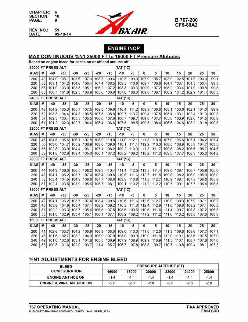
CHAPTER: 6SECTION: 10PAGE: 8 B 767-200
CF6-80A2REV. NO.: 51DATE: 09-19-14
MAX CONTINUOUS %N1 25000 FT to 16000 FT Pressure Altitudes
ENGINE INOP
Based on engine bleed for packs on or off and anti-ice off
25000 FT PRESS ALT TAT (°C)
KIAS M -40 -35 -30 -25 -20 -15 -10 -5 0 5 10 15 20 25 30
200220240260
.49
.53
.58
.63
104.0103.1101.9100.7
105.1104.2103.0101.8
105.6104.6103.5102.3
107.3106.4105.1103.9
108.3107.4106.2105.0
109.4108.5107.2106.0
110.5109.5108.3107.0
109.9110.6109.3108.0
107.9108.7109.0109.0
105.7106.6107.2108.1
103.9104.7105.2106.2
102.5103.1103.4104.2
101.0101.5101.9102.9
100.0100.4100.8101.4
99.199.599.8
100.3
24000 FT PRESS ALT TAT (°C)
KIAS M -40 -35 -30 -25 -20 -15 -10 -5 0 5 10 15 20 25 30
200220240260
.48
.52
.57
.61
104.2103.3102.3101.2
105.3104.4103.4102.3
105.7104.8103.8102.7
107.5106.5105.5104.4
108.5107.6106.6105.4
109.6108.8107.6106.6
110.4109.7108.7107.5
111.2110.7109.7108.5
108.9109.4109.6109.5
106.8107.5107.7108.4
105.1105.4105.8106.6
103.6103.1103.9104.6
102.1102.4102.6103.2
101.0101.3101.5101.8
99.9100.3100.6100.8
22000 FT PRESS ALT TAT (°C)
KIAS M -40 -35 -30 -25 -20 -15 -10 -5 0 5 10 15 20 25 30
200220240260
.46
.50
.55
.59
104.5103.6102.8101.8
105.6104.7103.9102.9
106.1105.2104.4103.4
107.8106.9106.1105.0
108.9108.0107.1106.1
110.0109.0108.2107.2
111.0110.1109.2108.2
112.1111.1110.3109.2
111.8112.2111.3110.2
110.0110.3111.7111.2
107.9108.5109.6109.5
106.6106.9108.2107.7
105.1105.8106.6106.3
104.2104.7105.7105.2
103.4103.5104.6104.2
20000 FT PRESS ALT TAT (°C)
KIAS M -40 -35 -30 -25 -20 -15 -10 -5 0 5 10 15 20 25 30
200220240260
.44
.48
.53
.57
104.9104.1103.4102.4
106.0105.2104.5103.5
106.5105.7104.9103.9
108.2107.4106.6105.6
109.3108.4107.7106.7
110.4109.5108.8108.1
111.4110.6109.8109.1
112.5111.6110.8110.2
113.3112.7111.9111.2
111.4111.5112.7112.2
109.6109.8110.9110.7
108.1108.2109.1109.1
106.7106.9107.8107.7
105.8105.9106.6106.4
105.0105.0105.9105.5
18000 FT PRESS ALT TAT (°C)
KIAS M -40 -35 -30 -25 -20 -15 -10 -5 0 5 10 15 20 25 30
200220240260
.42
.46
.51
.55
104.1103.8102.2101.8
105.2104.9103.3102.9
105.7105.4103.7103.4
107.4107.1105.4105.1
108.4108.2106.5106.1
109.5109.2107.5107.1
110.6110.3108.6108.2
111.6111.3109.6109.2
112.6112.4110.6111.2
112.7112.9111.6111.2
110.9111.0111.4111.6
109.3109.9109.7110.2
107.9108.2108.3108.8
107.1107.1107.2107.6
106.3106.5106.3106.8
16000 FT PRESS ALT TAT (°C)
KIAS M -40 -35 -30 -25 -20 -15 -10 -5 0 5 10 15 20 25 30
200220240260
.41
.45
.49
.53
102.6101.6101.6100.5
103.7102.7102.6101.6
104.2103.2103.1102.0
105.9104.9104.8103.7
106.9105.9105.8111.4
108.0107.0106.9105.7
109.0108.0107.9106.7
110.0109.0108.9107.8
111.0110.0109.9108.8
112.0111.0110.9109.7
111.3112.0111.5110.7
109.8110.1110.1110.8
108.6108.6108.7109.4
107.7107.5107.8108.1
107.1107.0107.0107.3
%N1 ADJUSTMENTS FOR ENGINE BLEEDBLEED
CONFIGURATIONPRESSURE ALTITUDE (FT)
16000 18000 20000 22000 24000 25000
ENGINE ANTI-ICE ON -1.4 -1.4 -1.4 -1.4 -1.4 -1.4
ENGINE & WING ANTI-ICE ON -2.8 -2.8 -2.8 -2.8 -2.8 -2.8
767 OPERATING MANUAL FAA APPROVEDK:\FLOP\STDSMANS\767 AOM\767VOL1\767VOL1Rev51\PERF6_10.fm EMI-FSDO
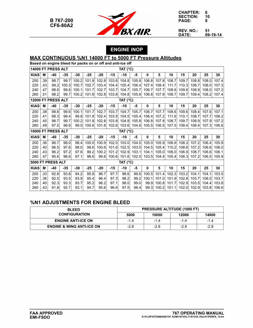
CHAPTER: 6SECTION: 10
B 767-200 PAGE: 9CF6-80A2
REV. NO.: 51DATE: 09-19-14
MAX CONTINUOUS %N1 14000 FT to 5000 FT Pressure Altitudes
ENGINE INOP
Based on engine bleed for packs on or off and anti-ice off
14000 FT PRESS ALT TAT (°C)
KIAS M -40 -35 -30 -25 -20 -15 -10 -5 0 5 10 15 20 25 30
200220240260
.39
.43
.47
.51
98.799.298.698.2
99.7100.399.699.7
100.2100.7100.1100.2
101.8102.7101.7101.8
102.8103.4102.7102.8
103.8104.4103.7103.8
104.8105.4104.7104.8
105.8106.4105.7105.8
106.8107.4106.7106.8
107.8108.4107.7107.8
108.7111.7108.6108.7
109.7110.3109.6109.7
108.8108.7108.9109.4
108.0108.0108.0108.2
107.4107.3107.2107.4
12000 FT PRESS ALT TAT (°C)
KIAS M -40 -35 -30 -25 -20 -15 -10 -5 0 5 10 15 20 25 30
200220240260
.38
.41
.45
.49
98.698.398.797.5
99.699.499.798.6
100.199.8
100.299.0
101.7101.9101.8100.6
102.7102.4102.8101.6
103.7103.5103.8102.6
104.7104.5104.8103.6
105.7105.4105.8104.6
106.7106.4106.8105.5
107.7107.2107.8106.5
108.6111.6108.7107.5
109.6110.1109.7108.4
108.4108.7108.9108.4
107.6107.7107.9107.3
107.1106.2107.2106.6
10000 FT PRESS ALT TAT (°C)
KIAS M -40 -35 -30 -25 -20 -15 -10 -5 0 5 10 15 20 25 30
200220240260
.36
.40
.43
.47
96.796.596.295.6
98.097.697.296.6
98.498.097.697.1
100.099.699.298.6
100.9100.6100.299.6
102.0101.6101.2100.6
103.0102.5102.9101.6
104.0103.5103.1102.5
105.0104.5104.1103.5
105.9105.4105.0104.4
106.9110.2106.0105.4
108.3108.6106.9106.3
107.2107.2108.7107.2
106.4106.6106.6106.5
105.9106.0106.1105.9
5000 FT PRESS ALT TAT (°C)
KIAS M -40 -35 -30 -25 -20 -15 -10 -5 0 5 10 15 20 25 30
200220240260
.33
.36
.40
.43
92.892.592.391.8
93.893.593.392.7
94.293.993.793.1
95.895.495.294.7
96.796.496.295.6
97.797.397.196.6
98.698.298.097.5
99.699.299.098.4
100.5100.1
99.999.3
101.4101.0100.8100.2
102.3101.9101.7101.1
103.2102.8102.9102.0
104.1103.7103.5102.9
104.1106.0104.4103.8
103.5103.7103.8106.6
%N1 ADJUSTMENTS FOR ENGINE BLEEDBLEED
CONFIGURATIONPRESSURE ALTITUDE (1000 FT)
5000 10000 12000 14000
ENGINE ANTI-ICE ON -1.4 -1.4 -1.4 -1.4
ENGINE & WING ANTI-ICE ON -2.8 -2.8 -2.8 -2.8
767 OPERATING MANUALK:\FLOP\STDSMANS\767 AOM\767VOL1\767VOL1Rev51\PERF6_10.fm
FAA APPROVEDEMI-FSDO
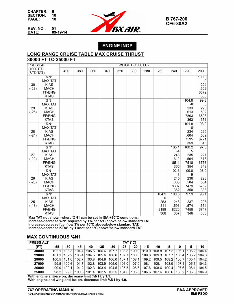
CHAPTER: 6SECTION: 10PAGE: 10 B 767-200
CF6-80A2REV. NO.: 51DATE: 09-19-14
ENGINE INOP
LONG RANGE CRUISE TABLE MAX CRUISE THRUST30000 FT TO 25000 FTPRESS ALT(1000 FT)(STD TAT)
WEIGHT (1000 LB)
400 380 360 340 320 300 280 260 240 220 200
30(-28)
%N1MAX TAT
KIASMACH
FF/ENGKTAS
100.9-2
224.602
6872355
29(-26)
%N1MAX TAT
KIASMACH
FF/ENGKTAS
104.8-8
233.6137803363
99.33
225.592
6806351
28(-24)
%N1MAX TAT
KIASMACH
FF/ENGKTAS
101.80
234.6047595359
98.2
226.582
6771346
27(-22)
%N1MAX TAT
KIASMACH
FF/ENGKTAS
105.1-4
243.6128511365
100.25
235.5947518354
97.0
227.573
6753342
26(-20)
%N1MAX TAT
KIASMACH
FF/ENGKTAS
102.33
245.6038307362
99.09
236.5847479350
96.0
228.564
6752338
25(-18)
%N1MAX TAT
KIASMACH
FF/ENGKTAS
104.90
253.611
9188368
100.88
246.5938226357
97.9
237.5747458346
95.1
228.554
6747333
Max TAT not shown where %N1 can be set in ISA +30°C conditions.Increase/decrease %N1 required by 1% per 5°C above/below standard TAT.Increase/decrease fuel flow 3% per 10°C above/below standard TAT.Increase/decrease KTAS by 1 knot per 1°C above/below standard TAT.
MAX CONTINUOUS %N1PRESS ALT
(FT)TAT (°C)
-55 -50 -45 -40 -35 -30 -25 -20 -15 -10 -5 0 5 10300002900028000
102.1101.1100.5
103.3102.2101.6
104.4103.4102.7
105.5104.5103.8
106.6105.6104.9
107.7106.6106.0
108.8107.7107.1
109.9108.8108.1
110.0109.8109.2
108.8109.3109.5
107.2107.7108.2
106.1106.4106.7
105.2105.2105.4
104.4104.3104.2
270002600025000
99.599.098.2
100.6100.199.3
101.7101.2100.3
102.8102.3101.4
103.9103.4102.5
105.0104.5103.5
106.0105.5104.6
107.0106.6105.6
108.1107.6106.6
109.1108.6107.6
108.9109.4108.6
107.1107.6108.2
105.7106.1106.5
104.3104.5104.9
With engine anti-ice on, decrease limit %N1 by 1.1.With engine and wing anti-ice on, decrease limit %N1 by 1.9.
767 OPERATING MANUAL FAA APPROVEDK:\FLOP\STDSMANS\767 AOM\767VOL1\767VOL1Rev51\PERF6_10.fm EMI-FSDO
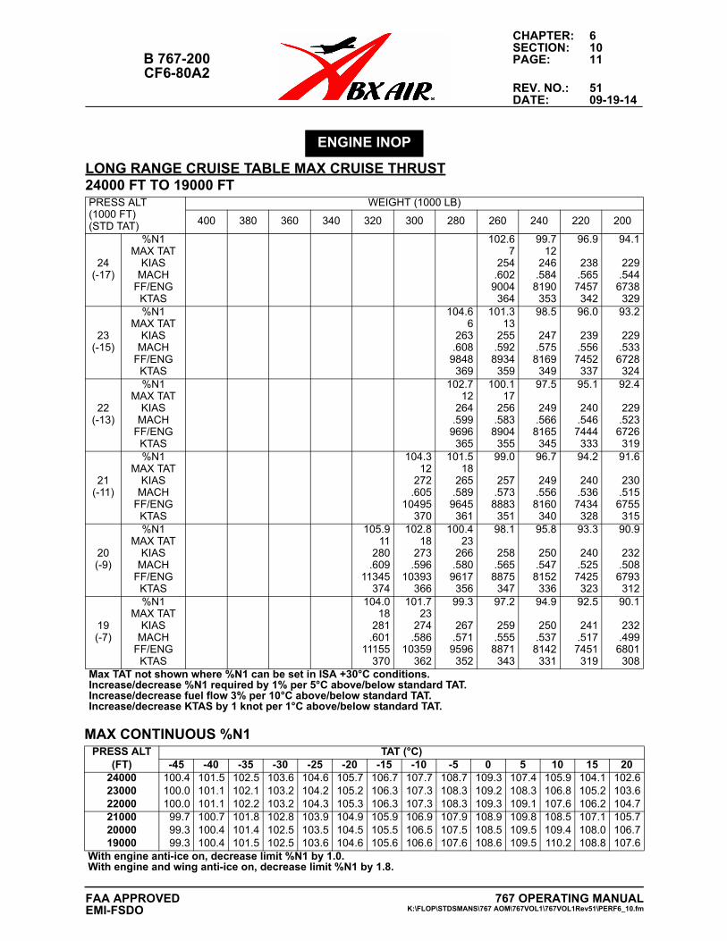
CHAPTER: 6SECTION: 10
B 767-200 PAGE: 11CF6-80A2
REV. NO.: 51DATE: 09-19-14
ENGINE INOP
LONG RANGE CRUISE TABLE MAX CRUISE THRUST24000 FT TO 19000 FTPRESS ALT(1000 FT)(STD TAT)
WEIGHT (1000 LB)
400 380 360 340 320 300 280 260 240 220 200
24(-17)
%N1MAX TAT
KIASMACH
FF/ENGKTAS
102.67
254.602
9004364
99.712
246.584
8190353
96.9
238.565
7457342
94.1
229.544
6738329
23(-15)
%N1MAX TAT
KIASMACH
FF/ENGKTAS
104.66
263.608
9848369
101.313
255.592
8934359
98.5
247.575
8169349
96.0
239.556
7452337
93.2
229.533
6728324
22(-13)
%N1MAX TAT
KIASMACH
FF/ENGKTAS
102.712
264.599
9696365
100.117
256.583
8904355
97.5
249.566
8165345
95.1
240.546
7444333
92.4
229.523
6726319
21(-11)
%N1MAX TAT
KIASMACH
FF/ENGKTAS
104.312
272.605
10495370
101.518
265.589
9645361
99.0
257.573
8883351
96.7
249.556
8160340
94.2
240.536
7434328
91.6
230.515
6755315
20(-9)
%N1MAX TAT
KIASMACH
FF/ENGKTAS
105.911
280.609
11345374
102.818
273.596
10393366
100.423
266.580
9617356
98.1
258.565
8875347
95.8
250.547
8152336
93.3
240.525
7425323
90.9
232.508
6793312
19(-7)
%N1MAX TAT
KIASMACH
FF/ENGKTAS
104.018
281.601
11155370
101.723
274.586
10359362
99.3
267.571
9596352
97.2
259.555
8871343
94.9
250.537
8142331
92.5
241.517
7451319
90.1
232.499
6801308
Max TAT not shown where %N1 can be set in ISA +30°C conditions.Increase/decrease %N1 required by 1% per 5°C above/below standard TAT.Increase/decrease fuel flow 3% per 10°C above/below standard TAT.Increase/decrease KTAS by 1 knot per 1°C above/below standard TAT.
MAX CONTINUOUS %N1PRESS ALT
(FT)TAT (°C)
-45 -40 -35 -30 -25 -20 -15 -10 -5 0 5 10 15 20240002300022000
100.4100.0100.0
101.5101.1101.1
102.5102.1102.2
103.6103.2103.2
104.6104.2104.3
105.7105.2105.3
106.7106.3106.3
107.7107.3107.3
108.7108.3108.3
109.3109.2109.3
107.4108.3109.1
105.9106.8107.6
104.1105.2106.2
102.6103.6104.7
210002000019000
99.799.399.3
100.7100.4100.4
101.8101.4101.5
102.8102.5102.5
103.9103.5103.6
104.9104.5104.6
105.9105.5105.6
106.9106.5106.6
107.9107.5107.6
108.9108.5108.6
109.8109.5109.5
108.5109.4110.2
107.1108.0108.8
105.7106.7107.6
With engine anti-ice on, decrease limit %N1 by 1.0.With engine and wing anti-ice on, decrease limit %N1 by 1.8.
767 OPERATING MANUALK:\FLOP\STDSMANS\767 AOM\767VOL1\767VOL1Rev51\PERF6_10.fm
FAA APPROVEDEMI-FSDO
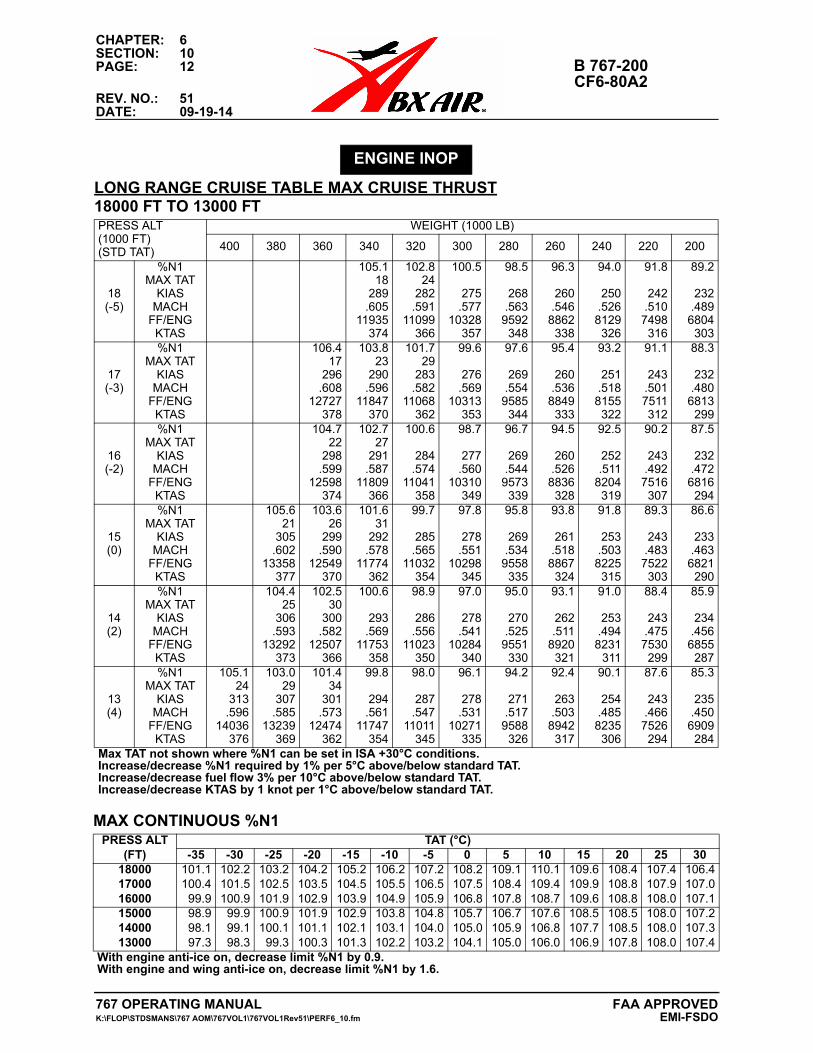
CHAPTER: 6SECTION: 10PAGE: 12 B 767-200
CF6-80A2REV. NO.: 51DATE: 09-19-14
ENGINE INOP
LONG RANGE CRUISE TABLE MAX CRUISE THRUST18000 FT TO 13000 FTPRESS ALT(1000 FT)(STD TAT)
WEIGHT (1000 LB)
400 380 360 340 320 300 280 260 240 220 200
18(-5)
%N1MAX TAT
KIASMACH
FF/ENGKTAS
105.118
289.605
11935374
102.824
282.591
11099366
100.5
275.577
10328357
98.5
268.563
9592348
96.3
260.546
8862338
94.0
250.5268129326
91.8
242.5107498316
89.2
232.489
6804303
17(-3)
%N1MAX TAT
KIASMACH
FF/ENGKTAS
106.417
296.608
12727378
103.823
290.596
11847370
101.729
283.582
11068362
99.6
276.569
10313353
97.6
269.554
9585344
95.4
260.536
8849333
93.2
251.5188155322
91.1
243.5017511312
88.3
232.480
6813299
16(-2)
%N1MAX TAT
KIASMACH
FF/ENGKTAS
104.722
298.599
12598374
102.727
291.587
11809366
100.6
284.574
11041358
98.7
277.560
10310349
96.7
269.544
9573339
94.5
260.526
8836328
92.5
252.511
8204319
90.2
243.4927516307
87.5
232.472
6816294
15(0)
%N1MAX TAT
KIASMACH
FF/ENGKTAS
105.621
305.602
13358377
103.626
299.590
12549370
101.631
292.578
11774362
99.7
285.565
11032354
97.8
278.551
10298345
95.8
269.534
9558335
93.8
261.518
8867324
91.8
253.5038225315
89.3
243.4837522303
86.6
233.463
6821290
14(2)
%N1MAX TAT
KIASMACH
FF/ENGKTAS
104.425
306.593
13292373
102.530
300.582
12507366
100.6
293.569
11753358
98.9
286.556
11023350
97.0
278.541
10284340
95.0
270.525
9551330
93.1
262.511
8920321
91.0
253.4948231
311
88.4
243.4757530299
85.9
234.456
6855287
13(4)
%N1MAX TAT
KIASMACH
FF/ENGKTAS
105.124
313.596
14036376
103.029
307.585
13239369
101.434
301.573
12474362
99.8
294.561
11747354
98.0
287.547
11011345
96.1
278.531
10271335
94.2
271.517
9588326
92.4
263.503
8942317
90.1
254.4858235306
87.6
243.4667526294
85.3
235.450
6909284
Max TAT not shown where %N1 can be set in ISA +30°C conditions.Increase/decrease %N1 required by 1% per 5°C above/below standard TAT.Increase/decrease fuel flow 3% per 10°C above/below standard TAT.Increase/decrease KTAS by 1 knot per 1°C above/below standard TAT.
MAX CONTINUOUS %N1PRESS ALT
(FT)TAT (°C)
-35 -30 -25 -20 -15 -10 -5 0 5 10 15 20 25 30180001700016000
101.1100.499.9
102.2101.5100.9
103.2102.5101.9
104.2103.5102.9
105.2104.5103.9
106.2105.5104.9
107.2106.5105.9
108.2107.5106.8
109.1108.4107.8
110.1109.4108.7
109.6109.9109.6
108.4108.8108.8
107.4107.9108.0
106.4107.0107.1
150001400013000
98.998.197.3
99.999.198.3
100.9100.1
99.3
101.9101.1100.3
102.9102.1101.3
103.8103.1102.2
104.8104.0103.2
105.7105.0104.1
106.7105.9105.0
107.6106.8106.0
108.5107.7106.9
108.5108.5107.8
108.0108.0108.0
107.2107.3107.4
With engine anti-ice on, decrease limit %N1 by 0.9.With engine and wing anti-ice on, decrease limit %N1 by 1.6.
767 OPERATING MANUAL FAA APPROVEDK:\FLOP\STDSMANS\767 AOM\767VOL1\767VOL1Rev51\PERF6_10.fm EMI-FSDO
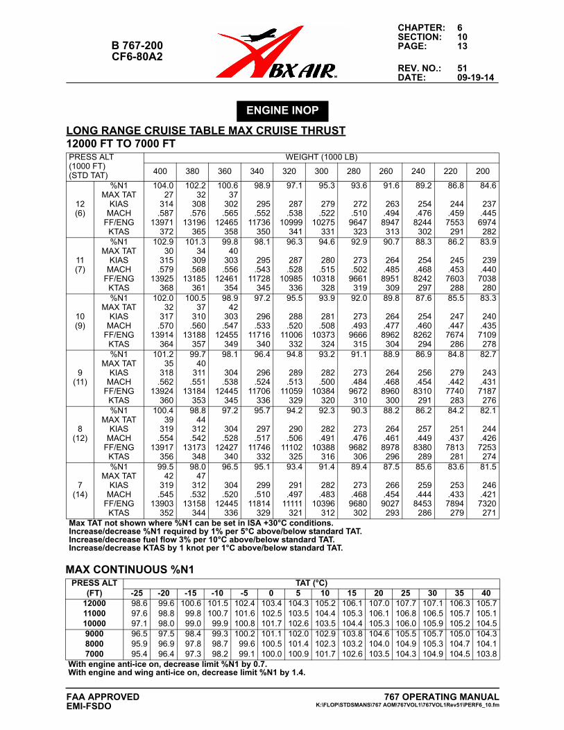
CHAPTER: 6SECTION: 10
B 767-200 PAGE: 13CF6-80A2
REV. NO.: 51DATE: 09-19-14
ENGINE INOP
LONG RANGE CRUISE TABLE MAX CRUISE THRUST12000 FT TO 7000 FTPRESS ALT(1000 FT)(STD TAT)
WEIGHT (1000 LB)
400 380 360 340 320 300 280 260 240 220 200
12(6)
%N1MAX TAT
KIASMACH
FF/ENGKTAS
104.027
314.587
13971372
102.232
308.576
13196365
100.637
302.565
12465358
98.9
295.552
11736350
97.1
287.538
10999341
95.3
279.522
10275331
93.6
272.510
9647323
91.6
263.494
8947313
89.2
254.476
8244302
86.8
244.459
7553291
84.6
237.445
6974282
11(7)
%N1MAX TAT
KIASMACH
FF/ENGKTAS
102.930
315.579
13925368
101.334
309.568
13185361
99.840
303.556
12461354
98.1
295.543
11728345
96.3
287.528
10985336
94.6
280.515
10318328
92.9
273.502
9661319
90.7
264.485
8951309
88.3
254.468
8242297
86.2
245.453
7603288
83.9
239.440
7038280
10(9)
%N1MAX TAT
KIASMACH
FF/ENGKTAS
102.032
317.570
13914364
100.537
310.560
13188357
98.942
303.547
12455349
97.2
296.533
11716340
95.5
288.520
11006332
93.9
281.508
10373324
92.0
273.493
9666315
89.8
264.477
8962304
87.6
254.460
8262294
85.5
247.447
7674286
83.3
240.435
7109278
9(11)
%N1MAX TAT
KIASMACH
FF/ENGKTAS
101.235
318.562
13924360
99.740
311.551
13184353
98.1
304.538
12445345
96.4
296.524
11706336
94.8
289.513
11059329
93.2
282.500
10384320
91.1
273.484
9672310
88.9
264.468
8960300
86.9
256.454
8310291
84.8
279.442
7740283
82.7
243.431
7187276
8(12)
%N1MAX TAT
KIASMACH
FF/ENGKTAS
100.439
319.554
13917356
98.844
312.542
13173348
97.2
304.528
12427340
95.7
297.517
11746332
94.2
290.506
11102325
92.3
282.491
10388316
90.3
273.476
9682306
88.2
264.461
8978296
86.2
257.449
8380289
84.2
251.437
7813281
82.1
244.426
7253274
7(14)
%N1MAX TAT
KIASMACH
FF/ENGKTAS
99.542
319.545
13903352
98.047
312.532
13158344
96.5
304.520
12445336
95.1
299.510
11814329
93.4
291.497
11111321
91.4
282.483
10396312
89.4
273.468
9680302
87.5
266.454
9027293
85.6
259.444
8453286
83.6
253.433
7894279
81.5
246.421
7320271
Max TAT not shown where %N1 can be set in ISA +30°C conditions.Increase/decrease %N1 required by 1% per 5°C above/below standard TAT.Increase/decrease fuel flow 3% per 10°C above/below standard TAT.Increase/decrease KTAS by 1 knot per 1°C above/below standard TAT.
MAX CONTINUOUS %N1PRESS ALT
(FT)TAT (°C)
-25 -20 -15 -10 -5 0 5 10 15 20 25 30 35 40120001100010000
98.697.697.1
99.698.898.0
100.699.899.0
101.5100.799.9
102.4101.6100.8
103.4102.5101.7
104.3103.5102.6
105.2104.4103.5
106.1105.3104.4
107.0106.1105.3
107.7106.8106.0
107.1106.5105.9
106.3105.7105.2
105.7105.1104.5
900080007000
96.595.995.4
97.596.996.4
98.497.897.3
99.398.798.2
100.299.699.1
101.1100.5100.0
102.0101.4100.9
102.9102.3101.7
103.8103.2102.6
104.6104.0103.5
105.5104.9104.3
105.7105.3104.9
105.0104.7104.5
104.3104.1103.8
With engine anti-ice on, decrease limit %N1 by 0.7.With engine and wing anti-ice on, decrease limit %N1 by 1.4.
767 OPERATING MANUALK:\FLOP\STDSMANS\767 AOM\767VOL1\767VOL1Rev51\PERF6_10.fm
FAA APPROVEDEMI-FSDO
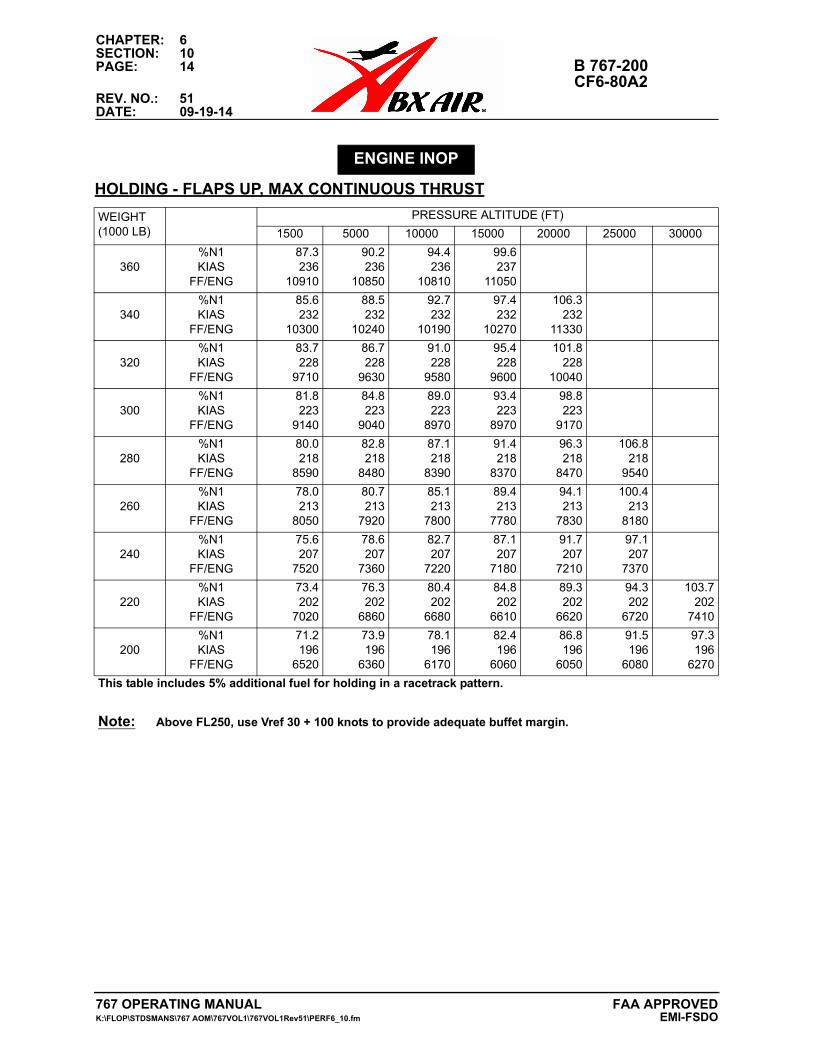
CHAPTER: 6SECTION: 10PAGE: 14 B 767-200
CF6-80A2REV. NO.: 51DATE: 09-19-14
HOLDING - FLAPS UP, MAX CONTINUOUS THRUST
ENGINE INOP
WEIGHT(1000 LB)
PRESSURE ALTITUDE (FT)
1500 5000 10000 15000 20000 25000 30000
360%N1KIAS
FF/ENG
87.3236
10910
90.2236
10850
94.4236
10810
99.6237
11050
340%N1KIAS
FF/ENG
85.6232
10300
88.5232
10240
92.7232
10190
97.4232
10270
106.3232
11330
320%N1KIAS
FF/ENG
83.7228
9710
86.7228
9630
91.0228
9580
95.4228
9600
101.8228
10040
300%N1KIAS
FF/ENG
81.8223
9140
84.8223
9040
89.0223
8970
93.4223
8970
98.8223
9170
280%N1KIAS
FF/ENG
80.0218
8590
82.8218
8480
87.1218
8390
91.4218
8370
96.3218
8470
106.8218
9540
260%N1KIAS
FF/ENG
78.0213
8050
80.7213
7920
85.1213
7800
89.4213
7780
94.1213
7830
100.4213
8180
240%N1KIAS
FF/ENG
75.6207
7520
78.6207
7360
82.7207
7220
87.1207
7180
91.7207
7210
97.1207
7370
220%N1KIAS
FF/ENG
73.4202
7020
76.3202
6860
80.4202
6680
84.8202
6610
89.3202
6620
94.3202
6720
103.7202
7410
200%N1KIAS
FF/ENG
71.2196
6520
73.9196
6360
78.1196
6170
82.4196
6060
86.8196
6050
91.5196
6080
97.3196
6270
This table includes 5% additional fuel for holding in a racetrack pattern.
Note: Above FL250, use Vref 30 + 100 knots to provide adequate buffet margin.
767 OPERATING MANUAL FAA APPROVEDK:\FLOP\STDSMANS\767 AOM\767VOL1\767VOL1Rev51\PERF6_10.fm EMI-FSDO
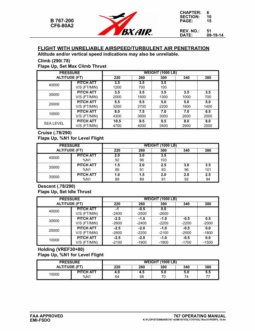
CHAPTER: 6SECTION: 10
B 767-200 PAGE: 15CF6-80A2
REV. NO.: 51DATE: 09-19-14
FLIGHT WITH UNRELIABLE AIRSPEED/TURBULENT AIR PENETRATIONAltitude and/or vertical speed indications may also be unreliable.
Climb (290/.78)Flaps Up, Set Max Climb Thrust
PRESSUREALTITUDE (FT)
WEIGHT (1000 LB)220 260 300 340 380
40000PITCH ATT
V/S (FT/MIN)3.5
12003.5700
3.5100
30000PITCH ATT
V/S (FT/MIN)3.5
20003.5
16003.5
13003.5
10003.5700
20000PITCH ATT
V/S (FT/MIN)5.5
32005.5
27005.0
22005.0
18005.0
1400
10000PITCH ATT
V/S (FT/MIN)8.0
43007.5
36007.0
30007.0
26006.5
2000
SEA LEVELPITCH ATT
V/S (FT/MIN)10.54700
9.54000
8.53400
8.02900
8.02500
Cruise (.78/290)Flaps Up, %N1 for Level Flight
PRESSUREALTITUDE (FT)
WEIGHT (1000 LB)220 260 300 340 380
40000PITCH ATT
%N12.092
3.096
3.5103
35000PITCH ATT
%N11.589
2.091
2.593
3.096
3.5101
30000PITCH ATT
%N11.089
1.589
2.091
2.092
2.594
Descent (.78/290)Flaps Up, Set Idle Thrust
PRESSUREALTITUDE (FT)
WEIGHT (1000 LB)220 260 300 340 380
40000PITCH ATT
V/S (FT/MIN)-1
-2400-0.5
-25000.0
-2600
30000PITCH ATT
V/S (FT/MIN)-2.5
-2600-1.5
-2400-1.0
-2200-0.5
-22000.5
-2000
20000PITCH ATT
V/S (FT/MIN)-2.5
-2600-2.0
-2200-1.0
-2100-0.5
-20000.0
-1800
10000PITCH ATT
V/S (FT/MIN)-2.5
-2100-2.0
-1900-1.0
-1800-0.5
-17000.0
-1500
Holding (VREF30+80)Flaps Up, %N1 for Level Flight
PRESSUREALTITUDE (FT)
WEIGHT (1000 LB)220 260 300 340 380
10000PITCH ATT
%N14.064
4.568
5.070
5.074
5.577
767 OPERATING MANUALK:\FLOP\STDSMANS\767 AOM\767VOL1\767VOL1Rev51\PERF6_10.fm
FAA APPROVEDEMI-FSDO
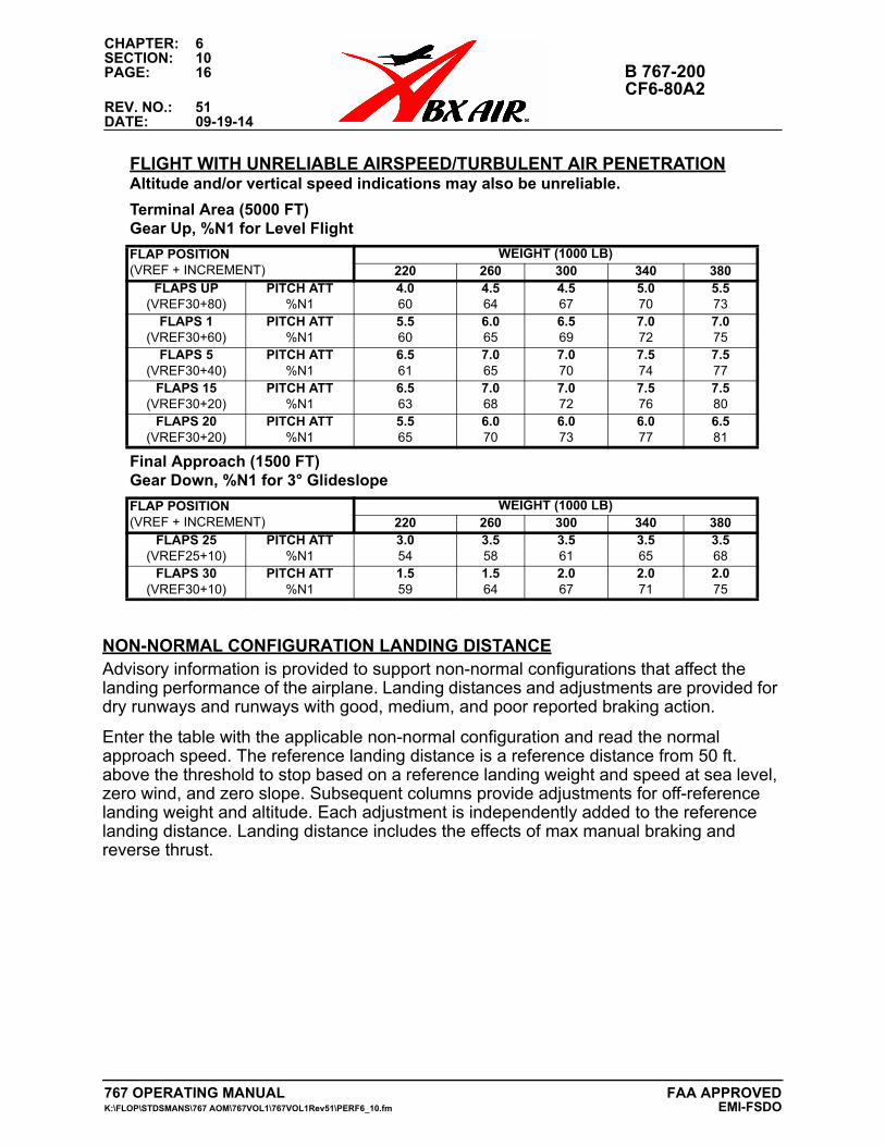
CHAPTER: 6SECTION: 10PAGE: 16 B 767-200
CF6-80A2REV. NO.: 51DATE: 09-19-14
NON-NORMAL CONFIGURATION LANDING DISTANCEAdvisory information is provided to support non-normal configurations that affect the landing performance of the airplane. Landing distances and adjustments are provided for dry runways and runways with good, medium, and poor reported braking action.
Enter the table with the applicable non-normal configuration and read the normal approach speed. The reference landing distance is a reference distance from 50 ft. above the threshold to stop based on a reference landing weight and speed at sea level, zero wind, and zero slope. Subsequent columns provide adjustments for off-reference landing weight and altitude. Each adjustment is independently added to the reference landing distance. Landing distance includes the effects of max manual braking and reverse thrust.
Terminal Area (5000 FT)Gear Up, %N1 for Level Flight
FLAP POSITION(VREF + INCREMENT)
WEIGHT (1000 LB)220 260 300 340 380
FLAPS UP(VREF30+80)
PITCH ATT%N1
4.060
4.564
4.567
5.070
5.573
FLAPS 1(VREF30+60)
PITCH ATT%N1
5.560
6.065
6.569
7.072
7.075
FLAPS 5(VREF30+40)
PITCH ATT%N1
6.561
7.065
7.070
7.574
7.577
FLAPS 15(VREF30+20)
PITCH ATT%N1
6.563
7.068
7.072
7.576
7.580
FLAPS 20(VREF30+20)
PITCH ATT%N1
5.565
6.070
6.073
6.077
6.581
Final Approach (1500 FT)Gear Down, %N1 for 3° Glideslope
FLAP POSITION(VREF + INCREMENT)
WEIGHT (1000 LB)220 260 300 340 380
FLAPS 25(VREF25+10)
PITCH ATT%N1
3.054
3.558
3.561
3.565
3.568
FLAPS 30(VREF30+10)
PITCH ATT%N1
1.559
1.564
2.067
2.071
2.075
FLIGHT WITH UNRELIABLE AIRSPEED/TURBULENT AIR PENETRATIONAltitude and/or vertical speed indications may also be unreliable.
767 OPERATING MANUAL FAA APPROVEDK:\FLOP\STDSMANS\767 AOM\767VOL1\767VOL1Rev51\PERF6_10.fm EMI-FSDO
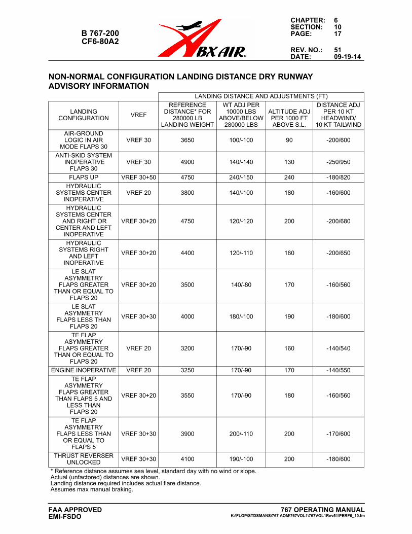
CHAPTER: 6SECTION: 10
B 767-200 PAGE: 17CF6-80A2
REV. NO.: 51DATE: 09-19-14
NON-NORMAL CONFIGURATION LANDING DISTANCE DRY RUNWAYADVISORY INFORMATION
LANDING DISTANCE AND ADJUSTMENTS (FT)
LANDINGCONFIGURATION VREF
REFERENCEDISTANCE* FOR
280000 LBLANDING WEIGHT
WT ADJ PER10000 LBS
ABOVE/BELOW280000 LBS
ALTITUDE ADJPER 1000 FTABOVE S.L.
DISTANCE ADJPER 10 KT
HEADWIND/10 KT TAILWIND
AIR-GROUNDLOGIC IN AIR
MODE FLAPS 30VREF 30 3650 100/-100 90 -200/600
ANTI-SKID SYSTEM INOPERATIVE
FLAPS 30VREF 30 4900 140/-140 130 -250/950
FLAPS UP VREF 30+50 4750 240/-150 240 -180/820
HYDRAULICSYSTEMS CENTER
INOPERATIVEVREF 20 3800 140/-100 180 -160/600
HYDRAULIC SYSTEMS CENTER
AND RIGHT ORCENTER AND LEFT
INOPERATIVE
VREF 30+20 4750 120/-120 200 -200/680
HYDRAULICSYSTEMS RIGHT
AND LEFTINOPERATIVE
VREF 30+20 4400 120/-110 160 -200/650
LE SLATASYMMETRY
FLAPS GREATERTHAN OR EQUAL TO
FLAPS 20
VREF 30+20 3500 140/-80 170 -160/560
LE SLATASYMMETRY
FLAPS LESS THANFLAPS 20
VREF 30+30 4000 180/-100 190 -180/600
TE FLAPASYMMETRY
FLAPS GREATERTHAN OR EQUAL TO
FLAPS 20
VREF 20 3200 170/-90 160 -140/540
ENGINE INOPERATIVE VREF 20 3250 170/-90 170 -140/550
TE FLAPASYMMETRY
FLAPS GREATERTHAN FLAPS 5 AND
LESS THANFLAPS 20
VREF 30+20 3550 170/-90 180 -160/560
TE FLAPASYMMETRY
FLAPS LESS THANOR EQUAL TO
FLAPS 5
VREF 30+30 3900 200/-110 200 -170/600
THRUST REVERSERUNLOCKED VREF 30+30 4100 190/-100 200 -180/600
* Reference distance assumes sea level, standard day with no wind or slope.Actual (unfactored) distances are shown.Landing distance required includes actual flare distance.Assumes max manual braking.
767 OPERATING MANUALK:\FLOP\STDSMANS\767 AOM\767VOL1\767VOL1Rev51\PERF6_10.fm
FAA APPROVEDEMI-FSDO

CHAPTER: 6SECTION: 10PAGE: 18 B 767-200
CF6-80A2REV. NO.: 51DATE: 09-19-14
NON-NORMAL CONFIGURATION LANDING DISTANCE GOOD REPORTED BRAKING ACTION ADVISORY INFORMATION
LANDING DISTANCE AND ADJUSTMENTS (FT)
LANDINGCONFIGURATION
VREF
REFERENCEDISTANCE* FOR
280000 LBLANDING WEIGHT
WT ADJ PER 10000 LBS
ABOVE/BELOW280000 LBS
ALTITUDE ADJPER 1000 FTABOVE S.L.
DISTANCE ADJPER 10 KT
HEADWIND/10 KT HEADWIND
AIR-GROUNDLOGIC IN AIR
MODE FLAPS 30VREF 30 5400 150/-150 150 -300/1050
ANTI-SKID SYSTEM INOPERATIVE
FLAPS 30VREF 30 6000 190/-190 180 -350/1300
FLAPS UP VREF 30+50 5900 170/-150 260 -270/920HYDRAULIC
SYSTEMS CENTERINOPERATIVE
VREF 20 5000 150/-160 220 -240/900
HYDRAULIC SYSTEMS CENTER
AND RIGHT ORCENTER AND LEFT
INOPERATIVE
VREF 30+20 6400 180/-170 280 -320/1060
HYDRAULICSYSTEMS RIGHT
AND LEFTINOPERATIVE
VREF 30+20 6200 170/-160 230 -300/1100
LE SLATASYMMETRY
FLAPS GREATERTHAN OR EQUAL TO
FLAPS 20
VREF 30+20 4700 140/-120 210 -240/840
LE SLATASYMMETRY
FLAPS LESS THANFLAPS 20
VREF 30+30 5300 150/-150 230 -260/900
TE FLAPASYMMETRY
FLAPS GREATERTHAN OR EQUAL TO
FLAPS 20
VREF 20 4250 140/-130 190 -220/820
ENGINE INOPERATIVE VREF 20 4500 140/-150 200 -230/860TE FLAP
ASYMMETRYFLAPS GREATER
THAN FLAPS 5 ANDLESS THANFLAPS 20
VREF 30+20 4700 140/-130 210 -240/840
TE FLAPASYMMETRY
FLAPS LESS THANOR EQUAL TO
FLAPS 5
VREF 30+30 5000 140/-130 220 -250/860
THRUST REVERSERUNLOCKED VREF 30+30 5600 170/-150 250 -280/940
* Reference distance assumes sea level, standard day with no wind or slope.Actual (unfactored) distances are shown.Landing distance required includes actual flare distance.Assumes max manual braking.
767 OPERATING MANUAL FAA APPROVEDK:\FLOP\STDSMANS\767 AOM\767VOL1\767VOL1Rev51\PERF6_10.fm EMI-FSDO
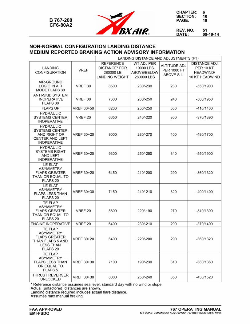
CHAPTER: 6SECTION: 10
B 767-200 PAGE: 19CF6-80A2
REV. NO.: 51DATE: 09-19-14
NON-NORMAL CONFIGURATION LANDING DISTANCE MEDIUM REPORTED BRAKING ACTION ADVISORY INFORMATION
LANDING DISTANCE AND ADJUSTMENTS (FT)
LANDINGCONFIGURATION
VREF
REFERENCEDISTANCE* FOR
280000 LBLANDING WEIGHT
WT ADJ PER 10000 LBS
ABOVE/BELOW280000 LBS
ALTITUDE ADJPER 1000 FTABOVE S.L.
DISTANCE ADJPER 10 KT
HEADWIND/10 KT HEADWIND
AIR-GROUNDLOGIC IN AIR
MODE FLAPS 30VREF 30 8500 230/-230 230 -550/1900
ANTI-SKID SYSTEM INOPERATIVE
FLAPS 30VREF 30 7600 260/-250 240 -500/1950
FLAPS UP VREF 30+50 8200 250/-250 360 -410/1460HYDRAULIC
SYSTEMS CENTERINOPERATIVE
VREF 20 6650 240/-220 300 -370/1390
HYDRAULIC SYSTEMS CENTER
AND RIGHT ORCENTER AND LEFT
INOPERATIVE
VREF 30+20 9000 280/-270 400 -480/1700
HYDRAULICSYSTEMS RIGHT
AND LEFTINOPERATIVE
VREF 30+20 9300 250/-250 340 -550/1900
LE SLATASYMMETRY
FLAPS GREATERTHAN OR EQUAL TO
FLAPS 20
VREF 30+20 6450 210/-200 290 -360/1320
LE SLATASYMMETRY
FLAPS LESS THANFLAPS 20
VREF 30+30 7150 240/-210 320 -400/1400
TE FLAPASYMMETRY
FLAPS GREATERTHAN OR EQUAL TO
FLAPS 20
VREF 20 5800 220/-190 270 -340/1300
ENGINE INOPERATIVE VREF 20 6400 230/-210 290 -370/1400TE FLAP
ASYMMETRYFLAPS GREATER
THAN FLAPS 5 ANDLESS THANFLAPS 20
VREF 30+20 6400 220/-200 290 -360/1320
TE FLAPASYMMETRY
FLAPS LESS THANOR EQUAL TO
FLAPS 5
VREF 30+30 7100 190/-230 310 -380/1360
THRUST REVERSERUNLOCKED VREF 30+30 8000 250/-240 350 -430/1520
* Reference distance assumes sea level, standard day with no wind or slope.Actual (unfactored) distances are shown.Landing distance required includes actual flare distance.Assumes max manual braking.
767 OPERATING MANUALK:\FLOP\STDSMANS\767 AOM\767VOL1\767VOL1Rev51\PERF6_10.fm
FAA APPROVEDEMI-FSDO
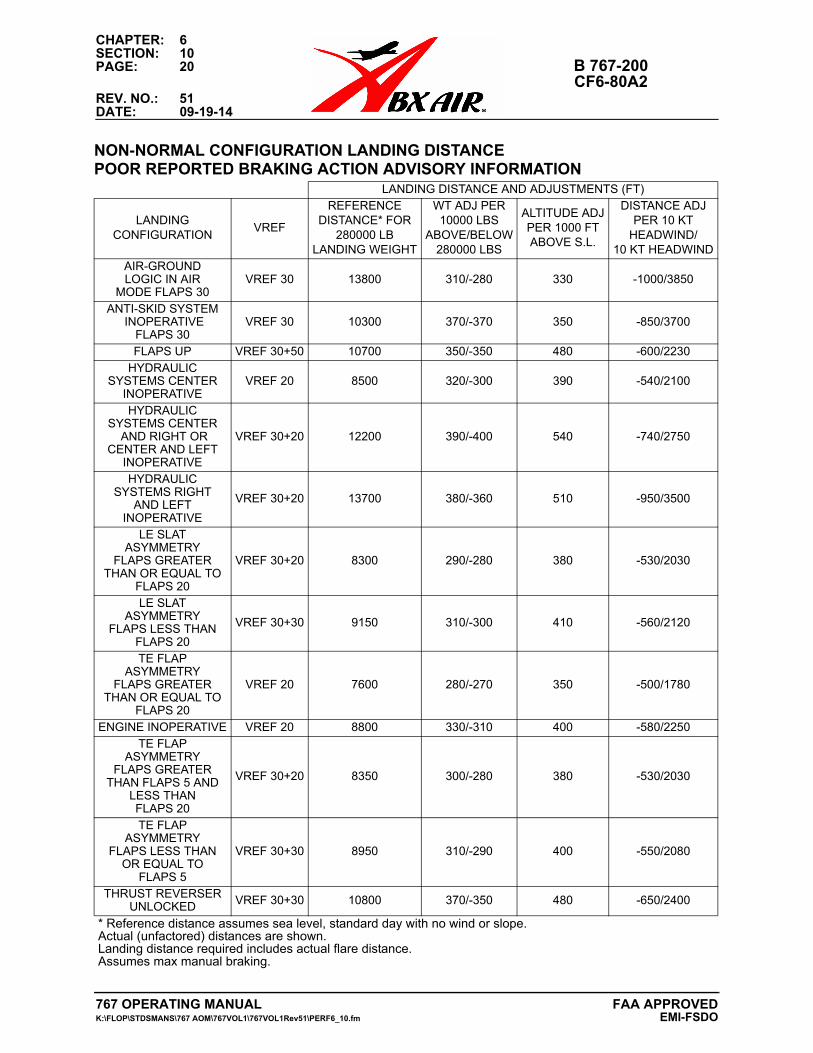
CHAPTER: 6SECTION: 10PAGE: 20 B 767-200
CF6-80A2REV. NO.: 51DATE: 09-19-14
NON-NORMAL CONFIGURATION LANDING DISTANCE POOR REPORTED BRAKING ACTION ADVISORY INFORMATION
LANDING DISTANCE AND ADJUSTMENTS (FT)
LANDINGCONFIGURATION
VREF
REFERENCEDISTANCE* FOR
280000 LBLANDING WEIGHT
WT ADJ PER 10000 LBS
ABOVE/BELOW280000 LBS
ALTITUDE ADJPER 1000 FTABOVE S.L.
DISTANCE ADJPER 10 KT
HEADWIND/10 KT HEADWIND
AIR-GROUNDLOGIC IN AIR
MODE FLAPS 30VREF 30 13800 310/-280 330 -1000/3850
ANTI-SKID SYSTEM INOPERATIVE
FLAPS 30VREF 30 10300 370/-370 350 -850/3700
FLAPS UP VREF 30+50 10700 350/-350 480 -600/2230HYDRAULIC
SYSTEMS CENTERINOPERATIVE
VREF 20 8500 320/-300 390 -540/2100
HYDRAULIC SYSTEMS CENTER
AND RIGHT ORCENTER AND LEFT
INOPERATIVE
VREF 30+20 12200 390/-400 540 -740/2750
HYDRAULICSYSTEMS RIGHT
AND LEFTINOPERATIVE
VREF 30+20 13700 380/-360 510 -950/3500
LE SLATASYMMETRY
FLAPS GREATERTHAN OR EQUAL TO
FLAPS 20
VREF 30+20 8300 290/-280 380 -530/2030
LE SLATASYMMETRY
FLAPS LESS THANFLAPS 20
VREF 30+30 9150 310/-300 410 -560/2120
TE FLAPASYMMETRY
FLAPS GREATERTHAN OR EQUAL TO
FLAPS 20
VREF 20 7600 280/-270 350 -500/1780
ENGINE INOPERATIVE VREF 20 8800 330/-310 400 -580/2250TE FLAP
ASYMMETRYFLAPS GREATER
THAN FLAPS 5 ANDLESS THANFLAPS 20
VREF 30+20 8350 300/-280 380 -530/2030
TE FLAPASYMMETRY
FLAPS LESS THANOR EQUAL TO
FLAPS 5
VREF 30+30 8950 310/-290 400 -550/2080
THRUST REVERSERUNLOCKED VREF 30+30 10800 370/-350 480 -650/2400
* Reference distance assumes sea level, standard day with no wind or slope.Actual (unfactored) distances are shown.Landing distance required includes actual flare distance.Assumes max manual braking.
767 OPERATING MANUAL FAA APPROVEDK:\FLOP\STDSMANS\767 AOM\767VOL1\767VOL1Rev51\PERF6_10.fm EMI-FSDO
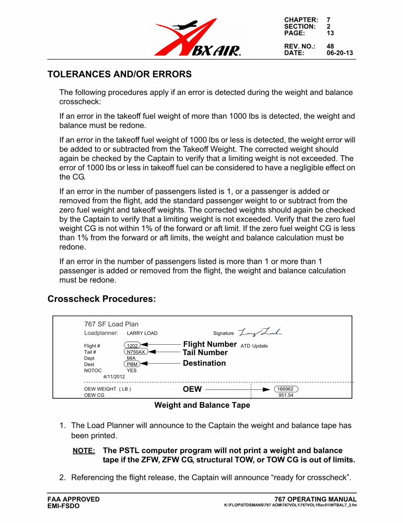
CHAPTER: 7SECTION: 2PAGE: 13
REV. NO.: 48DATE: 06-20-13
TOLERANCES AND/OR ERRORS
The following procedures apply if an error is detected during the weight and balance crosscheck:
If an error in the takeoff fuel weight of more than 1000 lbs is detected, the weight and balance must be redone.
If an error in the takeoff fuel weight of 1000 lbs or less is detected, the weight error will be added to or subtracted from the Takeoff Weight. The corrected weight should again be checked by the Captain to verify that a limiting weight is not exceeded. The error of 1000 lbs or less in takeoff fuel can be considered to have a negligible effect on the CG.
If an error in the number of passengers listed is 1, or a passenger is added or removed from the flight, add the standard passenger weight to or subtract from the zero fuel weight and takeoff weights. The corrected weights should again be checked by the Captain to verify that a limiting weight is not exceeded. Verify that the zero fuel weight CG is not within 1% of the forward or aft limit. If the zero fuel weight CG is less than 1% from the forward or aft limits, the weight and balance calculation must be redone.
If an error in the number of passengers listed is more than 1 or more than 1 passenger is added or removed from the flight, the weight and balance calculation must be redone.
Crosscheck Procedures:
Weight and Balance Tape
1. The Load Planner will announce to the Captain the weight and balance tape hasbeen printed.
NOTE: The PSTL computer program will not print a weight and balancetape if the ZFW, ZFW CG, structural TOW, or TOW CG is out of limits.
2. Referencing the flight release, the Captain will announce “ready for crosscheck”.
767 SF Load PlanLoadplanner: LARRY LOAD Signature
Flight # 1202 ATD UpdateTail # N750AXDept MIADest PBMNOTOC YES
4/11/2012
OEW WEIGHT ( LB ) 166962OEW CG 951.54
OEW
Flight NumberTail NumberDestination
767 OPERATING MANUALK:\FLOP\STDSMANS\767 AOM\767VOL1\767VOL1Rev51\WTBAL7_2.fm
FAA APPROVEDEMI-FSDO
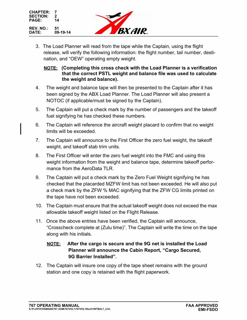
CHAPTER: 7SECTION: 2PAGE: 14
REV. NO.: 51DATE: 09-19-14
3. The Load Planner will read from the tape while the Captain, using the flightrelease, will verify the following information: the flight number, tail number, desti-nation, and “OEW” operating empty weight.
NOTE: (Completing this cross check with the Load Planner is a verificationthat the correct PSTL weight and balance file was used to calculate the weight and balance).
4. The weight and balance tape will then be presented to the Captain after it hasbeen signed by the ABX Load Planner. The Load Planner will also present aNOTOC (if applicable/must be signed by the Captain).
5. The Captain will put a check mark by the number of passengers and the takeofffuel signifying he has checked these numbers.
6. The Captain will reference the aircraft weight placard to confirm that no weightlimits will be exceeded.
7. The Captain will announce to the First Officer the zero fuel weight, the takeoffweight, and takeoff stab trim units.
8. The First Officer will enter the zero fuel weight into the FMC and using thisweight information from the weight and balance tape, determine takeoff perfor-mance from the AeroData TLR.
9. The Captain will put a check mark by the Zero Fuel Weight signifying he haschecked that the placarded MZFW limit has not been exceeded. He will also puta check mark by the ZFW % MAC signifying that the ZFW CG limits printed onthe tape have not been exceeded.
10. The Captain must ensure that the actual takeoff weight does not exceed the maxallowable takeoff weight listed on the Flight Release.
11. Once the above entries have been verified, the Captain will announce,“Crosscheck complete at (Zulu time)”. The Captain will write the time on the tapealong with his initials.
NOTE: After the cargo is secure and the 9G net is installed the LoadPlanner will announce the Cabin Report, “Cargo Secured, 9G Barrier Installed”.
12. The Captain will insure one copy of the tape sheet remains with the groundstation and one copy is retained with the flight paperwork.
767 OPERATING MANUALK:\FLOP\STDSMANS\767 AOM\767VOL1\767VOL1Rev51\WTBAL7_2.fm
FAA APPROVED EMI-FSDO
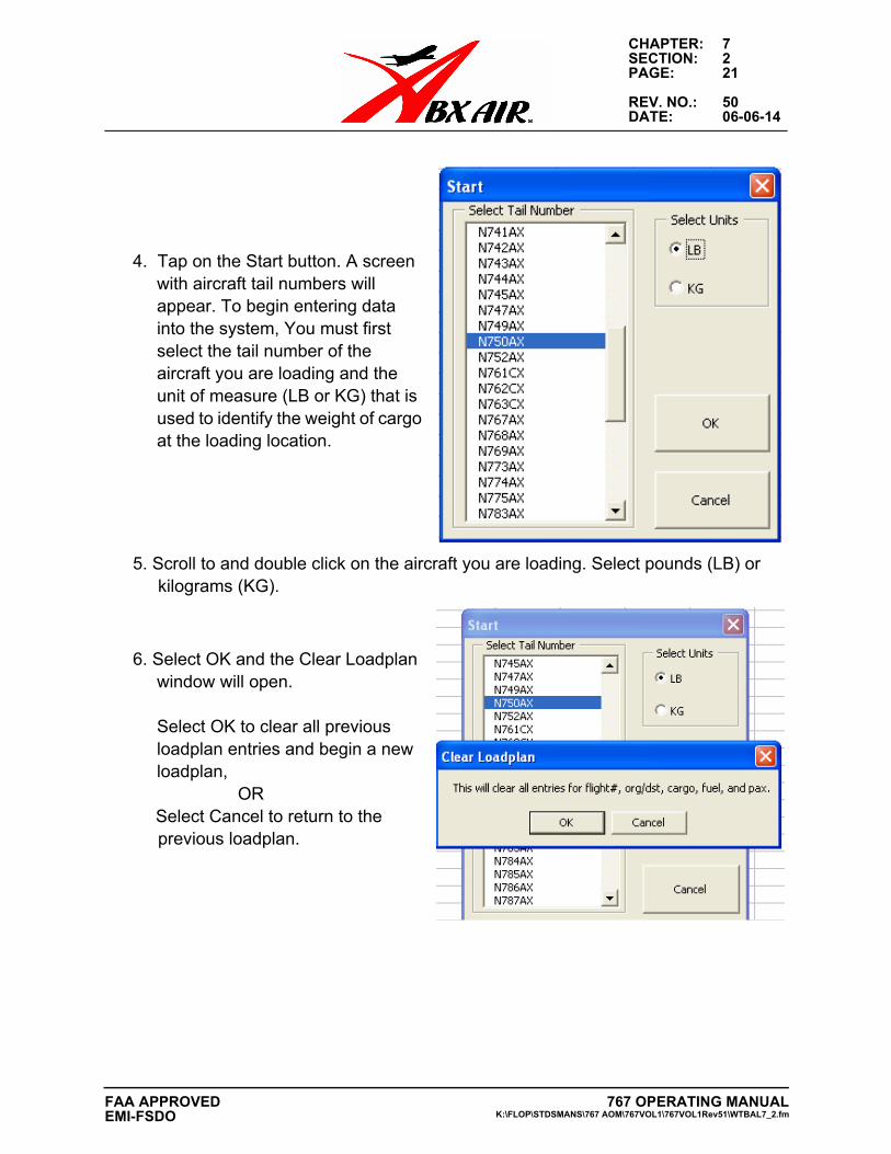
CHAPTER: 7SECTION: 2PAGE: 21
REV. NO.: 50DATE: 06-06-14
4. Tap on the Start button. A screenwith aircraft tail numbers willappear. To begin entering datainto the system, You must firstselect the tail number of theaircraft you are loading and theunit of measure (LB or KG) that isused to identify the weight of cargoat the loading location.
5. Scroll to and double click on the aircraft you are loading. Select pounds (LB) orkilograms (KG).
6. Select OK and the Clear Loadplanwindow will open.
Select OK to clear all previous loadplan entries and begin a new loadplan,
ORSelect Cancel to return to the previous loadplan.
767 OPERATING MANUALK:\FLOP\STDSMANS\767 AOM\767VOL1\767VOL1Rev51\WTBAL7_2.fm
FAA APPROVEDEMI-FSDO
CHAPTER: 7SECTION: 2PAGE: 22
REV. NO.: 51DATE: 09-19-14
7. The Create Flight sheet will now be available to enter administrative data for theflight. Fourteen fields are available. Instruction for entering information is located below.
Create Flight Sheet
Create Flight Sheet
Enter the administrative information for the flight. Select each of the 14 entry fields identified on the Start Sheet and enter the applicable information.
NOTE: To access the keyboard, tap the larger blue box with the stylus symbol on the lower menu bar.
767 OPERATING MANUALK:\FLOP\STDSMANS\767 AOM\767VOL1\767VOL1Rev51\WTBAL7_2.fm
FAA APPROVED EMI-FSDO
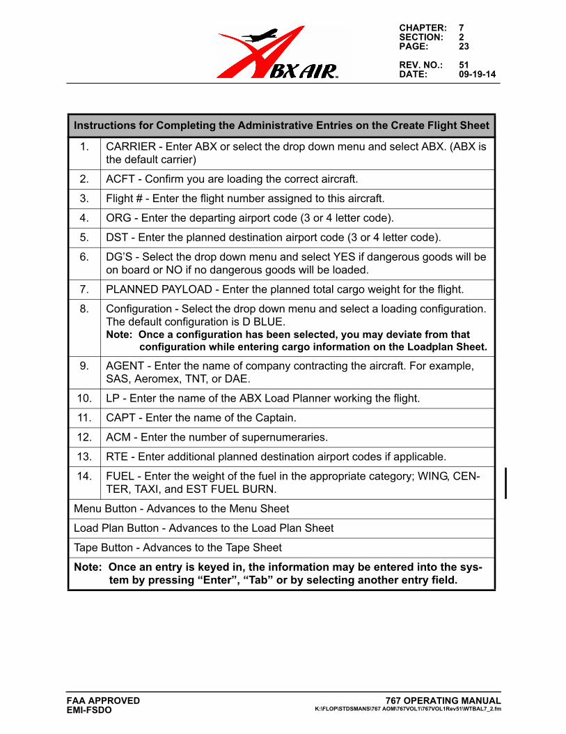
CHAPTER: 7SECTION: 2PAGE: 23
REV. NO.: 51DATE: 09-19-14
Instructions for Completing the Administrative Entries on the Create Flight Sheet
1. CARRIER - Enter ABX or select the drop down menu and select ABX. (ABX is the default carrier)
2. ACFT - Confirm you are loading the correct aircraft.
3. Flight # - Enter the flight number assigned to this aircraft.
4. ORG - Enter the departing airport code (3 or 4 letter code).
5. DST - Enter the planned destination airport code (3 or 4 letter code).
6. DG’S - Select the drop down menu and select YES if dangerous goods will be on board or NO if no dangerous goods will be loaded.
7. PLANNED PAYLOAD - Enter the planned total cargo weight for the flight.
8. Configuration - Select the drop down menu and select a loading configuration. The default configuration is D BLUE. Note: Once a configuration has been selected, you may deviate from that
configuration while entering cargo information on the Loadplan Sheet.
9. AGENT - Enter the name of company contracting the aircraft. For example, SAS, Aeromex, TNT, or DAE.
10. LP - Enter the name of the ABX Load Planner working the flight.
11. CAPT - Enter the name of the Captain.
12. ACM - Enter the number of supernumeraries.
13. RTE - Enter additional planned destination airport codes if applicable.
14. FUEL - Enter the weight of the fuel in the appropriate category; WING, CEN-TER, TAXI, and EST FUEL BURN.
Menu Button - Advances to the Menu Sheet
Load Plan Button - Advances to the Load Plan Sheet
Tape Button - Advances to the Tape Sheet
Note: Once an entry is keyed in, the information may be entered into the sys-tem by pressing “Enter”, “Tab” or by selecting another entry field.
767 OPERATING MANUALK:\FLOP\STDSMANS\767 AOM\767VOL1\767VOL1Rev51\WTBAL7_2.fm
FAA APPROVEDEMI-FSDO
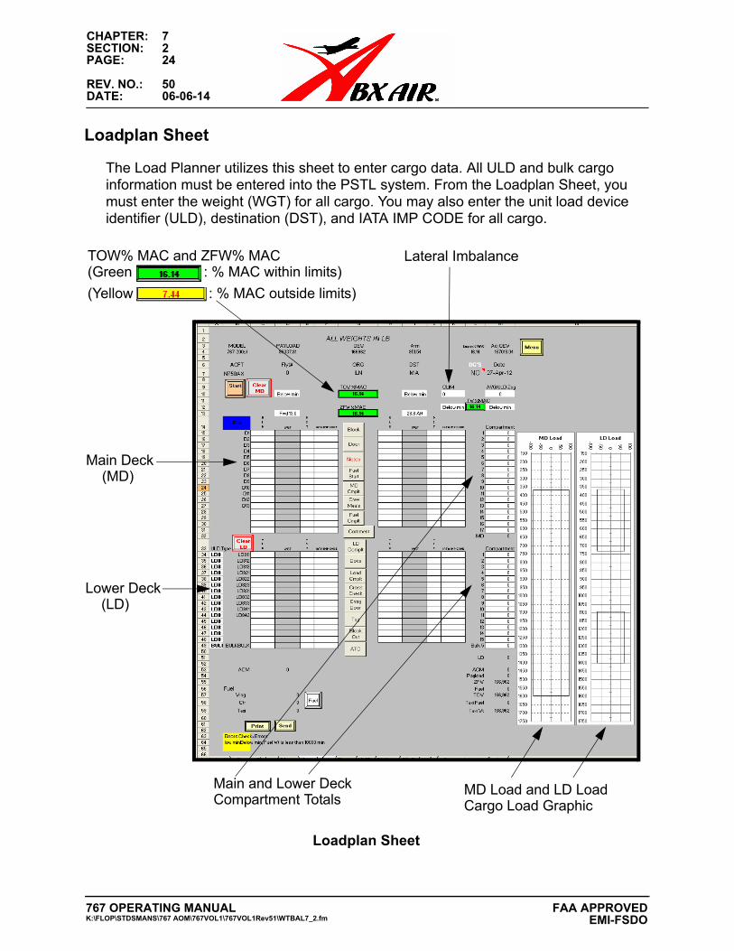
CHAPTER: 7SECTION: 2PAGE: 24
REV. NO.: 50DATE: 06-06-14
Loadplan Sheet
The Load Planner utilizes this sheet to enter cargo data. All ULD and bulk cargo information must be entered into the PSTL system. From the Loadplan Sheet, you must enter the weight (WGT) for all cargo. You may also enter the unit load device identifier (ULD), destination (DST), and IATA IMP CODE for all cargo.
Loadplan Sheet
(Yellow : % MAC outside limits)
TOW% MAC and ZFW% MAC
Main Deck
Main and Lower Deck
(Green : % MAC within limits)
Lateral Imbalance
Lower Deck
MD Load and LD Load Cargo Load GraphicCompartment Totals
(MD)
(LD)
767 OPERATING MANUALK:\FLOP\STDSMANS\767 AOM\767VOL1\767VOL1Rev51\WTBAL7_2.fm
FAA APPROVED EMI-FSDO
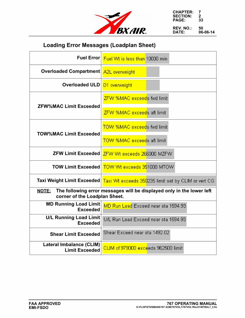
CHAPTER: 7SECTION: 2PAGE: 33
REV. NO.: 50DATE: 06-06-14
Loading Error Messages (Loadplan Sheet)
Fuel Error
Overloaded Compartment
Overloaded ULD
ZFW%MAC Limit Exceeded
TOW%MAC Limit Exceeded
ZFW Limit Exceeded
TOW Limit Exceeded
Taxi Weight Limit Exceeded
NOTE: The following error messages will be displayed only in the lower left corner of the Loadplan Sheet.
MD Running Load LimitExceeded
U/L Running Load LimitExceeded
Shear Limit Exceeded
Lateral Imbalance (CLIM)Limit Exceeded
767 OPERATING MANUALK:\FLOP\STDSMANS\767 AOM\767VOL1\767VOL1Rev51\WTBAL7_2.fm
FAA APPROVEDEMI-FSDO
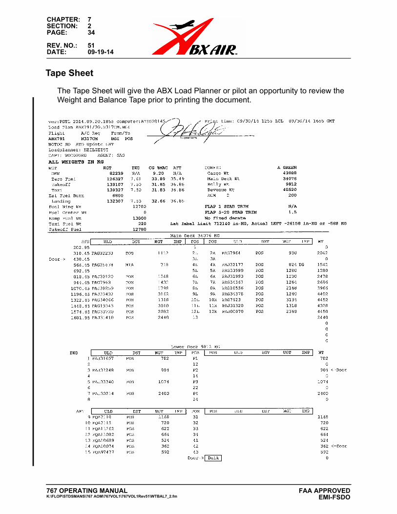
CHAPTER: 7SECTION: 2PAGE: 34
REV. NO.: 51DATE: 09-19-14
Tape Sheet
The Tape Sheet will give the ABX Load Planner or pilot an opportunity to review the Weight and Balance Tape prior to printing the document.
767 OPERATING MANUALK:\FLOP\STDSMANS\767 AOM\767VOL1\767VOL1Rev51\WTBAL7_2.fm
FAA APPROVED EMI-FSDO
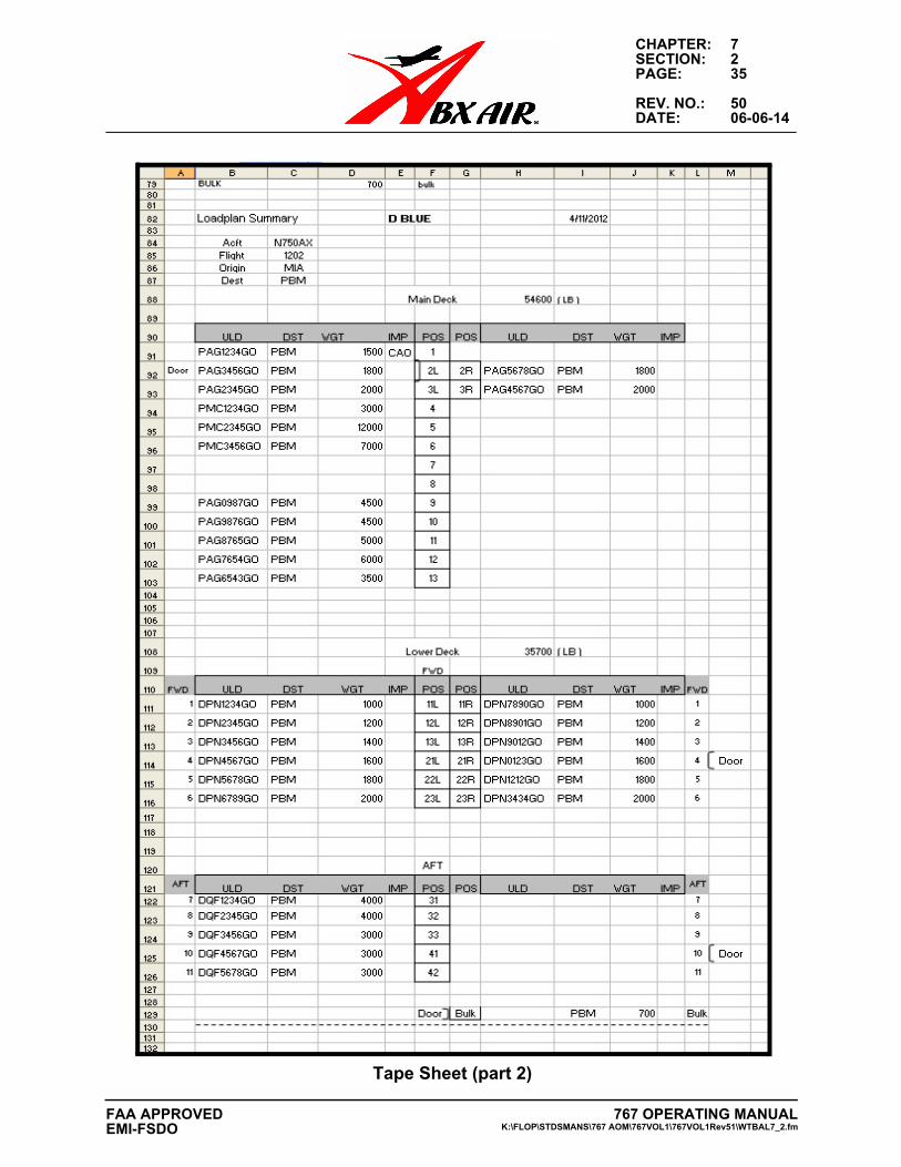
CHAPTER: 7SECTION: 2PAGE: 35
REV. NO.: 50DATE: 06-06-14
.
Tape Sheet (part 2)
767 OPERATING MANUALK:\FLOP\STDSMANS\767 AOM\767VOL1\767VOL1Rev51\WTBAL7_2.fm
FAA APPROVEDEMI-FSDO
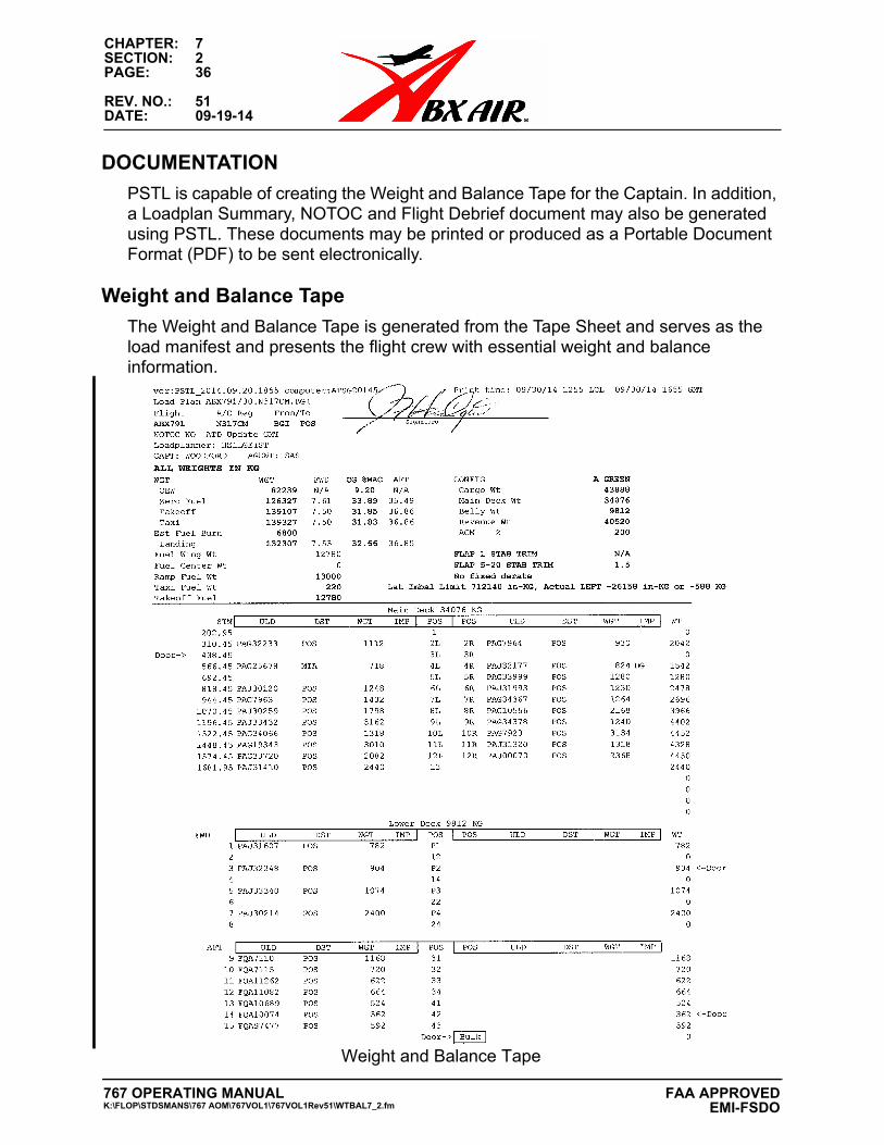
CHAPTER: 7SECTION: 2PAGE: 36
REV. NO.: 51DATE: 09-19-14
DOCUMENTATION
PSTL is capable of creating the Weight and Balance Tape for the Captain. In addition, a Loadplan Summary, NOTOC and Flight Debrief document may also be generated using PSTL. These documents may be printed or produced as a Portable Document Format (PDF) to be sent electronically.
Weight and Balance Tape
The Weight and Balance Tape is generated from the Tape Sheet and serves as the load manifest and presents the flight crew with essential weight and balance information.
Weight and Balance Tape
767 OPERATING MANUALK:\FLOP\STDSMANS\767 AOM\767VOL1\767VOL1Rev51\WTBAL7_2.fm
FAA APPROVED EMI-FSDO
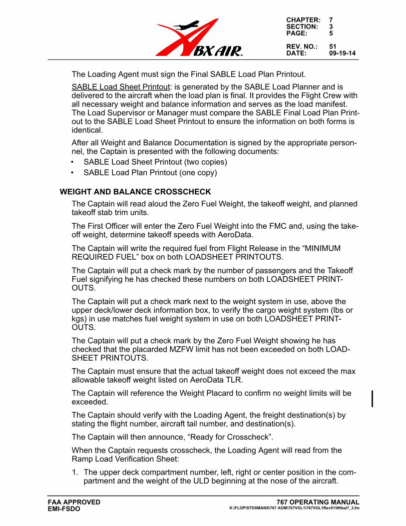
CHAPTER: 7SECTION: 3PAGE: 5
REV. NO.: 51DATE: 09-19-14
The Loading Agent must sign the Final SABLE Load Plan Printout.
SABLE Load Sheet Printout: is generated by the SABLE Load Planner and is delivered to the aircraft when the load plan is final. It provides the Flight Crew with all necessary weight and balance information and serves as the load manifest. The Load Supervisor or Manager must compare the SABLE Final Load Plan Print-out to the SABLE Load Sheet Printout to ensure the information on both forms is identical.
After all Weight and Balance Documentation is signed by the appropriate person-nel, the Captain is presented with the following documents:• SABLE Load Sheet Printout (two copies)• SABLE Load Plan Printout (one copy)
WEIGHT AND BALANCE CROSSCHECK
The Captain will read aloud the Zero Fuel Weight, the takeoff weight, and planned takeoff stab trim units.
The First Officer will enter the Zero Fuel Weight into the FMC and, using the take-off weight, determine takeoff speeds with AeroData.
The Captain will write the required fuel from Flight Release in the “MINIMUM REQUIRED FUEL” box on both LOADSHEET PRINTOUTS.
The Captain will put a check mark by the number of passengers and the Takeoff Fuel signifying he has checked these numbers on both LOADSHEET PRINT-OUTS.
The Captain will put a check mark next to the weight system in use, above the upper deck/lower deck information box, to verify the cargo weight system (lbs or kgs) in use matches fuel weight system in use on both LOADSHEET PRINT-OUTS.
The Captain will put a check mark by the Zero Fuel Weight showing he has checked that the placarded MZFW limit has not been exceeded on both LOAD-SHEET PRINTOUTS.
The Captain must ensure that the actual takeoff weight does not exceed the max allowable takeoff weight listed on AeroData TLR.
The Captain will reference the Weight Placard to confirm no weight limits will be exceeded.
The Captain should verify with the Loading Agent, the freight destination(s) by stating the flight number, aircraft tail number, and destination(s).
The Captain will then announce, “Ready for Crosscheck”.
When the Captain requests crosscheck, the Loading Agent will read from the Ramp Load Verification Sheet:
1. The upper deck compartment number, left, right or center position in the com-partment and the weight of the ULD beginning at the nose of the aircraft.
767 OPERATING MANUALK:\FLOP\STDSMANS\767 AOM\767VOL1\767VOL1Rev51\Wtbal7_3.fm
FAA APPROVEDEMI-FSDO
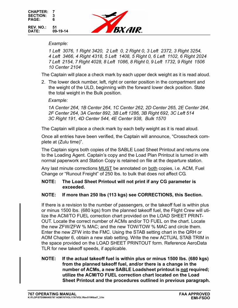
CHAPTER: 7SECTION: 3PAGE: 6
REV. NO.: 51DATE: 09-19-14
Example:
1 Left 3076, 1 Right 3420, 2 Left 0, 2 Right 0, 3 Left 2372, 3 Right 3254,4 Left 3466, 4 Right 4318, 5 Left 1408, 5 Right 0, 6 Left 1102, 6 Right 20247 Left 2154, 7 Right 4028, 8 Left 1086, 8 Right 0, 9 Left 1732, 9 Right 1506 10 Center 2104
The Captain will place a check mark by each upper deck weight as it is read aloud.
2. The lower deck number, left, right or center position in the compartment andthe weight of the ULD, beginning with the forward lower deck position. Statethe total weight in the Bulk position.
Example:
1A Center 264, 1B Center 264, 1C Center 262, 2D Center 265, 2E Center 264,2F Center 264, 3A Center 892, 3B Left 1286, 3B Right 692, 3C Left 5143C Right 191, 4D Center 544, 4E Center 938, Bulk 1570
The Captain will place a check mark by each belly weight as it is read aloud.
Once all entries have been verified, the Captain will announce, “Crosscheck com-plete at (Zulu time)”.
The Captain signs both copies of the SABLE Load Sheet Printout and returns one to the Loading Agent. Captain’s copy and the Load Plan Printout is turned in with normal paperwork and Station Copy is retained on file at the departure station.
Any last minute corrections MUST be annotated on both copies, i.e. ACM, Fuel Change or “Runout Freight” of 250 lbs. to bulk that does not affect CG.
NOTE: The Load Sheet Printout will not print if any CG parameter is exceeded.
NOTE: If more than 250 lbs (113 kgs) see CORRECTIONS, this Section.
If there is a revision to the number of passengers, or the takeoff fuel is within plus or minus 1500 lbs. (680 kgs) from the planned takeoff fuel, the Flight Crew will uti-lize the ACM/TO FUEL correction chart provided on the LOAD SHEET PRINT-OUT. Locate the correct number of ACMs and/or TO FUEL on the chart. Locate the new ZFW/ZFW % MAC; and the new TOW/TOW % MAC and circle them. Enter the new ZFW into the FMC. Using the STAB setting chart in the QRH or AOM Chapter 6, obtain a new stab setting. Write the new ACTUAL STAB TRIM in the space provided on the LOAD SHEET PRINTOUT form. Reference AeroData TLR for new takeoff speeds, if applicable.
NOTE: If the actual takeoff fuel is within plus or minus 1500 lbs. (680 kgs) from the planned takeoff fuel, and/or there is a change in the number of ACMs, a new SABLE Loadsheet printout is not required; utilize the ACM/TO FUEL correction chart located on the Load Sheet Printout and the procedures outlined in previous paragraph.
767 OPERATING MANUALK:\FLOP\STDSMANS\767 AOM\767VOL1\767VOL1Rev51\Wtbal7_3.fm
FAA APPROVED EMI-FSDO
CHAPTER: 7SECTION: 3PAGE: 7
REV. NO.: 51DATE: 09-19-14
CORRECTIONS, LOAD SHEET PRINTOUT AND LOAD PLAN PRINTOUTCORRECTIONS TO LOAD SHEET PRINTOUTExcept as described in items 1, 2 and 3 below, the Captain may not make pen and ink changes to any weight and balance related information, including tail number, on the Load Sheet Printout. The Captain may make pen and ink changes to other information on Load Sheet Printout that does not affect weight and balance calcu-lations.1. Changes to ACMs and/or FUEL using the ACM/TO FUEL Correction Chart.2. Tolerances/Errors up to 250 lbs. (113 kgs) procedure.3. Diversions within DHL System and Sable Loading Agent NOT Available, Alter-
nate Procedure 2.Note: The Load Planner or Load Supervisor may make pen and ink
changes to the Load Sheet Printout for Flight Number, Departure/Code, Destination Airports and/or Identifier Codes.
Errors of 250 lbs. (113 kgs) or less are permissible provided the TOW CG and the ZFW CG is not less than 1% from their respective FWD or AFT limits. The weight error(s) will be added to or subtracted from the Zero Fuel Weight and the Takeoff Weight. The corrected weights should be checked by the Captain to verify that a limiting weight is not exceeded. A single weight error or multiple weight errors that exceed 250 lbs. (113 kgs) require the SABLE Load Planner to create a new Load Sheet Printout. Errors up to 250 pounds with the TOW CG or the ZFW CG less than 1% from either the forward or aft limit also require the SABLE Load Planner to create a new Load Sheet Printout.
The use of correction fluid (White-out) or erasure of information is prohibited. Pen and ink corrections will be done by drawing a single line through the incorrect information, entering the correct information, and initialed by Load Planner, Load Supervisor or Captain.
The SABLE Load Planner is responsible for ensuring a new Load Sheet Printout and Load Plan Printout (if required) is delivered to the Loading Agent and/or the Flight Crew immediately after printing the documents.
CORRECTIONS TO LOAD PLAN PRINTOUTS
If the SABLE Load Planner discovers an error, they must immediately contact the Loading Agent or Load Supervisor and advise them of the error on the load plan.
If the Loading Agent discovers an error in a ULD or bulk freight conveyance infor-mation on the Load Plan printout, the following procedures must be followed to make the correction:1. The Loading Agent or Load Supervisor must contact the SABLE Load Planner
immediately following the discovery of the error.2. The suspect ULD tag, contents, or description must be checked to verify the
correct information.3. After determining the correct ULD information, the Loading Agent or Load
Supervisor must make the corrections to the Load Plan and initial the change.The affected aircraft will not be loaded until the error has been corrected and the Load Planner and Load Supervisor are in agreement.Load plans should only be returned to the SABLE Load Planner if the issue cannot be resolved by the above methodology.As minor Load Plan corrections (pen and ink) to the ULD number or description do not affect the CG or weight of the aircraft, a new Load Plan Printout Form is not required after making such corrections.
767 OPERATING MANUALK:\FLOP\STDSMANS\767 AOM\767VOL1\767VOL1Rev51\Wtbal7_3.fm
FAA APPROVEDEMI-FSDO
CHAPTER: 7SECTION: 3PAGE: 8
REV. NO.: 48DATE: 06-20-13
NOTOC STATEMENT CHANGES
The Load Sheet Printout Form contains a notation of NOTOC YES or NOTOC NO indicating whether a NOTOC is required for the flight.
NOTOC YES - Indicating a NOTOC is required for departure.
NOTOC NO - Indicating a NOTOC is not required for departure.
If the Weight and Balance contains the notation NOTOC YES, the flight may not depart without a NOTOC, except:
If the Captain is informed that no dangerous goods are onboard, the Captain will contact the Loading Agent and inform him/her of the conflicting information. After it is confirmed that no dangerous goods are onboard the aircraft may depart without a NOTOC. The Load Sheet Printout notation NOTOC YES need not be removed from the Load Sheet Printout.
If the Load Sheet Printout contains the notation NOTOC NO, the flight may depart without a NOTOC except; if the Captain is notified there are dangerous goods onboard, a NOTOC must be presented to the Captain prior to departure. The Load Sheet Printout notation NOTOC NO need not be removed from the Load Sheet Printout.
AFTER DEPARTURE WEIGHT DISCREPANCY
If the aircraft is still on the stand (including during engine start) and the Flight Crew is informed there is a Weight and Balance discrepancy that requires new paperwork to be presented for the Flight Crew, the aircraft will be shut down.
If the aircraft has departed the Loading Stand (gate or parking spot) attempts must be made to get the aircraft back into spot. The Flight Crew will receive communication there is a Weight and Balance Discrepancy that requires new paperwork.
If the aircraft is Airborne, ABX Flight Control will contact the flight and provide the following:
1. Re-established Total Load
2. Re-established ZFW
3. Re-established ZFW CG
4. Re-established TOW Weight
5. Re-established Planned Landing Weight
A new Load Message/Flight Movement report will be transmitted to the downline station and to correct the data in the system and communication will be made to ensure the re-established load was received and is being utilized for any additional flight segments.
767 OPERATING MANUALK:\FLOP\STDSMANS\767 AOM\767VOL1\767VOL1Rev51\Wtbal7_3.fm
FAA APPROVED EMI-FSDO


