Embed Size (px)
Citation preview
2007-08
15th Induction Training Report
Water And Land Management Institute,
Aurangabad
Table of Content
Abbreviations .................................................................................................................................................... 6
Chapter 1. Main System ................................................................................................................................ 9
1.1 Salient Features of Jayakwadi Project .................................................................................... 9
1.1.1 Related Terminology ................................................................................................................. 10
1.1.2 Classification of Reservoir ....................................................................................................... 11
1.1.3 Spillway Operation Schedule ................................................................................................. 12
1.1.4 Introduction of ROS & EAP ..................................................................................................... 12
1.2 Introduction to Gate Operation Schedule ................................................................................ 12
1.2.1 Necessity of ROS and GOS ...................................................................................................... 13
1.2.2 Principle of Operation of Reservoir .................................................................................... 13
1.2.3 Catchment Area of Paithan Dam........................................................................................... 15
1.2.4 Existing River Gauging Stations ........................................................................................... 16
1.2.5 Proposed River Gauging Stations ......................................................................................... 16
1.2.6 Competent Authority for Approval ....................................................................................... 16
1.2.7 Guidelines for preparing ROS ................................................................................................ 17
1.2.8 Guidelines for preparing GOS ................................................................................................ 17
1.2.9 Guidelines for preparing EAP ................................................................................................. 18
1.2.10 Some Important Points .......................................................................................................... 18
1.2.11 Real Time Operation of Reservoir ...................................................................................... 19
1.2.12 Guide Curve for ROS ................................................................................................................ 20
1.2.13 Development of GOS ............................................................................................................... 20
1.3 Approved ROS for Jayakwadi Project ........................................................................................ 23
1.3.1 ROS for Jayakwadi Project .................................................................................................... 26
15th Induction Training Course WALMI, Aurangabad ________________________________________________________________
Page 2 of 101
1.3.2 Approved GOS for Jayakwadi Project ................................................................................. 27
1.3.3 Existing GOS for Jayakwadi Project .................................................................................... 28
1.3.4 Advantage of this ROS .............................................................................................................. 28
1.3.5 Standard Performa ..................................................................................................................... 28
1.3.6 Concluding Remarks .................................................................................................................. 30
1.3.7 References ..................................................................................................................................... 30
1.4 Walk Through of Minor No.1, of Dy. No.10, PLBC ................................................................. 31
1.4.1 Details of minor No 1 are as follows: ................................................................................. 31
1.4.2 Design details of Minor No. 1 ................................................................................................. 31
1.4.3. Existing Cross-Section of Minor No. 1 ............................................................................... 31
1.4.3 Cross-Section as per Design ................................................................................................... 32
1.4.4 L-Section of Minor ...................................................................................................................... 33
1.4.5 Schematic Presentation of M1, Dy 10, PLBC .................................................................... 36
1.4.6 Cross Regulator & Head Regulator Of Minor N0-1 ........................................................ 47
1.4.7 LINING IN GOOD CONDITION IN INITIAL STRETCH ................................................... 47
1.4.8 Damaged Canal Lining .............................................................................................................. 48
1.4.9 Silting and Stagnation of Water ............................................................................................ 48
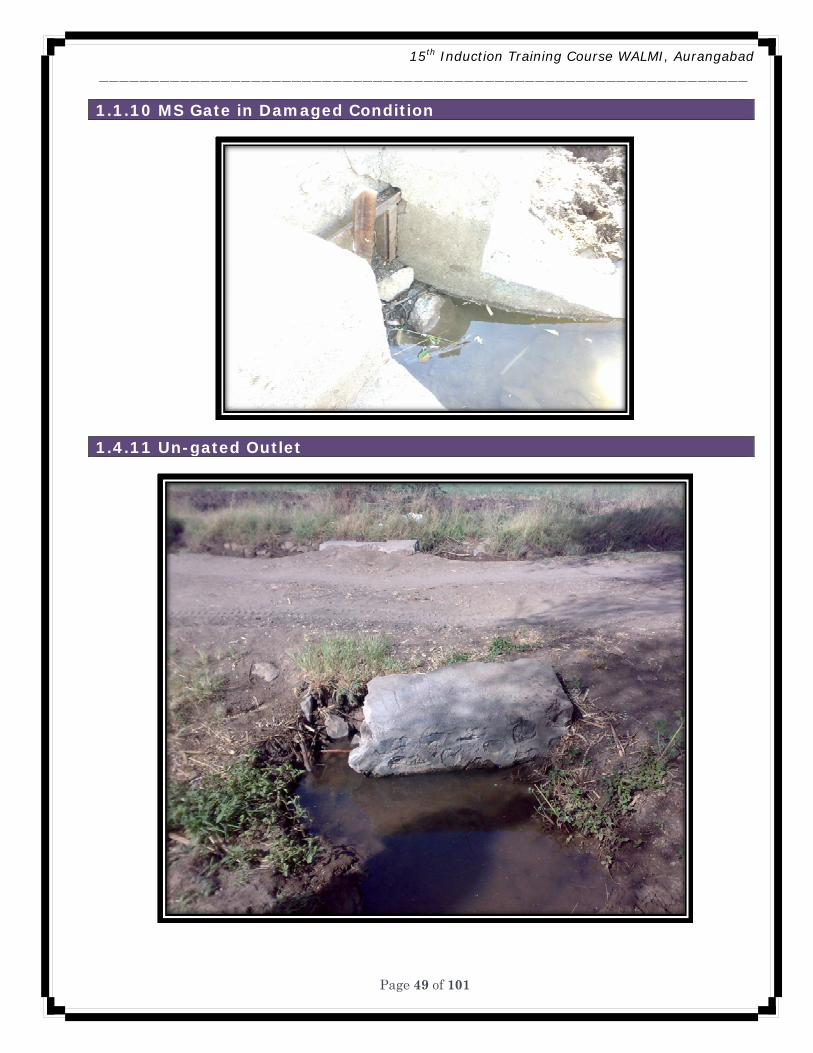
1.1.10 MS Gate in Damaged Condition .......................................................................................... 49
1.4.11 Un-gated Outlet ........................................................................................................................ 49
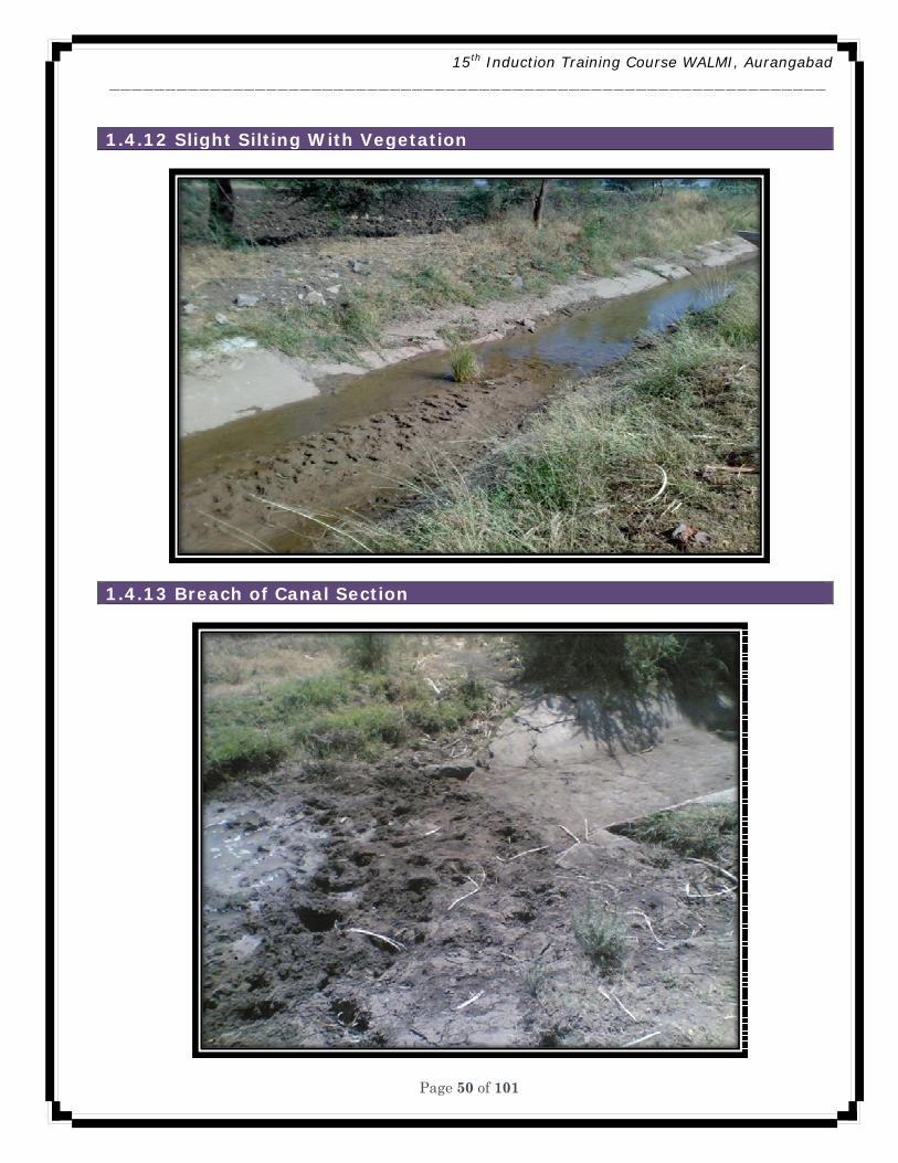
1.4.12 Slight Silting With Vegetation ............................................................................................. 50
1.4.13 Breach of Canal Section ......................................................................................................... 50
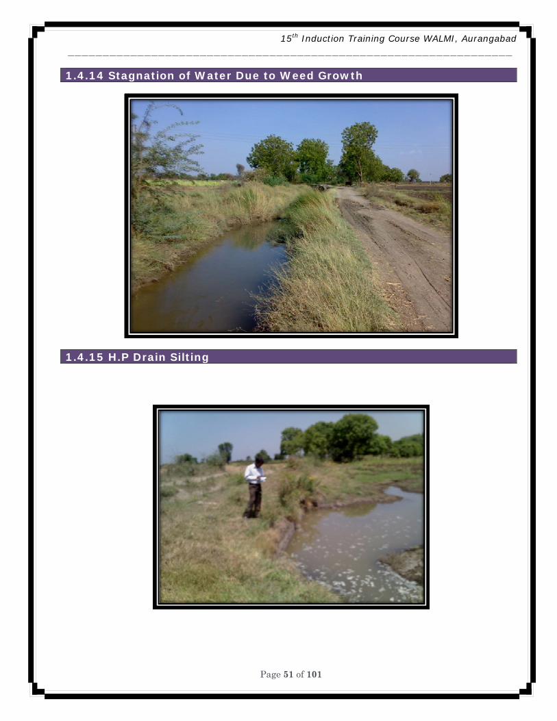
1.4.14 Stagnation of Water Due to Weed Growth..................................................................... 51
1.4.15 H.P Drain Silting ....................................................................................................................... 51
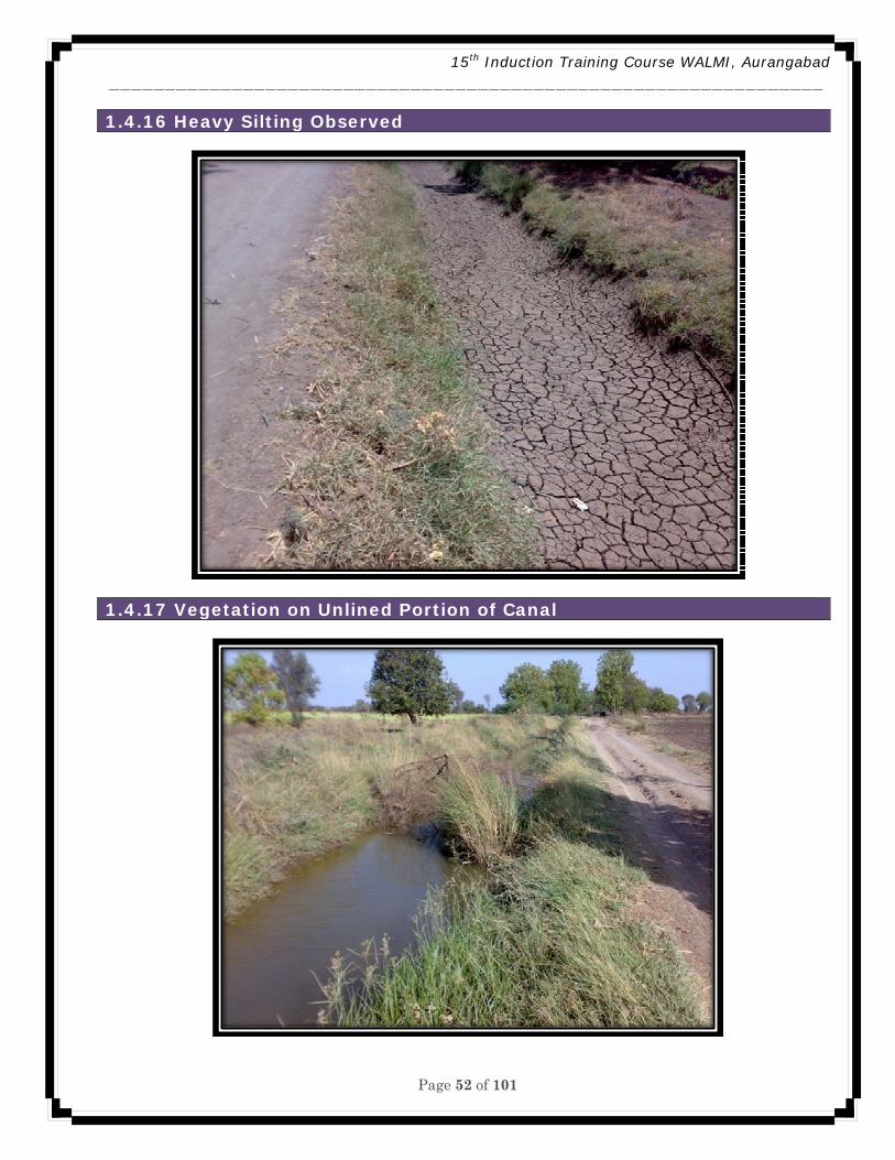
1.4.16 Heavy Silting Observed .......................................................................................................... 52
1.4.17 Vegetation on Unlined Portion of Canal .......................................................................... 52
1.4.18 Abstract of Vegetation ........................................................................................................... 54
1.4.19 Abstract of Weeds .................................................................................................................... 55
1.4.20 Abstract of Silting .................................................................................................................... 55
15th Induction Training Course WALMI, Aurangabad ________________________________________________________________
Page 3 of 101
1.4.21 Priority of Repairs for Earthwork ...................................................................................... 56
1.4.22 Priority of Repairs for Structures ...................................................................................... 56
1.4.23 Recommendations ................................................................................................................... 57
Chapter 2. Evaluation of Standing Wave Flume (SWF) .................................................................. 58
2.1 Introduction ......................................................................................................................................... 58
2.2 Methodology ......................................................................................................................................... 58
2.3 Design of Standing Wave Flume as per IS Code: .................................................................. 59
2.4 Evaluation & Improvement of Standing Wave Flume: ........................................................ 62
2.5 Procedure for Evaluation and Improvement of Existing Standing Wave Flume: ..... 62
2.6 Common deviation/defects: .......................................................................................................... 64
2.7 Preparation of Discharge Table: ................................................................................................... 64
2.8 Common Problems and Solutions ................................................................................................ 64
2.8 Design of SWF Based on Procedure in IS-Code ..................................................................... 65
2.9 Data Collection .................................................................................................................................... 66
2.10 Step 4: Calculations of X from Stage Dischagre relationship ....................................... 67
2.11 Introduction ....................................................................................................................................... 68
2.12 Proforma ............................................................................................................................................. 74
2.13 Comparison ........................................................................................................................................ 76
2.14 Problems / defects Identified: ................................................................................................... 77
2.15 Remedial measures suggested: ................................................................................................. 77
2.16 Photo Gallery ..................................................................................................................................... 77
2.17 Conclusion .......................................................................................................................................... 79
2.18 References .......................................................................................................................................... 79
Chapter 3. On Farm System ....................................................................................................................... 81
3.1 Theory ..................................................................................................................................................... 81
3.2 Salient Features .................................................................................................................................. 81
3.3 Reconnaissance Survey and Observations .......................................................................... 82
3.4 Field Channel Walk Through and Levelling .............................................................................. 82
3.5 Field Channel Walk Through and Levelling .............................................................................. 83
3.6 L-Section of FC..................................................................................................................................... 84
3.8 Definition of Evaluation of Land Forming Works ................................................................... 85
3.9 Purpose of Land Forming Techniques ........................................................................................ 85
Purpose of Land Forming Techniques ............................................................................................... 85
3.10 LAND FORMING is applicable to ................................................................................................ 85
15th Induction Training Course WALMI, Aurangabad ________________________________________________________________
Page 4 of 101
3.11 LAND FORMING is not applicable to ........................................................................................ 85
3.12 LAND FORMING TECHNIQUES .................................................................................................... 85
3.13 LAND FORMING TECHNIQUES is based on ............................................................................ 86
3.14 LAND FORMING PLANNING PROCESS ..................................................................................... 86
3.15 CRITERIA FOR SUB DIVISION OF FIELD FOR LAND FORMING ..................................... 86
3.16 DESIRED SLOPE CRITERIA FOR LAND SMOOTHENING TECHNIQUE ........................... 86
3.17 DESIRED SLOPE CRITERIA FOR LAND GRADING TECHNIQUE ...................................... 87
3.18 Optimizing cuts and fill ................................................................................................................. 87
3.19 DESIGN OBJECTIVES ...................................................................................................................... 87
3.20 DESIGN METHODS ........................................................................................................................... 87
3.21 Calculation for Land Smoothening Of Gat No. 486 of Village Vihamandva .............. 88
3.22 Hence cost of Land Smoothening .............................................................................................. 88
3.23 CONCLUSION ..................................................................................................................................... 88
Chapter 4. Soil and Cropping System .................................................................................................... 89
4.1 Introduction ......................................................................................................................................... 89
4.2 objective of soil survey .................................................................................................................... 89
4.3 Fertility status of soil ........................................................................................................................ 90
4.4 Salinity ................................................................................................................................................... 90
4.5 Sodicity .................................................................................................................................................. 90
4.6 TABLE NO 1: Determination of soil irrigability class ............................................................ 90
4.7 LAND IRRIGABILITY CLASS ........................................................................................................... 91
4.8 Quality of Water .................................................................................................................................. 91
4.9 Values ...................................................................................................................................................... 92
4.10 Constraints ......................................................................................................................................... 92
4.11 Recommendation ............................................................................................................................ 92
Crop Survey .................................................................................................................................................. 92
4.12 Objective of crop survey ............................................................................................................... 92
4.13 Name of Crop: Sugarcane (Pre-seasonal) ............................................................................. 93
4.14 Name of Crop: Wheat ..................................................................................................................... 93
4.15 Name of Crop: Gram ....................................................................................................................... 94
4.16 Name of Crop: Cotton ..................................................................................................................... 95
4.17 Designed crop pattern for Jayakwadi project and Existing cropping pattern of Dharamveer water users society, Navgaon (Dy.No.10, Minor No.1) PLBC, Jaykwadi Project. ........................................................................................................................................................... 96
4.18 Conclusion .......................................................................................................................................... 96
15th Induction Training Course WALMI, Aurangabad ________________________________________________________________
Page 5 of 101
Chapter 5. Evaluation of Water User’s Association ......................................................................... 97
5.1 Introduction ......................................................................................................................................... 97
5.2 Factors Affecting Evaluation .......................................................................................................... 97
5.3 Study of WUA ....................................................................................................................................... 97
5.3.1 General Information ...................................................................................................................... 97
5.3.2 Other Related Information ......................................................................................................... 97
5.3.3 WUA: Institutional Aspects ........................................................................................................ 97
5.4 Interaction with Chairman of WUA ............................................................................................. 97
5.4 Interaction with Chairman Field Officer ................................................................................... 97
5.5 Concluding Remarks ......................................................................................................................... 97
Chapter 6. Concluding Remark ................................................................................................................. 97
15th Induction Training Course WALMI, Aurangabad ________________________________________________________________
Page 6 of 101
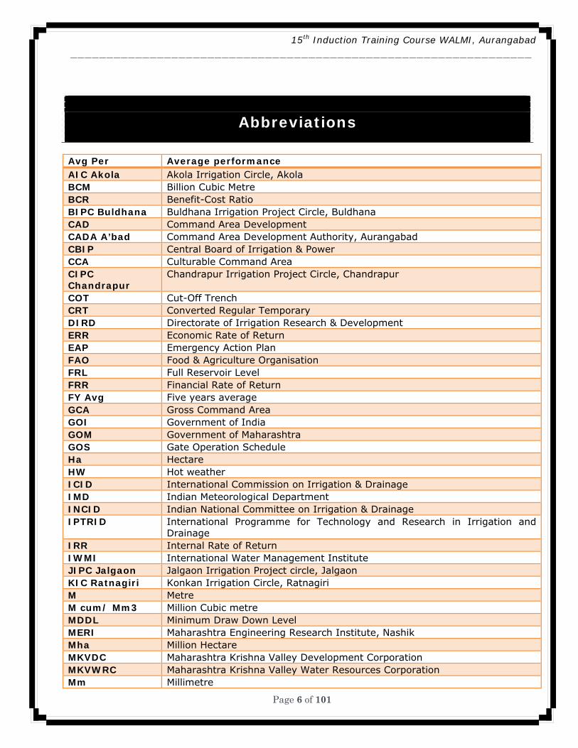
Abbreviations
Avg Per Average performance AIC Akola Akola Irrigation Circle, Akola BCM Billion Cubic Metre BCR Benefit-Cost Ratio BIPC Buldhana Buldhana Irrigation Project Circle, Buldhana CAD Command Area Development CADA A’bad Command Area Development Authority, Aurangabad CBIP Central Board of Irrigation & Power CCA Culturable Command Area CIPC Chandrapur
Chandrapur Irrigation Project Circle, Chandrapur
COT Cut-Off Trench CRT Converted Regular Temporary DIRD Directorate of Irrigation Research & Development ERR Economic Rate of Return EAP Emergency Action Plan FAO Food & Agriculture Organisation FRL Full Reservoir Level FRR Financial Rate of Return FY Avg Five years average GCA Gross Command Area GOI Government of India GOM Government of Maharashtra GOS Gate Operation Schedule Ha Hectare HW Hot weather ICID International Commission on Irrigation & Drainage IMD Indian Meteorological Department INCID Indian National Committee on Irrigation & Drainage IPTRID International Programme for Technology and Research in Irrigation and
Drainage IRR Internal Rate of Return IWMI International Water Management Institute JIPC Jalgaon Jalgaon Irrigation Project circle, Jalgaon KIC Ratnagiri Konkan Irrigation Circle, Ratnagiri M Metre M cum/ Mm3 Million Cubic metre MDDL Minimum Draw Down Level MERI Maharashtra Engineering Research Institute, Nashik Mha Million Hectare MKVDC Maharashtra Krishna Valley Development Corporation MKVWRC Maharashtra Krishna Valley Water Resources Corporation Mm Millimetre

15th Induction Training Course WALMI, Aurangabad ________________________________________________________________
Page 7 of 101
MWIC Maharashtra Water & Irrigation Commission NIC Nagpur Nagpur Irrigation Circle, Nagpur NIC Nanded Nanded Irrigation Circle, Nanded NIPC Dhule Nashik Irrigation Project Circle, Dhule NKIPC Thane North Konkan Irrigation Project Circle, Thane NPV Net Present Value O & M Operation & Maintenance Past Max Maximum value observed in Past Past Min Minimum value observed in Past PIC Pune Pune Irrigation Circle, Pune PIM Participatory Irrigation Management PIP Preliminary Irrigation Programme PLBC Paithan Left Bank Canal PRBC Paithan Right Bank Canal RBL Reservoir Bed Level PWD Public Works Department ROS Reservoir Operation Schedule RoR Rate of Return SIC Sangli Sangli Irrigation Circle, Sangli Sq km Square Kilometre State Tar State target SGRY Sampurna Gramin Rojgar Yojna TIC Thane Thane Irrigation Circle, Thane UWPC Amravati Upper Wardha Project Circle, Amravati WALMI Water And Land Management Institute, Aurangabad WRD Water Resources Department WUA Water Users’ Association WUE Water use efficiency YIC Yeotmal Yeotmal Irrigation Circle, Yeotmal
15th Induction Training Course WALMI, Aurangabad ________________________________________________________________
Page 8 of 101
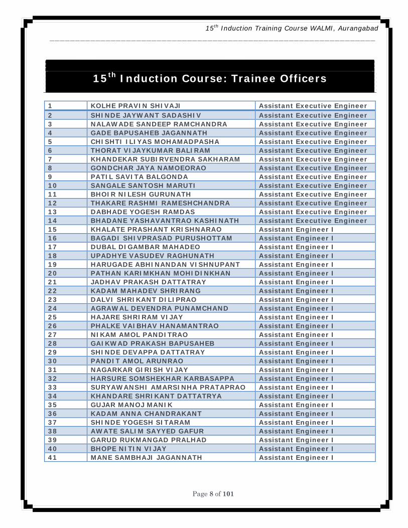
15th Induction Course: Trainee Officers
1 KOLHE PRAVIN SHIVAJI Assistant Executive Engineer 2 SHINDE JAYWANT SADASHIV Assistant Executive Engineer 3 NALAWADE SANDEEP RAMCHANDRA Assistant Executive Engineer 4 GADE BAPUSAHEB JAGANNATH Assistant Executive Engineer 5 CHISHTI ILIYAS MOHAMADPASHA Assistant Executive Engineer 6 THORAT VIJAYKUMAR BALIRAM Assistant Executive Engineer 7 KHANDEKAR SUBIRVENDRA SAKHARAM Assistant Executive Engineer 8 GONDCHAR JAYA NAMOEORAO Assistant Executive Engineer 9 PATIL SAVITA BALGONDA Assistant Executive Engineer 10 SANGALE SANTOSH MARUTI Assistant Executive Engineer 11 BHOIR NILESH GURUNATH Assistant Executive Engineer 12 THAKARE RASHMI RAMESHCHANDRA Assistant Executive Engineer 13 DABHADE YOGESH RAMDAS Assistant Executive Engineer 14 BHADANE YASHAVANTRAO KASHINATH Assistant Executive Engineer 15 KHALATE PRASHANT KRISHNARAO Assistant Engineer I 16 BAGADI SHIVPRASAD PURUSHOTTAM Assistant Engineer I 17 DUBAL DIGAMBAR MAHADEO Assistant Engineer I 18 UPADHYE VASUDEV RAGHUNATH Assistant Engineer I 19 HARUGADE ABHINANDAN VISHNUPANT Assistant Engineer I 20 PATHAN KARIMKHAN MOHIDINKHAN Assistant Engineer I 21 JADHAV PRAKASH DATTATRAY Assistant Engineer I 22 KADAM MAHADEV SHRIRANG Assistant Engineer I 23 DALVI SHRIKANT DILIPRAO Assistant Engineer I 24 AGRAWAL DEVENDRA PUNAMCHAND Assistant Engineer I 25 HAJARE SHRIRAM VIJAY Assistant Engineer I 26 PHALKE VAIBHAV HANAMANTRAO Assistant Engineer I 27 NIKAM AMOL PANDITRAO Assistant Engineer I 28 GAIKWAD PRAKASH BAPUSAHEB Assistant Engineer I 29 SHINDE DEVAPPA DATTATRAY Assistant Engineer I 30 PANDIT AMOL ARUNRAO Assistant Engineer I 31 NAGARKAR GIRISH VIJAY Assistant Engineer I 32 HARSURE SOMSHEKHAR KARBASAPPA Assistant Engineer I 33 SURYAWANSHI AMARSINHA PRATAPRAO Assistant Engineer I 34 KHANDARE SHRIKANT DATTATRYA Assistant Engineer I 35 GUJAR MANOJ MANIK Assistant Engineer I 36 KADAM ANNA CHANDRAKANT Assistant Engineer I 37 SHINDE YOGESH SITARAM Assistant Engineer I 38 AWATE SALIM SAYYED GAFUR Assistant Engineer I 39 GARUD RUKMANGAD PRALHAD Assistant Engineer I 40 BHOPE NITIN VIJAY Assistant Engineer I 41 MANE SAMBHAJI JAGANNATH Assistant Engineer I
15th
Ind
ucti
on T
rain
ing
Cou
rse
Bat
ch ,
WA
LMI
(07.
04.2
008
to 2
5.05
.200
8)
15th Induction Training Course WALMI, Aurangabad ________________________________________________________________
Page 9 of 101
Chapter 1. Main System
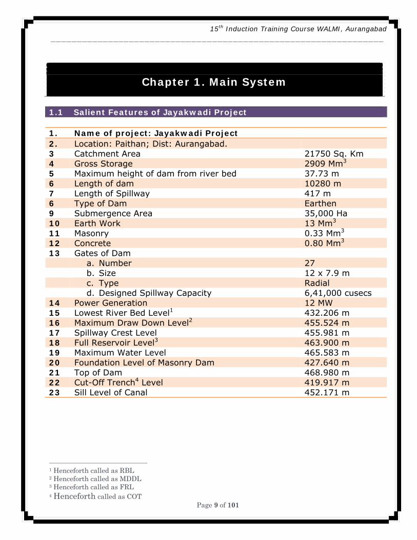
1.1 Salient Features of Jayakwadi Project 1. Name of project: Jayakwadi Project 2. Location: Paithan; Dist: Aurangabad. 3 Catchment Area 21750 Sq. Km 4 Gross Storage 2909 Mm3 5 Maximum height of dam from river bed 37.73 m 6 Length of dam 10280 m 7 Length of Spillway 417 m 6 Type of Dam Earthen 9 Submergence Area 35,000 Ha 10 Earth Work 13 Mm3 11 Masonry 0.33 Mm3 12 Concrete 0.80 Mm3 13 Gates of Dam a. Number 27 b. Size 12 x 7.9 m c. Type Radial d. Designed Spillway Capacity 6,41,000 cusecs 14 Power Generation 12 MW 15 Lowest River Bed Level1 432.206 m 16 Maximum Draw Down Level2 455.524 m 17 Spillway Crest Level 455.981 m 18 Full Reservoir Level3 463.900 m 19 Maximum Water Level 465.583 m 20 Foundation Level of Masonry Dam 427.640 m 21 Top of Dam 468.980 m 22 Cut-Off Trench4 Level 419.917 m 23 Sill Level of Canal 452.171 m 1 Henceforth called as RBL 2 Henceforth called as MDDL 3 Henceforth called as FRL 4 Henceforth called as COT
15th Induction Training Course WALMI, Aurangabad ________________________________________________________________
Page 10 of 101
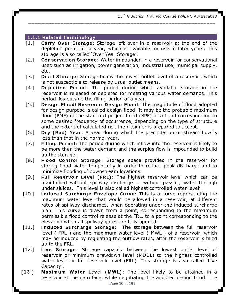
1.1.1 Related Terminology
[1.] Carry Over Storage: Storage left over in a reservoir at the end of the depletion period of a year, which is available for use in later years. This storage is also called ‘Over Year Storage’.
[2.] Conservation Storage: Water impounded in a reservoir for conservational uses such as irrigation, power generation, industrial use, municipal supply, etc.
[3.] Dead Storage: Storage below the lowest outlet level of a reservoir, which is not susceptible to release by usual outlet means.
[4.] Depletion Period: The period during which available storage in the reservoir is released or depleted for meeting various water demands. This period lies outside the filling period of a year.
[5.] Design Flood/Reservoir Design Flood: The magnitude of flood adopted for design purpose is called design flood. It may be the probable maximum flood (PMF) or the standard project flood (SPF) or a flood corresponding to some desired frequency of occurrence, depending on the type of structure and the extent of calculated risk the designer is prepared to accept.
[6.] Dry (Bad) Year: A year during which the precipitation or stream flow is less than that in the normal year.
[7.] Filling Period: The period during which inflow into the reservoir is likely to be more than the water demand and the surplus flow is impounded to build up the storage.
[8.] Flood Control Storage: Storage space provided in the reservoir for storing flood water temporarily in order to reduce peak discharge and to minimize flooding of downstream locations.
[9.] Full Reservoir Level (FRL): The highest reservoir level which can be maintained without spillway discharge or without passing water through under sluices. This level is also called highest controlled water level’.
[10.] Induced Surcharge Envelope Curve: This is a curve representing the maximum water level that would be allowed in a reservoir, at different rates of spillway discharges, when operating under the induced surcharge plan. This curve is drawn from a point, corresponding to the maximum permissible flood control release at the FRL, to a point corresponding to the elevation when all spillway gates are fully opened.
[11.] Induced Surcharge Storage: The storage between the full reservoir level ( FRL ) and the maximum water level ( MWL ) of a reservoir, which may be induced by regulating the outflow rates, after the reservoir is filled up to the FRL.
[12.] Live Storage: Storage capacity between the lowest outlet level of reservoir or minimum drawdown level (MDDL) to the highest controlled water level or full reservoir level (FRL). This storage is also called ‘Live Capacity’.
[13.] Maximum Water Level (MWL): The level likely to be attained in a reservoir at the dam face, while negotiating the adopted design flood. The
15th Induction Training Course WALMI, Aurangabad ________________________________________________________________
Page 11 of 101
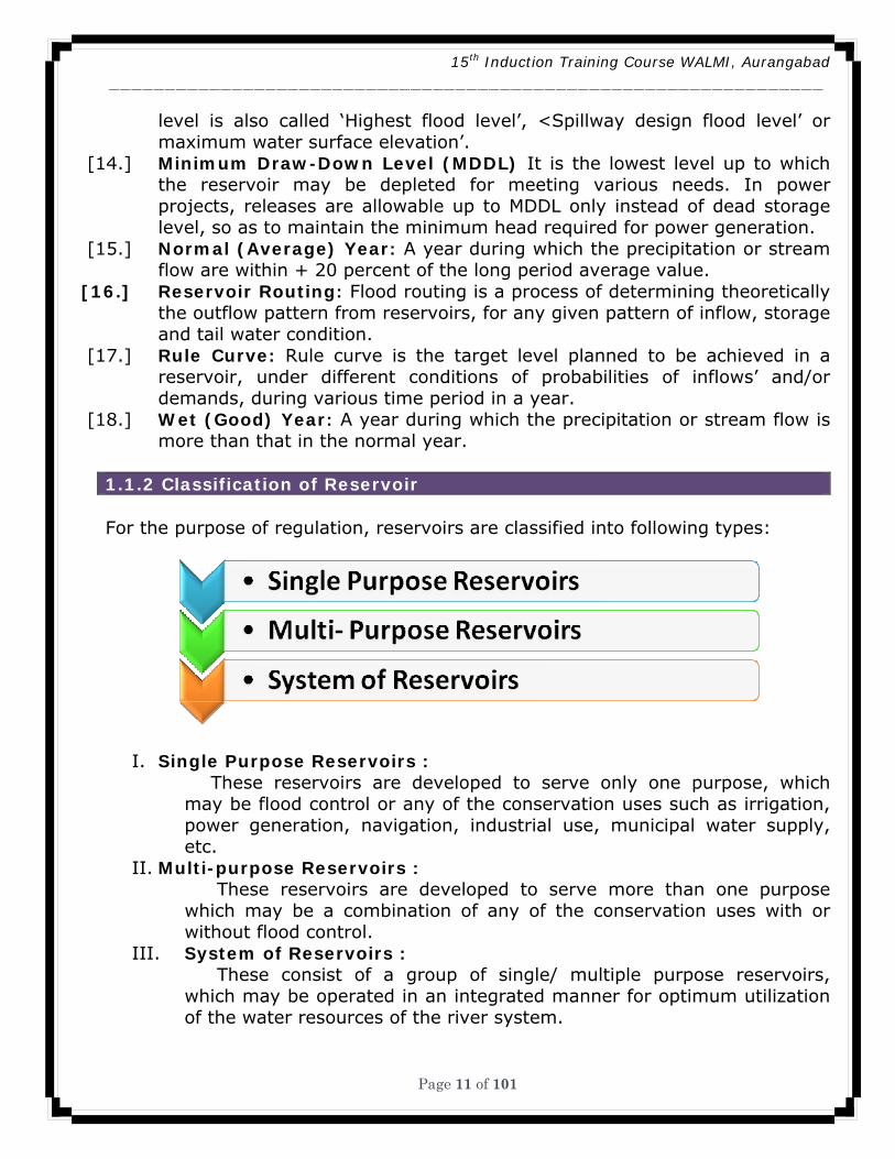
level is also called ‘Highest flood level’, <Spillway design flood level’ or maximum water surface elevation’.
[14.] Minimum Draw-Down Level (MDDL) It is the lowest level up to which the reservoir may be depleted for meeting various needs. In power projects, releases are allowable up to MDDL only instead of dead storage level, so as to maintain the minimum head required for power generation.
[15.] Normal (Average) Year: A year during which the precipitation or stream flow are within + 20 percent of the long period average value.
[16.] Reservoir Routing: Flood routing is a process of determining theoretically the outflow pattern from reservoirs, for any given pattern of inflow, storage and tail water condition.
[17.] Rule Curve: Rule curve is the target level planned to be achieved in a reservoir, under different conditions of probabilities of inflows’ and/or demands, during various time period in a year.
[18.] Wet (Good) Year: A year during which the precipitation or stream flow is more than that in the normal year.
1.1.2 Classification of Reservoir For the purpose of regulation, reservoirs are classified into following types:
I. Single Purpose Reservoirs : These reservoirs are developed to serve only one purpose, which
may be flood control or any of the conservation uses such as irrigation, power generation, navigation, industrial use, municipal water supply, etc.
II. Multi-purpose Reservoirs : These reservoirs are developed to serve more than one purpose
which may be a combination of any of the conservation uses with or without flood control.
III. System of Reservoirs : These consist of a group of single/ multiple purpose reservoirs,
which may be operated in an integrated manner for optimum utilization of the water resources of the river system.
15th Induction Training Course WALMI, Aurangabad ________________________________________________________________
Page 12 of 101
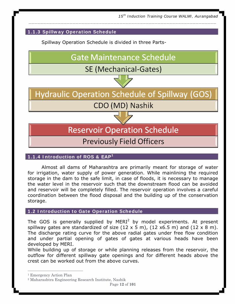
1.1.3 Spillway Operation Schedule Spillway Operation Schedule is divided in three Parts-
1.1.4 Introduction of ROS & EAP1 Almost all dams of Maharashtra are primarily meant for storage of water
for irrigation, water supply of power generation. While mainlining the required storage in the dam to the safe limit, in case of floods, it is necessary to manage the water level in the reservoir such that the downstream flood can be avoided and reservoir will be completely filled. The reservoir operation involves a careful coordination between the flood disposal and the building up of the conservation storage.
1.2 Introduction to Gate Operation Schedule
The GOS is generally supplied by MERI2 by model experiments. At present spillway gates are standardized of size (12 x 5 m), (12 x6.5 m) and (12 x 8 m). The discharge rating curve for the above radial gates under free flow condition and under partial opening of gates of gates at various heads have been developed by MERI. While building up of storage or while planning releases from the reservoir, the outflow for different spillway gate openings and for different heads above the crest can be worked out from the above curves.
1 Emergency Action Plan 2 Maharashtra Engineering Research Institute, Nashik

15th Induction Training Course WALMI, Aurangabad ________________________________________________________________
Page 13 of 101
The GOS must be prepared based on site conditions, the results of model studies & the regulation schedule of the reservoir. The GOS should clearly indicate the complete sequence and stages of operations of various gates corresponding to various lake levels and the flood situations. These details should also be incorporated in Standing Operating Procedures of the reservoir along with the regulation schedule and maintenance schedule of gates. A
1.2.1 Necessity of ROS and GOS
1. Water Resources Department had obstructed natural flow by construction of dams across river for irrigation, water supply and for other remarkable benefits.
2. Accumulation of incoming flood in reservoir, safely release of flood without damage to structure and life of people with their property on down stream of dam.
3. Accumulation of incoming flood in reservoir, safely release of flood will be done with the help of Approved Reservoir Operation Schedule, Gate Operation Schedule and Emergency Action Plan.
4. Sectional Engineer and Deputy Engineer with staff related to maintenance of dam must stay at dam during emergency period. i.e. 15th June to 31st Oct. Concern Executive Engineer related to dam keep watch on hourly increase in water level and release of flood during emergency.
5. At the time release of water through dam 48 hours before inform to Emergency Cell. Also inform to Emergency Cell at the time of actual release of water and rate of flow with depth of water and obtain the receipt.
1.2.2 Principle of Operation of Reservoir
Following are some of the common principles of reservoir operation. I Single Purpose Reservoirs 1. Flood control - Operation of flood control reservoirs is primarily governed
by the available flood storage capacity, discharge capacity of outlets, their location and nature of damage centers to be protected, flood characteristics, ability and accuracy of flood/storm forecast and size of the uncontrolled drainage area. A regulation plan to cover all the complicated situations may be difficult to evolve, but generally it should be possible according to one of the following principles:
a. Effective use of available flood control storage - Operation under this principle aims at reducing flood damages of the locations to be protected to the maximum extent possible, by effective use of flood control storage capacity available at the time of each flood event. Since the release under this plan would obviously be lower than those required for controlling the reservoir design flood, there is distinct possibility of having a portion of the flood control space occupied during the occurrence of a subsequent heavy flood. In order to
15th Induction Training Course WALMI, Aurangabad ________________________________________________________________
Page 14 of 101
reduce this element of risk, maintenance of an adequate network of flood forecasting stations both in the upstream and downstream area would be absolutely necessary.
b. Control of reservoir design flood - According to this principle, releases from flood control reservoirs operated on this concept are made on the same hypothesis as adopted for controlling the reservoir design flood that is the full storage capacity would be utilized only when the flood develops into the reservoir design flood. However, as the design flood is usually an extreme event, regulation of minor and major floods, which occur more often, is less satisfactory when this method is applied.
c. Combination of principles (1) and (2) - In this method, a combination of the principles (1) and (2) is followed. The principle (1) is followed for the lower portion of the flood reserve to achieve the maximum benefits by controlling the earlier part of the flood. Thereafter releases are made as scheduled for the reservoir design flood as in principle (2). In most cases this plan will result in the best overall regulation, as it combines the good points of both the methods.
d. Flood control in emergencies -- It is advisable to prepare an emergency release schedule that uses information on reservoir data immediately available to the operator. Such schedule should be available with the operator to enable him to comply with necessary precautions under extreme flood conditions. 2. Conservation -- Reservoirs meant for augmentation of supplies during lean
period should usually be operated to fill as early as possible during filling period, while meeting the requirements. All .water in excess of the requirements of the filling period shall be impounded. No spilling of water over the spillway will normally be permitted until the FRL is reached. Should any flood occur when the reservoir is at or near the FRL, release of flood waters should be affected, so as not to exceed the discharge that would have occurred had there been no reservoir. In case the year happens to be dry, the draft for filling period should be curtailed by applying suitable factors. The depletion period should begin thereafter. However, in case the reservoir is planned with carry-over capacity, it is necessary to ensure that the regulation will provide the required carry-over capacity at the end of the depletion period.
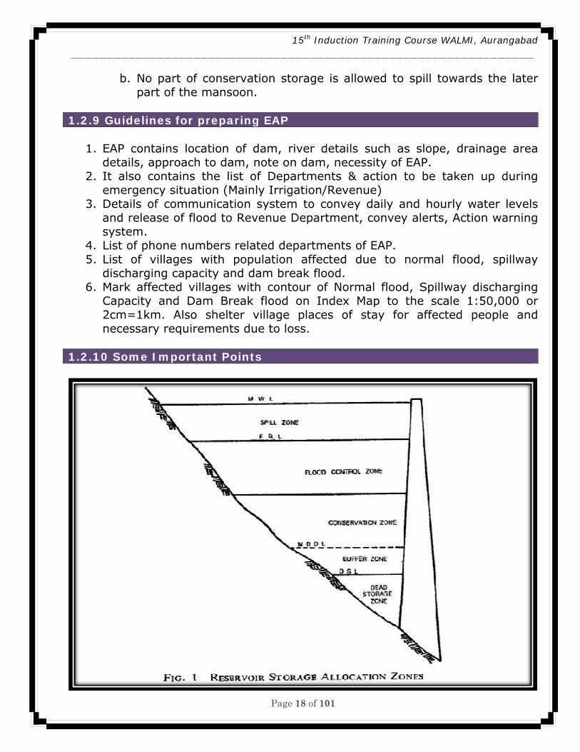
II. Multi-purpose Reservoirs Operation of a multi-purpose reservoir should be governed by the manner in which various uses of the reservoir have been combined. While operating the reservoirs to meet the demands of end users, the priorities for allocation may be used as a guideline. In general five basic zones of reservoir space may be used in operating a reservoir for various functions. Typical storage allocations for various uses are indicated in Fig. I. The various storage zones often identified are:
a. Spill zone - Storage space above the flood control zone between FRL and MWL, is generally referred to as spill zone. This space is occupied mostly
15th Induction Training Course WALMI, Aurangabad ________________________________________________________________
Page 15 of 101
during high floods and the releases from this zone are trade-off between structural safety and downstream flood damages.
b. Flood control zone - This is the storage space earmarked as temporary storage for absorbing high flows for alleviating downstream flood damages. This should be space emptied as soon as possible to negotiate next flood event.
c. Conservation zone - This storage space is used for conservation of water for meeting various future demands. This zone is generally between FRL and dead storage level.
d. Buffer ZOHP -- This is the storage space above dead storage level which is used to satisfy only very essential water needs in case of extreme situation.
e. Dead storage zone -- This is also called inactive zone. This is the lowest zone in which the storage is meant to absorb some of the sediments entering into the reservoir. The storage in this zone is not susceptible to release by the in-built outlet means.
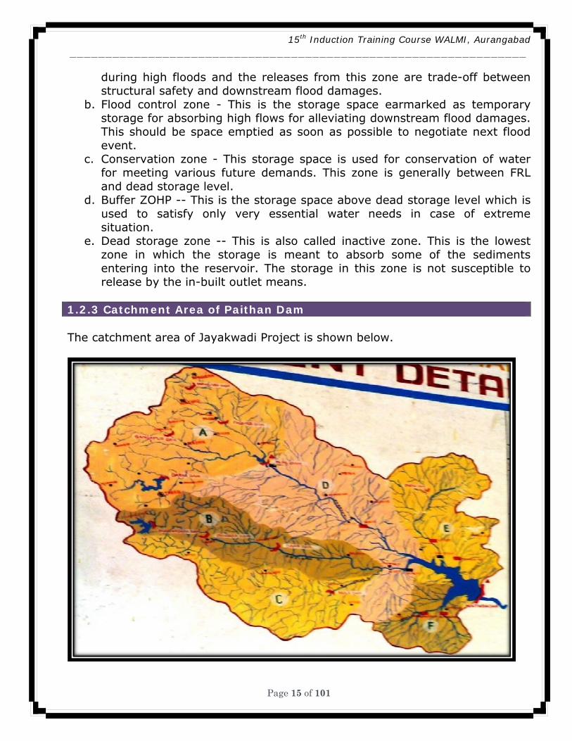
1.2.3 Catchment Area of Paithan Dam The catchment area of Jayakwadi Project is shown below.
15th Induction Training Course WALMI, Aurangabad ________________________________________________________________
Page 16 of 101
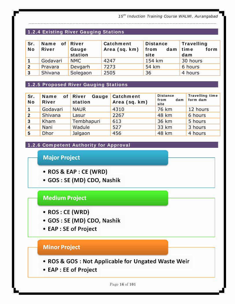
1.2.4 Existing River Gauging Stations Sr. No
Name of River
River Gauge station
Catchment Area (sq. km)
Distance from dam site
Travelling time form dam
1 Godavari NMC 4247 154 km 30 hours 2 Pravara Devgarh 7273 54 km 6 hours 3 Shivana Solegaon 2505 36 4 hours 1.2.5 Proposed River Gauging Stations Sr. No
Name of River
River Gauge station
Catchment Area (sq. km)
Distance from dam site
Travelling time form dam
1 Godavari NAUR 4310 76 km 12 hours 2 Shivana Lasur 2267 48 km 6 hours 3 Kham Tembhapuri 613 36 km 5 hours 4 Nani Wadule 527 33 km 3 hours 5 Dhor Jalgaon 456 48 km 4 hours 1.2.6 Competent Authority for Approval
15th Induction Training Course WALMI, Aurangabad ________________________________________________________________
Page 17 of 101
1.2.7 Guidelines for preparing ROS ROS contains following data-
1. Monthly planning of accumulation of incoming inflow on the basis of observed data of previous years.
a. July End: b. August End: c. September End: d. October End
2. Reservoir levels were fixed on the basis of observed data at dam site before impounding reservoir. Revision is necessary after 10 years experience of flood accumulation and release.
3. On the basis of observed data prepare10 day runoff series for 90% and 75 % dependability by deducting projected utilization form 10 day runoff.
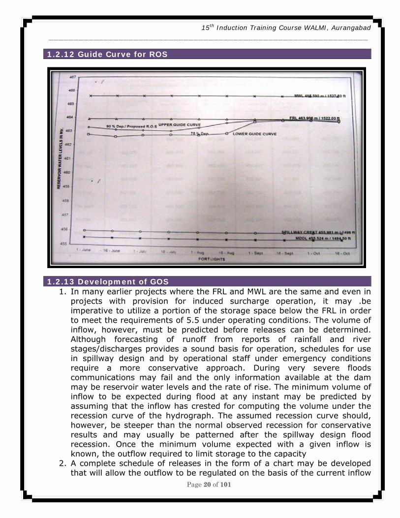
4. Prepare guide curves for 90% & 75% dependability. 5. Surplus flood can be routed safely without damage to life and property of
villages on down stream of dam as per approved ROS. 1.2.8 Guidelines for preparing GOS
Following are general guide lines for the gate operation-
1. If the dam has got stilling basin at two different elevations, then generally the gates with stilling basin at lower level need to be operated first.
2. The end gate should normally be opened first to prevent cross flow striking against guide walls and junctions.
3. At any time during the operation of different gates, the difference in gate opening for any two consecutive gates should not exceed 0.5 m.
4. After opening the end gates, the gate/gates at the centre should be opened and the other gates should be opened in symmetrical manner starting form the centre towards the end through gradual increase in the opening.
5. While closing the gates, the gate that was opened last should be closed first. The procedure to be followed for closing the gates would generally be the reverse of the procedure followed for opening of gates. Complete closure of the gates should be accomplished by gradual lowering of the gates by 0.2 to 0.3 m in the proper sequence.
6. An efficient and reliable system of flood forecasting should be estimated at dam site to facilitated-
a. Formulation of accurate forecasts of rate of inflow and volume of floods at the dam site and
b. Regulation of the gates for efficient flood disposal. 7. While surplussing the floods when the reservoir is at or near about the FRL
towards the end of mansoon, a. The reservoir level should not be allowed to encroach up to free
board.
15th Induction Training Course WALMI, Aurangabad ________________________________________________________________
Page 18 of 101
b. No part of conservation storage is allowed to spill towards the later part of the mansoon.
1.2.9 Guidelines for preparing EAP
1. EAP contains location of dam, river details such as slope, drainage area details, approach to dam, note on dam, necessity of EAP.
2. It also contains the list of Departments & action to be taken up during emergency situation (Mainly Irrigation/Revenue)
3. Details of communication system to convey daily and hourly water levels and release of flood to Revenue Department, convey alerts, Action warning system.
4. List of phone numbers related departments of EAP. 5. List of villages with population affected due to normal flood, spillway
discharging capacity and dam break flood. 6. Mark affected villages with contour of Normal flood, Spillway discharging
Capacity and Dam Break flood on Index Map to the scale 1:50,000 or 2cm=1km. Also shelter village places of stay for affected people and necessary requirements due to loss.
1.2.10 Some Important Points
15th Induction Training Course WALMI, Aurangabad ________________________________________________________________
Page 19 of 101
1. With restraints on downstream channel capacity and likely damage to towns and villages on downstream, the flood releases form the spillway shall have to be planned and regulated judiciously; on respect of forecast warnings of heavy precipitations and/or releases form upstream storage if any, and with due considerations to the reservoir level and flood absorption capacity etc.
2. Based on the discharge rating curves and the general principles of operation of gates given above it will be possible for the field officers to finalize the GOS for individual projects to meet the flood situations.
1.2.11 Real Time Operation of Reservoir
1. The operation of reservoirs based on fixed operation rules, which are
developed taking into account the demands and historic/synthetic time series data, often poses difficulties in making appropriate reservoir release decisions due to the uncertainty in the probability of occurrence of the flood event exactly similar to the past event, though the demands could be fairly stable. Operation of reservoirs, therefore, becomes an operation in real time in which water control decisions have to be taken at each instant of time.
2. The real time reservoir operation control decisions are made quickly, for a finite future condition of the system at that instant of time and the forecast of the likely inputs over this time horizon depending on the purpose of the reservoir operation that is flood control,
3. Use of systems engineering techniques using computer technology should be employed and a computer model be developed for real time operation. Some of the important aspects of real time reservoir operation are listed below:
a. Collection of catchment hydrological data and water demand data and transmission of the data to the operation manager at the control station through suitable logistics such as hydrological sensors, data loggers and telemetry network;
b. Availability of a computer system at the control station; c. A real time data base management system; and d. A computer model having capability of flow forecast, control
decisions forecast with flexibility for modified data entry and updating, preferably in an interactive mode, in shortest possible execution time.
15th Induction Training Course WALMI, Aurangabad ________________________________________________________________
Page 20 of 101
1.2.12 Guide Curve for ROS
1.2.13 Development of GOS
1. In many earlier projects where the FRL and MWL are the same and even in projects with provision for induced surcharge operation, it may .be imperative to utilize a portion of the storage space below the FRL in order to meet the requirements of 5.5 under operating conditions. The volume of inflow, however, must be predicted before releases can be determined. Although forecasting of runoff from reports of rainfall and river stages/discharges provides a sound basis for operation, schedules for use in spillway design and by operational staff under emergency conditions require a more conservative approach. During very severe floods communications may fail and the only information available at the dam may be reservoir water levels and the rate of rise. The minimum volume of inflow to be expected during flood at any instant may be predicted by assuming that the inflow has crested for computing the volume under the recession curve of the hydrograph. The assumed recession curve should, however, be steeper than the normal observed recession for conservative results and may usually be patterned after the spillway design flood recession. Once the minimum volume expected with a given inflow is known, the outflow required to limit storage to the capacity
2. A complete schedule of releases in the form of a chart may be developed that will allow the outflow to be regulated on the basis of the current inflow
15th Induction Training Course WALMI, Aurangabad ________________________________________________________________
Page 21 of 101
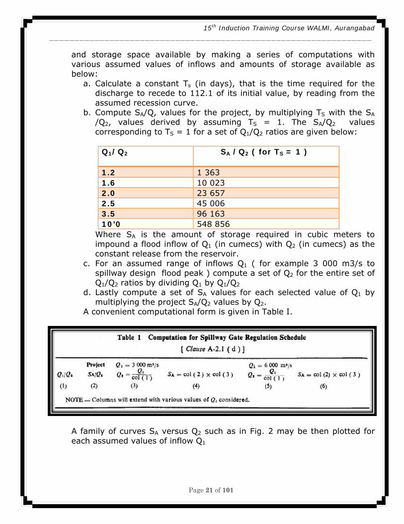
and storage space available by making a series of computations with various assumed values of inflows and amounts of storage available as below:
a. Calculate a constant Ts (in days), that is the time required for the discharge to recede to 112.1 of its initial value, by reading from the assumed recession curve.
b. Compute SA/Q, values for the project, by multiplying TS with the SA /Q2, values derived by assuming TS = 1. The SA/Q2 values corresponding to TS = 1 for a set of Q1/Q2 ratios are given below:
Q1/Q2 SA /Q2 ( for TS = 1 )
1.2 1 363 1.6 10 023 2.0 23 657 2.5 45 006 3.5 96 163 10’0 548 856
Where SA is the amount of storage required in cubic meters to impound a flood inflow of Q1 (in cumecs) with Q2 (in cumecs) as the constant release from the reservoir.
c. For an assumed range of inflows Q1 ( for example 3 000 m3/s to spillway design flood peak ) compute a set of Q2 for the entire set of Q1/Q2 ratios by dividing Q1 by Q1/Q2
d. Lastly compute a set of SA values for each selected value of Q1 by multiplying the project SA/Q2 values by Q2.
A convenient computational form is given in Table I.
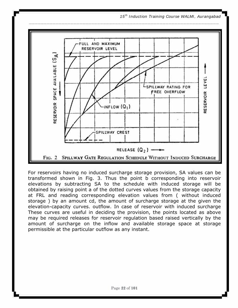
A family of curves SA versus Q2 such as in Fig. 2 may be then plotted for each assumed values of inflow Q1
15th Induction Training Course WALMI, Aurangabad ________________________________________________________________
Page 22 of 101
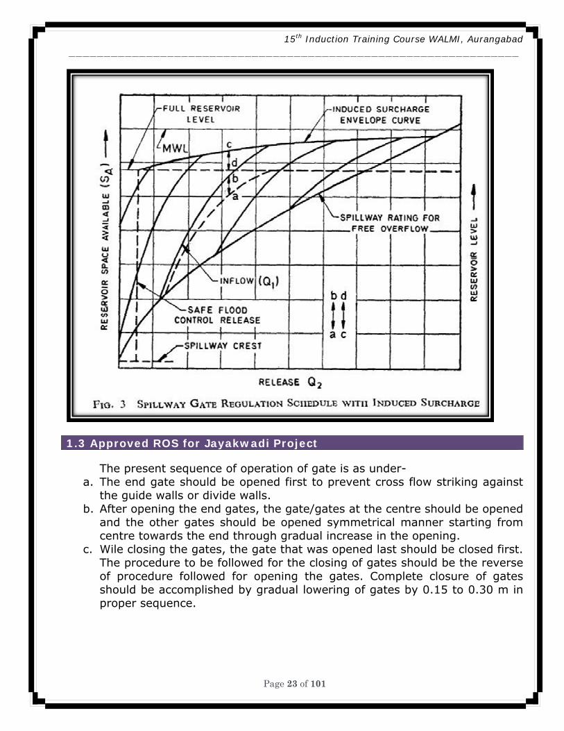
For reservoirs having no induced surcharge storage provision, SA values can be transformed shown in Fig. 3. Thus the point b corresponding into reservoir elevations by subtracting SA to the schedule with induced storage will be obtained by raising point a of the dotted curves values from the storage capacity at FRL and reading corresponding elevation values from ( without induced storage ) by an amount cd, the amount of surcharge storage at the given the elevation-capacity curves. outflow. In case of reservoir with induced surcharge These curves are useful in deciding the provision, the points located as above may be required releases for reservoir regulation based raised vertically by the amount of surcharge on the inflow and available storage space at storage permissible at the particular outflow as any instant.
15th Induction Training Course WALMI, Aurangabad ________________________________________________________________
Page 23 of 101
1.3 Approved ROS for Jayakwadi Project
The present sequence of operation of gate is as under-
a. The end gate should be opened first to prevent cross flow striking against the guide walls or divide walls.
b. After opening the end gates, the gate/gates at the centre should be opened and the other gates should be opened symmetrical manner starting from centre towards the end through gradual increase in the opening.
c. Wile closing the gates, the gate that was opened last should be closed first. The procedure to be followed for the closing of gates should be the reverse of procedure followed for opening the gates. Complete closure of gates should be accomplished by gradual lowering of gates by 0.15 to 0.30 m in proper sequence.
15th Induction Training Course WALMI, Aurangabad ________________________________________________________________
Page 24 of 101
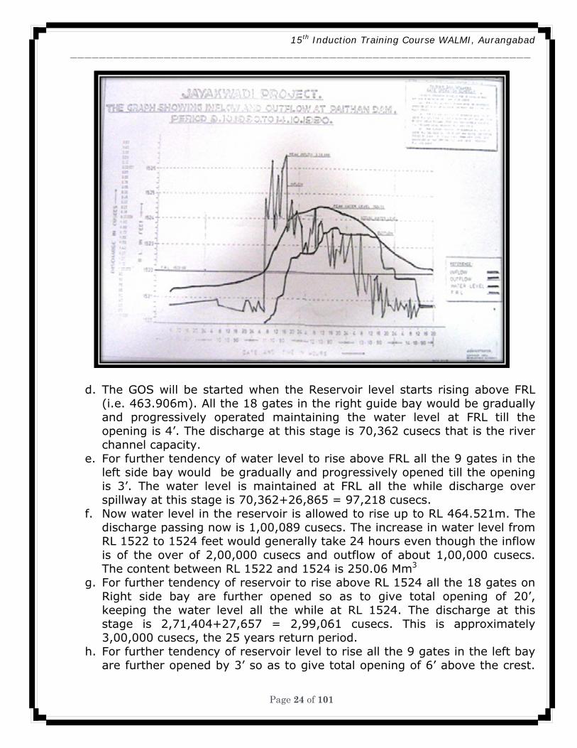
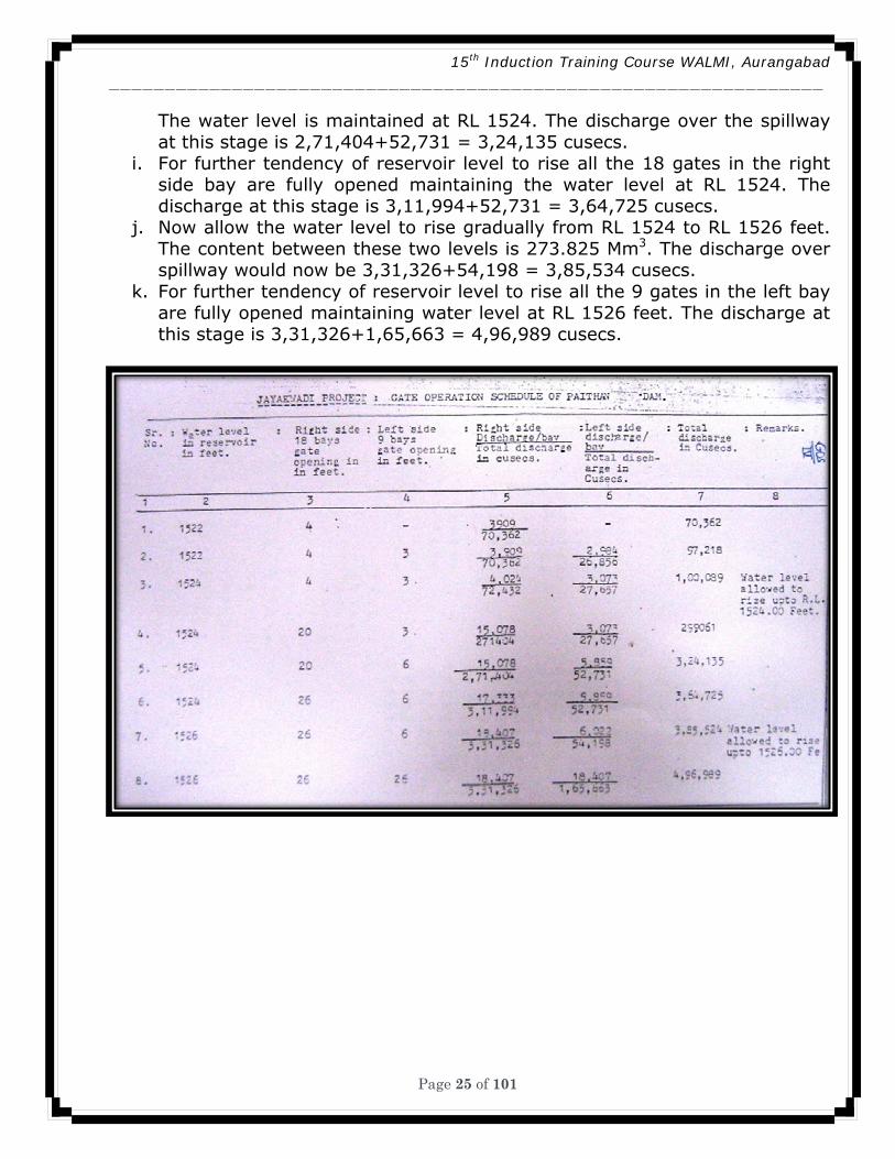
d. The GOS will be started when the Reservoir level starts rising above FRL (i.e. 463.906m). All the 18 gates in the right guide bay would be gradually and progressively operated maintaining the water level at FRL till the opening is 4’. The discharge at this stage is 70,362 cusecs that is the river channel capacity.
e. For further tendency of water level to rise above FRL all the 9 gates in the left side bay would be gradually and progressively opened till the opening is 3’. The water level is maintained at FRL all the while discharge over spillway at this stage is 70,362+26,865 = 97,218 cusecs.
f. Now water level in the reservoir is allowed to rise up to RL 464.521m. The discharge passing now is 1,00,089 cusecs. The increase in water level from RL 1522 to 1524 feet would generally take 24 hours even though the inflow is of the over of 2,00,000 cusecs and outflow of about 1,00,000 cusecs. The content between RL 1522 and 1524 is 250.06 Mm3
g. For further tendency of reservoir to rise above RL 1524 all the 18 gates on Right side bay are further opened so as to give total opening of 20’, keeping the water level all the while at RL 1524. The discharge at this stage is 2,71,404+27,657 = 2,99,061 cusecs. This is approximately 3,00,000 cusecs, the 25 years return period.
h. For further tendency of reservoir level to rise all the 9 gates in the left bay are further opened by 3’ so as to give total opening of 6’ above the crest.
15th Induction Training Course WALMI, Aurangabad ________________________________________________________________
Page 25 of 101
The water level is maintained at RL 1524. The discharge over the spillway at this stage is 2,71,404+52,731 = 3,24,135 cusecs.
i. For further tendency of reservoir level to rise all the 18 gates in the right side bay are fully opened maintaining the water level at RL 1524. The discharge at this stage is 3,11,994+52,731 = 3,64,725 cusecs.
j. Now allow the water level to rise gradually from RL 1524 to RL 1526 feet. The content between these two levels is 273.825 Mm3. The discharge over spillway would now be 3,31,326+54,198 = 3,85,534 cusecs.
k. For further tendency of reservoir level to rise all the 9 gates in the left bay are fully opened maintaining water level at RL 1526 feet. The discharge at this stage is 3,31,326+1,65,663 = 4,96,989 cusecs.
15th Induction Training Course WALMI, Aurangabad ________________________________________________________________
Page 26 of 101
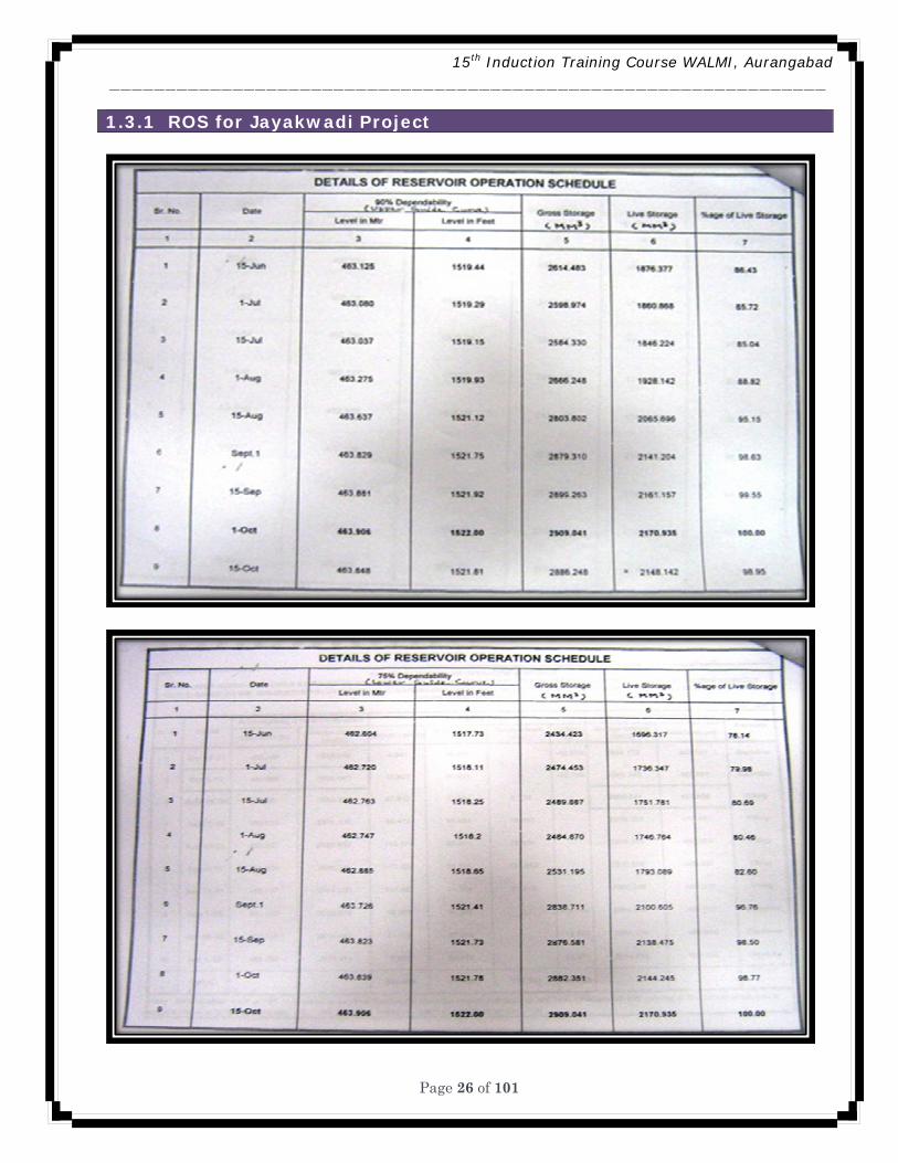
1.3.1 ROS for Jayakwadi Project
15th Induction Training Course WALMI, Aurangabad ________________________________________________________________
Page 27 of 101
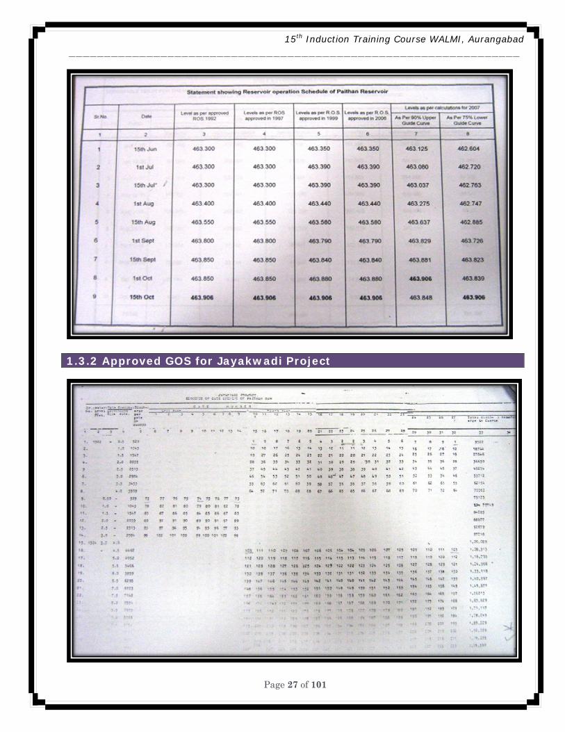
1.3.2 Approved GOS for Jayakwadi Project
15th Induction Training Course WALMI, Aurangabad ________________________________________________________________
Page 28 of 101
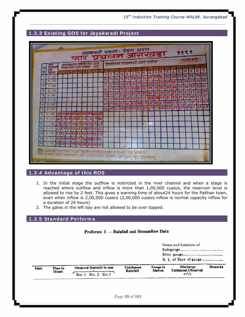
1.3.3 Existing GOS for Jayakwadi Project
1.3.4 Advantage of this ROS
1. In the initial stage the outflow is restricted in the river channel and when a stage is reached where outflow and inflow is more than 1,00,000 cusecs, the reservoir level is allowed to rise by 2 feet. This gives a warning time of about24 hours for the Paithan town, even when inflow is 2,00,000 cusecs (2,00,000 cusecs inflow is normal capacity inflow for a duration of 24 hours)
2. The gates in the left bay are not allowed to be over topped. 1.3.5 Standard Performa
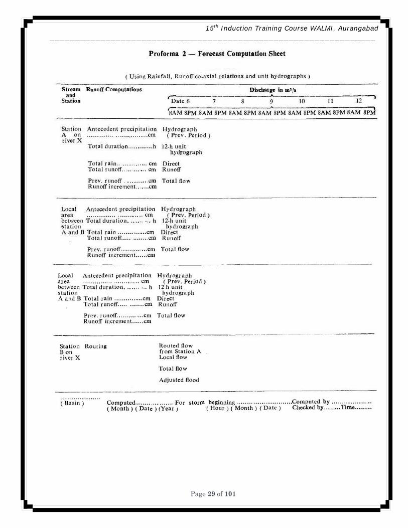
15th Induction Training Course WALMI, Aurangabad ________________________________________________________________
Page 29 of 101
15th Induction Training Course WALMI, Aurangabad ________________________________________________________________
Page 30 of 101
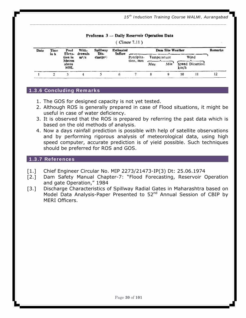
1.3.6 Concluding Remarks
1. The GOS for designed capacity is not yet tested. 2. Although ROS is generally prepared in case of Flood situations, it might be
useful in case of water deficiency. 3. It is observed that the ROS is prepared by referring the past data which is
based on the old methods of analysis. 4. Now a days rainfall prediction is possible with help of satellite observations
and by performing rigorous analysis of meteorological data, using high speed computer, accurate prediction is of yield possible. Such techniques should be preferred for ROS and GOS.
1.3.7 References
[1.] Chief Engineer Circular No. MIP 2273/21473-IP(3) Dt: 25.06.1974 [2.] Dam Safety Manual Chapter-7: “Flood Forecasting, Reservoir Operation
and gate Operation,” 1984 [3.] Discharge Characteristics of Spillway Radial Gates in Maharashtra based on
Model Data Analysis-Paper Presented to 52nd Annual Session of CBIP by MERI Officers.
15th Induction Training Course WALMI, Aurangabad ________________________________________________________________
Page 31 of 101
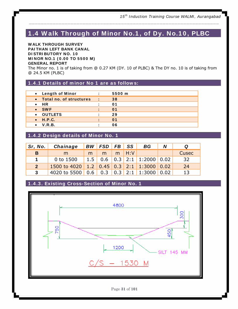
1.4 Walk Through of Minor No.1, of Dy. No.10, PLBC WALK THROUGH SURVEY PAITHAN LEFT BANK CANAL DISTRIBUTORY NO. 10 MINOR NO.1 (0.00 TO 5500 M) GENERAL REPORT The Minor no. 1 is of taking from @ 0.27 KM (DY. 10 of PLBC) & The DY no. 10 is of taking from @ 24.5 KM (PLBC)
1.4.1 Details of minor No 1 are as follows:
• Length of Minor : 5500 m • Total no. of structures : 38 • HR : 01 • SWF : 01 • OUTLETS : 29 • H.P.C. : 01 • V.R.B. : 06
1.4.2 Design details of Minor No. 1
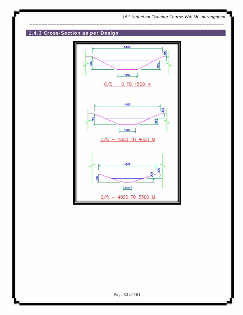
Sr, No. Chainage BW FSD FB SS BG N Q B m m m m H:V Cusec 1 0 to 1500 1.5 0.6 0.3 2:1 1:2000 0.02 32 2 1500 to 4020 1.2 0.45 0.3 2:1 1:3000 0.02 24 3 4020 to 5500 0.6 0.3 0.3 2:1 1:3000 0.02 13
1.4.3. Existing Cross-Section of Minor No. 1
15th Induction Training Course WALMI, Aurangabad ________________________________________________________________
Page 32 of 101
1.4.3 Cross-Section as per Design

15th Induction Training Course WALMI, Aurangabad ________________________________________________________________
Page 47 of 101
1.4.6 Cross Regulator & Head Regulator Of Minor N0-1
1.4.7 LINING IN GOOD CONDITION IN INITIAL STRETCH

15th Induction Training Course WALMI, Aurangabad ________________________________________________________________
Page 48 of 101
1.4.8 Damaged Canal Lining
1.4.9 Silting and Stagnation of Water
15th Induction Training Course WALMI, Aurangabad ________________________________________________________________
Page 49 of 101
1.1.10 MS Gate in Damaged Condition
1.4.11 Un-gated Outlet
15th Induction Training Course WALMI, Aurangabad ________________________________________________________________
Page 50 of 101
1.4.12 Slight Silting With Vegetation
1.4.13 Breach of Canal Section
15th Induction Training Course WALMI, Aurangabad ________________________________________________________________
Page 51 of 101
1.4.14 Stagnation of Water Due to Weed Growth
1.4.15 H.P Drain Silting
15th Induction Training Course WALMI, Aurangabad ________________________________________________________________
Page 52 of 101
1.4.16 Heavy Silting Observed
1.4.17 Vegetation on Unlined Portion of Canal
15th Induction Training Course WALMI, Aurangabad ________________________________________________________________
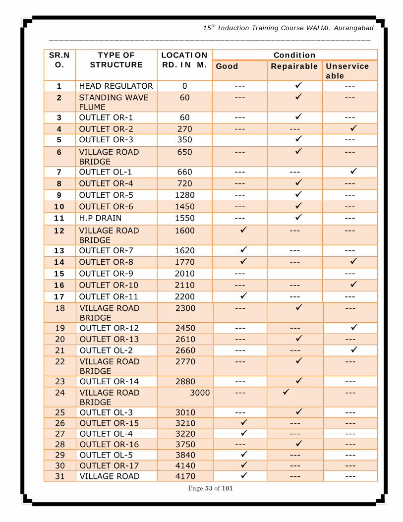
Page 53 of 101
SR.NO.
TYPE OF STRUCTURE
LOCATION RD. IN M.
Condition Good Repairable Unservice
able 1 HEAD REGULATOR 0 --- --- 2 STANDING WAVE
FLUME 60 --- ---
3 OUTLET OR-1 60 --- --- 4 OUTLET OR-2 270 --- --- 5 OUTLET OR-3 350 ---
6 VILLAGE ROAD BRIDGE
650 --- ---
7 OUTLET OL-1 660 --- --- 8 OUTLET OR-4 720 --- --- 9 OUTLET OR-5 1280 --- ---
10 OUTLET OR-6 1450 --- --- 11 H.P DRAIN 1550 --- ---
12 VILLAGE ROAD BRIDGE
1600 --- ---
13 OUTLET OR-7 1620 --- --- 14 OUTLET OR-8 1770 --- 15 OUTLET OR-9 2010 --- --- 16 OUTLET OR-10 2110 --- --- 17 OUTLET OR-11 2200 --- --- 18 VILLAGE ROAD
BRIDGE 2300 --- ---
19 OUTLET OR-12 2450 --- --- 20 OUTLET OR-13 2610 --- --- 21 OUTLET OL-2 2660 --- --- 22 VILLAGE ROAD
BRIDGE 2770 --- ---
23 OUTLET OR-14 2880 --- --- 24 VILLAGE ROAD
BRIDGE 3000 --- ---
25 OUTLET OL-3 3010 --- --- 26 OUTLET OR-15 3210 --- --- 27 OUTLET OL-4 3220 --- --- 28 OUTLET OR-16 3750 --- --- 29 OUTLET OL-5 3840 --- --- 30 OUTLET OR-17 4140 --- --- 31 VILLAGE ROAD 4170 --- ---
15th Induction Training Course WALMI, Aurangabad ________________________________________________________________
Page 54 of 101
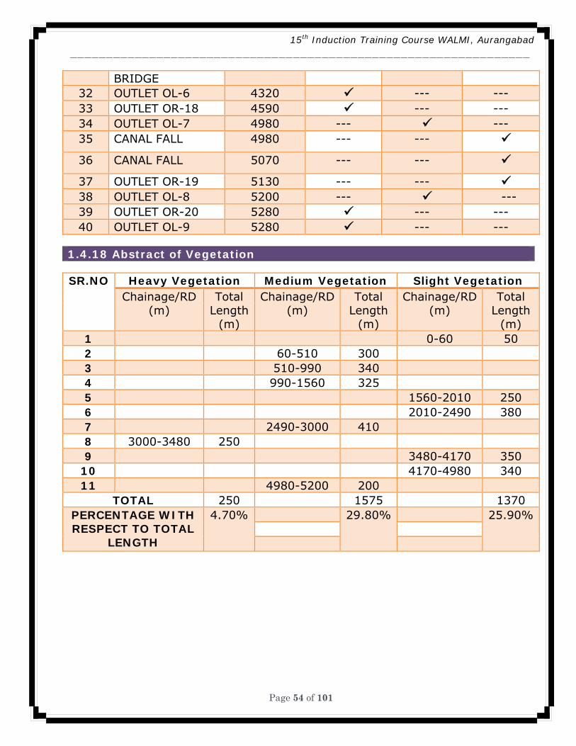
BRIDGE 32 OUTLET OL-6 4320 --- --- 33 OUTLET OR-18 4590 --- --- 34 OUTLET OL-7 4980 --- --- 35 CANAL FALL 4980 --- ---
36 CANAL FALL 5070 --- ---
37 OUTLET OR-19 5130 --- --- 38 OUTLET OL-8 5200 --- --- 39 OUTLET OR-20 5280 --- --- 40 OUTLET OL-9 5280 --- ---
1.4.18 Abstract of Vegetation
SR.NO Heavy Vegetation Medium Vegetation Slight Vegetation Chainage/RD
(m) Total
Length (m)
Chainage/RD (m)
Total Length
(m)
Chainage/RD (m)
Total Length
(m) 1 0-60 50 2 60-510 300 3 510-990 340 4 990-1560 325 5 1560-2010 250 6 2010-2490 380 7 2490-3000 410 8 3000-3480 250 9 3480-4170 350
10 4170-4980 340 11 4980-5200 200
TOTAL 250 1575 1370 PERCENTAGE WITH RESPECT TO TOTAL
LENGTH
4.70% 29.80% 25.90%
15th Induction Training Course WALMI, Aurangabad ________________________________________________________________
Page 55 of 101
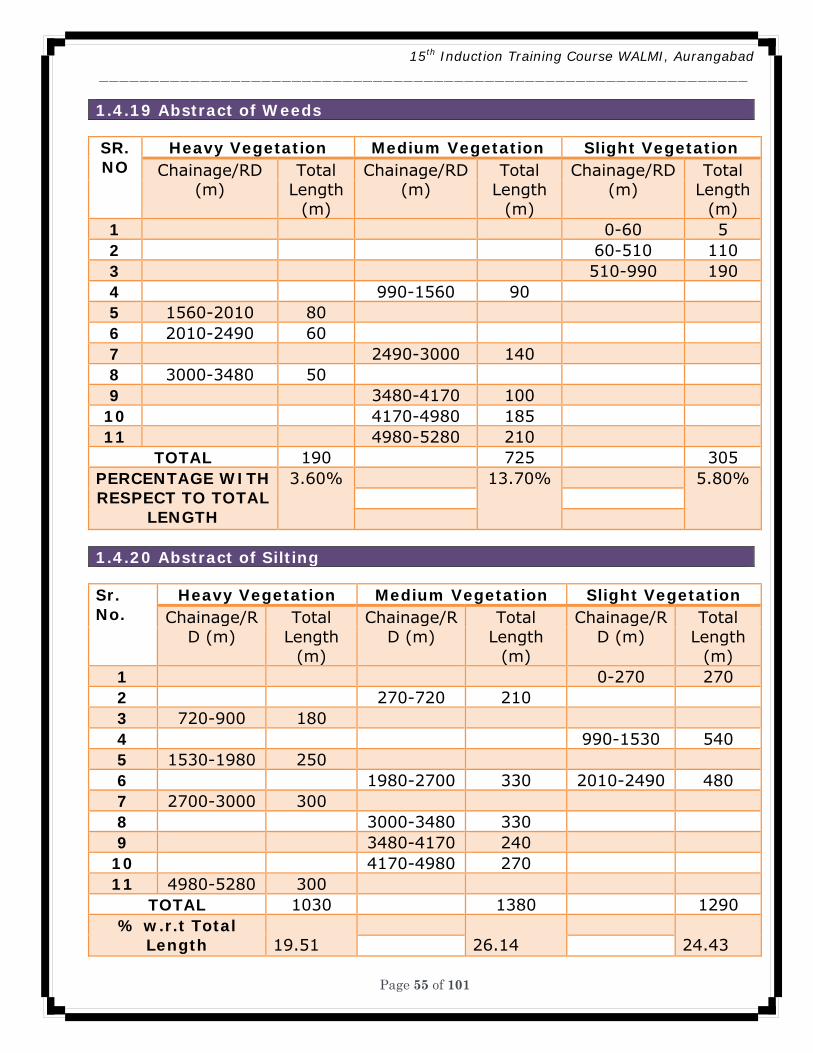
1.4.19 Abstract of Weeds
SR. NO
Heavy Vegetation Medium Vegetation Slight Vegetation Chainage/RD
(m) Total
Length (m)
Chainage/RD (m)
Total Length
(m)
Chainage/RD (m)
Total Length
(m) 1 0-60 5 2 60-510 110 3 510-990 190 4 990-1560 90 5 1560-2010 80 6 2010-2490 60 7 2490-3000 140 8 3000-3480 50 9 3480-4170 100
10 4170-4980 185 11 4980-5280 210
TOTAL 190 725 305 PERCENTAGE WITH RESPECT TO TOTAL
LENGTH
3.60% 13.70% 5.80%
1.4.20 Abstract of Silting
Sr. No.
Heavy Vegetation Medium Vegetation Slight Vegetation Chainage/R
D (m) Total
Length (m)
Chainage/RD (m)
Total Length
(m)
Chainage/RD (m)
Total Length
(m) 1 0-270 270 2 270-720 210 3 720-900 180 4 990-1530 540 5 1530-1980 250 6 1980-2700 330 2010-2490 480 7 2700-3000 300 8 3000-3480 330 9 3480-4170 240
10 4170-4980 270 11 4980-5280 300
TOTAL 1030 1380 1290 % w.r.t Total
Length 19.51
26.14
24.43
15th Induction Training Course WALMI, Aurangabad ________________________________________________________________
Page 56 of 101
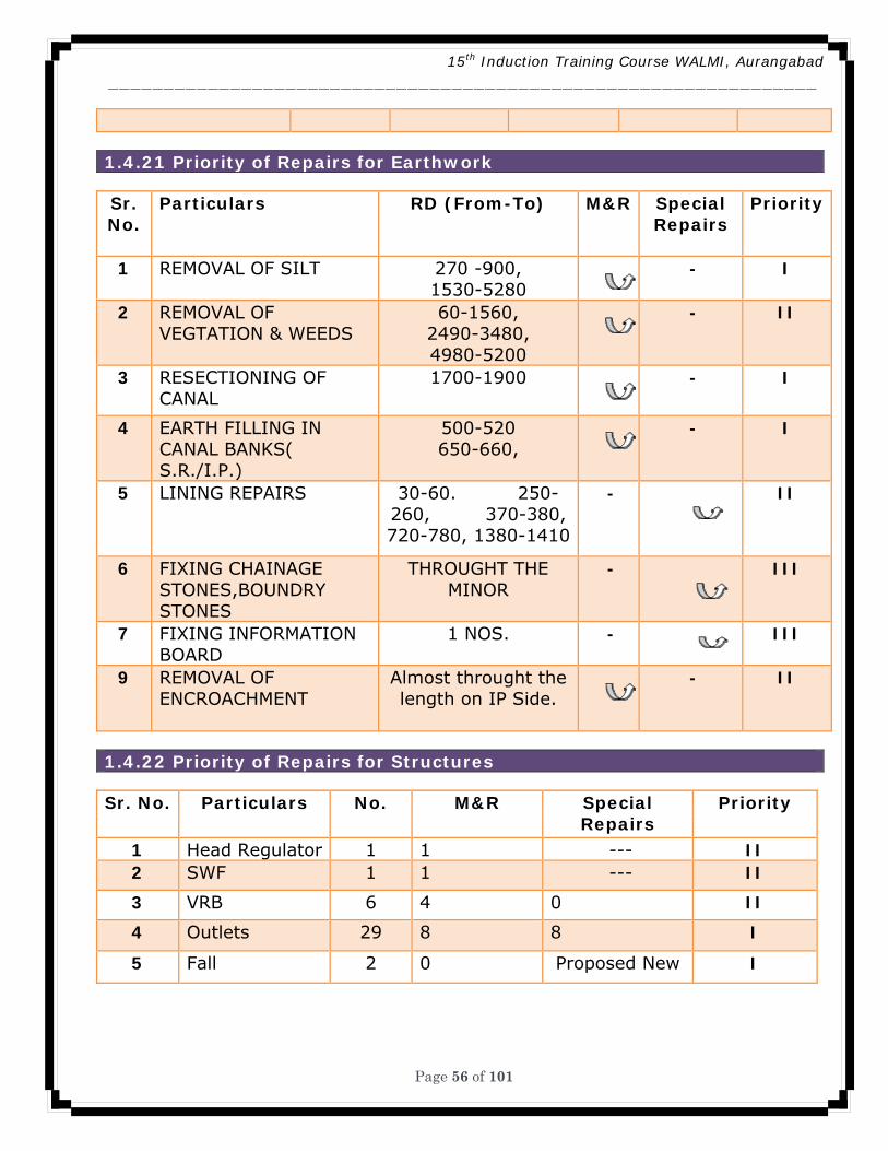
1.4.21 Priority of Repairs for Earthwork
Sr. No.
Particulars RD (From-To) M&R Special Repairs
Priority
1 REMOVAL OF SILT 270 -900, 1530-5280
- I
2 REMOVAL OF VEGTATION & WEEDS
60-1560, 2490-3480, 4980-5200
- II
3 RESECTIONING OF CANAL
1700-1900 - I
4 EARTH FILLING IN CANAL BANKS( S.R./I.P.)
500-520 650-660,
- I
5 LINING REPAIRS 30-60. 250-260, 370-380, 720-780, 1380-1410
- II
6 FIXING CHAINAGE STONES,BOUNDRY STONES
THROUGHT THE MINOR
- III
7 FIXING INFORMATION BOARD
1 NOS. - III
9 REMOVAL OF ENCROACHMENT
Almost throught the length on IP Side.
- II
1.4.22 Priority of Repairs for Structures
Sr. No. Particulars No. M&R Special Repairs
Priority
1 Head Regulator 1 1 --- II 2 SWF 1 1 --- II
3 VRB 6 4 0 II
4 Outlets 29 8 8 I
5 Fall 2 0 Proposed New I
15th Induction Training Course WALMI, Aurangabad ________________________________________________________________
Page 57 of 101
1.4.23 Recommendations
• Urgent removal of silt, vegetation & Weeds. • Murum topping on service road. • Repairs to structure, Reconstruction of damaged structure (Earthwork). • It is Proposed to construct SR Outlet where reconstruction is required. • Repairs to Existing Damaged Lining. • Resectioning & Lining of remaining length • Providing chainage, boundary stones and information board on minor. • Encroachment of Agri. farming on the minor network should be removed.
1.4.24. Conclusion
• Urgent removal of silt, vegetation & Weeds. • Murum topping on service road. • Repairs to structure, Reconstruction of damaged structure (Earthwork). • It is Proposed to construct SR Outlet where reconstruction is required. • Repairs to Existing Damaged Lining. • Resectioning & Lining of remaining length • Providing chainage, boundary stones and information board on minor. • Encroachment of Agri. farming on the minor network should be removed.
15th Induction Training Course WALMI, Aurangabad ________________________________________________________________
Page 58 of 101
Chapter 2. Evaluation of Standing Wave Flume (SWF)
2.1 Introduction Flow measurement is important aspect in irrigation water management. Generally Standing Wave Flume (SWF is used to measure the flow. It is designed using procedure given in IS Code No. 6063 – 1971. This procedure is tedious and time consuming. It involves computation of height of hump by establishing the stage discharge relationship of a given cross section maximum head, throat width and then remaining dimensions using long formulae and limits. Similarly, after construction if proper hydraulic conditions are not maintained for proper functioning of SWF, it gives incorrect results. It is therefore necessary to evaluate the performance of such SWF periodically and improvements / rectification are made to bring back the flume to function properly. It involves some computation. Sometimes discharge table of the flume is not available. (1) Design of SWF (2) Rectification of SWF by increasing hump height (3) Preparing discharge table of SWF. 2.2 Methodology
15th Induction Training Course WALMI, Aurangabad ________________________________________________________________
Page 59 of 101
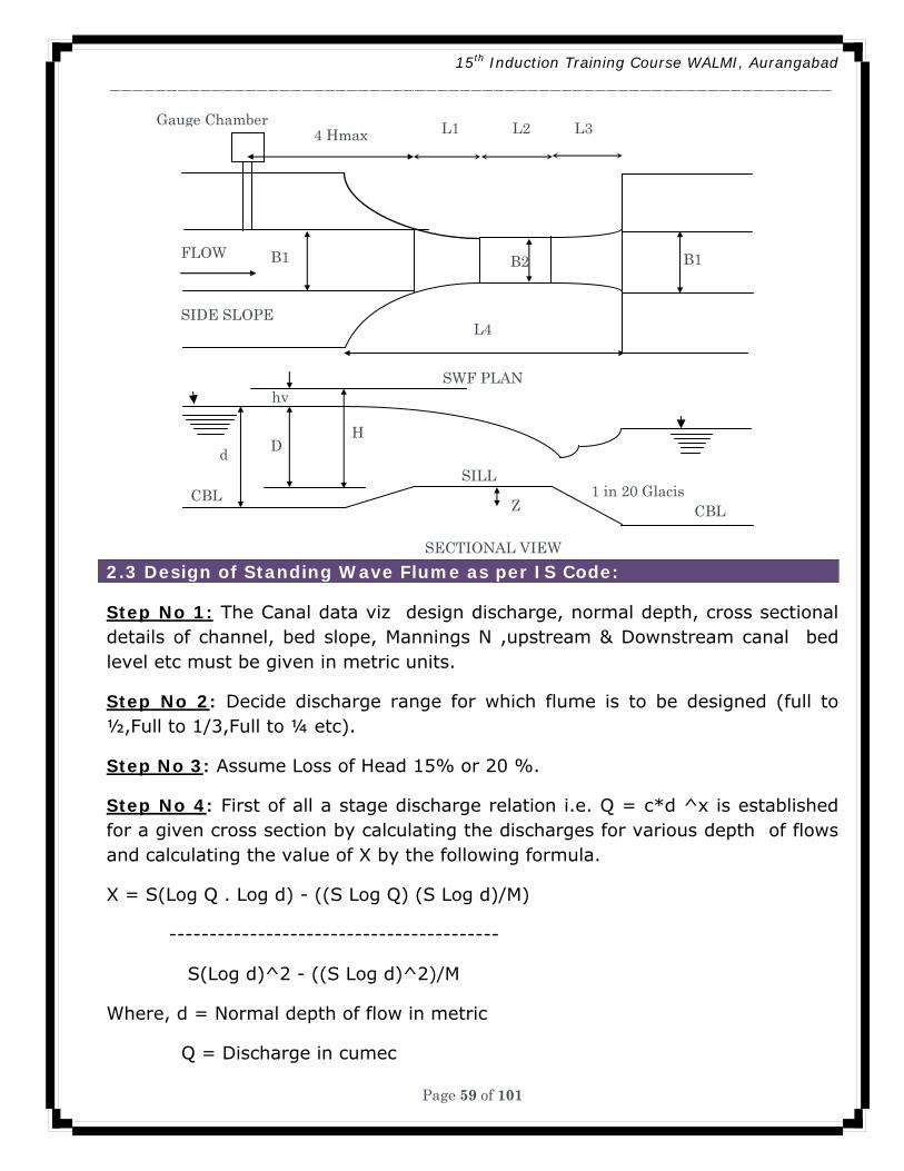
2.3 Design of Standing Wave Flume as per IS Code: Step No 1: The Canal data viz design discharge, normal depth, cross sectional details of channel, bed slope, Mannings N ,upstream & Downstream canal bed level etc must be given in metric units.
Step No 2: Decide discharge range for which flume is to be designed (full to ½,Full to 1/3,Full to ¼ etc).
Step No 3: Assume Loss of Head 15% or 20 %.
Step No 4: First of all a stage discharge relation i.e. Q = c*d ^x is established for a given cross section by calculating the discharges for various depth of flows and calculating the value of X by the following formula.
X = S(Log Q . Log d) - ((S Log Q) (S Log d)/M)
-----------------------------------------
S(Log d)^2 - ((S Log d)^2)/M
Where, d = Normal depth of flow in metric
Q = Discharge in cumec
d D H
hv
SILL
Z1 in 20 Glacis
CBL
SECTIONAL VIEW
SWF PLAN
CBL
SIDE SLOPE
FLOW
Gauge Chamber
B1 B2 B1
4 Hmax L1 L2 L3
L4
15th Induction Training Course WALMI, Aurangabad ________________________________________________________________
Page 60 of 101
M = No. of depths of flow considered
Step No. 5: Calculations of Height of Hump
The height of hump depends on the normal depth for the design discharge fraction of the design discharge considered in establishing the stage discharge relation.
Q = Cd^x and the exponent X, calculated from the above formula and is given by the following formula.
Z1 = DN . m^(1/x) *(1 - (1/m^(1/x) - 1)/(1/m^(2/3) - 1))
Step No. 6: Computation of Maximum Head (Hmax):
The gauge reading and maximum head for the design discharge are calculated as follows.
1. Area of flow corresponding to the normal depth of flow and design discharge
A = B1*DN+Z*DN^2
2. Velocity of Approach
VA = Design Discharge/Area of Flow
3. Approach Velocity Head = (Velocity of Approach)^2/15.2
4. Gauge Reading = Normal depth - Height of Hump
5. Maximum Head = Gauge Reading + Approach Velocity Head (Hmax)
Step No. 7: Computation of Throat Width:
The standing wave flume being a modified broad crested weir, the discharge equation is as follows.
Q = 2/3 * v2/3 g * CF*B2*H^1.5
Where Q = discharge in Cumecs
g = acceleration due to gravity
CF = Coefficient of function its value depends on the discharge Q
Knowing Qmax and Hmax, the throat width is calculated, by substituting the values of Qmax, Hmax, coefficient of discharge in the above equation.
15th Induction Training Course WALMI, Aurangabad ________________________________________________________________
Page 61 of 101
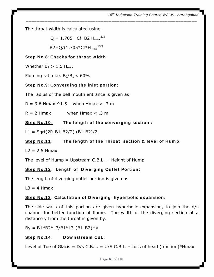
The throat width is calculated using,
Q = 1.705 Cf B2 Hmax3/2
B2=Q/(1.705*Cf*Hmax3/2)
Step No.8: Checks for throat width:
Whether B2 > 1.5 Hmax
Fluming ratio i.e. B2/B1 < 60%
Step No.9: Converging the inlet portion:
The radius of the bell mouth entrance is given as
R = 3.6 Hmax ^1.5 when Hmax > .3 m
R = 2 Hmax when Hmax < .3 m
Step No.10: The length of the converging section :
L1 = Sqrt(2R-B1-B2/2) (B1-B2)/2
Step No.11: The length of the Throat section & level of Hump:
L2 = 2.5 Hmax
The level of Hump = Upstream C.B.L. + Height of Hump
Step No.12: Length of Diverging Outlet Portion:
The length of diverging outlet portion is given as
L3 = 4 Hmax
Step No.13: Calculation of Diverging hyperbolic expansion:
The side walls of this portion are given hyperbolic expansion, to join the d/s channel for better function of flume. The width of the diverging section at a distance y from the throat is given by.
By = B1*B2*L3/B1*L3-(B1-B2)^y
Step No.14: Downstream CBL:
Level of Toe of Glacis = D/s C.B.L. = U/S C.B.L. - Loss of head (fraction)*Hmax
15th Induction Training Course WALMI, Aurangabad ________________________________________________________________
Page 62 of 101
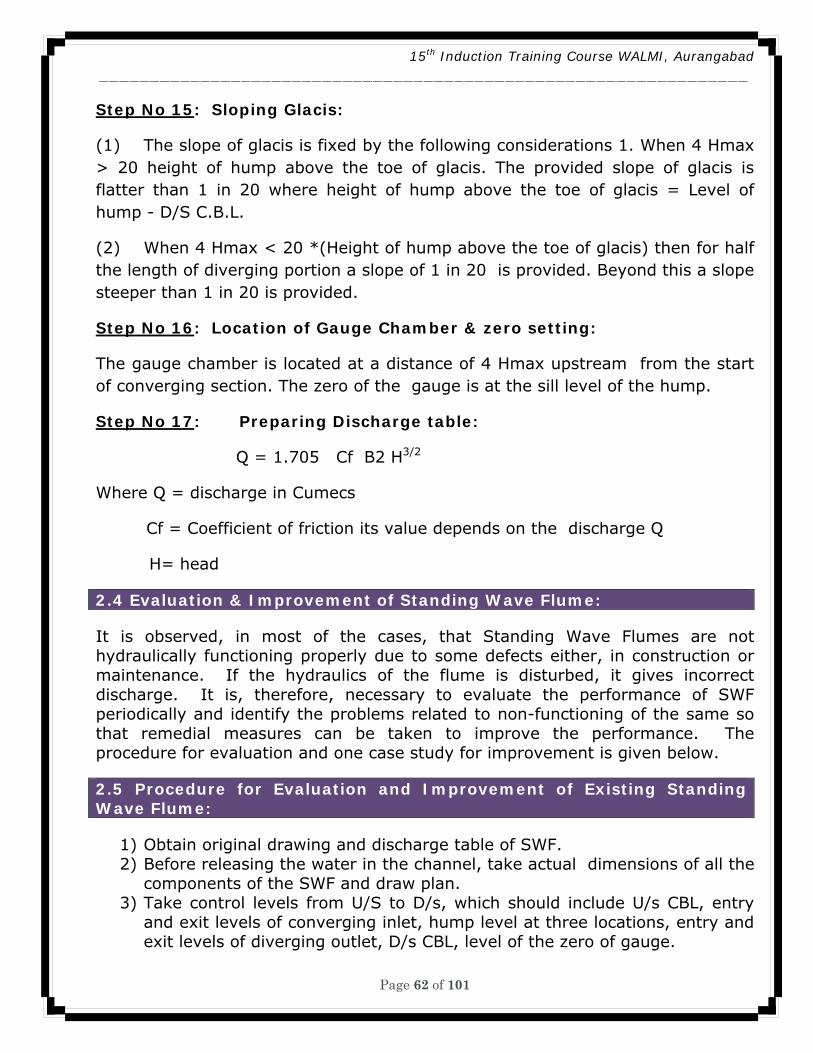
Step No 15: Sloping Glacis:
(1) The slope of glacis is fixed by the following considerations 1. When 4 Hmax > 20 height of hump above the toe of glacis. The provided slope of glacis is flatter than 1 in 20 where height of hump above the toe of glacis = Level of hump - D/S C.B.L.
(2) When 4 Hmax < 20 *(Height of hump above the toe of glacis) then for half the length of diverging portion a slope of 1 in 20 is provided. Beyond this a slope steeper than 1 in 20 is provided.
Step No 16: Location of Gauge Chamber & zero setting:
The gauge chamber is located at a distance of 4 Hmax upstream from the start of converging section. The zero of the gauge is at the sill level of the hump.
Step No 17: Preparing Discharge table:
Q = 1.705 Cf B2 H3/2
Where Q = discharge in Cumecs
Cf = Coefficient of friction its value depends on the discharge Q
H= head
2.4 Evaluation & Improvement of Standing Wave Flume: It is observed, in most of the cases, that Standing Wave Flumes are not hydraulically functioning properly due to some defects either, in construction or maintenance. If the hydraulics of the flume is disturbed, it gives incorrect discharge. It is, therefore, necessary to evaluate the performance of SWF periodically and identify the problems related to non-functioning of the same so that remedial measures can be taken to improve the performance. The procedure for evaluation and one case study for improvement is given below. 2.5 Procedure for Evaluation and Improvement of Existing Standing Wave Flume:
1) Obtain original drawing and discharge table of SWF. 2) Before releasing the water in the channel, take actual dimensions of all the
components of the SWF and draw plan. 3) Take control levels from U/S to D/s, which should include U/s CBL, entry
and exit levels of converging inlet, hump level at three locations, entry and exit levels of diverging outlet, D/s CBL, level of the zero of gauge.
15th Induction Training Course WALMI, Aurangabad ________________________________________________________________
Page 63 of 101
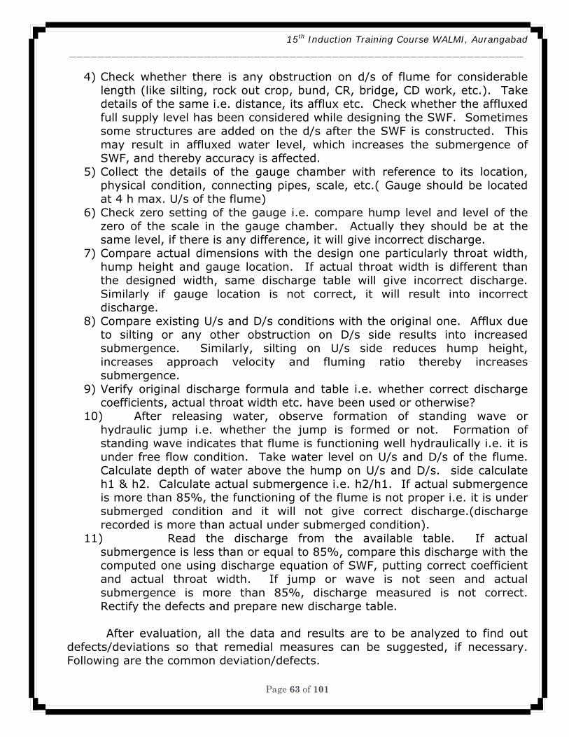
4) Check whether there is any obstruction on d/s of flume for considerable length (like silting, rock out crop, bund, CR, bridge, CD work, etc.). Take details of the same i.e. distance, its afflux etc. Check whether the affluxed full supply level has been considered while designing the SWF. Sometimes some structures are added on the d/s after the SWF is constructed. This may result in affluxed water level, which increases the submergence of SWF, and thereby accuracy is affected.
5) Collect the details of the gauge chamber with reference to its location, physical condition, connecting pipes, scale, etc.( Gauge should be located at 4 h max. U/s of the flume)
6) Check zero setting of the gauge i.e. compare hump level and level of the zero of the scale in the gauge chamber. Actually they should be at the same level, if there is any difference, it will give incorrect discharge.
7) Compare actual dimensions with the design one particularly throat width, hump height and gauge location. If actual throat width is different than the designed width, same discharge table will give incorrect discharge. Similarly if gauge location is not correct, it will result into incorrect discharge.
8) Compare existing U/s and D/s conditions with the original one. Afflux due to silting or any other obstruction on D/s side results into increased submergence. Similarly, silting on U/s side reduces hump height, increases approach velocity and fluming ratio thereby increases submergence.
9) Verify original discharge formula and table i.e. whether correct discharge coefficients, actual throat width etc. have been used or otherwise?
10) After releasing water, observe formation of standing wave or hydraulic jump i.e. whether the jump is formed or not. Formation of standing wave indicates that flume is functioning well hydraulically i.e. it is under free flow condition. Take water level on U/s and D/s of the flume. Calculate depth of water above the hump on U/s and D/s. side calculate h1 & h2. Calculate actual submergence i.e. h2/h1. If actual submergence is more than 85%, the functioning of the flume is not proper i.e. it is under submerged condition and it will not give correct discharge.(discharge recorded is more than actual under submerged condition).
11) Read the discharge from the available table. If actual submergence is less than or equal to 85%, compare this discharge with the computed one using discharge equation of SWF, putting correct coefficient and actual throat width. If jump or wave is not seen and actual submergence is more than 85%, discharge measured is not correct. Rectify the defects and prepare new discharge table.
After evaluation, all the data and results are to be analyzed to find out defects/deviations so that remedial measures can be suggested, if necessary. Following are the common deviation/defects.
15th Induction Training Course WALMI, Aurangabad ________________________________________________________________
Page 64 of 101
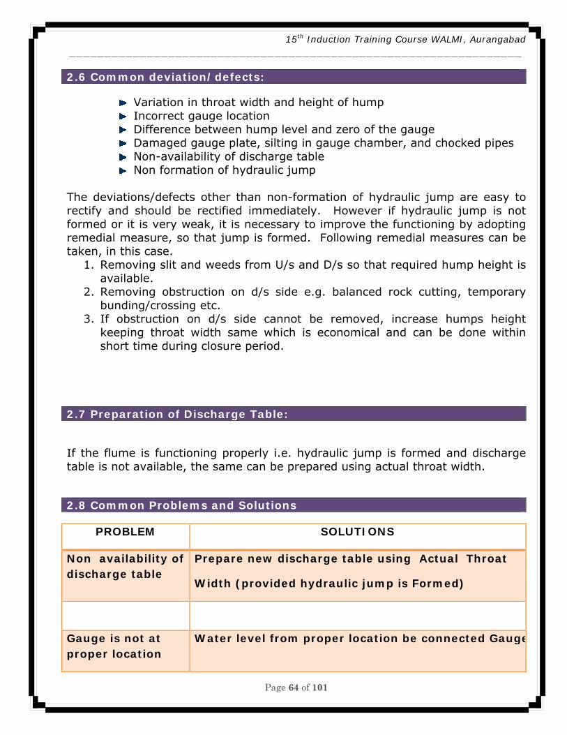
2.6 Common deviation/defects:
Variation in throat width and height of hump Incorrect gauge location Difference between hump level and zero of the gauge Damaged gauge plate, silting in gauge chamber, and chocked pipes Non-availability of discharge table Non formation of hydraulic jump
The deviations/defects other than non-formation of hydraulic jump are easy to rectify and should be rectified immediately. However if hydraulic jump is not formed or it is very weak, it is necessary to improve the functioning by adopting remedial measure, so that jump is formed. Following remedial measures can be taken, in this case.
1. Removing slit and weeds from U/s and D/s so that required hump height is available.
2. Removing obstruction on d/s side e.g. balanced rock cutting, temporary bunding/crossing etc.
3. If obstruction on d/s side cannot be removed, increase humps height keeping throat width same which is economical and can be done within short time during closure period.
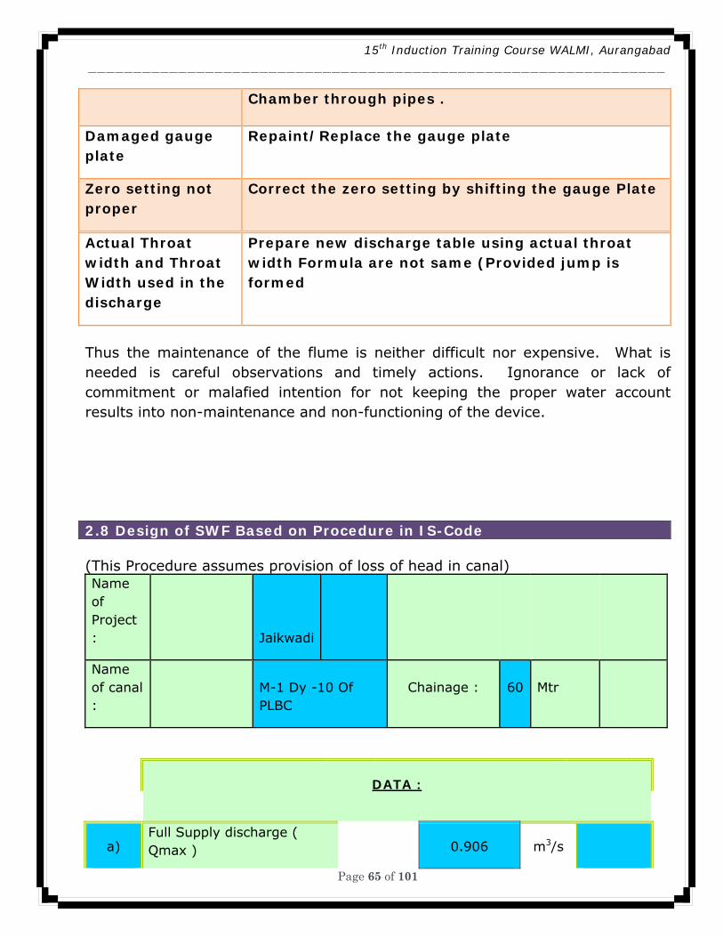
2.7 Preparation of Discharge Table: If the flume is functioning properly i.e. hydraulic jump is formed and discharge table is not available, the same can be prepared using actual throat width. 2.8 Common Problems and Solutions
PROBLEM SOLUTIONS
Non availability of discharge table
Prepare new discharge table using Actual Throat
Width (provided hydraulic jump is Formed)
Gauge is not at proper location
Water level from proper location be connected Gauge
15th Induction Training Course WALMI, Aurangabad ________________________________________________________________
Page 65 of 101
Chamber through pipes .
Damaged gauge plate
Repaint/Replace the gauge plate
Zero setting not proper
Correct the zero setting by shifting the gauge Plate
Actual Throat width and Throat Width used in the discharge
Prepare new discharge table using actual throat width Formula are not same (Provided jump is formed
Thus the maintenance of the flume is neither difficult nor expensive. What is needed is careful observations and timely actions. Ignorance or lack of commitment or malafied intention for not keeping the proper water account results into non-maintenance and non-functioning of the device.
2.8 Design of SWF Based on Procedure in IS-Code (This Procedure assumes provision of loss of head in canal) Name of Project : Jaikwadi
Name of canal :
M-1 Dy -10 Of PLBC
Chainage : 60 Mtr
DATA :
a) Full Supply discharge ( Qmax ) 0.906 m3/s
15th Induction Training Course WALMI, Aurangabad ________________________________________________________________
Page 66 of 101
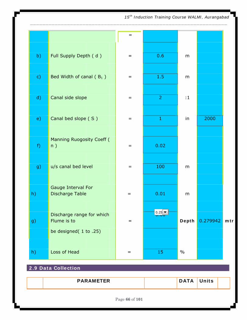
=
b) Full Supply Depth ( d ) = 0.6 m
c) Bed Width of canal ( B1 ) = 1.5 m
d) Canal side slope = 2 :1
e) Canal bed slope ( S ) = 1 in 2000
f) Manning Ruogosity Coeff ( n ) = 0.02
g) u/s canal bed level = 100 m
h) Gauge Interval For Discharge Table = 0.01 m
g) Discharge range for which Flume is to =
6.00 Depth 0.279942 mtr
be designed( 1 to .25)
h) Loss of Head = 15 %
2.9 Data Collection
PARAMETER DATA Units
15th Induction Training Course WALMI, Aurangabad ________________________________________________________________
Page 67 of 101
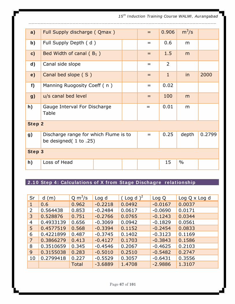
a) Full Supply discharge ( Qmax ) = 0.906 m3/s
b) Full Supply Depth ( d ) = 0.6 m
c) Bed Width of canal ( B1 ) = 1.5 m
d) Canal side slope = 2
e) Canal bed slope ( S ) = 1 in 2000
f) Manning Ruogosity Coeff ( n ) = 0.02
g) u/s canal bed level = 100 m
h) Gauge Interval For Discharge Table
= 0.01 m
Step 2
g) Discharge range for which Flume is to be designed( 1 to .25)
= 0.25 depth 0.2799
Step 3
h) Loss of Head 15 %
2.10 Step 4: Calculations of X from Stage Dischagre relationship
Sr d (m) Q m3/s Log d ( Log d )2 Log Q Log Q x Log d 1 0.6 0.962 -0.2218 0.0492 -0.0167 0.0037 2 0.564438 0.853 -0.2484 0.0617 -0.0690 0.0171 3 0.528876 0.751 -0.2766 0.0765 -0.1243 0.0344 4 0.4933139 0.656 -0.3069 0.0942 -0.1829 0.0561 5 0.4577519 0.568 -0.3394 0.1152 -0.2454 0.0833 6 0.4221899 0.487 -0.3745 0.1402 -0.3123 0.1169 7 0.3866279 0.413 -0.4127 0.1703 -0.3843 0.1586 8 0.3510659 0.345 -0.4546 0.2067 -0.4625 0.2103 9 0.3155038 0.283 -0.5010 0.2510 -0.5482 0.2747 10 0.2799418 0.227 -0.5529 0.3057 -0.6431 0.3556 Total -3.6889 1.4708 -2.9886 1.3107
15th Induction Training Course WALMI, Aurangabad ________________________________________________________________
Page 68 of 101
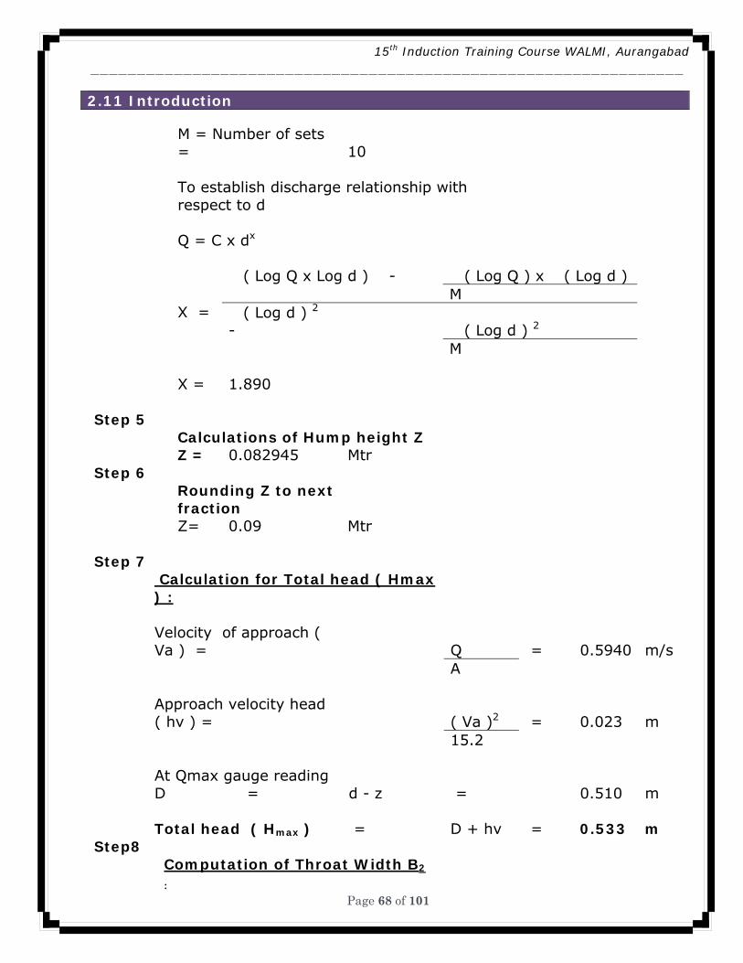
2.11 Introduction
M = Number of sets = 10
To establish discharge relationship with respect to d
Q = C x dx
X =
�( Log Q x Log d ) - �( Log Q ) x �( Log d ) M
�( Log d ) 2 - �( Log d ) 2
M X = 1.890 Step 5 Calculations of Hump height Z Z = 0.082945 Mtr Step 6
Rounding Z to next fraction
Z= 0.09 Mtr Step 7
Calculation for Total head ( Hmax ) :
Velocity of approach ( Va ) = Q = 0.5940 m/s
A
Approach velocity head ( hv ) = ( Va )2 = 0.023 m
15.2 At Qmax gauge reading D = d - z = 0.510 m Total head ( Hmax ) = D + hv = 0.533 m Step8
Computation of Throat Width B2
:
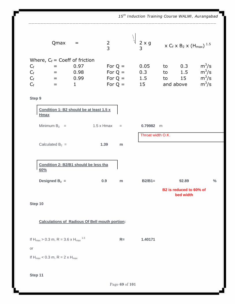
15th Induction Training Course WALMI, Aurangabad ________________________________________________________________
Page 69 of 101
Qmax = 2 2 x g x Cf x B2 x (Hmax)
1.5 3 3 Where, Cf = Coeff of friction Cf = 0.97 For Q = 0.05 to 0.3 m3/sCf = 0.98 For Q = 0.3 to 1.5 m3/sCf = 0.99 For Q = 1.5 to 15 m3/sCf = 1 For Q = 15 and above m3/s
Step 9
Condition 1: B2 should be at least 1.5 x Hmax
Minimum B2 = 1.5 x Hmax = 0.79982 m
Throat width O.K.
Calculated B2 = 1.39 m
Condition 2: B2/B1 should be less tha 60%
Designed B2 = 0.9 m B2/B1= 92.89 %
B2 is reduced to 60% of
bed width
Step 10
Calculations of Radious Of Bell mouth portion:
If Hmax > 0.3 m, R = 3.6 x Hmax 1.5 R= 1.40171
or
If Hmax < 0.3 m, R = 2 x Hmax
Step 11
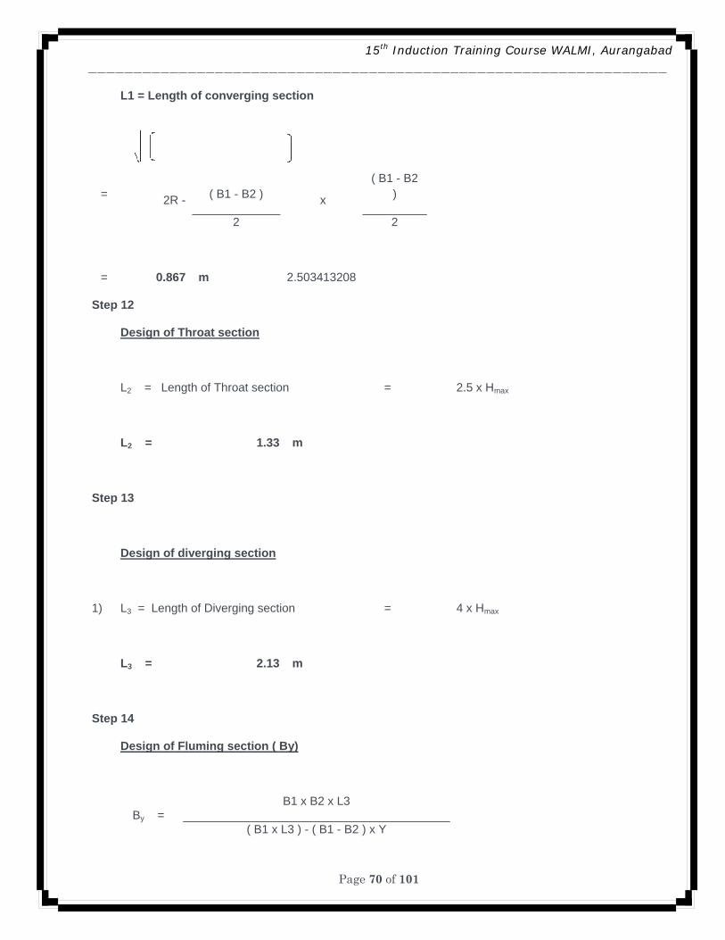
15th Induction Training Course WALMI, Aurangabad ________________________________________________________________
Page 70 of 101
L1 = Length of converging section
= 2R - ( B1 - B2 ) x
( B1 - B2 )
2 2
= 0.867 m 2.503413208
Step 12
Design of Throat section
L2 = Length of Throat section = 2.5 x Hmax
L2 = 1.33 m
Step 13
Design of diverging section
1) L3 = Length of Diverging section = 4 x Hmax
L3 = 2.13 m
Step 14
Design of Fluming section ( By)
By =
B1 x B2 x L3
( B1 x L3 ) - ( B1 - B2 ) x Y
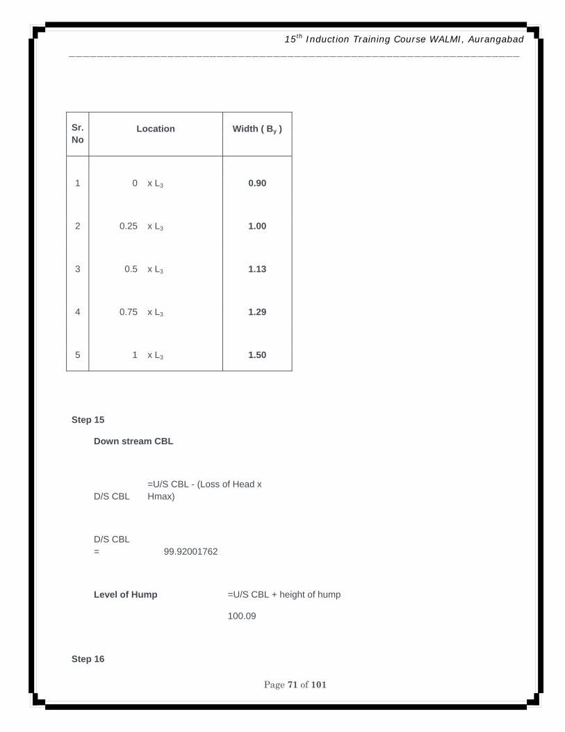
15th Induction Training Course WALMI, Aurangabad ________________________________________________________________
Page 71 of 101
Sr. No
Location Width ( By )
1 0 x L3 0.90
2 0.25 x L3 1.00
3 0.5 x L3 1.13
4 0.75 x L3 1.29
5 1 x L3 1.50
Step 15
Down stream CBL
D/S CBL =U/S CBL - (Loss of Head x Hmax)
D/S CBL = 99.92001762
Level of Hump =U/S CBL + height of hump
100.09
Step 16
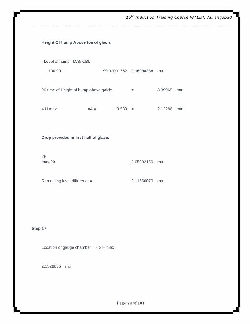
15th Induction Training Course WALMI, Aurangabad ________________________________________________________________
Page 72 of 101
Height Of hump Above toe of glacis
=Level of hump - D/S/ CBL
100.09 - 99.92001762 0.16998238 mtr
20 time of Height of hump above galcis = 3.39965 mtr
4 H max =4 X 0.533 = 2.13286 mtr
Drop provided in first half of glacis
2H max/20 0.05332159 mtr
Remaining level difference= 0.11666079 mtr
Step 17
Location of gauge chamber = 4 x H max
2.1328635 mtr
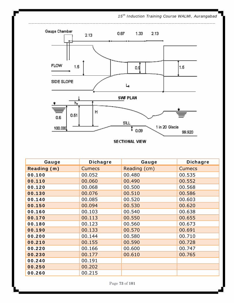
15th Induction Training Course WALMI, Aurangabad ________________________________________________________________
Page 73 of 101
Gauge Dichagre Gauge Dichagre Reading (m) Cumecs Reading (cm) Cumecs 00.100 00.052 00.480 00.535 00.110 00.060 00.490 00.552 00.120 00.068 00.500 00.568 00.130 00.076 00.510 00.586 00.140 00.085 00.520 00.603 00.150 00.094 00.530 00.620 00.160 00.103 00.540 00.638 00.170 00.113 00.550 00.655 00.180 00.123 00.560 00.673 00.190 00.133 00.570 00.691 00.200 00.144 00.580 00.710 00.210 00.155 00.590 00.728 00.220 00.166 00.600 00.747 00.230 00.177 00.610 00.765 00.240 00.191 00.250 00.202 00.260 00.215
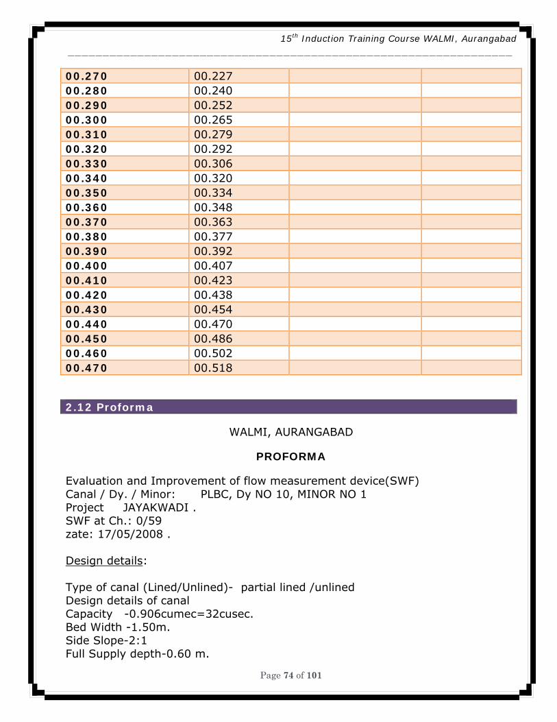
15th Induction Training Course WALMI, Aurangabad ________________________________________________________________
Page 74 of 101
00.270 00.227 00.280 00.240 00.290 00.252 00.300 00.265 00.310 00.279 00.320 00.292 00.330 00.306 00.340 00.320 00.350 00.334 00.360 00.348 00.370 00.363 00.380 00.377 00.390 00.392 00.400 00.407 00.410 00.423 00.420 00.438 00.430 00.454 00.440 00.470 00.450 00.486 00.460 00.502 00.470 00.518
2.12 Proforma
WALMI, AURANGABAD
PROFORMA
Evaluation and Improvement of flow measurement device(SWF) Canal / Dy. / Minor: PLBC, Dy NO 10, MINOR NO 1 Project JAYAKWADI . SWF at Ch.: 0/59 zate: 17/05/2008 . Design details: Type of canal (Lined/Unlined)- partial lined /unlined Design details of canal Capacity -0.906cumec=32cusec. Bed Width -1.50m. Side Slope-2:1 Full Supply depth-0.60 m.
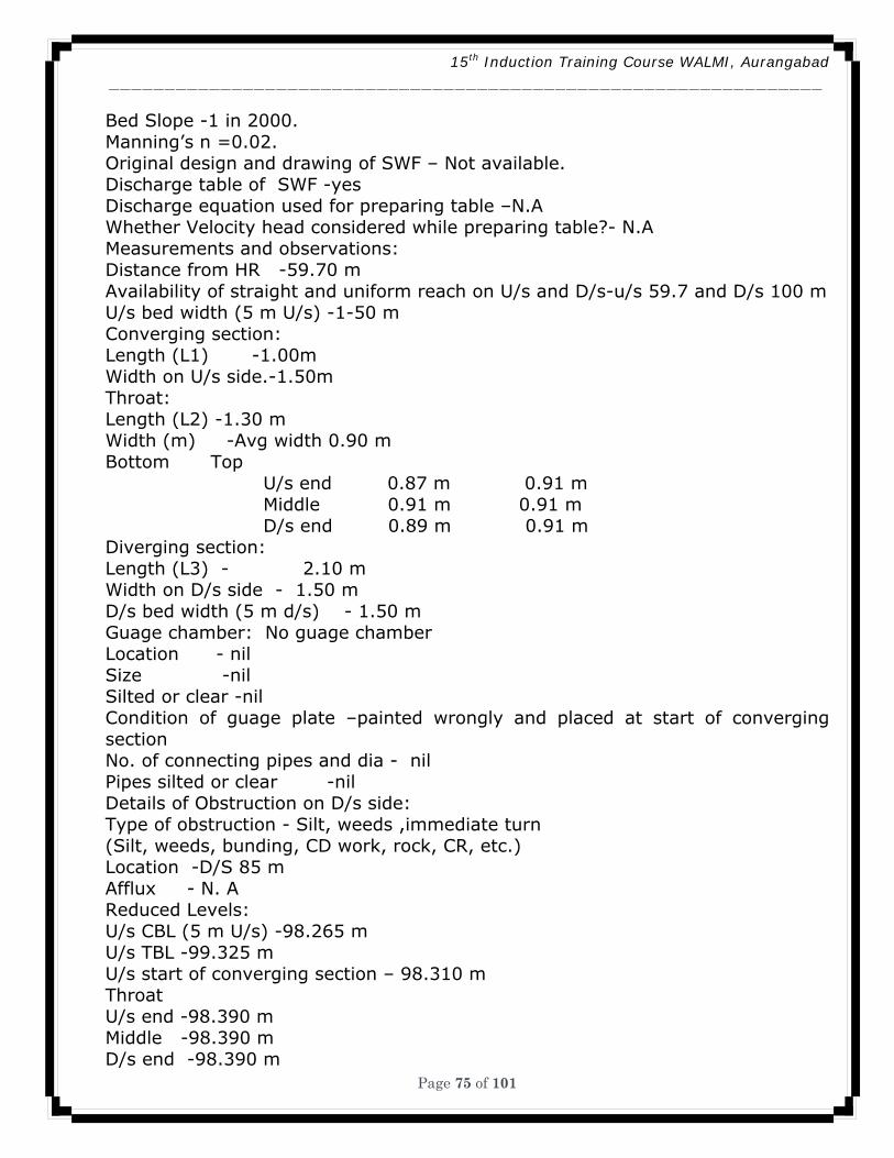
15th Induction Training Course WALMI, Aurangabad ________________________________________________________________
Page 75 of 101
Bed Slope -1 in 2000. Manning’s n =0.02. Original design and drawing of SWF – Not available. Discharge table of SWF -yes Discharge equation used for preparing table –N.A Whether Velocity head considered while preparing table?- N.A Measurements and observations: Distance from HR -59.70 m Availability of straight and uniform reach on U/s and D/s-u/s 59.7 and D/s 100 m U/s bed width (5 m U/s) -1-50 m Converging section: Length (L1) -1.00m Width on U/s side.-1.50m Throat: Length (L2) -1.30 m Width (m) -Avg width 0.90 m Bottom Top U/s end 0.87 m 0.91 m Middle 0.91 m 0.91 m D/s end 0.89 m 0.91 m Diverging section: Length (L3) - 2.10 m Width on D/s side - 1.50 m D/s bed width (5 m d/s) - 1.50 m Guage chamber: No guage chamber Location - nil Size -nil Silted or clear -nil Condition of guage plate –painted wrongly and placed at start of converging section No. of connecting pipes and dia - nil Pipes silted or clear -nil Details of Obstruction on D/s side: Type of obstruction - Silt, weeds ,immediate turn (Silt, weeds, bunding, CD work, rock, CR, etc.) Location -D/S 85 m Afflux - N. A Reduced Levels: U/s CBL (5 m U/s) -98.265 m U/s TBL -99.325 m U/s start of converging section – 98.310 m Throat U/s end -98.390 m Middle -98.390 m D/s end -98.390 m
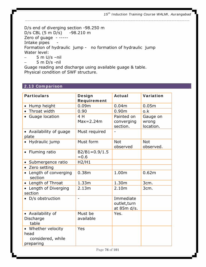
15th Induction Training Course WALMI, Aurangabad ________________________________________________________________
Page 76 of 101
D/s end of diverging section -98.250 m D/s CBL (5 m D/s) -98.210 m Zero of guage - ----- Intake pipes - Formation of hydraulic jump - no formation of hydraulic jump Water level: − 5 m U/s –nil − 5 m D/s -nil Guage reading and discharge using available guage & table. Physical condition of SWF structure.
2.13 Comparison
Particulars Design Requirement
Actual Variation
• Hump height 0.09m 0.04m 0.05m • Throat width 0.90 0.90m o.k • Guage location 4 H
Max=2.24m Painted on converging section.
Gauge on wrong location.
• Availability of guage plate
Must required -
• Hydraulic jump Must form Not observed
Not observed.
• Fluming ratio B2/B1=0.9/1.5=0.6
• Submergence ratio H2/H1 • Zero setting • Length of converging section
0.38m 1.00m 0.62m
• Length of Throat 1.33m 1.30m 3cm. • Length of Diverging section
2.13m 2.10m 3cm.
• D/s obstruction - Immediate outlet,turn at 85m d/s.
• Availability of Discharge table
Must be available
Yes.
• Whether velocity head considered, while preparing
Yes
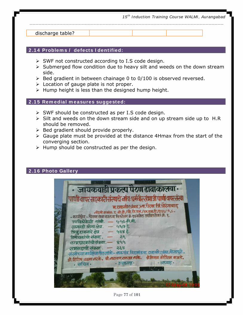
15th Induction Training Course WALMI, Aurangabad ________________________________________________________________
Page 77 of 101
discharge table?
2.14 Problems / defects Identified:
SWF not constructed according to I.S code design. Submerged flow condition due to heavy silt and weeds on the down stream
side. Bed gradient in between chainage 0 to 0/100 is observed reversed. Location of gauge plate is not proper. Hump height is less than the designed hump height.
2.15 Remedial measures suggested:
SWF should be constructed as per I.S code design. Silt and weeds on the down stream side and on up stream side up to H.R
should be removed. Bed gradient should provide properly. Gauge plate must be provided at the distance 4Hmax from the start of the
converging section. Hump should be constructed as per the design.
2.16 Photo Gallery
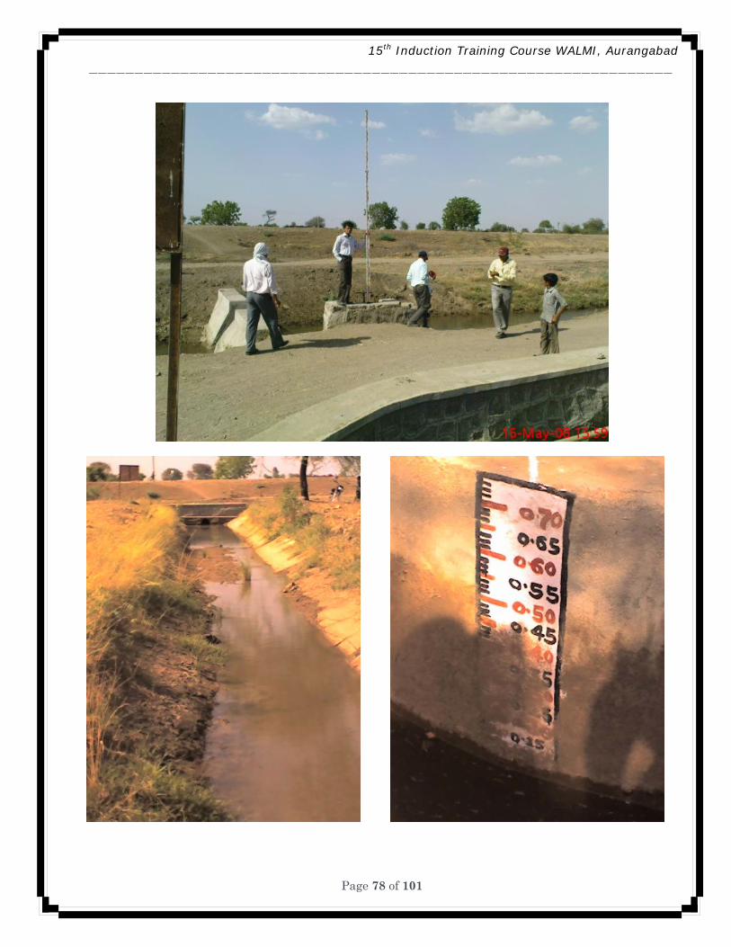
15th Induction Training Course WALMI, Aurangabad ________________________________________________________________
Page 78 of 101
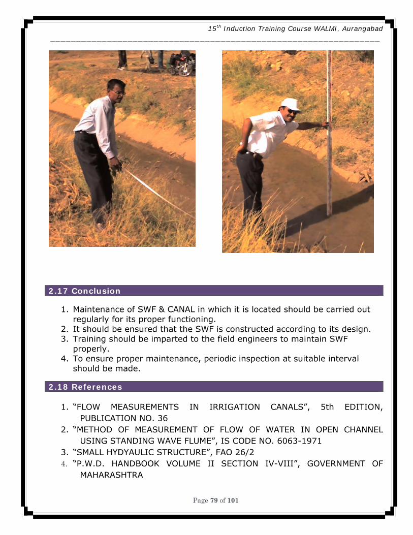
15th Induction Training Course WALMI, Aurangabad ________________________________________________________________
Page 79 of 101
2.17 Conclusion
1. Maintenance of SWF & CANAL in which it is located should be carried out regularly for its proper functioning.
2. It should be ensured that the SWF is constructed according to its design. 3. Training should be imparted to the field engineers to maintain SWF
properly. 4. To ensure proper maintenance, periodic inspection at suitable interval
should be made. 2.18 References
1. “FLOW MEASUREMENTS IN IRRIGATION CANALS”, 5th EDITION, PUBLICATION NO. 36
2. “METHOD OF MEASUREMENT OF FLOW OF WATER IN OPEN CHANNEL USING STANDING WAVE FLUME”, IS CODE NO. 6063-1971
3. “SMALL HYDYAULIC STRUCTURE”, FAO 26/2 4. “P.W.D. HANDBOOK VOLUME II SECTION IV-VIII”, GOVERNMENT OF
MAHARASHTRA

15th Induction Training Course WALMI, Aurangabad ________________________________________________________________
Page 80 of 101
5. “MANUAL OF MINOR IRRIGATION WORKS, WRD”, GOVERNMENT OF MAHARASHTRA
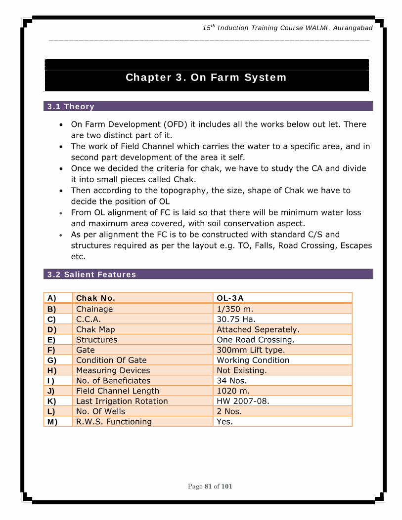
15th Induction Training Course WALMI, Aurangabad ________________________________________________________________
Page 81 of 101
Chapter 3. On Farm System
3.1 Theory
• On Farm Development (OFD) it includes all the works below out let. There are two distinct part of it.
• The work of Field Channel which carries the water to a specific area, and in second part development of the area it self.
• Once we decided the criteria for chak, we have to study the CA and divide it into small pieces called Chak.
• Then according to the topography, the size, shape of Chak we have to decide the position of OL
• From OL alignment of FC is laid so that there will be minimum water loss and maximum area covered, with soil conservation aspect.
• As per alignment the FC is to be constructed with standard C/S and structures required as per the layout e.g. TO, Falls, Road Crossing, Escapes etc.
3.2 Salient Features
A) Chak No. OL-3A B) Chainage 1/350 m. C) C.C.A. 30.75 Ha. D) Chak Map Attached Seperately. E) Structures One Road Crossing. F) Gate 300mm Lift type. G) Condition Of Gate Working Condition H) Measuring Devices Not Existing. I) No. of Beneficiates 34 Nos. J) Field Channel Length 1020 m. K) Last Irrigation Rotation HW 2007-08. L) No. Of Wells 2 Nos. M) R.W.S. Functioning Yes.
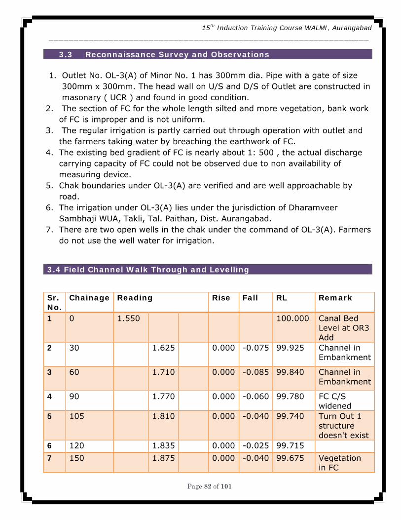
15th Induction Training Course WALMI, Aurangabad ________________________________________________________________
Page 82 of 101
3.3 Reconnaissance Survey and Observations
1. Outlet No. OL-3(A) of Minor No. 1 has 300mm dia. Pipe with a gate of size 300mm x 300mm. The head wall on U/S and D/S of Outlet are constructed in masonary ( UCR ) and found in good condition.
2. The section of FC for the whole length silted and more vegetation, bank work of FC is improper and is not uniform.
3. The regular irrigation is partly carried out through operation with outlet and the farmers taking water by breaching the earthwork of FC.
4. The existing bed gradient of FC is nearly about 1: 500 , the actual discharge carrying capacity of FC could not be observed due to non availability of measuring device.
5. Chak boundaries under OL-3(A) are verified and are well approachable by road.
6. The irrigation under OL-3(A) lies under the jurisdiction of Dharamveer Sambhaji WUA, Takli, Tal. Paithan, Dist. Aurangabad.
7. There are two open wells in the chak under the command of OL-3(A). Farmers do not use the well water for irrigation.
3.4 Field Channel Walk Through and Levelling
Sr. No.
Chainage Reading Rise Fall RL Remark
1 0 1.550 100.000 Canal Bed Level at OR3 Add
2 30 1.625 0.000 -0.075 99.925 Channel in Embankment
3 60 1.710 0.000 -0.085 99.840 Channel in Embankment
4 90 1.770 0.000 -0.060 99.780 FC C/S widened
5 105 1.810 0.000 -0.040 99.740 Turn Out 1 structure doesn't exist
6 120 1.835 0.000 -0.025 99.715
7 150 1.875 0.000 -0.040 99.675 Vegetation in FC
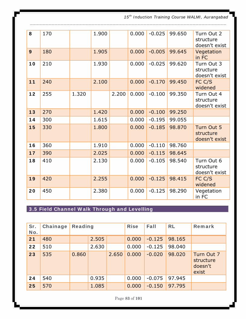
15th Induction Training Course WALMI, Aurangabad ________________________________________________________________
Page 83 of 101
8 170 1.900 0.000 -0.025 99.650 Turn Out 2 structure doesn't exist
9 180 1.905 0.000 -0.005 99.645 Vegetation in FC
10 210 1.930 0.000 -0.025 99.620 Turn Out 3 structure doesn't exist
11 240 2.100 0.000 -0.170 99.450 FC C/S widened
12 255 1.320 2.200 0.000 -0.100 99.350 Turn Out 4 structure doesn't exist
13 270 1.420 0.000 -0.100 99.250
14 300 1.615 0.000 -0.195 99.055
15 330 1.800 0.000 -0.185 98.870 Turn Out 5 structure doesn't exist
16 360 1.910 0.000 -0.110 98.760
17 390 2.025 0.000 -0.115 98.645
18 410 2.130 0.000 -0.105 98.540 Turn Out 6 structure doesn't exist
19 420 2.255 0.000 -0.125 98.415 FC C/S widened
20 450 2.380 0.000 -0.125 98.290 Vegetation in FC
3.5 Field Channel Walk Through and Levelling
Sr. No.
Chainage Reading Rise Fall RL Remark
21 480 2.505 0.000 -0.125 98.165
22 510 2.630 0.000 -0.125 98.040
23 535 0.860 2.650 0.000 -0.020 98.020 Turn Out 7 structure doesn't exist
24 540 0.935 0.000 -0.075 97.945
25 570 1.085 0.000 -0.150 97.795
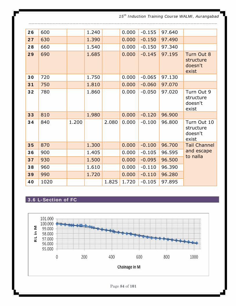
15th Induction Training Course WALMI, Aurangabad ________________________________________________________________
Page 84 of 101
26 600 1.240 0.000 -0.155 97.640
27 630 1.390 0.000 -0.150 97.490
28 660 1.540 0.000 -0.150 97.340
29 690 1.685 0.000 -0.145 97.195 Turn Out 8 structure doesn't exist
30 720 1.750 0.000 -0.065 97.130
31 750 1.810 0.000 -0.060 97.070
32 780 1.860 0.000 -0.050 97.020 Turn Out 9 structure doesn't exist
33 810 1.980 0.000 -0.120 96.900
34 840 1.200 2.080 0.000 -0.100 96.800 Turn Out 10 structure doesn't exist
35 870 1.300 0.000 -0.100 96.700 Tail Channel and escape to nalla
36 900 1.405 0.000 -0.105 96.595
37 930 1.500 0.000 -0.095 96.500
38 960 1.610 0.000 -0.110 96.390
39 990 1.720 0.000 -0.110 96.280
40 1020 1.825 1.720 -0.105 97.895
3.6 L-Section of FC
15th Induction Training Course WALMI, Aurangabad ________________________________________________________________
Page 85 of 101
3.8 Definition of Evaluation of Land Forming Works
It is the process of developing surface of land to a planned grade to provide
better water application, drainage and soil conservation.
3.9 Purpose of Land Forming Techniques
• Uniform distribution of water over the field • Economic use of water • Draining of excess water, either from rain or from irrigation, without
damage to the crops or soils. • Uniform distribution of fertilizers along with irrigation water if necessary. • Bringing some uncommanded portion under irrigation by moving soil to the
lower elevations. • Increasing yield and quality of crops incidentally. • Obtaining better and more uniform plant population. • Effecting saving of labour in all farming operations.
Purpose of Land Forming Techniques 3.10 LAND FORMING is applicable to
1. FLAT LAND 2. IRRIGATED CROPS 3. MEDIUM TO DEEP SOILS 4. MEDIUM TO FINE SOIL TEXTURE 5. ADEQUATE WATER AVAILABLE 6. NO MUCH LOSS OF SOIL FERTILITY 7. BASIN, BORDER AND STRAIGHT FURROWS
3.11 LAND FORMING is not applicable to
1. SHALLOW SOIL DEPTH 2. COARSE SOIL TEXTURE 3. STEEP LAND SLOPES 4. HIGHER COST THAN SPRINKLER AND DRIP SYSTEMS 5. DRY LAND AGRICULTURE
3.12 LAND FORMING TECHNIQUES
A. LAND SMOOTHENING B. LAND GRADING C. LAND LEVELLING
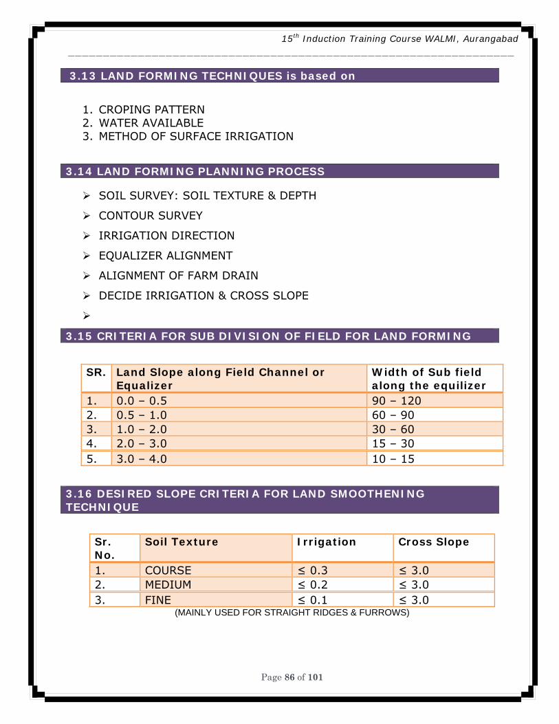
15th Induction Training Course WALMI, Aurangabad ________________________________________________________________
Page 86 of 101
3.13 LAND FORMING TECHNIQUES is based on
1. CROPING PATTERN 2. WATER AVAILABLE 3. METHOD OF SURFACE IRRIGATION
3.14 LAND FORMING PLANNING PROCESS
SOIL SURVEY: SOIL TEXTURE & DEPTH
CONTOUR SURVEY
IRRIGATION DIRECTION
EQUALIZER ALIGNMENT
ALIGNMENT OF FARM DRAIN
DECIDE IRRIGATION & CROSS SLOPE
3.15 CRITERIA FOR SUB DIVISION OF FIELD FOR LAND FORMING
SR. Land Slope along Field Channel or Equalizer
Width of Sub field along the equilizer
1. 0.0 – 0.5 90 – 120 2. 0.5 – 1.0 60 – 90 3. 1.0 – 2.0 30 – 60 4. 2.0 – 3.0 15 – 30 5. 3.0 – 4.0 10 – 15
3.16 DESIRED SLOPE CRITERIA FOR LAND SMOOTHENING TECHNIQUE
Sr. No.
Soil Texture Irrigation Cross Slope
1. COURSE ≤ 0.3 ≤ 3.0 2. MEDIUM ≤ 0.2 ≤ 3.0 3. FINE ≤ 0.1 ≤ 3.0
(MAINLY USED FOR STRAIGHT RIDGES & FURROWS)
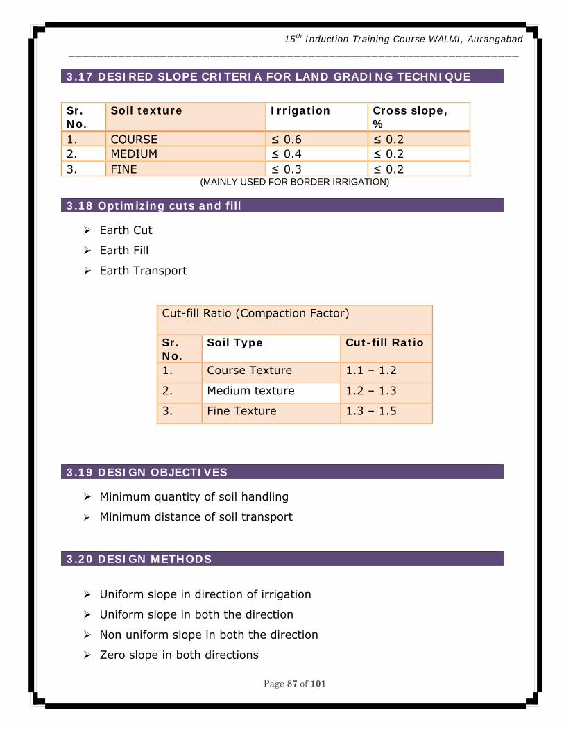
15th Induction Training Course WALMI, Aurangabad ________________________________________________________________
Page 87 of 101
3.17 DESIRED SLOPE CRITERIA FOR LAND GRADING TECHNIQUE
Sr. No.
Soil texture Irrigation Cross slope, %
1. COURSE ≤ 0.6 ≤ 0.2 2. MEDIUM ≤ 0.4 ≤ 0.2 3. FINE ≤ 0.3 ≤ 0.2
(MAINLY USED FOR BORDER IRRIGATION)
3.18 Optimizing cuts and fill
Earth Cut
Earth Fill
Earth Transport
Cut-fill Ratio (Compaction Factor)
Sr. No.
Soil Type Cut-fill Ratio
1. Course Texture 1.1 – 1.2
2. Medium texture 1.2 – 1.3
3. Fine Texture 1.3 – 1.5
3.19 DESIGN OBJECTIVES
Minimum quantity of soil handling
Minimum distance of soil transport
3.20 DESIGN METHODS
Uniform slope in direction of irrigation
Uniform slope in both the direction
Non uniform slope in both the direction
Zero slope in both directions
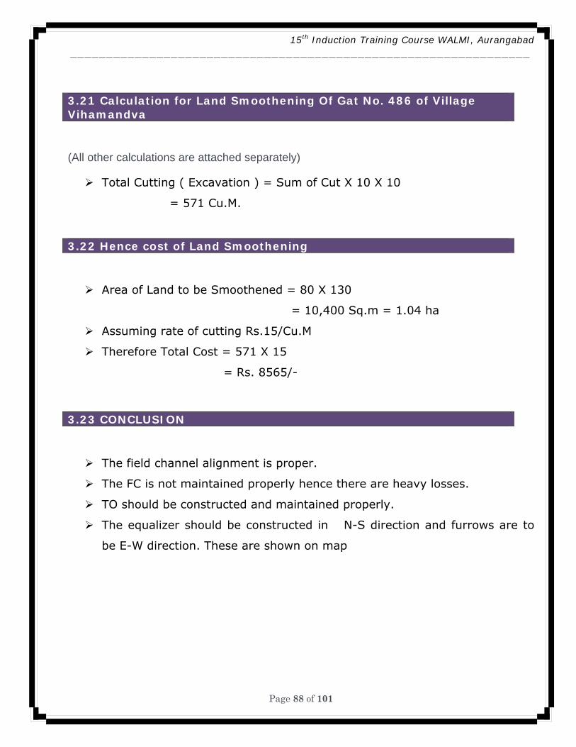
15th Induction Training Course WALMI, Aurangabad ________________________________________________________________
Page 88 of 101
3.21 Calculation for Land Smoothening Of Gat No. 486 of Village Vihamandva
(All other calculations are attached separately)
Total Cutting ( Excavation ) = Sum of Cut X 10 X 10
= 571 Cu.M.
3.22 Hence cost of Land Smoothening
Area of Land to be Smoothened = 80 X 130
= 10,400 Sq.m = 1.04 ha
Assuming rate of cutting Rs.15/Cu.M
Therefore Total Cost = 571 X 15
= Rs. 8565/-
3.23 CONCLUSION
The field channel alignment is proper.
The FC is not maintained properly hence there are heavy losses.
TO should be constructed and maintained properly.
The equalizer should be constructed in N-S direction and furrows are to
be E-W direction. These are shown on map
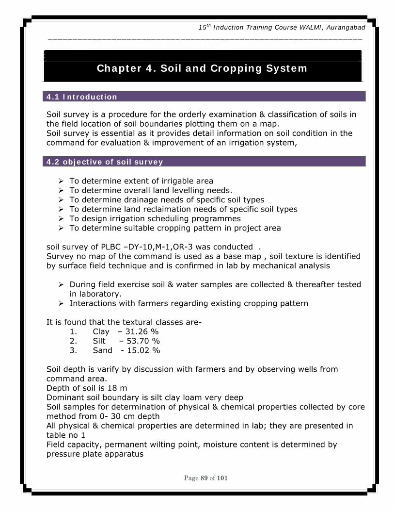
15th Induction Training Course WALMI, Aurangabad ________________________________________________________________
Page 89 of 101
Chapter 4. Soil and Cropping System
4.1 Introduction Soil survey is a procedure for the orderly examination & classification of soils in the field location of soil boundaries plotting them on a map. Soil survey is essential as it provides detail information on soil condition in the command for evaluation & improvement of an irrigation system, 4.2 objective of soil survey
To determine extent of irrigable area To determine overall land levelling needs. To determine drainage needs of specific soil types To determine land reclaimation needs of specific soil types To design irrigation scheduling programmes To determine suitable cropping pattern in project area
soil survey of PLBC –DY-10,M-1,OR-3 was conducted . Survey no map of the command is used as a base map , soil texture is identified by surface field technique and is confirmed in lab by mechanical analysis
During field exercise soil & water samples are collected & thereafter tested in laboratory.
Interactions with farmers regarding existing cropping pattern It is found that the textural classes are-
1. Clay – 31.26 % 2. Silt – 53.70 % 3. Sand - 15.02 %
Soil depth is varify by discussion with farmers and by observing wells from command area. Depth of soil is 18 m Dominant soil boundary is silt clay loam very deep Soil samples for determination of physical & chemical properties collected by core method from 0- 30 cm depth All physical & chemical properties are determined in lab; they are presented in table no 1 Field capacity, permanent wilting point, moisture content is determined by pressure plate apparatus
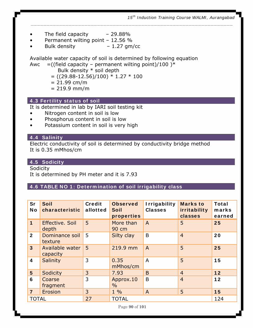
15th Induction Training Course WALMI, Aurangabad ________________________________________________________________
Page 90 of 101
• The field capacity – 29.88% • Permanent wilting point – 12.56 % • Bulk density – 1.27 gm/cc Available water capacity of soil is determined by following equation Awc =((field capacity – permanent wilting point)/100 )* Bulk density * soil depth = ((29.88-12.56)/100) * 1.27 * 100 = 21.99 cm/m = 219.9 mm/m 4.3 Fertility status of soil It is determined in lab by IARI soil testing kit • Nitrogen content in soil is low • Phosphorus content in soil is low • Potassium content in soil is very high 4.4 Salinity Electric conductivity of soil is determined by conductivity bridge method It is 0.35 mMhos/cm 4.5 Sodicity Sodicity It is determined by PH meter and it is 7.93 4.6 TABLE NO 1: Determination of soil irrigability class
Sr No
Soil characteristic
Credit allotted
Observed Soil properties
IrrigabilityClasses
Marks to irritability classes
Total marks earned
1 Effective. Soil depth
5 More than 90 cm
A 5 25
2 Dominance soil texture
5 Silty clay B 4 20
3 Available water capacity
5 219.9 mm A 5 25
4 Salinity 3 0.35 mMhos/cm
A 5 15
5 Sodicity 3 7.93 B 4 12 6 Coarse
fragment 3 Approx.10
% B 4 12
7 Erosion 3 1 % A 5 15 TOTAL 27 TOTAL 124
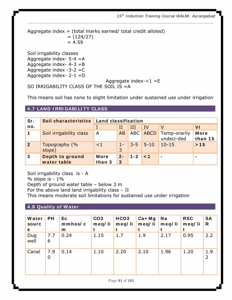
15th Induction Training Course WALMI, Aurangabad ________________________________________________________________
Page 91 of 101
Aggregate index = (total marks earned/ total credit alloted) = (124/27) = 4.59 Soil irrigability classes Aggregate index- 5-4 =A Aggregate index- 4-3 =B Aggregate index -3-2 =C Aggregate index- 2-1 =D Aggregate index-<1 =E SO IRRIGABILITY CLASS OF THE SOIL IS =A This means soil has none to slight limitation under sustained use under irrigation 4.7 LAND IRRIGABILITY CLASS Sr. no.
Soil characteristics Land classification I II III IV V VI
1 Soil irrigability class A AB ABC ABCD Temp-orarily undeci-ded
More than 15
2 Topography (% slope)
<1 1-3
3-5 5-10 10-15 >15
3 Depth to ground water table
More than 3
2-3
1-2 <1 - -
Soil irrigability class is - A % slope is - 1% Depth of ground water table – below 3 m For the above land land irrigability class – II This means moderate soil limitations for sustained use under irrigation 4.8 Quality of Water Water source
PH Ec mmhos/cm
CO3 meq/lit
HCO3 meq/lit
Ca+Mgmeq/lit
Na meq/lit
RSC meq/lit
SAR
Dug well
7.76
0.24 1.15 1.7 1.9 2.17 0.95 2.2
Canal 7.90
0.14 1.10 2.20 2.10 1.96 1.20 1.92
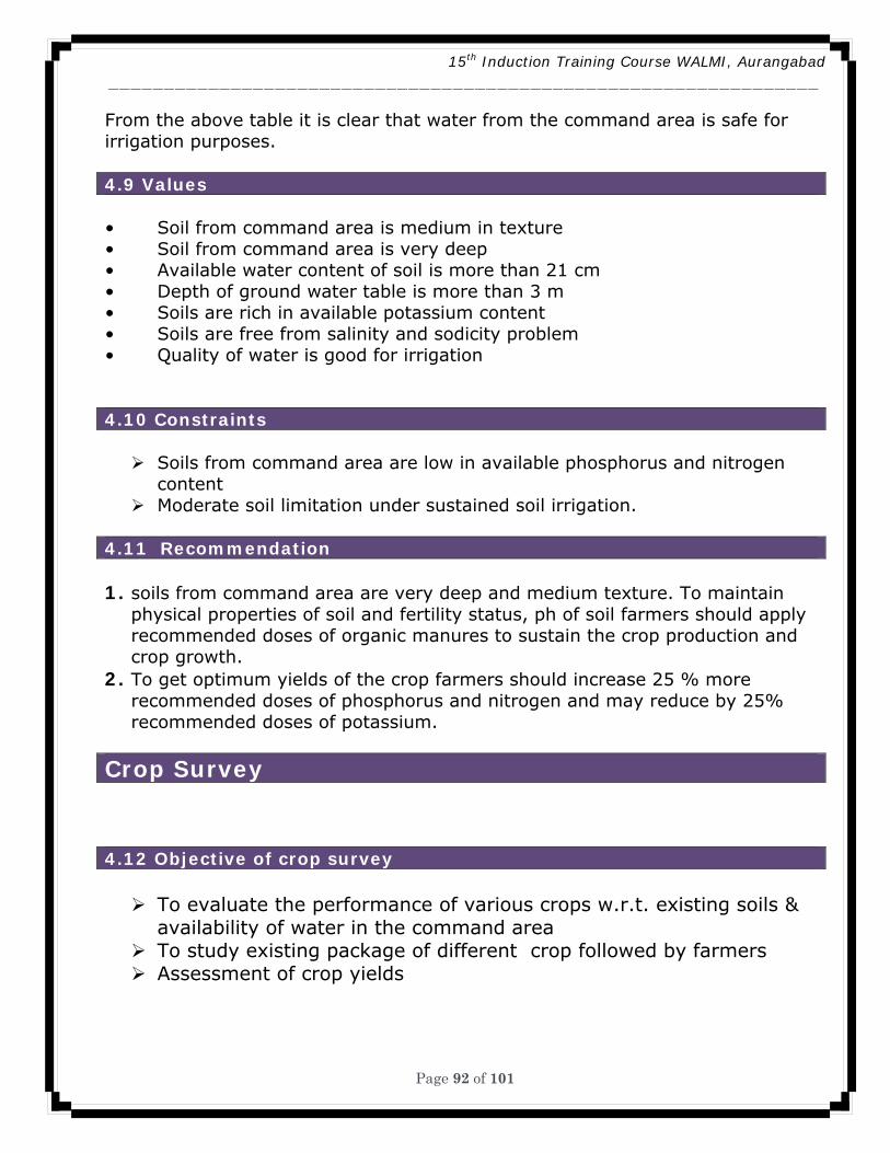
15th Induction Training Course WALMI, Aurangabad ________________________________________________________________
Page 92 of 101
From the above table it is clear that water from the command area is safe for irrigation purposes. 4.9 Values
• Soil from command area is medium in texture • Soil from command area is very deep • Available water content of soil is more than 21 cm • Depth of ground water table is more than 3 m • Soils are rich in available potassium content • Soils are free from salinity and sodicity problem • Quality of water is good for irrigation 4.10 Constraints
Soils from command area are low in available phosphorus and nitrogen content
Moderate soil limitation under sustained soil irrigation. 4.11 Recommendation
1. soils from command area are very deep and medium texture. To maintain
physical properties of soil and fertility status, ph of soil farmers should apply recommended doses of organic manures to sustain the crop production and crop growth.
2. To get optimum yields of the crop farmers should increase 25 % more recommended doses of phosphorus and nitrogen and may reduce by 25% recommended doses of potassium.
Crop Survey 4.12 Objective of crop survey
To evaluate the performance of various crops w.r.t. existing soils & availability of water in the command area
To study existing package of different crop followed by farmers Assessment of crop yields
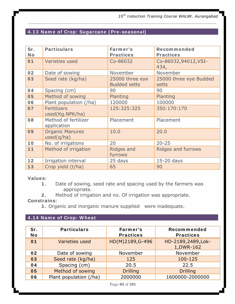
15th Induction Training Course WALMI, Aurangabad ________________________________________________________________
Page 93 of 101
4.13 Name of Crop: Sugarcane (Pre-seasonal) Sr. No
Particulars Farmer’s Practices
Recommended Practices
01 Varieties used Co-86032 Co-86032,94012,VSI-434,
02 Date of sowing November November 03 Seed rate (kg/ha) 25000 three eye
Budded setts 25000 three eye Budded setts
04 Spacing (cm) 90 90 05 Method of sowing Planting Planting 06 Plant population (/ha) 120000 100000 07 Fertilizers
used(Kg.NPK/ha) 125:325:325 350:170:170
08 Method of fertilizer application
Placement Placement
09 Organic Manures used(q/ha)
10.0 20.0
10 No. of irrigations 20 20-25 11 Method of irrigation Ridges and
furrows Ridges and furrows
12 Irrigation interval 25 days 15-20 days 13 Crop yield (t/ha) 65 90 Values:
1. Date of sowing, seed rate and spacing used by the farmers was appropriate.
2. Method of irrigation and no. Of irrigation was appropriate. Constrains:
1. Organic and inorganic manure supplied were inadequate.
4.14 Name of Crop: Wheat Sr. No
Particulars Farmer’s Practices
Recommended Practices
01 Varieties used HD(M)2189,G-496 HD-2189,2489,Lok-1,DWR-162
02 Date of sowing November November 03 Seed rate (kg/ha) 125 100-125 04 Spacing (cm) 20.5 22.5 05 Method of sowing Drilling Drilling 06 Plant population (/ha) 2000000 1600000-2000000
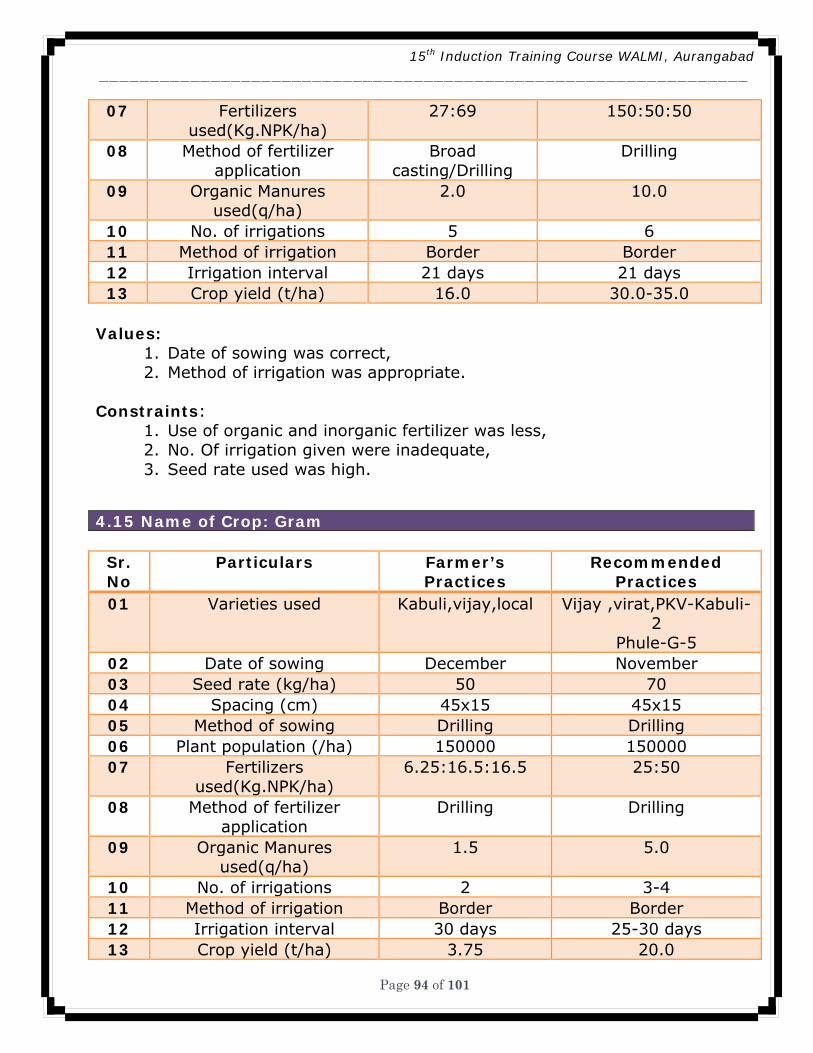
15th Induction Training Course WALMI, Aurangabad ________________________________________________________________
Page 94 of 101
07 Fertilizers used(Kg.NPK/ha)
27:69 150:50:50
08 Method of fertilizer application
Broad casting/Drilling
Drilling
09 Organic Manures used(q/ha)
2.0 10.0
10 No. of irrigations 5 6 11 Method of irrigation Border Border 12 Irrigation interval 21 days 21 days 13 Crop yield (t/ha) 16.0 30.0-35.0
Values:
1. Date of sowing was correct, 2. Method of irrigation was appropriate.
Constraints:
1. Use of organic and inorganic fertilizer was less, 2. No. Of irrigation given were inadequate, 3. Seed rate used was high.
4.15 Name of Crop: Gram
Sr. No
Particulars Farmer’s Practices
Recommended Practices
01 Varieties used Kabuli,vijay,local Vijay ,virat,PKV-Kabuli-2
Phule-G-5 02 Date of sowing December November 03 Seed rate (kg/ha) 50 70 04 Spacing (cm) 45x15 45x15 05 Method of sowing Drilling Drilling 06 Plant population (/ha) 150000 150000 07 Fertilizers
used(Kg.NPK/ha) 6.25:16.5:16.5 25:50
08 Method of fertilizer application
Drilling Drilling
09 Organic Manures used(q/ha)
1.5 5.0
10 No. of irrigations 2 3-4 11 Method of irrigation Border Border 12 Irrigation interval 30 days 25-30 days 13 Crop yield (t/ha) 3.75 20.0
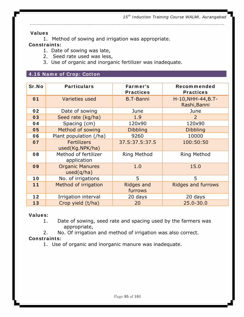
15th Induction Training Course WALMI, Aurangabad ________________________________________________________________
Page 95 of 101
Values 1. Method of sowing and irrigation was appropriate.
Constraints: 1. Date of sowing was late, 2. Seed rate used was less, 3. Use of organic and inorganic fertilizer was inadequate.
4.16 Name of Crop: Cotton Sr.No Particulars Farmer’s
Practices Recommended
Practices 01 Varieties used B.T-Banni H-10,NHH-44,B.T-
Rashi,Banni 02 Date of sowing June June 03 Seed rate (kg/ha) 1.9 2 04 Spacing (cm) 120x90 120x90 05 Method of sowing Dibbling Dibbling 06 Plant population (/ha) 9260 10000 07 Fertilizers
used(Kg.NPK/ha) 37.5:37.5:37.5 100:50:50
08 Method of fertilizer application
Ring Method Ring Method
09 Organic Manures used(q/ha)
1.0 15.0
10 No. of irrigations 5 5 11 Method of irrigation Ridges and
furrows Ridges and furrows
12 Irrigation interval 20 days 20 days 13 Crop yield (t/ha) 20 25.0-30.0
Values:
1. Date of sowing, seed rate and spacing used by the farmers was appropriate,
2. No. Of irrigation and method of irrigation was also correct. Constraints:
1. Use of organic and inorganic manure was inadequate.
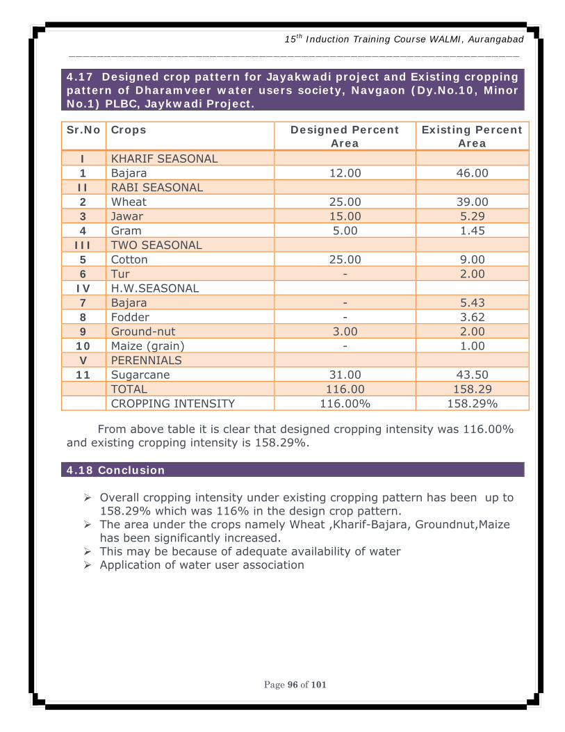
15th Induction Training Course WALMI, Aurangabad ________________________________________________________________
Page 96 of 101
4.17 Designed crop pattern for Jayakwadi project and Existing cropping pattern of Dharamveer water users society, Navgaon (Dy.No.10, Minor No.1) PLBC, Jaykwadi Project. Sr.No Crops Designed Percent
Area Existing Percent
Area I KHARIF SEASONAL 1 Bajara 12.00 46.00 II RABI SEASONAL 2 Wheat 25.00 39.00 3 Jawar 15.00 5.29 4 Gram 5.00 1.45
III TWO SEASONAL 5 Cotton 25.00 9.00 6 Tur - 2.00 IV H.W.SEASONAL 7 Bajara - 5.43 8 Fodder - 3.62 9 Ground-nut 3.00 2.00
10 Maize (grain) - 1.00 V PERENNIALS 11 Sugarcane 31.00 43.50
TOTAL 116.00 158.29 CROPPING INTENSITY 116.00% 158.29%
From above table it is clear that designed cropping intensity was 116.00% and existing cropping intensity is 158.29%. 4.18 Conclusion
Overall cropping intensity under existing cropping pattern has been up to 158.29% which was 116% in the design crop pattern.
The area under the crops namely Wheat ,Kharif-Bajara, Groundnut,Maize has been significantly increased.
This may be because of adequate availability of water Application of water user association
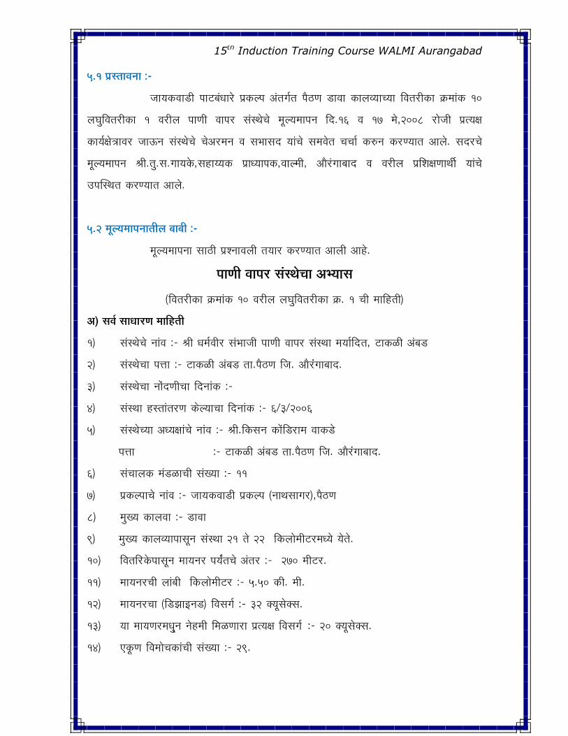
15th Induction Training Course WALMI Aurangabad
5.1 ¯ÖÏßÖÖ¾Ö−ÖÖ :-
•ÖÖµÖ�ú¾ÖÖ›üß ¯ÖÖ™ü²ÖÓ¬ÖÖ êü ¯ÖÏ�ú»¯Ö †ÓŸÖ�ÖÔŸÖ ¯Öîšü�Ö ›üÖ¾ÖÖ �úÖ»Ö¾µÖÖ“µÖÖ ×¾ÖŸÖ¸üß�úÖ �Îú´ÖÖÓ�ú 10
»Ö‘Öã×¾ÖŸÖ¸üß�úÖ 1 ¾Ö¸üᯙ ¯ÖÖ�Öß ¾ÖÖ¯Ö¸ü ÃÖÓãÖê“Öê ´Ö滵ִÖÖ¯Ö−Ö ×¤ü.16 ¾Ö 17 ´Öê,2008 ¸üÖê•Öß ¯ÖÏŸµÖ>Ö
�úÖµÖÔ>Öê¡ÖÖ¾Ö¸ü •ÖÖ‰ú−Ö ÃÖÓãÖê“Öê “Öꆸü´Ö−Ö ¾Ö ÃÖ³ÖÖÃÖ¤ü µÖÖÓ“Öê ÃÖ´Ö¾ÖêŸÖ “Ö“ÖÖÔ �ú¹ý−Ö �ú¸ü�µÖÖŸÖ †Ö»Öê. ÃÖ¤ü ü“Öê
´Ö滵ִÖÖ¯Ö−Ö ÁÖß.ŸÖã.ÃÖ.�ÖÖµÖ�êú,ÃÖÆüÖµµÖ�ú ¯ÖÏÖ¬µÖÖ¯Ö�ú,¾ÖÖ»´Öß, †Öî Óü�ÖÖ²ÖÖ¤ü ¾Ö ¾Ö¸üᯙ ¯ÖÏ׿Ö>Ö�ÖÖ£Öá µÖÖÓ“Öê
ˆ¯ÖÛÃ£ÖŸÖ �ú¸�µÖÖŸÖ †Ö»Öê.
5.2 ´Ö滵ִÖÖ¯Ö−ÖÖŸÖᯙ ²ÖÖ²Öß :-
´Ö滵ִÖÖ¯Ö−ÖÖ ÃÖÖšüß ¯ÖÏ¿−ÖÖ¾Ö»Öß ŸÖµÖÖ¸ü �ú¸ü�µÖÖŸÖ †Ö»Öß †ÖÆêü.
¯ÖÖ*Öß ¾ÖÖ¯Ö¸ü ÃÖÓãÖê“ÖÖ †³µÖÖÃÖ
(×¾ÖŸÖ¸üß�úÖ �Îú´ÖÖÓ�ú 10 ¾Ö¸üᯙ »Ö‘Öã×¾ÖŸÖ¸üß�úÖ �Îú. 1 “Öß ´ÖÖ×ÆüŸÖß)
†) ÃÖ¾ÖÔ ÃÖÖ¬ÖÖ¸ü*Ö ´ÖÖ×ÆüŸÖß
1) ÃÖÓãÖê“Öê −ÖÖÓ¾Ö :- ÁÖß ¬Ö´ÖÔ¾Ö߸ü ÃÖÓ³ÖÖ•Öß ¯ÖÖ�Öß ¾ÖÖ¯Ö¸ü ÃÖÓãÖÖ ´ÖµÖÖÔפüüŸÖ, ™üÖ�úôûß †Ó²Ö›ü
2) ÃÖÓãÖê“ÖÖ ¯Ö¢ÖÖ :- ™üÖ�úôûß †Ó²Ö› ŸÖÖ.¯Öîšü�Ö ×•Ö. †Öî ÓüÓ�ÖÖ²ÖÖ¤ü.
3) ÃÖÓãÖê“ÖÖ −ÖÖÓê¤ü�Öß“ÖÖ ×¤ü−ÖÖÓ�ú :-
4) ÃÖÓãÖÖ ÆüßÖÖÓŸÖ¸ü�Ö �ú껵ÖÖ“ÖÖ ×¤ü−ÖÖÓ� ú:- 6/3/2006
5) ÃÖÓãÖꓵÖÖ †¬µÖ>ÖÖÓ“Öê −ÖÖÓ¾Ö :- ÁÖß.×�úÃÖ−Ö �úÖêüÓ×›¸üÖ´Ö ¾ÖÖ�ú›ê
¯Ö¢ÖÖ :- ™üÖ�úôûß †Ó²Ö› ŸÖÖ.¯Öîšü�Ö ×•Ö. †Öî ÓüÓ�ÖÖ²ÖÖ¤ü.ü
6) ÃÖÓ“ÖÖ»Ö�ú ´ÖÓ›üôûÖ“Öß ÃÖÓ�µÖÖ :- 11
7) ¯ÖÏ�ú»¯ÖÖ“Öê −ÖÖÓ¾Ö :- •ÖÖµÖ�ú¾ÖÖ›üß ¯ÖÏ�ú»¯Ö (−ÖÖ£ÖÃÖÖ�Ö¸ü),¯Öîšü�Ö
8) ´Öã�µÖ �úÖ»Ö¾ÖÖ :- ›üÖ¾ÖÖ
9) ´Öã�µÖ �úÖ»Ö¾µÖÖ¯ÖÖÃÖæ−Ö ÃÖÓãÖÖ 21 ŸÖê 22 ×�ú»ÖÖê Öß™ü¸ü´Ö¬µÖê µÖêŸÖê.
10) ×¾ÖŸÖ׸üü�êú¯ÖÖÃÖæ−Ö ´ÖÖµÖ−Ö¸ü ¯ÖµÖÕÓŸÖ“Öê †ÓŸÖ¸ü :- 270 ´Öß™ü¸ü.
11) ´ÖÖµÖ−Ö¸ü“Öß »ÖÖÓ²Öß ×�ú»ÖÖê Öß™ü¸ü :- 5.50 �úß. ´Öß.
12) ´ÖÖµÖ−Ö¸ü“ÖÖ (×›ü—ÖÖ‡−Ö›ü) ×¾ÖÃÖ�ÖÔ :- 32 ŒµÖæÃÖêŒÃÖ.
13) µÖÖ ´ÖÖµÖ�Ö¸ü´Ö¬ÖËã−Ö −ÖêÆü Öß ×´Öôû�ÖÖ¸üÖ ¯ÖÏŸµÖ>Ö ×¾ÖÃÖ�ÖÔ :- 20 ŒµÖæÃÖêŒÃÖ.
14) ‹�æú�Ö ×¾Ö´ÖÖê“Ö�úÖÓ“Öß ÃÖÓ�µÖÖ :- 29.
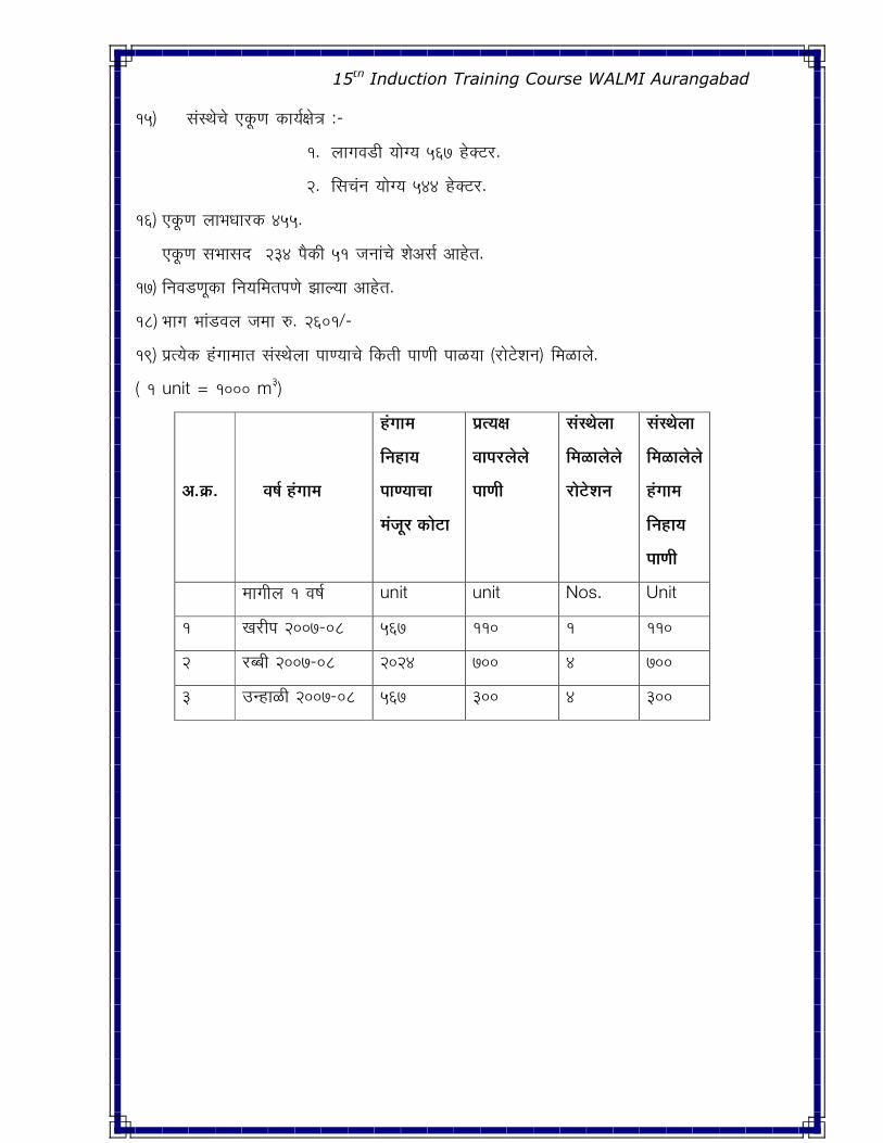
15th Induction Training Course WALMI Aurangabad
15) ÃÖÓãÖê“Öê ‹�æú�Ö �úÖµÖÔ>Öê¡Ö :-
1. »ÖÖ�Ö¾Ö›üß µÖÖê�µÖ 567 ÆêüŒ™ü¸ü.
2. ×ÃÖ“ÖÓ−Ö µÖÖê�µÖ 544 ÆêüŒ™ü¸ü.
16) ‹�æú�Ö »ÖÖ³Ö¬ÖÖ¸ü�ú 455.
‹�æú�Ö ÃÖ³ÖÖÃÖ¤ü 234 ¯Öî�úß 51 •Ö−ÖÖÓ“Öê ¿Öê†ÃÖÔ †ÖÆêüŸÖ.
17) ×−Ö¾Ö›ü�Öæ�úÖ ×−ÖµÖ×´ÖŸÖ¯Ö�Öê —ÖÖ»µÖÖ †ÖÆêüŸÖ.
18) ³ÖÖ�Ö ³ÖÖÓ›ü¾Ö»Ö •Ö´ÖÖ ¹ý. 2601/-
19) ÖÏŸµÖê�ú ÆÓüÓ�ÖÖ´ÖÖŸÖ ÃÖÓãÖê»ÖÖ ¯ÖÖ�µÖÖ“Öê ×�úŸÖß ¯ÖÖ�Öß ¯ÖÖôûµÖÖ (¸üÖê™êü¿Ö−Ö) ×´ÖôûÖ»Öê.
( 1 unit = 1000 m3)
†.FÎú.
¾ÖÂÖÔ ÆÓüJÖÖ´Ö
ÆÓüJÖÖ´Ö
×−ÖÆüÖµÖ
¯ÖÖ*µÖÖ“ÖÖ
´ÖÓ•Öæ ü FúÖê™üÖ
¯ÖÏŸµÖ)Ö
¾ÖÖ¯Ö¸ü»Öê»Öê
¯ÖÖ*Öß
ÃÖÓãÖê»ÖÖ
×´ÖôûÖ»Öê»Öê
¸üÖê™êü¿Ö−Ö
ÃÖÓãÖê»ÖÖ
×´ÖôûÖ»Öê»Öê
ÆÓüJÖÖ´Ö
×−ÖÆüÖµÖ
¯ÖÖ*Öß
´ÖÖ�Öᯙ 1 ¾ÖÂÖÔ unit unit Nos. Unit
1 �Ö¸üß¯Ö 2007-08 567 110 1 110
2 ¸ü²²Öß 2007-08 2024 700 4 700
3 ˆ−ÆüÖôûß 2007-08 567 300 4 300
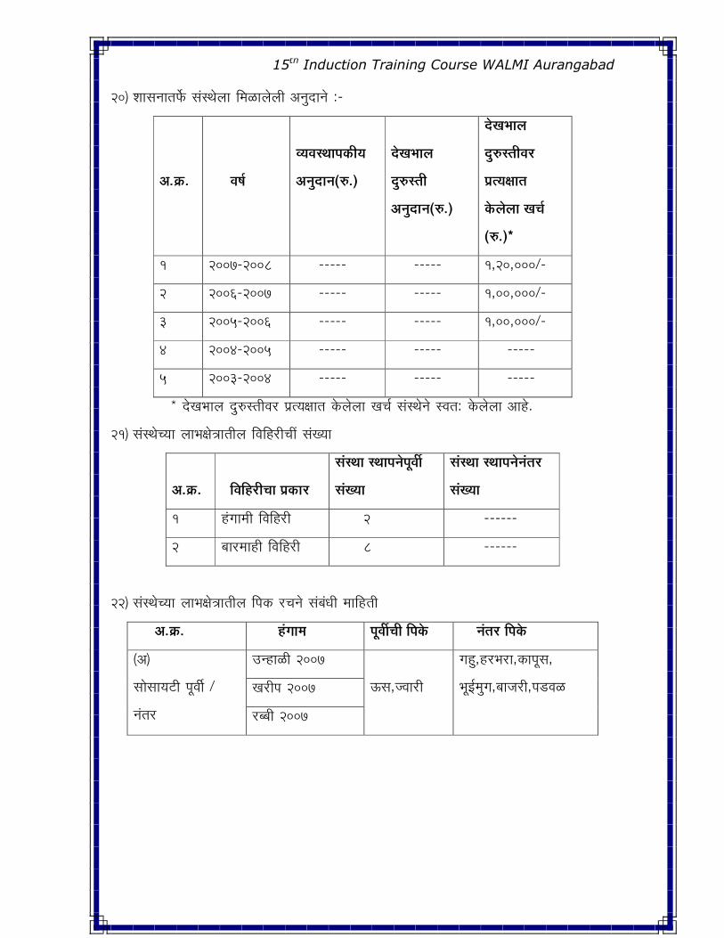
15th Induction Training Course WALMI Aurangabad
20) ¿ÖÖÃÖ−ÖÖŸÖ±ìú ÃÖÓãÖê»ÖÖ ×´ÖôûÖ»Öê»Öß †−Öã¤üÖ−Öê :-
†.FÎú.
¾ÖÂÖÔ
¾µÖ¾ÖãÖÖ¯ÖFúßµÖ
†−Öã¤üÖ−Ö(¹ý.)
¤êüSÖ³ÖÖ»Ö
¤ãü¹ýßÖß
†−Öã¤üÖ−Ö(¹ý.)
¤êüSÖ³ÖÖ»Ö
¤ãü¹ýßÖß¾Ö¸ü
¯ÖÏŸµÖ)ÖÖŸÖ
Fêú»Öê»ÖÖ SÖ“ÖÔ
(¹ý.)*
1 2007-2008 ----- ----- 1,20,000/-
2 2006-2007 ----- ----- 1,00,000/-
3 2005-2006 ----- ----- 1,00,000/-
4 2004-2005 ----- ----- -----
5 2003-2004 ----- ----- -----
* ¤êü�Ö³ÖÖ»Ö ¤ãü¹ýßÖß¾Ö¸ü ¯ÖÏŸµÖ>ÖÖŸÖ �êú»Öê»ÖÖ �Ö“ÖÔ ÃÖÓãÖê−Öê þ֟Ö: �êú»Öê»ÖÖ †ÖÆêü.
21) ÃÖÓãÖꓵÖÖ »ÖÖ³Ö>Öê¡ÖÖŸÖß»Ö ×¾Ö×Ƹüß“Öà ÃÖÓ�µÖÖ
†.FÎú.
×¾Ö×Ƹüß“ÖÖ ¯ÖÏFúÖ¸ü
ÃÖÓãÖÖ Ã£ÖÖ¯Ö−Öê Öæ¾Öá
ÃÖÓSµÖÖ
ÃÖÓãÖÖ Ã£ÖÖ¯Ö−Öê−ÖÓŸÖ¸ü
ÃÖÓSµÖÖ
1 ÆÓü�ÖÖ´Öß ×¾Ö×Ƹüß 2 ------
2 ²ÖÖ¸ü´ÖÖÆüß ×¾Ö×Ƹüß 8 ------
ü
22) ÃÖÓãÖꓵÖÖ »ÖÖ³Ö>Öê¡ÖÖŸÖß»Ö ×¯Ö�ú ¸ü“Ö−Öê ÃÖÓ²ÖÓ¬Öß ´ÖÖ×ÆüŸÖß
†.FÎú. ÆÓüJÖÖ´Öü ¯Öæ¾Öá“Öß ×¯ÖFê −ÖÓŸÖ¸ü ׯÖFê
(†)
ÃÖÖêÃÖÖµÖ™üß ¯Öæ¾Öá /
−ÖÓŸÖ¸ü
ˆ−ÆüÖôûß 2007
‰úÃÖ,•¾ÖÖ¸üß
�ÖÆãü,Æü¸ü³Ö¸üÖ,�úÖ¯ÖæÃÖ,
³Öæ‡Ô Öã�Ö,²ÖÖ•Ö¸üß,¯Ö›ü¾Öôû �Ö¸üß¯Ö 2007
¸ü²²Öß 2007
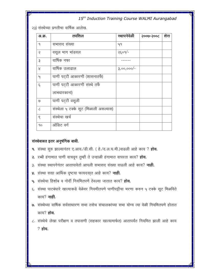
15th Induction Training Course WALMI Aurangabad
23) ÃÖÓãÖꓵÖÖ ¯ÖÏ�ÖŸÖß“ÖÖ ¾ÖÖÙÂÖ�ú †Ö»Öê�Ö.
†.FÎú. ŸÖ¯Ö×¿Ö»Ö Ã£ÖÖ¯Ö−Öê¾Öêôûß 2007-2008 ¿Öê üÖ
1 ÃÖ³ÖÖÃÖ¤ü ÃÖÓ�µÖÖ 51
2 ¾ÖÃÖæ»Ö ³ÖÖ�Ö ³ÖÖÓ›ü¾Ö»Ö 2601/-
3 ¾ÖÖÙÂÖ�ú −Ö±úÖ ------
4 ¾ÖÖÙÂÖ�ú ˆ»ÖÖœüÖ»Ö 3,00,000/-
5 ¯ÖÖ�Öß ¯Ö™Ëü™üß †Ö�úÖ¸ü�Öß (¿ÖÖÃÖ−ÖÖŸÖ±ìú)
6 ¯ÖÖ�Öß ¯Ö™Ëü™üß †Ö�úÖ¸ü�Öß ÃÖÓãÖê ŸÖ±ìú
»ÖÖ³Ö¬ÖÖ¸ü�úÖ−ÖÖÓ)
7 ¯ÖÖ�Öß ¯Ö™Ëü™üß ¾ÖÃÖæ»Öß
8 ÃÖÓãÖê»ÖÖ 5 ™üŒ�êú ÃÖæ™ü (×´ÖôûÖ»Öß †ÃÖ»µÖÖÃÖ)
9 ÃÖÓãÖê“ÖÖ �Ö“ÖÔ
10 †Öò×›ü™ü ¾Ö�ÖÔ
ÃÖÓãÖê²ÖÖ²ÖŸÖ ‡ŸÖ¸ü †−ÖãÂÖÓØJÖFú ²ÖÖ²Öß.
1. ÃÖÓãÖÖ ÃÖã¹ý —ÖÖ»µÖÖ−ÖÓŸÖ¸ü ‹.†ÖµÖ./›üß.ÃÖß. ( Æêü./¤ü.»Ö.‘Ö.´Öß.)¾ÖÖœü»Öß †ÖÆêü �úÖµÖ ? ÆüÖêµÖ.
2. ¸ü²²Öß ÆÓü�ÖÖ´ÖÖŸÖ ¯ÖÖ�Öß ¾ÖÖ“Ö¾Öæ−Ö ŸÖã Æüß ŸÖê ˆ−ÆüÖôûß ÆÓü�ÖÖ´ÖÖŸÖ ¾ÖÖ¯Ö¸üŸÖÖ �úÖµÖ? ÆüÖêµÖ.
3. ÃÖÓãÖÖ Ã£ÖÖ¯Ö−Öê−ÖÓŸÖ¸ü †ÖŸÖÖ¯ÖÖ¾ÖêŸÖÖê †Ö¯Ö»Öß ÃÖ³ÖÖÃÖ¤ü ÃÖÓ�µÖÖ ¾ÖÖœü»Öß †ÖÆêü �úÖµÖ? −ÖÖÆüß.
4. ÃÖÓãÖÖ ÃÖªÖ †ÖÙ£Ö�ú ¥ü™üµÖÖ ±úÖµÖ¤üµÖÖËŸÖ †ÖÆêü �úÖµÖ? −ÖÖÆüß.
5. ÃÖÓãÖê“ÖÖ ×Æü¿ÖÖê²Ö ¾Ö −ÖÖê¤üà ×−ÖµÖ×´ÖŸÖ¯Ö�Öê šêü¾Ö»µÖÖ •ÖÖŸÖÖŸÖ �úÖµÖ? ÆüÖêµÖ.
6. ÃÖÓãÖÖ ¯ÖÖ™ü²ÖÓ¬ÖÖ êü �ÖÖŸµÖÖ�ú›êü ¾Öêôêû¾Ö¸ü ×−ÖµÖ´Öߟ֯Ö�Öê ¯ÖÖ�Öּ߯üß“ÖÖ ³Ö¸ü�ÖÖ �ú¹ý−Ö 5 ™üŒ�êú ÃÖæ™ü ×´Öôû×¾ÖŸÖê
�úÖµÖ? −ÖÖÆüß.
7. ÃÖÓãÖꓵÖÖ ¾ÖÖÙÂÖ�ú ÃÖ¾ÖÔÃÖÖ¬ÖÖ¸ü�Ö ÃÖ³ÖÖ ŸÖÃÖê“Ö ÃÖÓ“ÖÖ»Ö�úÖÓ“µÖÖ ÃÖ³ÖÖ µÖÖê�µÖ ŸµÖÖ ¾Öêôûß ×−ÖµÖ×´ÖŸÖ¯Ö�Öê ÆüÖêŸÖÖŸÖ
�úÖµÖ? ÆüÖêµÖ.
8. ÃÖÓãÖê“Öê »Öê�ÖÖ ¯Ö¸üß>Ö�Ö ¾Ö ŸÖ¯ÖÖÃÖ�Öß (ÃÖÆü�úÖ¸ü �ÖÖŸµÖÖ´ÖÖ±ÔúŸÖ) †ÖŸÖÖ¯ÖµÖÕŸÖ ×−ÖµÖ×´ÖŸÖ —ÖÖ»Öß †ÖÆêü �úÖµÖ
? ÆüÖêµÖ.
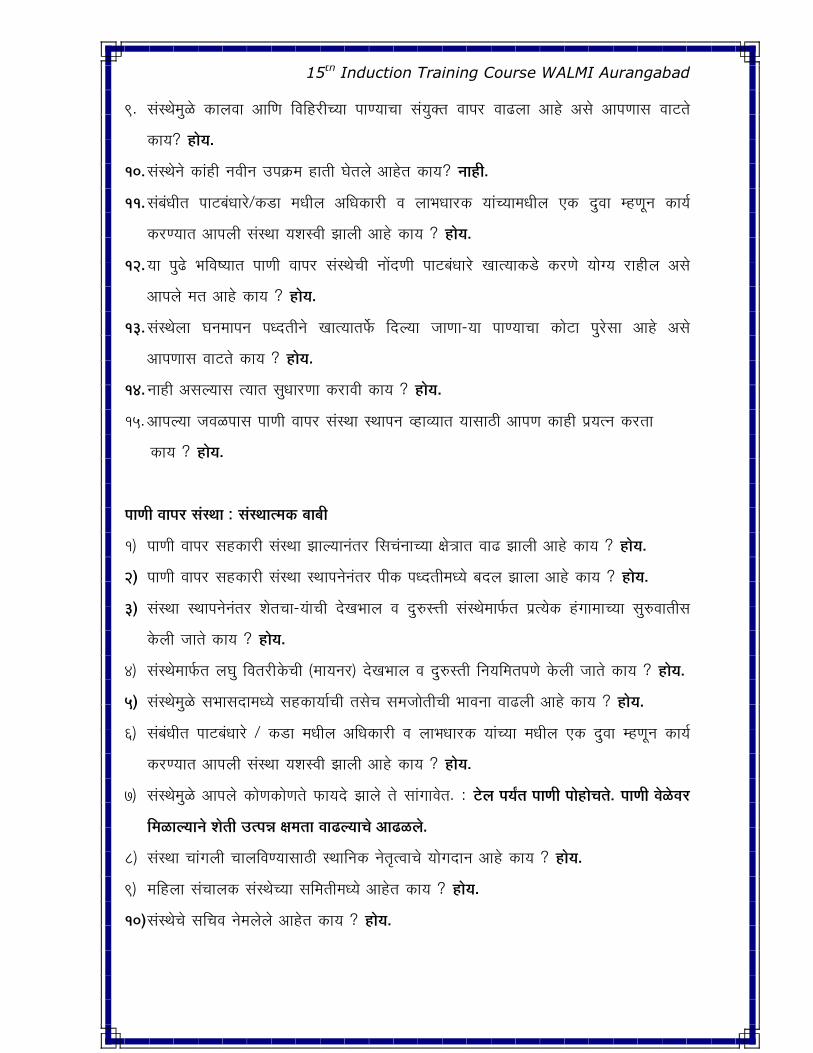
15th Induction Training Course WALMI Aurangabad
9. ÃÖÓãÖê Öãôêû �úÖ»Ö¾ÖÖ †Ö×�Ö ×¾Ö×Æü¸üß“µÖÖ ¯ÖÖ�µÖÖ“ÖÖ ÃÖÓµÖãŒŸÖ ¾ÖÖ¯Ö¸ü ¾ÖÖœü»ÖÖ †ÖÆêü †ÃÖê †Ö¯Ö�ÖÖÃÖ ¾ÖÖ™üŸÖê
�úÖµÖ? ÆüÖêµÖ.
10. ÃÖÓãÖê−Öê �úÖÓÆüß −Ö¾Öß−Ö ˆ¯Ö�Îú´Ö ÆüÖŸÖß ‘ÖêŸÖ»Öê †ÖÆêüŸÖ �úÖµÖü? −ÖÖÆüß.
11. ÃÖÓ²ÖÓ¬ÖßŸÖ ¯ÖÖ™ü²ÖÓ¬ÖÖ¸êü/�ú›üÖ ´Ö¬Öᯙ †×¬Ö�úÖ¸üß ¾Ö »ÖÖ³Ö¬ÖÖ¸ü�ú µÖÖÓ“µÖÖ´Ö¬Öᯙ ‹�ú ¤ãü¾ÖÖ ´Æü�Öæ−Ö �úÖµÖÔ
�ú¸ü�µÖÖŸÖ †Ö¯Ö»Öß ÃÖÓãÖÖ µÖ¿ÖþÖß —ÖÖ»Öß †ÖÆêü �úÖµÖ ? ÆüÖêµÖ.
12. µÖÖ ¯Öãœêü ³Ö×¾ÖµÖÖŸÖ ¯ÖÖ�Öß ¾ÖÖ¯Ö¸ü ÃÖÓãÖê“Öß −ÖÖë¤ü�Öß ¯ÖÖ™ü²ÖÓ¬ÖÖ êü �ÖÖŸµÖÖ�ú›êü �ú¸ü�Öê µÖÖê�µÖ ¸üÖÆßü»Ö †ÃÖê
†Ö¯Ö»Öê ´ÖŸÖ †ÖÆêü �úÖµÖ ? ÆüÖêµÖ.
13. ÃÖÓãÖê»ÖÖ ‘Ö−Ö´ÖÖ¯Ö−Ö ¯Ö¬¤üŸÖß−Öê �ÖÖŸµÖÖŸÖ±ìú פü»µÖÖ •ÖÖ�ÖÖ-µÖÖ ¯ÖÖ�µÖÖ“ÖÖ �úÖê™üÖ ¯Öã êüÃÖÖ †ÖÆêü †ÃÖê
†Ö¯Ö�ÖÖÃÖ ¾ÖÖ™üŸÖê �úÖµÖ ? ÆüÖêµÖ.
14. −ÖÖÆüß †ÃÖ»µÖÖÃÖ ŸµÖÖŸÖ ÃÖã¬ÖÖ¸ü�ÖÖ �ú¸üÖ¾Öß �úÖµÖ ? ÆüÖêµÖ.
15. †Ö¯Ö»µÖÖ •Ö¾Öôû¯ÖÖÃÖ ¯ÖÖ�Öß ¾ÖÖ¯Ö¸ü ÃÖÓãÖÖ Ã£ÖÖ¯Ö−Ö ¾ÆüÖ¾µÖÖŸÖ µÖÖÃÖÖšüß †Ö¯Ö�Ö �úÖÆüß ¯Öϵ֟−Ö �ú¸üŸÖÖ
�úÖµÖ ? ÆüÖêµÖ.
¯ÖÖ*Öß ¾ÖÖ¯Ö¸ü ÃÖÓãÖÖ : ÃÖÓãÖÖŸ´ÖFú ²ÖÖ²Öß
1) ¯ÖÖ�Öß ¾ÖÖ¯Ö¸ü ÃÖÆü�úÖ¸üß ÃÖÓãÖÖ —ÖÖ»µÖÖ−ÖÓŸÖ¸ü ×ÃÖ“ÖÓ−ÖÖ“µÖÖ >Öê¡ÖÖŸÖ ¾ÖÖœü —ÖÖ»Öß †ÖÆêü �úÖµÖ ? ÆüÖêµÖ.
2) ¯ÖÖ�Öß ¾ÖÖ¯Ö¸ü ÃÖÆü�úÖ¸üß ÃÖÓãÖÖ Ã£ÖÖ¯Ö−Öê−ÖÓŸÖ¸ ¯Öß�ú ¯Ö¬¤üŸÖß´Ö¬µÖê ²Ö¤ü»Ö —ÖÖ»ÖÖ †ÖÆêü �úÖµÖ ? ÆüÖêµÖ.
3) ÃÖÓãÖÖ Ã£ÖÖ¯Ö−Öê−ÖÓŸÖ¸ ¿ÖêŸÖ“ÖÖ-µÖÓÖ“Öß ¤êü�Ö³ÖÖ»Ö ¾Ö ¤ãü¹ýâÖß ÃÖÓãÖê ÖÖ±ÔúŸÖ ¯ÖÏŸµÖê�ú ÆÓü�ÖÖ´ÖÖ“µÖÖ ÃÖã¹ý¾ÖÖŸÖßÃÖ
�êú»Öß •ÖÖŸÖê �úÖµÖ ? ÆüÖêµÖ.
4) ÃÖÓãÖê ÖÖ±ÔúŸÖ »Ö‘Öã ×¾ÖŸÖ¸üßü�êú“Öß (´ÖÖµÖ−Ö¸ü) ¤êü�Ö³ÖÖ»Ö ¾Ö ¤ãü¹ýßÖß ×−ÖµÖ×´ÖŸÖ¯Ö�Öê �êú»Öß •ÖÖŸÖê �úÖµÖ ? ÆüÖêµÖ.
5) ÃÖÓãÖê Öãôêû ÃÖ³ÖÖÃÖ¤üÖ´Ö¬µÖê ÃÖÆü�úÖµÖÖÔ“Öß ŸÖÃÖê“Ö ÃÖ´Ö•ÖÖêŸÖß“Öß ³ÖÖ¾Ö−ÖÖ ¾ÖÖœü»Öß †ÖÆêü �úÖµÖ ? ÆüÖêµÖ.
6) ÃÖÓ²ÖÓ¬ÖßŸÖ ¯ÖÖ™ü²ÖÓ¬ÖÖ¸êü / �ú›üÖ ´Ö¬Öᯙ †×¬Ö�úÖ¸üß ¾Ö »ÖÖ³Ö¬ÖÖ¸ü�ú µÖÖÓ“µÖÖ ´Ö¬Öᯙ ‹�ú ¤ãü¾ÖÖ ´Æü�Öæ−Ö �úÖµÖÔ
�ú¸ü�µÖÖŸÖ †Ö¯Ö»Öß ÃÖÓãÖÖ µÖ¿ÖþÖß —ÖÖ»Öß †ÖÆêü �úÖµÖ ? ÆüÖêµÖ.
7) ÃÖÓãÖê Öãôêû †Ö¯Ö»Öê �úÖê�Ö�úÖê�ÖŸÖê ±úÖµÖ¤êü —ÖÖ»Öê ŸÖê ÃÖÖÓ�ÖÖ¾ÖêŸÖ. : ™êü»Ö ¯ÖµÖÕŸÖ ¯ÖÖ*Öß ¯ÖÖêÆüÖê“ÖŸÖê. ¯ÖÖ*Öß ¾Öêôêû¾Ö¸ü
×´ÖôûÖ»µÖÖ−Öê ¿ÖêŸÖß ˆŸ¯Ö®Ö )Ö´ÖŸÖÖ ¾ÖÖœü»µÖÖ“Öê †Öœüôû»Öê.
8) ÃÖÓãÖÖ “ÖÖÓ�Ö»Öß “ÖÖ»Ö×¾Ö�µÖÖÃÖÖšüß Ã£ÖÖ×−Ö�ú −ÖêŸÖ韾ÖÖ“Öê µÖÖê�Ö¤üÖ−Ö †ÖÆêü �úÖµÖ ? ÆüÖêµÖ.
9) ´Ö×Æü»ÖÖ ÃÖÓ“ÖÖ»Ö�ú ÃÖÓãÖꓵÖÖ ÃÖ×´ÖŸÖß´Ö¬µÖê †ÖÆêüŸÖ �úÖµÖ ? ÆüÖêµÖ.
10) ÃÖÓãÖê“Öê ÃÖ×“Ö¾Ö −Öê Ö»Öê»Öê †ÖÆêüŸÖ �úÖµÖ ? ÆüÖêµÖ.
15th Induction Training Course WALMI Aurangabad
5.3 ×¾ÖŸÖ¸üßFêú¾Ö¸üᯙ ¯ÖÖ*Öß ¾ÖÖ¯Ö¸ü Fú¸ü*ÖÖ-µÖÖ ¿ÖêŸÖFú-µÖÖÓ¿Öß SÖÖ»Öᯙ ´Ö㬤üµÖÖ¾Ö¸ü “Ö“ÖÖÔ Fêú»Öß.
1 ¯ÖÖ*Öß ™êü»Ö ¯ÖµÖÕŸÖ ×´ÖôûŸÖê FúÖ ?
™êü»Ö“Öê ¿ÖêŸÖ�ú¸üß ÁÖß.ׯָüÖ•Öß ´ÖÖê êü, OL4 µÖÖÓ“µÖÖ¿Öß “Ö“ÖÖÔ �ú¸üŸÖÖ »Ö‘Öã×¾ÖŸÖ¸üß�êú“µÖÖ 5.5 ×�ú.´Öß.
‹�æú�Ö »ÖÖÓ²Öß ¯Öî�ß ¯ÖÖ�Öß ¾ÖÖ¯Ö¸ü ÃÖÓãÖê�ú›êü ÆüßÖÖŸÖÓ ü�ÖÖ¯Öæ¾Öá †Ó¤üÖ•Öê 2.5 ×�ú.´Öß. »ÖÖÓ²Öß ¯ÖµÖÕŸÖ ¯ÖÖ�Öß
×´ÖôûŸÖ ÆüÖêŸÖê.¯Ö¸ÓüŸÖã ¯ÖÖ�Öß ¾ÖÖ¯Ö¸ü ÃÖÓãÖê�ú›êü ÆüßÖÖŸÖÓ ü�Ö —ÖÖ»µÖÖ −ÖÓŸÖ¸ü †Ó¤üÖ•Öê 4.5
×�ú.´Öß.»ÖÖÓ²Öß ¯ÖµÖÕŸÖ ¯ÖÖ�Öß ×´ÖôûŸÖê ŸµÖÖ´Öãôêû ׳֕Ö�ÖÖ-µÖÖ >Öê¡ÖÖŸÖ ¾ÖÖœü —ÖÖ»Öê»Öß †ÖÆêü.
2. ׯÖFúÖ´Ö¬Öᯙ —ÖÖ»Öê»Öê ²Ö¤ü»Ö .
¯ÖÖ�µÖÖ“µÖÖ ˆ¯Ö»Ö²¬ÖŸÖê−ÖãÃÖÖ¸ü ¯Öß�ú ¸ü“Ö−ÖÖ ÃÖ³ÖêŸÖ šü¸ü¾Ö»Öß •ÖÖŸÖê. ÆüßÖÖŸÖÓ ü�ÖÖ¯Öæ¾Öá ‰úÃÖÖ“Öê >Öê¡Ö
´ÖÖêšüµÖÖ ¯ÖÏ´ÖÖ�ÖÖŸÖ ÆüÖêŸÖê ¯Ö¸ÓüŸÖã ÆüßÖÖŸÖÓ ü�ÖÖ−ÖÓŸÖ¸ü ŸµÖÖŸÖ ‘Ö™ü —ÖÖ»Öê»Öß †ÖÆêü.µÖÖ“Öß �úÖ¸ü�Öê
�ÖÖ»Ö߻֯ÖÏ´ÖÖ�Öê †ÖÆêüŸÖ.
a. ´ÖÖ�Öᯙ ¤üÖê−Ö ¾ÖÂÖÖÔŸÖ ‰úÃÖ �úÖ¸ü�ÖÖ−Öê ¯Öæ�ÖÔ ‰úÃÖ −Öê‰ú ¿Ö�ú»Öê»Öê −ÖÖÆüߟÖ.
b. ‰úÃÖÖ“ÖÖ ¤ü¸ü ¾Ö ŸµÖÖ´Öãôêû ×´Öôû�ÖÖ-µÖÖü ˆŸ¯Ö®ÖÖŸÖ ‘Ö™ü —ÖÖ»Öê»Öß †ÖÆêü.
3 ¯ÖÖ*µÖÖ“ÖÖ †¯Ö¾µÖµÖ ™üÖôû»ÖÖ •ÖÖŸÖÖê FúÖ ?
¿ÖÖÃÖ−Ö »Ö‘Öã ×¾ÖŸÖ¸üß�êú“µÖÖ ´Öã�ÖÖ¿Öß ¯ÖÖ�Öß ´ÖÖê•Öæ−Ö ¤êüŸÖê ¾Ö ŸµÖÖ¾Ö¸ü“Ö ¯ÖÖ�µÖÖ“Öß †Ö�úÖ¸ü�Öß ÆüÖêŸÖê.
ŸµÖÖ´Öãôêû ¯ÖÖ�Öß ¾ÖÖ¯Ö¸ü ÃÖÓãÖÖ ¯ÖÖ�µÖÖ“ÖÖ †¯Ö¾µÖµÖ ÆüÖê�ÖÖ¸ü −ÖÖÆüß µÖÖ“Öß ¤ü>ÖŸÖÖ ‘ÖêŸÖê. ŸµÖÖ�ú¸üߟÖÖ ¸üÖ¡Ö
¯ÖÖôûßŸÖ �ÖÃŸÖ ‘ÖÖ»Ö�Öê, ¿ÖêŸÖ�ú-µÖÖ−ÖÖÓ ¯ÖÖ�Öß −ÖÖ¿Ö �ú¸ü�Öê ÖÖÃÖæ−Ö ¯Ö¸üÖ¾Öé¢Ö �ú¸ü�Öê ‡ŸµÖÖ¤üß ²ÖÖ²Öß �êú»µÖÖ
•ÖÖŸÖÖŸÖ.
4. ¯ÖÖ*Öß ¾ÖÖ¯Ö¸ü ÃÖÓãÖêÃÖ ×¾Ö¸üÖê¬Ö †ÖÆêü FúÖ ?
�úÖÆüß ¿ÖêŸÖ�ú-µÖÖ−Öß ÃÖãã ü¾ÖÖŸÖßÃÖ ¯ÖÖ�Öß ¾ÖÖ¯Ö¸ü ÃÖÓãÖËêÃÖ ¯ÖÏ�Ö¸ü ×¾Ö¸üÖê¬Ö �êú»ÖÖ. ŸµÖÖ−ÖÓŸÖ¸ü šü üÖ¾Öß�ú
¿ÖêŸÖ�ú-µÖÖ−ÖÖÓ ¾ÖÖ»´Öß, †Öî Óü�ÖÖ²ÖÖ¤ü µÖê£Öê ¯ÖÏ׿Ö>Ö�ÖÖÃÖ ¯ÖÖšü×¾Ö�µÖÖŸÖ †Ö»Öê.ŸµÖÖÓ“Öê ¯ÖÏ׿Ö>�ÖÖ−ÖÓŸÖ¸ü ¯Öæ�ÖÔ
´ÖŸÖ ¯Ö׸ü¾ÖŸÖÔ−Ö —ÖÖ»Öê ¾Ö †Ö•Ö ŸÖê ¯ÖÖ�Öß ¾ÖÖ¯Ö¸ü ÃÖÓãÖê Ö¬µÖê ÃÖ�ÎúßµÖ †ÖÆêüŸÖ.
5. »Ö‘Öã×¾ÖŸÖ¸üßFêú“µÖÖ ×Fú.´Öß.4.5 ŸÖê 5.5 ´Ö¬µÖê ¯ÖÖ*Öß •ÖÖŸÖ −ÖÃÖ»µÖÖ−Öê ŸµÖÖŸÖᯙ ¿ÖêŸÖFú¸üß FúÖê*ÖŸÖê ¯ÖßFú
‘ÖêŸÖÖŸÖ ?
¿ÖêŸÖ�ú¸üß �Ö¸üß¯Ö ÆÓü�ÖÖ´ÖÖ−ÖÓŸÖ¸ü ¸ü²²Öß �ÖÆæü ¯Öê üŸÖÖŸÖ ¾Ö Æêü›ü´Ö¬Öᯙ ¿ÖêŸÖ�ú-µÖÖÓ“Öê ‰úÃÖÖ“Öê ¯ÖÏ´ÖÖ�Ö �ú´Öß
—ÖÖ»µÖÖ−Öê ŸµÖÖ−ÖÖÓ ¯ÖÖ�Öß �ú´Öß »ÖÖ�ÖŸÖ †ÃÖ»µÖÖ−Öê �Ö¾ÆüÖÃÖÖšüß ¯ÖÖ�Öß ˆ¯Ö»Ö²¬Ö ÆüÖêŸÖê. ×�ú.´Öß.4.5 ŸÖê
5.5 ´Ö¬µÖê ¿ÖêŸÖ�ú¸üß ¸ü²²Öß �ÖÆæü“Ö ¯Öê üŸÖÖŸÖ ¾Ö ‹�ÖÖ¤ü ¤ãüÃÖ¸Óü ¯ÖÖ�Öß ×´ÖôûÖ»µÖÖÃÖ ŸµÖÖ¾Ö¸ü ¯Öß�ú ‘ÖêŸÖÖŸÖ.
15th Induction Training Course WALMI Aurangabad
6. »Ö‘Öã ×¾ÖŸÖ¸üßFêú´Ö¬µÖê FúÖÆüß ×šüFúÖ*Öß Fú“Ö¸üÖ ¯Ö›ü»ÖÖ †ÃÖæ−Ö •ÖÖ*Öê µÖê*ÖêÃÖÖšüß »ÖÖêFúÖ−Öß ¾ÖÖ™üÖ Fêú»µÖÖ
†ÖÆêüŸÖ.
¯ÖÖ�Öß ¾ÖÖ¯Ö¸ü ÃÖÓãÖÖ ¾Ö �úÖÆüß ¿ÖêŸÖ�ú¸üß Æêü »Ö‘Öã ×¾ÖŸÖ¸üß�êú´Ö¬Öᯙ �ú“Ö¸üÖ �úÖœü�µÖÖÃÖ »ÖÖê�úÖ−ÖÖÓ
×¾Ö−ÖÓŸÖß �ú¸üŸÖÖŸÖ ¾Ö ˆ¯Ö»Ö²¬Ö †ÃÖ�ÖÖ-µÖÖ ‹�úÖ ´Ö•Öã üÖ�ú›æü−Ö �úÖÆü߯ÖÏ´ÖÖ�ÖÖŸÖ »Ö‘Öã×¾ÖŸÖ¸üß�úÖ Ã¾Ö“”û
šêü¾Ö�µÖÖ“ÖÖ ¯Öϵ֟−Ö �ú¸üŸÖÖŸÖ.
7. ¿ÖêŸÖFú-µÖÖ´Ö¬µÖê ׯÖFêú ‘Öê*µÖÖ²ÖÖ²ÖŸÖ ˆ¤üÖ×ÃÖ−ÖŸÖÖ FúÖ †ÖÆêü?
•µÖÖ¾Öêôûß ¿ÖÖÃÖ−ÖÖ´ÖÖ±ÔúŸÖ »Ö‘Öã×¾ÖŸÖ¸üß�úß“Öê ×−ÖµÖÖê•Ö−Ö ¾Ö ¾µÖ¾ÖãÖÖ¯Ö−Ö ÆüÖêŸÖê ŸµÖÖ¾Öêôûß ÃÖÖŸÖ ×¤ü¾ÖÃÖ
¯ÖÖ�Öß ×´ÖôûÖµÖ“Öê ¾Ö “ÖÖî¤üÖ ×¤ü¾ÖÃÖ ¯ÖÖ�Öß ²ÖÓ¤ü †ÃÖÖµÖ“Öê.ŸµÖÖ¾Öêôûß ³Öã‡Ô Öã�ÖÖÃÖÖ¸ü�Öß ×¯Ö�êú ˆ¢Ö´Ö׸üŸµÖÖ
‘ÖêŸÖ»Öß •ÖÖµÖ“Öß ¾Ö ¿ÖêŸÖ�ú-µÖÖ−ÖÖÓ “ÖÖÓ�Ö»Öê ¯ÖîÃÖê ×´ÖôûÖµÖ“Öê. ¯Ö¸ÓüŸÖã †ÖŸÖÖ ´Ö×Æü−µÖÖŸÖæ−Ö ‹�ú¤üÖ ¯ÖÖ�Öß
×´ÖôûŸÖ †ÃÖ»µÖÖ´Öãôêû ׯÖ�úÖÓ“ÖÖ ˆŸÖÖ¸üÖ �ú´Öß ×´Öôæû »ÖÖ�Ö»ÖÖ †ÖÆêü.×¾Ö¿ÖêÂÖ ¯ÖîÃÖê ×´ÖôûŸÖ −ÖÃÖ»µÖÖ´Öãôêû
¿ÖêŸÖ�ú-µÖÖ´Ö¬µÖê ׯÖ�úÖ²ÖÖ²ÖŸÖ ˆ¤üÖ×ÃÖ−ÖŸÖÖ ×¤üÃÖæ−Ö µÖêŸÖê.
5.4 ×¾ÖŸÖ׸üFêú¾Ö¸üᯙ ¯ÖÖ*Öß ¾ÖÖ¯Ö¸ü Fú¸ü*ÖÖ-µÖÖ ÃÖÓãÖê“Öê “Öꆸü´Ö−Ö µÖÖÓ“Öê¿Öß SÖÖ»Öᯙ ´ÖãªÖ¾Ö¸ü “Ö“ÖÖÔ Fêú»Öß.
1. ¿ÖêŸÖFú-µÖÖÓ“µÖÖFú›æü−Ö ¯ÖÖ*Ö߯֙üË™üß ¾ÖÃÖã»Ö ÆüÖêŸÖê FúÖ ?
¯ÖÖ�Öּ߯üß ¾ÖÃÖã»ÖßŸÖ £ÖÖê›üÖ ¾Öêôû »ÖÖ�ÖŸÖÖê ¯Ö¸ÓüŸÖã ¾ÖÃÖã»Öß ÆüÖêŸÖê.�úÖÆüß ¿ÖêŸÖ�ú¸üß ¯Öîšü�Ö ¾Ö ‡ŸµÖÖ¤üß
¤æü¸ü“µÖÖ ×šü�úÖ�Öß ¸üÆüÖŸÖÖŸÖ ŸµÖÖ´Öãôêû ¾ÖÃÖã»ÖßŸÖ †œü£Öôêû µÖêŸÖÖŸÖ.
2. ¤ã¹ýßÖß“Öß FúÖ´Öê FúÖê*Ö Fú¸üŸÖÖŸÖ ¾Ö ŸµÖÖ“Öê ü†ÖÙ£ÖFú ×−ÖµÖÖê•Ö−Ö FúÖµÖ ?
¤ãü¹ýßÖß“Öß�úÖ´Öê ¯ÖÖ�Öß ¾ÖÖ¯Ö¸ü ÃÖÓãÖê−Öê þÖ�Ö“ÖÖÔ−Öê �êú»Öê»Öß †ÖÆêüŸÖ. ¾Ö ŸµÖÖ“Öê †−Öã¤üÖ−Ö ¿ÖÖÃÖ−ÖÖ�ú›æü−Ö
¯ÖÖ�Öß ¾ÖÖ¯Ö¸ü ÃÖÓãÖêÃÖ †ªÖ¯Ö ×´ÖôûÖ»Öê»Öê −ÖÖÆüß.
3. ÃÖÓãÖêFú›êü ¯ÖÖ*Ö߯֙ü™üß £ÖFú²ÖÖFúß †ÖÆêü FúÖµÖ ?
¿ÖÖÃÖ−ÖÖ“Öê ¬ÖÖê ü�ÖÖ−ÖãÃÖÖ¸ü 100% ¯ÖÖ�Ö߯֙ü™üß ¿ÖÖÃÖ−ÖÖ�ú›êü ³Ö¸ü»Öê−ÖÓŸÖ¸ü ŸµÖÖŸÖᯙ 50% ¸üŒ�ú´Ö
¿ÖÖÃÖ−Ö ÃÖÓãÖêÃÖ ¯Ö¸üŸÖ �ú¸üŸÖê. ¯Ö ÓüŸÖã ÃÖÓãÖê“Öê ´Æü�Ö�Öê †ÖÆêü �úß, ×´ÖôûÖ»Ö껵ÖÖ ¯ÖÖ�Öß ¯Ö™ü™üߟÖæ−Ö“Ö
ÃÖÓãÖê“ÖÖ �Ö“ÖÔ ˆ¤üÖ: �ú´ÖÔ“ÖÖ¸üß �Ö“ÖÔ, ¾ÖÃÖã»Öß �Ö“ÖÔ ‡ŸµÖÖ¤üß �êú»ÖÖ •ÖÖŸÖÖê. ŸµÖÖ´Öãôêû ÃÖÓãÖÖ 100%
¯ÖÖ�Ö߯֙ü™üß ³Ö¹ý“Ö ¿Ö�úŸÖ −ÖÖÆüß. ŸÖÃÖê“Ö �úÖÆüß ÃÖÓãÖÖÓ−Öß ¤üÖê−Ö ÆÓü�ÖÖ´ÖÖ“Öß 100% ¯ÖÖ�Ö߯֙ü™üß
³Ö¹ý−Ö ÃÖ㬤üÖ †ªÖ¯Ö 50% ¸üŒ�ú´Ö ¯Ö¸üŸÖ ¿ÖÖÃÖ−ÖÖ �ú›ãü−Ö ×´ÖôûÖ»Öê»Öß −ÖÖÆüß. ŸµÖÖ´Öãôêû ¿ÖÖÃÖ−ÖÖ−Öê
ÃÖÓãÖê�ú›æü−Ö 50% ¯ÖÖ�Ö߯֙ü™üß“Öß“Ö ¸üŒ�ú´Ö ³Ö¹ý−Ö ‘µÖÖ¾Öß †ÃÖê ÃÖÓãÖê“Öê ´Æü�Ö�Öê †ÖÆêü. ŸµÖÖ´Öãôêû
ÃÖÓãÖê−Öê †ªÖ¯Ö ¯ÖÖ�Öß ¯Ö™ü™üß ³Ö¸ü»Öê»Öß −ÖÖÆüß ŸµÖÖ´Öãôêû ÃÖÓãÖê�ú›êü ¯ÖÖ�Ö߯֙ü™üß“Öß £Ö�ú²ÖÖ�úß †ÖÆêü.
15th Induction Training Course WALMI Aurangabad
4. ¾Öêôêû¾Ö¸ü ¯ÖÖ*Ö߯֙ü™üß ³Ö¸ü»Öê−ÖÓŸÖ¸ü ¿ÖÖÃÖ−Ö 5% ׸ü²Öß™ü ¤êüŸÖê ŸÖê ÃÖÓãÖêÃÖ ×´ÖôûÖ»Öê †ÖÆêü FúÖµÖ ?
´ÖÖ�Öᯙ ÆÓü�ÖÖ´ÖÖ“Öß ¯ÖÖ�Ö߯֙ü™üß ¾Öêôêû¾Ö¸ü ³Ö¹ý−Ö ÃÖ㬤üÖ ¿ÖÖÃÖ−ÖÖ−Öê †ªÖ¯Ö 5% ׸ü²Öê™ü“Öß ¸üŒ�ú´Ö ¯Ö¸üŸÖ
פü»Öê»Öß −ÖÖÆüß.
5. ÃÖÓãÖê“ÖÖ SÖ“ÖÔ FúÖê*ÖFúÖê*ÖŸÖÖ †ÖÆêü ?
ÃÖÓãÖÖ ¯ÖÖ�µÖÖ“µÖÖ †Ö¾ÖŸÖÔ−ÖÖ ¾Öêôûß �ú´ÖÔ“ÖÖ¸üß ¸üÖê•ÖÓ¤üÖ¸üß¾Ö¸ü ‘ÖêŸÖê, ¯ÖÖ�Ö߯֙™üß ¾ÖÃÖã»ÖßÃÖÖšüß ×¾Ö×¾Ö¬Ö
ךü�úÖ�Öß ×±ú¸ü�µÖÖÃÖ �Ö“ÖÔ ÆüÖêŸÖÖê, Ùêü¿Ö−Ö¸üß ŸÖÃÖê“Ö ×¾Ö´ÖÖê“Ö�úÖÓ−ÖÖ »ÖÖ¾Ö�ÖêÃÖÖšüß �ãú»Öæ Ö ‡ŸµÖÖ¤üß
²ÖÖ²Öà¾Ö¸ü ÃÖÓãÖê“ÖÖ �Ö“ÖÔ ÆüÖêŸÖÖê.
6. ¿ÖÖÃÖFúßµÖ †×¬ÖFúÖ-µÖÖFú›æü−Ö ÃÖÆüFúÖµÖÔ ×´ÖôûŸÖê FúÖµÖ?
¿ÖÖÃÖ�úßµÖ †×¬Ö�úÖ-µÖÖ�ú›æü−Ö ¯Öæ�ÖÔ ÃÖÆü�úÖµÖÔ ×´ÖôûŸÖê. ¿ÖÖÃÖ�úßµÖ †Û¬Ö�úÖ-µÖÖÓ−Öß ÃÖÓãÖꓵÖÖ
†¬µÖ>ÖÖ“µÖÖÓ ²Öîšü�úÖ ‘Öê‰ú ÃÖÓãÖꓵÖÖ †›ü“Ö�Öß ÃÖ´Ö•ÖÖ¾Öæ−Ö ‘µÖÖ¾µÖÖŸÖ ŸÖÃÖê“Ö ÃÖÓãÖꓵÖÖ ¯Ö¡ÖÖ−ÖÖÓ ¿ÖÖÃÖ�úßµÖ
†×¬Ö�úÖ-µÖÖ−Öß ¯ÖÏŸÖßÃÖÖ¤ü ¤üµÖÖ˾ÖÖ †¿Öß ÃÖÓãÖê“Öß ×¾Ö−ÖÓŸÖß ÆüÖêŸÖß. ŸÖÃÖê“Ö ÃÖÓãÖê“Öß −ÖÖë¤ü�Öß ÃÖÆü�úÖµÖÔ
�ÖÖŸµÖÖ‹ê¾Ö•Öß ¯ÖÖ™ü²ÖÓ¬ÖÖ êü �ÖÖŸµÖÖ�ú›êü �ú¸ü�ÖêŸÖ µÖÖ¾Öß.
7. ¯ÖÖ*Öß ¯Ö¼üß“Öß †ÖFúÖ¸ü*Öß Fú¿Öß Fêú»Öê»Öß †ÖÆêü ?
ÃÖÓãÖê−Öê ÆÓü�ÖÖ´Ö¾ÖÖ¸ü ¾Öê�Ö¾Öê�ÖôûµÖÖ ¤ü¸üÖ−Öê ¯ÖÖ�Öß ¯Ö¼üß“Öß †Ö�úÖ¸ü�Öß �êú»Öê»Öß †ÖÆêü. ¿ÖêŸÖ�ú-µÖÖ−Öß ¯Öæ�ÖÔ
ÆÓü�ÖÖ´ÖÖ‹ê¾Ö•Öß ‹�ú Ø�ú¾ÖÖ ¤üÖê−Ö ¯ÖÖ�Öß �Ö¸ü•Öê ¯ÖÏ ÖÖ�Öê ‘ÖêŸÖ»µÖÖÃÖ ŸµÖÖ¯ÖÏ´ÖÖ�ÖÖŸÖ“ÖÓ ¯ÖÖ�Öß ¯Ö¼üß“Öß †Ö�úÖ¸ü�Öß
�êú»Öß •ÖÖŸÖê. ×¾Ö×Æü¸üß¾Ö¸üᯙ ØÃÖ“Ö−Ö >Öê¡ÖÖÃÖÖšüß ÃÖ㬤üÖ ¯ÖÖ�Öß ¯Ö¼üß“Öß †Ö�úÖ¸ü�Öß �êú»Öê»Öß †ÖÆêü. ¯Ö ÓüŸÖã
†¤üµÖÖË Ö ¾ÖÃÖã»Öß —ÖÖ»Öê»Öß −ÖÖÆüß.
5.5 ×¾ÖŸÖ׸üFêú¾Ö¸üᯙ ¿ÖÖÃÖFúßµÖ †×¬ÖFúÖ-µÖÖÓ¿Öß SÖÖ»Öᯙ ´ÖãªÖ¾Ö¸ü “Ö“ÖÖÔ Fêú»Öß.
1) ¯ÖÖ*Öß ¯Ö¼üß¾ÖÃÖã»ÖßŸÖ ¾ÖÖœü —ÖÖ»Öß †ÖÆêü FúÖ ?
×¾ÖŸÖ׸ü�êú“µÖÖ ÆüßÖÖŸÖÓ üÖ−ÖÓŸÖ¸ü ¯ÖÖ�Öß ¯Ö¼üß ¾ÖÃÖã»ÖßŸÖ £ÖÖê›üß ‘Ö™ü —ÖÖ»Öê»Öß †ÖÆêü.¯Ö¸ÓüŸÖã ÃÖÓãÖÖ −Ö¾Öß−Ö
†ÃÖ»µÖÖ´Öãôêû Æüß ‘Ö™ü פüÃÖæ−Ö µÖêŸÖê. ³Ö×¾ÖµÖÖŸÖ ¾ÖÃÖã»ÖßŸÖ ÆüôæûÆüôãû ¾ÖÖœü ÆüÖê‡Ô»Ö.
15th Induction Training Course WALMI Aurangabad
5.6 ×−ÖÂFúÂÖÔ :
1. ¯ÖÖ�Öß ¾ÖÖ¯Ö¸ü ÃÖÓãÖê�ú›êü ×¾ÖŸÖ׸ü�úÖ ÆüßÖÖÓŸÖ¸üßŸÖ —ÖÖ»µÖÖ−ÖÓŸÖ¸ü ¯ÖÖ�µÖÖ“ÖÖ †¯Ö¾µÖµÖ �ú´Öß
—ÖÖ»Öê»ÖÖ †ÖÆêü. ŸµÖÖ´Öãôêû ØÃÖ“Ö−Ö >Öê¡ÖÖŸÖ ¾ÖÖœü —ÖÖ»Öê»Öß †ÖÆêü.
2. »ÖÖê�úÖÓ−Öß“Ö ¯ÖÖ�Öß ¾ÖÖ™ü ÖÖ“Öê ¾µÖ¾ÖãÖÖ¯Ö−Ö �ú¸üÖ¾ÖµÖÖ“Öê †ÃÖ»µÖÖ−Öê “ÖÖÓ�Ö»µÖÖ ¯Ö¬¤üŸÖß−Öê ¯ÖÖ�Öß
¾ÖÖ™ü¯Ö ÆüÖêŸÖê.
3. ™êü»Ö ŸÖê Æêü›ü ÃÖ¾ÖÔ ¿ÖêŸÖ�ú-µÖÖÓ−ÖÖ ¯ÖÖ�Öß ×´Öôû�µÖÖ“Öß Æü´Öß ×´Öôû»Öß †ÖÆêü ŸµÖÖ´Öãôêû ¿ÖêŸÖ�ú¸üß
ׯÖ�úÖÓ“Öß ×−Ö¾Ö›ü �ú¹ý ¿Ö�úŸÖÖŸÖ.
4. ³Ö×¾ÖµÖÖŸÖ ¿ÖÖÃÖ−ÖÖ“µÖÖ ¾µÖ¾ÖãÖÖ¯Ö−Ö �Ö“ÖÖÔŸÖ ²Ö“ÖŸÖ ÆüÖê�ÖÖ¸ü †ÖÆêü.
5. ¿ÖêŸÖ�ú-µÖÖÓ�ú›æü−Ö ×¾ÖŸÖ¸ß�êú“Öß ¤êü�Ö³ÖÖ»Ö “ÖÖÓ�Ö»µÖÖ ¯ÖÏ�úÖ êü ÆüÖêŸÖê.
6. ×¾ÖŸÖ¸üß�êú“Öß ¯Öã êü¿ÖÖ ¯ÖÏ ÖÖ�ÖÖŸÖ ¤ãü¹ýßÖß —ÖÖ»Öê»Öß −ÖÖÆüß. ¤ãü¹ýßÖß“Öß �úÖ´Öê ¯Öæ�ÖÔ —ÖÖ»µÖÖ−ÖÓŸÖ¸ü
¯Öã�ÖÔ »ÖÖÓ²ÖßŸÖ ¯ÖÖ�Öß •ÖÖ‰ú ¿Ö�úŸÖê.
7. ‹�Óú¤ü¸üßŸÖ Æüß ¯ÖÖ�Öß ¾ÖÖ¯Ö¸ü ÃÖÓãÖÖ ³Ö×¾ÖµÖÖŸÖ ‹�ú µÖ¿ÖþÖß ¯ÖÖ�Öß ¾ÖÖ¯Ö¸ü ÃÖÓãÖÖ ÆüÖê‡Ô»Ö
µÖÖŸÖ ´Öãôûß“Ö ¿ÖÓ�úÖ −ÖÖÆüß.


![[ For Monday,15th June 2020] - The Gauhati High Court](https://img.pdfslide.net/doc/110x75/631c05137051d371800f48b6/-for-monday15th-june-2020-the-gauhati-high-court.jpg)
