Embed Size (px)
Citation preview
DIC183
Read this manual carefully before operating this vehicle.
1P7-F8199-E2
AT115S(C)
OWNER’S MANUAL
E_1P7F8199E2.book Page 1 Tuesday, January 27, 2009 10:29 AM
Read this manual carefully before operating this vehicle. This manual should stay with this vehicle if it is sold.
E_1P7F8199E2.book Page 1 Tuesday, January 27, 2009 10:29 AM
INTRODUCTIONEAU10102
Welcome to the Yamaha world of motorcycling!As the owner of the AT115S/AT115C, you are benefiting from Yamaha’s vast experience and newest technology regardingthe design and manufacture of high-quality products, which have earned Yamaha a reputation for dependability.Please take the time to read this manual thoroughly, so as to enjoy all advantages of your AT115S/AT115C. The Owner’sManual does not only instruct you in how to operate, inspect and maintain your motorcycle, but also in how to safeguardyourself and others from trouble and injury.In addition, the many tips given in this manual will help keep your motorcycle in the best possible condition. If you have anyfurther questions, do not hesitate to contact your Yamaha dealer.The Yamaha team wishes you many safe and pleasant rides. So, remember to put safety first!Yamaha continually seeks advancements in product design and quality. Therefore, while this manual contains the most cur-rent product information available at the time of printing, there may be minor discrepancies between your motorcycle and thismanual. If there is any question concerning this manual, please consult a Yamaha dealer.
EWA10031
WARNING_
Please read this manual carefully and completely before operating this motorcycle. _
E_1P7F8199E2.book Page 1 Tuesday, January 27, 2009 10:29 AM
IMPORTANT MANUAL INFORMATIONEAU10132
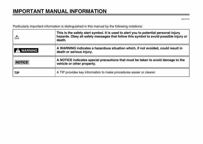
Particularly important information is distinguished in this manual by the following notations:
This is the safety alert symbol. It is used to alert you to potential personal injury hazards. Obey all safety messages that follow this symbol to avoid possible injury or death.
A WARNING indicates a hazardous situation which, if not avoided, could result in death or serious injury.
A NOTICE indicates special precautions that must be taken to avoid damage to the vehicle or other property.
A TIP provides key information to make procedures easier or clearer.
WARNING
NOTICE
TIP
E_1P7F8199E2.book Page 1 Tuesday, January 27, 2009 10:29 AM
IMPORTANT MANUAL INFORMATION
EAU37430
AT115S/AT115COWNER’S MANUAL
©2008 by Thai Yamaha Motor Co., Ltd.1st edition, October 2008
All rights reserved.Any reprinting or unauthorized usewithout the written permission of
Thai Yamaha Motor Co., Ltd.is expressly prohibited.
Printed in Thailand.
E_1P7F8199E2.book Page 2 Tuesday, January 27, 2009 10:29 AM
TABLE OF CONTENTSLOCATION OF IMPORTANT LABELS..............................................1-1
SAFETY INFORMATION ..................2-1Further safe-riding points ................2-5Helmets ...........................................2-6
DESCRIPTION ...................................3-1Left view .........................................3-1Right view .......................................3-2Controls and instruments ................3-3
INSTRUMENT AND CONTROL FUNCTIONS .......................................4-1
Main switch/steering lock ................4-1Indicator lights ...............................4-2Speedometer unit ...........................4-2Handlebar switches .........................4-2Front brake lever ............................4-3Rear brake lever .............................4-3Fuel tank cap ..................................4-4Fuel .................................................4-4Catalytic converter ..........................4-6Kickstarter .......................................4-6Seat ................................................4-7Convenience hook ..........................4-7Storage compartment .....................4-8
FOR YOUR SAFETY – PRE-OPERATION CHECKS ..............5-1
OPERATION AND IMPORTANT RIDING POINTS................................. 6-1
Starting a cold engine .................... 6-1Starting off ...................................... 6-2Acceleration and deceleration ........ 6-2Braking ............................................ 6-2Tips for reducing fuel
consumption ............................... 6-3Engine break-in .............................. 6-3Parking ........................................... 6-5General note .................................. 6-6
PERIODIC MAINTENANCE AND ADJUSTMENT ................................... 7-1
Owner’s tool kit ............................... 7-1Periodic maintenance chart for the
emission control system ............. 7-2General maintenance and
lubrication chart .......................... 7-3Removing and installing cowlings
and panels .................................. 7-6Checking the spark plug ................. 7-7Engine oil and oil strainer ............... 7-9Final transmission oil .................... 7-11Air filter and V-belt case air filter
elements ................................... 7-12Adjusting the carburetor ............... 7-15Adjusting the engine idling
speed ........................................ 7-15Adjusting the throttle cable free
play ........................................... 7-16Valve clearance ............................ 7-16
Tires ............................................. 7-17Wheels ......................................... 7-18Checking the front brake lever
free play .................................... 7-19Adjusting the rear brake lever
free play .................................... 7-19Checking the front brake pads
and rear brake shoes ............... 7-20Checking the brake fluid level ...... 7-21Changing the brake fluid .............. 7-22Checking the V-belt ..................... 7-22Checking and lubricating the
cables ....................................... 7-22Checking and lubricating the
throttle grip and cable ............... 7-23Lubricating the front and rear
brake levers............................... 7-23Checking and lubricating the
centerstand and sidestand ....... 7-24Checking the front fork ................. 7-24Checking the steering .................. 7-25Checking the wheel bearings ....... 7-26Battery ......................................... 7-26Replacing the fuse ....................... 7-28Replacing a headlight bulb .......... 7-29Replacing a front turn signal light
bulb ........................................... 7-30Replacing the tail/brake light bulb
or a rear turn signal light bulb ... 7-31Troubleshooting ........................... 7-32Troubleshooting charts ................ 7-33
E_1P7F8199E2.book Page 1 Tuesday, January 27, 2009 10:29 AM
TABLE OF CONTENTSMOTORCYCLE CARE AND STORAGE ..........................................8-1
Care ................................................8-1Storage ...........................................8-3
SPECIFICATIONS..............................9-1
CONSUMER INFORMATION...........10-1Identification numbers ..................10-1
E_1P7F8199E2.book Page 2 Tuesday, January 27, 2009 10:29 AM
LOCATION OF IMPORTANT LABELS
1-1
1
2
3
4
5
6
7
8
9
10
EAU10383
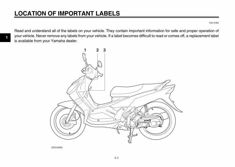
Read and understand all of the labels on your vehicle. They contain important information for safe and proper operation ofyour vehicle. Never remove any labels from your vehicle. If a label becomes difficult to read or comes off, a replacement labelis available from your Yamaha dealer.
2 31
ZAUU0265
1-LOCATION OF IMPORTANT LABELS
E_1P7F8199E2.book Page 1 Tuesday, January 27, 2009 10:29 AM
2-1
2
1- SAFETY INFORMATIONEAU10313
Be a Responsible OwnerAs the vehicle’s owner, you are respon-sible for the safe and proper operationof your motorcycle.Motorcycles are single-track vehicles.Their safe use and operation are de-pendent upon the use of proper ridingtechniques as well as the expertise ofthe operator. Every operator shouldknow the following requirements beforeriding this motorcycle.He or she should:
● Obtain thorough instructions froma competent source on all aspectsof motorcycle operation.
● Observe the warnings and mainte-nance requirements in this Own-er’s Manual.
● Obtain qualified training in safeand proper riding techniques.
● Obtain professional technical ser-vice as indicated in this Owner’sManual and/or when made neces-sary by mechanical conditions.
Safe RidingPerform the pre-operation checks eachtime you use the vehicle to make sure itis in safe operating condition. Failure toinspect or maintain the vehicle properlyincreases the possibility of an accidentor equipment damage. See page 5-1for a list of pre-operation checks.
● This motorcycle is designed tocarry the operator and a passen-ger.
● The failure of motorists to detectand recognize motorcycles in traf-fic is the predominating cause ofautomobile/motorcycle accidents.Many accidents have beencaused by an automobile driverwho did not see the motorcycle.Making yourself conspicuous ap-pears to be very effective in reduc-ing the chance of this type ofaccident.Therefore:• Wear a brightly colored jacket.• Use extra caution when you are
approaching and passingthrough intersections, since in-
tersections are the most likelyplaces for motorcycle accidentsto occur.
• Ride where other motorists cansee you. Avoid riding in anothermotorist’s blind spot.
● Many accidents involve inexperi-enced operators. In fact, many op-erators who have been involved inaccidents do not even have a cur-rent motorcycle license.• Make sure that you are qualified
and that you only lend your mo-torcycle to other qualified opera-tors.
• Know your skills and limits.Staying within your limits mayhelp you to avoid an accident.
• We recommend that you prac-tice riding your motorcyclewhere there is no traffic until youhave become thoroughly famil-iar with the motorcycle and all ofits controls.
● Many accidents have beencaused by error of the motorcycleoperator. A typical error made by
E_1P7F8199E2.book Page 1 Tuesday, January 27, 2009 10:29 AM
SAFETY INFORMATION
2-2
2
the operator is veering wide on aturn due to excessive speed or un-dercornering (insufficient lean an-gle for the speed).• Always obey the speed limit and
never travel faster than warrant-ed by road and traffic condi-tions.
• Always signal before turning orchanging lanes. Make sure thatother motorists can see you.
● The posture of the operator andpassenger is important for propercontrol.• The operator should keep both
hands on the handlebar andboth feet on the operator foot-rests during operation to main-tain control of the motorcycle.
• The passenger should alwayshold onto the operator, the seatstrap or grab bar, if equipped,with both hands and keep bothfeet on the passenger footrests.Never carry a passenger unlesshe or she can firmly place bothfeet on the passenger footrests.
● Never ride under the influence ofalcohol or other drugs.
Protective apparelThe majority of fatalities from motorcy-cle accidents are the result of head in-juries. The use of a safety helmet is thesingle most critical factor in the preven-tion or reduction of head injuries.
● Always wear an approved helmet.● Wear a face shield or goggles.
Wind in your unprotected eyescould contribute to an impairmentof vision that could delay seeing ahazard.
● The use of a jacket, heavy boots,trousers, gloves, etc., is effectivein preventing or reducing abra-sions or lacerations.
● Never wear loose-fitting clothes,otherwise they could catch on thecontrol levers, footrests, or wheelsand cause injury or an accident.
● Always wear protective clothingthat covers your legs, ankles, andfeet. The engine or exhaust sys-
tem become very hot during or af-ter operation and can causeburns.
● A passenger should also observethe above precautions.
Avoid Carbon Monoxide PoisoningAll engine exhaust contains carbonmonoxide, a deadly gas. Breathing car-bon monoxide can cause headaches,dizziness, drowsiness, nausea, confu-sion, and eventually death.Carbon Monoxide is a colorless, odor-less, tasteless gas which may bepresent even if you do not see or smellany engine exhaust. Deadly levels ofcarbon monoxide can collect rapidlyand you can quickly be overcome andunable to save yourself. Also, deadlylevels of carbon monoxide can lingerfor hours or days in enclosed or poorlyventilated areas. If you experience anysymptoms of carbon monoxide poison-ing, leave the area immediately, getfresh air, and SEEK MEDICAL TREAT-MENT.
E_1P7F8199E2.book Page 2 Tuesday, January 27, 2009 10:29 AM
SAFETY INFORMATION
2-3
2
● Do not run engine indoors. Even ifyou try to ventilate engine exhaustwith fans or open windows anddoors, carbon monoxide can rap-idly reach dangerous levels.
● Do not run engine in poorly venti-lated or partially enclosed areassuch as barns, garages, or car-ports.
● Do not run engine outdoors whereengine exhaust can be drawn intoa building through openings suchas windows and doors.
LoadingAdding accessories or cargo to yourmotorcycle can adversely affect stabili-ty and handling if the weight distributionof the motorcycle is changed. To avoidthe possibility of an accident, use ex-treme caution when adding cargo oraccessories to your motorcycle. Useextra care when riding a motorcyclethat has added cargo or accessories.Here, along with the information aboutaccessories below, are some general
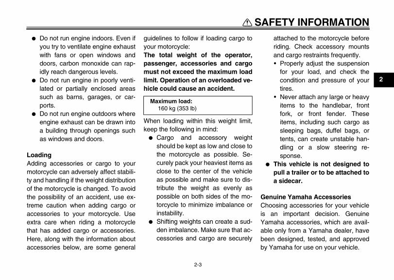
guidelines to follow if loading cargo toyour motorcycle:The total weight of the operator,passenger, accessories and cargomust not exceed the maximum loadlimit. Operation of an overloaded ve-hicle could cause an accident.
When loading within this weight limit,keep the following in mind:
● Cargo and accessory weightshould be kept as low and close tothe motorcycle as possible. Se-curely pack your heaviest items asclose to the center of the vehicleas possible and make sure to dis-tribute the weight as evenly aspossible on both sides of the mo-torcycle to minimize imbalance orinstability.
● Shifting weights can create a sud-den imbalance. Make sure that ac-cessories and cargo are securely
attached to the motorcycle beforeriding. Check accessory mountsand cargo restraints frequently.• Properly adjust the suspension
for your load, and check thecondition and pressure of yourtires.
• Never attach any large or heavyitems to the handlebar, frontfork, or front fender. Theseitems, including such cargo assleeping bags, duffel bags, ortents, can create unstable han-dling or a slow steering re-sponse.
● This vehicle is not designed topull a trailer or to be attached toa sidecar.
Genuine Yamaha AccessoriesChoosing accessories for your vehicleis an important decision. GenuineYamaha accessories, which are avail-able only from a Yamaha dealer, havebeen designed, tested, and approvedby Yamaha for use on your vehicle.
Maximum load: 160 kg (353 lb)
E_1P7F8199E2.book Page 3 Tuesday, January 27, 2009 10:29 AM
SAFETY INFORMATION
2-4
2
Many companies with no connection toYamaha manufacture parts and acces-sories or offer other modifications forYamaha vehicles. Yamaha is not in aposition to test the products that theseaftermarket companies produce.Therefore, Yamaha can neither en-dorse nor recommend the use of ac-cessories not sold by Yamaha ormodifications not specifically recom-mended by Yamaha, even if sold andinstalled by a Yamaha dealer.
Aftermarket Parts, Accessories, andModificationsWhile you may find aftermarket prod-ucts similar in design and quality togenuine Yamaha accessories, recog-nize that some aftermarket accessoriesor modifications are not suitable be-cause of potential safety hazards toyou or others. Installing aftermarketproducts or having other modificationsperformed to your vehicle that changeany of the vehicle’s design or operationcharacteristics can put you and othersat greater risk of serious injury or death.
You are responsible for injuries relatedto changes in the vehicle.Keep the following guidelines in mind,as well as those provided under “Load-ing” when mounting accessories.
● Never install accessories or carrycargo that would impair the perfor-mance of your motorcycle. Care-fully inspect the accessory beforeusing it to make sure that it doesnot in any way reduce groundclearance or cornering clearance,limit suspension travel, steeringtravel or control operation, or ob-scure lights or reflectors.• Accessories fitted to the handle-
bar or the front fork area cancreate instability due to improp-er weight distribution or aerody-namic changes. If accessoriesare added to the handlebar orfront fork area, they must be aslightweight as possible andshould be kept to a minimum.
• Bulky or large accessories mayseriously affect the stability ofthe motorcycle due to aerody-
namic effects. Wind may at-tempt to lift the motorcycle, orthe motorcycle may become un-stable in cross winds. These ac-cessories may also causeinstability when passing or be-ing passed by large vehicles.
• Certain accessories can dis-place the operator from his orher normal riding position. Thisimproper position limits the free-dom of movement of the opera-tor and may limit control ability,therefore, such accessories arenot recommended.
● Use caution when adding electri-cal accessories. If electrical acces-sories exceed the capacity of themotorcycle’s electrical system, anelectric failure could result, whichcould cause a dangerous loss oflights or engine power.
Aftermarket Tires and RimsThe tires and rims that came with yourmotorcycle were designed to match theperformance capabilities and to pro-
E_1P7F8199E2.book Page 4 Tuesday, January 27, 2009 10:29 AM
SAFETY INFORMATION
2-5
2
vide the best combination of handling,braking, and comfort. Other tires, rims,sizes, and combinations may not beappropriate. Refer to page 7-17 for tirespecifications and more information onreplacing your tires.
EAU10372
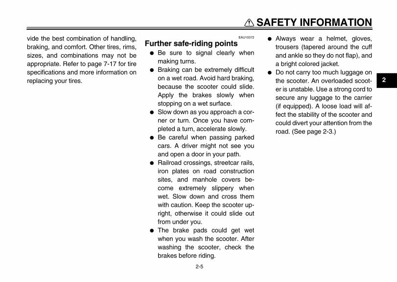
Further safe-riding points ● Be sure to signal clearly when
making turns.● Braking can be extremely difficult
on a wet road. Avoid hard braking,because the scooter could slide.Apply the brakes slowly whenstopping on a wet surface.
● Slow down as you approach a cor-ner or turn. Once you have com-pleted a turn, accelerate slowly.
● Be careful when passing parkedcars. A driver might not see youand open a door in your path.
● Railroad crossings, streetcar rails,iron plates on road constructionsites, and manhole covers be-come extremely slippery whenwet. Slow down and cross themwith caution. Keep the scooter up-right, otherwise it could slide outfrom under you.
● The brake pads could get wetwhen you wash the scooter. Afterwashing the scooter, check thebrakes before riding.
● Always wear a helmet, gloves,trousers (tapered around the cuffand ankle so they do not flap), anda bright colored jacket.
● Do not carry too much luggage onthe scooter. An overloaded scoot-er is unstable. Use a strong cord tosecure any luggage to the carrier(if equipped). A loose load will af-fect the stability of the scooter andcould divert your attention from theroad. (See page 2-3.)
E_1P7F8199E2.book Page 5 Tuesday, January 27, 2009 10:29 AM
SAFETY INFORMATION
2-6
2
EAUU0030
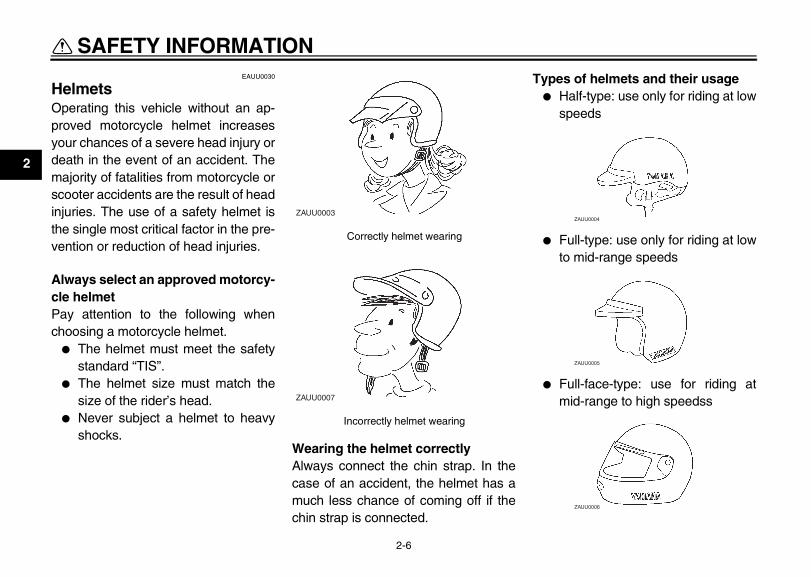
Helmets Operating this vehicle without an ap-proved motorcycle helmet increasesyour chances of a severe head injury ordeath in the event of an accident. Themajority of fatalities from motorcycle orscooter accidents are the result of headinjuries. The use of a safety helmet isthe single most critical factor in the pre-vention or reduction of head injuries.
Always select an approved motorcy-cle helmetPay attention to the following whenchoosing a motorcycle helmet.
● The helmet must meet the safetystandard “TIS”.
● The helmet size must match thesize of the rider’s head.
● Never subject a helmet to heavyshocks.
Wearing the helmet correctly Always connect the chin strap. In thecase of an accident, the helmet has amuch less chance of coming off if thechin strap is connected.
Types of helmets and their usage ● Half-type: use only for riding at low
speeds
● Full-type: use only for riding at lowto mid-range speeds
● Full-face-type: use for riding atmid-range to high speedss
Correctly helmet wearing
Incorrectly helmet wearing
ZAUU0003
ZAUU0007
ZAUU0004
ZAUU0005
ZAUU0006
E_1P7F8199E2.book Page 6 Tuesday, January 27, 2009 10:29 AM
DESCRIPTION
3-1
3
EAU10410
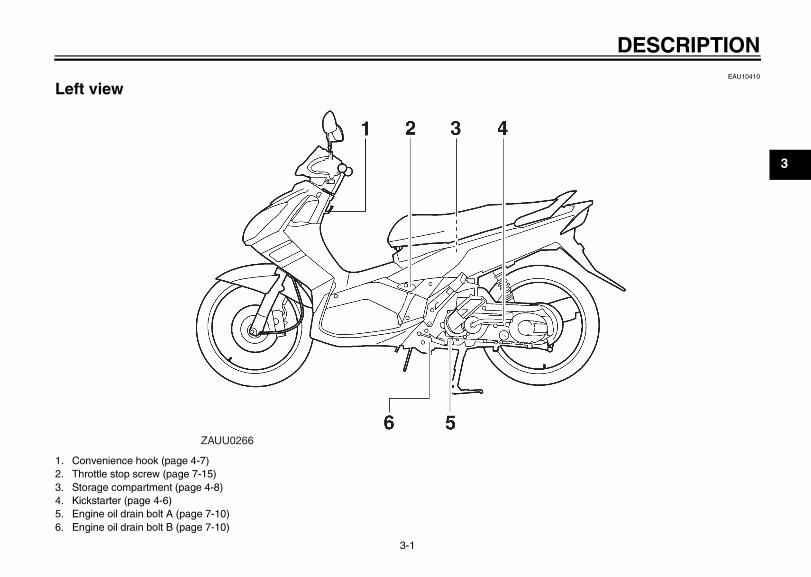
Left view
1. Convenience hook (page 4-7)2. Throttle stop screw (page 7-15)3. Storage compartment (page 4-8)4. Kickstarter (page 4-6)5. Engine oil drain bolt A (page 7-10)6. Engine oil drain bolt B (page 7-10)
ZAUU0266
1-DESCRIPTION
E_1P7F8199E2.book Page 1 Tuesday, January 27, 2009 10:29 AM
DESCRIPTION
3-2
3
EAU10420
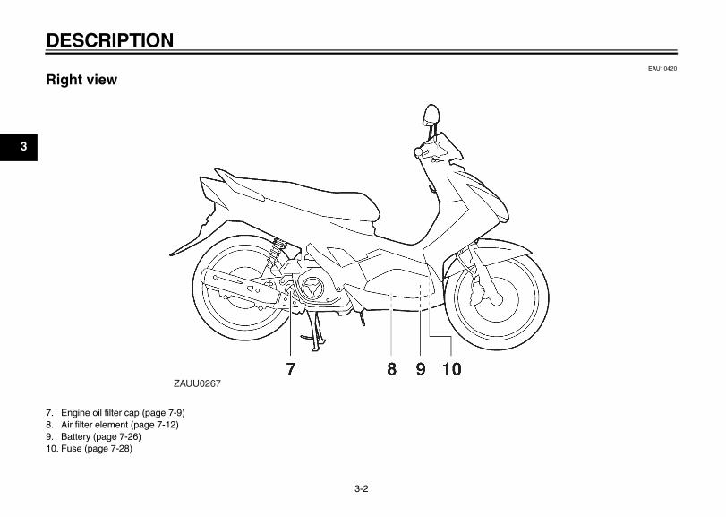
Right view
7. Engine oil filter cap (page 7-9)8. Air filter element (page 7-12)9. Battery (page 7-26)10. Fuse (page 7-28)
ZAUU0267
E_1P7F8199E2.book Page 2 Tuesday, January 27, 2009 10:29 AM
DESCRIPTION
3-3
3
EAU10430
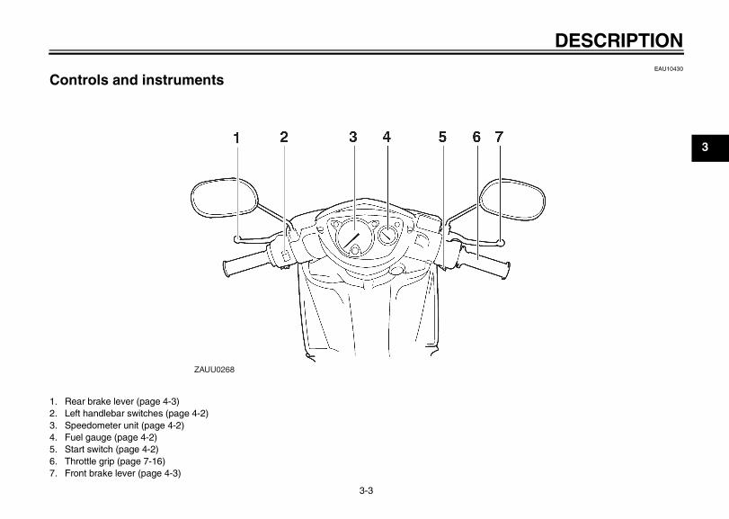
Controls and instruments
1. Rear brake lever (page 4-3)2. Left handlebar switches (page 4-2)3. Speedometer unit (page 4-2)4. Fuel gauge (page 4-2)5. Start switch (page 4-2)6. Throttle grip (page 7-16)7. Front brake lever (page 4-3)
ZAUU0268
E_1P7F8199E2.book Page 3 Tuesday, January 27, 2009 10:29 AM
INSTRUMENT AND CONTROL FUNCTIONS
4-1
4
EAU10460
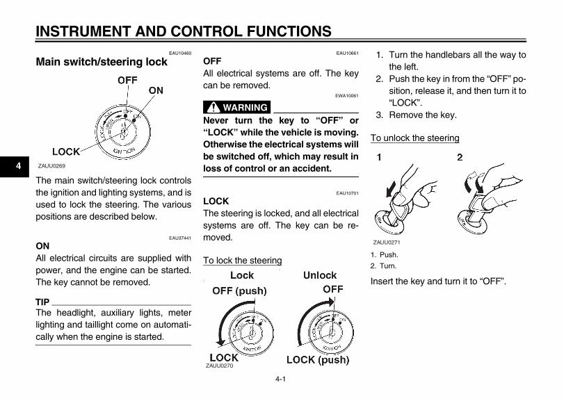
Main switch/steering lock
The main switch/steering lock controlsthe ignition and lighting systems, and isused to lock the steering. The variouspositions are described below.
EAU37441
ONAll electrical circuits are supplied withpower, and the engine can be started.The key cannot be removed.
TIP_
The headlight, auxiliary lights, meterlighting and taillight come on automati-cally when the engine is started. _
EAU10661
OFFAll electrical systems are off. The keycan be removed.
EWA10061
WARNING_
Never turn the key to “OFF” or“LOCK” while the vehicle is moving.Otherwise the electrical systems willbe switched off, which may result inloss of control or an accident. _
EAU10701
LOCKThe steering is locked, and all electricalsystems are off. The key can be re-moved.
To lock the steering
1. Turn the handlebars all the way tothe left.
2. Push the key in from the “OFF” po-sition, release it, and then turn it to“LOCK”.
3. Remove the key.
To unlock the steering
Insert the key and turn it to “OFF”.
ZAUU0269
ZAUU0270
1. Push.
2. Turn.
ZAUU0271
1-INSTRUMENT AND CONTROL FUNCTIONS
E_1P7F8199E2.book Page 1 Tuesday, January 27, 2009 10:29 AM
INSTRUMENT AND CONTROL FUNCTIONS
4-2
4
EAU10981
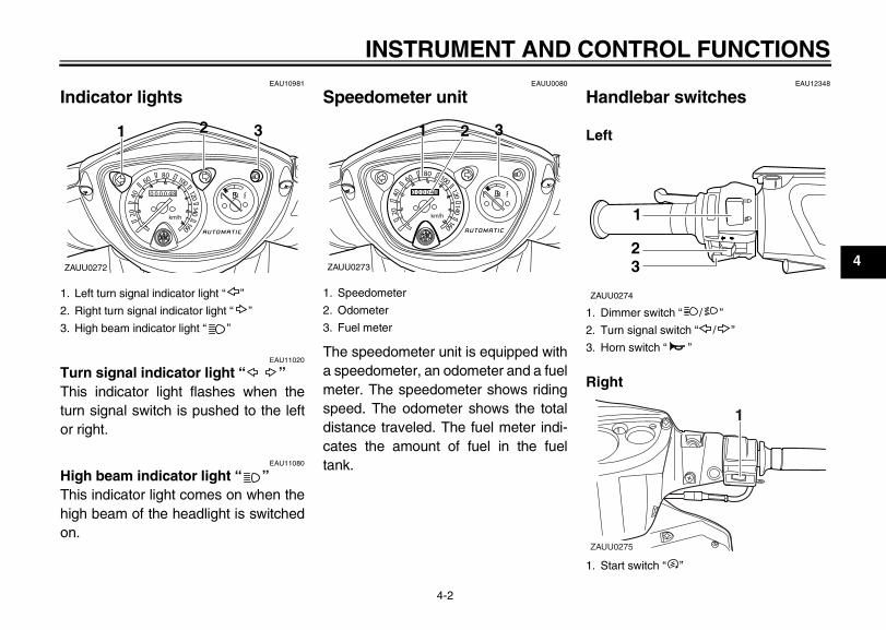
Indicator lights
EAU11020
Turn signal indicator light “ ” This indicator light flashes when theturn signal switch is pushed to the leftor right.
EAU11080
High beam indicator light “ ” This indicator light comes on when thehigh beam of the headlight is switchedon.
EAUU0080
Speedometer unit
The speedometer unit is equipped witha speedometer, an odometer and a fuelmeter. The speedometer shows ridingspeed. The odometer shows the totaldistance traveled. The fuel meter indi-cates the amount of fuel in the fueltank.
EAU12348
Handlebar switches
Left
Right
1. Left turn signal indicator light “ ”
2. Right turn signal indicator light “ ”
3. High beam indicator light “ ”
ZAUU0272
111 22 33
1. Speedometer
2. Odometer
3. Fuel meter
ZAUU0273
11 22 33
1. Dimmer switch “ / ”
2. Turn signal switch “ / ”
3. Horn switch “ ”
1. Start switch “ ”
ZAUU0274
11
2233
111
ZAUU0275
E_1P7F8199E2.book Page 2 Tuesday, January 27, 2009 10:29 AM
INSTRUMENT AND CONTROL FUNCTIONS
4-3
4
EAU12400
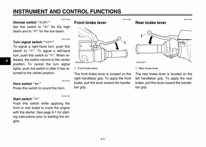
Dimmer switch “ / ”Set this switch to “ ” for the highbeam and to “ ” for the low beam.
EAU12460
Turn signal switch “ / ”To signal a right-hand turn, push thisswitch to “ ”. To signal a left-handturn, push this switch to “ ”. When re-leased, the switch returns to the centerposition. To cancel the turn signallights, push the switch in after it has re-turned to the center position.
EAU12500
Horn switch “ ” Press this switch to sound the horn.
EAUM1132
Start switch “ ” Push this switch while applying thefront or rear brake to crank the enginewith the starter. See page 6-1 for start-ing instructions prior to starting the en-gine.
EAU12900
Front brake lever
The front brake lever is located on theright handlebar grip. To apply the frontbrake, pull this lever toward the handle-bar grip.
EAU12950
Rear brake lever
The rear brake lever is located on theleft handlebar grip. To apply the rearbrake, pull this lever toward the handle-bar grip.
1. Front brake lever
ZAUU0276
11
1. Rear brake lever
ZAUU0277
11
E_1P7F8199E2.book Page 3 Tuesday, January 27, 2009 10:29 AM
INSTRUMENT AND CONTROL FUNCTIONS
4-4
4
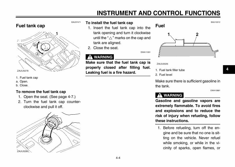
EAU37471
Fuel tank cap
To remove the fuel tank cap1. Open the seat. (See page 4-7.)2. Turn the fuel tank cap counter-
clockwise and pull it off.
To install the fuel tank cap1. Insert the fuel tank cap into the
tank opening and turn it clockwiseuntil the “ ” marks on the cap andtank are aligned.
2. Close the seat.EWA11091
WARNING_
Make sure that the fuel tank cap isproperly closed after filling fuel.Leaking fuel is a fire hazard. _
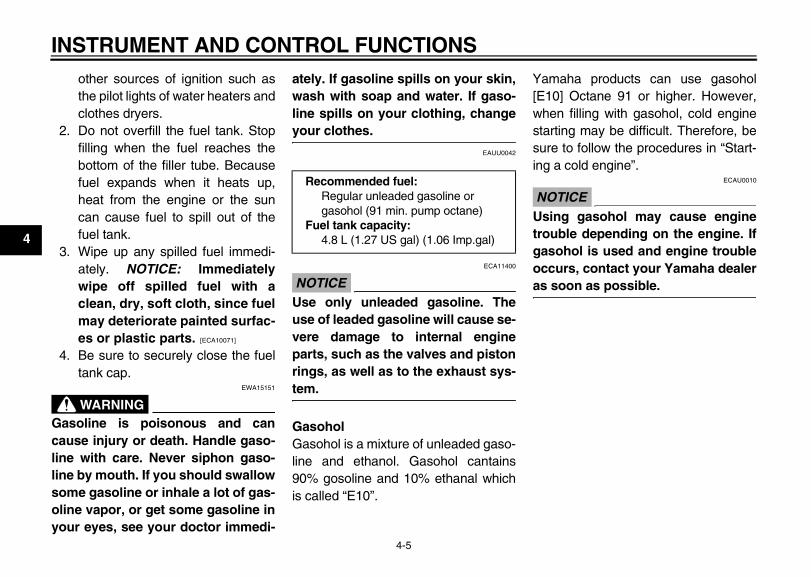
EAU13212
Fuel
Make sure there is sufficient gasoline inthe tank.
EWA10881
WARNING_
Gasoline and gasoline vapors areextremely flammable. To avoid firesand explosions and to reduce therisk of injury when refueling, followthese instructions. _
1. Before refueling, turn off the en-gine and be sure that no one is sit-ting on the vehicle. Never refuelwhile smoking, or while in the vi-cinity of sparks, open flames, or
1. Fuel tank capa. Open.b. Close.
ZAUU0278
ZAUU0280
1. Fuel tank filler tube
2. Fuel level
ZAUU0026
E_1P7F8199E2.book Page 4 Tuesday, January 27, 2009 10:29 AM
INSTRUMENT AND CONTROL FUNCTIONS
4-5
4
other sources of ignition such asthe pilot lights of water heaters andclothes dryers.
2. Do not overfill the fuel tank. Stopfilling when the fuel reaches thebottom of the filler tube. Becausefuel expands when it heats up,heat from the engine or the suncan cause fuel to spill out of thefuel tank.
3. Wipe up any spilled fuel immedi-ately. NOTICE: Immediatelywipe off spilled fuel with aclean, dry, soft cloth, since fuelmay deteriorate painted surfac-es or plastic parts. [ECA10071]
4. Be sure to securely close the fueltank cap.
EWA15151
WARNING_
Gasoline is poisonous and cancause injury or death. Handle gaso-line with care. Never siphon gaso-line by mouth. If you should swallowsome gasoline or inhale a lot of gas-oline vapor, or get some gasoline inyour eyes, see your doctor immedi-
ately. If gasoline spills on your skin,wash with soap and water. If gaso-line spills on your clothing, changeyour clothes. _
EAUU0042
ECA11400
NOTICE_
Use only unleaded gasoline. Theuse of leaded gasoline will cause se-vere damage to internal engineparts, such as the valves and pistonrings, as well as to the exhaust sys-tem. _
GasoholGasohol is a mixture of unleaded gaso-line and ethanol. Gasohol cantains90% gosoline and 10% ethanal whichis called “E10”.
Yamaha products can use gasohol[E10] Octane 91 or higher. However,when filling with gasohol, cold enginestarting may be difficult. Therefore, besure to follow the procedures in “Start-ing a cold engine”.
ECAU0010
NOTICE_
Using gasohol may cause enginetrouble depending on the engine. Ifgasohol is used and engine troubleoccurs, contact your Yamaha dealeras soon as possible. _
Recommended fuel: Regular unleaded gasoline or gasohol (91 min. pump octane)
Fuel tank capacity: 4.8 L (1.27 US gal) (1.06 Imp.gal)
E_1P7F8199E2.book Page 5 Tuesday, January 27, 2009 10:29 AM
INSTRUMENT AND CONTROL FUNCTIONS
4-6
4
EAU13433
Catalytic converter This model is equipped with a catalyticconverter in the exhaust system.
EWA10862
WARNING_
The exhaust system is hot after op-eration. To prevent a fire hazard orburns:
● Do not park the vehicle nearpossible fire hazards such asgrass or other materials thateasily burn.
● Park the vehicle in a placewhere pedestrians or childrenare not likely to touch the hotexhaust system.
● Make sure that the exhaust sys-tem has cooled down before do-ing any maintenance work.
● Do not allow the engine to idlemore than a few minutes. Longidling can cause a build-up ofheat.
_
ECA10701
NOTICE_
Use only unleaded gasoline. Theuse of leaded gasoline will causeunrepairable damage to the catalyticconverter. _
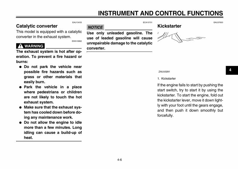
EAU37650
Kickstarter
If the engine fails to start by pushing thestart switch, try to start it by using thekickstarter. To start the engine, fold outthe kickstarter lever, move it down light-ly with your foot until the gears engage,and then push it down smoothly butforcefully.
1. Kickstarter
ZAUU0281
E_1P7F8199E2.book Page 6 Tuesday, January 27, 2009 10:29 AM
INSTRUMENT AND CONTROL FUNCTIONS
4-7
4
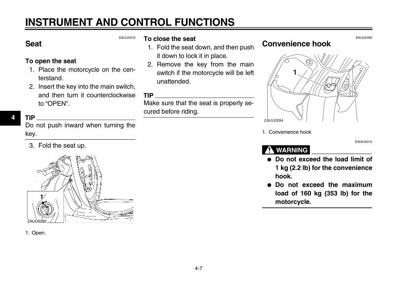
EAUU0370
Seat
To open the seat1. Place the motorcycle on the cen-
terstand. 2. Insert the key into the main switch,
and then turn it counterclockwiseto “OPEN”.
TIP_
Do not push inward when turning thekey. _
3. Fold the seat up.
To close the seat1. Fold the seat down, and then push
it down to lock it in place.2. Remove the key from the main
switch if the motorcycle will be leftunattended.
TIP_
Make sure that the seat is properly se-cured before riding. _
EAUU0390
Convenience hook
EWAU0010
WARNING_
● Do not exceed the load limit of1 kg (2.2 lb) for the conveniencehook.
● Do not exceed the maximumload of 160 kg (353 lb) for themotorcycle.
_
1. Open.
ZAUU0282
1. Convenience hook
ZAUU0284
11
E_1P7F8199E2.book Page 7 Tuesday, January 27, 2009 10:29 AM
INSTRUMENT AND CONTROL FUNCTIONS
4-8
4
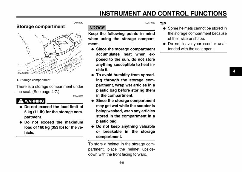
EAU14510
Storage compartment
There is a storage compartment underthe seat. (See page 4-7.)
EWA10960
WARNING_
● Do not exceed the load limit of5 kg (11 lb) for the storage com-partment.
● Do not exceed the maximumload of 160 kg (353 lb) for the ve-hicle.
_
ECA10080
NOTICE_
Keep the following points in mindwhen using the storage compart-ment.
● Since the storage compartmentaccumulates heat when ex-posed to the sun, do not storeanything susceptible to heat in-side it.
● To avoid humidity from spread-ing through the storage com-partment, wrap wet articles in aplastic bag before storing themin the compartment.
● Since the storage compartmentmay get wet while the scooter isbeing washed, wrap any articlesstored in the compartment in aplastic bag.
● Do not keep anything valuableor breakable in the storagecompartment.
_
To store a helmet in the storage com-partment, place the helmet upside-down with the front facing forward.
TIP_
● Some helmets cannot be stored inthe storage compartment becauseof their size or shape.
● Do not leave your scooter unat-tended with the seat open.
_
1. Storage compartment
ZAUU0283
E_1P7F8199E2.book Page 8 Tuesday, January 27, 2009 10:29 AM
FOR YOUR SAFETY – PRE-OPERATION CHECKS
5-1
5
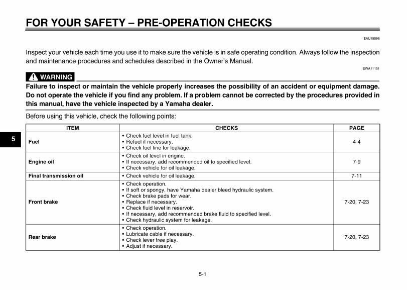
EAU15596
Inspect your vehicle each time you use it to make sure the vehicle is in safe operating condition. Always follow the inspectionand maintenance procedures and schedules described in the Owner’s Manual.
EWA11151
WARNING_
Failure to inspect or maintain the vehicle properly increases the possibility of an accident or equipment damage.Do not operate the vehicle if you find any problem. If a problem cannot be corrected by the procedures provided inthis manual, have the vehicle inspected by a Yamaha dealer._
Before using this vehicle, check the following points:
ITEM CHECKS PAGE
Fuel• Check fuel level in fuel tank.• Refuel if necessary.• Check fuel line for leakage.
4-4
Engine oil• Check oil level in engine.• If necessary, add recommended oil to specified level.• Check vehicle for oil leakage.
7-9
Final transmission oil • Check vehicle for oil leakage. 7-11
Front brake
• Check operation.• If soft or spongy, have Yamaha dealer bleed hydraulic system.• Check brake pads for wear.• Replace if necessary.• Check fluid level in reservoir.• If necessary, add recommended brake fluid to specified level.• Check hydraulic system for leakage.
7-20, 7-23
Rear brake
• Check operation.• Lubricate cable if necessary.• Check lever free play.• Adjust if necessary.
7-20, 7-23
1-FOR YOUR SAFETY – PRE-OPERATION CHECKS
E_1P7F8199E2.book Page 1 Tuesday, January 27, 2009 10:29 AM
FOR YOUR SAFETY – PRE-OPERATION CHECKS
5-2
5
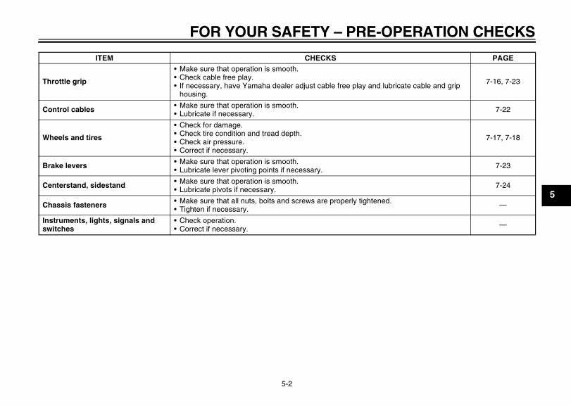
Throttle grip
• Make sure that operation is smooth.• Check cable free play.• If necessary, have Yamaha dealer adjust cable free play and lubricate cable and grip
housing.
7-16, 7-23
Control cables • Make sure that operation is smooth.• Lubricate if necessary. 7-22
Wheels and tires
• Check for damage.• Check tire condition and tread depth.• Check air pressure.• Correct if necessary.
7-17, 7-18
Brake levers • Make sure that operation is smooth.• Lubricate lever pivoting points if necessary. 7-23
Centerstand, sidestand • Make sure that operation is smooth.• Lubricate pivots if necessary. 7-24
Chassis fasteners • Make sure that all nuts, bolts and screws are properly tightened.• Tighten if necessary. —
Instruments, lights, signals and switches
• Check operation.• Correct if necessary. —
ITEM CHECKS PAGE
E_1P7F8199E2.book Page 2 Tuesday, January 27, 2009 10:29 AM
OPERATION AND IMPORTANT RIDING POINTS
6-1
6
EAU15951
Read the Owner’s Manual carefully tobecome familiar with all controls. Ifthere is a control or function you do notunderstand, ask your Yamaha dealer.
EWA10271
WARNING_
Failure to familiarize yourself withthe controls can lead to loss of con-trol, which could cause an accidentor injury. _
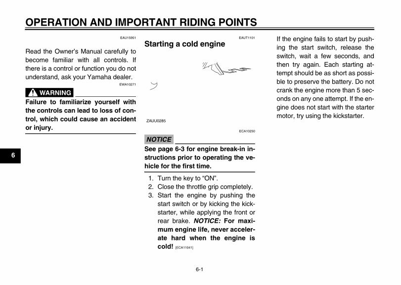
EAUT1101
Starting a cold engine
ECA10250
NOTICE_
See page 6-3 for engine break-in in-structions prior to operating the ve-hicle for the first time. _
1. Turn the key to “ON”.2. Close the throttle grip completely.3. Start the engine by pushing the
start switch or by kicking the kick-starter, while applying the front orrear brake. NOTICE: For maxi-mum engine life, never acceler-ate hard when the engine iscold! [ECA11041]
If the engine fails to start by push-ing the start switch, release theswitch, wait a few seconds, andthen try again. Each starting at-tempt should be as short as possi-ble to preserve the battery. Do notcrank the engine more than 5 sec-onds on any one attempt. If the en-gine does not start with the startermotor, try using the kickstarter.
ZAUU0285
1-OPERATION AND IMPORTANT RIDING POINTS
E_1P7F8199E2.book Page 1 Tuesday, January 27, 2009 10:29 AM
OPERATION AND IMPORTANT RIDING POINTS
6-2
6
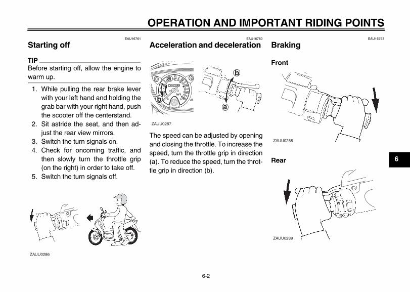
EAU16761
Starting off
TIP_
Before starting off, allow the engine towarm up. _
1. While pulling the rear brake leverwith your left hand and holding thegrab bar with your right hand, pushthe scooter off the centerstand.
2. Sit astride the seat, and then ad-just the rear view mirrors.
3. Switch the turn signals on.4. Check for oncoming traffic, and
then slowly turn the throttle grip(on the right) in order to take off.
5. Switch the turn signals off.
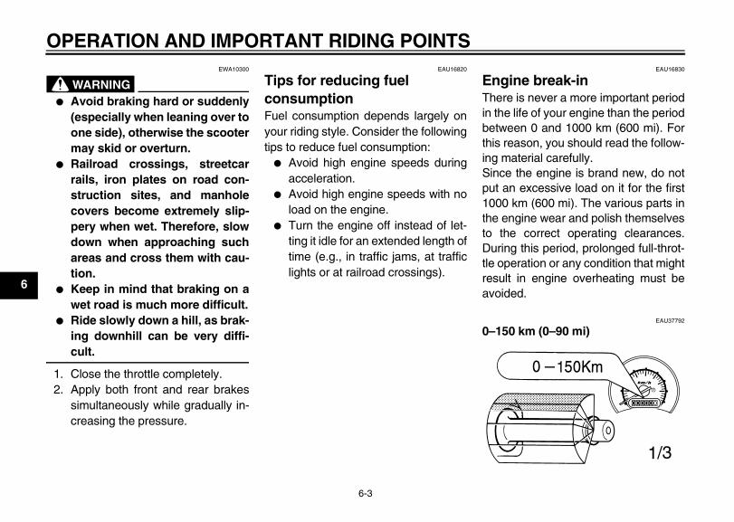
EAU16780
Acceleration and deceleration
The speed can be adjusted by openingand closing the throttle. To increase thespeed, turn the throttle grip in direction(a). To reduce the speed, turn the throt-tle grip in direction (b).
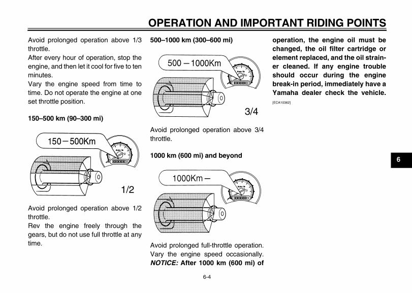
EAU16793
Braking
Front
Rear
ZAUU0286
AU
ZAUU0287
b
ab
a
ZAUU0288
ZAUU0289
E_1P7F8199E2.book Page 2 Tuesday, January 27, 2009 10:29 AM
OPERATION AND IMPORTANT RIDING POINTS
6-3
6
EWA10300
WARNING_
● Avoid braking hard or suddenly(especially when leaning over toone side), otherwise the scootermay skid or overturn.
● Railroad crossings, streetcarrails, iron plates on road con-struction sites, and manholecovers become extremely slip-pery when wet. Therefore, slowdown when approaching suchareas and cross them with cau-tion.
● Keep in mind that braking on awet road is much more difficult.
● Ride slowly down a hill, as brak-ing downhill can be very diffi-cult.
_
1. Close the throttle completely.2. Apply both front and rear brakes
simultaneously while gradually in-creasing the pressure.
EAU16820
Tips for reducing fuel consumption Fuel consumption depends largely onyour riding style. Consider the followingtips to reduce fuel consumption:
● Avoid high engine speeds duringacceleration.
● Avoid high engine speeds with noload on the engine.
● Turn the engine off instead of let-ting it idle for an extended length oftime (e.g., in traffic jams, at trafficlights or at railroad crossings).
EAU16830
Engine break-in There is never a more important periodin the life of your engine than the periodbetween 0 and 1000 km (600 mi). Forthis reason, you should read the follow-ing material carefully.Since the engine is brand new, do notput an excessive load on it for the first1000 km (600 mi). The various parts inthe engine wear and polish themselvesto the correct operating clearances.During this period, prolonged full-throt-tle operation or any condition that mightresult in engine overheating must beavoided.
EAU37792
0–150 km (0–90 mi)
E_1P7F8199E2.book Page 3 Tuesday, January 27, 2009 10:29 AM
OPERATION AND IMPORTANT RIDING POINTS
6-4
6
Avoid prolonged operation above 1/3throttle.After every hour of operation, stop theengine, and then let it cool for five to tenminutes.Vary the engine speed from time totime. Do not operate the engine at oneset throttle position.
150–500 km (90–300 mi)
Avoid prolonged operation above 1/2throttle.Rev the engine freely through thegears, but do not use full throttle at anytime.
500–1000 km (300–600 mi)
Avoid prolonged operation above 3/4throttle.
1000 km (600 mi) and beyond
Avoid prolonged full-throttle operation.Vary the engine speed occasionally.NOTICE: After 1000 km (600 mi) of
operation, the engine oil must bechanged, the oil filter cartridge orelement replaced, and the oil strain-er cleaned. If any engine troubleshould occur during the enginebreak-in period, immediately have aYamaha dealer check the vehicle.[ECA10362]
E_1P7F8199E2.book Page 4 Tuesday, January 27, 2009 10:29 AM
OPERATION AND IMPORTANT RIDING POINTS
6-5
6
EAU17213
Parking When parking, stop the engine, andthen remove the key from the mainswitch.
EWA10311
WARNING_
● Since the engine and exhaustsystem can become very hot,park in a place where pedestri-ans or children are not likely totouch them and be burned.
● Do not park on a slope or onsoft ground, otherwise the vehi-cle may overturn, increasing therisk of a fuel leak and fire.
● Do not park near grass or otherflammable materials whichmight catch fire.
_
E_1P7F8199E2.book Page 5 Tuesday, January 27, 2009 10:29 AM
OPERATION AND IMPORTANT RIDING POINTS
6-6
6
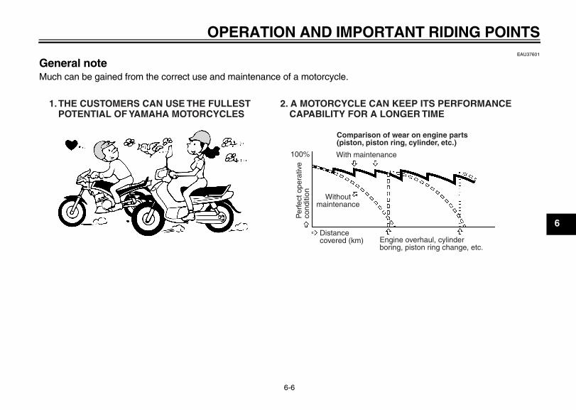
EAU37601
General note Much can be gained from the correct use and maintenance of a motorcycle.
1. THE CUSTOMERS CAN USE THE FULLESTPOTENTIAL OF YAMAHA MOTORCYCLES
2. A MOTORCYCLE CAN KEEP ITS PERFORMANCECAPABILITY FOR A LONGER TIME
Comparison of wear on engine parts(piston, piston ring, cylinder, etc.)
100%
Per
fect
ope
rativ
eco
nditi
on Withoutmaintenance
Distancecovered (km) Engine overhaul, cylinder
boring, piston ring change, etc.
With maintenance
E_1P7F8199E2.book Page 6 Tuesday, January 27, 2009 10:29 AM
OPERATION AND IMPORTANT RIDING POINTS
6-7
6
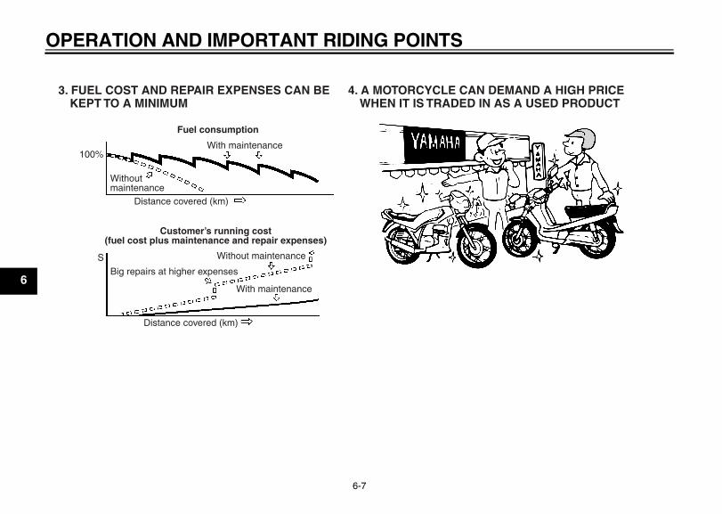
3. FUEL COST AND REPAIR EXPENSES CAN BEKEPT TO A MINIMUM
4. A MOTORCYCLE CAN DEMAND A HIGH PRICEWHEN IT IS TRADED IN AS A USED PRODUCT
Fuel consumption
100%
Withoutmaintenance
Distance covered (km)
With maintenance
Customer’s running cost(fuel cost plus maintenance and repair expenses)
Without maintenance
With maintenance
Big repairs at higher expenses
Distance covered (km)
S
E_1P7F8199E2.book Page 7 Tuesday, January 27, 2009 10:29 AM
PERIODIC MAINTENANCE AND ADJUSTMENT
7-1
7
EAU17241
Periodic inspection, adjustment, andlubrication will keep your vehicle in thesafest and most efficient condition pos-sible. Safety is an obligation of the vehi-cle owner/operator. The mostimportant points of vehicle inspection,adjustment, and lubrication are ex-plained on the following pages.The intervals given in the periodicmaintenance and lubrication chartshould be simply considered as a gen-eral guide under normal riding condi-tions. However, depending on theweather, terrain, geographical location,and individual use, the maintenance in-tervals may need to be shortened.
EWA10321
WARNING_
Failure to properly maintain the ve-hicle or performing maintenance ac-tivities incorrectly may increaseyour risk of injury or death duringservice or while using the vehicle. Ifyou are not familiar with vehicle ser-
vice, have a Yamaha dealer performservice. _
EWA15121
WARNING_
Turn off the engine when performingmaintenance unless otherwisespecified.
● A running engine has movingparts that can catch on bodyparts or clothing and electricalparts that can cause shocks orfires.
● Running the engine while ser-vicing can lead to eye injury,burns, fire, or carbon monoxidepoisoning – possibly leading todeath. See page 2-2 for more in-formation about carbon monox-ide.
_
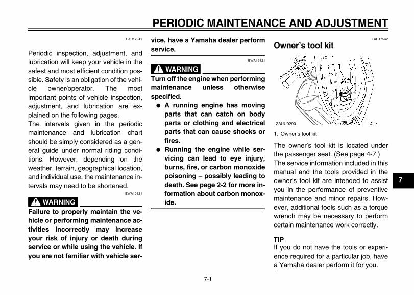
EAU17542
Owner’s tool kit
The owner’s tool kit is located underthe passenger seat. (See page 4-7.)The service information included in thismanual and the tools provided in theowner’s tool kit are intended to assistyou in the performance of preventivemaintenance and minor repairs. How-ever, additional tools such as a torquewrench may be necessary to performcertain maintenance work correctly.
TIP_
If you do not have the tools or experi-ence required for a particular job, havea Yamaha dealer perform it for you. _
1. Owner’s tool kit
ZAUU0290
1-PERIODIC MAINTENANCE AND ADJUSTMENT
E_1P7F8199E2.book Page 1 Tuesday, January 27, 2009 10:29 AM
PERIODIC MAINTENANCE AND ADJUSTMENT
7-2
7
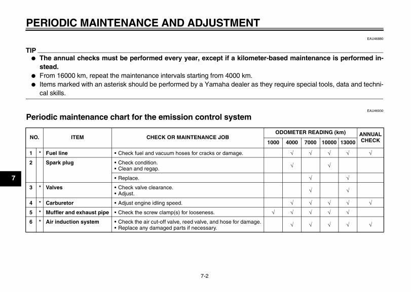
EAU46880
TIP_
● The annual checks must be performed every year, except if a kilometer-based maintenance is performed in-stead.
● From 16000 km, repeat the maintenance intervals starting from 4000 km.● Items marked with an asterisk should be performed by a Yamaha dealer as they require special tools, data and techni-
cal skills. _
EAU46930
Periodic maintenance chart for the emission control system
NO. ITEM CHECK OR MAINTENANCE JOBODOMETER READING (km) ANNUAL
CHECK1000 4000 7000 10000 13000
1 * Fuel line • Check fuel and vacuum hoses for cracks or damage. √ √ √ √ √
2 Spark plug • Check condition.• Clean and regap. √ √
• Replace. √ √
3 * Valves • Check valve clearance.• Adjust. √ √
4 * Carburetor • Adjust engine idling speed. √ √ √ √ √
5 * Muffler and exhaust pipe • Check the screw clamp(s) for looseness. √ √ √ √ √
6 * Air induction system • Check the air cut-off valve, reed valve, and hose for damage.• Replace any damaged parts if necessary. √ √ √ √ √
E_1P7F8199E2.book Page 2 Tuesday, January 27, 2009 10:29 AM
PERIODIC MAINTENANCE AND ADJUSTMENT
7-3
7
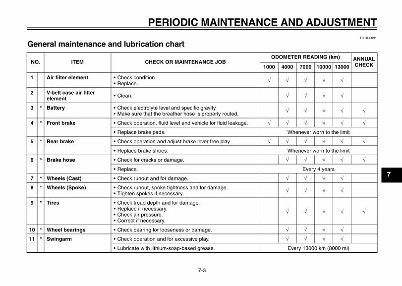
EAUU0091
General maintenance and lubrication chart
NO. ITEM CHECK OR MAINTENANCE JOBODOMETER READING (km) ANNUAL
CHECK1000 4000 7000 10000 13000
1 Air filter element • Check condition.• Replace. √ √ √ √ √
2 V-belt case air filter element • Clean. √ √ √ √
3 * Battery • Check electrolyte level and specific gravity.• Make sure that the breather hose is properly routed. √ √ √ √ √
4 * Front brake • Check operation, fluid level and vehicle for fluid leakage. √ √ √ √ √ √
• Replace brake pads. Whenever worn to the limit
5 * Rear brake • Check operation and adjust brake lever free play. √ √ √ √ √ √
• Replace brake shoes. Whenever worn to the limit
6 * Brake hose • Check for cracks or damage. √ √ √ √ √
• Replace. Every 4 years
7 * Wheels (Cast) • Check runout and for damage. √ √ √ √
8 * Wheels (Spoke) • Check runout, spoke tightness and for damage.• Tighten spokes if necessary. √ √ √ √
9 * Tires • Check tread depth and for damage.• Replace if necessary.• Check air pressure.• Correct if necessary.
√ √ √ √ √
10 * Wheel bearings • Check bearing for looseness or damage. √ √ √ √
11 * Swingarm • Check operation and for excessive play. √ √ √ √
• Lubricate with lithium-soap-based grease. Every 13000 km (8000 mi)
E_1P7F8199E2.book Page 3 Tuesday, January 27, 2009 10:29 AM
PERIODIC MAINTENANCE AND ADJUSTMENT
7-4
7
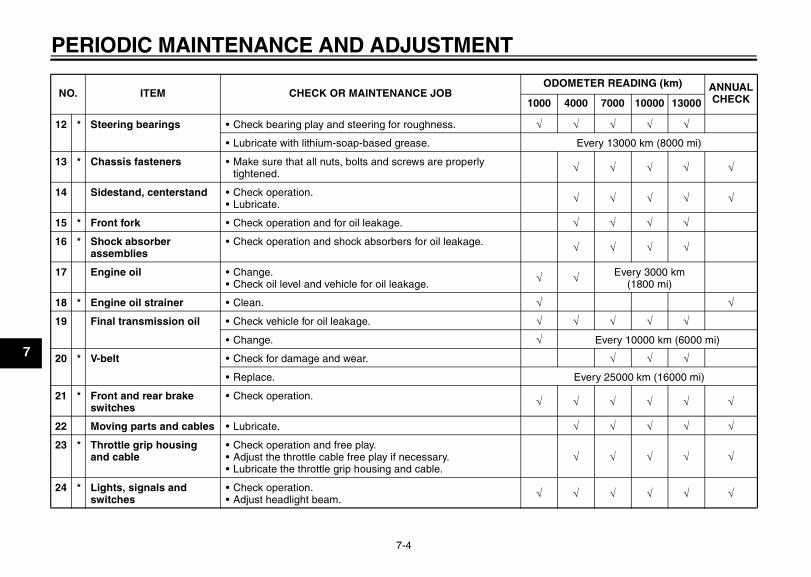
12 * Steering bearings • Check bearing play and steering for roughness. √ √ √ √ √
• Lubricate with lithium-soap-based grease. Every 13000 km (8000 mi)
13 * Chassis fasteners • Make sure that all nuts, bolts and screws are properly tightened. √ √ √ √ √
14 Sidestand, centerstand • Check operation.• Lubricate. √ √ √ √ √
15 * Front fork • Check operation and for oil leakage. √ √ √ √
16 * Shock absorber assemblies
• Check operation and shock absorbers for oil leakage. √ √ √ √
17 Engine oil • Change.• Check oil level and vehicle for oil leakage. √ √ Every 3000 km
(1800 mi)
18 * Engine oil strainer • Clean. √ √
19 Final transmission oil • Check vehicle for oil leakage. √ √ √ √ √
• Change. √ Every 10000 km (6000 mi)
20 * V-belt • Check for damage and wear. √ √ √
• Replace. Every 25000 km (16000 mi)
21 * Front and rear brake switches
• Check operation. √ √ √ √ √ √
22 Moving parts and cables • Lubricate. √ √ √ √ √
23 * Throttle grip housing and cable
• Check operation and free play.• Adjust the throttle cable free play if necessary.• Lubricate the throttle grip housing and cable.
√ √ √ √ √
24 * Lights, signals and switches
• Check operation.• Adjust headlight beam. √ √ √ √ √ √
NO. ITEM CHECK OR MAINTENANCE JOBODOMETER READING (km) ANNUAL
CHECK1000 4000 7000 10000 13000
E_1P7F8199E2.book Page 4 Tuesday, January 27, 2009 10:29 AM
PERIODIC MAINTENANCE AND ADJUSTMENT
7-5
7
EAU18660
TIP_
● The air filter needs more frequent service if you are riding in unusually wet or dusty areas.● Hydraulic brake service
• Regularly check and, if necessary, correct the brake fluid level.• Every two years replace the internal components of the brake master cylinder and caliper, and change the brake fluid.• Replace the brake hoses every four years and if cracked or damaged.
_
E_1P7F8199E2.book Page 5 Tuesday, January 27, 2009 10:29 AM
PERIODIC MAINTENANCE AND ADJUSTMENT
7-6
7
EAU18712
Removing and installing cowlings and panels
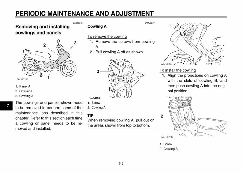
The cowlings and panels shown needto be removed to perform some of themaintenance jobs described in thischapter. Refer to this section each timea cowling or panel needs to be re-moved and installed.
EAUU0270
Cowling A
To remove the cowling1. Remove the screws from cowling
A.2. Pull cowling A off as shown.
TIP_
When removing cowling A, pull out onthe areas shown from top to bottom. _
To install the cowling1. Align the projections on cowling A
with the slots of cowling B, andthen push cowling A into the origi-nal position.
1. Panel A
2. Cowling B
3. Cowling A
ZAUU0291
1. Screw
2. Cowling A
ZA
1. Screw
2. Cowling B
ZAUU0294
ZAUU0293
22 11
11
E_1P7F8199E2.book Page 6 Tuesday, January 27, 2009 10:29 AM
PERIODIC MAINTENANCE AND ADJUSTMENT
7-7
7
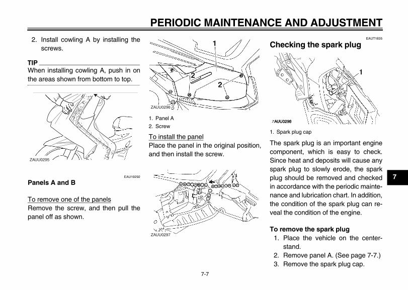
2. Install cowling A by installing thescrews.
TIP_
When installing cowling A, push in onthe areas shown from bottom to top. _
EAU19292
Panels A and B
To remove one of the panelsRemove the screw, and then pull thepanel off as shown.
To install the panelPlace the panel in the original position,and then install the screw.
EAUT1835
Checking the spark plug
The spark plug is an important enginecomponent, which is easy to check.Since heat and deposits will cause anyspark plug to slowly erode, the sparkplug should be removed and checkedin accordance with the periodic mainte-nance and lubrication chart. In addition,the condition of the spark plug can re-veal the condition of the engine.
To remove the spark plug1. Place the vehicle on the center-
stand.2. Remove panel A. (See page 7-7.)3. Remove the spark plug cap.
ZAUU0295
1. Panel A
2. Screw
ZAUU0296
ZAUU0297
1. Spark plug cap
ZA
E_1P7F8199E2.book Page 7 Tuesday, January 27, 2009 10:29 AM
PERIODIC MAINTENANCE AND ADJUSTMENT
7-8
7
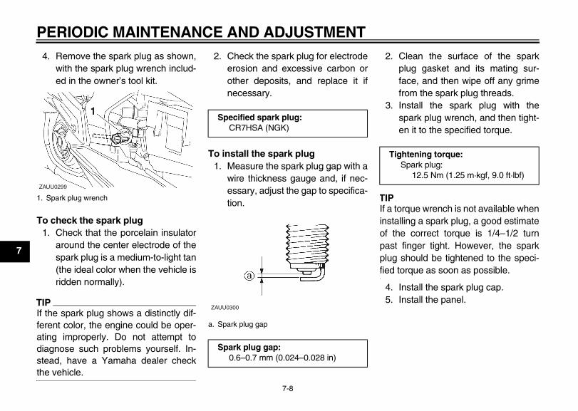
4. Remove the spark plug as shown,with the spark plug wrench includ-ed in the owner’s tool kit.
To check the spark plug1. Check that the porcelain insulator
around the center electrode of thespark plug is a medium-to-light tan(the ideal color when the vehicle isridden normally).
TIP_
If the spark plug shows a distinctly dif-ferent color, the engine could be oper-ating improperly. Do not attempt todiagnose such problems yourself. In-stead, have a Yamaha dealer checkthe vehicle. _
2. Check the spark plug for electrodeerosion and excessive carbon orother deposits, and replace it ifnecessary.
To install the spark plug1. Measure the spark plug gap with a
wire thickness gauge and, if nec-essary, adjust the gap to specifica-tion.
2. Clean the surface of the sparkplug gasket and its mating sur-face, and then wipe off any grimefrom the spark plug threads.
3. Install the spark plug with thespark plug wrench, and then tight-en it to the specified torque.
TIP_
If a torque wrench is not available wheninstalling a spark plug, a good estimateof the correct torque is 1/4–1/2 turnpast finger tight. However, the sparkplug should be tightened to the speci-fied torque as soon as possible. _
4. Install the spark plug cap.5. Install the panel.
1. Spark plug wrench
ZAUU0299
Specified spark plug:CR7HSA (NGK)
a. Spark plug gap
Spark plug gap:0.6–0.7 mm (0.024–0.028 in)
ZAUU0300
Tightening torque:Spark plug:
12.5 Nm (1.25 m·kgf, 9.0 ft·lbf)
E_1P7F8199E2.book Page 8 Tuesday, January 27, 2009 10:29 AM
PERIODIC MAINTENANCE AND ADJUSTMENT
7-9
7
EAUU0341
Engine oil and oil strainer The engine oil level should be checkedbefore each ride. In addition, the oilmust be changed and the oil strainercleaned at the intervals specified in theperiodic maintenance and lubricationchart.
To check the engine oil level1. Place the vehicle on the center-
stand. A slight tilt to the side canresult in a false reading.
2. Start the engine, warm it up forseveral minutes, and then turn itoff.
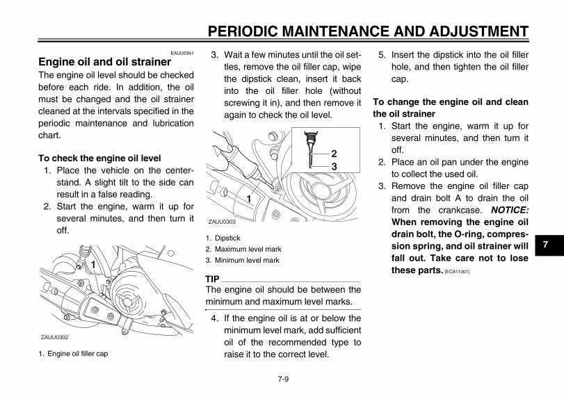
3. Wait a few minutes until the oil set-tles, remove the oil filler cap, wipethe dipstick clean, insert it backinto the oil filler hole (withoutscrewing it in), and then remove itagain to check the oil level.
TIP_
The engine oil should be between theminimum and maximum level marks. _
4. If the engine oil is at or below theminimum level mark, add sufficientoil of the recommended type toraise it to the correct level.
5. Insert the dipstick into the oil fillerhole, and then tighten the oil fillercap.
To change the engine oil and cleanthe oil strainer
1. Start the engine, warm it up forseveral minutes, and then turn itoff.
2. Place an oil pan under the engineto collect the used oil.
3. Remove the engine oil filler capand drain bolt A to drain the oilfrom the crankcase. NOTICE:When removing the engine oildrain bolt, the O-ring, compres-sion spring, and oil strainer willfall out. Take care not to losethese parts. [ECA11001]
1. Engine oil filler cap
ZAUU0302
111
1. Dipstick
2. Maximum level mark
3. Minimum level mark
ZAUU0303
222
11
33
E_1P7F8199E2.book Page 9 Tuesday, January 27, 2009 10:29 AM
PERIODIC MAINTENANCE AND ADJUSTMENT
7-10
7
TIP_
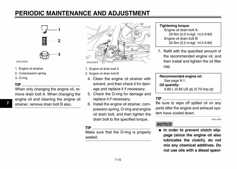
When only changing the engine oil, re-move drain bolt A. When changing theengine oil and cleaning the engine oilstrainer, remove drain bolt B also. _
4. Clean the engine oil strainer withsolvent, and then check it for dam-age and replace it if necessary.
5. Check the O-ring for damage andreplace it if necessary.
6. Install the engine oil strainer, com-pression spring, O-ring and engineoil drain bolt, and then tighten thedrain bolt to the specified torque.
TIP_
Make sure that the O-ring is properlyseated. _
7. Refill with the specified amount ofthe recommended engine oil, andthen install and tighten the oil fillercap.
TIP_
Be sure to wipe off spilled oil on anyparts after the engine and exhaust sys-tem have cooled down. _
ECA11620
NOTICE_
● In order to prevent clutch slip-page (since the engine oil alsolubricates the clutch), do notmix any chemical additives. Donot use oils with a diesel speci-
1. Engine oil strainer
2. Compression spring
3. O-ring
ZAUU0056
1. Engine oil drain bolt A
2. Engine oil drain bolt B
11 22
ZAUU0304
Tightening torque: Engine oil drain bolt A:
20 Nm (2.0 m·kgf, 14.5 ft·lbf) Engine oil drain bolt B:
20 Nm (2.0 m·kgf, 14.5 ft·lbf)
Recommended engine oil: See page 9-1.
Oil quantity: 0.80 L (0.85 US qt) (0.70 Imp.qt)
E_1P7F8199E2.book Page 10 Tuesday, January 27, 2009 10:29 AM
PERIODIC MAINTENANCE AND ADJUSTMENT
7-11
7
fication of “CD” or oils of ahigher quality than specified. Inaddition, do not use oils labeled“ENERGY CONSERVING II” orhigher.
● Make sure that no foreign mate-rial enters the crankcase.
_
8. Start the engine, and then let it idlefor several minutes while checkingit for oil leakage. If oil is leaking,immediately turn the engine offand check for the cause.
9. Turn the engine off, and thencheck the oil level and correct it ifnecessary.
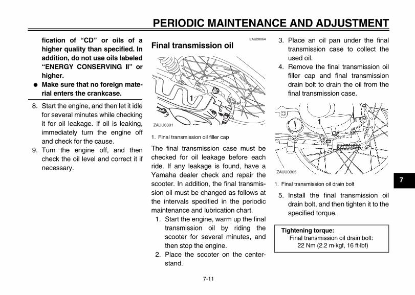
EAU20064
Final transmission oil
The final transmission case must bechecked for oil leakage before eachride. If any leakage is found, have aYamaha dealer check and repair thescooter. In addition, the final transmis-sion oil must be changed as follows atthe intervals specified in the periodicmaintenance and lubrication chart.
1. Start the engine, warm up the finaltransmission oil by riding thescooter for several minutes, andthen stop the engine.
2. Place the scooter on the center-stand.
3. Place an oil pan under the finaltransmission case to collect theused oil.
4. Remove the final transmission oilfiller cap and final transmissiondrain bolt to drain the oil from thefinal transmission case.
5. Install the final transmission oildrain bolt, and then tighten it to thespecified torque.
1. Final transmission oil filler cap
ZAUU0301
11
1. Final transmission oil drain bolt
Tightening torque:Final transmission oil drain bolt:
22 Nm (2.2 m·kgf, 16 ft·lbf)
ZAUU0305
E_1P7F8199E2.book Page 11 Tuesday, January 27, 2009 10:29 AM
PERIODIC MAINTENANCE AND ADJUSTMENT
7-12
7
6. Refill with the specified amount ofthe recommended final transmis-sion oil, and then install and tight-en the oil filler cap. WARNING!Make sure that no foreign ma-terial enters the final transmis-sion case. Make sure that no oilgets on the tire or wheel. [EWA11311]
7. Check the final transmission casefor oil leakage. If oil is leaking,check for the cause.
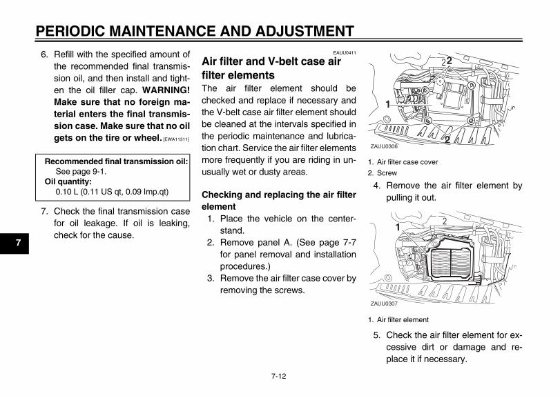
EAUU0411
Air filter and V-belt case air filter elements The air filter element should bechecked and replace if necessary andthe V-belt case air filter element shouldbe cleaned at the intervals specified inthe periodic maintenance and lubrica-tion chart. Service the air filter elementsmore frequently if you are riding in un-usually wet or dusty areas.
Checking and replacing the air filterelement
1. Place the vehicle on the center-stand.
2. Remove panel A. (See page 7-7for panel removal and installationprocedures.)
3. Remove the air filter case cover byremoving the screws.
4. Remove the air filter element bypulling it out.
5. Check the air filter element for ex-cessive dirt or damage and re-place it if necessary.
Recommended final transmission oil:See page 9-1.
Oil quantity:0.10 L (0.11 US qt, 0.09 Imp.qt)
1. Air filter case cover
2. Screw
1. Air filter element
ZAUU0306
2
11
22
22
2
ZAUU0307
111
E_1P7F8199E2.book Page 12 Tuesday, January 27, 2009 10:29 AM
PERIODIC MAINTENANCE AND ADJUSTMENT
7-13
7
6. Place the air filter element in itsoriginal position.
7. Install the air filter case cover byinstalling the screws.
8. Install the panel.
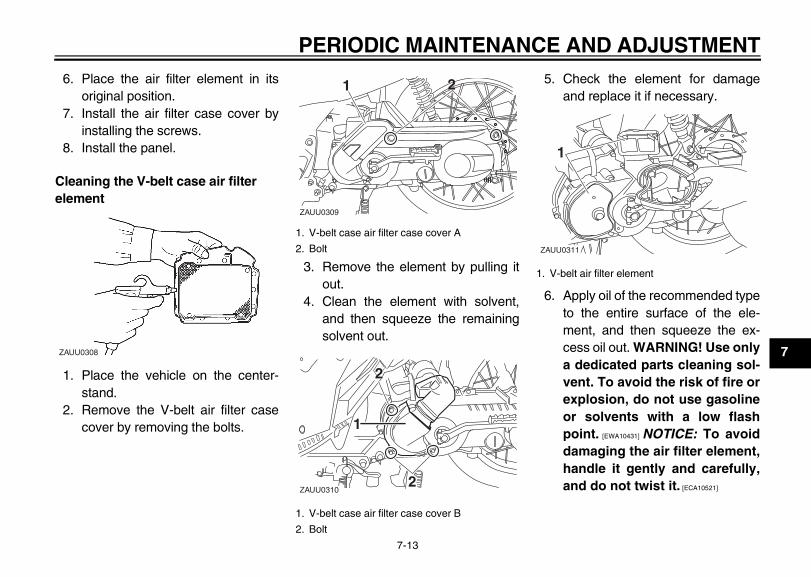
Cleaning the V-belt case air filter element
1. Place the vehicle on the center-stand.
2. Remove the V-belt air filter casecover by removing the bolts.
3. Remove the element by pulling itout.
4. Clean the element with solvent,and then squeeze the remainingsolvent out.
5. Check the element for damageand replace it if necessary.
6. Apply oil of the recommended typeto the entire surface of the ele-ment, and then squeeze the ex-cess oil out. WARNING! Use onlya dedicated parts cleaning sol-vent. To avoid the risk of fire orexplosion, do not use gasolineor solvents with a low flashpoint. [EWA10431] NOTICE: To avoiddamaging the air filter element,handle it gently and carefully,and do not twist it. [ECA10521]
ZAUU0308
1. V-belt case air filter case cover A
2. Bolt
1. V-belt case air filter case cover B
2. Bolt
ZAUU0309
1 221
222
11
22
ZAUU0310
1. V-belt air filter element
ZAUU0311
111
E_1P7F8199E2.book Page 13 Tuesday, January 27, 2009 10:29 AM
PERIODIC MAINTENANCE AND ADJUSTMENT
7-14
7
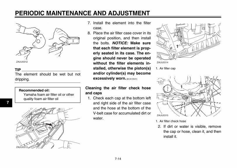
TIP_
The element should be wet but notdripping. _
7. Install the element into the filtercase.
8. Place the air filter case cover in itsoriginal position, and then installthe bolts. NOTICE: Make surethat each filter element is prop-erly seated in its case. The en-gine should never be operatedwithout the filter elements in-stalled, otherwise the piston(s)and/or cylinder(s) may becomeexcessively worn. [ECA10531]
Cleaning the air filter check hoseand caps
1. Check each cap at the bottom leftand right side of the air filter caseand the hose at the bottom of theV-belt case for accumulated dirt orwater.
2. If dirt or water is visible, removethe cap or hose, clean it, and theninstall it.
Recommended oil:Yamaha foam air filter oil or other quality foam air filter oil
ZAUU0312
ZAUU0313
1. Air filter cap
1. Air filter check hose
ZAUU0314
111
ZAUU0315
E_1P7F8199E2.book Page 14 Tuesday, January 27, 2009 10:29 AM
PERIODIC MAINTENANCE AND ADJUSTMENT
7-15
7
EAU21280
Adjusting the carburetor The carburetor is an important part ofthe engine and requires very sophisti-cated adjustment. Therefore, most car-buretor adjustments should be left to aYamaha dealer, who has the neces-sary professional knowledge and expe-rience. The adjustment described inthe following section, however, may beserviced by the owner as part of routinemaintenance.
ECA10550
NOTICE_
The carburetor has been set and ex-tensively tested at the Yamaha fac-tory. Changing these settingswithout sufficient technical knowl-edge may result in poor perfor-mance of or damage to the engine. _
EAUU0320
Adjusting the engine idling speed The engine idling speed must bechecked and, if necessary, adjusted asfollows at the intervals specified in theperiodic maintenance and lubricationchart.The engine should be warm beforemaking this adjustment.
TIP_
● The engine is warm when it quick-ly responds to the throttle.
● A diagnostic tachometer is neededto make this adjustment.
_
1. Open the seat. (See page 4-7 forseat opening and closing proce-dures.)
2. Remove panel A. (See page 7-7for panel removal and installationprocedures.)
3. Attach the tachometer to the sparkplug lead.
4. Check the engine idling speedand, if necessary, adjust it to spec-ification as follows.
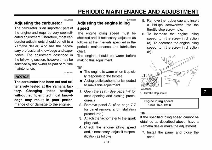
5. Remove the rubber cap and inserta Phillips screwdriver into thethrottle stop screw hole.
6. To increase the engine idlingspeed, turn the screw in direction(a). To decrease the engine idlingspeed, turn the screw in direction(b).
TIP_
If the specified idling speed cannot beobtained as described above, have aYamaha dealer make the adjustment. _
7. Install the panel and close theseat.
1. Throttle stop screw
Engine idling speed: 1400–1600 r/min
b
aZAUU0316
11
E_1P7F8199E2.book Page 15 Tuesday, January 27, 2009 10:29 AM
PERIODIC MAINTENANCE AND ADJUSTMENT
7-16
7
EAU21370
Adjusting the throttle cable free play
The throttle cable free play shouldmeasure 3.0–7.0 mm (0.12–0.28 in) atthe throttle grip. Periodically check thethrottle cable free play and, if neces-sary, adjust it as follows.
TIP_
The engine idling speed must be cor-rectly adjusted before checking and ad-justing the throttle cable free play. _
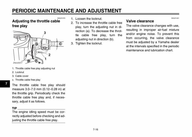
1. Loosen the locknut.2. To increase the throttle cable free
play, turn the adjusting nut in di-rection (a). To decrease the throt-tle cable free play, turn theadjusting nut in direction (b).
3. Tighten the locknut.
EAU21401
Valve clearance The valve clearance changes with use,resulting in improper air-fuel mixtureand/or engine noise. To prevent thisfrom occurring, the valve clearancemust be adjusted by a Yamaha dealerat the intervals specified in the periodicmaintenance and lubrication chart.
1. Throttle cable free play adjusting nut
2. Locknut
3. Cable cover
c. Throttle cable free play
1122
33
ZAUU0317
b
a
c
E_1P7F8199E2.book Page 16 Tuesday, January 27, 2009 10:29 AM
PERIODIC MAINTENANCE AND ADJUSTMENT
7-17
7
EAU21572
Tires To maximize the performance, durabil-ity, and safe operation of your motorcy-cle, note the following points regardingthe specified tires.
Tire air pressureThe tire air pressure should bechecked and, if necessary, adjustedbefore each ride.
EWA10501
WARNING_
Operation of this vehicle with im-proper tire pressure may cause se-vere injury or death from loss ofcontrol.
● The tire air pressure must bechecked and adjusted on coldtires (i.e., when the temperatureof the tires equals the ambienttemperature).
● The tire air pressure must beadjusted in accordance with theriding speed and with the total
weight of rider, passenger, car-go, and accessories approvedfor this model.
_
EWA10511
WARNING_
Never overload your vehicle. Opera-tion of an overloaded vehicle couldcause an accident. _
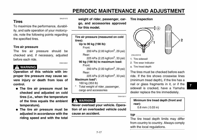
Tire inspection
The tires must be checked before eachride. If the tire shows crosswise lines(minimum tread depth), if the tire has anail or glass fragments in it, or if thesidewall is cracked, have a Yamahadealer replace the tire immediately.
TIP_
The tire tread depth limits may differfrom country to country. Always complywith the local regulations. _
Tire air pressure (measured on cold tires):
Up to 90 kg (198 lb):Front:
200 kPa (2.00 kgf/cm2, 29 psi)Rear:
225 kPa (2.25 kgf/cm2, 33 psi)90 kg (198 lb) to maximum load:
Front:200 kPa (2.00 kgf/cm2, 29 psi)
Rear:225 kPa (2.25 kgf/cm2, 33 psi)
Maximum load*:160 kg (353 lb)
* Total weight of rider, passenger, cargo and accessories
1. Tire sidewall
2. Tire wear indicator
a. Tire tread depth
Minimum tire tread depth (front and rear):
0.8 mm ( 0.03 in)
ZAUU0318
E_1P7F8199E2.book Page 17 Tuesday, January 27, 2009 10:29 AM
PERIODIC MAINTENANCE AND ADJUSTMENT
7-18
7
Tire informationThis motorcycle is equipped with tubetires.
EWA10461
WARNING_
The front and rear tires should be ofthe same make and design, other-wise the handling characteristics ofthe vehicle may be different, whichcould lead to an accident. _
After extensive tests, only the tires list-ed below have been approved for thismodel by Yamaha Motor Co., Ltd.
EWA10560
WARNING_
● It is dangerous to ride with aworn-out tire. When a tire treadbegins to show crosswise lines,have a Yamaha dealer replacethe tire immediately.
● The replacement of all wheel-and brake-related parts, includ-ing the tires, should be left to aYamaha dealer, who has thenecessary professional knowl-edge and experience.
● It is not recommended to patcha punctured tube. If unavoid-able, however, patch the tubevery carefully and replace it assoon as possible with a high-quality product.
_
EAUU0290
Wheels To maximize the performance, durabil-ity, and safe operation of your motorcy-cle, note the following points regardingthe specified wheels.
● The wheel rims should be checkedfor cracks, bends or warpage, andthe spokes for looseness (forspoke wheel model) or damagebefore each ride. If any damage isfound, have a Yamaha dealer re-place the wheel. Do not attempteven the smallest repair to thewheel. A deformed or crackedwheel must be replaced.
● The wheel should be balancedwhenever either the tire or wheelhas been changed or replaced. Anunbalanced wheel can result inpoor performance, adverse han-dling characteristics, and a short-ened tire life.
● Ride at moderate speeds afterchanging a tire since the tire sur-face must first be “broken in” for itto develop its optimal characteris-tics.
Front tire:Size:
70/90-16M/C 36PManufacturer/model:
IRC/NF59Dunlop/D110
Rear tire:Size:
80/90-16M/C 43PManufacturer/model:
IRC/NR76Dunlop/D110
E_1P7F8199E2.book Page 18 Tuesday, January 27, 2009 10:29 AM
PERIODIC MAINTENANCE AND ADJUSTMENT
7-19
7
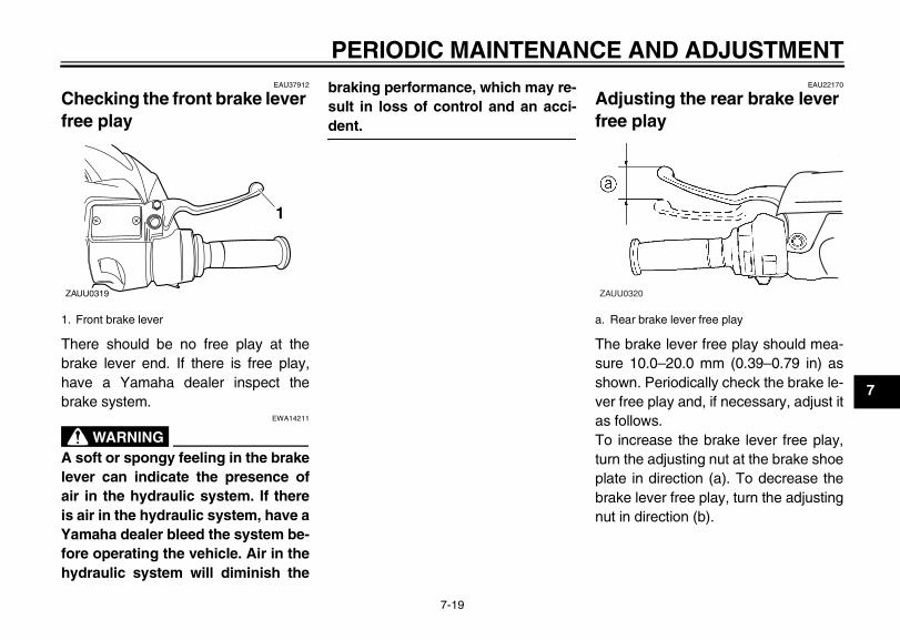
EAU37912
Checking the front brake lever free play
There should be no free play at thebrake lever end. If there is free play,have a Yamaha dealer inspect thebrake system.
EWA14211
WARNING_
A soft or spongy feeling in the brakelever can indicate the presence ofair in the hydraulic system. If thereis air in the hydraulic system, have aYamaha dealer bleed the system be-fore operating the vehicle. Air in thehydraulic system will diminish the
braking performance, which may re-sult in loss of control and an acci-dent. _
EAU22170
Adjusting the rear brake lever free play
The brake lever free play should mea-sure 10.0–20.0 mm (0.39–0.79 in) asshown. Periodically check the brake le-ver free play and, if necessary, adjust itas follows.To increase the brake lever free play,turn the adjusting nut at the brake shoeplate in direction (a). To decrease thebrake lever free play, turn the adjustingnut in direction (b).
1. Front brake lever
ZAUU0319
11
a. Rear brake lever free play
ZAUU0320
E_1P7F8199E2.book Page 19 Tuesday, January 27, 2009 10:29 AM
PERIODIC MAINTENANCE AND ADJUSTMENT
7-20
7
EWA10650
WARNING_
If proper adjustment cannot be ob-tained as described, have a Yamahadealer make this adjustment. _
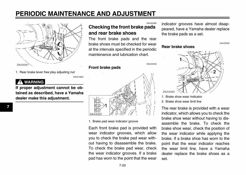
EAU22380
Checking the front brake pads and rear brake shoes The front brake pads and the rearbrake shoes must be checked for wearat the intervals specified in the periodicmaintenance and lubrication chart.
EAU22430
Front brake pads
Each front brake pad is provided withwear indicator grooves, which allowyou to check the brake pad wear with-out having to disassemble the brake.To check the brake pad wear, checkthe wear indicator grooves. If a brakepad has worn to the point that the wear
indicator grooves have almost disap-peared, have a Yamaha dealer replacethe brake pads as a set.
EAU22540
Rear brake shoes
The rear brake is provided with a wearindicator, which allows you to check thebrake shoe wear without having to dis-assemble the brake. To check thebrake shoe wear, check the position ofthe wear indicator while applying thebrake. If a brake shoe has worn to thepoint that the wear indicator reachesthe wear limit line, have a Yamahadealer replace the brake shoes as aset.
1. Rear brake lever free play adjusting nut
ZAUU0321
1. Brake pad wear indicator groove
ZAUU0322
1. Brake shoe wear indicator
2. Brake shoe wear limit line
ZAUU0323
E_1P7F8199E2.book Page 20 Tuesday, January 27, 2009 10:29 AM
PERIODIC MAINTENANCE AND ADJUSTMENT
7-21
7
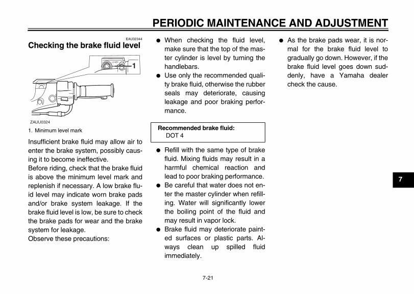
EAU32344
Checking the brake fluid level
Insufficient brake fluid may allow air toenter the brake system, possibly caus-ing it to become ineffective.Before riding, check that the brake fluidis above the minimum level mark andreplenish if necessary. A low brake flu-id level may indicate worn brake padsand/or brake system leakage. If thebrake fluid level is low, be sure to checkthe brake pads for wear and the brakesystem for leakage.Observe these precautions:
● When checking the fluid level,make sure that the top of the mas-ter cylinder is level by turning thehandlebars.
● Use only the recommended quali-ty brake fluid, otherwise the rubberseals may deteriorate, causingleakage and poor braking perfor-mance.
● Refill with the same type of brakefluid. Mixing fluids may result in aharmful chemical reaction andlead to poor braking performance.
● Be careful that water does not en-ter the master cylinder when refill-ing. Water will significantly lowerthe boiling point of the fluid andmay result in vapor lock.
● Brake fluid may deteriorate paint-ed surfaces or plastic parts. Al-ways clean up spilled fluidimmediately.
● As the brake pads wear, it is nor-mal for the brake fluid level togradually go down. However, if thebrake fluid level goes down sud-denly, have a Yamaha dealercheck the cause.
1. Minimum level mark
ZAUU0324
11
Recommended brake fluid:DOT 4
E_1P7F8199E2.book Page 21 Tuesday, January 27, 2009 10:29 AM
PERIODIC MAINTENANCE AND ADJUSTMENT
7-22
7
EAU22721
Changing the brake fluid Have a Yamaha dealer change thebrake fluid at the intervals specified inthe TIP after the periodic maintenanceand lubrication chart. In addition, havethe oil seals of the brake master cylin-der and caliper as well as the brakehose replaced at the intervals listed be-low or whenever they are damaged orleaking.
● Oil seals: Replace every twoyears.
● Brake hose: Replace every fouryears.
EAUU0310
Checking the V-belt The V-belt must be checked and re-placed by a Yamaha dealer at the inter-vals specified in the periodicmaintenance and lubrication chart.
EAU23101
Checking and lubricating the cables The operation of all control cables andthe condition of the cables should bechecked before each ride, and the ca-bles and cable ends should be lubricat-ed if necessary. If a cable is damagedor does not move smoothly, have aYamaha dealer check or replace it.WARNING! Damage to the outersheath may interfere with propercable operation and will cause theinner cable to rust. Replace a dam-aged cable as soon as possible toprevent unsafe conditions. [EWA10721]
Recommended lubricant:Engine oil
E_1P7F8199E2.book Page 22 Tuesday, January 27, 2009 10:29 AM
PERIODIC MAINTENANCE AND ADJUSTMENT
7-23
7
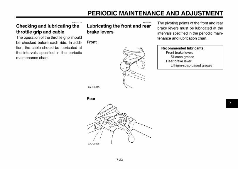
EAU23111
Checking and lubricating the throttle grip and cable The operation of the throttle grip shouldbe checked before each ride. In addi-tion, the cable should be lubricated atthe intervals specified in the periodicmaintenance chart.
EAU43641
Lubricating the front and rear brake levers
Front
Rear
The pivoting points of the front and rearbrake levers must be lubricated at theintervals specified in the periodic main-tenance and lubrication chart.
ZAUU0325
ZAUU0326
Recommended lubricants:Front brake lever:
Silicone greaseRear brake lever:
Lithium-soap-based grease
E_1P7F8199E2.book Page 23 Tuesday, January 27, 2009 10:29 AM
PERIODIC MAINTENANCE AND ADJUSTMENT
7-24
7
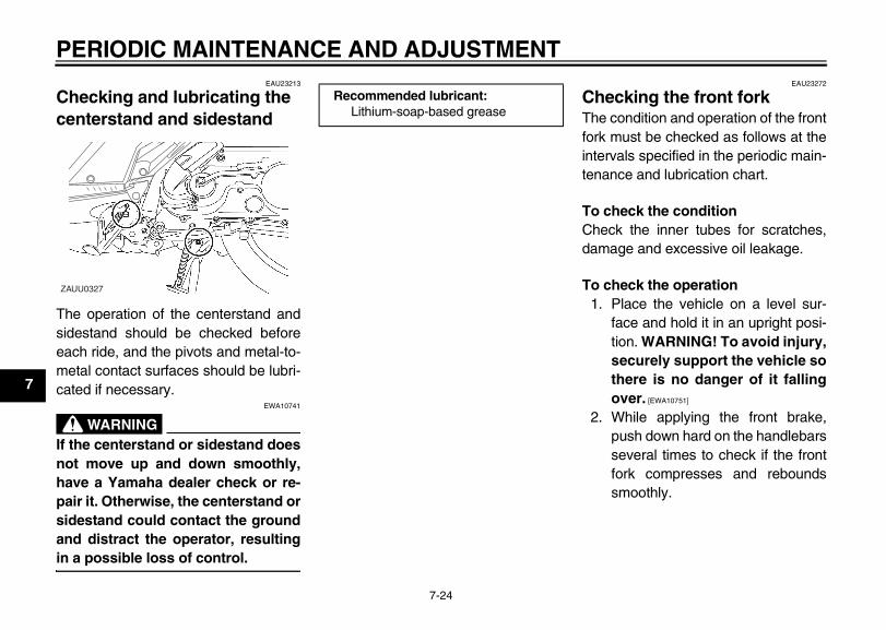
EAU23213
Checking and lubricating the centerstand and sidestand
The operation of the centerstand andsidestand should be checked beforeeach ride, and the pivots and metal-to-metal contact surfaces should be lubri-cated if necessary.
EWA10741
WARNING_
If the centerstand or sidestand doesnot move up and down smoothly,have a Yamaha dealer check or re-pair it. Otherwise, the centerstand orsidestand could contact the groundand distract the operator, resultingin a possible loss of control. _
EAU23272
Checking the front fork The condition and operation of the frontfork must be checked as follows at theintervals specified in the periodic main-tenance and lubrication chart.
To check the conditionCheck the inner tubes for scratches,damage and excessive oil leakage.
To check the operation1. Place the vehicle on a level sur-
face and hold it in an upright posi-tion. WARNING! To avoid injury,securely support the vehicle sothere is no danger of it fallingover. [EWA10751]
2. While applying the front brake,push down hard on the handlebarsseveral times to check if the frontfork compresses and reboundssmoothly.
ZAUU0327
Recommended lubricant:Lithium-soap-based grease
E_1P7F8199E2.book Page 24 Tuesday, January 27, 2009 10:29 AM
PERIODIC MAINTENANCE AND ADJUSTMENT
7-25
7
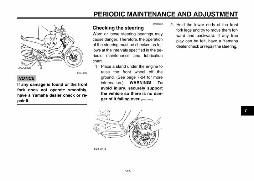
ECA10590
NOTICE_
If any damage is found or the frontfork does not operate smoothly,have a Yamaha dealer check or re-pair it. _
EAU23283
Checking the steering Worn or loose steering bearings maycause danger. Therefore, the operationof the steering must be checked as fol-lows at the intervals specified in the pe-riodic maintenance and lubricationchart.
1. Place a stand under the engine toraise the front wheel off theground. (See page 7-24 for moreinformation.) WARNING! Toavoid injury, securely supportthe vehicle so there is no dan-ger of it falling over. [EWA10751]
2. Hold the lower ends of the frontfork legs and try to move them for-ward and backward. If any freeplay can be felt, have a Yamahadealer check or repair the steering.
ZAUU0328
ZAUU0329
E_1P7F8199E2.book Page 25 Tuesday, January 27, 2009 10:29 AM
PERIODIC MAINTENANCE AND ADJUSTMENT
7-26
7
EAU23290
Checking the wheel bearings The front and rear wheel bearings mustbe checked at the intervals specified inthe periodic maintenance and lubrica-tion chart. If there is play in the wheelhub or if the wheel does not turnsmoothly, have a Yamaha dealercheck the wheel bearings.
EAUU0551
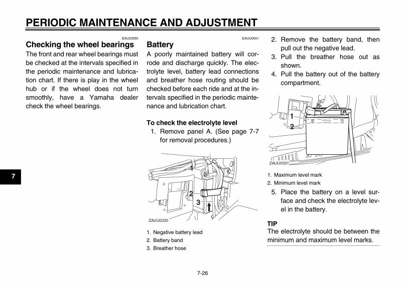
Battery A poorly maintained battery will cor-rode and discharge quickly. The elec-trolyte level, battery lead connectionsand breather hose routing should bechecked before each ride and at the in-tervals specified in the periodic mainte-nance and lubrication chart.
To check the electrolyte level1. Remove panel A. (See page 7-7
for removal procedures.)
2. Remove the battery band, thenpull out the negative lead.
3. Pull the breather hose out asshown.
4. Pull the battery out of the batterycompartment.
5. Place the battery on a level sur-face and check the electrolyte lev-el in the battery.
TIP_
The electrolyte should be between theminimum and maximum level marks. _
1. Negative battery lead
2. Battery band
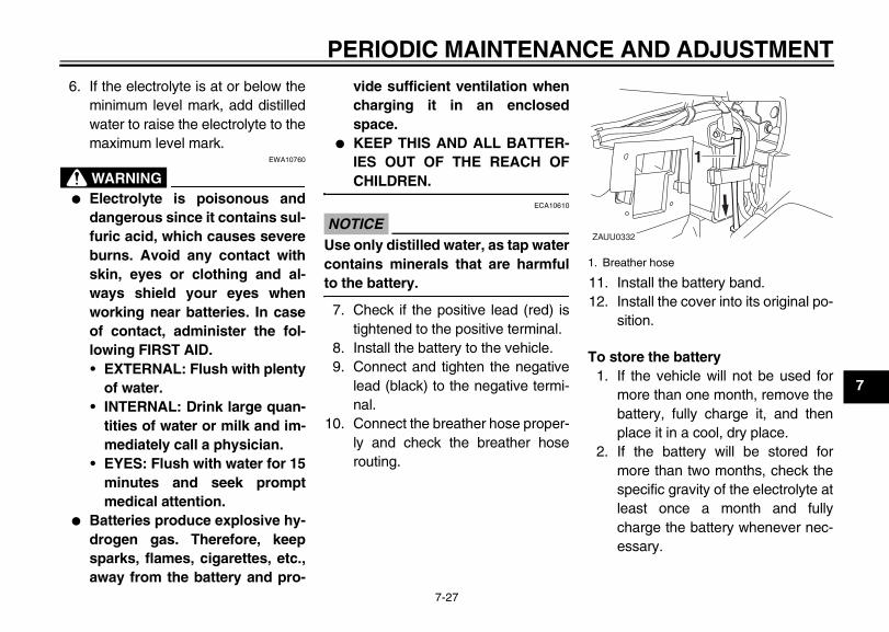
3. Breather hose
ZAUU0330
11
2233
1. Maximum level mark
2. Minimum level mark
ZAUU0331
1122
E_1P7F8199E2.book Page 26 Tuesday, January 27, 2009 10:29 AM
PERIODIC MAINTENANCE AND ADJUSTMENT
7-27
7
6. If the electrolyte is at or below theminimum level mark, add distilledwater to raise the electrolyte to themaximum level mark.
EWA10760
WARNING_
● Electrolyte is poisonous anddangerous since it contains sul-furic acid, which causes severeburns. Avoid any contact withskin, eyes or clothing and al-ways shield your eyes whenworking near batteries. In caseof contact, administer the fol-lowing FIRST AID.• EXTERNAL: Flush with plenty
of water.• INTERNAL: Drink large quan-
tities of water or milk and im-mediately call a physician.
• EYES: Flush with water for 15minutes and seek promptmedical attention.
● Batteries produce explosive hy-drogen gas. Therefore, keepsparks, flames, cigarettes, etc.,away from the battery and pro-
vide sufficient ventilation whencharging it in an enclosedspace.
● KEEP THIS AND ALL BATTER-IES OUT OF THE REACH OFCHILDREN.
_
ECA10610
NOTICE_
Use only distilled water, as tap watercontains minerals that are harmfulto the battery. _
7. Check if the positive lead (red) istightened to the positive terminal.
8. Install the battery to the vehicle.9. Connect and tighten the negative
lead (black) to the negative termi-nal.
10. Connect the breather hose proper-ly and check the breather hoserouting.
11. Install the battery band.12. Install the cover into its original po-
sition.
To store the battery1. If the vehicle will not be used for
more than one month, remove thebattery, fully charge it, and thenplace it in a cool, dry place.
2. If the battery will be stored formore than two months, check thespecific gravity of the electrolyte atleast once a month and fullycharge the battery whenever nec-essary.
1. Breather hose
ZAUU0332
11
E_1P7F8199E2.book Page 27 Tuesday, January 27, 2009 10:29 AM
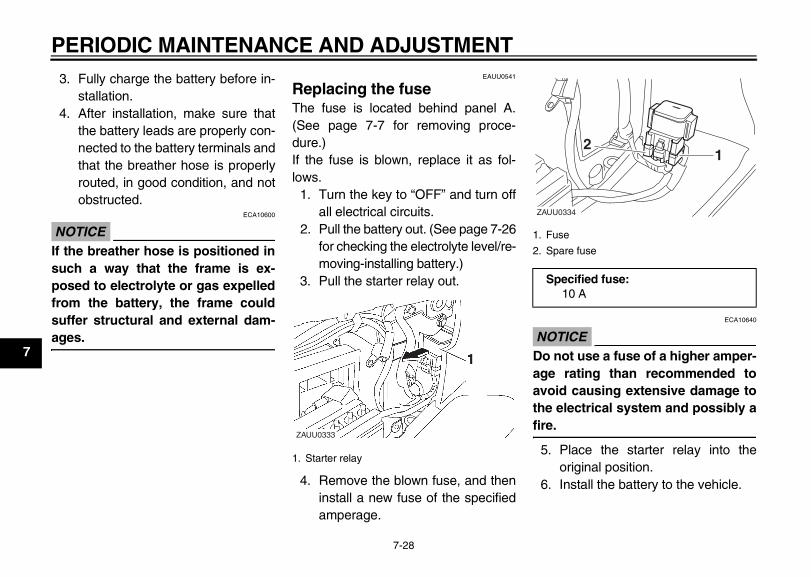
PERIODIC MAINTENANCE AND ADJUSTMENT
7-28
7
3. Fully charge the battery before in-stallation.
4. After installation, make sure thatthe battery leads are properly con-nected to the battery terminals andthat the breather hose is properlyrouted, in good condition, and notobstructed.
ECA10600
NOTICE_
If the breather hose is positioned insuch a way that the frame is ex-posed to electrolyte or gas expelledfrom the battery, the frame couldsuffer structural and external dam-ages. _
EAUU0541
Replacing the fuse The fuse is located behind panel A.(See page 7-7 for removing proce-dure.)If the fuse is blown, replace it as fol-lows.
1. Turn the key to “OFF” and turn offall electrical circuits.
2. Pull the battery out. (See page 7-26for checking the electrolyte level/re-moving-installing battery.)
3. Pull the starter relay out.
4. Remove the blown fuse, and theninstall a new fuse of the specifiedamperage.
ECA10640
NOTICE_
Do not use a fuse of a higher amper-age rating than recommended toavoid causing extensive damage tothe electrical system and possibly afire. _
5. Place the starter relay into theoriginal position.
6. Install the battery to the vehicle.
1. Starter relay
ZAUU0333
1. Fuse
2. Spare fuse
Specified fuse:10 A
11122
ZAUU0334
E_1P7F8199E2.book Page 28 Tuesday, January 27, 2009 10:29 AM
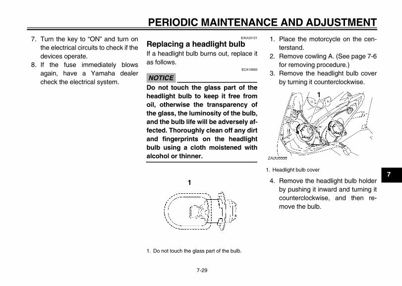
PERIODIC MAINTENANCE AND ADJUSTMENT
7-29
7
7. Turn the key to “ON” and turn onthe electrical circuits to check if thedevices operate.
8. If the fuse immediately blowsagain, have a Yamaha dealercheck the electrical system.
EAUU0121
Replacing a headlight bulb If a headlight bulb burns out, replace itas follows.
ECA10660
NOTICE_
Do not touch the glass part of theheadlight bulb to keep it free fromoil, otherwise the transparency ofthe glass, the luminosity of the bulb,and the bulb life will be adversely af-fected. Thoroughly clean off any dirtand fingerprints on the headlightbulb using a cloth moistened withalcohol or thinner. _
1. Place the motorcycle on the cen-terstand.
2. Remove cowling A. (See page 7-6for removing procedure.)
3. Remove the headlight bulb coverby turning it counterclockwise.
4. Remove the headlight bulb holderby pushing it inward and turning itcounterclockwise, and then re-move the bulb.
1. Do not touch the glass part of the bulb.
1. Headlight bulb cover
ZAUU0335
E_1P7F8199E2.book Page 29 Tuesday, January 27, 2009 10:29 AM
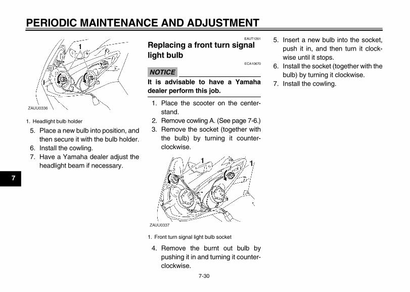
PERIODIC MAINTENANCE AND ADJUSTMENT
7-30
7
5. Place a new bulb into position, andthen secure it with the bulb holder.
6. Install the cowling.7. Have a Yamaha dealer adjust the
headlight beam if necessary.
EAUT1261
Replacing a front turn signal light bulb
ECA10670
NOTICE_
It is advisable to have a Yamahadealer perform this job. _
1. Place the scooter on the center-stand.
2. Remove cowling A. (See page 7-6.)3. Remove the socket (together with
the bulb) by turning it counter-clockwise.
4. Remove the burnt out bulb bypushing it in and turning it counter-clockwise.
5. Insert a new bulb into the socket,push it in, and then turn it clock-wise until it stops.
6. Install the socket (together with thebulb) by turning it clockwise.
7. Install the cowling.
1. Headlight bulb holder
ZAUU0336
1. Front turn signal light bulb socket
ZAUU0337
E_1P7F8199E2.book Page 30 Tuesday, January 27, 2009 10:29 AM
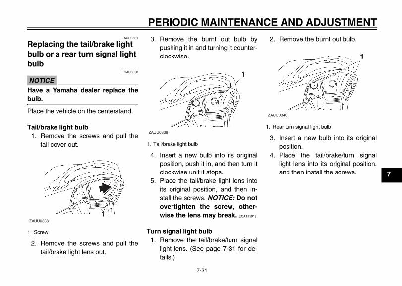
PERIODIC MAINTENANCE AND ADJUSTMENT
7-31
7
EAUU0561
Replacing the tail/brake light bulb or a rear turn signal light bulb
ECAU0030
NOTICE_
Have a Yamaha dealer replace thebulb. _
Place the vehicle on the centerstand.
Tail/brake light bulb1. Remove the screws and pull the
tail cover out.
2. Remove the screws and pull thetail/brake light lens out.
3. Remove the burnt out bulb bypushing it in and turning it counter-clockwise.
4. Insert a new bulb into its originalposition, push it in, and then turn itclockwise unit it stops.
5. Place the tail/brake light lens intoits original position, and then in-stall the screws. NOTICE: Do notovertighten the screw, other-wise the lens may break. [ECA11191]
Turn signal light bulb1. Remove the tail/brake/turn signal
light lens. (See page 7-31 for de-tails.)
2. Remove the burnt out bulb.
3. Insert a new bulb into its originalposition.
4. Place the tail/brake/turn signallight lens into its original position,and then install the screws.
1. Screw
ZAUU0338
1. Tail/brake light bulb
ZAUU03391. Rear turn signal light bulb
ZAUU0340
E_1P7F8199E2.book Page 31 Tuesday, January 27, 2009 10:29 AM
PERIODIC MAINTENANCE AND ADJUSTMENT
7-32
7
EAU25851
Troubleshooting Although Yamaha motorcycles receivea thorough inspection before shipmentfrom the factory, trouble may occur dur-ing operation. Any problem in the fuel,compression, or ignition systems, forexample, can cause poor starting andloss of power.The following troubleshooting chartrepresents a quick and easy procedurefor checking these vital systems your-self. However, should your motorcyclerequire any repair, take it to a Yamahadealer, whose skilled technicians havethe necessary tools, experience, andknow-how to service the motorcycleproperly.Use only genuine Yamaha replace-ment parts. Imitation parts may looklike Yamaha parts, but they are ofteninferior, have a shorter service life andcan lead to expensive repair bills.
EWA15141
WARNING_
When checking the fuel system, donot smoke, and make sure there are
no open flames or sparks in the ar-ea, including pilot lights from waterheaters or furnaces. Gasoline orgasoline vapors can ignite or ex-plode, causing severe injury orproperty damage. _
E_1P7F8199E2.book Page 32 Tuesday, January 27, 2009 10:29 AM
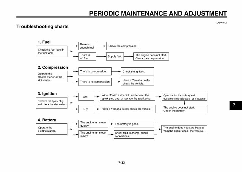
PERIODIC MAINTENANCE AND ADJUSTMENT
7-33
7
EAUW0351
Troubleshooting charts
Check the fuel level in the fuel tank.
1. FuelThere isenough fuel.
There isno fuel.
Check the compression.
Supply fuel. The engine does not start.Check the compression.
Operate theelectric starter or thekickstarter.
2. CompressionThere is compression.
There is no compression.
Check the ignition.
Have a Yamaha dealer check the vehicle.
Remove the spark plug and check the electrodes.
3. IgnitionWet
Dry
Wipe off with a dry cloth and correct the spark plug gap, or replace the spark plug.
Have a Yamaha dealer check the vehicle.
The engine does not start. Have a Yamaha dealer check the vehicle.
The engine does not start.Check the battery.
Open the throttle halfway and operate the electric starter or kickstarter.
Operate theelectric starter.
4. BatteryThe engine turns overquickly.
The engine turns overslowly.
The battery is good.
Check fluid, recharge, check connections.
E_1P7F8199E2.book Page 33 Tuesday, January 27, 2009 10:29 AM
MOTORCYCLE CARE AND STORAGE
8-1
8
EAUU0403
Care While the open design of a motorcyclereveals the attractiveness of the tech-nology, it also makes it more vulnera-ble. Rust and corrosion can developeven if high-quality components areused. A rusty exhaust pipe may go un-noticed on a car, however, it detractsfrom the overall appearance of a mo-torcycle. Frequent and proper caredoes not only comply with the terms ofthe warranty, but it will also keep yourmotorcycle looking good, extend its lifeand optimize its performance.
Before cleaning1. Cover the muffler outlet with a
plastic bag after the engine hascooled down.
2. Make sure that all caps and coversas well as all electrical couplersand connectors, including thespark plug cap, are tightly in-stalled.
3. Remove extremely stubborn dirt,like oil burnt onto the crankcase,with a degreasing agent and abrush, but never apply such prod-ucts onto seals, gaskets andwheel axles. Always rinse the dirtand degreaser off with water.
CleaningECA10782
NOTICE_
● Avoid using strong acidic wheelcleaners, especially on spokedwheels. If such products areused on hard-to-remove dirt, donot leave the cleaner on the af-fected area any longer than in-structed. Also, thoroughly rinsethe area off with water, immedi-ately dry it, and then apply acorrosion protection spray.
● Improper cleaning can damageplastic parts (such as cowlings,panels, windshields, headlightlenses, meter lenses, etc.) andthe mufflers. Use only a soft,clean cloth or sponge with wa-
ter to clean plastic. However, ifthe plastic parts cannot be thor-oughly cleaned with water, di-luted mild detergent with watermay be used. Be sure to rinseoff any detergent residue usingplenty of water, as it is harmfulto plastic parts.
● Do not use any harsh chemicalproducts on plastic parts. Besure to avoid using cloths orsponges which have been incontact with strong or abrasivecleaning products, solvent orthinner, fuel (gasoline), rust re-movers or inhibitors, brake flu-id, antifreeze or electrolyte.
● Do not use high-pressure wash-ers or steam-jet cleaners sincethey cause water seepage anddeterioration in the following ar-eas: seals (of wheel and swing-arm bearings, fork and brakes),electric components (couplers,connectors, instruments, switch-es and lights), breather hosesand vents.
1-MOTORCYCLE CARE AND STORAGE
E_1P7F8199E2.book Page 1 Tuesday, January 27, 2009 10:29 AM
MOTORCYCLE CARE AND STORAGE
8-2
8
● For scooters equipped with awindshield: Do not use strongcleaners or hard sponges asthey will cause dulling orscratching. Some cleaningcompounds for plastic mayleave scratches on the wind-shield. Test the product on asmall hidden part of the wind-shield to make sure that it doesnot leave any marks. If the wind-shield is scratched, use a quali-ty plastic polishing compoundafter washing.
_
After normal useRemove dirt with warm water, a milddetergent, and a soft, clean sponge,and then rinse thoroughly with cleanwater. Use a toothbrush or bottlebrushfor hard-to-reach areas. Stubborn dirtand insects will come off more easily ifthe area is covered with a wet cloth fora few minutes before cleaning.
After riding in the rain or near the seaince sea salt is extremely corrosive car-ry out the following steps after eachride in the rain or near the sea.
1. Clean the motorcycle with coldwater and a mild detergent afterthe engine has cooled down. NO-TICE: Do not use warm watersince it increases the corrosiveaction of the salt. [ECA10791]
2. Apply a corrosion protection sprayon all metal, including chrome-and nickel-plated, surfaces to pre-vent corrosion.
After cleaning1. Dry the motorcycle with a chamois
or an absorbing cloth.2. Use a chrome polish to shine
chrome, aluminum and stainless-steel parts, including the exhaustsystem. (Even the thermally in-duced discoloring of stainless-steel exhaust systems can be re-moved through polishing.)
3. To prevent corrosion, it is recom-mended to apply a corrosion pro-tection spray on all metal,including chrome- and nickel-plat-ed, surfaces.
4. Use spray oil as a universal clean-er to remove any remaining dirt.
5. Touch up minor paint damagecaused by stones, etc.
6. Wax all painted surfaces.7. Let the motorcycle dry completely
before storing or covering it.EWA10941
WARNING_
Contaminants on the brakes or tirescan cause loss of control.
● Make sure that there is no oil orwax on the brakes or tires. Ifnecessary, clean the brakediscs and brake linings with aregular brake disc cleaner or ac-etone, and wash the tires withwarm water and a mild deter-gent.
E_1P7F8199E2.book Page 2 Tuesday, January 27, 2009 10:29 AM
MOTORCYCLE CARE AND STORAGE
8-3
8
● Before operating the scootertest its braking performanceand cornering behavior.
_
ECAU0020
NOTICE_
● Apply spray oil and wax spar-ingly and make sure to wipe offany excess.
● Never apply oil or wax to anyrubber parts, plastic parts orheadlight, taillight and meterlenses, but treat them with asuitable care product.
● Avoid using abrasive polishingcompounds as they will wearaway the paint.
_
TIP_
● Consult a Yamaha dealer for ad-vice on what products to use.
● Washing, rainy weather or humidclimates can cause the headlightlens to fog. Turning the headlighton for a short period of time willhelp remove the moisture from thelens.
_
EAU26301
Storage
Short-termAlways store your scooter in a cool, dryplace and, if necessary, protect itagainst dust with a porous cover.
ECA10820
NOTICE_
● Storing the scooter in a poorlyventilated room or covering itwith a tarp, while it is still wet,will allow water and humidity toseep in and cause rust.
● To prevent corrosion, avoiddamp cellars, stables (becauseof the presence of ammonia)and areas where strong chemi-cals are stored.
_
Long-termBefore storing your scooter for severalmonths:
1. Follow all the instructions in the“Care” section of this chapter.
2. Drain the carburetor float chamberby loosening the drain bolt; this willprevent fuel deposits from buildingup. Pour the drained fuel into thefuel tank.
3. Fill up the fuel tank and add fuelstabilizer (if available) to preventthe fuel tank from rusting and thefuel from deteriorating.
4. Perform the following steps to pro-tect the cylinder, piston rings, etc.from corrosion.a. Remove the spark plug cap and
spark plug.b. Pour a teaspoonful of engine oil
into the spark plug bore.c. Install the spark plug cap onto
the spark plug, and then placethe spark plug on the cylinderhead so that the electrodes aregrounded. (This will limit spark-ing during the next step.)
d. Turn the engine over severaltimes with the starter. (This willcoat the cylinder wall with oil.)WARNING! To prevent dam-age or injury from sparking,
E_1P7F8199E2.book Page 3 Tuesday, January 27, 2009 10:29 AM
MOTORCYCLE CARE AND STORAGE
8-4
8
make sure to ground thespark plug electrodes whileturning the engine over.[EWA10951]
e. Remove the spark plug capfrom the spark plug, and theninstall the spark plug and thespark plug cap.
5. Lubricate all control cables and thepivoting points of all levers andpedals as well as of the sidestand/centerstand.
6. Check and, if necessary, correctthe tire air pressure, and then liftthe scooter so that both of itswheels are off the ground. Alterna-tively, turn the wheels a little everymonth in order to prevent the tiresfrom becoming degraded in onespot.
7. Cover the muffler outlet with aplastic bag to prevent moisturefrom entering it.
8. Remove the battery and fullycharge it. Store it in a cool, dryplace and charge it once a month.Do not store the battery in an ex-
cessively cold or warm place [lessthan 0 °C (30 °F) or more than30 °C (90 °F)]. For more informa-tion on storing the battery, seepage 7-26.
TIP_
Make any necessary repairs beforestoring the scooter. _
E_1P7F8199E2.book Page 4 Tuesday, January 27, 2009 10:29 AM
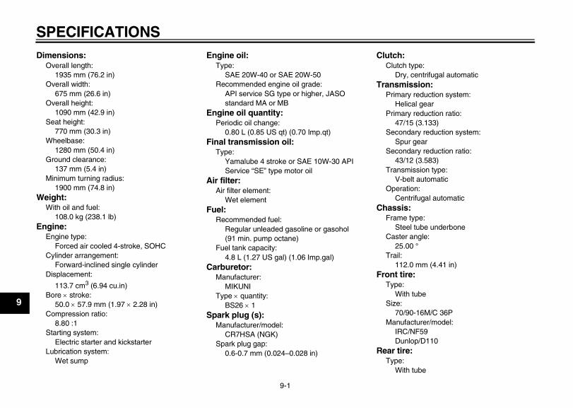
SPECIFICATIONS
9-1
9
Dimensions:Overall length:
1935 mm (76.2 in)Overall width:
675 mm (26.6 in)Overall height:
1090 mm (42.9 in)Seat height:
770 mm (30.3 in)Wheelbase:
1280 mm (50.4 in)Ground clearance:
137 mm (5.4 in)Minimum turning radius:
1900 mm (74.8 in)Weight:
With oil and fuel:108.0 kg (238.1 lb)
Engine:Engine type:
Forced air cooled 4-stroke, SOHCCylinder arrangement:
Forward-inclined single cylinderDisplacement:
113.7 cm3 (6.94 cu.in)Bore × stroke:
50.0 × 57.9 mm (1.97 × 2.28 in) Compression ratio:
8.80 :1Starting system:
Electric starter and kickstarterLubrication system:
Wet sump
Engine oil:Type:
SAE 20W-40 or SAE 20W-50Recommended engine oil grade:
API service SG type or higher, JASO standard MA or MB
Engine oil quantity:Periodic oil change:
0.80 L (0.85 US qt) (0.70 Imp.qt)Final transmission oil:
Type:Yamalube 4 stroke or SAE 10W-30 APIService “SE” type motor oil
Air filter:Air filter element:
Wet elementFuel:
Recommended fuel:Regular unleaded gasoline or gasohol (91 min. pump octane)
Fuel tank capacity:4.8 L (1.27 US gal) (1.06 Imp.gal)
Carburetor:Manufacturer:
MIKUNIType × quantity:
BS26 × 1Spark plug (s):
Manufacturer/model:CR7HSA (NGK)
Spark plug gap:0.6-0.7 mm (0.024–0.028 in)
Clutch:Clutch type:
Dry, centrifugal automaticTransmission:
Primary reduction system:Helical gear
Primary reduction ratio:47/15 (3.133)
Secondary reduction system:Spur gear
Secondary reduction ratio:43/12 (3.583)
Transmission type:V-belt automatic
Operation:Centrifugal automatic
Chassis:Frame type:
Steel tube underboneCaster angle:
25.00 °Trail:
112.0 mm (4.41 in)Front tire:
Type:With tube
Size:70/90-16M/C 36P
Manufacturer/model:IRC/NF59Dunlop/D110
Rear tire:Type:
With tube
1-SPECIFICATIONS
E_1P7F8199E2.book Page 1 Tuesday, January 27, 2009 10:29 AM
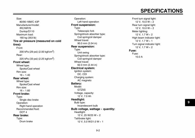
SPECIFICATIONS
9-2
9
Size:80/90-16M/C 43P
Manufacturer/model:IRC/NR76Dunlop/D110
Maximum load:160 kg (353 lb)
Tire air pressure (measured on cold tires):
Front:
200 kPa (29 psi) (2.00 kgf/cm2)Rear:
225 kPa (33 psi) (2.25 kgf/cm2)Front wheel:
Wheel type:Spoke/Cast wheel
Rim size:16 × 1.40
Rear wheel:Wheel type:
Spoke/Cast wheelRim size:
16 × 1.60Front brake:
Type:Single disc brake
Operation:Right hand operation
Recommended fluid:DOT 4
Rear brake:Type:
Drum brake
Operation:Left hand operation
Front suspension:Type:
Telescopic forkSpring/shock absorber type:
Coil spring/oil damperWheel travel:
90.0 mm (3.54 in)Rear suspension:
Type:Unit swing
Spring/shock absorber type:Coil spring/oil damper
Wheel travel:62.0 mm (2.44 in)
Electrical system:Ignition system:
DC. CDICharging system:
AC magnetoBattery:
Model:GTZ5S
Voltage, capacity:12 V, 7.0 Ah
Headlight:Bulb type:
Incandescent bulbBulb voltage, wattage × quantity:
Headlight:12 V, 25 W/25 W × 2
Tail/brake light:12 V, 5.0 W/21.0 W × 1
Front turn signal light:12 V, 10.0 W × 2
Rear turn signal light:12 V, 10.0 W × 2
Meter lighting:12 V, 1.7 W × 2
High beam indicator light:12 V, 1.7 W × 1
Turn signal indicator light:12 V, 1.7 W × 2
Fuse:Fuse:
10.0 A
E_1P7F8199E2.book Page 2 Tuesday, January 27, 2009 10:29 AM
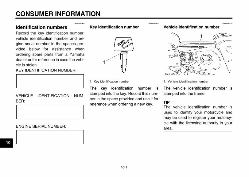
CONSUMER INFORMATION
10-1
10
EAU26360
Identification numbers Record the key identification number,vehicle identification number and en-gine serial number in the spaces pro-vided below for assistance whenordering spare parts from a Yamahadealer or for reference in case the vehi-cle is stolen.KEY IDENTIFICATION NUMBER:
VEHICLE IDENTIFICATION NUM-BER:
ENGINE SERIAL NUMBER:
EAU26390
Key identification number
The key identification number isstamped into the key. Record this num-ber in the space provided and use it forreference when ordering a new key.
EAU26410
Vehicle identification number
The vehicle identification number isstamped into the frame.
TIP_
The vehicle identification number isused to identify your motorcycle andmay be used to register your motorcy-cle with the licensing authority in yourarea. _
1. Key identification number 1. Vehicle identification number
ZAUU0341
1-CONSUMER INFORMATION
E_1P7F8199E2.book Page 1 Tuesday, January 27, 2009 10:29 AM
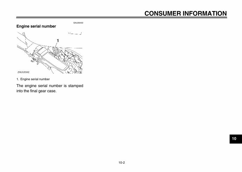
CONSUMER INFORMATION
10-2
10
EAU26450
Engine serial number
The engine serial number is stampedinto the final gear case.
1. Engine serial number
ZAUU0342
E_1P7F8199E2.book Page 2 Tuesday, January 27, 2009 10:29 AM

E_1P7F8199E2.book Page 3 Tuesday, January 27, 2009 10:29 AM

E_1P7F8199E2.book Page 4 Tuesday, January 27, 2009 10:29 AM

PRINTED IN THAILAND
E_1P7F8199E2.book Page 1 Tuesday, January 27, 2009 10:29 AM


