Embed Size (px)
Citation preview
(2360) PLANT MIXED ASPHALT PAVEMENT Gyratory Design Specification
February 1, 2010
This Specification requires the Contractor to provide a mix that complies with all of the design, production, and placement requirements of the specification. The Department does not make any guaranty or warranty, either express or implied, that compliance with one part of this specification guarantees that the Contractor will meet the other aspects of the specification. 2360.1 DESCRIPTION
This work consists of the construction of one or more pavement courses of hot plant mixed asphalt-aggregate mixture on the approved prepared foundation, base course or existing surface in accordance with the specifications and in conformity with the lines, grades, thicknesses and typical cross sections shown on the plans or established by the Engineer. Mixture design will be 2360 (gyratory) as described in the Special Provisions through the mixture designation. A Mixture Designations
Mixture designations for asphalt mixtures contain the following information:
(1) The first two letters indicate the mixture design type: SP = Gyratory Mixture Design SM = Gyratory Mixture Design for Stone Matrix Asphalt (SMA)
(2) The third and fourth letters indicate the course:
WE = Wearing and Shoulder Wearing Course NW = Non-Wearing Course
(3) The fifth letter indicates the maximum aggregate size*:
A = 1/2 inch [12.5mm], SP 9.5 B = 3/4 inch [19.0mm], SP 12.5 C = 1 inch [25.0mm], SP 19.0 D = 3/8 inch [9.5mm], SP 4.75 E = See provision for SMA design
(4) For Gyratory Design:
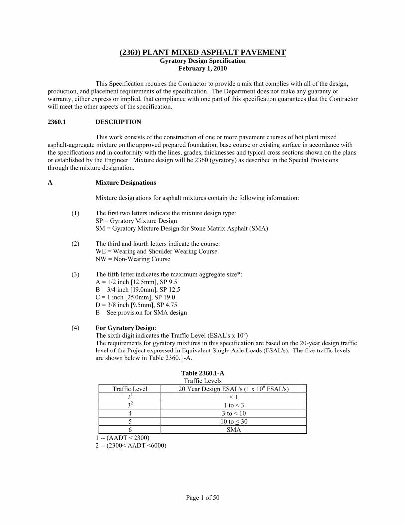
The sixth digit indicates the Traffic Level (ESAL's x 106) The requirements for gyratory mixtures in this specification are based on the 20-year design traffic level of the Project expressed in Equivalent Single Axle Loads (ESAL's). The five traffic levels are shown below in Table 2360.1-A.
Table 2360.1-A Traffic Levels
Traffic Level 20 Year Design ESAL's (1 x 10⁶ ESAL's) 21 < 1 32 1 to < 3 4 3 to < 10 5 10 to < 30 6 SMA
1 -- (AADT < 2300) 2 -- (2300< AADT <6000)
Page 1 of 50
2360 Specification February 1, 2010
(5) The last two digits indicate the air void requirement: 40 = 4.0% for SP and SM Wear mixtures 30 = 3.0% for SP Non-Wear and Shoulder
(6) The letter at the end of the mixture designation identifies the asphalt binder grade:
Standard Grades Specialty Grades B = PG 58-28 A = PG 52-34 C = PG 58-34 H = PG 70-28 E = PG 64-28 F = PG 64-34 L = PG 64-22
Ex: Gyratory Mixture Designation -- SPWEB540E (Design Type, Lift, Agg Size, Traffic Level, Voids, Binder) Ex: SMA Mixture Designation -- SMWEE640H (Design Type, Lift, Agg Size, Traffic Level, Voids, Binder) B Minimum Lift thickness
Minimum design recommended paving lift thickness based on maximum aggregate size are:
Aggregate Size D: Minimum Lift thickness = 1/2 inch [12 mm] Aggregate Size A: Minimum Lift thickness = 1 inch [25 mm] Aggregate Size B: Minimum Lift thickness = 1 ½ inch [40 mm] Aggregate Size C (for non-wear only): Minimum Lift thickness = 2 ½ inch [65 mm]
2360.2 MATERIALS A Aggregate A1 General
The aggregate shall consist of sound, durable particles of gravel and sand, crushed stone and sand, or combinations thereof. It shall be free of objectionable matter such as metal, glass, wood, plastic, brick, rubber, and any other material having similar characteristics. Coarse aggregate shall be free from coatings of clay and silt to the satisfaction of the Engineer.
The Contractor shall not compensate for the lack of fines by adding soil materials such as clay, loam, or silt. Overburden shall not be blended into the asphalt aggregate.
Each different material (source, class, kind, or size) shall be fed at a uniform rate from its storage unit. An individual source, class, type, or size of material shall not be stockpile blended with another source, class, type or size of material. A2 Classification
The aggregate shall conform to one of the following classifications. The class of aggregate to be used shall be the Contractor's option unless otherwise specified in the Contract. A2a Class A
Class A aggregate shall consist of crushed igneous bedrock (specifically; basalt, gabbro, granite, gneiss, rhyolite, diorite and andosite) and rock from the Sioux Quartzite Formation. Other igneous or metamorphic rock may be used with specific approval of the Engineer. Class A materials may contain no more than 4.0% non-Class A aggregate. This recognizes the fact that some quarries may contain small pockets of non-Class A material within that source. Intentional blending or addition of non-Class A material is strictly prohibited!
Page 2 of 50
2360 Specification February 1, 2010
A2b Class B
Class B aggregate shall consist of crushed rock from all other bedrock sources such as carbonate and metamorphic rocks. (Schist) A2c Class C
Class C aggregate shall consist of natural or partly crushed natural gravel obtained from a natural gravel deposit. A2d Class D
Class D aggregate shall consist of 100 percent crushed natural gravel. The crushed gravel shall be produced from material retained on a square mesh sieve having an opening at least twice as large as the Specification permits for the maximum size of the aggregate in the composite asphalt mixture. The amount of carryover (material finer than) the selected screen shall not exceed ten percent. A2e Class E
Class E aggregate shall consist of a mixture of any two or more of the above classes of approved aggregate (A, B, and D). The use of Class E aggregate, as well as the relative proportions of the different constituent aggregates, shall be subject to the approval of the Engineer. The relative proportions of the constituent aggregates shall be accurately controlled either by the use of a blending belt approved by the Engineer prior to production or by separately weighing each aggregate during batching operations. A2f Steel Slag
Steel slag may not exceed 25 percent of the mass of the total aggregate. Steel slag shall be free of metallics and other mill waste. Stockpiles will be accepted for use if the total expansion, determined by ASTM D4792, is less than 0.50%. A2g Taconite Tailings (TT)
Taconite tailings shall be obtained from ore that is mined westerly of a north-south line located east of Biwabik, Mn (R15W-R16W); except that taconite tailings from ore mined in southwestern Wisconsin will also be permitted for use.
Approved taconite tailing sources are on file with the Department Bituminous Engineer. A2h Recycled Asphalt Shingles (RAS)
RAS may be included in the mixture to a maximum of 5 percent of the total weight of mixture as shown in Table 2360.3-B2a. Either manufactured waste scrap asphalt shingles (MWSS) or tear-off scrap asphalt shingles (TOSS) may be included in the mixture. The percentage of RAS used will be considered part of the maximum allowable RAP percentage. Refer to Section 2360.2 G1 to select a virgin asphalt binder grade. The ratio of added new asphalt binder to total asphalt binder shall be 70% or greater ((added binder/total binder) x 100 >= 70). A minimum of 1 spotcheck per day per mixture blend is required to determine new added binder.
All RAS materials shall be processed to meet the following gradation requirements:
Gradation (% passing)
Sieve Size (inch [mm]) (% passing)1/2 inch [12.5 ] 100
#4 [4.75] 90
Page 3 of 50
2360 Specification February 1, 2010
To conduct the gradation testing, a 500-700 gram sample of processed shingle material is air dried and then dry sieved over the 1/2" and #4 sieves and then weighed.
Shingle asphalt binder content is to be determined by chemical extraction, MnDOT Lab Procedure 1851 or 1852.
An aggregate bulk specific gravity (Gsb) of 2.650 may be used in lieu of determining the shingle aggregate Gsb by Mn/DOT 1205 (AASHTO T84).
RAS shall not contain extraneous waste materials. Extraneous materials including, but not limited to, metals, glass, rubber, nails, soil, brick, tars, paper, wood, and plastics shall not exceed 0.5 percent by weight as determined on material retained on the No. 4 (4.75-mm) sieve. To conduct deleterious material testing, a 500-700 gram sample of processed shingle material is sieved on the #4 sieve and any extraneous waste material is picked and weighed.
RAS shall be stockpiled separate from other salvage material. Blending of RAS in a stockpile with other salvage material is prohibited. Blending of MWSS and TOSS is not allowed. Blending of a virgin sand material with the processed shingles, to minimize agglomeration of the shingle material, is allowed, but, the blended sand must be accounted for in the mixture design.
Before a Mixture Design Report for a particular mixture is authorized, the following shall be submitted, along with materials and paperwork required by 2360.3:
I. Certification, of the RAS, by the processor. Certification forms for both MWSS and TOSS are located on the Bituminous Office website at: www.dot.state.mn.us/materials/bituminous.html
A2i Crushed Concrete and Salvaged Aggregate
Crushed concrete is allowed as an aggregate source for up to 50 percent of the aggregate in non-wear mixtures. Crushed concrete is not allowed in wearing courses.
Salvaged aggregate is allowed as an aggregate source for up to 100 percent of the aggregate in wear and non-wear mixtures. All salvaged aggregate shall be stockpiled uniformly to limit variation in mixture properties. Salvaged aggregates shall meet quality and crushing requirements as specified herein. A2j Sewage Sludge Ash (SSA)
Sewage sludge ash is allowed as an aggregate source in both wear and non-wear courses to a maximum of 5 percent of the total weight of mixture. Only SSA that meets the Tier II hazard evaluation criteria as approved by Mn/DOT's Office of Environmental Services, Environmental Analysis Section, will be allowed for use in the mixture.
Approved waste incinerator ash sources are on file with the Department Bituminous Engineer. A3 Recycled Asphaltic Pavement Materials (RAP)
The combined RAP and virgin aggregate shall meet the composite coarse and fine aggregate angularity for the mixture being produced. RAP containing any objectionable material, i.e., road tar, metal, glass, wood, plastic, brick, fabric, or any other objectionable material having similar characteristics will not be permitted for use in the asphalt pavement mixture.
Asphalt binder content in the RAP shall be determined according to Mn/DOT Lab Manual Method 1851 or 1852.
Page 4 of 50
2360 Specification February 1, 2010
B Manufactured Crushed Fines (-4 material)
All Class A, B, D, and E material that passes the #4 [4.75 mm] screen will be considered as crushed fines.
Manufactured Crushed Fines (-4 material) from Class C Aggregate. Produce manufactured crushed fines (-4 material) from a gravel source by passing the gravel over a selected screen, 3/8 inch [9.5 mm] or larger, prior to mechanical crushing. The material which passes the 3/8 inch [9.5 mm] screen shall not be incorporated into the manufactured crushed fines but may be used as it qualifies for natural sand. The amount of carryover (material finer than) the selected screen shall not exceed ten percent.
The material retained on the 3/8 inch [9.5 mm] screen shall be crushed. The material that passes the #4 [4.75 mm] screen, after crushing, will be considered as 100% crushed fines. Material retained on the #4 [4.75 mm] screen after crushing will not be counted as +4 crushing until tested. C Quality Requirements C1 Los Angeles Rattler Test .......................................................................................... AASHTO T96
The Los Angeles Rattler loss on the coarse aggregate fraction (material retained on the #4 [4.75 mm] sieve shall not exceed 40 percent for any individual source used within the mix. An aggregate proportion which passes the #4 [4.75 mm] sieve and exceeds 40 percent LAR loss on the coarse aggregate fraction is prohibited from use in the mixture. C2 Soundness (Magnesium Sulfate) ........................................................................... AASHTO T104
The magnesium sulfate soundness loss at 5 cycles on the coarse aggregate fraction (material retained on the #4 [4.75 mm]) shall not exceed the following for any individual source used within the mix: *
a) No more than 14 % loss on the 3/4 inch [19 mm] to 1/2 inch [12.5 mm] and larger fractions. b) No more than 18% loss on the 1/2 inch [12.5 mm] to 3/8 inch [9.5 mm] fraction. c) No more than 23% loss on the 3/8 inch [9.5 mm] to #4 [4.75 mm] fraction. d) No more than 18% for the composite loss. (Applies only if all three size fractions are tested).
* 1) If the composite requirement is met but one or more individual components do not, the source may
be accepted if no individual component is more than 110% of the requirement for that component.
2) If each individual component requirement is met but the composite does not, the source may be accepted if the composite is no greater than 110% of the requirement.
Coarse aggregate that exceeds the requirements listed above shall not be processed for use as
minus #4 [4.75 mm] material. C3 Spall Materials and Lumps .......................................................... Mn/DOT Laboratory Manual
Spall is defined as shale, iron oxide, unsound cherts, pyrite, highly weathered and/or soft phyllite and argillite (may be scratched with a brass pencil), and other materials having similar characteristics.
Lumps are defined as loosely bonded aggregations and clayey masses. If the percent of lumps measured in the stockpile or cold feed exceed the values listed below, asphalt production shall cease and compliance shall be determined by dry batching. This procedure may be repeated at any time at the discretion of the Engineer.
Maximum limits for Spall and lumps, expressed as percentages by mass, are listed in Table 2360.3-B2a.
Page 5 of 50
2360 Specification February 1, 2010
C4 Insoluble Residue Test ................................................................... Mn/DOT Laboratory Manual
If Class B carbonate material is used in the mix, the minus #200 [0.075 mm] sieve size portion of the insoluble residue shall not exceed 10 percent. D Aggregate Restrictions
Class B carbonate aggregate restrictions are specified in Table 2360.3-B2a. E Gradation Requirement
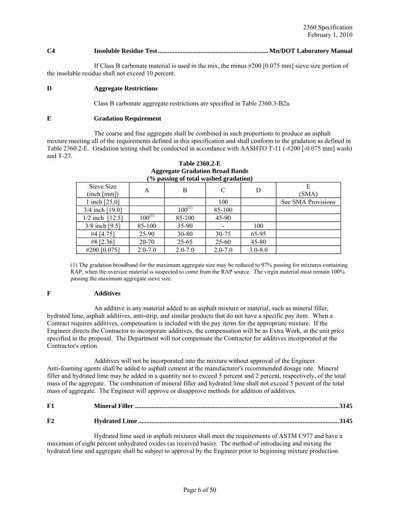
The coarse and fine aggregate shall be combined in such proportions to produce an asphalt mixture meeting all of the requirements defined in this specification and shall conform to the gradation as defined in Table 2360.2-E. Gradation testing shall be conducted in accordance with AASHTO T-11 (-#200 [-0.075 mm] wash) and T-27.
Table 2360.2-E Aggregate Gradation Broad Bands
(% passing of total washed gradation) Sieve Size
(inch [mm]) A B C D E (SMA)
1 inch [25.0] 100 See SMA Provisions 3/4 inch [19.0] 100(1) 85-100 1/2 inch [12.5] 100(1) 85-100 45-90 3/8 inch [9.5] 85-100 35-90 - 100
#4 [4.75] 25-90 30-80 30-75 65-95 #8 [2.36] 20-70 25-65 25-60 45-80
#200 [0.075] 2.0-7.0 2.0-7.0 2.0-7.0 3.0-8.0
(1) The gradation broadband for the maximum aggregate size may be reduced to 97% passing for mixtures containing RAP, when the oversize material is suspected to come from the RAP source. The virgin material must remain 100% passing the maximum aggregate sieve size.
F Additives
An additive is any material added to an asphalt mixture or material, such as mineral filler, hydrated lime, asphalt additives, anti-strip, and similar products that do not have a specific pay item. When a Contract requires additives, compensation is included with the pay items for the appropriate mixture. If the Engineer directs the Contractor to incorporate additives, the compensation will be as Extra Work, at the unit price specified in the proposal. The Department will not compensate the Contractor for additives incorporated at the Contractor's option.
Additives will not be incorporated into the mixture without approval of the Engineer. Anti-foaming agents shall be added to asphalt cement at the manufacturer's recommended dosage rate. Mineral filler and hydrated lime may be added in a quantity not to exceed 5 percent and 2 percent, respectively, of the total mass of the aggregate. The combination of mineral filler and hydrated lime shall not exceed 5 percent of the total mass of aggregate. The Engineer will approve or disapprove methods for addition of additives. F1 Mineral Filler ............................................................................................................................ 3145 F2 Hydrated Lime .......................................................................................................................... 3145
Hydrated lime used in asphalt mixtures shall meet the requirements of ASTM C977 and have a maximum of eight percent unhydrated oxides (as received basis). The method of introducing and mixing the hydrated lime and aggregate shall be subject to approval by the Engineer prior to beginning mixture production.
Page 6 of 50
2360 Specification February 1, 2010
F3 Liquid Anti-Stripping Additive
When a liquid anti-strip additive is added to the asphalt binder, blending shall be completed before the asphalt binder is mixed with the aggregate. Liquid anti-strip additives that alter the asphalt binder, such that it fails to meet the Performance Grade (PG) requirements, shall not be used. Liquid anti-strip may be added by the supplier at the refinery or by the Contractor at the plant site. The company/supplier adding the additive shall be responsible for testing the binder/additive blend to ensure compliance with the AASHTO M 320, Standard Specification for Performance Graded Asphalt Binder. No paving will be allowed until the asphalt binder/additive blend has been tested and results show that binder/additive blend properties meet the criteria in Section 2360.2G. The testing shall be done in accordance with a Mn/DOT approved Asphalt Binder QC Plan. Requirements for the Asphalt Binder QC Plan are on file in the Bituminous Office.
The following requirements for HMA mixture and asphalt binder must also be met when liquid anti-strip is added at the HMA plant site. Mixture Requirements at Design:
1) The Contractor must design the mixture with the same asphalt binder that will be supplied to the plant site. (Both Laboratory Mixture Design (Option 1) and Modified Mixture Design (Option 2).
2) The Contractor must provide documentation with either design option that includes Tensile Strength Ratio results with the liquid anti-strip dosed at the optimal rate. Documentation must include verification the binder/additive blend meets AASHTO M 320 at the optimal dose rate.
Contractor Production Testing Requirements for Asphalt Binder/Liquid Anti-Strip Blend:
1) The Contractor shall, on a daily basis, sample and test the asphalt binder/anti-strip blend. Testing of the blend can be by viscosity, penetration, or dynamic shear rheometer (DSR). When a polymer modified asphalt binder is specified, the Contractor shall use the DSR as the daily QC test.
2) The Contractor shall, on a weekly basis, send the Engineer and Mn/DOT Chemical Laboratory Director a weekly QC report summarizing the results of the daily testing as required in number 1.
3) The Contractor shall, on a bi-weekly basis, test the binder/anti-strip blend to ensure compliance with the AASHTO M 320, Standard Specification for Performance Graded Asphalt Binder (minimum 1/project). Test results shall be sent to the Engineer and Mn/DOT Chemical Laboratory Director.
4) In addition to the sampling requirements listed above, the Contractor shall obtain asphalt binder/anti-strip blend field verification samples according to 2360.4 E12.
Liquid Anti-Strip Additive Metering System:
1) The metering system shall include a liquid anti-strip flow meter in addition to an anti-strip pump. The flow meter shall be connected to the liquid anti-strip supply to measure and display only the anti-strip being fed to the asphalt binder.
2) The meter readout shall be positioned for convenient observation. 3) There shall be a means provided for comparing the flow meter readout with the calculated output
of the anti-strip pump. See number 7. 4) The system shall display in units of gallons [liters] to the nearest gallon [liter] or in units of tons
[metric tons] to the nearest 0.001 tons [0.001 metric tons], the accumulated anti-strip quantity being delivered to the mixer unit.
5) The system shall be calibrated and adjusted to maintain an accuracy of ± one percent error. 6) Calibration shall be required for each plant set-up prior to production of mixture. 7) The Engineer may require, on a daily basis, the Contractor "stick" the anti-strip tank at the end of
the days production to verify anti-strip usage quantities. 8) The system shall provide for a convenient method for sampling the binder/anti-strip after blending
has occurred. 9) Alternative blending and metering systems must be pre-approved by the Engineer
Page 7 of 50
2360 Specification February 1, 2010
F4 Coating and Anti-Stripping Additive ...................................................................................... 3161 G Asphalt Binder Material ...................................................................................... AASHTO M 320
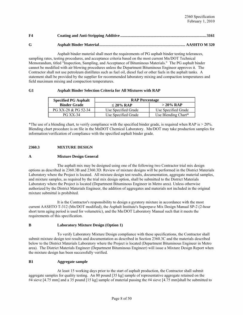
Asphalt binder material shall meet the requirements of PG asphalt binder testing tolerances, sampling rates, testing procedures, and acceptance criteria based on the most current Mn/DOT Technical Memorandum, titled "Inspection, Sampling, and Acceptance of Bituminous Materials." The PG asphalt binder cannot be modified with air blowing procedures unless the Department Bituminous Engineer approves it. The Contractor shall not use petroleum distillates such as fuel oil, diesel fuel or other fuels in the asphalt tanks. A statement shall be provided by the supplier for recommended laboratory mixing and compaction temperatures and field maximum mixing and compaction temperatures. G1 Asphalt Binder Selection Criteria for All Mixtures with RAP
Specified PG Asphalt Binder Grade
RAP Percentage ≤ 20% RAP > 20% RAP
PG XX-28 & PG 52-34 Use Specified Grade Use Specified Grade PG XX-34 Use Specified Grade Use Blending Chart*
*The use of a blending chart, to verify compliance with the specified binder grade, is required when RAP is > 20%. Blending chart procedure is on file in the MnDOT Chemical Laboratory. Mn/DOT may take production samples for information/verification of compliance with the specified asphalt binder grade. 2360.3 MIXTURE DESIGN A Mixture Design General
The asphalt mix may be designed using one of the following two Contractor trial mix design options as described in 2360.3B and 2360.3D. Review of mixture designs will be performed in the District Materials Laboratory where the Project is located. All mixture design test results, documentation, aggregate material samples, and mixture samples, as required by the trial mix design option, shall be submitted to the District Materials Laboratory where the Project is located (Department Bituminous Engineer in Metro area). Unless otherwise authorized by the District Materials Engineer, the addition of aggregates and materials not included in the original mixture submittal is prohibited.
It is the Contractor's responsibility to design a gyratory mixture in accordance with the most current AASHTO T-312 (Mn/DOT modified), the Asphalt Institute's Superpave Mix Design Manual SP-2 (2-hour short term aging period is used for volumetric), and the Mn/DOT Laboratory Manual such that it meets the requirements of this specification. B Laboratory Mixture Design (Option 1)
To verify Laboratory Mixture Design compliance with these specifications, the Contractor shall submit mixture design test results and documentation as described in Section 2360.3C and the materials described below to the District Materials Laboratory where the Project is located (Department Bituminous Engineer in Metro area). The District Materials Engineer (Department Bituminous Engineer) will issue a Mixture Design Report when the mixture design has been successfully verified. B1 Aggregate sample
At least 15 working days prior to the start of asphalt production, the Contractor shall submit aggregate samples for quality testing. An 80 pound [35 kg] sample of representative aggregate retained on the #4 sieve [4.75 mm] and a 35 pound [15 kg] sample of material passing the #4 sieve [4.75 mm]shall be submitted to
Page 8 of 50
2360 Specification February 1, 2010
the District Materials Laboratory where the Project is located (Bituminous Engineer in Metro area). In addition to the preceding requirements the Contractor shall also submit an 80 pound [35 kg] sample of representative RAP material and/or a 10 pound [5 kg] sample of representative RAS material when the mixture includes asphaltic recycled materials. The Contractor shall provide 24 hour notice of intent to sample aggregates. These samples will be tested for quality of each source, class, type, and size of virgin and non-asphaltic salvage aggregate source used in the mix design. The Contractor shall retain a companion sample of equal size until a Mixture Design Report is issued. Quality requirements are defined in Section 2360.2C.
Aggregates that require the magnesium sulfate soundness test shall be submitted to the Department Bituminous Engineer or District Materials Engineer at least 30 calendar days prior to the start of asphalt production. Dispute resolution procedures for aggregate qualities are on file in the Bituminous Office. B2 Mixture sample
At least 7 working days prior to the start of asphalt production, the Contractor shall submit in writing a proposed Job Mix Formula (JMF) for each combination of aggregates to be used in the mixture. The JMF will be reviewed in the District Materials Laboratory where the Project is located (Department Bituminous Engineer in Metro area). A Level II Quality Management mix designer must sign the proposed JMF. For each JMF submitted, the Contractor shall include test data to demonstrate conformance to mixture properties as specified in Table's 2360.3-B2b and 2360.3-B2c. The proposed JMF shall be submitted on forms approved by the Department. In addition, the Contractor shall submit an uncompacted mixture sample plus briquettes compacted at the optimum asphalt content and required compactive effort conforming to the JMF for laboratory examination and evaluation. Mixture sample size and number of compacted briquettes are as follows:
Table 2360.3-B2 Mixture Sample Requirements
Item Gyratory Design Un-compacted Mixture Sample Size 75 pounds [30 Kg] Number of compacted briquettes 2
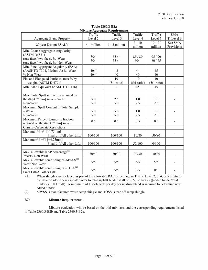
B2a Mixture Aggregate Requirements
The aggregate fractions shall be sized, graded, and combined in such proportions that the resulting mixture will meet the requirements listed in Section 2360.2-E and Table 2360.3-B2a shown below.
Page 9 of 50
2360 Specification February 1, 2010
Table 2360.3-B2a Mixture Aggregate Requirements
Aggregate Blend Property
Traffic Level 2
Traffic Level 3
Traffic Level 4
Traffic Level 5
SMA T. Level 6
20 year Design ESAL's <1 million 1 - 3 million 3 - 10 million
10 – 30 million
See SMA Provisions
Min. Coarse Aggregate Angularity (ASTM D5821) (one face / two face), %- Wear (one face / two face), %- Non-Wear
30/- 30/-
55 / - 55 / -
85 / 80 60/ -
95 / 90 80 / 75
-
Min. Fine Aggregate Angularity (FAA) (AASHTO T304, Method A) %- Wear %-Non-Wear
40(2) 40(2)
42 40
44 40
45 40
-
Flat and Elongated Particles, max % by weight, (ASTM D 4791) - 10
(5:1 ratio) 10
(5:1 ratio) 10
(5:1 ratio) -
Min. Sand Equivalet (AASHTO T 176) - - 45 45 - Max. Total Spall in fraction retained on the #4 [4.75mm] sieve – Wear Non-Wear
5.0 5.0
2.5 5.0
1.0 2.5
1.0 2.5
-
Maximum Spall Content in Total Sample – Wear Non-Wear
5.0 5.0
5.0 5.0
1.0 2.5
1.0 2.5
-
Maximum Percent Lumps in fraction retained on the #4 [4.75mm] sieve 0.5 0.5 0.5 0.5 -
Class B Carbonate Restrictions Maximum% -#4 [-4.75mm]
Final Lift/All other Lifts
100/100
100/100
80/80
50/80 -
Maximum% +#4 [+4.75mm] Final Lift/All other Lifts
100/100
100/100
50/100
0/100 -
Max. allowable RAP percentage(1) Wear / Non Wear 30/40 30/30 30/30 30/30 -
Max. allowable scrap shingles–MWSS(2) Wear/Non Wear 5/5 5/5 5/5 5/5 -
Max. allowable scrap shingles –TOSS(2) Final Lift/All other Lifts 5/5 5/5 0/5 0/0 -
(1) When shingles are included as part of the allowable RAP percentage in Traffic Level 2, 3, 4, or 5 mixtures the ratio of added new asphalt binder to total asphalt binder shall be 70% or greater ((added binder/total binder) x 100 >= 70). A minimum of 1 spotcheck per day per mixture blend is required to determine new added binder.
(2) MWSS is manufactured waste scrap shingle and TOSS is tear-off scrap shingle. B2b Mixture Requirements
Mixture evaluation will be based on the trial mix tests and the corresponding requirements listed in Table 2360.3-B2b and Table 2360.3-B2c.
Page 10 of 50
2360 Specification February 1, 2010
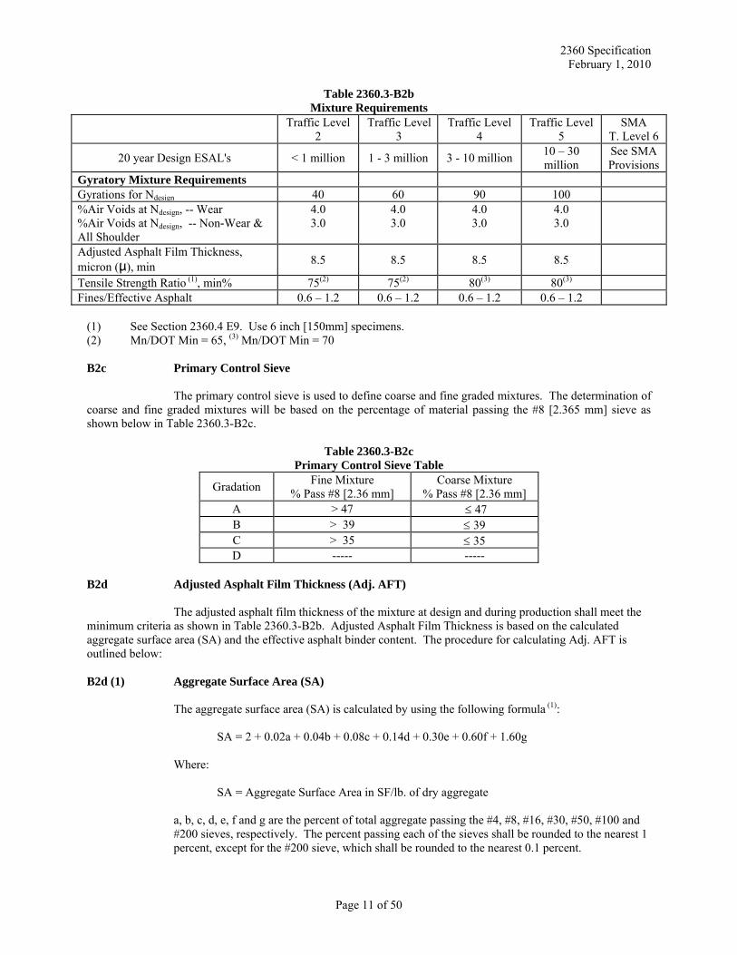
Table 2360.3-B2b Mixture Requirements
Traffic Level 2
Traffic Level 3
Traffic Level 4
Traffic Level 5
SMA T. Level 6
20 year Design ESAL's < 1 million 1 - 3 million 3 - 10 million 10 – 30 million
See SMA Provisions
Gyratory Mixture Requirements Gyrations for Ndesign 40 60 90 100 %Air Voids at Ndesign, -- Wear %Air Voids at Ndesign, -- Non-Wear & All Shoulder
4.0 3.0
4.0 3.0
4.0 3.0
4.0 3.0
Adjusted Asphalt Film Thickness, micron (μ), min 8.5 8.5 8.5 8.5
Tensile Strength Ratio (1), min% 75(2) 75(2) 80(3) 80(3) Fines/Effective Asphalt 0.6 – 1.2 0.6 – 1.2 0.6 – 1.2 0.6 – 1.2
(1) See Section 2360.4 E9. Use 6 inch [150mm] specimens. (2) Mn/DOT Min = 65, (3) Mn/DOT Min = 70 B2c Primary Control Sieve The primary control sieve is used to define coarse and fine graded mixtures. The determination of coarse and fine graded mixtures will be based on the percentage of material passing the #8 [2.365 mm] sieve as shown below in Table 2360.3-B2c.
Table 2360.3-B2c Primary Control Sieve Table
Gradation Fine Mixture % Pass #8 [2.36 mm]
Coarse Mixture % Pass #8 [2.36 mm]
A > 47 ≤ 47 B > 39 ≤ 39 C > 35 ≤ 35 D ----- -----
B2d Adjusted Asphalt Film Thickness (Adj. AFT)
The adjusted asphalt film thickness of the mixture at design and during production shall meet the minimum criteria as shown in Table 2360.3-B2b. Adjusted Asphalt Film Thickness is based on the calculated aggregate surface area (SA) and the effective asphalt binder content. The procedure for calculating Adj. AFT is outlined below:
B2d (1) Aggregate Surface Area (SA)
The aggregate surface area (SA) is calculated by using the following formula (1):
SA = 2 + 0.02a + 0.04b + 0.08c + 0.14d + 0.30e + 0.60f + 1.60g
Where:
SA = Aggregate Surface Area in SF/lb. of dry aggregate
a, b, c, d, e, f and g are the percent of total aggregate passing the #4, #8, #16, #30, #50, #100 and #200 sieves, respectively. The percent passing each of the sieves shall be rounded to the nearest 1 percent, except for the #200 sieve, which shall be rounded to the nearest 0.1 percent.
Page 11 of 50
2360 Specification February 1, 2010
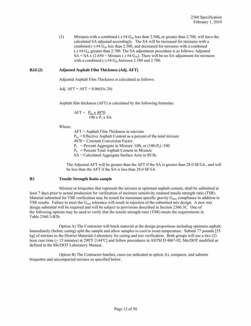
(1) Mixtures with a combined (-) #4 Gsb less than 2.580, or greater than 2.700, will have the
calculated SA adjusted accordingly. The SA will be increased for mixtures with a combined (-) #4 Gsb less than 2.580, and decreased for mixtures with a combined (-) #4 Gsb greater than 2.700. The SA adjustment procedure is as follows: Adjusted SA = SA x (2.650 ÷ Mixture (-) #4 Gsb). There will be no SA adjustment for mixtures with a combined (-) #4 Gsb between 2.580 and 2.700.
B2d (2) Adjusted Asphalt Film Thickness (Adj. AFT) Adjusted Asphalt Film Thickness is calculated as follows: Adj. AFT = AFT + 0.06(SA-28)
Asphalt film thickness (AFT) is calculated by the following formulas:
AFT = Pbe x 4870 100 x Ps x SA
Where:
AFT = Asphalt Film Thickness in microns Pbe = Effective Asphalt Content as a percent of the total mixture 4870 = Constant Conversion Factor Ps = Percent Aggregate in Mixture /100, or (100-Pb) /100 Pb = Percent Total Asphalt Cement in Mixture SA = Calculated Aggregate Surface Area in SF/lb.
The Adjusted AFT will be greater than the AFT if the SA is greater than 28.0 SF/Lb., and will be less than the AFT if the SA is less than 28.0 SF/Lb.
B3 Tensile Strength Ratio sample
Mixture or briquettes that represent the mixture at optimum asphalt content, shall be submitted at least 7 days prior to actual production for verification of moisture sensitivity retained tensile strength ratio (TSR). Material submitted for TSR verification may be tested for maximum specific gravity Gmm compliance in addition to TSR results. Failure to meet the Gmm tolerance will result in rejection of the submitted mix design. A new mix design submittal will be required and will be subject to provisions described in Section 2360.3C. One of the following options may be used to verify that the tensile strength ratio (TSR) meets the requirements in Table 2360.3-B2b.
Option A) The Contractor will batch material at the design proportions including optimum asphalt. Immediately (before curing) split the sample and allow samples to cool to room temperature. Submit 77 pounds [35 kg] of mixture to the District Materials Laboratory for curing and test verification. Both groups will use a two (2) hour cure time (+ 15 minutes) at 290oF [144oC] and follow procedures in ASTM D 4867-92, Mn/DOT modified as defined in the Mn/DOT Laboratory Manual.
Option B) The Contractor batches, cures (as indicated in option A), compacts, and submits briquettes and uncompacted mixture as specified below.
Page 12 of 50
2360 Specification February 1, 2010
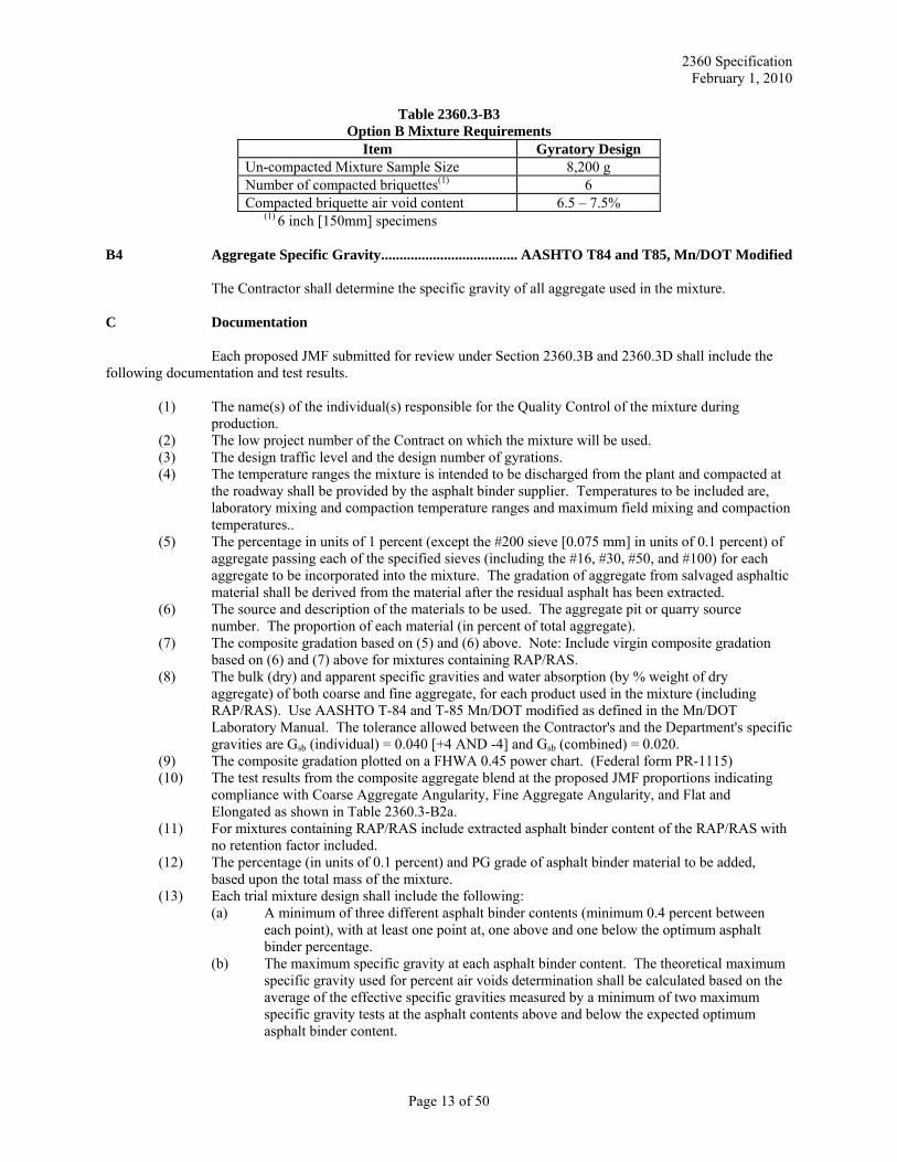
Table 2360.3-B3 Option B Mixture Requirements
Item Gyratory Design Un-compacted Mixture Sample Size 8,200 g Number of compacted briquettes(1) 6 Compacted briquette air void content 6.5 – 7.5%
(1) 6 inch [150mm] specimens B4 Aggregate Specific Gravity ..................................... AASHTO T84 and T85, Mn/DOT Modified
The Contractor shall determine the specific gravity of all aggregate used in the mixture. C Documentation
Each proposed JMF submitted for review under Section 2360.3B and 2360.3D shall include the following documentation and test results.
(1) The name(s) of the individual(s) responsible for the Quality Control of the mixture during production.
(2) The low project number of the Contract on which the mixture will be used. (3) The design traffic level and the design number of gyrations. (4) The temperature ranges the mixture is intended to be discharged from the plant and compacted at
the roadway shall be provided by the asphalt binder supplier. Temperatures to be included are, laboratory mixing and compaction temperature ranges and maximum field mixing and compaction temperatures..
(5) The percentage in units of 1 percent (except the #200 sieve [0.075 mm] in units of 0.1 percent) of aggregate passing each of the specified sieves (including the #16, #30, #50, and #100) for each aggregate to be incorporated into the mixture. The gradation of aggregate from salvaged asphaltic material shall be derived from the material after the residual asphalt has been extracted.
(6) The source and description of the materials to be used. The aggregate pit or quarry source number. The proportion of each material (in percent of total aggregate).
(7) The composite gradation based on (5) and (6) above. Note: Include virgin composite gradation based on (6) and (7) above for mixtures containing RAP/RAS.
(8) The bulk (dry) and apparent specific gravities and water absorption (by % weight of dry aggregate) of both coarse and fine aggregate, for each product used in the mixture (including RAP/RAS). Use AASHTO T-84 and T-85 Mn/DOT modified as defined in the Mn/DOT Laboratory Manual. The tolerance allowed between the Contractor's and the Department's specific gravities are Gsb (individual) = 0.040 [+4 AND -4] and Gsb (combined) = 0.020.
(9) The composite gradation plotted on a FHWA 0.45 power chart. (Federal form PR-1115) (10) The test results from the composite aggregate blend at the proposed JMF proportions indicating
compliance with Coarse Aggregate Angularity, Fine Aggregate Angularity, and Flat and Elongated as shown in Table 2360.3-B2a.
(11) For mixtures containing RAP/RAS include extracted asphalt binder content of the RAP/RAS with no retention factor included.
(12) The percentage (in units of 0.1 percent) and PG grade of asphalt binder material to be added, based upon the total mass of the mixture.
(13) Each trial mixture design shall include the following: (a) A minimum of three different asphalt binder contents (minimum 0.4 percent between
each point), with at least one point at, one above and one below the optimum asphalt binder percentage.
(b) The maximum specific gravity at each asphalt binder content. The theoretical maximum specific gravity used for percent air voids determination shall be calculated based on the average of the effective specific gravities measured by a minimum of two maximum specific gravity tests at the asphalt contents above and below the expected optimum asphalt binder content.
Page 13 of 50
2360 Specification February 1, 2010
(c) The test results for the individual and average bulk specific gravity, density, and heights, of at least two specimens at each asphalt binder content.
(d) The percent air voids in the mixture at each asphalt binder content. (e) The Adj. Asphalt Film Thickness (Adj. AFT) at each asphalt binder content. (f) The fines to Effective Asphalt (F/A) ratio calculated to the nearest 0.1 percent. (g) TSR results at the optimum asphalt binder content. (h) Graphs showing air voids, adjusted AFT, Gmb, Gmm and unit weight vs. percent asphalt
binder content for each of the three asphalt binder contents submitted with trial mix. (i) Evidence the completed mixture will conform to design air voids (Va), Adj. AFT, TSR,
F/Ae (Fines to effective asphalt ratio). (j) The documentation shall also include labeled gyratory densification tables and curves
generated from the gyratory compactor for all points used in the mixture submittal. (14) Optional Add-Rock/Add-Sand Provisions
If the Contractor chooses to use the add-material option to augment the submitted JMF, the Contractor shall provide samples of the aggregate for quality analysis in accordance with Section 2360.3B1. The Contractor shall provide mix design data for two additional design points per add-material. One point shall show a proportional adjustment to the submitted JMF that includes 5 percent, by mass, add-material at the JMF optimum asphalt percent. The second point shall show a proportional adjustment to the submitted JMF that includes 10 percent, by mass, add-material at the JMF optimum asphalt percent. The following information will be reported for each of these two points: (a) The maximum specific gravity (average of two tests). (b) The test results for the individual and average bulk specific gravity, density, and height of
at least two specimens at the optimum asphalt binder content. (c) The percent air voids in the mixture for each point. (d) The Fines to Effective Asphalt ratio calculated to the nearest 0.1 of a percent. (e) Coarse and Fine Aggregate crushing counts (f) The Adjusted Asphalt Film Thickness
Up to two add-materials will be allowed per mix design submittal. Aggregate quality and mix characteristics are required for each proposed add-material and shall be submitted at the time of the original trial mix submittal. No mixture sample or briquettes are required for these two additional points.
D Modified Mixture Design (Option 2)
The Contractor shall submit mixture design test results and documentation as described in Section 2360.3C to the District Materials Laboratory where the Project is located (Department Bituminous Engineer in Metro area) to verify compliance with these specifications. The District Materials Engineer (Department Bituminous Engineer) will issue a Mixture Design Report when the mixture design has been successfully verified. Mixture submittal is not required. The Contractor may use this option if all of the following conditions are met:
a) The aggregates must have been tested for and meet all applicable quality requirements in the current construction season.
b) The Level II mix designer submitting the mixture design must have a minimum of 2 years experience in mixture design.
D1 JMF Submittal
At least 2 working days prior to the start of asphalt production, the Contractor shall submit in writing a proposed Job Mix Formula (JMF) for each combination of aggregates to the Department Bituminous Engineer or District Materials Engineer for review. A Level II Quality Management mix designer must sign this proposed JMF. For each JMF submitted, the Contractor shall include documentation as outlined in Section 2360.3C to demonstrate conformance to mixture properties as specified in Table 2360.3-B2b and 2360.3-B2c. The proposed JMF shall be submitted on forms approved by the Department.
Page 14 of 50
2360 Specification February 1, 2010
D2 Initial Production Test Verification
At the start of production, the testing frequency for the first 1,800 metric tons [2,000 tons] of each mix type shall be as specified in Table 2360.4-D.
All mixture placed on Mn/DOT projects shall meet the specified quality indicators and required field density. Failure to do so will result in reduced payment or removal and replacement with acceptable material.
The Department shall take a mix verification sample within the first four samples at the start of production of each mix type. D3 Tensile Strength Ratio sample
See Section 2360.4E9 E Mixture Design Report
A Mixture Design Report consists of the JMF (Job Mix Formula). The JMF includes composite gradation, aggregate component proportions, asphalt binder content of the mixture, design air voids, adj. asphalt film thickness, and aggregate bulk specific gravity values. JMF limits will be shown for gradation control sieves (JMF limits will be aggregate gradation broadbands shown in Table 2360.2-E), percent asphalt binder content, air voids, and Adj. Asphalt Film Thickness. Issuance of a Mixture Design Report confirms the mixture has been reviewed for and meets volumetric properties only. No guaranty or warranty, either express or implied, is made regarding placement and compaction of the mixture.
A Department reviewed Mixture Design Report is required for all paving except for small quantities of material provided under Section 2360.5H. All submitted materials must meet aggregate and mixture design requirements before a Mixture Design Report is issued. The Department will review two trial mix designs per mix type designated in the plan, per Contract at no cost to the Contractor. Additional mix designs will be verified at a cost of $2000 per design, payable to the Commissioner of Transportation.
For city, county, and other agency projects, the Contractor shall provide to the District Materials Laboratory a complete Project proposal including addenda, supplemental agreements, change orders, and any Plan sheets (including typical sections) that affect the mix design. The Department will not start the verification process without this information. 2360.4 MIXTURE QUALITY MANAGEMENT (Quality Control/Quality Assurance) A Quality Control (QC)
The Contractor shall provide and maintain a quality control program for HMA production. A quality control program is defined as all activities, including mix design, process control inspection, sampling and testing, and necessary adjustments in the process that are related to the production of a hot mix asphalt (HMA) pavement which meets the requirements of the specifications. A1 Contractor Certified Plant HMA A1a Certification Procedure
The Contractor shall:
(1) Complete application form and request for plant inspection. (2) Provide a site map of stockpile locations. (3) Pass plant and testing facility inspection by having the Plant Inspector and Bituminous Plant
Authorized Agent complete and sign the Asphalt Plant Inspection Report (TP 02142-02, TP 02143-02). By signing the Asphalt Plant Inspection Report, the plant authorized agent agrees
Page 15 of 50
2360 Specification February 1, 2010
to calibrate and maintain all plant and laboratory equipment within allowable tolerances set forth in these specifications, Standard Specifications for Construction, and the Mn/DOT Bituminous Manual.
(4) Obtain a Mixture Design Report prior to production. A1b Maintaining Certification
To maintain certification, the plant must produce, test, and document all certified plant asphalt mixtures in accordance with the above requirements on a continuous basis. Continuous basis means all asphalt mixtures supplied from a certified plant to any Department project with 2360 asphalt mixtures must be sampled and tested in accordance with 2360 requirements and the Schedule of Materials Control.
The Contractor shall assure the plant certification procedure is performed annually after winter suspension and before producing material for a Project. In addition, a first day sampling and testing frequency rate as stated in Table 2360.4-D shall be followed.
The Contractor shall recertify a plant when it is moved to a new location or a previously occupied location. A1c Revocation of Plant Certification
The Department Construction Engineer may revoke certification of an asphalt plant when requirements are not being met or records are falsified. The Department may revoke the Technician Certification for the individual involved.
The Department Bituminous Engineer and Department Contract Administrator will maintain a list of companies who have had their asphalt plant certification revoked. B Quality Assurance (QA)
The Department will perform QA testing as part of the acceptance process. The Engineer is responsible for QA testing, records, and acceptance. The Engineer will accomplish the QA process by:
(1) Conducting Quality assurance and verification sampling and testing. (2) Observing sampling and tests performed by the QC personnel. (3) Taking additional samples at any time and any location during production. (4) Monitoring the required QC summary sheets and control charts. (5) Verifying calibration of laboratory testing equipment. (6) Communicating Mn/DOT test results to the Contractor's QC personnel in a timely manner (See
2360.4M and 2360.4N). (7) Ensuring Independent Assurance Sampling and testing requirements are met.
C Contractor's Quality Control C1 Personnel Requirements
Along with the proposed mix design data, the Contractor shall submit to the Engineer an organizational chart listing the names and phone numbers of individuals and alternates responsible for mix design, process control administration, and inspection. The Contractor shall also post a current organizational chart and if required by the Engineer, post a daily roster of individuals performing QC testing in the Contractor's test facility.
The Contractor's quality control organization or private testing firm shall have Certified Technicians who have met the requirements on file with the Department's Technical Certification program. Individuals performing process control testing must be certified as a Level I Bituminous Quality Management (QM) Tester. Individuals performing mix design calculations or mix design adjustments must be certified as Level II Bituminous QM Mix Designer. The Contractor shall have a Certified Level II Bituminous QM Mix Designer
Page 16 of 50
2360 Specification February 1, 2010
available to make any necessary process adjustments. The Contractor shall have a minimum of one person per paving operation certified as a Level II Bituminous Street Inspector. C2 Laboratory Requirements:
The Contractor shall furnish and maintain a laboratory at the plant site or other site as approved by the Engineer. The laboratory shall be furnished with the necessary equipment and supplies for performing Contractor quality control testing. The laboratory equipment shall meet the requirements listed in Section 400 of the Mn/DOT Bituminous Manual, Mn/DOT Lab Manual, and these specifications, including having extraction capabilities. The laboratory shall be calibrated and operational prior to the beginning of production. In addition to the requirements listed above, the laboratory shall be equipped with a telephone for use by the Contractor or the Engineer. A fax machine and copy machine shall be available for use by the Contractor or the Engineer at the laboratory site. The Engineer may waive the requirement to have a fax machine available at the laboratory site if transfer of data and test results can be accomplished through electronic transmittal (email). The laboratory shall also include a computer and printer. The computer shall have the following minimum requirements: 1) Intel based with either Celeron or Pentium IV processor with a minimum processor speed of 1.8 MHZ. 2) CD writer with CD/RW capability and a minimum write speed of 16x. 3) Windows 2000 or Windows XP with Microsoft Excel version 97 or newer. The printer must be able to print control charts.
The Engineer shall be allowed to inspect measuring and testing devices to confirm both calibration and condition. The Contractor shall calibrate and correlate all testing equipment in accordance with the latest version of the Mn/DOT Bituminous Manual and Mn/DOT Lab Manual. Records of calibration for each piece of testing equipment shall be kept in the same facility as the equipment. D Sampling and Testing
The Contractor shall ensure that all QC samples are taken at random locations. Random number generation and determination of random sample location shall be consistent with the Mn/DOT Bituminous Manual Section 5-693.7 Table A or Section 5 of ASTM D3665. The Engineer may approve alternate methods of random number generation.
The tests for mixture properties shall be conducted on representative portions of the mix, quartered from a larger sample of mixture taken from behind the paver, or when approved by the Engineer, an alternate sampling location. The procedure for truck box sampling, an alternate sampling location, is on file in the Bituminous Office. When an alternate sampling location is approved and used by the Contractor, the daily verification sample must still be taken from behind the paver.
The Contractor shall obtain a sample of at least 55 pounds [25 kg]. This sample may be either split in the field or transported to the test facility by a method to retain heat to facilitate sample quartering procedures. The Contractor shall store and retain mixture bulk samples and companion samples for the Department for a period of 10 calendar days. The Contractor shall maintain these split samples in containers labeled with companion numbers. The Contractor shall perform QC sampling and testing according to the following schedule.
Determine the planned tonnage for each mixture to be produced during the production day. Divide the planned production by 1000. Round the number to the next higher whole number. This number will be the number of production tests required for that mixture. Required production tests are listed in Table 2360.4-E. Split the planned production into even increments and select sample locations as described above. If actual tonnage exceeds planned tonnage additional tests may be required. During production, mixture volumetric property tests will not be required when mix production is less than 300 tons [270 metric tons]. However, production tests will be required when the accumulative tonnage on successive days exceeds 300 tons [270 metric tons].
At the start of production, the testing frequency for the first 2,000 tons [1800 metric tons] of each mix type shall be as follows:
Page 17 of 50
2360 Specification February 1, 2010
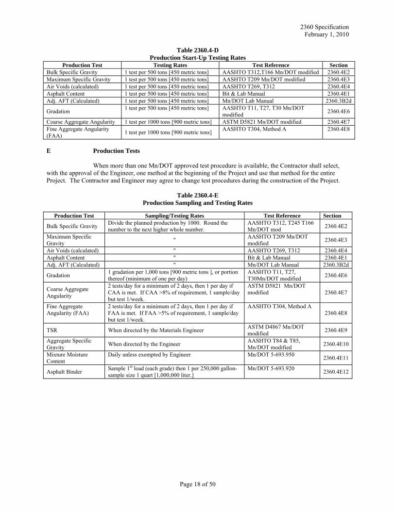
Table 2360.4-D Production Start-Up Testing Rates
Production Test Testing Rates Test Reference Section Bulk Specific Gravity 1 test per 500 tons [450 metric tons] AASHTO T312,T166 Mn/DOT modified 2360.4E2 Maximum Specific Gravity 1 test per 500 tons [450 metric tons] AASHTO T209 Mn/DOT modified 2360.4E3 Air Voids (calculated) 1 test per 500 tons [450 metric tons] AASHTO T269, T312 2360.4E4 Asphalt Content 1 test per 500 tons [450 metric tons] Bit & Lab Manual 2360.4E1 Adj. AFT (Calculated) 1 test per 500 tons [450 metric tons] Mn/DOT Lab Manual 2360.3B2d
Gradation 1 test per 500 tons [450 metric tons] AASHTO T11, T27, T30 Mn/DOT modified 2360.4E6
Coarse Aggregate Angularity 1 test per 1000 tons [900 metric tons] ASTM D5821 Mn/DOT modified 2360.4E7 Fine Aggregate Angularity (FAA) 1 test per 1000 tons [900 metric tons] AASHTO T304, Method A 2360.4E8
E Production Tests
When more than one Mn/DOT approved test procedure is available, the Contractor shall select, with the approval of the Engineer, one method at the beginning of the Project and use that method for the entire Project. The Contractor and Engineer may agree to change test procedures during the construction of the Project.
Table 2360.4-E
Production Sampling and Testing Rates
Production Test Sampling/Testing Rates Test Reference Section
Bulk Specific Gravity Divide the planned production by 1000. Round the number to the next higher whole number.
AASHTO T312, T245 T166 Mn/DOT mod 2360.4E2
Maximum Specific Gravity " AASHTO T209 Mn/DOT
modified 2360.4E3
Air Voids (calculated) " AASHTO T269, T312 2360.4E4 Asphalt Content " Bit & Lab Manual 2360.4E1 Adj. AFT (Calculated) " Mn/DOT Lab Manual 2360.3B2d
Gradation 1 gradation per 1,000 tons [900 metric tons ], or portion thereof (minimum of one per day)
AASHTO T11, T27, T30Mn/DOT modified 2360.4E6
Coarse Aggregate Angularity
2 tests/day for a minimum of 2 days, then 1 per day if CAA is met. If CAA >8% of requirement, 1 sample/day but test 1/week.
ASTM D5821 Mn/DOT modified 2360.4E7
Fine Aggregate Angularity (FAA)
2 tests/day for a minimum of 2 days, then 1 per day if FAA is met. If FAA >5% of requirement, 1 sample/day but test 1/week.
AASHTO T304, Method A 2360.4E8
TSR When directed by the Materials Engineer ASTM D4867 Mn/DOT modified 2360.4E9
Aggregate Specific Gravity When directed by the Engineer AASHTO T84 & T85,
Mn/DOT modified 2360.4E10
Mixture Moisture Content
Daily unless exempted by Engineer Mn/DOT 5-693.950 2360.4E11
Asphalt Binder Sample 1st load (each grade) then 1 per 250,000 gallon-sample size 1 quart [1,000,000 liter.]
Mn/DOT 5-693.920 2360.4E12
Page 18 of 50
2360 Specification February 1, 2010
E1 Asphalt Binder Content (2) (a) Spot Check (Virgin only) .................................................................... Mn/DOT Bituminous Manual (b) Incinerator Oven (1) ........................................................ Mn/DOT Laboratory Manual Method 1853 (c) Chemical Extraction ......................................... Mn/DOT Laboratory Manual Method 1851 or 1852 (d) Meter Method (Virgin only)................................................................ Mn/DOT Bituminous Manual
(1) Incinerator Oven may not be used when the percentage of Class B material exceeds 50%
within the composite blend, unless a correction factor is determined by the Contractor and approved by the District Materials Engineer.
(2) For Traffic Level 2, 3, 4, and 5 mixtures that include shingles as part of the allowable RAP percentage a minimum of 1 spotcheck per day per mixture blend is required to determine new added asphalt binder (See footnote 1 of Table 2360.3-B2a).
E2 Gyratory Bulk Specific Gravity, Gmb (2 specimens) ................................ AASHTO T312, T166,
Mn/DOT Modified E3 Maximum Specific Gravity, Gmm ........................................ AASHTO T209, Mn/DOT Modified E4 Air Voids - Individual and Isolated (calculation) ...................................... AASHTO T269, T312
Isolated air voids are calculated using the maximum mixture specific gravity and the corresponding bulk specific gravity from a single test. Individual air voids are calculated from the maximum specific gravity moving average and the bulk specific gravity from that single test.
For gyratory design, compaction shall be conducted to Ndesign , as shown in Table 2360.3-B2b, for the specified Traffic Level. E5 Adj. Asphalt Film Thickness (AFT) (calculation) .................................... Mn/DOT Lab Manual E6 Gradation - Blended Aggregate ......... AASHTO T-11, T-27, and T-30 (all Mn/DOT modified)
Testing to determine the blended aggregate gradation shall be determined every 1,000 tons [1800 metric tons], or portion thereof (minimum of one per day), on samples taken at the same time as the required mixture sample for a given increment.
All gradations require a-#200 [- 0.075 mm] wash.
(a) Virgin Aggregate Mixtures - Drum or Screenless Plants Belt Samples or extracted production samples.
(b) All Other Mixtures: 1. Hot Bins - Drybatch (Optional) 2. Incinerator Oven Mn/DOT Laboratory Manual Method 1853 (Optional) except
samples that contain over 50% class B. (1) 3. Extraction Mn/DOT Laboratory Manual Method 1851 or 1852 (Optional)
(1) Incinerator Oven may not be used when the percentage of Class B
material exceeds 50% within the composite blend, unless a correction factor is determined by the Contractor and approved by the District Materials Engineer.
E7 Coarse Aggregate Angularity ................................................... ASTM D5821 Mn/DOT modified
CAA test results shall meet the minimum percent fractured faces as shown in Table 2360.3-B2a. ASTM D-5821 shall be used to determine coarse aggregate angularity on the composite blend from aggregates used in production of hot mix asphalt. Mixtures that contain virgin aggregates may be tested from composite belt samples. Mixtures that contain RAP must be tested from extracted aggregates taken from standard production
Page 19 of 50
2360 Specification February 1, 2010
samples. The percentage of fractured faces of the composite aggregate blend less than 100% shall be tested at the following rates:
(1) Perform two tests per day for each mixture blend for a minimum of two days and then one per day if the test samples meet CAA requirements.
(2) If CAA crushing test results exceed 8 percent of the requirement, take one sample per day and perform one test per week.
CAA results must be reported on the test summary sheet. Mixture placed and represented by
results below the minimum requirement, as shown in Table 2360.3-B2a, will be subject to reduced payment as outlined in Table 2360.4-L3. Tonnage subjected to reduced payment shall be calculated as the tons placed from the sample point of the failing test until the sampling point when the test result is back within specifications. E8 Fine Aggregate Angularity ..................................................................... ASTM C1252 Method A
FAA test results shall meet the minimum criteria shown in Table 2360.3-B2a. ASTM C1252 Method A shall be used to determine fine aggregate angularity on the composite blend from aggregates used in production of HMA. Mixtures that contain virgin aggregates may be tested from composite belt samples. Mixtures that contain RAP must be tested from extracted aggregates taken from standard production samples. The percentage of uncompacted voids from the composite aggregate blend shall be tested at the following rates.
(1) Perform two tests per day for each mixture blend for a minimum of two days and then one per day if the test samples meet FAA requirements.
(2) If FAA test results exceed 5 percent of the requirement, take one sample per day and perform one test per week.
FAA results must be reported on the test summary sheet. Mixture placed and represented by
results below the minimums, as shown in Table 2360.3-B2a, will be subject to reduced payment as outlined in Table 2360.4-L3. Tonnage is subjected to reduced payment shall be calculated as the tons placed from the sample point of the failing test until the sampling point when the test result is back within specifications. E9 Field Tensile Strength Ratio (TSR) ........................................ ASTM D4867 Mn/DOT Modified
At the discretion of the Materials Engineer, mixture will be sampled and tested to verify tensile strength ratio (TSR)(1). If the Materials Engineer requires sampling and testing, both the Contractor and the Department will be required to test these samples within 72 hours after it is sampled. Sample size shall be 110 pound [50 kg] minimum and split in half to provide a sample for the Department and the Contractor. The Department companion of this split shall be labeled with the date, time, Project number and approximate cumulative tonnage to date. The Department companion shall be given to the Department Street Inspector or Plant Monitor immediately or delivered to the District Materials Engineer within 24 hours of sampling, as specified by the Engineer. Mixture samples shall be taken from behind the paver unless the Engineer approves an alternate sampling location. Specimen size shall be 6 inch [150 mm] for gyratory design The Contractor may test the sample at a permanent lab site or a field lab site.
(1) When utilizing Option 2 mix design, it is recommended a sample be obtained within the first 5,000 tons [4,500 metric tons] of HMA produced or by the second day of production, whichever comes first, to verify tensile strength ratio (TSR).
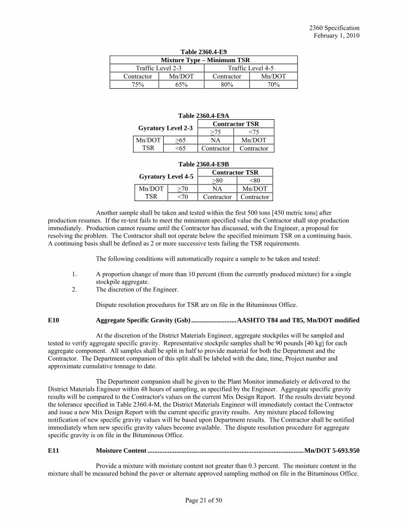
Minimum acceptable TSR values for production are shown in Table 2360.4-E9. The Contractor
shall stop production immediately if minimum TSR requirements are not met. The Contractor will not be allowed to resume production until anti-strip has been added to the asphalt binder. Determination of who is responsible for the cost of the anti-strip is based on Mn/DOT and Contractor TSR values as outlined in Tables 2360.4E9A and 2360.4E9B. When Mn/DOT is responsible for the cost of the anti-strip, payment will be made only for the cost of the anti-strip for mixtures placed on that project. Mn/DOT will not reimburse the Contractor for any delay costs associated with making changes related to this testing.
Page 20 of 50
2360 Specification February 1, 2010
Table 2360.4-E9 Mixture Type – Minimum TSR Traffic Level 2-3 Traffic Level 4-5 Contractor Mn/DOT Contractor Mn/DOT 75% 65% 80% 70%
Table 2360.4-E9A
Gyratory Level 2-3 Contractor TSR >75 <75
Mn/DOT TSR
>65 NA Mn/DOT <65 Contractor Contractor
Table 2360.4-E9B
Gyratory Level 4-5 Contractor TSR >80 <80
Mn/DOT TSR
>70 NA Mn/DOT <70 Contractor Contractor
Another sample shall be taken and tested within the first 500 tons [450 metric tons] after
production resumes. If the re-test fails to meet the minimum specified value the Contractor shall stop production immediately. Production cannot resume until the Contractor has discussed, with the Engineer, a proposal for resolving the problem. The Contractor shall not operate below the specified minimum TSR on a continuing basis. A continuing basis shall be defined as 2 or more successive tests failing the TSR requirements.
The following conditions will automatically require a sample to be taken and tested:
1. A proportion change of more than 10 percent (from the currently produced mixture) for a single stockpile aggregate.
2. The discretion of the Engineer.
Dispute resolution procedures for TSR are on file in the Bituminous Office. E10 Aggregate Specific Gravity (Gsb) ........................... AASHTO T84 and T85, Mn/DOT modified
At the discretion of the District Materials Engineer, aggregate stockpiles will be sampled and tested to verify aggregate specific gravity. Representative stockpile samples shall be 90 pounds [40 kg] for each aggregate component. All samples shall be split in half to provide material for both the Department and the Contractor. The Department companion of this split shall be labeled with the date, time, Project number and approximate cumulative tonnage to date.
The Department companion shall be given to the Plant Monitor immediately or delivered to the District Materials Engineer within 48 hours of sampling, as specified by the Engineer. Aggregate specific gravity results will be compared to the Contractor's values on the current Mix Design Report. If the results deviate beyond the tolerance specified in Table 2360.4-M, the District Materials Engineer will immediately contact the Contractor and issue a new Mix Design Report with the current specific gravity results. Any mixture placed following notification of new specific gravity values will be based upon Department results. The Contractor shall be notified immediately when new specific gravity values become available. The dispute resolution procedure for aggregate specific gravity is on file in the Bituminous Office. E11 Moisture Content ............................................................................................. Mn/DOT 5-693.950
Provide a mixture with moisture content not greater than 0.3 percent. The moisture content in the mixture shall be measured behind the paver or alternate approved sampling method on file in the Bituminous Office.
Page 21 of 50
2360 Specification February 1, 2010
Sampling and testing shall be conducted by the Contractor on a daily basis unless exempted by the Engineer. Sampling and testing is suggested when rain on stockpiles exceed more than 0.2 inch [5 mm] in a 24 hour period. The sample shall be stored in an airtight container. Microwave testing is prohibited.
HMA that exceeds 0.3% moisture content is unacceptable. The Contractor shall take appropriate action to remove excess water from the mixture. This action may include reducing the production rate, mixing stockpile aggregates prior to placement into the feed bins, and use of covered stockpiles. E12 Asphalt Binder Samples
The Contractor shall sample the first shipment of each type of asphalt binder, then sample at a rate of one per 250,000 gallons [1,000,000 liters]; sample size shall be 1 quart [1.0L]. All samples shall be taken in accordance with the Mn/DOT Bituminous Manual 5-693.920. Sampling shall be conducted by Contractor and monitored by the Inspector. The Contractor shall record sample information on Asphalt Sample Identification Card. Promptly submit the sample to the Department Materials Laboratory in Maplewood. Contact the Department Chemical Laboratory Director for disposition of failing asphalt binder samples. F Documentation (Records)
The Contractor shall maintain documentation, including test summary sheets and control charts, on an ongoing basis. The Contractor shall also maintain a file of gyratory specimen heights for all gyratory compacted samples and test worksheets. Reports, records, and diaries developed during the progress of construction activities for the Project, shall be filed as directed by the Engineer and will become the property of the Department. The Contractor shall:
(1) Number test results in accordance with standard Department procedures and record on forms approved/supplied by the Department.
(2) Facsimile or when approved by the Engineer, electronically transmit (email) all production test
results on test summary sheets to the District Materials Laboratory and to other sites as requested by the Engineer, by 11 AM of the day following production.
(2a) Include the following production test results and mixture information on the Department approved
test summary sheet.
1. Percent passing on all sieves listed in Table 2360.2-E (including #16, #30, #50, #100). 2. Coarse and fine aggregate crushing. 3. Maximum specific gravity (Gmm.). 4. Bulk specific gravity (Gmb ). 5. Percent total asphalt binder content (Pb) and new added asphalt binder content. 6. Calculated production air voids (Va ). 7. Calculated adjusted AFT (Adj. AFT). 8. Composite aggregate specific gravity (Gsb) reflecting current proportions. 9. Aggregate proportions in use at the time of sampling. 10. Tons where sampled. 11 Tons represented by a test and cumulative tons produced. 12. Fines to effective asphalt ratio (F/Ae). 13. Signature Line for Mn/DOT and Contractor Representative. 14. Mixture Moisture Content. 15. Mn/DOT verification sample test result.
(2b) Submit copies of all failing test results to the Engineer on a daily basis.
(3) Provide the Engineer with asphalt manifests or BOL's on a daily basis.
Page 22 of 50
2360 Specification February 1, 2010
(4) Provide a daily plant diary to include a description of QC actions taken (adjustment of cold feed percentages, changes in JMFs, etc.) include all changes or adjustments on the test summary sheets.
(5) Provide weekly truck scale spot checks.
(6) Provide a Department approved accounting system for all mixes and provide a daily and final
Project summary of material quantities and types.
(6a) Provide a final hardcopy summary of all quality control test summary sheets and control charts at completion of bituminous operations on the Project to the Engineer. Because Certified Plant test data often represents test data for multiple projects, it may be necessary to make duplicate copies of the data for each project. The Contractor shall also submit a diskette of the quality control summary sheets, control charts and density worksheets to the Bituminous Engineer.
(7) Furnish an automated weigh scale and computer generated weigh ticket. The ticket shall indicate
project number, mix designation (including binder grade), Mixture Design Report#, truck identification and tare, net mass, date and time of loading. Any deviations from the minimum information to be provided on the computer generated weigh ticket must be approved by the Engineer in writing.
(8) Test summary sheets, charts, and records for a mixture produced at one plant site shall be
continued from contract to contract. The Contractor shall begin new summary sheets and charts annually for winter carry-over projects. The Contractor shall begin new summary sheets and charts when an asphalt plant is re-setup in the same location after it has moved out.
G Documentation (Control Charts)
The following data shall be recorded on the standardized control charts, all control charts and summary sheets shall be computer generated using software approved by the Engineer. Software is available from the Mn/DOT Bituminous Office at www.mrr.dot.state.mn.us/pavement/bituminous/bituminous.asp.
(1) Blended aggregate gradation, include sieves shown in Table 2360.2-E for specified mixture. (2) Percent asphalt binder content (Pb) (3) Maximum specific gravity (Gmm.) (4) Production air voids (Va ) (5) Adj. AFT
Individual test results shall be plotted for each test point. A solid line shall connect individual
points. The moving average for each test variable shall be plotted starting with the fourth test. A dashed line shall connect the moving average points. The Department's quality assurance and verification test results shall be plotted with triangles. Specification JMF limits shall be indicated on the control charts using a dotted line. The Engineer may waive the plotting of control charts. H JMF Limits
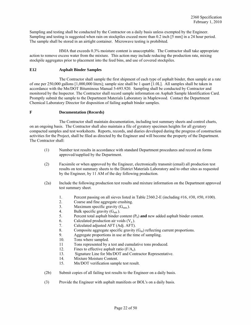
The production air voids and adj. AFT are based upon the minimum specified requirements as shown in Table 2360.3-B2b. Gradations and asphalt binder content limits are based upon the current Department reviewed Mixture Design Report. Gradation control sieves are shown in Table 2360.2-E. The mixture production targets are listed on the Mixture Design Report. JMF limits are the target plus or minus the limits shown in Table 2360.4-H. JMF limits are used as the criteria for acceptance of materials based on the moving average.
Page 23 of 50
2360 Specification February 1, 2010
Table 2360.4-H JMF Limits (N=4)
Item JMF Limits Adj. AFT - 0.5 Production Air Voids, % ± 1.0 Asphalt Binder Content, % - 0.4 Sieve - % Passing 1 inch, 3/4 inch, 1/2 inch, 3/8 inch, #4 [25, 19, 12.5, 9.5, 4.75 mm] Broad Band Limits #8 [2.36 mm] Broad Band Limits #200 [0.075 mm] Broad Band Limits
H1 Moving Average Calculation A moving average is the average of the last four test results. The calculation of the moving average shall continue without interruption except under the following conditions:
1) The Contractor shall begin new summary sheets and charts annually for winter carry-over projects. 2) The Contractor shall begin new summary sheets and charts when an asphalt plant is re-setup in the
same site after it has been moved out. I JMF Bands
JMF Bands are defined as the area between the target, as identified on the Mixture Design Report, and the JMF limits. J JMF Adjustment
The Contractor shall begin mixture production with the materials (gradation, asphalt content, and aggregate proportions) closely conforming to the reviewed Mixture Design Report. Closely conforming shall be defined as aggregate proportions within 5 percent of the design proportions (1) and other mixture parameters within the JMF limits in Table 2360.4-H. This requirement may be waived if the Contractor provides the District Materials Laboratory with prior documented production data showing how production affects the mixture properties or if the Contractor provides the District Materials Laboratory with a written justification or explanation of material changes since the original mixture submittal. (1) The Contractor shall begin mixture production using all aggregate proportions included on the Mixture Design Report unless the aggregate proportion is shown as 0 percent. J1 JMF Request for Adjustment
If, during production, the Contractor determines from results of QC tests that adjustments to the mix design are necessary to achieve the specified properties, the following provisions shall apply. Unless otherwise authorized by the District Materials Engineer, no adjustments are allowed using aggregates or materials not part of the original mix design.
The Contractor shall make a request for a JMF adjustment to the Department Bituminous Engineer or District Materials Engineer. The requested change will be reviewed for the Department by a Certified Level II Bituminous QM Mix Designer. If the request meets the design requirements in Tables 2360.3-B2a and 2360.3-B2b, a revised Mixture Design Report shall be issued. Each trial mixture design submittal as described in Section 2360.3A may have three JMF adjustments per mixture per project without charge. Additional JMF adjustments requested must be accompanied with a $500 fee per each additional JMF adjustment, payable to the Commissioner of Transportation.
The adjusted JMF shall be within the mixture specification gradation design broadbands shown in Section 2360.2E. Should a redesign of the mixture become necessary, a new JMF shall be submitted. The JMF
Page 24 of 50
2360 Specification February 1, 2010
asphalt content may only be reduced if at least the last four Adjusted AFT production tests (calculations) average 8.5 microns or more, and have minimum Individual Adjusted AFT's of at least 7.5 microns.
Adjustments will be made as a result of an interactive process between the Contractor, Engineer, and District Materials Engineer. Consecutive requests for JMF adjustments, without production data, are not allowed. The calculation of the moving average shall continue after the JMF has been approved. J1a JMF Request for Adjustment for Proportion Change > 10%
If a JMF adjustment is requested for a proportion change exceeding 10% (from the currently produced mixture) for a single stockpile aggregate, supporting production test data from a minimum of four tests run at an accelerated testing rate of 1 test per 500 tons [450 metric tons] must be included with the request for adjustment. In addition to the requirements listed above, acceptable verification and approval of the requested JMF will be based on individual and moving average test results. Individual test results must be within twice the requested JMF limits for percent asphalt binder, production air voids, and Adjusted AFT. Individual gradations must be within the Broad Bands. The moving average values must be within the control limits of Table 2360.4-H. The calculation of the moving average shall continue after the change in proportions.
If the mixture meets the specified quality indicators, the request for JMF adjustment will be signed by the District Materials Laboratory and considered effective from the point the proportion change was made. Failure to meet the quality indicators will result in reduced payment or removal and replacement with acceptable material. Consecutive requests for JMF adjustments without production data are not allowed. K Corrective Action -- Percent Asphalt Binder Content, Adj. AFT, and Gradation and
Production Air Voids
When the moving average values trend toward the JMF limits, the Contractor shall take corrective action. The corrective action taken shall be documented on summary sheets and, if applicable, a request for JMF adjustment shall be submitted to the District Materials Engineer for review and approval. All tests shall be part of the project files and shall be included in the moving average calculations. The Contractor shall notify the Engineer whenever the moving average values exceed the JMF limits. L Failing Materials
The determination of price adjustments for failing materials will be based on the criteria outlined in this Section. Material acceptance is based on individual and moving average test results. Isolated test results are used for acceptance of air voids at the start of mixture production. Generally, individual test results which are more than twice the JMF bands are considered failing. Moving average test results are considered failing when they exceed the JMF limits. The Contractor shall begin new summary sheets annually for winter carry-over projects.
If the moving average values exceed the JMF limits, the Contractor shall stop production and
make adjustments. The Contractor shall restart production only after notifying the Engineer of the adjustments that have been made. Testing shall resume at the accelerated rates and for the tests listed in Table 2360.4-D for the next 2,000 tons [1800 metric tons] of mixture produced. The calculation of the moving average shall continue after the stop in production.
Mixture produced where the moving average of four exceeds the JMF limits shall be considered unsatisfactory and subject to requirements of Section 2360.4L4, L5, L6, and L7. Individual test failures are discussed in Section 2360.4L1, L2, and L3.
When the total production of a mixture type for the entire project requires less than four tests, acceptance of material will be consistent with the criteria outlined in Section 2360.4L1 and L3.
When the Contractor's testing data fails to meet specified tolerances as listed in Table 2360.4-M, quality assurance/verification data shall be used in place of the Contractor's data to determine the appropriate payment factor.
Page 25 of 50
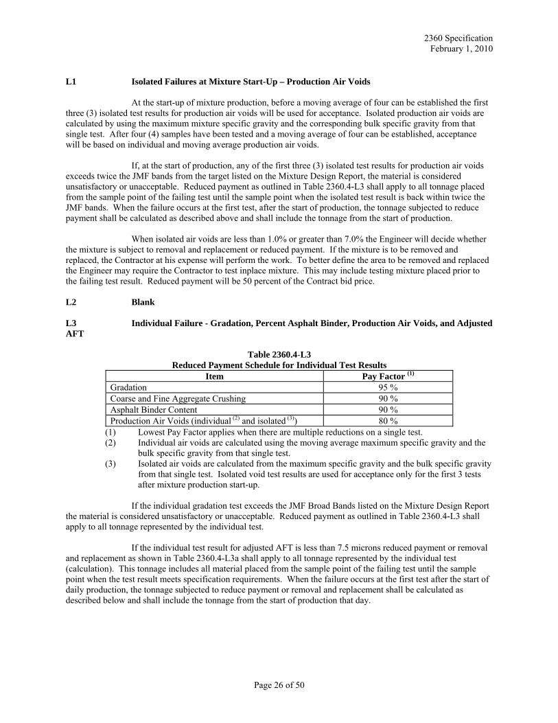
2360 Specification February 1, 2010
L1 Isolated Failures at Mixture Start-Up – Production Air Voids
At the start-up of mixture production, before a moving average of four can be established the first three (3) isolated test results for production air voids will be used for acceptance. Isolated production air voids are calculated by using the maximum mixture specific gravity and the corresponding bulk specific gravity from that single test. After four (4) samples have been tested and a moving average of four can be established, acceptance will be based on individual and moving average production air voids.
If, at the start of production, any of the first three (3) isolated test results for production air voids exceeds twice the JMF bands from the target listed on the Mixture Design Report, the material is considered unsatisfactory or unacceptable. Reduced payment as outlined in Table 2360.4-L3 shall apply to all tonnage placed from the sample point of the failing test until the sample point when the isolated test result is back within twice the JMF bands. When the failure occurs at the first test, after the start of production, the tonnage subjected to reduce payment shall be calculated as described above and shall include the tonnage from the start of production.
When isolated air voids are less than 1.0% or greater than 7.0% the Engineer will decide whether the mixture is subject to removal and replacement or reduced payment. If the mixture is to be removed and replaced, the Contractor at his expense will perform the work. To better define the area to be removed and replaced the Engineer may require the Contractor to test inplace mixture. This may include testing mixture placed prior to the failing test result. Reduced payment will be 50 percent of the Contract bid price. L2 Blank L3 Individual Failure - Gradation, Percent Asphalt Binder, Production Air Voids, and Adjusted AFT
Table 2360.4-L3 Reduced Payment Schedule for Individual Test Results
Item Pay Factor (1) Gradation 95 % Coarse and Fine Aggregate Crushing 90 % Asphalt Binder Content 90 % Production Air Voids (individual (2) and isolated (3)) 80 %
(1) Lowest Pay Factor applies when there are multiple reductions on a single test. (2) Individual air voids are calculated using the moving average maximum specific gravity and the
bulk specific gravity from that single test. (3) Isolated air voids are calculated from the maximum specific gravity and the bulk specific gravity
from that single test. Isolated void test results are used for acceptance only for the first 3 tests after mixture production start-up.
If the individual gradation test exceeds the JMF Broad Bands listed on the Mixture Design Report
the material is considered unsatisfactory or unacceptable. Reduced payment as outlined in Table 2360.4-L3 shall apply to all tonnage represented by the individual test.
If the individual test result for adjusted AFT is less than 7.5 microns reduced payment or removal
and replacement as shown in Table 2360.4-L3a shall apply to all tonnage represented by the individual test (calculation). This tonnage includes all material placed from the sample point of the failing test until the sample point when the test result meets specification requirements. When the failure occurs at the first test after the start of daily production, the tonnage subjected to reduce payment or removal and replacement shall be calculated as described below and shall include the tonnage from the start of production that day.
Page 26 of 50
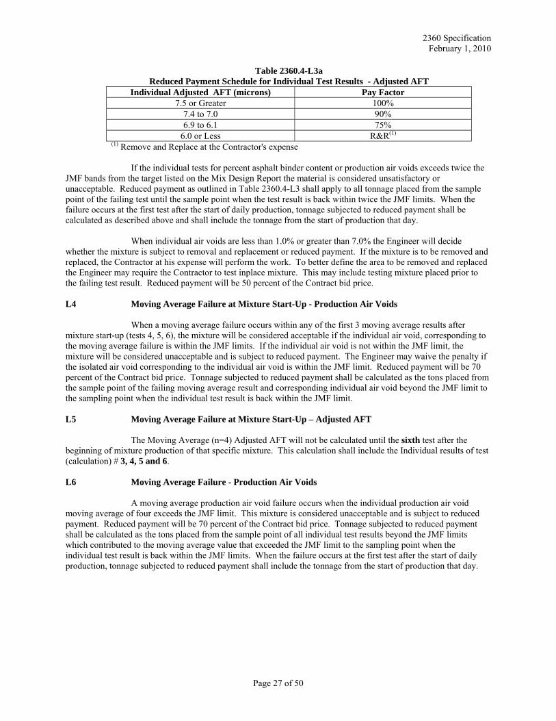
2360 Specification February 1, 2010
Table 2360.4-L3a Reduced Payment Schedule for Individual Test Results - Adjusted AFT
Individual Adjusted AFT (microns) Pay Factor 7.5 or Greater 100%
7.4 to 7.0 90% 6.9 to 6.1 75%
6.0 or Less R&R(1)
(1) Remove and Replace at the Contractor's expense
If the individual tests for percent asphalt binder content or production air voids exceeds twice the JMF bands from the target listed on the Mix Design Report the material is considered unsatisfactory or unacceptable. Reduced payment as outlined in Table 2360.4-L3 shall apply to all tonnage placed from the sample point of the failing test until the sample point when the test result is back within twice the JMF limits. When the failure occurs at the first test after the start of daily production, tonnage subjected to reduced payment shall be calculated as described above and shall include the tonnage from the start of production that day.
When individual air voids are less than 1.0% or greater than 7.0% the Engineer will decide whether the mixture is subject to removal and replacement or reduced payment. If the mixture is to be removed and replaced, the Contractor at his expense will perform the work. To better define the area to be removed and replaced the Engineer may require the Contractor to test inplace mixture. This may include testing mixture placed prior to the failing test result. Reduced payment will be 50 percent of the Contract bid price. L4 Moving Average Failure at Mixture Start-Up - Production Air Voids
When a moving average failure occurs within any of the first 3 moving average results after mixture start-up (tests 4, 5, 6), the mixture will be considered acceptable if the individual air void, corresponding to the moving average failure is within the JMF limits. If the individual air void is not within the JMF limit, the mixture will be considered unacceptable and is subject to reduced payment. The Engineer may waive the penalty if the isolated air void corresponding to the individual air void is within the JMF limit. Reduced payment will be 70 percent of the Contract bid price. Tonnage subjected to reduced payment shall be calculated as the tons placed from the sample point of the failing moving average result and corresponding individual air void beyond the JMF limit to the sampling point when the individual test result is back within the JMF limit. L5 Moving Average Failure at Mixture Start-Up – Adjusted AFT
The Moving Average (n=4) Adjusted AFT will not be calculated until the sixth test after the beginning of mixture production of that specific mixture. This calculation shall include the Individual results of test (calculation) # 3, 4, 5 and 6. L6 Moving Average Failure - Production Air Voids
A moving average production air void failure occurs when the individual production air void moving average of four exceeds the JMF limit. This mixture is considered unacceptable and is subject to reduced payment. Reduced payment will be 70 percent of the Contract bid price. Tonnage subjected to reduced payment shall be calculated as the tons placed from the sample point of all individual test results beyond the JMF limits which contributed to the moving average value that exceeded the JMF limit to the sampling point when the individual test result is back within the JMF limits. When the failure occurs at the first test after the start of daily production, tonnage subjected to reduced payment shall include the tonnage from the start of production that day.
Page 27 of 50
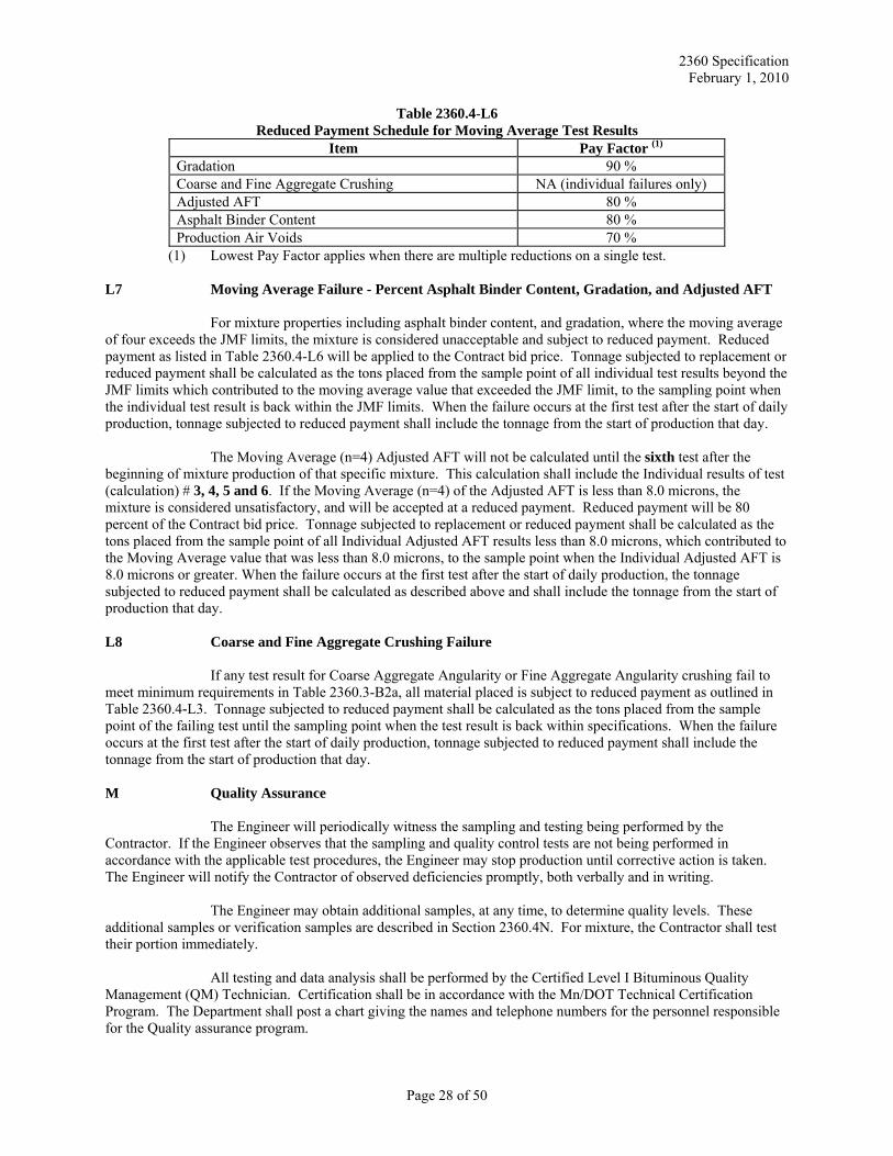
2360 Specification February 1, 2010
Table 2360.4-L6 Reduced Payment Schedule for Moving Average Test Results
Item Pay Factor (1) Gradation 90 % Coarse and Fine Aggregate Crushing NA (individual failures only) Adjusted AFT 80 % Asphalt Binder Content 80 % Production Air Voids 70 %
(1) Lowest Pay Factor applies when there are multiple reductions on a single test. L7 Moving Average Failure - Percent Asphalt Binder Content, Gradation, and Adjusted AFT
For mixture properties including asphalt binder content, and gradation, where the moving average of four exceeds the JMF limits, the mixture is considered unacceptable and subject to reduced payment. Reduced payment as listed in Table 2360.4-L6 will be applied to the Contract bid price. Tonnage subjected to replacement or reduced payment shall be calculated as the tons placed from the sample point of all individual test results beyond the JMF limits which contributed to the moving average value that exceeded the JMF limit, to the sampling point when the individual test result is back within the JMF limits. When the failure occurs at the first test after the start of daily production, tonnage subjected to reduced payment shall include the tonnage from the start of production that day.
The Moving Average (n=4) Adjusted AFT will not be calculated until the sixth test after the beginning of mixture production of that specific mixture. This calculation shall include the Individual results of test (calculation) # 3, 4, 5 and 6. If the Moving Average (n=4) of the Adjusted AFT is less than 8.0 microns, the mixture is considered unsatisfactory, and will be accepted at a reduced payment. Reduced payment will be 80 percent of the Contract bid price. Tonnage subjected to replacement or reduced payment shall be calculated as the tons placed from the sample point of all Individual Adjusted AFT results less than 8.0 microns, which contributed to the Moving Average value that was less than 8.0 microns, to the sample point when the Individual Adjusted AFT is 8.0 microns or greater. When the failure occurs at the first test after the start of daily production, the tonnage subjected to reduced payment shall be calculated as described above and shall include the tonnage from the start of production that day. L8 Coarse and Fine Aggregate Crushing Failure
If any test result for Coarse Aggregate Angularity or Fine Aggregate Angularity crushing fail to meet minimum requirements in Table 2360.3-B2a, all material placed is subject to reduced payment as outlined in Table 2360.4-L3. Tonnage subjected to reduced payment shall be calculated as the tons placed from the sample point of the failing test until the sampling point when the test result is back within specifications. When the failure occurs at the first test after the start of daily production, tonnage subjected to reduced payment shall include the tonnage from the start of production that day. M Quality Assurance
The Engineer will periodically witness the sampling and testing being performed by the Contractor. If the Engineer observes that the sampling and quality control tests are not being performed in accordance with the applicable test procedures, the Engineer may stop production until corrective action is taken. The Engineer will notify the Contractor of observed deficiencies promptly, both verbally and in writing.
The Engineer may obtain additional samples, at any time, to determine quality levels. These additional samples or verification samples are described in Section 2360.4N. For mixture, the Contractor shall test their portion immediately.
All testing and data analysis shall be performed by the Certified Level I Bituminous Quality Management (QM) Technician. Certification shall be in accordance with the Mn/DOT Technical Certification Program. The Department shall post a chart giving the names and telephone numbers for the personnel responsible for the Quality assurance program.
Page 28 of 50
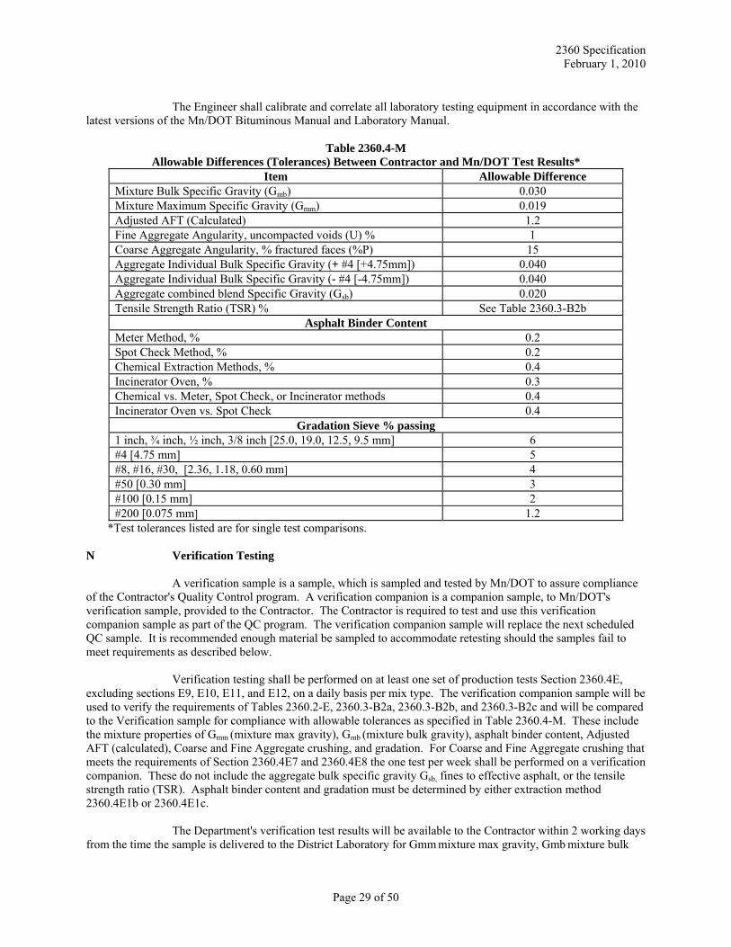
2360 Specification February 1, 2010
The Engineer shall calibrate and correlate all laboratory testing equipment in accordance with the
latest versions of the Mn/DOT Bituminous Manual and Laboratory Manual.
Table 2360.4-M Allowable Differences (Tolerances) Between Contractor and Mn/DOT Test Results*
Item Allowable Difference Mixture Bulk Specific Gravity (Gmb) 0.030 Mixture Maximum Specific Gravity (Gmm) 0.019 Adjusted AFT (Calculated) 1.2 Fine Aggregate Angularity, uncompacted voids (U) % 1 Coarse Aggregate Angularity, % fractured faces (%P) 15 Aggregate Individual Bulk Specific Gravity (+ #4 [+4.75mm]) 0.040 Aggregate Individual Bulk Specific Gravity (- #4 [-4.75mm]) 0.040 Aggregate combined blend Specific Gravity (Gsb) 0.020 Tensile Strength Ratio (TSR) % See Table 2360.3-B2b
Asphalt Binder Content Meter Method, % 0.2 Spot Check Method, % 0.2 Chemical Extraction Methods, % 0.4 Incinerator Oven, % 0.3 Chemical vs. Meter, Spot Check, or Incinerator methods 0.4 Incinerator Oven vs. Spot Check 0.4
Gradation Sieve % passing 1 inch, ¾ inch, ½ inch, 3/8 inch [25.0, 19.0, 12.5, 9.5 mm] 6 #4 [4.75 mm] 5 #8, #16, #30, [2.36, 1.18, 0.60 mm] 4 #50 [0.30 mm] 3 #100 [0.15 mm] 2 #200 [0.075 mm] 1.2
*Test tolerances listed are for single test comparisons. N Verification Testing
A verification sample is a sample, which is sampled and tested by Mn/DOT to assure compliance of the Contractor's Quality Control program. A verification companion is a companion sample, to Mn/DOT's verification sample, provided to the Contractor. The Contractor is required to test and use this verification companion sample as part of the QC program. The verification companion sample will replace the next scheduled QC sample. It is recommended enough material be sampled to accommodate retesting should the samples fail to meet requirements as described below.
Verification testing shall be performed on at least one set of production tests Section 2360.4E, excluding sections E9, E10, E11, and E12, on a daily basis per mix type. The verification companion sample will be used to verify the requirements of Tables 2360.2-E, 2360.3-B2a, 2360.3-B2b, and 2360.3-B2c and will be compared to the Verification sample for compliance with allowable tolerances as specified in Table 2360.4-M. These include the mixture properties of Gmm (mixture max gravity), Gmb (mixture bulk gravity), asphalt binder content, Adjusted AFT (calculated), Coarse and Fine Aggregate crushing, and gradation. For Coarse and Fine Aggregate crushing that meets the requirements of Section 2360.4E7 and 2360.4E8 the one test per week shall be performed on a verification companion. These do not include the aggregate bulk specific gravity Gsb, fines to effective asphalt, or the tensile strength ratio (TSR). Asphalt binder content and gradation must be determined by either extraction method 2360.4E1b or 2360.4E1c.
The Department's verification test results will be available to the Contractor within 2 working days from the time the sample is delivered to the District Laboratory for Gmm mixture max gravity, Gmb mixture bulk
Page 29 of 50
2360 Specification February 1, 2010
gravity, air voids (calculated), asphalt binder content, Adj. AFT (calculated). Gradation and crushing results will be provided to the Contractor within 3 Mn/DOT working days. Once the verification test results are available, they will be included on the test summary sheet. These results and those from the Contractor's verification companion will be compared for allowable tolerances as specified in Table 2360.4-M. If the tolerances are met, the verification process is complete.
If the tolerances between Department and Contractor are not met, retests of the material shall be conducted by the Department. If the retests fail to meet tolerances, the Department's verification test results will be substituted for the Contractor's results in the QC program and used for acceptance. Only those parameters out of tolerance will be substituted and, if applicable, volumetric properties will be recalculated (1).
If the Adjusted AFT calculation is out of tolerance, the Mn/DOT Adjusted AFT calculation (based
on Mn/DOT test results) will be Equalized and used for the Individual Adjusted AFT result, and calculation of Moving Average Adjusted AFT results. Equalization of the Mn/DOT Adjusted AFT result consists of increasing the original Mn/DOT value by 0.5 microns. This increased value will then be used for acceptance.
When tolerances from the verification sample retests are not met, an investigation will begin
immediately to determine the cause of the difference. Testing equipment, procedures, worksheets, gyratory specimen height sheets, and personnel will be reviewed to determine the source of the problem. The District Materials Engineer may also require at least one hot-cold comparison of mixture properties be performed. The procedure for hot-cold comparisons is as follows:
The hot-cold comparison sample will be split into three representative portions. The Engineer will observe the Contractor testing the sample. One part shall be compacted immediately while still hot (additional heating maybe required to raise the temperature of the sample to compaction temperature). The second and third part will be allowed to cool to air temperature. The Contractor will retain the second part and the third part will be transported to the District Materials Laboratory. On the same day and at approximately the same time the Contractor and the District Materials Laboratory will heat their samples to compaction temperature and compact them. From this information a calibration factor will be developed to compare the specific gravity of the hot compacted samples to reheated compacted samples. Each test will involve a minimum of two gyratory specimens. The Materials Engineer or the Contractor may require additional test comparisons.
Note: Care must be taken when reheating samples for mixture properties analysis tests. Mix samples
should be reheated to 160°F [70°C] to allow splitting of the sample into representative fractions for the various tests. Overheating of the mixture portions to be tested for maximum specific gravity (Rice Test) may result in additional asphalt being absorbed in the aggregate.
The Department will test the previously collected QA samples until they meet the tolerances or the
remaining samples are all tested. Once these samples are tested, the department will test QA samples subsequent to the verification sample until tolerances are met. Acceptance will be based on QC data with substitution of Department test results for those parameters out of tolerance (1). If reestablishment of test result tolerances is not achieved within 48 hours, the Contractor shall cease mixture production and placement until the problem is resolved.
(1) If, through analysis of data, it is determined there is a bias in the test results, the Engineer will determine which results are appropriate and shall govern. Methods to analyze data for determination of bias are on file in the Bituminous Office.
2360.5 CONSTRUCTION REQUIREMENTS A General
The following construction requirements provide for the construction of all courses. When construction is under traffic, the requirements of Mn/DOT 2221.3D will apply.
Page 30 of 50
2360 Specification February 1, 2010
B Restrictions
In general, no work within the roadway will be permitted in the spring until seasonal load restrictions on roads in the vicinity have been removed. However, work within the roadbed may be permitted before that time if, in the opinion of the Engineer, it can be done without damage to the subgrade. HMA shall not be placed when, in the opinion of the Engineer, the weather or roadbed conditions are unfavorable.
No asphalt pavement wearing course (final wearing course if multiple wearing courses) shall be placed after October 15th in that part of the state north of an east-west line between Browns Valley and Holyoke, nor after November 1st south of that line. The Engineer may waive these restrictions when:
(1) The asphalt mixture is not being placed on the traveled portion of the roadway, or
(2) The roadway involved will not be open to traffic during the following winter, or
(3) The Engineer directs in writing the mixture be placed.
The Contractor shall not use petroleum distillates such as kerosene and fuel oil to prevent adhesion of asphalt mixtures in pavement hoppers, truck beds, or on the contact surfaces of the compaction equipment. Anti-adhesive agent must meet the criteria for "Effect on Asphalt" as described in the most recent Asphalt Release Agent Report on file in Mn/DOT's Office of Environmental Services and the Bituminous Office. C Equipment C1 Asphalt Mixing Plants C1a Requirement for All Plants
The Contractor shall test and calibrate all scales according to Mn/DOT 1901, except as otherwise designated by the Contract. C1a(1) Equipment for the Preparation of the Aggregate
Add mineral filler to the mixture using a storage silo equipped with a device to ensure a constant and uniform feed. C1a(2) Equipment for the Preparation of Asphalt Material
Tanks for storage of asphalt material at the plant shall be equipped to heat the material and maintain the material at the required temperatures. The discharge end of the circulating line shall be below the surface of the asphalt material. Provide agitation for modified asphalt, when used, if recommended by the supplier.
An outage table or chart and measuring stick shall be provided for each storage or working tank. Tanks shall be equipped with provisions for taking of asphalt binder material samples. After delivery of asphalt binder material to the Project, the Contractor shall not heat the material above 350oF [175°C]. For modified asphalt, the maximum storage temperature shall not exceed the recommendation of the asphalt supplier. C1a(3) Asphalt Binder Control
When asphalt binder material is proportioned by volume, the plant shall be equipped with either a working tank or a metering system for determining asphalt binder content of the mixture.
The working tank shall have a capacity between 1,000 gallons [3 800 L] and 2,000 gallons [7 600 L]. The working tank shall be calibrated and supplied with a calibrated measuring stick. The tank may be
Page 31 of 50
2360 Specification February 1, 2010
connected to a mixing unit and used only during spot check operations, but it shall be available at all times. Any feedback shall be returned to the working tank during spot check operations.
The metering system shall consist of at least one approved asphalt binder flow meter in addition to the asphalt binder pump. The flow meter shall be connected to the asphalt binder supply to measure and display only the asphalt binder being fed to the mixer unit. The meter readout shall be positioned for convenient observation. Means shall be provided for comparing the flow meter readout with the calculated output of the asphalt binder pump. In addition, the system shall display in gallons [liters] or to the nearest 0.001 tons [0.001 metric tons], the accumulated asphalt binder quantity being delivered to the mixer unit. The system shall be calibrated and adjusted to maintain an accuracy of + one percent error. This calibration shall be required for each plant set-up prior to production of mixture. C1a(4) Dryer: The aggregate shall be free of unburned fuel. C1a(5) Thermometric Equipment:
The plant shall be equipped with a sufficient number of thermometric instruments to ensure temperature control of the aggregate and the asphalt binder material. C1a(6) Pollution Controls C1a(6)(a) Pollution ..................................................................................................................................... 1717 C1a(7) Surge and Storage Bins
The plant may include facilities to store hot asphalt mixture for coordinating the rate of production with the paving operations. Storage of the hot mixture will be permitted for a period not to exceed 18 hours, provided the following requirements are met:
(a) Hot mix storage facilities shall be designed and operated to prevent segregation of the mix, drainage of the asphalt from the mix, and to prevent excessive cooling or overheating of the mixture.
(b) The temperature of the mixture at time of discharge from the storage facility shall be within a
tolerance of 9oF [5°C] of the temperature when discharged from the silo or mixer. C2 Placement and Hauling Equipment
All equipment shall be serviced away from the paving site to prevent contamination of the mixture. Units that drip fuel, oil, or grease shall be removed from the paved surface until such leakage is corrected. C2a Asphalt Pavers
Asphalt pavers shall be self-contained, power-propelled units, with an operational vibratory screed, capable of spreading and finishing courses of asphalt plant mix material in widths applicable to the specified typical sections and thicknesses, indicated in the Contract.
The screed or strike-off assembly shall produce a finished surface of the required evenness and texture without tearing, shoving, or gouging. For mainline paving, if the paving width is greater than the basic screed, auger and mainframe extensions, which meet manufacture's recommendations for the paving width, are required unless otherwise directed by the Engineer. Strike-off only extension assemblies are not allowed for mainline wearing course paving, unless directed by the Engineer.
All pavers shall be equipped with an approved automatic screed control. The automatic controls shall include a system of sensor-operated devices, which follow reference lines, or surfaces on one or both sides of the paver as required. The speed of the paver shall be adjusted to produce the best results.
Page 32 of 50
2360 Specification February 1, 2010
Automatic screed control by means of an erected string line shall only be required when stated in
the Contract.
All mixtures shall be spread without segregation to the cross sections shown in the plans. In general, leveling layers shall be spread by the method producing the best results as approved by the Engineer. The objective is to secure a smooth base of uniform grade and cross section so that subsequent courses will be uniform in thickness. The leveling layer may be spread with a properly equipped paver or, when approved by the Engineer, a motor grader equipped with a leveling device or with other means for controlling the surface elevation of the leveling layer.
All mixtures shall be spread, to the fullest extent practicable, by an asphalt paver. When approved by the Engineer, mixtures may be spread by a motor grader in areas that are inaccessible to a paver such as on driveway entrances, irregular areas, short isolated areas or when the quantity of mixture makes it impractical to place with a paver.
On shoulder surfacing and uniform width widening, when the placement width is too narrow for a paver, the mixture in each course shall be spread with an approved mechanical device.
The placement of each course shall be completed over the full width of the section under construction on each day's run unless otherwise directed by the Engineer. C2b Trucks
Trucks for hauling asphalt mixtures shall have tight, clean, and smooth beds. Mixture shall not be allowed to adhere to the truck beds. Adherence may be prevented by spraying the truck bed with an anti-adhesive agent in accordance with Section 2360.5B. Each truck shall be equipped with a cover of canvas or other suitable material to protect the mixture from weather. The cover shall extend at least 1 foot [300 mm] over the sides and be attached to tie-downs unless the truck is furnished with a mechanical or automated covering system, which prevents airflow underneath by stretching the cover tightly on the top of or inside the sideboards. The cover shall be used when directed by the Engineer. C2c Motor Graders
Motor graders shall be self-propelled and have pneumatic tires with a tread depth of 1/2 inch [13 mm] or less. They shall be equipped with a blade not less than 10 feet [3 m] in length and shall have a wheelbase of not less than 15 feet [4.5 m]. C2d Distributor
Use a distributor designed, equipped, calibrated, maintained, and operated to uniformly apply material on surfaces with varying widths and up to 15 feet [4.6 m] wide. Provide a distributor capable of maintaining a uniform distributing pressure and controlling the application rates up to 2.0 gallons [9.0L] per square yard [square meter] within a tolerance of 0.02 gallon per square yard [0.09 L/m2]. Provide a distributor equipped with a tachometer, pressure gauges, accurate volume-measuring devices or a calibrated tank, a thermometer for measuring temperatures of tank contents, a power-operated pump, and full circulation spray bars with lateral and vertical adjustments. D Treatment of the Surface D1 Tack Coat
An asphalt tack coat shall be applied to existing asphalt and concrete surfaces, and to the surface of each course or lift constructed, except for the final course or lift, according to Mn/DOT 2357. Emulsified asphalt tack coats shall be allowed to break, as indicated by a color change from brown to black, before a subsequent lift is placed.
Page 33 of 50
2360 Specification February 1, 2010
The contact surfaces of all fixed structures and the edge of the in-place mixture in all courses at
transverse joints and longitudinal joints shall be given a uniform but not excessive coating of liquid asphalt or emulsified asphalt before placing the adjoining mixture. E Compaction Operations
After being spread, each course shall be compacted to the required density. The rollers shall, as practicable, be operated continuously so all areas are thoroughly compacted to the required density. When not operating, the rollers shall not stand on the uncompacted mixture or newly rolled pavement having a surface temperature exceeding 140oF [60°C]. Rolling with steel-wheeled rollers shall be discontinued if it produces excessive crushing or pulverizing of the aggregate or displacement of the mixture.
To prevent adhesion of the mixture to the steel roller wheels, the contact surfaces of the wheels shall be kept properly moistened using water or a water solution containing small quantities of a detergent or other approved material.
To secure a true surface, variations such as depressions or high areas, which may develop during rolling operations, and lean, fat or segregated areas shall be corrected by removing and replacing the material in the defective area. All such corrections shall be accomplished as directed by the Engineer at no expense to the Department.
When mixtures are spread by a motor grader, pneumatic tired rollers shall compact the mixture simultaneously with the spreading operation. F Construction Joints
Joints shall be thoroughly compacted to produce a neat, tightly bonded joint that meets surface tolerances. Both transverse and longitudinal joints are subject to density requirements as outlined in Section 2360.6 Pavement Density. F1 Transverse Joints
A transverse joint (full paver width at right angles to the centerline) shall be constructed when mixture placement operations are suspended. The forward end of the freshly laid strip shall be thoroughly compacted by rolling before the mixture has cooled. When work is resumed, the end shall be cut vertically for the full depth of the layer unless a formed edge is constructed as approved by the Engineer. F2 Longitudinal Joints
Longitudinal joints between strips shall be parallel to the centerline. In multiple lift construction, the longitudinal joints between strips in each lift shall be constructed not less than 6 inches [150 mm] measured transversely from the longitudinal joints in the previously placed lift. When the wearing course is constructed in an even number of strips, one longitudinal joint shall be on the centerline of the road. When it is constructed in an odd number of strips, the centerline of one strip shall be on the centerline of the road, provided that no joint is located in the wheel path area of a traffic lane. Longitudinal joints in multiple lift construction over Portland cement concrete pavements may be aligned directly over the concrete pavement longitudinal joints at the discretion of the Engineer.
At longitudinal joints formed by placing multiple strips, the adjoining surface being laid shall, after final compacting, be slightly higher (but not to exceed 1/8 inch [3 mm]) than the previously placed strip. When constructing a strip adjoining a previously placed strip or a concrete pavement, any fresh mixture that overlaps a previously placed strip or pavement shall be removed (to the longitudinal joint line) before any rolling is done.
Page 34 of 50
2360 Specification February 1, 2010
G Asphalt Mixture Production (FOB Department Trucks)
For asphalt mixture production, the Contractor shall, in addition to the asphalt mixture required on the Project, produce and deliver asphalt mixture to the Department. The mixture shall be the mixture being produced and shall be loaded on Department furnished trucks at the mixing plant at a time agreed on by the Engineer and Contractor. The Engineer will notify the Contractor of the total quantity of mixture desired not less than 2 weeks prior to completion of the wearing course construction. The Engineer will not accept the asphalt mixture if it is inappropriate for the Department's intended use. H Small Quantity HMA Paving
Unless otherwise indicated in the Special Provisions, the following provision for a small quantity of asphalt mixture shall apply.
A Mixture Design Report is not required for planned project quantities less than 9,000 square yard inches (4,500 square yards per 2 inch thickness, etc) [191,200 m2 mm] or 500 tons [450 metric tons]. However, the Contractor shall verify in writing the asphalt mixture delivered to the project meets the requirements of Table 2360.3-B2a and Table 2360.3B2b. The Department will obtain samples, as determined by the Engineer, to verify mixture requirements. These results will be used for material acceptance. Acceptance of material will be in accordance with the criteria outlined in Section 2360.4L1, L2, L3, and L8. 2360.6 PAVEMENT DENSITY A General
All pavements will be compacted in accordance with the Maximum Density Method unless otherwise specified in the Contract special provisions or as noted in Section 2360.6C. Density evaluation will be for both compacted mat density and compacted longitudinal joint density on those projects utilizing gyratory design. B Maximum Density Method
All courses or layers of plant mixed asphalt mixtures for which the Maximum Density Method is used shall be compacted to a density not less than the percentage shown in the Table of Required Density, Tables 2360.6-B2 and 2360.6-B2 LJ, for the applicable mixture and course and longitudinal joint type (i.e. confined or unconfined). Longitudinal joint density will not be evaluated on those lifts, which have a 1% reduced density requirement. If the Contractor elects to waive the 1% reduced density requirement as per 2360.6B4, then the Longitudinal Joint Density will be a requirement. B1 Maximum Density Determination
The Density requirements listed in Table 2360.6B2 are percent of maximum specific gravity (Gmm) based on the individual lot. The Maximum specific gravity value used to calculate the percentage density for the lot shall be the average value obtained from the maximum gravity results from production tests taken during that days paving. If only one or two maximum specific gravity values were obtained that day, then the moving average value (at that test point) shall be used. If three or more maximum specific gravity values are obtained that day, then the average of those tests alone shall be used as indicated above. B1a Pavement Density Determination
The density of each lot shall be expressed as a percentage of the maximum specific gravity (% Gmm) obtained by dividing the average bulk specific gravity for the lot by the maximum specific gravity multiplied by 100, (maximum specific gravity basis is the average Gmm of QC tests done on the day that the individual lot was paved as described above). Determination of the bulk specific gravity of the cores shall be in accordance with AASHTO T-166, Mn/DOT modified. For coarse graded mixtures the Engineer may require determination of bulk specific gravity of the cores be in accordance with ASTM D6752 Mn/DOT modified (Corelok). Both the Contractor and Mn/DOT shall use the same test method to determine bulk specific gravity. The
Page 35 of 50
2360 Specification February 1, 2010
determination of coarse and fine graded mixtures will be based on the percentage of material passing the #8 sieve [2.365 mm] as defined in Table 2360.3-B2c.
Compaction operations shall be completed within 8 hours of mixture placement and before core samples are obtained for density determination. Only pneumatic tired or static steel rollers are permitted for any compactive effort performed between 6 and 8 hours after mixture placement.
Compacted mixtures represented by samples or tests having deficient densities shall not be re-rolled. The Contractor shall not operate below the specified minimum density on a continuing basis. A continual basis shall be defined as all lots in a day's production failing to meet minimum density or more than 50% of lots on multiple days which fail to meet minimum density requirements. Production shall be stopped until the source of the problem is determined and corrective action is taken to bring the work into compliance with specified minimum required density. B2 Required Density
Minimum density requirements for gyratory (SP) designed mixtures are listed in Table 2360.6-B2. Minimum density requirements for longitudinal joint are listed in Table 2360.6-B2 LJ.
Unless otherwise indicated in the Plans or Special Provisions, shoulders wider than 6 feet [1.8 meters] paved shall be compacted by the Maximum Density Method. When shoulders are required to be compacted by the Maximum Density Method and are paved in a separate operation or have a different required minimum density than the driving lane, the lot tonnage placed on the shoulder shall be delineated in separate lots from the driving lanes for the day paving was conducted.
Unless otherwise indicated in the Plans or Special Provisions a narrow shoulder, 6 feet [1.8 meters] or less wide, that is paved in the same pass as a driving lane or that is paved separately will be compacted by the Ordinary Compaction Method. Mixture compacted under Ordinary Compaction is excluded from lot density requirements and that tonnage is also excluded from incentive/disincentive payment.
If the Plans or Special Provisions indicate a narrow shoulder is to be compacted by the Maximum Density Method, the minimum required density is listed in Table 2360.6-B2. If the minimum required density of the shoulder is different than the driving lane, the tonnage placed on the shoulder shall be delineated in separate lots from the driving lane.
Echelon paving (two pavers running next to each other in adjacent lanes) shall be considered separate operations.
Table 2360.6-B2 Required Minimum Lot Density (Mat)
SP Wear Mixtures (1)(2) SP Nonwear (1)(2) SP Shoulders (1)(2)
Designed at 3% voids
Designed at 4% voids
% Gmm 92.0 93.0 93.0 92.0
1) Minimum reduced by one percent on the first lift constructed over PCC pavements. 2) Minimum reduced by one percent for the first lift constructed on aggregate base (mainline and
shoulder), reclaimed or cold inplace recycled base courses and first lift of an overlay on a roadway with a 7 ton [6.35 metric ton] or less spring load restriction (roadway includes shoulders).
Page 36 of 50
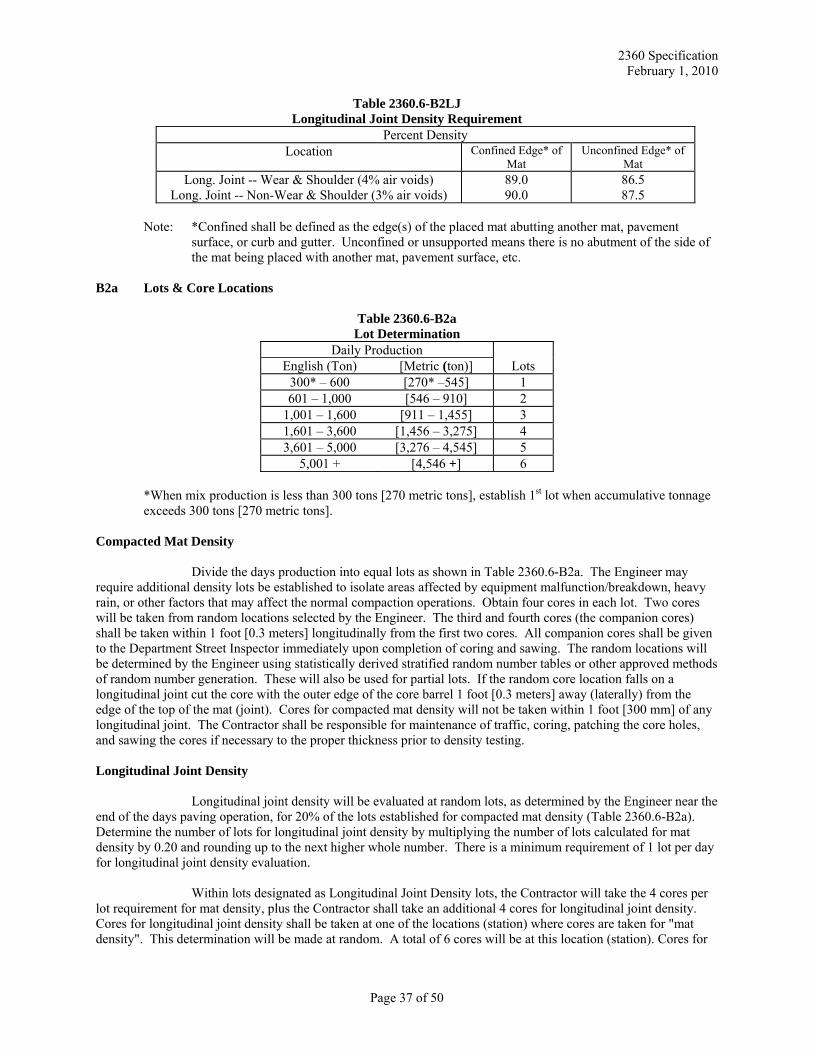
2360 Specification February 1, 2010
Table 2360.6-B2LJ Longitudinal Joint Density Requirement
Percent Density Location Confined Edge* of
Mat Unconfined Edge* of
Mat Long. Joint -- Wear & Shoulder (4% air voids)
Long. Joint -- Non-Wear & Shoulder (3% air voids) 89.090.0
86.5 87.5
Note: *Confined shall be defined as the edge(s) of the placed mat abutting another mat, pavement
surface, or curb and gutter. Unconfined or unsupported means there is no abutment of the side of the mat being placed with another mat, pavement surface, etc.
B2a Lots & Core Locations
Table 2360.6-B2a Lot Determination
Daily Production Lots English (Ton) [Metric (ton)]
300* – 600 [270* –545] 1 601 – 1,000 [546 – 910] 2
1,001 – 1,600 [911 – 1,455] 3 1,601 – 3,600 [1,456 – 3,275] 4 3,601 – 5,000 [3,276 – 4,545] 5
5,001 + [4,546 +] 6 *When mix production is less than 300 tons [270 metric tons], establish 1st lot when accumulative tonnage exceeds 300 tons [270 metric tons]. Compacted Mat Density
Divide the days production into equal lots as shown in Table 2360.6-B2a. The Engineer may require additional density lots be established to isolate areas affected by equipment malfunction/breakdown, heavy rain, or other factors that may affect the normal compaction operations. Obtain four cores in each lot. Two cores will be taken from random locations selected by the Engineer. The third and fourth cores (the companion cores) shall be taken within 1 foot [0.3 meters] longitudinally from the first two cores. All companion cores shall be given to the Department Street Inspector immediately upon completion of coring and sawing. The random locations will be determined by the Engineer using statistically derived stratified random number tables or other approved methods of random number generation. These will also be used for partial lots. If the random core location falls on a longitudinal joint cut the core with the outer edge of the core barrel 1 foot [0.3 meters] away (laterally) from the edge of the top of the mat (joint). Cores for compacted mat density will not be taken within 1 foot [300 mm] of any longitudinal joint. The Contractor shall be responsible for maintenance of traffic, coring, patching the core holes, and sawing the cores if necessary to the proper thickness prior to density testing. Longitudinal Joint Density
Longitudinal joint density will be evaluated at random lots, as determined by the Engineer near the end of the days paving operation, for 20% of the lots established for compacted mat density (Table 2360.6-B2a). Determine the number of lots for longitudinal joint density by multiplying the number of lots calculated for mat density by 0.20 and rounding up to the next higher whole number. There is a minimum requirement of 1 lot per day for longitudinal joint density evaluation.
Within lots designated as Longitudinal Joint Density lots, the Contractor will take the 4 cores per lot requirement for mat density, plus the Contractor shall take an additional 4 cores for longitudinal joint density. Cores for longitudinal joint density shall be taken at one of the locations (station) where cores are taken for "mat density". This determination will be made at random. A total of 6 cores will be at this location (station). Cores for
Page 37 of 50
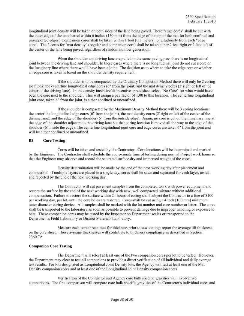
2360 Specification February 1, 2010
longitudinal joint density will be taken on both sides of the lane being paved. These "edge cores" shall be cut with the outer edge of the core barrel within 6 inches (150 mm) from the edge of the top of the mat for both confined and unsupported edges. Companion cores shall be taken within 1 foot [0.3 meters] longitudinally from each "edge core". The 2 cores for "mat density" (regular and companion core) shall be taken either 2 feet right or 2 feet left of the center of the lane being paved, regardless of random number generation.
When the shoulder and driving lane are pulled in the same paving pass there is no longitudinal joint between the driving lane and shoulder. In these cases where there is no longitudinal joint do not cut a core on the imaginary line where there would have been a joint. The decision as to where to take the edge core or whether an edge core is taken is based on the shoulder density requirement.
If the shoulder is to be compacted by the Ordinary Compaction Method there will only be 2 coring locations: the centerline longitudinal edge cores (6" from the joint) and the mat density cores (2' right or left of the center of the driving lane). In the density incentive/disincentive spreadsheet select "No Core" for what would have been the core next to the shoulder. This will assign a pay factor of 1.00 to this location. The centerline longitudinal joint core, taken 6" from the joint, is either confined or unconfined.
If the shoulder is compacted by the Maximum Density Method there will be 3 coring locations: the centerline longitudinal edge cores (6" from the joint), the mat density cores (2' right or left of the center of the driving lane), and the edge of the shoulder (6" from the outside edge). Again, no core is cut on the imaginary line at the edge of the shoulder adjacent to the driving lane but that coring location is moved all the way to the edge of the shoulder (6" inside the edge). The centerline longitudinal joint core and edge cores are taken 6" from the joint and will be either confined or unconfined. B3 Core Testing
Cores will be taken and tested by the Contractor. Core locations will be determined and marked by the Engineer. The Contractor shall schedule the approximate time of testing during normal Project work hours so that the Engineer may observe and record the saturated surface dry and immersed weight of the cores.
Density determination will be made by the end of the next working day after placement and compaction. If multiple layers are placed in a single day, cores shall be sawn and separated for each layer, tested and reported by the end of the next working day.
The Contractor will cut pavement samples from the completed work with power equipment, and restore the surface by the end of the next working day with new, well compacted mixture without additional compensation. Failure to restore the surface within 24 hours of coring shall subject the Contractor to a fine of $100 per working day, per lot, until the core holes are restored. Cores shall be cut using a 4 inch [100 mm] minimum outer diameter coring device. All samples shall be marked with the lot number and core number or letter. The cores shall be transported to the laboratory as soon as possible to prevent damage due to improper handling or exposure to heat. These companion cores may be tested by the Inspector on Department scales or transported to the Department's Field Laboratory or District Materials Laboratory.
Measure each core three times for thickness prior to saw cutting; report the average lift thickness on the core sheet. These average thicknesses will contribute to thickness compliance as described in Section 2360.7A Companion Core Testing
The Department will select at least one of the two companion cores per lot to be tested. However, the Department may elect to test all companions to provide a direct verification of all individual and daily average test results. For lots designated as Longitudinal Joint Density lots, the Agency will test at least one of the Mat Density companion cores and at least one of the Longitudinal Joint Density companion cores.
Verification of the Contractor and Agency core bulk specific gravities will involve two comparisons. The first comparison will compare core bulk specific gravities of the Contractor's individual cores and
Page 38 of 50
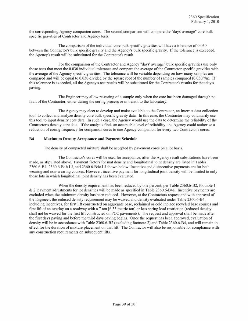
2360 Specification February 1, 2010
the corresponding Agency companion cores. The second comparison will compare the "days' average" core bulk specific gravities of Contractor and Agency tests.
The comparison of the individual core bulk specific gravities will have a tolerance of 0.030 between the Contractor's bulk specific gravity and the Agency's bulk specific gravity. If the tolerance is exceeded, the Agency's result will be substituted for the Contractor's result.
For the comparison of the Contractor and Agency "days' average" bulk specific gravities use only those tests that meet the 0.030 individual tolerance and compare the average of the Contractor specific gravities with the average of the Agency specific gravities. The tolerance will be variable depending on how many samples are compared and will be equal to 0.030 divided by the square root of the number of samples compared (0.030/√n). If this tolerance is exceeded, all the Agency's test results will be substituted for the Contractor's results for that day's paving.
The Engineer may allow re-coring of a sample only when the core has been damaged through no fault of the Contractor, either during the coring process or in transit to the laboratory.
The Agency may elect to develop and make available to the Contractor, an Internet data collection tool, to collect and analyze density core bulk specific gravity data. In this case, the Contractor may voluntarily use this tool to input density core data. In such a case, the Agency would use the data to determine the reliability of the Contractor's density core data. If the analysis finds an acceptable level of reliability, the Agency could authorize a reduction of coring frequency for companion cores to one Agency companion for every two Contractor's cores. B4 Maximum Density Acceptance and Payment Schedule
The density of compacted mixture shall be accepted by pavement cores on a lot basis.
The Contractor's cores will be used for acceptance, after the Agency result substitutions have been made, as stipulated above. Payment factors for mat density and longitudinal joint density are listed in Tables 2360.6-B4, 2360.6-B4b LJ, and 2360.6-B4c LJ shown below. Incentive and disincentive payments are for both wearing and non-wearing courses. However, incentive payment for longitudinal joint density will be limited to only those lots in which longitudinal joint density has been evaluated.
When the density requirement has been reduced by one percent, per Table 2360.6-B2, footnote 1 & 2, payment adjustments for lot densities will be made as specified in Table 2360.6-B4a. Incentive payments are excluded when the minimum density has been reduced. However, at the Contractors request and with approval of the Engineer, the reduced density requirement may be waived and density evaluated under Table 2360.6-B4, including incentives, for first lift constructed on aggregate base, reclaimed or cold inplace recycled base courses and first lift of an overlay on a roadway with a 7 ton [6.35 metric ton] or less spring load restriction (reduced density shall not be waived for the first lift constructed on PCC pavements). The request and approval shall be made after the first days paving and before the third days paving begins. Once the request has been approved, evaluation of density will be in accordance with Table 2360.6-B2 (excluding footnote 2) and Table 2360.6-B4, and will remain in effect for the duration of mixture placement on that lift. The Contractor will also be responsible for compliance with any construction requirements on subsequent lifts.
Page 39 of 50
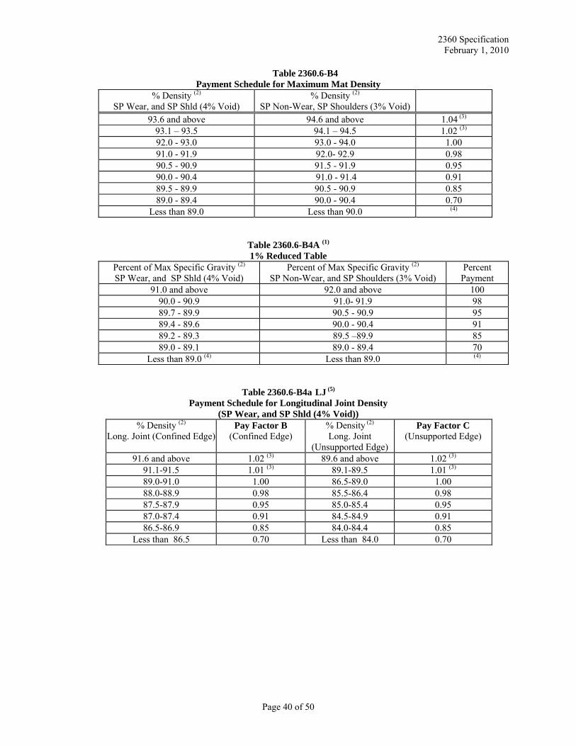
2360 Specification February 1, 2010
Table 2360.6-B4 Payment Schedule for Maximum Mat Density
% Density (2) SP Wear, and SP Shld (4% Void)
% Density (2) SP Non-Wear, SP Shoulders (3% Void)
93.6 and above 94.6 and above 1.04 (3) 93.1 – 93.5 94.1 – 94.5 1.02 (3) 92.0 - 93.0 93.0 - 94.0 1.00 91.0 - 91.9 92.0- 92.9 0.98 90.5 - 90.9 91.5 - 91.9 0.95 90.0 - 90.4 91.0 - 91.4 0.91 89.5 - 89.9 90.5 - 90.9 0.85 89.0 - 89.4 90.0 - 90.4 0.70
Less than 89.0 Less than 90.0 (4)
Table 2360.6-B4A (1) 1% Reduced Table
Percent of Max Specific Gravity (2) SP Wear, and SP Shld (4% Void)
Percent of Max Specific Gravity (2) SP Non-Wear, and SP Shoulders (3% Void)
Percent Payment
91.0 and above 92.0 and above 100 90.0 - 90.9 91.0- 91.9 98 89.7 - 89.9 90.5 - 90.9 95 89.4 - 89.6 90.0 - 90.4 91 89.2 - 89.3 89.5 –89.9 85 89.0 - 89.1 89.0 - 89.4 70
Less than 89.0 (4) Less than 89.0 (4)
Table 2360.6-B4a LJ (5) Payment Schedule for Longitudinal Joint Density
(SP Wear, and SP Shld (4% Void)) % Density (2) Pay Factor B % Density (2) Pay Factor C
Long. Joint (Confined Edge) (Confined Edge) Long. Joint (Unsupported Edge)
(Unsupported Edge)
91.6 and above 1.02 (3) 89.6 and above 1.02 (3) 91.1-91.5 1.01 (3) 89.1-89.5 1.01 (3) 89.0-91.0 1.00 86.5-89.0 1.00 88.0-88.9 0.98 85.5-86.4 0.98 87.5-87.9 0.95 85.0-85.4 0.95 87.0-87.4 0.91 84.5-84.9 0.91 86.5-86.9 0.85 84.0-84.4 0.85
Less than 86.5 0.70 Less than 84.0 0.70
Page 40 of 50
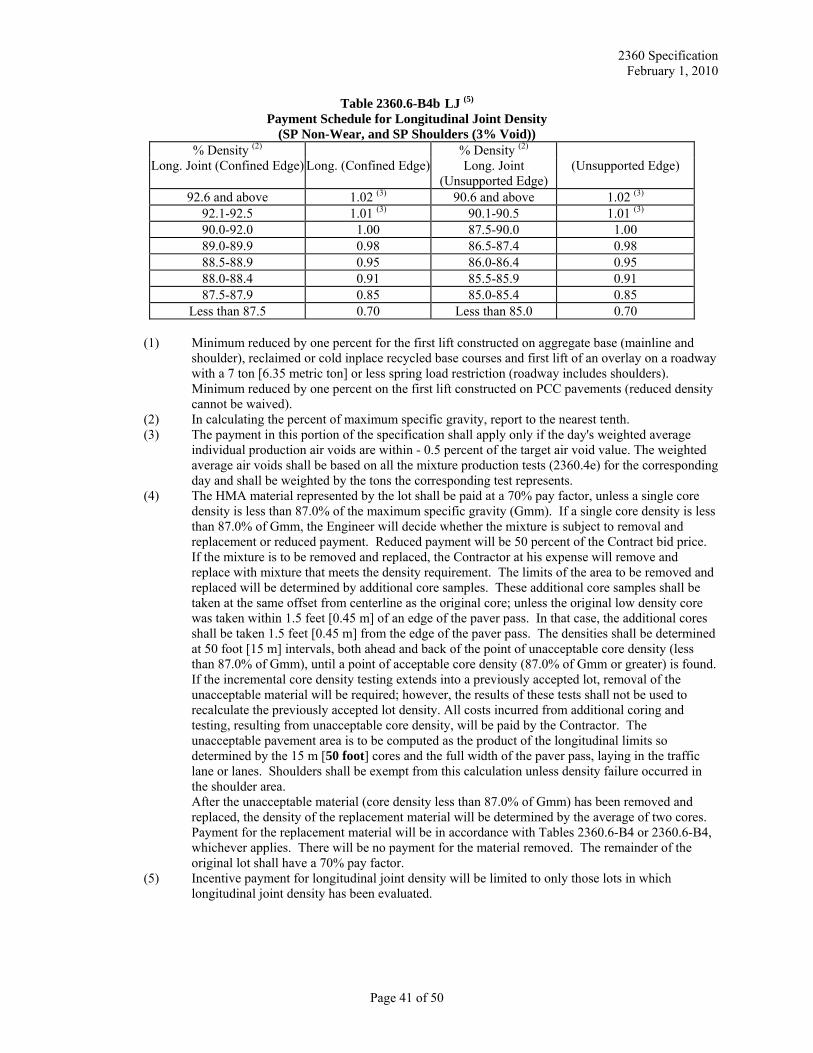
2360 Specification February 1, 2010
Table 2360.6-B4b LJ (5) Payment Schedule for Longitudinal Joint Density
(SP Non-Wear, and SP Shoulders (3% Void)) % Density (2) % Density (2)
Long. Joint (Confined Edge) Long. (Confined Edge) Long. Joint (Unsupported Edge)
(Unsupported Edge)
92.6 and above 1.02 (3) 90.6 and above 1.02 (3) 92.1-92.5 1.01 (3) 90.1-90.5 1.01 (3) 90.0-92.0 1.00 87.5-90.0 1.00 89.0-89.9 0.98 86.5-87.4 0.98 88.5-88.9 0.95 86.0-86.4 0.95 88.0-88.4 0.91 85.5-85.9 0.91 87.5-87.9 0.85 85.0-85.4 0.85
Less than 87.5 0.70 Less than 85.0 0.70
(1) Minimum reduced by one percent for the first lift constructed on aggregate base (mainline and shoulder), reclaimed or cold inplace recycled base courses and first lift of an overlay on a roadway with a 7 ton [6.35 metric ton] or less spring load restriction (roadway includes shoulders). Minimum reduced by one percent on the first lift constructed on PCC pavements (reduced density cannot be waived).
(2) In calculating the percent of maximum specific gravity, report to the nearest tenth. (3) The payment in this portion of the specification shall apply only if the day's weighted average
individual production air voids are within - 0.5 percent of the target air void value. The weighted average air voids shall be based on all the mixture production tests (2360.4e) for the corresponding day and shall be weighted by the tons the corresponding test represents.
(4) The HMA material represented by the lot shall be paid at a 70% pay factor, unless a single core density is less than 87.0% of the maximum specific gravity (Gmm). If a single core density is less than 87.0% of Gmm, the Engineer will decide whether the mixture is subject to removal and replacement or reduced payment. Reduced payment will be 50 percent of the Contract bid price. If the mixture is to be removed and replaced, the Contractor at his expense will remove and replace with mixture that meets the density requirement. The limits of the area to be removed and replaced will be determined by additional core samples. These additional core samples shall be taken at the same offset from centerline as the original core; unless the original low density core was taken within 1.5 feet [0.45 m] of an edge of the paver pass. In that case, the additional cores shall be taken 1.5 feet [0.45 m] from the edge of the paver pass. The densities shall be determined at 50 foot [15 m] intervals, both ahead and back of the point of unacceptable core density (less than 87.0% of Gmm), until a point of acceptable core density (87.0% of Gmm or greater) is found. If the incremental core density testing extends into a previously accepted lot, removal of the unacceptable material will be required; however, the results of these tests shall not be used to recalculate the previously accepted lot density. All costs incurred from additional coring and testing, resulting from unacceptable core density, will be paid by the Contractor. The unacceptable pavement area is to be computed as the product of the longitudinal limits so determined by the 15 m [50 foot] cores and the full width of the paver pass, laying in the traffic lane or lanes. Shoulders shall be exempt from this calculation unless density failure occurred in the shoulder area.
After the unacceptable material (core density less than 87.0% of Gmm) has been removed and replaced, the density of the replacement material will be determined by the average of two cores. Payment for the replacement material will be in accordance with Tables 2360.6-B4 or 2360.6-B4, whichever applies. There will be no payment for the material removed. The remainder of the original lot shall have a 70% pay factor.
(5) Incentive payment for longitudinal joint density will be limited to only those lots in which longitudinal joint density has been evaluated.
Page 41 of 50
2360 Specification February 1, 2010
Pay Factor Determination
The total pay factor will be determined by selecting one of the following three cases based on longitudinal joint construction i.e., whether the edges of the mat (right and left) are confined or unsupported. Confined shall be defined as the edge(s) of the placed mat abutting another mat, pavement surface, or curb and gutter. Unsupported means there is no abutment of the side of the mat being placed with another mat, pavement surface, etc.
Case 1) Total Pay Factor = (Pay Factor A) X (Pay Factor B) X (Pay Factor C) Case 2) Total Pay Factor = (Pay Factor A) X (Pay Factor B) X (Pay Factor B) Case 3) Total Pay Factor = (Pay Factor A) X (Pay Factor C) X (Pay Factor C)
Where: Pay Factor A is for mat density Pay Factor B is confined edge density, and Pay Factor C is for unsupported edge density
Note: Use a pay factor of 1.00 for Pay factor B and/or Pay factor C in lots where no cores are taken at the longitudinal joint.
C Ordinary Compaction Method
Ordinary compaction shall be used for layers identified in the typical sections with a minimum planned thickness of less than 1 1/2 inches [40 mm], thin lift leveling, wedging layers, patching layers, driveways, areas which cannot be compacted with standard highway construction equipment. Unless otherwise indicated in the Plans or Special Provisions recreational trails shall also be compacted by ordinary compaction. The ordinary compaction method shall not be used on mainline, ramp, or loop paving, unless otherwise designated in the plans or special provisions. When density is evaluated by the ordinary compaction method a control strip shall be used to establish a rolling pattern. This shall be used by the Contractor for the compaction of the asphalt mixture for the layer on which the control strip is constructed, or until a new control strip is constructed. The control strip requirement may be waived, by the Engineer, in small localized areas or other areas not conducive to its establishment.
A control strip shall be constructed at the beginning of the work on each lift of each course. Each
control strip shall have an area of at least 395 square yards [330 m2] and shall be of the same thickness as the lift it represents. The subgrade or pavement course upon which a control strip is to be constructed shall have the prior approval of the Engineer. The control strips shall remain in place and become part of the completed work.
The materials used in the construction of the control strips shall conform to the specified
requirements for the course. The materials used in the control strip shall be from the same source and of the same type as the materials used in the remainder of the course that the control strip represents.
The equipment used in the construction of the control strips shall be approved by the Engineer and
shall be the same type and mass used on the remainder of the pavement course represented by the control strip. A minimum of two rollers shall be required. A rolling pattern shall be established for each roller. A pneumatic tired roller shall be available for compaction operations within 24 hours after request by the Engineer. The final rolling shall be performed with a tandem steel-wheeled roller. Areas that are inaccessible to the conventional type rolling equipment shall be compacted to the required density by using trench rollers or mechanical tampers.
Construction of the control strips will be as directed by the Engineer. Compaction shall
commence as soon as possible after the mixture has been spread to the desired thickness and shall continue until no appreciable increase in density can be obtained by additional roller's coverage. Densities will be determined by means of a portable nuclear testing device or suitable approved alternate and a growth curve shall be developed to determine the optimum rolling pattern. The Contractor shall furnish documentation of the growth curve to the Engineer.
Page 42 of 50
2360 Specification February 1, 2010
To determine when no appreciable increase in density can be obtained, two test points shall be established in the control strip on a random basis and the density at each point shall be measured by a portable nuclear device or suitable approved alternate after each roller pass. Rolling shall be suspended when testing shows either a decline of more than 2% of the maximum specific gravity or when additional roller passes fail to increase the density.
After said testing is accomplished, rolling on the remainder of that course shall be done in
accordance with the pattern developed in the test strip for that roller. A separate rolling pattern and time interval shall be established for each roller.
A new control strip shall be ordered by the Engineer when:
(a) A change in the JMF is made, or (b) A change in the source of material is made or a change in the material from the same source is
observed.
A new control strip may be ordered by the Engineer or requested by the Contractor when: (a) Ten days of production have been accepted without construction of a new control strip, or (b) There are other reasons to believe that a control strip density is not representative of the HMA
mixture being placed.
The nuclear testing device shall be furnished and operated by the Contractor. The furnishing of the testing device and the operator will be considered incidental to the furnishing and placement of the HMA mixture and shall not be compensated for separately. The device shall be calibrated according to procedures described in the Mn/DOT Bituminous Manual.
Each course shall be uniformly compacted until there is no further evidence of consolidation and all roller marks are eliminated. When this method is employed, and the quantity of mixture placed by the paver exceeds 110 tons [100 metric tons] per hour, at least two rollers are required for compacting the mixture placed by each paver. C1 Rollers
The following requirements for rollers apply only when compaction is obtained by the ordinary compaction method. C2 Steel-Wheeled Rollers
Steel-wheeled rollers shall be self-propelled and has a minimum total mass of 8 tons [7.3 metric tons], or as otherwise specified in the Contract. When vibratory rollers are used, they shall produce 3,085 lbf per foot [45 kN per meter] of width. The frequency should be at least 2400 vpm and amplitude setting low. The roller shall be capable of reversing without backlash and shall be equipped with spray attachments for moistening all rollers on both sets of wheels. C3 Pneumatic Tired Rollers
The pneumatic-tired roller shall have a compacting width of 5 feet [1.5 m] or more. It shall be so constructed that the gross wheel load force shall be a minimum of 3,000 pounds [13 kN] per wheel for SP Level 2-3 mixtures and 5,000 pounds [22 kN] per wheel for SP Level 4-6 mixtures and can be varied as directed by the Engineer. The tire arrangement shall be such that full compaction will be obtained over the full width with each pass of the roller.
The roller may be self propelled or provided with suitable tractive equipment, unless otherwise specified in the Contract. If more than one roller is propelled by a single tractive unit, then that combination will be counted as a single roller unit.
Page 43 of 50
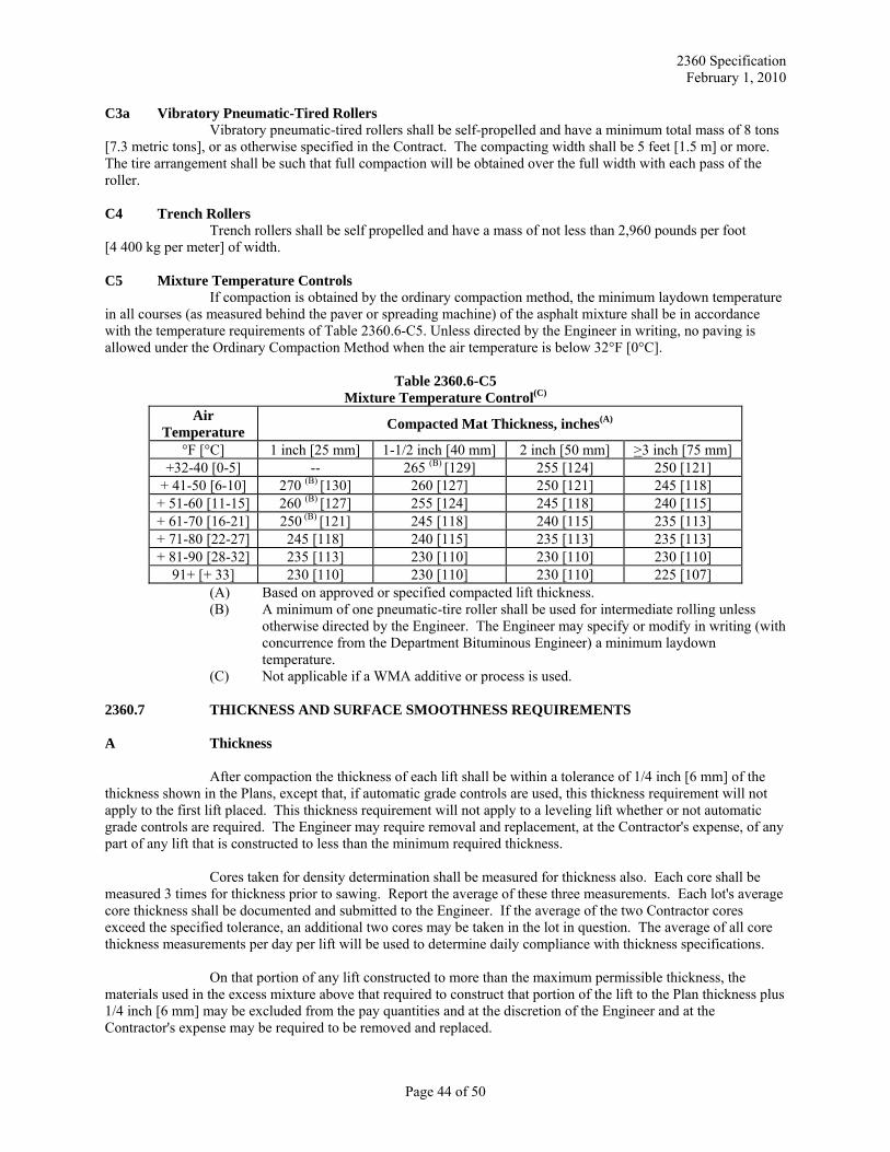
2360 Specification February 1, 2010
C3a Vibratory Pneumatic-Tired Rollers Vibratory pneumatic-tired rollers shall be self-propelled and have a minimum total mass of 8 tons
[7.3 metric tons], or as otherwise specified in the Contract. The compacting width shall be 5 feet [1.5 m] or more. The tire arrangement shall be such that full compaction will be obtained over the full width with each pass of the roller. C4 Trench Rollers
Trench rollers shall be self propelled and have a mass of not less than 2,960 pounds per foot [4 400 kg per meter] of width. C5 Mixture Temperature Controls
If compaction is obtained by the ordinary compaction method, the minimum laydown temperature in all courses (as measured behind the paver or spreading machine) of the asphalt mixture shall be in accordance with the temperature requirements of Table 2360.6-C5. Unless directed by the Engineer in writing, no paving is allowed under the Ordinary Compaction Method when the air temperature is below 32°F [0°C].
Table 2360.6-C5 Mixture Temperature Control(C)
Air Temperature Compacted Mat Thickness, inches(A)
°F [°C] 1 inch [25 mm] 1-1/2 inch [40 mm] 2 inch [50 mm] >3 inch [75 mm] +32-40 [0-5] -- 265 (B) [129] 255 [124] 250 [121]
+ 41-50 [6-10] 270 (B) [130] 260 [127] 250 [121] 245 [118] + 51-60 [11-15] 260 (B) [127] 255 [124] 245 [118] 240 [115] + 61-70 [16-21] 250 (B) [121] 245 [118] 240 [115] 235 [113] + 71-80 [22-27] 245 [118] 240 [115] 235 [113] 235 [113] + 81-90 [28-32] 235 [113] 230 [110] 230 [110] 230 [110]
91+ [+ 33] 230 [110] 230 [110] 230 [110] 225 [107] (A) Based on approved or specified compacted lift thickness. (B) A minimum of one pneumatic-tire roller shall be used for intermediate rolling unless
otherwise directed by the Engineer. The Engineer may specify or modify in writing (with concurrence from the Department Bituminous Engineer) a minimum laydown temperature.
(C) Not applicable if a WMA additive or process is used. 2360.7 THICKNESS AND SURFACE SMOOTHNESS REQUIREMENTS A Thickness
After compaction the thickness of each lift shall be within a tolerance of 1/4 inch [6 mm] of the thickness shown in the Plans, except that, if automatic grade controls are used, this thickness requirement will not apply to the first lift placed. This thickness requirement will not apply to a leveling lift whether or not automatic grade controls are required. The Engineer may require removal and replacement, at the Contractor's expense, of any part of any lift that is constructed to less than the minimum required thickness.
Cores taken for density determination shall be measured for thickness also. Each core shall be measured 3 times for thickness prior to sawing. Report the average of these three measurements. Each lot's average core thickness shall be documented and submitted to the Engineer. If the average of the two Contractor cores exceed the specified tolerance, an additional two cores may be taken in the lot in question. The average of all core thickness measurements per day per lift will be used to determine daily compliance with thickness specifications.
On that portion of any lift constructed to more than the maximum permissible thickness, the materials used in the excess mixture above that required to construct that portion of the lift to the Plan thickness plus 1/4 inch [6 mm] may be excluded from the pay quantities and at the discretion of the Engineer and at the Contractor's expense may be required to be removed and replaced.
Page 44 of 50
2360 Specification February 1, 2010
B Surface Requirements
After compaction, the finished surface of each lift shall be reasonably free of segregated, open and torn sections, and shall be smooth and true to the grade and cross section shown on the Plans with the following tolerances:
(1) Where a leveling lift is specified, it shall be constructed to within a tolerance of 1/2 inch [15 mm] of the elevations and grades established by the Engineer. This requirement shall also apply to the first lift placed other than leveling when automatic controls are used.
(2) The surface of the final two lifts placed shall show no variation greater than 6 mm 1/4 inch [6 mm]
from the edge of a 10 foot [3 m] straightedge laid parallel to or at right angles to the centerline. Shoulder surfacing and surfacing on temporary connections and bypasses shall show no variations greater than 1/4 inch [6 mm] from the edge of a 10 foot [3 m] straightedge laid parallel to the centerline.
(3) After final compaction, all final lift asphalt wearing surfaces adjacent to concrete pavements shall
be slightly higher (but not to exceed 1/4 inch [6 mm] than the concrete surface.
After final compaction, all asphalt surfaces adjacent to gutters, manholes, pavement headers, or other fixed structures shall be slightly higher (but not to exceed 1/4 inch [6 mm] than the surface of the structure.
(4) Transverse joints (construction joints), at the beginning and end of a project, at paving
exceptions, or caused by suspension of daily paving operations, shall show no variation greater than 1/4 inch [6 mm] from the edge of a 10 foot [3 m] straightedge centered longitudinally across the transverse joint. The Engineer may require correction by diamond grinding when material is placed outside the above-described limitations.
(5) The transverse slope of the surface of each lift, exclusive of the shoulder wearing lift, shall not
vary from the slope shown in the Plans by more than 0.4 percent.
(6) The distance between the edge of each lift and the established centerline shall be no less than the Plan distance nor more than 3 inches [75 mm] greater than the Plan distance. In addition, the edge alignment of the wearing lift on tangent sections and on curve sections of 3 degrees or less shall not deviate from the established alignment by more than 1 inch [25 mm] in any 25 foot [7.5 m] section.
(7) The finished surface of each lift shall be reasonably free of segregated and open and torn sections
and deleterious materials.
Any material placed outside the above described limitations shall be removed and replaced after being cut or sawed at no expense to the Department or with the approval of the Engineer, allowed to remain inplace at a reduced cost calculated at $10 per square yard [$12 per square meter]. Any single occurrence of material outside the limitations described above shall be considered to have a minimum dimension of one square yard square [one square meter] in any dimension. C Pavement Smoothness Specification – IRI (International Roughness Index) C1 General
Pavement smoothness will be evaluated on the final mainline pavement surface using an Inertial Profiler (IP) and the International Roughness Index (IRI). Unless otherwise authorized by the Engineer, all smoothness testing shall be performed in the presence of the Engineer. The Engineer and the Contractor shall mutually agree upon scheduling of smoothness testing so that testing can be observed. Any testing performed
Page 45 of 50
2360 Specification February 1, 2010
without the Engineer's presence, unless otherwise authorized, may be ordered retested at the Contractor's expense. The following Table 2360.7-A (IRI) shows pavement surfaces that are excluded from smoothness testing but subject to 2360.7B surface requirements.
Table 2360.7 – A (IRI) Testing Exclusions
25 foot [7.62 m] feet either side of obstructions such as manholes, water supply castings, etc.* Ramps, Loops, Climbing lanes Side Streets, Side Connections Turn Lanes, Storage Lanes, Crossovers, Bypass Lanes Shoulders Intersections constructed under traffic – Begin and end the exclusion100 feet [30.5m] from the intersection radius Sections less than 25 foot [7.62 m]in length Acceleration, Deceleration Lanes Projects less than 1000 feet [300m] in length Mainline paving where the normally posted regulatory speed is less than or equal to 45 miles per hour [70 km/hr] Begin the exclusion at the sign Single lift overlays over concrete
*Mainline shall be included in profiling if obstructions are located in auxiliary or parking lanes C1A Smoothness Requirements
Pavement smoothness requirements will be evaluated by the International Roughness Index (IRI) Equation A, Equation B, or Equation C. The pavement smoothness Equation will be identified in the Special Provisions of the proposal. Location of bumps and/or dips and magnitude will be based on California Test Method 526. C2 Measurement
Smoothness will be measured with an IP, which produces both an IRI value and a profilogram (profile trace of the surface tested). The IP shall conform to the Class 1 requirements of ASTM E950-94 and must be certified according to the most recent procedure on file in the Bituminous Office. For pavement evaluation, one pass will be made in the right wheel path of each traffic lane. The IP shall be run in the direction the traffic will be moving. Each lane will be tested and evaluated separately. The Engineer will determine the length in miles [kilometers] for each mainline traffic lane. The IP shall be operated at the optimum speed as defined by the manufacturer. C3 Smoothness testing
The Contractor shall furnish a properly calibrated, documented, and MnDOT certified IP. The IP shall be equipped with automatic data reduction capabilities. Computer programs used to calculate the IRI statistic from a longitudinal roadway profile shall follow the procedure developed by the World Bank for a quarter-car simulation as described in NCHRP report 228.
Mn/DOT certification documentation shall be provided to the Engineer on the first day the IP is used on the project. IP settings are on file in the Bituminous Office. The Contractor shall furnish a competent operator, trained in the operation of the IP and evaluation of both California Test Method 526 and the International Roughness Index.
The Contractor shall remove all objects and foreign material on the pavement surface prior to surface evaluation by power brooming.
Page 46 of 50
2360 Specification February 1, 2010
The pavement surface will be divided into sections which represent continuous placement. A section will terminate 25 foot [7.62 m] before a bridge approach panel, bridge surface, manhole or similar interruption. In the final pavement evaluation, a day's work joint will be included in the trace with no special consideration. A section will be separated into segments of 0.1 mi [0.1 km]. A segment will be in one traffic lane only.
An IRI value shall be computed for each segment of 25 foot [7.62 m] or more. The IRI value will include the 25 foot [7.62 m] at the ends of the section only when the Contractor is responsible for the adjoining surface.
End of run areas not included in the IRI value and any sections of pavement less than 25 foot [7.62m] in length shall be checked longitudinally with a 10 ft [3.028 m] straight edge and the surface shall not deviate from a straight line by more than 1/4 inch in 10 ft [6 mm in 3.028 m]. Transverse joints shall be evaluated by centering the straightedge longitudinally across the transverse joint.
The Contractor shall submit the graphical trace, a summary of the bump(s)/dip(s) locations, the magnitude of the bump(s)/dip(s) and each segment IRI value on the same day as the profiling was conducted.
The Contractor shall submit a final spreadsheet summary of the smoothness data to the Engineer within five calendar days after all mainline pavement placement. The summary shall be signed by the Contractor. The spreadsheet summary shall be in tabular form, with each 0.1 mile [0.1 km] segment occupying a row. Each row shall include the beginning and ending station for the segment, the length of the segment, the final IRI value for the segment, the IRI based incentive/disincentive in dollars for the segment, and the deductions for bump(s)/dip(s) in dollars for the segment. Each continuous run will occupy a separate table and each table will have a header that includes the following: the project number, the roadway number or designation, a lane designation, the mix type of the final lift, the PG binder of the final lift, the date of the final smoothness runs, and the beginning and ending station of the continuous run. The following information shall be included at the bottom of each summary: a subtotal for the IRI based incentive/disincentive, a subtotal for the bump deductions, and a total for incentive/disincentive for both IRI values and bumps. Software to summarize the data is available from the Mn/DOT Bituminous Office at www.mrr.dot.state.mn.us/pavement/bituminous/bituminous.asp.
The Contractor will be responsible for all traffic control associated with the smoothness testing and any corrective action (when applicable) that is required of the final pavement surface. C3A Retesting
The Engineer may require any portion or the total project to be retested if the results are questioned. This includes both IRI values and bump/dip locations. The Engineer will decide whether Mn/DOT, an independent testing firm (ITF), or the Contractor will retest the roadway surface.
If the retested IRI values differ by more than 10% from the original IRI values, the retested values will be used as the basis for acceptance and any incentive/disincentive payments. In addition, bump/dip locations as shown by the retest will replace the original results.
If the Engineer directs the Contractor or an independent testing firm to perform retesting and the original results are found to be accurate, the Department will pay the Contractor or the independent testing firm $62.14 per lane km [$100 per lane mile] that is retested, with a minimum charge of $500.00. The Contractor will be responsible for any costs associated with retesting if the original values differ by more than 10% from the retested values. C4 IRI Values
The IP shall be equipped with automatic data reduction capabilities for determining the IRI values. An IRI value shall be calculated for each segment of the final pavement surface. Segments greater than or equal to 7.62 m [25 feet] and less than 161m [528 feet] shall be evaluated as a separate segment. The IRI values shall be determined by following NCHRP report 228. The IRI values shall be reported in units of inches per mile [m per
Page 47 of 50
2360 Specification February 1, 2010
km]. Report inches per mile with one digit right of the decimal and for m per km report with two digits right of the decimal. Follow Mn/DOT rounding procedures per the Bituminous Manual section 5-693.730. C4a Bumps and Dips – IRI Equation A and IRI Equation B
Bump/dip location will be determined in accordance with California Method 526. Bumps and dips equal to or exceeding 0.4 inch in a 25 ft [10.2 mm in a 7.62 m] span shall be identified separately. When the profile trace shows a successive, uninterrupted bump, dip; or dip, bump combination (up to a maximum of 3 alternating trace deviations that relate to one bump or dip on the roadway), identify and evaluate these occurrences as one event.
The Contractor shall correct, by diamond grinding, all areas represented by bumps or dips of 0.4 inch [10.2 mm] or more as measured by California Test Method 526. However, the Engineer may allow bumps or dips of 0.4 inches to 0.6 inches [10.2 mm to 15.2 mm] in a 25 foot [7.62 m] span to be left uncorrected, and in such case, the contractor will be assessed a price deduct as specified in section C6 ("Payment") of this special provision.
Corrected dips or bumps will be considered satisfactory when the profilogram shows the deviations are less than 0.4 inch in a 25 foot [10.2 mm in a 7.62 m] span. C4b Bumps and Dips – IRI Equation C
Bump/dip location will be determined in accordance with California Method 526. Bumps and dips equal to or exceeding 0.5 inch in a 25 ft [12.7 mm in a 7.62 m] span shall be identified separately. When the profile trace shows a successive, uninterrupted bump, dip; or dip, bump combination (up to a maximum of 3 alternating trace deviations that relate to one bump or dip on the roadway), identify and evaluate these occurrences as one event.
The Contractor shall correct, by diamond grinding, all areas represented by bumps or dips of 0.5 inch [12.7 mm] or more as measured by California Test Method 526. However, the Engineer may allow bumps or dips of 0.5 inches to 0.7 inches [12.7 mm to 17.8 mm] in a 25 foot [7.62 m] span to be left uncorrected, and in such case, the contractor will be assessed a price deduct as specified in section C6 ("Payment") of this special provision.
Corrected dips or bumps will be considered satisfactory when the profilogram shows the deviations are less than 0.5 inch in a 25 foot [12.7 mm in a 7.62 m] span. C5 Surface Correction
Unless otherwise approved by the Engineer, corrective work shall be by diamond grinding. Other methods may include; overlaying the area, or replacing the area by milling and inlaying. The Engineer shall approve of the Contractor's method of correcting segment(s) prior to the Contractor starting corrective work. Any corrective actions by milling and inlay or overlay shall meet the specifications for ride quality over the entire length of the correction, including the first and last 25 foot [7.62 m]. Bumps or dips in excess of 0.4 inches [10.2 mm] where evaluation is by Equation A or B or bumps or dips in excess of 0.5 inch [12.7 mm] where evaluation is by Equation C that are located at transverse joints at areas of corrective actions utilizing overlay or milling and inlay, shall be removed by diamond grinding. The Contractor shall notify the Engineer prior to commencement of the corrective action. If the surface is corrected by overlay, inlay or replacement, the surface correction shall begin and end with a transverse saw cut. Surface corrections shall be made prior to placing permanent pavement markings. In the event that permanent pavement marking are damaged or destroyed during surface correction activities, they will be replaced at no cost to the Agency.
When pavement smoothness evaluation by Equation A is specified the Engineer may require that the Contractor, at no expense to the Department, correct segments with an IRI greater than 65 inches/mile [1.03 m per km] or the Engineer may assess a $900 per 0.1 mile [$560 per 0.1 km] penalty in lieu of requiring corrective work.
Page 48 of 50
2360 Specification February 1, 2010
When pavement smoothness evaluation by Equation B is specified the Engineer may require that the Contractor, at no expense to the Department, correct segments with an IRI greater than 75 inches/mile [1.18 m per km] or the Engineer may assess a $675 per 0.1 mile [$420 per 0.1 km] penalty in lieu of requiring corrective work.
When pavement smoothness evaluation by Equation C is specified the Engineer may require that the Contractor, at no expense to the Department, correct segments with an IRI greater than 85 inches/mile [1.34 m per km] or the Engineer may assess a $450 per 0.1 mile [$280 per 0.1 km] penalty in lieu of requiring corrective work.
Bump, dip, and smoothness correction work shall be for the entire traffic lane width. Pavement cross slope shall be maintained through corrective areas.
All corrective work shall be subject to the approval of the Engineer. After all required corrective work is completed a final segment(s) IRI value and bump/dip tabulation shall be determined and submitted to the Engineer. Corrective work and re-evaluation shall be at the Contractor's expense.
Segments requiring grinding will be re-profiled within two working days of completion of grinding. Individual bumps/dips and segments requiring grinding shall be completed with 15 working days of notification. C6 Payment
The cost of traffic control for certified smoothness testing and/or any corrective work is incidental to the cost of the Wear course mixture.
The Contractor may receive an incentive payment or be assessed a penalty based on the number of segments and the IRI value. The total ride incentive shall not exceed 10% of the total mix price for pavement smoothness evaluated under IRI Equation A, 5% of the total mix price for pavement smoothness evaluated under Equation B, or 5% of the total mix price for pavement smoothness evaluated under Equation C. Total mix shall be defined as all mixture placed on the project. Only those segments which have had no corrective work or work to improve the ride are eligible for IRI incentive payment. Incentive payment for IRI will be based on the roadway segment before corrective work is performed. Grinding of the segment into incentive payment or grinding of the segment in order to obtain a higher incentive payment is not allowed. IRI incentive payment is independent of pay adjustment for bumps and dips.
The Contractor will not receive a net incentive payment for ride if more than 25% of all density lots (excluding longitudinal joint density) for the project fail to meet minimum density requirements.
For pavement smoothness evaluated under Equation A uncorrected bumps or dips greater than or equal to 0.4 inches [10.2 mm] in a 25 foot [7.62 m] span will be assessed a price deduction of $900 per event.
For pavement smoothness evaluated under Equation B uncorrected bumps or dips greater than or equal to 0.4 inches [10.2 mm] in a 25 foot [7.62 m]span will be assessed a price deduction of $675 per event.
For pavement smoothness evaluated under Equation C uncorrected deviations (bumps or dips) greater than or equal to 0.5 inches [12.7 mm] in a 25 foot [7.62 m] span will be assessed a price deduction of $450 per event.
Combinations of bumps and dips which arise from the same single bump or dip are considered to be one event, and shall be counted only once for the purposes of calculating price deductions. Typically, bump-dip-bump combinations, or dip-bump-dip combinations, that are confined to a 30 feet longitudinal segment are considered to be one event.
Bumps or dips resulting from a construction joint will be assessed a $900 penalty, regardless of the IRI Equation used for evaluation or pavement smoothness.
Page 49 of 50
2360 Specification February 1, 2010
Page 50 of 50
Incentive/disincentive payments will be based on the IRI determined for each segment and will be
based on the following equations and criteria. C6a IRI Equation A* Inches/mile [IRI m/km] Incentive/Disincentive $/0.1mile [$/0.1km] < 30 inches/mile [<0.47 m/km] $400 [$249] 30 inches/mile to 65 inches/mile [0.47 m/km to 1.03 m/km] $850 – (IRI x 15) [$523 – (IRI x 584)] > 65 inches/mile [>1.03 m/km] -$900 [-$560] * Typically, 3-lift minimum construction C6b IRI Equation B* Inches/mile [IRI m/km] Incentive/Disincentive $/0.1mile [$/0.1km] < 33 inches/mile [< 0.52 m/km] $270 [$168] 33 inches/mile to 75 inches/mile [0.52 m/km to 1.18 m/km] $600 – (IRI x 10) [$373 – (IRI x 395)] > 75 inches/mile [>1.18 m/km] -$675 [-$420] * Typically, 2-lift construction C6c IRI Equation C* Inches/mile [IRI m/km] Incentive/Disincentive $/0.1mile [$/0.1km] < 36 inches/mile [< 0.57 m/km] $180 [$112] 36 inches/mile to 85 inches/mile [0.57 m/km to 1.34 m/km] $414 – (IRI x 6. 5) [$258 – (IRI x 257)] > 85 inches/mile [>1.34 m/km] -$450 [-$280] * Typically, single lift construction 2360.8 METHOD OF MEASUREMENT A Asphalt Mixture
Asphalt mixture of each type will be measured separately by mass, based on the total quantity of material hauled from the mixing plant, with no deductions being made for the asphalt materials. B Blank C Asphalt Mixtures Measured by the Square Yard [Square Meter] per Specified (inch [mm])
and for Mixtures Measured by the Square Yard inch
Asphalt mixture of each type and for each specific lift will be measured separately by area and by thickness on the basis of actual final dimensions placed. The constructed thickness shall meet tolerances set forth in Sections 2360.7A.


