Embed Size (px)
Citation preview


Z-30/20N • Z-30/20N RJ • Z-34/22 • Z-34/22N Part No. 139378
September 2013
ii
Introduction
Important
Read, understand and obey the safety rules andoperating instructions in the Genie Z-30/20NOperator's Manual or the Z-34/22 and Z-34/22NOperator's Manual before attempting anymaintenance or repair procedure.
This manual provides detailed scheduledmaintenance information for the machine ownerand user. It also provides troubleshooting faultcodes and repair procedures for qualified serviceprofessionals.
Basic mechanical, hydraulic and electrical skillsare required to perform most procedures.However, several procedures require specializedskills, tools, lifting equipment and a suitableworkshop. In these instances, we stronglyrecommend that maintenance and repair beperformed at an authorized Genie dealer servicecenter.
Compliance
Machine ClassificationGroup B/Type 3 as defined by ISO 16368
Machine Design LifeUnrestricted with proper operation, inspection andscheduled maintenance.
Technical Publications
Genie has endeavored to deliver the highest degreeof accuracy possible. However, continuousimprovement of our products is a Genie policy.Therefore, product specifications are subject tochange without notice.
Readers are encouraged to notify Genie of errorsand send in suggestions for improvement. Allcommunications will be carefully considered forfuture printings of this and all other manuals.
Contact Us:
Copyright © 2011 Terex Corporation
139378 Rev B June 2011Third Edition, Second Printing
Genie and "Z" are registered trademarks ofTerex South Dakota, Inc. in the USA and manyother countries.
Printed on recycled paper
Printed in U.S.A.
Serial Number Information
Genie offers the following Service Manuals forthese models:
Title Part No.
Z-30/20N Service Manual(before serial number 5934) ................................ 35532
Z-30/20N Service Manual(from serial number 5934 to 11499) ..................106373
Z34/22N (before serial number 6291)Z-34/22DC (before serial number 5427) .............. 36540
Introduction
http://www.genielift.come-mail: [email protected]

Part No. 139378 Z-30/20N • Z-30/20N RJ • Z-34/22 • Z-34/22N
September 2013
Serial Number Legend
INTRODUCTION
iii
Z30N 05 - 12345
Model
Year ofmanufacture
Sequencenumber
Country of manufacture: USA
This machine complies with:
Model: Z-30/20N
Serial number: Z30N05-12345
Electrical schematic number: ESXXXX
Machine unladen weight:
Rated work load (including occupants): XXX lb / XXX kg
Maximum allowable inclination of the chassis:
0 deg
Gradeability: N/A
Maximum allowable side force : XXX lb / XXX N
Maximum number of platfrm occupants: X
Model year: Manufacture date: 04/12/052005
Maximum wind speed : XX mph/ XX m/s
Maximum platform height : XX ft / XX m
Maximum platform reach : XX ft / XX m
Serial numberstamped on chassis
Serial label(located under cover)
Serial numberstamped on chassis
Serial label(located under cover)
Z-30/20NZ-30/20N RJ
Z-34/22Z-34/22N
Terex South Dakota, Inc.500 Oak Wood RoadPO Box 1150Watertown, SD 57201USA

Z-30/20N • Z-30/20N RJ • Z-34/22 • Z-34/22N Part No. 139378
September 2013
iv
This page intentionally left blank.

Part No. 139378 Z-30/20N • Z-30/20N RJ • Z-34/22 • Z-34/22N
September 2013
v
DangerFailure to obey the instructions and safety rulesin this manual and the Genie Z-30/20N Operator’sManual or the Z-34/22 and Z-34/22N Operator'sManual will result in death or serious injury.
Many of the hazards identified in theoperator’s manual are also safety hazardswhen maintenance and repair proceduresare performed.
Do Not Perform MaintenanceUnless:
You are trained and qualified to performmaintenance on this machine.
You read, understand and obey:- manufacturer’s instructions and safety rules- employer’s safety rules and worksite
regulations- applicable governmental regulations
You have the appropriate tools, liftingequipment and a suitable workshop.
Safety Rules
Section 1 • Safety Rules

Z-30/20N • Z-30/20N RJ • Z-34/22 • Z-34/22N Part No. 139378
September 2013
SAFETY RULES
vi
Personal SafetyAny person working on or around a machine mustbe aware of all known safety hazards. Personalsafety and the continued safe operation of themachine should be your top priority.
Read each procedure thoroughly. Thismanual and the decals on the machine,use signal words to identify the following:
Safety alert symbol—used to alertpersonnel to potential personalinjury hazards. Obey all safetymessages that follow this symbolto avoid possible injury or death.
Indicates an imminently hazardoussituation which, if not avoided, willresult in death or serious injury.
Indicates a potentially hazardoussituation which, if not avoided,could result in death or seriousinjury.
Indicates a potentially hazardoussituation which, if not avoided,may cause minor or moderateinjury.
Indicates a potentially hazardoussituation which, if not avoided,may result in property damage.
Be sure to wear protective eye wear andother protective clothing if the situationwarrants it.
Be aware of potential crushing hazardssuch as moving parts, free swinging orunsecured components when lifting or
placing loads. Always wear approved steel-toedshoes.
Workplace SafetyBe sure to keep sparks, flames andlighted tobacco away from flammable andcombustible materials like battery gases
and engine fuels. Always have an approved fireextinguisher within easy reach.
Be sure that all tools and working areasare properly maintained and ready foruse. Keep work surfaces clean and free of
debris that could get into machine components andcause damage.
Be sure any forklift, overhead crane orother lifting or supporting device is fullycapable of supporting and stabilizing the
weight to be lifted. Use only chains or straps thatare in good condition and of ample capacity.
Be sure that fasteners intended for onetime use (i.e., cotter pins and self-lockingnuts) are not reused. These components
may fail if they are used a second time.
Be sure to properly dispose of old oil orother fluids. Use an approved container.Please be environmentally safe.
Be sure that your workshop or work areais properly ventilated and well lit.
Section 1 • Safety Rules

Part No. 139378 Z-30/20N • Z-30/20N RJ • Z-34/22 • Z-34/22N
September 2013
Table of Contents
vii
Introduction
Important Information ................................................................................................... ii
Serial Number Information............................................................................................ ii
Serial Number Legend ................................................................................................. iii
Section 1 Safety Rules
General Safety Rules .................................................................................................. v
Section 2 Rev Specifications
C Machine Specifications .......................................................................................... 2 - 1
Performance Specifications ................................................................................... 2 - 2
Hydraulic Oil Specifications ................................................................................... 2 - 3
Hydraulic Component Specifications ...................................................................... 2 - 3
Manifold Component Specifications ....................................................................... 2 - 4
Machine Torque Specifications .............................................................................. 2 - 4
Hydraulic Hose and Fitting Torque Specifications .................................................. 2 - 5
SAE and Metric Fasteners Torque Charts .............................................................. 2 - 6
Section 3 Rev Scheduled Maintenance Procedures
Introduction ............................................................................................................ 3 - 1
Pre-Delivery Preparation ........................................................................................ 3 - 3
Maintenance Inspection Report .............................................................................. 3 - 5
A Checklist A Procedures
A-1 Inspect the Manuals and Decals .................................................................. 3 - 6
A-2 Perform Pre-operation Inspection ................................................................ 3 - 7
A-3 Perform Function Tests ............................................................................... 3 - 7
A-4 Perform 30 Day Service ............................................................................... 3 - 8
A-5 Grease the Turntable Rotation Bearing and Worm Drive Gear ...................... 3 - 8
A-6 Replace the Drive Hub Oil ............................................................................ 3 - 9
Section 1 • Safety Rules

Z-30/20N • Z-30/20N RJ • Z-34/22 • Z-34/22N Part No. 139378
September 2013
TABLE OF CONTENTS
viii
Section 3 Rev Scheduled Maintenance Procedures, continued
B Checklist B Procedures
B-1 Check the Batteries.................................................................................... 3 - 10
B-2 Inspect the Electrical Wiring ....................................................................... 3 - 11
B-3 Test the Key Switch ................................................................................... 3 - 12
B-4 Check the Tires, Wheels and Lug Nut Torque ............................................ 3 - 13
B-5 Confirm the Proper Brake Configuration...................................................... 3 - 13
B-6 Check the Oil Level in the Drive Hubs and Mounting Bolt Torque ............... 3 - 14
B-7 Test the Ground Control Override ............................................................... 3 - 14
B-8 Test the Platform Self-leveling ................................................................... 3 - 15
B-9 Test the Drive Brakes ................................................................................ 3 - 15
B-10 Test the Drive Speed - Stowed Position ..................................................... 3 - 16
B-11 Test the Drive Speed - Raised or Extended Position .................................. 3 - 16
B-12 Test the Alarm Package (if equipped) ........................................................ 3 - 17
B-13 Test the Turntable Rotation Stop ................................................................ 3 - 18
B-14 Check the Electrical Contactors ................................................................. 3 - 18
B-15 Perform Hydraulic Oil Analysis ................................................................... 3 - 19
A Checklist C Procedures
C-1 Grease the Platform Overload Mechanism (if equipped) ............................. 3 - 20
C-2 Test the Platform Overload System (if equipped) ....................................... 3 - 20

Part No. 139378 Z-30/20N • Z-30/20N RJ • Z-34/22 • Z-34/22N
September 2013
Section 3 Rev Scheduled Maintenance Procedures, continued
A Checklist D Procedures
D-1 Check the Primary Boom Wear Pads ......................................................... 3 - 23
D-2 Check the Free-wheel Configuration ........................................................... 3 - 24
D-3 Check the Turntable Rotation Bearing Bolts ............................................... 3 - 25
D-4 Replace the Drive Hub Oil .......................................................................... 3 - 26
D-5 Replace the Hydraulic Tank Return Filter Element ..................................... 3 - 26
D-6 Inspect for Turntable Bearing Wear ............................................................ 3 - 27
A Checklist E Procedures
E-1 Test or Replace the Hydraulic Oil ............................................................... 3 - 29
E-2 Grease the Steer Axle Wheel Bearings ...................................................... 3 - 31
Section 4 Rev Repair Procedures
Introduction ............................................................................................................ 4 - 1
A Platform Controls
1-1 Controllers .................................................................................................... 4 - 2
A Platform Components
2-1 Platform Leveling Slave Cylinder .................................................................. 4 - 4
2-2 Platform Rotator ........................................................................................... 4 - 5
2-3 Platform Overload System (if equipped) ....................................................... 4 - 7
A Jib Boom Components
3-1 Jib Boom...................................................................................................... 4 - 9
3-2 Jib Boom Bell Crank (models without rotating jib boom) ............................. 4 - 10
3-3 Jib Boom Rotator (models with rotating jib boom) ....................................... 4 - 11
3-4 Jib Boom Lift Cylinder ................................................................................ 4 - 13
TABLE OF CONTENTS
ix

Z-30/20N • Z-30/20N RJ • Z-34/22 • Z-34/22N Part No. 139378
September 2013
x
Section 4 Rev Repair Procedures, continued
A Primary Boom Components
4-1 Cable Track ................................................................................................ 4 - 14
4-2 Primary Boom ............................................................................................ 4 - 14
4-3 Primary Boom Lift Cylinder ......................................................................... 4 - 18
4-4 Extension Cylinder ..................................................................................... 4 - 19
4-5 Platform Leveling Master Cylinder .............................................................. 4 - 20
A Secondary Boom Components
5-1 Secondary Boom........................................................................................ 4 - 23
5-2 Secondary Boom Lift Cylinder .................................................................... 4 - 28
A Hydraulic Pump
6-1 Auxiliary and Function Pump...................................................................... 4 - 30
B Manifolds
7-1 Function Manifold Components .................................................................. 4 - 32
7-2 Valve Adjustments - Function Manifold ...................................................... 4 - 36
7-3 Jib Boom and Platform / Jib Boom Rotate Manifold Components ............... 4 - 39
7-4 Valve Coils ................................................................................................. 4 - 41
A Turntable Rotation Components
8-1 Turntable Rotation Hydraulic Motor ............................................................. 4 - 43
A Steer Axle Components
9-1 Hub and Bearings ....................................................................................... 4 - 44
A Motor Controller
10-1 Motor Controller .......................................................................................... 4 - 45
Section 5 Rev Fault Codes
Introduction ............................................................................................................ 5 - 1
B Fault Code Chart .................................................................................................... 5 - 3
TABLE OF CONTENTS

Part No. 139378 Z-30/20N • Z-30/20N RJ • Z-34/22 • Z-34/22N
September 2013
TABLE OF CONTENTS
Section 6 Rev Schematics
Introduction ............................................................................................................ 6 - 1
A Electrical Symbols Legend .................................................................................... 6 - 2
A Hydraulic Symbols Legend .................................................................................... 6 - 3
A Limit switch Location Legend ................................................................................. 6 - 4
B Electrical Schematic, (ANSI / CSA / AS)(before serial numbers Z30N10-12119, Z34N10-8857 and Z3410-7774) ........ 6 - 6
B Ground Control Box Terminal Strip Wiring Diagram, (ANSI / CSA / AS)(before serial numbers Z30N10-12119, Z34N10-8857 and Z3410-7774) ...... 6 - 10
B Ground Control Box Switch Panel Wiring Diagram, (ANSI / CSA / AS)(before serial numbers Z30N10-12119, Z34N10-8857 and Z3410-7774) ...... 6 - 11
B Platform Control Box Wiring Diagram, (ANSI / CSA / AS)(before serial numbers Z30N10-12119, Z34N10-8857 and Z3410-7774) ...... 6 - 13
B Electrical Schematic (CE)(before serial numbers Z30N10-12119, Z34N10-8857 and Z3410-7774) ...... 6 - 16
B Ground Control Box Terminal Strip Wiring Diagram, (CE)(before serial numbers Z30N10-12119, Z34N10-8857 and Z3410-7774) ...... 6 - 20
B Ground Control Box Switch Panel Wiring Diagram, (CE) (before serial numbers Z30N10-12119, Z34N10-8857 and Z3410-7774) ..... 6 - 21
B Platform Control Box Wiring Diagram, (CE)(before serial numbers Z30N10-12119, Z34N10-8857 and Z3410-7774) ...... 6 - 23
A Electrical Schematic, (ANSI / CSA)(from serial numbers Z30N10-12119, Z34N10-8857 and Z3410-7774) ......... 6 - 26
A Ground Control Box Terminal Strip Wiring Diagram, (ANSI / CSA)(from serial numbers Z30N10-12119, Z34N10-8857 and Z3410-7774) ......... 6 - 30
A Ground Control Box Switch Panel Wiring Diagram, (ANSI / CSA)(from serial numbers Z30N10-12119, Z34N10-8857 and Z3410-7774) ......... 6 - 31
A Platform Control Box Wiring Diagram, (ANSI / CSA)(from serial numbers Z30N10-12119, Z34N10-8857 and Z3410-7774) ......... 6 - 33
xi

Z-30/20N • Z-30/20N RJ • Z-34/22 • Z-34/22N Part No. 139378
September 2013
xii
Section 6 Rev Schematics, continued
B Electrical Schematic (AS / CE)(from serial numbers Z30N10-12119, Z34N10-8857 and Z3410-7774) ......... 6 - 36
A Ground Control Box Terminal Strip Wiring Diagram, (AS / CE)(from serial numbers Z30N10-12119, Z34N10-8857 and Z3410-7774) ......... 6 - 40
A Ground Control Box Switch Panel Wiring Diagram, (AS / CE) (from serial numbers Z30N10-12119, Z34N10-8857 and Z3410-7774) ........ 6 - 41
A Platform Control Box Wiring Diagram, (AS / CE)(from serial numbers Z30N10-12119, Z34N10-8857 and Z3410-7774) ......... 6 - 44
A Power Cable Wiring Diagram ................................................................................ 6 - 45
B Drive Contactor Panel Wiring Diagram ................................................................. 6 - 48
B Manifold and Limit Switch Wiring Diagram ........................................................... 6 - 49
A LVI/BCI Option Wiring Diagram ............................................................................ 6 - 52
A Charger Interlock option ....................................................................................... 6 - 53
A CTE Option, (CE Models) .................................................................................... 6 - 56
B Hydraulic Schematic ............................................................................................ 6 - 57
TABLE OF CONTENTS

Part No. 139378 Z-30/20N • Z-30/20N RJ • Z-34/22 • Z-34/22N 2 - 1
Section 2 • SpecificationsJune 2011
REV C Specifications
Machine Specifications
Tires and wheels,Z-30/20N, Z-30/20N RJ and Z-34/22N
Tire size (solid rubber) 22 x 7 x 17.5 in56 x 18 x 44 cm
Load range 7600 lbs3447 kg
Overall tire diameter 22 in56 cm
Wheel diameter 17.5 in44 cm
Wheel width 7 in18 cm
Tires and wheels, Z-34/22
Tire size 9-14.5 LT
Tire ply rating 12
Tire weight, new foam-filled (minimum) 175 lbs79 kg
Overall tire diameter 28 in71 cm
Wheel diameter 14.5 in37 cm
Wheel width 7 in18 cm
Wheel lugs
Front 8 @ 5/8 -18Rear 9 @ 5/8 -18
Lug nut torque, dry 125 ft-lbs169.5 Nm
Lug nut torque, lubricated 95 ft-lbs129 Nm
Fluid Capacities
Hydraulic tank capacity 4 gallons15.1 liters
Hydraulic system capacity 6 gallons(including tank) 22.7 liters
Drive hubs48:1 24.5 ounces 0.72 liter57:1 24.5 ounces 0.72 liter
Drive hub oil type:SAE 90 multipurpose hypoid gear oil API serviceclassification GL5
For operational specifications, refer to theOperator's Manual.
Continuous improvement of our products is aGenie policy. Product specifications aresubject to change without notice.

2 - 2 Z-30/20N • Z-30/20N RJ • Z-34/22 • Z-34/22N Part No. 139378
Section 2 • Specifications June 2011
REV CSPECIFICATIONS
Performance Specifications,Z-30/20N and Z-30/20N RJ
Drive speed, maximum
Stowed position 4.5 mph7.2 km/h
40 ft / 6.0 sec12.2 m / 6.0 sec
Boom raised or extended 0.6 mph1 km/h
40 ft / 42 sec12.2 m / 42 sec
Braking distance, maximum
High range on paved surface 2 to 4 ft0.6 to 1.2m
Gradeability See Operator's Manual
Boom function speeds, maximum from platformcontrols (with rated load secured to platform)
Jib boom up 19 to 23 seconds
Jib boom down 17 to 21 seconds
Jib boom rotate, 180° 13 to 17 seconds
Primary boom up 14 to 22 seconds
Primary boom down 12 to 20 seconds
Primary boom extend 15 to 19 seconds
Primary boom retract 10 to 14 seconds
Secondary boom up 11 to 18 seconds
Secondary boom down 7 to 15 seconds
Turntable rotate, 355° 62 to 68 seconds
Platform rotate, 180° 5 to 11 seconds
Platform level up 14 to 19 seconds
Platform level down 13 to 18 seconds
Performance Specifications,Z-34/22 and Z-34/22N
Drive speed, maximum
Stowed position 4.5 mph7.2 km/h
40 ft / 6.0 sec12.2 m / 6.0 sec
Boom raised or extended 0.6 mph1 km/h
40 ft / 42 sec12.2 m / 42 sec
Braking distance, maximum
High range on paved surface 2 to 4 ft0.6 to 1.2m
Gradeability See Operator's Manual
Boom function speeds, maximum from platformcontrols (with rated load secured to platform)
Jib boom up 20 to 24 seconds
Jib boom down 18 to 22 seconds
Primary boom up 16 to 22 seconds
Primary boom down 13 to 20 seconds
Primary boom extend 11 to 15 seconds
Primary boom retract 13 to 17 seconds
Secondary boom up 15 to 22 seconds
Secondary boom down 11 to 18 seconds
Turntable rotate, 355° 62 to 68 seconds
Platform rotate, 180° 5 to 11 seconds
Platform level up 14 to 19 seconds
Platform level down 13 to 18 seconds
Continuous improvement of our products is aGenie policy. Product specifications aresubject to change without notice.

Part No. 139378 Z-30/20N • Z-30/20N RJ • Z-34/22 • Z-34/22N 2 - 3
Section 2 • SpecificationsJune 2011
REV C
Hydraulic Oil Specifications
Hydraulic Oil Specifications
Hydraulic oil type Chevron Rando HD equivalentViscosity grade Multi-viscosityViscosity index 200
Cleanliness level, minimum 15/13
Water content, maximum 200 ppm
Chevron Rando HD oil is fully compatible andmixable with Shell Donax TG (Dexron III) oils.Genie specifications require hydraulic oils which aredesigned to give maximum protection to hydraulicsystems, have the ability to perform over a widetemperature range, and the viscosity index shouldexceed 140. They should provide excellent antiwear,oxidation, corrosion inhibition, seal conditioning, andfoam and aeration suppression properties.
Optional fluids
Biodegradable Petro Canada Environ MV46Statoil Hydra Way Bio Pa 32
BP Biohyd SE-S
Fire resistant UCON Hydrolube HP-5046Quintolubric 822
Mineral based Shell Tellus T32Shell Tellus T46
Chevron Aviation A
Continued use of ChevronAviation A hydraulic fluid whenambient temperatures areconsistently above 32°F / 0°C mayresult in component damage.
Note: Use Chevron Aviation A hydraulic fluid whenambient temperatures are consistently below0°F / -18°C.
Note: Use Shell Tellus T46 hydraulic oil when oiltemperatures consistently exceed 205°F / 96°C.
Note: Genie specifications require additionalequipment and special installation instructions forthe approved optional fluids. Consult the GenieIndustries Service Department before use.
Continuous improvement of our products is aGenie policy. Product specifications aresubject to change without notice.
SPECIFICATIONS
Hydraulic ComponentSpecifications
Function pump
Type: Fixed displacement gear pump
Displacement 0.183 cu in3 cc
Flow rate @ 2.1 gpm2800 psi / 172 bar 7.9 L/min
Hydraulic tank 10 micron withreturn filter 25 psi / 1.7 bar bypass
Function manifold
System relief valve pressure, 2800 psiZ-30/20N and Z-30/20N RJ 193 bar
System relief valve pressure, 3200 psiZ-34/22 and Z-34/22N 221 bar
Primary boom down relief pressure 1600 psi110 bar
Secondary boom down relief pressure 1600 psi110 bar
Primary boom extend relief pressure 1800 psiModels with rotating jib 124 bar
Turntable rotate relief pressure 1100 psi76 bar
Auxiliary pump
Type: Fixed displacement gear pump
Displacement 0.3 gpm1.14 L/min

2 - 4 Z-30/20N • Z-30/20N RJ • Z-34/22 • Z-34/22N Part No. 139378
Section 2 • Specifications June 2011
REV C
Machine Torque Specifications
Platform rotator and jib boom rotator (Z-30/20N RJ)
1-8 center bolt, GR 5, lubricated 480 ft-lbs(Jib boom rotator) 650 Nm
3/4 -10 bolt, GR 8, lubricated 280 ft-lbs(Platform rotator) 379 Nm
3/8 -16 bolts, GR 8, lubricated 23 ft-lbs(Platform rotator) 31 Nm
1/2 -13 bolts, GR 5, lubricated 57 ft-lbs(Jib boom rotator) 77 Nm
Platform rotator (Z-30/20N, Z-34/22 and Z-34/22N)
3/4 -10 bolt, GR 8, lubricated 280 ft-lbs379 Nm
3/8 -16 bolts, GR 8, lubricated 23 ft-lbs31 Nm
Turntable rotate bearing
Rotate bearing mounting bolts, lubricated 180 ft-lbs244 Nm
Drive hubs, brakes and motors
Drive hub mounting bolts, lubricated 180 ft-lbs244 Nm
Brake mounting bolts, lubricated 93 ft-lbs126 Nm
Drive motor mounting bolts 31 ft-lbs42 Nm
SPECIFICATIONS
Manifold ComponentSpecifications
Plug torque
SAE No. 2 36 in-lbs / 4 Nm
SAE No. 4 10 ft-lbs / 13 Nm
SAE No. 6 14 ft-lbs / 19 Nm
SAE No. 8 38 ft-lbs / 51 Nm
SAE No. 10 41 ft-lbs / 55 Nm
SAE No. 12 56 ft-lbs / 76 Nm
Valve Coil Resistance
Note: The following coil resistance specifications are atan ambient temperature of 68°F / 20°C. As valve coilresistance is sensitive to changes in air temperature,the coil resistance will typically increase or decrease by4% for each 18°F / 10°C that your air temperatureincreases or decreases from 68°F / 20°C.
Valve Coil Resistance Specification
Description Specification
Solenoid valve, 3 position 4 way, 20V DC 22 Ω(schematic items A, J, K, U, V, Y, AA, AB and CC)
Proportional solenoid valve, 24V DC 19.5 Ω(schematic item H)
Solenoid valve, N.C. poppet, 20V DC 23.5 Ω(schematic item M)
Solenoid valve, N.O. poppet, 20V DC 23.5 Ω(schematic item P)
Continuous improvement of our products is aGenie policy. Product specifications aresubject to change without notice.

Part No. 139378 Z-30/20N • Z-30/20N RJ • Z-34/22 • Z-34/22N 2 - 5
Section 2 • SpecificationsJune 2011
REV C SPECIFICATIONS
Hydraulic Hose and FittingTorque SpecificationsYour machine is equipped with Parker Seal-Lok®
fittings and hose ends. Genie specifications requirethat fittings and hose ends be torqued tospecification when they are removed and installedor when new hoses or fittings are installed.
Seal-Lok® fittings
1 Replace the O-ring. The O-ring must be replacedanytime the seal has been broken. The O-ringcannot be re-used if the fitting or hose end hasbeen tightened beyond finger tight.
Note: The O-rings used in the Parker Seal Lok®fittings and hose ends are custom-size O-rings.They are not standard SAE size O-rings. They areavailable in the O-ring field service kit (Genie partnumber 49612).
2 Lubricate the O-ring before installation.
3 Be sure that the face seal O-ring is seated andretained properly.
4 Position the tube and nut squarely on the faceseal end of the fitting and tighten the nut fingertight.
5 Tighten the nut or fitting to the appropriatetorque per given size as shown in the table.
6 Operate all machine functions and inspect thehoses and fittings and related components toconfirm that there are no leaks.
SAE O-ring Boss Port(tube fitting - installed into Aluminum)
SAE Dash size Torque
-4 11 ft-lbs / 14.9 Nm
-6 23 ft-lbs / 31.2 Nm
-8 40 ft-lbs / 54.2 Nm
-10 69 ft-lbs / 93.6 Nm
-12 93 ft-lbs / 126.1 Nm
-16 139 ft-lbs / 188.5 Nm
-20 172 ft-lbs / 233.2 Nm
-24 208 ft-lbs / 282 Nm
SAE O-ring Boss Port(tube fitting - installed into Steel)
SAE Dash size Torque
-4 16 ft-lbs / 21.7 Nm
-6 35 ft-lbs / 47.5 Nm
-8 60 ft-lbs / 81.3 Nm
-10 105 ft-lbs / 142.4 Nm
-12 140 ft-lbs / 190 Nm
-16 210 ft-lbs / 284.7 Nm
-20 260 ft-lbs / 352.5 Nm
-24 315 ft-lbs / 427.1 Nm
Seal-Lok® Fittings(hose end)
SAE Dash size Torque
-4 18 ft-lbs / 24.4 Nm
-6 27 ft-lbs / 36.6 Nm
-8 40 ft-lbs / 54.2 Nm
-10 63 ft-lbs / 85.4 Nm
-12 90 ft-lbs / 122 Nm
-16 120 ft-lbs / 162.7 Nm
-20 140 ft-lbs / 190 Nm
-24 165 ft-lbs / 223.7 Nm

2 - 6 Z-30/20N • Z-30/20N RJ • Z-34/22 • Z-34/22N Part No. 139378
Section 2 • Specifications June 2011
REV CSPECIFICATIONS
SIZE THREAD
in-lbs N m in- lbs N m in- lbs N m in- lbs N m in- lbs N m20 80 9 100 11.3 110 12.4 140 15.8 130 14.728 90 10.1 120 13.5 120 13.5 160 18 140 15.8
f t - lbs N m ft- lbs N m ft- lbs N m ft- lbs N m ft- lbs N m18 13 17.6 17 23 18 24 25 33.9 21 28.424 14 19 19 25.7 20 27.1 27 36.6 24 32.516 23 31.2 31 42 33 44.7 44 59.6 38 51.524 26 35.2 35 47.4 37 50.1 49 66.4 43 58.314 37 50.1 49 66.4 50 67.8 70 94.7 61 82.720 41 55.5 55 74.5 60 81.3 80 108.4 68 92.113 57 77.3 75 101.6 80 108.4 110 149 93 12620 64 86.7 85 115 90 122 120 162 105 14212 80 108.4 110 149 120 162 150 203 130 17618 90 122 120 162 130 176 170 230 140 18911 110 149 150 203 160 217 210 284 180 24418 130 176 170 230 180 244 240 325 200 27110 200 271 270 366 280 379 380 515 320 43316 220 298 300 406 310 420 420 569 350 4749 320 433 430 583 450 610 610 827 510 69114 350 474 470 637 500 678 670 908 560 7598 480 650 640 867 680 922 910 1233 770 104412 530 718 710 962 750 1016 990 1342 840 11397 590 800 790 1071 970 1315 1290 1749 1090 147712 670 908 890 1206 1080 1464 1440 1952 1220 16547 840 1138 1120 1518 1360 1844 1820 2467 1530 207412 930 1260 1240 1681 1510 2047 2010 2725 1700 23046 1460 1979 1950 2643 2370 3213 3160 4284 2670 362012 1640 2223 2190 2969 2670 3620 3560 4826 3000 4067
5/16
3/8
7/16
1/2
1 1/2
9/16
5/8
3/4
7/8
1
1 1/8
1 1/4
LUBED
1/4
LUBED DRY LUBED DRY
LUBEDDRYLUBED
SAE FASTENER TORQUE CHART
Grade 5DRYLUBED
• This chart is to be used as a guide only unless noted elsewhere in this manual •A574 High Strength Black Oxide BoltsGrade 8
Size(mm)
in- lbs N m in-lbs N m in- lbs N m in- lbs N m in- lbs N m in- lbs N m in- lbs N m in- lbs N m5 16 1.8 21 2.4 41 4.63 54 6.18 58 6.63 78 8.84 68 7.75 91 10.36 19 3.05 36 4.07 69 7.87 93 10.5 100 11.3 132 15 116 13.2 155 17.67 45 5.12 60 6.83 116 13.2 155 17.6 167 18.9 223 25.2 1.95 22.1 260 29.4
f t - lbs N m ft-lbs N m ft- lbs N m ft- lbs N m ft- lbs N m ft- lbs N m ft- lbs N m ft- lbs N m8 5.4 7.41 7.2 9.88 14 19.1 18.8 25.5 20.1 27.3 26.9 36.5 23.6 32 31.4 42.6
10 10.8 14.7 14.4 19.6 27.9 37.8 37.2 50.5 39.9 54.1 53.2 72.2 46.7 63.3 62.3 84.412 18.9 25.6 25.1 34.1 48.6 66 64.9 88 69.7 94.5 92.2 125 81 110 108 14714 30.1 40.8 40 54.3 77.4 105 103 140 110 150 147 200 129 175 172 23416 46.9 63.6 62.5 84.8 125 170 166 226 173 235 230 313 202 274 269 36518 64.5 87.5 86.2 117 171 233 229 311 238 323 317 430 278 377 371 50320 91 124 121 165 243 330 325 441 337 458 450 610 394 535 525 71322 124 169 166 225 331 450 442 600 458 622 612 830 536 727 715 97024 157 214 210 285 420 570 562 762 583 791 778 1055 682 925 909 1233
LUBED DRY LUBED DRYLUBED DRY LUBED DRY
LUBEDDRYLUBED
Class 12.9Class 4.6DRYLUBED
METRIC FASTENER TORQUE CHART• This chart is to be used as a guide only unless noted elsewhere in this manual •
LUBED DRY
Class 10.9Class 8.8DRY
10.9 12.98.84.6

Part No. 139378 Z-30/20N • Z-30/20N RJ • Z-34/22 • Z-34/22N 3 - 1
Section 3 • Scheduled Maintenance ProceduresJune 2011
Scheduled Maintenance Procedures
About This Section
This section contains detailed procedures for eachscheduled maintenance inspection.
Each procedure includes a description, safetywarnings and step-by-step instructions.
Symbols Legend
Safety alert symbol—used to alertpersonnel to potential personalinjury hazards. Obey all safetymessages that follow this symbolto avoid possible injury or death.
Indicates an imminently hazardoussituation which, if not avoided, willresult in death or serious injury.
Indicates a potentially hazardoussituation which, if not avoided,could result in death or seriousinjury.
Indicates a potentially hazardoussituation which, if not avoided,may cause minor or moderateinjury.
Indicates a potentially hazardoussituation which, if not avoided,may result in property damage.
Indicates that a specific result is expected afterperforming a series of steps.
Indicates that an incorrect result has occurredafter performing a series of steps.
Observe and Obey:
Maintenance inspections shall be completed bya person trained and qualified on themaintenance of this machine.
Scheduled maintenance inspections shall becompleted daily, quarterly, six months, annuallyand every 2 years as specified on theMaintenance Inspection Report.
Failure to properly complete eachinspection when required couldresult in death, serious injury orsubstantial machine damage.
Immediately tag and remove from service adamaged or malfunctioning machine.
Repair any machine damage or malfunctionbefore operating machine.
Use only Genie approved replacement parts.
Machines that have been out of service for aperiod longer than 3 months must complete thequarterly inspection.
Unless otherwise specified, perform eachprocedure with the machine in the followingconfiguration:
• Machine parked on a firm, level surface
• Boom in the stowed position
• Turntable rotated with the boom between thenon-steer wheels
• Key switch in the off position with thekey removed
• Wheels chocked
• All external AC power supply disconnectedfrom the machine

3 - 2 Z-30/20N • Z-30/20N RJ • Z-34/22 • Z-34/22N Part No. 139378
Section 3 • Scheduled Maintenance Procedures June 2011
Maintenance Symbols Legend
The following symbols have been used in thismanual to help communicate the intent of theinstructions. When one or more of the symbolsappear at the beginning of a maintenanceprocedure, it conveys the meaning below.
Indicates that tools will be required toperform this procedure.
Indicates that new parts will be requiredto perform this procedure.
Indicates that a cold motor or pump willbe required to perform this procedure.
Indicates that dealer service will berequired to perform this procedure.
Maintenance Schedule
There are five types of maintenance inspectionsthat must be performed according to a schedule—daily, quarterly, six months, annual, and two year.The Scheduled Maintenance Procedures Sectionand the Maintenance Inspection Report have beendivided into five subsections—A, B, C, D and E.Use the following chart to determine whichgroup(s) of procedures are required to perform ascheduled inspection.
Inspection Checklist
Daily or every 8 hours A
Quarterly or every 250 hours A + B
Six months or every 500 hours A + B + C
Annual or every 1000 hours A + B + C + D
Two year or every 2000 hours A + B + C + D + E
Maintenance Inspection Report
The maintenance inspection report containschecklists for each type of scheduled inspection.
Make copies of the Maintenance Inspection Reportto use for each inspection. Maintain completedforms for a minimum of 4 years or in compliancewith employer, jobsite and governmental regulationsand requirements.
SCHEDULED MAINTENANCE PROCEDURES

Part No. 139378 Z-30/20N • Z-30/20N RJ • Z-34/22 • Z-34/22N 3 - 3
Section 3 • Scheduled Maintenance ProceduresJune 2011
Terex South Dakota, Inc USA500 Oak Wood RoadPO Box 1150Watertown, SD 57201-6150(605) 882-4000
Copyright © 2011 Terex Corporation. Genie® is a registered trademark of Terex SouthDakota, Inc. 133192 Rev D
Genie UKThe Maltings, Wharf Road
Grantham, LincolnshireNG31- 6BH England
(44) 1476-584333
Pre-DeliverPre-DeliverPre-DeliverPre-DeliverPre-Delivery Preparationy Preparationy Preparationy Preparationy Preparation
Pre-Delivery Preparation Y N R
Pre-operation inspectioncompleted
Maintenance items completed
Function tests completed
Model
Serial number
Date
Machine owner
Inspected by (print)
Inspector signature
Inspector title
Inspector company
Instructions
Use the operator’s manual on your machine.
The Pre-delivery Preparation consists of completingthe Pre-operation Inspection, the Maintenance itemsand the Function Tests.
Use this form to record the results. Place a check inthe appropriate box after each part is completed.Follow the instructions in the operator’s manual.
If any inspection receives an N, remove the machinefrom service, repair and reinspect it. After repair, placea check in the R box.
LegendY = yes, completedN = no, unable to completeR = repaired
Comments
Fundamentals
It is the responsibility of the dealer to perform thePre-delivery Preparation.
The Pre-delivery Preparation is performed prior to eachdelivery. The inspection is designed to discover ifanything is apparently wrong with a machine before itis put into service.
A damaged or modified machine must never be used.If damage or any variation from factory deliveredcondition is discovered, the machine must be taggedand removed from service.
Repairs to the machine may only be made by aqualified service technician, according to themanufacturer's specifications.
Scheduled maintenance inspections shall beperformed by qualified service technicians, accordingto the manufacturer's specifications and therequirements listed in the responsibilities manual.

3 - 4 Z-30/20N • Z-30/20N RJ • Z-34/22 • Z-34/22N Part No. 139378
Section 3 • Scheduled Maintenance Procedures June 2011
This page intentionally left blank.
Part No. 139378 Z-30/20N • Z-30/20N RJ • Z-34/22 • Z-34/22N 3 - 5
Section 3 • Scheduled Maintenance ProceduresJune 2011
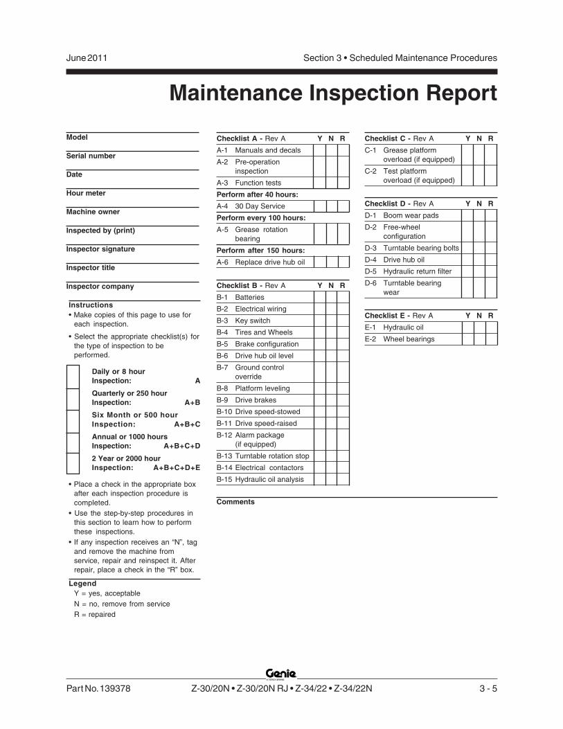
Checklist A - Rev A Y N R
A-1 Manuals and decals
A-2 Pre-operationinspection
A-3 Function tests
Perform after 40 hours:
A-4 30 Day Service
Perform every 100 hours:
A-5 Grease rotationbearing
Perform after 150 hours:
A-6 Replace drive hub oil
Checklist B - Rev A Y N R
B-1 Batteries
B-2 Electrical wiring
B-3 Key switch
B-4 Tires and Wheels
B-5 Brake configuration
B-6 Drive hub oil level
B-7 Ground controloverride
B-8 Platform leveling
B-9 Drive brakes
B-10 Drive speed-stowed
B-11 Drive speed-raised
B-12 Alarm package(if equipped)
B-13 Turntable rotation stop
B-14 Electrical contactors
B-15 Hydraulic oil analysis
Checklist C - Rev A Y N R
C-1 Grease platformoverload (if equipped)
C-2 Test platformoverload (if equipped)
Checklist D - Rev A Y N R
D-1 Boom wear pads
D-2 Free-wheelconfiguration
D-3 Turntable bearing bolts
D-4 Drive hub oil
D-5 Hydraulic return filter
D-6 Turntable bearingwear
Checklist E - Rev A Y N R
E-1 Hydraulic oil
E-2 Wheel bearings
Instructions• Make copies of this page to use for
each inspection.
• Select the appropriate checklist(s) forthe type of inspection to beperformed.
Daily or 8 hourInspection: A
Quarterly or 250 hourInspection: A+B
Six Month or 500 hourInspection: A+B+C
Annual or 1000 hoursInspection: A+B+C+D
2 Year or 2000 hourInspection: A+B+C+D+E
• Place a check in the appropriate boxafter each inspection procedure iscompleted.
• Use the step-by-step procedures inthis section to learn how to performthese inspections.
• If any inspection receives an “N”, tagand remove the machine fromservice, repair and reinspect it. Afterrepair, place a check in the “R” box.
LegendY = yes, acceptableN = no, remove from serviceR = repaired
Maintenance Inspection Report
Model
Serial number
Date
Hour meter
Machine owner
Inspected by (print)
Inspector signature
Inspector title
Inspector company
Comments

3 - 6 Z-30/20N • Z-30/20N RJ • Z-34/22 • Z-34/22N Part No. 139378
Section 3 • Scheduled Maintenance Procedures June 2011
REV AChecklist A Procedures
A-1Inspect the Manuals and DecalsNote: Genie specifications require that thisprocedure be performed daily or every 8 hours,whichever comes first.
Maintaining the operator’s and safety manuals ingood condition is essential to safe machineoperation. Manuals are included with eachmachine and should be stored in the containerprovided in the platform. An illegible or missingmanual will not provide safety and operationalinformation necessary for a safe operatingcondition.
In addition, maintaining all of the safety andinstructional decals in good condition is mandatoryfor safe machine operation. Decals alert operatorsand personnel to the many possible hazardsassociated with using this machine. They alsoprovide users with operation and maintenanceinformation. An illegible decal will fail to alertpersonnel of a procedure or hazard and couldresult in unsafe operating conditions.
1 Check to make sure that the operator's andsafety manuals are present and complete in thestorage container on the platform.
2 Examine the pages of each manual to be surethat they are legible and in good condition.
Result: The operator's manual is appropriate forthe machine and all manuals are legible and ingood condition.
Result: The operator's manual is notappropriate for the machine or all manuals arenot in good condition or are illegible. Removethe machine from service until the manual isreplaced.
3 Open the operator's manual to the decalsinspection section. Carefully and thoroughlyinspect all decals on the machine for legibilityand damage.
Result: The machine is equipped with allrequired decals, and all decals are legible andin good condition.
Result: The machine is not equipped with allrequired decals, or one or more decals areillegible or in poor condition. Remove themachine from service until the decals arereplaced.
4 Always return the manuals to the storagecontainer after use.
Note: Contact your authorized Genie distributor orGenie Industries if replacement manuals or decalsare needed.

Part No. 139378 Z-30/20N • Z-30/20N RJ • Z-34/22 • Z-34/22N 3 - 7
Section 3 • Scheduled Maintenance ProceduresJune 2011
REV A
A-2Perform Pre-operationInspectionNote: Genie specifications require that thisprocedure be performed daily or every 8 hours,whichever comes first.
Completing a pre-operation inspection is essentialto safe machine operation. The pre-operationinspection is a visual inspection performed by theoperator prior to each work shift. The inspection isdesigned to discover if anything is apparentlywrong with a machine before the operator performsthe function tests. The pre-operation inspectionalso serves to determine if routine maintenanceprocedures are required.
Complete information to perform this procedure isavailable in the Operator's Manual located on yourmachine.
CHECKLIST A PROCEDURES
A-3Perform Function TestsNote: Genie specifications require that thisprocedure be performed daily or every 8 hours,whichever comes first.
Completing the function tests is essential to safemachine operation. Function tests are designed todiscover any malfunctions before the machine isput into service. A malfunctioning machine mustnever be used. If malfunctions are discovered, themachine must be tagged and removed fromservice.
Complete information to perform this procedure isavailable in the Operator's Manual located on yourmachine.

3 - 8 Z-30/20N • Z-30/20N RJ • Z-34/22 • Z-34/22N Part No. 139378
Section 3 • Scheduled Maintenance Procedures June 2011
REV A
A-4Perform 30 Day Service
The 30 day maintenance procedure is a one-timesequence of procedures to be performed after thefirst 30 days or 40 hours of usage. After thisinterval, refer to the maintenance checklists forcontinued scheduled maintenance.
1 Perform the following maintenance procedures:
• A-5 Grease the Turntable RotationBearing and Worm Drive Gear
• B-4 Inspect the Tires, Wheels and Lug NutTorque
• D-3 Check the Turnable RotationBearing Bolts
• D-5 Replace the Hydraulic TankReturn Filter Element
A-5Grease the Turntable RotationBearing and Worm Drive Gear
Note: Genie specifications require that thisprocedure be performed every 100 hours.
Frequent application of lubrication to the turntablebearing and worm drive gear is essential to goodmachine performance and service life. Continueduse of an insufficiently greased gear will result incomponent damage.
1 Locate the grease fitting on the tank sideturntable cover bulkhead.
2 Pump grease into the turntable rotation bearing.Rotate the turntable in increments of 4 to 5inches / 10 to 13 cm at a time and repeat thisstep until the entire bearing has been greased.
3 Locate the 2 grease fittings on top of the wormdrive housing.
a grease fittings
4 Pump grease into the gear until you see itcoming out of the side of the gear housing.
5 Grease each tooth on the outside of theturntable rotation bearing.
Grease Specification
Chevron Ultra-duty grease, EP NLGI 2 (lithium based)or equivalent
CHECKLIST A PROCEDURES
a

Part No. 139378 Z-30/20N • Z-30/20N RJ • Z-34/22 • Z-34/22N 3 - 9
Section 3 • Scheduled Maintenance ProceduresJune 2011
REV A
A-6Replace the Drive Hub Oil
Note: Manufacturer drive hub specifications requirethat this one-time procedure be performed after thefirst 150 hours.
Replacing the drive hub oil is essential for goodmachine performance and service life. Failure toreplace the drive hub oil after the first 150 hours ofuse may cause the machine to perform poorly andcontinued use may cause component damage.
1 Select the drive hub to be serviced. Drive themachine until one of the two plugs is at thelowest point.
2 Remove both plugs and drain the oil into asuitable container.
3 Drive the machine until one plug is at the topand the other is at 90 degrees.
a drive hub plugs
4 Fill the hub with oil from the top hole until the oillevel is even with the bottom of the side plughole. Refer to Section 2, Specifications.
5 Install the plugs into the drive hub.
6 Repeat this procedure for the other drive hub.
CHECKLIST A PROCEDURES
a

3 - 10 Z-30/20N • Z-30/20N RJ • Z-34/22 • Z-34/22N Part No. 139378
Section 3 • Scheduled Maintenance Procedures June 2011
REV BChecklist B Procedures
B-1Inspect the Battery
Genie requires that this procedure be performedevery 250 hours or quarterly, whichever comesfirst.
Proper battery condition is essential to goodmachine performance and operational safety.Improper fluid levels or damaged cables andconnections can result in component damage andhazardous conditions.
Electrocution/burn hazard. Contactwith electrically charged circuitscould result in death or seriousinjury. Remove all rings, watchesand other jewelry.
Bodily injury hazard. Batteriescontain acid. Avoid spilling orcontacting battery acid. Neutralizebattery acid spills with baking sodaand water.
1 Put on protective clothing and eye wear.
2 Be sure that the battery cable connections arefree of corrosion.
Note: Adding terminal protectors and a corrosionpreventative sealant will help eliminate corrosion onthe battery terminals and cables.
3 Be sure that the battery retainers and cableconnections are tight.
5 Be sure that the battery retainers and cableconnections are tight.
4 Fully charge the battery. Allow the battery torest 24 hours before performing this procedureto allow the battery cells to equalize.
5 Remove the battery vent caps and check thespecific gravity of each battery cell with ahydrometer. Note the results.
6 Check the ambient air temperature and adjustthe specific gravity reading for each cell asfollows:
• Add 0.004 to the reading of each cell forevery 10° / 5.5° C above 80° F / 26.7° C.
• Subtract 0.004 from the reading of each cell forevery 10° / 5.5° C below 80° F / 26.7° C.
Result: All battery cells display an adjustedspecific gravity of 1.277 +/- 0.007. The batteryis fully charged. Proceed to step 10.
Result: One or more battery cells display aspecific gravity of 1.269 or below. Proceed tostep 7.
7 Perform an equalizing charge OR fully chargethe batteries and allow the battery to rest atleast 6 hours.
8 Remove the battery vent caps and check thespecific gravity of each battery cell with ahydrometer. Note the results.
Part No. 139378 Z-30/20N • Z-30/20N RJ • Z-34/22 • Z-34/22N 3 - 11
Section 3 • Scheduled Maintenance ProceduresJune 2011
REV B CHECKLIST B PROCEDURES
9 Check the ambient air temperature and adjustthe specific gravity reading for each cell asfollows:
• Add 0.004 to the reading of each cell forevery 10° / 5.5° C above 80° F / 26.7° C.
• Subtract 0.004 from the reading of each cell forevery 10° / 5.5° C below 80° F / 26.7° C.
Result: All battery cells display a specificgravity of 1.277 +/- 0.007. The battery is fullycharged. Proceed to step 10.
Result: One or more battery cells display aspecific gravity from 1.269 to 1.218. The batteryis still usable, but at a lower performance so willneed to be recharged more often. Proceed tostep 11.
Result: One or more battery cells display aspecific gravity from 1.217 to 1.173. The batteryis approaching the end of its life. Proceed tostep 11.
Result: The difference in specific gravityreadings between cells is greater than 0.1 ORthe specific gravity of one or more cells is 1.172or less. Replace the battery.
10 Check the battery acid level. If needed,replenish with distilled water to 1/8 inch / 3 mmbelow the bottom of the battery fill tube. Do notoverfill.
11 Install the vent caps and neutralize anyelectrolyte that may have spilled.
B-2Inspect the Electrical Wiring
Note: Genie specifications require that thisprocedure be performed every 250 hours orquarterly, whichever comes first.
Maintaining electrical wiring in good condition isessential to safe operation and good machineperformance. Failure to find and replace burnt,chafed, corroded or pinched wires could result inunsafe operating conditions and may causecomponent damage.
Electrocution/burn hazard. Contactwith hot or live circuits could resultin death or serious injury. Removeall rings, watches and otherjewelry.
1 Remove the drive chassis cover from thenon-steer end of the machine.
2 Inspect the following areas for burnt, chafed,corroded and loose wires:
• Electrical power panel
• Electrical relay panel
• Ground control panel
• Function manifold wiring

3 - 12 Z-30/20N • Z-30/20N RJ • Z-34/22 • Z-34/22N Part No. 139378
Section 3 • Scheduled Maintenance Procedures June 2011
REV BCHECKLIST B PROCEDURES
3 Turn the key switch to ground controls and pullout the red Emergency Stop button to the onposition at both the ground and platformcontrols.
4 Raise the secondary boom until the mid-pivot isapproximately 10 feet / 3 m off the ground.
5 Inspect the turntable center area for burnt,chafed and pinched cables.
6 Lower the boom to the stowed position and turnthe machine off.
7 Inspect the following areas for burnt, chafed,corroded, pinched and loose wires:
• Cable track on the primary boom
• Primary boom to platform cable harness
• Inside of the platform control box
8 Inspect for a liberal coating of dielectric greaseat the following location:
• All wire harness connectors to the platformcontrol box
• All wire harness connectors located under theground control side turntable cover
• Harness connector to the drive motorcontroller located in the non-steer end of thedrive chassis
B-3Test the Key SwitchNote: Genie specifications require that thisprocedure be performed every 250 hours orquarterly, whichever comes first.
Proper key switch action and response is essentialto safe machine operation. The machine can beoperated from the ground or platform controls andthe activation of one or the other is accomplishedwith the key switch. Failure of the key switch toactivate the appropriate control panel could resultin a hazardous operating situation.
1 Pull out the red Emergency Stop button to theon position at both the ground and platformcontrols.
2 Turn the key switch to platform controls.
3 Check the machine functions from the groundcontrols.
Result: The machine functions should notoperate.
4 Turn the key switch to ground controls.
5 Check the machine functions from the platformcontrols.
Result: The machine functions should notoperate.
6 Turn the key switch to the off position.
Result: No function should operate.

Part No. 139378 Z-30/20N • Z-30/20N RJ • Z-34/22 • Z-34/22N 3 - 13
Section 3 • Scheduled Maintenance ProceduresJune 2011
REV B
B-4Inspect the Tires, Wheels andLug Nut Torque
Note: Genie specifications require that thisprocedure be performed every 250 hours orquarterly, whichever comes first.
Maintaining the tires and wheels, including properwheel fastener torque, is essential to safeoperation and good performance. Tire and/orwheel failure could result in a machine tip-over.Component damage may also result if problemsare not discovered and repaired in a timely fashion.
1 Check the tire surface and sidewalls for cuts,cracks and unusual wear.
2 Check each wheel for damage, bends andcracks.
3 Check each lug nut for proper torque. Refer toSection 2, Specifications.
B-5Confirm the ProperBrake Configuration
Note: Genie specifications require that thisprocedure be performed every 250 hours orquarterly, whichever comes first.
Proper brake configuration is essential to safeoperation and good machine performance.Hydraulically-released, spring-applied individualwheel brakes can appear to operate normally whenthey are actually not fully operational.
1 Check each drive hub disconnect cap to besure it is in the engaged position.
CHECKLIST B PROCEDURES
disengaged position
engaged position

3 - 14 Z-30/20N • Z-30/20N RJ • Z-34/22 • Z-34/22N Part No. 139378
Section 3 • Scheduled Maintenance Procedures June 2011
REV B
B-6Check the Oil Level in the DriveHubs and Mounting Bolt Torque
Note: Genie specifications require that thisprocedure be performed every 250 hours orquarterly, whichever comes first.
Failure to maintain proper drive hub oil levels,including proper drive hub fastener torque, maycause the machine to perform poorly andcontinued use may cause component damage.
1 Drive the machine to rotate the hub until one ofthe plugs is located on top and the other is at90 degrees.
a drive hub plugs
2 Remove the plug located at 90 degrees andcheck the oil level.
Result: The oil level should be even with thebottom of the side plug hole.
3 If necessary, remove the top plug and add oiluntil the oil level is even with the bottom of theside plug hole. Refer to Section 2,Specifications.
4 Install the plugs into the drive hub.
5 Check the torque of the drive hub bolts.Refer to Section 2, Specifications.
6 Repeat this procedure for each drive hub.
B-7Test the Ground ControlOverrideNote: Genie specifications require that thisprocedure be performed every 250 hours orquarterly, whichever comes first.
A properly functioning ground control override isessential to safe machine operation. The groundcontrol override function is intended to allowground personnel to operate the machine from theground controls whether the red Emergency Stopbutton on the platform controls is in the on or offposition. This function is particularly useful if theoperator at the platform controls cannot return theboom to the stowed position.
1 Push in the red Emergency Stop button at theplatform controls to the off position.
2 Turn the key switch to ground controls and pullout the red Emergency Stop button to the onposition.
3 Operate each boom function through apartial cycle at the ground controls.
Result: All boom functions should operate.
CHECKLIST B PROCEDURES
a
Part No. 139378 Z-30/20N • Z-30/20N RJ • Z-34/22 • Z-34/22N 3 - 15
Section 3 • Scheduled Maintenance ProceduresJune 2011
REV B CHECKLIST B PROCEDURES
B-8Test the Platform Self-leveling
Note: Genie specifications require that thisprocedure be performed every 250 hours orquarterly, whichever comes first.
Automatic platform self-leveling throughoutthe full cycle of boom raising and lowering isessential for safe machine operation. Theplatform is maintained level by the platform levelingslave cylinder which is controlled by the platformleveling master cylinder located at the base of theprimary boom. A platform self-leveling failurecreates an unsafe working condition for platformand ground personnel.
1 Turn the key switch to ground controls and pullout the red Emergency Stop button to the onposition at both the ground and platformcontrols.
2 Lower the boom to the stowed position.
3 Adjust the platform to a level position using theplatform leveling toggle switch.
4 Raise and lower the primary boom througha full cycle.
Result: The platform should remain level atall times to within ±5 degrees.
B-9Test the Drive Brakes
Note: Genie specifications require that thisprocedure be performed every 250 hours orquarterly, whichever comes first.
Proper brake action is essential to safe machineoperation. The drive brake function should operatesmoothly, free of hesitation, jerking and unusualnoise. Hydraulically-released individual wheelbrakes can appear to operate normally when theyare actually not fully operational.
Collision hazard. Be sure that themachine is not in free-wheel orpartial free-wheel configuration.Refer to B-5, Confirm the ProperBrake Configuration.
1 Select a test area that is firm, level and free ofobstructions.
2 Mark a test line on the ground for reference.
3 Lower the boom to the stowed position.
4 Turn the key switch to platform controls.
5 Choose a reference point on the machine; i.e.,contact patch of a tire, as a visual reference foruse when crossing the test line.
6 Bring the machine to top drive speed beforereaching the test line. Release the drive joystickwhen your reference point on the machinecrosses the test line.
7 Measure the distance between the test line andyour machine reference point. Refer toSection 2, Specifications.
Note: The brakes must be able to hold the machineon any slope it is able to climb.
3 - 16 Z-30/20N • Z-30/20N RJ • Z-34/22 • Z-34/22N Part No. 139378
Section 3 • Scheduled Maintenance Procedures June 2011
REV BCHECKLIST B PROCEDURES
B-10Test the Drive Speed -Stowed Position
Note: Genie specifications require that thisprocedure be performed every 250 hours orquarterly, whichever comes first.
Proper drive function movement is essential tosafe machine operation. The drive function shouldrespond quickly and smoothly to operator control.Drive performance should also be free ofhesitation, jerking and unusual noise over theentire proportionally controlled speed range.
1 Select a test area that is firm, level and free ofobstructions.
2 Create start and finish lines by marking twolines on the ground 40 feet / 12.2 m apart.
3 Turn the key switch to platform control and pullout the red Emergency Stop button to the onposition at both the ground and platformcontrols.
4 Choose a reference point on the machine; i.e.,contact patch of a tire, as a visual reference foruse when crossing the start and finish lines.
5 Bring the machine to maximum drive speedbefore reaching the start line. Begin timingwhen your reference point on the machinecrosses the start line.
6 Continue at full speed and note the time whenyour machine reference point passes over thefinish line. Refer to Section 2, Specifications.
B-11Test the Drive Speed -Raised or Extended Position
Note: Genie specifications require that thisprocedure be performed every 250 hours orquarterly, whichever comes first.
Proper drive function movement is essential tosafe machine operation. The drive function shouldrespond quickly and smoothly to operator control.Drive performance should also be free ofhesitation, jerking and unusual noise over theentire proportionally controlled speed range.
1 Select a test area that is firm, level and free ofobstructions.
2 Create start and finish lines by marking twolines on the ground 40 feet / 12.2 m apart.
3 Raise the primary boom more than5 feet / 1.5 m.
4 Choose a reference point on the machine; i.e.,contact patch of a tire, as a visual reference foruse when crossing the start and finish lines.
5 Bring the machine to maximum drive speedbefore reaching the start line. Begin timingwhen your reference point on the machinecrosses the start line.
6 Continue at full speed and note the time whenyour machine reference point passes over thefinish line. Refer to Section 2, Specifications.

Part No. 139378 Z-30/20N • Z-30/20N RJ • Z-34/22 • Z-34/22N 3 - 17
Section 3 • Scheduled Maintenance ProceduresJune 2011
REV B CHECKLIST B PROCEDURES
B-12Test the Alarm Package(if equipped)Note: Genie specifications require that thisprocedure be performed every 250 hours orquarterly, whichever comes first.
The alarm package includes:
• Travel alarm
• Descent alarm
• Flashing beacon
Alarms and a beacon are installed to alert operatorsand ground personnel of machine proximity andmotion. The alarm package is installed on theground controls side turntable cover.
1 At the ground controls, pull out the redEmergency Stop button to the on position andturn the key switch to ground control.
Result: The flashing beacon should be on andflashing.
2 Move the primary boom switch to the downposition, hold for a moment and then release it.Move the secondary boom switch to the downposition, hold for a moment and then release it.Move the jib boom switch to the down position,hold for a moment and then release it.
Result: The descent alarm should sound wheneach switch is held down.
3 Turn the key switch to platform control.
4 At the platform controls pull out the redEmergency Stop button to the on position.
Result: The flashing beacon should be onand flashing.
5 Press down the foot switch. Move the primaryboom switch to the down position, hold for amoment and then release it. Move thesecondary boom switch to the down position,hold for a moment and then release it. Move thejib boom switch to the down position, hold for amoment and then release it.
Result: The descent alarm should sound wheneach control switch is held down.
6 Press down the foot switch. Move the drivecontrol handle off center, hold for a moment andthen release it. Move the drive control handle offcenter in the opposite direction, hold for amoment and then release it.
Result: The travel alarm should sound when thedrive control handle is moved off center in eitherdirection.

3 - 18 Z-30/20N • Z-30/20N RJ • Z-34/22 • Z-34/22N Part No. 139378
Section 3 • Scheduled Maintenance Procedures June 2011
REV BCHECKLIST B PROCEDURES
B-13Test the Turntable Rotation StopNote: Genie specifications require that thisprocedure be performed every 250 hours orquarterly, whichever comes first.
The turntable is capable of rotating the boom 359degrees and is stopped midpoint between the steerwheels by the rotation stop. Detecting a rotationstop malfunction is essential to safe operation andgood machine performance. If the turntable rotatespast the rotation stop, component damage mayresult.
1 Turn the key switch to platform controls and pullout the red Emergency Stop buttons to the onposition at both ground and platform controls.
2 Rotate the turntable to the left as far as itwill go.
Result: Movement should stop when theprimary boom reaches midpoint between thesteer tires.
3 Rotate the turntable to the right as far as itwill go.
Result: Movement should stop when theprimary boom reaches midpoint between thesteer tires.
B-14Check the Electrical Contactors
Note: Genie specifications require that thisprocedure be performed every 250 hours orquarterly, whichever comes first.
Maintaining the electrical contactors in goodcondition is essential to safe machine operation.Failure to locate a worn or damaged contactorcould result in an unsafe working condition andcomponent damage.
1 Remove the drive chassis cover from the non-steer end of the machine and locate theelectrical contactors mounted on the electricalcomponent mounting panel.
2 Visually inspect the contact points of eachcontactor for the following items:
• Excessive burns
• Excessive arcs
• Excessive pitting
Electrocution/burn hazard. Contactwith hot or live circuits could resultin death or serious injury. Removeall rings, watches and otherjewelry.
Note: Replace the contactors if any damage isfound.

Part No. 139378 Z-30/20N • Z-30/20N RJ • Z-34/22 • Z-34/22N 3 - 19
Section 3 • Scheduled Maintenance ProceduresJune 2011
REV B CHECKLIST B PROCEDURES
B-15Perform Hydraulic Oil Analysis
Note: Genie specifications require that thisprocedure be performed every 250 hours orquarterly, whichever comes first.
Replacement or testing of the hydraulic oil isessential for good machine performance andservice life. Dirty oil and suction strainers maycause the machine to perform poorly andcontinued use may cause component damage.Extremely dirty conditions may require oil changesto be performed more often.
Note: Before replacing the hydraulic oil, the oil maybe tested by an oil distributor for specific levels ofcontamination to verify that changing the oil isnecessary. If the hydraulic oil is not replaced atthe two year inspection, test the oil quarterly.Replace the oil when it fails the test. See E-1,Test or Replace the Hydraulic Oil.

3 - 20 Z-30/20N • Z-30/20N RJ • Z-34/22 • Z-34/22N Part No. 139378
Section 3 • Scheduled Maintenance Procedures June 2011
REV AChecklist C Procedures
C-1Grease the Platform OverloadMechanism (if equipped)
Note: Genie specifications require that thisprocedure be performed every 500 hours or 6months, whichever comes first. Perform thisprocedure more often if dusty conditions exist.
Application of lubrication to the platform overloadmechanism is essential to safe machine operation.Continued use of an improperly greased platformoverload mechanism could result in the system notsensing an overloaded platform condition and willresult in component damage.
1 Locate the grease fittings on each pivot pin ofthe platform overload assembly.
2 Thoroughly pump grease into each greasefitting using a multipurpose grease.
Grease Specification
Chevron Ultra-duty grease, EP NLGI 2 (lithium based)or equivalent
C-2Test the Platform OverloadSystem (if equipped)
Note: Genie specifications require that thisprocedure be performed every 500 hours or sixmonths, whichever comes first.
Testing the platform overload system regularly isessential to safe machine operation. Continueduse of an improperly operating platform overloadsystem could result in the system not sensing anoverloaded platform condition. Machine stabilitycould be compromised resulting in the machinetipping over.
The platform overload system is designed to detectan overloaded platform and prevent machineoperation anytime the machine is turned on. Whenactivated, the system halts all normal boomoperation, giving visual and audible warning to theoperator.
Models equipped with the platform overload optionare provided with additional machine components:an adjustable spring-loaded platform supportsubassembly, a limit switch, an electronic modulewhich receives the overload signal and interruptspower, and an audio/visual warning indication toalert the operator of the overload.

Part No. 139378 Z-30/20N • Z-30/20N RJ • Z-34/22 • Z-34/22N 3 - 21
Section 3 • Scheduled Maintenance ProceduresJune 2011
REV A CHECKLIST C PROCEDURES
The platform support subassembly utilizes two loadsupport arms that are opposed in a fullparallelogram link. This isolates platform loads intoa shear or vertical state, which translates into acompressive load. A spring in the parallelogramlink supports this purely compressive loadregardless of where the load is placed in theplatform.
As weight is added to the platform, the spring willcompress until, when the platform is overloaded,the lower arm contacts a limit switch and therebyactivating the overload signal. When adjustedcorrectly, the platform overload system willdeactivate normal boom operation at platformcapacity.
Note: Perform this procedure with the machine ona firm, level surface.
1 Turn the key switch to platform control. Start theengine and level the platform.
2 Determine the maximum platform capacity.Refer to the machine serial plate.
3 Remove all weight, tools and accessories fromthe platform.
Note: Failure to remove all weight, tools andaccessories from the platform will result in aninaccurate test.
4 Using a suitable lifting device, place a testweight equal to that of the available capacityone of the locations shown.Refer to Illustration 1.
Result: The platform overload indicator lightsshould be off at both the ground and platformcontrols and the alarm should not sound.
Result: The platform overload indicator lightsare on and the alarm is sounding. Calibrate theplatform overload system. Refer to RepairProcedure 2-3, How to Calibrate the PlatformOverload System (if equipped).
5 Carefully move the test weight to eachremaining location. Refer to Illustration 1.
Result: The platform overload indicator lightsshould be off at both the ground and platformcontrols and the alarm should not sound.
Result: The platform overload indicator lightsare on and the alarm is sounding. Calibrate theplatform overload system. Refer to RepairProcedure 2-3, How to Calibrate the PlatformOverload System (if equipped).
Illustration 1
6 Using a suitable lifting device, place anadditional 10 lbs / 4.5 kg of weight onto theplatform.
Result: The alarm should sound.The platform overload indicator lights should beflashing at both the ground and platformcontrols.
Result: The alarm does not sound and theplatform overload indicator lights are notflashing. Calibrate the platform overloadsystem. Refer to Repair Procedure 2-3,How to Calibrate the Platform Overload System(if equipped).
Note: There may be a 2 second delay before theoverload indicator lights flash and the alarmsounds.

3 - 22 Z-30/20N • Z-30/20N RJ • Z-34/22 • Z-34/22N Part No. 139378
Section 3 • Scheduled Maintenance Procedures June 2011
REV A
7 Carefully move the test weights to eachremaining location on the platform.Refer to Illustration 1.
Result: The alarm should sound.The platform overload indicator lights should beflashing at both the ground and platformcontrols.
Result: The alarm does not sound and theplatform overload indicator lights are notflashing. Calibrate the platform overloadsystem. Refer to Repair Procedure 2-3,How to Calibrate the Platform OverloadSystem (if equipped).
Note: There may be a 2 second delay before theoverload indicator lights flash and the alarmsounds.
8 Test all machine functions from the platformcontrols.
Result: All platform control functions should notoperate.
9 Turn the key switch to ground control.
10 Test all machine functions from the groundcontrols.
Result: All ground control functions should notoperate.
11 Using auxiliary power, test all machine functionsfrom the ground controls.
Result: All ground control functions shouldoperate.
CHECKLIST C PROCEDURES
12 Using a suitable lifting device, lift the additionaltest weight from the platform.
Result: The platform overload indicator lightsshould turn off at both the ground and platformcontrols and the alarm should not sound.
Note: There may be an 2 second delay before theoverload indicator lights and alarm turn off.
13 Start the engine and test all machine functionsfrom the ground controls.
Result: All ground control functions shouldoperate normally.
14 Turn the key switch to platform control.
15 Test all machine functions from the platformcontrols.
Result: All platform control functions shouldoperate.
Note: If the platform overload system is notoperating properly, Refer to Repair Procedure 2-3,How to Calibrate the Platform Overload System(if equipped).
16 Using a suitable lifting device, remove theremaining test weights from the platform.

Part No. 139378 Z-30/20N • Z-30/20N RJ • Z-34/22 • Z-34/22N 3 - 23
Section 3 • Scheduled Maintenance ProceduresJune 2011
REV AChecklist D Procedures
D-1Check the Primary BoomWear Pads
Note: Genie specifications require that thisprocedure be performed every 1000 hours orannually, whichever comes first.
Maintaining the primary boom wear pads in goodcondition is essential to safe machine operation.Wear pads are placed on boom tube surfaces toprovide a low friction, replaceable wear padbetween moving parts. Improperly shimmed wearpads or continued use of worn out wear pads mayresult in component damage and unsafe operatingconditions.
1 Measure each wear pad. Replace the wear padonce it reaches the minimum allowablethickness. If the wear pad is still withinspecifications, shim as necessary to obtainminimum clearance with zero binding.
2 Extend and retract the primary boom throughthe entire range of motion to check for tightspots that could cause binding or scraping.
Note: Always maintain squareness between theprimary boom outer and inner tubes.
Models without rotating jib boom:
Primary boom wearpad specifications Minimum
Top and side wear pads 5/8 inch(extension end of boom) 15.9 mm
Bottom wear pads 5/8 inch(extension end of boom) 15.9 mm
Bottom and side wear pads 5/8 inch(pivot end of boom) 15.9 mm
Top wear pads 3/8 inch(pivot end of boom) 9.5 mm
Models with rotating jib boom:
Primary boom wearpad specifications Minimum
All wear pads 3/8 inch9.5 mm

3 - 24 Z-30/20N • Z-30/20N RJ • Z-34/22 • Z-34/22N Part No. 139378
Section 3 • Scheduled Maintenance Procedures June 2011
REV ACHECKLIST D PROCEDURES
D-2Check the Free-wheelConfiguration
Note: Genie specifications require that thisprocedure be performed every 1000 hours orannually, whichever comes first.
Proper use of the free-wheel configuration isessential to safe machine operation. Thefree-wheel configuration is used primarily fortowing. A machine configured to free-wheelwithout operator knowledge may cause death orserious injury and property damage.
Collision hazard. Select a worksite that is firm and level.
Component damage hazard. If themachine must be towed, do notexceed 2 mph / 3.2 km/h.
1 Chock the steer wheels to prevent the machinefrom rolling.
2 Center a lifting jack of ample capacity(15,000 lbs / 7000 kg) under the drive chassisbetween the non-steer wheels.
3 Lift the wheels off the ground and then placeblocks under the drive chassis for support.
4 Disengage the drive hubs by turning over thedrive hub disconnect caps on eachnon-steer wheel hub.
5 Manually rotate each non-steer wheel.
Result: Each non-steer wheel should rotate withminimum effort.
6 Engage the drive hubs by turning overthe drive hub disconnect caps.
7 Carefully remove the blocks, lower the machineand remove the jack.
Collision hazard. Failure to engagethe drive hubs could result indeath or serious injury andproperty damage.
disengaged position
engaged position

Part No. 139378 Z-30/20N • Z-30/20N RJ • Z-34/22 • Z-34/22N 3 - 25
Section 3 • Scheduled Maintenance ProceduresJune 2011
REV A
D-3Check the Turntable RotationBearing Bolts
Note: Genie specifications require that thisprocedure be performed every 1000 hours orannually, whichever comes first.
Maintaining proper torque on the turntable bearingbolts is essential to safe machine operation.Improper bolt torque could result in an unsafeoperating condition and component damage.
1 Raise the secondary boom and place a safetychock on the secondary boom lift cylinder.Carefully lower the secondary boom onto the liftcylinder safety chock.
Crushing hazard. Keep handsaway from the cylinder and allmoving parts when lowering thesecondary boom.
Note: A lift cylinder safety chock is availablethrough Genie Service Parts (Genie part no.36555).
2 Confirm that each turntable mounting bolt istorqued in sequence to specification. Refer toSection 2, Specifications.
Bolt torque sequence
CHECKLIST D PROCEDURES
3 Raise the secondary boom and remove thesafety chock. Lower the secondary boom to thestowed position.
4 Open the latch on the battery packs and swingthem out to expose the turntable bearing boltaccess hole.
5 Confirm that each turntable bearing mountingbolt is torqued in sequence to specification.Refer to Section 2, Specifications.
Bolt torque sequence
1
7
3
5
8
2
6
4
1
7
11
5
3
108
6
12
2
9
4

3 - 26 Z-30/20N • Z-30/20N RJ • Z-34/22 • Z-34/22N Part No. 139378
Section 3 • Scheduled Maintenance Procedures June 2011
REV A
D-4Replace the Drive Hub Oil
Note: Genie specifications require that thisprocedure be performed every 1000 hours orannually, whichever comes first.
Replacing the drive hub oil is essential for goodmachine performance and service life. Failure toreplace the drive hub oil at yearly intervals maycause the machine to perform poorly andcontinued use may cause component damage.
1 Select the drive hub to be serviced. Drive themachine until one of the two plugs is at thelowest point.
2 Remove both plugs and drain the oil into asuitable container.
3 Drive the machine until one plug is at the topand the other is at 90 degrees.
a drive hub plugs
4 Fill the hub with oil from the top hole until the oillevel is even with the bottom of the side plughole. Refer to Section 2, Specifications.
5 Install the plugs into the drive hub.
6 Repeat this procedure for the other drive hub.
CHECKLIST D PROCEDURES
D-5Replace the Hydraulic TankReturn Filter Element
Note: Genie specifications require that thisprocedure be performed every 1000 hours orannually, whichever comes first. Perform thisprocedure more often if dusty conditions exist.
Replacement of the hydraulic return filter element isessential for good machine performance andservice life. A dirty or clogged filter element maycause the machine to perform poorly andcontinued use may cause component damage.Extremely dirty conditions may require that thefilter element be replaced more often.
Bodily injury hazard. Beware ofhot oil. Contact with hot oil maycause severe burns.
1 Locate the hydraulic return filter housing on topof the hydraulic tank.
2 Clean the area around the oil filter housing caplocated on top of the reservoir.
3 Remove the cap from the housing.
4 Lift the handle on the filter element and rotatethe element counterclockwise to release theelement from the housing.
5 Remove the filter element from the filterhousing.
a

Part No. 139378 Z-30/20N • Z-30/20N RJ • Z-34/22 • Z-34/22N 3 - 27
Section 3 • Scheduled Maintenance ProceduresJune 2011
REV A
6 Install the new oil filter element into the filterhousing.
7 Push the filter element down to be sure the o-ring on the element is fully seated into thehousing.
8 Rotate the filter element clockwise to lock it inplace.
9 Install the filter housing cap.
10 Clean up any oil that may have spilled duringthe replacement procedure.
11 Use a permanent ink marker to write the dateand number of hours from the hour meter onthe oil filter housing.
12 Turn the key switch to ground controls and pullout the red Emergency Stop button to the onposition.
13 Move and hold the function enable toggle switchto either side and move and hold the primaryboom toggle switch in the up direction.
14 Inspect the filter housing and relatedcomponents to be sure that there are no leaks.
CHECKLIST D PROCEDURES
D-6Inspect for Turntable BearingWear
Note: Genie requires that this procedure beperformed every 1000 hours or annually, whichevercomes first.
Periodic inspection of turntable bearing wear isessential to safe machine operation, good machineperformance and service life. Continued use of aworn turntable bearing could create an unsafeoperating condition, resulting in death or seriousinjury and component damage.
1 Grease the turntable bearing. See A-5, Greasethe Turntable Bearing and Rotate Gear.
2 Torque the turntable bearing bolts tospecification. See D-3, Check the TurntableRotation Bearing Bolts.
3 Raise the primary and secondary booms to fullheight using the ground controls. Do not extendthe primary boom.

3 - 28 Z-30/20N • Z-30/20N RJ • Z-34/22 • Z-34/22N Part No. 139378
Section 3 • Scheduled Maintenance Procedures June 2011
REV ACHECKLIST D PROCEDURES
4 Place a dial indicator between the drive chassisand the turntable at a point that is directlyunder, or in line with, the boom and no morethan 1 inch / 2.5 cm from the bearing.
Note: To obtain an accurate measurement, placethe dial indicator no more than 1 inch / 2.5 cm fromthe turntable rotation bearing.
a turntableb dial indicatorc drive chassisd turntable rotation bearing
5 Adjust the dial indicator to "0".
6 Lower the secondary boom to the stowedposition and lower the primary boom to ahorizontal position. Fully extend the primaryboom.
7 Note the reading on the dial indicator.
Result: The measurement is less than0.055 inch / 1.4 mm. The bearing is good.
Result: The measurement is more than0.055 inch / 1.4 mm. The bearing is worn andneeds to be replaced.
8 Fully retract the primary boom. Raise theprimary and secondary booms to full height.Visually inspect the dial indicator to be sure theneedle returns to the "0" position.
9 Remove the dial indicator and rotate theturntable 90°.
10 Repeat steps 4 through 9 until the rotationbearing has been checked in at least fourequally spaced areas 90° apart.
11 Lower the primary and secondary booms to thestowed position and turn the machine off.
12 Remove the dial indicator from the machine.
a
b
c
d
Part No. 139378 Z-30/20N • Z-30/20N RJ • Z-34/22 • Z-34/22N 3 - 29
Section 3 • Scheduled Maintenance ProceduresJune 2011
REV A
E-1Test or Replace the Hydraulic Oil
Note: Genie specifications require that thisprocedure be performed every 2000 hours or everytwo years, whichever comes first. Perform thisprocedure more often if dusty conditions exist.
Replacement or testing of the hydraulic oil isessential for good machine performance andservice life. Dirty oil and suction strainers maycause the machine to perform poorly andcontinued use may cause component damage.Extremely dirty conditions may require that the oilbe changed more often.
Note: Before replacing the hydraulic oil, the oil maybe tested by an oil distributor for specific levels ofcontamination to verify that changing the oil isnecessary. If the hydraulic oil is not replaced atthe two year inspection, test the oil quarterly.Replace the oil when it fails the test.
Note: When removing a hose assembly or fitting,the O-ring on the fitting and/or hose end must bereplaced and then torqued to specification duringinstallation. Refer to Section 2, Hydraulic Hose andFitting Torque Specifications.
Note: Perform this procedure with the boom in thestowed position.
1 Close the hydraulic shutoff valve located at thehydraulic tank.
Component damage hazard. Themachine must not be operatedwith the hydraulic tank shutoffvalve in the closed position orcomponent damage will occur. Ifthe tank valve is closed, removethe key from the key switch andtag the machine to informpersonnel of the condition.
2 Place a suitable container under the hydraulictank. Refer to Section 2, Specifications.
3 Tag, disconnect and plug the hydraulic hosefrom the hydraulic tank shutoff valve.
Bodily injury hazard. Sprayinghydraulic oil can penetrate andburn skin. Loosen hydraulicconnections very slowly to allowthe oil pressure to dissipategradually. Do not allow oil to squirtor spray.
4 Open the valve on the hydraulic tank andcompletely drain the oil into a suitablecontainer.
Bodily injury hazard. Beware ofhot oil. Contact with hot oil maycause severe burns.
Checklist E Procedures

3 - 30 Z-30/20N • Z-30/20N RJ • Z-34/22 • Z-34/22N Part No. 139378
Section 3 • Scheduled Maintenance Procedures June 2011
REV A
5 Tag, disconnect and plug the hydraulic hosesfrom the hydraulic tank return filter housing.Cap the fittings on the filter housing.
Bodily injury hazard. Sprayinghydraulic oil can penetrate andburn skin. Loosen hydraulicconnections very slowly to allowthe oil pressure to dissipategradually. Do not allow oil to squirtor spray.
Bodily injury hazard. Beware ofhot oil. Contact with hot oil maycause severe burns.
6 Remove the hydraulic tank mounting fasteners.Remove the hydraulic tank from the machine.
7 Remove the tank lid retaining fasteners andremove the lid and return filter assembly fromthe tank.
8 Remove the suction strainer from the hydraulictank and clean it using a mild solvent.
9 Rinse out the inside of the tank with a mildsolvent.
10 Install the suction strainer into the tank.
11 Install the lid and return filer assembly onto thehydraulic tank.
12 Install the hydraulic tank on the machine. Installthe hydraulic tank mounting fasteners andtorque them to 8 ft-lbs / 10.8 Nm.
Component damage hazard. Thehydraulic tank is plastic and maybecome damaged if the tankmounting fasteners are overtightened.
13 Install the hydraulic hoses.
14 Fill the tank with hydraulic oil until the fluid iswithin the FULL and ADD marks on the hydraulictank. Do not overfill. Refer to Section 2,Specifications.
15 Clean up any oil that may have spilled. Properlydiscard of used oil.
16 Open the hydraulic tank shutoff valve.
Component damage hazard. Besure to open the hydraulic tankshutoff valve after installing thehydraulic tank.
CHECKLIST E PROCEDURES

Part No. 139378 Z-30/20N • Z-30/20N RJ • Z-34/22 • Z-34/22N 3 - 31
Section 3 • Scheduled Maintenance ProceduresJune 2011
REV A
E-2Grease the Steer AxleWheel Bearings
Note: Genie requires that this procedure beperformed every 2000 hours or every two years,whichever comes first.
Maintaining the steer axle wheel bearings isessential for safe machine operation and servicelife. Operating the machine with loose or wornwheel bearings may cause an unsafe operatingcondition and continued use may result incomponent damage. Extremely wet or dirtyconditions or regular steam cleaning and pressurewashing of the machine may require that thisprocedure be performed more often.
1 Loosen the wheel lug nuts. Do not removethem.
2 Block the non-steer wheels and center a liftingjack under the steer axle.
3 Raise the machine 6 inches / 15 cm and placeblocks under the drive chassis for support.
4 Remove the lug nuts. Remove the tire andwheel assembly.
5 Check for wheel bearing wear by attempting tomove the wheel hub side to side, then up anddown.
Result: There should be no side to side or upand down movement.
Skip to step 10 if there is no movement.
6 Remove the dust cap from the hub. Remove thecotter pin from the castle nut.
7 Tighten the castle nut to 158 ft-lbs / 214 Nm toseat the bearings.
Note: Rotate the hub by hand while torquing thecastle nut to make sure the bearings seat properly.
8 Loosen the castle nut one full turn and thentorque to 35 ft-lbs / 47 Nm.
9 Check for wheel bearing wear by attempting tomove the wheel hub side to side, then up anddown.
Result: If there is no side to side or up anddown movement, continue with step 10 togrease the wheel bearings.
Result: If there is side to side or up and downmovement, continue to step 10 and replace thewheel bearings with new ones.
Note: When replacing a wheel bearing, both theinner and outer bearings, including the pressed-inraces, must be replaced.
10 Remove the castle nut.
11 Pull the hub off of the spindle. The washer andouter bearing should fall loose from the hub.
12 Place the hub on a flat surface and gently prythe bearing seal out of the hub. Remove therear bearing.
13 Pack both bearings with clean, fresh grease.
Grease Specification
Chevron Ultra-duty grease, EP NLGI 2 (lithium based)or equivalent
CHECKLIST E PROCEDURES

3 - 32 Z-30/20N • Z-30/20N RJ • Z-34/22 • Z-34/22N Part No. 139378
Section 3 • Scheduled Maintenance Procedures June 2011
REV ACHECKLIST E PROCEDURES
14 Place the large inner bearing into the rear of thehub.
15 Install a new bearing grease seal into the hub bypressing it evenly into the hub until it is flush.
Note: Always replace the bearing grease sealwhen the hub has been removed.
16 Slide the hub onto the yoke spindle.
Component damage hazard. Donot apply excessive force ordamage to the lip of the seal mayoccur.
17 Fill the hub cavity with clean, fresh grease.
18 Place the outer bearing into the hub.
19 Install the washer and castle nut.
20 Tighten the castle nut to 158 ft-lbs / 214 Nm toseat the bearings.
Note: Rotate the hub by hand while torquing thecastle nut to make sure the bearings seat properly.
21 Loosen the castle nut one full turn and thentorque to 35 ft-lbs / 47 Nm.
22 Install a new cotter pin. Bend the cotter pinto lock it in.
Note: Always use a new cotter pin when installinga castle nut.
23 Install the dust cap, then the tire and wheelassembly. Torque the wheel lug nuts tospecification. Refer to Section 2, Specifications.

Part No. 139378 Z-30/20N • Z-30/20N RJ • Z-34/22 • Z-34/22N 4 - 1
June 2011 Section 4 • Repair Procedures
Repair Procedures
Observe and Obey:
Repair procedures shall be completed by aperson trained and qualified on the repair of thismachine.
Immediately tag and remove from service adamaged or malfunctioning machine.
Repair any machine damage or malfunctionbefore operating the machine.
Before Repairs Start:
Read, understand and obey the safety rules andoperating instructions in the appropriateoperator's manual on your machine beforeattempting any maintenance or repair procedure.
Be sure that all necessary tools and parts areavailable and ready for use.
Read each procedure completely and adhereto the instructions. Attempting shortcuts mayproduce hazardous conditions.
Unless otherwise specified, perform eachrepair procedure with the machine in thefollowing configuration:
• Machine parked on a firm, level surface
• Boom in stowed position
• Turntable rotated with the boom betweenthe non-steer wheels
• Key switch in the off position with thekey removed
• Wheels chocked
• All external AC power supply disconnectedfrom the machine
About This SectionMost of the procedures in this section should onlybe performed by a trained service professionalin a suitably equipped workshop. Select theappropriate repair procedure after troubleshootingthe problem.
Perform disassembly procedures to the pointwhere repairs can be completed. Then toreassemble, perform the disassembly steps inreverse order.
Symbols Legend
Safety alert symbol—used to alertpersonnel to potential personalinjury hazards. Obey all safetymessages that follow this symbolto avoid possible injury or death.
Indicates an imminently hazardoussituation which, if not avoided, willresult in death or serious injury.
Indicates a potentially hazardoussituation which, if not avoided,could result in death or seriousinjury.
Indicates a potentially hazardoussituation which, if not avoided,may cause minor or moderateinjury.
Indicates a potentially hazardoussituation which, if not avoided,may result in property damage.
Indicates that a specific result is expected afterperforming a series of steps.
Indicates that an incorrect result has occurredafter performing a series of steps.

4 - 2 Z-30/20N • Z-30/20N RJ • Z-34/22 • Z-34/22N Part No. 139378
June 2011Section 4 • Repair Procedures
REV A
1-1Controllers
The drive joystick is connected to the drive motorcontroller, located under the drive chassis cover atthe non-steer end of the machine. Maintaining theboom function speed controller at the propersettings is essential to safe machine operation.The boom function speed controller should operatesmoothly and provide proportional speed controlthrough its entire range of motion. For furtherinformation or assistance, contact the GenieIndustries Service Department.
a boom function speed controllerb drive and brake printed circuit boardc drive joystick
Boom Function SpeedController Adjustments
Electrocution/burn hazard. Contactwith electrically charged circuitscould result in death or seriousinjury. Remove all rings, watchesand other jewelry.
Note: Do not adjust the boom function speedcontroller unless the static battery supply voltage isabove 24V DC.
1 Turn the key switch to platform controls and pullout the red Emergency Stop button to the onposition at both the ground and platformcontrols.
2 Open the platform control box lid and locate theboom function speed controller.
a black/red wireb diodec white/red wired boom function speed controllere ramp rate trimpotf threshold trimpotg max out trimpot
Platform Controls
a
b
c
a
b
c
d
f
g
e

Part No. 139378 Z-30/20N • Z-30/20N RJ • Z-34/22 • Z-34/22N 4 - 3
June 2011 Section 4 • Repair Procedures
REV A PLATFORM CONTROLS
3 Locate the diode between the black/red wirefrom the boom function speed controller and thewhite/red wire. Disconnect the white/red wirefrom the diode on the black/red wire.
4 Connect the negative lead from a multimeter setto measure amperage to the wire connector ofthe white/red wire. Connect the positive lead ofthe multimeter to the diode on the black/redwire.
5 Turn the boom function speed controller to theCREEP position.
6 Set the threshold: Press down the foot switchand move the primary boom toggle switch tothe up position. Adjust the amperage to 0.28A.Turn the threshold trimpot adjustment screwclockwise to increase the amperage orcounterclockwise to decrease the amperage.
7 Turn the boom function speed controller tothe 9 position.
8 Set the max out: Press down the foot switchand move the primary boom toggle switch tothe down position. Adjust the amperageto 0.65A. Turn the max out trimpot adjustmentscrew clockwise to increase the amperage orcounterclockwise to decrease the amperage.
9 Start a timer and simultaneously press downthe foot switch and move the primary boomtoggle switch in the down direction. Note howlong it takes to reach 0.65A.
10 Set the ramp rate: Turn the ramp rate trimpot toobtain a 2 second delay from 0 to 0.65A. Turnthe trimpot clockwise to increase the time orcounterclockwise to decrease the time.
11 Disconnect the leads from the multimeter andconnect the white/red wire to the diode on theblack/red wire.
Boom function speedcontroller specifications
Threshold 0.28A(controller turned to CREEP)
Max out 0.65A(controller turned to 9)
Ramp rate 2 seconds

4 - 4 Z-30/20N • Z-30/20N RJ • Z-34/22 • Z-34/22N Part No. 139378
June 2011Section 4 • Repair Procedures
REV A
2-1Platform Leveling Slave Cylinder
The slave cylinder and the rotator pivot are thetwo primary supports for the platform. The slavecylinder keeps the platform level through theentire range of primary boom motion. It operates ina closed loop hydraulic circuit with the mastercylinder. The slave cylinder is equipped withcounterbalance valves to prevent platformmovement in the event of a hydraulic line failure.
How to Remove the SlaveCylinderNote: Before cylinder removal is considered, bleedthe slave cylinder to be sure there is noair in the closed loop hydraulic circuit.
Note: When removing a hose assembly or fitting,the O-ring on the fitting and/or hose end must bereplaced and then torqued to specification duringinstallation. Refer to Section 2, Hydraulic Hose andFitting Torque Specifications.
1 Extend the boom until the slave cylinderbarrel-end pivot pin is accessible.
2 Raise the boom slightly and place blocks underthe platform for support. Lower the boom untilthe platform is resting on the blocks.
3 Tag and disconnect the hydraulic hoses to theslave cylinder at the union and connect themtogether with a connector. Cap the fittings onthe cylinder hoses.
Bodily injury hazard. Sprayinghydraulic oil can penetrate andburn skin. Loosen hydraulicconnections very slowly to allowthe oil pressure to dissipategradually. Do not allow oil tosquirt or spray.
4 Remove the external snap rings from therod-end pivot pin. Do not remove the pin.
5 Remove the external snap rings from thebarrel-end pivot pin.
6 Place a block of wood under the barrel of theslave cylinder for support.
7 Use a soft metal drift to remove the rod-endpivot pin.
Crushing hazard. The platformcould fall if not properly supported.
8 Use a soft metal drift to remove the barrel-endpivot pin.
9 Carefully pull the cylinder with hydraulic hosesout of the boom.
Crushing hazard. The slavecylinder could fall if not properlysupported.
How to Bleed the Slave Cylinder1 Raise the jib boom to a horizontal position.
2 Move the platform level toggle switch up anddown through two platform leveling cycles toremove any air that might be in the system.
Platform Components

Part No. 139378 Z-30/20N • Z-30/20N RJ • Z-34/22 • Z-34/22N 4 - 5
June 2011 Section 4 • Repair Procedures
REV A PLATFORM COMPONENTS
2-2Platform Rotator
The platform rotator is a hydraulically activatedhelical gear assembly used to rotate the platform180 degrees.
How to Remove thePlatform RotatorNote: When removing a hose assembly or fitting,the O-ring on the fitting and/or hose end must bereplaced and then torqued to specification duringinstallation. Refer to Section 2, Hydraulic Hose andFitting Torque Specifications.
1 Remove the platform.
2 Tag, disconnect and plug the hydraulic hosesfrom the platform rotate manifold.
Bodily injury hazard. Sprayinghydraulic oil can penetrate andburn skin. Loosen hydraulicconnections very slowly to allowthe oil pressure to dissipategradually. Do not allow oil to squirtor spray.
3 Support the platform mounting weldment. Donot apply any lifting pressure.
4 Remove the six mounting bolts from theplatform mounting weldment. Remove thecenter bolt and slide the platform mountingweldment off of the platform rotator.
5 Support the platform rotator with a suitable liftingdevice. Do not apply any lifting pressure.
6 Remove the pin retaining fasteners from the jibboom and leveling links to platform rotator pivotpins. Do not remove the pins.
7 Support the jib boom, jib boom cylinder andleveling links with an overhead crane.
8 Use a soft metal drift to drive both pins out, thenremove the platform rotator from the machine.
Crushing hazard. The platformrotator may fall when the pins areremoved if not properly supported.
Note: When installing the platform rotator, be sureto torque the fasteners to specification. Refer toSection 2, Specifications.
How to Bleed the PlatformRotator Note: This procedure will require two people.
1 Move the function enable toggle switch to eitherside and activate the platform rotate toggleswitch to the right and then to the left throughtwo platform rotation cycles. Then hold theswitch to the right position until the platform isfully rotated to the right.

4 - 6 Z-30/20N • Z-30/20N RJ • Z-34/22 • Z-34/22N Part No. 139378
June 2011Section 4 • Repair Procedures
REV APLATFORM COMPONENTS
2 Connect a clear hose to the top bleed valve.Place the other end of the hose in a containerto collect any drainage. Secure the container tothe boom.
3 Open the top bleed valve on the rotator, but donot remove it.
a clear hoseb top bleed valvec bottom bleed valved container
4 Move the function enable toggle switch to eitherside and hold the platform rotate toggle switchto the left position until the platform is fullyrotated to the left. Continue holding the toggleswitch until air stops coming out of the bleedvalve. Close the bleed valve.
Crushing hazard. Keep clear ofthe platform during rotation.
5 Connect the clear hose to the bottom bleedvalve and open the valve. Do not remove thebleed valve.
6 Move the function enable toggle switch to eitherside and hold the platform rotate toggle switchto the right position until the platform is fullyrotated to the right. Continue holding the toggleswitch until air stops coming out of the bleedvalve. Close the bleed valve.
Crushing hazard. Keep clear ofthe platform during rotation.
7 Remove the hose from the bleed valve andclean up any hydraulic oil that may have spilled.
8 Rotate the platform fully in both directions andinspect the bleed valves for leaks.
b
c
d
a

Part No. 139378 Z-30/20N • Z-30/20N RJ • Z-34/22 • Z-34/22N 4 - 7
June 2011 Section 4 • Repair Procedures
REV A PLATFORM COMPONENTS
2-3Platform Overload System(if equipped)
How to Calibrate the PlatformOverload SystemCalibration of the platform overload system isessential to safe machine operation. Continueduse of an improperly calibrated platform overloadsystem could result in the system failing to sensean overloaded platform. The stability of themachine is compromised and it could tip over.
Note: Perform this procedure with the machine ona firm, level surface.
1 Turn the key switch to platform control.
2 Determine the maximum platform capacity.Refer to the machine serial plate.
3 Remove all weight, tools and accessories fromthe platform.
Note: Failure to remove all weight, tools andaccessories from the platform will result in anincorrect calibration.
4 Using a suitable lifting device, place a testweight equal to the maximum platform capacityat the center of the platform floor.
5 Move the platform up and down by hand, so itbounces approximately 2.5 to 5 cm / 1 to 2inches. Allow the platform to settle.
Result: The overload indicator lights are off andthe alarm does not sound. Proceed to step 6.
Result: The overload indicator lights areflashing at the platform and ground controls,and the alarm is sounding. Slowly tighten theload spring adjustment nut in a clockwisedirection in 10° increments until the overloadindicator light turns off, and the alarm does notsound. Proceed to step 8.
Note: The platform will need to be moved up anddown and allowed to settle between eachadjustment.
Note: There may be a 2 second delay before theplatform overload indicator light and alarmresponds.
6 Move the platform up and down by hand, so itbounces approximately 2.5 to 5 cm / 1 to 2inches. Allow the platform to settle.
Result: The overload indicator lights are off atthe platform and ground controls, and the alarmdoes not sound. Slowly loosen the load springadjustment nut in a counterclockwise directionin 10° increments until the overload indicatorlight flashes at both the platform and groundcontrols, and the alarm sounds.Proceed to step 7.
Result: The overload indicator lights areflashing at the platform and ground controls,and the alarm is sounding. Repeat thisprocedure beginning with step 5.
Note: The platform will need to be moved up anddown and allowed to settle between eachadjustment.
Note: There may be a 2 second delay before theplatform overload indicator lights and alarmresponds.

4 - 8 Z-30/20N • Z-30/20N RJ • Z-34/22 • Z-34/22N Part No. 139378
June 2011Section 4 • Repair Procedures
REV APLATFORM COMPONENTS
7 Move the platform up and down by hand, so itbounces approximately 2.5 to 5 cm / 1 to 2inches. Allow the platform to settle.
Result: The overload indicator lights are off andthe alarm does not sound. Proceed to step 8.
Result: The overload indicator lights areflashing at the platform and ground controls,and the alarm is sounding. Repeat thisprocedure beginning with step 5.
Note: There may be a 2 second delay before theplatform overload indicator light and alarmresponds.
8 Add an additional 10 lb / 4.5 kg test weight tothe platform.
Result: The overload indicator light is flashing atboth the ground and platform controls, and thealarm is sounding. Proceed to step 9.
Result: The overload indicator light is off at boththe ground and platform controls, and the alarmdoes not sound. Remove the additional 10 lb /4.5 kg test weight. Repeat this procedurebeginning with step 6.
Note: There may be a 2 second delay before theplatform overload indicator light and alarmresponds.
9 Test all machine functions from the platformcontrols.
Result: All platform control functions should notoperate.
10 Turn the key switch to ground control.
11 Test all machine functions from the groundcontrols.
Result: All ground control functions should notoperate.
12 Using a suitable lifting device, lift the test weightoff the platform floor.
Result: The platform overload indicator lightshould be off at both the ground and platformcontrols and the alarm should not sound.
Note: There may be a 2 second delay before theoverload indicator lights and alarm turn off.
13 Test all machine functions from the groundcontrols.
Result: All ground control functions shouldoperate normally.
14 Turn the key switch to platform control.
15 Test all machine functions from the platformcontrols.
Result: All platform control functions shouldoperate normally.

Part No. 139378 Z-30/20N • Z-30/20N RJ • Z-34/22 • Z-34/22N 4 - 9
June 2011 Section 4 • Repair Procedures
REV A
3-1Jib Boom
How to Remove the Jib BoomNote: When removing a hose assembly or fitting,the O-ring on the fitting and/or hose end must bereplaced and then torqued to specification duringinstallation. Refer to Section 2, Hydraulic Hose andFitting Torque Specifications.
1 Remove the platform.
2 Remove the platform mounting weldmentand the platform rotator. See 2-2, How toRemove the Platform Rotator.
3 Tag, disconnect and plug the jib boom liftcylinder hydraulic hoses. Cap the fittings on thejib boom lift cylinder.
Bodily injury hazard. Sprayinghydraulic oil can penetrate andburn skin. Loosen hydraulicconnections very slowly to allowthe oil pressure to dissipategradually. Do not allow oil tosquirt or spray.
4 Remove the cable cover from the side of thejib boom.
5 Remove the mounting fasteners from the jibboom/platform rotate manifold and lay themanifold to the side. Do not remove the hosesor disconnect the wiring.
Component damage hazard.Hoses and cables can bedamaged if they are kinked orpinched.
6 Models with rotating jib boom: Tag,disconnect and plug the hydraulic hoses fromthe jib boom rotator. Cap the fittings on therotator manifold.
Bodily injury hazard. Sprayinghydraulic oil can penetrate andburn skin. Loosen hydraulicconnections very slowly to allowthe oil pressure to dissipategradually. Do not allow oil tosquirt or spray.
7 Attach a lifting strap from an overhead crane tothe jib boom.
8 Models without rotating jib boom: Removethe pin retaining fastener from the jib boompivot pin at the jib boom bellcrank. Use a softmetal drift to remove the pin, then remove thejib boom from the jib boom bellcrank.
Crushing hazard. The jib boomcould fall when the pin is removedif not properly supported by theoverhead crane.
Models with rotating jib boom: Remove thepin retaining fastener from the jib boom pivotpin at the jib boom rotator. Use a soft metal driftto remove the pin, then remove the jib boomfrom the jib boom rotator.
Crushing hazard. The jib boomcould fall when the pin is removedif not properly supported by theoverhead crane.
Jib Boom Components

4 - 10 Z-30/20N • Z-30/20N RJ • Z-34/22 • Z-34/22N Part No. 139378
June 2011Section 4 • Repair Procedures
REV A
9 Remove the pin retaining fasteners from the jibboom lift cylinder rod-end pivot pin. Do notremove the pin.
10 Models without rotating jib boom: Removeboth of the jib boom leveling links from the bellcrank.
Models with rotating jib boom: Remove bothof the jib boom leveling links from the jib boomrotator.
11 Attach a lifting strap from an overhead crane tothe rod-end of the jib boom lift cylinder.
12 Models without rotating jib boom: Use a softmetal drift to remove the jib boom lift cylinderrod-end pivot pin. Remove the jib boom liftcylinder from the bell crank.
Models with rotating jib boom: Use a softmetal drift to remove the jib boom lift cylinderrod-end pivot pin. Remove the jib boom liftcylinder from the jib boom rotator.
Crushing hazard. The jib boomlift cylinder could fall when the pinis removed if not properlysupported by the overhead crane.
JIB BOOM COMPONENTS
3-2Jib Boom Bell Crank(models without rotatingjib boom)
How to Remove the Jib BoomBell CrankNote: Perform this procedure with the boom in thestowed position.
Note: When removing a hose assembly or fitting,the O-ring on the fitting and/or hose end must bereplaced and then torqued to specification duringinstallation. Refer to Section 2, Hydraulic Hose andFitting Torque Specifications.
1 Remove the Jib Boom, See 3-1, How toRemove the Jib Boom.
2 Support and secure the jib boom bell crank toan appropriate lifting device.
3 Remove the pin retaining fasteners from theslave cylinder rod-end pivot pin. Do not removethe pin.
4 Place a block of wood under the platformleveling slave cylinder for support. Protect thecylinder rod from damage.
5 Remove the pin retaining fasteners from the jibboom bell crank at the extension boom. Use asoft metal drift to remove the pin.
6 Use a soft metal drift to remove the slavecylinder rod-end pivot pin.
7 Remove the jib boom bell crank from theextension boom.
Crushing hazard. The jib boombell crank could becomeunbalanced and fall when the pinsare removed if not properlysupported and secured to thelifting device.
Part No. 139378 Z-30/20N • Z-30/20N RJ • Z-34/22 • Z-34/22N 4 - 11
June 2011 Section 4 • Repair Procedures
REV A
7 Place a block of wood under the platformleveling slave cylinder for support. Protect thecylinder rod from damage.
8 Remove the pin retaining fasteners from the jibboom bell crank at the extension boom. Use asoft metal drift to remove the pin.
9 Use a soft metal drift to remove the slavecylinder rod-end pivot pin.
10 Remove the jib boom bell crank from theextension boom.
Crushing hazard. The jib boombell crank could becomeunbalanced and fall when the pinsare removed if not properlysupported and secured to thelifting device.
3-3Jib Boom Rotator(models with rotating jib boom)
The platform rotator is a hydraulically activatedhelical gear assembly used to rotate the jib boom160 degrees.
How to Remove the Jib BoomRotatorNote: When removing a hose assembly or fitting,the O-ring on the fitting and/or hose end must bereplaced and then torqued to specification duringinstallation. Refer to Section 2, Hydraulic Hose andFitting Torque Specifications.
1 Remove the jib boom, See 3-1, How to Removethe Jib Boom.
2 Support and secure the jib boom rotator to anappropriate lifting device.
3 Remove the eight mounting bolts from the jibboom rotator mount.
4 Remove the center bolt. Carefully remove thejib boom rotator from the machine.
Crushing hazard. The jib boomrotator could become unbalancedand fall when removed from themachine if not properly supportedand secured to the lifting device.
Note: When installing the jib boom rotator, be sureto torque the fasteners to specification. Refer toSection 2, Specifications.
5 Support and secure the jib boom bell crank toan appropriate lifting device.
6 Remove the pin retaining fasteners from theslave cylinder rod-end pivot pin. Do not removethe pin.
JIB BOOM COMPONENTS

4 - 12 Z-30/20N • Z-30/20N RJ • Z-34/22 • Z-34/22N Part No. 139378
June 2011Section 4 • Repair Procedures
REV A
How to Bleed the Jib BoomRotatorNote: This procedure will require two people.
1 Turn the key switch to ground controls and pullout the red Emergency Stop buttons to the onposition at both the ground and platformcontrols.
2 Connect a clear hose to the top bleed valve.Place the other end of the hose in a containerto collect any drainage. Open the top bleedvalve, but do not remove it.
a top bleed valveb clear hosec containerd bottom bleed valve
3 Move and hold the function enable toggle switchto either side and move and hold the jib boomrotate toggle switch to the right forapproximately 5 seconds, then release it.Repeat three times.
Crushing hazard. Keep hands andhead clear of the platform pivotweldment during rotation.
4 Move and hold the function enable switch toeither side and move and hold the jib boomrotate toggle switch to the left for approximately5 seconds, then release it. Repeat three times.
5 Fully rotate the jib boom to the left and continueholding the jib boom rotate toggle switch untilair stops coming out of the bleed valve.Immediately release the platform rotate toggleswitch and close the bleed valve.
Crushing hazard. Keep hands andhead clear of the platform pivotweldment during rotation.
6 Rotate the jib boom to the right until the jibboom is centered.
7 Connect the clear hose to the bottom bleedvalve and open the valve.
8 Rotate the jib boom to the right and continueholding the platform rotate toggle switch until airstops coming out of the bleed valve.
Crushing hazard. Keep hands andhead clear of the jib boom duringrotation.
9 Close the bleed valve and remove the hose.
10 Rotate the jib boom full left and right andinspect the bleed valves for leaks.
Crushing hazard. Keep hands andhead clear of the platform pivotweldment during rotation.
11 Turn the key switch to the off position and cleanup any hydraulic oil that may have spilled.
JIB BOOM COMPONENTS
c
b
a
d

Part No. 139378 Z-30/20N • Z-30/20N RJ • Z-34/22 • Z-34/22N 4 - 13
June 2011 Section 4 • Repair Procedures
REV A
3-4Jib Boom Lift Cylinder
How to Remove the Jib BoomLift Cylinder
Note: When removing a hose assembly orfitting, the O-ring on the fitting and/or hose endmust be replaced and then torqued tospecification during installation. Refer toSection 2, Hydraulic Hose and Fitting TorqueSpecifications.
1 Raise the jib boom slightly and place blocksunder the platform mounting weldment forsupport. Lower the jib boom until the platform isresting on the blocks.
2 Tag, disconnect and plug the jib boom liftcylinder hydraulic hoses. Cap the fittings on thecylinder.
Bodily injury hazard. Sprayinghydraulic oil can penetrate andburn skin. Loosen hydraulicconnections very slowly to allowthe oil pressure to dissipategradually. Do not allow oil tosquirt or spray.
3 Remove the pin retaining fasteners from the jibboom lift cylinder rod-end pivot pin. Do notremove the pin.
4 Use a soft metal drift to tap the rod-end pivotpin half way out and lower one of the levelinglinks to the ground. Tap the pin the otherdirection and lower the opposite leveling link.Do not remove the pin.
5 Attach a lifting strap from an overhead crane tothe rod end of the jib boom lift cylinder.
6 Remove the pin retaining fasteners from the jibboom lift cylinder barrel-end pivot pin. Use asoft metal drift to remove the barrel-end pivotpin.
7 Use a soft metal drift to remove the jib boom liftcylinder rod-end pivot pin. Remove the jib boomlift cylinder from the machine.
Crushing hazard. The jib boom liftcylinder could fall when the pinsare removed if not properlysupported by the overhead crane.
JIB BOOM COMPONENTS

4 - 14 Z-30/20N • Z-30/20N RJ • Z-34/22 • Z-34/22N Part No. 139378
June 2011Section 4 • Repair Procedures
REV A
4-1Cable Track
The primary boom cable track guides the cablesand hoses running up the boom. It can be repairedlink by link without removing the cables and hosesthat run through it. Removing the entire primaryboom cable track is only necessary whenperforming major repairs that involve removing theprimary boom.
How to Repair the Plastic CableTrack
Component damage hazard. Theprimary boom cable track can bedamaged if it is twisted.
1 Use a slotted screwdriver to pry down on thelower clip.
a link separation pointb lower clip
2 Repeat step 1 for each link.
3 To remove a single link, open the lower clip.Use a screwdriver to pry the link to the side.
4-2Primary Boom
How to Shim the Primary Boom1 Extend the boom until the wear pads are
accessible.
2 Loosen the wear pad mounting fasteners.
3 Install the new shims under the wear pad toobtain zero clearance and zero drag.
4 Tighten the mounting fasteners.
5 Extend and retract the boom through an entirecycle. Check for tight spots that could causescraping or binding.
Note: Always maintain squareness between theouter and inner boom tubes.
Primary Boom Components
a
b

Part No. 139378 Z-30/20N • Z-30/20N RJ • Z-34/22 • Z-34/22N 4 - 15
June 2011 Section 4 • Repair Procedures
REV A PRIMARY BOOM COMPONENTS
How to Remove thePrimary Boom
Bodily injury hazard. Thisprocedure requires specific repairskills, lifting equipment and asuitable workshop. Attempting thisprocedure without these skills andtools could result in death orserious injury and significantcomponent damage. Dealerservice is strongly recommended.
Note: Perform this procedure with the boom in thestowed position.
Note: When removing a hose assembly or fitting,the O-ring on the fitting and/or hose end must bereplaced and then torqued to specification duringinstallation. Refer to Section 2, Hydraulic Hose andFitting Torque Specifications.
1 Remove the platform.
2 Remove the platform rotator. See 2-3, How toRemove the Platform Rotator.
3 Remove the jib boom. See 3-1,How to Remove the Jib Boom.
4 Models without rotating jib boom: Removethe jib boom bellcrank. See 3-2, How toRemove the Jib Boom Bellcrank.
Models with rotating jib boom: Remove thejib boom rotator. See 3-3, How to Remove theJib Boom Rotator.
5 Tag, disconnect and cap the slave cylinderhydraulic hoses at the union. Plug the hosesfrom the slave cylinder.
Bodily injury hazard. Sprayinghydraulic oil can penetrate andburn skin. Loosen hydraulicconnections very slowly to allowthe oil pressure to dissipategradually. Do not allow oil tosquirt or spray.
6 Remove the upper cable track mountingfasteners from the platform end of the boom.
7 Remove the cable track mounting fasteners,then remove the cable track from the boom andlay it flat on the ground.
Component damage hazard. Thecable track can be damaged if it istwisted.
Component damage hazard.Cables and hoses can bedamaged if they are kinked orpinched.
8 Raise the secondary boom until the primaryboom lift cylinder rod-end pivot pin is accessibleabove the mid-pivot weldment. Turn themachine off.
9 Disconnect the battery packs from the machine.
10 Remove all the hose and cable clamps from theunderside of the primary boom and at the pivotend of the primary boom.

4 - 16 Z-30/20N • Z-30/20N RJ • Z-34/22 • Z-34/22N Part No. 139378
June 2011Section 4 • Repair Procedures
REV A
11 Attach a lifting strap of ample capacity from anoverhead 5 ton / 5000 kg crane to the primaryboom for support.
12 Locate the cables from the primary boom cabletrack to the platform control box. Number eachcable and its entry location at the platformcontrol box.
13 Open the platform control box.
14 Tag and disconnect each wire from the cables inthe platform control box.
15 Pull all the cables out of the platform controlbox.
16 Remove the front counterweight cover.
17 Remove the extension boom drive limit switchfrom the side of the primary boom at the pivotend. Do not disconnect the wiring.
18 Tag, disconnect and plug the hydraulic hosesfrom the jib boom/platform rotate manifold.
19 Pull all the electrical cables and hydraulic hosesout of the plastic cable track. Then pull all theelectrical cables and hydraulic hoses outthrough the boom rest pad.
Component damage hazard.Cables and hoses can bedamaged if they are kinked orpinched.
20 Remove the pin retaining fastener from themaster cylinder rod-end pivot pin. Use a softmetal drift to remove the pivot pin. Pull thecylinder back and secure it from moving.
21 Tag, disconnect and plug the extension cylinderhydraulic hoses. Cap the fittings on thecylinder.
Bodily injury hazard. Sprayinghydraulic oil can penetrate andburn skin. Loosen hydraulicconnections very slowly to allowthe oil pressure to dissipategradually. Do not allow oil tosquirt or spray.
22 Attach a lifting strap from an overhead crane tothe primary boom lift cylinder.
23 Place 2 x 4 x 18 inch / 5 x 10 x 46 cm supportblocks under the cylinder, across the secondaryboom.
24 Remove the pin retaining fastener from theprimary boom lift cylinder rod-end pivot pin. Usea soft metal drift to remove the pin.
Crushing hazard. The primaryboom lift cylinder could fall when itis removed from the machine if notproperly supported.
25 Lower the rod end of the primary boom liftcylinder onto support blocks. Protect thecylinder rod from damage.
26 Remove the pin retaining fastener from theprimary boom pivot pin.
27 Remove the primary boom pivot pin with a softmetal drift. Carefully remove the primary boomassembly from the machine.
Crushing hazard. The primaryboom assembly could becomeunbalanced and fall whenremoved from the machine if notproperly supported by theoverhead crane.
PRIMARY BOOM COMPONENTS

Part No. 139378 Z-30/20N • Z-30/20N RJ • Z-34/22 • Z-34/22N 4 - 17
June 2011 Section 4 • Repair Procedures
REV A PRIMARY BOOM COMPONENTS
How to Disassemblethe Primary BoomNote: Complete disassembly of the boom is onlynecessary if the outer or inner boom tubes mustbe replaced. The extension cylinder can beremoved without completely disassembling theboom. See 4-4, How to Remove the ExtensionCylinder.
1 Remove the primary boom. See 4-2,How to Remove the Primary Boom.
2 Place blocks under the extension cylinder forsupport.
3 Remove the retaining fasteners from theextension cylinder barrel-end pivot pin. Use asoft metal drift to remove the pin.
4 Remove and label the location of the wear padsfrom the top side of the boom tube at theplatform end of the boom.
Note: Pay careful attention to the location andamount of shims used with each wear pad.
5 Support the extension tube with an overheadcrane at the platform end of the boom.
Crushing hazard. The boomextension tube could fall whenremoved from the boom if notproperly supported.
6 Support and slide the extension tube out of theprimary boom tube. Place the extension tubeon blocks for support.
Note: During removal, the overhead crane strapwill need to be carefully adjusted for properbalancing.
7 Remove the external snap rings from the slavecylinder barrel-end pivot pin.
8 Use a soft metal drift and drive the slavecylinder barrel-end pivot pin out.
9 Remove the slave cylinder from the primaryextension boom tube.
10 Remove the external snap rings from theextension cylinder rod-end pivot pins at theplatform end of the extension tube. Use a softmetal drift to remove the pins.
11 Support and slide the extension cylinder out ofthe pivot end of the boom extension tube. Placethe extension cylinder on blocks for support.
Note: During removal, the overhead crane strapwill need to be carefully adjusted for properbalancing.

4 - 18 Z-30/20N • Z-30/20N RJ • Z-34/22 • Z-34/22N Part No. 139378
June 2011Section 4 • Repair Procedures
REV APRIMARY BOOM COMPONENTS
4-3Primary Boom Lift Cylinder
The primary boom lift cylinder raises and lowersthe primary boom. The primary boom lift cylinder isequipped with counterbalance valves to preventmovement in the event of a hydraulic line failure.
How to Remove the PrimaryBoom Lift Cylinder
Bodily injury hazard. Thisprocedure requires specific repairskills, lifting equipment and asuitable workshop. Attempting thisprocedure without these skills andtools could result in death orserious injury and significantcomponent damage. Dealerservice is strongly recommended.
Note: When removing a hose assembly or fitting,the O-ring on the fitting and/or hose end must bereplaced and then torqued to specification duringinstallation. Refer to Section 2, Hydraulic Hose andFitting Torque Specifications.
1 Raise the secondary boom enough to accessthe primary boom lift cylinder barrel-endpivot pin.
2 Raise the primary boom enough to access theprimary boom lift cylinder rod-end pivot pin.
3 Support the primary boom lift cylinder with asuitable lifting device. Place a block of woodacross the upper secondary boom to supportthe cylinder when the rod-end pin is removed.
4 Attach an overhead crane to the primary boomat the platform end for support. Raise theprimary boom using the overhead crane justenough to relieve the pressure on the primaryboom lift cylinder rod-end pivot pin.
5 Remove the counterweight cover fasteners.Remove the counterweight cover from themachine.
6 Place a block of wood between thecounterweight plate on the leveling link and thecross member of the upper secondary boom.Carefully lower the secondary boom onto theblock.
Crushing hazard. Keep handsaway from the block and allmoving parts when lowering thesecondary boom onto the block.
7 Remove the pin retaining fasteners from theprimary boom lift cylinder rod-end pivot pin. Usea soft metal drift to remove the pin.
Crushing hazard. The primaryboom lift cylinder may fall if notproperly supported when therod-end pivot pin is removed.
8 Lower the rod end of the cylinder onto theblocks that were placed on the uppersecondary boom.
9 Remove the pin retaining fastener from theground control side upper secondary levelinglink pivot pin at the upper pivot (same side ofmachine as the primary boom lift cylinderbarrel-end pivot pin retainer).
10 Place a rod through the upper secondaryleveling link pivot pin at the upper pivot andtwist to remove the pin.
Part No. 139378 Z-30/20N • Z-30/20N RJ • Z-34/22 • Z-34/22N 4 - 19
June 2011 Section 4 • Repair Procedures
REV A
11 Swing the leveling link up out of the way andsecure it from moving.
12 Tag, disconnect and plug the primary boom liftcylinder hydraulic hoses. Cap the fittings on thecylinder.
Bodily injury hazard. Sprayinghydraulic oil can penetrate andburn skin. Loosen hydraulicconnections very slowly to allowthe oil pressure to dissipategradually. Do not allow oil to squirtor spray.
13 Support the barrel end of the primary boom liftcylinder with straps or ropes to restrict it fromswinging freely.
14 Remove the pin retaining fastener from theprimary boom lift cylinder barrel-end pivot pin.Do not remove the pivot pin.
15 Place a rod through the barrel-end pivot pin andtwist to remove the pin.
Crushing hazard. The primaryboom lift cylinder may fall whenthe barrel-end pivot pin is removedif not properly supported.
16 Attach an overhead crane or similar liftingdevice to the lug on the rod-end of the primaryboom lift cylinder. Carefully loosen the strapsand allow the primary boom lift cylinder toslowly swing down.
17 Carefully remove the cylinder from the machine.
Crushing hazard. The primaryboom lift cylinder will fall if notproperly supported when it isremoved from the machine.
PRIMARY BOOM COMPONENTS
4-4Extension Cylinder
The extension cylinder extends and retracts theprimary boom extension tube. The extensioncylinder is equipped with counterbalance valves toprevent movement in the event of a hydraulic linefailure.
How to Remove theExtension Cylinder
Bodily injury hazard. Thisprocedure requires specific repairskills, lifting equipment and asuitable workshop. Attempting thisprocedure without these skills andtools could result in death orserious injury and significantcomponent damage. Dealerservice is strongly recommended.
Note: When removing a hose assembly or fitting,the O-ring on the fitting and/or hose end must bereplaced and then torqued to specification duringinstallation. Refer to Section 2, Hydraulic Hose andFitting Torque Specifications.
1 Raise the primary boom to the horizontalposition. Extend the boom 3 to 4 feet / 1 m untilthe extension cylinder rod-end pivot pins areaccessible.
2 Remove the external snap rings from theextension cylinder rod-end pivot pins. Use asoft metal drift to remove the pins.
3 Remove the counterweight cover fasteners.Remove the counterweight cover from themachine.
4 Raise the secondary boom until the mastercylinder rod-end pivot pin is accessible.

4 - 20 Z-30/20N • Z-30/20N RJ • Z-34/22 • Z-34/22N Part No. 139378
June 2011Section 4 • Repair Procedures
REV APRIMARY BOOM COMPONENTS
5 Remove the primary boom extend drive limitswitch from the pivot end of the primary boom.Do not disconnect the wiring.
6 Remove the retaining fastener from the mastercylinder rod-end pivot pin. Use a soft metal driftto remove the pin.
7 Manually retract the master cylinder and push ittoward the platform end of the boom to obtainenough clearance for extension cylinderremoval.
8 Tag, disconnect and plug the extension cylinderhydraulic hoses. Cap the fittings on thecylinder.
Bodily injury hazard. Sprayinghydraulic oil can penetrate andburn skin. Loosen hydraulicconnections very slowly to allowthe oil pressure to dissipategradually. Do not allow oil to squirtor spray.
9 Remove the retaining fastener from theextension cylinder barrel-end pivot pin. Use asoft metal drift to remove the pin.
10 Carefully pull out and properly support theextension cylinder from the primary boom witha lifting strap from an overhead crane.
Crushing hazard. The cylindercould fall if not properly supportedwhen it is pulled out of theextension tube.
Note: To make installation of the extension cylindereasier, be sure that the cylinder rod is extended3 to 4 feet / 1 m.
Note: During removal, the overhead crane strap willneed to be carefully adjusted for proper balancing.
4-5Platform Leveling MasterCylinder
The platform leveling master cylinder acts as apump for the slave cylinder. It is part of the closed-loop hydraulic circuit that keeps the platform levelthrough the entire range of primary boom motion.The platform leveling master cylinder is locatedinside the upper mid-pivot at the pivot end of theprimary boom.
How to Remove the PlatformLeveling Master Cylinder
Bodily injury hazard. Thisprocedure requires specific repairskills, lifting equipment and asuitable workshop. Attempting thisprocedure without these skills andtools could result in death orserious injury and significantcomponent damage. Dealerservice is strongly recommended.
Note: When removing a hose assembly or fitting,the O-ring on the fitting and/or hose end must bereplaced and then torqued to specification duringinstallation. Refer to Section 2, Hydraulic Hose andFitting Torque Specifications.
Note: Before cylinder removal is considered, bleedthe cylinder to be sure that there is no air in theclosed loop. See 2-1, How to Bleed the SlaveCylinder.

Part No. 139378 Z-30/20N • Z-30/20N RJ • Z-34/22 • Z-34/22N 4 - 21
June 2011 Section 4 • Repair Procedures
REV A PRIMARY BOOM COMPONENTS
1 Remove the counterweight cover.
2 Raise the secondary boom until the mastercylinder barrel-end pivot pin is above theturntable counterweights.
3 Raise the primary boom until the mastercylinder rod-end pivot pin is accessible.
4 Attach an overhead crane to the pivot end of theprimary boom for support. Do not lift it.
5 Secure the upper secondary boom to the pivotend of the primary boom with a strap (this willprevent the upper secondary boom from fallingwhen the master cylinder barrel-end pivot pin isremoved from the cylinder).
6 Tag, disconnect and plug the master cylinderhydraulic hoses. Cap the fittings on thecylinder.
Bodily injury hazard. Sprayinghydraulic oil can penetrate andburn skin. Loosen hydraulicconnections very slowly to allowthe oil pressure to dissipategradually. Do not allow oil to squirtor spray.
7 Attach a lifting strap from an overhead crane tothe lug on the rod end of the master cylinder,then secure the strap to the primary boom (usethis strap to lower the master cylinder out of theupper pivot).
8 Remove the pin retaining fastener from themaster cylinder rod-end pivot pin. Use a softmetal drift to remove the pin.
9 Remove the pin retaining fastener from themaster cylinder barrel-end pivot pin. Use a softmetal drift to remove the pin from the cylinder.Do not remove the pin from the upper pivot.Push the pin to one side, only far enough toremove the cylinder. The pin should remain inone side of the upper secondary boom andupper pivot.
Crushing hazard. The uppersecondary boom and the upperpivot could fall if the pivot pin iscompletely removed.
10 Use the strap around the rod-end lug to lowerthe cylinder out of the machine.

4 - 22 Z-30/20N • Z-30/20N RJ • Z-34/22 • Z-34/22N Part No. 139378
June 2011Section 4 • Repair Procedures
REV ASecondary Boom Components
Secondary Booma upper pivotb upper compression armc mid-pivotd compression linke lower secondary boomf lower compression armg turntable pivoth counterweight (Z-30N / Z-30N RJ)i upper secondary boom
a
b
c
e
f
g
h
i
b
d

Part No. 139378 Z-30/20N • Z-30/20N RJ • Z-34/22 • Z-34/22N 4 - 23
June 2011 Section 4 • Repair Procedures
REV A SECONDARY BOOM COMPONENTS
5-1Secondary Boom
How to Disassemble theSecondary Boom
Bodily injury hazard. Theprocedures in this section requirespecific repair skills, liftingequipment and a suitableworkshop. Attempting thisprocedure without these skills andtools could result in death orserious injury and significantcomponent damage. Dealerservice is required.
Note: When removing a hose assembly or fitting,the O-ring on the fitting and/or hose end must bereplaced and then torqued to specification duringinstallation. Refer to Section 2, Hydraulic Hose andFitting Torque Specifications.
1 Remove the counterweight cover.
2 Place a suitable lifting device under the platformfor support.
3 Disconnect the battery packs from the machine.
4 Remove the cable cover from the side of the jibboom.
5 Remove the wire loom from the cables at theplatform control box.
6 Locate the cables from the primary boom cabletrack to the platform control box. Number eachcable and its entry location at the platformcontrol box.
7 Open the platform control box.
8 Tag and disconnect each wire from the cablesin the platform control box.
Electrocution/burn hazard. Contactwith electrically charged circuitscould result in death or seriousinjury. Remove all rings, watchesand other jewelry.
9 Pull the cables out of the platform control box.
10 Pull all of the electrical cables out of the plasticcable track. Do not pull out the hydraulic hoses.
11 Remove the hose clamps from the bottom sideof the primary boom.
12 Tag, disconnect and plug the hydraulic hosesfrom the "P" and "T" ports at the jib boom/rotatemanifold. Cap the fittings on the manifold.
Bodily injury hazard. Sprayinghydraulic oil can penetrate andburn skin. Loosen hydraulicconnections very slowly to allowthe oil pressure to dissipategradually. Do not allow oil to squirtor spray.
13 Remove the hose clamp from the side of theprimary boom at the pivot end.
14 Remove the primary boom extend drive speedlimit switch (LS1) mounted on the side of theprimary boom at the pivot end. Do notdisconnect the wiring.

4 - 24 Z-30/20N • Z-30/20N RJ • Z-34/22 • Z-34/22N Part No. 139378
June 2011Section 4 • Repair Procedures
REV ASECONDARY BOOM COMPONENTS
15 Attach a lifting strap from an overhead crane tothe pivot end of the primary boom.
16 Carefully lift the secondary and primary boomassembly with the overhead crane until themaster cylinder and primary boom lift cylinderhydraulic hoses are accessible.
17 Remove the cable covers from the top of theupper secondary boom.
18 Tag, disconnect and plug the primary boom liftcylinder and master cylinder hydraulic hoses.Cap the fittings on the cylinders.
Bodily injury hazard. Sprayinghydraulic oil can penetrate andburn skin. Loosen hydraulicconnections very slowly to allowthe oil pressure to dissipategradually. Do not allow oil to squirtor spray.
19 Lower the secondary boom to the fully stowedposition.
20 Pull all the cables and hoses through the upperpivot.
Component damage hazard.Cables and hoses can bedamaged if they are kinked orpinched.
21 Position a lifting strap from the overhead craneapproximately 2 feet / 60 cm from the platformend of the primary boom. Measure from theplatform end of the primary boom tube.
22 Remove the pin retaining fasteners from theupper pivot to upper secondary compressionarm pivot pins. Use a soft metal drift to removethe pins.
23 Swing the compression arms down and out ofthe way. Secure them from moving.
24 Remove the pin retaining fasteners from theupper pivot to the upper secondary boom pivotpin. Use a soft metal drift to remove the pin.
25 Carefully remove the entire primary boomassembly from the machine (primary boomassembly, jib boom assembly, platform, mastercylinder, primary lift cylinder and upper pivot).
Crushing hazard. The primaryboom assembly could becomeunbalanced and fall whenremoved from the machine if notproperly supported by theoverhead crane. Do not removethe assembly from the machineuntil it is properly balanced.
Note: During removal, the overhead crane strapwill need to be carefully adjusted for properbalancing.
26 Place the entire assembly onto a structurecapable of supporting it.
27 Remove the pin retaining fasteners from theupper secondary compression arm pivot pins.Do not remove the pins.

Part No. 139378 Z-30/20N • Z-30/20N RJ • Z-34/22 • Z-34/22N 4 - 25
June 2011 Section 4 • Repair Procedures
REV A SECONDARY BOOM COMPONENTS
28 Position a lifting strap from an overhead crane atthe center of the control box side uppersecondary compression arm.
29 Use a soft metal drift to remove the uppersecondary boom compression arm pivot pinsand remove the compression arm from themachine. Repeat this step for the hydraulic tankside upper secondary compression arm.
Crushing hazard. The uppersecondary compression arm couldbecome unbalanced and fall whenremoved from the machine if notproperly supported by theoverhead crane.
30 Close the hydraulic tank shutoff valve. Tag,disconnect and plug the hydraulic hose fromthe hydraulic tank shutoff valve.
Bodily injury hazard. Sprayinghydraulic oil can penetrate andburn skin. Loosen hydraulicconnections very slowly to allowthe oil pressure to dissipategradually. Do not allow oil to squirtor spray.
31 Open the valve on the hydraulic tank and drainthe oil into a container of suitable capacity.Refer to Section 2, Specifications.
Bodily injury hazard. Beware ofhot oil. Contact with hot oil maycause severe burns.
32 Tag, disconnect and plug the hydraulic hosefrom the hydraulic tank return filter housing.Cap the fitting on the filter housing.
Bodily injury hazard. Sprayinghydraulic oil can penetrate andburn skin. Loosen hydraulicconnections very slowly to allowthe oil pressure to dissipategradually. Do not allow oil to squirtor spray.
Bodily injury hazard. Beware ofhot oil. Contact with hot oil maycause severe burns.
33 Remove the hydraulic tank mounting fasteners.Remove the hydraulic tank from the machine.
34 Open the ground controls side turntable cover.
35 Remove the terminal strip cover retainingfasteners. Remove the cover.
36 Remove the terminal strip retaining fasteners.Do not disconnect the wiring.
37 Remove the plastic plug in the bulkhead toaccess the secondary boom lift cylinder rod-endpivot pin.
38 Remove the pin retaining fastener from the rodend of the secondary boom lift cylinder. Use asoft metal drift to remove the pin through theaccess holes in the bulkheads. Secure thecylinder from moving.
39 Remove the pin retaining fastener from thelower pivot pin on the compression link. Use asoft metal drift to remove the pin.

4 - 26 Z-30/20N • Z-30/20N RJ • Z-34/22 • Z-34/22N Part No. 139378
June 2011Section 4 • Repair Procedures
REV ASECONDARY BOOM COMPONENTS
40 Attach a lifting strap from an overhead crane tothe upper secondary boom.
41 Remove the pin retaining fastener from themid-pivot to upper secondary boom pivot pin.Use a soft metal drift to remove the pin.
42 Remove the upper secondary boom withcompression link from the machine.
Crushing hazard. The uppersecondary boom withcompression link could becomeunbalanced and fall whenremoved from the machine if notproperly supported by theoverhead crane.
43 Z-30N and Z-30N RJ: Remove the mountingfasteners from the counterweight attached tothe lower leveling link.
44 Z-30N and Z-30N RJ: Attach a lifting strap froman overhead crane to the counterweight.Remove the counterweight from the lowerleveling link.
Tip-over hazard. The counterweightis critical to machine stability. Ifthe counterweight is not installedduring reassembly of the machine,the machine will become unstableand tip over.
Crushing hazard. Thecounterweight could becomeunbalanced and fall whenremoved from the machine if notproperly supported by the overheadcrane.
45 Remove the mounting fasteners from thefunction manifold and slide the function manifoldto the side. This will allow access to thesecondary boom lift cylinder barrel-end pivotpin.
46 Remove the mounting fasteners from theauxiliary power unit. Do not disconnect theelectrical cables or hydraulic hoses.
47 Slide the auxiliary power unit to the side toaccess the other secondary boom lift cylinderbarrel-end pivot pin.
48 Remove the retaining fasteners from thesecondary boom lift cylinder barrel-end pivotpins.
49 Attach a lifting strap from an overhead crane tothe lug on the rod end of the secondary boomlift cylinder.
50 Tag, disconnect and plug the hydraulic hosesfrom the secondary boom lift cylinder. Cap thefittings on the cylinder.
Bodily injury hazard. Sprayinghydraulic oil can penetrate andburn skin. Loosen hydraulicconnections very slowly to allowthe oil pressure to dissipategradually. Do not allow oil to squirtor spray.
51 Use a slide hammer to remove the barrel-endpivot pins (access the pins from the accessholes in the bulkheads, one on each side).Remove the secondary boom lift cylinder fromthe machine.
Crushing hazard. The secondaryboom lift cylinder could becomeunbalanced and fall whenremoved from the machine if notproperly supported by the overheadcrane.
Part No. 139378 Z-30/20N • Z-30/20N RJ • Z-34/22 • Z-34/22N 4 - 27
June 2011 Section 4 • Repair Procedures
REV A SECONDARY BOOM COMPONENTS
52 Attach a lifting strap from an overhead crane tothe mid-pivot for support.
53 Remove the pin retaining fasteners from themid-pivot to the lower secondary compressionarm pivot pins. Use a slide hammer andremove the pins. Lower the compression armsdown.
54 Remove the pin retaining fasteners from themid-pivot to the lower secondary boom pivotpin. Use a soft metal drift to remove the pins.
55 Remove the mid-pivot from the machine.
Crushing hazard. The mid-pivotcould become unbalanced and fallwhen removed from the machine ifnot properly supported by theoverhead crane.
56 Remove the secondary boom drive speed limitswitch (LS4) mounted to the turntable riser onthe ground controls side. Do not disconnect thewiring.
57 Attach a lifting strap from an overhead crane tothe ground control side lower secondary boomcompression arm.
58 Remove the pin retaining fastener from thelower secondary boom compression arm toturntable riser pivot pin.
59 Use a slide hammer and remove the pin.Remove the compression arm from themachine. Repeat for the hydraulic tank sidelower secondary boom compression arm.
Crushing hazard. The lowersecondary compression arm couldbecome unbalanced and fall whenremoved from the machine if notproperly supported by the overheadcrane.
60 Attach a lifting strap from an overhead crane tothe lower secondary boom.
61 Remove the pin retaining fastener from the lowersecondary boom to turntable riser pivot pin. Usea soft metal drift to remove the pin.
62 Remove the lower secondary boom from themachine.
Crushing hazard. The lowersecondary boom could becomeunbalanced and fall whenremoved from the machine if notproperly supported by theoverhead crane.

4 - 28 Z-30/20N • Z-30/20N RJ • Z-34/22 • Z-34/22N Part No. 139378
June 2011Section 4 • Repair Procedures
REV A
5-2Secondary Boom Lift Cylinder
The secondary boom lift cylinder raises andlowers the secondary boom. The secondaryboom lift cylinder is equipped with counterbalancevalves to prevent movement in the event of ahydraulic line failure.
How to Remove the SecondaryBoom Lift Cylinder
Bodily injury hazard. Thisprocedure requires specific repairskills, lifting equipment and asuitable workshop. Attempting thisprocedure without these skills andtools could result in death orserious injury and significantcomponent damage. Dealerservice is strongly recommended.
Note: When removing a hose assembly or fitting,the O-ring on the fitting and/or hose end must bereplaced and then torqued to specification duringinstallation. Refer to Section 2, Hydraulic Hose andFitting Torque Specifications.
1 Rotate the turntable to either side until the boomis centered between the steer and non-steertires.
2 Raise the primary boom to full height. Do notextend it.
3 Swing out the battery pack that is directly belowthe secondary boom lift cylinder.
4 Disconnect the battery packs from the machine.
SECONDARY BOOM COMPONENTS
5 Open the hydraulic tank side turntable cover.
6 Tag and disconnect the power cables on theauxiliary power unit.
Electrocution/burn hazard. Contactwith electrically charged circuitscould result in death or seriousinjury. Remove all rings, watchesand other jewelry.
7 Close the hydraulic tank shutoff valve. Tag anddisconnect and plug the hydraulic hose fromthe hydraulic tank shutoff valve.
Bodily injury hazard. Sprayinghydraulic oil can penetrate andburn skin. Loosen hydraulicconnections very slowly to allowthe oil pressure to dissipategradually. Do not allow oil to squirtor spray.
8 Open the valve on the hydraulic tank and drainthe oil into a container of suitable capacity.Refer to Section 2, Specifications.
Bodily injury hazard. Beware ofhot oil. Contact with hot oil maycause severe burns.
9 Tag, disconnect and plug the hydraulic hosefrom the hydraulic tank return filter housing.Cap the fitting on the filter housing.
Bodily injury hazard. Sprayinghydraulic oil can penetrate andburn skin. Loosen hydraulicconnections very slowly to allowthe oil pressure to dissipategradually. Do not allow oil to squirtor spray.
Bodily injury hazard. Beware ofhot oil. Contact with hot oil maycause severe burns.

Part No. 139378 Z-30/20N • Z-30/20N RJ • Z-34/22 • Z-34/22N 4 - 29
June 2011 Section 4 • Repair Procedures
REV A
10 Remove the hydraulic tank mounting fasteners.Remove the hydraulic tank from the machine.
11 Open the ground controls side turntable cover.
12 Remove the terminal strip cover retainingfasteners. Remove the cover.
13 Remove the terminal strip retaining fasteners.Do not disconnect the wiring.
14 Remove the plastic plug in the bulkhead toaccess the secondary boom lift cylinder rod-endpivot pin.
15 Remove the mounting fasteners from thefunction manifold and slide the manifold to theside This will allow access to the hydraulic tankside barrel-end pivot pin.
16 Attach a lifting strap from an overhead crane tothe lug on the rod end of the secondary boomlift cylinder.
17 From the bottom side of the cylinder, removethe retaining fasteners from the secondaryboom lift cylinder barrel-end pivot pins.
18 Remove the hose clamp under the lowersecondary boom.
19 Use a slide hammer to remove both barrel-endpivot pins (access the pins from the accessholes in the bulkheads, one on each side).
20 Remove the pin retaining fastener from thesecondary boom lift cylinder rod-end pivot pin.
SECONDARY BOOM COMPONENTS
21 Use a soft metal drift to remove the secondaryboom rod-end pivot pin.
Crushing hazard. The secondaryboom lift cylinder may fall whenthe rod-end pivot pin is removed ifnot properly supported by theoverhead crane.
22 Carefully lower the cylinder down through thesecondary boom, enough to access thehydraulic hoses. Do not pinch the hoses.
Component damage hazard.Hoses can be damaged if they arekinked or pinched.
23 Tag, disconnect and plug the hydraulic hosesfrom the secondary boom lift cylinder. Cap thefittings on the cylinder.
Bodily injury hazard. Sprayinghydraulic oil can penetrate andburn skin. Loosen hydraulicconnections very slowly to allowthe oil pressure to dissipategradually. Do not allow oil to squirtor spray.
24 Remove the cylinder through the top of thesecondary boom.
Crushing hazard. The secondaryboom lift cylinder could becomeunbalanced and fall whenremoved from the machine if notproperly supported by theoverhead crane.
4 - 30 Z-30/20N • Z-30/20N RJ • Z-34/22 • Z-34/22N Part No. 139378
June 2011Section 4 • Repair Procedures
REV AHydraulic Pumps
6-1Auxiliary and Function Pump
How to Remove the AuxiliaryPump or Function PumpNote: When removing a hose assembly or fitting,the O-ring on the fitting and/or hose end must bereplaced and then torqued to specification duringinstallation. Refer to Section 2, Hydraulic Hose andFitting Torque Specifications.
1 Tag and disconnect the cables from the auxiliarypump.
Electrocution/burn hazard. Contactwith electrically charged circuitscould result in death or seriousinjury. Remove all rings, watchesand other jewelry.
2 Close the hydraulic shutoff valve located at thehydraulic tank.
Component damage hazard. Themachine must not be operatedwith the hydraulic tank shutoffvalve in the closed position orcomponent damage will occur. Ifthe tank valve is closed, removethe key from the key switch andtag the machine to informpersonnel of the condition.
3 Tag, disconnect and plug the hydraulic hosesfrom the pump. Cap the fittings on the pump.
Bodily injury hazard. Sprayinghydraulic oil can penetrate andburn skin. Loosen hydraulicconnections very slowly to allowthe oil pressure to dissipategradually. Do not allow oil to squirtor spray.
4 Remove the pump mounting bolts from thepump. Carefully remove the pump from theelectric motor.

Part No. 139378 Z-30/20N • Z-30/20N RJ • Z-34/22 • Z-34/22N 4 - 31
June 2011 Section 4 • Repair Procedures
REV A
This page intentionally left blank.

4 - 32 Z-30/20N • Z-30/20N RJ • Z-34/22 • Z-34/22N Part No. 139378
June 2011Section 4 • Repair Procedures
REV B
7-1Function Manifold Components
The function manifold is locate behind the ground controls turntable cover.
Index SchematicNo. Description Item Function Torque
1 Solenoid valve, 3 position 4 way ......A ........... Platform level up/down ..................... 20-25 ft-lbs / 27-34 Nm
2 Counterbalance valve .......................B ........... Platform level down .......................... 20-25 ft-lbs / 27-34 Nm
3 Counterbalance valve ...................... C ........... Platform level up ............................... 20-25 ft-lbs / 27-34 Nm
4 Relief valve, 1100 psi / 75.8 bar ...... D ........... Turntable rotate left/right .................. 30-35 ft-lbs / 41-47 Nm
5 Relief valve, 1600 psi / 110 bar ........E ........... Secondary boom down .................... 20-25 ft-lbs / 27-34 Nm
6 Relief valve, 1600 psi / 110 bar ........ F ........... Primary boom down ......................... 20-25 ft-lbs / 27-34 Nm
7 Relief Valve, 1800 psi / 124 bar
(Z-30 N RJ) ....................................... G ........... Primary boom extend ....................... 20-25 ft-lbs / 27-34 Nm
8 Proportional solenoid valve ............. H ........... System flow regulating circuit ........... 30-35 ft-lbs / 41-47 Nm
9 Check valve ....................................... I ............ Brake circuit ...................................... 10-12 ft-lbs / 14-16 Nm
10 Solenoid valve, 3 position 4 way ...... J ............ Steer left/right .................................... 20-25 ft-lbs / 27-34 Nm
11 Solenoid valve, 3 position 4 way ......K ........... Primary boom extend/retract ............ 20-25 ft-lbs / 27-34 Nm
12 Pressure switch ................................. L ........... Brake circuit
13 Solenoid valve, N.C. poppet ............ M ........... Brake circuit ...................................... 20-25 ft-lbs / 27-34 Nm
14 Orifice, 0.045 inch / 1.14 mm ........... N ........... Brake circuit
This list continues. Please turn the page.
Manifolds

Part No. 139378 Z-30/20N • Z-30/20N RJ • Z-34/22 • Z-34/22N 4 - 33
June 2011 Section 4 • Repair Procedures
REV B MANIFOLDS
22232425
5 6 8 109
21
16
20
19
18
13
14
15
17
11
1 43
12
2 7
A B C D E F G H I J
K
L
M
N
O
P
Q
R
S
T
U
VWXY

4 - 34 Z-30/20N • Z-30/20N RJ • Z-34/22 • Z-34/22N Part No. 139378
June 2011Section 4 • Repair Procedures
REV BMANIFOLDS
Function Manifold Components, continued
The function manifold is locate behind the ground controls turntable cover.
Index SchematicNo. Description Item Function Torque
15 Orifice, 0.045 inch / 1.14 mm ........... O ........... Brake and steer circuit
16 Solenoid valve, N.O. poppet .............P ........... Brake circuit ...................................... 20-25 ft-lbs / 27-34 Nm
17 Differential sensing valve ................. Q ........... Differential sensing circuit ................ 30-35 ft-lbs / 41-47 Nm
18 Relief valve,2800 psi / 193 bar(Z-30N and Z-30N RJ)
3200 psi / 221 bar(Z-34N and Z-34DC) ........................ R ........... System relief ..................................... 20-25 ft-lbs / 27-34 Nm
19 Orifice, 0.035 inch / 0.89 mm ............S ........... Tank return circuit
20 Diagnostic fitting ................................ T ........... Testing
21 Solenoid valve, 3 position 4 way ..... U ........... Secondary boom up/down ............... 20-25 ft-lbs / 27-34 Nm
22 Solenoid valve, 3 position 4 way ......V ........... Primary boom up/down .................... 20-25 ft-lbs / 27-34 Nm
23 Flow regulator valve,1.5 gpm / 5.7 L/min(before serial number 10808)
Flow regulator valve,1.8 gpm / 6.8 L/min(after serial number 10807) ............. W ........... Turntable rotate circuit ...................... 20-25 ft-lbs / 27-34 Nm
24 Flow regulator valve,0.8 gpm / 3 L/min ...............................X ........... Jib boom/platform rotate circuit ........ 20-25 ft-lbs / 27-34 Nm
25 Solenoid valve, 3 position 4 way ......Y ........... Turntable rotate left/right .................. 20-25 ft-lbs / 27-34 Nm

Part No. 139378 Z-30/20N • Z-30/20N RJ • Z-34/22 • Z-34/22N 4 - 35
June 2011 Section 4 • Repair Procedures
REV B MANIFOLDS
22232425
5 6 8 109
21
16
20
19
18
13
14
15
17
11
1 43
12
2 7
A B C D E F G H I J
K
L
M
N
O
P
Q
R
S
T
U
VWXY

4 - 36 Z-30/20N • Z-30/20N RJ • Z-34/22 • Z-34/22N Part No. 139378
June 2011Section 4 • Repair Procedures
REV B
7-2Valve Adjustments -Function Manifold
How to Adjust the System ReliefValve1 Connect a 0 to 5000 psi / 0 to 350 bar pressure
gauge to the test port on the function manifold.
2 Turn the key switch to ground control and pullout the red Emergency Stop button to the onposition.
3 Move and hold the function enable toggle switchto either side and move and hold the primaryboom extend/retract toggle switch in the retractdirection with the primary boom fully retracted.Observe the pressure reading on the pressuregauge. Refer to Section 2, Specifications.
4 Turn the machine off. Hold the system reliefvalve with a wrench and remove the cap(item R).
5 Adjust the internal hex socket. Turn it clockwiseto increase the pressure or counterclockwise todecrease the pressure. Install the relief valvecap.
Tip-over hazard. Do not adjustthe relief valve higher thanspecified.
6 Repeat steps 2 and 3 to confirm the relief valvepressure setting.
How to Adjust the Primary BoomDown Relief Valve1 Connect a 0 to 3000 psi / 0 to 200 bar pressure
gauge to the test port on the function manifold.
2 Turn the key switch to ground control and pullout the red Emergency Stop button to the onposition.
3 Move and hold the function enable toggle switchto either side and move and hold the primaryboom up/down toggle switch in the downdirection with the primary boom fully lowered.Observe the pressure reading on the pressuregauge. Refer to Section 2, Specifications.
4 Turn the machine off. Hold the primary downrelief valve with a wrench and remove the cap(item F).
5 Adjust the internal hex socket. Turn it clockwiseto increase the pressure or counterclockwise todecrease the pressure. Then install the reliefvalve cap.
Tip-over hazard. Do not adjustthe relief valve higher thanspecified.
6 Repeat steps 2 and 3 to confirm the relief valvepressure setting.
MANIFOLDS

Part No. 139378 Z-30/20N • Z-30/20N RJ • Z-34/22 • Z-34/22N 4 - 37
June 2011 Section 4 • Repair Procedures
REV B
How to Adjust the SecondaryBoom Down Relief Valve1 Connect a 0 to 3000 psi / 0 to 200 bar pressure
gauge to the test port on the function manifold.
2 Turn the key switch to ground control and pullout the red Emergency Stop button to the onposition.
3 Move and hold the function enable toggle switchto either side and move and hold the secondaryboom up/down toggle switch in the downdirection with the secondary boom fullylowered. Observe the pressure reading on thepressure gauge. Refer to Section 2,Specifications.
4 Turn the machine off. Hold the secondary boomdown relief valve with a wrench and remove thecap (item E).
5 Adjust the internal hex socket. Turn it clockwiseto increase the pressure or counterclockwise todecrease the pressure. Install the relief valvecap.
Tip-over hazard. Do not adjustthe relief valve higher thanspecified.
6 Repeat steps 2 and 3 to confirm the relief valvepressure setting.
How to Adjust the Primary BoomExtend Relief Valve1 Connect a 0 to 3000 psi / 0 to 200 bar pressure
gauge to the test port on the function manifold.
2 Turn the key switch to ground control and pullout the red Emergency Stop button to the onposition.
3 Move and hold the function enable toggle switchto either side and move and hold the primaryboom extend/retract toggle switch in the extenddirection with the primary boom fully extended.Observe the pressure reading on the pressuregauge. Refer to Section 2, Specifications.
4 Turn the machine off. Hold the primary boomextend relief valve with a wrench and removethe cap (item G).
5 Adjust the internal hex socket. Turn it clockwiseto increase the pressure or counterclockwise todecrease the pressure. Install the relief valvecap.
Tip-over hazard. Do not adjustthe relief valves higher thanspecified.
6 Repeat steps 2 and 3 to confirm the relief valvepressure setting.
MANIFOLDS

4 - 38 Z-30/20N • Z-30/20N RJ • Z-34/22 • Z-34/22N Part No. 139378
June 2011Section 4 • Repair Procedures
REV B
How to Adjust the TurntableRotate Relief Valve1 Connect a 0 to 3000 psi / 0 to 200 bar pressure
gauge to the test port on the function manifold.
2 Turn the key switch to ground control and pullout the red Emergency Stop button to the onposition.
3 Move and hold the function enable toggle switchto either side and move and hold the turntablerotate toggle switch in the right direction (untilturntable stops against the rotation stop).Observe the pressure reading on the pressuregauge. Refer to Section 2, Specifications.
4 Turn the machine off. Hold the turntable reliefvalve(s) with a wrench and remove the cap(item D).
5 Adjust the internal hex socket. Turn it clockwiseto increase the pressure or counterclockwise todecrease the pressure. Install the relief valvecap.
Tip-over hazard. Do not adjustthe relief valve higher thanspecified.
6 Repeat steps 2 and 3 to confirm the relief valvepressure setting.
MANIFOLDS

Part No. 139378 Z-30/20N • Z-30/20N RJ • Z-34/22 • Z-34/22N 4 - 39
June 2011 Section 4 • Repair Procedures
REV B MANIFOLDS
7-3Jib Boom and Platform / Jib Boom Rotate Manifold Components(before serial numbers Z30N10-12102, Z30N10 (RJ)-12197, Z34N10-8838and Z3410-7720)
The jib boom/platform rotate manifold is mounted to the jib boom.
Index SchematicNo. Description Item Function Torque
1 Solenoid valve, 3 position 4 way .... AA .......... Jib boom up/down ............................ 20-25 ft-lbs / 27-34 Nm
2 Solenoid valve, 3 position 4 way .... AB .......... Platform rotate left/right ..................... 20-25 ft-lbs / 27-34 Nm
3 Solenoid valve, 3 position 4 way .... AC .......... Jib boom rotate left/right ................... 20-25 ft-lbs / 27-34 Nm
4 Flow regulator valve,0.3 gpm / 1.14 L/min ........................ AD .......... Platform rotate circuit ........................ 20-25 ft-lbs / 27-34 Nm
5 Orifice plug, 0.025 inch / 0.64 mm .. AE .......... Jib boom rotate circuit(located under plug)
4
5
1 2 31
2
4
Models withoutrotating jib boom
Models withrotating jib boom
AA AB AC AD AA
AB
AE
AD

4 - 40 Z-30/20N • Z-30/20N RJ • Z-34/22 • Z-34/22N Part No. 139378
June 2011Section 4 • Repair Procedures
REV B MANIFOLDS
Jib Boom and Platform / Jib Boom Rotate Manifold Components(from serial numbers Z30N10-12102, Z30N10 (RJ)-12197, Z34N10-8838and Z3410-7720)
The jib boom/platform rotate manifold is mounted to the jib boom.
Index SchematicNo. Description Item Function Torque
1 Solenoid valve, 3 position 4 way .... AA .......... Jib boom up/down ............................ 20-25 ft-lbs / 27-34 Nm
2 Solenoid valve, 3 position 4 way .... AB .......... Platform rotate left/right ..................... 20-25 ft-lbs / 27-34 Nm
3 Solenoid valve, 3 position 4 way .... AC .......... Jib boom rotate left/right ................... 20-25 ft-lbs / 27-34 Nm
4 Flow regulator valve,0.3 gpm / 1.14 L/min ........................ AD .......... Platform rotate circuit ........................ 20-25 ft-lbs / 27-34 Nm
5 Orifice plug, 0.025 inch / 0.64 mm .. AE .......... Jib boom rotate circuit(located under plug)
Models withoutrotating jib boom
Models withrotating jib boom
1AA
2AB
1 2 3
AA AB AC
4
AD
4AD
5AE

Part No. 139378 Z-30/20N • Z-30/20N RJ • Z-34/22 • Z-34/22N 4 - 41
June 2011 Section 4 • Repair Procedures
REV B
7-4Valve Coils
How to Test a CoilA properly functioning coil provides anelectromotive force which operates the solenoidvalve. Critical to normal operation is continuitywithin the coil that provides this force field.
Electrocution/burn hazard. Contactwith electrically charged circuitscould result in death or seriousinjury. Remove all rings, watchesand other jewelry.
1 Tag and disconnect the wiring from the coil tobe tested.
2 Test the coil resistance.
Coils with 2 terminals: Connect the leads fromthe ohmmeter to the valve coil terminals.
Coils with 1 terminal: Connect the positivelead from the ohmmeter to the valve coilterminal, then connect the negative lead fromthe ohmmeter to the internal ring of the valvecoil.
Result: The resistance should be withinspecification, plus or minus 30%.
Result: If the resistance is not withinspecification, plus or minus 30%, replace thecoil.
Valve Coil ResistanceSpecificationNote: The following coil resistance specificationsare at an ambient temperature of 68°F / 20°C. Asvalve coil resistance is sensitive to changes in airtemperature, the coil resistance will typicallyincrease or decrease by 4% for each 18°F / 10°Cthat your air temperature increases or decreasesfrom 68°F / 20°C.
Valve Coil Resistance Specification
Description Specification
Solenoid valve, 3 position 4 way, 20V DC 22 Ω(schematic items A, J, K, U, V, Y, AA, BB and CC)
Proportional solenoid valve, 24V DC 19.5 Ω(schematic item H)
Solenoid valve, N.C. poppet, 20V DC 23.5 Ω(schematic item M)
Solenoid valve, N.O. poppet, 20V DC 23.5 Ω(schematic item P)
MANIFOLDS
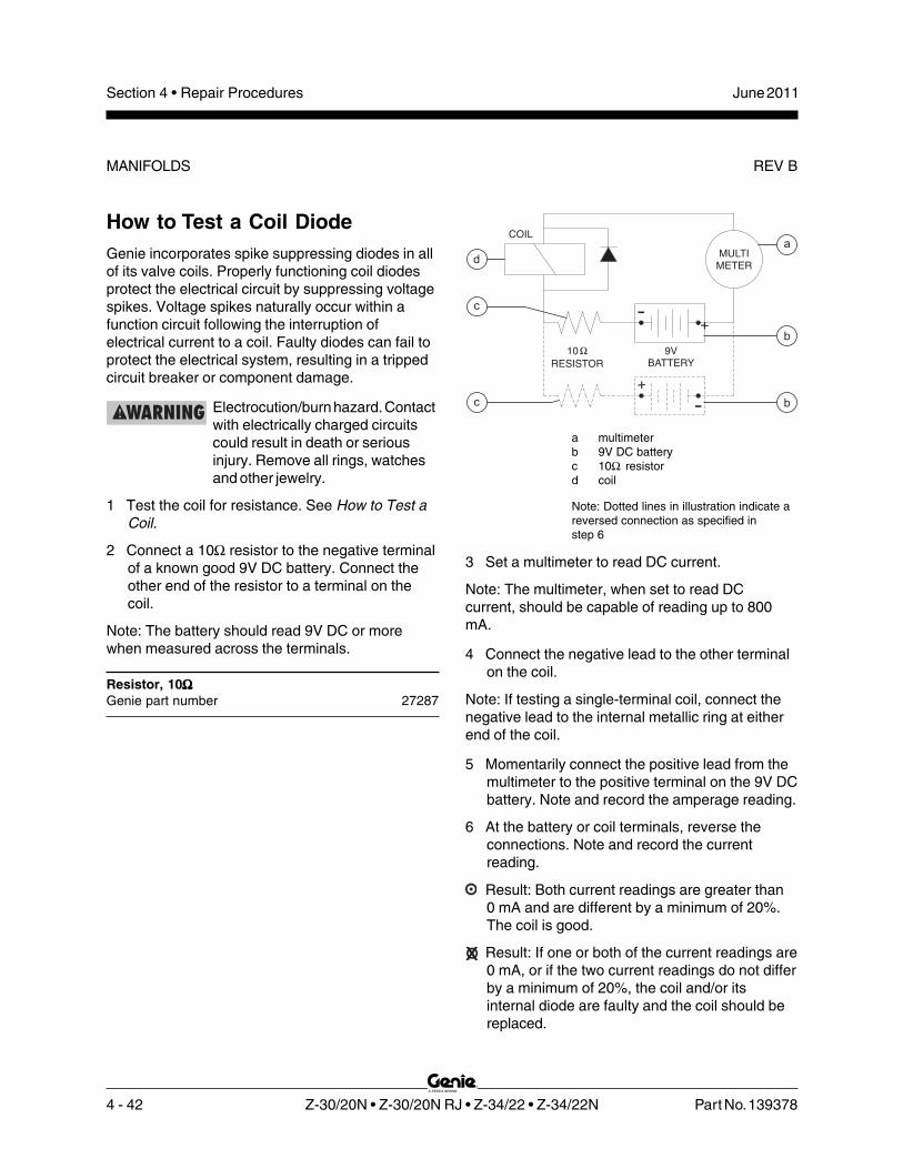
4 - 42 Z-30/20N • Z-30/20N RJ • Z-34/22 • Z-34/22N Part No. 139378
June 2011Section 4 • Repair Procedures
REV BMANIFOLDS
9V
BATTERY
10
RESISTOR
�
MULTI
METER
COIL
+
-
+
-
d
b
b
a
c
c
How to Test a Coil DiodeGenie incorporates spike suppressing diodes in allof its valve coils. Properly functioning coil diodesprotect the electrical circuit by suppressing voltagespikes. Voltage spikes naturally occur within afunction circuit following the interruption ofelectrical current to a coil. Faulty diodes can fail toprotect the electrical system, resulting in a trippedcircuit breaker or component damage.
Electrocution/burn hazard. Contactwith electrically charged circuitscould result in death or seriousinjury. Remove all rings, watchesand other jewelry.
1 Test the coil for resistance. See How to Test aCoil.
2 Connect a 10Ω resistor to the negative terminalof a known good 9V DC battery. Connect theother end of the resistor to a terminal on thecoil.
Note: The battery should read 9V DC or morewhen measured across the terminals.
Resistor, 10ΩΩΩΩΩGenie part number 27287
a multimeterb 9V DC batteryc 10Ω resistord coil
Note: Dotted lines in illustration indicate areversed connection as specified instep 6
3 Set a multimeter to read DC current.
Note: The multimeter, when set to read DCcurrent, should be capable of reading up to 800mA.
4 Connect the negative lead to the other terminalon the coil.
Note: If testing a single-terminal coil, connect thenegative lead to the internal metallic ring at eitherend of the coil.
5 Momentarily connect the positive lead from themultimeter to the positive terminal on the 9V DCbattery. Note and record the amperage reading.
6 At the battery or coil terminals, reverse theconnections. Note and record the currentreading.
Result: Both current readings are greater than0 mA and are different by a minimum of 20%.The coil is good.
Result: If one or both of the current readings are0 mA, or if the two current readings do not differby a minimum of 20%, the coil and/or itsinternal diode are faulty and the coil should bereplaced.

Part No. 139378 Z-30/20N • Z-30/20N RJ • Z-34/22 • Z-34/22N 4 - 43
June 2011 Section 4 • Repair Procedures
REV A
8-1Turntable Rotation HydraulicMotor
The turntable rotation hydraulic motor is the onlyserviceable component of the turntable rotationassembly. The worm gear must not be removedfrom the housing. In order to remove the housing,the turntable has to be removed.
How to Remove the TurntableRotation MotorNote: When removing a hose assembly or fitting,the O-ring on the fitting and/or hose end must bereplaced and then torqued to specification duringinstallation. Refer to Section 2, Hydraulic Hose andFitting Torque Specifications.
1 Tag, disconnect and plug the hydraulic hosesfrom the turntable rotation motor. Cap thefittings on the motor.
Bodily injury hazard. Sprayinghydraulic oil can penetrate andburn skin. Loosen hydraulicconnections very slowly to allowthe oil pressure to dissipategradually. Do not allow oil to squirtor spray.
2 Remove the turntable rotation motor mountingbolts. Remove the motor from the machine.
Turntable Rotation Components

4 - 44 Z-30/20N • Z-30/20N RJ • Z-34/22 • Z-34/22N Part No. 139378
June 2011Section 4 • Repair Procedures
REV ASteer Axle Components
9-1Hub and Bearings
How to Remove theHub and Bearings1 Loosen the wheel lug nuts. Do not remove
them.
2 Block the non-steer wheels and place a liftingjack under the steer axle.
3 Raise the machine. Place blocks underthe drive chassis for support.
4 Remove the lug nuts. Remove the tireand wheel assembly.
5 Remove the dust cap, cotter pin andcastle nut.
Note: Always use a new cotter pin when installing acastle nut.
6 Pull the hub off the yoke spindle. The washerand outer bearing should fall loose from thehub.
7 Place the hub on a flat surface and gently prythe grease seal out of the hub. Remove theinner bearing.
Note: When removing a bearing, always use a newinner bearing seal.
How to Install the Huband BearingsNote: When replacing a wheel bearing, both theinner and outer bearings, including the pressed-inraces, must be replaced.
1 Be sure that both bearings are packedwith clean, fresh grease.
2 Place the large inner bearing into the rear of thehub.
3 Install a new bearing grease seal into the hubby pressing it evenly into the hub until it is flush.
Note: Always replace the bearing grease sealwhen removing the hub.
4 Slide the hub onto the yoke spindle.
Component damage hazard. Donot apply excessive force ordamage to the lip of the seal mayoccur.
5 Fill the hub cavity with clean, fresh grease.
6 Place the outer bearing into the hub.
7 Install the washer and castle nut.
8 Tighten the castle nut to 158 ft-lbs / 214 Nmto seat the bearings.
Note: Rotate the hub by hand while torquing thecastle nut to make sure the bearings seat properly.
9 Loosen the castle nut one full turn and thentorque to 35 ft-lbs / 47 Nm.
10 Install a new cotter pin. Bend the cotter pin tolock it in place.
Note: Always use a new cotter pin when installing acastle nut.
11 Install the dust cap, then the tire and wheelassembly.
12 Lower the machine and remove the blocks.
13 Torque the wheel lug nuts to specification. Referto Section 2, Specifications.

Part No. 139378 Z-30/20N • Z-30/20N RJ • Z-34/22 • Z-34/22N 4 - 45
June 2011 Section 4 • Repair Procedures
REV A
10-1Motor Controller
The drive motor controller is located under the non-steer end drive chassis cover. The drive motorcontroller can recognize machine drivemalfunctions and display controller fault codes byflashing a LED at the ground controls and on themotor controller. See the Fault Code section of thismanual for a list of fault codes and additionalinformation. There are no adjustments needed onthe drive joystick controller. For further informationor assistance, consult the Genie Industries ServiceDepartment.
How to Test the Motor ControllerNote: Use the following procedure to test the motorcontroller. If the motor controller is found to befaulty, note which test failed and which fault code(if any) was present at the time of failure.
1 Turn the key switch to the off position anddisconnect the battery packs from the machine.
2 Tag and disconnect all power cables from themotor controller.
Electrocution/burn hazard. Contactwith electrically charged circuitscould result in death or seriousinjury. Remove all rings, watchesand other jewelry.
3 Press the release tab on the motor controllerharness connector and remove the motorcontroller harness connector from the motorcontroller.
4 Set an ohmmeter to diode test mode.
5 Connect the leads from an ohmmeter to testeach motor controller terminal combinationlisted below and check the forward / reversebias (diode test).
Result: All desired results must be within thespecified range. If any test has a result notwithin the specified range, replace the motorcontroller.
Forward Bias:
Test Desired result
Positive Lead Negative Lead
M- B+ 0.4 to 0.45
B- M- 0.4 to 0.45
F1 B+ 0.45 to 0.5
F2 B+ 0.45 to 0.5
B- F1 0.45 to 0.5
B- F2 0.45 to 0.5
Reverse Bias:
Test Desired result
Positive Lead Negative Lead
B+ M- Rises to .0L V
M- B- Rises to .0L V
B+ F1 Rises to .0L V
B+ F2 Rises to .0L V
F1 B- Rises to .0L V
F2 B- Rises to .0L V
Motor Controller

4 - 46 Z-30/20N • Z-30/20N RJ • Z-34/22 • Z-34/22N Part No. 139378
June 2011Section 4 • Repair Procedures
This page intentionally left blank.

Part No. 139378 Z-30/20N • Z-30/20N RJ • Z-34/22 • Z-34/22N 5 - 1
June 2011 Section 5 • Fault Codes
Before Troubleshooting:
Read, understand and obey the safety rules andoperating instructions in the appropriateoperator's manual on your machine beforeattempting any maintenance or repair procedure.
Be sure that all necessary tools and testequipment are available and ready for use.
Be aware of the following hazards and followgenerally accepted safe workshop practices.
Crushing hazard. When testingor replacing any hydrauliccomponent, always supportthe structure and secure itfrom movement.
Electrocution/burn hazard. Contactwith electrically charged circuitscould result in death or seriousinjury. Remove all rings, watchesand other jewelry.
Bodily injury hazard. Sprayinghydraulic oil can penetrate andburn skin. Loosen hydraulicconnections very slowly to allowthe oil pressure to dissipategradually. Do not allow oil tosquirt or spray.
Note: Two persons will be required to safelyperform some troubleshooting procedures.
Fault Codes
Observe and Obey:
Troubleshooting and repair procedures shall becompleted by a person trained and qualified onthe repair of this machine.
Immediately tag and remove from service adamaged or malfunctioning machine.
Repair any machine damage or malfunctionbefore operating the machine.
Unless otherwise specified, perform eachrepair procedure with the machine in thefollowing configuration:
• Machine parked on a firm, level surface
• Boom in stowed position
• Turntable rotated with the boom betweenthe non-steer wheels
• Key switch in the off position with thekey removed
• Wheels chocked
• All external AC power supply disconnectedfrom the machine

5 - 2 Z-30/20N • Z-30/20N RJ • Z-34/22 • Z-34/22N Part No. 139378
June 2011Section 5 • Fault Codes
REV BFAULT CODES
Tip-over hazard. When adjustingthe raised drive speed settings,the maximum raised drive speedmust not exceed 0.6 mph / 1Km/hor 40 feet / 45 seconds /12.2 meters / 45 seconds. If themachine is allowed to drive fasterthan specification, the machinecould become unstable and will tipover.
Note: Additional troubleshooting of the fault codesmay by accomplished by using the hand-heldpendant motor controller programmer (Genie partnumber 128551).
Note: When using the hand-held pendant motorcontroller programmer, the M1 MAX SPEED needsto be set to 33. If needed, adjust the M1 MAXSPEED higher or lower to achieve the maximumraised drive speed of 0.6 mph / 1Km/h or 40 feet /45 seconds / 12.2 meters / 45 seconds.
The controller status indicator light will flash a faultcode to aid in troubleshooting. This indicator lightis mounted on the tilt level sensor mountingbracket, located behind the cover on the groundcontrols side.
Fault codes are two digits. The controller statusindicator light will blink the first digit of a two digitcode, pause for 1 second, and then blink thesecond digit. There will be a 2 second pausebetween codes.
For example: the indicator light blinks 4consecutive times, pauses for 1 second, and thenblinks 1 time. That would indicate Fault Code 41.

Part No. 139378 Z-30/20N • Z-30/20N RJ • Z-34/22 • Z-34/22N 5 - 3
June 2011 Section 5 • Fault Codes
REV BFault Code Chart
Fault Code Programmer Diagnostic Display Condition Possible Causes Solution
Fault code LED is off or is on,
but not blinking
COMMUNICATION ERROR Machine will not drive.
The key switch or Emergency Stop button(s) was cycled on and off faster than 5 seconds OR controller sensed an internal error during start up.
Push in the ground control red Emergency Stop button to the off position and wait for 5 seconds. Pull out the ground control red Emergency Stop button to the on position. If problem persists, replace the motor controller.
01 Normal operation.
12 HW FAILSAFE 1-2-3 Machine will not drive. The motor controller failed self test.
Replace the motor controller.
13 M- SHORTED Machine will not drive.
The motor controller has a internal short between M- and B- terminals.
Test the motor controller. See Repair Section.
FIELD OPEN Machine will not drive.
Motor wiring is loose OR motor is defective OR motor controller has an internal short.
Check for loose or open connections at the drive motors and motor controller OR replace the defective drive motor OR test the motor controller. See Repair Section.
ARM SENSOR Machine will not drive. Defective motor controller.
Replace the motor controller.
FLD SENSOR Machine will not drive. Defective motor controller.
Replace the motor controller.

5 - 4 Z-30/20N • Z-30/20N RJ • Z-34/22 • Z-34/22N Part No. 139378
June 2011Section 5 • Fault Codes
REV BFAULT CODE CHART
Fault Code Programmer Diagnostic Display Condition Possible Causes Solution
21 THROTTLE FAULT 1 Machine will not drive.
Open in wht/red wire #32 at pin 14 or red/wht wire #29 at pin 16 on the motor controller going from drive joystick to pins 14 and 16 at the motor controller OR pin 14 is internally shorted to power or ground OR the potentiometer on the drive joystick is defective.
Consult Genie Industries Service Department.
THROTTLE FAULT 2 Machine will not drive.
Pin 14 (wht/red #32) is shorted to power or ground OR the potentiometer on the drive joystick is defective.
Consult Genie Industries Service Department.
31 CONT DRVR OC Machine will not drive.
Main contactor (PR1) coil defective OR brake release relay CR5 defective.
Replace main contactor PR1 or brake release relay CR5 OR replace the motor controller.
32 MAIN CONT WELDED Machine will not drive.
Main contactor (PR1) contacts stuck closed OR grn wire at pin 17 on motor controller shorted to ground OR open in motor armature wiring OR motor controller has an internal short to ground.
Consult Genie Industries Service Department.
33 PRECHARGE FAULT Machine will not drive.
External short between B+ terminal on motor controller and ground OR motor controller is defective.
Repair short between B+ terminal on motor controller and ground OR replace motor controller. Note: Short can be on any part of circuit connected to the B+ terminal on the motor controller.

Part No. 139378 Z-30/20N • Z-30/20N RJ • Z-34/22 • Z-34/22N 5 - 5
June 2011 Section 5 • Fault Codes
REV B FAULT CODE CHART
Fault Code Programmer Diagnostic Display Condition Possible Causes Solution
34 MISSING CONTACTOR Machine will not drive.
Motor controller does not detect the main contactor PR1 or brake release relay CR5.
Consult Genie Industries Service Department.
MAIN CONT DNC Machine will not drive.
Main contactor PR1 or brake release relay CR5 did not close OR open in org/red wire to PR1 and/or CR5 OR main contactor and/or brake release relay is defective.
Consult Genie Industries Service Department.
41 LOW BATTERY VOLTAGE Machine will not drive.
Battery supply voltage to motor controller less than 32V DC.
Completely charge batteries OR check battery cable condition OR check for corrosion or loose connections at battery terminals and motor controller.
42 OVERVOLTAGE Machine will not drive.
Battery supply voltage to motor controller more than 55V DC OR machine is being operated with the battery charger plugged in.
Be sure the battery charger is disconnected OR check for loose battery cables or poor connections.
43 THERMAL CUTBACK Machine will not drive.
Machine being operated outside of temperature range of -13°F to 185°F / -25°C to 85°C OR machine being driven under excessive load OR motor controller is not being cooled sufficently.
Operate machine within specified temperature limits OR check for debris around motor controller preventing proper cooling of the controller OR check for mechanical restrictions causing excessive load on the machine.

5 - 6 Z-30/20N • Z-30/20N RJ • Z-34/22 • Z-34/22N Part No. 139378
June 2011Section 5 • Fault Codes
This page intentionally left blank.

Part No. 139378 Z-30/20N • Z-30/20N RJ • Z-34/22 • Z-34/22N 6 - 1
June 2011 Section 6 • Schematics
Schematics
Observe and Obey:
Troubleshooting and repair procedures shall becompleted by a person trained and qualified onthe repair of this machine.
Immediately tag and remove from service adamaged or malfunctioning machine.
Repair any machine damage or malfunctionbefore operating the machine.
Before Troubleshooting:
Read, understand and obey the safety rulesand operating instructions in the appropriateoperator's manual on your machine beforeattempting any maintenance or repair procedure.
Be sure that all necessary tools and testequipment are available and ready for use.
About This SectionThere are two groups of schematics in this section.
Electrical Schematics
Electrocution/burn hazard. Contactwith electrically charged circuitscould result in death or seriousinjury. Remove all rings, watchesand other jewelry.
Hydraulic Schematics
Bodily injury hazard. Sprayinghydraulic oil can penetrate andburn skin. Loosen hydraulicconnections very slowly to allowthe oil pressure to dissipategradually. Do not allow oil to squirtor spray.
General Repair Process
Malfunctiondiscovered
Identifysymptoms
Troubleshoot
Performrepair
Return toservice problem
solved
problemstill exists
Inspectand test

6 - 2 Z-30/20N • Z-30/20N RJ • Z-34/22 • Z-34/22N Part No. 139378
June 2011Section 6 • Schematics
REV A
Electrical Symbols Legend
+
-
6V DCBattery
OR
G/B
LK-1
numbercablewithcolorWire
Connectionno terminal
P1
EmergencyStop button
normaly closed
PR4
Relay panelcontactor
Solenoid orrelay coil
Horn
Tilt sensor
NOHCLS1
Limit switchnormally open
held closed
P3HORN
Horn buttonnormally open
T-circuitconnected
LED
AP1
Quick disconnectterminal
Diode
BLK
FS1
Foot switch
Relay contactnormaly open
Relay contactnormally closed
TS3
EN
GIN
ES
TAR
T
Toggle switchSPDT
Circuits crossingno connection
Auxiliary / Primarylift pump
PUMP
Boom functionspeed controller
WH
T
GRNRED
BP1 BL
K/R
ED
Pressureswitch
PS
ITerminal
TB20
T-circuitconnects at terminal
BLK #21TB21
Circuit breaker
Drive motor
A2
A1 S1
S2
FB
Flashingbeacon
Hour meter
Fuse
Limit switch
NO
LS3
NC
Toggle switchDPDT
TS6
RIG
HT
LEFT
GR
N/B
LK
TB17
Groundsupression
circuit _
HM
+
PLATFORM
GROUND
KS1
Key switch
CR2
30
8785
86
CR2
30
8785
86

Part No. 139378 Z-30/20N • Z-30/20N RJ • Z-34/22 • Z-34/22N 6 - 3
June 2011 Section 6 • Schematics
REV A
Hydraulic Symbols Legend
Fixed displacementpump
M
Pump prime mover(motor)
Check valve
Differentialsensing valve
Solenoid operatedproportional valve
Solenoid operated 3 position,4 way, directional valve
Pressure switch
N.C.COM
N.O.
Brake
Double actingcylinder
Orifice
0.045 /1.14 mm
Relief valve
Hydraulic filter
Counterbalance valve(dual)
Normally openpoppet valve
Normally closedpoppet valve
Filter with by-passcheck valve
Dual relief valve
Flow regulator valve
Counterbalance valve(single)
Bi-directional motor
Regen circuit
Shutoff valve

6 - 4 Z-30/20N • Z-30/20N RJ • Z-34/22 • Z-34/22N Part No. 139378
June 2011Section 6 • Schematics
REV A
Limit Switch Location Legend
Z-30/20NZ-30/20N RJ
Z-34/22Z-34/22N
LS1
LS2
LS4
LS2
LS4
LS1

6 - 5
Section 6 • Schematics June 2011
Electrical Schematic, (ANSI / CSA / AS)(before serial numbers Z30N10-12119, Z34N10-8857 and Z3410-7774)
6 - 6

Section 6 • Schematics June 2011
1
2
3
4
5
6
7
8
A B C D E F G H I J K L M N
6 - 6 Z-30/20N • Z-30/20N RJ • Z-34/22 • Z-34/22N Part No. 139378
REV BElectrical Schematic, (ANSI / CSA / AS)(before serial numbers Z30N10-12119, Z34N10-8857 and Z3410-7774)
LS
4-S
EC
. UP
/DW
N
LS
2-P
RI. U
P/D
WN
LS
1-E
XT
/RE
T
C48-3TB52
C9
HR
N B
K/R
D
C19LPE GR/WHP42BAT OR/RD
85
86
PR
IMA
RY
LIF
TP
UM
PP
R2
33�
R4
2B
AT
GR
/WH
PR2
CR20
30
87
AU
XIL
IAR
YL
IFT
PU
MP
PR
3
PR
IMA
RY
LIF
TP
UM
PC
ON
TA
CT
OR
RE
LA
Y
33�
PR3
C4
9-1
1 C
19
LP
E G
R/W
H
C4
9-1
R2
7A
UX
RD
87a
CR3
87
30
P42BAT OR/RD C48-2
C7
B-2
P2
3B
AT
WH
C7
P-2
C4
8-1
P1
82
BA
TR
D
P2
2B
AT
BK
RD
P134BAT RD TB134
R42BAT OR/RD
C12FTS
10A
CB3
C1
33
PL
AB
L/R
DC
2P
-1C
2B
-1
C32
U6AMOTOR CONTROLLER
F4500A
C3
B-9
C1
B-1
2
H2
GR/BK
RD
TB134
C1P-12C132PLI BL/WH
C7
B-1
1 3
4
6 7
5
12 8
C40LS
C4
9-9
OR
C29JSH RD/WH
C32JSL WH/RD
C30FWD WH
C31REV WH/BK
BK 2 GA
CH
AS
SIS
GR
OU
ND
J2
-BK
RD
P26BAT
13LS1
(EXT)
14 2
P2
2B
AT
BK
C7P-1
HO
RN
B
A C
P42BAT OR/RD
C4
9-7
C1
78
CS
LB
K
C49-10
C4
9-8
BK
C11
-3 B
K-6
C11
-4 W
H-6
C1
0-2
WH
-7
C1
0-1
BK
-7P
22
LS
BK
C5
2-1
BK
-8
C5
2-2
WH
-8
J1-WH
C4
9-3
C4
9-6
C4
9-5
C4
9-4
C2
B-4
C3
B-3
C1
B-2
C1
B-3
C1
B-4
C1
B-5
C1
B-6
C9P-2
C9P-3
R4
2B
AT
OR
/RD
C2
P-4
C3
BA
TR
D/W
HC
3P
-3
C2
8T
TA
RD
/BK
C1
P-2
C9
HR
N B
K/R
DC
3P
-9
C2
9JS
H R
D/W
HC
1P
-3
C3
2JS
LW
H/R
DC
1P
-6
C3
1R
EV
WH
/BK
C1
P-5
CR5
P182BAT BK
C19LPE GR/WH
R42BAT OR/RD
P24BAT WH
RD
C12DRE BL/WH
CR3
GND BR
TILTALARM
RD
WH-(FS)
FS1
H1
RD-(FS)
PLATFORM
GROUND
P1KS1
TB22
P3HORN
P2
RD
C9P-1 BK
+
RD
P182BAT RD
BK-(FS)
OR
/RD
CR1
CR2
TB42
RD
/WH
30
8785
86
87
3086
85
BR
N
BR
N
PR
1
OF
F-L
IMT
SP
D IN
P
INT
ER
LO
CK
L3
53 17
C1
82
PW
R G
R LS4(SEC)
OR
/RD
LS2(PRI)
RD
/BK
OR
/RD
C4
9-2
C4
8B
RK
RD
/BK
OR
/RD
20
CR
5
22
21
22
21
86
85
CB2
10 A
C1
P-4
RD
20
AP2
24V
FO
RW
AR
D
PO
T. L
OW
DIO
DE
RE
TU
RN
+4
8V
INP
UT
PO
T. H
I
RE
VE
RS
E
10
1 9 11
16
14
PR1
AP2 48V
R4
2B
AT
OR
/RD
WH
WH
/BK
WH
/RD
RD
/WH
F3100A
F510A
F2100A
++
+
+
LEFTBOX
--
-
-
48V
C3
0F
WD
WH
2
48
V P
OW
ER
RE
LA
YC
R1
FL
AS
HIN
G B
EA
CO
NO
PT
ION
48
V P
OW
ER
RE
LA
YC
R2
FB
+
HO
RN
RE
LA
Y
BA
SE
CO
NT
RO
LB
OX
GR
OU
ND
CR4
TIL
TS
EN
SO
RR
D
WH
BK
BR
N
F1
+
86
85
30
87
BR
N
BR
AK
E R
EL
EA
SE
RE
LA
YC
R5
PR
1 D
RIV
EC
ON
TA
CT
OR
AP1
AU
XIL
IAR
YL
IFT
PU
MP
PR
IMA
RY
LIF
TP
UM
P
PR3 PR2
WH
BK
AC POWER
F2 F1
A2
A1
A2
A1+
-
PUMP
+
++
+
CHARGER
LEFTMOTOR
RIGHTBOX
-
--
-
GROUND
24V
SWITCH SHOWN WITH BOOM EXTENDED.
NOTES:
1. ALL LIMIT SWITCHES SHOWN WITH BOOM IN STOWED POSITION EXCEPT AS NOTED.
SWITCH SHOWN WITH BOOM ROTATED PAST EITHER NON-STEER WHEEL.
4. ALL SOLENOID AND RELAY COILS ARE 24VDC EXCEPT WHERE NOTED.
F2
F2F1 B+M-AP1 B-
PUMP
RIGHTMOTOR
2
3
BL
/WH
L48
ES34DCT
SETUP ENABLE: USE TO SET THE BATTERY INDICATOR PROFILES.5
OR
TS48DRIVELIGHTS
TS49WORKLIGHTS
CR45N.O.
87
30 86
85
L30
+
L30
+
PLATFORM BOXGROUND
C1
B-9
R4
2B
AT
OR
/RD
P4
8L
PS
WH
/RD
C1
P-9
F187A
WH
/RD
C2
B-9
WH
(16
/2)
WH
C1
B-8
DL
ITE
BK
/WH
C1
P-8
F197A
BK
/WH
C2
B-1
2W
H (1
6/2
)
CR23N.O.
87
30 86
85
L29
+
L29
+
WH
WH
WH
BK
BK
L3
0 W
OR
K L
IGH
TS
(OP
TIO
N)
L2
9 D
RIV
E L
IGH
T(O
PT
ION
)

June 2011 Section 6 • Schematics
1
2
3
4
5
6
7
8
N M L K J I H G F E D C B A
Part No. 139378 Z-30/20N • Z-30/20N RJ • Z-34/22 • Z-34/22N 6 - 7
REV B Electrical Schematic, (ANSI / CSA / AS)(before serial numbers Z30N10-12119, Z34N10-8857 and Z3410-7774)
JIB ROTATE OPTION(Z30N RJ ONLY)
JIBROTATE
RE
TR
AC
T
(GND)
CR3
TU
RN
TA
BL
ER
OTA
TE
LE
FT
TU
RN
TA
BL
ER
OTA
TE
RIG
HT
DE
SC
EN
TA
LA
RM
SE
CO
ND
AR
YB
OO
M D
OW
N
SE
CO
ND
AR
YB
OO
M U
P
H4
+
WH
/BK
WH
TB4
BL
/BK
BL
TB5 TB11 TB10
OR
/BK
OR
PR
IMA
RY
BO
OM
UP
PR
IMA
RY
BO
OM
DO
WN
PR
IMA
RY
BO
OM
RE
TR
AC
T
PR
IMA
RY
BO
OM
EX
TE
ND
PL
AT
FO
RM
LE
VE
LD
OW
N
PL
AT
FO
RM
LE
VE
LU
P
BK
/WH
BK
RD
/BK
RD
TB2 TB1 TB8 TB7 TB15 TB14
JIB
BO
OM
DO
WN
JIB
BO
OM
UP
PRIMARYBOOM
C19LPE GR/WH
TS55
C12DRE BL/WH
RD
CR5
RD
C2
PB
D R
D/B
K
C1
0S
BU
BL
C11
SB
D B
L/B
K
C5
TR
R W
H/B
K
C4
TR
LW
H
RIG
HT
TURNTABLEROTATE
FUNCTIONENABLE
LE
FT
TS62
RD
C3
B-4
C3
B-5
SECONDARYBOOM
TS60
DO
WN
UP
C3
B-1
1
C3
B-1
0
C3
B-1
C3
B-2
C3
P-4
C3
P-5
LE
FT
TS12
RIG
HT
TURNTABLEROTATE
C3
P-1
0
C3
P-1
1
C1
PB
U R
D
C3
P-2
C3
P-1
SECONDARYBOOM
DO
WN
2
6
CR19
UP
TS10
DO
WN
CR19
1
5
TS11
UP
C30FWD WH
C29JSH RD/WH
C31REV WH/BK
C32JSL WH/RD
R42BAT OR/RD
P24BAT WH
C1
8P
RR
BL
PLATFORMROTATE
PLATFORMROTATE
C1
8P
RR
GR
/BK
C1
7P
RL
GR
C1
5P
LD
OR
/BK
C1
4P
LU
OR
C7
PB
E B
K
C8
PB
R B
K/W
H
DO
WN
TS61
UP
PRIMARYBOOM
TS63
EX
TE
ND
PRIMARYBOOM
C3
B-7
C3
B-8
PLATFORMLEVEL
DO
WN
TS59
C4
B-6
C4
B-5
C4
B-3
C4
B-2
C3
P-7
C3
P-8
EX
TE
ND
PRIMARYBOOM
RE
TR
AC
T
TS13
DO
WN
TS9
C4
P-3
C4
P-2
C4
P-5
C4
P-6
PLATFORMLEVEL
UP
RIG
HT
LE
FT
TS7
C4
7JR
R R
D
C4
6JR
LY
L
C4
7JR
R O
R/B
K
C4
6JR
LO
R
C4
4JD
WH
C4
3JU
BK
C1
7P
RL
OR
C4
3JU
GR
C4
4JD
GR
/BK
RIG
HT
LE
FT
TS57
C2
B-6
C2
B-5
JIB MANIFOLD
DO
WN
TS58
UP
JIBBOOM
C2
B-2
C2
B-3
C2
P-5
C2
P-6
DO
WN
TS8
UP
JIBBOOM
C2
P-3
C2
P-2
RIG
HT
LE
FT
TS16
C7
P-3
BA
TG
ND
BR
N
C8
-4
C8
-3
C1
6D
E O
R/R
D
PS
1
GR/WHP
RO
PO
RT
ION
AL
CO
NT
RO
LV
ALV
E
AU
XIL
IAR
YP
UM
P
TB6
WH
/RD
GR/WH
CR3
TB19
86
85
C19LPE
C2
7A
UX
RD
HO
UR
ME
TE
R
_
BR
AK
E R
EL
EA
SE
N.C
. VA
LV
E
ST
EE
R R
IGH
T
ST
EE
R L
EF
T
BR
AK
EP
RE
SS
UR
ES
WIT
CH
+
WH
/BK
HM
+
TB19
R48BRK
GR/WH
BL
BL
/BK
R4
8B
RK
RD
/WH
TB48
C8
-1
C7
B-3
BA
TG
ND
BR
N
C8
-2
TR
AV
EL
AL
AR
M
H3
TB52
13
RD
-5
RD
/WH
14
BR
N-5
22
LS321
DR
IVE
EN
AB
LE
LIM
ITS
WIT
CH
BK
-5
TB16
WH
-5
TS15DRIVEENABLE
DP1
C6
MF
V W
H/R
D
C1
9L
PE
GR
/WH
C1
9L
PE
GR
/WH
LE
FT
TS66
RIG
HT
JIBROTATE
C3
B-6
C4
B-7
TB27C27AUX RD
RD
TS51AUXILIARYPUMP
ROTARYOEMFLOWCONTROL
BP1
C3
P-6
BK/RD
RD
GR
C4
P-7
+
BCIOPTION
E
F
C3
7S
CW
BL
/BK
C1
B-1
TB37
TB3687
30
CR5
C1
B-1
1
C1
B-1
0TS1AUXILIARYPUMP
C2
7A
UX
RD
C1
P-1
STEER
L R 10
9
LIFT
DRIVE
FWD
RD
-AU
X
REV
20K
4
8
7
6
5
3
2
1
C1
P-1
1
C1
P-1
0C
36
SC
C B
LR
D
P24BAT WH
C32JSL WH/RD
C30FWD WH
C31REV WH/BK
C29JSH RD/WH
C1
3D
EL
BL
/RD
C1
2F
TS
BL
/WH
C1
2F
TS
BL
/WH
OR
/RD
C1
3D
EL
BL
/RD
BR
N
C3
B-1
2
TB12
C4
B-4
C4
B-1
C3
P-1
2
C1
6D
E O
R/R
DC
4P
-4
C4
P-1
L1
OR
/RD4
8
2 3
76
1
5
LVI/BCI(OPTION)
BK
7
8
CR19
BRN
WH
WH/RD
WH
UP
UP
5
C4
7-2
C4
7-1
C4
7-3
C4
7-4
C2
P-5
C2
P-5
3
OR
BR
AK
E R
EL
EA
SE
N.O
. VA
LV
E
PLATFORM CONTROLBOX GROUND
PL
AT
FO
RM
RO
TA
TE
LE
FT
PL
AT
FO
RM
RO
TA
TE
RIG
HT
D29
D30
D50
C47-8 GRN
D72
D74
D4
D75
D71
D73
D66
D77
D78
D59
D60
D76
D87
D86
C4
9-1

6 - 8
June 2011 Section 6 • Schematics
6 - 7
Electrical Schematic, (ANSI / CSA / AS)(before serial numbers Z30N10-12119, Z34N10-88577 and Z3410-7774)

6 - 9
Section 6 • Schematics June 2011
Ground Control Box Terminal Strip Wiring Diagram,(ANSI / CSA / AS), (before serial numbers Z30N10-12119,Z34N10-8857 and Z3410-7774)
6 - 10
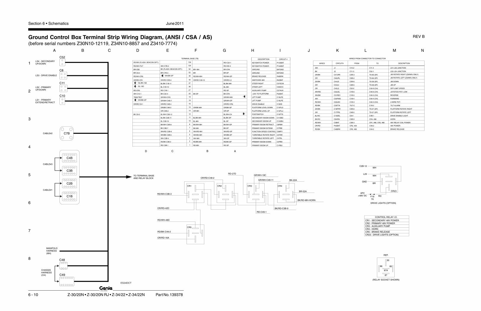
Section 6 • Schematics June 2011
1
2
3
4
5
6
7
8
A B C D E F G H I J K L M N
6 - 10 Z-30/20N • Z-30/20N RJ • Z-34/22 • Z-34/22N Part No. 139378
REV BGround Control Box Terminal Strip Wiring Diagram, (ANSI / CSA / AS)(before serial numbers Z30N10-12119, Z34N10-8857 and Z3410-7774)
RD-C32-1 DESCRIPTIONTOFROMCIRCUIT#WIRES
C1B-5
C1B-4
C1B-3
C4B-6
C4B-5
C3B-9
C8-4
TILT-C
C52-2
C3B-3
C2B-5
C2B-6
C10-2
C11-3
C1B-6
C2B-3
C2B-2
WIRES FROM CONNECTOR TO CONNECTORTERMINAL BASE (TB)
TO TERMINAL BASEAND RELAY BLOCK
C49
C48
CHASSISHARNESS(CH)
MANIFOLDHARNESS(MH)
C1B
C2B
C4B
C3B
CABLE#3
CABLE#1
CABLE#2 C7B
C11
C8
C52
C10
LS4 - SECONDARYUP/DOWN
LS3 - DRIVE ENABLE
LS2 - PRIMARYUP/DOWN
LS1 - PRIMARYEXTEND/RETRACT
RD/WH-TILT WH C7B-2 134
134
RD-KSI-4
RD/WH (FLASH. BEACON OPT.)
JIB ROTATE LEFT (Z30NRJ ONLY)
JIB ROTATE RIGHT (Z30NRJ ONLY)
TS-66 (SP)C46JRLOR
OR/BK C47JRR TS-66 (SP)
BR- MH
RD/WH-MHWH/BK-SP
WH/BK-SP
OR/RD-CR5
BL-19D
BL/BK-19D
RD/WH-CR5
OR/RD-16A
RD/BK-C49-2
BK-22A
BK/RD-MH-HORN
BK/RD-C3B-9
CR5 - BRAKE RELEASE
RD-27D
CR1 - SECONDARY 48V POWER
CR3 - AUXILIARY PUMP
CR2 - PRIMARY 48V POWER
CR4 - HORN
CONTROL RELAY I.D.
WH C10-1
OR/RD-CR1
JOYSTICK POT. LOWWH/RD C32JSL C49-6 (CH)
CR1, #86, CR2, #86
RD-C49-1
LS1-LS2 JUNCTION
LS2-LS4 JUNCTION
OR/BK-MH
OR/RD C8-1
BR-CB2
BRBK
BK (FLASH. BEACON OPT.)
BR-SP
BR-CR4
RD/WH-SP
52
52J2
48
C52-1BR C7B-3BR C8-2
OR/RD-L3OR/RD C49-10
C49-4 (CH)
RD-CR3
TB36/TB37 GR/WH-CR3
GR/WH-SP
48V RELAY COIL POWER
GR/WH-19C
BR-52A
BL-MH
BL/BK-MH
C49-9 (CH)
CR4
GR/WH-C49-11
CR3CR2CR1
CR5
RD/WH-48D
OR/RD-42D
OR/RD-C48-2
RD/WH-C3B-3
WH J1 C11-4
TS-58 (SP)
TS-58 (SP)GR/BK
C43JU
C44JD
JIB UP
JIB DOWN
GR
C40LS
42
36
37
BK-CR4
RD-SP
C28TTA
27
C31REV
C30FWD
C29JSH
22
TILT ALARM
REVERSE
FORWARD
2-WIRE POT.
OFF-LIMIT SPEED
TS-57 (SP)
TS-57 (SP)
GR/WH-MH
BK C8-3
OR/BK-SP
OR-SPC17PRL
C18PRR
19
19
C13DEL12
14
15
16
BK/WH-SP
BK-SP
BL-SP
WH/BK-SP
RD/WH
RD/BK-SP
WH-SP
WH/RD-SP
8
C9HRN
7
10C3BAT
4
5
2
6
11 BL/BK-SP
DRIVE ENABLE LIGHT
PLATFORM ROTATE RIGHT
PLATFORM ROTATE LEFT
HORN
ORBL-MH
BL/BK-MH
RD/BK
C49-3 (CH)
C49-5 (CH)BK-SP
BL/RDBL/WH-CH
OR-MH
BK-MH
BK/RD
BK/WH-MH
WH-MH
RD/BK-MH
WH/BK-MH
WH/RD-MHWH/RD C3B-6
RD/BK C3B-2
WH/BK C3B-5
WH C3B-4
C4B-1
CR4, #86
BK/WH C3B-8
BK C3B-7
BL/WH C3B-12
BL/BK C3B-11
BL C3B-10
GR
OR/BK C4B-3
OR C4B-2
OR/RD C4B-4
GR/BK
GR/WH C4B-7
C1B-2
BK-C32-4
RD C1B-1
RD/WH
WH
WH/BK
BL C1B-10
BL/BK C1B-11
OR/RD C2B-4
ABCD
RD-MHRD C3B-1 1 RD-SP C1PBU
C12FTS
C6MFV
C7PBE
C11SBD
C10SBU
C19LPE
C8PBR
C14PLU
C15PLD
C2PBD
C4TRL
C5TRR
C37SCW
C27AUX
P22BAT
C36SCC
C16DE
C19LPE
R42BAT
R48BRK
BATGND
BATGND
P134BAT
P134BAT
CIRCUIT #DESCRIPTION
KEYSWITCH POWER
KEYSWITCH POWER
GROUND
GROUND
BRAKE RELEASE
SWITCHED 48V
LIFT PUMP
DRIVE ENABLE
STEER LEFT
+24V TO PLATFORM
AUXILIARY PUMP
STEER RIGHT
TURNTABLE ROTATE RIGHT
TURNTABLE ROTATE LEFT
PRIMARY BOOM DOWN
PLATFORM LEVEL DOWN
PLATFORM LEVEL UP
PRIMARY BOOM RETRACT
LIFT PUMP
SECONDARY BOOM UP
SECONDARY BOOM DOWN
PRIMARY BOOM EXTEND
FUNCTION SPEED CONTROL
FOOTSWITCH
PRIMARY BOOM UP
30
8586
87A
87
REF.
(RELAY SOCKET SHOWN)
ES34DCT
OR/RD P42BAT CR2, #30 C48-2 48V POWER
RD/BK C48BRK CR5, #85 C49-2 BRAKE RELEASE
RD
L29
BR
CR23
F197A
WH
C2B-12WH
GND
AP2+48V DC
CR23 - DRIVE LIGHTS (OPTION)
DRIVE LIGHTS (OPTION)

June 2011 Section 6 • Schematics
1
2
3
4
5
6
7
8
N M L K J I H G F E D C B A
Part No. 139378 Z-30/20N • Z-30/20N RJ • Z-34/22 • Z-34/22N 6 - 11
REV B Ground Control Box Switch Panel Wiring Diagram, (ANSI / CSA / AS)(before serial numbers Z30N10-12119, Z34N10-8857 and Z3410-7774)
KS1
TS51
TS57
TS55
P1
LABEL
TS61
TS63
TS62
CB2
TS59
PRIMARY BOOM EXTEND/RETRACT TOGGLE SWITCH
CIRCUIT BREAKER, CONTROLS, 10A
PRIMARY BOOM UP/DOWN TOGGLE SWITCH
PLATFORM ROTATE TOGGLE SWITCH
TURNTABLE ROTATE TOGGLE SWITCH
PLATFORM LEVEL TOGGLE SWITCH
DESCRIPTION
AUXILIARY TOGGLE SWITCH
KEY SWITCH
EMERGENCY STOP BUTTON
TS60 SECONDARY BOOM UP/DOWN TOGGLE SWITCH
TS58 JIB BOOM UP/DOWN TOGGLE SWITCH
HOURMETERHM
CHASSIS HARNESSCH
FUNCTION ENABLE TOGGLE SWITCH
MANIFOLD HARNESSMH
SP SWITCH PANEL
CR CONTROL RELAY
SWITCH PANEL
DESCENT ALARM (OPTION)
TRAVEL ALARM
H4
H3
L3
CB3BK-C49-7
OR/RD-42A
BR-52D
BR-C48-3
TS58
TS66
TS60
TS62
TS61
TS63
TS51
HM
H3RD/WH-48A
TS60
TS58 TS61
TS62TS55
TS66 TS63
CB2
TS51
HM
H3
P1
OR
NC
NC
BR-52AH4
OR
DESCENT ALARM WIRING
TILT SENSOR
RD/BK-C1B-2
RD/WH-134D
BK BR-CB2
U
D
U
D D
U
L R R E
L R
CONTROLLER STATUS LEDL3
TS66 JIB ROTATE TOGGLE SWITCH (Z30NRJ ONLY)
TS57
TS59
OR
CB2
P1
NC
NC
TS55
TS59
TS57
BK-22A
RD-27A
OR/BK-15A
OR/BK-C2-3
WH/RD-6A
BK-7A
BK/WH-8A
WH-4A
WH/BK-5A
GN-17A
RD-1A
GN-43A
RD/BK-2A
OR-14A
GN/BK-18A
GN/WH-19A
WH/BK-19C/48C
RD-C48-1
BL/BK-11A
BL-10A
L R
D
U
OR-C2-2
GN/BK-44A
JIB ROTATE(Z30N RJ MODELS)
KS1
CB3 CIRCUIT BREAKER, CONTROLS RETURN, 10A
WH
RDA
C
B
12876543
BL
/WH
C1
32
PL
I
BK
22
C
BK
P2
2B
AT
BR
/GN
D
1
C32
RD/134A
RD-C23-6
RD-C32-7
BR HM(-)
BK C7-1
BK 22C
BL/WH C1-12
TO TERMINAL BASEAND CONNECTORS
BR-52A
BR C32-12
RD
-C2
3-6
KS1
ES34DCT

6 - 12
June 2011 Section 6 • Schematics
6 - 11
Ground Control Box Switch Panel Wiring Diagram,(ANSI / CSA / AS), (before serial numbers Z30N10-12119,
Z34N10-8857 and Z3410-7774)

Section 6 • SchematicsJune 2011
1
2
3
4
5
6
7
8
N M L K J I H G F E D C B A
Part No. 139378 Z-30/20N • Z-30/20N RJ • Z-34/22 • Z-34/22N 6 - 13
REV B Platform Control Box Wiring Diagram, (ANSI / CSA / AS),(before serial numbers Z30N10-12119, Z34N10-8857 and Z3410-7774)
Y
Y
JIB
H1
BR
N-J
IBB
RN
-2
F.S.
C2P
C9
C7B
C1P
C47
C4POPTION
C3P
PL
AT
FO
RM
CO
NT
RO
LB
OX
RD/BK
RD
C1
32
PL
I BL
/WH
C1
P-1
2
C2
8T
TA
RD
/BK
C1
P-2
TURNTABLE TILT ALARM LED (CSA OPTION)
L48
JIB ROTATE(Z30N RJ MODELS)
P2
3B
AT
WH
C7
P-2
C1
2F
TS
BL
/WH
C3
P-1
2
C1
6D
RE
OR
/RD
C4
P-4
C5
TR
R W
H/B
K C
3P
-5
C4
TR
LW
H C
3P
-4
C11
SB
D B
L/B
K C
3P
-11
C1
0S
BU
BL
C3
P-1
0
C6
MF
V W
H/R
D C
3P
-6
C1
8P
RR
GR
/BK
C4
P-6
C1
7P
RL
GR
C4
P-5
C4
3JU
GR
C2
P-5
C1
9L
PE
GR
/WH
C4
P-7
C4
4JD
GR
/BK
C2
P-6
C2
PB
D R
D/B
K C
3P
-2
C1
PB
U R
D C
3P
-1
C1
4P
LU
OR
C4
P-2
C4
7JR
R O
R/B
K C
2P
-3
C4
6JR
LO
R C
2P
-2
C4
7JR
R R
D C
47
-6
C4
6JR
LY
LC
47
-5
C1
5P
LD
OR
/BK
C4
P-3
DRIVE ENABLE TOGGLE SWITCHTS15
TS9
UD
TS7
L
R
RE
R
L
R
L
D
D
DU
U
U
WH
BRN
RD
RD
C2
9JS
H R
D/W
H C
1P
-3
109876
BP1
BCI
OR
G/R
D
C3
BA
TR
D/W
H C
3P
-3
BATTERY CHARGE INDICATOR (OPTION)BCI
TILT ALARMH1
R4
2B
AT
OR
/RD
C2
P-4
P2
4B
AT
WH
C9
P-2
C1
3D
EL
BL
/RD
C4
P-1
BK
/RD
RD
GR
N
C3
7S
CW
BL
/BK
C1
P-1
1
C3
2JS
LW
H/R
D C
1P
-6
L1 DRIVE ENABLE LED
HORN BUTTONP3
AUXILIARY TOGGLE SWITCH
EMERGENCY STOP BUTTON
DRIVE CONTROLLER
BOOM FUNCTION SPEED CONTROLLER
PLATFORM ROTATE TOGGLE SWITCH
JIB ROTATE TOGGLE SWITCH (Z30NRJ ONLY)
JIB BOOM UP/DOWN TOGGLE SWITCH
PRIMARY BOOM UP/DOWN TOGGLE SWITCH
SECONDARY BOOM UP/DOWN TOGGLE SWITCH
EXTEND/RETRACT TOGGLE SWITCH
PLATFORM LEVEL TOGGLE SWITCH
TURNTABLE ROTATE TOGGLE SWITCH
TS8
TS7
TS9
TS13
TS11
TS12
TS10
P2
TS1
BP1
DP1
TS16
L1
P2
DP1
TS8TS16
TS13
TS11
TS10
TS12
TS15
TS1
P3
53 41 2
C1
8P
RL
OR
C4
7-1
C1
7P
RR
BL
C4
7-2
C4
4JD
WH
C4
7-3
C4
3JU
BK
C4
7-4
C8
PB
R B
K/W
H C
3P
-8
C7
PB
E B
K C
3P
-7
C2
7A
UX
RD
C1
P-1
C3
1R
EV
WH
/BK
C1
P-5
C3
0F
WD
WH
C1
P-4
C3
6S
CC
BL
C1
P-1
0
C9
HR
N B
K/R
D C
3P
-9
P2
2B
AT
BK
C7
P-1
P2
6B
AT
BK
C9
P-1
NC
NC
NO
1
L48
D73
D71
D40D66
ES34DCT
D77
OPTION
P4
8L
PS
WH
/RD
C1
P-9
L3
0
BR
CR
45
WH W
OR
K L
IGH
TS
(OP
TIO
N)WH/RD TS49
85
86
873
0NOTES:
1 TURNTABLE TILT ALARM LED (OPTION).
2ON Z-34/22 MODELS, THIS LOCATION IS USED FORTS49, WORK LIGHT OPTION.
TS49
P2
6B
AT
RD
P2
WH
/RD
CR
45
#8
6
WORK LIGHTS OPTION(Z30N (RJ) MODELS)
2
RELAY, N.O., WORK LIGHTS (OPTION)
DESCRIPTIONLABEL
CR45

6 - 14
June 2011 Section 6 • Schematics
Platform Control Box Wiring Diagram, (ANSI / CSA / AS),(before serial numbers Z30N10-12119, Z34N10-8857 and Z3410-7774)
6 - 13

6 - 15
Section 6 • Schematics June 2011
6 - 16
Electrical Schematic, (CE)(before serial numbers Z30N10-12119, Z34N10-8857 and Z3410-7774)

Section 6 • Schematics June 2011
1
2
3
4
5
6
7
8
A B C D E F G H I J K L M N
6 - 16 Z-30/20N • Z-30/20N RJ • Z-34/22 • Z-34/22N Part No. 139378
Electrical Schematic, (CE)(before serial numbers Z30N10-12119, Z34N10-8857 and Z3410-7774)
REV B
LS
4-S
EC
. UP
/DW
N
LS
2-P
RI. U
P/D
WN
LS
1-E
XT
/RE
T
C48-3TB52
C9
HR
N B
K/R
D
C19LPE GR/WHP42BAT OR/RD
85
86
PR
IMA
RY
LIF
TP
UM
PP
R2
33�
R1
9L
PE
GR
/WH
PR2
CR2030
87
AU
XIL
IAR
YL
IFT
PU
MP
PR
3
PR
IMA
RY
LIF
TP
UM
PC
ON
TA
CT
OR
RE
LA
Y
33�
PR3
C4
9-1
1 C
19
LP
E G
R/W
H
C4
9-1
R2
7A
UX
RD
87a
CR3
87
30
P42BAT OR/RD C48-2
C7
B-2
P2
3B
AT
WH
C7
P-2
C4
8-1
P1
82
BA
TR
D
P2
2B
AT
BK
RD
C134BAT RD TB134
R42BAT OR/RD
C12FTS
10A
CB3
C1
33
PL
AB
L/R
DC
2P
-1C
2B
-1
D39
L4
H6 L45
U33
U6AMOTOR CONTROLLER
F4500A
ADD D40 ONLY IF UNIT HAS L4 AND L48.
C3
B-9
C1
B-1
2
H2
GR/BK
RD
TB134
C1P-12C132PLI BL/WH
C7
B-1
LS18
D40
1 3
4
6 7
5
12 8
C40LS
C4
9-9
C29JSH RD/WH
C32JSL WH/RD
C30FWD WH
C31REV WH/BK
BK 2 GA
CH
AS
SIS
GR
OU
ND
J2
-BK
RD
P26BAT
13LS1
(EXT)
14
2
P2
2B
AT
BK
C7P-1
HO
RN
B
A C
P42BAT OR/RD
C4
9-7
C1
78
CS
LB
K
C49-10
C4
9-8
BK
C11
-3 B
K-6
C11
-4 W
H-6
C1
0-2
WH
-7
C1
0-1
BK
-7P
22
LS
BK
C5
2-1
BK
-8
C5
2-2
WH
-8
J1-WH
C4
9-3
C4
9-6
C4
9-5
C4
9-4
C2
B-4
C3
B-3
C1
B-2
C1
B-3
C1
B-4
C1
B-5
C1
B-6
C9P-2
C9P-3
R4
2B
AT
OR
/RD
C2
P-4
C3
BA
TR
D/W
HC
3P
-3
C2
8T
TA
RD
/BK
C1
P-2
C9
HR
N B
K/R
DC
3P
-9
C2
9JS
H R
D/W
HC
1P
-3
C3
2JS
LW
H/R
DC
1P
-6
C3
1R
EV
WH
/BK
C1
P-5
CR5
P182BAT BK
C19LPE GR/WH
R42BAT OR/RD
P24BAT WH
RD
C12DRE BL/WH
CR3
GND BR
TILTALARM
RD
WH-(FS)
FS1
H1
RD-(FS)
PLATFORM
GROUND
P1
KS1
TB22
P3HORN
P2
RD
C9P-1 BK
+
RD
P182BAT RD
BK-(FS)
OR
/RDCR1
CR2
TB42
RD
/WH
30
8785
86
87
3086
85
BR
N
BR
N
PR
1
OF
F-L
IMT
SP
D IN
P
INT
ER
LO
CK
L3
53 17
C1
82
PW
R G
R
LS4(SEC)
OR
/RD
LS2(PRI)
RD
/BK
OR
/RD
C4
9-2
C4
8B
RK
RD
/BK
OR
/RD
20
CR
5
22
21
22
21
86
85
CB2
10 A
C1
P-4
RD
20
AP2
24 V
FO
RW
AR
D
PO
T. L
OW
DIO
DE
RE
TU
RN
+4
8V
INP
UT
PO
T. H
I
RE
VE
RS
E
10
1 9 11
16
14
PR1
AP2 48V
R4
2B
AT
OR
/RD
WH
WH
/BK
WH
/RD
RD
/WH
F3100A
F510A
F2100A
+
++
+
LEFTBOX
-
--
-
48V
C3
0F
WD
WH
2
48
V P
OW
ER
RE
LA
YC
R1
FL
AS
HIN
G B
EA
CO
NO
PT
ION
48
V P
OW
ER
RE
LA
YC
R2
FB
+
HO
RN
RE
LA
Y
BA
SE
CO
NT
RO
LB
OX
GR
OU
ND
CR4
TIL
TS
EN
SO
RR
D
WH
BK
BR
N
F1
+
86
85
30
87
BR
N
BR
AK
E R
EL
EA
SE
RE
LA
YC
R5
PR
1 D
RIV
EC
ON
TA
CT
OR
AP1
AU
XIL
IAR
YL
IFT
PU
MP
PR
IMA
RY
LIF
TP
UM
P
PR3 PR2
WH
BK
AC POWER
F2 F1
A2
A1
A2
A1+
-
PUMP
+
++
+
CHARGER
LEFTMOTORRIGHT
BOX
-
--
-
GROUND
24V
SWITCH SHOWN WITH BOOM EXTENDED.
NOTES:
1. ALL LIMIT SWITCHES SHOWN WITH BOOM IN STOWED POSITION EXCEPT AS NOTED.
SWITCH SHOWN WITH BOOM ROTATED PAST EITHER NON-STEER WHEEL.
4. ALL SOLENOID AND RELAY COILS ARE 24VDC EXCEPT WHERE NOTED.
F2
F2F1 B+M-AP1 B-
PUMP
RIGHTMOTOR
2
3
5
5
BL
/WH
L48
ES34DCT
OR
OR
TS48DRIVELIGHTS
TS49WORKLIGHTS
CR45N.O.
87
30 86
85
L30
+
L30
+
PLATFORM BOXGROUND
C1
B-9
R4
2B
AT
OR
/RD
P4
8L
PS
WH
/RD
C1
P-9
F187A
WH
/RD
C2
B-9
WH
(16
/2)
C1
B-8
DL
ITE
BK
/WH
C1
P-8
F197A
BK
/WH
C2
B-1
2W
H (1
6/2
)
CR23N.O.
87
30 86
85
L29
+
L29
+
WH
WH
WH
BK
BK
L3
0 W
OR
K L
IGH
TS
(OP
TIO
N)
L2
9 D
RIV
E L
IGH
T(O
PT
ION
)
WH

June 2011 Section 6 • Schematics
1
2
3
4
5
6
7
8
N M L K J I H G F E D C B A
Part No. 139378 Z-30/20N • Z-30/20N RJ • Z-34/22 • Z-34/22N 6 - 17
Electrical Schematic, (CE)(before serial numbers Z30N10-12119, Z34N10-8857 and Z3410-7774)
REV B
JIB ROTATE OPTION(Z30N RJ ONLY)
JIBROTATE
RE
TR
AC
T
(GND)
CR3
TU
RN
TA
BL
ER
OTA
TE
LE
FT
TU
RN
TA
BL
ER
OTA
TE
RIG
HT
DE
SC
EN
TA
LA
RM
SE
CO
ND
AR
YB
OO
M D
OW
N
SE
CO
ND
AR
YB
OO
M U
P
H4
+
WH
/BK
WH
TB4
BL
/BK
BL
TB5 TB11 TB10
OR
/BK
OR
PR
IMA
RY
BO
OM
UP
PR
IMA
RY
BO
OM
DO
WN
BO
OM
RE
TR
AC
T
BO
OM
EX
TE
ND
PL
AT
FO
RM
LE
VE
L
DO
WN
CO
IL
PL
AT
FO
RM
LE
VE
LU
PC
OIL
BK
/WH
BK
RD
/BK
RD
TB2 TB1 TB8 TB7 TB15 TB14
PL
AT
FO
RM
RO
TA
TE
LE
FT
/JIB
BO
OM
DO
WN
PL
AT
FO
RM
RO
TA
TE
RIG
HT
/JIB
BO
OM
UP
PRIMARYBOOM
C19LPE GR/WH
TS55
C12DRE BL/WH
RD
CR5
RD
C2
PB
D R
D/B
K
C1
0S
BU
BL
C11
SB
D B
L/B
K
C5
TR
R W
H/B
K
C4
TR
LW
H
RIG
HT
TURNTABLEROTATE
FUNCTIONENABLE
LE
FT
TS62
RD
C3
B-4
C3
B-5
SECONDARYBOOM
TS60
DO
WN
UP
C3
B-1
1
C3
B-1
0
C3
B-1
C3
B-2
C3
P-4
C3
P-5
LE
FT
TS12
RIG
HT
TURNTABLEROTATE
C3
P-1
0
C3
P-1
1
C1
PB
U R
D
C3
P-2
C3
P-1
SECONDARYBOOM
DO
WN
2
6
CR19
UP
TS10
DO
WN
CR19
1
5
TS11
UP
C30FWD WH
C29JSH RD/WH
C31REV WH/BK
C32JSL WH/RD
R42BAT OR/RD
P24BAT WH
C1
8P
RR
BL
PLATFORMROTATE
PLATFORMROTATE
C1
8P
RR
GR
/BK
C1
7P
RL
GR
C1
5P
LD
OR
/BK
C1
4P
LU
OR
C7
PB
E B
K
C8
PB
R B
K/W
H
DO
WN
TS61
UP
PRIMARYBOOM
TS63
EX
TE
ND
PRIMARYBOOM
C3
B-7
C3
B-8
PLATFORMLEVEL
DO
WN
TS59
C4
B-6
C4
B-5
C4
B-3
C4
B-2
C3
P-7
C3
P-8
EX
TE
ND
PRIMARYBOOM
RE
TR
AC
T
TS13
DO
WN
TS9
C4
P-3
C4
P-2
C4
P-5
C4
P-6
PLATFORMLEVEL
UP
RIG
HT
LE
FT
TS7
C4
7JR
R R
D
C4
6JR
LY
L
C4
7JR
R O
R/B
K
C4
6JR
LO
R
C4
4JD
WH
C4
3JU
BK
C1
7P
RL
OR
C4
3JU
GR
C4
4JD
GR
/BK
RIG
HT
LE
FT
TS57
C2
B-6
C2
B-5JIB MANIFOLD
DO
WN
TS58
UP
JIBBOOM
C2
B-2
C2
B-3
C2
P-5
C2
P-6
DO
WN
TS8
UP
JIBBOOM
C2
P-3
C2
P-2
RIG
HT
LE
FT
TS16
C7
P-3
BA
TG
ND
BR
N
C8
-4
C8
-3
C1
6D
E O
R/R
D
PS
1
GR/WHP
RO
PO
RT
ION
AL
CO
NT
RO
LV
ALV
E
AU
XIL
IAR
YC
ON
TR
OL
RE
LA
Y
TB6
WH
/RD
GR/WH
CR3
TB19
86
85
C19LPE
HO
UR
ME
TE
R
_
BR
AK
E R
EL
EA
SE
NC
CO
IL
ST
EE
R R
IGH
T
ST
EE
R L
EF
T
BR
AK
E R
EL
EA
SE
PR
ES
SU
RE
SW
ITC
H
+
WH
/BK
HM
+
TB19
R48BRK
GR/WH
BL
BL
/BK
R4
8B
RK
RD
/WH
TB48
C8
-1
C7
B-3
BA
TG
ND
BR
N
C8
-2
TR
AV
EL
AL
AR
M
H3
TB52
13
RD
-5
RD
/WH
14
BR
N-5
22
LS321
DR
IVE
EN
AB
LE
LIM
ITS
WIT
CH
BK
-5
TB16
WH
-5
TS15DRIVEENABLE
DP1
C6
MF
V W
H/R
D
C1
9L
PE
GR
/WH
C1
9L
PE
GR
/WH
LE
FT
TS66
RIG
HT
JIBROTATE
C3
B-6
C4
B-7
TB27C27AUX RD
RD
TS51AUXILIARYPUMP
ROTARYOEMFLOWCONTROL
BP1
C3
P-6
BK/RD
RD
GR
C4
P-7
+
BCIE
F
C3
7S
CW
BL
/BK
C1
B-1
TB37
TB3687
30
CR5
C1
B-1
1
C1
B-1
0
TS1AUXILIARYPUMP
C2
7A
UX
RD
C1
P-1
STEER
L R 10
9
LIFT
DRIVE
FWD
RD
-AU
X
REV
20K
4
8
7
6
5
3
2
1
C1
P-1
1
C1
P-1
0C
36
SC
C B
LR
D
P24BAT WH
C32JSL WH/RD
C30FWD WH
C31REV WH/BK
C29JSH RD/WH
C1
3D
EL
BL
/RD
C1
2F
TS
BL
/WH
C1
2F
TS
BL
/WH
OR
/RD
C1
3D
EL
BL
/RD
BR
N
C3
B-1
2
TB12
C4
B-4
C4
B-1
C3
P-1
2
C1
6D
E O
R/R
DC
4P
-4
C4
P-1
L1
OR
/RD4
8
2 3
76
1
5
LVI/BCI(OPTION)
BK
7
8
CR19
BRN
WH
WH/RD
WH
UP
UP
5
C4
7-2
C4
7-1
C4
7-3
C4
7-4
C2
P-5
C2
P-5
3
OR
BR
AK
E R
EL
EA
SE
NO
CO
IL
D29
D30
D50
C47-8 GRN
D73
D71
D66
D75
D4
D74
D72
D59
D60
D76
D86
D87
D77
D78
C4
9-1
C2
7A
UX
RD

6 - 18
June 2011 Section 6 • Schematics
Electrical Schematic, (CE)(before serial numbers Z30N10-12119, Z34N10-8857 and Z3410-7774)
6 - 17

6 - 19
Section 6 • Schematics June 2011
6 - 20
Ground Control Box Terminal Strip Wiring Diagram, (CE)(before serial numbers Z30N10-12119, Z34N10-8857 and Z3410-7774)

Section 6 • Schematics June 2011
1
2
3
4
5
6
7
8
A B C D E F G H I J K L M N
6 - 20 Z-30/20N • Z-30/20N RJ • Z-34/22 • Z-34/22N Part No. 139378
REV BGround Control Box Terminal Strip Wiring Diagram, (CE)(before serial numbers Z30N10-12119, Z34N10-8857 and Z3410-7774)
RD-C32-1
C32-3BL/WH PLATFORM OVERLOAD INPUT
C133PLA
C132PLI
GR/BK PLATFORM OVERLOAD ALARMH6(-), L45(-)C2B-1
C1B-12
DESCRIPTIONTOFROMCIRCUIT#WIRES
C1B-5
C1B-4
C1B-3
C4B-6
C4B-5
C3B-9
C8-4
TILT-C
C52-2
C3B-3
C2B-5
C2B-6
C10-2
C11-3
C1B-6
C2B-3
C2B-2
WIRES FROM CONNECTOR TO CONNECTORTERMINAL BASE (TB)
TO TERMINAL BASEAND RELAY BLOCK
C49
C48
CHASSISHARNESS(CH)
MANIFOLDHARNESS(MH)
C1B
C2B
C4B
C3B
CABLE#3
CABLE#1
CABLE#2 C7B
C11
C8
C52
C10
LS4 - SECONDARYUP/DOWN
LS3 - DRIVE ENABLE
LS2 - PRIMARYUP/DOWN
LS1 - PRIMARYEXTEND/RETRACT
RD/WH-TILT WH C7B-2 134
134
RD-KSI-4RD-H6
RD/WH (FLASH. BEACON OPT.)
JIB ROTATE LEFT (Z30N RJ ONLY)
JIB ROTATE RIGHT (Z30N RJ ONLY)
TS-66 (SP)C46JRLOR
OR/BK C47JRR TS-66 (SP)
BR- MH
RD/WH-MHWH/BK-SP
WH/BK-SP
OR/RD-CR5
BL-19D
BL/BK-19D
RD/WH-CR5
OR/RD-16A
RD/BK-C49-2
BK-22A
BK/RD-MH-HORN
BK/RD-C3B-9
RD-27D
WH C10-1
OR/RD-CR1
JOYSTICK POT. LOWWH/RD C32JSL C49-6 (CH)
CR1, #86, CR2, #86
RD-C49-1
LS1-LS2 JUNCTION
LS2-LS4 JUNCTION
OR/BK-MH
OR/RD C8-1
BR-CB2
BRBK
BK (FLASH. BEACON OPT.)
BR-SP
BR-CR4
RD/WH-SP
52
52J2
48
C52-1BR C7B-3BR C8-2
OR/RD-L3OR/RD C49-10
C49-4 (CH)
RD-CR3
TB36/TB37 GR/WH-CR3
GR/WH-SP
48V RELAY COIL POWER
GR/WH-19C
BR-52A
BL-MH
BL/BK-MH
C49-9 (CH)
CR4
GR/WH-C49-11
CR3CR2CR1
CR5
RD/WH-48D
OR/RD-42D
OR/RD-C48-2
RD/WH-C3B-3
WH J1 C11-4
TS-58 (SP)
TS-58 (SP)GR/BK
C43JU
C44JD
JIB UP
JIB DOWN
GR
C40LS
42
36
37
BK-CR4
RD-SP
C28TTA
27
C31REV
C30FWD
C29JSH
22
TILT ALARM
REVERSE
FORWARD
2-WIRE POT.
OFF-LIMIT SPEED
TS-57 (SP)
TS-57 (SP)
GR/WH-MH
BK C8-3
OR/BK-SP
OR-SPC17PRL
C18PRR
19
19
C13DEL12
14
15
16
BK/WH-SP
BK-SP
BL-SP
WH/BK-SP
RD/WH
RD/BK-SP
WH-SP
WH/RD-SP
8
C9HRN
7
10C3BAT
4
5
2
6
11 BL/BK-SP
DRIVE ENABLE LIGHT
PLATFORM ROTATE RIGHT
PLATFORM ROTATE LEFT
HORN
ORBL-MH
BL/BK-MH
RD/BK
C49-3 (CH)
C49-5 (CH)BK-SP
BL/RDBL/WH-CH
OR-MH
BK-MH
BK/RD
BK/WH-MH
WH-MH
RD/BK-MH
WH/BK-MH
WH/RD-MHWH/RD C3B-6
RD/BK C3B-2
WH/BK C3B-5
WH C3B-4
C4B-1
CR4, #86
BK/WH C3B-8
BK C3B-7
BL/WH C3B-12
BL/BK C3B-11
BL C3B-10
GR
OR/BK C4B-3
OR C4B-2
OR/RD C4B-4
GR/BK
GR/WH C4B-7
C1B-2
BK-C32-4
RD C1B-1
RD/WH
WH
WH/BK
BL C1B-10
BL/BK C1B-11
OR/RD C2B-4
ABCD
RD-MHRD C3B-1 1 RD-SP C1PBU
C12FTS
C6MFV
C7PBE
C11SBD
C10SBU
C19LPE
C8PBR
C14PLU
C15PLD
C2PBD
C4TRL
C5TRR
C37SCW
C27AUX
P22BAT
C36SCC
C16DE
C19LPE
R42BAT
R48BRK
BATGND
BATGND
P134BAT
P134BAT
CIRCUIT #DESCRIPTION
KEYSWITCH POWER
KEYSWITCH POWER
GROUND
GROUND
BRAKE RELEASE
SWITCHED 48V
LIFT PUMP
DRIVE ENABLE
STEER LEFT
+24V TO PLATFORM
AUXILIARY PUMP
STEER RIGHT
TURNTABLE ROTATE RIGHT
TURNTABLE ROTATE LEFT
PRIMARY BOOM DOWN
PLATFORM LEVEL DOWN
PLATFORM LEVEL UP
PRIMARY BOOM RETRACT
LIFT PUMP
SECONDARY BOOM UP
SECONDARY BOOM DOWN
PRIMARY BOOM EXTEND
FUNCTION SPEED CONTROL
FOOTSWITCH
PRIMARY BOOM UP
ES34DCT
OR/RD P42BAT CR2, #30 C48-2 48V POWER
RD/BK C48BRK CR5, #85 C49-2 BRAKE RELEASE
RD CE C11-1 CR10A #86, CR10B #86 PLATFORM LEVEL CUT-OUT
CR5 - BRAKE RELEASE
CR1 - SECONDARY 48V POWER
CR3 - AUXILIARY PUMP
CR2 - PRIMARY 48V POWER
CR4 - HORN
CONTROL RELAY I.D.
30
8586
87A
87
REF.
(RELAY SOCKET SHOWN)
RD
L29
BR
CR23
F197A
WH
C2B-12WH
GND
AP2+48V DC
CR23 - DRIVE LIGHTS (OPTION)
DRIVE LIGHTS (OPTION)

June 2011 Section 6 • Schematics
1
2
3
4
5
6
7
8
N M L K J I H G F E D C B A
Part No. 139378 Z-30/20N • Z-30/20N RJ • Z-34/22 • Z-34/22N 6 - 21
REV B Ground Control Box Switch Panel Wiring Diagram, (CE)(before serial numbers Z30N10-12119, Z34N10-8857 and Z3410-7774)
KS1
TS51
TS57
TS55
P1
LABEL
TS61
TS63
TS62
CB2
TS59
PRIMARY BOOM EXTEND/RETRACT TOGGLE SWITCH
CIRCUIT BREAKER, CONTROLS, 10A
PRIMARY BOOM UP/DOWN TOGGLE SWITCH
PLATFORM ROTATE TOGGLE SWITCH
TURNTABLE ROTATE TOGGLE SWITCH
PLATFORM LEVEL TOGGLE SWITCH
DESCRIPTION
AUXILIARY TOGGLE SWITCH
KEY SWITCH
EMERGENCY STOP BUTTON
TS60 SECONDARY BOOM UP/DOWN TOGGLE SWITCH
TS58 JIB BOOM UP/DOWN TOGGLE SWITCH
HOURMETERHM
CHASSIS HARNESSCH
FUNCTION ENABLE TOGGLE SWITCH
MANIFOLD HARNESSMH
SP SWITCH PANEL
CR CONTROL RELAY
SWITCH PANEL
DESCENT ALARM
TRAVEL ALARM
H4
H3
L3
CB3BK-C49-7
OR/RD-42A
BR-52D
BR-C48-3
TS58
TS66
TS60
TS62
TS61
TS63
TS51
HM
H3RD/WH-48A
TS60
TS58 TS61
TS62TS55
TS66 TS63
CB2
L45
TS51
HM
H3
P1
OR
NC
NC
BR-52AH4
OR
DESCENT ALARM WIRING
TILT SENSOR
RD/BK-C1B-2
RD/WH-134D
BK BR-CB2
U
D
U
D D
U
L R R E
L R
CONTROLLER STATUS LEDL3
TS66 JIB ROTATE TOGGLE SWITCH (Z30N RJ ONLY)
TS57
TS59
OR
L45
CB2
P1
NC
NC
TS55
TS59
TS57
BK-22A
RD-27A
OR/BK-15A
OR/BK-C2-3
WH/RD-6A
BK-7A
BK/WH-8A
WH-4A
WH/BK-5A
GN-17A
RD-1A
GN-43A
RD/BK-2A
OR-14A
GN/BK-18A
GN/WH-19A
WH/BK-19C/48C
RD-C48-1
BL/BK-11A
BL-10A
L R
D
U
OR-C2-2
GN/BK-44A
JIB ROTATE(Z30N RJ ONLY)
KS1
CB3 CIRCUIT BREAKER, CONTROLS RETURN, 10A
WH
RDA
C
B
L45 PLATFORM OVERLOAD LED
12876543
RD
A6
GN
/BK
A6
BL
/WH
C1
32
PL
I
BK
22
C
BK
P2
2B
AT
BR
/GN
D
U33
1
C32
RD/134A
RD-C23-6
RD-C32-7
H6
RD C32-1
GN/BK
BR HM(-)
BK C7-1
BK 22C
BL/WH C1-12
TO TERMINAL BASEAND CONNECTORS
RD 134B
BL/RD C2B-1
BR-52A
BR C32-12
RD
-C2
3-6
H6 PLATFORM OVERLOAD
KS1
ES34DCT

6 - 22
June 2011 Section 6 • Schematics
6 - 21
Ground Control Box Switch Panel Wiring Diagram, (CE)(before serial numbers Z30N10-12119, Z34N10-8857 and Z3410-7774)

Section 6 • SchematicsJune 2011
1
2
3
4
5
6
7
8
N M L K J I H G F E D C B A
Part No. 139378 Z-30/20N • Z-30/20N RJ • Z-34/22 • Z-34/22N 6 - 23
REV B Platform Control Box Wiring Diagram, (CE)(before serial numbers Z30N10-12119, Z34N10-8857 and Z3410-7774)
Y
Y
JIB
H1
BR
N-J
IBB
RN
-2
F.S.
C2P
C9
C7B
C1P
C47
C4POPTION
C3P
PL
AT
FO
RM
CO
NT
RO
LB
OX
RD/BK
RD
C1
32
PL
I BL
/WH
C1
P-1
2
C1
33
PL
AB
L/R
D C
2P
-1
C2
8T
TA
RD
/BK
C1
P-2
TURNTABLE TILT ALARM LED (OPTION)
L4
L48
LS18
JIB ROTATE(Z30N RJ ONLY)
P2
3B
AT
WH
C7
P-2
C1
2F
TS
BL
/WH
C3
P-1
2
C1
6D
RE
OR
/RD
C4
P-4
C5
TR
R W
H/B
K C
3P
-5
C4
TR
LW
H C
3P
-4
C11
SB
D B
L/B
K C
3P
-11
C1
0S
BU
BL
C3
P-1
0
C6
MF
V W
H/R
D C
3P
-6
C1
8P
RR
GR
/BK
C4
P-6
C1
7P
RL
GR
C4
P-5
C4
3JU
GR
C2
P-5
C1
9L
PE
GR
/WH
C4
P-7
C4
4JD
GR
/BK
C2
P-6
C2
PB
D R
D/B
K C
3P
-2
C1
PB
U R
D C
3P
-1
C1
4P
LU
OR
C4
P-2
C4
7JR
R O
R/B
K C
2P
-3
C4
6JR
LO
R C
2P
-2
C4
7JR
R R
D C
47
-6
C4
6JR
LY
LC
47
-5
C1
5P
LD
OR
/BK
C4
P-3
DRIVE ENABLE TOGGLE SWITCHTS15
TS9
UD
TS7
L
R
RE
R
L
R
L
D
D
DU
U
U
WH
BRN
RD
RD
C2
9JS
H R
D/W
H C
1P
-3
109876
BP1
BCI
OR
G/R
D
C3
BA
TR
D/W
H C
3P
-3
BATTERY CHARGE INDICATOR (OPTION)BCI
TILT ALARMH1
R4
2B
AT
OR
/RD
C2
P-4
P2
4B
AT
WH
C9
P-2
C1
3D
EL
BL
/RD
C4
P-1
BK
/RD
RD
GR
N
C3
7S
CW
BL
/BK
C1
P-1
1
C3
2JS
LW
H/R
D C
1P
-6
NOTES:
L1 DRIVE ENABLE LED
HORN BUTTONP3
AUXILIARY TOGGLE SWITCH
EMERGENCY STOP BUTTON
DRIVE CONTROLLER
BOOM FUNCTION SPEED CONTROLLER
DESCRIPTION
PLATFORM ROTATE TOGGLE SWITCH
JIB ROTATE TOGGLE SWITCH (Z30N RJ ONLY)
JIB BOOM UP/DOWN TOGGLE SWITCH
PRIMARY BOOM UP/DOWN TOGGLE SWITCH
SECONDARY BOOM UP/DOWN TOGGLE SWITCH
EXTEND/RETRACT TOGGLE SWITCH
PLATFORM LEVEL TOGGLE SWITCH
TURNTABLE ROTATE TOGGLE SWITCH
TS8
TS7
TS9
TS13
TS11
TS12
TS10
LABEL
P2
TS1
BP1
DP1
TS16
L1
P2
DP1
TS8TS16
TS13
TS11
TS10
TS12
TS15
TS1
P3
53 41 2
C1
8P
RL
OR
C4
7-1
C1
7P
RR
BL
C4
7-2
C4
4JD
WH
C4
7-3
C4
3JU
BK
C4
7-4
C8
PB
R B
K/W
H C
3P
-8
C7
PB
E B
K C
3P
-7
C2
7A
UX
RD
C1
P-1
C3
1R
EV
WH
/BK
C1
P-5
C3
0F
WD
WH
C1
P-4
C3
6S
CC
BL
C1
P-1
0
C9
HR
N B
K/R
D C
3P
-9
P2
2B
AT
BK
C7
P-1
P2
6B
AT
BK
C9
P-1
NC
NC
NO
L4
1
1 TURNTABLE TILT ALARM LED (OPTION).
PLATFORM OVERLOAD LED
L48
D73
D71
D40
D39
D66
ES34DCT
D77
P4
8L
PS
WH
/RD
C1
P-9
L3
0
BR
CR
45
WH W
OR
K L
IGH
TS
(OP
TIO
N)WH/RD TS49
85
86
873
0
2
2ON Z-34/22 MODELS, THIS LOCATION IS USED FORTS49, WORK LIGHT OPTION.
TS49
P2
6B
AT
RD
P2
WH
/RD
CR
45
#8
6
WORK LIGHTS OPTION(Z30N (RJ) MODELS)
RELAY, N.O., WORK LIGHTS (OPTION)CR45

6 - 24
June 2011 Section 6 • Schematics
Platform Control Box Wiring Diagram, (CE)(before serial numbers Z30N10-12119, Z34N10-8857 and Z3410-7774)
6 - 23

6 - 25
Section 6 • Schematics June 2011
6 - 26
Electrical Schematic, (ANSI / CSA)(from serial numbers Z30N10-12119, Z34N10-8857 and Z3410-7774)

Section 6 • Schematics June 2011
1
2
3
4
5
6
7
8
A B C D E F G H I J K L M N
6 - 26 Z-30/20N • Z-30/20N RJ • Z-34/22 • Z-34/22N Part No. 139378
REV AElectrical Schematic, (ANSI / CSA)(from serial numbers Z30N10-12119, Z34N10-8857 and Z3410-7774)
LS
4-S
EC
. UP
/DW
N
LS
2-P
RI. U
P/D
WN
LS
1-E
XT
/RE
T
C48-3TB52
C9
HR
N B
K/R
D
C19LPE GR/WHP42BAT OR/RD
85
86
PR
IMA
RY
LIF
TP
UM
PP
R2
33�
R4
2B
AT
GR
/WH
PR2
CR20
30
87
AU
XIL
IAR
YL
IFT
PU
MP
PR
3
PR
IMA
RY
LIF
TP
UM
PC
ON
TA
CT
OR
RE
LA
Y
33�
PR3
C4
9-1
1 C
19
LP
E G
R/W
H
C4
9-1
R2
7A
UX
RD
87a
CR3
87
30
P42BAT OR/RD C48-2
C7
B-2
P2
3B
AT
WH
C7
P-2
C4
8-1
P1
82
BA
TR
D
P2
2B
AT
BK
RD
P134BAT RD TB134
R42BAT OR/RD
C12FTS
10A
CB3
C1
33
PL
AB
L/R
DC
2P
-1C
2B
-1
C32
U6AMOTOR CONTROLLER
F4500A
C3
B-9
C1
B-1
2
H2
GR/BK
RD
TB134
C1P-12C132PLI BL/WH
C7
B-1
1 3
4
6 7
5
12 8
C40LS
C4
9-9
OR
C29JSH RD/WH
C32JSL WH/RD
C30FWD WH
C31REV WH/BK
BK 2 GA
CH
AS
SIS
GR
OU
ND
J2
-BK
RD
P26BAT
13LS1
(EXT)
14 2
P2
2B
AT
BK
C7P-1
HO
RN
B
A C
P42BAT OR/RD
C4
9-7
C1
78
CS
LB
K
C49-10
C4
9-8
BK
C11
-3 B
K-6
C11
-4 W
H-6
C1
0-2
WH
-7
C1
0-1
BK
-7P
22
LS
BK
C5
2-1
BK
-8
C5
2-2
WH
-8
J1-WH
C4
9-3
C4
9-6
C4
9-5
C4
9-4
C2
B-4
C3
B-3
C1
B-2
C1
B-3
C1
B-4
C1
B-5
C1
B-6
C9P-2
C9P-3
R4
2B
AT
OR
/RD
C2
P-4
C3
BA
TR
D/W
HC
3P
-3
C2
8T
TA
RD
/BK
C1
P-2
C9
HR
N B
K/R
DC
3P
-9
C2
9JS
H R
D/W
HC
1P
-3
C3
2JS
LW
H/R
DC
1P
-6
C3
1R
EV
WH
/BK
C1
P-5
CR5
C108LPR
C19LPE GR/WH
R42BAT OR/RD
P24BAT WH
RD
C12DRE BL/WH
CR3
GND BR
TILTALARM
RD
WH-(FS)
FS1
H1
RD-(FS)
PLATFORM
GROUND
P1KS1
TB22
P3HORN
P2
RD
C9P-1 BK
+
RD
P182BAT RD
BK-(FS)
OR
/RD
CR1
CR2
TB42
RD
/WH
30
8785
86
87
3086
85
BR
N
BR
N
PR
1
OF
F-L
IMT
SP
D IN
P
INT
ER
LO
CK
L3
53 17
C1
82
PW
R G
R LS4(SEC)
OR
/RD
LS2(PRI)
RD
/BK
OR
/RD
C4
9-2
C4
8B
RK
RD
/BK
OR
/RD
20
CR
5
22
21
22
21
86
85
CB2
10 A
C1
P-4
RD
20
AP2
24V
FO
RW
AR
D
PO
T. L
OW
DIO
DE
RE
TU
RN
+4
8V
INP
UT
PO
T. H
I
RE
VE
RS
E
10
1 9 11
16
14
PR1
AP2 48V
R4
2B
AT
OR
/RD
WH
WH
/BK
WH
/RD
RD
/WH
F3100A
F510A
F2100A
++
+
+
LEFTBOX
--
-
-
48V
C3
0F
WD
WH
2
48
V P
OW
ER
RE
LA
YC
R1
FL
AS
HIN
G B
EA
CO
NO
PT
ION
48
V P
OW
ER
RE
LA
YC
R2
FB
+
HO
RN
RE
LA
Y
BA
SE
CO
NT
RO
LB
OX
GR
OU
ND
CR4
TIL
TS
EN
SO
RR
D
WH
BK
BR
N
F1
+
86
85
30
87
BR
N
BR
AK
E R
EL
EA
SE
RE
LA
YC
R5
PR
1 D
RIV
EC
ON
TA
CT
OR
AP1
AU
XIL
IAR
YL
IFT
PU
MP
PR
IMA
RY
LIF
TP
UM
P
PR3 PR2
WH
BK
AC POWER
F2 F1
A2
A1
A2
A1+
-
PUMP
+
++
+
CHARGER
LEFTMOTOR
RIGHTBOX
-
--
-
GROUND
24V
SWITCH SHOWN WITH BOOM EXTENDED.
NOTES:
1. ALL LIMIT SWITCHES SHOWN WITH BOOM IN STOWED POSITION EXCEPT AS NOTED.
SWITCH SHOWN WITH BOOM ROTATED PAST EITHER NON-STEER WHEEL.
4. ALL SOLENOID AND RELAY COILS ARE 24VDC EXCEPT WHERE NOTED.
F2
F2F1 B+M-AP1 B-
PUMP
RIGHTMOTOR
2
3
BL
/WH
L48
ES34DCU
SETUP ENABLE: USE TO SET THE BATTERY INDICATOR PROFILES.5
OR
TS48DRIVELIGHTS
TS49WORKLIGHTS
CR45N.O.
87
30 86
85
L30
+
L30
+
PLATFORM BOXGROUND
P4
8L
PS
WH
/RD
C2
P-1
0
F187A
WH
C2
P-1
2
F197A
RD
(16
/4)
CR23N.O.
87
30 86
85
L29
+
L29
+
WH
WH
WH
BK
BK
L3
0 W
OR
K L
IGH
TS
(OP
TIO
N)
L2
9 D
RIV
E L
IGH
T(O
PT
ION
)
C2
P-1
1B
R (1
6/4
)
WH
(16
/4)

June 2011 Section 6 • Schematics
1
2
3
4
5
6
7
8
N M L K J I H G F E D C B A
Part No. 139378 Z-30/20N • Z-30/20N RJ • Z-34/22 • Z-34/22N 6 - 27
REV A Electrical Schematic, (ANSI / CSA)(from serial numbers Z30N10-12119, Z34N10-8857 and Z3410-7774)
JIB ROTATE OPTION(Z30N RJ ONLY)
JIBROTATE
RE
TR
AC
T
(GND)
CR3
TU
RN
TA
BL
ER
OTA
TE
LE
FT
TU
RN
TA
BL
ER
OTA
TE
RIG
HT
DE
SC
EN
TA
LA
RM
SE
CO
ND
AR
YB
OO
M D
OW
N
SE
CO
ND
AR
YB
OO
M U
P
H4
+
WH
/BK
WH
TB4
BL
/BK
BL
TB5 TB11 TB10
OR
/BK
OR
PR
IMA
RY
BO
OM
UP
PR
IMA
RY
BO
OM
DO
WN
PR
IMA
RY
BO
OM
RE
TR
AC
T
PR
IMA
RY
BO
OM
EX
TE
ND
PL
AT
FO
RM
LE
VE
LD
OW
N
PL
AT
FO
RM
LE
VE
LU
P
BK
/WH
BK
RD
/BK
RD
TB2 TB1 TB8 TB7 TB15 TB14
JIB
BO
OM
DO
WN
JIB
BO
OM
UP
PRIMARYBOOM
C19LPE GR/WH
TS55
C12DRE BL/WH
RD
CR5
RD
C2
PB
D R
D/B
K
C1
0S
BU
BL
C11
SB
D B
L/B
K
C5
TR
R W
H/B
K
C4
TR
LW
H
RIG
HT
TURNTABLEROTATE
FUNCTIONENABLE
LE
FT
TS62
RD
C3
B-4
C3
B-5
SECONDARYBOOM
TS60
DO
WN
UP
C3
B-1
1
C3
B-1
0
C3
B-1
C3
B-2
C3
P-4
C3
P-5
LE
FT
TS12
RIG
HT
TURNTABLEROTATE
C3
P-1
0
C3
P-1
1
C1
PB
U R
D
C3
P-2
C3
P-1
SECONDARYBOOM
DO
WN
2
6
CR19
UP
TS10
DO
WN
CR19
1
5
TS11
UP
C30FWD WH
C29JSH RD/WH
C31REV WH/BK
C32JSL WH/RD
R42BAT OR/RD
P24BAT WH
C1
8P
RR
BL
PLATFORMROTATE
PLATFORMROTATE
C1
8P
RR
GR
/BK
C1
7P
RL
GR
C1
5P
LD
OR
/BK
C1
4P
LU
OR
C7
PB
E B
K
C8
PB
R B
K/W
H
DO
WN
TS61
UP
PRIMARYBOOM
TS63
EX
TE
ND
PRIMARYBOOM
C3
B-7
C3
B-8
PLATFORMLEVEL
DO
WN
TS59
C4
B-6
C4
B-5
C4
B-3
C4
B-2
C3
P-7
C3
P-8
EX
TE
ND
PRIMARYBOOM
RE
TR
AC
T
TS13
DO
WN
TS9
C4
P-3
C4
P-2
C4
P-5
C4
P-6
PLATFORMLEVEL
UP
RIG
HT
LE
FT
TS7
C4
7JR
R R
D
C4
6JR
LY
L
C4
7JR
R O
R/B
K
C4
6JR
LO
R
C4
4JD
WH
C4
3JU
BK
C1
7P
RL
OR
C4
3JU
GR
C4
4JD
GR
/BK
RIG
HT
LE
FT
TS57
C2
B-6
C2
B-5
JIB MANIFOLD
DO
WN
TS58
UP
JIBBOOM
C2
B-2
C2
B-3
C2
P-5
C2
P-6
DO
WN
TS8
UP
JIBBOOM
C2
P-3
C2
P-2
RIG
HT
LE
FT
TS16
C7
P-3
BA
TG
ND
BR
N
C8
-4
C8
-3
C1
6D
E O
R/R
D
PS
1
GR/WHP
RO
PO
RT
ION
AL
CO
NT
RO
LV
ALV
E
AU
XIL
IAR
YP
UM
P
TB6
WH
/RD
GR/WH
CR3
TB19
86
85
C19LPE
C2
7A
UX
RD
HO
UR
ME
TE
R
_
BR
AK
E R
EL
EA
SE
N.C
. VA
LV
E
ST
EE
R R
IGH
T
ST
EE
R L
EF
T
BR
AK
EP
RE
SS
UR
ES
WIT
CH
+
WH
/BK
HM
+
TB19
R48BRK
GR/WH
BL
BL
/BK
R4
8B
RK
RD
/WH
TB48
C8
-1
C7
B-3
BA
TG
ND
BR
N
C8
-2
TR
AV
EL
AL
AR
M
H3
TB52
13
RD
-5
RD
/WH
14
BR
N-5
22
LS321
DR
IVE
EN
AB
LE
LIM
ITS
WIT
CH
BK
-5
TB16
WH
-5
TS15DRIVEENABLE
DP1
C6
MF
V W
H/R
D
C1
9L
PE
GR
/WH
C1
9L
PE
GR
/WH
LE
FT
TS66
RIG
HT
JIBROTATE
C3
B-6
C4
B-7
TB27C27AUX RD
RD
TS51AUXILIARYPUMP
ROTARYOEMFLOWCONTROL
BP1
C3
P-6
BK/RD
RD
GR
C4
P-7
+
BCIOPTION
E
F
C3
7S
CW
BL
/BK
C1
B-1
TB37
TB3687
30
CR5
C1
B-1
1
C1
B-1
0
TS1AUXILIARYPUMP
C2
7A
UX
RD
C1
P-1
STEER
L R 10
9
LIFT
DRIVE
FWD
RD
-AU
X
REV
20K
4
8
7
6
5
3
2
1
C1
P-1
1
C1
P-1
0C
36
SC
C B
LR
D
P24BAT WH
C32JSL WH/RD
C30FWD WH
C31REV WH/BK
C29JSH RD/WH
C1
3D
EL
BL
/RD
C1
2F
TS
BL
/WH
C1
2F
TS
BL
/WH
OR
/RD
C1
3D
EL
BL
/RD
BR
N
C3
B-1
2
TB12
C4
B-4
C4
B-1
C3
P-1
2
C1
6D
E O
R/R
DC
4P
-4
C4
P-1
L1
OR
/RD4
8
2 3
76
1
5
LVI/BCI(OPTION)
BK
7
8
CR19
BRN
WH
WH/RD
WH
UP
UP
5
C4
7-2
C4
7-1
C4
7-3
C4
7-4
C2
P-5
C2
P-5
3
OR
BR
AK
E R
EL
EA
SE
N.O
. VA
LV
E
PLATFORM CONTROLBOX GROUND
PL
AT
FO
RM
RO
TA
TE
LE
FT
PL
AT
FO
RM
RO
TA
TE
RIG
HT
D29
D30
D50
C47-8 GRN
D72
D74
D4
D75
D71
D73
D66
D77
D78
D59
D60
D76
D87
D86
C4
9-1

6 - 28
June 2011 Section 6 • Schematics
6 - 27
Electrical Schematic, (ANSI / CSA)(from serial numbers Z30N10-12119, Z34N10-8857 and Z3410-7774)

6 - 29
Section 6 • Schematics June 2011
6 - 30
Ground Control Box Terminal Strip Wiring Diagram,(ANSI / CSA), (from serial numbers Z30N10-12119, Z34N10-8857and Z3410-7774)

Section 6 • Schematics June 2011
1
2
3
4
5
6
7
8
A B C D E F G H I J K L M N
6 - 30 Z-30/20N • Z-30/20N RJ • Z-34/22 • Z-34/22N Part No. 139378
REV AGround Control Box Terminal Strip Wiring Diagram, (ANSI / CSA)(from serial numbers Z30N10-12119, Z34N10-8857 and Z3410-7774)
RD-C32-1 DESCRIPTIONTOFROMCIRCUIT#WIRES
C1B-5
C1B-4
C1B-3
C4B-6
C4B-5
C3B-9
C8-4
TILT-C
C52-2
C3B-3
C2B-5
C2B-6
C10-2
C11-3
C1B-6
C2B-3
C2B-2
WIRES FROM CONNECTOR TO CONNECTORTERMINAL BASE (TB)
TO TERMINAL BASEAND RELAY BLOCK
C49
C48
CHASSISHARNESS(CH)
MANIFOLDHARNESS(MH)
C1B
C2B
C4B
C3B
CABLE#3
CABLE#1
CABLE#2 C7B
C11
C8
C52
C10
LS4 - SECONDARYUP/DOWN
LS3 - DRIVE ENABLE
LS2 - PRIMARYUP/DOWN
LS1 - PRIMARYEXTEND/RETRACT
RD/WH-TILT WH C7B-2 134
134
RD-KSI-4
RD/WH (FLASH. BEACON OPT.)
JIB ROTATE LEFT (Z30NRJ ONLY)
JIB ROTATE RIGHT (Z30NRJ ONLY)
TS-66 (SP)C46JRLOR
OR/BK C47JRR TS-66 (SP)
BR- MH
RD/WH-MHWH/BK-SP
WH/BK-SP
OR/RD-CR5
BL-19D
BL/BK-19D
RD/WH-CR5
OR/RD-16A
RD/BK-C49-2
BK-22A
BK/RD-MH-HORN
BK/RD-C3B-9
CR5 - BRAKE RELEASE
RD-27D
CR1 - SECONDARY 48V POWER
CR3 - AUXILIARY PUMP
CR2 - PRIMARY 48V POWER
CR4 - HORN
CONTROL RELAY I.D.
WH C10-2
OR/RD-CR1
JOYSTICK POT. LOWWH/RD C32JSL C49-6 (CH)
CR1, #86, CR2, #86
RD-C49-1
LS1-LS2 JUNCTION
LS2-LS4 JUNCTION
OR/BK-MH
OR/RD C8-1
BR-CB2
BRBK
BK (FLASH. BEACON OPT.)
BR-SP
BR-CR4
RD/WH-SP
52
52J2
48
C52-1BR C7B-3BR C8-2
OR/RD-L3OR/RD C49-10
C49-4 (CH)
RD-CR3
TB36/TB37 GR/WH-CR3
GR/WH-SP
48V RELAY COIL POWER
GR/WH-19C
BR-52A
BL-MH
BL/BK-MH
C49-9 (CH)
CR4
GR/WH-C49-11
CR3CR2CR1
CR5
RD/WH-48D
OR/RD-42D
OR/RD-C48-2
RD/WH-C3B-3
WH J1 C11-4
TS-58 (SP)
TS-58 (SP)GR/BK
C43JU
C44JD
JIB UP
JIB DOWN
GR
C40LS
42
36
37
BK-CR4
RD-SP
C28TTA
27
C31REV
C30FWD
C29JSH
22
TILT ALARM
REVERSE
FORWARD
2-WIRE POT.
OFF-LIMIT SPEED
TS-57 (SP)
TS-57 (SP)
GR/WH-MH
BK C8-3
OR/BK-SP
OR-SPC17PRL
C18PRR
19
19
C13DEL12
14
15
16
BK/WH-SP
BK-SP
BL-SP
WH/BK-SP
RD/WH
RD/BK-SP
WH-SP
WH/RD-SP
8
C9HRN
7
10C3BAT
4
5
2
6
11 BL/BK-SP
DRIVE ENABLE LIGHT
PLATFORM ROTATE RIGHT
PLATFORM ROTATE LEFT
HORN
ORBL-MH
BL/BK-MH
RD/BK
C49-3 (CH)
C49-5 (CH)BK-SP
BL/RDBL/WH-CH
OR-MH
BK-MH
BK/RD
BK/WH-MH
WH-MH
RD/BK-MH
WH/BK-MH
WH/RD-MHWH/RD C3B-6
RD/BK C3B-2
WH/BK C3B-5
WH C3B-4
C4B-1
CR4, #86
BK/WH C3B-8
BK C3B-7
BL/WH C3B-12
BL/BK C3B-11
BL C3B-10
GR
OR/BK C4B-3
OR C4B-2
OR/RD C4B-4
GR/BK
GR/WH C4B-7
C1B-2
BK-C23-4
RD C1B-1
RD/WH
WH
WH/BK
BL C1B-10
BL/BK C1B-11
OR/RD C2B-4
ABCD
RD-MHRD C3B-1 1 RD-SP C1PBU
C12FTS
C6MFV
C7PBE
C11SBD
C10SBU
C19LPE
C8PBR
C14PLU
C15PLD
C2PBD
C4TRL
C5TRR
C37SCW
C27AUX
P22BAT
C36SCC
C16DE
C19LPE
R42BAT
R48BRK
BATGND
BATGND
P134BAT
P134BAT
CIRCUIT #DESCRIPTION
KEYSWITCH POWER
KEYSWITCH POWER
GROUND
GROUND
BRAKE RELEASE
SWITCHED 48V
LIFT PUMP
DRIVE ENABLE
STEER LEFT
+24V TO PLATFORM
AUXILIARY PUMP
STEER RIGHT
TURNTABLE ROTATE RIGHT
TURNTABLE ROTATE LEFT
PRIMARY BOOM DOWN
PLATFORM LEVEL DOWN
PLATFORM LEVEL UP
PRIMARY BOOM RETRACT
LIFT PUMP
SECONDARY BOOM UP
SECONDARY BOOM DOWN
PRIMARY BOOM EXTEND
FUNCTION SPEED CONTROL
FOOTSWITCH
PRIMARY BOOM UP
30
8586
87A
87
REF.
(RELAY SOCKET SHOWN)
ES34DCU
OR/RD P42BAT CR2, #30 C48-2 48V POWER
RD/BK C48BRK CR5, #85 C49-2 BRAKE RELEASE
RD
L29
BR
CR23
F197A
WH
C2B-12WH
GND
AP2+48V DC
CR23 - DRIVE LIGHTS (OPTION)
DRIVE LIGHTS (OPTION)

June 2011 Section 6 • Schematics
1
2
3
4
5
6
7
8
N M L K J I H G F E D C B A
Part No. 139378 Z-30/20N • Z-30/20N RJ • Z-34/22 • Z-34/22N 6 - 31
REV A Ground Control Box Switch Panel Wiring Diagram, (ANSI / CSA)(from serial numbers Z30N10-12119, Z34N10-8857 and Z3410-7774)
KS1
TS51
TS57
TS55
P1
LABEL
TS61
TS63
TS62
CB2
TS59
PRIMARY BOOM EXTEND/RETRACT TOGGLE SWITCH
CIRCUIT BREAKER, CONTROLS, 10A
PRIMARY BOOM UP/DOWN TOGGLE SWITCH
PLATFORM ROTATE TOGGLE SWITCH
TURNTABLE ROTATE TOGGLE SWITCH
PLATFORM LEVEL TOGGLE SWITCH
DESCRIPTION
AUXILIARY TOGGLE SWITCH
KEY SWITCH
EMERGENCY STOP BUTTON
TS60 SECONDARY BOOM UP/DOWN TOGGLE SWITCH
TS58 JIB BOOM UP/DOWN TOGGLE SWITCH
HOURMETERHM
CHASSIS HARNESSCH
FUNCTION ENABLE TOGGLE SWITCH
MANIFOLD HARNESSMH
SP SWITCH PANEL
CR CONTROL RELAY
SWITCH PANEL
DESCENT ALARM (OPTION)
TRAVEL ALARM
H4
H3
L3
CB3BK-C49-7
OR/RD-42A
BR-52D
BR-C48-3
TS58
TS66
TS60
TS62
TS61
TS63
TS51
HM
H3RD/WH-48A
TS60
TS58 TS61
TS62TS55
TS66 TS63
CB2
TS51
HM
H3
P1
OR
NC
NC
BR-52AH4
OR
DESCENT ALARM WIRING
TILT SENSOR
RD/BK-C1B-2
RD/WH-134D
BK BR-CB2
U
D
U
D D
U
L R R E
L R
CONTROLLER STATUS LEDL3
TS66 JIB ROTATE TOGGLE SWITCH (Z30NRJ ONLY)
TS57
TS59
OR
CB2
P1
NC
NC
TS55
TS59
TS57
BK-22A
RD-27A
OR/BK-15A
OR/BK-C2-3
WH/RD-6A
BK-7A
BK/WH-8A
WH-4A
WH/BK-5A
GN-17A
RD-1A
GN-43A
RD/BK-2A
OR-14A
GN/BK-18A
GN/WH-19A
WH/BK-19C/48C
RD-C48-1
BL/BK-11A
BL-10A
L R
D
U
OR-C2-2
GN/BK-44A
JIB ROTATE(Z30N RJ MODELS)
KS1
CB3 CIRCUIT BREAKER, CONTROLS RETURN, 10A
WH
RDA
C
B
RD
A6
GN
/BK
A6
BL
/WH
C1
32
PL
I
BK
22
C
BK
P2
2B
AT
BR
/GN
D
RD/134A
RD-C23-6
RD-C32-7
GN/BK
BR HM(-)
BK C7-1
BK 22C
BL/WH C1-12
TO TERMINAL BASEAND CONNECTORS
BR-52A
BR C32-12
RD
-C2
3-6
KS1
ES34DCU
128765431
C32

6 - 32
June 2011 Section 6 • Schematics
6 - 31
Ground Control Box Switch Panel Wiring Diagram,(ANSI / CSA), (from serial numbers Z30N10-12119, Z34N10-8857
and Z3410-7774)

Section 6 • SchematicsJune 2011
1
2
3
4
5
6
7
8
N M L K J I H G F E D C B A
Part No. 139378 Z-30/20N • Z-30/20N RJ • Z-34/22 • Z-34/22N 6 - 33
REV A Platform Control Box Wiring Diagram, (ANSI / CSA)(from serial numbers Z30N10-12119, Z34N10-8857 and Z3410-7774)
Y
Y
JIB
H1
BR
N-J
IBB
RN
-2
F.S.
C2P
C9
C7B
C1P
C47
C4POPTION
C3P
PL
AT
FO
RM
CO
NT
RO
LB
OX
RD/BK
RD
C1
32
PL
I BL
/WH
C1
P-1
2
C2
8T
TA
RD
/BK
C1
P-2 TURNTABLE TILT ALARM LED (CSA OPTION)
L48
JIB ROTATE(Z30N RJ MODELS)
P2
3B
AT
WH
C7
P-2
C1
2F
TS
BL
/WH
C3
P-1
2
C1
6D
RE
OR
/RD
C4
P-4
C5
TR
R W
H/B
K C
3P
-5
C4
TR
LW
H C
3P
-4
C11
SB
D B
L/B
K C
3P
-11
C1
0S
BU
BL
C3
P-1
0
C6
MF
V W
H/R
D C
3P
-6
C1
8P
RR
GR
/BK
C4
P-6
C1
7P
RL
GR
C4
P-5
C4
3JU
GR
C2
P-5
C1
9L
PE
GR
/WH
C4
P-7
C4
4JD
GR
/BK
C2
P-6
C2
PB
D R
D/B
K C
3P
-2
C1
PB
U R
D C
3P
-1
C1
4P
LU
OR
C4
P-2
C4
7JR
R O
R/B
K C
2P
-3
C4
6JR
LO
R C
2P
-2
C4
7JR
R R
D C
47
-6
C4
6JR
LY
LC
47
-5
C1
5P
LD
OR
/BK
C4
P-3
DRIVE ENABLE TOGGLE SWITCHTS15
TS9
UD
TS7
L
R
RE
R
L
R
L
D
D
DU
U
U
WH
BRN
RD
RD
C2
9JS
H R
D/W
H C
1P
-3
109876
BP1
BCI
OR
G/R
D
C3
BA
TR
D/W
H C
3P
-3
BATTERY CHARGE INDICATOR (OPTION)BCI
TILT ALARMH1
R4
2B
AT
OR
/RD
C2
P-4
P2
4B
AT
WH
C9
P-2
C1
3D
EL
BL
/RD
C4
P-1
BK
/RD
RD
GR
N
C3
7S
CW
BL
/BK
C1
P-1
1
C3
2JS
LW
H/R
D C
1P
-6
L1 DRIVE ENABLE LED
HORN BUTTONP3
AUXILIARY TOGGLE SWITCH
EMERGENCY STOP BUTTON
DRIVE CONTROLLER
BOOM FUNCTION SPEED CONTROLLER
PLATFORM ROTATE TOGGLE SWITCH
JIB ROTATE TOGGLE SWITCH (Z30NRJ ONLY)
JIB BOOM UP/DOWN TOGGLE SWITCH
PRIMARY BOOM UP/DOWN TOGGLE SWITCH
SECONDARY BOOM UP/DOWN TOGGLE SWITCH
EXTEND/RETRACT TOGGLE SWITCH
PLATFORM LEVEL TOGGLE SWITCH
TURNTABLE ROTATE TOGGLE SWITCH
TS8
TS7
TS9
TS13
TS11
TS12
TS10
P2
TS1
BP1
DP1
TS16
L1
P2
DP1
TS8TS16
TS13
TS11
TS10
TS12
TS15
TS1
P3
53 41 2
C1
8P
RL
OR
C4
7-1
C1
7P
RR
BL
C4
7-2
C4
4JD
WH
C4
7-3
C4
3JU
BK
C4
7-4
C8
PB
R B
K/W
H C
3P
-8
C7
PB
E B
K C
3P
-7
C2
7A
UX
RD
C1
P-1
C3
1R
EV
WH
/BK
C1
P-5
C3
0F
WD
WH
C1
P-4
C3
6S
CC
BL
C1
P-1
0
C9
HR
N B
K/R
D C
3P
-9
P2
2B
AT
BK
C7
P-1
P2
6B
AT
BK
C9
P-1
NC
NC
NO
1
L48
D73
D71
D40D66
ES34DCU
D77
P4
8L
PS
WH
C2
P-1
0
L3
0
BR
CR
45
WH W
OR
K L
IGH
TS
(OP
TIO
N)WH/RD TS49
85
86
873
0
OPTION
TS49
P2
6B
AT
RD
P2
WH
/RD
CR
45
#8
6
WORK LIGHTS OPTION(Z30N (RJ) MODELS)
2
NOTES:
1 TURNTABLE TILT ALARM LED (OPTION).
2ON Z-34/22 MODELS, THIS LOCATION IS USED FORTS49, WORK LIGHT OPTION.
RELAY, N.O., WORK LIGHTS (OPTION)
DESCRIPTIONLABEL
CR45

6 - 34
June 2011 Section 6 • Schematics
Platform Control Box Wiring Diagram, (ANSI / CSA)(from serial numbers Z30N10-12119, Z34N10-8857 and Z3410-7774)
6 - 33

6 - 35
Section 6 • Schematics September 2013
6 - 36
Electrical Schematic, (AS / CE)(from serial numbers Z30N10-12119, Z34N10-8857 and Z3410-7774)

Section 6 • Schematics September 2013
1
2
3
4
5
6
7
8
A B C D E F G H I J K L M N
6 - 36 Z-30/20N • Z-30/20N RJ • Z-34/22 • Z-34/22N Part No. 139378
Electrical Schematic, (AS / CE)(from serial numbers Z30N10-12119, Z34N10-8857 and Z3410-7774)
LS
4 - S
EC
ON
DA
RY
LIM
ITS
WIT
CH
LS
2 - P
RIM
AR
YL
IMIT
SW
ITC
H
LS
1-E
XT
/RE
TL
IMIT
SW
ITC
H
C48-3 TB52
C9
HR
N B
K/R
D
C19LPE GR/WHP42BAT OR/RD
85
86
33 �
R1
9L
PE
GR
/WH
PR2
CR20
30
87
PR
3 - A
UX
ILIA
RY
LIF
TP
UM
P
CR
-20
- RE
LA
YP
RIM
AR
YL
IFT
PU
MP
CO
NTA
CT
OR
PR
2 - P
RIM
AR
YL
IFT
PU
MP
CO
IL
33 �PR3
C4
9-1
1 C
19
LP
E G
R/W
H
C4
9-1
R2
7A
UX
RD
87A
CR3
87
30
P42BAT OR/RD C48-2
C7
B-2
P2
3B
AT
WH
C7
P-2
C4
8-1
P1
82
BA
TR
D
P2
2B
AT
BK
RD
C134PWR RD
TB134
R42PWR
C12DE
10A
CB3
C1
33
PL
AB
L/R
DC
2P
-1C
2B
-1
D39
L4
H6 L45
U33
U6AMOTOR CONTROLLER
F4500A
C3
B-9
C1
B-1
2
H2
GR/BK
RD
TB134
C7
B-1
1 3
4
6 7
5
12 8
C40LS
C4
9-9
C29JSH RD/WH
C32JSL WH/RD
C30FWD WH
C31REV WH/BK
BK
2 G
AG
RO
UN
D - C
HA
SS
IS
J2
-BK
RD
RD
/BK
BK P26BAT
13
LS1
14
P2
2B
AT
C7P-1
HO
RN
B
A C
P42BAT OR/RD
C4
9-7
C1
78
CS
LB
K
C49-10
C4
9-8
BK
C11
-3 B
K-6
C11
-4 W
H-6
C1
0-2
WH
-7
C1
0-1
BK
-7P
22
LS
BK
C5
2-1
BK
-8
C5
2-2
WH
-8
J1-WH
C4
9-3
C4
9-6
C4
9-5
C4
9-4
C2
B-4
C3
B-3
C1
B-2
C1
B-3
C1
B-4
C1
B-5
C1
B-6
R4
2P
WR
OR
/RD
C2
P-4
C3
BA
TR
D/W
HC
3P
-3
C2
8T
TA
RD
/BK
C1
P-2
C9
HR
N B
K/R
DC
3P
-9
C2
9JS
H R
D/W
HC
1P
-3
C3
2JS
LW
H/R
DC
1P
-6
C3
1R
EV
WH
/BK
C1
P-5
CR5
PR3
PR2
C180LPR BK
C19LPE GR/WH
RD
C12DE BL/WH
CR3
01GND BR
RD
H1
PLATFORM
GROUND
P1 KS1
TB22
P3
RD
+
RD
P182BAT RD
OR/RD
CR1
CR2
TB42
RD
/WH
30
8785
86
87
3086
85
BR
N
BR
N
PR1
OF
F-L
MT
SP
D IN
P
INT
ER
LO
CK
L3
53 17
LS4
BL
/WH
OR
/RD
LS2
RD
/BK
OR
/RD
C4
9-2
C4
8B
RK
RD
/BK
OR
/RD
20
CR5
22
21
22
21
86
85
CB2
10A
C1
P-4
RD
20
AP2
24 V
FO
RW
AR
D
PO
T. L
OW
DIO
DE
RE
TU
RN
+4
8V
INP
UT
PO
T. H
I
RE
VE
RS
E
101 9 11 1614
PR1AP2
48V
R4
2P
WR
OR
/RD
WH
WH
/BK
WH
/RD
RD
/WH
F3100A
F510A
F2100A
+
LEFTSIDE
_
+48 V
C3
0F
WD
WH
2
CR
1 - R
EL
AY
48
V D
C P
OW
ER
FL
AS
HIN
G B
EA
CO
N(O
PT
ION
)
FB
+
CR
4 - R
EL
AY
HO
RN
GR
OU
ND
- BA
SE
CO
NT
RO
LB
OX
CR4
TIL
TS
EN
SO
RR
D
WH
BK
BR
N
F1
+
86
85
30
87
RIGHTMOTOR
BR
N
CR
5 - R
EL
AY
BR
AK
E R
EL
EA
SE
PR
1 - M
AIN
PU
MP
CO
NTA
CT
OR
AP1
AU
XIL
IAR
YL
IFT
PU
MP
PR
IMA
RY
LIF
TP
UM
P
PR3 PR2
WH
BK AC POWER
F2 F1
A2
A1
A2
A1+
-
M2
BA
TT
ER
YC
HA
RG
ER
LEFTMOTOR
RIGHTSIDE
+24 V
F2
F2F1 B+M-AP1 B-
R42PWR OR/RD
P26BAT RD
D79
1
C1
79
DP
R G
R
LS18A
BK
RD
BK
RD
C1P-12 BL/WHC132PLI1 GR
LS18
WH
OR
D88
R20
4.7k �
NO
U3530A
2 SEC
5
2
COM
3
+
-
D90
P2BK-(FS)C9P-1 BK
RD-(FS)FS1
WH-(FS) P24BAT WH
C9P-3
C9P-2
P26BAT
U3
5 - T
IME
DE
LA
Y
LS
18
-OV
ER
LO
AD
LIM
ITS
WIT
CH
+ _
+ _
+ _
+ _
+ _
+ _
M5
8
9
ES34DCU
S7
CR
2 - R
EL
AY
48
V D
C P
OW
ER
FS
1 - F
OO
TS
WIT
CH
ADD D40 ONLY IF UNIT HAS L4 AND L48.
SWITCH SHOWN WITH BOOM EXTENDED.
NOTES:
1. ALL LIMIT SWITCHES SHOWN WITH BOOM IN STOWED POSITION EXCEPT AS NOTED.
SWITCH SHOWN WITH BOOM ROTATED PAST EITHER NON-STEER WHEEL.
4. ALL SOLENOID AND RELAY COILS ARE 24VDC EXCEPT WHERE NOTED.
2
3
5
REV B

September 2013 Section 6 • Schematics
1
2
3
4
5
6
7
8
N M L K J I H G F E D C B A
Part No. 139378 Z-30/20N • Z-30/20N RJ • Z-34/22 • Z-34/22N 6 - 37
Electrical Schematic, (AS / CE)(from serial numbers Z30N10-12119, Z34N10-8857 and Z3410-7774)
JIB ROTATE OPTION(Z30N RJ ONLY)
RE
TR
AC
T
(GND)
CR3
TU
RN
TA
BL
ER
OTA
TE
LE
FT
TU
RN
TA
BL
ER
OTA
TE
RIG
HT
DE
SC
EN
TA
LA
RM
SE
CO
ND
AR
YB
OO
M D
OW
N
SE
CO
ND
AR
YB
OO
M U
P
H4
+
WH
/BK
WH
TB4
BL
/BK
BL
TB5 TB11 TB10
OR
/BK
OR
PR
IMA
RY
BO
OM
UP
PR
IMA
RY
BO
OM
DO
WN
BO
OM
RE
TR
AC
T
BO
OM
EX
TE
ND
PL
AT
FO
RM
LE
VE
LD
OW
N
PL
AT
FO
RM
LE
VE
LU
P
BK
/WH
BK
RD
/BK
RD
TB2 TB1 TB8 TB7 TB15 TB14
PL
AT
FO
RM
RO
TA
TE
RIG
HT
JIB
BO
OM
UP
C19LPE GR/WH
TS55FUNCTIONENABLE
C12DE BL/WH
RD
CR5
RD
C2
PB
D R
D/B
K
C1
0S
BU
BL
C11
SB
D B
L/B
K
C5
TR
R W
H/B
K
C4
TR
LW
H
RIG
HT
TURNTABLEROTATE
LE
FT
TS62
RD
C3
B-4
C3
B-5
SECONDARYBOOM
TS60
DO
WN
UP
C3
B-1
1
C3
B-1
0
C3
B-1
C3
B-2
C3
P-4
C3
P-5
LE
FT
TS12TURNTABLEROTATE
RIG
HT
C3
P-1
0
C3
P-1
1
C1
PB
U R
D
C3
P-2
C3
P-1
DO
WN
2
6
CR19
UP
TS10SEC.BOOM
DO
WN
CR19
1
5
TS11PRIMARYBOOM
UP
C30FWD WH
C29JSH RD/WH
C31REV WH/BK
C32JSL WH/RD
R42PWR OR/RD
P26BAT RD
C4
7-2
C1
8P
RR
BL
PLATFORMROTATE
C1
8P
RR
GR
/BK
C1
7P
RL
GR
C1
5P
LD
OR
/BK
C1
4P
LU
OR
C7
PB
E B
K
C8
PB
R B
K/W
H
DO
WN
TS61
UP
PRIMARYBOOM
TS63
EX
TE
ND
PRIMARYBOOM
C3
B-7
C3
B-8
PLATFORMLEVEL
DO
WN
TS59
C4
B-6
C4
B-5
C4
B-3
C4
B-2
C3
P-7
C3
P-8
EX
T.
RE
T.
TS13PRIMARYBOOM
DO
WN
TS9PLATFORMLEVEL
C4
P-3
C4
P-2 C
4P
-5
C4
P-6
UP
RIG
HT
LE
FT
TS7PLATFORMROTATE
C4
7-6
C4
7JR
R R
D
C4
7-5
C4
6JR
LY
L
C4
7JR
R O
R/B
K
C4
6JR
LO
R
C4
7-4
C4
4JD
WH
C4
7-3
C4
3JU
BK
C4
7-1
C1
7P
RL
OR
C4
3JU
GR
C4
4JD
GR
/BK
RIG
HT
LE
FT
TS57
C2
B-6
GR
/BK
C2
B-5
GR
JIB MANIFOLD
DO
WN
TS58
UP
JIBBOOM
C2
B-2
OR
C2
B-3
OR
/BK
C2
P-5
C2
P-6
DO
WN
TS8JIBBOOM
UP
C2
P-3
C2
P-2
RIG
HT
LE
FT
TS16JIBROTATE
C7
P-3
BA
TG
ND
BR
N
C8
-4
C8
-3
C1
6D
E O
R/R
D
PS
1
PR
OP
OR
TIO
NA
LC
ON
TR
OL
VA
LV
E
AU
XIL
IAR
YC
ON
TR
OL
RE
LA
Y
TB6
WH
/RD
TB46 TB47
GR/WH
CR3
TB19
86
85
C19LPE GR/WH
RD
HO
UR
ME
TE
R
_
BR
AK
E R
EL
EA
SE
(NO
)
ST
EE
R R
IGH
T
ST
EE
R L
EF
T
BR
AK
E R
EL
EA
SE
PR
ES
SU
RE
SW
ITC
H
+
WH
/BK
HM
+
TB19
R48BRK
GR/WH
BL
BL
/BK
R4
8B
RK
RD
/WH
TB48
C8
-1
C7
B-3
BA
TG
ND
BR
N
C8
-2
TR
AV
EL
AL
AR
M
H3
TB52
13
RD
-5
RD
/WH
14
BR
N-5
22
LS321
BK
-5TB16
WH
-5
DP1
C6
MF
V W
H/R
D
C1
9L
PE
GR
/WH
C1
9L
PE
GR
/WH
LE
FT
TS66
RIG
HT
JIBROTATE
C3
B-6
WH
/RD
TS51AUXILIARYPUMP
C4
B-7
GR
/WH
TB27
C27AUX RD
RD
BP1ROTARYFLOWCONTROL
C3
P-6
C4
P-7
+
BCI(OPTION)
E
F
C3
7S
CC
BL
/BK
C1
B-1
TB37
TB3687
30CR5
CR5
C1
B-1
1
C1
B-1
0
C2
7A
UX
RD
C1
P-1
STEER
L R10
9
LIFT
DRIVE
TS1AUXILIARYPUMP
FWD
WH
-AU
X REV
20K
4OR/BK-R6
8
7
6
5
3
2
1C
1P
-11
C1
P-1
0C
36
SC
W B
LW
HTS15DRIVEENABLE
LVI/BCI OPTION
P24BAT WH
C32JSL WH/RD
C30FWD WH
C31REV WH/BK
C29JSH RD/WH
C1
3D
EL
BL
/RD
C1
2D
E B
L/W
HC
12
DE
BL
/WH
OR
/RD
C1
3D
EL
BL
/RD
BR
N
C3
B-1
2
TB12
BRN
C4
B-4
C4
B-1
C3
P-1
2
C1
6D
E O
R/R
DC
4P
-4
C4
P-1
L1
3
OR
/RD
48
2 376
15
LVI/BCI
BK
7
8
CR19
WH
2
WH
OR
BR
BR
AK
E R
EL
EA
SE
(NC
)
C2
P-1
0
BK
CR45NO
BR
WH
WH
TS48DRIVELIGHT
WO
RK
LIG
HT
S(O
PT
ION
)
DR
IVE
LIG
HT
S(O
PT
ION
)
CR23NO
L29
L30
(AP2)
48VWH
WH
F187A
P4
8L
PS
WH
P24BAT WH
D30
D50
D29
D71
D69
D77
D78
D4
D75
D59
D60
D76
D73
D74
D72
C2
P-1
2
C2
P-1
1
UP
TS49WORKLIGHT
L30
WH
BR
F197A
WH
L29
BK
GND BR
C47-8
WH/RD
BRN
RD
BK/RD
C47-8
PL
AT
FO
RM
RO
TA
TE
LE
FT
JIB
BO
OM
DO
WN
JIB
BO
OM
RO
TA
TE
RIG
HT
JIB
BO
OM
RO
TA
TE
LE
FT
DR
IVE
EN
AB
LE
LIM
ITS
WIT
CH
DR
IVE
EN
AB
LE
LE
D
REV B

6 - 38
September 2013 Section 6 • Schematics
Electrical Schematic, (AS / CE)(from serial numbers Z30N10-12119, Z34N10-8857 and Z3410-7774)
6 - 37

6 - 39
Section 6 • Schematics June 2011
6 - 40
Ground Control Box Terminal Strip Wiring Diagram,(AS / CE), (from serial numbers Z30N10-12119, Z34N10-8857and Z3410-7774)

Section 6 • Schematics June 2011
1
2
3
4
5
6
7
8
A B C D E F G H I J K L M N
6 - 40 Z-30/20N • Z-30/20N RJ • Z-34/22 • Z-34/22N Part No. 139378
Ground Control Box Terminal Strip Wiring Diagram, (AS / CE)(from serial numbers Z30N10-12119, Z34N10-8857 and Z3410-7774)
REV A
RD-C32-1
C32-3BL/WH PLATFORM OVERLOAD INPUT
C133PLA
C132PLI
BL/RD PLATFORM OVERLOAD ALARMH6(-), L45(-)C2B-1
C1B-12
DESCRIPTIONTOFROMCIRCUIT#WIRES
C1B-5
C1B-4
C1B-3
C4B-6
C4B-5
C3B-9
C8-4
TILT-C
C52-2
C3B-3
C2B-5
C2B-6
C11-3
C11-4
C1B-6
C2B-3
C2B-2
WIRES FROM CONNECTOR TO CONNECTORTERMINAL BASE (TB)
TO TERMINAL BASEAND RELAY BLOCK
C49
C48
CHASSISHARNESS(CH)
MANIFOLDHARNESS(MH)
C1B
C2B
C4B
C3B
CABLE#3
CABLE#1
CABLE#2 C7B
C11
C8
C52
C10
LS4 - SECONDARYUP/DOWN
LS3 - DRIVE ENABLE
LS2 - PRIMARYUP/DOWN
LS1 - PRIMARYEXTEND/RETRACT
RD/WH-TILT WH C7B-2 134
134
RD-KSI-4RD-H6
RD/WH (FLASH. BEACON OPT.)
JIB ROTATE LEFT (Z30N RJ ONLY)
JIB ROTATE RIGHT (Z30N RJ ONLY)
TS-66 (SP)C46JRLOR
OR/BK C47JRR TS-66 (SP)
BR- MH
RD/WH-MHWH/BK-SP
WH/BK-SP
OR/RD-CR5
BL-19D
BL/BK-19D
RD/WH-CR5
OR/RD-16A
RD/BK-C49-2
BK-22A
BK/RD-MH-HORN
BK/RD-C3B-9
RD-27D
BK C10-1
OR/RD-CR1
JOYSTICK POT. LOWWH/RD C32JSL C49-6 (CH)
CR1, #86, CR2, #86
RD-C49-1
LS1-LS2 JUNCTION
LS2-LS4 JUNCTION
OR/BK-MH
OR/RD C8-1
BR-CB2
BRWH
BK (FLASH. BEACON OPT.)
BR-SP
BR-CR4
RD/WH-SP
52
52J2
48
C10-2BR C7B-3BR C8-2
OR/RD-L3OR/RD C49-10
C49-4 (CH)
RD-CR3
TB36/TB37 GR/WH-CR3
GR/WH-MH
48V RELAY COIL POWER
GR/WH-19C
BR-52A
BL-MH
BL/BK-MH
C49-9 (CH)
CR4
GR/WH-C49-11
CR3CR2CR1
CR5
RD/WH-48D
OR/RD-42D
OR/RD-C48-2
RD/WH-C3B-3
BK J1 C52-1
TS-58 (SP)
TS-58 (SP)GR/BK
C43JU
C44JD
JIB UP
JIB DOWN
GR
C40LS
42
36
37
BK-CR4
RD-SP
C28TTA
27
C31REV
C30FWD
C29JSH
22
TILT ALARM
REVERSE
FORWARD
2-WIRE POT.
OFF-LIMIT SPEED
TS-57 (SP)
TS-57 (SP)
GR/WH-SP
BK C8-3
OR/BK-SP
OR-SPC17PRL
C18PRR
19
19
C13DEL12
14
15
16
BK/WH-SP
BK-SP
BL-SP
WH/BK-SP
RD/WH
RD/BK-SP
WH-SP
WH/RD-SP
8
C9HRN
7
10C3BAT
4
5
2
6
11 BL/BK-SP
DRIVE ENABLE LIGHT
PLATFORM ROTATE RIGHT
PLATFORM ROTATE LEFT
HORN
ORBL-MH
BL/BK-MH
RD/BK
C49-3 (CH)
C49-5 (CH)BK-SP
BL/RDBL/WH-CH
OR-MH
BK-MH
BK/RD
BK/WH-MH
WH-MH
RD/BK-MH
WH/BK-MH
WH/RD-MHWH/RD C3B-6
RD/BK C3B-2
WH/BK C3B-5
WH C3B-4
C4B-1
CR4, #86
BK/WH C3B-8
BK C3B-7
BL/WH C3B-12
BL/BK C3B-11
BL C3B-10
GR
OR/BK C4B-3
OR C4B-2
OR/RD C4B-4
GR/BK
GR/WH C4B-7
C1B-2
BK-C32-4
RD C1B-1
RD/WH
WH
WH/BK
BL C1B-10
BL/BK C1B-11
OR/RD C2B-4
ABCD
RD-MHRD C3B-1 1 RD-SP C1PBU
C12FTS
C6MFV
C7PBE
C11SBD
C10SBU
C19LPE
C8PBR
C14PLU
C15PLD
C2PBD
C4TRL
C5TRR
C37SCW
C27AUX
P22BAT
C36SCC
C16DE
C19LPE
R42BAT
R48BRK
BATGND
BATGND
P134BAT
P134BAT
CIRCUIT #DESCRIPTION
KEYSWITCH POWER
KEYSWITCH POWER
GROUND
GROUND
BRAKE RELEASE
SWITCHED 48V
LIFT PUMP
DRIVE ENABLE
STEER LEFT
+24V TO PLATFORM
AUXILIARY PUMP
STEER RIGHT
TURNTABLE ROTATE RIGHT
TURNTABLE ROTATE LEFT
PRIMARY BOOM DOWN
PLATFORM LEVEL DOWN
PLATFORM LEVEL UP
PRIMARY BOOM RETRACT
LIFT PUMP
SECONDARY BOOM UP
SECONDARY BOOM DOWN
PRIMARY BOOM EXTEND
FUNCTION SPEED CONTROL
FOOTSWITCH
PRIMARY BOOM UP
ES34DCU
OR/RD P42BAT CR2, #30 C48-2 48V POWER
RD/BK C48BRK CR5, #85 C49-2 BRAKE RELEASE
CR5 - BRAKE RELEASE
CR1 - SECONDARY 48V POWER
CR3 - AUXILIARY PUMP
CR2 - PRIMARY 48V POWER
CR4 - HORN
CONTROL RELAY I.D.
30
8586
87A
87
REF.
(RELAY SOCKET SHOWN)
RD
L29
BR
CR23
F197A
WH
C2B-12WH
GND
AP2+48V DC
CR23 - DRIVE LIGHTS (OPTION)
DRIVE LIGHTS (OPTION)

June 2011 Section 6 • Schematics
1
2
3
4
5
6
7
8
N M L K J I H G F E D C B A
Part No. 139378 Z-30/20N • Z-30/20N RJ • Z-34/22 • Z-34/22N 6 - 41
Ground Control Box Switch Panel Wiring Diagram, (AS / CE)(from serial numbers Z30N10-12119, Z34N10-8857 and Z3410-7774)
REV A
KS1
TS51
TS57
TS55
P1
LABEL
TS61
TS63
TS62
CB2
TS59
PRIMARY BOOM EXTEND/RETRACT TOGGLE SWITCH
CIRCUIT BREAKER, CONTROLS, 10A
PRIMARY BOOM UP/DOWN TOGGLE SWITCH
PLATFORM ROTATE TOGGLE SWITCH
TURNTABLE ROTATE TOGGLE SWITCH
PLATFORM LEVEL TOGGLE SWITCH
DESCRIPTION
AUXILIARY TOGGLE SWITCH
KEY SWITCH
EMERGENCY STOP BUTTON
TS60 SECONDARY BOOM UP/DOWN TOGGLE SWITCH
TS58 JIB BOOM UP/DOWN TOGGLE SWITCH
HOURMETERHM
CHASSIS HARNESSCH
FUNCTION ENABLE TOGGLE SWITCH
MANIFOLD HARNESSMH
SP SWITCH PANEL
CR CONTROL RELAY
SWITCH PANEL
DESCENT ALARM
TRAVEL ALARM
H4
H3
L3
CB3BK-C49-7
OR/RD-42A
BR-52D
BR-C48-3
TS58
TS66
TS60
TS62
TS61
TS63
TS51
HM
H3RD/WH-48A
TS60
TS58 TS61
TS62TS55
TS66 TS63
CB2
L45
TS51
HM
H3
P1
OR
NC
NC
BR-52AH4
OR
DESCENT ALARM WIRING
TILT SENSOR
RD/BK-C1B-2
RD/WH-134D
BK BR-CB2
U
D
U
D D
U
L R R E
L R
CONTROLLER STATUS LEDL3
TS66 JIB ROTATE TOGGLE SWITCH (Z30N RJ ONLY)
TS57
TS59
OR
L45
CB2
P1
NC
NC
TS55
TS59
TS57
BK-22A
RD-27A
OR/BK-15A
OR/BK-C2-3
WH/RD-6A
BK-7A
BK/WH-8A
WH-4A
WH/BK-5A
GN-17A
RD-1A
GN-43A
RD/BK-2A
OR-14A
GN/BK-18A
GN/WH-19A
WH/BK-19D/48C
RD-C48-1
BL/BK-11A
BL-10A
L R
D
U
OR-C2-2
GN/BK-44A
JIB ROTATE(Z30N RJ ONLY)
KS1
CB3 CIRCUIT BREAKER, CONTROLS RETURN, 10A
WH
RDA
C
B
L45 PLATFORM OVERLOAD LED
12876543
RD
A6
GN
/BK
H6
BL
/WH
C1
32
PL
I
BK
22
C
BK
P2
2B
AT
BR
/GN
D
U33
1
C32
RD/134A
RD-C23-6
RD-C32-7
H6
RD C32-1
GN/BK
BR HM(-)
BK C7-1
BK 22C
BL/WH C1-12
TO TERMINAL BASEAND CONNECTORS
RD 134B
BL/RD C2B-1
BR-52A
BR C32-12
RD
-C2
3-6
H6 PLATFORM OVERLOAD ALARM
KS1
ES34DCU

6 - 42
June 2011 Section 6 • Schematics
Ground Control Box Switch Panel Wiring Diagram,(AS / CE), (from serial numbers Z30N10-12119, Z34N10-8857
and Z3410-7774)
6 - 41

6 - 43
Section 6 • Schematics June 2011
6 - 44
Platform Control Box Wiring Diagram, (AS / CE)(from serial numbers Z30N10-12119, Z34N10-8857 and Z3410-7774)

Section 6 • Schematics June 2011
1
2
3
4
5
6
7
8
A B C D E F G H I J K L M N
6 - 44 Z-30/20N • Z-30/20N RJ • Z-34/22 • Z-34/22N Part No. 139378
Platform Control Box Wiring Diagram, (AS / CE)(from serial numbers Z30N10-12119, Z34N10-8857 and Z3410-7774)
1 D39NO
NC
NC
P2
2B
AT
BK
C7
P-1
C9
HR
N B
K/R
D C
3P
-9
C3
6S
CW
BL
C1
P-1
0
C3
0F
WD
WH
C1
P-4
C3
1R
EV
WH
/BK
C1
P-5
C2
7A
UX
RD
C1
P-1
C7
PB
E B
K C
3P
-7
C8
PB
R B
K/W
H C
3P
-8
C4
3JU
BK
C4
7-3
C4
4JD
WH
C4
7-4
C1
8P
RR
BL
C4
7-2
C1
7P
RL
OR
C4
7-1
21 43 5
P3
TS1
TS15
TS12
TS10
TS11
TS13
TS16 TS8
DP1
P2
L1
C3
2JS
LW
H/R
D C
1P
-6
C3
7S
CC
BL
/BK
C1
P-1
1
GR
RD
BK
/RD
P2
4B
AT
WH
C9
P-2
R4
2P
WR
OR
/RD
C2
P-4
OR
/RD
BCI(OPTION)
BP1
6 7 8 9 10
C2
9JS
H R
D/W
H C
1P
-3
RD
WH
RD
BR
WH
U
U
U D
D
D
L
R
L
R
E R
R
L
TS7
D U
TS9
C1
5P
LD
OR
/BK
C4
P-3
C4
6JR
LY
LC
47
-5
C4
7JR
R R
D C
47
-6
C4
6JR
LO
R C
2P
-2
C4
7JR
R O
R/B
K C
2P
-3
C1
4P
LU
OR
C4
P-2
C1
PB
U R
D C
3P
-1
C2
PB
D R
D/B
K C
3P
-2
C4
4JD
GR
/BK
C2
P-6
C1
9L
PE
GR
/WH
C4
P-7
C4
3JU
GR
C2
P-5
C1
7P
RL
GR
C4
P-5
C1
8P
RR
GR
/BK
C4
P-6
C6
MF
V W
H/R
D C
3P
-6
C1
0S
BU
BL
C3
P-1
0
C11
SB
D B
L/B
K C
3P
-11
C4
TR
LW
H C
3P
-4
C5
TR
R W
H/B
K C
3P
-5
C1
6D
RE
OR
/RD
C4
P-4
C1
2F
TS
BL
/WH
C3
P-1
2
P2
3B
AT
WH
C7
P-2
JIB ROTATE(Z30N RJ ONLY)
LS18LS18A
L48
L4
C2
8T
TA
RD
/BK
C1
P-2
C1
33
PL
AB
L/R
D C
2P
-1
C1
32
PL
I1 B
L/W
H C
1P
-12
RD
RD
RD/BK
GR/BK
PL
AT
FO
RM
CO
NT
RO
LB
OX
C3P
OPTIONC4P
C47JIB
C1P
C7P
C9F.S.
C2P
BR
N-2
BR
N-J
IB
H1
R2
0
D88
D90
P2
6B
AT
BK
P2
C3
BA
TR
D/W
H C
3P
-3
R2
6B
AT
BK
C9
P-1
D40
RDBK
WH
OR
D77
D71
D73
C1
3D
EL
BL
/RD
C4
P-1
U352 +
3 -
5
1
TURNTABLE TILT ALARM LED (OPTION)
L4
DRIVE ENABLE TOGGLE SWITCHTS15
BATTERY CHARGE INDICATOR (OPTION)BCI
TILT ALARMH1
L1 DRIVE ENABLE LED
HORN BUTTONP3
AUXILIARY TOGGLE SWITCH
EMERGENCY STOP BUTTON
DRIVE CONTROLLER
BOOM FUNCTION SPEED CONTROLLER
PLATFORM ROTATE TOGGLE SWITCH
JIB ROTATE TOGGLE SWITCH (Z30NRJ ONLY)
JIB BOOM UP/DOWN TOGGLE SWITCH
PRIMARY BOOM UP/DOWN TOGGLE SWITCH
SECONDARY BOOM UP/DOWN TOGGLE SWITCH
EXTEND/RETRACT TOGGLE SWITCH
PLATFORM LEVEL TOGGLE SWITCH
TURNTABLE ROTATE TOGGLE SWITCH
TS8
TS7
TS9
TS13
TS11
TS12
TS10
P2
TS1
BP1
DP1
TS16
PLATFORM OVERLOAD LED
L48
TIME DELAY RELAY - 2 SECONDS, 30AU35ES34DCU
RESISTOR, 4.7k �R20
TS49
P2
6B
AT
RD
P2
WH
/RD
CR
45
#8
6
WORK LIGHTS OPTION(Z30N (RJ) MODELS)
P4
8L
PS
WH
C2
P-1
0
L3
0
BR
CR
45
WH W
OR
K L
IGH
TS
(OP
TIO
N)WH/RD TS49
85
86
873
0
NOTES:
1 TURNTABLE TILT ALARM LED (OPTION).
2ON Z-34/22 MODELS, THIS LOCATION IS USED FORTS49, WORK LIGHT OPTION.
2
RELAY, N.O., WORK LIGHTS (OPTION)
DESCRIPTIONLABEL
CR45
REV A

June 2011 Section 6 • Schematics
1
2
3
4
5
6
7
8
N M L K J I H G F E D C B A
Part No. 139378 Z-30/20N • Z-30/20N RJ • Z-34/22 • Z-34/22N 6 - 45
REV A Power Cable Wiring Diagram
LEFT SIDEBATTERY PACK
+
+
+
+
A1 D1
A2
F2 A2
F1
A1 A2
F2
F1A1
48V
D1
+ +
++
AP2 AP1
+
WH (10)
BK (10)
ACBATTERYCHARGER
+
+
+
+
RIGHT SIDEBATTERY PACK
24V
AUXILIARYLIFT PUMP
BK (4)
PRIMARYLIFT PUMP
BK
(4)
BK (2)
BK (2)
WH
(10
)
BK
(10
)
RD (2)
RIGHT SIDEDRIVE MOTOR
LEFT SIDEDRIVE MOTOR
RD (10)
RD (10) RD (10)
BK (2)
PRIMARY LIFTPUMP CONTACTOR
(PR2)
AUXILIARY LIFTPUMP CONTACTOR
(PR3)
BK (2)
BK (2)
RD
(4)
BK
(2)
RD
(2)
RD
(2)
BK
(2)
AMMETER
DRIVE CONTACTOR(PR1)
RD (2)
NOTE: WIRE GAUGE NOTED IN PAENTHESES AFTER WIRE COLOR.
F2100A
F1500A
F3100A
BK (2)
B+M-B-
F1 F2
RD
(4)
CURTIS / SEPEXMOTOR CONTROLLER
BATTERY
CONTROLLER 3 DIODES
_
_
_ _
_ _
_
_
_
_ _
_
_
ES34DCN

6 - 46
June 2011 Section 6 • Schematics
6 - 45
Power Cable Wiring Diagram

6 - 47
Section 6 • Schematics June 2011
6 - 48
Drive Contactor Panel Wiring Diagram

Section 6 • Schematics June 2011
1
2
3
4
5
6
7
8
A B C D E F G H I J K L M N
6 - 48 Z-30/20N • Z-30/20N RJ • Z-34/22 • Z-34/22N Part No. 139378
Drive Contactor Panel Wiring Diagram REV B
C48
C49
SEEDETAIL-A
OR
/RD
#C
R2
0
C48-2 P42BAT OR/RD
P182BAT BK / P180LPR BK
BR
1316 1519 18 17 14212224 23 20
23456789101112
C49-6 C32JSL WH/RD
C49-2 C48BRK RD/BK
OR
/RD
#C
R2
P4
2B
AT
GR/WH #PR2 R42BAT
GR/WH #CR3 C19LPE BR
DETAIL-A
CR20RELAY SOCKET WIRING
(WIRE INSERTION SIDE SHOWN)
C49-11 C19LPE GR/WH
CR20LIFT PUMP
CONTACTORRELAY
C48-3 01GND BR
MOTOR CONTROLLER
CURTIS SEPEX
PR3AUXILIARYLIFT PUMP
CONTACTOR
PR1DRIVE
CONTACTOR
PR2
PRIMARYLIFT PUMP
CONTACTOR
C49-5 C31REV WH/BK
C49-4 C30FWD WH
C49-7 C178CSL BK
24V
F410A
48V
BR
OR/RD
OR/RD
GR
C49-1 R27AUX RD
C48-1 P182BAT RD
C49-9 C4OLS OR
C49-8 C12FTS BL/WH
C49-10 R42BAT OR/RD
OR/RD #CR20
R42BAT GR/WH #PR2
C49-3 C29JSH RD/WH
1
ES34DCU
30
8586
87
87A
CIRCUIT CHANGE:P182BAT BEFORE SERIAL NUMBERS:Z30N (RJ), Z30N10-12120Z34 (DC), Z3410-7774Z34N, Z34N10-8858
C180LPR AFTER SERIAL NUMBERS:Z30N (RJ), Z30N10-12119Z34 (DC), Z3410-7773Z34N, Z34N10-8857
1
1

June 2011 Section 6 • Schematics
1
2
3
4
5
6
7
8
N M L K J I H G F E D C B A
Part No. 139378 Z-30/20N • Z-30/20N RJ • Z-34/22 • Z-34/22N 6 - 49
REV B Manifold and Limit Switch Wiring Diagram
H2
PIN# WIRES
1 BK
C52
WH2
3 BK
WH4
2 BR
C8
RD1
WIRESPIN#
PIN# WIRES
1 RD
C11
BR2
4 WH
BK3
2 WH
C10
BK1
WIRESPIN#
C47
PIN# WIRES CIRCUIT#
1 OR C17PRL
C47
BL2 C18PRR
C43JU
4
BK
C44JDWH
3
GNDBR
NC
8
5 ----
----
----
NC
NC
7
6
RD
#1
34
RD
/BK
C2
8T
TA
BR
A B C
WH
RD
BK
TILT SENSOR
P
T
JIB CABLE TO PLATFORM BOX
BL-JIB
(PLATFORMROTATE RIGHT)
OR-JIB
(PLATFORMROTATE LEFT)
JIB / PLATFORM ROTATE MANIFOLD(TOP VIEW)
WH-JIB
(JIB DOWN)
BK-JIB
(JIB UP)
BR-JIB
(GROUND)
1413
2221
21 22
1413
21 22
1413
21
13
BRAKE RELEASE N.O. VALVE
GR
/WH
C1
9L
PE
RD
/WH
C4
8B
RK
BL
C3
6S
CC
(L
EF
T)
BL
/BK
C3
7S
CW
(R
IGH
T)
BRAKE RELEASE N.C. VALVE
BRAKE PRESSURE SWITCH
MANIFOLD HARNESS (MH) TO GROUND CONTROL BOX
SERVICE HORN
BL
K/R
ED
#C
R4
BR
ST
EE
R R
IGH
T/ L
EF
T
PR
OP
OR
TIO
NA
LF
LO
W C
ON
TR
OL
PR
IMA
RY
BO
OM
EX
TE
ND
/ R
ET
RA
CT
PR
IMA
RY
BO
OM
UP
/ D
OW
N
SE
CO
ND
AR
YB
OO
MU
P/ D
OW
N
TU
RN
TA
BL
E R
OTA
TE
RIG
HT
/ L
EF
T
PL
AT
FO
RM
LE
VE
LU
P/ D
OW
N
(SHOWN WITH BOOM ROTATEDPAST EITHER NON-STEER WHEEL)
BR
NOTE:ALL LIMIT SWITCHES SHOWN WITH THE BOOM INTHE STOWED POSITION EXCEPT WHERE NOTED.
(SHOWN WITH BOOM EXTENDED)
CABLE 7
CABLE 6
CABLE 5
CABLE 8
OR
C1
4P
LU
(U
P)
OR
/BK
C1
5P
LD
(D
OW
N)
WH
/BK
C5
TR
R (
RIG
HT
)
WH
C4
TR
L(L
EF
T)
BL
C1
0S
BU
(U
P)
BL
/BK
C11
SB
D (
DO
WN
)
RD
/BK
C2
PB
D (
DO
WN
)
RD
C1
PB
U (
UP
)
LS1EXTEND/RETRACT
LIMIT SWITCH
14
22
WH-7BK-7
LS2PRIMARY BOOMLIMIT SWITCH
WH-6
LS3DRIVE ENABLELIMIT SWITCH
BK-6
RD-6
BR-5
RD-5
WH-5
BK-5
LS4SECONDARY BOOM
LIMIT SWITCH
BK-8WH-8
BR-6
BR
N
WH
/RD
C6
MF
V
BK
C7
PB
E (
EX
TE
ND
)
BK
/WH
C7
PB
R (
RE
TR
AC
T)
6
7
RD
NC
C47JRR
-----
C47
C46JRL5
8
YL
BR GND
3 BK C43JU
WH4 C44JD
C18PRR2 BL
C47
C17PRLOR1
CKT#WIRESPIN#
JR1
JR2
P
T
BR-JIB
(JIB L)
(GROUND)
RD-JIB
(JIB R)
YL-JIB
(JIB DOWN)(PLAT L)
WH-JIB
BK-JIB
(JIB UP)(PLAT R)
BL-JIB
OR-JIB
JIB MANIFOLD WITH JIB ROTATE OPTION(Z30N RJ ONLY)
(TOP VIEW) JIB CABLE TO PLATFORM BOX
ES34DCU

6 - 50
June 2011 Section 6 • Schematics
Manifold and Limit Switch Wiring Diagram
6 - 49

6 - 51
Section 6 • Schematics June 2011
6 - 52
LVI/BCI Option Wiring Diagram

Section 6 • Schematics June 2011
1
2
3
4
5
6
7
8
A B C D E F G H I J K L M N
6 - 52 Z-30/20N • Z-30/20N RJ • Z-34/22 • Z-34/22N Part No. 139378
LVI/BCI Option Wiring Diagram
C3P
C4P
C1P
C2P
LS18
OPTION
C47 JIB
C7B
C9 F.S.
TS2
TS4TS6
RD
BL
CR
19
LV
I BK
GN
D B
RN
P2
4B
AT
WH
TS7TS9
TS1 L1
R4
2B
AT
OR
/RD
10986 75431 2
DP1
C3
P-1
C1
PB
U R
D
C3
P-1
0 C
10
SB
U B
L
C2
P-4
R4
2B
AT
OR
/RD
CR19
BP1
LVI/BCI
21
2
6
4
3
1
5
3
4
7
7
5
8
8
6
BK/RD
RD
GR
LIFT LOCKOUTRELAY
P2
TS8
TS13 TS11 TS10
TS12
TS15
P3
NC
NC
NO
15
48
GN
D B
RN
CR
19
LV
I BK
SETUP ENABLE (+) WIREENABLE WHEN IT IS TEMPORARILY CONNECTED TO 24VDC
WH/RD
WH
BK
BRN
P2
4B
AT
WH
1
1
ES34DCN
REV A

June 2011 Section 6 • Schematics
1
2
3
4
5
6
7
8
N M L K J I H G F E D C B A
Part No. 139378 Z-30/20N • Z-30/20N RJ • Z-34/22 • Z-34/22N 6 - 53
Charger Interlock OptionREV A
R42BAT RD
R42BAT RD R42BAT RD
WH
BK
LEDCHARGERINDICATOR
SEPEX CONTROLLER
18 B-M- B+F1 F2
2
R4
2P
WR
OR
/RD
14 161191 10
RE
VE
RS
E
PO
T. H
I
+4
8V
INP
UT
DIO
DE
RE
TU
RN
PO
T. L
OW
FO
RW
AR
D
20
OR
/RD
GR
173 5
INT
ER
LO
CK
OF
F-L
MT
SP
D IN
P
PR1COIL
U6ASEPEX CONTROLLER
ACBATTERYCHARGER
C56-1 BK (N.O.)
C56-2 WH (COM)
87
85
30
86
CR24
P42BAT OR/RD
R42BAT OR/RD
C1
08
PL
PG
R/B
K
GR
/BK
PR1 - DRIVE CONTACTOR(TOP VIEW)
CONTROLLER
BATTERY
23
12
24
4 3 1267 511 10 9 8
C1
79
DP
R G
R
CR
5 R
D/B
K
2022 21 19 18
C2
9JS
H R
D/W
H
C3
2JS
LW
H/R
D
1617 15 1314
PR-1
DIODE
ACBATTERYCHARGER
C56-1 BK (NO)C56-2 WH (COM)
BATTERY INDICATOR LED1. LED IS RED DURING PHASES I1 AND P (BULK CHARGE). (20% BATTERY CHARGED)2. LED IS YELLOW DURING PHASES U AND I2. (80% BATTERY CHARGED)3. LED IS GREEN AT THE END OF CHARGE. (100% BATTERY CHARGED)4. LED FLASHES GREEN DURING CYCLE EQUALIZATION.5. LED IS OFF WHEN THE CHARGER IS NOT POWERED.6. LED FLASHES RED, INDICATES DEFECT / FAULT.
INTERLOCK RELAY (N.O.), 10A CONTACT1. CHARGER NOT CONNECTED TO BATTERY OR MAIN SUPPLY, CONTACT OPEN.2. CHARGER CONNECTED TO BATTERY, CONTACT CLOSED.3. CHARGER CONNECTED TO BATTERY AND MAIN SUPPLY, CONTACT OPEN.
48V DCOUTPUT
SCHEMATIC
C49-10
WIRING DIAGRAM
CHARGER ECU
SUPPLY BATTERY CONTACT
OPENNCNC
CLOSEDCONNECTNC
OPENCONNECTCONNECT
OPENNCCONNECT
87
30
86
85
ES34BEAB
6 - 54
June 2011 Section 6 • Schematics
6 - 53
Charger Interlock Option

6 - 55
Section 6 • Schematics June 2011
6 - 56
CTE Option, (CE Models)

Section 6 • Schematics June 2011
1
2
3
4
5
6
7
8
A B C D E F G H I J K L M N
6 - 56 Z-30/20N • Z-30/20N RJ • Z-34/22 • Z-34/22N Part No. 139378
CTE Option, (CE Models) REV A
ES0276N
C21-1
SCHEMATIC - PLATFORM LEVEL CUTOUT
PL
AT
FO
RM
LE
VE
LD
OW
N
GROUND BR
BR
C1
5P
LD
OR
/BK
CR18B
C1
5P
LD
OR
/BK
TB15
P22LS BK
LIM
ITS
WIT
CH
ES
TB14
C1
4P
LU
OR
CR18A
C1
4P
LU
OR
C52-2 WH-8
LOAD WEIGHING LIM. SW. +12V (2)
LOAD WEIGHING LIM. SW. +12V (1)
PLATFORM LEVEL DOWN
PLATFORM LEVEL UP
WIRING DIAGRAM
CR18APLATFORM LEVEL UP
OR-TS59
OR/BK-TS59
14
15
P134FB WH-FH
RD-KS1
134
134
GROUND BOLT
C15PLD OR/BK C21-1
C14PLU OR C20-1
BR
CR18BPLATFORM LEVEL DOWN
C15PLD OR/BK CR18B#86
C14PLU OR CR18A#86
C15PLD OR/BK C4B-3
C14PLU OR C4B-2
14
15
P134BAT BK-LS5 C37-3
P134TTS RD A
P134BAT RD-LS17 C38-1
134
134
FU
NC
TIO
N H
AR
NE
SS
C21-2
C20-1
C20-2
PL
AT
FO
RM
LE
VE
LU
P
C40LS OR
C10-1 BK-7
C40LS1 OR CR18A#30
+24V TO PLATFORMP22LS BK C10-1
22 22
P22BAT BK C32-4 P22BAT BK KSI
P22BAT BK CR4-30

June 2011 Section 6 • Schematics
1
2
3
4
5
6
7
8
N M L K J I H G F E D C B A
Part No. 139378 Z-30/20N • Z-30/20N RJ • Z-34/22 • Z-34/22N 6 - 57
REV B Hydraulic Schematic
L2
(Z30N, Z30NRJ) 2800 psi / 193 bar(Z34N, Z34DC) 3200 psi / 221 bar
AUXILIARYPUMP0.5 gpm1.89 L/min
100 MESH10 MICRON
HYDRAULIC RESERVOIR
M
PRIMARYPUMP2.1 gpm7.95 L/min
T1
M
COM
0.045 inch1.14 mm
0.090 inch /2.29 mm
0.045 inch1.14 mm
P1 G1 BRAKE
BRAKES
M M
S2
0.8 gpm3 L/min
3000 psi207 bar
3:1
3200 psi221 bar
3:13000 psi207 bar
1.5:1
N.O.
N.C.
PS S1
STEERCYLINDER
MASTERCYLINDER
L1P2
3000 psi207 bar
4.5:1
PLATFORM LEVELINGSLAVE CYLINDER
1600 psi110 bar
1600 psi110 bar
1100 psi75.8 bar
TURNTABLE ROTATEMOTOR
TR1 TR2 SC1 SC2 PC1 PC2
0.035 inch0.89 mm
T2
JIB BOOM
SECONDARY BOOMCYLINDER
3000 psi207 bar
1.5:1
P
0.025 inch0.635 mm
JR1 JR2 J1
3300 psi227.5 bar
3:13300 psi227.5 bar
3:1
JIB BOOM ROTATE(Z30NRJ)
PRIMARY BOOMCYLINDER
J2
0.3 gpm1.14 L/min
PR1
T
PR2
PLATFORM ROTATE
JIB BOOM MANIFOLD
ROTATE MANIFOLD(PLATFORM)
ROTATE MANIFOLD(JIB BOOM)
1800 psi124 bar
2500 psi172 bar
3:1
2500 psi172 bar
3:1
EXT RET
EXTENSION CYLINDER(Z30N, Z34N, Z34DC)
EXTENSION CYLINDER(Z30NRJ)
0.032 inch0.81 mm
FUNCTION MANIFOLD
AB
BJ
AD
AEAC
AX
W
Y
B
D
E
U V
F G
K
S
C
H
OQ
R
P I J
L
M
N
T
7.6 cu in/rev124.5 cc/rev
1.86.8
gpmL/min
1
1
HS0079C
RATIO PRESSURE
2500 PSI
3000 PSI
3200 PSI
3:1
3300 PSI
3:1
3:1
3:1
4.5:1 3000 PSI
1.5:1 3000 PSI
COUNTERBALANCE VALVES
BF
BD BE
BC
BA BB
BK BL
BI BJ
B C
SCHEMATIC ITEM
BA BB
BC
BD BE
BG BH
BI BK BL BM BN
AA
BF
BG BH
BM BN
CA
CB
CHECK VALVES
DESCRIPTION
CA
SCHEMATIC ITEM
CB
PILOT CHECK VALVE
CHECK VALVE
K

6 - 58
June 2011 Section 6 • Schematics
Hydraulic Schematic
6 - 57

Dis
trib
ute
d B
y:
Genie North America
Genie Australia Pty Ltd.
Genie China
Genie Malaysia
Genie Japan
Genie Korea
Genie Brasil
Genie Holland
Phone 425.881.1800
Toll Free USA and Canada
800.536.1800
Fax 425.883.3475
Phone +61 7 3375 1660
Fax +61 7 3375 1002
Phone +86 21 53852570
Fax +86 21 53852569
Phone +65 98 480 775
Fax +65 67 533 544
Phone +81 3 3453 6082
Fax +81 3 3453 6083
Phone +82 25 587 267
Fax +82 25 583 910
Phone +55 11 41 665 755
Fax +55 11 41 665 754
Phone +31 183 581 102
Fax +31 183 581 566
Genie Scandinavia
Genie France
Genie Iberica
Genie Germany
Genie U.K.
Genie Mexico City
Phone +46 31 575100
Fax +
Phone +33 (0)2 37 26 09 99
Fax +33 (0)2 37 26 09 98
Phone +34 93 579 5042
Fax +34 93 579 5059
Phone 0800 180 9017
Fax +49 422 149 1820
Phone +44 (0)1476 584333
Fax +44 (0)1476 584334
Phone +52 55 5666 5242
Fax +52 55 5666 3241
46 31 579020
Phone +49 422 149 1818


