Embed Size (px)
Citation preview
ENGINEERING REPORT FOR
00214
SUBMISSION TO THE WASHINGTON STATE DEPARTMENT OF HEAL TH
2751E, 2752E, 2753E EMERGENCY DRAIN FIELD REPLACEMENT
I
PROJECT L-092
Prepared for
Westinghouse Hanford Company
February 1992
For the U.S. Department of Energy Contract DE-AC06-87RL 10900
Prepared by
Kaiser Engineers Hanford Company Richland, Washington
L092WSER CR9636
L092WSER
ENGINEERING REPORT FOR
SUBMISSION TO THE WASHINGTON STATE DEPARTMENT OF HEAL TH
2751E, 2752E, 2753E EMERGENCY DRAIN FIELD REPLACEMENT
PROJECT L-092
Prepared by
Kaiser Engineers Hanford Company Richland, Washington
for
~~ Environmental 2:-&1-
Date
N/A Kc.~ 2 -lt/-9z_ _______ ___;a...,;;_...;...____,;;_.;........;;;. ___ _
Chief Design Enginee Date Quality Engineering Date
--~~--3/ir:~~[~ Project Manager ate bi5c1uCNIReview
z/11-;c; ·t. Date
Westinghouse Hanford , Comp~n~ ,
~ (__~_ '- b N'-She> "') ;;.-t{-9~ Projects Department Date
- i -
TABLE OF CONTENTS
I. GENERAL PLAN . . . . . . . . . . . . . . . . . . . . . . . . . . . . . . . . . . . . . . . . . . . 1 A. WATER SOURCE . . . . . . . . . . . . . . . . . . . . . . . . . . . . . . . . . . . . . . 1 B. WASTEWATER SYSTEM . . . . . . . . . . . . . . . . . . . . . . . . . . . . . . . . . 1
11. WASTEWATER DISPOSAL SITE . . . . . . . . . . . . . . . . . . . . . . . . . . . . . . . 2 A. LOCATION AND LAND USE . . . . . . . . . . . . . . . . . . . . . . . . . . . . . . . 2 B. GEOLOGY/GROUND WATER . . . . . . . . . . . . . . . . . . . . . . . . . . . . . . 3 C. SOIL . . . . . . . . . . . . . . . . . . . . . . . . . . . . . . . . . . . . . . . . . . . . . . . 4
111. DESIGN CRITERIA . . . . . . . . . . . . . . . . . . . . . . . . . . . . . . . . . . . . . . . . . 4 A . SCOPE ................ · . . . . . . . . . . . . . . . . . . . . . . . . . . . . . 4 B. DRAIN FIELD . . . . . . . . . . . . . . . . . . . . . . . . . . . . . . . . . . . . . . . . . 5 C. SEPTIC TANK AND DOSING CHAMBER . . . . . . . . . . . . . . . . . . . . . . 6
IV. QUALITY ASSURANCE/QUALITY CONTROL . . . . . . . . . . . . . . . . . . . . . . . 6
V. OPERATION AND MAINTENANCE . . . . . . . . . . . . . . . . . . . . . . . . . . . . . . 7
VI. REQUEST FOR WAIVER . . . . . . . . . . . . . . . . . . . . . . . . . . . . . . . . . . . . . 7
VII. REFERENCES . . . . . . . . .. . . . . . . . . . . . . . . . . . . . . . . . . . . . . . . . . . . . . 8
VIII. OWNERSHIP . . . . . . . . . . . . . . . . . . . . . . . . . . . . . . . . . . . . . . . . . . . . . 8
APPENDICES
· Appendix A . Soils Report Appendix B. Design Calculations Appendix C. Preventive Maintenance Procedure and Revisions Appendix D. Construction Specifications Appendix E. Drawings
- ii -
Corps
DOE
EPA
FDC
KEH
NEPA
STSAS
USDA
WAC WHC
ABBREVIATIONS
U.S. Corps of Engineers
Department of Energy
Environmental Protection Agency
Functional Design Criteria
Kaiser Engineers Hanford Company
National Environmental Policy Act
septic tank soil absorption system
United States Department of Agriculture
Washington Administrative Code Westinghouse Hanford Company
- Ill -
ENGINEERING REPORT FOR
SUBMISSION TO THE WASHINGTON STATE DEPARTMENT OF HEAL TH
2751E, 2752E, 2753E EMERGENCY DRAIN FIELD REPLACEMENT
PROJECT L-092
I. GENERAL PLAN
The proposed project will be located within the secured core of 200-East Area
on the Hanford Site. The Site is located approximately 26 miles northwest of
Richland, Washington within Benton County. The project will serve a multi
building complex of office personnel. Major wastewater production occurs
during the day, Monday through Friday. The existing septic tank soil absorption
system (STSAS) has failed. The proposed replacement system will eliminate the
failed condition and provide for future additional load to the system.
Project L-092 has complied with the National Environmental Policy Act (NEPA)
and has been approved by the Department of Energy (DOE). Other permits
unique to construction on the Hanford Site will be obtained at the time
construction commences. No other permits are required for construction on the
Hanford Site .
A. WATER SOURCE
The buildings contributing to the proposed wastewater disposal system are
served by a public water system operated by Westinghouse Hanford
Company (WHC) and owned by the DOE.
B. WASTEWATER SYSTEM
Project L-092 will utilize the existing wastewater collection system. This
system is 8-in. polyvinyl chloride (PVC) pipe with manholes appropriately
L092WSER. TD.2404 - 1 - 02/92
spaced. Approximately 100 ft of new 8-in. sewer pipe will be installed to
direct flow through the proposed new septic tank.
The proposed design will provide an adequate STSAS for the currently
connected facilities and expansion capability for future buildings. Future
building projects will provide additional septic tank capacity as required .
A STSAS was chosen due to the lack of a sanitary sewer collection
system and treatment plant within an economic distance. The proposed
design flow of 14,297 gal/day requires a pressure distribution s"ystem. A
new 6,000-gal septic tank will be installed. The existing 10,000-gal septic
tank will be converted to a dosing tank with duplex pressure pumps
installed in a new, adjacent, pump chamber. The pumps will pump the
effluent to three alternating pressurized disposal fields. Space is reserved
adjacent to the proposed fields for a replacement field .
II. WASTEWATER DISPOSAL SITE
A. LOCATION AND LAND USE
The proposed site for the drain field is located outside the limited access
area on the west side of the 200-East Area on the Hanford Site. The drain
field site is adjacent to an unimproved service road . The topography of the
site of the drain field ranges in elevation from approximately 718 ft above
mean sea level in the northeast to 722 ft in the southwest. The area
slopes less than 1 %. Vegetation consists of sagebrush and sparse
grasses. The shortest distance from the drain field to the Columbia River
is more than six miles to the northeast.
The climate at the Site is semi-arid with an annual average precipitation of
6.3 in. Temperatures have ranged from a winter extreme of -27°F to a
summer extreme of 115°F.
L092WSER.TD.2404 - 2 - . 02/92
B. GEOLOGY/GROUND WATER
The geology of the site consists of unconsolidated sediments overlying
basalt. These sediments are composed of fluvial and glacio-fluvial
materials deposited when ice dams failed and released enormous amounts
of meltwater.
The surface of the unconfined aquifer has been defined by groundwater
investigations. The water table is approximately 260 ft below the
proposed drain field in the sediments overlying the basalt.
The probable maximum flood for the Columbia River below Priest Rapids
Dam was calculated by the U.S. Corps of Engineers (Corps) as
1,440,000ft3tsec (40,000m3tsec) (COE 1951 , 1969). The Corps
defined this flood as an estimate "representing flood disch·arge that may
be expected from the most severe combination of meteorological and
hydrological conditions that are reasonably possible in the region ." This
estimate was determined from factors including the upper limit of
precipitation falling on a drainage area, antecedent moisture conditions,
snow melt, and tributary conditions. The flood plain associated with this
flood exceeds the area which would be inundated during a 100-yr flood.
The site of the drain field would not be affected by the probable maximum
flood .
The largest historical flood of the Columbia River occurred on June 7,
1894. The estimated peak flowrate was approximately 742,000 ft3 /sec
which would produce a flood plain that is less than the calculated probable
maximum flood .
The other potential source of flooding is run-off from a large precipitation
event in the watershed of ephemeral Cold Creek. Skaggs and Walters
( 1 981) estimated the probable maximum flood using conservative values
of precipitation, infiltration, and topography. The resulting flood area
would not affect the drain field .
L092WSER.TD.2404 - 3 - 02/92
,.
C. SOIL
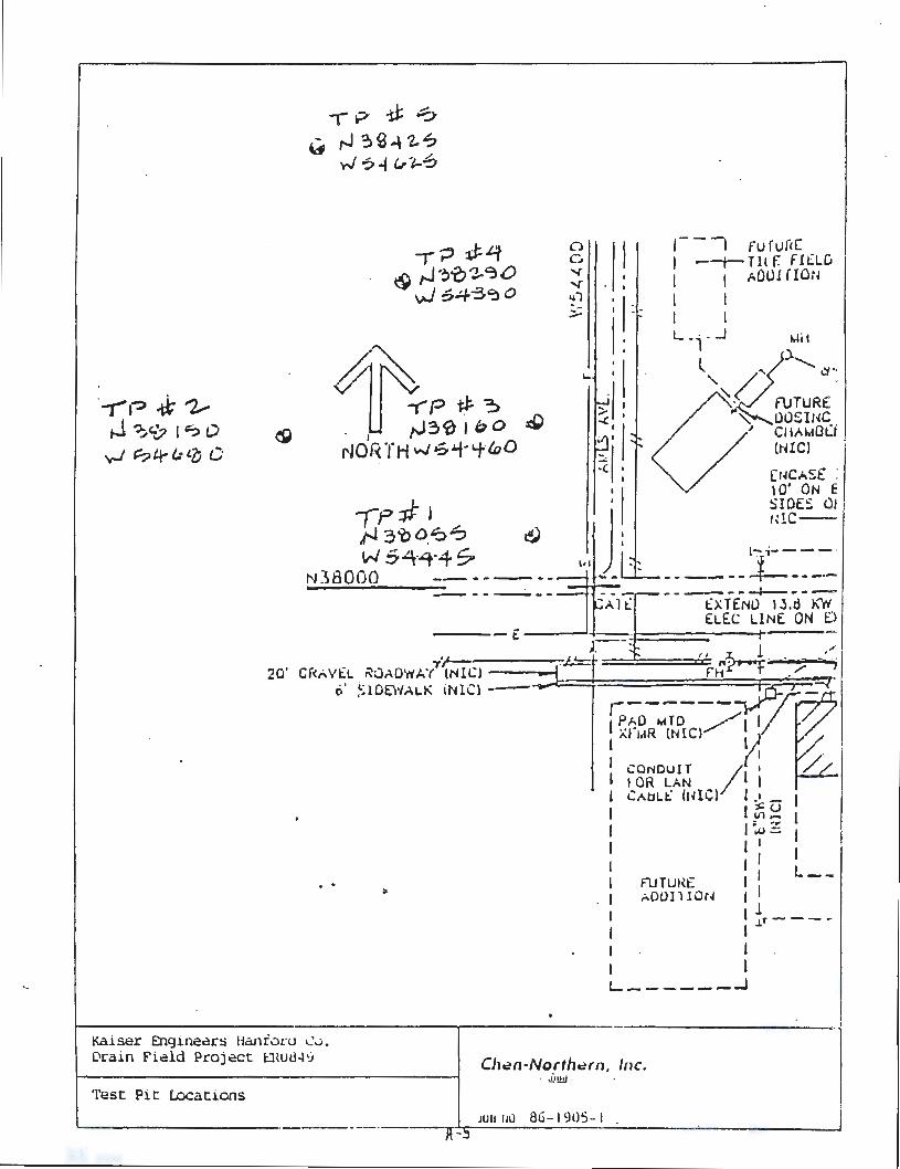
On July 19, 1990, a soils investigation consisting of four test pits was
performed. Test pit locations were based on the proposed location of the
soil absorption beds. Kaiser Engineers Hanford Company (KEH)
construction forces performed the excavations with a backhoe. Charles
S. Mortimer, P.E., KEH, and Ken Lane, Chen-Northern, were present to
witness the excavation, log the test pits , and obtain samples for further
laboratory analysis.
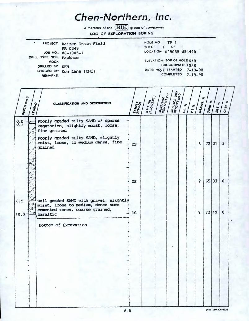
The deepest pit reached a depth of 12.5 ft . Sieve and hydrometer
analyses were performed on each sample to determine a United States
Department of Agricultu·re (USDA) classification of from sand to sandy
loam. Sand components were primarily medium to fine grained. Detailed
descriptions of these soils are contained in appendix A .
Additional test pits dug October 18~ 1991 , indicated a fine t o very fine
sand soil at the approximate trench bottom level.
Based on the above data, the absorption rate was set at 0.6 gal/day/ft2.
Ill . DESIGN CRITERIA
A. SCOPE
Personnel loads for each of the existing buildings were furnished by WHC.
These figures were converted to daily flows based on Environmental
Protection Agency (EPA) published figures. The septic tank was sized to
serve only existing facilities in accordance with the direction from WHC.
The soil absorption system was then sized to accommodate the maximum
daily flow of 14,297 gal as directed by the Functional Design Criteria
(FDC) .
L092WSER.TD.2404 - 4 - 02/92
The existing collection system is 8-in. PVC pipe with manholes
appropriately spaced.
B. DRAIN FIELD
Soil samples taken at the proposed drain field sites yielded a
0 .6 gal/day/ft2 loading rate. _ The disposal system consists of three
individual drain fields, each having a capacity of 50% of the maximum
daily flow (14,297 gal). A reserve area of 50% of the maximum daily flow
is also provided adjacent to the drain field site. This reserve area will not
be constructed at this time.
Based on the soils· classification, a bed-type drain field was chosen for
ease of construction and a smaller total land area occupied. A
dual-manifold design was selected utilizing eight long narrow beds in each
50% field. Each manifold serves 1 /2 a 50% field. A lateral spacing of
3-1 /2 ft . with an orifice spacing of 3-1 /2 ft was chosen. The lateral
diameter and manifold diameter was chosen utilizing PC based "MathCAD"
t o analyze the various options for size. Likewise, the orifice diameter was
also analyzed. Based on the analysis, a 6-in . manifold, 1-in. laterals and
3/16-in. orifices were chosen. Orifices are oriented in the 12 o'clock
position except for the first , middle, and last orifices of each lateral which
are inverted to the 6 o'clock position for lateral drainage.
A 1-ft layer of washed drain rock, 3/4- to 1 ½-in., will be placed with the
distribution pipes centered within the drain rock. Geotextile fabric will be
installed on top of the drain rock to minimize infiltration of native backfill
into the soil absorption bed. Four-inch PVC monitor ports will be installed
near the ends of three beds in each 50% field . The monitor ports are to
be perforated within the drain rock and capped with a threaded cap at the
top.
With a minimum residual head at the orifices of 2-1 /2 ft, the system flow
will be approximately 830 gal/min. A theoretical difference in orifice
L092WSER.TD.2404 - 5 - 02/92
discharge of 8% will exist within each 50% field. Supporting calculations
are attached in appendix C.
A dose frequency of 4/day was selected using both the soil type and the
dosage/pipe volume ratio . The resultant dose volume is 3 ,527 gal/cycle.
A timer will be used to deliver a dose every 6 hrs for 4.25 minutes,
provided an adequate volume of effluent has reached the dose chamber.
A system of switches will prevent the timer from starting without
adequate effluent for a full dose and will also bypass the t imer and start
the pumps should the timer fail.
C. SEPTIC TANK AND DOSING CHAMBER
All domestic sewage generated by the currently served buildings is
collected in an existing collection system. The collection system will be
redirected into a new 6,000-gal septic tank. The existing 10,000-gal
sept ic tank will be modified for use as the dosing chamber in conjunction
w ith a new, adjacent 2,500-gal pump chamber.
The dosing chamber provides a reserve capacity of 7,064 gal or 49% of
the maximum daily flow. Three dose cycles can be missed without
activating the alarm. Duplex pumps discharge to the drain field through
dual 8-in. force mains and a valve vault to direct flow t o any of the drain
fields.
IV. QUALITY ASSURANCE/QUALITY CONTROL
Project L-092 will be constructed under the construction management of KEH.
Quality Services procedures will be utilized for the duration of the construction
phase. Procedures applicable to this project include:
• •
OS 7.0
OS 7.4
L092WSER.TD.2404
"Quality Control Receiving Inspection"
"Construction Management Quality Engineering"
- 6 - 02/92
V.
• OS 9.0 "Quality Services Planning"
• OS 10.3 "Open Item Reporting"
• OS 10.4 "Project Punchlist"
• OS 10.12 "Concrete Inspection"
• OS 10.13 "Earthwork Inspection"
• OS 10.16 "Official Acceptance of Construction"
• OS 10.17 "Inspection Reporting"
• OS 11.0 "Leak/Pressure Test Inspection"
• OS 17.0 "OS Records and Documentation
OPERATION AND MAINTENANCE
The operating contractor has a maintenance program in 'place to inspect septic
tanks on an annual basis and pump and/or clean as prescribed in the preventive
maintenance procedure. Proposed additions to that procedure for inspecting the
soil absorption beds and dosing and resting the beds are included as appendix D.
VI . REQUEST FOR WAIVER
The absorption field design features three 50% fields , each consisting of eight
seepage beds, 10 ft wide. The soils in the proposed absorption bed area are
predominantly Type 2 and 3, with some Type 4. The "198 7 Design Guidance
for Larger On-Site Systems" allows seepage beds only in soil Types 1 and 2.
However, the Site has very dry and loose soils in some places, which could allow
significant migrations of fines into the drain field rock during construction of a
trench system.
A waiver is requested to allow the use of the 10-ft seepage beds. This request
is made under the provisions of Washington Administrative Code (WAC)
WAC 246-272-210.
L092WSER .TD.2404 - 7 - 02/9 2
VII. REFERENCES
In addition to the references listed in the calculations, the following documents
are hereby incorporated:
• WAC 173-240-070, "Submission of Plans and Reports for Construction of
Wastewater Facilities, Plans and Specifications."
., DOE 5440.1 C, "National Environmental Policy Act."
• 42 U.S.C. 4321 et seq., "National Environmental Policy Act."
VIII. OWNERSHIP
Owner: U.S. Department of Energy
Richland Field Office
P. 0 . Box 550
Richland , WA 99352
Attn: S. D. Stites
Telephone: (509) 376-8566
Design Engineer: Kaiser Engineers Hanford Company
P. 0 . Box 888
L092WSER.TD.2404
Richland , WA 99352
Attn: Charles S. Mortimer, P.E.
Telephone: (509) 376-7228
- 8 - 02/92
I
A-0
REPORT OF
DRAIN FIELD SOILS EVALUATION
TO KAISER ENGINEERS HANFORD, CO
RICHLAND, WASHINGTON
DRAIN FIELD PROJECT ER 08~9 HANFORD FEDERA~ RESERVATION
PROJECT NO. 8~-1905-l
PREPARED BY
CHEN-NORTHERN, INC . CONSULTING GEOTECHNICAL ENGINEERS
PASCO, WASHINGTON
. .
AUGUST 1990
A- 1
Chen ~Nor1hem. Inc.
.•
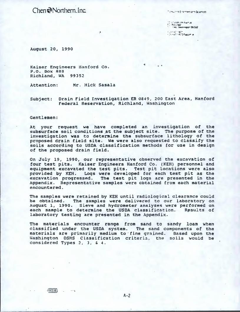
August 20, 1990
Kaiser Engineers Hanford Co. P.O. Box 880 Richland, WA 99J52
Attention: Mr. Mick Sasala
. .
: : · .;. • 1r. 11n .; :n ~1e"'·.e = - ~._.. : s,)· ·. , •-s : ,.1VM'Q14'f": '}~3VZ
.. ! ~ l ; . ,; ~ •
. > -a~ •.;.-J~.w;i.- ~
Subject: Drain Field Investigation ER 0849, 200 East Area, Hanford Federal Reservation, Richland, Washington
Gentlemen:
At your request we have completed an investigation of the subsurface soil conditions ~t the subject site . The purpose of the investigation was to determine the subsurface lithology of the proposed drain field site. We were also requested to classify the soils according to USDA classification methods for use in design of the proposed drain field.
On July 19, 1990, our representative observed the excavation of four test pits. Kaiser Engineers Hanford Co. (KEH) personnel and equipment excavated the test pits. Test pit locations were also provided by KEH. Logs were developed for each test pit as the excavation progressP.d. The test pit logs are presented in the Append i x . Representative samples were obtained from each material encountered .
The samples were retained by KEH until radiological clearance could be obtained. The samples were delivered to our laboratory on August 1, 1990. Sieve and hydrometer analyses were performed on each sample to determine the USDA class i ficat i on . R~sults of laboratory testing are presented in the Appendix.
The materials encounter range from sand to sandy loam when classified under the USDA system. The sand components of the materials are primarily medium to · fine grained. Based upon the Washington DSHS Classification criteria, the soils would be considered Types 2, J, & 4.
-IHIHj .. l
1\ - 2
Kaiser Engineers Hanford Co Richland, Washingcon August 20, 1990 Page 2
We appreciate the opporcunity to work wi th you on thi~ projecc . If you have any qu~~cion~ or need addiciondl inrormacion, please contact us at your convenience.
DJB/mbr
. .
Chen~Northern. Inc. :· • - , -.. ; c. ··•_f. ,:-.:•\ ..1 ••I :. ... ,:•:; ~ ;.
A- 3

. .
APPENDIX
A- 4
·-i-,~ -tt" ~ .J ~<b I'? t)
~ 0tr(..-'o C
,-p -u: '? (f ,-.J ?l 9 4 2. -:,
._.J? • "1-~
1.P=tf l fl 3'0D.~'? t4) w 54·-'t·4 So
N38000 --------
,- - 7 ru rurcc I --t-Tllf. F!LLC I I ;..0U1 f IO;i
I I I I L _i _ _J I.lit
l / .... )')............, .:J •·
"-~{/ f\JTUR£ .
'\.."""-ll0£INC
/
~ CiiAl.~Ot:i . (tHCl
(r~C;.S£ : 10' ON E 5IOE~ 01 ,~!C-
,-;--- - · ---- --~ -----------~---
t::x T ErW 1 J.d 'r\r/ EL£C LINE ON D
---- C: ----'-1 r---. " :x,___ 1 ."' 20' Cf<AV£L K8AOW.:;?'1(N!C) -----4-i.=t- Ft-ii",..........f° ·.;: -, j
..
o' :,:10E\•IALK (NlC) -- :o::z:-::-4 ~iR~:V;--71;( I ~ 1
1 cormurr /t : tOR LAN I
I CAtJLt:: (IHC) I .I ._ I I I~~ I I ·i.0 = I I I I I I I I I I FUTUl~E I I L- -1 A00l 110,~ f I
I ±r- -- -I I I
L------..J
Kaiser Engineers Hanion.i (\.l.
Ocain Field Project EH.Ut3-l ':i Ch~n -North~rn . J11c • . il!.!!J .
Test Pit Locations
JUII JIU 86-1905-1 .
PROJECT
JOB NO.:
DAILL TYPE: SOIL
ROCK
OAILLEO BY·
LOGGED BY:
REMARKS.
Chen-Northern, Inc. A member ol ltle [HIHJ group of comoan,es
LOG OF EXPLORATION BORING
Kaiser Dr:u.n Field HOLE NO TP 1
rn 0849 86-1905-1 Bac.'choe
KEH Ken Urie (CNI)
SH~ET OF 1 LOCATION ~08055 W54445
ELEVATION: TOP OF HOLE N/R GnOUNOWA TER N/R
0ATE: HqLe STARTED 7-19-90 COMPLETED 7-19-90
l l
CU.SSIF1C.\TION ANO OESCAIPT10N
.., Q
8:9
8.5
10.0
Pcorly graded silty SAND w/ sparse vegetation, slightly roist, loose, fine grained
Pcorly graded silty SAND, slightly roist, loose, to medium dense, fine grained
Well graded SAND with gravel, slight!~ ( o." ..... . rroist , l oose to medium, dense sane
OS
OS
_:_a_.·. cesrented zones, coarse grained, · · •
0 basaltic OS
~ 1 I 1
Botton of Excavation
1' -6
5 72 21 2
2 65 33 0
9 72 19 0
Chen-Northern, ·Inc. A 1110:moc:r Ill llld [IIIH] gr~up 01 co111p,u111,:;
LOG Of EXPLORATION BORING
=-...: .... f "' Q
a.a 0.2
PROJECT:
JOB NO.:
DRILL TYPE: SOIL
ROCK
DRILLED av: LOGGED BY:
REMARKS:
Kaiser Dr31n Field ER0849
86-1905-1 Backiu:l<:
KEH K«::ll lane ( OH l
CLASSlflCA TION ANO OESCAIPTION
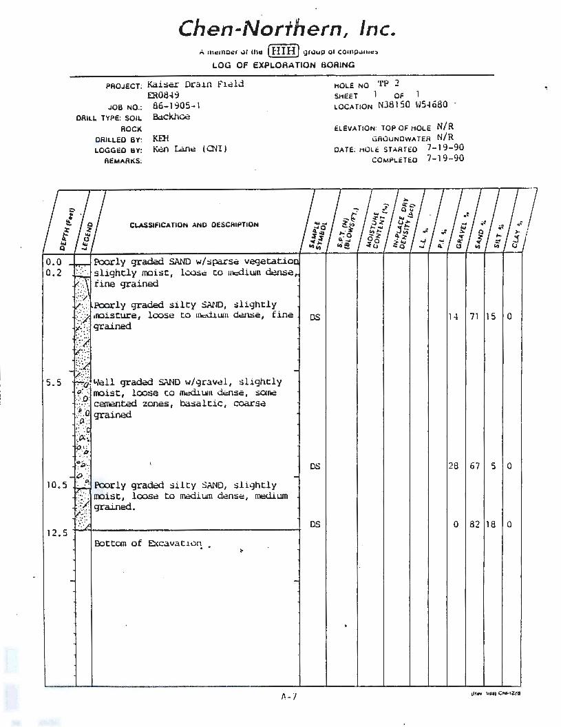
Poorly gradoo SAND w/spa.rsc vegetatio
..... .. ...
slightly moist, loose: to ucdium ~l:ie fine grained
Poorly graded silty SAND, slightly loose to nlc:dium d~e, fine
5.5 /}"lell gradoo SAND w/gra.vcl, slightly {~; moist, loose to m.:dillln . dcl1Sc, sOI~ -:: .- _-. cewentoo zones, basaltic, coarse: } ."o grained .:'1 .; : •.·'
OS
HOLE NO •rp 2 SHEET 1 OF 1 LOCATION NJ81 50 W54 680
ELEVATION TOP OF HOLE N/R GRuuNDWA TEA N/R
DATE; HOLi: STARTED 7-19-90 COMPLETED 7-19- 90
-;;-•' ·• ....... ~-- •'
.:)~ ... ..... ~ "' .. .. -~ ~ Oo -- ~ ~(.j Q,. Cl
1 -t
Q ~ • II)
71 15 0
DS 28 67 5 0 i:) .
10. 5 :",t>: Poorly graded silty SAND, slightly / :: moist, loosi: to mcdiU1n dense: , 1nt=dium ./( grained.
12.5
:,-.- ::·· • •'· •. ·
BottOln of Excavation
DS 0 82 18 0
.. •' ~
a
A- 7 1lln ~••tCNHUli
0.0 0.2
6.5
11 . 0
Chen-Northern, Inc. A member of the [HIH] group of compan,es
LOG OF EXPLORATION BORING
PROJECT Kaiser Dr,un Fi.eld rn.0849
JOB NO . 86-1 905-1
HOLE NO TP •I SHEET or LOCMIOM MJ0290 W 54590
DAILL TYPE: SOIL Backhoe ELE'IA TION· TOP OF HOLE N/R
.. ·.
..
.. ..
. . , .. . .
.a·" 0
·--o ,I . .
. o · O ·
•· po •o
j I
j
ROCK
DRILLED BY· KEl-1 LOGGED BY: Ken Lane (Oil)
REMARKS:
CLASSIF1CATION ANO DESCRIPTION
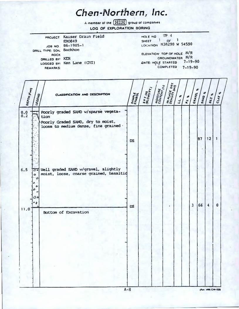
Poorly graded SAND w/sparse veqeta-tion Poorly Graded St\ND, dry to roist, loose to medium dense, fine grained ·
\"Jell graded SAND w/gravel, slightly
OS
rroist, loose , coarse grained, basalti
OS
Botton of E::<cavation
A- 8
GROUNDWATER N/R ,OATE: HOLE STARTED 7-19-90 . .
COMPLETED 7-19-90
87
J 66
12
4 0
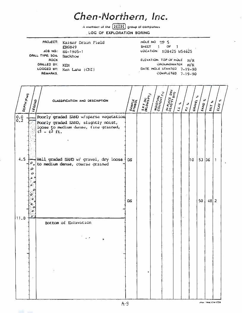
a.a 0.2
PROJECT:
JOB NO.:
Chen-Northern, Inc. A 111,w1uc:1 Ill rnc (HI H) g,uup ol compan11::>
LOG OF EXPLORATION BORING
Kaiser Dra1n Fi~ld ffi0849
HOLE NO
SHEET
LOCATION.
'l'P 5 OF 1
136-1905-1 tl38425 \·/54625 OAILL TYPE; SOIL Backhui::
· . .. • ·. •· -
ROCK
OAILLEO BY; KEH LOGGEO BY: K~ L.lfl~ ( O'II )
REMARKS:
CLASSIFICATION ANO OESCHIPTION
Poorly· graded SAND \·J/ sparse: v,::gatatio Poorly gradi=d SAND, slightly moist, loose to nlt::Ciium d.:11:..:, i HI~ '-Jr .:1inc::d, 41 - 4j ft.
ELEVA11ON TOP uf HULE N/R ~HOuNOWATEH N/R
CATE. HOLE STAHTED 7-19-90 COMPLflED 7-19-90
4. 5 Well. graded SAND w/ gr~wel , dry loose OS 10 53 36 9 .. to medium dense, coors~ grained ,o .o
. o\
. .. ~ :o-: · . .. : :: o.: .;o.:··.:o \ o.'•• .. . ~ ..
OS
;o··· 11 .0 -t-....... ------------------1
Bottom of Excava ci cn
. .
1\-9
50 48 2
. Jo, tlw,,, ; l11c. :~ •!!J
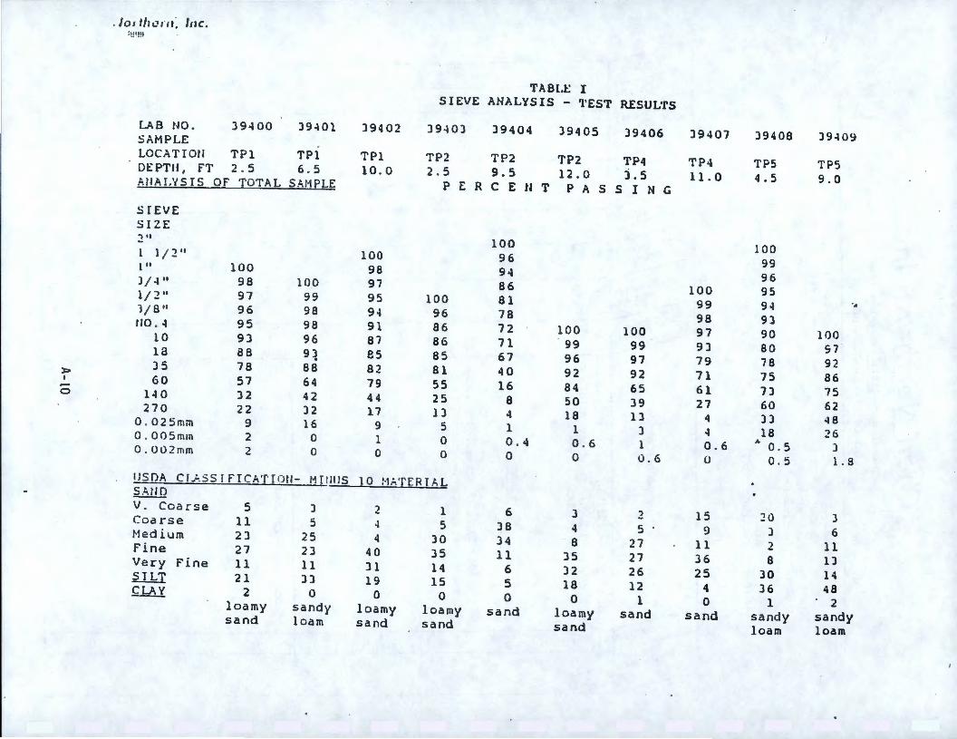
TABI.I:: I SIEVE ANALYSIS - 'l'EST RESUL'rs
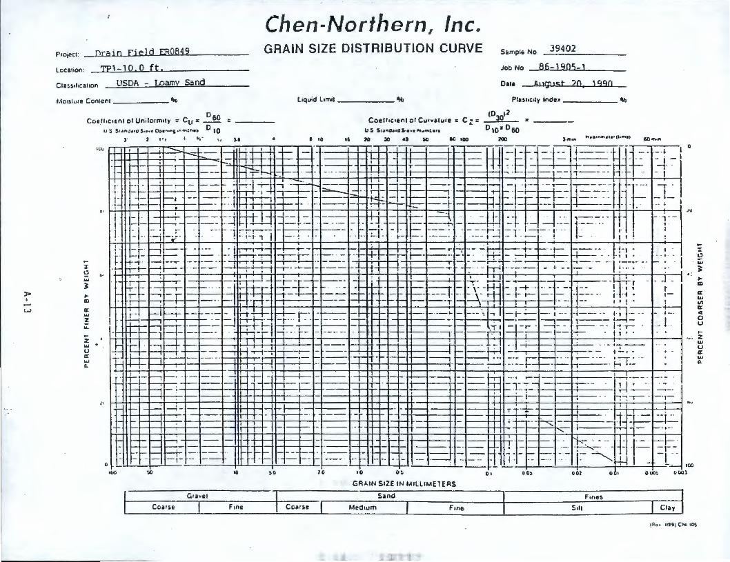
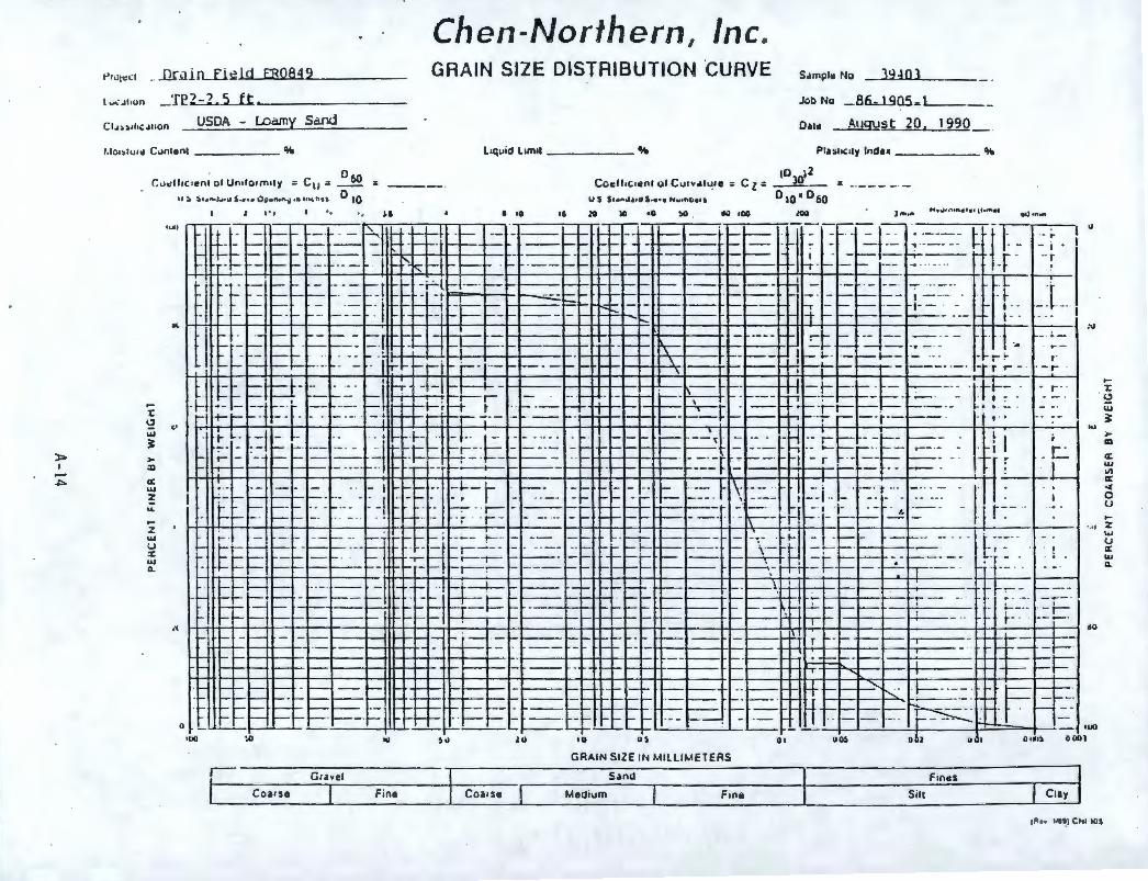
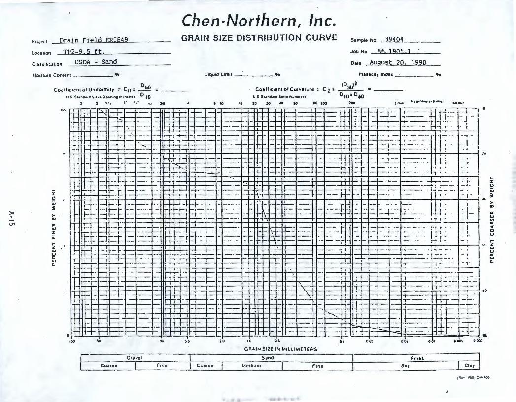
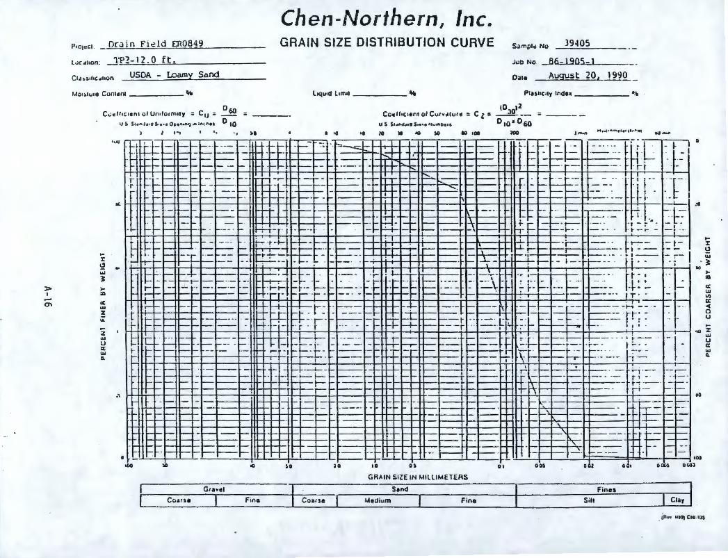
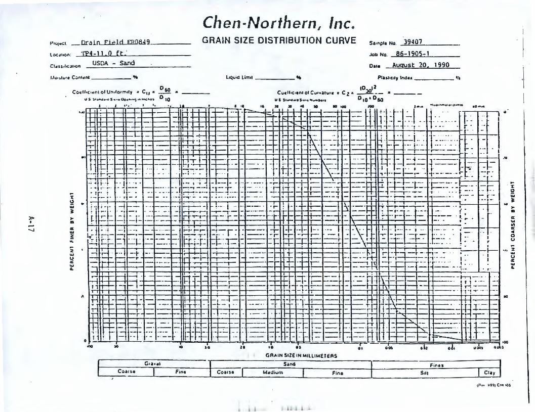
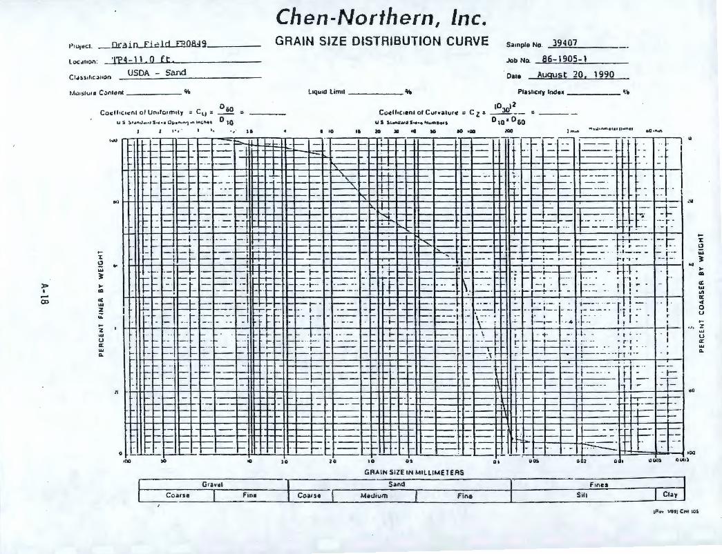
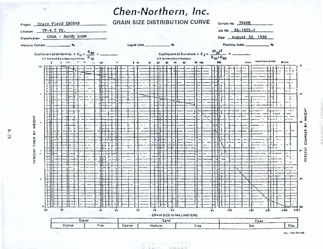
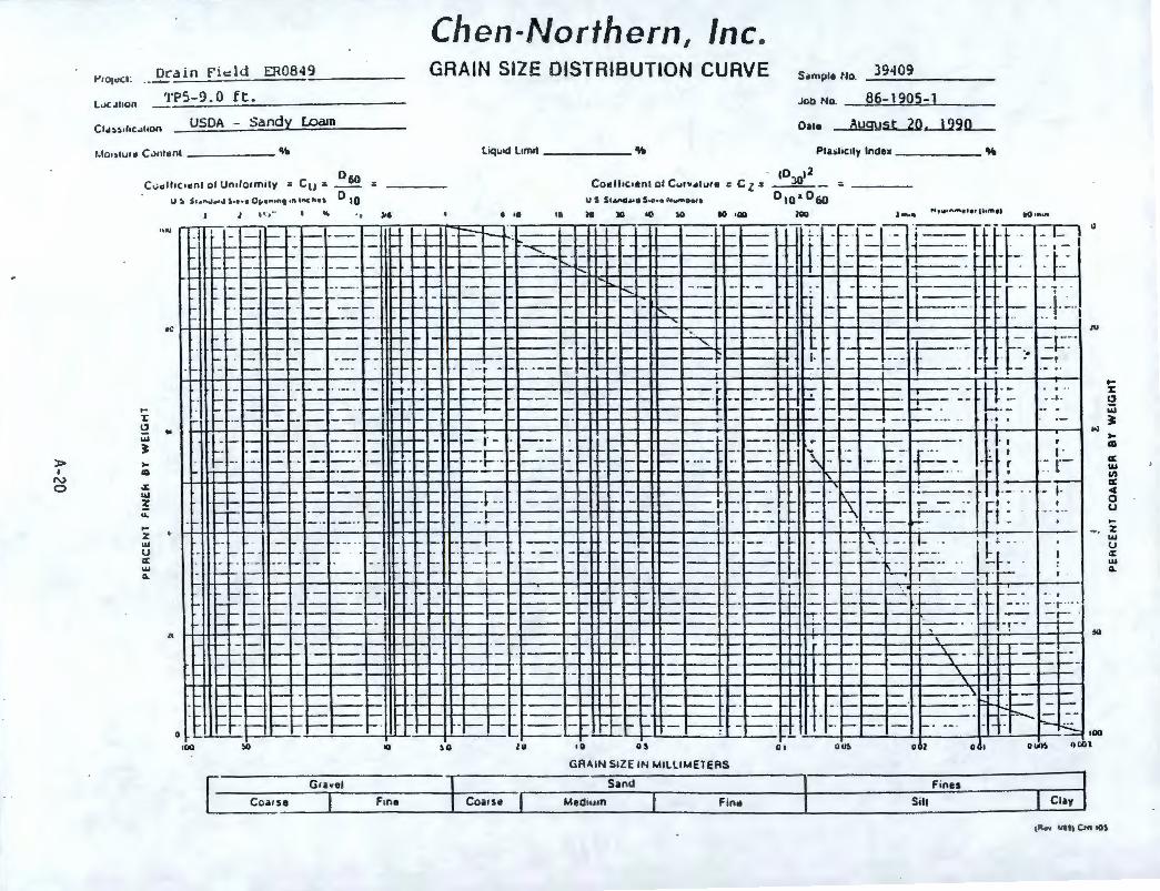
LAB NO . )9400 )9401 )9402 )940) )9404 )9405 )9406 )9407 )9408 )9-lO<J SAMPLE LOCATIOll TPl TPl TPl TP2 TP2 TP2 TP4 TP4 TP5 TPS DEPTH, fT 2 . 5 6 . 5 10 . 0 2 . 5 9.5 12.0 3.5 11. 0 4.5 9.0 AtlAI.YSJS OF TOTAL SbMPLE P E R C E U T P A S S I N G
SIEVE SIZE • ti
100 100 l l / 2" 100 96 99 1 II 100 98 94 96 3/-l" 98 100 97 86 100 95 l / 2 11 97 99 95 100 81 99 94 -. l/ 8 11 96 98 94 96 78 98 9) 110 . 4 95 98 91 86 72 100 100 97 90 100 10 9) 96 87 86 71 99 99 9) 80 57 18 88 91 es 85 67 96 97 79 78 92 )5 78 88 82 81 40 92 92 71 75 86 )>
57 64 79 55 16 65 61 7) 75 I 60
84 .-
25 62
0 14 0 )2 42 44 8 50 )9 27 60 270 22 )2 17 l) 4 18 13 4 )) 48 0 . 025mm 9 16 9 5 l l ) 4 18 26 0 . 005mm 2 0 1 0 0 . 4 0 . 6 l 0 . 6 ,. 0. 5 ) 0.002mm 2 0 0 0 0 0 0 . 6 0 0.5 l . 3
IJSOA Cf.J..SS I FICAT TOtl- MT tll JS 1 O :-1.;TER I b L ~ V. Coarse 5 ) 2 l 6 ) 2 15 20 ) Coarse 11 5 4 5 )8 4 5 9 ) 6 Medium 2) 25 4 )0 )4 8 27 11 2 11 fine 27 2) 40 )5 11 )5 27 )6 8 1) Very fine 11 11 )1 14 6 )2 26 25 )0 14 SILT 21 )) 19 15 5 18 12 4 )6 48 CLAY 2 0 0 0 0 0 l 0 1 2 loamy sandy loamy loamy sand loamy sand sand sandy sandy sand loam sand sand sand loam loam
> I -
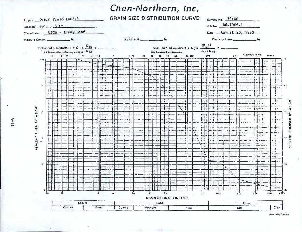
Chen-Northern, Inc. Pro1ecl. Drain Field ER0849 GRAIN SIZE DISTRIBUTION CURVE Sample No. .....:.3..:a.9....:4--=0--=0 ___ _
Loca1ton: TP] - :2,5 Ft. Job No
Oare
86-1905-1
Cla~silica1ton USDA - l.Damy Sand August 20, 1990
l.401s1u,e Con1en1 _______ ~ Liquid Limit % PIUliCily Index ______ %
Ccelf,c,enl of Uniformtly = C 11 = US St.Jna~," S•c•t 0"•"•"9 •ti •ncP\e1
D50
o,o = Coell,c,enl o f Curva ture
I.JS S••no,,o S•t•e N..,1ne>e11
: Cz = 1D3012 = D10• 060
•~V
l: c; • ..., l • Cl
C: ..., z ... ... 2 ..., u C: w r..
1·
l 2 • • , 1 . , • • ,. ),I ! If) ,, :,0 lO •O ~ 10 100 200 l ""'"
-I
+ i ---1----t+---4~-=---= - t-t~ --- -= -: =----~-+:7 .... 1---t-1---..,.--t --+.::::==+-,_•---H ,,·i, -... ~-:~I--~1-= l Jl~---,.- - -- ·- - H ..;_1_ - - - . :::.-::- ___ - ._ -+'-+-•-----•----1---•---............ ~-• • ......._ ; I
l ,. ·· 1
H r--!
... .. t
1, I , ........
~ --1 <-l
------·--~
-
,_ ,_
,_
- !
! -r ~ --··-,- - - -- ---.. - ,-· -
. j !..;- - - - -- -- - - - ::-~I+-,_ • • I- L __ , - - -- ~-; --1 ·- - · - -- ~--~---- 1- -h----1~-: -· - ---~--- - - - - - -~r:------t---j--- 17- 1----4-- ---- -- 7 · - j . , ___ - -----1-f--:- -• r-:·•-· · --- - -'-1 i- r - -1- - ---- ·· - - ·· - . u-~~- ,_ - - --- --+--+•-i- -1-- - __ J -•---+--, - -- t--+--+-- •-------- . -
1 • , • • ·1 , . 1
I -- - . . - ; I _; • . -- . ., -t -' t+-r i ,-::1- -,-,--+- ~ 7" i---_ ·1 ~_r 1-r,_ - --·•-- --~ -- ->-'-
; I I --:-, I · •· 1,......---..,-,---,--- --- .. -·•- - -,- ·--. 1-; -:- . . - . . . . . . - - .,!_ - -~ --.; -;-.J_ -
=-·! ---~ ~-:~ =i· =--11 :.= ~--=-..:~=--~ -~. ---1-j-· · ·· -1 ·-· -- - ·- . ·1-1 .
H---+--1f---tt-..--t---t----t--,-i--.----+1--1f---'--+-+---t--t--t--;-;,---i---:-1---·t--1---~--r1-----i--..-
~ -- --- --1~"7'...L __ _J _ _ __ -t· ··--rt,- 'Tl!-=-+--- h+· -l- . -·• . .. r+-- ·-
t: -- ---t- -
-_,___ ->--
------
-_-_ = =- =·--... ·i.·~-·---...+---+--_1-- +--+--+---<'-,-•--•--,~-- -~-:- : : -q-~ - ~=- -. . t"-==-~.::i~..:_: __ I-•!-·-- ·--- ·!' _,__r::: ~.=.-= ~-, , ' ~-,· - In-·•· - - -• •• ·-r,---- 1,--• ,- -i---
t , __ ,_
-,.-,- -·-~t-
I
I- I I _! \ _ _ . ;..._ I
: ~~ :-: · '. ;:f- . ··--=- + 1= ,. I .. ; . -,- - --.--. · ·-· · - -· - ·· -t- - · 11 • I • --· I -~- --•---- · -- ·
,----· -I·•-· ·r . .. I l i l _,_
-1----- --r- 1--t--H--i-"1--1
1- -- · __ .J -· - · .~ I -- t ·- -- , -.---- · f"i I
-r--· 1·!....:::..._ -- __ ,_ -- -t- -=.-_-_-·'1 = -~: .. · : 1J-· -:: :-t··_ ·:=- --- r -~~ ,·L!-: -
>-i-,- >- .. · - - • · - • --1--+--t-t-- --· - -· ~-- :-! I - ,- r- - - -t- · . I I . .
' I
4 -----n·----- +-4 t-'-_..;....'-+---H .. :~~-:.:_~_. _ _ -__ -_-_-_ -__ -- -r- --- t _ l i ! . ·: ,-;- ·- · -1- ·-- ·- ,, ---- · I - r- \1 1 1 ---r-,-r--1'-~-- ~•.
1 - --~ >-->- ++--r-1 -H--1---l -r--, , .. ~ - · - t~--+-- ,---- · ~-- ·
1+-+--1,---1~--•---+---,+~, --..-, -tt-,---rl-t----t---•--t-+-+-• --t-1 • ... ---1-- >-- -- ~,~ •--~ --;----•-.-,---- -r- -
f-t-,- - ---;-1----- - ---i---i - · -- 1~, -·, 1-i ----·-+-t-------::--·>---+-1---• ---<---- r7-~-t-- --r--i--- -r-, - ---.h, ---r --~-1- -- -~---- --- ·- -"--,-,--.
.,..., -- -I I
-·-1--
· t ··
.J .. I .. r . ·r-
- ·r ··
··-,- · - ,-- -
I~ T
+--- - - I t--.-t+-,-..-t--,-t--.---r--- ·--- --+-••--•----- 1 ---t++ ::_:-7• I -- T7 -:-- ___J -
-H..;--+--+-;+---,,-t----• ---+-++o-_...-+-...-...+-4--1---+--+-----t--4-+--+-+-+--+-~I I , • I r. °7" - ';- • . - ,-- -1- --+---+---H-.-....--+--1--. - - ·-1-1----+---,f-.H--4-~- - -t-- - t-•t----t--• ~ --i- '-.._-, -+---+--+----- · I . t---+--1
I I I '
,]_
,..__
_,_
-H-,-+--1---+ll---; -- - 1-- --- ,: - - --·- h----~-t=· ·r:ri __ := _--_ -·t ___ -_ --- - -f---1-.--H~ -,- - - I ". '- +--- I I =1:
·- ·--· I I
,__ I I - -
---·H--- -== - H- - -- - .. ~ ....... •-----• r- - - - • --- >---••-'+-+---11--++--+--- I~ .:::-_• ::-
-----;-~ 1 , __ - · ·· .,.,~-- -1 I··-- --- ----·- ·---=-J--H ·r · - ----t---- ---- ~-,.-.:... --· - ·
- --~lo--
-
I,
...
~ I -• -· - -1- ·- --- ~ -- ·-- -1-- --- ---~ l- - - ~ -t - - ----~ ........... _ __; __ .......;......__.,_ __ i r-- I I ·i- ·~
·-=---+-''--'--"-!-----+-'-~--+-- 11).J ,w IC 2U IU 0 I 0 1 0 I uwl
GRAIN SIZE IN MILLIMElERS
Gravel Sand F,nes
Coarse Fane Coars e Med,um Fme Clay
... :c !:2 :.u ~ • ID
a: w VI CZ: c(
0 u ... -..., u C: w ll.
)> I
N
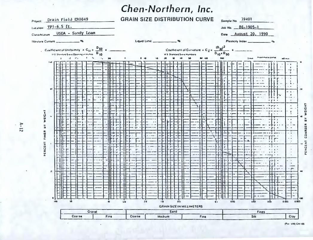
l uCJIIOn :
Drain Fi~lJ ER08 49
_TI>l-6 . 5 ft.
USDA - Sandy Lo&n
Chen-Northern, Inc. GRAIN SIZE DISTRIBUTION CURVE Sarnpld No.
Job No.
)9401
86-1905-1
Oare August 20 , 1990
'-lo1>lur11 Cunl11n1 ________ % l 1qu1d l im11 _ ______ "- Pl. ~11c11 y lnde• _______ ~~
Cucll1c1cnl ol Un1lo1m1ly " C 11 = IJ S :i-1 .t•uJ ., , li,J S •• • • Ope n,n~ ,n 10 1. f'l • I
0 60 = o ,o
,0)012 __ Cocll,c,~n l ol C u,~a rure : C z. = =
U j 5••n~••G 5•••• NwmD011 Q IQ a Q 60
t ~ ... ~ .. ::i
CZ: ... : ... :: "' u a: w :i.
, .. '• ., )It I 10 •• lO IO lm•11 t t,fil•n.ffloele11hffl • I .0 ,n,n
"'° -' I '"" 1 '"" 1 ~ __ .. ....__- • .. _-• _- = --=t ~-~ ~ - -
--- ---h-- ---- --· !..---=,-:-~·-·-·rtr·-,, -, " ,- · >--t--+lf-t--- --....._ ~ - ~ f- - - - t--t-- -t- - -- r t- - r - . --- . t- ' Hhl-_-+,_...., .... _-+,__--l ... _- :: _-_ ... _a._-_-1:~::. ·•~·-t-,:...-t-,,- -,.._-::.::::::~';1;::_.,-__ -+-• -, .... , .. -1--•-- r- · r-~: = - h . F . ·-r
- - ~ -- ~-- --~-- -i--~- 1----- - - - • t<>-+-t-o-- - -I'"--- -
-: '.::. = : ---= =: ~: ~: - .. -~~~---•-... =- ...... -:::::·--:· ...... -~ .. ·: ..... , .. · f_· _: - I • I: = ~: . r ' ... ~. ,r -· - ~ ,..._ - - - ..... ,... ___ - ~ ~ - ~ I- ~ ,___ ·r -1--+--•-f=
o<: H-+IH--+-+--++-+--+-+--+--+H--t-+-+--H-if--+--t--t--- -t-+-t-irl-+-t-++ ...... ,-+--+l-+--H-+lf-+-t--+-+-+--+-----++--1-+---1----1 ...... - ·- - - - - rr--+--+-t--- ,____ -- L. ..... I ....
"
0
t- ~t- .,.__ _ i,--_ - - - 1--- - ~ 1---- ~
_.,...__ -- --- ..... 1--+--1- - - - - ~ ~- -~ - ~ ~ ~ i--- ~- - I -.·
,- • . , .. >-• -1-,t-• >--t--r--r-i-- · - - -· ~~- - - 1-- - ,._. ~-- ~ - - -~- :-- t ' - t- - j- -.~ - . • ·- - - - - - ,__ ~ ·- -- -r . r - I--· -_-,.r __ --+-+-----.. • .. r_• ___ .,__.._-j
l ~-f - t"""-r- - '.. . . ~1 -I- - t-- -1-t---- t---,h•-+-+-11-+-· t - ~ r ~ 7"" -t- --.- -~- . • -r, · . ·1 ~ -~ ~ _.,.___.,_ ._ -t---- · - - -1--1--t-"1-'~-- - -~-r -1---1-- - ·-.·1---r---- - ---•r . -. -+- . · - •·t· --~ - - ;-~-t- -f-~- ·--- -1--,1-r--+-t-+-+ll--t----+-t-- ,,__ i-- _ -,--. - -• · · - t"--- ··
• I
- , 1-~ - ·t- - I •• • - - - +-- t ~- t-· · - - - - 1-..... -l-l--•--• - --- - -- -i-- - ~ -- ,.._ I
-1- --i-- -:- _ ,___ -~ -'-r-· +: :-- · , - 1 - -r·I- -~ - -- · · · t- - - ·I - t-· t - - t· -· - -. ... T-n,r- - --- -- rr r -· -i- ·r- -
- i- ~ ~~ t -- - --I'-- -- 1-- - -~ -
- - ·r· ...:..,_,___ ~-- -~ r:·r-·---· - -- - -- - - . .. -i,,.--- - - • - ' - ~ i. . ... -- .. - - f-
- -- - -t--..-,--,,i-.• ---r- - --• --+---
-- · I
I ,
. r: .
I I I
I
;- ... ..... -4 - - l- - - -- - - H-l- ..... -·l-i- . >-- - -t-t-+-tt--t- >--- · ·--1- - ....... ' .. -+ .!._,- I-- - . t -- --- - .. ; .--·,-
'l L ' i t ' ·t - 1
-:-1 ·1
- 1
_I
-·-
w'": ~1 ~i:- -=::=: ~ ~::-f: =r ~-r----- -= = :iFF ~ - t =--="-~ -= -:-r-= -=E r-=--~~T.r,...: ·c - - , '· -__ · - - -~---_· ... ... ~~ ...... ~ .-...-1-·+:-t-t--_,,--_ ... _1 _ _ _ - __ --t----+--..... --t-1~,--11--t-,----+----·t--..... - __ -_l .. , .. ---•-..,..· -•-..... --1--..... --.... _ ..... --1 ... +-,--·_· _· ·--... • ... ::·_• _· --
,-- .--- r-- ·r • - - ·r- t- r - t--- - - -- - - - -- - r r · --- -,----,-. -,t,- - . - r · - -r r -- - -i=- r- 1--f---- r-- -- t-- __ .,___ ____ -- -t- -·
r: ..::.. ~ ::.:.· :.. -=- ~--=- = -~~ ..=J =+-~ ~ -::::._--= = ~, ~: -= --- ~ ~Ff ~~;: ~ ~ _t_:_·_-~ -~-- ---~r ........ --..--+-t---- ~-t-ic+-c+--t---t--1f-l---t----+t--t----+-......+ ~ ---· 1- - I -~ -1-- - - - - ·· ,.... -i.... ,_... - ,____ ~- -~~ - ---- r-t -
~ ~-~ = -= -_-~ .. --11,-1-- .:1 =-F I=: :=== -:-:. : .... =:: =------. ~ =----~- · ~ = =~ '--- L- - -- -Pr:.;:~ --- ~ i---- - - - - - - - - - -l , 1 - - ~t--•---..---,.."---+.., r
>----
,-. -- --1---t--!it--+--+--il - - - -- - ._ ·t--+-..._ '- H-----H- ..... -,--t-+-- t--·t - ,-. . -- - ~I- - - - •-• ---+---++-ll-- - ·+ ··· ~ - - ~ -1--+--- - H-+-+--•-t-+--+-• - - - H-+--•-+-
- - ~ . -1-+-++-+--l----t-+ .... --- - - -- 1-- · - ~~f-- -
- - ---~- - 1-- - ~..•--- - rr ----~--·-== ....... _-• ---;~~}:!;_,:~,::::::~~t~~--!-t--,-_-_•,__-~.~--- - -- - .,- ,-. ---- - - -- ,_ - - ,.__ - - >---- >-- .
~f-- - · -1-- -•- ,-. ,-. -- _ .... --- - -· -- ..... ..... ·- - -~ ~ . . -~--- ,-. ,-. ,-. - · - ... -i- - ,___ ,__ -- - ~ . - - --
"'
-- ,__ ~~ - . r--
- ~ - - -1---+- _._ ......... .... - - - --- -- -_,___ - - - - - · - ,- -->--- .___ : .__
.___ ~- >-~- - ·- ,__ .
~ - -- i. - =-- ,oo •00 ,u ~o lO 10 u 0 1 00~ 0 2 0 I O llu~ 0 001
GRA IN Srl.E IN MILLI METERS
Grhel Sand Fines
Coar se Fine Co a,se Medium Fine Sill Clay
... -x: ~ w ~ .. m CZ: w II)
a:
" a u
:: .., u .x w (1.
• -w
Projecl __Il[ain field ER0849
Chen-Northern, Inc. GRAIN SIZE DISTRIBUTION CURVE Sample No.
Joo No
39402
Locat ion: TP1 - 1 0, 0 ft, 86-1905-1 USDA - Loamy Sand Dill l-11gi1st 20, 1990
Mo,sture Con1en1 _______ ~ Liquid L1mil _______ 8Ai PliShCII)' Index _______ •1o
0 60 Cot_ll,c,e:nl ol Unilorm,1y = Cu= = U ::i S t.tntJ••O !.-~•I' O'-•".,"'i •r'l •nc"•• O 10
103012 Coell,c1en1 ol Cur~lllu•e : C z = -------- = ___ _
U 5 51•na••C 5,e,1 "wmte11 0 10 I O 60
.. I: 2 ... ~
• l:O
er ... z .... .. z ... u er ..., t.
,., .... .. :u I 10 16 10 lO •O tG 1110 100 ltn•" 60nun
l~v .......... I . : ~ --.;;::._- -= t:tm .:= - --=-~-+--I~'-~:'-·r- ,- _:--IE-~ -f:: J--· t ~-: . :- . ·=·t_ - I 0
. >-- - ri >-- ,-- -- - .__ , • T .....- . · -1---1---~f- ---- I-'- · ,__ -; - - I I ---- ~4-::--- ··-· - ···-------L--1>--H---l---,1+-l---+--o-1..; . - --,--,--- -- ,- ·- .. . I
,,
~-
.
,,
0
r 1· j-
. ,-I
I . I I ~1 ---- ----1--1--11 l I I ':::L=r==-=-==-_; 8~-4 ~~ -·----- - -~ =1= =-~ --·-; ~,-i=~-- j--:.:-__ · r _F ___ i -1-=t~, -- -----.. I I I I - ----= ·~"- - :-1- l-- --i l-r--1 - -r- 1--t .·· - · 7 -- -- . - ,_ H- • '-· - ·l rrn I + .. --- - '- . -"'-'- '- --t- -,--1- - ,-,- ---1-- -- . . . . •
l - =-LRc::±-=~- ~:tq±.l.:, ='=i=- -=.-~~:t+:J~==t= 17~ - !·. :_~f- -- ~ -~::. 4=~:- t I ! ~1- ::...; -l· ·_ ... - ·1 :;.:;,·1 - ·: . -~-:--: .t:-: ;:r - t·- r--~==-: . -.::·r-~ :-r. ~,~ . ! .. ,~ . . i I !
- ,--1 .
,u
!. -~H--- . ·-- · r . I +--1--+----'- l I --r...:.. ____ _: j._.J ___ -t-->--· ·i-- --- •- · L!-J 7 f . -f- >- 1-- - -- . - · t ~~ -i-t- .. '-· . - .. i ~- r-· - •· -'• -. . I--;...; - -·~:::::::::- ~y--- · · !· • I Cl t- +-+ · ~ --~ ·-- -- · · -,-.,..,-+-+-t ' .. --- I T --. - ---i--!-•-·;_- -,- -- ·· 1 •-. - . w
·'- -;-t-~~- · ----- --1~~--+---~--~----1- --1---,- I ~ .. ~· · ·-~ ----,·- - • ·--- ·- - , .. ~.- ;:: +-14-i---t-+......i"T""--,f---+---+-++,,-,--+--+--;+...--;--+-+----+--l--lf-"-..J...+--t--lf+--+--""'"°"i---J.-',.----1--,,._i---+---+-----1-..J...----;....;-----1'--....;.._..JI , ;
- - --1--- ,, I I -,-1----· -~ . I .• !.,.. ,-!J - I' ·m-· -1. I +· - ·---·· -111 , , -.-- - - - - • · - ·- '-.._ ___ - ---. - - · \• -H-1 - r-+- ·· · · - · ·j--- .. • ,. ..... , - -, - r -..J...---1--- Ir , ·- - -- -- · · - -·· - - · ·--- 1· - •· - ·, - r-H -- -,- i-- ..:_ _ -- • ,-
r- r-----: , ----~ - ~ -rf- 1 --- -- -- 1- ----T 1-~ • , , -- , • ~ • --~--1----4
r ·• ---1 ..... ,_ ... - ... --- - lh-l...+- rl-1-· ---- ---~ ____ ... _ ,1-t---· •··· -i--- · · til·-1 - H-1-r-, · - =.J t-,-h·-, -r-··· · -- - ·-·· -- '-- - ·i--·t---+--. -,-- ~- ,--- 1--,-
·'- ------ r=r-· ==--=- -~ m~~, + ·+- ~ -----· ~- -~ -- ~, =-~~ ~~- :..:. -r=- -_- I; ·:. - 4- -
! ; I I ! I I I I , __ ... _..~..J...--1---.....I!- Ll - - ~--ti! - -rt- I I ·- --- -- - --- ~ -~ ·----
- !_ -f-- , ---- · ---,- --,-;--.~-:------'-...... ~'---'- ~--- 1 ----- t!-,. -- ~--- --· - - .:T....J. ___ ,_ - --- ·-- -- -- 1.----, t-·t--- -- .. J='=-- -.. ·r--- • · - ·
~ I~~_: . ·- -- j :_ ~· -i _'_j_ ~ =-·-'--'---~ ,__ --, -., ~-- ~-,--=- I hi:~~-·::~.- -.· . -l- · ---- - _ ~--,--,- _._ _____ ~ . -'- t-i---_...i .... - 11 -,--~- -,--r- ,
---~ H - •-+--1----+--«+-+-+--1--+ --t--- - -- ·-- -1---1--..J...-1.1--1--- - --.....-..... - · --.- · - ---1-+---- ----' . '-- --- - ... ,__.._ I -1---.J-.....j...--l-+-+-+--l--l-i--l--~-+---1---+...;_-< • • .
........... __,._..,..__ I I I --+----l-~~ ............ 4- ·----1-+-+--r. ·t-- -H-- ·. 7:-,-. -·1-
r'_ ----, --,- ·- il - - ~- - - .. ,,-·+--'- '-- - I -~---- . 1· -t - --l· ..
~ -----1 ~-1----11---1-_-_-~"',~,--+----....... -~ ... ;---+--+--+- t-----~----1 ..... ..J...-11-- --- - 1---•l-+-I • -i- -- ~ ' - -,--- - · -'- . - -- - -- ,__ . -f- ....._ -I----.....--;- --'.-· --- - - - :-,-- -- - - --- - - ~- -·
I >-- >-- 1-- -~ -~ ~ ~ - --- ---1- ..
..;__.;._ __ c_-4-=_,.__,___;c_.i.;.._;_ _ _;__..L_-= =~ ;; =~ -= - =: T ~ ~ = :. -T~± I~ =L ,oo
10() !,() 10 H 10 10 01 0 02 0 I 000~ ~ [I())
GRAIN SIZE IN MILLIMEl ERS ~----------
Gravel Sand F,nes Coa rH F,ne Coa rse Medium Clay
~Oo l rtiJ C"'11 I~
• ~
C: w '1)
C: Cl 0 u .. z w u a: w Q.
> I
.:,.
t> ,0,., (1 _ ..nr .Ji n_f.i~ .... l d=-... rn"-'-"'o..,.8""'4,..._ _____ _
Chen -Northern , Inc" GRAIN SIZE DISTRIBUTION CURVE S .imp l11 No
l ,.i.: .1 toon _Te ~_s__tt .__ _________ _ Job No _86.J.905 .. L.._ __
Oa1o1 ~st 20, 1990 USDA - Loamy Sand
l.l0 1>lur d Conlan! ________ % Liquid L1m1I _______ ~ PlhhC1ly lndu ------- ~
...
1: ~ <' .., ~
• !II
a: .., z ... ... z .., u % .., ~
"
0
:: 1010'2 __
Co cll,c11Hll ol Curv,.,~,e :: C z: : u s s,-o.1. ,0 s .••• Nw, nOot1 D 10 I O 60
I" • I ,o I I 20 lO •O )0 . lkl ,oo IOO M) ,n ,n
: ~~- - >- - · >- - - ~.1 ... ,-,- -:·-:---:--:-t·~ . ·--- - I- !-r-
- -- -- - ~ - 1--1-- - - - -- ,, - - - - - J- -1- -=: ,_. --- - I .. _-1~....-11<;:"-.. .._--t+--+---+-- ~ · - _:- ;::- -- -,----- I -f" -- -- --- --~~=~- -- -- .._ ,--
- ---- - - - .._ - - --- -- --- ._ ..__ 1----- . >- --- ~i-- -~- --•- ._
·- .. - i .. f
H-+,.+1-1-+•-tt-+-t--1-_-_- _--1 .. _-
1tt1._-t._-1-_~i-1-. •l·•~-1-_-_- _+_--+-_•_---• .. ---_:-1---++--1+--• ~--11-_--1..-_• 1-.__---11-_-_ :::~H-_-1,_---_-+-1-... -,1--1-r-1---11-- _ __ . _ __ . l
~ - - · -· ~~ - -t r-,-;.::...:1-- I- 1-;.- --- ~ - . - - -r-- ~- '---- - · - ~
: '° - :=-: - --- -~-= -: i ._ - - ..:t= =-- - ---~ .. --• -,~-• :::--1t--.t-~- = _-- .. -- .. -----1--t-• ~ - -1----,---11-·--_ ~ - --- : ~ -. t-t----tf---H-+---+-+--f+-.._+--t--+--+--+------•-+-+-+---
~
_:[_ __
,-
....
-
-
r- -
~- --~-= r- ·
E'= ---
>-- - -
- - >--
- - -- - --r + ·_ - -- i,---- - ·. - --- - ~ -1-1--•--+---+-- - - • ,,_ -~ 14-+-1----11-1--+-- +-+----1- · -
- - -r- ~1---+11-- t----t--1--' == =- - ·----- 1-. -~ i--P-- .... .-+ - --+- -- -- f - ~- ·-i--J.-- - ~~ ---·· '" · - - 1+---,t -r-1·-- --,__ __ ,__
__ . ll -r - - -~ -
-~+--+-++-...;\.,_, - - - -'-j :--t-- - ---- ----·- · -p .... -- - I-~-· ~ . --· - ·1' ti=,-~ . I
-~ - r-- ' i---r-_ __ __ _ _ ---l-r -t t . -1--r- ·--¾- - -r-- ---~-ti---~----· ;__.. . ----- ·t --- f I
~ •-- +--+--•t• -t- ._ t · -- '"" r >-- -1 r-- - ·- · ------- - - - - -•--+--+t--- - - ·--.. - ~,--,I-·•· - - -t-- -- .
--- --~,--
-- . - : l: --- -- ---- - ··
._ -1-- -1·· ~ - - - · ·• •· --- - ---·d· - ·- · --i ·-,- ---- - -..... 1= ,__ - i-- · - - - · - ,--,---t - ___ . .., .. ,_ __ .. __ ·-- ·-I-- . r- ~ - • •- ~ - - • · -t-t--f--1--1+-•t-t-- · --•-r T ~-- 1-1-1 - r • . .. --1-- - - -
~~-~ - -,. i---~+--t---- ,,____ · - -t--H--lt-- - --t - ; I ·r--- - .. - _,.._. .
-r-~-~I-- .. .
•· -- - -~-r· - r
- · --- -- -~ .. - - ·--- I : _[ ~ -- r-- -
. , ·- ------I
-- -- -· - - ,-- - -·-- --- - - -- -~ - --t--- -,. •h- t- - i-- ; --- t- ·· -- t-- ,--- - . ----- -.- Fl I-,--r--- -- - - ~ ~r-~ r- - -- --
-- .... --,-- - i-- r--~ -~ -i-- ,._._ .
--- ------ -\ --l! =-~-- --.:_---r -t---- - - i---- - - -
-- ~__:...,- : - t- - _ _ _!_!°r __ _
.. ,. l ' ....
,-
t_;-~·. ~-r- -
~ . -- .
r· · -r
. r · .
c:. I
>-- - - r--- - ~.H0--t-t---11-+---t--11--+-,---- - - ~~ - ~-- ·· -- I -~r- - -• I --- --
I- - -~-~-~-~-~- r.--- - +--1---i-,---- .. -----t- . - r---~-
I - - ,-..-- 1-- - --- _,_..., ___ _
- .- t---++---1- -- ~- >---h--t--t---1--1-+---t~---i----1--• \-,.1 r - - ,_
-1H---t---11--1--1--- :::-_ -1-1--t--+-• - - -+----+-- • H-+-+-+-
,--..-~- . ---->---!-----if-+-• 1,--.. - ' !
-->------- - . - -----~ ,--. - - I--- - t--
I u I
.. 1
dO
- rt-+-tt--t-+-+--+--,~+++--i+-+-+-+-+---+-++Ht-+-+++--+---+-1---.f-+-+lh-+H--f'-...-+-+.....-----+-HH--+---i--l 1----- · i
_::-. · - -1--- - - - - -- - --t---i-- ·-- -- ----....
t-·t-- .. --+ r- - - ~ ~ - 1-- - - .. --+--•--- - --- - 1-- - - r- - ·-- ~-i.-- - -----~ ----~-· ~- ·- -I- - - - ~ - -- 1---- • I--- ~ ~ 1-- - - . !--- - ~
----- 1.,,... - - ~ - --...... - ~ ----------~- ·--- •~-,uo NI lll I ll 0 1
GR ... IN SIZE IN MILLIME TERS
Gravel Sand
Coarse Fine Coa,se Mediu m F in e
.._ ~ i"--:..-
.._ f-
uo~
~ I -· --·
-F,__-- -~--:- · . - - -
II I
,uo OOOl
Fin11s
Sill Clay
... J: · u w ~
• CD
a: w
"' a: ~ 0 u ... z w u a: w C1.
> I
I.Tl
Drain field F:80849
Location. TP2-9,5 ft. C1ass,fo:ation USDA - Sand
l.lo,s1ure Conlent _______ 0,t,
0 Co~lf,c,ent of Uniformity = Cu= ___!£
us S1.-.no.-,,c S·•·· OP•"•"C. '" lnthel D 10 1· a ,._, •· •.·· .,
=
)II
Chen-Northern, Inc. GRAIN SIZE DISTRIBUTION CURVE
Liquid Limit %
Coelltc,ent of Curvatur~ = C z =
U 5 $1inOi110 S•t•• hwmt>era
• • 10 II 20 )0 •o $0 10 100
s.mple No. 39404 Job No. _8.......,6.=.-_..)..,_9..,.0c..Sc:-c..a) ___ _
Date August 20. 1990 Pli$licity Index
_______ %
ID:m12 =
D10• D60 ~ ) fntft 60"'·"
l(Jv 1--.......-1--,-..,+-ilr"--_....._l,t-_t-l ._._ __ ---u-.-1· -i- ..__" ..,___ ~
. >- ,..l.... . .---1-- ,_ - - -- 1- ~-1--~
- H-t-i-4 -'- - . -...J.......J.-lt' I- - L-- - H1 ~-=;:-i:J-=- ·. -~-fI;-I - - 1-. I 0
H . I l --~-- -•-'- - - -;-·- - · . - -.-- I-· -·1-· 1' .. - _._,...._ _ __ t - ·•- · ·• 't-1 ~ l- -- -- - _,._ L-- ·- f - -i..- +---f---,--f--f---4-i~- •- •- -,- • -•--•-- ·t•-, , : . • '
'I:
!2 •· w ~
>-ID
a: w ! ... ,-2 w u a: w c..
0
·p--. _..__
--~;:__-_'·1,.,--... ---_--l·I---= ~:~)c:..:.-:====·:-::=t- I -- - ===-l_,n'~_:_ ...:~---·--= ·:---=---_:~--·-i-- t,-=- . I __.._ - ----..- i _____ ....___ '-'----·- L>- - -;-- -- ---17 ,_ ,_ ,_ -j·--· ... ,-- · - ! . . ·- -- -1
l I t 1 1 ____ - --- ,_.._ I-- , - -- ! • ·t- ----- • 1"~ ... ,
j I . .
_ _:_ ~--·- -_: -+ . .
t--H- 1-, , __ - _, __ -I+- - -·. IL ---- _- -_-· ··+,I · ~-- - -·- ·· I· 1· •.: M--......_~ ---- - - -· - ·-- _._ - -~ll- -- - -t- ~ 1 - --- . . -+--. , -----·•- . - ~ - -'- .!-- -- - --17 -~-·r - - • . ... . • • . ~i+•7 -- ~~ - --- . ._ ~- -: i----- -- - -·•---~-• 1--- - --· - - · -- - ·- ·• - - 7 · •.
-- .., - . •·
II• li=f- - --1-- - -- --- · -· r1 : , ; : , : --- ·•-- ~--- --+-.-:--
. . .- ~ . - ---- - I 4r .. - - - _;~ ~- r-- --·-+-+-11+-.....j---,f--+-----1- __.. - · "' -· - .-- - :-, - r - · -- -· r+ t- t-4- ~-1- •--~--.....___.___, _ __,__.__,_~--T-' ---1--...-,f-...+- -+-+~..____ - - ._: _::-:-· - ..... .+-'->--+--+--..,___ - --•l--~1+---.1--• I - -- ~-"-k-t I t- - -- f-~ ~-- -__ , - •• f-- • , . • •
·•·· t-
• I •
,-· --1-l ._ -~ --- - - -.. IH-1-l -l -,- .. I · I ----- - - --.'-I-II-· ~,,-.I--· •+--It= --= ... ,.
·---+>-'
,---~- I I I
•---~ . 1~ "- t= ___ -~ =~ -- rH-!--, -,--r·· H~-1-+--f+--l- --- .. --+--_• t-+~ ~=t= - ~ I t--+------,f......-1---+--+-+--..--- -- . I l I . . I
I .-- I l I j--1--4----
1 ~ -t--+---+-+---.--+--t - . - -+- ... --1---r ---- -· t- - _ .. -r
' l l I I I ..... -1-, .r-, . . 1--i-t-r-r-t-··· r -t7"-1-· ' -t .. · .. .
- --. 1-+-4-li-_+_- ~ = t--..: -L- . -- ,- ·r-- ---
- - I--'. - t-- --1
I
-- ,·-- ·- -, . --- - - ··1--
· -j- - · --- --j---
j__ +- . __ : -+- __ : : I I I : ____ -·'- _ --·'-'---'·--_J--1 - __ . °"7 ~ ____ ·t--.- -1 J -- - ---- ~~- -~ -:---,- - · - • -- _ : -~ 1--+----+-H--i--• -~ rr I - r;-~· . I I - - ·1---•"--• .L.~ + = ~ -:-+--+--+-
,- .
-----·..-. j_; I I
I, ti·· I
~ r:
~-----~-,~: __ - I
n-,- ·-
Tit- :t=t ... -_ .. · ... --... :---+--=--=-== ~ t=tr l ·i .. --4--1---1--L-- ... :--+-':--_ -_ -_-_ -1 .. -...... -• -1--~-- -
1•---• _--<l-<_t::,:z:::::-1.J_ --- ~ - ~- ---+---+-~1-·-- *' _ ~
-.-- ·- - I -+--1-----1--u.1:_--,_~-....._•_, ... -+-___ + __ -~.._-_-:_-_-:_-:_°!_-:_~:~ .. --~1-_-..,1-_-_•._-:_~1-_,_1-_-_-_,~_,_-._.-_-_-_._,-·-~ ·+ ; I I . - _: :-__::_ ~- - -1 - -1---+I---+- - - - f l I l I , 1 I - . , - . -:- .
H1
I I I I • -+---.-\4-<1-+--..;...~:l-f-;...._,l-+--4--4-~~-----+-;....;---'----l - - ---i - t- . -+-1----+--<i--l>--i--l-4C- - ~ - ---11-- ~ i-~ I -~-- ri-'-
1 _._..__._ ...... _ ..... __ I - -- _ .. , . .-.::--:. - - -,-- - • - - ~--H-_-_+-_-.......:.:.,+_~_-:::_ , j ·- ,--- . . - .......- - I -r- . - -1--+--• -+--- 1---+---+--111•,......-, ""l,-;,--.+~--+---1 ...,_ - - - 1 I -
l--+--+-----<~-1--1·~-i-----<l--~l•,-,-.;II-.- - - - - . -- - -i-,~-lf-1-+.+• -- - I- ~1+ I - -· -- : -t--. - ,---c- I--,_ >---,_ ._ I-- ..__ ,__ --
~ I-- - ---1---H-li-
H- ; ,.._ ._
i"+-- I ._,_ --I-
._ ,_,_ >- --..__ - - --......-- 1 l I ,_ ---- ,_ ,_,_ I I 1 -
>--- C-L..
100 !,I) II) ~o 10 10 0~
GRA IN SIZE IN MILLIMETERS
Grave l Sand Fines
Coar$e Fine Cca rse Medium Fane s,11 Clay
.,
... ,
.1,
t-'I: !:? w ~ >-II)
er: ..., Ill C: C 0 u ,-2 w u a: ... ~
• I -O'\
P,o,.,c1 .
luc,11100:
Orain Fi~ld rn0849
1'P2-12.0 ft.
Ct.a,~1hc,111on USDA - Loamy Sand
Mo,,1ur1 Con1.n1 ________ ~
060 c..,c,11,c,en1 of Un,lo1m11y = Cu = "s s,.,..,, .,,o s .••• Oci•"•"'l •" ' " '·"•• D 10
:
1,,1
Chen-Northern, Inc. GRAIN SIZE DISTRIBUTION CURVE Samplt1 No. )9405
Job No. __86=1_9(}_5 __ 1 __ _
August 20, 1990
Pru1,c11y Ind•• _______ ~'o
1030•2 __ Co11fl1c1en1 of Curvo1lut.i : C z : :
US $1.....i .. o $ 0 0•• ,.,.,nh11 0 10 I 0 ,60 • ,o •• lO lO IO IIIO )ffi,n ..... , ..... .,~··· , ...... , a.Q , fttl'I
l ull -----~·--- -~ --· -~--
= :::J __ --_-~_-:. ·-r---.:.:::.::::.. ........ - .- =---- ... - r-~~ -E ~-~-~frl1J u
_ _ _ _ .... _-_-_-_-_ ... ~I--H:-t-t ..... "'-6 ..... c-•t--t---+- t---t-H, .. ~, . ::. -= =r-- ---. t n- t -F-
...
E :~= ... t- -
:t=--= + .... ~-
---- - -- ~ I '- I I I
~ i-- -- - · ~---- -- -1---- - --- -~ -,--- - ~-
= _-r __ :_ : ~ ~ =l-~+-+-~---i---l"""=------1-.;_;::~...._-=-:~ = ~ ~ ~ f .:. ~ ~~= . - . t! t -- ··r-- . --· - - : _-_-_:-_-_-- : ~ ~~ ~ -~t---H---t-Htt-+-==-=== --· -- ~ -i- - _t I
I--- - .,___. ~ - 1-- --~ - ~
~ ' - ~ ~ 1--<-++-+· ,- ,-- - -t--+-• +-:-t-+--t-tl+-
-- - -t----- · - . ~ --- . -
1--11---+- - - --- - • ·r tt1H-t-t-+,-..1--+------ - · - ~ -
-i-T-f ' I . ,-..
-- -._ -,- -
----
,- -- -· ... I:\ - ,. F ---· i--n· ,--.---1-- .
... -f- I I ~ ., - :--.
' ~ -·.. --- i-,- ·r -t- lo--~ - lo--- - - : : : t-• .---+-+-1 -Li-'+-+-- . 1-
~+-=-I -, I
.11
... I:
9 w I:
<.l
- - -- - --r-·· . >--- - F1 --_ _ .....__ ±-:1
- ~ I ...Lr-_.__· ,,.r-__ .=:_~-- - ~ :-=------L ··- ~-- --r '--~~-~ ~ ~ - -~--- ' ~ ! ..... --,-i----~ -- -- _.,., __ _ - , - -- - ·, ~--1 - 1- - - · - -- - · ,-.-,'.-t-+-,t--t-• -t-<, ..... -t--- , ........ ,,---'t- - ~ - - -- -- i . l ...
w l • = CZ: w : ~
z ... u CZ: w :1.
.,
0
---· 4 -,r.-1 -·- - -~ ! L •-- ,_,___ -1.·-H :-1---1i---t-- t - , ==~l:t:-·1=-: ..:_:.. __ .:-.t -::.::.:.:: == ::.-.-:. - ~\.~ ... ~ r: .::.. - ,_____ -~:.
- .... · ·-r-· - r · ·r-- -.... - -· - -1- - ..... .... ...._ --- ______ ...,,... __ ·--,------.. -- --- -· · , ;- · ----1--+-~
I=~-- -= r ....
.... ,-.>--1--t 1--1-·t---+-·-
-+ --;-r- -~---
r-- - -----.--1--- ::~ =t-=-r: :~----.--~ ---:r:-;- ::::..=:- =,-- '( --=t===·-=-F=~hr· ~~= -t r- --.--•·· - ~ -1- --,· -~ .... --- - --t .. ·-· L.:.,. - -, ..... - - - --- •· •• + , - - - - - - - - j- · r · 1 - - ,_-4- - - - -r · ----, f, :- ·, ,..._ - --.r · · · . ! ' ·
b ' I t=:-1-- - --~' -. I . ~- --
1 =- - =~-~ ----: :=~ - ~ 1-i =L-i-· - - · ,-:-: r+ ~ ~ --- ~ --~f ~-:_-~ - - -t --
I
·r-· . ~----t ;.. ..
t· --- - ~1-- -- - - ..-r-, - ··t..· - --- - - -~ -r-- 1----- --- ~~tt- ~ · t--- · -tl - .... t--++--1--1--1---+-- - ~t- - r-1 --~-- ~ - i.-~t--+--++---+--- 1--~-"' . \ 1--+--+-- -.
. ~ -- . . ·r ·- -
~ j tt_~ _- _~_--r1 __ --,.-11-_-__ - .. _---t-_-1-1rt--1--t_-1r-_++_ .... t---~-1--_+ .... • ----+=~-=~~~-=~-=~-=~~-• -+_--1_ ,.._---+_+·-+---.-_ ... ,--.1-,~, .. _-_-+-_--+_--_+,__-.-+-_ +---_-_- _-_-+T ... -r--_-__ - -- ,---- - - ~ ~ 1-- - i---~ - .._ -t--- L,_ - 1----- ~ - 1-- • -1-- t---,t----1- 1-- ::=. ~r . -~ -- --~ -- . ·-· t° I - . ·t-- .
--
· --
-r--r--- I---~~-- --1o---t---+•~·--1-_-_- __ ._ -1-1-+-++--+-- - -~-- t-: ·- - · - - i--- -
-~~ ~-~-----,-- I ~!\--~- --t -- ~ - -
~--- r- - -~- _,._. --~- - · - - 1-- •---~- r- - · --H-----~--i---~~----t--+.t-1- -- - r-- - i- - - ~ - 1- - - ·HH·l-1-1-- ~- - ~ - -- ~ --·
~ - - - - t--+---+-1-H-t-l-tr-tt-tr--1--,1- J-----t--t-tl+-+--t-t-1+--+---+- - --- ~ - . - i,-...- - \. - - ~ r--- -....._,__...__,__H-----t-H ..L-· ~ ----- -- -- --·~ - c-1-+1,-t--+--t-
1-+--t--• 1--- r-~ r---- - H--++-+-+l-+--+--1-- -1--t-t--tl- i--- I---- . -
~ - - r--1---1--II--+--+--+-• -- -~ • --P--r- --~-
. -- --~-t-+-+-t--1- - -t--+--Hl-l-11-- >--
--- 1--~- -
-i---
----t---1-t-1 ---- "9-___ ...... -~-"9-
·, I
. -t--t--1-~ ...... ~ t-• __ --:::::::::: • ~: • ,___- -::_ - --- ~ - ~- ---
...
....
,o
~ .;.o..;.....;_•_ ...... ____ -------------+-,__L.."--.:...+;.....:..._.,_ _ _ .__ '--- - -
----'-· ---- f >--
1.L::....!--l~..L-L...Jq:===~F===:b,:,_-11--,.!_~ulO ,oo 20 10 o, 01 oo, 0 2 0 I OCAll
GRAIN SIZE IN MILLIMETERS
G1av11I So1n<1 Fines
Coa,se Fino Coa,se Medium Fino Sill
i111.. lllfl CH1-10l
• CII
CZ: w Ill a: c( 0 u ... z ... u CZ: ... Q.
:x> • ---..J
l-'ro1•c;I . _DraiILEi..rld ER0~9 _____ _
Chen-Northern, Inc" GRAIN SIZE DISTRIBUTION CURVE S•rnple No. -=)""--9-'-4-"-0_7 ___ _
'l'P4 - 11. 0 ft.' Job No. 86-1905-1
Cl .. u,hcJIIOn USDA - Sand D••• August 20, 1990
f.lo,,11.1,• C.;;nl•nl _______ ~ l1q1.1iCS Lim,! -------~ Pturic:,ry lnCSu _______ ~.
0 60 Cocll,c ,cnl ol Un,lo rmo ly ~ C 11 : "'
u s ),.,...,,., .• s .•.• OD•"'•-) - 'A("•• O 10 Cu,ill,c,enl of Cu1v.111.11,e : C z: 10
301~- a
us s, ....... o I••··........... 0 10 1 O 60
·~ i ... 1-~ __ -•_-+;·1-~--=-=: - =-·_ .... ·++;~-i· .... : .... --=--•~--+-=---.... ,__-··_'._ ... ~ ~ °: ~ :~ ~ ~; G ~@~ff 111: J-.[. r:::: .. ·:·· ~: ri••- I
... 1:: ~ ... 1 • ID
- . - ,__L I I-!-- - -- -->- -- -- ,- - - _ f\. ... .. j .. • •• • 1• ·1'-. -~ ...
--+·O--•t · -· 1
I ; .j -.-.;::::::::: - - • - -- f - · - -, ._ -- ·- .; . --r-,--, .. .-.•.• ··· .. . - . . - -- - r-• -----~ t-- - -, - - - -+- -----~ ,. ~• ....- · -- ,-·-
t--t--·t--t-t---t->->--- · · ~I . ------ ·-----~---•--y --,-- I -- ---.-- -,---- -- · -• • t I I t----1- I -~ • ... t1 -- . - ----- -:l t!"I.b =t= - - -r i. - - -- ;_~ ---1 . . .. -- - !.-.- . - -· "1 --- ,--·t----:-1-·-
t1 .: ~ = -=-:---:-:-: ~~ -·. :...!~-:- i -r ~-= ~=-=- -: ·_ .: r.;·· ~- =:: t:: ~~-: -=-==:~ t-,- · :::,.~---1----- -~::--· -t-___ t-~ - --~ -- · ·· - · · · 1· •• : .: . • 1 · ·· ,· · · - ·· r··- --- · -··- ·- - --,--- -,---r- -,-· -- -1---· -- ·-• · ---r·
I • • • • - ; · • - , •
·:: ~----~- ._. 1 .:.~: · .:.__ ~-- --~- 'r· ·-~~ :-1 :~=-~~ · .-: ~~~:r-:.-,· -;= ·--~; =--=-=·: _ ± t~::..:r_-.:: .. ·t=.=.:-·. :i-::: · ~.-r:-. .• _!r:_ .'. I - • - - . -- ·· . - --·--· -•-·-' ··- · - --~--1:q:- -:-r- --. - .___ --· -1-~---- ., . . . . r . -~ ~ . . " - • ·-..: ~ -;. . ; __ . _; ___ - -· - . . ·- ~- ____ ,,_,_ ., .- ·-·· -- ~-~- -- - 1--·· . ,~ -- - - r ·-
• . . . . ·•-,-· .. I . • . . I ! ! I • I l \ ' I I
; ·• ; -j- ! -- ··· ---· -- · ----· - ,_ •·- · I · r- : - • • -\· ··-· - - rT -t--;-~- -- · · • . , , ,L: I=,· .. ·--, -• •· ---· -- + ·..-, ~.-- - _ .. ____ -.- . ~-__ ,..,.. -~. -,-- ·-+·-- :':
. t -I - •- ·- · --· ;-r-r-r- ,-·r - ·· ---- · ·t-· · - - - -ft----.. ~- - 1\-- _,_ -~- -· r- -· ·1- - --- · 1 .. .. . --;- - t -t- ·- ---- H ·r :-- t-..... ___ , - 1 ·--··I- - , , -· · • q; ... = ... ... z ... u q; ... 4.
· j · ·! -·I --- ·· -· - t-H-r- -r-r· ·--- + ·--1-· ··- ~ -- -·~. ,.. !.. .. : •.. ..• , .. , __ . -,- -r-•--- --- - - ~- -- . . . -,- --r -·,- r-· - ! - ·•· - - ._ -,- - ,- ·-r- - - t·.. .. . f -_ .. , ' · 1-r· · · ~ - - iT + - -r - • · · - ·-1-·· · ··-r · -·-~ L~ =1.:...:.-:i..:. ..:.: = -~::- H-~~r.: =1-·:.1=: == -- r-r ' r::. - - , • ---· - · . ~
• --,_ I $ ·· I --L : I .-1.. . I I -~ • + ! I ..__ -1---. • 1 - • · ·-- - • • 1 -+--1- - - .. --· ·-- t- ==i - ··· - r ·- --,·-r-· r, ·- '. . · I --+ ~-r--t--1--- --t-·-tt.-t·-t-f I ' - t--·t-t+...-:+ I- -- -- -· ,- ->-·1-;--•-- ·t ·· 1 . I - -, -- - ·- -- - -- - ·-r---r-rr,--r- ----·--r +- ·, , -- ,_---, rn ·-r· -~-..:.::. ·r..:..:.~: • . ..
I I I I I , r - - · --;!"7 , • - . I · • t •
-----
..::J ', ,· - · · -· -- -!-1- ..!.. - 1--r-,------ --- rl-,.. r-- --i ---H 1-r -•---,--, ...... ------t-,--,- ·- . ~t+-+--t--H--i --•-- •--· 1-,- 1-,--r-t-ll---- ,--r-+-j -t- .---r . - ~, - t·\_- -- - -- ,___ __ _ If 1 • -- ·
II
....
...
.•.
f 1 rH- I - -- - - I I ,-- ·-- -- t-r- !- -, - ·--, --t-r -- --- r. --t • , , • , t--11---- - .- !7- - r- , -r- . , ~,_,-:c-_-_-_•.r------.~~-:::~-- ·1 .. ! - · ·- · ..,
"~---•--1-_ : I-,-, -~ -- + '-- -·'1· h--·---LL i-f---. .-' f-+-1-T--· .. ,___ ,_. -t- - -- - -- 1T+· ·, - r-, ·· -r ·•-- · • H- H- · • -~.:i·- - --,- ,- ,_. ,__ ~ ,- --t---.•.....;--.--+--1,t--+--...;...-t. -t-----+--t--1-+--+--+--,--t--• - • '- - - ,T l -~ -- - --1--+----- 1 R= r- ·-- _ , + 'r ,___ -!- •-+---+t--+---,·- "T ~- ' ~- . ,__
rr- ~-_::- H~; . - - . ··=1 t!~ft. ~ ,~·.= ~~ :-.=:= =~ _:: :'~ t-= -==· ~ ==·H-5,~- ~- ·- -... '- ...._ ~ ==:::-.·. • ., . t- ·- --- ·-•-- ·- !·,-- --- _,__ -- --r I- - - - ·11 ,_ J~ -=
O I I f - • • .. -- • . - . >-- • - .. ,- I - -- , . -- - . ,___ . ,- ---
:,o .C. 1'0 ~~ ,o u [.- - 11~ oh '"" GA,..IN SIZE IN MllllME t EAS
Fines Fine Co~is• MitiJium Fine
~
:z: e ... 1 • CD
cc
"' "' CIC C 0 u ... ;: ... u .:z: ... 4.
> I -CD
P,u1 .. ,1 . _Dr ai~ld.__EE_OB.!19 _____ _
Chen-Northern, Inc. GRAIN SIZE DISTRIBUTION CURVE Saonple No. 39407
loc.i1ton: 'l'P4-11.Q ft. 86-1905-1
Cl.iu,hCJhOn USDA - Sand Job No.
Dale August 20, 1990
1-luo,lu•e C.;,nhtnl ________ ~ L1qu1d Limll _______ ~ Plu1tc:11y lndu _______ ~-
Coc:ll•coenl ol Un,lo1m1ly = C 11 = O 60 = US )1,.nJ .. 11J S·••• O"•"'•"' 'l ,n '"''"'& D 10
10)012 __ Cu!!lhc:1en1 ol Curva1u11! : C z = =
US 51-MO S•••• "wm0.11 0 10 • O 60
,-"l:
~ w i • IZI
a: w z ... z w u a: w "-
.... .. II I •O •• .IQ
I.a.I ~, - --->-- - - ~- --1-- - .__ - -- -I ._ -- - >-
f-- · >---
I ..... ·- - - ,__ -- - ·- ---
r---:t+-+4=-~'-:.·:1..1~ ·- '--- ~ - . •--- '-'---~>-1'-IL-.._~
-.H-4-4-1-1+4--1>---~4 ---- '- -1-• -~·'-4--1-+ -~~'- .... ~-- ...... -'-
---~>- -~ >--
_ ,_. _ .... . _ 1 .... ._ _ _ _ ~ L'L- ....... _ ~ _ .___ ~
Ml •OO
-- - .__ J
- .t - --- , ..
.._ -,__ T"
f--- -__ ,_ f---
---- -- ._ ... .
-t-- -- -- -· >--· -
E-~ -1-. ·-· ~ ---- r
- - - 1-- -
... . . ...
aO•thn
-- 1- I II
I
=: = ..._·: ~: :=:·1 : : : :H~·-1~-~,-~-- ~l-~:::-:.'-:.-:."-1-~----.=- ~: ~'=-.. -=-'-'-- >-- 1- •
.,, HH·Hf-+--+-+t--+--ir---if---t---'-++-+++-+++-+-+•---• --'-f-+,1--i--1f-++l---l---+l--l----l-+-Hi-4-• -1--1--~---l-,------1-;....;~,---~--1-'-•I -- L--- ~ 1 :L-~ - --~ ·--.. ____ ... _ - .... -;_--
..
/I
0
-~ -- ·- ~- -~~-- - - - .. +---t-t .---- ·--r· --t---++--+ ~ .- t-- +-J---J--- ~4-~- =_- =-r=-- L------ ._L- -.· -t-
· - - i-- - - -- - -1 I-~~ - --~-~- '- - •- - - ~ ...!.,_!,_ ~~ - - I---J-1-1 ,- - -~-,- ··· · --- 1-- ·r .-· - -, · - H--1f-+-1+-~•-• ---t-~+-+-+-+-++--l--+-++---+-1f-l----4-.;;:..-H--11----lf-+--++-H-++-1----• --1~-----~-+----1--i>-~
- -- - ~- •- - -· - ·t ~ --f- ~ ~ t - - - --.- ~ ~ I-++- t-
... i-- - · - ~ - I I ~ -t-= . ~ - - ~-l- -- ~ ==t -• r--- ~ ....;.. - . I . r=.:-: ~t-~ ~ _:: .. J • .
· - -! -I- - >---•f-- ; 1•1-•--lf--'-·H-1---t-- ~ ->-- - -t----lf--- 1----- - · •·•-·- - - r·r- -t~t- - ~ ---1---.,M,,-..+4- - '- --- - '--- ---- '- · +--h,.....-!1-+-1-l-;--1,---'.:.--t -• -- - -i-: "9'"'-~t--!-- ~--- -r----- . t-, ·1 . • • - r- ·
~~- :~. ~ -~ ~-/1=~ ~==E ~=-------::-:_-:: _=~g~ :=at .. -~~LttJ~ k~ -rt~ : - - - f--i-. -- .... ----1 .... ~1--- --i-- - - --- - .. - 1---'-- - - ---1-- -- - - ... . - , __ , __ . . -i-- -- ·-··r' t
--1--- - ~ i----~-- - - t rr-r ·- t ·- - ~ -- - ~ -, - --- -~ r-• I · 1
F,_ - >-- ·t ·--- -· -1h-t-·>- ---,----- -- ------ --------1- ·-\ ·· · · • - -·1· .--~-- := --·-· · ,·11 - . • • . . - - •. - - >- -L t-· . t--t---t-j-t-t-----if--t-+l---.~--if---• --f-f-----f----11+-l~..l...\· _· ~ :4 --+lh-+-t-· __., ... -_·+·-·_,._ · t- .. I !
~'_· -=--.. - -, '--I-· '- -- _,___ -- ~'-r- ·---- \ 1-- r · -t· -1· - .,
r I
ti
L - t- .. -=--=- :_-I _r-...... -_-_.,.__ - -~ = - -=: -;: '=f=: = -___ - :·. :~~ - ~ L :- t -_-..: .;~~ . . . ; ~ ~ t+-t-+---,.-+--1"t--f--t--t---+---!tit--+--r,......·+-'---!+--+----l-:---l-'-~c:::_-_--4-_:c.;;;:-r:~~-:JT;::'::::.:c:::-:4-+---~---·-.:.· 1.:...;l--+,-.-4' 1--'"-·+-• --·-~+----'--.---li-.----.., __ -_-_-_-_-_i_r_·,r·-· __ -+_-.•_· ---i
- -- :.=_' --i - -- - i ~~ --- - - - ftf ! ___ .. -1 - - -t=-'--- r~=F = -, __ .-:. :- ·· H -,--=::=-·------~--==- --, . - --.... --1-'--.. +-+-· ... -~- ·r-~==i:=- .=. ~----- ,.:- -~F
--- --- -- --- ---...... - -
I
- - --- -- ---- ~ --- >-
- - - - - -- ,--- ' -- - -- - -·-1---H>---·- -rr--*
H-i-+---1c--- - -+---- -=-H-:-r=-- ::_ -. 1-- - - --if-+---- ~
- - -+---J---J--J------++ I -t--
- - --- -- - --- -
-------- -+--+---+-~fff--+-+-1--
--- --~ -
- - - --- -- - - - · :::-\ - -- - ------- -- ~- - _,.__ - ~ ~- - - ·--- -- __ ..___1+--1--- ---- -.... ._ 1--- - >-- 1----1---~ - 1..- ......_ - .__..__ - • t- · .__ 1-- - ~ 1-- ~ ~ ~ ........ ---L- ~ .... _.__._ ... ~t---- t-- --,_ - --- --L- L- - >---- .
..,
, .. ,
&10
'-- ....... ---•-~>--~--------•..,_..__-'-• ----'---'--~~I.- L.... - L..-L..+-L.:...._..:... __ ..;..J..... ,___
•00 >0 t0 10 211 I ll IIS 01 0 2 0 I
100
n U11l
GRAIN SIZ E IN MILLIMETERS
Sind F,nes
Co~rse Fini Coit511 Medium Fine Sill
... :c ~ w ~
• ID
a: w Ill a:
" 0 u .... ... w u :i: w "-
)> I
I.O
Projeci: Drain Field rnOB49
Loca1oon: TP-4.5 ft.
Chen-Northern, Inc. GRAIN SIZE DISTRIBUTION CURVE Sample No. ~3~9_4_0~8 ____ _
Job Nb. 86-] 905-1
Cla ssil,ca1ion USDA - Sandy Loam Date August 20, 1990
Mo,slure Con1en1 _______ % Liquid Limil _______ % Ptuticity Index _______ %
D50 Cot: lf (c,ent of Uniformity = Cu = = 10
3012
Coellec,ent of Curwalure : C z:: ---'=--- = -----us s,.no .. o 5 .••• .... "'""'· D ,o I D 60
... :t !2 w ~ ... II)
a: w :z ... ... :z w u a: w C.
u !, s •• ,..(:,jlC s .••• Op,el'\ , f\l) ·" ln(hel O 10 2 , ... . 1·· l l,. ' :u I 10 •• 10 )0 IO 1110 l ffl•ft N,O,hfflllt f ... ,... ••
'°"'"' - H- I 1..;-4.-..--lf-.+---I ...:......,c; - lo---- i--- - t .__I - ~ - -l----f-.j-~-f--11--4----f. i---- -
;_ - - - ::. r-::::: ~+---=-+--' -+--1._-1.._-Hl·-+--+---f. -----+-f-=~ ... t-_.._'-_1.---+o• •+- •-4----4--1---f..--... . - 1fL==:: -·F ·1====t1--t
li ·t- --=1-- ~------ ... 1= - ~-I-
~
1·
0
-7-·, ~ ~-L I
_,_
-- t,- . -I
1-- ---. ...->--
....._ ... -~~-1-----.- I - 1r . ;--,- --, i--r- --
- . fr . f..,, ~J 1- - - - -- -'-.L..:{-i-••- 1--~---H-------1-+-• +--t-. - -,-.--1- - - --- ,_ - .. , ..
- ~ ~ - · 1- -- -- - - - - .- ' - 1--- 1· · I · . -- --- --t-___ - - I H- -+--+..;.._ 1----1--1-1~1 ...... _ -- · r - i -- L- ·- - · -; -.-, ....... .....f1--+--+1---...---+-
_ _ ,_ __ ,_,_ I
- 1- I- -y • - 1-- -- --- --- -- - 1----... R. - ~ ,,___ - -- I,- ---- -- •- - --
--i-- - · - - - - ,-1-------1- - ·-
I • ;-· 1- - - --- - -;- - · -
-· rt- ~ : :...r ,~ - ··-t= : : ,_-= r-- r - ,___,_ Ti--t---•- ~- ·lr-:---,_ ......
·---1-,. --, --
~~i- . I i •·.
-1~ I
rl'--r I .. '. i I -t--!.- - - . -~-TJ......11...;i-+---+---+---'+l--l--,- - -.:.._.:- . - . •t-,--1- . ·i- -- -~r-· ,-~--i•• --+- 7>--+-- ---- ->--- l - -t-- - t--- :----· · · t+·-• .
-
.._ ii--,-
j -
~ . ._
'--· ·-IH- ··-· -·--- __ _ , __ :..·I- · · I · :-L---r-- --1 -- , 1------ -i-- ··· · 1'· ·!,.; . ~ ~ I:.:.' ::. : -_-_ =-:.. .. :..t ~ ~ 1:.: :. --=--~ --- -=--= C:.: :.: ~ = . -t- --- .... \ ~. :-:=. ~::.. ~ ~-----·t .;.·-·
I
--I_ f,-1--++--+-<-- ---f- ""1....._,.__.._~_. ___ .....___. ____ - i- ----r I I . t • -----------c \:\_, :,_:- ·-,-~~ l"tl-~--
--~ . I 1,.-.- - ...... ----- - ~~1-:1-'. --f..-4-'--+--r- - --- - • t-
l-.-~--• -l--~-___ -_1-_ :=~: ~- · .. g-· ·-1~r·- --~-~ - :· ~ ::_ - -. -- -~ ..... - - '
-~ - - - -- - - 1 ·· r ·I-· -· ·•·- · - -- - ~- -· - -- -~ rH-W - - -- ·-- - --- - --
'--1- -
'-- -- ·- •--
--1 -----1·
---r ----,· --
I • -- a+ !- i- -i-----·· . -- . -1--+--• -+----ll--+
- - . - -I--+--++-.-·'---..; --t·---+-+• ----1-- 1----,-- -- -- · -- r ,-,-t- · -•-· ----- I ,______ ~ ---- __.._.~ ....................... ~- - - T
-- -- ---
- ,. t-- -- I -~ -- --t- . . .. -+- -· 1-
t- \-+-....... ~- ---4---- !+ ..__ -r-, --,..,- -, ~ - -- --,----· - ~-
_ , ; ;:-- , . =1:_ =- =.' ----= =-= -_j ri· --f -;1-,__ ___ - --- _ _ -- - - - -l--+-., ,-.+---+-.;....----+---1,-ll-•- - - - .
I - - - +--+-1--~ -7 n · .. -;7 - - ; .=.---.::_-_-.::_-_·c_-;_-.;-; ....... _1-....1 . ....;1--.t.t:::1c::::::.1+-•:·:::: ... _ .. .: ~-+ ....... '--., , --+..;... _______ ' '== -==-1
I ! 1 t , T"" -t++-+--+-+t--+--+--t·-- - 1 1 I - - -,- - ---+-+-++++-t-t+--+---t-!--lf---H-+H-l-+--11---ii-....'.c--HI--- - - -f-- · -+--
+- - - -1---......;.--14-t- -- - - - . -·'---'---....;1---'-~I- - -.. ~ ~- -- ----,]_ 1--
'-+-+--l--1 - -- --+- -4---+---4.-+------+--1-1----+--.---i
... ----- -l---1-4---1+--1- 1--+---1-- ._....__... __ 1 ........ _ ...... _--+_--_ ... __ ..... _-:_-:_-:_-:_-=._-'--_..._ ...... _.__ ...... _ ...... __ ._ _ _..._ --1---H-·-_·+----------• --+--+11 -f.--- - · - -- --,1....--'"......,~--+-+-1 - - ::c-
' · -->-'-,_.._
1-
1---~ ,._ -- -- - ,_ --- -~ -- ·-- -- - --------+--++---+,.._-= ~ =-'··•~-· ..... -~ ...... ~_ .......... -_-__ -+-_-__
..... 1--1-
1--1--+ ...... , -- - 1-- . - 1--- - - -- . ,_ , _
-1-+-+--+-11--1- ~--1--....1---....1 - - -- 1-1-. 1--- .__ .__ _ _ 1---, _____ . ~- - ~ 1-- -- 1--------L- ____ ,_ - - - - ___,__,
'--'-'---'--+--'--'---'-- I Ill
..;.....;'c.....:.....:--''--- ~ ~ ;........._ ____ ,__ L....--1-<-'-.;__..:._ __ __,L_ --- -
100 10 10 01
GRAIN SIZE IN MILLIMETERS
Sand
Coarse Fine Coarse Med,um
DO~ 0 0 I
F,nes
Silt Clay
0
_..,
... X C)
LU
~ 10
• CD
a: w Ill c:c "' 0 u ... ... 2: w u a: w C.
eJ
> I
N 0
l"C.lhOR
Drain field ER0849
1'P5-<J. 0 ft.
Chen-f.Jorthern, Inc. GRAIN SIZE DISTRIBUTlON CURVE )9409
Job No. 86-1905-1
C1,u~,l,c.11ton USDA - Sandy lD~n Oil• _oygys.Ll.Q ~9Q__
l.10,.1ur11 C,m111n1 ________ 'Iii liquid l1mi! _______ II\ Pli,;litlly lnele. _______ II\
050 C0cfl1coc:n l ol Un1lo1m11y = Cu ; ; Co~ll1c,en1 o l Cur~.i1ur11 = C z : (Dl0
12 _ :
... "I: ll u.l
J .. CD
:I: u.l
= ... ... z u.l u a: w ~
u ~ s, .. l'\t,,1.-, , J ~ --·· o.-.A,AQ . n 1.-.Cf'lel D 10 us s,....a ... a S·•·• '"-D•11 D 10 1 D 60 , .. ,-· ... • •• 10 1111 ,oo lQO J ..... liiQ,n,n
.... . , I
>- I · t-t,-· t--1
I- -- -
- - --- • r-- --- -------_ ._ - - -
----~ ~ ~ ~ 1-- 1-- - 1- - - -H---t----+ - -- ... --lfH-+• -ll-+i--1--11-- ~ ---=-...e_ ~ - IH--+-1-t--H---1-----t+- ,__
t- 1--- 1--- t- - --- :::... '
,.... ------ --
- - .... ~ ---0-•t--++-+-+-·•- - --·
- - - t--11+--1---1-.... -1--- '"- '"- J: -~ :- -l=-- ~-=== ~ -
· - -- Hr----- --1 . - - - · - ....----- ,__ -
- --- - t-- r- - - ---~ ,__. ,.._ -~..- ~- - 1--• - - ·
,...._ - - - ~ P-- · · - ~ -1----1,---t-·t-·t-i--1......_:::- -- - - - - -- - -~ - - --------- -1-- ~ • - - - r- ~t---1-lr-+·-~ - - t--1--0- - - --- - - - -t--+-++----,1----1--1---11---
-- I .---- . I --~ ··- - -- J:== - ~+.:. .. , I
->- - - . .... ~--- - t-tC HH~r-t--+-+t--+-tr--t----t---t,tt-+-t--t,---1"1--+--+-•• ----+--ll-t-+• -l-+--+1--~--+-1--+--• +-H-+• -t--+--11--+------HH-11--·1----~ ~
t~
..
"
.....
- - ..---i--.-- - --- - - --~-- -
- - ~ - ~ t-- · ,._ - - -
- ~ - · - -1- -1-----
~t-- - ,___~ -~~r---- - -- ~~-1-1----- 1-- - - ,_ ______ 1--t---- ... . -
~--- ' t- . - - -1-------,1-11-+-->- -l--+--t+-- -1-'1--1---
·---.... ·• - · ··t - - ~ - ~ -•----•-------•-------- I- -
-· -- - -- ..... -- - -- ·i=-··- - ~-- -- --- . .
t- -~- . --- · .....
H· -- --r- ·-- -- -t--H~•-,-- 1--+---·t •-to--· --""'""""'"" ,__. , t--1-- --· ~- -- .... I- - t- - - - - · • - · -
I"- - - I-- r ~ 1----""'"" ~ i-- t-- i-- - I'-- :-.----- - -t!· -f--t-+---- t--lt-tt• -11-+--+-t--·t---+ -t---t-t-, >- · .-1--1--t-- ~- · · -
........... _:~- -~ - -t-~f-4-t-+• +-- ----... ·•-- - - .... H ~ ~ ~- - _. -- i-- - - - · t ·: · - ·- 1--- ~ - - - - - ~ --- . -- --~ -t--· ~ -- --- -·- -1"-~I--'
- - -i--
-~---- . . .. -r
==-~-~=--== ~= ---- -~=--=--.::·-~', - >--·1...::.:...-· t'·: :...:.:!:"~~----- ~= ~=== = ·---- -=- -- --- ""' .. ~ -~ ·r r
"\ ---tr-· ~--t
·--- ----- '"--•--+---·· - ---~- -• ·----- t .... _,_+--+t--11-·1--•I- •--~ - - - 1--'-
i--- - ~I-~
t-·t--1--• -- ---------1--- - - t---~ ·- !'----
~-- 1--1-- - · · --- - - --1----,---r ---.-I- -- · - ~ -
- I·
- - 1- -t-+-• .... -1 ... _-+_-iH-----•:::::r ---- - - - - -- . - ~ - t : ... : ·· ---~- - ~- -- ~ - t i--• -- -_ - .-. - .- --- ~ - f' • I
H-++l-+--+-+t---+--1--lr---+--+-+t--+-+--t-tt--t--,1- • -t----t--tr-tt--t-tr-+--+t--+---..._+--+-----t-t--+tr---t-+--t-.--,+--+-,,-----+-
11-~ i------ - - -~ ~ -~ - -::: ~:= .. _-•-1 ___ --,, ____ ...... ·--~= ---· ~~ . -· ~; -·
--
-
- 1- - ~ - - - -· - - ...: ~~-=-r- :. -1-- •I-- - - - - - ~ - -·, -r -...... --1,--+,----+tf---• --+----t------t---'"fif--• .... -t ..... r-t---l+-+---+-:--+---+ .. -_-_ -T -_-_ --·-t•-... -• .. _-~·H:-_:-_-• .. -~+-+lf----+----• .... --t>------1--,--+ ~ - - - - ~ ~ - · - L-.... ·+--...,..--+----
~ ~ - f--, - -- - - -1 ~ -- -t-+--+--~- - - ~-~~ -i----. - ~ - · - - -~ ---
-- ,.._ - -----i--- - -+--•----·---t==-==-- --t---11-..... -+~---~ =:~=~ ~~==~ ~-·- - r -,·. ->- - --- -- ----------- ,__ ---- --- - ,__
-- - --- ---..... . ·- --
-- I-- - - to- -t-•t--+-+-+-.... -+-11-1--- ,___ -t----+-f--1 ~t--t--+---+-• -l---- - -,- - ---,._
,-,-.--t-+--- ---~
- - - - · - ~ -- >-- ,- -t--+---++--...... '--- r-- - -- - i----
- - - - t--Ht--t----Hr-·t--- +-+-H-+-+-• -+-t--++--...... "'- ,,_ - - - - - - . - - - - -- --I•-- .... "'--+-+-+-+---t-- -- -
1---t---t-+----'~ ..... H--t-+-- . ,__ --t--+----+--++l-+-l-tr-+t-lr--1---,1- •----+-+-tt-t--+--1-+--H~---- - - ----
t-t--·t--~
' - - -- - - ~ 1-- ,.._ - 1-- - -t----1- - ~ e->-tt--f-- -t---t-t-• -~~- ___ \ r-- -i---i----•-- --- >--- t-
H~-1r-t--Ht-t---t--- -- ""'"" r- t--tt--t--tr-- . ,.. ___ >-- - H--+--t---lt- ...... --+---t--1--J. ---+--+-•
1-·t--+t-+- -- - ->--- --..-~-· 1-- - ~ - - t----
. ..... :::~- ----i---- -- --· ·
,u
.. ,
- - - - - -- ,___ --· D ~- ~t--t--- - ~ - - ·--- · - -~------..... ~~---+-----~t---- - ----,-+_ .. __ ..;... __ ..;....__.._ __ _
-t--- - - . - -.:.._..:.... ___ -1-t--....L.>--_-~ _ _:• ------lr-· .. -...,_..;.. __ .. -__ ~ 100
,coo loO IQ lll 10 0 1 II~ 0 01 I 11001
GRAIN SIZE IN MILLIMETERS r-=== Gtivtt l Sind Fines ~s-e----r----f-,-n-•----+--C-o_i_1_s_it_,-___ M_e_d_11_1_rn __ ---.....------F-in-11-----+--------S-i-lt....:....;..;;c.:;... _____ 1 _C_l_a_y1
... X ~ .., 3 • CD
a: w "' a::
" 0 u ... z w u a: u.l Cl.
B-0
~j/4. -17 L -~,,P~ -6ltl/
KAISER ENGINEERS CALCULATION IDENTIFICATION AND INDEX ~°-< uJ7/L ~, e.
· HANFORD D• •e \//7/'f t.
This sheet shows the sta tu s and description o f the attached Design Analysis sheets.
Discipl ine E 11. v l- (7) 1t /1fe,vfa/' ~a ,.. ~?, e e,n )y q_ / /
Project No. & Name ,,I. - 0 I/ 7. : ,). 7 SI~ 7:i 2~ ~ 2~.Z E. t E ~r., ttJ.'9'-I
12/-1.,:0. 6\d ef &,r,l~ ,-r Cal culat ion Item f're, S$ vri 1,LJ {J; .5. trt 4, c1:f7rr': .S.¥.s.ft.Jw\. --- - - -
---------
l11ese calculations apply to :
Dwg. No . //-7. -u 7/f _.. /-I z- ~'l7J'j_ Re·, . No . -t)
Dwg. No . Re 'I . No .
Other (Study, CDA I ________ -----------Rev . No .
The status of these calculations is :
• Preliminary Calculations
~ Final Calculations
D Check Calculations (On Calculation Da ted I
D Void Calculation ( Reason Voided ---)
Incorporated in Final Drawings' ~ Yes • No
lhis calculation verified by independent " check " calcul,!lions' 0 Yes ~ No
Original and Revised Calculation Approvals :
Rev. 0 Rev , 1 Rev . 2 Signature/ Date S,gnature I Date Sign ature /Date
Originator J. b. l1. 1 _.-r--J ///6/ 92. Checked by .~~~ /·;J.'#~?'J.., - ------Approved by
- - -·-- -- -------1..necked Aga111st Approved Vendor Data
INDEX Design Analysis ---
Page No. Ocscr i1.11io11
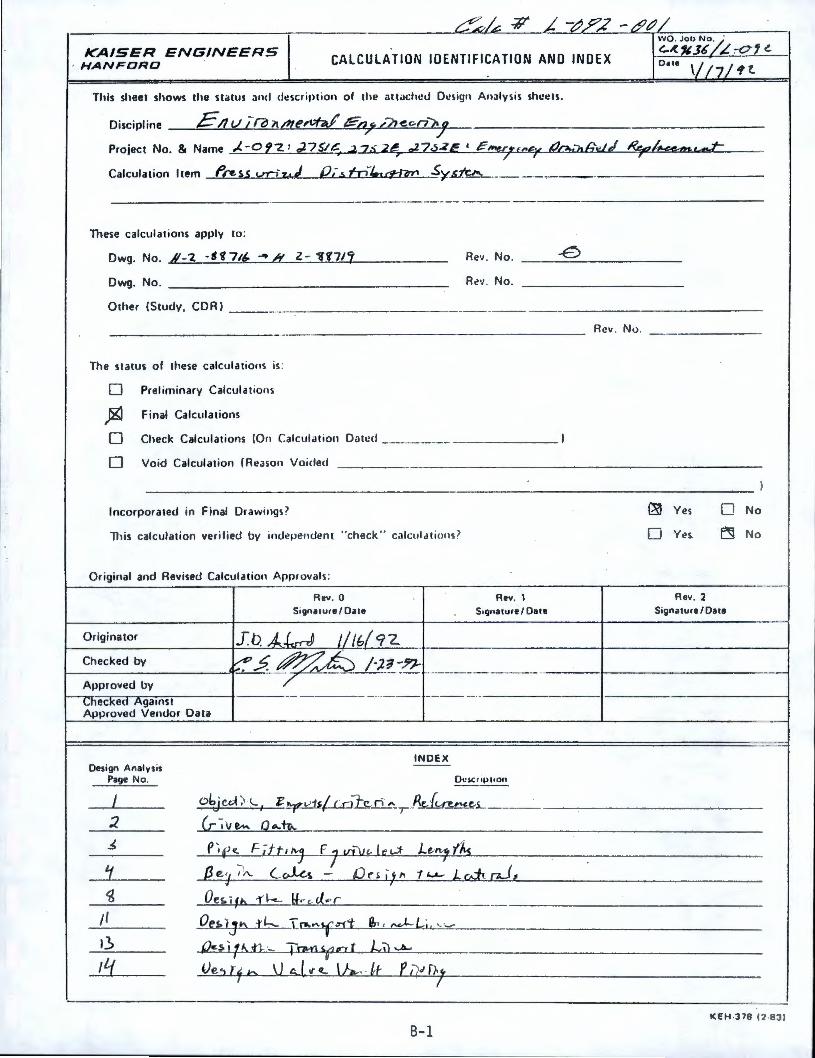
I ob1c.d > \... tJ I 'C ¥- v-ts/_co"h n "-,P.1,-, ~...1:,,5-_ __
:z G-~ve- Q ... tc-...
~ P~f <l. F itt, "'j F 7 1.D~l'- t ~ d- Le.~'/~
'j_ fl. e ,1 ~ C~!. - Oes. ,t" tu- led! uJ, a (
~ Oes ifb -rk If,, c. J,,, r -- -- ---/I ~.h....f.h._ T r-.."¥ "ii: e, ,, ,-..,LL,.j, .... __
I.) Q~s • ;.t,, ,n_ ._ T~ ,,,fo. i &'i1. ..A.,
11:f Ve::i [~ 0 ~ ~t "~ v~. lt e11"f)..,, , I
KEH -378 12-831
B-1
KAISER ENGINEERS HANFORD CALCULATION IDENTIFICATION ANO INDEX
This sheet shows tht1 status and dt!script ion of the altacht!d Dcsi!Jn Analysis sheets.
Discipline _______ _ ______ _
WO . Job No .
Project & Name - - ---------- ---------- ----------------Calculation m _ ____ _ __________ _
These calculations apply
Dwg. No .
Dwg. No.
Other !Study, CORI ____ ..,_ _______ _
The status of these calculations is :
0 Prel iminary Calculat io ns
0 Final Calculations
Rev. No .
Rt! v. No .
0 Check Calculations ·· ·--··- ·-- --------
0 Void Calculation I R11aso11 Vo ided - --~~--
Incorporated in Final Drawings?
Th is calculation verified by inde ndent " check " calculations?
Origina to r
n Approvals :
Rev. 0 S,gnature / Date
Re·, . No .
0 Yes
0 Yes
0 No
0 No
Rev. 2 Signature/Oare
_ __________ _...,~1--------------
Design Analysis Page No.
/.5 /~
IND EX
Ot!scr iµt ion
. .S -; Z~L~- ~~ L-,~- ---·----- -- ·---··-- . __________ _
n~ Is w itv"-~s j
KE H -378 12-BJ I
B-2
I , .
KAISER ENGINEERS HANFORD
Page No. / of 20 e
DESIGN ANALYSIS Revision _____ _
Client w J./ C. WO/Job No. <. I.. 'tG 3( / J. -of Z
SubJect -' #, , ,., ~ .• _ J..s Date - //
Checked -
Location Revised
ORIGIN= 1
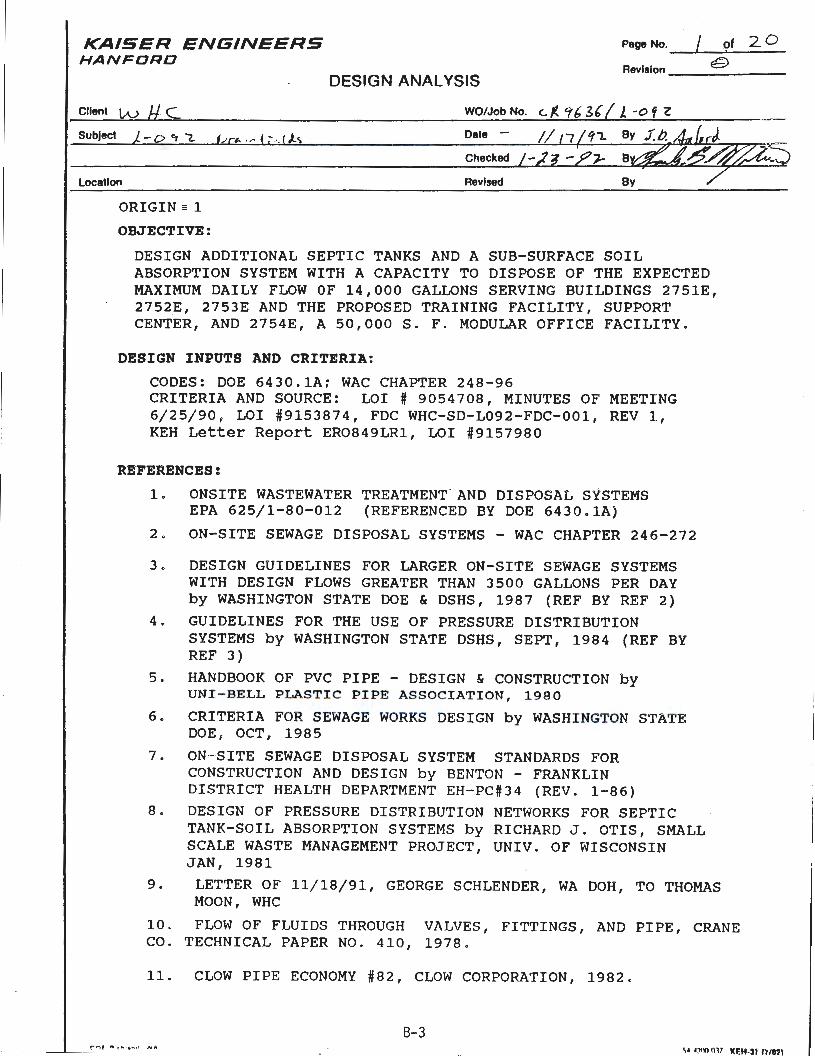
OBJECTIVE:
DESIGN ADDITIONAL SEPTIC TANKS AND A SUB-SURFACE SOIL ABSORPTION SYSTEM WITH A CAPACITY TO DISPOSE OF THE EXPECTED MAXIMUM DAILY FLOW OF 14,000 GALLONS SERVING BUILDINGS 2751E, 2752E, 2753E AND THE PROPOSED TRAINING FACILITY, SUPPORT CENTER, AND 2754E, A 50,000 S. F. MODULAR OFFICE FACILITY.
DESIGN INPUTS AND CRITERIA:
CODES: DOE 6430.lA; WAC CHAPTER 248-96 CRITERIA AND SOURCE: LOI# 9054708, MINUTES OF MEETING 6/25/90, LOI #9153874, FDC WHC-SD-L092 - FDC- 001 , REV 1, KEH Letter Report ERO849LR1, LOI #9157980
REFERENCES:
1. ONSITE WASTEWATER TREATMENT. AND DISPOSAL SYSTEMS EPA 625/1-80-012 (REFERENCED BY DOE 6430.lA)
2. ON- SITE SEWAGE DISPOSAL SYSTEMS - WAC CHAPTER 246-272
3. DESIGN GUIDELINES FOR LARGER ON- SITE SEWAGE SYSTEMS WITH DESIGN FLOWS GREATER THAN 3500 GALLONS PER DAY by WASHINGTON STATE DOE & DSHS, 1987 (REF BY REF 2)
4 . GUIDELINES FOR THE USE OF PRESSURE DISTRIBUTION SYSTEMS by WASHINGTON STATE DSHS, SEPT, 1984 (REF BY REF 3)
5. HANDBOOK OF PVC PIPE - DESIGN & CONSTRUCTION by UNI - BELL PLASTIC PIPE ASSOCIATION , 1980
6. CRITERIA FOR SEWAGE WORKS DESIGN by WASHINGTON STATE DOE , OCT, 1985
7. ON- SITE SEWAGE DISPOSAL SYSTEM STANDARDS FOR CONSTRUCTION AND DESIGN by BENTON - FRANKLIN DISTRICT HEALTH DEPARTMENT EH-PC#34 (REV . 1 - 86)
8 . DESIGN OF PRESSURE DISTRIBUTION NETWORKS FOR SEPTIC TANK-SOIL ABSORPTION SYSTEMS by RICHARD J. OTIS, SMALL SCALE WASTE MANAGEMENT PROJECT, UNIV . OF WISCONSIN JAN, 1981
9. LETTER OF 11/18/91, GEORGE SCHLENDER, WA DOH, TO THOMAS MOON, WHC
10. FLOW OF FLUIDS THROUGH VALVES, FITTINGS, AND PIPE, CRANE CO . TECHNICAL PAPER NO . 410, 1978 .
11. CLOW PIPE ECONOMY #82, CLOW CORPORATION, 1982.
B-3 rr,, ", ._ ., .. ,. ~A
-----'-- :....:.C...-'--'--- - -- -- -- . ~· A'.'(l(J llll KF.H-3f me,i
Page No. 2...- of 20 KAISER ENGINEERS HANFORD
DESIGN ANALYSIS Revision __ -& ___ _
Client (;.J Et C... WO/Job No.
Subject _ 0 c, 1... Date
Location Revised
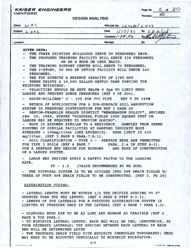
GIVEN DATA: - THE THREE EXISTING BUILDINGS SERVE 90 PERSONNEL EACH. - THE PROPOSED TRAINING FACILITY WILL SERVE 330 PERSONNEL
ON AN 8 HOUR OR LESS BASIS. - THE TRAINING SUPPORT CENTER WILL SERVE 70 PERSONNEL. - THE 2-STORY, 50 000 SF OFFICE FACILITY WILL SERVE 320
PERSONNEL. - THE FDC DIRECTS A RESERVE CAPACITY OF 1790 GPO - THERE EXISTS A 10,000 GALLON SEPTIC TANK SERVING THE EXISTING BUILDINGS. - VELOCITIES SHOULD BE KEPT BELOW 5 fps TO LIMIT HEAD LOSSES AND PREVENT SURGE PRESSURES (REF 5 PF 204).
- HAZEN-WILLIAMS' C = 150 FOR PVC PIPE REF 5 PG 1901
- METHOD OF APPLICATION FOR A SUB-SURFACE SOIL ABSORPTION SYSTEM IS PRESSURE DISTRIBUTION PER REF 3 PAGE 20 - BENTON-FRANKLIN HEALTH DISRTICT "MEMORANDUM POLICY", REVISED JAN . 20 , 1986, STATES "DISPOSAL FIELDS 1000 SQUARE FEET OR LARGER MAY BE REQUIRED TO PROVIDE DOSING". - BODS IS ASSUMED SIMILAR TO A RESIDENCE. SAMPLES FROM SEWER SYSTEMS OF SIMILAR FACILITIES AT HANFORD INDICATE BOD5 AVERAGES< l00mg/liter (SEE APPENDIX). DSHS LIMIT IS 230 mg/liter, (REF 3 PAGE 9 PARA.7.b.1). - SOIL CLASSIFICATION - TYPE 3 - SEEPAGE BEDS ARE P~RMITTED FOR TYPE 3 SOILS (REF 4 PAGE 7 PARA. 2 . a IN STEP A-1). USE A SEEPAGE BED DESIGN FOR ECONOMY AND EASE OF CONSTRUCTION ON A LARGER SYSTEM.
·LARGE BED DESIGNS APPLY A SAFETY FACTOR TO THE LOADING RATE.
SF= 1 . 2 (VALUE RECOMMENDED BY WA DOH)
- THE DISPOSAL SYSTEM IS TO BE DIVIDED INTO 50% DRAIN FIELDS W/ THREE OF FOUR 50% DRAIN FIELDS TO BE CONSTRUCTED . (REF 3, PG 20)
DISTRIBUTION PIPING:
- LATERAL LENGTH MUST BE WITHIN 1/2 THE ORIFICE SPACING TO 6 11
SHORTER THAN THE BED LENGTH. (REF 4 PAGE 8 STEP A-2. 1) . - LENGTH OF THE LATERALS FOR A PRESSURE DISTRIBUTION SYSTEM· IS LIMITED BY PRESSURE DROP IN THE LATERAL (REF 4 PAGE 7 PARA 2.c).
- DISPOSAL BEDS ARE TO BE AS LONG AND NARROW AS FEASIBLE (REF 4 PAGE 8 TOP PARA . ). - TO MINIMIZE LATERAL LENGTH, EACH BED WILL BE FED, LENGTHWISE, BY FOUR SEPERATE LATERALS; THE SPACING BETWEEN EACH LATERAL IN EACH BED WILL BE DETERMINED LATER · - THE PROPOSED DRAIN FIELD SITE EXHIBITS IRREGULAR TOPOGRAPHY; BEDS MAY NEED TO BE ADJUSTED VERTICALLY TO MINIMIZE EXCAVATION.
8-4 ,...,..., .. ....... ' ... ... ~• A:,,V, n 17 111:H-37 (7/11)
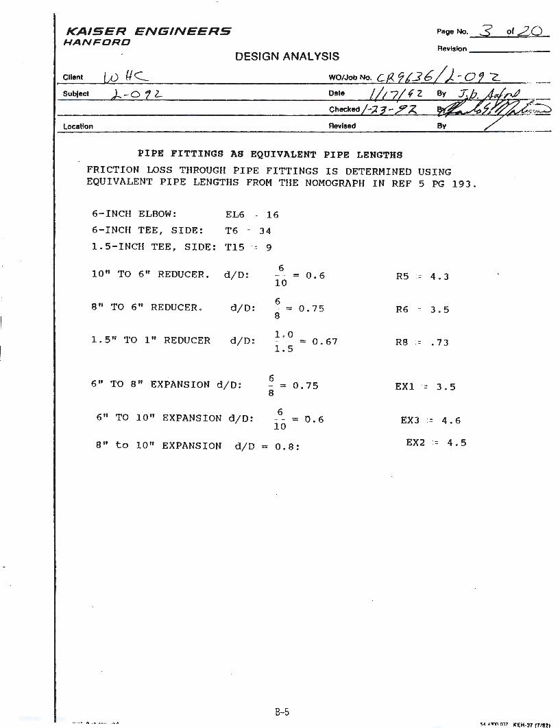
KAISER ENGINEERS HANFORD
Client
SubJect
Location
Page No. 3 of 20 Revision ____ _ _
Date
Checked
Revised
PIPE FITTINGS AS EQUIVALENT PI PE LENGTHS
FRI CTION LOSS THROUGH PIPE FITTINGS IS DETERMI NED USI NG EQUIVALENT PIPE LENGTHS FROM THE NOMOGRA PH IN REF 5 PG 19 3.
6-INCH ELBOW:
6-INCH TEE, SIDE:
EL6 - 16
T6 = 34
1 . 5- INCH TEE, SIDE: T15 = 9
10 " TO 6" REDUCER. d/D: 6
10
8" TO 6" REDUCER . d/D: 6
= 8
1 . 5" TO 1" REDUCER d/D: 1.0 1.5
6
= 0.6
0 . 75
= 0.67
6" TO 8 11 EXPANSION d/D: = 0 . 75 8
6 = 0 . 6
10 6" TO 10" EXPANSION d/ D:
8 11 to 10" EXPANSION d/D = 0 . 8 :
B-5
RS - 4.3
R6 - 3.5
R8 .- . 7 3
EXl - 3.5
EX3 := 4. 6
EX2 = 4.5
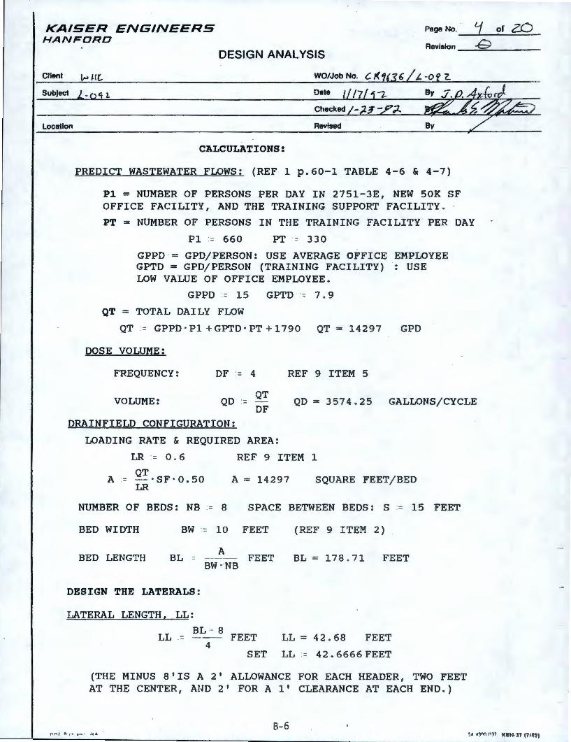
KAISER ENGINEERS HANFORD
Page No. :( of ZO Revision -G
DESIGN ANALYSIS
Client i,., HC... WO/Job No. C. /( 1(3 6 /t. -0 f 2.
Subject _ 'i L
Location
Checked
Revised
CALCULATIONS:
PREDICT WASTEWATER FLOWS: (REF 1 p.60-1 TABLE 4-6 & 4-7)
Pl= NUMBER OF PERSONS PER DAY IN 2751-3E, NEW SOK SF OFFICE FACILITY, AND THE TRAINING SUPPORT FACILITY.
PT= NUMBER OF PERSONS IN THE TRAINING FACILITY PER DAY
Pl = 660 PT = 330
GPPD ·= GPO/PERSON: USE AVERAGE OFFICE EMPLOYEE GPTD = GPO/PERSON (TRAINING FACILITY) : USE LOW VALUE OF OFFICE EMPLOYEE.
GPPD = 15 GPTD = 7.9
QT= TOTAL DAILY FLOW
QT := GPPD ·Pl+ GPTD ·PT+ 1790 QT = 14297 GPD
DOSE VOLUME:
FREQUENCY:
VOLUME:
DF := 4
QT QD -
DF
REF 9 ITEM 5
QD = 3574 . 25 GALLONS/CYCLE
DRAINFIELD CONFIGURATION:
LOADING RATE & REQUIRED AREA:
LR := 0 . 6
A= QT·SF·0.50 LR
REF 9 ITEM 1
A = 14297 SQUARE FEET/BED
NUMBER OF BEDS: NB = 8 SPACE BETWEEN BEDS: S = 15 FEET
BED WIDTH BW = 10 FEET (REF 9 ITEM 2)
BED LENGTH BL =
DESIGN THE LATERALS:
LATERAL LENGTH, LL:
A
BW · NB
BL - 8
FEET BL = 178 . 71 FEET
LL .= -- FEET LL = 42 . 68 FEET 4
SET LL = 42.6666FEET
(THE MINUS 8'IS A 2' ALLOWANCE FOR EACH HEADER, TWO FEET AT THE CENTER, AUD 2' FOR A 1 1 CLEARANCE AT EACH END.)
8- 6 r~"" ' " , , . ... . , ·",.
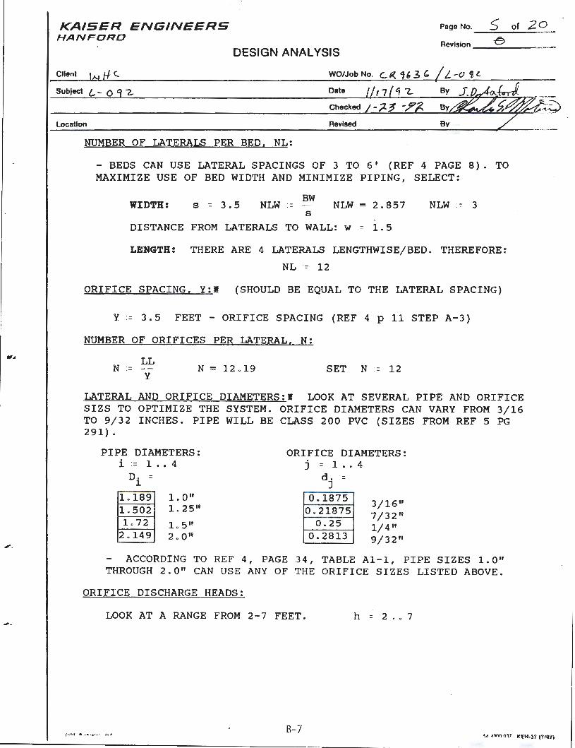
..,,._
Page No. 5 of 20 KAISER ENGINEERS HANFORD
DESIGN ANALYSIS Revision __ c> ____ _
Client \N tf C.
Subject l. - o -z..
WO/Job No.
Date
Checked
Location Revised
NUMBER OF LATERALS PER BED, NL:
- BEDS CAN USE LATERAL SPACINGS OF 3 TO 6 1 (REF 4 PAGE 8). TO MAXIMIZE USE OF BED WIDTH AND MINIMIZE PIPING, SELECT:
WIDTH: s = 3.5 BW
NLW = - - NLW = 2.857 s
DISTANCE FROM LATERALS TO WALL: w = 1 . 5
NLW .= 3
LENGTH: THERE ARE 4 LATERALS LENGTHWISE/BED. THEREFORE:
NL = 12
ORIFICE SPACING, Y:I (SHOULD BE EQUAL TO THE LATERAL SPACING)
Y = 3 . 5 FEET - ORIFICE SPACING (REF 4 p 11 STEP A- 3)
NUMBER OF ORIFICES PER LATERAL, N:
LL N = -
y N = 12. 19 SET N = 12
LATERAL AND ORIFICE DIAMETERS:I LOOK AT SEVERAL PIPE AND ORIFICE SIZS TO OPTIMIZE THE SYSTEM. ORIFICE DIAMETERS CAN VARY FROM 3/16 TO 9/32 INCHES. PIPE WILL BE CLASS 200 PVC (SIZES FROM REF 5 PG 291) 0
PIPE DIAMETERS: i = 1 •• 4
D. J.
L189 1. 0 11
1.502 1 . 25 11
L72 10 5 11
2.149 2. 0 11
ORIFICE DIAMETERS: j = 1 .. 4
d . = J
0.1875 0.21875
0 . 25 0 . 2813
3/16" 7/32" 1/4" 9/32 11
- ACCORDING TO REF 4, PAGE 34, TABLE Al-1, PIPE SIZES l.O" THROUGH 2.0" CAN USE ANY OF THE ORIFICE SIZES LISTED ABOVE .
ORIFICE DISCHARGE HEADS:
LOOK AT A RANGE FROM 2 - 7 FEET . h = 2 •• 7
B-7
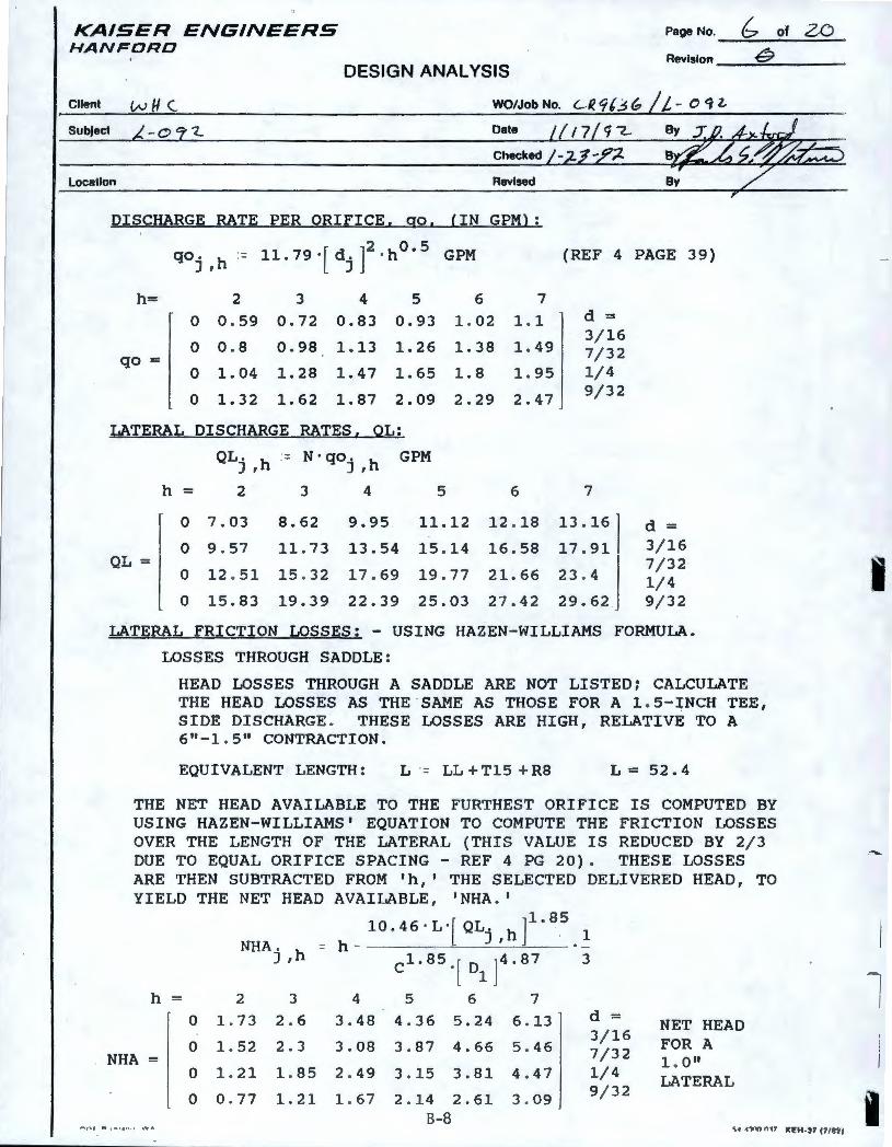
KAISER ENGINEERS HANFORD
Page No. & of ZO
Revision 0 DESIGN ANALYSIS
Cllenl w H (. WO/Job No.
Dale
Location Revised
DISCHARGE RATE PER ORIFICE, go, (IN GPM):
qo j , h = 11. 7 9 · [ dj J2 · h O • 5
G PM (REF 4 PAGE 39)
h= 2 3 4 5 6 7 0 0.59 0.72 0.83 0.93 1.02 1.1 d =
qo = 0 0.8 0.98 1.13 1.26 1.38 1.49
3/16 7/32
0 1.04 1.28 1.47 1.65 1.8 1.95 1/4
0 1.32 1.62 1.87 2.09 2.29 2.47 9/32
LATERAL DISCHARGE RATES, OL:
QL. h .- N·qo. h GPM J , J ,
h = 2 3 4 5 6 7
0 7.03 8.62 9.95 11.12 12.18 13.16 d = 0 9.57 11.73 13.54 15 .14 16.58 17.91 3/16
QL = 7/32 0 12 . 51 15 . 32 17.69 19 .77 21.66 23 . 4 1/4 0 15 .83 19.39 22.39 25.03 27.42 29.62 9/32
LATERAL FRICTION LOSSES: - USING HAZEN-WILLIAMS FORMULA.
LOSSES THROUGH SADDLE:
HEAD LOSSES THROUGH A SADDLE ARE NOT LISTED; CALCULATE THE HEAD LOSSES AS THE SAME AS THOSE FOR A 1.5-INCH TEE, SIDE DISCHARGE. THESE LOSSES ARE HIGH, RELATIVE TO A 6"-1 . 5" CONTRACTION.
EQUIVALENT LENGTH: L = LL +Tl5 +RB L = 52. 4
THE NET HEAD AVAILABLE TO THE FURTHEST ORIFICE IS COMPUTED BY USING HAZEN-WILLIAMS' EQUATION TO COMPUTE THE FRICTION LOSSES OVER THE LENGTH OF THE LATERAL (THIS VALUE IS REDUCED BY 2/3 DUE TO EQUAL ORIFICE SPACING - REF 4 PG 20). THESE LOSSES ARE THEN SUBTRACTED FROM 'h,' THE SELECTED DELIVERED HEAD, TO YIELD THE NET HEAD AVAILABLE , 'NHA.'
h =
NHA =
10.46 · L·[QL. ]l.B 5
NHA . h = h - J ' h . · ~ J, c1.ss.[ 01 J4 . a7 3
2 3 4 5 6 7
0 1.73 2.6 3 . 48 4.36 5.24 6 . 13
0 1.52 2 . 3 3.08 3.87 4.66 5.46
0 1.21 1.85 2 . 49 3 . 15 3.81 4 .47
0 0 . 77 1.21 1.67 2 . 14 2. 61 B-8
3 . 09
d = 3/16 7/32 1/4 9/32
NET HEAD FOR A 1 . O" LATERAL
I
I
I
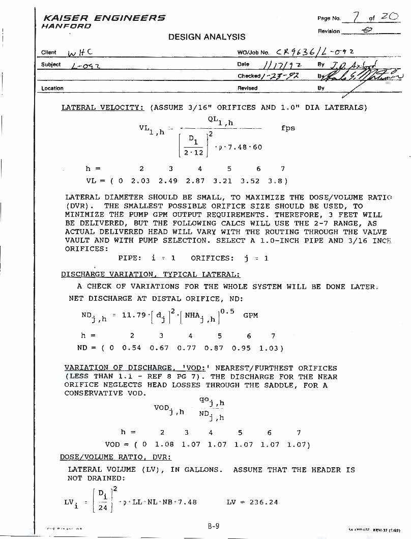
KAISER ENGINEERS HANFORD
Page No. 7 of 2 0 Revision __ ...::-GJ::....· _ _ _
DESIGN ANALYSIS
Client l,v ff C WO/Job No. C f--1 b- 3 b /L -o-, '2.
SubJect 1. Date
Location Revised
LATERAL VELOCITY: (ASSUME 3/16" ORIFICES AND 1. 0 11 DIA LATERALS)
QLl h VL1 ,h :- ' fps
h = 2 3
12 ]
2
· p·7 . 48 · 60 2 · 12
4 5 6 7
VL = ( 0 2 . 0 3 2 . 4 9 2 . 8 7 3 . 2 1 3 . 5 2 3 . 8 )
LATERAL DIAMETER SHOULD BE SMALL, TO MAXIMIZE THE DOSE/VOLUME RATI O (DVR). THE SMALLEST POSSIBLE ORIFICE SIZE SHOULD BE USED, TO MINIMIZE THE PUMP GPM OUTPUT REQUIREMENTS. THEREFORE, 3 FEET WILL BE DELIVERED, BUT THE FOLLOWING CALCS WILL USE THE 2-7 RANGE, AS ACTUAL DELIVERED HEAD WILL VARY WITH THE ROUTING THROUGH THE VALVE VAULT AND WITH PUMP SELECTION. SELECT A 1.0-INCH PIPE AND 3/16 INC ORIFICES:
PIPE: i = 1 ORIFICES: j = 1
DISCHARGE VARIATION, TYPICAL LATERAL:
A CHECK OF VARIATIONS FOR THE WHOLE SYSTEM WILL BE DONE LATER .
NET DISCHARGE AT DISTAL ORIFICE, ND:
NDj ,h - 11. 79 ·[ dj J2 ·[ NHAj ,h ]O. 5
GPM
h = 2 3 4 5 6 7
ND = ( 0 0 . 5 4 0 . 6 7 0 . 7 7 0 . 8 7 0 . 9 5 1 . 0 3 )
VARIATION OF DISCHARGE, 'VOD:' NEAREST/FURTHEST ORIFICES (LESS THAN 1 . 1 - REF 8 PG 7). THE DISCHARGE FOR THE NEAR ORIFICE NEGLECTS HEAD LOSSES THROUGH THE SADDLE , FOR A CONSERVATIVE VOD.
qo. h VOD. h . C
J , ------
J , ND , h J ,
h = 2 3 4 5 6 7
VOD = ( 0 1.08 1.07 1.07 1.07 1.07 1.07)
DOSE/VOLUME RATIO, DVR:
LATERAL VOLUME (LV), IN GALLONS . ASSUME THAT THE HEADER IS NOT DRAINED :
LV , 1
t",-•f fl r .. . , .. , 1 ~" A
- [:!r •p·LL ·NL ·NB ·7.48 LV = 236 . 24
B-9
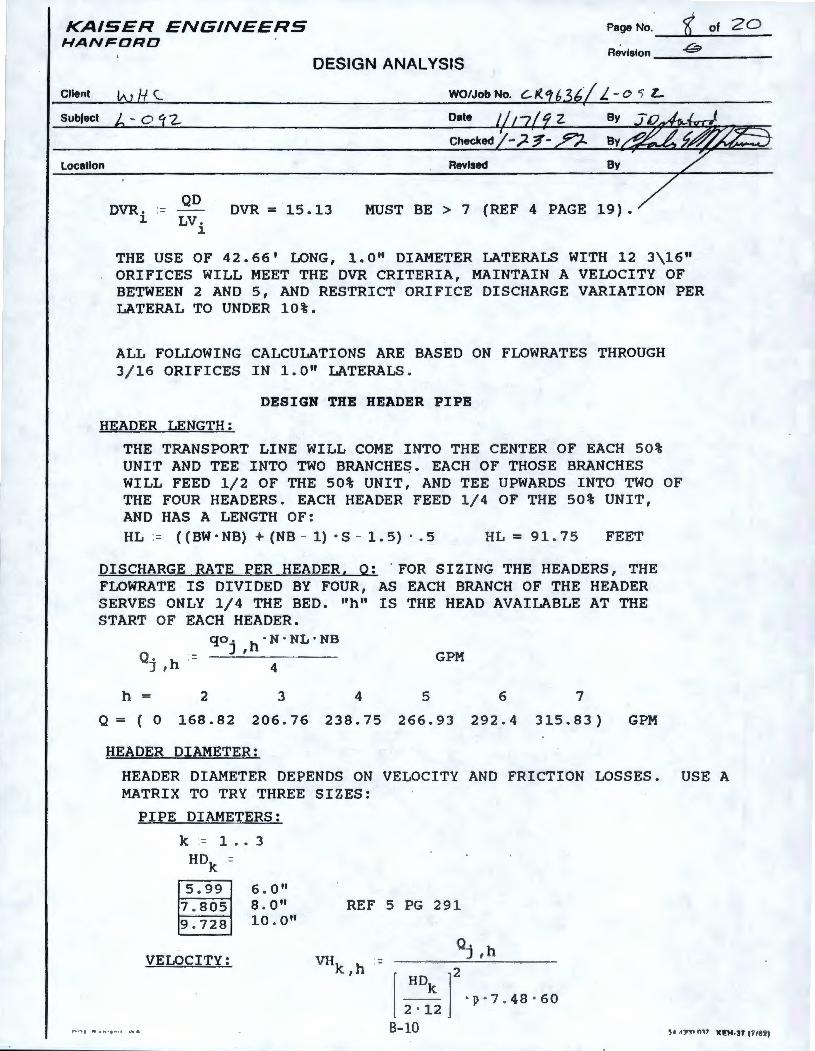
KAISER ENGINEERS HA.NFDRD
Page No. __ <K...._~o_f_2_0_ Revision __ 8 ___ _
DESIGN ANALYSIS
Client WO/Job No.
Subject Date
Checked
Location Revised
QD DVR. - DVR = 15. 13
1 LV. MUST BE> 7 (REF 4 PAGE 19).
1
THE USE OF 42. 66' LONG, 1. 0 11 DIAMETER LATERALS WITH 12 3\16 11
ORIFICES WILL MEET THE DVR CRITERIA, MAINTAIN A VELOCITY OF BETWEEN 2 AND 5, AND RESTRICT ORIFICE DISCHARGE VARIATION PER LATERAL TO UNDER 10%.
ALL FOLLOWING CALCULATIONS ARE BASED ON FLOWRATES THROUGH 3/16 ORIFICES IN 1.0 11 LATERALS.
DESIGN THE HEADER PIPE
HEADER LENGTH:
THE TRANSPORT LINE WILL COME INTO THE CENTER OF EACH 50% UNIT AND TEE INTO TWO BRANCHE~. EACH OF THOSE BRANCHES WILL FEED 1/2 OF THE 50% UNIT, AND TEE UPWARDS INTO TWO OF THE FOUR HEADERS. EACH HEADER FEED 1/4 OF THE 50% UNIT, AND HAS A LENGTH OF: HL = ((BW · NB) + (NB - 1) · S - 1. 5) · . 5 HL = 91. 75 FEET
DISCHARGE RATE PER HEADER, Q: . FOR SIZING THE HEADERS, THE FLOWRATE IS DIVIDED BY FOUR, AS EACH BRANCH OF THE HEADER SERVES ONLY 1/4 THE BED. "h" IS THE HEAD AVAILABLE AT THE START OF EACH HEADER.
Q. h .J ,
qo. ·N · NL·NB J ,h
4 GPM
4 5 h = Q = ( 0
2
168.82
3
206.76 238.75 266.93
HEADER DIAMETER:
6
292.4
7
315.83) GPM
HEADER DIAMETER DEPENDS ON VELOCITY AND FRICTION LOSSES. USE A MATRIX TO TRY THREE SIZES:
PIPE DIAMETERS:
k = 1 .• 3 HD -k -
5.99 6.0 11
7 . 805 8.0" 9 . 728 l0.0"
VELOCITY:
REF 5 PG 291
Q. h J ,
I HD ]2
_ k_ · p · 7 . 48 · 60 2 · 12
B-10
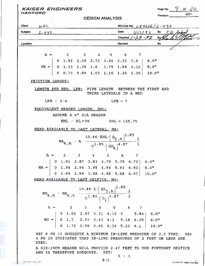
KAISER ENGINEERS HANF ORD
Page No. J of 26 Revision ___ ._€9---" _ _ _
DESIGN ANALYSIS
Client VJ u C. WO/Job No.
SubJect - o 'IL Date
Checked
Location Revised
h = 2 3 4 5 6 7
0 1. 9 2 2.35 2. 7 2 3 . 04 3.33 3.6 6 . O"
VH = 0 1.13 1.39 1. 6 1.79 1. 96 2 . 12 8. O"
0 0.73 0. 89 1. 03 1.15 1. 26 1. 36 10. 0"
FRI CTION LOSSES :
LENGTH PER BED . LPB: PIPE LENGTH BETWEEN THE FIRST AND THIRD LATERA LS IN A BED
LPB = 2 · s LPB = 7
EQUIVALENT HEADER LENGTH. EHL :
ASSUME A 6 " DIA HEADER
-EHL = HL +T6 EHL = 125. 75
HEAD AVAILABLE TO LAST LATERAL. HA:
10.46 · EHL·[Q, ]1 · 85 - h - J , h 1
3
h = 2 3 4 5 6 7
0 1.91 2 . 87 3.83 4.79 5. 7 5 6.72
HA = 0 1.98 2 .96 3.95 4 .94 5 . 93 6 . 92
0 1.99 2.99 3. 98 4 . 98 5. 98 6. 97
HEAD AVAILABLE TO LAST ORIFICE, HO:
Hok,h -
h =
HO=
HAk h _ 10 . 46 ·L ·[ QLj ,h ]1.a
5
, cl.85 .[ DiJ4 . 87
2 3 4 5
0 1.64 2 . 47 3.31 4 . 15 5
1 3
6 7
5 . 84
0 1. 7 2 . 57 3 . 43 4 . 3 5 . 18 6 . 05
0 1.72 2 . 59 3.46 4.34 5 . 22 6 . 1
6 . O"
8 . O"
10 . 0 11
6 . O"
8. 0 11
10 . 0 11
REF 8 PG 10 SUGGESTS A MINIMUM I N- LINE PRESSURE OF 2 . 5 FEET . RE 4 PG 2 0 I NDICATES THAT IN- LINE PRESSURES OF 2 FEET OR LESS ARE USED . A SIX-INCH HEADER WILL PROVIDE 2 . 47 FEET TO THE FURTHEST ORIFICE AND IS THEREFORE ADEQUATE . SET :
k = 1 B- 11 I
~• •:wn 011 111!1-f-'.lf {f / U )
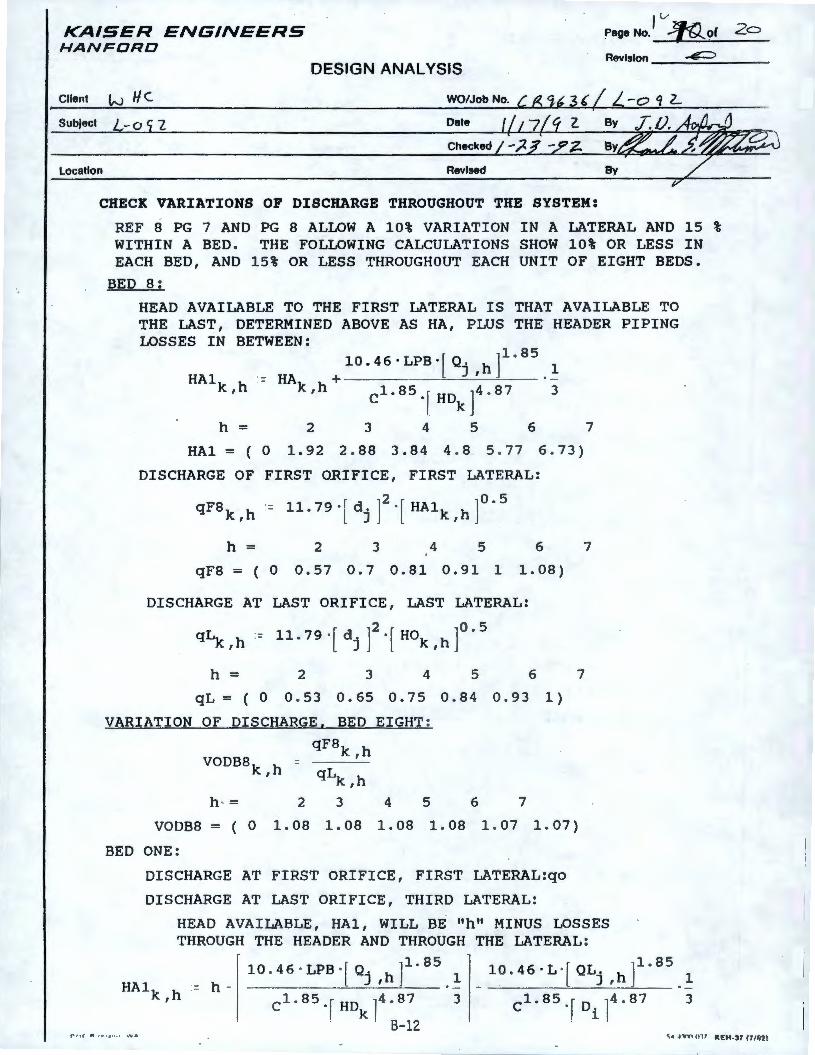
KAISER ENGINEERS HANFORD
1 v Page No. Jf{)..._of 2o
· Revision ~ DESIGN ANALYSIS
Client IN He
Subject -0 "2 Date
Checked
Location Revised
CHECK VARIATIONS OF DISCHARGE THROUGHOUT THE SYSTEM:
REF 8 PG 7 AND PG 8 ALLOW A 10% VARIATION IN A LATERAL AND 15 % WITHIN A BED. THE FOLLOWING CALCULATIONS SHOW 10% OR LESS IN EACH BED, AND 15% OR LESS THROUGHOUT EACH UNIT OF EIGHT BEDS.
BED 8:
HEAD AVAILABLE TO THE FIRST LATERAL IS THAT AVAILABLE TO THE LAST, DETERMINED ABOVE AS HA, PLUS THE HEADER PIPING LOSSES IN BETWEEN:
10.46·LPB·[Q, h]1
·85
l HAl - HA + J ' · -
k,h k,h Cl.85·rHDkr · 87 3
h = 2 3 4 5 6
HAl = ( 0 1.92 2 . 88 3.84 4 . 8 5.77 6.73)
DISCHARGE OF FIRST ORIFICE, FIRST LATERAL:
qF8k ,h - ll.79·[dj ]2
·[ HA1k,h ]o.5
7
h = 2 3 4 5 6 7
qF8 = ( 0 0.57 0.7 0.81 0.91 1 1.08)
DISCHARGE AT LAST ORIFICE, LAST LATERAL:
qLk , h - 11. 7 9 • [ d j J2 · [ HOk , h ]° . 5
2 3 4 5 6 h = qL = ( 0 0 . 53 0.65 0.7 5 0.84 0.93 1)
VARIATION OF DISCHARGE, BED EIGHT:
VODBBk h = ,
h · = 2
qFBk ,h
qLk,h
3 4 5 6 7
7
VODBB = ( 0 1. 08 1. 08 1. 08 1. 08 1. 07 1. 07)
BED ONE:
DISCHARGE AT FIRST ORIFICE, FIRST LATERAL:qo
DISCHARGE AT LAST ORIFICE , THIRD LATERAL:
HEAD AVAILABLE, HAl, WILL BE "h" MINUS LOSSES THROUGH THE HEADER AND THROUGH THE LATERAL :
HAlk h = h -10 . 4 6 · LPB · [ Qj , h ] 1.
8 5 . ~ 10. 4 6 · L · [ QLj , h ] 1.
8 5 l
, cl.85.fHDkl4 . 87 3 cl.85 ·r o ii4·87 · . B- 12 . .
3
r ll f ft , ,- . . .. . , ~'lo A o; ,e .n nn 011 kE.H-:t f ff /R'll
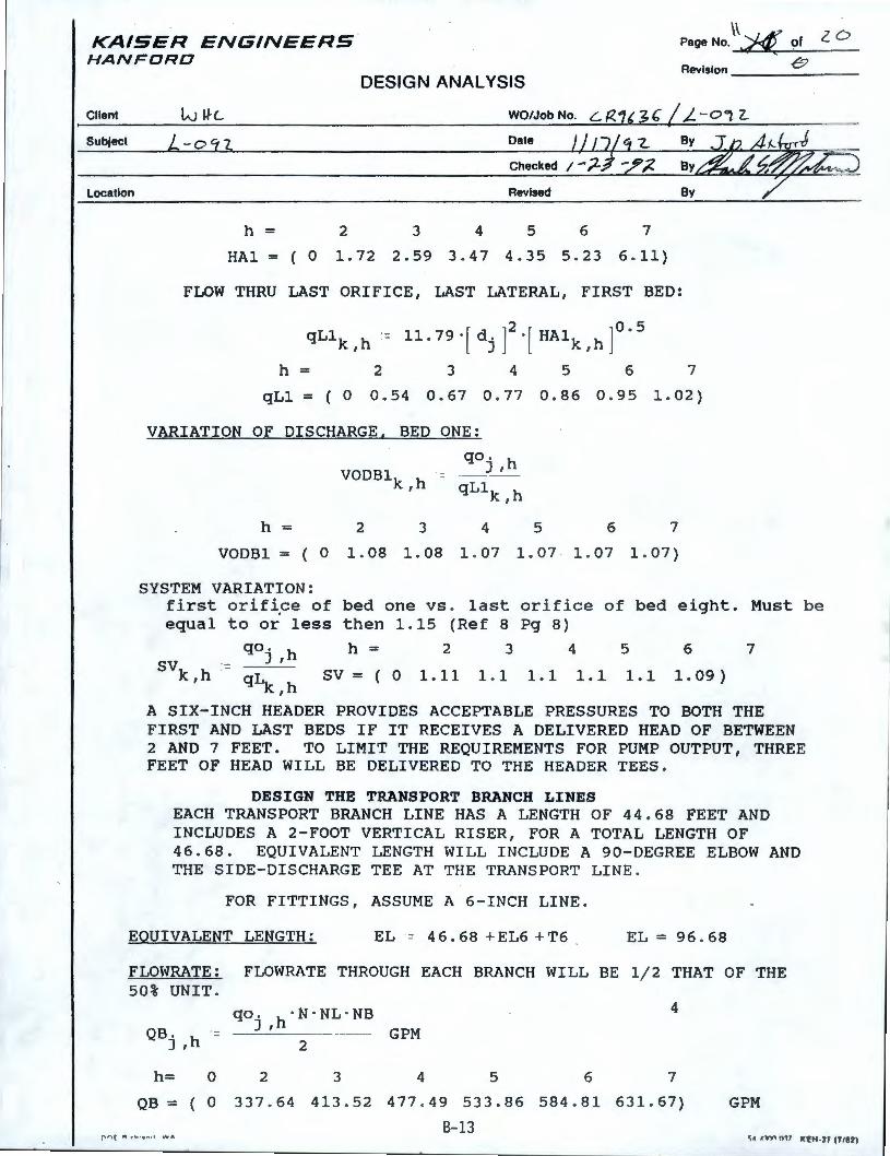
KAISER ENGINEERS HANFORD
\\ PegeNo. ~ of
Revision ___ e _ _ _ DESIGN ANALYSIS
Client WO/Job No.
SubJect Date
Location Revised
h = 2 3 4 5 6 7
HA 1 = ( 0 1 . 7 2 2 . 5 9 3 . 4 7 4 . 3 5 5 . 2 3 6 . 11 )
FLOW THRU LAST ORIFICE, LAST LATERAL, FIRST BED:
h = 2 3 4 5 6 7
qLl = ( 0 0.54 0.67 0 . 77 0.86 0 .95 1.02)
VARIATION OF DISCHARGE, BED ONE:
VODBlk,h
h = 2 3
qo . h J , = ----- - ·
qLlk h ,
4 5 6 7
VODBl = ( 0 1.08 1.08 1.07 1.07 1.07 1.07)
SYSTEM VARIATION: first orif i .ce of equal to or less
bed one vs. last orifice of bed eight. Must be then 1.15 (Ref 8 Pg 8)
qo. h J ,
svk h = L. sv = ( o 1. 11 ' q_k ,h
h = 2 3 5
1.1 1.1
4
1.1 1.1
6
1. 09)
7
A SIX-INCH HEADER PROVIDES ACCEPTABLE PRESSURES TO BOTH THE FIRST AND LAST BEDS IF IT RECEIVES A DELIVERED HEAD OF BETWEEN 2 AND 7 FEET. TO LIMIT THE REQUIREMENTS FOR PUMP OUTPUT, THREE FEET OF HEAD WILL BE DELIVERED TO THE HEADER TEES.
DESIGN THE TRANSPORT BRANCH LINES EACH TRANSPORT BRANCH LINE HAS A LENGTH OF 44 . 68 FEET AND INCLUDES A 2 - FOOT VERTICAL RISER, FOR A TOTAL LENGTH OF 46 . 68. EQUIVALENT LENGTH WILL INCLUDE A 90-DEGREE ELBOW AND THE SIDE-DISCHARGE TEE AT THE TRANSPORT LINE .
FOR FITTINGS, ASSUME A 6-INCH LINE.
EQUIVALENT LENGTH: EL = 4 6. 68 + EL6 + T6 EL=96 . 68
FLOWRATE: FLOWRATE THROUGH EACH BRANCH WILL BE 1/2 THAT OF THE 50% UNIT .
QB. h = J ,
h= 0
QB= ( 0
r ri ( n , .., . , ,.. ,, WA
qo . · N · NL · NB J ,h
2
2 3
337 . 64 413.52
4
GPM
4 5 6 7
477 .49 533.86 584.81 631.67) GPM
B- 13 ~• ,t,ry, fl11 Kl!H-'1 (11871
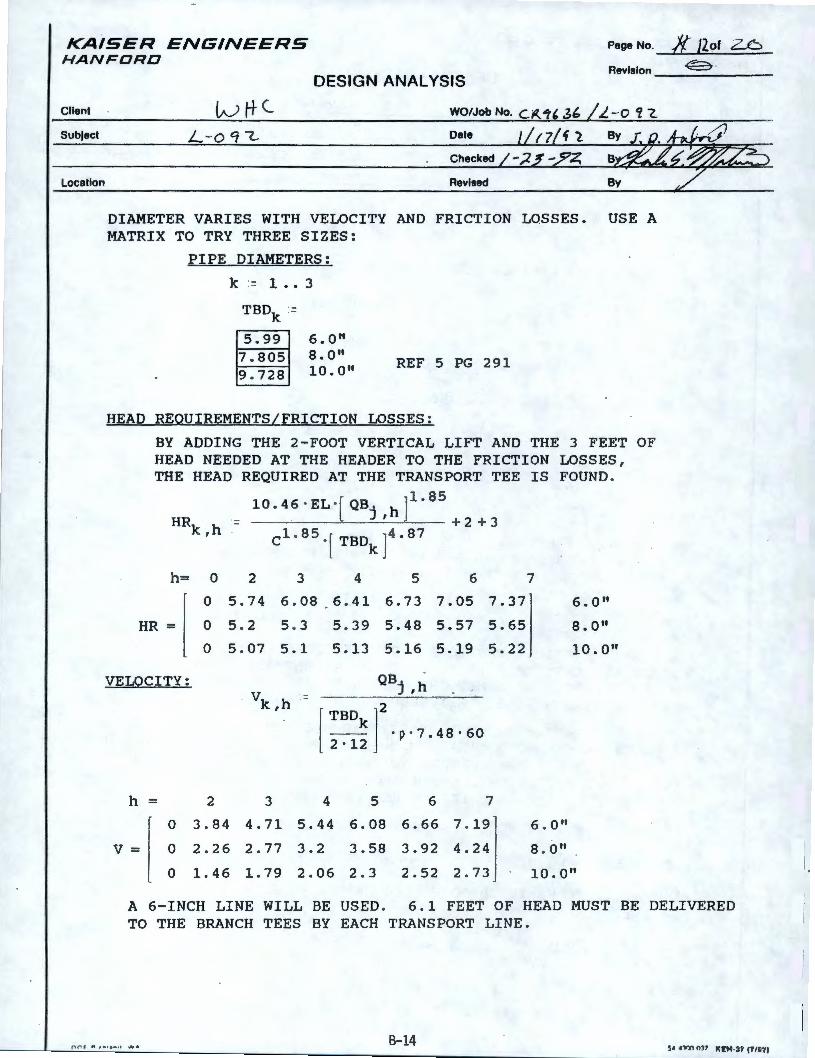
Page No. /{ }lot 26 KAISER ENGINEERS HANFORD
DESIGN ANALYSIS Revision __ ~ __ . __ _
Client
Subject
Location
L-o c; (... Date
Checked
Revised
DIAMETER VARIES WITH VELOCITY AND FRICTION LOSSES. USE A MATRIX TO TRY THREE SIZES:
PIPE DIAMETERS:
k = 1 •• 3
TBDk :=
5.99 6. 0 11
7 . 805 8.0" 9 . 728 l0.0"
REF 5 PG 291
HEAD REQUIREMENTS/FRICTION LOSSES:
BY ADDING THE 2-FOOT V~RTICAL LIFT AND THE 3 FEET OF HEAD NEEDED AT THE HEADER TO THE FRICTION LOSSES , THE HEAD REQUIRED AT THE TRANSPORT TEE IS FOUND .
10.46 · EL ·[QB. h]1
·85
HRk h - J ' + 2 + 3 , Cl. 85 · [ TBDk J4. 87
h= 0 2 3 4 5 6
HR=
VELOCITY:
h =
0
V= 0
0 5. 74
0 5 . 2
0 5. 07
2 3
6 . 08
5 . 3
5.1
6 . 41 6.73 7.05 7.37
5 . 39 5.48 5.57 5.65
5.13 5.16 5.19 5.22
QB. h J ,
[ TBD ]
2
_ _ k ·p · 7.48 · 60 2 · 12
4 5 6 7
3.84 4.71 5.44 6.08 6.66 7 . 19
2.26 2.77 3.2 3.58 3.92 4.24
7
6. 0"
8. 0 11
10.0"
6 • Q II
8 . O"
0 1.46 1. 79 2.06 2 . 3 2.52 2 . 73 10.0 11
A 6-INCH LINE WILL BE USED . 6 . 1 FEET OF HEAD MUST TO THE BRANCH TEES BY EACH TRANSPORT LINE.
BE DELIVERED
r, f"\r " ..... ... . , ,,,,.,., 8-14
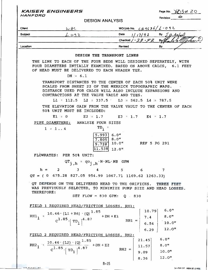
KA ISER E N GINEERS HANFORD
Page No. ~)3of 20
Revision--~-- ___ _ DESIGN ANALYSIS
Client WO/Job No.
Subject Date
Location Revised
DESIGN THE TRANSPORT LINES
THE LINE TO EACH OF THE FOUR BEDS WILL DESIGNED SEPERATELY, WITH FOUR DIAMETERS INTIALLY EXAMINED. BASED ON ABOVE CALCS, 6 . 1 FEET OF HEAD MUST BE DELIVERED TO EACH HEADER TEE .
DH = 6.1
TRANSPORT DISTANCES TO THE CENTER OF EACH 50% UNIT WERE SCALED FROM SHEET 22 OF THE MERRICK TOPOGRAPHIC MAPS. DISTANCE USED FOR CALCS WILL ALSO INCLUDE EXPANSIONS AND CONTRACTIONS AT THE VALVE VAULT AND TEES .
Ll : = 112 . 5 L2 : = 3 3 7 . 5 L3 = 5 6 2 . 5 L4 : = 7 8 7 . 5
THE ELEVATION GAIN FROM THE VALVE VAULT TO THE CENTER OF EACH 50% UNIT MUST BE INCLUDED:
El = 0
PIPE DIAMETERS:
1 = 1 • . 4
E2 ·= 1. 7 E3 = 1.7
ANALYZE FOUR SIZES TD1 =
5 . 993 6 . 0" 7.805 8.0 11
·
9.728 l0.0" 11.538 12.0 11
FLOWRATES: PER 50% UNIT :
QT, = qo , · N · NL · NB GPM J ,h J ,h
E4 = L 7
REF 5 PG 291
h = 2 3 4 5 6 7
QT = ( 0 6 7 5 . 2 8 8 2 7 . 0 5 9 5 4 . 9 9 10 6 7 . 7 1 116 9 . 6 2 12 6 3 • 3 3)
QT DEPENDS ON THE DELIVERED HEAD TO THE ORIFICES. THREE FEET WAS PREVI OUS LY SELECTED , TO MI NIMIZE PUMP S I ZE AND HEAD LOSSES . THEREFORE :
SET FLOW = 8 3 0 GPM : Q - 8 30
FIELD 1 REQUIRED HEAD/FRICTION LOSSES, RHl:
10 . 46 · (Ll + R6) · (Q) 1. 85 RHl = +DH + El
1 Cl .85 . [ TDl ]4 . 87
10 . 79
7 . 4 RHl =
6 . 54
6 . 29 FIELD 2 REQUIRED HEAD/FRICTION LOSSES, RH2:
10 . 46 · (L2) · (Q) 1. 85 RH2 ·= - - - ----- - + DH + E2
1 Cl. 85 . [ TD1]4 . 8 7 RH2 =
21. 45
11. 57
9 . 09
8 . 36
B-15 ll 0 f ",.., , . .. ,. ....,.,
6 ; O"
8 . 0 11
10 . 0 11
12 . 0 11
6 . 0 11
8 . O"
10 . 0 11
12 . O"
5A A:,t)(l 017 Kl!:H-U (f /&21
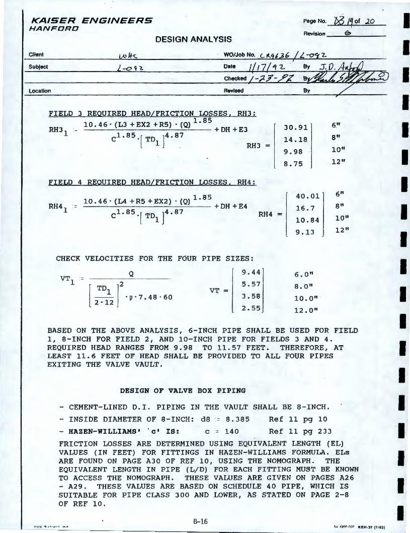
KAISER ENGINEERS HANFORD
Page No. '/;6 11 of JO
Revision e, DESIGN ANALYSIS
Client WO/Job No.
SubJect Date
Checked
Location Revised
FIELD 3 REQUIRED HEAD/FRICTION LOSSES. RH3: 10.46· (L3 +EX2 +RS)• (Q) 1. 95
+ DH +E3 cl.85.[TD1]4.87 RH3 =
FIELD 4 REQUIRED HEAD/FRICTION LOSSES. RH4:
RH4 1 -10.46· (L4 +RS +EX2) · (Q) 1.
85 + DH +E4
Cl. 85 ·[ TDl J4. 87 RH4 =
CHECK VELOCITIES FOR THE FOUR PIPE SIZES:
VTl = [ TD ]2 .
--1
· p·7 . 48·60 2·12
Q
VT=
9.44
5 .57
3.58
2.55
30.91
14.18
9.98
8.75
40.01
16.7
10.84
9.13
6. 0"
8. on 10.0 11 ·
12.0"
6"
8"
10"
12"
6"
8"
10"
12 11
BASED ON THE ABOVE ANALYSIS, 6-INCH PIPE SHALL BE USED FOR FIELD 1, 8-INCH FOR FIELD 2, AND 10-INCH PIPE FOR FIELDS 3 AND 4. REQUIRED HEAD RANGES FROM 9.98 TO 11.57 FEET. THEREFORE, AT LEAST 11.6 FEET OF HEAD SHALL BE PROVIDED TO ALL FOUR PIPES EXITING THE VALVE VAULT.
DESIGN OF VALVE BOX PIPING
- CEMENT-LINED D.I . PIPING IN THE VAULT SHALL BE 8 - INCH.
- INSIDE DIAMETER OF 8 -INCH: d8 = 8.385 Ref 11 pg 10
- HAZEN-WILLIAMS' . c• IS: c - 140 Ref 11 pg 233
FRICTION LOSSES ARE DETERMINED USING EQUIVALENT LENGTH (EL) VALUES (IN FEET) FOR FITTINGS IN HAZEN- WILLIAMS FORMULA. ELs ARE FOUND ON PAGE A30 OF REF 10, USING THE NOMOGRAPH . THE EQUIVALENT LENGTH IN PIPE (L/D) FOR EACH FITTING MUST BE KNOWN TO ACCESS THE NOMOGRAPH. THESE VALUES ARE GIVEN ON PAGES A26 - A29. THESE VALUES ARE BASED ON SCHEDULE 40 PIPE, WHICH IS SUITABLE FOR PIPE CLASS 300 AND LOWER, AS STATED ON PAGE 2-8 OF REF 10.
B-16 r"' O ( ._ , .. , ... . , ,. .. ,.
I I I I I I I I I I I I I I I ·1 I I I
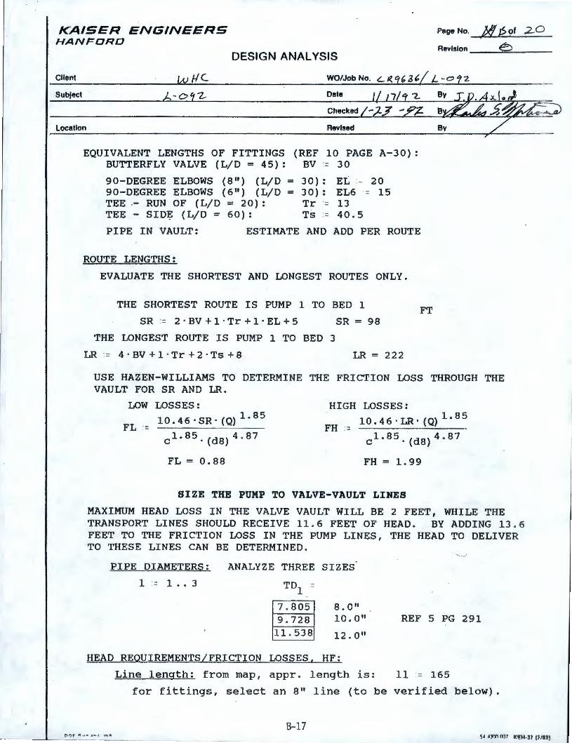
KAISER ENGINEERS HANFORD
Page No. Jl!JSof 2..0 I
Revision E) DESIGN ANALYSIS
Client w /IC WO/Job No.
SubJect - C, -z_ Date
Location Revised
EQUIVALENT LENGTHS OF FITTINGS (REF 10 PAGE A- 30): BUTTERFLY VALVE (L/D = 45): BV - 30
90-DEGREE ELBOWS (8") (L/D = 90-DEGREE ELBOWS (6 11
) (L/D = TEE - RUN OF (L/D = 20): TEE - SID~ (L/D = 60):
3 o) : EL - 2 O 30): EL6 = 15 Tr = 13 Ts = 40 . 5
PI PE I N VAULT: ESTIMATE AND ADD PER ROUTE
ROUTE LENGTHS:
EVALUATE THE SHORTEST AND LONGEST ROUTES ONLY.
THE SHORTEST ROUTE IS PUMP 1 TO BED 1
SR := 2 · BV + 1 · Tr + 1 · EL + 5
THE LONGEST ROUTE IS PUMP 1 TO BED 3
LR := 4 · BV+l · Tr+2· Ts + 8
SR = 98
LR = 222
FT
USE HAZEN- WILLIAMS TO DETERMI NE THE FRI CTION LOSS THROUGH THE VAULT FOR SR AND LR.
LOW LOSSES:
10.46 · SR· (Q) 1. 85 FL =
cl. 85. (d8 ) 4 . 87
FL = 0.88
HIGH LOSSES:
10 . 4 6 • LR · ( Q) 1. 8 5 FH :=
cl. 85. (d8) 4 . 87
FH = 1.99
SIZE THE PUMP TO VALVE-VAULT LINES
MAXIMUM HEAD LOSS IN THE VALVE VAULT WILL BE 2 FEET, WHILE THE TRANSPORT LI NES SHOULD RECEIVE 1 1 . 6 FEET OF HEAD . BY ADDI NG 1 3 .6 FEET TO THE FRICTION LOSS IN THE PUMP LINES , THE HEAD TO DELIVER TO THESE LINES CAN BE DETERMINED .
PIPE DIAMETERS:
1 = 1 . . 3
ANALYZE THREE SIZES
TD -1 -
7 . 805 9 . 728
11. 538
8 . 0 11
10 . 0 11
12 , 0 II
HEAD REQUIREMENTS/FRICTION LOSSES, HF:
Line length: from map , appr . length is :
'.,J
REF 5 PG 291
11 ·= 165
for fittings, select an 8" line (to be ver ified below) .
B-17 ___ __. ___ _ ______ -- ---r,r,f " ·~" . .. . , \.., . SA AJl11 0J7 Kl!H-37 l f /92)
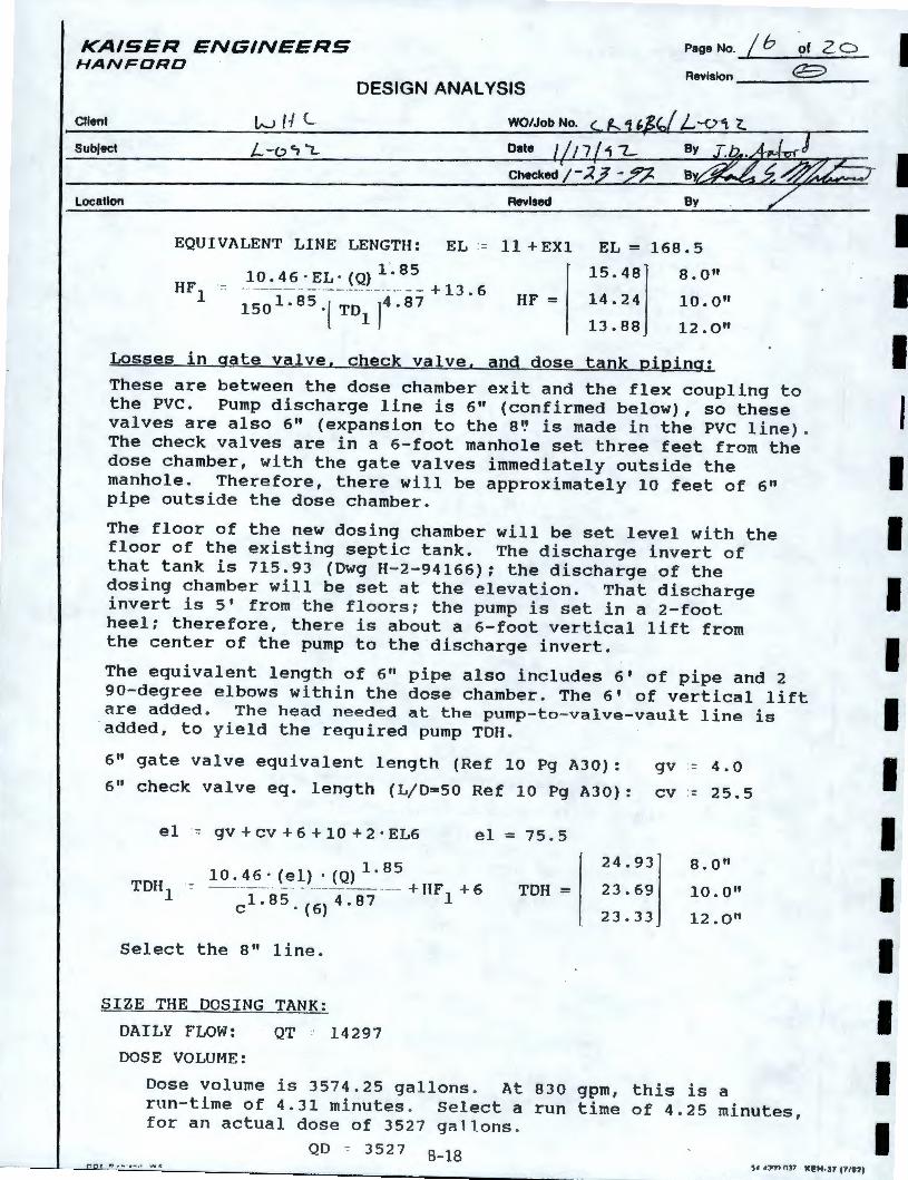
KAISER ENGINEERS HANFORD
Cllent
Subfect
Location
DESIGN ANALYSIS
WO/Job No.
Date
Revised
EQUIVALENT LINE LENGTH: EL = 11 + EXl
10.46·EL· (Q) 1'.BS HF1 :-: · - ----- -· · ·- ·-- ·-··-··· ·· ·•· - - +13.6
1501.85.l TD! ]4.87 HF=
Page No . ...... /_b _____ o_f _z_o_ Revision ___ <E> ___ _
EL= 168.5
15. 48! 8. O"
14.24 10.0"
13.88 12. O"
Losses in gate valve, check valve, and dose tank piping:
These are between the dose chamber exit and the flex coupling to the PVC. Pump discharge line is 6" (confirmed below), so these valves are also 6 11 (expansion to the a, is made in the PVC line) . The check valves are in a 6-foot manhole set three feet from the dose chamber, with the gate valves immediately outside the manhole. Therefore, there will be approximately 10 feet of 6" pipe outside the dose chamber.
The floor of the new dosing chamber will be set level with the floor of the existing septic tank. The discharge invert of that tank is 715 . 93 (Dwg H-2-94166); the discharge of the dosing chamber will be set at the elevation. That discharge invert is 5' from the floors; the pump is set in a 2-foot heel; therefore, there is about a 6-foot vertical lift from the center of the pump to the discharge invert.
The equivalent length of 6" pipe also includes 6' of pipe and 2 90-degree elbows within the dose chamber. The 6 1 of vertical lift are added. The head needed at the pump-to- valve-vault line is added, to yield the required pump TOH .
6" gate valve equivalent length (Ref 10 Pg A30): gv - 4.0
6" check valve eq. length (L/0=50 Ref 10 Pg A30): cv - 25.5
e 1 · = gv + CV + 6 + 10 + 2 · E L6 el= 75.5
10. 46 · (el) · (Q) 1. 85 =- - ··- --- - - ·· ··-· ·-- ---- ·-··-- + HF + 6
cl.BS. ( 6 ) 4.87 1 TOH=
Select the B" line.
SIZE THE DOSING TANK:
DAILY FLOW: QT 14297
DOSE VOLUME:
24.93
23.69
23.33
8. O"
10.0 11
12. 0 11
Dose volume is 3574.25 gallons . At 830 gpm, this is a run-time of 4.31 minutes . Select a run time of 4 . 25 minutes, for an actual dose of 3527 gallons .
QD --= 3527 B-lS 0 II~ .. , ... ,, WA 5• , :w, 037 1(£tf.3f (1187)
I I I I I I I I I I I I I I I I I I I
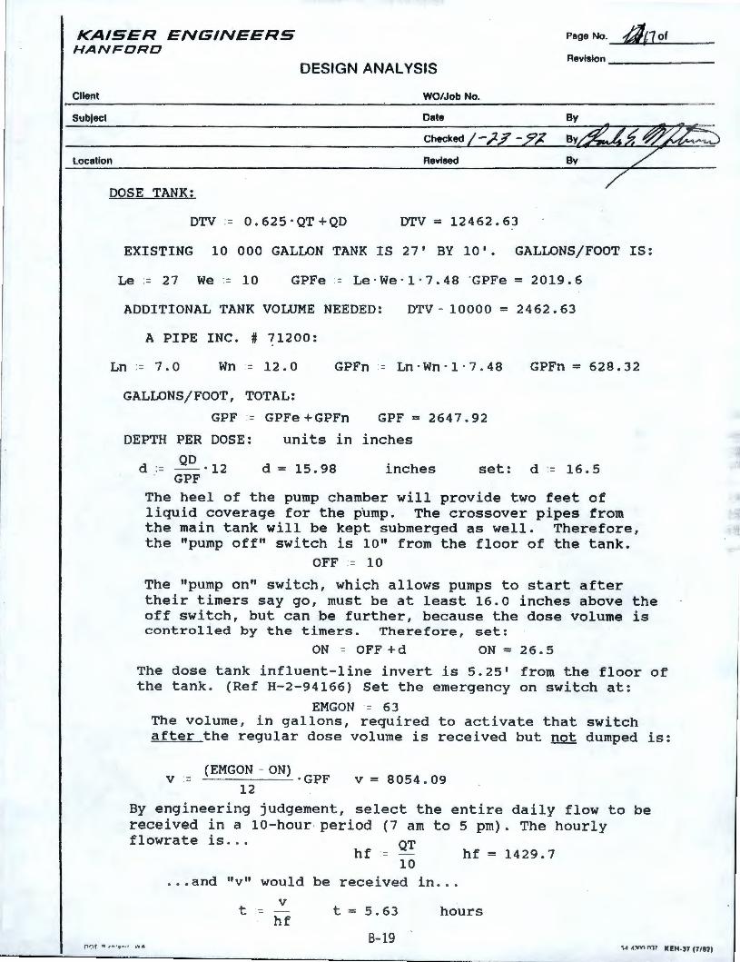
KAISER ENGINEERS HANFORD
Page No. dn of
DESIGN ANALYSIS Revision ______ _
Client WO/Job No.
SubJect Date
Checked/-/-f-_z'7 Location Revised
DOSE TANK:
DTV = 0 . 6 2 5 · QT + QD DTV = 12462.63
EXISTING 10 000 GALLON TANK IS 27' BY 10'. GALLONS/FOOT IS:
Le = 27 We := 10 GPFe := Le·We·1 · 7 . 48 "GPFe = 2019.6
ADDITIONAL TANK VOLUME NEEDED: DTV - 10000 = 2462. 63
A PIPE INC. # ~1200:
Ln = 7.0 Wn = 12.0 GPFn - Ln·Wn · 1 · 7 . 48 GPFn = 628.32
GALLONS/FOOT, TOTAL:
GPF - GPFe + GPFn GPF = 2647.92
DEPTH PER DOSE: units in inches
QD d := -·12
. GPF d = 15.98 inches set: d = 16.5
The heel of the pump chamber will provide two feet of liquid coverage for the pump. The crossover pipes from the main tank will be kept submerged as well. Therefore, the "pump off" switch is 10" from the floor of the tank.
OFF = 10
The "pump on" switch, which allows pumps to start after their timers say go, must be at least 16.0 inches above the off switch, but can be further, because the dose volume is controlled by the timers. Therefore, set:
ON = OFF +d ON= 26 . 5
The dose tank influent-line invert is 5.25' from the floor of the tank . (Ref H-2-94166) Set the emergency on switch at:
EMGON = 63 The volume, in gallons, required to activate that switch after the regular dose volume is received but not dumped is:
V ·-.-_( E_M_G_O_N_-_O_N_) . GPF
12 V = 8054 . 09
By engineering judgement, select the entire daily flow to be received in a 10- hour - period (7 am to 5 pm). The hourly flowrate is. . . QT
hf - hf = 1429. 7
f'HJf ",.., , ,,. ,, ~'If A
10 .. . and "v" would be received in ...
V t =
hf t = 5 . 63
B-19
hours
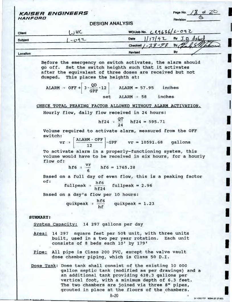
KAISER ENGINEERS HANFORD
Page No. IX of zb -®-
Revision ______ _
Client
Subject
Location
DESIGN ANALYSIS
B~fore the emergency on switch activates, the alarm should go off. Set the switch heighth such that it activates after the equivalent of three doses are received but not dumped. This places the heighth at:
ALARM .- OFF+[ 3 · QD · 12 ] ALARM = 57. 95 inches GPF
set ALARM - 58 inches
CHECK TOTAL PEAKING . FACTOR ALLOWED WITHOUT ALARM ACTIVATION.
Hourly flow, daily flow received in 24 hours:
QT hf24 = - hf24 = 595. 71
24 Volume required to activate alarm, measured from the OFF switch: ·
[ ALARM - OFF ] vr :=
12 · GPF vr = 10591. 68 gallons
To activate alarm in a properly-functioning system , this volume would have to be received in six hours, for a hourly flow of:
hf6 -vr 6
hf6 = 1765.2 8
Based on a full day of even flow , this is a peaking factor of:
fullpeak -hf6
fullpeak = 2.96 hf24
Based on a day's flow per 10 hours:
quikpeak -hf6 hf
quikpeak = 1 .23
SUMMARY:
System Capacity: 14 297 gallons per day
Area: 14 297 square feet per 50% unit, with three units built, used in a two per year rotation . Each unit consists of 8 beds each 10 1 by 179'
Pipe: All pipe is Class 200 PVC, except the valve vault dose chamber piping, which is Class 50 O.I .
Dose Tank: Dose tank shall consist of the existing 10 000 gallon septic tank (modified as per drawings) and a an additional tank providing 628.3 gallons per vertical foot, with a minimum depth of 6.3 feet . The two chambers are joined via three 8" pipes, grouted in place at the floors of the .chambers.
B-20 5• •JtJO n37 Kl!H-31 (f/87)
I I I I I I I I I I I I I I I I I I I
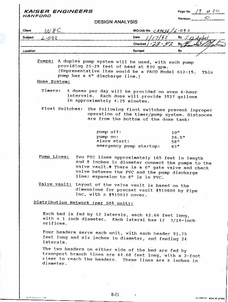
KAISER ENGINEERS HANFDRD
Page No. / 1 · of 2 0
Revision __ _..;£;>~-- -
Client
Subfect
Location
DESIGN ANALYSIS
WO/Job No.
Date
Checked
Revised
Pumps: l\ duplex pump system will be used, with each pump providing 25-29 feet of head at 830 gpm . (Representative item would be a Pl\CO Model 612-15. This pump has a 6 11 discharge line.)
Dose System:
Timers: 4 doses per day will be provided · on even 6- hour intervals. Each dose will provide 3527 gallons in approximately 4 ~25 minutes.
Float Switches: The following flont switches prevent inproper operation of the timer/pump system. Distances are from the bottom of the dose tank:
pump off: pump on: alarm start: emergency pump startup :
10 11
26.5" 58" 63"
Pump Lines: Two PVC lines ;ipproximately 165 feet in length and 8 inches in diameter connect the pumps to the valve vault.I There is a 6" gate valve and check valve between the PVC and the pump discharge line: expansion to B" is in PVC . ·
Valve vault: L;iyout of the vc1 lve vault is based on the dimensions for precast vault #510600 by Pipe Inc, with a #510633 cover.
Distribution Network {per 50% unit):
Each bed is fed by 12 laterals, each 42 . 66 feet long, withal inch diameter. Each lateral has 12 3/16- inch orifices .
Four headers serve each unit, with each header 91. 75 feet Jong and six inches in diameter, and feeding 24 laterals .
The two headers on either side of the bed are fed by transport brancl1 lines are 44.68 feet long, with a 2- foot riser to reach the headers . These lines are 6 inches in diameter .
B-21 ~• •Jm OJ7 ICl:H-31 (71821
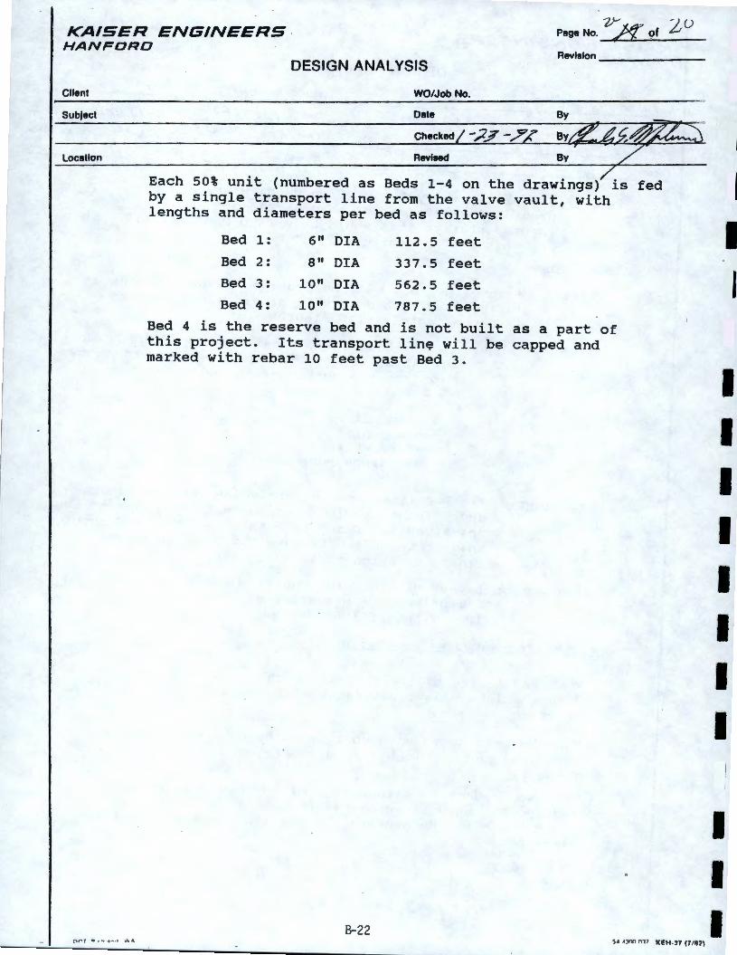
KAISER ENGINEERS · HANFORD
v--- -;u Page No. g" of µ
Client
SubJact
Location
o r , ,. , .. .. ... , ,,,., ,.
DESIGN ANALYSIS Revision ______ _
WO/Job No.
Date By
Each 50% unit (numbered as Beds 1-4 on the drawings) is fed by a single transport line from the valve vault, with lengths and diameters per bed as follows:
Bed 1:
Bed 2:
Bed 3:
Bed 4:
6 11 DIA
8" DIA
10" DIA
10" DIA
112.5 feet
337.5 feet
562.5 feet
787.5 feet
Bed 4 is the reserve bed and is not built this project. Its transport lin~ will be marked with rebar 10 feet past Bed 3.
B-22
as a part of capped and
S• •Y'tl 017 Kl!H-37 (7/87)
I I
I I I
I I I I I I I I
I I I
C-0
' ~~INTENANCE ENGINEERING SERVICES Issue Date PREVENTIVE MAINTENANCE PROCEDURE ----SEPTIC TANK INSPECTION - 200 E, 200 W, ANO 600 AREAS
Impact Level 4
Attachment D
2M24059 Rev. O Page 2 of 12
r\ i:·,:, r; 1::"1~ t~,::osrl: i ·, :"6ii -~11t~ ~
Frequency: Annual Craft: Pipefitter
1.0 PURPOSE
2.0 2. I
3 . 0
3 . 1
4.0
This procedure provides a safe and uniform way to perform insP.ection of 200- E, 200-W, and 600 Areas septic tanks to determine need for cleaning and/or pumping .
REFERENCES Hanford Drawings, as required (see Data Sheets).
PERSONNEL REQUIREMENTS Obtain a Health Physics Technician (HPT) for survey coverage as required .
PRECAUTIONS AND LIMITATIONS 4. 1 If this procedure cannot be performed as written, stop work. Return
equipment to safe configuration and inform Maintenance Supervisor that procedure cannot be performed as written, and a revision or Field Change Notice is required.
4. 2 Rope off the area once the excavation and tank opening process begins to prevent personnel injury at the work site.
4.3 Do not enter any areas designated as "Radiation Areas" or "Surface Contamination Areas" without the approval of an IIPT .
5.0 TOOLS, EQUIPMENT ANO MATERIALS 5. 1 Rigid clear plastic tube, about I in . diameter and long enough to
mea~ure tank depth .
5. 2 Excavation equipment.
5.3 Gloves and other personal protective equipment (PPE). 5. 4 Rags .
5.5 Rigging equipment as required for heavy tank covers . 5.6 Ruler or yardstick .
:---------------------------------------------------------------------------- : C-1
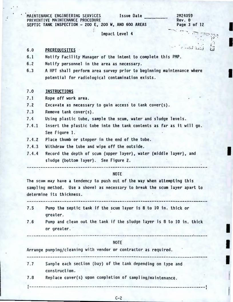
' MAINTENANCE ENGINEERING SERVICES Issue Date PREVENTIVE MAINTENANCE PROCEDURE ----
2M24059 Rev. 0
SEPTIC TANK INSPECTION - 200 E, 200 W, AND 600 AREAS Page 3 of 12 - -... .
Impact level 4
• !
6 .0
6. I
6 . 2
6.3
PREREOUIS ITES • • l • '•I :. i, .:.·.i
7.0 7 .1
7. 2
7.3 7. 4
7 . 4 . 1
Notify Facility Manager of the intent to complete this PMP . Notify personnel in the area as necessary.
A HPT shall perform area survey prior to beginning maintenance where potential for radiological contamination exists .
INSTRUCTIONS Rope off work area. Excavate as necessary to gain access to tank cover(s).
Remove tank cover(s) . Using plastic tube, sample the scum, water and sludge levels. Insert the plastic tube into the tank contents as far as it will go .
See Figure 1.
7.4 . 2 Place thumb or stopper in the end of the tube.
7. 4.3 Withdraw the tube and wipe off the outside.
7. 4. 4 Record the depth of scum {upper layer), water (middle layer), and sludge (bottom layer). See Figure 2.
NOTE The scum may have a tendency to push out of the way when attempting this sampling method . Use a shovel as necessary to break the scum layer apart to determine its thickness.
7. 5 Pump the septic tank if the scum layer is 8 to 10 in . thick or greater .
7.6 Pump and clean out the tank if the sludge layer is 8 to 10 in. thick
or greater. ·
NOTE Arrange pumping/cleaning with vendor or contractor as required .
7. 7 Sample each section (bay) of the tank depending on type and
construction . 7.8 Replace cover(s) upon completion of sampling/maintenance .
----------------------------------------------------------------------------
C-2
I I
I
I
I I I
· 'MAINTENANCE ENGINEERING SERVICES Issue Date ----PREVENTIVE MAINTENANCE PROCEDURE SEPTIC TANK INSPECTION - 200 E, 200 W, AND 600 AREAS
7.9 7.10 7 . 11
7 . 12
Impact Level 4
Fill in access holes as required. Remove temporary barricades, ropes, etc . Shift drainage fields on tanks so equipped. Complete necessary Data Sheets .
8.0 RESTORATION
2M24059 Rev. 0 Page 4 of 12
8. 1 Verify all equipment removed from the job s ite and properly stored'.
9.0 TESTING AND ACCtPTANCE None .
10 .0 DISPOSITION 10 . l Report any deficiencies and/or probable cause of early failure to the
Maintenance Manager. 10 . 2 Inform Operations management and Maintenance/Facility management that
procedure is complete. 10 . 3 Return Data Sheets to Maintenance or Facility Manager, as requested.
C-3
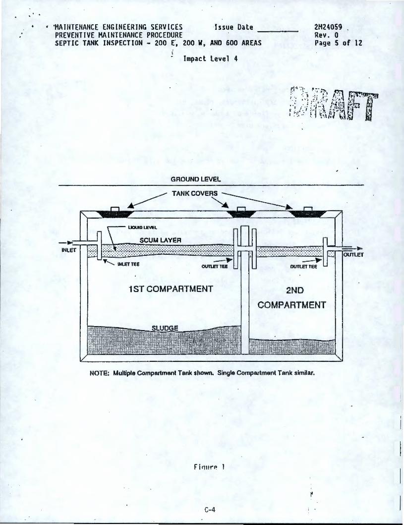
• 'MAIHTENANCE ENGINEERING SERVICES Issue Oate PREVENTIVE MAINTENANCE PROCEDURE ----
2M24059 . Rev. 0
SEPTIC TANK INSPECTION - 200 E·, 200 W, AND 600 AREAS Page 5 of 12
Impact Level 4
r: ·;·.-r .. ~::·:7-, B·· ~ : . ·. , -:: , ... I: ·' li-;'f ,'.911!"~ ·. · ... · . .. _,.-.. ~ .·.:.· ,. ')'h ·'.
; . ; ! . . , ··. . I, • 1'::1 ;_.;:· . ' • · , ... . •,•,. ·I ; , ., .-- t·· .1,-1 r • .' f ! . , . '4 , ;..,• • ~• : . ' , .•• ·. :· f -:- . .. ,· rA ~} • . ';• .. ~- ~-~., ;:. ~(t ~,,., .
GROUND LEVEL
~ TANKCOVERS ----- . .
~ ~ - -----... UOUIO l.E'n:l
,, .......... INlETTEE _ ,...
OUl\.ETlEE
1 ST COMPARTMENT
_ ,... OllnETTEE
2ND
COMPARTMENT
NOTE: Multiple Compartment Tank shown. Single Compartment Tank similar.
Fi ri11 r11 1
C-4
---.----• ..._ OUTl.Ef
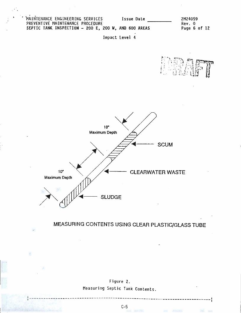
. I •
• ~AINTENANCE ENGINEERING SERVICES Issue Date PREVENTIVE MAINTENANCE PROCEDURE ----SEPTIC TANK INSPECTION - 200 E, 200 W, AND 600 AREAS
Impact Level 4
10"
SCUM
2M24059 Rev. 0 Page 6 of 12
10·
Maximum Depth CLEARWATER WASTE
SLUDGE
MEASURING CONTENTS USING CLEAR PLASTIC/GLASS TUBE
Figure 2.
Measuring Septic Tank Contents.
:----------------------------------------------------------------------------: C-5
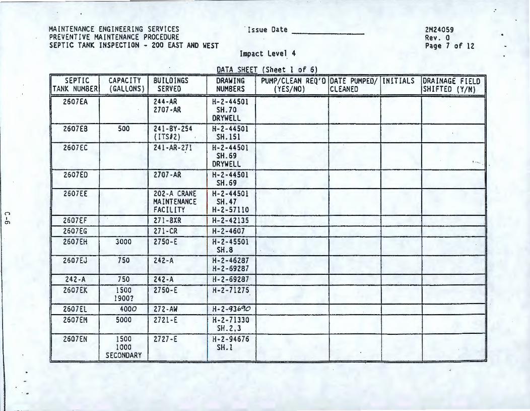
n I
°'
. ..
MAINTENANCE ENGINEERING SERV ICES PREVENTIVE MAINTENANCE PROCEDURE
· Is sue Dat e -------SEPTIC TANK INSPECTION - 200 EAST ANO WEST
Impact Level_ 4
DATA SHEET (Sheet 1 of 6) SEPTIC CAPACITY BUILD INGS DRAWING PUMP/CLEAN REQ'O DATE PUMPED/
TANK NUMBER (GALLONS) SERVED NUMBERS (YES/NO) CLEANED 2607EA 244-AR H-2-44501
2707-AR SH .70 ORYWELL
2607EB 500 241-BY-254 H-2 -44501 {ITSl2) SH .151
2607EC 241 -AR-271 H-2-44501 SH . 69
ORYWELL 2607ED 2707 -AR H-2-44501
SH .69 2607EE 202-A CRANE H-2-44501
MAINTENANCE SH.47 FACILITY H-2-57110
2607EF 271 -BXR H-2-42135 2607EG 271-CR H-2-4607 2607EH 3000 2750-E H-2-45501
SH.8 2607EJ 750 242-A H-2-46287
H-2-69287 242-A 750 242-A H-2-69287
2607EK 1500 2750-E H-2 -71275 1900?
2607EL 4000 272-AW H-2 -'13bC}O 2607EM 5000 2721-E H-2-71330
SH .2,3 2607EN 1500 2727-E H-2-94676
1000 SH. l SECONDARY
INITIALS
2M24059 Rev . 0 Page 7 of 12
DRAINAGE FIELD SHIFTED (Y/N)
~ .. ' .
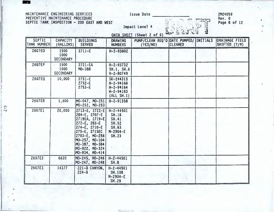
I , n I I ! '-I
-MAINTENANCE ENGINEERING SERV ICES PREVENTIVE MAINTENANCE PROCEDURE SEPTIC TANK INSPECTION - 200 EAST AND WEST
SEPTIC CAPACITY BUILDINGS DRAWING TANK NUMBER (GALLONS) SERVED NUMBERS
2607EO 1500 2711-E H-2-93802 1000
SECONDARY 2607EP 1500 2721-EA H-2-93 732
1000 M0-388 SH .1, SH. 6 SECONDARY ' H-2-80749
2607EQ 10,000 2751-E SK-244315 2752-E H-2-94166 2753-E H-2-94164
H-2-94163 (ALL SH . I)
2607ER 1,600 M0-047, M0-251 H-2-91358 M0-252, M0-253
2607El 20 , 000 2713-E, 2722-E H-2-44501 284-E, 2707-E SH .16 2719EA, 2719-E SH.41 272-E, 283-E SH.52 274-E, 2710-E SH.63 275-E, 2715EC M-2904-E 2703-E, M0-256 SH.23 M0-257, M0-104 M0-387, M0-384 M0-922, M0-324 M0-934, M0-414
2607£2 6620 M0-245, M0-246 H-2-44501 M0-247, M0-248 SH.8
2607£3 14377 221-B CANYON, H-2-44501 224-B SH .108
M-2904-E SH . 28
Issue Date -------
PUMP/CLEAN REQ'O DATE PUMPED/ (YES/NO) CLEANED
INITIALS
2M24059 Rev. 0 Page 8 of 12
DRAINAGE FIELD SHIFTED (Y/N)
1
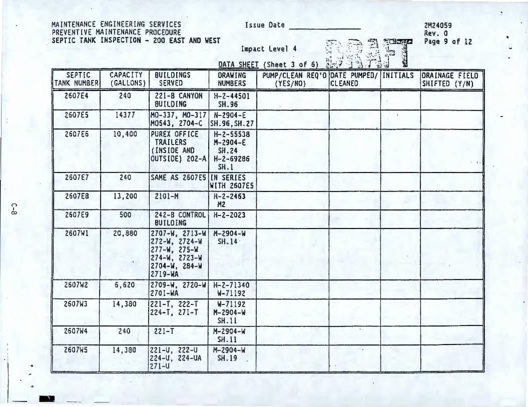
n I
co
• ..
MAINTENANCE ENGINEERING SERVICES PREVENT[VE MAINTENANCE PROCEDURE
Issue Date -------SEPTIC TANK INSPECTION - 200 EAST AND WEST
Impact Level 4
DATA SHEET (Sheet 3 of 6) ~-~~~ ! ·:J ·:~\ :· ',:ij (:
SEPTIC CAPACITY BUI LDINGS DRAWING PUMP/CLEAN REQ'D DATE PUMPED/ INITIALS TANK NUMBER (GALLONS } SERVED NUMBERS (YES/NO} CLEANED
2607£4 240 221-8 CANYON H-2-44501 BUILDING SH.96
2607£5 14377 M0-337, M0-317 N-2904-E M0543, 2704-C SH .96,SH.27
2607E6 10,400 PUREX OFFI CE H-2--55538 TRAILERS M-2904-E
( INSIDE AND SH.24 OUTS IDE) 202-A H-2-69286
SH. l 2607E7 240 SAME AS 2607£5 IN SERIES
WITH 260 7ES 2607£8 13, 200 2101-M H-2-2463
M2 2607£9 500 242-8 CONTROL H-2-2023
BUILD ING 2607Wl 20,880 2707 -W, 271 3-W M-2904-W
272-W, 2724-W SH.14 277-W, 275-W 274-W, 2723-W 2704-W, 284-W 2719-WA
2607W2 6,620 2709-W, 2720-W H.;.2-71340 2701-WA W-71192
2607W3 14, 380 221-T , 222-T W-71192 224-T, 271-T M-2904-W
SH . 11 2607W4 ·240
( 221-T M-2904-W
{_ SH . 11 2607W5 14,380 221-U, 222-U M-2904-W
224-U , 224-UA SH .19 271-U
-
2M24059 Rev . O Page 9 of 12
DRAINAGE FIELD SHIFTED (Y/N)
. ! •
• ;..
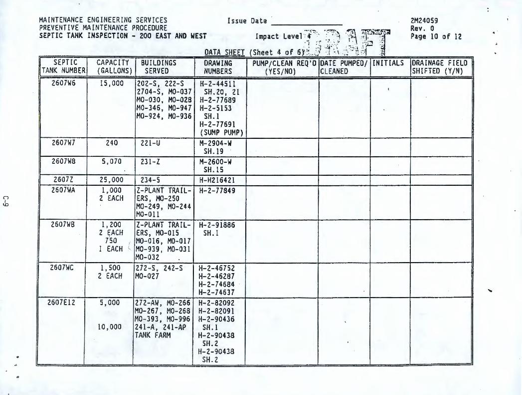
("") I ~
..
MAINTENANCE ENGINEERING SERVICES PREVENT IVE MAINTENANCE PROCEDURE
Issue Date -------SEPTIC TANK INSPECTION - 200 EAST AND WEST Impact Leve 1 : ct · :·· : ; · ·,., ' l', ., •· -- -,:~. •-.~~~·, -~-~ ~!"~-"~~,,(·
... ; ··:· ··- .. :, . ~ ·. ·_·, ._\i ::_~ • . .. , . ; ~; -·t - r--. • ••a; ''"• \ . -•~•• .. 1 .
DATA SHEET (Sheet 4 of 6Y,::_,./} . -_; ~-\ .·.:: ~ .. :;: ~-:, -~
SEPTIC CAPACITY BUILDINGS DRAWING PUMP/CLEAN REQ'O DATE PUMPED/ INITIALS TANK NUMBER (GALLONS) SERVED NUMBERS (YES/NO) CLEANED
2607W6 15,000 202-S, 222-S H-2-44511 2704-S, M0-037 SH. 20, 21 I
M0-030, M0-028 H-2-77689 M0-346 , M0-947 H-2-5153 M0-924, M0-936 SH. l
H-2-77691 (SUMP PUMP)
2607W7 240 221-U M-2904-W SH . 19
2607\.18 5,070 231-Z M-2600-W SH . 15
2607Z 25,000 234-5 H-H216421 2607\.IA 1,000 Z-PLANT TRAIL- H-2-77849
2 EACH ERS, M0-250 M0-249 , M0-244 M0-011
2607\.18 1, 200 Z-PLANT TRAIL- H-2-91886 2 EACH ERS , M0-015 SH . l
tso M0-016 , M0-017 1 EACH l M0-939 , M0-031
M0-032 2607WC 1, 500 272-S , 242-S H-2-46752
2 EACH M0-027 H-2-46287 H-2-74684 -H-2-74637
2607El2 5,000 272-AW , M0-266 H-2-82092 M0-267 , M0-268 H-2-82091 M0-393, M0-996 H-2-90436 .
10,000 241-A, 241-AP SH . I TANK FARM H-2-90438
SH.2 H-2-90438
SH . 2
2M24059 Rev . 0 Page 10 of 12
DRAINAGE FIELD SHIFTED (Y/N)
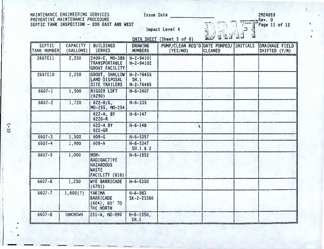
n I ......
0
.. •
MAINTENANCE ENGINEER ING SERVICES PREVENTIVE MAINTENANCE PROC EDURE
Issue Date -------SEPTIC TANK INSPECTION - 200 EAST ANO WEST
Impact Level 4 . DATA SHEET (Sheet 5 of 6) ~;;.:,-1 ; . ::..:,
SEPTIC CAPAC ITY BUILDINGS DRAWING PUMP/CLEAN REQ ' D DATE PUMPED/ TANK NUMBER (GALLONS ) SERVED NUMBERS (YES / NO) CLEANED
2607£11 2, 250 2400-E , M0- 386 H-2-94101 TRANSPORTABLE H-2-94102 GROUT F AC IL ITY
2607El0 2,250 GROUT , SHALLOW H-2-76455 LAND D(SPOSAL SH . I SITE TRA ILERS H-2-76465
6607-1 1,500 RIGGER LOFT H-6-2407 (6290 )
6607-2 1, 720 622 -R/ G, H-6- 335 M0- 255, M0- 254
622 -A, BY H-6- 147 622G-R 622-A BY H-6-148 \ 622-GR
6607-3 1, 500 609-G H-6- 5357 6607 - 4 1,900 609-A H-6-5347
SH . I & 2 6607-5 1,000 NON- H-6-1552
RADIOACTI VE HAZARDOUS WASTE FAC ILITY (616)
6607-6 1, 250 WYE BARRICADE H-6- 5350 (6701 )
660 7- 7 1, 600 (?) YAK IMA H-6-983 BARRI CADE SK- 2-23366 (604 ), 60' TO THE NORTH
660 7-8 UNKNOWN 251 -W, M0-990 H-6- 1550, SH . 1
~ . . . INITIALS DRAINAGE FIELD
SHIFTED (Y/N)
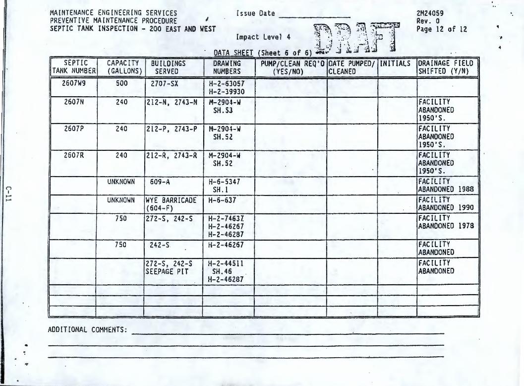
n I ...... ......
•
MAINTENANCE ENGINEERING SERVICES Issue Date PREVENTIVE MAINTENANCE PROCEDURE 1 -------SEPTIC TANK INSPECTION - 200 EAST AND WEST
Impact Level 4
DATA SHEET ( Sheet 6 of 6) ~.- ..
SEPTIC CAPACITY BUILDINGS DRAWING PUMP/CLEAN REQ'O DATE PUMPED/ TANK NUMBER (GALLONS) SERVED NUMBERS (YES/NO) CLEANED
2607W9 500 2707-SX H-2-63057 H-2-39930
2607N 240 212-N, 2743-N M-2904-W SH.SJ
2607P 240 212-P, 2743-P M-2904-W SH.5Z
2607R 240 212-R , 2743-R M-2904-W SH.52
UNKNOWN 609-A H-6-5347 SH. l
UNKNOWN WYE BARRICADE H-6-637 (604-F)
750 272-S, 242-S H-2-7463Z H-2-46267 H-2-46287
750 242-S H-2-46267
272-S , 242-S H-2-44511 SEE.PAGE PIT SH.46
H-2-46287
ADDITIONAL COMMENTS:
INITIALS
2M24059 Rev. a Page 12 of 12
' .
DRAINAGE FIELD SHIFTED (Y /N)
FACILITY ABANDONED 1950 1 S. FACILITY ABANDONED 1950 1 S. FACILITY ABANDONED 1950 1 S. FACILITY ABANDONED 1988 FAC Ill TY ABANDONED 1990 FACILITY ABANDONED 1978
FAC Ill TY ABANDONED FACILITY ABANDONED
____________________ _.;... _______ _
·-
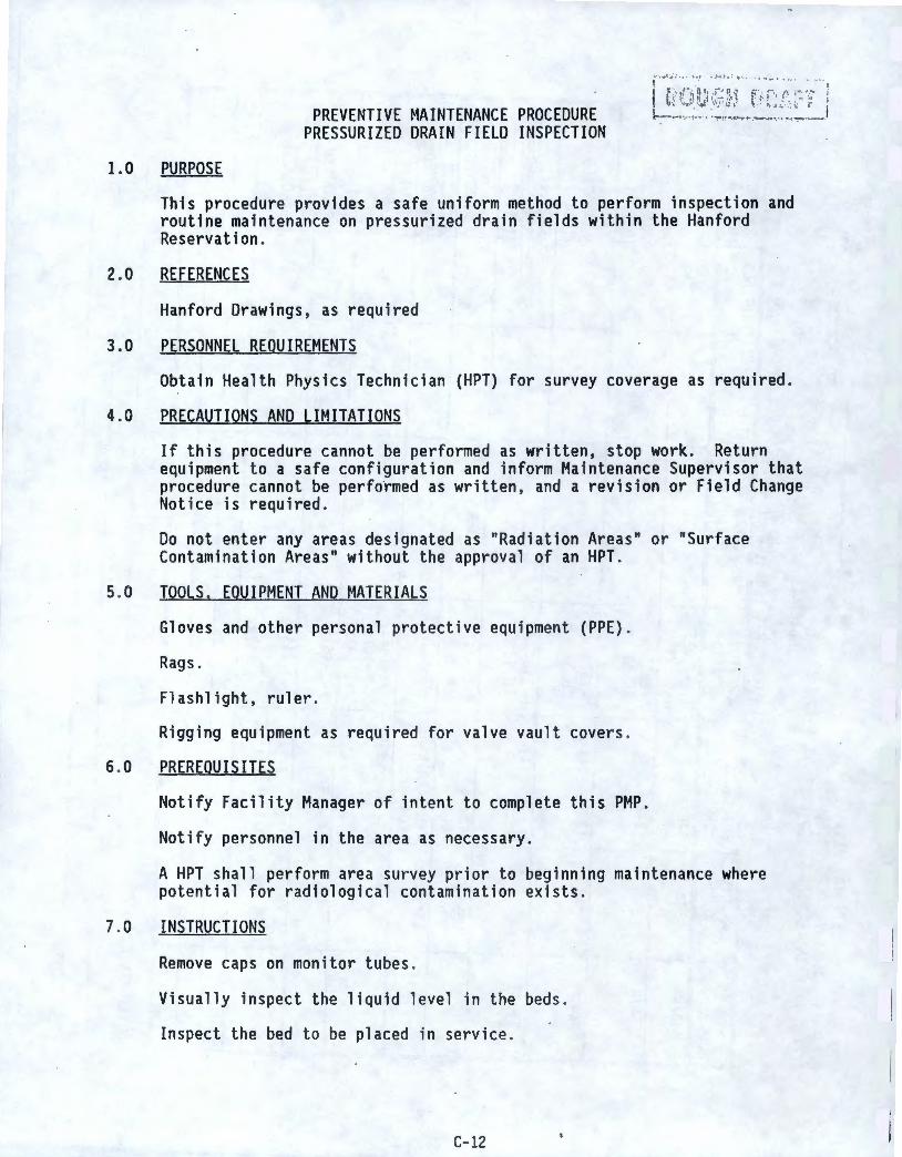
1.0 PURPOSE
PREVENTIVE MAINTENANCE PROCEDURE PRESSURIZED DRAIN FIELD INSPECTION
:" .... , ,. ; ... .. , . .. : . ,. . ; " --. ' ".
1 t/ <.) ru.;;,~~i~ ~·J r '. c~ /·· __ ~:: ·r ~ . .
r.--" ·---_•"• ·.···~• ~· • • ';'9 · • .~. r."•r •· .... --., ••. , , • ·• --:--·~••·••
This procedure provides a safe uniform method to perform inspection and routine maintenance on pressurized drain fields within the Hanford Reservation.
2.0 REFERENCES
Hanford Drawings, as required
3.0 PERSONNEL REQUIREMENTS
Obtain Health Physics Technician (HPT) for survey coverage as required .
4.0 PRECAUTIONS AND LIMITATIONS
If this procedure cannot be performed as written, stop work . Return equipment to a safe configuration and inform Maintenance Supervisor that procedure cannot be perfotmed as written , and a revision or Field Change Notice is required.
Do not enter any areas designated as "Radiati on Areas" or "Surface Contamination Areas" without the approval of an HPT .
5.0 TOOLS. EQUIPMENT AND MATERIALS
Gloves and other personal protect i ve equ ipment (PPE) .
Rags.
Flashlight, ruler.
Rigging equipment as required for valve vault covers .
6.0 PREREQUISITES
Notify Facility Manager of intent to complete this PMP .
Notify personnel in the area as necessary.
A HPT shall perform area survey prior to beginning maintenance where potential for radiological contamination exists.
7.0 INSTRUCTIONS
Remove caps on monitor tubes .
Visually inspect the liquid level in the beds .
Inspect the bed to be placed in service .
C-12
Record the inspection results.
Rope off area around the valve vault.
Remove valve vault cover .
Remove effluent pumps from service.
Open and close valves in accordance with schedule.
Place effluent pumps back in service.
Replace valve vault cover .
Manually cycle pumps to insure pump operation .
8.0 RESTORATION
Verify all equipment removed from the job site and properly stored .
9.0 TESTING AND ACCEPTANCE
None .
10.0 DISPOSITION
Report any abnormalities (i.e ponded water in the bed to near the surface) and/or probable cause to the Maintenance Manager .
Inform Operations management and Maintenance/Facility management that the procedure is complete.
Return Data Sheets to Maintenance of Facility Manager, as required.
C-13
.I
0-0
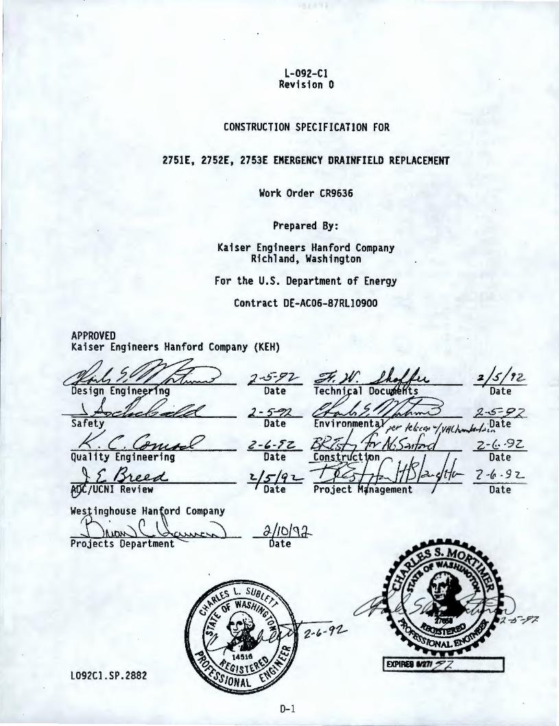
L-092-Cl Revision 0
CONSTRUCTION SPECIFICATION FOR
2751E, 2752E, 2753E EMERGENCY DRAINFIELD REPLACEMENT
APPROVED
Work Order CR9636
Prepared By:
Kaiser Engineers Hanford Company Richland, Washington
For the U.S. Department of Energy
Contract DE-AC06-87Rll0900
Kaiser Engineers Hanford Company (KEH)
_l Safety
~G~ Quality Engineering
~l~ /UCNI Review
Wes inghouse Han ord Company
L092Cl .SP .2882
2 -S-,?'l--Date
J- 5"---:72 Date
f)./tD[C\d---Oate
0-1
a/sj,z '6ate -
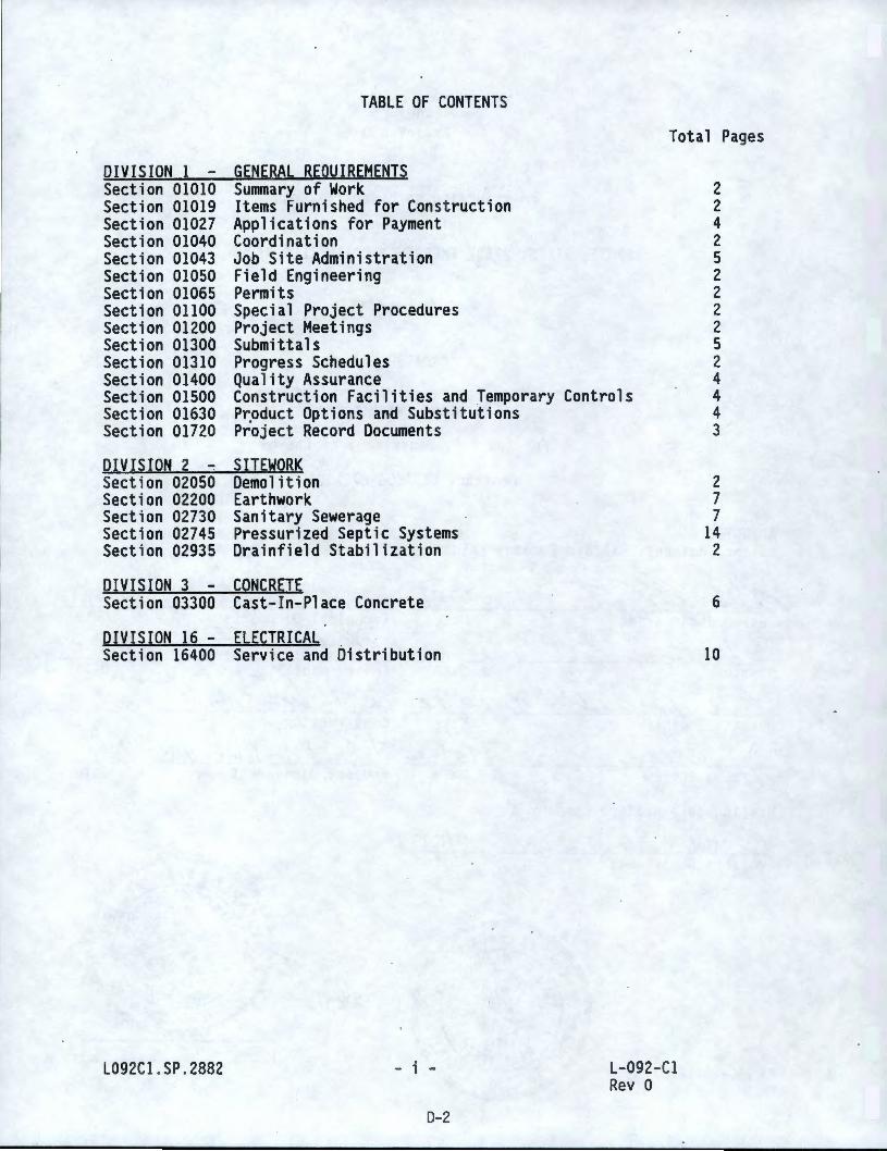
TABLE OF CONTENTS
Total Pages
DIVISION 1 - GENERAL REQUIREMENTS Section 01010 Summary of Work 2 Section 01019 Items Furnished for Construction 2 Section 01027 Applications for Payment 4 Section 01040 Coordination 2 Section 01043 Job Site Administration 5 Section 01050 Field Engineering 2 Section 01065 Permits 2 Section 01100 Special Project Procedures 2 Section 01200 Project Meetings 2 Section 01300 Submittals 5 Section 01310 Progress Schedules 2 Section 01400 Quality Assurance 4 Section 01500 Construction Facilities and Temporary Controls 4 Section 01630 P~oduct Options and Substitutions 4 Section 01720 Project Record Documents 3
DIVISION 2 ~ SITEWORK Section 02050 Demolit i on 2 Section 02200 Earthwork 7 Section 02730 Sanitary Sewerage 7 Section 02745 Pressurized Septic Systems 14 Section 02935 Drainfield Stabilization 2
DIVISION 3 - CONCRETE Section 03300 Cast-In-Place Concrete
DIVISION 16 - ELECTRICAL _ Section 16400 Service and Distribution
L092Cl .SP.2882 - i -
D-2
L-092-Cl Rev O
6
10
PART 1 - GENERAL
1. 1 INTRODUCTION
SECTION 01010
SUMMARY OF WORK
1.1.1 Project L-092 will install a septic tank and a pressurized drainfield system in the 200 East Limited Area in the Controlled Access Area of the Hanford Site, approximately 25 road miles northwest of Richland, Washington.
1.2 STATEMENT OF WORK
1.2.1 Scope: Work consists of furnishing labor, equipment, and materials to provide an operating system in accordance with the Contract Documents .
1.2.2 Work Included: Following itemization is intended to be broad in scope to identify major work elements and is not all inclusive .
1.2.2.1 Furnish and install new 6000 gal septic tank.
1.2.2.2 Furnish and install manholes and sewer lines between the existing lines and the new septic tank.
1.2.2.3 Construct 3 pressure distribution drainfields (8 beds per field).
1.2.2.4 Furnish and install pressure sewer lines between the pumps and the valve vault .
1.2 .2.5 Furni .sh and install valve vault and plumbing within the vault.
1.2.2.6 Clean and modify existing septic tank.
1.2 .2. 7 Furnish and i nsta 11 electrical service.
1.2.2.8 Furnish and i nsta 11 pumps and pump panel.
1. 2. 2.9 Furnish and i nsta 11 drainfield stabilization .
1.2.3 Work Not Included: Foll9wing work elements are part of Project and are covered by other documents noted and will be done concurrently with work included in the Contract Documents.
1.2.3.1 Pumping and disposal of influent to the septic tanks . This will be accomplished by others during the project.
1.2 .3.2 Items shown on the Drawings to be done by others .
L092Cl.SP.2882 01010 - 1
0- 3
L-092 -Cl Rev O
1:3 SEQUENCE OF WORK
1.3.1 Work shall be accomplished in following sequence to maintain the operational function of the system.
1.3.1.1 Construct the sewer lines, septic tank, valve vault, drainfield beds, and connecting lines between the dosing tank to just short of the existing tank, the valve vault to just short of the existing disposal field, and the electrical service.
1.3 . 1.2 Redirect the raw sewage flow through the new manholes to the new septic tank. The new septic tank will be emptied (pumped) regularly (see subparagraph 1.2.3.1).
1.3.1.3 Clean the existing tank. Liquids will be removed by others .
1.3.1.4 Modify the existing tank, construct balance of connecting lines, and install the pumps.
1.3. 1.5
1.4
Perform final system tests.
DRAWINGS
1.4.2 Drawings which show work to be accomplished by the Contract Documents are listed in the Schedule of Drawings.
PART 2 - PRODUCTS
Not Used
PART 3 - EXECUTION
Not Used
L092Cl.SP . 2882
ENO OF SECTION
01010 - 2
D-4
L-092 -Cl Rev 0
SECTION 01019
ITEMS FURNISHED FOR CONSTRUCTION
PART 1 - GENERAL 1. 1 REFERENCES
1.1 .1 Reference Standards and Specifications: The following standards and specifications, including documents referenced therein, form part of this Section to extent designated herein .
1.1.1.1 Code of Federal Regulations (CFR)
Title 30 Mineral Resources
Part 56
1.2 SUBMITTALS: Not Used
1.3 GENERAL
Safety and Health Standards--Surface Metal Nonmetal Mines
1.3.1 Material and equipment furnished or made available for incorporation into the Work are identified in this Section. Other services and util~ties provided are covered in other sections of this Specification.
1.3.2 Meet the provisions of Section 9 of the Contract General Conditions for items furnished for construction .
1.3.3 Provide KEH access to premises where items furnished for construction are stored before incorporation into the Work.
1.4 MATERIAL AND EQUIPMENT
1.4 .1 Gravel and Sand
1.4.1.1 Unmined natural deposits are available at no cost from sites designated by KEH within 6 miles of Project site. KEH makes no representation that materials will meet physical properties required i n thi s Specification.
1.4. 1.2 If Contractor elects to utilize available gravel sites he shall furnish equipment and labor required to excavate, process, load, transport, and place material .
1.4. 1.3 Material shall be used only for the Work covered by this . Specification and no gravel or sand, processed or unprocessed, or concrete manufactured therefrom shall be transported off the Hanford Site.
1.4.1 .4 Access to gravel sites and travel between gravel and constructicn sites shall be on roads designated by KEH and use shall be in accordance with Section 01500.
L092Cl .SP . 2882 01019 - 1
0-5
L-092-Cl Rev 0
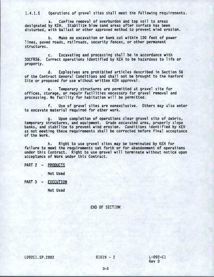
1.4.1.5 Operations of gravel sites shall meet the following requirements.
a. Confine removal of overburden and top soil to areas designated by KEH. Stabilize blow sand areas after surface has been disturbed, with ballast or other approved method to prevent wind erosion.
b. Make no excavation or bank _cut within 100 feet of power lines, paved roads, railroads, security fences, or other permanent structures.
30CFR56. property.
c. Excavating and processing shall be in accordance with Correct operations identified by KEH to be hazardous to life or
d. Explosives are prohibited articles described in Section 56 of the Contract General Conditions and shall not be brought to the Hanford Site or proposed for use without written KEH approval.
e. Temporary structures are permitted at gravel site for offices, storage, or repair facilities necessary for gravel removal and processing. No facility for habitation will be permitted.
f. Use of gravel sites are nonexclusive . Others may al~o enter to excavate material required for other work.
g. Upon completion of operations clear gravel site of debris, temporary structures, and equipment. Grade excavated area, properly slope banks, and stabilize to prevent wind erosion. Conditions identified by KEH as not meeting these requirements shall be corrected before final acceptance ~f the Work. · ·
h. Right to use gravel sites may be terminated by KEH for failure to meet the requirements set forth or for abandonment of operat i ans under this Contract. Right to use gravel will terminate without notice upon acceptance of Work under this Contract.
PART 2 - PRODUCTS
Not Used
PART 3 - EXECUTION
Not Used
L092Cl.SP . 2882
ENO OF SECTION
01019 - 2
D-6
L-092-Cl Rev 0
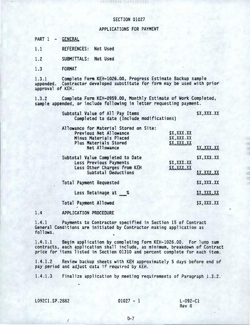
PART 1 - GENERAL
SECTION 01027
APPLICATIONS FOR PAYMENT
1.1 REFERENCES: Not Used
1.2 SUBMITTALS: Not Used
1.3 FORMAT
1.3 .1 Complete Form KEH-1026.00, Progress Estimate Backup sample appended. Contractor developed substitute for form may be used with prior approval of KEH.
1.3.2 Complete Form KEH-0959 .00, Monthly Estimate of Work Completed, sample appended, or include following in letter requesting payment .
Subtotal Value of All Pay Items sx,xxx .xx Completed to date (lnclud~ modifications}
Allowance for Material Stored on Site: Previous Net Allowance Minus Materials Placed Plus Materials Stored
Net Allowance
Subtotal Value Completed to Date Less Previous Payments Less Other Charges from KEH
Subtotal Deductions
Total Payment Requested
Less Retainage at_%
Total Pay~ent Allowed
1.4 APPLICATION PROCEDURE
sx ,xxx.xx sx,xxx .xx sx.xxx.xx
sx,xxx.xx sx.xxx.xx
sx.xxx.xx sx ,xxx .xx
sx.xxx .xx sx,xxx.xx $X.XXX.XX
sx,xxx .xx
1. 4. 1 Payments to Contractor specified in Section 15 of Contract General Condit i ons are ini t iated by Contractor making application as fa 11 ows .
1.4 .1.1 Begin application by completing Form KEH-1026.00 . For lump sum contracts, each application shall include, as minimum, breakdown of Contract price for items listed in Section 01310 and percent complete for each item.
1.4.1.2 Review backup sheets with KEH approximately 5 days before end of pay period and adjust data if required by KEH . ·
1.4 . 1.3 Finalize application by meeting requirements of Paragraph _1.3.2 .
L092Cl .SP . 2882 01027 - 1
0-7
L-092-Cl Rev 0
1.5 PAYMENT PROCEDURE
1.5.1 Upon receipt of application, KEH will audit data and check for compliance with requirements of Section 01720. When satisfied that Contract requirements are up-to-date, Form KEH-0959.00 will be signed by KEH .
1.5.2 Copy of signed Form KEH-0959.00 showing amount of payment to be made will be furnished to Contractor.
1.5.3 KEH will mail check to Contractor's designated address .
1.6 ADDITIONAL DATA REQUIRED
1.6 .1 When processing applications for payment and preparing payment documents, KEH may require data to substantiate and justify amounts requested. Processing of payment documents may be delayed if data is not forwarded expeditiously to KEH.
1.6.2 Requests for payment for equipment or material which Contractor has received, but has not installed, shall be accompanied by invoice or other data to provide evidence that title to equipment or material is held by Contractor.
PART 2 - PRODUCTS
Not Used
PART 3 - EXECUTION
Not Used
L092Cl .SP.2882 01027 - 2
0-8
L-092-Cl Rev 0
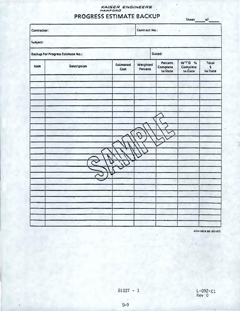
L
KAISER ENGINEERS · HANFORD
PROGRESS ESTIMATE BACKUP
Contractor: Contract No. :
Subject:
Backup for Progress Estimate No.: Dated:
Estimated Weighted Percent . Item Description Complete
Cost Percent to Date
A - \ \ -
1....-...\\ ,~; -< <"'- \\\ \ \,./\
- ( \' f\. VJ\ \,/\V ., ""\ I\\\ \V
" < '\. \.'\..''\' \. \ _)
~\~ ', \ '':\. V ( ~ \\ ) - '".~\) ...
'---' \ \'-"' ("--)) , ... .....__,
01027 - 3
0-9
..
Sheet of
WTD % Total Complete s
to Date to Date
KEH• ~026.00 (0) ·111)
L-092-Cl Rev 0
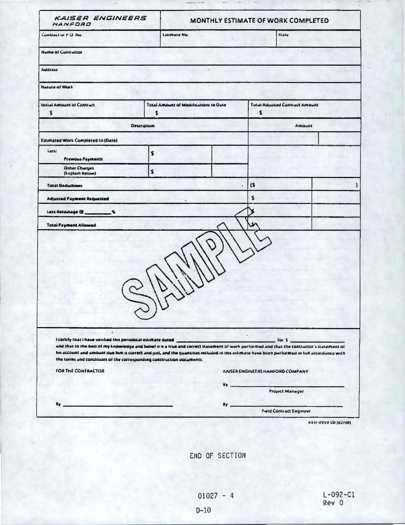
KAISER ENGINEERS HANFORD
(uut1.u.,l u, t" 0 Nu
Aua,.,,,
N,olwt•ulWUtlr.
ln,11 .. 1 Amo..n1 al Canu'""
s
Len: s
Oinc1Ch,o,1jo,, (tapi.,n llcl.:iwl S
MONTHLY ESTIMATE OF WORK COMPLETED
T u&•I Ao1wu,u.l C.:inu '"" Amawn1
s s Amaw111
Adj1med P•1'••nt aequellH S
...... lh,ol la lh• D<HI al ,.,, lr.-i.d<J• •Ad lwlNrl II 11 • uue •Ad ,auftl \l,OICfflCAI QI wu, IL 11•• Ilk m cll •nd lh,ol lh• ,unu ,o(tQI ·, u ,uotmcnl al
h11 .uaun1 •Ad'""'°""'' aue lwnl 11 COIIKI ,ond I""• .nd th4t qw.on111 .. , 1nclwd11d ,n 1n11 cu,m,uo, h•v• lk!cn po,,lu1mwd ,n h,U o1ccu1do1n,,: w,1h
lh• ,.,m, ....... UU\UlbUAI al inc (Qltc,jllkld"'9 WAIIIY(IIQII QQ(wmcnn .
FOR THE CONTRACTOR
By-------------------
"AISER ENGINEERS HANFORD COMPANY
Uy--------------------Uy------------------
END OF SECTION
01027 - 4
0- 10
f,cld Can11•ct Eng,n.-c,
,;. t H ·U'J~'J 00 (UlrJO)
L-092-Cl Rev 0
PART 1 GENERAL
SECTION 01040
COORDINATION
1.1 REFERENCES: Not Used
1.2 SUBMITTALS: Not Used
1.3 CONSTRUCTION ACTIVITIES
1.3.1 Coordinate construction activities to ensure efficient and orderly sequence of work, with provisions for accommodating items to be installed latef.
1.3 .2 It is not anticipated that other contractors noted in Section 29 of the Contract General Conditions will be working in vicinity of the Work included in this Specification.
1.4 WORK IN EXISTING FACILITIES
1.4.1 Buildings 2751E, 2752E, and 2753E are operating facilities. Work shall be planned and scheduled to prevent interference with plant operations and sustain safety of operating personnel.
1.4.2 Access to work area will be as directed by KEH to minimize disruptions to work force.
1.4.3· Keep work area safe and orderly for construction and operating personnel. Clean work area after each work period and stack tools and materials away from traffic areas.
1.5 CONNECTIONS TO EXISTING SYSTEMS
1.5. 1 Advance notice of work that will affect existing systems shall be given to KEH. Careful planning and scheduling of work is required to coordinate operations of existing systems to keep disruptions at minimum.
1.5.2 As required in subsection 50.8 of the Contract General Conditions, connections to existing systems shall be scheduled well in advance for work to be done. KEH will coordinate schedule with Contractor and user.
1.5.3 Connection shall be accomplished within 8 hours.
1.6 ACCESS TO WORK AFTER POSSESSION
1.6. 1 Access to warranty work as specified in Section 24 of the Contract General Conditions or access to work after possession as specified in Section 20 of the Contract General Conditions will be coordinated by KEH with other contractors, and users of facility. Notify KEH in advance of proposed work to minimize disruptions .
L092Cl .SP . 2882 01040 - l
D-11
L-092-Cl Rev a
PART 2 PRODUCTS
Not Used
PART 3 - EXECUTION
Not Used
L092Cl .SP .2882
END OF SECTION
01040 - 2
D-12
L-092-C l Rev .0
SECTION 01043
JOB SITE ADMINISTRATION
PART 1 - GENERAL
1. 1 REFERENCES
1.1.1 Reference Standards and Specifications: The following standards and specifications, including documents referenced therein, form part of this Section to extent designated herein .
1.1.1.1 American National Standards Institute (ANSI)
Z41-1983
287.1-1989
1.2 SUBMITTALS: Not Used
1.3 WORKING HOURS
Personnel .Protection -Protective Footwear
Practice for Occupational and Educational Eye and Face Protection
1.3.1 Regular day shift working hours are from 7:30 am to 4:00 pm, Monday through Friday, excluding holidays.
1.3.2 For other than regular day shift work refer to Section 51 of Contract General Conditions.
1.4 BADGE, DOSIMETER, ANO ORIENTATION
1.4 . 1 For work within the Controlled Access Area, and inside Limited Areas, badge, basic dosimeter, and orientation requirements will be in accordance with Section 56 of Contract General Conditions. ·
1.4.2 Badges will not be provided until notice to proceed letter has been signed and returned to KEH, supervisors have attended KEH safety training course, requirements of Section 55 of Contract General Conditions have been received and approved by KEH, and site labor conference and preconstruction meeting specified in Section 01200 have been completed .
1.5 EMERGENCY RESPONSE DRILLS
1.5. 1 Personnel working on Hanford Site shall participate in emergency response drills held approximately once each calendar quarter and lasting approximately one hour.
1. 5.2 Maintain daily log or other suitable record of personnel names, including subcontractors, working on Hanford Site .
L092Cl . SP .2882 01043 - 1
0- 13
l-092-Cl Rev 0
1.6 SECURITY
1.6.l General: Contractor employees shall comply with Sections 56 and 87 of Contract General Conditions. Copies of KEH security procedures will be provided upon request after contract award .
1.6.2 Security Escorts
1.6 . 2.1 Security Escorts are required for following. Personnel include all employees of the Contractor, his subcontractors, and lower tier companies.
a. Personnel working within 100, 200-East, 200- West, 300, and 400 Limited Areas if they do not have an unescorted security badge .
b. Personnel working within Protected Areas .
1.6.2 . 2 Provide fo1lowing
a. List of employees and vehicles for which security escorts are required. Submit list one week before start of work in Limited Areas and 2 weeks before start of work in Protected Areas.
b. Weekly work schedule of employees. Submit schedule no later than Thursday of week preceding escort requirement.
1.6.2 .3 KEH will provide 1 escort for every 5 personnel, or portion thereof, for da i ly transportation of men and material to the worksite. This same ratio will be prov ided throughout the workday . The Contractor shall minimi ze the number of pool vehicles to maintain a 1 to 5 escort rat io. One escort is requ i red in each veh icle .
1.6.2.4 Escorts will be assigned from the KEH trailer outside 200-East Limited Area near Access Gate No. 814. Meet and transport personnel and escorts at/from these locations. Parking for personnel and contractor vehicles is available at escort trailers.
1.6. 2. 5 Escorts are provided at no cost, except that a charge of $24 . 00 per hour may be assessed for each escort if personnel do not arrive at the scheduled time and place.
1.6.3 Unescorted Access
1.6.3. l KEH may authorize unescorted access to Limited Area for personnel meeting following requirements.
a. Full time employment with expectation of full employment for contract duration.
b. Past employment suitability investigation by KEH .
1.6.3. 2 Personnel security questionnaire (PSQ) : Complete for each person requesting clearance immediately after Contract award or as soon as onsite
L092Cl .SP .2882 01043 - 2
D-14
L-092-Cl Rev O
personnel requirements are known. PSQ forms available upon request. Anticipate 4 weeks for investigation process.
1.7 WORK ON OR NEAR SECURITY FENCE ·
1.7.1 When effectiveness of fence is disturbed by equipment operating within 10 feet of fence and/or excavating to depth of 6 inches or more under fence, a site security guard is required to standby. Notify KEH 2 working days before excavating under fence or performing work affecting fence as barrier . Plan work so physical integrity of fence is restored at end of each work day. ·
1.7.2 Site security guard is furnished by KEH, at no cost, to standby during regular day shift hours. If integrity of fence .is not restored, Contractor will be charged $50 per hour for each guard for standby time after regular day shift.
1.8 WORK ON OR NEAR ELECTRICAL LINES OR UTILITY POLES
1.8. l In addition to requirements of subsection 50.2 of the Contract General Conditions, whenever work is performed under, adjacent to, or on overhead electrical lines or utility poles, notify KEH at least 3 working days before work commences . Notification shall include names and qualifications of personnel performing work, and the methods and equipment that will be used. KEH will coordinate with the Site Utility Organization and notify the Contractor of special safety or operational requirements.
1.8.2 Some work will require that standby lineman be in attendance. Lineman will be · furnished by KEH .
1.9 SAFETY REQUIREMENTS
1.9. l Fire Safety
1.9 . 1. 1 Address fire safety as part of construction safety plan required by Section 55 of the Contract General Conditions. Incorporate following requirements into plan.
a. Utilizing portable shields wherever welding, cutting, or grinding.
b. Ma i ntaining fire watch minimum 1/ 2 hour after welding , cutt i ng, or gri nding .
c. Having fully charged fire extinguisher available whenever welding, cutting, or grinding.
d. Method to prevent ignition of brush fires.
1.9. 1. 2 See Section 01500 for off-road driving and grass fire prevention requirements .
1.9.2 Safety Apparel : Personnel shall not be allowed in construction areas without approved safety apparel . Personnel are required to wear the
L092Cl.SP . 2882 01043 - 3
0-15
L- 092- Cl Rev 0
following in construction areas, and KEH's shops and yards: steel-toed type shoes meeting the requirements of ANSI 241; eye protection with eye shield devices meeting the requirements of ANSI Z87.l; hardhats, and clothing that prevents direct exposure to the construction environment . Steel-toed shoes shall be constructed of substantial material, preferably leather . Steel-toed shoes shall be in good condition; damaged footwear, impaired in the performance of it's protective function, is not acceptable . Tennis shoes, canvas type shoes, or other athletic type shoes , including those with steel toe protection, are not acceptable . Tank-top type shirts, sleeveless shirts, dresses or other than full length pants are not allowed. Exceptions to these requirements, for specific work tasks, require ad~ance KEH approval .
1. 9.3 Materials Containing Asbestos
1.9.3 . 1 It is not anticipated that Contractor will encounter ma t erials containing asbestos. However, asbestos which is not readily identifiable may be present in some materials in and around work area . Example s include :
a. Floor tile.
b. Floor tile adhesive.
c. Transite siding.
d. Transite pipe.
e. Roofing shingles/matt i ng .
f . Electri cal insul atfon .
g. Gasket material s.
1.9.3 . 2 Material suspected of containing asbestos shall not be disturbed. Contact KEH for direction before proceeding wi th work which would disturb material.
1.9.4 Core Drilling: Equip core drill with kill switch to stop drill upon hitting metal. Demonstrate that switch is operat ional before drilling.
1.9.5 'Job safety analysis required in subsection 55 . 2 of the General Conditions shall address following work i tems as minimum. appropriate items and add i tems not included which require safety considerat ion).
1. 9. 5. 1
1.9 . 5 . 2
1.9 . 5. 3
1.9 . 5. 4
Excavations.
Hazardous material s.
Shoring.
Welding or cutting .
L092Cl.SP . 2882 01043 - 4
D-16
L-092-Cl Rev 0
Contract (Select
1.9.5 . 5
1.9.5.6
Confined spaces .
Paint/coatings .
PART 2 - PRODUCTS
Not Used
PART 3 - EXECUTION
Not Used
L092Cl .SP . 2882
END OF SECTION
01043 - 5
D-17
L- 092 -Cl Rev 0
PART 1 - GENERAL
SECTION 01050
FIELD ENGINEERING
1. 1 REFERENCES: Not Used
1.2 . SUBMITTALS: Not Used
1.3 QUALITY CONTROL
1.3 . 1 Use skilled personnel trained and experienced in construction staking and familiar with requirements and methods needed for proper performance of work.
1.3. 2 · Deliver field notes, records, and documentation to KEH to · review and verify procedures used and accuracy of work.
1. 4 SURVEY DATA
1.4.l Basic reference points with coordinate descriptions and bench mark with elevation identified will be located adjacent to the work area .
1.4.2 Preserve bench marks and reference points, including stakes or other markers established until removal is authorized by KEH.
1.4.3 From information and dimensions shown on the Drawings, perform s-urvey /1 ayout required by the Work.
1. 5 PROCEDURES
1.5. 1 Before i nitial layout, field verify horizontal and vertical data. Report discrepancies to KEH befor~ proceeding.
1. 5.2 Establish adequate permanent reference points to be used duri ng construction , referenced to original control points. Record locations wi th horizontal and vertical data on Project record documents . . 1.5.3 Protect and preserve control and reference points until Work is complete. Report loss or destruction of control points to KEH . Report rel ocation or change in data affecting reference points.
1.5. 4 Period ically verify data for control and reference points, and construction stakes to maintain construction accuracy.
L092Cl . SP . 2882 01050 - 1
0-18
L-092-Cl Rev O
I
I
PART 2 - PRODUCTS
Not Used
PART 3 - EXECUTION
Not Used
L092Cl .SP . 2882
END OF SECTION
01050 - 2
D- 19
L-092-Cl Rev O
PART 1 GENERAL
SECTION 01065
PERMITS
1.1 REFERENCES: Nat Used
1.2 SUBMITTALS: Nat Used
1.3 FEDERAL, STATE, AND MUNICIPAL LAWS, CODES , ANO REGULATIONS
1.3.1 Required permits or licenses ta do .business are responsibility of Contractor as specified in Section 6 of the Contract General Conditions.
1.3.2 Washington Department of Health review and approval of the plans and specifications is not the responsibility of the Contractor.
1.4 HANFORD SITE PERMITS
1.4.l General: Before certain types of work can be done at Hanford, Contractor is required ta have a permit. Permits are provided by KEH at no cast, however, furnish information required and notify KEH in advance of work requiring permit. Meet the requirements and restrictions set forth in each permit. Keep permits pasted in visible location at site of work being performed.
1.4.2 Excavation Permit: Do not excavate without the permit specified in subsection 50 . 10 of the Contract General Conditions . Permit will be i ssued before start of const ruction and is far duration of the Wark .
1.4.3 Backfill Permi t : Each el ement of fill and backfill requ i res a permit . Permits are goad for 5 days, or duration of work element provided Work does not stop for 5 consecutive days . Complete permit farm, furnished by KEH, and return ta KEH for approval before starting work.
1.4.4 Tie-in Permit: Each utility tie- i n requires a permit. Permits are valid until t ie- in is complete . Permits furnished by KEH with 5 days notice.
1.4.5 Hazardous Wark Permit: Start no work without permit. Permit wil l provide personnel protection requirements and restrictions for work involving welding and cutting, confined spaces, hazardous materials, · or other hazardous working conditions. Permit is good for duration of Contract .
1. 4.6 Oversize Load Permit: In addition to Washington State permit, obtain permits far each movement of each oversize vehicle or load within the Hanford Site. Permits will be furnished by KEH with 48 hour notice of width, height, and length of oversized load and proposed route of travel. Verify proposed route has been traveled and limitations have been identified. See Section 01500 for additional requirements .
L092Cl .SP . 2882 01065 - 1
D-20
L-092-Cl Rev 0
1.4.7 Solid Waste Disposal Permit: See Section 01500, Paragraph 1.3.3. This permit is required for disposal of nonhazardous waste on the Hanford Site. Obtain form from KEH, complete and return to KEH for approval before moving waste to the disposal site.
PART 2 - PRODUCTS
Not Used
PART 3 - EXECUTION
Not Used
L092Cl . SP . 2882
I
END OF SECTION
01065 - 2
0-21
L-092-Cl Rev O
SECTION- 01100
SPECIAL PROJECT PROCEDURES
PART l - GENERAL
1.1 REFERENCES
1.1 . 1 Reference Standards and Specifications: The following standards and specifications including documents referenced therein, form part of this Section to extent designated herein.
1.1.1.1
1.1.1.2
Code of Federal Regulations (CFR)
Title 29, Labor
Part 1910
Federal Standards (FED STD)
FED-STD-313C
Occupational Safety and Health Standards
Material Safety Data, Transportation Data, And Disposal Data For Hazardous Materials Furnished To Government Activities
1.1.1.3 Washington Administrative Code (WAC)
Title 173, Department of Ecology
Chapter 173.-303 Dangerous Waste Regulations
1.2 SUBMITTALS: Refer to Section 01300 for submittal procedures.
1.2.1 Hazardous Materials: Submit list of hazardous materials to be used. Include current Material Safety Data Sheet for each material.
1.2.2 Hazar~ous Material Storage: Submit proposed method for storage of materials.
1.2.3 Hazardous Waste: Submit physical descriptions and quantity of waste and waste containers to be generated.
1. 2.4 Control of Hazardous Energy: Submit lockout/tagout procedures and training certifications for employees.
1.3 HAZARDOUS MATERIAL REQUIREMENTS
1.3.1 Hazardous products, defined in Section 111 of the Contract General Condit i ans_, .whether spec if i ed, recommended, or voluntarily requisitioned by Contractor, shall be governed by requirements of FED-STD-313 and Section 111 of the Contract General Conditions .
L092Cl .SP .2882 01100 - 1
0-22
L:.092-Cl Rev O
1. 4 DANGEROUS WASTE HANDLING REQUIREMENTS
1.4.1 Dangerous waste, defined in WAC Chapter 173-303, generated by Contractor at Project shall be turned over to KEH for disposal.
1.4.2 Contractor personnel who handle, transfer, accumulate, or otherwise work with dangerous waste shall be trained by KEH to the requirements of WAC Chapter 173-303-330 .
1.4.3 Report dangerous waste or hazardous material spills to KEH immediately.
1.4.4 After identification of dangerous waste to be generated, a satellite accumulation area will be designated for Contractor to deposit waste.
1. 4. S Identify and package dangerous wastes as approved or d•i rected by KEH.
PART 2 - PRODUCTS
Not Used
PART 3 - EXECUTION
Not Used
L092Cl.SP . 2882
END OF SECTION
on oo - 2
D-23
L- 092- Cl Rev o
. \
I I
I
I
I I
1
PART 1 - GENERAL
SECTfON 01200
PROJECT MEETINGS
1.1 REFERENCES: Not Used
1.2 SUBMITTALS: Not Used
1.3 PROCEDURES
1.3.1 Representatives from KEH, Contractor, and major subcontractors shall participate in project meetings. Representatives from Operating Contractor and DOE may attend as required by items to be discussed .
1.3.2 Meeting times and locations shall be mutually agreed to by Contractor and KEH and will be held at the Hanford Site in Richland, Washington, except informal design reviews. KEH will issue notices of meetings and prepare meeting minutes which will be distributed to project participants.
1.4 SITE LABOR CONFERENCE
1.4. 1 Before starting construction onsite, conduct informational conference on Hanford Site labor requirements applicable to Project . KEH will provide meeting notice to representatives from labor organizations, identified by Contractor, whose members may be utilized in construction and are to attend conference. Contractor shall present proposed work plan and craft utilization, and review Contract General Conditions relating to labor.
1.5 ?RECONSTRUCTION
1. 5.1 Meeting will be scheduled by KEH before start of onsite work. Authorized representatives of Contractor and major subcontractors shall attend and KEH will advise others having interest in Work. Meeting will be chaired by KEH.
1.5. 2 Following items, as minimum, will be incorporated into agenda for meet i ng.
1.5.2 . 1 Point of contact and key personnel representing Operating Contractor, Safety, QA/QC, Acceptance Inspectors, and Construction Engineers .
1. 5. 2.2 Schedule requirements and restraints, submittals and work limitations.
1. 5.2.3 Safety, construction progress meetings and frequency, and certified payrolls.
1.5 . 2.4
1.5 . 2.5
Report requirements and frequency .
Quality requirements .
L092Cl .SP.2882 01200 - 1
D-24
L-092- Cl Rev 0
I I I
' I
I I
' I I I I
1.5.2.6
1.5 . 2. 7
1.6
Major material and equipment lists.
Other pertinent items.
CONSTRUCTION PROGRESS
1.6.1 Meetings held weekly at time and location determined at preconstruction meeting will be approximately one hour long .
1.6.2 KEH will chair meeting and request attendance of key personnel required. Authorized representatives of Contractor and pertinent subcontractors shall attend.
1.6.3 Purpose of meetings is to monitor status and provide forum for exchange of pertinent information related to the Work. Major topics may · include, but not be limited to, following.
Schedule, cost, and construction status .
Design and scope changes.
1.6 . 3 . l
1.6.3.2
1.6.3.3
1.6.3.4
1.6 . 3.5
1. 6. 3 . 6
1.6 .3 . 7
Submittal status, key material , and equipment delivery status . .
Potential problem areas.
Inspection and testing status.
Action item status, goals for next meeting.
Other appropriate items.
1.6. 4 Meeting minutes will be issued by KEH as promptly as possible following meeting. Action items will be identified with assigned follow-up. Issues resolved will be reported in minutes, as well as closed action items.
PART 2 - PRODUCTS
Not Used
PART 3 - EXECUTION
Not Used
L092Cl . SP . 2882
END OF SECTION
01200 - 2
0-25
L-092- Cl Rev O
PART l - GENERAL
1. l DESC_RI PTION
SECTION 01300
SUBMITTALS
1. 1. 1 This Section summarizes submittals required in Contract General Conditions and Part 1 of each section of this Specification. It explains type of submittals required, and describes procedures for submittals and review.
1. 1. 2 Submittals required are summarized in Article 1.3 . Each · submittal is identified by General Conditions and Specifications
Section/Paragraph Number and Title. Submittals are required for either "Review and Approval" or "Review for Record" .
1. 1.2.1 Submittals requiring review and approval are to receive approval before procurement, fabrication, or construction is started.
1. 1.2.2 Submi ttals requiring review for record are those on which procurement, fabrication, construction, or acceptance testing may proceed, but acceptance is contingent upon compliance with Drawings and Specificat i ans.
1.2 SUBMITTAL PROCEDURES
1.2. 1 Transmit submittals to KEH by Data Transmittal form .
1.2. 2 Identify each submittal by Sect ion/Paragraph Number and Title noted in Article 1.3. Number of copies requ i red for retention by KEH are shown in Sunvnary and include 2 copies to be returned to Contractor. Additional copies required for Contractor uses shall be added .
1.2.3 Review each submittal for completeness, compliance with Contract Documents, and proper identificat i on before sending to KEH. Submittal data shall either be stamped showing rev i ew process has taken place or Data Transmittal form ·lnay be signed with st atement of "Reviewed for Compl iance. 11
Submi ttals not stamped or signed to show review will be returned without consideration.
1.2.4 Submittals requiring review and approval wi ll be stamped by KEH and marked "Approved", 11 Approved with Exception 11 or "Not Approved, Revise and Resubmit." Approval of submittals does not relieve Contractor of responsibtlity for errors contained therein.
1.2 .4.1 Approved submittals are identified by submittal stamp with 11 Approved 11 or 11 Approved with Exception 11 box checked. "Approved" signifies general concurrence to achieve conformance with design concept of Project and compliance with requirements of Contract Documents . "Approv~d with Exception 11 signifies general concurrence with noteworthy comments or clarifications. Approval of specific item shall not be construed as approval of system or assembly of which item is a component .
L092Cl .SP.2882 01300 - I
D-26
L-092-Cl Rev o
1.2.4.2 A submittal which is not approved is identified as "Not Approved, Revise and Resubmit." Submittal is considered by KEH to be technically deficient or incomplete and therefore, unacceptable. Resubmittal is required, hence fabrication, procurement, or performance of procedures shall not proceed.
1.2.4.3 Upon receipt of deficient submittal data, make corrections noted on transmittal and resubmit data to KEH within 10 calendar days.
1.2.5 Materials and equipment fabricated or installed without required approved submittals, or which differ from approved Drawings· or vendor data are subject to rejection and replacement at Contractor's expense.
1.2.6 Delays arising from failure to submit, in timely manner, required Drawings, and other related data described in Contract Documents, shall not constitute excusable delays for extensions, unless excusable under other provisions of Contract. Allow 15 calendar days for KEH review and disposition of submittals, including shop drawings and vendor information, required to be furnished. Time period will be measured from date of receipt of submittal in KEH's office to date of return mailing .
1.2.7 Contractor is responsible for dimensions to be confirmed and correlated at Project site.
1.2.8 Submittals for review and record will be reviewed and filed. Incomplete or inaccurate data will be returned marked "Resubmit" with appropriate convnents, and items procured or work performed shall be corrected. Payment for equipment will not be made unless required vendor information has been furnished.
1.2.9 Supplemental submittals shall contain sufficient data to show substantial compliance with Drawings and Specifications. Substitute produ.ct submittals shall contain as minimum, outline dimensions, operating clearances, and engineering data. Identify each submittal by Specification Section number and Paragraph number or referenced Drawing number and detail. Improperly identified or incomplete submittals will be returned without consideration .
1.2.10 Proced\Jres for performing certain items of work are required to be submitted for review and approval before work is commenced. Those work procedures which have been approved by KEH for work similar to that to be accomplished on Project may not need to be reapproved . Forward one copy of previously approved procedure to KEH by Data Transmittal form and identify by Section/Paragraph Number, Title, and either procedure number or project number for which procedure was approved. Submittal will be reviewed by KEH and if acceptable retained for record . If previously approved procedure is not acceptable submittal will be returned with requirements for resubmittal.
L092Cl .SP .2882 01300 - 2
0-27
L-092-Cl Rev O
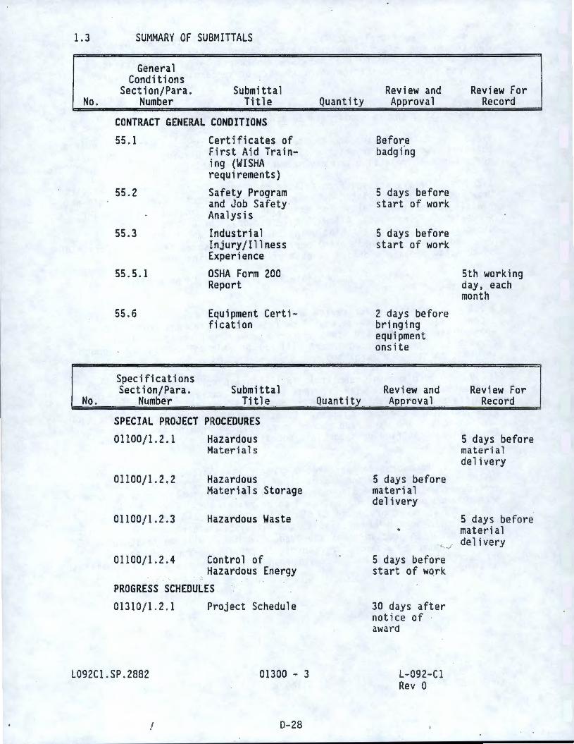
1.3 SUMMARY OF SUBMITTALS
No.
General Condit i ans
Section/Para. Number
Submittal Title
CONTRACT GENERAL CONDITIONS
55.1 Certificates of First Aid Training (WISHA requirements)
55.2 Safety Program and Job Safety Analysis
55 .3
55.5 . 1
55 .6
Specifi cat i ans Section/Para .
Industrial Injury/Illness Experience
OSHA Form 200 Report
Equipment Certification
No. Number Submittal
Title
SPECIAL PROJECT PROCEDURES 01100/1.2.1 Hazardous
Materials
01100/1 .2.2
01100/1. 2 .3
01100/1.2 .4
Hazardous Materials Storage
Hazardous Waste
Control of Hazardous Energy
PROGRESS SCHEDULES
01310/1 .2. 1 Project Schedule
L092Cl.SP . 2882 01300 - 3
D-28
Quantity
Quant i ty
Review and Approval
Before badgfog
5 days before start of work
5 days before start of work
2 days before bringing equipment onsite
Rev i ew and Approval
5 days before material delivery
Review For Record
5th working day, each month
Review For Record
5 days before material delivery
5 days before material
, .,f de l i very
5 days before start of work
30 days after notice of award
L- 092- Cl Rev O
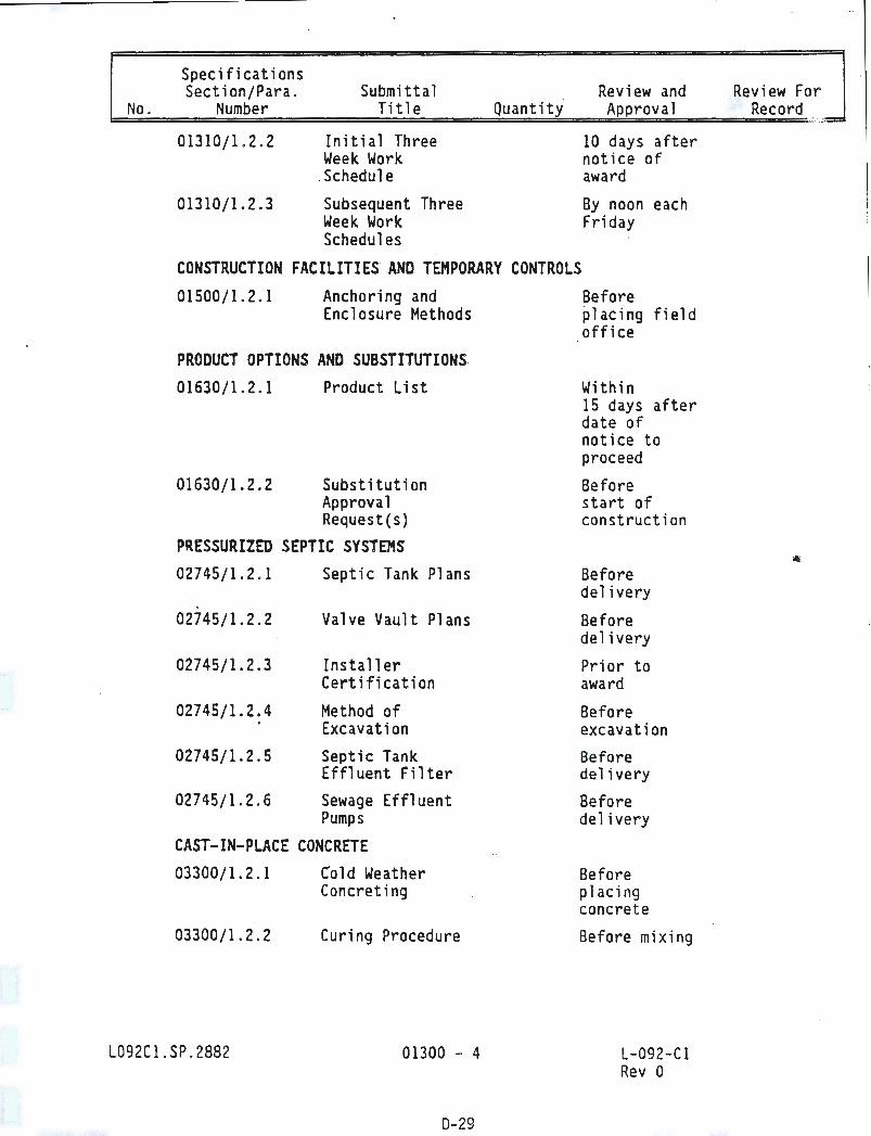
Specifications Section/Para .
No. Number
01310/1.2 . 2
01310/1.2.3
Submitta 1 Title
Initial Three Week Work
.Schedule
Subsequent Three Week Work Schedules
Quantity Review and Approval
10 days after notice of award
By noon each Friday
CONSTRUCTION FACILITIES AND TEMPORARY CONTROLS 01500/1.2.1 Anchoring and
Enclosure Methods
PRODUCT OPTIONS AND SUBSTITUTIONS 01630/1.2 . 1 Product List
01630/1.2.2 Substitution Approval Request(s)
PRESSURIZED SEPTIC SYSTEMS 02745/1.2 . 1 Septic Tank Pl ans
02745/1.2.2 Va 1 ve Vault Plans
02745/1.2.3 Installer Certification
02745/1.2.4 Method of Excavation
02745/1.2.5 Septic Tank Effluent Filter
02745/1 . 2. 6 Sewage Effluent Pumps
CAST-IN-PLACE CONCRETE 03300/1. 2 . 1
03300/1.2 . 2
L092Cl. SP . 2882
Cold Weather Concreting
Curing Procedure
01300 - 4
0-29
Before placing field office
Within 15 days after date of notice to proceed
Before start of construction
Before delivery
Before delivery
Prior to award
Before excavation Before delivery Before delivery
Before placing concrete
Before mixing
L-092 -Cl Rev 0
Review Fo r Record
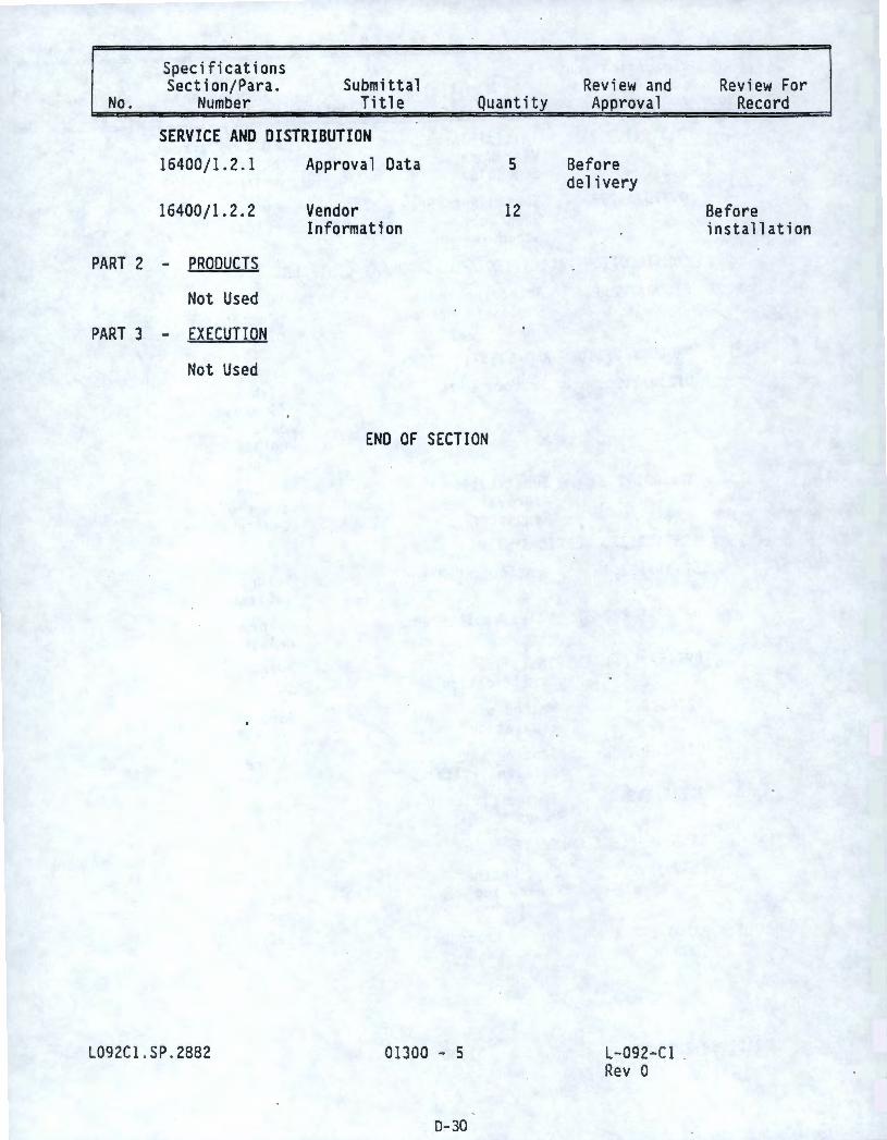
Specifications Section/Para.
No. Number Submittal
Title Quantity
SERVICE AND DISTRIBUTION 16400/1. 2 .1
16400/ 1. 2. 2
PART 2 - PRODUCTS
Not Used
PART 3 - EXECUTION
Not Used
L092Cl . SP . 2882
Approval Data
Vendor Information
END OF SECTION
01300 - 5
0-30
5
12
Review and Approva 1
Before delivery
L- 092- Cl Rev 0
Review For Record
Before installation
PART 1 - GENERAL
SECTION 01310
PROGRESS SCHEDULES
1.1 REFERENCES: Not Used
1.2 SUBMITTALS: Refer to Section 01300 for submittal procedures .
1.2.l Project Schedule: Submit schedule required in Article 1.3.
1.2 .2 Initial Three Week -Work Schedule: Submit schedule required in Article 1.4.
1.2.3 Subsequent Three Week Work Schedules: Submit schedules required· in Article 1.4.
1.3 PROJECT SCHEDULE
1.3.1 Prepare schedule identifying activities which include logical sequence and relationship of activities for engineering, design, submittals, procurement, fabrication, delivery, erection, installation, and testing of work covered by Contract.
1.3.2 Activity durations shall be working days. Subdivide activities exceeding 20 working days by identifying logical subactivities . Activity titles shall be self-explanatory with abbreviations shown in legend on document. Show early start, early finish, late start, late finish, restraining activities, and total float for activities. Highlight critical path activities to identify Project's critical path.
1.3.3 Schedule shall include, but not be limited to, following activities.
1.3.3 . 1 Significant engineering functions performed before fabrication, such as specific procedures, and shop and field drawi ngs, submitted for approval and approved.
1.3.3.2
1.3 . 3 . 3
1.3.3 .4
1.3 .3 . 5
Major material acquisitions and delivery.
Offsite fabrication and delivery schedules .
Subcontractor activities .
Field installation and nondestructive examination activities.
1.3 .3.6 Indications that work for each activity will be performed during periods of time other than regular day shift hours as indicated in Section 01043 of this Specification .
1.3.3.7
1.3 . 3. 8
Wl72Cl .SP
Identification of inspection hold points .
Manpower loading and leveling .
01310 - l
0-31
L- 092- Cl Rev 0
1.3.3.9 Milestones indicating interface requirements with construction activities performed by others.
1.4 THREE WEEK WORK SCHEDULE
1.4.1 Prepare initial and subsequent detailed schedules of next three week's work. The three week work schedule shall be updated weekly. Schedule shall include following as minimum.
1.4 .1.l
1.4 . 1.2
1.4 . 1.3
1.5
1.5.1 actual and cornpletion schedules.
Work description.
Location of work.
Work involving outages, overtime, weekends, etc.
REVISIONS TO SCHEDULES
Whenever KEH determines there are significant variances between scheduled progress, endangering completion within Contract time, Contractor may be required to prepare and submit revised
1.5.2 Show progress to date of submittal and projected completion date of each activity. Identify activities modified since previous submittal, major changes in scope, and other identifiable changes.
1.5.3 Provide narrative report to define problem areas, anticipated delays, and impact on schedule. Report corrective action taken, or proposed, and its effect, including changes on schedules of separate contractors .
1. 5. 4 Distribute copies of revised schedules to KEH Project file, subcontractors, suppliers, and other concerned entities. Instruct recipients to promptly report, in writing, problems anticipated by projections shown in revised schedules.
1.5. 5 If Contractor fails to submit progress schedule specified in Paragraph 1.3.1 within prescribed time, or revised schedules specified in Paragraph 1.6.1, within requested time, KEH may withhold approval of progress payments until time Contractor submits required schedules.
PART 2 - PRODUCTS
Not Used
PART 3 - EXECUTION
Not -Used
Wl72Cl.SP
END OF SECTION
01310 - 2
D-32
L-092- Cl Rev 0
PART 1 - GENERAL
SECTION 01400
QUALITY ASSURANCE
1. 1 REFERENCES: Not Used
1.2 SPECIFIC CONTRACTOR QUALITY REQUIREMENTS
1.2.1 Requirements are identified in the Contract documents (Drawings and Specifications}.
1.2 .2 Inspection and Testing:
1. 2.2.1 Perform tests specifically required by contract documents , including minimum code and standard requirements .
1.2.2.2 Perform inspections of work for compliance with requirements . Documentation of tests shall be submitted as required by Contract requirements.
1.2.3 Test Status: The supplier shall maintain a positive system for identifying testing status of items or systems.
1.2.4 Control of Nonconforming Items: Provide a method of notification for all construction items and activities which do not conform to requirements . Notification shall be given to the KEH Field Construction Engineer.
1.2.5 KEH may review/audit Contractor compliance wi th the Contract Documents .
1.3 INSPECTING ANO TESTING
1.3 .1 In accordance with Section 19 of the Contract General Conditions, perform the following.
1.3 . 1.1 Perfonn tests identified in the Contract documents.
1.3 .2 In accordance with Section 19 of the Contract General Conditions , KEH will perform the follow i ng .
1. 3. 2. 1
1.3 . 2.2
1.3.2.3
1.3.2 .4
Sample and test backfill material .
Sample and test concrete.
Witness specific inspection and witness points .
Perform final acceptance inspection .
1.3. 2.5 Witness , perform acceptance inspection , and document the results of any air pressure or hydrostatic pressure tests .
l092Cl .SP .2882 01400 - 1
D-33
L-092-Cl Rev 0
. 1. 3. 3 Specific Inspection Points .
1.3.3.1 Adhere to inspection points. · Ensure that personnel have completed inspections of, and approved portions of work in accordance with Contract requirements before notifying KEH.
a. Specific inspection points are defined as follows .
1) Construction inspection (H): Required for witnessing of specific construction features, before further construction is allowed to proceed.
2) Receiving (R): Special items of fabrication, equipment, or material scheduled to be delivered to the Project site, or other designated location, which require inspection upon arrival and before installation. Notify KEH within four hours after item arrival .
3) Witness (W): Selected for inspection at the option of KEH. Work may proceed upon verbal release by •KEH or upon expiration of one hour beyond scheduled time of witnessing.
b; H, R, and W points apply to (both) onsite (and offsite) work. Except where a longer period is specified, notify KEH at least four working hours before each point for onsite work. For offsite work , notify KEH at least three working days before each required point .
1.3 .3.2
1.4
H, R, and W points are listed in Article 1.7.
OPEN ITEM ANO NONCONFORMANCE REPORTING
1.4. l KEH util izes Open Item Reports and Nonconformance Reports (NCRs) to document deviat i ons from Contract requirements .
1.4 . 1.1 Open Item Reporting: Documented on the Open Items List available from KEH. Items shall be corrected by the Contractor without additional direction. Correction shall bring item into compliance with Contract requirements , using approved rework procedures or standards, without violating Contract requirements . . 1.4. 1.2 Nonconfonnance report: Documented on nonconformance report (NCR) fonns. NCR's document deviations from Contract requirements when characteristic, documentation, or procedure renders quality of an item or activity unacceptable, or indeterminate. Nonconformances are identified by a red construction hold tag, or blue NCR tag. A hold t ag prohibits movement, installation, processing, or further fabrication of nonconforming items pending approval of the NCR disposition. An NCR tag identifies a nonconformance, but allows work to proceed based on an approved NCR disposit ion. No action shall be taken to correct or alter an actual condition before receipt of an approved disposition. Tags are not to be removed by anyone other than the agency who applied the tag.
1.4.2 The Contractor shall ensure its organization is represented by individuals with sufficient authority to commit the Contractor to corrective action requirements identified by KEH.
L092Cl .SP.2882 01400 - 2
0 - 34
L-092-Cl Rev 0
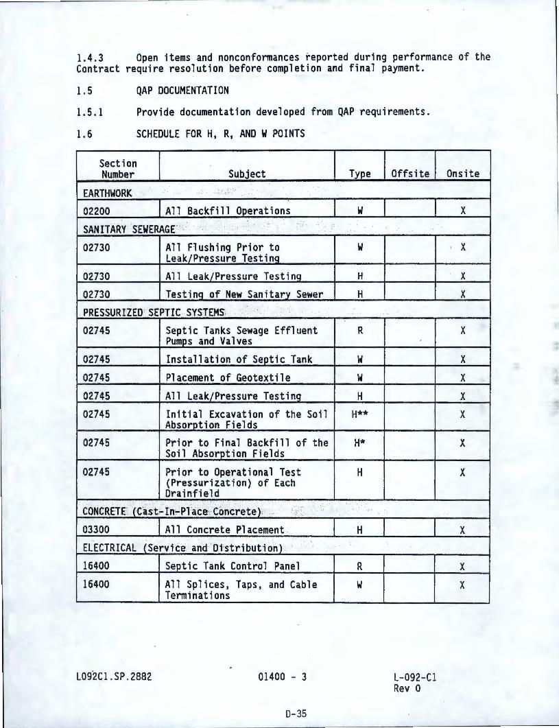
1.4.3 Open items and nonconformances reported during performance of the Contract require resolution before completion and final payment.
1.5 QAP DOCUMENTATION
1.5.1 Provide documentation developed from QAP requirements.
1.6 SCHEDULE FOR H, R, AND W POINTS
Section Number Subject
EARTHWORK ;
02200 All Backfi 11 Operations
· SANITARY SEWERAGE > : ., ..
:··:··<
02730 All Flushing Prior to Leak/Pressure TestinQ
02730 All Leak/Pressure TestinQ
02730 Testinq of New Sanitary Sewer
PRESSURIZED 'SEPTrc .· svsTEMS: ... ., ,' . .
02745 Septic Tanks Sewage Effluent Pumps and Valves
02745 Install at ion of Septic Tank
02745 Placement of Geotextile
02745 All Leak/Pressure Testing
02745 Initial Excavation of the Soil Absorption Fields
02745 Prior to Final Backfill of the Soil Absorption Fields
02745 Prior to Operational Test (Pressurization) of Each Drainfield
. . , · .. . CONCRETE}Cast~Iri~PlaCe\ Concrete);· ....
03300 All Concrete Placement .
ELECTRICAL (Service and Distribution)
16400 Septic Tank Control Panel
16400 All Splices, Taps, and Cable Terminations
L09.2Cl . SP . 2882 01400 - 3
0-35
Type
w
w
H
H
R
w w
H
H**
H*
H
.:.
H
R
w
Off site
L- 092- Cl Rev 0
On site
X
' X
X
X
X
X
X
X
X
X
X
X
X
X
Section Number Subject Type Offs ite
16400 All Megger Testing H
16400 All Other Electrical Testinq w * Requires a minimum of 5 working days advance notification . **Requires 24 hour advance notification.
PART 2 - PRODUCTS
Not Used
PART 3 - EXECUTION
Not Used
L092Cl.SP . 2882
ENO OF SECTION
01400 - 4
D-36
L- 092- Cl Rev O
Onsite
X
X
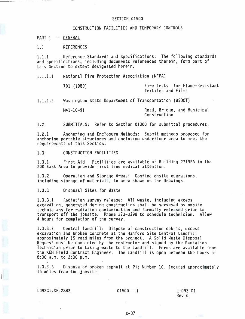
SECTION 01500
CONSTRUCTION FACILITIES AND TEMPORARY CONTROLS
PART 1 - GENERAL
1.1 REFERENCES
1.1.1 Reference Standards and Specifications: The following standards and specifications, including documents referenced therein, form part of this Section to extent designated herein.
1.1.1.1 National Fire Protection Association (NFPA)
701 (1989) Fire Tests for Flame-Resistant Textiles and Films
1.1.1.2 Washington State Department of Transportation (WSDOT)
M41-10-91 Road, Bridge, and Municipal Construction
1.2 SUBMITTALS: Refer to Section 01300 for submittal procedures .
1. 2.1 Anchoring and Enclosure Methods: Submit methods proposed for anchoring portable structures and enclosing underfloor area to meet the requirements of this Section .
1.3 CONSTRUCTION FACILITIES
1.3.1 First Aid: Facilities are available at Building 2719EA in the 200 East Area to provide first line medical attention .
1.3.2 Operation and Storage Areas: Confine onsite operations, including storage of materials, to area shown on the Drawings .
1.3.3 Disposal Sites for Waste
1.3.3.1 Radiation survey release: All waste, including excess excav~tion, generated during construction shall be surveyed by onsite technicians for radiation contamination and formally released prior to transport off the jobsite. Phone 373-3398 to schedule technician . Allow 4 hours for completion of the survey.
1.3 .3.2 Central landfill: Dispose of construction debris, excess excavation and broken concrete at the Hanford Site Central Landfill approximately 15 road miles from the project. A Solid Waste Disposal Request must be completed by the contractor and signed by the Radiation Technician prior to taking waste to the Landfill. Forms are available from the KEH Field Contract Engineer. The Landfill is open between the hours of 8:30 a.m. to 2:30 p.m.
1.3.3.3 Dispose of broken asphalt at Pit Number 10, located approximate~y 16 miles from the jobsite .
L092C 1. SP. 2882 01500 - 1
0-37
L-0-92- Cl Rev o
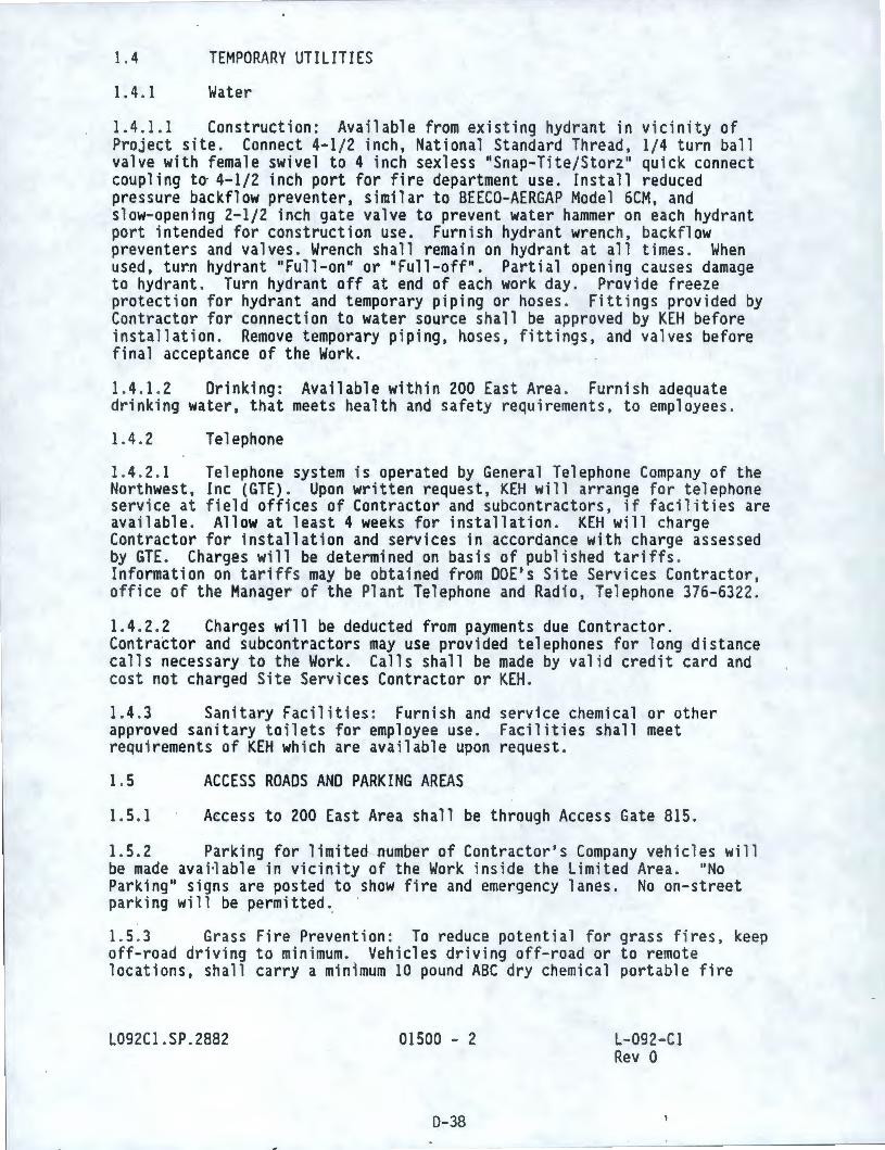
1.4 TEMPORARY UTILITIES
1.4.1 Water
1.4.1.1 Construction: Available from existing hydrant in vicinity of Project site. Connect 4-1/2 inch, National Standard Thread, 1/4 turn ball valve with female swivel to 4 inch sexless "Snap-Tite/Storz" quick connect coupling to 4-1/2 inch port for fire department use. Install reduced pressure backflow preventer, similar to BEECO-AERGAP Model 6CM, and slow-opening 2-1/2 inch gate valve to prevent water hammer on each hydrant port intended for construction use. Furnish hydrant wrench, backflow preventers and valves. Wrench shall remain on hydrant at all times. When used, turn hydrant "Full-on" or "Full-off". Partial opening causes damage to hydrant. Turn hydrant off at end of each work day. Provide freeze protection for hydrant and temporary piping or hoses . Fittings provided by Contractor for connection to water source shall be approved by KEH before installation. Remove temporary piping, hoses, fittings, and valves before final acceptance of the Work.
1.4.1.2 Drinking: Available within 200 East Area . Furnish adequate drinking water, that meets health and safety requirements, to employees.
1. 4. 2 Telephone
1.4. 2.1 Telephone system is operated by General Telephone Company of the Northwest, Inc (GTE). Upon written request, KEH will arrange for telephone service at field offices of Contractor and subcontractors, if facilities are available. Allow at least 4 weeks for installation. KEH will charge Contractor for installation and services in accordance with charge assessed by GTE. Charges will be determined on basis of published tariffs . Information on tariffs may be obtained from DOE's Site Services Contractor, office of the Manager of the Plant Telephone and Radio, Telephone 376-6322.
1. 4.2.2 Charges will be deducted from payments due Contractor. Contractor and subcontractors may use provided telephones for long distance calls necessary to the Work. Calls shall be made by valid credit card and cost not charged Site Services Contractor or KEH.
1.4.3 Sanitary Facilities: Furnish and service chemical or other approved sanitary toilets for employee use. Facilities shall meet requirements of KEH which are available upon request.
1. 5 ACCESS ROADS AND PARKING AREAS
1.5.1 Access to 200 East Area shall be through Access Gate 815.
1.5.2 Parking for limited, ntjmber of Contractor's Company vehicles will be made avai~able in vicinity of the Work inside the Limited Area. "No Parking 11 signs are posted to show fire and emergency lanes. No on-street parking will be permitted.
1.5 .3 Grass Fire Prevention: To reduce potential for grass fires, keep off-road driving to minimum. Vehicles driving off-road or to remote locations, shall carry a minimum 10 pound ABC dry chemical portable fire
L092Cl.SP.2882 01500 - 2
D-38
L-092-Cl Rev 0
- - --- - - -------------
extinguisher, communications equipment consisting of 2 way radio or mobile phone (CB type radios are not acceptable), and shovel. Report fires immediately to nearest Hanford Patrol and Hanford Fire Department.
1.6 TEMPORARY CONTROLS
1.6.1 Dust Control: Maintain work areas to prevent hazard or nuisance to others . Accomplish dust control by sprinkling or other methods approved by KEH. Repeat sprinkling at necessary intervals to keep disturbed area damp at all . times . Keep sufficient equipment on Project to accomplish dust control as work proceeds and whenever dust nuisance or hazard occurs. No separate or direct payment will be made for dust control and cost shall be considered incidental to and included in Contract price.
1.6 .2 Temporary Enclosures : Plastic sheeting materials used to form enclosures shall b~ minimum 14 mils thick and have fire retardant properties meeting the requirements of NFPA 701. Acceptable manufacturers are Winman Corp (Plastic Division), St. Cloud, Minnesota; Lanes Industries, Kirkland, Washington; and Protective Plastics, Inc, Greer, South Carolina .
1.6.3 Traffic Control: Temporary traffic control and barricades in accordance with WSDOT M41-10, Section 1-07.23(3).
1.6 .3.1 Vehicle and equipment movement
a. Slow moving vehicles and equipment shall not travel on Hanford Site roads during heavy traffic periods between 6:30 and 8:00 am, and 3:30 and 5:30 pm.
b. Do not block existing roads .
c. Do not park on roadway shoulders.
1.6 .3.2 Oversized vehicles and loads
a. Permits specified in Section 01065 are required for vehicles or loads exceeding following dimensions.
1) Width: 8'-6".
2) Height: 14 feet .
3) Length : Single un it, 40 feet . Single t r ai ling unit , 48 fee t.
•.~ b. Additional requirements for vehicles and loads exceeding 8'-6" width .
1) Display oversize load sign on front of towing vehicle and rear of trailing unit .
2) Attach red flags to each corner .
3) Notify KEH 5 days before mov i ng loads .
L092Cl .SP . 2882 01500 - 3
D-39 .
L-092- Cl Rev 0
4) Travel between 9:00 am and 2:30 pm unless special arrangements are made.
c. Escort vehicle requirements.
1) Equip with oversize load signs and amber lights.
2) Vehicles or loads over 10 feet wide: Provide escort cars in front and rear on 2 lane highways .
3) Vehicles or loads over 14 feet wide: Provide escort car in rear on multiple lane highways .
4) Vehicles or loads over 20 feet wide : Provide escort cars in front and rear on multiple lane highways .
d. Electrical escort requirements : KEH will provide qualified electrical escorts, at no cost to Contractor, when load reaches height of 14 feet or more from road surface, or when clearance of at least 6 feet cannot be maintained from overhead electrical or signal lines . Notify KEH at least 3 working days before escort is required .
1. 7 FIELD OFFICE
1. 7.1 A field office is not required. However, keep copies of Drawings, Specifi cations, and other information pertinent to the Work at Project site. KEH shall have access to documents at all times. Should Contractor elect to utilize portable or relocatable structures , requirements of Paragraph 1.7.2 shall apply .
PART 2 - PRODUCTS
Not Used
PART 3 - EXECUTION
Not Used
L092Cl .SP.2882
END OF SECTION
01500 - 4
D- 40
L- 09 2-C l Rev O
SECTION 01630
PRODUCT OPTIONS AND SUBSTITUTIONS
PART 1 - GENERAL
1.1 REFERENCES: Not Used
1.2 SUBMITTALS: Refer to Section 01300 for submittal procedures.
1.2.1 Product List: Submit listing described in Article 1.4.
1.2 . 2 Substitution Approval Request(s): Submit request(s) as required by Paragraphs 1.3.4 and 1.3.5, prepared in accordance with Article 1.6.
1.3 SUBSTITUTIONS
1.3.l Products include those .items identified on the Drawings as well as in Part 2 of the Specification Sections.
1.3.2 Product options given in the Specification Sections represent functionally and physically similar items. In addition to generic type, form and size, physical similarity includes maintainability, reliability, and durability characteristics.
1.3.3 A substitute product may be used in place of a product or the product options identified in Specification Sections, without approval, if it is functionally and physically similar as defined above.
1.3 . 4 Substitution of a product that is functionally similar but physically dissimilar will require submittal of a Substitution Approval Request .
1.3.5 Submittal of a Substitution Approval Request is also required when a product callout in the Specification Sections includes the phrase "or an approved substitute".
1.3.6 Products required in quantity within Specification sections shall be the same and b'e interchangeable.
1. 3 . 7 Do not use materials and equipment removed from existing structure, except as specifically required or allowed by Contract Documents.
1. 4 PRODUCT LIST -1.4.1 Provide a listing of products proposed for installation, including·~ ames of manufacturers and product identification numbers.
1.4.1.1. Tabulate products by Specification Section number and Article or Paragraph number, or by drawing number and zone.
1. 4. 1.2 Far products specified only by reference standards, give manufacturer, trade name, model or catalog designation, and reference standard . .
L092Cl.SP.2882 01630 - 1
0-41
L-092-Cl Rev O
1.4.1.3 Place asterisks to left of items that are substitutes, having requests for substitutions submitted or in preparation.
1.4.1.4 KEH will reply within 10 calendar days stating whether there is reasonable objection to listed items that are not substitutions. Failure to object to a listed item will not constitute waiver of specified requirements.
1.4.1.5 When the substitution approval process is complete, provide an updated, final listing (without asterisks).
1.5 LIMITATIONS ON SUBSTITUTIONS
1.5.1 Substitutions will not be considered when indicated or implied on fabricator drawings, or product data submittals, without separate Substitution Approval Requests, when requested directly by subcontractors or suppliers, or when acceptance will require substantial revi·sio~ of Contract Documents.
1.5 .2 Substitute products that require a substitution approval request shall not be ordered or installed before the request is approved .
1.5.3 Only one Substitution Approval Request for each product will be considered. When a substitution is not accepted, provide specified product.
1.5. 4 KEH will determine acceptability of substitution approval requests.
1.6 REQUESTS FOR SUBSTITUTIONS
1.6.1 Submit a separate Substitution Approval Request for each substitution, using Form KEH-1151.00, sample attached.
1.6.2 Identify Paragraph numbers. product, and model appropriate.
products by Specification Section and Article or Provide manufacturer's name ~nd address, trade name of
or catalog number. List fabricators and suppliers as
· 1.6.3 To each Substitution Approval Request attach descriptive information for substitute and original products. The information shall consist of drawings, calculations, and data as appropriate to define operational and physical characteristics of products, and establish a basis for comparison.
1.6.4 Give an itemized comparison of proposed substitution with specified product, listing variations, with reference to Specification Section and Article or Paragraph numbers.
1.6.5 Give quality and performance comparisons between proposed substitution and specified product.
1.6.6 Give cost data comparing proposed substitution with specified product, showing the Contract Sum net change.
L092Cl.SP.2882 01630 - 2
D-42
L-092-Cl Rev O
L__
1.6.7 List availability of maintenance services and replacement materials.
1.6.8 State effect of the substitution on construction schedule, and changes required in other work or products. If a substitute product requires or necessitates revisions to structures, foundations, footings, services, systems, piping, electrical, etc., engineering costs shall be borne by Contractor. Submit drawings, calculations, and vendor data, clearly showing revisions to accommodate substitution, for approval.
1.6.9 KEH will review requests for substitution with reasonable promptness.
1.6.10 For accepted substitute products make the same submittals, in accordance with Section 01300, required for the original products.
1.7 CONTRACTOR REPRESENTATION
1. 7. 1 Request for substitution constitutes representation that Contractor has investigated proposed product, has determined that it is equal to or superior to that specified, and that cost reduction offered (if there is one) is ample justification for accepting offered substitution.
1. 7.2 Provide same warranty for a substitute as for specified product.
1.7.3 Coordinate installation of accepted substitutes, making changes required for work to be completed.
1.7 .4 Certify that cost data presented is complete, and includes related costs under the Contract.
1.7 .5 Waive claim for additional costs related to substitutions which may later become apparent.
1.7 .6 Waive claim for additional performance time resulting from product substitutions.
PART 2 - PRODUCTS
Not Used
PART 3 - EXECUTION
Not Used
L092Cl.SP.2882 01630 - 3
D-43
L-092-Cl Rev a

KAISER ENGINEERS HANFORD
SUBSTITUTION APPROVAL REQUEST
From (Comr.:ictor) __________________ _ Contr.:ictNo. ____________ _
Project-------------------------------------------
Oescripcion of Proposed 'iub\titucion -------------------------------
We hereby submit for con-.ideration the following product innead of speci tied item lo, above pro1ect:
Specification No. __________________ _ Section ______________ _
Drawing No. ____________________ _ Section or Zone ___________ _
Specified Item----------------------------------------
Propo-.ed Subuitution -------------------------------------
Attach complete technical data, including laboratory tests and sample-., .:is applicable.
Provide detailed comparison of the significant qualitie-; (\ystem performance · merf .. ce requirements, size weight. aurab11i1y, performance and similar ch.aracteristic\, and including vi\ual e here .:ippl,cabhd lor 1he propo\ed sul>\titutaon of comparison with the original requlfements.
Oe-.cribe other changes to drawing-. and specificacions requir inlormo1tion as necessary.
Complete Each Item
B. Effect of substicutio
0 . Manufacturer's guarancees of proposed and specified items .:ire:
'iame Di Herent (explain on attachment) -------- ----------Undero;igned attests function, and quality equality equivalenc or superior to specified item .:ind has reviewed Cene,al Condiciom paragraph GC· IJ for au1gnment of respon\ib1l,1y ,/ 1he subu1tu11on ,s .:ipprovcc'd.
END ,OF SECTION
01630 - 4
D-44
l'h<.11111
~tH • I I~ I UU (IU,11/)
L-092 -Cl Rev 0
SECTION 01720
PROJECT RECORD DOCUMENTS
PART 1 - GENERAL
1.1 REFERENCES
1.1.1 Reference Standards and Specifications: The following standards and specifications, including documents referenced therein, form part of this Section to extent designated herein.
1.1.1.1 Washington Administrative Code (WAC)
Title 296
Chapter 296-155
1.2 SUBMITTALS: Not Used
1.3 RECORD REQUIREMENTS
Labor and Industries
Safety Standards for Construction Work
1.3.1 The nature of work at the Hanford Site requires certain documents, defined herein, be held to record construction process and administration of the Contract. KEH will assemble pertinent data for final disposition. Prepare, preserve, and deliver project record documents required by this Contract to KEH. Documents are in addition to submittals required in Section 01300.
1.3.2 Mark project record documents to identify copies for record and to prevent use for construction. Keep record copies of construction documents in field office and make available to KEH during progress of Work.
1.3.3 Some data required for project records shall be delivered to KEK during course of construction and contract administration, while others shall be assembled after completion of construction for delivery to KEH. Document delivery by retaining copy of reports delivered during course of work until construction completion, retaining copy of letter of transmittal itemizing delivered items, or other means acceptable to KEH.
1.3.4 When information for project records is to be recorded on standard KEH forms, copies of the forms will be supplied by KEH. Samples of the appropriate required forms are included_in the specification sections.
1.4 DOCUMENT IDENTIFICATION
1.4. 1 General: Documents required for project records are itemized herein. Identify complete documents by title or number. Notes or markings added by hand shall be legible utilizing permanent nonsmearing marking media, such as ink or felt tip markers, in contrasting color.
L092Cl.SP.2882 01720 - 1
0-45
L-092.-Cl Rev O
1.4.2 Storage and Marking: Store one set in the field office, apart from documents used in construction, and maintain in clean, dry, and legible condition. Legibly mark items to record actual construction, including changes to dimensions and details, manufacturer's name, catalog number, and substitute products.
1.4.3 Activity and Administrative Documents: Deliver or retain in accordance with following.
1.4.3.1 Certified Payrolls: Each week deliver certified payrolls, as required by Section 108 of Contract General Conditions, to KEH, and keep copies in the field office until Contract completion. Progress payments will not be processed unless certified payrolls for work periods have been received by KEH.
1.4.3.2 Daily Force and Equipment Reports: Before noon each day, deliver . one copy of a detailed daily force report, covering labor and supervision of Contractor and subcontractors for previous day. Report shall include a general description of work performed, and list major items of equipment on site.
1.4.3.3 Weekly Manpower Reports: Prepare weekly manpower reports and deliver, before 10 am on Monday, for previous week , during performance of Contract. Forms will be furnished by KEH.
1.4 .3.4 Weekly Safety Meetings: Conduct weekly walkaround safety inspections and safety meetings in accordance with WAC-296-155-110. Deliver one copy of meeting minutes to KEH, as completed.
1.4.3.5 Periodic Equipment Inspections: Document initial and followup, periodic heavy equipment inspections by the Contractor . Deliver one copy to KEH, as compl eted.
1.4.3.6 Subcontracting Plan Reports: Deliver reports documenting . conformance with Subcontracting Plan, as required by Section 89 of Contract General Conditions.
1.4.3. 7 Backfi ll Permit: Retain backfill permits approved for work required in Divi sion 2.
1. 4.3.8 Soil Compaction Procedure: Retain Forms KEH-0382 completed for work required in Division 2.
1.4 .3.9 Pour Slips: After obtaining KEH approval of concrete pour slips required in Division 3, deliver copies to KEH, and retain Contractor copies until Contract closeout. After closeout deliver them to KEH.
1.4.3.10 Trip Tickets: Deliver copies to KEH with each truck load of concrete required in Division 3, and retain Contractor copies until Contract closeout. After closeout deliver them to KEH.
L092Cl .SP.2882 01720 - 2
D-46
L-092-Cl Rev o
1.4.4 Construction, Quality Assurance, and Supporting Documents: Deliver in accordance with following when called for in specification sections.
1.4.4.1 Flushing/Cleaning Records: One copy of records verifying acceptable completion of flushing and cleaning, within 5 days after completion.
1.4.4.2 Leak/Pressure Testing Records: One copy of records verifying acceptable completion of leak and pressure testing, within 5 days after completion.
1.4.4.3 Electrical Testing: One copy of records verifying acceptable completion of electrical insulation, continuity, and grounding tests, within 5 days after completion . .
1.4.4 .4 Operational Testing: One copy of records of component or subsystem operational testing, within 15 days prior to the start of acceptance testing.
1.4.5 Product Samples' and Manufacturer's Instructions: In addition to submittals required in Section 01300, and requirements of this Section, information received by Contractor (from suppliers) that documents products used, and how they were installed, shall be delivered to KEH for Project Records.
PART 2 . - PRODUCTS
Not Used
PART 3 - EXECUTION
Not Used
· L092Cl.SP . 2882
END OF SECTION
01720 - 3
0-47
L-092-Cl Rev 0
PART 1 - GENERAL
SECTION 02050
DEMOLITION
1.1 REFERENCES: Not Used
1.2 SUBMITTALS: Not Used
1.3 PROJECT CONDITIONS
1.3.1 Existing Con~itions: Provide safeguards, including warning signs, barricades, and temporary closures required for protection of construction personnel and others during demolition and removal operations .
PART 2 - PRODUCTS
Not Used
PART 3 - EXECUTION
3. 1 EXAMINATION
3. 1.1 Before beginning cutting or demolition, survey exist i ng work and examine the Drawings and Specifications to determine extent of work. Take necessary precautions to ensure against damage to existing work to remain in place . Coordinate work of this Section with other work and construct and maintain shoring, bracing, and supports, as required. Ensure that structural elements are not overloaded and be responsible for increasing supports or adding new supports as required as r~sult of cutting, removal, or demolition performed.
3.2 PERFORMANCE
3.2.1 Remove portions of existing facility as shown on the Drawings and, subject to approval by KEH, other portions necessary to facilitate modifications.
3.2.2 Unsalvageable Materials: Dispose of concrete, masonry, and other combustible and noncombustible materials other than concrete permitted to remain in place, as directed by KEH.
3. 2.3 Removal of Utilities: Remove existing utilities shown on Drawings. When utility lines are encountered that are not shown on the Drawings, proceed only as directed by KEH.
3.2.4 Control amount of dust resulting from demolition to avoid creation of nuisance in surrounding area. Use of water will not be permitted when it will re~ult in, or create, hazardous or objectionable conditions such as ice, flooding, and pollution .
L092Cl.SP.2882 02050 - 1
D-48
l -092 -Cl Rev O
3.3 CLEANING
3.3 . 1 Remove septic tank wastes and dispose in accordance with WAC 246-272-220 .
END OF SECTION
L092Cl.SP.2882 02050 - 2
D-49
L-092-Cl Rev O
PART 1 - GENERAL
1.1 REFERENCES
SECTION 02200
EARTHWORK
1.1.1 Reference Standards and Specifications: The following standards and specifications, including documents referenced therein, form part of this Section to extent designated herein.
1.1.1.1 American Society for Testing and Materials (ASTM)
D 653-90 Terminology Relating to Soil , Rock, and Contained Fluids
1.1.1.2 Washington Administrative Code (WAC)
Title 296, Labor and Industries
Chapter 296-155 Safety Standards for Construction Work
1.1.1.3 Washington State Department of Transportation (WSDOT)
M41-10-91
1.2 SUBMITTALS: Not used .
PART 2 - PRODUCTS
2. 1 MATERIALS
Road, Bridge, and Municipal Construction
2. 1.1 General: Obtain select soils from excavation or other designated locations . Obtain onsite ~pproval for soils.
2. 1.2 Fill or Backfill
2. 1.2. 1 Structural: Well graded soil mixtures ·which may contain cobbles up to 3 inches in greatest dimension if uniformly distributed and not constituting more than 20 percent of volume of fill.
2.1.2 .2 Common: Well graded soil mixtures containing cobbles up to 8 inches in greatest dimension if uniformly distributed and not constituting more than 40 percent of volume of fill.
2.1.2.3 Select: Excavated sandy material having less than 20 percent gravel particles and maximum dimension of 1/2 inch .
2. 1.2.4 Gravel: Meeting the requirements of WSDOT M41 -10, Section 9-03.12(2) .
L092Cl.SP.2882 02200 - 1
0-50
L-092 -Cl Rev O
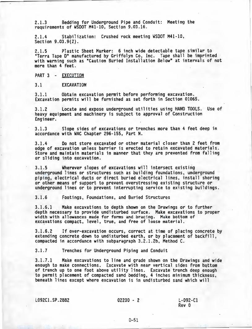
2.1.3 Bedding for Underground Pipe and Conduit: Meeting the requirements of WSOOT M41-10, Section 9.03.16.
2.1.4 Stabilization: Crushed rock meeting WSDOT M41-10, Section 9.03.9(2).
2.1.5 Plastic Sheet Marker: 6 inch wide detectable tape similar to HTerra Tape DH manufactured by Griffolyn Co, Inc. Tape shall be imprinted with warning such as HCaution Buried Installation BelowH at intervals of not more than 4 feet.
PART 3 - EXECUTION
3. 1 EXCAVATION
3.1.1 Obtain excavation permit before performing excavation. Excavation permits will be furnished as set forth in Section 01065 .
3. 1.2 Locate and expose underground utilities using HAND TOOLS. Use of heavy equipment and machinery is subject to approval of Construction Engineer.
3. 1.3 Slope sides of excavations or trenches more than 4 feet deep in accordance with WAC Chapter 296-155, Part N.
3. 1.4 Do not store excavated or other material closer than 2 feet from edge of excavation unless barrier is erected to retain excavated materials . Store and maintain materials in manner that they are prevented from falling or sliding into excavation.
3. 1.5 Wherever slopes of excavations will intersect existing underground lines or structures such as building foundations, underground piping, electrical ducts or direct buried electrical lines, install shoring or other means of support to prevent overstressing existing structure or underground lines or to prevent interrupting service to existing buildings.
3. 1.6 Footings, Foundations, and Buried Structures
3. 1.6.1 Make excavations to depth shown on the Drawings or to further depth necessary to provide undisturbed surface. Make excavations to proper width with allowances made for forms and bracing. Make bottom of excavations compact, level, true, and free of loose material.
3.1.6 . 2 If over-excavation occurs, correct at time of placing concrete by extending concrete down to undisturbed earth, or by placement of backfill, compacted in accordance with subparagraph 3.2.l.2b, Method C.
~. 1.7 Trenches for Underground Piping and Conduit
3.1 .7.1 Make excavations to line and grade shown on the Drawings and wide enough to make connections. Excavate with near vertical sides from bqttom of trench up to one foot above utility lines. Excavate trench deep enough to permit placement of compacted sand bedding, 4 inches minimum thickness, beneath lines except where excavation is in undisturbed sand which will
L092Cl.SP .2882 02200 - 2
0-51
L-092-Cl Rev 0
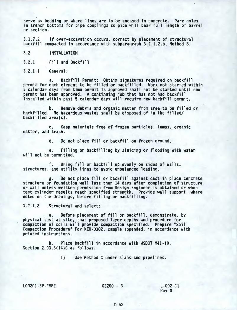
serve as bedding or where lines are to be encased in concrete. Pare holes in trench bottoms for pipe couplings so pipe will bear full length of barrel or section.
3.1.7.2 If over-excavation occurs, correct by placement of structural backfill compacted in accordance with subparagraph 3.2.1.2.b, Method B.
3.2
3.2.1
3.2.1.1
INSTALLATION
Fill and Backfill
General:
a. Backfill Permit: Obtain signatures required on backfill permit for each element to be filled or backfilled. Work not started within 5 calendar days from time permit is approved shall not be started until new permit has been approved. A continuing job that has not · had backfill installed within past 5 calendar days will require new backfill permit.
b. Remove debris and organic matter from area to be filled or backfilled. No hazardous wastes shall be disposed of in the filled/ backfilled area(s).
c. Keep materials free of frozen particles, lumps, organic matter, and trash.
d. Do not place fill or backfill on frozen ground.
e. Filling or backfilling by sluicing or flooding with water will not be permitted.
f. Bring fill or backfill up evenly on sides of walls, structures, and utility lines to avoid unbalanced loading.
g. Do not place fill or backfill against cast in place concrete structure or foundation wall less than 14 days after completion of structure or wall unless written permission from Design Engineer is obtained or when test cylinder results reach specified strength. Provide wall support, where noted on the Drawings, before filling or backfilling.
3. 2. 1.2 Structural and select:
a. Before placement of fill or backfill, demonstrate, by physical test at site, that proposed layer depths and procedure for compaction of soils will provide compaction specified. Prepare "Soil Compaction Procedure" For KEH-0382, sample appended, in accordance with printed instructions.
b. Place backfill in accordance with WSDOT M41-10, Section 2-03 .3(14)C as follows.
L092Cl. SP . 2882
1) Use Method C under slabs and pipelines.
02200 - 3
0--52
L-092-Cl Rev O
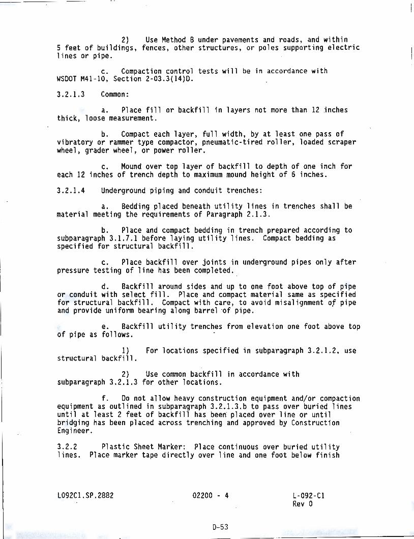
2) Use Method B under pavements and roads, and within 5 feet of buildings, fences, other structures, or poles supporting electric lines or pipe.
c. Compaction control tests will be in accordance with WSDOT M41-10, Section 2-03.3(14)0.
3.2.1.3 Common:
a. Place fill or backfill in layers not more than 12 inches thick, loose measurement.
b. Compact each layer, full width, by at least one pass of vibratory or rammer type compactor, pneumatic-tired roller, loaded scraper wheel, grader wheel, or power roller.
c. Mound over top layer of backfill to depth of one inch for each 12 inches of trench depth to maximum mound height of 6 inches .
3.2.1.4 Underground piping and conduit trenches:
a. Bedding placed beneath utility lines in trenches shall be material meeting the requirements of Paragraph 2.1.3 .
b. Place and compact bedding in trench prepared according to subparagraph 3.1.7.1 before laying utility lines. Compact bedding as specified for structural backfill.
c. Place backfill over joints in underground pipes only after pressure testing of line has .been completed.
d. Backfill around sides and up to one foot above top of pipe or conduit with select fill. Place and compact material same as specified for structural backfill. Compact with care, to avoid misalignment of pipe and provide uniform bearing along barrel ·of pipe.
e. Backfill utility trenches from elevation one foot above top of pipe as follows.
1) For locations specified in subparagraph 3.2.1.2, use structural backfill.
2) Use common backfill in accordance with subparagraph 3. 2. 1.3 for other locations.
f. Do not allow heavy construction equipment and/or compaction equipment as outlined in subparagraph 3.2 . 1.3.b to pass over buried lines until at least 2 feet of backfill has bee~ placed over line or until bridging has been placed across trenching and approved by Construction Engineer.
3.2.2 Plastic Sheet Marker: Place continuous over buried utility lines . Place marker tape directly over line and one foot below finish
L092Cl.SP .2882 02200 - 4
D-53
L-092-Cl Rev 0
grade . Place marker over each outside pipe of multiple lines. Place intermediate markers at maximum of 4 feet apart .
3.2.3 Finish Grading and Stabilization
3. 2.3 . 1 Rake area disturbed by work, remove surface stones larger than 6 inches and dispose of excess material and debris at area designated by Construction Eng i neer.
3.2. 3.2 Stabilize area disturbed by work with 3 inch course of gravel meeting the requirements of Paragraph 2.1.4. Finish stabilization course to elevations shown on the Drawings .
3.3 FIELD QUALITY CONTROL
3.3. 1 Soil Compaction Tests : Sampling and testing of compacted fill-and backfi ll will be performed by KEH .
L092Cl .SP.2882 02200 - 5
D-54
L-092 -Cl Rev 0
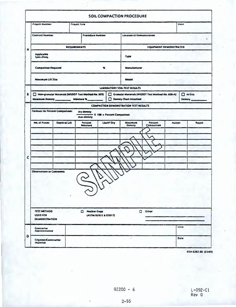
A
a
C
D
SOIL COMPACTION PROCEDURE
~,011tn NMmbcl ~,o,cn 1111c u.,~
(OAUA<t Nymbcr 1'1occd"'• N""'bef Lo<auon ol Oemon11r.a11on
•
UQUtafMENfS IQUll'MENJ DfMONSTAAflD
Applicable Type Spc,.10w9.
C-pactiorl Required ,. MAAUl.acture,
M••·- Lill Sire Model
LAIOAA TOH SOIL TEST llSUUS
• Norl-<)r111ulu Maletial1 (WSDOT Te11 Method No.'°" • Gralllllu ,...,.,..,, (~DOr Teu Method No. 606-AJ Q ln•Silu
,.....,._ Oenlicy
fo,ntula lo, Per,enc C0111pa<110A:
No.olhue, Deplll ol lJlt
Ob1crwa110111 or C0111men11
TUTMUHOO
USEOfOA
OUotONSTRA TION
Conu.a<1or llcp, •••"''""••
£ nqinNriCon,1111<10, IAll)C<llll
Moiuure 1' • Oenlily Chut Anadled
COMl'ACTION DlMONSTllATION TUT IISULTS
dryder11tly
111.a• de1111cy X I 00 • Perce111 C-pact-
l'cru111 Lblllll Dry Ma• iffllllll l'erccn1 Moo,, .... Ocn11ty ~omp•nlOII
< .,,,./ ./"\ ',~
~\. \. \. ( A.
.A.~ ('\ \\ \ \. -/ -( \ ~ V / \ 'V)"'
( ~, \. \. \ 'V
<"' '\ '\..' ~\V
~~~
• NudeuG•9• • Olhe,
(ASTM Oltl2 • 03017)
02200 - 6
0-55
Den,,,,
Al,cpc fl•1•<1
o.,.
o .. ,.
KEH-Olll .00 (Ol18'JJ
L-092-C l Rev 0
INSTRUCTIONS
This Soil Compaction Procedure form, when approved by the Engineer/Constructor Inspector, documents witnessing and verifying the compaction procedure.
Section A is the responsibility of the Construction Contractor. It is to be completed at the time of backfill compaction demonstration and presented to the Engineer/Constructor Inspector.
Section B is completed by the Engineer/Constructor Inspector. Data entered is obtained from the agency or individual that performed testing.
Section C is completed by the Engineer/Constructor Inspect or as the demonstration is performed. Using the applicable formula , the percent compaction achieved is determined and entered. Acceptance is based on the results as compared with the compaction percent required in Section A.
Section D is signed and dated by the Construction Contractor Representative acknowledging responsibility for this procedure and compliance thereto for applicable back fill operations. Section D is signed and dated by the Engineer/Constructor Inspector to signify witnessing and veri ncation.
KEH -0182 .00R (03189)
ENO OF SECTION
02200 - 7
0-56
L-092-C l Rev 0
SECTION 02730
SANITARY SEWERAGE
PART 1 - GENERAL
1. 1 REFERENCES
1.1.1 Reference Standards and Specifications: The following standards and specifications, including documents referenced therein, form part of this Section to extent designated herein.
1.1.1.1
1.1.1.2
1.1.1.3
American Society for Testing and Materials (ASTM)
D 2321-89
D 2855- 90
D 3034-89
D 3212-89
F 477-76 (1985)
Practice for Underground Installation of Flexible Thermoplastic Sewer Pipe
Making Solvent-Cemented Joints with Poly(Vinyl Chloride) (PVC) Pipe and· Fittings
Type PSM Poly(Vinyl Chloride) (PVC) Sewer Pipe and Fittings
Joints for Drain and Sewer Plastic Pipe Using Flexible Elastomeric Seals
Elastomeric Seals (Gaskets) for Joining Plastic Pipe
American Water Works Association (AWWA)
Cl04-90
Cll0-87
ClSl-86
Cement-Mortar Lining for Ductile-Iron Pipe and Fittings for Water
Ductile-Iron and Gray-Iron Fittings, 3 in. Through 48 ., for Water and Other Liquids
Ductile- Iron Pipe, Centrifugally Cast in Metal Molds or Sand- Lined Molds, for Water or Other Liquids
Washington State Department of Transportation . (WSDOT)
M21-0l-85, w/Revisions through May 1991
Plans for Road, Bridge and Municipal Construction
L092Cl .SP . 2882 02730 - 1 L-092-Cl Rev O
D-57
M41-10-91 Road, Bridge, and Municipal Construction
1.2 SUBMITTALS: Not Used
PART 2 - PRODUCTS
2.1 MATERIALS
2.1.1 Pipe: PVC meeting the requirements of ASTM D 3034, SOR 35 or cement-mortar lined ductile iron pipe meeting the requirements of AWWA Cl51, Class 50.
Fittings: 2.1.2
2.1.2.1 PVC meeting the requirements of ASTM D 3034, SOR 35.
2.1.2.2 Cement lined meeting the requirements of AWWA Cl04, with joints and pressure class ratings compatible with pipe used and shall meet the requirements of AWWA CllO . ·
2.1.3 Transition Couplings: Couplings between PVC and ductile iron pipe shall be water tight and rated by manufacturer for sanitary sewer service.
2. 1.4 Manholes: Precast concrete, 72-inch inside diameter, in accordance with WSOOT M21-0l Standard Plan B-23c .
PART 3 - EXECUTION
3. 1 INSTALLATION
3.1.1 General
3.1.1.1 Install ·sanitary sewer in accordance with WSOOT M41-10, Sections 7-17.3(1)8, and 7-17 .3(2)A through G, ASTM D2321, Section 02200, and the Drawings.
3. 1.1.2 Use ductile iron pipe fnr 10 feet minimum each side of sanitary/ fire water main crossing whenever sewer line crosses above or has less than 2 feet of clearance between pipes.
3.1 . 1.3 Keep piping systems clean during work. Once fabrication has started on length of pipe, plug or cap open ends when installation is not in progress to prevent entry of dirt and other foreign material.
3.1.1.4 Where piping is laid in trench, trench shall be free of frost or frozen earth and standing water.
3.1.1.5 Protect from impact shocks and dropping. Before laying, inspect and discard damaged sections.
3.1.1 .6 Start laying in finished trenches at lowest point of run and progress upgrade. Support pipe full length of barrel.
L092Cl.SP.2882 02730 - 2
0-58
L-092-Cl Rev a
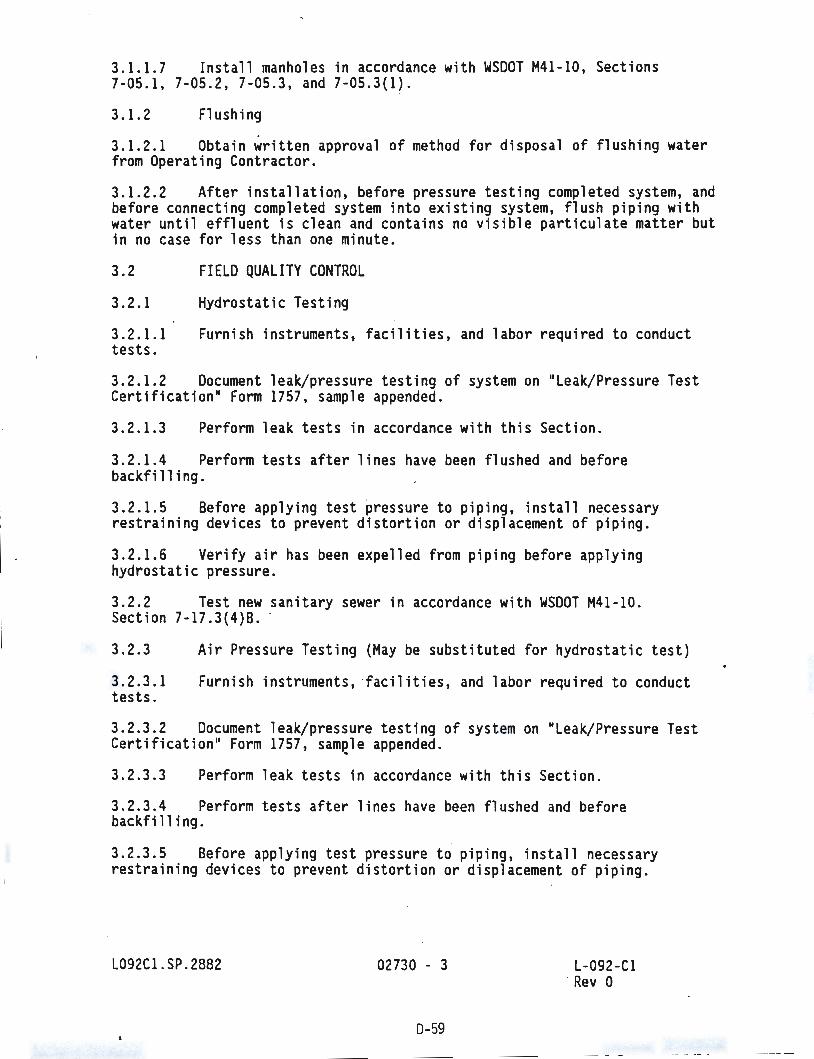
3.1.1.7 Install manholes in accordance with WSDOT M41-10, Sections 7-05.1, 7-05.2, 7-05.3, and 7-05.3(1).
3.1.2 Flushing
3.1.2.1 Obtain written approval of method for disposal of flushing water from Operating Contractor;
3.1.2.2 After installation, before pressure testing completed system, and before connecting completed system into existing system, flush piping with water until effluent is clean and contains no visible particulate matter but in no case for less than one minute.
FIELD QUALITY CONTROL
Hydrostatic Testing
3.2
3.2.1
3.2.1.1 tests.
Furnish instruments, facilities , and labor required to conduct
3.2.1.2 Document leak/pressure testing of system on "Leak/Pressure Test Certification" Form 1757, sample appended.
3.2.1.3 Perform leak tests in accordance with this Section .
3.2.1.4 Perform tests after lines have been flushed and before backf il 1 i ng.
3.2.1.5 Before applying test ~ressure to piping, install necessary restraining devices to prevent distortion or displacement of piping.
3.2.1.6 Verify air has been expelled from piping before applying hydrostatic pressure.
3.2.2 Test new sanitary sewer in accordance with WSDOT M41-10 . Section 7-17.3{4)8. ·
3.2.3
3.2.3.1 tests.
Air Pressure Testing (May be substituted for hydrostatic test)
Furnish instruments, ·facilities, and labor required to conduct
3. 2.3. 2 Document leak/pressure testing of system on "Leak/Pressure Test Certification" Form 1757, samele appended .
3.2.3.3 Perform leak tests in accordance with this Section .
3.2.3.4 Perform tests after lines have been flushed and before backfilling.
3. 2.3.5 Before applying test pressure to ·piping, install necessary restraining devices to prevent distortion or displacement of piping.
L092Cl .SP.2882 02730 - 3
0-59
L-092-Cl · Rev O
3.2.3.6 Test transport, header, riser pipes, and valve vault pipe and appurtenances, to 5 psi in accordance with WSDOT M41-10 Section 7-17.3(4}0 and 7-17.3(4)£.
L092Cl.SP.2882 02730 - 4
D-60
L-092-Cl Rev O
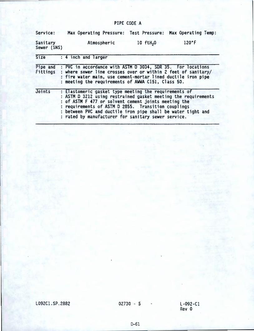
PIPE CODE A
Service: Max Operating Pressure: Test Pressure: Max Operating Temp:
Sanitary Atmospheric 10 ftH 20 12o·F Sewer (SNS)
Size
Pipe and Fittings
Joints
4 inch and larger
PVC in accordance with ASTM D 3034, SOR 35. For locations where sewer line crosses over or within 2 feet of sanitary/ fire water main, use cement-mortar lined ductile iron pipe meeting the requirements of AWWA Cl51, Class 50.
Elastomeric gasket type meeting the requirements of ASTM D 3212 using restrained gasket meeting the requirements of ASTM F 477 or solvent cement joints meeting the requirements of ASTM D 2855. Transition couplings between PVC and ductile iron pipe shall be water tight and rated by manufacturer for sanitary sewer service.
L092Cl .SP . 2882 02730 - 5 L-092-Cl Rev O
0-61
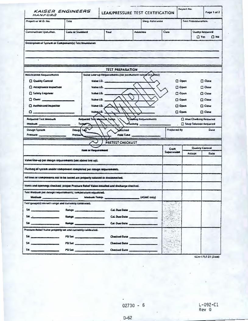
0 i\,3~
TJ-260-7
(llll•tl Io· lSl HIJ'll
"'"0 ,,.. ""·b•11 """""'S d•os 0 ""'"'h"lf f,u111•11) ""lfl 0
••01, 0 vfldo O
"'"'' 0 uado O
11101,0 uado O
""'t:) 0 m•rtoO
'""" 0 v•do O
11101) 0 uado O
l I" 111r.•,1
"""
zg-a
9 -ouzo
••!PO 8ft0 .,.,
(AfUO JWSVJ
>•s ISd
NS
NS
NS
•p•1""1'11'1 A1111"'"" """ ,,., A11adoffl ""'"" l'"l"N "'''""'d
-------8hq --------•&u.11
-cl••.1-
NS
NS
NS
--•"""811"' ... ,
... ,,1
NOil V11Vtf3tld lS3l
""''"""" ....... P '""""' S IO 111"')
,.,.,,.,,.,:011 ·r. .. o IIIIIJ
•-~•d 111•nAs ur,,,,.o
... ,,,." .,...,,_,. n• 1 P• lfflb•t1
• IOU8CINt par,'°'""" 0
IV'"I) 0
INUIWJ A1•1•S 0
IIOIPl'dlVI .,.,,,,d,mv O
'°"""' Alllfflb O
'nN ·0·1111 1n LUln1,1
NOil V:,1:lllllD .LS3l 3llnSS3Mdl)IV37 OHO,:,N't<'~
Stl:1:!Nl!:JN:1 t:I :15l't1'.>f
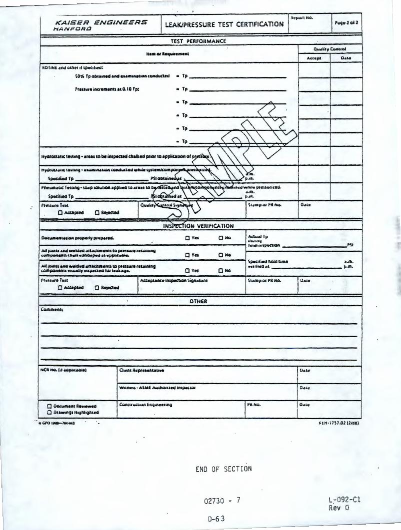
ENGINEERS llci,ullNQ.
KAISER LEAKJPRESSURE TEST CERTIFICATION P•g11 l 1112
HANFORD
TEST PERFOHMANCE Qw••••w (QRUOI
11aao,lla11w•••n1 -'"•Ill o.,.
110 I IN& •M Ulhlll 11 ljlc<IIMt&I:
SO% T p 11b&•1Red •nd 8Uffl1MllOII ccinduC\ad • Tp
Pranwa inu11111nu ,H 0.10 Tp: • Tp
• Tp -• Tp <! • Tp
0, '\__v(
< ("'\ \'\ '\ "'~ • Tp ' ' ✓ ' _.
Hya,1111•11( IIIIU!q • .... , 10 bot in1pecled (n.ikld !)fiat to •ppliullOft of~ \~ V 11,"'o"•"' llll>IIR') • ·--IIOll (cindw<tlkl wn.le ,,11•-::z3~, ~ \ ~
SIW(lfied Tp Ml 00 l ' 1,1.m.
l'Re-•ll( T •IIIAlj • 1G41p WW..IIOA •P~ W MIIIII Ml s~~o,~~~1oc.i w111111 p1cuw11,.u. , .m.
Sp.t<ihed Tp •• .a ,111 - Ii·"'· "'"""'• r.,, 1Qw.Mt~10
- s,.,npo,l'ttNo.
• '-'Uplad 0 ~1eald
INSPtt'flON IIERIFICA TION
Ocw:-IIUIIOII P,Op,t,ly P,IIIMfN. 0 Ya • NO MIYel T11 u,,-uu} tu••tu11ptte:110R
A1110111ll ell>lol -ld<Na .necha11n11 to Pf••-• 1111e,n1n9 LwffljWIIIIRII> U1.i~•IIIIO.paw 111> •l'tli"•IWla. • Ya 0 No
Sp.t<11illd llolcl lime All j011111 ilftd ..ica.o 11nM1Uaenu to ~•nw1111,111ftin9 wc1111o1a.1 UMlll,IOl><tRU .,....,lly Mllai,,<ICII IOI 111_11 ,il')llo 0 YII 0 NO
.. , ... ..,. r ... , I "''•P•-• tn~IOII Si9n.1we St11mp QI I'll NQ.
0 ""-PIN • RetKIM
OTHER Comm11n11
NCll NO. l•I •ppliuota) C1111nt llcp,..,11n1,11u ..
Wlln.11 • ASME Aw&Nlllllnl IRlpa(IGI
0 00CIHll8Rl llh-11 CIIIUUYC\IWI En9,n111111R11 l'ttNo.
Q OIAWIR')I HNJhh')hlllG
END OF SECTION
02730 - 7
0-6 3
o.,.
a.,.
o.,.
o.,.
o., .. I
PSI
•.m. 1,1.m.
l( tl1•1IS1 .0212111111
L-092-Cl Rev O
PART l - GENERAL
1.1 REFERENCES
SECTION 02745
PRESSURIZED SEPTIC SYSTEMS
1.1 . l Reference Standards and Specifications: The following standards and specifications, including documents referenced therein, form part of this Section to extent designated herein.
1.1.1.l American Association of State Highway and Transportation Officials (AASHTO)
Highway Bridges 14th Edition _(1989)
1.1.1.2 American Society for Testing and Materials (ASTM)
A 36-90
A 48-83 (1990)
A 53-90a
A 123-89a
A 126-84
A 276-90a
A 395 - 88
A 702 -89
B 61-86
C 177-85
L092Cl.SP . 2882 02745 - l
0-64
Structural Steel
Gray Iron Castings
Pipe, Steel, Black, and Hot -Dipped, Zinc-Coated Welded and Seamless
Zinc (Hot-Dip Galvanized) Coatings on Iron and Steel Products
Gray Iron Castings for Valves, Flanges, and Pipe Fittings
Stainless and Heat-Resisting Steel Bars and Shapes
Ferritic Ductile Iron · Pressure-Retaining Castings for
Use at Elevated Temperatures
Steel Fence Posts and Assemblies, Hot Wrought
Steam or Valve Bronze Castings .,I
Test Method for Steady-State Heat Flux Measurements and Thermal Transmission Properties by Means of the Guarded -HotPlate Apparatus
L-092-Cl Rev 0
1.1.1.3
C 272-53(1980)
C 518-91
C 578-87a
D 2241-89
D 2466 -90a
D 2564-88
D 2729-89
D 2855-90
D 3034-89.
D 3139-89
American Welding Society {AWS)
01.1-90
Test Method for Water Absorption of Core Materials for Structural Sandwich Construction
Test Method for Steady-State Heat Flux Measurements and Thermal Transmission Properties by Means of the Heat Flow Meter Apparatus
Preformed, Cellular. Polystyrene Thermal Insulation
Poly (Vinyl Chloride) {PVC) Pressure-Rated Pipe {SOR Series)
Poly {Vinyl Chloride) {PVC) Plastic Pipe Fittings, Schedule 40
Solvent Cements for Poly {Vinyl Chloride) {PVC) Plastic Pipe and Fittings
Poly {Vinyl Chloride) {PVC) Sewer Pipe and Fittings
Making Solvent-Cemented Joints with Poly {Vinyl Chloride) {PVC) Pipe and Fittings
Type PSM Poly {Vinyl Chloride) {PVC) Sewer Pipe and Fittings
Joints for Plastic Pressure Pipes Using Flexible Elastomeric Seals
Structural Welding Code-Steel
1.1.1.4 American Water Works Association {AWWA)
Cl04-90 .,f
Cll0-87
L092Cl .SP .2882 02745 - 2
D-65
Cement-Mortar Lining for Ductile-Iron Pipe and Fittings for Water
Ductile-Iron and Gray-Iron Fittings, 3 in. Through 48 in., for Water and Other Liquids
L-092 -Cl Rev O
1.1.1.5
1.1.1.6
1.1.1.7
1. 1. 1.8
Cll 1-90
ClSl-86
CS00-86
C900-89
M23-80
Federal Specifications (FS)
RR-C- 271C
TT- E-489H
Rubber-Gasket Joints for Ductile-Iron and Gray-Iron Pressure Pipe and Fittings
Ductile-Iron Pipe, Centrifugally Cast in Metal Molds or Sand-Lined Molds, for Water or Other Liquids
Gate Valves for Water and Sewerage Systems
Polyvinyl Chloride (PVC) Pressure Pipe, 4 in. through 12 in., for Water Distribution
Manual for PVC Pipe-- Design and Insta 11 at ion
Chains and Attachments, Welded and Weldless
Enamel, Alkyd, Gloss (For Exterior and Interior Surfaces)
National Fire Protection Association (NFPA)
70 (1990) National Electrical Code
Wash ington Administrative Code (WAC)
Title 246, Department of Health
Chapt er 246-272-230 On- Site Sewage System, Installer Requirements
Washington State Department of Transportation (WSDOT)
M41-10-91 Road, Bridge, & Municipal Construction
1.2 SUBMITTALS: Refer to Section 01300 for submittal procedures .
1.2. 1 Septic Tank Plans: Submit plans showing dimensions, reinforcing, and structural calculations including certifications of tank capacity and structural capacity .
1.2.2 Valve Vault Plans: Submit plans showing dimensions, reinforcing, · structural capacity. For precast vaults, include manufacturer's installation procedures .
L092Cl . SP.2882 02745 - 3
0-6'6
L-092- Cl Rev O ·
1.2.3 Installer Certification: Submit evidence that installer of septic system is certified by the Benton-Franklin Health Department in accordance with WAC 246-272-230.
1. 2. 4 Method of Excavation: Submit method of excavation.
1.2.5 Septic Tank Effluent Filter: Submit manufacturer's installation procedures and catalog part numbers.
1.2 .6 Sewage Effluent Pumps: Submit pump performance curves. Submit manufacturers catalog cuts.
PART 2 - PRODUCTS
2. 1 MATERIALS
2.1.1 Concrete: See Section 03300 .
2~1.2 Drain Rock: Washed stone or gravel of uniform size between 3/4 and 1-1/2 inches. Stone or gravel shall be naturally occurring material . Crushed stone will not be permitted .
2. 1.3 Geotextile Fabric: Non-woven polyester or polypropylene fabric weighing 4 oz/sq yd or more.
2.1.4 Lateral Pipe: 1· inch PVC Class 200 drilled with 3/16 inch holes. Finished holes shall be true, round, and free of burrs . Pipe shall conform to ASTM D 2241.
2.1 .5 Transport and Header Pipe: PVC Class 200 meeting the requirements of ASTM D 2241 or PVC PC 150 meeting the requirements of AWWA C 900. Joints shall meet requirements of ASTM D 3139-89.
2. 1.6 PVC Fittings: ASTM D 2466 :
2. 1. 7 Solvent Cement: ASTM D 2564.
2.1.8 Valve Vault Pipe: Cement lined meeting the requirements of AWWA Cl04 and· ductile iron, Class SO minimum, meeting the requirements of AWWA ClSl. Pipe shall have rubber gasketed mechanical joints or push-on j oints meeting the requirements of AWWA Clll.
2. 1.9 Valve Vault Pipe Support : ASTM A 36 , hot-dip galvanized in accordance with ASTM A 123 .
2.1.10 Flexible Couplings: Installed where shown on Drawings, sized to match the pipe OD of each mating pipe. Representative products include Rockwell (Smith-Blair} Steel Coupling. Coat with bitumastic. Allow time for bitumastic to dry before backfilling.
2.1.11 Swing Check Valves: Class 125 iron conforming to ASTM A 126 Class B with bronze trim.
L092Cl .SP .2882 02745 - 4
0-67
L-092-Cl Rev 0
2.1.12 Butterfly Valves: Valve body shall be cast iron conforming to ASTM A 126, Class 8. The disc shall be bronze conforming to ASTM B 61. Stem materials shall be stainless steel conforming to ASTM A 276, Type 304. The operator handle shall be a multi-position locking lever handle.
2.1.13 Gate Valve: 6 inch meeting the requirements of AWWA CSOO and provided with adjustable cast iron valve box.
2.1.14 Fittings: Cement lined meeting the requirements of AWWA Cl04, with joints and pressure class ratings compatible with pipe used and shall meet the requirements of AWWA CllO.
2.1.15
2 .1.16
Weld i ng Electrodes: E70XX.
Chain Barricade
2.1.16 . l Posts: Meet the requirements of ASTM A 702, minimum 6 feet long, and designed for driving into earth .
I
2.1.16.2 Chain: Trade No. 10 galvanized steel jack Type II -meeting the requirements of FS RR-C-271.
2.1.16.3 Signs: 20 gage galvanized steel plate painted with 2 coats of yellow enamel. Signs shall state "SANITARY TILE FIELD" in one inch high black letters.
2. 1.17 Zinc-Rich Coating : Galvicon MZP metallic zinc paint or ZRC zinc rich coating.
2 . 1.18 Paint: FS TT-E-489. Colors: Yell ow and black.
2.1.19 Rigid Board Insulation: Compressive strength-40 psi min in accordance with ASTM C-578; Thermal Conductivity, k-0.2 or less in accordance with ASTM C-177 or C-518; water resistance, percent <1.0 in accordance with ASTM C-272. ·
2.2 EQUIPMENT
2. 2. 1 Septic Tanks: Minimum 2 compartments with .minimum fluid capacity of 6,000 gallons. Inlet compartment at least 2/3 total tank capacity. Tank shall .be precast concrete designed to withstand HS 20-44 load criteria given in AASHTO Figures 3.7.68 and 3.7.7A, and constructed in accordance with WAC 246-272-150. Provide 3 each 24 inch diameter risers with covers to 6 inches above finish grade for access to each-tank compartment. Two accesses shall be into the large compartment, one at each end. The third access shall be over the effluent discharge.
2. 2.1.l Septic tank effluent filter: Install effluent filter(s) on the effluent line within the septic tank per manufacturer's directions. Installation shall permit access to the filter(s) for maintenance. A representative product is Zabel Industries Model A300 or approved substitute. The septic tank effluent filter shall have an intake point at 40 percent of the total liquid depth below the effluent discharge elevation .
.L092Cl.SP.2882 02745 - 5
0-6 8
L-092- Cl Rev O
2.2.2 Dosing Chamber: Chamber shall be precast concrete designed to withstand HS20-44 load criteria given in AASHTO Figures 3.7.6B and 3.7.7A. Dimensions as shown on Drawings.
2.2.3 Dosing Chamber Access Cover: Sized as shown on Drawings. The door leaves shall be aluminum diamond pattern plate to withstand a live load of 150 psf. Hardware shall be stainless steel. A representative product is Bilco Co. Model JD .
2. 2.4 Sewage Effluent Pumps
2. 2.4.1 General: Each pump shall be equipped with a 7.5 hp, submersible electric motor 208 volts, 3-phase, 60 hertz, 4 wire service with 35 feet power and sensor cable. Each pump shall discharge through a 6 inch mating cast iron elbow and deliver 830 gpm at 27 feet plus/minus 2 TOH. Each pump shall. be fitted with 15 feet of stainless steel lifting cable of adequate strength to permit raising and lowering the pump from the ground surface.
2.2.4.2 Pump design:
a. The pump shall be capable of pumping septic tank effluent. The discharge connection elbow shall be permanently installed in the dosing chamber along with the discharge piping. The pumps shall be automatically connected to the discharge elbow when lowered into place. Guide rails for raising and lowering the pumps shall be hot-dipped galvanized pipe, sized in accordance with the pump manufactur~r's recommendations . The pumps shall be easily removable for inspection and service and shall not require service personnel to enter the dosing chamber .
b. Sealing of the pumping unit to the discharge connection elbow shall be accomplished by a simple linear downward motion of the pump. A rail guide bracket shall be an integral part of the pump unit. The entire weight of the pumping unit shall be guided by at least two guide bars and pressed tightly against the discharge connection elbow with metal-to-metal contact. Sealing· of the discharge interface by means of a diaphragm, 0-Ring, or other device will not be acceptable. No portion of the pump shall bear directly on the floor of the dosing chamber. The pump, with its appurtenances and power cable, shall be capable of continuous submergence underwater without loss of watertight integrity to a depth of 65 feet.
2. 2.4 .3 Pump construction:
a. Major pump components shall be of ASTM A 48 Class 30B close-grain gray cast iron, with smooth surfaces and passages free of blow holes and other irregularities.
b. Where water tight sealing is required, 0-rings shall be used. Exposed nuts and bolts shall be of Type 304 stainless steel. All external surfaces coming into contact with sewage, other than stainless steel fittings shall be protected by a sewage/wastewater resistant coating .
c. Mating surfaces where watertight seal•ing is required shall be machined and fitted with nitrile rubber 0-rings. Fitting shall be accomplished by metal-to-metal contact between machined surfaces resulting
L092Cl.SP .2882 02745 - 6
0- 6 9
L-092-Cl Rev 0
in controlled compression of the nitrile rubber 0-rings without the requirement of· a specific torque limit. No secondary sealing compounds, rectangular gaskets, elliptical 0-rings, grease or other devices shall be used.
d. The cable entry water-tight sealing design shall exclude specific torque requirements or epoxy, silicone, or other sealing compounds to ensure a water tight seal. The cable entry shall comprise of an elastomer gronvnet, with stainless washer with close tolerance fit, compressed by a combination sealing gland and strain relief fitting. The cable entry junction chamber shall be separated from the motor housing by an isolated terminal board.
e. The pump motor shall be of induction, squirrel-cage design, housed in an air-filled, water-tight chamber. The stator windings shall be dipped and baked to Class F insulation rating which will resist a temperature of 155°C (311°F). The stator shall be heat shrunk fit into the stator housing to ensure perfect alignment. The use of any other means of securing the stator is not acceptable. The motor shall be designed for continuous duty, capable of sustaining 10 starts per hour. At the design point, the stator, winding temperature shall not exceed 125°C, and the motor shall not draw more than 25 amperes at nominal utility supplied voltage . The motor shall be non-overloading across the entire operating range without the use of the service factor .
f. At maximum rated power, pump shall be of adequate design to provide the radiant cooling required by the motor. Cooling jackets or other related devices shall not be necessary for continuous pumping at a sump level below the midpoint of the stator housing.
g. The motor stator shall be protected by 3 low resistant, bi -metallic thermo switches embedded into the stator coil windings. The sensors shall be connected to series with the motor starter coil and used in conjunction with, and supplemental to, third leg overload protection provided by the motor starter.
h. The pump shaft shall be of Type 316 sta in less steel. The shaft shall rotate on 2 permanently lubricated bal l bearings. The upper bearing shall be a single row ball bearing and the lower bearing a 2 row angular contact ball bearing. The shaft shall be of such design to provide for a minimum overhang to reduce shaft deflection and prolong bearing life.
i. Each pump shall be provided with a tandem mechanical shaft seal system. The upper mechanical seal shall operate entirely in an oil chamber located just below the stator housing. The upper mechanical seal shall contain one stationary stainless steel ring and one positively driven rotating carbon ring. This upper mechanical seal shall function as a secondary barrier between the pumped liquid and the stator housing. The lower set.of mechanical seals shall function as the primary barrier. The lower seal shall contain one stationary silicon carbide ring and one positively driven rotating tungsten carbide ring. Both seal surfaces shall be lubricated and cooled by oil.
L092Cl.SP.2882 02745 - 7
D-70
L-092-Cl Rev 0
I I I I
I I
j. The tandem seals shall be arranged in a cartridge to ensure perfect installation and alignment, providing for service and inspection without removal of the oil chambers or exposing the bearings.
k. Shaft seals of conventional double seal design using single or double spring action between the upper and lower seal and requiring pressure differentials to offset external pressures are not acceptable.
1. The impeller shall be of ASTM A 395 ductile iron, dynamically balanced, double shrouded, with back pump out vanes, of non-clog smooth contour design without acute turns. The impeller shall be capable of handling septic tank effluent. Securing the impeller to the shaft shall be accomplished by means of a sealing washer and impeller screw of AISI 304 stainless steel.
m.- The impeller shall not require coating. Performance data submitted shall be based on the performance of an uncoated impeller. Attempts to improve efficiency shown on the data submitted by coating impellers shall not be acceptable.
n. The pump volute shall be a single piece, non-concentric design, of ASTM A 48 Class 30B close-grain cast iron and shall have smooth contoured fluid passages large enough to pass solid which may pass through the impeller.
o. A wear ring system shall be installed to provide efficient sealing between the volute and the impeller. The wear ring shall consist of a stationary ring of appropriate materials for the application and shall be easily field adjustable. Rubber or other synthetic materials shall not be ac~eptable.
p. The pump motor cable, installed, shall be suitable for submersible pump application with Pl22-MSHA approval indicated by a code or legend permanently embossed on the cable. Cable sizing shall conform to NEC specifications for pump motors.
2.2.4.4 Pump warranty: The pump manufacturer shall warrant the units being supplied against defects in workmanship and material for a period of 5 years or 10,000 hours, whichever comes first. The warranty shall be in printed certificate form and apply to similar units.
2. 2.5 Valve Vault: Sized as shown on the Drawings . Design the vault to withstand HS 20-44 load criteria in accordance with AASHTO Figures 3.7. 6B and 3.7.7A.
PART 3 - EXECUTION
3.1 INSTALLATION
3.1 . 1 Excavate for septic tank, valve vault, and trenches in accordance with Section 02200.
3.1.2 Install septic tank in accordance with approved submittals and WAC 246-272-150.
L092Cl.SP.2882 02745 - 8
0-71
L-092-Cl Rev 0
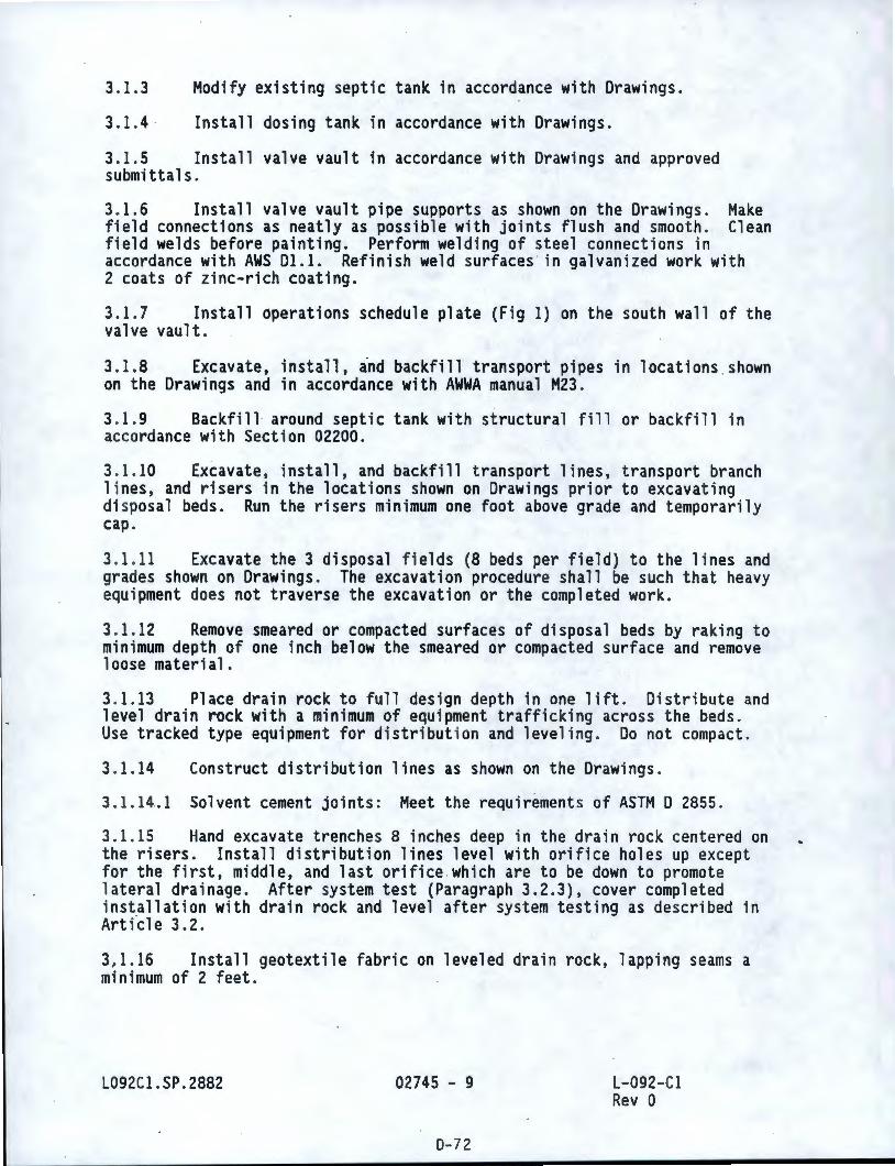
3.1.3
3.1.4 ·
Modify existing septic tank in accordance with Drawings.
Install dosing tank in accordance with Drawings.
3.1.5 Install valve vault in accordance with Drawings and approved submittals.
3. 1.6 Install valve vault pipe supports as shown on the Drawings . Make field connections as neatly as possible with joints flush and smooth. Clean field welds before painting. Perform welding of steel connections in accordance with AWS 01.1. Refinish weld surfaces in galvanized work with 2 coats of zinc-rich coating.
3. 1.7 Install operations schedule plate (Fig 1) on the south wall of the valve vault .
3. 1.8 Excavate, install, ind backfill transport pipes in locations shown on the Drawings and in accordance with AWWA manual M23.
3. 1.9 Backfill around septic tank with structural fill or backfill in accordance with Section 02200 .
3. 1. 10 Excavate , install , and backfill t ransport lines, transport branch l ines, and risers in the locat ions shown on Drawings pr ior to excavating di sposal beds. Run the risers min imum one foot above grade and temporari ly cap .
3. 1.11 Excavate the 3 disposal fie lds (8 beds per field) to the lines and grades shown on Drawings . The excavation procedure shall be such that heavy equi pment does not traverse the excavation or the comp leted wor k.
3. 1. 12 Remove smeared or compacted surfaces of di sposal beds by raking to minimum depth of one inch below the smeared or compacted surface and remove loose material .
3. 1.13 Place drain rock to full design depth in one lift. Distribute and level drain rock with a mi nimum of equ i pment traffi cki ng across the beds. Use t racked type equipment for di stribut ion and level ing . Do not compact.
3. 1. 14 Construct distribution lines as shown on the Drawings .
3. 1. 14 . 1 Solvent cement joints: Meet the requirements of ASTM D 2855.
3. 1.15 Hand excavate trenches 8 inches deep in the drain rock cen t ered on the r i sers . Install distribut ion lines level with orifice holes up except for the first, middle, and last orifice which are to be down to promote lateral drainage. After system test (Paragraph 3.2.3), cover completed installat ion with drain rock and level after system testing as descr i bed in Arti~le 3.2.
3, 1. 16 Install geotextile fabric on leveled drain rock , lapping seams a minimum of 2 feet .
L092Cl.SP.2882 02745 - 9
D- 72
L-092-Cl Rev O
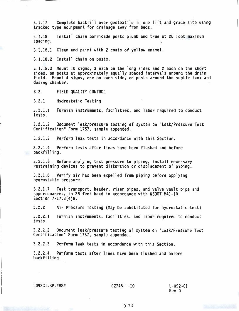
3.1.17 Complete backfill over geotextile in one lift and grade site using tracked type equipment -for drainage away from beds.
3.1.18 spacing.
Install chain barricade posts plumb and true at 20 foot maximum
3.1.18.1 Clean and paint with 2 coats of yellow enamel.
3.1.18.2 Install chain on posts.
3.1.18.3 Mount 10 signs, 3 each on the long sides and 2 each on the short sides, on posts at approximately equally spaced intervals around the drain field. Mount 4 signs, one on each side, on posts around the septic tank and dosing chamber.
3.2 FIELD QUALITY CONTROL
3.2.1 Hydrostatic Testing
3.2.1.1 Furnish instruments, facilities, and labor required to conduct tests.
3.2.1.2 Document leak/pressure testing of system on "Leak/Pressure Test Certification" Form 1757, sample appended .
3.2.1.3 Perform leak tests in accordance with this Section.
3.2.1.4 Perform tests after lines have been flushed and before backfilling.
3.2.1.5 Before applying test pressure to piping, install necessary restraining devices to prevent distortion or displacement of piping.
3.2.1 .6 Verify air has been expelled from piping before applying hydrostatic pressure.
3. 2. 1.7 Test transport, header, riser pipes, and valve vault pipe and appurtenances, to 35 feet head in accordance with WSDOT M41-10 Section 7-17.3(4)8.
3. 2.2 Air Pressure Testing {May be substituted for hydrostatic test)
3. 2. 2. 1 Furnish instruments , facilities, and labor required to conduct tests .
3.2.2 . 2 Document leak/pressure testing of system on "Leak/Pressure Test Certification" Form 1757, sample appended.
3.2.2.3 Perform leak tests in accordance with this Section.
3.2.2.4 Perform tests after lines have been flushed and before backfilling.
L092Cl.SP.2882 02745 - 10
0- 73
L-092 -Cl Rev 0
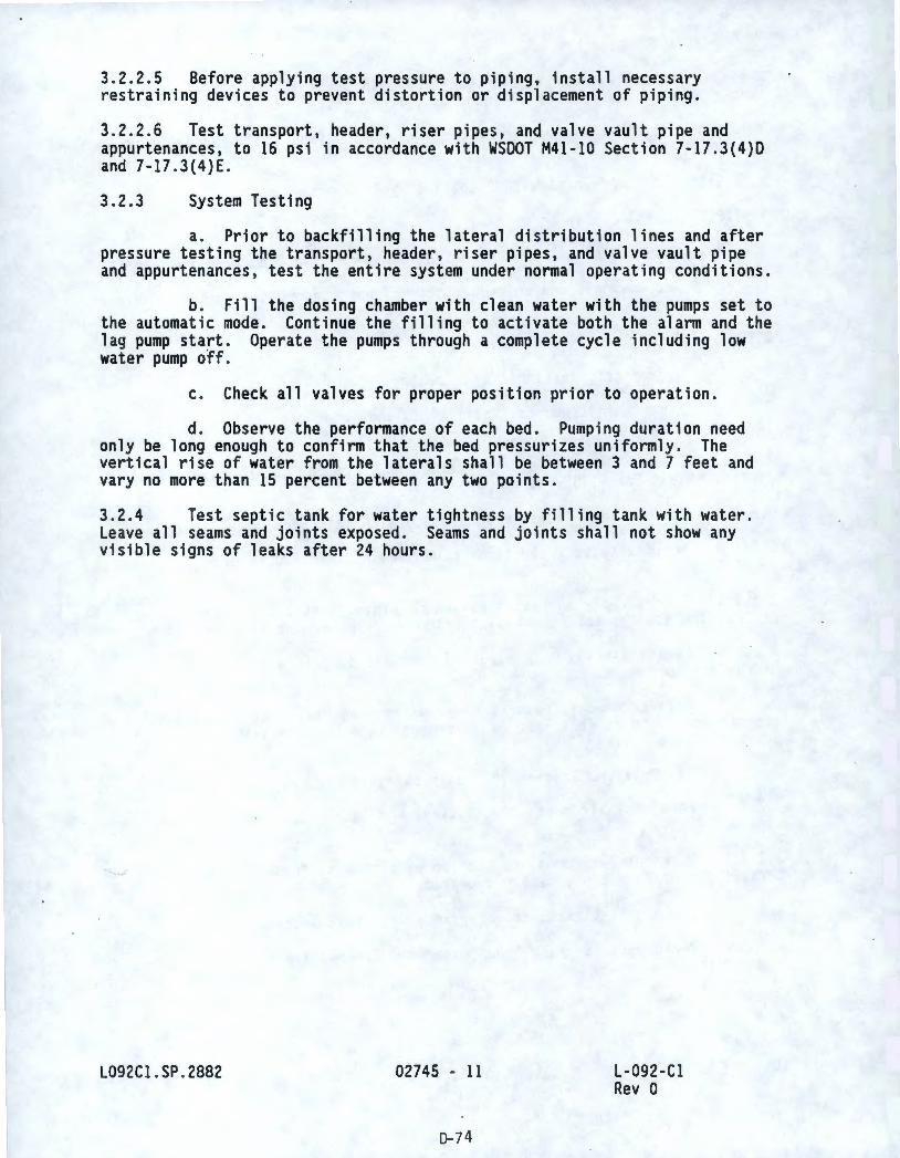
3.2.2.5 Before applying test pressure to p1p1ng, install necessary restraining devices to prevent distortion or displacement of piping.
3.2.2.6 Test transport, header, riser pipes, and valve vault pipe and appurtenances, to 16 psi in accordance with WSOOT M41-10 Section 7-17.3(4)0 and 7 -17 . 3 ( 4) E.
3.2.3 System Testing
a. Prior to backfilling the lateral distribution lines and after pressure testing the transport, header, riser pipes, and valve vault pipe and appurtenances, test the entire system under normal operating conditions.
b. Fill the dosing chamber with clean water with the pumps set to the automatic mode. Continue the filling to activate both the alarm and the lag pump start. Operate the pumps through a complete cycle including low water pump off .
c. Check all valves for proper position prior to operation.
d. Observe the performance of each bed. Pumping duration need only be long enough to confirm that the bed pressurizes uniformly . The vertical rise of water from the laterals shall be between 3 and 7 feet and vary no more than 15 percent between any two points.
3.2.4 Test septic tank for water tightness by filling tank with water. Leave all seams and joints exposed. Seams and joints shall not show any visible signs of leaks after 24 hours.
_,J
L092Cl .SP. 2882 02745 - 11
D- 74
L-092-Cl Rev 0
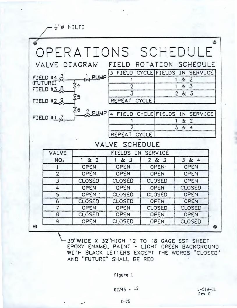
/ {-"Ill HIL TI
©{ @
OPERATIONS SCHEDULE VALVE DIAGRAM FIELD ROTATION SCHEDULE
F'IELD tt4 3,.. ~
(FUTURE) - -FIELD tt3 -~A --F'lEL D tt 2 -~A --
FI ELD tt 1 -?A --
VALVE NO. 1
2 3 4
5 6 7 8 9
@
\_
i
-~- PUMP 3 F'IELD CYCLE FIELDS IN SERVICE
... "' 1 1 & 2 04 A 2 1 & .3
3 2 3 & ''5 A REPEAT CYCLE
{6 ... 2,.. PUMP 4 FIELD CYCLE FIELDS IN SERVICE .... "' 1 1 & 2 2 J &. 4
REPEAT CYCLE -
VALVE SCHEDULE FIELDS IN SERVICE
1 & 2 1 & 3 2 & 3 .3 & 4
OPEN OPEN OPEN · OPEN OPEN OPEN OPEN OPEN
CLOSED CLOSED CLOSED OPEN OPEN OPEN OPEN CLOSED OPEN . CLOSED CLOSED OPEN
CLOSED CLOSED OPEN OPEN OPEN OPEN CLOSED CLOSED
CLOSED OPEN OPEN OPEN OPEN . CLOSED OPEN CLOSED
@
.. II JO WIDE X 32 HIGH 12 TO 18 CAGE SST SHEET EPOXY ENAMEL PAINT - LIGHT GREEN BACKGROUND WITH SLACK LETTERS EXCEPT THE WORDS "CLOSl::D" ANO "FUTURE" SHALL BE RED
Figure 1
0274S - 12
0-75
L-Sl9-Cl Rev 0
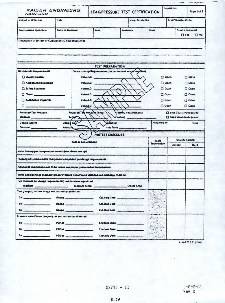
KAISER ENGINEERS HANFORD LEAK/PRESSURE TEST CERTIFICATION
~IOjCLl UI W.0 . N ...
ll•""P'•un ul S~u•m 0, CIUlllklfl•Rl(I) r "" llown"•""'
TEST PREPARATION
V•I•• Lu, .. vp lltq...,•menu (liu p.t1m•ncn1 ••I•
O Q~li1y Conuol
• S•le1r Eng,n.,e,
• ci,.,n, --------• AulllOflHd lnlpe(IDI
•---------llorq .. ,u,c, f•II Mot"'-Mdt..- ________ _
D•"'JR Sru ... P1e11w1e ______ _
l&e•Of .... wife ....
~-------- ..... _ TeMp. --------- (ASMf llnlr)
1.11 g ........ , ""'"° ....... ....a""'"""•,_., ... . SN ______ _ RMge ______ _ C.al. OueD•ce ______ _
SN _______ _ R•nge _______ _ c.i. o ... o.,. --------
SN _______ _ hn<J• -------
c.i. 011e o.,. _______ _
SN ______ _ PSI Sec _______ _ Checked 0•&• _______ _
SN ______ _ PSIS..c _______ _ Checked 0•1• _______ _
SN _______ _ PSI Sec _______ _ Ch11<ked 0•&• _______ _
02745 - 13
D-76
0 Yu 0 No
• Op.,n 0 Clo1e
iJ Oj><fn 0 Clo••
0 Oj><fR 0 Clu•c
0 Op.n 0 Clo••
0 Op.n 0 Clo,.,
0 Op•n 0 Clo,.,
O lllv• Ch•l&IO'j llcq .. .,.,.,
0 Sa.p SOluuon K.,q .. ucd
A((cpl D,ue
i.lH•l757 .QI (2111111
L-092-Cl Rev 0
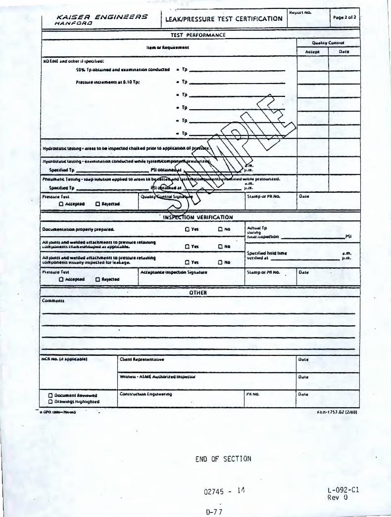
I . '
lt•I-""' NO. KAI.SER ENGINEERS LEAK/PRESSURE TEST CERTIFICATION 1'•9•2 ol 2
HANFDRO
TEST PERFORMANCE
Qiuloty Co'""" Ill• ot lleqllife•enl
""•Pt o .. ,.
110 T1NE ,mu otncr ,I 1p.,,t,~;
so,_ r p ollc•tned •Rd •••m•n•&,on lORdMcted • Tp
Pr emu• inu11men11 •• 0.10 Tp: • Tp
• Tp -• Tp <<
(\ ""~ • Tp
~ < ("'\ \ "\ "\ ""v;> • Tp , '
HydfOla.llC teUIA.IJ •• , ... ,o be in,pened ,~lked priot to •ppliull0II ol ~ \~ < V 11y.UOU•"' ICUIIICJ • •utnlllc&oOA (IWIQW(ICQ wnlitt 'W""""'°"'~~~ ~ \ ~
Spaciliti4 Tp Ml . , C ', l'-tn.
Pna,.,acc,c I alllll .. • wicp Mllw&MMI •pplMrd to••••• to Q::~'' '- ..,,_~"""111c..t w111lc l"IIIIWlllc..t.
\.> " ... m. Spac1h1N1 Tp I I c4 ., - IJ ,IR.
.. , .. , .. ,., r.,, Q .... ~,~)\)
\1•1Rp Ill l'K NO •
O A((epted 0 Re1.all4
INslt!cfiON \IERlflCA TI0N
Oociuae11uuon p,ope,ly Pf•PM•4. QYn QNO A.n,...i Tp U~ftR'j 1••14• u,1pttC11on
All 1oin11 ~-1c111c1 •n"R••n11111 p,euwe re&MRUIIJ •wffljlW&otllll ,n.111.c61110..jlc61 ... •PpllC•Cli-- Q Yet QNo
Sp.c1h•d hold Um• All 1oin11 end weldotd cn•,llln•nu co ~•e1111111111clflillg vo:11lurt.1 "' ,omaion11nu ..,,. ... 11, 1111jl<C(lotO 1111 ••• •':I•· QYn QNo
1'1c11..,• Tell AU•PlMIH 1Aljlll(1AQR Si<Jn•llll • \&•mp Ol l'K NO.
QMUpled • Ra1ected
OTHER Co.nm•n11
NCR No. (11 •pplic.CIIII Chotnl ROIP,•Mln&•uw•
w,,ne'6 • ASMi Awll\Ofiled IR\pot(IW
O Oocwmenc R••••w•d Conu,wa.un ER'JtRCIIIIRCJ l'ltNO.
0 0•••"'IJ' 11,9n1ign1cd
END OF SECTION
02745 - 111,
0-7 7
o .. ,.
o.,.
o.,.
o .. ,.
o .. , ..
PSI
• . m.
I'·"'·
l(tH • l757 .0.l (lidUI
L-092-Cl Rev O
I I I I
I 1,
I I I I
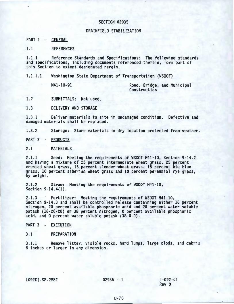
SECTION 02935
DRAINFIELD STABILIZATION
PART 1 - GENERAL
1.1 REFERENCES
1. 1.1 Reference Standards and Specifications: The following standards and specifications, including documents referenced therein, form part of this Section to extent designated herein.
1.1.1.1 Washington State Department of Transportation (WSDOT)
M41-10-91
1.2 SUBMITTALS: Not used.
1.3 DELIVERY AND STORAGE
Road, Bridge , and Municipal Construction
1.3.1 Deliver materials to site in undamaged condition. Defective and damaged materials shall be replaced.
1.3.2 Storage : Store materials in dry location protected from weather.
PART 2 - PRODUCTS
2. 1 MATERIALS
2. 1. 1 Seed : Meeting the requ i rements of WSDOT M41 -10, Section 9-14 .2 and having a mixture of 25 percent intermediate wheat grass, 25 percent crested wheat grass, 15 percent slender wheat grass, 15 percent big blue grass, 10 percent siberian wheat grass and 10 percent perennial rye gr~ss, by weight.
2. 1. 2 Straw: Meeting the requirements of WSDOT M41-10, Section 9-14.4(1}.
2. 1.3 Fertilizer: Meeting the requirements of WSDOT M41-10, Section 9-14 .3 and shall be controlled release containing either 16 percent nitrogen, 20 percent available phosphoric acid and 20 percent water soluble potash (16-20-20) or 38 percent nitrogen, 0 percent available phosphoric acid, and O percent water soluble potash (38-0-0}.
PART 3
3. 1
EXECUTION
PREPARATION
3.1.1 Remove litter, visible rocks, hard lumps, large clods, and debris 6 inches or larger in any dimension .
L092Cl.SP . 2882 02935 - 1
D-78
.L-092 -Cl Rev 0
3.2 INSTALLATION
3.2.1 Smooth and compact soil in accordance with WSOOT M41-10, Section 8-01.3(1) B.
3. 2.2 Plant seed, fertilize, and mulch between Febr~ary 15 and April 15 or September 1 and November 15 in the disturbed and regraded area over and around the valve vault and the soil absorption beds.
3.2.3 Apply seed at a rate of 60 pounds per acre in accordance with WSOOT M41-10, Section 8-01 .3(4) A.
3.2.4 Apply 16-20-20 fertilizer at 500 pounds per acre and 38-0-0 fertilizer at 100 pounds per acre in accordance with WSOOT M41-10, Section 8-01.3(4).
3.2.5 Apply straw at a rate of 4000 pounds per acre in accordance with WSOOT M41-10, Section 8-01.3(5) .
3.2.6 Protection and Care: In accordance with WSOOT M41 -10, Section 8-01.3(9).
L092Cl.SP.2882
END OF SECTION
02935 - 2
0-79
L-092 -Cl Rev 0
SECTION 03300
CAST-IN-PLACE CONCRETE
PART I - GENERAL
I.I REFERENCES
I.I.I Reference Standards and Specifications: The following standards and specifications, including documents referenced therein, form part of this Section to extent designated herein.
I.I.I.I
1.1.1.2
American
301-89
306R-88
347R-88
SP-4-89
American
A 185-90a
A 615 -90
A 853-90
C 33-90
C 94-90
C 150-89
C 260-86
Concrete Institute (ACI)
Society for Testing and
Structural Concrete for Buildings
Cold Weather Concreting
Recommended Practice for Concrete Formwork
Formwork for Concrete, Fifth Edition
Materials (ASTM)
Steel Welded Wire Fabric, Pla i n, for Concrete Reinforcement
Deformed and Plain Billet-Steel Bars for Concrete Reinforcement
Steel Wire, Carbon, for General Use
Concrete Aggregates
Ready-Mixed Concrete
.Portland Cement
Air -Entraining Admixtures for Concrete
1.1.1.3 National Ready Mixed Concrete Association (NRMCA)
Certificate of Conformance for Concrete Production Facilities
L092CI. SP . 2882 03300 - I
D-80
Certi·fication of Ready Mixed Concrete Production Facilities January 1, 1984 (Fourth Revision)
L-092-CI Rev O
1.1.1.4 Washington State Department of Transportation (WSDOT}
M41-10-91 Road, Bridge, and Municipal Construction
1.2 SUBMITTALS: Refer to Section 01300 for submittal procedures.
1.2.1 Cold Weather Concreting: Submit detailed procedure which satisfies ACI 306 .
1.2.2 Curing Procedure: Submit description of materials and methods of curing in accordance with AC! 301, Section 12.2 .
PART 2 - PRODUCTS
2.1 SUBSTITUTES : Refer t o Section 01630 for substitution approvals .
2. 2
2.2. 1
2. 2.1.1
2.2.1.2
MATERIALS
Concrete
Cement: ASTM C 150, Type II (Low Alkali}
Aggregates : ASTM C 33, maximum size 1-1/2 inch
2. 2.1.3 Air-entraining admixture: Meet the requirements of ASTM C 260; Sika Chemical Company "SIKA AER" , Chem-Masters Corp "Adz-Air", or Protex Industries "AES".
2. 2. 1.4
28 days.
and 3.9.
2. 2. 1.5
2.2. 1. 6
2.2 . 2
2.2.2 . 1
Properties
a. Minimum allowable compress i ve strength: 4000 psi at
b. Slump: 4 inch in accordance with AC! 301, Section 3.5.
c. Air content: In accordance with AC! 301, Table 3.4.1.
d. Proportions~ In accordance with ACI 301, Sections 3.8
Mixing: In accordance with ASTM C 94 .
Delivery: In accordance with ASTM C 94 .
Reinforcing Steel
Steel bars : ASTM A 615, deformed, Grade 60 .
2. 2.2.2 Tie wire : Carbon steel, 0.062 inch minimum, annealed, in accordance with ASTM A 853 .
. L092C 1. SP . 2882 03300 - 2
0-81
L-092 -Cl Rev 0
2.2.3 Joint Materials
2.2.3.1 Epoxy resin: Meet the requirements of WSOOT M41-10, Section 9-26, Type II, Grade 2, Class B or C; EAS8 Class A by QCM Company, Concresive 1001 LPL by Adhesive Engineering, or Probond 822 by Protex.
2.2.4 Nonshrink Grout: Nonmetallic type; "Five Star Grout" by US Grout Corp, "Sika Grout 212" by Sika Corp, or "Masterflow 713" by Master Builders.
2.2 . 5 Forms: Wood, steel, plywood, or Masonite Corporation "Concrete Form Presdwood", as required for various specified finishes.
2.2 .6 Form Coating Materials: Magic Kate by Symons Corp, Form Shield by AC Horn Inc, or Burke Release 1 by the Burke Company.
PART 3 - EXECUTION
3. 1 PREPARATION
3. 1. 1 Form Construction
3.1.1.1 Install formwork in accordance with ACI 301, Section 4.2 . Interior shape and rigidity shall be such that finished concrete will meet the requirements of the Dr awings within tolerances specified in AC! 301, Table 4 .3 .1.
3. 1.1 . 2 Prepare form surfaces in accordance with ACI 301, Section 4.4 using spec i fied form coating materials, or as described below.
3.1.1. 3 Forms for surfaces wh i ch will be permanently concealed from view may be saturated with water before plac i ng concrete instead of other t reatment, except in freezing weather forms shall be treat ed with oil or stearate.
3.1.1.4
3.2
3.2 .1
Clean forms of foreign material before placing concrete.
INSTALLATION
Reinforcing Steel
3.2. 1. 1 Fabricate bars accurately to dimensions shown on the Drawings, wi thin tolerances shown in ACI 301, Section 5.6.
3. 2. 1.2 Place with i n tolerances specified in ACI 301, Sections 5.6 and 5.7.
3. 2. 1.3 Tie to prevent displacement during placement of concrete.
3.2.1.4 Do not force into concrete after initial set has started.
3. 2.1 . 5 Place with dimension of concrete protection equal to minimum ~iven in AC! 301, Section 5.7, except where shown otherwise on the Drawings.
L092Cl.SP . 2882 03300 - 3
D-82
L-092-Cl Rev 0
3.2.2 Concrete
3.2.2.1 Before ordering, obtain approval.
3.2.2.2 Before batching, obtain approval of formwork and reinforcement by KEH.
3.2.2.3 Before placing
a. Obtain approval of "Pour Slip" by KEH. "Pour Slip" shall include appropriate reference to specific portion of structure to be placed, maximum size of coarse aggregate, design strength, admixture, and slump. "Pour Sl i p" forms can be obtained from KEH .
b. For each truck load, deliver "Trip Ticket" to KEH. "Trip Ticket" shall contain information listed in ASTM C 94, subparagraphs 16.1.1 through 16 . 1.10, and include water/cement ratio .
3. 2.2 .4 Place in accordance with ACI 301, Sections 8. 1, 8.2, and 8.3. Do not drop (free fall) more than 5 feet. Insert vibrator, vertically if possible, into concrete and reach small distance into concrete in next lower layer. Do not insert vibrators into lower courses that have reached initial set . Take care to avoid allowing head of vibrator to come in contact with forms, reinforcement, or embedded items .
3.2.2.5 Temper only as permitted in ACI 301, Section 7.5.
3.2.2 .6 Place nonshrink grout where shown on the Drawings and in accordance with manufacturer's recommendations .
3. 2.2.7 Weather conditions: Protect concrete during placement in accordance with ACI 301, Section 8.4 . Cold weather concreting shall be in accordance with approved procedure .
3.2. 2.8 Embedded items: Install in accordance with ACI 301, Sections 6.4 and 6.5.
3.2.2.9 Placing concrete against earth: surfaces free of frost, ice and free water. compaction has been obtained. Dampen earth concrete.
Place on or against firm, damp Do not place until required
surfaces to receive fresh
3.2. 2. 10 Consolidation: Consolidate concrete slabs in accordance with ACI 301, Section 11 .6.
Concrete Repair and Form Removal 3.2.3
3.2.3.1 Form removal: Remove in accordance with ACI 301, Section 4.5.
3.2.3 .2 Cut back form ties and examine concrete surfaces for defects. Repair only after permission for patching is given by KEH (Construction Engineer].
L092Cl.SP.2882 03300 - 4
0-8 3
L-092 -Cl Rev o
3.2.3.3 Place concrete repair mortar within one hour after mixing. Do not retemper mortar.
3.2.3 . 4 Surface defect repair: Repair in accordance with ACI 301, Sections 9.1, 9.2 and 9.3 . Cure concrete repairs same as new concrete.
3.2.4 Concrete Finishes and Tolerances
3.2.4.1 Formed surfaces: Start finishing following concrete repair and complete within 96 hours after forms have been removed . Finish in accordance with sections of ACI 301 noted below .
a. Surfaces exposed to Section 10.2.1 earth backfill
b. Interior surfaces Section 10.2.2
c. Exterior surfaces Section 10.2.2 exposed to weather
d. Related unformed surfaces Section 10.5
e . Surfaces to receive Section 10.3.2 special protective coating
3. 2.4 . 2 Unformed surfaces: Finish in accordance with sections of ACI 301 noted below .
a. Interior floors
b. Exterior equ i pment slabs
c. Exterior slabs subject to foot traffic
3.3 FIELD QUALITY CONTROL
Section 11. 7 .3
Secti on 11.7 . 3
Section 11. 7 .4
3.3.1 Concrete Testing: Sampling and testing of concrete will be the responsibility of KEH . Concrete will be tested to ACI 301, Sections 16.3.4, 16 .3 .5 , 16.3 . 6 and 16.3.8, and the results recorded.
3. 4 CURING ANO PROTECTION
3. 4.1 Curi ng
3.4.1.1 Cure concrete in accordance with ACI 301, Section 12.2. Clear curing compounds shall be tinted or applied to surfaces marked to delineate extent of spraying.
3. 4. 1.2 Do not use curing compound on concrete surfaces to receive flooring or special protective coating.
L092Cl. SP. 2882 03300 - 5
D-84
L-092 -Cl Rev O
3.4.2 Protection
3.4.2.1 Protect concrete during extreme weather conditions in accordance with ACI 301, Section 12.3.
3.4.2 . 2 Protect concrete from mechanical injury in accordance with ACI 301, Section 12 .4.
END OF SECTION
L092Cl . SP . 2882 03300 - 6
D-85
L-092 -Cl Rev o
PART 1 - GENERAL
1.1 REFERENCES
SECTION 16400
SERVICE AND DISTRIBUTION
I . I . I Reference Standards and Specifications: The following standards and specifications, including documents referenced therein, form part of this Section to extent designated herein .
1. 1.1.1
1.1. 1. 2
1.1.1.3
1. 1.1.4
American National Standards Institute (ANSI)
C80.l - 1990 Rigid Steel Conduit-- Zinc Coated
National Electrical Manufacturers Association (NEMA)
FB 1- 1988
ICS 6-1988
RN 1-1989
Fittings, Cast Metal Boxes, and conduit Bodies for Conduit and Cable Assemblies .
Encl osures for Industrial Controls and Systems
Polyvinyl-Chloride Externally Coated Galvanized Rigid Steel Conduit and Electrical Metallic Tubing
National Fire Protection Association (NFPA)
70 (1990) National Electrical Code (NEC)
Underwriters Laboratories, Inc (UL)
. 1991
1991
Electrical Appliance and Ut i lization Equipment Directory
Electrical Construction Materials Directory
1. 2 SUBMITTALS : Refer to Section 01300 for submittal procedures.
1.2.1 Approval Data: Submit information listed in Column 5 of Approval Data List in this Section.
1.2.2 Vendor Information: Submit information listed in Column 5 of Vendor Information List in this Section.
L092Cl .SP.2882 16400 - 1
D- 86
L- 092-Cl Rev O
I
1.3 QUALITY ASSURANCE
1.3.l Standards: Products shall be identified for intended purpose by Underwriters Laboratories, Inc (UL) in the Electrical Appliance and Utilization Equipment Directory or Electrical Construction Materials Directory, and bear listing mark of laboratory. In absence of mark, submit documentation of applicable listing . Listing and marking by UL is not required for products specified to meet the requirements of a national standard, or designated by manufacturer's part number on the Drawings or in this Sect ion.
PART 2 - PRODUCTS
2. 1 MATERIALS
2.1.1 .Solderless Connectors and Termi nal Lugs : Pressure type, rated for use with copper or aluminum conductors with insulating caps or covers rated for system utilization voltage. Connectors shall be types specified below.
2. 1.1.1 For conductors No. 8 AWG and smaller .
a. Ideal Industries, Inc "Wire-Nuts."
b. Thomas and Betts Company "Sta- Kon."
c. 3M Company "Scotchlok ."
2.1.1.2 For conductors No. 6 AWG and larger.
a. Burndy Engineering Company "Screw Pressure Connectors" or "Hydent."
b. Thomas and Betts Company "Lock-tite . "
2. 1.2 Raceways, Fittings, and Boxes
2.1.2 . 1 Conduit shall meet the requirements of appropriate standard as follows.
a. Rigid steel ANSI C80.l
2.1.2.2 PVC coating on rigid steel conduit: Factory applied , and meeting the requirements of NEMA RN 1, Type A-40 .
2. 1.2.3 Conduit fittings for rigid steel shall meet the requirements of NEMA FB 1.
2. 1.2.4 Use "Myers" type watertight fittings or sealing locknuts manufactured by Midwest Electric Manufacturing Corp, for conduit entries into sides or tops of NEMA Type 3 or 4 enclosure.
2.1.3 Conductors: Stranded, Type THWN/THHN or XHHW, with AWG size specified on the Drawings .
L092Cl . SP . 2882 16400 - 2
D- 8,7
L-092-Cl Rev 0
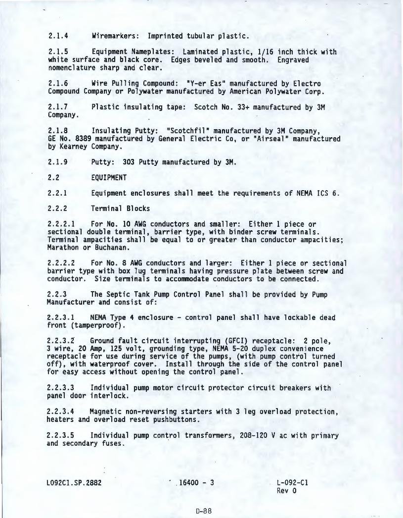
2.1.4 Wiremarkers: Imprinted tubular plastic.
2.1.5 Equipment Nameplates : Laminated plastic, 1/16 inch thick with white surface and black core. Edges beveled and smooth. Engraved nomenclature sharp and clear.
2. 1.6 Wire Pulling Compound : "Y-er Eas" manufactured by Electro Compound Company or Polywater manufactured by American Polywater Corp.
2. 1.7 Plastic insulating tape: Scotch No. 33+ manufactured by 3M Company.
2.1.8 Insulating Putty: "Scotchfil" manufactured by 3M Company, GE No. 8389 manufactured by General Electric Co, or "Airseal" manufactured by Kearney Company.
2. 1.9 Putty: 303 Putty manufactured by 3M.
2. 2 EQUIPMENT
2. 2. 1 Equipment enclosures shall meet the requirements of NEMA res 6.
2.2.2 Terminal Blocks
2.2.2. 1 For No. 10 AWG conductors and smaller: Either 1 piece or sectional double terminal, barrier type, with binder screw terminals. Terminal ampacities shall be equal to or greater than conductor ampacities; Marathon or Buchanan.
2. 2.2.2 For No . 8 AWG conductors and larger : Either 1 piece or sectional barrier type with box lug t erminals having pressure plat e between screw and conductor. Size terminals to accommodate conductors to be connected.
2.2 .3 The Septic Tank Pump Control Panel shall be provided by Pump Manufacturer and consist of:
2. 2. 3. 1 NEMA Type 4 enclosure - control panel shall have lockable dead front (tamperproof).
2. 2.3. 2 Ground fault circu i t interrupting (GFCI) receptacle: 2 pole, 3 wire, 20 Amp, 125 volt, grounding type, NEMA 5-20 duplex convenience receptacle for use during service of the pumps, (with pump control turned off), with waterproof cover. Install through the side of the control panel for easy access without opening the control panel .
2. 2.3 .3 Individual pump motor circuit protector circuit breakers with panel door interlock.
2.2.3 .4 Magnetic non-reversing starters with 3 leg overload protection, heaters and overload reset pushbuttons.
2.2.3.5 Individual pump control transformers , 208- 120 V ac with primary and secondary fuses.
L092Cl . SP . 2882 · . 16400 - 3
D-88
L- 092- Cl Rev O
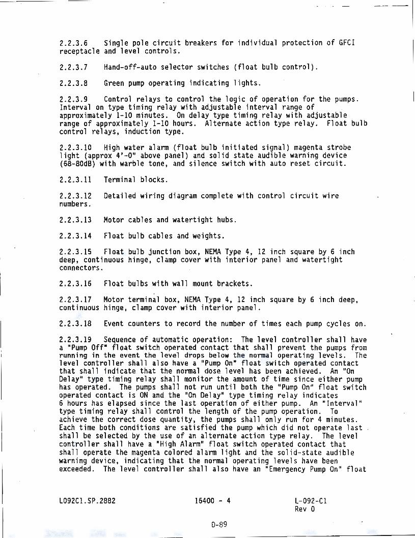
2.2.3.6 Single pole circuit breakers for individual protection of GFCI receptacle and level controls.
2.2.3.7
2.2.3.8
Hand-off-auto selector switches (float bulb control).
Green pump operating indicating lights.
2.2.3.9 Control relays to control the logic of operation for the pumps. Interval on type timing relay with adjustable interval range of approximately 1-10 minutes. On delay type timing relay with adjustable range of approximately 1-10 hours. Alternate action type relay . Float bulb control relays, induction type.
2. 2.3.10 High water alarm (float bulb initiated signal) magenta strobe light (approx 4'-0" above panel) and solid state audible warning device (68-80d8) with warble tone, and silence switch with auto reset circuit.
2. 2.3. 11 Terminal blocks .
2. 2.3 . 12 Detailed wiring diagram complete with control circu i t wire numbers.
2. 2.3.13 Motor cables and watertight hubs .
2.2.3.14 Float bulb cables and weights .
2. 2.3.15 Float bulb junction box, NEMA Type 4, 12 inch square by 6 inch deep, continuous hinge, clamp cover with interior panel and watertight connectors. ·
2.2.3.16 Float bulbs with wall mount bracket s .
2. 2.3.17 Motor terminal box, NEMA Type 4, 12 inch square by 6 inch deep, continuous hinge, clamp cover with interior panel .
2.2 .3.18 Event counters to record the number of times each pump cycles on.
2.2.3 . 19 Sequence of automatic operation: The level controller shall have a "Pump Off" float switch operated contact that shal l prevent the pumps from running in the event the level drops below the normal operat i ng levels. The level controller shall also have a "Pump On" float switch operated contact that shall indicate that the normal dose level has been ach ieved . An "On Delay" type timing relay shall monitor the amount of time since either pump has operated. The pumps shall not run until both the "Pump On" float switch operated contact is ON and the "On Delay" type timing relay indicates 6 hours has elapsed since the last operation of either pump. An "Interval" type timing relay shall control the length of the pump operation. To achieve the correct dose quantity, the pumps shall only run for 4 minutes . Each time both conditions are satisfied the pump which did not operate last shall be selected by the use of an alternate action type relay . The level controller shall have a "High Alarm" float switch operated contact that shall operate the magenta colored alarm light and the solid-state audible warning device, indicating that the normal operating levels have been exceeded. The level controller shall also have an "Emergency Pump On" float
L092Cl.SP.2882 16400 - 4
0-89
L-092- Cl Rev O
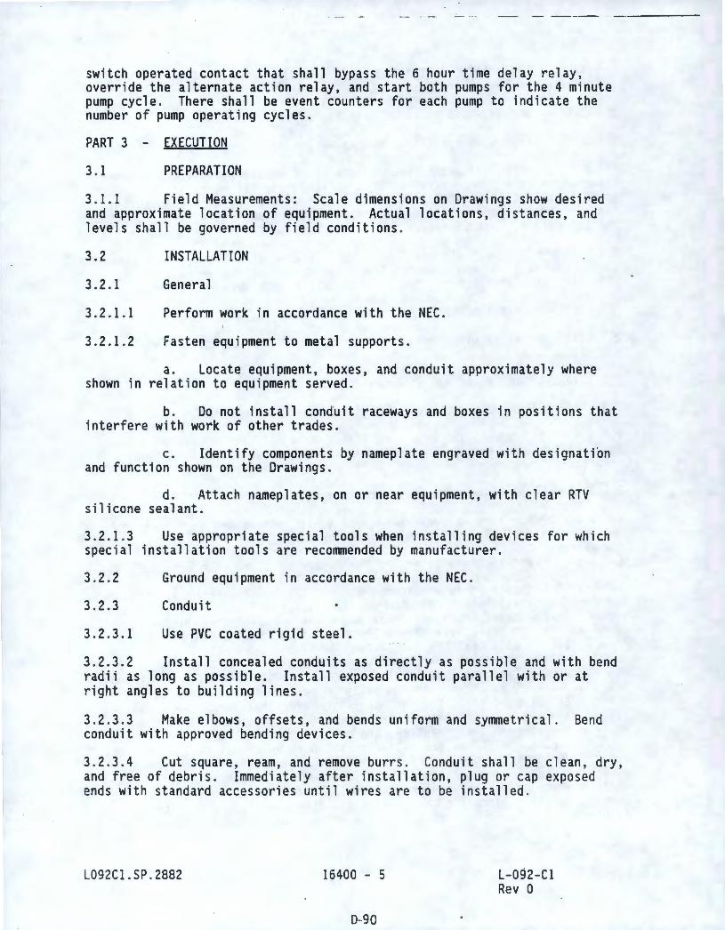
switch operated contact that shall bypass the 6 hour time delay relay, override the alternate action relay, and start both pumps for the 4 minute pump cycle. There shall be event counters for each pump to indicate the number of pump operating cycles.
PART 3 - EXECUTION
3. 1 PREPARATION
3. 1.1 Field Measurements: Scale dimensions on Drawings show desired and approximate location of equipment. Actual locations, distances, and levels shall be governed by field conditions .
3.2
3.2.1
3.2.1.1
3.2.1.2
INSTALLATION
General
Perform work in accordance with the NEC.
Fasten equipment to metal supports.
a. Locate equipment, boxes, and conduit approximately where shown in relation to equipment served.
b. Do not install cond~it raceways and boxes in positi~ns that interfere with work of other trades.
c. Identify components by nameplate engraved with designation and function shown on the Drawings .
d. Attach nameplates, on or near equipment, with clear RTV silicone sealant.
3. 2.1 .3 Use appropriate special tools when installing devices for which special installation tools are recommended by manufacturer.
3.2.2
3.2.3
3. 2.3. 1
Ground equipment in accordance with the NEC .
Conduit
Use PVC coated rigid steel.
3. 2.3 . 2 Install concealed conduits as directly as possible and with bend radii as long as possible. Install exposed conduit parallel with or at right angles to building lines.
3.2.3.3 Make elbows, offsets, and bends uniform and symmetrical. Bend conduit with approved bending devices.
3. 2.3.4 Cut square, ream, and remove burrs . Conduit shall be clean, dry, and free of debris. Immediately after installation, plug or cap exposed ends with standard accessories until wires are to be installed.
L092Cl.SP.2882 16400 - 5
D-90
L-092-Cl Rev 0
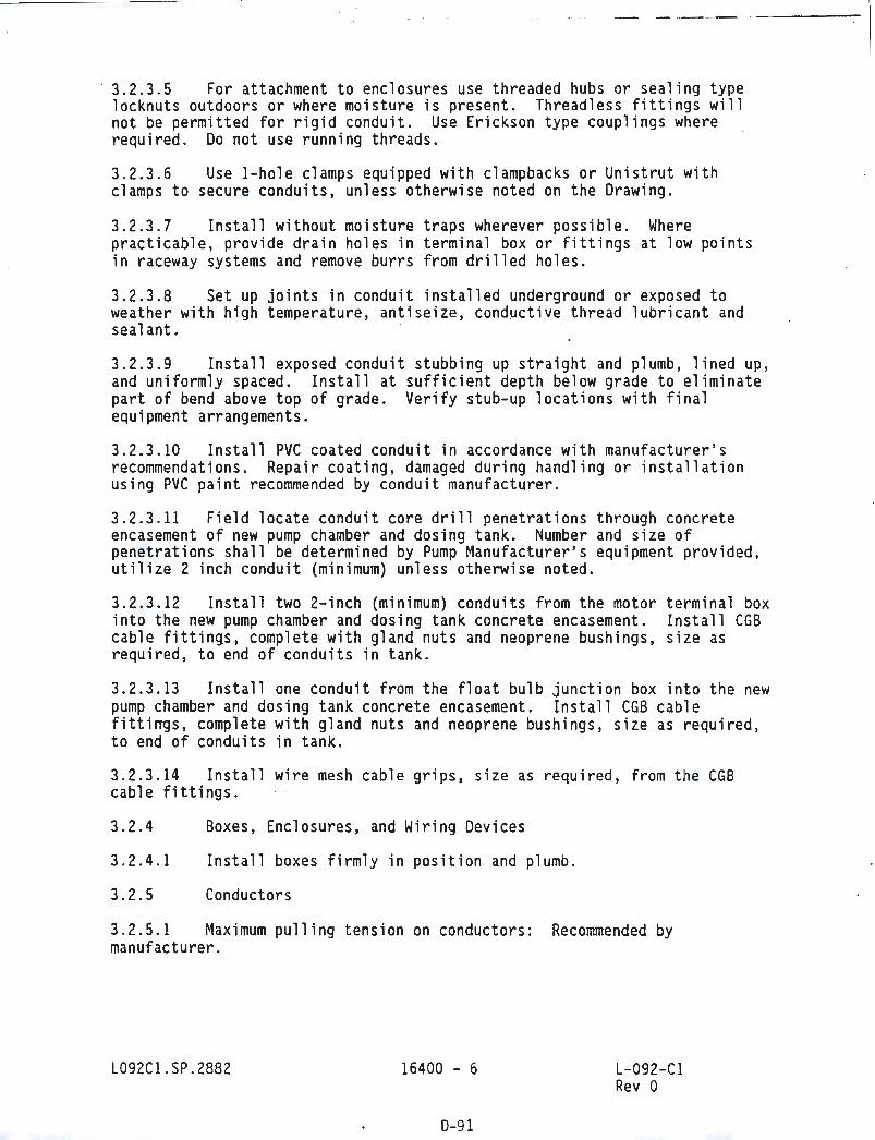
·- - --- --- - - --
3.2.3.5 For attachment to enclosures use threaded hubs or sealing type locknuts outdoors or where moisture is present. Threadless fittings will not be permitted for rigid conduit. Use Erickson type couplings where required . Do not use running threads .
3.2.3.6 Use 1-hole clamps equipped with clampbacks or Unistrut with clamps to secure conduits, unless otherwise noted on the Drawing.
3. 2.3 .7 Install without moisture traps wherever possible. Where practicable, provide drain holes in terminal box or fittings at low points in raceway systems and remove burrs from drilled holes.
3. 2.3 .8 Set up joints in conduit installed underground or exposed to weather with high temperature, antiseize, conductive thread lubricant and sea 1 ant.
3. 2.3.9 Install exposed conduit stubbi ng up st raigh t and plumb , lined up, and uniformly spaced. Install at sufficient depth be l ow grade to eliminate part of bend above top of grade. Verify stub-up locations with final equipment arrangements.
3. 2.3 . 10 Install PVC coated conduit in accordance with manufacturer ' s recommendations. Repair coating, damaged during handling or installation using PVC paint recommended by conduit manufacturer .
3. 2.3. 11 Field locate conduit core drill penetrat i ons through concrete encasement of new pump chamber and dosing tank . Number and size of penetrations shall be determined by Pump Manufacturer's equipment provided, utilize 2 inch conduit (minimum) unless otherwi se noted .
3. 2.3.1 2 Install two 2-inch (minimum) conduits from the motor terminal box into the new pump chamber and dosing tank concrete encasement. Install CGB cable fittings, complete with gland nuts and neoprene bushings, size as required, to end of conduits in tank.
3.2.3.13 Install one conduit from the float bulb junction box into the new pump chamber and dos i ng tank concrete encasement. Install CGB cable fittirrgs, complete with gland nuts and neoprene bushings, size as required, to end of conduits in tank.
3.2.3.14 Install wire mesh cable gr i ps, si ze as requ i red , f r om t he CGB cable fittings .
3. 2.4
3. 2.4.1
3.2 .5
Boxes, Enclosures, and Wi ring Dev ices
Install boxes f i rmly in posit i on and plumb .
Conductors
3.2.5 . 1 Maximum pulling tension on conductors : Recommended by manufacturer .
L092Cl .SP.2882 16400 - 6
0-91
L-092 -Cl Rev O
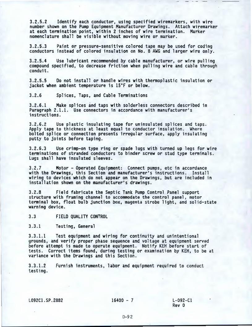
3.2.5.2 Identify each conductor, using specified wiremarkers, with wire number shown on the Pump Equipment Manufacturer Drawings. Attach wiremarker at each termination point, within 2 inches of wire termination. Marker nomenclature shall be visible without moving wire or marker.
3.2.5.3 Paint or pressure-sensitive colored tape may be used for coding conductors instead of colored insulation on No. 8 AWG and larger wire only.
3.2.5.4 Use lubricant reconvnended by cable manufacturer, or wire pulling compound specified, to decrease friction when pulling wire and cable through conduit.
3.2.5.5 Do not install or handle wires with thermoplastic insulation or jacket when ambient temperature is 15°F or below.
3.2.6 Splices, Taps, and Cable Terminations
3.2.6.l Make splices and taps with solderless connectors described in Paragraph 2.1.1. Use connectors in accordance with manufacturer's instructions.
3. 2.6.2 Use plastic insulating tape for uninsulated splices and taps . Apply tape to thickness at least equal to conductor insulation. Where bolted splice or connection presents irregular surface, apply insulating putty to joints before taping.
3.2.6.3 Use crimp-on type ring or spade lugs with turned up legs for wire terminations of stranded conductors to binder screw or stud type terminals. Lugs shall have insulated sleeves .
3.2.7 Motor - Operated Equ i pment: Connect pumps, etc in accordance with the Drawings, this Section and manufacturer's instructions. Install wiring to devices which do not appear on the Drawings, but are included in installation shown on the manufacturer's drawings.
3. 2.8 Field fabricate the Septic Tank Pump Control Panel support structure with framing channel to accommodate the control panel, motor terminal box , float bulb junction box, magenta strobe light, and solid-state warning device.
3.3
3.3. 1
FIELD QUALITY CONTROL
Testing, General
3.3. 1. 1 Test equipment and w1r1ng for continuity and unintentional grounds, and verify proper phase sequence and voltage at equipment served before attempt is made to operate equipment. Notify KEH before start of tests. Correct items found, during testing or examination by KEH, to be at variance with the Drawings and this Section.
3.3.1.2 testing.
Furnish instruments, labor and equipment required to conduct
L092Cl .SP.2882 16400 - 7
D-9 2
L-092- Cl Rev O
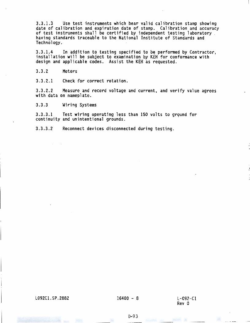
3.3.1.3 Use test instruments which bear valid calibration stamp showing date of calibration and expiration date of stamp. Calibration and accuracy of test instruments shall be certified by independent testing laboratory having standards traceable to the National Institute of Standards and Technology.
3.3.1.4 In addition to testing specified to be performed by Contractor, installation will be subject to examination by KEH for conformance with design and applicable codes . Assist the KEH as requested.
3.3.2
3.3.2 . 1
Motors
Check for correct rotation .
3.3.2. 2 Measure and record voltage and current, and verify value agrees with data on nameplate .
3. 3.3 Wiring Systems
3.3.3. 1 Test wiring operating less than 150 volts to grqund for continuity and unintentional grounds.
3.3.3. 2 Reconnect devices disconnected during testing .
L092Cl .SP . 2882 16400 - 8
0-9 3
L-092- Cl Rev 0
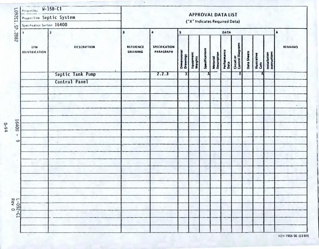
0 I
\.0 .po
· • · - W- 158-C l - -J' 1lljt •1t f,J, y
r 0 I.D N n
-- --
-VI '"O
N co co N
-
;:o r (t) I < O
I.D O N
I n -
P•UJHI l ,llt- Se ptic System
S1,i-> <1Lta1 1c11 ~t c ti c,P 16400
1 2
lPN DESCRIPTION
ID l NTIF IC Al ION
Septic Tank Pump Con t rol Panel
3 4
RlFER l NCI SPfClflCATION
DRAWING PARAGRAPH
. 2. 2.,
APPROVAL DATA LIST ("X" Indicates Required Data)
5 DATA 6
.. E .. ~
REMARKS
2 .. C .. .. .9 g ., 01 ..
C C .! .. .t
C ,.
a r .. J 0 C .. .. :J '.2 i .. .. 0
E .. E 0- ·- 0 .. • ·c C ·- Cl ~ :§ .1:: f .. ... .. ·c ~ !! "' 5 .2' ! ~
.. ~i E,. l :I .. .. ....
·- .. C, .. i ~ t .. ., C .. ~ !i t: 0 0 ... J lo d '9 ..
"' 0 :u .5 .5
-x 1 X. }
t:E H-1986 00 (03 :89)
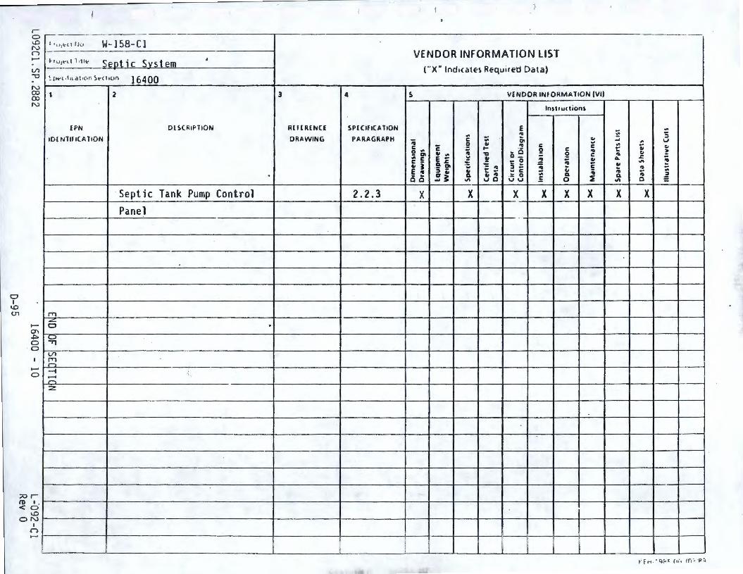
C, I
\.0 (.11
s - ---------- --------- -----~---- --------------------------------- -------'° N W-158- Cl n _______________________ __,
....... Sentic Svstem Vl '"'O ~ ,,.-1 ,111 .; t,or. S.-n.un 164 00 N
~ 1 2 N
lPN DlSOHf'TION
101 NTH l(A TION
Septic Tank Pump Control Panel
rr, -"'-....... 0 .
0) .::,. ._, 0 .,, 0
Vl rr, ~
....... --1 " 0 .-. ~
z
;;or
3
R(f(R[NCl
DRAWING
4
SP lC lflCA TI0N
PARAGRAPH
2.2.3
VENDOR INFORMATION LIST
("X" Indicate~ Required Data)
5 VENDOR INFORMATION (VI)
~ C 0.,. ;; g' C -" I E • 00
X
c .. .,. E ... a.,= 5 2' C7 .. ... ~
X
.,. .. ... "0
~ - "' t: ... " "' uo
E "' 01 "' - 0 o_
'= e :i ... .., C
.:: 0 vu
X
ln structioni.
X
C
2 :! c., Q. 0
X X X X
(l) I . t--------f-----------------+--------f---------1---f----f---t----t---t----1---4---------+---+----1 <O
'° ONt--------+-------------------4-------+----------4---+----1---+----4----f-----+--+---~l----4------+----t I
n ....... t-------t------------- --- ---+---- - --+-------+--+---+--+---,f----l\--- ~ - --+-----11----+------>j- --f------j
E-0
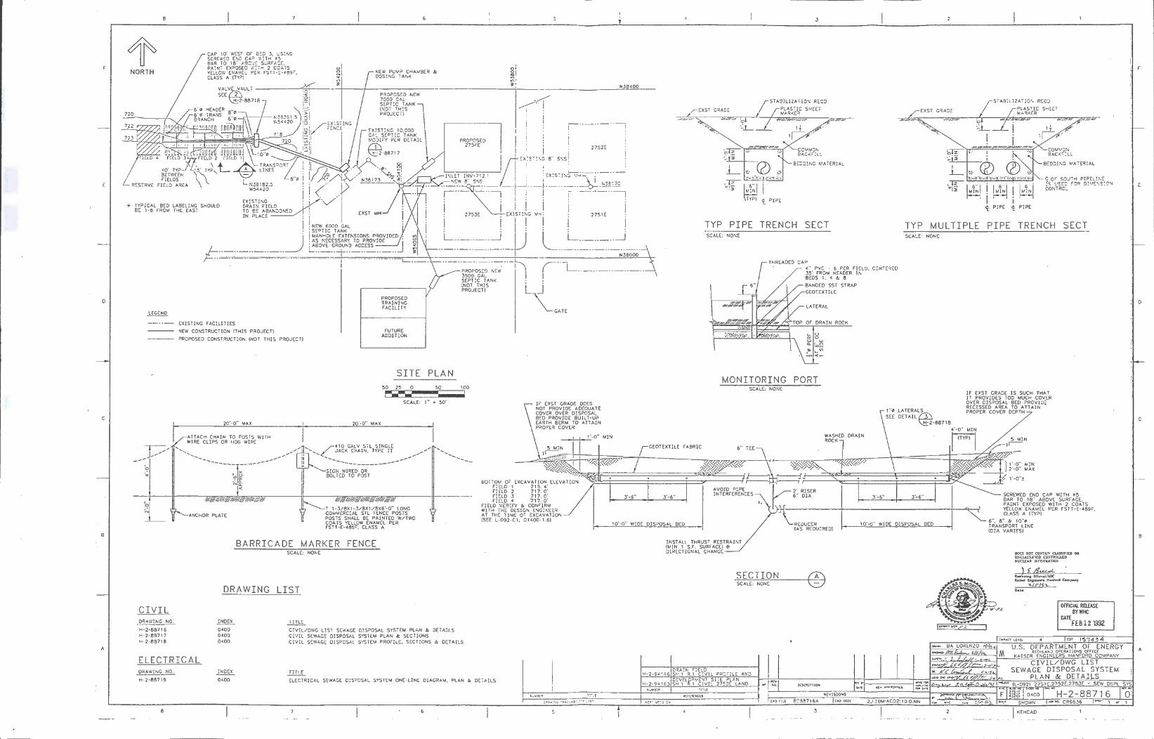
F
D
C
B
A
8
NORTH
<Q'
CAP 10' WE ST OF 0£D J, L:SINC SCREWED END CA' WITH =5 BAR TO 18" A3CV::: SURF AC£. PAINT EXPOSED Wi:T H 2 COATS Y£:.LO'.'/ ENAMEL PER FSTT-£-489F. CLASS A (TY?}
BE TWEEN \" FiELOS , \,_
RESERVE FIELD AREA
* TYPICAL BED LABELING SHOULD BE 1-8 FROM THE EAST
---
L·
EXISTING FACILITIES
NEW CONSTRUCTION !THIS PROJECT}
PROPOSED CONSTRUCTION INOT THI S PROJECT}
20'-Q" MAX
ATTAC H CHAIN TO POSTS WIT H WIRE CLIPS OR HOG WIRE
....... ......... ........ __ _ ---
ANCHOR PLATE
NEW PUMP CHAMBER & DOSING TANK
PROPOSED NEW 7000 GAL SEPTIC TANK (NOT THIS
PROPOSED TRAINING FACILITY
FUTURE ADDITION
PROPOSED 275<E
N38C00
/'"I I • : i I . : i I .
i :::x:STIN~ e" s~s !
r ·-- ----·, ' ' ' . I I
I 2752E
! I I . L._._ __ ____ __ ___J
INLET INV 2 7 12 i . EXISTING 'i·+-... I N-w a" SN~ I I \ r->~ ~-i j-f-T-&.-"'';
! 2753E U::x1sr11,G MH: ! 2751E !
L __ J~ L L~~~~'\ PROPOSED NEW /--l_ _____________ _ 3500 GAL I SEPTIC TANK (NOT THIS L' J' PROJECT}
GATE
3
C0'.1 1.J: ON 2ACr<FlLL
BEOJINC ~/ATERIAL
TYP PIPE TRENC H SECT SCALE: NONE
CAP <" PVC • 6 PER FIELD. CENTERED JS' FROM HEADER I~ BEDS 1, 4 & 8
BANDED SST STRAP GEOTEXTILE
LATERAL
OF DRAIN ROCK
/
STABILIZATION REDO
PLASTIC SHEET MARKER
C OF SO:.JTH PIPELI ,E fs us::~ FOR 0 ! '.~E:'!S!ON CONTROL
TYP MULTIPLE PIPE TRENCH SECT SCALE: NONE
SITE PL A.N 50 25 0 50 100
~ SCALE: 1" = 50'
20'· 0" MAX
~\•· ~~~- ~~~\'' \~~\'" ,~~-
T 1·3/8X1·3/8X 1/8X6'· 0" LONG COMMERCIAL STL FENCE POSTS POSTS SHALL BE PAINTED W/TWO COATS YELLOW ENAMEL PER FSTT-E-489F. CLASS A
............. ...,. .......... __ _
I F EXST GRADE DOES OT PROVIDE ADEQUATE OVER OVER DISPOSAL ~O PROVIDE BUILT-UP ARTH BERM TO ATTAIN ROPER COVER
1 1'-0" MlN
I
MONITORING PORT SCALE: NONE
GEOTEXTILE FABRIC 6" TEE
WASHED DRAIN ROCK
1"<• LATERALS DETAILLl'I
QE2-887 18
IF EXST GRADE IS SUCH THAT IT PROVIDES TOO MUCH COVER OVER DISPOSAL BED PROVIOE RECESSED AREA TO ATTAIN PROPER COVER DEPTH
4'-0" MIN
Fl 5 MIN 1r-
. ,'«'~ \ ~ "1/
')fy,i~t===========~~=-___, u...r t====~=~~~~~~~;;£~~~~~~~1~r-BOTTOM OF EXCAVATION ELEVATION •J,...L,L ,
FIELD 1 715. 4' t:= ~mg ~ m: g: J '-6" 3'-6" tifl~F:J:Jm r iir5r J'-6" 3'-6" SCREWED END CAP WITH •5 FI ELD 4 717 . D' BAR TO 18" ABOVE SURF ACE.
FIELD VERIFY & CONFIRM t PAINT EXPOSED WITH 2 COATS WITH THE DESIGN ENGINEER 1 --------1----------------'--4---t YELLOW ENAMEL PER FSTT- E-489F, AT THE TIME OF EXCAVATiON ~ CLASS A ITYP}
!SEE L·092·C l. 01<00·l.5l 10'-o" WIDE DISPOSAL BED REDUCER 10'--0" WIDE DISPOSAL BED 5", 5" & lO"~ (AS REOUIREO) itt..'fAOR~~S~INE
BARRICADE MARKER FENCE INST ALL THRUST RESTRAINT !MIN 1 S.F. SURFACE) i! DIRECTIONAL CHANGE
CIVIL DRAWING NO.
H-2-88716 H-2-88717 H-2-88718
ELECTRICAL DRAWING NO.
H- 2-88719
8
SCALE: NONE
DRAWING LIST
INDEX
04 00 0400 0400
INDEX
0400
i ITLE
C!VIL/DWG LIST SEWAGE O!S?OSAL SYSTEM PLAN & DETAILS CIVIL SEWAGE DISPOSAL SYSTEM PLAN & SECTIONS CIVIL SEWAGE DISPOSAL SYSTEM PROFILE. SECTIONS & DETA I LS
TITLE
ELECTRICAL SEWAGE DISPOSAL SYSTEM ONE-LINE DIAGRAM. PLAN & DETAILS
SECTION SCALE: NONE ®
c1o :i mt 8038716A R£VISIONS
C1oO coo;: 2J:IBM:AC02: 10.0:NN
- .. - I __________ 2
DOts SOT CO!\"TA!.'i" cu.sstnm OR USCLASSlm;o COSTROU.CO !,'UCLEAR l,t;fORMATIO!'i
di.= K.iser tn1meen Hanford Compa.nJ
-z..1:,-19"1-Dal•
OFFICIAi. RELUSE BYWHC
OAT£ FEB 12 19S2
"'' l'S7 "4 U.S. DEPARTMENT OF ENER GY
RtCHLASQ C='ERA no:-.is OffICE KAISER ENGINEERS HANFORD CO.,,PANY
CIVIL/DWG LIST SEWAGE DISPOSAL SYSTE M
PL AN & DETAILS
0400 H-2-887 16 CR9636 ~ 1 or 1
D
C
B
A
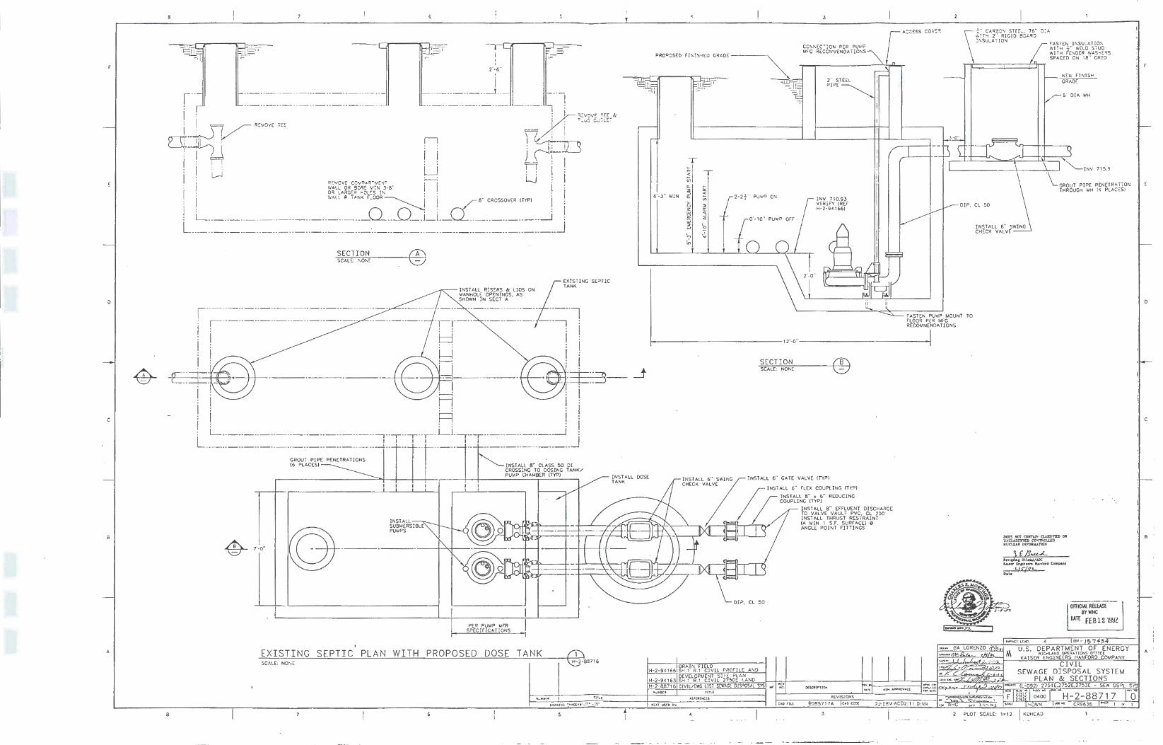
SECTIO N SCALE: NONE
D
C
a 7'-0"
~ ·-
A EXI STING SEPTI C, PLAN SCALE: NON~
8
®
INSTALL i~~~[RSIBLE
WITH
PER PUM? MFR SPECIFICATIONS
PROPOS ED DOSE
--- -
DOSE
TANK
1l1l[
5
3
CONNEC ro P•R p / ACCESS
rM_F_CT R-EC- C _· _'" _E __ [)_A_-,_ i-~-'.~:-~-~- ~1/...n_
COVE,
PROPO~EO f"IN!SHED GRADE-----
6'-3" MIN
0.. ::, :::, a.
>u 3 '-' ffi i:',
2" STEEL PIPE
!NV 71D.93 VERIF'Y (REF H-2-9<\661
DIP. CL SO
FASTEN PUMP MOUNT TO FLOOR PER MFG RECOMMENDA TJONS
12'-0"------------_J
SEC TI ON SCALE: NONE ®
CHECK VALVE I NSTALL 6" CATE VALVE (TYP) I NSTALL Z " SWI NG
;;
I NSTALL 6" FLEX COUPLING ITYPI
INSTALL 8" x 6" R COUPLING ITYP) EDUC I NG
I NSTALL 8" EFF ·'<----'--- TO VALVE VAUL ~U~~~ DISCHARGE lJ:s~t~\ THRUST RESTR~~N?oo
H- 2-9<16 DRAIN FIELD 6 SH . 1 R.1 CIVIL PROFILE ANO
H-2 -94163 ~~V,EL~P>JE';'T SITE PLAN H- 2 887 . .1 C. VI L 2750:- LANO
N'.J~ 9[R 16 CIVJL/DWG U ST S£'NJ.G£ O!S?OSAL SYS ""' HO.
UO rll[
ANGLE P01tf rW~rng~) i!l
REV ISIONS
80~8717A o o CO'JC
3
NEW FINISH CRACE
6' DIA MH
·\_ "'-!NV 715.9
CROUT PIPE PENETRATiON THROUGH MH {4 PLACES)
. OFFICIAL RELEASE BYWHC
om F[B12. l9~Z
U.S. DEPA RTM ENT OF KAISERR I~~tl~E~R~"'TIONS orncf NE RGY HANFORD COMPANY
CIVIL SEWAGE DI SPOSAL SYSTEM
D
C
B
A i
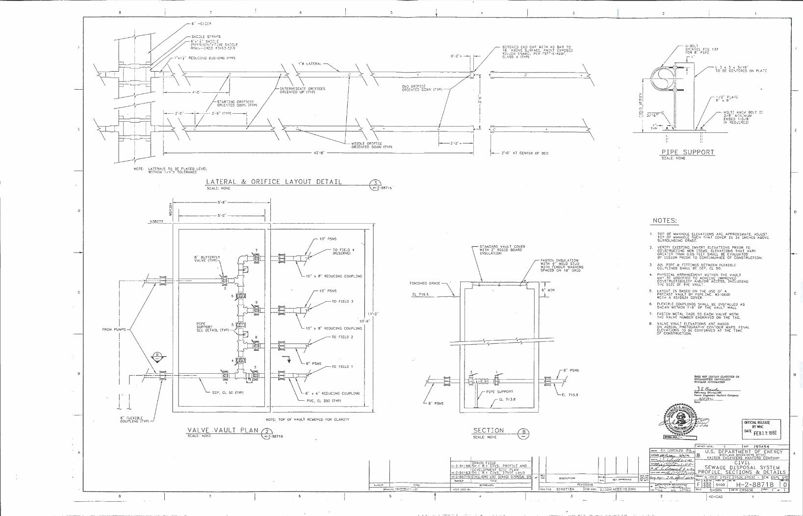
D
C
FROM
B
A
/
SCR:::\\::O END CAP WITH ;5 SAR TO 18 A30VE SURPACE PAINT EX 0 :::::SEO Y~LLO\'.' ENAMEL PER FSTT-E-489r",
\
0 - 2· + __,I ' CLASS A (TYP) \
\, ... LATERAL~ I/ ~~\----~i-~\------------,1.1 -:~--_-,-----~\
END ORIFICE INTERMEDIATE ORIFICES ORIENTED DOWN ORI ENT ED UP (TYPJ
NOTE: LATERALS TO SE PLACED LEVEL WITHIN 1 /4 " :t TOLERANCE
,.!:;:.:.c~_:_LT..'..._E: .c:::~~..'..._.t~L::__:&:::::__..::O~R_:_I:::...F:_I:::...c::.C..:::E_.::L:..:.A_:_Y.:.....=.O-=U:....:T----'D==-=E_;._T.:_A:....:I:....:L=--------,@,--H=~=-'2
_8871 6
.
r,--5'-8" ~
~, ~5•-0" ~ I _.:.,N,c38e,2c:,7.,_7__ - --------------------,-
1---i i i i
PUMPS
8" BUTTERFLY VALVE (TYPJ
2
~~=i-1=2-=--~~~~~_ffiJr--f~~--\-tl-'-,
I ' I Jr; ii
8" FLEXIBLE COUPLING (TYP)
\_ DIP, CL 50 (TYPJ
PSNS
TO FIELD 4 (RESERVE)
10" PSNS
TO FIELD 3
-.
11·-2"
10'-6"
REDUCING COUPLING
TO FIELD 2
TO FIELD 1
8" x 6" REDUCING COUPLING
PVC , CL 200 (TYP)
NOTE: TOP OF VAULT REMOVED FOR CLARITY
V A LVE . VAULT
SCALE: NONE PLAN @ 887 16
8
FINISHED GRADE
EL 719.5
8" PSNS
Till[
·8-=------------- -----="\
L 2'-0" AT CENTER OF BED
STANDARD VAULT COVER WITH 2" RIGID SOARD INSULATION
FASTEN INSULATION WITH -¼-" WELD STUD WITH FENDER WASHERS SPACED ON 18" GRID
,------.,,I'".::~::::===c=====1-':'.:.-,~ T
EL 713.9
SECTION
SCALE: NONE ®
DRAIN FIELD H-2-94166 SH.1 R.1 CIVIL PROFILE AND
DEVELOPMENT SITE PLAN H-2-9~163 SH. 1 R.1 CIVIL 2750E LANO H-2-88716 CIVIL/DWG LIST SfWA.Cl DISPOSAL S
Rtf"[R[NC!S
i,;!tt US!O 0-.
6" MIN
,cv ,-o. 0!'.SCR!PTION
REVISJONS
30C8718A c ... o coot 2J:18M:AC02: 10.0:NN
3 -- -- - __ I __
I:: 5 > 0
U-3DLT GR!NN::L flC FOR 8 " PIPE r1"
/t1rT rcJa[
137
L 3 x 3 x 3/ 16" TO s::: CENTERED ON PLAT::
1/2" PLATE 8" X 6"
~ 3/l~.v G\ , ____. - /
HILTI KWIK BOLT II 3/8'' M!NIMUM EM5ED 1-5/8" (4 REOUIR::Dl
L rv:> ' ...I..
1.
2.
3.
II
l!
PIPE
II II
"
SUPPORT
SCALE : NONE
NOTES:
TO? OF MANHOLE ELEVATIONS ARE APPROXIMATE. ADJUST TO? OF MANHOLE SUCH THAT COVER IS 3± INCHES ABOVE SU~R0UNDING GRADE.
VERIFY EXISTING INVERT ELEVATIONS PRIOR TO cm:STRUCTING NEW ITEMS. ELEVATIONS TH AT VARY GRcA1ER THAN 0.05 FEET SHALL BE EVALUATED BY DESIGN PRIOR TO CONTINUANCE OF CONSTRUCTION.
AL'- PIP£ & FITTINGS BETWEEN FLEXIBLE C0U?L!NGS SHALL BE DIP. CL 50.
4. PH":'SICAL ARRANGEMENT WITHIN THE VAULT MAY 5E MODIFIED TO ACHIEVE IMPROVED C0,~STRUCTIBILI TY AND/OR ACCESS, INCLUDING THc SIZE OF THE VAULT.
5. LA ':'CUT IS BASED ON THE USE OF A PRcCAST VAULT BY PIPE.INC . • 510600 \'/!TH A • 51 D634 COVER.
6. FLEXlSLE COUPLINGS SHALL BE INSTALLED AS SHC'1t1N WITHIN 1·- 5·• OF THE VAULT WALL.
7. FASTEN METAL TAGS TO EACH VALVE WITH THE VALVE NUMBER ENGRAVED ON THE T/IG.
8. VALV:: VAULT ELEVATIONS ARE BASED ON AERIAL PHOTOGRAPHY CONTOUR MAPS. FINAL ELEVATIONS TO BE CONFIRMC::D AT THE TIME OF C0NS1RUCTI0N.
DOES NOT co:-1.us cu.ssmtD OR WCUSSIJTI:D CO:,O'TROLl.ED SUClLAR JNrORlrUTIO!i
R9111e...-u,1 Offid&l/ADC K1bsu En11nun Hanford Ccmp,an7
z. /.rjt/T.-De. l e
OITICIIJ. RElfASE BYWHC
DATE FEB 1?, 1992
U.S. DEPARTMENT OF ENERGY RICHLAND O?(RATfCSS on:1cr
KAISER ENGINEERS HANFORD COMPANY
CIVI L SEWAGE DISPOSAL SYSTEM
PROFILE. SECTIONS & DETAILS SYS
js-<Cr 1 " 1
D
C
B
A
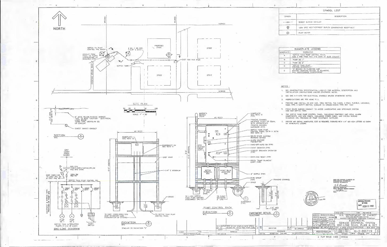
F
D
C
B
A
e
1r NORTH
~ 9 .... .
~ w > < C: '-' '-' z ~
~ X w
0
R ~
"" 3'
,: ~ r---~ 6" WIDE YELLOW PLASTIC MARKER _, w · TAPE. TO READ "CAUTION - ELECTRI CAL n w LINES BELOW" ~ TERRA TAPE, GRlFFOLYN CO.
OR SHULAR
DIRECT BURI ED CONDUIT
SECTION ® NTS
EXST 13.8KV POWER
SOURCE . ___ .....,_ __ _ I
i C> '-'j..,_, 500 KV A D.. r"'.",(r• ~lJK,;'T~o~;~f0VAC,JPH, 4W
~ // I
EXST 208Y/ 120~ 'j ~ TO EXST PNL 1/ 1 ~ & EXST PNL M2 r··-+ SEPTIC TA 'K _?UIJP CONTROL P7 : I I ' I l I
I ) .l@Af ) rn ) .l.Q.QM ) 100AF ! h h 1 20AT 1 10AT
11 I 1 I i ~0~-m- --, L-1-----1----- ___ .....1 ____ _J . . \
i i (~) (~) PUMP PUMP NO 1 NO 2
SEPTIC TANK ALTERNATING PUMPS (7 · 1/2 HP EACH)
ONE- LINE DI AGRAM
8 7
~
< z Si. 0 z
11
11
11
11
11
6
PROPOSED 275<E
275JE
L
SITE PLAN
I 50 25 0 50 100
~•-a»:uoww• @lf·• SCALE: 1" = ' 50'
I
NAMEPLATE (SEE NOTE 7)
AS REO'D
I
_J
GRADE:
""-----10 SEPTIC TANK PU 1J.P CONl ROL PANEL
ELEVATION NTS ® SIMILAR TO ELEVATION "C"
N38-'00 1~ I i 7
2752E
L _J 500 KV A XFMR
i -, 2751E
L _J N38000
SYM BOL LI ST
SY,J.30L OESCRIPTiON
- - J3- - ! F
l---------+------------------------------------1
A I B I C
0
i 20V GFCI \',':::.t.. 7~ :::~:::;wo:- DUPLEX CONVENIE 'CE RECEPTACLE
PUMP MOTOR
NA MEPL AT E LEGEND E~GRAVING
"SEPTI C TANK PUM? CONT .~ ~:.. ?A:'\:::1.. 1208 V PWR r"RQlv' PAD I.I.TD Xr"M .~ AT 8!..0G 2753-EJ"
"PUMP NO 1··
"PUMP NO 2" "SEPTIC TANK PUM =: CONTROL DISCONNECT "'
"IF BEACON IS FLASr":ING ANO AUDIBLE WARNING DEVICE !S SOUNDING, CALL MAINTENANCE ENGINE:::R!NG"
1. SEC: CONSTRUC TION SPECIFICATION . L-092-C 1 FOR MATERIAL DESCRIPTI ON AND INSTALLATION INSTRUCTIONS UNLESS OTHERWISE NOTED. r \
\ 2. SEE OWG H-7-1275 FOR ELECTRICAL SYMBOLS UNLESS OTHERWISE NOTED.
3. A93REVI A TIONS ARE PER ASMC: Yl.1. 0
5
MAGENTA BEACON LIGHT
AS REC'D
NAMEPLATE (SEE NOTE 7) (TY?)
FRAMING CHANNEL UNISTRUT P1000 OR EQUAL WITH APPROPRIATE FRAMI NG CHANN:'.L HARDWARE (TYP)
SEPTIC TANK PU~J? CONTROL PANEL (20"W X J6"H) (SEE NOTE 6)
j - i~----~_'..._-_-_-_-_-_-_-_--;-;;---tr_-_-_-_-_-__ 1l~~t-_-_-_-_- _-_-_= SOLJO STATE AUDIBLE
WARNING DEVICE
ALARM SILENCE PUSHBUTTON
HANO-OFF-AUTO SW ITYP)
I --- --EVENT COUNTER (TYP)
CIRCUIT BREAKER OPERA TOR (TYP)
~--- - 0~ _._---IWI----- - GREEN "PUMP RUNNI~:G" LIGHT (TYP)
4. PROVIOc ANO INSTALL (1) 240 VAC, 100A SWITCH, 75A FUSES, 3 POLE, FUSI8LE. LOCKABLE, NEMA TYPE 3 SAFETY SWITCH, SIMILAR TO CROUSE-HINDS TYPE WST 1003
5. FJELD ROUTE BURIED CONDUIT TO AVOID LANDSCAPING ANO SPRINKLER SYSTEM AND NEW SEPTIC TANK.
6 . THE SEPTIC TANK PUMP CONTROL PANEL, INCLUDING CONTROLS ANO LOCAL ALARM COMPONENTS, AND NEW PUMPS, INCLUDING POWER CABLE, AND SYSTEM WI RING OJAGRA-.,S ARE PROVIDED BY PUMP EQUIPMENT SUPPLIER.
7. PROVIDE ANO I NSTALL NAMEPLATES, SIZE AS REQUIRED, ENGRAVED WITH 1/4" MIN HIGH LETTERS AS SHOWN ON NAMEPLATE LEGEND.
2" NIPPLE (TYP)
PIPE STRAP (TYP) FRAM I NG CHANNEL DOES NOT CO !'o"UJS cu.ssmm OJI:
Ti ll(
PUMP CON TROL RACK
"-@ E•l.3EOMENT (TY?)
_J 1'-0" MIN (TYP)
ELEV ATI ON NTS
EM BEDM ENT DETAI L ED SCALE:NONE
H-2-96233 200~ OFF1C[ COM?LEX BLDG 27 5.3 ·E SH 1 J 13-5091 PNc SCHEO P-IIR R! ScR OIAG
TJTL[
RC,
'°· REVI SIONS
8088 71 9A CA.O COO( 28:IBM:ACD2:i 1.0:NN
_ _l __ _
UNCUSSITT!:O COP.TROULD NUCI.LAR tr-;fOJUU.TION
q£~-J?e'ric,rin1 Offki&.1/ADC Kaber f:/tlinttn He.nlord Company
7-/•/r~ D•h
' OFflCI.IJ. REl.EASE BY 'li'IIC
0/,Tl f£B1 2 1992
, ... P.1. Ct L£YEl lllT - I? 74-3
U.S. DEPA RTMENT OF ENERGY RI CHLAND OPEN.A TJONS Df'TICE
KAISER ENGINEERS HANFORD COMPANY
ELECTR ICA L SEW AGE DI SPOSA L SYSTEM
ONE - LI NE DI AG. PLAN & DET SYS
H-2-887 19 0 CR9636 P<l' 1 go- 1
2 PLOT SCALE: 1 •600
C '
B
A


