Embed Size (px)
Citation preview
3. System design3.1 Introduction
System design is the transformation of the analysis model into a
system design model. Up to now we were in the problem domain.
System design is the first part to get into the solution domain
in a software development. This chapter focuses on transforming
the analysis model into the design model that takes into account
the non-functional requirements and constraints described in the
problem statement and requirement analysis sections discussed
earlier.
The purpose of designing is to show the direction how the system
is built and to obtain clear and enough information needed to
drive the actual implementation of the system. It is based on
understanding of the model the software built on. The objectives
of design are to model the system with high quality. Implementing
of high quality system depend on the nature of design created by
the designer. If one wants to change to the system after it has
been put in to operation depends on the quality of the system
design. So if the system is design effetely, it will be easy to
make changes to it.
3.1.1 Design goals and objectives
The objectives of design are to model the system with high
quality. The design goals are derived from non-functional
requirements that means non-functional requirement is the
description of the feature characteristics and attribute of the
system as well as any constraints that may limit the boundary of
the proposed solution.
Design goals describe the qualities of the system that the
developers should consider.
Reliability: Debre markos university student information
system portal should be reliable.
Fault Tolerance: Debre markos university student information
system portal should be fault tolerant to loss of
connectivity with the service.
Security: Debre markos university student information system
portal should be secured, i.e., not allow other users or
unauthorized users to access data that has no the right to
access it.
Modifiability: Debre markos university student information
system portal should be modifiable for further modification
and enhancement of the application.
Performance: - The system should respond fast with high
throughput, i.e. it should perform the task quickly possible
as possible such as submitting students grades reports and
generating students grade reports, viewing student grade
report and other related information etc.
Cost: The system should be developed with minimum cost
possible. In reality there is always trade-offs or
disadvantages and therefore from its previous experience the
University prefers to invest more on development cost than
maintenance cost to minimize bugs which may appear at the
later stage.
End User Criteria: - The system should have simple and
understandable graphical user Interface such as forms and
buttons, which have descriptive names. It should give
reliable response for each user request at least
before the session expires. All the interfaces, forms and
buttons are written or designed in a simple language or
common language so that the user can access it without any
difficult.
3.2 Design the class diagramThe class diagram is a static diagram. It represents the static
view of an application. Class diagram is not only used for
visualizing, describing and documenting different aspects of a
system but also for constructing executable code of the software
application.
The class diagram describes the attributes and operations of a
class and also the constraints imposed on the system. The classes
diagrams are widely used in the modeling of object oriented
systems because they are the only UML diagrams which can be
mapped directly with object oriented languages.
The class diagram shows a collection of classes, interfaces,
associations, collaborations and constraints. It is also known as
a structural diagram.
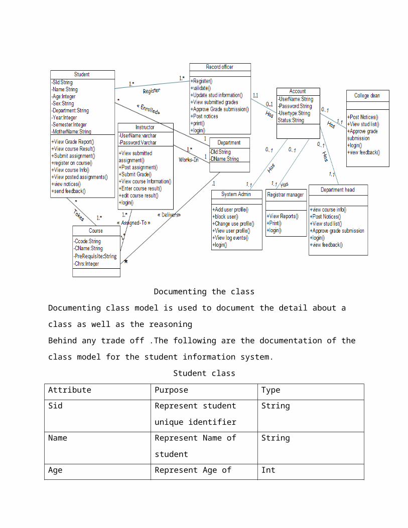
Documenting the class
Documenting class model is used to document the detail about a
class as well as the reasoning
Behind any trade off .The following are the documentation of the
class model for the student information system.
Student class
Attribute Purpose TypeSid Represent student
unique identifier
String
Name Represent Name of
student
String
Age Represent Age of Int
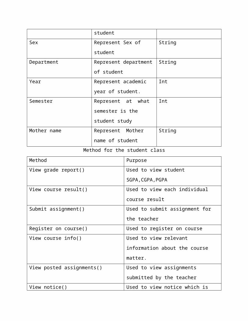
studentSex Represent Sex of
student
String
Department Represent department
of student
String
Year Represent academic
year of student.
Int
Semester Represent at what
semester is the
student study
Int
Mother name Represent Mother
name of student
String
Method for the student class
Method Purpose View grade report() Used to view student
SGPA,CGPA,PGPAView course result() Used to view each individual
course resultSubmit assignment() Used to submit assignment for
the teacherRegister on course() Used to register on course View course info() Used to view relevant
information about the course
matter.View posted assignments() Used to view assignments
submitted by the teacherView notice() Used to view notice which is
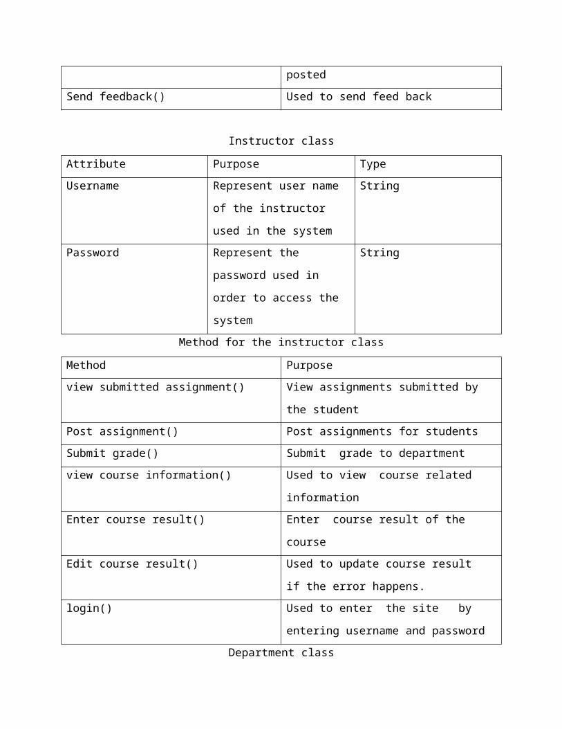
postedSend feedback() Used to send feed back
Instructor class
Attribute Purpose TypeUsername Represent user name
of the instructor
used in the system
String
Password Represent the
password used in
order to access the
system
String
Method for the instructor class
Method Purpose view submitted assignment() View assignments submitted by
the studentPost assignment() Post assignments for studentsSubmit grade() Submit grade to departmentview course information() Used to view course related
informationEnter course result() Enter course result of the
courseEdit course result() Used to update course result
if the error happens.login() Used to enter the site by
entering username and passwordDepartment class
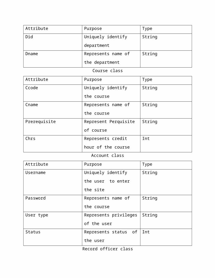
Attribute Purpose Type Did Uniquely identify
department
String
Dname Represents name of
the department
String
Course class
Attribute Purpose Type Ccode Uniquely identify
the course
String
Cname Represents name of
the course
String
Prerequisite Represent Perquisite
of course
String
Chrs Represents credit
hour of the course
Int
Account class
Attribute Purpose Type Username Uniquely identify
the user to enter
the site
String
Password Represents name of
the course
String
User type Represents privileges
of the user
String
Status Represents status of
the user
Int
Record officer class
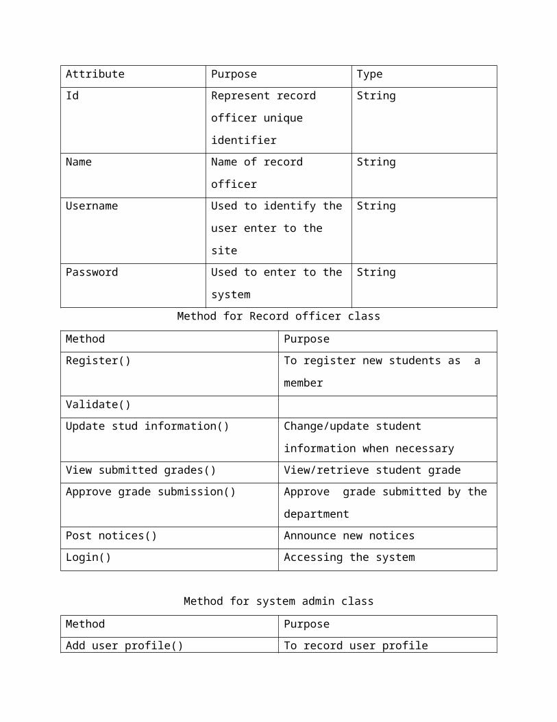
Attribute Purpose TypeId Represent record
officer unique
identifier
String
Name Name of record
officer
String
Username Used to identify the
user enter to the
site
String
Password Used to enter to the
system
String
Method for Record officer class
Method PurposeRegister() To register new students as a
member Validate()Update stud information() Change/update student
information when necessaryView submitted grades() View/retrieve student gradeApprove grade submission() Approve grade submitted by the
departmentPost notices() Announce new notices Login() Accessing the system
Method for system admin class
Method PurposeAdd user profile() To record user profile
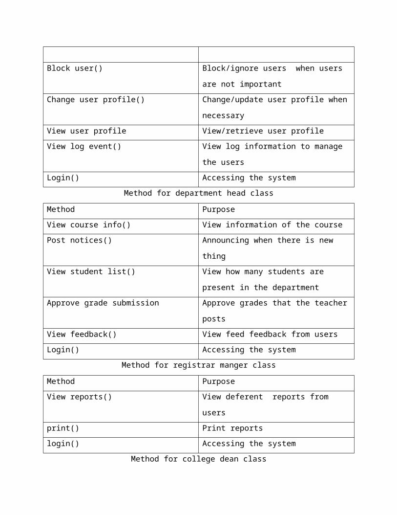
Block user() Block/ignore users when users
are not importantChange user profile() Change/update user profile when
necessaryView user profile View/retrieve user profileView log event() View log information to manage
the usersLogin() Accessing the system
Method for department head class
Method PurposeView course info() View information of the coursePost notices() Announcing when there is new
thingView student list() View how many students are
present in the departmentApprove grade submission Approve grades that the teacher
postsView feedback() View feed feedback from usersLogin() Accessing the system
Method for registrar manger class
Method PurposeView reports() View deferent reports from
usersprint() Print reportslogin() Accessing the system
Method for college dean class
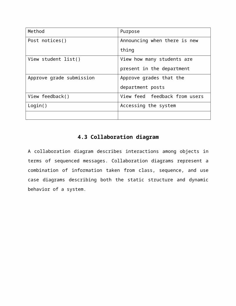
Method PurposePost notices() Announcing when there is new
thingView student list() View how many students are
present in the departmentApprove grade submission Approve grades that the
department postsView feedback() View feed feedback from usersLogin() Accessing the system
4.3 Collaboration diagram
A collaboration diagram describes interactions among objects in
terms of sequenced messages. Collaboration diagrams represent a
combination of information taken from class, sequence, and use
case diagrams describing both the static structure and dynamic
behavior of a system.
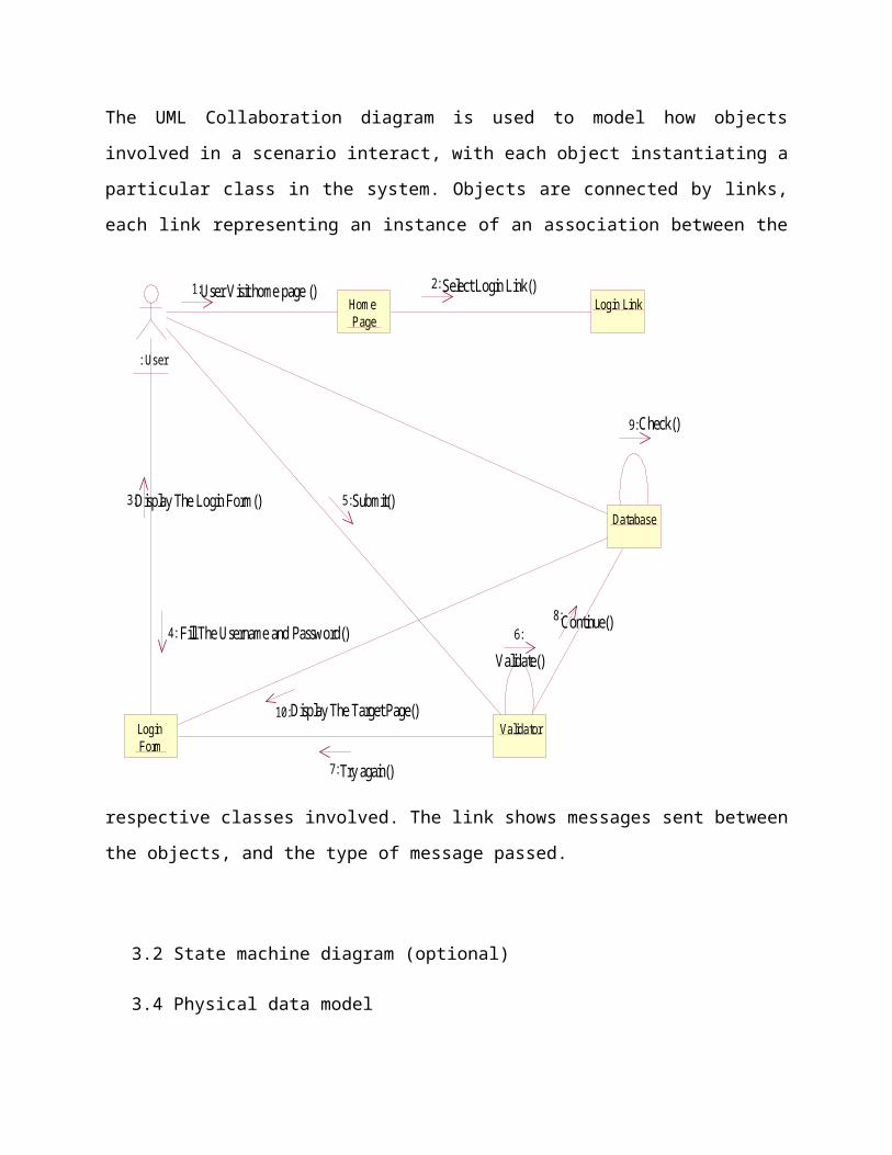
The UML Collaboration diagram is used to model how objects
involved in a scenario interact, with each object instantiating a
particular class in the system. Objects are connected by links,
each link representing an instance of an association between the
respective classes involved. The link shows messages sent between
the objects, and the type of message passed.
3.2 State machine diagram (optional)
3.4 Physical data model
: User
Hom e Page
Login Link
Login Form
Validator
Database
6:
9:
User Visit home page () Select Login Link()
Display The Login Form()
Fill The Username and Password()
Submit()
Display The Target Page()
Try again()
Validate()
Check()
Continue()
1:
5:
2:
3:
4:
7:
8:
10:
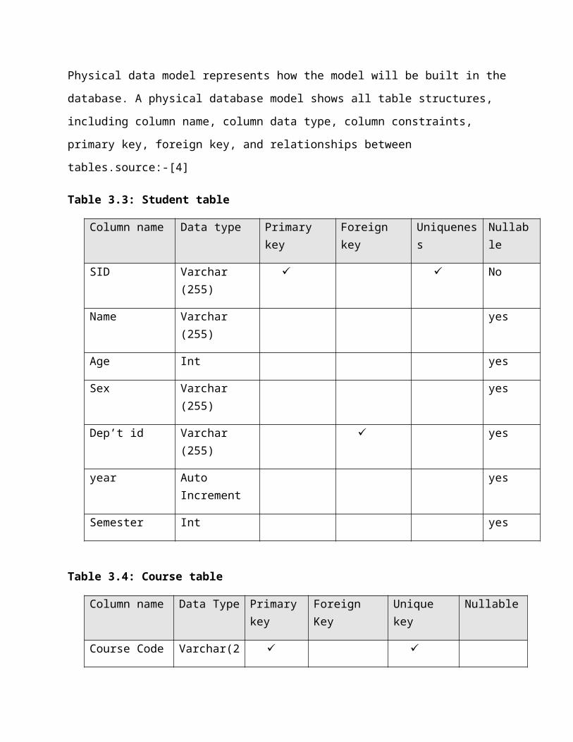
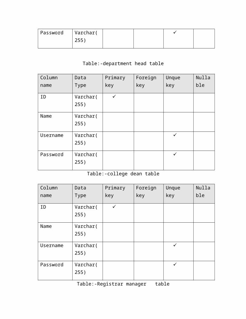
Physical data model represents how the model will be built in the
database. A physical database model shows all table structures,
including column name, column data type, column constraints,
primary key, foreign key, and relationships between
tables.source:-[4]
Table 3.3: Student table
Column name Data type Primary key
Foreign key
Uniqueness
Nullable
SID Varchar (255)
No
Name Varchar (255)
yes
Age Int yes
Sex Varchar (255)
yes
Dep’t id Varchar (255)
yes
year Auto Increment
yes
Semester Int yes
Table 3.4: Course table
Column name Data Type Primarykey
Foreign Key
Unique key
Nullable
Course Code Varchar(2
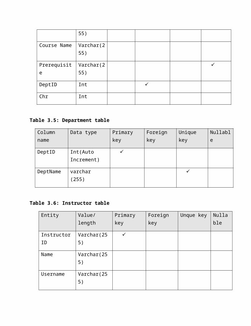
55)
Course Name Varchar(255)
Prerequisite
Varchar(255)
DeptID Int
Chr Int
Table 3.5: Department table
Column name
Data type Primary key
Foreign key
Unique key
Nullable
DeptID Int(Auto Increment)
DeptName varchar (255)
Table 3.6: Instructor table
Entity Value/length
Primary key
Foreign key
Unque key Nullable
InstructorID
Varchar(255)
Name Varchar(255)
Username Varchar(255)
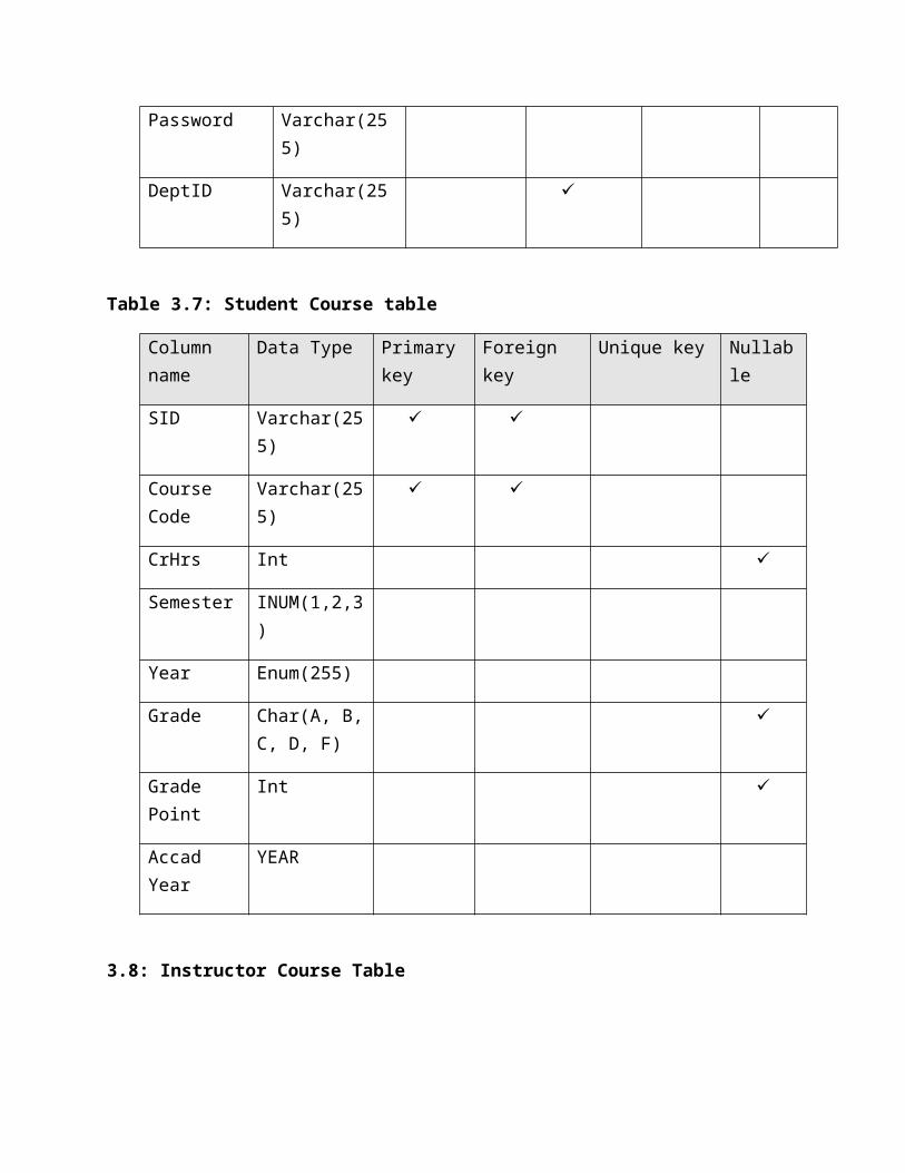
Password Varchar(255)
DeptID Varchar(255)
Table 3.7: Student Course table
Column name
Data Type Primarykey
Foreign key
Unique key Nullable
SID Varchar(255)
Course Code
Varchar(255)
CrHrs Int
Semester INUM(1,2,3)
Year Enum(255)
Grade Char(A, B,C, D, F)
Grade Point
Int
Accad Year
YEAR
3.8: Instructor Course Table
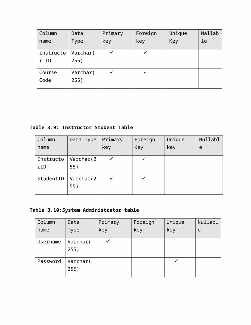
Column name
Data Type
Primary key
Foreign key
Unique Key
Nallable
instructor ID
Varchar(255)
Course Code
Varchar(255)
Table 3.9: Instructor Student Table
Column name
Data Type Primary key
Foreign Key
Unique key
Nullable
InstructorID
Varchar(255)
StudentID Varchar(255)
Table 3.10:System Administrator table
Column name
Data Type
Primary key
Foreign key
Unique key
Nullable
Username Varchar(255)
Password Varchar(255)
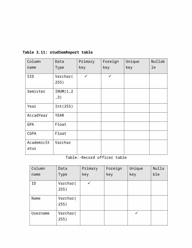
Table 3.11: studSemReport table
Column name
Data Type
Primary key
Foreign key
Unique key
Nullable
SID Varchar(255)
Semister INUM(1,2,3)
Year Int(255)
AccadYear YEAR
GPA Float
CGPA Float
AcademicStatus
Varchar
Table:-Record officer table
Column name
Data Type
Primary key
Foreign key
Unique key
Nullable
ID Varchar(255)
Name Varchar(255)
Username Varchar(255)
Password Varchar(255)
Table:-department head table
Column name
Data Type
Primary key
Foreign key
Unque key
Nullable
ID Varchar(255)
Name Varchar(255)
Username Varchar(255)
Password Varchar(255)
Table:-college dean table
Column name
Data Type
Primary key
Foreign key
Unque key
Nullable
ID Varchar(255)
Name Varchar(255)
Username Varchar(255)
Password Varchar(255)
Table:-Registrar manager table
Colum name Data Type
Primary key
Foreign key
Unque key
Nullable
ID Varchar(255)
Name Varchar(255)
Username Varchar(255)
Password Varchar(255)
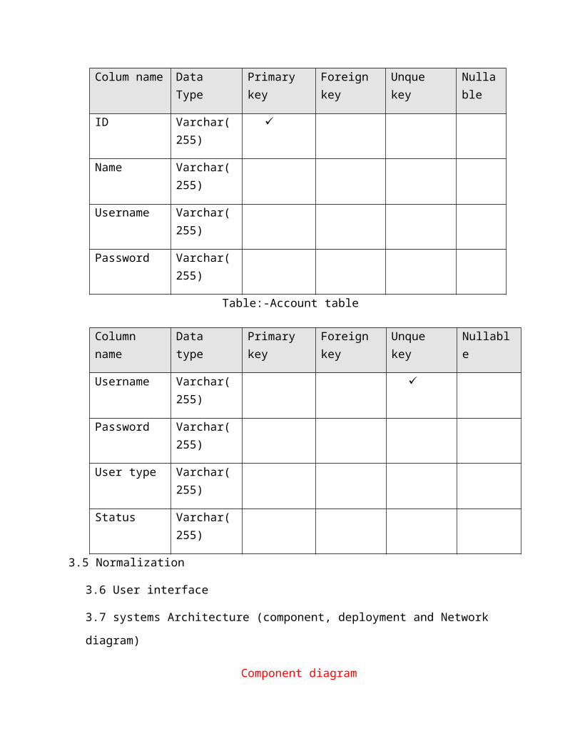
Table:-Account table
Column name
Data type
Primary key
Foreign key
Unque key
Nullable
Username Varchar(255)
Password Varchar(255)
User type Varchar(255)
Status Varchar(255)
3.5 Normalization
3.6 User interface
3.7 systems Architecture (component, deployment and Network
diagram)
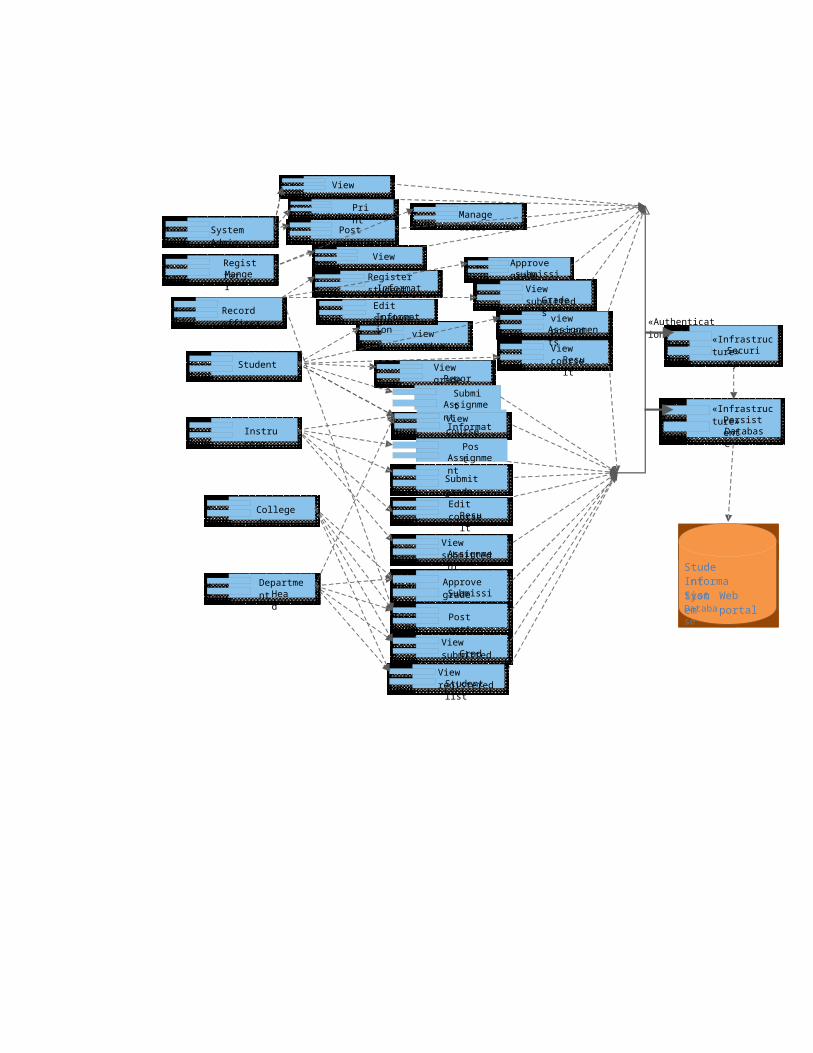
Component diagram
In the Unified Modeling Language, a component diagram depicts how
components are wired together to form larger components and or
software systems. They are used to illustrate the structure of
arbitrarily complex systems. A component diagram displays
the structural relationship of components of a software system.
These are mostly used when working with complex systems that have
many components. Components communicate with each other using
interfaces. The interfaces are linked using connectors. Component
diagrams show the physical placement of the components in the
system. It is a type of design diagram that shows overall system
architecture and the logical components within it for how the
system implemented. Source:[5, 6, 7]
System Admin
Record officer
Registrar Manger
Student
Instructor
Department Hea
d
College dean
view notice
View grade Report
view course Information
Submit Assignme
nt
View course Resu
lt
view posted Assignments
Manage usersPost
noticeView log
View reports
Register student InformationEdit student Information
Approve grade submissionView submitted Grade
s
Submit grade
View submitted Assignment
Edit course Result
Post Assignme
nt
Approve grade Submission
View submitted Grad
e
Post notice
View registered Student list
«Infrastructure»Securi
ty
«Infrastructure»Persist
ent Database
StudentInforma
tion System
Web portalDataba
se
«Authentication»
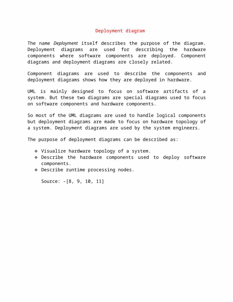
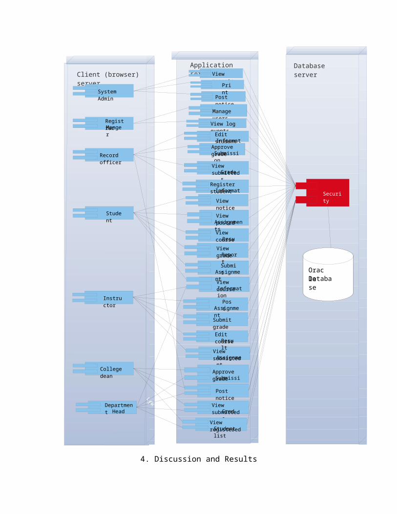
Deployment diagram
The name Deployment itself describes the purpose of the diagram.Deployment diagrams are used for describing the hardwarecomponents where software components are deployed. Componentdiagrams and deployment diagrams are closely related.
Component diagrams are used to describe the components anddeployment diagrams shows how they are deployed in hardware.
UML is mainly designed to focus on software artifacts of asystem. But these two diagrams are special diagrams used to focuson software components and hardware components.
So most of the UML diagrams are used to handle logical componentsbut deployment diagrams are made to focus on hardware topology ofa system. Deployment diagrams are used by the system engineers.
The purpose of deployment diagrams can be described as:
Visualize hardware topology of a system. Describe the hardware components used to deploy software
components. Describe runtime processing nodes.
Source: -[8, 9, 10, 11]
Client (browser) server
Application server
Database server
System Admin
Record officer
Registrar Manger
Student
Instructor
Department Head
College dean
Post notice
View reports
Manage usersView log eventsEdit student InformationApprove
grade SubmissionView submitted Grade
sRegister student InformationView notice
View course Information
Submit Assignme
nt
View course Resu
lt
View posted Assignments
View grade Report
Submit grade
View submitted Assignment
Edit course Resu
lt
Post Assignme
nt
Approve grade Submission
View submitted Grad
e
Post notice
View registered Student list
LinkLink
Link
LinkLinkLink
Li nk
Oracle Database
Security
LinkLinkLinkLinkLinLinkLink
LinkLinkLink
Link
Link
Link
Link
Link
Li nk
Li nk
Li nk
4. Discussion and Results
5. Conclusion and Future work
Reference
1) http://www.agiledata.org/essays/objectOrientation101.html
2) http://www.ibm.com/developerworks/rational/library/content/
RationalEdge/sep04/bell/
3) http://en.wikipedia.org/wiki/Class_diagram
4) http://www.1keydata.com/datawarehousing/physical-data-
model.html
5) http://www.visual-paradigm.com/VPGallery/diagrams/
Component.html
6) http://en.wikipedia.org/wiki/Component_diagram
7) http://www.umldiagrams.org/componediagrams.html
8) http://en.wikipedia.org/wiki/Deployment_diagram
9) http://www.visual-paradigm.com/VPGallery/diagrams/
Deployment.html
10) http://www.ibm.com/developerworks/rational/library/
content/RationalEdge/sep04/bell/
11) http://www.uml-diagrams.org/deployment-diagrams.html


