Embed Size (px)
Citation preview
Valve Group
0810C
3800 SeriesFarris Engineering
Pressure Relief Valves
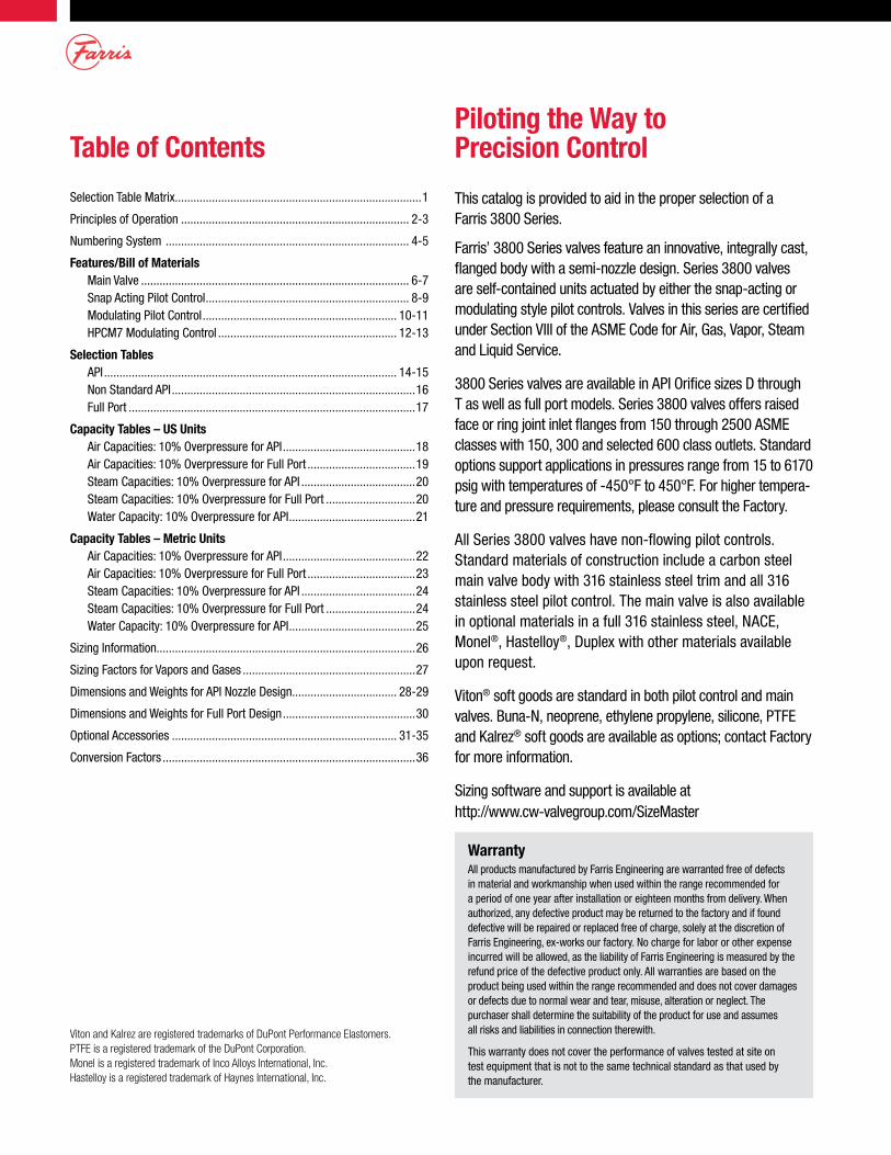
Table of ContentsPiloting the Way to Precision Control
Selection Table Matrix ................................................................................1
Principles of Operation .......................................................................... 2-3
Numbering System ............................................................................... 4-5
Features/Bill of Materials Main Valve ....................................................................................... 6-7 Snap Acting Pilot Control .................................................................. 8-9 Modulating Pilot Control ............................................................... 10-11 HPCM7 Modulating Control .......................................................... 12-13
Selection Tables API ............................................................................................... 14-15 Non Standard API ...............................................................................16 Full Port .............................................................................................17
Capacity Tables – US Units Air Capacities: 10% Overpressure for API ...........................................18 Air Capacities: 10% Overpressure for Full Port ...................................19 Steam Capacities: 10% Overpressure for API .....................................20 Steam Capacities: 10% Overpressure for Full Port .............................20 Water Capacity: 10% Overpressure for API .........................................21
Capacity Tables – Metric Units Air Capacities: 10% Overpressure for API ...........................................22 Air Capacities: 10% Overpressure for Full Port ...................................23 Steam Capacities: 10% Overpressure for API .....................................24 Steam Capacities: 10% Overpressure for Full Port .............................24 Water Capacity: 10% Overpressure for API .........................................25
Sizing Information....................................................................................26
Sizing Factors for Vapors and Gases ........................................................27
Dimensions and Weights for API Nozzle Design.................................. 28-29
Dimensions and Weights for Full Port Design ...........................................30
Optional Accessories ......................................................................... 31-35
Conversion Factors ..................................................................................36
WarrantyAll products manufactured by Farris Engineering are warranted free of defects in material and workmanship when used within the range recommended for a period of one year after installation or eighteen months from delivery. When authorized, any defective product may be returned to the factory and if found defective will be repaired or replaced free of charge, solely at the discretion of Farris Engineering, ex-works our factory. No charge for labor or other expense incurred will be allowed, as the liability of Farris Engineering is measured by the refund price of the defective product only. All warranties are based on the product being used within the range recommended and does not cover damages or defects due to normal wear and tear, misuse, alteration or neglect. The purchaser shall determine the suitability of the product for use and assumes all risks and liabilities in connection therewith.
This warranty does not cover the performance of valves tested at site on test equipment that is not to the same technical standard as that used by the manufacturer.
This catalog is provided to aid in the proper selection of a Farris 3800 Series.
Farris’ 3800 Series valves feature an innovative, integrally cast, flanged body with a semi-nozzle design. Series 3800 valves are self-contained units actuated by either the snap-acting or modulating style pilot controls. Valves in this series are certified under Section VIII of the ASME Code for Air, Gas, Vapor, Steam and Liquid Service.
3800 Series valves are available in API Orifice sizes D through T as well as full port models. Series 3800 valves offers raised face or ring joint inlet flanges from 150 through 2500 ASME classes with 150, 300 and selected 600 class outlets. Standard options support applications in pressures range from 15 to 6170 psig with temperatures of -450°F to 450°F. For higher tempera-ture and pressure requirements, please consult the Factory.
All Series 3800 valves have non-flowing pilot controls. Standard materials of construction include a carbon steel main valve body with 316 stainless steel trim and all 316 stainless steel pilot control. The main valve is also available in optional materials in a full 316 stainless steel, NACE, Monel®, Hastelloy®, Duplex with other materials available upon request.
Viton® soft goods are standard in both pilot control and main valves. Buna-N, neoprene, ethylene propylene, silicone, PTFE and Kalrez® soft goods are available as options; contact Factory for more information.
Sizing software and support is available at http://www.cw-valvegroup.com/SizeMaster
Viton and Kalrez are registered trademarks of DuPont Performance Elastomers.PTFE is a registered trademark of the DuPont Corporation.Monel is a registered trademark of Inco Alloys International, Inc.Hastelloy is a registered trademark of Haynes International, Inc.
1
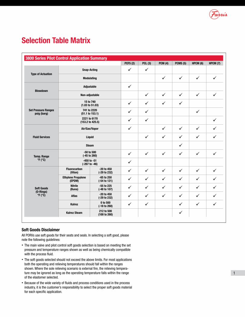
3800 Series Pilot Control Application SummaryPCF5 (2) PCL (3) PCM (4) PCMS (5) HPCM (6) HPCM (7)
Type of ActuationSnap-Acting ü ü
Modulating ü ü ü ü
BlowdownAdjustable ü
Non-adjustable ü ü ü ü ü
Set Pressure Ranges psig (barg)
15 to 740 (1.03 to 51.03) ü ü ü ü
741 to 2220 (51.1 to 153.1) ü ü ü2221 to 6170
(153.2 to 425.5) ü ü ü
Fluid Services
Air/Gas/Vapor ü ü ü ü ü
Liquid ü ü ü ü ü
Steam ü
Temp. Range °F (°C)
-50 to 500 (-45 to 260) ü ü ü ü ü ü-450 to -51
(-267 to -46) ü
Soft Goods (O-Rings)
°F (°C)
Fluorocarbon (Viton)
-20 to 450(-29 to 232) ü ü ü ü ü ü
Ethylene Propylene (EPDM)
-65 to 250 (-54 to 121) ü ü ü ü ü ü
Nitrile (Buna)
-55 to 225 (-48 to 107) ü ü ü ü ü ü
Aflas -20 to 450 (-29 to 232) ü ü ü ü ü ü
Kalrez 0 to 500 (-18 to 260) ü ü ü ü ü
Kalrez Steam 212 to 500 (100 to 260) ü
Selection Table Matrix
Soft Goods Disclaimer All PORVs use soft goods for their seats and seals. In selecting a soft good, please note the following guidelines:
• The main valve and pilot control soft goods selection is based on meeting the set pressure and temperature ranges shown as well as being chemically compatible with the process fluid.
• The soft goods selected should not exceed the above limits. For most applications both the operating and relieving temperatures should fall within the ranges shown. Where the sole relieving scenario is external fire, the relieving tempera-ture may be ignored as long as the operating temperature falls within the range of the elastomer selected.
• Because of the wide variety of fluids and process conditions used in the process industry, it is the customer’s responsibility to select the proper soft goods material for each specific application.
2
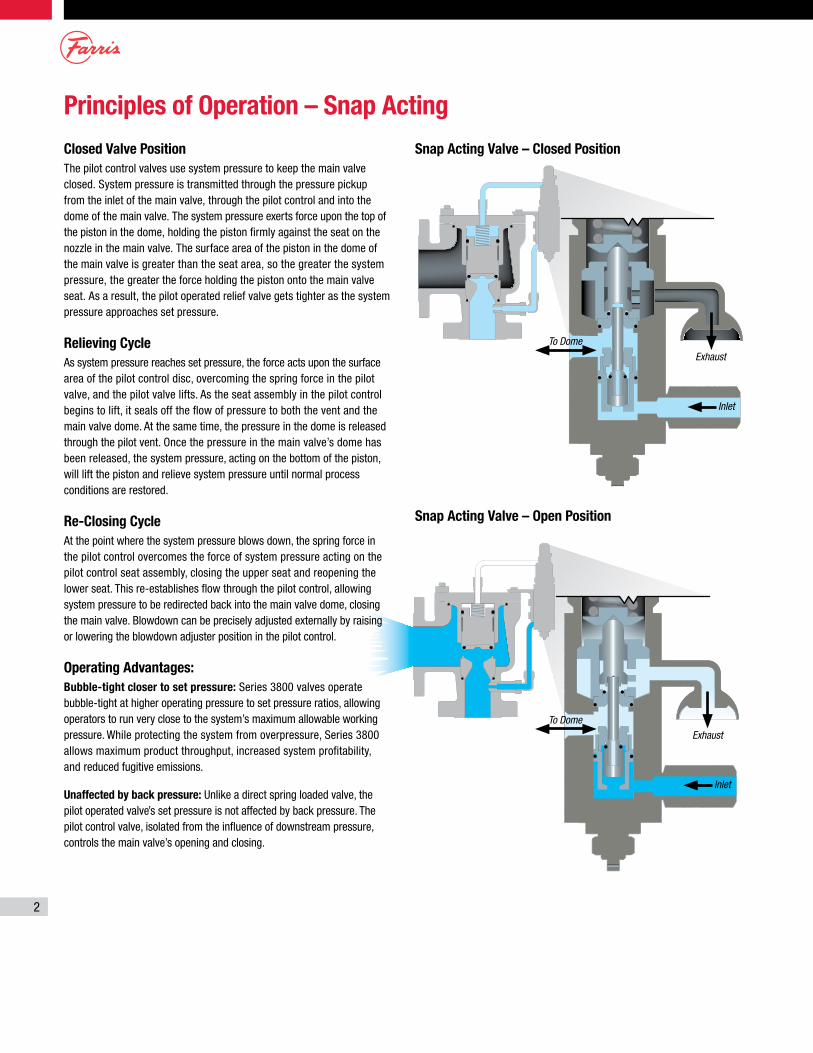
Snap Acting Valve – Closed Position
To Dome
To Dome
Exhaust
Exhaust
Inlet
Inlet
Snap Acting Valve – Open Position
Closed Valve PositionThe pilot control valves use system pressure to keep the main valve closed. System pressure is transmitted through the pressure pickup from the inlet of the main valve, through the pilot control and into the dome of the main valve. The system pressure exerts force upon the top of the piston in the dome, holding the piston firmly against the seat on the nozzle in the main valve. The surface area of the piston in the dome of the main valve is greater than the seat area, so the greater the system pressure, the greater the force holding the piston onto the main valve seat. As a result, the pilot operated relief valve gets tighter as the system pressure approaches set pressure.
Relieving CycleAs system pressure reaches set pressure, the force acts upon the surface area of the pilot control disc, overcoming the spring force in the pilot valve, and the pilot valve lifts. As the seat assembly in the pilot control begins to lift, it seals off the flow of pressure to both the vent and the main valve dome. At the same time, the pressure in the dome is released through the pilot vent. Once the pressure in the main valve’s dome has been released, the system pressure, acting on the bottom of the piston, will lift the piston and relieve system pressure until normal process conditions are restored.
Re-Closing CycleAt the point where the system pressure blows down, the spring force in the pilot control overcomes the force of system pressure acting on the pilot control seat assembly, closing the upper seat and reopening the lower seat. This re-establishes flow through the pilot control, allowing system pressure to be redirected back into the main valve dome, closing the main valve. Blowdown can be precisely adjusted externally by raising or lowering the blowdown adjuster position in the pilot control.
Operating Advantages:Bubble-tight closer to set pressure: Series 3800 valves operate bubble-tight at higher operating pressure to set pressure ratios, allowing operators to run very close to the system’s maximum allowable working pressure. While protecting the system from overpressure, Series 3800 allows maximum product throughput, increased system profitability, and reduced fugitive emissions.
Unaffected by back pressure: Unlike a direct spring loaded valve, the pilot operated valve’s set pressure is not affected by back pressure. The pilot control valve, isolated from the influence of downstream pressure, controls the main valve’s opening and closing.
Principles of Operation – Snap Acting
3
To Dome
To Dome
To Dome
Exhaust
Exhaust
Exhaust
Inlet
Inlet
Inlet
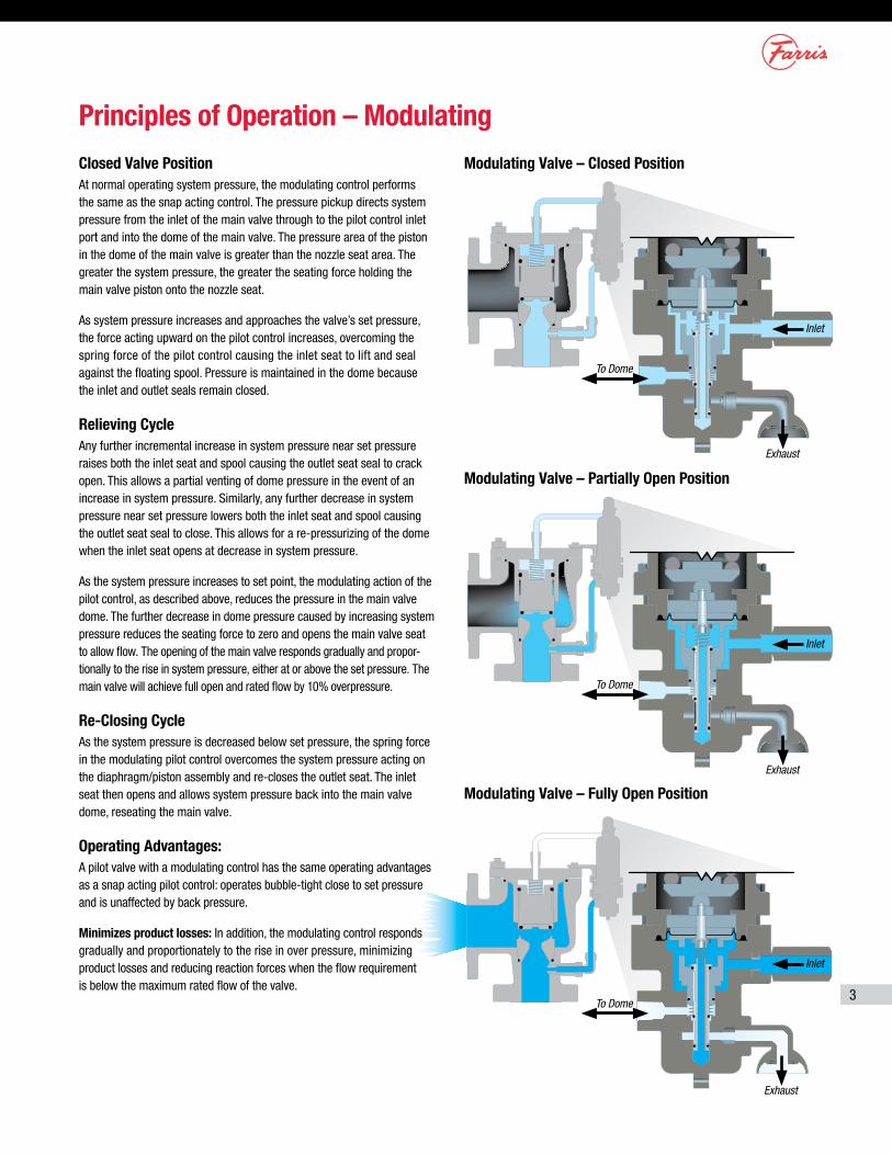
Modulating Valve – Closed Position
Principles of Operation – Modulating
Modulating Valve – Partially Open Position
Modulating Valve – Fully Open Position
Closed Valve PositionAt normal operating system pressure, the modulating control performs the same as the snap acting control. The pressure pickup directs system pressure from the inlet of the main valve through to the pilot control inlet port and into the dome of the main valve. The pressure area of the piston in the dome of the main valve is greater than the nozzle seat area. The greater the system pressure, the greater the seating force holding the main valve piston onto the nozzle seat.
As system pressure increases and approaches the valve’s set pressure, the force acting upward on the pilot control increases, overcoming the spring force of the pilot control causing the inlet seat to lift and seal against the floating spool. Pressure is maintained in the dome because the inlet and outlet seals remain closed.
Relieving CycleAny further incremental increase in system pressure near set pressure raises both the inlet seat and spool causing the outlet seat seal to crack open. This allows a partial venting of dome pressure in the event of an increase in system pressure. Similarly, any further decrease in system pressure near set pressure lowers both the inlet seat and spool causing the outlet seat seal to close. This allows for a re-pressurizing of the dome when the inlet seat opens at decrease in system pressure.
As the system pressure increases to set point, the modulating action of the pilot control, as described above, reduces the pressure in the main valve dome. The further decrease in dome pressure caused by increasing system pressure reduces the seating force to zero and opens the main valve seat to allow flow. The opening of the main valve responds gradually and propor-tionally to the rise in system pressure, either at or above the set pressure. The main valve will achieve full open and rated flow by 10% overpressure.
Re-Closing CycleAs the system pressure is decreased below set pressure, the spring force in the modulating pilot control overcomes the system pressure acting on the diaphragm/piston assembly and re-closes the outlet seat. The inlet seat then opens and allows system pressure back into the main valve dome, reseating the main valve.
Operating Advantages:A pilot valve with a modulating control has the same operating advantages as a snap acting pilot control: operates bubble-tight close to set pressure and is unaffected by back pressure.
Minimizes product losses: In addition, the modulating control responds gradually and proportionately to the rise in over pressure, minimizing product losses and reducing reaction forces when the flow requirement is below the maximum rated flow of the valve.
4
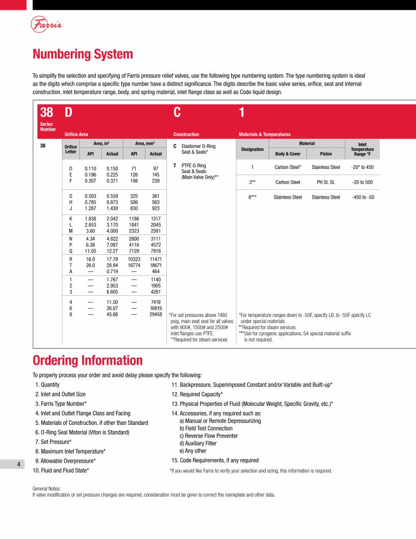
Numbering System
Ordering InformationTo properly process your order and avoid delay please specify the following:
1. Quantity
2. Inlet and Outlet Size
3. Farris Type Number*
4. Inlet and Outlet Flange Class and Facing
5. Materials of Construction, if other than Standard
6. O-Ring Seal Material (Viton is Standard)
7. Set Pressure*
8. Maximum Inlet Temperature*
9. Allowable Overpressure*
10. Fluid and Fluid State*
General Notes:If valve modification or set pressure changes are required, consideration must be given to correct the nameplate and other data.
To simplify the selection and specifying of Farris pressure relief valves, use the following type numbering system. The type numbering system is ideal as the digits which comprise a specific type number have a distinct significance. The digits describe the basic valve series, orifice, seat and internal construction, inlet temperature range, body, and spring material, inlet flange class as well as Code liquid design.
11. Backpressure, Superimposed Constant and/or Variable and Built-up*
12. Required Capacity*
13. Physical Properties of Fluid (Molecular Weight, Specific Gravity, etc.)*
14. Accessories, if any required such as: a) Manual or Remote Depressurizing b) Field Test Connection c) Reverse Flow Preventer d) Auxiliary Filter e) Any other
15. Code Requirements, if any required
*If you would like Farris to verify your selection and sizing, this information is required.
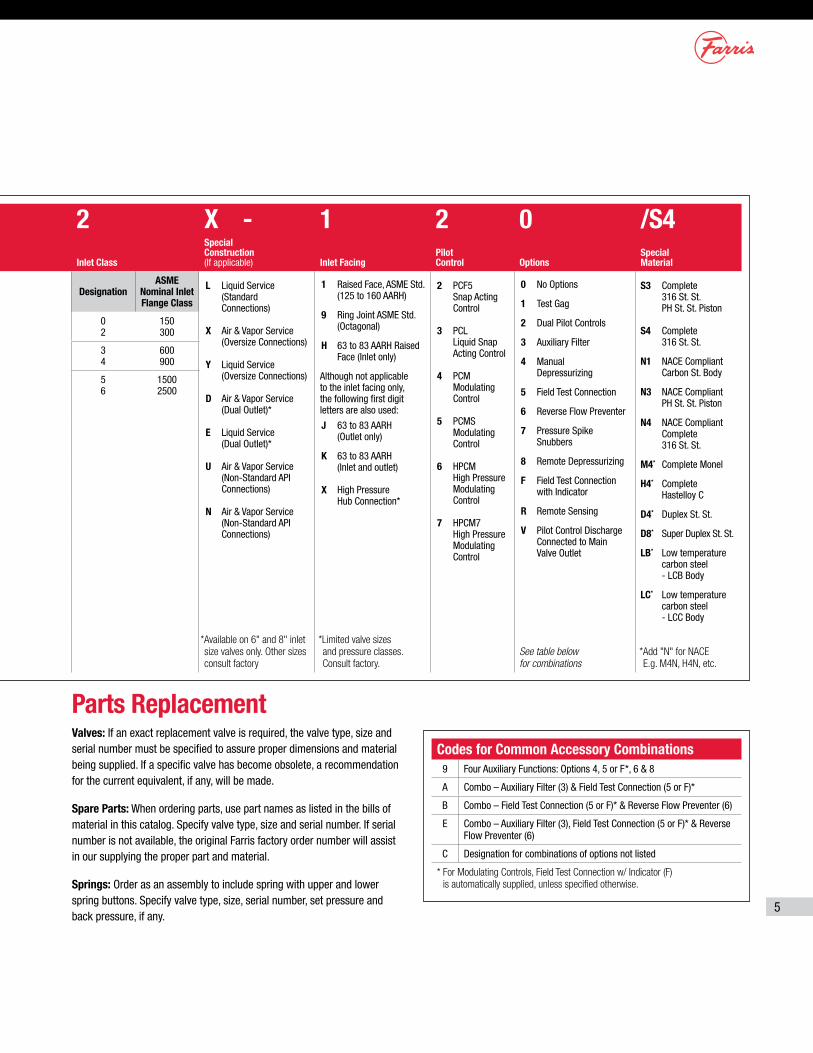
38 D C 1 2 X - 1 2 0 /S4Series Number
Orifice Area Construction Materials & Temperatures Inlet Class
Special Construction (If applicable) Inlet Facing
Pilot Control Options
Special Material
38 Orifice Letter
Area, in2 Area, mm2
C Elastomer O-Ring Seat & Seals*
T PTFE O-Ring Seat & Seals (Main Valve Only)**
DesignationMaterial Inlet
Temperature Range °F
DesignationASME
Nominal Inlet Flange Class
L Liquid Service (Standard Connections)
X Air & Vapor Service (Oversize Connections)
Y Liquid Service (Oversize Connections)
D Air & Vapor Service (Dual Outlet)*
E Liquid Service (Dual Outlet)*
U Air & Vapor Service (Non-Standard API Connections)
N Air & Vapor Service (Non-Standard API Connections)
1 Raised Face, ASME Std. (125 to 160 AARH)
9 Ring Joint ASME Std. (Octagonal)
H 63 to 83 AARH Raised Face (Inlet only)
Although not applicable to the inlet facing only, the following first digit letters are also used:
J 63 to 83 AARH (Outlet only)
K 63 to 83 AARH (Inlet and outlet)
X High Pressure Hub Connection*
2 PCF5 Snap Acting Control
3 PCL Liquid Snap Acting Control
4 PCM Modulating Control
5 PCMS Modulating Control
6 HPCM High Pressure Modulating Control
7 HPCM7 High Pressure Modulating Control
0 No Options
1 Test Gag
2 Dual Pilot Controls
3 Auxiliary Filter
4 Manual Depressurizing
5 Field Test Connection
6 Reverse Flow Preventer
7 Pressure Spike Snubbers
8 Remote Depressurizing
F Field Test Connection with Indicator
R Remote Sensing
V Pilot Control Discharge Connected to Main Valve Outlet
S3 Complete 316 St. St. PH St. St. Piston
S4 Complete 316 St. St.
N1 NACE Compliant Carbon St. Body
N3 NACE Compliant PH St. St. Piston
N4 NACE Compliant Complete 316 St. St.
M4* Complete Monel
H4* Complete Hastelloy C
D4* Duplex St. St.
D8* Super Duplex St. St.
LB* Low temperature carbon steel - LCB Body
LC* Low temperature carbon steel - LCC Body
API Actual API Actual Body & Cover Piston
D E F
0.110 0.196 0.307
0.150 0.225 0.371
71 126 198
97 145 239
1 Carbon Steel* Stainless Steel -20* to 450 0 2
150 300
2** Carbon Steel PH St. St. -20 to 500 3 4
600 900
G H J
0.503 0.785 1.287
0.559 0.873 1.430
325 506 830
361 563 923
8*** Stainless Steel Stainless Steel -450 to -50 5 6
1500 2500
K L M
1.838 2.853 3.60
2.042 3.170 4.000
1186 1841 2323
1317 2045 2581
N P Q
4.34 6.38 11.05
4.822 7.087 12.27
2800 4116 7129
3111 4572 7916
R T A
16.0 26.0 —
17.78 28.94 0.719
10323 16774
—
11471 18671 464
1 2 3
— — —
1.767 2.953 6.605
— — —
1140 1905 4261
*For set pressures above 1480 psig, main seat seal for all valves with 900#, 1500# and 2500# inlet flanges use PTFE.**Required for steam services
* For temperature ranges down to -50F, specify LB, to -55F specify LC under special materials
* ** Required for steam services** ** Use for cyrogenic applications, S4 special material suffix
is not required.
4 6 8
— — —
11.50 26.07 45.66
— — —
7419 16819 29458
*Available on 6" and 8" inlet size valves only. Other sizes consult factory
*Limited valve sizes and pressure classes. Consult factory.
See table below for combinations
*Add "N" for NACE E.g. M4N, H4N, etc.
5
Parts ReplacementValves: If an exact replacement valve is required, the valve type, size and serial number must be specified to assure proper dimensions and material being supplied. If a specific valve has become obsolete, a recommendation for the current equivalent, if any, will be made.
Spare Parts: When ordering parts, use part names as listed in the bills of material in this catalog. Specify valve type, size and serial number. If serial number is not available, the original Farris factory order number will assist in our supplying the proper part and material.
Springs: Order as an assembly to include spring with upper and lower spring buttons. Specify valve type, size, serial number, set pressure and back pressure, if any.
Codes for Common Accessory Combinations9 Four Auxiliary Functions: Options 4, 5 or F*, 6 & 8
A Combo – Auxiliary Filter (3) & Field Test Connection (5 or F)*
B Combo – Field Test Connection (5 or F)* & Reverse Flow Preventer (6)
E Combo – Auxiliary Filter (3), Field Test Connection (5 or F)* & Reverse Flow Preventer (6)
C Designation for combinations of options not listed
* For Modulating Controls, Field Test Connection w/ Indicator (F) is automatically supplied, unless specified otherwise.
38 D C 1 2 X - 1 2 0 /S4Series Number
Orifice Area Construction Materials & Temperatures Inlet Class
Special Construction (If applicable) Inlet Facing
Pilot Control Options
Special Material
38 Orifice Letter
Area, in2 Area, mm2
C Elastomer O-Ring Seat & Seals*
T PTFE O-Ring Seat & Seals (Main Valve Only)**
DesignationMaterial Inlet
Temperature Range °F
DesignationASME
Nominal Inlet Flange Class
L Liquid Service (Standard Connections)
X Air & Vapor Service (Oversize Connections)
Y Liquid Service (Oversize Connections)
D Air & Vapor Service (Dual Outlet)*
E Liquid Service (Dual Outlet)*
U Air & Vapor Service (Non-Standard API Connections)
N Air & Vapor Service (Non-Standard API Connections)
1 Raised Face, ASME Std. (125 to 160 AARH)
9 Ring Joint ASME Std. (Octagonal)
H 63 to 83 AARH Raised Face (Inlet only)
Although not applicable to the inlet facing only, the following first digit letters are also used:
J 63 to 83 AARH (Outlet only)
K 63 to 83 AARH (Inlet and outlet)
X High Pressure Hub Connection*
2 PCF5 Snap Acting Control
3 PCL Liquid Snap Acting Control
4 PCM Modulating Control
5 PCMS Modulating Control
6 HPCM High Pressure Modulating Control
7 HPCM7 High Pressure Modulating Control
0 No Options
1 Test Gag
2 Dual Pilot Controls
3 Auxiliary Filter
4 Manual Depressurizing
5 Field Test Connection
6 Reverse Flow Preventer
7 Pressure Spike Snubbers
8 Remote Depressurizing
F Field Test Connection with Indicator
R Remote Sensing
V Pilot Control Discharge Connected to Main Valve Outlet
S3 Complete 316 St. St. PH St. St. Piston
S4 Complete 316 St. St.
N1 NACE Compliant Carbon St. Body
N3 NACE Compliant PH St. St. Piston
N4 NACE Compliant Complete 316 St. St.
M4* Complete Monel
H4* Complete Hastelloy C
D4* Duplex St. St.
D8* Super Duplex St. St.
LB* Low temperature carbon steel - LCB Body
LC* Low temperature carbon steel - LCC Body
API Actual API Actual Body & Cover Piston
D E F
0.110 0.196 0.307
0.150 0.225 0.371
71 126 198
97 145 239
1 Carbon Steel* Stainless Steel -20* to 450 0 2
150 300
2** Carbon Steel PH St. St. -20 to 500 3 4
600 900
G H J
0.503 0.785 1.287
0.559 0.873 1.430
325 506 830
361 563 923
8*** Stainless Steel Stainless Steel -450 to -50 5 6
1500 2500
K L M
1.838 2.853 3.60
2.042 3.170 4.000
1186 1841 2323
1317 2045 2581
N P Q
4.34 6.38 11.05
4.822 7.087 12.27
2800 4116 7129
3111 4572 7916
R T A
16.0 26.0 —
17.78 28.94 0.719
10323 16774
—
11471 18671 464
1 2 3
— — —
1.767 2.953 6.605
— — —
1140 1905 4261
*For set pressures above 1480 psig, main seat seal for all valves with 900#, 1500# and 2500# inlet flanges use PTFE.**Required for steam services
* For temperature ranges down to -50F, specify LB, to -55F specify LC under special materials
* ** Required for steam services** ** Use for cyrogenic applications, S4 special material suffix
is not required.
4 6 8
— — —
11.50 26.07 45.66
— — —
7419 16819 29458
*Available on 6" and 8" inlet size valves only. Other sizes consult factory
*Limited valve sizes and pressure classes. Consult factory.
See table below for combinations
*Add "N" for NACE E.g. M4N, H4N, etc.
6
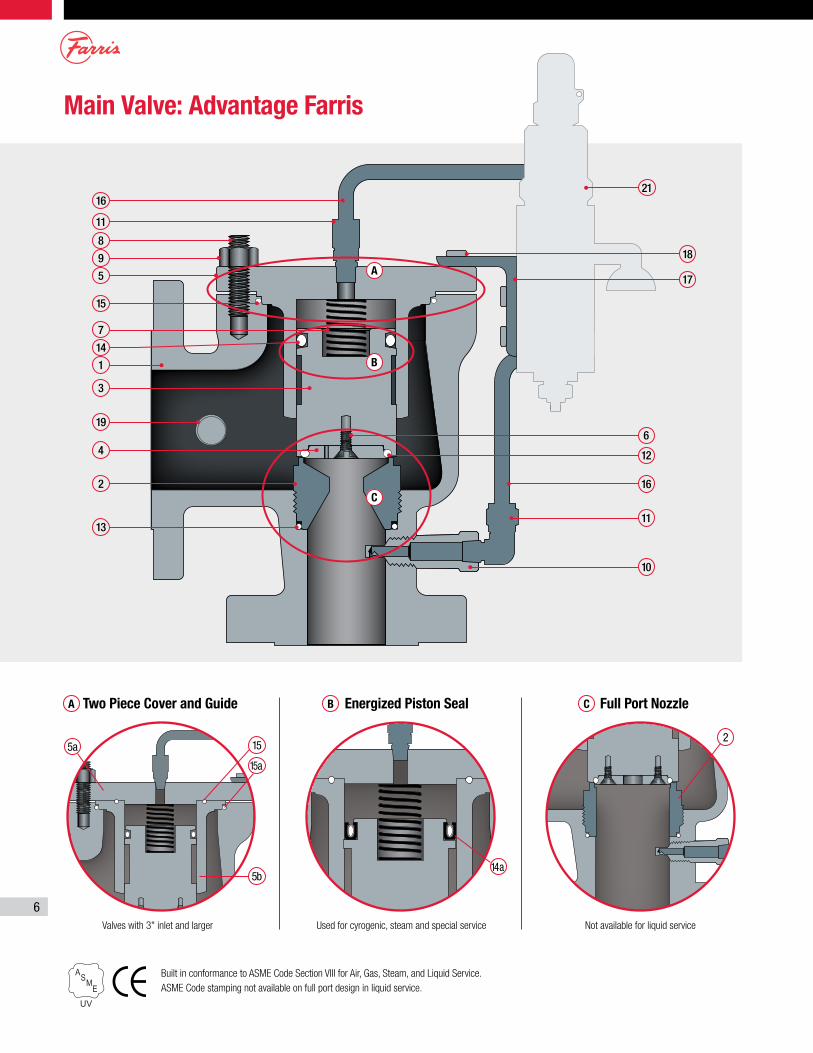
Main Valve: Advantage Farris
Built in conformance to ASME Code Section VIII for Air, Gas, Steam, and Liquid Service.ASME Code stamping not available on full port design in liquid service.
Valves with 3" inlet and larger
Two Piece Cover and Guide
Not available for liquid service
Full Port Nozzle
Used for cyrogenic, steam and special service
Energized Piston Seal
16
11
8
9
3
4
7
5
1
2
14
13
5a 15
15a
14a5b
2
19
15
21
17
12
16
11
10
18
6
A
A B C
B
C
7
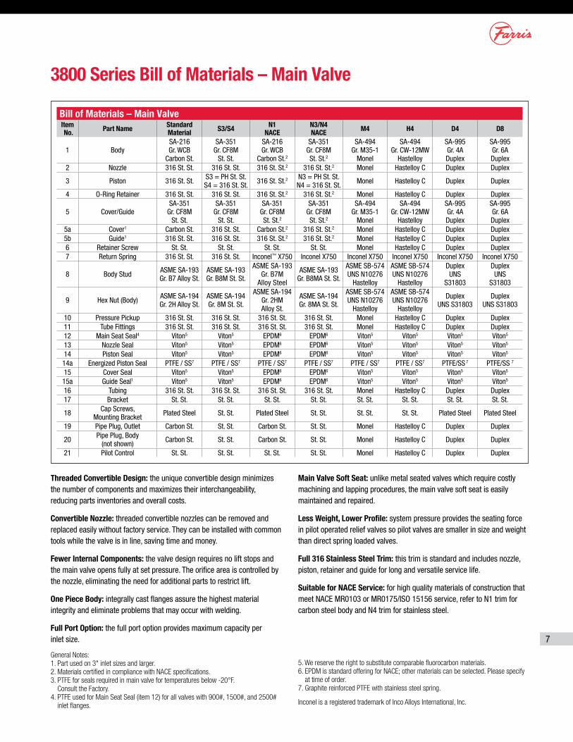
3800 Series Bill of Materials – Main Valve
Bill of Materials – Main ValveItem No. Part Name Standard
Material S3/S4 N1 NACE
N3/N4 NACE M4 H4 D4 D8
1 BodySA-216 Gr. WCB
Carbon St.
SA-351 Gr. CF8M
St. St.
SA-216 Gr. WCB
Carbon St.2
SA-351 Gr. CF8M St. St.2
SA-494 Gr. M35-1
Monel
SA-494 Gr. CW-12MW
Hastelloy
SA-995 Gr. 4A Duplex
SA-995 Gr. 6A Duplex
2 Nozzle 316 St. St. 316 St. St. 316 St. St.2 316 St. St.2 Monel Hastelloy C Duplex Duplex
3 Piston 316 St. St. S3 = PH St. St. S4 = 316 St. St. 316 St. St.2 N3 = PH St. St.
N4 = 316 St. St. Monel Hastelloy C Duplex Duplex
4 O-Ring Retainer 316 St. St. 316 St. St. 316 St. St.2 316 St. St.2 Monel Hastelloy C Duplex Duplex
5 Cover/GuideSA-351
Gr. CF8M St. St.
SA-351 Gr. CF8M
St. St.
SA-351 Gr. CF8M St. St.2
SA-351 Gr. CF8M St. St.2
SA-494 Gr. M35-1
Monel
SA-494 Gr. CW-12MW
Hastelloy
SA-995 Gr. 4A Duplex
SA-995 Gr. 6A Duplex
5a Cover1 Carbon St. 316 St. St. Carbon St.2 316 St. St.2 Monel Hastelloy C Duplex Duplex5b Guide1 316 St. St. 316 St. St. 316 St. St.2 316 St. St.2 Monel Hastelloy C Duplex Duplex6 Retainer Screw St. St. St. St. St. St. St. St. Monel Hastelloy C Duplex Duplex7 Return Spring 316 St. St. 316 St. St. Inconel™ X750 Inconel X750 Inconel X750 Inconel X750 Inconel X750 Inconel X750
8 Body Stud ASME SA-193 Gr. B7 Alloy St.
ASME SA-193 Gr. B8M St. St.
ASME SA-193 Gr. B7M
Alloy Steel
ASME SA-193 Gr. B8MA St. St.
ASME SB-574 UNS N10276
Hastelloy
ASME SB-574 UNS N10276
Hastelloy
Duplex UNS
S31803
Duplex UNS
S31803
9 Hex Nut (Body) ASME SA-194 Gr. 2H Alloy St.
ASME SA-194 Gr. 8M St. St.
ASME SA-194 Gr. 2HM Alloy St.
ASME SA-194 Gr. 8MA St. St.
ASME SB-574 UNS N10276
Hastelloy
ASME SB-574 UNS N10276
Hastelloy
Duplex UNS S31803
Duplex UNS S31803
10 Pressure Pickup 316 St. St. 316 St. St. 316 St. St. 316 St. St. Monel Hastelloy C Duplex Duplex11 Tube Fittings 316 St. St. 316 St. St. 316 St. St. 316 St. St. Monel Hastelloy C Duplex Duplex12 Main Seat Seal4 Viton5 Viton5 EPDM6 EPDM6 Viton5 Viton5 Viton5 Viton5
13 Nozzle Seal Viton5 Viton5 EPDM6 EPDM6 Viton5 Viton5 Viton5 Viton5
14 Piston Seal Viton5 Viton5 EPDM6 EPDM6 Viton5 Viton5 Viton5 Viton5
14a Energized Piston Seal PTFE / SS7 PTFE / SS7 PTFE / SS7 PTFE / SS7 PTFE / SS7 PTFE / SS7 PTFE/SS 7 PTFE/SS 7
15 Cover Seal Viton5 Viton5 EPDM6 EPDM6 Viton5 Viton5 Viton5 Viton5
15a Guide Seal1 Viton5 Viton5 EPDM6 EPDM6 Viton5 Viton5 Viton5 Viton5
16 Tubing 316 St. St. 316 St. St. 316 St. St. 316 St. St. Monel Hastelloy C Duplex Duplex17 Bracket St. St. St. St. St. St. St. St. St. St. St. St. St. St. St. St.
18 Cap Screws, Mounting Bracket Plated Steel St. St. Plated Steel St. St. St. St. St. St. Plated Steel Plated Steel
19 Pipe Plug, Outlet Carbon St. St. St. Carbon St. St. St. Monel Hastelloy C Duplex Duplex
20 Pipe Plug, Body (not shown) Carbon St. St. St. Carbon St. St. St. Monel Hastelloy C Duplex Duplex
21 Pilot Control St. St. St. St. St. St. St. St. Monel Hastelloy C Duplex Duplex
Threaded Convertible Design: the unique convertible design minimizes the number of components and maximizes their interchangeability, reducing parts inventories and overall costs.
Convertible Nozzle: threaded convertible nozzles can be removed and replaced easily without factory service. They can be installed with common tools while the valve is in line, saving time and money.
Fewer Internal Components: the valve design requires no lift stops and the main valve opens fully at set pressure. The orifice area is controlled by the nozzle, eliminating the need for additional parts to restrict lift.
One Piece Body: integrally cast flanges assure the highest material integrity and eliminate problems that may occur with welding.
Full Port Option: the full port option provides maximum capacity per inlet size.
Main Valve Soft Seat: unlike metal seated valves which require costly machining and lapping procedures, the main valve soft seat is easily maintained and repaired.
Less Weight, Lower Profile: system pressure provides the seating force in pilot operated relief valves so pilot valves are smaller in size and weight than direct spring loaded valves.
Full 316 Stainless Steel Trim: this trim is standard and includes nozzle, piston, retainer and guide for long and versatile service life.
Suitable for NACE Service: for high quality materials of construction that meet NACE MR0103 or MR0175/ISO 15156 service, refer to N1 trim for carbon steel body and N4 trim for stainless steel.
General Notes:1. Part used on 3" inlet sizes and larger.2. Materials certified in compliance with NACE specifications.3. PTFE for seals required in main valve for temperatures below -20°F.
Consult the Factory.4. PTFE used for Main Seat Seal (item 12) for all valves with 900#, 1500#, and 2500#
inlet flanges.
5. We reserve the right to substitute comparable fluorocarbon materials.6. EPDM is standard offering for NACE; other materials can be selected. Please specify
at time of order.7. Graphite reinforced PTFE with stainless steel spring.
Inconel is a registered trademark of Inco Alloys International, Inc.
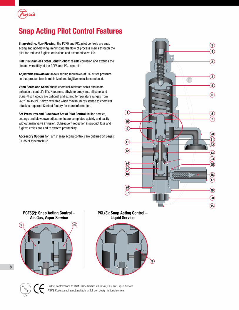
8
Snap Acting Pilot Control FeaturesSnap-Acting, Non-Flowing: the PCF5 and PCL pilot controls are snap acting and non-flowing, minimizing the flow of process media through the pilot for reduced fugitive emissions and extended valve life.
Full 316 Stainless Steel Construction: resists corrosion and extends the life and versatility of the PCF5 and PCL controls.
Adjustable Blowdown: allows setting blowdown at 3% of set pressure so that product loss is minimized and fugitive emissions reduced.
Viton Seats and Seals: these chemical-resistant seals and seats enhance a control's life. Neoprene, ethylene propylene, silicone, and Buna-N soft goods are optional and extend temperature ranges from -65°F to 450°F. Kalrez available when maximum resistance to chemical attack is required. Contact factory for more information.
Set Pressures and Blowdown Set at Pilot Control: in line service, settings and blowdown adjustments are completed quickly and easily without main valve intrusion. Subsequent reduction in product loss and fugitive emissions add to system profitability.
Accessory Options for Farris’ snap acting controls are outlined on pages 31-35 of this brochure.
PCF5(2): Snap Acting Control – Air, Gas, Vapor Service
PCL(3): Snap Acting Control – Liquid Service
Built in conformance to ASME Code Section VIII for Air, Gas, and Liquid Service.ASME Code stamping not available on full port design in liquid service.
1
10
9
11
12
24
26
27
14
18
19
20
15
9
9 10
17
16
13
22
21
28
7
5
6
5
2
8
4
3
25
23
9
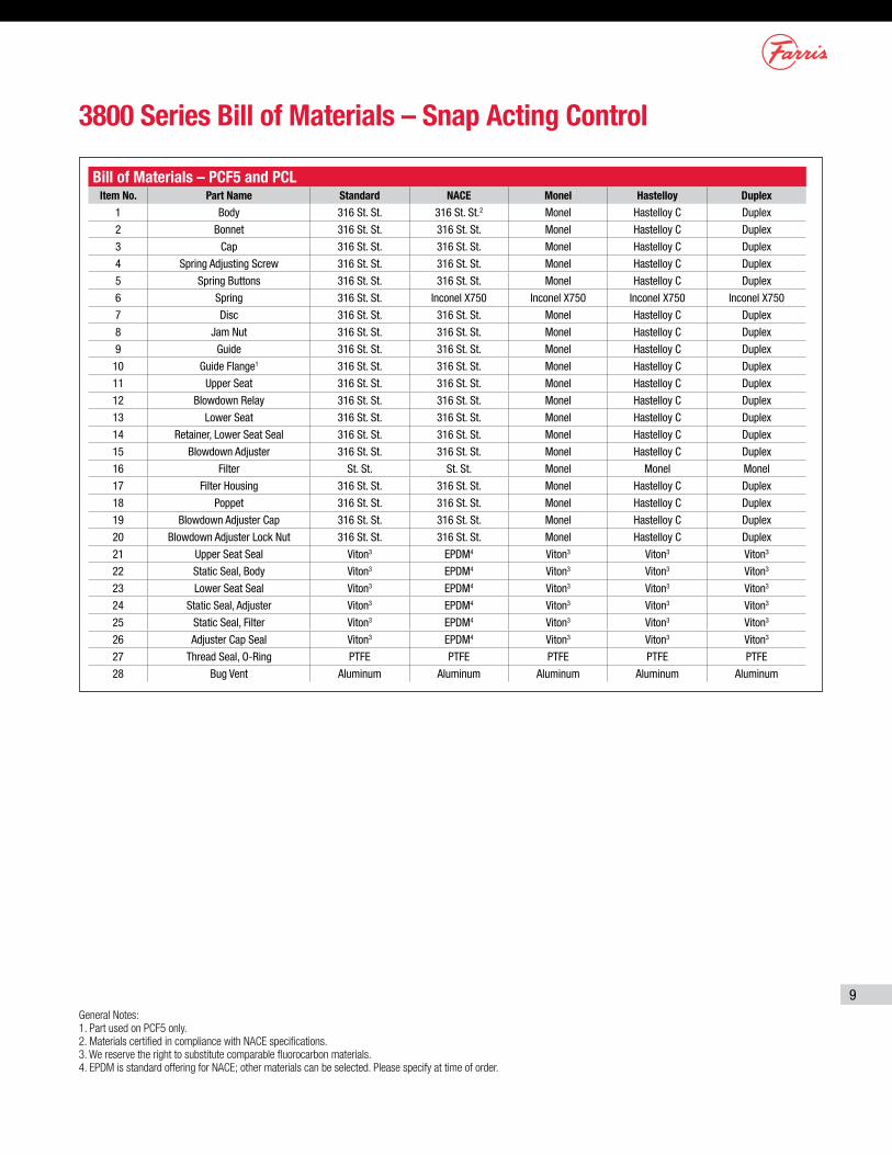
Bill of Materials – PCF5 and PCLItem No. Part Name Standard NACE Monel Hastelloy Duplex
1 Body 316 St. St. 316 St. St.2 Monel Hastelloy C Duplex
2 Bonnet 316 St. St. 316 St. St. Monel Hastelloy C Duplex
3 Cap 316 St. St. 316 St. St. Monel Hastelloy C Duplex
4 Spring Adjusting Screw 316 St. St. 316 St. St. Monel Hastelloy C Duplex
5 Spring Buttons 316 St. St. 316 St. St. Monel Hastelloy C Duplex
6 Spring 316 St. St. Inconel X750 Inconel X750 Inconel X750 Inconel X750
7 Disc 316 St. St. 316 St. St. Monel Hastelloy C Duplex
8 Jam Nut 316 St. St. 316 St. St. Monel Hastelloy C Duplex
9 Guide 316 St. St. 316 St. St. Monel Hastelloy C Duplex
10 Guide Flange1 316 St. St. 316 St. St. Monel Hastelloy C Duplex
11 Upper Seat 316 St. St. 316 St. St. Monel Hastelloy C Duplex
12 Blowdown Relay 316 St. St. 316 St. St. Monel Hastelloy C Duplex
13 Lower Seat 316 St. St. 316 St. St. Monel Hastelloy C Duplex
14 Retainer, Lower Seat Seal 316 St. St. 316 St. St. Monel Hastelloy C Duplex
15 Blowdown Adjuster 316 St. St. 316 St. St. Monel Hastelloy C Duplex
16 Filter St. St. St. St. Monel Monel Monel
17 Filter Housing 316 St. St. 316 St. St. Monel Hastelloy C Duplex
18 Poppet 316 St. St. 316 St. St. Monel Hastelloy C Duplex
19 Blowdown Adjuster Cap 316 St. St. 316 St. St. Monel Hastelloy C Duplex
20 Blowdown Adjuster Lock Nut 316 St. St. 316 St. St. Monel Hastelloy C Duplex
21 Upper Seat Seal Viton3 EPDM4 Viton3 Viton3 Viton3
22 Static Seal, Body Viton3 EPDM4 Viton3 Viton3 Viton3
23 Lower Seat Seal Viton3 EPDM4 Viton3 Viton3 Viton3
24 Static Seal, Adjuster Viton3 EPDM4 Viton3 Viton3 Viton3
25 Static Seal, Filter Viton3 EPDM4 Viton3 Viton3 Viton3
26 Adjuster Cap Seal Viton3 EPDM4 Viton3 Viton3 Viton3
27 Thread Seal, O-Ring PTFE PTFE PTFE PTFE PTFE
28 Bug Vent Aluminum Aluminum Aluminum Aluminum Aluminum
3800 Series Bill of Materials – Snap Acting Control
General Notes:1. Part used on PCF5 only.2. Materials certified in compliance with NACE specifications.3. We reserve the right to substitute comparable fluorocarbon materials.4. EPDM is standard offering for NACE; other materials can be selected. Please specify at time of order.
10
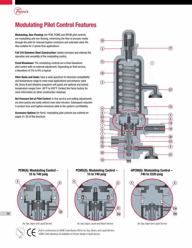
Modulating Pilot Control FeaturesModulating, Non-Flowing: the PCM, PCMS and HPCM pilot controls are modulating and non-flowing, minimizing the flow of process media through the pilot for reduced fugitive emissions and extended valve life. Also suitable for 2-phase flow applications.
Full 316 Stainless Steel Construction: resists corrosion and extends the operation and versatility of the modulating control.
Fixed Blowdown: The modulating controls are a fixed blowdown pilot control with no external adjustment. Depending on fluid service, a blowdown of 3% to 6% is typical.
Viton Seats and Seals: have a wide spectrum of chemical compatibility and temperature range to meet most applications and enhance valve life. Buna-N and ethylene propylene soft goods are optional and extend temperature ranges from -65°F to 450°F. Contact the Farris factory for more information on other construction materials.
Set Pressure Set at Pilot Control: in-line service and setting adjustments are done quickly and easily without main valve intrusion. Subsequent reduction in product loss and fugitive emissions adds to the system’s profitability.
Accessory Options for Farris’ modulating pilot controls are outlined on pages 31-35 of this brochure.
PCM(4): Modulating Control – 15 to 740 psig
PCMS(5): Modulating Control – 15 to 740 psig
HPCM(6): Modulating Control – 740 to 2220 psig
Built in conformance to ASME Code Section VIII for Air, Gas, Steam, and Liquid Service.ASME Code stamping not available on full port design in liquid service.
Air, Gas, Vapor and Liquid Service Air, Gas, Vapor, Liquid and Steam Service Air, Gas, Vapor and Liquid Service
2
16
11
3
10
24
23
12
4 4 4
15
22
7
5
1
20
14
8
11
27
8 8 8
2021 21a
20a 20b
9
18
25
19
4
6
13
27
17
26
11
3800 Series Bill of Materials – Modulating Control
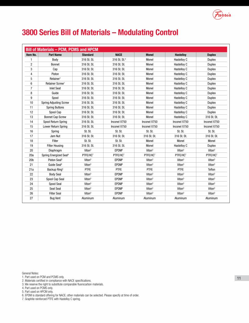
Bill of Materials – PCM, PCMS and HPCMItem No. Part Name Standard NACE Monel Hastelloy Duplex
1 Body 316 St. St. 316 St. St.2 Monel Hastelloy C Duplex
2 Bonnet 316 St. St. 316 St. St. Monel Hastelloy C Duplex
3 Cap 316 St. St. 316 St. St. Monel Hastelloy C Duplex
4 Piston 316 St. St. 316 St. St. Monel Hastelloy C Duplex
5 Retainer1 316 St. St. 316 St. St. Monel Hastelloy C Duplex
6 Retainer Screw1 316 St. St. 316 St. St. Monel Hastelloy C Duplex
7 Inlet Seat 316 St. St. 316 St. St. Monel Hastelloy C Duplex
8 Guide 316 St. St. 316 St. St. Monel Hastelloy C Duplex
9 Spool 316 St. St. 316 St. St. Monel Hastelloy C Duplex
10 Spring Adjusting Screw 316 St. St. 316 St. St. Monel Hastelloy C Duplex
11 Spring Buttons 316 St. St. 316 St. St. Monel Hastelloy C Duplex
12 Spool Cap 316 St. St. 316 St. St. Monel Hastelloy C Duplex
13 Bonnet Cap Screw 316 St. St. 316 St. St. Monel Hastelloy C 316 St. St.
14 Spool Return Spring 316 St. St. Inconel X750 Inconel X750 Inconel X750 Inconel X750
15 Lower Return Spring 316 St. St. Inconel X750 Inconel X750 Inconel X750 Inconel X750
16 Spring St. St. St. St. St. St. St. St. St. St.
17 Jam Nut 316 St. St. 316 St. St. 316 St. St. 316 St. St. 316 St. St.
18 Filter St. St. St. St. Monel Monel Monel
19 Filter Housing 316 St. St. 316 St. St. Monel Hastelloy C Duplex
20 Diaphragm Viton3 EPDM6 Viton3 Viton3 Viton3
20a Spring Energized Seal4 PTFE/HC7 PTFE/HC7 PTFE/HC7 PTFE/HC7 PTFE/HC7
20b Piston Seal5 Viton3 EPDM6 Viton3 Viton3 Viton3
21 Guide Seal4 Viton3 EPDM6 Viton3 Viton3 Viton3
21a Backup Ring5 PTFE PTFE PTFE PTFE Teflon
22 Body Seal Viton3 EPDM6 Viton3 Viton3 Viton3
23 Spool Cap Seal Viton3 EPDM6 Viton3 Viton3 Viton3
24 Spool Seal Viton3 EPDM6 Viton3 Viton3 Viton3
25 Seat Seal Viton3 EPDM6 Viton3 Viton3 Viton3
26 Filter Seal Viton3 EPDM6 Viton3 Viton3 Viton3
27 Bug Vent Aluminum Aluminum Aluminum Aluminum Aluminum
General Notes:1. Part used on PCM and PCMS only.2. Materials certified in compliance with NACE specifications.3. We reserve the right to substitute comparable fluorocarbon materials.4. Part used on PCMS only.5. Part used on HPCM only.6. EPDM is standard offering for NACE; other materials can be selected. Please specify at time of order.7. Graphite reinforced PTFE with Hastelloy C spring.
12
Inline Filter Assembly2
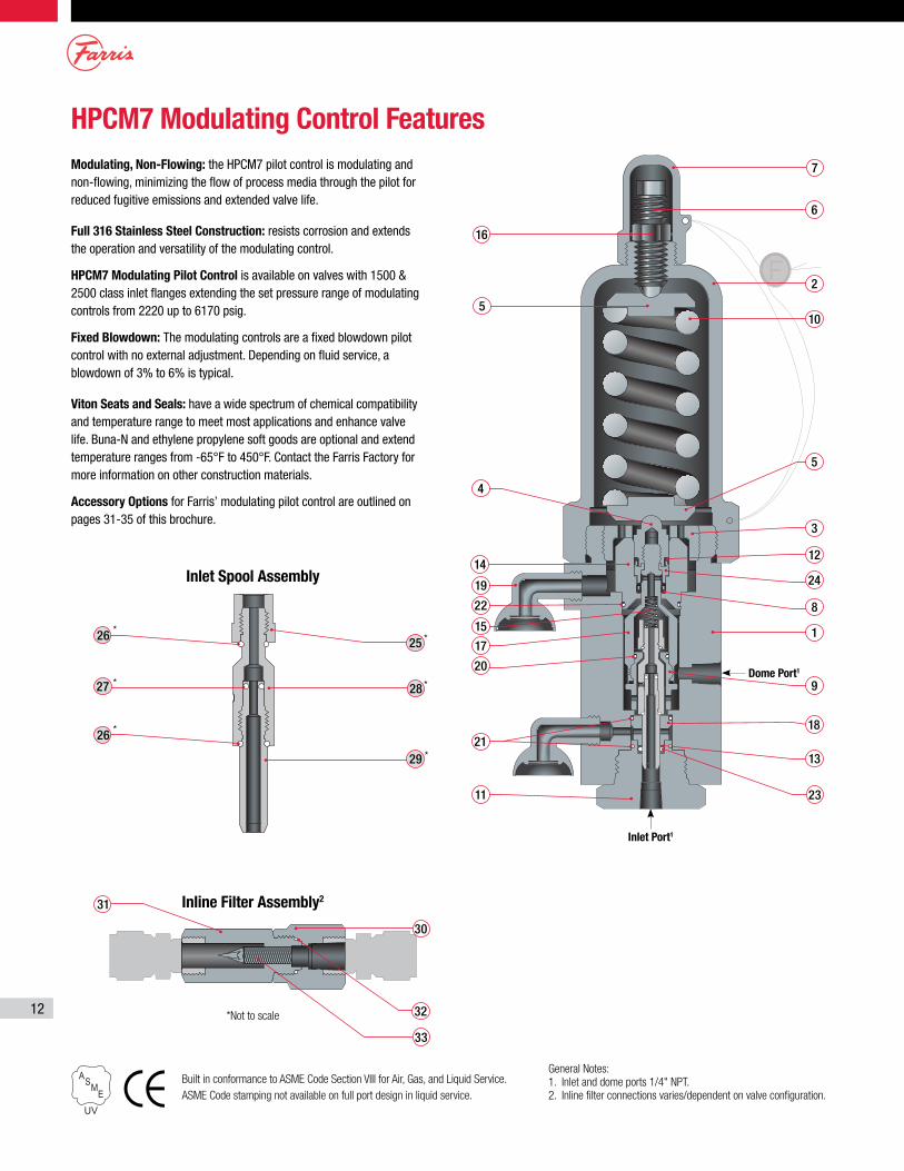
HPCM7 Modulating Control FeaturesModulating, Non-Flowing: the HPCM7 pilot control is modulating and non-flowing, minimizing the flow of process media through the pilot for reduced fugitive emissions and extended valve life.
Full 316 Stainless Steel Construction: resists corrosion and extends the operation and versatility of the modulating control.
HPCM7 Modulating Pilot Control is available on valves with 1500 & 2500 class inlet flanges extending the set pressure range of modulating controls from 2220 up to 6170 psig.
Fixed Blowdown: The modulating controls are a fixed blowdown pilot control with no external adjustment. Depending on fluid service, a blowdown of 3% to 6% is typical.
Viton Seats and Seals: have a wide spectrum of chemical compatibility and temperature range to meet most applications and enhance valve life. Buna-N and ethylene propylene soft goods are optional and extend temperature ranges from -65°F to 450°F. Contact the Farris Factory for more information on other construction materials.
Accessory Options for Farris’ modulating pilot control are outlined on pages 31-35 of this brochure.
Inlet Port1
Dome Port1
2
5
3
4
14
19
22
15
17
20
21
11
16
5
6
7
10
1
18
9
13
23
30
31
33
32
8
12
24
25
28
26
26
27
29
*
*
*
*
*
*
General Notes:1. Inlet and dome ports 1/4" NPT.2. Inline filter connections varies/dependent on valve configuration.
Inlet Spool Assembly
*Not to scale
Built in conformance to ASME Code Section VIII for Air, Gas, and Liquid Service.ASME Code stamping not available on full port design in liquid service.
13
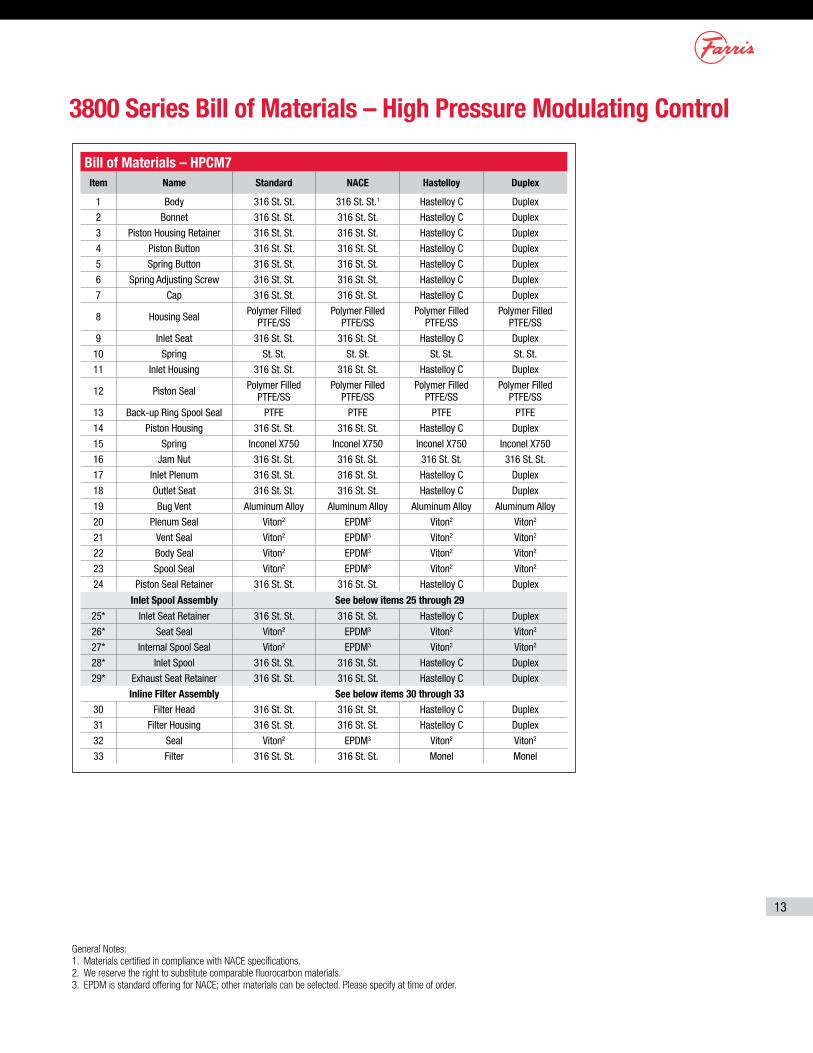
Bill of Materials – HPCM7Item Name Standard NACE Hastelloy Duplex
1 Body 316 St. St. 316 St. St.1 Hastelloy C Duplex
2 Bonnet 316 St. St. 316 St. St. Hastelloy C Duplex
3 Piston Housing Retainer 316 St. St. 316 St. St. Hastelloy C Duplex
4 Piston Button 316 St. St. 316 St. St. Hastelloy C Duplex
5 Spring Button 316 St. St. 316 St. St. Hastelloy C Duplex
6 Spring Adjusting Screw 316 St. St. 316 St. St. Hastelloy C Duplex
7 Cap 316 St. St. 316 St. St. Hastelloy C Duplex
8 Housing Seal Polymer Filled PTFE/SS
Polymer Filled PTFE/SS
Polymer Filled PTFE/SS
Polymer Filled PTFE/SS
9 Inlet Seat 316 St. St. 316 St. St. Hastelloy C Duplex
10 Spring St. St. St. St. St. St. St. St.
11 Inlet Housing 316 St. St. 316 St. St. Hastelloy C Duplex
12 Piston Seal Polymer Filled PTFE/SS
Polymer Filled PTFE/SS
Polymer Filled PTFE/SS
Polymer Filled PTFE/SS
13 Back-up Ring Spool Seal PTFE PTFE PTFE PTFE
14 Piston Housing 316 St. St. 316 St. St. Hastelloy C Duplex
15 Spring Inconel X750 Inconel X750 Inconel X750 Inconel X750
16 Jam Nut 316 St. St. 316 St. St. 316 St. St. 316 St. St.
17 Inlet Plenum 316 St. St. 316 St. St. Hastelloy C Duplex
18 Outlet Seat 316 St. St. 316 St. St. Hastelloy C Duplex
19 Bug Vent Aluminum Alloy Aluminum Alloy Aluminum Alloy Aluminum Alloy
20 Plenum Seal Viton2 EPDM3 Viton2 Viton2
21 Vent Seal Viton2 EPDM3 Viton2 Viton2
22 Body Seal Viton2 EPDM3 Viton2 Viton2
23 Spool Seal Viton2 EPDM3 Viton2 Viton2
24 Piston Seal Retainer 316 St. St. 316 St. St. Hastelloy C Duplex
Inlet Spool Assembly See below items 25 through 29
25* Inlet Seat Retainer 316 St. St. 316 St. St. Hastelloy C Duplex
26* Seat Seal Viton2 EPDM3 Viton2 Viton2
27* Internal Spool Seal Viton2 EPDM3 Viton2 Viton2
28* Inlet Spool 316 St. St. 316 St. St. Hastelloy C Duplex
29* Exhaust Seat Retainer 316 St. St. 316 St. St. Hastelloy C Duplex
Inline Filter Assembly See below items 30 through 3330 Filter Head 316 St. St. 316 St. St. Hastelloy C Duplex
31 Filter Housing 316 St. St. 316 St. St. Hastelloy C Duplex
32 Seal Viton2 EPDM3 Viton2 Viton2
33 Filter 316 St. St. 316 St. St. Monel Monel
3800 Series Bill of Materials – High Pressure Modulating Control
General Notes:1. Materials certified in compliance with NACE specifications.2. We reserve the right to substitute comparable fluorocarbon materials.3. EPDM is standard offering for NACE; other materials can be selected. Please specify at time of order.
14
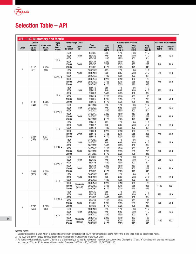
Selection Table – API
General Notes:1. Standard elastomer is Viton which is suitable to a maximum temperature of 450°F. For temperatures above 450°F the o-ring seals must be specified as Kalrez.2. The 300# and 600# flanges have identical drilling with flange thickness equal to the 600# class.3. For liquid service applications, add “L” to the end of the base type number for valves with standard size connections. Change the “X” to a “Y” for valves with oversize connections
and change “D” to an “E” for valves with dual outlet. Examples: 38FC10L-120, 38FC10Y-120, 38TC10E-120.
API – U.S. Customary and Metric Orifice Valve
Size Inlet x Outlet
ASME Flange ClassType
Number
Maximum Set Pressure Maximum Back Pressure
LetterAPI Area
Sq. In. (mm)
Actual Area Sq. In. (mm)
Inlet RF or RJ
Outlet RF
psig -20°F 100°F
psig 500°F
(note 1)
barg -29°C 38°C
barg 260°C
(note 1)
psig @ 100°F
barg @ 38°C
D 0.110 (71)
0.150 (97)
1 x 2
150# 300# 600#
150#38DC10 38DC12 38DC13
285 740 1480
170 605 1205
19.6 51.0 102
11.7 41.7 83
285 19.6
900# 1500# 2500#
300#38DC14 38DC15 38DC16
2220 3705 6170
1810 3015 5025
153 255 425
125 208 346
740 51.0
1-1/2 x 2
150# 300# 600#
150#38DC10X 38DC12X 38DC13X
285 740 1480
170 605 1205
19.6 51.0 102
11.7 41.7 83
285 19.6
900# 1500# 2500#
300#38DC14X 38DC15X 38DC16X
2220 3705 6170
1810 3015 5025
153 255 425
125 208 346
740 51.0
E 0.196 (126)
0.225 (145)
1 x 2
150# 300# 600#
150#38EC10 38EC12 38EC13
285 740 1480
170 605 1205
19.6 51.0 102
11.7 41.7 83
285 19.6
900# 1500# 2500#
300#38EC14 38EC15 38EC16
2220 3705 6170
1810 3015 5025
153 255 425
125 208 346
740 51.0
1-1/2 x 2
150# 300# 600#
150#38EC10X 38EC12X 38EC13X
285 740 1480
170 605 1205
19.6 51.0 102
11.7 41.7 83
285 19.6
900# 1500# 2500#
300#38EC14X 38EC15X 38EC16X
2220 3705 6170
1810 3015 5025
153 255 425
125 208 346
740 51.0
F 0.307 (198)
0.371 (239)
1 x 2
150# 300# 600#
150#38FC10 38FC12 38FC13
285 740 1480
170 605 1205
19.6 51.0 102
11.7 41.7 83
285 19.6
900# 1500# 2500#
300#38FC14 38FC15 38FC16
2220 3705 6170
1810 3015 5025
153 255 425
125 208 346
740 51.0
1-1/2 x 2
150# 300# 600#
150#38FC10X 38FC12X 38FC13X
285 740 1480
170 605 1205
19.6 51.0 102
11.7 41.7 83
285 19.6
900# 1500# 2500#
300#38FC14X 38FC15X 38FC16X
2220 3705 6170
1810 3015 5025
153 255 425
125 208 346
740 51.0
G 0.503 (325)
0.559 (361)
1-1/2 x 3
150# 300# 600#
150#38GC10 38GC12 38GC13
285 740 1480
170 605 1205
19.6 51.0 102
11.7 41.7 83
285 19.6
900# 1500# 2500#
300#38GC14 38GC15 38GC16
2220 3705 6170
1810 3015 5025
153 255 425
125 208 346
740 51.0
2 x 3
150# 300# 600#
150#38GC10X 38GC12X 38GC13X
285 740 1480
170 605 1205
19.6 51.0 102
11.7 41.7 83
285 19.6
900# 1500# 2500#
300/600# (note 2)
38GC14X 38GC15X 38GC16X
2220 3705 6170
1810 3015 5025
153 255 425
125 208 346
1480 102
H 0.785 (506)
0.873 (563)
1-1/2 x 3
150# 300# 600#
150#38HC10 38HC12 38HC13
285 740 1480
170 605 1205
19.6 51.0 102
11.7 41.7 83
285 19.6
900# 1500# 2500#
300#38HC14 38HC15 38HC16
2220 3705 6170
1810 3015 5025
153 255 425
125 208 346
740 51.0
2 x 3
150# 300# 600#
150#38HC10X 38HC12X 38HC13X
285 740 1480
170 605 1205
19.6 51.0 102
11.7 41.7 83
285 19.6
900# 1500# 2500#
300/600# (note 2)
38HC14X 38HC15X 38HC16X
2220 3705 6170
1810 3015 5025
153 255 425
125 208 346
1480 102
15
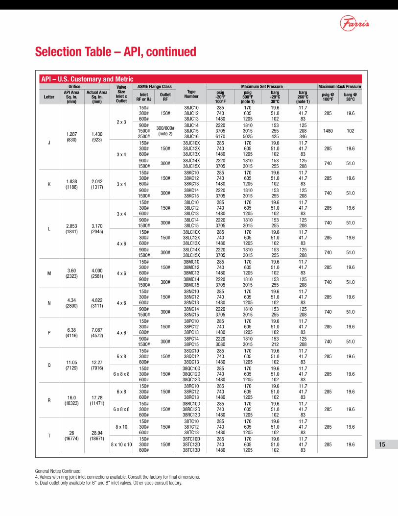
Selection Table – API, continued
API – U.S. Customary and Metric Orifice Valve
Size Inlet x Outlet
ASME Flange ClassType
Number
Maximum Set Pressure Maximum Back Pressure
LetterAPI Area
Sq. In. (mm)
Actual Area Sq. In. (mm)
Inlet RF or RJ
Outlet RF
psig -20°F 100°F
psig 500°F
(note 1)
barg -29°C 38°C
barg 260°C
(note 1)
psig @ 100°F
barg @ 38°C
J
1.287 (830)
1.430 (923)
2 x 3
150# 300# 600#
150#38JC10 38JC12 38JC13
285 740 1480
170 605 1205
19.6 51.0 102
11.7 41.7 83
285 19.6
900# 1500# 2500#
300/600# (note 2)
38JC14 38JC15 38JC16
2220 3705 6170
1810 3015 5025
153 255 425
125 208 346
1480 102
3 x 4
150# 300# 600#
150#38JC10X 38JC12X 38JC13X
285 740 1480
170 605 1205
19.6 51.0 102
11.7 41.7 83
285 19.6
900# 1500# 300# 38JC14X
38JC15X2220 3705
1810 3015
153 255
125 208 740 51.0
K 1.838 (1186)
2.042 (1317) 3 x 4
150# 300# 600#
150#38KC10 38KC12 38KC13
285 740 1480
170 605 1205
19.6 51.0 102
11.7 41.7 83
285 19.6
900# 1500# 300# 38KC14
38KC152220 3705
1810 3015
153 255
125 208 740 51.0
L 2.853 (1841)
3.170 (2045)
3 x 4
150# 300# 600#
150#38LC10 38LC12 38LC13
285 740 1480
170 605 1205
19.6 51.0 102
11.7 41.7 83
285 19.6
900# 1500# 300# 38LC14
38LC152220 3705
1810 3015
153 255
125 208 740 51.0
4 x 6
150# 300# 600#
150#38LC10X 38LC12X 38LC13X
285 740 1480
170 605 1205
19.6 51.0 102
11.7 41.7 83
285 19.6
900# 1500# 300# 38LC14X
38LC15X2220 3705
1810 3015
153 255
125 208 740 51.0
M 3.60 (2323)
4.000 (2581) 4 x 6
150# 300# 600#
150#38MC10 38MC12 38MC13
285 740 1480
170 605 1205
19.6 51.0 102
11.7 41.7 83
285 19.6
900# 1500# 300# 38MC14
38MC152220 3705
1810 3015
153 255
125 208 740 51.0
N 4.34 (2800)
4.822 (3111) 4 x 6
150# 300# 600#
150#38NC10 38NC12 38NC13
285 740 1480
170 605 1205
19.6 51.0 102
11.7 41.7 83
285 19.6
900# 1500# 300# 38NC14
38NC152220 3705
1810 3015
153 255
125 208 740 51.0
P 6.38 (4116)
7.087 (4572) 4 x 6
150# 300# 600#
150#38PC10 38PC12 38PC13
285 740 1480
170 605 1205
19.6 51.0 102
11.7 41.7 83
285 19.6
900# 1500# 300# 38PC14
38PC152220 3080
1810 3015
153 212
125 208 740 51.0
Q 11.05 (7129)
12.27 (7916)
6 x 8150# 300# 600#
150#38QC10 38QC12 38QC13
285 740 1480
170 605 1205
19.6 51.0 102
11.7 41.7 83
285 19.6
6 x 8 x 8150# 300# 600#
150#38QC10D 38QC12D 38QC13D
285 740 1480
170 605 1205
19.6 51.0 102
11.7 41.7 83
285 19.6
R 16.0 (10323)
17.78 (11471)
6 x 8150# 300# 600#
150#38RC10 38RC12 38RC13
285 740 1480
170 605 1205
19.6 51.0 102
11.7 41.7 83
285 19.6
6 x 8 x 8150# 300# 600#
150#38RC10D 38RC12D 38RC13D
285 740 1480
170 605 1205
19.6 51.0 102
11.7 41.7 83
285 19.6
T 26 (16774)
28.94 (18671)
8 x 10150# 300# 600#
150#38TC10 38TC12 38TC13
285 740 1480
170 605 1205
19.6 51.0 102
11.7 41.7 83
285 19.6
8 x 10 x 10150# 300# 600#
150#38TC10D 38TC12D 38TC13D
285 740 1480
170 605 1205
19.6 51.0 102
11.7 41.7 83
285 19.6
General Notes Continued:4. Valves with ring joint inlet connections available. Consult the factory for final dimensions.5. Dual outlet only available for 6" and 8" inlet valves. Other sizes consult factory.
16
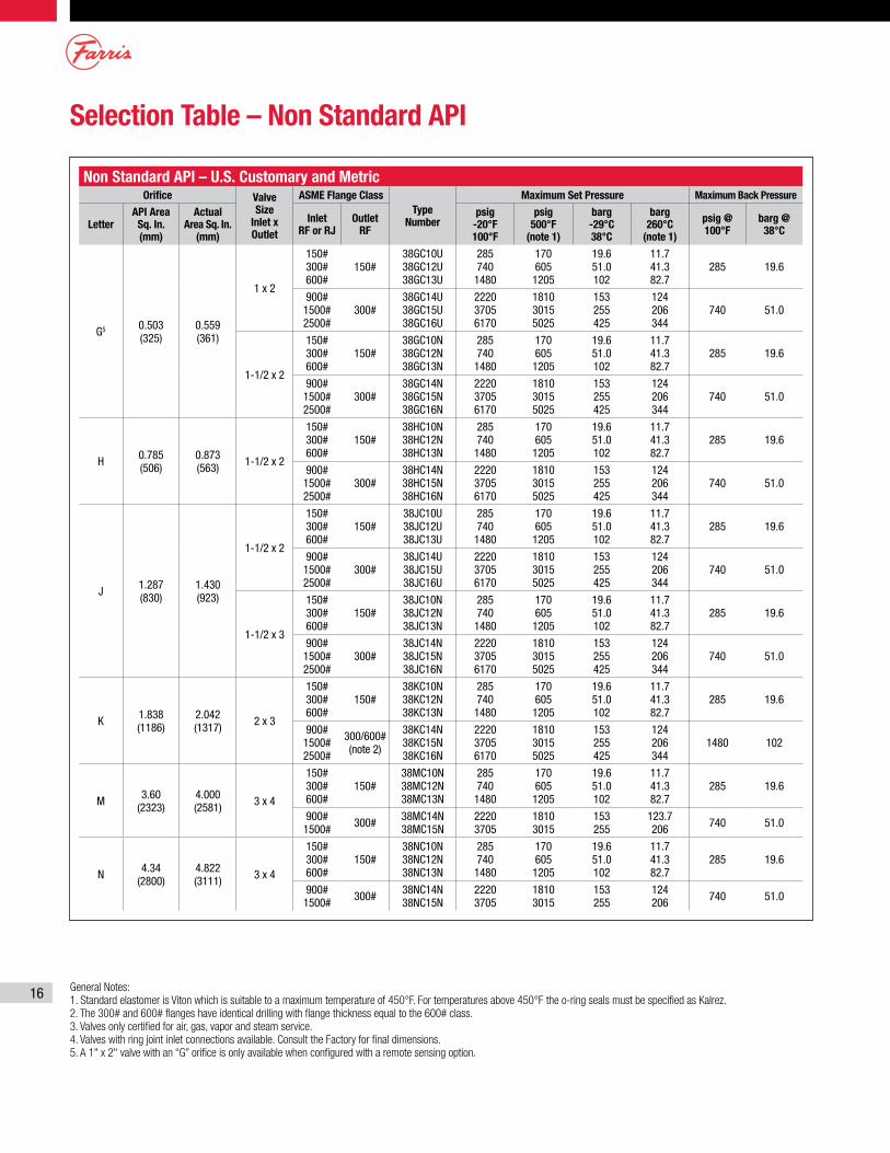
Selection Table – Non Standard API
Non Standard API – U.S. Customary and MetricOrifice Valve
Size Inlet x Outlet
ASME Flange ClassType
Number
Maximum Set Pressure Maximum Back Pressure
LetterAPI Area
Sq. In. (mm)
Actual Area Sq. In.
(mm)
Inlet RF or RJ
Outlet RF
psig -20°F 100°F
psig 500°F
(note 1)
barg -29°C 38°C
barg 260°C
(note 1)
psig @ 100°F
barg @ 38°C
G5 0.503 (325)
0.559 (361)
1 x 2
150# 300# 600#
150#38GC10U 38GC12U 38GC13U
285 740 1480
170 605 1205
19.6 51.0 102
11.7 41.3 82.7
285 19.6
900# 1500# 2500#
300#38GC14U 38GC15U 38GC16U
2220 3705 6170
1810 3015 5025
153 255 425
124 206 344
740 51.0
1-1/2 x 2
150# 300# 600#
150#38GC10N 38GC12N 38GC13N
285 740 1480
170 605 1205
19.6 51.0 102
11.7 41.3 82.7
285 19.6
900# 1500# 2500#
300#38GC14N 38GC15N 38GC16N
2220 3705 6170
1810 3015 5025
153 255 425
124 206 344
740 51.0
H 0.785 (506)
0.873 (563) 1-1/2 x 2
150# 300# 600#
150#38HC10N 38HC12N 38HC13N
285 740 1480
170 605 1205
19.6 51.0 102
11.7 41.3 82.7
285 19.6
900# 1500# 2500#
300#38HC14N 38HC15N 38HC16N
2220 3705 6170
1810 3015 5025
153 255 425
124 206 344
740 51.0
J 1.287 (830)
1.430 (923)
1-1/2 x 2
150# 300# 600#
150#38JC10U 38JC12U 38JC13U
285 740 1480
170 605 1205
19.6 51.0 102
11.7 41.3 82.7
285 19.6
900# 1500# 2500#
300#38JC14U 38JC15U 38JC16U
2220 3705 6170
1810 3015 5025
153 255 425
124 206 344
740 51.0
1-1/2 x 3
150# 300# 600#
150#38JC10N 38JC12N 38JC13N
285 740 1480
170 605 1205
19.6 51.0 102
11.7 41.3 82.7
285 19.6
900# 1500# 2500#
300#38JC14N 38JC15N 38JC16N
2220 3705 6170
1810 3015 5025
153 255 425
124 206 344
740 51.0
K 1.838 (1186)
2.042 (1317) 2 x 3
150# 300# 600#
150#38KC10N 38KC12N 38KC13N
285 740 1480
170 605 1205
19.6 51.0 102
11.7 41.3 82.7
285 19.6
900# 1500# 2500#
300/600# (note 2)
38KC14N 38KC15N 38KC16N
2220 3705 6170
1810 3015 5025
153 255 425
124 206 344
1480 102
M 3.60 (2323)
4.000 (2581) 3 x 4
150# 300# 600#
150#38MC10N 38MC12N 38MC13N
285 740 1480
170 605 1205
19.6 51.0 102
11.7 41.3 82.7
285 19.6
900# 1500# 300# 38MC14N
38MC15N2220 3705
1810 3015
153 255
123.7 206 740 51.0
N 4.34 (2800)
4.822 (3111) 3 x 4
150# 300# 600#
150#38NC10N 38NC12N 38NC13N
285 740 1480
170 605 1205
19.6 51.0 102
11.7 41.3 82.7
285 19.6
900# 1500# 300# 38NC14N
38NC15N2220 3705
1810 3015
153 255
124 206 740 51.0
General Notes: 1. Standard elastomer is Viton which is suitable to a maximum temperature of 450°F. For temperatures above 450°F the o-ring seals must be specified as Kalrez.2. The 300# and 600# flanges have identical drilling with flange thickness equal to the 600# class.3. Valves only certified for air, gas, vapor and steam service.4. Valves with ring joint inlet connections available. Consult the Factory for final dimensions.5. A 1" x 2" valve with an “G” orifice is only available when configured with a remote sensing option.
17
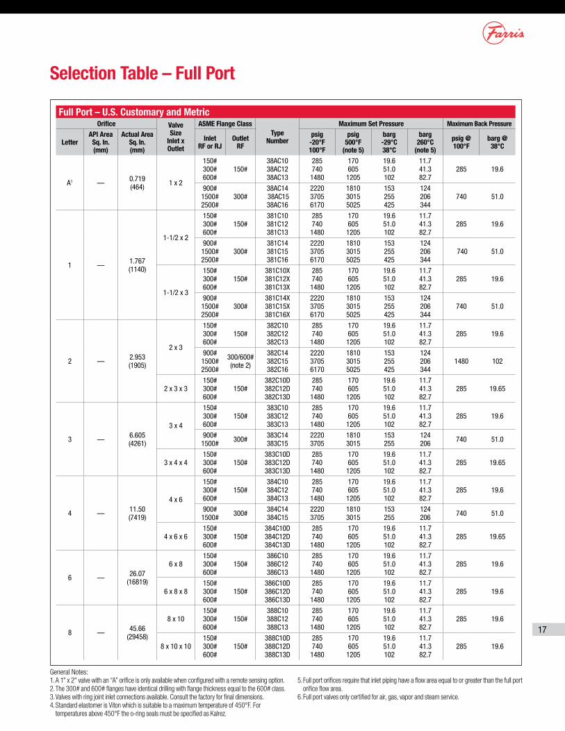
Selection Table – Full Port
Full Port – U.S. Customary and MetricOrifice Valve
Size Inlet x Outlet
ASME Flange ClassType
Number
Maximum Set Pressure Maximum Back Pressure
LetterAPI Area
Sq. In. (mm)
Actual Area Sq. In. (mm)
Inlet RF or RJ
Outlet RF
psig -20°F 100°F
psig 500°F
(note 5)
barg -29°C 38°C
barg 260°C
(note 5)
psig @ 100°F
barg @ 38°C
A1 — 0.719 (464) 1 x 2
150# 300# 600#
150#38AC10 38AC12 38AC13
285 740 1480
170 605 1205
19.6 51.0 102
11.7 41.3 82.7
285 19.6
900# 1500# 2500#
300#38AC14 38AC15 38AC16
2220 3705 6170
1810 3015 5025
153 255 425
124 206 344
740 51.0
1 — 1.767 (1140)
1-1/2 x 2
150# 300# 600#
150#381C10 381C12 381C13
285 740 1480
170 605 1205
19.6 51.0 102
11.7 41.3 82.7
285 19.6
900# 1500# 2500#
300#381C14 381C15 381C16
2220 3705 6170
1810 3015 5025
153 255 425
124 206 344
740 51.0
1-1/2 x 3
150# 300# 600#
150#381C10X 381C12X 381C13X
285 740 1480
170 605 1205
19.6 51.0 102
11.7 41.3 82.7
285 19.6
900# 1500# 2500#
300#381C14X 381C15X 381C16X
2220 3705 6170
1810 3015 5025
153 255 425
124 206 344
740 51.0
2 — 2.953 (1905)
2 x 3
150# 300# 600#
150#382C10 382C12 382C13
285 740 1480
170 605 1205
19.6 51.0 102
11.7 41.3 82.7
285 19.6
900# 1500# 2500#
300/600# (note 2)
382C14 382C15 382C16
2220 3705 6170
1810 3015 5025
153 255 425
124 206 344
1480 102
2 x 3 x 3150# 300# 600#
150#382C10D 382C12D 382C13D
285 740 1480
170 605 1205
19.6 51.0 102
11.7 41.3 82.7
285 19.65
3 — 6.605 (4261)
3 x 4
150# 300# 600#
150#383C10 383C12 383C13
285 740 1480
170 605 1205
19.6 51.0 102
11.7 41.3 82.7
285 19.6
900# 1500# 300# 383C14
383C152220 3705
1810 3015
153 255
124 206 740 51.0
3 x 4 x 4150# 300# 600#
150#383C10D 383C12D 383C13D
285 740 1480
170 605 1205
19.6 51.0 102
11.7 41.3 82.7
285 19.65
4 — 11.50 (7419)
4 x 6
150# 300# 600#
150#384C10 384C12 384C13
285 740 1480
170 605 1205
19.6 51.0 102
11.7 41.3 82.7
285 19.6
900# 1500# 300# 384C14
384C152220 3705
1810 3015
153 255
124 206 740 51.0
4 x 6 x 6150# 300# 600#
150#384C10D 384C12D 384C13D
285 740 1480
170 605 1205
19.6 51.0 102
11.7 41.3 82.7
285 19.65
6 — 26.07 (16819)
6 x 8150# 300# 600#
150#386C10 386C12 386C13
285 740 1480
170 605 1205
19.6 51.0 102
11.7 41.3 82.7
285 19.6
6 x 8 x 8150# 300# 600#
150#386C10D 386C12D 386C13D
285 740 1480
170 605 1205
19.6 51.0 102
11.7 41.3 82.7
285 19.6
8 — 45.66 (29458)
8 x 10150# 300# 600#
150#388C10 388C12 388C13
285 740 1480
170 605 1205
19.6 51.0 102
11.7 41.3 82.7
285 19.6
8 x 10 x 10150# 300# 600#
150#388C10D 388C12D 388C13D
285 740 1480
170 605 1205
19.6 51.0 102
11.7 41.3 82.7
285 19.6
General Notes:1. A 1" x 2" valve with an “A” orifice is only available when configured with a remote sensing option.2. The 300# and 600# flanges have identical drilling with flange thickness equal to the 600# class.3. Valves with ring joint inlet connections available. Consult the factory for final dimensions.4. Standard elastomer is Viton which is suitable to a maximum temperature of 450°F. For
temperatures above 450°F the o-ring seals must be specified as Kalrez.
5. Full port orifices require that inlet piping have a flow area equal to or greater than the full port orifice flow area.
6. Full port valves only certified for air, gas, vapor and steam service.
18
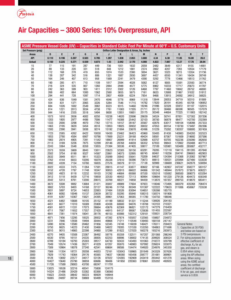
Air Capacities – 3800 Series: 10% Overpressure, API
ASME Pressure Vessel Code (UV) – Capacities in Standard Cubic Feet Per Minute at 60°F – U.S. Customary UnitsSet Pressure (psig) Orifice Letter Designation & Areas, Sq. Inches
Areas D E F G H J K L M N P Q R T API 0.110 0.196 0.307 0.503 0.785 1.287 1.838 2.853 3.600 4.34 6.38 11.05 16.00 26.0
Actual 0.150 0.225 0.371 0.559 0.873 1.43 2.042 3.170 4.000 4.822 7.087 12.27 17.78 28.94
15 20 30 40 50
77 89 112 138 164
115 133 168 207 246
191 220 278 342 407
287 331 419 516 613
449 518 655 806 958
736 848 1074 1321 1569
1051 1212 1533 1887 2241
1632 1881 2380 2930 3479
2059 2374 3004 3697 4390
2482 2862 3621 4457 5292
3649 4207 5323 6550 7778
6317 7283 9215 11341 13466
9155 10554 13354 16434 19513
14901 17179 21736 26749 31762
60 70 80 90 100
190 216 242 268 294
285 324 363 402 441
471 535 599 664 728
710 807 903 1000 1097
1109 1260 1411 1562 1714
1817 2064 2312 2560 2807
2594 2948 3302 3655 4009
4028 4577 5126 5675 6224
5082 5775 6468 7161 7854
6127 6962 7797 8633 9468
9005 10233 11460 12688 13915
15591 17717 19842 21967 24092
22593 25673 28752 31832 34912
36774 41787 46800 51812 56825
150 200 250 300 350
424 554 684 814 944
636 831 1026 1221 1416
1049 1371 1692 2013 2335
1581 2065 2549 3034 3518
2470 3226 3982 4738 5494
4046 5284 6523 7761 9000
5778 7546 9315 11083 12851
8969 11715 14460 17205 19951
11318 14782 18246 21711 25175
13644 17820 21996 26172 30348
20053 26191 32328 38466 44604
34719 45345 55972 66598 77225
50310 65708 81107 96505 111903
81889 106952 132015 157079 182142
400 450 500 550 600
1073 1203 1333 1463 1593
1610 1805 2000 2195 2390
2656 2977 3298 3620 3941
4002 4486 4970 5454 5938
6250 7006 7762 8518 9274
10238 11477 12715 13953 15192
14620 16388 18157 19925 21694
22696 25442 28187 30932 33678
28639 32103 35567 39032 42496
34524 38700 42876 47053 51229
50741 56879 63017 69154 75292
87851 98477 109104 119730 130357
127302 142700 158098 173497 188895
207206 232269 257333 282396 307459
650 700 750 800 850
1723 1853 1983 2113 2243
2585 2780 2974 3169 3364
4262 4584 4905 5226 5548
6422 6907 7391 7875 8359
10030 10786 11542 12299 13055
16430 17669 18907 20146 21384
23462 25231 26999 28768 30536
36423 39168 41914 44659 47405
45960 49424 52888 56352 59817
55405 59581 63757 67933 72109
81430 87567 93705 99843 105981
140983 151609 162236 172862 183489
204293 219692 235090 250488 265887
332523 357586 382650 407713 432777
900 950 1000 1050 1100
2373 2502 2632 2762 2892
3559 3754 3949 4144 4339
5869 6190 6511 6833 7154
8843 9327 9811 10295 10780
13811 14567 15323 16079 16835
22623 23861 25099 26338 27576
32305 34073 35842 37610 39379
50150 52895 55641 58386 61131
63281 66745 70209 73673 77138
76285 80461 84637 88813 92989
112118 118256 124394 130531 136669
194115 204741 215368 225994 236621
281285 296683 312082 327480 342878
457840 482903 507967 533030 558094
1150 1200 1250 1300 1350
3022 3152 3282 3412 3542
4533 4728 4923 5118 5313
7475 7797 8118 8439 8761
11264 11748 12232 12716 13200
17591 18347 19103 19859 20615
28815 30053 31292 32530 33769
41147 42915 44684 46452 48221
63877 66622 69368 72113 74858
80602 84066 87530 90994 94459
97166 101342 105518 109694 113870
142807 148944 155082 161220 167357
247247 257873 268500 279126 289753
358277 373675 389073 404472 419870
583157 608221 633284 658348 683411
1400 1450 1500 1550 1600
3672 3802 3931 4061 4191
5508 5703 5897 6092 6287
9082 9403 9724 10046 10367
13684 14168 14653 15137 15621
21371 22127 22883 23639 24395
35007 36246 37484 38722 39961
49989 51758 53526 55295 57063
77604 80349 83094 85840 88585
97923 101387 104851 108315 111780
118046 122222 126398 130574 134750
173495 179633 185770 191908 198046
300379 311006
435268 450667
708474 733538
1650 1700 1750 1800 1850
4321 4451 4581 4711 4841
6482 6677 6872 7067 7261
10688 11010 11331 11652 11974
16105 16589 17073 17557 18041
25152 25908 26664 27420 28176
41199 42438 43676 44915 46153
58832 60600 62369 64137 65906
91331 94076 96821 99567 102312
115244 118708 122172 125636 129101
138926 143103 147279 151455 155631
204183 210321 216459 222597 228734
1900 2000 2100 2200 2300
4971 5231 5490 5750 6010
7456 7846 8236 8625 9015
12295 12938 13580 14223 14865
18525 19494 20462 21430 22398
28932 30444 31956 33468 34980
47392 49868 52345 54822 57299
67674 71211 74748 78285 81822
105057 110548 116039 121530 127020
132565 139493 146421 153350 160278
159807 168159 176511 184863 193216
234872 247147 259423 271698 283973
2400 2500 2600 2700 2800
6270 6530 6789 7049 7309
9405 9795 10184 10574 10964
15508 16151 16793 17436 18078
23367 24335 25303 26271 27240
36492 38005 39517 41029 42541
59776 62253 64730 67207 69684
85359 88896 92433 95970 99506
132511 138002 143493 148983 154474
167207 174135 181063 187992 194920
201568 209920 218272 226624 234976
296249 308524 320799 333075 345350
2900 3000 3500 4000 4500
7569 7829 9128 10427 11726
11354 11743 13692 15640 17589
18721 19364 22577 25790 29003
28208 29176 34017 38859 43700
44053 45565 53126 60686 68247
72161 74637 87022 99406 111791
103043 106580 124265 141950
159965 165456 192909 220363
201849 208777 243419 278061
243329 251681 293442 335202
357626 369901 431278 492655
5000 5500 6000 6170
13025 14324 15623 16065
19538 21486 23435 24097
32216 35429 38642 39734
48541 53382 58223 59869
75808 83368 90929 93499
124175 136560 148944 153155
General Notes:1. Capacities at 30 PSIG
and below are based on 3 PSI overpressure.
2. For sizing purposes the effective coefficient of discharge, Kd for air, gas, and steam is 0.954 when sizing using the API effective areas. When sizing using the ASME actual areas, the certified coefficient of discharge K for air, gas, and steam service is 0.859.
19
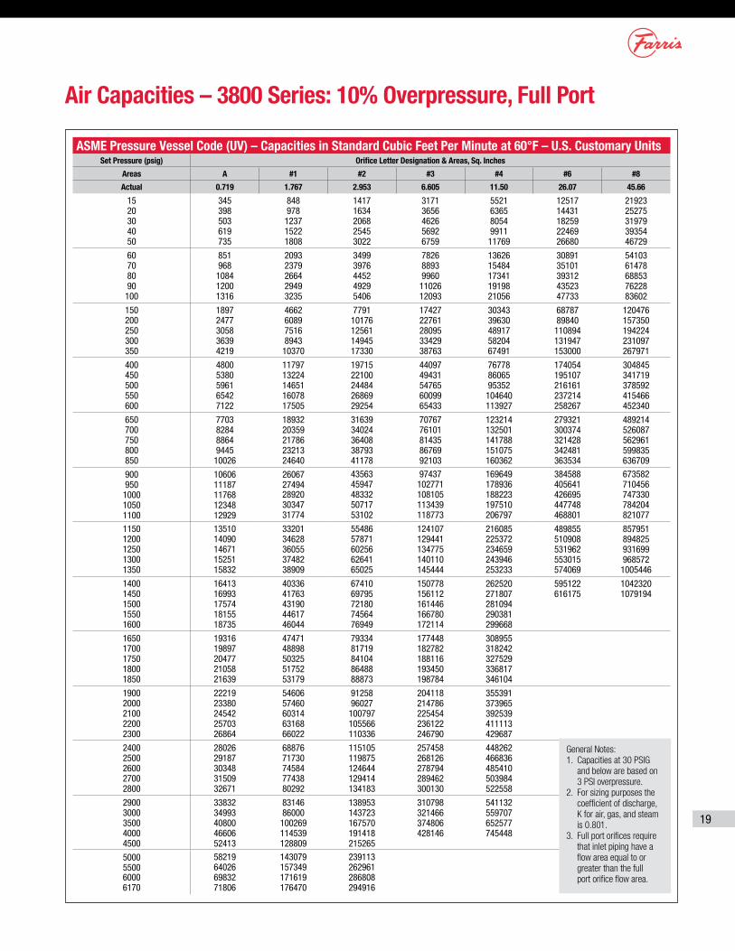
Air Capacities – 3800 Series: 10% Overpressure, Full Port
ASME Pressure Vessel Code (UV) – Capacities in Standard Cubic Feet Per Minute at 60°F – U.S. Customary UnitsSet Pressure (psig) Orifice Letter Designation & Areas, Sq. Inches
Areas A #1 #2 #3 #4 #6 #8
Actual 0.719 1.767 2.953 6.605 11.50 26.07 45.66
15 20 30 40 50
345 398 503 619 735
848 978 1237 1522 1808
1417 1634 2068 2545 3022
3171 3656 4626 5692 6759
5521 6365 8054 9911 11769
12517 14431 18259 22469 26680
21923 25275 31979 39354 46729
60 70 80 90 100
851 968 1084 1200 1316
2093 2379 2664 2949 3235
3499 3976 4452 4929 5406
7826 8893 9960 11026 12093
13626 15484 17341 19198 21056
30891 35101 39312 43523 47733
54103 61478 68853 76228 83602
150 200 250 300 350
1897 2477 3058 3639 4219
4662 6089 7516 8943 10370
7791 10176 12561 14945 17330
17427 22761 28095 33429 38763
30343 39630 48917 58204 67491
68787 89840 110894 131947 153000
120476 157350 194224 231097 267971
400 450 500 550 600
4800 5380 5961 6542 7122
11797 13224 14651 16078 17505
19715 22100 24484 26869 29254
44097 49431 54765 60099 65433
76778 86065 95352 104640 113927
174054 195107 216161 237214 258267
304845 341719 378592 415466 452340
650 700 750 800 850
7703 8284 8864 9445 10026
18932 20359 21786 23213 24640
31639 34024 36408 38793 41178
70767 76101 81435 86769 92103
123214 132501 141788 151075 160362
279321 300374 321428 342481 363534
489214 526087 562961 599835 636709
900 950 1000 1050 1100
10606 11187 11768 12348 12929
26067 27494 28920 30347 31774
43563 45947 48332 50717 53102
97437 102771 108105 113439 118773
169649 178936 188223 197510 206797
384588 405641 426695 447748 468801
673582 710456 747330 784204 821077
1150 1200 1250 1300 1350
13510 14090 14671 15251 15832
33201 34628 36055 37482 38909
55486 57871 60256 62641 65025
124107 129441 134775 140110 145444
216085 225372 234659 243946 253233
489855 510908 531962 553015 574069
857951 894825 931699 968572 1005446
1400 1450 1500 1550 1600
16413 16993 17574 18155 18735
40336 41763 43190 44617 46044
67410 69795 72180 74564 76949
150778 156112 161446 166780 172114
262520 271807 281094 290381 299668
595122 616175
1042320 1079194
1650 1700 1750 1800 1850
19316 19897 20477 21058 21639
47471 48898 50325 51752 53179
79334 81719 84104 86488 88873
177448 182782 188116 193450 198784
308955 318242 327529 336817 346104
1900 2000 2100 2200 2300
22219 23380 24542 25703 26864
54606 57460 60314 63168 66022
91258 96027 100797 105566 110336
204118 214786 225454 236122 246790
355391 373965 392539 411113 429687
2400 2500 2600 2700 2800
28026 29187 30348 31509 32671
68876 71730 74584 77438 80292
115105 119875 124644 129414 134183
257458 268126 278794 289462 300130
448262 466836 485410 503984 522558
2900 3000 3500 4000 4500
33832 34993 40800 46606 52413
83146 86000 100269 114539 128809
138953 143723 167570 191418 215265
310798 321466 374806 428146
541132 559707 652577 745448
5000 5500 6000 6170
58219 64026 69832 71806
143079 157349 171619 176470
239113 262961 286808 294916
General Notes:1. Capacities at 30 PSIG
and below are based on 3 PSI overpressure.
2. For sizing purposes the coefficient of discharge, K for air, gas, and steam is 0.801.
3. Full port orifices require that inlet piping have a flow area equal to or greater than the full port orifice flow area.
20
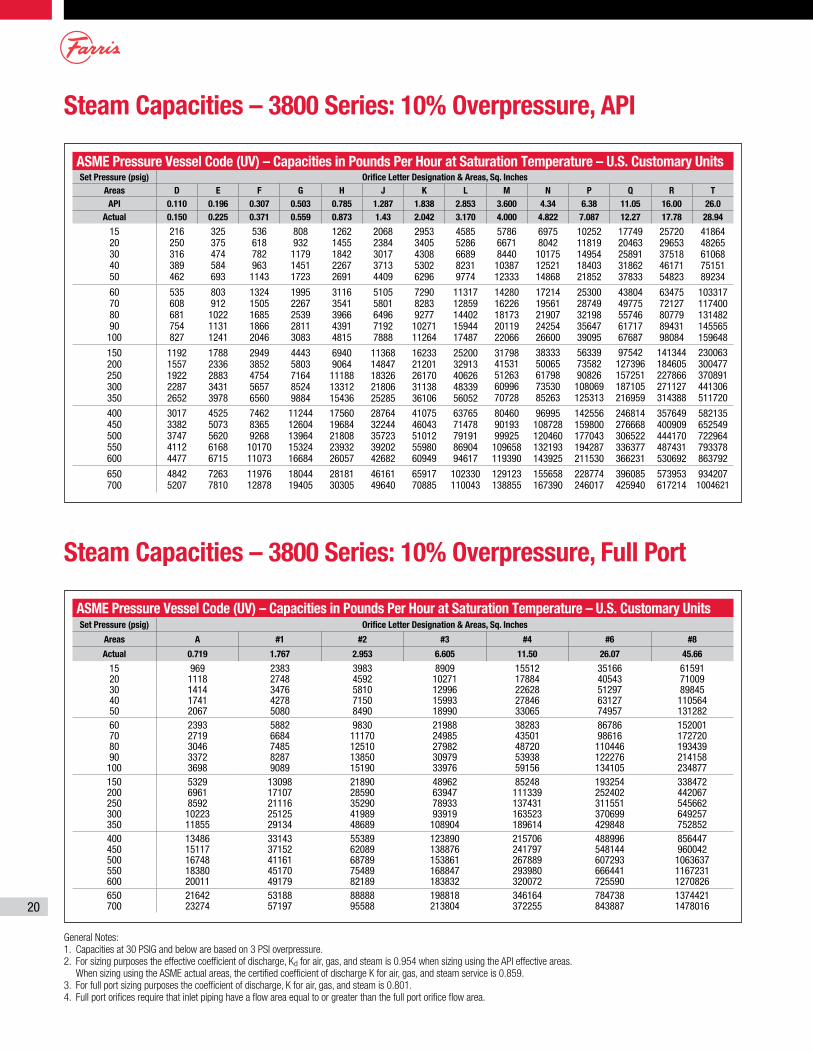
Steam Capacities – 3800 Series: 10% Overpressure, API
Steam Capacities – 3800 Series: 10% Overpressure, Full Port
ASME Pressure Vessel Code (UV) – Capacities in Pounds Per Hour at Saturation Temperature – U.S. Customary UnitsSet Pressure (psig) Orifice Letter Designation & Areas, Sq. Inches
Areas D E F G H J K L M N P Q R T API 0.110 0.196 0.307 0.503 0.785 1.287 1.838 2.853 3.600 4.34 6.38 11.05 16.00 26.0
Actual 0.150 0.225 0.371 0.559 0.873 1.43 2.042 3.170 4.000 4.822 7.087 12.27 17.78 28.94
15 20 30 40 50
216 250 316 389 462
325 375 474 584 693
536 618 782 963 1143
808 932 1179 1451 1723
1262 1455 1842 2267 2691
2068 2384 3017 3713 4409
2953 3405 4308 5302 6296
4585 5286 6689 8231 9774
5786 6671 8440 10387 12333
6975 8042 10175 12521 14868
10252 11819 14954 18403 21852
17749 20463 25891 31862 37833
25720 29653 37518 46171 54823
41864 48265 61068 75151 89234
60 70 80 90 100
535 608 681 754 827
803 912 1022 1131 1241
1324 1505 1685 1866 2046
1995 2267 2539 2811 3083
3116 3541 3966 4391 4815
5105 5801 6496 7192 7888
7290 8283 9277 10271 11264
11317 12859 14402 15944 17487
14280 16226 18173 20119 22066
17214 19561 21907 24254 26600
25300 28749 32198 35647 39095
43804 49775 55746 61717 67687
63475 72127 80779 89431 98084
103317 117400 131482 145565 159648
150 200 250 300 350
1192 1557 1922 2287 2652
1788 2336 2883 3431 3978
2949 3852 4754 5657 6560
4443 5803 7164 8524 9884
6940 9064 11188 13312 15436
11368 14847 18326 21806 25285
16233 21201 26170 31138 36106
25200 32913 40626 48339 56052
31798 41531 51263 60996 70728
38333 50065 61798 73530 85263
56339 73582 90826 108069 125313
97542 127396 157251 187105 216959
141344 184605 227866 271127 314388
230063 300477 370891 441306 511720
400 450 500 550 600
3017 3382 3747 4112 4477
4525 5073 5620 6168 6715
7462 8365 9268 10170 11073
11244 12604 13964 15324 16684
17560 19684 21808 23932 26057
28764 32244 35723 39202 42682
41075 46043 51012 55980 60949
63765 71478 79191 86904 94617
80460 90193 99925 109658 119390
96995 108728 120460 132193 143925
142556 159800 177043 194287 211530
246814 276668 306522 336377 366231
357649 400909 444170 487431 530692
582135 652549 722964 793378 863792
650 700
4842 5207
7263 7810
11976 12878
18044 19405
28181 30305
46161 49640
65917 70885
102330 110043
129123 138855
155658 167390
228774 246017
396085 425940
573953 617214
934207 1004621
General Notes:1. Capacities at 30 PSIG and below are based on 3 PSI overpressure.2. For sizing purposes the effective coefficient of discharge, Kd for air, gas, and steam is 0.954 when sizing using the API effective areas.
When sizing using the ASME actual areas, the certified coefficient of discharge K for air, gas, and steam service is 0.859.3. For full port sizing purposes the coefficient of discharge, K for air, gas, and steam is 0.801.4. Full port orifices require that inlet piping have a flow area equal to or greater than the full port orifice flow area.
ASME Pressure Vessel Code (UV) – Capacities in Pounds Per Hour at Saturation Temperature – U.S. Customary UnitsSet Pressure (psig) Orifice Letter Designation & Areas, Sq. Inches
Areas A #1 #2 #3 #4 #6 #8
Actual 0.719 1.767 2.953 6.605 11.50 26.07 45.66
15 969 2383 3983 8909 15512 35166 6159120 1118 2748 4592 10271 17884 40543 7100930 1414 3476 5810 12996 22628 51297 8984540 1741 4278 7150 15993 27846 63127 11056450 2067 5080 8490 18990 33065 74957 13128260 2393 5882 9830 21988 38283 86786 15200170 2719 6684 11170 24985 43501 98616 17272080 3046 7485 12510 27982 48720 110446 19343990 3372 8287 13850 30979 53938 122276 214158100 3698 9089 15190 33976 59156 134105 234877150 5329 13098 21890 48962 85248 193254 338472200 6961 17107 28590 63947 111339 252402 442067250 8592 21116 35290 78933 137431 311551 545662300 10223 25125 41989 93919 163523 370699 649257350 11855 29134 48689 108904 189614 429848 752852400 13486 33143 55389 123890 215706 488996 856447450 15117 37152 62089 138876 241797 548144 960042500 16748 41161 68789 153861 267889 607293 1063637550 18380 45170 75489 168847 293980 666441 1167231600 20011 49179 82189 183832 320072 725590 1270826650 21642 53188 88888 198818 346164 784738 1374421700 23274 57197 95588 213804 372255 843887 1478016
21
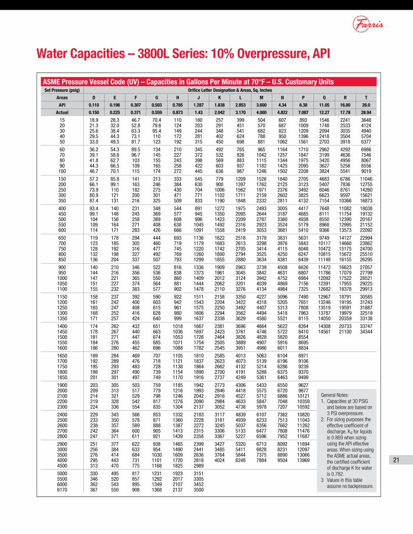
ASME Pressure Vessel Code (UV) – Capacities in Gallons Per Minute at 70°F – U.S. Customary UnitsSet Pressure (psig) Orifice Letter Designation & Areas, Sq. Inches
Areas D E F G H J K L M N P Q R T
API 0.110 0.196 0.307 0.503 0.785 1.287 1.838 2.853 3.600 4.34 6.38 11.05 16.00 26.0
Actual 0.150 0.225 0.371 0.559 0.873 1.43 2.042 3.170 4.000 4.822 7.087 12.27 17.78 28.94
15 18.9 28.3 46.7 70.4 110 180 257 399 504 607 893 1546 2241 364820 21.3 32.0 52.8 79.6 124 203 291 451 570 687 1009 1748 2533 412430 25.6 38.4 63.3 95.4 149 244 348 541 682 823 1209 2094 3035 494040 29.5 44.3 73.1 110 172 281 402 624 788 950 1396 2418 3504 570450 33.0 49.5 81.7 123 192 315 450 698 881 1062 1561 2703 3918 6377
60 36.2 54.3 89.5 134 210 345 492 765 965 1164 1710 2962 4292 698670 39.1 58.6 96.7 145 227 372 532 826 1042 1257 1847 3199 4636 754680 41.8 62.7 103 155 243 398 569 883 1115 1344 1975 3420 4956 806790 44.3 66.5 109 165 258 422 603 937 1182 1425 2095 3627 5256 8556100 46.7 70.1 115 174 272 445 636 987 1246 1502 2208 3824 5541 9019
150 57.2 85.8 141 213 333 545 779 1209 1526 1840 2705 4683 6786 11046200 66.1 99.1 163 246 384 630 900 1397 1762 2125 3123 5407 7836 12755250 73.9 110 182 275 430 704 1006 1562 1971 2376 3492 6046 8761 14260300 80.9 121 200 301 471 771 1102 1711 2159 2602 3825 6623 9597 15621350 87.4 131 216 325 509 833 1190 1848 2332 2811 4132 7154 10366 16873
400 93.4 140 231 348 544 891 1272 1975 2493 3005 4417 7648 11082 18038450 99.1 148 245 369 577 945 1350 2095 2644 3187 4685 8111 11754 19132500 104 156 258 389 608 996 1423 2209 2787 3360 4938 8550 12390 20167550 109 164 271 408 638 1045 1492 2316 2923 3524 5179 8968 12995 21152600 114 171 283 426 666 1091 1558 2419 3053 3681 5410 9366 13573 22092
650 119 178 294 444 693 1136 1622 2518 3178 3831 5631 9749 14127 22994700 123 185 305 460 719 1179 1683 2613 3298 3976 5843 10117 14660 23862750 128 192 316 477 745 1220 1742 2705 3414 4115 6048 10472 15175 24700800 132 198 327 492 769 1260 1800 2794 3525 4250 6247 10815 15672 25510850 136 204 337 507 793 1299 1855 2880 3634 4381 6439 11148 16155 26295
900 140 210 346 522 816 1336 1909 2963 3739 4508 6626 11472 16623 27057950 144 216 356 536 838 1373 1961 3045 3842 4631 6807 11786 17079 277991000 147 221 365 550 860 1409 2012 3124 3942 4752 6984 12092 17522 285211050 151 227 374 564 881 1444 2062 3201 4039 4869 7156 12391 17955 292251100 155 232 383 577 902 1478 2110 3276 4134 4984 7325 12682 18378 29913
1150 158 237 392 590 922 1511 2158 3350 4227 5096 7490 12967 18791 305851200 161 242 400 603 942 1543 2204 3422 4318 5205 7651 13246 19195 312431250 165 247 408 615 961 1575 2250 3492 4407 5313 7808 13519 19591 318871300 168 252 416 628 980 1606 2294 3562 4494 5418 7963 13787 19979 325191350 171 257 424 640 999 1637 2338 3629 4580 5521 8115 14050 20359 33138
1400 174 262 432 651 1018 1667 2381 3696 4664 5622 8264 14308 20733 337471450 178 267 440 663 1036 1697 2423 3761 4746 5722 8410 14561 21100 343441500 181 271 447 674 1053 1726 2464 3826 4828 5820 85541550 184 276 455 685 1071 1754 2505 3889 4907 5916 86951600 186 280 462 696 1088 1782 2545 3951 4986 6011 8834
1650 189 284 469 707 1105 1810 2585 4013 5063 6104 89711700 192 289 476 718 1121 1837 2623 4073 5139 6196 91061750 195 293 483 728 1138 1864 2662 4132 5214 6286 92391800 198 297 490 739 1154 1890 2700 4191 5288 6375 93701850 201 301 497 749 1170 1916 2737 4249 5361 6463 9499
1900 203 305 503 759 1185 1942 2773 4306 5433 6550 96272000 209 313 517 779 1216 1993 2846 4418 5575 6720 98772100 214 321 529 798 1246 2042 2916 4527 5712 6886 101212200 219 328 542 817 1276 2090 2984 4633 5847 7048 103592300 224 336 554 835 1304 2137 3052 4738 5978 7207 10592
2400 229 343 566 853 1332 2183 3117 4839 6107 7362 108202500 233 350 578 871 1360 2228 3181 4939 6233 7513 110432600 238 357 589 888 1387 2272 3245 5037 6356 7662 112622700 242 364 600 905 1413 2315 3306 5133 6477 7808 114762800 247 371 611 921 1439 2358 3367 5227 6596 7952 11687
2900 251 377 622 938 1465 2399 3427 5320 6713 8092 118943000 256 384 633 954 1490 2441 3485 5411 6828 8231 120973500 276 414 684 1030 1609 2636 3764 5844 7375 8890 130664000 295 443 731 1101 1720 2818 4024 6248 7884 9504 139694500 313 470 775 1168 1825 2989
5000 330 495 817 1231 1923 31515500 346 520 857 1292 2017 33056000 362 543 895 1349 2107 34526170 367 550 908 1368 2137 3500
Water Capacities – 3800L Series: 10% Overpressure, API
General Notes:1. Capacities at 30 PSIG
and below are based on 3 PSI overpressure.
2. For sizing purposes the effective coefficient of discharge, Kd for liquids is 0.869 when sizing using the API effective areas. When sizing using the ASME actual areas, the certified coefficient of discharge K for water is 0.782.
3 Values in this table assume no backpressure.
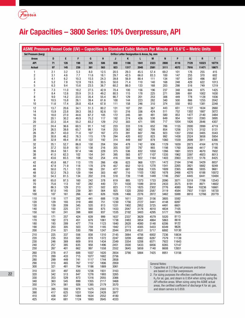
22
Air Capacities – 3800 Series: 10% Overpressure, API
ASME Pressure Vessel Code (UV) – Capacities in Standard Cubic Meters Per Minute at 15.6°C – Metric UnitsSet Pressure (barg) Orifice Letter Designation & Areas, Sq. mm
Areas D E F G H J K L M N P Q R T
API 71 126 198 325 506 830 1186 1841 2323 2800 4116 7129 10323 16774
Actual 97 145 239 361 563 923 1317 2045 2581 3111 4572 7916 11471 18671
1 2 3 4 5
2.1 3.1 4.1 5.2 6.3
3.2 4.6 6.2 7.8 9.4
5.3 7.7 10.3 12.9 15.6
8.0 11.6 15.5 19.5 23.5
12.5 18.1 24.3 30.5 36.7
20.5 29.7 39.8 50.0 60.2
29.3 42.5 56.9 71.4 86.0
45.5 66.0 88.4 110 133
57.4 83.3 111 140 168
69.2 100 134 168 203
101 147 197 248 298
176 255 342 429 516
255 370 496 622 749
415 602 807 1013 1219
6 7 8 9 10
7.3 8.4 9.0 10.5 11.6
11.0 12.6 14.2 15.8 17.4
18.2 20.9 23.5 26.1 28.8
27.5 31.5 35.4 39.4 43.4
42.9 49.2 55.4 61.6 67.8
70.4 80.5 90.7 100 111
100 115 129 144 158
156 178 201 223 246
196 225 253 282 310
237 271 306 340 374
348 399 449 500 550
604 691 778 866 953
875 1002 1128 1255 1381
1425 1630 1836 2042 2248
12 14 16 18 20
13.7 15.9 18.0 20.1 22.3
20.6 23.8 27.0 30.2 33.4
34.1 39.3 44.6 49.9 55.2
51.3 59.3 67.2 75.2 83.2
80.2 92.6 105 117 129
131 151 172 192 212
187 216 245 274 303
291 336 381 426 471
367 424 481 538 595
443 511 580 649 717
651 752 853 954 1054
1127 1302 1477 1651 1826
1634 1887 2140 2393 2646
2660 3072 3484 3895 4307
22 24 26 28 30
24.4 26.5 28.7 30.8 32.9
36.6 39.8 43.0 46.2 49.4
60.5 65.7 71.0 76.3 81.6
91.1 99.1 107 115 122
142 154 167 179 192
233 253 273 294 314
333 362 391 420 449
516 562 607 652 697
652 709 766 823 879
786 854 923 992 1060
1155 1256 1357 1458 1559
2000 2175 2350 2524 2699
2899 3152 3405 3658 3911
4719 5131 5543 5954 6366
32 34 36 38 40
35.1 37.2 39.4 41.5 43.6
52.7 55.9 59.1 62.3 65.5
86.8 92.1 97.4 102 108
130 138 146 154 162
204 216 229 241 254
334 355 375 395 416
478 507 536 565 594
742 787 832 877 922
936 993 1050 1107 1164
1129 1198 1266 1335 1403
1659 1760 1861 1962 2063
2873 3048 3223 3397 3572
4164 4417 4670 4923 5176
6778 7190 7602 8013 8425
42 44 46 48 50
45.8 47.9 50.0 52.2 54.3
68.7 71.9 75.1 78.3 81.5
113 118 123 129 134
170 178 186 194 202
266 279 291 303 316
436 457 477 497 518
623 652 681 710 739
968 1013 1058 1103 1148
1221 1278 1335 1392 1449
1472 1541 1609 1678 1746
2164 2265 2365 2466 2567
3746 3921 4096 4270 4445
5429 5682 5935 6188 6441
8837 9249 9661 10072 10484
60 70 80 90 100
65.0 75.6 86.3 97.0 107
97.5 113 129 145 161
160 187 213 239 266
242 282 321 361 401
378 440 502 564 626
619 721 823 925 1026
885 1030 1175 1320 1466
1373 1599 1825 2050 2276
1733 2018 2302 2587 2872
2090 2433 2776 3119 3462
3071 3575 4080 4584 5088
5318 6191 7064 7937 8810
7706 8971 10236 11501 12766
12543 14602 16661 18720 20779
110 120 130 140 150
118 129 139 150 161
177 193 209 225 241
292 319 345 371 398
441 480 520 560 600
688 751 813 875 937
1128 1230 1331 1433 1535
1611 1756 1902 2047 2192
2501 2727 2952 3178 3403
3156 3441 3725 4010 4295
3805 4148 4491 4834 5177
5592 6097 6601 7105 7609
160 170 180 190 200
171 182 193 203 214
257 273 289 305 321
424 451 477 503 530
639 679 719 759 799
999 1061 1123 1185 1247
1637 1738 1840 1942 2044
2337 2483 2628 2773 2919
3629 3854 4080 4305 4531
4579 4864 5148 5433 5717
5520 5863 6206 6549 6892
8113 8618 9122 9626 10130
210 220 230 240 250
225 235 246 257 267
337 353 369 385 401
556 583 609 635 662
838 878 918 958 997
1310 1372 1434 1496 1558
2145 2247 2349 2451 2552
3064 3209 3354 3500 3645
4756 4982 5208 5433 5659
6002 6287 6571 6856 7140
7236 7579 7922 8265 8608
10634 11139 11643 12147 12651
260 270 280 290 300
278 289 299 310 321
417 433 449 465 481
688 715 741 767 794
1037 1077 1117 1157 1196
1620 1682 1744 1806 1869
2654 2756 2858 2959 3061
3790 5884 7425 8951 13156
310 320 330 340 350
331 342 353 363 374
497 513 529 545 561
820 847 873 899 926
1236 1276 1316 1355 1395
1931 1993 2055 2117 2179
3163 3265 3366 3468 3570
370 390 410 425
395 417 438 454
593 625 657 681
979 1031 1084 1124
1475 1554 1634 1693
2303 2428 2552 2645
3773 3977 4180 4333
General Notes:1. Capacities at 2.0 Barg set pressure and below
are based on 0.2 Bar overpressure.2. For sizing purposes the effective coefficient of discharge,
Kd for air, gas, and steam is 0.954 when sizing using the API effective areas. When sizing using the ASME actual areas, the certified coefficient of discharge K for air, gas, and steam service is 0.859.
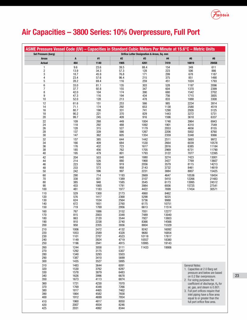
23
Air Capacities – 3800 Series: 10% Overpressure, Full Port
ASME Pressure Vessel Code (UV) – Capacities in Standard Cubic Meters Per Minute at 15.6°C – Metric UnitsSet Pressure (barg) Orifice Letter Designation & Areas, Sq. mm
Areas A #1 #2 #3 #4 #6 #8
Actual 464 1140 1905 4261 7419 16819 29458
1 2 3 4 5
9.6 13.9 18.7 23.4 28.2
23.6 34.3 45.9 57.6 69.4
39.5 57.3 76.8 96.4 116
88.4 128 171 215 259
154 223 299 375 451
349 506 678 851 1024
611 886 1187 1490 1793
6 7 8 9 10
33.0 37.7 42.0 47.3 52.0
81.1 92.8 104 116 128
135 155 174 194 213
303 347 390 434 478
528 604 680 756 833
1197 1370 1542 1715 1888
2096 2399 2702 3005 3308
12 14 16 18 20
61.6 71.1 80.7 90.2 99.7
151 174 198 221 245
253 292 331 370 409
566 653 741 829 916
985 1138 1290 1443 1596
2234 2580 2926 3272 3618
3914 4519 5125 5731 6337
22 24 26 28 30
109 118 128 137 147
268 292 315 339 362
449 488 527 566 605
1004 1092 1179 1267 1354
1748 1901 2053 2206 2359
3964 4310 4656 5002 5348
6943 7549 8155 8760 9366
32 34 36 38 40
157 166 176 185 195
385 409 432 456 479
644 684 723 762 801
1442 1530 1617 1705 1793
2511 2664 2816 2969 3122
5693 6039 6385 6731 7077
9972 10578 11184 11790 12395
42 44 46 48 50
204 214 223 233 242
503 526 550 573 596
840 880 919 958 997
1880 1968 2056 2143 2231
3274 3427 3579 3732 3884
7423 7769 8115 8461 8807
13001 13607 14213 14819 15425
60 70 80 90 100
290 338 385 433 481
714 831 948 1065 1183
1193 1389 1585 1781 1977
2669 3107 3545 3984 4422
4647 5410 6173 6936 7699
10536 12266 13995 15725 17454
18454 21483 24512 27541 30571
110 120 130 140 150
529 576 624 672 719
1300 1417 1534 1651 1769
2173 2368 2564 2760 2956
4860 5298 5736 6175 6613
8462 9225 9988 10751 11514
160 170 180 190 200
767 815 863 910 958
1886 2003 2120 2238 2355
3152 3348 3544 3740 3936
7051 7489 7927 8366 8804
12277 13040 13803 14566 15329
210 220 230 240 250
1006 1053 1101 1149 1196
2472 2589 2707 2824 2941
4132 4328 4523 4719 4915
9242 9680 10118 10557 10995
16092 16854 17617 18380 19143
260 270 280 290 300
1244 1292 1340 1387 1435
3058 3175 3293 3410 3527
5111 5307 5503 5699 5895
11433 19906
310 320 330 340 350
1483 1530 1578 1626 1673
3644 3762 3879 3996 4113
6091 6287 6483 6678 6874
360 370 380 390 400
1721 1769 1817 1864 1912
4230 4348 4465 4582 4699
7070 7266 7462 7658 7854
410 420 425
1960 2007 2031
4817 4934 4992
8050 8246 8344
General Notes:1. Capacities at 2.0 Barg set
pressure and below are based on 0.2 Bar overpressure.
2. For sizing purposes the coefficient of discharge, Kd for air, gas, and steam is 0.801.
3. Full port orifices require that inlet piping have a flow area equal to or greater than the full port orifice flow area.
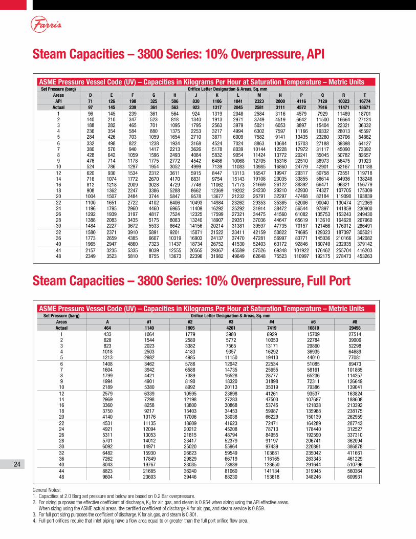
24
Steam Capacities – 3800 Series: 10% Overpressure, API
Steam Capacities – 3800 Series: 10% Overpressure, Full Port
ASME Pressure Vessel Code (UV) – Capacities in Kilograms Per Hour at Saturation Temperature – Metric UnitsSet Pressure (barg) Orifice Letter Designation & Areas, Sq. mm
Areas D E F G H J K L M N P Q R TAPI 71 126 198 325 506 830 1186 1841 2323 2800 4116 7129 10323 16774
Actual 97 145 239 361 563 923 1317 2045 2581 3111 4572 7916 11471 186711 2 3 4 5
96 140 188 236 284
145 210 282 354 426
239 347 465 584 703
361 523 701 880 1059
564 818 1095 1375 1654
924 1340 1795 2253 2710
1319 1913 2563 3217 3871
2048 2971 3979 4994 6009
2584 3749 5021 6302 7582
3116 4519 6053 7597 9141
4579 6642 8897 11166 13435
7929 11500 15404 19332 23260
11489 16664 22321 28013 33706
18701 27124 36332 45597 54862
6 7 8 9 10
332 380 428 476 524
498 570 642 714 786
822 940 1059 1178 1297
1238 1417 1596 1775 1954
1934 2213 2493 2772 3052
3168 3626 4084 4542 4999
4524 5178 5832 6486 7139
7024 8039 9054 10068 11083
8863 10144 11424 12705 13985
10684 12228 13772 15316 16860
15703 17972 20241 22510 24779
27188 31117 35045 38973 42901
39398 45090 50782 56475 62167
64127 73392 82657 91923 101188
12 14 16 18 20
620 716 812 908 1004
930 1074 1218 1362 1507
1534 1772 2009 2247 2484
2312 2670 3028 3386 3744
3611 4170 4729 5288 5847
5915 6831 7746 8662 9578
8447 9754 11062 12369 13677
13113 15143 17173 19202 21232
16547 19108 21669 24230 26791
19947 23035 26122 29210 32297
29317 33855 38392 42930 47468
50758 58614 66471 74327 82184
73551 84936 96321 107705 119090
119718 138248 156779 175309 193839
22 24 26 28 30
1100 1196 1292 1388 1484
1651 1795 1939 2083 2227
2722 2960 3197 3435 3672
4102 4460 4817 5175 5533
6406 6965 7524 8083 8642
10493 11409 12325 13240 14156
14984 16292 17599 18907 20214
23262 25292 27321 29351 31381
29353 31914 34475 37036 39597
35385 38472 41560 44647 47735
52006 56544 61082 65619 70157
90040 97897 105753 113610 121466
130474 141859 153243 164628 176012
212369 230900 249430 267960 286491
32 36 40
1580 1773 1965
2371 2659 2947
3910 4385 4860
5891 6607 7323
9201 10319 11437
15071 16903 18734
21522 24137 26752
33411 37470 41530
42159 47281 52403
50822 56997 63172
74695 83771 92846
129323 145036 160749
187397 210166 232935
305021 342082 379142
44 48
2157 2349
3235 3523
5335 5810
8039 8755
12555 13673
20565 22396
29367 31982
45589 49649
57526 62648
69348 75523
101922 110997
176462 192175
255704 278473
416203 453263
ASME Pressure Vessel Code (UV) – Capacities in Kilograms Per Hour at Saturation Temperature – Metric UnitsSet Pressure (barg) Orifice Letter Designation & Areas, Sq. mm
Areas A #1 #2 #3 #4 #6 #8Actual 464 1140 1905 4261 7419 16819 29458
1 2 3 4 5
433 628 823 1018 1213
1064 1544 2023 2503 2982
1779 2580 3382 4183 4985
3980 5772 7565 9357 11150
6929 10050 13171 16292 19413
15709 22784 29860 36935 44010
27514 39906 52298 64689 77081
6 7 8 9 10
1408 1604 1799 1994 2189
3462 3942 4421 4901 5380
5786 6588 7389 8190 8992
12942 14735 16528 18320 20113
22534 25655 28777 31898 35019
51085 58161 65236 72311 79386
89473 101865 114257 126649 139041
12 14 16 18 20
2579 2969 3360 3750 4140
6339 7298 8258 9217 10176
10595 12198 13800 15403 17006
23698 27283 30868 34453 38038
41261 47503 53745 59987 66229
93537 107687 121838 135988 150139
163824 188608 213392 238175 262959
22 24 26 28 30
4531 4921 5311 5701 6092
11135 12094 13053 14012 14971
18609 20212 21815 23417 25020
41623 45208 48794 52379 55964
72471 78713 84955 91197 97439
164289 178440 192590 206741 220891
287743 312527 337310 362094 386878
32 36 40
6482 7262 8043
15930 17849 19767
26623 29829 33035
59549 66719 73889
103681 116165 128650
235042 263343 291644
411661 461229 510796
44 48
8823 9604
21685 23603
36240 39446
81060 88230
141134 153618
319945 348246
560364 609931
General Notes:1. Capacities at 2.0 Barg set pressure and below are based on 0.2 Bar overpressure.2. For sizing purposes the effective coefficient of discharge, Kd for air, gas, and steam is 0.954 when sizing using the API effective areas.
When sizing using the ASME actual areas, the certified coefficient of discharge K for air, gas, and steam service is 0.859.3. For full port sizing purposes the coefficient of discharge, K for air, gas, and steam is 0.801.4. Full port orifices require that inlet piping have a flow area equal to or greater than the full port orifice flow area.
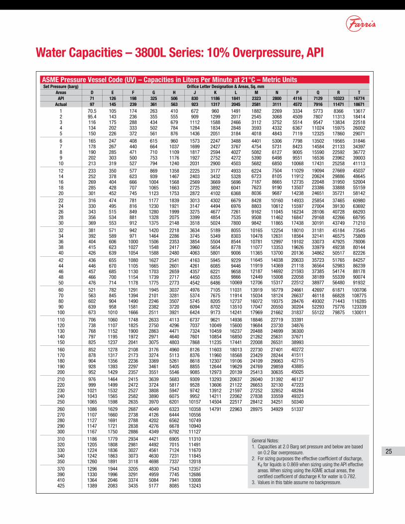
25
Water Capacities – 3800L Series: 10% Overpressure, API
ASME Pressure Vessel Code (UV) – Capacities in Liters Per Minute at 21°C – Metric UnitsSet Pressure (barg) Orifice Letter Designation & Areas, Sq. mm
Areas D E F G H J K L M N P Q R TAPI 71 126 198 325 506 830 1186 1841 2323 2800 4116 7129 10323 16774
Actual 97 145 239 361 563 923 1317 2045 2581 3111 4572 7916 11471 186711 2 3 4 5
70.5 95.4 116 134 150
105 143 175 202 226
174 236 288 333 372
263 355 434 502 561
410 555 679 784 876
672 909 1112 1284 1436
960 1299 1588 1834 2051
1491 2017 2466 2848 3184
1882 2545 3112 3593 4018
2269 3068 3752 4332 4843
3334 4509 5514 6367 7119
5773 7807 9547 11024 12325
8366 11313 13834 15975 17860
13617 18414 22518 26002 29071
6 7 8 9 10
165 178 190 202 213
247 267 285 303 319
408 440 471 500 527
615 664 710 753 794
960 1037 1109 1176 1240
1573 1699 1817 1927 2031
2247 2427 2594 2752 2900
3488 3767 4027 4272 4503
4401 4754 5082 5390 5682
5306 5731 6127 6498 6850
7798 8423 9005 9551 10068
13502 14584 15590 16536 17431
19565 21133 22592 23962 25258
31846 34397 36772 39003 41113
12 14 16 18 20
233 252 269 285 301
350 378 404 428 452
577 623 666 707 745
869 939 1004 1065 1123
1358 1467 1568 1663 1753
2225 2403 2569 2725 2872
3177 3432 3669 3892 4102
4933 5328 5696 6041 6368
6224 6723 7187 7623 8036
7504 8105 8665 9190 9687
11029 11912 12735 13507 14238
19094 20624 22048 23386 24651
27669 29886 31950 33888 35721
45037 48645 52004 55159 58142
22 24 26 28 30
316 330 343 356 369
474 495 515 534 553
781 816 849 881 912
1177 1230 1280 1328 1375
1839 1921 1999 2075 2148
3013 3147 3275 3399 3518
4302 4494 4677 4854 5024
6679 6976 7261 7535 7800
8428 8803 9162 9508 9842
10160 10612 11045 11462 11865
14933 15597 16234 16847 17438
25854 27004 28106 29168 30191
37465 39130 40728 42266 43749
60980 63692 66293 68795 71210
32 34 36 38 40
381 392 404 415 426
571 589 606 623 639
942 971 1000 1027 1054
1420 1464 1506 1548 1588
2218 2286 2353 2417 2480
3634 3745 3854 3960 4063
5189 5349 5504 5654 5801
8055 8303 8544 8778 9006
10165 10478 10781 11077 11365
12254 12631 12997 13353 13700
18010 18564 19102 19626 20136
31181 32141 33073 33979 34862
45184 46575 47925 49238 50517
73545 75809 78006 80144 82226
42 44 46 48 50
436 446 457 466 476
655 670 685 700 714
1080 1105 1130 1154 1178
1627 1665 1703 1739 1775
2541 2601 2659 2717 2773
4163 4261 4357 4450 4542
5945 6085 6221 6355 6486
9229 9446 9658 9866 10069
11645 11919 12187 12449 12706
14038 14369 14692 15008 15317
20633 21118 21593 22058 22512
35723 36564 37385 38189 38977
51765 52983 54174 55339 56480
84257 86239 88178 90074 91932
60 70 80 90 100
521 563 602 639 673
782 845 904 958 1010
1291 1394 1490 1581 1666
1945 2101 2246 2382 2511
3037 3281 3507 3720 3921
4976 5374 5745 6094 6424
7105 7675 8205 8702 9173
11031 11914 12737 13510 14241
13919 15034 16072 17047 17969
16779 18124 19375 20550 21662
24661 26637 28476 30204 31837
42697 46118 49302 52293 55122
61871 66828 71443 75776 79875
100706 108775 116285 123339 130011
110 120 130 140 150
706 738 768 797 825
1060 1107 1152 1195 1237
1748 1825 1900 1972 2041
2633 2750 2863 2971 3075
4113 4296 4471 4640 4803
6737 7037 7324 7601 7868
9621 10049 10459 10854 11235
14936 15600 16237 16850 17441
18846 19684 20488 21262 22008
22719 23730 24699 25631 26531
33391 34876 36300 37671 38993
160 170 180 190 200
852 878 904 928 952
1278 1317 1356 1393 1429
2108 2173 2236 2297 2357
3176 3274 3369 3461 3551
4960 5113 5261 5405 5546
8126 8376 8618 8855 9085
11603 11960 12307 12644 12973
18013 18568 19106 19629 20139
22730 23429 24109 24769 25413
27401 28244 29063 29859 30635
40272 41511 42715 43885 45025
210 220 230 240 250
976 999 1021 1043 1065
1464 1499 1532 1565 1598
2415 2472 2527 2582 2635
3639 3724 3808 3890 3970
5683 5817 5947 6075 6201
9309 9528 9742 9952 10157
13293 13606 13912 14211 14504
20637 21122 21597 22062 22517
26040 26653 27252 27838 28412
31392 32130 32852 33559 34251
46137 47223 48284 49323 50340
260 270 280 290 300
1086 1107 1127 1147 1167
1629 1660 1691 1721 1750
2687 2738 2788 2838 2886
4049 4126 4202 4276 4349
6323 6444 6562 6678 6792
10358 10556 10749 10940 11127
14791 22963 28975 34929 51337
310 320 330 340 350
1186 1205 1224 1242 1260
1779 1808 1836 1863 1891
2934 2981 3027 3073 3118
4421 4492 4561 4630 4698
6905 7015 7124 7231 7337
11310 11491 11670 11845 12018
370 390 410 425
1296 1330 1364 1389
1944 1996 2046 2083
3205 3291 3374 3435
4830 4959 5084 5177
7543 7745 7941 8085
12357 12686 13008 13243
General Notes:1. Capacities at 2.0 Barg set pressure and below are based
on 0.2 Bar overpressure.2. For sizing purposes the effective coefficient of discharge,
Kd for liquids is 0.869 when sizing using the API effective areas. When sizing using the ASME actual areas, the certified coefficient of discharge K for water is 0.782.
3. Values in this table assume no backpressure.
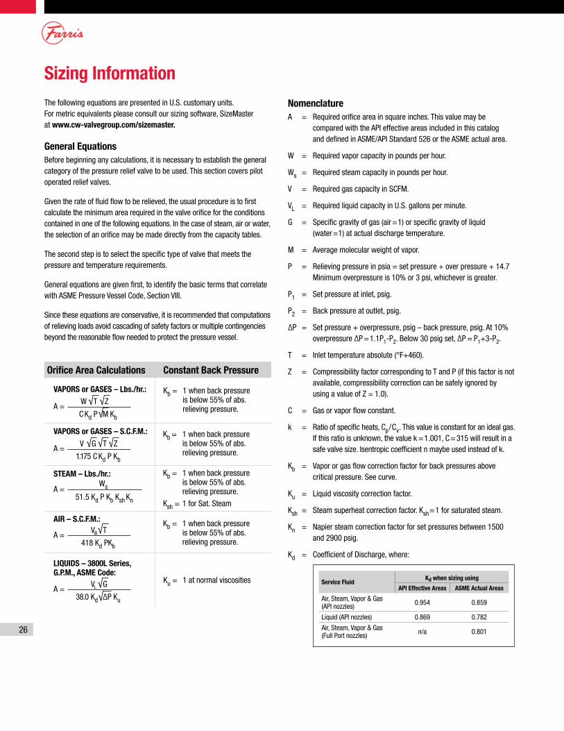
26
Sizing InformationThe following equations are presented in U.S. customary units. For metric equivalents please consult our sizing software, SizeMaster at www.cw-valvegroup.com/sizemaster.
General EquationsBefore beginning any calculations, it is necessary to establish the general category of the pressure relief valve to be used. This section covers pilot operated relief valves.
Given the rate of fluid flow to be relieved, the usual procedure is to first calculate the minimum area required in the valve orifice for the conditions contained in one of the following equations. In the case of steam, air or water, the selection of an orifice may be made directly from the capacity tables.
The second step is to select the specific type of valve that meets the pressure and temperature requirements.
General equations are given first, to identify the basic terms that correlate with ASME Pressure Vessel Code, Section VIII.
Since these equations are conservative, it is recommended that computations of relieving loads avoid cascading of safety factors or multiple contingencies beyond the reasonable flow needed to protect the pressure vessel.
NomenclatureA = Required orifice area in square inches. This value may be
compared with the API effective areas included in this catalog and defined in ASME/API Standard 526 or the ASME actual area.
W = Required vapor capacity in pounds per hour.
Ws = Required steam capacity in pounds per hour.
V = Required gas capacity in SCFM.
VL = Required liquid capacity in U.S. gallons per minute.
G = Specific gravity of gas (air=1) or specific gravity of liquid (water=1) at actual discharge temperature.
M = Average molecular weight of vapor.
P = Relieving pressure in psia = set pressure + over pressure + 14.7 Minimum overpressure is 10% or 3 psi, whichever is greater.
P1 = Set pressure at inlet, psig.
P2 = Back pressure at outlet, psig.
∆P = Set pressure + overpressure, psig – back pressure, psig. At 10% overpressure ∆P =1.1P1-P2. Below 30 psig set, ∆P = P1+3-P2.
T = Inlet temperature absolute (°F+460).
Z = Compressibility factor corresponding to T and P (if this factor is not available, compressibility correction can be safely ignored by using a value of Z = 1.0).
C = Gas or vapor flow constant.
k = Ratio of specific heats, Cp/Cv. This value is constant for an ideal gas. If this ratio is unknown, the value k =1.001, C= 315 will result in a safe valve size. Isentropic coefficient n maybe used instead of k.
Kb = Vapor or gas flow correction factor for back pressures above critical pressure. See curve.
Ku = Liquid viscosity correction factor.
Ksh = Steam superheat correction factor. Ksh=1 for saturated steam.
Kn = Napier steam correction factor for set pressures between 1500 and 2900 psig.
Kd = Coefficient of Discharge, where:
Service FluidKd when sizing using
API Effective Areas ASME Actual Areas
Air, Steam, Vapor & Gas (API nozzles) 0.954 0.859
Liquid (API nozzles) 0.869 0.782
Air, Steam, Vapor & Gas (Full Port nozzles) n/a 0.801
Ku = 1 at normal viscosities
Kb = 1 when back pressure is below 55% of abs. relieving pressure.
Kb = 1 when back pressure is below 55% of abs. relieving pressure.
Ksh = 1 for Sat. Steam
Kb = 1 when back pressure is below 55% of abs. relieving pressure.
Constant Back Pressure
Kb = 1 when back pressure is below 55% of abs. relieving pressure.
Orifice Area Calculations
A =√ √
√W T Z
M C Kd P Kb
VAPORS or GASES – Lbs./hr.:
A =√√
VL G
38.0 Kd ∆P Ku
LIQUIDS – 3800L Series, G.P.M., ASME Code:
A =√Va T
418 Kd PKb
AIR – S.C.F.M.:
A =√ √ √V G T Z
1.175 C Kd P Kb
VAPORS or GASES – S.C.F.M.:
A =Ws
51.5 Kd P Kb Ksh Kn
STEAM – Lbs./hr.:
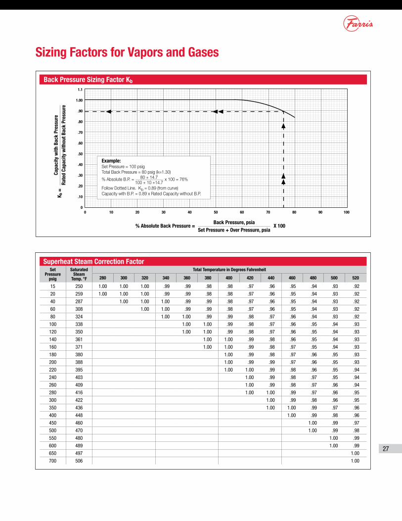
27
Superheat Steam Correction FactorSet
Pressure psig
Saturated Steam
Temp. °F
Total Temperature in Degrees Fahrenheit
280 300 320 340 360 380 400 420 440 460 480 500 520
15 250 1.00 1.00 1.00 .99 .99 .98 .98 .97 .96 .95 .94 .93 .92
20 259 1.00 1.00 1.00 .99 .99 .98 .98 .97 .96 .95 .94 .93 .92
40 287 1.00 1.00 1.00 .99 .99 .98 .97 .96 .95 .94 .93 .92
60 308 1.00 1.00 .99 .99 .98 .97 .96 .95 .94 .93 .92
80 324 1.00 1.00 .99 .99 .98 .97 .96 .94 .93 .92
100 338 1.00 1.00 .99 .98 .97 .96 .95 .94 .93
120 350 1.00 1.00 .99 .98 .97 .96 .95 .94 .93
140 361 1.00 1.00 .99 .98 .96 .95 .94 .93
160 371 1.00 1.00 .99 .98 .97 .95 .94 .93
180 380 1.00 .99 .98 .97 .96 .95 .93
200 388 1.00 .99 .99 .97 .96 .95 .93
220 395 1.00 1.00 .99 .98 .96 .95 .94
240 403 1.00 .99 .98 .97 .95 .94
260 409 1.00 .99 .98 .97 .96 .94
280 416 1.00 1.00 .99 .97 .96 .95
300 422 1.00 .99 .98 .96 .95
350 436 1.00 1.00 .99 .97 .96
400 448 1.00 .99 .98 .96
450 460 1.00 .99 .97
500 470 1.00 .99 .98
550 480 1.00 .99
600 489 1.00 .99
650 497 1.00
700 506 1.00
Sizing Factors for Vapors and Gases
Back Pressure Sizing Factor Kb
% Absolute Back Pressure = X 100Back Pressure, psia
Set Pressure + Over Pressure, psia
Capa
city
with
Bac
k Pr
essu
reRa
ted
Capa
city
with
out B
ack
Pres
sure
K b =
1.1
1.00
.90
.80
.70
.60
.50
.40
.30
.20
.10
00 10 20 30 40 50 60 70 80 90 100
Example:Set Pressure = 100 psigTotal Back Pressure = 80 psig (k=1.30)
% Absolute B.P. = 80 + 14.7 x 100 = 76% 100 + 10 +14.7Follow Dotted Line. Kb = 0.89 (from curve)Capacity with B.P. = 0.89 x Rated Capacity without B.P.
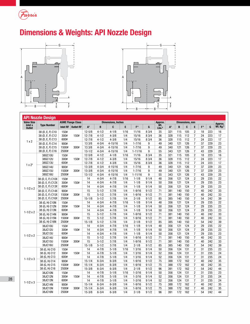
28
Dimensions & Weights: API Nozzle Design
API Nozzle DesignValve Size
Inlet x Outlet
Type NumberASME Flange Class Dimensions, Inches Approx.
Wt. Lbs.6
Dimensions, mm Approx. Wt. Kg.6Inlet RF Outlet RF A3 B C E F 4 G A3 B C E F 4 G
1 x 2
38 (D, E, F) C10 38 (D, E ,F) C12 38 (D, E, F) C13
150# 300# 600#
150#12-5/8 4-1/2 4-1/8 1/16 11/16 8 3/4 35 321 115 105 2 18 223 1612-7/8 4-1/2 4-3/8 1/4 15/16 8 3/4 36 328 115 112 7 24 223 1712-7/8 4-1/2 4-3/8 1/4 15/16 8 3/4 36 328 115 112 7 24 223 17
38 (D, E, F) C14 38 (D, E, F) C15 38 (D, E, F) C16
900# 1500# 2500#
300# 13 3/8 4-3/4 4-15/16 1/4 1-7/16 9 49 340 121 126 7 37 229 2313 3/8 4-3/4 4-15/16 1/4 1-7/16 9 49 340 121 126 7 37 229 2313-1/2 4-3/4 4-15/16 1/4 1-11/16 9 55 343 121 126 7 43 229 25
1 x 25
38GC10U 38GC12U 38GC13U
150# 300# 600#
150#12-5/8 4-1/2 4-1/8 1/16 11/16 8 3/4 35 321 115 105 2 18 223 1612-7/8 4-1/2 4-3/8 1/4 15/16 8 3/4 36 328 115 112 7 24 223 1712-7/8 4-1/2 4-3/8 1/4 15/16 8 3/4 36 328 115 112 7 24 223 17
38GC14U 38GC15U 38GC16U
900# 1500# 2500#
300# 13-3/8 4-3/4 4-15/16 1/4 1-7/16 9 49 340 121 126 7 37 229 2313-3/8 4-3/4 4-15/16 1/4 1-7/16 9 49 340 121 126 7 37 229 2313-1/2 4-3/4 4-15/16 1/4 1-11/16 9 55 343 121 126 7 43 229 25
1-1/2 x 2
38 (D, E, F) C10X 38 (D, E, F) C12X 38 (D, E, F) C13X
150# 300# 600#
150#14 4-3/4 4-7/8 1/16 1-1/8 9 1/4 48 356 121 124 2 29 235 2214 4-3/4 4-7/8 1/4 1-1/8 9 1/4 50 356 121 124 7 29 235 2314 4-3/4 4-7/8 1/4 1-1/8 9 1/4 50 356 121 124 7 29 235 23
38 (D, E, F) C14X 38 (D, E, F) C15X 38 (D, E, F) C16X
900# 1500# 2500#
300# 15 5-1/2 5 7/8 1/4 1-9/16 9 1/2 71 381 140 150 7 40 242 3315 5-1/2 5 7/8 1/4 1-9/16 9 1/2 71 381 140 150 7 40 242 33
15-1/8 5-1/2 5 7/8 1/4 2-1/8 9 1/2 85 385 140 150 7 54 242 39
1-1/2 x 2
38 (G, H) C10N 38 (G, H) C12N 38 (G, H) C13N
150# 300# 600#
150#14 4-3/4 4-7/8 1/16 1-1/8 9 1/4 48 356 121 124 2 29 235 2214 4-3/4 4-7/8 1/4 1-1/8 9 1/4 50 356 121 124 7 29 235 2314 4-3/4 4-7/8 1/4 1-1/8 9 1/4 50 356 121 124 7 29 235 23
38 (G, H) C14N 38 (G, H) C15N 38 (G, H) C16N
900# 1500# 2500#
300# 15 5-1/2 5 7/8 1/4 1-9/16 9 1/2 71 381 140 150 7 40 242 3315 5-1/2 5 7/8 1/4 1-9/16 9 1/2 71 381 140 150 7 40 242 33
15-1/8 5-1/2 5 7/8 1/4 2-1/8 9 1/2 85 385 140 150 7 54 242 39
1-1/2 x 2
38JC10U 38JC12U 38JC13U
150# 300# 600#
150#14 4-3/4 4-7/8 1/16 1-1/8 9 1/4 48 356 121 124 2 29 235 2214 4-3/4 4-7/8 1/4 1-1/8 9 1/4 50 356 121 124 7 29 235 2314 4-3/4 4-7/8 1/4 1-1/8 9 1/4 50 356 121 124 7 29 235 23
38JC14U 38JC15U 38JC16U
900# 1500# 2500#
300# 15 5-1/2 5 7/8 1/4 1-9/16 9 1/2 71 381 140 150 7 40 242 3315 5-1/2 5 7/8 1/4 1-9/16 9 1/2 71 381 140 150 7 40 242 33
15-1/8 5-1/2 5 7/8 1/4 2-1/8 9 1/2 85 385 140 150 7 54 242 39
1-1/2 x 3
38 (G, H) C10 38 (G, H) C12 38 (G, H) C13
150# 300# 600#
150#14 4-7/8 5-1/8 1/16 1 3/16 9 1/4 50 356 124 131 2 31 235 2314 4-7/8 5-1/8 1/4 1 3/16 9 1/4 52 356 124 131 7 31 235 2414 4-7/8 5-1/8 1/4 1 3/16 9 1/4 52 356 124 131 7 31 235 24
38 (G, H) C14 38 (G, H) C15 38 (G, H) C16
900# 1500# 2500#
300# 15-1/4 6-3/4 6-3/8 1/4 1-9/16 9 1/2 75 388 172 162 7 40 242 3515-1/4 6-3/4 6-3/8 1/4 1-9/16 9 1/2 75 388 172 162 7 40 242 3515-3/8 6-3/4 6-3/8 1/4 2-1/8 9 1/2 96 391 172 162 7 54 242 44
1-1/2 x 3
38JC10N 38JC12N 38JC13N
150# 300# 600#
150#14 4-7/8 5-1/8 1/16 1-3/16 9 1/4 50 356 124 131 2 31 235 2314 4-7/8 5-1/8 1/4 1-3/16 9 1/4 52 356 124 131 7 31 235 2414 4-7/8 5-1/8 1/4 1-3/16 9 1/4 52 356 124 131 7 31 235 24
38JC14N 38JC15N 38JC16N
900# 1500# 2500#
300# 15-1/4 6-3/4 6-3/8 1/4 1-9/16 9 1/2 75 388 172 162 7 40 242 3515-1/4 6-3/4 6-3/8 1/4 1-9/16 9 1/2 75 388 172 162 7 40 242 3515-3/8 6-3/4 6-3/8 1/4 2-1/8 9 1/2 96 391 172 162 7 54 242 44
A A
B
G
C
E F
C
E F
G
B B
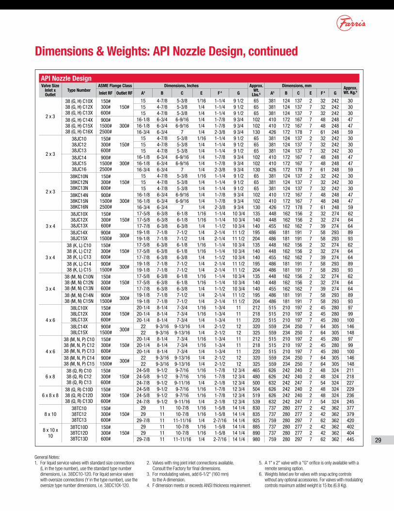
29
General Notes:1. For liquid service valves with standard size connections
(L in the type number), use the standard type number dimensions, i.e. 38DC10-120. For liquid service valves with oversize connections (Y in the type number), use the oversize type number dimensions, i.e. 38DC10X-120.
2. Valves with ring joint inlet connections available. Consult the Factory for final dimensions.
3. For modulating valves, add 6-1/2" (160 mm) to the A dimension.
4. F dimension meets or exceeds ANSI thickness requirement.
5. A 1" x 2" valve with a "G" orifice is only available with a remote sensing option.
6. Weights listed are for valves with snap acting controls without any optional accessories. For valves with modulating controls maximum added weight is 15 lbs (6.8 Kg).
Dimensions & Weights: API Nozzle Design, continued
API Nozzle DesignValve Size
Inlet x Outlet
Type NumberASME Flange Class Dimensions, Inches Approx.
Wt. Lbs.6
Dimensions, mm Approx. Wt. Kg.6Inlet RF Outlet RF A3 B C E F 4 G A3 B C E F 4 G
2 x 3
38 (G, H) C10X 38 (G, H) C12X 38 (G, H) C13X
150# 300# 600#
150#15 4-7/8 5-3/8 1/16 1-1/4 9 1/2 65 381 124 137 2 32 242 3015 4-7/8 5-3/8 1/4 1-1/4 9 1/2 65 381 124 137 7 32 242 3015 4-7/8 5-3/8 1/4 1-1/4 9 1/2 65 381 124 137 7 32 242 30
38 (G, H) C14X 38 (G, H) C15X 38 (G, H) C16X
900# 1500# 2500#
300# 16-1/8 6-3/4 6-9/16 1/4 1-7/8 9 3/4 102 410 172 167 7 48 248 4716-1/8 6-3/4 6-9/16 1/4 1-7/8 9 3/4 102 410 172 167 7 48 248 4716-3/4 6-3/4 7 1/4 2-3/8 9 3/4 130 426 172 178 7 61 248 59
2 x 3
38JC10 38JC12 38JC13
150# 300# 600#
150#15 4-7/8 5-3/8 1/16 1-1/4 9 1/2 65 381 124 137 2 32 242 3015 4-7/8 5-3/8 1/4 1-1/4 9 1/2 65 381 124 137 7 32 242 3015 4-7/8 5-3/8 1/4 1-1/4 9 1/2 65 381 124 137 7 32 242 30
38JC14 38JC15 38JC16
900# 1500# 2500#
300# 16-1/8 6-3/4 6-9/16 1/4 1-7/8 9 3/4 102 410 172 167 7 48 248 4716-1/8 6-3/4 6-9/16 1/4 1-7/8 9 3/4 102 410 172 167 7 48 248 4716-3/4 6-3/4 7 1/4 2-3/8 9 3/4 130 426 172 178 7 61 248 59
2 x 3
38KC10N 38KC12N 38KC13N
150# 300# 600#
150#15 4-7/8 5-3/8 1/16 1-1/4 9 1/2 65 381 124 137 2 32 242 3015 4-7/8 5-3/8 1/4 1-1/4 9 1/2 65 381 124 137 7 32 242 3015 4-7/8 5-3/8 1/4 1-1/4 9 1/2 65 381 124 137 7 32 242 30
38KC14N 38KC15N 38KC16N
900# 1500# 2500#
300# 16-1/8 6-3/4 6-9/16 1/4 1-7/8 9 3/4 102 410 172 167 7 48 248 4716-1/8 6-3/4 6-9/16 1/4 1-7/8 9 3/4 102 410 172 167 7 48 248 4716-3/4 6-3/4 7 1/4 2-3/8 9 3/4 130 426 172 178 7 61 248 59
3 x 4
38JC10X 38JC12X 38JC13X
150# 300# 600#
150#17-5/8 6-3/8 6-1/8 1/16 1-1/4 10 3/4 135 448 162 156 2 32 274 6217-5/8 6-3/8 6-1/8 1/16 1-1/4 10 3/4 140 448 162 156 2 32 274 6417-7/8 6-3/8 6-3/8 1/4 1-1/2 10 3/4 140 455 162 162 7 39 274 64
38JC14X 38JC15X
900# 1500# 300#
19-1/8 7-1/8 7-1/2 1/4 2-1/4 11 1/2 195 486 181 191 7 58 293 8919-1/8 7-1/8 7-1/2 1/4 2-1/4 11 1/2 204 486 181 191 7 58 293 93
3 x 4
38 (K, L) C10 38 (K, L) C12 38 (K, L) C13
150# 300# 600#
150#17-5/8 6-3/8 6-1/8 1/16 1-1/4 10 3/4 135 448 162 156 2 32 274 6217-5/8 6-3/8 6-1/8 1/16 1-1/4 10 3/4 140 448 162 156 2 32 274 6417-7/8 6-3/8 6-3/8 1/4 1-1/2 10 3/4 140 455 162 162 7 39 274 64
38 (K, L) C14 38 (K, L) C15
900# 1500# 300#
19-1/8 7-1/8 7-1/2 1/4 2-1/4 11 1/2 195 486 181 191 7 58 293 8919-1/8 7-1/8 7-1/2 1/4 2-1/4 11 1/2 204 486 181 191 7 58 293 93
3 x 4
38 (M, N) C10N 38 (M, N) C12N 38 (M, N) C13N
150# 300# 600#
150#17-5/8 6-3/8 6-1/8 1/16 1-1/4 10 3/4 135 448 162 156 2 32 274 6217-5/8 6-3/8 6-1/8 1/16 1-1/4 10 3/4 140 448 162 156 2 32 274 6417-7/8 6-3/8 6-3/8 1/4 1-1/2 10 3/4 140 455 162 162 7 39 274 64
38 (M, N) C14N 38 (M, N) C15N
900# 1500# 300#
19-1/8 7-1/8 7-1/2 1/4 2-1/4 11 1/2 195 486 181 191 7 58 293 8919-1/8 7-1/8 7-1/2 1/4 2-1/4 11 1/2 204 486 181 191 7 58 293 93
4 x 6
38LC10X 38LC12X 38LC13X
150# 300# 600#
150#20-1/4 8-1/4 7-3/4 1/16 1-3/4 11 212 515 210 197 2 45 280 9720-1/4 8-1/4 7-3/4 1/16 1-3/4 11 218 515 210 197 2 45 280 9920-1/4 8-1/4 7-3/4 1/4 1-3/4 11 220 515 210 197 7 45 280 100
38LC14X 38LC15X
900# 1500# 300#
22 9-3/16 9-13/16 1/4 2-1/2 12 320 559 234 250 7 64 305 14622 9-3/16 9-13/16 1/4 2-1/2 12 325 559 234 250 7 64 305 148
4 x 6
38 (M, N, P) C10 38 (M, N, P) C12 38 (M, N, P) C13
150# 300# 600#
150#20-1/4 8-1/4 7-3/4 1/16 1-3/4 11 212 515 210 197 2 45 280 9720-1/4 8-1/4 7-3/4 1/16 1-3/4 11 218 515 210 197 2 45 280 9920-1/4 8-1/4 7-3/4 1/4 1-3/4 11 220 515 210 197 7 45 280 100
38 (M, N, P) C14 38 (M, N, P) C15
900# 1500# 300#
22 9-3/16 9-13/16 1/4 2-1/2 12 320 559 234 250 7 64 305 14622 9-3/16 9-13/16 1/4 2-1/2 12 325 559 234 250 7 64 305 148
6 x 838 (Q, R) C10 38 (Q, R) C12 38 (Q, R) C13
150# 300# 600#
150#24-5/8 9-1/2 9-7/16 1/16 1-7/8 12 3/4 465 626 242 240 2 48 324 21124-5/8 9-1/2 9-7/16 1/16 1-7/8 12 3/4 480 626 242 240 2 48 324 21824-7/8 9-1/2 9-11/16 1/4 2-1/8 12 3/4 500 632 242 247 7 54 324 227
6 x 8 x 838 (Q, R) C10D 38 (Q, R) C12D 38 (Q, R) C13D
150# 300# 600#
150#24-5/8 9-1/2 9-7/16 1/16 1-7/8 12 3/4 504 626 242 240 2 48 324 22924-5/8 9-1/2 9-7/16 1/16 1-7/8 12 3/4 519 626 242 240 2 48 324 23624-7/8 9-1/2 9-11/16 1/4 2-1/8 12 3/4 539 632 242 247 7 54 324 245
8 x 10 38TC10 38TC12 38TC13
150# 300# 600#
150#29 11 10-7/8 1/16 1-5/8 14 1/4 830 737 280 277 2 42 362 37729 11 10-7/8 1/16 1-5/8 14 1/4 835 737 280 277 2 42 362 379
29-7/8 11 11-11/16 1/4 2-7/16 14 1/4 925 759 280 297 7 62 362 420
8 x 10 x 10
38TC10D 38TC12D 38TC13D
150# 300# 600#
150#29 11 10-7/8 1/16 1-5/8 14 1/4 885 737 280 277 2 42 362 40229 11 10-7/8 1/16 1-5/8 14 1/4 890 737 280 277 2 42 362 404
29-7/8 11 11-11/16 1/4 2-7/16 14 1/4 980 759 280 297 7 62 362 445
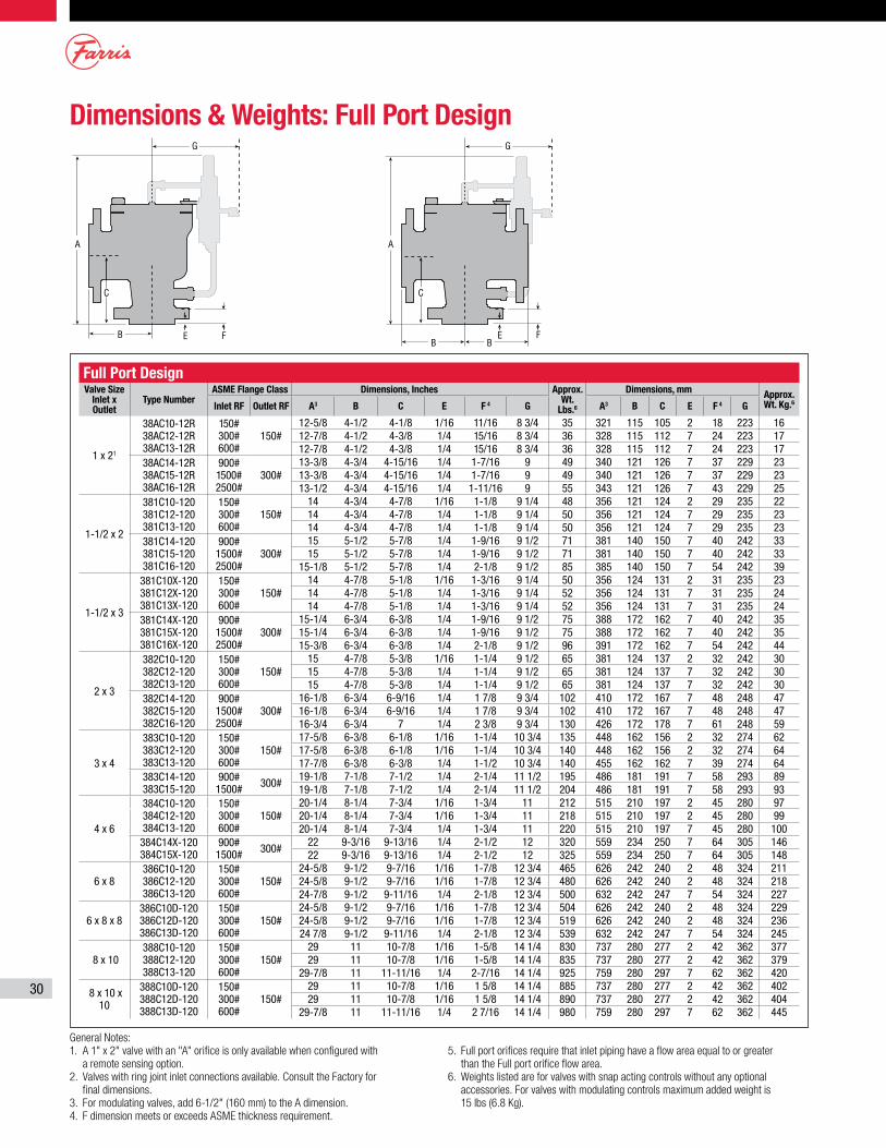
30
Dimensions & Weights: Full Port Design
General Notes:1. A 1" x 2" valve with an "A" orifice is only available when configured with
a remote sensing option. 2. Valves with ring joint inlet connections available. Consult the Factory for
final dimensions.3. For modulating valves, add 6-1/2" (160 mm) to the A dimension.4. F dimension meets or exceeds ASME thickness requirement.
5. Full port orifices require that inlet piping have a flow area equal to or greater than the Full port orifice flow area.
6. Weights listed are for valves with snap acting controls without any optional accessories. For valves with modulating controls maximum added weight is 15 lbs (6.8 Kg).
A A
B
G
C
E F
C
E F
G
B B
Full Port DesignValve Size
Inlet x Outlet
Type NumberASME Flange Class Dimensions, Inches Approx.
Wt. Lbs.6
Dimensions, mm Approx. Wt. Kg.6Inlet RF Outlet RF A3 B C E F 4 G A3 B C E F 4 G
1 x 21
38AC10-12R 38AC12-12R 38AC13-12R
150# 300# 600#
150#12-5/8 4-1/2 4-1/8 1/16 11/16 8 3/4 35 321 115 105 2 18 223 1612-7/8 4-1/2 4-3/8 1/4 15/16 8 3/4 36 328 115 112 7 24 223 1712-7/8 4-1/2 4-3/8 1/4 15/16 8 3/4 36 328 115 112 7 24 223 17
38AC14-12R 38AC15-12R 38AC16-12R
900# 1500# 2500#
300#13-3/8 4-3/4 4-15/16 1/4 1-7/16 9 49 340 121 126 7 37 229 2313-3/8 4-3/4 4-15/16 1/4 1-7/16 9 49 340 121 126 7 37 229 2313-1/2 4-3/4 4-15/16 1/4 1-11/16 9 55 343 121 126 7 43 229 25
1-1/2 x 2
381C10-120 381C12-120 381C13-120
150# 300# 600#
150#14 4-3/4 4-7/8 1/16 1-1/8 9 1/4 48 356 121 124 2 29 235 2214 4-3/4 4-7/8 1/4 1-1/8 9 1/4 50 356 121 124 7 29 235 2314 4-3/4 4-7/8 1/4 1-1/8 9 1/4 50 356 121 124 7 29 235 23
381C14-120 381C15-120 381C16-120
900# 1500# 2500#
300#15 5-1/2 5-7/8 1/4 1-9/16 9 1/2 71 381 140 150 7 40 242 3315 5-1/2 5-7/8 1/4 1-9/16 9 1/2 71 381 140 150 7 40 242 33
15-1/8 5-1/2 5-7/8 1/4 2-1/8 9 1/2 85 385 140 150 7 54 242 39
1-1/2 x 3
381C10X-120 381C12X-120 381C13X-120
150# 300# 600#
150#14 4-7/8 5-1/8 1/16 1-3/16 9 1/4 50 356 124 131 2 31 235 2314 4-7/8 5-1/8 1/4 1-3/16 9 1/4 52 356 124 131 7 31 235 2414 4-7/8 5-1/8 1/4 1-3/16 9 1/4 52 356 124 131 7 31 235 24
381C14X-120 381C15X-120 381C16X-120
900# 1500# 2500#
300#15-1/4 6-3/4 6-3/8 1/4 1-9/16 9 1/2 75 388 172 162 7 40 242 3515-1/4 6-3/4 6-3/8 1/4 1-9/16 9 1/2 75 388 172 162 7 40 242 3515-3/8 6-3/4 6-3/8 1/4 2-1/8 9 1/2 96 391 172 162 7 54 242 44
2 x 3
382C10-120 382C12-120 382C13-120
150# 300# 600#
150#15 4-7/8 5-3/8 1/16 1-1/4 9 1/2 65 381 124 137 2 32 242 3015 4-7/8 5-3/8 1/4 1-1/4 9 1/2 65 381 124 137 7 32 242 3015 4-7/8 5-3/8 1/4 1-1/4 9 1/2 65 381 124 137 7 32 242 30
382C14-120 382C15-120 382C16-120
900# 1500# 2500#
300#16-1/8 6-3/4 6-9/16 1/4 1 7/8 9 3/4 102 410 172 167 7 48 248 4716-1/8 6-3/4 6-9/16 1/4 1 7/8 9 3/4 102 410 172 167 7 48 248 4716-3/4 6-3/4 7 1/4 2 3/8 9 3/4 130 426 172 178 7 61 248 59
3 x 4
383C10-120 383C12-120 383C13-120
150# 300# 600#
150#17-5/8 6-3/8 6-1/8 1/16 1-1/4 10 3/4 135 448 162 156 2 32 274 6217-5/8 6-3/8 6-1/8 1/16 1-1/4 10 3/4 140 448 162 156 2 32 274 6417-7/8 6-3/8 6-3/8 1/4 1-1/2 10 3/4 140 455 162 162 7 39 274 64
383C14-120 383C15-120
900# 1500# 300#
19-1/8 7-1/8 7-1/2 1/4 2-1/4 11 1/2 195 486 181 191 7 58 293 8919-1/8 7-1/8 7-1/2 1/4 2-1/4 11 1/2 204 486 181 191 7 58 293 93
4 x 6
384C10-120 384C12-120 384C13-120
150# 300# 600#
150#20-1/4 8-1/4 7-3/4 1/16 1-3/4 11 212 515 210 197 2 45 280 9720-1/4 8-1/4 7-3/4 1/16 1-3/4 11 218 515 210 197 2 45 280 9920-1/4 8-1/4 7-3/4 1/4 1-3/4 11 220 515 210 197 7 45 280 100
384C14X-120 384C15X-120
900# 1500# 300#
22 9-3/16 9-13/16 1/4 2-1/2 12 320 559 234 250 7 64 305 14622 9-3/16 9-13/16 1/4 2-1/2 12 325 559 234 250 7 64 305 148
6 x 8 386C10-120 386C12-120 386C13-120
150# 300# 600#
150#24-5/8 9-1/2 9-7/16 1/16 1-7/8 12 3/4 465 626 242 240 2 48 324 21124-5/8 9-1/2 9-7/16 1/16 1-7/8 12 3/4 480 626 242 240 2 48 324 21824-7/8 9-1/2 9-11/16 1/4 2-1/8 12 3/4 500 632 242 247 7 54 324 227
6 x 8 x 8 386C10D-120 386C12D-120 386C13D-120
150# 300# 600#
150#24-5/8 9-1/2 9-7/16 1/16 1-7/8 12 3/4 504 626 242 240 2 48 324 22924-5/8 9-1/2 9-7/16 1/16 1-7/8 12 3/4 519 626 242 240 2 48 324 23624 7/8 9-1/2 9-11/16 1/4 2-1/8 12 3/4 539 632 242 247 7 54 324 245
8 x 10 388C10-120 388C12-120 388C13-120
150# 300# 600#
150#29 11 10-7/8 1/16 1-5/8 14 1/4 830 737 280 277 2 42 362 37729 11 10-7/8 1/16 1-5/8 14 1/4 835 737 280 277 2 42 362 379
29-7/8 11 11-11/16 1/4 2-7/16 14 1/4 925 759 280 297 7 62 362 420
8 x 10 x 10
388C10D-120 388C12D-120 388C13D-120
150# 300# 600#
150#29 11 10-7/8 1/16 1 5/8 14 1/4 885 737 280 277 2 42 362 40229 11 10-7/8 1/16 1 5/8 14 1/4 890 737 280 277 2 42 362 404
29-7/8 11 11-11/16 1/4 2 7/16 14 1/4 980 759 280 297 7 62 362 445
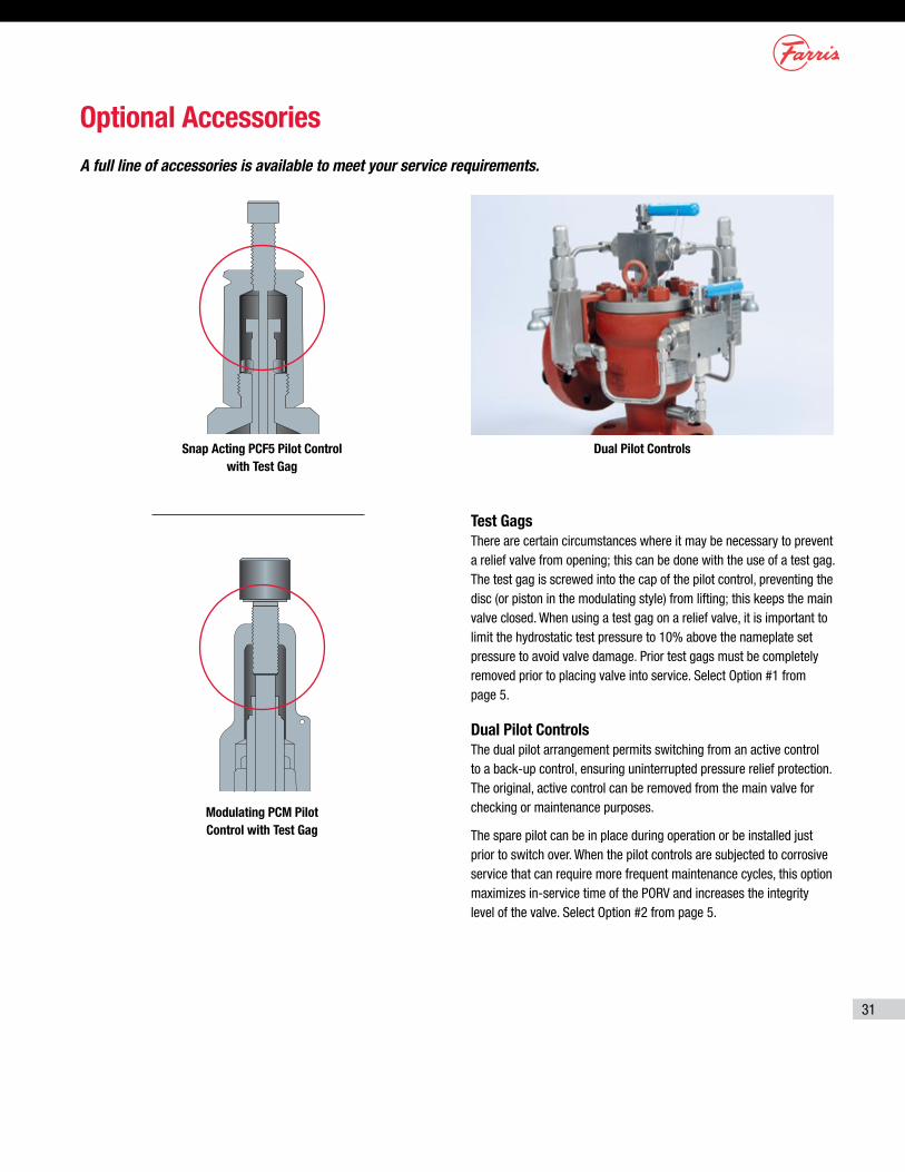
31
Optional AccessoriesA full line of accessories is available to meet your service requirements.
Dual Pilot ControlsSnap Acting PCF5 Pilot Control with Test Gag
Modulating PCM Pilot Control with Test Gag
Test GagsThere are certain circumstances where it may be necessary to prevent a relief valve from opening; this can be done with the use of a test gag. The test gag is screwed into the cap of the pilot control, preventing the disc (or piston in the modulating style) from lifting; this keeps the main valve closed. When using a test gag on a relief valve, it is important to limit the hydrostatic test pressure to 10% above the nameplate set pressure to avoid valve damage. Prior test gags must be completely removed prior to placing valve into service. Select Option #1 from page 5.
Dual Pilot Controls The dual pilot arrangement permits switching from an active control to a back-up control, ensuring uninterrupted pressure relief protection. The original, active control can be removed from the main valve for checking or maintenance purposes.
The spare pilot can be in place during operation or be installed just prior to switch over. When the pilot controls are subjected to corrosive service that can require more frequent maintenance cycles, this option maximizes in-service time of the PORV and increases the integrity level of the valve. Select Option #2 from page 5.
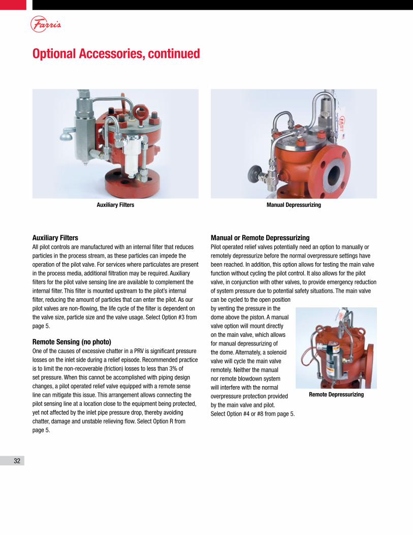
32
Optional Accessories, continued
Auxiliary Filters
All pilot controls are manufactured with an internal filter that reduces particles in the process stream, as these particles can impede the operation of the pilot valve. For services where particulates are present in the process media, additional filtration may be required. Auxiliary filters for the pilot valve sensing line are available to complement the internal filter. This filter is mounted upstream to the pilot’s internal filter, reducing the amount of particles that can enter the pilot. As our pilot valves are non-flowing, the life cycle of the filter is dependent on the valve size, particle size and the valve usage. Select Option #3 from page 5.
Remote Sensing (no photo) One of the causes of excessive chatter in a PRV is significant pressure losses on the inlet side during a relief episode. Recommended practice is to limit the non-recoverable (friction) losses to less than 3% of set pressure. When this cannot be accomplished with piping design changes, a pilot operated relief valve equipped with a remote sense line can mitigate this issue. This arrangement allows connecting the pilot sensing line at a location close to the equipment being protected, yet not affected by the inlet pipe pressure drop, thereby avoiding chatter, damage and unstable relieving flow. Select Option R from page 5.
Auxiliary Filters
Remote Depressurizing
Manual Depressurizing
Manual or Remote Depressurizing
Pilot operated relief valves potentially need an option to manually or remotely depressurize before the normal overpressure settings have been reached. In addition, this option allows for testing the main valve function without cycling the pilot control. It also allows for the pilot valve, in conjunction with other valves, to provide emergency reduction of system pressure due to potential safety situations. The main valve can be cycled to the open position by venting the pressure in the dome above the piston. A manual valve option will mount directly on the main valve, which allows for manual depressurizing of the dome. Alternately, a solenoid valve will cycle the main valve remotely. Neither the manual nor remote blowdown system will interfere with the normal overpressure protection provided by the main valve and pilot. Select Option #4 or #8 from page 5.
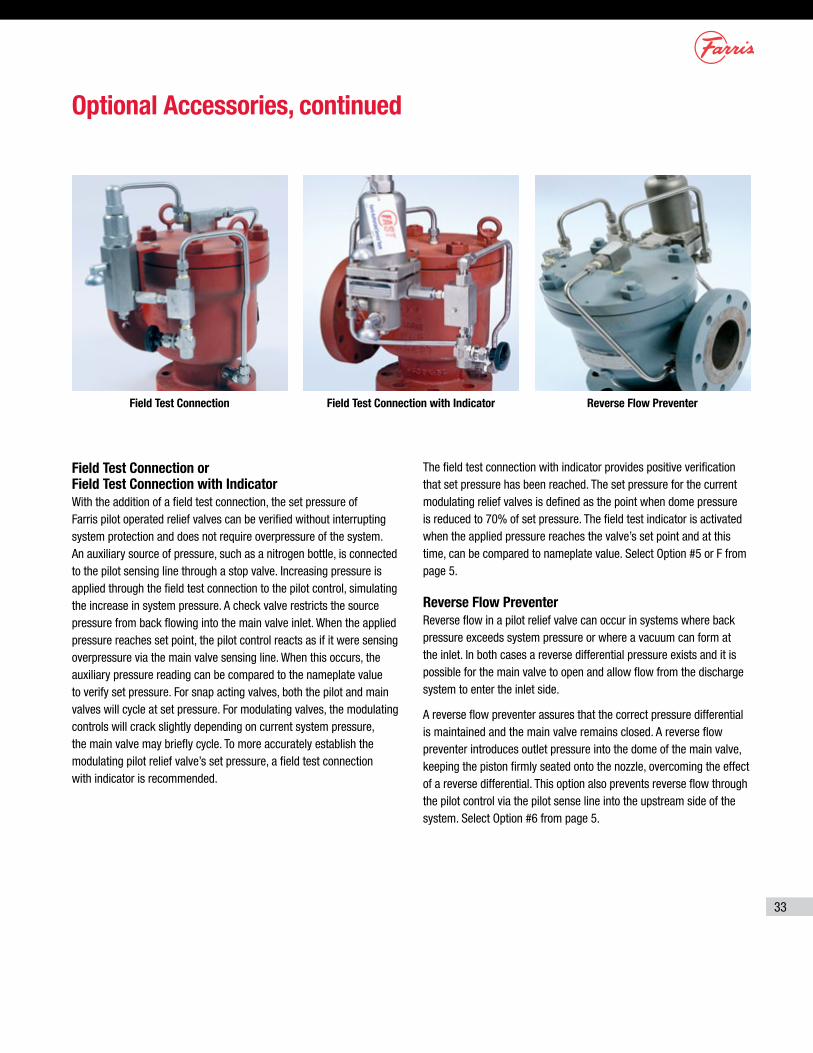
33
Optional Accessories, continued
Reverse Flow PreventerField Test Connection Field Test Connection with Indicator
Field Test Connection or Field Test Connection with Indicator With the addition of a field test connection, the set pressure of Farris pilot operated relief valves can be verified without interrupting system protection and does not require overpressure of the system. An auxiliary source of pressure, such as a nitrogen bottle, is connected to the pilot sensing line through a stop valve. Increasing pressure is applied through the field test connection to the pilot control, simulating the increase in system pressure. A check valve restricts the source pressure from back flowing into the main valve inlet. When the applied pressure reaches set point, the pilot control reacts as if it were sensing overpressure via the main valve sensing line. When this occurs, the auxiliary pressure reading can be compared to the nameplate value to verify set pressure. For snap acting valves, both the pilot and main valves will cycle at set pressure. For modulating valves, the modulating controls will crack slightly depending on current system pressure, the main valve may briefly cycle. To more accurately establish the modulating pilot relief valve’s set pressure, a field test connection with indicator is recommended.
The field test connection with indicator provides positive verification that set pressure has been reached. The set pressure for the current modulating relief valves is defined as the point when dome pressure is reduced to 70% of set pressure. The field test indicator is activated when the applied pressure reaches the valve’s set point and at this time, can be compared to nameplate value. Select Option #5 or F from page 5.
Reverse Flow Preventer Reverse flow in a pilot relief valve can occur in systems where back pressure exceeds system pressure or where a vacuum can form at the inlet. In both cases a reverse differential pressure exists and it is possible for the main valve to open and allow flow from the discharge system to enter the inlet side.
A reverse flow preventer assures that the correct pressure differential is maintained and the main valve remains closed. A reverse flow preventer introduces outlet pressure into the dome of the main valve, keeping the piston firmly seated onto the nozzle, overcoming the effect of a reverse differential. This option also prevents reverse flow through the pilot control via the pilot sense line into the upstream side of the system. Select Option #6 from page 5.
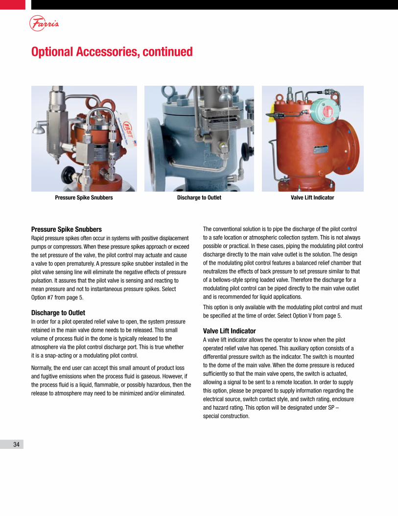
34
Pressure Spike Snubbers Rapid pressure spikes often occur in systems with positive displacement pumps or compressors. When these pressure spikes approach or exceed the set pressure of the valve, the pilot control may actuate and cause a valve to open prematurely. A pressure spike snubber installed in the pilot valve sensing line will eliminate the negative effects of pressure pulsation. It assures that the pilot valve is sensing and reacting to mean pressure and not to instantaneous pressure spikes. Select Option #7 from page 5.
Discharge to Outlet In order for a pilot operated relief valve to open, the system pressure retained in the main valve dome needs to be released. This small volume of process fluid in the dome is typically released to the atmosphere via the pilot control discharge port. This is true whether it is a snap-acting or a modulating pilot control.
Normally, the end user can accept this small amount of product loss and fugitive emissions when the process fluid is gaseous. However, if the process fluid is a liquid, flammable, or possibly hazardous, then the release to atmosphere may need to be minimized and/or eliminated.
Pressure Spike Snubbers Discharge to Outlet
The conventional solution is to pipe the discharge of the pilot control to a safe location or atmospheric collection system. This is not always possible or practical. In these cases, piping the modulating pilot control discharge directly to the main valve outlet is the solution. The design of the modulating pilot control features a balanced relief chamber that neutralizes the effects of back pressure to set pressure similar to that of a bellows-style spring loaded valve. Therefore the discharge for a modulating pilot control can be piped directly to the main valve outlet and is recommended for liquid applications.
This option is only available with the modulating pilot control and must be specified at the time of order. Select Option V from page 5.
Valve Lift Indicator A valve lift indicator allows the operator to know when the pilot operated relief valve has opened. This auxiliary option consists of a differential pressure switch as the indicator. The switch is mounted to the dome of the main valve. When the dome pressure is reduced sufficiently so that the main valve opens, the switch is actuated, allowing a signal to be sent to a remote location. In order to supply this option, please be prepared to supply information regarding the electrical source, switch contact style, and switch rating, enclosure and hazard rating. This option will be designated under SP – special construction.
Valve Lift Indicator
Optional Accessories, continued
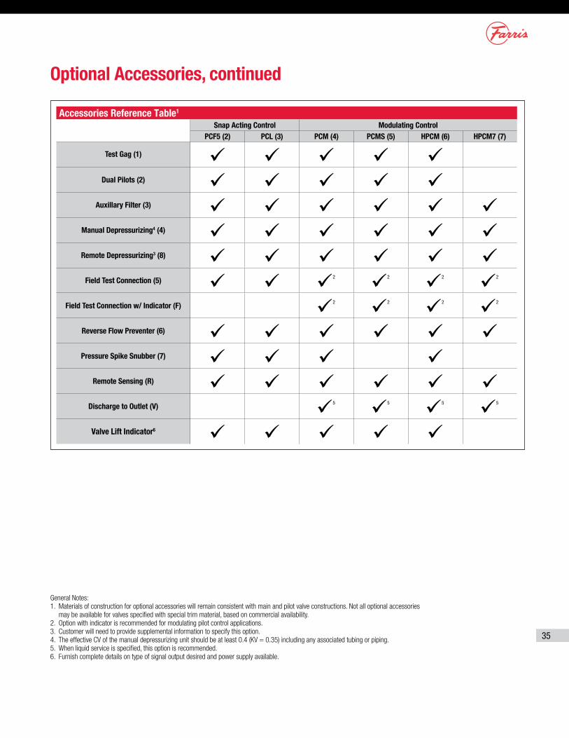
35
Optional Accessories, continued
Accessories Reference Table1
Snap Acting Control Modulating ControlPCF5 (2) PCL (3) PCM (4) PCMS (5) HPCM (6) HPCM7 (7)
Test Gag (1)
Dual Pilots (2)
Auxillary Filter (3)
Manual Depressurizing4 (4)
Remote Depressurizing3 (8)
Field Test Connection (5) 2 2 2 2
Field Test Connection w/ Indicator (F) 2 2 2 2
Reverse Flow Preventer (6)
Pressure Spike Snubber (7)
Remote Sensing (R)
Discharge to Outlet (V) 5 5 5 5
Valve Lift Indicator6
General Notes:1. Materials of construction for optional accessories will remain consistent with main and pilot valve constructions. Not all optional accessories
may be available for valves specified with special trim material, based on commercial availability. 2. Option with indicator is recommended for modulating pilot control applications. 3. Customer will need to provide supplemental information to specify this option. 4. The effective CV of the manual depressurizing unit should be at least 0.4 (KV = 0.35) including any associated tubing or piping. 5. When liquid service is specified, this option is recommended. 6. Furnish complete details on type of signal output desired and power supply available.
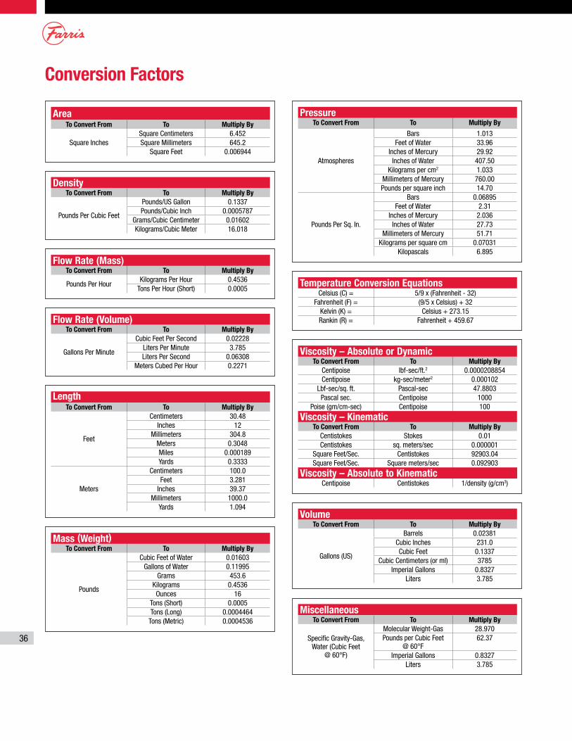
36
Conversion Factors
AreaTo Convert From To Multiply By
Square InchesSquare Centimeters 6.452Square Millimeters 645.2
Square Feet 0.006944
DensityTo Convert From To Multiply By
Pounds Per Cubic Feet
Pounds/US Gallon 0.1337Pounds/Cubic Inch 0.0005787
Grams/Cubic Centimeter 0.01602Kilograms/Cubic Meter 16.018
MiscellaneousTo Convert From To Multiply By
Specific Gravity-Gas, Water (Cubic Feet
@ 60°F)
Molecular Weight-Gas 28.970Pounds per Cubic Feet
@ 60°F62.37
Imperial Gallons 0.8327Liters 3.785
Mass (Weight)To Convert From To Multiply By
Pounds
Cubic Feet of Water 0.01603Gallons of Water 0.11995
Grams 453.6Kilograms 0.4536Ounces 16
Tons (Short) 0.0005Tons (Long) 0.0004464
Tons (Metric) 0.0004536
LengthTo Convert From To Multiply By
Feet
Centimeters 30.48Inches 12
Millimeters 304.8Meters 0.3048Miles 0.000189Yards 0.3333
Meters
Centimeters 100.0Feet 3.281
Inches 39.37Millimeters 1000.0
Yards 1.094
Flow Rate (Volume)To Convert From To Multiply By
Gallons Per Minute
Cubic Feet Per Second 0.02228Liters Per Minute 3.785Liters Per Second 0.06308
Meters Cubed Per Hour 0.2271
Flow Rate (Mass)To Convert From To Multiply By
Pounds Per HourKilograms Per Hour 0.4536
Tons Per Hour (Short) 0.0005Temperature Conversion Equations
Celsius (C) = 5/9 x (Fahrenheit - 32)Fahrenheit (F) = (9/5 x Celsius) + 32
Kelvin (K) = Celsius + 273.15Rankin (R) = Fahrenheit + 459.67
VolumeTo Convert From To Multiply By
Gallons (US)
Barrels 0.02381Cubic Inches 231.0Cubic Feet 0.1337
Cubic Centimeters (or ml) 3785Imperial Gallons 0.8327
Liters 3.785
Viscosity – Absolute or DynamicTo Convert From To Multiply By
Centipoise lbf-sec/ft.2 0.0000208854Centipoise kg-sec/meter2 0.000102
Lbf-sec/sq. ft. Pascal-sec 47.8803Pascal sec. Centipoise 1000
Poise (gm/cm-sec) Centipoise 100
Viscosity – KinematicTo Convert From To Multiply By
Centistokes Stokes 0.01Centistokes sq. meters/sec 0.000001
Square Feet/Sec. Centistokes 92903.04Square Feet/Sec. Square meters/sec 0.092903
Viscosity – Absolute to KinematicCentipoise Centistokes 1/density (g/cm3)
PressureTo Convert From To Multiply By
Atmospheres
Bars 1.013Feet of Water 33.96
Inches of Mercury 29.92Inches of Water 407.50
Kilograms per cm2 1.033Millimeters of Mercury 760.00Pounds per square inch 14.70
Pounds Per Sq. In.
Bars 0.06895Feet of Water 2.31
Inches of Mercury 2.036Inches of Water 27.73
Millimeters of Mercury 51.71Kilograms per square cm 0.07031
Kilopascals 6.895
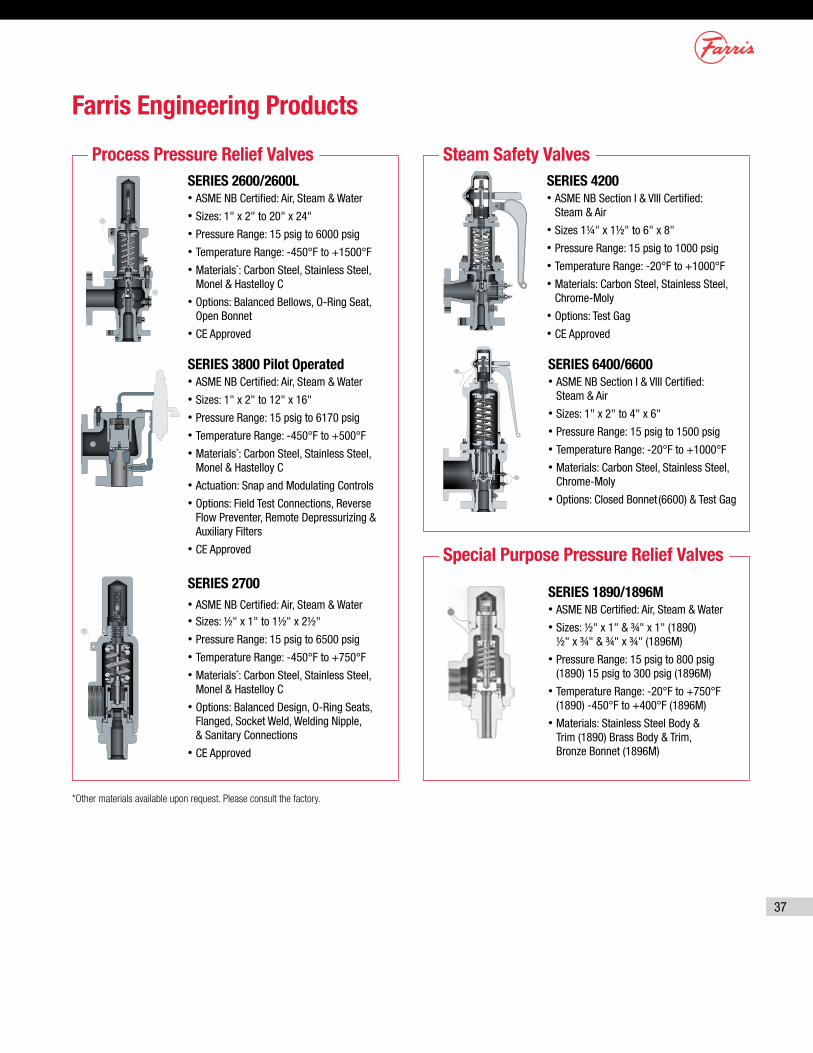
37
Farris Engineering Products
Process Pressure Relief Valves
Special Purpose Pressure Relief Valves
Steam Safety Valves
SERIES 6400/6600• ASME NB Section I & VIII Certified:
Steam & Air• Sizes: 1" x 2" to 4" x 6"• Pressure Range: 15 psig to 1500 psig• Temperature Range: -20°F to +1000°F• Materials: Carbon Steel, Stainless Steel,
Chrome-Moly• Options: Closed Bonnet (6600) & Test Gag
SERIES 1890/1896M• ASME NB Certified: Air, Steam & Water• Sizes: ½" x 1" & ¾" x 1" (1890)
½" x ¾" & ¾" x ¾" (1896M)• Pressure Range: 15 psig to 800 psig
(1890) 15 psig to 300 psig (1896M)• Temperature Range: -20°F to +750°F
(1890) -450°F to +400°F (1896M)• Materials: Stainless Steel Body &
Trim (1890) Brass Body & Trim, Bronze Bonnet (1896M)
SERIES 4200• ASME NB Section I & VIII Certified:
Steam & Air• Sizes 1¼" x 1½" to 6" x 8"• Pressure Range: 15 psig to 1000 psig• Temperature Range: -20°F to +1000°F• Materials: Carbon Steel, Stainless Steel,
Chrome-Moly• Options: Test Gag• CE Approved
SERIES 3800 Pilot Operated• ASME NB Certified: Air, Steam & Water• Sizes: 1" x 2" to 12" x 16"• Pressure Range: 15 psig to 6170 psig• Temperature Range: -450°F to +500°F• Materials*: Carbon Steel, Stainless Steel,
Monel & Hastelloy C• Actuation: Snap and Modulating Controls• Options: Field Test Connections, Reverse
Flow Preventer, Remote Depressurizing & Auxiliary Filters
• CE Approved
SERIES 2700• ASME NB Certified: Air, Steam & Water• Sizes: ½" x 1" to 1½" x 2½"• Pressure Range: 15 psig to 6500 psig• Temperature Range: -450°F to +750°F• Materials*: Carbon Steel, Stainless Steel,
Monel & Hastelloy C• Options: Balanced Design, O-Ring Seats,
Flanged, Socket Weld, Welding Nipple, & Sanitary Connections
• CE Approved
SERIES 2600/2600L• ASME NB Certified: Air, Steam & Water• Sizes: 1" x 2" to 20" x 24"• Pressure Range: 15 psig to 6000 psig• Temperature Range: -450°F to +1500°F• Materials*: Carbon Steel, Stainless Steel,
Monel & Hastelloy C• Options: Balanced Bellows, O-Ring Seat,
Open Bonnet• CE Approved
*Other materials available upon request. Please consult the factory.

NVV
Printed in U.S.A. 03/18 7.5M-3800 R3
Farris Engineering, a business unit of Curtiss-WrightHeadquarters: 10195 Brecksville Road, Brecksville, OH 44141 USA • Telephone: 440-838-7690 • Fax: 440-838-7699 • www. cw-valvegroup.com/farrisFacilities: Brecksville, OH, USA; Brantford, Ontario and Edmonton, Alberta, CA; Corby, Northants, UK; São Carlos-SP, Brazil; Tianjin, Beijing, China; Delhi, India Offices Worldwide: For a listing of our global sales network, visit our website at www.cw-valvegroup.com/farrisdistributors.
While this information is presented in good faith and believed to be accurate, Farris Engineering, division of Curtiss-Wright Flow Control Corporation, does not guarantee satisfactory results from reliance on such information. Nothing contained herein is to be construed as a warranty or guarantee, expressed or implied, regarding the performance, merchantability, fitness or any other matter with respect to the products, nor as a recommendation to use any product or process in conflict with any patent. Farris Engineering, division of Curtiss-Wright Flow Control Corporation, reserves the right, without notice, to alter or improve the designs or specifications of the products described herein.
© 2018 Curtiss-Wright. All rights reserved. Specifications are subject to change without notice. All trademarks are property of their respective owners.
Process Pressure Relief Valves – ASME Code Section VIIISeries 2600 ASME NB Certified for Air and Steam Series 2600S ASME NB Certified for Air and Steam Series 2600L ASME NB Certified for Air, Steam and Water Series 3800 ASME NB Certified for Air, Steam and Water Series 2700 ASME NB Certified for Air, Steam and Water Series 1890 / 1896M ASME NB Certified for Air, Steam and Water
Steam Safety Valves – ASME Code Section I & VIIISeries 4200 ASME NB Certified for Steam Series 6400/6600 ASME NB Certified for Steam
Nuclear Pressure Relief ValvesSeries 4700/4700L ASME NB Section III, Division 1 Class I, II & III Series 2700/3700 ASME NB Section III, Division 1 Class I, II & III Series 2600/2600L ASME NB Section III, Division 1 Class I, II & III Series 3800 ASME NB Section III, Division 1 Class I, II & III
Changeover ValvesSeries 320B & 370B
Certifications and Approvals:• ASME V, UV, NV and NPT• National Board Approval, NB• ISO 9001-2008• PED 2014/68/EU (European
Pressure Equipment Directive)• ATEX 94/9/EC (European
Potentially Explosive Atmospheres)
• CSA B51 (Canadian Registration)
• CSQL (China Safety Quality License)
• Customs Union TR CU 010-2011 and Customs Union TR CU 032-2013
• US Coast Guard• Nuclear - 10 CFR 50 Appendix B,
NCA-4000, NQA-1, N285.0
• First Point Assessment Limited
FAST Centers (Farris Authorized Service Team)• Worldwide Network of Service Centers with Factory Trained Technicians
• Local Inventory and Support, 24 Hours a Day, 7 Days a Week
• Access to Worldwide Farris Inventory through the Web
• ASME/National Board Approved Assembly, Repair & Test Facilities
• Application, Sizing & Selection Support
SizeMaster™ Mark IVPressure Relief Valve Engineering Software for Sizing and Selection
PSM Engineering Services• Pressure Relief System Design Services
• Pressure Relief System Audit Services
• iPRSM Pressure Relief System Management Software
Design
Maintain
Audit
Equip
Monitor
Farris Pressure Relief
ManagementSolutions
Farris Engineering Products and Services