Embed Size (px)
Citation preview

10/1Siemens Industry, Inc.Industrial Controls Catalog
Siemens / Industrial Controls Previous folio: 10/1
Contents PagesSectionOverview . . . . . . . . . . . . . . . . . . . . . . . . . 10/2.-.10/3
3SB2,16mmMountingDiameterPilotDevicesIntroduction. . . . . . . . . . . . . . . . . . . . . . . . . . . . . . . . . . . . 10/4Technical.Specifications . . . . . . . . . . . . . . . . . . . . . . . . . . 10/5PCB.Mounting.Instructions. . . . . . . . . . . . . . . . . . . . . . . . 10/6Complete.Units. . . . . . . . . . . . . . . . . . . . . . . . . . . . 10/7.-.10/8Pushbutton.and.Selector.Switch.Operators. . . . . . . . . . . 10/9Key-operated.Switches.and.Indicator.Lights. . . . . . . . . . 10/10Holders,.Lampholders.and.Contact.Blocks.with.Tabs. . . . 10/11Holders,.Lampholders.and.Contact.Blocks... with.Solder.Pins. . . . . . . . . . . . . . . . . . . . . . . . . . . . . . 10/12Inserts,.Legend.Plates,.and.Accessories . . . . . . 10/13.-.10/19Dimension.Drawings. . . . . . . . . . . . . . . . . . . . . . . . . . . . 10/20
Sirius3SB322mmMountingDiameterPilotDevicesIntroduction. . . . . . . . . . . . . . . . . . . . . . . . . . . . . 10/22.-.10/23Technical.Specifications . . . . . . . . . . . . . . . . . . . 10/24.-.10/253SB3.Metal.Round. Complete.Units. . . . . . . . . . . . . . . . . . . . . . . . 10/26.-.10/30. Pushbutton.Operators. . . . . . . . . . . . . . . . . . . 10/31.-.10/32. Emergency-stop.Mushroom.Pushbutton.Operators . . . .10/39. Indicator.Lights . . . . . . . . . . . . . . . . . . . . . . . . . . . . . . 10/40. Selector.Switch.Operators . . . . . . . . . . . . . . . 10/33.-.10/36. Key.Operated.Switch.Operators. . . . . . . . . . . 10/37.-.10/383SB3.Plastic.Round. Complete.Units. . . . . . . . . . . . . . . . . . . . . . . . 10/41.-.10/47. Pushbutton.Operators. . . . . . . . . . . . . . . . . . . 10/48.-.10/49. Emergency-stop.Mushroom.Pushbutton.Operators. . 10/53. Indicator.Lights . . . . . . . . . . . . . . . . . . . . . . . . . . . . . . 10/54. Selector.Switch.Operators . . . . . . . . . . . . . . . . . . . . . 10/50. Key.Operated.Switch.Operators. . . . . . . . . . . 10/51.-.10/52. Joystick.Switches. . . . . . . . . . . . . . . . . . . . . . 10/56.-.10/58. Twin.Pushbutton.Operators . . . . . . . . . . . . . . 10/54.-.10/553SB3.Plastic.Square. Complete.Units. . . . . . . . . . . . . . . . . . . . . . . . 10/59.-.10/60. Pushbutton.Operators. . . . . . . . . . . . . . . . . . . . . . . . . 10/61. Selector.Switch.Operators . . . . . . . . . . . . . . . . . . . . . 10/62. Key.Operated.Switches. . . . . . . . . . . . . . . . . . . . . . . . 10/63. Emergency-stop.Mushroom.Pushbuttons. . . . . . . . . . 10/64. Indicator.Lights . . . . . . . . . . . . . . . . . . . . . . . . . . . . . . 10/643SB3.Contact.Blocks.and.Lampholders . . . . . . . 10/65.-.10/683SB3.Special.Key.Operated.Switches . . . . . . . . . . . . . . 10/693SB3.Contact.Block.Position.Chart.for..Selector.Switches. . . . . . . . . . . . . . . . . . . . . . . . . . . . . . 10/703SB3.Laser.Inscription.and.Legend.Plates. . . . . 10/71.-.10/783SB3.Accessories.and.Spare.Parts. . . . . . . . . . . 10/79.-.10/86
Sirius3SB322mmEnclosedPushbuttonStationsIntroduction. . . . . . . . . . . . . . . . . . . . . . . . . . . . . . . . . . . 10/87Assembled.Metal.and.Plastic.Enclosures... with.Standard.Devices. . . . . . . . . . . . . . . . . . . 10/88.-.10/89Empty.Enclosures. . . . . . . . . . . . . . . . . . . . . . . . . . . . . . . . .10/90Customized.Enclosures. . . . . . . . . . . . . . . . . . . . . . . . . . 10/91Contact.Blocks.and.Lampholders. . . . . . . . . . . . 10/92.-.10/93Enclosure.Accessories . . . . . . . . . . . . . . . . . . . . . . . . . . 10/95Enclosure.Labelling.with.Inscription.Plates. . . . . . . . . . . 10/94Dimension.Drawings. . . . . . . . . . . . . . . . . . . . 10/100.-.10/106Wiring.Schematic.for.Lampholders.with... Separate.Lamp.Test.Function. . . . . . . . . . . . . . . . . . 10/107
22mmCommunicationCapableNetworkedProducts. As.Interface.Adapter.For.E-Stop. . . . . . . . . . . . . . . . . 10/96... Assembled.Enclosures . . . . . . . . . . . . . . . . . . 10/97.-.10/98. Field.Assembled.Components.for.Enclosures . . . . . . 10/99
Contents PagesSiriusSignalColumnsIntroduction. . . . . . . . . . . . . . . . . . . . . . . . . . . 10/110.-.10/111Technical.Specifications . . . . . . . . . . . . . . . . . . . . . . . . 10/1128WD42.signaling.columns,.50.mm.diameter.. and.accessories. . . . . . . . . . . . . . . . . . . . . . 10/113.-.10/1148WD44.signaling.columns,.70.mm.diameter.. and.accessories. . . . . . . . . . . . . . . . . . . . . . 10/115.-.10/1188WD53.beacons,.70.mm.diameter. . . . . . . . . . . . . . . . 10/119Dimensional.Drawings . . . . . . . . . . . . . . . . . . 10/120.-.10/122.
3SE2,3SE3FootSwitchesIntroduction. . . . . . . . . . . . . . . . . . . . . . . . . . . . . . . . . . 10/108Plastic.and.Metal.Enclosures . . . . . . . . . . . . . . . . . . . . 10/109.
Class50StandardDutyControlStationsIntroduction. . . . . . . . . . . . . . . . . . . . . . . . . . . . . . . . . . 10/123Standard.Duty.Type.1.and.1B. . . . . . . . . . . . . 10/124.-.10/128Heavy.Duty.Type.4.Stations. . . . . . . . . . . . . . . . . . . . . 10/129Class.50.Accessories . . . . . . . . . . . . . . . . . . . . . . . . . . 10/130Dimension.Drawings. . . . . . . . . . . . . . . . . . . . . . . . . . . 10/131
Class51NEMAType7/9HazardousLocationPilotDevicesIntroduction. . . . . . . . . . . . . . . . . . . . . . . . . . . . . . . . . . 10/132.Pushbutton.and.Push-pull.Operators . . . . . . . . . . . . . . 10/133Indicator.Lights. . . . . . . . . . . . . . . . . . . . . . . . . . . . . . . 10/134Push.to.Test/Illuminated.Pushbutton.Complete.Units . . . .10/135Selector.Switch.Operators . . . . . . . . . . . . . . . . . . . . . . 10/136Keyed.Selector.Switch.Operators. . . . . . . . . . . . . . . . . 10/137Cam.Selection.Guide.for.Selector.Switch. . . . . . . . . . . 10/138Stations.and.Enclosures . . . . . . . . . . . . . . . . . . . . . . . . 10/139Accessories. . . . . . . . . . . . . . . . . . . . . . . . . . . 10/140.-.10/142
Class5230.5mmMountingDiameterPilotDevicesIntroduction. . . . . . . . . . . . . . . . . . . . . . . . . . . . . . . . . . 10/143Momentary.Push.Button,.Non-Illuminated. . . 10/144.-.10/1452.&.3.Position.Push-Pull.Mushroom.Head.Devices,.. Non-Illuminated.. . . . . . . . . . . . . . . . . . . . . . 10/146.-.10/1472.&.3.Position.Push-Pull.Mushroom.Head.Devices,.. Illuminated. . . . . . . . . . . . . . . . . . . . . . . . . . 10/148.-.10/1492.Position.Twist-to-Release.Mushroom.Head.Devices,.. Non-Illuminated.. . . . . . . . . . . . . . . . . . . . . . . . . . . . . 10/1502.Position.Twist-to-Release.Mushroom.Head.Devices,... Illuminated. . . . . . . . . . . . . . . . . . . . . . . . . . . . . . . . . 10/151Indicator.Light. . . . . . . . . . . . . . . . . . . . . . . . . 10/152.-.10/153Push.Button.&.Push-to-Test,.Illuminated . . . . 10/154.-.10/155Push.Button.Mushroom.Head.Devices,Illuminated . . . 10/156Selector.Switches,.Illuminated. . . . . . . . . . . . . . . . . . . 10/157Selector.Switch.Short.&.Long.Lever,... Non-Illuminated. . . . . . . . . . . . . . . . . . . . . . 10/158.-.10/159Keyed.Selector.Switch . . . . . . . . . . . . . . . . . . 10/160.-.10/161Selector.Push.Button . . . . . . . . . . . . . . . . . . . . . . . . . . 10/162.Special.Devices. . . . . . . . . . . . . . . . . . . . . . . . . . . . . . . . . . 10/163Cam.Selection.Guide.for.Selector.Switch,.Keyed... Selector.Switch.and.Selector.Pushbutton. . . . . . . . . . 10/164Custom.Selector.Switch.Designs. . . . . . . . . . . . . . . . . 10/165Accessories.and.Spare.Parts. . . . . . . . . . . . . . 10/166.-.10/169Dimensional.Drawings . . . . . . . . . . . . . . . . . . 10/170.-.10/173
Class5230.5mmEnclosedPushbuttonStationsAssembled.Enclosures.with... Standard.Devices. . . . . . . . . . . . . . . . . . . . . 10/174.-.10/175P30.Empty.Enclosures.Only. . . . . . . . . . . . . . . . . . . . . 10/176Enclosure.Legend.Plates. . . . . . . . . . . . . . . . . . . . . . . . 10/177Enclosure.Dimensions. . . . . . . . . . . . . . . . . . . . . . . . . . 10/178Technical.Specifications . . . . . . . . . . . . . . . . . . . . . . . . 10/179
Control Circuit ComponentsPush Button Units and Indicator Lights

10/2 Siemens Industry, Inc.Industrial Controls Catalog
Control and Signaling DevicesPush Button Units and Indicator Lights
Siemens / Industrial Controls Previous folio: 10/2
3SB2 Page
Selection and ordering data
• 3SB22 complete units 10/7• 3SB20 pushbuttons and lens
assemblies 10/9• 3SB2 holders, lampholders
and contact blocks 10/11• 3SB29 inserts, legend plates,
and accessories 10/13
Introduction 10/4Technical specifications 10/5Dimension drawings 10/21
SIRIUS 3SB3, metal round Page
Selection and ordering data
• 3SB36 complete units 10/26• 3SB35 pushbuttons and lens
assemblies with holder 10/31• 3SB34 contact blocks and,
lampholders 10/65• 3SB3 accessories 10/79
Introduction 10/22Technical specifications 10/24Dimension drawings 10/100
SIRIUS 3SB3, plastic round Page
Selection and ordering data
• 3SB32 complete units 10/41• 3SB30 pushbuttons and lens
assemblies with holder 10/48• 3SB3 twin pushbuttons 10/54• 3SB19, 36B39 accessories 10/54,
10/79• 3SB34 contact blocks and
lampholders 10/65
Introduction 10/22Technical specifications 10/24Dimension drawings 10/100
22 mm mounting diameter,molded-plastic
22 mm mounting diameter,metal
16 mm mounting diameter,molded-plastic
26 mm x 26 mm mountingcutout, molded-plastic
Enclosed devices,22 mm mounting diameter
Communication-capableswitching devices
SIRIUS 3SB3, plastic square Page
Selection and ordering data
• 3SB33 complete units 10/59• 3SB31 pushbuttons and lens
assemblies with holder 10/61• 3SB34 contact blocks and
lampholders 10/65• 3SB19 accessories 10/79
Introduction 10/22Technical specifications 10/24Dimension drawings 10/100
SIRIUS 3SB3, plastic square Page
Selection and ordering data• 3SB38 enclosures with
standard equipment 10/78 • 3SB34 contact blocks and
lampholders 10/90• 3SB38 empty enclosures 10/90• 3SB38 enclosures with choice
of equipment 10/91• 3SB19 accessories, labels 10/95
Introduction 10/87Dimension drawings 10/100
SIRIUS 3SB3, plastic square Page
Selection and ordering data• Assembled enclosures 10/97• Field assembled components
for enclosures 10/99

10/3Siemens Industry, Inc.Industrial Controls Catalog
Control and Signaling DevicesPush Button Units and Indicator Lights
Siemens / Industrial Controls Previous folio: 10/3
Class 50 Page
Selection and ordering data• Standard duty Type 1 and 1B 10/124• Heavy duty Type 4 10/129• Class 50 accessories 10/130
Introduction 10/123Technical Specifications 10/123Dimension drawings 10/131
Class 51 Page
Selection and ordering data• Push pull complete units 10/133• Pilot lights 10/134• Selector switches 10/136• Push to test/illuminated
push buttons 10/135• Cam selection guide 10/138• Stations and enclosures 10/139• Accessories 10/140
Introduction 10/132Technical Specifications 10/132
Class 52 Page
Selection and ordering data• Momentary Push Button, Non-Illuminated 10/144-145• 2 & 3 Position Push-Pull
Mushroom Head Devices, Non-Illuminated 10/146-147
• 2 & 3 Position Push-Pull Mushroom Head Devices, Illuminated 10/148-149
• 2 Position Twist-to-Release Mushroom Head Devices, Non-Illuminated 10/150
• 2 Position Twist-to-Release Mushroom Head Devices, Illuminated 10/151
• Indicator Light 10/152-153
Introduction 10/143Technical Specifications 10/178Dimension drawings 10/169
Class 52 Page
Selection and ordering data• Class 52 assembled stations with standard offerings 10/173• P30 enclosures only 10/175• Custom station order form 10/175• Legend plates 10/176
3SE2, 3SE3 Foot Switches Page
Selection and ordering data
• Plastic and metal enclosures 10/109
Lamp & LED version, enclosure diameters 50 and 70 mm
• 8WD42 selection and accessories 10/113• 8WD44 selection and accessories 10/115
• 8WD53 beacons 10/119
Introduction 10/110Technical Specifications 10/112Dimension drawings 10/120
Standard duty control stations
Type 7/9 hazardous location— 3/4”–14 NPSM
NEMA 30.5 mm mounting diameter, corrosion resistant, watertight & oiltight
30.5 mm heavy duty control stations, Type 4/4X/12/13 enclosures
SIRIUS signal columns, built-in signal beacons and foot switches
Class 52 Page
Selection and ordering data• Push Button & Push-to-Test, Illuminated 10/154-155• Push Button Mushroom
Head Devices, Illuminated 10/156• Selector Switches,
Illuminated 10/157• Selector Switch Short & Long Lever, Non-Illuminated 10/158-159• Keyed Selector Switch 10/160-161• Selector Push Button 10/162

10/4 Siemens Industry, Inc.Industrial Controls Catalog
3SB2, Mounting Diameter 16 mm
General data
3SB2 Push Buttons and Indicator Lights, 16 mm
General data
13/4 Siemens IC 10 · 2012
13
OverviewThe 3SB2 push buttons and indicator lights are provided for front plate mounting and rear connection with flat connectors. For use on printed circuit boards, contact blocks and lamp holders with solder pins are also available.
StandardsIEC 60947-1, EN 60947-1, IEC 60947-5-1, EN 60947-5-1, IEC 60947-5-5, EN 60947-5-5 for EMERGENCY-STOP mush-room push buttons.
Version with flat connector
A1
C1
D
F1
G
G
A3
C2
D
B2
F2E
NS
D0_
0000
1b
A2
C1
D
G
B1
F2E
Button, flatIlluminated button, flatScrew lens for indicator lightInsert label, for labeling
Collar with extruded front ringCollar for indicator lightFrame for rectangular designWedge base lamp, W2 x 4.6d
Lampholder with holderHolders
Contact blocks (1NO or 1NC) for snapping onto the holder or onto the lampholder
A1A2A3B1B2C1C2DEF1F2G
Insert cap, for labeling
For PCB mountingFor use on printed circuit boards, special contact blocks and lamp holders for soldering into the printed circuit board are avail-able. For this purpose, the contact blocks and lamp holders are fitted with 0.8 mm × 0.8 mm solder pins of length 3.5 mm.
NS
D0_
0001
0b
AB
CD
EF
ActuatorFront panelSpacerHolderLampholder/actuatorPCB
ABCDE
F
Connection methods
Flat connectors
Solder pin connections
The terminals are indicated in the corresponding tables by the symbols shown on blue backgrounds.
ApplicationThe devices are climate-proof and suitable for marine applica-tions.
Safety EMERGENCY-STOP push buttons according toISO 13850For controls according to IEC 60204-1 or EN 60204-1, the mush-room push buttons of the 3SB2 series are suitable for use as safety EMERGENCY-STOP push buttons.
Safety circuitsIEC 60947-5-1 and EN 60947-5-1 require positive opening, i.e. for the purposes of personal safety, the assured opening of NC contacts is expressly stipulated for the electrical equipment of machines in all safety circuits and marked according to IEC 60947-5-1 with the symbol q.
Category 4 according to EN 954-1 can be attained with the EMERGENCY-STOP mushroom push buttons if the correspond-ing failsafe evaluation units are selected and correctly installed, e.g. the 3TK28 safety relays or matching units from the ASIsafe, SIMATIC or SINUMERIK product ranges.
IC10_13_03 ccorp.fm Page 4 Friday, October 4, 2013 1:03 PM
≤ ×
≥
Push Button Units and Indicator Lights

10/5Siemens Industry, Inc.Industrial Controls Catalog
3SB2, Mounting Diameter 16 mm
General data
3SB2 Push Buttons and Indicator Lights, 16 mm
13/5Siemens IC 10 · 2012
General data
13
Technical specifications
Type 3SB2Contact blocks and lamp holdersStandards IEC 60947-5-1, EN 60947-5-1
IEC 60947-5-5, EN 60947-5-5
Rated insulation voltage Ui V 250
Conventional thermal current Ith A 10
Rated operational current Ie at rated operational voltage Ue• Alternating current AC-12
- At Ue = 24 ... 230 V A 10
• Alternating current AC-15- At Ue = 24 ... 230 V A 4
• Direct current DC-12- At Ue = 24 V A 6- At Ue = 60 V A 5- At Ue = 110 V A 2.5- At Ue = 230 V A 1
• Direct current DC-13- At Ue = 24 V A 3- At Ue = 60 V A 1.5- At Ue = 110 V A 0.7- At Ue = 230 V A 0.3
Contact stability• Test voltage/test current 5 V/1 mA
Lamps• Bases Wedge base W2× 4.6 d• Rated voltage V 6, 12, 24, 30, 48, 60• Rated power, max. W 1
Short-circuit protection weld-free according to IEC 60947-5-1• DIAZED fuse links, utilization category gG 10 A TDz, 16 A Dz• Miniature circuit breaker with C characteristic according to IEC 60898 10 A
Electrical endurance• For utilization category AC-15 with 3RT10 15 to 3RT10 26 contactors 10 × 106 operating cycles
Mechanical endurance 10 × 106 operating cycles
Degree of protection acc. to IEC 60529• Connection of contact blocks and lamp holders behind the front panel IP00• Contact chambers of the contact blocks behind the front panel IP40
Finger-safe according to IEC 61140 and BGV A3 With voltages > 50 V AC or 120 V DC, insulation sleeves must be fitted to the unassigned tab connections.
Data according to UL and CSARated voltage• Contact blocks V 250 AC• Indicator light (lamp with wedge base W2 × 4.6 d) V 60; 1 W
Uninterrupted current A 5
Switching capacity B 300, R 300
Actuators and indicatorsMechanical endurance• Push Buttons 10 × 106 operating cycles• Actuators, rotary or maintained 3 × 10⁵ operating cycles• Illuminated push buttons 3 × 10⁶ operating cycles
Climatic withstand capability Climate-proof; suitable for marine applications
Ambient temperature• During operation, non-illuminated devices and complete with LED °C –25 ... +70• During operation, devices with incandescent lamp °C –25 ... +60• During storage, transport °C –40 ... +80
Degree of protection acc. to IEC 60529• Actuators and indicators IP65• Actuators and indicators with protective cap IP67
Protective measures• For mounting in metal front plates and enclosures The actuators and lens assemblies must not be included in the pro-
tective measures.• For fitting into enclosures with total insulation The protective measure "Total insulation" is retained.
Shock resistance acc. to IEC 60068-2-27• Shock amplitude ≤ 50 g• Shock duration ms 11• Shock form Half-sine
More technical information see Reference manual "Commanding and Signaling Devices".
IC10_13_03 ccorp.fm Page 5 Friday, October 4, 2013 1:03 PM
≤ ×
≥
Push Button Units and Indicator Lights

10/6 Siemens Industry, Inc.Industrial Controls Catalog
3SB2 Push Buttons and Indicator Lights, 16 mm
General data
13/6 Siemens IC 10 · 2012
13
ConfigurationDesign
Two design versions can be mounted:• Round design: The 3SB2 push buttons and indicator lights are
assembled with the modules – actuator, holder, contact block and lamp holder. Depending on the specific application, vari-ous versions can be assembled. Complete units are offered for the most commonly used applications.
• Square design: With square, black frames the round units can be given a square look. The frames are inserted underneath the round actuators. Further mounting is the same as for the round version.
Mounting and fixing:
Mounting dimensions according to EN 50007 (not applicable to EMERGENCY-STOP mushroom push buttons)
16,2 +0,2
a
bN
SD
0_00
002a
a
Minimum clearance a bRound version 19 19
Square version without inscription label
21 21
Round and square version with inscription label
21 32
For 2 selector switches with 3 switch positions, maintained, side by side
21 21
For mounting, the actuator or the lens assembly is inserted from the front into the hole in the front plate. Four small nubs ensure a secure fitting in the hole. The holder is plugged on from the back and snaps automatically into place. The module is fixed to the holder with 2 screws so that it is immune to vibrations.
One or two contact blocks can be mounted on the holder. They are inserted into the holder with slide slots and held down with two snap brackets.
NS
D0_
0014
0a 50
1...6
8
19
Ø19
Push button (flat) with holder and contact block
If a command point is fitted with an indicator light or illuminated push button, a lamp socket with lamp holder must be used in-stead of a holder. It is suitable for incandescent lamps or LEDs with bases of type W2 × 4.6d.
For PCB mounting
The command point comprises the actuator – e.g. 3SB2 push button, illuminated push button or indicator light –, which is mounted in the front plate, and a contact block and a lamp holder which are soldered to the PCB. For this purpose, the con-tact blocks and lamp holders are fitted with 0.8 mm × 0.8 mm solder pins of length 3.5 mm.
Mounting and fixing:
Mounting dimensions according to EN 50007.
The actuators are mounted in the same way as 3SB2 front plate mounting devices.
The contact blocks and lamp holders are plugged into the printed circuit board by means of their solder pins and can be flow-soldered. After soldering, the devices must be flush with the board and perpendicular to it. The printed circuit board must be supported on spacing bolts so that it cannot sag or bend more than 0.1 mm.
19
1...6
1,5.
..2,5
20,2
44-0
,2
NSD0_00011a
a
Length a of spacing bolts: a = 44-0.2 minus front plate thickness.
When using name plates, thelength a is reduced by 0.8 mm.
Illuminated push button with solder pin connection
To avoid bending the PCB when the control device is operated, sufficient spacing bolts must be provided as shown in the table below:
PCB thickness Max. distance betweenspacing bolts
1.5 mm 80 mm
2.5 mm 150 mm
When using EMERGENCY-STOP push buttons always 50 mm
These details are based on epoxy resin glass fiber mat.
Ø4,212,7
10,1
6
7,6 NS
D0_
0001
2a
Solder terminal Ø1.3+0,1
NO, NCLaNO, NC
Solder pin spacing
IC10_13_03 ccorp.fm Page 6 Friday, October 4, 2013 1:03 PM
≤ ×
≥
3SB2, Mounting Diameter 16 mm
General data
Push Button Units and Indicator Lights

10/7Siemens Industry, Inc.Industrial Controls Catalog
3SB2 Push Buttons and Indicator Lights, 16 mm
Complete units
13/7Siemens IC 10 · 2012* You can order this quantity or a multiple thereof.Illustrations are approximate
13
Selection and ordering data
Version Contact blocks
DT Color of handle
Flat connectors PS
Order No.
Pushbutton with flat button
Push buttonswith flat button
1 NO Black 3SB22 02-0AB01 1 unit1 NC Black 3SB22 03-0AB01 1 unit1 NC Red 3SB22 03-0AC01 1 unit1 NO Yellow 3SB22 02-0AD01 1 unit1 NO Green 3SB22 02-0AE01 1 unit1 NO Blue 3SB22 02-0AF01 1 unit1 NO White 3SB22 02-0AG01 1 unit1 NO Clear1) 3SB22 02-0AH01 1 unit
Illuminated push buttonswith flat button Lamp holder W2 x 4.6 d2)
1 NC Red 3SB22 07-0AC01 1 unit1 NO Yellow1) 3SB22 06-0AD01 1 unit1 NO Green 3SB22 06-0AE01 1 unit1 NO Blue 3SB22 06-0AF01 1 unit1 NO Clear1) 3SB22 06-0AH01 1 unit
Illuminated push buttonswith flat button Lamp holder W2 x 4.6 d with incandescent lamp 24 V
1 NC Red 3SB22 27-0AC01 1 unit1 NO Yellow1) 3SB22 26-0AD01 1 unit1 NO Green 3SB22 26-0AE01 1 unit1 NO Blue 3SB22 26-0AF01 1 unit1 NO Clear1) 3SB22 26-0AH01 1 unit
Illuminated push button with raised button
Push buttonswith raised button
1 NO Black 3SB22 02-0LB01 1 unit1 NC Red 3SB22 03-0LC01 1 unit1 NO Yellow 3SB22 02-0LD01 1 unit1 NO Blue 3SB22 02-0LF01 1 unit1 NO Clear1) 3SB22 02-0LH01 1 unit
Illuminated push buttonswith raised button Lamp holder W2 x 4.6 d2)
1 NC Red 3SB22 07-0LC01 1 unit1 NO Yellow1) 3SB22 06-0LD01 1 unit1 NO Green 3SB22 06-0LE01 1 unit1 NO Blue 3SB22 06-0LF01 1 unit1 NO Clear1) 3SB22 06-0LH01 1 unit
Illuminated push buttonswith raised buttonLamp holder W2 x 4.6 d with incandescent lamp 24 V
1 NC Red 3SB22 27-0LC01 1 unit1 NO Yellow1) 3SB22 26-0LD01 1 unit1 NO Green 3SB22 26-0LE01 1 unit1 NO Blue 3SB22 26-0LF01 1 unit1 NO Clear1) 3SB22 26-0LH01 1 unit
EMERGENCY-STOP mushroom push button
EMERGENCY-STOP mushroom pushbuttons acc. to ISO 13850,maintained3)Latches automatically when pressed;unlatches by turning the mushroom headanticlockwise,with yellow name plate,with inscription "NOT-HALT"
1 NC q 4) Red 3SB22 03-1AC01 1 unit
1) Inscription is possible by inserting a label.2)
3) The mushroom push button cannot be combined with 3SB29 02-0AB name plate or 3SB29 02-0AA single frame.
4) Positive opening according to IEC 60947-5-1, Appendix K.
IC10_13_03 ccorp.fm Page 7 Friday, October 4, 2013 1:03 PM
≤ ×
≥
3SB2, Mounting Diameter 16 mm
Complete units
Push Button Units and Indicator Lights
For wedge base lamps see “Accessories”, page 10/18.

10/8 Siemens Industry, Inc.Industrial Controls Catalog
3SB2, Mounting Diameter 16 mm
Complete units
Version Contact blocks
Color of handle
DT Flat connectors PS
Order No.
Selector switch
Selector switches,2 switch positions Switching sequence O-I, 62° operating angle, maintained
1 NO Black 3SB22 02-2AB01 1 unit1 NO Red 3SB22 02-2AC01 1 unit1 NO Green 3SB22 02-2AE01 1 unit1 NO White 3SB22 02-2AG01 1 unit
Selector switches,3 switch positions Switching sequence I-O-II, 2 × 62° operating angle, maintained
1 NO, 1 NO Black 3SB22 10-2DB01 1 unit1 NO, 1 NO Red 3SB22 10-2DC01 1 unit1 NO, 1 NO Green 3SB22 10-2DE01 1 unit1 NO, 1 NO White 3SB22 10-2DG01 1 unit
Selector switches,3 switch positions Switching sequence I-O-II, 2 × 50° operating angle, momentary, Spring return from left and right
1 NO, 1 NO Black 3SB22 10-2EB01 1 unit1 NO, 1 NO Red 3SB22 10-2EC01 1 unit1 NO, 1 NO Green 3SB22 10-2EE01 1 unit1 NO, 1 NO White 3SB22 10-2EG01 1 unit
3SB2 Push Buttons and Indicator Lights, 16 mm
Complete units
13/8 Siemens IC 10 · 2012* You can order this quantity or a multiple thereof.
Illustrations are approximate
13
Version Contact blocks
Lock No. Key removal position
DT Flat connectors PS
Order No.
CES key-operated switch
CES key-operated switches,2 switch positions Switching sequence O-I, 62° operating angle, maintained
1 NO SB2 O 3SB22 02-4LA01 1 unit1 NO SB2 O + I 3SB22 02-4LB01 1 unit
CES key-operated switches,3 switch positions Switching sequence I-O-II, 2 × 62° operating angle, maintained
1 NO, 1 NO SB2 O 3SB22 10-4PA01 1 unit1 NO, 1 NO SB2 I + O + II 3SB22 10-4PB01 1 unit
CES key-operated switches,3 switch positions Switching sequence I-O-II, 2 × 50° operating angle, momen-tary, Spring return from left and right
1 NO, 1 NO SB2 O 3SB22 10-4QA01 1 unit
Version Color of screw lens
DT Flat connectors PS
Order No.
Indicator light
Indicator lights Lamp holder W2 x 4.6 d without lamp1)
Red 3SB22 04-6BC06 1 unitYellow 3SB22 04-6BD06 1 unitGreen 3SB22 04-6BE06 1 unitWhite 3SB22 04-6BG06 1 unitClear 3SB22 04-6BH06 1 unit
Indicator lights Lamp holder W2 x 4.6 d with incandescent lamp 24 V
Red 3SB22 24-6BC06 1 unitYellow 3SB22 24-6BD06 1 unitGreen 3SB22 24-6BE06 1 unitWhite 3SB22 24-6BG06 1 unitClear 3SB22 24-6BH06 1 unit
1)
IC10_13_03 ccorp.fm Page 8 Friday, October 4, 2013 1:03 PM
≤ ×
≥
Push Button Units and Indicator Lights
For wedge base lamps see “Accessories”, page 10/18.

10/9Siemens Industry, Inc.Industrial Controls Catalog
3SB2, Mounting Diameter 16 mm
Actuators and indicators
3SB2 Push Buttons and Indicator Lights, 16 mm
Actuators and indicators
13/9Siemens IC 10 · 2012* You can order this quantity or a multiple thereof.Illustrations are approximate
13
Selection and ordering data
Version Color of handle
DT Order No. PS
Push buttons
Push button and illuminated push button with flat button
Push buttonswith flat button
Black 3SB20 00-0AB01 1 unitRed 3SB20 00-0AC01 1 unitYellow 3SB20 00-0AD01 1 unitGreen 3SB20 00-0AE01 1 unitBlue 3SB20 00-0AF01 1 unitWhite 3SB20 00-0AG01 1 unitClear1) 3SB20 00-0AH01 1 unit
Illuminated push buttonswith flat button
Red 3SB20 01-0AC01 1 unitYellow1) 3SB20 01-0AD01 1 unitGreen 3SB20 01-0AE01 1 unitBlue 3SB20 01-0AF01 1 unitWhite 3SB20 00-0AG01 1 unitClear1) 3SB20 00-0AH01 1 unit
Push button and illuminated push button with raised button
Push buttonswith raised button
Black 3SB20 00-0LB01 1 unitRed 3SB20 00-0LC01 1 unitYellow 3SB20 00-0LD01 1 unitBlue 3SB20 00-0LF01 1 unitWhite 3SB20 00-0LG01 1 unitClear1) 3SB20 00-0LH01 1 unit
Illuminated push buttonswith raised button
Red 3SB20 01-0LC01 1 unitYellow1) 3SB20 01-0LD01 1 unitGreen 3SB20 01-0LE01 1 unitBlue 3SB20 01-0LF01 1 unitClear1) 3SB20 00-0LH01 1 unit
EMERGENCY-STOP mush-room push button
EMERGENCY-STOP mushroom push buttonsacc. to ISO 13850, maintained2) Latches automatically when pressed; unlatches by turn-ing the mushroom head anticlockwise
Red 3SB20 00-1AC01 1 unit
1) Inscription is possible by inserting a label.2) The mushroom push button cannot be combined with 3SB29 02-0AB name
plate or 3SB29 02-0AA single frame.
Version Color of handle
DT Order No. PS
Selector switches
Selector switch
Selector switches with 2 switch positions Switching sequence O-I, 62° operating angle, maintained
Black 3SB20 00-2AB01 1 unitRed 3SB20 00-2AC01 1 unitGreen 3SB20 00-2AE01 1 unitWhite 3SB20 00-2AG01 1 unit
Selector switches with 2 switch positions Switching sequence O-I, 50° operating angle, momentary, spring return from right
Black 3SB20 00-2BB01 1 unitRed 3SB20 00-2BC01 1 unitGreen 3SB20 00-2BE01 1 unit
Selector switches with 2 switch positions Switching sequence O-I, 90° operating angle, maintained
Black 3SB20 00-2HB01 1 unitRed 3SB20 00-2HC01 1 unitGreen 3SB20 00-2HE01 1 unitWhite 3SB20 00-2HG01 1 unit
Selector switches with 3 switch positions Switching sequence I-O-II, 2 x 62° operating angle, maintained
Black 3SB20 00-2DB01 1 unitRed 3SB20 00-2DC01 1 unitGreen 3SB20 00-2DE01 1 unitWhite 3SB20 00-2DG01 1 unit
Selector switches with 3 switch positions Switching sequence I-O-II, 2 x 50° operating angle, momentary, spring return from left and right
Black 3SB20 00-2EB01 1 unitRed 3SB20 00-2EC01 1 unitGreen 3SB20 00-2EE01 1 unitWhite 3SB20 00-2EG01 1 unit
Selector switches with 3 switch positions Switching sequence I-O-II, 2 x 90° operating angle, maintained
Black 3SB20 00-2JB01 1 unit
IC10_13_03 ccorp.fm Page 9 Friday, October 4, 2013 1:03 PM
≤ ×
≥
Push Button Units and Indicator Lights

10/10 Siemens Industry, Inc.Industrial Controls Catalog
3SB2, Mounting Diameter 16 mm
Actuators and indicators
Version Lock No. Key removal position
DT Order No. PS
Key-operated switches
CES key-operated switch
CES key-operated switcheswith 2 keys, 2 switch positions Switching sequence O-I, 62° operating angle, maintained
SB2 O+I 3SB20 00-4LB01 1 unitO 3SB20 00-4LA01 1 unit
CES key-operated switcheswith 2 keys,2 switch positions Switching sequence O-I, 50° operating angle,momentary, spring return from right
SB2 O 3SB20 00-4MA01 1 unit
CES key-operated switcheswith 2 keys,3 switch positions Switching sequence I-O-II, 2 x 62° operating angle, maintained
SB2 I+O+II 3SB20 00-4PB01 1 unitO 3SB20 00-4PA01 1 unit
CES key-operated switcheswith 2 keys,3 switch positions Switching sequence I-O-II, 2 x 50° operating angle, momentary, spring return from left and right
SB2 O 3SB20 00-4QA01 1 unit
3SB2 Push Buttons and Indicator Lights, 16 mm
Actuators and indicators
13/10 Siemens IC 10 · 2012* You can order this quantity or a multiple thereof.
Illustrations are approximate
13
Version Color of screw lens
DT Order No. PS
Indicator lights
Indicator light
Indicator lightswith concentric rings (inscription by inserting a cap is not possible)
Red 3SB20 01-6BC06 1 unitYellow 3SB20 01-6BD06 1 unitGreen 3SB20 01-6BE06 1 unitBlue 3SB20 01-6BF06 1 unitWhite 3SB20 01-6BG06 1 unitClear 3SB20 01-6BH06 1 unit
Indicator lights, smoothfor inscription by inserting a cap1)
Red 3SB20 01-6CC06 1 unitYellow 3SB20 01-6CD06 1 unitGreen 3SB20 01-6CE06 1 unitBlue 3SB20 01-6CF06 1 unitClear 3SB20 01-6CH06 1 unit
1)
IC10_13_03 ccorp.fm Page 10 Friday, October 4, 2013 1:03 PM
≤ ×
≥
Push Button Units and Indicator Lights
Insert caps, see “Accessories”, page 10/15

10/11Siemens Industry, Inc.Industrial Controls Catalog
3SB2, Mounting Diameter 16 mm
Contact blocks and lampholders
3SB2 Push Buttons and Indicator Lights, 16 mm
Contact blocks and lampholders
13/11Siemens IC 10 · 2012* You can order this quantity or a multiple thereof.Illustrations are approximate
13
Selection and ordering data
Version Diagram Operating travel
Contact closed
Contact open
DT Flat connectors PS
Order No.
Contact blocks and lamp holders withflat connectors 2 x 2.8 – 0.8 mm according to IEC 60760
Holders for fixing the actuator and the contact blocks
Holder
Holders for 2 contact blocks Inscription with identification number 1-2
3SB29 08-0AA 5 units
Lamp holders with holder for fixing the actuator and the contact blocks
Lamp holder
Lamp holders W2 x 4.6 d without lamp
(L-)(L+)X2X1
NSD0_00003
3SB23 04-2A 1 unit
Lamp holders W2 x 4.6 d (L-)(L+)
X2X1
NSD0_00003• With 6 V incandescent lamp 3SB23 04-2F 1 unit
• With 24 V incandescent lamp 3SB23 04-2H 1 unit
Voltage reducer
Voltage reducers1) For connecting the 3SB29 08-1AE lamp (48 V) to 230 V AC
NSD0_0005a
X2X1 3SB24 04-3D 1 unit
Contact blocks for fixing in the holder or lamp holder
Contact block
Contact blockswith one contact2)
1 NO
.4
.33-4
mm
NSD0_00008 3SB24 04-0B 1 unit
1 NC q 3)
.2
.11-2
mm
NSD0_00009 3SB24 04-0C 1 unit
1) Use fixpoint terminal according to IEC 60439-1.2)
3) Positive opening according to IEC 60947-5-1, Appendix K.
IC10_13_03 ccorp.fm Page 11 Friday, October 4, 2013 1:03 PM
≤ ×
≥
0 1 2 3 4
0 1 2 3 4
Push Button Units and Indicator Lights
For plug-in and insulation sleeves see “Accessories”, page 10/19.

10/12 Siemens Industry, Inc.Industrial Controls Catalog
3SB2, Mounting Diameter 16 mm
Contact blocks and lamp holders
Version Diagram Operating travel
Contact closed
Contact open
DT Solder pinconnections
PS
Order No.
Contact blocks and lamp holders with solder pins
Holder
Holders for contact block with sol-der pins For fixing the actuators in the front panel
3SB29 08-0AB 5 units
Lamp holdersWedge base W2 x 4.6 d1)
(L-) X2
(L+) X1 3SB24 55-2A 1 unit
Contact blocks
Contact block with solder pins
1 NO
.4
.3
2,3
3-4
1mm
NSD0_00015 3SB24 55-0B 1 unit
1 NC q 2)
.2
.11-2
1,6
1mm
NSD0_00017 3SB24 55-0C 1 unit
1 NO + 1 NC q 2)
2214
211321-22
mm1,6
NSD0_00019 3SB24 55-0J 1 unit
1 NO + 1 NO
2414
2313
mm2,3
13-1423-24
NSD0_00021 3SB24 55-0E 1 unit
1 NC + 1 NC q 2)
2212
211121-2211-12
1,6mm
NSD0_00023 3SB24 55-0F 1 unit
Contact blocks and lamp holders, wedge base W2 x 4.6 d1)
Contact block and lamp holder with solder pins
1 NO
X2
X1
14
13
2,3mm
NSD0_01082
13-143SB24 55-1B 1 unit
1 NC q 2)X1
X222
2121-22
1,6mm
NSD0_01083 3SB24 55-1C 1 unit
1 NO + 1 NC q 2)X1
41 22 2X
31 1221-22
mm1,6
NSD0_00019 3SB24 55-1J 1 unit
1 NO + 1 NO
X2
X1
2414
2313
mm2,3
13-1423-24
NSD0_00021 3SB24 55-1E 1 unit
1 NC + 1 NC q 2)X1
X22212
211121-2211-12
1,6mm
NSD0_00023 3SB24 55-1F 1 unit
3SB2 Push Buttons and Indicator Lights, 16 mm
Contact blocks and lampholders
13/12 Siemens IC 10 · 2012* You can order this quantity or a multiple thereof.
Illustrations are approximate
13
1) The lamp is not included in the scope of supply.2) Positive opening according to IEC 60947-5-1, Appendix K.
IC10_13_03 ccorp.fm Page 12 Friday, October 4, 2013 1:03 PM
0 1 2 3 4
0 1 2 3 4
0 1 2 3 4
0 1 2 3 4
0 1 2 3 4
0 1 2 3 4
0 1 2 3 4
0 1 2 3 4
0 1 2 3 4
0 1 2 3 4
Push Button Units and Indicator Lights

10/13Siemens Industry, Inc.Industrial Controls Catalog
3SB2, Mounting Diameter 16 mm
Insert labels and insert caps
3SB2 Push Buttons and Indicator Lights, 16 mmAccessories and Spare Parts
Insert labels and insert caps
13/13Siemens IC 10 · 2012* You can order this quantity or a multiple thereof.Illustrations are approximate
13
OverviewClear push buttons, illuminated push buttons and indicator lights can be fitted with insert labels and caps for identification pur-poses.
The insert labels and insert caps are made of a milky-transpar-ent plastic with black lettering; they can be fitted in any 90° an-gle.
InscriptionsThe inscriptions have upper case initial letters. Graphic symbols, including those not listed in the catalog, are according to ISO 7000 or IEC 60417.
For customized inscriptions see "Options".
Selection and ordering data
Inscription/Symbol Symbol No. DT Insert labels For push buttons and illuminated push buttons, flat
PS
Order No.
For self-inscriptionBlank 3SB29 01-4AA 10 units
With inscriptionOn 3SB29 01-4EB 10 unitsStart 3SB29 01-4EK 10 unitsStop 3SB29 01-4EL 10 unitsReset 3SB29 01-4EM 10 unitsTest 3SB29 01-4EN 10 units
0 3SB29 01-4RA 10 units1 3SB29 01-4RB 10 units2 3SB29 01-4RC 10 units3 3SB29 01-4RD 10 units4 3SB29 01-4RE 10 units
5 3SB29 01-4RF 10 units6 3SB29 01-4RG 10 units7 3SB29 01-4RH 10 units8 3SB29 01-4RJ 10 units9 3SB29 01-4RK 10 units
Graphic ON/OFF symbolsO (Off) 5008 IEC 3SB29 01-4MB 10 units
I (On) 5007 IEC 3SB29 01-4MC 10 units
II (On) -- 3SB29 01-4MD 10 units
IC10_13_03 ccorp.fm Page 13 Friday, October 4, 2013 1:03 PM
Push Button Units and Indicator Lights

10/14 Siemens Industry, Inc.Industrial Controls Catalog
3SB2, Mounting Diameter 16 mm
Insert labels and insert caps
3SB2 Push Buttons and Indicator Lights, 16 mmAccessories and Spare Parts
Insert labels and insert caps
13/14 Siemens IC 10 · 2012* You can order this quantity or a multiple thereof.
Illustrations are approximate
13
Inscription/Symbol Symbol No. DT Insert labels For push buttons and illuminated push buttons, flat
PS
Order No.
Graphic equipment symbolsElectric motor 0011 ISO 3SB29 01-4PA 10 units
Horn 5014 IEC 3SB29 01-4PB 10 units
Pump 0134 ISO 3SB29 01-4PD 10 units
Coolant pump 0355 ISO 3SB29 01-4PE 10 units
Graphic motion symbolsMotion in direction of arrow (straight) 5022 IEC 3SB29 01-4NA 10 units
Motion in direction of arrow (diagonal) -- 3SB29 01-4NB 10 units
Clockwise rotation 0004 ISO 3SB29 01-4NC 10 units
Anticlockwise rotation -- 3SB29 01-4ND 10 units
Fast motion 0266 ISO 3SB29 01-4NE 10 units
Increase (plus) 5005 IEC 3SB29 01-4NG 10 units
Decrease (minus) 5006 IEC 3SB29 01-4MC 10 units
Graphic control symbolsClamp -- 3SB29 01-4QB 10 units
Release -- 3SB29 01-4QC 10 units
Brake off 0021 ISO 3SB29 01-4QE 10 units
Lock 0022 ISO 3SB29 01-4QF 10 units
Unlock 0023 ISO 3SB29 01-4QG 10 units
On/Off, momentary contact 5011 IEC 3SB29 01-4QJ 10 units
Manual operation 0096 ISO 3SB29 01-4QK 10 units
Automatic sequence 0017 ISO 3SB29 01-4QL 10 units
Customized inscriptionsAny inscription1 line of text with up to 6 characters of 3 mm in height. Please add the appropriate order code to the Order No. and specify the line of text required.
3SB29 01-4AZK0Y 1 unit
K1Y or K2Y 1 unit
K5Y 1 unit
Other graphic symbolsPlease add the order code "K3Y" to the Order No. and specify the serial num-ber and the applied standard (ISO 7000 or IEC 60417).
3SB29 01-4AZ 1 unit
K3Y
Any inscription or symbolPlease add the order code "K9Y" to the Order No. and specify the inscription or the symbol required.
3SB29 01-4AZ 1 unit
K9Y
IC10_13_03 ccorp.fm Page 14 Thursday, September 19, 2013 11:15 AM
Push Button Units and Indicator Lights

10/15Siemens Industry, Inc.Industrial Controls Catalog
3SB2, Mounting Diameter 16 mm
Insert labels and insert caps
Inscription/Symbol Symbol No. DT Insert capsFor push buttons and illuminated push buttons, raised
PS
Order No.
For self-inscriptionBlank 3SB29 01-5AA 10 units
With inscriptionOn 3SB29 01-5EB 10 units
0 3SB29 01-5RA 10 units1 3SB29 01-5RB 10 units2 3SB29 01-5RC 10 units3 3SB29 01-5RD 10 units4 3SB29 01-5RE 10 units
5 3SB29 01-5RF 10 units6 3SB29 01-5RG 10 units7 3SB29 01-5RH 10 units8 3SB29 01-5RJ 10 units9 3SB29 01-5RK 10 units
Graphic ON/OFF symbolsO (Off) 5008 IEC 3SB29 01-5MB 10 units
I (On) 5007 IEC 3SB29 01-5MC 10 units
II (On) -- 3SB29 01-5MD 10 units
Graphic motion symbolsMotion in direction of arrow 5022 IEC 3SB29 01-5NA 10 units
Motion in direction of arrow -- 3SB29 01-5NB 10 units
Increase (plus) 5005 IEC 3SB29 01-5NG 10 units
Decrease (minus) 5006 IEC 3SB29 01-5MC 10 units
Graphic control symbolsClamp -- 3SB29 01-5QB 10 units
Release -- 3SB29 01-5QC 10 units
Customized inscriptionsAny inscription1 line of text with up to 6 characters of 3 mm in height. Please add the appropriate order code to the Order No. and specify the line of text required.
3SB29 01-5AZK0Y 1 unit
K1Y or K2Y 1 unit
K5Y 1 unit
Other graphic symbolsPlease add the order code "K3Y" to the Order No. and specify the serial num-ber and the applied standard (ISO 7000 or IEC 60417).
3SB29 01-5AZ 1 unit
K3Y
Any inscription or symbolPlease add the order code "K9Y" to the Order No. and specify the inscription or the symbol required.
3SB29 01-5AZ 1 unit
K9Y
3SB2 Push Buttons and Indicator Lights, 16 mmAccessories and Spare Parts
Insert labels and insert caps
13/15Siemens IC 10 · 2012* You can order this quantity or a multiple thereof.Illustrations are approximate
13
IC10_13_03 ccorp.fm Page 15 Friday, October 4, 2013 1:03 PM
Push Button Units and Indicator Lights

10/16 Siemens Industry, Inc.Industrial Controls Catalog
3SB2, Mounting Diameter 16 mm
Insert labels and insert caps
Inscription/Symbol Symbol No. DT Insert caps For indicator lights
PS
Order No.
For self-inscriptionBlank 3SB29 01-7AA 10 units
Graphic symbolsPump 0134 ISO 3SB29 01-7PD 10 units
Manual operation 0096 ISO 3SB29 01-7QK 10 units
Customized inscriptionsAny inscription1 line of text with up to 6 characters of 3 mm in height. Please add the appropriate order code to the Order No. and specify the line of text required.
3SB29 01-7AZK0Y 1 unit
K1Y or K2Y 1 unit
K5Y 1 unit
Other graphic symbolsPlease add the order code "K3Y" to the Order No. and specify the serial num-ber and the applied standard (ISO 7000 or IEC 60417).
3SB29 01-7AZ 1 unit
K3Y
Any inscription or symbolPlease add the order code "K9Y" to the Order No. and specify the inscription or the symbol required.
3SB29 01-7AZ 1 unit
K9Y
3SB2 Push Buttons and Indicator Lights, 16 mmAccessories and Spare Parts
Insert labels and insert caps
13/16 Siemens IC 10 · 2012* You can order this quantity or a multiple thereof.
Illustrations are approximate
13
Options
Customized inscriptionsLabels and caps can be inscribed with text and symbols not listed in the ordering data. Append the following codes to the Order No.:• Text line in upper/lower case, always upper case for beginning
of line (e.g. "Lift"): K0Y• Text line in upper case (e.g. "LIFT"): K1Y• Text line in lower case (e.g. "lift"): K2Y• Text line in upper/lower case, all words begin with upper case
letters (e.g. "Lift"): K5Y• Symbol with number according to ISO 7000 or IEC 60417: K3Y
• Any inscription or symbols according to order form supple-ment: K9Y
When ordering, specify the required inscription in plain text in addition to the order number and order code. In the case of spe-cial inscriptions with words in languages other than German, give the exact spelling and specify the language.
One line with up to 6 characters with 3 mm letter height is possi-ble for the inscription (see ordering example 1).
Symbols can also be ordered with numbers according to ISO 7000 or IEC 60417 (see ordering examples 2 and 3).
For special symbols (order code K9Y), a CAD drawing in DXF format can be submitted.
Ordering example 1
3SB29 01–4AZ K1Y Z = pump
Ordering example 2
3SB29 01–4AZ K3Y Z = 5008 IEC
Ordering example 3
3SB29 01–4AZ K3Y Z = 1118 ISO
IC10_13_03 ccorp.fm Page 16 Friday, October 4, 2013 1:03 PM
Push Button Units and Indicator Lights

10/17Siemens Industry, Inc.Industrial Controls Catalog
3SB2, Mounting Diameter 16 mm
Name plates
3SB2 Push Buttons and Indicator Lights, 16 mmAccessories and Spare Parts
Name plates
13/17Siemens IC 10 · 2012* You can order this quantity or a multiple thereof.Illustrations are approximate
13
OverviewThe name plates consist of a black plastic label holder and an inscription label (silver with black print) for sticking in place.
Note mounting dimensions!
InscriptionsThe inscriptions (also special inscriptions) are lower case with upper case initial letters. Graphic symbols, including those not listed in the catalog, are according to ISO 7000 or IEC 60417.
Selection and ordering data
Inscription/Symbol Symbol No. DT Order No. PS
Inscription labels, self-adhesive, 9.5 mm × 18.5 mmBlank 3SB29 01-2AA 10 units
On 3SB29 01-2EB 10 unitsOff 3SB29 01-2EC 10 unitsStart 3SB29 01-2EL 10 unitsReset 3SB29 01-2EM 10 unitsFault 3SB29 01-2EW 10 units
Hand Auto 3SB29 01-2BA 10 unitsManual 0 Auto 3SB29 01-2BE 10 unitsMan 0 Auto 3SB29 01-2ET 10 units
Graphic symbolsO (Off) 5008 IEC 3SB29 01-2MB 1 unit
I (On) 5007 IEC 3SB29 01-2MC 1 unit
O I (horizontal) -- 3SB29 01-2MF 1 unit
Motion in direction of arrow 5002 IEC 3SB29 01-2NA 1 unit
Customized inscriptions or symbols(see Options)
3SB29 01-2XZK0Y 1 unit
K1Y, K2Y or K3Y 1 unit
K5Y 1 unit
K9Y 1 unit
Label holdersLabel holders for inscription labelsThe label holders must not be used with the 3SB2...-1AC01 EMERGENCY-STOP mushroom push button.
3SB29 02-0AB 1 unit
OptionsCustomized inscriptionsThe labels can be inscribed with text and symbols not listed in the ordering data. Append the following codes to the Order No.:• Text line(s) in upper/lower case, upper case always for begin-
ning of line (e.g. "Lift off"): K0Y• Text line(s) in upper case (e.g. "LIFT OFF"): K1Y• Text line(s) in lower case (e.g. "lift off"): K2Y• Text line(s) in upper/lower case, all words begin with upper
case letters (e.g. "Lift Off"): K5Y• Symbol with number according to ISO 7000 or IEC 60417: K3Y
• Any inscription or symbols according to order form supple-ment: K9Y
When ordering, specify the required inscription in plain text in addition to the order number and order code. In the case of spe-cial inscriptions with words in languages other than German, give the exact spelling and specify the language.Two lines of 11 characters are permitted with 4 mm letter height (1 line) or 3 mm (2-line).Symbols can also be ordered with numbers according to ISO 7000 or IEC 60417 (see ordering example).For special symbols (order code K9Y), a CAD drawing in DXF format can be submitted.
Ordering example3SB29 01–2XZ K3Y Z = 1118 ISO
IC10_13_03 ccorp.fm Page 17 Friday, October 4, 2013 1:03 PM
Push Button Units and Indicator Lights

10/18 Siemens Industry, Inc.Industrial Controls Catalog
3SB2, Mounting Diameter 16 mm
Mounting parts and components
3SB2 Push Buttons and Indicator Lights, 16 mmAccessories and Spare Parts
Mounting parts and components
13/18 Siemens IC 10 · 2012* You can order this quantity or a multiple thereof.
Illustrations are approximate
13
Selection and ordering data
Version Lamp voltage Color DT Order No. PS
V
Buttons and lenses1)
3SB29 10-0AF
Buttons, flat For push buttons
Black 3SB29 10-0AB 1 unitRed 3SB29 10-0AC 1 unitYellow 3SB29 10-0AD 1 unitGreen 3SB29 10-0AE 1 unitBlue 3SB29 10-0AF 1 unitWhite 3SB29 10-0AG 1 unitClear 3SB29 10-0AH 1 unit
3SB29 10-0CF
Buttons, flat For illuminated push buttons
Red 3SB29 10-0CC 1 unitYellow 3SB29 10-0CD 1 unitGreen 3SB29 10-0CE 1 unitBlue 3SB29 10-0CF 1 unitWhite 3SB29 10-0AG 1 unitClear 3SB29 10-0AH 1 unit
3SB29 10-0BD
Buttons, raised For push buttons
Black 3SB29 10-0BB 1 unitRed 3SB29 10-0BC 1 unitYellow 3SB29 10-0BD 1 unitClear 3SB29 10-0BH 1 unit
3SB29 10-0DD
Buttons, raised For illuminated push buttons
Red 3SB29 10-0DC 1 unitYellow 3SB29 10-0DD 1 unitClear 3SB29 10-0BH 1 unit
3SB29 10-1AD
Screw lenses With concentric rings
Red 3SB29 10-1AC 1 unitYellow 3SB29 10-1AD 1 unitGreen 3SB29 10-1AE 1 unitBlue 3SB29 10-1AF 1 unitWhite 3SB29 10-1AG 1 unitClear 3SB29 10-1AH 1 unit
3SB29 10-1BE
Screw lenses Smooth, for inscription with insert cap
Red 3SB29 10-1BC 1 unitYellow 3SB29 10-1BD 1 unitGreen 3SB29 10-1BE 1 unitBlue 3SB29 10-1BF 1 unitClear 3SB29 10-1BH 1 unit
Key for actuators
3SB29 08-2AJ
Keys For CES key-operated switch, lock No. SB2
3SB29 08-2AJ 1 unit
Lamps, wedge bases2)
3SB29 08-1AE
Incandescent lamps Wedge base W2 × 4.6 d, 1.0 W
AC/DC Clear6 3SB29 08-1AA 1 unit12 3SB29 08-1AB 1 unit24 3SB29 08-1AC 1 unit30 3SB29 08-1AD 1 unit48 3SB29 08-1AE 1 unit60 3SB29 08-1AF 1 unit
3SB39 01-1SB
LED lamps, super-bright Wedge base W2 × 4.6 d
24 AC/DC Red 3SB39 01-1SB 1 unitYellow 3SB39 01-1RB 1 unitGreen 3SB39 01-1TB 1 unitWhite 3SB39 01-1UB 1 unitBlue 3SB29 08-1BD 1 unit
3SB29 08-1BD
28 AC/DC Red 3SB39 01-1SE 1 unitYellow 3SB39 01-1RE 1 unitGreen 3SB39 01-1TE 1 unitWhite 3SB39 01-1UE 1 unitBlue 3SB39 01-1VE 1 unit
3SB29 08-1AB
Lamp extractors For lamps with bases W2 × 4.6 d
3SB29 08-2AB 1 unit
1) Included in the scope of supply of actuators or indicator lights.2) Included in the scope of supply of some complete units.
IC10_13_03 ccorp.fm Page 18 Friday, October 4, 2013 1:03 PM
≤ ×
≥
Push Button Units and Indicator Lights

10/19Siemens Industry, Inc.Industrial Controls Catalog
3SB2, Mounting Diameter 16 mm
Mounting parts and components
Version DT Order No. PS
Accessories for command points
3SB29 02-0AA
Single frames for square design1) 3SB29 02-0AA 1 unit
NOT-HALT
3SB29 08-2AG
Name plates, yellow, Ø 50 mm As backing plate for EMERGENCY-STOP, self-adhesive
• Blank 3SB29 08-2AF 1 unit• With German inscription "NOT-HALT" 3SB29 08-2AG 1 unit• With German inscription "NOT-AUS" 3SB29 08-2AK 1 unit
3SB29 08-3AA
Blanking plugs Black plastic (degree of protection IP65)
3SB29 08-3AA 1 unit
3SB29 08-1
Protective caps, clear Silicone, for push buttons with flat and raised button
3SB29 08-3AB 1 unit
Flat connectors
3SB29 08-8AA
Plug-in sleeves For flat connectors 2.8 × 0.8 mm, cross-section 0.5 ... 1.5 mm2
3SB29 08-8AA 1unit
3SB29 08-8AB
Insulation sleeves For flat connectors, connection from the front
3SB29 08-8AB 1 unit
3SB29 08-8AD
Complete connectors2) For connecting contact blocks and lamp holders (up to 10 connections). Guaranteed finger-safe acc. to IEC 61140 and BGV A3.
3SB29 08-8AD 1 unit
3SB29 08-8AE
Plug-in sleeves For flat connectors 2.8 × 0.8 mm, with locating spring for maintained in complete connector
3SB29 08-8AE 250 units
Tools
3SB29 08-2AA
Dismantling tools For holders and lamp holders with holder
3SB29 08-2AA 1 unit
3SB29 08-2AC
Mounting tools For buttons and screw lenses
3SB29 08-2AC 1 unit
3SB2 Push Buttons and Indicator Lights, 16 mmAccessories and Spare Parts
Mounting parts and components
13/19Siemens IC 10 · 2012* You can order this quantity or a multiple thereof.Illustrations are approximate
13
1) Not suitable for EMERGENCY-STOP mushroom push buttons.2) Required 3SB29 08-8AE plug-in sleeves for flat connectors 2.8 × 0.8 mm
are not included in the scope of supply.
IC10_13_03 ccorp.fm Page 19 Friday, October 4, 2013 1:03 PM
≤ ×
≥
Push Button Units and Indicator Lights

10/20 Siemens Industry, Inc.Industrial Controls Catalog
3SB2, Mounting Diameter 16 mm
Dimension drawings (mm)
Push Button Units and Indicator Lights
10/18 Siemens Energy & Automation, IncIndustrial Controls Catalog
Pushbutton Units and Indicator Lights3SB2, Mounting Diameter 16 mm
Actuators
Contact blocks with push-on connection
Accessories
Pushbutton or illuminated pushbuttonwith flat button
Pushbutton or illuminated pushbuttonwith raised button
Selector switch CES key-operated switch
* with key
EMERGENCY-STOP mushroom pushbutton
Indicator light
Pushbutton and contact block with holder for frontplate mounting
Contact blocks with soldering pins for use on printed circuit boards Mounting dimensionsIlluminated pushbutton unit with contact block and lamp-holder with solder pins
Solder pin spacing
Length a of spacers: a = 44–0.2
minus front plate thickness.When using backing plates, the length a is reduced by 0.8 mm.To avoid bending of the PCB when the actuator is operated, sufficient spacers must be provided spaced as shown in the table below:
Maximum PCB thickness
Max. distance between spacers
Minimum clearance a b
1.5 mm2.5 mmWhen using EMERGENCY-STOP actuators
80 mm150 mmgenerally 50 mm
Round designSquare design without inscription plateRound and square designs with inscription platesFor 2 selector switches and 3 switching positions, main-tained contact, side by side
1921
21
21
1921
32
21(These details are based on epoxy resin glass fibre mat.)
Complete connector
8
19
NSD01103
Ø19
NSD00143
20
(40
*)
Dimension drawings (mm)

10/21Siemens Industry, Inc.Industrial Controls Catalog
3SB3 Push Buttons and Indicator Lights, 22 mm
General data
3SB3 Push Buttons and Indicator Lights, 22 mm
General data
13/20 Siemens IC 10 · 2012
13
Overview
Front plate mounting
Mounting on printed circuit boards
ABCDEF
A
B
C
D
NS
D0_
0002
9b
A
B
C
F
D
E
ActuatorFront plateHolderContact blockLampholderSupport element
A
B
C
D
A ADD
E
NS
D0_
0003
0b
FG
ABCDEFG
ActuatorFront plateHolderHolder for printed circuit-boardLampholderContact blockPCB
IC10_13_04 ccorp.fm Page 20 Thursday, September 19, 2013 11:01 AM
Contact assignmentFor one contact blockwith 2 contacts,e.g. 1 NO + 1 NC
For 2 contact blockseach with 1contact,e.g. 1 NO, 1 NC
For 2 contact blockseach with 2 contacts,e.g. 1 NO + 1 NC, 1 NO + 1 NC
For one contact blockwith 2 contacts,e.g. 1 NO + 1 NC and a lampholder
Mounting surface depthDepth for contact blocks with 1 contactDepth for contact blocks with 2 contacts
Carrier for 3 blocks
Contact blocks, lamp holders
Hol
der
Push Button Units and Indicator Lights
For actuators see page 10/26 to 10/64.For contact blocks and lamp holders see page 10/65 to 10/67.For holders see page 10/68.
For contact blocks for use on printed circuit boards see page 10/68.

10/22 Siemens Industry, Inc.Industrial Controls Catalog
3SB3 Push Buttons and Indicator Lights, 22 mm
General data
3SB3 Push Buttons and Indicator Lights, 22 mm
13/21Siemens IC 10 · 2012
General data
13
DesignThe 3SB3 series is a modular range of commanding and signal-ing devices for front panel mounting and rear conductor connec-tion. As an alternative, individual elements can also be supplied for use on printed circuit boards. Complete units are offered for the most commonly used applications.
Actuators and indicators and complete units
The 3SB3 series is available:• Made of molded plastic in flat, round and square design • Made of metal in round design.
The devices are of modern industrial design and can be mounted rapidly by a single person. The operating surfaces of the push buttons and illuminated push buttons are concave. The lenses of the indicator lights are convex.
The metal version with a high degree of protection according to IP67 and NEMA 4X is available for the world market.
One command point comprises:• An actuator or lens assembly in front of the control panel• A holder for mounting behind the control panel• Up to 3 contact blocks and/or 1 lamp holder behind the control
panel• A comprehensive range of accessories for inscription
Two contact blocks can be snapped onto the actuator in the standard version.
When three contact blocks or illuminated actuators are required, an additional holder must be plugged onto the actuator from the rear.• 3SB39 01-0AB holder for 3 contact blocks or for 2 contact
blocks and 1 lamp holder • 3SB39 01-0AC holder with pressure plates for actuating a
central contact block when using a selector switch, key-oper-ated switch and twin push button with 3 contact blocks.
For illuminated push buttons, illuminated switches and illumi-nated selector switches the holder is included in the scope of supply as standard.
The contact blocks are fitted with slow-action contacts with dou-ble operating contacts. These ensure a high switching reliability even with small voltages and currents, such as 5 V/1 mA. They are suitable for use in solid-state systems as well as conven-tional controls.
StandardsIEC 60947-1, EN 60947-1, IEC 60947-5-1, EN 60947-5-1, IEC 60947-5-5, EN 60947-5-5 for EMERGENCY-STOP mush-room push buttons.
Connection methodsThe devices are available with screw terminals (box terminals), spring-type terminals or solder pins.
Screw terminals
Spring-type terminals
Solder pin connections
The terminals are indicated in the corresponding tables by the symbols shown on blue backgrounds.
Application
The devices are climate-proof (KTW 24) and suitable for stan-dard industrial applications and operation in marine applica-tions. For operation in oily atmospheres (organic oils/lubricants) we recommend actuators which are marked as "solvent-resis-tant".
AS-Interface solutionsThe 3SB3 commanding and signaling devices can be con-nected to the AS-Interface communication system quickly and safely with the help of various solutions.
"Intrinsic safety" type of protection EEx i according toATEX directive 94/9/ECThe push buttons and indicator lights in round design can also be used in hazardous areas. The 3SB34 ..-0. contact blocks and the 3SB34 ..-1A lamp holders (with 3SB39 01-1.A LED lamp) with screw terminals or spring-type terminals can be used.
See www.siemens.com/sirius/atex.
Safety EMERGENCY-STOP push buttons according toISO 13850For controls according to IEC 60204-1 or EN 60204-1, the mush-room push buttons of the 3SB3 series are suitable for use as safety EMERGENCY-STOP push buttons.
Safety circuitsIEC 60947-5-1 and EN 60947-5-1 require positive opening, i.e. for the purposes of personal safety, the assured opening of NC contacts is expressly stipulated for the electrical equipment of machines in all safety circuits and marked according to IEC 60947-5-1 with the symbol q.
Category 4 according to EN 954-1 can be attained with the EMERGENCY-STOP mushroom push buttons if the correspond-ing failsafe evaluation units are selected and correctly installed, e.g. the 3TK28 safety relays or matching units from the ASIsafe, SIMATIC or SINUMERIK product ranges.
IC10_13_04 ccorp.fm Page 21 Friday, October 4, 2013 1:16 PM
Push Button Units and Indicator Lights
The following solutions are available:• ASIsafe EMERGENCY-STOP mushroom push buttons
(see page 10/97)• AS-Interface enclosures with 1 to 6 command points
(see page 10/96).• AS-Interface front panel modules for 4 command points
(see Catalog IK PI)

10/23Siemens Industry, Inc.Industrial Controls Catalog
3SB3 Push Buttons and Indicator Lights, 22 mm
General data
3SB3 Push Buttons and Indicator Lights, 22 mm
General data
13/24 Siemens IC 10 · 2012
13
ConfigurationMounting and fixing
The 3SB3 devices can be easily and quickly mounted:• Actuators or indicator lights are positioned in the opening of
the front panel from the front• Position the holder from the rear• Tighten the screw on the holder• Snap on the contact block or the lamp holder directly onto the
actuator from the back
The holder for the round versions is set to a switchboard thick-ness of 1 to 4 mm when delivered and is placed in the direction of the arrow ↑ 1–4 mm ↑ on the actuator/indicator from the back. The fixing screw is located underneath, on the right.
For a switchboard thickness of 3 to 6 mm, the holder is reversed and mounted in the direction of the arrow at ↑ 3–6 mm↑ and the fixing screw is located on the upper right. In this case, the fixing screw must be rotated anticlockwise to its limit before mounting the holder.
The control panel depth of 1 to 4 mm can be compensated with the holder for the square version.
When label holders, protective caps or similar accessories are used, the greatest permissible control panel thickness must be reduced by the wall thickness of the accessory part.
Mounting dimensions on front plates
Ø22,3+0,4 -0
aa
b
NS
D0_
0015
0
26,0+0,2 -0
aa
b
NS
D0_
0015
1
Minimum clearance a bContact blocks (1 contact) and lamp holder• For front plate mounting, with screw terminals• For front plate mounting with spring-type terminals• For use on PCB, with solder pin connections
301)
301)
301)
45 301)
301)
Contact blocks with 2 contacts• for front plate mounting 301) 50
When using holders for inscription labels• 12.5 mm × 27 mm• 27.0 mm × 27 mm 301)
301) 452)
601) For mushroom push button, EMERGENCY-STOP and push-pull button:
Note mushroom diameter d = 40 mm or 60 mm.2) 60 mm with contact blocks having two contacts.
Mounting depth
NS
D0_
0021
7
20
2949
max
. 24
30
Push button with two contact blocks
2949
max
. 24
30
1030
NS
D0_
0021
8
Illuminated push button with lamp holder and two contact blocks
max
. 24
63
29
1030
30
NS
D0_
0022
0aIlluminated push button with lamp holder and two contact blocks with two contacts
Used on printed circuit boards
NS
D0_
0022
7b
45
min. 7,62,max. 10,16
NS
D0_
0022
6a
NO 1 2 3 NC
4
1234
Solder pin 1.3 PCB holderCentring hole 4.2 Lampholder
+0.1
+0.1
min. 7.62max. 10.16
15.2
420
.32
2.54
5.08
Illuminated push button with solder pins
IC10_13_04 ccorp.fm Page 24 Friday, October 4, 2013 1:16 PM
≤ ×
≥
Push Button Units and Indicator Lights

10/24 Siemens Industry, Inc.Industrial Controls Catalog
3SB3 Push Buttons and Indicator Lights, 22 mm
General data
3SB3 Push Buttons and Indicator Lights, 22 mm
General data
13/22 Siemens IC 10 · 2012
13
Technical specifications
Type 3SB34 00-0,3SB34 20-0
3SB14 00-0J 3SB34 00-1,3SB34 20-1
3SB34 03-0,3SB34 23-0
3SB34 03-1,3SB34 23-1
3SB34 11-0 3SB34 11-1
Contact blocks and lamp holdersStandards IEC 60947-5-1, IEC 60947-5-5, EN 60947-5-1, EN 60947-5-5
Connection type Screw terminals Spring-type terminals Solder pins
Rated insulation voltage Ui V 400 250 400 250 60For pollution degree according to IEC 60947-1 Class 3 Class 3 Class 3 Class 3 Class 3
Rated impulse withstand voltage Uimp kV 4 4 4 4 4 1.5
Conventional thermal current Ith A 10 — 10 — 10 —
Rated operational current Ieat rated operational voltage Ue• Alternating current 50/60 Hz, AC-12 10 — 10 — 10
- At Ue = 24 ... 230 V A 10 — 10 — 10 —- At Ue = 400 V A 10 — 10 — — —
• Alternating current 50/60 Hz, AC-15- At Ue = 24 ... 230 V A 6 6 — 6 — 4 —- At Ue = 400 V A 3 4 — 3 — — —
• Direct current DC-12- At Ue = 24 V A 10 10 — 10 — 10 —- At Ue = 48 V A 5 — — 5 — 5 —- At Ue = 110 V A 2.5 2 — 2.5 — 2.5 —- At Ue = 230 V A 1 0.5 — 1 — 1 —
• Direct current DC-13- At Ue = 24 V A 3 5 — 3 — 3 —- At Ue = 48 V A 1.5 — — 1.5 — 1.5 —- At Ue = 110 V A 0.7 0.5 — 0.7 — 0.7 —- At Ue = 230 V A 0.3 0.2 — 0.3 — 0.3 —
Contact stability• Test voltage V 5 — 5 — 5 —• Test current mA 1 — 1 — 1 —
Lamp holders — BA 9s — BA 9s — Wedge bases
Lamps — Incandes-cent lamps, glow lamps and LED lamps
— Incandes-cent lamps, glow lamps and LED lamps
— Incandes-cent lamps and LED lamps
Short-circuit protection, weld-free, acc. to IEC 60947-5-1• DIAZED fuse links,
utilization category gG acc. to IEC 60269-3-1Dz10 A
• DIAZED fuse links, quick according to DIN VDE 0635
Dz 16 A
• Miniature circuit breaker with C characteristic according to IEC 60898
A 10
Mechanical endurance 10 × 106 operating cycles
Electrical endurance• For utilization category AC-15 with 3RT20 15 to
3RT20 26 contactors10 × 106 operating cycles
• With utilization category DC-12, DC-13 With direct current it depends on the operational voltage, the breaking current, the circuit inductance and the switching frequency
Switching frequency 1/h 1000 operating cycles
Degree of protection acc. to IEC 60529• Connections IP20• Contact chambers IP40 — IP40 — IP40 —
Touch protection according to EN 61140 and BGV A3
Finger-safe Finger-safe —
Conductor cross-sections1)
• Finely stranded, without end sleeves mm2 — 2 (0.25 ... 1.5) —• Finely stranded, with end sleeves to DIN 46228 mm2 2 × (0.5 ... 1.5) 2 (0.25 ... 0.75) —• Solid mm2 2 (1 ... 1.5) 2 (0.25 ... 1.5) —• Solid with end sleeves to DIN 46228 mm2 2 (0.5 ... 0.75) — —• AWG cables, solid or stranded 2 AWG 18 ... 14 2 AWG 24 ... 16 —
Tightening torque, terminal screw Nm 0.8 — —
Solder pins mm2 — — 0.8 × 0.81) For standard screwdriver size 2 or Pozidriv 2.
IC10_13_04 ccorp.fm Page 22 Friday, October 4, 2013 1:16 PM
≤ ×
≥
× × ×
× ×
×
×
Push Button Units and Indicator Lights

10/25Siemens Industry, Inc.Industrial Controls Catalog
3SB3 Push Buttons and Indicator Lights, 22 mm
General data
Type 3SB34 00-0,3SB34 20-0
3SB34 00-1,3SB34 20-1
3SB34 03-0,3SB34 23-0
3SB34 03-1,3SB34 23-1
3SB34 11-0 3SB34 11-1
Data according to UL and CSARated operational voltage V AC 300 — 300 — 300 —
Conventional thermal current (uninterrupted current) A 10 — 10 — 10 —
Switching capacity A 300, R 300, A 600 same polarity
Rated voltage (lamps)• Lamp with BA 9s base V AC — 125 — 125 — —
• Lamp with wedge base V AC — 60 — 60 — 60
• Lamp holders with integrated LED V — 24 AC/DC, 110 AC, 230 AC
— 24 AC/DC, 110 AC, 230 AC
— —
Rated power (lamps) W — 2.5 — 2.5 — 1
Type 3SB30, 3SB32 (3SB31) 3SB31, 3SB33 3SB35, 3SB36Actuators and indicatorsEnclosure material Plastic Metal
Design Round Square Round
Terminal designation acc. to EN 50013 Identification number on the holder, function digit on the contact block
Device identification Snap-on label
Tightening torques• Screw on holder Nm max. 1
Mechanical endurance• Push buttons 10 × 106 operating cycles
• Illuminated push buttons 3 × 10⁶ operating cycles
• Actuators, rotary or maintained 3 × 10⁵ operating cycles
• Key-operated switch with key monitoring 1 × 10⁵ operating cycles
Switching frequency 1/h 1 000 operating cycles
Climatic withstand capability acc. to EN ISO 6270-2 Climate-proof KTW24; suitable for marine applications
Ambient temperature• During operation, non-illuminated and with LED °C –25 ... +70
• During operation, devices with incandescent lamp °C –25 ... +60
• During storage, transport °C –40 ... +80
Degree of protection acc. to IEC 60529 and NEMA Standards
• Actuators and indicators, standard IP66; NEMA Type 1,3,4,4X, 12 IP65; NEMA Type 1,3,4,4X, 12 IP67; NEMA Type 1,3,4,4X, 12
- with protective caps IP67; NEMA Type 1,3,4,4X, 12 IP67; NEMA Type 1,3,4,4X, 12 —
• Key-operated switch with key monitoring IP54; NEMA Type 1,3,4,4X, 12 — —
• Twin push buttons (3SB31) IP65; NEMA Type 1,3,4,4X, 12 — —
Protective measures Protective measures are met automatically when the actuators and lens assemblies are mounted on metal front plates and enclosures.
When mounted in insulated enclosures, the "total insulation" protective measures are met.
Grounding is necessary for operation with protective extra-low voltage (PELV).
Shock resistance according to IEC 60068-2-27 for half-sine shock type, 11 ms shock duration
• Devices without incandescent lamp 50 g
• Devices with incandescent lamp 30 g
Vibration resistance acc. to IEC 60068-2-6
• Acceleration at frequency 20 ... 200 Hz 5 g
Type 3SB38 0.-0, 3SB38 0.-1 — 3SB38 0.-2, 3SB38 0.-3EnclosuresEnclosure material Plastic Metal
Actuators and indicators Plastic, round Metal, round
Degree of protection acc. to IEC 60529 IP65 IP67 and NEMA Type 4
Resistance to extreme climates acc. to DIN 50017 KTW 24 KTW 24
3SB3 Push Buttons and Indicator Lights, 22 mm
13/23Siemens IC 10 · 2012
General data
13
IC10_13_04 ccorp.fm Page 23 Friday, October 4, 2013 1:16 PM
≤
≤ ≤
×
≥
Push Button Units and Indicator Lights

10/26 Siemens Industry, Inc.Industrial Controls Catalog
3SB3, Metal, Round, 22 mm
Complete Units
3SB3 Push Buttons and Indicator Lights, 22 mmActuators and Indicators, Metal, Round, 22 mm
Complete units
13/49Siemens IC 10 · 2012* You can order this quantity or a multiple thereof.Illustrations are approximate
13
Selection and ordering data
Rated voltage of lamp
Color of handle
Contacts for front plate mounting
DT Screw terminals DT Spring-type terminals
Configurator Configurator
Order No. Order No.V
Push buttonsPush buttons with flat button
Push button with flat button
Black 1 NO 3SB36 02-0AA11 3SB36 02-0AA11-0CC0Black 1 NC 3SB36 03-0AA11 3SB36 03-0AA11-0CC0Red 1 NC 3SB36 03-0AA21 3SB36 03-0AA21-0CC0Yellow 1 NO 3SB36 02-0AA31 3SB36 02-0AA31-0CC0Green 1 NO 3SB36 02-0AA41 3SB36 02-0AA41-0CC0Blue 1 NO 3SB36 02-0AA51 3SB36 02-0AA51-0CC0White 1 NO 3SB36 02-0AA61 3SB36 02-0AA61-0CC0Black 1 NO + 1 NC 3SB36 01-0AA11 3SB36 01-0AA11-0CC0Red 1 NO + 1 NC 3SB36 01-0AA21 3SB36 01-0AA21-0CC0Yellow 1 NO + 1 NC 3SB36 01-0AA31 3SB36 01-0AA31-0CC0Green 1 NO + 1 NC 3SB36 01-0AA41 3SB36 01-0AA41-0CC0Blue 1 NO + 1 NC 3SB36 01-0AA51 3SB36 01-0AA51-0CC0White 1 NO + 1 NC 3SB36 01-0AA61 3SB36 01-0AA61-0CC0Clear 1 NO + 1 NC 3SB36 01-0AA71 —
Push button unit with extended buttonBlack 1 NO 3SB36 02-0BA11 —Black 1 NC 3SB36 03-0BA11 —Red 1 NC 3SB36 03-0BA21 —Yellow 1 NO 3SB36 02-0BA31 —Blue 1 NO 3SB36 02-0BA51 —White 1 NO 3SB36 02-0BA61 —Black 1 NO + 1 NC 3SB36 01-0BA11 —Red 1 NO + 1 NC 3SB36 01-0BA21 —Yellow 1 NO + 1 NC 3SB36 01-0BA31 —Green 1 NO + 1 NC 3SB36 01-0BA41 —Blue 1 NO + 1 NC 3SB36 01-0BA51 —White 1 NO + 1 NC 3SB36 01-0BA61 —
Illuminated push button with flat button
Illuminated push buttons with flat buttonmomentary with integrated LED (incl. holder for 3 elements)
24 AC/DC Red1) 1 NC 3SB36 46-0AA21 3SB36 46-0AA21-0CC0Yellow1) 1 NO 3SB36 45-0AA31 3SB36 45-0AA31-0CC0Green1) 1 NO 3SB36 45-0AA41 3SB36 45-0AA41-0CC0Blue1) 1 NO 3SB36 45-0AA51 3SB36 45-0AA51-0CC0White 1 NO 3SB36 45-0AA61 3SB36 45-0AA61-0CC0Clear1) 1 NO 3SB36 45-0AA71 3SB36 45-0AA71-0CC0Red1) 1 NO + 1 NC 3SB36 47-0AA21 3SB36 47-0AA21-0CC0Yellow1) 1 NO + 1 NC 3SB36 47-0AA31 3SB36 47-0AA31-0CC0Green1) 1 NO + 1 NC 3SB36 47-0AA41 3SB36 47-0AA41-0CC0Blue1) 1 NO + 1 NC 3SB36 47-0AA51 3SB36 47-0AA51-0CC0White 1 NO + 1 NC 3SB36 47-0AA61 3SB36 47-0AA61-0CC0Clear1) 1 NO + 1 NC 3SB36 47-0AA71 3SB36 47-0AA71-0CC0
110 AC Red1) 1 NC 3SB36 50-0AA21 —Yellow1) 1 NO 3SB36 57-0AA31 —Green1) 1 NO 3SB36 57-0AA41 —Blue1) 1 NO 3SB36 57-0AA51 —White 1 NO 3SB36 57-0AA61 —Clear1) 1 NO 3SB36 57-0AA71 —Red1) 1 NO + 1 NC 3SB36 51-0AA21 —Yellow1) 1 NO + 1 NC 3SB36 51-0AA31 —Green1) 1 NO + 1 NC 3SB36 51-0AA41 —Blue1) 1 NO + 1 NC 3SB36 51-0AA51 —White 1 NO + 1 NC 3SB36 51-0AA61 —Clear1) 1 NO + 1 NC 3SB36 51-0AA71 —
230 AC Red1) 1 NC 3SB36 54-0AA21 3SB36 54-0AA21-0CC0Yellow1) 1 NO 3SB36 53-0AA31 3SB36 53-0AA31-0CC0Green1) 1 NO 3SB36 53-0AA41 3SB36 53-0AA41-0CC0Blue1) 1 NO 3SB36 53-0AA51 3SB36 53-0AA51-0CC0White 1 NO 3SB36 53-0AA61 3SB36 53-0AA61-0CC0Clear1) 1 NO 3SB36 53-0AA71 3SB36 53-0AA71-0CC0Red1) 1 NO + 1 NC 3SB36 55-0AA21 3SB36 55-0AA21-0CC0Yellow1) 1 NO + 1 NC 3SB36 55-0AA31 3SB36 55-0AA31-0CC0Green1) 1 NO + 1 NC 3SB36 55-0AA41 3SB36 55-0AA41-0CC0Blue1) 1 NO + 1 NC 3SB36 55-0AA51 3SB36 55-0AA51-0CC0White 1 NO + 1 NC 3SB36 55-0AA61 3SB36 55-0AA61-0CC0Clear1) 1 NO + 1 NC 3SB36 55-0AA71 3SB36 55-0AA71-0CC0
For online configurator see www.siemens.com/sirius/configurators . 1) Inscription is possible by inserting a label.
IC10_13_04 ccorp.fm Page 49 Friday, October 4, 2013 1:16 PM
Push Button Units and Indicator Lights

10/27Siemens Industry, Inc.Industrial Controls Catalog
3SB3, Metal, Round, 22 mm
Complete Units
3SB3 Push Buttons and Indicator Lights, 22 mmActuators and Indicators, Metal, Round, 22 mm
Complete units
13/50 Siemens IC 10 · 2012* You can order this quantity or a multiple thereof.
Illustrations are approximate
13
Rated voltage of lamp
Color of handle
Contacts for front plate mounting
DT Screw terminals DT Spring-type terminals
Configurator Configurator
Order No. Order No.V
Push buttons
Illuminated push button with flat button
Illuminated push buttons with flat buttonwith BA 9s lamp holder, without lamp (incl. holder for 3 elements)
— Red1) 1 NC 3SB36 07-0AA21 3SB36 07-0AA21-0CC0Amber1) 1 NO 3SB36 06-0AA01 —Yellow1) 1 NO 3SB36 06-0AA31 3SB36 06-0AA31-0CC0Green1) 1 NO 3SB36 06-0AA41 3SB36 06-0AA41-0CC0Blue1) 1 NO 3SB36 06-0AA51 3SB36 06-0AA51-0CC0White 1 NO 3SB36 06-0AA61 3SB36 06-0AA61-0CC0Clear1) 1 NO 3SB36 06-0AA71 3SB36 06-0AA71-0CC0Red1) 1 NO + 1 NC 3SB36 05-0AA21 3SB36 05-0AA21-0CC0Amber1) 1 NO + 1 NC 3SB36 05-0AA01 —Yellow1) 1 NO + 1 NC 3SB36 05-0AA31 3SB36 05-0AA31-0CC0Green1) 1 NO + 1 NC 3SB36 05-0AA41 3SB36 05-0AA41-0CC0Blue1) 1 NO + 1 NC 3SB36 05-0AA51 3SB36 05-0AA51-0CC0White 1 NO + 1 NC 3SB36 05-0AA61 3SB36 05-0AA61-0CC0Clear1) 1 NO + 1 NC 3SB36 05-0AA71 3SB36 05-0AA71-0CC0
Illuminated push button with flat button
Illuminated push buttons with flat,solvent-resistant button2),with integrated LED (incl. holder for 3 elements)
24 AC/DC Red1) 1 NC 3SB36 46-0AA21-0PA0 —Yellow1) 1 NO 3SB36 45-0AA31-0PA0 —Green1) 1 NO 3SB36 45-0AA41-0PA0 —Blue1) 1 NO 3SB36 45-0AA51-0PA0 —White 1 NO 3SB36 45-0AA61-0PA0 —Clear1) 1 NO 3SB36 45-0AA71-0PA0 —Red1) 1 NO + 1 NC 3SB36 47-0AA21-0PA0 —Yellow1) 1 NO + 1 NC 3SB36 47-0AA31-0PA0 —Green1) 1 NO + 1 NC 3SB36 47-0AA41-0PA0 —Blue1) 1 NO + 1 NC 3SB36 47-0AA51-0PA0 —White 1 NO + 1 NC 3SB36 47-0AA61-0PA0 —Clear1) 1 NO + 1 NC 3SB36 47-0AA71-0PA0 —
Mushroom push buttons
Mushroom push-pull button
Mushroom push-pull buttons, Ø 40 mm, main-tained with pull-to-unlatch mechanism
— Red 1 NC 3SB36 03-1CA21 3SB36 03-1CA21-0CC01 NO + 1 NC 3SB36 01-1CA21 3SB36 01-1CA21-0CC0
For online configurator see www.siemens.com/sirius/configurators .1) Inscription is possible by inserting a label.2) Not suitable for laser inscription.
IC10_13_04 ccorp.fm Page 50 Friday, October 4, 2013 1:16 PM
Push Button Units and Indicator Lights

10/28 Siemens Industry, Inc.Industrial Controls Catalog
3SB3, Metal, Round, 22 mm
Complete Units
3SB3 Push Buttons and Indicator Lights, 22 mmActuators and Indicators, Metal, Round, 22 mm
Complete units
13/51Siemens IC 10 · 2012* You can order this quantity or a multiple thereof.Illustrations are approximate
13
Version Color of handle/ Lock No.
Contacts for front plate mounting
DT Screw terminals DT Spring-type terminals
Configurator Configurator
Order No. Order No.
Selector switches
Selector switch
Selector switches, 2 switch positions Switching sequence O-I, 50° operating angle
Latching Black, Standard
1 NO 3SB36 02-2KA11 3SB36 02-2KA11-0CC01 NO + 1 NC 3SB36 01-2KA11 3SB36 01-2KA11-0CC0
Black, Heavy duty
1 NO 3SB36 02-2PA11 —1 NO + 1 NC 3SB36 01-2PA11 —
Selector switches, 3 switch positions switching sequence I-O-II, 2 x 50° operating angle
Latching Black, Standard
1 NO, 1 NO 3SB36 10-2DA11 3SB36 10-2DA11-0CC01 NO + 1 NC, 1 NO + 1 NC
3SB36 08-2DA11 3SB36 08-2DA11-0CC0
Black, Heavy duty
1 NO, 1 NO 3SB36 10-2SA11 —1 NO + 1 NC, 1 NO + 1 NC
3SB36 08-2SA11 —
Momentary, spring return from the left and right
Black, Standard
1 NO, 1 NO 3SB36 10-2EA11 3SB36 10-2EA11-0CC01 NO + 1 NC, 1 NO + 1 NC
3SB36 08-2EA11 3SB36 08-2EA11-0CC0
Black, Heavy duty
1 NO, 1 NO 3SB36 10-2TA11 —1 NO + 1 NC, 1 NO + 1 NC
3SB36 08-2TA11 —
Key-operated switches
RONIS key-operated switch
RONIS key-operated switch, 2 switch positionswith 2 keys, removal position O + I, switching sequence O-I, 50° operating angle
Latching SB 30 1 NO 3SB36 02-4AD11 3SB36 02-4AD11-0CC01 NO + 1 NC 3SB36 01-4AD11 3SB36 01-4AD11-0CC0
For online configurator see www.siemens.com/sirius/configurators .
IC10_13_04 ccorp.fm Page 51 Friday, October 4, 2013 1:16 PM
Push Button Units and Indicator Lights

10/29Siemens Industry, Inc.Industrial Controls Catalog
3SB3, Metal, Round, 22 mm
Complete Units
3SB3 Push Buttons and Indicator Lights, 22 mmActuators and Indicators, Metal, Round, 22 mm
Complete units
13/52 Siemens IC 10 · 2012* You can order this quantity or a multiple thereof.
Illustrations are approximate
13
Color of handle Contacts for front plate mounting
DT Screw terminals DT Spring-type terminals
Configurator Configurator
Order No. Order No.
EMERGENCY-STOP devices according to ISO 13850,with yellow name plate, Ø 80 mm, with inscription
EMERGENCY-STOP mushroom push button with rotate-to-unlatch mechanism
EMERGENCY-STOP mushroompush buttons, Ø 40 mm, with positive maintained function,with rotate-to-unlatch mechanism
• English inscription "EMERGENCY STOP"
Red 1 NC q 3SB36 03-1HR20 —
1 NC with mounting monitoring
q 3SB36 66-1HR20 —
1 NO + 1 NC q 3SB36 01-1HR20 —
EMERGENCY-STOP mushroom push button with rotate-to-unlatch mechanism and switch position indication
With rotate-to-unlatch mechanism and mechani-cal switch position indication
• English inscription "EMERGENCY STOP"
Red 1 NC q 3SB36 03-1HR26 —
1 NC with mounting monitoring
q 3SB36 66-1HR26 —
1 NO + 1 NC q 3SB36 01-1HR26 —
EMERGENCY-STOP mushroom push button Pull-to-unlatch mechanism
With pull-to-unlatch mechanism, solvent-resistant
• English inscription "EMERGENCY STOP"
Red 1 NC q 3SB36 03-1TR20 —
1 NO + 1 NC q 3SB36 01-1TR20 —
For online configurator see www.siemens.com/sirius/configurators .
qPositive opening according to IEC 60947-5-1, Appendix K. Can be used with 3TK28 safety relays. Certificate:
IC10_13_04 ccorp.fm Page 52 Friday, October 4, 2013 1:16 PM
Push Button Units and Indicator Lights

10/30 Siemens Industry, Inc.Industrial Controls Catalog
3SB3, Metal, Round, 22 mm
Complete Units
3SB3 Push Buttons and Indicator Lights, 22 mmActuators and Indicators, Metal, Round, 22 mm
Complete units
13/53Siemens IC 10 · 2012* You can order this quantity or a multiple thereof.Illustrations are approximate
13
Rated voltage of lamp
Color of lens DT Screw terminals DT Spring-type terminals
Configurator Configurator
Order No. Order No.V
Indicator lightsIndicator lights with lenswith concentric rings1) with integrated LED
Indicator light
24 AC/DC Red 3SB36 44-6BA20 3SB36 44-6BA20-0CC0Yellow 3SB36 44-6BA30 3SB36 44-6BA30-0CC0Green 3SB36 44-6BA40 3SB36 44-6BA40-0CC0Blue 3SB36 44-6BA50 3SB36 44-6BA50-0CC0White 3SB36 44-6BA60 3SB36 44-6BA60-0CC0Clear 3SB36 44-6BA70 3SB36 44-6BA70-0CC0Amber 3SB36 44-6BA00 —
110 AC Red 3SB36 48-6BA20 3SB36 48-6BA20-0CC0Yellow 3SB36 48-6BA30 3SB36 48-6BA30-0CC0Green 3SB36 48-6BA40 3SB36 48-6BA40-0CC0Blue 3SB36 48-6BA50 3SB36 48-6BA50-0CC0White 3SB36 48-6BA60 3SB36 48-6BA60-0CC0Clear 3SB36 48-6BA70 3SB36 48-6BA70-0CC0Amber 3SB36 48-6BA00 —
230 AC Red 3SB36 52-6BA20 3SB36 52-6BA20-0CC0Yellow 3SB36 52-6BA30 3SB36 52-6BA30-0CC0Green 3SB36 52-6BA40 3SB36 52-6BA40-0CC0Blue 3SB36 52-6BA50 3SB36 52-6BA50-0CC0White 3SB36 52-6BA60 3SB36 52-6BA60-0CC0Clear 3SB36 52-6BA70 3SB36 52-6BA70-0CC0
With BA 9s lamp holder, without lamp
— Red 3SB36 04-6BA20 3SB36 04-6BA20-0CC0Yellow 3SB36 04-6BA30 3SB36 04-6BA30-0CC0Green 3SB36 04-6BA40 3SB36 04-6BA40-0CC0Blue 3SB36 04-6BA50 3SB36 04-6BA50-0CC0White 3SB36 04-6BA60 3SB36 04-6BA60-0CC0Clear 3SB36 04-6BA70 3SB36 04-6BA70-0CC0
For online configurator see www.siemens.com/sirius/configurators .1) Inscription by inserting a label is not possible.
IC10_13_04 ccorp.fm Page 53 Friday, October 4, 2013 1:16 PM
Push Button Units and Indicator Lights

10/31Siemens Industry, Inc.Industrial Controls Catalog
3SB3, Metal, Round, 22 mm
Actuators and Indicators
3SB3 Push Buttons and Indicator Lights, 22 mmActuators and Indicators, Metal, Round, 22 mm
Actuators and indicators
13/54 Siemens IC 10 · 2012* You can order this quantity or a multiple thereof.
Illustrations are approximate
13
Selection and ordering data
Version Inscriptions Color of handle
DT Configurator PS
Order No.
Push buttons with holder1)
Push button with flat button
Push button with raised button
Push button with raised front ring
Illuminated push button with flat button
Illuminated push button with raised button
Push button with flat button
Push buttonswith flat button
Black 3SB35 00-0AA11 1 unitRed 3SB35 00-0AA21 1 unitYellow 3SB35 00-0AA31 1 unitGreen 3SB35 00-0AA41 1 unitBlue 3SB35 00-0AA51 1 unitWhite 3SB35 00-0AA61 1 unitGray 3SB35 00-0AB51 1 unitClear2) 3SB35 00-0AA71 1 unit
Up Black 3SB35-00-0AA11-ZED 1 unitDown Black 3SB35-00-0AA11-ZEE 1 unitForward Black 3SB35-00-0AA11-ZEF 1 unitReverse Black 3SB35-00-0AA11-ZEG 1 unitOn Green 3SB35 00–0AA41-ZEB 1 unitStart Green 3SB35 00–0AA41-ZEL 1 unit
I Green 3SB35 00-0AA81 1 unitO Red 3SB35 00-0AB01 1 unitI White 3SB35 00-0AB11 1 unitO Black 3SB35 00-0AB21 1 unitR Blue 3SB35 00-0AC81 1 unit
Push buttonswith flat solvent-resistant button3)
Black 3SB35 00-0AA11 1 unitRed 3SB35 00-0AA21-0PA0 1 unitYellow 3SB35 00-0AA31-0PA0 1 unitGreen 3SB35 00-0AA41-0PA0 1 unitBlue 3SB35 00-0AA51-0PA0 1 unitWhite 3SB35 00-0AA61-0PA0 1 unit
Push buttonswith raised button
Black 3SB35 00-0BA11 1 unitRed 3SB35 00-0BA21 1 unitYellow 3SB35 00-0BA31 1 unitGreen 3SB35 00-0BA41 1 unitBlue 3SB35 00-0BA51 1 unitWhite 3SB35 00-0BA61 1 unit
Off Red 3SB35-00-0BA21-ZECStop Red 3SB35-00-0BA21-ZEK
Push buttonswith raised front ring (height 15.5 mm)
Black 3SB35 00-0AA12 1 unitRed 3SB35 00-0AA22 1 unitYellow 3SB35 00-0AA32 1 unitGreen 3SB35 00-0AA42 1 unitBlue 3SB35 00-0AA52 1 unitWhite 3SB35 00-0AA62 1 unit
Illuminated push buttons with flat button (incl. holder for 3 elements)
Amber2) 3SB35 01-0AA01 1 unitRed2) 3SB35 01-0AA21 1 unitYellow2) 3SB35 01-0AA31 1 unitGreen2) 3SB35 01-0AA41 1 unitBlue2) 3SB35 01-0AA51 1 unitWhite 3SB35 01-0AA61 1 unitClear2) 3SB35 01-0AA71 1 unit
Illuminated push buttonswith flat, solvent-resistant button3) (incl. holder for 3 elements)
Red2) 3SB35 01-0AA21-0PA0 1 unitYellow2) 3SB35 01-0AA31-0PA0 1 unitGreen2) 3SB35 01-0AA41-0PA0 1 unitBlue2) 3SB35 01-0AA51-0PA0 1 unitWhite 3SB35 01-0AA61-0PA0 1 unitClear2) 3SB35 01-0AA71-0PA0 1 unit
Illuminated push buttonswith raised button (incl. holder for 3 elements)
Amber 3SB35 01-0BA01 1 unitRed 3SB35 01-0BA21 1 unitYellow 3SB35 01-0BA31 1 unitGreen 3SB35 01-0BA41 1 unitBlue 3SB35 01-0BA51 1 unitWhite 3SB35 01-0BA61Clear 3SB35 01-0BA71 1 unit
Push buttonswith flat button, maintained, unlatches by pressing again
Black 3SB35 00-0DA11 1 unitRed 3SB35 00-0DA21 1 unitYellow 3SB35 00-0DA31 1 unitGreen 3SB35 00-0DA41 1 unitBlue 3SB35 00-0DA51 1 unitWhite 3SB35 00-0DA61 1 unitGray 3SB35 00-0DB51 1 unit
Illuminated push buttonswith flat button, maintained, unlatches by pressing again (incl. holder for 3 elements)
Amber2) 3SB35 01-0DA01 1 unitRed2) 3SB35 01-0DA21 1 unitYellow2) 3SB35 01-0DA31 1 unitGreen2) 3SB35 01-0DA41 1 unitBlue2) 3SB35 01-0DA51 1 unitWhite 3SB35 01-0DA61 1 unitClear2) 3SB35 01-0DA71 1 unit
For online configurator see www.siemens.com/sirius/configurators .1) Also available without holder. Supplement Order No. with "–Z" and quote
order code "B01". Price reduction on request.
2) Inscription is possible by inserting a label.3) Not suitable for laser inscription.
IC10_13_04 ccorp.fm Page 54 Friday, October 4, 2013 1:16 PM
Push Button Units and Indicator Lights

10/32 Siemens Industry, Inc.Industrial Controls Catalog
3SB3, Metal, Round, 22 mm
Actuators and Indicators
Push Button Units and Indicator Lights
Version Color of handle DT Configurator PS
Order No.
Mushroom push buttons with holder1)
Mushroom push button, Ø 30 mm
Mushroom push buttons, Ø 30 mm Black 3SB35 00-1DA11 1 unitRed 3SB35 00-1DA21 1 unitYellow 3SB35 00-1DA31 1 unitGreen 3SB35 00-1DA41 1 unit
Mushroom push buttons, Ø 40 mm Black 3SB35 00-1GA11 1 unitRed 3SB35 00-1GA21 1 unitYellow 3SB35 00-1GA31 1 unitGreen 3SB35 00-1GA41 1 unit
Mushroom push button, Ø 40 mm
Mushroom push buttons, Ø 60 mm Black 3SB35 00-1QA11 1 unitRed 3SB35 00-1QA21 1 unitYellow 3SB35 00-1QA31 1 unitGreen 3SB35 00-1QA41 1 unit
Illuminated mushroom push buttons, Ø 30 mm (incl. holder for 3 elements)
Amber 3SB35 01-1DA01 1 unitYellow 3SB35 01-1DA31 1 unitGreen 3SB35 01-1DA41 1 unitWhite 3SB35 01-1DA61 1 unit
Illuminated mushroom push but-ton, Ø 60 mm
Illuminated mushroom push buttons, Ø 40 mm (incl. holder for 3 elements)
Amber 3SB35 01-1GA01 1 unitYellow 3SB35 01-1GA31 1 unitGreen 3SB35 01-1GA41 1 unitWhite 3SB35 01-1GA61 1 unitClear 3SB35 01-1GA71 1 unit
Illuminated mushroom push buttons, Ø 60 mm (incl. holder for 3 elements)
Amber 3SB35 01-1QA01 1 unitYellow 3SB35 01-1QA31 1 unitGreen 3SB35 01-1QA41 1 unitWhite 3SB35 01-1QA61 1 unit
Push-pull button, Ø 30 mm
Push-pull buttons, Ø 30 mm, maintained, pull to unlatch
Black 3SB35 00-1EA11 1 unitRed 3SB35 00-1EA21 1 unit
Push-pull buttons, Ø 40 mm, maintained, pull to unlatch
Black 3SB35 00-1CA11 1 unitRed 3SB35 00-1CA21 1 unitYellow 3SB35 00-1CA31 1 unitGreen 3SB35 00-1CA41 1 unit
Push-pull button, Ø 40 mm
Push-pull buttons, Ø 60 mm, maintained, pull to unlatch
Black 3SB35 00-1RA11 1 unitRed 3SB35 00-1RA21 1 unit
Push-pull buttons, Ø 30 mm, maintained, pull to unlatch, can be illuminated (incl. holder for 3 elements)
Amber 3SB35 01-1EA01 1 unitRed 3SB35 01-1EA21 1 unitYellow 3SB35 01-1EA31 1 unitGreen 3SB35 01-1EA41 1 unitBlue 3SB35 01-1EA51 1 unitClear 3SB35 01-1EA71 1 unit
Push-pull button, Ø 60 mm, can be illuminated
Push-pull buttons, Ø 40 mm, maintained, pull to unlatch, can be illuminated (incl. holder for 3 elements)
Amber 3SB35 01-1CA01 1 unitRed 3SB35 01-1CA21 1 unitYellow 3SB35 01-1CA31 1 unitGreen 3SB35 01-1CA41 1 unitBlue 3SB35 01-1CA51 1 unitClear 3SB35 01-1CA71 1 unit
Push-pull buttons, Ø 60 mm, maintained, pull to unlatch, can be illuminated (incl. holder for 3 elements)
Amber 3SB35 01-1RA01 1 unitRed 3SB35 01-1RA21 1 unitYellow 3SB35 01-1RA31 1 unitGreen 3SB35 01-1RA41 1 unitBlue 3SB35 01-1RA51 1 unitClear 3SB35 01-1RA71 1 unit
3SB3 Push Buttons and Indicator Lights, 22 mmActuators and Indicators, Metal, Round, 22 mm
Actuators and indicators
13/55Siemens IC 10 · 2012* You can order this quantity or a multiple thereof.Illustrations are approximate
13
For online configurator see www.siemens.com/sirius/configurators .1) Also available without holder. Supplement Order No. with "–Z" and quote
order code "B01". Price reduction on request.
IC10_13_04 ccorp.fm Page 55 Friday, October 4, 2013 1:16 PM

10/33Siemens Industry, Inc.Industrial Controls Catalog
Version Version Illumination
Color of handle
DT Configurator PS
Order No.
Selector switches with holders
Selector switch, 2 switch posi-tions, standard version, 90°
Selector switch, 2 switch posi-tions, standard version, 50°
Selector switch, 2 switch posi-tions, heavy-duty version
Selector switch, 2 switch posi-tions, long handle
Selector switches with 2 switch positions
Switching sequence O-I, 90° operating angle, maintained
Non-illuminated, standard version1)
Black 3SB35 00-2HA11 1 unitRed 3SB35 00-2HA21 1 unitGreen 3SB35 00-2HA41 1 unitWhite 3SB35 00-2HA61 1 unit
Non-illuminated, with solvent-resistantshort handle1)
Black 3SB35 00-2HA11-0PA0 1 unitRed 3SB35 00-2HA21-0PA0 1 unitGreen 3SB35 00-2HA41-0PA0 1 unit
Illuminated, standard version1) (incl. holder for 3 elements)
Amber 3SB35 01-2HA01 1 unitRed 3SB35 01-2HA21 1 unitYellow 3SB35 01-2HA31 1 unitGreen 3SB35 01-2HA41 1 unitBlue 3SB35 01-2HA51 1 unitClear 3SB35 01-2HA71 1 unit
Switching sequence O-I, 50° operating angle, maintained
Non-illuminated, standard version1)
Black 3SB35 00-2KA11 1 unitRed 3SB35 00-2KA21 1 unitGreen 3SB35 00-2KA41 1 unitWhite 3SB35 00-2KA61 1 unit
Non-illuminated, with solvent-resistantshort handle1)
Black 3SB35 00-2KA11-0PA0 1 unitRed 3SB35 00-2KA21-0PA0 1 unitGreen 3SB35 00-2KA41-0PA0 1 unit
Illuminated, standard version1) (incl. holder for 3 elements)
Amber 3SB35 01-2KA01 1 unitRed 3SB35 01-2KA21 1 unitYellow 3SB35 01-2KA31 1 unitGreen 3SB35 01-2KA41 1 unitBlue 3SB35 01-2KA51 1 unitClear 3SB35 01-2KA71 1 unit
Illuminated, with solvent-resistantshort handle1) (incl. holder for 3 elements)
Red 3SB35 01-2KA21-0PA0 1 unitGreen 3SB35 01-2KA41-0PA0 1 unitBlue 3SB35 01-2KA51-0PA0 1 unitClear 3SB35 01-2KA71-0PA0 1 unit
Non-illuminated, heavy-duty version
Black 3SB35 00-2PA11 1 unitRed 3SB35 00-2PA21 1 unitGreen 3SB35 00-2PA41 1 unitWhite 3SB35 00-2PA61 1 unit
Illuminated, heavy-duty version (incl. holder for 3 elements)
Amber 3SB35 01-2PA01 1 unitRed 3SB35 01-2PA21 1 unitYellow 3SB35 01-2PA31 1 unitGreen 3SB35 01-2PA41 1 unitBlue 3SB35 01-2PA51 1 unitClear 3SB35 01-2PA71 1 unit
Non-illuminated, long handle,heavy duty version
Black 3SB35 00-3PA11 1 unitRed 3SB35 00-3PA21 1 unitGreen 3SB35 00-3PA41 1 unitWhite 3SB35 00-3PA61 1 unit
Illuminated long handle,heavy duty version(incl. holder for 3 elements)
Red 3SB35 01-3PA21 1 unitYellow 3SB35 01-3PA31 1 unitGreen 3SB35 01-3PA41 1 unitBlue 3SB35 01-3PA51 1 unitAmber 3SB35 01–3PA01 1 unitClear 3SB35 01-3PA71 1 unit
3SB3 Push Buttons and Indicator Lights, 22 mmActuators and Indicators, Metal, Round, 22 mm
Actuators and indicators
13/56 Siemens IC 10 · 2012* You can order this quantity or a multiple thereof.
Illustrations are approximate
13
For online configurator see www.siemensv.com/sirius/configurators .1) Also available without holder. Supplement Order No. with "–Z" and quote
order code "B01". Price reduction on request.
IC10_13_04 ccorp.fm Page 56 Friday, October 4, 2013 1:16 PM
3SB3, Metal, Round, 22 mm
Actuators and Indicators
Push Button Units and Indicator Lights

10/34 Siemens Industry, Inc.Industrial Controls Catalog
3SB3, Metal, Round, 22 mm
Actuators and Indicators
Push Button Units and Indicator Lights
Version Version Illumination
Color of handle
DT Configurator PS
Order No.
Selector switches with holders
Selector switch, 2 switch positions, standard version
Selector switch, 2 switch positions, heavy-duty version
Selector switch, 2 switch positions, long handle
Selector switches with 2 switch positions
Switching sequence O-I, 50° operating angle, momentary, spring return from the right
Non-illuminated, standard version1)
Black 3SB35 00-2LA11 1 unitRed 3SB35 00-2LA21 1 unitGreen 3SB35 00-2LA41 1 unitWhite 3SB35 00-2LA61 1 unit
Non-illuminated, with solvent-resistantshort handle1)
Black 3SB35 00-2LA11-0PA0 1 unitRed 3SB35 00-2LA21-0PA0 1 unitGreen 3SB35 00-2LA41-0PA0 1 unit
Illuminated, standard version1) (incl. holder for 3 elements)
Amber 3SB35 01-2LA01 1 unitRed 3SB35 01-2LA21 1 unitYellow 3SB35 01-2LA31 1 unitGreen 3SB35 01-2LA41 1 unitBlue 3SB35 01-2LA51 1 unitClear 3SB35 01-2LA71 1 unit
Illuminated, with solvent-resistantshort handle1) (incl. holder for 3 elements)
Red 3SB35 01-2LA21-0PA0 1 unitGreen 3SB35 01-2LA41-0PA0 1 unitBlue 3SB35 01-2LA51-0PA0 1 unitClear 3SB35 01-2LA71-0PA0 1 unit
Non-illuminated, heavy-duty version
Black 3SB35 00-2QA11 1 unitRed 3SB35 00-2QA21 1 unitGreen 3SB35 00-2QA41 1 unitWhite 3SB35 00-2QA61 1 unit
Illuminated, heavy-dutyversion (incl. holder for 3 elements)
Amber 3SB35 01-2QA01 1 unitRed 3SB35 01-2QA21 1 unitYellow 3SB35 01-2QA31 1 unitGreen 3SB35 01-2QA41 1 unitBlue 3SB35 01-2QA51 1 unitClear 3SB35 01-2QA71 1 unit
Non-illuminated, long handle,heavy-duty version
Black 3SB35 00-3QA11 1 unitRed 3SB35 00-3QA21 1 unitGreen 3SB35 00-3QA41 1 unitWhite 3SB35 00-3QA61
Illuminated long handle,heavy-duty version(incl. holder for 3 elements)
Amber 3SB35 01-3QA01 1 unitRed 3SB35 01-3QA21 1 unitYellow 3SB35 01-3QA31 1 unitGreen 3SB35 01-3QA41 1 unitBlue 3SB35 01-3QA51 1 unitClear 3SB35 01-3QA71 1 unit
3SB3 Push Buttons and Indicator Lights, 22 mmActuators and Indicators, Metal, Round, 22 mm
Actuators and indicators
13/57Siemens IC 10 · 2012* You can order this quantity or a multiple thereof.Illustrations are approximate
13
For online configurator see www.siemens.com/sirius/configurators . 1) Also available without holder. Supplement Order No. with "–Z" and quote order code "B01". Price reduction on request.
IC10_13_04 ccorp.fm Page 57 Friday, October 4, 2013 1:16 PM

10/35Siemens Industry, Inc.Industrial Controls Catalog
3SB3 Push Buttons and Indicator Lights, 22 mmActuators and Indicators, Metal, Round, 22 mm
Actuators and indicators
13/58 Siemens IC 10 · 2012* You can order this quantity or a multiple thereof.
Illustrations are approximate
13
Version Version Illumination
Color of handle
DT Configurator PS
Order No.
Selector switches with holders
Selector switch, 3 switch positions, standard version
Selector switch, 3 switch positions, heavy-duty version
Selector switch, 3 switch positions, long handle
Selector switches with 3 switch positions
Switching sequence I-O-II, 2 x 50° operating angle, maintained
Non-illuminated, standard version1)
Black 3SB35 00-2DA11 1 unitRed 3SB35 00-2DA21 1 unitGreen 3SB35 00-2DA41 1 unitWhite 3SB35 00-2DA61 1 unit
Non-illuminated, with solvent-resistantshort handle1)
Black 3SB35 00-2DA11-0PA0 1 unitRed 3SB35 00-2DA21-0PA0 1 unitGreen 3SB35 00-2DA41-0PA0 1 unit
Illuminated, standard version 1) (incl. holder for 3 elements)
Amber 3SB35 01-2DA01 1 unitRed 3SB35 01-2DA21 1 unitYellow 3SB35 01-2DA31 1 unitGreen 3SB35 01-2DA41 1 unitBlue 3SB35 01-2DA51 1 unitClear 3SB35 01-2DA71 1 unit
Illuminated, with solvent-resistantshort handle1) (incl. holder for 3 elements)
Red 3SB35 01-2DA21-0PA0 1 unitGreen 3SB35 01-2DA41-0PA0 1 unitBlue 3SB35 01-2DA51-0PA0 1 unitClear 3SB35 01-2DA71-0PA0 1 unit
Non-illuminated, heavy-duty version
Black 3SB35 00-2SA11 1 unitRed 3SB35 00-2SA21 1 unitGreen 3SB35 00-2SA41 1 unitWhite 3SB35 00-2SA61 1 unit
Illuminated, heavy-duty version (incl. holder for 3 elements)
Amber 3SB35 01-2SA01 1 unitRed 3SB35 01-2SA21 1 unitYellow 3SB35 01-2SA31 1 unitGreen 3SB35 01-2SA41 1 unitBlue 3SB35 01-2SA51 1 unitClear 3SB35 01-2SA71 1 unit
Non-illuminated, long handle,heavy-duty version
Black 3SB35 00-3SA11 1 unitRed 3SB35 00-3SA21 1 unitGreen 3SB35 00-3SA41 1 unitWhite 3SB35 00-3SA61 1 unit
Illuminated long handle,heavy-duty version (incl. holder for 3 elements)
Amber 3SB35 01-3SA01 1 unitRed 3SB35 01-3SA21Yellow 3SB35 01-3SA31 1 unitGreen 3SB35 01-3SA41 1 unitBlue 3SB35 01-3SA51 1 unitClear 3SB35 01-3SA71 1 unit
Switching sequence I-O-II, 2 x 50° operating angle, momentary, spring return from the left and right
Non-illuminated, standard version1)
Black 3SB35 00-2EA11 1 unitRed 3SB35 00-2EA21 1 unitGreen 3SB35 00-2EA41 1 unitWhite 3SB35 00-2EA61 1 unit
Non-illuminated, with solvent-resistantshort handle1)
Black 3SB35 00-2EA11-0PA0 1 unitRed 3SB35 00-2EA21-0PA0 1 unitGreen 3SB35 00-2EA41-0PA0 1 unit
Illuminated, standard version1) (incl. holder for 3 elements)
Amber 3SB35 01-2EA01 1 unitRed 3SB35 01-2EA21 1 unitYellow 3SB35 01-2EA31 1 unitGreen 3SB35 01-2EA41 1 unitBlue 3SB35 01-2EA51 1 unitClear 3SB35 01-2EA71 1 unit
Illuminated, with solvent-resistantshort handle1) (incl. holder for 3 elements)
Red 3SB35 01-2EA21-0PA0 1 unitGreen 3SB35 01-2EA41-0PA0 1 unitBlue 3SB35 01-2EA51-0PA0 1 unitClear 3SB35 01-2EA71-0PA0 1 unit
Non-illuminated, heavy-dutyversion
Black 3SB35 00-2TA11 1 unitRed 3SB35 00-2TA21 1 unitGreen 3SB35 00-2TA41 1 unitWhite 3SB35 00-2TA61 1 unit
Illuminated, heavy-duty version (incl. holder for 3 elements)
Amber 3SB35 01-2TA01 1 unitRed 3SB35 01-2TA21 1 unitYellow 3SB35 01-2TA31 1 unitGreen 3SB35 01-2TA41 1 unitBlue 3SB35 01-2TA51 1 unitClear 3SB35 01-2TA71 1 unit
Non-illuminated, long handle,heavy-duty version
Black 3SB35 00-3TA11 1 unitRed 3SB35 00-3TA21 1 unitGreen 3SB35 00-3TA41 1 unitWhite 3SB35 00-3TA61 1 unit
Illuminated long handle,heavy-duty version(incl. holder for 3 elements)
Amber 3SB35 01-3TA01 1 unitRed 3SB35 01-3TA21 1 unitYellow 3SB35 01-3TA31 1 unitGreen 3SB35 01-3TA41 1 unitBlue 3SB35 01-3TA51 1 unitClear 3SB35 01-3TA71 1 unit
IC10_13_04 ccorp.fm Page 58 Friday, October 4, 2013 1:16 PM
3SB3, Metal, Round, 22 mm
Actuators and Indicators
Push Button Units and Indicator Lights

10/36 Siemens Industry, Inc.Industrial Controls Catalog
3SB3, Metal, Round, 22 mm
Actuators and Indicators
Push Button Units and Indicator Lights
Version Version Illumination
Color of handle
DT Configurator PS
Order No.
Selector switches with holders
Selector switch, 3 switch positions, standard version
Selector switch, 3 switch positions, heavy-duty version
Selector switch, 3 switch positions, long handle
Selector switches with 3 switch positions (cont)Switching sequence I-O-II, 2 x 50° operating angle, momentary to the left, spring return from the left, maintained to the right
Non-illuminated, standard version1)
Black 3SB35 00-2GA11 1 unitRed 3SB35 00-2GA21 1 unitGreen 3SB35 00-2GA41 1 unitWhite 3SB35 00-2GA61 1 unit
Illuminated, standard version1) (incl. holder for 3 elements)
Amber 3SB35 01-2GA01 1 unitRed 3SB35 01-2GA21 1 unitYellow 3SB35 01-2GA31 1 unitGreen 3SB35 01-2GA41 1 unitBlue 3SB35 01-2GA51 1 unitClear 3SB35 01-2GA71 1 unit
Non-illuminated, heavy-duty version
Black 3SB35 00-2VA11 1 unitRed 3SB35 00-2VA21 1 unitGreen 3SB35 00-2VA41 1 unitWhite 3SB35 00-2VA61 1 unit
Illuminated, heavy-duty version
Amber 3SB35 01-2VA01 1 unitRed 3SB35 01-2VA21 1 unitYellow 3SB35 01-2VA31 1 unitGreen 3SB35 01-2VA41 1 unitBlue 3SB35 01-2VA51 1 unitClear 3SB35 01-2VA71 1 unit
Non-illuminated, heavy-duty version
Black 3SB35 00-3VA11 1 unitRed 3SB35 00-3VA21 1 unitGreen 3SB35 00-3VA41 1 unitWhite 3SB35 00-3VA61 1 unit
Illuminated,long handle,heavy-duty version
Amber 3SB35 01-3UA01 1 unitRed 3SB35 01-3UA21 1 unitYellow 3SB35 01-3UA31 1 unitGreen 3SB35 01-3UA41 1 unitBlue 3SB35 01-3UA51 1 unitClear 3SB35 01-3UA71 1 unit
Switching sequence I-O-II, 2 x 50° operating angle, maintained to the left, momentary, to the right, spring return from the right
Non-illuminated, standard version1)
Black 3SB35 00-2FA11 1 unitRed 3SB35 00-2FA21 1 unitGreen 3SB35 00-2FA41 1 unitWhite 3SB35 00-2FA61 1 unit
Illuminated, standard version1) (incl. holder for 3 elements)
Amber 3SB35 01-2FA01 1 unitRed 3SB35 01-2FA21 1 unitYellow 3SB35 01-2FA31 1 unitGreen 3SB35 01-2FA41 1 unitBlue 3SB35 01-2FA51 1 unitClear 3SB35 01-2FA71 1 unit
Non-illuminated, heavy-duty version
Black 3SB35 00-2UA11 1 unitRed 3SB35 00-2UA21 1 unitGreen 3SB35 00-2UA41 1 unitWhite 3SB35 00-2UA61 1 unit
Illuminated, heavy-duty version
Amber 3SB35 01-2UA01 1 unitRed 3SB35 01-2UA21 1 unitYellow 3SB35 01-2UA31 1 unitGreen 3SB35 01-2UA41 1 unitBlue 3SB35 01-2UA51 1 unitClear 3SB35 01-2UA71 1 unit
Non-illuminated, long handle
Black 3SB35 00-3UA11 1 unitRed 3SB35 00-3UA21 1 unitGreen 3SB35 00-3UA41 1 unitWhite 3SB35 00-3UA61 1 unit
Illuminated,long handle,heavy-duty version(incl. holder for 3 elements)
Amber 3SB35 01-3UA01 1 unitRed 3SB35 01-3UA21 1 unitYellow 3SB35 01-3UA31 1 unitGreen 3SB35 01-3UA41 1 unitBlue 3SB35 01-3UA51 1 unitClear 3SB35 01-3UA71 1 unit
3SB3 Push Buttons and Indicator Lights, 22 mmActuators and Indicators, Metal, Round, 22 mm
Actuators and indicators
13/59Siemens IC 10 · 2012* You can order this quantity or a multiple thereof.Illustrations are approximate
13
For online configurator see www.siemens.com/sirius/configurators .1) Also available without holder. Supplement Order No. with "–Z" and quote
order code "B01". Price reduction on request.
IC10_13_04 ccorp.fm Page 59 Friday, October 4, 2013 1:16 PM
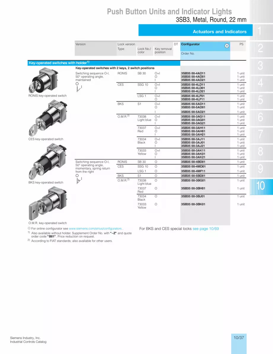
10/37Siemens Industry, Inc.Industrial Controls Catalog
Version Lock version DT Configurator PS
Type Lock No./ color
Key removal position Order No.
Key-operated switches with holder1)
RONIS key-operated switch
CES key-operated switch
BKS key-operated switch
O.M.R. key-operated switch
Key-operated switches with 2 keys, 2 switch positions
Switching sequence O-I, 50° operating angle, maintained
RONIS SB 30 O+I 3SB35 00-4AD11 1 unitO 3SB35 00-4AD01 1 unitI 3SB35 00-4AD21 1 unit
CES SSG 10 O+I 3SB35 00-4LD11 1 unitO 3SB35 00-4LD01 1 unitI 3SB35 00-4LD21 1 unit
LSG 1 O+I 3SB35 00-4LF01 1 unitO 3SB35 00-4LF11 1 unit
BKS S1 O+I 3SB35 00-5AD11 1 unitO 3SB35 00-5AD01 1 unit
I 3SB35 00-5AD21 1 unit
O.M.R.2) 73038 Light blue
O+I 3SB35 00-3AG11 1 unitO 3SB35 00-3AG01 1 unitI 3SB35 00-3AG21 1 unit
73037 Red
O+I 3SB35 00-3AH11 1 unitO 3SB35 00-3AH01 1 unitI 3SB35 00-3AH21 1 unit
73034 Black
O+I 3SB35 00-3AJ11 1 unitO 3SB35 00-3AJ01 1 unitI 3SB35 00-3AJ21 1 unit
73033 Yellow
O+I 3SB35 00-3AK11 1 unitO 3SB35 00-3AK01 1 unitI 3SB35 00-3AK21 1 unit
Switching sequence O-I, 50° operating angle, momentary, spring return from the right
RONIS SB 30 O 3SB35 00-4BD01 1 unit
CES SSG 10 O 3SB35 00-4MD01 1 unit
LSG 1 O 3SB35 00-4MF11 1 unit
BKS S1 O 3SB35 00-5BD01 1 unit
O.M.R.2) 73038 Light blue
O 3SB35 00-3BG01 1 unit
73037 Red
O 3SB35 00-3BH01 1 unit
73034 Black
O 3SB35 00-3BJ01 1 unit
73033 Yellow
O 3SB35 00-3BK01 1 unit
3SB3 Push Buttons and Indicator Lights, 22 mmActuators and Indicators, Metal, Round, 22 mm
Actuators and indicators
13/60 Siemens IC 10 · 2012* You can order this quantity or a multiple thereof.
Illustrations are approximate
13
For online configurator see www.siemens.com/sirius/configurators .1) Also available without holder. Supplement Order No. with "–Z" and quote
order code "B01". Price reduction on request.2) According to FIAT standards; also available for other users.
IC10_13_04 ccorp.fm Page 60 Friday, October 4, 2013 1:16 PM
3SB3, Metal, Round, 22 mm
Actuators and Indicators
Push Button Units and Indicator Lights
For BKS and CES special locks see page 10/69

10/38 Siemens Industry, Inc.Industrial Controls Catalog
3SB3, Metal, Round, 22 mm
Actuators and Indicators
Push Button Units and Indicator Lights
Version Lock version DT Configurator PS
Type Lock No./ color
Key removal position Order No.
Key-operated switches with holder1)
RONIS key-operated switch
CES key-operated switch
BKS key-operated switch
O.M.R. key-operated switch
Key-operated switches with 2 keys, 3 switch positions
Switching sequence I-O-II, 2 x 50° operating angle, maintained
RONIS SB 30 I+O+II 3SB35 00-4DD11 1 unitO 3SB35 00-4DD01 1 unitI+II 3SB35 00-4DD41 1 unitI 3SB35 00-4DD21 1 unitII 3SB35 00-4DD31 1 unitO+I 3SB35 00-4DD51 1 unit
CES SSG 10 O+I+II 3SB35 00-4PD11 1 unitO 3SB35 00-4PD01 1 unitI+II 3SB35 00-4PD41 1 unitI 3SB35 00-4PD21 1 unitII 3SB35 00-4PD31 1 unit
BKS S1 O 3SB35 00-5DD01 1 unitO+I+II 3SB35 00-5DD11 1 unitI 3SB35 00-5DD21II 3SB35 00-5DD31I+II 3SB35 00-5DD41
O.M.R.2) 73038 Light blue
I+O+II 3SB35 00-3DG11 1 unit
73037 Red
I+O+II O
3SB35 00-3DH113SB35 00-3DG01
1 unit 1 unit
73034 Black
I+O+II 3SB35 00-3DJ11 1 unitO 3SB35 00-3DJ01 1 unit
Switching sequence I-O-II, 2 x 50° operating angle, momentary, spring return from the left and right
RONIS SB 30 O 3SB35 00-4ED01 1 unit
CES SSG 10 O 3SB35 00-4QD01 1 unit
BKS S1 O 3SB35 00-5ED01 1 unit
O.M.R. 73034 Black
O 3SB35 00-3EJ01 1 unit
Switching sequence I-O-II, 2 x 50° operating angle, momentary to the left, spring return from the left, maintained to the right
RONIS SB 30 O + II 3SB35 00-4GD61 1 unitO II
3SB35 00-4GD013SB35 00-4GD31
1 unit 1 unit
CES SSG 10 O + II 3SB35 00-4SD61 1 unitO 3SB35 00-4SD01 1 unitII 3SB35 00-4SD31 1 unit
BKS S1 O + II 3SB35 00-5GD61 1 unitO II
3SB35 00-5GD013SB35 00-5GD31
1 unit 1 unit
O.M.R. 73033 Yellow
II 3SB35 00-3GK31 1 unit
73034 Black
II 3SB35 00-3GJ31 1 unit
Switching sequence I-O-II, 2 x 50° operating angle, maintained to the left, momentary to the right, spring return from the right
RONIS SB 30 O+I O I
3SB35 00-4FD513SB35 00-4FD013SB35 00-4FD21
1 unit 1 unit 1 unit
CES SSG 10 O+I 3SB35 00-4RD51 1 unitO 3SB35 00-4RD01 1 unitI 3SB35 00-4RD21 1 unit
BKS S1 O+I 3SB35 00-5FD51 1 unitO 3SB35 00-5FD01 1 unitI 3SB35 00-5FD21 1 unit
3SB3 Push Buttons and Indicator Lights, 22 mmActuators and Indicators, Metal, Round, 22 mm
Actuators and indicators
13/61Siemens IC 10 · 2012* You can order this quantity or a multiple thereof.Illustrations are approximate
13
For online configurator see www.siemens.com/sirius/configurators .1) Also available without holder. Supplement Order No. with "–Z" and quote
order code "B01". Price reduction on request.2) According to FIAT standards; also available for other users.
IC10_13_04 ccorp.fm Page 61 Friday, October 4, 2013 1:16 PM
For BKS and CES special locks see page 10/69

10/39Siemens Industry, Inc.Industrial Controls Catalog
Version Color of handle
Approval DT Configurator PS
Order No.
EMERGENCY-STOP devices according to ISO 13850 and IEC 60947-5-5,with holder1)2). Can also be used with 3TK28 safety relays.
Mushroom diameter 32 mm
EMERGENCY-STOP mushroom pushbuttons, Ø 32 mm, with positive latching according to ISO 13850, with rotate-to-unlatch mechanism
• Standard version 3SB35 00-1FA20 1 unit
• Solvent-resistant 3SB35 00-1FA20-0PA0 1 unit
Mushroom diameter 40 mm, with rotate-to-unlatch mechanism, with switch position indication
EMERGENCY-STOP mushroom pushbuttons, Ø 40 mm, with positive latching according to ISO 13850, with rotate-to-unlatch mechanism
Red
• Without switch position indicator 3SB35 00-1HA20 1 unit
• Without switch position indicator, solvent-resistant
3SB35 00-1HA20-0PA0 1 unit
• With mechanical switch position indication 3SB35 00-1HA26 1 unit
Mushroom diameter 40 mm, pull-to-unlatch mechanism
Mushroom diameter 60 mm
EMERGENCY-STOP mushroom pushbuttons, Ø 40 mm, with positive latching according to ISO 13850, with pull-to-unlatch mechanism
Red 3SB35 00-1TA20 1 unit
EMERGENCY-STOP mushroom pushbuttons, Ø 60 mm, with positive latching according to ISO 13850, with rotate-to-unlatch mecha-nism
Red 3SB35 00-1AA20 1 unit
EMERGENCY-STOP mushroom pushbuttons, Ø 40 mm with positive latchingfunction with IKON lockLock No. 360012K1, supplied with 2 keys, unlocking only possible using key
Red 3SB35 00–1UA20 1 unit
Mushroom diameter 40 mm, with RONIS key-operated switch
Mushroom diameter 40 mm, with CES key-operated switch
EMERGENCY-STOP mushroom pushbuttons, Ø 40 mm, with RONIS key-operated switch (with 2 keys), lock No. SB 30, with positive latching according to ISO 13850, unlocking only possible using key
Red 3SB35 00-1BA20 1 unit
EMERGENCY-STOP mushroom pushbuttons, Ø 40 mm, with CES key-operatedswitch, (with 2 keys), lock No. SSG 10, with positive latching according to ISO 13850, unlocking only possible using key
Red 3SB35 00-1KA20 1 unit
EMERGENCY-STOP mushroom pushbuttons, Ø 40 mm, with BKS key-operatedswitch, (with 2 keys), lock No. S1, with positive latch-ing according to ISO 13850, unlocking only possible using key
Red 3SB35 00-1LA20 1 unit
EMERGENCY-STOP mushroom pushbuttons, Ø 40 mm, with O.M.R. key-operated switch (with 2 keys), lock No. 73037, with positive latching according to ISO 13850, unlocking only using key
Red 3SB35 00-1MA20 1 unit
Wobble Stick 3SB35 00–7CB61
IC10_13_04 ccorp.fm Page 62 Friday, October 4, 2013 1:16 PM
3SB3 Push Buttons and Indicator Lights, 22 mmActuators and Indicators, Metal, Round, 22 mm
Actuators and indicators
13/62 Siemens IC 10 · 2012* You can order this quantity or a multiple thereof.
Illustrations are approximate
13
For online configurator see www.siemens.com/sirius/configurators .1) Also available without holder. Supplement Order No. with "–Z" and quote
order code "B01". Price reduction on request.2) Yellow backing plates must be ordered separately; see "Accessories" on
page 10/84.
For BKS and CES special locks see page 10/70\.
3SB3, Metal, Round, 22 mm
Actuators and Indicators
Push Button Units and Indicator Lights
For online configurator see www.siemens.com/sirius/configurators
1) Also available without holder. Supplement Order No. with “–Z” and quote order code “B01”. Price reduction on request.
2) Yellow backing plates must be ordered separately; see “Accessories” on page 10/84.
For BKS and CES special locks see page 10/69

10/40 Siemens Industry, Inc.Industrial Controls Catalog
3SB3, Metal, Round, 22 mm
Actuators and Indicators
Push Button Units and Indicator Lights3SB3 Push Buttons and Indicator Lights, 22 mmActuators and Indicators, Metal, Round, 22 mm
Actuators and indicators
13/63Siemens IC 10 · 2012* You can order this quantity or a multiple thereof.Illustrations are approximate
13
--
For online configurator see www.siemens.com/sirius/configurators .1) Also available without holder. Supplement Order No. with "–Z" and quote
order code "B01". Price reduction on request.2) Inscription by inserting a label is not possible.3) Not suitable for laser inscription.
Version Color of lens
DT Configurator PS
Order No.
Signaling elements with holder1)
Indicator light with smooth lens
Indicator lightswith lens with concentric rings2)
Amber 3SB35 01-6BA00 1 unitRed 3SB35 01-6BA20 1 unitYellow 3SB35 01-6BA30 1 unitGreen 3SB35 01-6BA40 1 unitBlue 3SB35 01-6BA50 1 unitWhite 3SB35 01-6BA60 1 unitClear 3SB35 01-6BA70 1 unit
Indicator lightswith smooth lens2)
Amber 3SB35 01-6AA00 1 unitRed 3SB35 01-6AA20 1 unitYellow 3SB35 01-6AA30 1 unitGreen 3SB35 01-6AA40 1 unitBlue 3SB35 01-6AA50 1 unitWhite 3SB35 01-6AA60 1 unitClear 3SB35 01-6AA70 1 unit
Indicator lightswith smooth solvent-resistant lens2)3)
Red 3SB35 01-6AA20-0PA0 1 unitYellow 3SB35 01-6AA30-0PA0 1 unitGreen 3SB35 01-6AA40-0PA0 1 unitBlue 3SB35 01-6AA50-0PA0 1 unitWhite 3SB35 01-6AA60-0PA0 1 unitClear 3SB35 01-6AA70-0PA0 1 unit
IC10_13_04 ccorp.fm Page 63 Friday, October 4, 2013 1:16 PM

10/41Siemens Industry, Inc.Industrial Controls Catalog
3SB3, Plastic, Round, 22 mm
Complete units
Push Button Units and Indicator Lights3SB3 Push Buttons and Indicator Lights, 22 mmActuators and Indicators, Plastic, Round, 22 mm
Complete units
13/25Siemens IC 10 · 2012* You can order this quantity or a multiple thereof.Illustrations are approximate
13
Selection and ordering data
Rated voltage of lamp
Color of handle
Contacts for front plate mounting
DT Screw terminals DT Spring-type terminals
Configurator Configurator
Order No. Order No.V
Push buttonsPush buttons with flat button
Push button with flat button
— Black 1 NO 3SB32 02-0AA11 3SB32 02-0AA11-0CC0Black 1 NC 3SB32 03-0AA11 3SB32 03-0AA11-0CC0Red 1 NC 3SB32 03-0AA21 3SB32 03-0AA21-0CC0Yellow 1 NO 3SB32 02-0AA31 3SB32 02-0AA31-0CC0Green 1 NO 3SB32 02-0AA41 3SB32 02-0AA41-0CC0Blue 1 NO 3SB32 02-0AA51 3SB32 02-0AA51-0CC0White 1 NO 3SB32 02-0AA61 3SB32 02-0AA61-0CC0Black 1 NO + 1 NC 3SB32 01-0AA11 3SB32 01-0AA11-0CC0Red 1 NO + 1 NC 3SB32 01-0AA21 3SB32 01-0AA21-0CC0Yellow 1 NO + 1 NC 3SB32 01-0AA31 3SB32 01-0AA31-0CC0Green 1 NO + 1 NC 3SB32 01-0AA41 3SB32 01-0AA41-0CC0Blue 1 NO + 1 NC 3SB32 01-0AA51 3SB32 01-0AA51-0CC0White 1 NO + 1 NC 3SB32 01-0AA61 3SB32 01-0AA61-0CC0
Push Button with extended buttonmonentary
Black 1 NO 3SB3202-0BA11 —Black 1 NC 3SB3203-0BA11 —Red 1 NC 3SB3203-0BA21 —Yellow 1 NO 3SB3202-0BA31 —Blue 1 NO 3SB3202-0BA51 —White 1 NO 3SB3202-0BA61 —Black 1 NO + 1 NC 3SB3201-0BA11 —Red 1 NO + 1 NC 3SB3201-0BA21 —Yellow 1 NO + 1 NC 3SB3201-0BA31 —Blue 1 NO + 1 NC 3SB3201-0BA51 —White 1 NO + 1 NC 3SB3201-0BA61 —
Illuminated push buttons with flat buttonwith integrated LED (incl. holder for 3 elements)
Illuminated push button with flat button
24 AC/DC Red1) 1 NC 3SB32 46-0AA21 3SB32 46-0AA21-0CC0Yellow1) 1 NO 3SB32 45-0AA31 3SB32 45-0AA31-0CC0Green1) 1 NO 3SB32 45-0AA41 3SB32 45-0AA41-0CC0Blue1) 1 NO 3SB32 45-0AA51 3SB32 45-0AA51-0CC0White 1 NO 3SB32 45-0AA61 3SB32 45-0AA61-0CC0Clear1) 1 NO 3SB32 45-0AA71 3SB32 45-0AA71-0CC0
24 AC/DC Red1) 1 NO + 1 NC 3SB32 47-0AA21 3SB32 47-0AA21-0CC0Yellow1) 1 NO + 1 NC 3SB32 47-0AA31 3SB32 47-0AA31-0CC0Green1) 1 NO + 1 NC 3SB32 47-0AA41 3SB32 47-0AA41-0CC0Blue1) 1 NO + 1 NC 3SB32 47-0AA51 3SB32 47-0AA51-0CC0White 1 NO + 1 NC 3SB32 47-0AA61 3SB32 47-0AA61-0CC0Clear1) 1 NO + 1 NC 3SB32 47-0AA71 3SB32 47-0AA71-0CC0
110 AC Red1) 1 NC 3SB32 50-0AA21 —Yellow1) 1 NO 3SB32 57-0AA31 —Green1) 1 NO 3SB32 57-0AA41 —Blue1) 1 NO 3SB32 57-0AA51 —White 1 NO 3SB32 57-0AA61 —Clear1) 1 NO 3SB32 57-0AA71 —
110 AC Red1) 1 NO + 1 NC 3SB32 51-0AA21 —Yellow1) 1 NO + 1 NC 3SB32 51-0AA31 —Green1) 1 NO + 1 NC 3SB32 51-0AA41 —Blue1) 1 NO + 1 NC 3SB32 51-0AA51 —White 1 NO + 1 NC 3SB32 51-0AA61 —Clear1) 1 NO + 1 NC 3SB32 51-0AA71 —
230 AC Red1) 1 NC 3SB32 54-0AA21 3SB32 54-0AA21-0CC0Yellow1) 1 NO 3SB32 53-0AA31 3SB32 53-0AA31-0CC0Green1) 1 NO 3SB32 53-0AA41 3SB32 53-0AA41-0CC0Blue1) 1 NO 3SB32 53-0AA51 3SB32 53-0AA51-0CC0White 1 NO 3SB32 53-0AA61 3SB32 53-0AA61-0CC0Clear1) 1 NO 3SB32 53-0AA71 3SB32 53-0AA71-0CC0
230 AC Red1) 1 NO + 1 NC 3SB32 55-0AA21 3SB32 55-0AA21-0CC0Yellow1) 1 NO + 1 NC 3SB32 55-0AA31 3SB32 55-0AA31-0CC0Green1) 1 NO + 1 NC 3SB32 55-0AA41 3SB32 55-0AA41-0CC0Blue1) 1 NO + 1 NC 3SB32 55-0AA51 3SB32 55-0AA51-0CC0White 1 NO + 1 NC 3SB32 55-0AA61 3SB32 55-0AA61-0CC0Clear1) 1 NO + 1 NC 3SB32 55-0AA71 3SB32 55-0AA71-0CC0
For online configurator see www.siemens.com/sirius/configurators .1) Inscription is possible by inserting a label.
IC10_13_04 ccorp.fm Page 25 Friday, October 4, 2013 1:16 PM
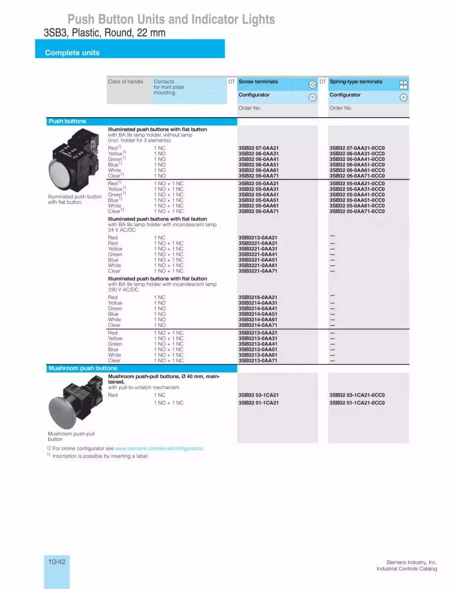
10/42 Siemens Industry, Inc.Industrial Controls Catalog
3SB3, Plastic, Round, 22 mm
Complete units
Push Button Units and Indicator Lights3SB3 Push Buttons and Indicator Lights, 22 mmActuators and Indicators, Plastic, Round, 22 mm
Complete units
13/26 Siemens IC 10 · 2012* You can order this quantity or a multiple thereof.
Illustrations are approximate
13
Color of handle Contacts for front plate mounting
DT Screw terminals DT Spring-type terminals
Configurator Configurator
Order No. Order No.
Push buttons
Illuminated push button with flat button
Illuminated push buttons with flat button with BA 9s lamp holder, without lamp (incl. holder for 3 elements)
Red1) 1 NC 3SB32 07-0AA21 3SB32 07-0AA21-0CC0Yellow1) 1 NO 3SB32 06-0AA31 3SB32 06-0AA31-0CC0Green1) 1 NO 3SB32 06-0AA41 3SB32 06-0AA41-0CC0Blue1) 1 NO 3SB32 06-0AA51 3SB32 06-0AA51-0CC0White 1 NO 3SB32 06-0AA61 3SB32 06-0AA61-0CC0Clear1) 1 NO 3SB32 06-0AA71 3SB32 06-0AA71-0CC0Red1) 1 NO + 1 NC 3SB32 05-0AA21 3SB32 05-0AA21-0CC0Yellow1) 1 NO + 1 NC 3SB32 05-0AA31 3SB32 05-0AA31-0CC0Green1) 1 NO + 1 NC 3SB32 05-0AA41 3SB32 05-0AA41-0CC0Blue1) 1 NO + 1 NC 3SB32 05-0AA51 3SB32 05-0AA51-0CC0White 1 NO + 1 NC 3SB32 05-0AA61 3SB32 05-0AA61-0CC0Clear1) 1 NO + 1 NC 3SB32 05-0AA71 3SB32 05-0AA71-0CC0Illuminated push buttons with flat button with BA 9s lamp holder with incandescent lamp 24 V AC/DC
Red 1 NC 3SB3213-0AA21 —Red 1 NO + 1 NC 3SB3221-0AA21 —Yellow 1 NO + 1 NC 3SB3221-0AA31 —Green 1 NO + 1 NC 3SB3221-0AA41 —Blue 1 NO + 1 NC 3SB3221-0AA51 —White 1 NO + 1 NC 3SB3221-0AA61 —Clear 1 NO + 1 NC 3SB3221-0AA71 —Illuminated push buttons with flat button with BA 9s lamp holder with incandescent lamp 230 V AC/DC
Red 1 NC 3SB3216-0AA21 —Yellow 1 NO 3SB3214-0AA31 —Green 1 NO 3SB3214-0AA41 —Blue 1 NO 3SB3214-0AA51 —White 1 NO 3SB3214-0AA61 —Clear 1 NO 3SB3214-0AA71 —Red 1 NO + 1 NC 3SB3213-0AA21 —Yellow 1 NO + 1 NC 3SB3213-0AA31 —Green 1 NO + 1 NC 3SB3213-0AA41 —Blue 1 NO + 1 NC 3SB3213-0AA51 —White 1 NO + 1 NC 3SB3213-0AA61 —Clear 1 NO + 1 NC 3SB3213-0AA71 —
Mushroom push buttons
Mushroom push-pull button
Mushroom push-pull buttons, Ø 40 mm, main-tained, with pull-to-unlatch mechanism
Red 1 NC 3SB32 03-1CA21 3SB32 03-1CA21-0CC01 NO + 1 NC 3SB32 01-1CA21 3SB32 01-1CA21-0CC0
For online configurator see www.siemens.com/sirius/configurators .1) Inscription is possible by inserting a label.
IC10_13_04 ccorp.fm Page 26 Friday, October 4, 2013 1:16 PM

10/43Siemens Industry, Inc.Industrial Controls Catalog
3SB3, Plastic, Round, 22 mm
Complete units
Push Button Units and Indicator Lights3SB3 Push Buttons and Indicator Lights, 22 mmActuators and Indicators, Plastic, Round, 22 mm
Complete units
13/27Siemens IC 10 · 2012* You can order this quantity or a multiple thereof.Illustrations are approximate
13
Version Color of handle/ Lock No.
Contacts for front plate mounting
DT Screw terminals DT Spring-type terminals
Configurator Configurator
Order No. Order No.
Selector switches
Selector switch
Selector switches, 2 switch positions Switching sequence O-I, 50° operating angle
Latching Black 1 NO 3SB32 02-2KA11 3SB32 02-2KA11-0CC01 NO + 1 NC 3SB32 01-2KA11 3SB32 01-2KA11-0CC0
Selector switches, 2 switch positions Switching sequence O-I, 90° operating angle
Latching Black 1 NO 3SB32 02-2HA11 —1 NO + 1 NC 3SB32 01-2HA11 —
Selector switches, 3 switch positions switching sequence I-O-II, 2 x 50° operating angle
Latching Black 1 NO, 1 NO 3SB32 10-2DA11 3SB32 10-2DA11-0CC01 NO + 1 NC, 1 NO + 1 NC
3SB32 08-2DA11 3SB32 08-2DA11-0CC0
Momentary, spring return from left and right
Black 1 NO, 1 NO 3SB32 10-2EA11 3SB32 10-2EA11-0CC01 NO + 1 NC, 1 NO + 1 NC
3SB32 08-2EA11 3SB32 08-2EA11-0CC0
Key-operated switches
RONIS key-operated switch
RONIS key-operated switches, 2 switchpositionswith 2 keys, removal position O + I, switching sequence O-I, 50° operating angle
Latching SB 30 1 NO 3SB32 02-4AD11 3SB32 02-4AD11-0CC01 NO + 1 NC 3SB32 01-4AD11 3SB32 01-4AD11-0CC0
Switching sequence I–O–II, maintained, operating angle 2 x 50°Latching SB 30 1 NO, 1 NO 3SB32 10–4DD11 —
1 NO + 1 NC, 1 NO + 1 NC
3SB32 08–4DD11 —
Twin push buttons
Twin push button with flat buttons
Twin push buttons, with flat, square buttons1)
With I/O inscrip-tion
White/White 1 NO + 1 NC, 1 NO + 1 NC
3SB31 00-8AC61 —
For online configurator see www.siemens.com/sirius/configurators .1)
IC10_13_04 ccorp.fm Page 27 Friday, October 4, 2013 1:16 PM
Mounting the twin push buttons in 3SB38 enclosure is not possible. For accessories see page 10/55.

10/44 Siemens Industry, Inc.Industrial Controls Catalog
3SB3, Plastic, Round, 22 mm
Complete units
Push Button Units and Indicator Lights3SB3 Push Buttons and Indicator Lights, 22 mmActuators and Indicators, Plastic, Round, 22 mm
Complete units
13/28 Siemens IC 10 · 2012* You can order this quantity or a multiple thereof.
Illustrations are approximate
13
Color of handle Contacts for front plate mounting
DT Screw terminals DT Spring-type terminals
Configurator Configurator
Order No. Order No.
EMERGENCY-STOP devices according to ISO 13850,with yellow name plate, Ø 80 mm, with inscription
With rotate-to-unlatch mechanism
EMERGENCY-STOP mushroom push buttons,Ø 40 mm, with positive maintained function,with rotate-to-unlatch mechanism
• English inscription "EMERGENCY STOP"
Red 1 NC q 3SB32 03-1HR20 —1 NC with mounting monitoring
q 3SB32 66-1HR20 —
Red 1 NO + 1 NC q 3SB32 01-1HR20 —
With rotate-to-unlatch mechanism and switch position indication
With rotate-to-unlatch mechanism and mechanical switch position indication
• English inscription "EMERGENCY STOP"
Red 1 NC q 3SB32 03-1HR26 —1 NC with mounting monitoring
q 3SB32 66-1HR26 —
Red 1 NO + 1 NC q 3SB32 01-1HR26 —
With pull-to-unlatch mechanism
With pull-to-unlatch mechanism
• English inscription "EMERGENCY STOP"
Red 1 NC q 3SB32 03-1TR20 —Red 1 NO + 1 NC q 3SB32 01-1TR20 —
For online configurator see www.siemens.com/sirius/configurators .
qPositive opening according to IEC 60947-5-1, Appendix K. Can be used with 3TK28 safety relays. Certificate:
IC10_13_04 ccorp.fm Page 28 Friday, October 4, 2013 1:16 PM

10/45Siemens Industry, Inc.Industrial Controls Catalog
3SB3, Plastic, Round, 22 mm
Complete units
Push Button Units and Indicator Lights3SB3 Push Buttons and Indicator Lights, 22 mmActuators and Indicators, Plastic, Round, 22 mm
Complete units
13/29Siemens IC 10 · 2012* You can order this quantity or a multiple thereof.Illustrations are approximate
13
Rated voltage of lamp Color of lens DT Screw terminals DT Spring-type terminals
Configurator Configurator
Order No. Order No.V
Indicator lights
Indicator light with smooth lens
Indicator lights with smooth lens1) with integrated LED
24 AC/DC Red 3SB32 44-6AA20 3SB32 44-6AA20-0CC0Yellow 3SB32 44-6AA30 3SB32 44-6AA30-0CC0Green 3SB32 44-6AA40 3SB32 44-6AA40-0CC0Blue 3SB32 44-6AA50 3SB32 44-6AA50-0CC0White 3SB32 44-6AA60 3SB32 44-6AA60-0CC0Clear 3SB32 44-6AA70 3SB32 44-6AA70-0CC0
110 AC Red 3SB32 48-6AA20 —Yellow 3SB32 48-6AA30 —Green 3SB32 48-6AA40 —Blue 3SB32 48-6AA50 —White 3SB32 48-6AA60 —Clear 3SB32 48-6AA70 —
230 AC Red 3SB32 52-6AA20 3SB32 52-6AA20-0CC0Yellow 3SB32 52-6AA30 3SB32 52-6AA30-0CC0Green 3SB32 52-6AA40 3SB32 52-6AA40-0CC0Blue 3SB32 52-6AA50 3SB32 52-6AA50-0CC0White 3SB32 52-6AA60 3SB32 52-6AA60-0CC0Clear 3SB32 52-6AA70 3SB32 52-6AA70-0CC0
With BA 9s lamp holder, without lamp
Red 3SB32 04-6AA20 3SB32 04-6AA20-0CC0Yellow 3SB32 04-6AA30 3SB32 04-6AA30-0CC0Green 3SB32 04-6AA40 3SB32 04-6AA40-0CC0Blue 3SB32 04-6AA50 3SB32 04-6AA50-0CC0White 3SB32 04-6AA60 3SB32 04-6AA60-0CC0Clear 3SB32 04-6AA70 3SB32 04-6AA70-0CC0
With BA 9s lamp holde with lamp (130 V)
24 V AC/DC Red 3SB32 17-6AA20 —Yellow 3SB32 17-6AA30 —Green 3SB32 17-6AA40 —Blue 3SB32 17-6AA50 —White 3SB32 17-6AA60 —Clear 3SB32 17-6AA70 —
With BA 9s lamp holder with lamp (130 V)
230 V AC/DC Red 3SB32 12-6AA20Yellow 3SB32 12-6AA30Green 3SB32 12-6AA40Blue 3SB32 12-6AA50White 3SB32 12-6AA60Clear 3SB32 12-6AA70
For online configurator see www.siemens.com/sirius/configurators .1) Inscription by inserting a label is not possible.
IC10_13_04 ccorp.fm Page 29 Friday, October 4, 2013 1:16 PM
3SB32 12-6AA20-0CC03SB32 12-6AA30-0CC0 3SB32 12-6AA40-0CC0 3SB32 12-6AA50-0CC0 3SB32 12-6AA60-0CC0 3SB32 12-6AA70-0CC0

10/46 Siemens Industry, Inc.Industrial Controls Catalog
3SB3, Plastic, Round, 22 mm
Complete units
Push Button Units and Indicator Lights3SB3 Push Buttons and Indicator Lights, 22 mmActuators and Indicators, Plastic, Round, 22 mm
Complete units
13/30 Siemens IC 10 · 2012* You can order this quantity or a multiple thereof.
Illustrations are approximate
13
Rated voltage of lamp Color of lens DT Screw terminals DT Spring-type terminals
Configurator Configurator
Order No. Order No.V
Indicator lights
Indicator light with lens with concentric rings
Indicator lights with lenswith concentric rings1) with integrated LED
24 AC/DC Red 3SB32 44-6BA20 3SB32 44-6BA20-0CC0Yellow 3SB32 44-6BA30 3SB32 44-6BA30-0CC0Green 3SB32 44-6BA40 3SB32 44-6BA40-0CC0Blue 3SB32 44-6BA50 3SB32 44-6BA50-0CC0White 3SB32 44-6BA60 3SB32 44-6BA60-0CC0Clear 3SB32 44-6BA70 3SB32 44-6BA70-0CC0
110 AC Red 3SB32 48-6BA20 —Yellow 3SB32 48-6BA30 —Green 3SB32 48-6BA40 —Blue 3SB32 48-6BA50 —White 3SB32 48-6BA60 —Clear 3SB32 48-6BA70 —
230 AC Red 3SB32 52-6BA20 3SB32 52-6BA20-0CC0Yellow 3SB32 52-6BA30 3SB32 52-6BA30-0CC0Green 3SB32 52-6BA40 3SB32 52-6BA40-0CC0Blue 3SB32 52-6BA50 3SB32 52-6BA50-0CC0White 3SB32 52-6BA60 3SB32 52-6BA60-0CC0Clear 3SB32 52-6BA70 3SB32 52-6BA70-0CC0
With BA 9s lamp holder, without lamp
Amber 3SB32 04-6BA00 —Red 3SB32 04-6BA20 3SB32 04-6BA20-0CC0Yellow 3SB32 04-6BA30 3SB32 04-6BA30-0CC0Green 3SB32 04-6BA40 3SB32 04-6BA40-0CC0Blue 3SB32 04-6BA50 3SB32 04-6BA50-0CC0White 3SB32 04-6BA60 3SB32 04-6BA60-0CC0Clear 3SB32 04-6BA70 3SB32 04-6BA70-0CC0
With BA 9s lamp holder, with LED
130 AC Amber 3SB32 40-6BA00 —Red 3SB32 40-6BA20 —Yellow 3SB32 40-6BA30 —Green 3SB32 40-6BA40 —Blue 3SB32 40-6BA50 —White 3SB32 40-6BA60 —Clear 3SB32 40-6BA70 —
With BA 9s lamp holder with incandescent lamp (130 V)
24 V AC/DC Red 3SB32 36-6BA20 —Yellow 3SB32 36-6BA30 —Green 3SB32 36-6BA40 —Blue 3SB32 36-6BA50 —White 3SB32 36-6BA60 —Clear 3SB32 36-6BA70 —
With integrated LED
230 AC Red 3SB32 52-6BA20Yellow 3SB32 52-6BA30Green 3SB32 52-6BA40Blue 3SB32 52-6BA50White 3SB32 52-6BA60Clear 3SB32 52-6BA70
IC10_13_04 ccorp.fm Page 30 Friday, October 4, 2013 1:16 PM
3SB32 52-6BA20-0CC0 3SB32 52-6BA30-0CC0 3SB32 52-6BA40-0CC0 3SB32 52-6BA50-0CC0 3SB32 52-6BA60-0CC0 3SB32 52-6BA70-0CC0
For online configurator see www.siemens.com/sirius/configurators 1) Inscription by inserting a label is not possible.

10/47Siemens Industry, Inc.Industrial Controls Catalog
3SB3, Plastic, Round, 22 mm
Complete units
Push Button Units and Indicator Lights
Version Rated voltage of lamp
Color of lens DT Screw terminals PS
Configurator
Order No.V
Signaling devicesAcoustic signaling devices, IP651)
Acoustic signaling device
Continuous tone 2.4 kHz, operational current min. 4 mA, sound pressure min. 80 dB/10 cm
(L-)(L+)X2X1
NSD0_00003
24 AC/DC Black 3SB32 33-7BA10 1 unit115 AC/DC 3SB32 34-7BA10 1 unit
230 AC/DC 3SB32 35-7BA10 1 unit
3SB3 Push Buttons and Indicator Lights, 22 mmActuators and Indicators, Plastic, Round, 22 mm
Complete units
13/31Siemens IC 10 · 2012* You can order this quantity or a multiple thereof.Illustrations are approximate
13
For online configurator see www.siemens.com/sirius/configurators .1) Mounting in 3SB38 enclosures only with the 3SB3400-1A lamp holder for
front plate mounting, which is included.
Version Degree of protection
Color of handle
DT Without connection PS
Order No.
Special devicesActuators for potentiometers2)3)
Potentiometer drive
With shaft Ø 6 mm, 30 ... 32 mm long
IP65 — 3SB10 00-7CH07 1 unit
Push buttons with extended stroke2)
for actuating relays
Push buttons with 12 mm stroke
12 mm stroke IP65 Black 3SB30 00-0EA11 1 unit
Mechanical Reset)
Overload reset adapter Reset Push Button IP65 Ø 22mm, 12 mm stroke
S00 to S10/S12
— 3RU19 00-1A 1 unit
Reset extension S10/S12 3SX1335 1 unit
Complete assembly 3SBES-RESET 1 unit
2) Mounting in 3SB38 enclosure is not possible.3) The potentiometer is not included in the scope of supply.
IC10_13_04 ccorp.fm Page 31 Friday, October 4, 2013 1:16 PM

10/48 Siemens Industry, Inc.Industrial Controls Catalog
3SB3, Plastic, Round, 22 mm
Actuators and Indicators
Push Button Units and Indicator Lights3SB3 Push Buttons and Indicator Lights, 22 mmActuators and Indicators, Plastic, Round, 22 mm
Actuators and indicators
13/35Siemens IC 10 · 2012* You can order this quantity or a multiple thereof.Illustrations are approximate
13
Selection and ordering data
Version Inscriptions Color of handle DT Configurator PS
Order No.
Push buttons with holder1)
With flat button
With raised button
Push buttons with flat button
Black 3SB30 00-0AA11 1 unitRed 3SB30 00-0AA21 1 unitYellow 3SB30 00-0AA31 1 unitGreen 3SB30 00-0AA41 1 unitBlue 3SB30 00-0AA51 1 unitWhite 3SB30 00-0AA61 1 unitGray 3SB30 00-0AB51 1 unitClear2) 3SB30 00-0AA71 1 unit
I Green 3SB30 00-0AA81 1 unitO Red 3SB30 00-0AB01 1 unitI White 3SB30 00-0AB11 1 unitO Black 3SB30 00-0AB21 1 unitR Blue 3SB30 00-0AC81 1 unit
Down Black 3SB30 00-0AA11-ZEE 1 unitUp Black 3SB30 00-0AA11-ZEDForward Black 3SB30 00-0AA11-ZEFReverse Black 3SB30 00-0AA11-ZEGOn Green 3SB30 00-0AA11-ZEBStart Red 3SB30 00-0AA11-ZELReset Blue 3SB30 00-0AA11-ZEM
Push buttons with raised button
Black 3SB30 00-0BA11 1 unitRed 3SB30 00-0BA21 1 unitYellow 3SB30 00-0BA31 1 unitGreen 3SB30 00-0BA41 1 unitBlue 3SB30 00-0BA51 1 unitWhite 3SB30 00-0BA61 1 unit
Off Red 3SB30 00-0BA21-ZECStop Red 3SB30 00-0BA21-ZEK
With raised button, main-tained
With raised front ring
With raised front ring, castellated
Illuminated push button with raised button
Push buttons with raised button,maintained by pressing in and turning to the right, unlatches by turning to the left
Black 3SB30 00-0CA11 1 unitRed 3SB30 00-0CA21 1 unit
Push buttons with raised front ring (height 13 mm)
Black 3SB30 00-0AA12 1 unitRed 3SB30 00-0AA22 1 unitYellow 3SB30 00-0AA32 1 unitGreen 3SB30 00-0AA42 1 unitBlue 3SB30 00-0AA52 1 unitWhite 3SB30 00-0AA62 1 unit
Push buttons with raised front ring, castellated (height 13 mm)
Black 3SB30 00-0AA13 1 unitRed 3SB30 00-0AA23 1 unitYellow 3SB30 00-0AA33 1 unitGreen 3SB30 00-0AA43 1 unitBlue 3SB30 00-0AA53White 3SB30 00-0AA63
Illuminated push buttons with flat button (incl. holder for 3 elements)
Amber2) 3SB30 01-0AA01 1 unitRed2) 3SB30 01-0AA21 1 unitYellow2) 3SB30 01-0AA31 1 unitGreen2) 3SB30 01-0AA41 1 unitBlue2) 3SB30 01-0AA51 1 unitWhite 3SB30 01-0AA61 1 unitClear2) 3SB30 01-0AA71 1 unit
Illuminated push buttons with raised button (incl. holder for 3 elements)
Red 3SB30 01-0BA21 1 unitYellow 3SB30 01-0BA31 1 unitGreen 3SB30 01-0BA41 1 unitBlue 3SB30 01-0BA51 1 unitClear 3SB30 01-0BA71 1 unit
Push buttons with flat button, maintained, unlatches by press-ing again
Black 3SB30 00-0DA11 1 unitRed 3SB30 00-0DA21 1 unitYellow 3SB30 00-0DA31 1 unitGreen 3SB30 00-0DA41 1 unitBlue 3SB30 00-0DA51 1 unitWhite 3SB30 00-0DA61 1 unitGray 3SB30 00-0DB51 1 unit
Illuminated push buttons with flat button, maintained, unlatches by press-ing again (incl. holder for 3 elements)
Red2) 3SB30 01-0DA21 1 unitYellow2) 3SB30 01-0DA31 1 unitGreen2) 3SB30 01-0DA41 1 unitBlue2) 3SB30 01-0DA51 1 unitWhite 3SB30 01-0DA61 1 unitClear2) 3SB30 01-0DA71 1 unit
For online configurator see www.siemens.com/sirius/configurators .1) Also available without holder. Supplement Order No. with "-Z" and quote
order code "B01". Price reduction on request.
2) Inscription is possible by inserting a label.
IC10_13_04 ccorp.fm Page 35 Friday, October 4, 2013 1:16 PM

10/49Siemens Industry, Inc.Industrial Controls Catalog
3SB3, Plastic, Round, 22 mm
Actuators and Indicators
Push Button Units and Indicator Lights
Version Color of han-dle
DT Configurator PS
Order No.
Mushroom push buttons with holder1)2)
Mushroom push buttons, Ø 30 mm Black 3SB30 00-1DA11 1 unitRed 3SB30 00-1DA21 1 unitYellow 3SB30 00-1DA31 1 unitGreen 3SB30 00-1DA41 1 unit
Mushroom push buttons, Ø 40 mm Black 3SB30 00-1GA11 1 unitRed 3SB30 00-1GA21 1 unitYellow 3SB30 00-1GA31 1 unitGreen 3SB30 00-1GA41 1 unit
Mushroom push buttons, Ø 60 mm Black 3SB30 00-1QA11 1 unitRed 3SB30 00-1QA21 1 unitYellow 3SB30 00-1QA31 1 unitGreen 3SB30 00-1QA41 1 unit
Illuminated mushroom push buttons, Ø 30 mm (incl. holder for 3 elements)
Red 3SB30 01-1DA21 1 unitYellow 3SB30 01-1DA31 1 unitGreen 3SB30 01-1DA41 1 unitBlue 3SB30 01-1DA51 1 unitWhite 3SB30 01-1DA61 1 unitClear 3SB30 01-1DA71 1 unit
Illuminated mushroom push buttons, Ø 40 mm (incl. holder for 3 elements)
Yellow 3SB30 01-1GA31 1 unitGreen 3SB30 01-1GA41 1 unitWhite 3SB30 01-1GA61 1 unit
Push-pull buttons, Ø 30 mm, maintained, pull to unlatch
Black 3SB30 00-1EA11 1 unitRed 3SB30 00-1EA21 1 unit
Push-pull buttons, Ø 40 mm, maintained, pull to unlatch
Black 3SB30 00-1CA11 1 unitRed 3SB30 00-1CA21 1 unit
Push-pull buttons, Ø 60 mm, maintained, pull to unlatch
Black 3SB30 00-1RA11 1 unitRed 3SB30 00-1RA21 1 unit
Push-pull buttons, Ø 30 mm, can be illuminated,maintained, pull to unlatch, (incl. holder for 3 elements)
Red 3SB30 01-1EA21 1 unitYellow 3SB30 01-1EA31 1 unitGreen 3SB30 01-1EA41 1 unitBlue 3SB30 01-1EA51 1 unitClear 3SB30 01-1EA71 1 unit
Push-pull buttons, Ø 40 mm, can be illuminated, maintained, pull to unlatch (incl. holder for 3 elements)
Red 3SB30 01-1CA21 1 unitYellow 3SB30 01-1CA31 1 unitGreen 3SB30 01-1CA41 1 unitBlue 3SB30 01-1CA51 1 unitClear 3SB30 01-1CA71 1 unit
3SB3 Push Buttons and Indicator Lights, 22 mmActuators and Indicators, Plastic, Round, 22 mm
Actuators and indicators
13/36 Siemens IC 10 · 2012* You can order this quantity or a multiple thereof.
Illustrations are approximate
13
For online configurator see www.siemens.com/sirius/configurators .1) Also available without holder. Supplement Order No. with "-Z" and quote
order code "B01". Price reduction on request.
2) Maximum permissible equipment: 3 single-pole or 2 double-pole contact blocks. When using the 3SB39 01-0AB holder, the central command point must not be empty.
IC10_13_04 ccorp.fm Page 36 Friday, October 4, 2013 1:16 PM

10/50 Siemens Industry, Inc.Industrial Controls Catalog
Version Version Illumination
Color of han-dle
DT Configurator PS
Order No.
Selector switches with holder1)
Selector switches with 2 switch positions
Non-illuminated
Illuminated
Switching sequence O-I, 90° operating angle, maintained
Non-illuminated Black 3SB30 00-2HA11 1 unitRed 3SB30 00-2HA21 1 unitGreen 3SB30 00-2HA41 1 unitWhite 3SB30 00-2HA61 1 unit
Illuminated (incl. holder for 3 elements)
Red 3SB30 01-2HA21 1 unitYellow 3SB30 01-2HA31 1 unitGreen 3SB30 01-2HA41 1 unitBlue 3SB30 01-2HA51 1 unitClear 3SB30 01-2HA71 1 unit
Switching sequence O-I, 50° operating angle, maintained
Non-illuminated Black 3SB30 00-2KA11 1 unitRed 3SB30 00-2KA21 1 unitGreen 3SB30 00-2KA41 1 unitWhite 3SB30 00-2KA61 1 unit
Illuminated (incl. holder for 3 elements)
Red 3SB30 01-2KA21 1 unitYellow 3SB30 01-2KA31 1 unitGreen 3SB30 01-2KA41 1 unitBlue 3SB30 01-2KA51 1 unitClear 3SB30 01-2KA71 1 unit
Switching sequence O-I, 50° operating angle, momentary, spring apart from right
Non-illuminated Black 3SB30 00-2LA11 1 unitRed 3SB30 00-2LA21 1 unitGreen 3SB30 00-2LA41 1 unitWhite 3SB30 00-2LA61 1 unit
Illuminated (incl. holder for 3 elements)
Red 3SB30 01-2LA21 1 unitYellow 3SB30 01-2LA31 1 unitGreen 3SB30 01-2LA41 1 unitBlue 3SB30 01-2LA51 1 unitClear 3SB30 01-2LA71 1 unit
Selector switches with 3 switch positions
Non-illuminated
Illuminated
Switching sequence I-O-II, 2 x 50° operating angle, maintained
Non-illuminated Black 3SB30 00-2DA11 1 unitRed 3SB30 00-2DA21 1 unitGreen 3SB30 00-2DA41 1 unitWhite 3SB30 00-2DA61 1 unit
Illuminated (incl. holder for 3 elements)
Red 3SB30 01-2DA21 1 unitYellow 3SB30 01-2DA31 1 unitGreen 3SB30 01-2DA41 1 unitBlue 3SB30 01-2DA51 1 unitClear 3SB30 01-2DA71 1 unit
Switching sequence I-O-II, 2 x 50° operating angle, momentary, spring return from left and right
Non-illuminated Black 3SB30 00-2EA11 1 unitRed 3SB30 00-2EA21 1 unitGreen 3SB30 00-2EA41 1 unitWhite 3SB30 00-2EA61 1 unit
Illuminated (incl. holder for 3 elements)
Red 3SB30 01-2EA21 1 unitYellow 3SB30 01-2EA31 1 unitGreen 3SB30 01-2EA41 1 unitBlue 3SB30 01-2EA51 1 unitClear 3SB30 01-2EA71 1 unit
Switching sequence I-O-II, 2 x 50° operating angle, momentary to the left, spring return to the left, maintained to the right
Non-illuminated Black 3SB30 00-2GA11 1 unitRed 3SB30 00-2GA21 1 unitGreen 3SB30 00-2GA41 1 unitWhite 3SB30 00-2GA61 1 unit
Illuminated (incl. holder for 3 elements)
Red 3SB30 01-2GA21 1 unitYellow 3SB30 01-2GA31 1 unitGreen 3SB30 01-2GA41 1 unitBlue 3SB30 01-2GA51 1 unitClear 3SB30 01-2GA71 1 unit
Switching sequence I-O-II, 2 x 50° operating angle, maintained to the left, momentary to the right, spring return from the right
Non-illuminated Black 3SB30 00-2FA11 1 unitRed 3SB30 00-2FA21 1 unitGreen 3SB30 00-2FA41 1 unitWhite 3SB30 00-2FA61 1 unit
Illuminated (incl. holder for 3 elements)
Red 3SB30 01-2FA21 1 unitYellow 3SB30 01-2FA31 1 unitGreen 3SB30 01-2FA41 1 unitBlue 3SB30 01-2FA51 1 unitClear 3SB30 01-2FA71 1 unit
3SB3 Push Buttons and Indicator Lights, 22 mmActuators and Indicators, Plastic, Round, 22 mm
Actuators and indicators
13/37Siemens IC 10 · 2012* You can order this quantity or a multiple thereof.Illustrations are approximate
13
For online configurator see www.siemens.com/sirius/configurators .1) Also available without holder. Supplement Order No. with "-Z" and quote
order code "B01". Price reduction on request.
IC10_13_04 ccorp.fm Page 37 Friday, October 4, 2013 1:16 PM
3SB3, Plastic, Round, 22 mm
Actuators and Indicators
Push Button Units and Indicator Lights

10/51Siemens Industry, Inc.Industrial Controls Catalog
Version Lock version DT Configurator PS
Type Lock No./ color
Key removal position Order No.
Key-operated switches with holder1)
RONIS key-operated switch
CES key-operated switch
BKS key-operated switch
O.M.R. key-operated switch
Key-operated switches with 2 keys, 2 switch positionsSwitching sequence O-I, 50° operating angle, maintained
RONIS SB 30 O+I 3SB30 00-4HD11 1 unitO 3SB30 00-4HD01 1 unitI 3SB30 00-4HD21 1 unit
Switching sequence O-I, 50° operating angle, maintained
RONIS SB 30 O+I 3SB30 00-4AD11 1 unitO 3SB30 00-4AD01 1 unitI 3SB30 00-4AD21 1 unit
CES SSG 10 O+I 3SB30 00-4LD11 1 unitO 3SB30 00-4LD01 1 unitI 3SB30 00-4LD21 1 unit
LSG 1 O+I 3SB30 00-4LF01 1 unitO 3SB30 00-4LF11 1 unit
CES with key monitoring2)
SSG 10 O 3SB30 00-4LD05 1 unit
BKS S1 O+I 3SB30 00-5AD11 1 unitO 3SB30 00-5AD01 1 unitI 3SB30 00-5AD21 1 unit
O.M.R.3) 73038 Light blue
O+I 3SB30 00-3AG11 1 unitO 3SB30 00-3AG01 1 unit
73037 Red
O+I 3SB30 00-3AH11 1 unitO 3SB30 00-3AH01 1 unit
73034 Black
O+I 3SB30 00-3AJ11 1 unitO 3SB30 00-3AJ01 1 unitI 3SB30 00-3AJ21 1 unit
73033 Yellow
O+I 3SB30 00-3AK11 1 unitO 3SB30 00-3AK01 1 unit
Switching sequence O-I, 50° operating angle, momentary, spring return from the right
RONIS SB 30 O 3SB30 00-4BD01 1 unit
CES SSG 10 O 3SB30 00-4MD01 1 unit
LSG 1 O 3SB30 00-4MF11 1 unit
BKS S1 O 3SB30 00-5BD01 1 unit
O.M.R.3) 73038 Light blue
O 3SB30 00-3BG01 1 unit
73037 Red
O 3SB30 00-3BH01 1 unit
73034 Black
O 3SB30 00-3BJ01 1 unit
73033 Yellow
O 3SB30 00-3BK01 1 unit
3SB3 Push Buttons and Indicator Lights, 22 mmActuators and Indicators, Plastic, Round, 22 mm
Actuators and indicators
13/38 Siemens IC 10 · 2012* You can order this quantity or a multiple thereof.
Illustrations are approximate
13
For online configurator see www.siemens.com/sirius/configurators .1) Also available without holder. Supplement Order No. with "-Z" and quote
order code "B01". Price reduction on request.2) For locks with key monitoring the supplied 3SB39 01-0AB holder must be
used. The key scan is performed by a 3SB34 single-pole NC contact block which must be snap-mounted in the center position. Scanning of the switch posi-tions must be performed by additional contact blocks which are snap-mounted on the actuator. Special locks can be ordered only with order code "Y01".
3) According to FIAT standards; also available for other users.
IC10_13_04 ccorp.fm Page 38 Friday, October 4, 2013 1:16 PM
3SB3, Plastic, Round, 22 mm
Actuators and Indicators
Push Button Units and Indicator Lights
For BKS and CES special locks see page 10/69.

10/52 Siemens Industry, Inc.Industrial Controls Catalog
Version Lock version DT Configurator PS
Type Lock No./ color
Key removal position Order No.
Key-operated switches with holder1)
RONIS key-operated switch
CES key-operated switch
BKS key-operated switch
O.M.R. key-operated switch
Key-operated switches with 2 keys, 3 switch positionsSwitching sequence I-O-II, 2 x 50° operating angle, maintained
RONIS SB 30 I+O+II 3SB30 00-4DD11 1 unitO 3SB30 00-4DD01 1 unitI+II 3SB30 00-4DD41 1 unitI 3SB30 00-4DD21 1 unitII 3SB30 00-4DD31 1 unitO+I 3SB30 00-4DD51 1 unit
CES SSG 10 I+O+II 3SB30 00-4PD11 1 unitO 3SB30 00-4PD01 1 unitO+I 3SB30 00-4PD51 1 unitI+II 3SB30 00-4PD41 1 unitI 3SB30 00-4PD21 1 unitII 3SB30 00-4PD31 1 unit
CES with key monitoring
SSG 10 2)
O 3SB30 00-4PD05 1 unit
BKS S1 I+O+II 3SB30 00-5DD11 1 unitII 3SB30 00-5DD31 1 unitO 3SB30 00–5DD01 1 unit
O.M.R.3) 73038 Light blue
I+O+II 3SB30 00-3DG11 1 unitO 3SB30 00-3DG01 1 unit
73037 Red
O 3SB30 00-3DH01 1 unitO+I 3SB30 00-3DH51 1 unit
73034 Black
I+O+II 3SB30 00-3DJ11 1 unitO 3SB30 00-3DJ01 1 unit
73033 Yellow
I+O+II 3SB30 00-3DK11 1 unit
Switching sequence I-O-II, 2 x 50° operating angle, momentary, spring return from left and right
RONIS SB 30 O 3SB30 00-4ED01 1 unit
CES SSG 10 O 3SB30 00-4QD01 1 unit
BKS S1 O 3SB30 00-5ED01 1 unit
O.M.R.3) 73034 Black
O 3SB30 00-3EJ01 1 unit
73037 Red
O 3SB30 00–3EH01
Switching sequence I-O-II, 2 x 50° operating angle, momentary to the left, spring return from the left, maintained to the right
RONIS SB 30 O + II 3SB30 00-4GD61 1 unitO 3SB30 00-4GD01 1 unitII 3SB30 00-4GD31 1 unit
CES SSG 10 O + II 3SB30 00-4SD61 1 unitO 3SB30 00-4SD01 1 unit
BKS S1 O 3SB30 00-5GD01 1 unit
Switching sequence I-O-II, 2 x 50° operating angle, maintained to the left, momentary to the right, spring return from the right
RONIS SB 30 O+I 3SB30 00-4FD51 1 unitO 3SB30 00-4FD01 1 unitI 3SB30 00-4FD21 1 unit
CES SSG 10 O+I 3SB30 00-4RD51 1 unitO 3SB30 00-4RD01 1 unitI 3SB30 00-4RD21 1 unit
BKS S1 O+I 3SB30 00-5FD51 1 unitO 3SB30 00-5FD01 1 unitI 3SB30 00-5FD21 1 unit
O.M.R.3) 73038 Light blue
O 3SB30 00-3FG01 1 unit
73034 Black
I 3SB30 00-3FJ21 1 unit
3SB3 Push Buttons and Indicator Lights, 22 mmActuators and Indicators, Plastic, Round, 22 mm
Actuators and indicators
13/39Siemens IC 10 · 2012* You can order this quantity or a multiple thereof.Illustrations are approximate
13
For online configurator see www.siemens.com/sirius/configurators .1) Also available without holder. Supplement Order No. with "-Z" and quote
order code "B01". Price reduction on request.2) For locks with key monitoring the supplied 3SB39 01-0AB holder must be
used. The key scan is performed by a 3SB34 single-pole NC contact block which must be snap-mounted in the center position. Scanning of the switch posi-tions must be performed by additional contact blocks which are snap-mounted on the actuator. Special locks can be ordered only with order code "Y01".
3) According to FIAT standards; also available for other users.
IC10_13_04 ccorp.fm Page 39 Friday, October 4, 2013 1:16 PM
3SB3, Plastic, Round, 22 mm
Actuators and Indicators
Push Button Units and Indicator Lights
For BKS and CES special locks see page 10/69.

10/53Siemens Industry, Inc.Industrial Controls Catalog
Version Color of handle
Approval DT Configurator PS
Order No.
EMERGENCY-STOP devices according to ISO 13850 and IEC 60947-5-5, with holder1)2).Can also be used with 3TK28 safety relays.
Mushroom diameter 32 mm
EMERGENCY-STOP mushroom pushbuttons, Ø 32 mm, with positive maintained according to ISO 13850, with rotate-to-unlatch mechanism
Red 3SB30 00-1FA20 1 unit
Mushroom diameter 40 mm, with rotate-to-unlatch mechanism, with switch position indication
EMERGENCY-STOP mushroom pushbuttons, Ø 40 mm, with positive maintained according to ISO 13850, with rotate-to-unlatch mechanism
Red
• Without switch position indicator 3SB30 00-1HA20 1 unit
• With mechanical switch position indication 3SB30 00-1HA26 1 unit
• Flat head style 3SB30 00-1XA20
Mushroom diameter 40 mm, pull-to-unlatch mechanism
EMERGENCY-STOP mushroom pushbuttons, Ø 40 mm, with positive maintained according to ISO 13850, with pull-to-unlatch mechanism
Red 3SB30 00-1TA20 1 unit
Mushroom diameter 60 mm
EMERGENCY-STOP mushroom pushbuttons, Ø 60 mm, with positive maintained according to ISO 13850, with rotate-to-unlatch mecha-nism
Red 3SB30 00-1AA20 1 unit
Mushroom diameter 40 mm, with RONIS key-operated switch
Mushroom diameter 40 mm, with CES key-operated switch
EMERGENCY-STOP mushroom pushbuttons, Ø 40 mm, with RONIS lock, lock No. SB 30, with positive maintained acc. to ISO 13850, unlocking only possible using key
Red 3SB30 00-1BA20 1 unit
EMERGENCY-STOP mushroom pushbuttons, Ø 40 mm, with CES lock,lock No. SSG 10, with positive maintainedaccording to ISO 13850,unlocking only possible using key
Red 3SB30 00-1KA20 1 unit
EMERGENCY-STOP mushroom pushbuttons, Ø 40 mm, with BKS lock, lock No. S1, with positive maintained according to ISO 13850, unlocking only possible using key
Red 3SB30 00-1LA20 1 unit
EMERGENCY-STOP mushroom pushbuttons, Ø 40 mm, with O.M.R. lock, lock No. 73037, with positive maintained according to ISO 13850, unlocking only possible using key
Red 3SB30 00-1MA20 1 unit
EMERGENCY-STOP mushroom pushbuttons, Ø 40 mm, with "EMO" markingfor SEMI S2 compliancewith mechanical maintained function acc. to EN418, turn short handle to left to unlatch
Red (flat) 3SB30 00-1XB80 1 unit
3SB3 Push Buttons and Indicator Lights, 22 mmActuators and Indicators, Plastic, Round, 22 mm
Actuators and indicators
13/40 Siemens IC 10 · 2012* You can order this quantity or a multiple thereof.
Illustrations are approximate
13
For online configurator see www.siemens.com/sirius/configurators .1) Also available without holder. Supplement Order No. with "-Z" and quote
order code "B01". Price reduction on request.2) The yellow backing plates must be ordered separately, see "Accessories"
on page 10/84.
For BKS and CES special locks see page 10/70.
IC10_13_04 ccorp.fm Page 40 Friday, October 4, 2013 1:16 PM
3SB3, Plastic, Round, 22 mm
Actuators and Indicators
Push Button Units and Indicator Lights
For online configurator see www.siemens.com/sirius/configurators
1) Also available without holder. Supplement Order No. with “–Z” and quote order code “B01”. Price reduction on request.
2) Yellow backing plates must be ordered separately; see “Accessories” on page 10/84..
For BKS and CES special locks see page 10/69.
10/54 Siemens Industry, Inc.Industrial Controls Catalog
Version Color of lens DT Configurator PS
Order No.
Signaling elements with holder1)
Indicator light with concentric rings
Indicator lights with smooth lens2)
Amber 3SB30 01-6AA00 1 unitRed 3SB30 01-6AA20 1 unitYellow 3SB30 01-6AA30 1 unitGreen 3SB30 01-6AA40 1 unitBlue 3SB30 01-6AA50 1 unitWhite 3SB30 01-6AA60 1 unitClear 3SB30 01-6AA70 1 unit
Indicator lights with lens with concentric rings2)
Amber 3SB30 01-6BA00 1 unitRed 3SB30 01-6BA20 1 unitYellow 3SB30 01-6BA30 1 unitGreen 3SB30 01-6BA40 1 unitBlue 3SB30 01-6BA50 1 unitWhite 3SB30 01-6BA60 1 unitClear 3SB30 01-6BA70 1 unit
Acoustic signaling device
Acoustic signaling devices, IP403) For acoustic signal transformer 24 V DC4) (without BA 9s base)
Black 3SB30 00-7AA10 1 unit
3SB3 Push Buttons and Indicator Lights, 22 mmActuators and Indicators, Plastic, Round, 22 mm
Actuators and indicators
13/41Siemens IC 10 · 2012* You can order this quantity or a multiple thereof.Illustrations are approximate
13
For online configurator see www.siemens.com/sirius/configurators .1) Also available without holder. Supplement Order No. with "-Z" and quote
order code "B01". Price reduction on request.2) Inscription by inserting a label is not possible.3) For acoustic signaling devices, IP65, see "Complete Units".
4) Following must be ordered separately: - 3SB1902-2BN acoustic signal transformer, see "Accessories". - 3SB34 00-1A lamp holder for front plate mounting or 3SB34 20-1A lamp holder for base mounting, both with screw terminals. Devices assembled in this way are suitable for use in enclosures. Lamp holders with spring-type terminals cannot be used.
Version Inscriptions Color of handle DT Configurator PS
Order No.
Twin push buttons with indicator light with holder1)2)
Twin push button with indicator light, with flat buttons
Twin push buttons with indicatorlight, IP65with flat, square buttons, incl. holder for 3 elements
I/O3) Green/Red 3SB31 01-8BC21 1 unitI/O3) White/Black 3SB31 01-8BC31 1 unit
↑ / ↓ 3) Green/Red 3SB31 01-8BC81 1 unit
Twin push buttons with indicator light, with flat and raised buttons
Twin push buttons with indicatorlight, IP65with flat and raised, square buttons, incl. holder for 3 elements
I/O3) Green/Red 3SB31 01-8DC21 1 unitI/O3) White/Black 3SB31 01-8DC31 1 unit
For online configurator see www.siemens.com/sirius/configurators .1) Mounting the twin push buttons in 3SB38 enclosure is not possible.2) Also available without holder. Supplement Order No. with "-Z" and quote
order code "B01". Price reduction on request.3) Black inscription for green, red and white buttons;
white inscription on black button.
IC10_13_04 ccorp.fm Page 41 Friday, October 4, 2013 1:16 PM
≤ ×
≥
3SB3, Plastic, Round, 22 mm
Actuators and Indicators
Push Button Units and Indicator Lights
For online configurator see www.siemens.com/sirius/configurators.
1)Mounting the twin push buttons in 3SB38 enclosure is not possible.
2)Also available without holder. Supplement Order No. with “-Z” and quote order code “B01”. Price reduction on request.
3)Black inscription for green, red and white

10/55Siemens Industry, Inc.Industrial Controls Catalog
Version Inscriptions Color of handle
DT Configurator PS
Order No.
Twin push buttons with holder1)2)
Twin push button with flat buttons
Twin push buttons, IP65with flat, square buttons
I/O3) Green/Red 3SB31 00-8AC21 1 unitI/O3) White/Black 3SB31 00-8AC31 1 unit
↑ / ↓ 3) White/White 3SB31 00-8AC61-0AD0 1 unit
Twin push buttons, IP65with flat and raised, square buttons
I/O3) Green/Red 3SB31 00-8CC21 1 unitI/O3) White/Black 3SB31 00-8CC31 1 unit
3SB3 Push Buttons and Indicator Lights, 22 mmActuators and Indicators, Plastic, Round, 22 mm
Actuators and indicators
13/42 Siemens IC 10 · 2012* You can order this quantity or a multiple thereof.
Illustrations are approximate
13
For online configurator see www.siemens.com/sirius/configurators .1) Mounting the twin push buttons in 3SB38 enclosure is not possible.2) Also available without holder. Supplement Order No. with "-Z" and quote
order code "B01". Price reduction on request.3) Black inscription for green, red and white buttons;
white inscription on black button.
Version Use DT Order No. PS
Accessories for twin push buttons
Label holder
Label holders 70 mm x 30 mm for inscription label 12.5 mm x 27 mm1)
Twin push buttons 3SB39 22-0AY 5 units
Protective cap
Protective caps, clear Silicone, for degree of protection IP67
Twin push buttons with flat buttons
3SB39 21-0AQ 1 unit
1)
IC10_13_04 ccorp.fm Page 42 Friday, October 4, 2013 1:16 PM
3SB3, Plastic, Round, 22 mm
Actuators and Indicators
Push Button Units and Indicator Lights
Mounting in 3SB38 enclosure is not possible. For inscription labels see pages 10/75 and 10/76.

10/56 Siemens Industry, Inc.Industrial Controls Catalog
3SB3 Push Buttons and Indicator Lights, 22 mmActuators and Indicators, Plastic, Round, 22 mm
Coordinate switches, complete
13/32 Siemens IC 10 · 2012* You can order this quantity or a multiple thereof.
Illustrations are approximate
13
Overview
Coordinate switch with contact blocks
Coordinate switches control auxiliary circuits permitting move-ments in various directions of machines and equipment.
The switches are designed for front panel mounting. They are cli-mate-proof.
OperationThe 3SB14 00-0J contact block is used, which due to its depth cannot be built into 3SB38 enclosures.
Switches are available as follows:• With 2 or 4 switch positions• Latching or momentary contact type• With or without mechanical interlocking
In the case of switches with mechanical interlock in O position, the switch is unlatched with the unlatching button at the front of the actuating lever.
InscriptionsA name plate consisting of a black, plastic label holder and two or four adhesive, silver-colored inscription labels of 27 mm x 27 mm in size is available for labeling purposes. These labels can be supplied with and without customized inscription.
Note mounting dimensions!
Selection and ordering data
Version Operating travel
Contact closed Contact open
DT Screw terminals PU (UNIT,
SET, M)
PS
Order No.
Coordinate switches2 switch positions, 1 NO per direction
Coordinate switch, 2 switch positions
Horizontal, momentary contact type
NSD0_01079
B 0A AB
0
43-4433-34
NSD0_01077
Without mechanical interlocking in the O position
• With plastic front ring, black C 3SB12 01-7DV01 1 1 unit
• With metal front ring C 3SB12 01-7DV20 1 1 unit
With mechanical interlocking in the O position
• With plastic front ring, black C 3SB12 01-7DW01 1 1 unit
• With metal front ring C 3SB12 01-7DW20 1 1 unit
Vertical, momentary contact type
NSD0_01080D
0
C
DC
0
13-1423-24
NSD0_01078
Without mechanical interlocking in the O position
• With plastic front ring, black C 3SB12 01-7FV01 1 1 unit
• With metal front ring C 3SB12 01-7FV20 1 1 unit
With mechanical interlocking in the O position
• With plastic front ring, black C 3SB12 01-7FW01 1 1 unit
• With metal front ring C 3SB12 01-7FW20 1 1 unit
IC10_13_04 ccorp.fm Page 32 Friday, October 4, 2013 1:16 PM
3SB3, Plastic, Round, 22 mm
Coordinate switches, complete
Push Button Units and Indicator Lights

10/57Siemens Industry, Inc.Industrial Controls Catalog
Version Operating travel
Contact closed Contact open
DT Screw terminals PS
Order No.
Coordinate switches2 switch positions, 1 NO per direction
Coordinate switch, 2 switch positions
Horizontal, maintained
NSD0_01079
B 0A AB
0
43-4433-34
NSD0_01077
Without mechanical interlocking in the O position
• With plastic front ring, black 3SB12 01-7EV01 1 unit
• With metal front ring 3SB12 01-7EV20 1 unit
With mechanical interlocking in the O position
• With plastic front ring, black 3SB12 01-7EW01 1 unit
• With metal front ring 3SB12 01-7EW20 1 unit
Vertical, maintained
NSD0_01080D
0
C
DC
0
13-1423-24
NSD0_01078
Without mechanical interlocking in the O position
• With plastic front ring, black 3SB12 01-7GV01 1 unit
• With metal front ring 3SB12 01-7GV20 1 unit
With mechanical interlocking in the O position
• With plastic front ring, black 3SB12 01-7GW01 1 unit
• With metal front ring 3SB12 01-7GW20 1 unit
4 switch positions, 1 NO per direction
Coordinate switch, 4 switch positions
Momentary contact type
NSD0_00076
B 0AD
C
NSD0_00077CD
BA
23-2413-14
33-3443-44
0
Without mechanical interlocking in the O position
• With plastic front ring, black 3SB12 08-7JV01 1 unit
• With metal front ring 3SB12 08-7JV20 1 unit
With mechanical interlocking in the O position
• With plastic front ring, black 3SB12 08-7JW01 1 unit
• With metal front ring 3SB12 08-7JW20 1 unit
Latching
NSD0_00076
B 0AD
C
NSD0_00077CD
BA
23-2413-14
33-3443-44
0
Without mechanical interlocking in the O position
• With plastic front ring, black 3SB12 08-7KV01 1 unit
• With metal front ring 3SB12 08-7KV20 1 unit
With mechanical interlocking in the O position
• With plastic front ring, black 3SB12 08-7KW01 1 unit
• With metal front ring 3SB12 08-7KW20 1 unit
3SB3 Push Buttons and Indicator Lights, 22 mmActuators and Indicators, Plastic, Round, 22 mm
Coordinate switches, complete
13/33Siemens IC 10 · 2012* You can order this quantity or a multiple thereof.Illustrations are approximate
13
IC10_13_04 ccorp.fm Page 33 Friday, October 4, 2013 1:16 PM
3SB3, Plastic, Round, 22 mm
Coordinate switches, complete
Push Button Units and Indicator Lights

10/58 Siemens Industry, Inc.Industrial Controls Catalog
3SB3 Push Buttons and Indicator Lights, 22 mmActuators and Indicators, Plastic, Round, 22 mm
Coordinate switches, complete
13/34 Siemens IC 10 · 2012* You can order this quantity or a multiple thereof.
Illustrations are approximate
13
Accessories
Options
Customized inscriptionsThese labeling plates can be inscribed with text or symbols. 5 lines with 11 characters each in a letter height of 4 mm are possible.
Ordering notes
Append the following order codes to the Order No.:• Text line(s) in upper/lower case, upper case always for begin-
ning of line (e.g. "Lift off"): K0Y• Text line(s) in upper case (e.g. "LIFT OFF"): K1Y• Text line(s) in lower case (e.g. "lift off"): K2Y• Text line(s) in upper/lower case, all words begin with upper
case letters (e.g. "Lift Off"): K5Y• Symbol with number according to ISO 7000 or IEC 60417: K3Y
• Any inscription or symbol according to order form supple-ment: K9Y
When ordering, specify the required inscription in plain text in addition to the order number and order code. In the case of spe-cial inscriptions with words in languages other than German, give the exact spelling and specify the language.
In the case of multi-line inscriptions, the text must be assigned to the respective line, e.g. "Z1 = Lift, Z2 =Lower".
Symbols can also be ordered with numbers according to ISO 7000 or IEC 60417.
For special symbols (order code K9Y), a CAD drawing in DXF format can be submitted.
Ordering example
A label inscribed with symbol No. 1117 according to ISO 7000 is required:
3SB19 06-2XZ K3Y Z = 1117 ISO
Version Contact blocks
Symbols/ operating travel
Contact closed Contact open
DT Screw terminals PS
Order No.
Spare contact blocks
3SB14 00-0J
Contact blocks with2 contacts 1 NO, 1 NO
(included in scope of supply of switch)
3SB14 00-0J 1 unit
Version DT Order No. PS
Name platesLabel holders for coordinate switches2 switch positions, horizontal, 89 mm × 30 mm 3SB19 06-0AU 1 unit
2 switch positions, vertical, 30 mm × 89 mm 3SB19 06-0AV 1 unit
4 switch positions 3SB19 06-0AW 1 unit
Inscription labels 27 mm × 27 mm,silver-colored, for sticking in placeWithout inscription 3SB19 06-2AA 1 unit
With inscription (engraved) 3SB19 06-2XZ• Text lines (up to 5 lines each with 11 characters) K0Y, K1Y, K2Y, or K5Y 1 unit
• Graphic symbol with number according to ISO 7000 or IEC 60417 K3Y 1 unit
• Any inscription or symbol K9Y 1 unit
.4
.3
.4
.3
.3/.4NSD0_00109a
BA.3/.4
0
IC10_13_04 ccorp.fm Page 34 Thursday, September 19, 2013 11:01 AM
3SB19 06-0AV
3SB19 06-0AW
3SB3, Plastic, Round, 22 mm
Coordinate switches, complete
Push Button Units and Indicator Lights
For other ordering examples see page 10/72.
For black plastic labels see page 10/76.

10/59Siemens Industry, Inc.Industrial Controls Catalog
3SB3 Push Buttons and Indicator Lights, 22 mmActuators and Indicators, Plastic, Square, 26 mm × 26 mm
Complete units
13/43Siemens IC 10 · 2012* You can order this quantity or a multiple thereof.Illustrations are approximate
13
Selection and ordering data
Version Rated voltage of lamp
Color of handle
Contacts for front plate mounting
DT Screw terminals PS
Configurator
Order No.V
Push buttons
Push button
Push buttons with flat button
— Black 1 NO 3SB33 02-0AA11 1 unitBlack 1 NC 3SB33 03-0AA11 1 unitRed 1 NC 3SB33 03-0AA21 1 unitYellow 1 NO 3SB33 02-0AA31 1 unitGreen 1 NO 3SB33 02-0AA41 1 unitBlue 1 NO 3SB33 02-0AA51 1 unitWhite 1 NO 3SB33 02-0AA61 1 unit
Black 1 NO + 1 NC 3SB33 01-0AA11 1 unitRed 1 NO + 1 NC 3SB33 01-0AA21 1 unitYellow 1 NO + 1 NC 3SB33 01-0AA31 1 unitGreen 1 NO + 1 NC 3SB33 01-0AA41 1 unitBlue 1 NO + 1 NC 3SB33 01-0AA51 1 unitWhite 1 NO + 1 NC 3SB33 01-0AA61 1 unit
Illuminated push button
Illuminated pushbuttons with flat button with integrated LED (incl. holder for 3 elements)
24 AC/DC Red1) 1 NC 3SB33 46-0AA21 1 unitYellow1) 1 NO 3SB33 45-0AA31 1 unitGreen1) 1 NO 3SB33 45-0AA41 1 unitBlue1) 1 NO 3SB33 45-0AA51 1 unitWhite 1 NO 3SB33 45-0AA61 1 unitClear1) 1 NO 3SB33 45-0AA71 1 unit
Red1) 1 NO + 1 NC 3SB33 47-0AA21 1 unitYellow1) 1 NO + 1 NC 3SB33 47-0AA31 1 unitGreen1) 1 NO + 1 NC 3SB33 47-0AA41 1 unitBlue1) 1 NO + 1 NC 3SB33 47-0AA51 1 unitWhite 1 NO + 1 NC 3SB33 47-0AA61 1 unitClear1) 1 NO + 1 NC 3SB33 47-0AA71 1 unit
Illuminated pushbuttons with flat button with integrated LED (incl. holder for 3 elements)
230 AC Red1) 1 NC 3SB33 54-0AA21 1 unitYellow1) 1 NO 3SB33 53-0AA31 1 unitGreen1) 1 NO 3SB33 53-0AA41 1 unitBlue1) 1 NO 3SB33 53-0AA51 1 unitWhite 1 NO 3SB33 53-0AA61 1 unitClear1) 1 NO 3SB33 53-0AA71 1 unit
Red1) 1 NO + 1 NC 3SB33 55-0AA21 1 unitYellow1) 1 NO + 1 NC 3SB33 55-0AA31 1 unitGreen1) 1 NO + 1 NC 3SB33 55-0AA41 1 unitBlue1) 1 NO + 1 NC 3SB33 55-0AA51 1 unitWhite 1 NO + 1 NC 3SB33 55-0AA61 1 unitClear1) 1 NO + 1 NC 3SB33 55-0AA71 1 unit
Illuminated push buttons with flat button with BA 9s lamp holder without lamp (incl. holder for 3 elements)
Red1) 1 NC 3SB33 07-0AA21 1 unitYellow1) 1 NO 3SB33 06-0AA31 1 unitGreen1) 1 NO 3SB33 06-0AA41 1 unitBlue1) 1 NO 3SB33 06-0AA51 1 unitWhite 1 NO 3SB33 06-0AA61 1 unitClear1) 1 NO 3SB33 06-0AA71 1 unit
Red1) 1 NO + 1 NC 3SB33 05-0AA21 1 unitYellow1) 1 NO + 1 NC 3SB33 05-0AA31 1 unitGreen1) 1 NO + 1 NC 3SB33 05-0AA41 1 unitBlue1) 1 NO + 1 NC 3SB33 05-0AA51 1 unitWhite 1 NO + 1 NC 3SB33 05-0AA61 1 unitClear1) 1 NO + 1 NC 3SB33 05-0AA71 1 unit
For online configurator see www.siemens.com/sirius/configurators .1) Inscription is possible by inserting a label.
IC10_13_04 ccorp.fm Page 43 Friday, October 4, 2013 1:16 PM
3SB3, Plastic, Square, 22 mm
Complete Units
Push Button Units and Indicator Lights

10/60 Siemens Industry, Inc.Industrial Controls Catalog
Version Color of handle
Contacts for front plate mounting
DT Screw terminals PS
Configurator
Order No.
EMERGENCY-STOP devices acc. to ISO 13850,with yellow name plate, Ø 80 mm, with inscription1).Can also be used with 3TK28 safety relays.
EMERGENCY-STOP mush-room push button with rotate-to-unlatch mecha-nism
EMERGENCY-STOPmushroom push buttons,Ø 40 mm, with positive main-tained function,with rotate-to-unlatch mechanism
Red 1 NC q 3SB33 03-1HA20 1 unit
1 NO + 1 NC q 3SB33 01-1HA20 1 unit
3SB3 Push Buttons and Indicator Lights, 22 mmActuators and Indicators, Plastic, Square, 26 mm × 26 mm
Complete units
13/44 Siemens IC 10 · 2012* You can order this quantity or a multiple thereof.
Illustrations are approximate
13
For online configurator see www.siemens.com/sirius/configurators .
qPositive opening according to IEC 60947-5-1, Appendix K. Can be used with 3TK28 safety relays. Certificate:
1) German inscription "NOT-HALT".
Version Rated voltage of lamp
Color of lens DT Screw terminals PS
Configurator
Order No.V
Signaling devices
Indicator light
Indicator lights with integrated LED
24 AC/DC Red 3SB33 44-6AA20 1 unitYellow 3SB33 44-6AA30 1 unitGreen 3SB33 44-6AA40 1 unitBlue 3SB33 44-6AA50 1 unitWhite 3SB33 44-6AA60 1 unitClear 3SB33 44-6AA70 1 unit
Indicator lights with integrated LED
230 AC Red 3SB33 52-6AA20 1 unitYellow 3SB33 52-6AA30 1 unitGreen 3SB33 52-6AA40 1 unitBlue 3SB33 52-6AA50 1 unitWhite 3SB33 52-6AA60 1 unitClear 3SB33 52-6AA70 1 unit
Indicator lightswith BA 9s lamp holder (without lamp)
– Red 3SB33 04-6AA20 1 unitYellow 3SB33 04-6AA30 1 unitGreen 3SB33 04-6AA40 1 unitBlue 3SB33 04-6AA50 1 unitWhite 3SB33 04-6AA60 1 unitClear 3SB33 04-6AA70 1 unit
For online configurator see www.siemens.com/sirius/configurators .
IC10_13_04 ccorp.fm Page 44 Friday, October 4, 2013 1:16 PM
3SB3, Plastic, Square, 22 mm
Complete units
Push Button Units and Indicator Lights

10/61Siemens Industry, Inc.Industrial Controls Catalog
3SB3 Push Buttons and Indicator Lights, 22 mmActuators and Indicators, Plastic, Square, 26 mm × 26 mm
Actuators and indicators
13/45Siemens IC 10 · 2012* You can order this quantity or a multiple thereof.Illustrations are approximate
13
Selection and ordering data
Version Color of handle DT Configurator PS
Order No.
Push buttons and switches with holder1)
Push button
Push buttons with flat button
Black 3SB31 10-0AA11 1 unitRed 3SB31 10-0AA21 1 unitYellow 3SB31 10-0AA31 1 unitGreen 3SB31 10-0AA41 1 unitBlue 3SB31 10-0AA51 1 unitWhite 3SB31 10-0AA61 1 unitClear2) 3SB31 10-0AA71 1 unit
Push button with raised front ring
Push buttons with raised front ring (height 13 mm)
Black 3SB31 10-0AA12 1 unitRed 3SB31 10-0AA22 1 unitGreen 3SB31 10-0AA42 1 unitWhite 3SB31 10-0AA62 1 unit
Push button with raised front ring, castellated
Push buttons with raised front ring, castellated (height 13 mm)
Black 3SB31 10-0AA13 1 unitRed 3SB31 10-0AA23 1 unitYellow 3SB31 10-0AA33 1 unitGreen 3SB31 10-0AA43 1 unitWhite 3SB31 10-0AA63 1 unit
Illuminated push button
Illuminated push buttons with flat button (incl. holder for 3 elements)
Red2) 3SB31 11-0AA21 1 unitYellow2) 3SB31 11-0AA31 1 unitGreen2) 3SB31 11-0AA41 1 unitBlue2) 3SB31 11-0AA51 1 unitWhite 3SB31 11-0AA61 1 unitClear2) 3SB31 11-0AA71 1 unit
Push button
Push buttons, maintained, with flat button,unlocking by pressing again
Black 3SB31 10-0DA11 1 unitRed 3SB31 10-0DA21 1 unitYellow 3SB31 10-0DA31 1 unitGreen 3SB31 10-0DA41 1 unitBlue 3SB31 10-0DA51 1 unitWhite 3SB31 10-0DA61 1 unit
Illuminated push button
Illuminated push buttons, maintained, with flat button(incl. holder for 3 elements), unlatches by pressing again,
Red2) 3SB31 11-0DA21 1 unitYellow2) 3SB31 11-0DA31 1 unitGreen2) 3SB31 11-0DA41 1 unitBlue2) 3SB31 11-0DA51 1 unitWhite 3SB31 11-0DA61 1 unitClear2) 3SB31 11-0DA71 1 unit
For online configurator see www.siemens.com/sirius/configurators .1) Also available without holder. Supplement Order No. with "-Z" and quote
order code "B01". Price reduction on request.2) Inscription is possible by inserting a label.
IC10_13_04 ccorp.fm Page 45 Friday, October 4, 2013 1:16 PM
3SB3, Plastic, Square, 22 mm
Actuators and Indicators
Push Button Units and Indicator Lights

10/62 Siemens Industry, Inc.Industrial Controls Catalog
Version Version Illumination
Color of handle
DT Configurator PS
Order No.
Selector switches with holder1)
Selector switch
Selector switch, illuminated
Selector switches with 2 switch positionsSwitching sequence O-I, 50° operating angle, maintained
Non-illuminated Black 3SB31 10-2KA11 1 unitRed 3SB31 10-2KA21 1 unitGreen 3SB31 10-2KA41 1 unitWhite 3SB31 10-2KA61 1 unit
Illuminated (incl. holder for 3 elements)
Red 3SB31 11-2KA21 1 unitYellow 3SB31 11-2KA31 1 unitGreen 3SB31 11-2KA41 1 unitBlue 3SB31 11-2KA51 1 unitClear 3SB31 11-2KA71 1 unit
Switching sequence O-I, 50° operating angle, momentary, spring return from the left
Non-illuminated Black 3SB31 10-2LA11 1 unitRed 3SB31 10-2LA21 1 unitGreen 3SB31 10-2LA41 1 unitWhite 3SB31 10-2LA61 1 unit
Illuminated (incl. holder for 3 elements)
Red 3SB31 11-2LA21 1 unitYellow 3SB31 11-2LA31 1 unitGreen 3SB31 11-2LA41 1 unitBlue 3SB31 11-2LA51 1 unitClear 3SB31 11-2LA71 1 unit
Selector switch
Selector switch, illuminated
Selector switches with 3 switch positionsSwitching sequence I-O-II, 2 x 50° operating angle, maintained
Non-illuminated Black 3SB31 10-2DA11 1 unitRed 3SB31 10-2DA21 1 unitGreen 3SB31 10-2DA41 1 unitWhite 3SB31 10-2DA61 1 unit
Illuminated (incl. holder for 3 elements)
Red 3SB31 11-2DA21 1 unitYellow 3SB31 11-2DA31 1 unitGreen 3SB31 11-2DA41 1 unitBlue 3SB31 11-2DA51 1 unitClear 3SB31 11-2DA71 1 unit
Switching sequence I-O-II, 2 x 50° operating angle, momentary, spring return from the left and right
Non-illuminated Black 3SB31 10-2EA11 1 unitRed 3SB31 10-2EA21 1 unitGreen 3SB31 10-2EA41 1 unitWhite 3SB31 10-2EA61 1 unit
Illuminated (incl. holder for 3 elements)
Red 3SB31 11-2EA21 1 unitYellow 3SB31 11-2EA31 1 unitGreen 3SB31 11-2EA41 1 unitBlue 3SB31 11-2EA51 1 unitClear 3SB31 11-2EA71 1 unit
Switching sequence I-O-II, 2 x 50° operating angle, momentary to the left, spring return from the left, maintained to the right
Non-illuminated Black 3SB31 10-2GA11 1 unitGreen 3SB31 10-2GA41 1 unitWhite 3SB31 10-2GA61 1 unit
Switching sequence I-O-II, 2 x 50° operating angle, maintained to the left, momentary to the right, spring return from the right
Non-illuminated Black 3SB31 10-2FA11 1 unitRed 3SB31 10-2FA21 1 unitGreen 3SB31 10-2FA41 1 unit
3SB3 Push Buttons and Indicator Lights, 22 mmActuators and Indicators, Plastic, Square, 26 mm × 26 mm
Actuators and indicators
13/46 Siemens IC 10 · 2012* You can order this quantity or a multiple thereof.
Illustrations are approximate
13
For online configurator see www.siemens.com/sirius/configurators .1) Also available without holder. Supplement Order No. with "-Z" and quote
order code "B01". Price reduction on request.
IC10_13_04 ccorp.fm Page 46 Friday, October 4, 2013 1:16 PM
3SB3, Plastic, Square, 22 mm
Actuators and Indicators
Push Button Units and Indicator Lights

10/63Siemens Industry, Inc.Industrial Controls Catalog
Version Lock version DT Configurator PS
Type Lock No./ color
Key removal position Order No.
Key-operated switches with holder1)
RONIS key-operated switch
CES key-operated switch
O.M.R. key-operated switch
Key-operated switches with 2 keys, 2 switch positions
Switching sequence O-I, 50° operating angle, maintained
RONIS SB 30 O+I 3SB31 10-4AD11 1 unitO 3SB31 10-4AD01 1 unitI 3SB31 10-4AD21 1 unit
CES SSG 10 O+I 3SB31 10-4LD11 1 unitO 3SB31 10-4LD01 1 unitI 3SB31 10-4LD21 1 unit
LSG 1 O+I 3SB31 10-4LF01 1 unitO 3SB31 10-4LF11 1 unit
BKS S1 O+I 3SB31 10-5AD11 1 unit
O 3SB31 10-5AD01 1 unit
O.M.R.2) 73037 Red
O 3SB31 10-3AH01 1 unit
73034 Black
O+I 3SB31 10-3AJ11 1 unit
73037 Red
O+I 3SB31 10-3AH11
Switching sequence O-I, 50° operating angle, momentary, spring return from the right
RONIS SB 30 O 3SB31 10-4BD01 1 unit
CES SSG 10 O 3SB31 10-4MD01 1 unit
Key-operated switches with 2 keys, 3 switch positions
Switching sequence I-O-II, 2 x 50° operating angle, maintained
RONIS SB 30 I+O+II 3SB31 10-4DD11 1 unit
CES SSG 10 I+O+II 3SB31 10-4PD11 1 unitO 3SB31 10-4PD01 1 unit
BKS S1 O 3SB31 10-5BD01 1 unit
Switching sequence I-O-II, 2 x 50° operating angle, momentary, spring return from the left and right
RONIS SB 30 O 3SB31 10-4ED01 1 unit
CES SSG 10 O 3SB31 10-4QD01 1 unit
Switching sequence I-O-II, 2 x 50° operating angle, momentary to the left, spring return from the left, maintained to the right
CES SSG 10 O 3SB31 10-4SD01 1 unit
Switching sequence I-O-II, 2 x 50° operating angle, maintainedmaintainedmain-tained to the left, momentary to the right, spring return from the right
CES SSG 10 O+I 3SB31 10-4RD51 1 unit
3SB3 Push Buttons and Indicator Lights, 22 mmActuators and Indicators, Plastic, Square, 26 mm × 26 mm
Actuators and indicators
13/47Siemens IC 10 · 2012* You can order this quantity or a multiple thereof.Illustrations are approximate
13
For online configurator see www.siemens.com/sirius/configurators .1) Also available without holder. Supplement Order No. with "-Z" and quote
order code "B01". Price reduction on request.2) According to FIAT standards; also available for other users.
IC10_13_04 ccorp.fm Page 47 Friday, October 4, 2013 1:16 PM
3SB3, Plastic, Square, 22 mm
Actuators and Indicators
Push Button Units and Indicator Lights
For BKS and CES special locks see page 10/69

10/64 Siemens Industry, Inc.Industrial Controls Catalog
Version Color of han-dle
Approval DT Configurator PS
Order No.
EMERGENCY-STOP devices according to ISO 13850 and IEC 60947-5-5, with holder1)2).Can also be used with 3TK28 safety relays.
EMERGENCY-STOP mushroom push button with rotate-to-unlatch mechanism
EMERGENCY-STOP mushroom push but-tons, Ø 40 mm, with positive latching according to ISO 13850, with rotate-to-unlatch mechanism
Red 3SB31 10-1HA20 1 unit
EMERGENCY-STOP mushroom push button with RONIS key-operated switch
EMERGENCY-STOP mushroom push but-tons, Ø 40 mm,with RONIS key-operated switch(with 2 keys), lock No. SB 30, with positive latching according to ISO 13850, unlocking only possible using key
Red 3SB31 10-1BA20 1 unit
EMERGENCY-STOP mushroom push button with CES key-oper-ated switch
EMERGENCY-STOP mushroom push but-tons, Ø 40 mm,with CES key-operated switch(with 2 keys), lock No. SSG 10, with positive latching according to ISO 13850, unlocking only possible using key
Red 3SB31 10-1KA20 1 unit
EMERGENCY-STOP mushroom push but-tons, Ø 40 mm,with BKS key-operated switch(with 2 keys), lock No. S1, with positive latching according to ISO 13850, unlocking only possible using key
Red 3SB31 10-1LA20 1 unit
EMERGENCY-STOP mushroom push button with O.M.R. key-operated switch
EMERGENCY-STOP mushroom push but-tons, Ø 40 mm, with O.M.R. key-operated switch (with 2 keys), lock No. 73037 with positive latching according to ISO 13850, unlocking only using key
Red 3SB31 10-1MA20 1 unit
3SB3 Push Buttons and Indicator Lights, 22 mmActuators and Indicators, Plastic, Square, 26 mm × 26 mm
Actuators and indicators
13/48 Siemens IC 10 · 2012* You can order this quantity or a multiple thereof.
Illustrations are approximate
13
For online configurator see www.siemens.com/sirius/configurators .1) Also available without holder. Supplement Order No. with "-Z" and quote
order code "B01". Price reduction on request.
2)
Version Color of lens DT Configurator PS
Order No.
Signaling elements with holder1)
Indicator lights
Indicator lights Red 3SB31 11-6AA20 1 unitYellow 3SB31 11-6AA30 1 unitGreen 3SB31 11-6AA40 1 unitBlue 3SB31 11-6AA50 1 unitClear 3SB31 11-6AA70 1 unitWhite 3SB31 11-6AA60 1 unit
For online configurator see www.siemens.com/sirius/configurators . 1) Also available without holder. Supplement Order No. with "-Z" and quote order code "B01". Price reduction on request.
IC10_13_04 ccorp.fm Page 48 Friday, October 4, 2013 1:16 PM
3SB3, Plastic, Square, 22 mm
Actuators and Indicators
Push Button Units and Indicator Lights
Yellow backing plates must be ordered separately; see “Accessories” on page 10/84.
For BKS and CES special locks see page 10/69
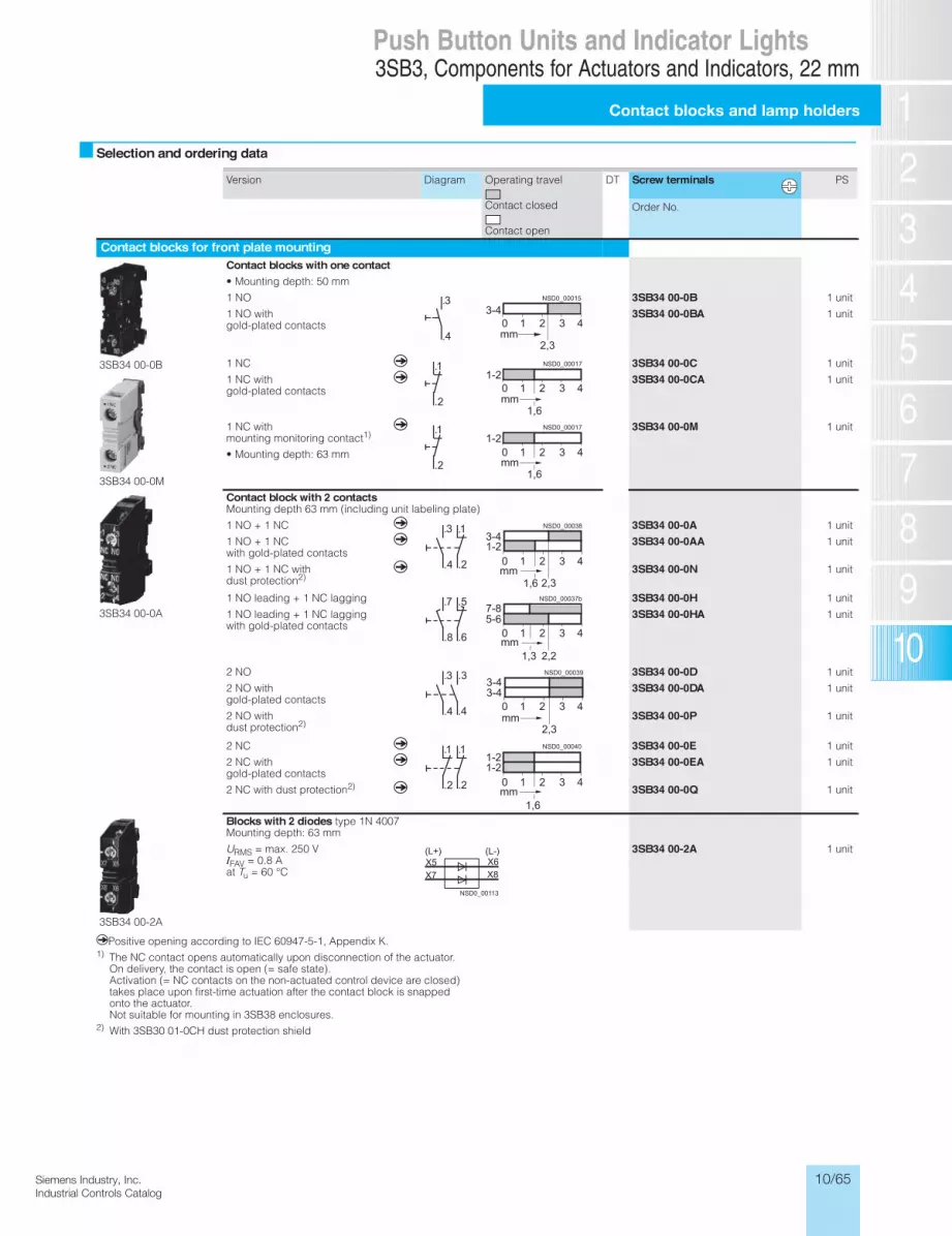
10/65Siemens Industry, Inc.Industrial Controls Catalog
3SB3 Push Buttons and Indicator Lights, 22 mmComponents for Actuators and Indicators
Contact blocks and lampholders
13/64 Siemens IC 10 · 2012* You can order this quantity or a multiple thereof.
Illustrations are approximate
13
Selection and ordering data
qPositive opening according to IEC 60947-5-1, Appendix K.1) The NC contact opens automatically upon disconnection of the actuator.
On delivery, the contact is open (= safe state). Activation (= NC contacts on the non-actuated control device are closed) takes place upon first-time actuation after the contact block is snapped onto the actuator. Not suitable for mounting in 3SB38 enclosures.
2) With 3SB30 01-0CH dust protection shield
Version Diagram Operating travel
Contact closed
Contact open
DT Screw terminals PS
Order No.
Contact blocks for front plate mounting
3SB34 00-0B
3SB34 00-0M
Contact blocks with one contact• Mounting depth: 50 mm
1 NO 3SB34 00-0B 1 unit
1 NO with gold-plated contacts
3SB34 00-0BA 1 unit
1 NC q 3SB34 00-0C 1 unit
1 NC with gold-plated contacts
q 3SB34 00-0CA 1 unit
1 NC with mounting monitoring contact1)
• Mounting depth: 63 mm
q 3SB34 00-0M 1 unit
3SB34 00-0A
Contact block with 2 contactsMounting depth 63 mm (including unit labeling plate)
1 NO + 1 NC q 3SB34 00-0A 1 unit
1 NO + 1 NC with gold-plated contacts
q 3SB34 00-0AA 1 unit
1 NO + 1 NC with dust protection2)
q 3SB34 00-0N 1 unit
1 NO leading + 1 NC lagging 3SB34 00-0H 1 unit
1 NO leading + 1 NC lagging with gold-plated contacts
3SB34 00-0HA 1 unit
2 NO 3SB34 00-0D 1 unit
2 NO with gold-plated contacts
3SB34 00-0DA 1 unit
2 NO with dust protection2)
3SB34 00-0P 1 unit
2 NC q 3SB34 00-0E 1 unit
2 NC with gold-plated contacts
q 3SB34 00-0EA 1 unit
2 NC with dust protection2) q 3SB34 00-0Q 1 unit
3SB34 00-2A
Blocks with 2 diodes type 1N 4007Mounting depth: 63 mm
URMS = max. 250 V IFAV = 0.8 A at Tu = 60 °C
3SB34 00-2A 1 unit
.4
.3
2,3
3-4
mm
NSD0_00015
.2
.11-2
1,6mm
NSD0_00017
.2
.11-2
1,6mm
NSD0_00017
.2.4
.1.3
2,31,6
3-41-2
mm
NSD0_00038
.6.8
.7 .5
3,1 2,2
7-85-6
mm
NSD0_00037b
.4.4
.3 .3
3-4
2,3
3-4
mm
NSD0_00039
.2.2
.1.11-21-2
1,6mm
NSD0_00040
X8X6
NSD0_00113
(L-)(L+)X5X7
IC10_13_04 ccorp.fm Page 64 Friday, October 4, 2013 1:16 PM
0 1 2 3 4
0 1 2 3 4
0 1 2 3 4
0 1 2 3 4
0 1 2 3 4
0 1 2 3 4
0 1 2 3 4
3SB3, Components for Actuators and Indicators, 22 mm
Contact blocks and lamp holders
Push Button Units and Indicator Lights

10/66 Siemens Industry, Inc.Industrial Controls Catalog
3SB3 Push Buttons and Indicator Lights, 22 mmComponents for Actuators and Indicators
Contact blocks and lampholders
13/65Siemens IC 10 · 2012* You can order this quantity or a multiple thereof.Illustrations are approximate
13
1) Use these lamps only.2) The lamp holder with separate lamp test function can not be installed in an
enclosure.3) For circuit examples see Reference manual "Commanding and Signaling
Devices".
4) Not suitable for LEDs which are suitable only for AC or DC.5) Not suitable for LED for 24/48/230 V AC/DC.
For connecting to DC, X5 must be connected to L–.
Version Diagram Rated voltage DT Screw terminals PS
V
Order No.
Contact blocks for front plate mounting
3SB34 00-1A
BA 9s lamp holders, mounting depth 50 mm
Without lamp Acc. to lamp 3SB34 00-1A 1 unit
With 24 V incandescent lamp (3SX1 344)
24 AC/DC 3SB34 00-1D 1 unit
BA 9s lamp holders, mounting depth 50 mm
With integrated voltage reducer and with 130 V lamp (3SX1 731)1)
230 / 240 AC 3SB34 00-1C 1 unit
BA 9s lamp holders, mounting depth 50 mm
With built-in resistor for longer endur-ance and with 130 V lamp (3SX1 731)1)
110/130 AC/DC 3SB34 00-1B 1 unit
3SB34 00-1F
BA 9s lamp holders with separate lamp test function2)3)
With integrated voltage reducer and with 130 V lamp (3SX1 731)1)
230 / 240 AC 3SB34 00-1F 1 unit
Without lamp
For incandescent lamp, max. 2.6 W; for LED lamp, 24/48/230 V AC/DC4)
Acc. to lamp 3SB34 00-1G 1 unit
Without lamp
For incandescent lamp, max. 2.6 W; for LED lamp, AC or DC5)
Acc. to lamp 3SB34 00-1L 1 unit
Without lamp
For incandescent lamp, max. 2.6 W; for glow lamp, AC
Acc. to lamp 3SB34 00-1H 1 unit
3SB34 00-1PA
Lamp holders with integrated LEDMounting depth: 50 mm
Yellow 24 AC/DC 3SB34 00-1PA 1 unitRed 3SB34 00-1PB 1 unitGreen 3SB34 00-1PC 1 unitBlue 3SB34 00-1PD 1 unitWhite 3SB34 00-1PE 1 unit
Yellow 110 AC 3SB34 00-1QA 1 unitRed 3SB34 00-1QB 1 unitGreen 3SB34 00-1QC 1 unitBlue 3SB34 00-1QD 1 unitWhite 3SB34 00-1QE 1 unit
Yellow 230 AC 3SB34 00-1RA 1 unitRed 3SB34 00-1RB 1 unitGreen 3SB34 00-1RC 1 unitBlue 3SB34 00-1RD 1 unitWhite 3SB34 00-1RE 1 unit
3SB34 00-3.
Transformers For snapping onto 3SB34 00-1A lamp holder
For incandescent lamp AC, max. 2 W
Mounting depth: 97 mm
127 / 24 3SB34 00-3A 1 unit240 / 24 3SB34 00-3C 1 unit260 / 24 3SB34 00-3E 1 unit400 / 24 3SB34 00-3F 1 unit
127 / 6 3SB34 00-3M 1 unit240 / 6 3SB34 00-3P 1 unit400 / 6 3SB34 00-3S 1 unit480 / 6 3SB34 00-3U 1 unit600 / 6 3SB34 00-3W 1 unit
(L-)(L+)X2X1
NSD0_00003
X2X1
NSD0_00042
NSD0_00041
(L-)(L+)X2X1
NSD0_00043
X2X1
X5
NSD0_00044b
AC/DC-LEDX5X1
(L+) (L-)
X2
(L+)(L-)
X5
X1X2
NSD0_00045
NSD0_00046a
X5X1
(L+) (L-)
X2
+kk
NSD0_01292b
X1
X2
+kk
NSD0_01296b
X1
X2
+kk
NSD0_01296b
X1
X2
NSD0_00047
X2X1
IC10_13_04 ccorp.fm Page 65 Friday, October 4, 2013 1:16 PM
3SB3, Components for Actuators and Indicators, 22 mm
Contact blocks and lamp holders
Push Button Units and Indicator Lights
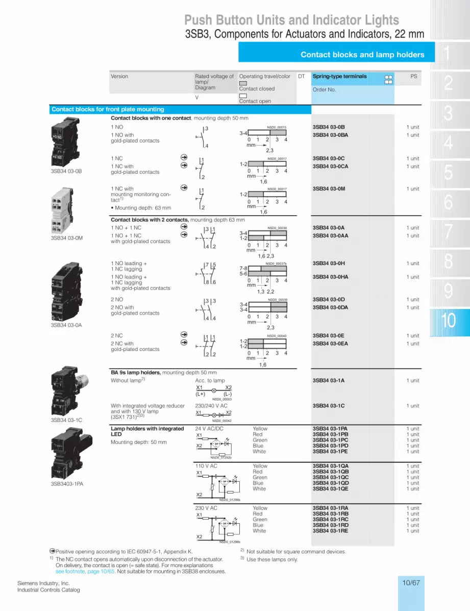
10/67Siemens Industry, Inc.Industrial Controls Catalog
3SB3 Push Buttons and Indicator Lights, 22 mmComponents for Actuators and Indicators
Contact blocks and lampholders
13/66 Siemens IC 10 · 2012* You can order this quantity or a multiple thereof.
Illustrations are approximate
13
qPositive opening according to IEC 60947-5-1, Appendix K.1)
2) Not suitable for square command devices.3) Use these lamps only.
Version Rated voltage of lamp/ Diagram
Operating travel/color
Contact closed
Contact open
DT Spring-type terminals PS
Order No.
V
Contact blocks for front plate mounting
3SB34 03-0B
Contact blocks with one contact, mounting depth 50 mm
1 NO 3SB34 03-0B 1 unit
1 NO with gold-plated contacts
3SB34 03-0BA 1 unit
1 NC q 3SB34 03-0C 1 unit
1 NC with gold-plated contacts
q 3SB34 03-0CA 1 unit
3SB34 03-0M
1 NC with mounting monitoring con-tact1)
• Mounting depth: 63 mm
q 3SB34 03-0M 1 unit
Contact blocks with 2 contacts, mounting depth 63 mm
1 NO + 1 NC q 3SB34 03-0A 1 unit
1 NO + 1 NC with gold-plated contacts
q 3SB34 03-0AA 1 unit
3SB34 03-0A
1 NO leading + 1 NC lagging
3SB34 03-0H 1 unit
1 NO leading + 1 NC lagging with gold-plated contacts
3SB34 03-0HA 1 unit
2 NO 3SB34 03-0D 1 unit
2 NO with gold-plated contacts
3SB34 03-0DA 1 unit
2 NC q 3SB34 03-0E 1 unit
3SB34 03-1C
2 NC with gold-plated contacts
q 3SB34 03-0EA 1 unit
BA 9s lamp holders, mounting depth 50 mm
Without lamp2) Acc. to lamp 3SB34 03-1A 1 unit
With integrated voltage reducer and with 130 V lamp (3SX1 731)2)3)
230/240 V AC 3SB34 03-1C 1 unit
3SB3403-1PA
Lamp holders with integratedLEDMounting depth: 50 mm
24 V AC/DC Yellow 3SB34 03-1PA 1 unitRed 3SB34 03-1PB 1 unitGreen 3SB34 03-1PC 1 unitBlue 3SB34 03-1PD 1 unitWhite 3SB34 03-1PE 1 unit
110 V AC Yellow 3SB34 03-1QA 1 unitRed 3SB34 03-1QB 1 unitGreen 3SB34 03-1QC 1 unitBlue 3SB34 03-1QD 1 unitWhite 3SB34 03-1QE 1 unit
230 V AC Yellow 3SB34 03-1RA 1 unitRed 3SB34 03-1RB 1 unitGreen 3SB34 03-1RC 1 unitBlue 3SB34 03-1RD 1 unitWhite 3SB34 03-1RE 1 unit
.4
.3
2,3
3-4
mm
NSD0_00015
.2
.11-2
1,6mm
NSD0_00017
.2
.11-2
1,6mm
NSD0_00017
.2.4
.1.3
2,31,6
3-41-2
mm
NSD0_00038
.6.8
.7 .5
3,1 2,2
7-85-6
mm
NSD0_00037b
.4.4
.3 .3
3-4
2,3
3-4
mm
NSD0_00039
.2.2
.1.11-21-2
1,6mm
NSD0_00040
(L-)(L+)X2X1
NSD0_00003
X2X1
NSD0_00042
+kk
NSD0_01292b
X1
X2
+kk
NSD0_01296b
X1
X2
+kk
NSD0_01296b
X1
X2
IC10_13_04 ccorp.fm Page 66 Friday, October 4, 2013 1:16 PM
0 1 2 3 4
0 1 2 3 4
0 1 2 3 4
0 1 2 3 4
0 1 2 3 4
0 1 2 3 4
0 1 2 3 4
3SB3, Components for Actuators and Indicators, 22 mm
Contact blocks and lamp holders
Push Button Units and Indicator Lights
The NC contact opens automatically upon disconnection of the actuator.On delivery, the contact is open (= safe state). For more explanationssee footnote, page 10/65. Not suitable for mounting in 3SB38 enclosures.

10/68 Siemens Industry, Inc.Industrial Controls Catalog
3SB3 Push Buttons and Indicator Lights, 22 mmComponents for Actuators and Indicators
Contact blocks and lampholders
13/67Siemens IC 10 · 2012* You can order this quantity or a multiple thereof.Illustrations are approximate
13
qPositive opening according to IEC 60947-5-1, Appendix K.
1) Holder also for mushroom push button and push-pull button.
Version Diagram Operating travel
Contact closed
Contact open
DT Solder pinconnections
PS
Order No.
Contact blocks for use on printed circuit boards
3SB34 11-0B
Contact blocks with one contactMounting depth 44 mm
1 NO
3SB34 11-0B 1 unit
1 NC q 3SB34 11-0C 1 unit
3SB34 11-1A
Wedge base lamp holders W2 x 4.6 dMounting depth: 44 mm
Without lamp 3SB34 11-1A 1 unit
.4
.3
2,3
3-4
mm
NSD0_00015
.2
.11-2
1,6mm
NSD0_00017
(L-)(L+)X2X1
NSD0_00003
Version DT Order No. PS
Holders for 3 contact blocks, for front panel mounting
3SB39 01-0AB
Holders for push buttons and switches1) for snapping on 3 blocks (for illuminated push buttons and illuminated selector switches the holder is included in the scope of supply)
3SB39 01-0AB 20 units
3SB39 01-0AC
Holders for selector switches, key-operated switches and twin push but-tons With pressure plate for actuating the central contact block of 3 contact blocks
3SB39 01-0AC 10 units
Pressure plates for use on printed circuit boards
3SB39 01-0AW
Pressure plates for selector switches and key-operated switches For actuating the central contact block of 3 contact blocks
3SB39 01-0AW 10 units
Accessories for printed circuit boards
3SB39 01-0AA
Holders for printed circuit boards for mounting the command devices on the printed circuit board (screw is included in the scope of supply)
3SB39 01-0AA 10 units16
21
IC10_13_04 ccorp.fm Page 67 Friday, October 4, 2013 1:16 PM
0 1 2 3 4
0 1 2 3 4
3SB3, Components for Actuators and Indicators, 22 mm
Contact blocks and lamp holders
Push Button Units and Indicator Lights

10/69Siemens Industry, Inc.Industrial Controls Catalog
3SB3 Push Buttons and Indicator Lights, 22 mmComponents for Actuators and Indicators
13/69Siemens IC 10 · 2012
Special locks
13
Options
Special locks for key-operated switchesThe BKS and CES plastic and metal key-operated switches, round and square versions, can be optionally equipped with special locks.
In this case the Order No. of the matching key-operated switch must be supplemented with "-Z", the matching order code "Y01" or "Y02" and the required lock number.
1) Delivery of these BKS key-operated switches (locks for VW) without key.
Ordering notes• For all special locks, an additional price applies.• The order code "Y01" or "Y02" must be quoted in accor-
dance with the table above. Automated processing of the or-der with a defined delivery time can be guaranteed only for correctly submitted orders.
• For applications in which access security is important and several lock numbers are used, we recommend the use of BKS or CES key-operated switches.
• Special locks for VW (E1, E2, ...) will be delivered without keys, all others with 2 keys.
Master and master-pass key systemsThe following key systems can be supplied with BKS or CES key-operated switches:• Central lock systems• Master key systems• Central master key systems• Master-pass key systems
When placing an order you must supplement the Order No. of the matching key-operated switches with "-Z" and quote the order code "Y03".Please enquire for price and delivery time.
Example of master-pass key system
Order code Y01 Y02In accordance with the table of special locks
No Yes
Normal delivery time 25 working days 5 working days
Additional price per unit
On request On request
Ordering example 3SB30 00-4LD01-Z Y01 Z = SSG18
3SB30 00-4LD01-Z Y02 Z = SSG11
Available special locks with order code "Y02"
Order No. with order code
Key-operated switchCES SSG 11 to SSG 15 3SB3. ..-4LD01-Z
Y023SB3. ..-4LD11-ZY023SB3. ..-4LD21-ZY023SB3. ..-4MD01-ZY023SB3. ..-4PD..-ZY023SB3. ..-4QD..-ZY023SB3. ..-4RD..-ZY023SB3. ..-4SD..-ZY02
BKS E1, E2, E7, E91) 3SB3. ..-5AD..-ZY023SB3. ..-5BD01-ZY023SB3. ..-5DD..-ZY023SB3. ..-5ED01-ZY023SB3. ..-5FD01-ZY023SB3. ..-5GD01-ZY02
BKS E91) 3SB3. ..-5FD51-ZY02
EMERGENCY-STOP mushroom pushbuttonsCES SSP 9 3SB3. ..-1KA20-Z
Y02BKS E2, E7, E91) 3SB3. ..-1LA20-Z
Y02
NSD0_00075
Masterpass key
Subgroupkey
Maingroup key
IC10_13_04 ccorp.fm Page 69 Friday, October 4, 2013 1:16 PM
3SB3, Components for Actuators and Indicators, 22 mm
Special locks
Push Button Units and Indicator Lights
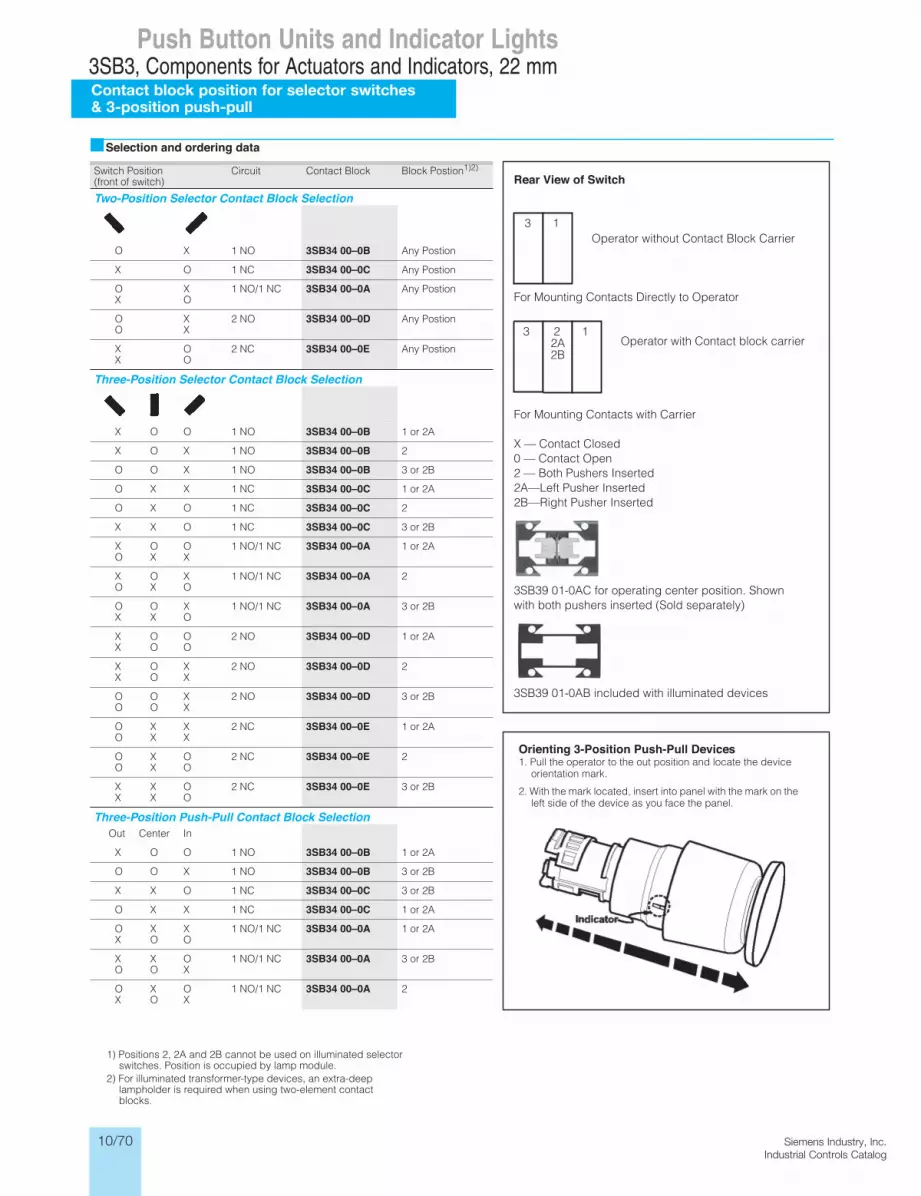
10/70 Siemens Industry, Inc.Industrial Controls Catalog
Push Button Units and Indicator Lights3SB3, Components for Actuators and Indicators, 22 mmContact block position for selector switches& 3-position push-pull
Selection and ordering data
Switch Position(front of switch)
Circuit Contact Block Block Postion1)2)
Two-Position Selector Contact Block Selection
O X 1 NO 3SB34 00–0B Any Postion
X O 1 NC 3SB34 00–0C Any Postion
O XX O
1 NO/1 NC 3SB34 00–0A Any Postion
O XO X
2 NO 3SB34 00–0D Any Postion
X OX O
2 NC 3SB34 00–0E Any Postion
Three-Position Selector Contact Block Selection
X O O 1 NO 3SB34 00–0B 1 or 2A
X O X 1 NO 3SB34 00–0B 2
O O X 1 NO 3SB34 00–0B 3 or 2B
O X X 1 NC 3SB34 00–0C 1 or 2A
O X O 1 NC 3SB34 00–0C 2
X X O 1 NC 3SB34 00–0C 3 or 2B
X O OO X X
1 NO/1 NC 3SB34 00–0A 1 or 2A
X O XO X O
1 NO/1 NC 3SB34 00–0A 2
O O XX X O
1 NO/1 NC 3SB34 00–0A 3 or 2B
X O OX O O
2 NO 3SB34 00–0D 1 or 2A
X O XX O X
2 NO 3SB34 00–0D 2
O O XO O X
2 NO 3SB34 00–0D 3 or 2B
O X XO X X
2 NC 3SB34 00–0E 1 or 2A
O X OO X O
2 NC 3SB34 00–0E 2
X X OX X O
2 NC 3SB34 00–0E 3 or 2B
Three-Position Push-Pull Contact Block SelectionOut Center In
X O O 1 NO 3SB34 00–0B 1 or 2A
O O X 1 NO 3SB34 00–0B 3 or 2B
X X O 1 NC 3SB34 00–0C 3 or 2B
O X X 1 NC 3SB34 00–0C 1 or 2A
O X XX O O
1 NO/1 NC 3SB34 00–0A 1 or 2A
X X OO O X
1 NO/1 NC 3SB34 00–0A 3 or 2B
O X OX O X
1 NO/1 NC 3SB34 00–0A 2
1) Positions 2, 2A and 2B cannot be used on illuminated selector switches. Position is occupied by lamp module.
2) For illuminated transformer-type devices, an extra-deeplampholder is required when using two-element contact blocks.
Rear View of Switch
Operator without Contact Block Carrier
For Mounting Contacts Directly to Operator
Operator with Contact block carrier
For Mounting Contacts with Carrier
X — Contact Closed0 — Contact Open2 — Both Pushers Inserted2A—Left Pusher Inserted2B—Right Pusher Inserted
3SB39 01-0AC for operating center position. Shownwith both pushers inserted (Sold separately)
3SB39 01-0AB included with illuminated devices
3 1
3 22A2B
1
Orienting 3-Position Push-Pull Devices1. Pull the operator to the out position and locate the device
orientation mark.
2. With the mark located, insert into panel with the mark on the left side of the device as you face the panel.

10/71Siemens Industry, Inc.Industrial Controls Catalog
3SB3 Push Buttons and Indicator Lights, 22 mmInscriptions
13/70Siemens IC 10 · 2012
Laser inscriptions
13
Overview
Inscription of actuators and indicatorsActuators and indicators of plastic as well as metal version can be optionally inscribed with a laser.
Pushbutton (metal) with laser inscription
The actuators of the push buttons, illuminated push buttons, mushroom push buttons and illuminated mushroom push but-tons can be inscribed as well as the lenses of the indicator lights.
Selector switches can be inscribed only if they are made of plas-tic (only one text line on the front ring).
Pushbutton and selector switch (plastic) with laser inscription
VersionA letter height of 4 mm is used as standard for text inscriptions:
The typeface used is Arial. Other letter heights and typefaces are possible, but must be specified when ordering.For round buttons and lenses, the possible number of charac-ters per line is:• 10 characters for one line of text• 8 characters for 2 lines of text• 6 characters for 3 lines of text,
but 10 characters in the middle line
On square buttons and lenses, 10 characters are possible per line.
Ordering notesWhen ordering, supplement the Order No. of the actuator or the indicator light with "–Z" and an order code:• Text line in upper/lower case, always upper case for beginning
of line (e.g. "Lift off"): Y10• Text in upper case (e.g. "LIFT OFF"): Y11• Text in lower case (e.g. "lift off"): Y12• Text in upper/lower case, all words begin with capital letters
(e.g. "Lift Off"): Y15• Symbol with number according to ISO 7000 or IEC 60417: Y13• Any inscription or symbol according to order form supple-
ment: Y19Additional price per unit for Y10 to Y19 on request.
When ordering, specify the required inscription in plain text in addition to the order number and order code. In the case of spe-cial inscriptions with words in languages other than German, give the exact spelling and specify the language (see ordering example 1).
In the case of multi-line inscriptions, the text must be assigned to the respective line, e.g. "Z1 = Lift, Z2 =Lower". For long words you can also specify the end-of-line division.
Symbols can also be ordered with numbers according to ISO 7000 or IEC 60417 (see ordering examples 2 and 3).
For special symbols (order code Y19), a CAD drawing in DXF format can be submitted.
Ordering example 1
A round push button with the inscription "Reset" is required:
3SB30 00–0AA41–Z Y10 Z = Reset (English)
Ordering example 2
A square push button inscribed with symbol No. 5389 according to IEC 60417 is required:
3SB31 10–0AA31–Z Y13 Z = 5389 IEC
Ordering example 3
A round push button inscribed with symbol No. 1118 according to ISO 7000 is required:
3SB30 00–0AA41–Z Y13 Z = 1118 ISO
IC10_13_05 ccorp.fm Page 70 Monday, September 30, 2013 7:52 PM
3SB3, Inscriptions, 22 mm
Laser inscriptions
Push Button Units and Indicator Lights

10/72 Siemens Industry, Inc.Industrial Controls Catalog
3SB3 Push Buttons and Indicator Lights, 22 mmInscriptions
Laser inscriptions
13/71 Siemens IC 10 · 2012
13
Options
Customized inscriptionsThe labels can be inscribed with text and symbols not listed in the ordering data.
Insert Labels
By default, a letter height of 4 mm (for a single line of text) or 3 mm (for 2 or 3 lines of text) is used for text inscriptions.
The typeface used is Arial. Other letter heights and typefaces are possible, but must be specified when ordering.
For round insert labels, the maximum possible number of char-acters per line is:• 10 characters for one line of text• 8 characters for 2 lines of text• 6 characters for 3 lines of text, but 10 characters in the middle
line
On square insert labels, 10 characters are possible per line.
Name plates
The following letter heights are used as standard for text inscrip-tions:• Label size 12.5 mm × 27 mm: maximum 3 lines with letter
height 4 mm (1-line), 3.5 mm (2-line) or 2.5 mm (3-line)• Label size 27 mm × 27 mm: maximum 5 lines with letter height
4 mm (1- to 5-line)• Label size 17.5 mm × 28 mm: maximum 3 lines with letter
height 4 mm (1- and 2-line) or 3 mm (3-line)
Up to 11 characters per line are possible. The typeface used is Arial. Other letter heights and typefaces are possible, but must be specified when ordering.
Inscription labels for enclosures
A letter height of 4 mm is used as standard for text inscriptions (1 to 3 lines)
Up to 11 characters per line are possible. The typeface used is Arial. Other letter heights and typefaces are possible, but must be specified when ordering.
Ordering notesAppend the following codes to the Order No.:• Text line(s) in upper/lower case, upper case always for begin-
ning of line (e.g. "Lift off"): K0Y• Text line(s) in upper case (e.g. "LIFT OFF"): K1Y• Text line(s) in lower case (e.g. "lift off"): K2Y• Text line(s) in upper/lower case, all words begin with upper
case letters (e.g. "Lift Off"): K5Y• Symbol with number according to ISO 7000 or IEC 60417: K3Y
• Any inscription or symbol according to order form supple-ment: K9Y
When ordering, specify the required inscription in plain text in addition to the order number and order code. In the case of spe-cial inscriptions with words in languages other than German, give the exact spelling and specify the language.
In the case of multi-line inscriptions, the text must be assigned to the respective line, e.g. "Z1 = Lift, Z2 =Lower". For long words you can also specify the end-of-line division (see ordering example 1).
Symbols can also be ordered with numbers according to ISO 7000 or IEC 60417 (see ordering examples 2 and 3).
For special symbols (order code K9Y), a CAD drawing in DXF format should be submitted to [email protected]
Ordering example 1
A label with 2 lines of text is required:
3SB39 02–1XZ K1Y Z1 = LIFT Z2 = LOWER
Ordering example 2
A label inscribed with symbol No. 5011 according to IEC 60417 is required:
3SB39 02–1XZ K3Y Z = 5011 IEC
Ordering example 3
A label inscribed with symbol No. 1118 according to ISO 7000 is required:
3SB39 02–1XZ K3Y Z = 1118 ISO
Examples for customized inscription
LiftOff
Two-line inscription in upper/lower case lettering (K0Y)(Insert labels)
Single-line inscription in upper case lettering (K1Y)(Name plates)
Three-line inscription in lower case lettering (K2Y)
Symbol number 5011 according to IEC 60417 (K3Y)
(Inscription labels for enclosures)
IC10_13_05 ccorp.fm Page 71 Monday, September 30, 2013 7:52 PM
≤ ×
≥
Any symbol according to order form supplement (K9Y)
3SB3, Inscriptions, 22 mm
Laser inscriptions
Push Button Units and Indicator Lights

10/73Siemens Industry, Inc.Industrial Controls Catalog
3SB3 Push Buttons and Indicator Lights, 22 mmInscriptions
13/72Siemens IC 10 · 2012
Inscriptions by laser printer
13
Overview
Label inscriptionsUsing the Label Designer software, which can be downloaded from the Internet, and the inscription labels for laser inscription you can create your own customized labels with a standard laser printer.
The self-adhesive or snap-on labels can be stuck or snapped onto the corresponding label holders (see Name plates). Round labels are provided for inserting in illuminated push buttons and switches.
The labels are suitable for printing with one to three lines of text or symbols.
For applications with more exacting requirements we recom-mend factory-printed inscription labels and insert labels (laser-printed or engraved depending on the type).
You can find the Label Designer software on the Internet at:
www.siemens.com/sirius-label-designer
Selection and ordering data
Version Color DT Order No. Price per PU
PU (UNIT,
SET, M)
PS
Labels for printingInsert labels for inserting in round illuminated push buttons and illuminated switches
Milky A 3SB39 01-2AB 100 480 units
Inscription labels 12.5 mm x 27 mm for sticking onto label holder
White A 3SB39 02-2AA 100 480 units
Inscription labels 27 mm x 27 mm for sticking onto label holder
White A 3SB39 03-2AA 100 480 units
Inscription labels 17.5 mm x 28 mm for snapping onto label holder
White A 3SB39 05-2AA 100 720 units
Inscription labels 22 mm x 22 mm for sticking onto enclosure
White A 3SB39 06-2AA 100 700 units
IC10_13_05 ccorp.fm Page 72 Monday, September 30, 2013 7:52 PM
3SB3, Inscriptions, 22 mm
Inscriptions by laser printer
Push Button Units and Indicator Lights

10/74 Siemens Industry, Inc.Industrial Controls Catalog
3SB3 Push Buttons and Indicator Lights, 22 mmInscriptions
Insert labels
13/73 Siemens IC 10 · 2012
13
OverviewPush buttons (clear) and illuminated push buttons with a flat but-ton can be fitted with insert labels for identification purposes, but indicator lights cannot.These insert labels are made of clear, transparent plastic with black inscription; they can be fitted in any 90° angle.
InscriptionsThe inscriptions have upper case initial letters. Graphic symbols, including those not listed in the catalog, are according to ISO 7000 or IEC 60417 The insert labels without inscription are suitable for user marking with permanent pen.
Selection and ordering data
Inscription/Symbol Symbol No. DT Round range DT Square rangeOrder No. Price
per PUOrder No. Price
per PU
Insert labelsFor self-inscriptionBlank B 3SB19 01-4AS B 3SB39 40-4AA
With inscriptionOn B 3SB19 01-4EB B 3SB39 40-4EBOff B 3SB19 01-4EC B 3SB39 40-4ECUp B 3SB19 01-4ED B 3SB39 40-4EDDown B 3SB19 01-4EE B 3SB39 40-4EEForward B 3SB19 01-4EF B 3SB39 40-4EFReverse B 3SB19 01-4EG B 3SB39 40-4EGRight C 3SB19 01-4EH —Left C 3SB19 01-4EJ —Open B 3SB19 01-4EP B —Close B 3SB19 01-4EQ —Fast B 3SB19 01-4ER —Slow B 3SB19 01-4ES —Running B 3SB19 01-4EV 3SB39 40–4EVFault B 3SB19 01-4EW 3SB39 40–4EWReset B 3SB19 01-4EM B 3SB39 40-4EMTest B 3SB19 01-4EN —Start B 3SB19 01-4EK B 3SB39 40-4EKStop B 3SB19 01-4EL B 3SB39 40-4ELWith graphic symbolO (Off) 5008 IEC B 3SB19 01-4MB B 3SB39 40-4MB
I (On) 5007 IEC B 3SB19 01-4MC B 3SB39 40-4MC
II (On) — B 3SB19 01-4MD B 3SB39 40-4MD
Electric motor 0011 ISO B 3SB19 01-4PA 3SB39 40–4PA
Motion in direction of arrow 5022 IEC B 3SB19 01-4NA B 3SB39 40-4NAIncrease, plus 5005 IEC B 3SB19 01-4NG B 3SB39 40-4NG
Decrease, minus 5006 IEC B 3SB19 01-4MC B 3SB39 40-4MCWith customized inscriptionFor inscriptions or symbols see "Options" 3SB19 01-4AZ 3SB39 40-4AZ• Text line(s) or symbol with No. B K0Y, K1Y, K2Y,
K3Y or K5YB K0Y. K1Y. K2Y.
K3Y or K5Y• Any inscription or symbol B K9Y B K9Y
IC10_13_05 ccorp.fm Page 73 Monday, September 30, 2013 7:52 PM
3SB3, Inscriptions, 22 mm
Insert labels
Push Button Units and Indicator Lights
For customized inscriptions see page 10/72.
(see page 10/72).

10/75Siemens Industry, Inc.Industrial Controls Catalog
3SB3 Push Buttons and Indicator Lights, 22 mmInscriptions
13/74Siemens IC 10 · 2012
Name plates
13
OverviewThe name plates consist of a black plastic label holder and an inscription label (black with white print or silver-colored with black print) for sticking or snapping in place. They are not suit-able for EMERGENCY-STOP push buttons.
Note mounting dimensions!
InscriptionsThe inscriptions have upper case initial letters. The typeface is Arial. Graphic symbols, including those not listed in the tables, are according to ISO 7000 or IEC 60417
Self-adhesive labelsThere are 2 sizes available for the round and square ranges:• Label holders 30 mm × 45 mm × 7 mm
with inscription label 12.5 mm × 27 mm.• Label holders 30 mm × 60 mm × 7 mm
with inscription label 27 mm × 27 mm.
Snap-on labelsThe following version is available for the round range:• Label holders 29.8 mm × 51 mm × 3 mm
with inscription label 17.5 mm × 28 mm (inscription area: 17.5 mm × 27 mm)
Selection and ordering data
Inscriptions DT Black DT Silver-colored Order No. Order No.
Inscription labels, self-adhesive,12.5 mm × 27 mm
For self-inscriptionBlank 3SB39 02-1AA B 3SB19 01-2AA
With inscriptionOn B 3SB39 02-1EB B 3SB19 01-2EBOff B 3SB39 02-1EC B 3SB19 01-2ECUp B 3SB39 02-1ED B 3SB19 01-2EDDown B 3SB39 02-1EE B 3SB19 01-2EEEmerg. Stop 3SB39 02–1AUHand O Auto 3SB39 02–1BEJog 3SB39 02–1BGMan O Auto 3SB39 02–1ETPower Off 3SB39 02–1BHPower On 3SB39 02–1BJReset 3SB39 02–1EMRun 3SB39 02–1EXForward B 3SB39 02-1EFReverse B 3SB39 02-1EGRight B 3SB39 02-1EH B 3SB19 01-2EHLeft B 3SB39 02-1EJ B 3SB19 01-2EJOpen B 3SB39 02-1EP B 3SB19 01-2EPClose B 3SB39 02-1EQ B 3SB19 01-2EQFast — B 3SB19 01-2ERSlow — B 3SB19 01-2ESStop B 3SB39 02-1EK B 3SB19 01-2EKStart B 3SB39 02-1EL B 3SB19 01-2ELTest B 3SB39 02-1EN B 3SB19 01-2ENRunning — B 3SB19 01-2EVFault B 3SB39 02-1EW B 3SB19 01-2EWReset — B 3SB19 01-2EMStop Start B 3SB39 02-1BC B 3SB19 01-2BCHand Auto B 3SB39 02-1BA B 3SB19 01-2BAMan Auto B 3SB39 02-1EU B 3SB19 01-2EUHand O Auto — B 3SB19 01-2BEMan O Auto — B 3SB19 01-2ETOff On 3SB39 02–1EA
IC10_13_05 ccorp.fm Page 74 Monday, September 30, 2013 7:52 PM
≤ ×
≥
3SB3, Inscriptions, 22 mm
Name plates
Push Button Units and Indicator Lights
For label holders see page 10/78.For customized inscriptions see page 10/72..
(see page 10/72).

10/76 Siemens Industry, Inc.Industrial Controls Catalog
3SB3 Push Buttons and Indicator Lights, 22 mmInscriptions
Name plates
13/75 Siemens IC 10 · 2012
13
Inscriptions DT Black DT Silver-colored Order No. Order No.
Inscription labels, self-adhesive,12.5 mm × 27 mm
With graphic symbolO B 3SB39 02-1MB B 3SB19 01-2MBI B 3SB39 02-1MC B 3SB19 01-2MCII — C 3SB19 01-2MDIII — B 3SB19 01-2MEO I B 3SB39 02-1MF B 3SB19 01-2MFI O II B 3SB39 02-1MG B 3SB19 01-2MG1 O 2 — B 3SB19 01-2MK1 2 B 3SB39 02-1ML — B 3SB39 02-1NJ B 3SB19 01-2NA B 3SB39 02-1NA B 3SB19 01-2NJWith customized inscriptionFor inscriptions or symbols see "Options" 3SB39 02-1XZ 3SB19 01-2XZ• Text line(s) B K0Y B K0Y• Text line(s) or symbol with No. B K1Y, K2Y, K3Y or
K5YB K1Y. K2Y. K3Y or
K5Y• Any inscription or symbol B K9Y B K9Y
Inscriptions DT Black DT Silver-coloredOrder No. Order No.
Inscription labels, self-adhesive,27 mm × 27 mm
For self-inscriptionBlank B 3SB39 03-1AA B 3SB19 06-2AAWith inscriptionOn B 3SB39 03-1EB —Off B 3SB39 03-1EC —Start B 3SB39 03-1EL —Emerg. Stop B 3SB39 03–1AU —Hand O Auto B 3SB39 03–1BE —Jog B 3SB39 03–1BG —Man O Auto B 3SB39 03–1ET —Power Off B 3SB39 03–1BH —Power On B 3SB39 03–1BJ —Reset B 3SB39 03–1EM —Run B 3SB39 03–1EX —Forward B 3SB39 03–1EF —Reverse B 3SB39 03–1EG —Right B 3SB39 03–1EH —Left B 3SB39 03–1EJ —Up B 3SB39 03–1ED —Down B 3SB39 03–1EE —Open B 3SB39 03–1EP —Close B 3SB39 03–1EQ —Test B 3SB39 03–1EN —Stop B 3SB39 03–1EK —Man Auto B 3SB39 03–1EU —Off On B 3SB39 03–1EA —Stop Start B 3SB39 03-1BC —Hand Auto B 3SB39 03-1BA —With graphic symbolO B 3SB39 03-1MB —O I B 3SB39 03-1MF — B 3SB39 03-1NA —With customized inscriptionFor inscriptions or symbols see "Options" 3SB39 03-1XZ 3SB19 06-2XZ• Text line(s) B K0Y B K0Y• Text line(s) or symbol with No. B K1Y, K2Y, K3Y or
K5YB K1Y. K2Y. K3Y or
K5Y• Any inscription or symbol B K9Y B K9Y
IC10_13_05 ccorp.fm Page 75 Monday, September 30, 2013 7:52 PM
≤ ×
≥
3SB3, Inscriptions, 22 mm
Name plates
Push Button Units and Indicator Lights
For label holders see page 10/78.For customized inscriptions see page 10/72.

10/77Siemens Industry, Inc.Industrial Controls Catalog
3SB3 Push Buttons and Indicator Lights, 22 mmInscriptions
13/76Siemens IC 10 · 2012
Name plates
13
Inscriptions DT Black DT Silver-coloredOrder No. Order No.
Inscription labels, for snapping on,17.5 mm × 28 mm
For self-inscriptionBlank B 3SB39 05-1AA B 3SB19 04-2AA
With inscriptionOn B 3SB39 05-1EB B 3SB19 04-2EBOff B 3SB39 05-1EC B 3SB19 04-2ECUp B 3SB39 05-1ED —Down B 3SB39 05-1EE —Forward B 3SB39 05-1EF B —Reverse B 3SB39 05-1EG B 3SB19 04-2EGRight B 3SB39 05-1EH —Left B 3SB39 05-1EJ —Open B 3SB39 05-1EP —Close B 3SB39 05-1EQ —Stop B 3SB39 05-1EK B 3SB19 04-2EKStart B 3SB39 05-1EL B 3SB19 04-2ELTest — B 3SB19 04-2ENRunning B 3SB39 05-1EV —Fault B 3SB39 05-1EW B 3SB19 04-2EWReset — B 3SB19 04-2EMStop Start B 3SB39 05-1BC B 3SB19 04-2BCHand Auto B 3SB39 05-1BA B 3SB19 04-2BAMan Auto B 3SB39 05-1EU C 3SB19 04-2EUMan O Auto — B 3SB19 04-2ET
With graphic symbolO B 3SB39 05-1MB B 3SB19 04-2MBI B 3SB39 05-1MC B 3SB19 04-2MCO I B 3SB39 05-1MF B 3SB19 04-2MFI O II — B 3SB19 04-2MG1 O 2 — B 3SB19 04-2MK B 3SB39 05-1NA B 3SB19 04-2NA B 3SB39 05-1NJ B 3SB19 04-2NJWith customized inscriptionFor inscriptions or symbols see "Options" 3SB39 05-1XZ 3SB19 04-2XZ• Text line(s) B K0Y B K0Y• Text line(s) or symbol with No. B K1Y, K2Y, K3Y or
K5YB K1Y. K2Y. K3Y or
K5Y• Any inscription or symbol B K9Y B K9Y
IC10_13_05 ccorp.fm Page 76 Monday, September 30, 2013 7:52 PM
≤ ×
≥
3SB3, Inscriptions, 22 mm
Name plates
Push Button Units and Indicator Lights
For label holders see page 10/78.For customized inscriptions see page 10/72.

10/78 Siemens Industry, Inc.Industrial Controls Catalog
Version DT Black PU (UNIT,
SET, M)
PS
Order No.
Label holders for inscription labels 12.5 mm × 27 mm
3SB39 22-0AV
For round range, flat B 3SB39 22-0AV 100 10 units
For potentiometer drives 3SB10 00-7CH071) B 3SB39 22-0AS 1 1 unit
For square range, flat B 3SB39 42-0AX 100 5 units
Label holders for inscription labels 27 mm × 27 mm
3SB39 23-0AV
For round range, flat B 3SB39 23-0AV 100 10 units
For round range, raised C 3SB39 23-0AX 1 10 units
For potentiometer drives, flat B 3SB39 23-0AS 1 1 unit
For square range, flat B 3SB39 43-0AX 100 1 unit
Label holders for inscription labels 17.5 mm × 28 mm
3SB39 25-0AV
For round design 3SB39 25-0AV 100 10 units
3SB3 Push Buttons and Indicator Lights, 22 mmInscriptions
Name plates
13/77 Siemens IC 10 · 2012
13
1) This label holder can also be used for push buttons with dust covers if the front panel thickness of 3 mm is not exceeded.
IC10_13_05 ccorp.fm Page 77 Monday, September 30, 2013 7:52 PM
3SB3, Inscriptions, 22 mm
Name plates
Push Button Units and Indicator Lights

10/79Siemens Industry, Inc.Industrial Controls Catalog
3SB3 Push Buttons and Indicator Lights, 22 mmAccessories and spare parts
13/78Siemens IC 10 · 2012
Buttons and lenses
13
Selection and ordering data
Version Color DT Order No. PU (UNIT,
SET, M)
PS
Buttons and lenses for round version1)
3SB39 30-0CA6
3SB39 30-0EA3
3SB39 30-0DA4
3SB39 30-0FA4
3SB39 30-0GA3
3SB39 30-0HA4
Buttons, flatfor round illuminated push buttons and illuminated switches, plastic version
Red B 3SB39 30-0CA2 1 10 unitsYellow B 3SB39 30-0CA3 1 10 unitsGreen B 3SB39 30-0CA4 1 10 unitsBlue B 3SB39 30-0CA5 1 10 unitsWhite B 3SB39 30-0CA6 1 10 unitsClear B 3SB39 30-0CA7 1 10 units
Buttons, flat for round push buttons and switches, metal version
Black B 3SB39 30-0EA1 1 10 unitsRed B 3SB39 30-0EA2 1 10 unitsYellow B 3SB39 30-0EA3 1 10 unitsGreen B 3SB39 30-0EA4 1 10 unitsBlue B 3SB39 30-0EA5 1 10 unitsWhite B 3SB39 30-0EA6 1 10 unitsClear B 3SB39 30-0EA7 1 10 units
Buttons, raised for round illuminated push buttons and illuminated switches, plastic version
Red B 3SB39 30-0DA2 1 10 unitsGreen B 3SB39 30-0DA4 1 10 unitsClear B 3SB39 30-0DA7 1 10 units
Buttons, raised for round push buttons and switches, metal version
Black D 3SB39 30-0FA1 1 10 unitsRed C 3SB39 30-0FA2 1 10 unitsYellow C 3SB39 30-0FA3 1 10 unitsGreen C 3SB39 30-0FA4 1 10 unitsBlue C 3SB39 30-0FA5 1 10 unitsWhite C 3SB39 30-0FA6 1 10 unitsClear C 3SB39 30-0FA7 1 10 units
Buttons, flat for round illuminated push buttons and illuminated switches, metal version
Amber B 3SB39 30-0GA0 1 10 unitsRed B 3SB39 30-0GA2 1 10 unitsYellow B 3SB39 30-0GA3 1 10 unitsGreen B 3SB39 30-0GA4 1 10 unitsBlue B 3SB39 30-0GA5 1 10 unitsWhite B 3SB39 30-0GA6 1 10 unitsClear B 3SB39 30-0GA7 1 10 units
Buttons, flat, solvent-resistant2),for round illuminated push buttons and switches, metal version
Red B 3SB39 30-0GA20-0PA0 1 10 unitsYellow B 3SB39 30-0GA30-0PA0 1 10 unitsGreen B 3SB39 30-0GA40-0PA0 1 10 unitsBlue B 3SB39 30-0GA50-0PA0 1 10 unitsWhite B 3SB39 30-0GA60-0PA0 1 10 unitsClear B 3SB39 30-0GA70-0PA0 1 10 units
Buttons, raised for round illuminated push buttons and illuminated switches, metal version
Amber C 3SB39 30-0HA0 1 10 unitsRed C 3SB39 30-0HA2 1 10 unitsYellow C 3SB39 30-0HA3 1 10 unitsGreen C 3SB39 30-0HA4 1 10 unitsBlue C 3SB39 30-0HA5 1 10 unitsWhite C 3SB39 30-0HA6 1 10 unitsClear C 3SB39 30-0HA7 1 10 units
3SB39 30-6BA3
Lenses, smooth For round indicator lights, plastic and metal version
Amber C 3SB39 30-6BA0 1 10 unitsRed B 3SB39 30-6BA2 1 10 unitsYellow B 3SB39 30-6BA3 1 10 unitsGreen B 3SB39 30-6BA4 1 10 unitsBlue B 3SB39 30-6BA5 1 10 unitsWhite B 3SB39 30-6BA6 1 10 unitsClear B 3SB39 30-6BA7 1 10 units
3SB39 30-6CA3
Lenses with concentric rings For round indicator lights, plastic and metal version
Amber B 3SB39 30-6CA0 1 10 unitsRed B 3SB39 30-6CA2 1 10 unitsYellow B 3SB39 30-6CA3 1 10 unitsGreen B 3SB39 30-6CA4 1 10 unitsBlue B 3SB39 30-6CA5 1 10 unitsWhite B 3SB39 30-6CA6 1 10 unitsClear B 3SB39 30-6CA7 1 10 units
Buttons and lenses for square version
3SB39 50-0CA6
Buttons, flat For square illuminated push buttons and illuminated switches, plastic version
Red B 3SB39 50-0CA2 1 10 unitsYellow B 3SB39 50-0CA3 1 10 unitsGreen B 3SB39 50-0CA4 1 10 unitsBlue B 3SB39 50-0CA5 1 10 unitsWhite B 3SB39 50-0CA6 1 10 unitsClear B 3SB39 50-0CA7 1 10 units
3SB39 50-6AA2
Lenses, smooth For square indicator lights, plastic version
Red B 3SB39 50-6AA2 1 10 unitsYellow B 3SB39 50-6AA3 1 10 unitsGreen B 3SB39 50-6AA4 1 10 unitsBlue B 3SB39 50-6AA5 1 10 unitsWhite B 3SB39 50-6AA6 1 10 unitsClear B 3SB39 50-6AA7 1 10 units
1) In scope of supply of push buttons or indicator lights.2) Not suitable for laser inscription.
IC10_13_05 ccorp.fm Page 78 Monday, September 30, 2013 7:52 PM
3SB3, Accessories and spare parts, 22 mm
Buttons and lenses
Push Button Units and Indicator Lights

10/80 Siemens Industry, Inc.Industrial Controls Catalog
3SB3 Push Buttons and Indicator Lights, 22 mmAccessories and spare parts
Lamps, acoustic signal transformers and keys
13/79 Siemens IC 10 · 2012
13
Selection and ordering data
Version Rated voltage Color DT Order No. PU (UNIT,
SET, M)
PS
V
Lamps, BA 9s bases1)
3SB19 02-0AY
Incandescent lamps 1.2W, length up to 28 mm, max. bulb diameter 10 mm
24 AC/DC Clear A 3SB19 02-0AY 1 10 units
Incandescent lamps 2W, length up to 28 mm, max. bulb diameter 10 mm
6 AC/DC Clear A 52AABN 1 1 units12 AC/DC A 52AACN 1 1 units24 AC/DC A 52AADN1 1 1 units30 AC/DC B 3SB19 02-2AF 1 10 units48 AC/DC B 3SB19 02-1AP 1 10 units60 AC/DC A 3SR94 24 1 10 units
Incandescent lamps 2.6W, length 28 mm, bulb diameter 10 mm
110 ... 130 AC/DC2)
Clear 3SX1 731 1 10 units
Incandescent lamps 3W, length 28 mm, bulb diameter 10 mm
120V #120 MB Clear 52AAENC 1 1 units
Multi-incandescent lamps 1.2W, endurance 25 000 h, high resistance to vibration
24 AC/DC B 3SB19 02-2BU 1 10 units
3SB39 01-1PA
LED lamps, super-bright Length up to 28 mm, max. bulb diameter 10 mm, max. operational current 15 mA
24 V AC/DC Red 52AED2 1 1 unitsGreen B 52AED3 1 1 unitsYellow 52AED4 1 1 unitsWhite B 52AEDB 1 1 unitsBlue 52AED5 1 1 units
48 AC/DC Red B 3SB39 01-1CC 1 10 unitsYellow B 3SB39 01-1BC 1 10 unitsGreen B 3SB39 01-1DC 1 10 unitsBlue B 3SB39 01-1PC 1 10 unitsWhite B 3SB39 01-1QC 1 10 units
120 AC/DC Red B 52AEE2 1 1 unitsGreen B 52AEE3 1 1 unitsYellow B 52AEE4 1 1 unitsWhite B 52AEEB 1 1 unitsBlue B 52AEE5 1 1 units
230 AC, 110 ... 160 DC, if X1 at "+"
Red B 3SB39 01-1CF 1 10 unitsYellow B 3SB39 01-1BF 1 10 unitsGreen B 3SB39 01-1DF 1 10 unitsBlue B 3SB39 01-1PF 1 10 unitsWhite B 3SB39 01-1QF 1 10 units
230 AC/DC Red B 3SB39 01-1CG 1 10 unitsYellow B 3SB39 01-1BG 1 10 unitsGreen B 3SB39 01-1DG 1 10 unitsBlue B 3SB39 01-1PG 1 10 unitsWhite B 3SB39 01-1QG 1 10 units
3SB19 02-4MC
LED lamps Length up to 28 mm, max. bulb diameter 10 mm, max. operational current 15 mA
22 ... 32 DC Red D 3SB19 02-4AJ 1 10 unitsYellow D 3SB19 02-4BJ 1 10 unitsGreen D 3SB19 02-4CJ 1 10 units
LED lamps, flashing (1.4 Hz), length up to 28 mm, bulb diameter 10 mm, operational current 24 ... 29 mA
24 DC Red B 3SB19 02-4LC 1 10 unitsYellow C 3SB19 02-4MC 1 10 unitsGreen C 3SB19 02-4NC 1 10 units
3SX1 703
Glow lamps3) length 28 mm, bulb diameter 10 mm, operational current approx. 1.8 mA
110 AC Clear A 3SX1 703 1 10 units220 AC Clear A 3SX1 701 1 10 units220 AC Green C 3SX1 702 1 10 units
3SB19 02-2AD
Lamp extractorsFor lamps with BA 9s base
3SB19 02-2AD 1 1 unit
1) Essential accessories when using lamp holders with BA 9s base and deliv-ery without lamp.
2) Also for 230 V when used with a 3SB34 00-1C voltage reducer.3) Due to the inherent orange color of glow lamps and their lower luminance
level compared to incandescent lamps, it is recommended that they should only be used with clear or red screw lenses and in areas where ambient light levels are not very high.
IC10_13_05 ccorp.fm Page 79 Monday, September 30, 2013 7:52 PM
3SB3, Accessories and spare parts, 22 mm
Lamps, acoustic signal transformers and keys
Push Button Units and Indicator Lights

10/81Siemens Industry, Inc.Industrial Controls Catalog
Version Rated voltage Color DT Order No. PU (UNIT,
SET, M)
PS
V
Lamps, Wedge bases1)
3SB29 08-1AE
Incandescent lamps Wedge base W2 × 4.6 d, 1.0 W
6 AC/DC Clear C 3SB29 08-1AA 100 10 units12 AC/DC B 3SB29 08-1AB 100 10 units24 AC/DC 3SB29 08-1AC 100 10 units30 AC/DC A 3SB29 08-1AD 100 10 units48 AC/DC B 3SB29 08-1AE 1 10 units60 AC/DC B 3SB29 08-1AF 1 10 units
3SB39 01-1SB
LED lamps, super-bright Wedge base W2 × 4.6 d, operational current 10 mA
24 AC/DC Red B 3SB39 01-1SB 1 10 unitsYellow B 3SB39 01-1RB 1 10 unitsGreen B 3SB39 01-1TB 1 10 unitsWhite B 3SB39 01-1UB 1 10 unitsBlue B 3SB29 08-1BD 1 10 units
3SB39 01-1VE
28 AC/DC Red B 3SB39 01-1SE 1 10 unitsYellow B 3SB39 01-1RE 1 10 unitsGreen B 3SB39 01-1TE 1 10 unitsWhite B 3SB39 01-1UE 1 10 unitsBlue D 3SB39 01-1VE 1 10 units
3SB29 08-2AB
Lamp extractorsfor lamps with bases W2 × 4.6 d
3SB29 08-2AB 1 1 unit
3SB19 02-1AU
Lamp adapters For fitting a lamp with a wedge base socket into a BA 9s lamp holder
C 3SB19 02-1AU 1 1 unit
Acoustic signal transformers, BA 9s base
3SB19 02-2BN
Acoustic signal transformers for acoustic signaling devices2) operational current 25 mA, 0.6 W, sound pressure 80 dB/10 cm
24 ... 28 DC B 3SB19 02-2BN 1 1 unit
3SB3 Push Buttons and Indicator Lights, 22 mmAccessories and spare parts
13/80Siemens IC 10 · 2012
Lamps, acoustic signal transformers and keys
13
1) Can be used with lamp adapters in lamp holders with BA 9s base.2) For increased protection, the IP65 acoustic signaling device (complete
unit) can be used.
Version Lock Color DT Order No. PU (UNIT,
SET, M)
PS
Manufacturer Lock No.
Keys for actuators1)
3SY1 054
RONIS SB 30 — B 3SB39 10-4A 1 1 unit
BKS S1 — A 3SY1 066 1 1 unit
CES LSG 1 — B 3SB19 10-2F 1 1 unitSSG 10 — B 3SY1 054 1 1 unitSSP 9 — A 3SY1 052 1 1 unit
O.M.R. 73038 Light blue C 3SB19 10-2L 1 1 unit73037 Red B 3SB19 10-2M 1 1 unit73034 Black B 3SB19 10-2N 1 1 unit73033 Yellow D 3SB19 10-2P 1 1 unit
1) Included in scope of supply of the key-operated switches and the EMERGENCY-STOP mushroom push buttons with key-operated switch.Also available with special lock. Supplement Order No. with "-Z" and quote the required lock in plain text. Additional price on request.This does not include locks for VW and main and general locking systems.
IC10_13_05 ccorp.fm Page 80 Monday, September 30, 2013 7:52 PM
≤ ×
≥
3SB3, Accessories and spare parts, 22 mm
Lamps, acoustic signal transformers and keys
Push Button Units and Indicator Lights

10/82 Siemens Industry, Inc.Industrial Controls Catalog
3SB3 Push Buttons and Indicator Lights, 22 mmAccessories and spare parts
Protective covers
13/81 Siemens IC 10 · 2012
13
Selection and ordering data
Version Use Color DT Order No. PU (UNIT,
SET, M)
PS
Protective caps1), degree of protection IP67Material: elastolan
3SB39 21-0AJ
Protective caps For round version
Flat button (plastic) Clear B 3SB39 21-0AJ 1 1 unit
Flat button (metal), raised button (plastic)
Clear B 3SB39 21-0AM 1 1 unit
• PVC Raised button (metal) Clear C 3SB19 02-2AN 1 1 unit
3SB39 41-0AJ
Protective caps For square version
Flat button (plastic) Clear B 3SB39 41-0AJ 1 1 unit
Material: silicone
3SB39 21-0AH
Protective caps For round version
Flat button (plastic) Clear B 3SB39 21-0AH 1 1 unit
3SB19 02-0AK
Flat button (metal), raised button (plastic)
Clear B 3SB19 02-0AK 1 1 unit
3SB19 02-0AN
Raised button (metal) Clear B 3SB19 02-0AN 1 1 unit
3SB39 21-0BA
Protective caps For round version
Selector switch (plastic and metal, normal handle)
Clear B 3SB39 21-0BA 1 1 unit
3SB19 02-2BH
Protective caps For round version
Mushroom push-pull button, Ø 40 mm (plastic and metal)
Clear B 3SB19 02-2BH 1 1 unit
3SB39 21-0BU
EMERGENCY-STOP mushroom pushbutton, Ø 40 mm (plastic and metal)
Clear B 3SB39 21-0BU 1 1 unit
3SB39 41-0AH
Protective caps For square version
Flat button (plastic) Clear B 3SB39 41-0AH 1 1 unit
1) Protective caps are not suitable for use with 3SB38 plastic enclosures. With 3SB38 metal enclosures, protective caps can only be used with 3SB34 00 single-pole contact blocks for front plate mounting. Not to be used with label holder.
IC10_13_05 ccorp.fm Page 81 Monday, September 30, 2013 7:52 PM
3SB3, Accessories and spare parts, 22 mm
Protective covers
Push Button Units and Indicator Lights

10/83Siemens Industry, Inc.Industrial Controls Catalog
Version Use Color DT Order No. PU (UNIT,
SET, M)
PS
Other protective caps1)
3SB19 02-0AL
3SB19 02-2AR
Sealable caps For round version
Flat button (plastic) Black B 3SB19 02-0AL 1 1 unit
Flat button (metal), raised button (plastic)
Clear B 3SB19 02-2AR 1 1 unit
3SB39 21-0BT
Dust covers For use in dusty environments
BKS, CES, O.M.R. key-operated switch
Clear B 3SB39 21-0BT 1 1 unit
Protective collars for front plates
3SB39 21-0AX
Protective collars forEMERGENCY-STOP2) For round version
EMERGENCY-STOP mushroom push button without key-operated switch
Yellow 3SB39 21-0AK 1 1 unit
Gray C 3SB39 21-0AP 1 1 unit
EMERGENCY-STOP mushroom pushbutton with key-operated switch
Yellow B 3SB39 21-0AX 1 1 unit
3SB39 21-0CG
Protective collars forEMERGENCY-STOPfor5 padlocks2) For round version
3SB3...-1AA20 EMERGENCY-STOP mushroom push button
Yellow 3SB39 21-0CG 1 1 unit
3SB39 21-0AS
Sun collars For round version
Illuminated push buttons Black B 3SB39 21-0AS 1 1 unit
Blanking plugs for spare command points for front plates
3SB39 21-0AA
Blanking plugs For round version
Plastic version Black 3SB39 21-0AA 1 10 units
3SB39 41-0AA
Blanking plugs For square version
Plastic version Black B 3SB39 41-0AA 1 1 unit
3SB19 02-0AQ
Blanking plugs(plastic) for round version
Metal version Alumi-nized
B 3SB19 02-0AQ 1 10 units
3SB3 Push Buttons and Indicator Lights, 22 mmAccessories and spare parts
13/82Siemens IC 10 · 2012
Protective covers
13
1) Not suitable for mounting in 3SB38 enclosures. Not to be used with label holder.
2) The protective collar must only be used to protect against inadvertent actuating and must be fitted to allow unimpeded actuation of the EMERGENCY-STOP mushroom pushbutton.
IC10_13_05 ccorp.fm Page 82 Monday, September 30, 2013 7:52 PM
3SB3, Accessories and spare parts, 22 mm
Protective covers
Push Button Units and Indicator Lights

10/84 Siemens Industry, Inc.Industrial Controls Catalog
3SB3 Push Buttons and Indicator Lights, 22 mmAccessories and spare parts
Miscellaneous accessories
13/83 Siemens IC 10 · 2012
13
Selection and ordering data
Version Use Inscriptions DT Order No. PU (UNIT,
SET, M)
PS
Yellow name plates for EMERGENCY-STOPFor use on front plates
3SB39 21-0AC
3SB39 21-0BW
Name plates, round Self-adhesive, external diameter 60 mm, internal diameter 23 mm
EMERGENCY-STOP mushroom push button (round version)
Blank B 3SB39 21-0DY 1 1 unit
Name plates, round Self-adhesive, external diameter 80 mm, internal diameter 23 mm
EMERGENCY-STOP mushroom push button (round version)
Blank B 3SB39 21-0AB 1 1 unit
EMERGENCY STOP
B 3SB39 21-0AD 1 1 unit
Name plates, round Self-adhesive, external diameter 80 mm, cutout 26 mm × 26 mm
EMERGENCY-STOP mushroom push buttons (square version)
Blank B 3SB39 41-0AB 1 1 unit
EMERGENCY STOP
B 3SB39 41-0AD 1 1 unit
Name plates, round 1 mm thick, external diameter 75 mm, internal diameter 22.5 mm
EMERGENCY-STOP mushroom push button (round version)
Blank B 3SB19 02-2BA 1 1 unit
3SB39 21-0DA
Name plates, round Self-adhesive, external diameter 60 mm, internal diameter 23 mm1)
Illuminated, suitable as signaling device for EMERGENCY-STOP, with plug-in connection for 24 V AC/DC2)
EMERGENCY-STOP mushroom push button (round version)
Blank B 3SB39 21-0DA 1 1 unit
EMERGENCY STOP
B 3SB39 21-0DD 1 1 unit
Inscriptio
Lockouts
n labels
3SB39 01-0CH
3SB3921-0BS
3SB3921-0BG
3SB3921-0BK
3SB3921-0BN
Inscription labels For supporting dust resistance
Contact blocks B 3SB39 01-0CH 100 10 units
3TX4 210-0H
Unit labeling plates Contact blocks B 3TX4 210-0H 100 100 units
IC10_13_05 ccorp.fm Page 83 Monday, September 30, 2013 7:52 PM
Locking cover Prevents access to pushbuttons, knob type selector switches and will work with both metal and plastic devices
3SB39 21-0BS 1 1 unit
Lockout for metal flush pushbutton 3SB39 21–0BG 1 1 unitfor metal extended pushbutton 3SB39 21–0BH 1 1 unitfor metal mushroom cap (40 mm) pushbutton 3SB39 21–0BJ 1 1 unit
2 Position SelectorSwitch Lockouts 3)
3 Position SelectorSwitch Lockouts 3)
1 1 unit1 1 unit
Lock in left postion 3SB39 21–0BKLock in right postion 3SB39 21–0BL
1 1 unit1 1 unit1 1 unit1 1 unit1 1 unit
1 1 unit
Lock in left postion 3SB39 21–0BMLock in center postion 3SB39 21–0BNLock in right postion 3SB39 21–0BPLock out -left postion only 3SB39 21–0BQLock out -right postion only 3SB39 21–0BR
3SB3, Accessories and spare parts, 22 mm
Miscellaneous accessories
Push Button Units and Indicator Lights
1) For front panel thickness of max. 4 mm. 2) The illuminated label can also be operated through the AS-Interface F adapter (see page 10/97).
3) For metal devices only.

10/85Siemens Industry, Inc.Industrial Controls Catalog
Version Use DT Order No. PU (UNIT,
SET, M)
PS
Holders and pressure plates
3SB39 01-0AB
HoldersFor snapping on 3 blocks1)
Push buttons, push-pull buttons, mushroom push buttons with front plate mounting
3SB39 01-0AB 100 20 units
3SB39 01-0AC
Holders with pressure plateFor actuating the central contact block of 3 contact blocks2)
Selector switches, key-oper-ated switches and twin push buttons with front plate mounting
3SB39 01-0AC 100 10 units
3SB39 01-0AW
Pressure platesFor actuating the central contact block of 3 contact blocks2)
Selector switches and key-oper-ated switches for use on PCBs or with base mounting
B 3SB39 01-0AW 100 10 units
Holders for commanding and signaling elements3)
3SB39 31-0AA
Holders For plastic version, round As-supplied
For standard pushbuttons,flush and extended. Also fits 30mm mushroom head devices
For 40mm mushroom headdevices standard momentaryor 2 position push-pull
state for front panel thickness 1 ... 4 mm
3SB39 31-0AA 1 10 units
3SB39 51-0AA
Holders For plastic version, square B 3SB39 51-0AA 1 1 unit
1 1 unit
1 1 unit
3SB39 31-0AC
3SB3921-0BE
Holders For metal version, round
3SB39 31-0AC 1 10 units
3SB39 21-0BD
3SB3921-0BF
Grounding screws For grounding metal actuators for fitting in front plates made of non-conducting materials
B 3SB39 21-0BD 100 50 units
Bolt for enclosureRing nut wretch
3SB39 31–0AB
IC10_13_05 ccorp.fm Page 84 Monday, September 30, 2013 7:52 PM
3SB3 Push Buttons and Indicator Lights, 22 mmAccessories and spare parts
13/84Siemens IC 10 · 2012
Miscellaneous accessories
13
Pushbutton Guard 3SB39 21–0BE
Guard 3SB39 21–0BF
Guards
3SB3, Accessories and spare parts, 22 mm
Miscellaneous accessories
Push Button Units and Indicator Lights
1) The holder for illuminated commanding devices is included in the scope of supply.
2) The pressure plates can be removed one by one to meet individual requirements.
3) The matching holder for actuators and indicators is included in the scope of supply (exception: Order with order code "B01").

10/86 Siemens Industry, Inc.Industrial Controls Catalog
3SB3 Push Buttons and Indicator Lights, 22 mmAccessories and spare parts
Miscellaneous accessories
13/85 Siemens IC 10 · 2012
13
Version Use Color DT Order No. PU (UNIT,
SET, M)
PS
Tools
3SB39 41-0AF
Blanking tools 26 mm × 26 mm, for square version
B 3SB39 41-0AF 1 1 unit
3SB19 02-2BG
Hole drilling templates for 30 mm × 30 mm grid, horizontal, for round and square versions
C 3SB19 02-2BG 1 1 unit
3SB39 21-0BC
Mounting tools For buttons and lenses, metal version
B 3SB39 21-0BC 1 1 unit
3SX1 707
Mounting tools For potentiometer drives and for push buttons with extended stroke
C 3SX1 707 1 1 unit
3SB39 01-0CB
Dismantling tools For contact blocks and lamp holders
Blocks with screw terminals
B 3SB39 01-0CB 1 1 unit
Dismantling tools For contact blocks and lamp holders
With spring-type terminals
C 3SB39 01-0CG 1 1 unit
Various accessories
3SB39 21-0AU
Single frames For square design of the round version
Black C 3SB39 21-0AU 1 1 unit
3SB39 21-0AE
Adapter parts Adapters for 30.5 mm mounting hole, comprising a metal disk with an adhe-sive layer on one side, degree of protection IP65
As thrust ring for a thin molded-plastic front plate
B 3SB39 21-0AE 1 1 unit
3SB39 01-0AA
Printed circuit board holders For mounting the command devices on the printed circuit board (screw is included in the scope of supply)
Contact blocks and lamp hold-ers for solder connection
B 3SB39 01-0AA 100 10 units
3SX1 335
Extension plungers For compensation of the distance between a push button and the unlatch-ing button of an overload relay
Push buttons with extended stroke
A 3SX1 335 1 1 unit
16
21
IC10_13_05 ccorp.fm Page 85 Monday, September 30, 2013 7:52 PM
3SB3, Accessories and spare parts, 22 mm
Miscellaneous accessories
Push Button Units and Indicator Lights

10/87Siemens Industry, Inc.Industrial Controls Catalog
3SB3 Push Buttons and Indicator Lights, 22 mmEnclosures
13/86Siemens IC 10 · 2012
General data
13
Overview
Enclosures with standard and customized equipment
Enclosed push buttons and indicator lights are used as hand op-erated control devices for separately allocated control units and cabinets.
Enclosures with handle are available for suspension (e.g. for crane control units).
The enclosed push buttons and indicator lights are available with conventional controls as well as for connection to the AS-In-terface bus system.
The following versions are available:• Enclosures with standard fittings
with 1 to 3 command points• Enclosures with customized equipment
with 1 to 6 command points• Empty enclosures (individual parts must be ordered sepa-
rately)
Customer-specific enclosuresOn request enclosures with more than 6 command points can also be supplied with AS-Interface connection.
Use the configurator for selection.
Enclosures with standard fittings
StandardsIEC 60947-5-1, EN 60947-5-1
Application
The devices are climate-proof (KTW 24) according to EN ISO 6270-2 and suitable for stationary use (weather-protected) and for use in marine applications.
Technical specifications
ABC1C2DEFGHI
NS
D0_
0004
9bC1B
AC2
E
H
IG
F
D
Top part of enclosureInscription labelsPushbuttonIndicator lightHolderContact designationsContact blocks, lampholders for floor mountingBottom part of enclosureIdentification letters for the command pointsIdentification number
Type 3SB38 0.-0, 3SB38 0.-1 3SB38 0.-2, 3SB38 0.-3EnclosuresEnclosure material Plastic Metal
Actuators and indicators Plastic, round Metal, round
Degree of protection acc. to IEC 60529 IP65 IP67 and NEMA Type 4
Climatic withstand capability according to EN ISO 6270-2 KTW 24
Shock resistance according to IEC 60068-2-27 for half-sine shock type, 11 ms shock duration
• Devices without incandescent lamp ≤ 50 g
• Devices with incandescent lamp ≤ 30 g
Vibration resistance acc. to IEC 60068-2-6
• Acceleration at frequency 20 ... 200 Hz 5 g
IC10_13_05 ccorp.fm Page 86 Monday, September 30, 2013 7:52 PM
≤ ×
≥
3SB3, Enclosures, 22 mm
General data
Push Button Units and Indicator Lights
For AS-Interface enclosures see page 10/96).

10/88 Siemens Industry, Inc.Industrial Controls Catalog
3SB3 Push Buttons and Indicator Lights, 22 mmEnclosures
Enclosures with standard fittings
13/87 Siemens IC 10 · 2012
13
OverviewEnclosures with standard fittings are available with:• 1 to 3 command points• Operational voltage up to 400 V• Vertical mounting type• Plastic enclosures are equipped with plastic actuators and in-
dicators, metal enclosures are equipped with metal actuators and indicators
• Contact blocks and lamp holders for base mounting (are snapped into the enclosure base); screw terminals (box termi-nals) as standard; some versions also with spring-type termi-nals (Order No. ends with -0CC0)
Color of enclosure cover:• Gray, RAL 7035• Yellow, RAL 1004
Color of enclosure base:• Black, RAL 9005
Selection and ordering data
For online configurator see www.siemens.com/sirius/configurators .
qPositive opening according to IEC 60947-5-1, Appendix K.1) The protective collar must only be used to protect against inadvertent actu-
ating and must be fitted to allow unimpeded access to the EMERGENCY-STOP mushroom pushbutton.
2) Only lamp holder; order lamp separately.
Equipment Contact block function
Number of command points
DT Screw terminals PU (UNIT,
SET, M)
PS
Configurator
Order No.
Plastic enclosures with standard fittingsCable entry top and bottom each 1 x M20
3SB38 01-0DA3
A = Pushbutton green, label "I" 1 NO 1 B 3SB38 01-0DA3 1 1 unit
A = Pushbutton red, label "O" 1 NC 1 B 3SB38 01-0DB3 1 1 unit
A = Pushbutton white, label "I" 1 NO 1 B 3SB38 01-0DD3 1 1 unit
A = Pushbutton black, label "O" 1 NC 1 B 3SB38 01-0DE3 1 1 unit
3SB38 01-0.F3
A = EMERGENCY-STOP mushroom pushbutton, Ø 40 mm, with positive latching according to ISO 13850 and rotate-to-unlatch mecha-nism
• With yellow top part, without protective collar
1 NC q 1 B 3SB38 01-0DG3 1 1 unit
2 NC q 1 B 3SB38 01-0EG3 1 1 unit
• With yellow top part, with protective collar1)
1 NC q 1 B 3SB38 01-0DF3 1 1 unit
2 NC q 1 B 3SB38 01-0EF3 1 1 unit
3SB38 02-0DA3
B = Pushbutton green, label "I" A = Pushbutton red, label "O"
1 NO, 1 NC
2 B 3SB38 02-0DA3 1 1 unit
B = Pushbutton white, label "I" A = Pushbutton black, label "O"
1 NO, 1 NC
2 B 3SB38 02-0DB3 1 1 unit
3SB38 03-0DA3
C = Indicator light clear, label without inscription, B = Pushbutton green, label "I", A = Pushbutton red, label "O"
BA 9s2), 1 NO, 1 NC
3 B 3SB38 03-0DA3 1 1 unit
C = Pushbutton black, label "II" B = Pushbutton black, label "I", A = Pushbutton red, label "O"
1 NO, 1 NO, 1 NC
3 C 3SB38 03-0DB3 1 1 unit
C = Indicator light clear, label without inscription, B = Pushbutton white, label "I", A = Pushbutton black, label "O"
BA 9s2), 1 NO, 1 NC
3 C 3SB38 03-0DC3 1 1 unit
IC10_13_05 ccorp.fm Page 87 Monday, September 30, 2013 7:52 PM
3SB3, Enclosures, 22 mm
Enclosures with standard fittings
Push Button Units and Indicator Lights

10/89Siemens Industry, Inc.Industrial Controls Catalog
3SB3 Push Buttons and Indicator Lights, 22 mmEnclosures
13/88Siemens IC 10 · 2012
Enclosures with standard fittings
13
For online configurator see www.siemens.com/sirius/configurators .
qPositive opening according to IEC 60947-5-1, Appendix K.1) The protective collar must only be used to protect against inadvertent actu-
ating and must be fitted to allow unimpeded access to the EMERGENCY-STOP mushroom pushbutton.
2) -0CC0: Contact blocks with spring-type terminals.3) Only lamp holder; order lamp separately.
Equipment Contact block function
Number of command points
DT Screw terminals PU (UNIT, SET, M)
PS
Spring-type terminals3)
Configurator
Order No.
Metal enclosures with standard fittingsCable entry top and bottom each 1 x M20
3SB38 01-2DB3
A = Pushbutton green, label "I" 1 NO 1 B 3SB38 01-2DA3 1 1 unit
A = Pushbutton red, label "O" 1 NC 1 B 3SB38 01-2DB3 1 1 unit
A = Pushbutton white, label "I" 1 NO 1 B 3SB38 01-2DD3 1 1 unit
A = Pushbutton black, label "O" 1 NC 1 B 3SB38 01-2DE3 1 1 unit
3SB38 01-2.F3
A = EMERGENCY-STOP mushroom pushbutton, Ø 40 mm, with positive latching according to ISO 13850 and rotate-to-unlatch mecha-nism
• With yellow top part, without protective collar
1 NC q 1 B 3SB38 01-2DG3 1 1 unit
2 NC q 1 B 3SB38 01-2EG3 1 1 unit
- With M12 socket 2 NC q 2) 1 C 3SB38 01-2EG10-0CC0 1 1 unit
• With yellow top part, with protective collar1)
1 NC q 1 B 3SB38 01-2DF3 1 1 unit
2 NC q 1 B 3SB38 01-2EF3 1 1 unit
3SB38 01-2EB30-0CC0
3SB38 02-2DA3
3SB38 03-2DA3
3SB38 03-2DB3
A = EMERGENCY-STOP mushroom pushbutton, Ø 60 mm, with positive latching according to ISO 13850 and rotate-to-unlatch mecha-nism
• With yellow top part, with protective collar for 5 padlocks
2 NC q 1 B 3SB38 01-2EA30 1 1 unit
2 NC q 2) 1 B 3SB38 01-2EA30-0CC0 1 1 unit
A = mushroom pushbutton, Ø 60 mm, black, with positive latching and rotate-to-unlatch mechanism
• With gray top part, with protective collar for 5 padlocks
2 NC2) 1 B 3SB38 01-2EB30-0CC0 1 1 unit
B = Pushbutton green, label "I" A = Pushbutton red, label "O"
1 NO, 1 NC
2 B 3SB38 02-2DA3 1 1 unit
B = Pushbutton white, label "I" A = Pushbutton black, label "O"
1 NO, 1 NC
2 B 3SB38 02-2DB3 1 1 unit
C = Indicator light clear, label without inscription, B = Pushbutton green, label "I", A = Pushbutton red, label "O"
BA 9s3), 1 NO, 1 NC
3 B 3SB38 03-2DA3 1 1 unit
C = Pushbutton black, label "II" B = Pushbutton black, label "I", A = Pushbutton red, label "O"
1 NO, 1 NO, 1 NC
3 B 3SB38 03-2DB3 1 1 unit
C = Indicator light clear, label without inscription, B = Pushbutton white, label "I", A = Pushbutton black, label "O"
BA 9s3), 1 NO, 1 NC
3 B 3SB38 03-2DC3 1 1 unit
IC10_13_05 ccorp.fm Page 88 Monday, September 30, 2013 7:52 PM
3SB3, Enclosures, 22 mm
Enclosures with standard fittings
Push Button Units and Indicator Lights

10/90 Siemens Industry, Inc.Industrial Controls Catalog
3SB3 Push Buttons and Indicator Lights, 22 mmEnclosures
Empty enclosures
13/89 Siemens IC 10 · 2012
13
Selection and ordering data
For online configurator see www.siemens.com/sirius/configurators .1) The protective collar must only be used to protect against inadvertent actu-
ating and must be fitted to allow unimpeded access to the EMERGENCY-STOP mushroom pushbutton.
Version Number of command points
DT Configurator PU (UNIT,
SET, M)
PS
Order No.
Empty enclosures, plastic
3SB38 02-0AA3
Cable entry top and bottomeach 1 x M20 for 1 to 3 command points,each 1 x M25 for 4 and 6 command pointsFor contact blocks, lamp holders and accessories with snap-on base mounting, also single-pole front plate blocks can be used (switch-ing state is maintained upon opening), with gray top part
1 B 3SB38 01-0AA3 1 1 unit2 B 3SB38 02-0AA3 1 1 unit3 B 3SB38 03-0AA3 1 1 unit4 B 3SB38 04-0AA3 1 1 unit6 B 3SB38 06-0AA3 1 1 unit
3SB38 01-0AB3
For EMERGENCY-STOP, for contact blocks, lamp holders and accessories with snap-on base mounting, also sin-gle-pole front plate blocks can be used (switching state is maintained upon opening)
• With yellow top part, without protective collar
1 B 3SB38 01-0AB3 1 1 unit
• With yellow top part, with protective collar1)
1 B 3SB38 01-0AD3 1 1 unit
Empty enclosures, metal
3SB38 04-2AA3
Cable entry top and bottomeach 1 x M20 for 1 to 3 command points,each 1 x M25 for 4 and 6 command pointsFor contact blocks, lamp holders and accessories with snap-on base mounting, also single-pole front plate blocks can be used (switch-ing state is maintained upon opening), with gray top part
1 B 3SB38 01-2AA3 1 1 unit2 B 3SB38 02-2AA3 1 1 unit3 B 3SB38 03-2AA3 1 1 unit4 B 3SB38 04-2AA3 1 1 unit6 B 3SB38 06-2AA3 1 1 unit
3SB38 01-2AB3
3SB38 01-2AD3
For EMERGENCY-STOP, for contact blocks, lamp holders and accessories with snap-on base mounting, also sin-gle-pole front plate blocks can be used (switching state is maintained upon opening)
• With yellow top part, without protective collar
1 B 3SB38 01-2AB3 1 1 unit
• With yellow top part, with protective collar1)
1 B 3SB38 01-2AD3 1 1 unit
• With gray top part, with protective collar
1 B 3SB38 01-2AE3 1 1 unit
3SB38 01-2EC3
• With yellow top part, with protective collar for 3 padlocks, for mushroom Ø 40 mm, can be locked (BKS, CES, O.M.R.)
1 B 3SB38 01-2EC3 1 1 unit
IC10_13_05 ccorp.fm Page 89 Monday, September 30, 2013 7:52 PM
3SB3, Enclosures, 22 mm
Empty enclosures
Push Button Units and Indicator Lights

10/91Siemens Industry, Inc.Industrial Controls Catalog
3SB3 Push Buttons and Indicator Lights, 22 mmEnclosures
13/90Siemens IC 10 · 2012
Customized enclosures
13
OverviewCustomized enclosures are available with:• 1 to 6 command points• Operational voltage up to 400 V
One command point comprises:• 1 actuator or indicator• Up to 3 contact blocks or up to 2 contact blocks + 1 lamp
holder• 1 inscription label
For plastic enclosures the command points are equipped as standard with plastic actuators and indicators, for metal enclo-sures they are equipped with metal actuators and indicators.
For cable entry in each case, a hole is provided at the top and bottom:• For M20 for 1 to 3 command points• For M25 for 4 and 6 command points
Ordering notes (selection by configurator)To order customized enclosures with the 3SB3 control devices (except suspended push buttons), use the 3SB3/3SF5 configu-rator to select the blocks for equipping. An electronic order form will be generated for the additional options. The configurator is available in the electronic catalog CA 01 on DVD or in the online catalog (Mall) on the Internet:www.siemens.com/industrymallSupplement the Order No. with the order code "K0Y"(as already listed in the selection table).The list price of the complete enclosure is generated in the con-figurator for the customized equipment.Please send the resulting electronic order form along with your order by e-mail to our Competence Center [email protected] you are unable to access either catalog, please contact our Technical Assistance.
Selection and ordering data
For online configurator see www.siemens.com/sirius/configurators .
Version Number of command points
DT Configurator PU (UNIT,
SET, M)
PS
Order No.
Plastic enclosures
3SB38 03-.AZ
With contact blocks and lamp holders for base mounting 1 C 3SB38 01-0AZK0Y 1 1 unit2 C 3SB38 02-0AZK0Y 1 1 unit3 C 3SB38 03-0AZK0Y 1 1 unit4 B 3SB38 04-0AZK0Y 1 1 unit6 B 3SB38 06-0AZK0Y 1 1 unit
With single-pole contact blocks and lamp holders for front plate mounting
1 C 3SB38 01-1AZK0Y 1 1 unit2 C 3SB38 02-1AZK0Y 1 1 unit3 C 3SB38 03-1AZK0Y 1 1 unit4 B 3SB38 04-1AZK0Y 1 1 unit6 B 3SB38 06-1AZK0Y 1 1 unit
Metal enclosures
3SB38 03-.AZ
With contact blocks and lamp holders for base mounting 1 C 3SB38 01-2AZK0Y 1 1 unit2 C 3SB38 02-2AZK0Y 1 1 unit3 C 3SB38 03-2AZK0Y 1 1 unit4 C 3SB38 04-2AZK0Y 1 1 unit6 C 3SB38 06-2AZK0Y 1 1 unit
With single-pole contact blocks and lamp holders for front plate mounting
1 C 3SB38 01-3AZK0Y 1 1 unit2 C 3SB38 02-3AZK0Y 1 1 unit3 C 3SB38 03-3AZK0Y 1 1 unit4 C 3SB38 04-3AZK0Y 1 1 unit6 C 3SB38 06-3AZK0Y 1 1 unit
IC10_13_05 ccorp.fm Page 90 Monday, September 30, 2013 7:52 PM
3SB3, Enclosures, 22 mm
Customized enclosures
Push Button Units and Indicator Lights
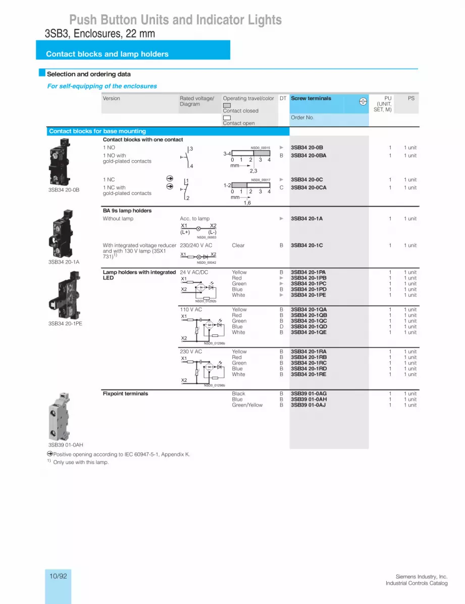
10/92 Siemens Industry, Inc.Industrial Controls Catalog
3SB3 Push Buttons and Indicator Lights, 22 mmEnclosures
Contact blocks and lampholders
13/91 Siemens IC 10 · 2012
13
Selection and ordering data
For self-equipping of the enclosures
qPositive opening according to IEC 60947-5-1, Appendix K.1) Only use with this lamp.
Version Rated voltage/ Diagram
Operating travel/color
Contact closed
Contact open
DT Screw terminals PU (UNIT,
SET, M)
PS
Order No.
Contact blocks for base mounting
3SB34 20-0B
Contact blocks with one contact1 NO
3SB34 20-0B 1 1 unit
1 NO with gold-plated contacts
B 3SB34 20-0BA 1 1 unit
1 NC q
3SB34 20-0C 1 1 unit
1 NC with gold-plated contacts
q C 3SB34 20-0CA 1 1 unit
3SB34 20-1A
BA 9s lamp holdersWithout lamp Acc. to lamp 3SB34 20-1A 1 1 unit
With integrated voltage reducer and with 130 V lamp (3SX1 731)1)
230/240 V AC Clear B 3SB34 20-1C 1 1 unit
3SB34 20-1PE
Lamp holders with integratedLED
24 V AC/DC Yellow B 3SB34 20-1PA 1 1 unitRed 3SB34 20-1PB 1 1 unitGreen 3SB34 20-1PC 1 1 unitBlue B 3SB34 20-1PD 1 1 unitWhite 3SB34 20-1PE 1 1 unit
110 V AC Yellow B 3SB34 20-1QA 1 1 unitRed B 3SB34 20-1QB 1 1 unitGreen B 3SB34 20-1QC 1 1 unitBlue D 3SB34 20-1QD 1 1 unitWhite B 3SB34 20-1QE 1 1 unit
230 V AC Yellow B 3SB34 20-1RA 1 1 unitRed B 3SB34 20-1RB 1 1 unitGreen B 3SB34 20-1RC 1 1 unitBlue B 3SB34 20-1RD 1 1 unitWhite B 3SB34 20-1RE 1 1 unit
3SB39 01-0AH
Fixpoint terminals Black B 3SB39 01-0AG 1 1 unitBlue B 3SB39 01-0AH 1 1 unitGreen/Yellow B 3SB39 01-0AJ 1 1 unit
.4
.3
2,3
3-4
mm
NSD0_00015
.2
.11-2
1,6mm
NSD0_00017
(L-)(L+)X2X1
NSD0_00003
X2X1
NSD0_00042
+kk
NSD0_01292b
X1
X2
+kk
NSD0_01296b
X1
X2
+kk
NSD0_01296b
X1
X2
IC10_13_05 ccorp.fm Page 91 Monday, September 30, 2013 7:52 PM
0 1 2 3 4
0 1 2 3 4
3SB3, Enclosures, 22 mm
Contact blocks and lamp holders
Push Button Units and Indicator Lights

10/93Siemens Industry, Inc.Industrial Controls Catalog
3SB3 Push Buttons and Indicator Lights, 22 mmEnclosures
13/92Siemens IC 10 · 2012
Contact blocks and lampholders
13
qPositive opening according to IEC 60947-5-1, Appendix K.
Version Rated voltage/ Diagram
Operating travel/color
Contact closed
Contact open
DT Spring-typeterminals
PU (UNIT,
SET, M)
PS
Order No.
Contact blocks for base mounting
3SB34 23-0B
Contact blocks with one contact 1 NO
B 3SB34 23-0B 1 1 unit
1 NO with gold-plated contacts
D 3SB34 23-0BA 1 1 unit
1 NC q
B 3SB34 23-0C 1 1 unit
1 NC with gold-plated contacts
q B 3SB34 23-0CA 1 1 unit
Lamp holders with integratedLED
24 V AC/DC Yellow B 3SB34 23-1PA 1 1 unitRed B 3SB34 23-1PB 1 1 unitGreen B 3SB34 23-1PC 1 1 unitBlue B 3SB34 23-1PD 1 1 unitWhite B 3SB34 23-1PE 1 1 unit
110 V AC Yellow B 3SB34 23-1QA 1 1 unitRed D 3SB34 23-1QB 1 1 unitGreen D 3SB34 23-1QC 1 1 unitBlue D 3SB34 23-1QD 1 1 unitWhite D 3SB34 23-1QE 1 1 unit
230 V AC Yellow D 3SB34 23-1RA 1 1 unitRed B 3SB34 23-1RB 1 1 unitGreen B 3SB34 23-1RC 1 1 unitBlue B 3SB34 23-1RD 1 1 unitWhite B 3SB34 23-1RE 1 1 unit
3SB34 23-2G
Fixpoint terminals Black B 3SB34 23-2F 1 1 unitBlue B 3SB34 23-2G 1 1 unitGreen/Yellow B 3SB34 23-2H 1 1 unit
.4
.3
2,3
3-4
mm
NSD0_00015
.2
.11-2
1,6mm
NSD0_00017
+kk
NSD0_01292b
X1
X2
+kk
NSD0_01296b
X1
X2
+kk
NSD0_01296b
X1
X2
Version DT Order No. PU (UNIT,
SET, M)
PS
Accessories
3SB39 01-0AW
Pressure plates for selector switches and key-operated switches For actuating the central contact block of 3 contact blocks
B 3SB39 01-0AW 100 10 units
IC10_13_05 ccorp.fm Page 92 Monday, September 30, 2013 7:52 PM
0 1 2 3 4
0 1 2 3 4
3SB3, Enclosures, 22 mm
Contact blocks and lamp holders
Push Button Units and Indicator Lights

10/94 Siemens Industry, Inc.Industrial Controls Catalog
3SB3 Push Buttons and Indicator Lights, 22 mmEnclosures
Inscription labels for enclosures
13/93 Siemens IC 10 · 2012
13
Overview
Inscription labelsThe inscription labels (black with white inscription or silver-colored with black print) have an adhesive layer on the back.The size of the labels is 22 mm x 22 mm.
Inscriptions
Selection and ordering data
Inscriptions DT Black DT Silver-coloredOrder No. Order No.
Inscription labels, self-adhesive, 22 mm × 22 mmFor self-inscriptionBlank B 3SB39 06-1AA B 3SB19 01-3AAWith inscriptionOn B 3SB39 06-1EB B 3SB19 01-3EBOff B 3SB39 06-1EC B 3SB19 01-3ECUp B 3SB39 06-1ED B 3SB19 01-3EDDown B 3SB39 06-1EE B 3SB19 01-3EEOpen B 3SB39 06-1EP B 3SB19 01-3EPClose B 3SB39 06-1EQ B 3SB19 01-3EQForward B 3SB39 06-1EF B 3SB19 01-3EFReverse B 3SB39 06-1EG B 3SB19 01-3EGRight B 3SB39 06-1EH —Left B 3SB39 06-1EJ —Fast B 3SB39 06-1ER —Slow B 3SB39 06-1ES —Running B 3SB39 06-1EV B 3SB19 01-3EVFault B 3SB39 06-1EW —Operation B 3SB39 06 -1AP —Start B 3SB39 06-1EL B 3SB19 01-3ELReset B 3SB39 06-1EM B 3SB19 01-3EMTest B 3SB39 06-1EN B 3SB19 01-3ENStop B 3SB39 06-1EK B 3SB19 01-3EKEMERGENCY STOP B 3SB39 06-1EY B 3SB19 01-3EYEquipmentFan B 3SB39 06 -1CA —Pump B 3SB39 06 -1CB —Cooling B 3SB39 06 -1CC —Heating B 3SB39 06 -1CD —Lighting B 3SB39 06 -1CE —Filter B 3SB39 06 -1CF —Motor B 3SB39 06 -1CG —Compressor B 3SB39 06 -1CH —With graphic symbolO B 3SB39 06-1MB B 3SB19 01-3MBI B 3SB39 06-1MC B 3SB19 01-3MCII B 3SB39 06-1MD B 3SB19 01-3MDIII B 3SB39 06-1ME B 3SB19 01-3MEO I (horizontal) B 3SB39 06-1MF B 3SB19 01-3MFI O II (horizontal) B 3SB39 06-1MG B 3SB19 01-3MGI O (vertical) B 3SB39 06-1MH B 3SB19 01-3MHII O I (vertical) B 3SB39 06-1MW C 3SB19 01-3MW B 3SB39 06-1NA B 3SB19 01-3NA
Inscriptions DT Black DT Silver-coloredOrder No. Order No.
Inscription labels, self-adhesive, 22 mm × 22 mmWith customized inscriptionFor inscriptions or symbols see "Options" 3SB39 06-0XZ 3SB19 01-3XZ• Text line(s) B K0Y B K0Y• Text line(s) or symbol with No. B K1Y, K2Y,
K3Y or K5YB K1Y, K2Y,
K3Y or K5Y• Any inscription or symbol B K9Y B K9Y
IC10_13_05 ccorp.fm Page 93 Monday, September 30, 2013 7:52 PM
≤ ×
≥
∅
Ωµ
3SB3, Enclosures, 22 mm
Inscription labels for enclosures
Push Button Units and Indicator Lights
For customized inscriptions see page 10/72.
The inscriptions have upper case initial letters. The typeface isArial. Graphic symbols, including those not listed in the catalog,are according to ISO 7000 or IEC 60417 (see page 10/95).

10/95Siemens Industry, Inc.Industrial Controls Catalog
3SB3 Push Buttons and Indicator Lights, 22 mmEnclosures
13/94Siemens IC 10 · 2012
Accessories for enclosures
13
Selection and ordering data
1) The holder for illuminated commanding devices is included in the scope of supply.
2) The pressure plates can be removed one by one to meet individual requirements.
3) Not suitable for plastic enclosures with 6 command points.
Version Color/ inscription
DT Order No. PU (UNIT,
SET, M)
PS
Blanking plugs for spare command points
3SB39 21-0AA
Blanking plugs For plastic version, round
Black 3SB39 21-0AA 1 10 units
3SB19 02-0AQ
Blanking plugs (plastic) For metal version, round
Aluminized B 3SB19 02-0AQ 1 10 units
Holders and pressure plates
3SB39 01-0AB
Holders for push buttons and switches For snapping on 3 blocks,1)
for front plate mounting
3SB39 01-0AB 100 20 units
3SB39 01-0AC
Holders for selector switches and key-operated switches with pressure plate For actuating a central contact block, for front plate mounting2)
3SB39 01-0AC 100 10 units
3SB39 01-0AW
Pressure plates for selector switches andkey-operated switches For actuating a central contact block, for base mounting2)
B 3SB39 01-0AW 100 10 units
Accessories for enclosuresYellow name plates As backing plate for EMERGENCY-STOP, self-adhesive
Without inscription D 3SB19 02-1AQ 1 1 unit
With recess for inscription label
B 3SB39 21-0BV 1 1 unit
3SB39 01-0CK
Cable gland includes hexagonal nut
• M20 B 3SB39 01-0CK 1 1 unit
• M25 B 3SB39 01-0CM 1 1 unit
• Pg 16 B 3SB39 01–0AK 1 1 unit
• Pg 22 B 3SB39 01–0AM 1 1 unit
3SB39 01-0CL
Hexagonal nuts For cable glands
• M25 B 3SB39 01-0CL 100 10 units
• M20 B 3SB39 01-0CN 100 10 units
• Pg 16 B 3SB39 01–0AL 100 10 units
• Pg 22 B 3SB39 01–0AN 100 10 units
3SB39 01-0CS
Connecting piecesFor connecting 2 plastic enclosures
• M20/M20 B 3SB39 01-0CS 1 1 unit
• M20/M253) B 3SB39 01-0CT 1 1 unit
• M25/M25 B 3SB39 01-0CU 1 1 unit
3SB39 01-0CP
Connecting piecesFor connecting 2 metal enclosures
• M20/M20 B 3SB39 01-0CP 1 1 unit
• M20/M25 B 3SB39 01-0CQ 1 1 unit
Pg 16 terminal for AS interface cablesuitable receptacles: crimp snap-in contacts 0.2–0.56 mm2
B 3SB39 01–0AF 1 1 unit
IC10_13_05 ccorp.fm Page 94 Monday, September 30, 2013 7:52 PM
3SB3, Enclosures, 22 mm
Accessories for enclosures
Push Button Units and Indicator Lights

10/96 Siemens Industry, Inc.Industrial Controls Catalog
3SB3 Push Buttons and Indicator Lights, 22 mmEnclosures for AS-Interface
General data
13/95 Siemens IC 10 · 2012
13
Overview
AS-Interface enclosure with customized equipment
Distributed command devices of the 3SB3 series can be quickly connected to the AS-Interface using AS-Interface enclosures. Using suitable components you can make your own enclosures with integrated AS-Interface or flexibly modify existing enclo-sures.
EMERGENCY-STOP enclosure
EnclosuresColor of enclosure cover:• Gray, RAL 7035, or• Yellow, RAL 1004, for EMERGENCY-STOP.
Color of enclosure base:• Black, RAL 9005
Installation of AS-Interface slavesThe following slave types are available for connecting the com-mand points:• Slave in A/B technology with 4 inputs and 3 outputs• Slave with 4 inputs and 4 outputs• F Slave with two secure inputs for EMERGENCY-STOP mush-
room pushbutton
The following table shows the maximum number of equippable slaves:
1) For metal enclosures with 4 command points, only 1 x slave 4I/4O or 4I/3O is possible.
ConnectionOne set of links is required in each case to connect a slave to contact blocks, to lamp holders and to the connection element.
The connection elements are mounted in the front-end cable glands and are used for connection of the AS-Interface or for bringing unused inputs or outputs out of the enclosure.
For connection to AS-Interface it can be selected between:• Terminal for shaped AS-Interface cable. The cable is con-
tacted by the insulation piercing method and routed past the enclosure on the outside (possible only with plastic enclo-sure).
• Cable gland for the shaped AS-Interface cable or round ca-ble. The cable is routed into the enclosure (preferable for metal enclosure).
• Connection using M12 plug.
If less than all inputs/outputs of the installed slaves in an enclo-sure are used for connecting the command devices, free inputs and outputs can be routed on request to the outside through an M12 socket on the top or bottom side of the enclosure.
To supply inputs with power, the S+ connection of the slave must be assigned to the socket, for outputs the OUT– connection must be assigned.
Addressing is performed using the AS-Interface connections or the integrated addressing socket. An external power supply is not required.
Customized enclosures (selection by configurator)To order customized 3SF58 AS-Interface enclosures with the 3SB3 control devices, use the 3SB3/3SF5 configurator to select the blocks for equipping. An electronic order form will be gener-ated for the additional options.
NSD
0_01414
Enclosures for Number of slavesfor enclosures withoutEMERGENCY-STOP
Number of slavesfor enclosures withEMERGENCY-STOP
1 command point Not available 1 x F slave
2 command points 1 x slave 4I/4O or 4I/3O Not available
3 command points 1 x slave 4I/4O or 4I/3O 1 x slave 4I/4O or 4I/3O + 1 x F slave
4 command points 2 x slave 4I/4O or 4I/3O1) 2 × slave 4I/4O or 4I/3O + 1 × F slave1)
6 command points 2 x slave 4I/4O or 4I/3O 2 x slave 4I/4O or 4I/3O + 1 x F slave
IC10_13_05 ccorp.fm Page 95 Monday, September 30, 2013 7:52 PM
3SB3, Enclosures for AS-Interface, 22 mm
General data
Push Button Units and Indicator Lights
For related ordering notes see page 10/91

10/97Siemens Industry, Inc.Industrial Controls Catalog
3SB3 Push Buttons and Indicator Lights, 22 mmComponents for Actuators and IndicatorsAS-Interface F adaptersfor EMERGENCY-STOP devices
13/68 Siemens IC 10 · 2012
13
Overview
EMERGENCY-STOP mushroom push button with F adapter for bus connection
The AS-Interface F adapter is used to connect an EMERGENCY-STOP device according to ISO 13850 from the 3SB3 series to the AS-Interface bus system. The F adapter is suitable for control devices with mounting on front plates.
The F adapter has a safe AS-Interface 2I slave and is snapped from behind onto the EMERGENCY-STOP mushroom push but-ton. In the 2I/1O expanded version, an output is also available for actuating an indicator light with LED.
Depending on the version, screw terminals or spring-type termi-nals or the insulation piercing method are used for connecting to the AS-Interface bus cable. Addressing is performed using the AS-Interface connection or the integrated addressing socket.
Safety category 4 (SIL 3) is achieved with the adapter.
Selection and ordering data
Version DT Screw terminals PS
Order No.
3SF5 402-1AA03
AS-Interface F adapter for 3SB3 EMERGENCY-STOP mushroom pushbuttons For mounting on front plates
• 2I 3SF5 402-1AA03 1 unit
• 2I/1O, with output for LED control 3SF5 402-1AB03 1 unit
Version DT Spring-type terminals PS
Order No.
3SF5 402-1AA04
AS-Interface F adapter for 3SB3 EMERGENCY-STOP mushroom pushbuttons For mounting on front plates
• 2I 3SF5 402-1AA04 1 unit
• 2I/1O, with output for LED control 3SF5 402-1AB04 1 unit
Version DT Insulation piercingmethod
PS
Order No.
3SF5 402-1AA05
AS-Interface F adapter for 3SB3 EMERGENCY-STOP mushroom pushbuttons For mounting on front plates
• 2I 3SF5 402-1AA05 1 unit
• 2I/1O, with output for LED control 3SF5 402-1AB05 1 unit
IC10_13_04 ccorp.fm Page 68 Friday, October 4, 2013 1:16 PM
3SB3, Components for Actuators and Indicators, 22 mmAS-Interface F adapters
for EMERGENCY-STOP devices
Push Button Units and Indicator Lights

10/98 Siemens Industry, Inc.Industrial Controls Catalog
3SB3 Push Buttons and Indicator Lights, 22 mmEnclosures for AS-Interface
13/96Siemens IC 10 · 2012
AS-Interface enclosures with standard fittings
13
OverviewEnclosures with standard fittings are available with:• 1 to 3 command points• Operational voltage through AS-Interface (approx. 30 V)• Vertical mounting type• Plastic enclosures are equipped with plastic actuators and in-
dicators, metal enclosures are equipped with metal actuators and indicators
The enclosures without EMERGENCY-STOP each have one user module with 4I/3O; the enclosures with EMERGENCY-STOP mushroom push buttons have a safe AS-Interface slave inte-grated in the enclosure.
Enclosures with EMERGENCY-STOP mushroom push buttons are fitted with two NC contact blocks, which are wired to the safe slave. The contact blocks and lamp holders (with spring-type terminals) of the control device, and the AS-Interface slaves, are mounted in the base of the enclosure and are cable-connected.
The plastic enclosures are designed with a connection for the AS-Interface flat cable (the cable is run passed the outside of the enclosure). For metal enclosures, the AS-Interface cable is run inside the enclosure.
The housing with EMERGENCY-STOP mushroom push buttons with an M12 connector is also available.
Selection and ordering data
For online configurator see www.siemens.com/sirius/configurators .
Equipping options (A, B, C = identification letters of the command points)
Number of command points
DT Configurator PU (UNIT,
SET, M)
PS
Order No.
AS-Interface enclosures, plastic
3SF5 811-0AA08
3SF5 812-0DA00
With M12 top connectorA = EMERGENCY-STOP mushroom push buttons,
with rotate-to-unlatch mechanism, 1 NC, 1 NC, yellow enclosure top
1 B 3SF5 811-0AA10 1 1 unit
With terminal for insulation piercing method at topA = EMERGENCY-STOP mushroom push buttons,
with rotate-to-unlatch mechanism, 1 NC, 1 NC
• Yellow enclosure top 1 A 3SF5 811-0AA08 1 1 unit• Yellow enclosure top, with protective collar 1 A 3SF5 811-0AB08 1 1 unit
B = Pushbutton green, label "I", 1 NO A = Pushbutton red, label "O", 1 NO
2 A 3SF5 812-0DA00 1 1 unit
B = Pushbutton white, label "I", 1 NO A = Pushbutton black, label "O", 1 NO
2 A 3SF5 812-0DB00 1 1 unit
C = Indicator lights clear, label without inscription
B = Pushbutton green, label "I", 1 NO A = Pushbutton red, label "O", 1 NO
3 A 3SF5 813-0DA00 1 1 unit
C = Indicator lights clear, label without inscription
B = Pushbutton white, label "I", 1 NO A = Pushbutton black, label "O", 1 NO
3 A 3SF5 813-0DC00 1 1 unit
C = Pushbutton black, label "II", 1 NO B = Pushbutton black, label "I", 1 NO A = Pushbutton red, label "O", 1 NO
3 A 3SF5 813-0DB00 1 1 unit
AS-Interface enclosures, metal
3SF5 811-2AB08
3SF5 813-2DA00
With M12 top connectorA = EMERGENCY-STOP mushroom push buttons,
with rotate-to-unlatch mechanism, 1 NC, 1 NC
• Yellow enclosure top 1 C 3SF58 11-2AA10 1 1 unit• Yellow enclosure top, with protective collar 1 C 3SF58 11-2AB10 1 1 unit
With cable gland at topA = EMERGENCY-STOP mushroom push buttons,
with rotate-to-unlatch mechanism, 1 NC, 1 NC
• Yellow enclosure top 1 A 3SF5 811-2AA08 1 1 unit• Yellow enclosure top, with protective collar 1 A 3SF5 811-2AB08 1 1 unit
B = Pushbutton green, label "I", 1 NO A = Pushbutton red, label "O", 1 NO
2 A 3SF5 812-2DA00 1 1 unit
B = Pushbutton white, label "I", 1 NO A = Pushbutton black, label "O", 1 NO
2 A 3SF5 812-2DB00 1 1 unit
C = Indicator lights clear, label without inscription
B = Pushbutton green, label "I", 1 NO A = Pushbutton red, label "O", 1 NO
3 A 3SF5 813-2DA00 1 1 unit
C = Indicator lights clear, label without inscription
B = Pushbutton white, label "I", 1 NO A = Pushbutton black, label "O", 1 NO
3 A 3SF5 813-2DC00 1 1 unit
C = Pushbutton black, label "II", 1 NO B = Pushbutton black, label "I", 1 NO A = Pushbutton red, label "O", 1 NO
3 A 3SF5 813-2DB00 1 1 unit
IC10_13_05 ccorp.fm Page 96 Monday, September 30, 2013 7:52 PM
3SB3, Enclosures for AS-Interface, 22 mm
AS-Interface enclosures with standard fittings
Push Button Units and Indicator Lights

10/99Siemens Industry, Inc.Industrial Controls Catalog
3SB3 Push Buttons and Indicator Lights, 22 mmEnclosures for AS-Interface
Components for AS-Interface enclosures
13/97 Siemens IC 10 · 2012
13
Selection and ordering data
For self-equipping of the enclosures
Version Number of command points
DT Order No. PU (UNIT,
SET, M)
PS
For plastic enclosures
3SF5 500-0BA
3SF5 500-0BB
AS-Interface slavesF slave, 2 safe inputs, for plastic enclosure, EMERGENCY-STOP, without protective collar
1 ... 6 A 3SF5 500-0BA 1 1 unit
F slave, 2 safe inputs, for plastic or metal enclosure, EMERGENCY-STOP, with protective collar
1 A 3SF5 500-0DA 1 1 unit
A/B slave, 4I/3O for plastic enclosure
2 ... 6 A 3SF5 500-0BB 1 1 unit
Slave, 4I/4O, for plastic enclosure
2 ... 6 A 3SF5 500-0BC 1 1 unit
3SF5 900-0CA
3SF5 900-0CC
3SF5 900-0CG
Sets of linksFor F slave A 3SF5 900-0BA 1 1 unit
For slave 4I/4O or A/B slave 4I(3O) A 3SF5 900-0BB 1 1 unit
Connection elementsFor AS-Interface shaped cable, connection by insulation piercing method, for plastic enclosure
1 ... 3 A 3SF5 900-0CA 1 1 unit
4 ... 6 B 3SF5 900-0CB 1 1 unit
For AS-Interface connection using M12 plug, for plastic enclosure
1 ... 3 B 3SF5 900-0CC 1 1 unit
4 ... 6 B 3SF5 900-0CD 1 1 unit
For bringing out unused inputs/outputs through an M12 socket, for plastic enclosure
1 ... 3 B 3SF5 900-0CE 1 1 unit
4 ... 6 B 3SF5 900-0CF 1 1 unit
For AS-Interface shaped cable, cable is routed into the enclosure, for plastic or metal enclosure
1 ... 3 A 3SF5 900-0CG 1 1 unit
4 ... 6 A 3SF5 900-0CH 1 1 unit
For round cable, cable is routed into the enclosure, for plastic or metal enclosure
1 ... 3 A 3SF5 900-0CJ 1 1 unit
4 ... 6 A 3SF5 900-0CK 1 1 unit
For metal enclosures
3SF5 500-0CB
AS-Interface slavesF slave, 2 safe inputs, for metal enclosure, EMERGENCY-STOP, without protective collar
1 ... 6 A 3SF5 500-0CA 1 1 unit
F slave, 2 safe inputs, for plastic or metal enclosure, EMERGENCY-STOP, with protective collar
1 A 3SF5 500-0DA 1 1 unit
A/B slave, 4I/3O, for metal enclosure 2 ... 6 A 3SF5 500-0CB 1 1 unit
Slave, 4I/4O, for metal enclosure 2 ... 6 A 3SF5 500-0CC 1 1 unit
3SF5 900-0CG
3SF5 900-0CJ
Sets of linksFor F slave A 3SF5 900-0BA 1 1 unit
For slave 4I/4O or A/B slave 4I(3O) A 3SF5 900-0BB 1 1 unit
Connection elementsFor AS-Interface connection using M12 plug, for metal enclosure
1 ... 3 B 3SF5 900-2CC 1 1 unit
4 ... 6 B 3SF5 900-2CD 1 1 unit
For bringing out unused inputs/outputs through an M12 socket, for metal enclosure
1 ... 3 B 3SF5 900-2CE 1 1 unit
4 ... 6 B 3SF5 900-2CF 1 1 unit
For AS-Interface shaped cable, cable is routed into the enclosure, for plastic or metal enclosure
1 ... 3 A 3SF5 900-0CG 1 1 unit
4 ... 6 A 3SF5 900-0CH 1 1 unit
For round cable, cable is routed into the enclosure, for plastic or metal enclosure
1 ... 3 A 3SF5 900-0CJ 1 1 unit
4 ... 6 A 3SF5 900-0CK 1 1 unit
IC10_13_05 ccorp.fm Page 97 Monday, September 30, 2013 7:52 PM
3SB3, Enclosures for AS-Interface, 22 mm
Components for AS-Interface enclosures
Push Button Units and Indicator Lights

10/100 Siemens Industry, Inc.Industrial Controls Catalog
SIRIUS 3SB3Dimension drawings (mm)Operator and indicator elements
Push Button Units and Indicator LightsPushbuttons and Indicator LightsSIGNUM 22 mm Nominal Diameter
Project planning aids
Dimension drawings
Molded-plastic version, round
Mounting dimensions Minimum clearance a b
redlohpmal dna )tcatnoc 1( skcolb hctiwSngised erauqSngised dnuoR• for front plate mounting, with screw terminals• for front plate mounting, with spring-loaded terminals• for use on PCB, with solder pins
30 1)30 1)30 1)
4530 1)30 1)
Switch blocks with 2 contacts03gnitnuom etalp tnorf rof• 1) 50
When using holders forlabeling plates• 12.5 mm × 27 mm• 27.0 mm×27 mm
30 1)30 1)
45 2)60
1) For mushroom pushbutton, EMERGENCY-STOP and push-pull button: Note mushroom diameter d = 40 mm or 60 mm.
2) 60 mm with switch blocks having two contacts.
Pushbutton orilluminated pushbutton with flat pushbutton and single-pole switch block (and lampholder)
Pushbutton orilluminated pushbuttonwith raised button
Pushbuttonwith raised front ring
Pushbuttonwith raised front ring castellated
Mushroom pushbutton, illuminated mushroom pushbutton, push-pull-button or illuminated push-pull-button, ? 30 mm
Mushroom pushbutton, illuminated mushroom pushbutton, push-pull-button or illuminated push-pull-button, ? 40 mm
Mushroom pushbutton, illuminated mushroom pushbutton, push-pull-button or illuminated push-pull-button, ? 60 mm
Selector switch orilluminated selector switch
RONIS key-operated switch BKS, CES, IKON, O.M.R. key-operated switches
Joystick switch
1) 82 with mechanical interlock, 77 without mechanical interlock
Pushbuttonwith raised button, latchable
Operating mechanism for potenti-ometerwith shaft Ø 6 mm, 30 ... 32 mm long
Pushbutton with extended stroke

10/101Siemens Industry, Inc.Industrial Controls Catalog
Siemens / Industrial Controls Previous folio: IC10 10/97
Siemens LV 10 · 200410/89
Pushbuttons and Indicator Lights
Project planning aids
SIGNUM 22 mm Nominal Diameter
EMERGENCY-STOP mushroom pushbutton,Ø 32 mm, pull to unlatch
EMERGENCY-STOP mushroom pushbutton,Ø 40 mm, pull to unlatch
EMERGENCY-STOP mushroom pushbutton,Ø 40 mm, pull to unlatch
EMERGENCY-STOP mushroom pushbutton,Ø 60 mm, rotate to unlatch
EMERGENCY-STOP mushroom pushbuttonwith RONIS key-operated switch
EMERGENCY-STOP mushroom pushbuttonwith BKS, CES, IKON, O.M.R. key-operated switch
redloH raeGthgil rotacidnI
Audible signal device Hole plug
On-Off pushbuttonwith flat buttons
On-Off pushbuttonwith raised buttons
On-Off pushbuttonwith or without indicator light
Top view
Operating mechanism for potenti-ometerwith shaft Ø 6 mm, 30 ... 32 mm long
Pushbutton with extended stroke
SIRIUS 3SB3Dimension drawings (mm)
Operator and indicator elements
Push Button Units and Indicator Lights

10/102 Siemens Industry, Inc.Industrial Controls Catalog
Siemens / Industrial Controls Previous folio: 10/99
SIRIUS 3SB3Dimension drawings (mm)Operator and indicator elements
Push Button Units and Indicator Lights
Siemens LV 10 · 2004 10/90
Pushbuttons and Indicator LightsSIGNUM 22 mm Nominal Diameter
Project planning aids
Plastic version, square
Pushbutton or illuminated pushbutton with flat pushbutton
Selector switch or illuminated selector switch
RONIS key-operated switch BKS, CES, IKON, O.M.R. key-operated switch
Indicator light
EMERGENCY-STOP mushroom pushbuttonwith safety lock
EMERGENCY-STOP mushroom pushbutton with RONIS key-operated switch
EMERGENCY-STOP mushroom pushbuttonwith BKS, CES, IKON, O.M.R. key-operated switch
Gear Holder
Hole plug

10/103Siemens Industry, Inc.Industrial Controls Catalog
Siemens / Industrial Controls Previous folio: 10/101
SIRIUS 3SB3Dimension drawings (mm)
Operator and indicator elements
Push Button Units and Indicator LightsPushbuttons and Indicator Lights
Project planning aids
SIGNUM 22 mm Nominal Diameter
Metal version, roundPushbutton or illuminated pushbuttonwith flat button and single-pole switch block (and lampholder)
Pushbutton or illuminated pushbuttonwith raised button
Pushbutton or illuminated pushbutton, latching, with flat button
Pushbuttonwith raised front ring
Mushroom pushbutton, illuminated mushroom pushbutton, push-pull-button or illuminated push-pull-button, ? 30 mm
Mushroom pushbutton, illuminated mushroom pushbutton, push-pull-button or illuminated push-pull-button, ? 40 mm
Mushroom pushbutton, illuminated mushroom pushbutton, push-pull-button or illuminated push-pull-button, ? 60 mm
Selector switch or illuminated selector switch,standard
Selector switch or illuminated selector switch,heavy duty
Selector switch or illuminated selector switchwith long handle
RONIS key-operated switch BKS, CES, IKON, O.M.R. key-operated switches
EMERGENCY-STOP mushroom pushbutton,Ø 32 mm, rotate to unlatch
EMERGENCY-STOP mushroom pushbutton,Ø 40 mm, pull to unlatch
EMERGENCY-STOP mushroom pushbutton,Ø 40 mm, rotate to unlatch
EMERGENCY-STOP mushroom pushbutton,Ø 60 mm, rotate to unlatch
EMERGENCY-STOP mushroom pushbuttonwith RONIS key-operated switch
EMERGENCY-STOP mushroom pushbutton with BKS, CES, IKON, O.M.R. key-operated switch
redloH raeGthgil rotacidnI

10/104 Siemens Industry, Inc.Industrial Controls Catalog
Siemens / Industrial Controls Previous folio: 10/102
SIRIUS 3SB3Dimension drawings (mm)Contact blocks and lamp holders
Push Button Units and Indicator Lights
Siemens LV 10 · 2004 10/92
Pushbuttons and Indicator LightsSIGNUM 22 mm Nominal Diameter
Project planning aids
Contact blocks and lampholders
Screw connection, for front plate mounting
Spring-loaded terminals, for front plate mounting
Switch block with 1 contact
Switch blockwith 2 contacts
BA 9s lampholder with or without integrated voltage reducer
BA 9s lampholder with separate lamp test function
Lampholder with integrated LED
Pushbutton or illuminated pushbutton with switch blocks with 1 contact
Pushbutton with switch blocks with 1 contact
Illuminated pushbutton with switch blocks with 1 contact and lampholder
Pushbutton or illuminated pushbutton with switch blocks with 2 contacts
Illuminated pushbutton with switch blocks with 2 contacts and lampholder
Illuminated pushbutton with switch blocks with 1 contact and lampholder with snapped-on transformer
Switch block with 1 contact
Switch blockwith 2 contacts
Lampholder BA 9s Lampholder with integrated LED
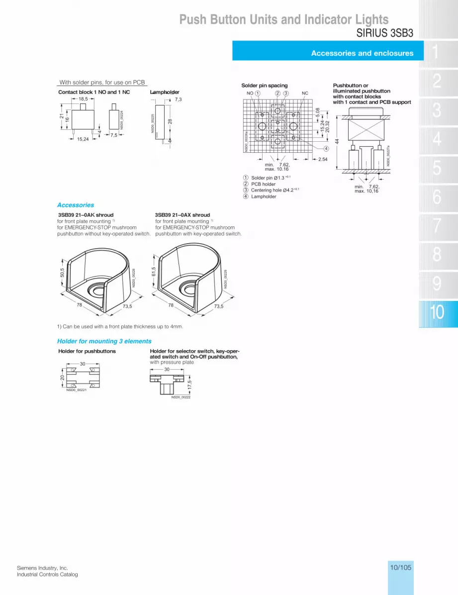
10/105Siemens Industry, Inc.Industrial Controls Catalog
Siemens / Industrial Controls Previous folio: 10/103
SIRIUS 3SB3
Accessories and enclosures
Push Button Units and Indicator Lights
10/93
Project planning aids
Accessories
Holder for mounting 3 elements
Contact block 1 NO and 1 NC Lampholde ro nottubhsuPgnicaps nip redloS
r illuminated pushbutton with contact blocks with 1 contact and PCB support
3SB39 21–0AK shroud 3SB39 21–0AX shroud
Holder for pushbuttons Holder for selector switch, key-oper-ated switch and On-Off pushbutton,
for front plate mounting 1)
for EMERGENCY-STOP mushroompushbutton without key-operated switch.
for front plate mounting 1)
for EMERGENCY-STOP mushroompushbutton with key-operated switch.
1) Can be used with a front plate thickness up to 4mm.
with pressure plate
With solder pins, for use on PCB

10/106 Siemens Industry, Inc.Industrial Controls Catalog
Siemens / Industrial Controls Previous folio: 10/104
SIRIUS 3SB3Dimension drawings (mm)Accessories and enclosures
Push Button Units and Indicator Lights
Siemens LV 10 · 2004 10/94
Enclosures
Screw connection, for base mounting
Spring-loaded terminals, for base mounting
Enclosure without shroud, molded plastic
top and bottom with knockouts for one gland each
Enclosure without shroud, metal
top and bottom with opening for one gland each
Enclosure with shroud, molded plastic
top and bottom with knockouts for one gland each
Enclosure with shroud, metal
top and bottom with opening for one gland each
Number of com-mand points
Lengtha
Spacingb
Spacingc
12346
85114154194280
5483
123163249
17,517,517,517,520,5
Number of com-mand points
Lengtha
Spacingb
Spacingc
12346
85114154194280
5483
123163249
2121212121
Contact block with 1 contact
BA9s lampholder with or without
integrated voltage reducer
Lampholder with integrated LED
Contact block with 1 contact
Lampholder with integrated LED
Support terminal

10/107Siemens Industry, Inc.Industrial Controls Catalog
Siemens / Industrial Controls Previous folio: 10/105
SIRIUS 3SB3Lamp holders
with separate lamp test function
Push Button Units and Indicator LightsPushbutton Units and Indicator LightsSIGNUM 3SB3
10/97Siemens Energy & Automation, IncIndustrial Controls Catalog
Lampholderswith separate lamp test function
Typical circuits3SB14 00–2N or 3SB34 00–1F lampholder incl. 130 V incandescent lamp
3SB14 00–2Q or 3SB34 00–1H lampholder for incandescent lamp to 2.6 W or AC neon bulbs or AC/DC LED lamps
Typical lamp test circuit with with 3SB14 00–3X or 3SB34 00–1N
3SB14 00–2P or 3SB34 00–1G lampholder for incandescent lamps up to 2.6 W or AC/DC LED lamps
3SB34 00–1L lampholder for incandescent lamp up to 2.6 W or DC LED lamps
Application examples for 3SB14 00–3X and 3SB34 00–1N diode elements
• Lamp test circuit, • Interference suppression, • Limiting voltage peaks, • Limiting DC coils, • Diode gates, • Rectifier circuits.
The diode element contains two 1N 4007 diodes. The element can be snapped onto the gear holder as required.
Notes on using the lamphold-ers with separate lamp test function
When connected in parallel with inductive loads (e.g. contac-tors), surge suppression re-quired.
The 3SB14 00–2Q and 3SB34 00–1H elements are notsuitable for use with a parallel load.
Example of a typical push to test circuit using a standard, illuminated push-button transformer type with 1 NO + 1 NC contact. e.g. Illuminated Pilot Light components require to make-up a 120 V red raised push to test trans-former type use (1) each of the following components:
• 3SB3 001-0BA21• 3SB3 400-1A
• 52AABN• 3SB3 400-3M
• 3SB3 400-0B• 3SB3 400-0C
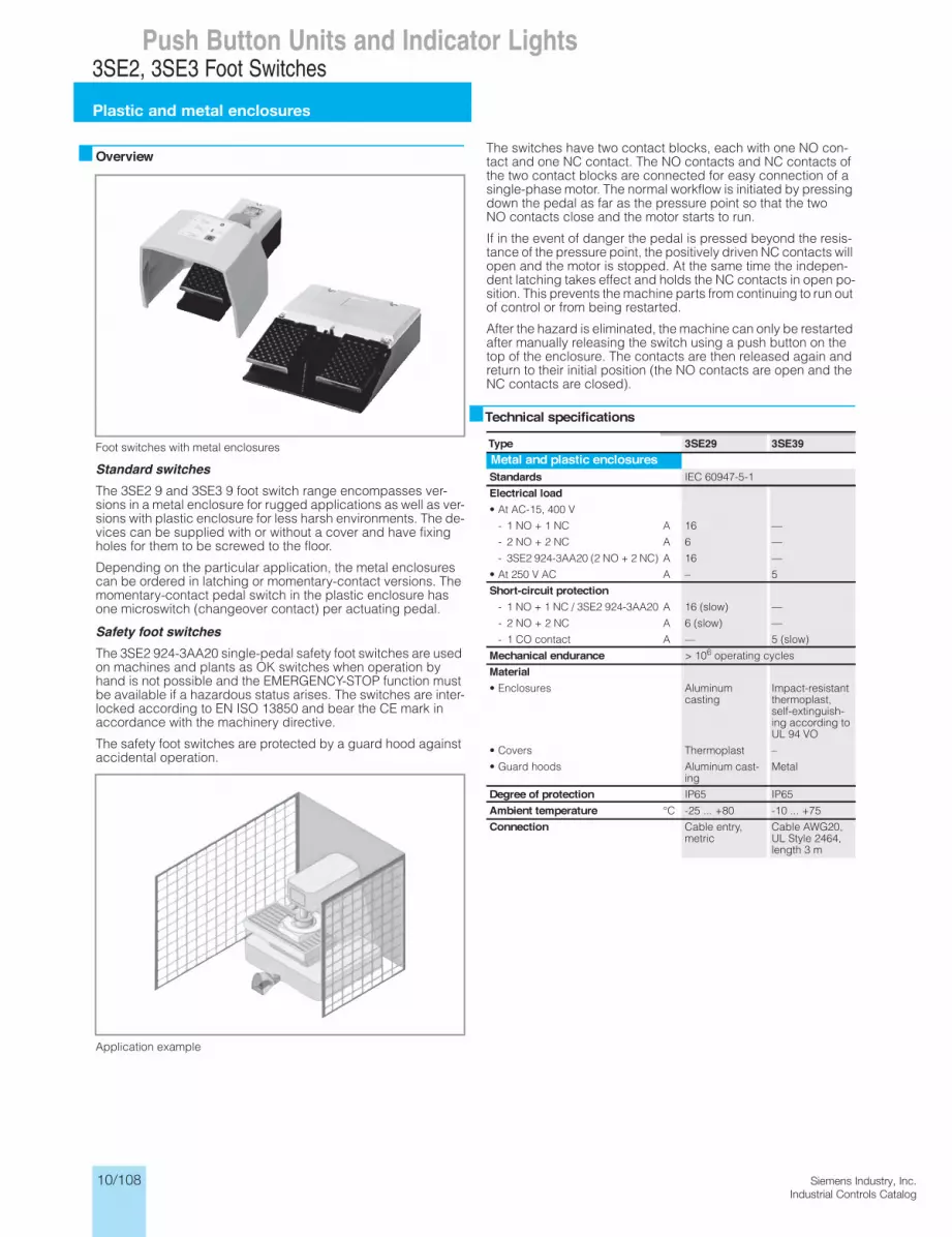
10/108 Siemens Industry, Inc.Industrial Controls Catalog
Siemens / Industrial Controls Previous folio: 10/106
3SE2, 3SE3 Foot Switches
Plastic and metal enclosures
Push Button Units and Indicator Lights3SE2, 3SE3 Foot Switches
13/105Siemens IC 10 · 2012
Plastic and metal enclosures
13
Overview
Foot switches with metal enclosures
Standard switchesThe 3SE2 9 and 3SE3 9 foot switch range encompasses ver-sions in a metal enclosure for rugged applications as well as ver-sions with plastic enclosure for less harsh environments. The de-vices can be supplied with or without a cover and have fixing holes for them to be screwed to the floor.
Depending on the particular application, the metal enclosures can be ordered in latching or momentary-contact versions. The momentary-contact pedal switch in the plastic enclosure has one microswitch (changeover contact) per actuating pedal.
Safety foot switchesThe 3SE2 924-3AA20 single-pedal safety foot switches are used on machines and plants as OK switches when operation by hand is not possible and the EMERGENCY-STOP function must be available if a hazardous status arises. The switches are inter-locked according to EN ISO 13850 and bear the CE mark in accordance with the machinery directive.
The safety foot switches are protected by a guard hood against accidental operation.
Application example
The switches have two contact blocks, each with one NO con-tact and one NC contact. The NO contacts and NC contacts of the two contact blocks are connected for easy connection of a single-phase motor. The normal workflow is initiated by pressing down the pedal as far as the pressure point so that the two NO contacts close and the motor starts to run.
If in the event of danger the pedal is pressed beyond the resis-tance of the pressure point, the positively driven NC contacts will open and the motor is stopped. At the same time the indepen-dent latching takes effect and holds the NC contacts in open po-sition. This prevents the machine parts from continuing to run out of control or from being restarted.
After the hazard is eliminated, the machine can only be restarted after manually releasing the switch using a push button on the top of the enclosure. The contacts are then released again and return to their initial position (the NO contacts are open and the NC contacts are closed).
Technical specifications
Type 3SE29 3SE39Metal and plastic enclosuresStandards IEC 60947-5-1
Electrical load• At AC-15, 400 V
- 1 NO + 1 NC A 16 —
- 2 NO + 2 NC A 6 —
- 3SE2 924-3AA20 (2 NO + 2 NC) A 16 —
• At 250 V AC A – 5
Short-circuit protection- 1 NO + 1 NC / 3SE2 924-3AA20 A 16 (slow) —
- 2 NO + 2 NC A 6 (slow) —
- 1 CO contact A — 5 (slow)
Mechanical endurance > 106 operating cycles
Material• Enclosures Aluminum
castingImpact-resistant thermoplast, self-extinguish-ing according to UL 94 VO
• Covers Thermoplast –
• Guard hoods Aluminum cast-ing
Metal
Degree of protection IP65 IP65
Ambient temperature °C -25 ... +80 -10 ... +75
Connection Cable entry, metric
Cable AWG20, UL Style 2464, length 3 m
IC10_13_08 ccorp.fm Page 105 Monday, September 30, 2013 8:50 PM

10/109Siemens Industry, Inc.Industrial Controls Catalog
Siemens / Industrial Controls Previous folio: 10/107
3SE2, 3SE3 Foot Switches
Plastic and metal enclosures
Push Button Units and Indicator Lights3SE2, 3SE3 Foot Switches
Plastic and metal enclosures
13/106 Siemens IC 10 · 2012* You can order this quantity or a multiple thereof.
Illustrations are approximate
13
Selection and ordering data
Version Slow-action contacts for each pedal
DT Order No. PU (UNIT,
SET, M)
PS
Metal enclosures, degree of protection IP65
3SE2 90.-.AA20 3SE2 91.-.AA20
Momentary-contact foot switches,single pedal M20 x 1.5 cable entry
• Without hood 1 NO + 1 NC q A 3SE2 902-0AB20 1 1 unit
2 NO + 2 NC q A 3SE2 903-1AB20 1 1 unit
• With hood 1 NO + 1 NC q A 3SE2 902-0AA20 1 1 unit
2 NO + 2 NC q A 3SE2 903-1AA20 1 1 unit
Momentary-contact foot switches,single pedal M20 x 1.5 cable entry
• Without hood 1 NO + 1 NC q C 3SE2 912-2AB20 1 1 unit
• With hood 1 NO + 1 NC q C 3SE2 912-2AA20 1 1 unit
3SE2 932-.AB20
Momentary-contact foot switches, twopedals M25 x 1.5 cable entry
• Without hood 1 NO + 1 NC q B 3SE2 932-0AB20 1 1 unit
2 NO + 2 NC q B 3SE2 932-1AB20 1 1 unit
3SE2 932-.AA20
• With hood 1 NO + 1 NC q B 3SE2 932-0AA20 1 1 unit
2 NO + 2 NC q B 3SE2 932-1AA20 1 1 unit
3SE2 924-3AA20
Safety foot switches,single pedal, with hood, M20 x 1.5 cable entry, with interlock according to ISO 13850, NO closes as momentary contact type, NC opens with latching
2 NO + 2 NC q C 3SE2 924-3AA20 1 1 unit
Plastic enclosures, degree of protection IP65
3SE3 902-4CA20
Momentary-contact pedal switches, 3 m cable
Microswitch
• Single pedal
- Without hood 1 CO contact
B 3SE3 902-4CB20 1 1 unit
- With hood 1 CO contact
B 3SE3 902-4CA20 1 1 unit
3SE3 934-5CB20
• Two pedals, without hood 2 × 1 CO B 3SE3 934-5CB20 1 1 unit
q Positive opening according to IEC 60947-5-1, Appendix K.
IC10_13_08 ccorp.fm Page 106 Monday, September 30, 2013 8:50 PM

10/110 Siemens Industry, Inc.Industrial Controls Catalog
Siemens / Industrial Controls Previous folio: 10/108
8WD4 Signaling Columns
General Data
Push Button Units and Indicator Lights8WD4 Signaling Columns
13/107Siemens IC 10 · 2012
General data
13
OverviewThe 8WD4 signaling columns are flexible in design and versatile in use.
2
3
1
4
5
6
7
8
9
10
NSC0_00726b
12
13
14
11
1413121110987654321 Acoustic element 8WD42 .0-0FA
Light element 8WD42AS-Interface adapter element 8WD42 28-0BBConnection element 8WD42 08-0AABracket for wall mounting 8WD42 08-0CDAdapter for single-hole mounting 8WD42 08-0EHFoot for mounting 8WD42 08-0DEPipe 8WD42 08-0EF/8WD43 08-0E.Foot for mounting with pipe 8WD43 08-0DBFoot for mounting with pipe (> 400 mm) 8WD43 08-0DCAdjustable-angle foot for mounting on pipes 8WD44 08-0DFSocket 8WD43 08-0DDSocket (magnetic fixing) 8WD43 08-0DEBracket for mounting with foot 8WD44 08-0CC
8WD42 signaling columns (width 50 mm) with up to 4 elements
NS
C0_
0072
7b
5
2
3
1
10
11
8
15
16
4
7
15
6
9
8
1213
14
Acoustic element 8WD44Light element 8WD44 AS-Interface adapter element 8WD44 28-0BD/8WD44 28-0BEConnection element for mounting on bracket,base and floor 8WD44 08-0AB/8WD44 08-0AEConnection element for mounting on pipe 8WD44 08-0AA/8WD44 08-0AD Bracket for wall mounting 8WD43 08-0CABracket for wall mounting (two-sided) 8WD43 08-0CBSocket 8WD43 08-0DDBracket for base mounting 8WD44 08-0CDPipe 8WD42 08-0EF/8WD43 08-0E.Foot with pipe 8WD43 08-0DAFoot for mounting with pipe 8WD43 08-0DBFoot for mounting with pipe (> 400 mm) 8WD43 08-0DCAdjustable-angle foot for mounting on pipes 8WD44 08-0DF Socket (magnetic fixing) 8WD43 08-0DEBracket for mounting with foot 8WD44 08-0CC
1234
5
678910111213141516
8WD44 signaling columns (width 70 mm) with up to 5 elements
IC10_13_09 ccorp.fm Page 107 Monday, September 30, 2013 8:45 PM

10/111Siemens Industry, Inc.Industrial Controls Catalog
8WD4 Signaling Columns
General Data
Push Button Units and Indicator Lights8WD4 Signaling Columns
General data
13/108 Siemens IC 10 · 2012
13
Two product series are available:• 8WD42
- Thermoplast enclosure, diameter 50 mm- Degree of protection IP54- Up to 4 elements can be mounted between the connection
element and the cover• 8WD44
- Thermoplast enclosure, diameter 70 mm- Advanced design and significantly improved illumination- Faster and more flexible connection using spring-type
terminals- Integrated degree of protection IP65- Up to 5 elements can be mounted between the connection
element and the cover
Signaling columns, mounting examples
The illustrated examples are from the left:• 8WD42: Cover (no No.), 4 light elements %, connection
element (, pipe ,, foot -• 8WD44: Acoustic element with integral cover $, 2 light
elements %, connection element ), foot with pipe /• 8WD44: Cover (no No.), 4 light elements %,
AS-Interface adapter element &, connection element (, bracket for wall mounting *
• 8WD44: Cover (no No.), 3 light elements %, AS-Interface adapter element &, connection element ), foot with pipe /
Note:
The cover is supplied with the connection element; it is not needed with the acoustic element.
Benefits• Choice of various light and acoustic elements with different
functions: continuous light, blinklight, flashlight and rotating light; buzzer and siren
• Light elements with particularly long-lasting LEDs• Variety of colors: red, yellow, green, white or blue• Optimized illumination through improved prism technology
with the 8WD44• Acoustic elements can be adjusted in tone and volume• Extremely resistant to shock and vibrations• Easy connection and quick lamp change with secure bayonet
mechanism• Communication capability through connection to AS-Interface
Application8WD4 signaling columns are used in machines or in automatic processes for monitoring complex procedures or as visual or acoustic warning devices in emergency situations, e.g. for dis-playing individual assembly stages.
Communication capabilityConnection to AS-Interface
The 8WD4 signaling columns can be directly connected to the AS-Interface bus system through an adapter element that can be integrated in the column. Wiring outlay is reduced as the re-sult. The two-wire bus cable is fixed to the terminals in the con-nection element. Up to four signaling elements can be mounted on it using an adapter element.
A/B technology enables the connection of up to 62 slaves on one AS-Interface system.
ConnectionThe signaling elements are wired up using the screw terminals in the connection element, screw terminals on the 8WD42 and screw or spring-type terminals on the 8WD44.
Cable outlet
The connecting cables can be guided either downwards or side-ways through the cable gland using an adapter that can be screwed under the foot. This makes wiring easier if there is no access from below.
Connection to AS-Interface
8WD42:
The two-wire bus cable is fixed to the screw terminals in the con-nection element. The adapter element must be the first module to be mounted on the connection element. A maximum of 4 sig-naling elements can then be mounted on it.
The adapter element 8WD42 28-0BB is a standard slave.
8WD44:
The two-wire bus cable is fixed to the screw or spring-type ter-minals in the connection element. The adapter element must be the first module to be mounted on the connection element. The signaling elements can then be mounted on it.
The adapter element 8WD44 28-0BE is a standard slave. A max-imum of 4 signaling elements can be mounted on it.
The adapter element 8WD44 28-0BD with A/B technology en-ables the connection of up to 62 slaves on one AS-Interface sys-tem. The addressing socket provides user-friendly parameter-ization of the AS-Interface elements. A maximum of 3 signaling elements can be mounted on it.
IC10_13_09 ccorp.fm Page 108 Monday, September 30, 2013 8:45 PM

10/112 Siemens Industry, Inc.Industrial Controls Catalog
8WD4 Signaling Columns
General Data
Push Button Units and Indicator Lights8WD4 Signaling Columns
13/109Siemens IC 10 · 2012
General data
13
Technical specifications
Type 8WD42 8WD44General dataApprovals UL, CSA UL, CSA
Light and acoustic elementsRated voltage, power consumptionLight elements with incandescent lamp (AC values for 50/60 Hz) (AC values for 50/60 Hz)
• Continuous light 12 V, 24 V, 115 V, 230 V AC/DC 12 V, 24 V, 115 V, 230 V AC/DC
• Blinklight 24 V AC/DC/125 mA; 115 V AC/20 mA; 230 V AC/15 mA
24 V AC/DC/125 mA; 115 V AC/20 mA; 230 V AC/15 mA
• Flashlights — 24 V DC/125 mA; 115 V AC/20 mA; 230 V AC/35 mA
• Max. inrush current, blinklight/flashlight — 500 mA
Light elements with integrated LED
• Continuous light 24 V AC/DC/60 mA 24 V AC/DC/45 mA; 115 V AC/DC/25 mA; 230 V AC/25 mA
• Blinklight — 24 V AC/DC/40 mA
• Rotating light — 24 V AC/DC/70 mA
Acoustic elements
• Buzzer element (tone: pulsating or continuous, 85 dB)
24 V AC/DC/25 mA; 115 V AC/DC/25 mA; 230 V AC/25 mA
24 V AC/DC/25 mA; 115 V AC/DC/25 mA; 230 V AC/25 mA
• Siren element (8 tones + amplification can be set, 100 dB)
— 24 V AC/DC/80 mA; 115 V AC/30 mA; 230 V AC/16 mA
• Siren element (108 dB) — 24 V DC/100 mA
Power consumption• Incandescent lamps, base BA 15d W max. 5 7• Flashlight, flash energy Ws – 2
Endurance• Flashlights 4 × 10⁶ flashes 4 × 10⁶ flashes
AS-Interface adapter elementsIO code/ID code 8/F 8/E
Power supply Through bus cable Through bus cable• Operational voltage V 18.5 ... 31.6 18.5 ... 31.6• Power consumption Imax mA 50 100
Protective measures• Watchdog• Short-circuit/overload protection External back-up fuse M 1.6 A• Reverse polarity protection• Induction protection N/A
Outputs 4 Relay outputs 3 solid-state outputs
• Load voltageVV
External auxiliary voltage0 ... 30 DC 0 ... 230 AC
through bus cable or external auxiliary voltage, switch-selectable
• Current carrying capacity ∑ Imax- With external auxiliary voltage A 1.5 0.3- Without external auxiliary voltage A — 0.2
Operating temperature °C –20 ... +50 –20 ... +50
EnclosuresEnclosure material Thermoplast (polyamide), impact-resistant,
blackThermoplast (polyamide), impact-resistant, black
Light elements Thermoplast (polycarbonate) Thermoplast (polycarbonate)
Mounting• Horizontal (floor mounting,
foot with 25 mm Ø pipe)• Horizontal (single-hole mounting) —• Vertical with bracket
Degree of protection• Light elements IP54 IP65 (seal premounted with every module)• Acoustic elements, AS-i adapter elements IP54 IP65
Operating temperature °C –20 ... +50 –20 ... +50
Connection M3 screw terminal Spring-type terminals/M3 screw terminals• Conductor cross-sections mm2 Max. 2.5 Max. 2.5• Tightening torque Nm Max. 0.5 – / Max. 0.5
IC10_13_09 ccorp.fm Page 109 Monday, September 30, 2013 8:45 PM
≤ ×
≥
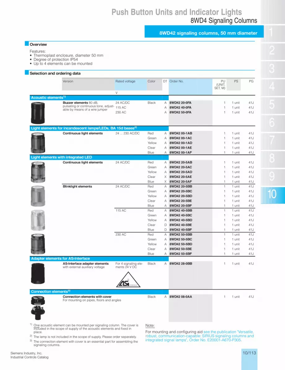
10/113Siemens Industry, Inc.Industrial Controls Catalog
8WD4 Signaling Columns
8WD42 signaling columns, 50 mm diameter
Push Button Units and Indicator Lights8WD4 Signaling Columns
8WD42 signaling columns, 50 mm diameter
13/110 Siemens IC 10 · 2012* You can order this quantity or a multiple thereof.
Illustrations are approximate
13
OverviewFeatures:• Thermoplast enclosure, diameter 50 mm• Degree of protection IP54• Up to 4 elements can be mounted
Selection and ordering data
Version Rated voltage Color DT Order No. PU (UNIT,
SET, M)
PS PG
V
Acoustic elements1)Buzzer elements 80 dB, pulsating or continuous tone, adjust-able by means of a wire jumper
24 AC/DC Black A 8WD42 20-0FA 1 1 unit 41J
115 AC A 8WD42 40-0FA 1 1 unit 41J
230 AC A 8WD42 50-0FA 1 1 unit 41J
Light elements for incandescent lamps/LEDs, BA 15d bases2)Continuous light elements 24 ... 230 AC/DC Red A 8WD42 00-1AB 1 1 unit 41J
Green A 8WD42 00-1AC 1 1 unit 41J
Yellow A 8WD42 00-1AD 1 1 unit 41J
Clear A 8WD42 00-1AE 1 1 unit 41J
Blue A 8WD42 00-1AF 1 1 unit 41J
Light elements with integrated LEDContinuous light elements 24 AC/DC Red A 8WD42 20-5AB 1 1 unit 41J
Green A 8WD42 20-5AC 1 1 unit 41J
Yellow A 8WD42 20-5AD 1 1 unit 41J
Clear X 8WD42 20-5AE 1 1 unit 41J
Blue X 8WD42 20-5AF 1 1 unit 41J
Blinklight elements 24 AC/DC Red A 8WD42 20-5BB 1 1 unit 41J
Green A 8WD42 20-5BC 1 1 unit 41J
Yellow A 8WD42 20-5BD 1 1 unit 41J
Clear A 8WD42 20-5BE 1 1 unit 41J
Blue A 8WD42 20-5BF 1 1 unit 41J
115 AC Red A 8WD42 40-5BB 1 1 unit 41J
Green A 8WD42 40-5BC 1 1 unit 41J
Yellow A 8WD42 40-5BD 1 1 unit 41J
Clear D 8WD42 40-5BE 1 1 unit 41J
Blue D 8WD42 40-5BF 1 1 unit 41J
230 AC Red A 8WD42 50-5BB 1 1 unit 41J
Green A 8WD42 50-5BC 1 1 unit 41J
Yellow A 8WD42 50-5BD 1 1 unit 41J
Clear A 8WD42 50-5BE 1 1 unit 41J
Blue A 8WD42 50-5BF 1 1 unit 41J
Adapter elements for AS-InterfaceAS-Interface adapter elements with external auxiliary voltage
For 4 signaling ele-ments 24 V DC
Black A 8WD42 28-0BB 1 1 unit 41J
Connection elements3)Connection elements with cover For mounting on pipes, floors and angles
Black A 8WD42 08-0AA 1 1 unit 41J
1) One acoustic element can be mounted per signaling column. The cover is included in the scope of supply of the acoustic elements and fixed in place.
2) The lamp is not included in the scope of supply. Please order separately.3) The connection element with cover is an essential part for assembling the
signaling columns.
Note:
For mounting and configuring aid see the publication "Versatile, robust, communication-capable: SIRIUS signaling columns and integrated signal lamps", Order No. E20001-A670-P305.
IC10_13_09 ccorp.fm Page 110 Monday, September 30, 2013 8:45 PM

10/114 Siemens Industry, Inc.Industrial Controls Catalog
8WD4 Signaling Columns
8WD42 signaling columns, 50 mm diameter
Push Button Units and Indicator Lights
Version Rated voltage Color DT Order No. PU (UNIT,
SET, M)
PS
V
LampsIncandescent lamps, 5WBase BA 15d 24 AC/DC A 8WD43 28-1XX 1 10 units
115 AC A 8WD43 48-1XX 1 10 units
230 AC A 8WD43 58-1XX 1 10 units
LEDsBase BA 15d 24 AC/DC Red A 8WD44 28-6XB 1 1 unit
Green A 8WD44 28-6XC 1 1 unitYellow A 8WD44 28-6XD 1 1 unitClear A 8WD44 28-6XE 1 1 unitBlue A 8WD44 28-6XF 1 1 unit
115 AC Red A 8WD44 48-6XB 1 1 unitGreen A 8WD44 48-6XC 1 1 unitYellow A 8WD44 48-6XD 1 1 unitClear A 8WD44 48-6XE 1 1 unitBlue A 8WD44 48-6XF 1 1 unit
230 AC Red A 8WD44 58-6XB 1 1 unitGreen A 8WD44 58-6XC 1 1 unitYellow A 8WD44 58-6XD 1 1 unitClear A 8WD44 58-6XE 1 1 unitBlue A 8WD44 58-6XF 1 1 unit
MountingFeet, single Plastic, for mounting
on pipesA 8WD43 08-0DB 1 1 unit
Metal, for pipe lengths > 400 mm
A 8WD43 08-0DC 1 1 unit
Plastic, for floor mount-ing (without pipe)
A 8WD42 08-0DE 1 1 unit
Adjustable-angle feetfor positioning in 7.5° increments1)
Plastic, for mounting on pipes, incl. rubber seal
X 8WD44 08-0DF 1 1 unit
Pipes, single Length 100 mm A 8WD42 08-0EF 1 1 unit
Length 150 mm A 8WD43 08-0EE 1 1 unit
Length 250 mm A 8WD43 08-0EA 1 1 unit
Length 400 mm A 8WD43 08-0EB 1 1 unit
Length 1000 mm A 8WD43 08-0ED 1 1 unit
Sockets for feet Side cable outlet A 8WD43 08-0DD 1 1 unit
Side cable outlet, with magnetic fixing2)
A 8WD43 08-0DE 1 1 unit
Brackets for mounting with foot A 8WD44 08-0CC 1 1 unit
Brackets for wall mounting(plastic)
Mounting without feet and pipe
A 8WD42 08-0CD 1 1 unit
Adapters for single-hole mounting Mounting without feet and pipe, with M18 thread and fixing nut
A 8WD42 08-0EH 1 1 unit
8WD4 Signaling Columns
8WD42 signaling columns, 50 mm diameter
13/111Siemens IC 10 · 2012* You can order this quantity or a multiple thereof.Illustrations are approximate
13
1) Markings for 30°, 45°, 60° and 90°.2) For horizontal mounting, only 1 element is recommended.
IC10_13_09 ccorp.fm Page 111 Monday, September 30, 2013 8:45 PM
For labeling panels see 8WD44, page 10/118.

10/115Siemens Industry, Inc.Industrial Controls Catalog
8WD4 Signaling Columns
8WD44 signaling columns, 70 mm diameter
Push Button Units and Indicator Lights8WD4 Signaling Columns
8WD44 signaling columns, 70 mm diameter
13/112 Siemens IC 10 · 2012* You can order this quantity or a multiple thereof.
Illustrations are approximate
13
OverviewFeatures:• Thermoplast enclosure, diameter 70 mm• Advanced design and significantly improved illumination
• Fast and flexible connection using spring-type terminals• Integrated degree of protection IP65• Up to 5 elements can be mounted
Selection and ordering data
Version Rated voltage Color DT Order No. PU (UNIT,
SET, M)
PS
V
Acoustic elements1)Buzzer elements 85 dB, pulsating or continuous tone, adjust-able by means of a wire jumper
24 AC/DC Black A 8WD44 20-0FA 1 1 unit
115 AC A 8WD44 40-0FA 1 1 unit
230 AC A 8WD44 50-0FA 1 1 unit
Siren elements, multi-tone, 100 dB, 8 tones and volume are adjustable
24 AC/DC Black A 8WD44 20-0EA2 1 1 unit
115 AC A 8WD44 40-0EA2 1 1 unit
230 AC A 8WD44 50-0EA2 1 1 unit
Siren elements 108 dB, IP40 24 DC Black A 8WD44 20-0EA 1 1 unit
Light elements for incandescent lamps/LEDs, BA 15d bases2)Continuous light elements 12 ... 230 AC/DC Red A 8WD44 00-1AB 1 1 unit
Green A 8WD44 00-1AC 1 1 unit
Yellow A 8WD44 00-1AD 1 1 unit
Clear A 8WD44 00-1AE 1 1 unit
Blue A 8WD44 00-1AF 1 1 unit
Blinklight elements 24 AC/DC Red A 8WD44 20-1BB 1 1 unit
Green A 8WD44 20-1BC 1 1 unit
Yellow A 8WD44 20-1BD 1 1 unit
Clear A 8WD44 20-1BE 1 1 unit
Blue A 8WD44 20-1BF 1 1 unit
115 AC Red A 8WD44 40-1BB 1 1 unit
Green A 8WD44 40-1BC 1 1 unit
Yellow A 8WD44 40-1BD 1 1 unit
Clear A 8WD44 40-1BE 1 1 unit
Blue A 8WD44 40-1BF 1 1 unit
230 AC Red A 8WD44 50-1BB 1 1 unit
Green A 8WD44 50-1BC 1 1 unit
Yellow A 8WD44 50-1BD 1 1 unit
Clear A 8WD44 50-1BE 1 1 unit
Blue A 8WD44 50-1BF 1 1 unit
Light elements with integrated flash lamps3)Flashlight elements with integrated electronic flash
24 DC Red A 8WD44 20-0CB 1 1 unit
Green A 8WD44 20-0CC 1 1 unit
Yellow A 8WD44 20-0CD 1 1 unit
Clear A 8WD44 20-0CE 1 1 unit
Blue A 8WD44 20-0CF 1 1 unit
115 AC Red A 8WD44 40-0CB 1 1 unit
Green D 8WD44 40-0CC 1 1 unit
Yellow A 8WD44 40-0CD 1 1 unit
Clear D 8WD44 40-0CE 1 1 unit
Blue D 8WD44 40-0CF 1 1 unit
230 AC Red A 8WD44 50-0CB 1 1 unit
Green A 8WD44 50-0CC 1 1 unit
Yellow A 8WD44 50-0CD 1 1 unit
Clear A 8WD44 50-0CE 1 1 unit
Blue A 8WD44 50-0CF 1 1 unit1) One acoustic element can be mounted per signaling column. The cover is
included in the scope of supply of the acoustic elements and fixed in place.
2) The lamp is not included in the scope of supply. Please order separately.3) The lamp is included in the scope of supply.
IC10_13_09 ccorp.fm Page 112 Monday, September 30, 2013 8:45 PM
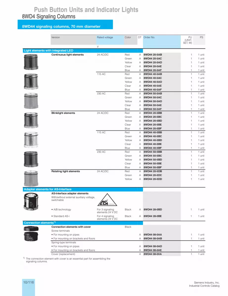
10/116 Siemens Industry, Inc.Industrial Controls Catalog
8WD4 Signaling Columns
8WD44 signaling columns, 70 mm diameter
Push Button Units and Indicator Lights
Version Rated voltage Color DT Order No. PU (UNIT,
SET, M)
PS
V
Light elements with integrated LEDContinuous light elements 24 AC/DC Red A 8WD44 20-5AB 1 1 unit
Green A 8WD44 20-5AC 1 1 unit
Yellow A 8WD44 20-5AD 1 1 unit
Clear A 8WD44 20-5AE 1 1 unit
Blue A 8WD44 20-5AF 1 1 unit
115 AC Red A 8WD44 40-5AB 1 1 unit
Green A 8WD44 40-5AC 1 1 unit
Yellow A 8WD44 40-5AD 1 1 unit
Clear A 8WD44 40-5AE 1 1 unit
Blue A 8WD44 40-5AF 1 1 unit
230 AC Red A 8WD44 50-5AB 1 1 unit
Green A 8WD44 50-5AC 1 1 unit
Yellow A 8WD44 50-5AD 1 1 unit
Clear A 8WD44 50-5AE 1 1 unit
Blue A 8WD44 50-5AF 1 1 unit
Blinklight elements 24 AC/DC Red A 8WD44 20-5BB 1 1 unit
Green A 8WD44 20-5BC 1 1 unit
Yellow A 8WD44 20-5BD 1 1 unit
Clear X 8WD44 20-5BE 1 1 unit
Blue A 8WD44 20-5BF 1 1 unit
115 AC Red A 8WD44 40-5BB 1 1 unit
Green A 8WD44 40-5BC 1 1 unit
Yellow A 8WD44 40-5BD 1 1 unit
Clear A 8WD44 40-5BE 1 1 unit
Blue A 8WD44 40-5BF 1 1 unit
230 AC Red A 8WD44 50-5BB 1 1 unit
Green A 8WD44 50-5BC 1 1 unit
Yellow A 8WD44 50-5BD 1 1 unit
Clear A 8WD44 50-5BE 1 1 unit
Blue A 8WD44 50-5BF 1 1 unit
Rotating light elements 24 AC/DC Red A 8WD44 20-5DB 1 1 unit
Green A 8WD44 20-5DC 1 1 unit
Yellow A 8WD44 20-5DD 1 1 unit
Adapter elements for AS-InterfaceAS-Interface adapter elementsWith/without external auxiliary voltage, switchable
• A/B technology For 3 signaling elements 24 V DC
Black A 8WD44 28-0BD 1 1 unit
• Standard AS-i For 4 signaling elements 24 V DC
Black A 8WD44 28-0BE 1 1 unit
Connection elements1)Connection elements with cover Black
Screw terminals
• For mounting on pipes A 8WD44 08-0AA 1 1 unit
• For mounting on brackets and floors A 8WD44 08-0AB 1 1 unit
Spring-type terminals
• For mounting on pipes A 8WD44 08-0AD 1 1 unit
• For mounting on brackets and floors A 8WD44 08-0AE 1 1 unit
Cover (replacement) A 8WD44 08-0XA 1 1 unit
8WD4 Signaling Columns
8WD44 signaling columns, 70 mm diameter
13/113Siemens IC 10 · 2012* You can order this quantity or a multiple thereof.Illustrations are approximate
13
1) The connection element with cover is an essential part for assembling the signaling columns.
IC10_13_09 ccorp.fm Page 113 Monday, September 30, 2013 8:45 PM

10/117Siemens Industry, Inc.Industrial Controls Catalog
8WD4 Signaling Columns
8WD44 signaling columns, 70 mm diameter
Push Button Units and Indicator Lights
Version DT Order No. PU (UNIT,
SET, M)
PS
MountingFoot with pipe Pipe length 100 mm A 8WD43 08-0DA 1 1 unit
Feet, single Plastic, for mounting on pipes A 8WD43 08-0DB 1 1 unit
Metal, for pipe lengths > 400 mm
A 8WD43 08-0DC 1 1 unit
Adjustable-angle feet for positioning in 7.5° increments1)
Plastic, for mounting on pipes, incl. rubber seal
X 8WD44 08-0DF 1 1 unit
Pipes, single Length 100 mm A 8WD42 08-0EF 1 1 unit
Length 150 mm A 8WD43 08-0EE 1 1 unit
Length 250 mm A 8WD43 08-0EA 1 1 unit
Length 400 mm A 8WD43 08-0EB 1 1 unit
Length 1000 mm A 8WD43 08-0ED 1 1 unit
Sockets for feet Side cable outlet (can also be used without feet)
A 8WD43 08-0DD 1 1 unit
Side cable outlet, with magnetic fixing2)
A 8WD43 08-0DE 1 1 unit
Brackets for wall mounting (mounting without feet and pipe)
For single-sided mounting A 8WD43 08-0CA 1 1 unit
For double-sided mounting A 8WD43 08-0CB 1 1 unit
Brackets for mounting with foot A 8WD44 08-0CC 1 1 unit
Brackets for base mounting Mounting without feet and pipe A 8WD44 08-0CD 1 1 unit
Adapter for mounting on pipes accord-ing to NPT
Mounting on pipes, ∅ 25 mm, with NPT 1/2" thread
A 8WD43 08-0DF 1 1 unit
8WD4 Signaling Columns
8WD44 signaling columns, 70 mm diameter
13/114 Siemens IC 10 · 2012* You can order this quantity or a multiple thereof.
Illustrations are approximate
13 1) Markings for 30°, 45°, 60° and 90°.2) For horizontal mounting, only 1 element is recommended.
Note:
For mounting and configuring aid see the publication "Versatile, robust, communication-capable: SIRIUS signaling columns and integrated signal lamps", Order No. E20001-A670-P305.
IC10_13_09 ccorp.fm Page 114 Monday, September 30, 2013 8:45 PM
≤ ×
≥
∅

10/118 Siemens Industry, Inc.Industrial Controls Catalog
8WD4 Signaling Columns
8WD44 signaling columns, 70 mm diameter
Push Button Units and Indicator Lights
Version Rated voltage Color DT Order No. PU (UNIT,
SET, M)
PS
V
LampsIncandescent lamps, 5WBase BA 15d 24 AC/DC A 8WD43 28-1XX 1 10 units
115 AC A 8WD43 48-1XX 1 10 units
230 AC A 8WD43 58-1XX 1 10 units
LEDsBase BA 15d 24 AC/DC Red A 8WD44 28-6XB 1 1 unit
Green A 8WD44 28-6XC 1 1 unitYellow A 8WD44 28-6XD 1 1 unitClear A 8WD44 28-6XE 1 1 unitBlue A 8WD44 28-6XF 1 1 unit
115 AC Red A 8WD44 48-6XB 1 1 unitGreen A 8WD44 48-6XC 1 1 unitYellow A 8WD44 48-6XD 1 1 unitClear A 8WD44 48-6XE 1 1 unitBlue A 8WD44 48-6XF 1 1 unit
230 AC Red A 8WD44 58-6XB 1 1 unitGreen A 8WD44 58-6XC 1 1 unitYellow A 8WD44 58-6XD 1 1 unitClear A 8WD44 58-6XE 1 1 unitBlue A 8WD44 58-6XF 1 1 unit
Inscriptions
Labeling panelsWith fixing accessories for mounting on pipe ∅ 25 mm
Inscription area/ step 50 mm x 140 mm
Suitable for standard labels, e.g.• Zweckform 3425• Herma 4457
A 8WD44 08-0FA 1 1 unit
8WD4 Signaling Columns
8WD44 signaling columns, 70 mm diameter
13/115Siemens IC 10 · 2012* You can order this quantity or a multiple thereof.Illustrations are approximate
13
IC10_13_09 ccorp.fm Page 115 Monday, September 30, 2013 8:45 PM
≤ ×
≥
∅

10/119Siemens Industry, Inc.Industrial Controls Catalog
8WD53 Beacons
8WD53 beacons, 70 mm diameter
Push Button Units and Indicator Lights8WD5 Integrated Signal Lamps
8WD53 integrated signal lamps, 70 mm diameter
13/116 Siemens IC 10 · 2012* You can order this quantity or a multiple thereof.
Illustrations are approximate
13
Overview
Integrated signal lamps
DesignFeatures:• Thermoplast enclosures, diameter 70 mm• Degree of protection IP65• Rated voltage 24 V, 115 V, 230 V AC/DC• Ambient temperature -20 to +50 °C, incandescent lamp up to
60 °C
The special shape of the integrated signal lamps means that the light is emitted optimally in every direction (to the sides and up-wards). Continuous lights (with incandescent lamp or LED) and single-flash lights are available in five colors.
The LED versions of the integrated signal lamps offer a consid-erably longer endurance than the incandescent lamp versions.
All integrated signal lamps have a high degree of protection IP65 and are made of a material highly resistant to impact.
Mounting8WD53 integrated signal lamps can be mounted directly at any point of the machine for the purpose of giving visual signals. They are mounted by means of a PG29 screw base with nut.
Selection and ordering data
1) Lamp not included in scope of supply. Please order separately.
Version Rated voltage Color DT Order No. Priceper PU
PU(UNIT,
SET, M)
PS PG
V
Luminaires for incandescent lamps/LED, BA 15d baseContinuous light1) 12 ... 230 AC/DC Red A 8WD53 00-1AB 1 1 unit 41J
Green A 8WD53 00-1AC 1 1 unit 41J
Yellow A 8WD53 00-1AD 1 1 unit 41J
Clear A 8WD53 00-1AE 1 1 unit 41J
Blue A 8WD53 00-1AF 1 1 unit 41J
Luminaires with integrated flash lampSingle-flash light with integrated electronic flash
24 AC/DC Red A 8WD53 20-0CB 1 1 unit 41J
Green D 8WD53 20-0CC 1 1 unit 41J
Yellow A 8WD53 20-0CD 1 1 unit 41J
Clear A 8WD53 20-0CE 1 1 unit 41J
Blue A 8WD53 20-0CF 1 1 unit 41J
115 AC Red A 8WD53 40-0CB 1 1 unit 41J
Green D 8WD53 40-0CC 1 1 unit 41J
Yellow D 8WD53 40-0CD 1 1 unit 41J
Clear D 8WD53 40-0CE 1 1 unit 41J
Blue D 8WD53 40-0CF 1 1 unit 41J
230 AC Red A 8WD53 50-0CB 1 1 unit 41J
Green D 8WD53 50-0CC 1 1 unit 41J
Yellow A 8WD53 50-0CD 1 1 unit 41J
Clear A 8WD53 50-0CE 1 1 unit 41J
Blue D 8WD53 50-0CF 1 1 unit 41J
Luminaires with integrated LEDContinuous light 24 AC/DC Red A 8WD53 20-5AB 1 1 unit 41J
Green A 8WD53 20-5AC 1 1 unit 41J
Yellow A 8WD53 20-5AD 1 1 unit 41J
Blinklight lamps 24 AC/DC Red A 8WD53 20-5BB 1 1 unit 41J
Green D 8WD53 20-5BC 1 1 unit 41J
Yellow A 8WD53 20-5BD 1 1 unit 41J
Rotating light 24 AC/DC Red A 8WD53 20-5DB 1 1 unit 41J
Green A 8WD53 20-5DC 1 1 unit 41J
Yellow A 8WD53 20-5DD 1 1 unit 41J
IC10_13_10.fm Page 116 Sunday, October 6, 2013 9:17 PM
For incandescent lamps and LEDs see “Signaling Columns” page 10/118

10/120 Siemens Industry, Inc.Industrial Controls Catalog
8WD4 Signaling Columns
Dimension drawings
Push Button Units and Indicator Lights
Signaling column (4-tier) tnemele noitcennoCtooF
Bracket for wall mounting
Adapter for single-hole mounting

10/121Siemens Industry, Inc.Industrial Controls Catalog
8WD4 Signaling Columns
Dimension drawings
Push Button Units and Indicator Lights
Dimension drawings
Signaling column (5-t smargaid noitcennoC)rei
,ecafretnI-SA htiwlanoitnevnocwithout external auxiliary voltage
with external auxiliary voltage
Connection element and coverfor mounting on pipes
Connection element and coverfor mounting on floor/bracket
dedis-elgnis rof tekcarBepip htiw tooFmounting
Bracket for double-sided mounting

10/122 Siemens Industry, Inc.Industrial Controls Catalog
Dimension drawings
8WD53 Beacons
Dimension drawings
Push Button Units and Indicator Lights
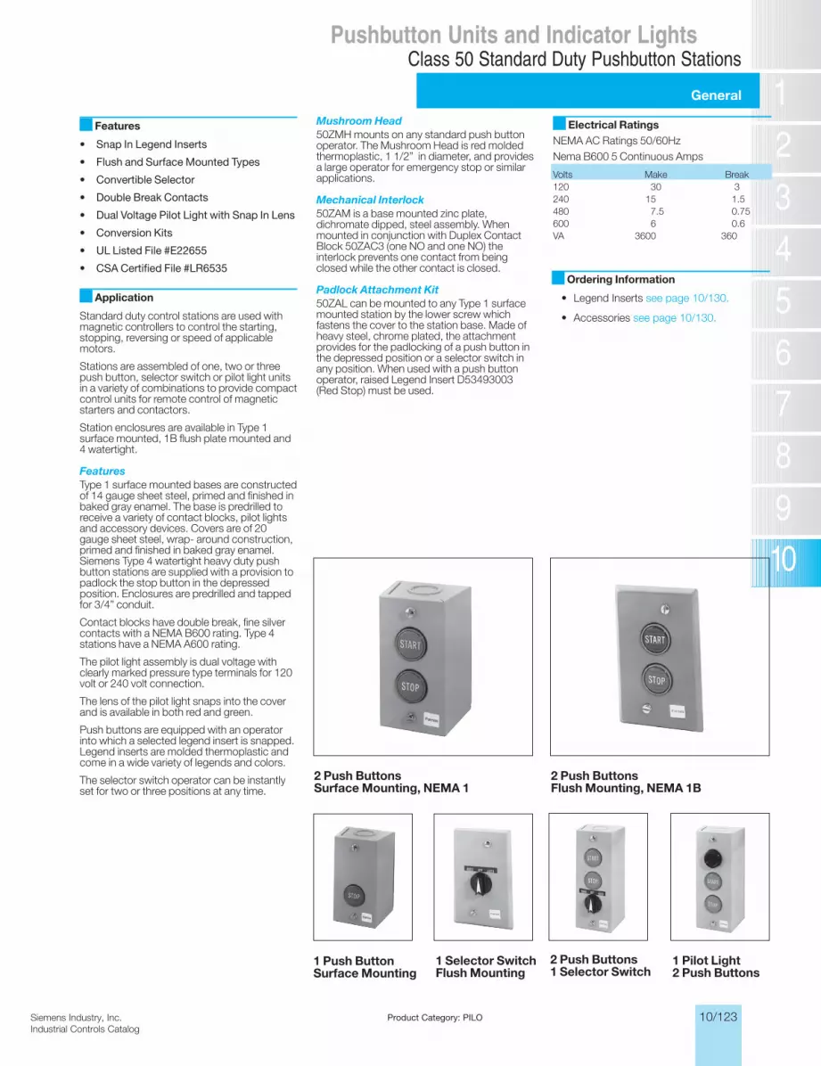
10/123Siemens Industry, Inc.Industrial Controls Catalog
General
Class 50 Standard Duty Pushbutton StationsPushbutton Units and Indicator Lights
Product Category: PILO
Siemens / Industrial Controls Previous folio: IC10 10/110
Features
• Snap In Legend Inserts
• Flush and Surface Mounted Types
• Convertible Selector
• Double Break Contacts
• Dual Voltage Pilot Light with Snap In Lens
• Conversion Kits
• UL Listed File #E22655
• CSA Certified File #LR6535
Application
Standard duty control stations are used with magnetic controllers to control the starting, stopping, reversing or speed of applicable motors.
Stations are assembled of one, two or three push button, selector switch or pilot light units in a variety of combinations to provide compact control units for remote control of magnetic starters and contactors.
Station enclosures are available in Type 1 surface mounted, 1B flush plate mounted and 4 watertight.
FeaturesType 1 surface mounted bases are con structed of 14 gauge sheet steel, primed and finished in baked gray enamel. The base is predrilled to receive a variety of con tact blocks, pilot lights and accessory de vices. Covers are of 20 gauge sheet steel, wrap- around construction, primed and fin ished in baked gray enamel. Siemens Type 4 watertight heavy duty push button stations are supplied with a provision to padlock the stop button in the depressed position. Enclo sures are predrilled and tapped for 3/4” con duit.
Contact blocks have double break, fine sil ver contacts with a NEMA B600 rating. Type 4 stations have a NEMA A600 rating.
The pilot light assembly is dual voltage with clearly marked pressure type terminals for 120 volt or 240 volt connection.
The lens of the pilot light snaps into the cover and is available in both red and green.
Push buttons are equipped with an operator into which a selected legend insert is snapped. Legend inserts are molded ther moplastic and come in a wide variety of leg ends and colors.
The selector switch operator can be instantly set for two or three positions at any time.
Mushroom Head50ZMH mounts on any standard push button operator. The Mushroom Head is red molded thermoplastic, 1 1/2” in diameter, and provides a large operator for emergency stop or similar applications.
Mechanical Interlock50ZAM is a base mounted zinc plate, dichro mate dipped, steel assembly. When mounted in conjunction with Duplex Contact Block 50ZAC3 (one NO and one NO) the in terlock prevents one contact from being closed while the other contact is closed.
Padlock Attachment Kit50ZAL can be mounted to any Type 1 sur face mounted station by the lower screw which fastens the cover to the station base. Made of heavy steel, chrome plated, the at tachment provides for the padlocking of a push button in the depressed position or a selector switch in any position. When used with a push button operator, raised Legend Insert D53493003 (Red Stop) must be used.
Electrical RatingsNEMA AC Ratings 50/60HzNema B600 5 Continuous Amps
Volts Make Break120 30 3240 15 1.5480 7.5 0.75600 6 0.6VA 3600 360
2 Push ButtonsSurface Mounting, NEMA 1
1 Selector SwitchFlush Mounting
1 Pilot Light2 Push Buttons
2 Push Buttons1 Selector Switch
2 Push ButtonsFlush Mounting, NEMA 1B
1 Push ButtonSurface Mounting
Ordering Information
• Legend Inserts see page 10/130.
• Accessories see page 10/130.

10/124 Siemens Industry, Inc.Industrial Controls Catalog
5A 600V AC NEMA B600
Class 50 Standard Duty Pushbutton StationsPushbutton Units and Indicator Lights
Siemens / Industrial Controls Previous folio: 10/111
Product Category: PILO
Selection and ordering data
Number of com- mandpoints
Order No. Packs Operator identification
Degree of protection
Contacts / voltage
UnitA = Momentary flush pushbutton green,
sur face, label “START”NEMA 1 1NO - 1NC with common
jumper (50ZAC1)1 50AA3D 1
A = Momentary flush pushbutton red, sur face, label “STOP”
NEMA 1 1NO - 1NC with common jumper (50ZAC1)
1 50AA3E 1
A = Momentary raised pushbutton red, sur face, label “STOP”
NEMA 1 1NO - 1NC with common jumper (50ZAC1)
1 50AA3F 1
A = Momentary mushroom head red, sur face, label “STOP”
NEMA 1 1NO - 1NC with common jumper (50ZAC1)
1 50AA3G 1
A = Momentary flush pushbutton less insert, surface
NEMA 1 1NO - 1NC with common jumper (50ZAC1)
1 50AA3A 1
A = 3 position selector switch, surface, label “HAND-OFF-AUTO”
NEMA 1 2 NO 2SPST (50ZAC8) 1 50AA3C3 1
A = 2 position selector switch, surface, label “Off-On”
NEMA 1 2 NO 2SPST (50ZAC8) 1 50AA3C6 1
A = 2/3 selector switch, surface, multiple legends
NEMA 1 2 NO 2SPST (50ZAC8) 1 50AA3B9 1
A = Indicator light, red, surface NEMA 1 120/240V dual voltage 120PSB lamp
1 50BA3Y 1
A = Indicator light, green, surface NEMA 1 120/240V dual voltage 120PSB lamp
1 50BA3Z 1
A = Indicator light, less lens, surface NEMA 1 120/240V dual voltage 120PSB lamp
1 50BA32 1
A = Momentary flush pushbutton green, flush, label “START”
NEMA 1B 1NO - 1NC with common jumper (50ZAC1)
1 50AA2D 1
A = Momentary flush pushbutton red, flush, label “STOP”
NEMA 1B 1NO - 1NC with common jumper (50ZAC1)
1 50AA2E 1
A = Momentary raised pushbutton red, flush, label “STOP”
NEMA 1B 1NO - 1NC with common jumper (50ZAC1)
1 50AA2F 1
A = Momentary flush pushbutton less insert, flush
NEMA 1B 1NO - 1NC with common jumper (50ZAC1)
1 50AA2A 1
A = Momentary flush pushbutton less insert, flush, chrome plate
NEMA 1B 1NO - 1NC with common jumper (50ZAC1)
1 50AA6A 1
A = 3 position selector switch, flush, label “HAND-OFF-AUTO”
NEMA 1B 2 NO 2SPST (50ZAC8) 1 50AA2C3 1
A = 3 position selector switch, flush, label “Off-On”
NEMA 1B 2 NO 2SPST (50ZAC8) 1 50AA2C6 1
A = 2/3 selector switch, multiple legends, flush NEMA 1B 2 NO 2SPST (50ZAC8) 1 50AA2B9 1
A = 2/3 selector switch, multiple legends, chrome plate, flush
NEMA 1B 2 NO 2SPST (50ZAC8) 1 50AA6B9 1
A = Indicator light, red, flush NEMA 1B 120/240V dual voltage 1 50BA2Y 1
A = Indicator light, green, flush NEMA 1B 120/240V dual voltage 1 50BA2Z 1
A = Indicator light, less lens, flush NEMA 1B 120/240V dual voltage 1 50BA22 1
A = Indicator light, less lens, chrome plate, flush
NEMA 1B 120PSB lamp 1 50BA62 1
B = Momentary pushbutton green, surface, label “START”
A = Momentary pushbutton red, surface, label “STOP”
NEMA 1 1NO, 1NC (50ZAC2) 2 50CA3DE 1
B = Momentary pushbutton green, surface, label “START”
A = Momentary raised pushbutton red, sur face, label “STOP”
NEMA 1 1NO, 1NC (50ZAC2) 2 50CA3DF 1
B = Momentary pushbutton green, surface, label “START”
A = Momentary mushroom head pushbutton red, surface, label “STOP”
NEMA 1 1NO, 1NC (50ZAC2) 2 50CA3DG 1
B = Momentary pushbutton, less insert, surface
A = Momentary pushbutton, less insert, surface
NEMA 1 1NO, 1NC (50ZAC2) 2 50CA3AA 1
B = Momentary pushbutton, surface, label “FORWARD”
A = Momentary pushbutton, surface, label “REVERSE”
NEMA 1 2 NO (50ZAC3) 2 50DA3KL 1
1 unit surface mount-momentary pushbutton
1 unit flush mount-momentary push button
2 unit surface mount-momentary pushbutton

10/125Siemens Industry, Inc.Industrial Controls Catalog
5A 600V AC NEMA B600
Class 50 Standard Duty Pushbutton StationsPushbutton Units and Indicator Lights
Siemens / Industrial Controls Previous folio: 10/112
Selection and ordering data
Number of com- mandpoints
Order No. Packs Operator identification
Degree of protection
Contacts / voltage
UnitB = Momentary pushbutton, surface,
label “OPEN”A = Momentary pushbutton, surface,
label “CLOSE”
NEMA 1 2 NO (50ZAC3) 2 50DA3HJ 1
B = Momentary pushbutton, surface, label “UP”
A = Momentary pushbutton, surface, label “DOWN”
NEMA 1 2 NO (50ZAC3) 2 50DA3NP 1
B = Momentary pushbutton, surface, less insert
A = Momentary pushbutton, surface, less insert
NEMA 1 2 NO (50ZAC3) 2 50DA3AA 1
B = Momentary pushbutton, surface, label “FORWARD”
A = Momentary pushbutton, surface, label “REVERSE”
NEMA 1 2 NO mechanically inter - locked (50ZA3C w/ 50ZAM)
2 50RA3KL 1
B = Momentary pushbutton, surface, label “OPEN”
A = Momentary pushbutton, surface, label “CLOSE”
NEMA 1 2 NO mechanically inter- locked (50ZA3C w/ 50ZAM)
2 50RA3HJ 1
B = Momentary pushbutton, surface, label “UP”
A = Momentary pushbutton, surface, label “DOWN”
NEMA 1 2 NO mechanically inter- locked (50ZA3C w/ 50ZAM)
2 50RA3NP 1
B = Momentary pushbutton, surface, label “ON”
A = Momentary pushbutton, surface, label “OFF”
NEMA 1 2 NO mechanically inter- locked (50ZA3C w/ 50ZAM)
2 50RA334 1
B = Momentary pushbutton, less insert surface
A = Momentary pushbutton, less insert, surface
NEMA 1 2 NO mechanically inter - locked (50ZA3C w/ 50ZAM)
2 50RA3AA 1
B = Momentary pushbutton, surface, label “FORWARD”
A = Momentary pushbutton, surface, label “REVERSE”
NEMA 1 2 NO, 2 NC (2 - 50ZAC2) 2 50EA3KL 1
B = Momentary pushbutton, surface, label “OPEN”
A = Momentary pushbutton, surface, label “CLOSE”
NEMA 1 2 NO, 2 NC (2 - 50ZAC2) 2 50EA3HJ 1
B = Momentary pushbutton, surface, label “UP”
A = Momentary pushbutton, surface, label “DOWN”
NEMA 1 2 NO, 2 NC (2 - 50ZAC2) 2 50EA3NP 1
B = Momentary pushbutton, surface, label “ON”
A = Momentary pushbutton, surface, label “OFF”
NEMA 1 2 NO, 2 NC (2 - 50ZAC2) 2 50EA334 1
B = Momentary pushbutton, surface, less insert
A = Momentary pushbutton, surface, less insert
NEMA 1 2 NO, 2 NC (2 - 50ZAC2) 2 50EA3AA 1
B = Momentary pushbutton green, flush, label “START”
A = Momentary pushbutton red, flush, label “STOP”
NEMA 1B 1NO, 1NC (50ZAC2) 2 50CA2DE 1
B =Momentary pushbutton, less insert, flushA = Momentary pushbutton, less insert, flush
NEMA 1B 1NO, 1NC (50ZAC2) 2 50CA2AA 1
B = Momentary pushbutton green, flush, label “START”
A = Momentary raised pushbutton red, flush, label “STOP”
NEMA 1B 1NO, 1NC (50ZAC2) 2 50CA2DF 1
B = Momentary pushbutton green, flush, label “START”
A = Momentary mushroom head pushbutton red, flush, label “STOP”
NEMA 1B 1NO, 1NC (50ZAC2) 2 50CA2DG 1
B = Momentary pushbutton, less insert, flushA = Momentary pushbutton, less insert, flush
NEMA 1B 1NO, 1NC (50ZAC2) 2 50CA6AA 1
2 unit surface mount-momentary pushbutton
2 unit flush mount-momentary push button

10/126 Siemens Industry, Inc.Industrial Controls Catalog
Pushbutton Units and Indicator Lights
5A 600V AC NEMA A600
Class 50 Standard Duty Pushbutton Stations
Siemens / Industrial Controls Previous folio: 10/113
Product Category: PILO
Selection and ordering data
Number of com- mandpoints
Order No. Packs Operator identification
Degree of protection
Contacts / voltage
UnitB = Momentary pushbutton, flush,
label “FORWARD”A = Momentary pushbutton, flush,
label “REVERSE”
NEMA 1B 2 NO (50ZAC3) 2 50DA2KL 1
B = Momentary pushbutton, flush, label “OPEN”
A = Momentary pushbutton, flush, label “CLOSE”
NEMA 1B 2 NO (50ZAC3) 2 50DA2HJ 1
B = Momentary pushbutton, flush, label “UP”
A = Momentary pushbutton, flush, label “DOWN”
NEMA 1B 2 NO (50ZAC3) 2 50DA2NP 1
B = Momentary pushbutton, less insert, flushA = Momentary pushbutton, less insert, flush
NEMA 1B 2 NO (50ZAC3) 2 50DA2AA 1
B = Momentary pushbutton, less insert, chrome plate, flush
A = Momentary pushbutton, less insert, chrome plate, flush
NEMA 1B 2 NO (50ZAC3) 2 50DA6AA 1
B = Momentary pushbutton, flush, label “FORWARD”
A = Momentary pushbutton, flush, label “REVERSE”
NEMA 1B 2 NO mechanically inter locked (50ZA3C w/ 50ZAM)
2 50RA2KL 1
B = Momentary pushbutton, flush, label “OPEN”
A = Momentary pushbutton, flush, label “CLOSE”
NEMA 1B 2 NO mechanically inter locked (50ZA3C w/ 50ZAM)
2 50RA2HJ 1
B = Momentary pushbutton, flush, label “UP”
A = Momentary pushbutton, flush, label “DOWN”
NEMA 1B 2 NO mechanically inter locked (50ZA3C w/ 50ZAM)
2 50RA2NP 1
B = Momentary pushbutton, flush, label “ON”
A = Momentary pushbutton, flush, label “OFF”
NEMA 1B 2 NO mechanically inter locked (50ZA3C w/ 50ZAM)
2 50RA234 1
B = Momentary pushbutton, less insert, flushA = Momentary pushbutton, less insert, flush
NEMA 1B 2 NO mechanically inter locked (50ZA3C w/ 50ZAM)
2 50RA2AA 1
B = Momentary pushbutton, less insert, chrome plate, flush
A = Momentary pushbutton, less insert, chrome plate, flush
NEMA 1B 2 NO mechanically inter locked (50ZA3C w/ 50ZAM)
2 50RA6AA 1
B = Momentary pushbutton, flush, label “FORWARD”
A = Momentary pushbutton, flush, label “REVERSE”
NEMA 1B 2 NO, 2 NC (2 - 50ZAC2) 2 50EA2KL 1
B = Momentary pushbutton, flush, label “OPEN”
A = Momentary pushbutton, flush, label “CLOSE”
NEMA 1B 2 NO, 2 NC (2 - 50ZAC2) 2 50EA2HJ 1
B = Momentary pushbutton, flush, label “UP”
A = Momentary pushbutton, flush, label “DOWN”
NEMA 1B 2 NO, 2 NC (2 - 50ZAC2) 2 50EA2NP 1
B = Momentary pushbutton, flush, label “ON”
A = Momentary pushbutton, flush, label “OFF”
NEMA 1B 2 NO, 2 NC (2 - 50ZAC2) 2 50EA234 1
B = Momentary pushbutton, less insert, flushA = Momentary pushbutton, less insert, flush
NEMA 1B 2 NO, 2 NC (2 - 50ZAC2) 2 50EA2AA 1
B = Momentary pushbutton, less insert, chrome plate, flush
A = Momentary pushbutton, less insert, chrome plate, flush
NEMA 1B 2 NO, 2 NC (2 - 50ZAC2) 2 50EA6AA 1
2 unit flush mount-momentary push button

10/127Siemens Industry, Inc.Industrial Controls Catalog
5A 600V AC NEMA B600
Class 50 Standard Duty Pushbutton StationsPushbutton Units and Indicator Lights
Siemens / Industrial Controls Previous folio: 10/114
Product Category: PILO
Selection and ordering data
Number of com- mandpoints
Order No. Packs Operator identification
Degree of protection
Contacts / voltage
UnitB = Momentary pushbutton green, surface,
label “START”A = Maintained selector switch, surface, label
“HAND-OFF-AUTO”
NEMA 1 1NO, 1NC (50ZAC1)
2 NO 2SPDT w/ common jumper (50ZAC8)
2 50FA3DC3 1
B = Momentary pushbutton less insert, sur faceA = Maintained selector switch, multiple
leg ends, surface
NEMA 1 1NO, 1NC (50ZAC1)
2 NO 2SPDT w/ common jumper (50ZAC8)
2 50FA3AB9 1
B = Indicator light, red, surface
A = Maintained selector switch, surface, label “HAND-OFF-AUTO”
NEMA 1 120/240V dual voltage (120PSB lamp)2 NO 2SPDT w/ common jumper (50ZAC8)
2 50HA3YC3 1
B = Indicator light, red, surface
A = Maintained selector switch, multiple leg ends, surface
NEMA 1 120/240V dual voltage (120PSB lamp)2 NO 2SPDT w/ common jumper (50ZAC8)
2 50HA32B9 1
B = Indicator light, green, surfaceA = Indicator light, red, surface
NEMA 1 120/240V dual voltage (120PSB lamp)
2 50GA3ZY 1
B = Indicator light, less lens, surfaceA = Indicator light, less lens, surface
NEMA 1 120/240V dual voltage (120PSB lamp)
2 50GA322 1
B = Momentary pushbutton green, flush, label “START”
A = Maintained selector switch, flush, label “HAND-OFF-AUTO”
NEMA 1B 1NO, 1NC (50ZAC1) 2 NO 2SPDT w/ common jumper (50ZAC8)
2 50FA2DC3 1
B = Momentary pushbutton less insert, flushA = Maintained selector switch, multiple
leg ends, flush
NEMA 1B 1NO, 1NC (50ZAC1) 2 NO 2SPDT w/ common jumper (50ZAC8)
2 50FA2AB9 1
B = Momentary pushbutton less insert chrome plate, flush
A = Maintained selector switch, multiple legends, flush
NEMA 1B 1NO, 1NC (50ZAC1) 2 NO 2SPDT w/ common jumper (50ZAC8)
2 50FA6AB9 1
B = Indicator light, red, flushA = Maintained selector switch, flush, label
“HAND-OFF-AUTO”
NEMA 1B 120/240V dual voltage (120PSB lamp)2 NO 2SPDT w/ common jumper (50ZAC8)
2 50HA2YC3 1
B = Indicator light, less lens, flushA = Maintained selector switch, multiple
leg ends, flush
NEMA 1B 120/240V dual voltage (120PSB lamp)2 NO 2SPDT w/ common jumper (50ZAC8)
2 50HA22B9 1
B = Indicator light, less lens, chrome plate, flush
A = Maintained selector switch, multiple leg ends, flush
NEMA 1B 120/240V dual voltage (120PSB lamp)2 NO 2SPDT w/ common jumper (50ZAC8)
2 50HA62B9 1
B = Indicator light, green, flushA = Indicator light, red, flush
NEMA 1B 120/240V dual voltage (120PSB lamp)
2 50GA2ZY 1
B = Indicator light, less lens, flushA = Indicator light, less lens, flush
NEMA 1B 120/240V dual voltage (120PSB lamp)
2 50GA222 1
B = Indicator light, less lens, chrome plate, flush
A = Indicator light, less lens, chrome plate, flush
NEMA 1B 120/240V dual voltage (120PSB lamp)
2 50GA622 1
C = Momentary pushbutton, surface, label “FORWARD”
B = Momentary pushbutton, surface, label “REVERSE”
A = Momentary pushbutton, surface, label “STOP”
NEMA 1 2 NO, 2 NC (2 - 50ZAC2)1NO - 1NC with common jumper (50ZAC1)
3 50MA3KLE 1
C = Momentary pushbutton, surface, label “UP”
B = Momentary pushbutton, surface, label “DOWN”
A = Momentary pushbutton, surface, label “STOP”
NEMA 1 2 NO, 2 NC (2 - 50ZAC2)1NO - 1NC with common jumper (50ZAC1)
3 50MA3NPE 1
C = Momentary pushbutton, surface, label “OPEN”
B = Momentary pushbutton, surface, label “CLOSE”
A = Momentary pushbutton, surface, label “STOP”
NEMA 1 2 NO, 2 NC (2 - 50ZAC2)1NO - 1NC with common jumper (50ZAC1)
3 50MA3HJE 1
2 unit surface mount-momentary pushbutton and selector switch
2 unit surface mount-momentary pushbutton and indicator light
2 unit flush mount-momentary push button and selec tor switch
2 unit flush mount-momentary push button and indica tor light
3 unit surface mount-momentary pushbutton

10/128 Siemens Industry, Inc.Industrial Controls Catalog
5A 600V AC NEMA B600
Class 50 Standard Duty Pushbutton StationsPushbutton Units and Indicator Lights
Siemens / Industrial Controls Previous folio: 10/115
Product Category: PILO
Selection and ordering data
Number of com- mandpoints
Order No. Packs Operator identification
Degree of protection
Contacts / voltage
UnitC = Momentary pushbutton, surface, label
“FAST”B = Momentary pushbutton, surface, label
“SLOW”A = Momentary pushbutton, surface, label
“STOP”
NEMA 1 2 NO, 2 NC (2 - 50ZAC2)1NO - 1NC with common jumper (50ZAC1)
3 50MA3TUE 1
C = Momentary pushbutton, surface, label “START”
B = Momentary pushbutton, surface, label “JOG”
A = Momentary pushbutton, surface, label “STOP”
NEMA 1 2 NO, 2 NC (2 - 50ZAC2)1NO - 1NC with common jumper (50ZAC1)
3 50MA3DME 1
C = Momentary pushbutton, surface, label less insert
B = Momentary pushbutton, surface, label less insert
A = Momentary pushbutton, surface. label less insert
NEMA 1 2 NO, 2 NC (2 - 50ZAC2)1NO - 1NC with common jumper (50ZAC1)
3 50MA3AAA 1
C = Momentary pushbutton, surface, label “START”
B = Momentary pushbutton, surface, label “STOP”
A = Maintained selector switch, surface, label “HAND-OFF-AUTO”
NEMA 1 1 NO, 1 NC (50ZAC2)2 NO, 2 SPST with common jumper (50ZAC8)
3 50LA3DEC3 1
C = Momentary pushbutton, less insert, sur face
B = Momentary pushbutton, less insert, sur face
A = Maintained selector switch, multiple leg ends, surface
NEMA 1 1 NO, 1 NC (50ZAC2)2 NO, 2 SPST with common jumper (50ZAC8)
3 50LA3AAB9 1
C = Indicator light, red, surfaceB = Momentary pushbutton, surface, label
“START”A = Momentary pushbutton, surface, label
“STOP”
NEMA 1 120/240V dual voltage (120PSB lamp)1 NO, 1 NC (50ZAC2)
3 50JA3YDE 1
C = Indicator light, green, surfaceB = Momentary pushbutton, surface, label
“START”A = Momentary pushbutton, surface, label
“STOP”
NEMA 1 120/240V dual voltage (120PSB lamp)1 NO, 1 NC (50ZAC2)
3 50JA3ZDE 1
C = Indicator light, less lens, surfaceB = Momentary pushbutton, less insert,
sur faceA = Momentary pushbutton, less insert,
sur face
NEMA 1 120/240V dual voltage (120PSB lamp)1 NO, 1 NC (50ZAC2)
3 50JA32AA 1
C = Indicator light, green, surfaceB = Indicator light, red, surfaceA = Maintained selector switch, surface, label
“HAND-OFF-AUTO”
NEMA 1 120/240V dual voltage (120PSB lamp)2 NO, 2 SPST with common jumper (50ZAC8)
3 50NA3ZYC3 1
C = Indicator light, less lens, surfaceB = Indicator light, less lens, surfaceA = Maintained selector switch, multiple
leg ends, surface
NEMA 1 120/240V dual voltage (120PSB lamp)2 NO, 2 SPST with common jumper (50ZAC8)
3 50NA322B9 1
3 unit surface mount-momentary pushbutton and selector switch
3 unit surface mount-momentary pushbutton
3 unit surface mount-momentary pushbutton and indicator light

10/129Siemens Industry, Inc.Industrial Controls Catalog
Heavy duty - 10A 600V AC NEMA A600
Class 50 Standard Duty Pushbutton StationsPushbutton Units and Indicator Lights
Siemens / Industrial Controls Previous folio: 10/116
Product Category: PILO
Selection and ordering data
Number of com- mandpoints
Order No. Packs Operator identification
Degree of protection
Contacts / voltage
UnitA = Momentary pushbutton green, surface,
label “START””NEMA 4 1NO - 1NC 1 50HA1E1 1
A = Momentary pushbutton red, surface, label “STOP”
NEMA 4 1NO - 1NC 1 50HA1E2 1
A = Momentary pushbutton green, surface, label “RESET”
NEMA 4 1NO - 1NC 1 50HA1E4 1
A = Momentary pushbutton green, surface, label “JOG”
NEMA 4 1NO - 1NC 1 50HA1E5 1
A = Maintained selector switch, surface, label “SAFE-RUN”
NEMA 4 1NO - 1NC 1 50HA1E6 1
A = Maintained selector switch, surface, label “OFF-ON”
NEMA 4 1NO - 1NC 1 50HA1E7 1
A = Maintained selector switch, surface, label “JOG-RUN”
NEMA 4 1NO - 1NC 1 50HA1E8 1
A = Maintained selector switch, surface, label “HAND-OFF-AUTO”
NEMA 4 1NO - 1NC 1 50HA1E9 1
B = Momentary pushbutton green, surface, label “START”
A = Momentary pushbutton red, surface, label “STOP”
NEMA 4 1NO - 1NC
1NO - 1NC
2 50HA2E1 1
B = Momentary pushbutton green, surface, label “FORWARD”
A = Momentary pushbutton red, surface, label “REVERSE”
NEMA 4 1NO - 1NC
1NO - 1NC
2 50HA2E2 1
B = Momentary pushbutton green, surface, label “UP”
A = Momentary pushbutton red, surface, label “DOWN”
NEMA 4 1NO - 1NC
1NO - 1NC
2 50HA2E3 1
B = Momentary pushbutton green, surface, label “OPEN”
A = Momentary pushbutton red, surface, label “CLOSE”
NEMA 4 1NO - 1NC
1NO - 1NC
2 50HA2E4 1
B = Momentary pushbutton green, surface, label “FAST”
A = Momentary pushbutton red, surface, label “SLOW”
NEMA 4 1NO - 1NC
1NO - 1NC
2 50HA2E5 1
C = Momentary pushbutton green, surface, label “FORWARD”
B = Momentary pushbutton green, surface, label “REVERSE”
A = Momentary pushbutton red, surface, label “STOP”
NEMA 4 1NO - 1NC
1NO - 1NC
1NO - 1NC
3 50HA3E1 1
C = Momentary pushbutton green, surface, label “UP”
B = Momentary pushbutton green, surface, label “DOWN”
A = Momentary pushbutton red, surface, label “STOP”
NEMA 4 1NO - 1NC
1NO - 1NC
1NO - 1NC
3 50HA3E2 1
C = Momentary pushbutton green, surface, label “OPEN”
B = Momentary pushbutton green, surface, label “CLOSE”
A = Momentary pushbutton red, surface, label “STOP”
NEMA 4 1NO - 1NC
1NO - 1NC
1NO - 1NC
3 50HA3E3 1
C = Momentary pushbutton green, surface, label “START”
B = Momentary pushbutton green, surface, label “JOG”
A = Momentary pushbutton red, surface, label “STOP”
NEMA 4 1NO - 1NC
1NO - 1NC
1NO - 1NC
3 50HA3E9 1
C = Momentary pushbutton green, surface, label “FAST”
B = Momentary pushbutton green, surface, label “SLOW”
A = Momentary pushbutton red, surface, label “STOP”
NEMA 4 1NO - 1NC
1NO - 1NC
1NO - 1NC
3 50HA3E4 1

10/130 Siemens Industry, Inc.Industrial Controls Catalog
Standard duty station accessories
Class 50 Standard Duty Pushbutton StationsPushbutton Units and Indicator Lights
Heavy duty station accessories
Siemens / Industrial Controls Previous folio: 10/117
Product Category: PILO
Selection and ordering dataLegend inscription insert for snap-on mounting
Inscription Color Order No. Pack
Unit
CloseDownFastForwardHighHoistJogLowLowerOffOnOpenReverseSlowStartStopStop (raised)Up
OrangeOrangeBlackGreenBlackGreenBlackBlackOrangeRedGreenGreenOrangeBlackGreenRedRedGreen
50D5349300550D5349301050D5349301350D5349300650D5349301550D5349301150D5349300850D5349301650D5349301250D5349301850D5349301750D5349300450D5349300750D5349301450D5349300150D5349300250D5349300350D53493009
111111111111111111
Version Suitable for Color Order No. Pack
Unit
Mushroom head
Padlock attachment
Mechanical interlock kit
Used only for raised buttons
Red 50ZMH
50ZAL
50ZAM
1
1
1
Contact blocks1NO, 1NC2NO, 2SPST1NO, 1NC1NO, 1NO
Single buttonSelector switchTwo buttonTwo button
50ZAC150ZAC850ZAC250ZAC3
1111
Pilot light
Pilot light lens
120/240V Dual Voltage, no lens
RedGreen
50ZAC6
50ZPL0150ZPL02
1
11
Replacement lampsSlide base, lamp type 120PSB
Class 50 type 1, 1B 120V 50D21983001 1
Version Suitable for Color Order No. Pack
Unit
Pushbutton caps NEMA 4 control stationsNEMA 4 control stations
RedBlack
BHP15XBHP16X
11
50ZAC250ZAC1
50ZAC350ZAC8

10/131Siemens Industry, Inc.Industrial Controls Catalog
Standard duty - 5A 600V AC NEMA B600
Class 50 Standard Duty Pushbutton StationsPushbutton Units and Indicator Lights
Siemens / Industrial Controls Previous folio: 10/118
1 Unit Station Surface Mounting—Type 1 1 Unit Station Flush Mounting—Type 1B
2 Pushbutton Stations Surface Mounting—Type 1
2 Unit Stations Surface Mounting—Type 1 2 Unit Station Flush Mounting—Type 1B
2 Pushbutton Stations Flush Mounting—Type 1B
3 Unit Stations Surface Mounting 1 Unit Stations—Type 4

10/132 Siemens Industry, Inc.Industrial Controls Catalog
Touchsafe Terminals
Ordering Information
• Accessories see page 10/140-10/141.
• Selector Operating Position and Contact Operation page 10/138.
• Legend Plates see page 10/177.
• Enclosures see page 10/139.
• Technical Specifications: page 10/179.
Hazardous location
Class 51 Pilot DevicesPushbutton Units and Indicator Lights
Product Category: PILO
Siemens / Industrial Controls Previous folio: 10/119
Features
• UL Listed and cUL Listed for Class I, Groups C & D and Class II, Groups E, F & G
• Short or Long Bushing Lengths
• Mount into 3/4-14 NPSM Threaded Hole
• Sealing Lock Nut
• Similar in Appearance to Class 52 Oil Tight Pilot Devices
• Double Break Bifurcated Contacts Rated AC NEMA A600, DC NEMA P600
• Positively Driven Contacts
• Touchsafe Terminals
• UL Listed File # E39935
Application
When properly installed in a Type 7 & 9 en-closure, these components meet the National Electrical Code’s requirements for Class I, Division 1 & 2, Groups C and D haz-ardous gases, Class II, Division 1, Groups E, F and G hazardous dust, and Class III, hazardous fibers and flyings. Class 51 pilot de-vices may be used in a location where the presence of flammable gases, vapors or finely pulverized dusts in the atmosphere are sufficient to create a threat of explosion or fire. They may also be required where easily ignitable fibers or flyings are present. Short bushing units are used in most standard Type 7 & 9 enclosures. Long bushings are used when an additional front panel is required or in enclosures up to 2 V8 inches thick. Class 51 devices also meet Type 4 applications.
RuggedHazardous location control units are durable one piece castings of a corrosion resistant copper free aluminum alloy with stainless steel springs and type 316 stainless steel shafts to provide a long dependable life. The “0” ring ensures the longest seal life available. Contact blocks have double break bifurcated contacts for increased reliability.
FlexibleControl units mount into industry standard 3/4-14 NPSM threaded holes. Both short bushings for enclosure mounting and long bushings for panel mounting are available.
Pilot light bulbs are removable from the front for ease of maintenance. Many common parts between the Class 51 hazardous loca-tion pilot devices and the Class 52 oil tight pilot devices allow for increased serviceability with fewer parts.
Industrial AppearanceHazardous location control units add luster to panels. They are uniform in appearance and match 52 Class oil tight pilot devices.
Typical Applications
Class I
Class II
Class III
Electrical RatingsNEMA AC Ratings 50/60HzNema A600 10 Continuous AmpsVolts Make Break120 60 6240 30 3480 15 1.5600 12 1.2VA 7200 720
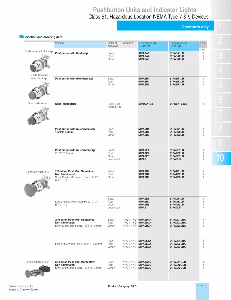
10/133Siemens Industry, Inc.Industrial Controls Catalog
Operators only
Class 51, Hazardous Location NEMA Type 7 & 9 DevicesPushbutton Units and Indicator Lights
Siemens / Industrial Controls Previous folio: 10/120
Selection and ordering data
Version Color of operator
Contacts Short bushingOrder No.
Long bushingOrder No.
Pack
UnitPushbutton with flush cap Black
RedGreen
51PA8A151PA8A251PA8A3
51PA8A1LB51PA8A2LB51PA8A3LB
111
Pushbutton with extended cap BlackRedGreen
51PA8B151PA8B251PA8B3
51PA8B1LB51PA8B2LB51PA8B3LB
111
Dual Pushbutton Flush BlackRaised Red
51PD8A1B2 51PD8A1B2LB 1
Pushbutton with mushroom cap1 5/8"(41.3mm)
BlackRedGreen
51PA9D151PA9D251PA9D3
51PA9D1LB51PA9D2LB51PA9D3LB
111
Pushbutton with mushroom cap2 1/2"(63.5mm)
BlackRedGreenLess head
51PA9E151PA9E251PA9E351PA9
51PA9E1LB51PA9E2LB51PA9E3LB51PA9LB
1111
2 Position Push Pull Maintained, Non IlluminatedSmall Plastic Mushroom Head, 1 5/8" (41.3 mm)
BlackRedGreen
51PA2D151PA2D251PA2D3
51PA2D1LB51PA2D2LB51PA2D3LB
111
Large Plastic Mushroom Head, 2 1/4"(57.2 mm)
BlackRedGreenLess head
51PA2E151PA2E251PA2E351PA2
51PA2E1LB51PA2E2LB51PA2E3LB51PA2LB
1111
2 Position Push Pull Maintained, Non IlluminatedSmall Mushroom Head, 1 5/8"(41.3mm)
BlackRedGreen
1NC + 1NO1NC + 1NO1NC + 1NO
51PA2D1A51PA2D2A51PA2D3A
51PA2D1LBA51PA2D2LBA51PA2D3LBA
111
Large Mushroom Head, 2 1/2"(63.5mm)BlackRedGreen
1NC + 1NO1NC + 1NO1NC + 1NO
51PA2E1A51PA2E2A51PA2E3A
51PA2E1LBA51PA2E2LBA51PA2E3LBA
111
3 Position Push Pull Momentary, Non IlluminatedSmall Mushroom Head, 1 5/8"(41.3mm)
BlackRedGreen
1NC + 1NO1NC + 1NO1NC + 1NO
51PA3A1U51PA3A2U51PA3A3U
51PA3A1ULB51PA3A2ULB51PA3A3ULB
111
3 position push-pull
2 position push-pull
Dual pushbutton
Pushbutton with flat cap
Pushbutton withextended cap
Product Category: PILO

10/134 Siemens Industry, Inc.Industrial Controls Catalog
Indicator light
Class 51, Hazardous Location NEMA Type 7 & 9 DevicesPushbutton Units and Indicator Lights
Selection and ordering data
Version Color of operator
Contacts Short bushingOrder No.
Long bushingOrder No.
Pack
UnitIndicator light with glass lens - Full voltage type AC/DC (with 6" pigtail leads) 1) 3)Operators with Incandescent Lamp6-8V with 755 type
RedGreenAmberLess lens
51PC5B251PC5B351PC5B951PC5BN
51PC5B2LB51PC5B3LB51PC5B9LB51PC5BNLB
1
deRepyt 657 htiw V21GreenAmberLess lens
51PC5C251PC5C351PC5C951PC5CN
51PC5C2LB51PC5C3LB51PC5C9LB51PC5CNLB
1
deRepyt 757 htiw V42GreenAmberLess lens
51PC5D251PC5D351PC5D951PC5DN
51PC5D2LB51PC5D3LB51PC5D9LB51PC5DNLB
1
Operators with LED Lamp 2)6-8V with BA9 type LED
RedGreenAmber
51PE5B251PE5B351PE5B9
51PE5B2LB51PE5B3LB51PE5B9LB
1
deRDEL epyt 9AB htiw V42GreenAmber
51PE5D251PE5D351PE5D9
51PE5D2LB51PE5D3LB51PE5D9LB
1
Indicator light with glass lens - Transformer type AC/DC 1) 3)Operators with Incandescent Lamp120V with 6V 755 type lamp
RedGreenAmberLess lens
51PC5G251PC5G351PC5G951PC5GN
51PC5G2LB51PC5G3LB51PC5G9LB51PC5GNLB
1
240V with 6V 755 type lamp RedGreenAmberLess lens
51PC5H251PC5H351PC5H951PC5HN
51PC5H2LB51PC5H3LB51PC5H9LB51PC5HNLB
1
480V with 6V 755 type lamp RedGreenAmberLess lens
51PC5J251PC5J351PC5J951PC5JN
51PC5J2LB51PC5J3LB51PC5J9LB51PC5JNLB
1
600V with 6V 755 type lamp RedGreenAmberLess lens
51PC5K251PC5K351PC5K951PC5KN
51PC5K2LB51PC5K3LB51PC5K9LB51PC5KNLB
1
Operators with LED Lamp 2)120V with 6V BA9 type LED
RedGreenAmberLess lens
51PE5G251PE5G351PE5G9—
51PE5G2LB51PE5G3LB51PE5G9LB—
1
240V with 6V BA9 type LED RedGreenAmberLess lens
51PE5H251PE5H351PE5H9—
51PE5H2LB51PE5H3LB51PE5H9LB—
1
480V with 6V BA9 type LED RedGreenAmberLess lens
51PE5J251PE5J351PE5J9—
51PE5J3LB51PE5J3LB51PE5J9LB—
1
600V with 6V BA9 type LED RedGreenAmberLess lens
51PE5K251PE5K351PE5K9—
51PE5K2LB51PE5K3LB51PE5K9LB—
1
Indicator light with glass lens - Resistor type AC/DC*120V with 24V 757 type lamp
RedGreenAmberLess lens
51PC5M251PC5M351PC5M951PC5MN
51PC5M2LB51PC5M3LB51PC5M9LB51PC5MNLB
1
120V with 24V BA9 type LED lamp )2
RedGreenAmber
51PE5M251PE5M351PE5M9
51PE5M2LB51PE5M3LB51PE5M9LB
1
1) For other colors not listed, order operator less lens and separate lens from page 10/127.
2) LED color must match lens color. 3) All illuminated devices come with std. Touch-safe shield per UL stds.
Indicator light-full voltage
Indicator light-transformer type
Siemens / Industrial Controls Previous folio: 10/121
Product Category: PILO

10/135Siemens Industry, Inc.Industrial Controls Catalog
Push to test complete units
Class 51, Hazardous Location NEMA Type 7 & 9 DevicesPushbutton Units and Indicator Lights
10/124 Siemens Energy & Automation, IncIndustrial Controls Catalog
Selection and ordering data
Version Color of operator
Contacts Short bushingOrder No.
Long bushingOrder No.
Pack
UnitPush to test/Illuminated pushbutton with glass lens - Full voltage type AC/DC 1) 3)Operators with Incandescent Lamp6V with 755 type lamp
RedGreenAmberLess lens
1NO + 1NC1NO + 1NC1NO + 1NC1NO + 1NC
51PC6B2A51PC6B3A51PC6B9A51PC6BNA
51PC6B2ALB51PC6B3ALB51PC6B9ALB51PC6BNALB
1111
deRpmal epyt 757 htiw V42AmberGreenLess lens
1NO + 1NC1NO + 1NC1NO + 1NC1NO + 1NC
51PC6D2A51PC6D3A51PC6D9A51PC6DNA
51PC6D2ALB51PC6D3ALB51PC6D9ALB51PC6DNALB
1111
Operators with LED Lamp 2)6-8V with BA9 type LED
RedGreenAmber
1NO + 1NC1NO + 1NC1NO + 1NC
51PE6B2A51PE6B3A51PE6B9A
51PE6B2ALB51PE6B3ALB51PE6B9ALB
111
deRDEL epyt 9AB htiw V42GreenAmber
1NO + 1NC1NO + 1NC1NO + 1NC
51PE6D2A51PE6D3A51PE6D9A
51PE6D2ALB51PE6D3ALB51PE6D9ALB
111
Push to test/Illuminated pushbutton with glass lens - Transformer type (50/60 Hz) 1) 3)Operators with Incandescent Lamp120V with 6V 755 type lamp
RedGreenAmberLess lens
1NO + 1NC1NO + 1NC1NO + 1NC1NO + 1NC
51PC6G2A51PC6G3A51PC6G9A51PC6GNA
51PC6G2ALB51PC6G3ALB51PC6G9ALB51PC6GNALB
1111
240V with 6V 755 type lamp RedGreenAmberLess lens
1NO + 1NC1NO + 1NC1NO + 1NC1NO + 1NC
51PC6H2A51PC6H3A51PC6H9A51PC6HNA
51PC6H2ALB51PC6H3ALB51PC6H9ALB51PC6HNALB
1111
480V with 6V 755 type lamp RedGreenAmberLess lens
1NO + 1NC1NO + 1NC1NO + 1NC1NO + 1NC
51PC6J2A51PC6J3A51PC6J9A51PC6JNA
51PC6J2ALB51PC6J3ALB51PC6J9ALB51PC6JNALB
1111
600V with 6V 755 type lamp RedGreenAmberLess lens
1NO + 1NC1NO + 1NC1NO + 1NC1NO + 1NC
51PC6K2A51PC6K3A51PC6K9A51PC6KNA
51PC6K2ALB51PC6K3ALB51PC6K9ALB51PC6KNALB
1111
Operators with LED Lamp 2)120V with 6V BA9 type LED
RedGreenAmber
1NO + 1NC1NO + 1NC1NO + 1NC
51PE6G2A51PE6G3A51PE6G9A
51PE6G2ALB51PE6G3ALB51PE6G9ALB
111
240V with 6V BA9 type LED RedGreenAmber
1NO + 1NC1NO + 1NC1NO + 1NC
51PE6H2A51PE6H3A51PE6H9A
51PE6H2ALB51PE6H3ALB51PE6H9ALB
111
480V with 6V BA9 type LED RedGreenAmber
1NO + 1NC1NO + 1NC1NO + 1NC
51PE6J2A51PE6J3A51PE6J9A
51PE6J2ALB51PE6J3ALB51PE6J9ALB
111
600V with 6V BA9 type LED RedGreenAmber
1NO + 1NC1NO + 1NC1NO + 1NC
51PE6K2A51PE6K3A51PE6K9A‘
51PE6K2ALB51PE6K3ALB51PE6K9ALB
111
Version Color LegendInscription
Order No.
Single unit7/8" diameter reset pad, 10" shaft can be cut to length.
Red Reset 51AAS
Multi unitFor use with multi push operation requirements.
Red Reset 51AAM
Overload reset operators with reset legend plate
1) For other colors not listed, order operator less lens and separate lens from page 10/127.
2) LED color must match lens color. 3) All illuminated devices come with std. Touch-safe shield per UL stds.
Push to testtransformer type
Push to test full voltage
Siemens / Industrial Controls Previous folio: 10/122
Product Category: PILO

10/136 Siemens Industry, Inc.Industrial Controls Catalog
Selector switch operators
Class 51, Hazardous Location NEMA Type 7 & 9 DevicesPushbutton Units and Indicator Lights
Selection and ordering data
Version Lever type Colorofinsert
CamCode1) 2)
ShortbushingOrder No.
LongbushingOrder No.
Pack
UnitSelector switches with Short lever, non-Illuminated White A 51SA2AA 51SA2AALB 12 switching positionsMaintained operation
Long lever, non-Illuminated White A 51SB2AA 51SB2AALB
Spring return from Short lever, non-Illuminated White A 51SA2AC 51SA2ACLB 1right operation Long lever, non-Illuminated White A 51SB2AC 51SB2ACLB
Selector switches with Short lever, non-Illuminated White B 51SA2BA 51SA2BALB 13 switching positions Long lever, non-Illuminated White B 51SB2BA 51SB2BALBMaintained operation Short lever, non-Illuminated White C 51SA2CA 51SA2CALB
Long lever, non-Illuminated White C 51SB2CA 51SB2CALBShort lever, non-Illuminated White D 51SA2DA 51SA2DALBLong lever, non-Illuminated White D 51SB2DA 51SB2DALBShort lever, non-Illuminated White E 51SA2EA 51SA2EALBLong lever, non-Illuminated White E 51SB2EA 51SB2EALBShort lever, non-Illuminated White G 51SA2GA 51SA2GALBLong lever, non-Illuminated White G 51SB2GA 51SB2GALB
Spring return from Short lever, non-Illuminated White B 51SA2BC 51SA2BCLB 1right operation Long lever, non-Illuminated White B 51SB2BC 51SB2BCLB
Short lever, non-Illuminated White C 51SA2CC 51SA2CCLBLong lever, non-Illuminated White C 51SB2CC 51SB2CCLBShort lever, non-Illuminated White D 51SA2DC 51SA2DCLBLong lever, non-Illuminated White D 51SB2DC 51SB2DCLBShort lever, non-Illuminated White E 51SA2EC 51SA2ECLBLong lever, non-Illuminated White E 51SB2EC 51SB2ECLBShort lever, non-Illuminated White G 51SA2GC 51SA2GCLBLong lever, non-Illuminated White G 51SB2GC 51SB2GCLB
Spring return from Short lever, non-Illuminated White B 51SA2BB 51SA2BBLB 1left operation Long lever, non-Illuminated White B 51SB2BB 51SB2BBLB
Short lever, non-Illuminated White C 51SA2CB 51SA2CBLBLong lever, non-Illuminated White C 51SB2CB 51SB2CBLBShort lever, non-Illuminated White D 51SA2DB 51SA2DBLBLong lever, non-Illuminated White D 51SB2DB 51SB2DBLBShort lever, non-Illuminated White E 51SA2EB 51SA2EBLBLong lever, non-Illuminated White E 51SB2EB 51SB2EBLBShort lever, non-Illuminated White G 51SA2GB 51SA2GBLBLong lever, non-Illuminated White G 51SB2GB 51SB2GBLB
Spring return from left Short lever, non-Illuminated White B 51SA2BD 51SA2BDLB 1and right operation Long lever, non-Illuminated White B 51SB2BD 51SB2BDLB
Short lever, non-Illuminated White C 51SA2CD 51SA2CDLBLong lever, non-Illuminated White C 51SB2CD 51SB2CDLBShort lever, non-Illuminated White D 51SA2DD 51SA2DDLBLong lever, non-Illuminated White D 51SB2DD 51SB2DDLBShort lever, non-Illuminated White E 51SA2ED 51SA2EDLBLong lever, non-Illuminated White E 51SB2ED 51SB2EDLBShort lever, non-Illuminated White G 51SA2GD 51SA2GDLBLong lever, non-Illuminated White G 51SB2GD 51SB2GDLB
Siemens / Industrial Controls Previous folio: 10/123
Product Category: PILO
2) For contact operation, see CAM selection chart on page 10/138.
1) C CAM limited to 4 single or double pole blocks on spring return operators.

10/137Siemens Industry, Inc.Industrial Controls Catalog
Selector switch operators
Class 51, Hazardous Location NEMA Type 7 & 9 DevicesPushbutton Units and Indicator Lights
Selection and ordering data
To order 1 to 25 special locks for keyed selector switches simply replace the 6 in the 5th digit of the catalog number with a 5 when entering your order. (Ordering Example: 52SC6AE is changed to 52SC5AE and all locks - up to
Version Keyremovalposition
Locknumber
CAMCode1) 2)
ShortbushingOrder No.
LongbushingOrder No.
Pack
UnitKey-operated selector switches with Both 550CH A 51SA6AE 51SA6AELB 12 switching positions Left 550CH A 51SA6AF 51SA6AFLBMaintained operation
Spring return from right operation Left 550CH A 51SA6AC 51SA6ACLB 1Key-operated selector switches with All 550CH B 51SA6BE 51SA6BELB 13 switching positions C 51SA6CE 51SA6CELB
Dnoitarepo deniatniaM 51SA6DE 51SA6DELBE 51SA6EE 51SA6EELBG 51SA6GE 51SA6GELB
Left 550CH B 51SA6BF 51SA6BFLB 1C 51SA6CF 51SA6CFLBD 51SA6DF 51SA6DFLBE 51SA6EF 51SA6EFLBG 51SA6GF 51SA6GFLB
Right 550CH B 51SA6BG 51SA6BGLB 1C 51SA6CG 51SA6CGLBD 51SA6DG 51SA6DGLBE 51SA6EG 51SA6EGLBG 51SA6GG 51SA6GGLB
Center 550CH B 51SA6BH 51SA6BHLB 1C 51SA6CH 51SA6CHLBD 51SA6DH 51SA6DHLBE 51SA6EH 51SA6EHLBG 51SA6GH 51SA6GHLB
Left and 550CH B 51SA6BK 51SA6BKLB 1Center C 51SA6CK 51SA6CKLB
D 51SA6DK 51SA6DKLBE 51SA6EK 51SA6EKLBG 51SA6GK 51SA6GKLB
Spring return from right operation Center 550CH B 51SA6BU 51SA6BULB 1C 51SA6CU 51SA6CULBD 51SA6DU 51SA6DULBE 51SA6EU 51SA6EULBG 51SA6GU 51SA6GULB
Spring return from left operation Center 550CH B 51SA6BT 51SA6BTLB 1C 51SA6CT 51SA6CTLBD 51SA6DT 51SA6DTLBE 51SA6ET 51SA6ETLBG 51SA6GT 51SA6GTLB
Spring return from left and right operation Center 550CH B 51SA6BV 51SA6BVLB 1C 51SA6CV 51SA6CVLBD 51SA6DV 51SA6DVLBE 51SA6EV 51SA6EVLBG 51SA6GV 51SA6GVLB
To order special locks for keyed selector switches, append corresponding 'X' suffix to part numberOrdering example: #549CH X639 151SA6AEX298 #548CH X640 1
#547CH X641 1#501CH X642 1#506CH X643 1
5 5
Siemens / Industrial Controls Previous folio: 10/124
Product Category: PILO
2) For contact operation, see CAM selection chart on page 10/138.
1) C CAM limited to 4 single or double pole blocks on spring return operators.
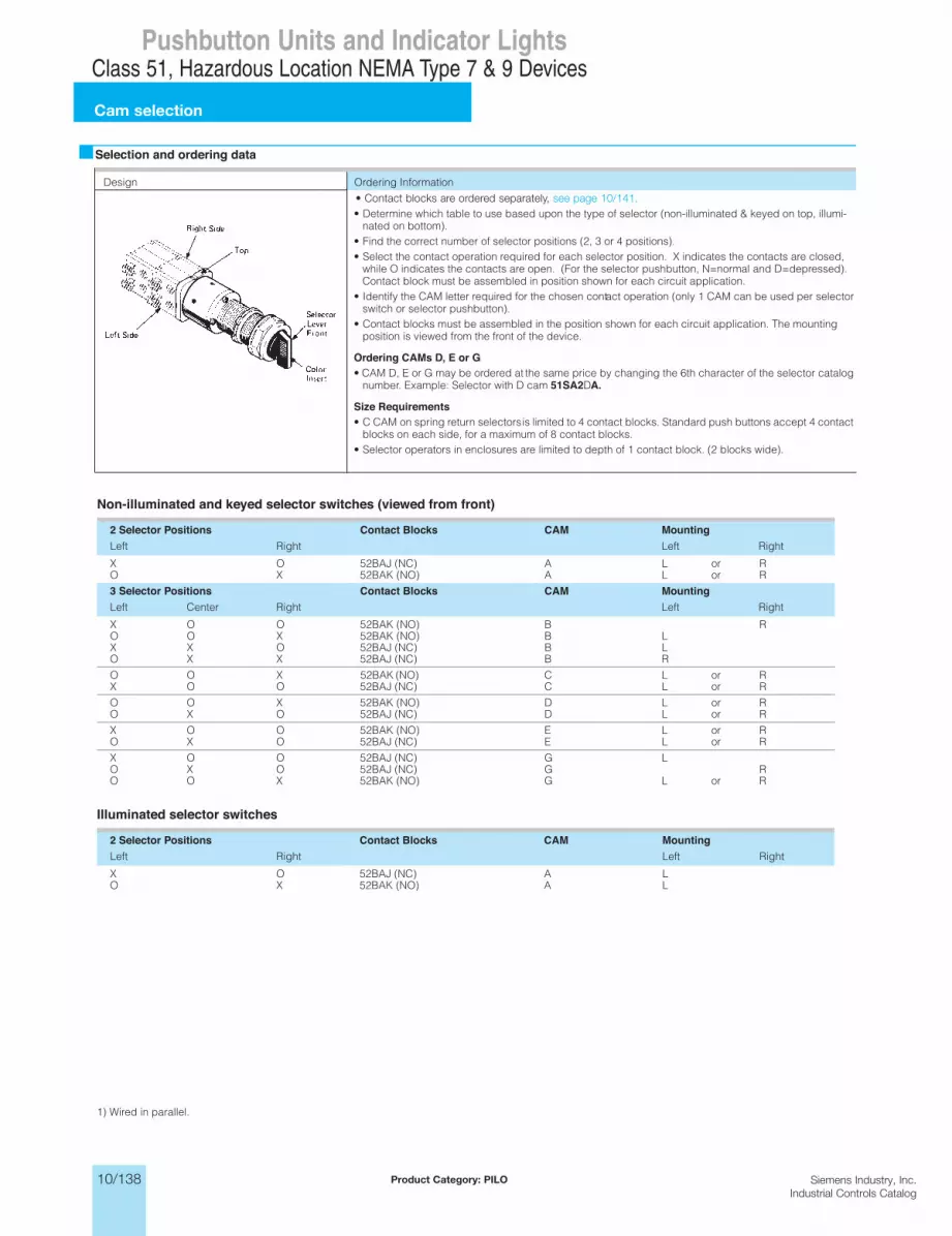
10/138 Siemens Industry, Inc.Industrial Controls Catalog
Cam selection
Class 51, Hazardous Location NEMA Type 7 & 9 DevicesPushbutton Units and Indicator Lights
Selection and ordering data
Non-illuminated and keyed selector switches (viewed from front)
Illuminated selector switches
Design Ordering Information
• Determine which table to use based upon the type of selector (non-illuminated & keyed on top, illumi-nated on bottom).
• Find the correct number of selector positions (2, 3 or 4 positions).• Select the contact operation required for each selector position. X indicates the contacts are closed,
while O indicates the contacts are open. (For the selector pushbutton, N=normal and D=depressed). Contact block must be assembled in position shown for each circuit application.
• Identify the CAM letter required for the chosen contact operation (only 1 CAM can be used per selector switch or selector pushbutton).
• Contact blocks must be assembled in the position shown for each circuit application. The mounting position is viewed from the front of the device.
Ordering CAMs D, E or G• CAM D, E or G may be ordered at the same price by changing the 6th character of the selector catalog
number. Example: Selector with D cam 51SA2DA.
Size Requirements• C CAM on spring return selectors is limited to 4 contact blocks. Standard push buttons accept 4 contact
blocks on each side, for a maximum of 8 contact blocks.• Selector operators in enclosures are limited to depth of 1 contact block. (2 blocks wide).
2 Selector Positions Contact Blocks CAM MountingthgiRtfeL Left Right
RroLA)CN( JAB25OXRroLA)ON( KAB25XO
3 Selector Positions Contact Blocks CAM MountingLeft Center Right Left Right
RB)ON( KAB25OOXLB)ON( KAB25XOOLB)CN( JAB25OXXRB)CN( JAB25XXO
Rroro
LC KAB25 XOORLC)CN( JAB25OOX
RroLD)ON(
)ON(
KAB25XOORroLD)CN( JAB25OXO
RroLE)ON( KAB25OOXRroLE)CN( JAB25OXO
LG)CN( JAB25OOXRG)CN( JAB25OXORroLG)ON( KAB25XOO
2 Selector Positions Contact Blocks CAM MountingthgiRtfeL Left Right
LA)CN( JAB25OXLA)ON( KAB25XO
1) Wired in parallel.
Siemens / Industrial Controls Previous folio: 10/125
Product Category: PILO
• Contact blocks are ordered separately, see page 10/141.
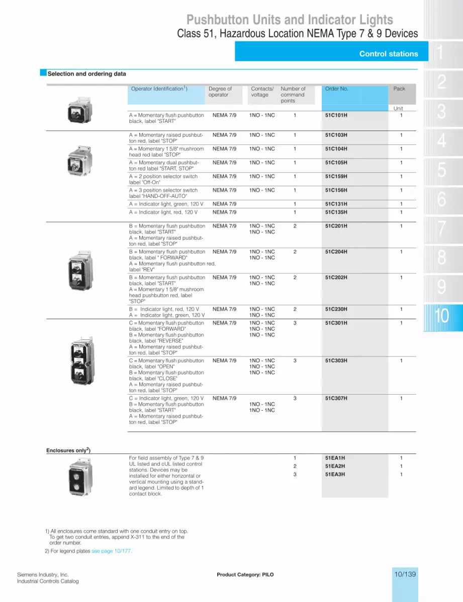
10/139Siemens Industry, Inc.Industrial Controls Catalog
Control stations
Class 51, Hazardous Location NEMA Type 7 & 9 DevicesPushbutton Units and Indicator Lights
Siemens / Industrial Controls Previous folio: 10/126
Selection and ordering data
Operator Identification1) Degree of operator
Contacts/voltage
Number of commandpoints
Order No. Pack
UnitA = Momentary flush pushbutton black, label "START"
NEMA 7/9 1NO - 1NC 1 51C101H 1
A = Momentary raised pushbut-ton red, label "STOP"
NEMA 7/9 1NO - 1NC 1 51C103H 1
A = Momentary 1 5/8" mushroom head red label "STOP"
NEMA 7/9 1NO - 1NC 1 51C104H 1
A = Momentary dual pushbut-ton red label "START, STOP"
NEMA 7/9 1NO - 1NC 1 51C105H 1
A = 2 position selector switch label "Off-On"
NEMA 7/9 1NO - 1NC 1 51C159H 1
A = 3 position selector switch label "HAND-OFF-AUTO"
NEMA 7/9 1NO - 1NC 1 51C156H 1
A = Indicator light, green, 120 V 19/7 AMEN 51C131H 1A = Indicator light, red, 120 V 19/7 AMEN 51C135H 1
B = Momentary flush pushbutton black, label "START"A = Momentary raised pushbut-ton red, label "STOP"
NEMA 7/9 1NO - 1NC1NO - 1NC
2 51C201H 1
B = Momentary flush pushbutton black, label " FORWARD"A = Momentary flush pushbutton red, label "REV"
NEMA 7/9 1NO - 1NC1NO - 1NC
2 51C204H 1
B = Momentary flush pushbutton black, label "START"A = Momentary 1 5/8" mushroom head pushbutton red, label "STOP"
NEMA 7/9 1NO - 1NC1NO - 1NC
2 51C202H 1
B = Indicator light, red, 120 VA = Indicator light, green, 120 V
NEMA 7/9 1NO - 1NC1NO - 1NC
2 51C230H 1
C = Momentary flush pushbutton black, label "FORWARD"B = Momentary flush pushbutton black, label "REVERSE"A = Momentary raised pushbut-ton red, label "STOP"
NEMA 7/9 1NO - 1NC1NO - 1NC1NO - 1NC
3 51C301H 1
C = Momentary flush pushbutton black, label "OPEN"B = Momentary flush pushbutton black, label "CLOSE"A = Momentary raised pushbut-ton red, label "STOP"
NEMA 7/9 1NO - 1NC1NO - 1NC1NO - 1NC
3 51C303H 1
C = Indicator light, green, 120 VB = Momentary flush pushbutton black, label "START"A = Momentary raised pushbut-ton red, label "STOP"
NEMA 7/91NO - 1NC1NO - 1NC
3 51C307H 1
Enclosures only2)For field assembly of Type 7 & 9 UL listed and cUL listed control stations. Devices may be installed for either horizontal or vertical mounting using a stand-ard legend. Limited to depth of 1 contact block.
1 51EA1H 12 51EA2H 13 51EA3H 1
Product Category: PILO
1) All enclosures come standard with one conduit entry on top. To get two conduit entries, append X-311 to the end of the order number.
2) For legend plates see page 10/177.

10/140 Siemens Industry, Inc.Industrial Controls Catalog
Accessories and spare parts
Class 51, Hazardous Location NEMA Type 7 & 9 DevicesPushbutton Units and Indicator Lights
Siemens / Industrial Controls Previous folio: 10/127
10/129Siemens Energy & Automation, IncIndustrial Controls Catalog
Selection and ordering data
rof elbatiuSnoisreV Conduitsize (in.)
Color Order No. Pack
UnitMushroom head cap - Plastic For small 1 5/8" (41.3mm) type,
non-illuminated mushroom push-buttons
Black 52RB3D1 1Red 52RB3D2Green 52RB3D3Yellow 52RB3D4Blue 52RB3D5Gray 52RB3D6Orange 52RB3D81 kit of each
52RB3DN
Mushroom head cap - Plastic For large 2 1/2" (63.5mm) type, non-illuminated mushroom push-buttons
Black 52RB3E1 1Red 52RB3E2Green 52RB3E3Yellow 52RB3E4Blue 52RB3E5Gray 52RB3E6Orange 52RB3E81 kit of each
52RB3EN
Replacement lens for pilot lights Red 51RC4G2 1Green 51RC4G3
Glass lens Blue 51RC4G5Amber 51RC4G9Clear 51RC4GA
Replacement lens for push to test/illuminated pushbuttons
Red 51RC5G2 1Green 51RC5G3
Glass lens Amber 51RC5G9
Lever inserts Red 52RA2A2 1Short lever Green 52RA2A3
Blue 52RA2A4Amber 52RA2A5Gray 52RA2A6Orange 52RA2A8White 52RA2AB
Guards Chrome 51AAGM 1Prevents accidental operation
Long lever Red 52RA2B2 1Green 52RA2B3Blue 52RA2B4Amber 52RA2B5Gray 52RA2B6Orange 52RA2B8White 52RA2BB
Padlock attachment Only for raised pushbuttonoperators
51AAL 1
Breather/drain(Stainless Steel)
Installs in bottom as a drain or in the top as a breather. Suitable for Class 1 groups C & D and for Class 2 groups F & G applications only. Fits 1/2" NPT.
Non-illuminated Pushbuttons& Push Pull Operators with MushroomHead Caps 1 5/8” to 1 3/4” in diameter.
51AADB 1
Lock nut wrench All devices 52MAWB 1Spare keys 550CH (1 key) 152KEY-550CH
Product Category: PILO

10/141Siemens Industry, Inc.Industrial Controls Catalog
Accessories and spare parts
Class 51, Hazardous Location NEMA Type 7 & 9 DevicesPushbutton Units and Indicator Lights
Selection and ordering data
Hermetically sealed. Positive opening according to IEC 60947-5-1, Appendix K.
rof elbatiuSnoisreV Conduitsize (in.)
Color Order No. Pack
Unit
Reducer bushings Cast aluminum, UL recognized and CSA certified. Used to reduce existing tapered NPT conduit opening when required.
3/4 - 1/2 51AARBA 11 - 1/2 51AARCA
1 1/2 - 3/4 51AARDB1 1/2 - 1 51AARDC
2 1/2- 3/4 51AARFB2 1/2 - 1 51AARFC
2 1/2 - 1 1/2 51AARFD2 1/2 - 2 51AARFE
3 - 1 51AARGC3 - 1 1/2 51AARGD
3 - 2 51AARGE3 - 2 1/2 51AARGF
Lamps with screw connection, miniature bayonet incandescent lampsFlashing, type 267 lamp (replaces 755 lamp)
51, 52 6V 52AABNF 1
6V Full voltage, transformer type 755 lamp
51, 52 6V 52AABN 1
12V full voltage, type 756 51, 52 12V 52AACN 124V full voltage, 120/240V resistor push-to-test type 757
51, 52 24V 52AADN 1
Neon (uses resistors) type B2A (NE-51H)
51, 52 120V 52AAPN 1
120V, full voltage type 3S6/5 51, 52 120V 52AAENC 1LEDs, Single element 51, 52 6V Red 52AEB2 1
51, 52 6V Green 52AEB351, 52 6V Yellow 52AEB451, 52 6V White 52AEBB51, 52 6V Blue 52AEB551, 52 24V Red 52AED251, 52 24V Green 52AED351, 52 24V Yellow 52AED451, 52 24V White 52AEDB51, 52 24V Blue 52AED551, 52 120V Red 52AEE251, 52 120V Green 52AEE351, 52 120V Yellow 52AEE451, 52 120V White 52AEEB51, 52 120V Blue 52AEE5
52BAJ
52BAK
52BAR
Touchsafe contact blocks with gold flashing1 NO 52BAK 11 NC 52BAJ1 NO - 1 NC 52BJK1 NO early make closes before 52BAK 52BAH1 NC late break opens after 52BAJ 52BAE1 NO - 1 NC Reed switch
UL listed for class 1 division 2.25A Max, 200V AC, 10 Watt max.5A Max, 200V DC, 10 Watt max
52BAR1)
2)
2)
1 NC extra late break 52BAU
Siemens / Industrial Controls Previous folio: 10/128
Product Category: PILO

10/142 Siemens Industry, Inc.Industrial Controls Catalog
Selection and ordering data
Hermetically sealed. Positive opening according to IEC 60947-5-1, Appendix K.
rof elbatiuSnoisreV Conduitsize (in.)
Color Order No. Pack
Unit
Reducer bushings Cast aluminum, UL recognized and CSA certified. Used to reduce existing tapered NPT conduit opening when required.
3/4 - 1/2 51AARBA 11 - 1/2 51AARCA
1 1/2 - 3/4 51AARDB1 1/2 - 1 51AARDC
2 1/2- 3/4 51AARFB2 1/2 - 1 51AARFC
2 1/2 - 1 1/2 51AARFD2 1/2 - 2 51AARFE
3 - 1 51AARGC3 - 1 1/2 51AARGD
3 - 2 51AARGE3 - 2 1/2 51AARGF
Lamps with screw connection, miniature bayonet incandescent lampsFlashing, type 267 lamp (replaces 755 lamp)
51, 52 6V 52AABNF 1
6V Full voltage, transformer type 755 lamp
51, 52 6V 52AABN 1
12V full voltage, type 756 51, 52 12V 52AACN 124V full voltage, 120/240V resistor push-to-test type 757
51, 52 24V 52AADN 1
Neon (uses resistors) type B2A (NE-51H)
51, 52 120V 52AAPN 1
120V, full voltage type 3S6/5 51, 52 120V 52AAENC 1LEDs, Single element 51, 52 6V Red 52AEB2 1
51, 52 6V Green 52AEB351, 52 6V Yellow 52AEB451, 52 6V White 52AEBB51, 52 6V Blue 52AEB551, 52 24V Red 52AED251, 52 24V Green 52AED351, 52 24V Yellow 52AED451, 52 24V White 52AEDB51, 52 24V Blue 52AED551, 52 120V Red 52AEE251, 52 120V Green 52AEE351, 52 120V Yellow 52AEE451, 52 120V White 52AEEB51, 52 120V Blue 52AEE5
52BAJ
52BAK
52BAR
Touchsafe contact blocks with gold flashing1 NO 52BAK 11 NC 52BAJ1 NO - 1 NC 52BJK1 NO early make closes before 52BAK 52BAH1 NC late break opens after 52BAJ 52BAE1 NO - 1 NC Reed switch
UL listed for class 1 division 2.25A Max, 200V AC, 10 Watt max.5A Max, 200V DC, 10 Watt max
52BAR1)
2)
2)
1 NC extra late break 52BAU
Accessories and spare parts
Pushbutton Units and Indicator LightsClass 51, Hazardous Location NEMA Type 7 & 9 Devices
Selection and ordering data
Hermetically sealed. Positive opening according to IEC 60947-5-1, Appendix K.
rof elbatiuSnoisreV Conduitsize (in.)
Color Order No. Pack
Unit
Reducer bushings Cast aluminum, UL recognized and CSA certified. Used to reduce existing tapered NPT conduit opening when required.
3/4 - 1/2 51AARBA 11 - 1/2 51AARCA
1 1/2 - 3/4 51AARDB1 1/2 - 1 51AARDC
2 1/2- 3/4 51AARFB2 1/2 - 1 51AARFC
2 1/2 - 1 1/2 51AARFD2 1/2 - 2 51AARFE
3 - 1 51AARGC3 - 1 1/2 51AARGD
3 - 2 51AARGE3 - 2 1/2 51AARGF
Lamps with screw connection, miniature bayonet incandescent lampsFlashing, type 267 lamp (replaces 755 lamp)
51, 52 6V 52AABNF 1
6V Full voltage, transformer type 755 lamp
51, 52 6V 52AABN 1
12V full voltage, type 756 51, 52 12V 52AACN 124V full voltage, 120/240V resistor push-to-test type 757
51, 52 24V 52AADN 1
Neon (uses resistors) type B2A (NE-51H)
51, 52 120V 52AAPN 1
120V, full voltage type 3S6/5 51, 52 120V 52AAENC 1LEDs, Single element 51, 52 6V Red 52AEB2 1
51, 52 6V Green 52AEB351, 52 6V Yellow 52AEB451, 52 6V White 52AEBB51, 52 6V Blue 52AEB551, 52 24V Red 52AED251, 52 24V Green 52AED351, 52 24V Yellow 52AED451, 52 24V White 52AEDB51, 52 24V Blue 52AED551, 52 120V Red 52AEE251, 52 120V Green 52AEE351, 52 120V Yellow 52AEE451, 52 120V White 52AEEB51, 52 120V Blue 52AEE5
52BAJ
52BAK
52BAR
Touchsafe contact blocks with gold flashing1 NO 52BAK 11 NC 52BAJ1 NO - 1 NC 52BJK1 NO early make closes before 52BAK 52BAH1 NC late break opens after 52BAJ 52BAE1 NO - 1 NC Reed switch
UL listed for class 1 division 2.25A Max, 200V AC, 10 Watt max.5A Max, 200V DC, 10 Watt max
52BAR1)
2)
2)
1 NC extra late break 52BAU

10/143Siemens Industry, Inc.Industrial Controls Catalog
Pushbutton complete units
30 mm Heavy Duty, Watertight/Oiltight, Class 52Pushbutton Units and Indicator Lights
Features
• Octagonal Mounting Nuts
• Meets Type 1, 3, 3R, 4, 4X, 12, 13 and Automotive Standards
• Heavy Duty Rated NEMA A600/P600 Contacts
• Positively Driven Contacts
• Positive Indexing Selectors
• Bifurcated Movable Contacts
• Attractive Chrome Plating
• Boots Not Required for Type 4
• UL Listed File # E22655
• CSA Certified File # LR6535
• Touchsafe Terminals
Application
Oil tight pilot controls and accessories are designed to provide long, trouble free serv ice in the most demanding industrial appli cations. These controls are oil and dust tight and meet Type 3, 4, 4X, 12 and 13 specifica tions.
Rugged
Industrial control operators are durable one piece castings. Heavy duty plastic buttons resist oils and corrosion. Silver contacts carry heavy duty ratings.
Flexible
Accessories modify standard push buttons, selector switches and pilot lights. Building block construction of contact blocks makes possible many circuitry combinations.
Industrial Appearance
Pilot controls add luster to panels. Chrome plating covers exposed metal parts.
Push Button Operators
The Operator Base consists of a durable, one piece casting equipped with a heavy duty actuator with a stainless steel spring, a neoprene actuator sealing ring to prevent oil and dust from penetrating to the contact blocks, a neoprene gasket to seal operator mounting hole and a chrome plated lock nut.
Mushroom Head Push Button Operators
The Mushroom Head base construction is identical to the push button base. The actua tor is molded of high impact material for ei ther a 1 5⁄8 inch or 2 1⁄2 inch diameter molded head.
E-STOP Mushroom Head Operators according to EN 60947-5-5 Cat. No. 52BP, 52BR, 52PP, and 52PR, 2 Position, Twist-To-Release & 2 Position, Push Pull Maintained operators provided with red operating heads and 52BJK contact blocks meet the requirements of EN 60947-5-5 for Electrical Emergency Stop Device With Mechanical Latching Function (e-stop).
Contact Blocks
Contact Blocks have double break bifurcated silver contacts, with gold flashing as standard, which improves contact reliability. Contact blocks are heavy duty rated NEMA A600 and suitable for applications down to 5V/1MA solid state outputs. 52BJK offers
Positive Opening Contacts according to IEC 60947-5-1, Appendix K. Molded bodies and pushers resist arcing and tracking. All units have stainless steel springs that resist corrosion and provide strong contact pressure. Captive mounting screws speed panel assembly.
Push Pull Operators
Push Pull Operators combine two or three functions in one unit. The maintained opera tor has two positions, typically pull to start, push to stop. The momentary operator with three positions provides spring return from both pull and push positions. In addition, a three position push maintained, pull momen tary operator is available. The actuator come is 1 3/4 inch or 2 1/2 inch diameter and is available in an illuminated version.
2 Button Maintained Operator
Maintained Push Buttons consist of two push buttons and a latching assembly. When ac tuated the button remains depressed and is freed only by the release operator to which it is linked. The button assembly adjusts for mounting from a 1 13⁄16 inch to a 2 5⁄8 inch center.
Transformer Type Pilot Lights
Transformer Type Pilot Lights are available with a 120, 240, 480 or 600 Volt primary (50/60 Hertz) and a separate secondary winding which supplies reduced voltage to a minia ture bayonet base 6 Volt lamp. These units are suitable for applications where vibration is present and long bulb life is desirable.
Full Voltage Type Pilot Lights
Full Voltage Pilot Lights are available for 6,12, 24 and 120 Volt AC and DC applications.
Resistor Type Pilot Lights
Resistor Type Pilot Lights are available for 240 Volt AC and DC applications. The 240 Volt pilot light is supplied with a 120 Volt lamp and a voltage dropping resistor.
LED Type Pilot Lights
LED’s (light emitting diodes) can be used in pilot lights instead of incandescent bulbs because of their long life (up to 10 years), resistance to vibration and ambient sensitivity. Clusted LED options are available for standard pilot lights only. Cluster LED options are not available on Push to test Pilot Lights, Illuminated Pushbuttons, Push-pull, or Twist-to-Release Operators.
Integrated LED Module Type Pilot Lights
The integrated LED module is available for 24, 120, and 240 V. LED modules are vibration resistant and have a long life (up to 10 years). The integrated LED module is available for 24, 120, and 240 V. LED modules are vibra tion resistant and have a long life (up to 10 yrs.).
Selector Operators
Selector Operators have positive action in dexing. Operators are available with either a short or long lever. The molded black lever is designed to accept a color insert. A white in sert is provided as standard. Each operator is equipped with a cam to actuate plungers of contact blocks assembled behind the op erator. Two, three and four position operators are available with seven different cams.
Lever color inserts are available in 8 colors.
Ordering Information
• Accessories: pages 10/166 – 10/169
• Selector Position and Contact Operation: page 10/164 – 10/165.
• Legend Plates: page 10/177.
• Enclosures: page 10/178.
• Technical Specifications: page 10/179.
Electrical RatingsNEMA AC Ratings 50/60HzNEMA A600 10 Continuous Amps
Volts Make Break120 60 6240 30 3480 15 1.5600 12 1.2VA 7200 720
Indicator Light Push Button Selector Switch Selector Push Button

10/144 Siemens Industry, Inc.Industrial Controls Catalog
Selection Guid
a Code FinishP Chrome - Command 52
B Epoxy Coated - Black Max
b Code Type
M Momentary Push Button
c Code Style / Head Type
Flush / Extended Cap
8A Flush
8B Extended
Mushroom Head Metal
9A Small Mushroom Head 1 3/4” (44.5mm)
Mushroom Head Plastic
9W Small Mushroom Head 1 3/4” (44.5mm)
9V Large Mushroom Head 2 1/2” (63.5mm)
Momentary Push Button - Non-Illuminated
d Code Plastic Metal1 Black —
2 Red Red
3 Green Green
4 Yellow —
5 Blue —
6 Gray —
7 All Color Caps —
8 Orange —
C — Chrome
e Code Contact BlocksA 1 NO + 1 NC
B 2 NO + 2 NC
C 3 NO + 3 NC
D 4 NO + 4 NC
E 1 NC (LB)
F 2 NO
G 2 NC
H 1NO (EM)
J 1 NC
K 1 NO
Part Number52 M _______ _______ _______
a b c d e
Push Buttons & Signaling Devices30mm Water, Oil Tight & Corrosion Resistant – Class 52
Push Button
Flush Head Large Mushroom Head 2 1/2˝Extended Head Small Mushroom Head 1 3/4˝
Product Category: PILO
1 For operator without contact blocks leave position e blank.
1
1
10/145Siemens Industry, Inc.Industrial Controls Catalog
Momentary Push Button - Non-Illumniated
Selection Tables
Finish
Head Style Contacts Color Chrome Black Max
Flush
—
Less cap 52PM8 52BM8
Black 52PM8A1 52BM8A1
Red 52PM8A2 52BM8A2
Green 52PM8A3 52BM8A3
Yellow 52PM8A4 52BM8A4
1 NO - 1 NC
Black 52PM8A1A 52BM8A1A
Red 52PM8A2A 52BM8A2A
Green 52PM8A3A 52BM8A3A
1 NO
Black 52PM8A1K 52BM8A1K
Red 52PM8A2K 52BM8A2K
Green 52PM8A3K 52BM8A3K
1 NC Red 52PM8A2J 52BM8A2J
Extended
—
Black 52PM8B1 52BM8B1
Red 52PM8B2 52BM8B2
Green 52PM8B3 52BM8B3
1 NOBlack 52PM8B1K 52BM8B1K
Red 52PM8B2K 52BM8B2K
1 NC Red 52PM8B2J 52BM8B2J
Mushroom Head Plastic Ø 1 3/4”
—Less cap 52PM9 52BM9
Red 52PM9W2 52BM9W2
1 NO Green 52PM9W3K 52BM9W3K
1 NO - 1 NCBlack 52PM9W1A 52BM9W1A
Red 52PM9W2A 52BM9W2A
1 NO - 1 NC Green 52PM9W3A 52BM9W3A
Mushroom Head Plastic Ø 2 1/2”
— Red 52PM9V2 52BM9V2
1 NO - 1 NC
Black 52PM9V1A 52BM9V1A
Red 52PM9V2A 52BM9V2A
Green 52PM9V3A 52BM9V3A
Readily available items are in bold.This is a small representation of stocked items.
Push Buttons & Signaling Devices30mm Water, Oil Tight & Corrosion Resistant – Class 52
Push Buttons
Product Category: PILO

10/146 Siemens Industry, Inc.Industrial Controls Catalog
Product Category: PILO
a Code FinishP Chrome-Command 52
B Epoxy Coated-Black Max
b Code Type
P Push Pull
c Code Function
2 2 positions - maintained1
3 3 positions - momentary in - momentary out
7 3 positions - maintained in - momentary out
d Code StyleA Small metal 1-3/4” (44.5 mm)
W Small plastic 1-3/4” (44.5 mm)
V Large plastic 2-1/2” (63.5 mm)
e Code Color
Plastic Metal
1 Black —
2 Red1 Red1
3 Green Green
4 Yellow —
5 Blue —
6 Gray —
8 Orange —
C — Chrome
No Operating Head
Z No head
1 EMERGENCY-STOP control devices according to IEC 60947-5-5 when provided with red operating head and positively driven NC contact blocks. Positive opening contacts according to IEC 60947-5-1, Appendix K.
2 Blocks cannot be interchanged (stop-start circuit - pull to start, push to stop).
3 For operator without contact blocks leave position f blank.
2 & 3 Position Push-Pull Mushroom Head Devices - Non-Illuminated
Part Number52 _______ P _______ _______ _______ _______
a b c d e f 3
f3 Code Contact Blocks
2 Position
A 1 NO + 1 NC1
B 2 NO + 2 NC1
C 3 NO + 3 NC1
D 4 NO + 4 NC1
E 1 NC (LB)
F 2 NO
G 2 NC1
H 1 NO (EM)
J 1 NC1
K 1 NO
Q 1 NO - 1 NC (ELB)
3 Position
U 1 NO - 1 NC extra late break2
Selection Guide
Push Buttons & Signaling Devices30mm Water, Oil Tight & Corrosion Resistant – Class 52
Non-Illuminated Push Pull
Mushroom Head Metal Ø 1 3/4˝ Mushroom Head Plastic Ø 2 1/2˝ Mushroom Head Plastic Ø 1 3/4˝

10/147Siemens Industry, Inc.Industrial Controls Catalog
2 & 3 Position Push-Pull Mushroom Head Devices - Non-Illuminated
Product Category: PILO
Selection Tables
2 pos - maintainedMetal Ø 1 3/4” Plastic Ø 1 3/4” Plastic Ø 2 1/2”
Contacts Color Chrome Black Max Chrome Black Max Chrome Black Max
—
Black — — 52PP2W1 52BP2W1 52PP2V1 2BP2V1
Red 52PP2A2 52BP2A2 52PP2W2 52BP2W2 52PP2V2 52BP2V2
Green 52PP2A3 52BP2A3 52PP2W3 52BP2W3 52PP2V3 52BP2V3
Yellow — — 52PP2W4 52BP2W4 52PP2V4 52BP2V4
1 NO - 1 NC
Red 52PP2A2A1 52BP2A2A1 52PP2W2A1 52BP2W2A1 52PP2V2A1 52BP2V2A1
Green 52PP2A3A 52BP2A3A 52PP2W3A 52BP2W3A 52PP2V3A —
Yellow — — 52PP2W4A 52BP2W4A 52BP2V4A 52BP2V4A
Chrome 52PP2ACA 52BP2ACA — — — —
3 pos - momentary in - momentary outMetal Ø 1 3/4” Plastic Ø 1 3/4” Plastic Ø 2 1/2”
Contacts Color Chrome Black Max Chrome Black Max Chrome Black Max
—
Black — — 52PP3W1 52BP3W1 52PP3V1 52BP3V1
Red 52PP3A2 52BP3A2 52PP3W2 52BP3W2 52PP3V2 52BP3V2
Green 52PP3A3 52BP3A3 52PP3W3 52BP3W3 52PP3V3 2BP3V3
Chrome 52PP3AC 52BP3AC — — — —
1 NO - 1 NCELBRed 52PP3A2U 52BP3A2U 52PP3W2U 52BP3W2U 52PP3V2U 52BP3V2U
Green 52PP3A3U 52BP3A3U 52PP3W3U 52BP3W3U 52PP3V3U 52BP3V3U
3 pos - maintained in - momentary outMetal Ø 1 3/4” Plastic Ø 1 3/4” Plastic Ø 2 1/2”
Contacts Color Chrome Black Max Chrome Black Max Chrome Black Max
—
Black — — 52PP7W1 52BP7W1 52PP7V1 52BP7V1
Red 52PP7A2 52BP7A2 52PP7W2 52BP7W2 52PP7V2 52BP7V2
Green 52PP7A3 52BP7A3 52PP7W3 52BP7W3 52PP7V3 52BP7V3
Chrome 52PP7AC 52BP7AC — — — —
1 NO - 1 NCELBRed 52PP7A2U1 52BP7A2U 52PP7W2U 52BP7W2U 52PP7V2U 52BP7V2U
Green 52PP7A3U 52BP7A3U 52PP7W3U 52BP7W3U 52PP7V3U 52BP7V3U
Readily available items are in bold. This is a small representation of stocked items.
1 EMERGENCY-STOP control devices according to IEC 60947-5-5
Push Buttons & Signaling Devices30mm Water, Oil Tight & Corrosion Resistant – Class 52
Non-Illuminated Push Pull

10/148 Siemens Industry, Inc.Industrial Controls Catalog
Product Category: PILO
a Code FinishP Chrome-Command 52
B Epoxy Coated-Black Max
b Code TypeP Push Pull Operator
c Code Function2 2 positions - maintained1
3 3 positions - momentary in - momentary out2
7 3 positions - maintained in - momentary out2
d Code Operation
Full Voltage3 (AC/DC )
Incandescent LED4
B 6-8V 6V
C 12-13V —
D 24-28V 24-28V
E 120V 120V
F 240V 240V
Transformer3
G 120V AC
H 240V AC
J 480V AC
K 600V AC
1 EMERGENCY-STOP control devices according to IEC 60947-5-5 when provided with red operating head and positively driven NC contact blocks.
Positive opening contacts according to IEC 60947-5-1, Appendix K,
2 Blocks cannot be interchanged (stop-start circuit - pull to start, push to stop).
3 Default bulb type is incandescent. For LED options, append field g. LED option not available on units sold “no head”.
4 LED voltages apply to table g option code B and Y. 6V and 120V are currently AC only. Replaced by AC/DC rated versions end of 2014.
2 & 3 Position Push-Pull Mushroom Head Devices - Illuminated
Part Number52 _______ P _______ _______ _______ _______ _______
a b c d e f g
e Code Style / Color
Mushroom Head Metal Ø 1 3/4” (44.5mm)
2 Red1
3 Green
5 Blue
9 Amber
A Clear
B White
Mushroom Head Plastic Ø 1 3/4” (44.5 mm)
R Red1
S Green
T Amber
Mushroom Head Plastic Ø 2 1/2” (63.5mm)
D Red1
E Green
F Amber
No Head (full voltage & transformer only)
Z No head
f Code Contact Blocks
2 Position
A 1 NO + 1 NC1
B 2 NO - 2 NC1
F 2 NO
G 2 NC1
J 1 NC1
K 1 NO
Q 1 NO - 1 NC (ELB)
3 Position
U 1 NO - 1 NC extra late break2
g Code Bulb Type
Blank Incandescent
B LED
Y Super-Bright LED
Selection Guide
Push Buttons & Signaling Devices30mm Water, Oil Tight & Corrosion Resistant – Class 52
Illuminated Push Pull & Push Button
Mushroom Head Metal Ø 1 3/4” Mushroom Head Plastic Ø 2 1/2” Mushroom Head Plastic Ø 1 3/4”

10/149Siemens Industry, Inc.Industrial Controls Catalog
Product Category: PILO
Selection Tables
Operator Type2 pos - maintained
Metal Ø 1 3/4” Plastic Ø 1 3/4”
Type Lamp Type Voltage Color Contacts Chrome Black Max Chrome Black Max
Full Voltage(AC/DC)
LED 24VRed 1 NO - 1 NC 52PP2D2AB1 52BP2D2AB1 52PP2DRAB1 52BP2DRAB1
Green 1 NO - 1 NC 52PP2D3AB 52BP2D3AB 52PP2DSAB 52BP2DSAB
Incandescent
24VRed 1 NO - 1 NC 52PP2D2A1 52BP2D2A1 52PP2DRA1 52BP2DRA1
Green 1 NO - 1 NC 52PP2D3A 52BP2D3A 52PP2DSA 52BP2DSA
120V Red1 NO - 1 NC 52PP2E2A1 52BP2E2A1 52PP2ERA1 52BP2ERA1
— 52PP2E2 52BP2E2 52PP2ER 52BP2ER
Transformer(AC)
LED 120VRed 1 NO - 1 NC 52PP2G2AB1 52BP2G2AB1 52PP2GRAB1 52BP2GRAB1
Green 1 NO - 1 NC 52PP2G3AB 52BP2G3AB 52PP2GSAB 52BP2GSAB
Incandescent 120VRed 1 NO - 1 NC 52PP2G2A1 52BP2G2A1 52PP2GRA1 52BP2GRA1
Green 1 NO - 1 NC 52PP2G3A 52BP2G3A 52PP2GSA 52BP2GSA
Operator Type3 pos - momentary in - momentary outMetal Ø 1 3/4” Plastic Ø 1 3/4”
Type Lamp Type Voltage Color Contacts Chrome Black Max Chrome Black Max
Full Voltage(AC/DC)
LED 24V Green 1 NO - 1 NCELB 52PP3D3UB 52BP3D3UB 52PP3DRUB 52BP3DRUB
Incandescent24V
Green 1 NO - 1 NCELB 52PP3D3U 52BP3D3U 52PP3DSU 52BP3DSU
Red 1 NO - 1 NCELB 52PP3D2U 52BP3D2U 52PP3DRU 52BP3DRU
120V Red — 52PP3E2 52BP3E2 52PP3ER 52BP3ER
Transformer(AC)
LED 120VRed 1 NO - 1 NCELB 52PP3G2UB 52BP3G2UB 52PP3GRUB 52BP3GRUB
Green 1 NO - 1 NCELB 52PP3G3UB 52BP3G3UB 52PP3GSUB 52BP3GSUB
Incandescent 120VRed 1 NO - 1 NCELB 52PP3G2U 52BP3G2U 52PP3GRU 52BP3GRU
Green 1 NO - 1 NCELB 52PP3G3U 52BP3G3U 52PP3GRU 52BP3GRU
Operator Type3 pos - maintained in - momentary outMetal Ø 1 3/4” Plastic Ø 1 3/4”
Type Lamp Type Voltage Color Contacts Chrome Black Max Chrome Black Max
Full Voltage(AC/DC)
LED 24V Green 1 NO - 1 NCELB 52PP7D3UB 52BP7D3UB 52PP7DSUB 52BP7DSUB
Incandescent24V
Green 1 NO - 1 NCELB 52PP7D3U 52BP7D3U 52PP7DSU 52BP7DSU
Red 1 NO - 1 NCELB 52PP7D2U 52BP7D2U 52PP7DRU 52BP7DRU
120V Red — 52PP7E2 52BP7E2 52PP7ER 52BP7ER
Transformer(AC)
LED 120VRed 1 NO - 1 NCELB 52PP7G2UB 52BP7G2UB 52PP7GRUB 52BP7GRUB
Green 1 NO - 1 NCELB 52PP7G3UB 52BP7G3UB 52PP7GSUB 52BP7GSUB
Incandescent 120VRed 1 NO - 1 NCELB 52PP7G2U 52BP7G2U 52PP7GRU 52BP7GRU
Green 1 NO - 1 NCELB 52PP7G3U 52BP7G3U 52PP7GRU 52BP7GRU
Readily available items are in bold. This is a small representation of stocked items.
1 EMERGENCY-STOP control devices according to IEC 60947-5-5
Push Buttons & Signaling Devices30mm Water, Oil Tight & Corrosion Resistant – Class 52
Illuminated Push Pull

10/150 Siemens Industry, Inc.Industrial Controls Catalog
a Code FinishP Chrome-Command 52
B Epoxy Coated-Black Max
b Code FunctionR 2 Position Twist-to-Release, Maintained1
c Code Style
8 Plastic 1 3/4” Mushroom Head
d Code Lamp Type
W Non-Illuminated
1 EMERGENCY-STOP control devices according to IEC 60947-5-5 when provided with red operating head and positively driven NC contact blocks. Positive opening contacts according to IEC 60947-5-1, Appendix K.
2 For operator without contact blocks leave position f blank.
2 Position Twist-to-Release Devices Mushroom Head - Non-Illuminated
Part Number52 _______ R 8 W _______ _______
a b c d e f 2
e Code Color2 Red1
3 Green
4 Yellow
Z No head
f 2 Code Contact BlocksA 1 NO + 1 NC1
B 2 NO + 2 NC1
C 3 NO + 3 NC1
D 4 NO + 4 NC1
E 1 NC (LB)
F 2 NO
G 2NC1
H 1NO (EM)
J 1 NC1
K 1 NO
Finish Function Style Color Contacts Part NumberChrome 2 Position Twist-to-Release Plastic 1 3/4” Mushroom Head Red 1 NO - 1 NC 52PR8W2A
Black Max 2 Position Twist-to-Release Plastic 1 3/4” Mushroom Head Red 1 NO - 1 NC 52BR8W2A
Chrome 2 Position Twist-to-Release Plastic 1 3/4” Mushroom Head Red None 52PR8W2
Readily available items are in bold.This is a small representation of stocked items.
Selection Guide
Push Buttons & Signaling Devices30mm Water, Oil Tight & Corrosion Resistant – Class 52
Non-Illuminated Twist-to-Release
Plastic 1 3/4” Mushroom Head - Chrome Plastic 1 3/4” Mushroom Head - Black Max
Product Category: PILO

10/151Siemens Industry, Inc.Industrial Controls Catalog
a Code FinishP Chrome-Command 52
B Epoxy Coated-Black Max
b Code FunctionR 2 Position Twist-to-Release, Maintained
c Code Style8 Plastic 1 3/4” Mushroom Head
d Code Operation
Full Voltage2 (AC/DC)
Incandescent LED3
B 6-8V 6V
C 12-13V —
D 24-28V 24-28V
E 120V 120V
F 240V 240V
Transformer2
G 120V AC
H 240V AC
J 480V AC
K 600V AC
1 EMERGENCY-STOP control devices according to IEC 60947-5-5 when provided with red operating head and positively driven NC contact blocks. Positive opening contacts according to IEC 60947-5-1, Appendix K, Molded bodies.
2 Default bulb type is incandescent. For LED options, append field g. LED option not available on units sold “no head.”
3 LED voltages apply to table g option code B and Y. 6V and 120V are currently AC only. Replaced by AC/DC rated versions end of 2014.
2 Position Twist-to-Release Mushroom Head Devices - Illuminated
Part Number52 _______ R 8 _______ _______ _______ _______
a b c d e f g
e Code ColorR Red1
S Green
T Amber
Z No head
f Code Contact BlocksA 1 NO + 1 NC1
B 2 NO + 2 NC1
C 3 NO + 3 NC1
D 4 NO + 4 NC1
E 1 NC (LB)
F 2 NO
G 2NC1
H 1NO (EM)
J 1 NC1
K 1 NO
g Code Bulb Type
Blank Incandescent
B LED
Y Super-Bright LED
Finish Style Voltage Bulb Type Color Contacts Part NumberChrome Plastic 1 3/4” Mushroom Head 24V LED Red 1 NO - 1 NC 52PR8DRAB
Chrome Plastic 1 3/4” Mushroom Head 120V Incandescent Red 1 NO - 1 NC 52PR8ERA
Chrome Plastic 1 3/4” Mushroom Head 120V LED Red 1 NO - 1 NC 52PR8GRAB
Readily available items are in bold.This is a small representation of stocked items.
Selection Guide
Push Buttons & Signaling Devices30mm Water, Oil Tight & Corrosion Resistant – Class 52
Illuminated Twist-to-Release
Plastic 1 3/4” Mushroom Head - Chrome Plastic 1 3/4” Mushroom Head - Black Max
Product Category: PILO

10/152 Siemens Industry, Inc.Industrial Controls Catalog
Product Category: PILO
a Code FinishP Chrome-Command 52
B Epoxy Coated-Black Max
b Code TypeL Indicator Light
c Code Style
4 Plastic Lens
5 Glass Lens
d Code Operation
Full Voltage1 (AC/DC)
Incandescent LED2
B 6-8V 6V
C 12-13V —
D 24-28V 24-28V
E 120V 120V
F 240V 240V
Transformer1
G 120V AC
H 240V AC
J 480V AC
K 600V AC
1 Default bulb type is incandescent. For LED options, append field f. LED option not available on units sold “No Lens”.
2 LED voltages apply to table f option code XB and XY. 6V, 24V (Super Bright only) and 120V are currently AC only. Replaced by AC/DC rated versions end of 2014.
Indicator Light
Part Number52 _______ L _______ _______ _______ _______
a b c d e f
e Code Color2 Red
3 Green
5 Blue
7 All Colors
9 Amber
A Clear
B White
N No Lens
f Code Bulb TypeBlank Incandescent
XB LED
XY Super-Bright LED
Selection Guide
Push Buttons & Signaling Devices30mm Water, Oil Tight & Corrosion Resistant – Class 52
Indicator Light
Plastic Lens Glass Lens

10/153Siemens Industry, Inc.Industrial Controls Catalog
Indicator Light
Selection Tables
Plastic Lens
Type Lamp Type Voltage Color Chrome Black Max
Full Voltage(AC/DC)
LED
24V
Red 52PL4D2XB 52BL4D2XB
Green 52PL4D3XB 52BL4D3XB
Blue 52PL4D5XB 52BL4D5XB
Amber 52PL4D9XB 52BL4D9XB
White 52PL4DBXB 52BL4DBXB
120V
Red 52PL4E2XB 52BL4E2XB
Green 52PL4E3XB 52BL4E3XB
Amber 52PL4E9XB 52BL4E9XB
Clear 52PL4EAXB 52BL4EAXB
White 52PL4EBXB 52BL4EBXB
Incandescent
24V
Red 52PL4D2 52BL4D2
Green 52PL4D3 52BL4D3
Blue 52PL4D5 52BL4D5
Amber 52PL4D9 52BL4D9
White 52PL4DB 52BL4DB
No Lens 52PL4DN 52BL4DN
120V
Red 52PL4E2 52BL4E2
Green 52PL4E3 52BL4E3
Amber 52PL4E9 52BL4E9
No Lens 52PL4EN 52BL4EN
Transformer(AC)
LED
120V
Red 52PL4G2XB 52BL4G2XB
Green 52PL4G3XB 52BL4G3XB
Amber 52PL4G9XB 52BL4G9XB
White 52PL4GBXB 52BL4GBXB
480V
Red 52PL4J2XB 52BL4J2XB
Green 52PL4J3XB 52BL4J3XB
White 52PL4JBXB 52BL4JBXB
Incandescent
120V
Red 52PL4G2 52BL4G2
Green 52PL4G3 52BL4G3
Amber 52PL4G9 52BL4G9
White 52PL4GB 52BL4GB
No Lens 52PL4GN 52BL4GN
240VRed 52PL4H2 52BL4H2
Green 52PL4H3 52BL4H3
480V
Red 52PL4J2 52BL4J2
Green 52PL4J3 52BL4J3
Amber 52PL4J9 52BL4J9
Readily available items are in bold.This is a small representation of stocked items.
Push Buttons & Signaling Devices30mm Water, Oil Tight & Corrosion Resistant – Class 52
Indicator Lights
Product Category: PILO

10/154 Siemens Industry, Inc.Industrial Controls Catalog
Product Category: PILO
a Code FinishP Chrome-Command 52
B Epoxy Coated-Black Max
b Code FunctionT Illuminated Push Button / Push-to-Test1
c Code Style6 Extended Lens
8 Flush Lens2
d Code Operation
Full Voltage3 (AC/DC)
Incandescent LED4
B 6-8V 6V
C 12-13V —
D 24-28V 24-28V
E 120V 120V
F 240V 240V
Transformer3
G 120V AC
H 240V AC
J 480V AC
K 600V AC
1 For push-to-test functionality, wire according to wiring diagram below.
2 Products available early 2014.
Push Button & Push-to-Test - Illuminated
e Code Color2 Red
3 Green
5 Blue
7 All Colors
9 Amber
A Clear
B White
N No Lens
f Code Contact BlocksA 1 NO - 1 NC
B 2 NO + 2 NC
C 3 NO + 3 NC
D 4 NO + 4 NC
E 1 NC (LB)
F 2 NO
G 2 NC
H 1NO (EM)
J 1 NC
K 1 NO
g Code Bulb TypeBlank Incandescent
B LED
Y Super-Bright LED
Part Number52 _______ T _______ _______ _______ _______
a b c d e f g
Selection Guide
Push Buttons & Signaling Devices30mm Water, Oil Tight & Corrosion Resistant – Class 52
Illuminated Push Button & Push-to-Test
Extended Lens Flush Lens
3 Default bulb type is incandescent. For LED options, append field g. LED option not available on units sold “No Lens”.
4 LED voltages apply to table g option code B and Y. 6V and 120V are currently AC only. Replaced by AC/DC rated versions end of 2014.

10/155Siemens Industry, Inc.Industrial Controls Catalog
Push Button & Push-to-Test - Illuminated
Selection Tables
Extended Lens
Type Lamp Type Voltage Color Contacts Chrome Black Max
Full Voltage(AC/DC)
LED
24V
Red 1 NO - 1 NC 52PT6D2AB 52BT6D2AB
Green 1 NO - 1 NC 52PT6D3AB 52BT6D3AB
Blue 1 NO - 1 NC 52PT6D5AB 52BT6D5AB
Amber 1 NO - 1 NC 52PT6D9AB 52BT6D9AB
White 1 NO - 1 NC 52PT6DBAB 52BT6DBAB
120VRed 1 NO - 1 NC 52PT6E2AB 52BT6E2AB
Green 1 NO - 1 NC 52PT6E3AB 52BT6E3AB
Incandescent
24V
Red 1 NO - 1 NC 52PT6D2A 52BT6D2A
Green 1 NO - 1 NC 52PT6D3A 52BT6D3A
Blue 1 NO - 1 NC 52PT6D5A 52BT6D5A
Amber 1 NO - 1 NC 52PT6D9A 52BT6D9A
White 1 NO - 1 NC 52PT6DBA 52BT6DBA
120VRed 1 NO - 1 NC 52PT6E2A 52BT6E2A
Green 1 NO - 1 NC 52PT6E3A 52BT6E3A
Transformer(AC)
LED
120V
Red 1 NO - 1 NC 52PT6G2AB 52BT6G2AB
Green 1 NO - 1 NC 52PT6G3AB 52BT6G3AB
Amber 1 NO - 1 NC 52PT6G9AB 52BT6G9AB
White 1 NO - 1 NC 52PT6GBAB 52BT6GBAB
240VRed 1 NO - 1 NC 52PT6H2AB 52BT6H2AB
Green 1 NO - 1 NC 52PT6H3AB 52BT6H3AB
Incandescent
120V
Red 1 NO - 1 NC 52PT6G2A 52BT6G2A
Green 1 NO - 1 NC 52PT6G3A 52BT6G3A
Amber 1 NO - 1 NC 52PT6G9A 52BT6G9A
White 1 NO - 1 NC 52PT6GBA 52BT6GBA
No Lens 1 NO - 1 NC 52PT6GNA 52BT6GNA
240V Green 1 NO - 1 NC 52PT6H3A 52BT6H3A
480V Clear 1 NO - 1 NC 52PT6JAA 52BT6JAA
Readily available items are in bold.This is a small representation of stocked items.
Push Buttons & Signaling Devices30mm Water, Oil Tight & Corrosion Resistant – Class 52
Illuminated Push Buttons & Push-to-Test
Product Category: PILO

10/156 Siemens Industry, Inc.Industrial Controls Catalog
Product Category: PILO
a Code FinishP Chrome-Command 52
B Epoxy Coated-Black Max
b Code TypeT Push Button Operator
c Code Function9 2 positions – momentary in
d Code Operation
Full Voltage2 (AC/DC )
Incandescent LED3
B 6-8V 6V
C 12-13V —
D 24-28V 24-28V
E 120V 120V
F 240V 240V
Transformer2
G 120V AC
H 240V AC
J 480V AC
K 600V AC
1 Positive opening according to IEC 60947-5-1, Appendix K.
2 Default bulb type is incandescent. For LED options, append field g. LED option not available on units sold “no head”.
3 LED voltages apply to table g option code B and Y. 6V and 120V are currently AC only. Replaced by AC/DC rated versions end of 2014.
Push Button Mushroom Head Devices – Illuminated
Part Number52 _______ T 9 _______ _______ _______ _______
a b c d e f g
e Code Style / Color
Mushroom Head Metal Ø 1 3/4” (44.5mm)
2 Red1
3 Green
5 Blue
9 Amber
A Clear
B White
Mushroom Head Plastic Ø 1 3/4” (44.5 mm)
R Red
S Green
T Amber
Mushroom Head Plastic Ø 2 1/2” (63.5mm)
D Red1
E Green
F Amber
No Head (full voltage & transformer only)
Z No head
f Code Contact BlocksA 1 NO + 1 NC
B 2 NO + 2 NC
C 3 NO + 3 NC
D 4 NO + 4 NC
E 1 NC (LB)
F 2 NO
G 2 NC
H 1NO (EM)
J 1 NC
K 1 NO
g Code Bulb Type
Blank Incandescent
B LED
Y Super-Bright LED
Selection Guide
Mushroom Head Metal Ø 1 3/4” Mushroom Head Plastic Ø 2 1/2” Mushroom Head Plastic Ø 1 3/4”
Push Buttons & Signaling Devices30mm Water, Oil Tight & Corrosion Resistant – Class 52
Illuminated Push Button

10/157Siemens Industry, Inc.Industrial Controls Catalog
a Code TypeS Selector Switch
b Code FinishA Chrome - Command 52
X Epoxy Coated - Black Max
c Code Style7 Maintained
d Code FunctionA 2 Position: CAM A
B 3 Position: CAM B
C 3 Position: CAM C
e Code Operation
Full Voltage1 (AC/DC )Incandescent LED2
B 6-8V 6V
C 12-13V —
D 24-28V 24-28V
E 120V 120V
F 240V 240V
Transformer1
G 120V AC
H 240V AC
J 480V AC
K 600V AC
Selector Switches – Illuminated
f Code Color2 Red
3 Green
5 Blue
9 Amber
A Clear
N No Insert
g Code Contact BlocksA 1 NO - 1 NC
E 1 NC (LB)
H 1 NO (EM)
J 1 NC
K 1 NO
h Code Contact Quantity & Location
Left Right
0 1 —
1 — 1
2 1 1
3 2 —
4 — 2
5 2 1
6 1 2
7 2 2
8 3 —
9 — 3
i Code Bulb TypeBlank Incandescent
B LED
Y Super-Bright LED
Part Number52 S ______ 7 _____ _____ _____ _____ _____ _____
a b c d e f g h i
Finish Style Cam Type Function Color Contacts Part NumberChrome Maintained 2 Position: CAM A 24-28V AC/DC No Insert None 52SA7ADN
Chrome Maintained 2 Position: CAM A 120V AC (Transformer) No Insert None 52SA7AGN
Chrome Maintained 3 Position: CAM C 120V AC No Insert None 52SA7CGN
Readily available items are in bold.This is a small representation of stocked items.
Selection Guide
Push Buttons & Signaling Devices30mm Water, Oil Tight & Corrosion Resistant – Class 52
Illuminated Selector Switches
Short Lever – Chrome Short Lever – Black Max
Product Category: PILO
1 Default bulb type is incandescent. For LED options, append field i. LED option not available on units sold “no head”.
2 LED voltages apply to table i option code B and Y. 6V and 120V are currently AC only. Replaced by AC/DC rated versions end of 2014.
For CAM selection see page 10/164.

10/158 Siemens Industry, Inc.Industrial Controls Catalog
a Code TypeS Selector Switch
b Code FinishA Chrome - Short Lever
B Chrome - Long Lever
X BlackMax - Short Lever
W BlackMax - Long Lever
c Code Style2 Non-Illuminated
d Code Function
A 2 Position: CAM A
B 3 Position: CAM B
C 3 Position: CAM C 1
D 3 Position: CAM D
E 3 Position: CAM E
G 3 Position: CAM G
H 4 Position: CAM H
e Code Type
2 PositionMaintained Spring Return
A All —
C Left Right
3 PositionMaintained Spring Return
A All —
B Center, Right Left
C Center, Left Right
D Center Left, Right
4 Position
Maintained Position Spring Return
A All —
Keyed Selector Switch
f Code Color2 Red
3 Green
4 Yellow
5 Blue
6 Gray
8 Orange
B White
N No Insert (Black)
g2 Code Contact Blocks A 1 NO - 1 NC
E 1 NC (LB)
H 1 NO (EM)
J 1 NC
K 1 NO
h2 Code Contact Quantity & Location
Left Right
0 1 —
1 — 1
2 1 1
3 2 —
4 — 2
5 2 1
6 1 2
7 2 2
8 3 —
9 — 3
Part Number52 S ______ 2 ______ ______ ______ ______ ______
a b c d e f g2 h2
Selection Guide
1 C CAM on spring return selectors is limited to 4 contact blocks. For CAM selection see page 10/164.
2 For operator without contact blocks leave positions g and h blank.
Push Buttons & Signaling Devices30mm Water, Oil Tight & Corrosion Resistant – Class 52
Non-Illuminated Selector Switch
Short Lever Long Lever
Product Category: PILO

10/159Siemens Industry, Inc.Industrial Controls Catalog
Push Buttons & Signaling Devices30mm Water, Oil Tight & Corrosion Resistant – Class 52
Non-Illuminated Selector Switch
Selector Switch, Non-Illuminated1)
Switch Position Type Chrome Black Max
Contact Type Contact Left RightM = Maintained S = Spring Return Short Lever Long Lever Short Lever Long Lever
2-Position Operator
No Contacts — — —M M 52SA2AAB 52SB2AAB 52SX2AAB 52SW2AAB
M<---S 52SA2ACB 52SB2ACB 52SX2ACB 52SW2ACB
1 N.O. A O XM M 52SA2AABK1 52SB2AABK1 52SX2AABK1 52SW2AABK1
M<---S 52SA2ACBK1 52SB2ACBK1 52SX2ACBK1 52SW2ACBK1
1 N.O. A O X M M 52SA2AABA1 52SB2AABA1 52SX2AABA1 52SW2AABA1
1 N.C. B X O M<---S 52SA2ACBA1 52SB2ACBA1 52SX2ACBA1 52SW2ACBA1
Switch Position Type Chrome Black Max
Contact Type Contact Left Center Right
M = Maintained S = Spring Return Short Lever Long Lever Short Lever Long Lever
3-Position Operator
No Contacts
— — — —
M M M 52SA2CAB 52SB2CAB 52SX2CAB 52SW2CAB
M M M 52SA2BAB 52SB2BAB 52SX2BAB 52SW2BAB
S--->M M 52SA2BBB 52SB2BBB 52SX2BBB 52SW2BBB
M M<----S 52SA2BCB 52SB2BCB 52SX2BCB 52SW2BCB
S--->M<---S 52SA2BDB 52SB2BDB 52SX2BDB 52SW2BDB
1 N.O. A O O XM M M 52SA2CABA1 52SB2CABA1 52SX2CABA1 52SW2CABA1
S--->M M 52SA2CBBA1 52SB2CBBA1 52SX2CBBA1 52SW2CBBA1
1 N.C. B X O OM M<----S 52SA2CCBA1 52SB2CCBA1 52SX2CCBA1 52SW2CCBA1
S--->M<---S 52SA2CDBA1 52SB2CDBA1 52SX2CDBA1 52SW2CDBA1
1 N.O. A O O X M M M 52SA2CABA2 52SB2CABA2 52SX2CABA2 52SW2CABA2
1 N.C. B X O O S--->M M 52SA2CBBA2 52SB2CBBA2 52SX2CBBA2 52SW2CBBA2
1 N.O. C O O X M M<----S 52SA2CCBA2 52SB2CCBA2 52SX2CCBA2 52SW2CCBA2
1 N.C. D X O O S--->M<---S 52SA2CDBA2 52SB2CDBA2 52SX2CDBA2 52SW2CDBA2
1 N.O. A O O X
M M M 52SA2GABJ2K1 52SB2GABJ2K1 52SX2GABJ2K1 52SW2GABJ2K11 N.C. B X O O
1 N.C. C O X O
Note: X = Closed / O = Open
1) Readily available items are in bold.
This is a small representation of stocked items.
Switch Position Type Chrome Black Max
Contact Type Contact Left
Left Center
Right Center Right
M = Maintained S = Spring Return Short Lever Long Lever Short Lever Long Lever
4-Position Operator
No Contacts
— — — — — M M M M 52SA2HAB 52SB2HAB 52SX2HAB 52SW2HAB
1 N.O. A X O O O
M M M M 52SA2HABJ2K1 52SB2HABJ2K1 52SX2HABJ2K1 52SW2HABJ2K11 N.C. B O X O O
1 N.C. C O O X O
1 N.O. A O O O X
M M M M 52SA2HABJ2K2 52SB2HABJ2K2 52SX2HABJ2K2 52SW2HABJ2K21 N.O. B X O O O
1 N.C. C O X O O
1 N.C. D O O X O
Product Category: PILO

10/160 Siemens Industry, Inc.Industrial Controls Catalog
Selection Guide
a Code TypeS Selector Switch
b Code FinishC Chrome – Command 52
c Code Style5 Non-Standard Lock/Key1a
6 Standard Lock/Key
d Code FunctionA 2 Position: CAM A
B 3 Postion: CAM B
C 3 Postion: CAM C 2
D 3 Postion: CAM D
E 3 Postion: CAM E
G 3 Postion: CAM G
H 4 Postion: CAM H
e Code Lock Type
2 Position
Maintained /Spring Return
Key RemovalLeft Right
E All Maintained X X
F All Maintained X —
G All Maintained — X
X Spring from Right X —
3 Position
Maintained Position
Spring Return
Key Removal
Left Center Right
E All — X X X
F All — X — —
G All — — — X
H All — — X —
J All — X — X
K All — X X —
M All — — X X
T Center, Right Left — X —
U Left, Center Right — X —
V Center Left, Right — X —
W Center, Right Left — — X
Y Center, Right Left — X X
Z Left, Center Right X X X
4 Position
Maintained Position
Key Removal
Left Left Center Right Center Right
E All X X X X
F All X — — —
G All — — — X
1a. To Order 1 to 25 special locks for keyed selector switches simply replace the 6 in the 5th digit of the catalog number with a 5 when entering your order.
(Ordering Example: 52SC6AE is changed to 52SC5AE and all locks - up to 25 will be unique).
Per order, line will be uniquely keyed.
1b. b. To order the specific lock types shown in table h, simply append the corresponding “X” suffix to a standard part number (Ordering Example: 52SC6AEX298).
Note: Same list price applies as standard keyed locks.
2. C CAM on spring return selectors is limited to 4 contact blocks. For CAM selection see page 10/164.
3 For operator without contact blocks leave positions f and g blank.
Keyed Selector Switch
f3 Code Contact Blocks A 1 NO - 1 NC
J 1 NC
K 1 NO
E 1 NC (LB)
H 1 NO (EM)
g 3 Code Contact Quantity & Location
Left Right
0 1 —
1 — 1
2 1 1
3 2 —
4 — 2
5 2 1
6 1 2
7 2 2
8 3 —
9 — 3
h Code Key Type1b
Blank 501CH
X298 550CH
X299 549CH
X300 548CH
X301 547CH
X302 506CH
Part Number52 S C ______ ______ ______ ______ ______ ______
a b c d e f 3 g 3 h
Push Buttons & Signaling Devices30mm Water, Oil Tight & Corrosion Resistant – Class 52
Keyed Selector Switch
Standard Lock/Key
Product Category: PILO
10/161Siemens Industry, Inc.Industrial Controls Catalog
Push Buttons & Signaling Devices30mm Water, Oil Tight & Corrosion Resistant – Class 52
Keyed Selector Switch
Note: X = Closed / O = Open
All Operatores listed above are furnished with Lock No. 501CH
1) Readily available items are in bold.
This is a small representation of stocked items.
Key-operated Selector Switch, Non-Illuminated1)
Switch Position Type Key Removal
Contact Type Contact Left RightM = Maintained S = Spring Return Left Both
2-Position Operator
No Contacts — — —M M 52SC6AF 52SC6AE
M<---S 52SC6AX —
1 N.O. A O XM M 52SC6AFK1 52SC6AEK1
M<---S 52SC6AXK1 —
1 N.O. A O X M M 52SC6AFA1 52SC6AEA1
1 N.C. B X O M<---S 52SC6AXA1 —
Switch Position Type Key Removal
Contact Type
Con-tact Left
Cen-ter Right
M = MaintainedS = Spring Return Left Right Center
Left & Center
Left & Right
Center & Right
All Positions
3-Position Operator
No Con-tacts
— — — —
M M M 52SC6CF 52SC6CG 52SC6CH 52SC6CK 52SC6CJ 52SC6CM 52SC6CE
M M M 52SC6BF 52SC6BG 52SC6BH 52SC6BK 52SC6BJ 52SC6BM 52SC6BE
S--->M M — 52SC6BW 52SC6BT — — 52SC6BY —
M M<----S — — 52SC6BU 52SC6BZ — — —
S--->M<---S — — 52SC6BV — — — —
1 N.O. A O O XM M M 52SC6CFA1 52SC6CGA1 52SC6CHA1 52SC6CKA1 52SC6CJA1 52SC6CMA1 52SC6CEA1
S--->M M — 52SC6CWA1 52SC6CTA1 — — 52SC6CYA1 —
1 N.C. B X O OM M<----S — — 52SC6CUA1 52SC6CZA1 — — —
S--->M<---S — — 52SC6CVA1 — — — —
1 N.O. A O O X M M M 52SC6CFA2 52SC6CGA2 52SC6CHA2 52SC6CKA2 52SC6CJA2 52SC6CMA2 52SC6CEA2
1 N.C. B X O O S--->M M — 52SC6CWA2 52SC6CTA2 — — 52SC6CYA2 —
1 N.O. C O O X M M<----S — — 52SC6CUA2 52SC6CZA2 — — —
1 N.C. D X O O S--->M<---S — — 52SC6CVA2 — — — —
1 N.O. A O O X
M M M 52SC6GFJ2K1 52SC6GGJ2K1 52SC6GHJ2K1 52SC6GKJ2K1 52SC6GJJ2K1 52SC6GMJ2K1 52SC6GEJ2K11 N.C. B X O O
1 N.C. C O X O
Switch Position Type Key Removal
Contact Type Contact LeftLeft Center
Right Center Right
M = Maintained S = Spring Return Right All Positions
4-Position Operator
No Contacts — — — — — M M M M 52SC6HG 52SC6HE
1 N.O. A X O O O
M M M M 52SC6HGJ2K1 52SC6HEJ2K11 N.C. B O X O O
1 N.C. C O O X O
1 N.O. A O O O X
M M M M 52SC6HGJ2K2 52SC6HEJ2K21 N.O. B X O O O
1 N.C. C O X O O
1 N.C. D O O X O
Product Category: PILO

10/162 Siemens Industry, Inc.Industrial Controls Catalog
Selection Guide
Selector Push Button
Part Number52 S A ______ ______ ______ ______
a b c d e f 1
a Code TypeS Selector Push Buttons
b Code FinishA Chrome - Command 52
c Code Style3 Flush Button
4 Extended Button - 1/2”
d Code FunctionP 2 Position: CAM P
Q 2 Position: CAM Q
R 2 Position: CAM R
S 3 Position: CAM S
e Code Color1 Black
2 Red
Finish Style Function Color Contacts Part NumberChrome Flush Selector Push Button 2 Position CAM Q Black None 52SA3Q1
Chrome Flush Selector Push Button 2 Position CAM R Black None 52SA3R1
Chrome Flush Selector Push Button 2 Position CAM P Black None 52SA3P1
Readily available items are in bold.This is a small representation of stocked items.
f 1 Code Contact Blocks
CAM P (2 Selector Position)
Left Center Right Contact Blocks
Mounting PositionN D N/A N/A N D
J0 X O — — O O NC Left
K0 O X — — X X NO Left
CAM Q (2 Selector Position)
Left Center Right Contact Blocks
Mounting PositionN D N/A N/A N D
J0 X X — — O O NC Left
J1 X O — — O O NC Right
K0 O O — — O X NO Left
K1 O X — — O X NO Right
CAM R (2 Selector Position)
Left Center Right Contact Blocks
Mounting PositionN D N/A N/A N D
J0 X X — — X O NC Left
J1 X O — — X X NC Left
K0 O O — — O X NO Right
K1 O X — — O O NO Right
CAM S (3 Selector Position)
Left Center Right Contact Blocks
Mounting PositionN D N D N D
J0 X O O O O O NC Left
J1 X O X X O O NC Right
K0 O O O X O X NO Left
K1 O X O O O X NO Right
Push Buttons & Signaling Devices30mm Water, Oil Tight & Corrosion Resistant – Class 52
Selector Push Button
Product Category: PILO
Selector Push Buttons
Note: X = Closed / O = Open 1 For operator without contact blocks leave position f blank

10/163Siemens Industry, Inc.Industrial Controls Catalog
Selection and ordering data
Version Ohms / color Order no. Pack
Unit
Potentiometer operator 50 52MA3B01 12 Watts, 500 V AC/DC (Type 12/3 only) 150 52MA3B03
250 52MA3B04500 52MA3B06750 52MA3B071 K 52MA3B082.5 K 52MA3B105 K 52MA3B1210 K 52MA3B1415 K 52MA3B1525 K 52MA3B1650 K 52MA3B18100 K 52MA3B20150 K 52MA3B21250 K 52MA3B22500 K 52MA3B241 M 52MA3B261.5 M 52MA3B272 M 52MA3B285 M 52MA3B31
2 Button maintained operator black (flush) / red (flush) 52MA2A1A2 1
black (flush) / red (extended) 52MA2A1B2black (flush) / yellow (mushroom) 52MA2A1D4green (flush) / red (flush) 52MA2A3A2green (flush) / red (extended) 52MA2A3B2green (flush) / red (mushroom) 52MA2A3D2green (flush) / green (mushroom) 52MA2A3D3
Button remains depressed when pushed less caps 52MA2
Wobble stick 2.5” operatorFor use with 52BAJ (NC) contact block red 52ABW2 1
green 52ABW3
grey 52ABW6
Maintained toggle operator 52ABT 1
For use with 52BAJ (NC) contact block
Special devices
30mm Water, Oil Tight & Corrosion Resistant – Class 52Pushbutton Units and Indicator Lights
10/164 Siemens Industry, Inc.Industrial Controls Catalog
Product Category: PILO
Siemens / Industrial Controls Previous folio: IC10 10/156
Cam selection
30mm Water, Oil Tight & Corrosion Resistant – Class 52Pushbutton Units and Indicator Lights
Selection and ordering data
Non-illuminated and keyed selector switches (viewed from front)
Illuminated selector switches (viewed from front)
Selector Pushbuttons (viewed from front)
Ordering Information
• Determine which table to use based upon the type of selector (non-illum selector switch-top, illum selector switch-middle, and selector pushbutton-bottom).
• Find the correct number of selector positions (2, 3 or 4 positions).• Select the contact operation required for each selector position. X indicates the contacts are closed,
while O indicates the contacts are open. (For the selector pushbutton, N=normal and D=depressed). Contact block must be assembled in position shown for each circuit application.
• Identify the CAM letter required for the chosen contact operation (only 1 CAM can be used per selector switch or selector pushbutton).
• Contact blocks must be assembled in the position shown for each circuit application. The mounting position is viewed from the front of the device.
Ordering CAMs D, E or G• CAM D, E or G may be ordered at the same price by changing the 6th character of the selector catalog
number. Example: Selector with D cam 52SX2DAB.Size Requirements• C CAM on spring return selectors is limited to 4 contact blocks. • Selector operators in enclosures are limited to depth of 1 contact block. (2 blocks wide).
2 Selector Positions Contact Blocks CAM MountingthgiRtfeL Left Right
RroRro
LA)JAB25( CNOXLA)KAB25( ONXO
3 Selector Positions Contact Blocks CAM MountingLeft Center Right Left Right
RB)KAB25( ONOOXLB)KAB25( ONXOOLB)JAB25( CNOXX
RB)JAB25( CNXXORdnaLB)KAB25-2( ON2XOXRroLC)JAB25( CNOOXRroLC)KAB25( ONXOORroLD)JAB25( CNOXORroLD)KAB25( ONXOORroLE)KAB25( ONOOXRroLE)JAB25( CNOXO
LG)JAB25( CNOOXRG)JAB25( CNOXORroLG)KAB25( ONXOO
4 Selector Positions Contact Blocks CAM MountingLeft Left Center Right Center Right Left Right
RH)KAB25( ONOOOXLH)JAB25( CNOOXO
RH)JAB25( CNOXOOLH)KAB25( ONXOOO
2 Selector Positions Contact Blocks CAM MountingthgiRtfeL Left Right
LA)JAB25( CNOXLA)KAB25( ONXO
3 Selector Positions Contact Blocks CAM MountingLeft Center Right Left Right
RB)JAB25( CNXOORB)KAB25( ONOXO
LC)JAB25( CNOOXLC)KAB25( ONXOO
2 Selector Positions Contact Blocks CAM MountingthgiRtfeL Left Right
N D N DRQ)JAB25( CNOOOX
LQ)JAB25( CNOOXXRQ)KAB25( ONXOXO
LQ)KAB25( ONXOOORroLP)JAB25( CNOOOXRroLP)KAB25( ONXXXO
LR)JAB25( CNOXXXRR)JAB25( CNXXOXRR)KAB25( ONOOXO
LR)KAB25( ONXOOO3 Selector Positions Contact Blocks CAM Mounting
thgiRtfeL Left RightN D N D
LS)JAB25( CNOOOXRS)JAB25( CNOOOXRS)KAB25( ONXOXO
LS)KAB25( ONXOOO
CenterN D
OOXXOOXO
• Contact blocks are ordered separately, see page 10/164

10/165Siemens Industry, Inc.Industrial Controls Catalog
Product Category: PILO
Siemens / Industrial Controls Previous folio: IC10 10/157
Selection and ordering data
Assembled Non-illuminated Selector Switches
• Determine contact block and location from above.
• Select block suffix. Ex: J = 52BAJ.
• Now select position suffix.
• 1-52BAJ block mounted on right side, suffix will be J 1.
• Additional suffixes allow for multiple quantities and locations.
• Repeat process for next block if required.
• Add list price of blocks to operator list price.
• Consult factory for delivery.
Example 1: X O O Block Suffix Position Suffix O O X Quantity and LocationHAND-OFF-AUTO Maintained Switch A = 1 NO - 1 NC, 52BJK Suffix Left RightCatalog No 52SA2CAB A 1 = 52A2CABA1 E = NC Late Break, 52BAE 0 1 —(52BJK block mounted on right side) H = NO Early Make, 52BAH 1 — 1
J = NC, 52BAJ 2 1 1Example 2: X O O 52BAJ (L) K = NO, 52BAK 3 2 — O X O 52BAJ (R) 4 — 2 O O X 52BAK (L or R) K1 5 2 1G Cam required 6 1 2Catalog No 52SA2GAB J2 K1 = 52SA2GABJ2K1 7 2 2
8 3 —9 — 3
Custom selector switch designs
30mm Water, Oil Tight & Corrosion Resistant – Class 52Pushbutton Units and Indicator Lights
10/166 Siemens Industry, Inc.Industrial Controls Catalog
Product Category: PILO
Siemens / Industrial Controls Previous folio: IC10 10/158
Selection and ordering data
Version Suitable for Color Order no.
Flush actuator lens cap black 52RA1A1red 52RA1A2green 52RA1A3yellow 52RA1A4blue 52RA1A5gray 52RA1A6orange 52RA1A8kit- all colors 52RA1AN
Extended actuator lens cap black 52RA1B1red 52RA1B2green 52RA1B3yellow 52RA1B4blue 52RA1B5gray 52RA1B6orange 52RA1B81 of each color cap 52RA1BN
Mushroom head cap - Plastic black 52RB3E1red 52RB3E2green 52RB3E3yellow 52RB3E4blue 52RB3E5gray 52RB3E6orange 52RB3E81 kit of each color cap 52RB3EN
black 52RB3D1red 52RB3D2green 52RB3D3yellow 52RB3D4blue 52RB3D5gray 52RB3D6orange 52RB3D81 of each color cap 52RB3DN
Mushroom head cap - Metal chrome 52RB3FCred 52RB3F2green 52RB3F3
Replacement Lens for Indicator Lights red 52RA4S2
green 52RA4S3blue 52RA4S5amber 52RA4S9clear 52RA4SAwhite 52RA4SB
1 of each color 52RA4SN
red 52RA4T2green 52RA4T3blue 52RA4T5amber 52RA4T9clear 52RA4TAwhite 52RA4TB1 of each color 52RA4TN
Replacement Lens forPush to Test/Illuminated Pushbuttons red 52RA5S2
green 52RA5S3blue 52RA5S5amber 52RA5S9clear 52RA5SAwhite 52RA5SB
Accessories and spare parts
30mm Water, Oil Tight & Corrosion Resistant – Class 52Pushbutton Units and Indicator Lights

10/167Siemens Industry, Inc.Industrial Controls Catalog
Product Category: PILO
Accessories and spare parts
30mm Water, Oil Tight & Corrosion Resistant – Class 52Pushbutton Units and Indicator Lights
Selection and ordering data
Version Suitable for Color Order no.
Mushroom head push pull illuminated plastic
For small 1 3/4” type, push-pull units red 52RC3JRgreen 52RC3JSamber 52RC3JT
For large 2 1/2” type, push-pull units red 52RC3KRgreen 52RC3KSamber 52RC3KT
Mushroom head push pull illuminated metal
Chrome, for small 1 3/4” type, push-pull units
red 52RB3H2green 52RB3H3amber 52RB3H9white 52RB3HB
BlackMax, for small 1 3/4” type, push-pull units
red 52RX3H2green 52RX3H3amber 52RX3H9white 52RX3HB
Mushroom head push pull non-illuminated plastic
For small 1 3/4” type, push-pull units (catalog numbers starting with 52PP or 52BP)
black 52RC3D1red 52RC3D2green 52RC3D3yellow 52RC3D4blue 52RC3D5gray 52RC3D6orange 52RC3D81 of each color 52RC3DN
For large 2 1/2” type, push-pull units (catalog numbers starting with 52PP or 52BP)
black 52RC3E1red 52RC3E2green 52RC3E3yellow 52RC3E4blue 52RC3E5gray 52RC3E6orange 52RC3E81 of each color 52RC3EN
Mushroom head push pull non-illuminated metal
For small 1 3/4” type, push-pull units (catalog numbers starting with 52PP or 52BP)
red 52RC3F2green 52RC3F3chrome 52RC3FC
Twist to release head illuminated plastic
For small twist to release units red 52RC3RRgreen 52RC3RSamber 52RC3RT
Twist to release head non-illuminated plastic
For small twist to release units red 52RC3R2green 52RC3R3yellow 52RC3R4
Replacement lens kit for red 52RA6P2Illuminated selector switches (Knob with Insert)
green 52RA6P3blue 52RA6P5amber 52RA6P9clear 52RA6PAwhite 52RA6PB
Lever inserts red 52RA2A2Short lever green 52RA2A3
yellow 52RA2A4blue 52RA2A5gray 52RA2A6orange 52RA2A8white 52RA2AB
Long lever red 52RA2B2green 52RA2B3yellow 52RA2B4blue 52RA2B5gray 52RA2B6orange 52RA2B8white 52RA2BB
For push-pull units whose catalog numbers that start with 52PX, 52PA or 52PE, replacement heads are available. Order from the 52RB type “Mushroom head pushbutton cap” section on page 10/164.

10/168 Siemens Industry, Inc.Industrial Controls Catalog
Product Category: PILO
Siemens / Industrial Controls Previous folio: 10/154
These can also be used with the 1 5/8” push-pull devices. For push-pull units starting with part numbers 52PA, 52PE or 52PX, replacement
locknuts can be ordered using 52AANL (Chrome) and 52AXNL (BlackMax).
Hermetically Sealed Positive opening according to IEC 60947-5-1, Appendix K.
Selection and ordering data
Version Suitable for Color Order no.
Protective boot Flush pushbutton operations clear 52AABAOffers protection from ice and foreign sub- stances from interfering with button operation
black 52AAB1
Guards Non-illuminated basic pushbuttons chrome 52AAGPPrevents accidental operation blackmax 52AXGP
1 5/8” mushroom pushbuttons, 1 3/4” push-pull units, and twist to release units
chrome 52AAGMblackmax 52AXGM
Push to test/illuminated pushbutton and indicator lights
chrome 52AAGLblackmax 52AXGL
EMERGENCY-STOP Lock Out Class 52 Illuminated Mushroom Head Pushbuttons; 304 Stainless Steel
chrome (304 SS) 52AALE
EMERGENCY-STOP Backing Ring Yellow 90mm E-STOP Backing Ring 52AAR
Locknuts Non-illuminated basic pushbuttons chrome 52AANPReplacement front ring blackmax 52AXNP
Non-illuminated mushroom pushbuttons chrome 52AANLblackmax 52AXNL
Push-pull and twist-to-release units (only for push-pull units starting with 52PP or 52BP)
chrome 52CANPblackmax 52CXNP
Indicator Lights blue 52AANLamber 52AXNL
Selector switches chrome 52AANSblackmax 52AXNS
Mounting Accessories Class 52 Trim Washer Kit (Set of 10 pcs) chrome 52AAQClass 52 Washer Kit (Include 2-Neoprene Gaskets, 1-Trim Washer, 1-Index Locking Ring (chrome)
52AAD
Padlock attachments Non-illuminated basic pushbuttons flush 52AALAextended 52AALB
Padlock cover Pushbuttons, selector switches, and non-illuminated mushroom heads
52AALSLock devices in off position
Lock nut wrench All devices 52MAWB
Hole plugs corrosion resistant 52AAH6steel, grey 52ABH6stainless steel 52ABHS
Spare keys Class 52 Standard Keyed Selector Switch. 501CH 52KEY-501CH
(Kit includes 1 Key) Keyed Selector Switch ordered with Suffix X302. 506CH 52KEY-506CHKeyed Selector Switch ordered with Suffix X301. 547CH 52KEY-547CHKeyed Selector Switch ordered with Suffix X300. 548CH 52KEY-548CHKeyed Selector Switch ordered with Suffix X299. 549CH 52KEY-549CHKeyed Selector Switch ordered with Suffix X298. 550CH 52KEY-550CH
Grounding kit All devices 52AL109145
Touchsafe contact blocks with gold flashing
1 NO 52BAK1 NC 52BAJ
1 NO - 1 NC 52BJK
1 NO early make closes before 52BAK 52BAH1 NC late break opens after 52 BAJ 52BAE1 NO - 1 NC Reed switch; UL listed for class 1 division 2;
.25A Max, 200V AC, 10 Watt max
.5A Max, 200V DC, 10 Watt max
52BAR
1 NC extra late break 52BAU
52 BAJ
52 BAK
52 BAR
Accessories and spare parts
30mm Water, Oil Tight & Corrosion Resistant – Class 52Pushbutton Units and Indicator Lights

10/169Siemens Industry, Inc.Industrial Controls Catalog
Siemens / Industrial Controls Previous folio: 10/155
Product Category: PILO
Standard LED lamps are recommended for indoor applications, Super-Bright LED Lamps are recommended for outdoor applications.
6V, 24V (Super Bright only) and 120V are currently AC only. Replaced by AC/DC rated versions end of 2014.
Selection and ordering data
Version Suitable for Lampvoltage
Color Order no.
Lamps with screw connection, miniature bayonet (BA 9s style)Incandescent lamps, Flashing, type 267 lamp (replaces 755 lamp) 51, 52 6 V 52AABNF6V type 755 lamp (Rated 150 mA) 51, 52 6 V 52AABN12V type 756 (Rated 80 mA) 51, 52 12 V 52AACN24V type 757 (Rated 80 mA) 51, 52 24 V 52AADN48V, 2W 52 48 V 3SB1902-1AP60V, 2W 52 60 V 3SR9424120V, 2.5W, type #120MB (Rated 250 mA) 52 120 V 52AAENC1Neon (uses resistors) type B2A (NE-51H) 52 120 V 52AAPN
Candelabra,120V, 3W, Full voltage type 3S6/5 52 older revision styles 120 V 52AAENC
LED bulbs
LED, BA9s type Class 52 6 V AC/DC 52AEBm24 V AC/DC 52AEDm120 V AC/DC 52AEEm
Super-Bright LED Class 52 6 V AC/DC 52AEBm724 V AC/DC 52AEDm7120 V AC/DC 52AEEm7120 V DC 52AEVm7
LED lighting module with integrated LED.Single LED (Rated 35 mA Maximum) Class 52 24 V AC/DC 52AAILm
120 V AC 52AAIMm240 V AC 52AAINm
Full voltage lighting module accessory with BA9s type lamp
LED Class 52 6 V AC/DC 52AAFBmB24 V AC/DC 52AAFDmB120 V AC/DC 52AAFEmB
Super-Bright LED Class 52 6 V AC/DC 52AAFBmY24 V AC/DC 52AAFDmY120 V AC/DC 52AAFEmY
Incandescent bulb Class 52 6 V AC/DC 52AAFB24 V AC/DC 52AAFD120 V AC/DC 52AAFE
Transformer lighting module accessory with BA9s type lamp
LED Class 52 120 V AC 52AATGmB240 V AC 52AATHmB480 V AC 52AATJmB600 V AC 52AATKmB
Super-Bright LED Class 52 120 V AC 52AATGmY240 V AC 52AATHmY480 V AC 52AATJmY600 V AC 52AATKmY
Incandescent bulb Class 52 120 V AC 52AATG240 V AC 52AATH480 V AC 52AATJ600 V AC 52AATK
red 2green 3yellow/amber 4blue 5white/clear B
Color options:
Accessories and spare parts
30mm Water, Oil Tight & Corrosion Resistant – Class 52Pushbutton Units and Indicator Lights

10/170 Siemens Industry, Inc.Industrial Controls Catalog
Non-Illuminated Push-Pull Metal Mushroom Head
Illuminated Push-Pull Metal Mushroom Head
Non-Illuminated Twist Release Plastic Mushroom Head
Non-Illuminated Push-Pull Small Plastic Mushroom Head
Fully Illuminated Push-Pull Small Plastic Mushroom Head
Illuminated Twist Release Plastic Mushroom Head
Non-Illuminated Push-Pull Large Plastic Mushroom Head
Illuminated Push-Pull Large Plastic Mushroom Head
Illuminated Pushbutton Flush Lens Illuminated Pushbutton Extended Lens Illuminated Push to Test
Siemens / Industrial Controls Previous folio: new page
Dimensional drawings
30mm Water, Oil Tight & Corrosion Resistant – Class 52Pushbutton Units and Indicator Lights

10/171Siemens Industry, Inc.Industrial Controls Catalog
Selector Switch Non-Illuminated
Momentary Pushbutton Non-Illuminated Flush Cap
Momentary Pushbutton Metal Mushroom Head
Selector Switch Illuminated
Momentary Pushbutton Non-Illuminated Raised Cap
Momentary Pushbutton Small Plastic Mushroom Head
Indicator Light Plastic Lens
Indicator Light Glass Lens
Momentary Pushbutton Large Plastic Mushroom Head
Siemens / Industrial Controls Previous folio: 10/156
Dimensional drawings
30mm Water, Oil Tight & Corrosion Resistant – Class 52Pushbutton Units and Indicator Lights

10/172 Siemens Industry, Inc.Industrial Controls Catalog
Siemens / Industrial Controls Previous folio: 10/157
Dimensional drawings
30mm Water, Oil Tight & Corrosion Resistant – Class 52Pushbutton Units and Indicator Lights
Illuminated Momentary Pushbutton Metal Mushroom Head
Selector Switch Keyed
Toggle Switch
Illuminated Momentary Pushbutton Small Plastic Mushroom Head
Wobble Switch
Selector Pushbutton Switch Flush Cap
Illuminated Momentary Pushbutton Large Plastic Mushroom Head
Potentiometer Switch
Selector Pushbutton Switch Raised Cap

10/173Siemens Industry, Inc.Industrial Controls Catalog
Dimensional drawings
30mm Water, Oil Tight & Corrosion Resistant – Class 52Pushbutton Units and Indicator Lights
Momentary Pushbutton Guard Illuminated Push to Test Guard
Large Metal Legend Plate
Mushroom Head Guard
Automotive Metal Legend Plate
Contact Block
Large Plastic Legend Plate

10/174 Siemens Industry, Inc.Industrial Controls Catalog
Product Category: PILO
Siemens / Industrial Controls Previous folio: 10/158
Selection and ordering data
Actuator identificationC = top device in stationB = middle device in stationA = bottom device in station
Degree of protection Contact / voltage No. ofcommand
points
Order no. Pack
Unit
A = Momentary flush pushbutton black, label “START” NEMA 12 1NO - 1NC 1 52C101A
A = Momentary raised pushbutton red, label “STOP” NEMA 12 1NO - 1NC 1 52C103A
A = Momentary mushroom head red, label “STOP” NEMA 12 1NO - 1NC 1 52C104A
A = Maintained metal mushroom head red, label“EMERGENCY STOP”
NEMA 12 1NO - 1NC 1 52C117A
A = 2 position selector switch “OFF-ON” NEMA 12 1NO - 1NC 1 52C159A
A = 3 position selector switch “HAND-OFF-AUTO” NEMA 12 1NO - 1NC 1 52C156A
A = Indicator light, red NEMA 12 120V Transformertype
1 52C131A
A = Indicator light, green NEMA 12 120V Transformertype
1 52C135A
A = Momentary flush pushbutton black, label “START” NEMA 4X Stainless Steel 1NO - 1NC 1 52C101S
A = Momentary raised pushbutton red, label “STOP” NEMA 4X Stainless Steel 1NO - 1NC 1 52C103S
A = Momentary mushroom head red, label “STOP” NEMA 4X Stainless Steel 1NO - 1NC 1 52C104S
A = Maintained metal mushroom head red, label “EMERGENCY STOP”
NEMA 4X Stainless Steel 1NO - 1NC 1 52C116S
A = 2 position selector switch “OFF-ON” NEMA 4X Stainless Steel 1NO - 1NC 1 52C159S
A = 3 position selector switch “HAND-OFF-AUTO” NEMA 4X Stainless Steel 1NO - 1NC 1 52C156S
A = Momentary flush pushbutton black, label “START” NEMA 4X Fiberglass 1NO - 1NC 1 52C101X
A = Momentary raised pushbutton red, label “STOP” NEMA 4X Fiberglass 1NO - 1NC 1 52C103X
A = Momentary mushroom head red, label “STOP” NEMA 4X Fiberglass 1NO - 1NC 1 52C104X
A = Maintained metal mushroom head red, label “EMERGENCY STOP”
NEMA 4X Fiberglass 1NO - 1NC 1 52C116X
A = 2 position selector switch “OFF-ON” NEMA 4X Fiberglass 1NO - 1NC 1 52C159X
A = 3 position selector switch “HAND-OFF-AUTO” NEMA 4X Fiberglass 1NO - 1NC 1 52C156X
B = Momentary flush pushbutton black, label “START”A = Momentary raised pushbutton red, label “STOP”
NEMA 12 1NO, 1NC 1NO, 1NC
2 52C201A
B = Momentary flush pushbutton black, label “START”A = Momentary Mushroom head pushbutton red,
label “STOP”
NEMA 12 1NO, 1NC1NO, 1NC
2 52C202A
B = Momentary flush pushbutton, label “FORWARD”A = Momentary flush pushbutton, label “REVERSE”
NEMA 12 1NO, 1NC1NO, 1NC
2 52C204A
B = Momentary flush pushbutton, label “UP”A = Momentary flush pushbutton, label “DOWN”
NEMA 12 1NO, 1NC 1NO, 1NC
2 52C223A
B = Indicator light, red, label “RUN”A = Maintained selector switch, label
“HAND-OFF-AUTO”
NEMA 12 120V Transformertype
2 52C224A
B = Indicator light, redA = Indicator light, green
NEMA 12 120V Transformertype
2 52C230A
B = Momentary flush pushbutton black, label “START”A = Momentary raised pushbutton red, label “STOP”
NEMA 4X Stainless Steel 1NO, 1NC 1NO, 1NC
2 52C201S
B = Momentary flush pushbutton black, label “START”A = Momentary Mushroom head pushbutton red, label
“STOP”
NEMA 4X Stainless Steel 1NO, 1NC1NO, 1NC
2 52C202S
B = Momentary flush pushbutton, label “UP”A = Momentary flush pushbutton, label “DOWN”
NEMA 4X Stainless Steel 1NO, 1NC 1NO, 1NC
2 52C223S
B = Indicator light, red, label “RUN”A = Maintained selector switch, label “HAND-OFF-AUTO”
NEMA 4X Stainless Steel 120V Transformertype
1NO, 1NC
2 52C224S
B = Momentary flush pushbutton black, label “START”A = Momentary raised pushbutton red, label “STOP”
NEMA 4X Fiberglass 1NO, 1NC 1NO, 1NC
2 52C201X
B = Momentary flush pushbutton black, label “START”A = Momentary Mushroom head pushbutton red, label
“STOP”
NEMA 4X Fiberglass 1NO, 1NC1NO, 1NC
2 52C202X
B = Momentary flush pushbutton, label “UP”A = Momentary flush pushbutton, label “DOWN”
NEMA 4X Fiberglass 1NO, 1NC 1NO, 1NC
2 52C223X
B = Indicator light, red, label “RUN”A = Maintained selector switch, label “HAND-OFF-AUTO”
NEMA 4X Fiberglass 120V Transformertype
1NO, 1NC
2 52C224X
1 unit controlstation
2 unit controlstation
NEMA 4X Stainless Steel Enclosure is 304 SS.
Class 52 oiltight pushbutton stations
30mm Water, Oil Tight & Corrosion Resistant - Class 52Pushbutton Units and Indicator Lights

10/175Siemens Industry, Inc.Industrial Controls Catalog
Product Category: PILO
Siemens / Industrial Controls Previous folio: 10/159
Selection and ordering data
Actuator identification Degree of protection Contact / voltage
No. ofcommand
points
Order no. Pack
Unit
C = Indicator light, red
B = Momentary flush pushbutton black, label “START”A = Momentary raised pushbutton red, label “STOP”
NEMA 12 120V1NO, 1NC1NO, 1NC1NO, 1NC
3 52C307A
C = Momentary flush pushbutton black, label “FORWARD”B = Momentary flush pushbutton black, label “REVERSE”A = Momentary raised pushbutton red, label “STOP”
NEMA 12 1NO, 1NC1NO, 1NC 1NO, 1NC
3 52C301A
C = Momentary flush pushbutton black, label “UP”B = Momentary flush pushbutton black, label “DOWN”A = Momentary raised pushbutton red, label “STOP”
NEMA 12 1NO, 1NC1NO, 1NC 1NO, 1NC
3 52C332A
C = Momentary flush pushbutton black, label “OPEN”B = Momentary flush pushbutton black, label “CLOSE”A = Momentary raised pushbutton red, label “STOP”
NEMA 12 1NO, 1NC1NO, 1NC 1NO, 1NC
3 52C333A
C = Momentary flush pushbutton black, label “HI”B = Momentary flush pushbutton, black label “LOW”A = Momentary raised pushbutton red, label “STOP”
NEMA 12 1NO, 1NC1NO, 1NC 1NO, 1NC
3 52C334A
C = Indicator light, red
B = Momentary flush pushbutton black, label “START”A = Momentary raised pushbutton red, label “STOP”
NEMA 4X Stainless Steel 120V1NO, 1NC 1NO, 1NC1NO, 1NC
3 52C307S
C = Momentary flush pushbutton black, label “FORWARD”B = Momentary flush pushbutton black, label “REVERSE”A = Momentary raised pushbutton red, label “STOP”
NEMA 4X Stainless Steel 1NO, 1NC 1NO, 1NC 1NO, 1NC
3 52C301S
C = Momentary flush pushbutton black, label “UP”B = Momentary flush pushbutton black, label “DOWN”A = Momentary raised pushbutton red, label “STOP”
NEMA 4X Stainless Steel 1NO, 1NC 1NO, 1NC 1NO, 1NC
3 52C332S
C = Momentary flush pushbutton black, label “OPEN”B = Momentary flush pushbutton black, label “CLOSE”A = Momentary raised pushbutton red, label “STOP”
NEMA 4X Stainless Steel 1NO, 1NC 1NO, 1NC 1NO, 1NC
3 52C333S
C = Momentary flush pushbutton black, label “HI”B = Momentary flush pushbutton, black label “LOW”A = Momentary raised pushbutton red, label “STOP”
NEMA 4X Stainless Steel 1NO, 1NC 1NO, 1NC1NO, 1NC
3 52C334S
C = Indicator light, redB = Momentary flush pushbutton black, label “START”A = Momentary raised pushbutton red, label “STOP”
NEMA 4X Fiberglass 120V1NO, 1NC 1NO, 1NC
3 52C307X
C = Momentary flush pushbutton black, label “FORWARD”B = Momentary flush pushbutton black, label “REVERSE”A = Momentary raised pushbutton red, label “STOP”
NEMA 4X Fiberglass 1NO, 1NC 1NO, 1NC 1NO, 1NC
3 52C301X
C = Momentary flush pushbutton black, label “UP”B = Momentary flush pushbutton black, label “DOWN”A = Momentary raised pushbutton red, label “STOP”
NEMA 4X Fiberglass 1NO, 1NC 1NO, 1NC 1NO, 1NC
3 52C332X
C = Momentary flush pushbutton black, label “OPEN”B = Momentary flush pushbutton black, label “CLOSE”A = Momentary raised pushbutton red, label “STOP”
NEMA 4X Fiberglass 1NO, 1NC 1NO, 1NC 1NO, 1NC
3 52C333X
C = Momentary flush pushbutton black, label “HI”B = Momentary flush pushbutton, black label “LOW”A = Momentary raised pushbutton red, label “STOP”
NEMA 4X Fiberglass 1NO, 1NC 1NO, 1NC 1NO, 1NC
3 52C334X
3 unit controlstation
NEMA 4X Stainless Steel Enclosure is 304 SS.
Class 52 oiltight pushbutton stations
30mm Water, Oil Tight & Corrosion Resistant - Class 52Pushbutton Units and Indicator Lights

10/176 Siemens Industry, Inc.Industrial Controls Catalog
Product Category: PILO
Siemens / Industrial Controls Previous folio: 10/160
Selection and ordering data
Version Number of command points
Degree of protection
Order No. Pack
UnitStandard enclosures come with 2 1/4” leg 1 NEMA Type 12/13 P30EMS01center for legend spacing. Automotive 1 NEMA Type 12/13 extra deep P30EMS01Dend plates require 2 1/2 “ spacing. For 1 NEMA Type 4/4X stainless steel P30EMS014more than 2 contact blocks on the right or 1 NEMA Type 4/4X Fiberglass P30EMS01Xleft, use extra deep enclosure. 2 NEMA Type 12/13 P30EMS02
2 NEMA Type 12/13 extra deep P30EMS02DMounting hole arrangement 2 NEMA Type 4/4X stainless steel P30EMS024
2 NEMA Type 4/4X Fiberglass P30EMS02X1 thu 4 are in one row 3 NEMA Type 12/13 P30EMS036 holes are 3 down and 2 across 3 NEMA Type 12/13 extra deep P30EMS03D9 holes are 3 down and 3 across 3 NEMA Type 4/4X stainless steel P30EMS03412 holes are 4 down and 3 across 3 NEMA Type 4/4X Fiberglass P30EMS03X16 holes are 4 down and 4 across 4 NEMA Type 12/13 P30EMS04
4 NEMA Type 12/13 extra deep P30EMS04D4 NEMA Type 4/4X stainless steel P30EMS0444 NEMA Type 4/4X Fiberglass P30EMS04X6 NEMA Type 12/13 P30EMS066 NEMA Type 12/13 extra deep P30EMS06D6 NEMA Type 4/4X stainless steel P30EMS0649 NEMA Type 12/13 P30EMS099 NEMA Type 12/13 extra deep P30EMS09D9 NEMA Type 4/4X stainless steel P30EMS09412 NEMA Type 12/13 P30EMS1212 NEMA Type 12/13 extra deep P30EMS12D12 NEMA Type 4/4X stainless steel P30EMS12416 NEMA Type 12/13 P30EMS1616 NEMA Type 12/13 extra deep P30EMS16D16 NEMA Type 4/4X stainless steel P30EMS164
NEMA 4X Stainless Steel Enclosure is 304 SS.
Empty enclosures
30mm Water, Oil Tight & Corrosion Resistant - Class 52Pushbutton Units and Indicator Lights
Order Form
Ordering Information
To order non-standard control stations select catalog numbers from the previous pages, determine the required position in the enclosure and fill in the table below. If a special legend plate is required, specify description in the table. The combined list prices of the components is the list price of the station.
• Select enclosure
• Vertical or Horizontal. Outline Diagram at left starting at the top left-hand corner. Example: 3 unit vertical outline location No. 1A, 2A and 3A. 3 unit horizontal outline location No. 1A, 1B, and 1C
• List location No. and applicable catalog numbers in the table below. Use complete catalog numbers where possible
Order No./Item No.
Customer
Enclosure Catalog No.
LocationOperatorPB-SEL.-PL
AccessoriesKey Lock, Boot, Etc,
Legend PlateLegend or Blank Special Marking
A
1
2
3
4
B C D
Enclosure Hole Arrangement

10/177Siemens Industry, Inc.Industrial Controls Catalog
Product Category: PILO
Siemens / Industrial Controls Previous folio: IC10 10/168
Design The 30 mm legend plates are approved for the use with both Class 51 and Class 52 devices. Automotive legend plates require 2 1/2” mounting centers. Plastic legend plates will have white letters ingraved. When ordering custom engraved legend plates, specify the required inscription text.
Selection and ordering data
Inscription Large(1 7/16” x 2”)
Order No.
Automotive (2 7/16” x 2 7/16”)
Order No.
Large Plastic (1 7/16” x 2”)
Order No.
Automotive Plastic (2 7/16” x 2 7/16”)
Order No.
“Blank (brushed aluminum)” 52NL02 52NA02 — —“Blank (red)” 52NL02R 52NA02R 52ND02R 52NE02R“Blank (Black)” 52NL02B 52NA02B 52ND02B 52NE02B
Close 52NL18 52NA18 — —Down 52NL10 52NA10 — —Emerg Stop 52NL16 52NA16 — —Emerg Stop (red) 52NL16R 52NA16R — —Fast-Slow 52NL33 52NA33 — —Forward 52NL05 52NA05 — —For-Off-Rev 52NL38 52NA38 — —For-Rev 52NL31 52NA31 — —Hand-Off-Auto 52NL37 52NA37 — —High 52NL07 52NA07 — —High-Low 52NL30 52NA30 — —High-Off-Low 52NL44 52NA44 — —In 52NL21 52NA21 — —Jog 52NL13 52NA13 — —Jog-Forward 52NL24 52NA24 — —Jog-Reverse 52NL25 52NA25 — —Low 52NL08 52NA08 — —Lower 52NL20 52NA20 — —Man-Auto 52NL35 52NA35 — —Off 52NL12 52NA12 — —Off-On 52NL26 52NA26 — —On 52NL11 52NA11 — —On-Off-Auto 52NL40 52NA40 — —Open 52NL17 52NA17 — —Open-Close 52NL34 52NA34 — —Open-Off-Close 52NL41 52NA41 — —Out 52NL22 52NA22 — —Pull to Start Push to Stop 52NL47 52NA47 — —Raise 52NL19 52NA19 — —Raise-Lower 52NL36 52NA36 — —Reset 52NL14 52NA14 — —Reverse 52NL06 52NA06 — —Run 52NL23 52NA23 — —Run-Jog 52NL29 52NA29 — —Safe-Run 52NL27 52NA27 — —Slow-Off-Fast 52NL39 52NA39 — —Start 52NL03 52NA03 — —Start-Jog 52NL28 52NA28 — —Start-Stop 52NL32 52NA32 — —Stop 52NL04 52NA04 — —Stop (red) 52NL04R 52NA04R — —Up 52NL09 52NA09 — —Up-Down 52NL49 52NA49 — —Up-Off-Down 52NL42 52NA42 — —
“Custom engraved(brushed aluminum)”
52NL02E 52NA02E — —
“Custom engraved (red)” 52NL02RE 52NA02RE 52ND02RE 52NE02RE“Custom engraved (Black)” 52NL02BE 52NA02BE 52ND02BE 52NE02BE
Max. number of rows 2 2 2 2Letter height 5/32” 1/4” 5/32” 1/4”Characters per row 14 16 14 16
Automotive requires 2 1/2” mounting centers White letters on plastic nameplate.
Inscribed legend plates with large brushed aluminum background
Inscription plates with custom engraving
2
1 1/4
1 5/82 7/16
2
Legend plates for Class 51 and 52
30 mm Heavy Duty, Watertight/Oiltight, Class 52Pushbutton Units and Indicator Lights

10/178 Siemens Industry, Inc.Industrial Controls Catalog
Product Category: PILO
Siemens / Industrial Controls Previous folio: IC10 10/169
Standard 4-Way
All dimensions shown in inches and (millimeters). Forreference purposes only. Not to be used for design orconstruction purposes.
1) Grounding stud in body of enclosure.2) For stainless steel add 1.75 (45) to depth.
Enclosure Size Mounting Overall
Units A B C G H L W J T X Y
1 3.50 (89) 3.25 (83) 2.75 (70) 4.00 (102) 2.38 (60) 4.50 (114) 3.47 (88) 2.31 (59) 3.00 (76) 1.73 (44) 1.86 (47)2 5.75 (146) 3.25 (83) 2.75 (70) 6.25 (159) 2.38 (60) 6.75 (171) 3.47 (88) 2.31 (59) 3.00 (76) 1.73 (44) 1.86 (47)3 8.00 (203) 3.25 (83) 2.75 (70) 8.50 (216) 2.38 (60) 9.00 (229) 3.47 (88) 2.31 (59) 3.00 (76) 1.73 (44) 1.86 (47)4 10.25 (260) 3.25 (83) 2.75 (70) 10.75 (273) 2.38 (60) 11.25 (286) 3.47 (88) 2.31 (59) 3.00 (76) 1.73 (44) 1.86 (47)6 9.50 (241) 6.25 (159) 3.00 (76) 10.00 (254) 5.38 (137) 10.50 (267) 6.47 (164) 2.56 (65) 6.00 (152) 2.11 (54) 2.61 (66)9 9.50 (241) 8.50 (216) 3.00 (76) 10.00 (254) 7.62 (194) 10.50 (267) 8.72 (221) 2.56 (65) 8.25 (210) 2.11 (54) 2.61 (66)
12 11.75 (298) 8.50 (216) 3.00 (76) 12.25 (311) 7.62 (194) 12.75 (324) 8.72 (221) 2.56 (65) 8.25 (210) 2.11 (54) 2.61 (66)162) 11.75 (298) 10.75 (273) 3.00 (76) 12.25 (311) 9.88 (251) 12.75 (324) 10.97 (279) 2.56 (65)2) 10.50 (267) 2.11 (54) 2.61 (66)
Enclosure Size Mounting Overall
Units A B C G H L W J T X Y
1 4.00 4.00 4.75 4.50 3.12 5.00 4.22 4.31 3.75 2.11 2.112 6.00 4.00 4.75 6.50 3.12 7.00 4.22 4.31 3.75 2.11 1.983 8.00 4.00 4.75 8.50 3.12 4.31 3.75 2.11 1.864 10.00 4.00 4.75 10.50 3.12 11.00 4.22 4.31 3.75 2.11 1.736 9.50 6.25 4.75 10.00 5.38 4.31 6.00 9 9.50 8.50 4.75 10.00 7.62 10.50 8.25 2.11 2.61
12 4.75 12.25 7.62 4.31 8.25 1 4.75 12.25 9.88 12.75 10.97 4.31 10.50 2.11 2.61
Enclosure Size Mounting Overall
Units A B C G H L W
1 6.00 3.19 3.63 4.88 2.94 6.63 3.812 6.00 3.19 3.63 4.88 2.94 6.63 3.813 8.26 3.19 3.63 7.13 2.94 8.88 3.814 10.51 3.19 3.63 9.37 2.94
Hole Arrangement
.672(17)
1.210(31)
.190(5)
Type 4X Non-Metallic
Type 12/13 and 4X Stainless Steel
Type 12/13 Extra Deep Enclosures
Type 4X Non-Metallic
162)
Dimensional drawings
30mm Heavy Duty, Watertight/Oiltight, Class 52Pushbutton Units and Indicator Lights

10/179Siemens Industry, Inc.Industrial Controls Catalog
RatedOperationalCurrentNEMAA600–10ContinuousAmpsVoltageAC MakeAmps BreakAmps
120V.. 60 6240V.. 30 3480V.. 15 1.5600V.. 12 1.2Total.VA.. 7200 720
NEMAP600–RatingCodesforDCControlCircuitApplicationThermalContinuousTestCurrentAmps. 5 .0MaximumMakeorBreak;Current/Amps125V. 1 .10250V. 0 .55301-600V. 0 .20MaximumMakeorBreakVoltamperesat300VorLess. 138
Standards. UL.Listed.File.#.E22655. CSA.Certified.File.#.LR6535
Utilization Category.NEMA. A600/P600
DegreeofProtection 52B,.52P-,.52S-,.52M-.Operators. NEMA:.1,.3,.3R,.4,.4X,.12.and.13IEC.529;.IP10,.IP11,.IP14,.IP52,.IP54,.IP56.and.IP66
ContactBlocks 52BAK,.-BAJ,.-BAH,.-BAU,.-BJK.52BAR
600VAC.Maximum,.Heavy.Duty200VAC. .25.Amp,.10.Watt.Maximum200VDC. .50.Amp,.10.Watt.Maximum
. Positively.driven.contacts . Contact.blocks.are.suitable.for.applications.down.to.5V/1MA.low.voltage.applications.as.found.in.PLCs ..52BAR are Class 1; Division 2 Compliant
PilotLight Full.VoltageLED.ModuleTransformer.Type
52PL4/52PL5or52BL4/52BL5
-B.(6-8V),.-C.(12V),.-D.(24V),.-E.(120V)-L.(24V),.-M.(120V).-N.(240V)-G.(120V),.-H.(240V),.-J.(480V),.-K.(600V)
120V.AC.Max .240V.AC.Max .600V.AC.Max .,.50/60.Hz
Push-to-Test Full.VoltageLED.ModuleTransformer.Type
52PT6or52BT6
-B.(6-8V),.-C.(12V),.-D.(24V),.-E.(120V)-L.(24V),.-M.(120V),.-N.(240V)-G.(120V),.-H.(240V),.-J.(480V),.-K.(600V)
120V.AC.Max .240V.AC.Max .600VAC.Max .,.50/60.Hz
IlluminatedPush-Pull
Full.Voltage.LED.ModuleTransformer
52PP2(3,7)or52BP2(3,7)
-B.(6-8V),.-C.(12V),.-D.(24V),.-E.(120V)-L.(24V),.-M.(120V),.-.N.(240V)-G.(120V),.-H.(240V),.-J.(480V),.-K.(600V)
120V.AC.Max .240V.AC.Max .600VAC.Max .,.50/60.Hz
IlluminatedSelectorSwitch
Full.VoltageTransformer
52SA7(A,B,C)or52SX7(A,B,C)
-B.(6-8V),.-C.(12V),.-D.(24V),.-E.(120V)-G.(120V),.-H.(240V),.-J.(480V),.-K.(600V)
120V.AC.Max .600V.AC.Max .,.50/60.Hz
DielectricStrength 2200V.for.one.minute
MechanicalDesignLifeCyclesVibration Frequency.5.-.60Hz .;.Disp .. .030.inches,.sweep.5.minutes.for.a.duration.of.30.minutes.on.
each.axis ..Not.to.exceed.5 .5.G’s.for.maximum.of.1.minute .Pushbuttons. Momentary,.Non-illuminated.
Momentary,.Illuminated.5,000,000.Operating.Cycles...300,000.Operating.Cycles
Push-Pull Maintained.Momentary.
...300,000.Operating.Cycles2,000,000.Operating.Cycles
Twist-to-Release. ...300,000.Operating.Cycles
SelectorSwitches
Non-illuminated.Illuminated,.Key-operated.
2,000,000.Operating.Cycles2,000,000.Operating.Cycles
ContactOperation Standard.Contact.BlackLogic.Reed
WireGauge #18-12.AWG
TerminalScrewTorque. 2-10.lb-in./.20.lb-in.max;.8.lb-in.recommended
LocknutTorque 15.ft ..lbs ..max
TemperatureRange
Operating.Storage.
31F.to.+158F.(-35C.to.+70C)40F.to.+185F.(-40C.to.+85C)
All.parts.are.designed.and.manufactured.of.corrosion.resistant.material.or.are.plated.or.painted.as.corrosion.protection ..All.contact.block.contacts.are.gold.flashed.as.a.standard.offering ..Internal.return.spring.mechanisms.of.operators.and.contact.blocks.of.stainless.steel ..RoHS.Compliant .DeclarationofConformity.—.The.products.listed.below,.to.which.this.declaration.relates,.are.in.conformity.with.the.following.standards,.following.the.provisions.of.the.Low.Voltage.Directive.(LVD).(73/23/EEC),.and.the.Electromagnetic.Compatibility.Directive.(89/336/EEC .)Products:.Contact.Blocks:.Cat.Nos ..52BAE,.52BAH,.52BAJ,.52BAK,.52BAR,.52BAU.and.52BJK,.with.suffixes ..Pilot.Lights:.Cat.Nos.52P,.with.suffixes ..Operators:.Cat.Nos.52S.or.52P,.with.suffixes .ApplicableStandards:EN.60947-5-1.Low-Voltage.Switchgear.and.controlgear ..Enclosed.devices.meet.the.requirements.of.environmental.ratings.of.IP10,.IP11,.IP14,.IP52,.IP54,.and.IP56 ..Open.devices,.when.mounted.as.instructed,.in.environmental.type.IP10,.IP11,.IP14,.IP52,.IP54.or.IP56.enclosures,.main-tain.the.environmental.requirements.for.those.enclosure.types ..Cat ..No ..52BP,.52BR,.52PP,.and.52PR,.2.Position,.Twist-To-Release.and.2.Position,.Push.Pull.Maintained.operators.provided.with.red.operating.heads.and.52BJK.contact.blocks.meet.the.requirements.of.EN.60947-5-5.for.Electrical.Emergency.Stop.Device.With.Mechanical.Latching.Function.(e-stop) .
Product Category: PILO
Technical Specifications
30 mm Pilot DevicesPushbutton Units and Indicator Lights

10/180 Siemens Industry, Inc.Industrial Controls Catalog
Notes
Pushbutton Units and Indicator Lights