Embed Size (px)
Citation preview
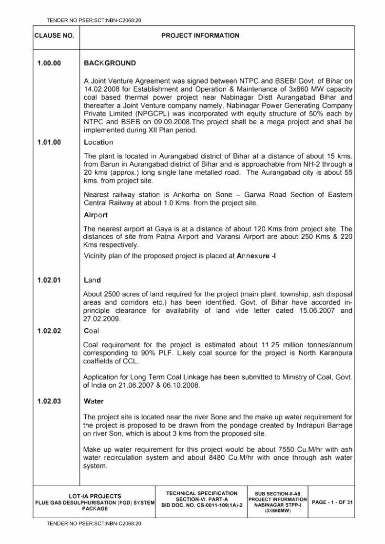
TITLE: - 3X660 MW NPGCL NABINAGAR FGD SPECIFICATIONS FOR RCC CHIMNEY
SPECIFICATION NO. PE-TS-457-620-C002
VOLUME : IIB
SECTION : C
REV.NO. 00
SHEET
3X660 MW NPGCL NABINAGAR STPP
FGD SYSTEM PACKAGE
VOLUME II-B
CIVIL, STRUCTURAL AND ARCHITECTURAL WORKS
SECTION – C
SPECIFIC TECHNICAL REQUIREMENTS
(RCC CHIMNEY)
SPECIFICATION NO. PE-TS-457-620-C002 REV-00
Bharat Heavy Electricals Limited Project Engineering Management
Power Sector, PPEI BUILDING, Plot No-25 SECTOR 16A, NOIDA-201301, UP
TENDER NO PSER:SCT:NBN-C2068:20
TENDER NO PSER:SCT:NBN-C2068:20
TITLE: - 3X660 MW NPGCL NABINAGAR FGD SPECIFICATIONS FOR RCC CHIMNEY
SPECIFICATION NO. PE-TS-457-620-C002
VOLUME : IIB
SECTION : C
REV.NO. 00
SHEET
PREAMBLE
Standard technical details as indicated in specification shall be agreed upon between
BHEL & Bidder.
Technical requirements are stipulated in this Volume which comprises of
Section C : This section indicates the technical requirements
specific to the contract not covered in Section D
Section D : This section comprises of technical specification(s)
The requirements mentioned in the Section C shall prevail and govern in case of
conflict between the same and the corresponding requirements mentioned in the
Section D in the specification. In case on any conflict between technical specification
and BOQ, BOQ shall prevail.
TENDER NO PSER:SCT:NBN-C2068:20
TENDER NO PSER:SCT:NBN-C2068:20

TITLE: - 3X660 MW NPGCL NABINAGAR FGD SPECIFICATIONS FOR RCC CHIMNEY
SPECIFICATION NO. PE-TS-457-620-C002
VOLUME : IIB
SECTION : C
REV.NO. 00
SHEET
INDEX SECTION DESCRIPTION
3 Section-C SPECIFIC TECHNICAL REQUIREMENTS 12
i) CIVIL ii) ELECTRICAL
iii) Chimney Elevator
Section-D SPECIFICATION FOR CIVIL, STRUCTURAL 22 AND ARCHITECTURAL WORKS
Sub-section D1: Earthwork in excavation and backfilling
Sub-section D2: Cement concrete (Plain and reinforced) and formwork
Sub-section D3: Carpentry and joinery
Sub-section D4: Roof and underground structures water proofing, insulation and allied works
Sub-section D5: Metal doors, windows, ventilators, louvers etc.
Sub-section D6: Glass and glazing.
Sub-section D7: Rolling Steel Shutter and Grills
Sub-section D8: Miscellaneous Metal
Sub-section D9: Masonry and allied works
Sub-section D10: Finish to masonry and concrete
Sub-section D11: Painting, Whitewashing, polishing
Sub-section D12: Floor finish and allied works
Sub-section D13: Sheet work in roof and siding
Sub-section D14: Suspended ceiling
Sub-section D15: Water supply, drainage & sanitation
Sub-section D16: Road and drainage
Sub-section D17: Fabrication of structural steelwork
Sub-section D18: Erection of structural steelwork
Sub-section D19: Roof decking
TENDER NO PSER:SCT:NBN-C2068:20
TENDER NO PSER:SCT:NBN-C2068:20

TITLE: - 3X660 MW NPGCL NABINAGAR FGD SPECIFICATIONS FOR RCC CHIMNEY
SPECIFICATION NO. PE-TS-457-620-C002
VOLUME : IIB
SECTION : C
REV.NO. 00
SHEET
Sub-section D20: False flooring
Sub-section D21: Bored cast in situ RCC pile
Sub-section D22: Levelling and grading
Sub-section D23: Anti termite
Sub-section D24: Quality Assurance & Inspection
Sub-section D25: RCC stack
Sub-section D26: Borosilicate glass block lining system
Sub-section D27: Specification for electrical works.
Sub-section D28: specification for chimney elevator
TENDER NO PSER:SCT:NBN-C2068:20
TENDER NO PSER:SCT:NBN-C2068:20

TITLE: - 3X660 MW NPGCL NABINAGAR FGD SPECIFICATIONS FOR RCC CHIMNEY
SPECIFICATION NO. PE-TS-457-620-C002
VOLUME : IIB
SECTION : C
REV.NO. 00
SHEET
SECTION-C
SPECIFIC TECHNICAL REQUIREMENTS FOR CIVIL WORKS
SPECIFICATION NO. PE-TS-457-620-C002
TENDER NO PSER:SCT:NBN-C2068:20
TENDER NO PSER:SCT:NBN-C2068:20
LOT-IA PROJECTS FLUE GAS DESULPHURISATION (FGD) SYSTEM PACKAGE
TECHNICAL SPECIFICATION SECTION-VI
BID DOCUMENT NO.: CS-0011-109(1A)-2
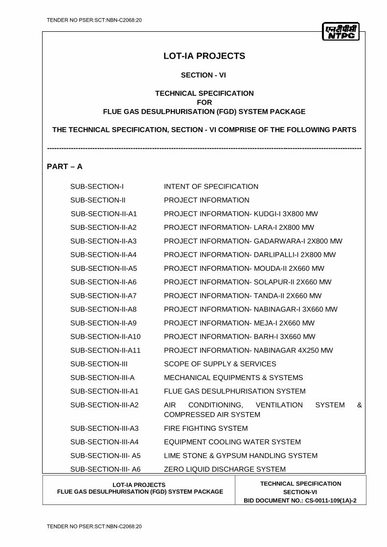
LOT-IA PROJECTS
SECTION - VI
TECHNICAL SPECIFICATION FOR
FLUE GAS DESULPHURISATION (FGD) SYSTEM PACKAGE
THE TECHNICAL SPECIFICATION, SECTION - VI COMPRISE OF THE FOLLOWING PARTS
------------------------------------------------------------------------------------------------------------------------------------
PART – A SUB-SECTION-I INTENT OF SPECIFICATION
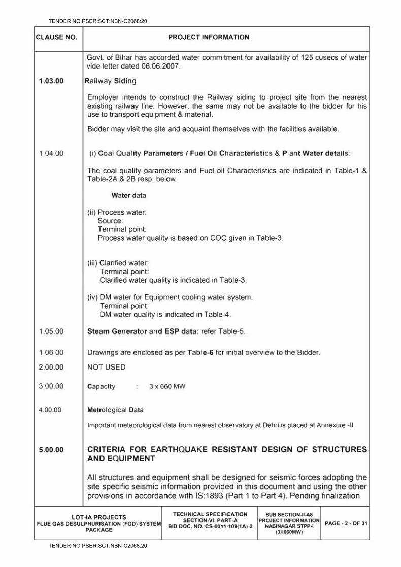
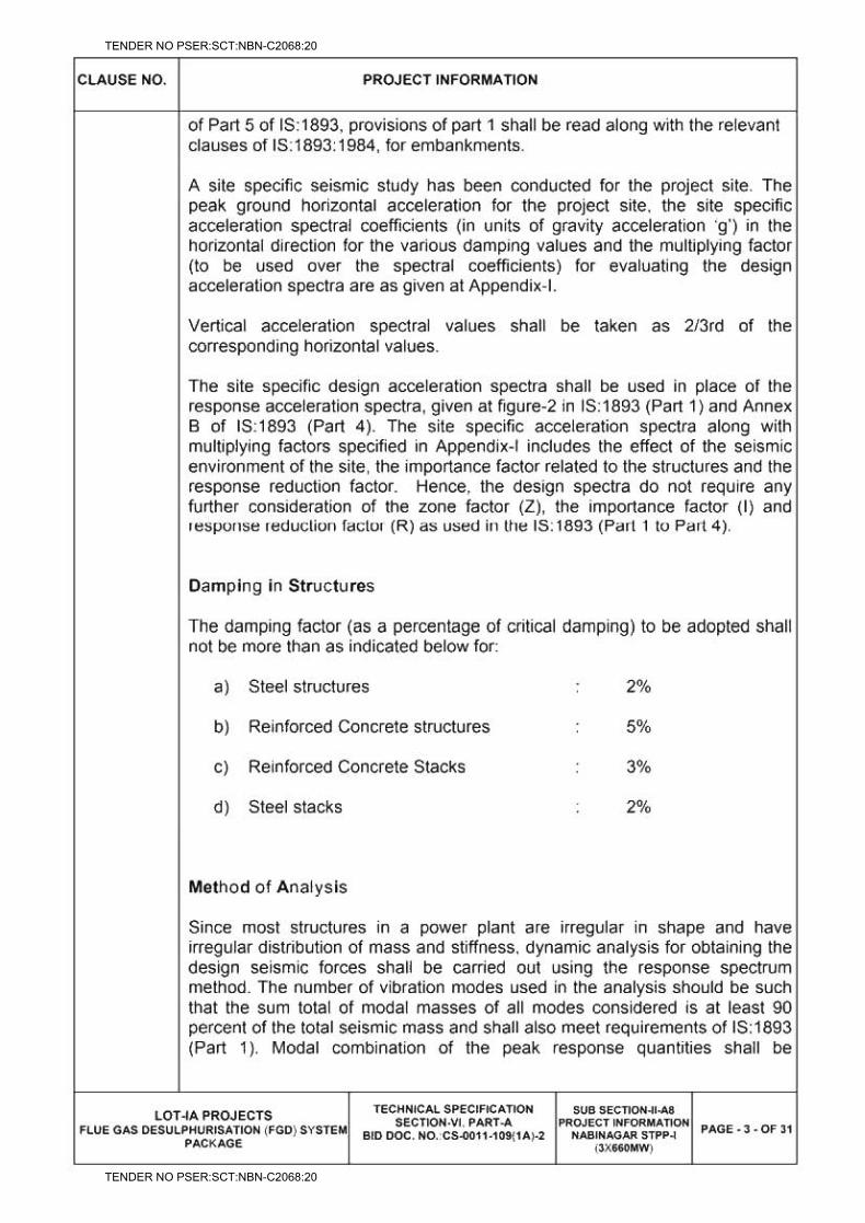
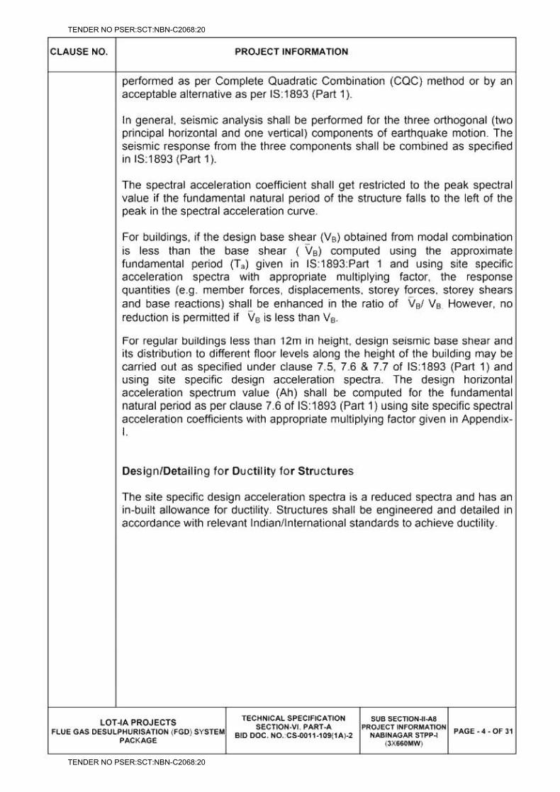
SUB-SECTION-II PROJECT INFORMATION
SUB-SECTION-II-A1 PROJECT INFORMATION- KUDGI-I 3X800 MW
SUB-SECTION-II-A2 PROJECT INFORMATION- LARA-I 2X800 MW
SUB-SECTION-II-A3 PROJECT INFORMATION- GADARWARA-I 2X800 MW
SUB-SECTION-II-A4 PROJECT INFORMATION- DARLIPALLI-I 2X800 MW
SUB-SECTION-II-A5 PROJECT INFORMATION- MOUDA-II 2X660 MW
SUB-SECTION-II-A6 PROJECT INFORMATION- SOLAPUR-II 2X660 MW
SUB-SECTION-II-A7 PROJECT INFORMATION- TANDA-II 2X660 MW
SUB-SECTION-II-A8 PROJECT INFORMATION- NABINAGAR-I 3X660 MW
SUB-SECTION-II-A9 PROJECT INFORMATION- MEJA-I 2X660 MW
SUB-SECTION-II-A10 PROJECT INFORMATION- BARH-I 3X660 MW
SUB-SECTION-II-A11 PROJECT INFORMATION- NABINAGAR 4X250 MW
SUB-SECTION-III SCOPE OF SUPPLY & SERVICES
SUB-SECTION-III-A MECHANICAL EQUIPMENTS & SYSTEMS
SUB-SECTION-III-A1 FLUE GAS DESULPHURISATION SYSTEM
SUB-SECTION-III-A2 AIR CONDITIONING, VENTILATION SYSTEM & COMPRESSED AIR SYSTEM
SUB-SECTION-III-A3 FIRE FIGHTING SYSTEM
SUB-SECTION-III-A4 EQUIPMENT COOLING WATER SYSTEM
SUB-SECTION-III- A5 LIME STONE & GYPSUM HANDLING SYSTEM
SUB-SECTION-III- A6 ZERO LIQUID DISCHARGE SYSTEM
TENDER NO PSER:SCT:NBN-C2068:20
TENDER NO PSER:SCT:NBN-C2068:20
LOT-IA PROJECTS FLUE GAS DESULPHURISATION (FGD) SYSTEM PACKAGE
TECHNICAL SPECIFICATION SECTION-VI
BID DOCUMENT NO.: CS-0011-109(1A)-2
SUB-SECTION-III-B ELECTRICAL SYSTEM/EQUIPMENT
SUB-SECTION-III-C CONTROL AND INSTRUMENTATION SYSTEM
SUB-SECTION-III-D CIVIL WORKS
SUB-SECTION-IV TERMINAL POINTS & EXCLUSIONS
SUB-SECTION-V SALIENT DESIGN DATA & SIZING
SUB-SECTION-VI FUNCTIONAL GUARANTEES & LIQUIDATED DAMAGES
SUB-SECTION-VII MANDATORY SPARES
PART – B (DETAILED TECHNICAL SPECIFICATION) SUB-SECTION-I-M (MECHANICAL SYSTEM) SUB-SECTION-I-M1 FLUE GAS DESULPHURISATION SYSTEM
SUB-SECTION-I-M2 AIR CONDITIONING & VENTILATION SYSTEM
SUB-SECTION-I-M3 COMPRESSED AIR SYSTEM
SUB-SECTION-I-M4 FIRE DETECTION & PROTECTION SYSTEM
SUB-SECTION-I-M5 EQUIPMENT COOLING WATER SYSTEM
SUB-SECTION-I-M6 LIME STONE & GYPSUM HANDLING SYSTEM
SUB-SECTION-I-M7 ZERO LIQUID DISCHARGE SYSTEM
SUB-SECTION-I-M8 PIPING
SUB-SECTION-I-M9 MDL
PART – B (DETAILED TECHNICAL SPECIFICATION) SUB-SECTION-II-E (ELECTRICAL SYSTEM) SUB-SECTION-II-E1 GENERAL ELECTRICAL SPECIFICATION
SUB-SECTION-II-E2 MOTORS
SUB-SECTION-II-E3 MEDIUM VOLTAGE BUS DUCTS
SUB-SECTION-II-E4 LT POWER CABLES
SUB-SECTION-II-E5 LT CONTROL CABLES
SUB-SECTION-II-E6 CABLING EARTHING & LIGHTNING PROTECTION
SUB-SECTION-II-E7 HT CABLES
TENDER NO PSER:SCT:NBN-C2068:20
TENDER NO PSER:SCT:NBN-C2068:20

LOT-IA PROJECTS FLUE GAS DESULPHURISATION (FGD) SYSTEM PACKAGE
TECHNICAL SPECIFICATION SECTION-VI
BID DOCUMENT NO.: CS-0011-109(1A)-2
SUB-SECTION-II-E8 ELECTRIC ACTUATORS WITH INTEGRAL STARTERS
SUB-SECTION-II-E9 HT SWTIGCHGEAR
SUB-SECTION-II-E10 LT SWTIGCHGEAR & LT BUSDUCT
SUB-SECTION-II-E11 DIESEL GENERATORS
SUB-SECTION-II-E12 OUTDOOR TRANSFORMERS
SUB-SECTION-II-E13 ELEVATOR ELECTRICAL
SUB-SECTION-II-E14 FIRE PROOF CABLE PENETRATION SEALING SYSTEM
SUB-SECTION-II-E15 LIGHTING
SUB-SECTION-II-E16 BATTERY
SUB-SECTION-II-E17 BATTERY CHARGER
PART – B (DETAILED TECHNICAL SPECIFICATION) SUB-SECTION-III-C (CONTROL & INSTRUMENTATION SYSTEM) SUB-SECTION-III-C1 BASIC DESIGN CRITERIA
SUB-SECTION-III-C2 MEASURING INSTRUMENTS (PRIMARY AND SECONDARY)
SUB-SECTION-III-C3 PROCESS CONNECTION AND PIPING
SUB-SECTION-III-C4 INSTRUMENTATION CABLES
SUB-SECTION-III-C5 PLC BASED CONTROL SYSTEM
SUB-SECTION-III-C6 TYPE TEST REQUIREMENTS
SUB-SECTION-III-C7 CONTROL VALVES, ACTUATORS & ACCESSORIES
PART – B (DETAILED TECHNICAL SPECIFICATION) SUB-SECTION-IV-D (CIVIL WORKS) SUB-SECTION-IV-D CIVIL WORKS
TENDER NO PSER:SCT:NBN-C2068:20
TENDER NO PSER:SCT:NBN-C2068:20
LOT-IA PROJECTS FLUE GAS DESULPHURISATION (FGD) SYSTEM PACKAGE
TECHNICAL SPECIFICATION SECTION-VI
BID DOCUMENT NO.: CS-0011-109(1A)-2
PART – B (DETAILED TECHNICAL SPECIFICATION)
SUB-SECTION- V-Q (QUALITY ASSURANCE)
(MECHANICAL)
SUB-SECTION-V-QM1 FLUE GAS DESULPHURISATION SYSTEM
SUB-SECTION-V-QM2 LIME & GYPSUM HANDLING
SUB-SECTION-V-QM3 EQUIPMENT COOLING WATER SYSTEM
SUB-SECTION-V-QM4 AIR CONDITIONING & VENTILATION
SUB-SECTION-V-QM5 ZERO LIQUID DISCHARGE SYSTEM
SUB-SECTION-V-QM6 COMPRESSOR AIR SYSTEM
SUB-SECTION-V-QM7 FIRE DETECTION & PROTECTION SYSTEM
(ELECTRICAL)
SUB-SECTION-V-QE1 MOTORS
SUB-SECTION-V-QE2 MEDIUM VOLTAGE BUS DUCTS
SUB-SECTION-V-QE3 LT POWER CABLES
SUB-SECTION-V-QE4 CONTROL CABLES
SUB-SECTION-V-QE5 CABLING EARTHING & LIGHTNING PROTECTION
SUB-SECTION-V-QE6 HT CABLES
SUB-SECTION-V-QE7 ELECTRIC ACTUATORS WITH INTEGRAL STARTERS
SUB-SECTION-V-QE8 HT SWTIGCHGEAR
SUB-SECTION-V-QE9 LT SWTIGCHGEAR
SUB-SECTION-V-QE10 DIESEL GENERATORS
SUB-SECTION-V-QE11 AUXILIARY TRANSFORMERS
SUB-SECTION-V-QE12 ELEVATOR
SUB-SECTION-V-QE13 VFD MODULE
TENDER NO PSER:SCT:NBN-C2068:20
TENDER NO PSER:SCT:NBN-C2068:20
LOT-IA PROJECTS FLUE GAS DESULPHURISATION (FGD) SYSTEM PACKAGE
TECHNICAL SPECIFICATION SECTION-VI
BID DOCUMENT NO.: CS-0011-109(1A)-2
SUB-SECTION-V-QE14 STATION LIGHTING
(CONTROL & INSTRUMENTATION SYSTEM)
SUB-SECTION-V-QC1 MEASURING INSTRUMENTS
(PRIMARY & SECONDARY
SUB-SECTION-V-QC2 PROCESS CONNECTION & PIPING
SUB-SECTION-V-QC3 INSTRUMENTATION CABLES
SUB-SECTION-V-QC4 CONTROL DESK PLC PANEL SMOKE DETECTOR
FIRE ALARM & CONTROL SYSTEM
SUB-SECTION-V-QC5 POWER SUPPLY SYSTEM
SUB-SECTION-V-QC6 CONTROL VALVE ACTUATORS AND ACCESSORIES
SUB-SECTION-V-QC7 ELECTRICAL ACTUATOR WITH INTEGRAL STARTERS
(CIVIL WORKS)
SUB-SECTION-V-QD1
SUB-SECTION- VI
(PRE-COMMISSIONING ACTIVITIES, COMMISSIONING OF FACILITIES AND
INITIAL OPERATIONS)
PART - C
GENERAL CONDITIONS OF CONTRACT
PART - D
ERECTION CONDITIONS OF CONTRACTS
PART - E
LIST OF TENDER DRAWINGS
PART - F
ATTACHMENT-12 TO SECTION-VII (TECHNICAL DATA SHEETS)
TENDER NO PSER:SCT:NBN-C2068:20
TENDER NO PSER:SCT:NBN-C2068:20
TENDER NO PSER:SCT:NBN-C2068:20
TENDER NO PSER:SCT:NBN-C2068:20
TENDER NO PSER:SCT:NBN-C2068:20
TENDER NO PSER:SCT:NBN-C2068:20
TENDER NO PSER:SCT:NBN-C2068:20
TENDER NO PSER:SCT:NBN-C2068:20
TENDER NO PSER:SCT:NBN-C2068:20
TENDER NO PSER:SCT:NBN-C2068:20
TENDER NO PSER:SCT:NBN-C2068:20
TENDER NO PSER:SCT:NBN-C2068:20
TENDER NO PSER:SCT:NBN-C2068:20
TENDER NO PSER:SCT:NBN-C2068:20
TENDER NO PSER:SCT:NBN-C2068:20
TENDER NO PSER:SCT:NBN-C2068:20
TENDER NO PSER:SCT:NBN-C2068:20
TENDER NO PSER:SCT:NBN-C2068:20
TENDER NO PSER:SCT:NBN-C2068:20
TENDER NO PSER:SCT:NBN-C2068:20
TENDER NO PSER:SCT:NBN-C2068:20
TENDER NO PSER:SCT:NBN-C2068:20
TENDER NO PSER:SCT:NBN-C2068:20
TENDER NO PSER:SCT:NBN-C2068:20
TENDER NO PSER:SCT:NBN-C2068:20
TENDER NO PSER:SCT:NBN-C2068:20
TENDER NO PSER:SCT:NBN-C2068:20
TENDER NO PSER:SCT:NBN-C2068:20
TENDER NO PSER:SCT:NBN-C2068:20
TENDER NO PSER:SCT:NBN-C2068:20
TENDER NO PSER:SCT:NBN-C2068:20
TENDER NO PSER:SCT:NBN-C2068:20
TENDER NO PSER:SCT:NBN-C2068:20
TENDER NO PSER:SCT:NBN-C2068:20
TENDER NO PSER:SCT:NBN-C2068:20
TENDER NO PSER:SCT:NBN-C2068:20
TENDER NO PSER:SCT:NBN-C2068:20
TENDER NO PSER:SCT:NBN-C2068:20
TENDER NO PSER:SCT:NBN-C2068:20
TENDER NO PSER:SCT:NBN-C2068:20
TENDER NO PSER:SCT:NBN-C2068:20
TENDER NO PSER:SCT:NBN-C2068:20
TENDER NO PSER:SCT:NBN-C2068:20
TENDER NO PSER:SCT:NBN-C2068:20
TENDER NO PSER:SCT:NBN-C2068:20
TENDER NO PSER:SCT:NBN-C2068:20
TENDER NO PSER:SCT:NBN-C2068:20
TENDER NO PSER:SCT:NBN-C2068:20
TENDER NO PSER:SCT:NBN-C2068:20
TENDER NO PSER:SCT:NBN-C2068:20
TENDER NO PSER:SCT:NBN-C2068:20
TENDER NO PSER:SCT:NBN-C2068:20
TENDER NO PSER:SCT:NBN-C2068:20
TENDER NO PSER:SCT:NBN-C2068:20
TENDER NO PSER:SCT:NBN-C2068:20
TENDER NO PSER:SCT:NBN-C2068:20
TENDER NO PSER:SCT:NBN-C2068:20
TENDER NO PSER:SCT:NBN-C2068:20
TENDER NO PSER:SCT:NBN-C2068:20
TENDER NO PSER:SCT:NBN-C2068:20
TENDER NO PSER:SCT:NBN-C2068:20
TENDER NO PSER:SCT:NBN-C2068:20
TENDER NO PSER:SCT:NBN-C2068:20
TENDER NO PSER:SCT:NBN-C2068:20
TENDER NO PSER:SCT:NBN-C2068:20
TENDER NO PSER:SCT:NBN-C2068:20
TENDER NO PSER:SCT:NBN-C2068:20
TENDER NO PSER:SCT:NBN-C2068:20
TENDER NO PSER:SCT:NBN-C2068:20
TENDER NO PSER:SCT:NBN-C2068:20
TENDER NO PSER:SCT:NBN-C2068:20
TENDER NO PSER:SCT:NBN-C2068:20

TENDER NO PSER:SCT:NBN-C2068:20
TENDER NO PSER:SCT:NBN-C2068:20
TENDER NO PSER:SCT:NBN-C2068:20
TENDER NO PSER:SCT:NBN-C2068:20
TENDER NO PSER:SCT:NBN-C2068:20
TENDER NO PSER:SCT:NBN-C2068:20
TENDER NO PSER:SCT:NBN-C2068:20
TENDER NO PSER:SCT:NBN-C2068:20
TENDER NO PSER:SCT:NBN-C2068:20
TENDER NO PSER:SCT:NBN-C2068:20
TENDER NO PSER:SCT:NBN-C2068:20
TENDER NO PSER:SCT:NBN-C2068:20
TENDER NO PSER:SCT:NBN-C2068:20
TENDER NO PSER:SCT:NBN-C2068:20
TENDER NO PSER:SCT:NBN-C2068:20
TENDER NO PSER:SCT:NBN-C2068:20
NTPC Limited (A Government of India Enterprise)
LOT 1A PROJECTS
(PART –A)
SECTON – VI
TECHNICAL SPECIFICATION
FOR
FLUE GAS DESULPHURISATION (FGD)
SYSTEM PACKAGE
BIDDING DOCUMENT NO. : CS-0011-109(1A)-2
TENDER NO PSER:SCT:NBN-C2068:20
TENDER NO PSER:SCT:NBN-C2068:20
NTPC Limited (A Government of India Enterprise)
LOT 1A PROJECTS
(PART –A)
SECTON – VI
TECHNICAL SPECIFICATION
FOR
FLUE GAS DESULPHURISATION (FGD)
SYSTEM PACKAGE
BIDDING DOCUMENT NO. : CS-0011-109(1A)-2
This document is meant for the exclusive purpose of bidding against this specification and shall not be transferred, reproduced or otherwise used for purposes other than that for which it is specifically issued.
TENDER NO PSER:SCT:NBN-C2068:20
TENDER NO PSER:SCT:NBN-C2068:20
FLUE GAS DESULPHURISATION (FGD)
SYSTEM PACKAGE
BIDDING DOCUMENT NO. : CS-0011-109(1A)-2
LIST OF LOT 1A PROJECTS
1. PROJECT INFORMATION- KUDGI-I 3X800 MW
2. PROJECT INFORMATION- LARA-I 2X800 MW
3. PROJECT INFORMATION- GADARWARA-I 2X800 MW
4. PROJECT INFORMATION- DARLIPALLI-I 2X800 MW
5. PROJECT INFORMATION- MOUDA-II 2X660 MW
6. PROJECT INFORMATION- SOLAPUR-II 2X660 MW
7. PROJECT INFORMATION- TANDA-II 2X660 MW
8. PROJECT INFORMATION- NABINAGAR-I 3X660 MW
9. PROJECT INFORMATION- MEJA-I 2X660 MW
10. PROJECT INFORMATION- BARH-I 3X660 MW
11. PROJECT INFORMATION- NABINAGAR 4X250 MW
TENDER NO PSER:SCT:NBN-C2068:20
TENDER NO PSER:SCT:NBN-C2068:20
LOT-IA PROJECTS FLUE GAS DESULPHURISATION (FGD) SYSTEM PACKAGE
TECHNICAL SPECIFICATION
SECTION-VI
BID DOCUMENT NO.: CS-0011-109(1A)-2
LOT-IA PROJECTS
SECTION - VI
TECHNICAL SPECIFICATION FOR
FLUE GAS DESULPHURISATION (FGD) SYSTEM PACKAGE
THE TECHNICAL SPECIFICATION, SECTION - VI COMPRISE OF THE FOLLOWING PARTS
------------------------------------------------------------------------------------------------------------------------------------
PART – A SUB-SECTION-I INTENT OF SPECIFICATION
SUB-SECTION-II PROJECT INFORMATION
SUB-SECTION-II-A1 PROJECT INFORMATION- KUDGI-I 3X800 MW
SUB-SECTION-II-A2 PROJECT INFORMATION- LARA-I 2X800 MW
SUB-SECTION-II-A3 PROJECT INFORMATION- GADARWARA-I 2X800 MW
SUB-SECTION-II-A4 PROJECT INFORMATION- DARLIPALLI-I 2X800 MW
SUB-SECTION-II-A5 PROJECT INFORMATION- MOUDA-II 2X660 MW
SUB-SECTION-II-A6 PROJECT INFORMATION- SOLAPUR-II 2X660 MW
SUB-SECTION-II-A7 PROJECT INFORMATION- TANDA-II 2X660 MW
SUB-SECTION-II-A8 PROJECT INFORMATION- NABINAGAR-I 3X660 MW
SUB-SECTION-II-A9 PROJECT INFORMATION- MEJA-I 2X660 MW
SUB-SECTION-II-A10 PROJECT INFORMATION- BARH-I 3X660 MW
SUB-SECTION-II-A11 PROJECT INFORMATION- NABINAGAR 4X250 MW
SUB-SECTION-III SCOPE OF SUPPLY & SERVICES
SUB-SECTION-III-A MECHANICAL EQUIPMENTS & SYSTEMS
SUB-SECTION-III-A1 FLUE GAS DESULPHURISATION SYSTEM
SUB-SECTION-III-A2 AIR CONDITIONING, VENTILATION SYSTEM & COMPRESSED AIR SYSTEM
SUB-SECTION-III-A3 FIRE FIGHTING SYSTEM
SUB-SECTION-III-A4 EQUIPMENT COOLING WATER SYSTEM
SUB-SECTION-III- A5 LIME STONE & GYPSUM HANDLING SYSTEM
SUB-SECTION-III- A6 ZERO LIQUID DISCHARGE SYSTEM
TENDER NO PSER:SCT:NBN-C2068:20
TENDER NO PSER:SCT:NBN-C2068:20
LOT-IA PROJECTS FLUE GAS DESULPHURISATION (FGD) SYSTEM PACKAGE
TECHNICAL SPECIFICATION
SECTION-VI
BID DOCUMENT NO.: CS-0011-109(1A)-2
SUB-SECTION-III-B ELECTRICAL SYSTEM/EQUIPMENT
SUB-SECTION-III-C CONTROL AND INSTRUMENTATION SYSTEM
SUB-SECTION-III-D CIVIL WORKS
SUB-SECTION-IV TERMINAL POINTS & EXCLUSIONS
SUB-SECTION-V SALIENT DESIGN DATA & SIZING
SUB-SECTION-VI FUNCTIONAL GUARANTEES & LIQUIDATED DAMAGES
SUB-SECTION-VII MANDATORY SPARES
PART – B (DETAILED TECHNICAL SPECIFICATION) SUB-SECTION-I-M (MECHANICAL SYSTEM) SUB-SECTION-I-M1 FLUE GAS DESULPHURISATION SYSTEM
SUB-SECTION-I-M2 AIR CONDITIONING & VENTILATION SYSTEM
SUB-SECTION-I-M3 COMPRESSED AIR SYSTEM
SUB-SECTION-I-M4 FIRE DETECTION & PROTECTION SYSTEM
SUB-SECTION-I-M5 EQUIPMENT COOLING WATER SYSTEM
SUB-SECTION-I-M6 LIME STONE & GYPSUM HANDLING SYSTEM
SUB-SECTION-I-M7 ZERO LIQUID DISCHARGE SYSTEM
SUB-SECTION-I-M8 PIPING
SUB-SECTION-I-M9 MDL
PART – B (DETAILED TECHNICAL SPECIFICATION) SUB-SECTION-II-E (ELECTRICAL SYSTEM) SUB-SECTION-II-E1 GENERAL ELECTRICAL SPECIFICATION
SUB-SECTION-II-E2 MOTORS
SUB-SECTION-II-E3 MEDIUM VOLTAGE BUS DUCTS
SUB-SECTION-II-E4 LT POWER CABLES
SUB-SECTION-II-E5 LT CONTROL CABLES
SUB-SECTION-II-E6 CABLING EARTHING & LIGHTNING PROTECTION
SUB-SECTION-II-E7 HT CABLES
TENDER NO PSER:SCT:NBN-C2068:20
TENDER NO PSER:SCT:NBN-C2068:20
LOT-IA PROJECTS FLUE GAS DESULPHURISATION (FGD) SYSTEM PACKAGE
TECHNICAL SPECIFICATION
SECTION-VI
BID DOCUMENT NO.: CS-0011-109(1A)-2
SUB-SECTION-II-E8 ELECTRIC ACTUATORS WITH INTEGRAL STARTERS
SUB-SECTION-II-E9 HT SWTIGCHGEAR
SUB-SECTION-II-E10 LT SWTIGCHGEAR & LT BUSDUCT
SUB-SECTION-II-E11 DIESEL GENERATORS
SUB-SECTION-II-E12 OUTDOOR TRANSFORMERS
SUB-SECTION-II-E13 ELEVATOR ELECTRICAL
SUB-SECTION-II-E14 FIRE PROOF CABLE PENETRATION SEALING SYSTEM
SUB-SECTION-II-E15 LIGHTING
SUB-SECTION-II-E16 BATTERY
SUB-SECTION-II-E17 BATTERY CHARGER
PART – B (DETAILED TECHNICAL SPECIFICATION) SUB-SECTION-III-C (CONTROL & INSTRUMENTATION SYSTEM) SUB-SECTION-III-C1 BASIC DESIGN CRITERIA
SUB-SECTION-III-C2 MEASURING INSTRUMENTS (PRIMARY AND SECONDARY)
SUB-SECTION-III-C3 PROCESS CONNECTION AND PIPING
SUB-SECTION-III-C4 INSTRUMENTATION CABLES
SUB-SECTION-III-C5 PLC BASED CONTROL SYSTEM
SUB-SECTION-III-C6 TYPE TEST REQUIREMENTS
SUB-SECTION-III-C7 CONTROL VALVES, ACTUATORS & ACCESSORIES
PART – B (DETAILED TECHNICAL SPECIFICATION) SUB-SECTION-IV-D (CIVIL WORKS) SUB-SECTION-IV-D CIVIL WORKS
TENDER NO PSER:SCT:NBN-C2068:20
TENDER NO PSER:SCT:NBN-C2068:20
LOT-IA PROJECTS FLUE GAS DESULPHURISATION (FGD) SYSTEM PACKAGE
TECHNICAL SPECIFICATION
SECTION-VI
BID DOCUMENT NO.: CS-0011-109(1A)-2
PART – B (DETAILED TECHNICAL SPECIFICATION)
SUB-SECTION- V-Q (QUALITY ASSURANCE)
(MECHANICAL)
SUB-SECTION-V-QM1 FLUE GAS DESULPHURISATION SYSTEM
SUB-SECTION-V-QM2 LIME & GYPSUM HANDLING
SUB-SECTION-V-QM3 EQUIPMENT COOLING WATER SYSTEM
SUB-SECTION-V-QM4 AIR CONDITIONING & VENTILATION
SUB-SECTION-V-QM5 ZERO LIQUID DISCHARGE SYSTEM
SUB-SECTION-V-QM6 COMPRESSOR AIR SYSTEM
(ELECTRICAL)
SUB-SECTION-V-QE1 MOTORS
SUB-SECTION-V-QE2 MEDIUM VOLTAGE BUS DUCTS
SUB-SECTION-V-QE3 LT POWER CABLES
SUB-SECTION-V-QE4 CONTROL CABLES
SUB-SECTION-V-QE5 CABLING EARTHING & LIGHTNING PROTECTION
SUB-SECTION-V-QE6 HT CABLES
SUB-SECTION-V-QE7 ELECTRIC ACTUATORS WITH INTEGRAL STARTERS
SUB-SECTION-V-QE8 HT SWTIGCHGEAR
SUB-SECTION-V-QE9 LT SWTIGCHGEAR
SUB-SECTION-V-QE10 DIESEL GENERATORS
SUB-SECTION-V-QE11 AUXILIARY TRANSFORMERS
SUB-SECTION-V-QE12 ELEVATOR
SUB-SECTION-V-QE13 VFD MODULE SUB-SECTION-V-QE14 STATION LIGHTING
TENDER NO PSER:SCT:NBN-C2068:20
TENDER NO PSER:SCT:NBN-C2068:20
LOT-IA PROJECTS FLUE GAS DESULPHURISATION (FGD) SYSTEM PACKAGE
TECHNICAL SPECIFICATION
SECTION-VI
BID DOCUMENT NO.: CS-0011-109(1A)-2
(CONTROL & INSTRUMENTATION SYSTEM)
SUB-SECTION-V-QC1 MEASURING INSTRUMENTS
(PRIMARY & SECONDARY
SUB-SECTION-V-QC2 PROCESS CONNECTION & PIPING
SUB-SECTION-V-QC3 INSTRUMENTATION CABLES
SUB-SECTION-V-QC4 CONTROL DESK PLC PANEL SMOKE DETECTOR
FIRE ALARM & CONTROL SYSTEM
SUB-SECTION-V-QC5 POWER SUPPLY SYSTEM
SUB-SECTION-V-QC6 CONTROL VALVE ACTUATORS AND ACCESSORIES
SUB-SECTION-V-QC7 ELECTRICAL ACTUATOR WITH INTEGRAL STARTERS
(CIVIL WORKS)
SUB-SECTION-V-QD1
SUB-SECTION- VI
(PRE-COMMISSIONING ACTIVITIES, COMMISSIONING OF FACILITIES AND
INITIAL OPERATIONS)
PART - C
GENERAL CONDITIONS OF CONTRACT
PART - D
ERECTION CONDITIONS OF CONTRACTS
PART - E
LIST OF TENDER DRAWINGS
PART - F
ATTACHMENT-12 TO SECTION-VII (TECHNICAL DATA SHEETS)
TENDER NO PSER:SCT:NBN-C2068:20
TENDER NO PSER:SCT:NBN-C2068:20
LOT-IA PROJECTS FLUE GAS DESULPHURISATION (FGD) SYSTEM PACKAGE
TECHNICAL SPECIFICATION
SECTION-VI
BID DOCUMENT NO.: CS-0011-109(1A)-2
PART – A
TENDER NO PSER:SCT:NBN-C2068:20
TENDER NO PSER:SCT:NBN-C2068:20

LOT-IA PROJECTS FLUE GAS DESULPHURISATION (FGD) SYSTEM PACKAGE
TECHNICAL SPECIFICATION
SECTION-VI
BID DOCUMENT NO.: CS-0011-109(1A)-2
SUB-SECTION-I
INTENT OF SPECIFICATION
TENDER NO PSER:SCT:NBN-C2068:20
TENDER NO PSER:SCT:NBN-C2068:20
CLAUSE NO.
INTENT OF SPECIFICATION
LOT-IA PROJECTS
FLUE GAS DESULPHURISATION (FGD) SYSTEM PACKAGE
TECHNICAL SPECIFICATION SECTION – VI, PART-A
BID DOC. NO CS-0011-109-(1A)2
SUB-SECTION-I INTENT OF
SPECIFICATION
PAGE 1 OF 19
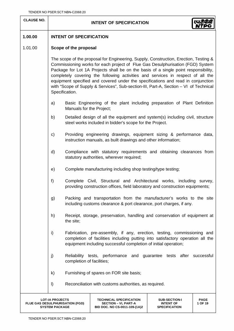
1.00.00 INTENT OF SPECIFICATION 1.01.00 Scope of the proposal
The scope of the proposal for Engineering, Supply, Construction, Erection, Testing &
Commissioning works for each project of Flue Gas Desulphurisation (FGD) System Package for Lot 1A Projects shall be on the basis of a single point responsibility, completely covering the following activities and services in respect of all the equipment specified and covered under the specifications and read in conjunction with “Scope of Supply & Services”, Sub-section-III, Part-A, Section – VI of Technical Specification.
a) Basic Engineering of the plant including preparation of Plant Definition
Manuals for the Project;
b) Detailed design of all the equipment and system(s) including civil, structure steel works included in bidder's scope for the Project.
c) Providing engineering drawings, equipment sizing & performance data, instruction manuals, as built drawings and other information;
d) Compliance with statutory requirements and obtaining clearances from statutory authorities, wherever required;
e) Complete manufacturing including shop testing/type testing;
f) Complete Civil, Structural and Architectural works, including survey, providing construction offices, field laboratory and construction equipments;
g) Packing and transportation from the manufacturer’s works to the site including customs clearance & port clearance, port charges, if any.
h) Receipt, storage, preservation, handling and conservation of equipment at the site;
i) Fabrication, pre-assembly, if any, erection, testing, commissioning and completion of facilities including putting into satisfactory operation all the equipment including successful completion of initial operation;
j) Reliability tests, performance and guarantee tests after successful completion of facilities;
k) Furnishing of spares on FOR site basis;
l) Reconciliation with customs authorities, as required.
TENDER NO PSER:SCT:NBN-C2068:20
TENDER NO PSER:SCT:NBN-C2068:20
CLAUSE NO.
INTENT OF SPECIFICATION
LOT-IA PROJECTS
FLUE GAS DESULPHURISATION (FGD) SYSTEM PACKAGE
TECHNICAL SPECIFICATION SECTION – VI, PART-A
BID DOC. NO CS-0011-109-(1A)2
SUB-SECTION-I INTENT OF
SPECIFICATION
PAGE 2 OF 19
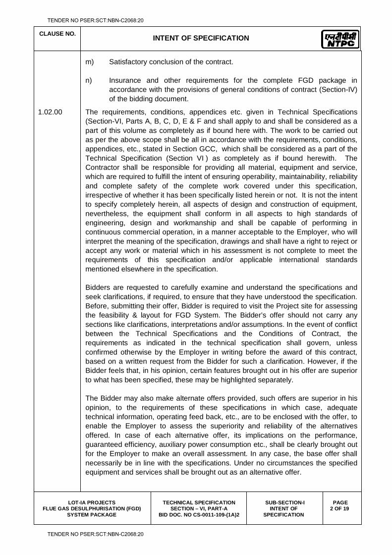
m) Satisfactory conclusion of the contract.
n) Insurance and other requirements for the complete FGD package in accordance with the provisions of general conditions of contract (Section-IV) of the bidding document.
1.02.00 The requirements, conditions, appendices etc. given in Technical Specifications (Section-VI, Parts A, B, C, D, E & F and shall apply to and shall be considered as a part of this volume as completely as if bound here with. The work to be carried out as per the above scope shall be all in accordance with the requirements, conditions, appendices, etc., stated in Section GCC, which shall be considered as a part of the Technical Specification (Section VI ) as completely as if bound herewith. The Contractor shall be responsible for providing all material, equipment and service, which are required to fulfill the intent of ensuring operability, maintainability, reliability and complete safety of the complete work covered under this specification, irrespective of whether it has been specifically listed herein or not. It is not the intent to specify completely herein, all aspects of design and construction of equipment, nevertheless, the equipment shall conform in all aspects to high standards of engineering, design and workmanship and shall be capable of performing in continuous commercial operation, in a manner acceptable to the Employer, who will interpret the meaning of the specification, drawings and shall have a right to reject or accept any work or material which in his assessment is not complete to meet the requirements of this specification and/or applicable international standards mentioned elsewhere in the specification.
Bidders are requested to carefully examine and understand the specifications and
seek clarifications, if required, to ensure that they have understood the specification. Before, submitting their offer, Bidder is required to visit the Project site for assessing the feasibility & layout for FGD System. The Bidder’s offer should not carry any sections like clarifications, interpretations and/or assumptions. In the event of conflict between the Technical Specifications and the Conditions of Contract, the requirements as indicated in the technical specification shall govern, unless confirmed otherwise by the Employer in writing before the award of this contract, based on a written request from the Bidder for such a clarification. However, if the Bidder feels that, in his opinion, certain features brought out in his offer are superior to what has been specified, these may be highlighted separately.
The Bidder may also make alternate offers provided, such offers are superior in his
opinion, to the requirements of these specifications in which case, adequate technical information, operating feed back, etc., are to be enclosed with the offer, to enable the Employer to assess the superiority and reliability of the alternatives offered. In case of each alternative offer, its implications on the performance, guaranteed efficiency, auxiliary power consumption etc., shall be clearly brought out for the Employer to make an overall assessment. In any case, the base offer shall necessarily be in line with the specifications. Under no circumstances the specified equipment and services shall be brought out as an alternative offer.
TENDER NO PSER:SCT:NBN-C2068:20
TENDER NO PSER:SCT:NBN-C2068:20
CLAUSE NO.
INTENT OF SPECIFICATION
LOT-IA PROJECTS
FLUE GAS DESULPHURISATION (FGD) SYSTEM PACKAGE
TECHNICAL SPECIFICATION SECTION – VI, PART-A
BID DOC. NO CS-0011-109-(1A)2
SUB-SECTION-I INTENT OF
SPECIFICATION
PAGE 3 OF 19
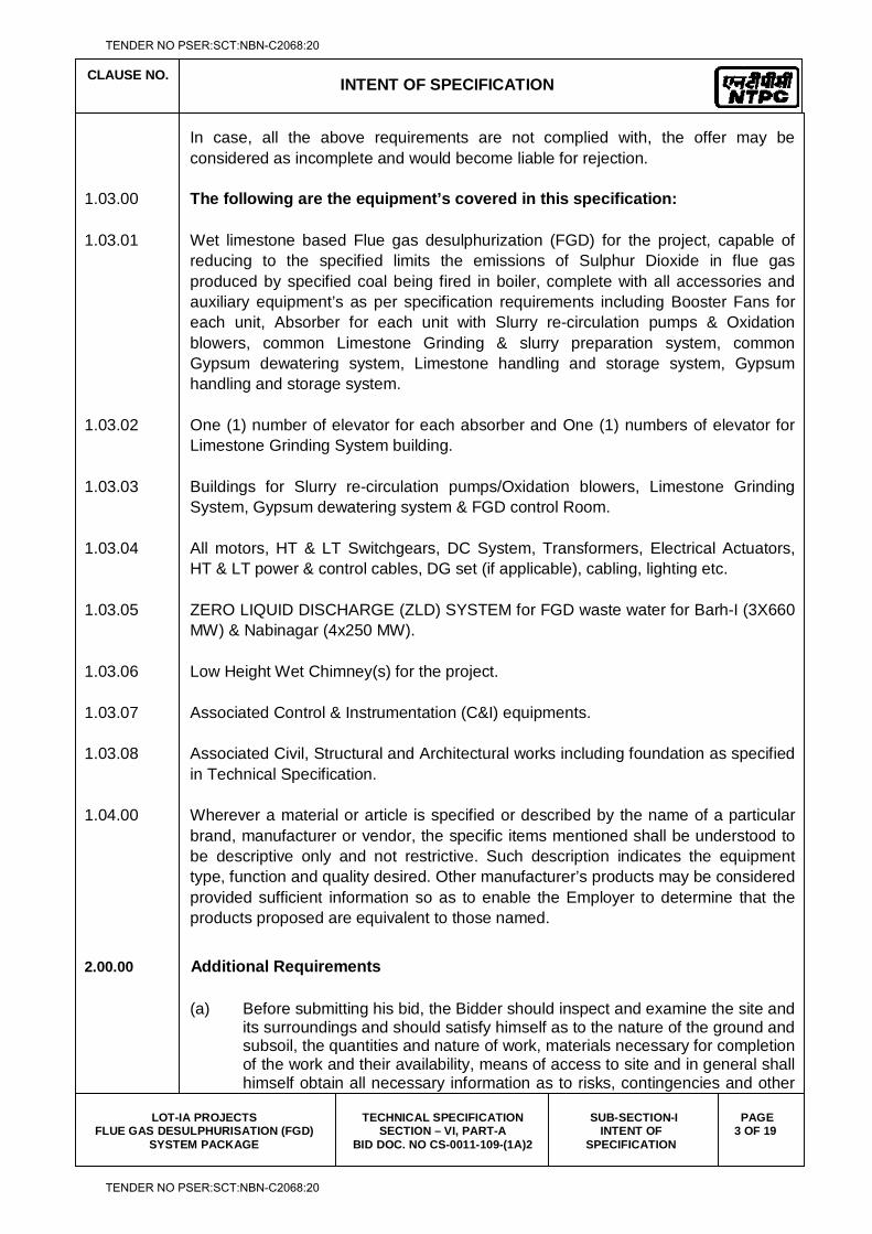
In case, all the above requirements are not complied with, the offer may be considered as incomplete and would become liable for rejection.
1.03.00 The following are the equipment’s covered in this specification: 1.03.01 Wet limestone based Flue gas desulphurization (FGD) for the project, capable of
reducing to the specified limits the emissions of Sulphur Dioxide in flue gas produced by specified coal being fired in boiler, complete with all accessories and auxiliary equipment’s as per specification requirements including Booster Fans for each unit, Absorber for each unit with Slurry re-circulation pumps & Oxidation blowers, common Limestone Grinding & slurry preparation system, common Gypsum dewatering system, Limestone handling and storage system, Gypsum handling and storage system.
1.03.02 One (1) number of elevator for each absorber and One (1) numbers of elevator for
Limestone Grinding System building. 1.03.03 Buildings for Slurry re-circulation pumps/Oxidation blowers, Limestone Grinding
System, Gypsum dewatering system & FGD control Room. 1.03.04 All motors, HT & LT Switchgears, DC System, Transformers, Electrical Actuators,
HT & LT power & control cables, DG set (if applicable), cabling, lighting etc. 1.03.05 ZERO LIQUID DISCHARGE (ZLD) SYSTEM for FGD waste water for Barh-I (3X660
MW) & Nabinagar (4x250 MW). 1.03.06 Low Height Wet Chimney(s) for the project. 1.03.07 Associated Control & Instrumentation (C&I) equipments. 1.03.08 Associated Civil, Structural and Architectural works including foundation as specified
in Technical Specification. 1.04.00 Wherever a material or article is specified or described by the name of a particular
brand, manufacturer or vendor, the specific items mentioned shall be understood to be descriptive only and not restrictive. Such description indicates the equipment type, function and quality desired. Other manufacturer’s products may be considered provided sufficient information so as to enable the Employer to determine that the products proposed are equivalent to those named.
2.00.00 Additional Requirements
(a) Before submitting his bid, the Bidder should inspect and examine the site and its surroundings and should satisfy himself as to the nature of the ground and subsoil, the quantities and nature of work, materials necessary for completion of the work and their availability, means of access to site and in general shall himself obtain all necessary information as to risks, contingencies and other
TENDER NO PSER:SCT:NBN-C2068:20
TENDER NO PSER:SCT:NBN-C2068:20
CLAUSE NO.
INTENT OF SPECIFICATION
LOT-IA PROJECTS
FLUE GAS DESULPHURISATION (FGD) SYSTEM PACKAGE
TECHNICAL SPECIFICATION SECTION – VI, PART-A
BID DOC. NO CS-0011-109-(1A)2
SUB-SECTION-I INTENT OF
SPECIFICATION
PAGE 4 OF 19
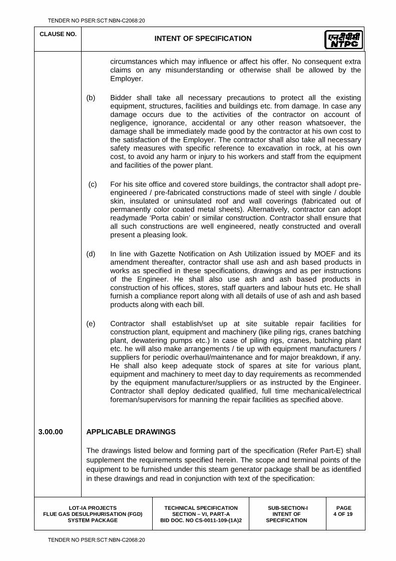
circumstances which may influence or affect his offer. No consequent extra claims on any misunderstanding or otherwise shall be allowed by the Employer.
(b) Bidder shall take all necessary precautions to protect all the existing equipment, structures, facilities and buildings etc. from damage. In case any damage occurs due to the activities of the contractor on account of negligence, ignorance, accidental or any other reason whatsoever, the damage shall be immediately made good by the contractor at his own cost to the satisfaction of the Employer. The contractor shall also take all necessary safety measures with specific reference to excavation in rock, at his own cost, to avoid any harm or injury to his workers and staff from the equipment and facilities of the power plant.
(c) For his site office and covered store buildings, the contractor shall adopt pre-engineered / pre-fabricated constructions made of steel with single / double skin, insulated or uninsulated roof and wall coverings (fabricated out of permanently color coated metal sheets). Alternatively, contractor can adopt readymade ‘Porta cabin’ or similar construction. Contractor shall ensure that all such constructions are well engineered, neatly constructed and overall present a pleasing look.
(d) In line with Gazette Notification on Ash Utilization issued by MOEF and its amendment thereafter, contractor shall use ash and ash based products in works as specified in these specifications, drawings and as per instructions of the Engineer. He shall also use ash and ash based products in construction of his offices, stores, staff quarters and labour huts etc. He shall furnish a compliance report along with all details of use of ash and ash based products along with each bill.
(e) Contractor shall establish/set up at site suitable repair facilities for construction plant, equipment and machinery (like piling rigs, cranes batching plant, dewatering pumps etc.) In case of piling rigs, cranes, batching plant etc. he will also make arrangements / tie up with equipment manufacturers / suppliers for periodic overhaul/maintenance and for major breakdown, if any. He shall also keep adequate stock of spares at site for various plant, equipment and machinery to meet day to day requirements as recommended by the equipment manufacturer/suppliers or as instructed by the Engineer. Contractor shall deploy dedicated qualified, full time mechanical/electrical foreman/supervisors for manning the repair facilities as specified above.
3.00.00 APPLICABLE DRAWINGS The drawings listed below and forming part of the specification (Refer Part-E) shall
supplement the requirements specified herein. The scope and terminal points of the equipment to be furnished under this steam generator package shall be as identified in these drawings and read in conjunction with text of the specification:
TENDER NO PSER:SCT:NBN-C2068:20
TENDER NO PSER:SCT:NBN-C2068:20
CLAUSE NO.
INTENT OF SPECIFICATION
LOT-IA PROJECTS
FLUE GAS DESULPHURISATION (FGD) SYSTEM PACKAGE
TECHNICAL SPECIFICATION SECTION – VI, PART-A
BID DOC. NO CS-0011-109-(1A)2
SUB-SECTION-I INTENT OF
SPECIFICATION
PAGE 5 OF 19
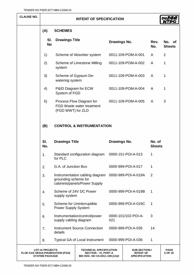
(A) SCHEMES
Sl. No
Drawings Title Drawings No. Rev. No.
No. of Sheets
1) Scheme of Absorber system 0011-109-POM-A-001 A 2
2) Scheme of Limestone Milling system
0011-109-POM-A-002 A 1
3) Scheme of Gypsum De-watering system
0011-109-POM-A-003 A 1
4) P&ID Diagram for ECW System of FGD
0011-109-POM-A-004 A 1
5) Process Flow Diagram for FGD Waste water treatment (FGD WWT) for ZLD
0011-109-POM-A-005 A 3
(B) CONTROL & INSTRUMENTATION
Sl. No.
Drawings Title Drawings No. No. of Sheets
1. Standard configuration diagram for PLC
0000-151-POI-A-013 1
2. G.A. of Junction Box 0000-999-POI-A-017 1
3. Instrumentation cabling diagram grounding scheme for cabinets/panels/Power Supply
0000-999-POI-A-019A 2
4. Scheme of 24V DC Power supply system
0000-999-POI-A-019B 1
5. Scheme for Uninterruptible Power Supply System
0000-999-POI-A-019C 1
6. Instrumentation/control/power supply cabling diagram
0000-101/102-POI-A-021
3
7. Instrument Source Connection details
0000-999-POI-A-035 14
8. Typical GA of Local Instrument 0000-999-POI-A-036 1
TENDER NO PSER:SCT:NBN-C2068:20
TENDER NO PSER:SCT:NBN-C2068:20
CLAUSE NO.
INTENT OF SPECIFICATION
LOT-IA PROJECTS
FLUE GAS DESULPHURISATION (FGD) SYSTEM PACKAGE
TECHNICAL SPECIFICATION SECTION – VI, PART-A
BID DOC. NO CS-0011-109-(1A)2
SUB-SECTION-I INTENT OF
SPECIFICATION
PAGE 6 OF 19
Sl. No.
Drawings Title Drawings No. No. of Sheets
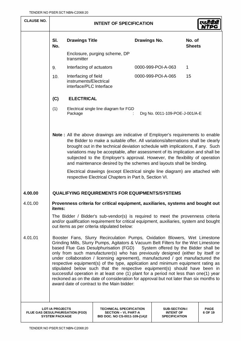
Enclosure, purging scheme, DP transmitter
9. Interfacing of actuators 0000-999-POI-A-063 1
10. Interfacing of field instruments/Electrical interface/PLC Interface
0000-999-POI-A-065 15
(C) ELECTRICAL (1) Electrical single line diagram for FGD Package : Drg No. 0011-109-POE-J-001/A-E Note : All the above drawings are indicative of Employer’s requirements to enable
the Bidder to make a suitable offer. All variations/alternations shall be clearly brought out in the technical deviation schedule with implications, if any. Such variations may be acceptable, after assessment of its implication and shall be subjected to the Employer’s approval. However, the flexibility of operation and maintenance desired by the schemes and layouts shall be binding.
Electrical drawings (except Electrical single line diagram) are attached with respective Electrical Chapters in Part b, Section VI.
4.00.00 QUALIFYING REQUIREMENTS FOR EQUIPMENTS/SYSTEMS 4.01.00 Provenness criteria for critical equipment, auxiliaries, systems and bought out
items:
The Bidder / Bidder's sub-vendor(s) is required to meet the provenness criteria and/or qualification requirement for critical equipment, auxiliaries, system and bought out items as per criteria stipulated below:
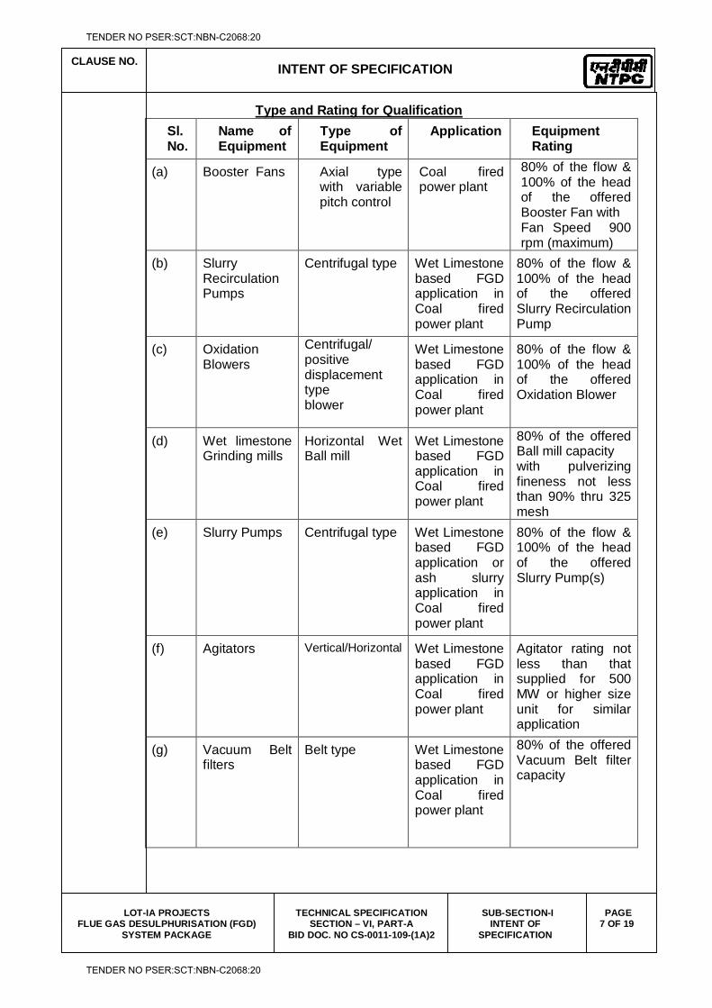
4.01.01 Booster Fans, Slurry Recirculation Pumps, Oxidation Blowers, Wet Limestone Grinding Mills, Slurry Pumps, Agitators & Vacuum Belt Filters for the Wet Limestone based Flue Gas Desulphurisation (FGD) System offered by the Bidder shall be only from such manufacturer(s) who has previously designed (either by itself or under collaboration / licensing agreement), manufactured / got manufactured the respective equipment(s) of the type, application and minimum equipment rating as stipulated below such that the respective equipment(s) should have been in successful operation in at least one (1) plant for a period not less than one(1) year reckoned as on the date of consideration for approval but not later than six months to award date of contract to the Main bidder:
TENDER NO PSER:SCT:NBN-C2068:20
TENDER NO PSER:SCT:NBN-C2068:20
CLAUSE NO.
INTENT OF SPECIFICATION
LOT-IA PROJECTS
FLUE GAS DESULPHURISATION (FGD) SYSTEM PACKAGE
TECHNICAL SPECIFICATION SECTION – VI, PART-A
BID DOC. NO CS-0011-109-(1A)2
SUB-SECTION-I INTENT OF
SPECIFICATION
PAGE 7 OF 19
Type and Rating for Qualification
Sl. No.
Name of Equipment
Type of Equipment
Application Equipment Rating
(a) Booster Fans Axial type with variable pitch control
Coal fired power plant
80% of the flow & 100% of the head of the offered Booster Fan with Fan Speed 900 rpm (maximum)
(b) Slurry Recirculation Pumps
Centrifugal type Wet Limestone based FGD application in Coal fired power plant
80% of the flow & 100% of the head of the offered Slurry Recirculation Pump
(c) Oxidation Blowers
Centrifugal/ positive displacement type blower
Wet Limestone based FGD application in Coal fired power plant
80% of the flow & 100% of the head of the offered Oxidation Blower
(d) Wet limestone Grinding mills
Horizontal Wet Ball mill
Wet Limestone based FGD application in Coal fired power plant
80% of the offered Ball mill capacity with pulverizing fineness not less than 90% thru 325 mesh
(e) Slurry Pumps Centrifugal type Wet Limestone based FGD application or ash slurry application in Coal fired power plant
80% of the flow & 100% of the head of the offered Slurry Pump(s)
(f) Agitators Vertical/Horizontal Wet Limestone based FGD application in Coal fired power plant
Agitator rating not less than that supplied for 500 MW or higher size unit for similar application
(g) Vacuum Belt filters
Belt type Wet Limestone based FGD application in Coal fired power plant
80% of the offered Vacuum Belt filter capacity
TENDER NO PSER:SCT:NBN-C2068:20
TENDER NO PSER:SCT:NBN-C2068:20
CLAUSE NO.
INTENT OF SPECIFICATION
LOT-IA PROJECTS
FLUE GAS DESULPHURISATION (FGD) SYSTEM PACKAGE
TECHNICAL SPECIFICATION SECTION – VI, PART-A
BID DOC. NO CS-0011-109-(1A)2
SUB-SECTION-I INTENT OF
SPECIFICATION
PAGE 8 OF 19
Bidder shall offer and supply only the type of the above equipment(s) for which he himself or the manufacturer proposed by the bidder for the above equipment(s) is qualified.
The provenness criteria for equipment (Booster Fans) stipulated at Sl. No. 4.01.01 (a) above shall also be considered acceptable provided the rating parameters (i.e., flow, head and rated rpm) is covered within the operating regime of the respective fan performance curve of the reference plant equipment.
4.01.02 In case the Bidder or the proposed sub-vendor is not manufacturer of proven Booster Fans as per clause 4.01.01 (a) above but is a manufacturer of such equipment for units of at least 500 MW rating, the Bidder or the proposed sub vendor can manufacture such equipment for 660 MW units also, provided it has collaboration or valid licensing agreement for design, engineering, manufacturing, supply of such equipment in India with such manufacturer who meet the requirements stipulated at clause 4.01.01 (a) above for the Booster Fans.
4.01.03 A JV / Subsidiary Company formed for manufacturing and supply of equipment(s) as listed at clause no. 4.01.01 above in India, can also manufacture such equipment(s), provided that it has a valid collaboration or licensing agreement for design, engineering, manufacturing of such equipment(s) in India with a qualified equipment manufacturer who meets the requirements stipulated at clause 4.01.01 above (or the technology provider of the qualified equipment manufacturer) for the respective equipment(s). Before taking up the manufacturing of such equipment(s), the bidder/ his sub-vendor(s) must create /have created manufacturing facilities at his works as per collaborator’s/licenser's design, manufacturing and quality control system for such equipment(s).
Further, in such a case, such qualified equipment manufacturers should have, directly or indirectly through its holding company/ subsidiary company, at least 26% equity participation in the Indian Joint Venture Company/ Subsidiary Company, which shall be maintained for a lock-in period of seven (7) years from the date of incorporation of such Joint Venture/ Subsidiary or upto the end of defect liability period of the contract, whichever is later.
4.01.04 In case the Bidder or the proposed sub-vendor is not manufacturer of proven
Oxidation Blowers as per clause 4.01.01 (c) above but is a manufacturer of Blowers/compressors for minimum 50 NM3/min capacity, the Bidder or the proposed sub-vendor can also manufacture Oxidation Blowers, provided it has collaboration or valid licensing agreement for design, engineering, manufacturing, supply of such Oxidation Blowers in India with such manufacturer who meet the requirements stipulated at clause 4.01.01 (c) above for the Oxidation Blowers. Before taking up the manufacturing of such equipment, the bidder/ his sub-vendor must create /have created manufacturing facilities at his works as per collaborator’s /licenser's design, manufacturing and quality control system for such equipments.
4.01.05 (i) In case the Bidder or the proposed sub-vendor is not manufacturer of proven Wet limestone Grinding mills as per clause 4.01.01 (d) above but is a manufacturer
TENDER NO PSER:SCT:NBN-C2068:20
TENDER NO PSER:SCT:NBN-C2068:20
CLAUSE NO.
INTENT OF SPECIFICATION
LOT-IA PROJECTS
FLUE GAS DESULPHURISATION (FGD) SYSTEM PACKAGE
TECHNICAL SPECIFICATION SECTION – VI, PART-A
BID DOC. NO CS-0011-109-(1A)2
SUB-SECTION-I INTENT OF
SPECIFICATION
PAGE 9 OF 19
of dry Grinding mills for power or cement industry of minimum 20 T/h capacity, the Bidder or the proposed sub-vendor can also manufacture Wet limestone Grinding mills, provided it has collaboration or valid licensing agreement for design, engineering, manufacturing, supply of such Wet limestone Grinding mills in India with such manufacturer who meet the requirements stipulated at clause 4.01.01 (d) above for the Wet limestone Grinding mills. Before taking up the manufacturing of such equipment, the bidder/ his sub-vendor must create /have created manufacturing facilities at his works as per collaborator’s /licenser's design, manufacturing and quality control system for such equipments.
In addition, the Bidder along with the qualified equipment manufacturer shall furnish DJU in which executant of the DJU shall be jointly and severally liable for the successful performance of the equipment as per the format enclosed in the bidding document. The DJU shall be submitted prior to the placement of order on the approved sub-vendor for Wet limestone Grinding mills. In case of award, each executant of the DJU except the Bidder shall be required to furnish an on demand bank guarantee for INR 10 Million (Indian Rupees Ten Million only) for each project.
OR
(ii) In case, the bidder or proposed sub vendor is not a manufacturer of proven Wet Limestone Grinding Mills as per clause 4.01.01 (d) above, but have designed, manufactured & supplied dry Grinding Ball Tube mills for at least 500 MW pulverized coal fired power plant, the Bidder or the proposed sub-vendor can also manufacture Wet limestone Grinding Mills provided it has a licensing agreement with a Wet limestone Grinding mills manufacturer who meet the requirements stipulated at clause 4.01.01 (d) above for the Wet limestone Grinding mills and provides extended warranty of three (3) years for the Wet Limestone Grinding Mills. In such a case Bidder shall provide an additional on demand bank guarantee for INR 10 Million (Indian Rupees Ten Million only) for each project.
4.01.06 In case the Bidder or the proposed sub-vendor is not manufacturer of proven Agitators as per clause 4.01.01 (f) above but is a manufacturer of Agitators for similar process/duty application in petrochemical or metals and mining industry, the Bidder or the proposed sub-vendor can also manufacture Agitators, provided it has collaboration or valid licensing agreement for design, engineering, manufacturing, supply of such Agitators in India with such manufacturer who meet the requirements stipulated at clause 4.01.01 (f) above for the Agitators. Before taking up the manufacturing of such equipment, the bidder/ his sub-vendor must create /have created manufacturing facilities at his works as per collaborator’s /licenser's design, manufacturing and quality control system for such equipments.
4.01.07 In case the Bidder or the proposed sub-vendor is a manufacturer of Slurry Pumps who meets the requirements stipulated at clause 4.01.01 (e) above, the Bidder or the proposed sub-vendor can also manufacture Slurry Recirculation Pumps,
TENDER NO PSER:SCT:NBN-C2068:20
TENDER NO PSER:SCT:NBN-C2068:20
CLAUSE NO.
INTENT OF SPECIFICATION
LOT-IA PROJECTS
FLUE GAS DESULPHURISATION (FGD) SYSTEM PACKAGE
TECHNICAL SPECIFICATION SECTION – VI, PART-A
BID DOC. NO CS-0011-109-(1A)2
SUB-SECTION-I INTENT OF
SPECIFICATION
PAGE 10 OF 19
provided it has collaboration or valid licensing agreement for design, engineering, manufacturing, supply of such equipment in India with such manufacturer who meet the requirements stipulated at clause 4.01.01 (e) above for the Slurry Recirculation Pumps. Before taking up the manufacturing of such equipment, the bidder/ his sub-vendor must create /have created manufacturing facilities at his works as per collaborator’s /licenser's design, manufacturing and quality control system for such equipment.
4.01.08 Before taking up the manufacturing of such equipment(s) as per clause 4.01.02, 4.01.03, 4.01.04, 4.01.05(i), 4.01.06 & 4.01.07 above, the Bidder / its sub vendor(s) must create (or should have created) manufacturing and testing facilities at its works as per Collaborator / licenser’s design, manufacturing and quality control system for such equipments duly certified by the Collaborator / licensor. Further, the Collaborator / Licenser shall provide (or should have provided) all design, design calculation, manufacturing drawings and must provide (or should have provided) technical and quality surveillance assistance and supervision during manufacturing, erection, testing, commissioning of equipments.
4.01.09 Bidder shall offer and supply only the type of the above equipment(s) for which it, itself or the manufacturer / Collaborator(s) / Licenser(s) proposed by the Bidder for the above equipment(s) is qualified.
4.01.10 The Employer reserves the right to fully satisfy himself regarding capability and capacity of Bidder / its sub-vendor(s) and the proposed arrangement and may prescribe additional requirement before allowing manufacture of the equipment listed above for this contract.
Note to clause 4.01.01
(1) Whenever the term 'coal fired' is appearing above, "Coal" shall be deemed to also include bituminous coal/brown coal/Anthracite Coal/lignite.
4.02.00 Sub QR for Civil Works:
4.02.01 Bidder or its agency should have in past executed civil and structural works for 500 MW or higher capacity coal based/Lignite based power plant including earthwork in filling involving mechanical compaction and cutting in hard rock, foundations, Bulk material handling plant involving underground storage hopper and underground tunnels.
4.02.02 Bidder can engage more than one agency, in case the Bidder itself is not able to meet the requirement at 4.02.01. The agency being engaged for a particular work should have in the past executed such works of 500 MW or higher capacity plant.
TENDER NO PSER:SCT:NBN-C2068:20
TENDER NO PSER:SCT:NBN-C2068:20
CLAUSE NO.
INTENT OF SPECIFICATION
LOT-IA PROJECTS
FLUE GAS DESULPHURISATION (FGD) SYSTEM PACKAGE
TECHNICAL SPECIFICATION SECTION – VI, PART-A
BID DOC. NO CS-0011-109-(1A)2
SUB-SECTION-I INTENT OF
SPECIFICATION
PAGE 11 OF 19
4.02.03 For Chimney, Bidder or its agency should have in the past built at least one (1) reinforced concrete chimney of minimum 100m height.
4.02.04 In case Bidder or its agency do not meet the requirements at 4.02.01and the Bidder proposes to engage agency (ies) for civil & structural works on work volume basis (except for Chimney), Bidder or its agency (ies) should have executed such works in the past and the annual rate of execution in the reference works should not be less than eighty percent (80%) of the asking rate of such works, (structural steel fabrication & erection, RCC, earthwork in filling involving mechanical compaction and cutting in hard rock, RCC in underground storage hopper and underground tunnels ) for which it is being engaged.
Successful Bidder shall finalize the agency (ies) for each work in consultation with Engineer-in-charge at site before engaging them.
Design agency for Civil & Steel Structural Works:
4.02.05 Bidder or its agency (ies) should have carried out the design and detailed engineering of following works:
(i) Civil & Structural works associated with at least one bulk material handling plant for 500 MW or higher capacity coal based/Lignite based power plant.
(ii) For Chimney, Bidder or its design agency (ies) should have carried out design & detailed engineering of at least one reinforced concrete chimney with steel flues, of minimum 100m height.
(iii) Machine foundations such as Mill foundations/ Block foundations.
4.02.06 Bidder can engage more than one agency (of repute), in case the Bidder itself is not able to meet the requirement at 4.02.05.
The design agency (ies) proposed by the Bidder shall be subject to Employer’s approval.
4.03.00 PROVENNESS CRITERIA FOR ELECTRICAL EQUIPMENTS
4.03.01 HT MOTORS
4.03.01.01 BOOSTER FAN MOTOR
The offered Squirrel cage Induction motor shall be from such a Manufacturer who has manufactured and supplied motor of 4MW or above rating, which should have been in successful operation for at least one (1) plant for a period not less than one (1) year reckoned as on the date of consideration for approval but not later than six months after award date of contract to the Main bidder.
TENDER NO PSER:SCT:NBN-C2068:20
TENDER NO PSER:SCT:NBN-C2068:20
CLAUSE NO.
INTENT OF SPECIFICATION
LOT-IA PROJECTS
FLUE GAS DESULPHURISATION (FGD) SYSTEM PACKAGE
TECHNICAL SPECIFICATION SECTION – VI, PART-A
BID DOC. NO CS-0011-109-(1A)2
SUB-SECTION-I INTENT OF
SPECIFICATION
PAGE 12 OF 19
4.03.02 LT SWITCHGEAR 4.03.02.01 ROUTE 1 4.03.02.01 (i) Bidder/ Sub Vendor should have manufactured and supplied at least a total of four
hundred & fifty (450) nos. draw out type Air Circuit Breaker Panels and / or draw out type Motor Control Centre Panels with fault rating of at least 45kA for 1 second and 105kA peak under a single order and these panels should have been in successful operation for a period of not less than two (2) years reckoned as on the date of consideration for approval but not later than six months after award date of contract to the Main bidder.
4.03.02.01 (ii) Bidder/ Sub Vendor should have manufactured and supplied at least one hundred
& fifty (150) nos. of Air Circuit Breakers having fault rating of at least 105kA MAKING and 45kA BREAKING, and their associated draw out type Air circuit breaker panels having fault rating of at least 45kA for 1 Second and 105kA peak, which should have been in successful operation for a period of not less than two (2) years reckoned as on the date of consideration for approval but not later than six months after award date of contract to the Main bidder.
4.03.02.02 ROUTE 2 4.03.02.02 (i) Bidder/Sub-vendor should have manufactured and supplied at least a total of two
hundred & twenty five (225) nos. draw out type Air Circuit Breaker Panels and / or draw out type Motor Control Centre Panels with fault rating of at least 45kA for 1 second and 105kA peak under a single order and these panels should have been in successful operation for a period of not less than two (2) years reckoned as on the date of consideration for approval but not later than six months after award date of contract to the Main bidder.
4.03.02.02 (ii) Bidder/Sub-vendor should have manufactured and supplied at least seventy five
(75) nos. of draw out type Air Circuit Breaker panels having fault rating of at least 45kA for 1 second and 105kA peak, which should have been in successful operation for a period of not less than two (2) years reckoned as on the date of consideration for approval but not later than six months after award date of contract to the Main bidder.
4.03.02.02 (iii) Bidder/Sub-vendor shall Associate/Collaborate with a manufacturer who meets the requirements stipulated in Route 1. In such a case, Bidder/Sub-vendor should furnish a Deed of Joint Undertaking executed by Bidder/Sub-vendor and its Associate/Collaborator as per the format enclosed in the bidding document in which the Bidder/Sub-vendor and its Associate/Collaborator are jointly and severally liable to the Employer for successful performance of the LT Switchgears under this package. This Deed of Joint Undertaking should be submitted prior to the placement of order on approved Sub Vendor. In case of award, the Associate or Collaborator of the Bidder / Sub Vendor (as applicable) will be required to
TENDER NO PSER:SCT:NBN-C2068:20
TENDER NO PSER:SCT:NBN-C2068:20
CLAUSE NO.
INTENT OF SPECIFICATION
LOT-IA PROJECTS
FLUE GAS DESULPHURISATION (FGD) SYSTEM PACKAGE
TECHNICAL SPECIFICATION SECTION – VI, PART-A
BID DOC. NO CS-0011-109-(1A)2
SUB-SECTION-I INTENT OF
SPECIFICATION
PAGE 13 OF 19
furnish an on-demand Bank Guarantee for INR 1 Million (Indian Rupees One Million only) per project.
Note: Each Single Front Panel shall be counted as one (1) Panel, Double Front Panel as one (1) Panel and Air Circuit Breaker Panel as one (1) Panel.
4.03.03 11 KV / 3.3 KV SWITCHGEARS
Route 1 4.03.03.01 The Bidder/ Sub Vendor should have manufactured and supplied on an average one
hundred (100) numbers of 11kV and /or 6.6kV Switchgear panels per annum during the last three years reckoned as on the date of consideration for approval but not later than six months after award date of contract to the Main bidder.
4.03.03.02 The Bidder/ Sub Vendor should have designed, manufactured and supplied at least
one hundred (100) numbers of 11kV and /or 6.6kV Switchgear panels complete in all respects with fault rating of at least 40kA for one (1) second and 100kA (peak), which should have been in successful operation for a period of at least two (2) years reckoned as on the date of consideration for approval but not later than six months after award date of contract to the Main bidder.
4.03.03.03 The Bidder/ Sub Vendor should have manufactured and supplied at least one
hundred (100) numbers of Vacuum Circuit Breakers for 11kV and /or 6.6kV panels with a rating of 40kA rms BREAKING, 100kA peak MAKING and 40kA withstand for one (1) second, which should have been in successful operation in 6.6kV or higher voltage application for a period of at least two (2) years reckoned as on the date of consideration for approval but not later than six months after award date of contract to the Main bidder.
Route 2
Bidder/ Sub Vendor based on technological support of its Associate or Collaborator, can also participate provided
4.03.03.04 The Bidder/ Sub Vendor should have manufactured and supplied on an average one
hundred (100) numbers of 11kV and /or 6.6kV Switchgear panels per annum during the last three years reckoned as on the date of consideration for approval but not later than six months after award date of contract to the Main bidder.
4.03.03.05 The Bidder/ Sub Vendor should have manufactured and supplied at least one
hundred (100) numbers of 11kV and /or 6.6kV Switchgear panels complete in all respects with fault rating of at least 40kA for one (1) second and 100kA (peak). The Bidder/ Sub Vendor should have type tested the offered type of panels as specified.
TENDER NO PSER:SCT:NBN-C2068:20
TENDER NO PSER:SCT:NBN-C2068:20
CLAUSE NO.
INTENT OF SPECIFICATION
LOT-IA PROJECTS
FLUE GAS DESULPHURISATION (FGD) SYSTEM PACKAGE
TECHNICAL SPECIFICATION SECTION – VI, PART-A
BID DOC. NO CS-0011-109-(1A)2
SUB-SECTION-I INTENT OF
SPECIFICATION
PAGE 14 OF 19
4.03.03.06 The Bidder/ Sub Vendor should have manufactured and supplied at least one
hundred (100) numbers of Vacuum Circuit Breakers for 11kV and /or 6.6kV panels with a rating of 40kA rms BREAKING, 100kA peak MAKING and 40kA withstand for one (1) second, reckoned as on the date of consideration for approval but not later than six months after award date of contract to the Main bidder.
4.03.03.07 Bidder‘s/ Sub Vendor’s Associate or Collaborator meets the qualifying requirement
stipulated at 4.03.03.02 & 4.03.03.03 stipulated under Route 1. 4.03.03.08 Bidder/ Sub Vendor furnishes a Deed of Joint Undertaking jointly executed by it and
its Associate/ Collaborator as per format enclosed in the bidding document in which the Bidder/ Sub Vendor and its Associate/ Collaborator are jointly and severally liable to the Employer for successful performance of the MV Switchgears. This Deed of Joint Undertaking should be submitted prior to the placement of order on approved Sub Vendor. In case of award, the Associate or Collaborator of the Bidder / Sub Vendor (as applicable) will be required to furnish an on-demand Bank Guarantee for INR 1 Million (Indian Rupees One Million only) per project.
Note: Equipment designed by the Bidder itself or through its Collaborator/Associate
for reference plant, shall also be considered meeting the requirement of design.
4.03.04 NUMERICAL RELAYS & NETWORKING 4.03.04.01 Numerical Relays shall be offered from a Manufacturer who has manufactured and
supplied and successfully configured at least 100 No’s of Numerical Relays with IEC 61850 used for application in Feeder Protections/Transformer Protections/Motor Protections. These relays should have been in successful operation for at least one (1) year reckoned as on the date of consideration for approval but not later than six months after award date of contract to the Main bidder.
4.03.04.02 The Numerical Relay Network system shall be offered from an Integrator
/Manufacturer who has designed and successfully done FAT for a network on IEC 61850 with at least 100 no’s of Communicable Numerical Relays reckoned as on the date of consideration for approval but not later than six months after award date of contract to the Main bidder.
4.03.05 AUXILIARY OIL FILLED TRANSFORMERS
4.03.05.01 The Bidder/ Sub-Vendor should have manufactured & supplied at least two numbers (one each at two different installations) of 16 MVA, 11KV or higher rating oil filled transformers which should have been in successful operation for a period of at least two (2) years reckoned as on the date of consideration for approval but not later than six months after award date of contract to the Main bidder.
TENDER NO PSER:SCT:NBN-C2068:20
TENDER NO PSER:SCT:NBN-C2068:20
CLAUSE NO.
INTENT OF SPECIFICATION
LOT-IA PROJECTS
FLUE GAS DESULPHURISATION (FGD) SYSTEM PACKAGE
TECHNICAL SPECIFICATION SECTION – VI, PART-A
BID DOC. NO CS-0011-109-(1A)2
SUB-SECTION-I INTENT OF
SPECIFICATION
PAGE 15 OF 19
And
4.03.05.02 Bidder/ Sub-Vendor should have his own facilities for conducting all routine and type tests as per IS: 2026 (except short circuit test).
And
4.03.05.03 16 MVA, 11 KV Class or higher rated oil filled transformer manufactured by Bidder/ Sub-Vendor should have been successfully short circuit tested.
Note:
i) Two different installations mean two different project sites or two different contracts.
ii) Equipment designed by the Bidder/Sub-vendor by itself or through its Collaborator/Associate for reference plant, shall also be considered meeting the requirement of design.
4.04.00 FGD WASTE WATER TREATMENT SYSTEM FOR ZERO LIQUID DISCHARGE (ZLD)
4.04.01 Route-1
4.04.01.01 Bidder/Bidder’s Sub vendor should have designed, supplied, erected/supervised
erection and commissioned/supervised commissioning at least one (1) number of FGD Waste Water Treatment System (essentially comprising of Evaporator (Brine Concentrator) and/or Crystalliser, Vapour Compressor) operating in Coal fired unit(s) of power plant, having inlet feed as FGD waste water of TDS not less than 30,000 ppm and treatment capacity of not less than 10 m3/hr. The above FGD Waste Water Treatment System should have been in successful operation for a period not less than one (1) year reckoned as on the date of consideration for approval but not later than six months after award date of contract to the Main bidder.
4.04.02 Route-2
4.04.02.01 The Bidder/its Sub-vendor who do not meet the qualification requirements stipulated
at 4.04.01.01 above, may also participate provided the Bidder/its Sub vendor is a contractor who have designed, supplied, erected/supervised erection and commissioned/supervised commissioning at least one (1) number of Waste Water Treatment System (essentially comprising of Evaporator (Brine Concentrator) and/or Crystalliser) operating in an Industrial unit which should have been in successful operation for a period not less than one (1) year reckoned as on the date of consideration for approval but not later than six months after award date of contract to the Main bidder and associates/collaborates with an Associate/Collaborator who in turn fully meets the requirements stipulated at 4.04.01.01 above.
4.04.02.02 Bidder/its sub vendor should also have a valid ongoing collaboration and technology
transfer agreement with an Associate/Collaborator meeting requirements of clause 4.04.01.01 above, valid minimum up to the end of the defect liability period of the
TENDER NO PSER:SCT:NBN-C2068:20
TENDER NO PSER:SCT:NBN-C2068:20
CLAUSE NO.
INTENT OF SPECIFICATION
LOT-IA PROJECTS
FLUE GAS DESULPHURISATION (FGD) SYSTEM PACKAGE
TECHNICAL SPECIFICATION SECTION – VI, PART-A
BID DOC. NO CS-0011-109-(1A)2
SUB-SECTION-I INTENT OF
SPECIFICATION
PAGE 16 OF 19
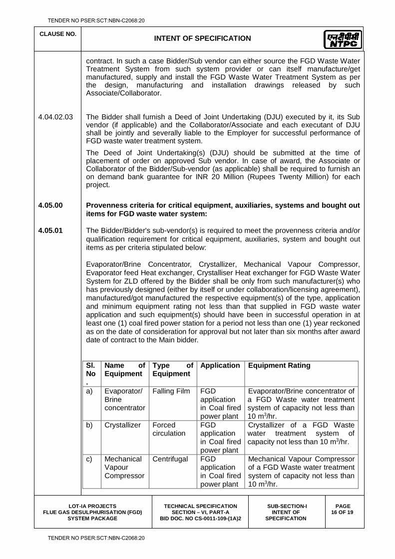
contract. In such a case Bidder/Sub vendor can either source the FGD Waste Water Treatment System from such system provider or can itself manufacture/get manufactured, supply and install the FGD Waste Water Treatment System as per the design, manufacturing and installation drawings released by such Associate/Collaborator.
4.04.02.03 The Bidder shall furnish a Deed of Joint Undertaking (DJU) executed by it, its Sub
vendor (if applicable) and the Collaborator/Associate and each executant of DJU shall be jointly and severally liable to the Employer for successful performance of FGD waste water treatment system. The Deed of Joint Undertaking(s) (DJU) should be submitted at the time of placement of order on approved Sub vendor. In case of award, the Associate or Collaborator of the Bidder/Sub-vendor (as applicable) shall be required to furnish an on demand bank guarantee for INR 20 Million (Rupees Twenty Million) for each project.
4.05.00 Provenness criteria for critical equipment, auxiliaries, systems and bought out
items for FGD waste water system: 4.05.01 The Bidder/Bidder's sub-vendor(s) is required to meet the provenness criteria and/or
qualification requirement for critical equipment, auxiliaries, system and bought out items as per criteria stipulated below:
Evaporator/Brine Concentrator, Crystallizer, Mechanical Vapour Compressor, Evaporator feed Heat exchanger, Crystalliser Heat exchanger for FGD Waste Water System for ZLD offered by the Bidder shall be only from such manufacturer(s) who has previously designed (either by itself or under collaboration/licensing agreement), manufactured/got manufactured the respective equipment(s) of the type, application and minimum equipment rating not less than that supplied in FGD waste water application and such equipment(s) should have been in successful operation in at least one (1) coal fired power station for a period not less than one (1) year reckoned as on the date of consideration for approval but not later than six months after award date of contract to the Main bidder.
Sl. No.
Name of Equipment
Type of Equipment
Application Equipment Rating
a) Evaporator/Brine concentrator
Falling Film FGD application in Coal fired power plant
Evaporator/Brine concentrator of a FGD Waste water treatment system of capacity not less than 10 m3/hr.
b) Crystallizer Forced circulation
FGD application in Coal fired power plant
Crystallizer of a FGD Waste water treatment system of capacity not less than 10 m3/hr.
c) Mechanical Vapour Compressor
Centrifugal FGD application in Coal fired power plant
Mechanical Vapour Compressor of a FGD Waste water treatment system of capacity not less than 10 m3/hr.
TENDER NO PSER:SCT:NBN-C2068:20
TENDER NO PSER:SCT:NBN-C2068:20
CLAUSE NO.
INTENT OF SPECIFICATION
LOT-IA PROJECTS
FLUE GAS DESULPHURISATION (FGD) SYSTEM PACKAGE
TECHNICAL SPECIFICATION SECTION – VI, PART-A
BID DOC. NO CS-0011-109-(1A)2
SUB-SECTION-I INTENT OF
SPECIFICATION
PAGE 17 OF 19
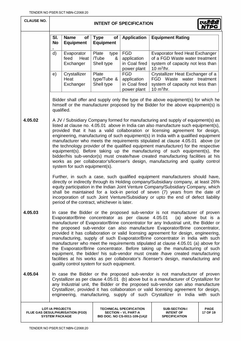
Sl. No.
Name of Equipment
Type of Equipment
Application Equipment Rating
d) Evaporator feed Heat Exchanger
Plate type /Tube & Shell type
FGD application in Coal fired power plant
Evaporator feed Heat Exchanger of a FGD Waste water treatment system of capacity not less than 10 m3/hr.
e) Crystallizer Heat Exchanger
Plate type/Tube & Shell type
FGD application in Coal fired power plant
Crystallizer Heat Exchanger of a FGD Waste water treatment system of capacity not less than 10 m3/hr.
Bidder shall offer and supply only the type of the above equipment(s) for which he himself or the manufacturer proposed by the Bidder for the above equipment(s) is qualified.
4.05.02 A JV / Subsidiary Company formed for manufacturing and supply of equipment(s) as
listed at clause no. 4.05.01 above in India can also manufacture such equipment(s), provided that it has a valid collaboration or licensing agreement for design, engineering, manufacturing of such equipment(s) in India with a qualified equipment manufacturer who meets the requirements stipulated at clause 4.05.01 above (or the technology provider of the qualified equipment manufacturer) for the respective equipment(s). Before taking up the manufacturing of such equipment(s), the bidder/his sub-vendor(s) must create/have created manufacturing facilities at his works as per collaborator’s/licenser's design, manufacturing and quality control system for such equipment(s).
Further, in such a case, such qualified equipment manufacturers should have, directly or indirectly through its Holding company/Subsidiary company, at least 26% equity participation in the Indian Joint Venture Company/Subsidiary Company, which shall be maintained for a lock-in period of seven (7) years from the date of incorporation of such Joint Venture/Subsidiary or upto the end of defect liability period of the contract, whichever is later.
4.05.03 In case the Bidder or the proposed sub-vendor is not manufacturer of proven
Evaporator/Brine concentrator as per clause 4.05.01 (a) above but is a manufacturer of Evaporator/Brine concentrator for any Industrial unit, the Bidder or the proposed sub-vendor can also manufacture Evaporator/Brine concentrator, provided it has collaboration or valid licensing agreement for design, engineering, manufacturing, supply of such Evaporator/Brine concentrator in India with such manufacturer who meet the requirements stipulated at clause 4.05.01 (a) above for the Evaporator/Brine concentrator. Before taking up the manufacturing of such equipment, the bidder/ his sub-vendor must create /have created manufacturing facilities at his works as per collaborator’s /licenser's design, manufacturing and quality control system for such equipment.
4.05.04 In case the Bidder or the proposed sub-vendor is not manufacturer of proven
Crystallizer as per clause 4.05.01 (b) above but is a manufacturer of Crystallizer for any Industrial unit, the Bidder or the proposed sub-vendor can also manufacture Crystallizer, provided it has collaboration or valid licensing agreement for design, engineering, manufacturing, supply of such Crystallizer in India with such
TENDER NO PSER:SCT:NBN-C2068:20
TENDER NO PSER:SCT:NBN-C2068:20
CLAUSE NO.
INTENT OF SPECIFICATION
LOT-IA PROJECTS
FLUE GAS DESULPHURISATION (FGD) SYSTEM PACKAGE
TECHNICAL SPECIFICATION SECTION – VI, PART-A
BID DOC. NO CS-0011-109-(1A)2
SUB-SECTION-I INTENT OF
SPECIFICATION
PAGE 18 OF 19
manufacturer who meet the requirements stipulated at clause 4.05.01 (a) above for the Crystallizer. Before taking up the manufacturing of such equipment, the bidder/ his sub-vendor must create /have created manufacturing facilities at his works as per collaborator’s /licenser's design, manufacturing and quality control system for such equipment.
4.05.05 In case the Bidder or the proposed sub-vendor is not manufacturer of proven
Mechanical Vapour Compressor as per clause 4.05.01 (c) above but is a manufacturer of Compressor, the Bidder or the proposed sub-vendor can also manufacture Mechanical Vapour Compressor, provided it has collaboration or valid licensing agreement for design, engineering, manufacturing, supply of such Mechanical Vapour Compressor in India with such manufacturer who meet the requirements stipulated at clause 4.05.01 (c) above for the Mechanical Vapour Compressor. Before taking up the manufacturing of such equipment, the bidder/ his sub-vendor must create /have created manufacturing facilities at his works as per collaborator’s /licenser's design, manufacturing and quality control system for such equipment.
4.05.06 In case the Bidder or the proposed sub-vendor is not manufacturer of proven
Evaporator feed Heat Exchanger as per clause 4.05.01 (d) above but is a manufacturer of Heat exchanger, the Bidder or the proposed sub-vendor can also manufacture Evaporator feed Heat Exchanger, provided it has collaboration or valid licensing agreement for design, engineering, manufacturing, supply of such Evaporator feed Heat Exchanger in India with such manufacturer who meet the requirements stipulated at clause 4.05.01 (d) above for the Evaporator feed Heat Exchanger. Before taking up the manufacturing of such equipment, the bidder/ his sub-vendor must create /have created manufacturing facilities at his works as per collaborator’s /licenser's design, manufacturing and quality control system for such equipment.
4.05.07 In case the Bidder or the proposed sub-vendor is not manufacturer of proven
Crystallizer Heat Exchanger as per clause 4.05.01 (e) above but is a manufacturer of Heat exchanger, the Bidder or the proposed sub-vendor can also manufacture Crystallizer Heat Exchanger, provided it has collaboration or valid licensing agreement for design, engineering, manufacturing, supply of such Crystallizer Heat Exchanger in India with such manufacturer who meet the requirements stipulated at clause 4.05.01 (e) above for the Crystallizer Heat Exchanger. Before taking up the manufacturing of such equipment, the bidder/ his sub-vendor must create /have created manufacturing facilities at his works as per collaborator’s /licenser's design, manufacturing and quality control system for such equipment.
4.05.08 Before taking up the manufacturing of such equipment(s) as per clause 4.05.03,
4.05.04, 4.05.05, 4.05.06, 4.05.07 above, the Bidder/its sub vendor(s) must create (or should have created) manufacturing and testing facilities at its works as per Collaborator/licenser’s design, manufacturing and quality control system for such equipments duly certified by the Collaborator/licensor. Further, the Collaborator / Licenser shall provide (or should have provided) all design, design calculation, manufacturing drawings and must provide (or should have provided) technical and quality surveillance assistance and supervision during manufacturing, erection, testing, commissioning of equipments.
TENDER NO PSER:SCT:NBN-C2068:20
TENDER NO PSER:SCT:NBN-C2068:20
CLAUSE NO.
INTENT OF SPECIFICATION
LOT-IA PROJECTS
FLUE GAS DESULPHURISATION (FGD) SYSTEM PACKAGE
TECHNICAL SPECIFICATION SECTION – VI, PART-A
BID DOC. NO CS-0011-109-(1A)2
SUB-SECTION-I INTENT OF
SPECIFICATION
PAGE 19 OF 19
4.05.09 Bidder shall offer and supply only the type of the above equipment(s) for which it, itself or the manufacturer / Collaborator(s) / Licenser(s) proposed by the Bidder for the above equipment(s) is qualified.
4.05.10 The Employer reserves the right to fully satisfy himself regarding capability and
capacity of Bidder / its sub-vendor(s) and the proposed arrangement and may prescribe additional requirement before allowing manufacture of the equipment listed above for this contract.
Note to clause 4.04.00 & 4.05.00
Whenever the term 'coal fired' is appearing above, "Coal" shall be deemed to also include bituminous coal/brown coal/Anthracite Coal/lignite.
4.06.00 Agency for Wet Stack Flow Model Study
Wet Stack Flow Model Study shall be carried out by an agency which has successfully performed at least two (2) flow model studies, in separate coal fired power plants, of wet stack installed after wet limestone based FGD Absorber (without reheating of cleaned flue gas), and based on the studies developed at least two (2) wet stack liquid collection systems which are in successful operation for a period of at least two (2) years reckoned as on the date of consideration for approval but not later than six months after award date of contract to the Main bidder.
4.07.00 Balance equipments/ systems
The Bidder at his option can source the balance of plant equipment/systems not covered in clause 4.01.00, 4.02.00, 4.03.00, 4.04.00, 4.05.00 & 4.06.00 above. However for such balance of plant equipment/systems, the Employer reserves the rights to satisfy himself on the provenness of the equipment and capability and capacity of the manufacturers.
4.08.00 Notwithstanding anything stated above, the Employer reserves the right to assess the capabilities and capacity of the Bidder/his collaborators/ licenser/ his sub-contractors to perform the contract, should the circumstances warrant such assessment in the overall interest of the Employer.
4.09.00 To enable the approval of sub-vendors, the Bidder shall provide all necessary data such as type, design, make, capacity, duty conditions, date of commissioning/ operation etc.
TENDER NO PSER:SCT:NBN-C2068:20
TENDER NO PSER:SCT:NBN-C2068:20

LOT-IA PROJECTS FLUE GAS DESULPHURISATION (FGD) SYSTEM PACKAGE
TECHNICAL SPECIFICATION
SECTION-VI
BID DOCUMENT NO.: CS-0011-109(1A)-2
SUB-SECTION-II
PROJECT INFORMATION (CHAPTERS FOR EACH 11 PROJECTS ENCLOSED SEPERATELY)
TENDER NO PSER:SCT:NBN-C2068:20
TENDER NO PSER:SCT:NBN-C2068:20

LOT-IA PROJECTS FLUE GAS DESULPHURISATION (FGD) SYSTEM PACKAGE
TECHNICAL SPECIFICATION
SECTION-VI
BID DOCUMENT NO.: CS-0011-109(1A)-2
SUB-SECTION-III
SCOPE OF SUPPLY & SERVICES
TENDER NO PSER:SCT:NBN-C2068:20
TENDER NO PSER:SCT:NBN-C2068:20
CLAUSE NO.
SCOPE OF SUPPLY & SERVICES
LOT-IA PROJECTS
FLUE GAS DESULPHURISATION (FGD) SYSTEM
PACKAGE
TECHNICAL SPECIFICATION
SECTION-VI
BID DOCUMENT NO.: CS-0011-109(1A)-2
PART-A
SUB-SECTION-III
SCOPE OF SUPPLY &
SERVICES
PAGE 1 OF 5
1.00.00 SCOPE OF SUPPLY AND SERVICES
The scope of work for the equipment and accessories to be furnished in accordance with this specification shall include design, engineering, manufacture, inspection and testing at supplier's works, packing, forwarding to site, unloading, pre- assembly, assembly, erection, supervision, pre-commissioning, testing and commissioning and performance testing of the equipment/system and works indicated in this Sub-section of the technical specification. Any item or works though not specifically mentioned in this specification but needed to complete the equipment & systems to meet the intent of the Specification shall also be furnished, unless specifically mentioned under “Exclusion” in Sub-Section-IV of Part-A, Section-VI of the Technical Specifications.
1.01.00 The scope of supply & services is detailed out in the following Sub-Sections. Sub-Section III A - Mechanical equipment and associated systems III B - Electrical Systems III C - C&I systems III D - Civil works 1.02.00 Scope of supply of the Contractor includes mandatory spares, start-up and
commissioning spares and consumables. The general requirements in respect of various types of spares is given in Sub-Section-VII, Part-A of Technical Specification.
1.03.00 Tests The scope of the Bidder includes all shop tests, type tests, site tests, routine tests,
etc., fulfillment of complete quality assurance & inspection requirements and related activities for all the equipment & systems covered under the scope of work of Bidder as per the stipulations of Technical Specifications.
1.04.00 Paints / Painting
The Contractor's scope of work includes supply of paints and painting of all equipments and structures as per the Employer’s standard color coding scheme which shall be furnished to the Contractor during detail engineering stage. The painting of various components shall comply with the requirements stipulated in different part of this specification. However, for components where no specific requirement is stipulated, the painting conforming to the requirements stipulated below shall be provided.
TENDER NO PSER:SCT:NBN-C2068:20
TENDER NO PSER:SCT:NBN-C2068:20
CLAUSE NO.
SCOPE OF SUPPLY & SERVICES
LOT-IA PROJECTS
FLUE GAS DESULPHURISATION (FGD) SYSTEM
PACKAGE
TECHNICAL SPECIFICATION
SECTION-VI
BID DOCUMENT NO.: CS-0011-109(1A)-2
PART-A
SUB-SECTION-III
SCOPE OF SUPPLY &
SERVICES
PAGE 2 OF 5
(i) Surface preparation shall be blast cleaned conforming to Sa 2-1/2 Swiss
Standard. (ii) Primer coat shall consist of epoxy resin based zinc phosphate primer
having minimum DFT of 100 microns. (iii) Intermediate coat (or under coat) shall consist of epoxy resin based
paint pigmented with Titanium dioxide with minimum DFT of 100 microns. (iv) Top coat shall consist of one coat of epoxy paint suitable pigmented of
approved shade and colour with glossy finish and DFT of 75 microns. Additionally finishing coat of polyurethane of minimum DFT of 25 microns shall be provided.
1.05.00 Pre-commissioning and Commissioning Activities 1.05.01 Contractor’s Scope shall include all pre-commissioning and commissioning activities,
required for successful performance of all equipments and systems under this package. Contractor's scope shall also include supply of all materials and services including the following for successful conductance of pre-commissioning and commissioning activities:
1.05.02 Complete pre-commissioning work including tests of facilities and all other tests as mutually agreed in the Contractor’s quality assurance program as well as those identified in the specification.
1.05.03 Commissioning and initial operation of the facilities. 1.05.04 Supply of all consumables as may be required for above pre-commissioning/
commissioning activities 1.05.05 Supply of all temporary equipment such as piping including supports, valves,
blowers and all necessary instrumentation for successful conductance of pre-commissioning and commissioning activities. All temporary equipments, blowers, valves etc. brought to sites, by the Contractor for pre-commissioning/commissioning purpose shall be in good working condition to ensure its safe and reliable operation at site. All such temporary equipments/components shall be brought to site at least three (3) months prior to commencement of relevant pre-commissioning/ commissioning activities. On receipt of the temporary equipments/components at site, the same shall be inspected by the Employer to ensure its safe and reliable operation and if in the opinion of the Employer the temporary equipments/ components are not in satisfactory conditions to ensure it's safe and reliable operation the same shall be immediately replaced by the Contractor.
1.05.06 The temporary equipments specifically brought by the Contractor solely for the pre-
commissioning and commissioning work shall on completion of these activities, remain the property of the Contractor.
TENDER NO PSER:SCT:NBN-C2068:20
TENDER NO PSER:SCT:NBN-C2068:20
CLAUSE NO.
SCOPE OF SUPPLY & SERVICES
LOT-IA PROJECTS
FLUE GAS DESULPHURISATION (FGD) SYSTEM
PACKAGE
TECHNICAL SPECIFICATION
SECTION-VI
BID DOCUMENT NO.: CS-0011-109(1A)-2
PART-A
SUB-SECTION-III
SCOPE OF SUPPLY &
SERVICES
PAGE 3 OF 5
1.05.07 The selection of material of all the temporary equipments/ instruments shall be compatible with the service conditions expected during pre-commissioning/ commissioning activities.
1.05.08 All temporary equipments and instruments shall be clearly listed out in the bid. 1.05.09 Supply of all labour, skilled/ semi skilled supervisors, engineers and any other
manpower. 1.05.10 The scope of Contractor shall also include necessary approach & Platforms for all
the instruments required during commissioning and testing. These approach platforms shall be provided to meet all required safety norms and these shall be permanent nature.
1.06.00 First Fill of Consumables, Oils & Lubricants All the first fill and one year’s topping requirements of consumable such as grease,
oil, lubricants servo fluids etc. which will be required to put the equipments covered under the scope of specifications, into successful commissioning/initial operation and to establish completion to facilities shall be furnished by the Contractor, unless specifically excluded under the Exclusions in these specifications and documents. Limestone shall be supplied by the Employer.
1.07.00 Guarantee Tests The Guarantee tests for various equipment and systems shall be carried out as
specified under Sub-Section-VI, Part-A of Technical Specification. All special equipment, tools and tackles, instruments, measuring devices required for the successful conductance of Guarantee Tests shall be provided by the Contractor, free of cost. All costs associated with the tests shall be included in bid price.
1.08.00 Spare Parts The Contractor’s scope of supply includes all the necessary commissioning spares,
mandatory spares as described Sub-Section-VII / Part-A in the schedule of spare parts. The Employer reserves the right to finalize the exact quantities of the spare parts and effect price adjustment on the basis of the rates quoted by the Contractor. The Spare ordered by Employer shall be delivered at the site as per agreed delivery schedule.
1.08.01 Mandatory Spares The Bidder shall indicate the prices for each & every item (except for items not
applicable to the Bidder’s design) in the ‘Schedule of mandatory spares’ whether or not he considers it necessary for the Employer to have such spares. If the Bidder fails to comply with the above or fails to quote the price of any spares items, the cost
TENDER NO PSER:SCT:NBN-C2068:20
TENDER NO PSER:SCT:NBN-C2068:20
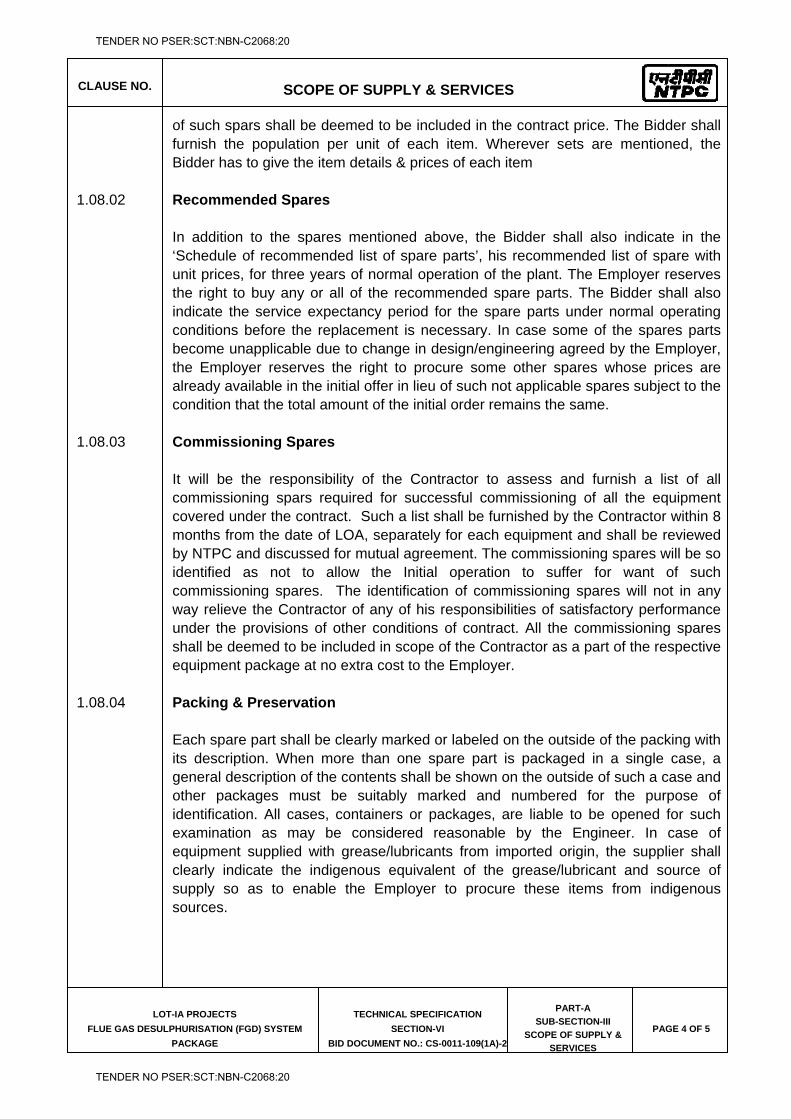
CLAUSE NO.
SCOPE OF SUPPLY & SERVICES
LOT-IA PROJECTS
FLUE GAS DESULPHURISATION (FGD) SYSTEM
PACKAGE
TECHNICAL SPECIFICATION
SECTION-VI
BID DOCUMENT NO.: CS-0011-109(1A)-2
PART-A
SUB-SECTION-III
SCOPE OF SUPPLY &
SERVICES
PAGE 4 OF 5
of such spars shall be deemed to be included in the contract price. The Bidder shall furnish the population per unit of each item. Wherever sets are mentioned, the Bidder has to give the item details & prices of each item
1.08.02 Recommended Spares In addition to the spares mentioned above, the Bidder shall also indicate in the
‘Schedule of recommended list of spare parts’, his recommended list of spare with unit prices, for three years of normal operation of the plant. The Employer reserves the right to buy any or all of the recommended spare parts. The Bidder shall also indicate the service expectancy period for the spare parts under normal operating conditions before the replacement is necessary. In case some of the spares parts become unapplicable due to change in design/engineering agreed by the Employer, the Employer reserves the right to procure some other spares whose prices are already available in the initial offer in lieu of such not applicable spares subject to the condition that the total amount of the initial order remains the same.
1.08.03 Commissioning Spares It will be the responsibility of the Contractor to assess and furnish a list of all
commissioning spars required for successful commissioning of all the equipment covered under the contract. Such a list shall be furnished by the Contractor within 8 months from the date of LOA, separately for each equipment and shall be reviewed by NTPC and discussed for mutual agreement. The commissioning spares will be so identified as not to allow the Initial operation to suffer for want of such commissioning spares. The identification of commissioning spares will not in any way relieve the Contractor of any of his responsibilities of satisfactory performance under the provisions of other conditions of contract. All the commissioning spares shall be deemed to be included in scope of the Contractor as a part of the respective equipment package at no extra cost to the Employer.
1.08.04 Packing & Preservation Each spare part shall be clearly marked or labeled on the outside of the packing with
its description. When more than one spare part is packaged in a single case, a general description of the contents shall be shown on the outside of such a case and other packages must be suitably marked and numbered for the purpose of identification. All cases, containers or packages, are liable to be opened for such examination as may be considered reasonable by the Engineer. In case of equipment supplied with grease/lubricants from imported origin, the supplier shall clearly indicate the indigenous equivalent of the grease/lubricant and source of supply so as to enable the Employer to procure these items from indigenous sources.
TENDER NO PSER:SCT:NBN-C2068:20
TENDER NO PSER:SCT:NBN-C2068:20
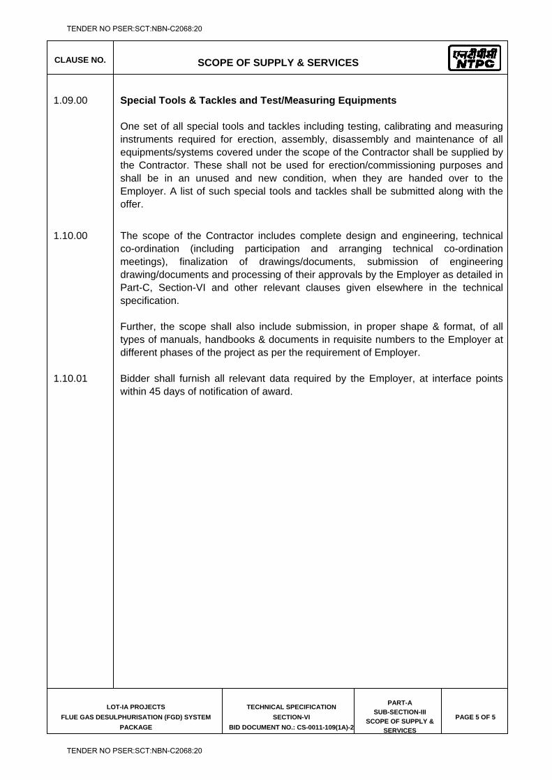
CLAUSE NO.
SCOPE OF SUPPLY & SERVICES
LOT-IA PROJECTS
FLUE GAS DESULPHURISATION (FGD) SYSTEM
PACKAGE
TECHNICAL SPECIFICATION
SECTION-VI
BID DOCUMENT NO.: CS-0011-109(1A)-2
PART-A
SUB-SECTION-III
SCOPE OF SUPPLY &
SERVICES
PAGE 5 OF 5
1.09.00 Special Tools & Tackles and Test/Measuring Equipments One set of all special tools and tackles including testing, calibrating and measuring
instruments required for erection, assembly, disassembly and maintenance of all equipments/systems covered under the scope of the Contractor shall be supplied by the Contractor. These shall not be used for erection/commissioning purposes and shall be in an unused and new condition, when they are handed over to the Employer. A list of such special tools and tackles shall be submitted along with the offer.
1.10.00 The scope of the Contractor includes complete design and engineering, technical
co-ordination (including participation and arranging technical co-ordination meetings), finalization of drawings/documents, submission of engineering drawing/documents and processing of their approvals by the Employer as detailed in Part-C, Section-VI and other relevant clauses given elsewhere in the technical specification.
Further, the scope shall also include submission, in proper shape & format, of all
types of manuals, handbooks & documents in requisite numbers to the Employer at different phases of the project as per the requirement of Employer.
1.10.01 Bidder shall furnish all relevant data required by the Employer, at interface points
within 45 days of notification of award.
TENDER NO PSER:SCT:NBN-C2068:20
TENDER NO PSER:SCT:NBN-C2068:20

LOT-IA PROJECTS FLUE GAS DESULPHURISATION (FGD) SYSTEM PACKAGE
TECHNICAL SPECIFICATION
SECTION-VI
BID DOCUMENT NO.: CS-0011-109(1A)-2
SUB-SECTION-III-A
MECHANICAL EQUIPMENTS & SYSTEMS
TENDER NO PSER:SCT:NBN-C2068:20
TENDER NO PSER:SCT:NBN-C2068:20

LOT-IA PROJECTS FLUE GAS DESULPHURISATION (FGD) SYSTEM PACKAGE
TECHNICAL SPECIFICATION
SECTION-VI
BID DOCUMENT NO.: CS-0011-109(1A)-2
SUB-SECTION-III-A1
FLUE GAS DESULPHURISATION SYSTEM
TENDER NO PSER:SCT:NBN-C2068:20
TENDER NO PSER:SCT:NBN-C2068:20
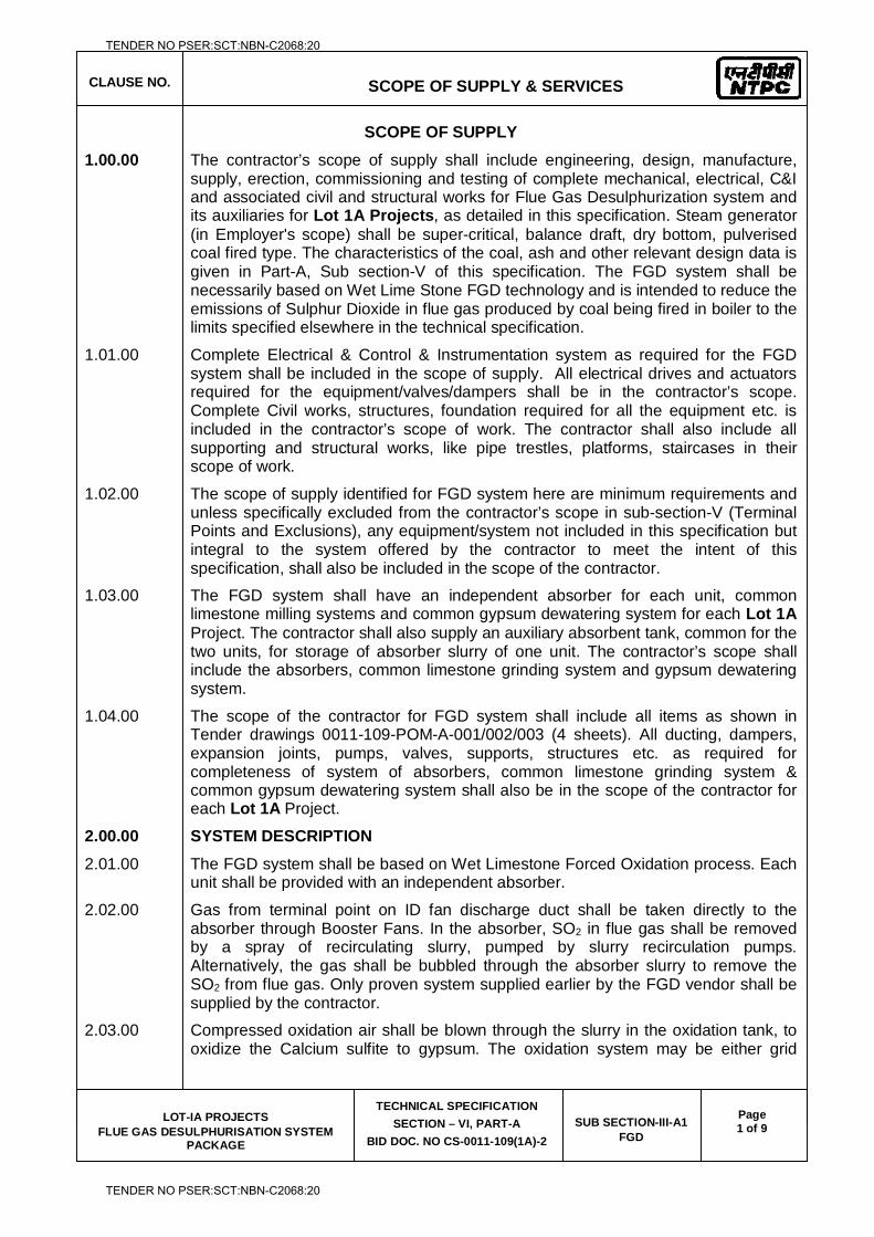
CLAUSE NO.
SCOPE OF SUPPLY & SERVICES
LOT-IA PROJECTS FLUE GAS DESULPHURISATION SYSTEM
PACKAGE
TECHNICAL SPECIFICATION
SECTION – VI, PART-A
BID DOC. NO CS-0011-109(1A)-2
SUB SECTION-III-A1 FGD
Page 1 of 9
SCOPE OF SUPPLY
1.00.00 The contractor’s scope of supply shall include engineering, design, manufacture, supply, erection, commissioning and testing of complete mechanical, electrical, C&I and associated civil and structural works for Flue Gas Desulphurization system and its auxiliaries for Lot 1A Projects, as detailed in this specification. Steam generator (in Employer's scope) shall be super-critical, balance draft, dry bottom, pulverised coal fired type. The characteristics of the coal, ash and other relevant design data is given in Part-A, Sub section-V of this specification. The FGD system shall be necessarily based on Wet Lime Stone FGD technology and is intended to reduce the emissions of Sulphur Dioxide in flue gas produced by coal being fired in boiler to the limits specified elsewhere in the technical specification.
1.01.00 Complete Electrical & Control & Instrumentation system as required for the FGD system shall be included in the scope of supply. All electrical drives and actuators required for the equipment/valves/dampers shall be in the contractor’s scope. Complete Civil works, structures, foundation required for all the equipment etc. is included in the contractor’s scope of work. The contractor shall also include all supporting and structural works, like pipe trestles, platforms, staircases in their scope of work.
1.02.00 The scope of supply identified for FGD system here are minimum requirements and unless specifically excluded from the contractor’s scope in sub-section-V (Terminal Points and Exclusions), any equipment/system not included in this specification but integral to the system offered by the contractor to meet the intent of this specification, shall also be included in the scope of the contractor.
1.03.00 The FGD system shall have an independent absorber for each unit, common limestone milling systems and common gypsum dewatering system for each Lot 1A Project. The contractor shall also supply an auxiliary absorbent tank, common for the two units, for storage of absorber slurry of one unit. The contractor’s scope shall include the absorbers, common limestone grinding system and gypsum dewatering system.
1.04.00 The scope of the contractor for FGD system shall include all items as shown in Tender drawings 0011-109-POM-A-001/002/003 (4 sheets). All ducting, dampers, expansion joints, pumps, valves, supports, structures etc. as required for completeness of system of absorbers, common limestone grinding system & common gypsum dewatering system shall also be in the scope of the contractor for each Lot 1A Project.
2.00.00 SYSTEM DESCRIPTION
2.01.00 The FGD system shall be based on Wet Limestone Forced Oxidation process. Each unit shall be provided with an independent absorber.
2.02.00 Gas from terminal point on ID fan discharge duct shall be taken directly to the absorber through Booster Fans. In the absorber, SO2 in flue gas shall be removed by a spray of recirculating slurry, pumped by slurry recirculation pumps. Alternatively, the gas shall be bubbled through the absorber slurry to remove the SO2 from flue gas. Only proven system supplied earlier by the FGD vendor shall be supplied by the contractor.
2.03.00 Compressed oxidation air shall be blown through the slurry in the oxidation tank, to oxidize the Calcium sulfite to gypsum. The oxidation system may be either grid
TENDER NO PSER:SCT:NBN-C2068:20
TENDER NO PSER:SCT:NBN-C2068:20
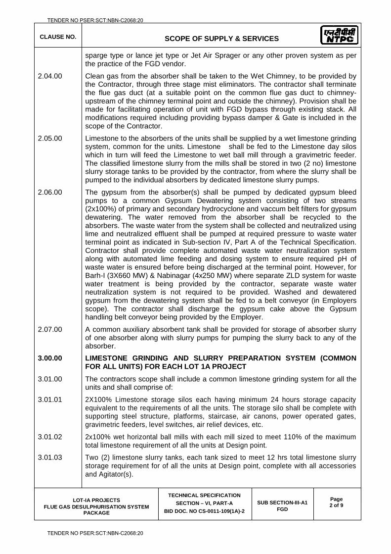
CLAUSE NO.
SCOPE OF SUPPLY & SERVICES
LOT-IA PROJECTS FLUE GAS DESULPHURISATION SYSTEM
PACKAGE
TECHNICAL SPECIFICATION
SECTION – VI, PART-A
BID DOC. NO CS-0011-109(1A)-2
SUB SECTION-III-A1 FGD
Page 2 of 9
sparge type or lance jet type or Jet Air Sprager or any other proven system as per the practice of the FGD vendor.
2.04.00 Clean gas from the absorber shall be taken to the Wet Chimney, to be provided by the Contractor, through three stage mist eliminators. The contractor shall terminate the flue gas duct (at a suitable point on the common flue gas duct to chimney-upstream of the chimney terminal point and outside the chimney). Provision shall be made for facilitating operation of unit with FGD bypass through existing stack. All modifications required including providing bypass damper & Gate is included in the scope of the Contractor.
2.05.00 Limestone to the absorbers of the units shall be supplied by a wet limestone grinding system, common for the units. Limestone shall be fed to the Limestone day silos which in turn will feed the Limestone to wet ball mill through a gravimetric feeder. The classified limestone slurry from the mills shall be stored in two (2 no) limestone slurry storage tanks to be provided by the contractor, from where the slurry shall be pumped to the individual absorbers by dedicated limestone slurry pumps.
2.06.00 The gypsum from the absorber(s) shall be pumped by dedicated gypsum bleed pumps to a common Gypsum Dewatering system consisting of two streams (2x100%) of primary and secondary hydrocyclone and vaccum belt filters for gypsum dewatering. The water removed from the absorber shall be recycled to the absorbers. The waste water from the system shall be collected and neutralized using lime and neutralized effluent shall be pumped at required pressure to waste water terminal point as indicated in Sub-section IV, Part A of the Technical Specification. Contractor shall provide complete automated waste water neutralization system along with automated lime feeding and dosing system to ensure required pH of waste water is ensured before being discharged at the terminal point. However, for Barh-I (3X660 MW) & Nabinagar (4x250 MW) where separate ZLD system for waste water treatment is being provided by the contractor, separate waste water neutralization system is not required to be provided. Washed and dewatered gypsum from the dewatering system shall be fed to a belt conveyor (in Employers scope). The contractor shall discharge the gypsum cake above the Gypsum handling belt conveyor being provided by the Employer.
2.07.00 A common auxiliary absorbent tank shall be provided for storage of absorber slurry of one absorber along with slurry pumps for pumping the slurry back to any of the absorber.
3.00.00 LIMESTONE GRINDING AND SLURRY PREPARATION SYSTEM (COMMON FOR ALL UNITS) FOR EACH LOT 1A PROJECT
3.01.00 The contractors scope shall include a common limestone grinding system for all the units and shall comprise of:
3.01.01 2X100% Limestone storage silos each having minimum 24 hours storage capacity equivalent to the requirements of all the units. The storage silo shall be complete with supporting steel structure, platforms, staircase, air canons, power operated gates, gravimetric feeders, level switches, air relief devices, etc.
3.01.02 2x100% wet horizontal ball mills with each mill sized to meet 110% of the maximum total limestone requirement of all the units at Design point.
3.01.03 Two (2) limestone slurry tanks, each tank sized to meet 12 hrs total limestone slurry storage requirement for of all the units at Design point, complete with all accessories and Agitator(s).
TENDER NO PSER:SCT:NBN-C2068:20
TENDER NO PSER:SCT:NBN-C2068:20
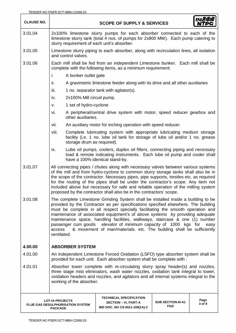
CLAUSE NO.
SCOPE OF SUPPLY & SERVICES
LOT-IA PROJECTS FLUE GAS DESULPHURISATION SYSTEM
PACKAGE
TECHNICAL SPECIFICATION
SECTION – VI, PART-A
BID DOC. NO CS-0011-109(1A)-2
SUB SECTION-III-A1 FGD
Page 3 of 9
3.01.04 2x100% limestone slurry pumps for each absorber connected to each of the limestone slurry tank (total 4 nos. of pumps for 2x800 MW). Each pump catering to slurry requirement of each unit’s absorber.
3.01.05 Limestone slurry piping to each absorber, along with recirculation lines, all isolation and control valves.
3.01.06 Each mill shall be fed from an independent Limestone bunker. Each mill shall be complete with the following items, as a minimum requirement:
i. A bunker outlet gate
ii. A gravimetric limestone feeder along with its drive and all other auxiliaries
iii. 1 no. separator tank with agitator(s).
iv. 2x100% Mill circuit pump.
v. 1 set of hydro-cyclone
vi. A peripheral/central drive system with motor, speed reducer gearbox and other auxiliaries.
vii. An auxiliary motor for inching operation with speed reducer.
viii. Complete lubricating system with appropriate lubricating medium storage facility (i.e. 1 no. lube oil tank for storage of lube oil and/or 1 no. grease storage drum as required).
ix. Lube oil pumps, coolers, duplex oil filters, connecting piping and necessary load & remote indicating instruments. Each lube oil pump and cooler shall have a 100% identical stand-by.
3.01.07 All connecting pipes / chutes along with necessary valves between various systems of the mill and from hydro-cyclone to common slurry storage tanks shall also be in the scope of the contractor. Necessary pipes, pipe supports, trestles etc. as required for the routing of the pipes shall be under the contractor’s scope. Any item not included above but necessary for safe and reliable operation of the milling system proposed by the contractor shall also be in the contractors’ scope.
3.01.08 The complete Limestone Grinding System shall be installed inside a building to be provided by the Contractor as per specifications specified elsewhere. The building must be complete in all respect specially facilitating the smooth operation and maintenance of associated equipment’s of above systems by providing adequate maintenance space, handling facilities, walkways, staircase & one (1) number passenger cum goods elevator of minimum capacity of 1000 kgs for easy access & movement of man/materials. etc. The building shall be sufficiently ventilated.
4.00.00 ABSORBER SYSTEM
4.01.00 An independent Limestone Forced Oxidation (LSFO) type absorber system shall be provided for each unit. Each absorber system shall be complete with :
4.01.01 Absorber tower complete with re-circulating slurry spray header(s) and nozzles, three stage mist eliminators, wash water nozzles, oxidation tank integral to tower, oxidation headers and nozzles, and agitators and all internal systems integral to the working of the absorber.
TENDER NO PSER:SCT:NBN-C2068:20
TENDER NO PSER:SCT:NBN-C2068:20
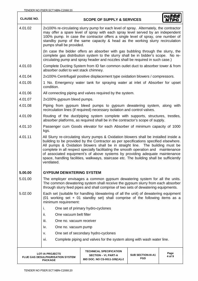
CLAUSE NO.
SCOPE OF SUPPLY & SERVICES
LOT-IA PROJECTS FLUE GAS DESULPHURISATION SYSTEM
PACKAGE
TECHNICAL SPECIFICATION
SECTION – VI, PART-A
BID DOC. NO CS-0011-109(1A)-2
SUB SECTION-III-A1 FGD
Page 4 of 9
4.01.02 2x100% re-circulating slurry pump for each level of spray. Alternately, the contractor may offer a spare level of spray with each spray level served by an independent 100% pump. In case the contractor offers a single level of spray, one number of standby pump of the same capacity & head as the working slurry recirculation pumps shall be provided.
(In case the bidder offers an absorber with gas bubbling through the slurry, the complete gas distribution system to the slurry shall be in bidder’s scope. No re-circulating pump and spray header and nozzles shall be required in such case.)
4.01.03 Complete Ducting System from ID fan common outlet duct to absorber tower & from absorber outlet to wet stack chimney.
4.01.04 2x100% Centrifugal/ positive displacement type oxidation blowers / compressors.
4.01.05 1 No. Emergency water tank for spraying water at inlet of Absorber for upset condition.
4.01.06 All connecting piping and valves required by the system.
4.01.07 2x100% gypsum bleed pumps.
4.01.08 Piping from gypsum bleed pumps to gypsum dewatering system, along with recirculation lines (if required) necessary isolation and control valves.
4.01.09 Routing of the duct/piping system complete with supports, structures, trestles, absorber platforms, as required shall be in the contractor’s scope of supply.
4.01.10 Passenger cum Goods elevator for each Absorber of minimum capacity of 1000 kgs.
4.01.11 All Slurry re-circulating slurry pumps & Oxidation blowers shall be installed inside a building to be provided by the Contractor as per specifications specified elsewhere. All pumps & Oxidation blowers shall be in straight line. The building must be complete in all respect specially facilitating the smooth operation and maintenance of associated equipment’s of above systems by providing adequate maintenance space, handling facilities, walkways, staircase etc. The building shall be sufficiently ventilated.
5.00.00 GYPSUM DEWATERING SYSTEM
5.01.00 The employer envisages a common gypsum dewatering system for all the units. The common dewatering system shall receive the gypsum slurry from each absorber through slurry feed pipes and shall comprise of two sets of dewatering equipments.
5.02.00 Each set (suitable for handling /dewatering of all the unit) of dewatering equipment (01 working set + 01 standby set) shall comprise of the following items as a minimum requirement:
i. One set of primary hydro-cyclones
ii. One vacuum belt filter
iii. One no. vacuum receiver
iv. One no. vacuum pump
v. One set of secondary hydro-cyclones
vi. Complete piping and valves for the system along with wash water line.
TENDER NO PSER:SCT:NBN-C2068:20
TENDER NO PSER:SCT:NBN-C2068:20
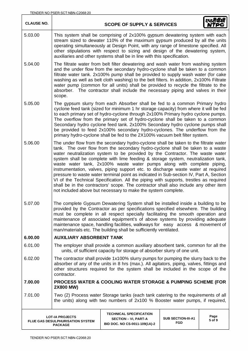
CLAUSE NO.
SCOPE OF SUPPLY & SERVICES
LOT-IA PROJECTS FLUE GAS DESULPHURISATION SYSTEM
PACKAGE
TECHNICAL SPECIFICATION
SECTION – VI, PART-A
BID DOC. NO CS-0011-109(1A)-2
SUB SECTION-III-A1 FGD
Page 5 of 9
5.03.00 This system shall be comprising of 2x100% gypsum dewatering system with each stream sized to dewater 110% of the maximum gypsum produced by all the units operating simultaneously at Design Point, with any range of limestone specified. All other stipulations with respect to sizing and design of the dewatering system, auxiliaries and other systems shall be in line with this specification.
5.04.00 The filtrate water from belt filter dewatering and wash water from washing system and the under flow from the secondary hydro-cyclone shall be taken to a common filtrate water tank. 2x100% pump shall be provided to supply wash water (for cake washing as well as belt cloth washing) to the belt filters. In addition, 2x100% Filtrate water pump (common for all units) shall be provided to recycle the filtrate to the absorber. The contractor shall include the necessary piping and valves in their scope.
5.05.00 The gypsum slurry from each Absorber shall be fed to a common Primary hydro cyclone feed tank (sized for minimum 1 hr storage capacity) from where it will be fed to each primary set of hydro-cyclone through 2x100% Primary hydro cyclone pumps. The overflow from the primary set of hydro-cyclone shall be taken to a common Secondary hydro cyclone feed tank. 2x100% Secondary hydro cyclone pumps shall be provided to feed 2x100% secondary hydro-cyclones. The underflow from the primary hydro-cyclone shall be fed to the 2X100% vacuum belt filter system.
5.06.00 The under flow from the secondary hydro-cyclone shall be taken to the filtrate water tank. The over flow from the secondary hydro-cyclone shall be taken to a waste water neutralization system to be provided by the Contractor. The waste water system shall be complete with lime feeding & storage system, neutralization tank, waste water tank, 2x100% waste water pumps along with complete piping, instrumentation, valves, piping support etc. to discharge waste water at required pressure to waste water terminal point as indicated in Sub-section IV, Part A, Section VI of the Technical Specification. All the piping with supports, trestles as required shall be in the contractors’ scope. The contractor shall also include any other item not included above but necessary to make the system complete.
5.07.00 The complete Gypsum Dewatering System shall be installed inside a building to be
provided by the Contractor as per specifications specified elsewhere. The building must be complete in all respect specially facilitating the smooth operation and maintenance of associated equipment’s of above systems by providing adequate maintenance space, handling facilities, walkways for easy access & movement of man/materials etc. The building shall be sufficiently ventilated.
6.00.00 AUXILIARY ABSORBENT TANK
6.01.00 The employer shall provide a common auxiliary absorbent tank, common for all the units, of sufficient capacity for storage of absorber slurry of one unit.
6.02.00 The contractor shall provide 1x100% slurry pumps for pumping the slurry back to the absorber of any of the units in 8 hrs (max.). All agitators, piping, valves, fittings and other structures required for the system shall be included in the scope of the contractor.
7.00.00 PROCESS WATER & COOLING WATER STORAGE & PUMPING SCHEME (FOR 2X800 MW)
7.01.00 Two (2) Process water Storage tanks (each tank catering to the requirements of all the units) along with two numbers of 2x100 % Booster water pumps, if required,
TENDER NO PSER:SCT:NBN-C2068:20
TENDER NO PSER:SCT:NBN-C2068:20
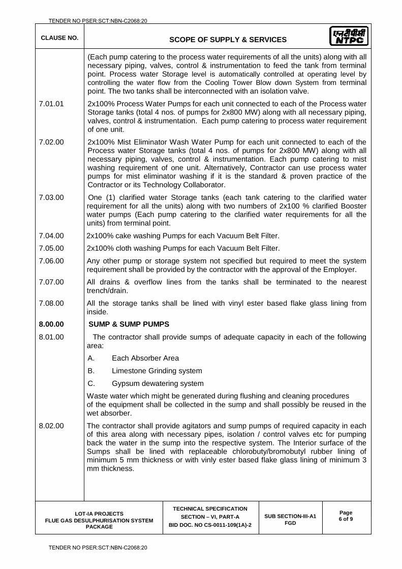
CLAUSE NO.
SCOPE OF SUPPLY & SERVICES
LOT-IA PROJECTS FLUE GAS DESULPHURISATION SYSTEM
PACKAGE
TECHNICAL SPECIFICATION
SECTION – VI, PART-A
BID DOC. NO CS-0011-109(1A)-2
SUB SECTION-III-A1 FGD
Page 6 of 9
(Each pump catering to the process water requirements of all the units) along with all necessary piping, valves, control & instrumentation to feed the tank from terminal point. Process water Storage level is automatically controlled at operating level by controlling the water flow from the Cooling Tower Blow down System from terminal point. The two tanks shall be interconnected with an isolation valve.
7.01.01 2x100% Process Water Pumps for each unit connected to each of the Process water Storage tanks (total 4 nos. of pumps for 2x800 MW) along with all necessary piping, valves, control & instrumentation. Each pump catering to process water requirement of one unit.
7.02.00 2x100% Mist Eliminator Wash Water Pump for each unit connected to each of the Process water Storage tanks (total 4 nos. of pumps for 2x800 MW) along with all necessary piping, valves, control & instrumentation. Each pump catering to mist washing requirement of one unit. Alternatively, Contractor can use process water pumps for mist eliminator washing if it is the standard & proven practice of the Contractor or its Technology Collaborator.
7.03.00 One (1) clarified water Storage tanks (each tank catering to the clarified water requirement for all the units) along with two numbers of 2x100 % clarified Booster water pumps (Each pump catering to the clarified water requirements for all the units) from terminal point.
7.04.00 2x100% cake washing Pumps for each Vacuum Belt Filter.
7.05.00 2x100% cloth washing Pumps for each Vacuum Belt Filter.
7.06.00 Any other pump or storage system not specified but required to meet the system requirement shall be provided by the contractor with the approval of the Employer.
7.07.00 All drains & overflow lines from the tanks shall be terminated to the nearest trench/drain.
7.08.00 All the storage tanks shall be lined with vinyl ester based flake glass lining from inside.
8.00.00 SUMP & SUMP PUMPS
8.01.00 The contractor shall provide sumps of adequate capacity in each of the following area:
A. Each Absorber Area
B. Limestone Grinding system
C. Gypsum dewatering system
Waste water which might be generated during flushing and cleaning procedures of the equipment shall be collected in the sump and shall possibly be reused in the wet absorber.
8.02.00 The contractor shall provide agitators and sump pumps of required capacity in each of this area along with necessary pipes, isolation / control valves etc for pumping back the water in the sump into the respective system. The Interior surface of the Sumps shall be lined with replaceable chlorobuty/bromobutyl rubber lining of minimum 5 mm thickness or with vinly ester based flake glass lining of minimum 3 mm thickness.
TENDER NO PSER:SCT:NBN-C2068:20
TENDER NO PSER:SCT:NBN-C2068:20
CLAUSE NO.
SCOPE OF SUPPLY & SERVICES
LOT-IA PROJECTS FLUE GAS DESULPHURISATION SYSTEM
PACKAGE
TECHNICAL SPECIFICATION
SECTION – VI, PART-A
BID DOC. NO CS-0011-109(1A)-2
SUB SECTION-III-A1 FGD
Page 7 of 9
9.00.00 Elevator
9.01.00 One (1) number passenger cum goods elevator of minimum capacity of 1000 kgs for each Absorber (to be provided in case height of absorber is higher than 20m) and One (1) number passenger cum goods elevator of minimum capacity of 1000 kgs in Limestone Grinding System Building shall be provided for easy access & movement of man/materials.
9.02.00 The scope shall include all items / accessories, service along with all electrical equipment etc. required to meet all design, installation, operation, safety, protection and other requirements of IS: 14665 (latest edition) (all parts), 'Lift' and service lifts'. This scope shall include all items / devices needed to comply with the requirements indicated elsewhere in the specification. The scope shall include provision of fireman's switch.
9.03.00 One (1) nos. adequately sized, Air conditioners each having minimum cooling capacity of 2.5 Ton shall be provided for each elevator machine room to make it dust proof.
9.04.00 Complete erection, testing and commissioning including all testing and commissioning materials, consumables and other tools and tackles required for erection.
9.05.00 To obtain necessary local administration permits / approvals and make arrangements for inspection and tests required thereby.
10.00.00 Thermal Insulation, Lagging, Cladding & Refractories
Thermal Insulation alongwith aluminum cladding, lagging, reinforcement wiremesh, cleats and supports, shall be provided for all the equipments/surfaces having skin temperature more than 60 degree Celsius. The insulation thickness shall be designed based on criteria specified in Part-B, Section-VI.
11.00.00 Buildings
11.01.00 Contractor shall provide buildings for Limestone Grinding System; Slurry re-circulating pumps & Oxidation blowers / Compressors; Gypsum Dewatering System & FGD control room & Analyser room (if required). The buildings must be complete in all respect specially facilitating the smooth operation and maintenance of associated equipments of above systems by providing adequate maintenance space, handling facilities, walkways, staircase etc.
12.00.00 Contractor shall provide Corrosion protection painting for structures & equipments as described in the specification
13.00.00 Contractors scope shall include all Platforms, walkways, staircase, safety rails for access of each equipment, valves, dampers, gates, instruments etc. handling facilities adequately each component of FGD system.
14.00.00 The contractor scope shall also include the provision of FGD trestle for routing of air & water lines, slurry lines, steam line, waste water, etc.. required for the complete process operations.
15.00.00 Contractor shall provide air conditioning for the FGD control room and Analyser room (if separately provided) & ventilation for the FGD system buildings as detailed in Sub-Section III-A2.
TENDER NO PSER:SCT:NBN-C2068:20
TENDER NO PSER:SCT:NBN-C2068:20
CLAUSE NO.
SCOPE OF SUPPLY & SERVICES
LOT-IA PROJECTS FLUE GAS DESULPHURISATION SYSTEM
PACKAGE
TECHNICAL SPECIFICATION
SECTION – VI, PART-A
BID DOC. NO CS-0011-109(1A)-2
SUB SECTION-III-A1 FGD
Page 8 of 9
16.00.00 Contractor shall provide compressed air system for the FGD system as detailed in Sub-Section III-A3.
17.00.00 Contractor shall provide FIRE FIGHTING SYSTEM as detailed in Sub-Section III-A4.
18.00.00 Contractor shall provide EQUIPMENT COOLING WATER SYSTEM as detailed in Sub-Section III-A5.
19.00.00 Contractor shall provide Limestone & Gypsum handling & storage system for FGD as detailed in Sub-Section III-A6.
20.00.00 Contractor shall provide ZERO LIQUID DISCHARGE SYSTEM for FGD waste water for Barh-I (3X660 MW) & Nabinagar (4x250 MW) as as detailed in Sub-Section III-A7.
21.00.00 The scope of civil works shall be as per Sub-Section-III D.
22.00.00 Associated Electrical and Control & Instrumentation systems for FGD as detailed in Sub-Section-IIIB & Sub-Section-IIIC respectively of Part-A/Section-VI of this specification.
23.00.00 Booster Fan & Isolation Gates
23.01.00 For each unit, two (2) nos. Booster Fans of axial type, Constant speed, variable pitch controlled each with drive motor, base plates, foundation bolts and nuts, inlet box, discharge case, coupling, coupling guard and suitable arrangement to prevent rain water entry to fan motor. Each Booster Fan shall be provided with bearing lubrication and hydraulic blade pitch control unit(s) consisting of
(1) 2x100% oil pumps each with motor, coupling and coupling guard.
(2) 2x100% oil coolers.
(3) 2x100% filters, differential pressure switches, etc.
(4) One (1) oil storage tank.
(5) Instrumentation, vibration monitoring, inter connected piping, valves and fittings including pressure relief valves and non return valves.
(6) Electrical actuator with accessories etc.
Alternatively, a forced oil lubrication system (consisting of 1to 6 above ) common to bearing lubrication and for servo motor operation to each BF Fan will also be acceptable.
At least two (02) nos. of duplex thermocouples or duplex platinum RTDs (100 ohm at 0oC) and one no. of temperature indicators shall be provided for bearing metal temperature measurement, control and monitoring.
Booster fans shall be suitable for the type of foundation being provided.
23.02.00 Motorized Guillotine type gates with 2x100% seal air fans shall also be provided at suction & discharge of each Booster Fan. The Gates shall be designed for tight shut-off. The design of the gates shall ensure 99.95% leak tightness without seal air. The gates shall be 100% leak tight with seal air fans under the above conditions.
TENDER NO PSER:SCT:NBN-C2068:20
TENDER NO PSER:SCT:NBN-C2068:20
CLAUSE NO.
SCOPE OF SUPPLY & SERVICES
LOT-IA PROJECTS FLUE GAS DESULPHURISATION SYSTEM
PACKAGE
TECHNICAL SPECIFICATION
SECTION – VI, PART-A
BID DOC. NO CS-0011-109(1A)-2
SUB SECTION-III-A1 FGD
Page 9 of 9
24.00.00 Contractor shall provide Low Height Wet Chimney(s) as per the criteria & specifications specified elsewhere in the specification for the project.
25.00.00 Wet Stack Condensate Collection System
25.00.01 Wet stack of 150 metre height shall be provided with a stack condensate collection system to avoid the carryover of the condensate/acidic dews/water droplets/Gypsum coming out of the stack. Design of the wet stack condensate system should be such that all the condensate are collected in the stack itself and no water droplet/condensate come out of the chimney and preventing falling of the acidic dews/water droplet/gypsum from the chimney in the plant/nearby area.
25.00.02 Drain piping shall be of suitable material from corrosion point of view.
25.00.03 All Stack liquid collection shall be easily accessible for O&M.
25.00.04 The design of the stack condensate collection system shall be provided by the bidders in its bid.
25.00.05 A common Nickel based alloy material storage/neutralizing tank for the both the units of storage capacity of 12 hrs of stack condensate of both the stack shall be provided. Storage tank/neutralization tank shall be complete with dosing, mixing and preparation system. After neutralization of the stack condensate collection, same shall be pumped to common drain system. Contractor shall provide 2 X100% pumps, complete with valves, piping fittings, level control/monitoring etc. Alternatively, bidder may propose its proven system for disposal of the condensate system in its bid for Employer’s consideration. All the material in contact with the condensate shall be of suitable material for the operating duty.
25.00.06 Stack outlet liquid collector shall be designed in such a way so that the liquid condensate film near the exit of the stack is collected instead of carrying with the exit gas. Bidders shall provide all these details in its bid.
TENDER NO PSER:SCT:NBN-C2068:20
TENDER NO PSER:SCT:NBN-C2068:20

LOT-IA PROJECTS FLUE GAS DESULPHURISATION (FGD) SYSTEM PACKAGE
TECHNICAL SPECIFICATION
SECTION-VI
BID DOCUMENT NO.: CS-0011-109(1A)-2
SUB-SECTION-III-A2
AIR CONDITIONING, VENTILATION SYSTEM & COMPRESSED AIR SYSTEM
TENDER NO PSER:SCT:NBN-C2068:20
TENDER NO PSER:SCT:NBN-C2068:20
CLAUSE NO.
SCOPE OF SUPPLY & SERVICES
LOT 1A PROJECTS FLUE GAS DESULPHURISATION SYSTEM
PACKAGE
TECHNICAL SPECIFICATION
SECTION – VI, PART-A
BID DOC. NO.:CS-0011-109(1A)-2
SUB SECTION-III-A2 AIR CONDITIONING,
VENTILATION SYSTEM & COMPRESSED AIR
SYSTEM
Page 1 of 4
1.00.00 AIR CONDITIONING SYSTEM
a) General
The scope includes Engineering, Supply, Construction, Erection, Testing and Commissioning for Complete Air conditioning system consisting of D-X units with refrigerant piping & valves, Air handling units, Hi-wall split air conditioner /Cassette Air conditioners, Packaged Air Conditioners, Fresh air fans, air distribution system (ducting, filters, isolation dampers, motorized fire dampers, diffusers, grills, volume control dampers, etc.) etc., along with all electrical equipment and instrumentation as required for all the buildings which are in the scope of the bidder, as detailed out in Part-B of Section-VI.
b) Air-conditioning system for F.G.D Control Room Building and ZLD control room building (if provided)
Air cooled condensing units (D-X type) type air conditioners with AHU of suitable capacity with 100 % redundancy ( as per actual heat load calculation ) shall be provided .
c) SO2 analyzer room (if required) and other air conditioned offices/areas covered under this package shall be provided with Ductable/Non ductable Split air conditioners etc. as per Design criteria specified in Chapter Salient Design Data. Non ductable Split air conditioner shall conform to minimum three (3) star (***) rating and above of latest version of Bureau of Energy Efficiency (BEE) HVAC code issued by Ministry of Power, Govt of India.
d) Supply of Mandatory spares as specified.
e) Any additional items required to make the system complete.
f) For Air conditioning system, the Bidder shall provide all Instrumentation systems, accessories and associated equipment, which are included in Bidder’s scope, in a fully operational condition acceptable to the Employer. The Bidder shall also provide all material, equipment and services which may not be specifically stated in the specifications but are required for completeness of the equipment/systems furnished by the Contractor and for meeting the intent and requirements of these specifications.
g) Contractor shall provide microprocessor/PLC/GIU based control system for control and monitoring of air conditioning system as per manufacturer’s standard practice. However relative humidity and temperature measurement of all control rooms and all major air-conditioned areas shall be made available in FGD/ ZLD control system. Control and monitoring of air conditioning system from FGD/ZLD control system is also acceptable.
h) Apart from the above, any area/building which are in the scope of the bidder and require air conditioning, the same shall be provided with air conditioning system, as detailed out in Part-B of Technical Specification.
TENDER NO PSER:SCT:NBN-C2068:20
TENDER NO PSER:SCT:NBN-C2068:20
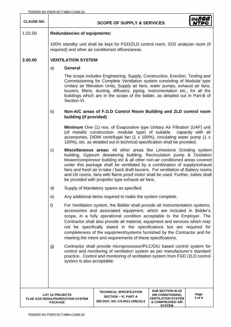
CLAUSE NO.
SCOPE OF SUPPLY & SERVICES
LOT 1A PROJECTS FLUE GAS DESULPHURISATION SYSTEM
PACKAGE
TECHNICAL SPECIFICATION
SECTION – VI, PART-A
BID DOC. NO.:CS-0011-109(1A)-2
SUB SECTION-III-A2 AIR CONDITIONING,
VENTILATION SYSTEM & COMPRESSED AIR
SYSTEM
Page 2 of 4
1.02.00 Redundancies of equipments:
100% standby unit shall be kept for FGD/ZLD control room, SO2 analyzer room (if required) and other air conditioned offices/areas.
2.00.00 VENTILATION SYSTEM
a) General
The scope includes Engineering, Supply, Construction, Erection, Testing and Commissioning for Complete Ventilation system consisting of Modular type Unitary air filteration Units, Supply air fans, water pumps, exhaust air fans, louvers, filters, ducting, diffusers, piping, instrumentation etc., for all the buildings which are in the scope of the bidder, as detailed out in Part-B of Section-VI.
b) Non-A/C areas of F.G.D Control Room Building and ZLD control room building (if provided)
Minimum One (1) nos. of Evaporative type Unitary Air Filtration (UAF) unit (of metallic construction- modular type) of suitable capacity with all accessories, DIDW centrifugal fan (1 x 100%), circulating water pump (1 x 100%), etc. as detailed out in technical specification shall be provided.
c) Miscellaneous areas: All other areas like Limestone Grinding system building, Gypsum dewatering building, Recirculation pump & Oxidation blower/compressor building etc & all other non-air conditioned areas covered under this package shall be ventilated by a combination of supply/exhaust fans and fresh air in-take / back draft louvers. For ventilation of Battery rooms and Oil rooms, fans with flame proof motor shall be used. Further, toilets shall be provided with propeller type exhaust air fans.
d) Supply of Mandatory spares as specified.
e) Any additional items required to make the system complete.
f) For Ventilation system, the Bidder shall provide all Instrumentation systems, accessories and associated equipment, which are included in Bidder’s scope, in a fully operational condition acceptable to the Employer. The Contractor shall also provide all material, equipment and services which may not be specifically stated in the specifications but are required for completeness of the equipment/systems furnished by the Contractor and for meeting the intent and requirements of these specifications.
g) Contractor shall provide microprocessor/PLC/GIU based control system for control and monitoring of ventilation system as per manufacturer’s standard practice. Control and monitoring of ventilation system from FGD /ZLD control system is also acceptable.
TENDER NO PSER:SCT:NBN-C2068:20
TENDER NO PSER:SCT:NBN-C2068:20
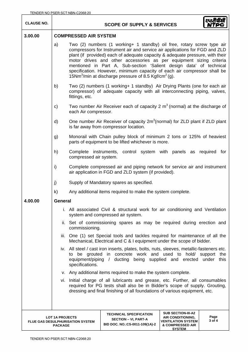
CLAUSE NO.
SCOPE OF SUPPLY & SERVICES
LOT 1A PROJECTS FLUE GAS DESULPHURISATION SYSTEM
PACKAGE
TECHNICAL SPECIFICATION
SECTION – VI, PART-A
BID DOC. NO.:CS-0011-109(1A)-2
SUB SECTION-III-A2 AIR CONDITIONING,
VENTILATION SYSTEM & COMPRESSED AIR
SYSTEM
Page 3 of 4
3.00.00 COMPRESSED AIR SYSTEM
a) Two (2) numbers (1 working+ 1 standby) oil free, rotary screw type air compressors for Instrument air and service air applications for FGD and ZLD plant (if provided) each of adequate capacity & adequate pressure, with their motor drives and other accessories as per equipment sizing criteria mentioned in Part A, Sub-section ‘Salient design data’ of technical specification. However, minimum capacity of each air compressor shall be 15Nm3/min at discharge pressure of 8.5 Kgf/cm2 (g).
b) Two (2) numbers (1 working+ 1 standby) Air Drying Plants (one for each air compressor) of adequate capacity with all interconnecting piping, valves, fittings, etc.
c) Two number Air Receiver each of capacity 2 m3 (normal) at the discharge of each Air compressor.
d) One number Air Receiver of capacity 2m3(normal) for ZLD plant if ZLD plant is far away from compressor location.
g) Monorail with Chain pulley block of minimum 2 tons or 125% of heaviest parts of equipment to be lifted whichever is more.
h) Complete instruments, control system with panels as required for compressed air system.
i) Complete compressed air and piping network for service air and instrument air application in FGD and ZLD system (if provided).
j) Supply of Mandatory spares as specified.
k) Any additional items required to make the system complete.
4.00.00 General
i. All associated Civil & structural work for air conditioning and Ventilation system and compressed air system.
ii. Set of commissioning spares as may be required during erection and commissioning.
iii. One (1) set Special tools and tackles required for maintenance of all the Mechanical, Electrical and C & I equipment under the scope of bidder.
iv. All steel / cast iron inserts, plates, bolts, nuts, sleeves, metallic-fasteners etc. to be grouted in concrete work and used to hold/ support the equipment/piping / ducting being supplied and erected under this specifications.
v. Any additional items required to make the system complete.
vi. Initial charge of all lubricants and grease, etc. Further, all consumables required for PG tests shall also be in Bidder’s scope of supply. Grouting, dressing and final finishing of all foundations of various equipment, etc.
TENDER NO PSER:SCT:NBN-C2068:20
TENDER NO PSER:SCT:NBN-C2068:20
CLAUSE NO.
SCOPE OF SUPPLY & SERVICES
LOT 1A PROJECTS FLUE GAS DESULPHURISATION SYSTEM
PACKAGE
TECHNICAL SPECIFICATION
SECTION – VI, PART-A
BID DOC. NO.:CS-0011-109(1A)-2
SUB SECTION-III-A2 AIR CONDITIONING,
VENTILATION SYSTEM & COMPRESSED AIR
SYSTEM
Page 4 of 4
vii. Repairing and making good/ sealing of cutouts / openings in floors, roofs and walls, for executing the works under this system and making them water tight as directed by the engineer.
Corrosion protection painting for all equipment / items by Bidder as detailed in relevant clauses of technical specification.
TENDER NO PSER:SCT:NBN-C2068:20
TENDER NO PSER:SCT:NBN-C2068:20

LOT-IA PROJECTS FLUE GAS DESULPHURISATION (FGD) SYSTEM PACKAGE
TECHNICAL SPECIFICATION
SECTION-VI
BID DOCUMENT NO.: CS-0011-109(1A)-2
SUB-SECTION-III-A3
FIRE FIGHTING SYSTEM
TENDER NO PSER:SCT:NBN-C2068:20
TENDER NO PSER:SCT:NBN-C2068:20
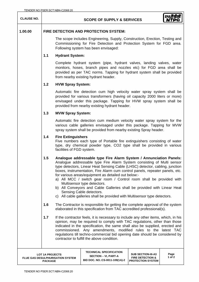
CLAUSE NO.
SCOPE OF SUPPLY & SERVICES
LOT 1A PROJECTS FLUE GAS DESULPHURISATION SYSTEM
PACKAGE
TECHNICAL SPECIFICATION
SECTION – VI, PART-A
BID DOC. NO.:CS-0011-109(1A)-2
SUB SECTION-III-A3 FIRE DETECTION &
PROTECTION SYSTEM
Page 1 of 2
1.00.00 FIRE DETECTION AND PROTECTION SYSTEM:
The scope includes Engineering, Supply, Construction, Erection, Testing and Commissioning for Fire Detection and Protection System for FGD area. Following system has been envisaged:
1.1 Hydrant System:
Complete hydrant system (pipe, hydrant valves, landing valves, water monitors, hoses, branch pipes and nozzles etc) for FGD area shall be provided as per TAC norms. Tapping for hydrant system shall be provided from nearby existing hydrant header.
1.2 HVW Spray System:
Automatic fire detection cum high velocity water spray system shall be provided for various transformers (having oil capacity 2000 liters or more) envisaged under this package. Tapping for HVW spray system shall be provided from nearby existing hydrant header.
1.3 MVW Spray System:
Automatic fire detection cum medium velocity water spray system for the various cable galleries envisaged under this package. Tapping for MVW spray system shall be provided from nearby existing Spray header.
1.4 Fire Extinguishers Five numbers each type of Portable fire extinguishers consisting of water type, dry chemical powder type, CO2 type shall be provided in various facilities of FGD system.
1.5 Analogue addressable type Fire Alarm System / Annunciation Panels: Analogue addressable type Fire Alarm System consisting of Multi sensor type detectors, Linear Heat Sensing Cable (LHSC) detector, cabling, junction boxes, instrumentation, Fire Alarm cum control panels, repeater panels, etc. for various areas/equipment as detailed out below:- a) All MCC / switch gear room / Control room shall be provided with
Multisensor type detectors. b) All Conveyors and Cable Galleries shall be provided with Linear Heat
Sensing Cable detectors. c) All cable galleries shall be provided with Multisensor type detectors.
1.6 The Contractor is responsible for getting the complete approval of the system
elaborated in this specification from TAC accredited professional(s).
1.7 If the contractor feels, it is necessary to include any other items, which, in his opinion, may be required to comply with TAC regulations, other than those indicated in the specification, the same shall also be supplied, erected and commissioned. Any amendments, modified rules to the latest TAC regulations till techno-commercial bid opening date should be considered by contractor to fulfill the above condition.
TENDER NO PSER:SCT:NBN-C2068:20
TENDER NO PSER:SCT:NBN-C2068:20
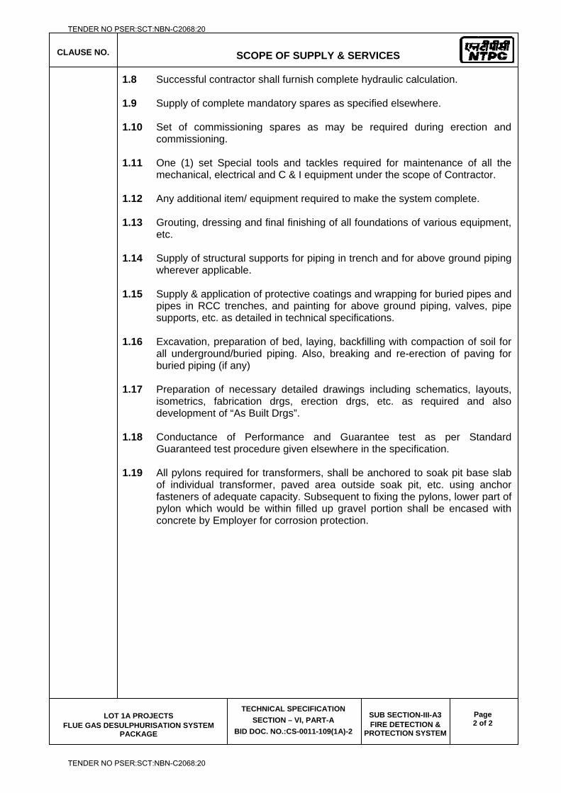
CLAUSE NO.
SCOPE OF SUPPLY & SERVICES
LOT 1A PROJECTS FLUE GAS DESULPHURISATION SYSTEM
PACKAGE
TECHNICAL SPECIFICATION
SECTION – VI, PART-A
BID DOC. NO.:CS-0011-109(1A)-2
SUB SECTION-III-A3 FIRE DETECTION &
PROTECTION SYSTEM
Page 2 of 2
1.8 Successful contractor shall furnish complete hydraulic calculation.
1.9 Supply of complete mandatory spares as specified elsewhere.
1.10 Set of commissioning spares as may be required during erection and commissioning.
1.11 One (1) set Special tools and tackles required for maintenance of all the
mechanical, electrical and C & I equipment under the scope of Contractor.
1.12 Any additional item/ equipment required to make the system complete.
1.13 Grouting, dressing and final finishing of all foundations of various equipment, etc.
1.14 Supply of structural supports for piping in trench and for above ground piping
wherever applicable.
1.15 Supply & application of protective coatings and wrapping for buried pipes and pipes in RCC trenches, and painting for above ground piping, valves, pipe supports, etc. as detailed in technical specifications.
1.16 Excavation, preparation of bed, laying, backfilling with compaction of soil for
all underground/buried piping. Also, breaking and re-erection of paving for buried piping (if any)
1.17 Preparation of necessary detailed drawings including schematics, layouts,
isometrics, fabrication drgs, erection drgs, etc. as required and also development of “As Built Drgs”.
1.18 Conductance of Performance and Guarantee test as per Standard
Guaranteed test procedure given elsewhere in the specification.
1.19 All pylons required for transformers, shall be anchored to soak pit base slab of individual transformer, paved area outside soak pit, etc. using anchor fasteners of adequate capacity. Subsequent to fixing the pylons, lower part of pylon which would be within filled up gravel portion shall be encased with concrete by Employer for corrosion protection.
TENDER NO PSER:SCT:NBN-C2068:20
TENDER NO PSER:SCT:NBN-C2068:20

LOT-IA PROJECTS FLUE GAS DESULPHURISATION (FGD) SYSTEM PACKAGE
TECHNICAL SPECIFICATION
SECTION-VI
BID DOCUMENT NO.: CS-0011-109(1A)-2
SUB-SECTION-III-A4
EQUIPMENT COOLING WATER SYSTEM
TENDER NO PSER:SCT:NBN-C2068:20
TENDER NO PSER:SCT:NBN-C2068:20
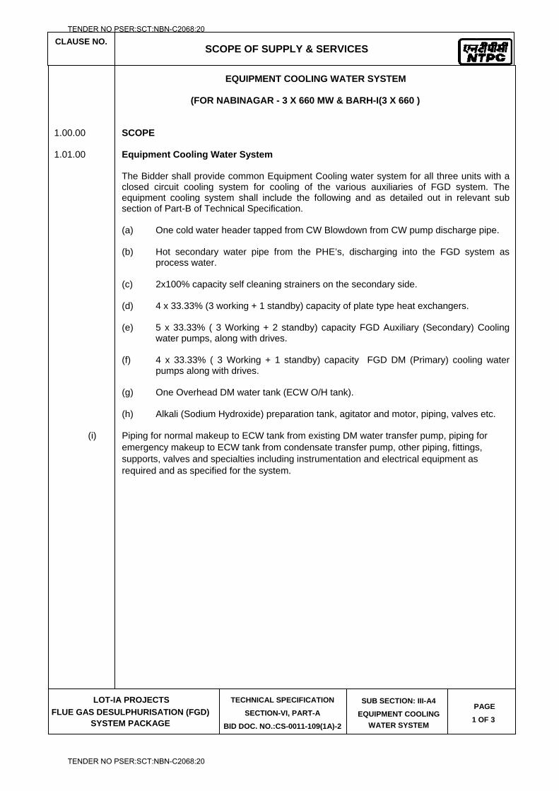
CLAUSE NO.
SCOPE OF SUPPLY & SERVICES
LOT-IA PROJECTS
FLUE GAS DESULPHURISATION (FGD) SYSTEM PACKAGE
TECHNICAL SPECIFICATION
SECTION-VI, PART-A
BID DOC. NO.:CS-0011-109(1A)-2
SUB SECTION: III-A4
EQUIPMENT COOLING
WATER SYSTEM
PAGE
1 OF 3
EQUIPMENT COOLING WATER SYSTEM
(FOR NABINAGAR - 3 X 660 MW & BARH-I(3 X 660 ) 1.00.00 SCOPE 1.01.00 Equipment Cooling Water System The Bidder shall provide common Equipment Cooling water system for all three units with a
closed circuit cooling system for cooling of the various auxiliaries of FGD system. The equipment cooling system shall include the following and as detailed out in relevant sub section of Part-B of Technical Specification.
(a) One cold water header tapped from CW Blowdown from CW pump discharge pipe.
(b) Hot secondary water pipe from the PHE’s, discharging into the FGD system as
process water. (c) 2x100% capacity self cleaning strainers on the secondary side. (d) 4 x 33.33% (3 working + 1 standby) capacity of plate type heat exchangers. (e) 5 x 33.33% ( 3 Working + 2 standby) capacity FGD Auxiliary (Secondary) Cooling
water pumps, along with drives. (f) 4 x 33.33% ( 3 Working + 1 standby) capacity FGD DM (Primary) cooling water
pumps along with drives. (g) One Overhead DM water tank (ECW O/H tank). (h) Alkali (Sodium Hydroxide) preparation tank, agitator and motor, piping, valves etc.
(i) Piping for normal makeup to ECW tank from existing DM water transfer pump, piping for emergency makeup to ECW tank from condensate transfer pump, other piping, fittings, supports, valves and specialties including instrumentation and electrical equipment as required and as specified for the system.
TENDER NO PSER:SCT:NBN-C2068:20
TENDER NO PSER:SCT:NBN-C2068:20
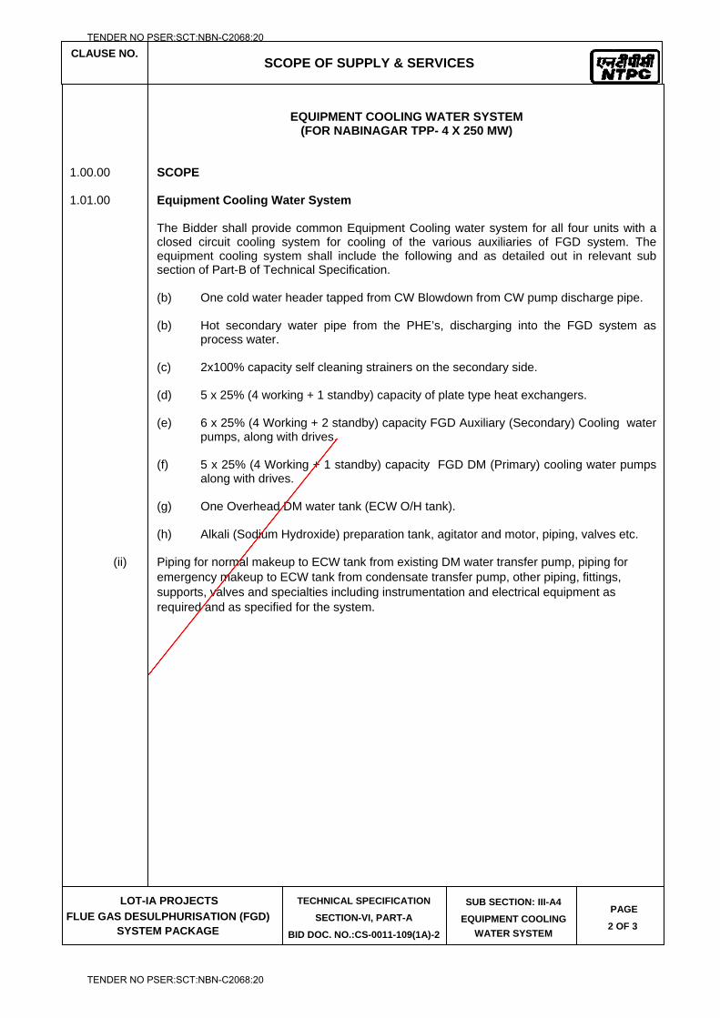
CLAUSE NO.
SCOPE OF SUPPLY & SERVICES
LOT-IA PROJECTS
FLUE GAS DESULPHURISATION (FGD) SYSTEM PACKAGE
TECHNICAL SPECIFICATION
SECTION-VI, PART-A
BID DOC. NO.:CS-0011-109(1A)-2
SUB SECTION: III-A4
EQUIPMENT COOLING
WATER SYSTEM
PAGE
2 OF 3
EQUIPMENT COOLING WATER SYSTEM
(FOR NABINAGAR TPP- 4 X 250 MW) 1.00.00 SCOPE 1.01.00 Equipment Cooling Water System The Bidder shall provide common Equipment Cooling water system for all four units with a
closed circuit cooling system for cooling of the various auxiliaries of FGD system. The equipment cooling system shall include the following and as detailed out in relevant sub section of Part-B of Technical Specification.
(b) One cold water header tapped from CW Blowdown from CW pump discharge pipe.
(b) Hot secondary water pipe from the PHE’s, discharging into the FGD system as
process water. (c) 2x100% capacity self cleaning strainers on the secondary side. (d) 5 x 25% (4 working + 1 standby) capacity of plate type heat exchangers. (e) 6 x 25% (4 Working + 2 standby) capacity FGD Auxiliary (Secondary) Cooling water
pumps, along with drives. (f) 5 x 25% (4 Working + 1 standby) capacity FGD DM (Primary) cooling water pumps
along with drives. (g) One Overhead DM water tank (ECW O/H tank). (h) Alkali (Sodium Hydroxide) preparation tank, agitator and motor, piping, valves etc.
(ii) Piping for normal makeup to ECW tank from existing DM water transfer pump, piping for emergency makeup to ECW tank from condensate transfer pump, other piping, fittings, supports, valves and specialties including instrumentation and electrical equipment as required and as specified for the system.
TENDER NO PSER:SCT:NBN-C2068:20
TENDER NO PSER:SCT:NBN-C2068:20
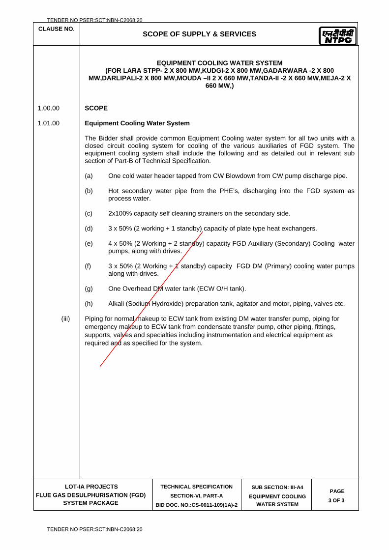
CLAUSE NO.
SCOPE OF SUPPLY & SERVICES
LOT-IA PROJECTS
FLUE GAS DESULPHURISATION (FGD) SYSTEM PACKAGE
TECHNICAL SPECIFICATION
SECTION-VI, PART-A
BID DOC. NO.:CS-0011-109(1A)-2
SUB SECTION: III-A4
EQUIPMENT COOLING
WATER SYSTEM
PAGE
3 OF 3
EQUIPMENT COOLING WATER SYSTEM
(FOR LARA STPP- 2 X 800 MW,KUDGI-2 X 800 MW,GADARWARA -2 X 800 MW,DARLIPALI-2 X 800 MW,MOUDA –II 2 X 660 MW,TANDA-II -2 X 660 MW,MEJA-2 X
660 MW,) 1.00.00 SCOPE 1.01.00 Equipment Cooling Water System The Bidder shall provide common Equipment Cooling water system for all two units with a
closed circuit cooling system for cooling of the various auxiliaries of FGD system. The equipment cooling system shall include the following and as detailed out in relevant sub section of Part-B of Technical Specification.
(a) One cold water header tapped from CW Blowdown from CW pump discharge pipe.
(b) Hot secondary water pipe from the PHE’s, discharging into the FGD system as
process water. (c) 2x100% capacity self cleaning strainers on the secondary side. (d) 3 x 50% (2 working + 1 standby) capacity of plate type heat exchangers. (e) 4 x 50% (2 Working + 2 standby) capacity FGD Auxiliary (Secondary) Cooling water
pumps, along with drives. (f) 3 x 50% (2 Working + 1 standby) capacity FGD DM (Primary) cooling water pumps
along with drives. (g) One Overhead DM water tank (ECW O/H tank). (h) Alkali (Sodium Hydroxide) preparation tank, agitator and motor, piping, valves etc.
(iii) Piping for normal makeup to ECW tank from existing DM water transfer pump, piping for emergency makeup to ECW tank from condensate transfer pump, other piping, fittings, supports, valves and specialties including instrumentation and electrical equipment as required and as specified for the system.
TENDER NO PSER:SCT:NBN-C2068:20
TENDER NO PSER:SCT:NBN-C2068:20

LOT-IA PROJECTS FLUE GAS DESULPHURISATION (FGD) SYSTEM PACKAGE
TECHNICAL SPECIFICATION
SECTION-VI
BID DOCUMENT NO.: CS-0011-109(1A)-2
SUB-SECTION-III- A5
LIME STONE & GYPSUM HANDLING SYSTEM
TENDER NO PSER:SCT:NBN-C2068:20
TENDER NO PSER:SCT:NBN-C2068:20
CLAUSE NO.
SCOPE OF SUPPLY & SERVICES
LOT-IA PROJECTS
FLUE GAS DESULPHURISATION (FGD) SYSTEM PACKAGE
TECHNICAL SPECIFICATION SECTION-VI, PART-A
BID DOC.NO. CS-0011-109(1A)-2
SUB-SECTION- III-A5
LIMESTONE & GYPSUM HANDLING
PLANTS
PAGE 1 OF 6
1.00.00 INTENT OF SPECIFICATION
This specification is intended to cover the following activities and services in respect of all the equipment of Lime Stone Handling Plant & Gypsum Handling plant to be installed for FGD Package, completely covering the following activities and services in respect of all the equipment specified and covered under the specifications and read in conjunction with “Scope of Supply & Services”, Part-A, Section–VI of Technical Specification.
(i) Detailed design and engineering of all the equipment and equipment system(s).
(ii) Complete manufacture including shop testing/ type testing.
(iii) Providing engineering data, drawings, Commissioning procedures and O & M manuals, etc. for the Employer’s review, approval and records.
(iv) Packing and transportation from the manufacturer’s works to site including transit insurance, customs clearance/ port clearance, if required.
(v) Receipt, unloading, storage, preservation, conservation and insurance of equipment at site.
(vi) Fabrication, pre-assembly, (if any), erection, testing and putting into satisfactory operation of all the equipment including successful completion of facilities.
(vii) Associated civil, structural, architectural and electrical works.
(viii) Commissioning and completion of facilities and Performance Guarantee Tests after successful completion of initial operation.
(ix) Furnishing of spares on FOR site basis and handing over to NTPC stores.
(x) Reconciliation with custom authorities, if applicable.
(xi) Satisfactory completion of the contract.
1.01.00 Before submitting his bid, the Bidder should inspect and examine the site and its
surroundings and should satisfy himself as to the nature of the ground and subsoil, the quantities and nature of work, materials necessary for completion of the work and their availability, means of access to site and in general shall himself obtain all necessary information as to risks, contingencies and other circumstances which may influence or affect his offer. No consequent extra claims on any misunderstanding or otherwise shall be allowed by the Employer.
1.02.01 Based on site visit, bidder shall submit layout for Limestone handling plant &
Gypsum handling facilities along with their techno-commercial bid. Bidder shall bring out all necessary modification and relocation of existing facilities, if required, along with proposed Layout submitted with the bid. In the absence of this, the bid shall be deemed incomplete and may be liable for rejection.
TENDER NO PSER:SCT:NBN-C2068:20
TENDER NO PSER:SCT:NBN-C2068:20
CLAUSE NO.
SCOPE OF SUPPLY & SERVICES
LOT-IA PROJECTS
FLUE GAS DESULPHURISATION (FGD) SYSTEM PACKAGE
TECHNICAL SPECIFICATION SECTION-VI, PART-A
BID DOC.NO. CS-0011-109(1A)-2
SUB-SECTION- III-A5
LIMESTONE & GYPSUM HANDLING
PLANTS
PAGE 2 OF 6
1.02.02 NTPC reserves the right to freeze a basic layout for each NTPC plant post techno commercial bid discussions.
1.03.00 The Bidder shall be responsible for providing all material, equipment and services,
specified or otherwise which are required to fulfill the intent of ensuring operability and the reliability of the complete system covered under this specification.
1.04.00 Cleaning of any debris produced by the bidder during erection and commissioning
shall be done immediately at each front by the bidder. 1.05.00 Bidder to extend all help and documentary support for compliance and addressing
any statutory issues raised at site which pertains to the area/ work under bidder’s scope.
2.00.0 DETAILED SCOPE
2.01.00 Limestone Handling Plant (LHP)
2.01.01 Limestone will be received to power plant either through road by trucks and/or through Indian railway rakes.
Lime stone received through Road shall be unloaded by Two (2) numbers Truck Tipplers each of minimum 20T capacity to discharge Limestone on to Box Feeders/ Surface Feeders/ Truck Unloading Hopper, complete with all mechanical, electrical and C&I, civil & structural works for unloading Limestone by truck tipplers.
Two (2) numbers Box Feeders/ Bulk-material Receiving Unit/ Underground Truck Unloading Hopper / Surface feeder, for unloading of limestone from trucks/ self-tippling trucks/ loader shovels, complete with drives, accessories all mechanical, electrical and C&I, Civil & structural works, including its supporting foundations etc. This unit shall feed limestone onto the conveyor before Limestone crusher house.
Limestone received through Indian Railway Rakes will be unloaded in one of the side discharge Wagon Tipplers or Track Hopper of existing Coal Handling Plant (CHP). Before existing Crusher house of CHP, the unloaded limestone will be fed to new limestone crusher house through series of new conveyors/bucket elevators. All necessary modifications involving Mechanical, Electrical, C&I, Civil and Structural works in the existing CHP for taking feed to new limestone path shall be in the scope of the bidder.
2.01.02 Limestone shall be conveyed to usage point through double stream of capacity 100% each for conveying & crushing.
2.01.03 Lime stone Belt Conveyors / Bucket Elevator complete with associated tunnel, conveyor galleries along with its supporting structures, short supports, stringers, deck plate, seal plate, conveyor foundations, drive motors, drive units, pulleys, idlers, gravity take ups including guides, pits etc., internal and external belt cleaners, pull chord switches, belt sway, zero speed switches, electro-hydraulic thruster brakes, all electrical etc. including all civil, structural and architectural works for tunnel, conveyor gallery, gallery supporting trestles and their associated foundations, as applicable.
2.01.04 One (1) number Lime stone crusher house (CH) complete with all civil, structural, architectural and electrical works etc. accommodating suitable nos. crushers and
TENDER NO PSER:SCT:NBN-C2068:20
TENDER NO PSER:SCT:NBN-C2068:20
CLAUSE NO.
SCOPE OF SUPPLY & SERVICES
LOT-IA PROJECTS
FLUE GAS DESULPHURISATION (FGD) SYSTEM PACKAGE
TECHNICAL SPECIFICATION SECTION-VI, PART-A
BID DOC.NO. CS-0011-109(1A)-2
SUB-SECTION- III-A5
LIMESTONE & GYPSUM HANDLING
PLANTS
PAGE 3 OF 6
associated Vibrating feeders, R&P and Rod gates etc., passenger cum goods elevator, conveyors, chute work along with actuator operated flap gates, monorails & hoists, hoist maintenance platform, external and internal staircases, hand rails and other equipment such as sampling unit, dust extraction system etc. as specified elsewhere.
2.01.05 Suitable numbers of vibrating feeders in limestone crusher house to feed the limestone to crushers with drives, dust hoods, all mechanical, electrical accessories and supporting structures etc.
2.01.06 Suitable numbers of hammer crusher complete with drives, accessories all mechanical, electrical civil & structural works, including crusher supporting foundations, vibration isolation system with springs and viscous dampers, vibration monitoring system etc.
2.01.07 Crushed limestone Reclaim Hopper (RH) /Silo, machinery hatches at each of end of limestone storage shed for RH, fully / partially underground or over ground junction towers, tunnels and pent houses, complete with civil, structural, architectural, electrical and C&I works including over ground structural shed for entire length of limestone ground storage and machinery hatches, removable chequered plate covers over openings in machinery hatches for handling underground equipment like paddle feeders etc. (as applicable). For Limestone storage shed and for all buildings, other equipment such as DS system, ventilation system, drinking water system, drainage system etc. as specified elsewhere in the specification.
2.01.08 Junction towers (along with underground / over ground RCC structures), tunnel/conveyor gallery / bucket elevator complete with all civil, structural, architectural, electrical and C&I works including chutes, monorails, hoists/chain pulley blocks, hoist maintenance platforms, external staircases, dust debris chutes etc. All over-ground junction towers shall have separate debris disposal chute up to the ground floor. Underground junction towers shall be provided with machinery hatches along with monorail, electric hoist for handling equipment from underground to over ground.
2.01.09 Complete chute work along with chute block switches and actuator operated flap gates, mobile discharge pulleys (as applicable) in all junction towers between various conveyors.
2.01.10 Suitable number of motorized travelling tripper / flow diverter plough (as applicable) on each feeding conveyor for feeding the crushed limestone to the covered storage shed. Trippers shall be complete with all mechanical, electrical equipment, rails, chute work, rail supporting structure (along with structural stools, as required), cables with cable festooning arrangement, thruster brakes, rail clamps, electric hoist, actuator flap gates etc.
2.01.11 One number of covered storage shed for crushed limestone. The storage shed shall be sufficient to store limestone equivalent to consumption of minimum 7 days at Design Point (Generation of all units to be considered). A reclaim hopper shall be provided below the limestone storage shed for the entire length of the stockpile. Alternatively, suitable number of Limestone Storage Silos to store limestone equivalent to consumption of minimum 7 days. Suitable number of Belt feeders below silos shall be provided taking feed from silo and discharging onto onward conveyors/ Bucket elevators.
TENDER NO PSER:SCT:NBN-C2068:20
TENDER NO PSER:SCT:NBN-C2068:20
CLAUSE NO.
SCOPE OF SUPPLY & SERVICES
LOT-IA PROJECTS
FLUE GAS DESULPHURISATION (FGD) SYSTEM PACKAGE
TECHNICAL SPECIFICATION SECTION-VI, PART-A
BID DOC.NO. CS-0011-109(1A)-2
SUB-SECTION- III-A5
LIMESTONE & GYPSUM HANDLING
PLANTS
PAGE 4 OF 6
2.01.12 Two (2) numbers paddle feeders (in case of covered storage shed) complete with all electrical, rails, supporting structures, end stops, cable reeling drums, trailing cables, and necessary arrangement for cabling on floor of reclaim hoppers along with accessories, shall be installed at the bottom of the reclaim hoppers to scoop the limestone from reclaim hoppers and feed limestone on to the underground conveyors.
2.01.13 Two (2) nos. of lime sampling units, one for as received limestone in crusher house and one for as used limestone in TP before feeding to limestone bunkers, complete with all accessories and electrical, civil, structural works, supporting structures, approach/maintenance platforms, hoists etc.
2.01.14 Suitable number of ploughs and its actuating mechanism shall be mounted on each conveyor to feed limestone into limestone mill bunkers. Alternatively, suitable nos. fixed Trippers on each conveyor to feed limestone into limestone mill bunkers.
2.01.15 Minimum four (4) Nos. sump pumps in limestone storage shed (in case of covered storage shed), and two (2) Nos. sump pumps in all TPs completely or partially underground complete with motors, local control panel, level switches, individual discharge piping with fittings and valves to nearest plant drain including pipes etc. upto disposal point.
2.01.16 Adequate number of ventilation equipment for ventilating the limestone reclaim hopper, underground tunnel of Conveyors, underground portion of Junction towers and limestone bunker bays (housing tripper/plough conveyors) complete with all mechanical, electrical, civil and structural works and associated foundations.
2.01.17 Pressurized Ventilation system for all Switchgear rooms, MCC rooms complete with all mechanical, electrical, accessories, civil and structural works.
2.01.18 Exhaust fans to be provided in all battery rooms and all toilets complete with electrical, civil & structural works etc. Supply and exhaust fans along with required ducting shall also be provided for all underground Structures/junction towers complete with all mechanical, electrical, civil and structural works and associated foundations.
2.01.19 One (1) number of passenger cum goods elevator with drives, all electrical, mechanical, civil, structural & associated foundation works, accessories and electrical to serve various floors of lime stone crusher house.
2.01.20 Two (2) numbers of in line magnetic separators (one no. on each conveyor feeding to crusher house) and two (2) number of suspended magnets, (one no. on each conveyor feeding to Limestone bunker (in case of covered storage shed)) on conveyors complete with reject chutes, reject trolleys, supporting arrangement and all mechanical, electrical, civil, structural works and accessories.
2.01.21 Four (4) numbers of metal detectors (min. one no. on each conveyor feeding to crusher house and conveyor feeding to Limestone bunker at FGD plant) complete with all mechanical, electrical, civil, structural works and accessories.
2.01.22 Four (4) numbers of electronic type belt scales (min. one no. on each conveyor feeding to crusher house and conveyor feeding to Limestone bunker at FGD plant) for continuous weighing, complete with all mechanical, electrical, civil, structural works and accessories.
TENDER NO PSER:SCT:NBN-C2068:20
TENDER NO PSER:SCT:NBN-C2068:20
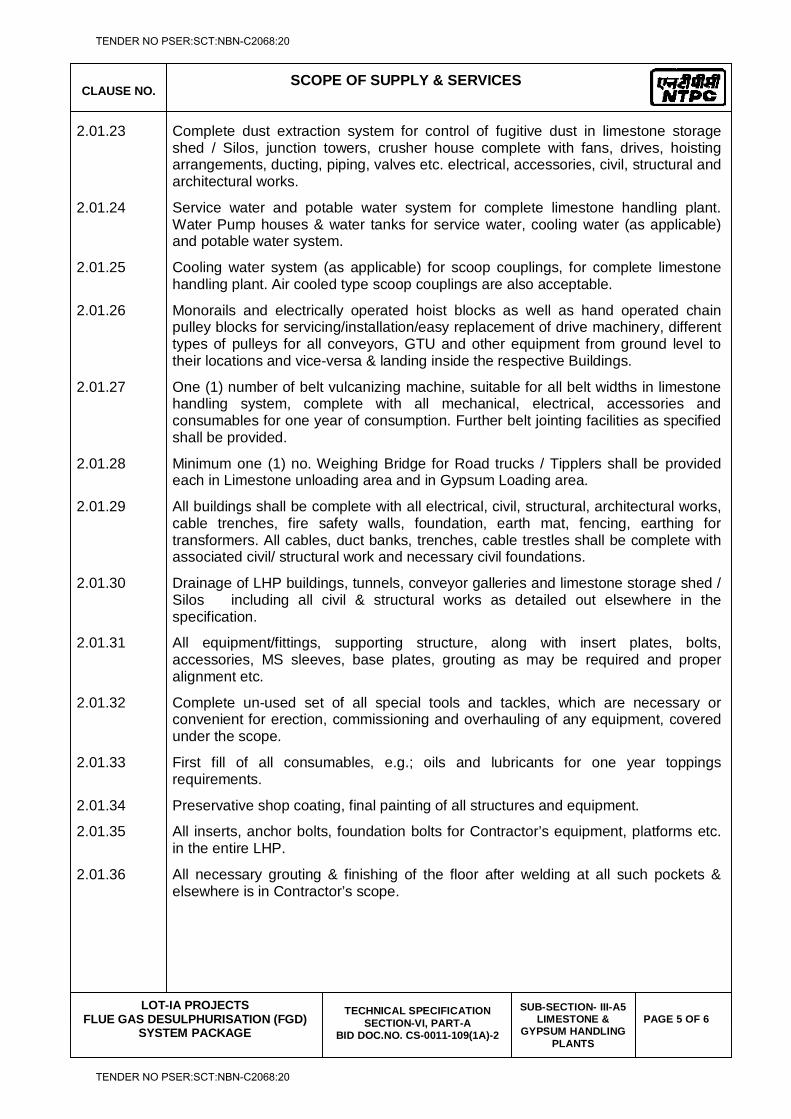
CLAUSE NO.
SCOPE OF SUPPLY & SERVICES
LOT-IA PROJECTS
FLUE GAS DESULPHURISATION (FGD) SYSTEM PACKAGE
TECHNICAL SPECIFICATION SECTION-VI, PART-A
BID DOC.NO. CS-0011-109(1A)-2
SUB-SECTION- III-A5
LIMESTONE & GYPSUM HANDLING
PLANTS
PAGE 5 OF 6
2.01.23 Complete dust extraction system for control of fugitive dust in limestone storage shed / Silos, junction towers, crusher house complete with fans, drives, hoisting arrangements, ducting, piping, valves etc. electrical, accessories, civil, structural and architectural works.
2.01.24 Service water and potable water system for complete limestone handling plant. Water Pump houses & water tanks for service water, cooling water (as applicable) and potable water system.
2.01.25 Cooling water system (as applicable) for scoop couplings, for complete limestone handling plant. Air cooled type scoop couplings are also acceptable.
2.01.26 Monorails and electrically operated hoist blocks as well as hand operated chain pulley blocks for servicing/installation/easy replacement of drive machinery, different types of pulleys for all conveyors, GTU and other equipment from ground level to their locations and vice-versa & landing inside the respective Buildings.
2.01.27 One (1) number of belt vulcanizing machine, suitable for all belt widths in limestone handling system, complete with all mechanical, electrical, accessories and consumables for one year of consumption. Further belt jointing facilities as specified shall be provided.
2.01.28 Minimum one (1) no. Weighing Bridge for Road trucks / Tipplers shall be provided each in Limestone unloading area and in Gypsum Loading area.
2.01.29 All buildings shall be complete with all electrical, civil, structural, architectural works, cable trenches, fire safety walls, foundation, earth mat, fencing, earthing for transformers. All cables, duct banks, trenches, cable trestles shall be complete with associated civil/ structural work and necessary civil foundations.
2.01.30 Drainage of LHP buildings, tunnels, conveyor galleries and limestone storage shed / Silos including all civil & structural works as detailed out elsewhere in the specification.
2.01.31 All equipment/fittings, supporting structure, along with insert plates, bolts, accessories, MS sleeves, base plates, grouting as may be required and proper alignment etc.
2.01.32 Complete un-used set of all special tools and tackles, which are necessary or convenient for erection, commissioning and overhauling of any equipment, covered under the scope.
2.01.33 First fill of all consumables, e.g.; oils and lubricants for one year toppings requirements.
2.01.34 Preservative shop coating, final painting of all structures and equipment.
2.01.35 All inserts, anchor bolts, foundation bolts for Contractor’s equipment, platforms etc. in the entire LHP.
2.01.36 All necessary grouting & finishing of the floor after welding at all such pockets & elsewhere is in Contractor’s scope.
TENDER NO PSER:SCT:NBN-C2068:20
TENDER NO PSER:SCT:NBN-C2068:20
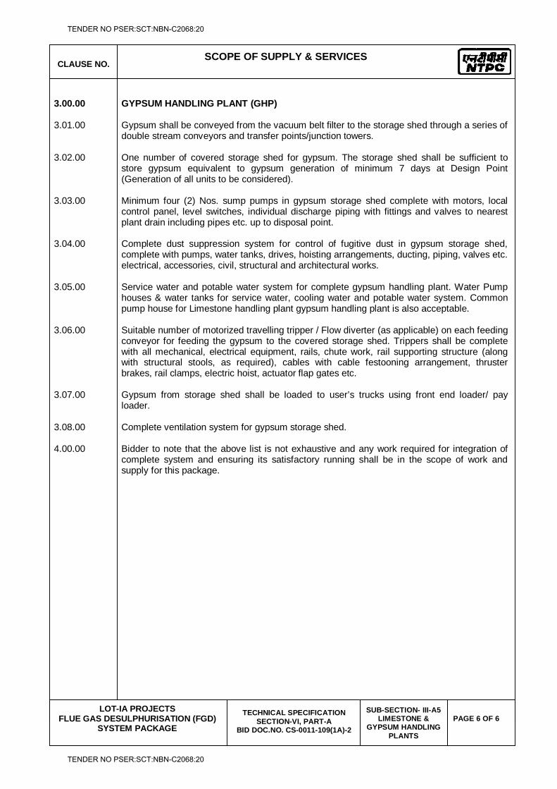
CLAUSE NO.
SCOPE OF SUPPLY & SERVICES
LOT-IA PROJECTS
FLUE GAS DESULPHURISATION (FGD) SYSTEM PACKAGE
TECHNICAL SPECIFICATION SECTION-VI, PART-A
BID DOC.NO. CS-0011-109(1A)-2
SUB-SECTION- III-A5
LIMESTONE & GYPSUM HANDLING
PLANTS
PAGE 6 OF 6
3.00.00 GYPSUM HANDLING PLANT (GHP) 3.01.00 Gypsum shall be conveyed from the vacuum belt filter to the storage shed through a series of
double stream conveyors and transfer points/junction towers. 3.02.00 One number of covered storage shed for gypsum. The storage shed shall be sufficient to
store gypsum equivalent to gypsum generation of minimum 7 days at Design Point (Generation of all units to be considered).
3.03.00 Minimum four (2) Nos. sump pumps in gypsum storage shed complete with motors, local
control panel, level switches, individual discharge piping with fittings and valves to nearest plant drain including pipes etc. up to disposal point.
3.04.00 Complete dust suppression system for control of fugitive dust in gypsum storage shed,
complete with pumps, water tanks, drives, hoisting arrangements, ducting, piping, valves etc. electrical, accessories, civil, structural and architectural works.
3.05.00 Service water and potable water system for complete gypsum handling plant. Water Pump
houses & water tanks for service water, cooling water and potable water system. Common pump house for Limestone handling plant gypsum handling plant is also acceptable.
3.06.00 Suitable number of motorized travelling tripper / Flow diverter (as applicable) on each feeding
conveyor for feeding the gypsum to the covered storage shed. Trippers shall be complete with all mechanical, electrical equipment, rails, chute work, rail supporting structure (along with structural stools, as required), cables with cable festooning arrangement, thruster brakes, rail clamps, electric hoist, actuator flap gates etc.
3.07.00 Gypsum from storage shed shall be loaded to user’s trucks using front end loader/ pay
loader. 3.08.00 Complete ventilation system for gypsum storage shed. 4.00.00 Bidder to note that the above list is not exhaustive and any work required for integration of
complete system and ensuring its satisfactory running shall be in the scope of work and supply for this package.
TENDER NO PSER:SCT:NBN-C2068:20
TENDER NO PSER:SCT:NBN-C2068:20

LOT-IA PROJECTS FLUE GAS DESULPHURISATION (FGD) SYSTEM PACKAGE
TECHNICAL SPECIFICATION
SECTION-VI
BID DOCUMENT NO.: CS-0011-109(1A)-2
SUB-SECTION-III- A6
ZERO LIQUID DISCHARGE SYSTEM
TENDER NO PSER:SCT:NBN-C2068:20
TENDER NO PSER:SCT:NBN-C2068:20
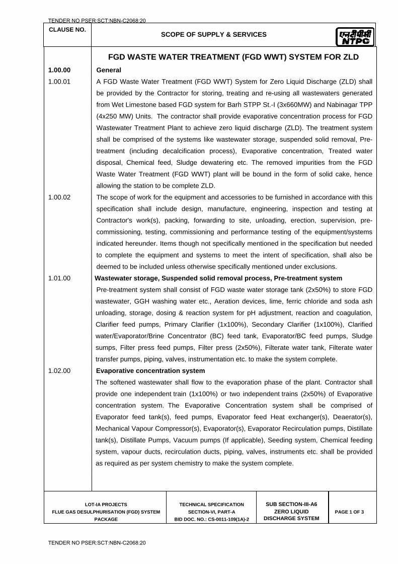
CLAUSE NO.
SCOPE OF SUPPLY & SERVICES
LOT-IA PROJECTS
FLUE GAS DESULPHURISATION (FGD) SYSTEM
PACKAGE
TECHNICAL SPECIFICATION
SECTION-VI, PART-A
BID DOC. NO.: CS-0011-109(1A)-2
SUB SECTION-III-A6 ZERO LIQUID
DISCHARGE SYSTEM
PAGE 1 OF 3
FGD WASTE WATER TREATMENT (FGD WWT) SYSTEM FOR ZLD
1.00.00 General
1.00.01 A FGD Waste Water Treatment (FGD WWT) System for Zero Liquid Discharge (ZLD) shall
be provided by the Contractor for storing, treating and re-using all wastewaters generated
from Wet Limestone based FGD system for Barh STPP St.-I (3x660MW) and Nabinagar TPP
(4x250 MW) Units. The contractor shall provide evaporative concentration process for FGD
Wastewater Treatment Plant to achieve zero liquid discharge (ZLD). The treatment system
shall be comprised of the systems like wastewater storage, suspended solid removal, Pre-
treatment (including decalcification process), Evaporative concentration, Treated water
disposal, Chemical feed, Sludge dewatering etc. The removed impurities from the FGD
Waste Water Treatment (FGD WWT) plant will be bound in the form of solid cake, hence
allowing the station to be complete ZLD.
1.00.02 The scope of work for the equipment and accessories to be furnished in accordance with this
specification shall include design, manufacture, engineering, inspection and testing at
Contractor's work(s), packing, forwarding to site, unloading, erection, supervision, pre-
commissioning, testing, commissioning and performance testing of the equipment/systems
indicated hereunder. Items though not specifically mentioned in the specification but needed
to complete the equipment and systems to meet the intent of specification, shall also be
deemed to be included unless otherwise specifically mentioned under exclusions.
1.01.00 Wastewater storage, Suspended solid removal process, Pre-treatment system
Pre-treatment system shall consist of FGD waste water storage tank (2x50%) to store FGD
wastewater, GGH washing water etc., Aeration devices, lime, ferric chloride and soda ash
unloading, storage, dosing & reaction system for pH adjustment, reaction and coagulation,
Clarifier feed pumps, Primary Clarifier (1x100%), Secondary Clarifier (1x100%), Clarified
water/Evaporator/Brine Concentrator (BC) feed tank, Evaporator/BC feed pumps, Sludge
sumps, Filter press feed pumps, Filter press (2x50%), Filterate water tank, Filterate water
transfer pumps, piping, valves, instrumentation etc. to make the system complete.
1.02.00 Evaporative concentration system
The softened wastewater shall flow to the evaporation phase of the plant. Contractor shall
provide one independent train (1x100%) or two independent trains (2x50%) of Evaporative
concentration system. The Evaporative Concentration system shall be comprised of
Evaporator feed tank(s), feed pumps, Evaporator feed Heat exchanger(s), Deaerator(s),
Mechanical Vapour Compressor(s), Evaporator(s), Evaporator Recirculation pumps, Distillate
tank(s), Distillate Pumps, Vacuum pumps (If applicable), Seeding system, Chemical feeding
system, vapour ducts, recirculation ducts, piping, valves, instruments etc. shall be provided
as required as per system chemistry to make the system complete.
TENDER NO PSER:SCT:NBN-C2068:20
TENDER NO PSER:SCT:NBN-C2068:20
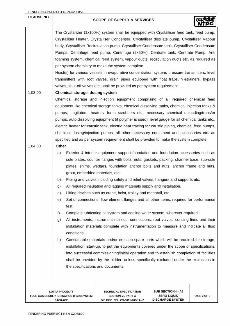
CLAUSE NO.
SCOPE OF SUPPLY & SERVICES
LOT-IA PROJECTS
FLUE GAS DESULPHURISATION (FGD) SYSTEM
PACKAGE
TECHNICAL SPECIFICATION
SECTION-VI, PART-A
BID DOC. NO.: CS-0011-109(1A)-2
SUB SECTION-III-A6 ZERO LIQUID
DISCHARGE SYSTEM
PAGE 2 OF 3
The Crystallizer (1x100%) system shall be equipped with Crystalliser feed tank, feed pump,
Crystalliser Heater, Crystalliser Condenser, Crystalliser distillate pump, Crystalliser Vapour
body, Crystalliser Recirculation pump, Crystalliser Condensate tank, Crystalliser Condensate
Pumps, Centrifuge feed pump, Centrifuge (2x50%), Centrate tank, Centrate Pump, Anti
foaming system, chemical feed system, vapour ducts, recirculation ducts etc. as required as
per system chemistry to make the system complete.
Hoist(s) for various vessels in evaporative concentration system, pressure transmitters, level
transmitters with root valves, drain pipes equipped with float traps, Y-strainers, bypass
valves, shut-off valves etc. shall be provided as per system requirement.
1.03.00 Chemical storage, dosing system
Chemical storage and injection equipment comprising of all required chemical feed
equipment like chemical storage tanks, chemical dissolving tanks, chemical injection tanks &
pumps, agitators, heaters, fume scrubbers etc., necessary chemical unloading/transfer
pumps, auto dissolving equipment (if polymer is used), level gauge for all chemical tanks etc.,
electric heater for caustic tank, electric heat tracing for caustic piping, chemical feed pumps,
chemical dosing/injection pumps, all other necessary equipment and accessories etc. as
specified and as per system requirement shall be provided to make the system complete.
1.04.00 Other
a) Exterior & interior equipment support foundation and foundation accessories such as
sole plates, counter flanges with bolts, nuts, gaskets, packing, channel base, sub-sole
plates, shims, wedges, foundation anchor bolts and nuts, anchor frame and nuts,
grout, embedded materials, etc.
b) Piping and valves including safety and relief valves, hangers and supports etc.
c) All required insulation and lagging materials supply and installation.
d) Lifting devices such as crane, hoist, trolley and monorail, etc.
e) Set of connections, flow element flanges and all other items, required for performance
test.
f) Complete lubricating oil system and cooling water system, wherever required.
g) All instruments, instrument nozzles, connections, root valves, sensing lines and their
installation materials complete with instrumentation to measure and indicate all fluid
conditions.
h) Consumable materials and/or erection spare parts which will be required for storage,
installation, start-up, to put the equipments covered under the scope of specifications,
into successful commissioning/initial operation and to establish completion of facilities
shall be provided by the bidder, unless specifically excluded under the exclusions in
the specifications and documents.
TENDER NO PSER:SCT:NBN-C2068:20
TENDER NO PSER:SCT:NBN-C2068:20
CLAUSE NO.
SCOPE OF SUPPLY & SERVICES
LOT-IA PROJECTS
FLUE GAS DESULPHURISATION (FGD) SYSTEM
PACKAGE
TECHNICAL SPECIFICATION
SECTION-VI, PART-A
BID DOC. NO.: CS-0011-109(1A)-2
SUB SECTION-III-A6 ZERO LIQUID
DISCHARGE SYSTEM
PAGE 3 OF 3
i) All the first fill & one year's topping requirement of consumable such as chemicals,
greases, oil, lubricants, servo fluids etc. which will be required to put the equipments
covered under the scope of specifications of Zero liquid discharge (ZLD) Plant for FGD
waste water, into successful commissioning/initial operation and to establish
completion of facilities shall be provided by the bidder, unless specifically excluded
under the Exclusions in these specifications and documents. Suitable standard
lubricants as available in India are desired. Effort should be made to limit the variety of
lubricants to minimum.
j) All attemperator systems including piping, control valves, isolation valves, check valves
and bypass valves.
k) Enclosures for required systems. These include sound, personnel protection, weather
and any other enclosures necessary to ensure a complete operating system.
l) Grounding pads with clamps or studs on the equipment.
m) Stairs and ladders, walkways, handrails, platforms and supports for monitoring,
operation and maintenance of all equipment furnished by the Supplier.
n) Safety showers and eye washers
o) Sample connections
p) All required modification, replacement, relocation, demolition work of existing facilities.
q) Vinyl esteric resin mortar material for tank lining.
r) All interconnecting piping, piping supports, valves and instrumentation.
s) All support platforms and access (by stairs) shall be provided. This applies to both
indoor and outdoor piping/equipment. Ladders shall be used for secondary access
only.
t) Stairs shall be able to access all platforms. All exterior steel shall be epoxy black
powder coated, no galvanized steel permitted in exterior applications.
u) The contractor shall envisage and provide any additional system as required to meet to
make the system complete.
TENDER NO PSER:SCT:NBN-C2068:20
TENDER NO PSER:SCT:NBN-C2068:20

LOT-IA PROJECTS FLUE GAS DESULPHURISATION (FGD) SYSTEM PACKAGE
TECHNICAL SPECIFICATION
SECTION-VI
BID DOCUMENT NO.: CS-0011-109(1A)-2
SUB-SECTION-III-B
ELECTRICAL SYSTEM/EQUIPMENT
TENDER NO PSER:SCT:NBN-C2068:20
TENDER NO PSER:SCT:NBN-C2068:20
CLAUSE NO.
SCOPE OF SUPPLY & SERVICES
LOT-1A PROJECTS FLUE GAS DESULPHURISATION SYSTEM
PACKAGE
TECHNICAL SPECIFICATIONS
SECTION-VI, PART-A
BID DOC NO:CS-0011-109(1A)-2
SUB-SECTION-III-B ELECTRICAL
SYSTEM/EQUIPMENT
PAGE 1 OF 6
ELECTRICAL SYSTEM / EQUIPMENT
1.00.00 GENERAL
The Contractor’s scope shall include design, engineering, manufacture, type testing, inspection & shop testing at supplier's works, packing, forwarding to site including customs clearance/ port clearance (if required), receipt and unloading, in plant transportation, handling and storage (preservation & conservation of equipment) at site, erection including associated civil and structural works, testing and commissioning of the Electrical equipment/ system and works indicated in this chapter. The scope includes all interface/ interconnections with the electrical systems under this contract as required and other systems mentioned elsewhere. Unless explicitly stated to be common for all the units, the Contractor shall provide all system/equipment for each of the units. The Electrical scope shall be as described briefly in the following clauses but not limited to it.
1.01.00 MOTORS
Motors along with couplings and coupling guards for all rotating auxiliaries covered under this package.
1.02.00 HT/ LT SWITCH GEAR
HT and 415V Switchgear / Motor control centers (as shown in Electrical Single Line Diagram Drg No. 0011-109-POE-J-001) Busduct / Cable (as applicable), distribution boards, AC/DC fuse boards, LDB, local emergency push button stations for all drives energized from MCC's under contractor scope and local motor starters (for ventilation fans) as required for plant and equipment in contractor’s scope.
1.03.00 DC SYSTEM
Battery and Battery Charger
Lead acid plante type/ Nickel Cadmium batteries and Float cum boost chargers for plant and equipment in the scope of the contractor, as per system requirement. The DC system (Battery and Charger) shall be supplied to cater to various DC loads in the plant. The design and sizing criteria shall be as detailed out in the chapter B-0, Part-B of Technical specifications.
1.04.00 TRANSFORMERS
Transformers as per Electrical Single Line Diagram Drg No. 0011-109-POE-J-001 and system requirement, however bidder to provide complete sizing & selection criteria of Transformer’s feeding Contractor’s own systems.
1.05.00 ELECTRIC ACTUATORS
Electric actuators with integral starters along with associated accessories etc shall be supplied on as required basis for Valves / Dampers to meet the functional and the other specification requirements.
TENDER NO PSER:SCT:NBN-C2068:20
TENDER NO PSER:SCT:NBN-C2068:20
CLAUSE NO.
SCOPE OF SUPPLY & SERVICES
LOT-1A PROJECTS FLUE GAS DESULPHURISATION SYSTEM
PACKAGE
TECHNICAL SPECIFICATIONS
SECTION-VI, PART-A
BID DOC NO:CS-0011-109(1A)-2
SUB-SECTION-III-B ELECTRICAL
SYSTEM/EQUIPMENT
PAGE 2 OF 6
1.06.00 CABLES / BUSDUCT
All HT/ LT power & control cables required for connection between equipment/devices in contractors scope and cables / Busduct (as applicable) between employers and contractors equipment as per Electrical Single Line Diagram Drg No. 0011-109-POE-J-001).
1.07.00 DG SET (IF APPLICABLE)
Diesel Generator sets of stationary type comprising the following:
(1.) Diesel Engine Complete with all accessories
(2.) An alternator directly coupled to engine through flexible/rigid coupling complete with all accessories (CT's & VT's etc.)
(3.) Control Panel
(4.) Complete starting arrangement along with battery ,its charger
(5.) Base frame and foundation bolts etc.
(6.) Exhaust ducting meeting the statuary requirements, accessories, support structure and foundation bolts.
(7.) Day Oil Tank, fuel piping and accessories
(8.) Interconnection piping and accessories
(9.) Power and control cable gland and lugs at Bidder’s equipment for all cables
(10.) Cable & Cabling between Bidder’s equipment.
(11.) All lubricants for first filling, consumables and touch up paints etc for commissioning.
(12.) Acoustic enclosure meeting the statuary requirements. Necessary ventilation along with necessary starters & lighting shall be provided.
1.08.00 CABLING
1) Contractor shall provide cable trays and their accessories with support arrangements, trestle, trenches, duct bank etc. as required for the cables under his scope of supply for the complete system. However the Cable tray, supports and tray earthing for contractor cables on employer cable vault shall be supplied by employer.
2) Contractor scope shall include laying of cable from employer board as shown
in Electrical Single Line Diagram Drg No. 0011-109-POE-J-001 on the employers nearest trestle in the FGD area as shown in Drg no 0011-999-POC-F-001 subject to availability of space and suitability. In case of non availability of space in employer’s trestle, contractor shall make necessary arrangements for cable tray erection & cable laying. Further Contractor shall
TENDER NO PSER:SCT:NBN-C2068:20
TENDER NO PSER:SCT:NBN-C2068:20
CLAUSE NO.
SCOPE OF SUPPLY & SERVICES
LOT-1A PROJECTS FLUE GAS DESULPHURISATION SYSTEM
PACKAGE
TECHNICAL SPECIFICATIONS
SECTION-VI, PART-A
BID DOC NO:CS-0011-109(1A)-2
SUB-SECTION-III-B ELECTRICAL
SYSTEM/EQUIPMENT
PAGE 3 OF 6
supply cables, trestle, trenches, duct bank, cable slit, cable trays and structure etc. from employer trestle to the equipment in FGD area in the contractor's scope.
3) Contractor shall supply, lay and terminate the cables under his scope of
supply
4) The contractor shall furnish the complete and consolidated feeder list for DC system, LT system and HT system for all loads and drives under the scope of supply of contractor to employer as per the format enclosed at Annexure-A. Contractor shall indicate the location of his equipment’s in feeder load list.
5) Contractor shall provide cable glands and lugs for all equipment’s in his scope.
6) Contractor shall provide all accessories such as rigid/ flexible conduits, fittings,
junction boxes, tying materials, cable tags, and markers etc. for the cables under his scope.
7) Contractor shall provide Straight-through jointing kits for HT XLPE power cable,
LT power and control cables, Cable termination kits for HT XLPE power cables, Welding receptacles, Trefoil cable clamps, Junction boxes.
8) Contractor shall provide Galvanised steel pipes/HDPE/hume pipes/PVC pipes,
Miscellaneous items like M.S sections etc as required,
9) Contractor shall provide Fire proof cable penetration sealing system of Type-A and Type-B for cable galleries, cable exits etc
10) In addition to other drawings, Contractor shall also prepare complete
equipment layout drawings, lighting layout drawings including cable tray layout, routing, Power and control cable schedules etc
11) Control interconnection charts shall also be prepared by bidder
1.09.00 LIGHTING
Complete lighting system for internal and external areas for the plant, buildings, chimney and equipment in the bidder’s scope. Lighting fixtures complete with lamps & accessories, LED lighting fixture complete with driver circuit & accessories Lighting Panels, Chimney aviation light, Receptacles, Switch boxes. Conduits. Lighting Wires, Ceiling fans with regulators, Lighting poles. Lighting masts, Earth wires and rods, Junction boxes, Battery operated automatic self contained lighting fixture, Maintenance ladders as required are included in the bidder’s scope.
Mandatory spare parts and maintenance equipment as required.
TENDER NO PSER:SCT:NBN-C2068:20
TENDER NO PSER:SCT:NBN-C2068:20
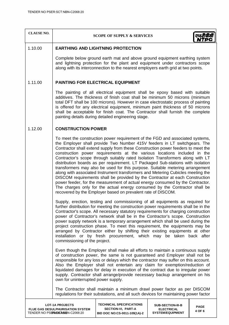
CLAUSE NO.
SCOPE OF SUPPLY & SERVICES
LOT-1A PROJECTS FLUE GAS DESULPHURISATION SYSTEM
PACKAGE
TECHNICAL SPECIFICATIONS
SECTION-VI, PART-A
BID DOC NO:CS-0011-109(1A)-2
SUB-SECTION-III-B ELECTRICAL
SYSTEM/EQUIPMENT
PAGE 4 OF 6
1.10.00 EARTHING AND LIGHTNING PROTECTION Complete below ground earth mat and above ground equipment earthing system
and lightning protection for the plant and equipment under contractors scope along with its interconnection to the nearest employers earth grid at two points.
1.11.00 PAINTING FOR ELECTRICAL EQUIPMENT The painting of all electrical equipment shall be epoxy based with suitable
additives. The thickness of finish coat shall be minimum 50 microns (minimum total DFT shall be 100 microns). However in case electrostatic process of painting is offered for any electrical equipment, minimum paint thickness of 50 microns shall be acceptable for finish coat. The Contractor shall furnish the complete painting details during detailed engineering stage.
1.12.00 CONSTRUCTION POWER
To meet the construction power requirement of the FGD and associated systems, the Employer shall provide Two Number 415V feeders in LT switchgears. The Contractor shall extend supply from these Construction power feeders to meet the construction power requirements at the various locations included in the Contractor’s scope through suitably rated Isolation Transformers along with LT distribution boards as per requirement. LT Packaged Sub-stations with isolation transformers may also be used for this purpose. Suitable metering arrangement along with associated Instrument transformers and Metering Cubicles meeting the DISCOM requirements shall be provided by the Contractor at each Construction power feeder, for the measurement of actual energy consumed by the Contractor. The charges only for the actual energy consumed by the Contractor shall be recovered by the Employer based on prevalent rate of DISCOM.
Supply, erection, testing and commissioning of all equipments as required for further distribution for meeting the construction power requirements shall be in the Contractor's scope. All necessary statutory requirements for charging construction power of Contractor’s network shall be in the Contractor’s scope. Construction power supply network is a temporary arrangement which shall be used during the project construction phase. To meet this requirement, the equipments may be arranged by Contractor either by shifting their existing equipments at other installation or by fresh procurement, which may be taken back after commissioning of the project.
Even though the Employer shall make all efforts to maintain a continuous supply of construction power, the same is not guaranteed and Employer shall not be responsible for any loss or delays which the contractor may suffer on this account. Also the Employer shall not entertain any claim for exemption/reduction of liquidated damages for delay in execution of the contract due to irregular power supply. Contractor shall arrange/provide necessary backup arrangement on his own for uninterrupted power supply.
The Contractor shall maintain a minimum drawl power factor as per DISCOM regulations for their substations, and all such devices for maintaining power factor
TENDER NO PSER:SCT:NBN-C2068:20
TENDER NO PSER:SCT:NBN-C2068:20
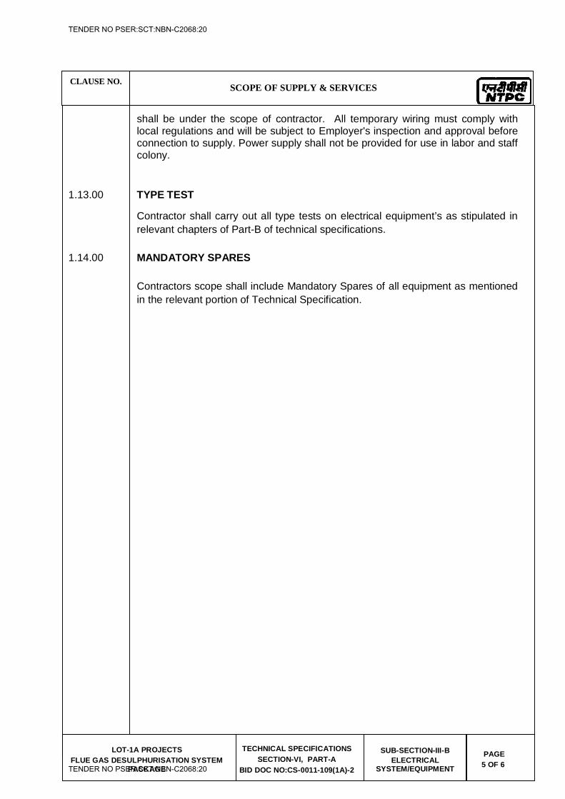
CLAUSE NO.
SCOPE OF SUPPLY & SERVICES
LOT-1A PROJECTS FLUE GAS DESULPHURISATION SYSTEM
PACKAGE
TECHNICAL SPECIFICATIONS
SECTION-VI, PART-A
BID DOC NO:CS-0011-109(1A)-2
SUB-SECTION-III-B ELECTRICAL
SYSTEM/EQUIPMENT
PAGE 5 OF 6
shall be under the scope of contractor. All temporary wiring must comply with local regulations and will be subject to Employer's inspection and approval before connection to supply. Power supply shall not be provided for use in labor and staff colony.
1.13.00 TYPE TEST
Contractor shall carry out all type tests on electrical equipment’s as stipulated in relevant chapters of Part-B of technical specifications.
1.14.00 MANDATORY SPARES
Contractors scope shall include Mandatory Spares of all equipment as mentioned in the relevant portion of Technical Specification.
TENDER NO PSER:SCT:NBN-C2068:20
TENDER NO PSER:SCT:NBN-C2068:20
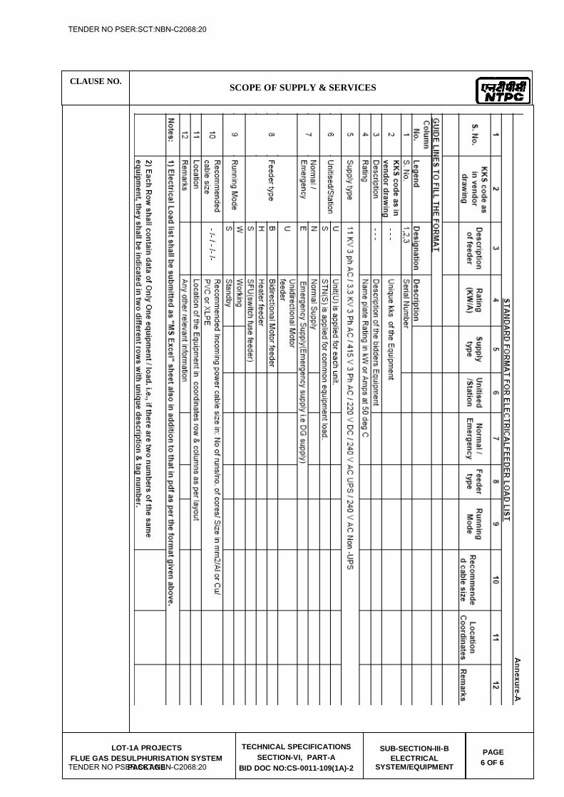
CLAUSE NO.
SCOPE OF SUPPLY & SERVICES
LOT-1A PROJECTS FLUE GAS DESULPHURISATION SYSTEM
PACKAGE
TECHNICAL SPECIFICATIONS
SECTION-VI, PART-A
BID DOC NO:CS-0011-109(1A)-2
SUB-SECTION-III-B ELECTRICAL
SYSTEM/EQUIPMENT
PAGE 6 OF 6
TENDER NO PSER:SCT:NBN-C2068:20
TENDER NO PSER:SCT:NBN-C2068:20
LOT-IA PROJECTS FLUE GAS DESULPHURISATION (FGD) SYSTEM PACKAGE
TECHNICAL SPECIFICATION
SECTION-VI
BID DOCUMENT NO.: CS-0011-109(1A)-2
SUB-SECTION-III-C
CONTROL AND INSTRUMENTATION SYSTEM
TENDER NO PSER:SCT:NBN-C2068:20
TENDER NO PSER:SCT:NBN-C2068:20
CLAUSE NO. SCOPE OF SUPPLY & SERVICES
LOT-IA PROJECTS
FLUE GAS DESULPHURISATION (FGD) SYSTEM PACKAGE
TECHNICAL SPECIFICATION
SECTION-VI, PART-A
BID DOCUMENT NO.: CS-0011-109(1A)2
SUB-SECTION-III-C
(C&I) PAGE 1 OF 8
CONTROL AND INSTRUMENTATION SYSTEM
1.00.00 GENERAL
a) The Contractor shall provide Independent Control & Instrumentation system for control, monitoring and operation of associated drives and auxiliaries in FGD system including Limestone grinding & handling system, Gypsum Dewatering & handling system, Zero liquid discharge system (ZLD) (if provided) and other systems being provided under the contract, in all regimes of operation in safe and most efficient manner. The Contractor shall provide all systems, equipment, accessories and associated equipment, which are included in Contractor’s scope, in a fully operational condition acceptable to the Employer.
b) The Contractor shall provide all material, equipment and services which may not be specifically stated in the specifications but are required for completeness of the equipment/systems furnished by the Contractor and for meeting the intent and requirements of these specifications. The work shall be consistent with modern FGD based power plant practices and shall be in compliance with all applicable codes, standards, guidelines and safety requirements in force on the date of award of the contract.
c) The Contractor shall also provide all the instruments along with cables, JB etc. for equipments / drives and services which may not be specifically stated in this specifications but are required for completeness of the FGD Control system shall be furnished by the Contractor and for meeting the intent and requirements of these specifications.
d) The Bidder scope shall include design, manufacture, engineering, inspection & testing at supplier's works, packing, forwarding to site, unloading, erection, testing & commissioning. The following clauses describe the brief scope of supplies. Scope shall be as described briefly in the following clauses but not limited to it. The detailed technical specifications are stipulated under Part - B, Section-VI of the specification as well as in various other Parts of the Technical Specifications.
2.00.00 MEASURING INSTRUMENTS
The following shall be provided as a minimum, meeting specification requirements of Sub-section - MEAS INST of Part-B, Section-VI of Technical Specification.
2.01.00 Primary instruments like Microprocessor based transmitters employing HART protocol, thermocouples & RTDs along with temperature transmitters, pressure/diff. pressure/temperature/flow (Ultrasonic/electromagnetic) transmitter & gauges, flow sensing elements (orifice plates, flow nozzles etc), Ultrasonic, Radar type level transmitters, density meter (Coriolis type. In case the bidder proposes other type of density meter as per the bidder standard and proven practice, the same shall also be acceptable except Nucleonic
TENDER NO PSER:SCT:NBN-C2068:20
TENDER NO PSER:SCT:NBN-C2068:20
CLAUSE NO. SCOPE OF SUPPLY & SERVICES
LOT-IA PROJECTS
FLUE GAS DESULPHURISATION (FGD) SYSTEM PACKAGE
TECHNICAL SPECIFICATION
SECTION-VI, PART-A
BID DOCUMENT NO.: CS-0011-109(1A)2
SUB-SECTION-III-C
(C&I) PAGE 2 OF 8
type density meter), pH analyser, SO2 analyser, Flue Gas flow transmitter, vibration transmitter, Analyzer for ZLD system etc. for:
(a) FGD plant and other system being provided under the contract, as indicated in enclosed tender diagrams (Part E) of this specification.
(b) Integral to equipment which are not indicated in the tender drawings, but are required for control, monitoring and operation of the equipment / plant systems for which no P&IDs are enclosed, all the instruments shall be provided to meet the actual system requirements and meeting redundancy and other requirements specified under technical specifications subject to Employer's approval.
(c) For Binary and analog inputs required in major equipments of FGD system, protection triple-sensing devices shall be provided. Binary and analog inputs, which are, required for protection of more than one equipment as well as protection signals for HT Drives etc., triple sensing devices shall be provided. However, for vibration measurements and protection minimum 2 number (X and Y direction) sensors per bearing shall be provided.
(d) For other critical binary and analog inputs required for protection and interlock purpose of other equipment (e.g. those interlocks which may result in loss of production, non-availability of a major equipment etc.), triple sensors shall be provided.
(e) Temperature elements, electronic transmitters etc. are to be provided for all the cases. Use of process actuated switches is acceptable only in the cases as indicated in the tender drawings.
2.02.00 Single Input DIN rail mounting type temp transmitters (mounted in JBs) shall be provided by the Contractor for all temperature elements under Contractor’s scope.
2.03.00 CONTINUOUS EMISSION MONITORING SYSTEM (CEMS)
2.03.01 CEMS comprising of analysers and associated items for measurement of SOx, NOx, CO,
CO2, Mercury, Particulate Emission (dust density/ stack opacity) monitor, Stack Flue Gas Ultrasonic Flow Meter shall be provided for each unit by the Contractor for stack emission monitoring.
A) LIST OF FLUE GAS EMISSION ANALYSERS
S. No. KKS CODE DESCRIPTION RANGE ZONE REMAR
K 1 HNE10CQ005 SOx ANALYSER 0-300/0-1000PPM
(SELECTABLE) CHIMNEY
TENDER NO PSER:SCT:NBN-C2068:20
TENDER NO PSER:SCT:NBN-C2068:20
CLAUSE NO. SCOPE OF SUPPLY & SERVICES
LOT-IA PROJECTS
FLUE GAS DESULPHURISATION (FGD) SYSTEM PACKAGE
TECHNICAL SPECIFICATION
SECTION-VI, PART-A
BID DOCUMENT NO.: CS-0011-109(1A)2
SUB-SECTION-III-C
(C&I) PAGE 3 OF 8
2 HNE10CQ001 NOx ANALYSER AT CHIMNEY
0-300/0-1000PPM (SELECTABLE)
CHIMNEY
3 HNE10CQ002 CO2 ANALYSER 0-40% CHIMNEY
4 HNE10CQ004 CO ANALYSER 0-1000 (SELECTABLE IN 0-100/0-200,0-500,0-999 PPM)
CHIMNEY
5 HNE10CQ003 OPACITY ANALYSER AT CHIMNEY
0-999 mg/m3 (PROGRAMMABLE)
CHIMNEY
6 HNE10CQ006 Mercury (Hg) Analyser
0-100 microgram/Nm3
CHIMNEY
7 HNE10CQ007 Flowmeter (Ultrasonic Time of Transit Type
- CHIMNEY
Notes:- 1) SOx, NOx, CO2 and CO analyser are shown separately for the purpose of input only, otherwise SOX, NOX, CO2 and CO analyser may be supplied as a single unit/ Combined Unit (s) meeting specification requirement.
2) These are per unit quantities.
2.03.02 CEMS, instruments shall be provided with provision for bidirectional connectivity over Modbus/RS-232/RS-485 with Employer’s central cloud server for real time data monitoring, remote diagnostics & remote calibration checks, etc., complying with CPCB IT Division document “Protocol for real time (Emission & Effluent) data management from industries version 1.2 (10.6.2015) or the latest regulatory requirement prevailing at the time of award of the contract. All necessary hardware and software required at instrument end shall be provided by the Contractor. Necessary details like scheme, register addresses of analyzer, etc. shall also be provided by the Contractor for implementation of above. The Contractor shall fully assist NTPC’s agency involved in implementation of above connectivity.
For CEMS - In addition to above requirement, 4-20 mA connectivity to DDCMIS shall be provided by the Contractor
2.03.03 Comprehensive Annual Maintenance Contract (AMC) for three (03) years after warranty period shall be provided by the contractor for CEMS.
2.04.00 SERVICES DURING DEFECT LIABILITY PERIOD FOR CEMS 2.04.01 The Contractor shall provide an unlimited warranty on all equipments during the Defect
liability period. This warranty shall include repair, replacement, replenishment of consumables (for e.g. reagents, calibration gases etc. as applicable) and correction of identified discrepancies including Analysers, Sample Handling System, Transmitters, (as applicable) etc. at no cost to Employer.
2.04.02 The Contractor shall provide warranty spares including components for each system based
on (and keeping adequate over margin) normally experienced failure rate. Exhaustive list of
TENDER NO PSER:SCT:NBN-C2068:20
TENDER NO PSER:SCT:NBN-C2068:20
CLAUSE NO. SCOPE OF SUPPLY & SERVICES
LOT-IA PROJECTS
FLUE GAS DESULPHURISATION (FGD) SYSTEM PACKAGE
TECHNICAL SPECIFICATION
SECTION-VI, PART-A
BID DOCUMENT NO.: CS-0011-109(1A)2
SUB-SECTION-III-C
(C&I) PAGE 4 OF 8
all such items shall be submitted along with Datasheet for Employer's review and approval during details Engg stage regarding adequacy of the same. The warranty spares as per the list mentioned above will be dispatched by the Contractor along with the main equipment consignment. However for items which have a limited shelf life shall be dispatched in a phased manner during the warranty period. Unused spares/consumables shall be Contractor’s property after expiry of warranty period and shall be taken back.
2.05.00 SERVICES DURING ANNUAL MAINTENANCE CONTRACT (AMC) PERIOD FOR CEMS 2.05.01 The Contractor shall provide complete maintenance services for each System under
comprehensive Annual Maintenance Contract (AMC) for period of three years after the Warranty period.
2.05.02 The AMC shall cover total maintenance of all Analysers, Sample Handling System
,Transmitters etc. coming under the scope of each system and shall include free repair/replacement of each items, replenishment of consumables, correction of problems (if any) and supply of expendable items.
2.05.03 Further, Contractor may note that during the AMC he will be allowed to use Employer's
mandatory spares, but has to replenish the same within three months’ time or before completion of AMC period whichever is earlier.
2.05.04 The Contractor shall prepare detailed list of faults corrected and parts, expendables utilized
during AMC period and shall furnish the same to Employer, properly documented at the end of AMC period. Further, during AMC period the details as required by Employer/ Project Manager shall be made available by Contractor's personnel.
2.05.05 Contractor shall also provide a list of all required AMC spares which shall be finalized along
with datasheet during detail Engineering stage. These spares will be dispatched by the Contractor at the beginning of AMC on yearly requirement basis. However for items which have a limited shelf life shall be dispatched in a phased manner during the AMC period. Unused spare/consumable shall be Contractor’s property after expiry of AMC period and shall be taken back.
2.06.00 DEPUTATION OF ENGINEER/ TECHNICAL EXPERT FOR CEMS 2.06.01 Contractor shall depute Technical Experts of the OAM /OEM/OES/ (Original Analyser
Manufacturer/Original Equipment Manufacturer/Original Equipment supplier) for each of the above system at Site, who will be fully qualified to perform the required duties, supervision of maintenance, repair etc. for a period of six month. Employer will intimate the contractor two weeks advance notice for start of deputation period.
2.06.02 After expiry of above six month period, Technical expert for each system shall visit site on
monthly basis for monitoring the performance and rectify the problem (if any) for each system for the remaining warranty period and during entire AMC period. In the event of any malfunction/fault/failure in the system or any component thereof contractor shall depute Technical expert of respective system to reach site within 48hrs of call raised by site during the remaining warranty period and entire AMC period.
TENDER NO PSER:SCT:NBN-C2068:20
TENDER NO PSER:SCT:NBN-C2068:20
CLAUSE NO. SCOPE OF SUPPLY & SERVICES
LOT-IA PROJECTS
FLUE GAS DESULPHURISATION (FGD) SYSTEM PACKAGE
TECHNICAL SPECIFICATION
SECTION-VI, PART-A
BID DOCUMENT NO.: CS-0011-109(1A)2
SUB-SECTION-III-C
(C&I) PAGE 5 OF 8
3.00.00 PROCESS CONNECTION & PIPING
Process connection & piping including LIE / LIR, all impulse piping, pneumatic piping/tubing, valves, valve manifolds, fittings and all other accessories shall be provided on as required basis for proper installation & completeness of impulse piping system and air supply system, as stipulated under Sub-section PCP, Part-B, Section-VI of Technical Specification.
4.00.00 INSTRUMENTATION CABLES, C & I SYSTEM, POWER SUPPLY DISTRIBUTION CABLES & CABLE SUB-TRAYS
a) All instrumentation cables (twisted & shielded, FRLS PVC insulated and sheathed), data highway / fibre optical cables including prefabricated cables (with plug-in connectors), cables as applicable for direct interconnection of two equipment/ system/ devices in Contractor’s scope as well as for connection of signals from/to systems like MCC/LT SWGR/HT SWGR etc. (even if they are not in Contractor’s Scope.) shall be provided by Contractor on as required basis.
b) All power supply distribution cables required for directly connecting two equipment / systems devices in contractor’s scope shall be provided by the contractor. All these cables shall be FRLS & as per IS-1554 Part – I latest edition.
c) Above cables shall be provided along with necessary laying & termination accessories, hardware etc. meeting requirements specified under Sub-section INST CABLE, Part -B, Section-VI of Technical Specification. All sub trays along with supporting, connecting hardware etc. required for laying of instrumentation, control, power and other cables etc. up to main cable trays are under Bidders scope.
d) Cables required for interfacing PLC control system with Employers DDCMIS (both SG and BOP) located in CER shall be in bidder’s scope.
e) Cables for connectivity of CEMS signals to Employer’s Unit DDCMIS located in unit CER shall be in bidder’s scope.
f) Junction boxes and power distribution boards for C&I Systems with requisite terminals shall be provided on as required basis.
5.00.00 CONTROL VALVES & ACTUATORS
5.01.00 Control valves, actuators and accessories, shall be provided on as required basis for meeting requirements specified under Sub-section CONTROL VALVE, Part-B, Section-VI of Technical Specification. Specially designed valves/trims to prevent cavitations and limit noise and control outlet velocity, shall be provided.
5.02.00 Microprocessor Based Electronic Positioner is to be provided on as required basis with all the Control valves and all control dampers being provided by the contractor.
TENDER NO PSER:SCT:NBN-C2068:20
TENDER NO PSER:SCT:NBN-C2068:20
CLAUSE NO. SCOPE OF SUPPLY & SERVICES
LOT-IA PROJECTS
FLUE GAS DESULPHURISATION (FGD) SYSTEM PACKAGE
TECHNICAL SPECIFICATION
SECTION-VI, PART-A
BID DOCUMENT NO.: CS-0011-109(1A)2
SUB-SECTION-III-C
(C&I) PAGE 6 OF 8
6.00.00 CONTROL SYSTEM
6.01.00 Instrumentation and Control System with interlocks, protection and annunciation for FGD system and other system being provided under the contract shall be provided with Software and hardware as required to provide a complete functioning of the system. Dual processor based PLC system with PC based Operator Work Station (OWS), programmable station and A4 size color Laser printer etc. on as required basis (to be decided during detail Engineering) for controlling and monitoring of the FGD and associated system being provided under the contract located in FGD control room. One OWS shall also be provided with capabilities of programming station of PLC and Human Machine Interface system (EWS cum OWS). The PLC configuration drawing shall be as per Tender drawing no. 0000-151-POI-A-013. Depending on the cable distance between FGD control room and FGD system such as Gypsum handling system, Limestone handling system etc, requirement of Remote Input Output (RIO) shall be finalized during detail engineering, In such cases, contractor to provide RIO on as required basis.
6.02.00 The Bidder shall provide software license for all software being used in Bidder’s System. The software licenses shall be provided for the organization i.e. it should not be site-specific and shall also not be hardware/machine-specific. That is, if any hardware/machine is upgraded or changed, the same license shall hold good and it shall not be necessary for Owner to seek a new license/renew license due to up gradation/change of hardware/machine in Bidder’s System at site. All licenses shall be valid for the continuous service life of the plant.
6.03.00 For each equipment/drives/pumps where Local Operation is envisaged in addition to control system as mentioned in respective Mechanical Sections, Bidder to consider Local Push button station comprising following: a) Start Push Button b) Stop Push Button c) ON Running Lamp d) OFF Lamp e) MCC Disturbance Indicating Lamp
6.04.00 Contractor has to provide KKS codes for instrument and drives in the P&ID and other related document.
6.05.00 The minimum quantity per unit of furniture envisaged in FGD control room is as mentioned below:
a) Chair-4 nos.
b) Printer table- 1 no
c) Computer table- 2 no.
d) Key pad- 1 no.
e) Locker set -1 no
TENDER NO PSER:SCT:NBN-C2068:20
TENDER NO PSER:SCT:NBN-C2068:20
CLAUSE NO. SCOPE OF SUPPLY & SERVICES
LOT-IA PROJECTS
FLUE GAS DESULPHURISATION (FGD) SYSTEM PACKAGE
TECHNICAL SPECIFICATION
SECTION-VI, PART-A
BID DOCUMENT NO.: CS-0011-109(1A)2
SUB-SECTION-III-C
(C&I) PAGE 7 OF 8
6.06.00 Complete wiring / cabling from field devices to panels / MCC and vice versa including conduits / trays / fixtures etc. shall be in bidders scope.
6.07.00 Microprocessor based modular 24V DC power supply system shall be used for powering the control systems including its network devices.
24V DC power supply system for PLC based control system shall comprise of two sets, each set shall consist of 1 x 100% microprocessor controlled, intelligent, modular rectifier banks, Controller – one for each rectifier bank, 1 x 100% Nickel - Cadmium batteries for one (1) hour duty, 1 X 100% DC distribution board. 1x100% Microprocessor controlled Battery Health Monitoring System (BHMS)–common for both the sets.
Contractor shall provide UPS of suitable capacity for the intended application meeting the requirements of Technical Specifications as per Cl. No. 9.05.00, Part B, III-C5.
Contractor to note that UPS of configuration C is acceptable only upto 5 KVA. In case the consolidated load requirements exceeds 5 KVA, Contractor to provide UPS with Configuration B in place of Configuration C as per Technical Specifications as per Cl. No 9.05.00, Part B, III-C5.
Bidder shall provide power supply distribution panels/cabinets/boxes for sub distribution of DC/Main UPS/Utility feeders on as required basis. The power supply distribution box shall include change over circuitry, switch fuse units, MCBs, terminal blocks etc. suitable for application.
For detailed requirements of FGD system, refer Sub-Section III-C, Part B Section VI of technical specifications.
7.00.00 TYPE TEST REQUIREMENT
The type tests to be conducted for C&I systems & equipments shall be as detailed out in Sub-Section-C-06 Type Test Requirements, Part-B, Section-VI of Technical Specification.
8.00.00 TOOLS & TACKLES
The Contractor shall furnish a complete new set of all special tools and tackles of reputed make and model which are required for erection, ease in maintenance to have minimum down time, testing and calibration of all the equipments and systems to be provided by the Contractor under this specification for C&I systems.
9.00.00 Interfacing with Employer’s DDCMIS
9.01.00 Hardwired Signal exchange: Hardwired signal exchange between BOP DDCMIS (under Employer's scope) and FGD PLC (under Contractor's scope) like bypass damper status, inlet and outlet gates status, ID Fans status, ESPs status, Boiler Load Index (BLI), MFT etc. shall be provided on as required basis, for implementation of protections and interlocks. Contractor
TENDER NO PSER:SCT:NBN-C2068:20
TENDER NO PSER:SCT:NBN-C2068:20
CLAUSE NO. SCOPE OF SUPPLY & SERVICES
LOT-IA PROJECTS
FLUE GAS DESULPHURISATION (FGD) SYSTEM PACKAGE
TECHNICAL SPECIFICATION
SECTION-VI, PART-A
BID DOCUMENT NO.: CS-0011-109(1A)2
SUB-SECTION-III-C
(C&I) PAGE 8 OF 8
shall provide Remote Input Output (RIO) for PLC per unit, placed in Central Equipment Room (CER) for the same. However, contractor to consider IOs and cables for minimum number of hardwired signal exchange per unit as follows DI – 80, DO – 80, AI – 20 and AO – 20. NTPC shall provide 2 (Two) nos. of 24V DC power supply feeders in CER for powering RIO panel.
9.02.00 Control, operation and monitoring of FGD and associated system being provided under the contract is primarily envisaged from Contractor's OWS placed in FGD control room. In addition to above, it is also envisaged to control, operate and monitor FGD and associated system remotely from main plant Central Control Room (CCR). To achieve the above the Contractor shall provide the following:
1) The FGD plant operation shall be made available through Ethernet link following TCP/IP standard. The system shall be OPC compliant.
2) Contractor shall provide necessary hardware and software for dual fibre optic connectivity & interconnection with station wide LAN for transfer of signals. All required plant data shall be transferred to / from through links ensuring complete security. The exact number of points to be transferred through the above communication link and the format of the data shall be finalized during detailed engineering.
3) The Contractor shall provide all assistance to the BOP C&I (in Employer’s scope) supplier including co-ordination and flow of required information etc.
4) Contractor shall provide complete logics for FGD and associated system such as booster fan blade pitch control, FGD bypass damper control, FGD inlet and outlet gate control etc. FGD OEM shall furnish recommendations, if any, for implementation in employer’s DDCMIS for boiler control.
9.03.00 Bidder to visit site to estimate the distance between FGD control room and Employer’s CCR/CER.
10.00.00 Grounding System
Suitable electronic grounding is to be provided by the contractor for all C&I equipments/panels/desk in the scope of the contractor. The exact scheme shall be as finalized during detailed engineering. Also Refer tender drawing 0000-999-POI-019A and Sub-Section titled “Basic Design Criteria” in Part-B, of this Technical Specification.
TENDER NO PSER:SCT:NBN-C2068:20
TENDER NO PSER:SCT:NBN-C2068:20

LOT-IA PROJECTS FLUE GAS DESULPHURISATION (FGD) SYSTEM PACKAGE
TECHNICAL SPECIFICATION
SECTION-VI
BID DOCUMENT NO.: CS-0011-109(1A)-2
SUB-SECTION-III-D
CIVIL WORKS
TENDER NO PSER:SCT:NBN-C2068:20
TENDER NO PSER:SCT:NBN-C2068:20
CLAUSE NO.
SCOPE OF SUPPLY & SERVICES
LOT-IA PROJECTS
FLUE GAS DESULPHURISATION (FGD) SYSTEM PACKAGE
TECHNICAL SPECIFICATION
SECTION-VI, PART-A
BID DOCUMENT NO.: CS-0011-109(1A)2
SUB-SECTION-III-D
CIVIL WORKS PAGE 1 OF 4
1.00.00 SCOPE OF CIVIL WORKS
1.01.01 Scope of Bidder shall include all Civil, Structural, Architectural works including underground facilities like drainage, sewerage, trenches, earthing mat/ grounding, of all the facilities associated with complete Flue gas desulfurization (FGD) system, Zero Liquid Discharge (ZLD) system & Chimney as specified elsewhere in the technical specification.
1.02.00 The work to be performed under this specification consists of providing all labour, materials, construction equipment, tools and plant, scaffolding, supplies, transportation, all incidental items not shown or specified, but reasonably implied or necessary for successful completion of the work including Bidder’s supervision and in strict accordance with the drawings and specifications. The nature of work shall generally involve earthwork in excavation & deep underground excavation, extensive de-watering, shoring and strutting, sheet piling, back filling around completed structures and plinth protection, paving , disposal of surplus excavated materials, piling, concreting including reinforcement and form work, brick work, fabrication and erection of structural / miscellaneous steel works, inserts, architectural items & finishes such as plastering, painting, flooring, doors, windows & ventilators, glass and glazing, rolling shutters etc., permanently colour coated profiled steel sheeting, anchor bolts, R. C. C. trenches with covers, laying and testing of water pipes, sanitation, water supply, drainage, damp proofing, water proofing and other ancillary items.
1.03.00 The work shall have to be carried out both below and above ground level and shall be involving, basements, equipment foundations, grounding, slabs, beams, columns, footings, rafts, walls, steel frames, brick walls, stairs, trenches, pits, access roads, culverts, trestles, finishes, false ceiling and complete architectural works, etc.
The works covered under the scope of the bidder have to be executed in an operating / under construction power station. The bidder shall take all necessary precautions to protect the entire existing equipments, structures, facilities and buildings etc. from damage. In case any damage occurs due to activities of the bidder on account of negligence, ignorance, accidental or any other reason what so ever, the damage shall be made - good by the bidder at his own cost to the satisfaction of the Owner. The bidder shall take all necessary safety measures to avoid any harm, injury to his workers/staff from the equipment / facilities of the power station.
1.04.00 If during the execution of works it is found that there is interference with the existing
facilities / structures, the bidder shall revise his design / detailed drawings to clear the interference and shall provide all necessary measures for the safety of existing structures. In case the details shown in tender drawings are found to be different from actual details at site, bidder shall revise his design/ detailed drawings to suit the constraints at site. No claim in terms of cost or relaxation in time shall be entertained for any redesign, rework and for safety measures provided. If at any stage of work, any dismantling or modification or relocation of any existing facility is required to be done to complete the work in bidder’s scope and which has been agreed by the Employer, the same shall be done by the bidder at no extra cost or time implication to the Employer. All such changes will be as per drawings and work plan approved by the employer.
TENDER NO PSER:SCT:NBN-C2068:20
TENDER NO PSER:SCT:NBN-C2068:20
CLAUSE NO.
SCOPE OF SUPPLY & SERVICES
LOT-IA PROJECTS
FLUE GAS DESULPHURISATION (FGD) SYSTEM PACKAGE
TECHNICAL SPECIFICATION
SECTION-VI, PART-A
BID DOCUMENT NO.: CS-0011-109(1A)2
SUB-SECTION-III-D
CIVIL WORKS PAGE 2 OF 4
1.05.00 Analysis, design and preparation of construction drawings for all structure/facilities under the scope of this package and getting the same approved from the owner.
1.06.00 Uniform Finished ground level (FGL) in FGD absorber area shall be made available by the owner at a level specified in tender drawing.
2.00.00 CONSTRUCTION FACILITIES
The following are also in the Bidder’s scope of work:
1. Providing drinking and service water for Bidder's labour, staff and other personnel working for Bidder at the work site and in his staff/ labour colony. He shall install necessary bore wells with associated pumping or water tankers and treatment facilities to supply quality water as per standards.
2. Developing temporary staff colony and labour colony along with fencing etc. Land if required shall be arranged by the Bidder himself.
However space required for bidder’s office, storage, pre assembly and fabrication areas shall be provided by owner free of charge within the plant premises.
The area to be allocated to the Bidder shall be discussed & finalized with the bidder after the award, keeping in view the availability of free space & similar requirement of other agencies.
3. Providing all arrangements for distribution of construction power at various locations as per his requirements from the supply point of Owner.
4. Providing all arrangements for the supply of construction water including bore-wells, water tankers etc.
5. Providing temporary construction office, construction stores (open / covered), workshops, material / field testing laboratory, any other temporary buildings
6. Providing all construction equipment, labour and materials. The Bidder shall provide all the tools and tackles required for the work.
7. Development of the pre-assembly and storage yard with fencing, drainage, internal roads, boulder soling, etc.
8. Approach road to project site is available. Further, Owner intends to construct the roads as per the layout shown in the General Layout plan in a progressive manner. Some of these roads may not be available to the bidder for his use. Similarly the drainage network for the plant site being constructed by the owner may not be available to full extent. The bidder shall plan his work within the plant area considering the above constraints of roads and drains. Access roads to his work sites, offices, stores, preassembly / fabrication yard, etc. as required for providing approach/access for men, materials, equipment, cranes, trailor, construction/erection activities etc., what so ever are required by the bidder, shall be constructed and maintained by the bidder. Bidder shall provide permanent access to all facilities/ structures from the nearby existing roads of the owner. Roads shall be in
TENDER NO PSER:SCT:NBN-C2068:20
TENDER NO PSER:SCT:NBN-C2068:20
CLAUSE NO.
SCOPE OF SUPPLY & SERVICES
LOT-IA PROJECTS
FLUE GAS DESULPHURISATION (FGD) SYSTEM PACKAGE
TECHNICAL SPECIFICATION
SECTION-VI, PART-A
BID DOCUMENT NO.: CS-0011-109(1A)2
SUB-SECTION-III-D
CIVIL WORKS PAGE 3 OF 4
concrete (M-35 grade) as per IRC standards, with minimum thickness of pavement (PQC) as 250mm. Width of all such roads shall be 7.5M concrete pavement.
9. Area lighting at the construction / erection site, pre-assembly and storage yard, office areas and labour / staff colony.
10. Providing all necessary fire-fighting devices / equipment / fire tender etc. required during the project execution stage. He shall maintain all such equipment / devices in proper working conditions throughout the period of work.
11. Providing first aid facilities at the construction / erection sites, workshops, laboratories, pre-assembly and storage yard and other places of work as per the requirement.
12. The Bidder shall arrange skilled / semiskilled / unskilled manpower from local source(s) as far as available in this country. He shall also arrange supervisory staff for quality execution of all works in his scope.
13. Bidder's office, store, workshop, laboratory or any other temporary buildings:
The Bidder shall adopt pre-engineered/ pre-fabricated constructions made of steel with single / double skin, insulated for un-insulated roof and wall coverings (fabricated out of permanently color coated metal sheets) for his site office, covered store workshop, laboratory or any other temporary buildings. Alternatively, bidder can adopt readymade `Portacabin' or similar construction. Bidder shall ensure that all such constructions are well-engineered, neatly constructed and overall present a pleasing look. The above requirements shall be applicable to his sub-vendors also and bidder shall be responsible for enforcing the same on his sub-vendors.
Any other type of construction if proposed by the bidder shall be subject to approval of the owner. However, such construction shall be based on proper design and shall have aesthetic look.
14. Use of ash and ash based products:
In line with Gazette Notification on Ash Utilization issued by MOEF and its amendment thereafter, Bidder shall use ash and ash based products in construction of his offices, stores, staff quarters and labour huts etc. He shall furnish a compliance report along with all details of use of ash and ash based products along with each bill. The above requirements shall be applicable to his sub-vendors also and Bidder shall be responsible for enforcing the same on his sub-vendors.
15. Repair & Maintenance Facilities by the Bidder:
Bidder shall establish/set up at site suitable repair facilities for construction plant, equipment and machinery (like cranes, hydra, forklifts, welding equipments, etc.) He will also make arrangements/tie up with manufacturers/ suppliers of such construction plant, equipment & machinery, for periodic overhaul/maintenance and for major breakdown, if any. He shall also keep
TENDER NO PSER:SCT:NBN-C2068:20
TENDER NO PSER:SCT:NBN-C2068:20
CLAUSE NO.
SCOPE OF SUPPLY & SERVICES
LOT-IA PROJECTS
FLUE GAS DESULPHURISATION (FGD) SYSTEM PACKAGE
TECHNICAL SPECIFICATION
SECTION-VI, PART-A
BID DOCUMENT NO.: CS-0011-109(1A)2
SUB-SECTION-III-D
CIVIL WORKS PAGE 4 OF 4
adequate stock of spares at site for various construction plant, equipment and machinery to meet day to day requirements as recommended by the equipment manufacturer/suppliers or as instructed by the Engineer. Bidder shall deploy dedicated qualified, full time mechanical/electrical foreman/supervisors for manning the repair facilities as specified above.
TENDER NO PSER:SCT:NBN-C2068:20
TENDER NO PSER:SCT:NBN-C2068:20

LOT-IA PROJECTS FLUE GAS DESULPHURISATION (FGD) SYSTEM PACKAGE
TECHNICAL SPECIFICATION
SECTION-VI
BID DOCUMENT NO.: CS-0011-109(1A)-2
SUB-SECTION-IV
TERMINAL POINTS & EXCLUSIONS
TENDER NO PSER:SCT:NBN-C2068:20
TENDER NO PSER:SCT:NBN-C2068:20
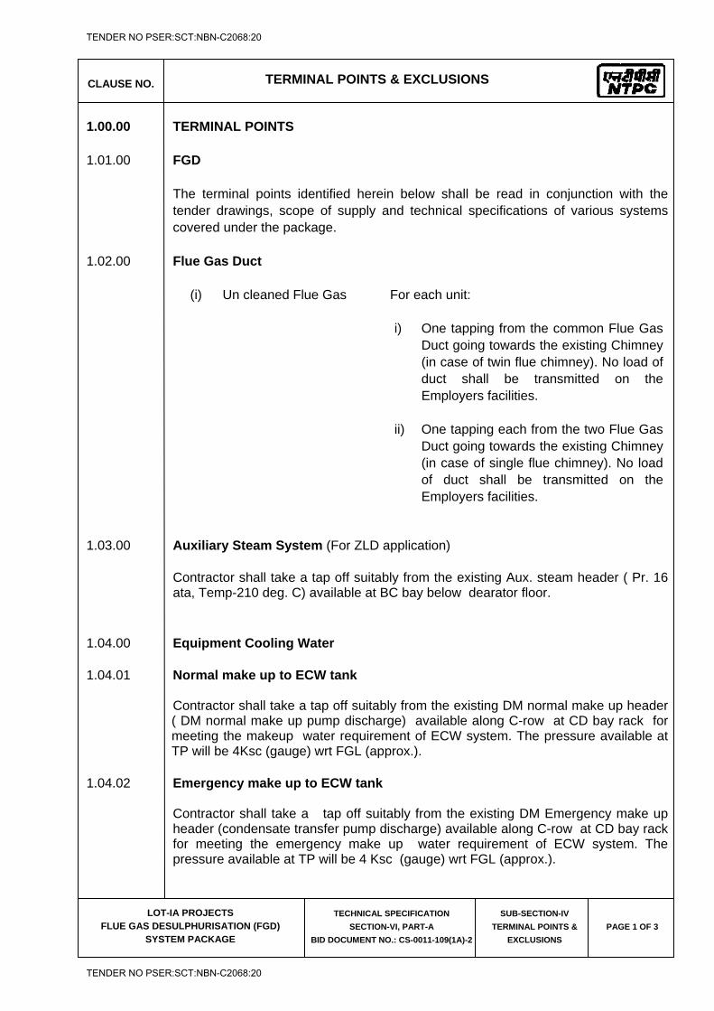
CLAUSE NO. TERMINAL POINTS & EXCLUSIONS
LOT-IA PROJECTS
FLUE GAS DESULPHURISATION (FGD) SYSTEM PACKAGE
TECHNICAL SPECIFICATION
SECTION-VI, PART-A
BID DOCUMENT NO.: CS-0011-109(1A)-2
SUB-SECTION-IV
TERMINAL POINTS &
EXCLUSIONS
PAGE 1 OF 3
1.00.00 TERMINAL POINTS 1.01.00 FGD
The terminal points identified herein below shall be read in conjunction with the tender drawings, scope of supply and technical specifications of various systems covered under the package.
1.02.00 Flue Gas Duct
(i) Un cleaned Flue Gas For each unit: i) One tapping from the common Flue Gas
Duct going towards the existing Chimney(in case of twin flue chimney). No load of duct shall be transmitted on the Employers facilities.
ii) One tapping each from the two Flue Gas Duct going towards the existing Chimney (in case of single flue chimney). No load of duct shall be transmitted on the Employers facilities.
1.03.00 Auxiliary Steam System (For ZLD application)
Contractor shall take a tap off suitably from the existing Aux. steam header ( Pr. 16 ata, Temp-210 deg. C) available at BC bay below dearator floor.
1.04.00 Equipment Cooling Water 1.04.01 Normal make up to ECW tank
Contractor shall take a tap off suitably from the existing DM normal make up header ( DM normal make up pump discharge) available along C-row at CD bay rack for meeting the makeup water requirement of ECW system. The pressure available at TP will be 4Ksc (gauge) wrt FGL (approx.).
1.04.02 Emergency make up to ECW tank
Contractor shall take a tap off suitably from the existing DM Emergency make up header (condensate transfer pump discharge) available along C-row at CD bay rack for meeting the emergency make up water requirement of ECW system. The pressure available at TP will be 4 Ksc (gauge) wrt FGL (approx.).
TENDER NO PSER:SCT:NBN-C2068:20
TENDER NO PSER:SCT:NBN-C2068:20
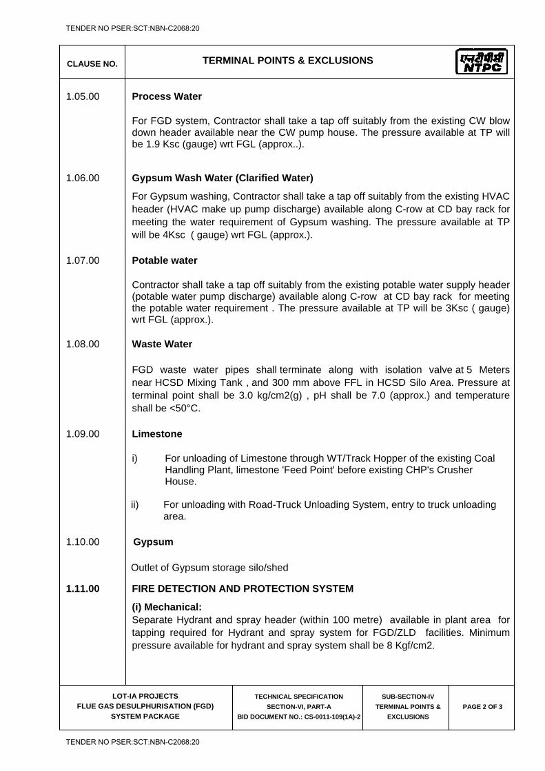
CLAUSE NO. TERMINAL POINTS & EXCLUSIONS
LOT-IA PROJECTS
FLUE GAS DESULPHURISATION (FGD) SYSTEM PACKAGE
TECHNICAL SPECIFICATION
SECTION-VI, PART-A
BID DOCUMENT NO.: CS-0011-109(1A)-2
SUB-SECTION-IV
TERMINAL POINTS &
EXCLUSIONS
PAGE 2 OF 3
1.05.00 Process Water
For FGD system, Contractor shall take a tap off suitably from the existing CW blow down header available near the CW pump house. The pressure available at TP will be 1.9 Ksc (gauge) wrt FGL (approx..).
1.06.00 Gypsum Wash Water (Clarified Water)
For Gypsum washing, Contractor shall take a tap off suitably from the existing HVAC header (HVAC make up pump discharge) available along C-row at CD bay rack for meeting the water requirement of Gypsum washing. The pressure available at TP will be 4Ksc ( gauge) wrt FGL (approx.).
1.07.00 Potable water
Contractor shall take a tap off suitably from the existing potable water supply header (potable water pump discharge) available along C-row at CD bay rack for meeting the potable water requirement . The pressure available at TP will be 3Ksc ( gauge) wrt FGL (approx.).
1.08.00 Waste Water FGD waste water pipes shall terminate along with isolation valve at 5 Meters
near HCSD Mixing Tank , and 300 mm above FFL in HCSD Silo Area. Pressure at terminal point shall be 3.0 kg/cm2(g) , pH shall be 7.0 (approx.) and temperature shall be <50°C.
1.09.00 Limestone
i) For unloading of Limestone through WT/Track Hopper of the existing Coal Handling Plant, limestone 'Feed Point' before existing CHP's Crusher House.
ii) For unloading with Road-Truck Unloading System, entry to truck unloading area.
1.10.00 Gypsum
Outlet of Gypsum storage silo/shed
1.11.00 FIRE DETECTION AND PROTECTION SYSTEM
(i) Mechanical: Separate Hydrant and spray header (within 100 metre) available in plant area for tapping required for Hydrant and spray system for FGD/ZLD facilities. Minimum pressure available for hydrant and spray system shall be 8 Kgf/cm2.
TENDER NO PSER:SCT:NBN-C2068:20
TENDER NO PSER:SCT:NBN-C2068:20
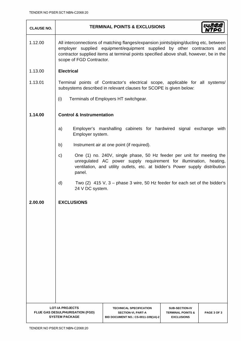
CLAUSE NO. TERMINAL POINTS & EXCLUSIONS
LOT-IA PROJECTS
FLUE GAS DESULPHURISATION (FGD) SYSTEM PACKAGE
TECHNICAL SPECIFICATION
SECTION-VI, PART-A
BID DOCUMENT NO.: CS-0011-109(1A)-2
SUB-SECTION-IV
TERMINAL POINTS &
EXCLUSIONS
PAGE 3 OF 3
1.12.00 All interconnections of matching flanges/expansion joints/piping/ducting etc, between employer supplied equipment/equipment supplied by other contractors and contractor supplied items at terminal points specified above shall, however, be in the scope of FGD Contractor.
1.13.00 Electrical 1.13.01 Terminal points of Contractor’s electrical scope, applicable for all systems/
subsystems described in relevant clauses for SCOPE is given below: (i) Terminals of Employers HT switchgear.
1.14.00 Control & Instrumentation
a) Employer’s marshalling cabinets for hardwired signal exchange with Employer system.
b) Instrument air at one point (if required).
c) One (1) no. 240V, single phase, 50 Hz feeder per unit for meeting the unregulated AC power supply requirement for illumination, heating, ventilation, and utility outlets, etc. at bidder’s Power supply distribution panel.
d) Two (2) 415 V, 3 – phase 3 wire, 50 Hz feeder for each set of the bidder’s 24 V DC system.
2.00.00 EXCLUSIONS
TENDER NO PSER:SCT:NBN-C2068:20
TENDER NO PSER:SCT:NBN-C2068:20

LOT-IA PROJECTS FLUE GAS DESULPHURISATION (FGD) SYSTEM PACKAGE
TECHNICAL SPECIFICATION
SECTION-VI
BID DOCUMENT NO.: CS-0011-109(1A)-2
SUB-SECTION-V
SALIENT DESIGN DATA
TENDER NO PSER:SCT:NBN-C2068:20
TENDER NO PSER:SCT:NBN-C2068:20
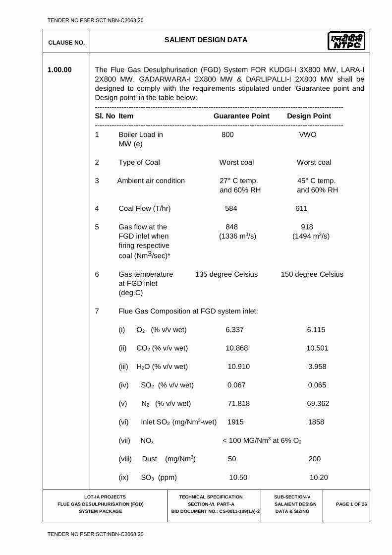
CLAUSE NO. SALIENT DESIGN DATA
LOT-IA PROJECTS
FLUE GAS DESULPHURISATION (FGD)
SYSTEM PACKAGE
TECHNICAL SPECIFICATION
SECTION-VI, PART-A
BID DOCUMENT NO.: CS-0011-109(1A)-2
SUB-SECTION-V
SALAIENT DESIGN
DATA & SIZING
PAGE 1 OF 26
1.00.00 The Flue Gas Desulphurisation (FGD) System FOR KUDGI-I 3X800 MW, LARA-I 2X800 MW, GADARWARA-I 2X800 MW & DARLIPALLI-I 2X800 MW shall be designed to comply with the requirements stipulated under 'Guarantee point and Design point' in the table below:
------------------------------------------------------------------------------------------------------- Sl. No Item Guarantee Point Design Point ------------------------------------------------------------------------------------------------------- 1 Boiler Load in 800 VWO MW (e) 2 Type of Coal Worst coal Worst coal 3 Ambient air condition 27° C temp. 45° C temp. and 60% RH and 60% RH 4 Coal Flow (T/hr) 584 611 5 Gas flow at the 848 918 FGD inlet when (1336 m3/s) (1494 m3/s) firing respective coal (Nm3/sec)* 6 Gas temperature 135 degree Celsius 150 degree Celsius at FGD inlet (deg.C) 7 Flue Gas Composition at FGD system inlet: (i) O2 (% v/v wet) 6.337 6.115 (ii) CO2 (% v/v wet) 10.868 10.501 (iii) H2O (% v/v wet) 10.910 3.958 (iv) SO2 (% v/v wet) 0.067 0.065 (v) N2 (% v/v wet) 71.818 69.362 (vi) Inlet SO2 (mg/Nm3-wet) 1915 1858 (vii) NOx < 100 MG/Nm3 at 6% O2 (viii) Dust (mg/Nm3) 50 200 (ix) SO3 (ppm) 10.50 10.20
TENDER NO PSER:SCT:NBN-C2068:20
TENDER NO PSER:SCT:NBN-C2068:20
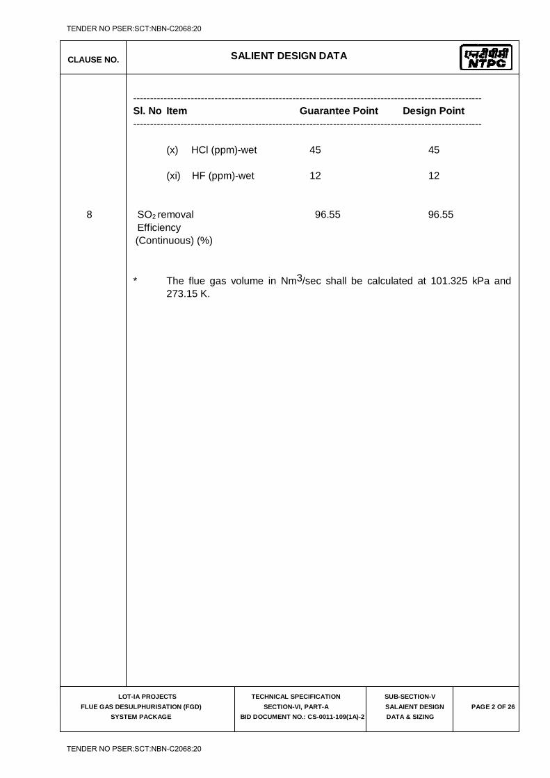
CLAUSE NO. SALIENT DESIGN DATA
LOT-IA PROJECTS
FLUE GAS DESULPHURISATION (FGD)
SYSTEM PACKAGE
TECHNICAL SPECIFICATION
SECTION-VI, PART-A
BID DOCUMENT NO.: CS-0011-109(1A)-2
SUB-SECTION-V
SALAIENT DESIGN
DATA & SIZING
PAGE 2 OF 26
------------------------------------------------------------------------------------------------------- Sl. No Item Guarantee Point Design Point ------------------------------------------------------------------------------------------------------- (x) HCl (ppm)-wet 45 45 (xi) HF (ppm)-wet 12 12 8 SO2
removal 96.55 96.55 Efficiency (Continuous) (%) * The flue gas volume in Nm3/sec shall be calculated at 101.325 kPa and
273.15 K.
TENDER NO PSER:SCT:NBN-C2068:20
TENDER NO PSER:SCT:NBN-C2068:20
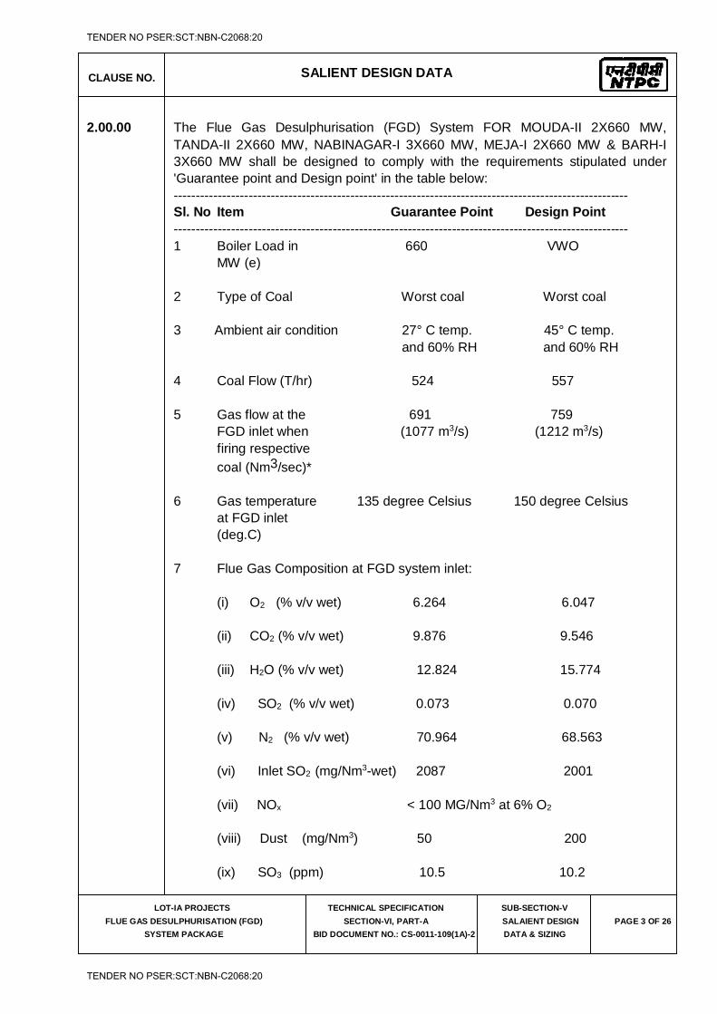
CLAUSE NO. SALIENT DESIGN DATA
LOT-IA PROJECTS
FLUE GAS DESULPHURISATION (FGD)
SYSTEM PACKAGE
TECHNICAL SPECIFICATION
SECTION-VI, PART-A
BID DOCUMENT NO.: CS-0011-109(1A)-2
SUB-SECTION-V
SALAIENT DESIGN
DATA & SIZING
PAGE 3 OF 26
2.00.00 The Flue Gas Desulphurisation (FGD) System FOR MOUDA-II 2X660 MW, TANDA-II 2X660 MW, NABINAGAR-I 3X660 MW, MEJA-I 2X660 MW & BARH-I 3X660 MW shall be designed to comply with the requirements stipulated under 'Guarantee point and Design point' in the table below:
------------------------------------------------------------------------------------------------------- Sl. No Item Guarantee Point Design Point ------------------------------------------------------------------------------------------------------- 1 Boiler Load in 660 VWO MW (e) 2 Type of Coal Worst coal Worst coal 3 Ambient air condition 27° C temp. 45° C temp. and 60% RH and 60% RH 4 Coal Flow (T/hr) 524 557 5 Gas flow at the 691 759 FGD inlet when (1077 m3/s) (1212 m3/s) firing respective coal (Nm3/sec)* 6 Gas temperature 135 degree Celsius 150 degree Celsius at FGD inlet (deg.C) 7 Flue Gas Composition at FGD system inlet: (i) O2 (% v/v wet) 6.264 6.047 (ii) CO2 (% v/v wet) 9.876 9.546 (iii) H2O (% v/v wet) 12.824 15.774 (iv) SO2 (% v/v wet) 0.073 0.070 (v) N2 (% v/v wet) 70.964 68.563 (vi) Inlet SO2 (mg/Nm3-wet) 2087 2001 (vii) NOx < 100 MG/Nm3 at 6% O2 (viii) Dust (mg/Nm3) 50 200 (ix) SO3 (ppm) 10.5 10.2
TENDER NO PSER:SCT:NBN-C2068:20
TENDER NO PSER:SCT:NBN-C2068:20

CLAUSE NO. SALIENT DESIGN DATA
LOT-IA PROJECTS
FLUE GAS DESULPHURISATION (FGD)
SYSTEM PACKAGE
TECHNICAL SPECIFICATION
SECTION-VI, PART-A
BID DOCUMENT NO.: CS-0011-109(1A)-2
SUB-SECTION-V
SALAIENT DESIGN
DATA & SIZING
PAGE 4 OF 26
------------------------------------------------------------------------------------------------------- Sl. No Item Guarantee Point Design Point ------------------------------------------------------------------------------------------------------- (x) HCl (ppm)-wet 45 45 (xi) HF (ppm)-wet 12 12 8 SO2
removal 96.91 96.91 Efficiency (Continuous) (%) * The flue gas volume in Nm3/sec shall be calculated at 101.325 kPa and
273.15 K.
TENDER NO PSER:SCT:NBN-C2068:20
TENDER NO PSER:SCT:NBN-C2068:20
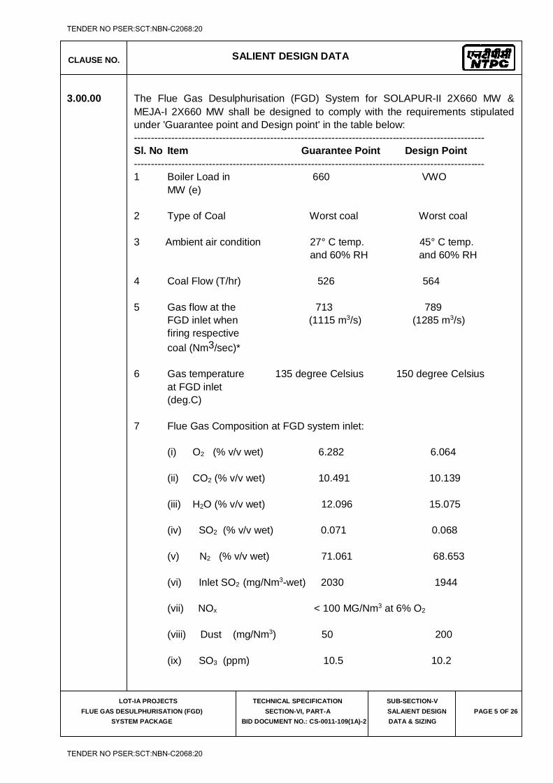
CLAUSE NO. SALIENT DESIGN DATA
LOT-IA PROJECTS
FLUE GAS DESULPHURISATION (FGD)
SYSTEM PACKAGE
TECHNICAL SPECIFICATION
SECTION-VI, PART-A
BID DOCUMENT NO.: CS-0011-109(1A)-2
SUB-SECTION-V
SALAIENT DESIGN
DATA & SIZING
PAGE 5 OF 26
3.00.00 The Flue Gas Desulphurisation (FGD) System for SOLAPUR-II 2X660 MW & MEJA-I 2X660 MW shall be designed to comply with the requirements stipulated under 'Guarantee point and Design point' in the table below:
------------------------------------------------------------------------------------------------------- Sl. No Item Guarantee Point Design Point ------------------------------------------------------------------------------------------------------- 1 Boiler Load in 660 VWO MW (e) 2 Type of Coal Worst coal Worst coal 3 Ambient air condition 27° C temp. 45° C temp. and 60% RH and 60% RH 4 Coal Flow (T/hr) 526 564 5 Gas flow at the 713 789 FGD inlet when (1115 m3/s) (1285 m3/s) firing respective coal (Nm3/sec)* 6 Gas temperature 135 degree Celsius 150 degree Celsius at FGD inlet (deg.C) 7 Flue Gas Composition at FGD system inlet: (i) O2 (% v/v wet) 6.282 6.064 (ii) CO2 (% v/v wet) 10.491 10.139 (iii) H2O (% v/v wet) 12.096 15.075 (iv) SO2 (% v/v wet) 0.071 0.068 (v) N2 (% v/v wet) 71.061 68.653 (vi) Inlet SO2 (mg/Nm3-wet) 2030 1944 (vii) NOx < 100 MG/Nm3 at 6% O2 (viii) Dust (mg/Nm3) 50 200 (ix) SO3 (ppm) 10.5 10.2
TENDER NO PSER:SCT:NBN-C2068:20
TENDER NO PSER:SCT:NBN-C2068:20

CLAUSE NO. SALIENT DESIGN DATA
LOT-IA PROJECTS
FLUE GAS DESULPHURISATION (FGD)
SYSTEM PACKAGE
TECHNICAL SPECIFICATION
SECTION-VI, PART-A
BID DOCUMENT NO.: CS-0011-109(1A)-2
SUB-SECTION-V
SALAIENT DESIGN
DATA & SIZING
PAGE 6 OF 26
------------------------------------------------------------------------------------------------------- Sl. No Item Guarantee Point Design Point ------------------------------------------------------------------------------------------------------- (x) HCl (ppm)-wet 45 45 (xi) HF (ppm)-wet 12 12 8 SO2
removal 96.91 96.91 Efficiency (Continuous) (%) * The flue gas volume in Nm3/sec shall be calculated at 101.325 kPa and
273.15 K.
TENDER NO PSER:SCT:NBN-C2068:20
TENDER NO PSER:SCT:NBN-C2068:20

CLAUSE NO. SALIENT DESIGN DATA
LOT-IA PROJECTS
FLUE GAS DESULPHURISATION (FGD)
SYSTEM PACKAGE
TECHNICAL SPECIFICATION
SECTION-VI, PART-A
BID DOCUMENT NO.: CS-0011-109(1A)-2
SUB-SECTION-V
SALAIENT DESIGN
DATA & SIZING
PAGE 7 OF 26
4.00.00 The Flue Gas Desulphurisation (FGD) System for NABINAGAR 4X250 MW shall be designed to comply with the requirements stipulated under 'Guarantee point and Design point' in the table below:
------------------------------------------------------------------------------------------------------- Sl. No Item Guarantee Point Design Point ------------------------------------------------------------------------------------------------------- 1 Boiler Load in 250 VWO MW (e) 2 Type of Coal Worst coal Worst coal 3 Ambient air condition 27° C temp. 45° C temp. and 60% RH and 60% RH 4 Coal Flow (T/hr) 210 222 5 Gas flow at the 280 307 FGD inlet when (424 m3/s) (481 m3/s) firing respective coal (Nm3/sec)* 6 Gas temperature 135 degree Celsius 150 degree Celsius at FGD inlet (deg.C) 7 Flue Gas Composition at FGD system inlet: (i) O2 (% v/v wet) 6.300 6.081 (ii) CO2 (% v/v wet) 9.988 9.652 (iii) H2O (% v/v wet) 12.320 15.303 (iv) SO2 (% v/v wet) 0.072 0.069 (v) N2 (% v/v wet) 71.320 68.895 (vi) Inlet SO2 (mg/Nm3-wet) 2059 1973 (vii) NOx < 100 MG/Nm3 at 6% O2 (viii) Dust (mg/Nm3) 50 200 (ix) SO3 (ppm) 10.50 10.20
TENDER NO PSER:SCT:NBN-C2068:20
TENDER NO PSER:SCT:NBN-C2068:20
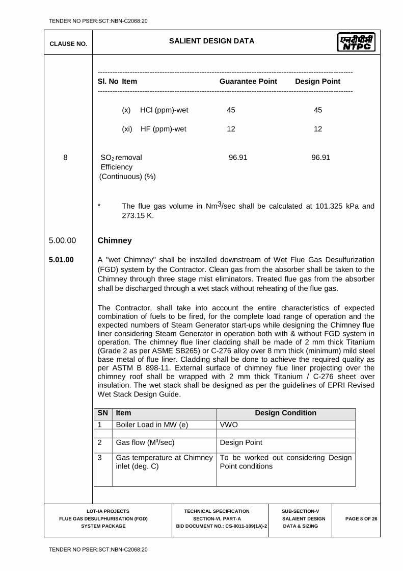
CLAUSE NO. SALIENT DESIGN DATA
LOT-IA PROJECTS
FLUE GAS DESULPHURISATION (FGD)
SYSTEM PACKAGE
TECHNICAL SPECIFICATION
SECTION-VI, PART-A
BID DOCUMENT NO.: CS-0011-109(1A)-2
SUB-SECTION-V
SALAIENT DESIGN
DATA & SIZING
PAGE 8 OF 26
------------------------------------------------------------------------------------------------------- Sl. No Item Guarantee Point Design Point ------------------------------------------------------------------------------------------------------- (x) HCl (ppm)-wet 45 45 (xi) HF (ppm)-wet 12 12 8 SO2
removal 96.91 96.91 Efficiency (Continuous) (%) * The flue gas volume in Nm3/sec shall be calculated at 101.325 kPa and
273.15 K.
5.00.00 Chimney 5.01.00 A "wet Chimney" shall be installed downstream of Wet Flue Gas Desulfurization
(FGD) system by the Contractor. Clean gas from the absorber shall be taken to the Chimney through three stage mist eliminators. Treated flue gas from the absorber shall be discharged through a wet stack without reheating of the flue gas.
The Contractor, shall take into account the entire characteristics of expected combination of fuels to be fired, for the complete load range of operation and the expected numbers of Steam Generator start-ups while designing the Chimney flue liner considering Steam Generator in operation both with & without FGD system in operation. The chimney flue liner cladding shall be made of 2 mm thick Titanium (Grade 2 as per ASME SB265) or C-276 alloy over 8 mm thick (minimum) mild steel base metal of flue liner. Cladding shall be done to achieve the required quality as per ASTM B 898-11. External surface of chimney flue liner projecting over the chimney roof shall be wrapped with 2 mm thick Titanium / C-276 sheet over insulation. The wet stack shall be designed as per the guidelines of EPRI Revised Wet Stack Design Guide.
SN Item Design Condition
1 Boiler Load in MW (e) VWO 2 Gas flow (M3/sec) Design Point
3 Gas temperature at Chimney inlet (deg. C)
To be worked out considering Design Point conditions
TENDER NO PSER:SCT:NBN-C2068:20
TENDER NO PSER:SCT:NBN-C2068:20
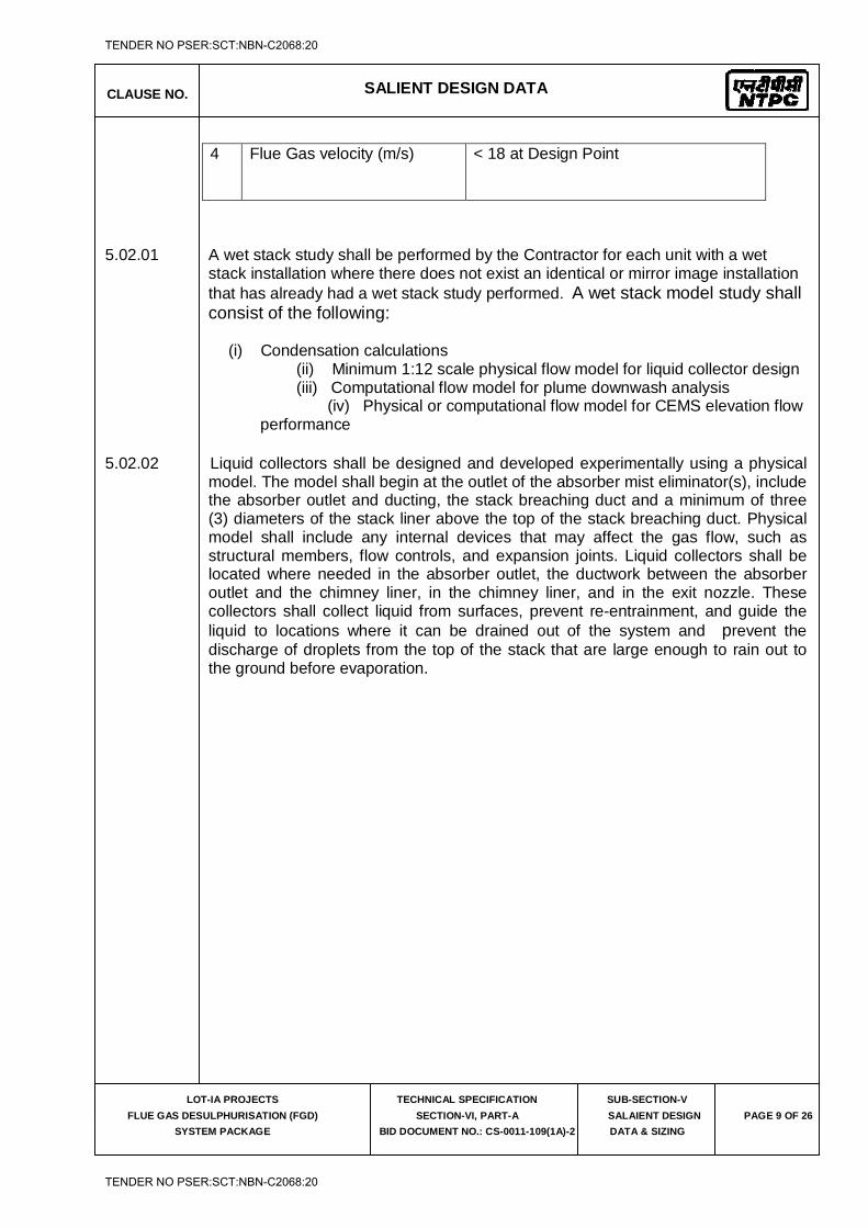
CLAUSE NO. SALIENT DESIGN DATA
LOT-IA PROJECTS
FLUE GAS DESULPHURISATION (FGD)
SYSTEM PACKAGE
TECHNICAL SPECIFICATION
SECTION-VI, PART-A
BID DOCUMENT NO.: CS-0011-109(1A)-2
SUB-SECTION-V
SALAIENT DESIGN
DATA & SIZING
PAGE 9 OF 26
5.02.01 A wet stack study shall be performed by the Contractor for each unit with a wet
stack installation where there does not exist an identical or mirror image installation that has already had a wet stack study performed. A wet stack model study shall consist of the following:
(i) Condensation calculations (ii) Minimum 1:12 scale physical flow model for liquid collector design (iii) Computational flow model for plume downwash analysis (iv) Physical or computational flow model for CEMS elevation flow
performance 5.02.02 Liquid collectors shall be designed and developed experimentally using a physical
model. The model shall begin at the outlet of the absorber mist eliminator(s), include the absorber outlet and ducting, the stack breaching duct and a minimum of three (3) diameters of the stack liner above the top of the stack breaching duct. Physical model shall include any internal devices that may affect the gas flow, such as structural members, flow controls, and expansion joints. Liquid collectors shall be located where needed in the absorber outlet, the ductwork between the absorber outlet and the chimney liner, in the chimney liner, and in the exit nozzle. These collectors shall collect liquid from surfaces, prevent re-entrainment, and guide the liquid to locations where it can be drained out of the system and prevent the discharge of droplets from the top of the stack that are large enough to rain out to the ground before evaporation.
4 Flue Gas velocity (m/s) < 18 at Design Point
TENDER NO PSER:SCT:NBN-C2068:20
TENDER NO PSER:SCT:NBN-C2068:20
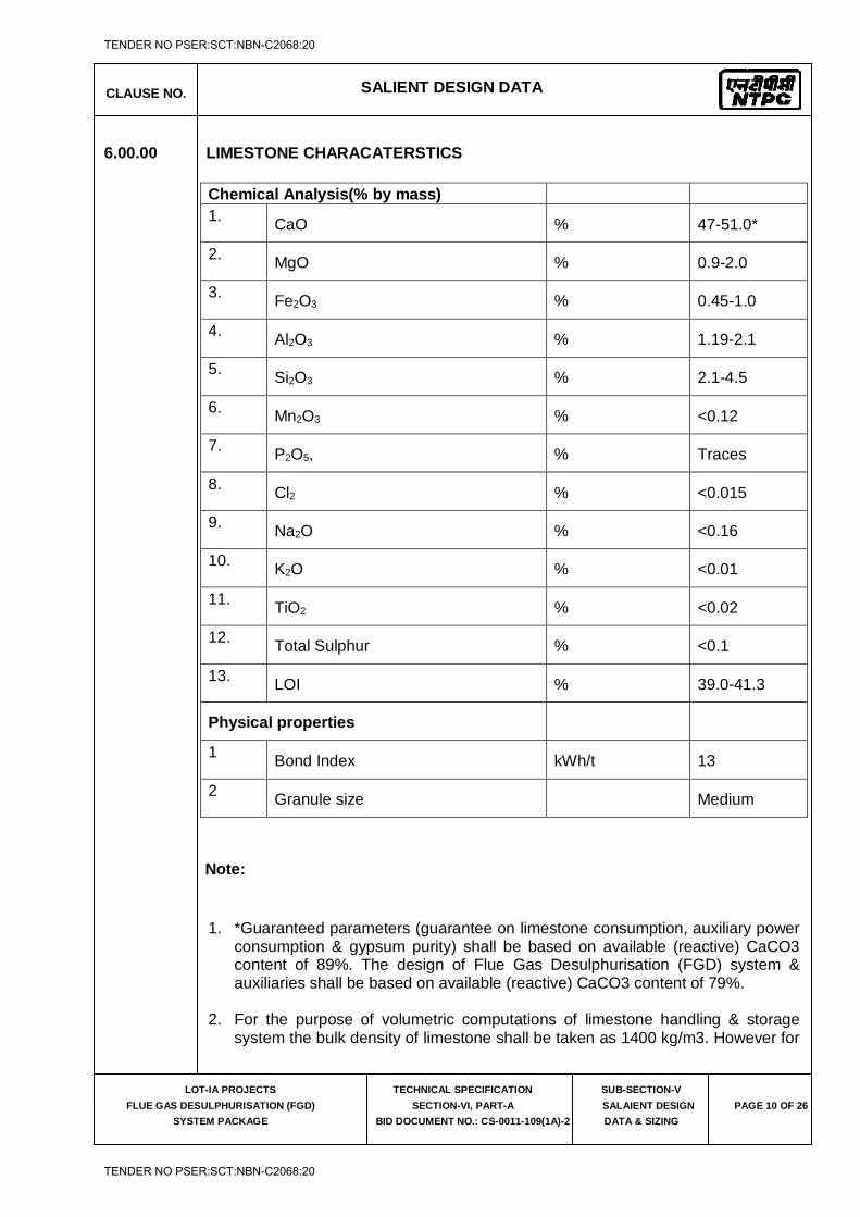
CLAUSE NO. SALIENT DESIGN DATA
LOT-IA PROJECTS
FLUE GAS DESULPHURISATION (FGD)
SYSTEM PACKAGE
TECHNICAL SPECIFICATION
SECTION-VI, PART-A
BID DOCUMENT NO.: CS-0011-109(1A)-2
SUB-SECTION-V
SALAIENT DESIGN
DATA & SIZING
PAGE 10 OF 26
6.00.00 LIMESTONE CHARACATERSTICS
Chemical Analysis(% by mass) 1. CaO % 47-51.0*
2. MgO % 0.9-2.0
3. Fe2O3 % 0.45-1.0
4. Al2O3 % 1.19-2.1
5. Si2O3 % 2.1-4.5
6. Mn2O3 % <0.12
7. P2O5, % Traces
8. Cl2 % <0.015
9. Na2O % <0.16
10. K2O % <0.01
11. TiO2 % <0.02
12. Total Sulphur % <0.1
13. LOI % 39.0-41.3
Physical properties
1 Bond Index kWh/t 13
2 Granule size Medium
Note:
1. *Guaranteed parameters (guarantee on limestone consumption, auxiliary power consumption & gypsum purity) shall be based on available (reactive) CaCO3 content of 89%. The design of Flue Gas Desulphurisation (FGD) system & auxiliaries shall be based on available (reactive) CaCO3 content of 79%.
2. For the purpose of volumetric computations of limestone handling & storage
system the bulk density of limestone shall be taken as 1400 kg/m3. However for
TENDER NO PSER:SCT:NBN-C2068:20
TENDER NO PSER:SCT:NBN-C2068:20
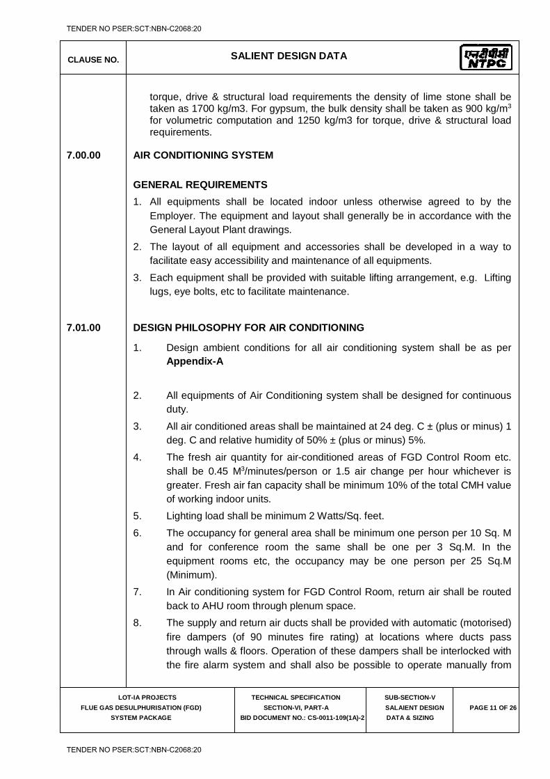
CLAUSE NO. SALIENT DESIGN DATA
LOT-IA PROJECTS
FLUE GAS DESULPHURISATION (FGD)
SYSTEM PACKAGE
TECHNICAL SPECIFICATION
SECTION-VI, PART-A
BID DOCUMENT NO.: CS-0011-109(1A)-2
SUB-SECTION-V
SALAIENT DESIGN
DATA & SIZING
PAGE 11 OF 26
torque, drive & structural load requirements the density of lime stone shall be taken as 1700 kg/m3. For gypsum, the bulk density shall be taken as 900 kg/m3 for volumetric computation and 1250 kg/m3 for torque, drive & structural load requirements.
7.00.00 AIR CONDITIONING SYSTEM
GENERAL REQUIREMENTS
1. All equipments shall be located indoor unless otherwise agreed to by the Employer. The equipment and layout shall generally be in accordance with the General Layout Plant drawings.
2. The layout of all equipment and accessories shall be developed in a way to facilitate easy accessibility and maintenance of all equipments.
3. Each equipment shall be provided with suitable lifting arrangement, e.g. Lifting lugs, eye bolts, etc to facilitate maintenance.
7.01.00 DESIGN PHILOSOPHY FOR AIR CONDITIONING
1. Design ambient conditions for all air conditioning system shall be as per Appendix-A
2. All equipments of Air Conditioning system shall be designed for continuous duty.
3. All air conditioned areas shall be maintained at 24 deg. C ± (plus or minus) 1 deg. C and relative humidity of 50% ± (plus or minus) 5%.
4. The fresh air quantity for air-conditioned areas of FGD Control Room etc. shall be 0.45 M3/minutes/person or 1.5 air change per hour whichever is greater. Fresh air fan capacity shall be minimum 10% of the total CMH value of working indoor units.
5. Lighting load shall be minimum 2 Watts/Sq. feet.
6. The occupancy for general area shall be minimum one person per 10 Sq. M and for conference room the same shall be one per 3 Sq.M. In the equipment rooms etc, the occupancy may be one person per 25 Sq.M (Minimum).
7. In Air conditioning system for FGD Control Room, return air shall be routed back to AHU room through plenum space.
8. The supply and return air ducts shall be provided with automatic (motorised) fire dampers (of 90 minutes fire rating) at locations where ducts pass through walls & floors. Operation of these dampers shall be interlocked with the fire alarm system and shall also be possible to operate manually from
TENDER NO PSER:SCT:NBN-C2068:20
TENDER NO PSER:SCT:NBN-C2068:20
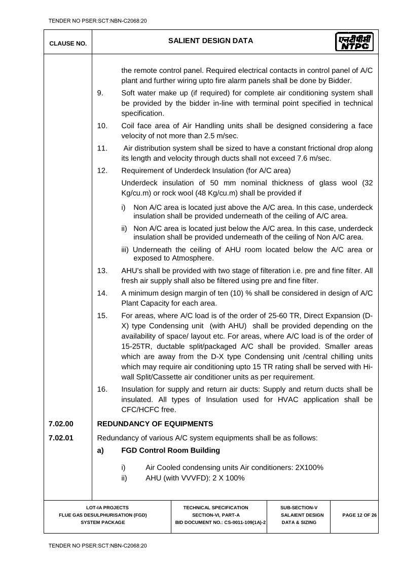
CLAUSE NO. SALIENT DESIGN DATA
LOT-IA PROJECTS
FLUE GAS DESULPHURISATION (FGD)
SYSTEM PACKAGE
TECHNICAL SPECIFICATION
SECTION-VI, PART-A
BID DOCUMENT NO.: CS-0011-109(1A)-2
SUB-SECTION-V
SALAIENT DESIGN
DATA & SIZING
PAGE 12 OF 26
the remote control panel. Required electrical contacts in control panel of A/C plant and further wiring upto fire alarm panels shall be done by Bidder.
9. Soft water make up (if required) for complete air conditioning system shall be provided by the bidder in-line with terminal point specified in technical specification.
10. Coil face area of Air Handling units shall be designed considering a face velocity of not more than 2.5 m/sec.
11. Air distribution system shall be sized to have a constant frictional drop along its length and velocity through ducts shall not exceed 7.6 m/sec.
12. Requirement of Underdeck Insulation (for A/C area) Underdeck insulation of 50 mm nominal thickness of glass wool (32
Kg/cu.m) or rock wool (48 Kg/cu.m) shall be provided if
i) Non A/C area is located just above the A/C area. In this case, underdeck insulation shall be provided underneath of the ceiling of A/C area.
ii) Non A/C area is located just below the A/C area. In this case, underdeck insulation shall be provided underneath of the ceiling of Non A/C area.
iii) Underneath the ceiling of AHU room located below the A/C area or exposed to Atmosphere.
13. AHU’s shall be provided with two stage of filteration i.e. pre and fine filter. All fresh air supply shall also be filtered using pre and fine filter.
14. A minimum design margin of ten (10) % shall be considered in design of A/C Plant Capacity for each area.
15. For areas, where A/C load is of the order of 25-60 TR, Direct Expansion (D-X) type Condensing unit (with AHU) shall be provided depending on the availability of space/ layout etc. For areas, where A/C load is of the order of 15-25TR, ductable split/packaged A/C shall be provided. Smaller areas which are away from the D-X type Condensing unit /central chilling units which may require air conditioning upto 15 TR rating shall be served with Hi-wall Split/Cassette air conditioner units as per requirement.
16. Insulation for supply and return air ducts: Supply and return ducts shall be insulated. All types of Insulation used for HVAC application shall be CFC/HCFC free.
7.02.00 REDUNDANCY OF EQUIPMENTS
7.02.01 Redundancy of various A/C system equipments shall be as follows:
a) FGD Control Room Building
i) Air Cooled condensing units Air conditioners: 2X100% ii) AHU (with VVVFD): 2 X 100%
TENDER NO PSER:SCT:NBN-C2068:20
TENDER NO PSER:SCT:NBN-C2068:20
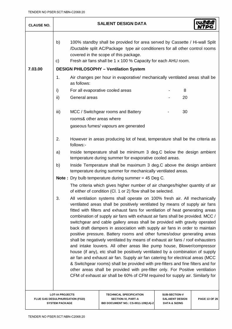
CLAUSE NO. SALIENT DESIGN DATA
LOT-IA PROJECTS
FLUE GAS DESULPHURISATION (FGD)
SYSTEM PACKAGE
TECHNICAL SPECIFICATION
SECTION-VI, PART-A
BID DOCUMENT NO.: CS-0011-109(1A)-2
SUB-SECTION-V
SALAIENT DESIGN
DATA & SIZING
PAGE 13 OF 26
b) 100% standby shall be provided for area served by Cassette / Hi-wall Split /Ductable split AC/Package type air conditioners for all other control rooms covered in the scope of this package.
c) Fresh air fans shall be 1 x 100 % Capacity for each AHU room.
7.03.00 DESIGN PHILOSOPHY – Ventilation System
1. Air changes per hour in evaporative/ mechanically ventilated areas shall be as follows:
i) For all evaporative cooled areas - 8 ii) General areas - 20
iii) MCC / Switchgear rooms and Battery - 30 rooms& other areas where
gaseous fumes/ vapours are generated
2. However in areas producing lot of heat, temperature shall be the criteria as follows:-
a) Inside temperature shall be minimum 3 deg.C below the design ambient temperature during summer for evaporative cooled areas.
b) Inside Temperature shall be maximum 3 deg.C above the design ambient temperature during summer for mechanically ventilated areas.
Note : Dry bulb temperature during summer = 45 Deg C.
The criteria which gives higher number of air changes/higher quantity of air of either of condition (Cl. 1 or 2) flow shall be selected.
3. All ventilation systems shall operate on 100% fresh air. All mechanically ventilated areas shall be positively ventilated by means of supply air fans fitted with filters and exhaust fans for ventilation of heat generating areas combination of supply air fans with exhaust air fans shall be provided. MCC / switchgear and cable gallery areas shall be provided with gravity operated back draft dampers in association with supply air fans in order to maintain positive pressure. Battery rooms and other fumes/odour generating areas shall be negatively ventilated by means of exhaust air fans / roof exhausters and intake louvers. All other areas like pump house, Blower/compressor house (if any), etc shall be positively ventilated by a combination of supply air fan and exhaust air fan. Supply air fan catering for electrical areas (MCC & Switchgear rooms) shall be provided with pre-filters and fine filters and for other areas shall be provided with pre-filter only. For Positive ventilation CFM of exhaust air shall be 60% of CFM required for supply air. Similarly for
TENDER NO PSER:SCT:NBN-C2068:20
TENDER NO PSER:SCT:NBN-C2068:20
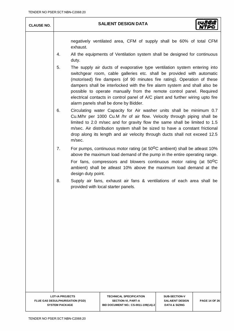
CLAUSE NO. SALIENT DESIGN DATA
LOT-IA PROJECTS
FLUE GAS DESULPHURISATION (FGD)
SYSTEM PACKAGE
TECHNICAL SPECIFICATION
SECTION-VI, PART-A
BID DOCUMENT NO.: CS-0011-109(1A)-2
SUB-SECTION-V
SALAIENT DESIGN
DATA & SIZING
PAGE 14 OF 26
negatively ventilated area, CFM of supply shall be 60% of total CFM exhaust.
4. All the equipments of Ventilation system shall be designed for continuous duty.
5. The supply air ducts of evaporative type ventilation system entering into switchgear room, cable galleries etc. shall be provided with automatic (motorised) fire dampers (of 90 minutes fire rating). Operation of these dampers shall be interlocked with the fire alarm system and shall also be possible to operate manually from the remote control panel. Required electrical contacts in control panel of A/C plant and further wiring upto fire alarm panels shall be done by Bidder.
6. Circulating water Capacity for Air washer units shall be minimum 0.7 Cu.M/hr per 1000 Cu.M /hr of air flow. Velocity through piping shall be limited to 2.0 m/sec and for gravity flow the same shall be limited to 1.5 m/sec. Air distribution system shall be sized to have a constant frictional drop along its length and air velocity through ducts shall not exceed 12.5 m/sec.
7. For pumps, continuous motor rating (at 50oC ambient) shall be atleast 10% above the maximum load demand of the pump in the entire operating range. For fans, compressors and blowers continuous motor rating (at 50oC ambient) shall be atleast 10% above the maximum load demand at the design duty point.
8. Supply air fans, exhaust air fans & ventilations of each area shall be provided with local starter panels.
TENDER NO PSER:SCT:NBN-C2068:20
TENDER NO PSER:SCT:NBN-C2068:20
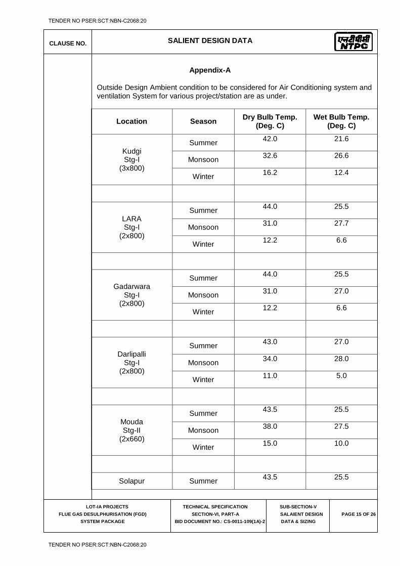
CLAUSE NO. SALIENT DESIGN DATA
LOT-IA PROJECTS
FLUE GAS DESULPHURISATION (FGD)
SYSTEM PACKAGE
TECHNICAL SPECIFICATION
SECTION-VI, PART-A
BID DOCUMENT NO.: CS-0011-109(1A)-2
SUB-SECTION-V
SALAIENT DESIGN
DATA & SIZING
PAGE 15 OF 26
Appendix-A
Outside Design Ambient condition to be considered for Air Conditioning system and ventilation System for various project/station are as under.
Location Season Dry Bulb Temp.
(Deg. C) Wet Bulb Temp.
(Deg. C)
Kudgi Stg-I
(3x800)
Summer 42.0 21.6
Monsoon 32.6 26.6
Winter 16.2 12.4
LARA Stg-I
(2x800)
Summer 44.0 25.5
Monsoon 31.0 27.7
Winter 12.2 6.6
Gadarwara Stg-I
(2x800)
Summer 44.0 25.5
Monsoon 31.0 27.0
Winter 12.2 6.6
Darlipalli Stg-I
(2x800)
Summer 43.0 27.0
Monsoon 34.0 28.0
Winter 11.0 5.0
Mouda Stg-II
(2x660)
Summer 43.5 25.5
Monsoon 38.0 27.5
Winter 15.0 10.0
Solapur Summer 43.5 25.5
TENDER NO PSER:SCT:NBN-C2068:20
TENDER NO PSER:SCT:NBN-C2068:20
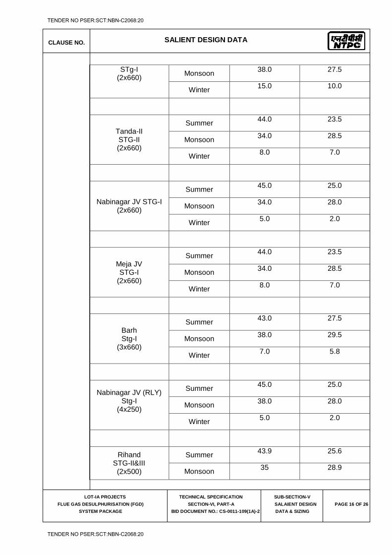
CLAUSE NO. SALIENT DESIGN DATA
LOT-IA PROJECTS
FLUE GAS DESULPHURISATION (FGD)
SYSTEM PACKAGE
TECHNICAL SPECIFICATION
SECTION-VI, PART-A
BID DOCUMENT NO.: CS-0011-109(1A)-2
SUB-SECTION-V
SALAIENT DESIGN
DATA & SIZING
PAGE 16 OF 26
STg-I (2x660) Monsoon 38.0 27.5
Winter 15.0 10.0
Tanda-II STG-II (2x660)
Summer 44.0 23.5
Monsoon 34.0 28.5
Winter 8.0 7.0
Nabinagar JV STG-I (2x660)
Summer 45.0 25.0
Monsoon 34.0 28.0
Winter 5.0 2.0
Meja JV STG-I
(2x660)
Summer 44.0 23.5
Monsoon 34.0 28.5
Winter 8.0 7.0
Barh Stg-I
(3x660)
Summer 43.0 27.5
Monsoon 38.0 29.5
Winter 7.0 5.8
Nabinagar JV (RLY) Stg-I
(4x250)
Summer 45.0 25.0
Monsoon 38.0 28.0
Winter 5.0 2.0
Rihand STG-II&III (2x500)
Summer 43.9 25.6
Monsoon 35 28.9
TENDER NO PSER:SCT:NBN-C2068:20
TENDER NO PSER:SCT:NBN-C2068:20
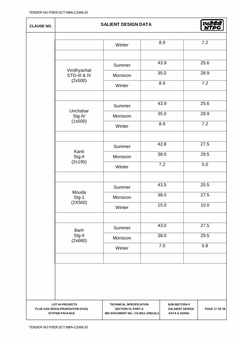
CLAUSE NO. SALIENT DESIGN DATA
LOT-IA PROJECTS
FLUE GAS DESULPHURISATION (FGD)
SYSTEM PACKAGE
TECHNICAL SPECIFICATION
SECTION-VI, PART-A
BID DOCUMENT NO.: CS-0011-109(1A)-2
SUB-SECTION-V
SALAIENT DESIGN
DATA & SIZING
PAGE 17 OF 26
Winter 8.9 7.2
Vindhyachal STG-III & IV
(2x500)
Summer 43.9 25.6
Monsoon 35.0 28.9
Winter 8.9 7.2
Unchahar Stg-IV
(1x500)
Summer 43.9 25.6
Monsoon 35.0 28.9
Winter 8.9 7.2
Kanti Stg-II
(2x195)
Summer 42.8 27.5
Monsoon 38.0 29.5
Winter 7.2 5.0
Mouda Stg-1
(2X500)
Summer 43.5 25.5
Monsoon 38.0 27.5
Winter 15.0 10.0
Barh Stg-II
(2x660)
Summer 43.0 27.5
Monsoon 38.0 29.5
Winter 7.0 5.8
TENDER NO PSER:SCT:NBN-C2068:20
TENDER NO PSER:SCT:NBN-C2068:20
CLAUSE NO. SALIENT DESIGN DATA
LOT-IA PROJECTS
FLUE GAS DESULPHURISATION (FGD)
SYSTEM PACKAGE
TECHNICAL SPECIFICATION
SECTION-VI, PART-A
BID DOCUMENT NO.: CS-0011-109(1A)-2
SUB-SECTION-V
SALAIENT DESIGN
DATA & SIZING
PAGE 18 OF 26
8.00.00 Fire Detection and Protection System
8.01.00 General Design Criteria
All major equipment/ system components in the entire fire protection & detection system shall have the approval from one of the following: a) Underwriters laboratories of USA b) LPCB-UK c) VDS d) BIS (for the approval of pumps and valves as applicable) e) FM- USA
However design and installation of complete system and requirements shall be approved by TAC accredited professional(s)-India.
8.02.00 Hydrant System
Design philosophy (minimum requirement) i) Category of Hazard and minimum terminal pressure shall be as TAC norms.
ii) All the landings of staircases, building, and other multi-storied structures of the plant shall be provided with hydrant landing valves.
iii) Each of the landing valves and external hydrant valves associated with FGD area shall be provided with a hose box. Each hose box shall contain two (2) numbers of 15M long hoses & coupling, branch pipes & nozzles, spanner etc as per TAC guidelines.
For landing valves of various buildings of FGD area, the hose box shall have two (2) numbers 7.5 m long hoses, branch pipes, couplings, nozzles, spanners, etc. as per TAC guidelines.
iv) The pipelines routed in RCC trenches shall be provided with coating and wrapping. Road, Rail or pipe trench crossing be through trestle/RCC hume pipes of appropriate pressure class and the pipe lines shall be provided with coating and wrapping as per specification.
8.03.00 HVW & MVW Spray System
Design Philosophy (Minimum Requirements) i) Design discharge density shall be as per the rules of TAC and/ or NFPA
standards. ii) Deluge valve along with trims like pressure gauge, water motor gong, etc.
shall be UL/FM or equivalent approved / listed. The deluge valve (auto resetting type) assembly shall consist of accessories such as water motor gong, alarm test valves, drip/drain valves, strainers for these valves, hydraulic releasing system, solenoid valves, etc. Further, the design
TENDER NO PSER:SCT:NBN-C2068:20
TENDER NO PSER:SCT:NBN-C2068:20
CLAUSE NO. SALIENT DESIGN DATA
LOT-IA PROJECTS
FLUE GAS DESULPHURISATION (FGD)
SYSTEM PACKAGE
TECHNICAL SPECIFICATION
SECTION-VI, PART-A
BID DOCUMENT NO.: CS-0011-109(1A)-2
SUB-SECTION-V
SALAIENT DESIGN
DATA & SIZING
PAGE 19 OF 26
features and make of all the projectors / spray nozzles shall be UL/FM or equivalent approved / listed.
iii) A strainer ('Y' type) be provided at upstream of deluge valve. iv) Pressure switches be provided in spray and detector piping to exhibit "FIRE"
and "SPRAY ON" annunciations and as well as for interlock. v) Wet type pipe detector network shall be provided for spray system using
quartzoid bulb detectors. vi) Each of the outdoor deluge valve and accessories shall be provided with
housing. vii) Remote manual operation of the deluge valves shall be possible from the
respective fire alarm cum control panel when the system is selected in remote manual mode. Apart from the automatic operation of the deluge valve, the system shall have provision for manual operation of the deluge valve by means of hand operated lever close to the deluge valve assembly. There shall also be a provision to operate deluge valve electrically from a nearby local panel.
8.04.00 Fire Detection, Alarm and Control System
Design Philosophy (Fire Alarm and Detection System)
i. The addressable type panels at FGD Control equipment rooms shall receive signal from sensors from various areas/ equipments of the respective units. This shall give audio-visual annunciations for fire in each of the risk area / equipment / status of the fire protection system as well as system operator open / short circuit status of detector or control cabling, etc. Further, this shall activate a hooter/sounder in each of the area provided with fire/smoke detection system
ii. Alarms from the FGD fire alarm panel shall be repeated simultaneously in repeater panel at Fire station. Also the fire alarms of this area has to be communicated to the main plant Fire alarm control panel through potential free contacts.
iii. The addressable panel shall evaluate the signals received from the detectors, transmit the fire or trouble alarms (audio-visual) to prearranged points, supervise and monitor the complete fire detection & extinguishing circuits, initiate control functions like shutdown of draft fans, air-conditioning and ventilation plant/equipment, closure of Fire dampers in A/C & Ventilation system etc. Opening smoke extraction vents, switching on smoke extraction equipment emergency lighting, tripping of transformer lockout relays etc.
iv. All the circuits from the detectors to the panels and the circuits from the panels to the actuating devices (such as solenoid valves, deluge valves, push buttons etc.) shall be closed loop type and shall be supervised for open and short circuiting. The trouble signal also be annunciated in the respective panels.
v. Facilities shall be provided on the fire alarm panel for simulating fire conditions, sensitivity adjustment, isolation of detectors etc. from the panel.
TENDER NO PSER:SCT:NBN-C2068:20
TENDER NO PSER:SCT:NBN-C2068:20
CLAUSE NO. SALIENT DESIGN DATA
LOT-IA PROJECTS
FLUE GAS DESULPHURISATION (FGD)
SYSTEM PACKAGE
TECHNICAL SPECIFICATION
SECTION-VI, PART-A
BID DOCUMENT NO.: CS-0011-109(1A)-2
SUB-SECTION-V
SALAIENT DESIGN
DATA & SIZING
PAGE 20 OF 26
9.00.00 Compressed Air System
DESIGN CRITERIA / BASIS AND PERFORMANCE GUARANTEE
1. All the equipments shall be designed for continuous duty and as well as for intermittent operation. Frequent start/stop of the system shall not result deterioration in performance nor damage to the equipment.
2. The compressors and Air Drying plants shall operate under the following ambient conditions.
i. Minimum temperature : 10 deg.C
ii. Maximum temperature : 50 deg. C
iii. Design condition (temperature & : 45 deg.C& 75% RH
Relative humidity)
iv. Height above MSL (m) : Refer Chapter “Project Information”
3. The design ambient conditions for the motors shall be as mentioned in relevant Electrical sub-sections.
9.01.00 Selection of Capacity of Air Compressor
a) Air Compressor Air Compressor shall be designed to meet the Instrument air and service air requirement of all the equipments/plant/systems to be supplied by the Contractor for FGD Plant and ZLD plant (if applicable) as follows:-
Sl. No. Continuous Requirement Quantity (in NM3/min)
1. Instrument air requirement for FGD plant (Continuous)
A
2. Instrument air requirement for ZLD plant (Continuous)
B
3. Service air requirement for FGD plant C
4. Service air requirement for ZLD plant D
5. Total Air requirement = A+B+C+D
6. Capacity of air compressor = 2(A+B+C+D)
Notes: While calculating the air requirement of Bidder’s equipments/plant/systems, for continuous requirements of instrument air and service air, no diversity factor shall be considered and they are to be assumed to be of “Simultaneous Requirements”. The intermittent requirement of instrument air and service air, if any shall be converted into
TENDER NO PSER:SCT:NBN-C2068:20
TENDER NO PSER:SCT:NBN-C2068:20
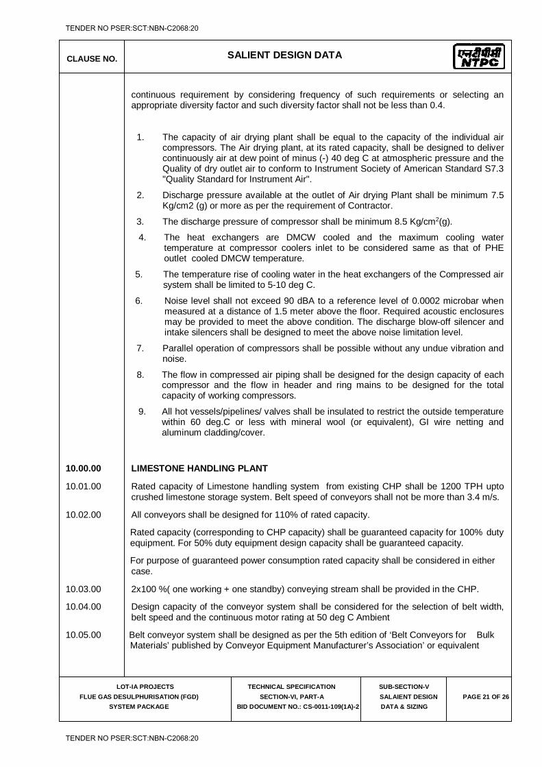
CLAUSE NO. SALIENT DESIGN DATA
LOT-IA PROJECTS
FLUE GAS DESULPHURISATION (FGD)
SYSTEM PACKAGE
TECHNICAL SPECIFICATION
SECTION-VI, PART-A
BID DOCUMENT NO.: CS-0011-109(1A)-2
SUB-SECTION-V
SALAIENT DESIGN
DATA & SIZING
PAGE 21 OF 26
continuous requirement by considering frequency of such requirements or selecting an appropriate diversity factor and such diversity factor shall not be less than 0.4.
1. The capacity of air drying plant shall be equal to the capacity of the individual air compressors. The Air drying plant, at its rated capacity, shall be designed to deliver continuously air at dew point of minus (-) 40 deg C at atmospheric pressure and the Quality of dry outlet air to conform to Instrument Society of American Standard S7.3 "Quality Standard for Instrument Air".
2. Discharge pressure available at the outlet of Air drying Plant shall be minimum 7.5 Kg/cm2 (g) or more as per the requirement of Contractor.
3. The discharge pressure of compressor shall be minimum 8.5 Kg/cm2(g).
4. The heat exchangers are DMCW cooled and the maximum cooling water temperature at compressor coolers inlet to be considered same as that of PHE outlet cooled DMCW temperature.
5. The temperature rise of cooling water in the heat exchangers of the Compressed air system shall be limited to 5-10 deg C.
6. Noise level shall not exceed 90 dBA to a reference level of 0.0002 microbar when measured at a distance of 1.5 meter above the floor. Required acoustic enclosures may be provided to meet the above condition. The discharge blow-off silencer and intake silencers shall be designed to meet the above noise limitation level.
7. Parallel operation of compressors shall be possible without any undue vibration and noise.
8. The flow in compressed air piping shall be designed for the design capacity of each compressor and the flow in header and ring mains to be designed for the total capacity of working compressors.
9. All hot vessels/pipelines/ valves shall be insulated to restrict the outside temperature within 60 deg.C or less with mineral wool (or equivalent), GI wire netting and aluminum cladding/cover.
10.00.00 LIMESTONE HANDLING PLANT
10.01.00 Rated capacity of Limestone handling system from existing CHP shall be 1200 TPH upto crushed limestone storage system. Belt speed of conveyors shall not be more than 3.4 m/s.
10.02.00 All conveyors shall be designed for 110% of rated capacity.
Rated capacity (corresponding to CHP capacity) shall be guaranteed capacity for 100% duty equipment. For 50% duty equipment design capacity shall be guaranteed capacity.
For purpose of guaranteed power consumption rated capacity shall be considered in either case.
10.03.00 2x100 %( one working + one standby) conveying stream shall be provided in the CHP.
10.04.00 Design capacity of the conveyor system shall be considered for the selection of belt width, belt speed and the continuous motor rating at 50 deg C Ambient
10.05.00 Belt conveyor system shall be designed as per the 5th edition of ‘Belt Conveyors for Bulk Materials’ published by Conveyor Equipment Manufacturer’s Association’ or equivalent
TENDER NO PSER:SCT:NBN-C2068:20
TENDER NO PSER:SCT:NBN-C2068:20
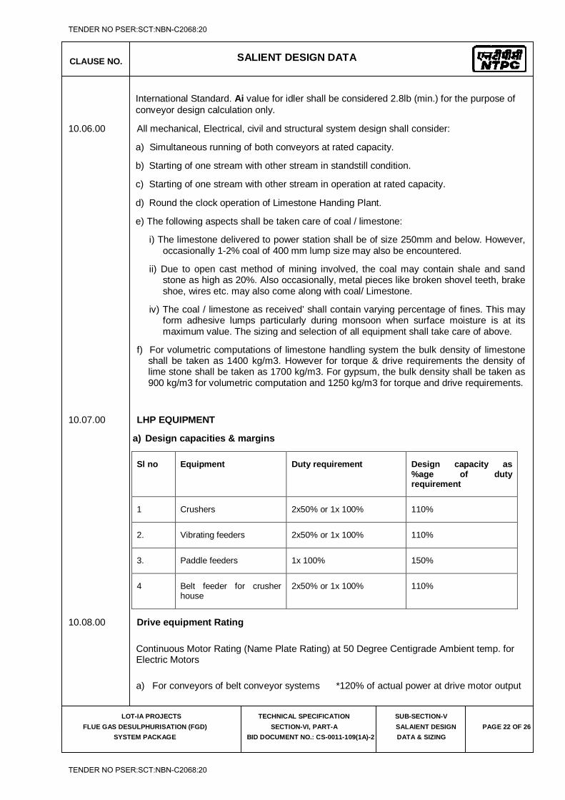
CLAUSE NO. SALIENT DESIGN DATA
LOT-IA PROJECTS
FLUE GAS DESULPHURISATION (FGD)
SYSTEM PACKAGE
TECHNICAL SPECIFICATION
SECTION-VI, PART-A
BID DOCUMENT NO.: CS-0011-109(1A)-2
SUB-SECTION-V
SALAIENT DESIGN
DATA & SIZING
PAGE 22 OF 26
International Standard. Ai value for idler shall be considered 2.8lb (min.) for the purpose of conveyor design calculation only.
10.06.00 All mechanical, Electrical, civil and structural system design shall consider:
a) Simultaneous running of both conveyors at rated capacity.
b) Starting of one stream with other stream in standstill condition.
c) Starting of one stream with other stream in operation at rated capacity.
d) Round the clock operation of Limestone Handing Plant.
e) The following aspects shall be taken care of coal / limestone:
i) The limestone delivered to power station shall be of size 250mm and below. However, occasionally 1-2% coal of 400 mm lump size may also be encountered.
ii) Due to open cast method of mining involved, the coal may contain shale and sand stone as high as 20%. Also occasionally, metal pieces like broken shovel teeth, brake shoe, wires etc. may also come along with coal/ Limestone.
iv) The coal / limestone as received’ shall contain varying percentage of fines. This may form adhesive lumps particularly during monsoon when surface moisture is at its maximum value. The sizing and selection of all equipment shall take care of above.
f) For volumetric computations of limestone handling system the bulk density of limestone shall be taken as 1400 kg/m3. However for torque & drive requirements the density of lime stone shall be taken as 1700 kg/m3. For gypsum, the bulk density shall be taken as 900 kg/m3 for volumetric computation and 1250 kg/m3 for torque and drive requirements.
10.07.00 LHP EQUIPMENT
a) Design capacities & margins
Sl no Equipment Duty requirement Design capacity as %age of duty requirement
1 Crushers 2x50% or 1x 100% 110%
2. Vibrating feeders 2x50% or 1x 100% 110%
3. Paddle feeders 1x 100% 150%
4 Belt feeder for crusher house
2x50% or 1x 100% 110%
10.08.00 Drive equipment Rating
Continuous Motor Rating (Name Plate Rating) at 50 Degree Centigrade Ambient temp. for Electric Motors
a) For conveyors of belt conveyor systems *120% of actual power at drive motor output
TENDER NO PSER:SCT:NBN-C2068:20
TENDER NO PSER:SCT:NBN-C2068:20
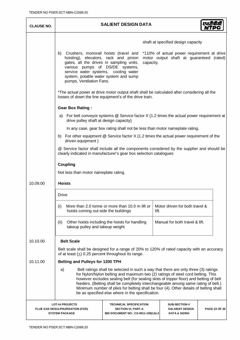
CLAUSE NO. SALIENT DESIGN DATA
LOT-IA PROJECTS
FLUE GAS DESULPHURISATION (FGD)
SYSTEM PACKAGE
TECHNICAL SPECIFICATION
SECTION-VI, PART-A
BID DOCUMENT NO.: CS-0011-109(1A)-2
SUB-SECTION-V
SALAIENT DESIGN
DATA & SIZING
PAGE 23 OF 26
shaft at specified design capacity
b) Crushers, monorail hoists (travel and hoisting), elevators, rack and pinion gates, all the drives in sampling units, various pumps of DS/DE systems, service water systems, cooling water system, potable water system and sump pumps, Ventilation Fans.
*110% of actual power requirement at drive motor output shaft at guaranteed (rated) capacity.
*The actual power at drive motor output shaft shall be calculated after considering all the losses of down the line equipment’s of the drive train.
Gear Box Rating :
a) For belt conveyor systems @ Service factor X {1.2 times the actual power requirement at drive pulley shaft at design capacity}
In any case, gear box rating shall not be less than motor nameplate rating.
b) For other equipment @ Service factor X {1.2 times the actual power requirement of the driven equipment }
@ Service factor shall include all the components considered by the supplier and should be clearly indicated in manufacturer’s gear box selection catalogues
Coupling
Not less than motor nameplate rating.
10.09.00 Hoists
Drive
(i) More than 2.0 tonne or more than 10.0 m lift or hoists coming out-side the buildings
Motor driven for both travel & lift.
(ii) Other hoists including the hoists for handling takeup pulley and takeup weight
Manual for both travel & lift.
10.10.00 Belt Scale
Belt scale shall be designed for a range of 20% to 120% of rated capacity with an accuracy of at least (+) 0.25 percent throughout its range.
10.11.00 Belting and Pulleys for 1200 TPH
a) Belt ratings shall be selected in such a way that there are only three (3) ratings for Nylon/Nylon belting and maximum two (2) ratings of steel cord belting. This however excludes sealing belt (for sealing slots of tripper floor) and belting of belt feeders. (Belting shall be completely interchangeable among same rating of belt.) Minimum number of plies for belting shall be four (4). Other details of belting shall be as specified else where in the specification.
TENDER NO PSER:SCT:NBN-C2068:20
TENDER NO PSER:SCT:NBN-C2068:20
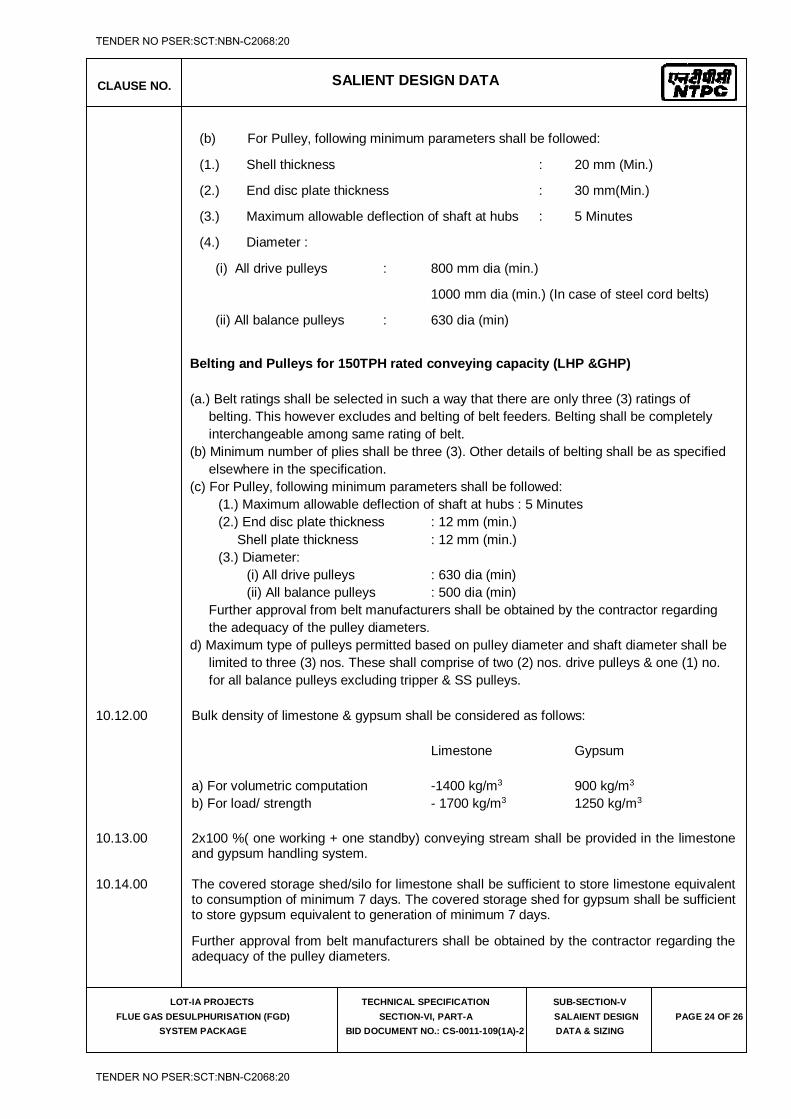
CLAUSE NO. SALIENT DESIGN DATA
LOT-IA PROJECTS
FLUE GAS DESULPHURISATION (FGD)
SYSTEM PACKAGE
TECHNICAL SPECIFICATION
SECTION-VI, PART-A
BID DOCUMENT NO.: CS-0011-109(1A)-2
SUB-SECTION-V
SALAIENT DESIGN
DATA & SIZING
PAGE 24 OF 26
(b) For Pulley, following minimum parameters shall be followed:
(1.) Shell thickness : 20 mm (Min.)
(2.) End disc plate thickness : 30 mm(Min.)
(3.) Maximum allowable deflection of shaft at hubs : 5 Minutes
(4.) Diameter :
(i) All drive pulleys : 800 mm dia (min.)
1000 mm dia (min.) (In case of steel cord belts)
(ii) All balance pulleys : 630 dia (min)
Belting and Pulleys for 150TPH rated conveying capacity (LHP &GHP) (a.) Belt ratings shall be selected in such a way that there are only three (3) ratings of
belting. This however excludes and belting of belt feeders. Belting shall be completely interchangeable among same rating of belt.
(b) Minimum number of plies shall be three (3). Other details of belting shall be as specified elsewhere in the specification.
(c) For Pulley, following minimum parameters shall be followed: (1.) Maximum allowable deflection of shaft at hubs : 5 Minutes (2.) End disc plate thickness : 12 mm (min.)
Shell plate thickness : 12 mm (min.) (3.) Diameter:
(i) All drive pulleys : 630 dia (min) (ii) All balance pulleys : 500 dia (min)
Further approval from belt manufacturers shall be obtained by the contractor regarding the adequacy of the pulley diameters.
d) Maximum type of pulleys permitted based on pulley diameter and shaft diameter shall be limited to three (3) nos. These shall comprise of two (2) nos. drive pulleys & one (1) no. for all balance pulleys excluding tripper & SS pulleys.
10.12.00 Bulk density of limestone & gypsum shall be considered as follows: Limestone Gypsum
a) For volumetric computation -1400 kg/m3 900 kg/m3 b) For load/ strength - 1700 kg/m3 1250 kg/m3
10.13.00 2x100 %( one working + one standby) conveying stream shall be provided in the limestone and gypsum handling system.
10.14.00 The covered storage shed/silo for limestone shall be sufficient to store limestone equivalent
to consumption of minimum 7 days. The covered storage shed for gypsum shall be sufficient to store gypsum equivalent to generation of minimum 7 days.
Further approval from belt manufacturers shall be obtained by the contractor regarding the adequacy of the pulley diameters.
TENDER NO PSER:SCT:NBN-C2068:20
TENDER NO PSER:SCT:NBN-C2068:20
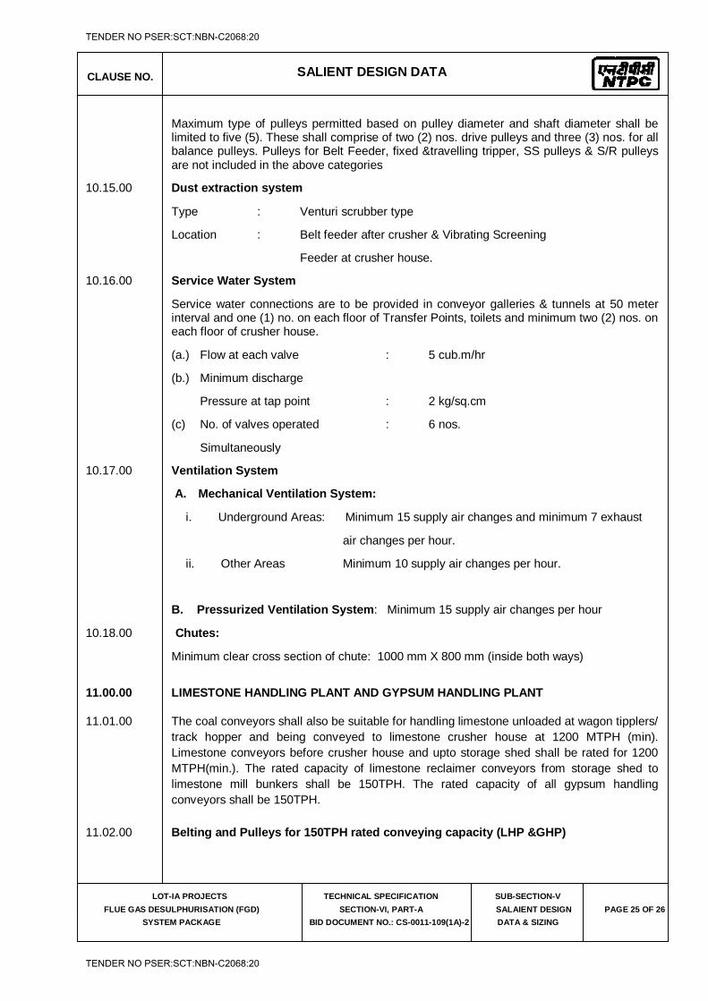
CLAUSE NO. SALIENT DESIGN DATA
LOT-IA PROJECTS
FLUE GAS DESULPHURISATION (FGD)
SYSTEM PACKAGE
TECHNICAL SPECIFICATION
SECTION-VI, PART-A
BID DOCUMENT NO.: CS-0011-109(1A)-2
SUB-SECTION-V
SALAIENT DESIGN
DATA & SIZING
PAGE 25 OF 26
Maximum type of pulleys permitted based on pulley diameter and shaft diameter shall be limited to five (5). These shall comprise of two (2) nos. drive pulleys and three (3) nos. for all balance pulleys. Pulleys for Belt Feeder, fixed &travelling tripper, SS pulleys & S/R pulleys are not included in the above categories
10.15.00 Dust extraction system
Type : Venturi scrubber type
Location : Belt feeder after crusher & Vibrating Screening
Feeder at crusher house.
10.16.00 Service Water System
Service water connections are to be provided in conveyor galleries & tunnels at 50 meter interval and one (1) no. on each floor of Transfer Points, toilets and minimum two (2) nos. on each floor of crusher house.
(a.) Flow at each valve : 5 cub.m/hr
(b.) Minimum discharge
Pressure at tap point : 2 kg/sq.cm
(c) No. of valves operated : 6 nos.
Simultaneously
10.17.00 Ventilation System
A. Mechanical Ventilation System:
i. Underground Areas: Minimum 15 supply air changes and minimum 7 exhaust
air changes per hour.
ii. Other Areas Minimum 10 supply air changes per hour.
B. Pressurized Ventilation System: Minimum 15 supply air changes per hour
10.18.00 Chutes:
Minimum clear cross section of chute: 1000 mm X 800 mm (inside both ways)
11.00.00 LIMESTONE HANDLING PLANT AND GYPSUM HANDLING PLANT
11.01.00 The coal conveyors shall also be suitable for handling limestone unloaded at wagon tipplers/
track hopper and being conveyed to limestone crusher house at 1200 MTPH (min). Limestone conveyors before crusher house and upto storage shed shall be rated for 1200 MTPH(min.). The rated capacity of limestone reclaimer conveyors from storage shed to limestone mill bunkers shall be 150TPH. The rated capacity of all gypsum handling conveyors shall be 150TPH.
11.02.00 Belting and Pulleys for 150TPH rated conveying capacity (LHP &GHP)
TENDER NO PSER:SCT:NBN-C2068:20
TENDER NO PSER:SCT:NBN-C2068:20
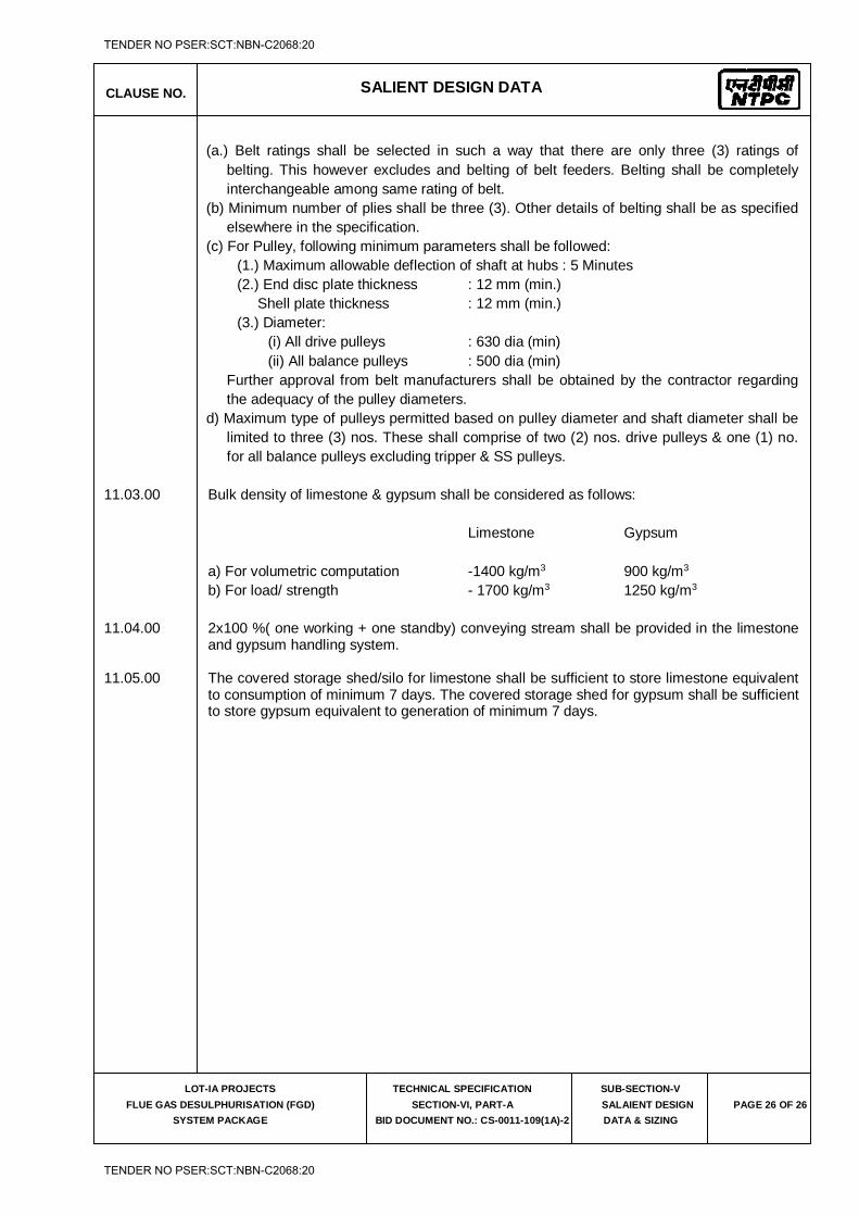
CLAUSE NO. SALIENT DESIGN DATA
LOT-IA PROJECTS
FLUE GAS DESULPHURISATION (FGD)
SYSTEM PACKAGE
TECHNICAL SPECIFICATION
SECTION-VI, PART-A
BID DOCUMENT NO.: CS-0011-109(1A)-2
SUB-SECTION-V
SALAIENT DESIGN
DATA & SIZING
PAGE 26 OF 26
(a.) Belt ratings shall be selected in such a way that there are only three (3) ratings of belting. This however excludes and belting of belt feeders. Belting shall be completely interchangeable among same rating of belt.
(b) Minimum number of plies shall be three (3). Other details of belting shall be as specified elsewhere in the specification.
(c) For Pulley, following minimum parameters shall be followed: (1.) Maximum allowable deflection of shaft at hubs : 5 Minutes (2.) End disc plate thickness : 12 mm (min.)
Shell plate thickness : 12 mm (min.) (3.) Diameter:
(i) All drive pulleys : 630 dia (min) (ii) All balance pulleys : 500 dia (min)
Further approval from belt manufacturers shall be obtained by the contractor regarding the adequacy of the pulley diameters.
d) Maximum type of pulleys permitted based on pulley diameter and shaft diameter shall be limited to three (3) nos. These shall comprise of two (2) nos. drive pulleys & one (1) no. for all balance pulleys excluding tripper & SS pulleys.
11.03.00 Bulk density of limestone & gypsum shall be considered as follows: Limestone Gypsum
a) For volumetric computation -1400 kg/m3 900 kg/m3 b) For load/ strength - 1700 kg/m3 1250 kg/m3
11.04.00 2x100 %( one working + one standby) conveying stream shall be provided in the limestone and gypsum handling system.
11.05.00 The covered storage shed/silo for limestone shall be sufficient to store limestone equivalent
to consumption of minimum 7 days. The covered storage shed for gypsum shall be sufficient to store gypsum equivalent to generation of minimum 7 days.
TENDER NO PSER:SCT:NBN-C2068:20
TENDER NO PSER:SCT:NBN-C2068:20
LOT-IA PROJECTS FLUE GAS DESULPHURISATION (FGD) SYSTEM PACKAGE
TECHNICAL SPECIFICATION
SECTION-VI
BID DOCUMENT NO.: CS-0011-109(1A)-2
SUB-SECTION-VI
FUNCTIONAL GUARANTEES & LIQUIDATED DAMAGES
TENDER NO PSER:SCT:NBN-C2068:20
TENDER NO PSER:SCT:NBN-C2068:20
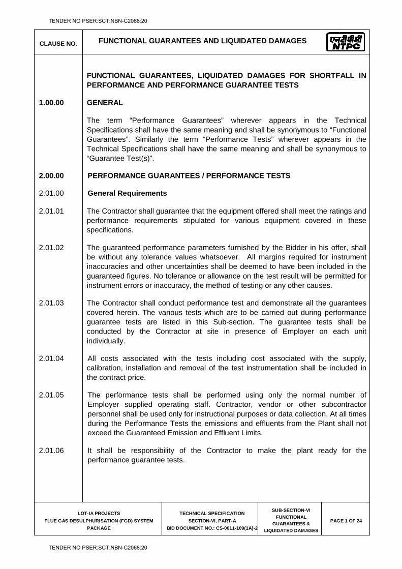
CLAUSE NO. FUNCTIONAL GUARANTEES AND LIQUIDATED DAMAGES
LOT-IA PROJECTS
FLUE GAS DESULPHURISATION (FGD) SYSTEM
PACKAGE
TECHNICAL SPECIFICATION
SECTION-VI, PART-A
BID DOCUMENT NO.: CS-0011-109(1A)-2
SUB-SECTION-VI
FUNCTIONAL
GUARANTEES &
LIQUIDATED DAMAGES
PAGE 1 OF 24
FUNCTIONAL GUARANTEES, LIQUIDATED DAMAGES FOR SHORTFALL IN PERFORMANCE AND PERFORMANCE GUARANTEE TESTS
1.00.00 GENERAL
The term “Performance Guarantees” wherever appears in the Technical Specifications shall have the same meaning and shall be synonymous to “Functional Guarantees”. Similarly the term “Performance Tests” wherever appears in the Technical Specifications shall have the same meaning and shall be synonymous to “Guarantee Test(s)”.
2.00.00 PERFORMANCE GUARANTEES / PERFORMANCE TESTS
2.01.00 General Requirements
2.01.01 The Contractor shall guarantee that the equipment offered shall meet the ratings and performance requirements stipulated for various equipment covered in these specifications.
2.01.02 The guaranteed performance parameters furnished by the Bidder in his offer, shall be without any tolerance values whatsoever. All margins required for instrument inaccuracies and other uncertainties shall be deemed to have been included in the guaranteed figures. No tolerance or allowance on the test result will be permitted for instrument errors or inaccuracy, the method of testing or any other causes.
2.01.03 The Contractor shall conduct performance test and demonstrate all the guarantees covered herein. The various tests which are to be carried out during performance guarantee tests are listed in this Sub-section. The guarantee tests shall be conducted by the Contractor at site in presence of Employer on each unit individually.
2.01.04 All costs associated with the tests including cost associated with the supply, calibration, installation and removal of the test instrumentation shall be included in the contract price.
2.01.05 The performance tests shall be performed using only the normal number of Employer supplied operating staff. Contractor, vendor or other subcontractor personnel shall be used only for instructional purposes or data collection. At all times during the Performance Tests the emissions and effluents from the Plant shall not exceed the Guaranteed Emission and Effluent Limits.
2.01.06 It shall be responsibility of the Contractor to make the plant ready for the performance guarantee tests.
TENDER NO PSER:SCT:NBN-C2068:20
TENDER NO PSER:SCT:NBN-C2068:20
CLAUSE NO. FUNCTIONAL GUARANTEES AND LIQUIDATED DAMAGES
LOT-IA PROJECTS
FLUE GAS DESULPHURISATION (FGD) SYSTEM
PACKAGE
TECHNICAL SPECIFICATION
SECTION-VI, PART-A
BID DOCUMENT NO.: CS-0011-109(1A)-2
SUB-SECTION-VI
FUNCTIONAL
GUARANTEES &
LIQUIDATED DAMAGES
PAGE 2 OF 24
2.02.00 Test Instrumentation, Flow Measurement and their Calibration
2.02.01 All instruments required for performance testing shall be of the type and accuracy required by the code and prior to the test, the Contractor shall get these instruments calibrated in an independent test Institute approved by the Employer and submit the same to Employer prior to commencement of test. All test instrumentation required for performance tests shall be supplied by the Contractor and shall be retained by him upon satisfactory completion of all such tests at site. All calibration procedures and standards shall be subject to the approval of the Employer prior to commencement of test. The protecting tubes, pressure connections and other test connections required for conducting guarantee test shall conform to the relevant codes.
Tools and tackles, thermowells (both screwed and welded) instruments/devices including flow devices, matching flanges, impulse piping & valves etc. and any special equipment, required for the successful completion of the tests, shall be provided by the Contractor free of cost.
The Performance test shall be carried out as per the agreed procedure. The detailed PG test procedure shall be submitted within 90 days of the date of Notification of Award and finalization of the PG test procedure shall be done within 180 days from the date of Notification of Award.
2.02.02 The P&G test procedures shall be submitted for equipments/system & subsystem under Contractor's scope for all Guarantees as mentioned below, as per latest International codes / standard including correction curves, meeting the specification requirements along with sample calculations & detailed activity plan of preparation (including test instrumentation), conductance and evaluation of Guarantees.
2.02.03 The Contractor shall submit for Employer’s approval the detailed Performance Test procedure containing the following:
(a) Object of the test.
(b) Various guaranteed parameters & tests as per contract.
(c) Method of conductance of test and test code.
(d) Duration of test, frequency of readings & number of test runs.
(e) Method of calculation.
(f) Correction calculations & curves.
(g) Instrument list consisting of range, accuracy, least count, and location of instruments.
TENDER NO PSER:SCT:NBN-C2068:20
TENDER NO PSER:SCT:NBN-C2068:20
CLAUSE NO. FUNCTIONAL GUARANTEES AND LIQUIDATED DAMAGES
LOT-IA PROJECTS
FLUE GAS DESULPHURISATION (FGD) SYSTEM
PACKAGE
TECHNICAL SPECIFICATION
SECTION-VI, PART-A
BID DOCUMENT NO.: CS-0011-109(1A)-2
SUB-SECTION-VI
FUNCTIONAL
GUARANTEES &
LIQUIDATED DAMAGES
PAGE 3 OF 24
(h) Scheme showing measurement points.
(i) Sample calculation.
(j) Acceptance criteria.
(k) Any other information required for conducting the test.
2.03.00 Test Reports
After the conductance of Performance test, the Contractor shall submit the test evaluation report of Performance test results to Employer promptly but not later than one month from the date of conductance of Performance test. Preliminary test reports shall be submitted to the Employer after completing each test run. Four (4) hard copies and two (2) soft copies on CD-ROM of each test report of final conducted test on each equipment/plant/system shall be submitted to Employer for approval.
2.03.01 Performance Guarantee Tests on the equipments/systems not covered in this Sub-section shall be carried out as per the procedure/test codes specified in respective detailed specifications.
2.04.00 Acceptance of Guarantee Test Results
(i) For Category-I Guarantees
In case during performance guarantee test(s) it is found that the equipment/system has failed to meet the guarantees, the Contractor shall carry out all necessary modifications and/or replacements to make the equipment/system comply with the guaranteed requirements at no extra cost to the Employer and re-conduct the performance guarantee test(s) with Employer’s consent. In case the specified performance guarantee(s) are still not met but are achieved within the Acceptable Shortfall Limit as specified at clause 3.00.00 of this sub-section, Employer will accept the equipment/system/plant after levying liquidated damages as per clause 3.00.00 of this sub-section. However, if, the demonstrated performance guarantee(s) continue to be beyond the stipulated Acceptable Shortfall Limit, even after the above modifications/replacements within ninety (90) days or a reasonable period allowed by the Employer, after the tests have been completed, the Employer will have the right to either of the following:
Reject the equipment / system / plant and recover from the Contractor the payments already made
OR
TENDER NO PSER:SCT:NBN-C2068:20
TENDER NO PSER:SCT:NBN-C2068:20
CLAUSE NO. FUNCTIONAL GUARANTEES AND LIQUIDATED DAMAGES
LOT-IA PROJECTS
FLUE GAS DESULPHURISATION (FGD) SYSTEM
PACKAGE
TECHNICAL SPECIFICATION
SECTION-VI, PART-A
BID DOCUMENT NO.: CS-0011-109(1A)-2
SUB-SECTION-VI
FUNCTIONAL
GUARANTEES &
LIQUIDATED DAMAGES
PAGE 4 OF 24
Accept the equipment /system/ plant after levying Liquidated Damages. The liquidated damages for shortfall in performance indicated in clause 3.00.00 of this sub-section shall be levied separately for each unit. The rates indicated in clause 3.00.00 of this sub-section are on per unit basis. The liquidated damages shall be pro-rated for the fractional parts of the deficiencies.
(ii) For Category-II Guarantees
In case during performance guarantee test(s) it is found that the equipment/ system has failed to meet the guarantees, the Contractor shall carry out all necessary modifications and/or replacements to make the equipment/system comply with the guaranteed requirements at no extra cost to the Employer and re-conduct the performance guarantee test(s) with Employer's consent. In case the specified performance guarantee(s) are still not met even after the above modifications/replacements with in ninety (90) days or a reasonable period allowed by the Employer, after the tests have been completed, the Employer will have the right to either of the following:
Reject the equipment /system / plant and recover from the Contractor the payments already made.
OR
Accept the equipment/system after assessing the deficiency in respect of the various ratings, performance parameters and capabilities and recover from the contract price an amount equivalent to the damages as determined by the Employer. Such damages shall, however be limited to the cost of replacement of the equipment(s)/system(s), replacement of which shall remove the deficiency so as to achieve the guaranteed performance. These parameters/capacities shall be termed as “Category-II” Guarantees.
3.00.00 AMOUNT OF LIQUIDATED DAMAGES (LD) APPLICABLE FOR GUARANTEES FOR EACH PROJECT
The rate of liquidated damages and acceptable shortfall limits for different guarantees shall be as under and such liquidated damages shall be deducted from the Contract Price of the project.
TENDER NO PSER:SCT:NBN-C2068:20
TENDER NO PSER:SCT:NBN-C2068:20

CLAUSE NO. FUNCTIONAL GUARANTEES AND LIQUIDATED DAMAGES
LOT-IA PROJECTS
FLUE GAS DESULPHURISATION (FGD) SYSTEM
PACKAGE
TECHNICAL SPECIFICATION
SECTION-VI, PART-A
BID DOCUMENT NO.: CS-0011-109(1A)-2
SUB-SECTION-VI
FUNCTIONAL
GUARANTEES &
LIQUIDATED DAMAGES
PAGE 5 OF 24
KUDGI-I (3X800 MW)
Sl.No Guarantee Rate of Liquidated Damage (LD)
Acceptable Shortfall Limit with LD
i) For shortfall in guaranteed SO2 removal efficiency in percentage points under conditions stipulated in clause 4.01.00 (i) of Sub-Section-VI, Part A, Section-VI.
US $ 63,704/- (US Dollar Sixty Three Thousand Seven Hundred Four only) for every 0.1% point shortfall in SO2 removal efficiency from the guaranteed value.
(-)0.25% point from the guaranteed SO2 removal efficiency.
ii) For increase in the limestone consumption of FGD system in T/hr under conditions stipulated in clause 4.01.00 (ii) of Sub-Section-VI, Part A, Section-VI.
US $ 249,736/- (US Dollar Two Hundred Forty Nine Thousand Seven Hundred Thirty Six only) for every 100 kg/hr increase in Limestone consumption from guaranteed value.
(+)10% of the guaranteed limestone consumption.
iii) Auxiliary Power Consumption
For increase in the auxiliary power consumption in KW guaranteed as per the requirements of clause 4.01.00 (iii), of Sub-Section-VI, Part A, Section-VI.
US $ 6032/- (US Dollar Six Thousand Thirty Two Dollars only) for every KW increase in Auxiliary power consumption from the guaranteed value.
(+)1% of the guaranteed auxiliary power consumption
TENDER NO PSER:SCT:NBN-C2068:20
TENDER NO PSER:SCT:NBN-C2068:20

CLAUSE NO. FUNCTIONAL GUARANTEES AND LIQUIDATED DAMAGES
LOT-IA PROJECTS
FLUE GAS DESULPHURISATION (FGD) SYSTEM
PACKAGE
TECHNICAL SPECIFICATION
SECTION-VI, PART-A
BID DOCUMENT NO.: CS-0011-109(1A)-2
SUB-SECTION-VI
FUNCTIONAL
GUARANTEES &
LIQUIDATED DAMAGES
PAGE 6 OF 24
LARA-I (2X800 MW)
Sl.No Guarantee Rate of Liquidated Damage (LD)
Acceptable Shortfall Limit with LD
i) For shortfall in guaranteed SO2 removal efficiency in percentage points under conditions stipulated in clause 4.01.00 (i) of Sub-Section-VI, Part A, Section-VI.
US $ 63,704/- (US Dollar Sixty Three Thousand Seven Hundred Four only) for every 0.1% point shortfall in SO2 removal efficiency from the guaranteed value
(-)0.25% point from the guaranteed SO2 removal efficiency.
ii) For increase in the limestone consumption of FGD system in T/hr under conditions stipulated in clause 4.01.00 (ii) of Sub-Section-VI, Part A, Section-VI.
US $ 243,718/- (US Dollar Two Hundred Forty Three Thousand Seven Hundred Eighteen only) for every 100 kg/hr increase in Limestone consumption from guaranteed value.
(+)10% of the guaranteed limestone consumption.
iii) Auxiliary Power Consumption
For increase in the auxiliary power consumption in KW guaranteed as per the requirements of clause 4.01.00 (iii), of Sub-Section-VI, Part A, Section-VI.
US $ 2494/- (US Dollar Two Thousand Four Hundred Ninety Four only) for every KW increase in Auxiliary power consumption from the guaranteed value.
(+)1% of the guaranteed auxiliary power consumption
TENDER NO PSER:SCT:NBN-C2068:20
TENDER NO PSER:SCT:NBN-C2068:20

CLAUSE NO. FUNCTIONAL GUARANTEES AND LIQUIDATED DAMAGES
LOT-IA PROJECTS
FLUE GAS DESULPHURISATION (FGD) SYSTEM
PACKAGE
TECHNICAL SPECIFICATION
SECTION-VI, PART-A
BID DOCUMENT NO.: CS-0011-109(1A)-2
SUB-SECTION-VI
FUNCTIONAL
GUARANTEES &
LIQUIDATED DAMAGES
PAGE 7 OF 24
GADARWARA-I (2X800 MW)
Sl.No Guarantee Rate of Liquidated Damage (LD)
Acceptable Shortfall Limit with LD
i) For shortfall in guaranteed SO2 removal efficiency in percentage points under conditions stipulated in clause 4.01.00 (i) of Sub-Section-VI, Part A, Section-VI.
US $ 63,704/- (US Dollar Sixty Three Thousand Seven Hundred Four only) for every 0.1% point shortfall in SO2 removal efficiency from the guaranteed value
(-)0.25% point from the guaranteed SO2 removal efficiency.
ii) For increase in the limestone consumption of FGD system in T/hr under conditions stipulated in clause 4.01.00 (ii) of Sub-Section-VI, Part A, Section-VI.
US $ 243,718/- (US Dollar Two Hundred Forty Three Thousand Seven Hundred Eighteen only) for every 100 kg/hr increase in Limestone consumption from guaranteed value.
(+)10% of the guaranteed limestone consumption.
iii) Auxiliary Power Consumption
For increase in the auxiliary power consumption in KW guaranteed as per the requirements of clause 4.01.00 (iii), of Sub-Section-VI, Part A, Section-VI.
US $ 2845/- (US Dollar Two Thousand Eight Hundred Forty Five only) for every KW increase in Auxiliary power consumption from the guaranteed value.
(+)1% of the guaranteed auxiliary power consumption
TENDER NO PSER:SCT:NBN-C2068:20
TENDER NO PSER:SCT:NBN-C2068:20
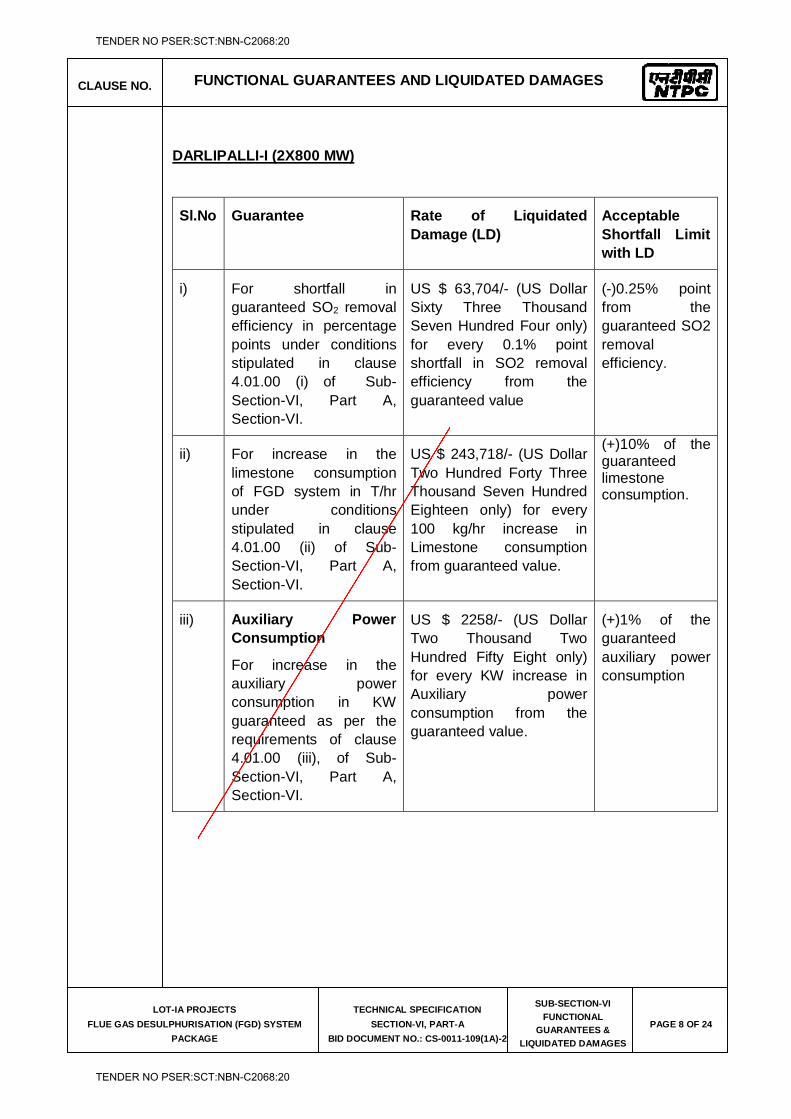
CLAUSE NO. FUNCTIONAL GUARANTEES AND LIQUIDATED DAMAGES
LOT-IA PROJECTS
FLUE GAS DESULPHURISATION (FGD) SYSTEM
PACKAGE
TECHNICAL SPECIFICATION
SECTION-VI, PART-A
BID DOCUMENT NO.: CS-0011-109(1A)-2
SUB-SECTION-VI
FUNCTIONAL
GUARANTEES &
LIQUIDATED DAMAGES
PAGE 8 OF 24
DARLIPALLI-I (2X800 MW)
Sl.No Guarantee Rate of Liquidated Damage (LD)
Acceptable Shortfall Limit with LD
i) For shortfall in guaranteed SO2 removal efficiency in percentage points under conditions stipulated in clause 4.01.00 (i) of Sub-Section-VI, Part A, Section-VI.
US $ 63,704/- (US Dollar Sixty Three Thousand Seven Hundred Four only) for every 0.1% point shortfall in SO2 removal efficiency from the guaranteed value
(-)0.25% point from the guaranteed SO2 removal efficiency.
ii) For increase in the limestone consumption of FGD system in T/hr under conditions stipulated in clause 4.01.00 (ii) of Sub-Section-VI, Part A, Section-VI.
US $ 243,718/- (US Dollar Two Hundred Forty Three Thousand Seven Hundred Eighteen only) for every 100 kg/hr increase in Limestone consumption from guaranteed value.
(+)10% of the guaranteed limestone consumption.
iii) Auxiliary Power Consumption
For increase in the auxiliary power consumption in KW guaranteed as per the requirements of clause 4.01.00 (iii), of Sub-Section-VI, Part A, Section-VI.
US $ 2258/- (US Dollar Two Thousand Two Hundred Fifty Eight only) for every KW increase in Auxiliary power consumption from the guaranteed value.
(+)1% of the guaranteed auxiliary power consumption
TENDER NO PSER:SCT:NBN-C2068:20
TENDER NO PSER:SCT:NBN-C2068:20
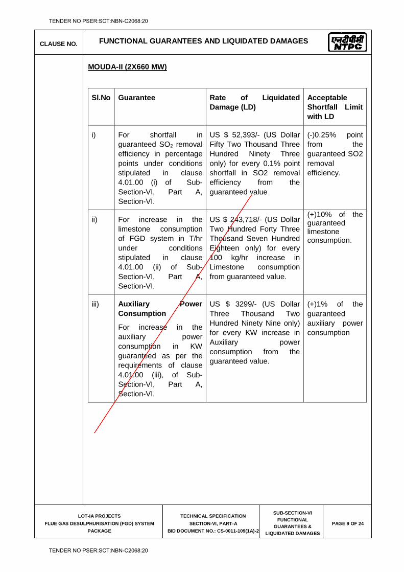
CLAUSE NO. FUNCTIONAL GUARANTEES AND LIQUIDATED DAMAGES
LOT-IA PROJECTS
FLUE GAS DESULPHURISATION (FGD) SYSTEM
PACKAGE
TECHNICAL SPECIFICATION
SECTION-VI, PART-A
BID DOCUMENT NO.: CS-0011-109(1A)-2
SUB-SECTION-VI
FUNCTIONAL
GUARANTEES &
LIQUIDATED DAMAGES
PAGE 9 OF 24
MOUDA-II (2X660 MW)
Sl.No Guarantee Rate of Liquidated Damage (LD)
Acceptable Shortfall Limit with LD
i) For shortfall in guaranteed SO2 removal efficiency in percentage points under conditions stipulated in clause 4.01.00 (i) of Sub-Section-VI, Part A, Section-VI.
US $ 52,393/- (US Dollar Fifty Two Thousand Three Hundred Ninety Three only) for every 0.1% point shortfall in SO2 removal efficiency from the guaranteed value
(-)0.25% point from the guaranteed SO2 removal efficiency.
ii) For increase in the limestone consumption of FGD system in T/hr under conditions stipulated in clause 4.01.00 (ii) of Sub-Section-VI, Part A, Section-VI.
US $ 243,718/- (US Dollar Two Hundred Forty Three Thousand Seven Hundred Eighteen only) for every 100 kg/hr increase in Limestone consumption from guaranteed value.
(+)10% of the guaranteed limestone consumption.
iii) Auxiliary Power Consumption
For increase in the auxiliary power consumption in KW guaranteed as per the requirements of clause 4.01.00 (iii), of Sub-Section-VI, Part A, Section-VI.
US $ 3299/- (US Dollar Three Thousand Two Hundred Ninety Nine only) for every KW increase in Auxiliary power consumption from the guaranteed value.
(+)1% of the guaranteed auxiliary power consumption
TENDER NO PSER:SCT:NBN-C2068:20
TENDER NO PSER:SCT:NBN-C2068:20
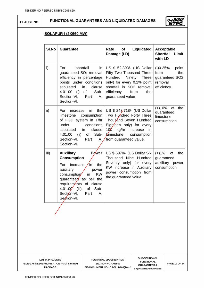
CLAUSE NO. FUNCTIONAL GUARANTEES AND LIQUIDATED DAMAGES
LOT-IA PROJECTS
FLUE GAS DESULPHURISATION (FGD) SYSTEM
PACKAGE
TECHNICAL SPECIFICATION
SECTION-VI, PART-A
BID DOCUMENT NO.: CS-0011-109(1A)-2
SUB-SECTION-VI
FUNCTIONAL
GUARANTEES &
LIQUIDATED DAMAGES
PAGE 10 OF 24
SOLAPUR-I (2X660 MW)
Sl.No Guarantee Rate of Liquidated Damage (LD)
Acceptable Shortfall Limit with LD
i) For shortfall in guaranteed SO2 removal efficiency in percentage points under conditions stipulated in clause 4.01.00 (i) of Sub-Section-VI, Part A, Section-VI.
US $ 52,393/- (US Dollar Fifty Two Thousand Three Hundred Ninety Three only) for every 0.1% point shortfall in SO2 removal efficiency from the guaranteed value
(-)0.25% point from the guaranteed SO2 removal efficiency.
ii) For increase in the limestone consumption of FGD system in T/hr under conditions stipulated in clause 4.01.00 (ii) of Sub-Section-VI, Part A, Section-VI.
US $ 243,718/- (US Dollar Two Hundred Forty Three Thousand Seven Hundred Eighteen only) for every 100 kg/hr increase in Limestone consumption from guaranteed value.
(+)10% of the guaranteed limestone consumption.
iii) Auxiliary Power Consumption
For increase in the auxiliary power consumption in KW guaranteed as per the requirements of clause 4.01.00 (iii), of Sub-Section-VI, Part A, Section-VI.
US $ 6970/- (US Dollar Six Thousand Nine Hundred Seventy only) for every KW increase in Auxiliary power consumption from the guaranteed value.
(+)1% of the guaranteed auxiliary power consumption
TENDER NO PSER:SCT:NBN-C2068:20
TENDER NO PSER:SCT:NBN-C2068:20
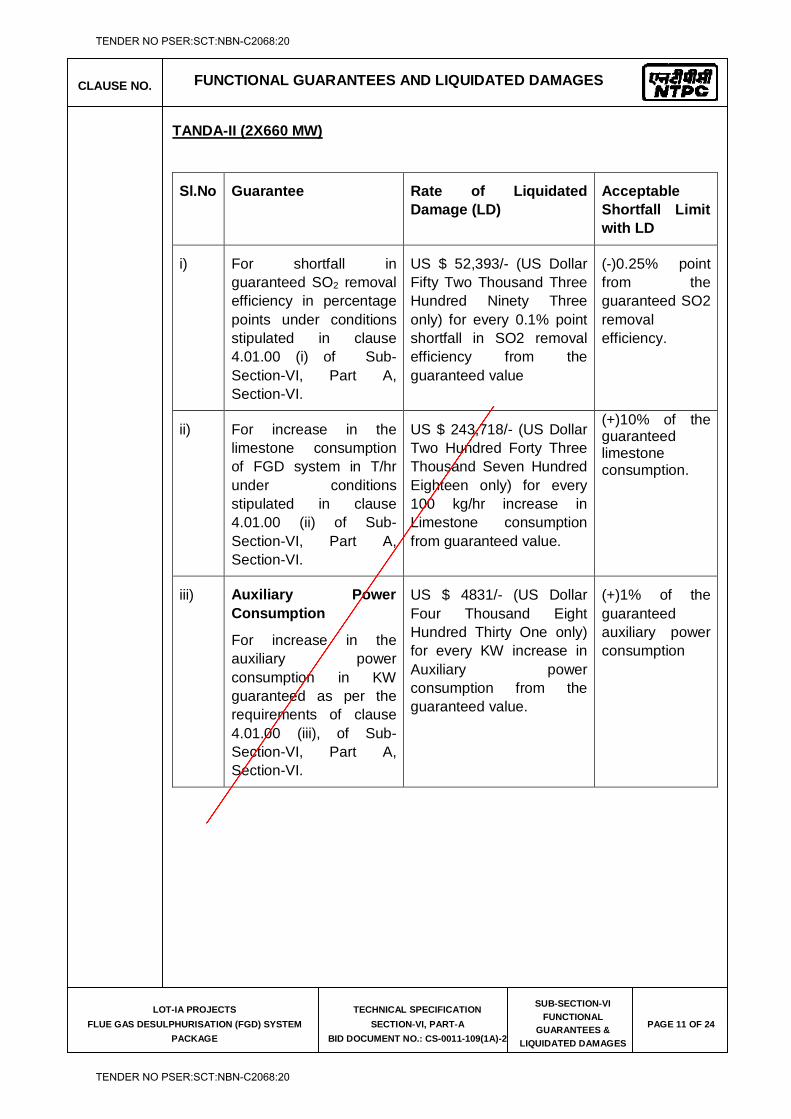
CLAUSE NO. FUNCTIONAL GUARANTEES AND LIQUIDATED DAMAGES
LOT-IA PROJECTS
FLUE GAS DESULPHURISATION (FGD) SYSTEM
PACKAGE
TECHNICAL SPECIFICATION
SECTION-VI, PART-A
BID DOCUMENT NO.: CS-0011-109(1A)-2
SUB-SECTION-VI
FUNCTIONAL
GUARANTEES &
LIQUIDATED DAMAGES
PAGE 11 OF 24
TANDA-II (2X660 MW)
Sl.No Guarantee Rate of Liquidated Damage (LD)
Acceptable Shortfall Limit with LD
i) For shortfall in guaranteed SO2 removal efficiency in percentage points under conditions stipulated in clause 4.01.00 (i) of Sub-Section-VI, Part A, Section-VI.
US $ 52,393/- (US Dollar Fifty Two Thousand Three Hundred Ninety Three only) for every 0.1% point shortfall in SO2 removal efficiency from the guaranteed value
(-)0.25% point from the guaranteed SO2 removal efficiency.
ii) For increase in the limestone consumption of FGD system in T/hr under conditions stipulated in clause 4.01.00 (ii) of Sub-Section-VI, Part A, Section-VI.
US $ 243,718/- (US Dollar Two Hundred Forty Three Thousand Seven Hundred Eighteen only) for every 100 kg/hr increase in Limestone consumption from guaranteed value.
(+)10% of the guaranteed limestone consumption.
iii) Auxiliary Power Consumption
For increase in the auxiliary power consumption in KW guaranteed as per the requirements of clause 4.01.00 (iii), of Sub-Section-VI, Part A, Section-VI.
US $ 4831/- (US Dollar Four Thousand Eight Hundred Thirty One only) for every KW increase in Auxiliary power consumption from the guaranteed value.
(+)1% of the guaranteed auxiliary power consumption
TENDER NO PSER:SCT:NBN-C2068:20
TENDER NO PSER:SCT:NBN-C2068:20
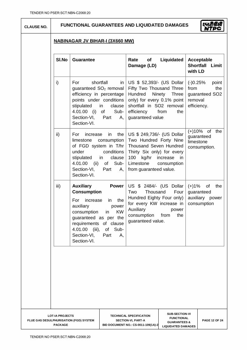
CLAUSE NO. FUNCTIONAL GUARANTEES AND LIQUIDATED DAMAGES
LOT-IA PROJECTS
FLUE GAS DESULPHURISATION (FGD) SYSTEM
PACKAGE
TECHNICAL SPECIFICATION
SECTION-VI, PART-A
BID DOCUMENT NO.: CS-0011-109(1A)-2
SUB-SECTION-VI
FUNCTIONAL
GUARANTEES &
LIQUIDATED DAMAGES
PAGE 12 OF 24
NABINAGAR JV BIHAR-I (3X660 MW)
Sl.No Guarantee Rate of Liquidated Damage (LD)
Acceptable Shortfall Limit with LD
i) For shortfall in guaranteed SO2 removal efficiency in percentage points under conditions stipulated in clause 4.01.00 (i) of Sub-Section-VI, Part A, Section-VI.
US $ 52,393/- (US Dollar Fifty Two Thousand Three Hundred Ninety Three only) for every 0.1% point shortfall in SO2 removal efficiency from the guaranteed value
(-)0.25% point from the guaranteed SO2 removal efficiency.
ii) For increase in the limestone consumption of FGD system in T/hr under conditions stipulated in clause 4.01.00 (ii) of Sub-Section-VI, Part A, Section-VI.
US $ 249,736/- (US Dollar Two Hundred Forty Nine Thousand Seven Hundred Thirty Six only) for every 100 kg/hr increase in Limestone consumption from guaranteed value.
(+)10% of the guaranteed limestone consumption.
iii) Auxiliary Power Consumption
For increase in the auxiliary power consumption in KW guaranteed as per the requirements of clause 4.01.00 (iii), of Sub-Section-VI, Part A, Section-VI.
US $ 2484/- (US Dollar Two Thousand Four Hundred Eighty Four only) for every KW increase in Auxiliary power consumption from the guaranteed value.
(+)1% of the guaranteed auxiliary power consumption
TENDER NO PSER:SCT:NBN-C2068:20
TENDER NO PSER:SCT:NBN-C2068:20
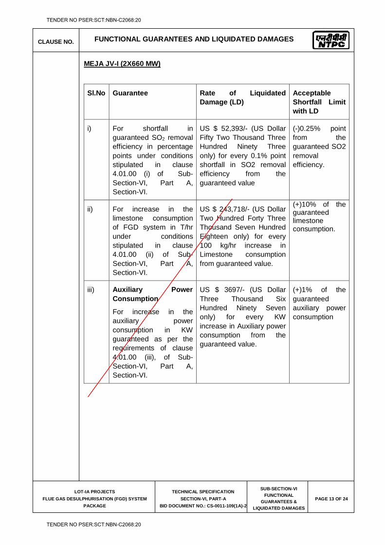
CLAUSE NO. FUNCTIONAL GUARANTEES AND LIQUIDATED DAMAGES
LOT-IA PROJECTS
FLUE GAS DESULPHURISATION (FGD) SYSTEM
PACKAGE
TECHNICAL SPECIFICATION
SECTION-VI, PART-A
BID DOCUMENT NO.: CS-0011-109(1A)-2
SUB-SECTION-VI
FUNCTIONAL
GUARANTEES &
LIQUIDATED DAMAGES
PAGE 13 OF 24
MEJA JV-I (2X660 MW)
Sl.No Guarantee Rate of Liquidated Damage (LD)
Acceptable Shortfall Limit with LD
i) For shortfall in guaranteed SO2 removal efficiency in percentage points under conditions stipulated in clause 4.01.00 (i) of Sub-Section-VI, Part A, Section-VI.
US $ 52,393/- (US Dollar Fifty Two Thousand Three Hundred Ninety Three only) for every 0.1% point shortfall in SO2 removal efficiency from the guaranteed value
(-)0.25% point from the guaranteed SO2 removal efficiency.
ii) For increase in the limestone consumption of FGD system in T/hr under conditions stipulated in clause 4.01.00 (ii) of Sub-Section-VI, Part A, Section-VI.
US $ 243,718/- (US Dollar Two Hundred Forty Three Thousand Seven Hundred Eighteen only) for every 100 kg/hr increase in Limestone consumption from guaranteed value.
(+)10% of the guaranteed limestone consumption.
iii) Auxiliary Power Consumption
For increase in the auxiliary power consumption in KW guaranteed as per the requirements of clause 4.01.00 (iii), of Sub-Section-VI, Part A, Section-VI.
US $ 3697/- (US Dollar Three Thousand Six Hundred Ninety Seven only) for every KW increase in Auxiliary power consumption from the guaranteed value.
(+)1% of the guaranteed auxiliary power consumption
TENDER NO PSER:SCT:NBN-C2068:20
TENDER NO PSER:SCT:NBN-C2068:20
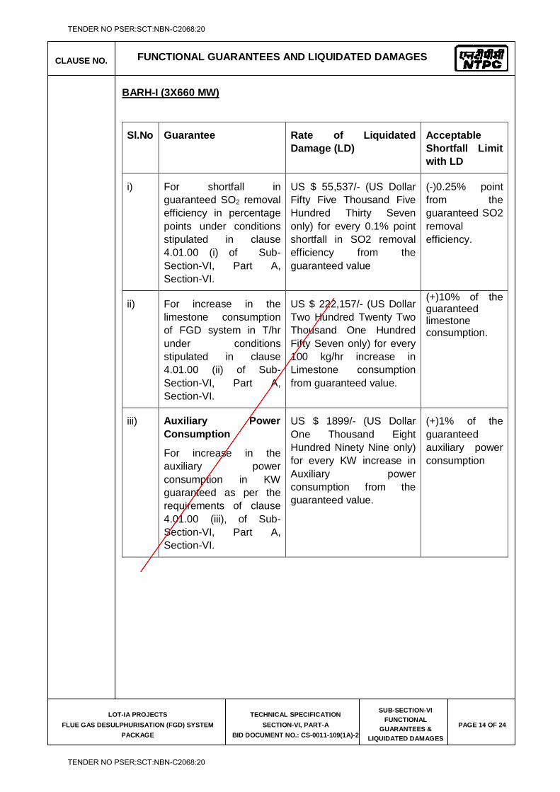
CLAUSE NO. FUNCTIONAL GUARANTEES AND LIQUIDATED DAMAGES
LOT-IA PROJECTS
FLUE GAS DESULPHURISATION (FGD) SYSTEM
PACKAGE
TECHNICAL SPECIFICATION
SECTION-VI, PART-A
BID DOCUMENT NO.: CS-0011-109(1A)-2
SUB-SECTION-VI
FUNCTIONAL
GUARANTEES &
LIQUIDATED DAMAGES
PAGE 14 OF 24
BARH-I (3X660 MW)
Sl.No Guarantee Rate of Liquidated Damage (LD)
Acceptable Shortfall Limit with LD
i) For shortfall in guaranteed SO2 removal efficiency in percentage points under conditions stipulated in clause 4.01.00 (i) of Sub-Section-VI, Part A, Section-VI.
US $ 55,537/- (US Dollar Fifty Five Thousand Five Hundred Thirty Seven only) for every 0.1% point shortfall in SO2 removal efficiency from the guaranteed value
(-)0.25% point from the guaranteed SO2 removal efficiency.
ii) For increase in the limestone consumption of FGD system in T/hr under conditions stipulated in clause 4.01.00 (ii) of Sub-Section-VI, Part A, Section-VI.
US $ 222,157/- (US Dollar Two Hundred Twenty Two Thousand One Hundred Fifty Seven only) for every 100 kg/hr increase in Limestone consumption from guaranteed value.
(+)10% of the guaranteed limestone consumption.
iii) Auxiliary Power Consumption
For increase in the auxiliary power consumption in KW guaranteed as per the requirements of clause 4.01.00 (iii), of Sub-Section-VI, Part A, Section-VI.
US $ 1899/- (US Dollar One Thousand Eight Hundred Ninety Nine only) for every KW increase in Auxiliary power consumption from the guaranteed value.
(+)1% of the guaranteed auxiliary power consumption
TENDER NO PSER:SCT:NBN-C2068:20
TENDER NO PSER:SCT:NBN-C2068:20
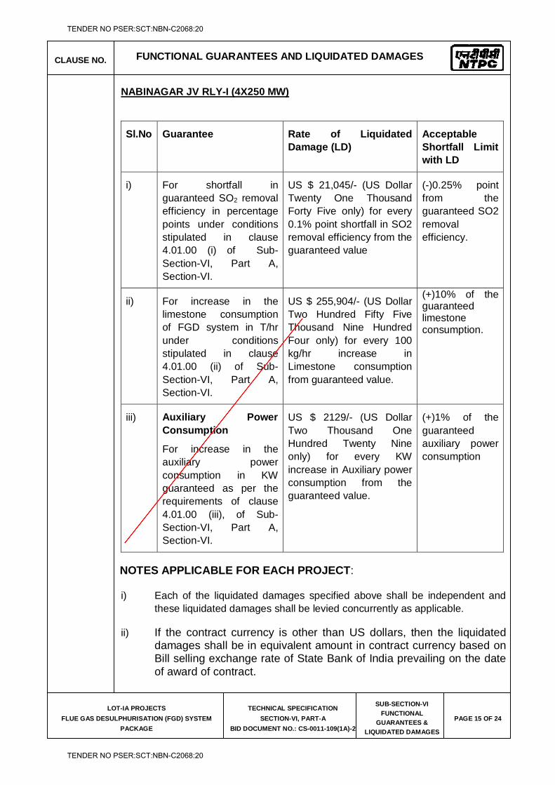
CLAUSE NO. FUNCTIONAL GUARANTEES AND LIQUIDATED DAMAGES
LOT-IA PROJECTS
FLUE GAS DESULPHURISATION (FGD) SYSTEM
PACKAGE
TECHNICAL SPECIFICATION
SECTION-VI, PART-A
BID DOCUMENT NO.: CS-0011-109(1A)-2
SUB-SECTION-VI
FUNCTIONAL
GUARANTEES &
LIQUIDATED DAMAGES
PAGE 15 OF 24
NABINAGAR JV RLY-I (4X250 MW)
Sl.No Guarantee Rate of Liquidated Damage (LD)
Acceptable Shortfall Limit with LD
i) For shortfall in guaranteed SO2 removal efficiency in percentage points under conditions stipulated in clause 4.01.00 (i) of Sub-Section-VI, Part A, Section-VI.
US $ 21,045/- (US Dollar Twenty One Thousand Forty Five only) for every 0.1% point shortfall in SO2 removal efficiency from the guaranteed value
(-)0.25% point from the guaranteed SO2 removal efficiency.
ii) For increase in the limestone consumption of FGD system in T/hr under conditions stipulated in clause 4.01.00 (ii) of Sub-Section-VI, Part A, Section-VI.
US $ 255,904/- (US Dollar Two Hundred Fifty Five Thousand Nine Hundred Four only) for every 100 kg/hr increase in Limestone consumption from guaranteed value.
(+)10% of the guaranteed limestone consumption.
iii) Auxiliary Power Consumption
For increase in the auxiliary power consumption in KW guaranteed as per the requirements of clause 4.01.00 (iii), of Sub-Section-VI, Part A, Section-VI.
US $ 2129/- (US Dollar Two Thousand One Hundred Twenty Nine only) for every KW increase in Auxiliary power consumption from the guaranteed value.
(+)1% of the guaranteed auxiliary power consumption
NOTES APPLICABLE FOR EACH PROJECT:
i) Each of the liquidated damages specified above shall be independent and these liquidated damages shall be levied concurrently as applicable.
ii) If the contract currency is other than US dollars, then the liquidated damages shall be in equivalent amount in contract currency based on Bill selling exchange rate of State Bank of India prevailing on the date of award of contract.
TENDER NO PSER:SCT:NBN-C2068:20
TENDER NO PSER:SCT:NBN-C2068:20
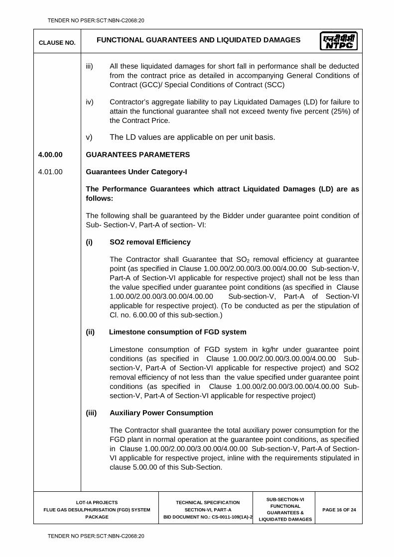
CLAUSE NO. FUNCTIONAL GUARANTEES AND LIQUIDATED DAMAGES
LOT-IA PROJECTS
FLUE GAS DESULPHURISATION (FGD) SYSTEM
PACKAGE
TECHNICAL SPECIFICATION
SECTION-VI, PART-A
BID DOCUMENT NO.: CS-0011-109(1A)-2
SUB-SECTION-VI
FUNCTIONAL
GUARANTEES &
LIQUIDATED DAMAGES
PAGE 16 OF 24
iii) All these liquidated damages for short fall in performance shall be deducted from the contract price as detailed in accompanying General Conditions of Contract (GCC)/ Special Conditions of Contract (SCC)
iv) Contractor’s aggregate liability to pay Liquidated Damages (LD) for failure to attain the functional guarantee shall not exceed twenty five percent (25%) of the Contract Price.
v) The LD values are applicable on per unit basis.
4.00.00 GUARANTEES PARAMETERS
4.01.00 Guarantees Under Category-I
The Performance Guarantees which attract Liquidated Damages (LD) are as follows:
The following shall be guaranteed by the Bidder under guarantee point condition of Sub- Section-V, Part-A of section- VI:
(i) SO2 removal Efficiency
The Contractor shall Guarantee that SO2 removal efficiency at guarantee point (as specified in Clause 1.00.00/2.00.00/3.00.00/4.00.00 Sub-section-V, Part-A of Section-VI applicable for respective project) shall not be less than the value specified under guarantee point conditions (as specified in Clause 1.00.00/2.00.00/3.00.00/4.00.00 Sub-section-V, Part-A of Section-VI applicable for respective project). (To be conducted as per the stipulation of Cl. no. 6.00.00 of this sub-section.)
(ii) Limestone consumption of FGD system
Limestone consumption of FGD system in kg/hr under guarantee point conditions (as specified in Clause 1.00.00/2.00.00/3.00.00/4.00.00 Sub-section-V, Part-A of Section-VI applicable for respective project) and SO2 removal efficiency of not less than the value specified under guarantee point conditions (as specified in Clause 1.00.00/2.00.00/3.00.00/4.00.00 Sub-section-V, Part-A of Section-VI applicable for respective project)
(iii) Auxiliary Power Consumption
The Contractor shall guarantee the total auxiliary power consumption for the FGD plant in normal operation at the guarantee point conditions, as specified in Clause 1.00.00/2.00.00/3.00.00/4.00.00 Sub-section-V, Part-A of Section-VI applicable for respective project, inline with the requirements stipulated in clause 5.00.00 of this Sub-Section.
TENDER NO PSER:SCT:NBN-C2068:20
TENDER NO PSER:SCT:NBN-C2068:20
CLAUSE NO. FUNCTIONAL GUARANTEES AND LIQUIDATED DAMAGES
LOT-IA PROJECTS
FLUE GAS DESULPHURISATION (FGD) SYSTEM
PACKAGE
TECHNICAL SPECIFICATION
SECTION-VI, PART-A
BID DOCUMENT NO.: CS-0011-109(1A)-2
SUB-SECTION-VI
FUNCTIONAL
GUARANTEES &
LIQUIDATED DAMAGES
PAGE 17 OF 24
4.02.00 Guarantees Under Category-II
The parameters/capabilities shall be demonstrated for various systems/ equipments shall include but not limited to the following:-
(i) Wet ball Mill capacity at rated fineness
The contractor shall demonstrate the guaranteed capacity of each limestone pulverizer under the following conditions:
i) Limestone fineness : 90% or higher (as per the requirement of the absorber) through 325 mesh. ii) Limestone Quality : All available quality from the specified range.
(ii) Wet ball Mill wear parts guarantee
Contractor shall demonstrate the life of wet ball Mill wear parts in line with requirements stipulated in Part B of the Technical Specification. The establishment of the above guarantee shall be based on the operating records available at the Power station and will be computed for each pulverizer based on actual total hours of operation.
(iii) Wet ball Mill ball consumption
Contractor shall guarantee ball consumption per ton of limestone throughput in line with requirements stipulated in Part B of the Technical Specification. Contractor shall furnish the minimum ball diameter below which the balls shall be replaced.
(iv) Vacuum Belt Filter Capacity
Contractor shall demonstrate the Designed Capacity of the Vaccum Belt Filters to dewater the quantity of gypsum with the specified purity and moisture content as specified in Part B of the Technical Specification.
(v) Gypsum Purity
The contractor shall demonstrate that the purity of the gypsum produced shall not be less than 90%, chloride content shall not be more than 100ppm and the moisture content shall not be more than 10% for guarantee point condition.
TENDER NO PSER:SCT:NBN-C2068:20
TENDER NO PSER:SCT:NBN-C2068:20
CLAUSE NO. FUNCTIONAL GUARANTEES AND LIQUIDATED DAMAGES
LOT-IA PROJECTS
FLUE GAS DESULPHURISATION (FGD) SYSTEM
PACKAGE
TECHNICAL SPECIFICATION
SECTION-VI, PART-A
BID DOCUMENT NO.: CS-0011-109(1A)-2
SUB-SECTION-VI
FUNCTIONAL
GUARANTEES &
LIQUIDATED DAMAGES
PAGE 18 OF 24
(vi) Waste Water
The Contractor guarantees that the maximum purge flow rate to waste water treatment system for the complete plant shall be 10m3/hr averaged over a 24 hour period from each unit.
(vii) Performance characteristics of fans (capacity, head developed, etc.).
(viii) Margins on fans in case Booster Fan is provided by the Contractor.
Booster Fans - As specified in Part B of Technical Specifications
(ix) Passenger cum Goods Elevator for FGD absorber & Limestone
Grinding Building: Over load tests, travel and hoist speed checks. (x) Noise
All the plant, equipment and systems covered under this specification shall
perform continuously without exceeding the noise level over the entire range of output and operating frequency specified in Part-C of Section-VI of the technical specifications.
Noise level measurement shall be carried out using applicable and internationally acceptable standards. The measurement shall be carried out with a calibrated integrating sound level meter meeting the requirement of IEC 651 or BS 5969 or is 9779.
Sound pressure shall be measured all around the equipment at a distance of 1.0 m horizontally from the nearest surface of any equipment/ machine and at a height of 1.5 m above the floor level in elevation.
A minimum of 6 points around each equipment shall be covered for measurement. additional measurement points shall be considered based on the applicable standards and the size of the equipment. the measurement shall be done with slow response on the a - weighting scale. the average of a-weighted sound pressure level measurements expressed in decibels to a reference of 0.0002 micro bar shall not exceed the guaranteed value. corrections for background noise shall be considered in line with the applicable standards. all the necessary data for determining these corrections, in line with the applicable standards, shall be collected during the tests.
TENDER NO PSER:SCT:NBN-C2068:20
TENDER NO PSER:SCT:NBN-C2068:20
CLAUSE NO. FUNCTIONAL GUARANTEES AND LIQUIDATED DAMAGES
LOT-IA PROJECTS
FLUE GAS DESULPHURISATION (FGD) SYSTEM
PACKAGE
TECHNICAL SPECIFICATION
SECTION-VI, PART-A
BID DOCUMENT NO.: CS-0011-109(1A)-2
SUB-SECTION-VI
FUNCTIONAL
GUARANTEES &
LIQUIDATED DAMAGES
PAGE 19 OF 24
(xi) Mist Outlet Droplet Content
The mist eliminator outlet droplet content shall be guaranteed to be < 20 mg/Nm3 at absorber outlet measured over a period of 24 hrs continuous operation.
Mist outlet-droplet content shall be measured as per applicable clauses in VDI Norm 3679 and the Contractor shall carry out the tests as per the test procedure approved by the Employer.
(xii) Availability of FGD Plant
The Contractor shall guarantee the maximum availability of FGD Plant for the range of coal and limestone specified inline with the requirements stipulated in clause 7.00.00 of this Sub-Section
(xiii) Air Conditioning System
A. Following shall be demonstrated at Shop
1) Capacity and static pressure of AHU fans at its rated duty point.
B. Following shall be demonstrated at Site
1) Capacity (TR) of air cooled condensing units (D-X type) for A/C system of FGD control room building.
2) Guaranteed room conditions during summer for all the Air conditioned areas.
3) Vibration and noise level of condensing units & centrifugal fans of AHUs.
(xiv) Ventilation System
A. Following shall be demonstrated at Shop
1) Capacity and discharge pressure of pumps of UAF units at its rated duty point of Ventilation system.
2) Capacity and static pressure of UAF fans at its rated duty point of Ventilation system.
B. Following shall be demonstrated at Site
1) Vibration & Noise level of centrifugal fans & pumps of UAF units.
(xv) Compressed Air System
a) Following shall be demonstrated at shop:
i) Capacity and discharge pressure of each air compressor.
b) Following shall be demonstrated at site:
ii) Dew point of air at the outlet of air drying plants of air compressor.
TENDER NO PSER:SCT:NBN-C2068:20
TENDER NO PSER:SCT:NBN-C2068:20
CLAUSE NO. FUNCTIONAL GUARANTEES AND LIQUIDATED DAMAGES
LOT-IA PROJECTS
FLUE GAS DESULPHURISATION (FGD) SYSTEM
PACKAGE
TECHNICAL SPECIFICATION
SECTION-VI, PART-A
BID DOCUMENT NO.: CS-0011-109(1A)-2
SUB-SECTION-VI
FUNCTIONAL
GUARANTEES &
LIQUIDATED DAMAGES
PAGE 20 OF 24
iv) Pressure drop across air drying plant .
v) Vibration and noise level of air compressors, blowers of air drying plant (if applicable)
xvi) Equipment Cooling Water System
i) Vibration, noise and parallel operation without hunting & abnormal noise and with flow sharing within 10% of each other at the rated duty point shall be demonstrated at site.
ii) Design heat load of plate type heat exchangers and Inlet & Outlet temperatures of the Plate type heat exchangers on the primary and secondary side to be demonstrated at site. Pressure drop across the Plate type heat exchanger on the primary & secondary water circuit to be demonstrated at site.
xvii) Waste Water Treatment System (Applicable for Barh-I (3X660 MW) & Nabinagar
(4x250 MW)
The Contractor shall guarantee the followings.
A). Wastewater treatment capacity(m3/hr) : ≥ 30 for Barh-I (3X660 MW)
B). Wastewater treatment capacity(m3/hr) : ≥ 20 for Nabinagar (4x250 MW)
C). Operating time : 16hr for Pre-treatment process, 24hr for Evaporation
process
D). The distillate quality (Evaporator and crystallizer combined) shall be a
maximum of 50 ppm TDS at 120 oF, while the solids produced for
disposal which will pass the paint filter test.
5.00.00 AUXILIARY POWER CONSUMPTION (PA) FOR EACH PROJECT
The unit auxiliary power consumption shall be calculated using the following relationship.
Pa = Pu + TL
Pa = Guaranteed Auxiliary Power Consumption.
Pu = Power consumed by the auxiliaries of the unit under test.
TL = Losses of the transformers supplied by bidder based on works test
reports.
While guaranteeing the auxiliary power consumption of each project the bidder shall necessarily include all continuously operating auxiliaries under this package. The auxiliaries to be considered shall include but not be limited to the following:
TENDER NO PSER:SCT:NBN-C2068:20
TENDER NO PSER:SCT:NBN-C2068:20
CLAUSE NO. FUNCTIONAL GUARANTEES AND LIQUIDATED DAMAGES
LOT-IA PROJECTS
FLUE GAS DESULPHURISATION (FGD) SYSTEM
PACKAGE
TECHNICAL SPECIFICATION
SECTION-VI, PART-A
BID DOCUMENT NO.: CS-0011-109(1A)-2
SUB-SECTION-VI
FUNCTIONAL
GUARANTEES &
LIQUIDATED DAMAGES
PAGE 21 OF 24
i. Absorber Recirculation Pump(s)/Gas Cooling Pumps
ii. Absorber Oxidation Air Blower(s)
iii. Absorber Oxidation Tank Agitator(s)
iv. Gypsum Bleed Pump
v. Limestone Gravimetric feeder, Wet ball mill and their integral Auxiliaries divided by the number of units in the project
vi. Limestone Slurry Pump
vii. Vacuum Belt Filter, Vacuum Pump and its integral auxiliaries divided by the number of units in the project
viii. Power consumption of Booster water pump (if provided) divided by the number of units in the project.
ix. Process water pump(s) divided by the number of units in the project
x. Mist Eliminator Wash Water pump(s)
xi. Power consumption of Belt Filter Wash Water Pump divided by the number of units in the project
xii. DM Cooling (normally working) Water pump one(1) to supply cooling water on the primary (DM) side of the plate type heat exchangers in the closed loop Equipment cooling water system.
xiii. Auxiliary Cooling (normally working) water pump one(1) to supply cooling water on the secondary side of the plate type heat exchangers in the closed loop Equipment cooling (unit auxiliary) water system.
xiv. Booster Fans
xv. Power consumption of Limestone Slurry Tank Agitator(s) divided by the number of units in the project
xvi. Power consumption of Filtrate Pump divided by the number of units in the project
xvii. Power consumption of Belt Filter Wash Water Pump divided by the number of units in the project
xviii. Power consumption of Cloth Wash Water Pump divided by the number of units in the project
TENDER NO PSER:SCT:NBN-C2068:20
TENDER NO PSER:SCT:NBN-C2068:20
CLAUSE NO. FUNCTIONAL GUARANTEES AND LIQUIDATED DAMAGES
LOT-IA PROJECTS
FLUE GAS DESULPHURISATION (FGD) SYSTEM
PACKAGE
TECHNICAL SPECIFICATION
SECTION-VI, PART-A
BID DOCUMENT NO.: CS-0011-109(1A)-2
SUB-SECTION-VI
FUNCTIONAL
GUARANTEES &
LIQUIDATED DAMAGES
PAGE 22 OF 24
xix. Power consumption of Hydro-cyclone and Waste Water Pump divided by the number of units in the project
xx. Power consumption of all other continuous running Agitators divided by the number of units in the project
xxi. Air Conditioning System (*)
Total Power consumption at motor input terminals of working units (i.e. excluding stand-by) at its rated duty point of compressor and condenser fans of air cooled condensing unit, Air handling unit (AHU) fans for the Air conditioning system of FGD Control Room Building and ZLD Control Room Building (if provided) divided by total nos. of units in respective project..
xxii Total power consumption at motor input terminal at rated duty of fan of UAF divided by total nos. of units in respective project. (*)
((*) Above guaranteed power consumption values shall be at 20 deg C for centrifugal fans of AHUs and at 30 deg C for centrifugal fans of air washer units and at an elevation of RL (+) - m for both AHUs and Air washer unit centrifugal fans.)
xxiii Total power consumption at motor input terminal at rated duty of Air compressor, Air drying plant (Heater and blower, as applicable) divided by total nos. of units in respective project
xxiv. Power consumption of Evaporator feed pump divided by the number of units in the project, in case ZLD system is provided
xxv. Power consumption of Evaporator/Brine concentrator recirculation pump divided by the number of units in the project, in case ZLD system is provided
xxvi. Power consumption of Distillate pump divided by the number of units in the project, in case ZLD system is provided
xxvii. Power consumption of Crystalliser feed pump divided by the number of units in the project, in case ZLD system is provided
xxviii. Power consumption of Crystalliser recirculation pump divided by the number of units in the project, in case ZLD system is provided
xxix. Power consumption of Mechanical vapour Compressor divided by the number of units in the project, in case ZLD system is provided
The equipment’s listed above for calculating auxiliary power consumption are indicative. Any other equipment required for continuous operation of the system shall also be considered for calculation of auxiliary power consumption. Power consumption of all equipments provided on unitized basis shall be included in the unit auxiliary power consumption. For common station auxiliaries, the power
TENDER NO PSER:SCT:NBN-C2068:20
TENDER NO PSER:SCT:NBN-C2068:20
CLAUSE NO. FUNCTIONAL GUARANTEES AND LIQUIDATED DAMAGES
LOT-IA PROJECTS
FLUE GAS DESULPHURISATION (FGD) SYSTEM
PACKAGE
TECHNICAL SPECIFICATION
SECTION-VI, PART-A
BID DOCUMENT NO.: CS-0011-109(1A)-2
SUB-SECTION-VI
FUNCTIONAL
GUARANTEES &
LIQUIDATED DAMAGES
PAGE 23 OF 24
consumption shall be assigned to each unit based on unit load for the purpose of calculating the unit auxiliary power consumption.
Note :
1. The bidder shall furnish a list of equipments to be covered under auxiliary power consumption, which shall be subject to Employer’s approval.
2. The equipments listed above for calculating auxiliary power consumption are indicative. Any other equipment required for continuous operation of the system shall also be considered for calculation of auxiliary power consumption.
6.00.00 METHOD OF COMPUTING TEST EFFICIENCY OF FGD
The performance tests shall be carried out in accordance with ASME PTC 40 (1991) code. No tolerance or allowance on the test result will be permitted for instrument errors or inaccuracy, the method of testing or any other causes. The details of the test shall, however be mutually agreed upon between the employer and the contractor.
7.00.00 METHOD OF COMPUTING AVAILABILITY
The Contractor shall guarantee 98 % availability of FGD plant including waste water treatment system for Zero Liquid Discharge (ZLD), wherever provided, for a continuous period of 120 days. An availability guarantee test shall be conducted to assure this level of availability for a period of 240 days as per the procedure indicated below.
Availability 'A' in %:
A= Tc x 100% Tk
Tc – recorded time of FGD operation, expressed in hours,
Tk – recorded time of boiler operation, expressed in hours,
However, it is required that:
(i) In order to calculate the FGD availability, operation hours will be counted except boiler start-ups when the operation hours counting will start on the moment of shut down of all oil burners,
(ii) FGD will be regarded as a FGD in operation, when by-pass damper is closed and total flow of flue gas from boiler goes via FGD, and SO2
TENDER NO PSER:SCT:NBN-C2068:20
TENDER NO PSER:SCT:NBN-C2068:20
CLAUSE NO. FUNCTIONAL GUARANTEES AND LIQUIDATED DAMAGES
LOT-IA PROJECTS
FLUE GAS DESULPHURISATION (FGD) SYSTEM
PACKAGE
TECHNICAL SPECIFICATION
SECTION-VI, PART-A
BID DOCUMENT NO.: CS-0011-109(1A)-2
SUB-SECTION-VI
FUNCTIONAL
GUARANTEES &
LIQUIDATED DAMAGES
PAGE 24 OF 24
content is below 100 mg/Nm3 (dry basis at 6% O2) in cleaned flue gas for the range of specified coals & loads.
(iii) If FGD is out of operation during the boiler operation time as a result of the Employer’s decision, this time will not be counted as boiler operation time for calculating the FGD availability,
(iv) Boiler operation hours will be counted based on the recorded boiler operation hours and the recorded data will be made available to the Contractor by the Employer.
Mandatory spares have been identified in the Employer. Contractor can use the mandatory spares supplied under the contract during this period in agreement with the Employer. However, if other additional spares are required for demonstration of availability demonstration guarantee, Bidder to should clearly indicate along with their offer.
If the calculated availability after 120 days availability test is lower than the guaranteed value, the Contractor will undertake actions as per clause 2.04.00 (ii) of this Sub-Section to achieve the guaranteed availability.
TENDER NO PSER:SCT:NBN-C2068:20
TENDER NO PSER:SCT:NBN-C2068:20
LOT-IA PROJECTS FLUE GAS DESULPHURISATION (FGD) SYSTEM PACKAGE
TECHNICAL SPECIFICATION
SECTION-VI
BID DOCUMENT NO.: CS-0011-109(1A)-2
SUB-SECTION-VII
MANDATORY SPARES
TENDER NO PSER:SCT:NBN-C2068:20
TENDER NO PSER:SCT:NBN-C2068:20
CLAUSE NO. MANDATORY SPARES
LOT-IA PROJECTS
FLUE GAS DESULPHURISATION (FGD)
SYSTEM PACKAGE
TECHNICAL SPECIFICATION
SECTION-VI, PART-A
BID DOCUMENT NO: CS-0011-109(1A)-2
SUB-SECTION-VII
MANDATORY SPARES PAGE 1 OF 61
1.00.00 GENERAL The Bidder shall include in his scope of supply all the necessary Mandatory spares,
Start-up and commissioning spares and Recommended spares and indicate these in the relevant schedules of the Bid Forms & Price Schedules. The general requirements pertaining to the supply of these spares is given below:
1.01.00 MANDATORY SPARES a) The list of mandatory spares considered essential by the Employer is
indicated in the list enclosed to this Sub-Section. The bidder shall indicate the prices for each and every item (except for items not applicable to the bidders design) in the ‘Schedule of Mandatory Spares’ whether or not he considers it necessary for the Employer to have such spares. If the bidder fails to comply with the above or fails to quote the price of any spare item, the cost of such spares shall be deemed to be included in the contract price. The bidder shall furnish the population per unit of each item in the Bid Forms & Price Schedules. Whenever the quantity is mentioned in “sets” the bidder has to give the item details and prices of each item.
b) Whenever the quantity is indicated as a percentage, it shall mean
percentage of total population of that item in the station (project), unless specified otherwise, and the fraction will be rounded off to the next higher whole number. Wherever the requirement has been specified as a ‘set’ (marked by **) it will include the total requirement of the item for a unit, module or the station as specified. Where it is specified as ‘set’ (marked by*) it would mean the requirement for the single equipment / system as the case may be. Also one set for the particular equipment. e.g. ‘set’ of bearings for a pump would include the total number of bearings in a pump. Also the ‘set’ would include all components required to replace the item; for example, a set of bearings shall include all hardware normally required while replacing the bearings.
c) The assembly / sub assembly which have different orientation (like left hand,
right hand, top or bottom), different direction of rotation or mirror image positioning or any other regions which result in maintaining two different sets of spares to be used for subject assembly / sub-assembly shall be considered as different type of assembly/sub-assembly.
d) The Employer reserves the right to buy any or all the mandatory spare parts. e) The prices of mandatory spares indicated by the Bidder in the Bid Proposal
sheets shall be used for bid evaluation purposes.
TENDER NO PSER:SCT:NBN-C2068:20
TENDER NO PSER:SCT:NBN-C2068:20
CLAUSE NO. MANDATORY SPARES
LOT-IA PROJECTS
FLUE GAS DESULPHURISATION (FGD)
SYSTEM PACKAGE
TECHNICAL SPECIFICATION
SECTION-VI, PART-A
BID DOCUMENT NO: CS-0011-109(1A)-2
SUB-SECTION-VII
MANDATORY SPARES PAGE 2 OF 61
f) All mandatory spares shall be delivered at site at least two months before scheduled date of initial operation of the first unit. However, spares shall not be dispatched before dispatch of corresponding main equipments.
g) Wherever quantity is specified both as a percentage and a value, the Bidder
has to supply the higher quantity until & unless specified otherwise. 1.02.00 RECOMMENDED SPARES a) In addition to the spare parts mentioned above, the Contractor shall also
provide a list of recommended spares for 3 years of normal operation of the plant and indicate the list and total prices in relevant schedule of the Bid Forms & Price Schedules. This list shall take into consideration the mandatory spares specified in this Sub-Section and should be independent of the list of the mandatory spares. The Employer reserves the right to buy any or all of the recommended spares. The recommended spares shall be delivered at project site at least two months before the scheduled date of initial operation of first unit. However, the spares shall not be dispatched before the dispatch of the main equipment.
b) Prices of recommended spares will not be used for evaluation of the bids.
The price of these spares will remain valid up to 6 months after placement of Notification of Award for the main equipment. However, the Contractor shall be liable to provide necessary justification for the quoted prices for these spares as desired by the Employer.
1.03.00 START-UP & COMMISSIONING SPARES a) Start-up & commissioning spares are those spares which may be required
during the start-up and commissioning of the equipment/system. All spares used till the Plant is handed over to the Employer shall come under this category. The Contractor shall provide for an adequate stock of such start up and commissioning spares to be brought by him to the site for the plant erection and commissioning. They must be available at site before the equipments are energized. The unused spares, if any, should be removed from there only after the issue of Taking Over certificate. All start up spares which remain unused at the time shall remain the property of the Contractor.
1.04.00 The Bidder shall include in his scope of supply all the necessary Mandatory spares,
Start-up and commissioning spares and indicate these in the relevant schedules of the Bid Forms & Price Schedules. The general requirements pertaining to the supply of these spares is given below:
TENDER NO PSER:SCT:NBN-C2068:20
TENDER NO PSER:SCT:NBN-C2068:20
CLAUSE NO. MANDATORY SPARES
LOT-IA PROJECTS
FLUE GAS DESULPHURISATION (FGD)
SYSTEM PACKAGE
TECHNICAL SPECIFICATION
SECTION-VI, PART-A
BID DOCUMENT NO: CS-0011-109(1A)-2
SUB-SECTION-VII
MANDATORY SPARES PAGE 3 OF 61
2.00.00 The Contractor shall indicate the service expectancy period for the spare parts (both mandatory and recommended) under normal operating conditions before replacement is necessary.
3.00.00 All spares supplied under this contract shall be strictly inter-changeable with the
parts for which they are intended for replacements. The spares shall be treated and packed for long storage under the climatic conditions prevailing at the site e.g. small items shall be packed in sealed transparent plastic with desiccators packs as necessary.
4.00.00 All the spares (both recommended and mandatory) shall be manufactured along
with the main equipment components as a continuous operation as per same specification and quality plan.
5.00.00 The Contractor will provide Employer with cross-sectional drawings, catalogues,
assembly drawings and other relevant documents so as to enable the Employer to identify and finalize order for recommended spares.
6.00.00 Each spare part shall be clearly marked or labeled on the outside of the packing
with its description. When more than one spare part is packed in a single case, a general description of the content shall be shown on the outside of such case and a detailed list enclosed. All cases, containers and other packages must be suitably marked and numbered for the purposes of identification.
7.00.00 All cases, containers or other packages are to be opened for such examination as
may be considered necessary by the Employer. 8.00.00 The Contractor will provide the Employer with all the addresses and particulars of
his sub-suppliers while placing the order on vendors for items/components/ equipments covered under the Contract and will further ensure with his vendors that the Employer, if so desires, will have the right to place order for spares directly on them on mutually agreed terms based on offers of such vendors.
9.00.00 The Contractor shall warrant that all spares supplied will be new and in accordance
with the Contract Documents and will be free from defects in design, material and workmanship.
10.00.00 In addition to the recommended spares listed by the Contractor, if the Employer
further identifies certain particular items of spares, the Contractor shall submit the prices and delivery quotation for such spares within 30 days of receipt of such request with a validity period of 6 months for consideration by the Employer and placement of order for additional spares if the Employer so desires.
11.00.00 The Contractor shall guarantee the long term availability of spares to the Employer
for the full life of the equipment covered under the Contract. The Contractor shall
TENDER NO PSER:SCT:NBN-C2068:20
TENDER NO PSER:SCT:NBN-C2068:20
CLAUSE NO. MANDATORY SPARES
LOT-IA PROJECTS
FLUE GAS DESULPHURISATION (FGD)
SYSTEM PACKAGE
TECHNICAL SPECIFICATION
SECTION-VI, PART-A
BID DOCUMENT NO: CS-0011-109(1A)-2
SUB-SECTION-VII
MANDATORY SPARES PAGE 4 OF 61
guarantee that before going out of production of spare parts of the equipment covered under the Contract, he shall give the Employer at least 2 years advance notice so that the latter may order his bulk requirement of spares, if he so desires. The same provision will also be applicable to Sub-contractors. Further, in case of discontinuance of manufacture of any spares by the Contractor and/or his Sub-Contractors, Contractor will provide the Employer, two years in advance, with full manufacturing drawings, material specifications and technical information including information on alternative equivalent makes required by the Employer for the purpose of manufacture/procurement of such items.
TENDER NO PSER:SCT:NBN-C2068:20
TENDER NO PSER:SCT:NBN-C2068:20
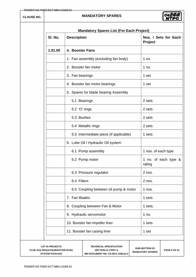
CLAUSE NO. MANDATORY SPARES
LOT-IA PROJECTS
FLUE GAS DESULPHURISATION (FGD)
SYSTEM PACKAGE
TECHNICAL SPECIFICATION
SECTION-VI, PART-A
BID DOCUMENT NO: CS-0011-109(1A)-2
SUB-SECTION-VII
MANDATORY SPARES PAGE 5 OF 61
Mandatory Spares List (For Each Project)
Sl. No. Description Nos. / Sets for Each Project
1.01.00 A. Booster Fans
1. Fan assembly (excluding fan body) 1 no.
2. Booster fan motor 1 no.
3. Fan bearings 1 set
4. Booster fan motor bearings 1 set
5. Spares for blade bearing Assembly
5.1 Bearings 2 sets
5.2 'O' rings 2 sets
5.3 Bushes 2 sets
5.4 Metallic rings 2 sets
5.5 Intermediate piece (if applicable) 1 sets
6. Lube Oil / Hydraulic Oil system
6.1 Pump assembly 1 nos. of each type
6.2 Pump motor 1 no. of each type & rating
6.3 Pressure regulator 2 nos.
6.4 Filters 2 nos.
6.5 Coupling between oil pump & motor 1 nos.
7. Fan Blades 1 sets
8. Coupling between Fan & Motor 1 sets.
9. Hydraulic servomotor 1 no.
10. Booster fan impeller liner 1 sets
11. Booster fan casing liner 1 set
TENDER NO PSER:SCT:NBN-C2068:20
TENDER NO PSER:SCT:NBN-C2068:20
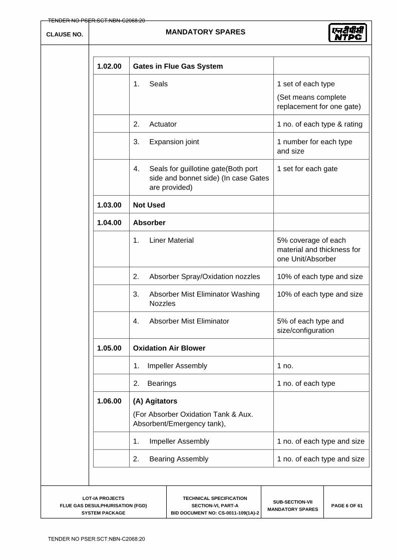
CLAUSE NO. MANDATORY SPARES
LOT-IA PROJECTS
FLUE GAS DESULPHURISATION (FGD)
SYSTEM PACKAGE
TECHNICAL SPECIFICATION
SECTION-VI, PART-A
BID DOCUMENT NO: CS-0011-109(1A)-2
SUB-SECTION-VII
MANDATORY SPARES PAGE 6 OF 61
1.02.00 Gates in Flue Gas System
1. Seals 1 set of each type
(Set means complete replacement for one gate)
2. Actuator 1 no. of each type & rating
3. Expansion joint 1 number for each type and size
4. Seals for guillotine gate(Both port side and bonnet side) (In case Gates are provided)
1 set for each gate
1.03.00 Not Used
1.04.00 Absorber
1. Liner Material 5% coverage of each material and thickness for one Unit/Absorber
2. Absorber Spray/Oxidation nozzles 10% of each type and size
3. Absorber Mist Eliminator Washing Nozzles
10% of each type and size
4. Absorber Mist Eliminator 5% of each type and size/configuration
1.05.00 Oxidation Air Blower
1. Impeller Assembly 1 no.
2. Bearings 1 no. of each type
1.06.00 (A) Agitators
(For Absorber Oxidation Tank & Aux. Absorbent/Emergency tank),
1. Impeller Assembly 1 no. of each type and size
2. Bearing Assembly 1 no. of each type and size
TENDER NO PSER:SCT:NBN-C2068:20
TENDER NO PSER:SCT:NBN-C2068:20
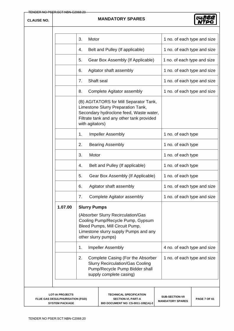
CLAUSE NO. MANDATORY SPARES
LOT-IA PROJECTS
FLUE GAS DESULPHURISATION (FGD)
SYSTEM PACKAGE
TECHNICAL SPECIFICATION
SECTION-VI, PART-A
BID DOCUMENT NO: CS-0011-109(1A)-2
SUB-SECTION-VII
MANDATORY SPARES PAGE 7 OF 61
3. Motor 1 no. of each type and size
4. Belt and Pulley (If applicable) 1 no. of each type and size
5. Gear Box Assembly (If Applicable) 1 no. of each type and size
6. Agitator shaft assembly 1 no. of each type and size
7. Shaft seal 1 no. of each type and size
8. Complete Agitator assembly 1 no. of each type and size
(B) AGITATORS for Mill Separator Tank, Limestone Slurry Preparation Tank, Secondary hydroclone feed, Waste water, Filtrate tank and any other tank provided with agitators)
1. Impeller Assembly 1 no. of each type
2. Bearing Assembly 1 no. of each type
3. Motor 1 no. of each type
4. Belt and Pulley (If applicable) 1 no. of each type
5. Gear Box Assembly (If Applicable) 1 no. of each type
6. Agitator shaft assembly 1 no. of each type and size
7. Complete Agitator assembly 1 no. of each type and size
1.07.00 Slurry Pumps
(Absorber Slurry Recirculation/Gas Cooling Pump/Recycle Pump, Gypsum Bleed Pumps, Mill Circuit Pump, Limestone slurry supply Pumps and any other slurry pumps)
1. Impeller Assembly 4 no. of each type and size
2. Complete Casing (For the Absorber Slurry Recirculation/Gas Cooling Pump/Recycle Pump Bidder shall supply complete casing)
1 no. of each type and size
TENDER NO PSER:SCT:NBN-C2068:20
TENDER NO PSER:SCT:NBN-C2068:20
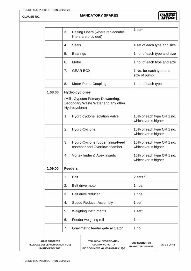
CLAUSE NO. MANDATORY SPARES
LOT-IA PROJECTS
FLUE GAS DESULPHURISATION (FGD)
SYSTEM PACKAGE
TECHNICAL SPECIFICATION
SECTION-VI, PART-A
BID DOCUMENT NO: CS-0011-109(1A)-2
SUB-SECTION-VII
MANDATORY SPARES PAGE 8 OF 61
3. Casing Liners (where replaceable liners are provided)
1 set*
4. Seals 4 set of each type and size
5. Bearings 1 no. of each type and size
6. Motor 1 no. of each type and size
7. GEAR BOX 1 No. for each type and size of pump.
8. Motor-Pump Coupling 1 no. of each type
1.08.00 Hydro-cyclones
(Mill , Gypsum Primary Dewatering, Secondary Waste Water and any other Hydrocyclone)
1. Hydro-cyclone Isolation Valve 10% of each type OR 1 no. whichever is higher
2. Hydro-Cyclone 10% of each type OR 1 no. whichever is higher
3. Hydro-Cyclone rubber lining-Feed chamber and Overflow chamber
10% of each type OR 1 no. whichever is higher
4. Vortex finder & Apex inserts 10% of each type OR 1 no. whichever is higher
1.09.00 Feeders
1. Belt 2 sets *
2. Belt drive motor 1 nos.
3. Belt drive reducer 1 nos.
4. Speed Reducer Assembly 1 set*
5. Weighing Instruments 1 set*
6. Feeder weighing roll 1 no.
7. Gravimetric feeder gate actuator 1 no.
TENDER NO PSER:SCT:NBN-C2068:20
TENDER NO PSER:SCT:NBN-C2068:20
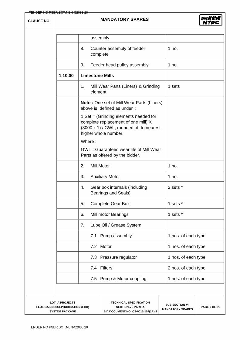
CLAUSE NO. MANDATORY SPARES
LOT-IA PROJECTS
FLUE GAS DESULPHURISATION (FGD)
SYSTEM PACKAGE
TECHNICAL SPECIFICATION
SECTION-VI, PART-A
BID DOCUMENT NO: CS-0011-109(1A)-2
SUB-SECTION-VII
MANDATORY SPARES PAGE 9 OF 61
assembly
8. Counter assembly of feeder complete
1 no.
9. Feeder head pulley assembly 1 no.
1.10.00 Limestone Mills
1. Mill Wear Parts (Liners) & Grinding element
1 sets
Note : One set of Mill Wear Parts (Liners) above is defined as under :
1 Set = (Grinding elements needed for complete replacement of one mill) X (8000 x 1) / GWL, rounded off to nearest higher whole number.
Where :
GWL = Guaranteed wear life of Mill Wear Parts as offered by the bidder.
2. Mill Motor 1 no.
3. Auxiliary Motor 1 no.
4. Gear box internals (including Bearings and Seals)
2 sets *
5. Complete Gear Box 1 sets *
6. Mill motor Bearings 1 sets *
7. Lube Oil / Grease System
7.1 Pump assembly 1 nos. of each type
7.2 Motor 1 nos. of each type
7.3 Pressure regulator 1 nos. of each type
7.4 Filters 2 nos. of each type
7.5 Pump & Motor coupling 1 nos. of each type
TENDER NO PSER:SCT:NBN-C2068:20
TENDER NO PSER:SCT:NBN-C2068:20
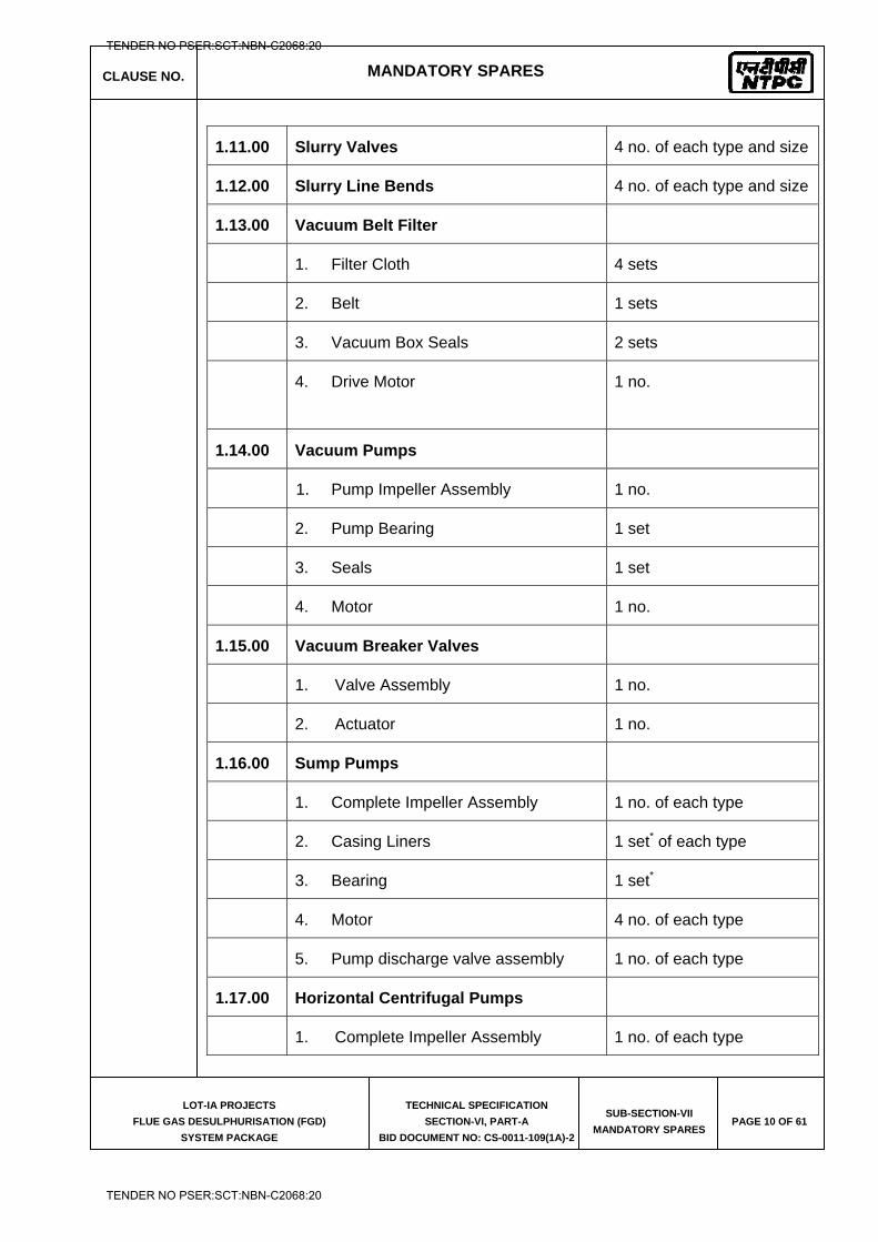
CLAUSE NO. MANDATORY SPARES
LOT-IA PROJECTS
FLUE GAS DESULPHURISATION (FGD)
SYSTEM PACKAGE
TECHNICAL SPECIFICATION
SECTION-VI, PART-A
BID DOCUMENT NO: CS-0011-109(1A)-2
SUB-SECTION-VII
MANDATORY SPARES PAGE 10 OF 61
1.11.00 Slurry Valves 4 no. of each type and size
1.12.00 Slurry Line Bends 4 no. of each type and size
1.13.00 Vacuum Belt Filter
1. Filter Cloth 4 sets
2. Belt 1 sets
3. Vacuum Box Seals 2 sets
4. Drive Motor 1 no.
1.14.00 Vacuum Pumps
1. Pump Impeller Assembly 1 no.
2. Pump Bearing 1 set
3. Seals 1 set
4. Motor 1 no.
1.15.00 Vacuum Breaker Valves
1. Valve Assembly 1 no.
2. Actuator 1 no.
1.16.00 Sump Pumps
1. Complete Impeller Assembly 1 no. of each type
2. Casing Liners 1 set* of each type
3. Bearing 1 set*
4. Motor 4 no. of each type
5. Pump discharge valve assembly 1 no. of each type
1.17.00 Horizontal Centrifugal Pumps
1. Complete Impeller Assembly 1 no. of each type
TENDER NO PSER:SCT:NBN-C2068:20
TENDER NO PSER:SCT:NBN-C2068:20
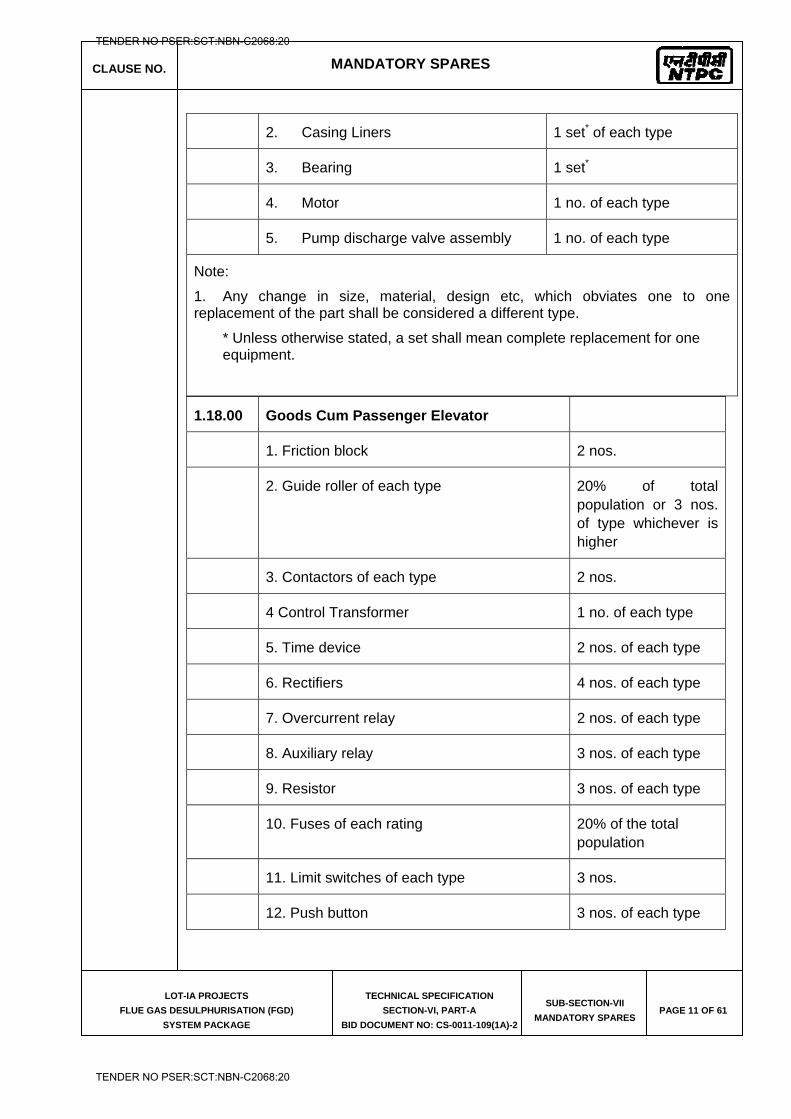
CLAUSE NO. MANDATORY SPARES
LOT-IA PROJECTS
FLUE GAS DESULPHURISATION (FGD)
SYSTEM PACKAGE
TECHNICAL SPECIFICATION
SECTION-VI, PART-A
BID DOCUMENT NO: CS-0011-109(1A)-2
SUB-SECTION-VII
MANDATORY SPARES PAGE 11 OF 61
2. Casing Liners 1 set* of each type
3. Bearing 1 set*
4. Motor 1 no. of each type
5. Pump discharge valve assembly 1 no. of each type
Note:
1. Any change in size, material, design etc, which obviates one to one replacement of the part shall be considered a different type.
* Unless otherwise stated, a set shall mean complete replacement for one equipment.
1.18.00 Goods Cum Passenger Elevator
1. Friction block 2 nos.
2. Guide roller of each type 20% of total population or 3 nos. of type whichever is higher
3. Contactors of each type 2 nos.
4 Control Transformer 1 no. of each type
5. Time device 2 nos. of each type
6. Rectifiers 4 nos. of each type
7. Overcurrent relay 2 nos. of each type
8. Auxiliary relay 3 nos. of each type
9. Resistor 3 nos. of each type
10. Fuses of each rating 20% of the total population
11. Limit switches of each type 3 nos.
12. Push button 3 nos. of each type
TENDER NO PSER:SCT:NBN-C2068:20
TENDER NO PSER:SCT:NBN-C2068:20
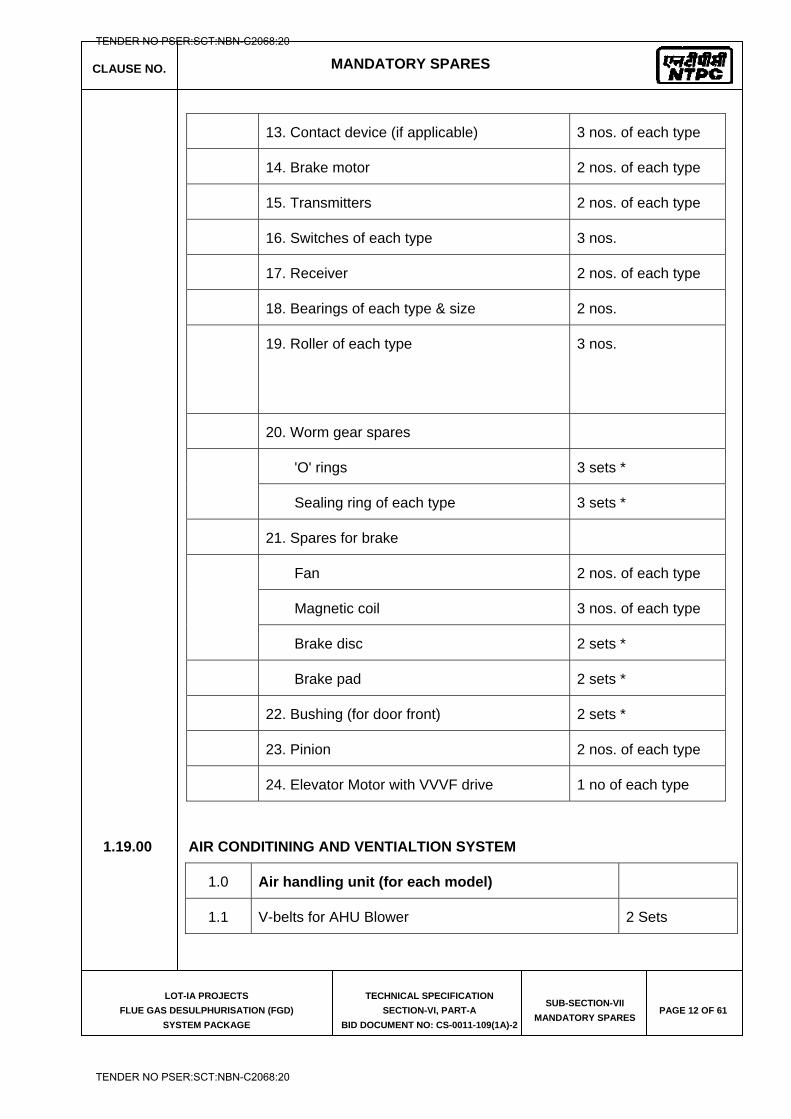
CLAUSE NO. MANDATORY SPARES
LOT-IA PROJECTS
FLUE GAS DESULPHURISATION (FGD)
SYSTEM PACKAGE
TECHNICAL SPECIFICATION
SECTION-VI, PART-A
BID DOCUMENT NO: CS-0011-109(1A)-2
SUB-SECTION-VII
MANDATORY SPARES PAGE 12 OF 61
13. Contact device (if applicable) 3 nos. of each type
14. Brake motor 2 nos. of each type
15. Transmitters 2 nos. of each type
16. Switches of each type 3 nos.
17. Receiver 2 nos. of each type
18. Bearings of each type & size 2 nos.
19. Roller of each type 3 nos.
20. Worm gear spares
'O' rings 3 sets *
Sealing ring of each type 3 sets *
21. Spares for brake
Fan 2 nos. of each type
Magnetic coil 3 nos. of each type
Brake disc 2 sets *
Brake pad 2 sets *
22. Bushing (for door front) 2 sets *
23. Pinion 2 nos. of each type
24. Elevator Motor with VVVF drive 1 no of each type
1.19.00 AIR CONDITINING AND VENTIALTION SYSTEM
1.0 Air handling unit (for each model)
1.1 V-belts for AHU Blower 2 Sets
TENDER NO PSER:SCT:NBN-C2068:20
TENDER NO PSER:SCT:NBN-C2068:20
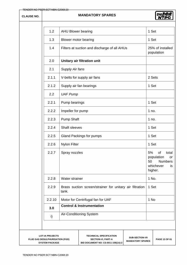
CLAUSE NO. MANDATORY SPARES
LOT-IA PROJECTS
FLUE GAS DESULPHURISATION (FGD)
SYSTEM PACKAGE
TECHNICAL SPECIFICATION
SECTION-VI, PART-A
BID DOCUMENT NO: CS-0011-109(1A)-2
SUB-SECTION-VII
MANDATORY SPARES PAGE 13 OF 61
1.2 AHU Blower bearing 1 Set
1.3 Blower motor bearing 1 Set
1.4 Filters at suction and discharge of all AHUs 25% of installed population
2.0 Unitary air filtration unit
2.1 Supply Air fans
2.1.1 V-belts for supply air fans 2 Sets
2.1.2 Supply air fan bearings 1 Set
2.2 UAF Pump
2.2.1 Pump bearings 1 Set
2.2.2 Impeller for pump 1 no.
2.2.3 Pump Shaft 1 no.
2.2.4 Shaft sleeves 1 Set
2.2.5 Gland Packings for pumps 1 Set
2.2.6 Nylon Filter 1 Set
2.2.7 Spray nozzles 5% of total population or 50 Numbers whichever is higher.
2.2.8 Water strainer 1 No.
2.2.9 Brass suction screen/strainer for unitary air filtration tank.
1 Set
2.2.10 Motor for Centrifugal fan for UAF 1 No
3.0 Control & Instrumentation
i) Air-Conditioning System
TENDER NO PSER:SCT:NBN-C2068:20
TENDER NO PSER:SCT:NBN-C2068:20
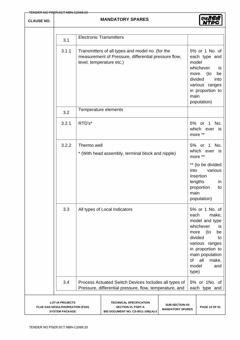
CLAUSE NO. MANDATORY SPARES
LOT-IA PROJECTS
FLUE GAS DESULPHURISATION (FGD)
SYSTEM PACKAGE
TECHNICAL SPECIFICATION
SECTION-VI, PART-A
BID DOCUMENT NO: CS-0011-109(1A)-2
SUB-SECTION-VII
MANDATORY SPARES PAGE 14 OF 61
3.1 Electronic Transmitters
3.1.1 Transmitters of all types and model no. (for the measurement of Pressure, differential pressure flow, level, temperature etc.)
5% or 1 No. of each type and model whichever is more. (to be divided into various ranges in proportion to main population)
3.2 Temperature elements
3.2.1 RTD's* 5% or 1 No. which ever is more **
3.2.2 Thermo well
* (With head assembly, terminal block and nipple)
5% or 1 No. which ever is more **
** (to be divided into various insertion lengths in proportion to main population)
3.3 All types of Local Indicators 5% or 1 No. of each make, model and type whichever is more (to be divided to various ranges in proportion to main population of all make, model and type)
3.4 Process Actuated Switch Devices Includes all types of Pressure, differential pressure, flow, temperature, and
5% or 1No. of each type and
TENDER NO PSER:SCT:NBN-C2068:20
TENDER NO PSER:SCT:NBN-C2068:20

CLAUSE NO. MANDATORY SPARES
LOT-IA PROJECTS
FLUE GAS DESULPHURISATION (FGD)
SYSTEM PACKAGE
TECHNICAL SPECIFICATION
SECTION-VI, PART-A
BID DOCUMENT NO: CS-0011-109(1A)-2
SUB-SECTION-VII
MANDATORY SPARES PAGE 15 OF 61
differential temperature, level switch Devices. model whichever is more.
3.5 Relative Humidity Sensors 1 No.
3.6 Geyserstat 1 No.
3.7 Local Humidity/Temperature indicators 2 Nos. each
4.0 Process Connection Piping (for Impulse Piping / Tubing, Sampling Piping / Tubing and Air Supply Piping as Applicable)
4.1 Valves 10% or 1 No. of
each type, class, size and model whichever is more.
4.2 2 way, 3way, 5way valve manifolds 10% or 1 No. of
each type, class, size and model whichever is more.
4.3 Fittings 10% or 1 No. of
each type, class, size and model whichever is more.
(II) Ventilation System
5.0 Measuring Instruments
5.1 Pressure Gauge 1 No. (for centrifugal pumps of UAF units).
5.2 Level transmitter 1 No.
5.3 Pressure transmitter
1 No. (for UAF units)
TENDER NO PSER:SCT:NBN-C2068:20
TENDER NO PSER:SCT:NBN-C2068:20
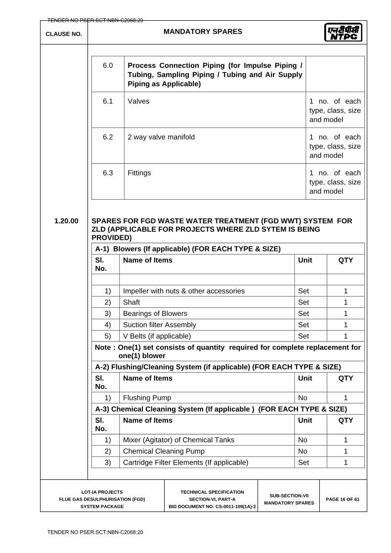
CLAUSE NO. MANDATORY SPARES
LOT-IA PROJECTS
FLUE GAS DESULPHURISATION (FGD)
SYSTEM PACKAGE
TECHNICAL SPECIFICATION
SECTION-VI, PART-A
BID DOCUMENT NO: CS-0011-109(1A)-2
SUB-SECTION-VII
MANDATORY SPARES PAGE 16 OF 61
6.0 Process Connection Piping (for Impulse Piping / Tubing, Sampling Piping / Tubing and Air Supply Piping as Applicable)
6.1 Valves 1 no. of each type, class, size and model
6.2 2 way valve manifold 1 no. of each type, class, size and model
6.3 Fittings 1 no. of each type, class, size and model
1.20.00 SPARES FOR FGD WASTE WATER TREATMENT (FGD WWT) SYSTEM FOR ZLD (APPLICABLE FOR PROJECTS WHERE ZLD SYTEM IS BEING PROVIDED)
A-1) Blowers (If applicable) (FOR EACH TYPE & SIZE)
Sl. No.
Name of Items Unit QTY
1) Impeller with nuts & other accessories Set 1 2) Shaft Set 1 3) Bearings of Blowers Set 1 4) Suction filter Assembly Set 1 5) V Belts (if applicable) Set 1
Note : One(1) set consists of quantity required for complete replacement for one(1) blower
A-2) Flushing/Cleaning System (if applicable) (FOR EACH TYPE & SIZE)
Sl. No.
Name of Items Unit QTY
1) Flushing Pump No 1 A-3) Chemical Cleaning System (If applicable ) (FOR EACH TYPE & SIZE)
Sl. No.
Name of Items Unit QTY
1) Mixer (Agitator) of Chemical Tanks No 1 2) Chemical Cleaning Pump No 1 3) Cartridge Filter Elements (If applicable) Set 1
TENDER NO PSER:SCT:NBN-C2068:20
TENDER NO PSER:SCT:NBN-C2068:20
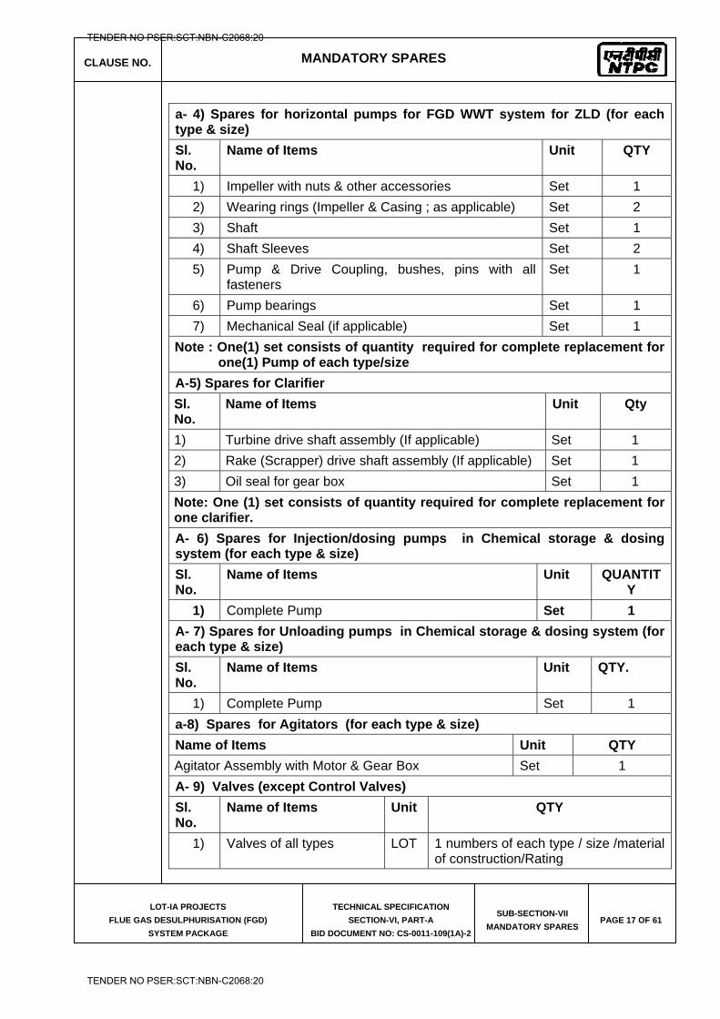
CLAUSE NO. MANDATORY SPARES
LOT-IA PROJECTS
FLUE GAS DESULPHURISATION (FGD)
SYSTEM PACKAGE
TECHNICAL SPECIFICATION
SECTION-VI, PART-A
BID DOCUMENT NO: CS-0011-109(1A)-2
SUB-SECTION-VII
MANDATORY SPARES PAGE 17 OF 61
a- 4) Spares for horizontal pumps for FGD WWT system for ZLD (for each type & size)
Sl. No.
Name of Items Unit QTY
1) Impeller with nuts & other accessories Set 1 2) Wearing rings (Impeller & Casing ; as applicable) Set 2 3) Shaft Set 1 4) Shaft Sleeves Set 2 5) Pump & Drive Coupling, bushes, pins with all
fasteners Set 1
6) Pump bearings Set 1 7) Mechanical Seal (if applicable) Set 1
Note : One(1) set consists of quantity required for complete replacement for one(1) Pump of each type/size
A-5) Spares for Clarifier
Sl. No.
Name of Items Unit Qty
1) Turbine drive shaft assembly (If applicable) Set 1 2) Rake (Scrapper) drive shaft assembly (If applicable) Set 1 3) Oil seal for gear box Set 1 Note: One (1) set consists of quantity required for complete replacement for one clarifier.
A- 6) Spares for Injection/dosing pumps in Chemical storage & dosing system (for each type & size)
Sl. No.
Name of Items Unit QUANTITY
1) Complete Pump Set 1
A- 7) Spares for Unloading pumps in Chemical storage & dosing system (for each type & size)
Sl. No.
Name of Items Unit QTY.
1) Complete Pump Set 1 a-8) Spares for Agitators (for each type & size)
Name of Items Unit QTY
Agitator Assembly with Motor & Gear Box Set 1 A- 9) Valves (except Control Valves)
Sl. No.
Name of Items Unit QTY
1) Valves of all types LOT 1 numbers of each type / size /material of construction/Rating
TENDER NO PSER:SCT:NBN-C2068:20
TENDER NO PSER:SCT:NBN-C2068:20
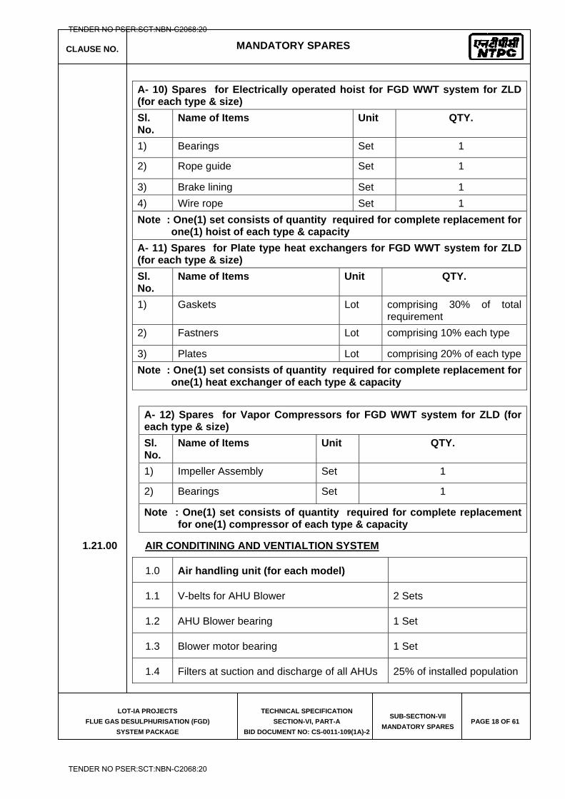
CLAUSE NO. MANDATORY SPARES
LOT-IA PROJECTS
FLUE GAS DESULPHURISATION (FGD)
SYSTEM PACKAGE
TECHNICAL SPECIFICATION
SECTION-VI, PART-A
BID DOCUMENT NO: CS-0011-109(1A)-2
SUB-SECTION-VII
MANDATORY SPARES PAGE 18 OF 61
A- 10) Spares for Electrically operated hoist for FGD WWT system for ZLD (for each type & size)
Sl. No.
Name of Items Unit QTY.
1) Bearings Set 1
2) Rope guide Set 1
3) Brake lining Set 1 4) Wire rope Set 1 Note : One(1) set consists of quantity required for complete replacement for
one(1) hoist of each type & capacity
A- 11) Spares for Plate type heat exchangers for FGD WWT system for ZLD (for each type & size)
Sl. No.
Name of Items Unit QTY.
1) Gaskets Lot comprising 30% of total requirement
2) Fastners Lot comprising 10% each type
3) Plates Lot comprising 20% of each typeNote : One(1) set consists of quantity required for complete replacement for
one(1) heat exchanger of each type & capacity
A- 12) Spares for Vapor Compressors for FGD WWT system for ZLD (for each type & size)
Sl. No.
Name of Items Unit QTY.
1) Impeller Assembly Set 1
2) Bearings Set 1
Note : One(1) set consists of quantity required for complete replacement for one(1) compressor of each type & capacity
1.21.00 AIR CONDITINING AND VENTIALTION SYSTEM
1.0 Air handling unit (for each model)
1.1 V-belts for AHU Blower 2 Sets
1.2 AHU Blower bearing 1 Set
1.3 Blower motor bearing 1 Set
1.4 Filters at suction and discharge of all AHUs 25% of installed population
TENDER NO PSER:SCT:NBN-C2068:20
TENDER NO PSER:SCT:NBN-C2068:20
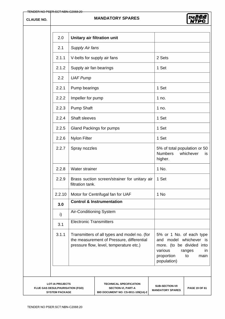
CLAUSE NO. MANDATORY SPARES
LOT-IA PROJECTS
FLUE GAS DESULPHURISATION (FGD)
SYSTEM PACKAGE
TECHNICAL SPECIFICATION
SECTION-VI, PART-A
BID DOCUMENT NO: CS-0011-109(1A)-2
SUB-SECTION-VII
MANDATORY SPARES PAGE 19 OF 61
2.0 Unitary air filtration unit
2.1 Supply Air fans
2.1.1 V-belts for supply air fans 2 Sets
2.1.2 Supply air fan bearings 1 Set
2.2 UAF Pump
2.2.1 Pump bearings 1 Set
2.2.2 Impeller for pump 1 no.
2.2.3 Pump Shaft 1 no.
2.2.4 Shaft sleeves 1 Set
2.2.5 Gland Packings for pumps 1 Set
2.2.6 Nylon Filter 1 Set
2.2.7 Spray nozzles 5% of total population or 50 Numbers whichever is higher.
2.2.8 Water strainer 1 No.
2.2.9 Brass suction screen/strainer for unitary air filtration tank.
1 Set
2.2.10 Motor for Centrifugal fan for UAF 1 No
3.0 Control & Instrumentation
i) Air-Conditioning System
3.1 Electronic Transmitters
3.1.1 Transmitters of all types and model no. (for the measurement of Pressure, differential pressure flow, level, temperature etc.)
5% or 1 No. of each type and model whichever is more. (to be divided into various ranges in proportion to main population)
TENDER NO PSER:SCT:NBN-C2068:20
TENDER NO PSER:SCT:NBN-C2068:20
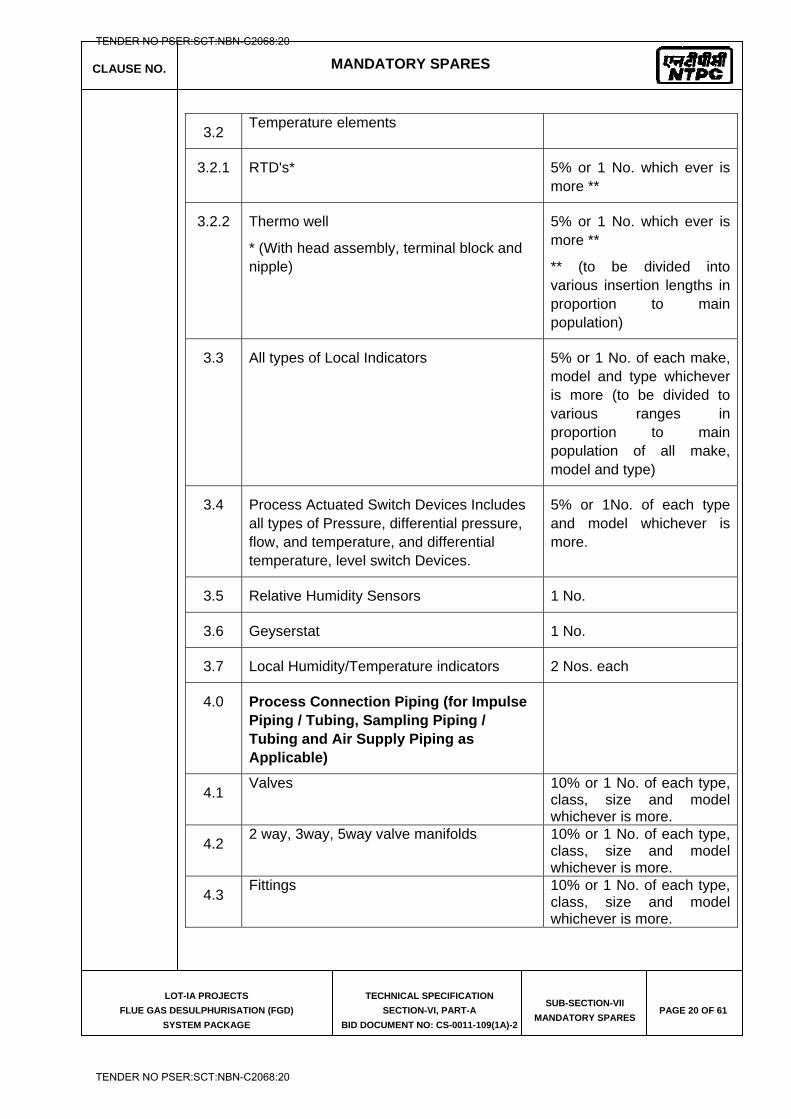
CLAUSE NO. MANDATORY SPARES
LOT-IA PROJECTS
FLUE GAS DESULPHURISATION (FGD)
SYSTEM PACKAGE
TECHNICAL SPECIFICATION
SECTION-VI, PART-A
BID DOCUMENT NO: CS-0011-109(1A)-2
SUB-SECTION-VII
MANDATORY SPARES PAGE 20 OF 61
3.2 Temperature elements
3.2.1 RTD's* 5% or 1 No. which ever is more **
3.2.2 Thermo well
* (With head assembly, terminal block and nipple)
5% or 1 No. which ever is more **
** (to be divided into various insertion lengths in proportion to main population)
3.3 All types of Local Indicators 5% or 1 No. of each make, model and type whichever is more (to be divided to various ranges in proportion to main population of all make, model and type)
3.4 Process Actuated Switch Devices Includes all types of Pressure, differential pressure, flow, and temperature, and differential temperature, level switch Devices.
5% or 1No. of each type and model whichever is more.
3.5 Relative Humidity Sensors 1 No.
3.6 Geyserstat 1 No.
3.7 Local Humidity/Temperature indicators 2 Nos. each
4.0 Process Connection Piping (for Impulse Piping / Tubing, Sampling Piping / Tubing and Air Supply Piping as Applicable)
4.1 Valves 10% or 1 No. of each type,
class, size and model whichever is more.
4.2 2 way, 3way, 5way valve manifolds 10% or 1 No. of each type,
class, size and model whichever is more.
4.3 Fittings 10% or 1 No. of each type,
class, size and model whichever is more.
TENDER NO PSER:SCT:NBN-C2068:20
TENDER NO PSER:SCT:NBN-C2068:20
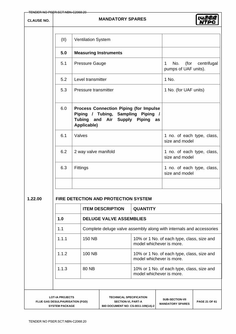
CLAUSE NO. MANDATORY SPARES
LOT-IA PROJECTS
FLUE GAS DESULPHURISATION (FGD)
SYSTEM PACKAGE
TECHNICAL SPECIFICATION
SECTION-VI, PART-A
BID DOCUMENT NO: CS-0011-109(1A)-2
SUB-SECTION-VII
MANDATORY SPARES PAGE 21 OF 61
(II) Ventilation System
5.0 Measuring Instruments
5.1 Pressure Gauge 1 No. (for centrifugal pumps of UAF units).
5.2 Level transmitter 1 No.
5.3 Pressure transmitter
1 No. (for UAF units)
6.0 Process Connection Piping (for Impulse Piping / Tubing, Sampling Piping / Tubing and Air Supply Piping as Applicable)
6.1 Valves 1 no. of each type, class, size and model
6.2 2 way valve manifold 1 no. of each type, class, size and model
6.3 Fittings 1 no. of each type, class, size and model
1.22.00 FIRE DETECTION AND PROTECTION SYSTEM
ITEM DESCRIPTION QUANTITY
1.0 DELUGE VALVE ASSEMBLIES
1.1 Complete deluge valve assembly along with internals and accessories
1.1.1 150 NB 10% or 1 No. of each type, class, size and model whichever is more.
1.1.2 100 NB 10% or 1 No. of each type, class, size and model whichever is more.
1.1.3 80 NB 10% or 1 No. of each type, class, size and model whichever is more.
TENDER NO PSER:SCT:NBN-C2068:20
TENDER NO PSER:SCT:NBN-C2068:20
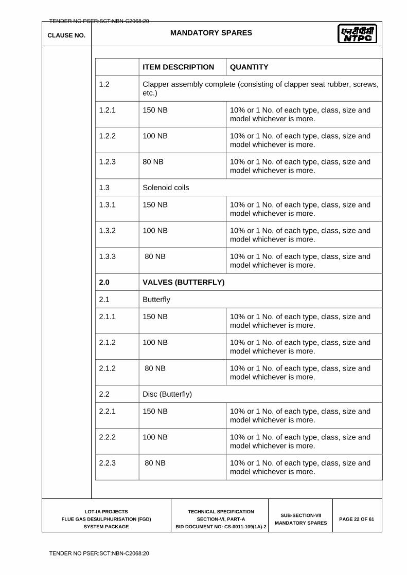
CLAUSE NO. MANDATORY SPARES
LOT-IA PROJECTS
FLUE GAS DESULPHURISATION (FGD)
SYSTEM PACKAGE
TECHNICAL SPECIFICATION
SECTION-VI, PART-A
BID DOCUMENT NO: CS-0011-109(1A)-2
SUB-SECTION-VII
MANDATORY SPARES PAGE 22 OF 61
ITEM DESCRIPTION QUANTITY
1.2 Clapper assembly complete (consisting of clapper seat rubber, screws, etc.)
1.2.1 150 NB 10% or 1 No. of each type, class, size and model whichever is more.
1.2.2 100 NB 10% or 1 No. of each type, class, size and model whichever is more.
1.2.3 80 NB 10% or 1 No. of each type, class, size and model whichever is more.
1.3 Solenoid coils
1.3.1 150 NB 10% or 1 No. of each type, class, size and model whichever is more.
1.3.2 100 NB 10% or 1 No. of each type, class, size and model whichever is more.
1.3.3 80 NB 10% or 1 No. of each type, class, size and model whichever is more.
2.0 VALVES (BUTTERFLY)
2.1 Butterfly
2.1.1 150 NB 10% or 1 No. of each type, class, size and model whichever is more.
2.1.2 100 NB 10% or 1 No. of each type, class, size and model whichever is more.
2.1.2 80 NB 10% or 1 No. of each type, class, size and model whichever is more.
2.2 Disc (Butterfly)
2.2.1 150 NB 10% or 1 No. of each type, class, size and model whichever is more.
2.2.2 100 NB 10% or 1 No. of each type, class, size and model whichever is more.
2.2.3 80 NB 10% or 1 No. of each type, class, size and model whichever is more.
TENDER NO PSER:SCT:NBN-C2068:20
TENDER NO PSER:SCT:NBN-C2068:20
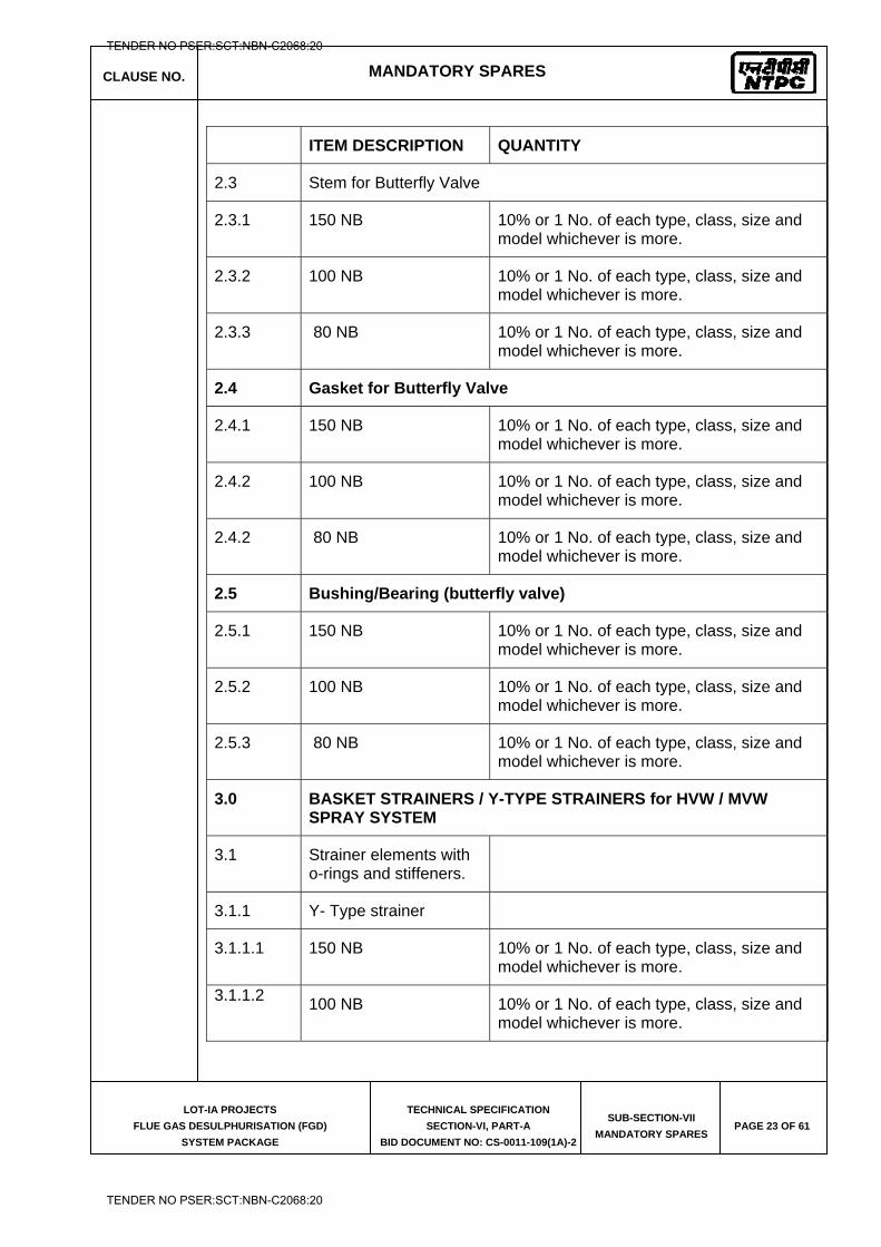
CLAUSE NO. MANDATORY SPARES
LOT-IA PROJECTS
FLUE GAS DESULPHURISATION (FGD)
SYSTEM PACKAGE
TECHNICAL SPECIFICATION
SECTION-VI, PART-A
BID DOCUMENT NO: CS-0011-109(1A)-2
SUB-SECTION-VII
MANDATORY SPARES PAGE 23 OF 61
ITEM DESCRIPTION QUANTITY
2.3 Stem for Butterfly Valve
2.3.1 150 NB 10% or 1 No. of each type, class, size and model whichever is more.
2.3.2 100 NB 10% or 1 No. of each type, class, size and model whichever is more.
2.3.3 80 NB 10% or 1 No. of each type, class, size and model whichever is more.
2.4 Gasket for Butterfly Valve
2.4.1 150 NB 10% or 1 No. of each type, class, size and model whichever is more.
2.4.2 100 NB 10% or 1 No. of each type, class, size and model whichever is more.
2.4.2 80 NB 10% or 1 No. of each type, class, size and model whichever is more.
2.5 Bushing/Bearing (butterfly valve)
2.5.1 150 NB 10% or 1 No. of each type, class, size and model whichever is more.
2.5.2 100 NB 10% or 1 No. of each type, class, size and model whichever is more.
2.5.3 80 NB 10% or 1 No. of each type, class, size and model whichever is more.
3.0 BASKET STRAINERS / Y-TYPE STRAINERS for HVW / MVW SPRAY SYSTEM
3.1 Strainer elements with o-rings and stiffeners.
3.1.1 Y- Type strainer
3.1.1.1 150 NB 10% or 1 No. of each type, class, size and model whichever is more.
3.1.1.2 100 NB 10% or 1 No. of each type, class, size and model whichever is more.
TENDER NO PSER:SCT:NBN-C2068:20
TENDER NO PSER:SCT:NBN-C2068:20
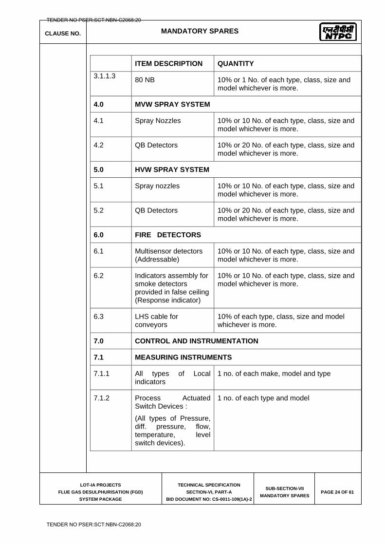
CLAUSE NO. MANDATORY SPARES
LOT-IA PROJECTS
FLUE GAS DESULPHURISATION (FGD)
SYSTEM PACKAGE
TECHNICAL SPECIFICATION
SECTION-VI, PART-A
BID DOCUMENT NO: CS-0011-109(1A)-2
SUB-SECTION-VII
MANDATORY SPARES PAGE 24 OF 61
ITEM DESCRIPTION QUANTITY
3.1.1.3 80 NB 10% or 1 No. of each type, class, size and model whichever is more.
4.0 MVW SPRAY SYSTEM
4.1 Spray Nozzles 10% or 10 No. of each type, class, size and model whichever is more.
4.2 QB Detectors 10% or 20 No. of each type, class, size and model whichever is more.
5.0 HVW SPRAY SYSTEM
5.1 Spray nozzles 10% or 10 No. of each type, class, size and model whichever is more.
5.2 QB Detectors 10% or 20 No. of each type, class, size and model whichever is more.
6.0 FIRE DETECTORS
6.1 Multisensor detectors (Addressable)
10% or 10 No. of each type, class, size and model whichever is more.
6.2 Indicators assembly for smoke detectors provided in false ceiling (Response indicator)
10% or 10 No. of each type, class, size and model whichever is more.
6.3 LHS cable for conveyors
10% of each type, class, size and model whichever is more.
7.0 CONTROL AND INSTRUMENTATION
7.1 MEASURING INSTRUMENTS
7.1.1 All types of Local indicators
1 no. of each make, model and type
7.1.2 Process Actuated Switch Devices :
(All types of Pressure, diff. pressure, flow, temperature, level switch devices).
1 no. of each type and model
TENDER NO PSER:SCT:NBN-C2068:20
TENDER NO PSER:SCT:NBN-C2068:20
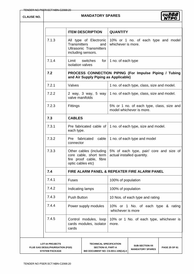
CLAUSE NO. MANDATORY SPARES
LOT-IA PROJECTS
FLUE GAS DESULPHURISATION (FGD)
SYSTEM PACKAGE
TECHNICAL SPECIFICATION
SECTION-VI, PART-A
BID DOCUMENT NO: CS-0011-109(1A)-2
SUB-SECTION-VII
MANDATORY SPARES PAGE 25 OF 61
ITEM DESCRIPTION QUANTITY
7.1.3 All type of Electronic Transmitters and Ultrasonic Transmitters including sensors.
10% or 1 no. of each type and model whichever is more.
7.1.4 Limit switches for isolation valves
1 no. of each type
7.2 PROCESS CONNECTION PIPING (For Impulse Piping / Tubing and Air Supply Piping as Applicable)
7.2.1 Valves 1 no. of each type, class, size and model.
7.2.2 2 way, 3 way, 5 way valve manifolds
1 no. of each type, class, size and model.
7.2.3 Fittings 5% or 1 no. of each type, class, size and model whichever is more.
7.3 CABLES
7.3.1 Pre fabricated cable of each type.
1 no. of each type, size and model.
7.3.2 Pre fabricated cable connector
1 no. of each type and model
7.3.3 Other cables (including core cable, short term fire proof cable, fibre optic cables etc)
5% of each type, pair/ core and size of actual installed quantity.
7.4 FIRE ALARM PANEL & REPEATER FIRE ALARM PANEL
7.4.1 Fuses 100% of population
7.4.2 Indicating lamps 100% of population
7.4.3 Push Button 10 Nos. of each type and rating
7.4.4 Power supply modules 10% or 1 No. of each type & rating whichever is more
7.4.5 Control modules, loop cards modules, isolator cards
10% or 1 No. of each type, whichever is more.
TENDER NO PSER:SCT:NBN-C2068:20
TENDER NO PSER:SCT:NBN-C2068:20
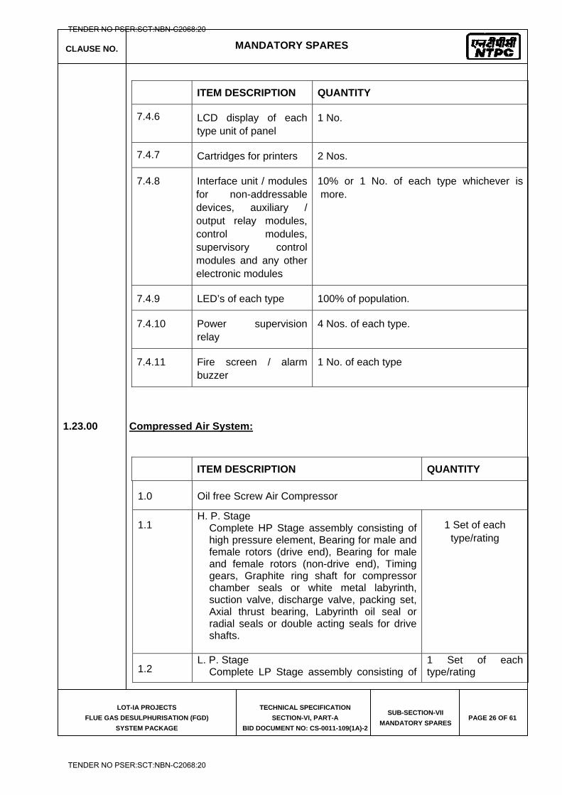
CLAUSE NO. MANDATORY SPARES
LOT-IA PROJECTS
FLUE GAS DESULPHURISATION (FGD)
SYSTEM PACKAGE
TECHNICAL SPECIFICATION
SECTION-VI, PART-A
BID DOCUMENT NO: CS-0011-109(1A)-2
SUB-SECTION-VII
MANDATORY SPARES PAGE 26 OF 61
ITEM DESCRIPTION QUANTITY
7.4.6 LCD display of each type unit of panel
1 No.
7.4.7 Cartridges for printers 2 Nos.
7.4.8 Interface unit / modules for non-addressable devices, auxiliary / output relay modules, control modules, supervisory control modules and any other electronic modules
10% or 1 No. of each type whichever is more.
7.4.9 LED’s of each type 100% of population.
7.4.10 Power supervision relay
4 Nos. of each type.
7.4.11 Fire screen / alarm buzzer
1 No. of each type
1.23.00 Compressed Air System:
ITEM DESCRIPTION QUANTITY
1.0 Oil free Screw Air Compressor
1.1 H. P. Stage
Complete HP Stage assembly consisting of high pressure element, Bearing for male and female rotors (drive end), Bearing for male and female rotors (non-drive end), Timing gears, Graphite ring shaft for compressor chamber seals or white metal labyrinth, suction valve, discharge valve, packing set, Axial thrust bearing, Labyrinth oil seal or radial seals or double acting seals for drive shafts.
1 Set of each type/rating
1.2 L. P. Stage
Complete LP Stage assembly consisting of 1 Set of each type/rating
TENDER NO PSER:SCT:NBN-C2068:20
TENDER NO PSER:SCT:NBN-C2068:20
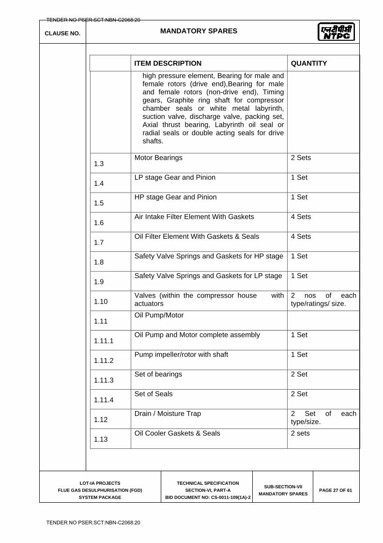
CLAUSE NO. MANDATORY SPARES
LOT-IA PROJECTS
FLUE GAS DESULPHURISATION (FGD)
SYSTEM PACKAGE
TECHNICAL SPECIFICATION
SECTION-VI, PART-A
BID DOCUMENT NO: CS-0011-109(1A)-2
SUB-SECTION-VII
MANDATORY SPARES PAGE 27 OF 61
ITEM DESCRIPTION QUANTITY
high pressure element, Bearing for male and female rotors (drive end),Bearing for male and female rotors (non-drive end), Timing gears, Graphite ring shaft for compressor chamber seals or white metal labyrinth, suction valve, discharge valve, packing set, Axial thrust bearing, Labyrinth oil seal or radial seals or double acting seals for drive shafts.
1.3 Motor Bearings 2 Sets
1.4 LP stage Gear and Pinion 1 Set
1.5 HP stage Gear and Pinion 1 Set
1.6 Air Intake Filter Element With Gaskets 4 Sets
1.7 Oil Filter Element With Gaskets & Seals 4 Sets
1.8 Safety Valve Springs and Gaskets for HP stage 1 Set
1.9 Safety Valve Springs and Gaskets for LP stage 1 Set
1.10 Valves (within the compressor house with actuators
2 nos of each type/ratings/ size.
1.11 Oil Pump/Motor
1.11.1 Oil Pump and Motor complete assembly 1 Set
1.11.2 Pump impeller/rotor with shaft 1 Set
1.11.3 Set of bearings 2 Set
1.11.4 Set of Seals 2 Set
1.12 Drain / Moisture Trap 2 Set of each
type/size.
1.13 Oil Cooler Gaskets & Seals 2 sets
TENDER NO PSER:SCT:NBN-C2068:20
TENDER NO PSER:SCT:NBN-C2068:20
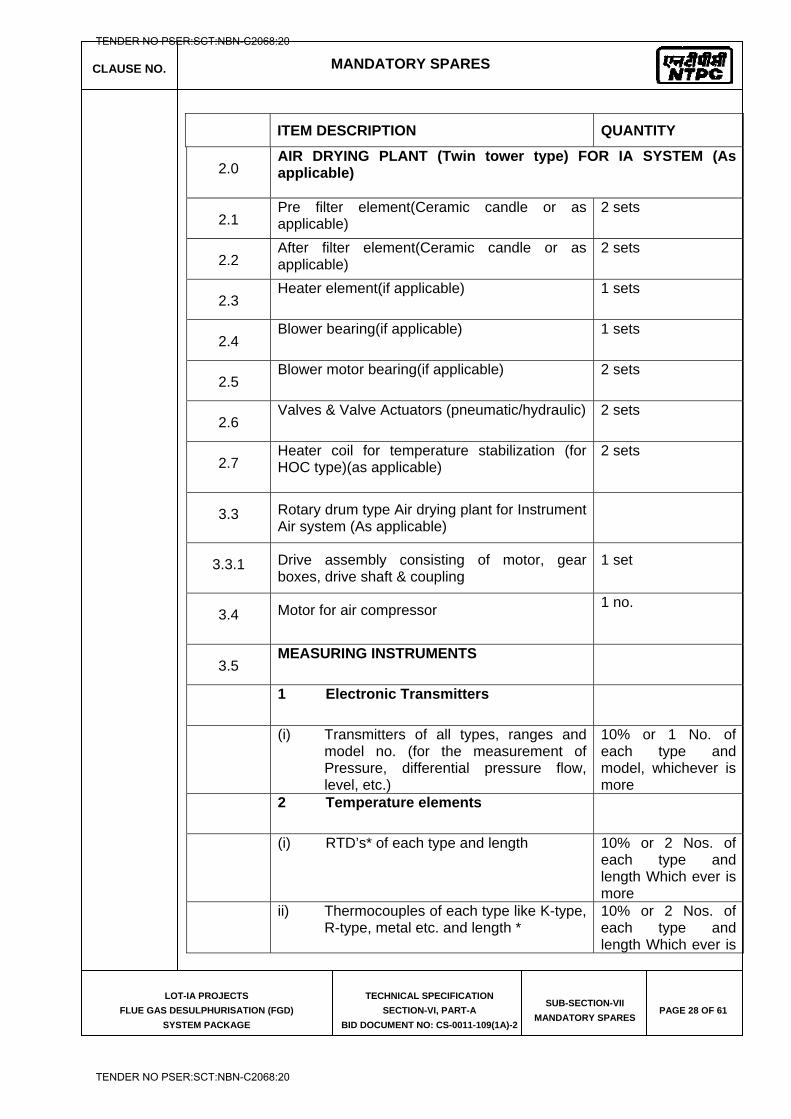
CLAUSE NO. MANDATORY SPARES
LOT-IA PROJECTS
FLUE GAS DESULPHURISATION (FGD)
SYSTEM PACKAGE
TECHNICAL SPECIFICATION
SECTION-VI, PART-A
BID DOCUMENT NO: CS-0011-109(1A)-2
SUB-SECTION-VII
MANDATORY SPARES PAGE 28 OF 61
ITEM DESCRIPTION QUANTITY
2.0 AIR DRYING PLANT (Twin tower type) FOR IA SYSTEM (As applicable)
2.1 Pre filter element(Ceramic candle or as applicable)
2 sets
2.2 After filter element(Ceramic candle or as applicable)
2 sets
2.3 Heater element(if applicable) 1 sets
2.4 Blower bearing(if applicable) 1 sets
2.5 Blower motor bearing(if applicable) 2 sets
2.6 Valves & Valve Actuators (pneumatic/hydraulic) 2 sets
2.7 Heater coil for temperature stabilization (for HOC type)(as applicable)
2 sets
3.3 Rotary drum type Air drying plant for Instrument Air system (As applicable)
3.3.1 Drive assembly consisting of motor, gear boxes, drive shaft & coupling
1 set
3.4 Motor for air compressor 1 no.
3.5 MEASURING INSTRUMENTS
1 Electronic Transmitters
(i) Transmitters of all types, ranges and
model no. (for the measurement of Pressure, differential pressure flow, level, etc.)
10% or 1 No. of each type and model, whichever is more
2 Temperature elements
(i) RTD’s* of each type and length 10% or 2 Nos. of
each type and length Which ever is more
ii) Thermocouples of each type like K-type,
R-type, metal etc. and length * 10% or 2 Nos. of each type and length Which ever is
TENDER NO PSER:SCT:NBN-C2068:20
TENDER NO PSER:SCT:NBN-C2068:20
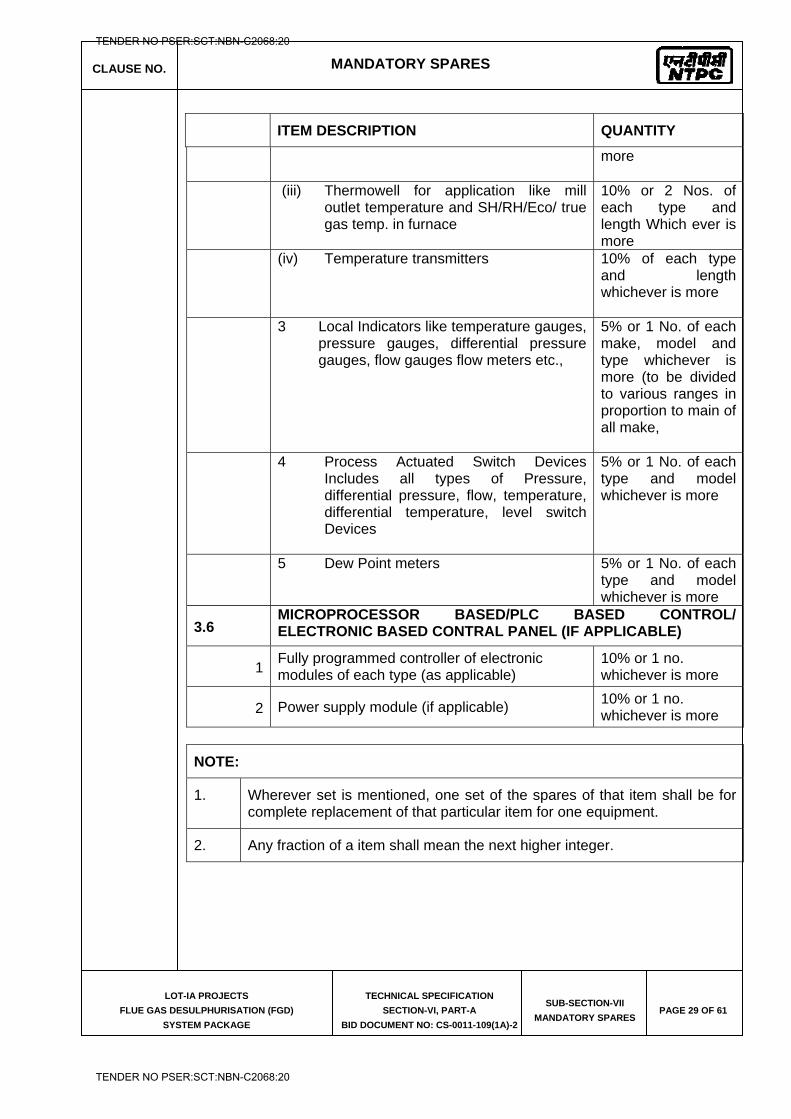
CLAUSE NO. MANDATORY SPARES
LOT-IA PROJECTS
FLUE GAS DESULPHURISATION (FGD)
SYSTEM PACKAGE
TECHNICAL SPECIFICATION
SECTION-VI, PART-A
BID DOCUMENT NO: CS-0011-109(1A)-2
SUB-SECTION-VII
MANDATORY SPARES PAGE 29 OF 61
ITEM DESCRIPTION QUANTITY
more
(iii) Thermowell for application like mill
outlet temperature and SH/RH/Eco/ true gas temp. in furnace
10% or 2 Nos. of each type and length Which ever is more
(iv) Temperature transmitters 10% of each type
and length whichever is more
3 Local Indicators like temperature gauges,
pressure gauges, differential pressure gauges, flow gauges flow meters etc.,
5% or 1 No. of each make, model and type whichever is more (to be divided to various ranges in proportion to main of all make,
4 Process Actuated Switch Devices
Includes all types of Pressure, differential pressure, flow, temperature, differential temperature, level switch Devices
5% or 1 No. of each type and model whichever is more
5 Dew Point meters 5% or 1 No. of each
type and model whichever is more
3.6 MICROPROCESSOR BASED/PLC BASED CONTROL/ ELECTRONIC BASED CONTRAL PANEL (IF APPLICABLE)
1 Fully programmed controller of electronic modules of each type (as applicable)
10% or 1 no. whichever is more
2 Power supply module (if applicable) 10% or 1 no. whichever is more
NOTE:
1. Wherever set is mentioned, one set of the spares of that item shall be for complete replacement of that particular item for one equipment.
2. Any fraction of a item shall mean the next higher integer.
TENDER NO PSER:SCT:NBN-C2068:20
TENDER NO PSER:SCT:NBN-C2068:20
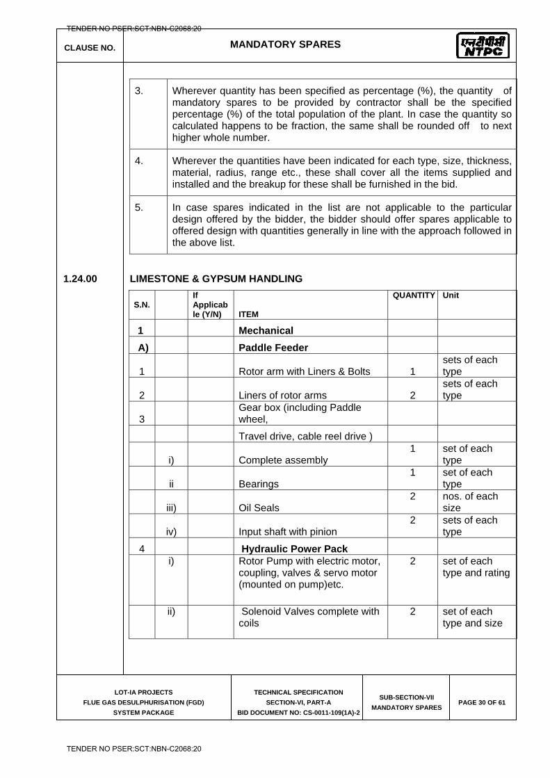
CLAUSE NO. MANDATORY SPARES
LOT-IA PROJECTS
FLUE GAS DESULPHURISATION (FGD)
SYSTEM PACKAGE
TECHNICAL SPECIFICATION
SECTION-VI, PART-A
BID DOCUMENT NO: CS-0011-109(1A)-2
SUB-SECTION-VII
MANDATORY SPARES PAGE 30 OF 61
3. Wherever quantity has been specified as percentage (%), the quantity of mandatory spares to be provided by contractor shall be the specified percentage (%) of the total population of the plant. In case the quantity so calculated happens to be fraction, the same shall be rounded off to next higher whole number.
4. Wherever the quantities have been indicated for each type, size, thickness, material, radius, range etc., these shall cover all the items supplied and installed and the breakup for these shall be furnished in the bid.
5. In case spares indicated in the list are not applicable to the particular design offered by the bidder, the bidder should offer spares applicable to offered design with quantities generally in line with the approach followed in the above list.
1.24.00 LIMESTONE & GYPSUM HANDLING
S.N.
If Applicable (Y/N) ITEM
QUANTITY Unit
1 Mechanical
A) Paddle Feeder
1
Rotor arm with Liners & Bolts 1 sets of each type
2
Liners of rotor arms 2 sets of each type
3 Gear box (including Paddle
wheel,
Travel drive, cable reel drive )
i)
Complete assembly 1 set of each
type
ii
Bearings 1 set of each
type
iii)
Oil Seals 2 nos. of each
size
iv)
Input shaft with pinion 2 sets of each
type
4 Hydraulic Power Pack
i) Rotor Pump with electric motor, coupling, valves & servo motor (mounted on pump)etc.
2 set of each type and rating
ii) Solenoid Valves complete with coils
2 set of each type and size
TENDER NO PSER:SCT:NBN-C2068:20
TENDER NO PSER:SCT:NBN-C2068:20
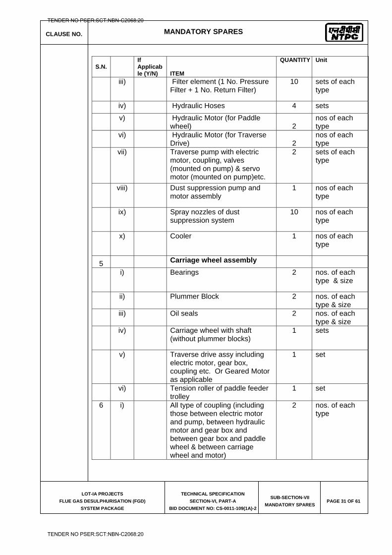
CLAUSE NO. MANDATORY SPARES
LOT-IA PROJECTS
FLUE GAS DESULPHURISATION (FGD)
SYSTEM PACKAGE
TECHNICAL SPECIFICATION
SECTION-VI, PART-A
BID DOCUMENT NO: CS-0011-109(1A)-2
SUB-SECTION-VII
MANDATORY SPARES PAGE 31 OF 61
S.N.
If Applicable (Y/N) ITEM
QUANTITY Unit
iii) Filter element (1 No. Pressure Filter + 1 No. Return Filter)
10 sets of each type
iv) Hydraulic Hoses 4 sets
v) Hydraulic Motor (for Paddle
wheel) 2 nos of each type
vi) Hydraulic Motor (for Traverse
Drive) 2 nos of each type
vii) Traverse pump with electric motor, coupling, valves (mounted on pump) & servo motor (mounted on pump)etc.
2 sets of each type
viii) Dust suppression pump and motor assembly
1 nos of each type
ix) Spray nozzles of dust suppression system
10 nos of each type
x) Cooler 1 nos of each type
5 Carriage wheel assembly
i) Bearings 2 nos. of each type & size
ii) Plummer Block 2 nos. of each
type & size
iii) Oil seals 2 nos. of each
type & size
iv) Carriage wheel with shaft (without plummer blocks)
1 sets
v) Traverse drive assy including electric motor, gear box, coupling etc. Or Geared Motor as applicable
1 set
vi) Tension roller of paddle feeder
trolley 1 set
6 i) All type of coupling (including those between electric motor and pump, between hydraulic motor and gear box and between gear box and paddle wheel & between carriage wheel and motor)
2 nos. of each type
TENDER NO PSER:SCT:NBN-C2068:20
TENDER NO PSER:SCT:NBN-C2068:20
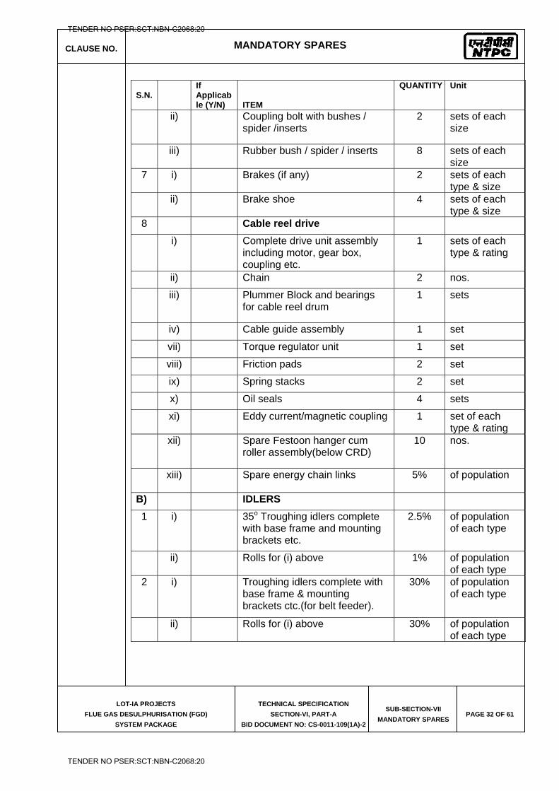
CLAUSE NO. MANDATORY SPARES
LOT-IA PROJECTS
FLUE GAS DESULPHURISATION (FGD)
SYSTEM PACKAGE
TECHNICAL SPECIFICATION
SECTION-VI, PART-A
BID DOCUMENT NO: CS-0011-109(1A)-2
SUB-SECTION-VII
MANDATORY SPARES PAGE 32 OF 61
S.N.
If Applicable (Y/N) ITEM
QUANTITY Unit
ii) Coupling bolt with bushes / spider /inserts
2 sets of each size
iii) Rubber bush / spider / inserts 8 sets of each size
7 i) Brakes (if any) 2 sets of each type & size
ii) Brake shoe 4 sets of each type & size
8 Cable reel drive
i) Complete drive unit assembly including motor, gear box, coupling etc.
1 sets of each type & rating
ii) Chain 2 nos.
iii) Plummer Block and bearings for cable reel drum
1 sets
iv) Cable guide assembly 1 set
vii) Torque regulator unit 1 set
viii) Friction pads 2 set
ix) Spring stacks 2 set
x) Oil seals 4 sets
xi) Eddy current/magnetic coupling 1 set of each type & rating
xii) Spare Festoon hanger cum roller assembly(below CRD)
10 nos.
xiii) Spare energy chain links
5% of population
B) IDLERS
1 i) 35o Troughing idlers complete with base frame and mounting brackets etc.
2.5% of population of each type
ii) Rolls for (i) above 1% of population of each type
2 i) Troughing idlers complete with base frame & mounting brackets ctc.(for belt feeder).
30% of population of each type
ii) Rolls for (i) above 30% of population of each type
TENDER NO PSER:SCT:NBN-C2068:20
TENDER NO PSER:SCT:NBN-C2068:20
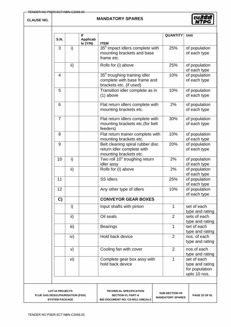
CLAUSE NO. MANDATORY SPARES
LOT-IA PROJECTS
FLUE GAS DESULPHURISATION (FGD)
SYSTEM PACKAGE
TECHNICAL SPECIFICATION
SECTION-VI, PART-A
BID DOCUMENT NO: CS-0011-109(1A)-2
SUB-SECTION-VII
MANDATORY SPARES PAGE 33 OF 61
S.N.
If Applicable (Y/N) ITEM
QUANTITY Unit
3 i) 350 impact idlers complete with mounting brackets and base frame etc.
25% of population of each type
ii) Rolls for (i) above 25% of population of each type
4 350 troughing training idler complete with base frame and brackets etc. (if used)
10% of population of each type
5 Transition idler complete as in (1) above
10% of population of each type
6 Flat return idlers complete with mounting brackets etc.
2% of population of each type
7 Flat return idlers complete with mounting brackets etc.(for belt feeders)
30% of population of each type
8 Flat return trainer complete with mounting brackets etc.
10% of population of each type
9 Belt cleaning spiral rubber disc return idler complete with mounting brackets etc.
20% of population of each type
10 i) Two roll 10o troughing return idler assy
2% of population of each type
ii) Rolls for (I) above 2% of population of each type
11 SS idlers 25% of population of each type
12 Any other type of idlers 10% of population of each type
C) CONVEYOR GEAR BOXES
i) Input shafts with pinion 1 set of each type and rating
ii) Oil seals 2 sets of each type and rating
iii) Bearings 1 set of each type and rating
iv) Hold back device 2 nos. of each type and rating
v) Cooling fan with cover 2 nos.of each type and rating
vi) Complete gear box assy with hold back device
1 set of each type and rating for population upto 10 nos.
TENDER NO PSER:SCT:NBN-C2068:20
TENDER NO PSER:SCT:NBN-C2068:20
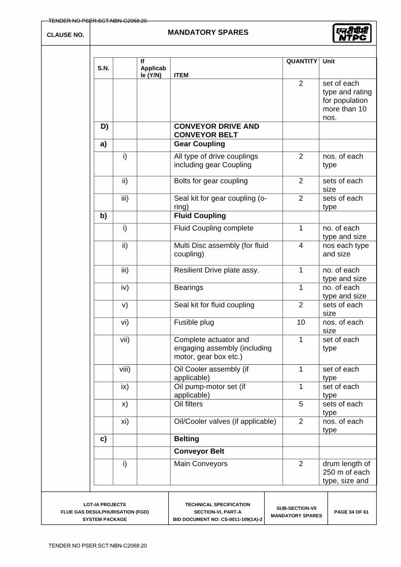
CLAUSE NO. MANDATORY SPARES
LOT-IA PROJECTS
FLUE GAS DESULPHURISATION (FGD)
SYSTEM PACKAGE
TECHNICAL SPECIFICATION
SECTION-VI, PART-A
BID DOCUMENT NO: CS-0011-109(1A)-2
SUB-SECTION-VII
MANDATORY SPARES PAGE 34 OF 61
S.N.
If Applicable (Y/N) ITEM
QUANTITY Unit
2 set of each type and rating for population more than 10 nos.
D) CONVEYOR DRIVE AND CONVEYOR BELT
a) Gear Coupling
i) All type of drive couplings including gear Coupling
2 nos. of each type
ii) Bolts for gear coupling 2 sets of each size
iii) Seal kit for gear coupling (o-ring)
2 sets of each type
b) Fluid Coupling
i) Fluid Coupling complete 1 no. of each type and size
ii) Multi Disc assembly (for fluid coupling)
4 nos each type and size
iii) Resilient Drive plate assy. 1 no. of each type and size
iv) Bearings 1 no. of each type and size
v) Seal kit for fluid coupling 2 sets of each size
vi) Fusible plug 10 nos. of each size
vii) Complete actuator and engaging assembly (including motor, gear box etc.)
1 set of each type
viii) Oil Cooler assembly (if applicable)
1 set of each type
ix) Oil pump-motor set (if applicable)
1 set of each type
x) Oil filters 5 sets of each type
xi) Oil/Cooler valves (if applicable) 2 nos. of each type
c) Belting
Conveyor Belt
i) Main Conveyors 2 drum length of 250 m of each type, size and
TENDER NO PSER:SCT:NBN-C2068:20
TENDER NO PSER:SCT:NBN-C2068:20
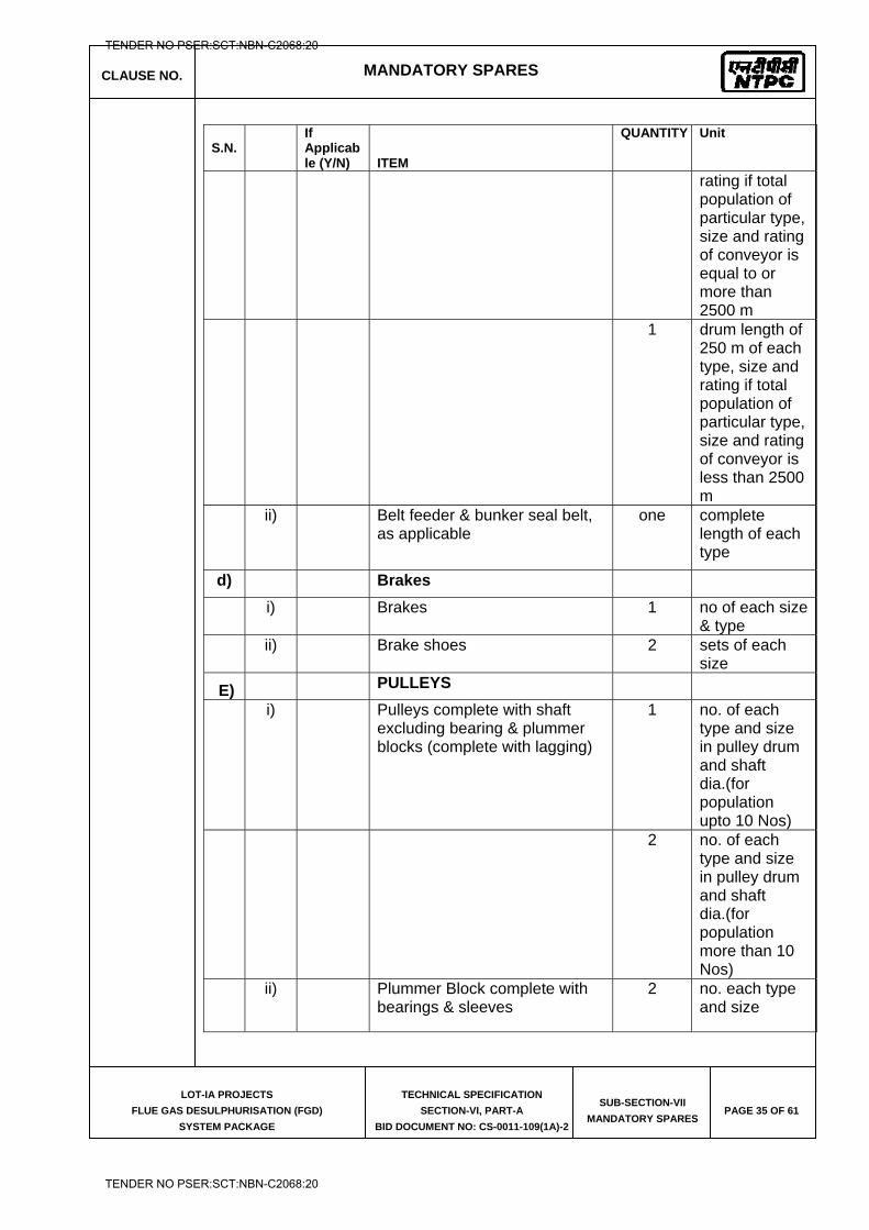
CLAUSE NO. MANDATORY SPARES
LOT-IA PROJECTS
FLUE GAS DESULPHURISATION (FGD)
SYSTEM PACKAGE
TECHNICAL SPECIFICATION
SECTION-VI, PART-A
BID DOCUMENT NO: CS-0011-109(1A)-2
SUB-SECTION-VII
MANDATORY SPARES PAGE 35 OF 61
S.N.
If Applicable (Y/N) ITEM
QUANTITY Unit
rating if total population of particular type, size and rating of conveyor is equal to or more than 2500 m
1 drum length of 250 m of each type, size and rating if total population of particular type, size and rating of conveyor is less than 2500 m
ii) Belt feeder & bunker seal belt, as applicable
one complete length of each type
d) Brakes
i) Brakes 1 no of each size & type
ii) Brake shoes 2 sets of each size
E) PULLEYS
i) Pulleys complete with shaft excluding bearing & plummer blocks (complete with lagging)
1 no. of each type and size in pulley drum and shaft dia.(for population upto 10 Nos)
2 no. of each type and size in pulley drum and shaft dia.(for population more than 10 Nos)
ii) Plummer Block complete with bearings & sleeves
2 no. each type and size
TENDER NO PSER:SCT:NBN-C2068:20
TENDER NO PSER:SCT:NBN-C2068:20
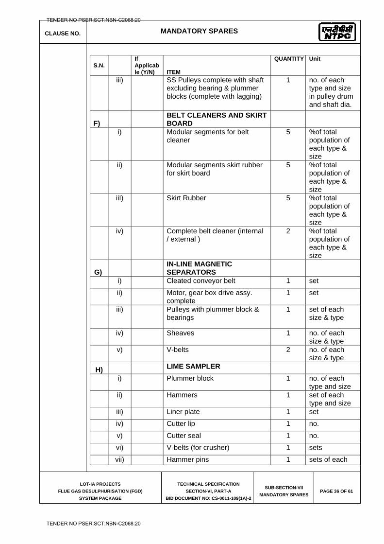
CLAUSE NO. MANDATORY SPARES
LOT-IA PROJECTS
FLUE GAS DESULPHURISATION (FGD)
SYSTEM PACKAGE
TECHNICAL SPECIFICATION
SECTION-VI, PART-A
BID DOCUMENT NO: CS-0011-109(1A)-2
SUB-SECTION-VII
MANDATORY SPARES PAGE 36 OF 61
S.N.
If Applicable (Y/N) ITEM
QUANTITY Unit
iii) SS Pulleys complete with shaft excluding bearing & plummer blocks (complete with lagging)
1 no. of each type and size in pulley drum and shaft dia.
F) BELT CLEANERS AND SKIRT
BOARD
i) Modular segments for belt cleaner
5 %of total population of each type & size
ii) Modular segments skirt rubber for skirt board
5 %of total population of each type & size
iiI) Skirt Rubber 5 %of total population of each type & size
iv) Complete belt cleaner (internal / external )
2 %of total population of each type & size
G) IN-LINE MAGNETIC
SEPARATORS
i) Cleated conveyor belt 1 set
ii) Motor, gear box drive assy. complete
1 set
iii) Pulleys with plummer block & bearings
1 set of each size & type
iv) Sheaves 1 no. of each size & type
v) V-belts 2 no. of each size & type
H) LIME SAMPLER
i) Plummer block 1 no. of each type and size
ii) Hammers 1 set of each type and size
iii) Liner plate 1 set
iv) Cutter lip 1 no.
v) Cutter seal 1 no.
vi) V-belts (for crusher) 1 sets
vii) Hammer pins 1 sets of each
TENDER NO PSER:SCT:NBN-C2068:20
TENDER NO PSER:SCT:NBN-C2068:20
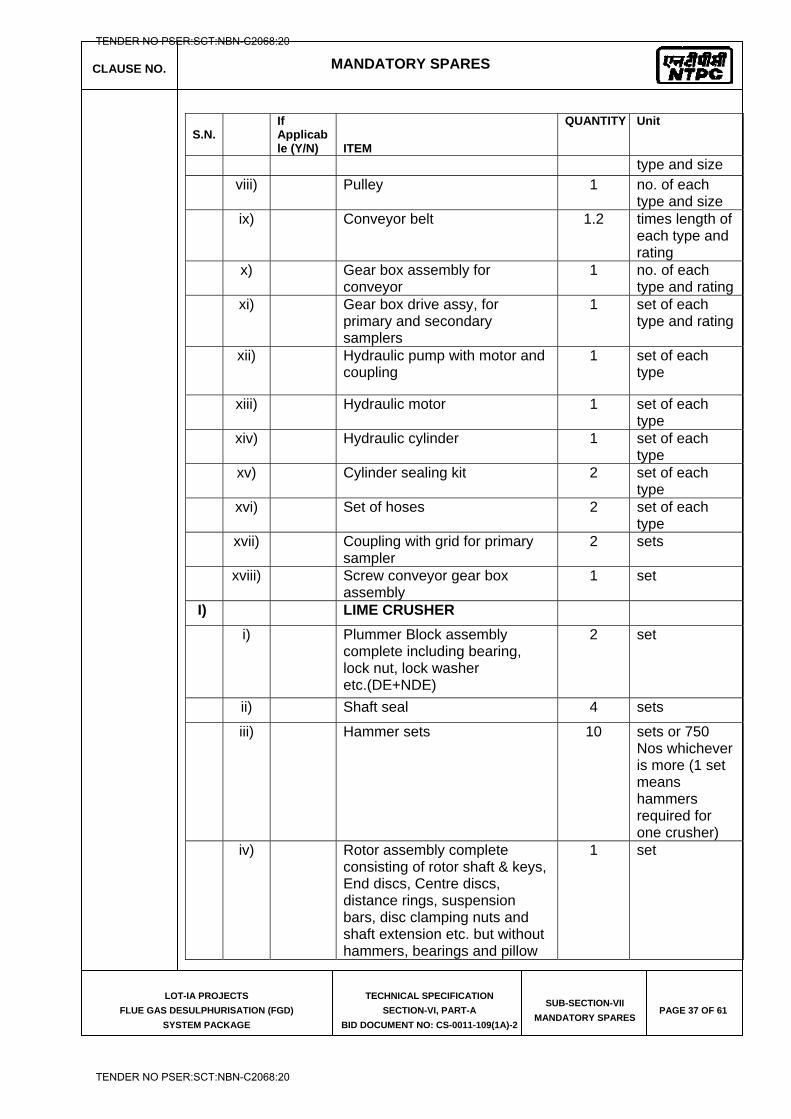
CLAUSE NO. MANDATORY SPARES
LOT-IA PROJECTS
FLUE GAS DESULPHURISATION (FGD)
SYSTEM PACKAGE
TECHNICAL SPECIFICATION
SECTION-VI, PART-A
BID DOCUMENT NO: CS-0011-109(1A)-2
SUB-SECTION-VII
MANDATORY SPARES PAGE 37 OF 61
S.N.
If Applicable (Y/N) ITEM
QUANTITY Unit
type and size viii) Pulley 1 no. of each
type and size ix) Conveyor belt 1.2 times length of
each type and rating
x) Gear box assembly for conveyor
1 no. of each type and rating
xi) Gear box drive assy, for primary and secondary samplers
1 set of each type and rating
xii) Hydraulic pump with motor and coupling
1 set of each type
xiii) Hydraulic motor 1 set of each type
xiv) Hydraulic cylinder 1 set of each type
xv) Cylinder sealing kit 2 set of each type
xvi) Set of hoses 2 set of each type
xvii) Coupling with grid for primary sampler
2 sets
xviii) Screw conveyor gear box assembly
1 set
I) LIME CRUSHER
i) Plummer Block assembly complete including bearing, lock nut, lock washer etc.(DE+NDE)
2 set
ii) Shaft seal 4 sets
iii) Hammer sets
10 sets or 750 Nos whichever is more (1 set means hammers required for one crusher)
iv) Rotor assembly complete consisting of rotor shaft & keys, End discs, Centre discs, distance rings, suspension bars, disc clamping nuts and shaft extension etc. but without hammers, bearings and pillow
1 set
TENDER NO PSER:SCT:NBN-C2068:20
TENDER NO PSER:SCT:NBN-C2068:20
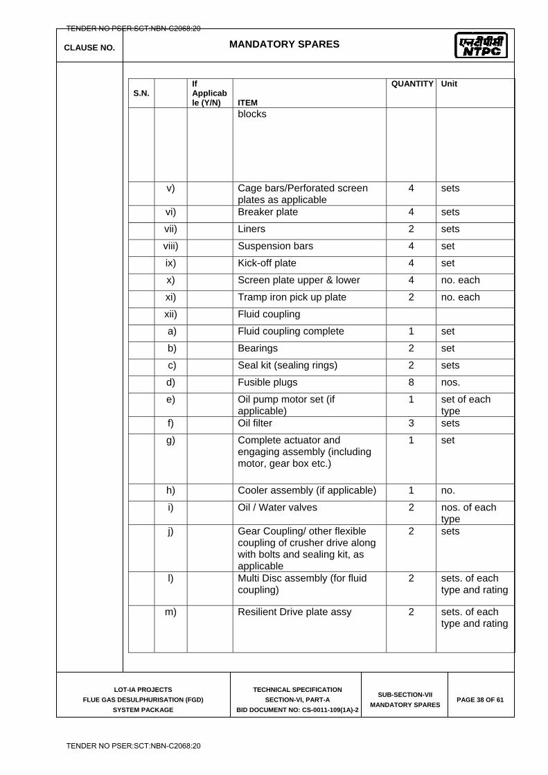
CLAUSE NO. MANDATORY SPARES
LOT-IA PROJECTS
FLUE GAS DESULPHURISATION (FGD)
SYSTEM PACKAGE
TECHNICAL SPECIFICATION
SECTION-VI, PART-A
BID DOCUMENT NO: CS-0011-109(1A)-2
SUB-SECTION-VII
MANDATORY SPARES PAGE 38 OF 61
S.N.
If Applicable (Y/N) ITEM
QUANTITY Unit
blocks
v) Cage bars/Perforated screen plates as applicable
4 sets
vi) Breaker plate 4 sets
vii) Liners 2 sets
viii) Suspension bars 4 set
ix) Kick-off plate 4 set
x) Screen plate upper & lower 4 no. each
xi) Tramp iron pick up plate 2 no. each
xii) Fluid coupling
a) Fluid coupling complete 1 set
b) Bearings 2 set
c) Seal kit (sealing rings) 2 sets
d) Fusible plugs 8 nos.
e) Oil pump motor set (if applicable)
1 set of each type
f) Oil filter 3 sets
g) Complete actuator and engaging assembly (including motor, gear box etc.)
1 set
h) Cooler assembly (if applicable) 1 no.
i) Oil / Water valves 2 nos. of each type
j) Gear Coupling/ other flexible coupling of crusher drive along with bolts and sealing kit, as applicable
2 sets
l) Multi Disc assembly (for fluid coupling)
2 sets. of each type and rating
m) Resilient Drive plate assy 2 sets. of each type and rating
TENDER NO PSER:SCT:NBN-C2068:20
TENDER NO PSER:SCT:NBN-C2068:20
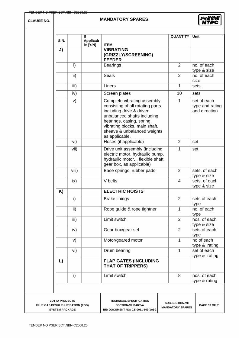
CLAUSE NO. MANDATORY SPARES
LOT-IA PROJECTS
FLUE GAS DESULPHURISATION (FGD)
SYSTEM PACKAGE
TECHNICAL SPECIFICATION
SECTION-VI, PART-A
BID DOCUMENT NO: CS-0011-109(1A)-2
SUB-SECTION-VII
MANDATORY SPARES PAGE 39 OF 61
S.N.
If Applicable (Y/N) ITEM
QUANTITY Unit
J) VIBRATING (GRIZZLY/SCREENING) FEEDER
i) Bearings 2 no. of each
type & size
ii) Seals 2 no. of each
size
iii) Liners 1 sets.
iv) Screen plates 10 sets
v) Complete vibrating assembly consisting of all rotating parts including drive & driven unbalanced shafts including bearings, casing, spring, vibrating blocks, main shaft, sheave & unbalanced weights as applicable.
1 set of each type and rating and direction
vi) Hoses (if applicable) 2 set
vii) Drive unit assembly (including electric motor, hydraulic pump, hydraulic motor, , flexible shaft, gear box, as applicable)
1 set
viii) Base springs, rubber pads 2 sets. of each
type & size
ix) V belts
4 sets. of each
type & size K) ELECTRIC HOISTS
i) Brake linings 2 sets of each type
ii) Rope guide & rope tightner 1 no. of each type
iii) Limit switch 2 nos. of each type & size
iv) Gear box/gear set 2 sets of each type
v) Motor/geared motor 1 no of each type & rating
vi) Drum bearing 1 set of each type & rating
L) FLAP GATES (INCLUDING THAT OF TRIPPERS)
i) Limit switch 8 nos. of each type & rating
TENDER NO PSER:SCT:NBN-C2068:20
TENDER NO PSER:SCT:NBN-C2068:20
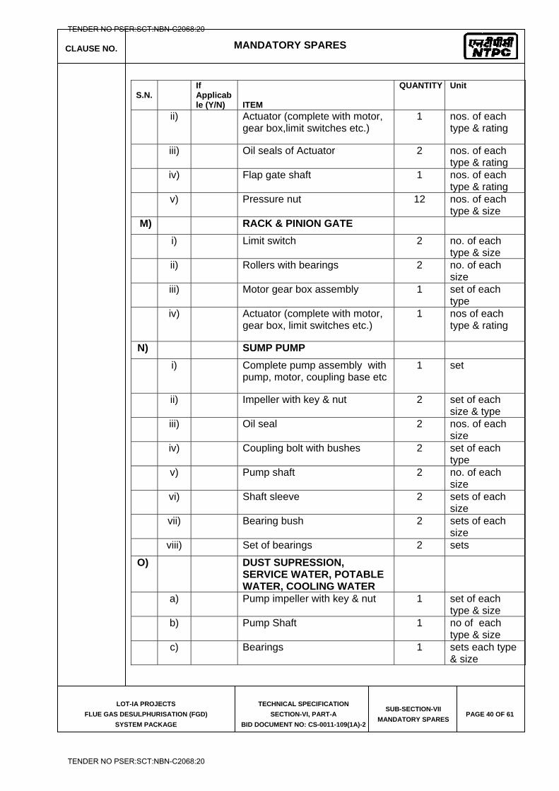
CLAUSE NO. MANDATORY SPARES
LOT-IA PROJECTS
FLUE GAS DESULPHURISATION (FGD)
SYSTEM PACKAGE
TECHNICAL SPECIFICATION
SECTION-VI, PART-A
BID DOCUMENT NO: CS-0011-109(1A)-2
SUB-SECTION-VII
MANDATORY SPARES PAGE 40 OF 61
S.N.
If Applicable (Y/N) ITEM
QUANTITY Unit
ii) Actuator (complete with motor, gear box,limit switches etc.)
1 nos. of each type & rating
iii) Oil seals of Actuator 2 nos. of each type & rating
iv) Flap gate shaft 1 nos. of each type & rating
v) Pressure nut 12 nos. of each type & size
M) RACK & PINION GATE
i) Limit switch 2 no. of each type & size
ii) Rollers with bearings 2 no. of each size
iii) Motor gear box assembly 1 set of each type
iv) Actuator (complete with motor, gear box, limit switches etc.)
1 nos of each type & rating
N) SUMP PUMP
i) Complete pump assembly with pump, motor, coupling base etc
1 set
ii) Impeller with key & nut 2 set of each size & type
iii) Oil seal 2 nos. of each size
iv) Coupling bolt with bushes 2 set of each type
v) Pump shaft 2 no. of each size
vi) Shaft sleeve 2 sets of each size
vii) Bearing bush 2 sets of each size
viii) Set of bearings 2 sets
O) DUST SUPRESSION, SERVICE WATER, POTABLE WATER, COOLING WATER
a) Pump impeller with key & nut 1 set of each type & size
b) Pump Shaft 1 no of each type & size
c) Bearings 1 sets each type & size
TENDER NO PSER:SCT:NBN-C2068:20
TENDER NO PSER:SCT:NBN-C2068:20
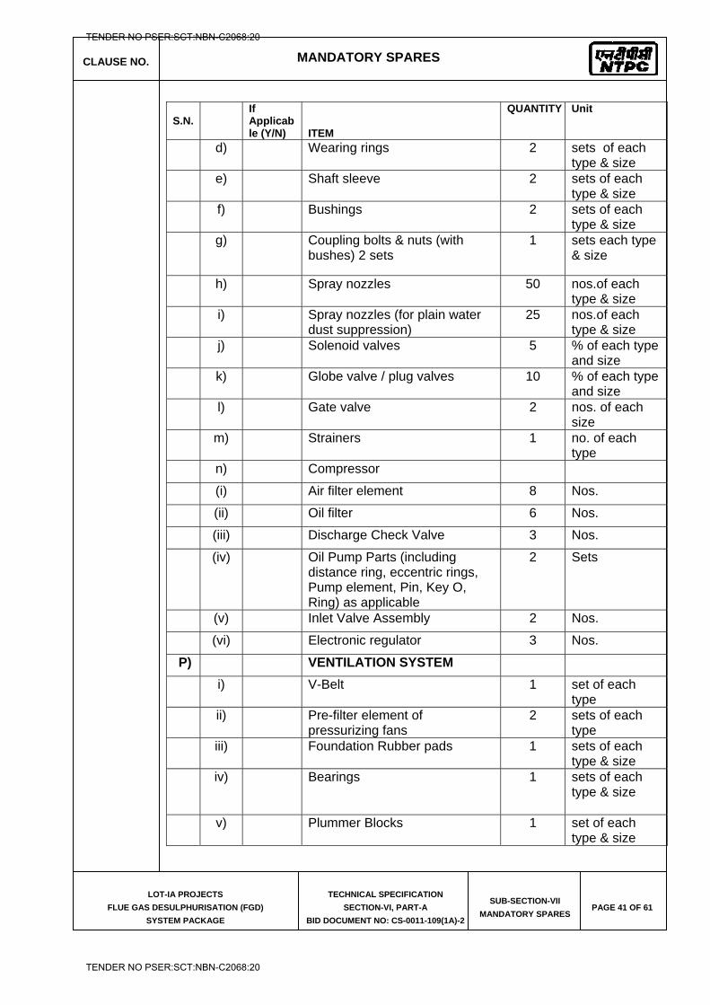
CLAUSE NO. MANDATORY SPARES
LOT-IA PROJECTS
FLUE GAS DESULPHURISATION (FGD)
SYSTEM PACKAGE
TECHNICAL SPECIFICATION
SECTION-VI, PART-A
BID DOCUMENT NO: CS-0011-109(1A)-2
SUB-SECTION-VII
MANDATORY SPARES PAGE 41 OF 61
S.N.
If Applicable (Y/N) ITEM
QUANTITY Unit
d) Wearing rings 2 sets of each type & size
e) Shaft sleeve 2 sets of each type & size
f) Bushings 2 sets of each type & size
g) Coupling bolts & nuts (with bushes) 2 sets
1 sets each type & size
h) Spray nozzles 50 nos.of each type & size
i) Spray nozzles (for plain water dust suppression)
25 nos.of each type & size
j) Solenoid valves 5 % of each type and size
k) Globe valve / plug valves 10 % of each type and size
l) Gate valve 2 nos. of each size
m) Strainers 1 no. of each type
n) Compressor
(i) Air filter element 8 Nos.
(ii) Oil filter 6 Nos.
(iii) Discharge Check Valve 3 Nos.
(iv) Oil Pump Parts (including distance ring, eccentric rings, Pump element, Pin, Key O, Ring) as applicable
2 Sets
(v) Inlet Valve Assembly 2 Nos.
(vi) Electronic regulator 3 Nos.
P) VENTILATION SYSTEM
i) V-Belt 1 set of each type
ii) Pre-filter element of pressurizing fans
2 sets of each type
iii) Foundation Rubber pads 1 sets of each type & size
iv) Bearings 1 sets of each type & size
v) Plummer Blocks 1 set of each type & size
TENDER NO PSER:SCT:NBN-C2068:20
TENDER NO PSER:SCT:NBN-C2068:20
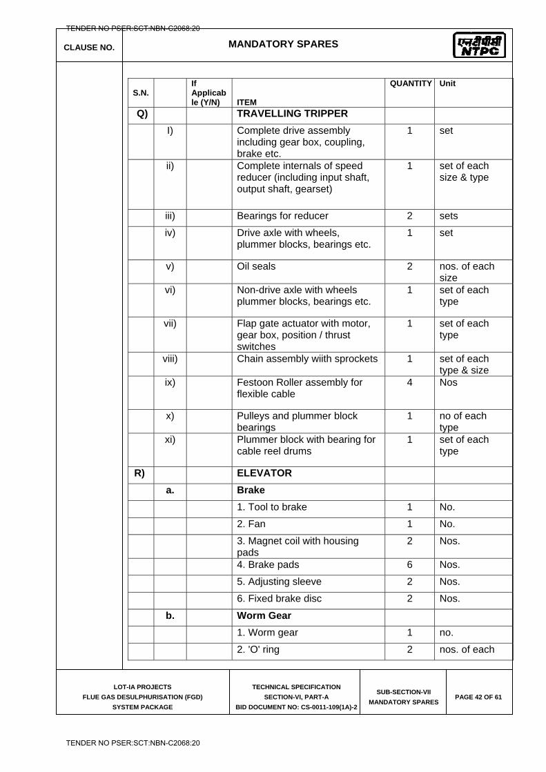
CLAUSE NO. MANDATORY SPARES
LOT-IA PROJECTS
FLUE GAS DESULPHURISATION (FGD)
SYSTEM PACKAGE
TECHNICAL SPECIFICATION
SECTION-VI, PART-A
BID DOCUMENT NO: CS-0011-109(1A)-2
SUB-SECTION-VII
MANDATORY SPARES PAGE 42 OF 61
S.N.
If Applicable (Y/N) ITEM
QUANTITY Unit
Q) TRAVELLING TRIPPER
I) Complete drive assembly including gear box, coupling, brake etc.
1 set
ii) Complete internals of speed reducer (including input shaft, output shaft, gearset)
1 set of each size & type
iii) Bearings for reducer 2 sets
iv) Drive axle with wheels, plummer blocks, bearings etc.
1 set
v) Oil seals 2 nos. of each size
vi) Non-drive axle with wheels plummer blocks, bearings etc.
1 set of each type
vii) Flap gate actuator with motor, gear box, position / thrust switches
1 set of each type
viii) Chain assembly wiith sprockets 1 set of each type & size
ix) Festoon Roller assembly for flexible cable
4 Nos
x) Pulleys and plummer block bearings
1 no of each type
xi) Plummer block with bearing for cable reel drums
1 set of each type
R) ELEVATOR
a. Brake
1. Tool to brake 1 No.
2. Fan 1 No.
3. Magnet coil with housing pads
2 Nos.
4. Brake pads 6 Nos.
5. Adjusting sleeve 2 Nos.
6. Fixed brake disc 2 Nos.
b. Worm Gear
1. Worm gear 1 no.
2. 'O' ring 2 nos. of each
TENDER NO PSER:SCT:NBN-C2068:20
TENDER NO PSER:SCT:NBN-C2068:20
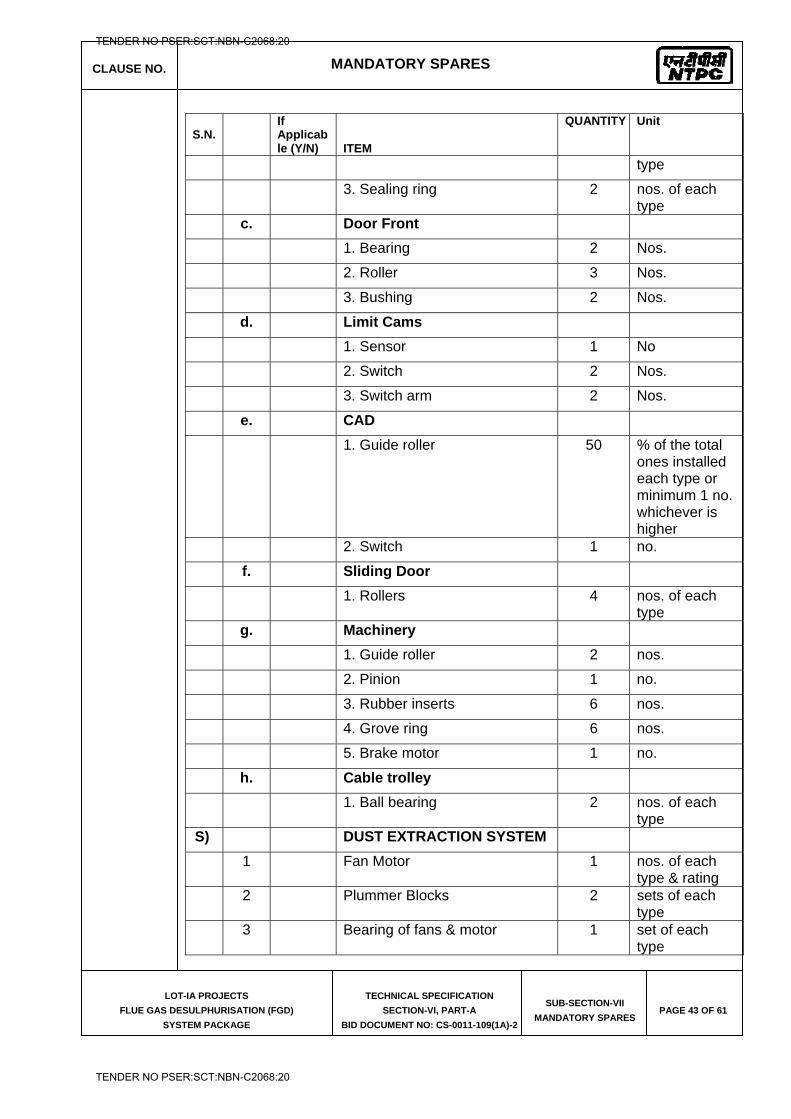
CLAUSE NO. MANDATORY SPARES
LOT-IA PROJECTS
FLUE GAS DESULPHURISATION (FGD)
SYSTEM PACKAGE
TECHNICAL SPECIFICATION
SECTION-VI, PART-A
BID DOCUMENT NO: CS-0011-109(1A)-2
SUB-SECTION-VII
MANDATORY SPARES PAGE 43 OF 61
S.N.
If Applicable (Y/N) ITEM
QUANTITY Unit
type
3. Sealing ring 2 nos. of each type
c. Door Front
1. Bearing 2 Nos.
2. Roller 3 Nos.
3. Bushing 2 Nos.
d. Limit Cams
1. Sensor 1 No
2. Switch 2 Nos.
3. Switch arm 2 Nos.
e. CAD
1. Guide roller 50 % of the total ones installed each type or minimum 1 no. whichever is higher
2. Switch 1 no.
f. Sliding Door
1. Rollers 4 nos. of each type
g. Machinery
1. Guide roller 2 nos.
2. Pinion 1 no.
3. Rubber inserts 6 nos.
4. Grove ring 6 nos.
5. Brake motor 1 no.
h. Cable trolley
1. Ball bearing 2 nos. of each type
S) DUST EXTRACTION SYSTEM
1 Fan Motor 1 nos. of each type & rating
2 Plummer Blocks 2 sets of each type
3 Bearing of fans & motor 1 set of each type
TENDER NO PSER:SCT:NBN-C2068:20
TENDER NO PSER:SCT:NBN-C2068:20
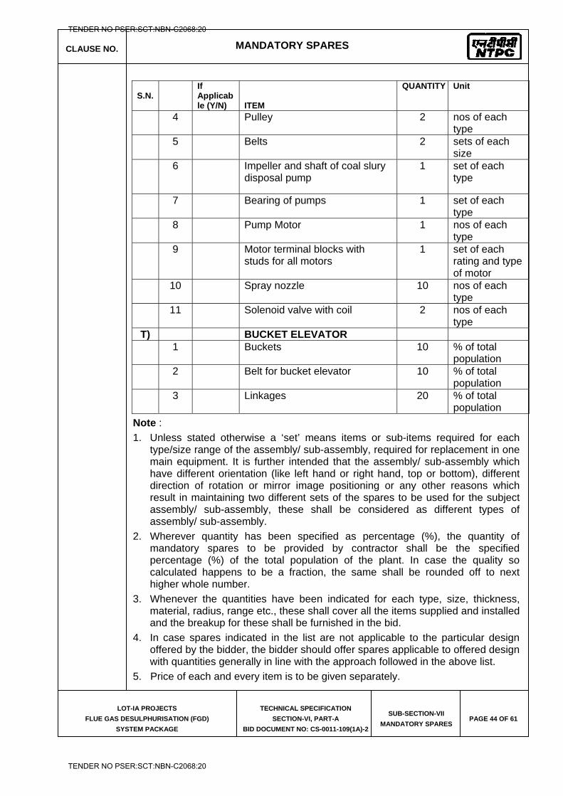
CLAUSE NO. MANDATORY SPARES
LOT-IA PROJECTS
FLUE GAS DESULPHURISATION (FGD)
SYSTEM PACKAGE
TECHNICAL SPECIFICATION
SECTION-VI, PART-A
BID DOCUMENT NO: CS-0011-109(1A)-2
SUB-SECTION-VII
MANDATORY SPARES PAGE 44 OF 61
S.N.
If Applicable (Y/N) ITEM
QUANTITY Unit
4 Pulley 2 nos of each type
5 Belts 2 sets of each size
6 Impeller and shaft of coal slury disposal pump
1 set of each type
7 Bearing of pumps 1 set of each type
8 Pump Motor 1 nos of each type
9 Motor terminal blocks with studs for all motors
1 set of each rating and type of motor
10 Spray nozzle 10 nos of each type
11 Solenoid valve with coil 2 nos of each type
T) BUCKET ELEVATOR 1 Buckets 10 % of total
population 2 Belt for bucket elevator 10 % of total
population 3 Linkages 20 % of total
population Note : 1. Unless stated otherwise a ‘set’ means items or sub-items required for each
type/size range of the assembly/ sub-assembly, required for replacement in one main equipment. It is further intended that the assembly/ sub-assembly which have different orientation (like left hand or right hand, top or bottom), different direction of rotation or mirror image positioning or any other reasons which result in maintaining two different sets of the spares to be used for the subject assembly/ sub-assembly, these shall be considered as different types of assembly/ sub-assembly.
2. Wherever quantity has been specified as percentage (%), the quantity of mandatory spares to be provided by contractor shall be the specified percentage (%) of the total population of the plant. In case the quality so calculated happens to be a fraction, the same shall be rounded off to next higher whole number.
3. Whenever the quantities have been indicated for each type, size, thickness, material, radius, range etc., these shall cover all the items supplied and installed and the breakup for these shall be furnished in the bid.
4. In case spares indicated in the list are not applicable to the particular design offered by the bidder, the bidder should offer spares applicable to offered design with quantities generally in line with the approach followed in the above list.
5. Price of each and every item is to be given separately.
TENDER NO PSER:SCT:NBN-C2068:20
TENDER NO PSER:SCT:NBN-C2068:20
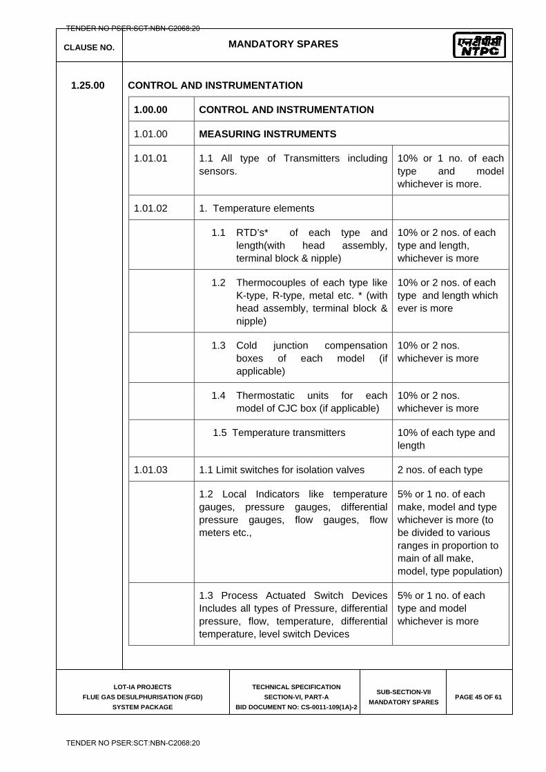
CLAUSE NO. MANDATORY SPARES
LOT-IA PROJECTS
FLUE GAS DESULPHURISATION (FGD)
SYSTEM PACKAGE
TECHNICAL SPECIFICATION
SECTION-VI, PART-A
BID DOCUMENT NO: CS-0011-109(1A)-2
SUB-SECTION-VII
MANDATORY SPARES PAGE 45 OF 61
1.25.00 CONTROL AND INSTRUMENTATION
1.00.00 CONTROL AND INSTRUMENTATION
1.01.00 MEASURING INSTRUMENTS
1.01.01 1.1 All type of Transmitters including sensors.
10% or 1 no. of each type and model whichever is more.
1.01.02 1. Temperature elements
1.1 RTD’s* of each type and length(with head assembly, terminal block & nipple)
10% or 2 nos. of each type and length, whichever is more
1.2 Thermocouples of each type like K-type, R-type, metal etc. * (with head assembly, terminal block & nipple)
10% or 2 nos. of each type and length which ever is more
1.3 Cold junction compensation boxes of each model (if applicable)
10% or 2 nos. whichever is more
1.4 Thermostatic units for each model of CJC box (if applicable)
10% or 2 nos. whichever is more
1.5 Temperature transmitters 10% of each type and length
1.01.03 1.1 Limit switches for isolation valves 2 nos. of each type
1.2 Local Indicators like temperature gauges, pressure gauges, differential pressure gauges, flow gauges, flow meters etc.,
5% or 1 no. of each make, model and type whichever is more (to be divided to various ranges in proportion to main of all make, model, type population)
1.3 Process Actuated Switch Devices Includes all types of Pressure, differential pressure, flow, temperature, differential temperature, level switch Devices
5% or 1 no. of each type and model whichever is more
TENDER NO PSER:SCT:NBN-C2068:20
TENDER NO PSER:SCT:NBN-C2068:20
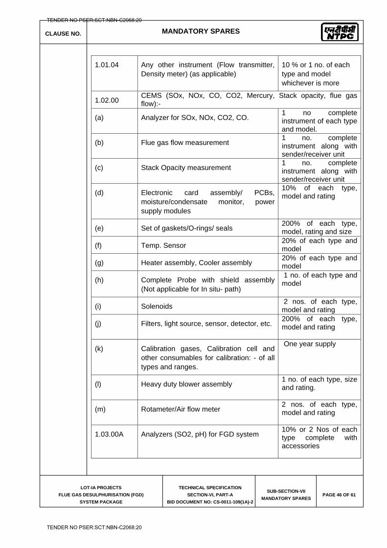
CLAUSE NO. MANDATORY SPARES
LOT-IA PROJECTS
FLUE GAS DESULPHURISATION (FGD)
SYSTEM PACKAGE
TECHNICAL SPECIFICATION
SECTION-VI, PART-A
BID DOCUMENT NO: CS-0011-109(1A)-2
SUB-SECTION-VII
MANDATORY SPARES PAGE 46 OF 61
1.01.04 Any other instrument (Flow transmitter, Density meter) (as applicable)
10 % or 1 no. of each type and model whichever is more
1.02.00 CEMS (SOx, NOx, CO, CO2, Mercury, Stack opacity, flue gas flow):-
(a) Analyzer for SOx, NOx, CO2, CO. 1 no complete instrument of each type and model.
(b) Flue gas flow measurement 1 no. complete instrument along with sender/receiver unit
(c) Stack Opacity measurement 1 no. complete instrument along with sender/receiver unit
(d) Electronic card assembly/ PCBs, moisture/condensate monitor, power supply modules
10% of each type, model and rating
(e) Set of gaskets/O-rings/ seals 200% of each type, model, rating and size
(f) Temp. Sensor 20% of each type and model
(g) Heater assembly, Cooler assembly 20% of each type and model
(h) Complete Probe with shield assembly (Not applicable for In situ- path)
1 no. of each type and model
(i) Solenoids 2 nos. of each type, model and rating
(j) Filters, light source, sensor, detector, etc. 200% of each type, model and rating
(k) Calibration gases, Calibration cell and other consumables for calibration: - of all types and ranges.
One year supply
(l) Heavy duty blower assembly 1 no. of each type, size and rating.
(m) Rotameter/Air flow meter 2 nos. of each type, model and rating
1.03.00A Analyzers (SO2, pH) for FGD system 10% or 2 Nos of each type complete with accessories
TENDER NO PSER:SCT:NBN-C2068:20
TENDER NO PSER:SCT:NBN-C2068:20
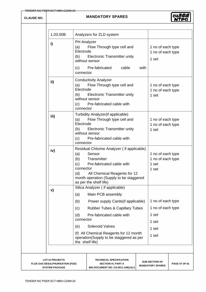
CLAUSE NO. MANDATORY SPARES
LOT-IA PROJECTS
FLUE GAS DESULPHURISATION (FGD)
SYSTEM PACKAGE
TECHNICAL SPECIFICATION
SECTION-VI, PART-A
BID DOCUMENT NO: CS-0011-109(1A)-2
SUB-SECTION-VII
MANDATORY SPARES PAGE 47 OF 61
1.03.00B Analyzers for ZLD system
i) PH Analyzer (a) Flow Through type cell and Electrode (b) Electronic Transmitter unity without sensor
(c) Pre-fabricated cable with connector
1 no of each type 1 no of each type
1 set
ii) Conductivity Analyzer (a) Flow Through type cell and Electrode (b) Electronic Transmitter unity without sensor (c) Pre-fabricated cable with connector
1 no of each type 1 no of each type 1 set
iii) Turbidity Analyzer(if applicable) (a) Flow Through type cell and Electrode (b) Electronic Transmitter unity without sensor (c) Pre-fabricated cable with connector
1 no of each type 1 no of each type 1 set
iv) Residual Chlorine Analyzer ( if applicable) (a) Sensor (b) Transmitter (c) Pre-fabricated cable with connector (d) All Chemical Reagents for 12 month operation (Supply to be staggered as per the shelf life)
1 no of each type 1 no of each type 1 set 1 set
v) Silica Analyzer ( if applicable)
(a) Main PCB assembly
(b) Power supply Cards(if applicable)
(c) Rubber Tubes & Capillary Tubes
(d) Pre-fabricated cable with connector
(e) Solenoid Valves
(f) All Chemical Reagents for 12 month operation(Supply to be staggered as per the shelf life)
1 no of each type
1 no of each type
1 set
1 set
1 set
1 set
TENDER NO PSER:SCT:NBN-C2068:20
TENDER NO PSER:SCT:NBN-C2068:20
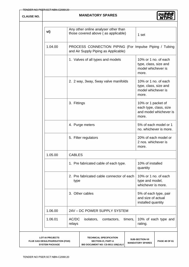
CLAUSE NO. MANDATORY SPARES
LOT-IA PROJECTS
FLUE GAS DESULPHURISATION (FGD)
SYSTEM PACKAGE
TECHNICAL SPECIFICATION
SECTION-VI, PART-A
BID DOCUMENT NO: CS-0011-109(1A)-2
SUB-SECTION-VII
MANDATORY SPARES PAGE 48 OF 61
vi) Any other online analyser other than those covered above ( as applicable)
1 set
1.04.00 PROCESS CONNECTION PIPING (For Impulse Piping / Tubing and Air Supply Piping as Applicable)
1. Valves of all types and models 10% or 1 no. of each type, class, size and model whichever is more.
2. 2 way, 3way, 5way valve manifolds 10% or 1 no. of each type, class, size and model whichever is more.
3. Fittings 10% or 1 packet of each type, class, size and model whichever is more.
4. Purge meters 5% of each model or 1 no. whichever is more.
5. Filter regulators 20% of each model or 2 nos. whichever is more.
1.05.00 CABLES
1. Pre fabricated cable of each type. 10% of installed quantity
2. Pre fabricated cable connector of each type
10% or 1 no. of each type and model, whichever is more.
3. Other cables 5% of each type, pair and size of actual installed quantity
1.06.00 24V – DC POWER SUPPLY SYSTEM
1.06.01 AC/DC isolators, contactors, timers, relays
10% of each type and rating.
TENDER NO PSER:SCT:NBN-C2068:20
TENDER NO PSER:SCT:NBN-C2068:20
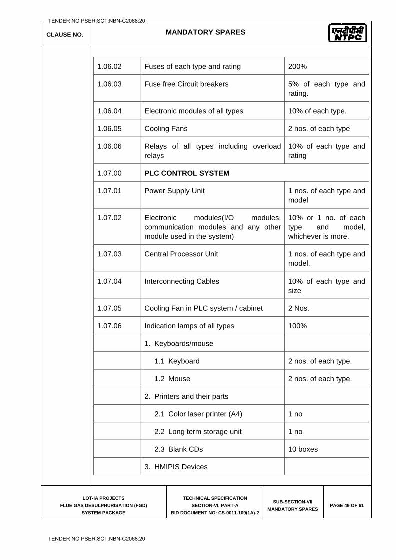
CLAUSE NO. MANDATORY SPARES
LOT-IA PROJECTS
FLUE GAS DESULPHURISATION (FGD)
SYSTEM PACKAGE
TECHNICAL SPECIFICATION
SECTION-VI, PART-A
BID DOCUMENT NO: CS-0011-109(1A)-2
SUB-SECTION-VII
MANDATORY SPARES PAGE 49 OF 61
1.06.02 Fuses of each type and rating 200%
1.06.03 Fuse free Circuit breakers 5% of each type and rating.
1.06.04 Electronic modules of all types 10% of each type.
1.06.05 Cooling Fans 2 nos. of each type
1.06.06 Relays of all types including overload relays
10% of each type and rating
1.07.00 PLC CONTROL SYSTEM
1.07.01 Power Supply Unit 1 nos. of each type and model
1.07.02 Electronic modules(I/O modules, communication modules and any other module used in the system)
10% or 1 no. of each type and model, whichever is more.
1.07.03 Central Processor Unit 1 nos. of each type and model.
1.07.04 Interconnecting Cables 10% of each type and size
1.07.05 Cooling Fan in PLC system / cabinet 2 Nos.
1.07.06 Indication lamps of all types 100%
1. Keyboards/mouse
1.1 Keyboard 2 nos. of each type.
1.2 Mouse 2 nos. of each type.
2. Printers and their parts
2.1 Color laser printer (A4) 1 no
2.2 Long term storage unit 1 no
2.3 Blank CDs 10 boxes
3. HMIPIS Devices
TENDER NO PSER:SCT:NBN-C2068:20
TENDER NO PSER:SCT:NBN-C2068:20
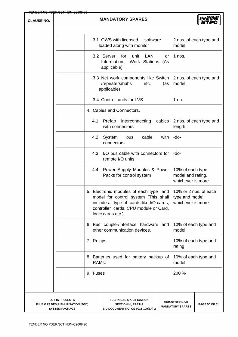
CLAUSE NO. MANDATORY SPARES
LOT-IA PROJECTS
FLUE GAS DESULPHURISATION (FGD)
SYSTEM PACKAGE
TECHNICAL SPECIFICATION
SECTION-VI, PART-A
BID DOCUMENT NO: CS-0011-109(1A)-2
SUB-SECTION-VII
MANDATORY SPARES PAGE 50 OF 61
3.1 OWS with licensed software loaded along with monitor
2 nos. of each type and model.
3.2 Server for unit LAN or Information Work Stations (As applicable)
1 nos.
3.3 Net work components like Switch /repeaters/hubs etc. (as applicable)
2 nos. of each type and model.
3.4 Control units for LVS 1 no.
4. Cables and Connectors.
4.1 Prefab interconnecting cables with connectors
2 nos. of each type and length.
4.2 System bus cable with connectors
-do-
4.3 I/O bus cable with connectors for remote I/O units
-do-
4.4 Power Supply Modules & Power Packs for control system
10% of each type model and rating, whichever is more
5. Electronic modules of each type and model for control system (This shall include all type of cards like I/O cards, controller cards, CPU module or Card, logic cards etc.)
10% or 2 nos. of each type and model whichever is more
6. Bus coupler/Interface hardware and other communication devices.
10% of each type and model
7. Relays 10% of each type and rating
8. Batteries used for battery backup of RAMs.
10% of each type and model
9. Fuses 200 %
TENDER NO PSER:SCT:NBN-C2068:20
TENDER NO PSER:SCT:NBN-C2068:20
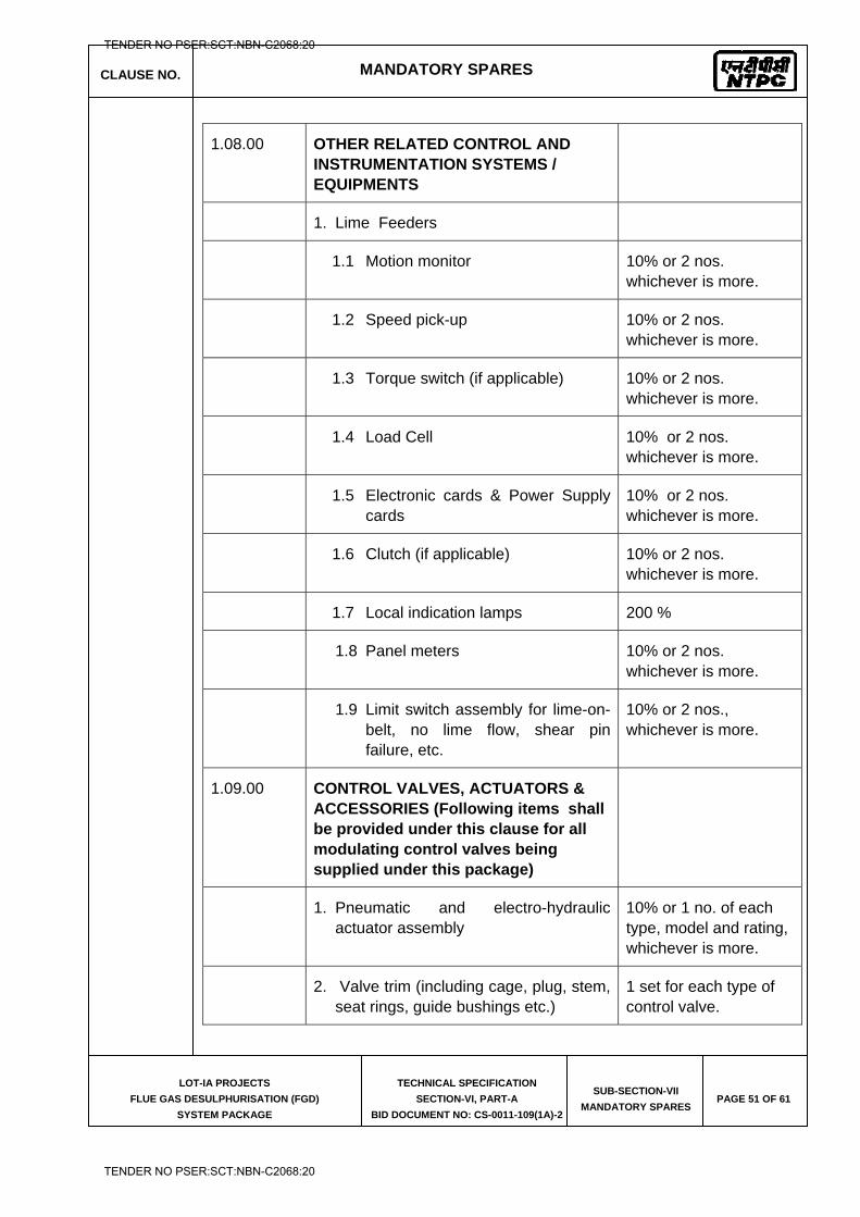
CLAUSE NO. MANDATORY SPARES
LOT-IA PROJECTS
FLUE GAS DESULPHURISATION (FGD)
SYSTEM PACKAGE
TECHNICAL SPECIFICATION
SECTION-VI, PART-A
BID DOCUMENT NO: CS-0011-109(1A)-2
SUB-SECTION-VII
MANDATORY SPARES PAGE 51 OF 61
1.08.00 OTHER RELATED CONTROL AND INSTRUMENTATION SYSTEMS / EQUIPMENTS
1. Lime Feeders
1.1 Motion monitor 10% or 2 nos. whichever is more.
1.2 Speed pick-up 10% or 2 nos. whichever is more.
1.3 Torque switch (if applicable) 10% or 2 nos. whichever is more.
1.4 Load Cell 10% or 2 nos. whichever is more.
1.5 Electronic cards & Power Supply cards
10% or 2 nos. whichever is more.
1.6 Clutch (if applicable) 10% or 2 nos. whichever is more.
1.7 Local indication lamps 200 %
1.8 Panel meters 10% or 2 nos. whichever is more.
1.9 Limit switch assembly for lime-on- belt, no lime flow, shear pin failure, etc.
10% or 2 nos., whichever is more.
1.09.00 CONTROL VALVES, ACTUATORS & ACCESSORIES (Following items shall be provided under this clause for all modulating control valves being supplied under this package)
1. Pneumatic and electro-hydraulic actuator assembly
10% or 1 no. of each type, model and rating, whichever is more.
2. Valve trim (including cage, plug, stem, seat rings, guide bushings etc.)
1 set for each type of control valve.
TENDER NO PSER:SCT:NBN-C2068:20
TENDER NO PSER:SCT:NBN-C2068:20
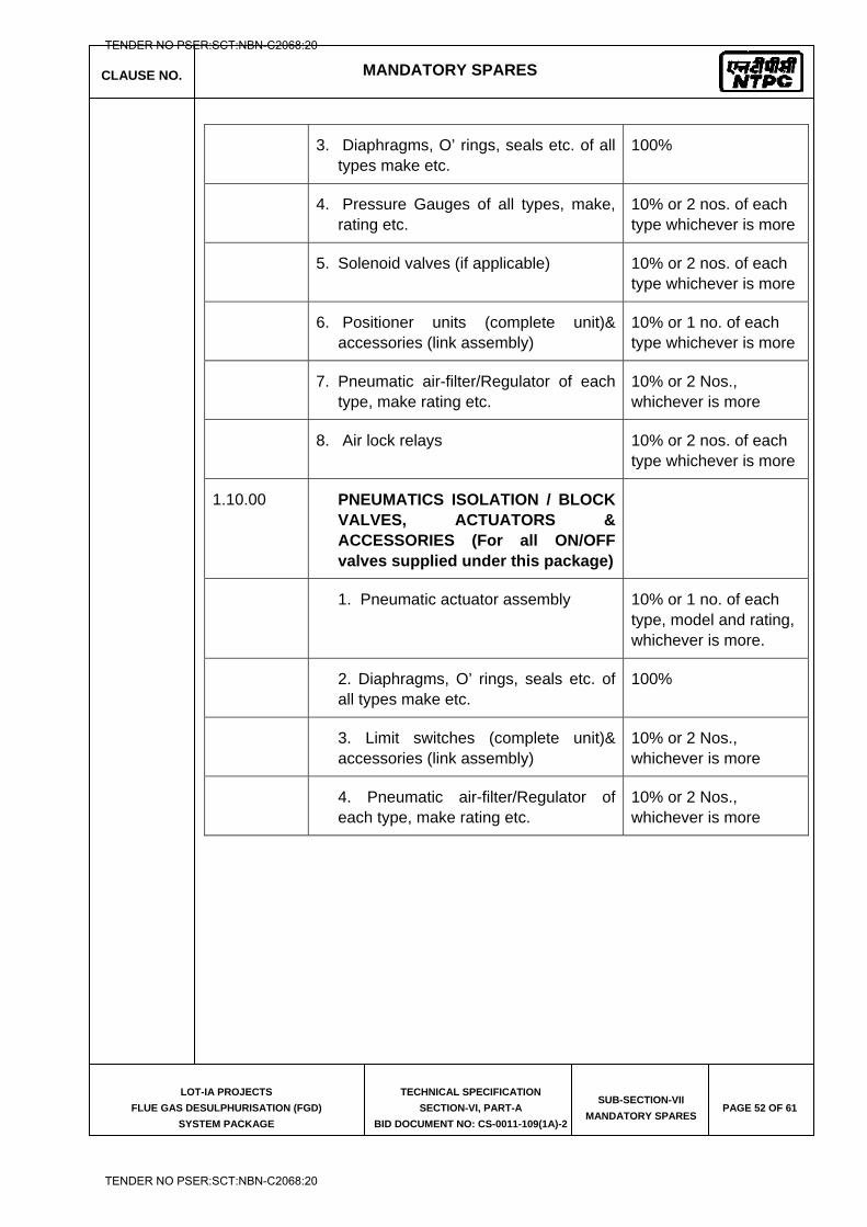
CLAUSE NO. MANDATORY SPARES
LOT-IA PROJECTS
FLUE GAS DESULPHURISATION (FGD)
SYSTEM PACKAGE
TECHNICAL SPECIFICATION
SECTION-VI, PART-A
BID DOCUMENT NO: CS-0011-109(1A)-2
SUB-SECTION-VII
MANDATORY SPARES PAGE 52 OF 61
3. Diaphragms, O’ rings, seals etc. of all types make etc.
100%
4. Pressure Gauges of all types, make, rating etc.
10% or 2 nos. of each type whichever is more
5. Solenoid valves (if applicable) 10% or 2 nos. of each type whichever is more
6. Positioner units (complete unit)& accessories (link assembly)
10% or 1 no. of each type whichever is more
7. Pneumatic air-filter/Regulator of each type, make rating etc.
10% or 2 Nos., whichever is more
8. Air lock relays 10% or 2 nos. of each type whichever is more
1.10.00 PNEUMATICS ISOLATION / BLOCK VALVES, ACTUATORS & ACCESSORIES (For all ON/OFF valves supplied under this package)
1. Pneumatic actuator assembly 10% or 1 no. of each type, model and rating, whichever is more.
2. Diaphragms, O’ rings, seals etc. of all types make etc.
100%
3. Limit switches (complete unit)& accessories (link assembly)
10% or 2 Nos., whichever is more
4. Pneumatic air-filter/Regulator of each type, make rating etc.
10% or 2 Nos., whichever is more
TENDER NO PSER:SCT:NBN-C2068:20
TENDER NO PSER:SCT:NBN-C2068:20
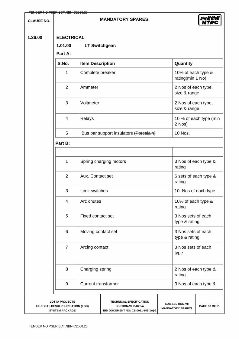
CLAUSE NO. MANDATORY SPARES
LOT-IA PROJECTS
FLUE GAS DESULPHURISATION (FGD)
SYSTEM PACKAGE
TECHNICAL SPECIFICATION
SECTION-VI, PART-A
BID DOCUMENT NO: CS-0011-109(1A)-2
SUB-SECTION-VII
MANDATORY SPARES PAGE 53 OF 61
1.26.00 ELECTRICAL
1.01.00 LT Switchgear:
Part A:
S.No. Item Description Quantity
1 Complete breaker 10% of each type & rating(min 1 No)
2 Ammeter 2 Nos of each type, size & range
3 Voltmeter 2 Nos of each type, size & range
4 Relays 10 % of each type (min 2 Nos)
5 Bus bar support insulators (Porcelain) 10 Nos.
Part B:
1 Spring charging motors 3 Nos of each type & rating
2 Aux. Contact set 6 sets of each type & rating
3 Limit switches 10 Nos of each type.
4 Arc chutes 10% of each type & rating
5 Fixed contact set 3 Nos sets of each type & rating
6 Moving contact set 3 Nos sets of each type & rating
7 Arcing contact 3 Nos sets of each type
8 Charging spring 2 Nos of each type & rating
9 Current transformer 3 Nos of each type &
TENDER NO PSER:SCT:NBN-C2068:20
TENDER NO PSER:SCT:NBN-C2068:20
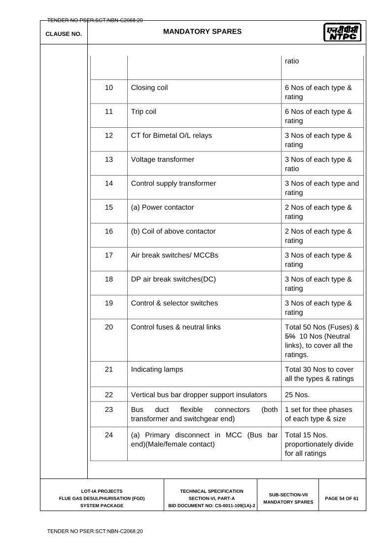
CLAUSE NO. MANDATORY SPARES
LOT-IA PROJECTS
FLUE GAS DESULPHURISATION (FGD)
SYSTEM PACKAGE
TECHNICAL SPECIFICATION
SECTION-VI, PART-A
BID DOCUMENT NO: CS-0011-109(1A)-2
SUB-SECTION-VII
MANDATORY SPARES PAGE 54 OF 61
ratio
10 Closing coil 6 Nos of each type & rating
11 Trip coil 6 Nos of each type & rating
12 CT for Bimetal O/L relays 3 Nos of each type & rating
13 Voltage transformer 3 Nos of each type & ratio
14 Control supply transformer 3 Nos of each type and rating
15 (a) Power contactor 2 Nos of each type & rating
16 (b) Coil of above contactor 2 Nos of each type & rating
17 Air break switches/ MCCBs 3 Nos of each type & rating
18 DP air break switches(DC) 3 Nos of each type & rating
19 Control & selector switches 3 Nos of each type & rating
20 Control fuses & neutral links Total 50 Nos (Fuses) & 5% 10 Nos (Neutral links), to cover all the ratings.
21 Indicating lamps Total 30 Nos to cover all the types & ratings
22 Vertical bus bar dropper support insulators 25 Nos.
23 Bus duct flexible connectors (both transformer and switchgear end)
1 set for thee phases of each type & size
24 (a) Primary disconnect in MCC (Bus bar end)(Male/female contact)
Total 15 Nos. proportionately divide for all ratings
TENDER NO PSER:SCT:NBN-C2068:20
TENDER NO PSER:SCT:NBN-C2068:20
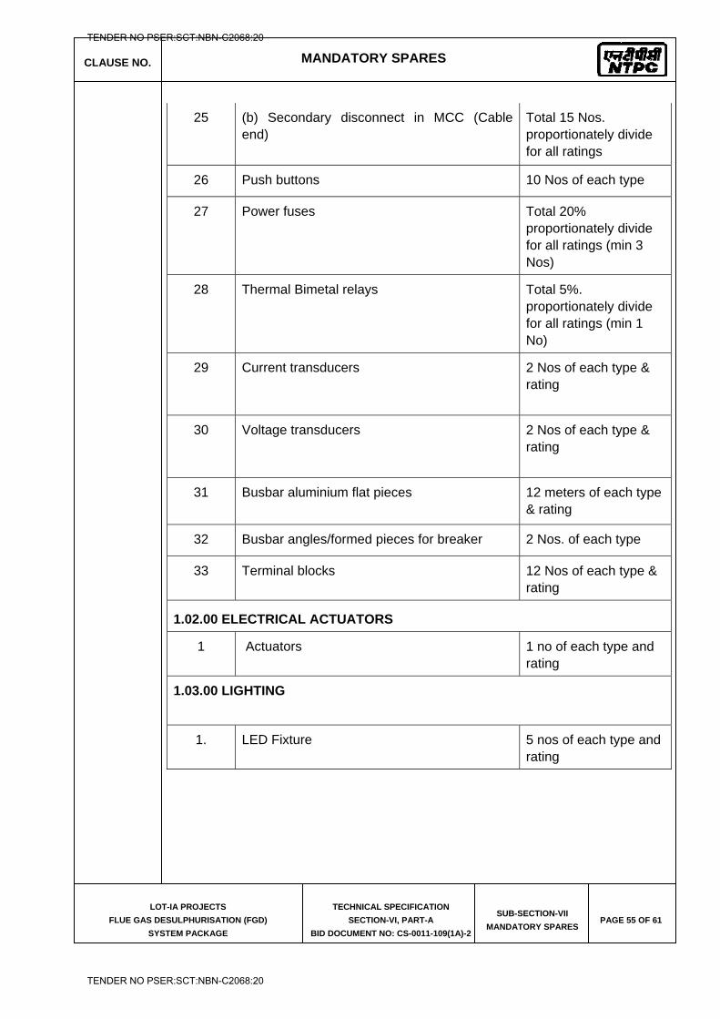
CLAUSE NO. MANDATORY SPARES
LOT-IA PROJECTS
FLUE GAS DESULPHURISATION (FGD)
SYSTEM PACKAGE
TECHNICAL SPECIFICATION
SECTION-VI, PART-A
BID DOCUMENT NO: CS-0011-109(1A)-2
SUB-SECTION-VII
MANDATORY SPARES PAGE 55 OF 61
25 (b) Secondary disconnect in MCC (Cable end)
Total 15 Nos. proportionately divide for all ratings
26 Push buttons 10 Nos of each type
27 Power fuses Total 20% proportionately divide for all ratings (min 3 Nos)
28 Thermal Bimetal relays Total 5%. proportionately divide for all ratings (min 1 No)
29 Current transducers 2 Nos of each type & rating
30 Voltage transducers 2 Nos of each type & rating
31 Busbar aluminium flat pieces 12 meters of each type & rating
32 Busbar angles/formed pieces for breaker 2 Nos. of each type
33 Terminal blocks 12 Nos of each type & rating
1.02.00 ELECTRICAL ACTUATORS
1 Actuators 1 no of each type and rating
1.03.00 LIGHTING
1. LED Fixture 5 nos of each type and rating
TENDER NO PSER:SCT:NBN-C2068:20
TENDER NO PSER:SCT:NBN-C2068:20
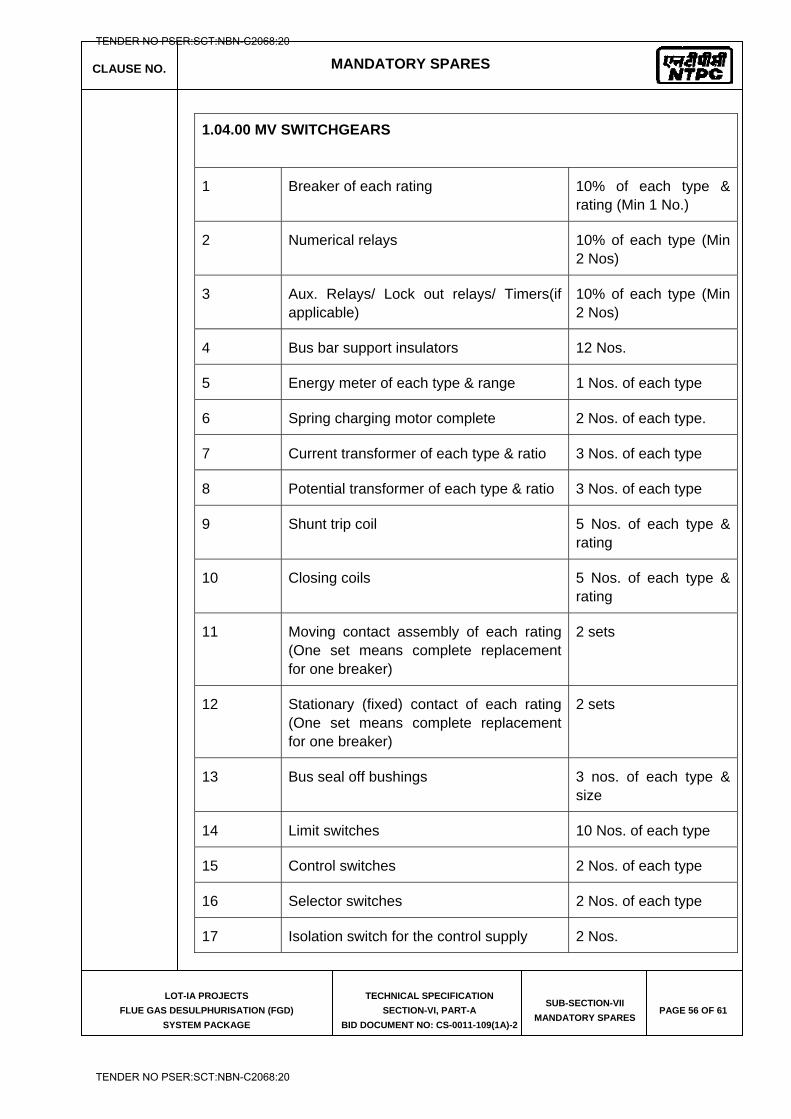
CLAUSE NO. MANDATORY SPARES
LOT-IA PROJECTS
FLUE GAS DESULPHURISATION (FGD)
SYSTEM PACKAGE
TECHNICAL SPECIFICATION
SECTION-VI, PART-A
BID DOCUMENT NO: CS-0011-109(1A)-2
SUB-SECTION-VII
MANDATORY SPARES PAGE 56 OF 61
1.04.00 MV SWITCHGEARS
1 Breaker of each rating 10% of each type & rating (Min 1 No.)
2 Numerical relays 10% of each type (Min 2 Nos)
3 Aux. Relays/ Lock out relays/ Timers(if applicable)
10% of each type (Min 2 Nos)
4 Bus bar support insulators 12 Nos.
5 Energy meter of each type & range 1 Nos. of each type
6 Spring charging motor complete 2 Nos. of each type.
7 Current transformer of each type & ratio 3 Nos. of each type
8 Potential transformer of each type & ratio 3 Nos. of each type
9 Shunt trip coil 5 Nos. of each type & rating
10 Closing coils 5 Nos. of each type & rating
11 Moving contact assembly of each rating (One set means complete replacement for one breaker)
2 sets
12 Stationary (fixed) contact of each rating (One set means complete replacement for one breaker)
2 sets
13 Bus seal off bushings 3 nos. of each type & size
14 Limit switches 10 Nos. of each type
15 Control switches 2 Nos. of each type
16 Selector switches 2 Nos. of each type
17 Isolation switch for the control supply 2 Nos.
TENDER NO PSER:SCT:NBN-C2068:20
TENDER NO PSER:SCT:NBN-C2068:20
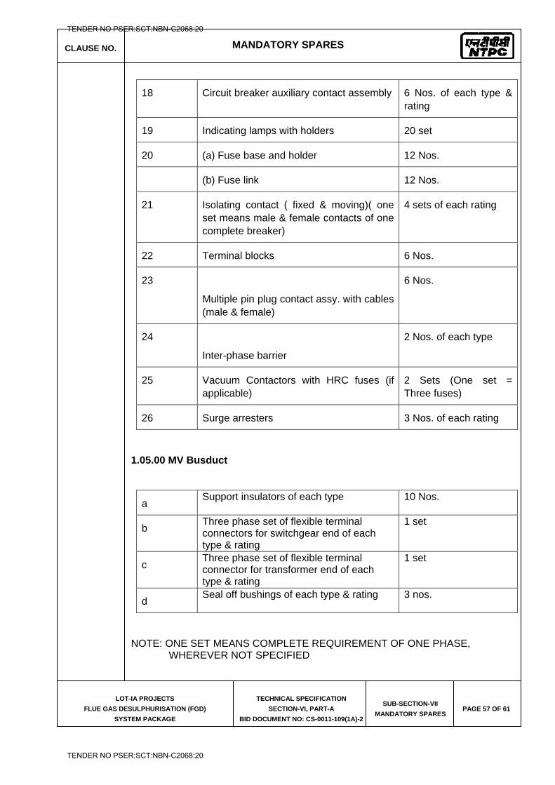
CLAUSE NO. MANDATORY SPARES
LOT-IA PROJECTS
FLUE GAS DESULPHURISATION (FGD)
SYSTEM PACKAGE
TECHNICAL SPECIFICATION
SECTION-VI, PART-A
BID DOCUMENT NO: CS-0011-109(1A)-2
SUB-SECTION-VII
MANDATORY SPARES PAGE 57 OF 61
18 Circuit breaker auxiliary contact assembly 6 Nos. of each type & rating
19 Indicating lamps with holders 20 set
20 (a) Fuse base and holder 12 Nos.
(b) Fuse link 12 Nos.
21 Isolating contact ( fixed & moving)( one set means male & female contacts of one complete breaker)
4 sets of each rating
22 Terminal blocks 6 Nos.
23
Multiple pin plug contact assy. with cables (male & female)
6 Nos.
24
Inter-phase barrier
2 Nos. of each type
25 Vacuum Contactors with HRC fuses (if applicable)
2 Sets (One set = Three fuses)
26 Surge arresters 3 Nos. of each rating
1.05.00 MV Busduct
a Support insulators of each type 10 Nos.
b Three phase set of flexible terminal connectors for switchgear end of each type & rating
1 set
c Three phase set of flexible terminal connector for transformer end of each type & rating
1 set
d Seal off bushings of each type & rating 3 nos.
NOTE: ONE SET MEANS COMPLETE REQUIREMENT OF ONE PHASE, WHEREVER NOT SPECIFIED
TENDER NO PSER:SCT:NBN-C2068:20
TENDER NO PSER:SCT:NBN-C2068:20
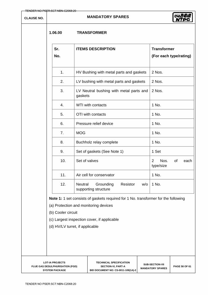
CLAUSE NO. MANDATORY SPARES
LOT-IA PROJECTS
FLUE GAS DESULPHURISATION (FGD)
SYSTEM PACKAGE
TECHNICAL SPECIFICATION
SECTION-VI, PART-A
BID DOCUMENT NO: CS-0011-109(1A)-2
SUB-SECTION-VII
MANDATORY SPARES PAGE 58 OF 61
1.06.00 TRANSFORMER
Sr.
No.
ITEMS DESCRIPTION
Transformer
(For each type/rating)
1. HV Bushing with metal parts and gaskets 2 Nos.
2. LV bushing with metal parts and gaskets 2 Nos.
3. LV Neutral bushing with metal parts and gaskets
2 Nos.
4. WTI with contacts 1 No.
5. OTI with contacts 1 No.
6. Pressure relief device 1 No.
7. MOG 1 No.
8. Buchholz relay complete 1 No.
9. Set of gaskets (See Note 1) 1 Set
10. Set of valves 2 Nos. of each type/size
11. Air cell for conservator 1 No.
12. Neutral Grounding Resistor w/o supporting structure
1 No.
Note 1: 1 set consists of gaskets required for 1 No. transformer for the following
(a) Protection and monitoring devices
(b) Cooler circuit
(c) Largest inspection cover, if applicable
(d) HV/LV turret, if applicable
TENDER NO PSER:SCT:NBN-C2068:20
TENDER NO PSER:SCT:NBN-C2068:20
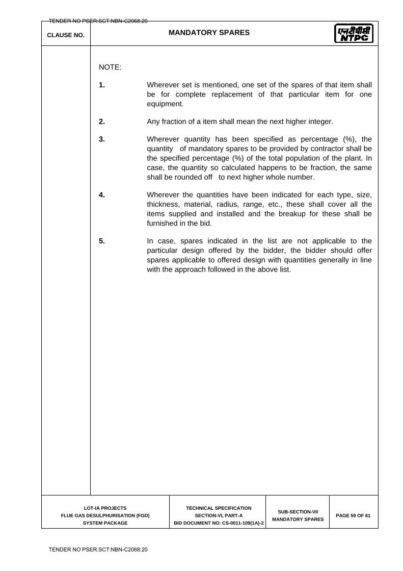
CLAUSE NO. MANDATORY SPARES
LOT-IA PROJECTS
FLUE GAS DESULPHURISATION (FGD)
SYSTEM PACKAGE
TECHNICAL SPECIFICATION
SECTION-VI, PART-A
BID DOCUMENT NO: CS-0011-109(1A)-2
SUB-SECTION-VII
MANDATORY SPARES PAGE 59 OF 61
NOTE:
1. Wherever set is mentioned, one set of the spares of that item shall be for complete replacement of that particular item for one equipment.
2. Any fraction of a item shall mean the next higher integer.
3. Wherever quantity has been specified as percentage (%), the quantity of mandatory spares to be provided by contractor shall be the specified percentage (%) of the total population of the plant. In case, the quantity so calculated happens to be fraction, the same shall be rounded off to next higher whole number.
4. Wherever the quantities have been indicated for each type, size, thickness, material, radius, range, etc., these shall cover all the items supplied and installed and the breakup for these shall be furnished in the bid.
5. In case, spares indicated in the list are not applicable to the particular design offered by the bidder, the bidder should offer spares applicable to offered design with quantities generally in line with the approach followed in the above list.
TENDER NO PSER:SCT:NBN-C2068:20
TENDER NO PSER:SCT:NBN-C2068:20
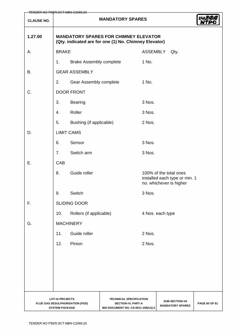
CLAUSE NO. MANDATORY SPARES
LOT-IA PROJECTS
FLUE GAS DESULPHURISATION (FGD)
SYSTEM PACKAGE
TECHNICAL SPECIFICATION
SECTION-VI, PART-A
BID DOCUMENT NO: CS-0011-109(1A)-2
SUB-SECTION-VII
MANDATORY SPARES PAGE 60 OF 61
1.27.00 MANDATORY SPARES FOR CHIMNEY ELEVATOR (Qty. indicated are for one (1) No. Chimney Elevator)
A. BRAKE ASSEMBLY Qty. 1. Brake Assembly complete 1 No. B. GEAR ASSEMBLY 2. Gear Assembly complete 1 No. C. DOOR FRONT 3. Bearing 3 Nos. 4. Roller 3 Nos. 5. Bushing (if applicable) 2 Nos. D. LIMIT CAMS 6. Sensor 3 Nos. 7. Switch arm 3 Nos. E. CAB 8. Guide roller 100% of the total ones installed each type or min. 1 no. whichever is higher 9. Switch 3 Nos. F. SLIDING DOOR 10. Rollers (if applicable) 4 Nos. each type G. MACHINERY 11. Guide roller 2 Nos. 12. Pinion 2 Nos.
TENDER NO PSER:SCT:NBN-C2068:20
TENDER NO PSER:SCT:NBN-C2068:20
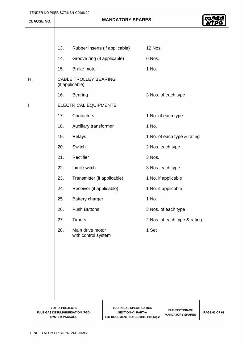
CLAUSE NO. MANDATORY SPARES
LOT-IA PROJECTS
FLUE GAS DESULPHURISATION (FGD)
SYSTEM PACKAGE
TECHNICAL SPECIFICATION
SECTION-VI, PART-A
BID DOCUMENT NO: CS-0011-109(1A)-2
SUB-SECTION-VII
MANDATORY SPARES PAGE 61 OF 61
13. Rubber inserts (if applicable) 12 Nos. 14. Groove ring (if applicable) 6 Nos. 15. Brake motor 1 No. H. CABLE TROLLEY BEARING (if applicable) 16. Bearing 3 Nos. of each type I. ELECTRICAL EQUIPMENTS 17. Contactors 1 No. of each type 18. Auxiliary transformer 1 No. 19. Relays 1 No. of each type & rating 20. Switch 2 Nos. each type 21. Rectifier 3 Nos. 22. Limit switch 3 Nos. each type 23. Transmitter (if applicable) 1 No. if applicable 24. Receiver (if applicable) 1 No. if applicable 25. Battery charger 1 No. 26. Push Buttons 3 Nos. of each type 27. Timers 2 Nos. of each type & rating 28. Main drive motor 1 Set with control system
TENDER NO PSER:SCT:NBN-C2068:20
TENDER NO PSER:SCT:NBN-C2068:20
NTPC Limited (A Government of India Enterprise)
LOT 1A PROJECTS
PART – B (DETAILED TECHNICAL SPECIFICATION)
SUB-SECTION-IV-D
(CIVIL WORKS)
SECTON – VI
TECHNICAL SPECIFICATION
FOR
FLUE GAS DESULPHURISATION (FGD)
SYSTEM PACKAGE
BIDDING DOCUMENT NO. : CS-0011-109(1A)-2
TENDER NO PSER:SCT:NBN-C2068:20
TENDER NO PSER:SCT:NBN-C2068:20
LOT-IA PROJECTS FLUE GAS DESULPHURISATION (FGD) SYSTEM PACKAGE
TECHNICAL SPECIFICATION
SECTION-VI
BID DOCUMENT NO.: CS-0011-109(1A)-2
PART – B (DETAILED TECHNICAL SPECIFICATION)
SUB-SECTION-IV-D (CIVIL WORKS)
TENDER NO PSER:SCT:NBN-C2068:20
TENDER NO PSER:SCT:NBN-C2068:20
LOT-IA PROJECTS FLUE GAS DESULPHURISATION (FGD) SYSTEM PACKAGE
TECHNICAL SPECIFICATION
SECTION-VI
BID DOCUMENT NO.: CS-0011-109(1A)-2
SUB-SECTION-IV-D
CIVIL WORKS
TENDER NO PSER:SCT:NBN-C2068:20
TENDER NO PSER:SCT:NBN-C2068:20
CLAUSE NO.
TECHNICAL REQUIREMENTS
LOT-1A PROJECTS
FLUE GAS DESULPHURISATION (FGD) SYSTEM PACKAGE
TECHNICAL SPECIFICATION
SECTION-VI, PART-B
BID DOCUMENT NO.: CS-0011-109(1A)-2
SUB-SECTION-IV-D
CIVIL WORKS
PAGE 1 OF 69
1.00.00 GENERAL
1.01.00 This section of the bidding document deals mainly with the technical specification for the design and preparation of detailed drawings, getting the design and drawings approved by the Employer, fabrication, erection and construction of the necessary civil, structural and architectural works associated with the FGD package for Lot-1A. The work shall have to be carried out both below and above ground level and shall be involving, basements, equipment foundations, slabs, beams, columns, footings, rafts, walls, steel frames, brick walls, stairs, trenches, pits, access roads, culverts, trestles, silos, sumps, Limestone storage hopper & shed, Crusher House, Transfer points, Conveyor Galleries, Tunnels, Gypsum storage shed, Chimney, Gypsum dewatering building, Ball Mill building, FGD control room building, Tank Foundations, absorber tower foundation, transformer foundation, MCC Building, finishes, complete architectural aspects, drainage, sanitation, water supply (from terminal points to various buildings/facilities) and all other civil, structural and architectural works associated with the complete FGD package.
1.02.00 The specifications are intended for the general description of the work, quality and workmanship. The specifications are not, however, intended to cover minutest details and the work shall be executed according to the relevant latest Indian Standard Codes / I. R. S. / I. R. C. specifications. In absence of the above, the work shall be executed according to the best prevailing local Public Works Department practices or to the recommendations of relevant American and British Standards or to the instructions of the Engineer. Some of the relevent I. S. Codes to be followed is mentioned in the Technical Specifications. The Contractor is expected to get clarified on any doubts about the specifications, etc. before bidding, in writing with the Employer in respect of interpretation of any portions of this document.
1.03.00 Bidder or his agencies engaged as detailer for fabrication drawings should have the experience of detailing for power plant structures or steel plant or Industrial structures like Petro/ Chemical/ Refinery/ Cement/FGD Plant/Coal Handling Plant/Ash Handling Plant etc.
The designer responsible for preparation of scope drawings shall review and approve the fabrication drawings prepared by the detailer before releasing them for fabrication.
2.00.00 Sub QR for Civil Works:
2.01.00 Bidder or its agency should have in past executed civil and structural works for 500 MW or higher capacity coal based/Lignite based power plant including earthwork in filling involving mechanical compaction and cutting in hard rock, foundations, Bulk material handling plant involving underground storage hopper and underground tunnels.
2.02.00 Bidder can engage more than one agency, in case the Bidder itself is not able to meet the requirement at 2.01.00. The agency being engaged for a particular work should have in the past executed such works of 500 MW or higher capacity plant.
TENDER NO PSER:SCT:NBN-C2068:20
TENDER NO PSER:SCT:NBN-C2068:20
CLAUSE NO.
TECHNICAL REQUIREMENTS
LOT-1A PROJECTS
FLUE GAS DESULPHURISATION (FGD) SYSTEM PACKAGE
TECHNICAL SPECIFICATION
SECTION-VI, PART-B
BID DOCUMENT NO.: CS-0011-109(1A)-2
SUB-SECTION-IV-D
CIVIL WORKS
PAGE 2 OF 69
2.03.00 For Chimney, Bidder or its agency should have in the past built at least one (1) reinforced concrete chimney of minimum 100m height.
2.04.00 In case Bidder or its agency do not meet the requirements at 2.01.00 and the Bidder proposes to engage agency (ies) for civil & structural works on work volume basis (except for Chimney), Bidder or its agency (ies) should have executed such works in the past and the annual rate of execution in the reference works should not be less than eighty percent (80%) of the asking rate of such works, (structural steel fabrication & erection, RCC, earthwork in filling involving mechanical compaction and cutting in hard rock, RCC in underground storage hopper and underground tunnels ) for which it is being engaged.
Successful Bidder shall finalize the agency (ies) for each work in consultation with Engineer-in-charge at site before engaging them.
Design agency for Civil & Steel Structural Works:
2.05.00 Bidder or its agency (ies) should have carried out the design and detailed engineering of following works:
(i) Civil & Structural works associated with at least one bulk material handling plant for 500 MW or higher capacity coal based/Lignite based power plant.
(ii) For Chimney, Bidder or its design agency (ies) should have carried out design & detailed engineering of at least one reinforced concrete chimney with steel flues, of minimum 100m height.
(iii) Machine foundations such as Mill foundations/ Block foundations.
2.06.00 Bidder can engage more than one agency (of repute), in case the Bidder itself is not able to meet the requirement at 2.05.00.
The design agency (ies) proposed by the Bidder shall be subject to Employer’s approval.
3.00.00 Work Description
3.01.00 Truck Hopper, Limestone Storage hopper and Underground Tunnel
Truck Hopper shall consist of underground portion, which shall be of R. C. C. with structural steel shed covered with permanently Colour coated profiled steel sheets.
Limestone storage hopper shall be of RCC with structural steel shed covered with permanently Colour coated profiled steel sheets.
The structural arrangement to be adopted for the design and construction of Limestone Storage hopper shall essentially consist of R. C. C. frames spaced at approx. 3.0M centers with R. C. C. wall panels on the sides and R. C. C. raft at the bottom, fixed to the frames. Minimum thickness of R. C. C. raft at bottom shall be 600
TENDER NO PSER:SCT:NBN-C2068:20
TENDER NO PSER:SCT:NBN-C2068:20
CLAUSE NO.
TECHNICAL REQUIREMENTS
LOT-1A PROJECTS
FLUE GAS DESULPHURISATION (FGD) SYSTEM PACKAGE
TECHNICAL SPECIFICATION
SECTION-VI, PART-B
BID DOCUMENT NO.: CS-0011-109(1A)-2
SUB-SECTION-IV-D
CIVIL WORKS
PAGE 3 OF 69
mm. Minimum thickness of RCC side walls shall be 600 mm at bottom and 300 mm at top.
The vertical and inclined portion of hopper shall be provided with 50 mm thick guniting (shotcreting). Details of shotcreting have been given elsewhere in this specification.
Expansion joints shall be provided at a maximum distance of 40m. 600 mm wide water stop fabricated with 22G copper plate with bitumen board fillers and polysulphide sealing compound as specified elsewhere shall be used as expansion joint material.
Floor shall be provided with cross slope not flatter than 1 in 50 towards side drains. Side drains shall be sloped towards sump where sump pumps as specified elsewhere, shall be provided. The slope of side drains shall not be flatter than 1 in 400. Side drains and sump shall have removable type steel grating cover.
Water proofing / Damp proofing of under ground Truck hopper, Limestone Storage hopper, tunnels and underground (i. e. basement) portion of transfer houses shall be done by providing the following treatments:
Chemical injection grouting for inner faces (details as specified elsewhere).
Polymer modified cementitious coating on earth side face as per the following :
(1) On the outer surface of walls, frames and roof slabs coming in contact with earth, polymer modified cementitious coating in two layers as specified and as per manufacturer’s specifications shall be provided directly on the concrete surface.
(2) 50 mm thick P. C. C. (1 : 2 : 4 with 10 mm nominal size stone aggregates) shall be provided under the raft i.e. over the lean concrete, followed by polymer modified cementitious coating in two layers ( slurry mix application ) as per manufacturer’s specification. 50 mm thick P. C. C. ( 1 : 2 : 4 ) with 10 mm nominal size stone aggregates shall then be laid over the polymer modified cementitious coating before laying the raft.
Truck hopper and its gratings shall be designed for movement of front end loader/ bulldozer over them. Bull dozer weight shall be considered as about 35T. The gratings shall be built of min. 200x28mm thick flats in main direction and min.100mm x 20mm thick in secondary direction. No painting/galvanization shall be provided in gratings. However, two coats of Red oxide Primer to be provided immediately after fabrication.
Plinth protection along with drains shall be provided along the Hopper complex. However, 5m wide paving shall also be provided around machinery hatches.
Earth pressure to be considered for design shall be due to earth pressure at rest (Ko) condition only. Earth pressure due to surcharge intensity of Uniformly Distributed Load (U. D. L) of intensity 2 T / Sq. M. shall be considered in the design.
A minimum safety factor of 1.2 against uplift due to ground water shall be ensured during execution and after execution, considering dead weight of the structure to be
TENDER NO PSER:SCT:NBN-C2068:20
TENDER NO PSER:SCT:NBN-C2068:20
CLAUSE NO.
TECHNICAL REQUIREMENTS
LOT-1A PROJECTS
FLUE GAS DESULPHURISATION (FGD) SYSTEM PACKAGE
TECHNICAL SPECIFICATION
SECTION-VI, PART-B
BID DOCUMENT NO.: CS-0011-109(1A)-2
SUB-SECTION-IV-D
CIVIL WORKS
PAGE 4 OF 69
0.9 times only, ground water table to be taken at adjoining formation level and soil wedge angle of not more than 15 degrees.
Also, FOS against uplift, to be taken as 1.0, considering the dead wt. of structure and soil resting on side projections if any in the vertical plane. Inclined wedge action of soil shall not be considered in this case.
Wherever, slope of tunnel exceeds 10o, R. C. C. steps shall be provided for the entire width of each walkway.
3.02.00 Overhead / Ground Conveyor Galleries and Trestles
Overhead conveyors shall be located in a suitably enclosed gallery of structural steel. The overhead gallery shall consist of two vertical latticed girders having rigid jointed portal frame at both ends. Cross beams at floor level supporting conveyor stringer beams shall be made of single rolled steel beam or single channel section (ISMB or ISMC) or plate girder. Horizontal bracings are to be provided at top & bottom plan of the gallery (latticed girders shall be braced together in plan at the top and bottom). Common end portal frame shall not be used for adjacent conveyor spans. Roof truss shall be provided at upper node points of latticed girders to form an enclosure. Contractor can also use tubular steel sections for roof truss only of conveyor galleries. The tubular steel section shall be of circular/rectangular/square shape. The circular steel tube shall conform to IS 1161 and rectangular/square steel sections shall conform to IS 4923. The steel structures using tubular sections shall be designed and fabricated as per IS 806 – “Code of Practice for use of steel tubes in general building construction.” and EN 1993-1-8:2005. The maximum span of overhead gallery shall be limited to 25 meters unless higher span is required due to site conditions, which shall be subject to approval of the Engineer. The gallery should as far as possible be erected as a box section keeping all the vertical and horizontal bracing tied in proper position. The gallery should be checked for all erection stresses that are likely to develop during handling and erection and if required, temporary strengthening of gallery members during erection shall be made.
Seal plates under the conveyor galleries shall be provided in such a way that complete gallery bottom shall form a leak proof floor.
The ground conveyors shall be located in suitably enclosed gallery of structural steel consisting of rigid portal frames spaced at regular intervals and suitably braced. Plinth protection along with drains shall be routed along the ground conveyors.
For double stream conveyor gallery, two side and one central walkway of width 800 mm and 1100 mm respectively shall be provided. The width of two side walkways for single stream conveyor gallery shall be 800 mm and 1100 mm respectively. Both sides of central and side walkways shall be provided with pipe handrails all along the conveyor gallery. Hand railing should not be supported on conveyor supporting stringers. The walkways shall be chequered plate construction with anti - skid arrangement. The anti - skid arrangement will consist of welding of 10 mm square steel bars at a maximum spacing of 500 mm along the length of the gallery. Where the slope of walkway is more than 10o, chequered plate steps with nosing and toe guard shall be provided. The floor of conveyor gallery all along the gallery length, shall be provided with minimum 12 gauge thick seal plates and other drainage arrangements as specified elsewhere
TENDER NO PSER:SCT:NBN-C2068:20
TENDER NO PSER:SCT:NBN-C2068:20
CLAUSE NO.
TECHNICAL REQUIREMENTS
LOT-1A PROJECTS
FLUE GAS DESULPHURISATION (FGD) SYSTEM PACKAGE
TECHNICAL SPECIFICATION
SECTION-VI, PART-B
BID DOCUMENT NO.: CS-0011-109(1A)-2
SUB-SECTION-IV-D
CIVIL WORKS
PAGE 5 OF 69
Conveyor gallery shall have permanently colour coated steel sheet covers on roof and both sides. However in roof, a panel of minimum 1.5 m x 1.5 m area at about 6.0 m center shall be provided with translucent sheets of polycarbonate material for natural lighting. A continuous slit opening of 500 mm shall be provided on both sides just below the roof sheeting. Adequate provision of windows shall be kept on both sides of conveyor gallery as appended in Mechanical Section (Belt conveyor system). Windows shall be provided with wire mesh as specified elsewhere in this specification.
Cross - over with chequered plate platform and ladder for crossing over the conveyors shall be provided at approximately every 100 M intervals of conveyor. Crossover shall preferably be located over four-legged rigid trestle location.
For railway tracks passing below overhead conveyor gallery and along conveyors, the railway clearances both underground as well as over ground shall have to be adhered to for design, execution and erection of foundations, trestles, galleries etc., so that movement of locomotives and wagons is not hampered in any way during execution and afterwards. However at the location where the overhead conveyor gallery crosses road / rail line, minimum clearance of 8.0m above the road crest / rail top shall be provided.
For calculation of material load on moving conveyor, a multiplication factor 1.6 shall be used to take care of inertia force, casual over burden and impact factor etc.
Thus material load per unit length of each moving conveyor shall be
Rated capacity of conveyor system
1.6 X ---------------------------------------------------------- x F
Conveyor Belt Speed
Where, F = 1700/1400 for lime & 1250/900 for gypsum
It should be noted that for structural design, unit weight of lime shall be assumed as 1700 Kgs. / Cu. M. instead of 1400 Kgs. / Cu. M., unit weight of gypsum shall be assumed as 1250 Kgs. / Cu. M. instead of 900 Kgs. / Cu. M. considered for system sizing purpose. Conveyor Gallery structure shall be designed considering both conveyors operating simultaneously.
Conveyor gallery and supporting trestles located between transfer houses / buildings shall be arranged in any one of the following ways.
a) All gallery supporting trestles shall be four legged type only. One end of each gallery span shall be hinged to the supporting trestle and the other end shall be slide type. Slide type support shall be with P. T. F. E. bearings to allow both rotation & longitudinal movements.
TENDER NO PSER:SCT:NBN-C2068:20
TENDER NO PSER:SCT:NBN-C2068:20
CLAUSE NO.
TECHNICAL REQUIREMENTS
LOT-1A PROJECTS
FLUE GAS DESULPHURISATION (FGD) SYSTEM PACKAGE
TECHNICAL SPECIFICATION
SECTION-VI, PART-B
BID DOCUMENT NO.: CS-0011-109(1A)-2
SUB-SECTION-IV-D
CIVIL WORKS
PAGE 6 OF 69
b) In between transfer houses / buildings, four legged trestles shall be placed at a maximum interval of 90 metres. The arrangement shall be such so as to ensure that force in the longitudinal direction (i. e. along the conveyor length) of conveyor gallery of length not more than 90 m is transferred to any four legged trestle. In the space between each successive four legged trestles, two legged trestles shall be provided at regular intervals. The end supports resting on the four-legged trestle can have either ends hinged or one hinge and the other on slide type depending on the arrangements. Slide type support shall be with P. T. F. E. bearings to allow both rotation & longitudinal movements.
End of conveyor gallery which will be supported over transfer house, shall be so detailed that only vertical reaction is transferred from conveyor gallery and no horizontal force in longitudinal direction is transferred from conveyor gallery to transfer house structure and vice - versa.
For trestles and trestle foundations for conveyor galleries located adjacent to existing structures, over ground and under ground facilities, location and details of these trestles and foundations shall have to be decided such that there is no interference both underground as well as over ground with existing structures and facilities. Trestle columns / ground conveyor portal column base shall be kept 300 mm higher than the existing ground level.
3.03.00 Transfer Houses
The over ground portion of the transfer house shall be framed structure of structural steel work with permanently colour coated profiled steel sheet side cladding (from lowest working floor level till top) and R. C. C. floors comprising of RCC slab over profiled metal deck sheets (to be used as permanent shuttering) over structural beams. Shear anchor studs shall be provided through metal deck at regular interval on all top flange/flange plate of structural beams. However, the lower portion of side cladding, at ground, for a minimum height of 0.9 m above the finished floor level shall be one brick thick wall plastered on both side. In some areas like MCC floors etc., one brick thick wall cladding shall be provided. Brick wall cladding shall be supported on encased wall beams and suitably anchored to adjoining columns and beams. Contractor shall have option to use tubular steel sections for roof truss only. Vertical bracings shall be provided only on four sides along the periphery. Grade slab with 0.9m height one brick thick wall plastered on both side at periphery shall be provided for all transfer houses.
Adequate steel doors and windows for proper natural lighting and ventilation shall be provided. In addition to steel windows, panels of suitable size to suit the architectural treatment and made of translucent sheets of polycarbonate material shall also be provided on the side cladding for natural lighting.
The roof of Transfer points shall be provided with pre-fabricated insulated metal sandwich panels. Composition of Insulated Metal Sandwich Panels shall be as described elsewhere in the Technical Specification. Adequate slope shall be provided for quick drainage of rain water.
TENDER NO PSER:SCT:NBN-C2068:20
TENDER NO PSER:SCT:NBN-C2068:20
CLAUSE NO.
TECHNICAL REQUIREMENTS
LOT-1A PROJECTS
FLUE GAS DESULPHURISATION (FGD) SYSTEM PACKAGE
TECHNICAL SPECIFICATION
SECTION-VI, PART-B
BID DOCUMENT NO.: CS-0011-109(1A)-2
SUB-SECTION-IV-D
CIVIL WORKS
PAGE 7 OF 69
3.04.00 Crusher House
The crusher house shall be framed structure of structural steel work with permanently colour coated profiled steel sheet side cladding. However, panels of suitable size to suit the architectural treatment and made of translucent sheets of polycarbonate material shall also be provided on the side cladding for natural lighting. The lower portion of side cladding, at ground, for a height of minimum 0.9m above the finished floor level shall be of one brick thick wall plastered on both faces. Floors shall be of R. C. C. slab over profiled metal deck sheets (to be used as permanent shuttering) over structural beams. Shear anchor studs shall be provided through metal deck at regular interval on all top flange/flange plate of structural beams. Within this building cubicles are to be provided for resting room of operators and these shall be constructed with one brick thick brickwork having both sides plastered and roof slab. Adequate steel doors and windows for natural lighting and ventilation shall be provided. Contractor shall have option to use tubular steel sections for roof truss only . Vertical bracings shall be provided only on four sides along the periphery.
The roof of Crusher house shall be provided with pre-fabricated insulated metal sandwich panels. Composition of Insulated Metal Sandwich Panels shall be as described elsewhere in the Technical Specification. Adequate slope shall be provided for quick drainage of rain water.
Crushers shall be supported on R. C. C. deck, which in turn will rest on suitable vibration isolation system consisting of springs and dampers. This R. C. C. deck shall be isolated from the floor. However, the vibration isolation system consisting of springs and dampers may rest on main building framework. Detailed specification of vibration isolation system including the unbalanced force, frequency and amplitude criteria and other design requirements are appended elsewhere in this specification
3.05.00 Control building, M. C. C. Buildings
These shall be steel or RCC framed building with R. C. C. roof and floor. For steel framed building roof /floor shall comprise of RCC slab over profiled metal deck sheets (to be used as permanent shuttering only ) over structural beams. Cladding shall be of brickwork/concrete blockwork with plastering on both sides. Roof shall be provided with roof water proofing treatment, as specified elsewhere in the Technical specification. Suitable arrangement shall be provided so as to prevent ingress of water into the cable trenches inside the building from cable entry locations.
All air - conditioned areas, shall be provided with the suspended permanently colour coated aluminium false ceiling system (details specified elsewhere) with under deck insulation.
Adequate aluminium doors and windows shall be provided for natural lighting, ventilation and view. All windows in air conditioned rooms shall have hermetically sealed double glazing.
3.06.00 Pent House
These shall be of R. C. C. framed structures with columns, beams, slabs and foundations etc. Cladding shall be of brickwork with plastering on both sides. Roof
TENDER NO PSER:SCT:NBN-C2068:20
TENDER NO PSER:SCT:NBN-C2068:20
CLAUSE NO.
TECHNICAL REQUIREMENTS
LOT-1A PROJECTS
FLUE GAS DESULPHURISATION (FGD) SYSTEM PACKAGE
TECHNICAL SPECIFICATION
SECTION-VI, PART-B
BID DOCUMENT NO.: CS-0011-109(1A)-2
SUB-SECTION-IV-D
CIVIL WORKS
PAGE 8 OF 69
shall be provided with roof water proofing treatment as specified elsewhere. Adequate nos. of steel doors and windows shall be provided for natural lighting and ventilation.
3.07.00 Gypsum Storage Shed
The Gypsum storage shed shall be RCC framed structure with structural steel work shed with permanently colour coated profiled steel sheet roof and side cladding, grade slab and RCC foundations etc. Roof shall be provided with troughed profile permanently colour coated sheet with adequate slope for quick drainage of rain water.
3.08.00 Toilets
Toilet with potable water line facilities shall be provided in each of the following locations:
(a.) In all M. C. C. Rooms
(b.) Control Building
3.09.00 Staircases, Gratings, Handrails
All floors of transfer points/crusher houses and other facility buildings shall be accessible through staircase. All staircases of Transfer points and crusher house shall be of steel. Cage ladders (min. 450mm wide) shall be provided for access to roof of penthouses, single storey mcc rooms & mumty. All Stairs shall be minimum 1200 mm wide, maximum rise should not be more than 180 mm and minimum tread with 250 mm. Numbers and arrangement (including enclosures etc.) of stair cases shall be such as to meet the fire safety requirement as per guide lines of statutory regulatory bodies. For steel staircases , Stringers shall be of rolled steel channel ( minimum ISMC 250) and tread shall be of steel gratings. Out side stairs to transfer points/crusher house shall be open type. Minimum 50 x 50 x 6 mm size angles with lugs shall be provided as edge protection for treads of stairs in underground TP's
All gratings shall be electro forged types. Minimum thickness of the grating shall be 40 mm for indoor installation and 32 mm for outdoor installation. However, at entry or road crossing point’s minimum thickness of grating shall be 40 mm The opening size shall not be more than 30mmx100mm. The minimum thickness of the main bearing bar shall be 6 mm or as per design requirement whichever is higher. All gratings shall be designed for minimum imposed load of 500Kgs. / Sq. M. If actual expected load is more than the specified load, then actual load is to be considered. All gratings shall be hot dip galvanized at the rate of 610 g. per sq.m. after surface preparation by means of blast cleaning/ acid pickling.
Minimum 1000 mm high hand railing shall be provided around all openings, projections / balconies, walkways, platforms, Stairs, etc. All handrails and ladder Pipes shall be 32 mm nominal bore MS Pipes (medium class) as per IS:1161. Handrails shall have top and middle rails at a height of 1000 mm and 500 mm and the vertical post spacing shall not exceed 1.50 M, with provision of kick Plates (100
TENDER NO PSER:SCT:NBN-C2068:20
TENDER NO PSER:SCT:NBN-C2068:20
CLAUSE NO.
TECHNICAL REQUIREMENTS
LOT-1A PROJECTS
FLUE GAS DESULPHURISATION (FGD) SYSTEM PACKAGE
TECHNICAL SPECIFICATION
SECTION-VI, PART-B
BID DOCUMENT NO.: CS-0011-109(1A)-2
SUB-SECTION-IV-D
CIVIL WORKS
PAGE 9 OF 69
mm high and 6 mm thick). All handrails and ladders shall be galvanised at the rate of 610 Gms / Sq. M as per IS:4736.
3.10.00 Trenches
All trenches for cables or any other underground facility as detailed out elsewhere shall be of R. C. C. Cable trenches shall be provided with pre - cast R. C. C. covers / chequered plate cover. Cable trenches as well as pre - cast covers shall be provided with edge protection angles and lifting hooks. All embedments / block outs as required and specified elsewhere in these specifications shall be provided. Proper drainage arrangement shall be provided. Trench pre - cast cover weight shall not be more than 65 Kgs. Trench covers near entry or at road crossings shall be designed for 10 T wheel load at centre. Pre - cast covers shall be designed for central point load of 75 Kgs. R. C. C. cable trenches shall be filled with sand after erection of cables, up to top level and covered with pre - cast R. C. C. covers. For cable trenches outside buildings, top level shall be 200 mm above G. L and sand filling shall be overlaid with 50 thk. PCC.
Minimum 50 x 50 x 6 mm size angles with lugs shall be provided as edge protection all around cut outs / openings in floor slabs, edges of drains supporting grating/precast RCC covers, edges of R. C. C. trenches supporting pre - cast covers, supported edges of pre - cast cover
3.11.00 Cable gallery/trestles
Cable galleries/trestles shall be made of structural steel. The contractor can use either rolled sections or tubular steel sections. The tubular steel section shall be of circular/rectangular/square shape. The circular steel tube shall conform to IS:1161 and rectangular/square steel sections shall confirm to IS:4923. The steel structures using tubular sections shall be designed and fabricated as per IS:806 – “Code of Practice for use of steel tubes in general building construction.” and EN 1993-1-8:2005.
3.12.00 Transformer Foundation
3.12.01 Foundations of transformers shall be designed for seismic and wind loads in addition to other applicable loads. Block foundations shall be provided for the main transformer block. The oil soak pit, if provided, shall be filled with gravel of size 40mm. The volume of the soak pit shall be sufficient to store complete oil of the transformer/reactor along with 10 minutes of fire water considering only 40% of the volume as available voids between gravel filling. However, in case a separate oil collection tank is provided for the transformer/reactor, oil soak pit of volume equivalent to one-third (1/3) the oil volume of transformer/reactor shall be provided around transformer/reactor. The oil collection tank, in such cases, shall be designed for an effective capacity of complete oil of the transformer along with 10 minutes of fire water. The oil soak pit shall also be provided with a sump at the corner to allow drainage of water/oil from the soak pit. Arrangement for moving the transformer into place using rail cum road, jacking pads and pulling blocks including inserts, as required, shall be provided along with the transformer/ reactor foundations.
TENDER NO PSER:SCT:NBN-C2068:20
TENDER NO PSER:SCT:NBN-C2068:20
CLAUSE NO.
TECHNICAL REQUIREMENTS
LOT-1A PROJECTS
FLUE GAS DESULPHURISATION (FGD) SYSTEM PACKAGE
TECHNICAL SPECIFICATION
SECTION-VI, PART-B
BID DOCUMENT NO.: CS-0011-109(1A)-2
SUB-SECTION-IV-D
CIVIL WORKS
PAGE 10 OF 69
RCC Firewall shall also be provided between the transformers wherever required. 300 mm thick PCC M20 encasement all around the Pylon supports inside soak pit for fire fighting system shall be provided up to top of gravel filling. Coarse aggregate filling inside the transformer oil soak pit shall be carried out only after construction/erection of Pylon supports and PCC encasement.
3.12.02 Fencing
Fencing with toe wall and steel gates shall be provided around the transformers. Fencing shall comprise of PVC coated GI chain link fencing of minimum 8G (including PVC coating) of mesh size 75 mm and of height 2.4 m above the toe wall. The diameter of the steel wire for chain link fence (excluding PVC coating) shall not be less than 12G. Fence posts shall be of pre – cast R. C. C. of minimum M20 grade. All corner posts will have two stay posts and every tenth post will have transverse stay post. Suitable R. C. C. foundation for the post and stays shall be provided based on prevailing soil conditions. Gates shall be sturdy with locking provisions.
Toe walls of brick masonry shall be provided between fence posts all along the run of the fence with suitable foundation. Toe wall shall be minimum 200 mm above the formation level with 50 mm thick P. C. C. coping (1: 1. 5: 3) and shall extend minimum 300 mm below the formation level. Toe wall shall be plastered on both sides and painted with two coats of cement paint of approved colour and shade. Toe wall shall be provided with weep holes at suitable spacing
3.13.00 Booster Fan Foundation Booster Fan foundations shall be RCC block foundation directly resting on virgin soil/ pile below Ground level. The vertical faces of this block foundation shall be isolated from adjacent footings by providing minimum 100mm thick polystyrene board of type-1 conforming to IS: 4671 with density 20 Kg/cum sandwiched between the vertical face of block foundation and 230 thick brick wall all round.
3.14.00 CHIMNEY
3.14.01 Salient Features
Single-flue or multi-flue chimney(s) shall be provided. Chimney shall be of reinforced concrete construction. There shall be one flue (liner) for each unit. The flue gas emission point shall be minimum 150 meters above the plant grade level.
The chimney shell (windshield) shall be constructed using slip form shuttering. Internal platforms of steel structure shall be provided for enabling access to various elevations of the chimney and to provide support to the flue liners. Spacing of internal platforms shall not exceed 45.0 M. The platform beams shall be supported on concrete shell using suitable load bearing arrangement in the recesses provided for the purpose. The platform beams getting supported in the chimney shell shall have complete bearing support within the thickness of shell at that location and shall in no case be supported completely/partially on corbels/ brackets from the shell. "Through openings" in shell if provided to facilitate erection of platform beams shall be closed with cast-in-situ RCC closure wall on the external face of the shell. Necessary dowel
TENDER NO PSER:SCT:NBN-C2068:20
TENDER NO PSER:SCT:NBN-C2068:20
CLAUSE NO.
TECHNICAL REQUIREMENTS
LOT-1A PROJECTS
FLUE GAS DESULPHURISATION (FGD) SYSTEM PACKAGE
TECHNICAL SPECIFICATION
SECTION-VI, PART-B
BID DOCUMENT NO.: CS-0011-109(1A)-2
SUB-SECTION-IV-D
CIVIL WORKS
PAGE 11 OF 69
bars shall be provided in the shell during construction for this purpose. Openings in the concrete shell for flue duct entry, access door & truck entry door at ground level, air ventilation etc shall be provided. Hand railing shall be provided all around internal staircase & around the ventilation voids in the internal platform using min. 32 mm nominal bore MS pipes of medium class conforming to IS:1161. Spacing of railing posts shall not be more than 1500 mm centre to centre with a minimum height of 1200 mm. The handrail shall have three rows of horizontal members between the railing posts including the top member. Kick plate of min. size 100x6 thick shall be provided in the hand railing.
The flue duct outside the chimney shall be suitably connected to the flue liner inside the chimney through a transition duct. The transition duct shall be bottom supported and shall be profiled into a circular shape to connect to the flue liner. The flue duct shall be so designed that no load is transferred on the chimney shell due to the duct. The interface between the flue liner and the transition ducting shall be provided with non-metallic fluroelastomeric fabric expansion joint.
The expansion joint in the flue liner shall comprise of non-metallic fluoroelastomeric material suitable to withstand a temperature of 300 Deg C, shall be acid resistant to withstand acidic flue gas condensates arising out of flue gas parameters & operating conditions as specified elsewhere in the specification and shall also prevent dust accumulation. The space between the expansion joint material and the liner shall be packed and sealed by providing a bolster made up of light weight compressible material suitable to withstand a temperature of 300 Deg C and acid resistant to withstand acidic flue gas condensates arising out of flue gas parameters & operating conditions as specified elsewhere in the specification. The bolster shall be confined in texturized glass fabric having a final covering of stainless steel wire mesh.
Chimney roof shall be of RCC slab over a grid of structural steel beams and provided with rainwater drainage system. An internal structural steel staircase supported from chimney shell with chequered plate floor panels and pipe handrails, shall be provided for full height of the chimney and an internal cage ladder for a small height, over last staircase landing to access the chimney roof through a roof access hatch.
The other components of the chimney include liner test ports (for continuous pollution monitoring), liner hatches, grade level slab of RCC with metallic hardener floor finish, acid resistant treatment on roof slab, a large electrically operated grill type roll-up door and personnel access metallic door at grade level, roof drain basin, rain water down comer pipe (150 mm diameter galvanized pipe), connection to plant drains, louvers with bird screens for ventilation and all other openings in the wind shield, mild steel wind strakes (if required), all finishing works, electrical power distribution boards, lighting panels, power & control cabling and wiring systems, stair and platforms lighting, socket outlet, lightning protection and grounding system, aviation obstruction lighting with photoelectric controller etc, communication system, a rack and pinion elevator and other items, though not specifically mentioned but reasonably implied and necessary to complete the job in all respects.
Aviation Warning Lights (AWL) shall be mounted on door panel of required size (open able from interior of chimney shell) fixed to openings in the chimney shell at locations and levels specified elsewhere. Suitable provision for approach to the AWL shall be provided at the platform level. AWL shall be located at about 1-1.5 metre above the top of platform to enable easy handling for maintenance.
The size of roll-up door shall be determined based on minimum requirement for ventilation and transportation & erection of flue segments.
TENDER NO PSER:SCT:NBN-C2068:20
TENDER NO PSER:SCT:NBN-C2068:20
CLAUSE NO.
TECHNICAL REQUIREMENTS
LOT-1A PROJECTS
FLUE GAS DESULPHURISATION (FGD) SYSTEM PACKAGE
TECHNICAL SPECIFICATION
SECTION-VI, PART-B
BID DOCUMENT NO.: CS-0011-109(1A)-2
SUB-SECTION-IV-D
CIVIL WORKS
PAGE 12 OF 69
3.14.02 Design Concept
Design and construction of various components and systems of the chimney shall be in accordance with relevant Indian Standard and where provisions are not covered in Indian Standard, reference shall be made to ACI, BS, CICIND and other international standards.
In case of any conflict between this document and the Indian and International Standards, the stipulations of this document shall prevail.
Imposed loading for design of all chimney components shall not be less than 5 kN/ Sq.m. An additional 25% of liner load shall be taken as impact loading for liner erection in addition to the liner load.
The min. thickness of web for plate girders shall be kept as 12 mm.
Seismic forces on the chimney system shall be determined based on site specific seismic information provided elsewhere in this document.
Wind forces on the chimney system shall be determined based on site specific wind design criteria provided elsewhere in this document.
The chimney and its components shall be designed to resist the most onerous forces resulting from all the possible combinations of the various loadings. Design of all chimney components shall be based on working stress method.
3.14.03 Wind Shield
The wind shield shall be designed for vertical loading, cross wind loading, seismic loading, circumferential wind loading, thermal gradients etc. The load calculation and load combinations shall be as detailed in IS 4998 (Part 1) : 1992. The wind shield shall be analysed for cases with and without flue liner loads.
Forces/stresses in the wind shield due to eccentricity effects of local (e.g. corbel) loadings, insolations effects, rotation of chimney foundations, construction tolerances and moments of second order shall also be considered.
Seismic response of the chimney shall be computed by the response spectrum method. At least, the first five modes of vibrations shall be used for this analysis.
The cross wind analysis of the chimney shall be carried out irrespective of the value of the Scruton Number for the chimney and other empirical considerations which suggest structural immunity to cross wind oscillations.
The effect of the openings/cut-outs in the chimney shell shall be duly considered in the design of the windshield. The minimum thickness of shell shall not be less than 500mm.
The stresses for the shell design shall not exceed the limits given in Cl. 7.0 of IS:4998 (PART-I) 1975 for various combinations of loads, excepting the stress in concrete for the case of dead load + wind load which shall not exceed 0.30fck where fck is the characteristic compressive strength of concrete.
The minimum vertical reinforcement shall be 0.3% of the concrete area. The maximum spacing of the reinforcement bars shall not be more than 250 mm on each face. The minimum circumferential reinforcement shall be 0.2% of the concrete area. The maximum spacing of the reinforcement bars shall not be more than 200 mm on each face. The circumferential reinforcement in the top 3 meters of the windshield
TENDER NO PSER:SCT:NBN-C2068:20
TENDER NO PSER:SCT:NBN-C2068:20
CLAUSE NO.
TECHNICAL REQUIREMENTS
LOT-1A PROJECTS
FLUE GAS DESULPHURISATION (FGD) SYSTEM PACKAGE
TECHNICAL SPECIFICATION
SECTION-VI, PART-B
BID DOCUMENT NO.: CS-0011-109(1A)-2
SUB-SECTION-IV-D
CIVIL WORKS
PAGE 13 OF 69
shall be twice that required from design forces. The clear cover to reinforcement shall be 50 mm.
There shall be a continuous ring of concrete shell without any opening for a height of atleast 5m below the soffit of flue duct openings.
There shall not be any reverse (outward) slope in the inside face of chimney shell. Where there is a sudden change in slope/ profile of the shell, the circumferential reinforcement shall be increased to twice the requirement as per the design in a circumferential band extending atleast 3m above and below such slope/profile change level.
The diameter of the reinforcing bar for the main vertical reinforcement of shell shall not be less than 25mm for a shell height upto the top level of flue duct opening.
Shell thickness between any two 10m reference levels shall not vary more than 150mm.
The minimum thickness of shell/closure wall at beam support recess/ opening locations shall be 100mm.
Grade of concrete for chimney shell, and other super structure shall be minimum M 30. Only OPC cement shall be used for Chimney shell and other super structure.
The final design shall be checked & verified by ‘Wind Tunnel Test’ and shall be conducted at a reputed institution. Dynamic interference effects due to additional chimney(s)/NDCTS’s and other tall structures located in the area or in the future expansion stage of the project shall be determined along with the other topographical features of the local area through model test.
3.14.04 Flue Liners
The flue gas parameters & various operating conditions for selection of flue liner material, material specification for flue liner and the criteria of flue gas exit velocity for sizing the flue liner shall be as specified elsewhere in the specification.
For flue liner with base metal as mild steel, the thickness of the base metal shall be determined from structural considerations. The thickness of any clad metal/coating/block lining etc. provided on the base metal shall not be considered for computing the structural strength of flue liner. The minimum thickness of the mild steel base metal shall, however, not be less than that specified elsewhere in the specification.
Two manholes placed diametrically opposite shall also be provided in each flue at all internal platform levels.
The supporting/restraining arrangements of the liners should be such that expansion of the liners longitudinally or circumferentially is not restrained.
Clean-out door shall be provided below the flue for the removal of ash.
3.14.05 Internal Platforms
The platforms shall be designed for dead, imposed (live), erection work and other possible loadings and temperatures effects. These platforms shall provide support and lateral restraint to the steel liners and provide access for inspections and maintenance. Forces imposed on the floors due to lateral restraint of flues shall be enhanced aptly for impact effects. These platforms shall also be designed suitably for
TENDER NO PSER:SCT:NBN-C2068:20
TENDER NO PSER:SCT:NBN-C2068:20
CLAUSE NO.
TECHNICAL REQUIREMENTS
LOT-1A PROJECTS
FLUE GAS DESULPHURISATION (FGD) SYSTEM PACKAGE
TECHNICAL SPECIFICATION
SECTION-VI, PART-B
BID DOCUMENT NO.: CS-0011-109(1A)-2
SUB-SECTION-IV-D
CIVIL WORKS
PAGE 14 OF 69
the liner erection works. The platform shall be made up of chequered floor panels supported on grid of structural steel beams. All beams shall have bolted connections. The maximum permissible deflection in main steel girders supporting flue liner shall be span/1000.
3.14.06 Internal Staircase
The staircase shall have a clear passage way width of not less than 800 mm and a clear headroom of not less than 2100 mm. The riser height shall not be more than 175 mm and tread width shall not be less than 225 mm.
3.14.07 Foundation
The chimney foundation shall be designed for the most critical combination of forces and moments, resulting from all possible combinations of the various loadings from the chimney system during all stages of constructions. The effect of water table shall be considered and the foundation shall be checked for overturning for minimum and maximum vertical loads. There should be no uplift under any portion of the foundation for any loading condition. Since chimney is a wind sensitive structure no allowance shall be made in the load carrying capacity of the bearing strata / piles under any load case/combination with wind. No allowance shall be made in the stresses for design of foundation for wind loading. The foundation diameter to depth ratio shall be maintained to around 10 and should preferably not exceed 12. The diameter of the reinforcing bar for the main radial and tangential reinforcement for the foundation shall not be less than 25mm. The spacing of radial steel at the outer edge of the foundation shall not be more than 250mm. Grade of concrete for foundation shall be minimum M 25.
3.14.08 Thermal insulation
The insulation shall be semi-rigid, resin bonded type, in the form of slabs and shall conform to IS: 8183. Blanket type insulation shall not be used. The density of insulation shall not be less than 64 kg/cu.m for resin bonded glass wool insulation and 100 kg/cu.m for resin bonded rock wool. The coefficient of thermal conductivity of insulation shall not be more than 0.52mW/cm/oC at a mean temperature of 100oC.
The insulation thickness shall be determined based on the maximum/minimum ambient temperature, surface air velocity worked out based on the draught of ventilation air in the annular space between the flue liner and chimney shell, insulation surface emissivity of 0.3 and the insulation cold face maximum temperature not exceeding 55 degree Celsius. The draught of air in the annular space shall be the natural draught created by the heating of air by the flue liner and the air being vented out through the openings in the chimney shell. The increase in the annulus air temperature due to the rising heated air shall be taken into account while calculating the insulation thickness.
The insulation thickness shall not be less than 100 mm, in any case, and shall be provided in two layers with the second layer of insulation covering the joints of the first layer. The insulation shall be wrapped on the outer-most surface with galvanised wire mesh using MS galvanised pins and speed washer.
TENDER NO PSER:SCT:NBN-C2068:20
TENDER NO PSER:SCT:NBN-C2068:20
CLAUSE NO.
TECHNICAL REQUIREMENTS
LOT-1A PROJECTS
FLUE GAS DESULPHURISATION (FGD) SYSTEM PACKAGE
TECHNICAL SPECIFICATION
SECTION-VI, PART-B
BID DOCUMENT NO.: CS-0011-109(1A)-2
SUB-SECTION-IV-D
CIVIL WORKS
PAGE 15 OF 69
3.14.09 Chimney Painting
(i) All exposed steel surfaces (including exterior surface of mild steel flue liner in case the design does not envisage provision of thermal insulation on the exterior surface of flue liner) except surfaces of steel wind strakes shall be painted as specified in corrosion protection clause of this specification.
(ii) All exposed surfaces of steel wind strakes shall be painted with epoxy phenolic coating system having total 240 microns DFT.
a) All steel surfaces shall be provided with two component epoxy primer coat (having solid by volume minimum 51% ±2%) of minimum 70 micron DFT to be applied over blast cleaned surface conforming to Sa 2½ finish of ISO 8501-1 with surface profile 40-60 Micron. The primer coat shall be applied in shop immediately after blast cleaning by airless spray technique.
b) Primer coat shall be followed with the application of Intermediate coat of epoxy phenolic coating (solid by volume minimum 63%) of minimum 100 micron DFT. This coat shall be applied in shop after an interval of minimum 24 hours (from the application of primer coat) by airless spray technique.
c) Intermediate coat shall be followed with the application of finish coat of two-pack aliphatic Isocyanate cured acrylic finish paint (solid by volume minimum 55% ±2%) with Gloss retention (SSPC Paint Spec No 36, ASTM D 4587, D 2244, D 523) of Level 2 (after minimum 1000 hours exposure, Gloss loss less than 30 and colour change less than 2.0 ∆E) and minimum 70 micron DFT. This coat shall be applied in shop after an interval of minimum 10 hours and within six (6) months (from the completion of Intermediate coat), Colour and shade of the coat shall be as approved by the Employer.
(iii) All steel parts embedded in concrete like Strake embedment assembly including bolts, nuts, washers, pipe sleeves and insert plate shall be galvanized as per IS:4736. The minimum weight for galvanizing shall be 610 g/sq.m and shall comply with relevant IS Codes.
(iv) The inside surface of chimney shell above roof, horizontal surface of shell at top, underside of concrete roof slab, external surface of mini-shell above roof etc shall be painted with epoxy phenolic coating system having total 220 microns DFT.
a) All concrete surfaces shall be provided with two component transparent polyamide cured epoxy sealer coating (having solid by volume minimum 40% ±2%) of minimum 50 micron DFT to be applied over cleaned surface in multiple coats. Surface to be coated shall be absolutely dry, clean and dust free.
b) Sealer coat shall be followed with the application of Intermediate coat of epoxy phenolic coating (solid by volume minimum 63%) of minimum 100 micron DFT. This coat shall be applied after an interval of minimum 24 hours (from the application of primer coat) by airless spray technique.
c) Intermediate coat shall be followed with the application of finish coat of two-pack aliphatic Isocyanate cured acrylic finish paint (solid by volume minimum 55% ±2%) with Gloss retention (SSPC Paint Spec No 36, ASTM D 4587, D 2244, D 523) of Level 2 (after minimum 1000 hours
TENDER NO PSER:SCT:NBN-C2068:20
TENDER NO PSER:SCT:NBN-C2068:20
CLAUSE NO.
TECHNICAL REQUIREMENTS
LOT-1A PROJECTS
FLUE GAS DESULPHURISATION (FGD) SYSTEM PACKAGE
TECHNICAL SPECIFICATION
SECTION-VI, PART-B
BID DOCUMENT NO.: CS-0011-109(1A)-2
SUB-SECTION-IV-D
CIVIL WORKS
PAGE 16 OF 69
exposure, Gloss loss less than 30 and colour change less than 2.0 ∆E) and minimum 70 micron DFT. This coat shall be applied after an interval of minimum 10 hours and within six (6) months (from the completion of Intermediate coat), Colour and shade of the coat shall be as approved by the Employer.
d) The entire external surface of chimney shell shall be painted with epoxy phenolic coating as specified in (iv) above in alternate bands of ‘signal red’ and ‘bright white’ colours.
3.14.10 Electrical System
415V, normal and emergency AC power supply for chimney shall be derived from main plant power supply system. Emergency supply shall feed 20% of platform lighting, 50% of staircase lighting, aviation obstruction lighting and elevator load. All other loads shall be connected on normal power supply.
Ambient temperature for design of all equipment shall be considered as 55 deg. C which is likely to be encountered inside the chimney. The equipment shall be suitable for installation and render trouble free operation at higher ambient temperature and rigorous weather conditions prevailing at chimney.
All equipment supplied shall comply with relevant IS Standards.
The distribution boards of chimney shall comprise switch fuse units of appropriate ratings. Emergency board shall have two incomers, one from emergency supply and other from normal AC distribution board itself. Auto changeover scheme shall be provided in emergency board to enable changeover to healthy source on failure of any source.
Dry type isolating transformer of Dyn connection shall be provided in emergency board to obtain neutral lead, in case 3 phase 3 wire emergency supply is derived from main plant.
Various platforms shall be illuminated by dust tight HPSV well glass lighting fixtures. Average illuminations level of 150 lux shall be maintained on equipment and 70 lux on platforms & 100 lux on staircases (minimum 1 lighting fixture at each landing).Any additional fixture to take care of dark patches/shadows shall also be provided. Lighting system shall be controlled through MCB provided in lighting panel.
A lighting and power panel each shall be located at grade level and at other in between levels as required. All distribution boards, aviation lighting controls, etc. shall be located at grade level only. At each platform, 1 No. 63A, 415V welding receptacle and 1 No. 20A, 240V receptacle shall be provided and shall be fed from power panel. Wiring installation for lighting fixture shall be of PVC insulated copper/aluminium wires through galvanised steel conduits.
Aviation obstruction lighting system shall conform to the requirements of the latest rules and regulations of the International Civil Aviation Organization (ICAO), National Airports Authority (NAA) and Directorate of Air Routes and Aerodromes (DARA). The type of aviation obstruction lighting system shall be of medium intensity aviation obstruction lights having an effective intensity of 2000 to 20,000 cd depending upon back ground illuminance. Obstacle lights shall have a day time effective intensity of minimum 20000 cd. The intensity of lights shall be 20000 cd ± 25% at twilight and shall reduce automatically to a night time intensity of 2000 cd ± 25% through the use of photo-cell. The obstacle lights shall flash simultaneously at a rate between 20 to 60 per minute. A minimum of three levels will be provided with aviation obstruction
TENDER NO PSER:SCT:NBN-C2068:20
TENDER NO PSER:SCT:NBN-C2068:20
CLAUSE NO.
TECHNICAL REQUIREMENTS
LOT-1A PROJECTS
FLUE GAS DESULPHURISATION (FGD) SYSTEM PACKAGE
TECHNICAL SPECIFICATION
SECTION-VI, PART-B
BID DOCUMENT NO.: CS-0011-109(1A)-2
SUB-SECTION-IV-D
CIVIL WORKS
PAGE 17 OF 69
lights and there will be four light units per level. The lowest level should not be lower than 45 meters above the ground and vertical spacing of the intermediate levels could vary between 45 and 105 meters. The intermediate lights shall be spaced as equally as possible. Aviation obstruction lighting shall be complete with lights, photo cell, controller, special cables, etc..
A temporary aviation obstruction lighting system shall be provided during construction of the chimney.
Cables from distribution board to lighting panels/power panels/receptacles shall be 1100V grade, multicore FRLS HR-PVC insulated, PVC inner sheathed, armoured, PVC outer sheathed stranded copper/ Aluminuim laid on galvanised sheet steel cable trays. Cables shall be terminated using double compression type cable glands and solder less crimping type tinned copper cable lugs. Minimum size of the power cable shall not be less than 2.5 sq.mm copper or 4 sq.mm Aluminuim. Minimum size of control cable shall not be less than 1.5 sq.mm.
Lightning protection system shall comprise minimum 3 vertical air terminations for each flue liner, horizontal air terminations and minimum 4 Nos. of down conductors spaced 90 degrees apart routed all along chimney height on external surface and connected to the earthing system. Down conductors shall be of minimum 50x6 mm galvanized steel strip. Each down conductor shall be provided with a test link at 1 metre above ground level. Each test link shall be enclosed in a galvanised sheet steel enclosure. Above ground level earthing and lightning protection system shall comprise galvanised steel strips. These materials provided at top 12 meters shall have additional coating of 2 mm thick seamless lead cover and the accessories like nuts, bolts, washers etc. shall be of stainless steel to take care of corrosion. Chimney earthing system shall be interconnected to main plant earthing system.
A temporary lightning protection & earthing system shall be provided during construction of the chimney till a permanent lightning protection & earthing system is installed. In no case reinforcement bars of Shell should be used as earthing Down Conductors
Communication system comprising of telephone socket at every internal platform level and at grade level, necessary wiring installation, a telephone hand set, junction boxes etc. shall also be provided. Telephone cables shall be of minimum 0.6 mm diameter annealed high conductivity electro copper conductor, PVC insulated, twisted, PVC tape wrapped, screened, rip corded, PVC sheathed, conforming to relevant ITD (Indian Telephones Department) specifications.
All equipment to be supplied shall be of type tested quality. The Contractor shall submit for Owner’s approval the reports of all type tests as listed below:
(A) Distribution boards/panels-Degree of protection tests
(B) Aviation lights:
(1) Intensity Test
(2) Degree of protection test
For various equipment, the technical requirements and practices shall conform to the relevant clauses of the main plant electrical specification.
3.14.11 Rack and Pinion Elevator
A rack and pinion elevator, with a load carrying capacity of 400 kg (min) (passenger cum goods), cabin floor size of 1100 mm x 1000 mm (min.) and an operating speed
TENDER NO PSER:SCT:NBN-C2068:20
TENDER NO PSER:SCT:NBN-C2068:20
CLAUSE NO.
TECHNICAL REQUIREMENTS
LOT-1A PROJECTS
FLUE GAS DESULPHURISATION (FGD) SYSTEM PACKAGE
TECHNICAL SPECIFICATION
SECTION-VI, PART-B
BID DOCUMENT NO.: CS-0011-109(1A)-2
SUB-SECTION-IV-D
CIVIL WORKS
PAGE 18 OF 69
of 40 m/min. (approx.), shall be provided for travel from the grade level to the top of the chimney. A landing platform shall be provided at all access/ platform levels. The elevator shall be of a proven and approved make. Enclosure shall be fabricated from tubular steel and expanded metal or wire mesh, 2.1 m high (Approx.). A Safety device comprising of an over speed governor in constant mesh with the rack by means of a flame hardened steel pinion shall be provided to protect the cab against over speed during the cab downward motion and the same shall actuate the brake mechanism and stop the down ward motion gradually. The lift shall be installed using anchor fasteners. The electrical requirement of the system shall conform to the main electrical specification. Drive motor shall be of S3 duty class with CDF of 25% and maximum number of 120 starts per hour in 55 degree Celsius ambient temperature. The motor shall be provided with internal 220V AC single phase space heaters or an alternate heating system. The elevator shall be supplied, installed, painted, tested, commissioned etc. complete with all mandatory spares (as specified in Part-F of this specification) and operation maintenance manual
4.00.00 Drainage & Water Supply Works
4.01.00 Drainage System:
The drainage arrangements shall be so planned so as to ensure quick disposal of drainage water without stagnation and / or overflow. It is envisaged to clean the facility buildings etc. with water periodically.
Minimum 4 nos. down comers shall be provided in each building at corners.
For Conveyors, each down comer shall lead the water / slurry to pit (of 2 Cu.M capacity) to allow settling of lime/gypsum. The water from the pit shall overflow into contractor’s R.C.C drain, which will lead the discharge finally into owner’s drain routed alongside the nearby road.
For Ball Mill building, Gypsum dewatering building, FGD control room building, peripheral drains (Brick drains with steel gratings provided around the building) shall lead the water / slurry to a local pit (of 2 Cu. M. capacity) near each facility to allow settling. The water from the pit shall overflow into contractor’s R.C.C drain, and finally into owner’s drain routed alongside the nearby road. In case of Control rooms and M. C. C. buildings Pump houses, etc, water / slurry coming from down comers shall discharge into peripheral drains (Brick drains with steel gratings provided around the building) which will lead the water / slurry into contractor’s R.C.C drain, which will lead the discharge finally into owner’s drain routed alongside the nearby road. Contractor’s scope shall also include construction of necessary culverts under the rail lines / roads as per railway / I. R. C. standards and approval of Railway culverts from concern Railway authorities.
4.02.00 Internal and external water supply, drainage etc.
The scope for potable water supply includes all distribution systems, tanks, pipes, fittings etc. as required and as described here or elsewhere in the specifications.
TENDER NO PSER:SCT:NBN-C2068:20
TENDER NO PSER:SCT:NBN-C2068:20

CLAUSE NO.
TECHNICAL REQUIREMENTS
LOT-1A PROJECTS
FLUE GAS DESULPHURISATION (FGD) SYSTEM PACKAGE
TECHNICAL SPECIFICATION
SECTION-VI, PART-B
BID DOCUMENT NO.: CS-0011-109(1A)-2
SUB-SECTION-IV-D
CIVIL WORKS
PAGE 19 OF 69
The scope for service water supply and dust control water supply shall be as described elsewhere in the specifications.
For water supply, medium class galvanized mild steel pipes conforming to IS: 1239 shall be used.
All facility buildings shall be provided with open surface brick drains of minimum size of 300 mm width and 300 mm depth all around the periphery. All drains excepting the peripheral drains around facility building shall be of R. C. C. construction. Drains shall have removable steel grating cover and shall be provided with edge protection angles.
The scope for foul water from toilets shall include layout and laying of sewers up to the Employer’s main sewer line for sewerage system together with all fittings and fixtures and inclusive of ancillary works such as connections, manholes and inspection chambers within the building and from the building to the Employer’s sewer line.
For rain water down comer and those to be used for conveying water / slurry generated from cleaning of buildings floors, Galvanised MS pipes conforming to IS: 1239 (for 150 mm NB Medium grade pipes) with welded joints shall be used for MCC buildings, penthouse, control rooms, ball mill building, gypsum dewatering building, storage sheds. Galvanising shall be as per IS: 4736. The minimum mass of zinc coating shall not be less than 400 gms/sq.m. as per IS:6745. The zinc coating shall be smooth and shall be subjected to testing as per IS: 2633, for uniformity of coating. The zinc coating shall be free from all defects as per IS: 2629. All rain water down comers shall be provided with roof drain heads and complete with shoes bends, junctions, sockets, adapters, brackets and finished with anti corrosive painting over a coat or primer. For design of building drainage system IS: 1742 shall be followed.
For sanitary / sewerage pipes above ground, sand cast iron pipes conforming to IS : 1729 with leak proof lead joints.
For underground drain pipes, minimum class NP - 2 pipes conforming to IS: 458. At road crossings, concrete pipes of class NP 3 conforming to IS: 458 and at rail crossing R.C.C. box culvert to be provided.
For sewerage below ground stoneware pipes conforming to IS: 651 with concrete bedding and haunch.
5.00.00 COLOUR COATED AND OTHER SHEETING WORK
5.01.00 Material
a) Wall Cladding & Roofing Material
Troughed permanently colour coated sheet of approved shade and colour shall be
TENDER NO PSER:SCT:NBN-C2068:20
TENDER NO PSER:SCT:NBN-C2068:20
CLAUSE NO.
TECHNICAL REQUIREMENTS
LOT-1A PROJECTS
FLUE GAS DESULPHURISATION (FGD) SYSTEM PACKAGE
TECHNICAL SPECIFICATION
SECTION-VI, PART-B
BID DOCUMENT NO.: CS-0011-109(1A)-2
SUB-SECTION-IV-D
CIVIL WORKS
PAGE 20 OF 69
i) either of steel with minimum 0.6mm bare metal thickness (i.e. excluding the thickness of galvanizing/aluminium-zinc coating and painting) of grade G250 as per AS1397 / grade SS255 as per ASTM A653M / grade S250GD as per EN 10326 with zinc coating to class Z275 / aluminium-zinc alloy coating to class AZ150
ii) or of minimum 0.5mm BMT (i.e. excluding the thickness of galvanizing/aluminium-zinc coating and painting) of grade G350 as per AS1397 / grade SS340 class 4 as per ASTM A792M / grade S350GD as per EN 10326 with zinc coating to class Z275 / aluminium-zinc alloy coating to class AZ150
iii) or of steel of minimum 0.4mm BMT (i.e. excluding the thickness of galvanizing/aluminium-zinc coating and painting) of grade G550 as per AS1397 / grade SS550 as per ASTM A792M / grade S550GD as per EN 10326 with zinc coating to class Z275 / aluminium-zinc alloy coating to class AZ150
Alternatively aluminium feed material of minimum bare metal thickness of 0.7 mm of aluminium alloy of Series 31000 and above as per IS 737 and IS 1254.
b) Metal Deck Roof Material
Troughed permanently colour coated metal decking sheets shall be
i) either of steel with minimum 0.8mm bare metal thickness (i.e. excluding the thickness of galvanizing/aluminium-zinc coating and painting) of grade G250 as per AS1397 / grade SS255 as per ASTM A653M / grade S250GD as per EN 10326 with zinc coating to class Z275
ii) or of minimum 0.6mm BMT (i.e. excluding the thickness of galvanizing/aluminium-zinc coating and painting) of grade G350 as per AS1397 / grade SS340 class 4 as per ASTM A792M / grade S350GD as per EN 10326 with zinc coating to class Z275
iii) or of steel of minimum 0.6mm BMT (i.e. excluding the thickness of galvanizing/aluminium-zinc coating and painting) of grade G550 as per AS1397 / grade SS550 as per ASTM A792M / grade S550GD as per EN 10326 with zinc coating to class Z275.
Alternatively aluminium feed material of minimum bare metal thickness of 0.9 mm of aluminium alloy of Series 31000 and above as per IS 737 and IS 1254 can also be used for metal decking.
Thickness tolerance of (+/-) 0.04mm is permissible. However, all design calculations shall be carried out on the basis of lowest value of sheet thickness provided.
5.02.00 Colour Coating
Steel shall be colour coated with total coating thickness of at least 40 microns (nominal) comprising of silicon modified polyester (SMP with silicon content of 30% to 50%) paint or Super Polyester paint, of minimum 20 microns (nominal) dry film thickness (DFT) on external face over primer coat of minimum 5 microns (nominal) and minimum 10 microns (nominal) SMP or super polyester paint over primer coat of minimum 5 microns (nominal) on internal face. SMP and Super polyester paint systems shall be of industrial finish of product type 4 of AS/NZ2728.
5.03.00 Design Criteria
For wall cladding insulated / uninsulated sides and roof, permanently colour coated sheet of troughed profile shall be used. The nominal depth of trough shall be 30 mm.
TENDER NO PSER:SCT:NBN-C2068:20
TENDER NO PSER:SCT:NBN-C2068:20
CLAUSE NO.
TECHNICAL REQUIREMENTS
LOT-1A PROJECTS
FLUE GAS DESULPHURISATION (FGD) SYSTEM PACKAGE
TECHNICAL SPECIFICATION
SECTION-VI, PART-B
BID DOCUMENT NO.: CS-0011-109(1A)-2
SUB-SECTION-IV-D
CIVIL WORKS
PAGE 21 OF 69
For profiled metal decking sheets (to be used for RCC floor slab or roof slab) the sectional modulus and moment of inertia of troughed profile per meter width shall be so as to limit the deflection of sheets to span/250 under total super imposed loading (DL +LL) comprising the self-weight of metal deck sheet, dead weight of green concrete and an additional construction load 100kg per sq.m for two span condition. The section modulus and moment of inertia of troughed profile shall be computed as per the provisions of IS 801 for satisfying the deflection and strength requirements.
For metal deck sheets used for roofing ( with or without RCC) and side cladding, the sectional modulus and moment of inertia of troughed profile per metre width shall be such that the deflection of sheets is limited to span/250 under design wind pressure for two span condition. The sectional modulus and moment of inertia of troughed profile shall be computed as per the provisions of IS 801 for satisfying the deflection and strength requirements. No increase in allowable stress is permissible under wind load condition.
5.04.00 Fasteners
Side cladding/roofing/decking sheets shall be fixed to the runner/purlins using self-drilling special coated fasteners confirming to corrosion resistant class 3 of AS3566 and tested for 1000 hours salt spray test. Spacing of Self-drilling fasteners in transverse direction (along runners/purlin) shall be equal to the pitch of trough or 250(+/-100) mm, whichever is lesser and in longitudinal direction at every runner/purlin location.
Shear anchor studs shall also be provided through troughed permanently colour coated metal decking sheets metal deck, which are to be used as permanent shuttering, at regular interval on all top flange / flange plate of structural beams.
The shear anchor studs for fixing metal deck sheet to floor structural beams shall conform to Type-B studs specified in AWS D1.1/D1.1M or equivalent as shear connector of 19mm diameter and 100mm length manufactured from cold drawn round steel bars conforming to the requirement of ASTM A 29, of grade designation 1010 through 1020, of standard quality with either semi-killed or killed, welded by Drawn Arc Stud Welding through metal deck sheet.
The shear anchor studs for fixing metal deck sheet to roof structural purlins shall conform to Type-B studs specified in AWS D1.1/D1.1M or equivalent as shear connector of 16mm diameter and 65mm length manufactured from cold drawn round steel bars conforming to the requirement of ASTM A 29, of grade designation 1010 through 1020, of standard quality with either semi-killed or killed, welded by Drawn Arc Stud Welding through metal deck sheet.
Alternatively, J/U type hooks shall be used in roofing which shall be provided in transverse direction (along runners/purlin) at a spacing equal to the pitch of trough or 250(+/-100) mm, whichever is lesser and in longitudinal direction at every runner/purlin location.
5.05.00 Miscellaneous Details
To minimize the number of joints, the length of the sheet shall preferably be not less than 4.5m, cut pieces shall not be used, unless specifically approved by the Engineer. However, the actual length shall be such so as to suit the purlin / runner spacing.
TENDER NO PSER:SCT:NBN-C2068:20
TENDER NO PSER:SCT:NBN-C2068:20
CLAUSE NO.
TECHNICAL REQUIREMENTS
LOT-1A PROJECTS
FLUE GAS DESULPHURISATION (FGD) SYSTEM PACKAGE
TECHNICAL SPECIFICATION
SECTION-VI, PART-B
BID DOCUMENT NO.: CS-0011-109(1A)-2
SUB-SECTION-IV-D
CIVIL WORKS
PAGE 22 OF 69
Lap between the sheets shall be at least 150mm in the longitudinal direction and at least one crest wide in the transverse direction which shall be properly anchored / fixed with fasteners.
Z spacers if required shall be made of at least 2 mm thick galvanised steel sheet of grade 350 as per IS 277
Sealant used for cladding shall be butyl based, two parts poly sulphide or equivalent approved, non stainless material and be flexible enough not to interface with fit of the sheets
. Filler blocks as a trough filler shall be used to seal cavities formed between the profiled sheet and the support or flashing. The filler blocks shall be manufactured from black synthetic rubber or any other material approved by the Engineer.
All flashings, trim closures, caps etc. required for the metal cladding system shall be made out of plain sheets having same material and any weather/moisture sealants with appropriate material and coating specification as mentioned above for the outer face of the metal cladding. Overlap shall be min. 150 mm or as specified by manufacturer.
5.06.00 Pre-Fabricated Insulated Metal Sandwich Panels
For structures where Pre-Fabricated Insulated Metal Sandwich Panels shall be used for Roofing, the sandwich panels shall comprise top sheet as troughed permanently colour coated sheet & bottom sheet as plain permanently colour coated with 50mm thick insulation sandwiched between the two sheets. Each sheet shall be
i) either of steel with minimum 0.6mm bare metal thickness (i.e. excluding the thickness of galvanizing/aluminium-zinc coating and painting) of grade G250 as per AS1397 / grade SS255 as per ASTM A653M / grade S250GD as per EN 10326 with zinc coating to class Z275 / aluminium-zinc alloy coating to class AZ150
ii) or of minimum 0.5mm BMT (i.e. excluding the thickness of galvanizing/aluminium-zinc coating and painting) of grade G350 as per AS1397 / grade SS340 class 4 as per ASTM A792M / grade S350GD as per EN 10326 with zinc coating to class Z275 / aluminium-zinc alloy coating to class AZ150
iii) or of steel of minimum 0.4mm BMT (i.e. excluding the thickness of galvanizing/aluminium-zinc coating and painting) of grade G550 as per AS1397 / grade SS550 as per ASTM A792M / grade S550GD as per EN 10326 with zinc coating to class Z275 / aluminium-zinc alloy coating to class AZ150.
Alternatively aluminium feed material of minimum bare metal thickness of 0.7 mm of aluminium alloy of Series 31000 and above as per IS 737 and IS 1254.
Metal sheets (steel or aluminium) shall be colour coated with total coating thickness of at least 40 microns (nominal) dry film thickness (DFT) comprising of Silicon Modified Polyester (SMP with silicon content of 30% to 50%) paint or Polyester paint, of minimum 20 microns (nominal) SMP or polyester paint on one side (exposed face), over minimum 5 micron (nominal) primer coat and minimum 10 micron (nominal) SMP or Polyester paint over minimum 5 micron (nominal) primer coat on other side. SMP and Super Polyester paint shall conform to product type 4 of AS/NZS 2728. Troughed sheet shall be of approved profile, sectional properties, (suitable for the specified loading / deflection and purlins / runners spacing), colour and shade.
TENDER NO PSER:SCT:NBN-C2068:20
TENDER NO PSER:SCT:NBN-C2068:20
CLAUSE NO.
TECHNICAL REQUIREMENTS
LOT-1A PROJECTS
FLUE GAS DESULPHURISATION (FGD) SYSTEM PACKAGE
TECHNICAL SPECIFICATION
SECTION-VI, PART-B
BID DOCUMENT NO.: CS-0011-109(1A)-2
SUB-SECTION-IV-D
CIVIL WORKS
PAGE 23 OF 69
Special coated fastener conforming to corrosion resistant Class 3 of AS3566 and tested for 1000 hours salt spray test shall be used for fixing Pre-Fabricated Insulated Metal Sandwich Panels with the structural members below.
The contractor shall prepare working drawings of sheeting system including end and side laps, fixing details etc. before starting sheeting work at site.
5.07.00 Polycarbonate Sheets
The polycarbonate sheet to be used for cladding and glazing purpose in conveyor galleries, Transfer points & pump houses shall have toughed profile to match with the metal cladding profile. Minimum 3.0mm thick fire retardant and UV resistant polycarbonate clean sheet of approved make shall be used. The polycarbonate sheet shall be installed along with the metal cladding so as to have a watertight lapping arrangement. Suitable detailing shall be made to cater for the thermal expansion. IS 14434 to be referred for other details
6.00.00 Roof Details
6.01.00 Roof slab shall be minimum 150 mm thick(above the top surface (crest) of the metal deck sheet) and shall have minimum 10 dia HYSD reinforcement bars placed at 200 mm center both ways at top and bottom.
6.02.00 900 mm high and minimum 100 mm thick R. C. C. parapet wall shall be provided over roofs of all buildings. Parapet wall shall have suitable coping. External face of parapet wall of the buildings provided with metal cladding shall also be finished with metal cladding of design and colour as per approved architectural drawings.
6.03.00 Junction of roof and parapet shall be provided with 150 x 150 mm size concrete fillet.
6.04.00 Drain level shall be provided with 45 x 45 cm size khurras having minimum thickness of 30 mm of M-15 concrete over PVC sheet of 1 m x 1m x 400 micron and finished with 12 mm 1 : 3 cement : sand plaster.
6.05.00 Roofs of all control rooms, M. C. C. rooms, penthouse etc., shall have roof water proofing treatment. Roof water proofing treatment shall be as follows:
1) Application of polymerised mastic over the RCC roof to achieve smooth surface as primer coat.
2) Application of high solid content liquid applied urethane based elastomeric water proofing membrane, over the primer coat, to give uniform joint less dry film thickness of minimum 1.5 mm (as per ASTM C 836 and C 898).
3) For efficient disposal of rain water, the run off gradient for the roof shall not be less than 1: 100. This gradient shall be provided by screed concrete M-15 (using 12.5 mm coarse aggregate) and / or cement mortar (1: 4) over the elastomeric water proofing membrane with 25mm thick cement mortar (1:4) topping.
4) Wearing course at top, shall consist of 25 mm thick P. C. C. (M-15) cast in panels of maximum 1.2 x 1.2 m size and reinforced with 0.56 mm diameter galvanized chicken wire mesh and sealing of joints using sealing compound / elastomeric water proofing membrane. Pathways for handling of materials and movement of personnel shall be provided with 22 mm thick chequered cement concrete tiles as per IS : 13801 for a width of 1000 mm in place of P. C. C.
6.06.00 For efficient disposal of rain water, the run off gradient for the roof shall not be less than 1:100. This gradient can be provided either in structure or subsequently by
TENDER NO PSER:SCT:NBN-C2068:20
TENDER NO PSER:SCT:NBN-C2068:20
CLAUSE NO.
TECHNICAL REQUIREMENTS
LOT-1A PROJECTS
FLUE GAS DESULPHURISATION (FGD) SYSTEM PACKAGE
TECHNICAL SPECIFICATION
SECTION-VI, PART-B
BID DOCUMENT NO.: CS-0011-109(1A)-2
SUB-SECTION-IV-D
CIVIL WORKS
PAGE 24 OF 69
screed concrete M-15 (using 12.5 mm coarse aggregate) and/ or cement mortar (1:4). However, minimum 25 mm thick cement mortar (1:4) shall be provided on top to achieve smooth surface.
6.07.00 Medium class galvanised mild steel pipes conforming to IS: 1239/ IS: 3589 with welded joints shall be provided for rain water down comers to drain off rain water from the roof. These shall be suitably concealed with masonry work, to match with the exterior finish. The number and size of down comers shall be governed by IS: 1742 and IS: 2527. RCC roof shall be provided with 45 x 45 cm size Khurras having minimum thickness of 30 mm with M-15 concrete over PVC sheet of 1mx1mx400micron and finished with 12 mm thick cement sand plaster 1:3.
6.08.00 Access to RCC roof of Gypsum dewatering building, FGD Control room building, MCC building, Ball mill building shall be through RCC staircase, and roof access to all other buildings all shall be through cage ladder as per requirement.
6.09.00 Fillets at junction of roof and vertical walls shall be provided with cast - in - situ cement concrete (M-15) nominal mix followed by 12 mm thick 1:4 cement sand plaster.
6.10.00 The rainwater down comers shall be provided with suitable C.I. grating at inlet point.
7.00.00 RCC Floors, Paving & Grade Slab details
The floor slabs shall be minimum 150 mm thick(above the top surface (crest) of the metal deck sheet) and shall have minimum 10 dia HYSD reinforcement bars placed at 200 mm center both ways at top and bottom. In case Bidder opts for steel super-structure with RCC floors/ roof, the bidder shall necessarily use Troughed permanently colour coated metal decking sheets having minimum thickness of 0.8mm as permanent shuttering. The detailed material property requirement of metal deck sheet is specified elsewhere in the specification. These profiled metal deck sheets shall be fixed to the structural steel beams/ purlins using headed shear anchor studs specified elsewhere in the specification.
Chequered plates (used for floors, walkways etc.) shall be minimum 6 mm thick. Mild steel flats/angles of suitable size shall be welded to the bottom portion of chequered plates at a designed spacing to stiffen chequered plates suitably. Chequered plates shall be fixed by staggered welding of suitable size. Floors of trenches shall have integral finish to concrete base.
Toe guard of size 100 x 6 mm shall be provided at various openings provided in floors e.g. around stair case openings, chute openings and other similar cutouts. For conveyor walkways, angle runner to act as toe guard shall be provided. R. C. C. floors (where no brick masonry walls are provided) shall be provided with handrails all along the periphery.
RCC paving of minimum 150 mm thick with M25 grade concrete, over an under bed as specified herein shall be provided for areas mentioned below. RCC paving shall be designed as rigid reinforced concrete pavement for the crane/ vehicular/ equipment movement loads which the paving has to bear. The under bed for paving shall consist of preparation and consolidation of sub-grade to the required level, laying of stone soling of 200mm compacted thick for normal duty paving and 400mm
TENDER NO PSER:SCT:NBN-C2068:20
TENDER NO PSER:SCT:NBN-C2068:20
CLAUSE NO.
TECHNICAL REQUIREMENTS
LOT-1A PROJECTS
FLUE GAS DESULPHURISATION (FGD) SYSTEM PACKAGE
TECHNICAL SPECIFICATION
SECTION-VI, PART-B
BID DOCUMENT NO.: CS-0011-109(1A)-2
SUB-SECTION-IV-D
CIVIL WORKS
PAGE 25 OF 69
compacted thick for heavy duty paving with 63 mm and down aggregate with interstices filled with selected moorum/ non-expansive soil followed by 75 mm thick 1:4:8 PCC (1 part cement, 4 parts sand and 8 parts stone aggregate) with 40 mm nominal size aggregate. For normal duty paving, reinforcement of the RCC paving shall consist of minimum 8mm dia bars @ 200 mm c / c in both directions at the centre of the slab. For heavy duty paving/ passage, reinforcement of the RCC paving shall consist of minimum 10mm dia bars @ 200 mm c / c in both directions at the centre of the slab.
Paving areas shall be provided with the metallic hardener floor finish as specified elsewhere in the specification.
Passages shall be provided inside the FGD block connecting to the outer periphery road to have access to the various facilities/buildings. These passage areas shall be provided with heavy duty paving for movement of heavy vehicles. The top surface of the passages shall be finished with 50 mm thick metallic hardener topping. Heavy duty paving shall also be provided for the areas in the equipment lay down area, unloading & maintenance area with 50 mm thick metallic hardener topping.
Lightly loaded areas such where no heavy traffic movement is envisaged shall be provided with Normal Duty paving.
All facility buildings shall be provided with 750 mm wide plinth protection all around. It consists of 50 mm thick P.C.C. M-20 grade with 12 mm maximum size aggregate over 200 mm thick stone soling using 40 mm nominal size rammed, consolidated and grouted with fine sand
An area of minimum 5 m width all around the tank foundations and other facility buildings shall be paved. This paving shall be beyond the extent of plinth protection. Further, heavy duty paving shall be provided for passages connecting the outer periphery road to have access to the various facilities/buildings.
Plinth level of all buildings shall be kept at least 500 mm above the finished grade / formation level.
Suitable open RCC drains shall be provided to dispose off storm water drain. The paving shall be provided with slope of 1:500 to dispose the surface water/wash water to the nearest drain.
Sewer lines (Cast Iron), interconnected by sewer manholes (RCC) at regular intervals (not exceeding 30 meter centre to centre) shall be provided to dispose off sewage from FGD block to sewage pump house.
GRADE SLAB OF BUILDINGS AT GROUND FLOOR
In buildings, the grade slab shall consist of 150mm thick RCC M25 grade base slab over an under bed as specified below. The under bed for ground floor slab shall consist of 75mm thick 1:4:8 PCC on stone soling of 200mm compacted thick with 63 mm and down aggregate with interstices filled with well graded selected sand/ moorum/ non-expansive soil on compacted and dressed sub - grade. Reinforcement for the slab shall consist of minimum 8mm dia. bars @ 200 mm c/c at top & bottom of the slab in both directions. However, at unloading & maintenance area, stone soiling of minimum 400mm thick and grade slab with minimum 10mm dia bars @ 200 mm c/c at top and bottom in both directions shall be provided.
Further, top surface of grade slabs shall be finished with 50mm thick metallic hardener topping.
TENDER NO PSER:SCT:NBN-C2068:20
TENDER NO PSER:SCT:NBN-C2068:20
CLAUSE NO.
TECHNICAL REQUIREMENTS
LOT-1A PROJECTS
FLUE GAS DESULPHURISATION (FGD) SYSTEM PACKAGE
TECHNICAL SPECIFICATION
SECTION-VI, PART-B
BID DOCUMENT NO.: CS-0011-109(1A)-2
SUB-SECTION-IV-D
CIVIL WORKS
PAGE 26 OF 69
8.00.00 Brickwork and allied masonry works
All brick walls shall be non - load bearing in-filled panel walls.
All brickwork shall be designed as per Indian Standards and shall be plastered on both faces. All external walls shall be minimum one brick thick in 1: 6 cement: sand mortar. Brick walls shall be provided with 12 mm and 18 mm thick 1: 6 cement: sand plaster on smooth and rough face of the brick work respectively.
Bricks to be used in brickwork shall be of minimum Class designation 50.
Brickwork cladding for various structures shall be so provided that there is a clear gap of 40 mm between inside face of external brick wall and outside face of column flange. Structural steel wall beams supporting brickwork shall be suitably encased with plaster or 1: 2: 4 concrete as the case may be. In case of box type steel beam, encasement shall be done with cement sand plaster in specified thickness and proportions over G. I. wire netting of 0.9 mm thickness.
Parapets, chajjas, windows and door heads, architectural faces, fins etc. shall be provided with drip course in 1 : 4 cement sand mortar.
50 mm thick Damp proof course shall be provided at plinth level for all brick wall.
All R. C. C. ceilings shall be rendered smooth and finished with whitewash unless otherwise specified. Ceiling of control rooms, M. C. C. rooms (except areas provided with false ceiling) shall be provided with 6 mm thick plaster.
9.00.00 Earthing Mat
40 mm Dia MS Rods as earthing mat, placed at a distance of 1.0M away and at depths between 0.60M and 1.00M shall be supplied and laid all around the periphery of buildings, structures, and outdoor equipment, as per the approved drawings. Risers of 40 mm Dia MS Rods and connecting to the above Earthing mat shall also be supplied and laid in position by the Contractor, as per the approved drawings. Risers shall be laid up to a height of 300 mm above the local Ground level, at each of the columns of the buildings on outside of the buildings, and minimum 2 (Two) numbers for structures and outdoor equipment. The contractor also supply and lay necessary number of 3.0 M deep vertical 40 mm Dia MS Rods Earthing electrodes and connecting them to the Earthing mat, as per the approved drawings and the supplying and laying of 40 mm Dia MS Rods for connecting the Contractor's earthing mat with the Employer's earthing mat separately at two locations.
10.00.00 SITE LEVELLING
Site leveling of gypsum storage area , lime storage area , gypsum dewatering area , truck hopper and associated areas to be levelled in one block. Each block shall be finished to the formation level as specified in drawing. Bidder shall deploy adequate number of experienced site leveling contracting agency(s) with requisite earth moving and compacting equipment to complete the work as per schedule. Bidder shall carry out the topographical survey before he commences detailed design and site leveling. This survey shall cover the entire FGD area including gypsum
TENDER NO PSER:SCT:NBN-C2068:20
TENDER NO PSER:SCT:NBN-C2068:20
CLAUSE NO.
TECHNICAL REQUIREMENTS
LOT-1A PROJECTS
FLUE GAS DESULPHURISATION (FGD) SYSTEM PACKAGE
TECHNICAL SPECIFICATION
SECTION-VI, PART-B
BID DOCUMENT NO.: CS-0011-109(1A)-2
SUB-SECTION-IV-D
CIVIL WORKS
PAGE 27 OF 69
storage ,gypsum handling area , lime storage area ,gypsum dewatering area , truck hopper area, limestone grinding and slurry storage area in Bidder's scope of work. Based on field observations the contractor shall prepare and submit for Owners review the survey maps of the surveyed sited on suitable scale, indicating grid lines, contour lines and demarcating all permanent features like roads, railways, water-ways, buildings, power lines, natural streams, trees etc. For each area two sets of survey maps shall be prepared and submitted, one showing the spot levels and contours with grid lines and the other showing the grid lines, contours and permanent features Since the construction of roads and drains for the FGD area including gypsum storage ,gypsum handling area , lime storage area ,gypsum dewatering area , truck hopper area, limestone grinding and slurry storage area is included in the scope of Bidder, it shall be the responsibility of the Bidder to ensure that these facilities are also constructed along with site leveling works. Bidder shall ensure that road access and drainage facilities for each block is available when site leveling in that block is completed. Unless otherwise instructed by the Engineers, all roads and drains within a block shall be constructed by the bidder within a month from the date of completion of site leveling of that block. The specified formation level(s) shall be achieved either by excavation where the existing ground levels are higher than the specified formation level or by raising by controlled filling with borrowed earth where the existing ground levels are lower than the specified level All materials arising out of site clearance and excavation shall be the property of owner. They shall be dealt with in the manner specified by the Engineer. Earth / boulders / rock etc. excavated and useful portion (serviceable materials) of trees cut shall be stacked at suitable places within Owner's acquired land for the plant including the reservoir and the ash disposal area in a manner as directed by the engineer. Woods, branches, trunks of trees shall be termed as serviceable material. Other materials like twigs, leaves, roots, vegetable and organic matters etc. shall be termed as unserviceable material and shall be sorted out from the serviceable materials before disposal. They shall be cleared from the area and disposed off at places within Owner's acquired land for the plant including the reservoir and the ash disposal area in a manner as directed by the engineer. If the excavated material is suitable and accepted by the Engineer as fill material, the same can be used for filling in other areas where raising by filling is required. Otherwise the same shall be taken and stacked at places(s) within the plant boundary as directed by the Engineer. Filling with rock shall be done only after the written permission of the Engineer in the following manner: Filling with rock shall be done only in areas identified for laydown and preassembly . Original ground after removal of all organic and vegetable matters shall be consolidated by rolling as directed by the engineer subject to a minimum of six passes of 8-10 tonnes roller.
TENDER NO PSER:SCT:NBN-C2068:20
TENDER NO PSER:SCT:NBN-C2068:20
CLAUSE NO.
TECHNICAL REQUIREMENTS
LOT-1A PROJECTS
FLUE GAS DESULPHURISATION (FGD) SYSTEM PACKAGE
TECHNICAL SPECIFICATION
SECTION-VI, PART-B
BID DOCUMENT NO.: CS-0011-109(1A)-2
SUB-SECTION-IV-D
CIVIL WORKS
PAGE 28 OF 69
- Excavated rock shall be laid (on original ground or after filling 300 mm thick layers of soil as specified), in layers not exceeding 1000 mm and rolled with with vibratory roller (10-15 tonnes static weight) with minimum six passes.
- Over the compacted layer of rock, soil shall be filled in horizontal layers not
exceeding 300mm in compacted thickness. The soil shall be compacted as specified elsewhere.
- It shall be ensured that the top soil layer is in minimum 3 layers of 300 mm each.
To achieve this the thickness and number of rockfill layers below can be suitably adjusted.
Contour map and spot levels of the area based on the preliminary survey carried out by Owner is enclosed for the purpose of guidance of Bidder. However, Owner does not lake any responsibility about the accuracy of the survey details furnished and any variation of the said data shall not constitute a valid reason for changing the terms and conditions of the contract. Bidder is requested to carry out his independent assessment of the existing ground levels before furnishing his. bid Detailed survey shall be carried out by Bidder after award of work and all findings as stated earlier shall be submitted for Owner's review.
Before commencement of cutting/filling, all organic and vegetable matters like grass. Plants shrubs bushes, weeds, trees (with girth less than 30 cm measured at height of 1m above ground level) etc. in the areas to be filled, shall be completely removed along with their roots and disposed off. .It shall also be ensured that the area to be filled is clear of any water, slush etc. Original ground shall be compacted by rolling as directed by the Engineer subject to a minimum of six passes of 8 to 10 tonne roller The earth shall then be spread in horizontal layers not exceeding 300 mm in compacted thickness. Each layer shall be watered and compacted with proper moisture content and with such equipment as may by required to obtain a compaction of 95% or more of Standard Proctor's maximum dry density. The moisture content of the fill material shall be controlled to obtain near optimum moisture content during compaction. The fill material shall be tested for determining optimum moisture content and maximum dry density by Standard Proctor Test as per IS : 2720 (Part-VII). The fill material shall also be tested for determining moisture content before compaction as per IS:2720 (Part-II) For each of the above tests, one sample for every 10,000 cubic metre of fill material shall be tested. Additional samples shall be tested, whenever there is a change in the source or type of fill material. The compacted soil shall be tested for its dry density as per IS2720 (Part-XXIX) or Part-XXVIII). Samples shall be taken at the rate of one sample for every 10,000 sq.m. area for each compacted layer. In addition random checks shall be carried out in compacted soils by means of Proctor needle penetration. Bidder shall submit to the Engineer, the test results immediately after completion of the tests. A sample shall be deemed to have passed the test when the in-situ dry density is equal to or more than the specified percentage of maximum dry density. If a sample taken from a layer fails to pass the test, the layer shall be further compacted till two samples
TENDER NO PSER:SCT:NBN-C2068:20
TENDER NO PSER:SCT:NBN-C2068:20
CLAUSE NO.
TECHNICAL REQUIREMENTS
LOT-1A PROJECTS
FLUE GAS DESULPHURISATION (FGD) SYSTEM PACKAGE
TECHNICAL SPECIFICATION
SECTION-VI, PART-B
BID DOCUMENT NO.: CS-0011-109(1A)-2
SUB-SECTION-IV-D
CIVIL WORKS
PAGE 29 OF 69
taken and tested from this layer pass without any negative deviation. Only after this. spreading of further layers shall be taken up.
Before start of filling, the Bidder shall submit to the Owner his proposal for the methodology to be adopted for compaction for each type of fill material. The Bidder shall also carry out compaction trials to establish the proposed methodology. The Bidder shall start the compaction work only after approval of the methodology by the Owner
The surface of the cut/filled up areas after reaching final level shall be dressed to the required levels and slopes. The difference in levels shall not be more than +/- 10cm locally.
The borrow areas outside the overall plant boundary limits for obtaining suitable fill material which is required over and above the earth available after cutting high grounds within the plant area, for site levelling shall be arranged by the Bidder himself and all expenses in respect of royalties, taxes, duties, etc. for borrow areas/fill material shall be borne by him. He shall also obtain and submit to the Owner the necessary clearances/permission from the concerned authorities for the borrow areas/fill material.
Material suitable for filling shall be loaded and transported to the filling site by the Bidder. Any coarse grained or fine grained low plastic soil, free from shingle, salts, organic matter, sod or any other foreign substances, may be used for filling. The Bidder shall test the fill material to establish its suitability and submit its results to the Owner. Fill material shall be approved by the Owner. The following types of materials shall not be used for filling:
a) Material from swamps, marshes and bogs.
b) Expansive clays
c) Peat, logs, stumps, sod and perishable materials.
d) Materials susceptible to combustion
e) Any material or industrial and domestic produce which will adversely affect
other materials in the work.
f) Materials from prohibited areas
Bidder shall include in his offer any extra filling that may be required on account of subsidence of the original ground due to overburden of filling above and/or compaction works for site levelling.
TENDER NO PSER:SCT:NBN-C2068:20
TENDER NO PSER:SCT:NBN-C2068:20
CLAUSE NO.
TECHNICAL REQUIREMENTS
LOT-1A PROJECTS
FLUE GAS DESULPHURISATION (FGD) SYSTEM PACKAGE
TECHNICAL SPECIFICATION
SECTION-VI, PART-B
BID DOCUMENT NO.: CS-0011-109(1A)-2
SUB-SECTION-IV-D
CIVIL WORKS
PAGE 30 OF 69
After levelling, the contractor shall establish concrete pillars at the intersection points of the grid lines for future reference. These pillars shall project at least 450 mm above the formation level and shall be labelled permanently with their respective coordinates and reduced levels.
Filling upto the specified formation level shall extend at least 2.0m beyond the outside face of boundary wall/fence. Thereafter, it shall be finished at a suitable slope (not steeper than 1 Vertical:2 Horizontal) and provided with good quality dry stone pitching minimum 300mm thick for slope upto level difference of 3m. If the level difference is more than 3m, the stone pitching shall be provided with RCC bands with suitable design and benching.
11.00.00 FENCING
Fencing with toe wall and steel gates shall be provided around the gypsum storage area , lime storage area , gypsum dewatering area , truck hopper and associated areas . Fencing shall comprise of PVC coated GI chain link fencing of minimum 8G (including PVC coating) of mesh size 75 mm and of height 2.4 m above the toe wall. The diameter of the steel wire for chain link fence (excluding PVC coating) shall not be less than 12G. All Fence posts shall be of 75 x 75 x 6 MS angles spaced at 2.5 m c/c distance. All corner posts will have two stay posts and every tenth post will have transverse stay post. Suitable R. C. C. foundation for the post and stays shall be provided based on prevailing soil conditions. Gates shall be sturdy with locking provisions.
Toe walls of brick masonry shall be provided between fence posts all along the run of the fence with suitable foundation. Toe wall shall be minimum 200 mm above the formation level with 50 mm thick P. C. C. coping (1: 2. 4) and shall extend minimum 300 mm below the formation level. Toe wall shall be plastered on both sides and painted with two coats of cement paint of approved colour and shade. Toe wall shall be provided with weep holes at suitable spacing.
12.00.00 ROADS
All roads shall be of rigid pavements unless otherwise specified. The design of rigid
pavement shall be carried out as per IRC: 58. The effects of design wheel load, maximum tyre inflation pressures, tyre contact area for the vehicle, traffic loads, environmental factors such as temperature changes in the pavement, other factors, like impact, load repetitions, etc., are to be taken. Detailed plate load tests to determine the modulus of sub grade reaction “K” shall be carried out as per the procedure outlined in IS: 1888. The design traffic load shall be a minimum value of 4 million standard axles. The road shall be designed for 30 years of life and considering a minimum traffic growth rate of 1 per cent per annum. The concrete pavement for roads shall be minimum 250 mm thick slab.
The road construction including its shoulders, base, sub base and concrete
pavement shall be as per IRC standards. IRC: 58 shall be followed for the pavement design and IRC: 15 shall be followed for the construction of the concrete pavement.
TENDER NO PSER:SCT:NBN-C2068:20
TENDER NO PSER:SCT:NBN-C2068:20
CLAUSE NO.
TECHNICAL REQUIREMENTS
LOT-1A PROJECTS
FLUE GAS DESULPHURISATION (FGD) SYSTEM PACKAGE
TECHNICAL SPECIFICATION
SECTION-VI, PART-B
BID DOCUMENT NO.: CS-0011-109(1A)-2
SUB-SECTION-IV-D
CIVIL WORKS
PAGE 31 OF 69
The road base shall be with minimum 150 mm thick dry lean concrete over granular sub base. Dry lean concrete shall be laid by a mechanical paver and compacted by vibratory rollers. Concrete pavement of the road shall be done with fully mechanized paver fitted with electronic sensors for construction techniques. Dry lean concrete shall be minimum M10 grade and concrete pavement slab shall be minimum M35 grade concrete.
The finished top (crest) of all roads shall be 350 mm above the surrounding finished
ground level. The sub grade under all roads and its shoulders shall be compacted to achieve 95
per cent or more of Standard Proctor’s Density MDD using mechanical means. Cutting / extending / rerouting / remaking of existing roads including associated
works to maintain continuity of road system / network shall also be carried out. All culverts and RCC bridges at crossings of all roads / rail tracks / facilities with
drains / nallahs / channels / roads / rail tracks / pipes / other facilities, etc. are to be designed and constructed.
Unless otherwise specified, all roads shall be double lane roads.
13.00.00 GATE ALONG BOUNDARY WALL:
The gate shall be complete with fabricated hinges, MS aldrops with locking arrangement, tempered steel pivot, guide track of MS tee, bronze aluminum ball bearing, castor wheel etc.
All gates shall be given anti-corrosive treatment in three coats.
The structural steel shall confirm to IS: 2062 (latest) and all other relevant IS codes.
Beside the each gate one room of size not less than 3m X 3m shall be provided for security guards. The room shall be made of brick/ RCC and with RCC roof. In addition to the room, one toilet block shall also be provided.
14.00.00 LIME & GYPSUM HANDLING AND ASSOCIATED BUILDINGS STORM WATER DRAINAGE SYSTEM
Storm water drain shall be designed taking into account the finished ground levels of the plant area, drainage pattern, intensity of rainfall, etc with a return period of 50 years. These values shall be based on rainfall intensity of 90mm/hr. All RCC drains shall be either RCC Cast-in-Situ or RCC Pre-cast drains. The minimum grade of concrete shall be M25 for RCC Cast-In-Situ drains and M30 for RCC Pre-cast drains. The maximum velocity for RCC open drains shall be limited to 1.8 metre per second. However, minimum velocity of 0.6 metre per second for self - cleansing shall be ensured. Bed slope not milder than 1 in 1000 shall be provided.
Open RCC rectangular section, unless required otherwise due to functioned requirement, shall be provided for all drains. The thickness of side walls and bottom slab of RCC drains shall be minimum 150mm or as per design considerations whichever is higher for drains upto depth of 1m from formation level. For depth of drain more than 1m from formation level, the thickness of side walls and bottom slab
TENDER NO PSER:SCT:NBN-C2068:20
TENDER NO PSER:SCT:NBN-C2068:20
CLAUSE NO.
TECHNICAL REQUIREMENTS
LOT-1A PROJECTS
FLUE GAS DESULPHURISATION (FGD) SYSTEM PACKAGE
TECHNICAL SPECIFICATION
SECTION-VI, PART-B
BID DOCUMENT NO.: CS-0011-109(1A)-2
SUB-SECTION-IV-D
CIVIL WORKS
PAGE 32 OF 69
of RCC drains shall be minimum 200mm or as per design considerations whichever is higher. The drains shall be provided on both sides of roads .These shall be designed to drain the road surface as well as all the free and covered areas, etc. Box culverts shall be provided at all rail, road and other crossings.
All drains inside the building shall have minimum 40 mm thick grating covers. In areas where heavy equipment loads would be coming, precast RCC covers shall be provided in place of steel grating.
The invert levels of the in-plant and plant peripheral drains shall be kept such that water can be discharged by gravity to the main / trunk drains under all conditions.
The invert levels of the drains shall be decided in such a way that the water can easily be discharged to the natural water bodies above the high flood.
15.00.00 SEWERAGE SYSTEM
The connection of sewer pipe line for the associated buildings of FGD and Lime and gypsum handling area to nearest owner’s sewage network is in bidder’s scope.
Cement concrete pipes of class NP-3 as per IS:458 shall be used below ground level for sewage disposal in all areas . However, for pressure pipes and under roads spun C.I. pipes conforming to IS:1536 of required class shall be used.
RCC manholes with CI cover shall be provided at every 30m along the length, at
connection points, and at every change of alignment, gradient or diameter of a sewer pipeline. This shall be as per IS:4111.
Sewage pump house shall be provided as per IS:4111.
16.00.00 LOADING
16.01.00 For consideration of loads on structures IS : 875 - ‘Code of practice for structural safety of buildings’ shall be followed. In addition to the dead load, live load, equipment load (including impact / vibration). Temperature loads etc. various loading conditions arising due to operation and maintenance of equipment shall be considered in the design. The structure and equipment shall also be designed for seismic loads as per the “Criteria for Earthquake Resistant Design of Structures and equipment" and the “Criteria for Wind Resistant Design of Structures and equipment" specified in the “Project Information section” of technical specification. Wind and seismic forces shall not be considered to act simultaneously. The following minimum live loads shall be adopted for the design of various structures. If actual expected load is more than the specified load, then actual load is to be considered.
TENDER NO PSER:SCT:NBN-C2068:20
TENDER NO PSER:SCT:NBN-C2068:20
CLAUSE NO.
TECHNICAL REQUIREMENTS
LOT-1A PROJECTS
FLUE GAS DESULPHURISATION (FGD) SYSTEM PACKAGE
TECHNICAL SPECIFICATION
SECTION-VI, PART-B
BID DOCUMENT NO.: CS-0011-109(1A)-2
SUB-SECTION-IV-D
CIVIL WORKS
PAGE 33 OF 69
a ) Roofs 150 Kgs. / Sq. M. for accessible roofs and 75 Kgs. / Sq. M. for non - accessible roofs. In addition to this dust load (Dead load) of 150 Kgs. / sq. m. on flat roofs & 75 Kgs. / sq. m. on inclined roofs shall also be considered.
b ) R. C. C. floors
500 Kgs. / Sq. M.
c ) Stair and balconies
500 Kgs. / Sq. M.
d ) Toilet rooms
200 Kgs. / Sq. M.
e ) Chequered plate floors
400 Kgs. / Sq. M.
f ) Walkways ( including walkways in conveyor galleries )
300 Kgs. / Sq. M.
g ) Conveyor galleries In addition to the live loads, loads due to cable trays, fire fighting / service water pipes shall also be considered @ 125 Kgs. / m ( minimum ) on each of the longitudinal girder. Roof-truss members are to be checked for supporting fire fighting pipes/ Service water pipes.
h ) Road Culverts and its allied structures including R. C. C. pipe crossing & road crossing of trenches.
For class 'AA' loading and checked for class A loading as per IRC standard.
i ) Channels / trenches In addition to earth pressure and water pressure, etc. additional earth pressure due to surcharge of 2T / Sq. M. shall also be considered for design.
j ) Covers for trenches / channels Covers for channels & trenches, shall be designed for a live load of 0.4T Sq. M. and loading as mentioned under clause in trenches, whichever is critical.
TENDER NO PSER:SCT:NBN-C2068:20
TENDER NO PSER:SCT:NBN-C2068:20
CLAUSE NO.
TECHNICAL REQUIREMENTS
LOT-1A PROJECTS
FLUE GAS DESULPHURISATION (FGD) SYSTEM PACKAGE
TECHNICAL SPECIFICATION
SECTION-VI, PART-B
BID DOCUMENT NO.: CS-0011-109(1A)-2
SUB-SECTION-IV-D
CIVIL WORKS
PAGE 34 OF 69
k ) Sumps and tanks and other underground basement type structures
In addition to earth pressure with a surcharge of 2T / Sq. M. (or surcharge due to Railway loading whichever is critical for Railway load bearing structures etc.) and sub - soil water pressure etc. These are also to be designed for the following conditions : i ) Water / liquid inside and no earth outside (applicable only to such structures which are liable to be filled up with water or any liquid ). ii ) Earth with surcharge outside and no water / liquid inside iii ) For underground (basement) structures protection against buoyancy during execution and after execution shall be ensured without superimposed loadings with minimum factor of safety of 1.2 against buoyancy.
If the erection load is higher than the specified live loads on any floor or part thereof, then the erection loads are to be considered for the design.
Permissible increase in stresses of materials and bearing pressure of soil due to wind load or seismic load shall be as per relevant I. R. S. and I. S. code.
16.02.00 Crane load
For crane loads, an impact factor of 25% and lateral crane surge of 10% (of lifted weight + trolley weight) shall be considered in the analysis of frame according to the provisions of IS:875. The longitudinal crane surge shall be 5% of the static wheel load. Longitudinal surge and lateral surge shall not be considered to act simultaneously.
16.03.00 Temperature load
For temperature loading, the total temperature variation shall be considered as 2/3 of the average maximum annual variation in temperature. The average maximum annual variation in temperature for this purpose shall be taken as the difference between the mean of the daily minimum ambient temperature during the coldest month of the year and mean of daily maximum ambient temperature during the hottest month of the year. The structure shall be designed to withstand stresses due to 50% of the total temperature variation.
Suitable expansion joints shall be provided in the longitudinal direction wherever necessary with provision of twin columns. The maximum distance of the expansion joint shall be as per the provisions of IS: 800 and IS: 456 for steel and concrete structures respectively.
17.00.00 DESIGN CRITERIA
17.01.00 The design of all R. C. C. structures shall be carried out as per ‘code of practice for plain and reinforced concrete for general building construction’, IS : 456 ( latest ).
TENDER NO PSER:SCT:NBN-C2068:20
TENDER NO PSER:SCT:NBN-C2068:20
CLAUSE NO.
TECHNICAL REQUIREMENTS
LOT-1A PROJECTS
FLUE GAS DESULPHURISATION (FGD) SYSTEM PACKAGE
TECHNICAL SPECIFICATION
SECTION-VI, PART-B
BID DOCUMENT NO.: CS-0011-109(1A)-2
SUB-SECTION-IV-D
CIVIL WORKS
PAGE 35 OF 69
17.01.00 Design of steel structures shall be done by the Working stress method. Design shall be as per provisions of IS:800 :1984 and other relevant IS standards.
17.02.00 Minimum size of the angle section to be used as structural members shall be 50 X 50 X 6. Minimum weld size shall be 6 mm. Connections shall be designed for 70 % of shear capacity of the member or the actual shear force, whichever is higher. The steel structures using tubular sections shall be designed and fabricated as per IS:806 – “Code of Practice for use of steel tubes in general building construction.” and EN 1993-1-8:2005. Minimum grade of steel & thickness of Tubular/Hollow sections shall be Yst 240 Mpa & 4.0mm respectively
17.03.00 The building shall conform to local bye - laws, rules and regulations for industrial buildings and also B. I. S. publications, SP 32 and 41.
17.04.00 Slotted holes shall not be assumed to act as expansion joint for relieving of stresses and suitable bearings shall be provided at the supports.
17.05.00 Stresses for all structures shall be checked for the higher of the forces obtained from gust factor method and the peak wind speed method.
17.06.00 Horizontal bracing system shall be provided at floor levels around the openings.
17.07.00 Shear force in steel columns shall be transferred to the pedestals / foundations exclusively either through foundation bolts or the shear key arrangement.
17.08.00 For design of liquid retaining structures, IS : 3370 ( Part - I to IV ) ( latest ) shall be followed. Face of the structure in contact with liquid shall be designed as un - cracked section. For design of R. C. C. pipes for culverts, latest editions of IS : 458, IS : 783 should be followed.
17.09.00 For design of all underground structures / foundations, ground water table shall be assumed at the formation level ( i. e. the adjoining ground level ). For all underground structures like tunnel, underground transfer point and underground hopper etc. crack width shall be limited to 0.2mm.
17.10.00 Design of masonry walls shall be made as per IS : 1905.
17.11.00 Civil task drawing indicating various equipment loading and supporting arrangement and floor loads to be submitted along with the design calculation.
17.12.00 Minimum 0.12% of reinforcement shall be provided on the top face of the foundation concrete on either direction and minimum percentage of reinforcement at bottom face of foundation shall be same as that stipulated for beam as per IS:456.
17.13.00 Foundations for all tanks shall be designed for as per IS: 803.
17.14.00 Footings shall be so proportioned to as to minimise the differential settlement.
17.15.00 All gallery supporting trestles shall be so proportioned that the transverse deflection of gallery due to wind / seismic load should not exceed trestle height / 1000 as stipulated in IS: 11592. This deflection condition shall be strictly followed. Peak wind speed method shall be considered for checking the transverse deflection.
TENDER NO PSER:SCT:NBN-C2068:20
TENDER NO PSER:SCT:NBN-C2068:20
CLAUSE NO.
TECHNICAL REQUIREMENTS
LOT-1A PROJECTS
FLUE GAS DESULPHURISATION (FGD) SYSTEM PACKAGE
TECHNICAL SPECIFICATION
SECTION-VI, PART-B
BID DOCUMENT NO.: CS-0011-109(1A)-2
SUB-SECTION-IV-D
CIVIL WORKS
PAGE 36 OF 69
17.16.00 The crusher and transfer house structures shall be so designed that transverse deflection at places where conveyor galleries meet, should be equal to the respective transverse deflection of conveyor supporting trestles.
17.17.00 Deflection criteria
The maximum Horizontal Deflection for various structures shall not exceed and be limited to the following:
---------------------------------------------------------------------------------------------------------------- Sl. No. Description Maximum value of ---------------------------------------------------------------------------------------------------------------- 1. For Trestles and transfer points Height/1000
(Transverse deflection at Conveyor (For Wind load by Peak Wind gallery supporting level) Speed Method / Seismic Load)
2. For other Buildings Height/325
---------------------------------------------------------------------------------------------------------------------
17.18.00 a) Permissible deflection (unless specified otherwise in this specification) for latticed framework and beams of floors other than drive floor shall be span/325.
b) The allowable deflection for beams directly supporting drive machinery shall be restricted to span/500 unless specified otherwise in this specification.
c) The deflection for manually operated cranes & monorail supporting beams shall not exceed span/500.
For electric overhead cranes :
1) upto 50 t capacity : span/750
2) over 50 t capacity : span/1000
d) The vertical deflection of metal deck sheet for roofing and side cladding shall be limited to span/250
e) The permissible vertical deflection for beams supporting drive machinery shall be restricted to span / 500 and for other beams it shall be within span / 325.
f) Permissible deflection for all purlins, cladding runners, roofing/cladding sheets and grating / chequered plates shall be span/250. However, the maximum vertical deflection of Grating/ Chequered plate shall be limited to 6 mm.
17.19.00 a) Dispersion of load in any direction through soil shall be as per IS: 8009 (relevant part).
b) Dispersion of load through concrete shall be considered at an angle of 45 degrees with horizontal from the edge of contact area.
17.20.00 a) The design and construction of RCC structures shall be carried out as per IS: 456. Working stress method shall be adopted for the design wherever
TENDER NO PSER:SCT:NBN-C2068:20
TENDER NO PSER:SCT:NBN-C2068:20
CLAUSE NO.
TECHNICAL REQUIREMENTS
LOT-1A PROJECTS
FLUE GAS DESULPHURISATION (FGD) SYSTEM PACKAGE
TECHNICAL SPECIFICATION
SECTION-VI, PART-B
BID DOCUMENT NO.: CS-0011-109(1A)-2
SUB-SECTION-IV-D
CIVIL WORKS
PAGE 37 OF 69
specifically mentioned in this specification.
b) For design and construction of steel-concrete composite members, IS: 11384 shall be followed.
c) For reinforcement detailing, IS: 5525 and SP: 34 shall be followed.
d) Two layers of reinforcement (on both inner and outer faces) shall be provided for RCC wall sections having thickness 150 mm or more.
17.21.00 a) All RCC liquid retaining/conveying shall be designed by working stress method as outlined in clause no. 4.5 of IS 3370 (Part-2) 2009 unless specified other wise.
b) Water proofing treatment shall be provided for liquid retaining/ carrying structures and basement type structures (requiring dry working condition). Dense and durable concrete with water cement ratio not more than 0.45 shall be used. Plasticiser /super-plasticiser cum water proofing compound shall be added to the concrete. All the construction/expansion joints shall be provided with PVC water bar and/or chemical injection grouting as per IS:6494. As applicable internal/external surface of such structures shall be provided with acrylic based polymer modified cementitious composite coating system for critical structures. For liquid carrying/retaining structures, minimum two coats of such coating shall be applied. For external application wherever the surface is in contact with the earth, fine silica/quartz sand of 0.6 mm nominal size shall be added in the coating mix for better abrasion resistance and total nominal thickness of such coating shall be minimum 1.5 mm. For non critical structures minimum two coats of bitumen grade 85/25 as per IS:702, mixed with 1% of anti-stripping compound meeting the requirement of IS:6241, shall be applied. The total application of bitumen shall not be less than 1.7 kg/sq.m.
Bidder shall submit a comprehensive scheme for water proofing treatment based on above or any other alternative scheme, internationally accepted for Employer's approval prior to commencement of work.
c) All liquid retaining/carrying structures shall be tested for water tightness as per the provisions of IS: 3370 and IS: 6494 and in case of leakage, the same shall be rectified by chemical injection grouting through nozzles.
17.22.00 For design of all underground structures, foundations, etc. ground water table shall be assumed at the finished ground level unless specified otherwise.
17.23.00 Earth pressure for all underground structures shall be calculated using coefficient of earth pressure at rest or co-efficient of active earth pressure, whichever is applicable, depending upon the structural configuration. However, for the design of substructure of pump houses, earth pressure at rest shall be considered. Co-efficient of passive earth pressure shall be used only in design of shear keys for stability against sliding.
17.24.00 a) Following loading conditions shall be considered in addition to the loading from super structure for the design of substructure of pump house, channels, sumps, tanks, trenches and other underground structures containing liquid
i) Water pressure from inside and no outside pressure, like earth pressure, ground water and surcharge pressure (applicable only to structures, which are liable to be filled up with water or any other liquid.)
ii) Earth pressure, surcharge pressure and ground water pressure from outside and no water pressure from inside.
TENDER NO PSER:SCT:NBN-C2068:20
TENDER NO PSER:SCT:NBN-C2068:20
CLAUSE NO.
TECHNICAL REQUIREMENTS
LOT-1A PROJECTS
FLUE GAS DESULPHURISATION (FGD) SYSTEM PACKAGE
TECHNICAL SPECIFICATION
SECTION-VI, PART-B
BID DOCUMENT NO.: CS-0011-109(1A)-2
SUB-SECTION-IV-D
CIVIL WORKS
PAGE 38 OF 69
iii) Design shall also be checked against buoyancy due to the ground water during construction as well as after construction stages. Minimum factor of safety of 1.2 against buoyancy shall be ensured considering empty condition inside and ignoring the superimposed loadings. Provision of pressure relief valves/flap valves, etc., shall not be permitted to counter the buoyancy unless specified otherwise.
iv) Base slab and piers of the pump houses shall also be designed for the condition of different combination of pump sumps being empty during maintenance stages with maximum ground water level.
b) Intermediate dividing pier of pump sumps and partition wall (if applicable) in channel shall be designed considering water on one side only and other side being empty for maintenance.
c) All pump houses and other substructures (wherever applicable) shall be checked for stability against sliding and overturning during construction as well as operating conditions for various combinations of loads.
17.25.00 Design of Block Foundation
a) Block foundation resting on soil shall be analyzed using elastic half space theory. In case the foundation is supported over piles, Novak’s approximation shall be used for determining the spring constant and damping ratio of pile groups. The mass of the RCC block shall be at least three times the mass of machine. Free vibration analysis of the foundation shall be carried out to evaluate the natural frequencies. The fundamental natural frequency shall be kept at least 20% away from the operating frequency (speed). Forced vibration analysis shall be carried out if the dynamic forces are made available by the machine supplier in which case the amplitude limits stipulated by the machine supplier and ISO 10816, whichever is lower, shall be satisfied.
Reinforcement design shall be done by working stress method as per IS:456-2000 and IS:2974 (Part-IV).
b) For the foundations supporting minor rotating equipment weighing less than one ton or if the mass of the rotating parts is less than one hundredth of the mass of the foundation, no dynamic analysis is necessary. However, if such minor equipment is to be supported on building structure, floors, etc., suitable vibration isolation shall be provided by means of springs, neoprene pads, etc., and such vibration isolation system shall be designed suitably.
18.00.00 Coating on RCC water retaining structures (other than drinking water)
Epoxy phenolic coating shall be applied on internal surfaces of the RCC water retaining structures, as per details specified below:
All concrete surfaces shall be provided with two component transparent polyamide cured epoxy sealer coating (having solid by volume minimum 40% ±2%) of minimum 50 micron DFT. Surface to be coated shall be absolutely dry, clean and dust free.
Sealer coat shall be followed with the application of epoxy phenolic coating (solid by volume minimum 63%) of minimum 400 micron DFT. This coat shall be applied after an interval of minimum 24 hours (from the application of primer coat) by airless spray technique.
TENDER NO PSER:SCT:NBN-C2068:20
TENDER NO PSER:SCT:NBN-C2068:20
CLAUSE NO.
TECHNICAL REQUIREMENTS
LOT-1A PROJECTS
FLUE GAS DESULPHURISATION (FGD) SYSTEM PACKAGE
TECHNICAL SPECIFICATION
SECTION-VI, PART-B
BID DOCUMENT NO.: CS-0011-109(1A)-2
SUB-SECTION-IV-D
CIVIL WORKS
PAGE 39 OF 69
Coating on RCC water retaining structures (drinking water)
Internal surfaces of RCC water retaining structures shall be provided with minimum 400 micron Food grade epoxy coating complying to FDA Title 21, Part 175.300. Surface to be coated shall be absolutely dry, clean and dust free
.
19.00.00 Fabrication
All steel structures shall be fabricated in factory, transported and erected at site. All factory fabricated structures shall have bolted field connections. Chimney flue liners can either be fabricated at factory in segments, transported and welded at site before erection or fabricated at site. For Chimney flue liners, to prevent flue gas leakages, the applicable field joints shall necessarily be welded.
20.00.00 Electrodes 20.01.00 The electrodes used for welding shall be of suitable type and size depending upon
specifications of the parent material, the method of welding, the position of welding and quality of welds desired. Only low hydrogen electrodes shall be used for welding of medium /high tensile steel and for mild steel plate thickness above 20 mm.
20.02.00 All low hydrogen electrodes shall be baked and stored before use as per
manufacturer's recommendation. The electrodes shall be re-baked at 250oC - 300oC for one hour and later on cooled in the same oven to 100o C. It shall be transferred to a holding oven maintained at 60oC - 70oC. The electrodes shall be drawn from this oven for use.
20.03.00 Where coated electrodes are used they shall meet the requirements of IS: 814 and
relevant ASME - Sec. II. Covering shall be heavy to withstand normal conditions of handling and storage.
20.04.00 Only those electrodes that give radiographic quality welds shall be used for welds,
which are subjected to radiographic testing. 20.05.00 Where bare electrodes are used these shall correspond to specification of the parent
material. The type of flux-wire combination for submerged arc welding shall conform to the requirements of F-60 class of AWSA-5-17-69 and IS: 3613. The electrodes shall be stored properly and the flux shall be baked before use in an oven in accordance with the manufacturer's requirements as stipulated.
20.06.00 The contractor shall take specific approval of the weld for the various electrodes
proposed to be used on the works before any welding is started. 20.07.00 Edge Preparation for Welding Suitable edge as per weld joint detail shall be prepared either by machines or by
automatic gas cutting. All edges cut by flame shall be ground before they are welded. 20.08.00 Pre Heating and Post Heating Mild steel and medium / high tensile steel plates thicker than 20mm, will require Pre-
Heating of the parent plate prior to welding as mentioned in Table - 1 for mild steel and Table - 2 for medium / high tensile steel, however, higher pre heat temperature
TENDER NO PSER:SCT:NBN-C2068:20
TENDER NO PSER:SCT:NBN-C2068:20
CLAUSE NO.
TECHNICAL REQUIREMENTS
LOT-1A PROJECTS
FLUE GAS DESULPHURISATION (FGD) SYSTEM PACKAGE
TECHNICAL SPECIFICATION
SECTION-VI, PART-B
BID DOCUMENT NO.: CS-0011-109(1A)-2
SUB-SECTION-IV-D
CIVIL WORKS
PAGE 40 OF 69
may be required as per approved welding procedure and it shall be followed. In welding materials of unequal thickness, the thicker part shall be taken for this purpose.
Base metal shall be preheated, not withstanding provisions of IS: 9595 to the
temperature given in Table - 1 for mild steel and Table - 2 for medium / high tensile steel, prior to welding or tack welding. When base metal not otherwise required to be pre heated is at a temperature below 0°C it shall be pre heated to atleast 20°C., prior to tack welding or welding. Pre heating shall bring the surface of the base metal to the specified pre heat and this temperature shall be maintained as minimum inter-pass temperature welding is in progress.
TABLE - 1
MINIMUM PREHEAT AND INTERPASS TEMPERATURE FOR WELDING MILD STEEL
---------------------------------------------------------------------------------------------------------------- Welding Using
--------------------------------------------------------------- Thickness of thicker part at Low hydrogen Other Point of welding electrode or than low
submerged arc hydrogen welding electrode
---------------------------------------------------------------------------------------------------------------- Upto and including 20mm None None Over 20mm and up to and including 40mm 20°C Not allowed Over 40mm and up to and 66°C Not allowed including 63mm Over 63mm 110°C Not allowed ---------------------------------------------------------------------------------------------------------------- Note: Type of electrode and the preheating requirements for welding shall be as per approved welding procedure.
TABLE - 2 MINIMUM PREHEAT AND INTERPASS TEMPERATURE FOR
WELDING MEDIUM / HIGH TENSILE STEEL ----------------------------------------------------------------------------------------------------------------
Welding Using ---------------------------------------------------------------
Thickness of thicker part at Low hydrogen Other Point of welding electrode or than low
submerged arc hydrogen welding electrode
---------------------------------------------------------------------------------------------------------------- Upto and including 20mm None Not Allowed Over 20mm 120oC - 140°C Not Allowed ---------------------------------------------------------------------------------------------------------------- Note : Type of electrode and the preheating requirements for welding of medium and high tensile steel shall be as per approved welding procedure.
20.09.00 Pre heating may be applied by external flame which is non-carbonizing like LPG, by electric resistance or electric induction process such that uniform heating of the
TENDER NO PSER:SCT:NBN-C2068:20
TENDER NO PSER:SCT:NBN-C2068:20
CLAUSE NO.
TECHNICAL REQUIREMENTS
LOT-1A PROJECTS
FLUE GAS DESULPHURISATION (FGD) SYSTEM PACKAGE
TECHNICAL SPECIFICATION
SECTION-VI, PART-B
BID DOCUMENT NO.: CS-0011-109(1A)-2
SUB-SECTION-IV-D
CIVIL WORKS
PAGE 41 OF 69
surface extending up to a distance of four times the thickness of the plate on either side of the welded joint is obtained.
20.10.00 Thermo-chalk, thermo-couple or other approved methods shall be used for
measuring the plate temperature. 20.11.00 All butt welds with plates thicker than 50mm and all site butt welds of main framing
beam supporting the bunker shall require post weld heat treatment as per procedure given in AWS D-1.1. Post heating shall be done up to 600oC and rate of application shall be 200oC per hour.
20.12.00 The post heat temperature shall be maintained for 60 minutes per 2.5cm thickness.
For maintaining slow and uniform cooling, asbestos pads shall be used for covering the heated areas.
21.00.00 Paving, Drainage and Sewage
RCC paving of minimum 150 mm thick with M25 grade concrete, over an underbed as specified herein shall be provided. RCC paving shall be designed as rigid reinforced concrete pavement for the crane/ vehicular/ equipment movement loads which the paving has to bear. The under bed for paving shall consist of preparation and consolidation of sub-grade to the required level, laying of stone soling of 200mm compacted thick for normal duty paving with 63 mm and down aggregate with interstices filled with selected moorum followed by 75 mm thick 1:4:8 PCC (1 part cement, 4 parts sand and 8 parts stone aggregate) with 40 mm nominal size aggregate. Paving areas shall be provided with the metallic hardener floor finish as specified elsewhere in the specification.
2.5 m wide paving with metallic hardener around periphery of all sumps and underground tanks shall be provided.
Suitable drains shall be provided to dispose off storm water as well as floor wash of the FGD area block. The paving shall be provided with slope of 1:500 to dispose the surface water/wash water to the nearest drain.
Sewer lines (Cast Iron), interconnected by sewer manholes (RCC) at regular intervals (not exceeding 30 meter centre to centre) shall be provided to dispose off sewage from FGD area to the nearest available manhole of the owner.
The plant storm water drainage shall be designed taking into account the finished grade levels of the plant area, drainage pattern, intensity of rainfall, etc., The storm water drainage shall cater to storm water run off resulting from one hour rainfall intensity, with a return period of 50 years. The value of minimum rainfall intensity shall be taken as 75mm/hr. The maximum velocity for pipe drains and open drains shall be limited to 2.4m/sec and 1.8 m/sec. respectively. However, minimum velocity of 0.6m/sec. for self-cleansing shall be ensured. Bed slope not milder than 1 in 1000 shall be provided. The open drains shall be open rectangular drains of RCC unless required otherwise due to functional requirement. RC box culverts shall be provided at rail, road or other crossings.
Sewers shall be designed for a minimum self-cleansing velocity of 0.75m/sec and the maximum velocity shall not exceed 2.4m/sec.
22.00.00 Statutory Requirements
Bidder shall comply with all the applicable statutory rules pertaining to Factories Act, Fire Safety Rules at Tariff Advisory Committee. Water Act for pollution control, Explosives Act, etc.
TENDER NO PSER:SCT:NBN-C2068:20
TENDER NO PSER:SCT:NBN-C2068:20
CLAUSE NO.
TECHNICAL REQUIREMENTS
LOT-1A PROJECTS
FLUE GAS DESULPHURISATION (FGD) SYSTEM PACKAGE
TECHNICAL SPECIFICATION
SECTION-VI, PART-B
BID DOCUMENT NO.: CS-0011-109(1A)-2
SUB-SECTION-IV-D
CIVIL WORKS
PAGE 42 OF 69
Provisions of safety, health and welfare according to Factories Act shall be complied with. These shall include provision of continuous walkways along the crane - girder level on both sides of building, comfortable approach to EOT crane cabin, railing, fire escape, locker room for workmen, pantry, toilets, rest room etc.
Provisions for fire proof doors, number of staircases, fire separation wall, lath plastering/encasing the structural members (in fire prone areas), type of glazing etc. shall be made according to the recommendations of Tarrif Advisory Committee.
Statutory clearances and norms of State Pollution Control Board shall be followed.
Bidder shall obtain approval of Civil/Architectural drawings from concerned authorities before taking up the construction work.
23.00.00 INSPECTION, TESTING AND QUALITY CONTROL
Sampling and testing of major items of civil works viz. earthwork, concreting, structural steel work (including welding), piling, sheeting, etc. shall be carried out in accordance with the requirements of this specification. Wherever nothing is specified relevant Indian Standards shall be followed. In absence of Indian Standard equivalent International Standards may be used.
The Bidder shall submit and finalise a detailed field Quality Assurance Programme before starting of the construction work according to the requirement of this specification. This shall include frequency of sampling and testing, nature/type of test, method of test, setting of a testing laboratory, arrangement of testing apparatus/equipment, deployment of qualified/experienced manpower, preparation of format for record, Field Quality Plan, etc. Tests shall be done in the field and/or at a laboratory approved by the Engineer. The Bidder shall furnish the test certificate from the manufacturer’s of various materials to be used in the construction.
24.00.00 CONCRETE
All R. C. C. works to the done under this specification, unless specified otherwise shall be design mix concrete. Minimum grade of concrete for various structures shall be as follows:
a ) M25 - For all underground / sub-structural/ super-structure R. C. C. work.
b )
c)
M30-
M35-
For Block Foundation
For spring supported RCC deck
Minimum 75 mm thick P.C.C M-7.5 shall be provided as mud mat below all foundations.
For concreting of underground structures requiring water tightness, plasticizer cum water proofing admixture shall be added to the concrete mix.
Both coarse and fine aggregates shall conform to IS: 383 for concrete, shotcreting etc. unless otherwise mentioned.
TENDER NO PSER:SCT:NBN-C2068:20
TENDER NO PSER:SCT:NBN-C2068:20
CLAUSE NO.
TECHNICAL REQUIREMENTS
LOT-1A PROJECTS
FLUE GAS DESULPHURISATION (FGD) SYSTEM PACKAGE
TECHNICAL SPECIFICATION
SECTION-VI, PART-B
BID DOCUMENT NO.: CS-0011-109(1A)-2
SUB-SECTION-IV-D
CIVIL WORKS
PAGE 43 OF 69
25.00.00 Excavation, Backfilling, Disposal and Stacking of materials Details
25.01.00 Excavation in Soil
Excavation for foundation shall be to the bottom of lean concrete and as shown on drawing or as directed by the Engineer. The bottom of all excavations shall be trimmed to required levels and when excavation is carried below such levels by error, it shall be brought back to the specified level by filling with concrete of nominal mix 1 : 3 : 6 (cement: coarse sand: 40 mm down aggregates ), as directed by the Engineer.
The Contractor shall ascertain for himself the nature of materials to be excavated and the difficulties, if any, likely to be encountered in executing this work. Cofferdams, sheet piling, shoring, bracing to maintain suitable slopes, draining etc. shall be provided and installed by the contractor, to the satisfaction of the Engineer.
Surplus excavated materials shall be disposed off by the contractor at locations up to a lead of 5 kms from the plant boundary wall as directed by the engineer.
The Contractor shall have to constantly pump out any water collected in excavated pits and other areas due to rain water, springs etc. and maintain dry working conditions at all times until the excavation, placement of reinforcement, shuttering, concreting, Backfilling is completed. The Contractor shall remove all slush/muck from the excavated areas to keep the work area dry. The Contractor, if required, shall employ sludge pumps, for this purpose.
For other details, excavation clauses as given at “Foundation system and Geotechnical Data Chapter” given at “Project Information section” of technical specification, are to be referred.
25.02.00 Excavation in Rock For the work of excavation in rock, Contractor shall engage specialised agency having experience of excavation in rock involving wedging and blasting. The agency shall be subject to approval of Engineer and the Contractor shall furnish details of relevant experience in support while seeking approval for the agency. Blasting shall be resorted to only with the written permission of the Engineer. All the statutory laws, (Explosives Act etc.) rules, regulations, Indian Standards etc. pertaining to the acquisition, transport, storage, handling and use of explosives etc. shall be strictly followed. The contractor shall obtain Licenses from Competent Authorities for undertaking blasting work as well as for procuring, transporting to site and storing the explosives as per Explosives Act. The Contractor shall be responsible for the safe transport, use, custody and proper accounting of the explosive materials. Surplus excavated materials shall be disposed off by the contractor at locations up to a lead of 5 kms from the plant boundary wall as directed by the engineer. The Contractor shall have to constantly pump out any water collected in excavated pits and other areas due to rain water, springs etc. and maintain dry working conditions at all times until the excavation, placement of reinforcement, shuttering, concreting, backfilling is completed. For other details for excavation in rock, clauses as given at
TENDER NO PSER:SCT:NBN-C2068:20
TENDER NO PSER:SCT:NBN-C2068:20
CLAUSE NO.
TECHNICAL REQUIREMENTS
LOT-1A PROJECTS
FLUE GAS DESULPHURISATION (FGD) SYSTEM PACKAGE
TECHNICAL SPECIFICATION
SECTION-VI, PART-B
BID DOCUMENT NO.: CS-0011-109(1A)-2
SUB-SECTION-IV-D
CIVIL WORKS
PAGE 44 OF 69
“Foundation system and Geotechnical Data Chapter” given at “Project Information section” of Technical specification, are to be referred.
25.03.00 Backfilling, Disposal and Stacking of materials
Backfilled earth shall be compacted as per “Foundation system and Geotechnical Data Chapter” given at “Project Information section” of technical specification.
However, the backfill under the rail lines and roads shall be compacted to minimum 95 % of the standard proctor density at OMC unless otherwise stated by rail Authorities.
The contractor is required to excavate upto any depth as shown on the drawings or as directed by the Engineer. Lifting of excavated materials shall be done either by manual or mechanical or both means if called for by the Engineer.
The disposal / stacking areas for excavated materials shall be indicated by the Engineer. The carriage of excavated materials shall be done by the methods mentioned below:
The excavated materials shall be carried beyond the initial lead of 50 m but upto 500 m by manual / animal labour or by mechanical means. If directed by the Engineer this material shall be used directly for filling purposes.
For leads exceeding 500 m the Contractor shall transport the excavated materials by mechanical means only and as directed by the Engineer. The Contractor may be allowed to carry materials through Kuccha roads. Providing and maintaining of the Kuccha roads shall be the responsibility of the Contractor. The transported material shall be neatly stacked as directed by the Engineer.
Some excavated materials required for filling purposes, may have to be carried upto a lead of 500 m and stacked as per instructions of the Engineer. Excavated materials carried beyond 500 m shall normally be for disposal purpose only. Double handling of materials shall be avoided as far as possible. However, depending on site condition excavated materials carried beyond a lead of 500 m may also be required to be brought back for filling purpose.
Materials to be used for filling purpose shall be stone, sand or other inorganic materials and they shall be clean and free from shingle, salts, organic matter, large roots and excessive amount of sod, lumps, concrete or any other foreign substances which could harm or impair the strength of the substances in any manner. All clods shall be suitably broken to small pieces. When the material is mostly rock boulders, these shall be broken into pieces not larger than 150 mm size before backfilling and shall be backfilled in layers of 300mm interstices filled with sand. In case of broken rock boulders used for back filling, the top cover shall be with 1.0m thick soil. The layers of rock boulders, interstices filled with sand shall be compacted by plate vibrators. Sand used for filling shall be clean, medium grained and free from impurities. Fines less than 75 microns shall not be more than 20%. In any case, the materials to be used for filling purposes shall have the prior written approval of the Engineer.
TENDER NO PSER:SCT:NBN-C2068:20
TENDER NO PSER:SCT:NBN-C2068:20
CLAUSE NO.
TECHNICAL REQUIREMENTS
LOT-1A PROJECTS
FLUE GAS DESULPHURISATION (FGD) SYSTEM PACKAGE
TECHNICAL SPECIFICATION
SECTION-VI, PART-B
BID DOCUMENT NO.: CS-0011-109(1A)-2
SUB-SECTION-IV-D
CIVIL WORKS
PAGE 45 OF 69
In case the materials have to be brought from pits / quarries, then it shall be the Contractor’s responsibility for identification of such quarry areas, obtaining approval from their use from concerned authorities, excavation / quarrying loading and carriage of such material, unloading and filling at specified locations. The Contractor shall pay any fees, royalties etc. that may have to be pain for utilisation of borrow areas.
26.00.00 GALVANISING
All burrs and irregular edges of the structural steel members to be galvanised shall be ground smooth before galvanising.
Purity of Zinc to be used for galvanising shall be 99.5 % as per IS : 209 ( latest edition ).
The weight of the zinc coating shall be at least 610 Gms. / m2 unless noted otherwise.
27.00.00 CHEMICAL INJECTION GROUTING
Minimum, 12 mm dia ( NB ) threaded nozzle of suitable length, shall be provided over the surface and along the construction joint line in a grid pattern at a spacing not exceeding 1.5 m c / c before concreting operation. Adequate precaution shall be taken to keep the nozzles plugged at both ends to prevent them from getting closed by concrete.
For fixing of any nozzle in set concrete suitable size hole shall be drilled, preferably by using repercussive hammer drill electrically operated, in grid pattern and grouting nozzle shall be fixed in these holes.
After the nozzles are fully set, neat cement slurry admixed with water soluble non - shrink polymer / monomer based chemical shall be injected through the net - work of nozzles with low pressure grout pumps at a pressure of about 2.0 Kgs. / cm2. Cement slurry shall be prepared by mixing cement with non-shrink polymer/monomer @ 500 gm/50 kg bag of cement and water, ensuring that Water: Cement ratio does not exceed 2 (by weight). Wetter the structure, lesser should be the water cement ratio. The property of the polymer/monomer should be such that when it is mixed with water @0.5% by weight of water, the viscosity of the resultant solution (water and polymer/monomer) should not be more than 1.2 centipoises. Plasticizing agent shall be added wherever required. The grouting shall be started at very low pressure and increased gradually to a required pressure. The grouting shall continue, till the hole refuses to take any further grout, even at an increased pressure. Applied pressure shall not be more than the designed strength of the concrete. After completion of grouting operation, the nozzles shall be sealed properly to the satisfaction of the Engineer.
TENDER NO PSER:SCT:NBN-C2068:20
TENDER NO PSER:SCT:NBN-C2068:20
CLAUSE NO.
TECHNICAL REQUIREMENTS
LOT-1A PROJECTS
FLUE GAS DESULPHURISATION (FGD) SYSTEM PACKAGE
TECHNICAL SPECIFICATION
SECTION-VI, PART-B
BID DOCUMENT NO.: CS-0011-109(1A)-2
SUB-SECTION-IV-D
CIVIL WORKS
PAGE 46 OF 69
28.00.00 POLYMER MODIFIED CEMENTITIOUS COATING
28.01.00 Materials
Modified liquid polymer blend shall be a dispersion containing 100 % acrylic based polymer solids. Polymer shall be mixed in the ratio of 1 cement: 0.5 polymer (for minimum solid content of polymer 30%).
Portland cement based dry powder.
Clean, fine specially prepared quartz sand approximately 0.6 mm size.
28.02.00 Mixing
The liquid polymer shall be stirred well and cement based powder shall then be added slowly to make a Slurry Mix. For preparation of Brush Topping Mix, quartz sand shall be added slowly and mixed well till a homogeneous mixture is obtained. The mix shall be used within half an hour of the preparation. Addition of quartz sand may not be necessary, in case dry power contains the same.
28.03.00 Properties of Coating
It must adhere to wet surface.
It should develop adequate bond strength, with the concrete surface, not less than 2 N / Sq. mm.
Co - efficient of permeability shall be about 5x10⁻¹⁰ Cm / Sec.
Water absorption after continuous soaking shall not be more than 1 %.
The materials shall be permeable under water vapour.
The material shall be resistant to acids and alkalies present in the soil and underground water with normal pH value between 4 and 14.
The co - efficient of thermal expansion of the material shall be close to that of concrete.
28.04.00 Application
The concrete surface shall be cleaned and made free from grease, oils or loosely adhered particles. The surface shall be damp without any free water. For exterior underground part, application (b) pertaining to Brush topping Mix shall be followed.
(a) For Slurry Mix
A minimum of 2 coats shall be applied on the surface. The first coat being applied, when the surface is still damp and left to harden for 4 to 6 hours. After 4 to 6 hours of the application of second coat, it shall be finished by rubbing down with a soft dry
TENDER NO PSER:SCT:NBN-C2068:20
TENDER NO PSER:SCT:NBN-C2068:20
CLAUSE NO.
TECHNICAL REQUIREMENTS
LOT-1A PROJECTS
FLUE GAS DESULPHURISATION (FGD) SYSTEM PACKAGE
TECHNICAL SPECIFICATION
SECTION-VI, PART-B
BID DOCUMENT NO.: CS-0011-109(1A)-2
SUB-SECTION-IV-D
CIVIL WORKS
PAGE 47 OF 69
sponge. The coverage shall not be less than 1 : 1 Kgs. / m2 in the 2 coats. A lap of 75 mm shall be provided at the joints.
The coating shall be air dried for 4 to 6 hours and, thereafter, cured for 7 days after the application of last coat.
(b) For Brush Topping Mix
This shall be applied in two coats. A primary coat of slurry mix can also be first applied on the surface as first coat. After the coating has dried up, a coat of Brush Topping Mix shall be applied over it with a push broom or any other similar brush. It shall be left in broom finished condition. The nominal thickness shall be 1.5 mm and minimum thickness shall be 1.0 mm. A lap of 75 mm shall be provided at the joints. It shall be ensured that no pinhole exists and rebrushing shall be done to cover the pinholes, if any.
The Coating shall be air dried for 4 to 6 hours and thereafter cured for 7 days after the application of last coat.
Rate of application of coating shall be established to achieve the required thickness.
29.00.00 Architectural Concepts
Buildings shall be architecturally treated in such a way that it presents a pleasing composition of mass and void with suitable and functionally designed projections and recesses. The overall impact of the building shall be one of aesthetically unified architectural composition having a comprehensive scale, blending with the surroundings and taking full consideration of the climatic conditions and the building orientation. All the buildings shall be architecturally treated in such a way so as to be in harmony with the surroundings. The over all composition may have straight or curvilinear profiles.
Necessary projections, fins, parapets, chajjas etc. in addition to the minimum area specified elsewhere in this specification shall be provided as required.
Nothing extra shall be payable for any changes required while getting the drawings / scheme approved and for executing the same.
All structures, buildings and facilities shall be designed as per provisions of National Building Code 2005 and Local building by - laws as applicable including provisions of the Factories Act of the State concerned, with regard to requirement of free access, stairs, minimum head room, walkways, ventilation, toilets etc. and safety requirements like railings, fire escapes etc. Further all layouts and detailed drawings shall meet the relevant statutory requirements specified in recommendations of Petroleum act, Explosives act and Indian Electricity rules’ as applicable.
29.01.00 FINISHING SCHEDULE
29.01.01 Flooring
The nominal total thickness of floor finish shall be 50mm i.e. underbed & topping. The floor shall be laid on an already laid and matured concrete base.
TENDER NO PSER:SCT:NBN-C2068:20
TENDER NO PSER:SCT:NBN-C2068:20
CLAUSE NO.
TECHNICAL REQUIREMENTS
LOT-1A PROJECTS
FLUE GAS DESULPHURISATION (FGD) SYSTEM PACKAGE
TECHNICAL SPECIFICATION
SECTION-VI, PART-B
BID DOCUMENT NO.: CS-0011-109(1A)-2
SUB-SECTION-IV-D
CIVIL WORKS
PAGE 48 OF 69
Flooring of tiles / stone shall be fixed with 18 mm thk cement sand mortar 1:4, above PCC under bed (M 20 (with graded aggregate of nominal size 12.5mm) design mix)
Flooring of Concrete hardener topping shall be provided above the PCC underbed (M 20 (with graded aggregate of nominal size 12.5mm) design mix).
29.01.02 Wherever specified Heavy duty ceramic tiles of size 300x300x7 mm thick (minimum) of reputed manufacturer (Kajaria, Orient, Johnson or equivalent) of approved finish shade and colour to be used. Vitrified ceramic tiles wherever specified shall be 600x600 mm with minimum 9.5 mm thickness and of reputed manufacturer (Kajaria, Johnson, Orient or equivalent).
29.02.00 Floor finish & skirting:
The nominal thickness of floor finish shall be 50 mm.
Floors of toilets, pantries / kitchen shall be finished with Heavy duty (grade-5) dust pressed ceramic tiles 300mmx300mm x7 mm thick as per IS:15622, including pointing the joints with white cement mixed with matching pigment, of approved make, size & colour shade.
(1) Floors of Office Room, Labs, Control Rooms, RIO Rooms and all other A/c Room shall be finished with Mirror polished Vitrified ceramic tiles ( minimum 9.5 mm thk) with 3 mm groove joints as per approved pattern, pointed neatly with 3X4mm stainless epoxy grout SP- 100 of Laticrete or approved equivalent in approved colour to match colour of tile.
(2) Suitable supporting arrangement shall be provided with M.S. angles / channels on cable trenches in MCC and Control rooms for mounting Control panels / MCC.
(3) In rest of the areas, IPS (Cement concrete flooring) with Concrete hardener topping shall be 12mm thick with ordinary grey cement using uniformly graded, properly treated iron particles shall be provided.
(4) Floors and sides of under ground RCC structures like valve pits, trenches and tanks shall have simultaneous (integral) neat cement finish at the time of concreting.
(5) The interconnecting walkway between various structures, buildings and facilities shall be finished with 22 mm chequered concrete tiles at top. 1000 mm wide walkway of 22mm thick chequered concrete tiles shall be provided on terrace for maintenance purpose, in all RCC /Metal deck roof buildings.
(6) Skirting in general shall be 150mm high, Dado in toilet, kitchen & pantry shall be up to specified height (up to 2200 mm for toilets, up to 600 mm high above counter top in kitchen and pantry area). The dado height shall be measured from finished floor level. Skirting and Dado shall match with the floor finish.
(7) Battery Room shall be provided with Acid resistant tile on horizontal and vertical surfaces, at all levels for all type of works, including One coat of bitumen primer followed by 12 mm thick bituminastic layer, 20 mm thick Acid Resistant tiles, 6 mm thick under-bed by potassium silicate mortar, 6 mm thick pointing of joints of tiles with acid/alkali resistant epoxy/furane mortar up
TENDER NO PSER:SCT:NBN-C2068:20
TENDER NO PSER:SCT:NBN-C2068:20
CLAUSE NO.
TECHNICAL REQUIREMENTS
LOT-1A PROJECTS
FLUE GAS DESULPHURISATION (FGD) SYSTEM PACKAGE
TECHNICAL SPECIFICATION
SECTION-VI, PART-B
BID DOCUMENT NO.: CS-0011-109(1A)-2
SUB-SECTION-IV-D
CIVIL WORKS
PAGE 49 OF 69
to a depth of 20 mm and bituminastic end sealing. 1200 mm high dado on wall shall be with 12 mm thk Acid resistant tiles of the similar finish and the joints to be finished as per flooring tiles, with the rest of wall height and ceiling finished in chemical resistant paint (chlorinated rubber based).
(8) Well polished 18 mm thick Kota stone jointed with neat cement slurry mixed with pigment to match the shade of the stone including rubbing and cleaning, complete, to be provided in entrance area, entrance steps, Entrance area, staircases (tread, riser, landings, skirting).
29.03.00 Sunken RCC slab shall be provided in false flooring area and toilet, Kitchen and pantry, so as to keep the finished floor level of these areas same as that of the surrounding area.
29.04.00 Water proofing treatment to be provided on sunken portion of all vertical and horizontal surfaces of depressed portions of all toilets, W.C., kitchen, Pantry and the like consisting of :
(i) Ist course of applying cement slurry @ 4.4 kg/sq.m mixed with water proofing compound conforming to IS 2645 in recommended proportions including rounding off junction of vertical and horizontal surface.
(ii) IInd course of 20 mm cement plaster 1:3 (1 cement: 3 coarse sand) mixed with water proofing compound in recommended proportion including rounding off junction of vertical and horizontal surface.
(iii) IIIrd course of applying blown or residual bitumen applied hot at 1.7 kg. per sq.m of area.
(iv) IVth course of 400 micron thick PVC sheet. (Overlaps at joints of PVC sheet should be 100 mm wide and pasted to each other with bitumen @ 1.7 kg/sq.m).
29.05.00 Acid / Alkali Resistant Treatment:
Acid / alkali resistant lining treatment shall be provided in different areas as follows:
Neutralization Pit: The walls shall be provided with one coat of bitumen primer, followed by 18 mm thick bitumastic layer, 115 mm thick A.R. bricks, 6 mm thick under bed of potassium silicate mortar, pointing the joints of bricks with acid / alkali resistant epoxy / furane mortar upto a depth of 20 mm and bitumastic end sealing. Suitable plasters shall be provided with A.R. bricks at regular intervals depending upon the height of lining, as per the specification.
The floor of neutralization pit shall be provided with acid / alkali resistant lining treatment as given in the above para, except that the 115 mm thick A.R.tile layer shall be replaced by 75 mm thick A.R. tile layer and pilasters shall be omitted.
The ceiling of neutralization pit shall be provided with one coat of epoxy primer followed by 2 coats of epoxy paint (150 micron).
Acid / Alkali storage area / projections above the floor, pedestals projecting from the floor / saddles. : The floor shall be provided with one coat of bitumen primer followed
TENDER NO PSER:SCT:NBN-C2068:20
TENDER NO PSER:SCT:NBN-C2068:20
CLAUSE NO.
TECHNICAL REQUIREMENTS
LOT-1A PROJECTS
FLUE GAS DESULPHURISATION (FGD) SYSTEM PACKAGE
TECHNICAL SPECIFICATION
SECTION-VI, PART-B
BID DOCUMENT NO.: CS-0011-109(1A)-2
SUB-SECTION-IV-D
CIVIL WORKS
PAGE 50 OF 69
by 12 mm thick bitumastic layer, 20 mm thick A.R. tiles, 6 mm thick under - bed by potassium silicate mortar, 6mm thick pointing of joints of tiles with acid / alkali resistant epoxy / furane mortar up to a depth of 20 mm and bitumastic end sealing. Dado of 12 mm thk Acid Resistant tiles up to 1.0M high shall also be provided if applicable in case of walls nearby.
Alum/Lime Storage area and first floor of Chemical House : One coat of bitumen primer followed by 12mm thick bitumastic layer, 20 mm thick A.R. tiles, 6 mm thick underbed of potassium silicate mortar, 6mm thick pointing of joints of tiles with acid /alkali resistant epoxy /furane mortar up to a depth of 20 mm and bitumastic end sealing.
Alum solution preparation tank:
The wall shall be provided with one coat of bitumen primer followed by 12 mm thick bitumastic layer, 75 mm thick A.R. tiles, 6 mm thick underbed by potassium silicate mortar, pointing of joints of tiles with acid / alkali resistant epoxy / furane mortar upto a depth of 20 mm and bitumastic end sealing.
The floor shall be provided with acid / alkali resistant lining treatment as given in the above para except that the 75 mm thick A.R. tile layer shall be replaced by 12 mm thick A.R. tile layer.
Basket of Alum solution preparation tank: 5 mm thick epoxy lining over a coat of epoxy primer.
Curved surfaces of saddles shall have minimum 12 MM thick bitumastic layer to support the vessel / tanks.
Effluent Drains: Acid Resistant lining treatment indicated for the storage area shall be provided on the bed as well as walls of the drains with 38 MM AR tiles. The underside of the pre-cast slab cover shall be applied with one coat of epoxy primer and two coats of epoxy coating, total DFT 150 microns.
Lime tank: Two coats of bitumen paint conforming to IS: 9862, with total DFT 150 microns.
29.06.00 Walls
29.06.01 All walls shall be non-load bearing infilled panel walls. All external walls shall be minimum one brick thick masonry wall.
29.06.02 All external and internal walls shall be with minimum one brick masonry (230 or 250 mm) including toilet walls. Toilet partition low height walls shall be minimum half brick masonry.
29.06.03 For all air conditioned areas/ rooms, wherever metal cladding is envisaged as cladding material, additional brick masonry wall (230m thick) shall also be provided in addition to metal cladding for effective air conditioning. This brick wall shall be plastered & painted as specified elsewhere in the specification.
29.06.04 RCC transoms and mullions of size 115x115mm with suitable reinforcement shall be provided wherever necessary to reinforce the brickwork.
29.06.05 50 mm thick DPC in Cement concrete (M-20) with water proofing compound followed by two layers of bitumen coating 85/ 25 grade as per IS: 702 @ 1.7 kg/ sq.m. shall be provided at plinth level before starting the masonry work.
TENDER NO PSER:SCT:NBN-C2068:20
TENDER NO PSER:SCT:NBN-C2068:20
CLAUSE NO.
TECHNICAL REQUIREMENTS
LOT-1A PROJECTS
FLUE GAS DESULPHURISATION (FGD) SYSTEM PACKAGE
TECHNICAL SPECIFICATION
SECTION-VI, PART-B
BID DOCUMENT NO.: CS-0011-109(1A)-2
SUB-SECTION-IV-D
CIVIL WORKS
PAGE 51 OF 69
29.06.06 The bricks shall be laid with cement mortar (1:6) for one brick thick walls and (1:4) for half brick thick walls IS: 1905, IS: 2212 and SP -- 20 shall be followed for brick work design and construction.
29.07.00 Plastering
29.07.01 External (rough) surface of walls shall be plastered with 18 mm thick cement plaster, consisting first (base) layer of 12 mm thick plaster in cement sand mortar (1:6) and second (finishing) layer of 6 mm thick plaster in cement sand mortar (1:4).
The internal (smooth) surface of walls shall have 12 mm thick plaster in cement sand mortar (1:6).
All external / internal RCC surfaces including RCC parapet walls shall be provided with minimum 12mm thick plaster in cement sand mortar (1:4) except walls of underground structures like cable trenches / valve pits etc.
29.07.02 All exposed faces of R.C.C. walls of structures, buildings and facilities shall have minimum 12 mm thick cement sand plaster 1:6.
29.07.03 All RCC ceilings (except areas provided with false ceilings and cable vault ceiling) shall be provided with 6 mm thick cement sand plaster 1:4.
29.07.04 All plastering work shall conform to IS: 1661.
29.08.00 Painting
29.08.01 All painting on masonry or concrete surface shall preferably be applied by roller. If
Applied by brush then same shall be finished off with roller.
29.08.02 All paints shall be of approved make including chemical resistant chlorinated rubber paint.
29.08.03 Minimum two finishing coats of paint shall be applied over a coat of primer.
29.08.04 The thinner shall not be used with textured paint (Sandtex Matt or equivalent) finish.
29.09.00 Internal Finish
All Air conditioned areas shall have 2mm of polymer based water resistant putty (wall putty) to given an even and smooth surface.
29.09.01 Acrylic emulsion paint shall be as per IS: 5411 (Part - 1). Acrylic distemper shall be as per IS: 428. Air - conditioned areas shall be applied with minimum 2 coats of acrylic emulsion paint. All other areas shall be applied with minimum 2 coats of Acrylic distemper.
29.09.02 Toilet, Pantry / Kitchen areas shall have dado with Designer ceramic tiles, 300x200mw (matt finish) upto 2.2 m height and shall match with floor finish. Above dado, Acrylic distemper shall be applied.
29.09.03 Areas coming in contact with chlorine fumes or acid / alkali shall have two coats of acid / alkali resistant chlorinated rubber paint over suitable primer on walls above dado & ceiling.
The paint shall be of approved colour shade and make.
29.10.00 External Wall Finish
One pack, ready mix and ready to use, resin / polymer bonded granular textured coating finish of 2.5 mm (natural coloured graded stone chips ), of approved colour, and shade for all types of plastered and / or exposed concrete surface, in all kinds of works, at all levels, including preparation of surface, preparation of working drawing,
TENDER NO PSER:SCT:NBN-C2068:20
TENDER NO PSER:SCT:NBN-C2068:20
CLAUSE NO.
TECHNICAL REQUIREMENTS
LOT-1A PROJECTS
FLUE GAS DESULPHURISATION (FGD) SYSTEM PACKAGE
TECHNICAL SPECIFICATION
SECTION-VI, PART-B
BID DOCUMENT NO.: CS-0011-109(1A)-2
SUB-SECTION-IV-D
CIVIL WORKS
PAGE 52 OF 69
labour, material, equipment, handling, transportation, mixing, laying, applying finishing, testing, curing, making grooves, scaffolding, staging, etc., all complete, as per specifications, drawings and instructions of the Engineer-in-charge.
Toe wall of chain link fencing shall be provided with two coats of Acrylic Smooth Exterior Paint
The finish shall be of approved colour shade and make. 29.11.00 Ceiling Finish
Ceiling shall have min. two (2) coats of Acrylic distemper except AC areas & Battery room.
29.11.01 For painting on concrete, masonry and plastered & surface, IS: 2395 shall be followed. For painting on steel work and ferrous metals, IS: 1477 shall be followed.
29.11.02 Fire resistant transparent paint (confirming to IS: 162 ) shall be provided on all wood work, over French police or flat oil paint. French polish shall confirm to IS : 348. Flat oil paint shall confirm to IS: 1237.
29.12.00 Doors, Windows, Ventilators, Louvers, Rolling Shutters & Glazing
29.12.01 Adequate Doors, Windows, Louvers and Ventilators shall be provided for proper lighting and ventilation of all buildings. The area of windows shall be at least 10% of the floor area of the respective building. In addition to the above, wherever room height is more than 3.5 m, a band of ventilators of 600 mm height (minimum) shall be provided at the top.
29.12.02 Unless specified all doors, of air conditioned areas, entrance lobby of all buildings shall have electro colour coated (anodised) aluminium frame work with glazing. Windows, ventilators & partitions of all buildings shall have electro colour coated (anodised) aluminium frame work with glazing. All doors of toilet, kitchen, pantry & store areas shall be of factory made pre - laminated solid core flush door shutters, as per IS: 2202 (Part-II) with pressed steel door frame. Control room shall have Aluminium glazed door & partitions. All other doors (unless otherwise specified) shall be of steel.
29.12.03 All steel doors shall consist of double plate flush door shutters. The door shutter shall be 45 mm thick with two outer sheets of 18 G rigidly connected with continuous vertical 20 G stiffeners at the rate of 150 mm centre to centre. Side, top and bottom edges of shutters shall be reinforced by continuous pressed steel channel with minimum 18 G. The door shall be sound deadened by filling the inside void with mineral wool. Doors shall be complete with all hardware and fixtures like door closer, tower bolts, handles, stoppers, aldrops, etc.
29.12.04 Wherever functionally required, rolling shutters of suitable size approved by the Owner, with suitable operating arrangement manual/ electric shall be provided to facilitate smooth operations. Rolling shutters shall conform to IS: 6248.
29.12.05 All windows and ventilators at ground floor level shall be provided with suitable anodised aluminum grill.
29.12.06 Fire proof doors with panic devices shall be provided at all fire exit points as per the requirements. However minimum Fire rating shall be 2 hours. These doors shall be double cover plated type with mineral wool insulation.
29.12.07 Hollow excluded Section of minimum 2 mm wall thickness as manufactured by INDAL, Jindal, Hindalco or equivalent shall be used for all Aluminium doors, windows, ventilators and Partitions.
TENDER NO PSER:SCT:NBN-C2068:20
TENDER NO PSER:SCT:NBN-C2068:20
CLAUSE NO.
TECHNICAL REQUIREMENTS
LOT-1A PROJECTS
FLUE GAS DESULPHURISATION (FGD) SYSTEM PACKAGE
TECHNICAL SPECIFICATION
SECTION-VI, PART-B
BID DOCUMENT NO.: CS-0011-109(1A)-2
SUB-SECTION-IV-D
CIVIL WORKS
PAGE 53 OF 69
29.12.08 The doors, Windows & ventilators frame shall be of suitable size & thickness for fixing the glazing. The Glazing thickness shall be minimum 6 mm thk clear toughened glass for all glazed doors, windows, ventilators & partitions. Windows in air conditioned areas shall be provided with 24mm thick hermetically sealed composite double glazing.
29.12.09 Doors and windows on external walls shall be provided with sunshade over the openings with width 600 mm more than the opening width. The projection from the finished face of the wall for sunshade shall generally be 450 mm over window openings, 750 mm over door openings and 900 over Rolling shutters, or as decided and approved by the Engineer.
29.12.10 Float glass or flat transparent sheet glass shall conform to IS: 2835.
29.12.11 All glazing work shall conform to IS: 3548.
29.12.12 Windows in conveyor gallery shall be provided with welded wire fabric of 1.6mm thick wire as per IS: 4948 and 12mm x 30mm mesh size.
30.00.00 WATER SUPPLY, DRAINAGE AND SANITATION
30.01.00 Polyethylene water storage tank conforming to IS: 12701 shall be provided (for the use of toilet, pantry and kitchen) over the roof, with adequate capacity depending on the number of users and 8 hours requirement complete with all fittings including float valve, stop cock etc. The capacity of tank shall be calculated minimum 500 liters, per toilet, pantry and kitchen
30.02.00 Galvanised MS pipe of medium class conforming to IS: 1239 shall be used for internal piping works for potable water supply.
30.03.00 Sand C.I. pipes with lead joints conforming to IS: 1729 shall be used for sanitary works above ground level.
30.04.00 The facilities provided in the toilet block shall depend on the number of users. However, minimum facilities to be provided shall be as stipulated below. IS: 1172 shall be followed for working out the basic requirements for water supply, drainage and sanitation. In addition, IS: 2064 and IS: 2065 shall be also be followed.
30.05.00 Each toilet block shall have the following minimum facilities. Unless specified all the fittings shall be of chromium plated brass (fancy type).
The common toilet area shall have finished floor level at 15 mm below the finished floor level of surrounding area.
Following minimum fittings & fixtures together with associated plumbing works shall be provided as specified below.
Sl. No.
Type of Fitting / Fixtures Gents Toilet
i) 1 no wall mounted coloured glazed vitreous china European water closet with flush valve.
1 No.
ii) Coloured glazed vitreous china flat back lipped urinals with photo voltaic controlled automatic flushing system including all requisite fittings and fixtures
1
Iii) Wash Basin (oval shape) with photo voltaic control system and all requisite fittings and fixtures to be fixed on concrete platform finished with 18mm thick first
1 No.
TENDER NO PSER:SCT:NBN-C2068:20
TENDER NO PSER:SCT:NBN-C2068:20
CLAUSE NO.
TECHNICAL REQUIREMENTS
LOT-1A PROJECTS
FLUE GAS DESULPHURISATION (FGD) SYSTEM PACKAGE
TECHNICAL SPECIFICATION
SECTION-VI, PART-B
BID DOCUMENT NO.: CS-0011-109(1A)-2
SUB-SECTION-IV-D
CIVIL WORKS
PAGE 54 OF 69
grade polished granite stone
iv) Wall to wall mirror minimum 450 mm high (minimum 6mm thick float glass) including all fittings
1 No.
v) Stainless steel Towel Rail 600mm Long x 20 mm dia. 1 No.
vi) Stainless steel Liquid soap holder cum dispenser with requisite fittings.
1 No.
vii) Overhead Drinking water storage tank (Minimum 500 Litres capacity)- High density polyethylene (cylindrical/vertical) molded seamless type.
1
viii) Overhead Service water storage tank (Minimum 500 Litres capacity)- High density polyethylene (cylindrical/vertical) molded seamless type
1 No.
One No. drinking water connection with C.P. brass valve for fixing water cooler by Owner.
Required plumbing work from Owner’s service water terminal point to the service water tank and from tank to the toilet accessories mentioned above.
Required plumbing work from Owner’s potable water terminal point to the drinking water tank and from tank up to the water coolers.
Janitor room. Adequate space shall be provided.
Provision for installation of water cooler. 30.06.00 All structures, buildings, facilities, liquid storage tanks shall be provided with
peripheral surface brick drains of all around periphery and suitably connected to nearest Owner’s drain. Overflow and drains from storage tanks shall be laid to and suitably connected to Owner’s open surface drains.
30.07.00 The sewerage and waste water disposal system shall consist of providing all associated plumbing and underground pipe works together with all fittings and fixtures and inclusive of ancillary works such as connections, manholes and inspection chambers, including connection to Owner’s nearest main sewer line or as directed by Engineer. If required, R.C.C. septic tank and soak pit of required capacity shall be provided by the Bidder.
30.08.00 Miscellaneous Architectural Items
(a.) In all buildings suitable arrangement with provision of floor traps for draining the water collected from leakage, floor washing, fire fighting etc. shall be provided on all floors which shall be connected to rain water down comers.
(b.) Wherever required minimum 1000 high hand railing with 32 NB M.S. pipes medium class as per IS : 1239 shall be provided, with toe & knee rail and toe guard plate, around all floor / roof openings, around periphery of Neutralisation Pit, projections of balconies, walkways, platforms, steel staircase etc.
(c.) However for RCC staircases in structures, buildings and facilities, railings with 20 mm square MS bar balustrades with suitable anti corrosive paint of approved colour MS flats for knee & toe guard with 50mm Ø NB MS pipe hand rail at top shall be provided.
(d.) All air conditioned areas / common corridors shall be provided with false ceiling constructed from 15 mm mineral Fibre Board in tile form of
TENDER NO PSER:SCT:NBN-C2068:20
TENDER NO PSER:SCT:NBN-C2068:20
CLAUSE NO.
TECHNICAL REQUIREMENTS
LOT-1A PROJECTS
FLUE GAS DESULPHURISATION (FGD) SYSTEM PACKAGE
TECHNICAL SPECIFICATION
SECTION-VI, PART-B
BID DOCUMENT NO.: CS-0011-109(1A)-2
SUB-SECTION-IV-D
CIVIL WORKS
PAGE 55 OF 69
600x600mm with supporting system as per manufacture guidelines. 50 mm thick mineral wool insulation (conforming to IS : 8183) shall be provided with as under deck insulation). Additional hangers and height adjustment clips shall be provided for return air grills, light fixtures, Air conditioning ducts etc. Minimum headroom below false ceiling shall be 3.0 m.
(e.) Under - deck insulation shall be provided on the ceiling (underside of roof slab) and underside of floor slab of air - conditioned areas depending upon the functional / air - conditioning requirements. The under - deck insulation shall consist of 50 mm thick mineral wool insulation conforming to IS : 8183 backed with 0.05 mm thick aluminium foil & 24 G x 25 mm mesh wire netting and shall be fixed to ceiling with 24 G wire ties and suitable fixing arrangements.
(f.) Parapets, chajjas, window / door heads, architectural facias, fins etc., shall be provided with drip course in cement mortar (1 : 3 ).
(g.) 150mm thick fillets at junction of roof slab / chajja slab and parapet / vertical walls shall be provided with cast - in - situ cement concrete 1 : 2 : 4 nominal mix, followed by 12 mm thick cement sand plaster (1 : 4).
(h.) Suitable provision shall be made for fixing of ceiling fans in office areas of different structures, buildings and facilities.
31.00.00 CORROSION PROTECTION
31.01.00 GENERAL
(a) All Steel structures shall be provided with painting as given in the specification. Further, painting system shall also meet the requirements of Corrosivity category C3 (durability High) as per ISO 12944.
Painting system for steel surfaces embedded in Concrete is given separately.
(b) All Painting shall be done as per technical specification. Painting scheme shall be submitted by the bidder for approval of employer.
(c) All steel structures shall be designed by following basic design criteria in ISO 12944 Part 3. However, where it is not feasible to follow the design criteria given in ISO 12944 Part 3 where the steel surface are inaccessible for application of protective coating, corrosion allowance of 1.5 mm shall be kept in thickness(over the design thickness) of structural steel members.
d) Painting scheme shall be resubmitted by the Bidder for approval of employer.
31.02.00 PAINTING OF STEEL SURFACES EMBEDDED IN CONCRETE: a) For the portion of Steel surfaces embedded in Concrete, the surface shall be
prepared by Manual Cleaning and provided with Primer Coat of Chlorinated Rubber based Zinc Phosphate Primer of Minimum 50 Micron Dry Film Thickness (DFT).
b) All threaded and other surfaces of foundation bolts and its materials, insulation pins, Anchor channels, sleeves, etc. shall be coated with temporary rust preventive fluid and during execution of civil works, the dried film of coating shall be removed using organic solvents.
31.03.00 PAINTING OF STEEL SURFACES (OTHER THAN THOSE EMBEDDED IN CONCRETE)
TENDER NO PSER:SCT:NBN-C2068:20
TENDER NO PSER:SCT:NBN-C2068:20
CLAUSE NO.
TECHNICAL REQUIREMENTS
LOT-1A PROJECTS
FLUE GAS DESULPHURISATION (FGD) SYSTEM PACKAGE
TECHNICAL SPECIFICATION
SECTION-VI, PART-B
BID DOCUMENT NO.: CS-0011-109(1A)-2
SUB-SECTION-IV-D
CIVIL WORKS
PAGE 56 OF 69
a) All steel surfaces shall be provided with two component moisture curing zinc (ethyl) silicate primer coat (having minimum 80% of metallic Zinc content in dry film, solid by volume minimum 60% ±2%) of minimum 70 micron DFT to be applied over blast cleaned surface conforming to Sa 2 ½ finish of ISO 8501-1 with surface profile 40-60 Micron. The primer coat shall be applied in shop immediately after blast cleaning by airless spray technique. Zinc dust composition and properties shall be Type-II as per ASTM D520-00.
b) Primer coat shall be followed with the application of Intermediate coat of two component polyamide cured epoxy with MIO Content (containing lamellar MIO minimum 30% on pigment, solid by volume minimum 80% ±2%) of minimum 100 micron DFT. This coat shall be applied in shop after an interval of minimum 24 hours (from the application of primer coat) by airless spray technique.
c) Intermediate coat shall be followed with the application of finish coat of two-pack aliphatic Isocyanate cured acrylic finish paint (solid by volume minimum 55% ±2%) with Gloss retention (SSPC Paint Spec No 36, ASTM D 4587, D 2244, D 523) of Level 2 (after minimum 1000 hours exposure, Gloss loss less than 30 and colour change less than 2.0 ∆E) and minimum 70 micron DFT. This coat shall be applied shop after an interval of minimum 10 hours and within six (6) months (from the completion of Intermediate coat), Colour and shade of the coat shall be as approved by the Employer.
Notes:
1. For Primer, high quality surface preparation is necessary and good amount of moisture is required for proper curing. Below 70 % relative humidity, curing time may go up to 7 days or more. In such a case additional water sprinkling may be ensured for completion of curing. Additionally Inorganic zinc silicate cannot be recoated; even with itself. Typically it should be used when coating bare steel surface for first time.
2. The most frequent problem associated when top coating Primer is bubbling/pin holing especially with non-weathered zinc silicate coatings. To a great extent, this bubbling of finish paint can be eliminated by applying a mist coat of intermediate/topcoat as the first pass of the product, allow the bubbles to subside and then apply a full coat, as required.
3. In case top coating of zinc silicate with epoxy/polyurethane coatings, is expected to be delayed, it is advisable to use a suitable tie coat to avoid formation of white rust. However, if white rust forms then clean the surface with high pressure water, dry and apply the subsequent coats as required.
4. Touch up paintings on damaged areas: Surface preparation by manual tools, wire brush/ emery paper etc. Minimum 6 inches peripheral area, adjoining to damaged area to be covered. If metal surface is exposed, it is to be painted with Zinc rich epoxy (70 micron) or suitable primer with existing paint scheme. If primer is intact, intermediate & top coat to be done with specified DFT in scheme.
31.04.00 COATING FOR MILD STEEL PARTS IN CONTACT WITH WATER.
a) All mild Steel parts coming in contact with water or water vapour shall be hot dip galvanised. The Minimum Coating of Zinc shall be 610 Gms / Sq. M. for galvanised Structures and shall comply with IS: 4759 and other relevant Codes. Galvanising shall be checked and tested in accordance with IS: 2629.
TENDER NO PSER:SCT:NBN-C2068:20
TENDER NO PSER:SCT:NBN-C2068:20
CLAUSE NO.
TECHNICAL REQUIREMENTS
LOT-1A PROJECTS
FLUE GAS DESULPHURISATION (FGD) SYSTEM PACKAGE
TECHNICAL SPECIFICATION
SECTION-VI, PART-B
BID DOCUMENT NO.: CS-0011-109(1A)-2
SUB-SECTION-IV-D
CIVIL WORKS
PAGE 57 OF 69
b) The galvanising shall be followed by the application of an etching Primer and dipping in black bitumen in accordance with BS: 3416, unless otherwise specified.
31.05.00 Gratings
All gratings shall be blast cleaned to Sa 2 ½ finish or cleaned by acid pickling as per ISO 8501-1 and shall be hot dip galvanized at the rate of 610 Gms / Sq. M.
31.06.00 Hand Railings and Ladders
All Mild steel handrails and ladders shall be galvanised at the rate of 610 Gms / Sq. as per IS: 4736. However, Stainless steel handrails shall be provided as specified in General Architectural Specification clause 9.0.0.
31.07.00 Sea Worthiness
All Steel Sections and fabricated Structures, which are required to be transported on sea, shall be provided with anti corrosive Paint before shipment to take care of sea worthiness.
31.08.00 For Reinforced Concrete Work.
i) The protection for concrete sub-structure shall be provided based on aggressiveness of the soil, chemical analysis of soil/sub-soil water and presence of harmful chemicals/salts.
ii) The protection to super structure shall depend on exposure condition and degree of atmospheric corrosion.
This shall require use of dense and durable concrete, control of water cement ratio, increase in clear cover, use of special type of cement and reinforcement, etc., coating of concrete surface, etc.,
Bidder shall furnish the details of corrosion protection measures.
32.00.00 Miscellaneous
32.01.00 Ordinary form work shall be used in roofs and floor slabs in transfer houses, footings, pedestals, cable trenches, pits etc., Plywood form work shall be used for all over ground exposed work like columns, beams, floors and ceilings in control room and M. C. C. buildings.
32.02.00 Monorail girders and fixtures shall be provided for monorails at the locations as required and as described elsewhere in these specifications or drawings. Monorail openings in the walls shall be provided with steel frame doors preferably sliding type or otherwise open able inside, access platforms and ladders.
32.03.00 Steel frame around openings in roof and on external walls for mounting of exhaust fans shall be provided.
32.04.00 Ready mix non - shrink cementitious grout of reputed manufacturer as approved by the Employer shall be used for grouting of block outs and foundation bolts, underpinning of base plates and machine bases. Crushing strength of grout shall be one grade higher than the foundation concrete. Minimum crushing strength shall be 30 N / mm2 unless higher strength requirement is specified by the equipment supplier or the grout manufacturers.
TENDER NO PSER:SCT:NBN-C2068:20
TENDER NO PSER:SCT:NBN-C2068:20
CLAUSE NO.
TECHNICAL REQUIREMENTS
LOT-1A PROJECTS
FLUE GAS DESULPHURISATION (FGD) SYSTEM PACKAGE
TECHNICAL SPECIFICATION
SECTION-VI, PART-B
BID DOCUMENT NO.: CS-0011-109(1A)-2
SUB-SECTION-IV-D
CIVIL WORKS
PAGE 58 OF 69
32.05.00 The bottom of steel in case of cable / pipe galleries and trestles shall be generally 3m above the ground except for rail / road crossing where it shall be 8m above the rail top / road crest/ground. Further in bunker areas it shall be 8 m above the ground.
32.06.00 Polysulphide Sealing Compound shall be two-part polysulphide sealant and shall be from approved manufacturer, conforming to IS : 12118. Materials shall consist of polysulphide polymer and a curing agent. Gun grade material shall be used unless otherwise specified. The application of the sealant shall be strictly followed as per manufacturer’s guidelines.
33.00.00 SHOTCRETING
33.01.00 General Requirements
33.01.01 Generally, shotcreting shall be done in accordance with IS : 9012.
33.01.02 Reinforcement for shotcreting shall be as detailed below, unless specified otherwise.
Reinforcement in one direction consisting of 6 mm M. S. bars at 750 mm c / c shall be connected to the lugs for fastening of the wire fabric. This shall be used in case of 50 mm or above thick shotcreting.
33.01.03 Wire fabric conforming to IS : 1566 shall be used as reinforcement and shall consist of wire, 3 mm diameter, spaced 50 mm both ways and shall be electrically cross welded. Wire fabric shall be securely tied to 6 mm bars for 50 mm thickness. Adjacent sheet of wire fabric shall be lapped at least 100 mm and tied.
33.01.04 Clear cover to reinforcement mesh shall not be less than 15 mm.
33.01.05 Minimum thickness of shotcreting shall be 50 mm. for abrasion resistant work and 25 mm for ordinary surface protection work.
33.02.00 Material
Generally, the materials shall be in accordance with aggregates specification given hereunder.
33.02.01 Fine aggregate shall consist of natural sand or crushed stone from a known source and shall be strong, hard, coarse, sharp, chemically inert, clean and free from any coating. It shall be free from clay, coal or coal residue, organic or any other impurities that may impair the strength or durability of the concrete and shall conform to IS : 383.
33.02.02 Fine aggregate (Sand) shall be well graded and particles shall range in size within the following limits. The Engineer, may approved the use of any other grading as per requirement or as per IS : 9012.
33.02.03 The fineness modulus shall be preferably between 2.5 and 3.3. Any other value can be used, with prior approval of the Engineer.
TENDER NO PSER:SCT:NBN-C2068:20
TENDER NO PSER:SCT:NBN-C2068:20
CLAUSE NO.
TECHNICAL REQUIREMENTS
LOT-1A PROJECTS
FLUE GAS DESULPHURISATION (FGD) SYSTEM PACKAGE
TECHNICAL SPECIFICATION
SECTION-VI, PART-B
BID DOCUMENT NO.: CS-0011-109(1A)-2
SUB-SECTION-IV-D
CIVIL WORKS
PAGE 59 OF 69
33.03.00 Application
33.03.01 After the placement of reinforcement and / or welded mesh and not more than six hours prior to the application of shotcrete, the surface shall be thoroughly cleaned of all loose materials and dirt. The Contractor shall properly prepare the surfaces, reinforcement and / or welded mesh to receive the shotcrete. Cleaned surfaces shall be wetted not more than hour prior to shotcreting.
33.03.02 The mix as placed on surface shall be one part cement to three parts approved sand by mass. Cement and sand shall be dry mixed; not water shall be added after mixing and before using in the gun. The quantity of water when added shall be only that which is sufficient to hydrate the cement. For average atmospheric conditions, the water cement ratio for shotcrete in place shall be between 0.35 and 0.5 by mass. Suitable admixture shall be used wherever required.
33.03.03 A uniform pressure of not less than 3 Kg/cm2 at the nozzle shall be maintained. Necessary adjustments shall be made to ensure this pressure, taking into account the length of hose and height of the place to be shotcreted, above location of the machine.
33.03.04 The application shall proceed in an upward direction. Beams, stiffeners and intermediate walls, if any, shall be wrapped with wire fabric and completely covered with shotcreting. All rebound shall be removed from the area of application as the work progresses and such rebound material shall not be reused.
33.03.05 As soon as the freshly shotcreted surface shows the first dry patches, a fine spray of water shall be applied to keep too moist. After the surface has hardened, it shall be kept continuously moist for minimum seven days. If there is extreme heat, especially when accompanied by hot winds, the shotcreted surface, immediately upon completion, shall be covered with burlap or similar covering, which must be kept continuously moist for 14 days after shotcreting. The temperature of the lining shall not be permitted to exceed 380C during placing of concrete.
34.00.00 VIBRATION ISOLATION SYSTEM
These specifications are meant for the design, supply and erection of vibration isolation system for supporting crushers.
34.01.00 Supporting Arrangement
34.01.01 For Crushers:
The crushers shall be supported on vibration isolation system consisting of steel helical springs and viscous dampers. The supporting arrangement for each crusher shall consist of an R. C. C. deck supported on steel helical spring units and viscous damper units which in turn shall be supported on girders. The girders shall be an integral part of the crusher house building.
The part of the structure consisting of the R. C. C. deck, springs and viscous dampers shall hitherto be referred to as “spring supported foundation”. The part of the structure, which is below the spring shall hitherto be called “supporting structure”.
TENDER NO PSER:SCT:NBN-C2068:20
TENDER NO PSER:SCT:NBN-C2068:20
CLAUSE NO.
TECHNICAL REQUIREMENTS
LOT-1A PROJECTS
FLUE GAS DESULPHURISATION (FGD) SYSTEM PACKAGE
TECHNICAL SPECIFICATION
SECTION-VI, PART-B
BID DOCUMENT NO.: CS-0011-109(1A)-2
SUB-SECTION-IV-D
CIVIL WORKS
PAGE 60 OF 69
34.01.02 The Contractor should do the Engineering / design, supply and erection of vibration isolation system consisting of steel helical spring units and viscous dampers supporting the top deck which in turn would support the crushers. The vibrations isolation system supplied shall be of a proven make. The Contractor or his sub - contractor who designs and supplies the system should have designed, supplied and installed such systems for not less than five machines of speeds and unbalance forces comparable to the machine proposed by the vendor. The vibration isolation systems installed by the contractor or his sub - contractor in such machines should have been working satisfactorily for at least five years.
34.02.00 Scope of Work
34.02.01 Scope of work shall include the following :
(a.) Engineering
(1.) Design of the vibration isolation system using steel helical springs and viscous dampers to support an R. C. C. top deck supporting the equipment. This includes the static and dynamic analysis of the vibration isolation system with the R. C. C. top deck and the equipment.
(2.) Structural design of the R. C. C. top deck including preparation of General Arrangement drawings, detailed reinforcement drawings, bar - bending schedules etc.
(3.) Calculation of loads on the structure supporting the springs and viscous dampers, their points of application and the stiffness requirements of the supporting structure.
(4.) Drawings showing embedments and their locations and details on the R. C. C. top deck.
(5.) Drawings showing blockouts, recesses etc. on the top deck.
(6.) Design of the supporting structure, including preparation of detailed drawings and bill of materials.
(b.) Supply including packing and transportation to site
(1.) Steel helical spring units and viscous dampers, including associated auxiliaries for installation of the spring units and dampers like steel shims, adhesive pads etc.
(2.) Frame ( s ) for pre-stressing of spring elements.
(3.) Suitable hydraulic jacks system including electric pumps, high pressure tubes etc. required for the installation, alignment etc. of the spring units, two extra hydraulic jacks, one hand operated pump and spares for the hydraulic jack system as required.
TENDER NO PSER:SCT:NBN-C2068:20
TENDER NO PSER:SCT:NBN-C2068:20
CLAUSE NO.
TECHNICAL REQUIREMENTS
LOT-1A PROJECTS
FLUE GAS DESULPHURISATION (FGD) SYSTEM PACKAGE
TECHNICAL SPECIFICATION
SECTION-VI, PART-B
BID DOCUMENT NO.: CS-0011-109(1A)-2
SUB-SECTION-IV-D
CIVIL WORKS
PAGE 61 OF 69
(c.) Erection and Commissioning
(1.) Complete erection and commissioning of the vibration isolation system including :
(2.) Pre-stressing of spring elements, placing of spring elements in position, checking clearances on the shuttering of the R. C. C. top deck, construction of the supporting structure and the R. C. C. top deck, releasing to pre-stress in spring elements and making final adjustments and alignments after machine installation etc.
(3.) The scope of work shall be deemed to include all activities which may not have been explicitly mentioned but are reasonably implied for the successful completion of the work for which these specifications are intended.
(4.) This part of the specifications is for vibration isolation system. For the construction of the supporting structure for the crusher and the top deck, the relevant parts of the specification should be referred to.
(d.) Documentation
(1.) Submission of detailed design calculation, analysis ( static and dynamic ) and drawings for Employer’s acceptance and approval.
(2.) Furnishing methodology of providing shuttering and its removal as well as concreting of deck slab, installation of springs and dampers and the sequence of operation.
(3.) Furnishing installation and maintenance manual indicating equipment, procedure etc., necessary for installation, maintenance of vibration isolation system.
(4.) Furnishing a check list for confirming the readiness of the civil fronts for the installation of vibration isolation system and equipment required at each stage installation.
(5.) Bill of materials of various elements such as springs, visco-dampers, with their rating, stiffness etc., included in supply.
(6.) Detailed specifications of the vibration isolation system and various items included in the supply and the standard (local or international) to which they conform.
(7.) Proposed erection strategy of the entire system.
34.03.00 Design Requirements for Crusher Foundation
34.03.01 Dynamic Analysis
Detailed dynamic analysis shall be done for the top deck together with springs and dampers and the natural frequencies and amplitudes of vibration shall be
TENDER NO PSER:SCT:NBN-C2068:20
TENDER NO PSER:SCT:NBN-C2068:20
CLAUSE NO.
TECHNICAL REQUIREMENTS
LOT-1A PROJECTS
FLUE GAS DESULPHURISATION (FGD) SYSTEM PACKAGE
TECHNICAL SPECIFICATION
SECTION-VI, PART-B
BID DOCUMENT NO.: CS-0011-109(1A)-2
SUB-SECTION-IV-D
CIVIL WORKS
PAGE 62 OF 69
determined. A mathematical model of the top deck shall be formulated with three - dimensional beam / plate finite elements for the purpose of analysis with the spring idealised with vertical and horizontal stiffnesses. The mass of the machine together with that of the top deck shall be considered for the analysis.
Natural frequencies upto at least 10 % above the operating speed shall be determined and these frequencies shall be checked against the design criteria.
Forced response dynamic analysis shall be carried out for the operating condition unbalance forces using a sinusoidal forcing function. Unbalance forces as given by this specifications shall be used for his purpose. The amplitudes shall be checked against the design criteria. The dynamic forces from this analysis shall be used for structural design with a suitable fatigue factor.
34.03.02 Isolation Efficiency
The vibration isolation system shall be designed for about 90 % isolation efficiency.
34.03.03 De-coupling
A ratio of the least 10 ( ten ) shall be ensured between the stiffness of the supporting structure and the stiffness of the spring system in the vertical direction to achieve de- coupling between the two ( the stiffness of the spring system being lower ). This ensures that dynamic analysis of the supporting structure need not be carried out.
34.03.04 Frequency Criteria
The frequency criterion has already been laid down implicitly by the isolation efficiency criteria and de-coupling required.
The first bending mode frequency of the top deck shall be at least 20 % above the operating speed.
34.03.05 Unbalance Forces for Crushers
Unbalance forces arising out of all the following cases shall be considered for checking the design and amplitudes.
(a.) Balance quality grade Q 40 as per VDI 2060 - 1966.
(b.) One hammer broken condition. The missing hammer shall be assumed to be closest to the crusher non - drive end of the crusher.
(c.) Three hammers broken condition. All the three hammers broken shall be assumed to be from the same suspension bar and located at the non - drive end of the crusher.
34.03.06 Amplitude Criteria for Crushers
The calculated amplitudes (mean to peak values) shall not exceed following limits under the specified conditions.
TENDER NO PSER:SCT:NBN-C2068:20
TENDER NO PSER:SCT:NBN-C2068:20
CLAUSE NO.
TECHNICAL REQUIREMENTS
LOT-1A PROJECTS
FLUE GAS DESULPHURISATION (FGD) SYSTEM PACKAGE
TECHNICAL SPECIFICATION
SECTION-VI, PART-B
BID DOCUMENT NO.: CS-0011-109(1A)-2
SUB-SECTION-IV-D
CIVIL WORKS
PAGE 63 OF 69
1) Operating speed of 750 RPM
(a.) 150 microns for an unbalance force arising out of balance quality grade Q 40 as per VDI 2060 - 1966.
(b.) 300 microns in case of a one hammer broken condition.
(c.) Amplitudes need not be checked for a three hammer broken condition.
2) Operating speed of 450 RPM
(a.) 200 microns for an imbalance force arising out of balance quality grade Q-40 as per VDI -2060-1966.
(b.) 400 microns in case of a one hammers broken condition.
(c.) Amplitude need not be checked for a three hammer broken condition.
For intermediate operating speed between 450 to 750 RPM the amplitude limits can be linearly interpolated.
The amplitude limits mentioned above are in both vertical and horizontal directions. The amplitudes shall be calculated at critical points on the top surface of the R. C. C. deck. The amplitudes shall be checked for the most unfavorable superposition of modes in any direction. However, phase difference between the maximum amplitude occurring in different directions due to the rotating vetor may be considered while superimposing the modes.
34.03.07 Unbalance force and Amplitude Criteria The unbalance forces and amplitude criteria shall be as per the equipment
manufacturer’s recommendations or as per VDI 2060/ VDI 2056, whichever is more stringent.
34.03.08 Transient Resonance
Transient resonance, which may occur during the start - up or coasting down condition of the crusher, shall be checked, and the amplitudes in such a condition should not exceed one - and - half times those at operating speed for each design condition.
34.04.00 Strength Criteria
The following criteria shall apply for the design of top deck :
(a.) Dead loads, live loads, Seismic loads and dynamic loads shall be considered for the design. The most unfavorable combination shall considered for design.
(b.) Seismic loads shall be assumed to act together with dynamic loads for a one millimeter eccentricity in the rotor. However, seismic loads and dynamic loads arising out of hammer breakage need not be considered together
TENDER NO PSER:SCT:NBN-C2068:20
TENDER NO PSER:SCT:NBN-C2068:20
CLAUSE NO.
TECHNICAL REQUIREMENTS
LOT-1A PROJECTS
FLUE GAS DESULPHURISATION (FGD) SYSTEM PACKAGE
TECHNICAL SPECIFICATION
SECTION-VI, PART-B
BID DOCUMENT NO.: CS-0011-109(1A)-2
SUB-SECTION-IV-D
CIVIL WORKS
PAGE 64 OF 69
(c.) Fatigue shall be considered while designing for dynamic forces. A fatigue factor of 2.0 shall be used on all dynamic forces to arrive at the equivalent static force for the purpose of design.
(d.) Working stress method shall be used for the design of R. C. C. deck. In survival condition, 10 % overstressing may be permitted.
(e.) The R. C. C. top deck shall be at least of M35 grade of concrete as per IS : 456.
(f.) Fatigue need not be considered for the three hammer broken condition.
(g.) For calculating unbalance forces, the heaviest hammer ( plain or toothed ) shall be considered.
34.05.00 Approval of Designs and Drawings
All design calculation, drawings and documents shall be in English. All design calculations and drawings shall be submitted to Employer for approval. However, approval of such designs and drawings shall not relieve the contractor of his responsibility regarding the adequacy of the foundation to carry the design forces.
34.06.00 Standards
Latest revisions of the following Codes shall be used for the design of the crusher foundations.
(a.) IS : 456 Code of Practice for Plain and Reinforced concrete.
(b.) IS : 2974 ( Part IV ) Code of Practice for Design and Construction of Machine Foundations ( Part IV ) for rotary type machine of low frequency.
(c.) IS : 1893 ( Criteria for Earthquake Resistant Design of Structures ).
(d.) DIN 4024 Machine Foundations :
Flexible supporting structures for machines with rotating masses.
(e.) DIN 2089
Helical Compression Springs out of round wire and rod; calculation and Design.
(f.) DIN 2096
Helical Compression Springs out of round wire and rod; quality requirements for hot formed compression springs.
(g.) VDI 2056 - Criteria for assessing mechanical vibrations of machines.
(h.) VDI 2060 - Criteria for assessing the state of balance of rotating rigid bodies.not be permitted to exceed 38oC during placing and curing
TENDER NO PSER:SCT:NBN-C2068:20
TENDER NO PSER:SCT:NBN-C2068:20
CLAUSE NO.
TECHNICAL REQUIREMENTS
LOT-1A PROJECTS
FLUE GAS DESULPHURISATION (FGD) SYSTEM PACKAGE
TECHNICAL SPECIFICATION
SECTION-VI, PART-B
BID DOCUMENT NO.: CS-0011-109(1A)-2
SUB-SECTION-IV-D
CIVIL WORKS
PAGE 65 OF 69
35.00.00 Packaging and Transportation.
All the equipment shall be suitably protected coated, covered or boxed and crated to prevent damage or deterioration during transit, handling and storage at site till the time of erection. While packing all the materials the limitations from the point of view of availability of railway wagon sizes in India should be taken into account. The contractor shall be responsible for any loss or damage during transportation, handling and storage due to improper packing.
36.00.00 Plant Life
The plant shall be designed for a minimum operating life of 30 years under the conditions of operation. Assurance shall be given that plant components are adequate for this lifetime. If there are any exceptional items of the plant on which an assurance of meeting this clause cannot be given, life of such components and the difficulties associated with them shall be stated.
37.00.00 PTFE (Poly Tetra Fluoroethylene) Bearing
The bearing shall be of reputed make and manufacturer as approved by the Engineer, for required vertical load and end displacement/rotation. PTFE bearing shall be sliding against highly polished stainless steel and the coefficient of friction between them shall be less than 0.06 at 55 kg/sq.cm. In order to prevent cold flow in PTFE surface it shall be rigidly bonded by a special high temperature resistance adhesive to the stainless steel substrata. The stainless steel surface that slides against the PTFE is mirror polished. The stainless steel shall be bonded to the top plate by special high strength adhesive. The thickness of stainless steel plate shall be between 1.0 mm to 1.5 mm.
38.00.00 TESTS FOR MATERIAL / WORKMANSHIP
All tests required for all materials, quality of workmanship or any other tests as desired by the Engineer shall be at contractor’s cost.
39.00.00 MATERIALS
39.01.00 For Civil, Structural and Architectural works
Employer will not supply any material. All materials including cement, reinforcement steel and structural steel, whatsoever required for execution and completion of the entire scope of work covered under this specification shall be arranged by the contractor at his own cost. All materials procured by the contractor shall meet the quality requirements specified in this specification.
The contractor shall keep sufficient stock of cement and steel at site at any point of time when the work is in progress excluding what has been already incorporated in the works, so that any disruption / delay in availability of these materials during procurement will not affect the progress of work at site. The minimum quantity of such materials in stock at site shall not be less then the Requirement of one ( 1 ) month in case of Cement and Requirement of two ( 2 ) Consecutive months in case of Steel.
TENDER NO PSER:SCT:NBN-C2068:20
TENDER NO PSER:SCT:NBN-C2068:20
CLAUSE NO.
TECHNICAL REQUIREMENTS
LOT-1A PROJECTS
FLUE GAS DESULPHURISATION (FGD) SYSTEM PACKAGE
TECHNICAL SPECIFICATION
SECTION-VI, PART-B
BID DOCUMENT NO.: CS-0011-109(1A)-2
SUB-SECTION-IV-D
CIVIL WORKS
PAGE 66 OF 69
39.02.00 Structural steel
Structural Steel (including embedded Steel) shall be straight, sound, free from twists, cracks, flaw, laminations and all other defects. Structural steel shall comprise of mild steel, medium strength steel and high tensile steel as specified below.
39.02.01 Mild Steel
a) Rolled sections shall be of grade designation E250, Quality A/BR, Semi-killed/ killed conforming to IS 2062. All steel plates shall be of Grade designation E250, Quality BR (fully killed), conforming to IS 2062 and shall be tested for impact resistance at room temperature. Plates beyond 12mm thickness and up to 40mm thickness shall be normalized rolled. Plates beyond 40mm thickness shall be vacuum degassed & furnace normalised and shall also be 100% ultrasonically tested as per ASTM –A578 level B-S2.
b) Pipes shall conform to IS 1161.
c) Hollow (square and rectangular) steel sections shall be hot formed conforming to IS: 4923 and shall be of minimum Grade Yst 240.
d) Chequered plate shall conform to IS 3502 and shall be minimum 6 mm thick excluding projection. Steel for chequered plate shall conform to grade E250A semi killed of IS: 2062 or equivalent grade conforming to ASTM & BS standards only.
39.02.02 Medium and High Tensile Steel
Rolled Sections and plates shall be of grade designation E350 or higher, Quality B0 (Fully killed), conforming to IS 2062. Plates beyond 12mm thickness and up to 40mm thickness shall be normalized rolled. Plates beyond 40mm thickness shall be vacuum degassed & furnace normalised and shall also be 100% ultrasonically tested as per ASTM –A578 level B-S2.
39.03.00 Fly ash based Portland pozzolona cement conforming to IS: 1489 Part - I shall preferably be used. However, the contractor may use other types of cements conforming to IS: 269, IS: 8112, IS: 12269, & IS: 455.
39.04.00 Reinforcement steel shall conform to:
a) Mild steel bars of grade I of IS: 432 Part – I or grade A of IS: 2062. b) High yield strength deformed TMT steel bars of grade Fe-500 having
minimum elongation of 14.5 % or Fe-500D, and conforming to other requirements of IS 1786.
40.00.00 CODES AND STANDARDS
All standards, specifications, acts and code of practice referred to herein shall be the latest editions including all applicable official amendments and revisions. Other Indian, foreign Codes and Standards not listed here but referred to elsewhere within this specification shall also be deemed to be part of this list.
In case of conflict between this specification and those (IS standards, codes etc.) referred to herein, the former shall prevail.
TENDER NO PSER:SCT:NBN-C2068:20
TENDER NO PSER:SCT:NBN-C2068:20
CLAUSE NO.
TECHNICAL REQUIREMENTS
LOT-1A PROJECTS
FLUE GAS DESULPHURISATION (FGD) SYSTEM PACKAGE
TECHNICAL SPECIFICATION
SECTION-VI, PART-B
BID DOCUMENT NO.: CS-0011-109(1A)-2
SUB-SECTION-IV-D
CIVIL WORKS
PAGE 67 OF 69
Some of the relevant Indian standards, Acts and Codes applicable to this section of the specification are listed below IS : 383 Specification for coarse and fine aggregates from
natural sources for Concrete.
IS : 432 Specification for mild steel and medium tensile steel bars and hard drawn steel wire for concrete reinforcement.
IS : 456 Code of practice for plain and reinforced concrete.
IS : 458 Specification for concrete pipes.
IS : 516 Method of test for strength of concrete.
IS : 800 Code of practice for use of structural steel in general building construction.
IS : 814 Specification for covered electrodes for metal arc welding for weld steel.
IS : 816 Code of practice for use of metal arc welding for general construction.
IS : 817 Code of practice for training and testing of metal arc welders.
IS : 875 (Pt. I to V) Code of practice for design loads other than earthquake) for buildings and structures.
IS : 1038 Steel doors, windows and ventilators.
IS : 1172 Basic requirements for water supply, drainage and sanitation.
IS : 1361 Steel windows for industrial buildings.
IS : 1786 Specification for high strength deformed steel bars and wires for concrete reinforcement.
IS : 1892 Code of practice for subsurface investigation for foundation.
IS : 1893 Criteria for earthquake resistant design of structures.
IS : 1904 Code of practice for design and construction of foundations in soils; general requirements.
IS : 1905 Code of practice for structural safety of buildings - Masonry walls.
IS : 1948 Specification for aluminium doors, windows and ventilators.
IS : 2062 Steel for general structural purposes.
TENDER NO PSER:SCT:NBN-C2068:20
TENDER NO PSER:SCT:NBN-C2068:20
CLAUSE NO.
TECHNICAL REQUIREMENTS
LOT-1A PROJECTS
FLUE GAS DESULPHURISATION (FGD) SYSTEM PACKAGE
TECHNICAL SPECIFICATION
SECTION-VI, PART-B
BID DOCUMENT NO.: CS-0011-109(1A)-2
SUB-SECTION-IV-D
CIVIL WORKS
PAGE 68 OF 69
IS : 2131 Method of standard penetration test for soils.
IS : 2212 Code of practice for brickwork.
IS : 2645 Specification for Integral cement water proofing compounds.
IS:2720 (Part-II, IV TO VIII, XIV, XXI, XXIII, XXIV, XXVII TO XXIX, XL)
Methods of test for soils - determination for water content etc code of practice for earth work on canals.
IS : 2911 Code of practice for design and construction of pile foundations.
(Part-1/Sec.1) Driven cast in situ concrete piles.
(Part-1/Sec.2) Bored cast-in-situ concrete piles.
(Part-IV) Load test on piles.
IS : 2974 (Part - I TO V)
Code of practice for design and construction of machine foundations.
IS : 3370 (Part I to IV)
Code of practice for concrete structures for the storage of liquids.
IS : 3658 Code of practice for liquid penetrant flaw detection.
IS : 3664 Code of practice for ultra sonic testing by pulse echo method.
IS : 4326 Code of practice for earthquake resistant design and construction of buildings.
IS : 4990 Specification for plywood for concrete shuttering work.
IS : 5624 Specification for foundation bolts.
IS : 7215 Tolerances for fabrication steel structures.
IS : 8112 Specification for 43 grade Ordinary Portland Cement.
IS : 9103 Specification for admixtures for concrete.
IS : 9595 Code of procedure of manual metal arc welding of mild steel.
IS : 10262 Recommended guidelines for concrete mix design.
IS : 13311 Method of non - destructive testing of concrete.
IS : 13755 Dust pressed ceramic tiles with water absorption of 3%, E6% (Group B11a)
TENDER NO PSER:SCT:NBN-C2068:20
TENDER NO PSER:SCT:NBN-C2068:20
CLAUSE NO.
TECHNICAL REQUIREMENTS
LOT-1A PROJECTS
FLUE GAS DESULPHURISATION (FGD) SYSTEM PACKAGE
TECHNICAL SPECIFICATION
SECTION-VI, PART-B
BID DOCUMENT NO.: CS-0011-109(1A)-2
SUB-SECTION-IV-D
CIVIL WORKS
PAGE 69 OF 69
ASTM 898 -89 Standard guide for use of high solid content, cold liquid-applied elastomeric water proofing membrane for use with separate wearing course.
AS/NZS 2728 Pre finished / pre painted sheet metal product for interior / exterior building applications – Performance requirements.
AS : 1365 Standards for steel manufacturing.
AS : 1397 A steel sheet & strip – hot – dipped-zinc-coated or Aluminium-Zinc coated.
AS : 3566 Self drilling screws for building and construction industry.
IRC : 37 Guidelines for the design of flexible pavements.
- Manual on sewerage and sewage treatment (Published by CPH & EEO) As updated.
Indian Explosives Act. 1940 as updated.
For “Foundation System and Geotechnical Data” refer “Project Information section” of Technical specification.
TENDER NO PSER:SCT:NBN-C2068:20
TENDER NO PSER:SCT:NBN-C2068:20
NTPC Limited (A Government of India Enterprise)
LOT 1A PROJECTS
PART – B (DETAILED TECHNICAL SPECIFICATION)
SUB-SECTION-I-M
(MECHANICAL SYSTEM)
SECTON – VI
TECHNICAL SPECIFICATION
FOR
FLUE GAS DESULPHURISATION (FGD)
SYSTEM PACKAGE
BIDDING DOCUMENT NO. : CS-0011-109(1A)-2
TENDER NO PSER:SCT:NBN-C2068:20
TENDER NO PSER:SCT:NBN-C2068:20
LOT-IA PROJECTS FLUE GAS DESULPHURISATION (FGD) SYSTEM PACKAGE
TECHNICAL SPECIFICATION
SECTION-VI
BID DOCUMENT NO.: CS-0011-109(1A)-2
PART – B (DETAILED TECHNICAL SPECIFICATION)
SUB-SECTION-I-M (MECHANICAL SYSTEM)
TENDER NO PSER:SCT:NBN-C2068:20
TENDER NO PSER:SCT:NBN-C2068:20

LOT-IA PROJECTS FLUE GAS DESULPHURISATION (FGD) SYSTEM PACKAGE
TECHNICAL SPECIFICATION
SECTION-VI
BID DOCUMENT NO.: CS-0011-109(1A)-2
SUB-SECTION-I-M1
FLUE GAS DESULPHURISATION SYSTEM
TENDER NO PSER:SCT:NBN-C2068:20
TENDER NO PSER:SCT:NBN-C2068:20
CLAUSE NO. TECHNICAL REQUIREMENTS
LOT-IA PROJECTS FLUE GAS DESULPHURISATION (FGD)
SYSTEM PACKAGE
TECHNICAL SPECIFICATION
SECTION-VI
BID DOCUMENT NO.: CS-0011-109(1A)-2
PART-B
SUB-SECTION-I-M1
(FGD)
PAGE 1 OF 51
FLUE GAS DESULPHURIZATION (FGD) SYSTEM
1.00.00 GENERAL
The design/specifications/sizing of various plants/systems/equipment offered for Flue Gas Desulphurisation (FGD) System shall comply with the requirements detailed hereinafter:
1.01.00 System Description
The Flue Gas Desulphurisation (FGD) System shall be based on Wet Limestone Forced Oxidation process. The FGD system shall be installed downstream of the Induced Draft (ID) fans (Employer's scope).The flue gas shall be drawn from air preheater outlets of the balanced draft, pulverised coal fired Steam Generator and guided through adequately sized duct work into the specified number of independent gas streams of each Electrostatic Precipators. The flue gas after the Electrostatic Precipitators shall be led to the suction of the ID fans. The flue gas temperature may approach the economiser outlet temperature of about 300°C in case the regenerative airpreheaters fails to operate. The Contractor shall take this aspect into account while designing the Flue Gas Desulphurisation (FGD) System.
1.02.00 Service Conditions
The Steam Generators, being provided by Employer, are designed to burn pulverised coal having properties as indicated in Sub-section-II-A (Project Information), Part-A, Section-VI. Also HFO/HPS/LSHS and LDO shall be used during startup and at low loads for warm up and flame stabilization as specified in respective Project Information Chapter. The design of Steam Generator shall not call for any oil support for flame stabilization beyond 40 % BMCR load when firing any coal. Further, the frequency and duration for startup and low loads operation may be quite long during the first year of unit commissioning and operation. The Steam Generator has been designed for cyclic/two shift operation. Expected numbers of Steam Generator start-ups during 25 years of design life are as follows:
Type of Starts Number of Starts a. Hot start (after 8 hours of unit shut down) 4000 b. Warm start (after 36 hours of unit shut
down) 1000
c. Cold start (after 72 hours of unit shut
down) 150
The Contractor, shall take into account the entire characteristics of expected
combination of fuels to be fired and the expected numbers of Steam Generator start-
TENDER NO PSER:SCT:NBN-C2068:20
TENDER NO PSER:SCT:NBN-C2068:20
CLAUSE NO. TECHNICAL REQUIREMENTS
LOT-IA PROJECTS FLUE GAS DESULPHURISATION (FGD)
SYSTEM PACKAGE
TECHNICAL SPECIFICATION
SECTION-VI
BID DOCUMENT NO.: CS-0011-109(1A)-2
PART-B
SUB-SECTION-I-M1
(FGD)
PAGE 2 OF 51
ups while designing the FGD system.
1.03.00 Design Criteria
1.03.01 The Flue Gas Desulphurisation (FGD) System shall be designed to meet all the conditions specified above. Representative coal and ash analysis for the expected coal and oil are given in Sub-section-II-A (Project Information), Part-A, Section-VI for each project. The FGD system and all the associated auxiliaries shall be designed to comply with the requirements stipulated under ‘Guarantee Point’ and ‘Design Point’ conditions indicated in Sub-Section-V, Part-A, Section-VI of the Technical Specification for the respective projects. The values indicated for FGD sizing shall be considered as minimum design criteria. These shall be modified to more conservative values if Contractor experience warrants the same. However, no credit shall be given to the Contractor for this during evaluation of the bids. Utilization of these values in no way relieves the Contractor of his responsibility to meet all the guarantee requirements. The Contractor shall also furnish along with his offer the detailed calculations and data along with his Bid to establish as to how the Bidder will meet the efficiency requirements both at design and guarantee point as specified in FGD sizing criteria.
1.03.02 The FGD system shall be installed downstream of the ID fans and shall be based on wet Limestone Forced Oxidation Process. The FGD system shall be designed to achieve the required SO2 capture without the use of oxalic acid or any other additives. The FGD System shall be designed so as to be in operation whenever the Steam Generator is in operation.
However, provision shall be made by the Contractor for facilitating operation of unit with emergency FGD bypass. This shall also facilitate the online maintenance of absorber system and associated equipment’s. The arrangement of the flue gas system shall allow complete isolation of the absorber from the gas side, with the unit in operation. For this purpose. Motorized Guillotine type gates has be provided at (i) hot gas inlet to Booster Fans, (ii) Outlet of Booster Fans and (iii) in the bypass duct (common Flue Gas Duct going towards the existing Chimney). Further, Quick opening Bi-plane motorized/pneumatic damper along with 2x100% seal air fans shall be provided in the by-pass duct by the Contractor. The same shall also be taken into account while designing the control & logics for the FGD System.
1.03.03 The wet absorber system shall be designed to maintain the required SO2 removal.
1.03.04 In order to be compatible to all possible modes of operation, the design of the FGD plant shall enable short start-up times, compatible with load changes in the Steam Generator and shall ensure reliable mode of continuous operation.
1.03.05 The flue gas desulphurization plant (FGD) shall be designed to be operated with
limestone as specified in Sub-Section-V, Part-A, Section-VI of the Technical Specification.
TENDER NO PSER:SCT:NBN-C2068:20
TENDER NO PSER:SCT:NBN-C2068:20
CLAUSE NO. TECHNICAL REQUIREMENTS
LOT-IA PROJECTS FLUE GAS DESULPHURISATION (FGD)
SYSTEM PACKAGE
TECHNICAL SPECIFICATION
SECTION-VI
BID DOCUMENT NO.: CS-0011-109(1A)-2
PART-B
SUB-SECTION-I-M1
(FGD)
PAGE 3 OF 51
1.03.06 The FGD and the ancillary facilities shall be suitable for unlimited operation with all transients and at any load point between the minimum and maximum load point of the Steam Generator. Further, the FGD plant shall be suitable for an unlimited operation at any pollutant concentrations between minimum and maximum without exceeding the emission values of SO2 emission of less than 100 mg/Nm3 (6% O2 dry).
1.03.07 In case of failure of the SG and ancillary equipment, the FGD plant shall be brought automatically to the off-load operation without restriction by the current load case by suitable measures.
1.03.08 In case of a power failure all items of equipment (e.g. minimum one agitator in
absorber and limestone slurry tank, flue gas damper upstream & downstream of FGD, Process water pump & lube oil system of Booster Fan & Ball Mill) which may cause irreversible damage to the FGD System shall be connected to the emergency power supply system to be provided by the Contractor. Bidder shall furnish a list of all such Auxiliaries in their bid proposal.
1.03.09 In case of shutdown and outage periods, draining and flushing of limestone slurry and
gypsum slurry pipe work, tanks and all other items being in contact with limestone slurry or gypsum slurry shall be possible without restriction and without necessity of extensive or unusual preparation and activity. Draining and flushing which are required even during short time outages or an emergency shutdown shall be started automatically and by remote control from the Control Room.
1.03.10 AII items or equipment which are subject to wear, abrasion or failure (e.g. nozzles, pumps, pipe work, etc.) shall be designed and installed for easy replacement, repair and maintenance.
1.03.11 The design and the construction shall be performed so as to avoid stress corrosion cracking, galvanic or other types of corrosion. Especially when using two different alloys, appropriate measures shall be taken to avoid corrosion. This is subject to approval by the Employer.
1.03.12 All items of equipment including flue gas ducts, expansion joints, etc. shall be designed considering thermal and mechanical strength as a function of the maximum temperature which might occur in case of a failure of any upstream equipment.
1.03.13 Waste water which might be generated during flushing and cleaning procedures of the equipment (e.g. lime slurry bins, pipes, trucks, etc.) shall be collected in sump and shall possibly be reused in the wet absorber.
1.04.00 Justification of Proposed Design
1.04.01 All the design procedures, systems, and components proposed shall have already been adequately developed and have demonstrated good reliability under similar or more arduous conditions elsewhere.
TENDER NO PSER:SCT:NBN-C2068:20
TENDER NO PSER:SCT:NBN-C2068:20
CLAUSE NO. TECHNICAL REQUIREMENTS
LOT-IA PROJECTS FLUE GAS DESULPHURISATION (FGD)
SYSTEM PACKAGE
TECHNICAL SPECIFICATION
SECTION-VI
BID DOCUMENT NO.: CS-0011-109(1A)-2
PART-B
SUB-SECTION-I-M1
(FGD)
PAGE 4 OF 51
1.04.02 The Bidder shall submit with the offer, comprehensive information on how the L/G ratio, mass balance, spray nozzle cone angle, spray nozzle arrangement, limestone consumption etc. of the proposed design has been arrived at. The Contractor shall also submit alongwith the offer, a detailed write up on the proposed design features with recent design modifications, if any, and their specific advantages over the previous designs.
1.05.00 Statutory Approval
The engineering, design, supply and installation of FGD system and the associated auxiliaries shall comply with the applicable safety code and regulation of the locality where the system is being installed.
1.06.00 Location & Layout Requirements
1.06.01 The Contractor shall offer the best design to accommodate the Flue Gas Desulphurisation (FGD) System and Lime stone & Gypsum handling & storage system within the confines of the space available. The location of FGD System and associated facilities shall be decided by the Bidder after visiting the Project site.
1.07.00 Capital Overhaul of FGD System
Employer envisages to carryout the capital overhaul of units once in three (3) years. The design and materials for various equipments/auxiliaries etc. shall be selected by the Contractor keeping in view the above requirement of the Employer, such that no major repairs/replacements, requiring shutdown of the unit, are needed in between the capital overhauls.
1.08.00 Maintenance
1.08.01 The Contractor shall provide adequate handling facilities & approach as for carrying out on-line and off-line maintenance of the FGD system and its auxiliaries. In order to carry out on-line maintenance, it shall be possible to readily disassemble, repair and reassemble the equipment supplied in the shortest period.
1.09.00 Noise level
The equivalent weighted average of sound level measured at a distance of 1.5 m above floor level in each elevation and one meter horizontally from the base of any equipments furnished and installed under these specifications, expressed in decibel to a reference of 0.0002 microbar, shall not exceed 85 dB(A).
2.00.00 EQUIPMENTS AND SYSTEMS SPECIFICATIONS
Specified hereafter are the minimum acceptable functional requirements of the Employer, and all components, equipments and systems for the Flue Gas
TENDER NO PSER:SCT:NBN-C2068:20
TENDER NO PSER:SCT:NBN-C2068:20
CLAUSE NO. TECHNICAL REQUIREMENTS
LOT-IA PROJECTS FLUE GAS DESULPHURISATION (FGD)
SYSTEM PACKAGE
TECHNICAL SPECIFICATION
SECTION-VI
BID DOCUMENT NO.: CS-0011-109(1A)-2
PART-B
SUB-SECTION-I-M1
(FGD)
PAGE 5 OF 51
Desulphurisation System shall be designed to cater to these requirements. Compliance to various stipulations of the Technical Specifications, functional requirements of Employer and utilization of various parameters and their values in the specification by the Contractor shall in no way relieve the Contractor of his responsibilities to meet all guarantee requirements or of providing completely safe and reliable operating equipment/systems.
The complete FGD system and the associated auxiliaries shall be designed by the standard industrial practices. The FGD system shall be designed to achieve the required SO2 capture without the use of oxalic acid or any other additives. Only field proven materials for similar application shall be used for the system. The complete installation of liners shall be made under the supervision of the liner supplier as per their guidelines.In the execution of the welds contractor must ensure that welding material has same corrosion resistance as the actual plate surface.
Alloy to carbon steel welds must either be hidden behind a covering strip of alloy material, or be executed by a special welding procedure ensuring the same quality at the weld surface as the alloy lining. All welding which shall be in the contact with process fluids shall be executed under the supervision of the designer/manufacturer.
3.00.00 FLUE GAS SYSTEM
3.01.00 The entire flue gas system, flue gas ducts, absorber etc. shall be designed to meet the following conditions:
1. Design internal pressure at 67% yield strength (mm wc)
+660 and -150 mmwc or maximum conceivable head of Booster fan (if provided), whichever is higher
2. Design Inlet Gas Temperature (deg.C)
150
3. Short temp excursion temperature of inlet gas (for approx. fifteen (15) minutes at a time) (deg. C)
300
4. Inlet Dust Burden in Gas (mg/Nm3) 200
5. Maximum flue gas velocity through the Absorber (M/sec)
Not more than 4 m/s at Design Point Conditions
6. Recirculation Slurry pH Not less than 5.5 under all operating conditions
TENDER NO PSER:SCT:NBN-C2068:20
TENDER NO PSER:SCT:NBN-C2068:20
CLAUSE NO. TECHNICAL REQUIREMENTS
LOT-IA PROJECTS FLUE GAS DESULPHURISATION (FGD)
SYSTEM PACKAGE
TECHNICAL SPECIFICATION
SECTION-VI
BID DOCUMENT NO.: CS-0011-109(1A)-2
PART-B
SUB-SECTION-I-M1
(FGD)
PAGE 6 OF 51
3.02.00 Design
3.02.01 The flue gas ducts shall be sized and designed to meet all the criteria as specified in Cl. No 16.00.00 this subsection.
3.02.02 All ducts with operating temperature above 600C shall be insulated in accordance with cl. No. 17.00.00 of this sub section.
3.02.03 The duct layout shall ensure that there is no accumulation of acid mist on the duct floor.
3.02.04 The duct to Absorber inlet shall be made of Carbon steel of minimum 7mm thickness. The duct to Absorber inlet shall be made of Carbon steel of minimum 7mm thickness. The duct from Absorber outlet to bypass duct shall be made of Carbon steel of minimum 7mm thickness with 2 mm (minimum) thickness lining / cladding / wall paper of Alloy C276 / Alloy 59 or better material.
3.02.05 In addition to the base offer as described above, the bidder may also submit an alternate offer for a different material / lining of duct from Absorber outlet to stack, if the bidder has previous experience of the same. The bidder should have supplied a similar design of duct in previous installations for similar application. Bidder shall indicate the applicable price implication for such an alternate offer in the relevant Bid Proposal sheet. The Bidder shall also furnish details of the previous installations of such system and bring out all the technical features of the system proposed. Bidder to note that application of lining material in the ducts shall be carried out under the supervision of designer/manufacturer. Bidder to note that application of lining material in the duct shall be carried out under supervision of Designer/Manufacturer.
3.02.06 Wherever required, expansion joints of proven design shall be provided in the ducts to take care of differential expansion in the system. The material chosen for expansion joints shall suitable for the duty conditions and the corrosive atmosphere of the FGD system and shall be field proven for similar applications. The expansion joints shall be guaranteed for faultless material and workmanship, for a minimum guaranteed life of not less than 20000 hrs. of operation. During Guarantee period any defects noticed in the expansion-joints due to faulty material and workmanship shall be rectified by the Contractor free of cost.
3.02.07 The Contractor, shall take into account the entire characteristics of expected combination of fuels to be fired, for the complete load range of operation and the expected numbers of Steam Generator start-ups while designing the Chimney flue liner. The chimney flue liner cladding shall be made of 2 mm thick Titanium (Grade 2 as per ASME SB265) or C-276 alloy over 8 mm thick (minimum) mild steel base metal of flue liner. Cladding shall be done to achieve the required quality as per ASTM B 898-11. External surface of chimney flue liner projecting over the chimney roof shall be wrapped with 2 mm thick Titanium / C-276 sheet over insulation.
TENDER NO PSER:SCT:NBN-C2068:20
TENDER NO PSER:SCT:NBN-C2068:20
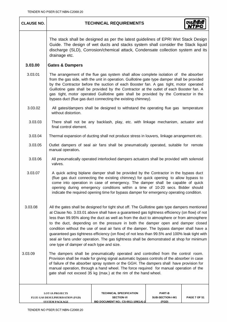
CLAUSE NO. TECHNICAL REQUIREMENTS
LOT-IA PROJECTS FLUE GAS DESULPHURISATION (FGD)
SYSTEM PACKAGE
TECHNICAL SPECIFICATION
SECTION-VI
BID DOCUMENT NO.: CS-0011-109(1A)-2
PART-B
SUB-SECTION-I-M1
(FGD)
PAGE 7 OF 51
The stack shall be designed as per the latest guidelines of EPRI Wet Stack Design Guide. The design of wet ducts and stacks system shall consider the Stack liquid discharge (SLD), Corrosion/chemical attack, Condensate collection system and its drainage etc.
3.03.00 Gates & Dampers
3.03.01 The arrangement of the flue gas system shall allow complete isolation of the absorber from the gas side, with the unit in operation. Guillotine gate type damper shall be provided by the Contractor before the suction of each Booster fan. A gas tight, motor operated Guillotine gate shall be provided by the Contractor at the outlet of each Booster fan. A gas tight, motor operated Guillotine gate shall be provided by the Contractor in the bypass duct (flue gas duct connecting the existing chimney).
3.03.02 All gates/dampers shall be designed to withstand the operating flue gas temperature
without distortion.
3.03.03 There shall not be any backlash, play, etc. with linkage mechanism, actuator and final control element.
3.03.04 Thermal expansion of ducting shall not produce stress in louvers, linkage arrangement etc.
3.03.05 Outlet dampers of seal air fans shall be pneumatically operated, suitable for remote
manual operation.
3.03.06 All pneumatically operated interlocked dampers actuators shall be provided with solenoid valves.
3.03.07 A quick acting biplane damper shall be provided by the Contractor in the bypass duct
(flue gas duct connecting the existing chimney) for quick opening to allow bypass to come into operation in case of emergency. The damper shall be capable of quick opening during emergency conditions within a time of 10-20 secs. Bidder should indicate the required opening time for bypass damper for emergency operating condition.
3.03.08 All the gates shall be designed for tight shut off. The Guillotine gate type dampers mentioned at Clause No. 3.03.01 above shall have a guaranteed gas tightness efficiency (on flow) of not less than 99.95% along the duct as well as from the duct to atmosphere or from atmosphere to the duct, depending on the pressure in both the damper open and damper closed condition without the use of seal air fans of the damper. The bypass damper shall have a guaranteed gas tightness efficiency (on flow) of not less than 99.5% and 100% leak tight with seal air fans under operation. The gas tightness shall be demonstrated at shop for minimum one type of damper of each type and size.
3.03.09 The dampers shall be pneumatically operated and controlled from the control room. Provision shall be made for giving signal automatic bypass controls of the absorber in case of failure of the absorber spray system or the GGH. The dampers shall have provision for manual operation, through a hand wheel. The force required for manual operation of the gate shall not exceed 35 kg (max.) at the rim of the hand wheel.
TENDER NO PSER:SCT:NBN-C2068:20
TENDER NO PSER:SCT:NBN-C2068:20
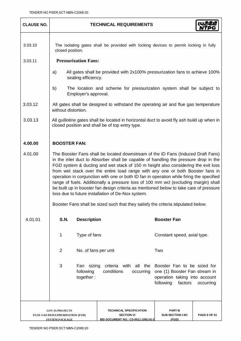
CLAUSE NO. TECHNICAL REQUIREMENTS
LOT-IA PROJECTS FLUE GAS DESULPHURISATION (FGD)
SYSTEM PACKAGE
TECHNICAL SPECIFICATION
SECTION-VI
BID DOCUMENT NO.: CS-0011-109(1A)-2
PART-B
SUB-SECTION-I-M1
(FGD)
PAGE 8 OF 51
3.03.10 The isolating gates shall be provided with locking devices to permit locking in fully
closed position.
3.03.11 Pressurization Fans:
a) All gates shall be provided with 2x100% pressurization fans to achieve 100% sealing efficiency.
b) The location and scheme for pressurization system shall be subject to Employer's approval.
3.03.12 All gates shall be designed to withstand the operating air and flue gas temperature without distortion.
3.03.13 All guillotine gates shall be located in horizontal duct to avoid fly ash build up when in closed position and shall be of top entry type.
4.00.00 BOOSTER FAN:
4.01.00 The Booster Fans shall be located downstream of the ID Fans (Induced Draft Fans) in the inlet duct to Absorber shall be capable of handling the pressure drop in the FGD system & ducting and wet stack of 150 m height also considering the exit loss from wet stack over the entire load range with any one or both Booster fans in operation in conjunction with one or both ID fan in operation while firing the specified range of fuels. Additionally a pressure loss of 100 mm wcl (excluding margin) shall be built up in booster fan design criteria as mentioned below to take care of pressure loss due to future installation of De-Nox system.
Booster Fans shall be sized such that they satisfy the criteria stipulated below.
4.01.01 S.N. Description Booster Fan
1 Type of fans Constant speed, axial type.
2 No. of fans per unit Two
3 Fan sizing criteria with all the following conditions occurring together :
Booster Fan to be sized for one (1) Booster Fan stream in operation taking into account following factors occurring
TENDER NO PSER:SCT:NBN-C2068:20
TENDER NO PSER:SCT:NBN-C2068:20
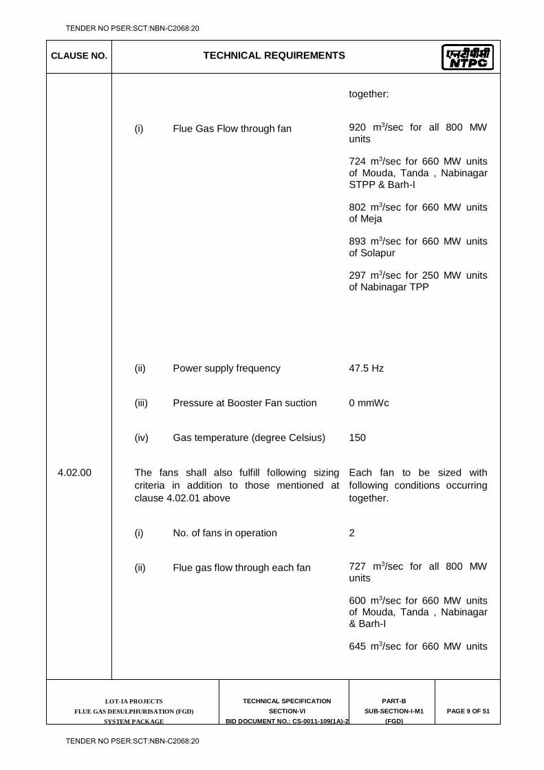
CLAUSE NO. TECHNICAL REQUIREMENTS
LOT-IA PROJECTS FLUE GAS DESULPHURISATION (FGD)
SYSTEM PACKAGE
TECHNICAL SPECIFICATION
SECTION-VI
BID DOCUMENT NO.: CS-0011-109(1A)-2
PART-B
SUB-SECTION-I-M1
(FGD)
PAGE 9 OF 51
together:
(i) Flue Gas Flow through fan 920 m3/sec for all 800 MW units
724 m3/sec for 660 MW units of Mouda, Tanda , Nabinagar STPP & Barh-I
802 m3/sec for 660 MW units of Meja
893 m3/sec for 660 MW units of Solapur
297 m3/sec for 250 MW units of Nabinagar TPP
(ii) Power supply frequency 47.5 Hz
(iii) Pressure at Booster Fan suction 0 mmWc
(iv) Gas temperature (degree Celsius) 150
4.02.00 The fans shall also fulfill following sizing criteria in addition to those mentioned at clause 4.02.01 above
Each fan to be sized with following conditions occurring together.
(i) No. of fans in operation 2
(ii) Flue gas flow through each fan 727 m3/sec for all 800 MW units
600 m3/sec for 660 MW units of Mouda, Tanda , Nabinagar & Barh-I
645 m3/sec for 660 MW units
TENDER NO PSER:SCT:NBN-C2068:20
TENDER NO PSER:SCT:NBN-C2068:20
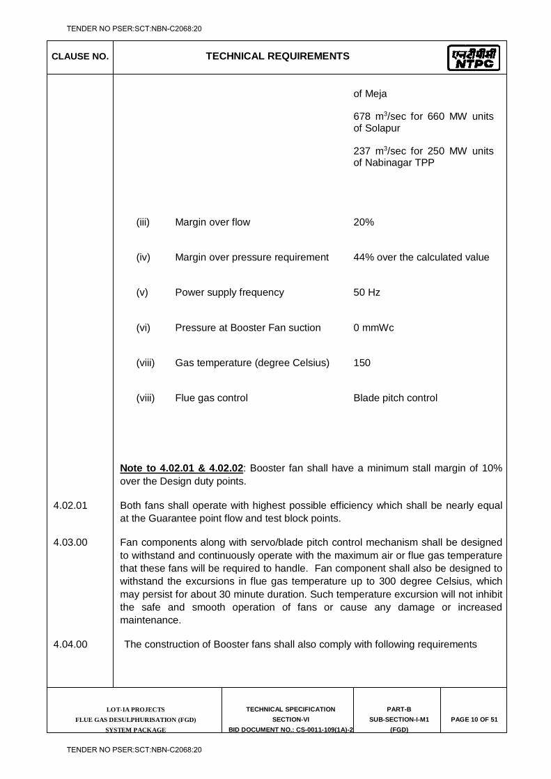
CLAUSE NO. TECHNICAL REQUIREMENTS
LOT-IA PROJECTS FLUE GAS DESULPHURISATION (FGD)
SYSTEM PACKAGE
TECHNICAL SPECIFICATION
SECTION-VI
BID DOCUMENT NO.: CS-0011-109(1A)-2
PART-B
SUB-SECTION-I-M1
(FGD)
PAGE 10 OF 51
of Meja
678 m3/sec for 660 MW units of Solapur
237 m3/sec for 250 MW units of Nabinagar TPP
(iii) Margin over flow 20%
(iv) Margin over pressure requirement 44% over the calculated value
(v) Power supply frequency 50 Hz
(vi) Pressure at Booster Fan suction 0 mmWc
(viii) Gas temperature (degree Celsius) 150
(viii) Flue gas control Blade pitch control
Note to 4.02.01 & 4.02.02: Booster fan shall have a minimum stall margin of 10% over the Design duty points.
4.02.01 Both fans shall operate with highest possible efficiency which shall be nearly equal at the Guarantee point flow and test block points.
4.03.00 Fan components along with servo/blade pitch control mechanism shall be designed to withstand and continuously operate with the maximum air or flue gas temperature that these fans will be required to handle. Fan component shall also be designed to withstand the excursions in flue gas temperature up to 300 degree Celsius, which may persist for about 30 minute duration. Such temperature excursion will not inhibit the safe and smooth operation of fans or cause any damage or increased maintenance.
4.04.00 The construction of Booster fans shall also comply with following requirements
TENDER NO PSER:SCT:NBN-C2068:20
TENDER NO PSER:SCT:NBN-C2068:20
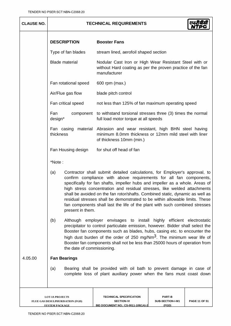
CLAUSE NO. TECHNICAL REQUIREMENTS
LOT-IA PROJECTS FLUE GAS DESULPHURISATION (FGD)
SYSTEM PACKAGE
TECHNICAL SPECIFICATION
SECTION-VI
BID DOCUMENT NO.: CS-0011-109(1A)-2
PART-B
SUB-SECTION-I-M1
(FGD)
PAGE 11 OF 51
DESCRIPTION Booster Fans
Type of fan blades stream lined, aerofoil shaped section
Blade material Nodular Cast Iron or High Wear Resistant Steel with or without Hard coating as per the proven practice of the fan manufacturer
Fan rotational speed 600 rpm (max.)
Air/Flue gas flow blade pitch control
Fan critical speed not less than 125% of fan maximum operating speed
Fan component design*
to withstand torsional stresses three (3) times the normal full load motor torque at all speeds
Fan casing material thickness
Abrasion and wear resistant, high BHN steel having minimum 8.0mm thickness or 12mm mild steel with liner of thickness 10mm (min.)
Fan Housing design for shut off head of fan
*Note :
(a) Contractor shall submit detailed calculations, for Employer's approval, to confirm compliance with above requirements for all fan components, specifically for fan shafts, impeller hubs and impeller as a whole. Areas of high stress concentration and residual stresses, like welded attachments shall be avoided on the fan rotor/shafts. Combined static, dynamic as well as residual stresses shall be demonstrated to be within allowable limits. These fan components shall last the life of the plant with such combined stresses present in them.
(b) Although employer envisages to install highly efficient electrostatic precipitator to control particulate emission, however. Bidder shall select the Booster fan components such as blades, hubs, casing etc. to encounter the high dust burden of the order of 250 mg/Nm3. The minimum wear life of Booster fan components shall not be less than 25000 hours of operation from the date of commissioning.
4.05.00 Fan Bearings
(a) Bearing shall be provided with oil bath to prevent damage in case of complete loss of plant auxiliary power when the fans must coast down
TENDER NO PSER:SCT:NBN-C2068:20
TENDER NO PSER:SCT:NBN-C2068:20
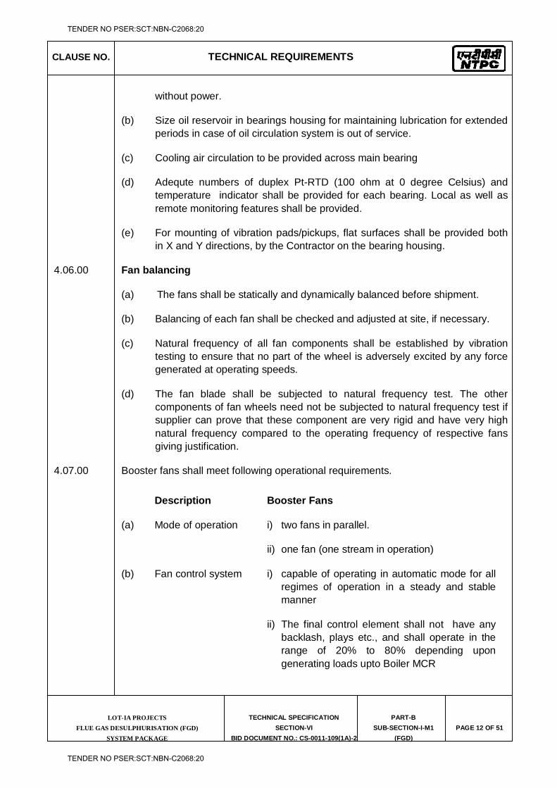
CLAUSE NO. TECHNICAL REQUIREMENTS
LOT-IA PROJECTS FLUE GAS DESULPHURISATION (FGD)
SYSTEM PACKAGE
TECHNICAL SPECIFICATION
SECTION-VI
BID DOCUMENT NO.: CS-0011-109(1A)-2
PART-B
SUB-SECTION-I-M1
(FGD)
PAGE 12 OF 51
without power.
(b) Size oil reservoir in bearings housing for maintaining lubrication for extended periods in case of oil circulation system is out of service.
(c) Cooling air circulation to be provided across main bearing
(d) Adequte numbers of duplex Pt-RTD (100 ohm at 0 degree Celsius) and temperature indicator shall be provided for each bearing. Local as well as remote monitoring features shall be provided.
(e) For mounting of vibration pads/pickups, flat surfaces shall be provided both in X and Y directions, by the Contractor on the bearing housing.
4.06.00 Fan balancing
(a) The fans shall be statically and dynamically balanced before shipment.
(b) Balancing of each fan shall be checked and adjusted at site, if necessary.
(c) Natural frequency of all fan components shall be established by vibration testing to ensure that no part of the wheel is adversely excited by any force generated at operating speeds.
(d) The fan blade shall be subjected to natural frequency test. The other components of fan wheels need not be subjected to natural frequency test if supplier can prove that these component are very rigid and have very high natural frequency compared to the operating frequency of respective fans giving justification.
4.07.00 Booster fans shall meet following operational requirements.
Description Booster Fans
(a) Mode of operation i) two fans in parallel.
ii) one fan (one stream in operation)
(b) Fan control system i) capable of operating in automatic mode for all regimes of operation in a steady and stable manner
ii) The final control element shall not have any backlash, plays etc., and shall operate in the range of 20% to 80% depending upon generating loads upto Boiler MCR
TENDER NO PSER:SCT:NBN-C2068:20
TENDER NO PSER:SCT:NBN-C2068:20
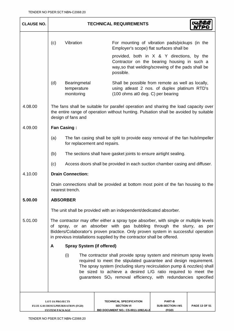
CLAUSE NO. TECHNICAL REQUIREMENTS
LOT-IA PROJECTS FLUE GAS DESULPHURISATION (FGD)
SYSTEM PACKAGE
TECHNICAL SPECIFICATION
SECTION-VI
BID DOCUMENT NO.: CS-0011-109(1A)-2
PART-B
SUB-SECTION-I-M1
(FGD)
PAGE 13 OF 51
(c) Vibration For mounting of vibration pads/pickups (in the Employer's scope) flat surfaces shall be
provided, both in X & Y directions, by the Contractor on the bearing housing in such a way,so that welding/screwing of the pads shall be possible.
(d) Bearingmetal temperature monitoring
Shall be possible from remote as well as locally, using atleast 2 nos. of duplex platinum RTD's (100 ohms at0 deg. C) per bearing
4.08.00 The fans shall be suitable for parallel operation and sharing the load capacity over the entire range of operation without hunting. Pulsation shall be avoided by suitable design of fans and
4.09.00 Fan Casing :
(a) The fan casing shall be split to provide easy removal of the fan hub/impeller for replacement and repairs.
(b) The sections shall have gasket joints to ensure airtight sealing.
(c) Access doors shall be provided in each suction chamber casing and diffuser.
4.10.00 Drain Connection:
Drain connections shall be provided at bottom most point of the fan housing to the nearest trench.
5.00.00 ABSORBER
The unit shall be provided with an independent/dedicated absorber.
5.01.00 The contractor may offer either a spray type absorber, with single or multiple levels of spray, or an absorber with gas bubbling through the slurry, as per Bidders/Colaborator’s proven practice. Only proven system in successful operation in previous installations supplied by the contractor shall be offered.
A Spray System (if offered)
(i) The contractor shall provide spray system and minimum spray levels required to meet the stipulated guarantee and design requirement. The spray system (including slurry recirculation pump & nozzles) shall be sized to achieve a desired L/G ratio required to meet the guarantees SO2 removal efficiency, with redundancies specified
TENDER NO PSER:SCT:NBN-C2068:20
TENDER NO PSER:SCT:NBN-C2068:20
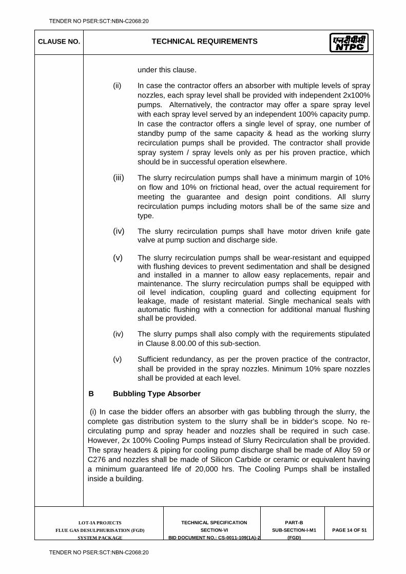
CLAUSE NO. TECHNICAL REQUIREMENTS
LOT-IA PROJECTS FLUE GAS DESULPHURISATION (FGD)
SYSTEM PACKAGE
TECHNICAL SPECIFICATION
SECTION-VI
BID DOCUMENT NO.: CS-0011-109(1A)-2
PART-B
SUB-SECTION-I-M1
(FGD)
PAGE 14 OF 51
under this clause.
(ii) In case the contractor offers an absorber with multiple levels of spray nozzles, each spray level shall be provided with independent 2x100% pumps. Alternatively, the contractor may offer a spare spray level with each spray level served by an independent 100% capacity pump. In case the contractor offers a single level of spray, one number of standby pump of the same capacity & head as the working slurry recirculation pumps shall be provided. The contractor shall provide spray system / spray levels only as per his proven practice, which should be in successful operation elsewhere.
(iii) The slurry recirculation pumps shall have a minimum margin of 10% on flow and 10% on frictional head, over the actual requirement for meeting the guarantee and design point conditions. All slurry recirculation pumps including motors shall be of the same size and type.
(iv) The slurry recirculation pumps shall have motor driven knife gate valve at pump suction and discharge side.
(v) The slurry recirculation pumps shall be wear-resistant and equipped
with flushing devices to prevent sedimentation and shall be designed and installed in a manner to allow easy replacements, repair and maintenance. The slurry recirculation pumps shall be equipped with oil level indication, coupling guard and collecting equipment for leakage, made of resistant material. Single mechanical seals with automatic flushing with a connection for additional manual flushing shall be provided.
(iv) The slurry pumps shall also comply with the requirements stipulated in Clause 8.00.00 of this sub-section.
(v) Sufficient redundancy, as per the proven practice of the contractor, shall be provided in the spray nozzles. Minimum 10% spare nozzles shall be provided at each level.
B Bubbling Type Absorber
(i) In case the bidder offers an absorber with gas bubbling through the slurry, the complete gas distribution system to the slurry shall be in bidder’s scope. No re-circulating pump and spray header and nozzles shall be required in such case. However, 2x 100% Cooling Pumps instead of Slurry Recirculation shall be provided. The spray headers & piping for cooling pump discharge shall be made of Alloy 59 or C276 and nozzles shall be made of Silicon Carbide or ceramic or equivalent having a minimum guaranteed life of 20,000 hrs. The Cooling Pumps shall be installed inside a building.
TENDER NO PSER:SCT:NBN-C2068:20
TENDER NO PSER:SCT:NBN-C2068:20
CLAUSE NO. TECHNICAL REQUIREMENTS
LOT-IA PROJECTS FLUE GAS DESULPHURISATION (FGD)
SYSTEM PACKAGE
TECHNICAL SPECIFICATION
SECTION-VI
BID DOCUMENT NO.: CS-0011-109(1A)-2
PART-B
SUB-SECTION-I-M1
(FGD)
PAGE 15 OF 51
The sparger and gas riser tubes shall be made proven material which shall have a minimum life of 5 years.
Minimum 10% redundancy, shall be provided in the Sparger Tubes.
5.02.00 Absorber Recirculation Tank
Sufficient number of agitators, as per the proven practice of the contractor, shall be provided for thorough mixing of the re-circulating slurry. In case the Contractor's Absorber includes side entry agitators, the contractor shall offer and demonstrate mixing arrangement such that n-1 number of agitators are sufficient to avoid the slurry settlement in the absorber tank in case of one agitator under breakdown (n-total no. of working agitators). In case vertical agitators in Absorber are offered, one complete mechanical assembly of agitator shall be supplied as warehouse spare for each Absorber.
5.03.00 Absorber Oxidation Systems
5.03.01 The contractor may offer either a grid type oxidation system or a sparge jet oxidation system or lance type or air rotary sparge system or jet air sparger system for oxidation of sulfite sludge to sulfates, or any other proven system as per the practice of the FGD vendor.
5.03.02 The oxygen required for oxidation shall be supplied by 2x100% oxidation air blowers
for each absorber. The compressor/blower shall be sized to supply at least 2.5 times the stoichiometric air requirement for spray tower process & at least 4.0 times the stoichiometric air requirement for Bubbling Type process or the actual requirement, whichever is higher, under the following condition, all occurring simultaneously. The natural oxidation of sulfite by residual oxygen in flue gas shall not be considered for this purpose.
Load Design point Flow
Flow Minimum 2.5 times for spray tower process & 4.0 for Bubbling Type process the stoichiometric requirement
Head For spray tower process actual requirement considering choking/ blockage of minimum 10% of the oxidation nozzles / sprayers or minimum 8500 mmwc whichever is higher.
For Bubbling Type process actual requirement considering choking/ blockage of minimum 10% of the oxidation nozzles / sprayers or minimum 3500 mmwc
TENDER NO PSER:SCT:NBN-C2068:20
TENDER NO PSER:SCT:NBN-C2068:20
CLAUSE NO. TECHNICAL REQUIREMENTS
LOT-IA PROJECTS FLUE GAS DESULPHURISATION (FGD)
SYSTEM PACKAGE
TECHNICAL SPECIFICATION
SECTION-VI
BID DOCUMENT NO.: CS-0011-109(1A)-2
PART-B
SUB-SECTION-I-M1
(FGD)
PAGE 16 OF 51
whichever is higher.
Margin on Head 10% under above conditions.
Ambient Conditions 45oC / 60% RH.
5.03.03 Oxidation nozzles / spargers shall have a minimum redundancy of 10% or as per the contractor’s proven practice whichever is maximum.
5.03.04 The oxidation system shall be complete with a quenching system to cool down heated oxidation air in order to prevent any scaling or buildup that could occur at the sparger tips due to localized evaporation of recycled slurry.
5.04.00 Gypsum Bleed Pump
Each absorber shall be provided with 2x100% Gypsum Bleed Pumps for supply of gypsum slurry to Gypsum Dewatering system. Each Gypsum bleed pump shall be sized to bleed-off the gypsum slurry from the absorber with slurry solid concentration not exceeding 30%, under the following conditions, all occurring simultaneously:
Load
Design point
Flow 100% of gypsum produced at Design point condition
Head As per system requirement
Margins
Flow -- 15%
Head – 20%
The pumps shall be designed to meet the stipulations of Clause No.9.00.00 of this Sub-Section.
Provision shall also be provide in the Gypsum Bleed Pumping system by provision of tap off, valves etc. for pumping the gypsum bleed to alternate source.
5.05.00 Emergency Spray System An emergency cooling system for automatic spray of quenching water for a sufficient time (minimum 15 min) at the inlet to the absorber, in case the gas temperature exceeds the design temperature due to failure of upstream equipment’s shall be provided to protect the FGD and all other sensitive downstream equipment against high flue gas temperatures. The water shall be supplied from an elevated tank (emergency water tank) installed near to the absorber. The tank volume and the
TENDER NO PSER:SCT:NBN-C2068:20
TENDER NO PSER:SCT:NBN-C2068:20
CLAUSE NO. TECHNICAL REQUIREMENTS
LOT-IA PROJECTS FLUE GAS DESULPHURISATION (FGD)
SYSTEM PACKAGE
TECHNICAL SPECIFICATION
SECTION-VI
BID DOCUMENT NO.: CS-0011-109(1A)-2
PART-B
SUB-SECTION-I-M1
(FGD)
PAGE 17 OF 51
injection lances/nozzles shall be designed to protect the inlet duct and the lining of the absorber. The inlet duct shall be sloped towards the absorber.
5.06.00 Design
5.06.01 The design and arrangement of the absorber shall be field proven for successful long-term operation in conjunction with a coal fired power plant.
5.06.02 The design of flue gas ducts and inlet and outlet hoods of the FGD as well as guide vanes and baffle plates shall ensure a homogeneous flue gas flow with respect to the distributions of: (i) temperature (ii) velocity (iii) dust content (iv) slurry injection and distribution. The above shall be proven by two phase Computational Fluid Dynamics simulations (liquid and gas). The scope of modelling shall include flue gas path inside the absorber vessel including inlet and outlet duct. Homogeneity shall be ensured, if the deviation from average is less than +10%. Further, in the Absorber outlet hood no internals such as guide vanes and baffle plates shall be allowed.
5.06.03 The fabrication of the absorber vessel shall follow common practice as there shall be
no longitudinal seams located behind any attachment or obstruction which would prevent inspection of the welds. Nozzles, access ways, and their reinforcements shall not be located in or on any seam. Inaccessible gaps or hollow beams shall be avoided.
5.06.04 The absorber shell shall be designed for pressure loads, piping forces and moments,
wind and seismic loads and all other loads imposed on the absorber. Bracing and reinforcement shall be adequate to prevent deflection and vibration. Internal supports for mist eliminator sections, etc. shall be designed to withstand the flooded weight of the supported section. The absorber and its structural supports shall be designed for the maximum operating loads including design positive & negative internal pressure, static head, external attachment loads (such as exerted by piping) wind load using the allowable stresses permitted by the applied standards.
5.06.05 It shall be possible to reach the SO2 emission guarantees, at Guarantee point
condition, with at least one spray level continuously out of service (in case the absorber is equipped with several spray levels) or one spare pump continuously out of service.
5.06.06 Three stage chevron type Mist Eliminators (ME) made of polysulfone or stainless steel shall be provided at the exit of the absorber. Provision shall be made for continuous washing of both ends of the first & second stage and the front section of the third stage of mist eliminators. Wash water arrangement shall also be provided at the back end of the second stage of mist eliminator. If the mist eliminator washing system is designed for cyclic washing of different sections, all the valves required for cycling shall be motorized or pneumatically operated. The automatic valve for the spray system shall be easily accessible on a platforms close to the mist eliminator.
TENDER NO PSER:SCT:NBN-C2068:20
TENDER NO PSER:SCT:NBN-C2068:20
CLAUSE NO. TECHNICAL REQUIREMENTS
LOT-IA PROJECTS FLUE GAS DESULPHURISATION (FGD)
SYSTEM PACKAGE
TECHNICAL SPECIFICATION
SECTION-VI
BID DOCUMENT NO.: CS-0011-109(1A)-2
PART-B
SUB-SECTION-I-M1
(FGD)
PAGE 18 OF 51
Entrained slurry shall be collected by mist eliminators downstream of the slurry spray system to avoid carry-over of slurry to the stack.
The ME system shall be equipped with washing and drain provisions, where drains are directed into the absorber. Washing provisions shall include external and internal piping systems with replaceable nozzles, water pressure booster pumps (if required) complete with all piping, valves, instrumentation and controls. The mist eliminator wash piping/header shall be constructed of rubber lined carbon steel or glass fiber reinforced plastics. Polypropylene or PVC is also acceptable for mist eliminator wash headers provided Contractor or its Collaborator has proven experience for the same. Ease of replace ability and placement of the mist eliminator on maintenance platforms is an important requirement. The ME shall be designed to allow for efficient cleaning in process. Test ports shall be provided downstream of the mist eliminator to enable performance testing. The mist eliminator system shall be capable of withstanding high velocity spray water jets typically employed during manual cleanings. The ME shall be constructed in individual cells. The design shall safely avoid ME vibration and/or humming. The individual cells shall be sized so that no more than two maintenance personnel are needed to handle them manually when they are fully scaled or plugged, and the cells shall be capable of passing through the access doors for the mist elimination section. Easy access for placement and replacement of the mist eliminator shall be incorporated in the design of the mist eliminator arrangement and the absorber vessel. Walkways shall be arranged and also measures shall be taken as appropriate to permit the internal components to be disassembled and reassembled during repairs without the necessity for time-consuming preparatory work. The headroom shall have a height of more than 2200 mm. The mist eliminator support beams shall be designed to act as maintenance walkways approximately 300 mm wide and shall allow for a minimum 500 Kg/m2 load. The support beam/walkways shall provide personnel access to all mist eliminator modules, wash headers and wash nozzles. Adequate number of viewing ports with flushing devices connected to automatically operating washing system shall be delivered at following locations: (i) upstream of 1st stage (ii) between 1st and 2nd stage (iii) downstream of 2nd stage. (iv) downstream of 3rd stage
The regular flushing shall be done in a defined time sequence.
5.06.07 The absorber oxidation tank shall be provided with an over flow line (for spray tower
process) complete with sealing pot, over flow and drain line. The absorber over flow shall be taken to a sump in the absorber region, from where the slurry shall be pumped back to the absorber by a sump pump.
5.06.08 Materials used shall be suitable for the chemistry of the absorber process and resist abrasion from any particulate contained in the incoming flue gas and from the
TENDER NO PSER:SCT:NBN-C2068:20
TENDER NO PSER:SCT:NBN-C2068:20
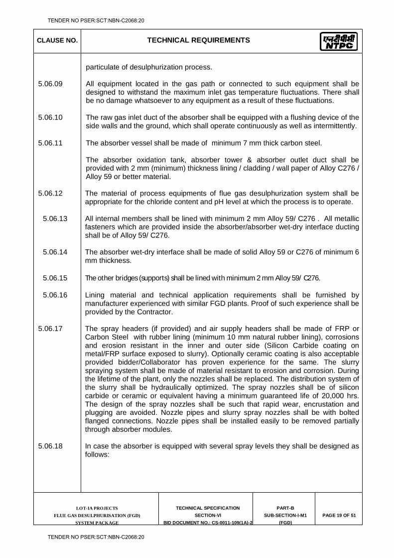
CLAUSE NO. TECHNICAL REQUIREMENTS
LOT-IA PROJECTS FLUE GAS DESULPHURISATION (FGD)
SYSTEM PACKAGE
TECHNICAL SPECIFICATION
SECTION-VI
BID DOCUMENT NO.: CS-0011-109(1A)-2
PART-B
SUB-SECTION-I-M1
(FGD)
PAGE 19 OF 51
particulate of desulphurization process. 5.06.09 All equipment located in the gas path or connected to such equipment shall be
designed to withstand the maximum inlet gas temperature fluctuations. There shall be no damage whatsoever to any equipment as a result of these fluctuations.
5.06.10 The raw gas inlet duct of the absorber shall be equipped with a flushing device of the
side walls and the ground, which shall operate continuously as well as intermittently.
5.06.11 The absorber vessel shall be made of minimum 7 mm thick carbon steel.
The absorber oxidation tank, absorber tower & absorber outlet duct shall be provided with 2 mm (minimum) thickness lining / cladding / wall paper of Alloy C276 / Alloy 59 or better material.
5.06.12 The material of process equipments of flue gas desulphurization system shall be appropriate for the chloride content and pH level at which the process is to operate.
5.06.13 All internal members shall be lined with minimum 2 mm Alloy 59/ C276 . All metallic
fasteners which are provided inside the absorber/absorber wet-dry interface ducting shall be of Alloy 59/ C276.
5.06.14 The absorber wet-dry interface shall be made of solid Alloy 59 or C276 of minimum 6
mm thickness.
5.06.15 The other bridges (supports) shall be lined with minimum 2 mm Alloy 59/ C276.
5.06.16 Lining material and technical application requirements shall be furnished by manufacturer experienced with similar FGD plants. Proof of such experience shall be provided by the Contractor.
5.06.17 The spray headers (if provided) and air supply headers shall be made of FRP or Carbon Steel with rubber lining (minimum 10 mm natural rubber lining), corrosions and erosion resistant in the inner and outer side (Silicon Carbide coating on metal/FRP surface exposed to slurry). Optionally ceramic coating is also acceptable provided bidder/Collaborator has proven experience for the same. The slurry spraying system shall be made of material resistant to erosion and corrosion. During the lifetime of the plant, only the nozzles shall be replaced. The distribution system of the slurry shall be hydraulically optimized. The spray nozzles shall be of silicon carbide or ceramic or equivalent having a minimum guaranteed life of 20,000 hrs. The design of the spray nozzles shall be such that rapid wear, encrustation and plugging are avoided. Nozzle pipes and slurry spray nozzles shall be with bolted flanged connections. Nozzle pipes shall be installed easily to be removed partially through absorber modules.
5.06.18 In case the absorber is equipped with several spray levels they shall be designed as follows:
TENDER NO PSER:SCT:NBN-C2068:20
TENDER NO PSER:SCT:NBN-C2068:20
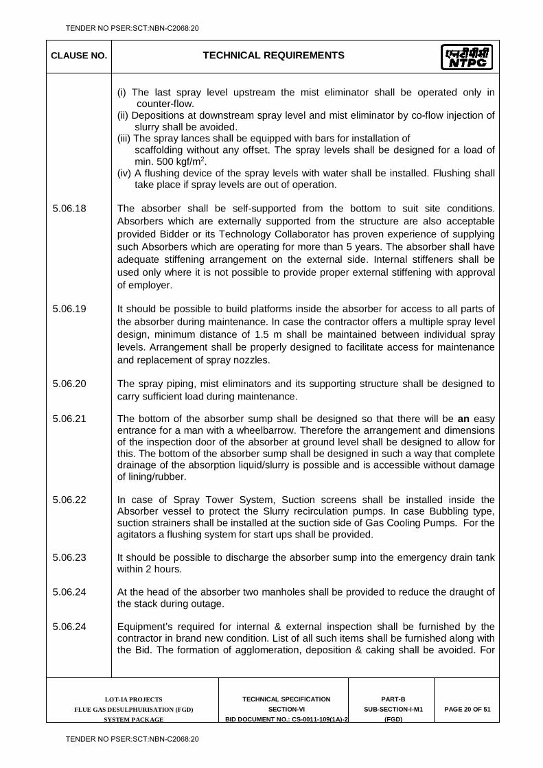
CLAUSE NO. TECHNICAL REQUIREMENTS
LOT-IA PROJECTS FLUE GAS DESULPHURISATION (FGD)
SYSTEM PACKAGE
TECHNICAL SPECIFICATION
SECTION-VI
BID DOCUMENT NO.: CS-0011-109(1A)-2
PART-B
SUB-SECTION-I-M1
(FGD)
PAGE 20 OF 51
(i) The last spray level upstream the mist eliminator shall be operated only in counter-flow.
(ii) Depositions at downstream spray level and mist eliminator by co-flow injection of slurry shall be avoided.
(iii) The spray lances shall be equipped with bars for installation of scaffolding without any offset. The spray levels shall be designed for a load of min. 500 kgf/m2.
(iv) A flushing device of the spray levels with water shall be installed. Flushing shall take place if spray levels are out of operation.
5.06.18 The absorber shall be self-supported from the bottom to suit site conditions. Absorbers which are externally supported from the structure are also acceptable provided Bidder or its Technology Collaborator has proven experience of supplying such Absorbers which are operating for more than 5 years. The absorber shall have adequate stiffening arrangement on the external side. Internal stiffeners shall be used only where it is not possible to provide proper external stiffening with approval of employer.
5.06.19 It should be possible to build platforms inside the absorber for access to all parts of the absorber during maintenance. In case the contractor offers a multiple spray level design, minimum distance of 1.5 m shall be maintained between individual spray levels. Arrangement shall be properly designed to facilitate access for maintenance and replacement of spray nozzles.
5.06.20 The spray piping, mist eliminators and its supporting structure shall be designed to carry sufficient load during maintenance.
5.06.21 The bottom of the absorber sump shall be designed so that there will be an easy entrance for a man with a wheelbarrow. Therefore the arrangement and dimensions of the inspection door of the absorber at ground level shall be designed to allow for this. The bottom of the absorber sump shall be designed in such a way that complete drainage of the absorption liquid/slurry is possible and is accessible without damage of lining/rubber.
5.06.22 In case of Spray Tower System, Suction screens shall be installed inside the Absorber vessel to protect the Slurry recirculation pumps. In case Bubbling type, suction strainers shall be installed at the suction side of Gas Cooling Pumps. For the agitators a flushing system for start ups shall be provided.
5.06.23 It should be possible to discharge the absorber sump into the emergency drain tank
within 2 hours. 5.06.24 At the head of the absorber two manholes shall be provided to reduce the draught of
the stack during outage. 5.06.24 Equipment’s required for internal & external inspection shall be furnished by the
contractor in brand new condition. List of all such items shall be furnished along with the Bid. The formation of agglomeration, deposition & caking shall be avoided. For
TENDER NO PSER:SCT:NBN-C2068:20
TENDER NO PSER:SCT:NBN-C2068:20
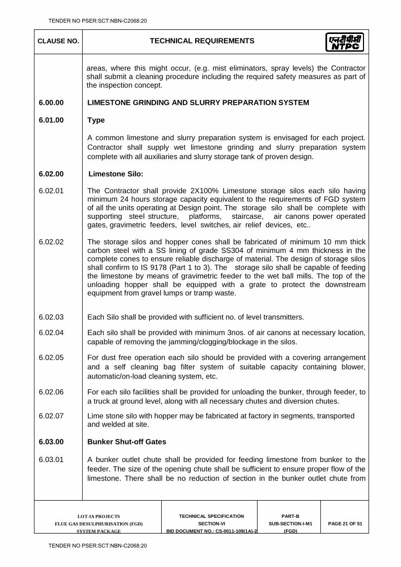
CLAUSE NO. TECHNICAL REQUIREMENTS
LOT-IA PROJECTS FLUE GAS DESULPHURISATION (FGD)
SYSTEM PACKAGE
TECHNICAL SPECIFICATION
SECTION-VI
BID DOCUMENT NO.: CS-0011-109(1A)-2
PART-B
SUB-SECTION-I-M1
(FGD)
PAGE 21 OF 51
areas, where this might occur, (e.g. mist eliminators, spray levels) the Contractor shall submit a cleaning procedure including the required safety measures as part of the inspection concept.
6.00.00 LIMESTONE GRINDING AND SLURRY PREPARATION SYSTEM
6.01.00 Type
A common limestone and slurry preparation system is envisaged for each project. Contractor shall supply wet limestone grinding and slurry preparation system complete with all auxiliaries and slurry storage tank of proven design.
6.02.00 Limestone Silo:
6.02.01 The Contractor shall provide 2X100% Limestone storage silos each silo having minimum 24 hours storage capacity equivalent to the requirements of FGD system of all the units operating at Design point. The storage silo shall be complete with supporting steel structure, platforms, staircase, air canons power operated gates, gravimetric feeders, level switches, air relief devices, etc..
6.02.02 The storage silos and hopper cones shall be fabricated of minimum 10 mm thick
carbon steel with a SS lining of grade SS304 of minimum 4 mm thickness in the complete cones to ensure reliable discharge of material. The design of storage silos shall confirm to IS 9178 (Part 1 to 3). The storage silo shall be capable of feeding the limestone by means of gravimetric feeder to the wet ball mills. The top of the unloading hopper shall be equipped with a grate to protect the downstream equipment from gravel lumps or tramp waste.
6.02.03 Each Silo shall be provided with sufficient no. of level transmitters.
6.02.04 Each silo shall be provided with minimum 3nos. of air canons at necessary location, capable of removing the jamming/clogging/blockage in the silos.
6.02.05 For dust free operation each silo should be provided with a covering arrangement and a self cleaning bag filter system of suitable capacity containing blower, automatic/on-load cleaning system, etc.
6.02.06 For each silo facilities shall be provided for unloading the bunker, through feeder, to a truck at ground level, along with all necessary chutes and diversion chutes.
6.02.07 Lime stone silo with hopper may be fabricated at factory in segments, transported and welded at site.
6.03.00 Bunker Shut-off Gates
6.03.01 A bunker outlet chute shall be provided for feeding limestone from bunker to the feeder. The size of the opening chute shall be sufficient to ensure proper flow of the limestone. There shall be no reduction of section in the bunker outlet chute from
TENDER NO PSER:SCT:NBN-C2068:20
TENDER NO PSER:SCT:NBN-C2068:20
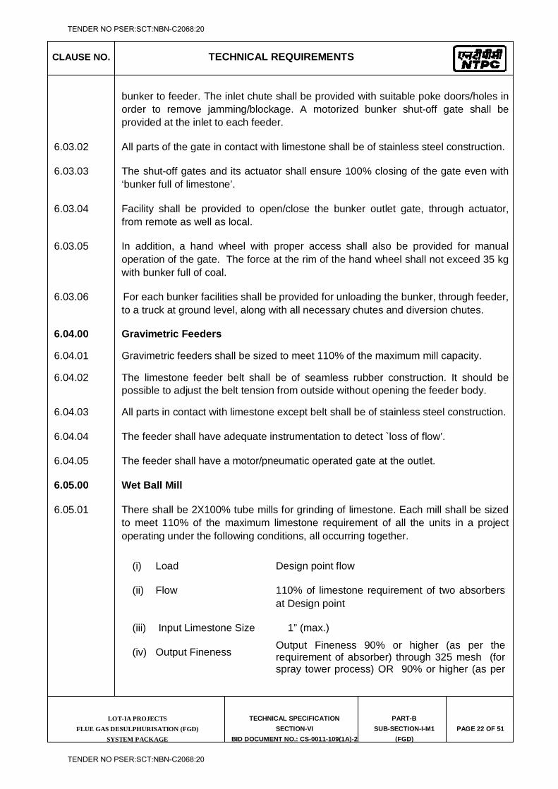
CLAUSE NO. TECHNICAL REQUIREMENTS
LOT-IA PROJECTS FLUE GAS DESULPHURISATION (FGD)
SYSTEM PACKAGE
TECHNICAL SPECIFICATION
SECTION-VI
BID DOCUMENT NO.: CS-0011-109(1A)-2
PART-B
SUB-SECTION-I-M1
(FGD)
PAGE 22 OF 51
bunker to feeder. The inlet chute shall be provided with suitable poke doors/holes in order to remove jamming/blockage. A motorized bunker shut-off gate shall be provided at the inlet to each feeder.
6.03.02 All parts of the gate in contact with limestone shall be of stainless steel construction.
6.03.03 The shut-off gates and its actuator shall ensure 100% closing of the gate even with ‘bunker full of limestone’.
6.03.04 Facility shall be provided to open/close the bunker outlet gate, through actuator, from remote as well as local.
6.03.05 In addition, a hand wheel with proper access shall also be provided for manual operation of the gate. The force at the rim of the hand wheel shall not exceed 35 kg with bunker full of coal.
6.03.06 For each bunker facilities shall be provided for unloading the bunker, through feeder, to a truck at ground level, along with all necessary chutes and diversion chutes.
6.04.00 Gravimetric Feeders
6.04.01 Gravimetric feeders shall be sized to meet 110% of the maximum mill capacity.
6.04.02 The limestone feeder belt shall be of seamless rubber construction. It should be possible to adjust the belt tension from outside without opening the feeder body.
6.04.03 All parts in contact with limestone except belt shall be of stainless steel construction.
6.04.04 The feeder shall have adequate instrumentation to detect `loss of flow’.
6.04.05 The feeder shall have a motor/pneumatic operated gate at the outlet.
6.05.00 Wet Ball Mill
6.05.01 There shall be 2X100% tube mills for grinding of limestone. Each mill shall be sized to meet 110% of the maximum limestone requirement of all the units in a project operating under the following conditions, all occurring together.
(i) Load Design point flow
(ii) Flow 110% of limestone requirement of two absorbers at Design point
(iii) Input Limestone Size 1” (max.)
(iv) Output Fineness Output Fineness 90% or higher (as per the requirement of absorber) through 325 mesh (for spray tower process) OR 90% or higher (as per
TENDER NO PSER:SCT:NBN-C2068:20
TENDER NO PSER:SCT:NBN-C2068:20
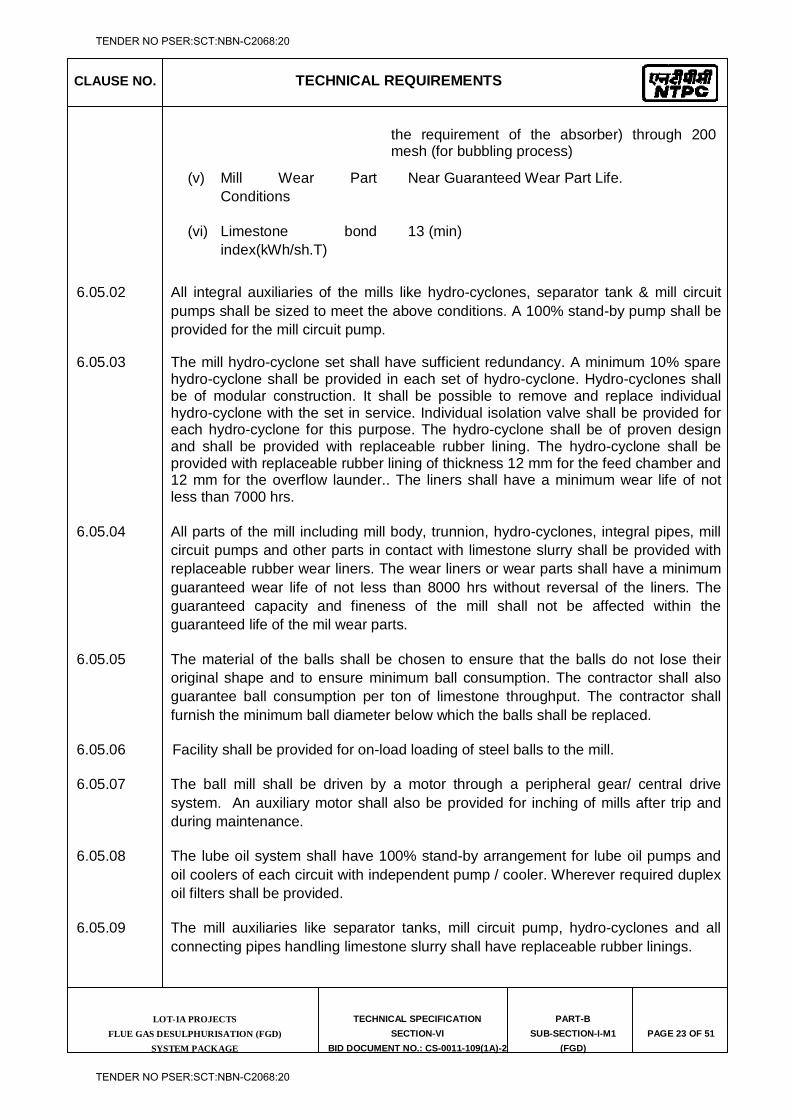
CLAUSE NO. TECHNICAL REQUIREMENTS
LOT-IA PROJECTS FLUE GAS DESULPHURISATION (FGD)
SYSTEM PACKAGE
TECHNICAL SPECIFICATION
SECTION-VI
BID DOCUMENT NO.: CS-0011-109(1A)-2
PART-B
SUB-SECTION-I-M1
(FGD)
PAGE 23 OF 51
the requirement of the absorber) through 200 mesh (for bubbling process)
(v) Mill Wear Part Conditions
Near Guaranteed Wear Part Life.
(vi) Limestone bond index(kWh/sh.T)
13 (min)
6.05.02 All integral auxiliaries of the mills like hydro-cyclones, separator tank & mill circuit pumps shall be sized to meet the above conditions. A 100% stand-by pump shall be provided for the mill circuit pump.
6.05.03 The mill hydro-cyclone set shall have sufficient redundancy. A minimum 10% spare hydro-cyclone shall be provided in each set of hydro-cyclone. Hydro-cyclones shall be of modular construction. It shall be possible to remove and replace individual hydro-cyclone with the set in service. Individual isolation valve shall be provided for each hydro-cyclone for this purpose. The hydro-cyclone shall be of proven design and shall be provided with replaceable rubber lining. The hydro-cyclone shall be provided with replaceable rubber lining of thickness 12 mm for the feed chamber and 12 mm for the overflow launder.. The liners shall have a minimum wear life of not less than 7000 hrs.
6.05.04 All parts of the mill including mill body, trunnion, hydro-cyclones, integral pipes, mill circuit pumps and other parts in contact with limestone slurry shall be provided with replaceable rubber wear liners. The wear liners or wear parts shall have a minimum guaranteed wear life of not less than 8000 hrs without reversal of the liners. The guaranteed capacity and fineness of the mill shall not be affected within the guaranteed life of the mil wear parts.
6.05.05 The material of the balls shall be chosen to ensure that the balls do not lose their original shape and to ensure minimum ball consumption. The contractor shall also guarantee ball consumption per ton of limestone throughput. The contractor shall furnish the minimum ball diameter below which the balls shall be replaced.
6.05.06 Facility shall be provided for on-load loading of steel balls to the mill.
6.05.07 The ball mill shall be driven by a motor through a peripheral gear/ central drive system. An auxiliary motor shall also be provided for inching of mills after trip and during maintenance.
6.05.08 The lube oil system shall have 100% stand-by arrangement for lube oil pumps and oil coolers of each circuit with independent pump / cooler. Wherever required duplex oil filters shall be provided.
6.05.09 The mill auxiliaries like separator tanks, mill circuit pump, hydro-cyclones and all connecting pipes handling limestone slurry shall have replaceable rubber linings.
TENDER NO PSER:SCT:NBN-C2068:20
TENDER NO PSER:SCT:NBN-C2068:20
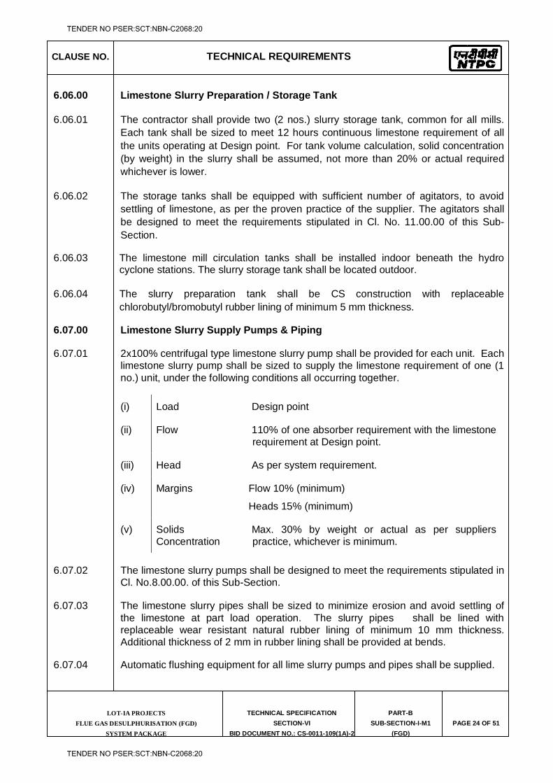
CLAUSE NO. TECHNICAL REQUIREMENTS
LOT-IA PROJECTS FLUE GAS DESULPHURISATION (FGD)
SYSTEM PACKAGE
TECHNICAL SPECIFICATION
SECTION-VI
BID DOCUMENT NO.: CS-0011-109(1A)-2
PART-B
SUB-SECTION-I-M1
(FGD)
PAGE 24 OF 51
6.06.00 Limestone Slurry Preparation / Storage Tank
6.06.01 The contractor shall provide two (2 nos.) slurry storage tank, common for all mills. Each tank shall be sized to meet 12 hours continuous limestone requirement of all the units operating at Design point. For tank volume calculation, solid concentration (by weight) in the slurry shall be assumed, not more than 20% or actual required whichever is lower.
6.06.02 The storage tanks shall be equipped with sufficient number of agitators, to avoid settling of limestone, as per the proven practice of the supplier. The agitators shall be designed to meet the requirements stipulated in Cl. No. 11.00.00 of this Sub-Section.
6.06.03 The limestone mill circulation tanks shall be installed indoor beneath the hydro cyclone stations. The slurry storage tank shall be located outdoor.
6.06.04 The slurry preparation tank shall be CS construction with replaceable chlorobutyl/bromobutyl rubber lining of minimum 5 mm thickness.
6.07.00 Limestone Slurry Supply Pumps & Piping
6.07.01 2x100% centrifugal type limestone slurry pump shall be provided for each unit. Each limestone slurry pump shall be sized to supply the limestone requirement of one (1 no.) unit, under the following conditions all occurring together.
(i) Load Design point
(ii) Flow 110% of one absorber requirement with the limestone requirement at Design point.
(iii) Head As per system requirement.
(iv) Margins Flow 10% (minimum)
Heads 15% (minimum)
(v) Solids Concentration
Max. 30% by weight or actual as per suppliers practice, whichever is minimum.
6.07.02 The limestone slurry pumps shall be designed to meet the requirements stipulated in Cl. No.8.00.00. of this Sub-Section.
6.07.03 The limestone slurry pipes shall be sized to minimize erosion and avoid settling of the limestone at part load operation. The slurry pipes shall be lined with replaceable wear resistant natural rubber lining of minimum 10 mm thickness. Additional thickness of 2 mm in rubber lining shall be provided at bends.
6.07.04 Automatic flushing equipment for all lime slurry pumps and pipes shall be supplied.
TENDER NO PSER:SCT:NBN-C2068:20
TENDER NO PSER:SCT:NBN-C2068:20
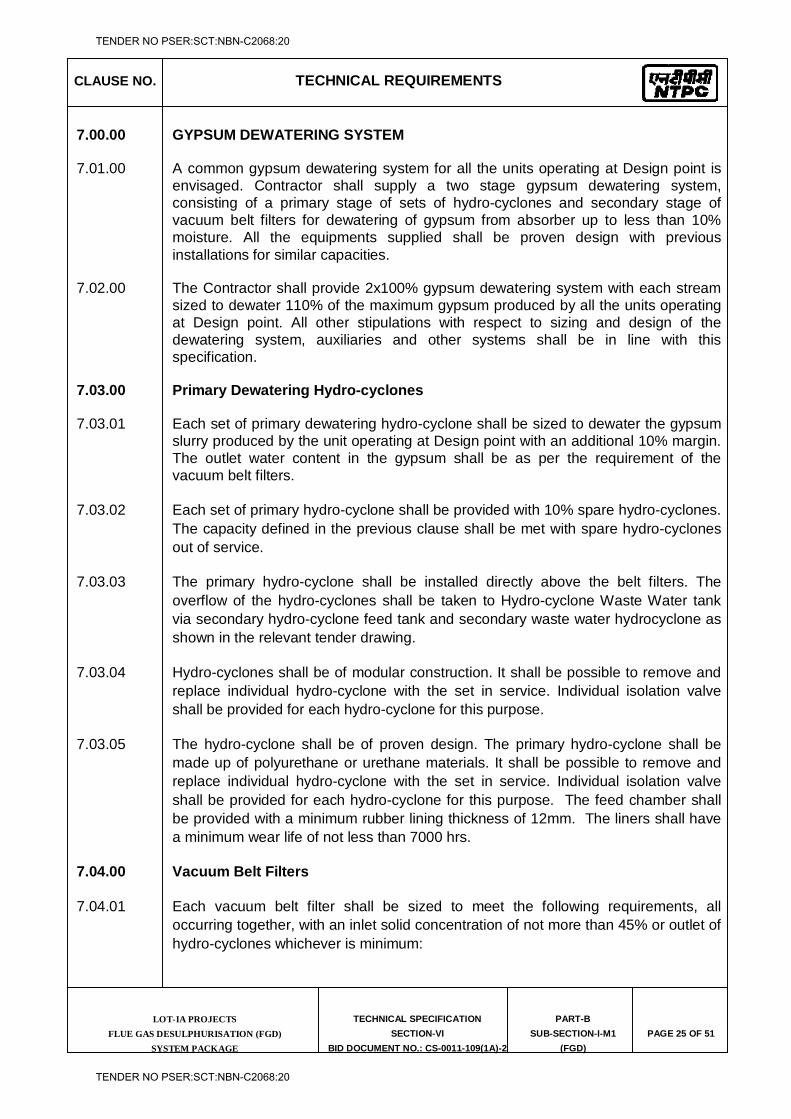
CLAUSE NO. TECHNICAL REQUIREMENTS
LOT-IA PROJECTS FLUE GAS DESULPHURISATION (FGD)
SYSTEM PACKAGE
TECHNICAL SPECIFICATION
SECTION-VI
BID DOCUMENT NO.: CS-0011-109(1A)-2
PART-B
SUB-SECTION-I-M1
(FGD)
PAGE 25 OF 51
7.00.00 GYPSUM DEWATERING SYSTEM
7.01.00 A common gypsum dewatering system for all the units operating at Design point is envisaged. Contractor shall supply a two stage gypsum dewatering system, consisting of a primary stage of sets of hydro-cyclones and secondary stage of vacuum belt filters for dewatering of gypsum from absorber up to less than 10% moisture. All the equipments supplied shall be proven design with previous installations for similar capacities.
7.02.00 The Contractor shall provide 2x100% gypsum dewatering system with each stream sized to dewater 110% of the maximum gypsum produced by all the units operating at Design point. All other stipulations with respect to sizing and design of the dewatering system, auxiliaries and other systems shall be in line with this specification.
7.03.00 Primary Dewatering Hydro-cyclones
7.03.01 Each set of primary dewatering hydro-cyclone shall be sized to dewater the gypsum slurry produced by the unit operating at Design point with an additional 10% margin. The outlet water content in the gypsum shall be as per the requirement of the vacuum belt filters.
7.03.02 Each set of primary hydro-cyclone shall be provided with 10% spare hydro-cyclones. The capacity defined in the previous clause shall be met with spare hydro-cyclones out of service.
7.03.03 The primary hydro-cyclone shall be installed directly above the belt filters. The overflow of the hydro-cyclones shall be taken to Hydro-cyclone Waste Water tank via secondary hydro-cyclone feed tank and secondary waste water hydrocyclone as shown in the relevant tender drawing.
7.03.04 Hydro-cyclones shall be of modular construction. It shall be possible to remove and replace individual hydro-cyclone with the set in service. Individual isolation valve shall be provided for each hydro-cyclone for this purpose.
7.03.05 The hydro-cyclone shall be of proven design. The primary hydro-cyclone shall be made up of polyurethane or urethane materials. It shall be possible to remove and replace individual hydro-cyclone with the set in service. Individual isolation valve shall be provided for each hydro-cyclone for this purpose. The feed chamber shall be provided with a minimum rubber lining thickness of 12mm. The liners shall have a minimum wear life of not less than 7000 hrs.
7.04.00 Vacuum Belt Filters
7.04.01 Each vacuum belt filter shall be sized to meet the following requirements, all occurring together, with an inlet solid concentration of not more than 45% or outlet of hydro-cyclones whichever is minimum:
TENDER NO PSER:SCT:NBN-C2068:20
TENDER NO PSER:SCT:NBN-C2068:20
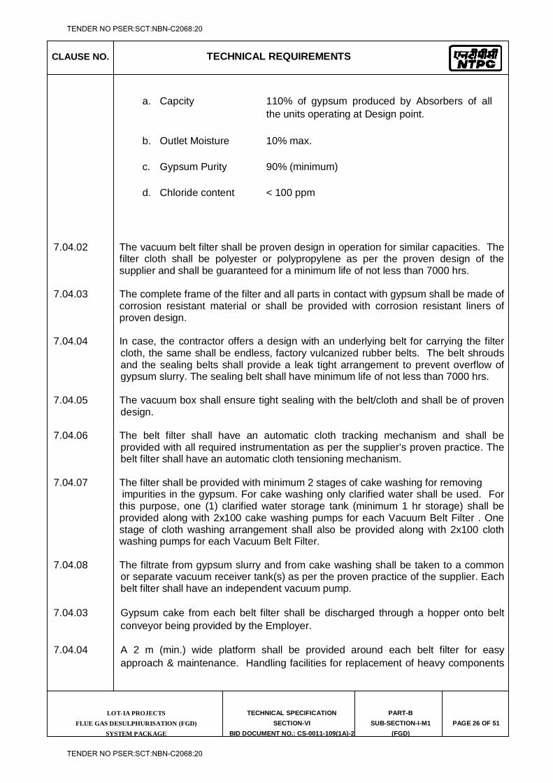
CLAUSE NO. TECHNICAL REQUIREMENTS
LOT-IA PROJECTS FLUE GAS DESULPHURISATION (FGD)
SYSTEM PACKAGE
TECHNICAL SPECIFICATION
SECTION-VI
BID DOCUMENT NO.: CS-0011-109(1A)-2
PART-B
SUB-SECTION-I-M1
(FGD)
PAGE 26 OF 51
a. Capcity 110% of gypsum produced by Absorbers of all the units operating at Design point.
b. Outlet Moisture 10% max.
c. Gypsum Purity 90% (minimum)
d. Chloride content < 100 ppm
7.04.02 The vacuum belt filter shall be proven design in operation for similar capacities. The filter cloth shall be polyester or polypropylene as per the proven design of the supplier and shall be guaranteed for a minimum life of not less than 7000 hrs.
7.04.03 The complete frame of the filter and all parts in contact with gypsum shall be made of
corrosion resistant material or shall be provided with corrosion resistant liners of proven design.
7.04.04 In case, the contractor offers a design with an underlying belt for carrying the filter
cloth, the same shall be endless, factory vulcanized rubber belts. The belt shrouds and the sealing belts shall provide a leak tight arrangement to prevent overflow of gypsum slurry. The sealing belt shall have minimum life of not less than 7000 hrs.
7.04.05 The vacuum box shall ensure tight sealing with the belt/cloth and shall be of proven
design. 7.04.06 The belt filter shall have an automatic cloth tracking mechanism and shall be
provided with all required instrumentation as per the supplier’s proven practice. The belt filter shall have an automatic cloth tensioning mechanism.
7.04.07 The filter shall be provided with minimum 2 stages of cake washing for removing impurities in the gypsum. For cake washing only clarified water shall be used. For
this purpose, one (1) clarified water storage tank (minimum 1 hr storage) shall be provided along with 2x100 cake washing pumps for each Vacuum Belt Filter . One stage of cloth washing arrangement shall also be provided along with 2x100 cloth washing pumps for each Vacuum Belt Filter.
7.04.08 The filtrate from gypsum slurry and from cake washing shall be taken to a common
or separate vacuum receiver tank(s) as per the proven practice of the supplier. Each belt filter shall have an independent vacuum pump.
7.04.03 Gypsum cake from each belt filter shall be discharged through a hopper onto belt conveyor being provided by the Employer.
7.04.04 A 2 m (min.) wide platform shall be provided around each belt filter for easy approach & maintenance. Handling facilities for replacement of heavy components
TENDER NO PSER:SCT:NBN-C2068:20
TENDER NO PSER:SCT:NBN-C2068:20
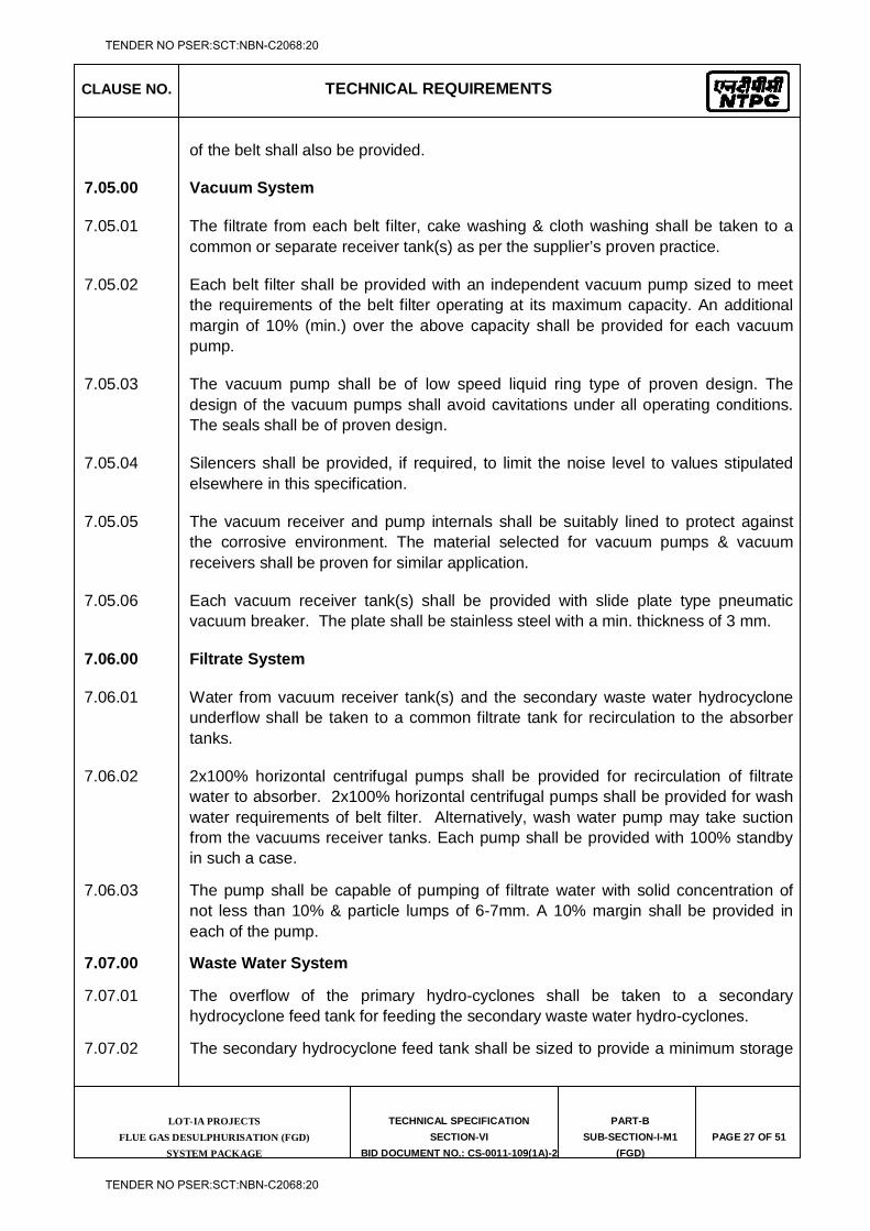
CLAUSE NO. TECHNICAL REQUIREMENTS
LOT-IA PROJECTS FLUE GAS DESULPHURISATION (FGD)
SYSTEM PACKAGE
TECHNICAL SPECIFICATION
SECTION-VI
BID DOCUMENT NO.: CS-0011-109(1A)-2
PART-B
SUB-SECTION-I-M1
(FGD)
PAGE 27 OF 51
of the belt shall also be provided.
7.05.00 Vacuum System
7.05.01 The filtrate from each belt filter, cake washing & cloth washing shall be taken to a common or separate receiver tank(s) as per the supplier’s proven practice.
7.05.02 Each belt filter shall be provided with an independent vacuum pump sized to meet the requirements of the belt filter operating at its maximum capacity. An additional margin of 10% (min.) over the above capacity shall be provided for each vacuum pump.
7.05.03 The vacuum pump shall be of low speed liquid ring type of proven design. The design of the vacuum pumps shall avoid cavitations under all operating conditions. The seals shall be of proven design.
7.05.04 Silencers shall be provided, if required, to limit the noise level to values stipulated elsewhere in this specification.
7.05.05 The vacuum receiver and pump internals shall be suitably lined to protect against the corrosive environment. The material selected for vacuum pumps & vacuum receivers shall be proven for similar application.
7.05.06 Each vacuum receiver tank(s) shall be provided with slide plate type pneumatic vacuum breaker. The plate shall be stainless steel with a min. thickness of 3 mm.
7.06.00 Filtrate System
7.06.01 Water from vacuum receiver tank(s) and the secondary waste water hydrocyclone underflow shall be taken to a common filtrate tank for recirculation to the absorber tanks.
7.06.02 2x100% horizontal centrifugal pumps shall be provided for recirculation of filtrate water to absorber. 2x100% horizontal centrifugal pumps shall be provided for wash water requirements of belt filter. Alternatively, wash water pump may take suction from the vacuums receiver tanks. Each pump shall be provided with 100% standby in such a case.
7.06.03 The pump shall be capable of pumping of filtrate water with solid concentration of not less than 10% & particle lumps of 6-7mm. A 10% margin shall be provided in each of the pump.
7.07.00 Waste Water System
7.07.01 The overflow of the primary hydro-cyclones shall be taken to a secondary hydrocyclone feed tank for feeding the secondary waste water hydro-cyclones.
7.07.02 The secondary hydrocyclone feed tank shall be sized to provide a minimum storage
TENDER NO PSER:SCT:NBN-C2068:20
TENDER NO PSER:SCT:NBN-C2068:20
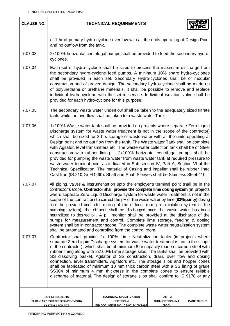
CLAUSE NO. TECHNICAL REQUIREMENTS
LOT-IA PROJECTS FLUE GAS DESULPHURISATION (FGD)
SYSTEM PACKAGE
TECHNICAL SPECIFICATION
SECTION-VI
BID DOCUMENT NO.: CS-0011-109(1A)-2
PART-B
SUB-SECTION-I-M1
(FGD)
PAGE 28 OF 51
of 1 hr of primary hydro-cyclone overflow with all the units operating at Design Point and no outflow from the tank.
7.07.03 2x100% horizontal centrifugal pumps shall be provided to feed the secondary hydro-cyclones.
7.07.04 Each set of hydro-cyclone shall be sized to process the maximum discharge from the secondary hydro-cyclone feed pumps. A minimum 10% spare hydro-cyclones shall be provided in each set. Secondary Hydro-cyclones shall be of modular construction and of proven design. The secondary hydro-cyclone shall be made up of polyurethane or urethane materials. It shall be possible to remove and replace individual hydro-cyclone with the set in service. Individual isolation valve shall be provided for each hydro-cyclone for this purpose.
7.07.05 The secondary waste water underflow shall be taken to the adequately sized filtrate tank, while the overflow shall be taken to a waste water Tank.
7.07.06 1x100% Waste water tank shall be provided (in projects where separate Zero Liquid Discharge system for waste water treatment is not in the scope of the contractor) which shall be sized for 8 hrs storage of waste water with all the units operating at Design point and no out flow from the tank. The Waste water Tank shall be complete with Agitator, level transmitters etc. The waste water collection tank shall be of Steel construction with rubber lining. 2x100% horizontal centrifugal pumps shall be provided for pumping the waste water from waste water tank at required pressure to waste water terminal point as indicated in Sub-section IV, Part A, Section VI of the Technical Specification. The material of Casing and impeller shall be rubber lined Cast Iron (IS:210 Gr FG260). Shaft and Shaft Sleeves shall be Stainless Steel-410.
7.07.07 All piping, valves & instrumentation upto the employer’s terminal point shall be in the contractor’s scope. Contractor shall provide the complete lime dosing system (in projects where separate Zero Liquid Discharge system for waste water treatment is not in the scope of the contractor) to correct the pH of the waste water by lime (83% purity) dosing shall be provided and after mixing of the effluent (using re-circulation system of the pumping system), the effluent shall be discharged once the waste water has been neutralized to desired pH. A pH monitor shall be provided at the discharge of the pumps for measurement and control. Complete lime storage, feeding & dosing system shall be in contractor scope. The complete waste water neutralization system shall be automated and controlled from the control room.
7.07.07 Contractor shall provide 2x 100% Lime Neutralization tanks (in projects where separate Zero Liquid Discharge system for waste water treatment is not in the scope of the contractor) which shall be of minimum 8 hr capacity made of carbon steel with rubber lining along with 2x100% Lime storage silos. The tanks shall be provided with SS dissolving basket, Agitator of SS construction, drain, over flow and dosing connection, level transmitters, Agitators etc. The storage silos and hopper cones shall be fabricated of minimum 10 mm thick carbon steel with a SS lining of grade SS304 of minimum 4 mm thickness in the complete cones to ensure reliable discharge of material. The design of storage silos shall confirm to IS 9178 or any
TENDER NO PSER:SCT:NBN-C2068:20
TENDER NO PSER:SCT:NBN-C2068:20
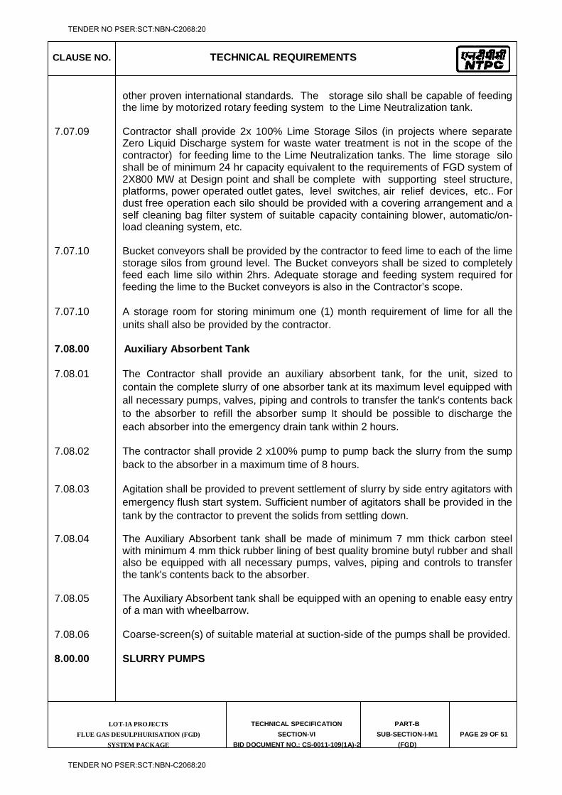
CLAUSE NO. TECHNICAL REQUIREMENTS
LOT-IA PROJECTS FLUE GAS DESULPHURISATION (FGD)
SYSTEM PACKAGE
TECHNICAL SPECIFICATION
SECTION-VI
BID DOCUMENT NO.: CS-0011-109(1A)-2
PART-B
SUB-SECTION-I-M1
(FGD)
PAGE 29 OF 51
other proven international standards. The storage silo shall be capable of feeding the lime by motorized rotary feeding system to the Lime Neutralization tank.
7.07.09 Contractor shall provide 2x 100% Lime Storage Silos (in projects where separate
Zero Liquid Discharge system for waste water treatment is not in the scope of the contractor) for feeding lime to the Lime Neutralization tanks. The lime storage silo shall be of minimum 24 hr capacity equivalent to the requirements of FGD system of 2X800 MW at Design point and shall be complete with supporting steel structure, platforms, power operated outlet gates, level switches, air relief devices, etc.. For dust free operation each silo should be provided with a covering arrangement and a self cleaning bag filter system of suitable capacity containing blower, automatic/on-load cleaning system, etc.
7.07.10 Bucket conveyors shall be provided by the contractor to feed lime to each of the lime
storage silos from ground level. The Bucket conveyors shall be sized to completely feed each lime silo within 2hrs. Adequate storage and feeding system required for feeding the lime to the Bucket conveyors is also in the Contractor’s scope.
7.07.10 A storage room for storing minimum one (1) month requirement of lime for all the units shall also be provided by the contractor.
7.08.00 Auxiliary Absorbent Tank
7.08.01 The Contractor shall provide an auxiliary absorbent tank, for the unit, sized to contain the complete slurry of one absorber tank at its maximum level equipped with all necessary pumps, valves, piping and controls to transfer the tank's contents back to the absorber to refill the absorber sump It should be possible to discharge the each absorber into the emergency drain tank within 2 hours.
7.08.02 The contractor shall provide 2 x100% pump to pump back the slurry from the sump back to the absorber in a maximum time of 8 hours.
7.08.03 Agitation shall be provided to prevent settlement of slurry by side entry agitators with emergency flush start system. Sufficient number of agitators shall be provided in the tank by the contractor to prevent the solids from settling down.
7.08.04 The Auxiliary Absorbent tank shall be made of minimum 7 mm thick carbon steel with minimum 4 mm thick rubber lining of best quality bromine butyl rubber and shall also be equipped with all necessary pumps, valves, piping and controls to transfer the tank's contents back to the absorber.
7.08.05 The Auxiliary Absorbent tank shall be equipped with an opening to enable easy entry of a man with wheelbarrow.
7.08.06 Coarse-screen(s) of suitable material at suction-side of the pumps shall be provided.
8.00.00 SLURRY PUMPS
TENDER NO PSER:SCT:NBN-C2068:20
TENDER NO PSER:SCT:NBN-C2068:20
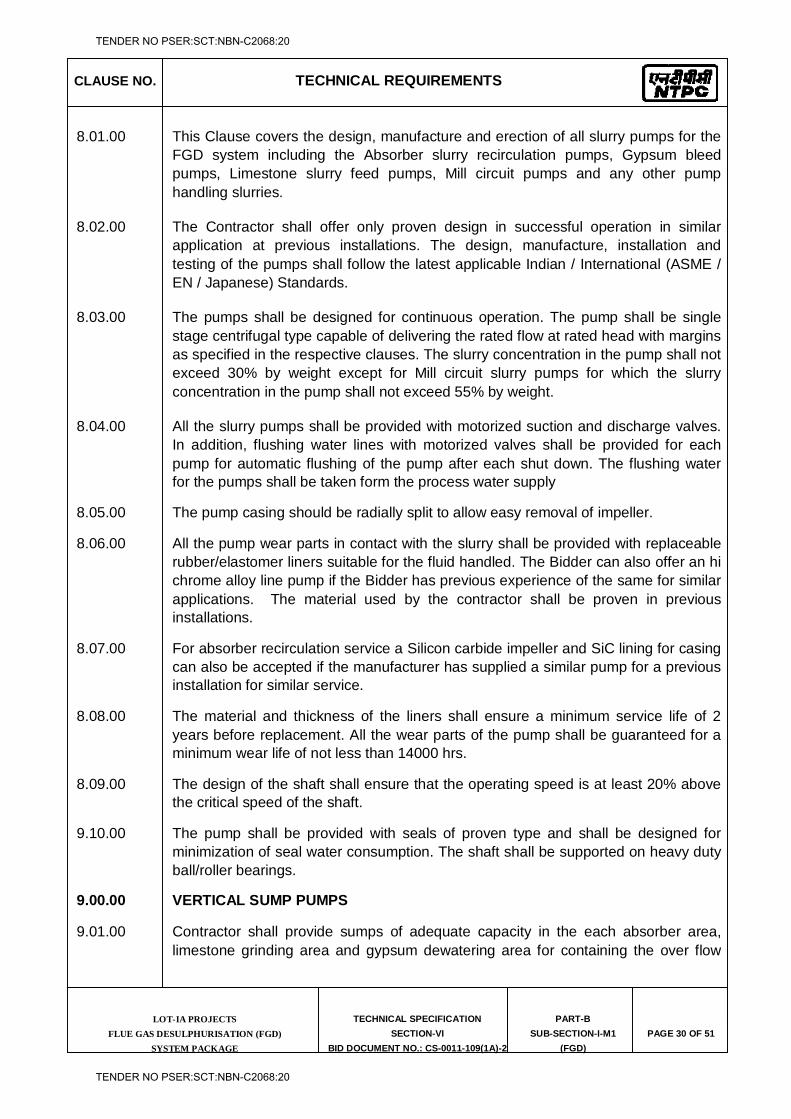
CLAUSE NO. TECHNICAL REQUIREMENTS
LOT-IA PROJECTS FLUE GAS DESULPHURISATION (FGD)
SYSTEM PACKAGE
TECHNICAL SPECIFICATION
SECTION-VI
BID DOCUMENT NO.: CS-0011-109(1A)-2
PART-B
SUB-SECTION-I-M1
(FGD)
PAGE 30 OF 51
8.01.00 This Clause covers the design, manufacture and erection of all slurry pumps for the FGD system including the Absorber slurry recirculation pumps, Gypsum bleed pumps, Limestone slurry feed pumps, Mill circuit pumps and any other pump handling slurries.
8.02.00 The Contractor shall offer only proven design in successful operation in similar application at previous installations. The design, manufacture, installation and testing of the pumps shall follow the latest applicable Indian / International (ASME / EN / Japanese) Standards.
8.03.00 The pumps shall be designed for continuous operation. The pump shall be single stage centrifugal type capable of delivering the rated flow at rated head with margins as specified in the respective clauses. The slurry concentration in the pump shall not exceed 30% by weight except for Mill circuit slurry pumps for which the slurry concentration in the pump shall not exceed 55% by weight.
8.04.00 All the slurry pumps shall be provided with motorized suction and discharge valves. In addition, flushing water lines with motorized valves shall be provided for each pump for automatic flushing of the pump after each shut down. The flushing water for the pumps shall be taken form the process water supply
8.05.00 The pump casing should be radially split to allow easy removal of impeller.
8.06.00 All the pump wear parts in contact with the slurry shall be provided with replaceable rubber/elastomer liners suitable for the fluid handled. The Bidder can also offer an hi chrome alloy line pump if the Bidder has previous experience of the same for similar applications. The material used by the contractor shall be proven in previous installations.
8.07.00 For absorber recirculation service a Silicon carbide impeller and SiC lining for casing can also be accepted if the manufacturer has supplied a similar pump for a previous installation for similar service.
8.08.00 The material and thickness of the liners shall ensure a minimum service life of 2 years before replacement. All the wear parts of the pump shall be guaranteed for a minimum wear life of not less than 14000 hrs.
8.09.00 The design of the shaft shall ensure that the operating speed is at least 20% above the critical speed of the shaft.
9.10.00 The pump shall be provided with seals of proven type and shall be designed for minimization of seal water consumption. The shaft shall be supported on heavy duty ball/roller bearings.
9.00.00 VERTICAL SUMP PUMPS
9.01.00 Contractor shall provide sumps of adequate capacity in the each absorber area, limestone grinding area and gypsum dewatering area for containing the over flow
TENDER NO PSER:SCT:NBN-C2068:20
TENDER NO PSER:SCT:NBN-C2068:20
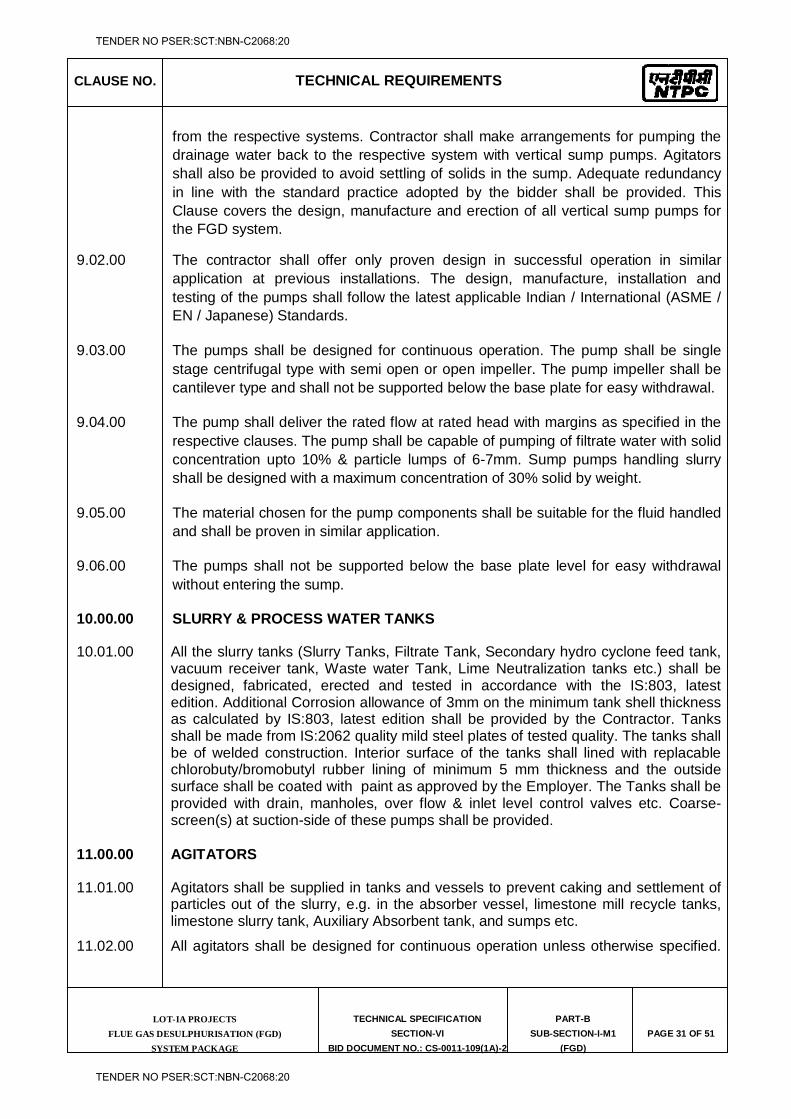
CLAUSE NO. TECHNICAL REQUIREMENTS
LOT-IA PROJECTS FLUE GAS DESULPHURISATION (FGD)
SYSTEM PACKAGE
TECHNICAL SPECIFICATION
SECTION-VI
BID DOCUMENT NO.: CS-0011-109(1A)-2
PART-B
SUB-SECTION-I-M1
(FGD)
PAGE 31 OF 51
from the respective systems. Contractor shall make arrangements for pumping the drainage water back to the respective system with vertical sump pumps. Agitators shall also be provided to avoid settling of solids in the sump. Adequate redundancy in line with the standard practice adopted by the bidder shall be provided. This Clause covers the design, manufacture and erection of all vertical sump pumps for the FGD system.
9.02.00 The contractor shall offer only proven design in successful operation in similar application at previous installations. The design, manufacture, installation and testing of the pumps shall follow the latest applicable Indian / International (ASME / EN / Japanese) Standards.
9.03.00 The pumps shall be designed for continuous operation. The pump shall be single stage centrifugal type with semi open or open impeller. The pump impeller shall be cantilever type and shall not be supported below the base plate for easy withdrawal.
9.04.00 The pump shall deliver the rated flow at rated head with margins as specified in the respective clauses. The pump shall be capable of pumping of filtrate water with solid concentration upto 10% & particle lumps of 6-7mm. Sump pumps handling slurry shall be designed with a maximum concentration of 30% solid by weight.
9.05.00 The material chosen for the pump components shall be suitable for the fluid handled and shall be proven in similar application.
9.06.00 The pumps shall not be supported below the base plate level for easy withdrawal without entering the sump.
10.00.00 SLURRY & PROCESS WATER TANKS
10.01.00 All the slurry tanks (Slurry Tanks, Filtrate Tank, Secondary hydro cyclone feed tank, vacuum receiver tank, Waste water Tank, Lime Neutralization tanks etc.) shall be designed, fabricated, erected and tested in accordance with the IS:803, latest edition. Additional Corrosion allowance of 3mm on the minimum tank shell thickness as calculated by IS:803, latest edition shall be provided by the Contractor. Tanks shall be made from IS:2062 quality mild steel plates of tested quality. The tanks shall be of welded construction. Interior surface of the tanks shall lined with replacable chlorobuty/bromobutyl rubber lining of minimum 5 mm thickness and the outside surface shall be coated with paint as approved by the Employer. The Tanks shall be provided with drain, manholes, over flow & inlet level control valves etc. Coarse-screen(s) at suction-side of these pumps shall be provided.
11.00.00 AGITATORS
11.01.00 Agitators shall be supplied in tanks and vessels to prevent caking and settlement of particles out of the slurry, e.g. in the absorber vessel, limestone mill recycle tanks, limestone slurry tank, Auxiliary Absorbent tank, and sumps etc.
11.02.00 All agitators shall be designed for continuous operation unless otherwise specified.
TENDER NO PSER:SCT:NBN-C2068:20
TENDER NO PSER:SCT:NBN-C2068:20
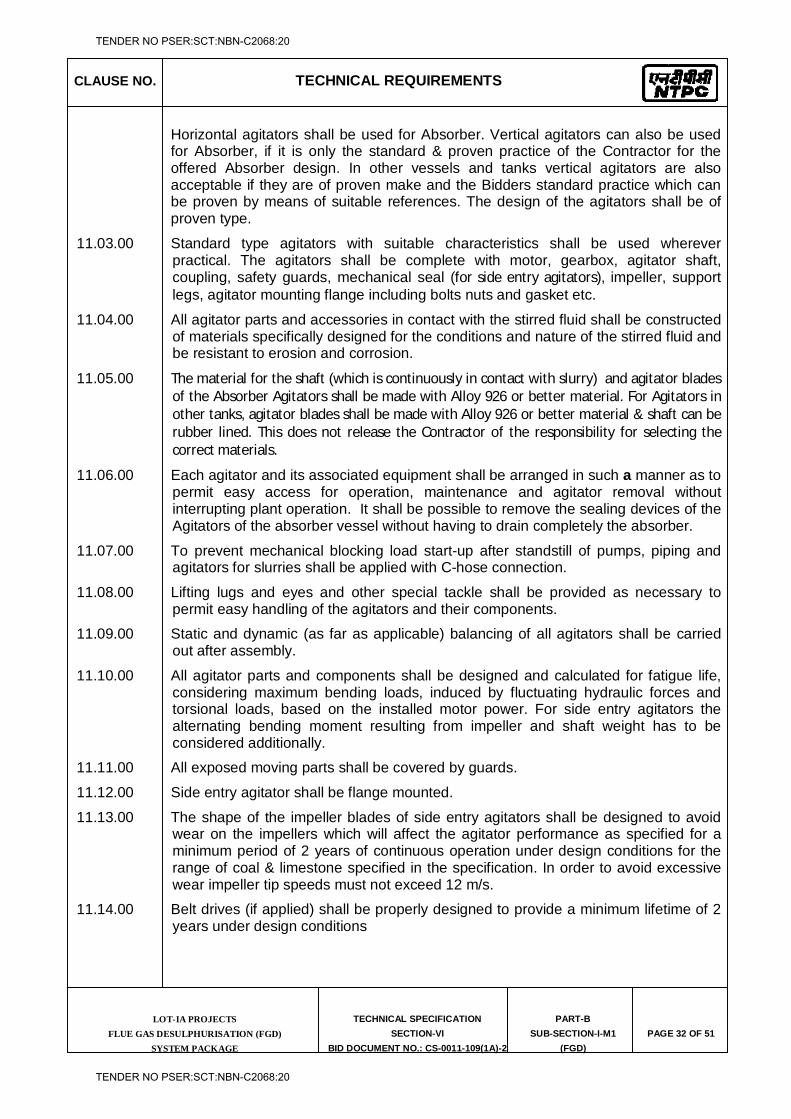
CLAUSE NO. TECHNICAL REQUIREMENTS
LOT-IA PROJECTS FLUE GAS DESULPHURISATION (FGD)
SYSTEM PACKAGE
TECHNICAL SPECIFICATION
SECTION-VI
BID DOCUMENT NO.: CS-0011-109(1A)-2
PART-B
SUB-SECTION-I-M1
(FGD)
PAGE 32 OF 51
Horizontal agitators shall be used for Absorber. Vertical agitators can also be used for Absorber, if it is only the standard & proven practice of the Contractor for the offered Absorber design. In other vessels and tanks vertical agitators are also acceptable if they are of proven make and the Bidders standard practice which can be proven by means of suitable references. The design of the agitators shall be of proven type.
11.03.00 Standard type agitators with suitable characteristics shall be used wherever practical. The agitators shall be complete with motor, gearbox, agitator shaft, coupling, safety guards, mechanical seal (for side entry agitators), impeller, support legs, agitator mounting flange including bolts nuts and gasket etc.
11.04.00 All agitator parts and accessories in contact with the stirred fluid shall be constructed of materials specifically designed for the conditions and nature of the stirred fluid and be resistant to erosion and corrosion.
11.05.00 The material for the shaft (which is continuously in contact with slurry) and agitator blades of the Absorber Agitators shall be made with Alloy 926 or better material. For Agitators in other tanks, agitator blades shall be made with Alloy 926 or better material & shaft can be rubber lined. This does not release the Contractor of the responsibility for selecting the correct materials.
11.06.00 Each agitator and its associated equipment shall be arranged in such a manner as to permit easy access for operation, maintenance and agitator removal without interrupting plant operation. It shall be possible to remove the sealing devices of the Agitators of the absorber vessel without having to drain completely the absorber.
11.07.00 To prevent mechanical blocking load start-up after standstill of pumps, piping and agitators for slurries shall be applied with C-hose connection.
11.08.00 Lifting lugs and eyes and other special tackle shall be provided as necessary to permit easy handling of the agitators and their components.
11.09.00 Static and dynamic (as far as applicable) balancing of all agitators shall be carried out after assembly.
11.10.00 All agitator parts and components shall be designed and calculated for fatigue life, considering maximum bending loads, induced by fluctuating hydraulic forces and torsional loads, based on the installed motor power. For side entry agitators the alternating bending moment resulting from impeller and shaft weight has to be considered additionally.
11.11.00 All exposed moving parts shall be covered by guards.
11.12.00 Side entry agitator shall be flange mounted.
11.13.00 The shape of the impeller blades of side entry agitators shall be designed to avoid wear on the impellers which will affect the agitator performance as specified for a minimum period of 2 years of continuous operation under design conditions for the range of coal & limestone specified in the specification. In order to avoid excessive wear impeller tip speeds must not exceed 12 m/s.
11.14.00 Belt drives (if applied) shall be properly designed to provide a minimum lifetime of 2 years under design conditions
TENDER NO PSER:SCT:NBN-C2068:20
TENDER NO PSER:SCT:NBN-C2068:20
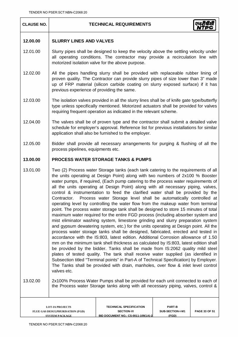
CLAUSE NO. TECHNICAL REQUIREMENTS
LOT-IA PROJECTS FLUE GAS DESULPHURISATION (FGD)
SYSTEM PACKAGE
TECHNICAL SPECIFICATION
SECTION-VI
BID DOCUMENT NO.: CS-0011-109(1A)-2
PART-B
SUB-SECTION-I-M1
(FGD)
PAGE 33 OF 51
12.00.00 SLURRY LINES AND VALVES
12.01.00 Slurry pipes shall be designed to keep the velocity above the settling velocity under all operating conditions. The contractor may provide a recirculation line with motorized isolation valve for the above purpose.
12.02.00 All the pipes handling slurry shall be provided with replaceable rubber lining of proven quality. The Contractor can provide slurry pipes of size lower than 3” made up of FRP material (silicon carbide coating on slurry exposed surface) if it has previous experience of providing the same.
12.03.00 The isolation valves provided in all the slurry lines shall be of knife gate type/butterfly type unless specifically mentioned. Motorized actuators shall be provided for valves requiring frequent operation as indicated in the relevant scheme.
12.04.00 The valves shall be of proven type and the contractor shall submit a detailed valve schedule for employer’s approval. Reference list for previous installations for similar application shall also be furnished to the employer.
12.05.00 Bidder shall provide all necessary arrangements for purging & flushing of all the process pipelines, equipments etc.
13.00.00 PROCESS WATER STORAGE TANKS & PUMPS
13.01.00 Two (2) Process water Storage tanks (each tank catering to the requirements of all the units operating at Design Point) along with two numbers of 2x100 % Booster water pumps, if required, (Each pump catering to the process water requirements of all the units operating at Design Point) along with all necessary piping, valves, control & instrumentation to feed the clarified water shall be provided by the Contractor. Process water Storage level shall be automatically controlled at operating level by controlling the water flow from the makeup water from terminal point. The process water storage tank shall be designed to store 15 minutes of total maximum water required for the entire FGD process (including absorber system and mist eliminator washing system, limestone grinding and slurry preparation system and gypsum dewatering system, etc.) for the units operating at Design point. All the process water storage tanks shall be designed, fabricated, erected and tested in accordance with the IS:803, latest edition. Additional Corrosion allowance of 1.50 mm on the minimum tank shell thickness as calculated by IS:803, latest edition shall be provided by the bidder. Tanks shall be made from IS:2062 quality mild steel plates of tested quality. The tank shall receive water supplied (as identified in Subsection titled “Terminal points” in Part-A of Technical Specification) by Employer. The Tanks shall be provided with drain, manholes, over flow & inlet level control valves etc.
13.02.00 2x100% Process Water Pumps shall be provided for each unit connected to each of the Process water Storage tanks along with all necessary piping, valves, control &
TENDER NO PSER:SCT:NBN-C2068:20
TENDER NO PSER:SCT:NBN-C2068:20
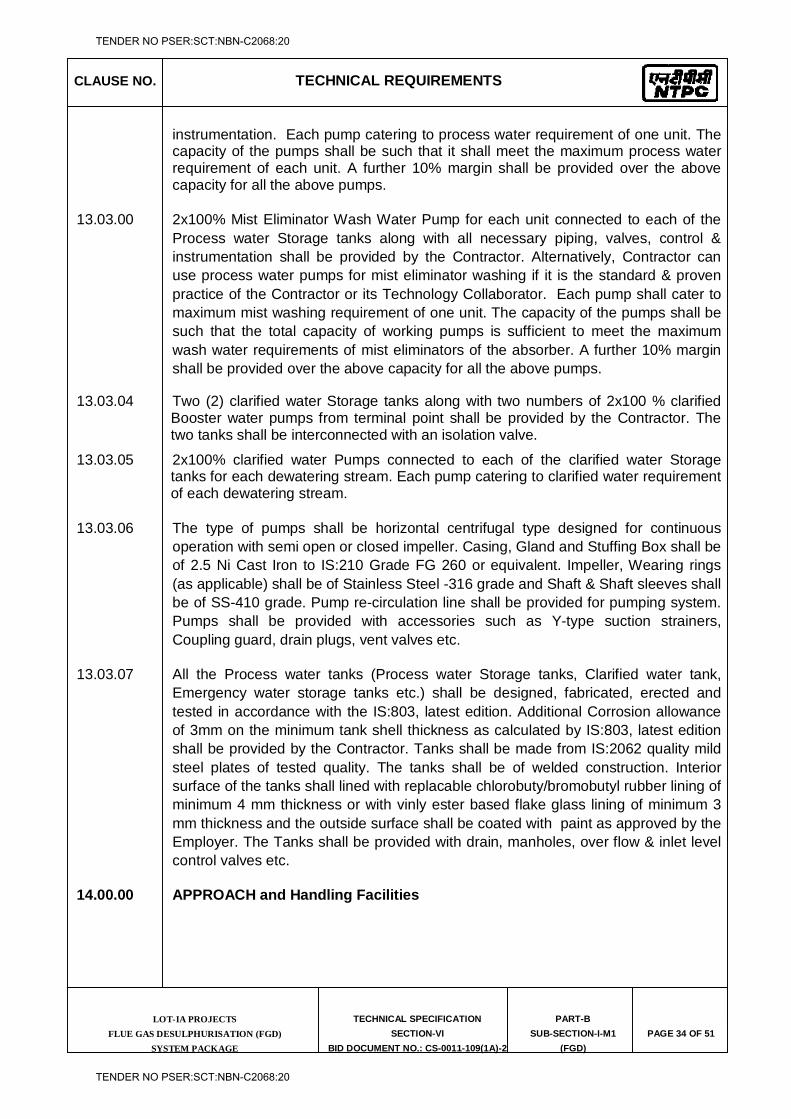
CLAUSE NO. TECHNICAL REQUIREMENTS
LOT-IA PROJECTS FLUE GAS DESULPHURISATION (FGD)
SYSTEM PACKAGE
TECHNICAL SPECIFICATION
SECTION-VI
BID DOCUMENT NO.: CS-0011-109(1A)-2
PART-B
SUB-SECTION-I-M1
(FGD)
PAGE 34 OF 51
instrumentation. Each pump catering to process water requirement of one unit. The capacity of the pumps shall be such that it shall meet the maximum process water requirement of each unit. A further 10% margin shall be provided over the above capacity for all the above pumps.
13.03.00 2x100% Mist Eliminator Wash Water Pump for each unit connected to each of the Process water Storage tanks along with all necessary piping, valves, control & instrumentation shall be provided by the Contractor. Alternatively, Contractor can use process water pumps for mist eliminator washing if it is the standard & proven practice of the Contractor or its Technology Collaborator. Each pump shall cater to maximum mist washing requirement of one unit. The capacity of the pumps shall be such that the total capacity of working pumps is sufficient to meet the maximum wash water requirements of mist eliminators of the absorber. A further 10% margin shall be provided over the above capacity for all the above pumps.
13.03.04 Two (2) clarified water Storage tanks along with two numbers of 2x100 % clarified Booster water pumps from terminal point shall be provided by the Contractor. The two tanks shall be interconnected with an isolation valve.
13.03.05 2x100% clarified water Pumps connected to each of the clarified water Storage tanks for each dewatering stream. Each pump catering to clarified water requirement of each dewatering stream.
13.03.06 The type of pumps shall be horizontal centrifugal type designed for continuous operation with semi open or closed impeller. Casing, Gland and Stuffing Box shall be of 2.5 Ni Cast Iron to IS:210 Grade FG 260 or equivalent. Impeller, Wearing rings (as applicable) shall be of Stainless Steel -316 grade and Shaft & Shaft sleeves shall be of SS-410 grade. Pump re-circulation line shall be provided for pumping system. Pumps shall be provided with accessories such as Y-type suction strainers, Coupling guard, drain plugs, vent valves etc.
13.03.07 All the Process water tanks (Process water Storage tanks, Clarified water tank, Emergency water storage tanks etc.) shall be designed, fabricated, erected and tested in accordance with the IS:803, latest edition. Additional Corrosion allowance of 3mm on the minimum tank shell thickness as calculated by IS:803, latest edition shall be provided by the Contractor. Tanks shall be made from IS:2062 quality mild steel plates of tested quality. The tanks shall be of welded construction. Interior surface of the tanks shall lined with replacable chlorobuty/bromobutyl rubber lining of minimum 4 mm thickness or with vinly ester based flake glass lining of minimum 3 mm thickness and the outside surface shall be coated with paint as approved by the Employer. The Tanks shall be provided with drain, manholes, over flow & inlet level control valves etc.
14.00.00 APPROACH and Handling Facilities
TENDER NO PSER:SCT:NBN-C2068:20
TENDER NO PSER:SCT:NBN-C2068:20
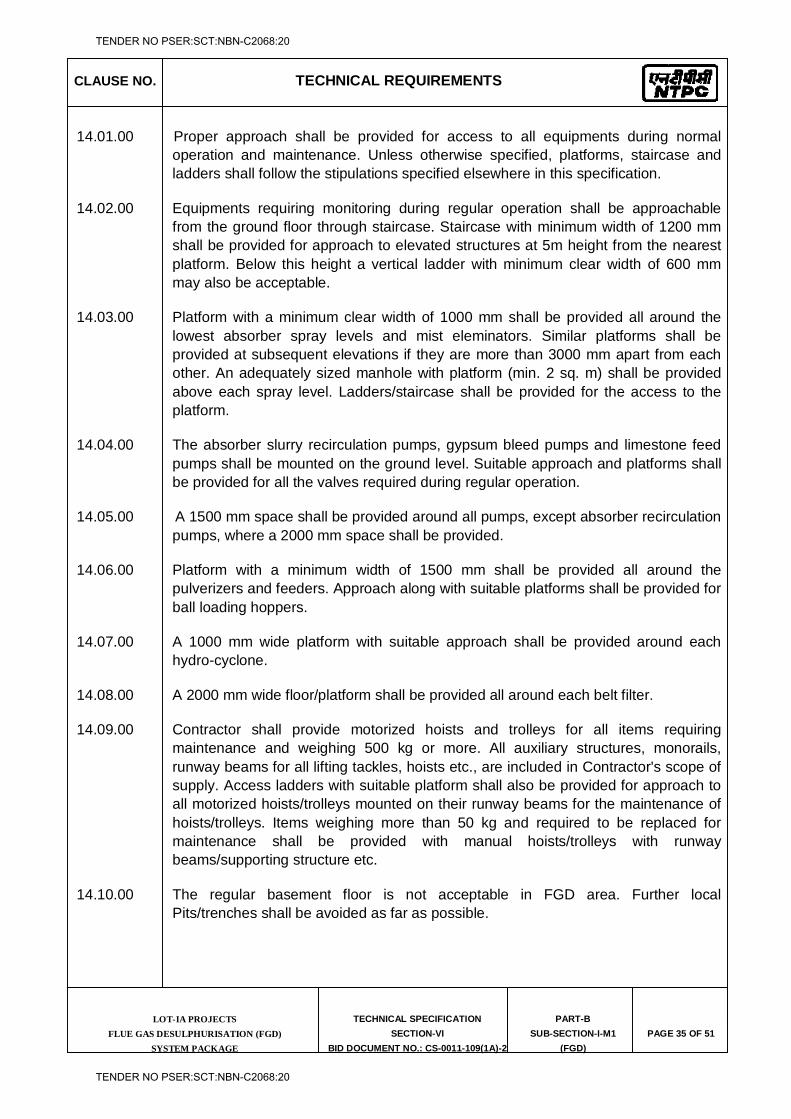
CLAUSE NO. TECHNICAL REQUIREMENTS
LOT-IA PROJECTS FLUE GAS DESULPHURISATION (FGD)
SYSTEM PACKAGE
TECHNICAL SPECIFICATION
SECTION-VI
BID DOCUMENT NO.: CS-0011-109(1A)-2
PART-B
SUB-SECTION-I-M1
(FGD)
PAGE 35 OF 51
14.01.00 Proper approach shall be provided for access to all equipments during normal operation and maintenance. Unless otherwise specified, platforms, staircase and ladders shall follow the stipulations specified elsewhere in this specification.
14.02.00 Equipments requiring monitoring during regular operation shall be approachable from the ground floor through staircase. Staircase with minimum width of 1200 mm shall be provided for approach to elevated structures at 5m height from the nearest platform. Below this height a vertical ladder with minimum clear width of 600 mm may also be acceptable.
14.03.00 Platform with a minimum clear width of 1000 mm shall be provided all around the lowest absorber spray levels and mist eleminators. Similar platforms shall be provided at subsequent elevations if they are more than 3000 mm apart from each other. An adequately sized manhole with platform (min. 2 sq. m) shall be provided above each spray level. Ladders/staircase shall be provided for the access to the platform.
14.04.00 The absorber slurry recirculation pumps, gypsum bleed pumps and limestone feed pumps shall be mounted on the ground level. Suitable approach and platforms shall be provided for all the valves required during regular operation.
14.05.00 A 1500 mm space shall be provided around all pumps, except absorber recirculation pumps, where a 2000 mm space shall be provided.
14.06.00 Platform with a minimum width of 1500 mm shall be provided all around the pulverizers and feeders. Approach along with suitable platforms shall be provided for ball loading hoppers.
14.07.00 A 1000 mm wide platform with suitable approach shall be provided around each hydro-cyclone.
14.08.00 A 2000 mm wide floor/platform shall be provided all around each belt filter.
14.09.00 Contractor shall provide motorized hoists and trolleys for all items requiring maintenance and weighing 500 kg or more. All auxiliary structures, monorails, runway beams for all lifting tackles, hoists etc., are included in Contractor's scope of supply. Access ladders with suitable platform shall also be provided for approach to all motorized hoists/trolleys mounted on their runway beams for the maintenance of hoists/trolleys. Items weighing more than 50 kg and required to be replaced for maintenance shall be provided with manual hoists/trolleys with runway beams/supporting structure etc.
14.10.00 The regular basement floor is not acceptable in FGD area. Further local Pits/trenches shall be avoided as far as possible.
TENDER NO PSER:SCT:NBN-C2068:20
TENDER NO PSER:SCT:NBN-C2068:20
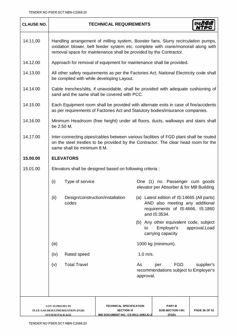
CLAUSE NO. TECHNICAL REQUIREMENTS
LOT-IA PROJECTS FLUE GAS DESULPHURISATION (FGD)
SYSTEM PACKAGE
TECHNICAL SPECIFICATION
SECTION-VI
BID DOCUMENT NO.: CS-0011-109(1A)-2
PART-B
SUB-SECTION-I-M1
(FGD)
PAGE 36 OF 51
14.11.00 Handling arrangement of milling system, Booster fans, Slurry recirculation pumps, oxidation blower, belt feeder system etc. complete with crane/monorail along with removal space for maintenance shall be provided by the Contractor.
14.12.00 Approach for removal of equipment for maintenance shall be provided.
14.13.00 All other safety requirements as per the Factories Act, National Electricity code shall be complied with while developing Layout.
14.14.00 Cable trenches/slits, if unavoidable, shall be provided with adequate cushioning of sand and the same shall be covered with PCC.
14.15.00 Each Equipment room shall be provided with alternate exits in case of fire/accidents as per requirements of Factories Act and Statutory bodies/insurance companies.
14.16.00 Minimum Headroom (free height) under all floors, ducts, walkways and stairs shall be 2.50 M.
14.17.00 Inter-connecting pipes/cables between various facilities of FGD plant shall be routed on the steel trestles to be provided by the Contractor. The clear head room for the same shall be minimum 8 M.
15.00.00 ELEVATORS
15.01.00 Elevators shall be designed based on following criteria :
(i) Type of service One (1) no. Passenger cum goods elevator per Absorber & for Mill Building
(ii) Design/construction/installation codes
(a) Latest edition of IS:14665 (All parts) AND also meeting any additional requirements of IS:4666, IS:1860 and IS:3534.
(b) Any other equivalent code, subject to Employer's approval.Load carrying capacity
(iii) 1000 kg (minimum).
(iv) Rated speed 1.0 m/s.
(v) Total Travel As per FGD supplier's recommendations subject to Employer's approval.
TENDER NO PSER:SCT:NBN-C2068:20
TENDER NO PSER:SCT:NBN-C2068:20
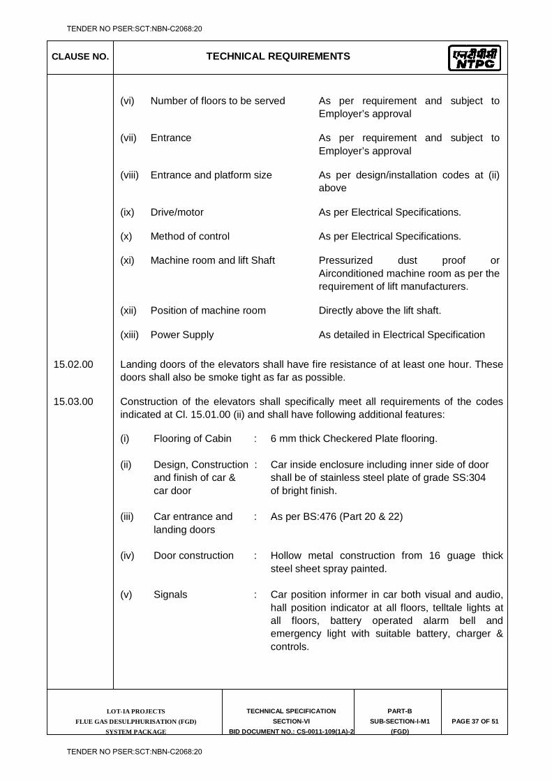
CLAUSE NO. TECHNICAL REQUIREMENTS
LOT-IA PROJECTS FLUE GAS DESULPHURISATION (FGD)
SYSTEM PACKAGE
TECHNICAL SPECIFICATION
SECTION-VI
BID DOCUMENT NO.: CS-0011-109(1A)-2
PART-B
SUB-SECTION-I-M1
(FGD)
PAGE 37 OF 51
(vi) Number of floors to be served As per requirement and subject to Employer’s approval
(vii) Entrance As per requirement and subject to Employer’s approval
(viii) Entrance and platform size As per design/installation codes at (ii) above
(ix) Drive/motor As per Electrical Specifications.
(x) Method of control As per Electrical Specifications.
(xi) Machine room and lift Shaft Pressurized dust proof or Airconditioned machine room as per the requirement of lift manufacturers.
(xii) Position of machine room Directly above the lift shaft.
(xiii) Power Supply As detailed in Electrical Specification
15.02.00 Landing doors of the elevators shall have fire resistance of at least one hour. These doors shall also be smoke tight as far as possible.
15.03.00 Construction of the elevators shall specifically meet all requirements of the codes indicated at Cl. 15.01.00 (ii) and shall have following additional features:
(i) Flooring of Cabin : 6 mm thick Checkered Plate flooring. (ii) Design, Construction : Car inside enclosure including inner side of door and finish of car & shall be of stainless steel plate of grade SS:304 car door of bright finish. (iii) Car entrance and : As per BS:476 (Part 20 & 22) landing doors (iv) Door construction : Hollow metal construction from 16 guage thick
steel sheet spray painted. (v) Signals : Car position informer in car both visual and audio,
hall position indicator at all floors, telltale lights at all floors, battery operated alarm bell and emergency light with suitable battery, charger & controls.
TENDER NO PSER:SCT:NBN-C2068:20
TENDER NO PSER:SCT:NBN-C2068:20
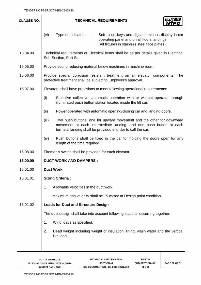
CLAUSE NO. TECHNICAL REQUIREMENTS
LOT-IA PROJECTS FLUE GAS DESULPHURISATION (FGD)
SYSTEM PACKAGE
TECHNICAL SPECIFICATION
SECTION-VI
BID DOCUMENT NO.: CS-0011-109(1A)-2
PART-B
SUB-SECTION-I-M1
(FGD)
PAGE 38 OF 51
(vi) Type of Indicators : Soft touch keys and digital luminous display in car operating panel and on all floors landings.
(All fixtures in stainless steel face plates).
15.04.00 Technical requirements of Electrical items shall be as per details given in Electrical Sub-Section, Part-B.
15.05.00 Provide sound reducing material below machines in machine room.
15.06.00 Provide special corrosion resistant treatment on all elevator components. The protective treatment shall be subject to Employer's approval.
15.07.00 Elevators shall have provisions to meet following operational requirements:
(i) Selective collective, automatic operation with or without operator through illuminated push button station located inside the lift car.
(ii) Power operated with automatic opening/closing car and landing doors.
(iii) Two push buttons, one for upward movement and the other for downward movement at each intermediate landing, and one push button at each terminal landing shall be provided in order to call the car.
(iv) Push buttons shall be fixed in the car for holding the doors open for any length of the time required.
15.08.00 Fireman's switch shall be provided for each elevator.
16.00.00 DUCT WORK AND DAMPERS :
16.01.00 Duct Work
16.01.01 Sizing Criteria :
1. Allowable velocities in the duct work.
Maximum gas velocity shall be 15 m/sec at Design point condition.
16.01.02 Loads for Duct and Structure Design
The duct design shall take into account following loads all occurring together:
1. Wind loads as specified.
2. Dead weight including weight of insulation, lining, wash water and the vertical live load.
TENDER NO PSER:SCT:NBN-C2068:20
TENDER NO PSER:SCT:NBN-C2068:20
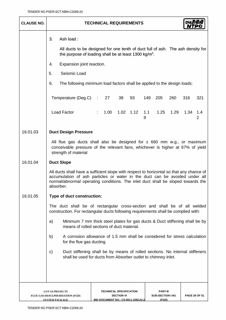
CLAUSE NO. TECHNICAL REQUIREMENTS
LOT-IA PROJECTS FLUE GAS DESULPHURISATION (FGD)
SYSTEM PACKAGE
TECHNICAL SPECIFICATION
SECTION-VI
BID DOCUMENT NO.: CS-0011-109(1A)-2
PART-B
SUB-SECTION-I-M1
(FGD)
PAGE 39 OF 51
33.. AAsshh llooaadd ::
AAllll dduuccttss ttoo bbee ddeessiiggnneedd ffoorr oonnee tteenntthh ooff dduucctt ffuullll ooff aasshh.. TThhee aasshh ddeennssiittyy ffoorr tthhee ppuurrppoossee ooff llooaaddiinngg sshhaallll bbee aatt lleeaasstt 11330000 kkgg//mm33..
4. Expansion joint reaction.
5. Seismic Load
6. The following minimum load factors shall be applied to the design loads:
Temperature (Deg.C) : 27 38 93 149 205 260 316 321
Load Factor : 1.00 1.02 1.12 1.19
1.25 1.29 1.34 1.42
16.01.03 Duct Design Pressure
All flue gas ducts shall also be designed for ± 660 mm w.g., or maximum conceivable pressure of the relevant fans, whichever is higher at 67% of yield strength of material
16.01.04 Duct Slope
All ducts shall have a sufficient slope with respect to horizontal so that any chance of accumulation of ash particles or water in the duct can be avoided under all normal/abnormal operating conditions. The inlet duct shall be sloped towards the absorber.
16.01.05 Type of duct construction:
The duct shall be of rectangular cross-section and shall be of all welded construction. For rectangular ducts following requirements shall be complied with:
a) Minimum 7 mm thick steel plates for gas ducts & Duct stiffening shall be by means of rolled sections of duct material.
b) A corrosion allowance of 1.5 mm shall be considered for stress calculation for the flue gas ducting.
c) Duct stiffening shall be by means of rolled sections. No internal stiffeners shall be used for ducts from Absorber outlet to chimney inlet.
TENDER NO PSER:SCT:NBN-C2068:20
TENDER NO PSER:SCT:NBN-C2068:20
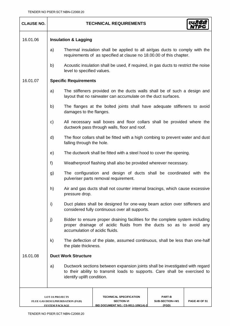
CLAUSE NO. TECHNICAL REQUIREMENTS
LOT-IA PROJECTS FLUE GAS DESULPHURISATION (FGD)
SYSTEM PACKAGE
TECHNICAL SPECIFICATION
SECTION-VI
BID DOCUMENT NO.: CS-0011-109(1A)-2
PART-B
SUB-SECTION-I-M1
(FGD)
PAGE 40 OF 51
16.01.06 Insulation & Lagging
a) Thermal insulation shall be applied to all air/gas ducts to comply with the requirements of as specified at clause no 18.00.00 of this chapter.
b) Acoustic insulation shall be used, if required, in gas ducts to restrict the noise level to specified values.
16.01.07 Specific Requirements
a) The stiffeners provided on the ducts walls shall be of such a design and layout that no rainwater can accumulate on the duct surfaces.
b) The flanges at the bolted joints shall have adequate stiffeners to avoid damages to the flanges.
c) All necessary wall boxes and floor collars shall be provided where the ductwork pass through walls, floor and roof.
d) The floor collars shall be fitted with a high combing to prevent water and dust falling through the hole.
e) The ductwork shall be fitted with a steel hood to cover the opening.
f) Weatherproof flashing shall also be provided wherever necessary.
g) The configuration and design of ducts shall be coordinated with the pulveriser parts removal requirement.
h) Air and gas ducts shall not counter internal bracings, which cause excessive pressure drop.
i) Duct plates shall be designed for one-way beam action over stiffeners and considered fully continuous over all supports.
j) Bidder to ensure proper draining facilities for the complete system including proper drainage of acidic fluids from the ducts so as to avoid any accumulation of acidic fluids.
k) The deflection of the plate, assumed continuous, shall be less than one-half the plate thickness.
16.01.08 Duct Work Structure
a) Ductwork sections between expansion joints shall be investigated with regard to their ability to transmit loads to supports. Care shall be exercised to identify uplift condition.
TENDER NO PSER:SCT:NBN-C2068:20
TENDER NO PSER:SCT:NBN-C2068:20
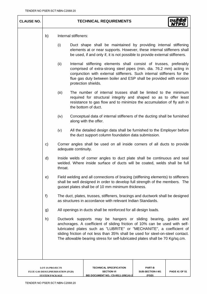
CLAUSE NO. TECHNICAL REQUIREMENTS
LOT-IA PROJECTS FLUE GAS DESULPHURISATION (FGD)
SYSTEM PACKAGE
TECHNICAL SPECIFICATION
SECTION-VI
BID DOCUMENT NO.: CS-0011-109(1A)-2
PART-B
SUB-SECTION-I-M1
(FGD)
PAGE 41 OF 51
b) Internal stiffeners:
(i) Duct shape shall be maintained by providing internal stiffening elements at or near supports. However, these internal stiffeners shall be used, if and only if, it is not possible to provide external stiffeners.
(ii) Internal stiffening elements shall consist of trusses, preferably comprised of extra-strong steel pipes (min. dia. 76.2 mm) acting in conjunction with external stiffeners. Such internal stiffeners for the flue gas duty between boiler and ESP shall be provided with erosion protection shields.
(iii) The number of internal trusses shall be limited to the minimum required for structural integrity and shaped so as to offer least resistance to gas flow and to minimize the accumulation of fly ash in the bottom of duct.
(iv) Conceptual data of internal stiffeners of the ducting shall be furnished along with the offer.
(v) All the detailed design data shall be furnished to the Employer before the duct support column foundation data submission.
c) Corner angles shall be used on all inside corners of all ducts to provide adequate continuity.
d) Inside welds of corner angles to duct plate shall be continuous and seal welded. Where inside surface of ducts will be coated, welds shall be full throat.
e) Field welding and all connections of bracing (stiffening elements) to stiffeners shall be well designed in order to develop full strength of the members. The gusset plates shall be of 10 mm minimum thickness.
f) The duct, plates, trusses, stiffeners, bracings and ductwork shall be designed as structures in accordance with relevant Indian Standards.
g) All openings in ducts shall be reinforced for all design loads.
h) Ductwork supports may be hangers or sliding bearing, guides and anchorages. A coefficient of sliding friction of 10% can be used with self-lubricated plates such as "LUBRITE" or "MECHANITE", a coefficient of sliding friction of not less than 35% shall be used for steel-on-steel contact. The allowable bearing stress for self-lubricated plates shall be 70 Kg/sq.cm.
TENDER NO PSER:SCT:NBN-C2068:20
TENDER NO PSER:SCT:NBN-C2068:20
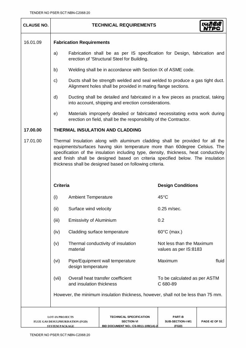
CLAUSE NO. TECHNICAL REQUIREMENTS
LOT-IA PROJECTS FLUE GAS DESULPHURISATION (FGD)
SYSTEM PACKAGE
TECHNICAL SPECIFICATION
SECTION-VI
BID DOCUMENT NO.: CS-0011-109(1A)-2
PART-B
SUB-SECTION-I-M1
(FGD)
PAGE 42 OF 51
16.01.09 Fabrication Requirements
a) Fabrication shall be as per IS specification for Design, fabrication and erection of 'Structural Steel for Building.
b) Welding shall be in accordance with Section IX of ASME code.
c) Ducts shall be strength welded and seal welded to produce a gas tight duct. Alignment holes shall be provided in mating flange sections.
d) Ducting shall be detailed and fabricated in a few pieces as practical, taking into account, shipping and erection considerations.
e) Materials improperly detailed or fabricated necessitating extra work during erection on field, shall be the responsibility of the Contractor.
17.00.00 THERMAL INSULATION AND CLADDING
17.01.00 Thermal Insulation along with aluminum cladding shall be provided for all the equipments/surfaces having skin temperature more than 60degree Celsius. The specification of the insulation including type, density, thickness, heat conductivity and finish shall be designed based on criteria specified below. The insulation thickness shall be designed based on following criteria.
Criteria Design Conditions (i) Ambient Temperature 45°C (ii) Surface wind velocity 0.25 m/sec. (iii) Emissivity of Aluminium 0.2 (iv) Cladding surface temperature 60°C (max.) (v) Thermal conductivity of insulation Not less than the Maximum material values as per IS:8183 (vi) Pipe/Equipment wall temperature Maximum fluid
design temperature (vii) Overall heat transfer coefficient To be calculated as per ASTM and insulation thickness C 680-89
However, the minimum insulation thickness, however, shall not be less than 75 mm.
TENDER NO PSER:SCT:NBN-C2068:20
TENDER NO PSER:SCT:NBN-C2068:20
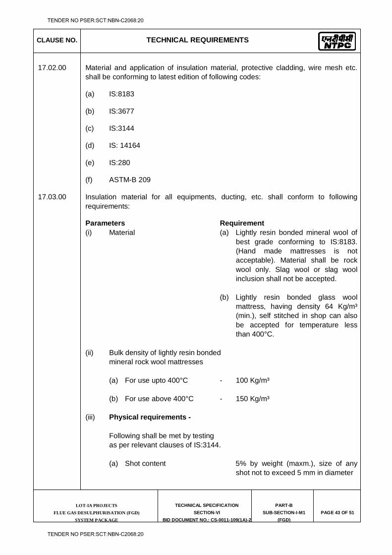
CLAUSE NO. TECHNICAL REQUIREMENTS
LOT-IA PROJECTS FLUE GAS DESULPHURISATION (FGD)
SYSTEM PACKAGE
TECHNICAL SPECIFICATION
SECTION-VI
BID DOCUMENT NO.: CS-0011-109(1A)-2
PART-B
SUB-SECTION-I-M1
(FGD)
PAGE 43 OF 51
17.02.00 Material and application of insulation material, protective cladding, wire mesh etc. shall be conforming to latest edition of following codes:
(a) IS:8183
(b) IS:3677
(c) IS:3144
(d) IS: 14164
(e) IS:280
(f) ASTM-B 209
17.03.00 Insulation material for all equipments, ducting, etc. shall conform to following requirements:
Parameters Requirement (i) Material (a) Lightly resin bonded mineral wool of
best grade conforming to IS:8183. (Hand made mattresses is not acceptable). Material shall be rock wool only. Slag wool or slag wool inclusion shall not be accepted.
(b) Lightly resin bonded glass wool
mattress, having density 64 Kg/m³ (min.), self stitched in shop can also be accepted for temperature less than 400°C.
(ii) Bulk density of lightly resin bonded mineral rock wool mattresses (a) For use upto 400°C - 100 Kg/m³ (b) For use above 400°C - 150 Kg/m³ (iii) Physical requirements - Following shall be met by testing as per relevant clauses of IS:3144. (a) Shot content 5% by weight (maxm.), size of any
shot not to exceed 5 mm in diameter
TENDER NO PSER:SCT:NBN-C2068:20
TENDER NO PSER:SCT:NBN-C2068:20
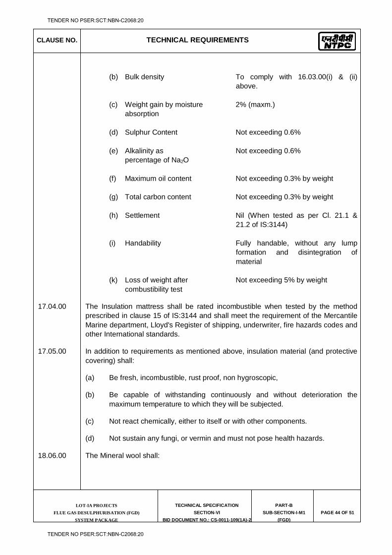
CLAUSE NO. TECHNICAL REQUIREMENTS
LOT-IA PROJECTS FLUE GAS DESULPHURISATION (FGD)
SYSTEM PACKAGE
TECHNICAL SPECIFICATION
SECTION-VI
BID DOCUMENT NO.: CS-0011-109(1A)-2
PART-B
SUB-SECTION-I-M1
(FGD)
PAGE 44 OF 51
(b) Bulk density To comply with 16.03.00(i) & (ii)
above. (c) Weight gain by moisture 2% (maxm.) absorption (d) Sulphur Content Not exceeding 0.6% (e) Alkalinity as Not exceeding 0.6% percentage of Na2O (f) Maximum oil content Not exceeding 0.3% by weight (g) Total carbon content Not exceeding 0.3% by weight (h) Settlement Nil (When tested as per Cl. 21.1 &
21.2 of IS:3144) (i) Handability Fully handable, without any lump
formation and disintegration of material
(k) Loss of weight after Not exceeding 5% by weight combustibility test
17.04.00 The Insulation mattress shall be rated incombustible when tested by the method prescribed in clause 15 of IS:3144 and shall meet the requirement of the Mercantile Marine department, Lloyd's Register of shipping, underwriter, fire hazards codes and other International standards.
17.05.00 In addition to requirements as mentioned above, insulation material (and protective covering) shall:
(a) Be fresh, incombustible, rust proof, non hygroscopic,
(b) Be capable of withstanding continuously and without deterioration the maximum temperature to which they will be subjected.
(c) Not react chemically, either to itself or with other components.
(d) Not sustain any fungi, or vermin and must not pose health hazards.
18.06.00 The Mineral wool shall:
TENDER NO PSER:SCT:NBN-C2068:20
TENDER NO PSER:SCT:NBN-C2068:20
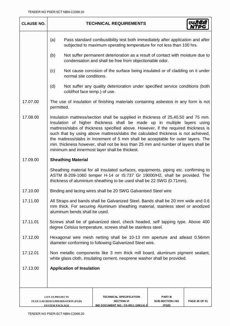
CLAUSE NO. TECHNICAL REQUIREMENTS
LOT-IA PROJECTS FLUE GAS DESULPHURISATION (FGD)
SYSTEM PACKAGE
TECHNICAL SPECIFICATION
SECTION-VI
BID DOCUMENT NO.: CS-0011-109(1A)-2
PART-B
SUB-SECTION-I-M1
(FGD)
PAGE 45 OF 51
(a) Pass standard combustibility test both immediately after application and after subjected to maximum operating temperature for not less than 100 hrs.
(b) Not suffer permanent deterioration as a result of contact with moisture due to condensation and shall be free from objectionable odor.
(c) Not cause corrosion of the surface being insulated or of cladding on it under normal site conditions.
(d) Not suffer any quality deterioration under specified service conditions (both cold/hot face temp.) of use.
17.07.00 The use of insulation of finishing materials containing asbestos in any form is not permitted.
17.08.00 Insulation mattress/section shall be supplied in thickness of 25,40,50 and 75 mm. Insulation of higher thickness shall be made up in multiple layers using mattress/slabs of thickness specified above. However, if the required thickness is such that by using above mattress/slabs the calculated thickness is not achieved, the mattress/slabs in increment of 5 mm shall be acceptable for outer layers. The min. thickness however, shall not be less than 25 mm and number of layers shall be minimum and innermost layer shall be thickest.
17.09.00 Sheathing Material
Sheathing material for all insulated surfaces, equipments, piping etc. confirming to ASTM B-209-1060 temper H-14 or IS:737 Gr 19000/H2, shall be provided. The thickness of aluminium sheathing to be used shall be 22 SWG (0.71mm).
17.10.00 Binding and lacing wires shall be 20 SWG Galvanised Steel wire
17.11.00 All Straps and bands shall be Galvanized Steel. Bands shall be 20 mm wide and 0.6 mm thick. For securing Aluminum sheathing material, stainless steel or anodized aluminum bends shall be used.
17.11.01 Screws shall be of galvanized steel, check headed, self tapping type. Above 400 degree Celsius temperature, screws shall be stainless steel.
17.12.00 Hexagonal wire mesh netting shall be 10-13 mm aperture and atleast 0.56mm diameter conforming to following Galvanized Steel wire.
17.12.01 Non metallic components like 3 mm thick mill board, aluminum pigment sealant, white glass cloth, insulating cement, neoprene washer shall be provided.
17.13.00 Application of Insulation
TENDER NO PSER:SCT:NBN-C2068:20
TENDER NO PSER:SCT:NBN-C2068:20
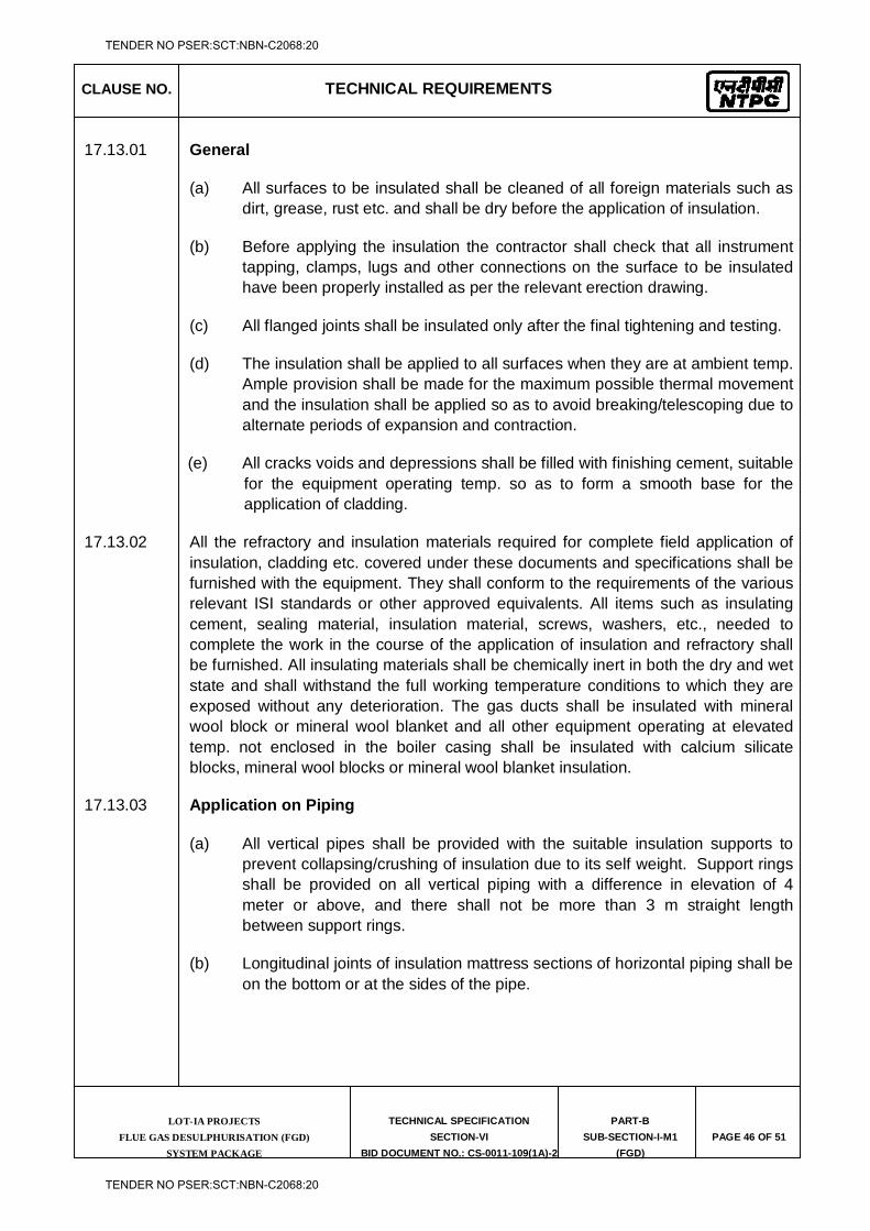
CLAUSE NO. TECHNICAL REQUIREMENTS
LOT-IA PROJECTS FLUE GAS DESULPHURISATION (FGD)
SYSTEM PACKAGE
TECHNICAL SPECIFICATION
SECTION-VI
BID DOCUMENT NO.: CS-0011-109(1A)-2
PART-B
SUB-SECTION-I-M1
(FGD)
PAGE 46 OF 51
17.13.01 General
(a) All surfaces to be insulated shall be cleaned of all foreign materials such as dirt, grease, rust etc. and shall be dry before the application of insulation.
(b) Before applying the insulation the contractor shall check that all instrument tapping, clamps, lugs and other connections on the surface to be insulated have been properly installed as per the relevant erection drawing.
(c) All flanged joints shall be insulated only after the final tightening and testing.
(d) The insulation shall be applied to all surfaces when they are at ambient temp. Ample provision shall be made for the maximum possible thermal movement and the insulation shall be applied so as to avoid breaking/telescoping due to alternate periods of expansion and contraction.
(e) All cracks voids and depressions shall be filled with finishing cement, suitable for the equipment operating temp. so as to form a smooth base for the application of cladding.
17.13.02 All the refractory and insulation materials required for complete field application of insulation, cladding etc. covered under these documents and specifications shall be furnished with the equipment. They shall conform to the requirements of the various relevant ISI standards or other approved equivalents. All items such as insulating cement, sealing material, insulation material, screws, washers, etc., needed to complete the work in the course of the application of insulation and refractory shall be furnished. All insulating materials shall be chemically inert in both the dry and wet state and shall withstand the full working temperature conditions to which they are exposed without any deterioration. The gas ducts shall be insulated with mineral wool block or mineral wool blanket and all other equipment operating at elevated temp. not enclosed in the boiler casing shall be insulated with calcium silicate blocks, mineral wool blocks or mineral wool blanket insulation.
17.13.03 Application on Piping
(a) All vertical pipes shall be provided with the suitable insulation supports to prevent collapsing/crushing of insulation due to its self weight. Support rings shall be provided on all vertical piping with a difference in elevation of 4 meter or above, and there shall not be more than 3 m straight length between support rings.
(b) Longitudinal joints of insulation mattress sections of horizontal piping shall be on the bottom or at the sides of the pipe.
TENDER NO PSER:SCT:NBN-C2068:20
TENDER NO PSER:SCT:NBN-C2068:20
CLAUSE NO. TECHNICAL REQUIREMENTS
LOT-IA PROJECTS FLUE GAS DESULPHURISATION (FGD)
SYSTEM PACKAGE
TECHNICAL SPECIFICATION
SECTION-VI
BID DOCUMENT NO.: CS-0011-109(1A)-2
PART-B
SUB-SECTION-I-M1
(FGD)
PAGE 47 OF 51
(c) When more than one layer of insulation mattress/section is required on piping the circumferential joints on adjacent layers shall be staggered by at least 150 mm and longitudinal joints shall be staggered by at least 50 mm.
(d) The mattress type insulation shall be formed to fit the pipe and applied with the mattress edges drawn together at the longitudinal joints and secured by lacing wire. Pipe section insulation shall be fitted on pipe using binding wires.
(e) Where insulation is applied in two or more layers each layer of mattress shall be backed with hexagonal wire mesh. For the first layer of insulation and in case of single layer insulation, hexagonal wire mesh shall be provided on both the surface of the mattress. For pipe sections, the sections shall be held in place by binding wires without any wire mesh.
(f) The ends of all wire loops shall be firmly twisted together with pliers, bent over and carefully pressed into the surface of the insulation. Any gap in the insulation shall be filled with loose mineral wool or finishing cement.
(g) Insulation mattress/section ends shall be terminated at a sufficient distance from the flanges to facilitate removal of bolts.
(h) The insulation shall be held in place by fastening over with binding wire for insulation surface with diameter upto and including 550 mm and with metal bends for insulation surfaces with diameter over 550 mm. The fastening shall be done at intervals of 250 mm except where specified otherwise. The ends of the binding wires shall be hooked and embedded in the insulation. The straps shall be mechanically stretched and fastened with metallic clamping seals of the same materials as the strap.
(i) Insulation for application on bends and elbows shall be cut into mitred segments, sufficiently short to form a reasonably smooth internal surface. After the application of insulation material place, insulating cement shall be applied as required to obtain a smooth surface.
(j) Weather hoods shall be provided for insulated piping passing through floors/walls.
(k) All pipe attachments coming on horizontal pipes, inclined pipes and bends shall be insulated along with pipe such that there will be no insulation applied to hanger rod and the component connecting hanger rod to pipe attachment. All pipe attachments exposed to weather shall be provided with weather proof covering.
(l) Upstream of all drain lines and the lines connected to steam traps, shall be insulated upto and including first isolating valve for heat conservation. Rest
TENDER NO PSER:SCT:NBN-C2068:20
TENDER NO PSER:SCT:NBN-C2068:20
CLAUSE NO. TECHNICAL REQUIREMENTS
LOT-IA PROJECTS FLUE GAS DESULPHURISATION (FGD)
SYSTEM PACKAGE
TECHNICAL SPECIFICATION
SECTION-VI
BID DOCUMENT NO.: CS-0011-109(1A)-2
PART-B
SUB-SECTION-I-M1
(FGD)
PAGE 48 OF 51
of such lines such as downstream of the drain valves, traps etc. and other lines such as safety valve discharges, vents, etc. shall be insulated for personnel protection.
17.13.04 Application on Valves and Fittings
(a) All valves fittings and specialties shall be insulated with the same type and thickness of insulation as specified for the connected piping with the special provisions and or exceptions as given below.
(b) All valves and flanges shall be provided with removable box type of insulation covered with box fabricated from aluminium sheets of thickness same as the connected pipe cladding. Adjoining pipe insulation shall be bevelled back to permit removal bolts and nuts or bands. The portion of the valve which can not be covered by box type insulation shall be filled by loose insulating material of packing density at least equal to that of the insulating material of adjoining pipe. The insulation for valves/flanges shall be applied after the finishing has been applied over the connected piping. The cladding shall be applied in such a manner that the bonnet flange can be exposed easily without disturbing the complete insulation and cladding.
(c) Flanges on lines having temperature upto and including 150 deg.C shall not be insulated.
(d) Union shall not be insulated.
(e) Expansion joints, metallic or rubber, shall not be insulated unless otherwise specifically indicated.
(f) Safety valves shall be insulated.
17.14.00 While applying mineral wool blanket insulation:
(a) Provide expended metal or hexagonal wire mesh on both sides for single layer mattress and on first layer in case of multilayer insulation. Subsequent layers of multilayer insulation to have only one side wire netting.
(b) The edges of adjacent blankets to be leased together, by appropriate lacing wire as per Clause 16.08.00.
(c) Any gap between joints between insulation layers shall be filled by loose mineral wool confirming to IS:3677.
(d) All insulation to be secured by 1.63 mm dia wire netting over blankets with ends of wire tightly twisted, and pressed in to insulation surface.
TENDER NO PSER:SCT:NBN-C2068:20
TENDER NO PSER:SCT:NBN-C2068:20
CLAUSE NO. TECHNICAL REQUIREMENTS
LOT-IA PROJECTS FLUE GAS DESULPHURISATION (FGD)
SYSTEM PACKAGE
TECHNICAL SPECIFICATION
SECTION-VI
BID DOCUMENT NO.: CS-0011-109(1A)-2
PART-B
SUB-SECTION-I-M1
(FGD)
PAGE 49 OF 51
(e) Impelling pins shall be placed on centers not exceeding 300 mm.
17.15.00 Flue Gas ducts with external stiffeners shall have first layer of insulation between the stiffeners and a second layer of insulation over stiffeners so that stiffeners are also insulated and a level surface is achieved. Other requirements are same as given in Clause 18.09.00.
17.16.00 Application of Metal Cladding
All insulated surfaces of the FGD shall be provided with metal cladding in accordance with the following requirements.
(a) All insulation procedure of metal cladding shall have prior approval of the Owner.
(b) All insulated surfaces of FGD shall be covered with aluminium cladding.
(c) Cladding for FGD components are to be finished with plain aluminium sheeting of thickness not less than the values specified. Wherever an inner casing plate is necessary to effect a gas tight enclosure, the plate shall be of mild steel of required thickness, but not less than four (4) mm suitably stiffened and supported.
(d) Cladding on straight surfaces shall be finished with aluminium sheeting of at least 20 SWG thicknesses suitably pressed along diagonals to form diamond shape or otherwise formed.
(e) Cladding for insulated circular surfaces will be constructed from aluminium sheets of thickness not less than 20 SWG.
(f) Weather proof flashings shall be installed where the panels intersect with columns and at other similar joints.
17.17.00 Application
All metal cladding shall be fabricated and installed to ensure a neat appearance and no open ended sections of cladding shall be left uncovered. The following provisions shall also be complied with:
(a) All closures, flashings and seals required shall be provided and installed.
(b) An asphalt and craft paper moisture barrier shall be provided to the aluminium cladding for all out door applications. Such moisture barriers shall be fixed to the inner surface of the cladding or shall be cemented to the outside surface of the insulation before application of cladding.
TENDER NO PSER:SCT:NBN-C2068:20
TENDER NO PSER:SCT:NBN-C2068:20
CLAUSE NO. TECHNICAL REQUIREMENTS
LOT-IA PROJECTS FLUE GAS DESULPHURISATION (FGD)
SYSTEM PACKAGE
TECHNICAL SPECIFICATION
SECTION-VI
BID DOCUMENT NO.: CS-0011-109(1A)-2
PART-B
SUB-SECTION-I-M1
(FGD)
PAGE 50 OF 51
(c) All the used in the out door cladding shall be provided with Neoprene washers.
(d) All openings and joints in outdoor cladding for piping connections, supports or access shall be suitably flashed and weather-proofed. Where such flashings or weather-proofing can not effectively control the entry of moisture, then such openings and joints shall be weather-proofed by application of aluminium pigmented sealer.
(e) Cladding on the top surfaces of the FGD, duct work and equipment shall be suitably reinforced to prevent damage by personnel walking thereon.
17.18.00 Protection of Equipment during insulation application
All equipment and structure shall be suitably protected from damage while applying insulation. After completion all equipment and structures shall be thoroughly cleaned of insulating materials which might have fallen on them.
18.00.00 TYPE TEST
18.01.00 Full scale type tests using actual equipment shall be conducted by the Contractor for the equipment mentioned in the subsequent clauses below:
18.01.01 Full range and full scale performance testing shall be conducted at shop on one number each of the following Fans as per BS 848, Part-1:
(a) Booster Fan
The performance testing at shop shall be conducted using actual fans
18.01.02 Leak tightness testing of dampers for each type and size of damper at shop to demonstrate the guaranteed gas tightness efficiency (on flow). The minimum guaranteed gas tightness efficiency of dampers shall not be less than that indicated in clause no. 3.03.08 of this Sub-Section.
18.02.00 The Bidder shall indicate the charges for each of these type tests separately in the relevant price schedule of Bid Proposal Sheet (BPS) and the same shall be considered for the evaluation of the Bids. The type test charges shall be paid only for the test(s) actually conducted successfully under this contract and upon certification by the Employer’s Engineer.
18.03.00 The type tests shall be carried out in presence of the Employer’s representative. Contractor shall inform the Employer about his readiness for conducting the type test and issue such notice to the Employer 30 days in advance, along with schedule of the type tests. The Contractor shall obtain the Employer’s approval for the type test procedure before notifying the Employer about his readiness for conducting the type
TENDER NO PSER:SCT:NBN-C2068:20
TENDER NO PSER:SCT:NBN-C2068:20
CLAUSE NO. TECHNICAL REQUIREMENTS
LOT-IA PROJECTS FLUE GAS DESULPHURISATION (FGD)
SYSTEM PACKAGE
TECHNICAL SPECIFICATION
SECTION-VI
BID DOCUMENT NO.: CS-0011-109(1A)-2
PART-B
SUB-SECTION-I-M1
(FGD)
PAGE 51 OF 51
test. The type test procedure shall clearly specify the test set-up, instruments to be used, procedure, acceptance norms, recording of different parameters, interval of recording, precautions to be taken etc. for the type test(s) to be carried out.
18.04.00 Irrespective of the requirement of conducting the type tests under this contract, The Contractor shall submit the reports of the type tests carried out for the equipments listed above in clause no. 18.01.00 and These reports should be for the tests conducted on the equipment for the model / type / size / rating to those proposed to be supplied under this contract and the test(s) should have been either be conducted at an test facility/shop/independent laboratory or should have been witnessed by a client. The Employer reserves the right to waive conducting of any or all of the specified type tests under this contract, in which case the type test charges shall not be payable for the type tests waived by the Employer.
18.05.00 All acceptance and routine tests as per the specification and relevant standards shall be carried out. Charges for these shall be deemed to be included in the equipment price.
TENDER NO PSER:SCT:NBN-C2068:20
TENDER NO PSER:SCT:NBN-C2068:20

LOT-IA PROJECTS FLUE GAS DESULPHURISATION (FGD) SYSTEM PACKAGE
TECHNICAL SPECIFICATION
SECTION-VI
BID DOCUMENT NO.: CS-0011-109(1A)-2
SUB-SECTION-I-M2
AIR CONDITIONING & VENTILATION SYSTEM
TENDER NO PSER:SCT:NBN-C2068:20
TENDER NO PSER:SCT:NBN-C2068:20
CLAUSE NO.
TECHNICAL REQUIREMENTS
LOT-IA PROJECTS FLUE GAS DESULPHURISATION SYSTEM
PACKAGE
TECHNICAL SPECIFICATION
SECTION – VI, PART-B
BID DOC. NO:CS-0011-109(1A)-2
SUB SECTION-I-M2 AIR CONDITIONING &
VENTILATION SYSTEM
Page 1 of 26
1.00.00 GENERAL 1.01.00 This section of specification covers details of system specifications, detailing the
areas to be air conditioned, basis of design, brief description of the system, equipment and services to be furnished by bidder. The Design, Engineering, Supply, Construction, Erection, and Testing & Commissioning of all the equipments & works listed here shall be on the basis of single point responsibility in bidder’s scope of work for satisfactory completion of the system in all respect.
2.00.00 AREAS TO BE AIR CONDITIONED
2.01.00 The areas to be air-conditioned shall be as follows: a) Air cooled condensing units (D-X type) type air conditioners with AHU of
suitable capacity with 100 % redundancy ( as per actual heat load calculation ) shall be provided for each FGD Control room building and ZLD control room building (if provided).
b) Cassette and Hi-wall Air-conditioners for Other auxiliary control room /control
room buildings not listed above but covered in the scope of Bidder.
3.00.00 AREAS TO BE VENTILATED
3.01.00 (i) Unitary Air Filtration (UAF) units of min. capacity 75,000 m3/hr or capacity calculated considering 8 air changes per hour whichever is higher, shall be provided for Non-Air Conditioned areas of FGD and ZLD (as provided) control building (e.g. Switch gear rooms, cable galleries, etc.)
(ii) Mechanical Ventilation (using Roof extractors/ Supply and/or Exhaust fans)
shall be provided for various other areas/buildings in the scope of bidder as under:
a) Grinding system building
b) Gypsum dewatering building
c) Recirculation pump & Oxidation blower/compressor building.
(iii) Toilets etc in above building (i) & (ii). Any other area not listed above but covered in the scope of Bidder.
iv) For other miscellaneous areas/ buildings not listed above but covered in the
scope of Bidder, mechanical type ventilation system using Supply and/or exhaust air fans/ roof exhausters shall be provided.
3.02.00 All non-air conditioned areas covered under this package shall be ventilated by a
combination of supply/exhaust fans and fresh air in-take / back draft louvers as detailed below:
TENDER NO PSER:SCT:NBN-C2068:20
TENDER NO PSER:SCT:NBN-C2068:20
CLAUSE NO.
TECHNICAL REQUIREMENTS
LOT-IA PROJECTS FLUE GAS DESULPHURISATION SYSTEM
PACKAGE
TECHNICAL SPECIFICATION
SECTION – VI, PART-B
BID DOC. NO:CS-0011-109(1A)-2
SUB SECTION-I-M2 AIR CONDITIONING &
VENTILATION SYSTEM
Page 2 of 26
4.00.00 EQUIPMENT DESCRIPTION – AIR CONDITIONING SYSTEM
4.01.00 Condensing Unit (Air-Cooled D-X type)
Condensing unit
Type : Air cooled scroll type
Vibration isolators : Steel spring / Neoprene rubber cushy foot type with isolation efficiency not less than 85%.
Compressor
Type : The Compressor shall be scroll, serviceable, either hermetic type or semi-hermetic type with automatic capacity control (minimum 3 steps).
Type of drive : Motor driven, direct or through V-belt.
Refrigerant : The refrigerant shall be R-134a/ R-410A/R-407C or any other environment friendly refrigerant.
Accessories : High/Low pressure cutouts, oil pressure switches, relief valves, pressure gauges at each stage, lube oil and control oil pressure gauges, suction & discharge stop valves, Muffler, Crank case heaters, oil filters, magnetic oil separators, temperature indicators for lube oil/heaters, oil level indicators, safety thermostat for crank case heater, vibration isolators, etc.
Motor Rating : 10% more than the power required by the compressor at 50 deg C design ambient temperature.
S.No Area
Type of Ventilation system
(i) General area like pump house, buildings etc
Combination of Supply air fan & Exhaust air fans
(ii) MCCs and Switchgear room etc
Supply air fan & Back draft dampers
(iii) Battery rooms & Oil rooms and fumes/odor generates
Combination of Supply air fan & Exhaust air fans. Motors shall be flame proof.
(iv) Toilet/pantry etc Propeller type exhaust air fan
TENDER NO PSER:SCT:NBN-C2068:20
TENDER NO PSER:SCT:NBN-C2068:20
CLAUSE NO.
TECHNICAL REQUIREMENTS
LOT-IA PROJECTS FLUE GAS DESULPHURISATION SYSTEM
PACKAGE
TECHNICAL SPECIFICATION
SECTION – VI, PART-B
BID DOC. NO:CS-0011-109(1A)-2
SUB SECTION-I-M2 AIR CONDITIONING &
VENTILATION SYSTEM
Page 3 of 26
Capacity : Minimum capacity shall be suitable for the identified/selected at evaporating temperature and condensing temperature and shall be indicated.
4.02.00 Air Handling Unit (AHU)
4.02.01 Each AHU shall consist of casing, fan impeller section, cooling coil section, damper section, steel frame with anti vibration mountings (AVMs) having minimum 85% vibration dampening efficiency and flame retardant, water proof neoprene impregnated flexible connection on fan discharge. Isolation dampers at the suction and discharge of each AHU shall be provided, in case return air duct is directly connected to AHU. However, in case AHU room is used for return air, isolation dampers are required to be provided only at AHU discharge of each AHU. Pre-filter at the suction and fine (micro-vee type) and absolute (HEPA type) filters (wherever applicable) at the discharge of each individual AHU, and heater section in the common discharge of AHUs shall be provided.
4.02.02 The casing of AHUs shall be of double skin construction. Double skin sandwich panels (inside and outside) shall be fabricated using minimum 0.63 mm (24g) galvanized steel sheet (thickness of galvanization as per manufacturer’s standard) , with 25mm thick polyurethane foam insulation of minimum 38 Kg/Cum density in between. Suitable reinforcements shall be provided to give structural strength to prevent any deformation/buckling.
4.02.03 Sloping condensate drain pan shall be made of minimum 1.2 mm thick Stainless Sheet Steel. It shall be isolated from bottom floor panel through 25mm thick heavy duty treated for Fire (TF) quality expanded polystyrene or polyurethane foam. Drain pan shall extend beyond the coil.
4.02.04 Cooling coil (min. 4 row deep) shall be made of seamless copper tubes with aluminium fins firmly bonded to copper tubes and shall be provided with suitable drains and vents connections.
4.02.05 All filter plenum shall be provided with a walking platform inside the plenum chamber for filter cleaning purpose. Inspection door shall be provided at the plenum chamber and a removable type ladder shall be attached to plenum.
4.02.06 Centrifugal fan for AHU
a) Fan Type : Double Width Double Inlet (DWDI) Centrifugal Type
b) Fan impeller : Backward curved blades
c) Casing material : GI /Mild steel with minimum thickness of 3 mm.
d) Impeller material : Carbon steel
e) Shaft : EN 8 Steel
TENDER NO PSER:SCT:NBN-C2068:20
TENDER NO PSER:SCT:NBN-C2068:20
CLAUSE NO.
TECHNICAL REQUIREMENTS
LOT-IA PROJECTS FLUE GAS DESULPHURISATION SYSTEM
PACKAGE
TECHNICAL SPECIFICATION
SECTION – VI, PART-B
BID DOC. NO:CS-0011-109(1A)-2
SUB SECTION-I-M2 AIR CONDITIONING &
VENTILATION SYSTEM
Page 4 of 26
f) Fan bearings : Self aligning type, permanently lubricated, heavy duty with a design life of 10,000 operating hours.
g) Critical speed : First critical speed of rotating assembly shall be at least 25% above the operating speed.
h) Drive : Motor driven with removable belt guard. Motor driven with removable belt guard. Motor rating (at 50 deg.C ambient) shall be atleast fifteen percent (15%) above the maximum load demand of drives at the design duty point.
i) Fans : For AHUs of capacity 50,000 CMH and above, Bidder may offer two (2) Nos. centrifugal fans of equal capacity for each AHU provided all such AHUs are accommodated within the space identified by the Employer.
4.02.07 Mixing Box:
Mixing box shall be complete with fresh and return air dampers. Mixing box shall be provided whenever the return air is ducted back to the AHU. Further, wherever return air is led back directly to AHU room, no mixing box is required.
4.02.08 Pan Humidifier:
Pan humidifier shall be made of 22 gauge SS 304 tank, duly insulated with 25 mm thick resin bonded fiber glass insulation (min. 24 Kg/m3 density) with 0.5 mm GSS cladding. The humidifier shall be complete with stainless steel immersion heaters, safety thermostat, float valve with stainless steel ball, sight glass, overflow and drain connections, steam outlet nozzle and float switch. Step controller shall be provided for switching on / off heater banks as per system requirement.
4.03.00 HI-WALL SPLIT/CASSETTE AIR-CONDITIONERS 4.03.01 Hi-wall Split/cassette air conditioners shall in general consist of the following:
i) Casing
ii) Hermetically sealed rotary/scroll Compressor
iii) Condenser and condenser cooling fan
iv) Evaporator along with fan
v) Cooling coil
vi) Filters
TENDER NO PSER:SCT:NBN-C2068:20
TENDER NO PSER:SCT:NBN-C2068:20
CLAUSE NO.
TECHNICAL REQUIREMENTS
LOT-IA PROJECTS FLUE GAS DESULPHURISATION SYSTEM
PACKAGE
TECHNICAL SPECIFICATION
SECTION – VI, PART-B
BID DOC. NO:CS-0011-109(1A)-2
SUB SECTION-I-M2 AIR CONDITIONING &
VENTILATION SYSTEM
Page 5 of 26
vii) Piping, valves, refrigerant strainer, etc.
viii) Controls, instruments, control panel/starter panels. ix) Vibration isolator pads, etc as required.
x) Refrigerant as per manufacturer practice.
4.03.02 Indoor unit of Ceiling Mounted Cassette Type Unit (Multi Flow Type):
The housing of the unit shall be powder coated galvanized steel. All the indoor units regardless of their difference in capacity should have same decorative panel size for harmonious aesthetic point of view.
Unit shall have four way supply air grills on sides and return air grill in center. Each unit shall have high lift drain pump and very low operating sound.
4.04.00 SPLIT/PACKAGED AIR CONDITIONERS 4.04.01 Split/packaged air conditioners shall in general consist of following:
I. Casing
II. Compressor
III. Condenser
IV. Evaporator and condenser cooling fan
V. Cooling Coil
VI. Filters
VII. Piping, Valves, refrigerant strainer etc.
VIII. Control, instruments, control panel/starter panels.
IX. Vibration isolator pads, ducting (if applicable) etc as required.
5.00.00 EQUIPMENT DESCRIPTION - VENTILATION SYSTEM
5.01.00 Unitary Air Filtration
5.01.01 Each modular unitary air filtration shall consist of Casing, Tanks, Fans, Distribution plates, Moisture eliminator and water repellant type nylon filter with frame and support, Header and standpipe with support, Spray and flooding type nozzle. Screen type suction strainer, Pumps, Necessary controls & Instrumentation, and all other required accessories.
5.01.02 The housing/ casing of air washer unit shall be double skin construction. Double skin panels shall be made of 22G galvanized sheet on outer side and 20G galvanized sheet inside with 25mm thick polyurethane foam insulation of minimum 38 kg/cub. Mtr. Density in between. Frame work for section shall be joined together with soft
TENDER NO PSER:SCT:NBN-C2068:20
TENDER NO PSER:SCT:NBN-C2068:20
CLAUSE NO.
TECHNICAL REQUIREMENTS
LOT-IA PROJECTS FLUE GAS DESULPHURISATION SYSTEM
PACKAGE
TECHNICAL SPECIFICATION
SECTION – VI, PART-B
BID DOC. NO:CS-0011-109(1A)-2
SUB SECTION-I-M2 AIR CONDITIONING &
VENTILATION SYSTEM
Page 6 of 26
rubber gasket in between to make the joints air tight. The entire fan section shall be mounted on rolled formed GSS channel frame work.
5.01.03 The unitary air filtration tank shall be fabricated from MS plate of minimum 6 mm thick and inside and outside surface of the tank shall be spray galvanized (minimum 60 microns DFT). Minimum depth of the tank shall be 600 mm. Tank construction shall be such that the suction screen can be replaced while the unit is operating. Tank shall be provided with overflow, drain with valve, float valve makeup connection with a gate valve backup, quick fill connection with globe valve etc. The overflow pipe shall be connected to drain pipe after isolating valve on drain pipe.
5.01.04 The distribution plate shall be fabricated out of 18G galvanized steel sheets & galvanized steel angle supports with minimum 50% free area.
5.01.05 Unitary air filtration shall be one-bank construction. All header and stand pipes shall be galvanised. Cat walks of suitable width shall be provided for maintenance of nozzle, filter etc.
5.01.06 The spray nozzles shall be of brass or bronze with chrome plating and shall be self cleaning type. The nozzle shall be designed to produce fine atomised spray and shall be properly spaced to give a uniform coverage of the air washer section. The pressure drop through the nozzle should be in the range of 1.4 to 2.4 Kg/cm2.
5.01.07 The eliminator plates shall be of 24G thick GS sheets class 275 or from 100% virgin PVC of minimum finished thickness of 2 mm. The eliminator section made of GSS shall have minimum six bends. The PVC eliminators shall be UV stabilised using Titanium di-oxide and shall withstand the weathering test as per IS:4892 for 500 hrs. Type test report of the compound testing carried out in any reputed laboratory shall be submitted for approval. All supports, tie rods and space bar shall be of either galvanised steel or PVC construction and shall be complete with suitable drip tray and drain pipe.
5.01.08 Air tight inspection doors of suitable size shall be provided for suction chamber. Spray chamber and fan suction for easy accessibility and maintenance and a water marine light be provided for each unitary air filtration.
5.01.09 Suitable number of brass screen shall be provided in the air washer tank to arrest the dirt entering the circulating water pump suction. Suitable GI grid shall be used inside the screen for reinforcement.
5.01.10 The specification for centrifugal fans shall generally be as indicated below. However, the fan shall be of DIDW type for UAF unit.
5.01.11 Saturation efficiency of Unitary Air Filtration units shall be minimum 60%.
5.02.00 Centrifugal Fan
5.02.01 The casing shall be of welded construction fabricated with heavy gauge galvanised sheet steel or MS sheet with spray galvanization (minimum 60 micron DFT). The minimum thickness of casing shall be 3 mm. It shall be rigidly reinforced and supported by structural angles. The seams shall be permanently sealed air-tight. Split casings shall be provided on larger sizes of fans. Casing drain with valves shall be provided wherever required.
The impeller shall have die-formed backward-curved blades tie welded to the rim and back plate to have a non overloading characteristic of the fan. Rim shall be spun to have a smooth contour. If required intermediate stiffening rings shall be
TENDER NO PSER:SCT:NBN-C2068:20
TENDER NO PSER:SCT:NBN-C2068:20
CLAUSE NO.
TECHNICAL REQUIREMENTS
LOT-IA PROJECTS FLUE GAS DESULPHURISATION SYSTEM
PACKAGE
TECHNICAL SPECIFICATION
SECTION – VI, PART-B
BID DOC. NO:CS-0011-109(1A)-2
SUB SECTION-I-M2 AIR CONDITIONING &
VENTILATION SYSTEM
Page 7 of 26
provided. Shaft sleeves shall be furnished wherever required. The impeller, pulley and shaft sleeves shall be secured to the shaft by key and/or nuts.
5.02.02 The bearing shall be self aligning, heavy duly ball, roller or sleeve bearing. They shall be adequately supported. They shall be easily accessible and lubricated properly from outside.
5.02.03 Inlet guard shall be spun to have a smooth contour. Inlet screen, if provided, shall be of galvanised wire mesh of 25 mm square.
5.02.04 Base plate with necessary number of spring type vibration isolators or ribbed neoprene rubber pad or cushy foot mounting shall be provided. The vibration isolators should have a minimum of 70% efficiency.
5.02.05 The first critical speed of the rotating assembly shall be at least 25% above the opening speed.
5.02.06 The fans shall be provided with V-belts and sheaves. All belts shall be sized for 150% rated HP. All V-belt shall be equipped with removable belt guards that do not impede the air flow to the fan inlet. There shall be a minimum of two belts per drive. Motor rating (at 50 deg.C ambient) shall be atleast fifteen percent (15%) above the maximum load demand of drives at the design duty point.
5.03.0 Roof Ventilators (If applicable)
5.03.01 The roof extractors shall be “COWL” type.
5.03.02 Impeller shall be of axial flow type, cast Aluminium in one piece and dynamically balanced. Casing shall be heavy gauge sheet steel construction of 3 mm thick for impeller upto 750 mm diameter and 5 mm for fans with impeller of diameter 750 and above. In casing, access door with locking arrangement be provided.
5.03.03 The cowl shall be designed for weather protection of the fan also inside of the roof on which the extractor is installed. Galvanised bird screen of 15 mm Square be provided with the cowl. All accessories, steel supports as required will be provided.
5.03.04 The speed of the fan be limited as per limitation given above for axial fans.
5.03.05 All accessories rain protection exhaust hood, transformation piece, vibration isolators, steel supports vibration isolators, bird screen, etc. as required shall be provided.
5.03.06 The vibration level for fans shall be as per ISO: 14694.
5.04.00 Centrifugal Pumps
a) Type : Horizontal Centrifugal, Axially or radial split type casing pump or end suction, top discharge horizontal centrifugal pump
b) Impeller : Closed type
c) Material of Construction
i) Casing : 2% Ni Cast Iron : IS:210 Gr. FG-260
TENDER NO PSER:SCT:NBN-C2068:20
TENDER NO PSER:SCT:NBN-C2068:20
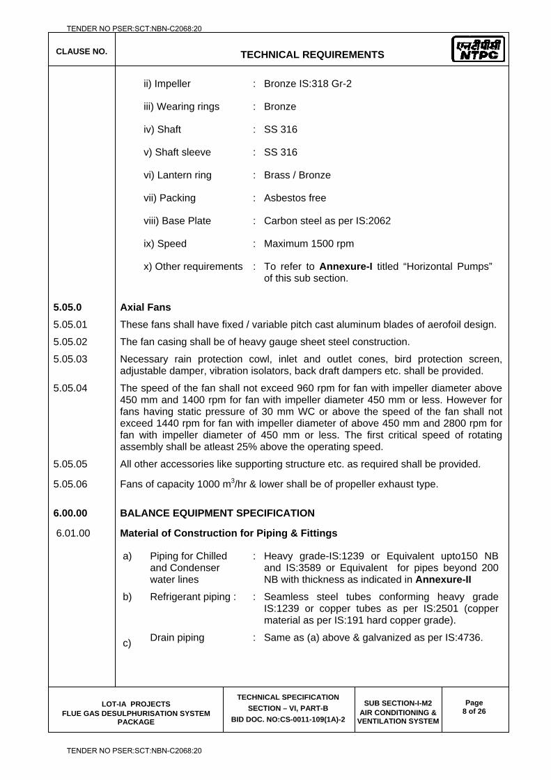
CLAUSE NO.
TECHNICAL REQUIREMENTS
LOT-IA PROJECTS FLUE GAS DESULPHURISATION SYSTEM
PACKAGE
TECHNICAL SPECIFICATION
SECTION – VI, PART-B
BID DOC. NO:CS-0011-109(1A)-2
SUB SECTION-I-M2 AIR CONDITIONING &
VENTILATION SYSTEM
Page 8 of 26
ii) Impeller : Bronze IS:318 Gr-2
iii) Wearing rings : Bronze
iv) Shaft : SS 316
v) Shaft sleeve : SS 316
vi) Lantern ring : Brass / Bronze
vii) Packing : Asbestos free
viii) Base Plate : Carbon steel as per IS:2062
ix) Speed : Maximum 1500 rpm
x) Other requirements : To refer to Annexure-I titled “Horizontal Pumps” of this sub section.
5.05.0 Axial Fans
5.05.01 These fans shall have fixed / variable pitch cast aluminum blades of aerofoil design.
5.05.02 The fan casing shall be of heavy gauge sheet steel construction.
5.05.03 Necessary rain protection cowl, inlet and outlet cones, bird protection screen, adjustable damper, vibration isolators, back draft dampers etc. shall be provided.
5.05.04 The speed of the fan shall not exceed 960 rpm for fan with impeller diameter above 450 mm and 1400 rpm for fan with impeller diameter 450 mm or less. However for fans having static pressure of 30 mm WC or above the speed of the fan shall not exceed 1440 rpm for fan with impeller diameter of above 450 mm and 2800 rpm for fan with impeller diameter of 450 mm or less. The first critical speed of rotating assembly shall be atleast 25% above the operating speed.
5.05.05 All other accessories like supporting structure etc. as required shall be provided.
5.05.06 Fans of capacity 1000 m3/hr & lower shall be of propeller exhaust type.
6.00.00 BALANCE EQUIPMENT SPECIFICATION
6.01.00 Material of Construction for Piping & Fittings
a) Piping for Chilled and Condenser water lines
: Heavy grade-IS:1239 or Equivalent upto150 NB and IS:3589 or Equivalent for pipes beyond 200 NB with thickness as indicated in Annexure-II
b) Refrigerant piping : : Seamless steel tubes conforming heavy grade IS:1239 or copper tubes as per IS:2501 (copper material as per IS:191 hard copper grade).
c) Drain piping : Same as (a) above & galvanized as per IS:4736.
TENDER NO PSER:SCT:NBN-C2068:20
TENDER NO PSER:SCT:NBN-C2068:20
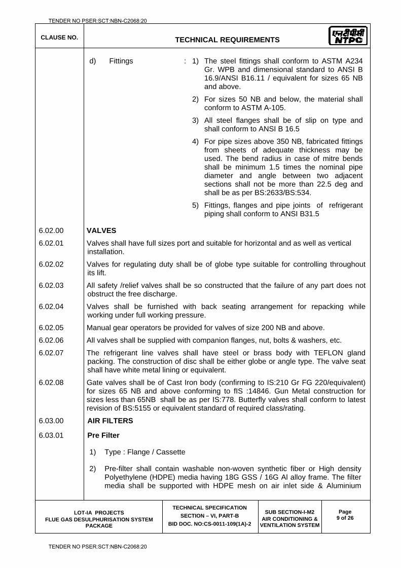
CLAUSE NO.
TECHNICAL REQUIREMENTS
LOT-IA PROJECTS FLUE GAS DESULPHURISATION SYSTEM
PACKAGE
TECHNICAL SPECIFICATION
SECTION – VI, PART-B
BID DOC. NO:CS-0011-109(1A)-2
SUB SECTION-I-M2 AIR CONDITIONING &
VENTILATION SYSTEM
Page 9 of 26
d)
Fittings
: 1) The steel fittings shall conform to ASTM A234 Gr. WPB and dimensional standard to ANSI B 16.9/ANSI B16.11 / equivalent for sizes 65 NB and above.
2) For sizes 50 NB and below, the material shall conform to ASTM A-105.
3) All steel flanges shall be of slip on type and shall conform to ANSI B 16.5
4) For pipe sizes above 350 NB, fabricated fittings from sheets of adequate thickness may be used. The bend radius in case of mitre bends shall be minimum 1.5 times the nominal pipe diameter and angle between two adjacent sections shall not be more than 22.5 deg and shall be as per BS:2633/BS:534.
5) Fittings, flanges and pipe joints of refrigerant piping shall conform to ANSI B31.5
6.02.00 VALVES
6.02.01 Valves shall have full sizes port and suitable for horizontal and as well as vertical installation.
6.02.02 Valves for regulating duty shall be of globe type suitable for controlling throughout its lift.
6.02.03 All safety /relief valves shall be so constructed that the failure of any part does not obstruct the free discharge.
6.02.04 Valves shall be furnished with back seating arrangement for repacking while working under full working pressure.
6.02.05 Manual gear operators be provided for valves of size 200 NB and above.
6.02.06 All valves shall be supplied with companion flanges, nut, bolts & washers, etc.
6.02.07 The refrigerant line valves shall have steel or brass body with TEFLON gland packing. The construction of disc shall be either globe or angle type. The valve seat shall have white metal lining or equivalent.
6.02.08 Gate valves shall be of Cast Iron body (confirming to IS:210 Gr FG 220/equivalent) for sizes 65 NB and above conforming to fIS :14846. Gun Metal construction for sizes less than 65NB shall be as per IS:778. Butterfly valves shall conform to latest revision of BS:5155 or equivalent standard of required class/rating.
6.03.00 AIR FILTERS
6.03.01 Pre Filter
1) Type : Flange / Cassette
2) Pre-filter shall contain washable non-woven synthetic fiber or High density Polyethylene (HDPE) media having 18G GSS / 16G Al alloy frame. The filter media shall be supported with HDPE mesh on air inlet side & Aluminium
TENDER NO PSER:SCT:NBN-C2068:20
TENDER NO PSER:SCT:NBN-C2068:20
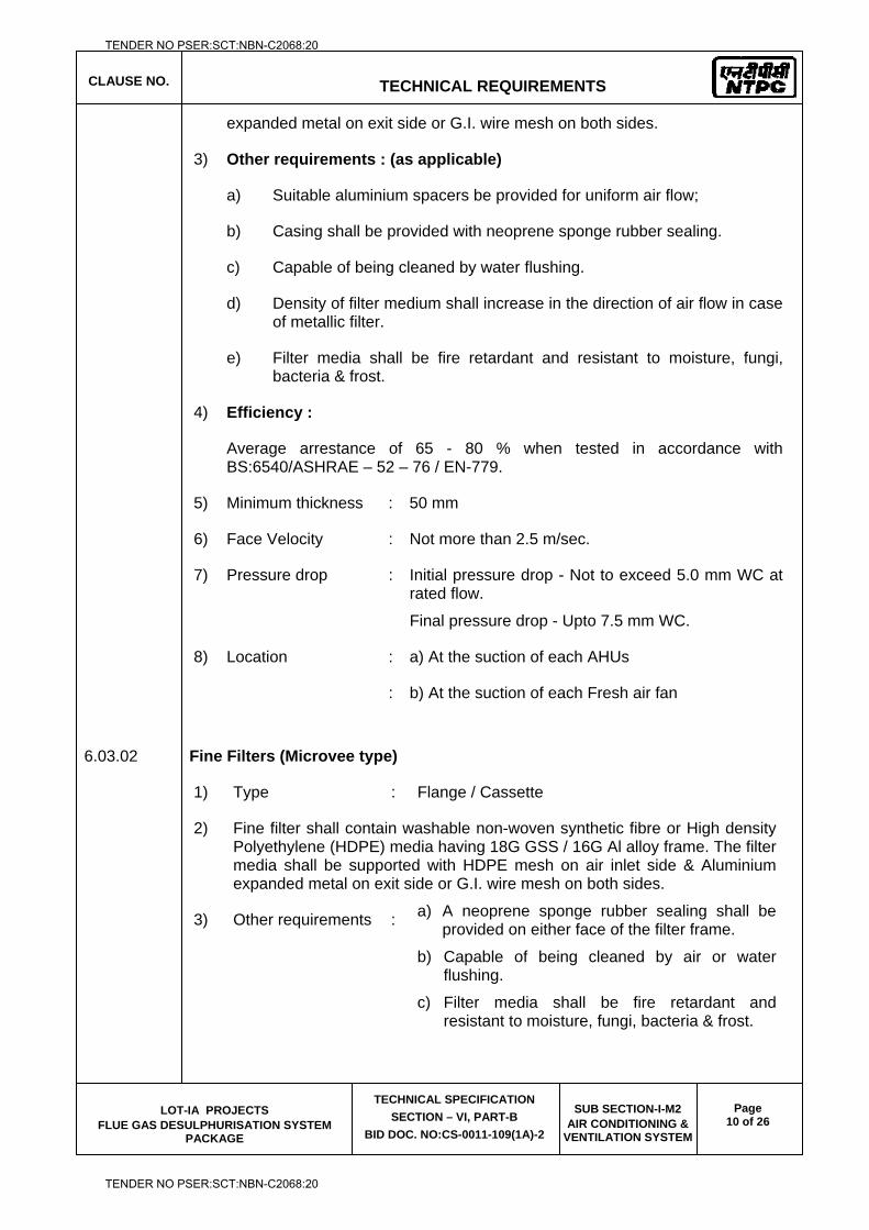
CLAUSE NO.
TECHNICAL REQUIREMENTS
LOT-IA PROJECTS FLUE GAS DESULPHURISATION SYSTEM
PACKAGE
TECHNICAL SPECIFICATION
SECTION – VI, PART-B
BID DOC. NO:CS-0011-109(1A)-2
SUB SECTION-I-M2 AIR CONDITIONING &
VENTILATION SYSTEM
Page 10 of 26
expanded metal on exit side or G.I. wire mesh on both sides.
3) Other requirements : (as applicable)
a) Suitable aluminium spacers be provided for uniform air flow;
b) Casing shall be provided with neoprene sponge rubber sealing.
c) Capable of being cleaned by water flushing.
d) Density of filter medium shall increase in the direction of air flow in case of metallic filter.
e) Filter media shall be fire retardant and resistant to moisture, fungi, bacteria & frost.
4) Efficiency :
Average arrestance of 65 - 80 % when tested in accordance with BS:6540/ASHRAE – 52 – 76 / EN-779.
5) Minimum thickness : 50 mm
6) Face Velocity : Not more than 2.5 m/sec.
7) Pressure drop : Initial pressure drop - Not to exceed 5.0 mm WC at rated flow.
Final pressure drop - Upto 7.5 mm WC.
8) Location : a) At the suction of each AHUs
: b) At the suction of each Fresh air fan
6.03.02 Fine Filters (Microvee type)
1) Type : Flange / Cassette
2) Fine filter shall contain washable non-woven synthetic fibre or High density Polyethylene (HDPE) media having 18G GSS / 16G Al alloy frame. The filter media shall be supported with HDPE mesh on air inlet side & Aluminium expanded metal on exit side or G.I. wire mesh on both sides.
3) Other requirements :
a) A neoprene sponge rubber sealing shall be provided on either face of the filter frame.
b) Capable of being cleaned by air or water flushing.
c) Filter media shall be fire retardant and resistant to moisture, fungi, bacteria & frost.
TENDER NO PSER:SCT:NBN-C2068:20
TENDER NO PSER:SCT:NBN-C2068:20
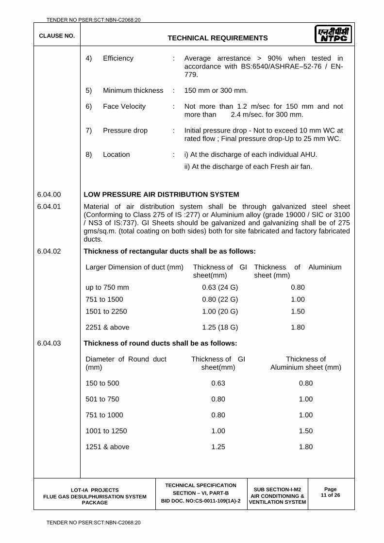
CLAUSE NO.
TECHNICAL REQUIREMENTS
LOT-IA PROJECTS FLUE GAS DESULPHURISATION SYSTEM
PACKAGE
TECHNICAL SPECIFICATION
SECTION – VI, PART-B
BID DOC. NO:CS-0011-109(1A)-2
SUB SECTION-I-M2 AIR CONDITIONING &
VENTILATION SYSTEM
Page 11 of 26
4) Efficiency : Average arrestance > 90% when tested in accordance with BS:6540/ASHRAE–52-76 / EN-779.
5) Minimum thickness : 150 mm or 300 mm.
6) Face Velocity : Not more than 1.2 m/sec for 150 mm and not more than 2.4 m/sec. for 300 mm.
7) Pressure drop : Initial pressure drop - Not to exceed 10 mm WC at rated flow ; Final pressure drop-Up to 25 mm WC.
8) Location : i) At the discharge of each individual AHU.
ii) At the discharge of each Fresh air fan.
6.04.00 LOW PRESSURE AIR DISTRIBUTION SYSTEM
6.04.01 Material of air distribution system shall be through galvanized steel sheet (Conforming to Class 275 of IS :277) or Aluminium alloy (grade 19000 / SIC or 3100 / NS3 of IS:737). GI Sheets should be galvanized and galvanizing shall be of 275 gms/sq.m. (total coating on both sides) both for site fabricated and factory fabricated ducts.
6.04.02 Thickness of rectangular ducts shall be as follows:
Larger Dimension of duct (mm) Thickness of GI sheet(mm)
Thickness of Aluminium sheet (mm)
up to 750 mm 0.63 (24 G) 0.80
751 to 1500 0.80 (22 G) 1.00
1501 to 2250 1.00 (20 G) 1.50
2251 & above 1.25 (18 G) 1.80
6.04.03 Thickness of round ducts shall be as follows:
Diameter of Round duct (mm)
Thickness of GI sheet(mm)
Thickness of Aluminium sheet (mm)
150 to 500 0.63 0.80
501 to 750 0.80 1.00
751 to 1000 0.80 1.00
1001 to 1250 1.00 1.50
1251 & above 1.25 1.80
TENDER NO PSER:SCT:NBN-C2068:20
TENDER NO PSER:SCT:NBN-C2068:20
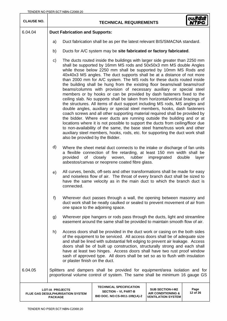
CLAUSE NO.
TECHNICAL REQUIREMENTS
LOT-IA PROJECTS FLUE GAS DESULPHURISATION SYSTEM
PACKAGE
TECHNICAL SPECIFICATION
SECTION – VI, PART-B
BID DOC. NO:CS-0011-109(1A)-2
SUB SECTION-I-M2 AIR CONDITIONING &
VENTILATION SYSTEM
Page 12 of 26
6.04.04 Duct Fabrication and Supports:
a) Duct fabrication shall be as per the latest relevant BIS/SMACNA standard.
b) Ducts for A/C system may be site fabricated or factory fabricated.
c) The ducts routed inside the buildings with larger side greater than 2250 mm shall be supported by 16mm MS rods and 50x50x3 mm MS double Angles while those below 2250 mm shall be supported by 10mm MS Rods and 40x40x3 MS angles. The duct supports shall be at a distance of not more than 2000 mm for A/C system. The MS rods for these ducts routed inside the building shall be hung from the existing floor beams/wall beams/roof beams/columns with provision of necessary auxiliary or special steel members or by hooks or can be provided by dash fasteners fixed to the ceiling slab. No supports shall be taken from horizontal/vertical bracings of the structures. All items of duct support including MS rods, MS angles and double angles, auxiliary or special steel members, hooks, dash fasteners coach screws and all other supporting material required shall be provided by the bidder. Where ever ducts are running outside the building and or at locations where it is not possible to support the ducts from ceiling/floor due to non-availability of the same, the base steel frame/truss work and other auxiliary steel members, hooks, rods, etc. for supporting the duct work shall also be provided by the Bidder.
d) Where the sheet metal duct connects to the intake or discharge of fan units a flexible connection of fire retarding, at least 150 mm width shall be provided of closely woven, rubber impregnated double layer asbestos/canvas or neoprene coated fibre glass.
e) All curves, bends, off-sets and other transformations shall be made for easy and noiseless flow of air. The throat of every branch duct shall be sized to have the same velocity as in the main duct to which the branch duct is connected.
f) Wherever duct passes through a wall, the opening between masonry and duct work shall be neatly caulked or sealed to prevent movement of air from one space to the adjoining space.
g) Wherever pipe hangers or rods pass through the ducts, light and streamline easement around the same shall be provided to maintain smooth flow of air.
h) Access doors shall be provided in the duct work or casing on the both sides of the equipment to be serviced. All access doors shall be of adequate size and shall be lined with substantial felt edging to prevent air leakage. Access doors shall be of built up construction, structurally strong and each shall have at least two hinges. Access doors shall have two rust proof window sash of approved type. All doors shall be set so as to flush with insulation or plaster finish on the duct.
6.04.05 Splitters and dampers shall be provided for equipment/area isolation and for proportional volume control of system. The same shall be minimum 16 gauge GS
TENDER NO PSER:SCT:NBN-C2068:20
TENDER NO PSER:SCT:NBN-C2068:20
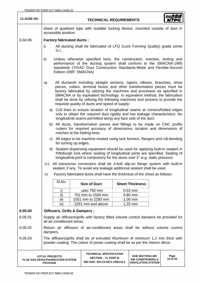
CLAUSE NO.
TECHNICAL REQUIREMENTS
LOT-IA PROJECTS FLUE GAS DESULPHURISATION SYSTEM
PACKAGE
TECHNICAL SPECIFICATION
SECTION – VI, PART-B
BID DOC. NO:CS-0011-109(1A)-2
SUB SECTION-I-M2 AIR CONDITIONING &
VENTILATION SYSTEM
Page 13 of 26
sheet of quadrant type with suitable locking device, mounted outside of duct in accessible position.
6.04.06 Factory fabricated ducts :
i) All ducting shall be fabricated of LFQ (Lock Forming Quality) grade prime G.I.
ii) Unless otherwise specified here, the construction, erection, testing and
performance of the ducting system shall conform to the SMACNA-1995 standards (“HVAC Duct Construction Standards-Metal and Flexible-Second Edition-1995” SMACNA)
iii) All ductwork including straight sections, tapers, elbows, branches, show
pieces, collars, terminal boxes and other transformation pieces must be factory fabricated by utilizing the machines and processes as specified in SMACNA or by equivalent technology. In equivalent method, the fabrication shall be done by utilizing the following machines and process to provide the requisite quality of ducts and speed of supply:
a) Coil lines to ensure location of longitudinal seams at corners/folded edges only to obtain the required duct rigidity and low leakage characteristics. No longitudinal seams permitted along any face side of the duct.
b) All ducts, transformation pieces and fittings to be made on CNC profile cutters for required accuracy of dimensions, location and dimensions of notches at the folding lines.
c) All edges to be machine treated using lock formers, flangers and roll-bending for turning up edges.
d) Sealant dispensing equipment should be used for applying built-in sealant in Pittsburgh lock where sealing of longitudinal joints are specified. Sealing of longitudinal joint is compulsory for the ducts over 2” w.g. static pressure
iv) All transverse connectors shall be 4-bolt slip-on flange system with built-in sealant, if any. To avoid any leakage additional sealant shall be used.
v) Factory fabricated ducts shall have the thickness of the sheet as follows:
6.05.00 Diffusers, Grills & Dampers :
6.05.01 Supply air diffusers/grills with factory fitted volume control dampers be provided for all air-conditioned areas.
6.05.02 Return air diffusers of air-conditioned areas shall be without volume control dampers.
6.05.03 The diffusers/grills shall be of extruded Aluminum of minimum 1.2 mm thick with powder coating. The colour of power coating shall be as per the interior décor.
Sl.No. Size of Duct Sheet Thickness
i) upto 750 mm 0.63 mm ii) 751 mm to 1500 mm 0.80 mm iii) 1501 mm to 2250 mm 1.00 mm iv) 2251 mm and above 1.25 mm
TENDER NO PSER:SCT:NBN-C2068:20
TENDER NO PSER:SCT:NBN-C2068:20
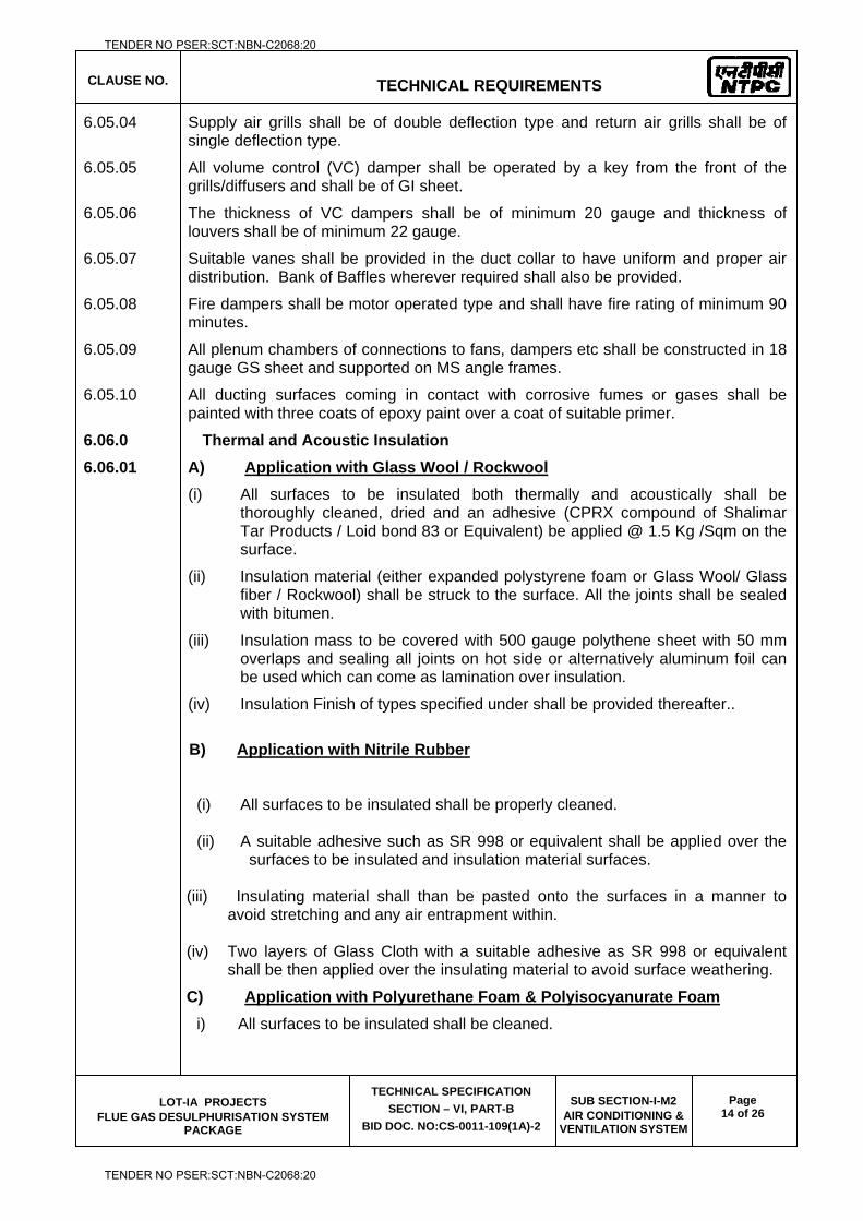
CLAUSE NO.
TECHNICAL REQUIREMENTS
LOT-IA PROJECTS FLUE GAS DESULPHURISATION SYSTEM
PACKAGE
TECHNICAL SPECIFICATION
SECTION – VI, PART-B
BID DOC. NO:CS-0011-109(1A)-2
SUB SECTION-I-M2 AIR CONDITIONING &
VENTILATION SYSTEM
Page 14 of 26
6.05.04 Supply air grills shall be of double deflection type and return air grills shall be of single deflection type.
6.05.05 All volume control (VC) damper shall be operated by a key from the front of the grills/diffusers and shall be of GI sheet.
6.05.06 The thickness of VC dampers shall be of minimum 20 gauge and thickness of louvers shall be of minimum 22 gauge.
6.05.07 Suitable vanes shall be provided in the duct collar to have uniform and proper air distribution. Bank of Baffles wherever required shall also be provided.
6.05.08 Fire dampers shall be motor operated type and shall have fire rating of minimum 90 minutes.
6.05.09 All plenum chambers of connections to fans, dampers etc shall be constructed in 18 gauge GS sheet and supported on MS angle frames.
6.05.10 All ducting surfaces coming in contact with corrosive fumes or gases shall be painted with three coats of epoxy paint over a coat of suitable primer.
6.06.0 Thermal and Acoustic Insulation
6.06.01 A) Application with Glass Wool / Rockwool
(i) All surfaces to be insulated both thermally and acoustically shall be thoroughly cleaned, dried and an adhesive (CPRX compound of Shalimar Tar Products / Loid bond 83 or Equivalent) be applied @ 1.5 Kg /Sqm on the surface.
(ii) Insulation material (either expanded polystyrene foam or Glass Wool/ Glass fiber / Rockwool) shall be struck to the surface. All the joints shall be sealed with bitumen.
(iii) Insulation mass to be covered with 500 gauge polythene sheet with 50 mm overlaps and sealing all joints on hot side or alternatively aluminum foil can be used which can come as lamination over insulation.
(iv) Insulation Finish of types specified under shall be provided thereafter..
B) Application with Nitrile Rubber
(i) All surfaces to be insulated shall be properly cleaned.
(ii) A suitable adhesive such as SR 998 or equivalent shall be applied over the surfaces to be insulated and insulation material surfaces.
(iii) Insulating material shall than be pasted onto the surfaces in a manner to
avoid stretching and any air entrapment within. (iv) Two layers of Glass Cloth with a suitable adhesive as SR 998 or equivalent
shall be then applied over the insulating material to avoid surface weathering.
C) Application with Polyurethane Foam & Polyisocyanurate Foam
i) All surfaces to be insulated shall be cleaned.
TENDER NO PSER:SCT:NBN-C2068:20
TENDER NO PSER:SCT:NBN-C2068:20
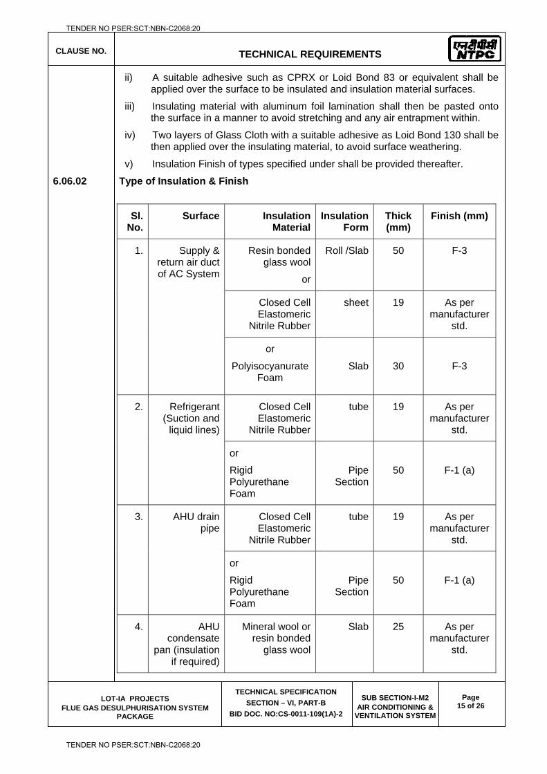
CLAUSE NO.
TECHNICAL REQUIREMENTS
LOT-IA PROJECTS FLUE GAS DESULPHURISATION SYSTEM
PACKAGE
TECHNICAL SPECIFICATION
SECTION – VI, PART-B
BID DOC. NO:CS-0011-109(1A)-2
SUB SECTION-I-M2 AIR CONDITIONING &
VENTILATION SYSTEM
Page 15 of 26
ii) A suitable adhesive such as CPRX or Loid Bond 83 or equivalent shall be applied over the surface to be insulated and insulation material surfaces.
iii) Insulating material with aluminum foil lamination shall then be pasted onto the surface in a manner to avoid stretching and any air entrapment within.
iv) Two layers of Glass Cloth with a suitable adhesive as Loid Bond 130 shall be then applied over the insulating material, to avoid surface weathering.
v) Insulation Finish of types specified under shall be provided thereafter.
6.06.02 Type of Insulation & Finish
Sl. No.
Surface Insulation Material
Insulation Form
Thick (mm)
Finish (mm)
1. Supply & return air duct of AC System
Resin bonded glass wool
or
Roll /Slab 50 F-3
Closed Cell Elastomeric
Nitrile Rubber
sheet 19 As per manufacturer
std.
or
Polyisocyanurate Foam
Slab
30
F-3
2. Refrigerant (Suction and
liquid lines)
Closed Cell Elastomeric
Nitrile Rubber
tube 19 As per manufacturer
std.
or
Rigid Polyurethane Foam
Pipe Section
50
F-1 (a)
3. AHU drain pipe
Closed Cell Elastomeric
Nitrile Rubber
tube 19 As per manufacturer
std.
or
Rigid Polyurethane Foam
Pipe Section
50
F-1 (a)
4. AHU condensate
pan (insulation if required)
Mineral wool or resin bonded
glass wool
Slab 25 As per manufacturer
std.
TENDER NO PSER:SCT:NBN-C2068:20
TENDER NO PSER:SCT:NBN-C2068:20
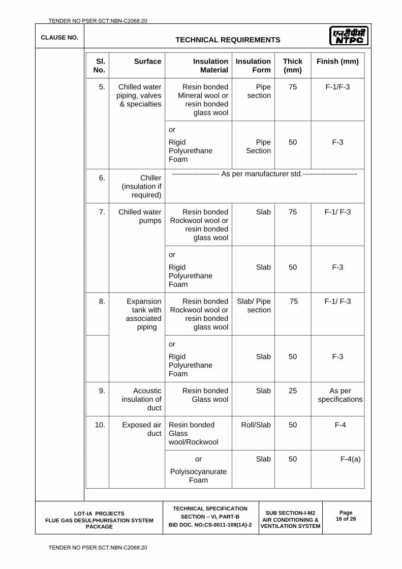
CLAUSE NO.
TECHNICAL REQUIREMENTS
LOT-IA PROJECTS FLUE GAS DESULPHURISATION SYSTEM
PACKAGE
TECHNICAL SPECIFICATION
SECTION – VI, PART-B
BID DOC. NO:CS-0011-109(1A)-2
SUB SECTION-I-M2 AIR CONDITIONING &
VENTILATION SYSTEM
Page 16 of 26
Sl. No.
Surface Insulation Material
Insulation Form
Thick (mm)
Finish (mm)
5. Chilled water piping, valves & specialties
Resin bonded Mineral wool or
resin bonded glass wool
Pipe section
75 F-1/F-3
or
Rigid Polyurethane Foam
Pipe Section
50
F-3
6. Chiller (insulation if
required)
------------------- As per manufacturer std.----------------------
7. Chilled water pumps
Resin bonded Rockwool wool or
resin bonded glass wool
Slab 75 F-1/ F-3
or
Rigid Polyurethane Foam
Slab
50
F-3
8. Expansion tank with
associated piping
Resin bonded Rockwool wool or
resin bonded glass wool
Slab/ Pipe section
75 F-1/ F-3
or
Rigid Polyurethane Foam
Slab
50
F-3
9. Acoustic insulation of
duct
Resin bonded Glass wool
Slab 25 As per specifications
10. Exposed air duct
Resin bonded Glass wool/Rockwool
Roll/Slab 50 F-4
or
Polyisocyanurate Foam
Slab 50 F-4(a)
TENDER NO PSER:SCT:NBN-C2068:20
TENDER NO PSER:SCT:NBN-C2068:20
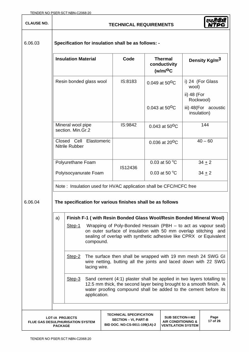
CLAUSE NO.
TECHNICAL REQUIREMENTS
LOT-IA PROJECTS FLUE GAS DESULPHURISATION SYSTEM
PACKAGE
TECHNICAL SPECIFICATION
SECTION – VI, PART-B
BID DOC. NO:CS-0011-109(1A)-2
SUB SECTION-I-M2 AIR CONDITIONING &
VENTILATION SYSTEM
Page 17 of 26
6.06.03 Specification for insulation shall be as follows: -
Insulation Material Code Thermal conductivity
(w/m/oC
Density Kg/m3
Resin bonded glass wool IS:8183 0.049 at 50oC
0.043 at 50oC
i) 24 (For Glass wool)
ii) 48 (For Rockwool)
iii) 48(For acoustic insulation)
Mineral wool pipe section. Min.Gr.2
IS:9842 0.043 at 50oC 144
Closed Cell Elastomeric Nitrile Rubber
0.036 at 20oC 40 – 60
Polyurethane Foam Polyisocyanurate Foam
IS12436
0.03 at 50 oC
0.03 at 50 oC
34 + 2
34 + 2
Note : Insulation used for HVAC application shall be CFC/HCFC free
6.06.04 The specification for various finishes shall be as follows
a) Finish F-1 ( with Resin Bonded Glass Wool/Resin Bonded Mineral Wool)
Step-1 Wrapping of Poly-Bonded Hessain (PBH – to act as vapour seal) on outer surface of insulation with 50 mm overlap stitching and sealing of overlap with synthetic adhesive like CPRX or Equivalent compound.
Step-2 The surface then shall be wrapped with 19 mm mesh 24 SWG GI wire netting, butting all the joints and laced down with 22 SWG lacing wire.
Step-3 Sand cement (4:1) plaster shall be applied in two layers totalling to 12.5 mm thick, the second layer being brought to a smooth finish. A water proofing compound shall be added to the cement before its application.
TENDER NO PSER:SCT:NBN-C2068:20
TENDER NO PSER:SCT:NBN-C2068:20
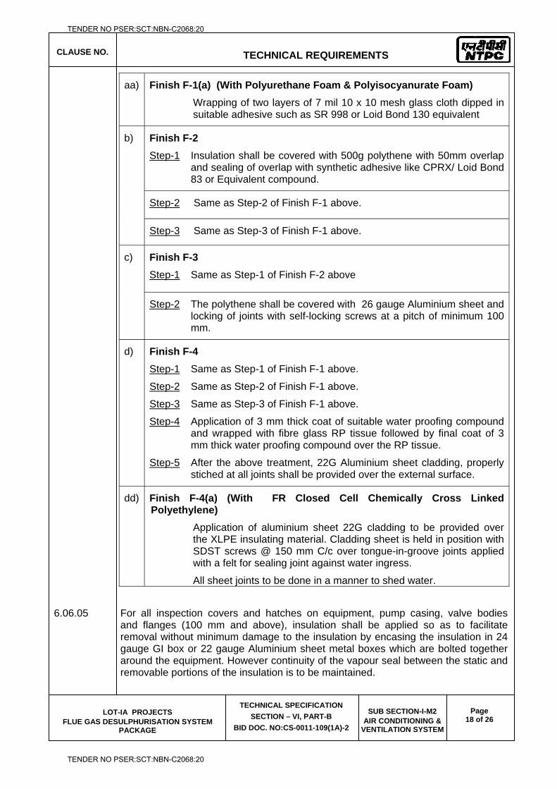
CLAUSE NO.
TECHNICAL REQUIREMENTS
LOT-IA PROJECTS FLUE GAS DESULPHURISATION SYSTEM
PACKAGE
TECHNICAL SPECIFICATION
SECTION – VI, PART-B
BID DOC. NO:CS-0011-109(1A)-2
SUB SECTION-I-M2 AIR CONDITIONING &
VENTILATION SYSTEM
Page 18 of 26
aa) Finish F-1(a) (With Polyurethane Foam & Polyisocyanurate Foam)
Wrapping of two layers of 7 mil 10 x 10 mesh glass cloth dipped in suitable adhesive such as SR 998 or Loid Bond 130 equivalent
b) Finish F-2
Step-1 Insulation shall be covered with 500g polythene with 50mm overlap and sealing of overlap with synthetic adhesive like CPRX/ Loid Bond 83 or Equivalent compound.
Step-2 Same as Step-2 of Finish F-1 above.
Step-3 Same as Step-3 of Finish F-1 above.
c) Finish F-3
Step-1 Same as Step-1 of Finish F-2 above
Step-2 The polythene shall be covered with 26 gauge Aluminium sheet and locking of joints with self-locking screws at a pitch of minimum 100 mm.
d) Finish F-4
Step-1 Same as Step-1 of Finish F-1 above.
Step-2 Same as Step-2 of Finish F-1 above.
Step-3 Same as Step-3 of Finish F-1 above.
Step-4 Application of 3 mm thick coat of suitable water proofing compound and wrapped with fibre glass RP tissue followed by final coat of 3 mm thick water proofing compound over the RP tissue.
Step-5 After the above treatment, 22G Aluminium sheet cladding, properly stiched at all joints shall be provided over the external surface.
dd) Finish F-4(a) (With FR Closed Cell Chemically Cross Linked Polyethylene)
Application of aluminium sheet 22G cladding to be provided over the XLPE insulating material. Cladding sheet is held in position with SDST screws @ 150 mm C/c over tongue-in-groove joints applied with a felt for sealing joint against water ingress.
All sheet joints to be done in a manner to shed water.
6.06.05 For all inspection covers and hatches on equipment, pump casing, valve bodies and flanges (100 mm and above), insulation shall be applied so as to facilitate removal without minimum damage to the insulation by encasing the insulation in 24 gauge GI box or 22 gauge Aluminium sheet metal boxes which are bolted together around the equipment. However continuity of the vapour seal between the static and removable portions of the insulation is to be maintained.
TENDER NO PSER:SCT:NBN-C2068:20
TENDER NO PSER:SCT:NBN-C2068:20
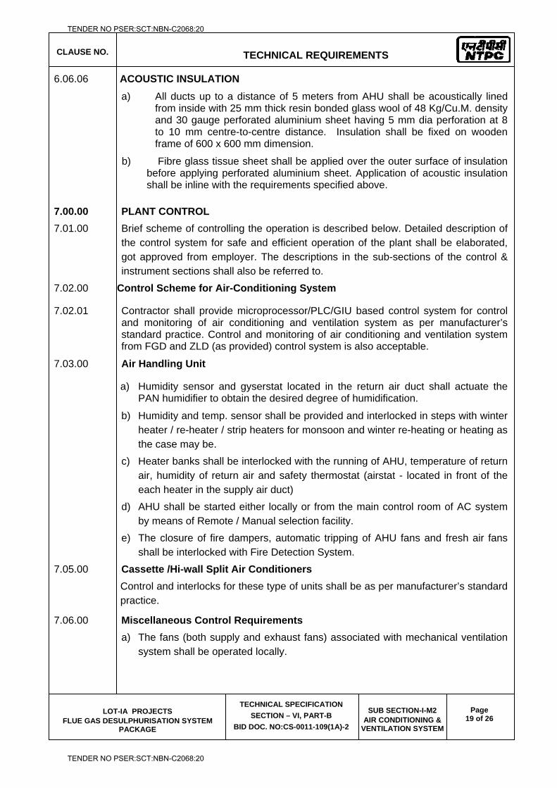
CLAUSE NO.
TECHNICAL REQUIREMENTS
LOT-IA PROJECTS FLUE GAS DESULPHURISATION SYSTEM
PACKAGE
TECHNICAL SPECIFICATION
SECTION – VI, PART-B
BID DOC. NO:CS-0011-109(1A)-2
SUB SECTION-I-M2 AIR CONDITIONING &
VENTILATION SYSTEM
Page 19 of 26
6.06.06 ACOUSTIC INSULATION
a) All ducts up to a distance of 5 meters from AHU shall be acoustically lined from inside with 25 mm thick resin bonded glass wool of 48 Kg/Cu.M. density and 30 gauge perforated aluminium sheet having 5 mm dia perforation at 8 to 10 mm centre-to-centre distance. Insulation shall be fixed on wooden frame of 600 x 600 mm dimension.
b) Fibre glass tissue sheet shall be applied over the outer surface of insulation before applying perforated aluminium sheet. Application of acoustic insulation shall be inline with the requirements specified above.
7.00.00 PLANT CONTROL 7.01.00 Brief scheme of controlling the operation is described below. Detailed description of
the control system for safe and efficient operation of the plant shall be elaborated, got approved from employer. The descriptions in the sub-sections of the control & instrument sections shall also be referred to.
7.02.00 Control Scheme for Air-Conditioning System
7.02.01 Contractor shall provide microprocessor/PLC/GIU based control system for control and monitoring of air conditioning and ventilation system as per manufacturer’s standard practice. Control and monitoring of air conditioning and ventilation system from FGD and ZLD (as provided) control system is also acceptable.
7.03.00 Air Handling Unit
a) Humidity sensor and gyserstat located in the return air duct shall actuate the PAN humidifier to obtain the desired degree of humidification.
b) Humidity and temp. sensor shall be provided and interlocked in steps with winter heater / re-heater / strip heaters for monsoon and winter re-heating or heating as the case may be.
c) Heater banks shall be interlocked with the running of AHU, temperature of return air, humidity of return air and safety thermostat (airstat - located in front of the each heater in the supply air duct)
d) AHU shall be started either locally or from the main control room of AC system by means of Remote / Manual selection facility.
e) The closure of fire dampers, automatic tripping of AHU fans and fresh air fans shall be interlocked with Fire Detection System.
7.05.00 Cassette /Hi-wall Split Air Conditioners Control and interlocks for these type of units shall be as per manufacturer’s standard
practice.
7.06.00 Miscellaneous Control Requirements a) The fans (both supply and exhaust fans) associated with mechanical ventilation
system shall be operated locally.
TENDER NO PSER:SCT:NBN-C2068:20
TENDER NO PSER:SCT:NBN-C2068:20
CLAUSE NO.
TECHNICAL REQUIREMENTS
LOT-IA PROJECTS FLUE GAS DESULPHURISATION SYSTEM
PACKAGE
TECHNICAL SPECIFICATION
SECTION – VI, PART-B
BID DOC. NO:CS-0011-109(1A)-2
SUB SECTION-I-M2 AIR CONDITIONING &
VENTILATION SYSTEM
Page 20 of 26
b) Relative humidity and temperature measurement of all control rooms and all major air-conditioned areas shall made be available in FGD and ZLD (as provided) control system
8.00.00 PAINTING:
8.01.00 All the Equipments shall be protected against external corrosion by providing suitable painting.
8.02.00 The surfaces of stainless steel, Galvanized steel, Gunmetal, brass, bronze and non-metallic components shall not be applied with any painting. The Contractor shall clean the external surfaces and internal surfaces before Erection by wire brushing and air blowing. The steel surface to be applied with painting shall be thoroughly cleaned before applying painting by brushing, shot blasting, etc. as per the agreed procedure.
8.03.00 For all the steel surfaces (external) exposed to atmosphere (outdoor installation), one(1) coat of red oxide primer of thickness 30 to 35 microns followed up with three (3) coats of synthetic enamel paint, with 25 microns as thickness of each coat, shall be applied.
8.04.00 For all the steel surfaces inside the building (indoor installation), One (1) Coat of red oxide primer of thickness 30 to 35 microns followed up with two (2) coats synthetic enamel paint, with 25 microns as thickness of each coat shall be applied.
8.05.00 For centrifugal fans - Casing shall have hot dip/ spray galvanization (minimum 60 micron DFT).
8.06.00 However, for all parts coming in contact with acid fumes (in Battery rooms), a coat of epoxy resin based zinc phosphate primer of minimum thickness 30 to 35 microns followed up with undercoat of epoxy resin based paint pigmented with Titanium dioxide of minimum thickness of 25 microns shall be applied and a top coat consisting of one coat of epoxy paint of approved shade and colour with glossy finish of minimum thickness of 25 microns.
9.00.00 CODES & STANDARDS
9.01.00 The design, manufacture and performance of equipment shall comply with all currently applicable statues, regulations and safety codes in the locality where the equipments are to be installed. Nothing in this specification shall be considered to relieve the bidder of this responsibility.
9.02.00 Unless otherwise specified, equipment shall conform to the latest applicable Indian or IEC standard. Equipment complying with other authoritative standards such as British, USA, ASHRAE etc. will also be considered if it ensures performance equivalent or superior to Indian Standard.
TENDER NO PSER:SCT:NBN-C2068:20
TENDER NO PSER:SCT:NBN-C2068:20
CLAUSE NO.
TECHNICAL REQUIREMENTS
LOT-IA PROJECTS FLUE GAS DESULPHURISATION SYSTEM
PACKAGE
TECHNICAL SPECIFICATION
SECTION – VI, PART-B
BID DOC. NO:CS-0011-109(1A)-2
SUB SECTION-I-M2 AIR CONDITIONING &
VENTILATION SYSTEM
Page 21 of 26
Annexure –I
GENERAL SPECIFICATION FOR HORIZONTAL PUMPS
1) SCOPE
This specification covers the design, material, construction features, manufacture, inspection, testing the performance at the Vendor’s/Sub-Vendor’s Works and delivery to site of Horizontal Centrifugal Pumps.
2) CODES AND STANDARDS
The design, material, construction, manufacture inspection and performance testing of Horizontal Centrifugal Pumps shall comply with all currently applicable statutes, regulations and safety codes in the locality where the Equipment will be installed. Nothing in these specifications shall be construed to relieve the Vendor of this responsibility. The Equipment supplied shall comply with the latest applicable Indian Standards listed below. Other National Standards are acceptable, if they are established to be equal or superior to the Indian Standards.
3) List of Applicable Standards.
IS : 1520 : Horizontal Centrifugal Pumps for clear cold fresh water
IS : 5120 : Technical requirements of roto dynamic special purpose pumps
API : 610 : Centrifugal pumps for general refinery service.
IS : 5639 : Pumps Handling Chemicals & corrosion liquids
IS : 5659 : Pumps for process water
HIS : Hydraulic Institute Standards, USA
ASTM-1-165-65 Standards Methods for Liquid Penetration Inspection.
In case of any contradiction with aforesaid standards and the stipulations as per the technical specifications as specified hereinafter the stipulations of the technical specifications shall prevail.
4) DESIGN REQUIREMENTS
a) The Pump shall be capable of developing the required total head at rated capacity for continuous operation. Also the pumps shall be capable of being operated to give satisfactory performance at any point on the HQ characteristics curve. The operating range of the pump shall be 40% to 120% of the duty point unless otherwise mentioned elsewhere. The maximum efficiency of pump shall preferably be within ± 10% of the rated design flow as indicated in data sheets.
b) The total head capacity curve shall be continuously rising from the operating point towards shut-off without any zone of instability and with a minimum shut-off head of about 15% more than the design head.
TENDER NO PSER:SCT:NBN-C2068:20
TENDER NO PSER:SCT:NBN-C2068:20
CLAUSE NO.
TECHNICAL REQUIREMENTS
LOT-IA PROJECTS FLUE GAS DESULPHURISATION SYSTEM
PACKAGE
TECHNICAL SPECIFICATION
SECTION – VI, PART-B
BID DOC. NO:CS-0011-109(1A)-2
SUB SECTION-I-M2 AIR CONDITIONING &
VENTILATION SYSTEM
Page 22 of 26
Annexure –I
c) Pumps of a particular category shall be identical and shall be suitable for parallel operation with equal load division. The head Vs capacity and BHP Vs capacity characteristics should match to ensure even load sharing and trouble free operation throughout the range. Components of identical pumps shall be interchangeable.
d) Pumps shall run smoothly without undue noise and vibration. Peak to peak vibration limits shall be restricted to the following values during operation:
Speed Antifriction Bearing Sleeve Bearing
1500 rpm and below 75.0 micron 75.0 micron
3000 rpm 50.0 micron 65.0 micron
The noise level shall not exceed 85 dBA overall sound pressure level reference 0.0002 microbar (the standard pressure reference for air sound measurement) at a distance of 1 M from the equipment surface.
e) The pumps shall be capable of starting with discharge valve fully open and close condition. Motors shall be selected to suit to the above requirements. Continuous Motor rating (at 50 deg.C ambient) shall be atleast ten percent (10%) above the maximum load demand of the pump in the entire operating range to take care of the system frequency variation and no case less than the maximum power requirement at any condition of the entire characteristic curve of the pump.
f) The kW rating of the drive unit shall be based on continuously driving the connected equipment for the conditions specified. However, in cases where parallel operation of the pumps are specified, the actual motor rating is to be selected by the Bidder considering overloading of the pumps in the event of tripping of operating pump(s).
g) Pumps shall be so designed that pump impellers and other accessories of the pumps are not damaged due to flow reversal.
h) The Contractor under this specification shall assume full responsibility in the operation of pump and motor as a unit.
5) DESIGN CONSTRUCTION
a) Design and construction of various components of the pumps shall conform to the following general specifications. For material of construction of the components, data sheets shall be referred to.
TENDER NO PSER:SCT:NBN-C2068:20
TENDER NO PSER:SCT:NBN-C2068:20
CLAUSE NO.
TECHNICAL REQUIREMENTS
LOT-IA PROJECTS FLUE GAS DESULPHURISATION SYSTEM
PACKAGE
TECHNICAL SPECIFICATION
SECTION – VI, PART-B
BID DOC. NO:CS-0011-109(1A)-2
SUB SECTION-I-M2 AIR CONDITIONING &
VENTILATION SYSTEM
Page 23 of 26
Annexure –I
b) Pump Casing
Pump casing shall have axially or radially split type construction as specified. The casing shall be designed to withstand the maximum shut-off pressure developed by the pump at the pumping temperature.
Pump casing shall be provided with a vent connection and piping with fittings & valves. Casing drain as required shall be provided complete with drain valves, piping and plugs. It shall be provided with a connection for suction and discharge pressure gauge as standard feature. It shall be structurally sound to provide housing for the pump assembly and shall be designed hydraulically to minimum radial load at part load operation.
c) Impeller
Impeller shall be closed, semi-closed or open type as specified elsewhere and designed in conformance with the detailed analysis of the liquid being handled.
The impeller shall be secured to the shaft, and shall be retained against circumferential movement by keying, pinning or lock rings. On pumps with overhung shaft, impellers shall be secured to the shaft by a lockout or cap screw which tightness in the direction of normal rotation.
d) Impeller/Casing Wearing Rings
Replaceable type wearing rings shall be provided at suitable locations of pumps. Suitable method of locking the wearing ring shall be used. Wearing rings shall be provided in pump casing and/or impeller as per manufacturer’s standard practice.
e) Shaft
The critical speed shall be well away from the operating speed and in no case less than 130% of the rated speed.
The shaft shall be ground and polished to final dimensions and shall be adequately sized to withstand all stresses from rotor weight, hydraulic loads, vibration and torques coming in during operation.
f) Shaft Sleeves
Renewable type fine finished shaft sleeves shall be provided at the stuffing boxes/mechanical seals. Length of the shaft sleeves must extend beyond the outer faces of gland packing of seal end plates so as to distinguish between the leakage between shaft and shaft sleeve and that past the seals/gland.
Shaft sleeves shall be fastened to the shaft to prevent any leakage or loosening. Shaft and shaft sleeve assembly should ensure concentric rotation.
TENDER NO PSER:SCT:NBN-C2068:20
TENDER NO PSER:SCT:NBN-C2068:20
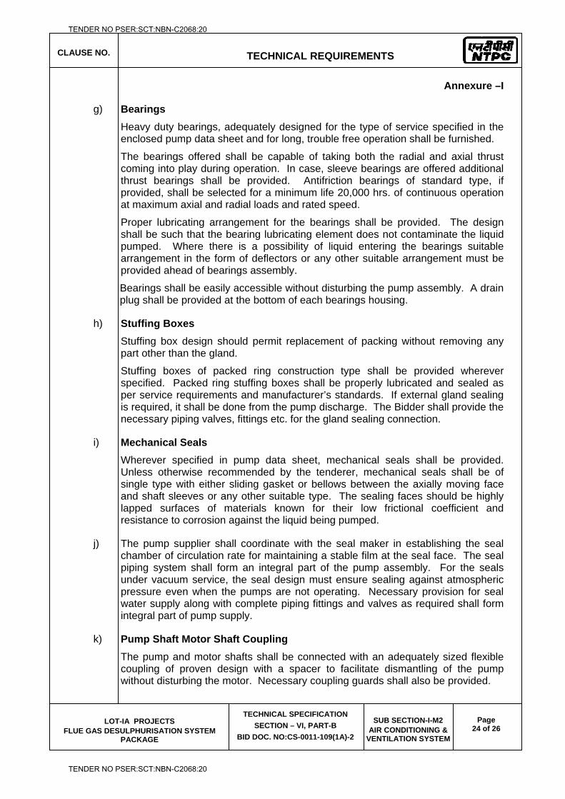
CLAUSE NO.
TECHNICAL REQUIREMENTS
LOT-IA PROJECTS FLUE GAS DESULPHURISATION SYSTEM
PACKAGE
TECHNICAL SPECIFICATION
SECTION – VI, PART-B
BID DOC. NO:CS-0011-109(1A)-2
SUB SECTION-I-M2 AIR CONDITIONING &
VENTILATION SYSTEM
Page 24 of 26
Annexure –I
g) Bearings
Heavy duty bearings, adequately designed for the type of service specified in the enclosed pump data sheet and for long, trouble free operation shall be furnished.
The bearings offered shall be capable of taking both the radial and axial thrust coming into play during operation. In case, sleeve bearings are offered additional thrust bearings shall be provided. Antifriction bearings of standard type, if provided, shall be selected for a minimum life 20,000 hrs. of continuous operation at maximum axial and radial loads and rated speed.
Proper lubricating arrangement for the bearings shall be provided. The design shall be such that the bearing lubricating element does not contaminate the liquid pumped. Where there is a possibility of liquid entering the bearings suitable arrangement in the form of deflectors or any other suitable arrangement must be provided ahead of bearings assembly.
Bearings shall be easily accessible without disturbing the pump assembly. A drain plug shall be provided at the bottom of each bearings housing.
h) Stuffing Boxes
Stuffing box design should permit replacement of packing without removing any part other than the gland.
Stuffing boxes of packed ring construction type shall be provided wherever specified. Packed ring stuffing boxes shall be properly lubricated and sealed as per service requirements and manufacturer’s standards. If external gland sealing is required, it shall be done from the pump discharge. The Bidder shall provide the necessary piping valves, fittings etc. for the gland sealing connection.
i) Mechanical Seals
Wherever specified in pump data sheet, mechanical seals shall be provided. Unless otherwise recommended by the tenderer, mechanical seals shall be of single type with either sliding gasket or bellows between the axially moving face and shaft sleeves or any other suitable type. The sealing faces should be highly lapped surfaces of materials known for their low frictional coefficient and resistance to corrosion against the liquid being pumped.
j) The pump supplier shall coordinate with the seal maker in establishing the seal chamber of circulation rate for maintaining a stable film at the seal face. The seal piping system shall form an integral part of the pump assembly. For the seals under vacuum service, the seal design must ensure sealing against atmospheric pressure even when the pumps are not operating. Necessary provision for seal water supply along with complete piping fittings and valves as required shall form integral part of pump supply.
k) Pump Shaft Motor Shaft Coupling
The pump and motor shafts shall be connected with an adequately sized flexible coupling of proven design with a spacer to facilitate dismantling of the pump without disturbing the motor. Necessary coupling guards shall also be provided.
TENDER NO PSER:SCT:NBN-C2068:20
TENDER NO PSER:SCT:NBN-C2068:20
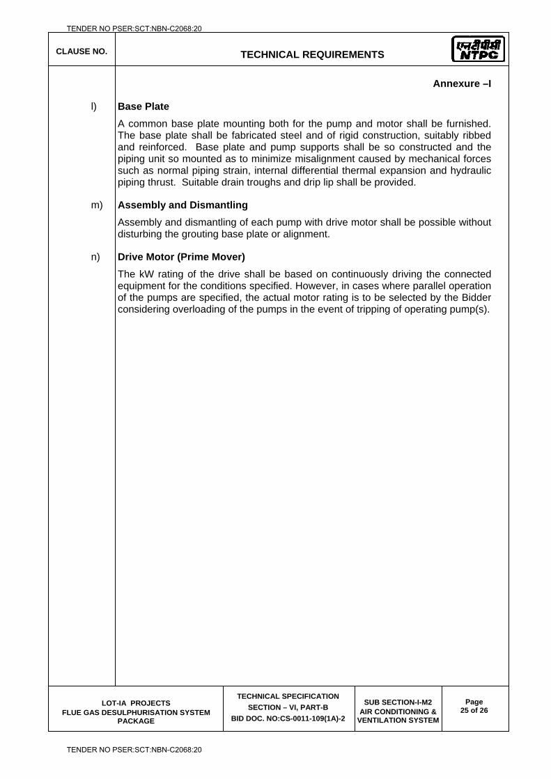
CLAUSE NO.
TECHNICAL REQUIREMENTS
LOT-IA PROJECTS FLUE GAS DESULPHURISATION SYSTEM
PACKAGE
TECHNICAL SPECIFICATION
SECTION – VI, PART-B
BID DOC. NO:CS-0011-109(1A)-2
SUB SECTION-I-M2 AIR CONDITIONING &
VENTILATION SYSTEM
Page 25 of 26
Annexure –I
l) Base Plate
A common base plate mounting both for the pump and motor shall be furnished. The base plate shall be fabricated steel and of rigid construction, suitably ribbed and reinforced. Base plate and pump supports shall be so constructed and the piping unit so mounted as to minimize misalignment caused by mechanical forces such as normal piping strain, internal differential thermal expansion and hydraulic piping thrust. Suitable drain troughs and drip lip shall be provided.
m) Assembly and Dismantling
Assembly and dismantling of each pump with drive motor shall be possible without disturbing the grouting base plate or alignment.
n) Drive Motor (Prime Mover)
The kW rating of the drive shall be based on continuously driving the connected equipment for the conditions specified. However, in cases where parallel operation of the pumps are specified, the actual motor rating is to be selected by the Bidder considering overloading of the pumps in the event of tripping of operating pump(s).
TENDER NO PSER:SCT:NBN-C2068:20
TENDER NO PSER:SCT:NBN-C2068:20
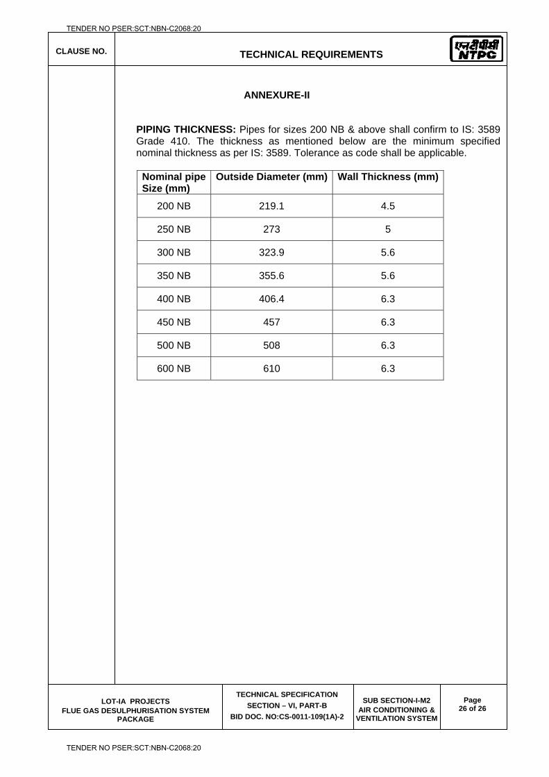
CLAUSE NO.
TECHNICAL REQUIREMENTS
LOT-IA PROJECTS FLUE GAS DESULPHURISATION SYSTEM
PACKAGE
TECHNICAL SPECIFICATION
SECTION – VI, PART-B
BID DOC. NO:CS-0011-109(1A)-2
SUB SECTION-I-M2 AIR CONDITIONING &
VENTILATION SYSTEM
Page 26 of 26
ANNEXURE-II
PIPING THICKNESS: Pipes for sizes 200 NB & above shall confirm to IS: 3589 Grade 410. The thickness as mentioned below are the minimum specified nominal thickness as per IS: 3589. Tolerance as code shall be applicable.
Nominal pipe Size (mm)
Outside Diameter (mm) Wall Thickness (mm)
200 NB 219.1 4.5
250 NB 273 5
300 NB 323.9 5.6
350 NB 355.6 5.6
400 NB 406.4 6.3
450 NB 457 6.3
500 NB 508 6.3
600 NB 610 6.3
TENDER NO PSER:SCT:NBN-C2068:20
TENDER NO PSER:SCT:NBN-C2068:20

LOT-IA PROJECTS FLUE GAS DESULPHURISATION (FGD) SYSTEM PACKAGE
TECHNICAL SPECIFICATION
SECTION-VI
BID DOCUMENT NO.: CS-0011-109(1A)-2
SUB-SECTION-I-M3
COMPRESSED AIR SYSTEM
TENDER NO PSER:SCT:NBN-C2068:20
TENDER NO PSER:SCT:NBN-C2068:20
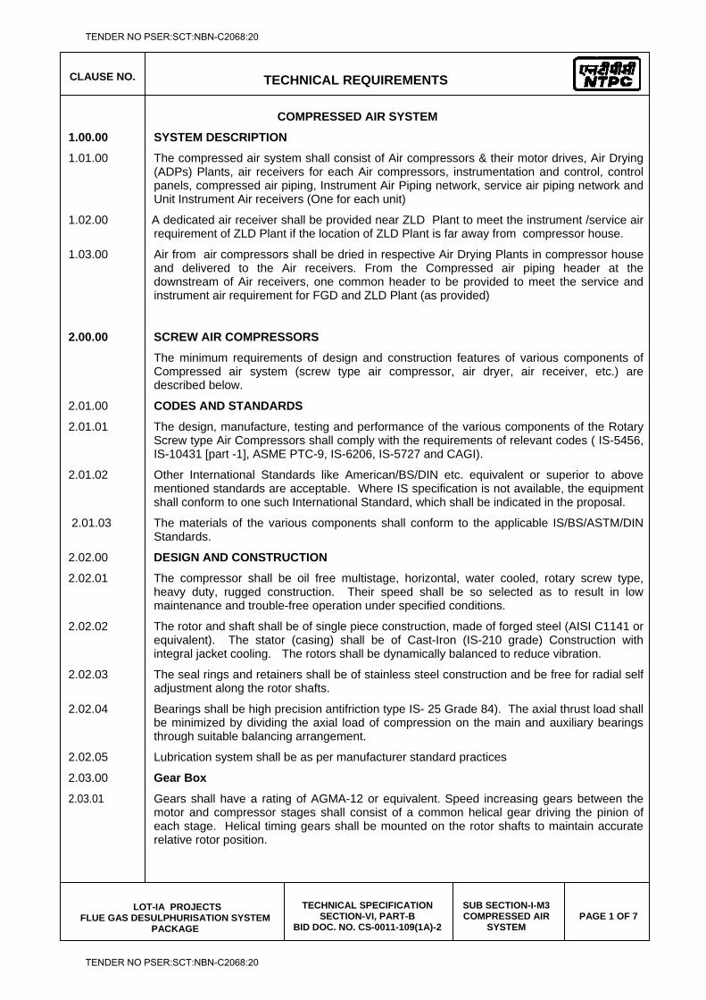
CLAUSE NO.
TECHNICAL REQUIREMENTS
LOT-IA PROJECTS FLUE GAS DESULPHURISATION SYSTEM
PACKAGE
TECHNICAL SPECIFICATION SECTION-VI, PART-B
BID DOC. NO. CS-0011-109(1A)-2
SUB SECTION-I-M3 COMPRESSED AIR
SYSTEM PAGE 1 OF 7
COMPRESSED AIR SYSTEM
1.00.00 SYSTEM DESCRIPTION
1.01.00 The compressed air system shall consist of Air compressors & their motor drives, Air Drying (ADPs) Plants, air receivers for each Air compressors, instrumentation and control, control panels, compressed air piping, Instrument Air Piping network, service air piping network and Unit Instrument Air receivers (One for each unit)
1.02.00 A dedicated air receiver shall be provided near ZLD Plant to meet the instrument /service air requirement of ZLD Plant if the location of ZLD Plant is far away from compressor house.
1.03.00 Air from air compressors shall be dried in respective Air Drying Plants in compressor house and delivered to the Air receivers. From the Compressed air piping header at the downstream of Air receivers, one common header to be provided to meet the service and instrument air requirement for FGD and ZLD Plant (as provided)
2.00.00 SCREW AIR COMPRESSORS
The minimum requirements of design and construction features of various components of Compressed air system (screw type air compressor, air dryer, air receiver, etc.) are described below.
2.01.00 CODES AND STANDARDS
2.01.01 The design, manufacture, testing and performance of the various components of the Rotary Screw type Air Compressors shall comply with the requirements of relevant codes ( IS-5456, IS-10431 [part -1], ASME PTC-9, IS-6206, IS-5727 and CAGI).
2.01.02 Other International Standards like American/BS/DIN etc. equivalent or superior to above mentioned standards are acceptable. Where IS specification is not available, the equipment shall conform to one such International Standard, which shall be indicated in the proposal.
2.01.03 The materials of the various components shall conform to the applicable IS/BS/ASTM/DIN Standards.
2.02.00 DESIGN AND CONSTRUCTION
2.02.01 The compressor shall be oil free multistage, horizontal, water cooled, rotary screw type, heavy duty, rugged construction. Their speed shall be so selected as to result in low maintenance and trouble-free operation under specified conditions.
2.02.02 The rotor and shaft shall be of single piece construction, made of forged steel (AISI C1141 or equivalent). The stator (casing) shall be of Cast-Iron (IS-210 grade) Construction with integral jacket cooling. The rotors shall be dynamically balanced to reduce vibration.
2.02.03 The seal rings and retainers shall be of stainless steel construction and be free for radial self adjustment along the rotor shafts.
2.02.04 Bearings shall be high precision antifriction type IS- 25 Grade 84). The axial thrust load shall be minimized by dividing the axial load of compression on the main and auxiliary bearings through suitable balancing arrangement.
2.02.05 Lubrication system shall be as per manufacturer standard practices
2.03.00 Gear Box
2.03.01 Gears shall have a rating of AGMA-12 or equivalent. Speed increasing gears between the motor and compressor stages shall consist of a common helical gear driving the pinion of each stage. Helical timing gears shall be mounted on the rotor shafts to maintain accurate relative rotor position.
TENDER NO PSER:SCT:NBN-C2068:20
TENDER NO PSER:SCT:NBN-C2068:20
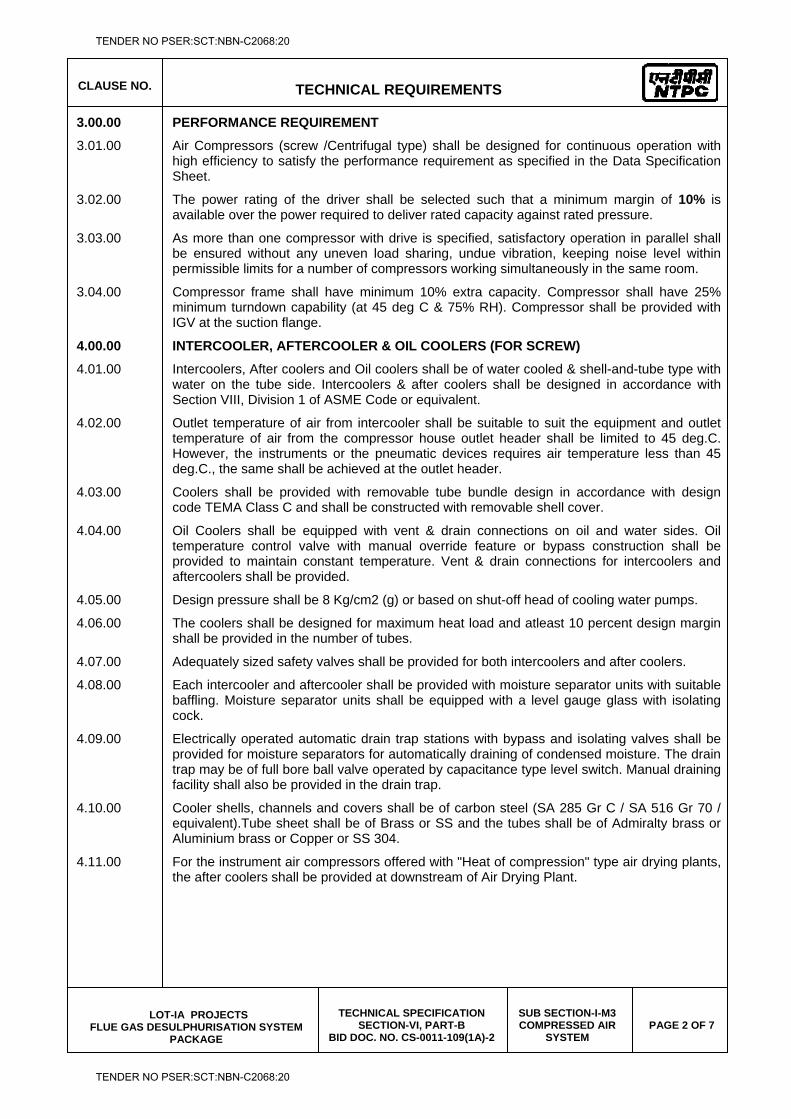
CLAUSE NO.
TECHNICAL REQUIREMENTS
LOT-IA PROJECTS FLUE GAS DESULPHURISATION SYSTEM
PACKAGE
TECHNICAL SPECIFICATION SECTION-VI, PART-B
BID DOC. NO. CS-0011-109(1A)-2
SUB SECTION-I-M3 COMPRESSED AIR
SYSTEM PAGE 2 OF 7
3.00.00 PERFORMANCE REQUIREMENT
3.01.00 Air Compressors (screw /Centrifugal type) shall be designed for continuous operation with high efficiency to satisfy the performance requirement as specified in the Data Specification Sheet.
3.02.00 The power rating of the driver shall be selected such that a minimum margin of 10% is available over the power required to deliver rated capacity against rated pressure.
3.03.00 As more than one compressor with drive is specified, satisfactory operation in parallel shall be ensured without any uneven load sharing, undue vibration, keeping noise level within permissible limits for a number of compressors working simultaneously in the same room.
3.04.00 Compressor frame shall have minimum 10% extra capacity. Compressor shall have 25% minimum turndown capability (at 45 deg C & 75% RH). Compressor shall be provided with IGV at the suction flange.
4.00.00 INTERCOOLER, AFTERCOOLER & OIL COOLERS (FOR SCREW)
4.01.00 Intercoolers, After coolers and Oil coolers shall be of water cooled & shell-and-tube type with water on the tube side. Intercoolers & after coolers shall be designed in accordance with Section VIII, Division 1 of ASME Code or equivalent.
4.02.00 Outlet temperature of air from intercooler shall be suitable to suit the equipment and outlet temperature of air from the compressor house outlet header shall be limited to 45 deg.C. However, the instruments or the pneumatic devices requires air temperature less than 45 deg.C., the same shall be achieved at the outlet header.
4.03.00 Coolers shall be provided with removable tube bundle design in accordance with design code TEMA Class C and shall be constructed with removable shell cover.
4.04.00 Oil Coolers shall be equipped with vent & drain connections on oil and water sides. Oil temperature control valve with manual override feature or bypass construction shall be provided to maintain constant temperature. Vent & drain connections for intercoolers and aftercoolers shall be provided.
4.05.00 Design pressure shall be 8 Kg/cm2 (g) or based on shut-off head of cooling water pumps.
4.06.00 The coolers shall be designed for maximum heat load and atleast 10 percent design margin shall be provided in the number of tubes.
4.07.00 Adequately sized safety valves shall be provided for both intercoolers and after coolers.
4.08.00 Each intercooler and aftercooler shall be provided with moisture separator units with suitable baffling. Moisture separator units shall be equipped with a level gauge glass with isolating cock.
4.09.00 Electrically operated automatic drain trap stations with bypass and isolating valves shall be provided for moisture separators for automatically draining of condensed moisture. The drain trap may be of full bore ball valve operated by capacitance type level switch. Manual draining facility shall also be provided in the drain trap.
4.10.00 Cooler shells, channels and covers shall be of carbon steel (SA 285 Gr C / SA 516 Gr 70 / equivalent).Tube sheet shall be of Brass or SS and the tubes shall be of Admiralty brass or Aluminium brass or Copper or SS 304.
4.11.00 For the instrument air compressors offered with "Heat of compression" type air drying plants, the after coolers shall be provided at downstream of Air Drying Plant.
TENDER NO PSER:SCT:NBN-C2068:20
TENDER NO PSER:SCT:NBN-C2068:20
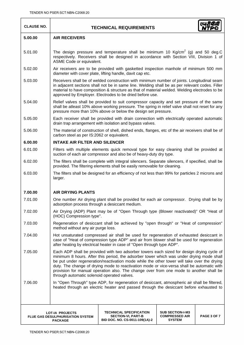
CLAUSE NO.
TECHNICAL REQUIREMENTS
LOT-IA PROJECTS FLUE GAS DESULPHURISATION SYSTEM
PACKAGE
TECHNICAL SPECIFICATION SECTION-VI, PART-B
BID DOC. NO. CS-0011-109(1A)-2
SUB SECTION-I-M3 COMPRESSED AIR
SYSTEM PAGE 3 OF 7
5.00.00 AIR RECEIVERS
5.01.00 The design pressure and temperature shall be minimum 10 Kg/cm2 (g) and 50 deg.C respectively. Receivers shall be designed in accordance with Section VIII, Division 1 of ASME Code or equivalent.
5.02.00 Air receivers are to be provided with gasketted inspection manhole of minimum 500 mm diameter with cover plate, lifting handle, davit cap etc.
5.03.00 Receivers shall be of welded construction with minimum number of joints. Longitudinal seam in adjacent sections shall not be in same line. Welding shall be as per relevant codes. Filler material to have composition & structure as that of material welded. Welding electrodes to be approved by Employer. Electrodes to be dried before use.
5.04.00 Relief valves shall be provided to suit compressor capacity and set pressure of the same shall be atleast 10% above working pressure. The spring in relief valve shall not reset for any pressure more than 10% above or below the design set pressure.
5.05.00 Each receiver shall be provided with drain connection with electrically operated automatic drain trap arrangement with isolation and bypass valves.
5.06.00 The material of construction of shell, dished ends, flanges, etc of the air receivers shall be of carbon steel as per IS:2062 or equivalent.
6.00.00 INTAKE AIR FILTER AND SILENCER
6.01.00 Filters with multiple elements quick removal type for easy cleaning shall be provided at suction of each air compressor and also be of heavy-duty dry type.
6.02.00 The filters shall be complete with integral silencers. Separate silencers, if specified, shall be provided. The filtering elements shall be easily removable for cleaning.
6.03.00 The filters shall be designed for an efficiency of not less than 99% for particles 2 microns and larger.
7.00.00 AIR DRYING PLANTS
7.01.00 One number Air drying plant shall be provided for each air compressor. Drying shall be by adsorption process through a desiccant medium.
7.02.00 Air Drying (ADP) Plant may be of "Open Through type (Blower reactivated)” OR “Heat of (HOC) Compression type".
7.03.00 Regeneration of desiccant shall be achieved by "open through" or "Heat of compression" method without any air purge loss.
7.04.00 Hot unsaturated compressed air shall be used for regeneration of exhausted desiccant in case of "Heat of compression type ADP" and air from blower shall be used for regeneration after heating by electrical heater in case of "Open through type ADP".
7.05.00 Each ADP shall be provided with two adsorber towers each sized for design drying cycle of minimum 8 hours. After this period, the adsorber tower which was under drying mode shall be put under regeneration/reactivation mode while the other tower will take over the drying duty. The change of drying mode to reactivation mode or vice-versa shall be automatic with provision for manual operation also. The change over from one mode to another shall be through automatic solenoid operated valves.
7.06.00 In "Open Through" type ADP, for regeneration of desiccant, atmospheric air shall be filtered, heated through an electric heater and passed through the desiccant before exhausted to
TENDER NO PSER:SCT:NBN-C2068:20
TENDER NO PSER:SCT:NBN-C2068:20
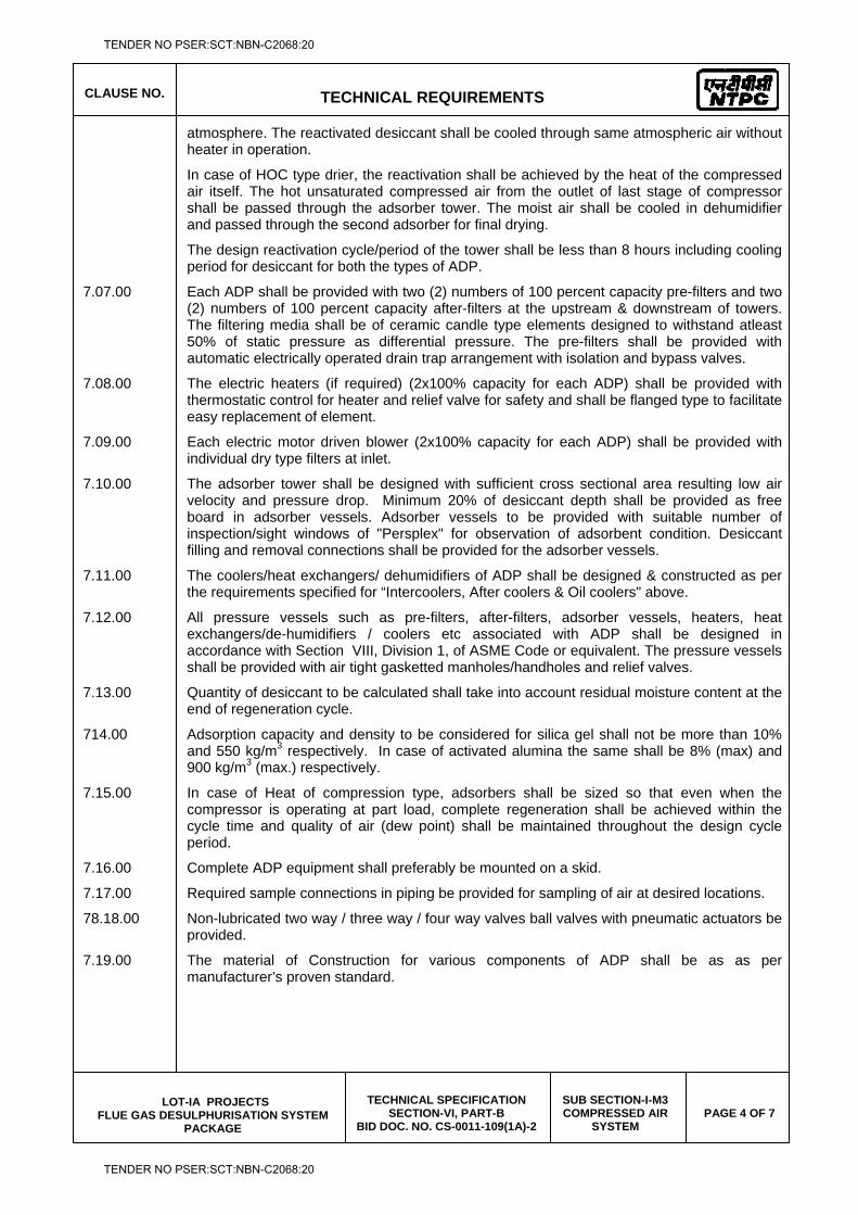
CLAUSE NO.
TECHNICAL REQUIREMENTS
LOT-IA PROJECTS FLUE GAS DESULPHURISATION SYSTEM
PACKAGE
TECHNICAL SPECIFICATION SECTION-VI, PART-B
BID DOC. NO. CS-0011-109(1A)-2
SUB SECTION-I-M3 COMPRESSED AIR
SYSTEM PAGE 4 OF 7
atmosphere. The reactivated desiccant shall be cooled through same atmospheric air without heater in operation.
In case of HOC type drier, the reactivation shall be achieved by the heat of the compressed air itself. The hot unsaturated compressed air from the outlet of last stage of compressor shall be passed through the adsorber tower. The moist air shall be cooled in dehumidifier and passed through the second adsorber for final drying.
The design reactivation cycle/period of the tower shall be less than 8 hours including cooling period for desiccant for both the types of ADP.
7.07.00 Each ADP shall be provided with two (2) numbers of 100 percent capacity pre-filters and two (2) numbers of 100 percent capacity after-filters at the upstream & downstream of towers. The filtering media shall be of ceramic candle type elements designed to withstand atleast 50% of static pressure as differential pressure. The pre-filters shall be provided with automatic electrically operated drain trap arrangement with isolation and bypass valves.
7.08.00 The electric heaters (if required) (2x100% capacity for each ADP) shall be provided with thermostatic control for heater and relief valve for safety and shall be flanged type to facilitate easy replacement of element.
7.09.00 Each electric motor driven blower (2x100% capacity for each ADP) shall be provided with individual dry type filters at inlet.
7.10.00 The adsorber tower shall be designed with sufficient cross sectional area resulting low air velocity and pressure drop. Minimum 20% of desiccant depth shall be provided as free board in adsorber vessels. Adsorber vessels to be provided with suitable number of inspection/sight windows of "Persplex" for observation of adsorbent condition. Desiccant filling and removal connections shall be provided for the adsorber vessels.
7.11.00 The coolers/heat exchangers/ dehumidifiers of ADP shall be designed & constructed as per the requirements specified for “Intercoolers, After coolers & Oil coolers" above.
7.12.00 All pressure vessels such as pre-filters, after-filters, adsorber vessels, heaters, heat exchangers/de-humidifiers / coolers etc associated with ADP shall be designed in accordance with Section VIII, Division 1, of ASME Code or equivalent. The pressure vessels shall be provided with air tight gasketted manholes/handholes and relief valves.
7.13.00 Quantity of desiccant to be calculated shall take into account residual moisture content at the end of regeneration cycle.
714.00 Adsorption capacity and density to be considered for silica gel shall not be more than 10% and 550 kg/m3 respectively. In case of activated alumina the same shall be 8% (max) and 900 kg/m3 (max.) respectively.
7.15.00 In case of Heat of compression type, adsorbers shall be sized so that even when the compressor is operating at part load, complete regeneration shall be achieved within the cycle time and quality of air (dew point) shall be maintained throughout the design cycle period.
7.16.00 Complete ADP equipment shall preferably be mounted on a skid.
7.17.00 Required sample connections in piping be provided for sampling of air at desired locations.
78.18.00 Non-lubricated two way / three way / four way valves ball valves with pneumatic actuators be provided.
7.19.00 The material of Construction for various components of ADP shall be as as per manufacturer’s proven standard.
TENDER NO PSER:SCT:NBN-C2068:20
TENDER NO PSER:SCT:NBN-C2068:20
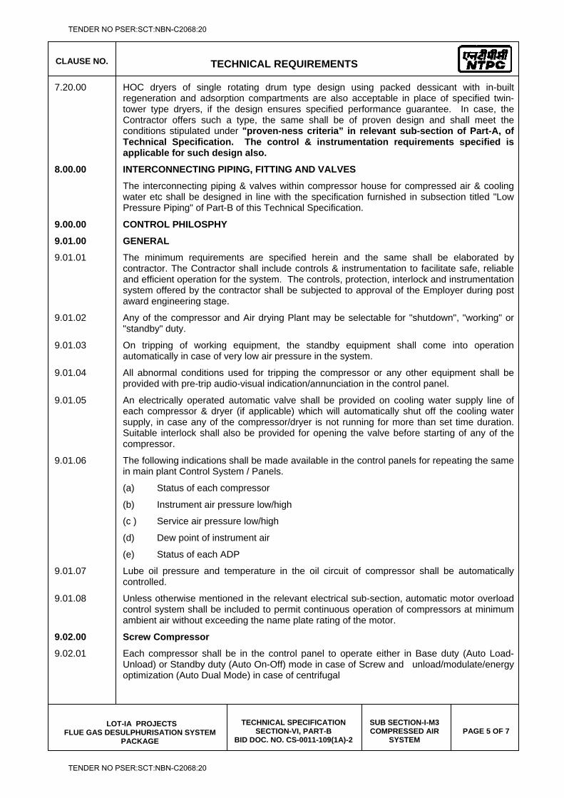
CLAUSE NO.
TECHNICAL REQUIREMENTS
LOT-IA PROJECTS FLUE GAS DESULPHURISATION SYSTEM
PACKAGE
TECHNICAL SPECIFICATION SECTION-VI, PART-B
BID DOC. NO. CS-0011-109(1A)-2
SUB SECTION-I-M3 COMPRESSED AIR
SYSTEM PAGE 5 OF 7
7.20.00 HOC dryers of single rotating drum type design using packed dessicant with in-built regeneration and adsorption compartments are also acceptable in place of specified twin-tower type dryers, if the design ensures specified performance guarantee. In case, the Contractor offers such a type, the same shall be of proven design and shall meet the conditions stipulated under "proven-ness criteria” in relevant sub-section of Part-A, of Technical Specification. The control & instrumentation requirements specified is applicable for such design also.
8.00.00 INTERCONNECTING PIPING, FITTING AND VALVES
The interconnecting piping & valves within compressor house for compressed air & cooling water etc shall be designed in line with the specification furnished in subsection titled "Low Pressure Piping" of Part-B of this Technical Specification.
9.00.00 CONTROL PHILOSPHY
9.01.00 GENERAL
9.01.01 The minimum requirements are specified herein and the same shall be elaborated by contractor. The Contractor shall include controls & instrumentation to facilitate safe, reliable and efficient operation for the system. The controls, protection, interlock and instrumentation system offered by the contractor shall be subjected to approval of the Employer during post award engineering stage.
9.01.02 Any of the compressor and Air drying Plant may be selectable for "shutdown", "working" or "standby" duty.
9.01.03 On tripping of working equipment, the standby equipment shall come into operation automatically in case of very low air pressure in the system.
9.01.04 All abnormal conditions used for tripping the compressor or any other equipment shall be provided with pre-trip audio-visual indication/annunciation in the control panel.
9.01.05 An electrically operated automatic valve shall be provided on cooling water supply line of each compressor & dryer (if applicable) which will automatically shut off the cooling water supply, in case any of the compressor/dryer is not running for more than set time duration. Suitable interlock shall also be provided for opening the valve before starting of any of the compressor.
9.01.06 The following indications shall be made available in the control panels for repeating the same in main plant Control System / Panels.
(a) Status of each compressor
(b) Instrument air pressure low/high
(c ) Service air pressure low/high
(d) Dew point of instrument air
(e) Status of each ADP
9.01.07 Lube oil pressure and temperature in the oil circuit of compressor shall be automatically controlled.
9.01.08 Unless otherwise mentioned in the relevant electrical sub-section, automatic motor overload control system shall be included to permit continuous operation of compressors at minimum ambient air without exceeding the name plate rating of the motor.
9.02.00 Screw Compressor
9.02.01 Each compressor shall be in the control panel to operate either in Base duty (Auto Load-Unload) or Standby duty (Auto On-Off) mode in case of Screw and unload/modulate/energy optimization (Auto Dual Mode) in case of centrifugal
TENDER NO PSER:SCT:NBN-C2068:20
TENDER NO PSER:SCT:NBN-C2068:20
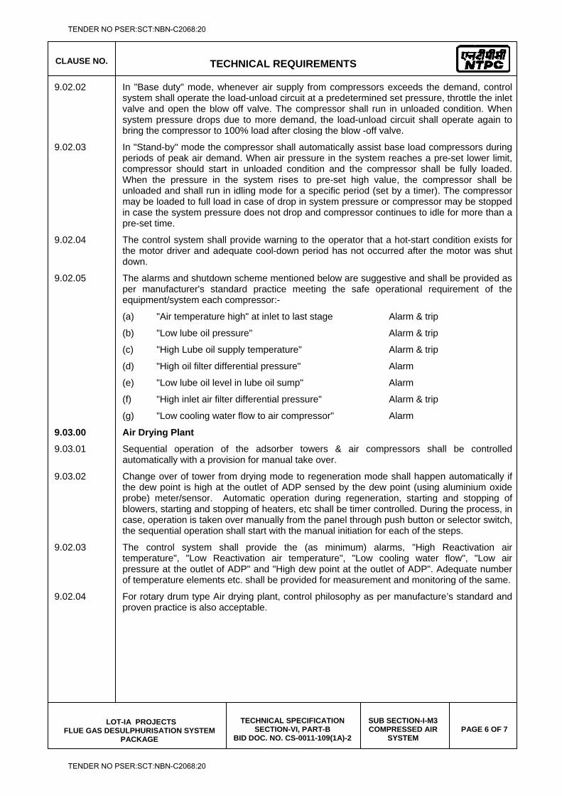
CLAUSE NO.
TECHNICAL REQUIREMENTS
LOT-IA PROJECTS FLUE GAS DESULPHURISATION SYSTEM
PACKAGE
TECHNICAL SPECIFICATION SECTION-VI, PART-B
BID DOC. NO. CS-0011-109(1A)-2
SUB SECTION-I-M3 COMPRESSED AIR
SYSTEM PAGE 6 OF 7
9.02.02 In "Base duty" mode, whenever air supply from compressors exceeds the demand, control system shall operate the load-unload circuit at a predetermined set pressure, throttle the inlet valve and open the blow off valve. The compressor shall run in unloaded condition. When system pressure drops due to more demand, the load-unload circuit shall operate again to bring the compressor to 100% load after closing the blow -off valve.
9.02.03 In "Stand-by" mode the compressor shall automatically assist base load compressors during periods of peak air demand. When air pressure in the system reaches a pre-set lower limit, compressor should start in unloaded condition and the compressor shall be fully loaded. When the pressure in the system rises to pre-set high value, the compressor shall be unloaded and shall run in idling mode for a specific period (set by a timer). The compressor may be loaded to full load in case of drop in system pressure or compressor may be stopped in case the system pressure does not drop and compressor continues to idle for more than a pre-set time.
9.02.04 The control system shall provide warning to the operator that a hot-start condition exists for the motor driver and adequate cool-down period has not occurred after the motor was shut down.
9.02.05 The alarms and shutdown scheme mentioned below are suggestive and shall be provided as per manufacturer's standard practice meeting the safe operational requirement of the equipment/system each compressor:-
(a) "Air temperature high" at inlet to last stage Alarm & trip
(b) "Low lube oil pressure" Alarm & trip
(c) "High Lube oil supply temperature" Alarm & trip
(d) "High oil filter differential pressure" Alarm
(e) "Low lube oil level in lube oil sump" Alarm
(f) "High inlet air filter differential pressure" Alarm & trip
(g) "Low cooling water flow to air compressor" Alarm
9.03.00 Air Drying Plant
9.03.01 Sequential operation of the adsorber towers & air compressors shall be controlled automatically with a provision for manual take over.
9.03.02 Change over of tower from drying mode to regeneration mode shall happen automatically if the dew point is high at the outlet of ADP sensed by the dew point (using aluminium oxide probe) meter/sensor. Automatic operation during regeneration, starting and stopping of blowers, starting and stopping of heaters, etc shall be timer controlled. During the process, in case, operation is taken over manually from the panel through push button or selector switch, the sequential operation shall start with the manual initiation for each of the steps.
9.02.03 The control system shall provide the (as minimum) alarms, "High Reactivation air temperature", "Low Reactivation air temperature", "Low cooling water flow", "Low air pressure at the outlet of ADP" and "High dew point at the outlet of ADP". Adequate number of temperature elements etc. shall be provided for measurement and monitoring of the same.
9.02.04 For rotary drum type Air drying plant, control philosophy as per manufacture’s standard and proven practice is also acceptable.
TENDER NO PSER:SCT:NBN-C2068:20
TENDER NO PSER:SCT:NBN-C2068:20
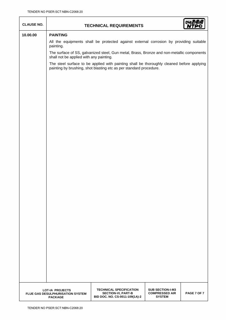
CLAUSE NO.
TECHNICAL REQUIREMENTS
LOT-IA PROJECTS FLUE GAS DESULPHURISATION SYSTEM
PACKAGE
TECHNICAL SPECIFICATION SECTION-VI, PART-B
BID DOC. NO. CS-0011-109(1A)-2
SUB SECTION-I-M3 COMPRESSED AIR
SYSTEM PAGE 7 OF 7
10.00.00 PAINTING
All the equipments shall be protected against external corrosion by providing suitable painting.
The surface of SS, galvanized steel, Gun metal, Brass, Bronze and non-metallic components shall not be applied with any painting.
The steel surface to be applied with painting shall be thoroughly cleaned before applying painting by brushing, shot blasting etc as per standard procedure.
TENDER NO PSER:SCT:NBN-C2068:20
TENDER NO PSER:SCT:NBN-C2068:20
LOT-IA PROJECTS FLUE GAS DESULPHURISATION (FGD) SYSTEM PACKAGE
TECHNICAL SPECIFICATION
SECTION-VI
BID DOCUMENT NO.: CS-0011-109(1A)-2
SUB-SECTION-I-M4
FIRE DETECTION & PROTECTION SYSTEM
TENDER NO PSER:SCT:NBN-C2068:20
TENDER NO PSER:SCT:NBN-C2068:20
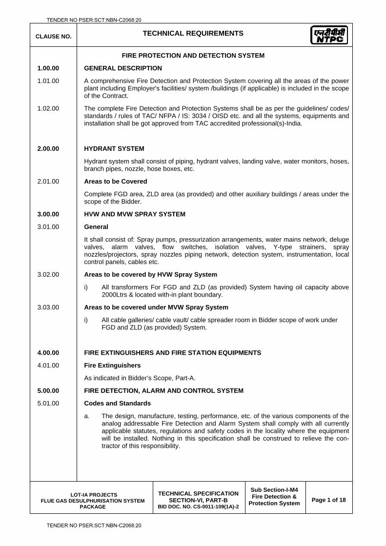
CLAUSE NO. TECHNICAL REQUIREMENTS
LOT-IA PROJECTS FLUE GAS DESULPHURISATION SYSTEM
PACKAGE
TECHNICAL SPECIFICATION
SECTION-VI, PART-B BID DOC. NO. CS-0011-109(1A)-2
Sub Section-I-M4 Fire Detection &
Protection System
Page 1 of 18
FIRE PROTECTION AND DETECTION SYSTEM
1.00.00 GENERAL DESCRIPTION
1.01.00 A comprehensive Fire Detection and Protection System covering all the areas of the power plant including Employer's facilities/ system /buildings (if applicable) is included in the scope of the Contract.
1.02.00 The complete Fire Detection and Protection Systems shall be as per the guidelines/ codes/ standards / rules of TAC/ NFPA / IS: 3034 / OISD etc. and all the systems, equipments and installation shall be got approved from TAC accredited professional(s)-India.
2.00.00 HYDRANT SYSTEM
Hydrant system shall consist of piping, hydrant valves, landing valve, water monitors, hoses, branch pipes, nozzle, hose boxes, etc.
2.01.00 Areas to be Covered
Complete FGD area, ZLD area (as provided) and other auxiliary buildings / areas under the scope of the Bidder.
3.00.00 HVW AND MVW SPRAY SYSTEM
3.01.00 General
It shall consist of: Spray pumps, pressurization arrangements, water mains network, deluge valves, alarm valves, flow switches, isolation valves, Y-type strainers, spray nozzles/projectors, spray nozzles piping network, detection system, instrumentation, local control panels, cables etc.
3.02.00 Areas to be covered by HVW Spray System
i) All transformers For FGD and ZLD (as provided) System having oil capacity above 2000Ltrs & located with-in plant boundary.
3.03.00 Areas to be covered under MVW Spray System
i) All cable galleries/ cable vault/ cable spreader room in Bidder scope of work under FGD and ZLD (as provided) System.
4.00.00 FIRE EXTINGUISHERS AND FIRE STATION EQUIPMENTS
4.01.00 Fire Extinguishers
As indicated in Bidder’s Scope, Part-A.
5.00.00 FIRE DETECTION, ALARM AND CONTROL SYSTEM
5.01.00 Codes and Standards
a. The design, manufacture, testing, performance, etc. of the various components of the analog addressable Fire Detection and Alarm System shall comply with all currently applicable statutes, regulations and safety codes in the locality where the equipment will be installed. Nothing in this specification shall be construed to relieve the con-tractor of this responsibility.
TENDER NO PSER:SCT:NBN-C2068:20
TENDER NO PSER:SCT:NBN-C2068:20
CLAUSE NO. TECHNICAL REQUIREMENTS
LOT-IA PROJECTS FLUE GAS DESULPHURISATION SYSTEM
PACKAGE
TECHNICAL SPECIFICATION
SECTION-VI, PART-B BID DOC. NO. CS-0011-109(1A)-2
Sub Section-I-M4 Fire Detection &
Protection System
Page 2 of 18
b. Unless otherwise specified, the Fire Detection and Alarm System and the components shall conform to the latest applicable Indian or IEC Standards. Equipment complying with any other authoritative National Standards such as British, USA, VDE, etc. will also be considered, provided the parameters specified are equivalent or better than the corresponding IS.
c. The Contractor shall be solely responsible for obtaining the required approval and clearance for the different components and systems of the Fire Detection and Alarm System from the following authorities, as applicable:
i. Department of Atomic Energy (Certification of safety from Radioactivity).
ii. Central Building Research Institute, Roorkee.
iii. Central Mining Research Station, Dhanbad.
iv. Local Fire Authorities.
d. The equipment and the system shall be of types approved by any of the following bodies, as applicable:
1. Loss Prevention Council, (LPC), U.K.
2. National Fire Protection Association, (NFPA), USA
3. Under-writers laboratories, (UL), USA
4. Factory mutual(FM)
5.02.00 Areas to be covered under Fire detection and alarm System
a) Multisensor type detection system (Above and below the false ceiling or below the false flooring as the case may be)
i) All switchgear / MCC/battery rooms of FGD and ZLD (as provided) control room building, various auxiliary buildings (if applicable), etc.
ii) Cable galleries of FGD and ZLD (as provided) control room building protected by MVW spray system. Further, multisensory detectors shall also be provided inside all cubicles/panels of control room, control equipment room and UPS / Battery charger areas.
iii) Above and Below false ceiling areas of all air-conditioned rooms of FGD and ZLD (as provided) control room building, various control rooms of auxiliaries as defined in Sl. No. (i) above and return air ducts of inert gas protected areas.
b) Linear heat sensing cable detection system
Gypsum and lime conveyor of FGD system and Cable Galleries covered under MVW Spray System.
c) Quartzoid bulb heat detection system
Equipments protected by HVW spray system, conveyors protected by MVW spray system.
5.03.00 General requirements for all types of Detectors
5.03.01 Detectors shall be housed or mounted in suitable enclosure in such a way that their performance is in no way affected. Special maintenance procedures if any required for the satisfactory operation of the detectors shall be clearly stated in the bid.
TENDER NO PSER:SCT:NBN-C2068:20
TENDER NO PSER:SCT:NBN-C2068:20
CLAUSE NO. TECHNICAL REQUIREMENTS
LOT-IA PROJECTS FLUE GAS DESULPHURISATION SYSTEM
PACKAGE
TECHNICAL SPECIFICATION
SECTION-VI, PART-B BID DOC. NO. CS-0011-109(1A)-2
Sub Section-I-M4 Fire Detection &
Protection System
Page 3 of 18
5.03.02 Necessary mounting accessories shall be provided for all the detectors.
5.03.03 In case the detectors are offered with their output (on sensing a fire) in the form of an electrical contact, it shall be noted that the contact shall be ‘NC’ type such that under fire conditions, this contact will open to initiate the fire alarm system.
5.03.04 Detectors shall preferably be designed as plug-in units, which fit into various bases according to place and type of mounting. This would also enable interchangeability.
5.03.05 Detectors shall be provided with the necessary compression type cable terminating glands for the incoming cables of flameproof type or PVC/metallic flexible/rigid conduits.
5.03.06 Depending upon the environmental conditions in which detectors are installed, chlorinated rubber based or epoxy or equivalent paint shall be used for finishing the surface of the enclosure.
5.03.07 The coverage or the zone of protection afforded by the detector and recommended height of mounting shall be furnished by the Bidder. The bidder shall furnish the test certificate in support of this.
5.03.08 Any metal parts used for detector construction shall be inherently resistant to corrosion or shall be plated or otherwise suitably treated to afford protection against corrosion. The plating or treatment shall in no way affect the detector performance.
5.03.09 Any plastic material or any sealing compound used in the detector shall be such as it will not deform or fail under the maximum temperature to be expected.
5.03.10 No detector shall contain any moving parts subject to wear and tear and must be able to operate afresh after each alarm release, without its exchange or adjustment.
5.03.11 The detector shall be located where the largest combustion gas concentration can be expected.
5.03.12 Adequate compensation and considerations shall be made for effects for wind velocities such as air-conditioning system and exhaust fans where dilution of particles of combustion is greater.
5.03.13 The exact location of detectors shall be coordinated with other services like air-conditioning grills, light fittings, cable trays etc. to provide aesthetically pleasing appearance. The return air paths of air-conditioning shall be avoided for detector location.
5.03.14 The detectors shall not be affected by temperature, humidity; air flow or by drift failures and shall not give any false alarm due to above.
5.03.15 The detectors shall not be sensitive to vibrations. Any special mounting arrangements required to counteract vibration shall be included in the contractor scope.
5.03.16 The quantity of multi- sensor detectors in each zone shall be based on the coverage factor of 25-sq. meter per detector. However the actual quantity of detectors required, taking into consideration obstructions due to floor beams, ventilation, doors, windows etc., shall be worked out and supplied (based on the actual layout) and installed by the contractor.
5.03.17 The detectors shall not give false alarm due to high humidity, temperature, and velocity of air in the surroundings and static electricity conditions.
TENDER NO PSER:SCT:NBN-C2068:20
TENDER NO PSER:SCT:NBN-C2068:20
CLAUSE NO. TECHNICAL REQUIREMENTS
LOT-IA PROJECTS FLUE GAS DESULPHURISATION SYSTEM
PACKAGE
TECHNICAL SPECIFICATION
SECTION-VI, PART-B BID DOC. NO. CS-0011-109(1A)-2
Sub Section-I-M4 Fire Detection &
Protection System
Page 4 of 18
5.03.18 Process actuated switch devices such as pressure switches, flow switches, level switches, etc. shall be provided with suitable individual addressable interface (local or remote) units or modules so that these devices are addressable from the panel.
5.05.00 Linear Heat Sensor Cables
Application Detection of Stationary fire
Type Digital
Operating voltage 24 V DC
Approval FM/UL
Conductor material Steel
Insulation Heat sensitive polymer
Outer Sheath Black or colored PVC or flouropolymer suitable for the application environment
Installation features for LHSC
1. Mounting arrangement have been indicated in tender drawing.
2. The detection zone/loop divisions of LHSC system shall match with MVW spray zones. Conveyors where LHSC shall be installed shall be divided into no. of various zones whereas conveyor for which IR detector is installed shall be considered as one zone.
3. Linear heat sensing cable detector shall run in a zigzag fashion (with an included angle of 90 deg) on each top cable tray, bottom tray and every alternate intermediate trays of each section of cable tray without undue sagging and interfering the normal operations. All supporting materials for mounting of LHSC shall be provided by the bidder.
5.06.00 Addressable Analog Intelligent Detectors
In addition to the features specified under the item General requirements for all types of Detectors, the Addressable Analog Intelligent Detectors shall be provided with the following features:
a) Detectors not specifically listed for sensitivity testing from the control panel are not acceptable due to the expense involved with manual testing as required by NFPA 72E.
b) The detector shall be suitable for two-wire operation and two-way communication on the intelligent analog signaling circuit.
c) The detector shall display a steady LED when in the Alarm State. The LED shall flash when in stand by or normal mode.
d) Each detector in a loop shall have short circuit isolator suitable for style-7 wiring as per NFPA-72.
TENDER NO PSER:SCT:NBN-C2068:20
TENDER NO PSER:SCT:NBN-C2068:20
CLAUSE NO. TECHNICAL REQUIREMENTS
LOT-IA PROJECTS FLUE GAS DESULPHURISATION SYSTEM
PACKAGE
TECHNICAL SPECIFICATION
SECTION-VI, PART-B BID DOC. NO. CS-0011-109(1A)-2
Sub Section-I-M4 Fire Detection &
Protection System
Page 5 of 18
e) Address and sensitivity assignments shall be set preferably electronically. However, dip switches / rotary switches for the same are acceptable. The detectors shall be assigned a sensitivity level based on environment, time of day or any programmable function as required by the system user, and shall respond at that level whether in the “on line” or “default” mode.
f) The fire alarm control panel shall permit detector sensitivity adjustment through field programming of the system.
g) The detectors furnished shall be listed for use in environments as covered by Factory Mutual and UL and shall be installed according to the requirements of NFPA 72E for open area coverage.
5.07.00 Multi sensor Detectors
5.07.01 Multi sensor detectors shall incorporate a heat detection element and a photoelectric detection element. Both the elements shall be incorporated in a single unit. Both the elements shall be operative at all times and the fire signal shall be available from any or both elements combined together.
5.07.02 The detectors shall be sensitive to very low smoke densities of the order of say 0.05 g/m3. Also it shall be possible to adjust this sensitivity on a step less basis over a range so that the optimum sensitivity could be selected at site to suit the conditions of installations. The coverage area of the smoke detection under standard NFPA test conditions shall not be less than 80-90m2.
5.07.03 The detectors shall be complete with a mounting base that includes a terminal box into which the detector can be plugged in. Terminals for looping of the cables shall be provided.
5.07.04 All detectors shall be provided with built-in response and indicating lamps which shall give local visual indication, when it has operated in dense smoke conditions. The failure of lamp shall not prevent the function of detector.
5.07.05 In areas such as false ceiling where detectors themselves are not easily accessible, the remote response indicators outside the enclosed areas shall be provided to indicate the fire condition.
5.07.06 It shall be possible to replace any type of detector head by a different type detector without requiring change in cabling/panel wiring and condition of the zone, originally covered by the detector.
5.08.00 System Configuration
5.08.01 The Addressable Fire Alarm panel shall be able to communicate with repeater annunciation panel located at different places. The detectors or other devices of any other unit/area shall be addressable only from the respective Addressable Fire Alarm Panel, so that each of the Addressable Fire Alarm Panel is under the control of designated operating personnel at that location.
5.08.02 At least one spare loop shall be provided in each of the addressable type fire alarm panel located in FGD and ZLD (as provided) control equipment room with complete loop card and all other accessories so that Employer can expand the system in future. Further, at least 10% of loop capacity be left free in each of the connected loop in all the panels, so that, additional devices may be connected to the system in any of the loop by Employer in future.
TENDER NO PSER:SCT:NBN-C2068:20
TENDER NO PSER:SCT:NBN-C2068:20
CLAUSE NO. TECHNICAL REQUIREMENTS
LOT-IA PROJECTS FLUE GAS DESULPHURISATION SYSTEM
PACKAGE
TECHNICAL SPECIFICATION
SECTION-VI, PART-B BID DOC. NO. CS-0011-109(1A)-2
Sub Section-I-M4 Fire Detection &
Protection System
Page 6 of 18
5.08.03 FGD and ZLD (as provided) Fire alarm system shall be provided with necessary interface hardware and software for communicating fire alarms from this fire alarm panel to the main plant fire alarm control panel through potential free contacts.
5.09.00 Analog Addressable Fire Detection and Alarm System
5.09.01 General Requirements
5.09.02 This specification in general covers the functional requirements, and general design aspects of Microprocessor based, Analog Addressable Fire Detection Alarm / Annunciation and Control System.
5.09.03 The following description intends to describe only the brief hardware and functional requirements, scope of hardware requirements etc. but the actual configuration of the system shall be in line with the prevalent normal practices in the industry and shall conform to latest product range of selected manufacturer.
The fire detection and control system offered shall be complete in all respects for the safe and reliable operation of the entire system. Any additional hardware/software than those mentioned herein required to make the system complete shall be included in the scope of the Bidder.
5.09.04 All the system and its equipment specifically detectors, interface modules, panels, power supply, battery chargers etc. shall be furnished from a single source and the same shall be new and latest state of the art products of manufacturer engaged in the manufacture of Integrated Microprocessor based Analog Addressable Fire Detection and Alarm System.
5.09.05 All equipments such as detectors, panels etc shall be approved and listed by UL/FM/LPCB/VDS.
5.09.06 All types of smoke detectors shall be of analogue addressable type. Conventional detectors with interface modules are not acceptable. Each zone of LHSC detector and each IR detector shall be provided with interface module.
5.09.07 All the fire detection systems, process actuated switch devices such as pressure/flow/temperature switches and relays of control functions shall be hooked up with the analogue addressable fire detection and alarm system. Required addressable interface units shall be provided for various switch devices by the bidder to make them addressable.
5.09.08 The wiring shall be of class-A as per NFPA-72.
5.09.09 Bidder shall provide isolators at the start & end of the loop.
5.09.10 The complete system shall include, but not be limited to the following :
a) Master system CPU.
b) Analog Addressable Fire Detection and Alarm System panels including alarm modules, system supervisory control modules, auxiliary output control modules etc.
c) Power supplies, batteries and battery chargers.
d) Analog addressable type smoke detectors.
TENDER NO PSER:SCT:NBN-C2068:20
TENDER NO PSER:SCT:NBN-C2068:20
CLAUSE NO. TECHNICAL REQUIREMENTS
LOT-IA PROJECTS FLUE GAS DESULPHURISATION SYSTEM
PACKAGE
TECHNICAL SPECIFICATION
SECTION-VI, PART-B BID DOC. NO. CS-0011-109(1A)-2
Sub Section-I-M4 Fire Detection &
Protection System
Page 7 of 18
e) Non addressable type conventional detectors (Linear heat sensing cable detector/ infra red type heat detector) and switching devices each with its own addressable interface modules.
f) Software and hardware as required for complete operation of the system.
g) Complete Wiring/cabling including its conduits/trays/fixtures etc.
i) The fire alarm control panel shall function as a communication interface between central processing unit and sensors. This panel shall have facility to process the input signal and to control all the input data received from initiating and indicating devices.
j) Fire alarm control panel shall have filters to ignore false alarm and increase sensitivity to real fire from sensors. The sensitivity of each detector should be automatically raised if detectors are gradually polluted due to dust and dirt entering inside the detector. If detectors are more polluted the control panel shall give a warning. The trouble report shall indicate the location of device requiring service.
k) Fire alarm control panel shall have printer to print out the alarm/ trouble occurrences.
l) The CPU shall serve as the systems central processor. Software shall be designed especially for fire alarm annunciation system applications and shall monitor status of processing alarms according to priorities, controlling/processing communications and synchronizing all system activities.
n) The system shall be able to recognize and indicate an alarm condition in a degrade mode of operation, in the event of processor failure or the loss of system communications to the circuit interface panels.
o) All devices shall be individually identifiable for its type, its zone location, alarm set value, alarm and trouble indication by an unique alpha numerical label.
p) The software logic modules and system database shall be programmable using a MS - Windows compatible program (latest version) on PC at site and required hardware shall be included in scope of supply. The system software programme shall be password protected and shall include full upload and download capability and during program upload or download through the PC, the capability of alarm reporting shall be retained. The software shall be downloaded to a PC for editing. The software shall enable Employer to add the spare loop provided in the fire alarm panels or addition of additional devices/detectors in any of the fire alarm panel.
q) The system shall support the use of Color Graphic display terminal for the display of information in an appropriate format.
r) The system shall include software for system data base, historical event log, logic, and operating system. The system shall require no manual input to initialise in the event of a complete power down condition. It shall return to an on line state as an operating system performing all programmed functions upon power restoration.
s) Activation of any fire alarm initiating device shall display (LCD alpha numeric display) message in describing the device originating the alarm condition at the Central monitoring station, at alarm panel, simultaneously at the repeater annunciation panel and shall initiate the associated protection systems & other related control functions. Similarly activation of any supervisory circuit, (supervised
TENDER NO PSER:SCT:NBN-C2068:20
TENDER NO PSER:SCT:NBN-C2068:20
CLAUSE NO. TECHNICAL REQUIREMENTS
LOT-IA PROJECTS FLUE GAS DESULPHURISATION SYSTEM
PACKAGE
TECHNICAL SPECIFICATION
SECTION-VI, PART-B BID DOC. NO. CS-0011-109(1A)-2
Sub Section-I-M4 Fire Detection &
Protection System
Page 8 of 18
valve closure, air pressure abnormal, fire pump trouble, water pressure low, etc.) or receipt of trouble report (primary power loss, open or grounded initiating or signaling circuit wiring, battery disconnect etc) shall display at the fire alarm control panel the origin of supervisory condition or origin of trouble condition as the case may be. It shall also record the occurrence of the event, the time of occurrence and the device initiating the same.
t) System configuration shall be menu driven and capable of being operated by, a person with no previous computer programming experience.
5.10.00 System Functional Requirements
5.10.01 The fire alarm panel shall evaluate the signals received from the detectors and shall handle the following functions:
1. System self monitoring and fault signaling.
2. Transmission of alarm and fault signals to the respective fire alarm panels and as well as in the repeater panel in fire station. Further, the panel shall activate a hooter/sounds in each of the area locally provided with fire/smoke detection system. Further, the system shall enable operation of spray system from the panel through monitoring station when the system operation is selected under remote, manual mode.
3. Initiate control functions like stoppage of conveyor, closure of fire doors, shutdown of draft fans, air-conditioning and ventilation plant/ equipment, opening smoke extraction vents, switching on smoke extraction equipment, emergency lighting etc.
4. Triggering stationary extinguishing systems such as clean agent system.
5. Supervising of unauthorised removal of a detector head from its base and giving a fault alarm on the control panel.
6. Supervising and monitoring the detection cabling, to indicate fault conditions in case of open/short circuit in the wiring.
7. Supervising by a separate annunciation window, changeover from mains supply to battery supply. “Mains On” indication shall be continuously on, as long as the main supply is available.
8. Facilitating simulation of fire conditions to enable the testing of circuits (without creating actual fire) under the test mode from the fire Alarm panel.
9. The control unit shall contain all the systems main switches lamps and fuses. Switches and lamps shall be easily identified even in closed casings.
10. All the circuits from the detectors to the panels and the circuits from panels to the actuating/operating devices of the respective extinguishing system shall be of closed loop type and shall be supervised for open-circuiting and short-circuiting of cables. The cable fault shall be audio-visually annunciated on the panels. Separate hooters with different tones shall be provided for ‘fault’ alarms and ‘fire’ alarms.
11. Actuate solenoid valve in spray system in case of fire from respective fire alarm panel. For achieving this if any additional hardware is required like relays, power supply and cables, the same may be provided.
TENDER NO PSER:SCT:NBN-C2068:20
TENDER NO PSER:SCT:NBN-C2068:20
CLAUSE NO. TECHNICAL REQUIREMENTS
LOT-IA PROJECTS FLUE GAS DESULPHURISATION SYSTEM
PACKAGE
TECHNICAL SPECIFICATION
SECTION-VI, PART-B BID DOC. NO. CS-0011-109(1A)-2
Sub Section-I-M4 Fire Detection &
Protection System
Page 9 of 18
5.10.02 Analog Addressable Fire Detection and Alarm System shall also meet the following functional requirements:
i. Each of the system shall support analog addressable detectors of all types, non-addressable type detectors/devices along with its addressable interface units/modules, Video display units etc.
ii. Each of the devices and/or detectors shall be individually, uniquely and continuously addressable by the panel to which it is connected.
iii. Detectors shall be interrogated for sensitivity settings from the control panel, logged for sensitivity changes indicating the requirement for cleaning and tested by a single technician using the field test routine. Sensitivity of each of the detectors made available in the panel shall be adjustable from the panel.
iv. The system shall be capable of self-adjustment to compensate for the accumulation of contaminants that would change the detector sensitivity in either a more or less sensitive direction to prevent false indications or failure to alarm in the actual fire conditions. The system shall annunciate a trouble condition when any analog addressable smoke detector reaches 80% of its alarm threshold due to gradual contamination, signaling the need for service and eliminating unwanted alarm.
v. Continuous supervision/monitoring of all the circuits and its components shall be made available from the panel for open, short circuits and grounding.
vi. The system shall be able to recognize and indicate and alarm condition in a degraded mode of operation, in the event of processor failure or the loss of system communications to the circuit interface panels.
vii. The system shall be programmable at site and required hardware shall be included in the scope of supply. The system software Programs shall be password protected and shall include full upload and download capability. During program upload or download the system shall retain the capability for alarm reporting. The system shall download to a PC for program editing. The software shall eligible employer to add the spare loop provided in the fire alarm panel or addition of additional devices/detectors in and of loop in any of the fire alarm panel.
viii. The system shall support the use of color interactive History Reporting video display terminal for the display of information in an appropriate format.
ix. The system shall include software for system database, historical event log, logic and operating system. The system shall require no manual input to initialize in the event of a complete power down condition. It shall return to an on line state performing all programmed functions upon power restoration.
x. Software logic modules and system database shall be programmable using a windows compatible program on PC. It shall be possible to program or edit the system database off site after down loading from the panel.
xi. All detectors shall incorporate internal automatic temperature compensation to overcome the effects of either high or low ambient temperatures in the installed environment on the detector sensitivity. The detectors shall be tested at a specified frequency by raising the detector sensitivity level to the alarm threshold, to check the operation of the detector without system alarming
TENDER NO PSER:SCT:NBN-C2068:20
TENDER NO PSER:SCT:NBN-C2068:20
CLAUSE NO. TECHNICAL REQUIREMENTS
LOT-IA PROJECTS FLUE GAS DESULPHURISATION SYSTEM
PACKAGE
TECHNICAL SPECIFICATION
SECTION-VI, PART-B BID DOC. NO. CS-0011-109(1A)-2
Sub Section-I-M4 Fire Detection &
Protection System
Page 10 of 18
automatically by the control panel.
xii. In an alarm or trouble condition the following shall occur on the monitoring station:
1. Sound an audible.
2. Write details of the actuation to a system log file on the PC.
3. Print the details of the actuation to the system printer.
4. Activate the color graphic display system controls, providing functions such as zooming, scrolling of Alarms, troubles, etc.
xiii. System configuration shall be menu driven and capable of being operated by a person with no previous computer programming experience.
5.11.00 Panel Display Requirements.
System display shall consist of minimum 80 character back lighted alphanumeric LCD display readable at any angle. Thirty-two character customer defined custom messages shall describe the location of the active device. In addition to the above, the following features shall be available.
a. The system shall be capable of programming to allow troubles occurred and restored in the system to be automatically removed from the display queue, eliminating the necessity for individual acknowledging of these events. This feature shall not affect the historical logging of events as programmed.
b. As a minimum an LED display for “Alarm”, “Audible Silenced”, “Supervisory”, “Trouble”, “Security”, “Power On”, And “Partial System Disabled”.
c. Touch activated membrane switches for “Alarm Acknowledge”, “Audible Silence”, “Supervisory Acknowledge”, “Security Acknowledge”, “Reset”, “Display Hold”, And “Display Next”.
d. All membrane switches shall be tactile with audible feedback when pressed.
5.12.00 System Software Requirements
i) The software shall control the operation, function and display of the graphic system and provide for automatic boot up and run from the hard disk drive of the computer.
ii) All project specifics actuating device programming shall be capable of being carried out on site via password access.
iii) The system shall monitor all alarm, supervisory; trouble and security conditions detected by the fire alarm control panel and provide separate disk based files, for each condition. These logs may be enabled, disabled, or cleared with password access.
This log information is not to be lost upon power failure or fire alarm control panel reset. A utility file shall be provided to sort the log data by date or by device and display this information either on the screen or the system printer.
TENDER NO PSER:SCT:NBN-C2068:20
TENDER NO PSER:SCT:NBN-C2068:20
CLAUSE NO. TECHNICAL REQUIREMENTS
LOT-IA PROJECTS FLUE GAS DESULPHURISATION SYSTEM
PACKAGE
TECHNICAL SPECIFICATION
SECTION-VI, PART-B BID DOC. NO. CS-0011-109(1A)-2
Sub Section-I-M4 Fire Detection &
Protection System
Page 11 of 18
iv) Selective memory storage up to 800 events, shall be stored in flash memory and displayed, printed or downloaded by classification for selective event reports.
a. Software shall allow selection of events to be logged, including; inputs as alarms, troubles, supervisors, securities, status changes and device verification; out puts, as audible control and output activation; action, as reset, set sensitivity, arm/disarm, override, password, set time and acknowledge.
b. Audible and visual indications shall be generated when memory is 80% and 90% full to allow downloading of data. The system shall be programmable circular logging, assuring that at least the last 400 events will always be stored in non-volatile memory.
v) Software has driven logic for adjusting the alarm threshold windows on detectors to compensate for accumulating contamination and keep detector response sensitivity constant. The software shall compensate for either over-sensitized or desensitized units, raising a system flag when a detector approaches the allowable limits of adjustment, indicating a requirement for cleaning.
a. Values shall be stored in non-volatile memory allowing activation of all tracking functions within 90 sec of system initiation from a "cold boot". During the boot sequence, alarms from detectors programmed with the feature shall be suppressed.
When the full data history is active all devices shall be checked and any active alarms displayed.
b. The control panel shall place each detector in the system in an alarm condition, transparent to the system user, every twenty-four hours as a dynamic check of the accuracy of the alarm threshold setting. Upon reception of the alarm report, the system detector shall be restored to its pretest state.
c. The system shall be capable of monitoring the stage of detectors and displaying a message when a detector is approaching the limits of adjustment as a result of contaminates. A second message shall be displayed when the detector reaches the limits of adjustment due to these contaminate.
d. The system shall be capable of recognizing that a detector has been cleaned, initiating a series of tests to determine if the cleaning was successful and display a detector cleaned message, readjusting that detectors normal sensitivity setting reference.
vi) When an alarm or trouble is registered at the fire alarm control panel the graphics system shall display the first screen image for the first actuated device. The system shall be capable of zooming in for further information if required. At all times when in the alarm or trouble mode the fire control panel status i.e. number of current alarms and or troubles is to be displayed on the graphics screen.
5.13.00 Power Supply for Fire Alarm Panels & Repeater Alarm Panel
5.13.01 One set of 24V DC redundant power supply system comprising of 2 x 100% chargers and 1 x 100% batteries shall be provided for fire alarm panel and repeater alarm panel. The
TENDER NO PSER:SCT:NBN-C2068:20
TENDER NO PSER:SCT:NBN-C2068:20
CLAUSE NO. TECHNICAL REQUIREMENTS
LOT-IA PROJECTS FLUE GAS DESULPHURISATION SYSTEM
PACKAGE
TECHNICAL SPECIFICATION
SECTION-VI, PART-B BID DOC. NO. CS-0011-109(1A)-2
Sub Section-I-M4 Fire Detection &
Protection System
Page 12 of 18
batteries for fire alarm system shall be sealed maintenance free lead acid type. The battery backup for each fire alarm panel and repeater alarm panel shall be 24 hours and 30 minutes (in alarm conditions). At least 25% of the devices shall be considered to be active in alarm conditions. Each of the redundant chargers shall be sized to meet connected load requirements and keep the connected batteries full charged (Float Mode). Furthermore, the charger shall be sized to enable the boost charge of a fully discharged battery in 10 hours while feeding the load.
5.13.02 The batteries shall be sized as per relevant IEEE standard. For battery sizing calculation, an
aging factor of 0.8, a temperature correction factor (based on temperature of 4 deg. C), voltage drop of 2V in cables. Capacity factor, Float Correction Factor, as per Battery Supplier Standard, shall be taken into consideration, if applicable and ambient temperature shall be considered as the electrolytic temperature. The sizing of the battery shall be as approved by Employer during detailed engineering.
5.13.03 The battery chargers and batteries shall be placed at a suitable location inside the fire alarm
panel with partitions. 5.13.04 The detailed specification related to power supply system of fire detection & protection
system shall be as specified in other sections of the technical specification.
5.14.00 Control & Instrumentation requirements
5.14.01 Not Used.
5.14.02 Not Used.
5.14.03 The specification related to Basic design criteria, Measuring Instruments, Process connection & piping, Control panels, Type test requirements etc shall be as specified in other sections of the technical specification.
5.15.00 Cabling for fire alarm system
All instrumentation cables twisted & shielded, FRLS PVC insulated and sheathed data highway / fibre optical cables, short term fire proof cables including prefabricated cables (with plug-in connectors) etc shall be provided by Contractor.
The contractor shall follow the cable philosophy as below:
Application Type of cable From To
PLC cabinets PC, Printers etc. As Mfr.’s Standard. However, connection between PLC and the remote I/Os shall be through fibre optic cable by Bidder if length is>300 M & coaxial cable if length<300 M
Detectors (including detectors mounted inside panels) /Any loop device
Detector (including detectors mounted inside panels) / Isolator/ Interface unit
Shielded, Twisted, PVC Cu. FRLS cables type “S” Refer Note 2, 3, 4 and 5 below.
Detectors (including detectors mounted inside panels) / Isolator / Interface Unit
JB Shielded, Twisted, PVC Cu. FRLS cables type “S” Refer Note 2, 3, 4 and 5 below.
TENDER NO PSER:SCT:NBN-C2068:20
TENDER NO PSER:SCT:NBN-C2068:20
CLAUSE NO. TECHNICAL REQUIREMENTS
LOT-IA PROJECTS FLUE GAS DESULPHURISATION SYSTEM
PACKAGE
TECHNICAL SPECIFICATION
SECTION-VI, PART-B BID DOC. NO. CS-0011-109(1A)-2
Sub Section-I-M4 Fire Detection &
Protection System
Page 13 of 18
JB Fire alarm Panel Shielded, Twisted, PVC Cu. FRLS cables type “S” Refer Note 2, 3, 4 and 5 below.
Notes:
1. 10% spare pair shall be provided for all cables having more than four pairs.
2. Type “S” cable shall be multicore control cable having overall shielding & specification similar to instrumentation cable except insulation thickness and voltage grade which shall be 1100 V. Type “S” cable shall also satisfy requirements of Article 760 of NFPA 70.
3. Over and above, contractor may note that short term fire proof cables shall be provided for coal handling plant and inert gas protected areas. Short term fire proof cables shall be Mineral insulated copper conductor and copper sheathed type satisfying requirements of Fire resistance, safety in the industrial application areas mentioned in the specification and also, shall be approved by UL standards and certified by LPCB. The contractor shall provide all the cables so as to complete the system
4. Cable size of 2 core 1.5 sq.mm shall be used for loop wiring in-case of both control cable and short term fire proof cable.
5. Cable size of 2 core 2.5 sq.mm shall be used to provide power supply to various devices in the loop in-case of both control cable and short term fire proof cable.
6. The detailed specification of instrumentation cables and optical fiber cable shall be as specified in other sections of the technical specification.
7. Detector cables outside the building shall be corrugated steel taped armoured laid through cable trays wherever available and for rest of the areas, cable shall be buried at 600 mm depth with sand filling and brick covering at the top.
8. Detector cable within the building shall be either unarmoured & laid through galvanized iron (GI) conduits or armoured cables, as per the standard and proven practice of the manufacturer.
5.16.00 Detection System for Conveyors
i) Linear Heat Sensor Cables:
a) The LHS cable detector for each conveyor to be provided for both forward and return conveyors and shall be mounted as per the standard practice of the manufacturer/ supplier. Suspension of LHSC through flexible chains is a preferred arrangement. Further, LHS cable shall also be provided for return side of conveyors inside the bunker house.
b) The detection zone/loop divisions of LHSC system shall match with the MVW spray system.
c) Upon detection of fire either by QB detector or LHSC detector, the spray system shall be initiated. It shall also initiate spray system for the two adjacent zones after a time delay settable at site.
d) The LHSC detector shall be provided with suitable interface unit, which shall generate/ make the signal compatible with fire alarm panel.
(e.) Type: Digital, Operating Voltage: 24V DC, Conductor Material: Steel, Approval: FM/UL
TENDER NO PSER:SCT:NBN-C2068:20
TENDER NO PSER:SCT:NBN-C2068:20
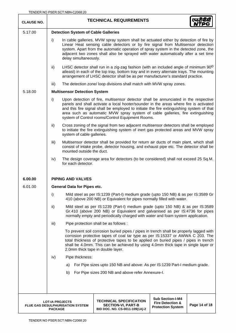
CLAUSE NO. TECHNICAL REQUIREMENTS
LOT-IA PROJECTS FLUE GAS DESULPHURISATION SYSTEM
PACKAGE
TECHNICAL SPECIFICATION
SECTION-VI, PART-B BID DOC. NO. CS-0011-109(1A)-2
Sub Section-I-M4 Fire Detection &
Protection System
Page 14 of 18
5.17.00 Detection System of Cable Galleries
i) In cable galleries, MVW spray system shall be actuated either by detection of fire by Linear Heat sensing cable detectors or by fire signal from Multisensor detection system. Apart from the automatic operation of spray system in the detected zone, the adjacent two zones shall also be sprayed with water automatically after a set time delay simultaneously.
ii) LHSC detector shall run in a zig-zag fashion (with an included angle of minimum 90o atleast) in each of the top tray, bottom tray and in every alternate trays. The mounting arrangement of LHSC detector shall be as per manufacturer’s standard practice.
iii) The detection zone/ loop divisions shall match with MVW spray zones.
5.18.00 Multisensor Detection System
i) Upon detection of fire, multisensor detector shall be annunciated in the respective panels and shall activate a local hooter/sounder in the areas where fire is activated and this fire signal shall be employed to initiate the fire extinguishing system of that area such as automatic MVW spray system of cable galleries, fire extinguishing system of Control rooms/Control Equipment Rooms.
ii) Cross zoning of the signal from two adjacent multisensor detectors shall be employed to initiate the fire extinguishing system of inert gas protected areas and MVW spray system of cable galleries.
iii) Multisensor detector shall be provided for return air ducts of main plant, which shall consist of intake probe, detector housing, and exhaust pipe etc. The detector shall be mounted outside the duct.
iv) The design coverage area for detectors (to be considered) shall not exceed 25 Sq.M. for each detector.
6.00.00 PIPING AND VALVES
6.01.00 General Data for Pipes etc.
i) Mild steel as per IS:1239 (Part-I) medium grade (upto 150 NB) & as per IS:3589 Gr 410 (above 200 NB) or Equivalent for pipes normally filled with water.
ii) Mild steel as per IS:1239 (Part-I) medium grade (upto 150 NB) & as per IS:3589 Gr.410 (above 200 NB) or Equivalent and galvanised as per IS:4736 for pipes normally empty and periodically charged with water and foam system application.
iii) Pipe protection shall be as follows :
To prevent soil corrosion buried pipes / pipes in trench shall be properly lagged with corrosion protective tapes of coal tar type as per IS:15337 or AWWA C 203. The total thickness of protective tapes to be applied on buried pipes / pipes in trench shall be 4.0mm. This can be achieved by using 4.0mm thick tape in single layer or 2.0mm thick tape in double layer.
iv) Pipe thickness:
a) For Pipe sizes upto 150 NB and above: As per IS:1239 Part-I medium grade.
b) For Pipe sizes 200 NB and above refer Annexure-I.
TENDER NO PSER:SCT:NBN-C2068:20
TENDER NO PSER:SCT:NBN-C2068:20
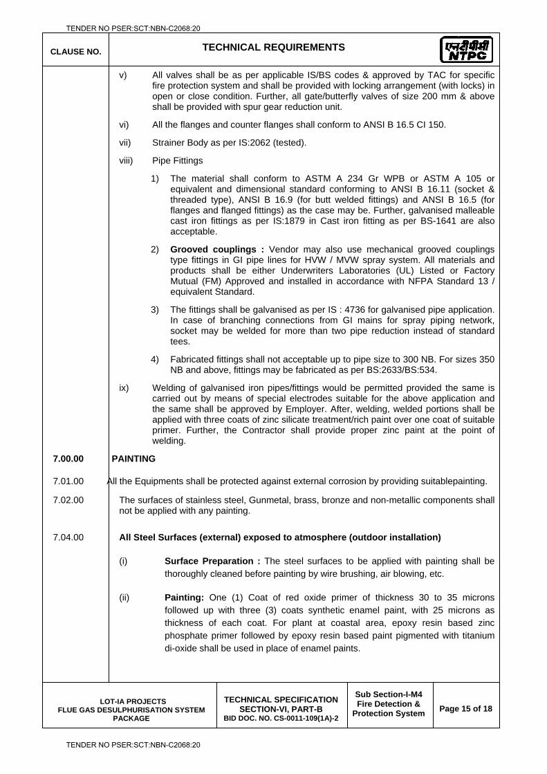
CLAUSE NO. TECHNICAL REQUIREMENTS
LOT-IA PROJECTS FLUE GAS DESULPHURISATION SYSTEM
PACKAGE
TECHNICAL SPECIFICATION
SECTION-VI, PART-B BID DOC. NO. CS-0011-109(1A)-2
Sub Section-I-M4 Fire Detection &
Protection System
Page 15 of 18
v) All valves shall be as per applicable IS/BS codes & approved by TAC for specific fire protection system and shall be provided with locking arrangement (with locks) in open or close condition. Further, all gate/butterfly valves of size 200 mm & above shall be provided with spur gear reduction unit.
vi) All the flanges and counter flanges shall conform to ANSI B 16.5 CI 150.
vii) Strainer Body as per IS:2062 (tested).
viii) Pipe Fittings
1) The material shall conform to ASTM A 234 Gr WPB or ASTM A 105 or equivalent and dimensional standard conforming to ANSI B 16.11 (socket & threaded type), ANSI B 16.9 (for butt welded fittings) and ANSI B 16.5 (for flanges and flanged fittings) as the case may be. Further, galvanised malleable cast iron fittings as per IS:1879 in Cast iron fitting as per BS-1641 are also acceptable.
2) Grooved couplings : Vendor may also use mechanical grooved couplings type fittings in GI pipe lines for HVW / MVW spray system. All materials and products shall be either Underwriters Laboratories (UL) Listed or Factory Mutual (FM) Approved and installed in accordance with NFPA Standard 13 / equivalent Standard.
3) The fittings shall be galvanised as per IS : 4736 for galvanised pipe application. In case of branching connections from GI mains for spray piping network, socket may be welded for more than two pipe reduction instead of standard tees.
4) Fabricated fittings shall not acceptable up to pipe size to 300 NB. For sizes 350 NB and above, fittings may be fabricated as per BS:2633/BS:534.
ix) Welding of galvanised iron pipes/fittings would be permitted provided the same is carried out by means of special electrodes suitable for the above application and the same shall be approved by Employer. After, welding, welded portions shall be applied with three coats of zinc silicate treatment/rich paint over one coat of suitable primer. Further, the Contractor shall provide proper zinc paint at the point of welding.
7.00.00 PAINTING
7.01.00 All the Equipments shall be protected against external corrosion by providing suitablepainting.
7.02.00 The surfaces of stainless steel, Gunmetal, brass, bronze and non-metallic components shall not be applied with any painting.
7.04.00 All Steel Surfaces (external) exposed to atmosphere (outdoor installation)
(i) Surface Preparation : The steel surfaces to be applied with painting shall be thoroughly cleaned before painting by wire brushing, air blowing, etc.
(ii) Painting: One (1) Coat of red oxide primer of thickness 30 to 35 microns followed up with three (3) coats synthetic enamel paint, with 25 microns as thickness of each coat. For plant at coastal area, epoxy resin based zinc phosphate primer followed by epoxy resin based paint pigmented with titanium di-oxide shall be used in place of enamel paints.
TENDER NO PSER:SCT:NBN-C2068:20
TENDER NO PSER:SCT:NBN-C2068:20
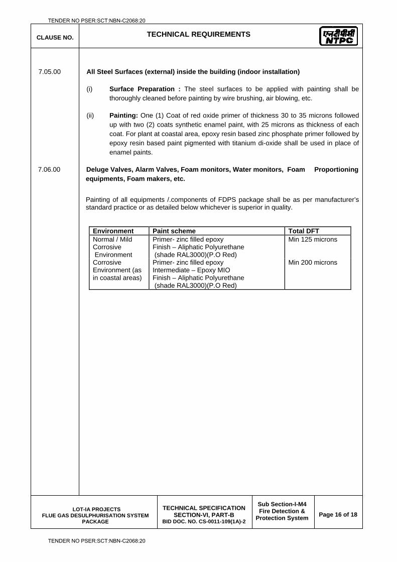
CLAUSE NO. TECHNICAL REQUIREMENTS
LOT-IA PROJECTS FLUE GAS DESULPHURISATION SYSTEM
PACKAGE
TECHNICAL SPECIFICATION
SECTION-VI, PART-B BID DOC. NO. CS-0011-109(1A)-2
Sub Section-I-M4 Fire Detection &
Protection System
Page 16 of 18
7.05.00 All Steel Surfaces (external) inside the building (indoor installation)
(i) Surface Preparation : The steel surfaces to be applied with painting shall be thoroughly cleaned before painting by wire brushing, air blowing, etc.
(ii) Painting: One (1) Coat of red oxide primer of thickness 30 to 35 microns followed up with two (2) coats synthetic enamel paint, with 25 microns as thickness of each coat. For plant at coastal area, epoxy resin based zinc phosphate primer followed by epoxy resin based paint pigmented with titanium di-oxide shall be used in place of enamel paints.
7.06.00 Deluge Valves, Alarm Valves, Foam monitors, Water monitors, Foam Proportioning equipments, Foam makers, etc.
Painting of all equipments /.components of FDPS package shall be as per manufacturer’s standard practice or as detailed below whichever is superior in quality.
Environment Paint scheme Total DFT Normal / Mild Corrosive Environment
Primer- zinc filled epoxy Finish – Aliphatic Polyurethane (shade RAL3000)(P.O Red)
Min 125 microns
Corrosive Environment (as in coastal areas)
Primer- zinc filled epoxy Intermediate – Epoxy MIO Finish – Aliphatic Polyurethane (shade RAL3000)(P.O Red)
Min 200 microns
TENDER NO PSER:SCT:NBN-C2068:20
TENDER NO PSER:SCT:NBN-C2068:20
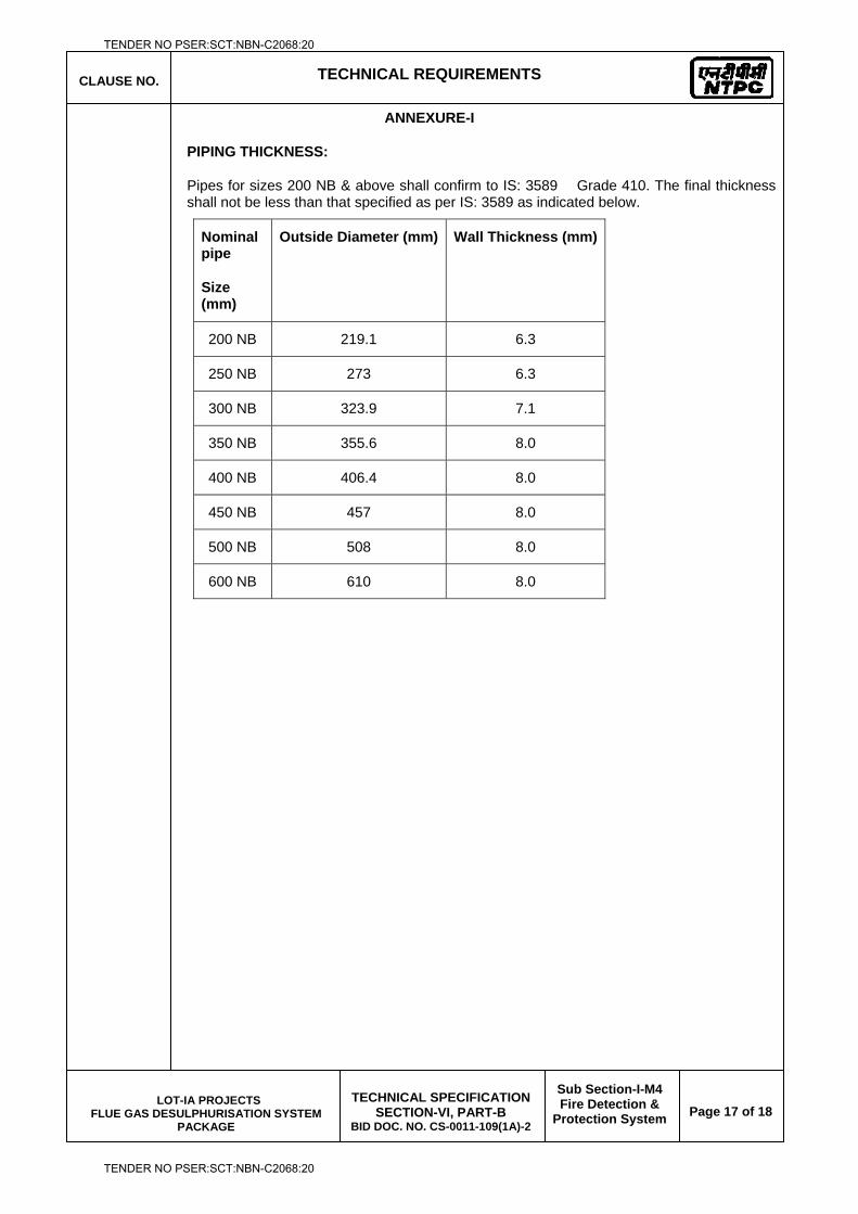
CLAUSE NO. TECHNICAL REQUIREMENTS
LOT-IA PROJECTS FLUE GAS DESULPHURISATION SYSTEM
PACKAGE
TECHNICAL SPECIFICATION
SECTION-VI, PART-B BID DOC. NO. CS-0011-109(1A)-2
Sub Section-I-M4 Fire Detection &
Protection System
Page 17 of 18
ANNEXURE-I
PIPING THICKNESS:
Pipes for sizes 200 NB & above shall confirm to IS: 3589 Grade 410. The final thickness shall not be less than that specified as per IS: 3589 as indicated below.
Nominal pipe
Size (mm)
Outside Diameter (mm)
Wall Thickness (mm)
200 NB 219.1 6.3
250 NB 273 6.3
300 NB 323.9 7.1
350 NB 355.6 8.0
400 NB 406.4 8.0
450 NB 457 8.0
500 NB 508 8.0
600 NB 610 8.0
TENDER NO PSER:SCT:NBN-C2068:20
TENDER NO PSER:SCT:NBN-C2068:20
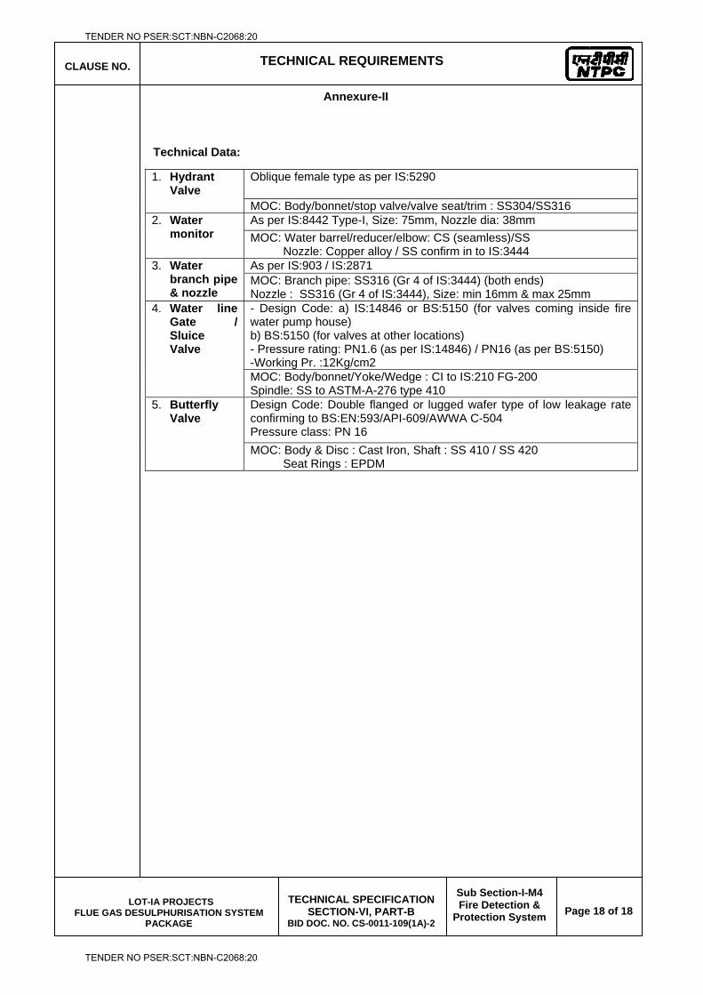
CLAUSE NO. TECHNICAL REQUIREMENTS
LOT-IA PROJECTS FLUE GAS DESULPHURISATION SYSTEM
PACKAGE
TECHNICAL SPECIFICATION
SECTION-VI, PART-B BID DOC. NO. CS-0011-109(1A)-2
Sub Section-I-M4 Fire Detection &
Protection System
Page 18 of 18
Annexure-II
Technical Data:
1. Hydrant Valve
Oblique female type as per IS:5290
MOC: Body/bonnet/stop valve/valve seat/trim : SS304/SS316 2. Water
monitor As per IS:8442 Type-I, Size: 75mm, Nozzle dia: 38mm MOC: Water barrel/reducer/elbow: CS (seamless)/SS Nozzle: Copper alloy / SS confirm in to IS:3444
3. Water branch pipe & nozzle
As per IS:903 / IS:2871 MOC: Branch pipe: SS316 (Gr 4 of IS:3444) (both ends) Nozzle : SS316 (Gr 4 of IS:3444), Size: min 16mm & max 25mm
4. Water line Gate / Sluice Valve
- Design Code: a) IS:14846 or BS:5150 (for valves coming inside fire water pump house) b) BS:5150 (for valves at other locations) - Pressure rating: PN1.6 (as per IS:14846) / PN16 (as per BS:5150) -Working Pr. :12Kg/cm2 MOC: Body/bonnet/Yoke/Wedge : CI to IS:210 FG-200 Spindle: SS to ASTM-A-276 type 410
5. Butterfly Valve
Design Code: Double flanged or lugged wafer type of low leakage rate confirming to BS:EN:593/API-609/AWWA C-504 Pressure class: PN 16 MOC: Body & Disc : Cast Iron, Shaft : SS 410 / SS 420 Seat Rings : EPDM
TENDER NO PSER:SCT:NBN-C2068:20
TENDER NO PSER:SCT:NBN-C2068:20

LOT-IA PROJECTS FLUE GAS DESULPHURISATION (FGD) SYSTEM PACKAGE
TECHNICAL SPECIFICATION
SECTION-VI
BID DOCUMENT NO.: CS-0011-109(1A)-2
SUB-SECTION-I-M5
EQUIPMENT COOLING WATER SYSTEM
TENDER NO PSER:SCT:NBN-C2068:20
TENDER NO PSER:SCT:NBN-C2068:20
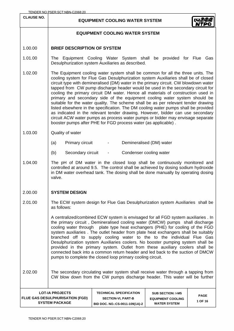
CLAUSE NO.
EQUIPMENT COOLING WATER SYSTEM
LOT-IA PROJECTS
FLUE GAS DESULPHURISATION (FGD) SYSTEM PACKAGE
TECHNICAL SPECIFICATION
SECTION-VI, PART-B
BID DOC. NO.:CS-0011-109(1A)-2
SUB SECTION: I-M5
EQUIPMENT COOLING
WATER SYSTEM
PAGE
1 OF 16
EQUIPMENT COOLING WATER SYSTEM
1.00.00 BRIEF DESCRIPTION OF SYSTEM 1.01.00 The Equipment Cooling Water System shall be provided for Flue Gas
Desulphurization system Auxiliaries as described. 1.02.00 The Equipment cooling water system shall be common for all the three units. The
cooling system for Flue Gas Desulphurization system Auxiliaries shall be of closed circuit type with demineralised (DM) water in the primary circuit. CW blowdown water tapped from CW pump discharge header would be used in the secondary circuit for cooling the primary circuit DM water. Hence all materials of construction used in primary and secondary side of the equipment cooling water system should be suitable for the water quality. The scheme shall be as per relevant tender drawing listed elsewhere in the specification. The DM cooling water pumps shall be provided as indicated in the relevant tender drawing. However, bidder can use secondary circuit ACW water pumps as process water pumps or bidder may envisage separate booster pumps after PHE for FGD process water (as applicable) .
1.03.00 Quality of water (a) Primary circuit - Demineralised (DM) water (b) Secondary circuit - Condenser cooling water 1.04.00 The pH of DM water in the closed loop shall be continuously monitored and
controlled at around 9.5. The control shall be achieved by dosing sodium hydroxide in DM water overhead tank. The dosing shall be done manually by operating dosing valve.
2.00.00 SYSTEM DESIGN 2.01.00 The ECW system design for Flue Gas Desulphurization system Auxiliaries shall be
as follows: A centralized/combined ECW system is envisaged for all FGD system auxiliaries . In
the primary circuit , Demineralised cooling water (DMCW) pumps shall discharge cooling water through plate type heat exchangers (PHE) for cooling of the FGD system auxiliaries . The outlet header from plate heat exchangers shall be suitably branched off to supply cooling water to the to the individual Flue Gas Desulphurization system Auxiliaries coolers. No booster pumping system shall be provided in the primary system. Outlet from these auxiliary coolers shall be connected back into a common return header and led back to the suction of DMCW pumps to complete the closed loop primary cooling circuit.
2.02.00 The secondary circulating water system shall receive water through a tapping from
CW blow down from the CW pumps discharge header. This water will be further
TENDER NO PSER:SCT:NBN-C2068:20
TENDER NO PSER:SCT:NBN-C2068:20
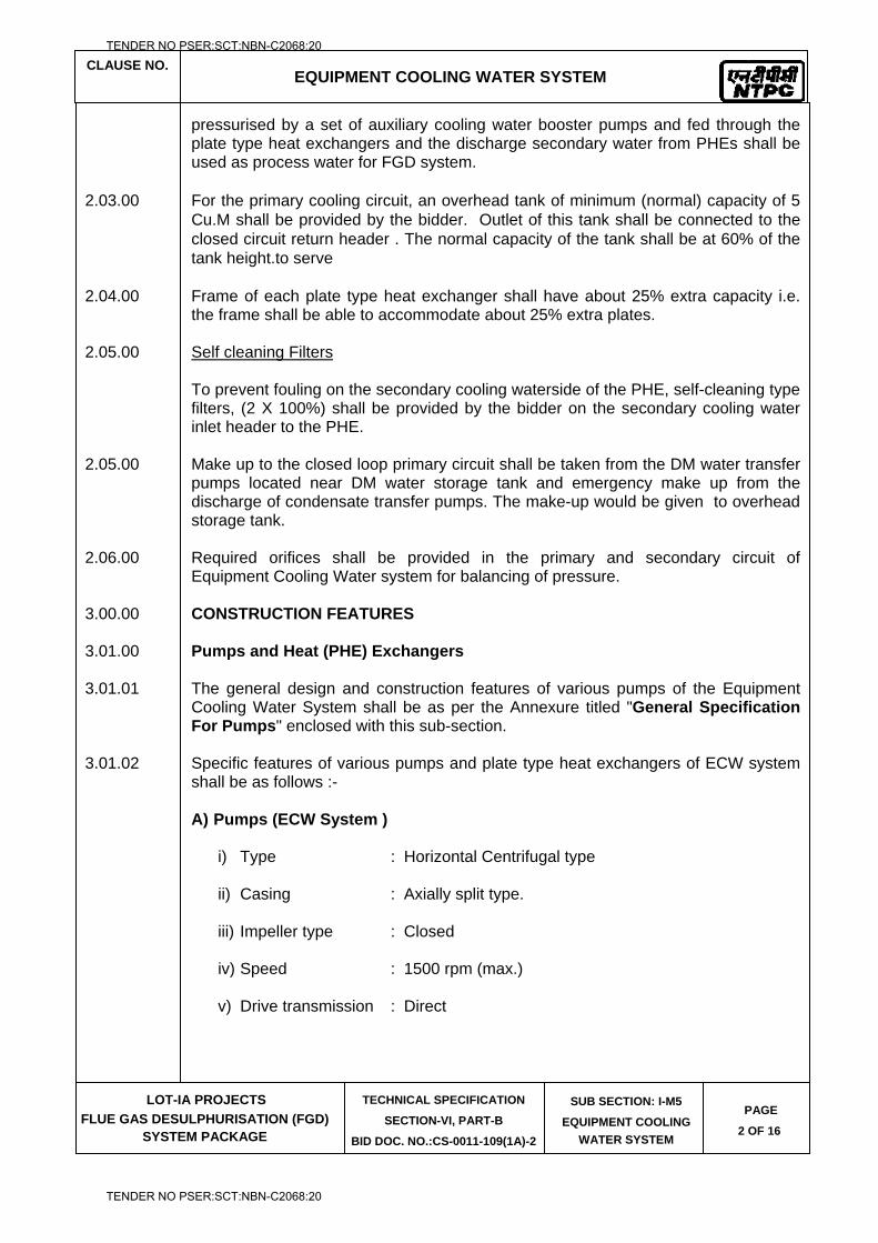
CLAUSE NO.
EQUIPMENT COOLING WATER SYSTEM
LOT-IA PROJECTS
FLUE GAS DESULPHURISATION (FGD) SYSTEM PACKAGE
TECHNICAL SPECIFICATION
SECTION-VI, PART-B
BID DOC. NO.:CS-0011-109(1A)-2
SUB SECTION: I-M5
EQUIPMENT COOLING
WATER SYSTEM
PAGE
2 OF 16
pressurised by a set of auxiliary cooling water booster pumps and fed through the plate type heat exchangers and the discharge secondary water from PHEs shall be used as process water for FGD system.
2.03.00 For the primary cooling circuit, an overhead tank of minimum (normal) capacity of 5
Cu.M shall be provided by the bidder. Outlet of this tank shall be connected to the closed circuit return header . The normal capacity of the tank shall be at 60% of the tank height.to serve
2.04.00 Frame of each plate type heat exchanger shall have about 25% extra capacity i.e.
the frame shall be able to accommodate about 25% extra plates. 2.05.00 Self cleaning Filters To prevent fouling on the secondary cooling waterside of the PHE, self-cleaning type
filters, (2 X 100%) shall be provided by the bidder on the secondary cooling water inlet header to the PHE.
2.05.00 Make up to the closed loop primary circuit shall be taken from the DM water transfer
pumps located near DM water storage tank and emergency make up from the discharge of condensate transfer pumps. The make-up would be given to overhead storage tank.
2.06.00 Required orifices shall be provided in the primary and secondary circuit of
Equipment Cooling Water system for balancing of pressure. 3.00.00 CONSTRUCTION FEATURES 3.01.00 Pumps and Heat (PHE) Exchangers 3.01.01 The general design and construction features of various pumps of the Equipment
Cooling Water System shall be as per the Annexure titled "General Specification For Pumps" enclosed with this sub-section.
3.01.02 Specific features of various pumps and plate type heat exchangers of ECW system
shall be as follows :- A) Pumps (ECW System ) i) Type : Horizontal Centrifugal type ii) Casing : Axially split type. iii) Impeller type : Closed iv) Speed : 1500 rpm (max.) v) Drive transmission : Direct
TENDER NO PSER:SCT:NBN-C2068:20
TENDER NO PSER:SCT:NBN-C2068:20
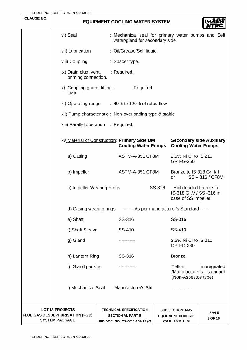
CLAUSE NO.
EQUIPMENT COOLING WATER SYSTEM
LOT-IA PROJECTS
FLUE GAS DESULPHURISATION (FGD) SYSTEM PACKAGE
TECHNICAL SPECIFICATION
SECTION-VI, PART-B
BID DOC. NO.:CS-0011-109(1A)-2
SUB SECTION: I-M5
EQUIPMENT COOLING
WATER SYSTEM
PAGE
3 OF 16
vi) Seal : Mechanical seal for primary water pumps and Self water/gland for secondary side
vii) Lubrication : Oil/Grease/Self liquid. viii) Coupling : Spacer type. ix) Drain plug, vent, ; Required. priming connection, x) Coupling guard, lifting : Required lugs xi) Operating range : 40% to 120% of rated flow xii) Pump characteristic : Non-overloading type & stable xiii) Parallel operation : Required. xv) Material of Construction: Primary Side DM Secondary side Auxiliary Cooling Water Pumps Cooling Water Pumps a) Casing ASTM-A-351 CF8M 2.5% Ni CI to IS 210 GR FG-260 b) Impeller ASTM-A-351 CF8M Bronze to IS 318 Gr. I/II or SS – 316 / CF8M c) Impeller Wearing Rings SS-316 High leaded bronze to IS-318 Gr.V / SS -316 in case of SS Impeller. d) Casing wearing rings --------As per manufacturer's Standard ----- e) Shaft SS-316 SS-316 f) Shaft Sleeve SS-410 SS-410 g) Gland ----------- 2.5% Ni CI to IS 210 GR FG-260 h) Lantern Ring SS-316 Bronze
i) Gland packing ------------ Teflon Impregnated /Manufacturer’s standard (Non-Asbestos type)
i) Mechanical Seal Manufacturer's Std ------------
TENDER NO PSER:SCT:NBN-C2068:20
TENDER NO PSER:SCT:NBN-C2068:20
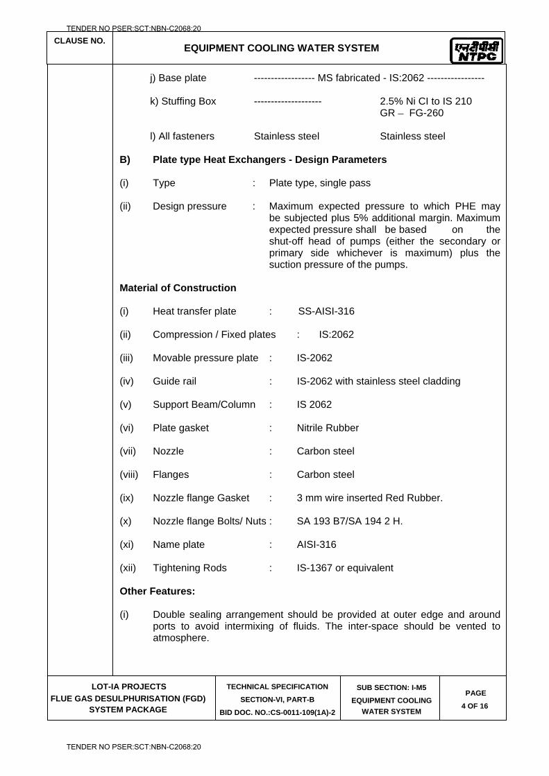
CLAUSE NO.
EQUIPMENT COOLING WATER SYSTEM
LOT-IA PROJECTS
FLUE GAS DESULPHURISATION (FGD) SYSTEM PACKAGE
TECHNICAL SPECIFICATION
SECTION-VI, PART-B
BID DOC. NO.:CS-0011-109(1A)-2
SUB SECTION: I-M5
EQUIPMENT COOLING
WATER SYSTEM
PAGE
4 OF 16
j) Base plate ------------------ MS fabricated - IS:2062 ----------------- k) Stuffing Box -------------------- 2.5% Ni CI to IS 210 GR FG-260 l) All fasteners Stainless steel Stainless steel B) Plate type Heat Exchangers - Design Parameters (i) Type : Plate type, single pass (ii) Design pressure : Maximum expected pressure to which PHE may
be subjected plus 5% additional margin. Maximum expected pressure shall be based on the shut-off head of pumps (either the secondary or primary side whichever is maximum) plus the suction pressure of the pumps.
Material of Construction (i) Heat transfer plate : SS-AISI-316 (ii) Compression / Fixed plates : IS:2062 (iii) Movable pressure plate : IS-2062 (iv) Guide rail : IS-2062 with stainless steel cladding (v) Support Beam/Column : IS 2062 (vi) Plate gasket : Nitrile Rubber (vii) Nozzle : Carbon steel (viii) Flanges : Carbon steel (ix) Nozzle flange Gasket : 3 mm wire inserted Red Rubber. (x) Nozzle flange Bolts/ Nuts : SA 193 B7/SA 194 2 H. (xi) Name plate : AISI-316 (xii) Tightening Rods : IS-1367 or equivalent Other Features: (i) Double sealing arrangement should be provided at outer edge and around
ports to avoid intermixing of fluids. The inter-space should be vented to atmosphere.
TENDER NO PSER:SCT:NBN-C2068:20
TENDER NO PSER:SCT:NBN-C2068:20
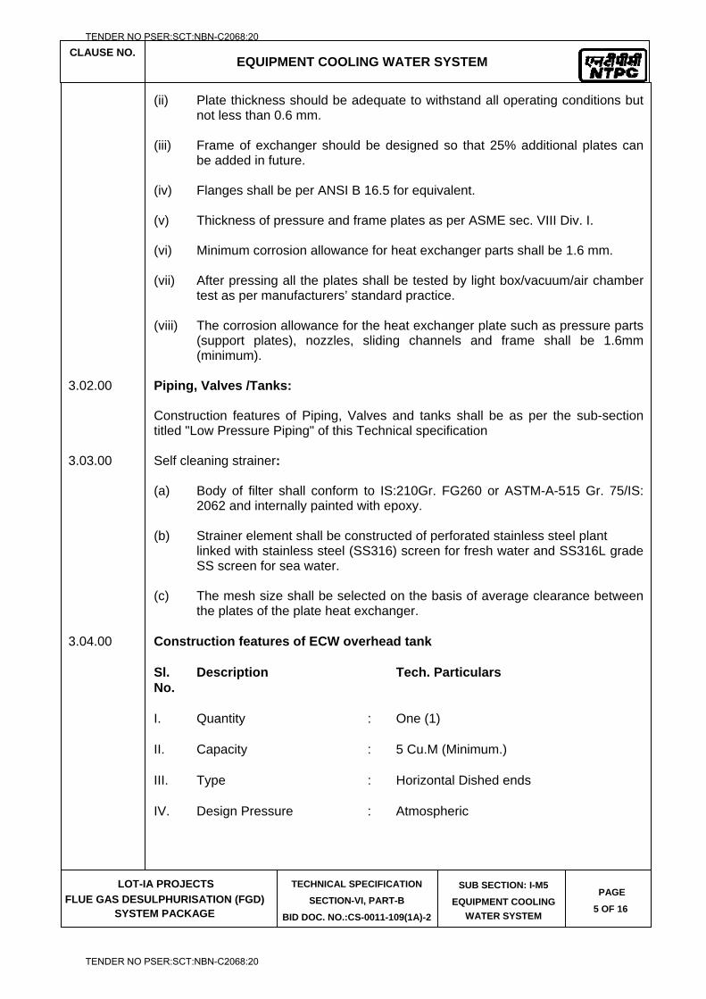
CLAUSE NO.
EQUIPMENT COOLING WATER SYSTEM
LOT-IA PROJECTS
FLUE GAS DESULPHURISATION (FGD) SYSTEM PACKAGE
TECHNICAL SPECIFICATION
SECTION-VI, PART-B
BID DOC. NO.:CS-0011-109(1A)-2
SUB SECTION: I-M5
EQUIPMENT COOLING
WATER SYSTEM
PAGE
5 OF 16
(ii) Plate thickness should be adequate to withstand all operating conditions but not less than 0.6 mm.
(iii) Frame of exchanger should be designed so that 25% additional plates can
be added in future. (iv) Flanges shall be per ANSI B 16.5 for equivalent. (v) Thickness of pressure and frame plates as per ASME sec. VIII Div. I. (vi) Minimum corrosion allowance for heat exchanger parts shall be 1.6 mm. (vii) After pressing all the plates shall be tested by light box/vacuum/air chamber
test as per manufacturers’ standard practice. (viii) The corrosion allowance for the heat exchanger plate such as pressure parts
(support plates), nozzles, sliding channels and frame shall be 1.6mm (minimum).
3.02.00 Piping, Valves /Tanks: Construction features of Piping, Valves and tanks shall be as per the sub-section
titled "Low Pressure Piping" of this Technical specification 3.03.00 Self cleaning strainer: (a) Body of filter shall conform to IS:210Gr. FG260 or ASTM-A-515 Gr. 75/IS:
2062 and internally painted with epoxy.
(b) Strainer element shall be constructed of perforated stainless steel plant linked with stainless steel (SS316) screen for fresh water and SS316L grade
SS screen for sea water. (c) The mesh size shall be selected on the basis of average clearance between
the plates of the plate heat exchanger. 3.04.00 Construction features of ECW overhead tank Sl. Description Tech. Particulars No. I. Quantity : One (1) II. Capacity : 5 Cu.M (Minimum.) III. Type : Horizontal Dished ends IV. Design Pressure : Atmospheric
TENDER NO PSER:SCT:NBN-C2068:20
TENDER NO PSER:SCT:NBN-C2068:20
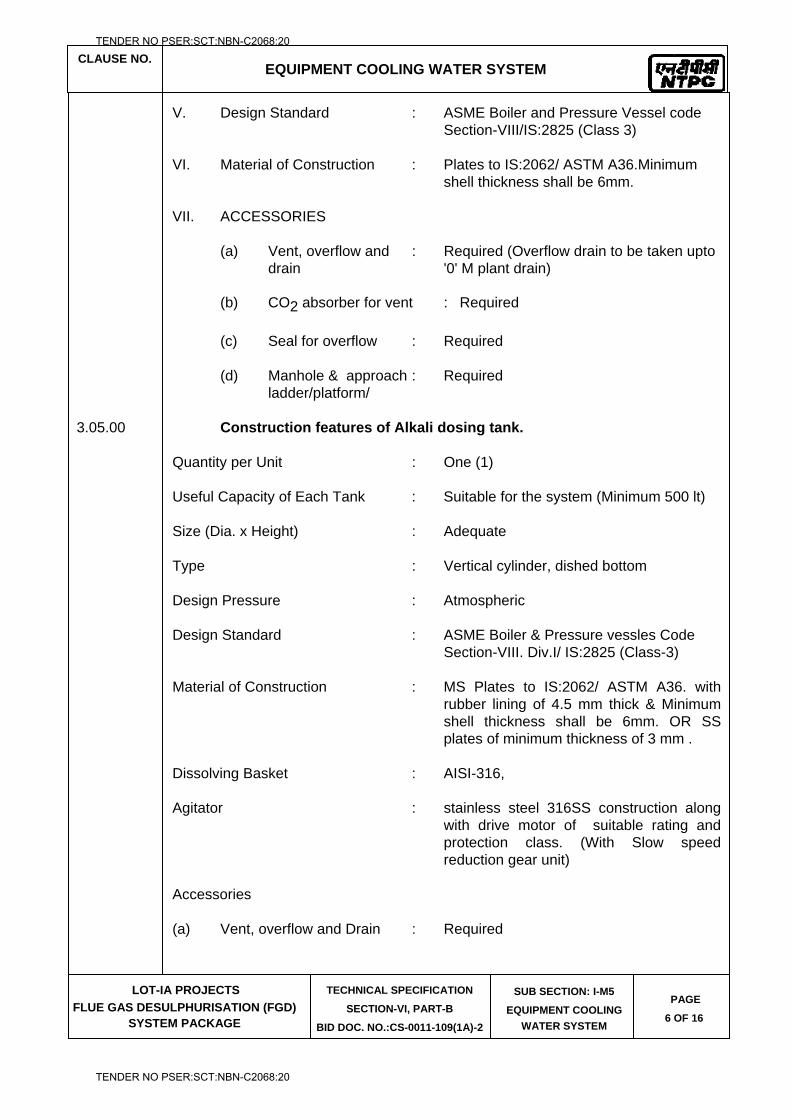
CLAUSE NO.
EQUIPMENT COOLING WATER SYSTEM
LOT-IA PROJECTS
FLUE GAS DESULPHURISATION (FGD) SYSTEM PACKAGE
TECHNICAL SPECIFICATION
SECTION-VI, PART-B
BID DOC. NO.:CS-0011-109(1A)-2
SUB SECTION: I-M5
EQUIPMENT COOLING
WATER SYSTEM
PAGE
6 OF 16
V. Design Standard : ASME Boiler and Pressure Vessel code Section-VIII/IS:2825 (Class 3) VI. Material of Construction : Plates to IS:2062/ ASTM A36.Minimum shell thickness shall be 6mm. VII. ACCESSORIES (a) Vent, overflow and : Required (Overflow drain to be taken upto drain '0' M plant drain) (b) CO2 absorber for vent : Required (c) Seal for overflow : Required (d) Manhole & approach : Required ladder/platform/ 3.05.00 Construction features of Alkali dosing tank. Quantity per Unit : One (1) Useful Capacity of Each Tank : Suitable for the system (Minimum 500 lt) Size (Dia. x Height) : Adequate Type : Vertical cylinder, dished bottom Design Pressure : Atmospheric Design Standard : ASME Boiler & Pressure vessles Code Section-VIII. Div.I/ IS:2825 (Class-3) Material of Construction : MS Plates to IS:2062/ ASTM A36. with
rubber lining of 4.5 mm thick & Minimum shell thickness shall be 6mm. OR SS plates of minimum thickness of 3 mm .
Dissolving Basket : AISI-316, Agitator : stainless steel 316SS construction along
with drive motor of suitable rating and protection class. (With Slow speed reduction gear unit)
Accessories (a) Vent, overflow and Drain : Required
TENDER NO PSER:SCT:NBN-C2068:20
TENDER NO PSER:SCT:NBN-C2068:20
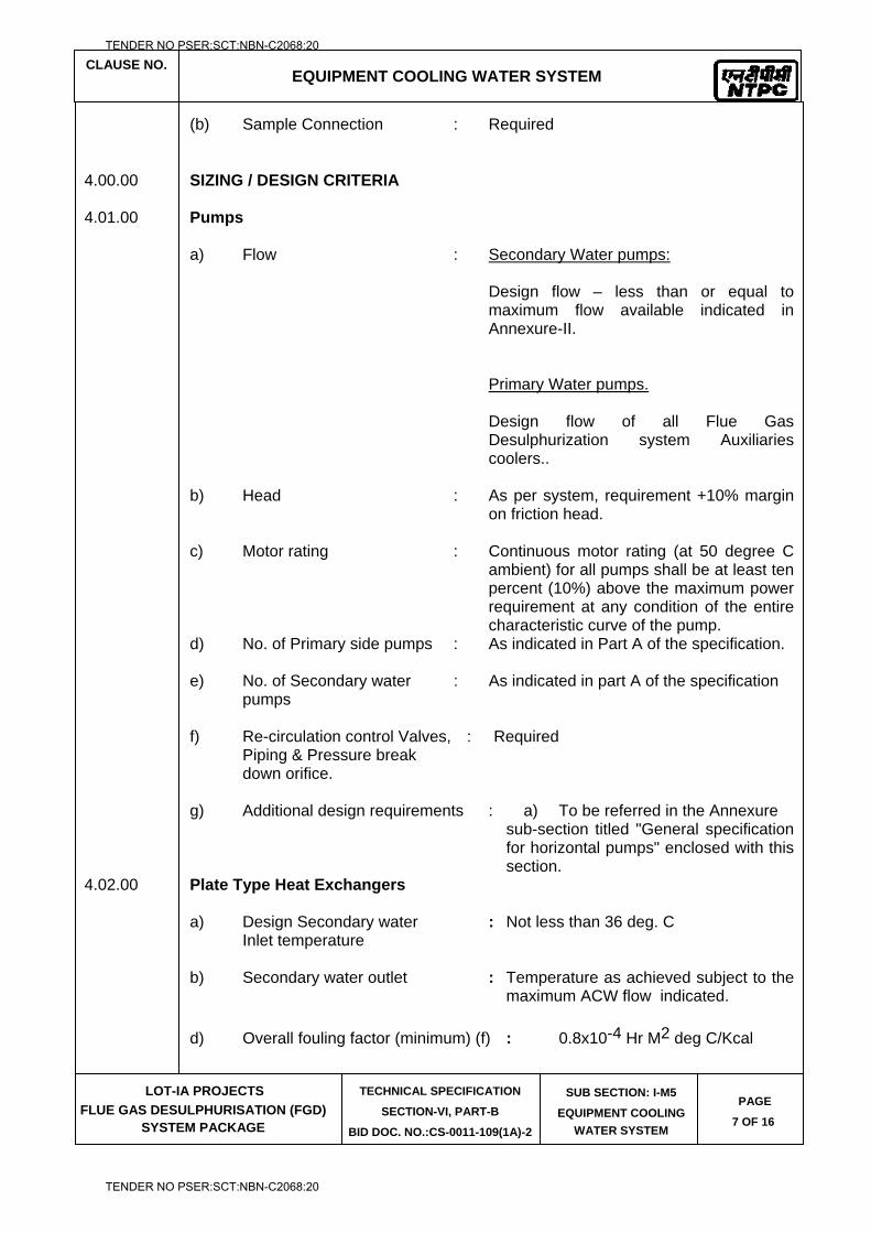
CLAUSE NO.
EQUIPMENT COOLING WATER SYSTEM
LOT-IA PROJECTS
FLUE GAS DESULPHURISATION (FGD) SYSTEM PACKAGE
TECHNICAL SPECIFICATION
SECTION-VI, PART-B
BID DOC. NO.:CS-0011-109(1A)-2
SUB SECTION: I-M5
EQUIPMENT COOLING
WATER SYSTEM
PAGE
7 OF 16
(b) Sample Connection : Required 4.00.00 SIZING / DESIGN CRITERIA 4.01.00 Pumps a) Flow : Secondary Water pumps: Design flow – less than or equal to
maximum flow available indicated in Annexure-II.
Primary Water pumps. Design flow of all Flue Gas
Desulphurization system Auxiliaries coolers..
b) Head : As per system, requirement +10% margin
on friction head. c) Motor rating : Continuous motor rating (at 50 degree C
ambient) for all pumps shall be at least ten percent (10%) above the maximum power requirement at any condition of the entire characteristic curve of the pump.
d) No. of Primary side pumps : As indicated in Part A of the specification. e) No. of Secondary water : As indicated in part A of the specification pumps f) Re-circulation control Valves, : Required Piping & Pressure break down orifice. g) Additional design requirements : a) To be referred in the Annexure
sub-section titled "General specification for horizontal pumps" enclosed with this section.
4.02.00 Plate Type Heat Exchangers
a) Design Secondary water : Not less than 36 deg. C Inlet temperature b) Secondary water outlet : Temperature as achieved subject to the
maximum ACW flow indicated. d) Overall fouling factor (minimum) (f) : 0.8x10⁻⁴ Hr M2 deg C/Kcal
TENDER NO PSER:SCT:NBN-C2068:20
TENDER NO PSER:SCT:NBN-C2068:20
CLAUSE NO.
EQUIPMENT COOLING WATER SYSTEM
LOT-IA PROJECTS
FLUE GAS DESULPHURISATION (FGD) SYSTEM PACKAGE
TECHNICAL SPECIFICATION
SECTION-VI, PART-B
BID DOC. NO.:CS-0011-109(1A)-2
SUB SECTION: I-M5
EQUIPMENT COOLING
WATER SYSTEM
PAGE
8 OF 16
e) No. of heat exchangers/ unit : As indicated in part A of the
specification f) Overall Heat transfer coefficient [U(o)]: As per manufacturer's design g) Dirty Heat transfer Coefficient [U(d)] : [1 / (1/U(o) +f) ] h) Heat Transfer Area (Sqm) : Total Heat Load (in Kcal/hr) U(d) x LMTD
i) Heat transfer area of PHE shall be selected such that each Sq.M of heat transfer plate shall transfer not more than 6500 Kcal/hr.
5.00.00 INSTRUMENTATION 5.01.00 All instruments, such as thermowell, temperature element alongwith temperature
transmitter, flow element, pressure/DP and temperature gauge/transmitters/sensors/switches, DP switch, pH analyzer, Rotameter etc. alongwith associated devices should meet the requirement as specified in relevant sub-section of this Technical Specification and shall be sufficient to meet all interlock/protection & operation requirement.
5.02.00 Minimum instrumentation required for the Equipment Cooling water system shall be
as per tender P & I Diagram wherever included in the specification. 6.00.00 CONTROL / OPERATION PHILOSOPHY 6.02.00 The pump suction valves, re-circulation valves and discharge valves shall be motor
actuated type to enable remote operation. 6.03.00 Pump suction valves shall be provided with required limit switches for interlock &
control. 6.04.00 The pumps shall be designed to operate under discharge valve open and as well as
in close condition. 6.05.00 Wherever more than one sump/tank is provided, Suction header shall be
interconnected such a way that any of the sump/tank may be selected from the panel for operation.
6.06.00 Any of the pump shall be selectable as standby duty. Standby pump shall come into
operation on tripping of working pump or inadequate pressure in the discharge header.
6.07.00 Suction and Discharge valves of pumps shall be interlocked with start/stop of
respective pumps. 6.08.00 Local emergency stop provision for each pump shall be provided.
TENDER NO PSER:SCT:NBN-C2068:20
TENDER NO PSER:SCT:NBN-C2068:20
CLAUSE NO.
EQUIPMENT COOLING WATER SYSTEM
LOT-IA PROJECTS
FLUE GAS DESULPHURISATION (FGD) SYSTEM PACKAGE
TECHNICAL SPECIFICATION
SECTION-VI, PART-B
BID DOC. NO.:CS-0011-109(1A)-2
SUB SECTION: I-M5
EQUIPMENT COOLING
WATER SYSTEM
PAGE
9 OF 16
6.09.00 All the working pumps shall be interlocked with the suction level or suction pressure condition as the case may be. Pumps operation shall be interlocked with the high discharge condition so that the pump may not operate at shut-off pressure.
6.10.00 Automatic inlet valves at supply line to each of the tank/sump shall be provided so
that the valves shall open and close at low-level and very high-level respectively. 6.11.00 A control valve shall be provided to maintain a constant pressure differential
between the main supply and return headers of DM water. The valve will bypass flow to maintain a constant return header pressure to compensate for fluctuations in coolant flow to the process heat exchangers due to modulating control valves on the process coolers or if any cooler goes out of service in DM circuit.
6.12.00 Alarm to indicate high differential pressure across self-cleaning filter strainers, heat exchangers as the case may be.
6.13.00 Manually operating globe / regulating valves shall be provided in the water side of
each of the cooler outlet for control of flow as specified in respective equipment specification.
6.14.00 Detailed Interlock & protection logic to be implemented in FGD control system shall
be provided by the contractor and the same shall be as finalized during detailed engineering.
7.00.00 PAINTING 7.01.00 All the equipments such as pumps, tanks and plate type exchangers of this system
shall be protected against external corrosion by providing suitable painting as mentioned below. For painting of valves and piping, relevant section shall be referred to.
7.02.00 The surfaces of stainless steel, Gunmetal, brass, bronze and non-metallic
components shall not be applied with any painting. 7.03.00 The steel surface to be applied with painting shall be thoroughly cleaned before
applying painting by brushing, shot-blasting etc as per the agreed procedure. 7.04.00 For all the steel surfaces exposed to (outdoor installation) atmosphere, a coat of
chlorinated rubber based zinc phosphate primer of minimum thickness DFT of 50 microns followed up with undercoat of chlorinated rubber paint of minimum DFT of 50 microns shall be applied. Then, intermediate coat consisting of one coat of chlorinated rubber based paint pigmented with Titanium di-oxide with minimum DFT of 50 microns and topcoat consisting of two coats of chlorinated rubber paint of approved shade and color with glossy finish and DFT of 100 microns shall be provided. Total DFT of paint system shall not be less than 200 microns.
7.05.00 For all the steel surfaces inside the (indoor installation) building, a coat of red oxide
primer of minimum thickness of 50 microns followed up with undercoat of synthetic enamel paint of minimum thickness of 50 microns shall be applied. The top coat shall consist of two coats each of minimum thickness of 50 microns of synthetic enamel paint and thus total thickness shall be minimum 200 microns.
TENDER NO PSER:SCT:NBN-C2068:20
TENDER NO PSER:SCT:NBN-C2068:20
CLAUSE NO.
EQUIPMENT COOLING WATER SYSTEM
LOT-IA PROJECTS
FLUE GAS DESULPHURISATION (FGD) SYSTEM PACKAGE
TECHNICAL SPECIFICATION
SECTION-VI, PART-B
BID DOC. NO.:CS-0011-109(1A)-2
SUB SECTION: I-M5
EQUIPMENT COOLING
WATER SYSTEM
PAGE
10 OF 16
7.06.00 Internal surfaces of ECW over tank shall be painted with One coat of unmodified
epoxy resin alongwith polyamide hardener and minimum two (2) coats unmodified epoxy resin alongwith Aromatic adduct hardener and total thickness of primer and paint should not be less than 400 microns.
TENDER NO PSER:SCT:NBN-C2068:20
TENDER NO PSER:SCT:NBN-C2068:20
CLAUSE NO.
EQUIPMENT COOLING WATER SYSTEM
LOT-IA PROJECTS
FLUE GAS DESULPHURISATION (FGD) SYSTEM PACKAGE
TECHNICAL SPECIFICATION
SECTION-VI, PART-B
BID DOC. NO.:CS-0011-109(1A)-2
SUB SECTION: I-M5
EQUIPMENT COOLING
WATER SYSTEM
PAGE
11 OF 16
Annexure-I to ECW system Specification
GENERAL SPECIFICATION FOR HORIZONTAL PUMPS
(1) SCOPE This specification covers the design, material, construction features, manufacture,
inspection, testing the performance at the Vendor's/Sub-Vendor's Works and delivery to site of Horizontal Centrifugal Pumps.
(2) CODES AND STANDARDS The design, material, construction, manufacture inspection and performance testing
of Horizontal Centrifugal Pumps shall comply with all currently applicable statutes, regulations and safety codes in the locality where the Equipment will be installed. Nothing in these specifications shall be construed to relieve the Vendor of this responsibility. The Equipment supplied shall comply with the latest applicable Indian Standards listed below. Other National Standards are acceptable, if they are established to be equal or superior to the Indian Standards.
(3) LIST OF APPLICABLE STANDARDS IS : 1520 : Horizontal Centrifugal Pumps for clear cold fresh water IS : 5120 : Technical requirements of rotodynamic special purpose
pumps API : 610 : Centrifugal pumps for general refinery service. IS : 5639 : Pumps Handling Chemicals & corrosion liquids IS : 5659 : Pumps for process water HIS : Hydraulic Institute Standards, USA ASTM-1-165-65: Standards Methods for Liquid Penetration Inspection. In case of any contradiction with aforesaid standards and the stipulations as per the
technical specifications as specified hereinafter the stipulations of the technical specifications shall prevail.
(4) DESIGN REQUIREMENTS (a) The Pump shall be capable of developing the required total head at rated
capacity for continuous operation. Also the pumps shall be capable of being operated to give satisfactory performance at any point on the HQ characteristics curve. The operating range of the pump shall be 40% to 120% of the duty point unless otherwise mentioned elsewhere. The maximum efficiency
TENDER NO PSER:SCT:NBN-C2068:20
TENDER NO PSER:SCT:NBN-C2068:20
CLAUSE NO.
EQUIPMENT COOLING WATER SYSTEM
LOT-IA PROJECTS
FLUE GAS DESULPHURISATION (FGD) SYSTEM PACKAGE
TECHNICAL SPECIFICATION
SECTION-VI, PART-B
BID DOC. NO.:CS-0011-109(1A)-2
SUB SECTION: I-M5
EQUIPMENT COOLING
WATER SYSTEM
PAGE
12 OF 16
of pump shall preferably be within ± 10% of the rated design flow as indicated in data sheets.
(b) The total head capacity curve shall be continuously rising from the operating
point towards shut – off without any zone of instability with the highest head at shut-off condition. Shut-off head shall be more than the rated design head by 15 % or more for radial flow pump and 25 % more than the design head for mixed flow/turbine type pumps.
(c) Pumps of a particular category shall be identical and shall be suitable for parallel operation with equal load division. The head Vs capacity and BHP Vs capacity characteristics should match to ensure even load sharing and trouble free operation throughout the range. Components of identical pumps shall be interchangeable.
(d) Pumps shall run smoothly without undue noise and vibration. Peak to peak
vibration limits shall be restricted to the following values during operation: Speed Antifriction Bearing Sleeve Bearing 1500 rpm and below 75.0 micron 75.0 micron 3000 rpm 50.0 micron 65.0 micron The noise level shall not exceed 85 dBA overall sound pressure level reference
0.0002 microbar (the standard pressure reference for air sound measurement) at a distance of 1 M from the equipment surface.
(e) The pumps shall be capable of starting with discharge valve fully open and
close condition. Motors shall be selected to suit to the above requirements. (f) Pumps shall be so designed that pump impellers and other accessories of the
pumps are not damaged due to flow reversal. (g) The Contractor under this specification shall assume full responsibility in the
operation of pump and motor as a unit. (5) DESIGN CONSTRUCTION (a) Design and construction of various components of the pumps shall conform to
the following general specifications. For material of construction of the components, data sheets shall be referred to.
(b) Pump Casing Pump casing shall have axially or radially split type construction as specified.
The casing shall be designed to withstand the maximum shut-off pressure developed by the pump at the pumping temperature.
Pump casing shall be provided with a vent connection and piping with fittings &
valves. Casing drain as required shall be provided complete with drain valves,
TENDER NO PSER:SCT:NBN-C2068:20
TENDER NO PSER:SCT:NBN-C2068:20
CLAUSE NO.
EQUIPMENT COOLING WATER SYSTEM
LOT-IA PROJECTS
FLUE GAS DESULPHURISATION (FGD) SYSTEM PACKAGE
TECHNICAL SPECIFICATION
SECTION-VI, PART-B
BID DOC. NO.:CS-0011-109(1A)-2
SUB SECTION: I-M5
EQUIPMENT COOLING
WATER SYSTEM
PAGE
13 OF 16
piping and plugs. It shall be provided with a connection for suction and discharge pressure gauge as standard feature. It shall be structurally sound to provide housing for the pump assembly and shall be designed hydraulically to minimum radial load at part load operation.
(c) Impeller Impeller shall be closed, semi-closed or open type as specified elsewhere and
designed in conformance with the detailed analysis of the liquid being handled. The impeller shall be secured to the shaft, and shall be retained against
circumferential movement by keying, pinning or lock rings. On pumps with overhung shaft, impellers shall be secured to the shaft by a lockout or cap screw which tightness in the direction of normal rotation.
(d) Impeller/Casing Wearing Rings Replaceable type wearing rings shall be provided at suitable locations of pumps
as per manufacturer's standard practice. Suitable method of locking the wearing ring shall be used.
(e) Shaft The critical speed shall be well away from the operating speed and in no case
less than 130% of the rated speed. The shaft shall be ground and polished to final dimensions and shall be
adequately sized to withstand all stresses from rotor weight, hydraulic loads, vibration and torques coming in during operation.
(f) Shaft Sleeves Renewable type fine finished shaft sleeves shall be provided at the stuffing
boxes/mechanical seals. Length of the shaft sleeves must extend beyond the outer faces of gland packing of seal end plates so as to distinguish between the leakage between shaft and shaft sleeve and that past the seals/gland.
Shaft sleeves shall be fastened to the shaft to prevent any leakage or
loosening. Shaft and shaft sleeve assembly should ensure concentric rotation. (g) Bearings Heavy duty bearings, adequately designed for the type of service specified in
the enclosed pump data sheet and for long, trouble free operation shall be furnished.
The bearings offered shall be capable of taking both the radial and axial thrust
coming into play during operation. In case, sleeve bearings are offered additional thrust bearings shall be provided. Antifriction bearings of standard
TENDER NO PSER:SCT:NBN-C2068:20
TENDER NO PSER:SCT:NBN-C2068:20
CLAUSE NO.
EQUIPMENT COOLING WATER SYSTEM
LOT-IA PROJECTS
FLUE GAS DESULPHURISATION (FGD) SYSTEM PACKAGE
TECHNICAL SPECIFICATION
SECTION-VI, PART-B
BID DOC. NO.:CS-0011-109(1A)-2
SUB SECTION: I-M5
EQUIPMENT COOLING
WATER SYSTEM
PAGE
14 OF 16
type, if provided, shall be selected for a minimum life 20,000 hrs. of continuous operation at maximum axial and radial loads and rated speed.
Proper lubricating arrangement for the bearings shall be provided. The design
shall be such that the bearing lubricating element does not contaminate the liquid pumped. Where there is a possibility of liquid entering the bearings suitable arrangement in the form of deflectors or any other suitable arrangement must be provided ahead of bearings assembly.
Bearings shall be easily accessible without disturbing the pump assembly. A
drain plug shall be provided at the bottom of each bearings housing. (h) Stuffing Boxes Stuffing boxes of packed ring construction type shall be provided wherever
specified. Packed ring stuffing boxes shall be properly lubricated and sealed as per service requirements and manufacturer's standards. If external gland sealing is required, it shall be done from the pump discharge. The Bidder shall provide the necessary piping valves, fittings etc. for the gland sealing connection.
(i) Mechanical Seals Wherever specified in pump data sheet, mechanical seals shall be provided.
Unless otherwise recommended by the tenderer, mechanical seals shall be of single type with either sliding gasket or bellows between the axially moving face and shaft sleeves or any other suitable type. The sealing faces should be highly lapped surfaces of materials known for their low frictional coefficient and resistance to corrosion against the liquid being pumped.
(j) The pump supplier shall coordinate with the seal maker in establishing the seal
chamber of circulation rate for maintaining a stable film at the seal face. The seal piping system shall form an integral part of the pump assembly. For the seals under vacuum service, the seal design must ensure sealing against atmospheric pressure even when the pumps are not operating. Necessary provision for seal water supply along with complete piping fittings and valves as required shall form integral part of pump supply.
(k) Pump Shaft Motor Shaft Coupling
The pump and motor shafts shall be connected with an adequately sized
flexible coupling of proven design with a spacer to facilitate dismantling of the pump without disturbing the motor. Necessary coupling guards shall also be provided.
(l) Base Plate A common base plate mounting both for the pump and motor shall be
furnished. The base plate shall be fabricated steel and of rigid construction, suitably ribbed and reinforced. Base plate and pump supports shall be so
TENDER NO PSER:SCT:NBN-C2068:20
TENDER NO PSER:SCT:NBN-C2068:20
CLAUSE NO.
EQUIPMENT COOLING WATER SYSTEM
LOT-IA PROJECTS
FLUE GAS DESULPHURISATION (FGD) SYSTEM PACKAGE
TECHNICAL SPECIFICATION
SECTION-VI, PART-B
BID DOC. NO.:CS-0011-109(1A)-2
SUB SECTION: I-M5
EQUIPMENT COOLING
WATER SYSTEM
PAGE
15 OF 16
constructed and the piping unit so mounted as to minimize misalignment caused by mechanical forces such as normal piping strain, internal differential thermal expansion and hydraulic piping thrust. Suitable drain troughs and drip lip shall be provided.
(m) Assembly and Dismantling Assembly and dismantling of each pump with drive motor shall be possible
without disturbing the grouting base plate or alignment. (n) Drive Motor (Prime Mover) Continuous Motor rating (at 50 0 C ambient) shall be at least ten percent (10%)
above the maximum load demand of the pump in the entire operating range to take care of the system frequency variation and in no case less than the maximum power requirement at any condition of the entire characteristic curve of the pump. The KW rating of the drive unit shall be based on continuously driving the connected equipment for the conditions specified. However, in cases where parallel operation of the pumps are specified, the actual motor rating is to be selected by the Bidder considering overloading of the pumps in the event of tripping of operating pump(s).
TENDER NO PSER:SCT:NBN-C2068:20
TENDER NO PSER:SCT:NBN-C2068:20
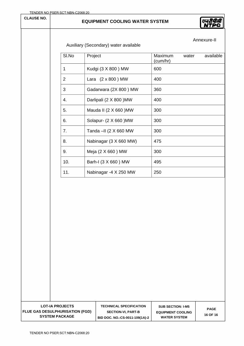
CLAUSE NO.
EQUIPMENT COOLING WATER SYSTEM
LOT-IA PROJECTS
FLUE GAS DESULPHURISATION (FGD) SYSTEM PACKAGE
TECHNICAL SPECIFICATION
SECTION-VI, PART-B
BID DOC. NO.:CS-0011-109(1A)-2
SUB SECTION: I-M5
EQUIPMENT COOLING
WATER SYSTEM
PAGE
16 OF 16
Annexure-II Auxiliary (Secondary) water available
Sl.No Project Maximum water available (cum/hr)
1 Kudgi (3 X 800 ) MW 600
2 Lara (2 x 800 ) MW 400
3 Gadarwara (2X 800 ) MW 360
4. Darlipali (2 X 800 )MW 400
5. Mauda II (2 X 660 )MW 300
6. Solapur- (2 X 660 )MW 300
7. Tanda –II (2 X 660 MW 300
8. Nabinagar (3 X 660 MW) 475
9. Meja (2 X 660 ) MW 300
10. Barh-I (3 X 660 ) MW 495
11. Nabinagar -4 X 250 MW 250
TENDER NO PSER:SCT:NBN-C2068:20
TENDER NO PSER:SCT:NBN-C2068:20

LOT-IA PROJECTS FLUE GAS DESULPHURISATION (FGD) SYSTEM PACKAGE
TECHNICAL SPECIFICATION
SECTION-VI
BID DOCUMENT NO.: CS-0011-109(1A)-2
SUB-SECTION-I-M6
LIME STONE & GYPSUM HANDLING SYSTEM
TENDER NO PSER:SCT:NBN-C2068:20
TENDER NO PSER:SCT:NBN-C2068:20
CLAUSE NO.
TECHNICAL REQUIREMENTS
LOT-IA PROJECTS
FLUE GAS DESULPHURISATION (FGD) SYSTEM PACKAGE
TECHNICAL SPECIFICATION SECTION-VI, PART-B
BID DOC. NO. CS-0011-109(1A)-2
SUB-SECTION-I-M6 LIMESTONE
HANDLING PLANT (LHP)
Page 1 of 73
1.0.0 INTRODUCTION
This section of the specification provides the detailed technical requirements for the Limestone Handling System.
2.0.0 CODES AND SPECIFICATIONS
2.1.0 All plant, equipment, systems and works covered under this contract shall comply with the latest editions including amendments of applicable codes, standards, statutes, regulations and safety rules as on the date of submission of bid. Particular care shall be exercised in observing compliance to the rules and regulations governing the locality where the plant is to be installed. Contractor’s obligations in this regard shall not be limited to only those codes and standards mentioned in this contract. Nothing in these specifications shall be construed to relieve the Contractor of his responsibility.
2.2.0 In the event of any conflict between the applicable codes and standards and the requirements of this contract, the more stringent of the two shall govern.
2.3.0 The specific codes / standards followed for the design of the system are as below and relevant codes are also indicated against each equipment:
CEMA Conveyor Belt Manufacturing Association
IS:11592 - 2000 Code of practice for selection and design of belt conveyors
IS:1891 - 1994 Conveyor and elevator textile beltings spec.Part.1 General
IS:14386 -1996 Belt conveyors-Traveling Tripper- Motorised for belt widths 650mm to 1600 mm- Dimensions
IS:8531-1986 Specification for Pulleys for Belt conveyors
IS:8598 - 1987 Specification for Idlers and idlers set for belt conveyors
IS 9295 - 1983 Steel tubes for Idlers for Belt conveyors
ISO 5049/1 or IS 800
Code of construction of structural works.
IS 16143 (Par 2& 4)/ ASTM C50// ASTM D2013
Lime stone Sampling System
IS:2062 - 2006 Steel for general structural purposes.
IS:1239 2004 part 1 Spec for mild steel tubes tubular and other wrought steel
IS:3589 : 2001 Steel pipes for water and sewage (168.3 to 2504mm outside diameter)
IS: 325 Three Phase induction motors
ASHRAE :2007 HVAC applications
IS 3832 : 2005 Manual hoist / CPB
TENDER NO PSER:SCT:NBN-C2068:20
TENDER NO PSER:SCT:NBN-C2068:20
CLAUSE NO.
TECHNICAL REQUIREMENTS
LOT-IA PROJECTS
FLUE GAS DESULPHURISATION (FGD) SYSTEM PACKAGE
TECHNICAL SPECIFICATION SECTION-VI, PART-B
BID DOC. NO. CS-0011-109(1A)-2
SUB-SECTION-I-M6 LIMESTONE
HANDLING PLANT (LHP)
Page 2 of 73
IS 3938 : 1983 Electric hoist
IS 3177 : 1999 EOT Crane
IS 4894 : 1987 Specification for centrifugal fan
IS 7155(part 5):1990 Code of Recommended Practice for Conveyor safety
The extraction capacity of dust extraction system shall be based on "American Conference of Governmental Industrial Hygienists"(ACGIH).
3.0.0 SYSTEM DESCRIPTION
The limestone handling system comprises the following: Unloading, Crushing and Stacking. Reclaiming and Limestone Bunker Feeding System
3.1.0 Unloading, Crushing and Bunker Feeding System
Indian Railway rakes consisting type of wagons as specified in RDSO G-33 (Rev-1) guidelines shall transport coal to the power plant. The coal received from wagons shall be unloaded in underground RCC hopper by means of side discharge type wagon tippler. Side discharge type wagon tipplers are to be employed for unloading IR Coal rake. Side arm chargers are envisaged for placement of wagon on the tippler table & removal of empty wagon from tippler table after tippling. Clear access shall be provided for movement of pay loaders/ bulldozers on the hopper grating of wagon tippler. Gratings over wagon tippler hopper shall be placed and designed accordingly. Apron feeder along with dribble conveyor are employed under each wagon tippler for extracting coal from wagon tippler hoppers. Indian Railway rakes consisting of Bottom discharge wagons shall also transport coal to the power plant. The coal received from wagons shall be unloaded in underground RCC Track hopper. Paddle feeders complete with all electrical, rails, supporting structures, end stops, cable reeling drums, trailing cables, and necessary arrangement for cabling on floor of track hoppers along with accessories, shall be installed at the bottom of the Track hoppers to scoop the coal from track hoppers and feed coal on to the underground conveyors. Limestone received through Indian railway rakes will be unloaded in one of these three side discharge wagon tipplers or track hopper.
Alternatively, Two (2) numbers Box feeders/ Bulk material receiving unit/ Truck unloading system/ Surface feeder for unloading of limestone from trucks/ self-tippling trucks/ loader shovels, This unit shall feed limestone onto the conveyor before crusher house. The complete truck unloading system must not have any underground structures/facilities.
A mechanized system shall be provided for unloading of limestone from trucks. The unloaded limestone shall be conveyed up to the limestone conveying stream before the limestone crusher.
3.2.0 Conveying
Limestone shall be conveyed using same conveyors as for coal before being taken to dedicated limestone crusher house.
“As received” limestone shall be fed on the double stream conveyors from where the same shall be conveyed upto the crushers. The crushed limestone shall be conveyed by double stream conveyors up to the limestone storage shed. From the limestone storage shed paddle feeders will extract/ reclaim crushed limestone and feed the same onto double stream conveying system up to the limestone mill bunkers.
TENDER NO PSER:SCT:NBN-C2068:20
TENDER NO PSER:SCT:NBN-C2068:20
CLAUSE NO.
TECHNICAL REQUIREMENTS
LOT-IA PROJECTS
FLUE GAS DESULPHURISATION (FGD) SYSTEM PACKAGE
TECHNICAL SPECIFICATION SECTION-VI, PART-B
BID DOC. NO. CS-0011-109(1A)-2
SUB-SECTION-I-M6 LIMESTONE
HANDLING PLANT (LHP)
Page 3 of 73
3.3.0 Crushing
In limestone crusher house, limestone from each incoming Conveyor shall pass through two (2) numbers of (dedicated) Vibrating grizzly/ screening Feeders and two (2) numbers of (dedicated) crushers respectively which shall crush limestone to (-) 20mm size or to suit limestone pulverizer and system. Each stream shall have a set of Rod gates and Rack & Pinion Gates before Vibrating grizzly Feeders to permit maintenance of equipment, hoppers and chutes in one stream without affecting the operation of other stream. Limestone sampling unit shall be provided to sample the limestone from either stream.
A passenger cum goods elevator shall be provided in limestone crusher house.
3.4.0 Limestone Storage and Bunker feeding system
Crushed limestone shall be stored in covered ground storage sheds using mobile trippers. The capacity of the storage shed shall be equivalent to limestone consumption for at least 7 days.
Two (2) numbers Travelling trippers shall be provided one each on a conveyors. The Travelling trippers shall operate on rails for stacking the Limestone in the stock yard area. During reclaiming operation the reclaimed Limestone shall be conveyed to the conveyor by the Paddle feeders for Conveying to Limestone Bunkers.
From Reclaim hopper, crushed Limestone of (-) 20mm size would be fed to Limestone bunkers through a series of belt conveyors, passing through various Junction Towers and ploughs/ fixed trippers.
3.5.0 SYSTEM DESCRIPTION: GYPSUM HANDLING PLANT
Double conveyor stream shall be provided for conveying dewatered gypsum from gypsum vacuum belt filter to over ground storage under a shed near plant boundary. The storage shed shall be sized for 7 days of gypsum production with all the units in operation. Gypsum from storage shed shall be loaded to user’s trucks using front end loader/ payloader.
4.0.0 MAJOR EQUIPMENT OF LIMESTONE HANDLING SYSTEM AND GYPSUM HANDLING SYSTEM
Specifications for Coal Handling system equipments shall be generally followed for Lime Handling System & Gypsum handling System unless specified otherwise.
4.1.0 BELT CONVEYOR SYSTEM
The belt conveyor system shall confirm to the latest edition of the following standards & codes :
“Belt Conveyors for Bulk Materials” published by Conveyor Equipment Manufacturers’ Association.
IS:7155 : Codes of Practice for Conveyor Safety.
IS:1891 (Part-I) : General Purpose Belting
IS:8598 : Idlers and Idler Sets for Belt Conveyors
IS:4009 (Part-II) : Conical Head Grease Nipples
IS:8531 : Pulleys for Belt Conveyors.
TENDER NO PSER:SCT:NBN-C2068:20
TENDER NO PSER:SCT:NBN-C2068:20
CLAUSE NO.
TECHNICAL REQUIREMENTS
LOT-IA PROJECTS
FLUE GAS DESULPHURISATION (FGD) SYSTEM PACKAGE
TECHNICAL SPECIFICATION SECTION-VI, PART-B
BID DOC. NO. CS-0011-109(1A)-2
SUB-SECTION-I-M6 LIMESTONE
HANDLING PLANT (LHP)
Page 4 of 73
IS:2062 : Hot Rolled Low, Medium and High Tensile Structural Steel
IS:4682 : Codes of Practice for Lining of Vessels and Equipment for Chemical Processes.
IS:11592 : Code of practice for selection and design of Belt Conveyors.
CAN / CASA - M422 M87 : Canadian standard association.
4.1.1 Belting:
The belting shall be of either synthetic fabric such as Nylon-Nylon etc. with rubber covers of adequate flexibility to give a troughing angle of 35 deg.
For all the conveyors the number of plies, cover thickness, factor of safety etc. shall be as per the recommendation of belt manufacturer, but not inferior to the figures as tabulated in data sheet. Longitudinal joints in the plies of synthetic fabric belts is not permitted.
4.1.2 Idlers
Carrying idlers shall be provided with three equal rolls with troughing angle of 35 deg. and 2 deg. forward tilt (except in case of reversible conveyors). The diameter of the idler roll shall not be less than 152 mm for both carrying side and return side. However for impact idlers roll the steel diameter shall not be less than 139 mm and rubber thickness shall be minimum 25 mm. Roller used in idlers shall be made from ERW steel tube. Wall thickness shall be minimum 4.0 mm without any negative tolerance. The rollers shall be mounted on EN-8 or equivalent material spindles by means of ball bearings of either deep groove type or seize resistant type (SKF/Equivalent), of 30 mm size for carrying idlers and 20 mm size for return idlers. The bearings shall be adequately sealed and lubricated for life. The rolls shall be supported from fabricated steel brackets. Fixing arrangement of rollers with brackets shall be drop-in type. For adjusting the alignment of the idlers, slotted holes shall be provided in idler supporting base plates. Direction of belt travel shall be clearly marked on the brackets of carrying idlers by embossing / punching. Idler rollers shall be waterproof, dust proof and weather proof against a high velocity water jet. All idlers shall be provided with minimum double labyrinth dust seal. All the conveyors shall be provided with one self cleaning type rubber disc return idler located near the head pulley for cleaning the return belt. Transition type troughing idlers shall be used adjacent to all pulleys to permit proper support of the loaded belt near the pulleys without excessive stretch of the belt edges. The transition idlers shall be provided with preferably adjustable concentrator (end) rolls and long center rolls to suit the troughed belt contour between the last regular troughing idler and the adjacent pulleys. The transition length and the number of the transition idlers shall be selected depending upon the tensions, type and size of belt, number of plies and other necessary governing factors.
4.1.3 Belt Cleaners
(i) External Belt Cleaner
Spring loaded scraper type cleaner with modular segmented and replaceable polyurethane scrapers blades complete with main cleaner, pre-cleaner (mounted separately) along with accessories and necessary fines (reject of scrapper) chutes shall be provided for all belt conveyors, tripper head pulley (not applicable for plough type feeding arrangement) and belt feeders at discharge pulleys. The modular units shall be easily replaceable. The scraper assembly shall be easily maintainable from outside without any interference with the chute arrangement and assembly.
TENDER NO PSER:SCT:NBN-C2068:20
TENDER NO PSER:SCT:NBN-C2068:20
CLAUSE NO.
TECHNICAL REQUIREMENTS
LOT-IA PROJECTS
FLUE GAS DESULPHURISATION (FGD) SYSTEM PACKAGE
TECHNICAL SPECIFICATION SECTION-VI, PART-B
BID DOC. NO. CS-0011-109(1A)-2
SUB-SECTION-I-M6 LIMESTONE
HANDLING PLANT (LHP)
Page 5 of 73
(ii) Internal Belt Cleaner
V-plough type belt cleaner made of mild steel flats and hard rubber strips with automatic wear adjustment and necessary accessories shall be furnished for cleaning internal surface of the conveyor belt.
4.1.4 Belt Take-up Arrangement
Automatic take-up of gravity type shall be generally provided with necessary take-up arrangements complete with bend pulleys, take-up pulley, with its supporting / sliding assembly, wire ropes with turn buckle arrangement (to adjust the level) for suspending the separate take - up weight sliding assembly close to the ground, counter weights and other accessories. Suitable guards marked up scale attached to the frame to monitor belt stretch and access/maintenance platforms with handrails all around etc. shall be provided.
4.1.5 Pulleys
The nominal diameter and face width of the pulleys shall be as stated in IS: 8531. The snub pulleys on each conveyor shall be located to provide a belt wrap on the drive pulleys of not less than 210 deg. The pulleys shall be made from mild steel conforming to IS:2062 (Tested Quality). However, for conveyors with in line magnetic separators, the head end pulleys shall have shell and end disc made of non-magnetic stainless steel material. Suitable stiffening shall be provided at all weld location in the shell on all pulleys. All the pulleys shall be mounted on the forged steel shafts of EN-8 or equivalent material of adequate proportion by taper lock arrangement, running in heavy duty roller bearings with proper greasing arrangement. The plummer blocks for pulleys shall be of horizontally split type construction with minimum (4) nos. bolts holding the two split halves and with min (4) nos. foundation bolts. The plummer blocks shall be dust tight with double labyrinth seals. Conical head shape nipples conforming to IS:4009, suitable drain plug and eye bolt shall be provided. Side covers of plummer blocks shall be heavy duty metallic sheets.
4.1.6 Drive Motors
Rating of all drive motors of conveyors shall not be less than 120% of the power required at drive motor output shaft at specified design capacity. The motor rating shall be at 50 deg Cent. Ambient. Single LT drive motors shall be used for conveyor drive ratings up to 160 KW. For conveyor drive rating beyond 160 KW, single HT drive shall be used for conveyors.
4.1.7 Conveyor Bridges
All overground and overhead conveyors shall be located in suitably enclosed bridge structure. Structural steel bridges of adequate width and depth (2700 mm clear head room) shall be provided complete with conveyor bottom deck plates, seal plates, walkways of chequered plates with anti-skid arrangement(s), hand rails (on both sides of each conveyor belt except where equipment (like trippers etc.) traverse over conveyor supports. Side and central walkways for double streams conveyors shall be 800mm and 1100mm wide respectively. The side walkways for single conveyors shall be 800 mm on one side and 1100mm on the other side. All conveyors shall be provided with 12 G steel seal plates throughout the length of the conveyor gallery in such a way that complete gallery bottom surface area forms a single water proof floor and no water / limestone falls down from conveyor gallery incase of cleaning / washing. The conveyors shall be provided with continuous decking plate of minimum 3 mm thickness plain steel sheet. Provision shall be kept with platforms and ladders for crossing over the conveyors at approximately every 100m intervals of route length and minimum one per conveyor.
4.1.8 Belt Vulcanizing Machine
Belt Vulcanizing Equipment shall be suitable for hot vulcanizing of belt splice and shall be of
TENDER NO PSER:SCT:NBN-C2068:20
TENDER NO PSER:SCT:NBN-C2068:20
CLAUSE NO.
TECHNICAL REQUIREMENTS
LOT-IA PROJECTS
FLUE GAS DESULPHURISATION (FGD) SYSTEM PACKAGE
TECHNICAL SPECIFICATION SECTION-VI, PART-B
BID DOC. NO. CS-0011-109(1A)-2
SUB-SECTION-I-M6 LIMESTONE
HANDLING PLANT (LHP)
Page 6 of 73
easy-to-handle type. Equipment should be suitable for vulcanizing of entire splice width in single setting. Equipment should be capable of applying uniform pressure over the splice by pneumatic or hydraulic means. Heating element should be preferably of flexible type.
4.2.0 ELECTRO HYDRAULIC THRUSTER BRAKES
The necessary Electro Hydraulic Thruster (AC) brakes / disc brakes, totally enclosed and fail safe, shall be provided as required for various equipment’s. Braking torque shall be adjustable from 0 to 100% of rated braking torque. The thruster brake shall be actuated by compression springs. The electro hydraulic thruster shall be fitted with the brake. Limit switches shall be provided for brake applied/released positions. The windings shall be provided with class-B insulation suitable for 415V ± 10% at 50 Hz ± 5% and combined variation of ± 10%. Brake lining shall be asbestos with inter woven brass wires capable of withstanding 200°C temperature.
Clamp
Electro-hydraulic thruster rail clamp shall be actuated by compression springs, the spring shall apply the clamping force directly on the Rail clamp mechanism once power supply is cut-off. The force transmission mechanism from spring to rail clamp faces shall be very simple with minimum linkages. Manual rail clamp shall be provided with positive locking arrangement and shall apply clamping force directly on rails. The manual rail clamp shall be of proven design.
4.3.0 MONORAILS AND HOISTS
4.3.1 The Monorails & Hoists shall conform to the latest edition of the following standards & codes. Other internationally acceptable standards/codes, which ensure equal or higher performance than those specified, shall also be accepted.
IS:3938 : Specification for Electric Wire Rope Hoist
IS:3832 : Chain pulley blocks
IS:2429 : Round steel short link chain
IS:6216 : Short link chain grade 80
IS:15560 : Points hooks with shank up to 160 Tonne - Specification
IS:210 : Cast Iron Castings
4.3.2 For the Hoists with more than 2.0 tonne lifting capacity or more than 10.0 M lift, with the exception of hoists for GTU and bend pulleys motor operated hoist blocks for both long travel and lift shall be provided. Other hoist blocks shall be of hand operated type for both travel and lift. All monorails coming out of the buildings shall be provided with electric hoist blocks, irrespective of load and lift. Minimum 3 meter length of Cantilever from edge of building/cladding, shall be provided in monorails coming out of the building to lower the equipment to ground level clearing the building sidewalls / cladding and any other facilities beneath the floor upto ground level. Clear height shall be maintained when handling one equipment over other, in such case dismantling of any equipment shall not be permitted. The center line of monorail shall not deviate by more than 500 mm from the center of gravity of any equipment that is to be lifted.
4.3.3 The electric hoist shall be designed and constructed in accordance with the latest revision of IS:3938 and shall be suitable for duty class 2. For electric hoists, trolley movement and hoisting shall be effected by using two separate motors. Motors shall be as per technical
TENDER NO PSER:SCT:NBN-C2068:20
TENDER NO PSER:SCT:NBN-C2068:20
CLAUSE NO.
TECHNICAL REQUIREMENTS
LOT-IA PROJECTS
FLUE GAS DESULPHURISATION (FGD) SYSTEM PACKAGE
TECHNICAL SPECIFICATION SECTION-VI, PART-B
BID DOC. NO. CS-0011-109(1A)-2
SUB-SECTION-I-M6 LIMESTONE
HANDLING PLANT (LHP)
Page 7 of 73
requirements discussed elsewhere. However the motors shall be suitable for 150 starts per hour at 40% CDF. Motor operated geared trolley shall have two (2) pairs of wheels, one pair of which shall be driven through motor. An electromechanical brake shall be provided for hoisting as well as cross travel. Brake lining shall be of asbestos
4.3.4 Wire rope shall be of pre-formed type, hemp cored, regular lay 6/36 construction with a breaking strength of 160 -175 kgf/ sq. mm. Minimum number of falls of rope shall be four (4). All running shafts and wheels shall be fitted with ball / roller bearings with a rated life not less than 20 years based on equivalent running time as per IS:3938.
4.3.5 All chain pulley blocks shall be designed to IS:3832, the operating hand chain shall conform to IS:2429 grade 30 pitched and polished and the load chain to IS:6216 grade 80. The chain pulley block shall be suitable for duty class 2. Hooks shall be as per IS: 15560 & with antifriction bearing.
4.3.6 The hoist mechanism shall consist of a grooved rope drum driven by electric motor through gears. Each end of the rope shall be anchored to the drum in such a way as the anchorage is readily available for maintenance. Each rope shall have two (2) full turns of the drum when the hook is at its lowest position and one (1) spare groove when the hook is at its highest position. The leading rope taken by the drum should not slope sideways when slack and it should not be caught between the gear wheel.
4.3.7 Inline magnetic separator shall have motorised hoist for handling / maintenance purpose. Each suspended magnet shall be provided with a dedicated motorised trolley.
4.4.0 CHUTES, SKIRT BOARDS, FLAP GATES, ROD GATE AND RACK & PINION GATE
4.4.1 Chutes
i. Direct impact of material on conveyor belt shall be avoided by providing an inclined surface at 60 degrees valley angle at the feeding point to guide the material in the direction of belt travel. Further, chute construction below flap gate shaft shall be such that there will not be any accumulation of limestone dust between chute and flap gate in that zone. Hoppers and Chutes shall be made of minimum 20 mm thick TISCRAL / SAILHARD / LSLAS07 or equivalent material. Long chutes guiding flow from considerable height shall be provided with impact plates wherever change in direction of flow takes place. Hinged inspection doors of leak proof construction shall be provided for access/ maintenance purpose at approachable heights for chutes and flap gates. All chutes should have one inspection door at every floor and for the ones in between the floors (more then 1.5 meter above the operating floor level) suitable access for trouble free maintenance shall be provided. For sealing of inspection doors labyrinth type arrangement to be provided. In addition to positive locking arrangement, mounting bolts, to tighten the door further against rubber shall also be provided. Bottom sides along with its adjacent sides shall be flanged and made from TISCRAL or equivalent material of 20 mm thickness. The non-striking surface i.e. the covers of the trough shall be of 10 mm thick mild steel and bolted to the flange provided on the trough. Further, the chute boxes not more than 1.5 m in length shall be joined through bolted flange connection to form the chute legs. Adequate care shall be taken to locate the flange joint away from floor level for easy maintenance. Complete chute work in the region of flap gates shall be fabricated from 20 thk TISCRAL or equivalent. In case of vertical chute (valley angle more than 80 degree) complete chute, work shall be of 20 mm thick TISCRAL or equivalent material.
ii. Hoods over the conveyor head pulleys shall be made of suitably stiffened minimum 4 mm M.S. Plates and shall be provided with hinged and gasketed inspection doors with suitable access to them. Further, serrated rubber seal shall also be provided at the very inlet of head chute to minimize dust nuisance.
TENDER NO PSER:SCT:NBN-C2068:20
TENDER NO PSER:SCT:NBN-C2068:20
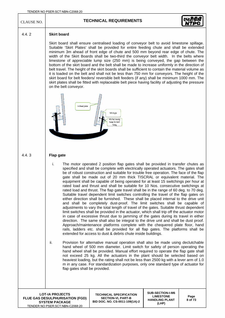
CLAUSE NO.
TECHNICAL REQUIREMENTS
LOT-IA PROJECTS
FLUE GAS DESULPHURISATION (FGD) SYSTEM PACKAGE
TECHNICAL SPECIFICATION SECTION-VI, PART-B
BID DOC. NO. CS-0011-109(1A)-2
SUB-SECTION-I-M6 LIMESTONE
HANDLING PLANT (LHP)
Page 8 of 73
4.4. 2 Skirt board
Skirt board shall ensure centralised loading of conveyor belt to avoid limestone spillage. Suitable ‘Skirt Plates’ shall be provided for entire feeding chute and shall be extended minimum 3m ahead of front edge of chute and 500 mm beyond rear edge of chute. The width of the Skirt Boards shall be two-third the conveyor belt width. In the belts where limestone of appreciable lump size (250 mm) is being conveyed, the gap between the bottom of the skirt board and the belt shall be made to increase uniformly in the direction of belt travel. The height of the skirt boards shall be sufficient to contain the material volume as it is loaded on the belt and shall not be less than 750 mm for conveyors. The height of the skirt board for belt feeders/ reversible belt feeders (if any) shall be minimum 1000 mm. The skirt plates shall be fitted with replaceable belt piece having facility of adjusting the pressure on the belt conveyor.
4.4. 3 Flap gate
i. The motor operated 2 position flap gates shall be provided in transfer chutes as specified and shall be complete with electrically operated actuators. The gates shall be of robust construction and suitable for trouble free operation. The face of the flap gate shall be made out of 20 mm thick TISCRAL or equivalent material. The equipment shall be capable of being operated for at least 15 switchings per hour at rated load and thrust and shall be suitable for 10 Nos. consecutive switchings at rated load and thrust. The flap gate travel shall be in the range of 60 deg. to 70 deg. Suitable travel dependent limit switches controlling the travel of the flap gates on either direction shall be furnished. These shall be placed internal to the drive unit and shall be completely dust-proof. The limit switches shall be capable of adjustments to vary the total length of travel of the gates. Suitable thrust dependent limit switches shall be provided in the actuator, which shall trip off the actuator motor in case of excessive thrust due to jamming of the gates during its travel in either direction. The same shall also be integral to the drive unit and shall be dust proof. Approach/maintenance platforms complete with the chequered plate floor, hand rails, ladders etc. shall be provided for all flap gates. The platforms shall be extended for access to dust & debris chute inside buildings.
ii. Provision for alternative manual operation shall also be made using declutchable hand wheel of 500 mm diameter. Limit switch for safety of person operating the hand wheel shall be provided. Manual effort required to operate the flap gate shall not exceed 25 kg. All the actuators in the plant should be selected based on heaviest loading, but the rating shall not be less than 2500 kg with a lever arm of 1.0 m in any case. For standardization purposes, only one standard type of actuator for flap gates shall be provided.
TENDER NO PSER:SCT:NBN-C2068:20
TENDER NO PSER:SCT:NBN-C2068:20
CLAUSE NO.
TECHNICAL REQUIREMENTS
LOT-IA PROJECTS
FLUE GAS DESULPHURISATION (FGD) SYSTEM PACKAGE
TECHNICAL SPECIFICATION SECTION-VI, PART-B
BID DOC. NO. CS-0011-109(1A)-2
SUB-SECTION-I-M6 LIMESTONE
HANDLING PLANT (LHP)
Page 9 of 73
iii. The material of shaft shall be EN-8 or equivalent. The diameter of the shaft shall be suitable for motor stalled condition and associated twisting. However, the diameter of the shaft shall not be less then 150 mm.
4.4.4 Rod Gate
Suitable manually operated rod gates shall be provided over rack and pinion gates for their easy operation and maintenance.
4.4.5 Rack & Pinion Gate
(i) The rack and pinion gate shall be guided properly and suitable rollers with bearings sealed for life and dust proof shall be provided. Rotary actuator operated rack and pinion gates shall be provided.
(ii) The rack and pinion gates shall be of mild steel construction with liner plate of 10 mm thick TISCRAL or equivalent material. The gates shall be operated by means of double rack and pinion. The material for rack & pinion wheel shall be cast steel and shaft shall be EN.-8. Provision for alternative manual operation (manual effort 25 kg) of motorized rack and pinion gates shall also be made. Limit switch for safety of person operating the hand wheel shall be provided.
4.5.0 DRIVE EQUIPMENT
4.5.1 Gear Box
The gearboxes shall be designed for 24 hours continuous duty. Gearboxes with cooling coils or external cooling are not acceptable. The gears used shall be helical conforming to IS:3681 (latest revision) or worm reduction units or spiral bevel speed reduction units conforming to suitable Indian Standards. The dimensions of the shaft end shall conform to IS:3688 or its latest revision. Above 40 kW drive rating, all gearboxes shall be helical or bevel helical type only. all gearboxes shall have suitable breather plugs, dipstick, drain plug etc.
4.5.2 Flexible / Rigid Coupling
The design of the coupling shall be such that it can take shock and misalignment without sacrificing its efficiency. Geared type flexible coupling shall be used on low speed side for all conveyors and other drive chains where gear box is provided. Other couplings in the drive chains shall be either rigid or flexible type, depending upon the requirement of equipment design.
4.5.3 Fluid Couplings
Fluid couplings shall be provided in all the drive machinery for belt conveyor systems and limestone crushers if the actual power requirement at motor output shaft is more than 40 kW. The fluid coupling for LT motors shall be of traction type and for HT motors, shall be of scoop tube type. Suitable electrically operated actuators shall be provided for scoop tube operation from local as well as remote. Manual operation may also be provided. Separate pump with motor or integral shaft driven oil pump shall be provided for circulating the fluid coupling oil through oil cooler. Forced cooling water supply to oil cooler shall be provided for which cooling water pumps to be provided for group of scoop couplings. Alternatively, Air cooled type scoop coupling is also acceptable for all conveyors with HT motors for ( AHP, LHP, GHP) and crusher scoop couplings. Suitable interlock using flow switches shall be provided in both oil as well as water lines to trip the drive motor in the event of flow in either lines falling below acceptable levels. Suitable pressure indicators and flow indicators shall be provided in the cooling water lines along with all-relevant valves, and accessories. Necessary isolation valves shall be provided in the oil / water line for
TENDER NO PSER:SCT:NBN-C2068:20
TENDER NO PSER:SCT:NBN-C2068:20
CLAUSE NO.
TECHNICAL REQUIREMENTS
LOT-IA PROJECTS
FLUE GAS DESULPHURISATION (FGD) SYSTEM PACKAGE
TECHNICAL SPECIFICATION SECTION-VI, PART-B
BID DOC. NO. CS-0011-109(1A)-2
SUB-SECTION-I-M6 LIMESTONE
HANDLING PLANT (LHP)
Page 10 of 73
maintenance of any equipment in the line. Necessary interlock shall also be provided so that the HT motor cannot be started from remote / local unless position of scoop tube permits no load start of the motor. Tripping of downstream equipment while the system is under normal operation shall result in scoop tube re-positioning to permit no load run of the concerned HT motor. Temperature switch shall be provided in the oil circuit and shall trip the system in case of high oil temperature. The scoop tube operation must be such so to ensure draining of oil from the operating circuit by providing a double speed motor. The speed (for draining) shall be selected to match the coasting time of down stream equipment/conveyor.
4.6.0 LIMESTONE HANDLING PLANT (LHP) BUILDINGS
4.6.1 All LHP buildings shall have sufficient space to accommodate the entire equipment like head end, drive unit and tail end of various conveyors, chutes, control equipments, MCCs, batteries, supports for conveyor bridges, tensioning arrangements, approach/maintenance platforms with ladders, external / internal stairs, handrails, RCC floors, foundations etc. Moreover, ample space shall be provided for maintenance purposes. Outside stairs to junction towers shall be open type. However, a weather canopy shall be provided at the top.
4.6.2 Building floors shall be washed periodically with water for which necessary slope & drains shall be provided from each floor leading to minimum 4 nos down comers of minimum 273 mm OD each building. However for MCC, control buildings and pump houses, minimum 150 mm dia, 4 nos galvanized MS pipes conforming to IS: 1239 shall be provided. The system shall be designed considering water mixed with limestone. A drain pit shall be provided near each building to collect water/limestone mixture. Overflow from this pit shall be connected to nearest drain. 1 mtr x 1 mtr size dust/debris MS chutes from all the floors to ground floor shall be provided at all buildings/junction towers and limestone crusher house. The plate thickness shall not be less than 6mm. Openings in the floors of LHP buildings (i.e. JTs/CH etc.) shall be provided with curb of 100mm high to avoid water falling down to lower floors.
4.6.3 Floor at ground shall be provided in all junction towers, ground conveyors etc. Level of floor at ground shall be 500 mm above ground/grade level unless noted otherwise. For enclosed ground conveyor 750mm wide plinth protection along with drainage arrangement shall be provided along the conveyor on both sides. Suitable opening at every 50mtr interval shall be provided on either side in a staggered manner for exit / entry of personals. Necessary drains must be provided all along the floors of ground conveyor.
4.7.0 TRAVELLING TRIPPER AND BUNKER SEALING ARRANGEMENT
4.7.1 Mobile Trippers on bunker conveyors along with belt sealing arrangement shall be furnished and erected complete with rails, including necessary supporting structures, approach/ maintenance platforms with ladders and hand railings, trailing cables, all electricals including machine mounted local control panel & control panel on one end of Bunker. The Mobile tripper on bunker/yard conveyors shall be motor driven type. The tripper shall have provision for dropping limestone from conveyor onto both sides of tripper to the bunker/storage shed or back to the conveyor for the purpose of skipping intermediate bunkers (as applicable). The rating of tripper travel motor shall be adequate to move the tripper smoothly either in same or opposite direction to belt direction under fully loaded conditions. Adhesive weight requirement and tractive effort calculations shall be subject to approval of Employer. Coefficient of adhesion shall be considered as maximum 0.15. Minimum two drive axles shall be provided for tripper travel. Arrangement shall be provided at the starting point of the tripper to avoid folding of belt. In case of tripper running at a speed more than its rated speed due to chute jamming or other reason, conveyor shall trip and annunciation shall appear.
4.7.2 Supply of adequate length of rails to cover the runway length for the motor driven tripper shall be included. The supporting structures for the rails with necessary end stops shall also be supplied under this specification. Suitable belt hold down guide pulley shall be provided over the concave curve of belt over tripper. The travelling trippers shall be provided with fail
TENDER NO PSER:SCT:NBN-C2068:20
TENDER NO PSER:SCT:NBN-C2068:20
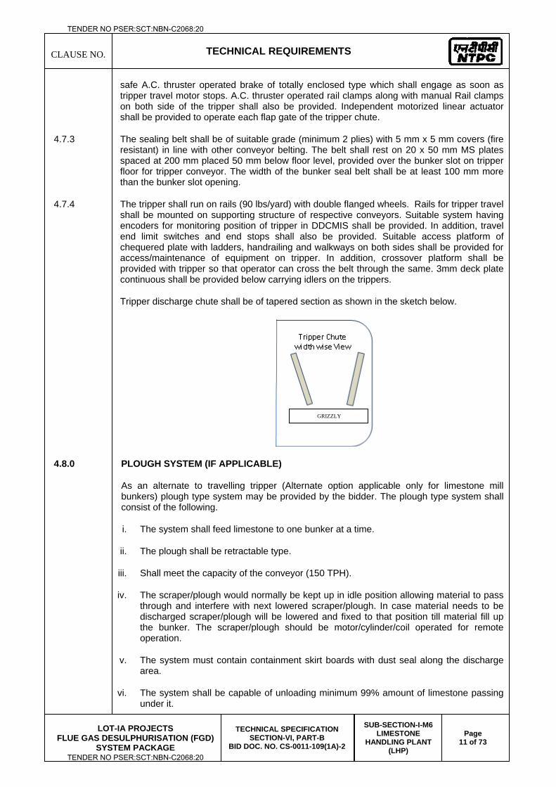
CLAUSE NO.
TECHNICAL REQUIREMENTS
LOT-IA PROJECTS
FLUE GAS DESULPHURISATION (FGD) SYSTEM PACKAGE
TECHNICAL SPECIFICATION SECTION-VI, PART-B
BID DOC. NO. CS-0011-109(1A)-2
SUB-SECTION-I-M6 LIMESTONE
HANDLING PLANT (LHP)
Page 11 of 73
safe A.C. thruster operated brake of totally enclosed type which shall engage as soon as tripper travel motor stops. A.C. thruster operated rail clamps along with manual Rail clamps on both side of the tripper shall also be provided. Independent motorized linear actuator shall be provided to operate each flap gate of the tripper chute.
4.7.3 The sealing belt shall be of suitable grade (minimum 2 plies) with 5 mm x 5 mm covers (fire resistant) in line with other conveyor belting. The belt shall rest on 20 x 50 mm MS plates spaced at 200 mm placed 50 mm below floor level, provided over the bunker slot on tripper floor for tripper conveyor. The width of the bunker seal belt shall be at least 100 mm more than the bunker slot opening.
4.7.4 The tripper shall run on rails (90 lbs/yard) with double flanged wheels. Rails for tripper travel shall be mounted on supporting structure of respective conveyors. Suitable system having encoders for monitoring position of tripper in DDCMIS shall be provided. In addition, travel end limit switches and end stops shall also be provided. Suitable access platform of chequered plate with ladders, handrailing and walkways on both sides shall be provided for access/maintenance of equipment on tripper. In addition, crossover platform shall be provided with tripper so that operator can cross the belt through the same. 3mm deck plate continuous shall be provided below carrying idlers on the trippers.
Tripper discharge chute shall be of tapered section as shown in the sketch below.
4.8.0 PLOUGH SYSTEM (IF APPLICABLE)
As an alternate to travelling tripper (Alternate option applicable only for limestone mill bunkers) plough type system may be provided by the bidder. The plough type system shall consist of the following.
i. The system shall feed limestone to one bunker at a time.
ii. The plough shall be retractable type.
iii. Shall meet the capacity of the conveyor (150 TPH).
iv. The scraper/plough would normally be kept up in idle position allowing material to pass through and interfere with next lowered scraper/plough. In case material needs to be discharged scraper/plough will be lowered and fixed to that position till material fill up the bunker. The scraper/plough should be motor/cylinder/coil operated for remote operation.
v. The system must contain containment skirt boards with dust seal along the discharge area.
vi. The system shall be capable of unloading minimum 99% amount of limestone passing under it.
GRIZZLY
TENDER NO PSER:SCT:NBN-C2068:20
TENDER NO PSER:SCT:NBN-C2068:20
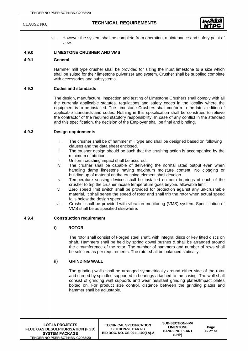
CLAUSE NO.
TECHNICAL REQUIREMENTS
LOT-IA PROJECTS
FLUE GAS DESULPHURISATION (FGD) SYSTEM PACKAGE
TECHNICAL SPECIFICATION SECTION-VI, PART-B
BID DOC. NO. CS-0011-109(1A)-2
SUB-SECTION-I-M6 LIMESTONE
HANDLING PLANT (LHP)
Page 12 of 73
vii. However the system shall be complete from operation, maintenance and safety point of view.
4.9.0 LIMESTONE CRUSHER AND VMS
4.9.1 General
Hammer mill type crusher shall be provided for sizing the input limestone to a size which shall be suited for their limestone pulverizer and system. Crusher shall be supplied complete with accessories and subsystems.
4.9.2 Codes and standards
The design, manufacture, inspection and testing of Limestone Crushers shall comply with all the currently applicable statutes, regulations and safety codes in the locality where the equipment is to be installed. The Limestone Crushers shall conform to the latest edition of applicable standards and codes. Nothing in this specification shall be construed to relieve the contractor of the required statutory responsibility. In case of any conflict in the standard and this specification, the decision of the Employer shall be final and binding.
4.9.3 Design requirements
i. The crusher shall be of hammer mill type and shall be designed based on following clauses and the data sheet enclosed.
ii. The crusher design should be such that the crushing action is accompanied by the minimum of attrition.
iii. Uniform crushing impact shall be assured. iv. The crusher shall be capable of delivering the normal rated output even when
handling damp limestone having maximum moisture content. No clogging or building up of material on the crushing element shall develop.
v. Temperature sensing devices shall be installed on both bearings of each of the crusher to trip the crusher incase temperature goes beyond allowable limit.
vi. Zero speed limit switch shall be provided for protection against any un-crushable material. It shall sense the speed of rotor and shall trip the rotor when actual speed falls below the design speed.
vii. Crusher shall be provided with vibration monitoring (VMS) system. Specification of VMS shall be as specified elsewhere.
4.9.4 Construction requirement
i) ROTOR
The rotor shall consist of Forged steel shaft, with integral discs or key fitted discs on shaft. Hammers shall be held by spring dowel bushes & shall be arranged around the circumference of the rotor. The number of hammers and number of rows shall be selected as per requirements. The rotor shall be balanced statically.
ii) GRINDING WALL
The grinding walls shall be arranged symmetrically around either side of the rotor and carried by spindles supported in bearings attached to the casing. The wall shall consist of grinding wall supports and wear resistant grinding plates/Impact plates bolted on. For product size control, distance between the grinding plates and hammer shall be adjustable.
TENDER NO PSER:SCT:NBN-C2068:20
TENDER NO PSER:SCT:NBN-C2068:20
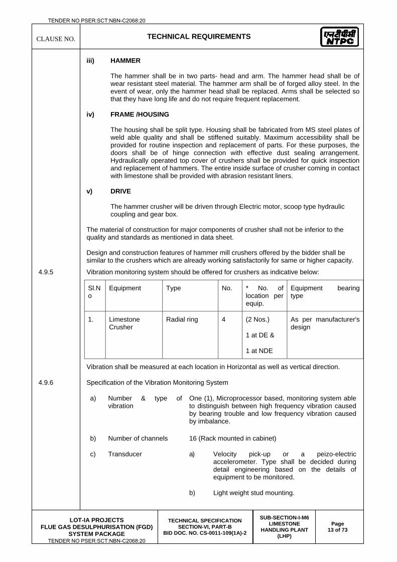
CLAUSE NO.
TECHNICAL REQUIREMENTS
LOT-IA PROJECTS
FLUE GAS DESULPHURISATION (FGD) SYSTEM PACKAGE
TECHNICAL SPECIFICATION SECTION-VI, PART-B
BID DOC. NO. CS-0011-109(1A)-2
SUB-SECTION-I-M6 LIMESTONE
HANDLING PLANT (LHP)
Page 13 of 73
iii) HAMMER
The hammer shall be in two parts- head and arm. The hammer head shall be of wear resistant steel material. The hammer arm shall be of forged alloy steel. In the event of wear, only the hammer head shall be replaced. Arms shall be selected so that they have long life and do not require frequent replacement.
iv) FRAME /HOUSING
The housing shall be split type. Housing shall be fabricated from MS steel plates of weld able quality and shall be stiffened suitably. Maximum accessibility shall be provided for routine inspection and replacement of parts. For these purposes, the doors shall be of hinge connection with effective dust sealing arrangement. Hydraulically operated top cover of crushers shall be provided for quick inspection and replacement of hammers. The entire inside surface of crusher coming in contact with limestone shall be provided with abrasion resistant liners.
v) DRIVE
The hammer crusher will be driven through Electric motor, scoop type hydraulic coupling and gear box.
The material of construction for major components of crusher shall not be inferior to the quality and standards as mentioned in data sheet. Design and construction features of hammer mill crushers offered by the bidder shall be similar to the crushers which are already working satisfactorily for same or higher capacity.
4.9.5 Vibration monitoring system should be offered for crushers as indicative below:
Sl.No
Equipment Type No. * No. of location per equip.
Equipment bearing type
1. Limestone Crusher
Radial ring 4 (2 Nos.)
1 at DE &
1 at NDE
As per manufacturer's design
Vibration shall be measured at each location in Horizontal as well as vertical direction.
4.9.6 Specification of the Vibration Monitoring System
a) Number & type of vibration
One (1), Microprocessor based, monitoring system able to distinguish between high frequency vibration caused by bearing trouble and low frequency vibration caused by imbalance.
b) Number of channels 16 (Rack mounted in cabinet)
c) Transducer a) Velocity pick-up or a peizo-electric accelerometer. Type shall be decided during detail engineering based on the details of equipment to be monitored.
b) Light weight stud mounting.
TENDER NO PSER:SCT:NBN-C2068:20
TENDER NO PSER:SCT:NBN-C2068:20
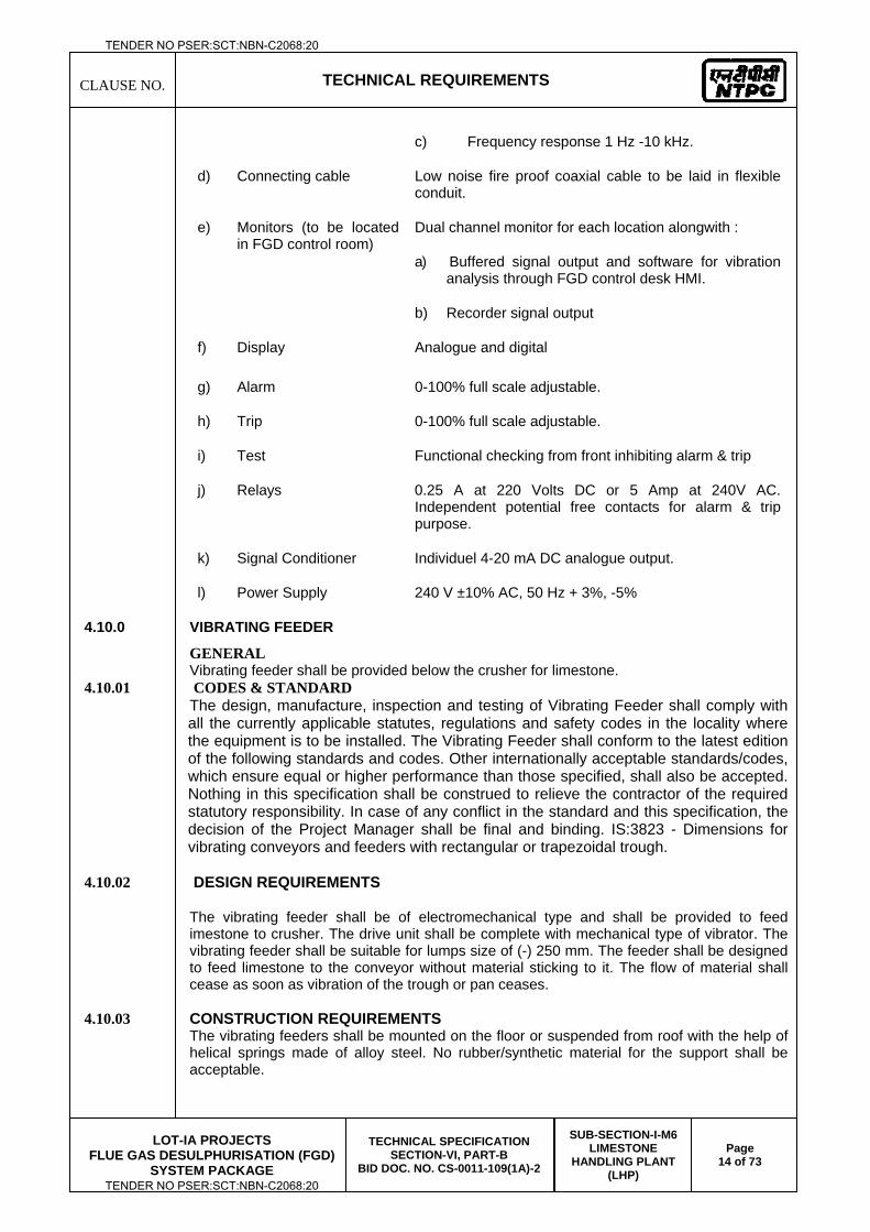
CLAUSE NO.
TECHNICAL REQUIREMENTS
LOT-IA PROJECTS
FLUE GAS DESULPHURISATION (FGD) SYSTEM PACKAGE
TECHNICAL SPECIFICATION SECTION-VI, PART-B
BID DOC. NO. CS-0011-109(1A)-2
SUB-SECTION-I-M6 LIMESTONE
HANDLING PLANT (LHP)
Page 14 of 73
c) Frequency response 1 Hz -10 kHz.
d) Connecting cable Low noise fire proof coaxial cable to be laid in flexible conduit.
e) Monitors (to be located in FGD control room)
Dual channel monitor for each location alongwith :
a) Buffered signal output and software for vibration analysis through FGD control desk HMI.
b) Recorder signal output
f) Display Analogue and digital
g) Alarm 0-100% full scale adjustable.
h) Trip 0-100% full scale adjustable.
i) Test Functional checking from front inhibiting alarm & trip
j) Relays 0.25 A at 220 Volts DC or 5 Amp at 240V AC. Independent potential free contacts for alarm & trip purpose.
k) Signal Conditioner Individuel 4-20 mA DC analogue output.
l) Power Supply 240 V ±10% AC, 50 Hz + 3%, -5%
4.10.0 VIBRATING FEEDER
GENERAL Vibrating feeder shall be provided below the crusher for limestone.
4.10.01 CODES & STANDARD The design, manufacture, inspection and testing of Vibrating Feeder shall comply with all the currently applicable statutes, regulations and safety codes in the locality where the equipment is to be installed. The Vibrating Feeder shall conform to the latest edition of the following standards and codes. Other internationally acceptable standards/codes, which ensure equal or higher performance than those specified, shall also be accepted. Nothing in this specification shall be construed to relieve the contractor of the required statutory responsibility. In case of any conflict in the standard and this specification, the decision of the Project Manager shall be final and binding. IS:3823 - Dimensions for vibrating conveyors and feeders with rectangular or trapezoidal trough.
4.10.02 DESIGN REQUIREMENTS
The vibrating feeder shall be of electromechanical type and shall be provided to feed imestone to crusher. The drive unit shall be complete with mechanical type of vibrator. The vibrating feeder shall be suitable for lumps size of (-) 250 mm. The feeder shall be designed to feed limestone to the conveyor without material sticking to it. The flow of material shall cease as soon as vibration of the trough or pan ceases.
4.10.03 CONSTRUCTION REQUIREMENTS The vibrating feeders shall be mounted on the floor or suspended from roof with the help of helical springs made of alloy steel. No rubber/synthetic material for the support shall be acceptable.
TENDER NO PSER:SCT:NBN-C2068:20
TENDER NO PSER:SCT:NBN-C2068:20
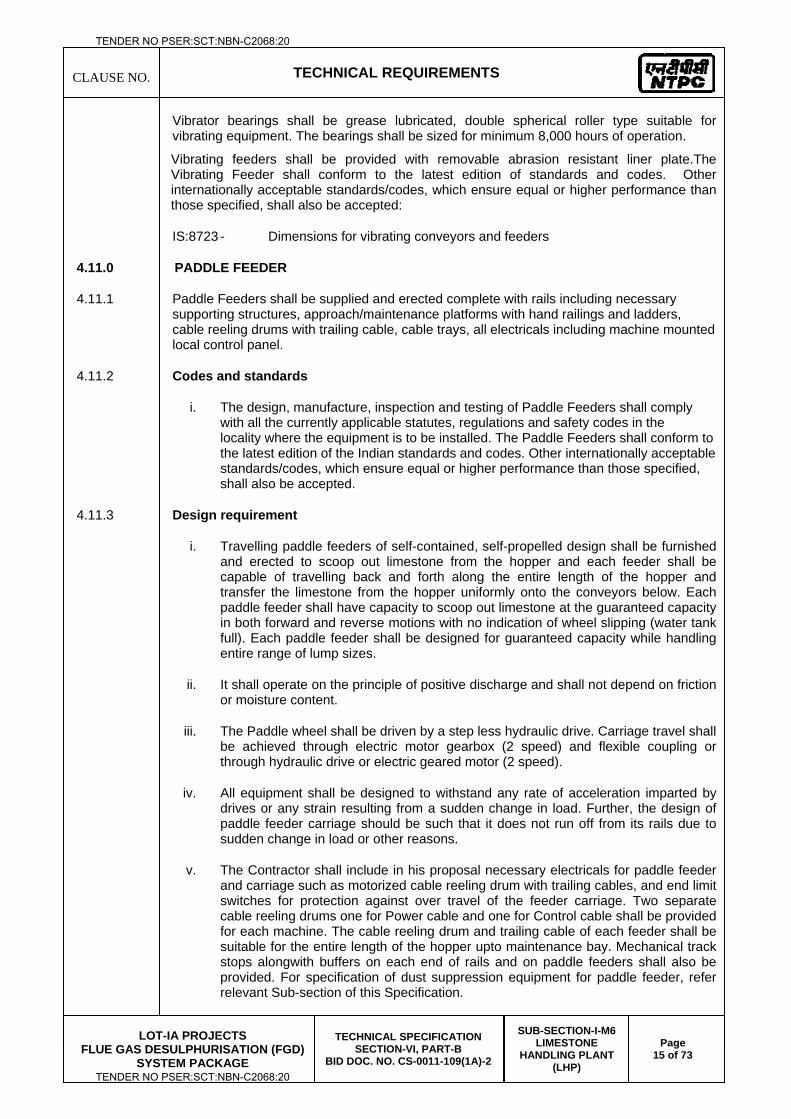
CLAUSE NO.
TECHNICAL REQUIREMENTS
LOT-IA PROJECTS
FLUE GAS DESULPHURISATION (FGD) SYSTEM PACKAGE
TECHNICAL SPECIFICATION SECTION-VI, PART-B
BID DOC. NO. CS-0011-109(1A)-2
SUB-SECTION-I-M6 LIMESTONE
HANDLING PLANT (LHP)
Page 15 of 73
Vibrator bearings shall be grease lubricated, double spherical roller type suitable for vibrating equipment. The bearings shall be sized for minimum 8,000 hours of operation.
Vibrating feeders shall be provided with removable abrasion resistant liner plate.The Vibrating Feeder shall conform to the latest edition of standards and codes. Other internationally acceptable standards/codes, which ensure equal or higher performance than those specified, shall also be accepted:
IS:8723 - Dimensions for vibrating conveyors and feeders
4.11.0 PADDLE FEEDER
4.11.1 Paddle Feeders shall be supplied and erected complete with rails including necessary supporting structures, approach/maintenance platforms with hand railings and ladders, cable reeling drums with trailing cable, cable trays, all electricals including machine mounted local control panel.
4.11.2 Codes and standards
i. The design, manufacture, inspection and testing of Paddle Feeders shall comply with all the currently applicable statutes, regulations and safety codes in the locality where the equipment is to be installed. The Paddle Feeders shall conform to the latest edition of the Indian standards and codes. Other internationally acceptable standards/codes, which ensure equal or higher performance than those specified, shall also be accepted.
4.11.3 Design requirement
i. Travelling paddle feeders of self-contained, self-propelled design shall be furnished and erected to scoop out limestone from the hopper and each feeder shall be capable of travelling back and forth along the entire length of the hopper and transfer the limestone from the hopper uniformly onto the conveyors below. Each paddle feeder shall have capacity to scoop out limestone at the guaranteed capacity in both forward and reverse motions with no indication of wheel slipping (water tank full). Each paddle feeder shall be designed for guaranteed capacity while handling entire range of lump sizes.
ii. It shall operate on the principle of positive discharge and shall not depend on friction or moisture content.
iii. The Paddle wheel shall be driven by a step less hydraulic drive. Carriage travel shall be achieved through electric motor gearbox (2 speed) and flexible coupling or through hydraulic drive or electric geared motor (2 speed).
iv. All equipment shall be designed to withstand any rate of acceleration imparted by drives or any strain resulting from a sudden change in load. Further, the design of paddle feeder carriage should be such that it does not run off from its rails due to sudden change in load or other reasons.
v. The Contractor shall include in his proposal necessary electricals for paddle feeder and carriage such as motorized cable reeling drum with trailing cables, and end limit switches for protection against over travel of the feeder carriage. Two separate cable reeling drums one for Power cable and one for Control cable shall be provided for each machine. The cable reeling drum and trailing cable of each feeder shall be suitable for the entire length of the hopper upto maintenance bay. Mechanical track stops alongwith buffers on each end of rails and on paddle feeders shall also be provided. For specification of dust suppression equipment for paddle feeder, refer relevant Sub-section of this Specification.
TENDER NO PSER:SCT:NBN-C2068:20
TENDER NO PSER:SCT:NBN-C2068:20
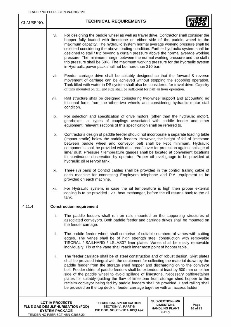
CLAUSE NO.
TECHNICAL REQUIREMENTS
LOT-IA PROJECTS
FLUE GAS DESULPHURISATION (FGD) SYSTEM PACKAGE
TECHNICAL SPECIFICATION SECTION-VI, PART-B
BID DOC. NO. CS-0011-109(1A)-2
SUB-SECTION-I-M6 LIMESTONE
HANDLING PLANT (LHP)
Page 16 of 73
vi. For designing the paddle wheel as well as travel drive, Contractor shall consider the hopper fully loaded with limestone on either side of the paddle wheel to the maximum capacity. The hydraulic system normal average working pressure shall be selected considering the above loading condition. Further hydraulic system shall be designed to stall / trip beyond a certain pressure above the normal average working pressure. The minimum margin between the normal working pressure and the stall / trip pressure shall be 50%. The maximum working pressure for the hydraulic system in Hydraulic power pack shall not be more than 210 bar.
vii. Feeder carriage drive shall be suitably designed so that the forward & reverse movement of carriage can be achieved without stopping the scooping operation. Tank filled with water in DS system shall also be considered for travel drive. Capacity of tank mounted on tail end side shall be sufficient for half an hour operation.
viii. Rail structure shall be designed considering two-wheel support and accounting no frictional force from the other two wheels and considering hydraulic motor stall condition.
ix. For selection and specification of drive motors (other than the hydraulic motor), gearboxes, all types of couplings associated with paddle feeder and other equipment, relevant sections of this specification shall be referred to.
x. Contractor’s design of paddle feeder should not incorporate a separate loading table (impact cradle) below the paddle feeders. However, the height of fall of limestone between paddle wheel and conveyor belt shall be kept minimum. Hydraulic components shall be provided with dust proof cover for protection against spillage of lime/ dust. Pressure /Temperature gauges shall be located at convenient locations for continuous observation by operator. Proper oil level gauge to be provided at hydraulic oil reservoir tank.
xi. Three (3) pairs of Control cables shall be provided in the control trailing cable of each machine for connecting Employers telephone and P.A. equipment to be provided on each machine.
xii. For Hydraulic system, in case the oil temperature is high then proper external cooling is to be provided , viz, heat exchanger, before the oil returns back to the oil tank.
4.11.4 Construction requirement
i. The paddle feeders shall run on rails mounted on the supporting structures of associated conveyors. Both paddle feeder and carriage drives shall be mounted on the feeder carriage.
ii. The paddle feeder wheel shall comprise of suitable numbers of vanes with cutting edges. The vanes shall be of high strength steel construction with removable TISCRAL / SAILHARD / LSLAS07 liner plates. Vanes shall be easily removable individually. Tip of the vane shall reach inner most point of hopper table.
iii. The feeder carriage shall be of steel construction and of robust design. Skirt plates shall be provided integral with the equipment for collecting the material drawn by the paddle feeder from the storage shed hopper and discharging on to the conveyor belt. Feeder skirts of paddle feeders shall be extended at least by 500 mm on either side of the paddle wheel to avoid spillage of limestone. Necessary baffle/retainer plates for suitably guiding the flow of limestone from storage shed hopper to the reclaim conveyor being fed by paddle feeders shall be provided. Hand railing shall be provided on the top deck of feeder carriage together with an access ladder.
TENDER NO PSER:SCT:NBN-C2068:20
TENDER NO PSER:SCT:NBN-C2068:20
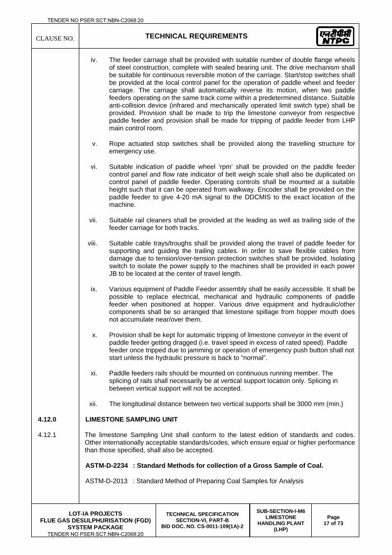
CLAUSE NO.
TECHNICAL REQUIREMENTS
LOT-IA PROJECTS
FLUE GAS DESULPHURISATION (FGD) SYSTEM PACKAGE
TECHNICAL SPECIFICATION SECTION-VI, PART-B
BID DOC. NO. CS-0011-109(1A)-2
SUB-SECTION-I-M6 LIMESTONE
HANDLING PLANT (LHP)
Page 17 of 73
iv. The feeder carriage shall be provided with suitable number of double flange wheels of steel construction, complete with sealed bearing unit. The drive mechanism shall be suitable for continuous reversible motion of the carriage. Start/stop switches shall be provided at the local control panel for the operation of paddle wheel and feeder carriage. The carriage shall automatically reverse its motion, when two paddle feeders operating on the same track come within a predetermined distance. Suitable anti-collision device (infrared and mechanically operated limit switch type) shall be provided. Provision shall be made to trip the limestone conveyor from respective paddle feeder and provision shall be made for tripping of paddle feeder from LHP main control room.
v. Rope actuated stop switches shall be provided along the travelling structure for emergency use.
vi. Suitable indication of paddle wheel ‘rpm’ shall be provided on the paddle feeder control panel and flow rate indicator of belt weigh scale shall also be duplicated on control panel of paddle feeder. Operating controls shall be mounted at a suitable height such that it can be operated from walkway. Encoder shall be provided on the paddle feeder to give 4-20 mA signal to the DDCMIS to the exact location of the machine.
vii. Suitable rail cleaners shall be provided at the leading as well as trailing side of the feeder carriage for both tracks.
viii. Suitable cable trays/troughs shall be provided along the travel of paddle feeder for supporting and guiding the trailing cables. In order to save flexible cables from damage due to tension/over-tension protection switches shall be provided. Isolating switch to isolate the power supply to the machines shall be provided in each power JB to be located at the center of travel length.
ix. Various equipment of Paddle Feeder assembly shall be easily accessible. It shall be possible to replace electrical, mechanical and hydraulic components of paddle feeder when positioned at hopper. Various drive equipment and hydraulic/other components shall be so arranged that limestone spillage from hopper mouth does not accumulate near/over them.
x. Provision shall be kept for automatic tripping of limestone conveyor in the event of paddle feeder getting dragged (i.e. travel speed in excess of rated speed). Paddle feeder once tripped due to jamming or operation of emergency push button shall not start unless the hydraulic pressure is back to “normal”.
xi. Paddle feeders rails should be mounted on continuous running member. The splicing of rails shall necessarily be at vertical support location only. Splicing in between vertical support will not be accepted.
xii. The longitudinal distance between two vertical supports shall be 3000 mm (min.)
4.12.0 LIMESTONE SAMPLING UNIT
4.12.1 The limestone Sampling Unit shall conform to the latest edition of standards and codes. Other internationally acceptable standards/codes, which ensure equal or higher performance than those specified, shall also be accepted.
ASTM-D-2234 : Standard Methods for collection of a Gross Sample of Coal.
ASTM-D-2013 : Standard Method of Preparing Coal Samples for Analysis
TENDER NO PSER:SCT:NBN-C2068:20
TENDER NO PSER:SCT:NBN-C2068:20
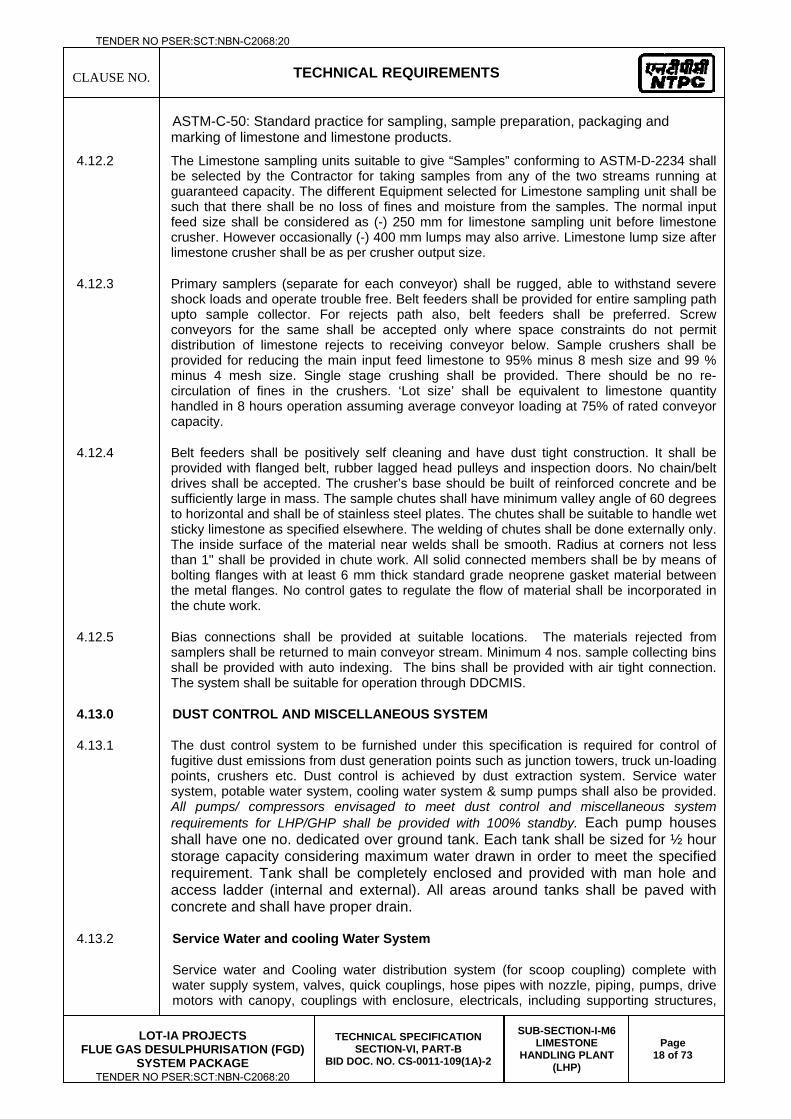
CLAUSE NO.
TECHNICAL REQUIREMENTS
LOT-IA PROJECTS
FLUE GAS DESULPHURISATION (FGD) SYSTEM PACKAGE
TECHNICAL SPECIFICATION SECTION-VI, PART-B
BID DOC. NO. CS-0011-109(1A)-2
SUB-SECTION-I-M6 LIMESTONE
HANDLING PLANT (LHP)
Page 18 of 73
ASTM-C-50: Standard practice for sampling, sample preparation, packaging and marking of limestone and limestone products.
4.12.2 The Limestone sampling units suitable to give “Samples” conforming to ASTM-D-2234 shall be selected by the Contractor for taking samples from any of the two streams running at guaranteed capacity. The different Equipment selected for Limestone sampling unit shall be such that there shall be no loss of fines and moisture from the samples. The normal input feed size shall be considered as (-) 250 mm for limestone sampling unit before limestone crusher. However occasionally (-) 400 mm lumps may also arrive. Limestone lump size after limestone crusher shall be as per crusher output size.
4.12.3 Primary samplers (separate for each conveyor) shall be rugged, able to withstand severe shock loads and operate trouble free. Belt feeders shall be provided for entire sampling path upto sample collector. For rejects path also, belt feeders shall be preferred. Screw conveyors for the same shall be accepted only where space constraints do not permit distribution of limestone rejects to receiving conveyor below. Sample crushers shall be provided for reducing the main input feed limestone to 95% minus 8 mesh size and 99 % minus 4 mesh size. Single stage crushing shall be provided. There should be no re-circulation of fines in the crushers. ‘Lot size’ shall be equivalent to limestone quantity handled in 8 hours operation assuming average conveyor loading at 75% of rated conveyor capacity.
4.12.4 Belt feeders shall be positively self cleaning and have dust tight construction. It shall be provided with flanged belt, rubber lagged head pulleys and inspection doors. No chain/belt drives shall be accepted. The crusher’s base should be built of reinforced concrete and be sufficiently large in mass. The sample chutes shall have minimum valley angle of 60 degrees to horizontal and shall be of stainless steel plates. The chutes shall be suitable to handle wet sticky limestone as specified elsewhere. The welding of chutes shall be done externally only. The inside surface of the material near welds shall be smooth. Radius at corners not less than 1" shall be provided in chute work. All solid connected members shall be by means of bolting flanges with at least 6 mm thick standard grade neoprene gasket material between the metal flanges. No control gates to regulate the flow of material shall be incorporated in the chute work.
4.12.5 Bias connections shall be provided at suitable locations. The materials rejected from samplers shall be returned to main conveyor stream. Minimum 4 nos. sample collecting bins shall be provided with auto indexing. The bins shall be provided with air tight connection. The system shall be suitable for operation through DDCMIS.
4.13.0 DUST CONTROL AND MISCELLANEOUS SYSTEM
4.13.1 The dust control system to be furnished under this specification is required for control of fugitive dust emissions from dust generation points such as junction towers, truck un-loading points, crushers etc. Dust control is achieved by dust extraction system. Service water system, potable water system, cooling water system & sump pumps shall also be provided. All pumps/ compressors envisaged to meet dust control and miscellaneous system requirements for LHP/GHP shall be provided with 100% standby. Each pump houses shall have one no. dedicated over ground tank. Each tank shall be sized for ½ hour storage capacity considering maximum water drawn in order to meet the specified requirement. Tank shall be completely enclosed and provided with man hole and access ladder (internal and external). All areas around tanks shall be paved with concrete and shall have proper drain.
4.13.2 Service Water and cooling Water System
Service water and Cooling water distribution system (for scoop coupling) complete with water supply system, valves, quick couplings, hose pipes with nozzle, piping, pumps, drive motors with canopy, couplings with enclosure, electricals, including supporting structures,
TENDER NO PSER:SCT:NBN-C2068:20
TENDER NO PSER:SCT:NBN-C2068:20
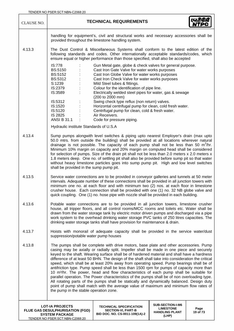
CLAUSE NO.
TECHNICAL REQUIREMENTS
LOT-IA PROJECTS
FLUE GAS DESULPHURISATION (FGD) SYSTEM PACKAGE
TECHNICAL SPECIFICATION SECTION-VI, PART-B
BID DOC. NO. CS-0011-109(1A)-2
SUB-SECTION-I-M6 LIMESTONE
HANDLING PLANT (LHP)
Page 19 of 73
handling for equipment’s, civil and structural works and necessary accessories shall be provided throughout the limestone handling system.
4.13.3 The Dust Control & Miscellaneous Systems shall conform to the latest edition of the following standards and codes. Other internationally acceptable standards/codes, which ensure equal or higher performance than those specified, shall also be accepted
IS:778 : Gun Metal gate, globe & check valves for general purpose. BS:5150 : Cast Iron Gate Valve for water works purposes BS:5152 : Cast Iron Globe Valve for water works purposes BS:5312 : Cast Iron Check Valve for water works purposes S:1239 : Mild Steel tubes & fittings. IS:2379 : Colour for the identification of pipe line. IS:3589 : Electrically welded steel pipes for water, gas & sewage (200 to 2000 mm) IS:5312 : Swing check type reflux (non return) valves. IS:1520 : Horizontal centrifugal pump for clean, cold fresh water. IS:5120 : Centrifugal pump for clean, cold & fresh water. IS 2825 : Air Receivers. ANSI B 31.1 : Code for pressure piping.
Hydraulic institute Standards of U.S.A
4.13.4 Sump pumps alongwith level switches & piping upto nearest Employer's drain (max upto 50.0 mtrs. from outside the building) shall be provided at all locations wherever natural drainage is not possible. The capacity of each pump shall not be less than 50 m3/hr. Minimum 10% margin on capacity and 20% margin on computed head shall be considered for selection of pumps. Size of the drain pit shall not be less than 2.0 meters x 2.0 meters x 1.8 meters deep. One no. of settling pit shall also be provided before sump pit so that water without heavy limestone particles goes into sump pump pit. High and low level switches shall be provided in the sump pump pit.
4.13.5 Service water connections are to be provided in conveyor galleries and tunnels at 50 meter intervals. Adequate number of these connections shall be provided in all junction towers with minimum one no. at each floor and with minimum two (2) nos. at each floor in limestone crusher house. Each connection shall be provided with one (1) no. 32 NB globe valve and quick coupling. One (1) no. hose pipe with nozzle shall be provided in each building.
4.13.6 Potable water connections are to be provided in all junction towers, limestone crusher house, all tripper floors, and all control rooms/MCC rooms and toilets etc. Water shall be drawn from the water storage tank by electric motor driven pumps and discharged via a pipe work system to the overhead drinking water storage PVC tanks of 250 litres capacities. The drinking water storage tanks shall have provision for maintenance & drain.
4.13.7 Hoists with monorail of adequate capacity shall be provided in the service water/dust suppression/potable water pump houses
4.13.8 The pumps shall be complete with drive motors, base plate and other accessories. Pump casing may be axially or radially split. Impeller shall be made in one piece and securely keyed to the shaft. Wearing surface shall be of hardened material and shall have a hardness difference of at least 50 BHN. The design of the shaft shall take into consideration the critical speed, which shall be at least 20% away from operating speed. Pump bearings shall be of antifriction type. Pump speed shall be less than 1500 rpm for pumps of capacity more than 10 m³/hr. The power, head and flow characteristics of each pump shall be suitable for parallel operation. The Power characteristics of the pumps shall be of non overloading type. All rotating parts of the pumps shall be statically and dynamically balanced. Design duty point of pump shall match with the average value of maximum and minimum flow rates of the pump in the stable operation zone.
TENDER NO PSER:SCT:NBN-C2068:20
TENDER NO PSER:SCT:NBN-C2068:20
CLAUSE NO.
TECHNICAL REQUIREMENTS
LOT-IA PROJECTS
FLUE GAS DESULPHURISATION (FGD) SYSTEM PACKAGE
TECHNICAL SPECIFICATION SECTION-VI, PART-B
BID DOC. NO. CS-0011-109(1A)-2
SUB-SECTION-I-M6 LIMESTONE
HANDLING PLANT (LHP)
Page 20 of 73
4.13.13 The sump pumps shall be of wet pit types, vertical shaft and impeller shall be specially designed to pass large solids or unscreened liquids. The construction and material shall be suitable for pumping limestone/dust contaminated water with a minimum of maintenance. All bearings of the pump shall be located above the water level.
4.13.14 In general pipe sizes 65 mm NB and larger are to be joined by butt welding and pipe work of size 50 mm NB and below by socket welding/screwed connections. Joints at valves or specialities shall be flanged for sizes 65 mm NB or large and screwed for sizes 50 mm NB and below. All galvanised piping shall be joined by screwed connections. Minimum pipe diameter selected for DS/SW/PW/Cooling Water System (along with branch pipes) shall be 32 NB. However, for dry fog DS system, the minimum pipe size shall be 20 NB.
4.13.15 Valves & Specialities shall be used to start, stop or regulate the flow. All valves/specialities below 50 mm size in service water/dust suppression/ potable water lines should be plug type. Gate/sluice valves shall be used for isolation of flow of pipe lines above 50NB and Globe valves shall be used for regulating the flow. All gate and globe valves of size 65 NB and large shall be bolted bonnet, outside screw, rising type with flanged ends. Valves of size 50 NB and smaller shall be with screwed ends. Non-return valves shall be swing check type. These valves will have a permanent ‘arrow’ inscription on its body to indicate direction of motion of the fluid.
4.13.16 Strainer shall be of duplex type designed with 3 way valves so that one filter can be cleaned while the other is in operation. Suitable vent and drain valves shall also be provided. Screen opening area shall be at least four times the pipe cross sectional area. Pressure drop in clean conditions shall not exceed 1.5 MWC at full flow.
4.13.17 The dust control and miscellaneous system to be supplied for limestone handling plant may be clubbed with the dust control and miscellaneous system for coal handling plant under this package.
4.13.18 Dust extraction system for Limestone Handling area:
Dust extraction system for limestone handling system shall be dry type comprising of dust collection hoods, ducting, fans, bag filter and dust collection hopper. The limestone dust collected in dust collection hopper shall be periodically emptied back to the conveyor leaving the building.
4.13.19 Limestone storage area dust extraction system:
a) For dust control in limestone storage shed during stacking and handling of limestone, roof extractors, ducting and collection hopper with bag filters shall be provided. The dust collected in the dust collection hoppers shall be periodically emptied back to the reclaim conveyor below the shed.
b) For the paddle feeder provided for the reclaim hopper below the limestone storage shed, the dust extraction system comprising of suction hood, ducting and trolley mounted dust collection hopper with bag filters shall be provided. The dust collection hopper shall be periodically emptied back to the reclaim conveyor.
4.14.0 VENTILATION SYSTEMS
4.14.1 Mechanical Ventilation system
The air quantity for mechanical ventilation system shall be estimated based on equipment and solar heat loads and the temperature rise inside the building. Necessary air filters shall be provided to supply only clean air into building. Exhaust air shall be discharged at a suitable height above building. The ventilation system generally consisting of adequate number of supply and exhaust air fans, air filters, ducting along with 3 phase AC motor
TENDER NO PSER:SCT:NBN-C2068:20
TENDER NO PSER:SCT:NBN-C2068:20
CLAUSE NO.
TECHNICAL REQUIREMENTS
LOT-IA PROJECTS
FLUE GAS DESULPHURISATION (FGD) SYSTEM PACKAGE
TECHNICAL SPECIFICATION SECTION-VI, PART-B
BID DOC. NO. CS-0011-109(1A)-2
SUB-SECTION-I-M6 LIMESTONE
HANDLING PLANT (LHP)
Page 21 of 73
drives, electricals, supporting structures, approach/maintenance platforms, civil and structural works and necessary accessories shall be furnished for ventilating the underground portion of junction towers, underground conveyor tunnels. Exhaust fans shall be provided for tripper floor, Toilets, Battery rooms. The exhaust fans for toilets and battery rooms will be propeller type and for tripper floors will be axial flow type complete with rain protection cowl and bird screen.
4.14.2 Pressurised Ventilation System
The pressurised ventilation system having adequate nos. of supply air fans with washable metallic pre filters, HDPE fine filters, and self closing flap (gravity louver shutter), ducting along with 3 phase AC motor drives, electricals, supporting structures, access / maintenance platforms shall be provided in all MCC/switchgear room areas of limestone handling plant to be furnished under this specification. The pressurized ventilation system shall be designed considering 15 air changes per hour to maintain these areas pressurised slightly above atmospheric pressure to prevent ingress of dust from outside
4.14.3 Air Conditioning System
Air conditioning system shall be furnished for control room area of main LHP control building (if applicable) and in electrical buildings. It shall be designed considering the equipment heat loads, solar heat loads, heat gain into the room, adequate no. of air changes etc. to maintain a uniform temperature and relative humidity within the air conditioned areas. 2x100% capacity air conditioning units with air cooled condensers shall be provided on the following basis. a) For areas where air conditioning load is in the range of 5-15 TR, Non-ductable ceiling mounted (cassette type) or wall mounted (high wall type) split air-conditioners of suitable capacity along with adequate redundancy shall be provided. b) Ductable split/packaged type A/Cs shall only be provided for control rooms where the load varies in the range 15- 25 TR. c) Central air conditioning system shall be provided for control rooms where the load varies in the range 25-60 TR.
Window ACs shall be provided for RIO room (if applicable). Supply and return air distribution ducting complete with insulation, of resin bonded mineral wool equivalent of density at least 24 kg/m³ and thermal conductivity of max. 0.49 mw/cm°C conforming to IS: 8183 including supporting structures, approach/ maintenance platforms, civil and structural works and necessary accessories shall be provided.
4.14.4 The Ventilation & A/C System shall conform to the latest edition of the following standards and codes. Other internationally acceptable standards/codes, which ensure equal or higher performance than those specified, shall also be accepted.
IS:3588 : Specification for electrical axial flow fans. IS:2312 : Propeller type AC Ventilation fans IS:3963 : Specification for roof-extractor units IS:4894 : Centrifugal Fans IS:655 : Specification for Metal Air Duct ARI:210 : Standard for Unitary air conditioning equipment. ARI:270 : Standard for application, installation and servicing of unitary equipment. IS:8183 : Specification for bonded mineral wool. IS:661 : Thermal insulation for cold surfaces. IS:4671 : Expanded polystyrene for thermal insulation purpose. IS:8148 : Packaged Air conditioners
TENDER NO PSER:SCT:NBN-C2068:20
TENDER NO PSER:SCT:NBN-C2068:20
CLAUSE NO.
TECHNICAL REQUIREMENTS
LOT-IA PROJECTS
FLUE GAS DESULPHURISATION (FGD) SYSTEM PACKAGE
TECHNICAL SPECIFICATION SECTION-VI, PART-B
BID DOC. NO. CS-0011-109(1A)-2
SUB-SECTION-I-M6 LIMESTONE
HANDLING PLANT (LHP)
Page 22 of 73
4.14.5 Axial Fans
Design duty point of the fan shall match with the average value of maximum and minimum flow rates of the fan in the stable operation zone. The speed of the fan shall not exceed 960 rpm for fan with impeller diameter above 450 mm and 1440 rpm for fan with impeller diameter 450 mm and less. The first critical speed of rotating assembly shall be at least 25% above operating speed. Impellers shall be axial flow type and single piece cast aluminum with aerofoil blades construction and shall be mounted directly on the motor shaft. It shall be finished all over and balanced dynamically. Rain protection cowls will be designed to suit wall exhausters/supply fans for protecting fans/motors from rain. It will be provided with bird screen. Inlet cone or bell and outlet cone shall be provided as required. It should be made of G.I. or M.S.
4.14.6 Centrifugal Fans
The fan units shall be centrifugal type with radial bladed impeller. For design, purpose out door ambient temperature shall be taken as 50 deg.C. All fan mountings shall have adequate arrangement for vibration isolation. The reverse flow through non-working fan shall be prevented by dampers. The dampers shall be made out of 18 SWG MS sheets. Design duty point of the fans shall match with the average value of maximum and minimum flow rate of the fan in the stable operation zone. Split casing shall be provided on larger sizes of fans. Casing drain with valves shall be provided wherever required. The impeller shall have die formed curved blades fabricated out of MS heavy gauge welded to the rim and back plate to have a non overloading characteristics of the fan. Rim shall be spun to have a smooth contour. The impeller, pulley and shaft sleeves shall be secured to the shaft by key and/or nuts. The impeller along with driven pulley shall be dynamically balanced. Fan shaft shall be of EN-8 equivalent. The bearings shall be self-aligning heavy-duty ball or roller bearings. They shall be adequately supported. They shall be easily accessible and lubricated properly from outside
4.14.7 Metallic Filters
Metallic cleanable filters shall be provided as required. Max. air velocity considered shall be 2 m/sec. Metallic cleanable filters shall consist of V-fold galvanized wire mesh inter spaced with a flat layer of galvanized wire mesh. The density of the filter medium shall increase in the direction of airflow. Wire mesh edges shall be suitably hemmed to eliminate the danger of abrasion during handling. Filter medium shall be supported on either side by galvanized expanded metal casing. Filter frame shall be constructed from galvanized sheet of thickness not less than 18 gauge.
4.14.8 HDPE Filters
HDPE filters should have an efficiency of 90% down to 5 microns. Velocity across the filter shall be limited to 2.5 m/sec. HDPE filters shall be provided as required. To facilitate periodic cleaning of filters by water washing, tap or service water connection near the filters shall be provided.
4.14.9 High efficiency filter (for A/C purpose)
High efficiency filter (for A/C purpose). Filtration efficiency shall not be less than 99% down to 5 microns. Pr. drop across the filter under clean condition shall not be more than 10 mm w.c. The media of the filter shall be made from either special synthetic non-woven bond fiber design or made from micro fiber glass media. It shall be supported with GI wire mesh or aluminum mesh and shall be housed in an aluminum sheet frame. It shall be of washable type several times.
TENDER NO PSER:SCT:NBN-C2068:20
TENDER NO PSER:SCT:NBN-C2068:20
CLAUSE NO.
TECHNICAL REQUIREMENTS
LOT-IA PROJECTS
FLUE GAS DESULPHURISATION (FGD) SYSTEM PACKAGE
TECHNICAL SPECIFICATION SECTION-VI, PART-B
BID DOC. NO. CS-0011-109(1A)-2
SUB-SECTION-I-M6 LIMESTONE
HANDLING PLANT (LHP)
Page 23 of 73
4.14.10 Packaged Air-Conditioning Unit
PAC units shall be factory tested and assembled self contained units complete with refrigerant compressor, coils, fans, insulation and wiring. Various parts of PAC units wherever required shall be insulated with expanded polyethylene conforming to IS:4671. The PAC unit shall comprise of an evaporator (indoor air) blower section and an air cooled condenser (outdoor air) section. Heavy gauge steel cabinet finished with paint of approved colour, shall be used to house components of PAC. The evaporator and condenser coils shall be arranged for direct expansion cooling and shall be formed of aluminum fins mechanically bonded to seamless copper tubes and electrically tinned. The inter-connecting refrigerant circuits shall comprise of hermetically sealed scroll compressor and motor with all necessary isolation valves, with adjustable set point, sight glass, copper tubing and pipeline ancillaries. The condenser coils shall be air cooled by propeller type fans complete with safety guards. The condensing coils The evaporator air blower(s) shall be centrifugal forward curved type belt driven by individual motor(s) and suitable for the external static pressure. The fan assembly shall be isolated from the casing by anti-vibration mounts. The fan/motor drive shall be capable of capacity adjustment by pulley changes within +15% of design duty shall be suitably arranged to avoid radiant heat pick-up from solar sources. Condenser capacity control shall be provided by means of fans and ‘head pressure’ sensing. High efficiency filters shall be provided in the main supply air duct and in the fresh air connection to return air duct.
A separate cubicle shall be provided within the overall casing to house the thermostatic controls, which shall be electric/electronic solid state, prewired and tested. The refrigerant system shall be protected by pressure limiting devices, electric and thermal overloads and unloading facilities to provide the required control range tolerances. A low voltage room thermostat or RTD based temperature sensing device shall be provided for wall mounting. The casing shall be fitted with all necessary coil drains and service connections/ entries. PAC (duty/standby) units shall be selected manually and be ON/OFF switched. The units shall be fully packaged and incorporate integral room air sensing control thermostats and manufacturers work fitted safety interlocks. All controls shall be prewired to unit mounted control/power terminal boxes.
4.14.11 Ventilation and Air Conditioning system ducting
All GI sheet metal ductwork required for ventilation and air conditioning system shall be furnished by the supplier. All ducts and plenums unless otherwise noted shall be constructed out of standard quality galvanised steel sheet. All sheet metal ducts shall be fabricated and installed in conformity to the requirements of IS: 655. Steel supports for the ductwork shall be furnished as required. The thickness of ducting steel shall be 1 mm min. For ducting with large size exceeding 1000 mm it shall be 1.2 mm. The flexible connection between fan and ducting shall be on teflon impregnated canvas. The zinc coating on GI sheet shall be 275 gm/m2
4.15.0 BELT SCALE
4.15.1 The Belt Scales shall conform to the latest edition of the following standards and codes. Other internationally acceptable standards/codes, which ensure equal or higher performance than those specified, shall also be accepted.
NEMA
NEC For electronic circuit enclosures.
IS:11547 Electronic weighing in motion system
4.15.2 The weigh scale shall be automatic and electronic type. It should be designed for continuous automatic weighing, metering and printing of limestone flow. Each belt weigh scale shall
TENDER NO PSER:SCT:NBN-C2068:20
TENDER NO PSER:SCT:NBN-C2068:20
CLAUSE NO.
TECHNICAL REQUIREMENTS
LOT-IA PROJECTS
FLUE GAS DESULPHURISATION (FGD) SYSTEM PACKAGE
TECHNICAL SPECIFICATION SECTION-VI, PART-B
BID DOC. NO. CS-0011-109(1A)-2
SUB-SECTION-I-M6 LIMESTONE
HANDLING PLANT (LHP)
Page 24 of 73
comprise of a belt weigh scale platform with minimum 4 nos. weighing idlers. It shall have unitised construction for ease of installation and shall be fully floating type (without pivot points). Minimum 4 nos. hermetically sealed load cells of precision strain gauge type shall be applied in tension to support the weigh bridge. The load cells shall have 100% overload protection and shall be structurally safe upto to 250% of rated belt scale capacity. Belt scale shall be electronic microprocessor based with its program stored in non-volatile memory. It shall be provided with self diagnostic features for trouble shooting of the entire belt scale system. Fully automatic zero and span calibration facility shall be provided. The flow rate indicator shall have minimum 4 digits. The flow totalizer should have 8 digits display scale with reset facility. Complete belt scale system shall be suitable for 50°C ambient temperature and 100% relative humidity. It shall be suitable for out door installation in a dusty area. The electronic circuit enclosure, sensors housing shall be dust and watertight. The electronic printed circuits shall be encapsulated with epoxy or other suitable material for protection against dust and moisture. Minimum three years battery back up power failure protection shall be provided.
4.15.3 Belt scale shall be designed for a range of 20% to 120% of rated capacity with an accuracy of atleast (+) 0.25 percent throughout its range. Per two (2) belt weighers, the contractor shall furnish one (1) necessary test load chain sets required for calibration and periodic testing of the equipment. The test load chain shall be ‘two idler spaces’ longer than the weighing length of the weighers and shall be complete with chain reset equipment with weight adding reels of adequate size. The calibrated weight parameter length of the test chain shall be stamped at a suitable location on the body of the equipment. Alternatively, supply of test weights for calibration of belt scales is also acceptable.
4.16.0 IN-LINE MAGNETIC SEPARATOR AND SUSPENDED MAGNET
4.16.1 Inline Magnetic Separators shall be provided for continuous and automatic extraction and discharge of tramp magnetic pieces from limestone being discharged from conveyors as specified. The sets shall be complete in all respects with drives, magnets, inline belts, hoppers, chutes, tramp-iron boxes and all electrical ancillaries like control panels etc. Suspended Magnetic Separator shall be provided for picking up tramp magnetic pieces buried under limestone from moving Conveyor.
4.16.2 Magnet core material shall be pure annealed iron or equivalent high permeability magnetic material. The coil shall be of aluminum wire with class ‘H’ insulation, to limit the absolute temperature of the winding to 140 deg. centigrade. The oil used for cooling the ILMS and SM shall be silicon based.
4.16.3 The ‘Force Index’ i.e. the product of flux density in gauss and rate of change of flux density w.r.t. distance, at the bottom of falling material trajectory shall be 100,000 (gauss x gauss/inch) minimum in hot condition for mounting height of 450mm in the conveyors carrying uncrushed limestone & 400 mm in the conveyors carrying crushed limestone. However, the strength of the magnet shall not be less than 1000 gauss in hot running condition at distance of 450mm in the conveyors carrying uncrushed limestone & 400 mm in the conveyors carrying crushed limestone. The minimum strength of the magnet shall be 1000 gauss at the specified mounting height at the centre of Belt width. Contractor shall select magnet width to suit above. Characteristic curve of magnet with the value of flux density varying between 50 mm to face of conveyor belt shall be provided. The cross section of magnet shall be suitably designed to provide sufficient area for magnetising the coil effectively covering full cross section of the discharge material. The magnetic separator shall be located such that it picks-up tramp iron from limestone trajectory after it has been discharged from head pulley.
4.16.4 The tramp magnetic pieces buried under limestone picked up by the magnetic separator shall be discharged suitably to ensure that it falls into the tramp iron chute, which shall be provided upto ground level. All conveyors with magnetic separator at head end shall have non-magnetic SS pulleys. Head pulleys of all conveyors with in line magnetic separator at
TENDER NO PSER:SCT:NBN-C2068:20
TENDER NO PSER:SCT:NBN-C2068:20

CLAUSE NO.
TECHNICAL REQUIREMENTS
LOT-IA PROJECTS
FLUE GAS DESULPHURISATION (FGD) SYSTEM PACKAGE
TECHNICAL SPECIFICATION SECTION-VI, PART-B
BID DOC. NO. CS-0011-109(1A)-2
SUB-SECTION-I-M6 LIMESTONE
HANDLING PLANT (LHP)
Page 25 of 73
head end shall be provided with SS shell and end disc. However, hub and shaft shall be of same materials as in other pulleys (EN-8 or equivalent). The motor and the gear reduction unit for driving the in-line belt shall be adequately sized with minimum 20% margin to avoid any over loading during operation. Suitable zero speed switch shall be provided. No Chain/belt drives shall be accepted. The belt shall be designed to withstand high temperature at the bottom of the magnet and any serious damage due to the impact of the sharp edges of the tramp iron. The belt shall be provided with rubber cleats spaced suitably. The belt shall be of fire resistant grade.
4.16.5 The magnetic separator units shall be supported by suitable structural member from the top by taking support from the operating floor beams with turn buckle arrangement to facilitate the necessary adjustments during operation. Further, electric Hoists operated cross travel arrangement shall be provided to move magnetic separator away to facilitate maintenance of the conveyor discharge pulley/Belt. ON/OFF control push buttons with indicating lamps shall be provided at the local station. The materials of chutes and hoppers associated with magnetic separators above the drive floor shall be SS-304 in the magnetic zone. Other chutes shall be of 1 mtr. sq. dimension and shall be made of MS. Chutes shall have poking doors at all floors to clear jammed material.
4.16.6 Suitable arrangements shall be provided in the magnet for keeping the coil of the magnet dry from atmospheric condensation when the magnetic separator is not in use. Protection against high oil temperature in magnet shall be provided.
4.17.0 METAL DETECTOR
4.17.1 Metal detectors shall be provided at specified location to detect metallic objects in the limestone stream. Metal detectors shall have high reliability with enough sensitivity to detect 25mm aluminum sphere below the burden of limestone in case of synthetic belting. However, for steel cord belting the sensitivity shall be 35mm. It shall also detect other metals, like brass, copper, stainless steel, manganese steel, bars, scraps etc. The equipment shall have provision for automatic static calibration with adjustable sensitivity.
4.17.2 Metal detectors shall be completely solid state using latest state of art technology. It shall be suitable for 50°C ambient and RH of 100%. The search sensor shall be protected from rain and direct sunlight by means of a non metallic covering other than wood. Control unit shall have adjustable controls for sensitivity, ON/OFF push buttons, resettable operation counter, audio-visual alarms local remote selector switch and all other necessary controls for trouble free operation of metal detector. It shall be suitable for mounting on wall, column, structure etc. with IP-65 Degree of protection. It shall be constructed from FRP of thickness not less than 2mm.
4.17.3 The coils shall be protected against being struck by an oversized material. The coils should have adjustment for magnetite/iron in incoming limestone. It should ignore magnetite/iron and shall distinguish between metal pieces and magnetite/iron. In order to counteract interference from external sources such as motors, lightning and radio-transmitters, and to nullify the effect of climate changes/aging, dual receiver coils are to be used. In order to allow passing of steel cord belt and metal belt fasteners without giving alarm and at the same time detecting tramps, suitable arrangements shall be provided. In case a few non-magnetic idlers or non magnetic deck plates are required, the Contractor shall provide these. However, these shall be metallic. Wood is not to be used. LED display of COAST COUNT to indicate the number of pieces of tramp iron detected since last reset shall be provided so that the operator is alerted for the pieces of tramps, if any, between tramp marker and coil before restoring conveyor. TOTAL COUNT, which is not resettable, shall also be provided on the same LED display on demand. The location of tramp metal pieces shall be indicated by sand bag marker.
4.17.4 Fiber glass enclosure (with IP 65 degree of protection) shall be provided for all type of coils. Local control panel shall be provided with IP:65 degree of protection.
TENDER NO PSER:SCT:NBN-C2068:20
TENDER NO PSER:SCT:NBN-C2068:20
CLAUSE NO.
TECHNICAL REQUIREMENTS
LOT-IA PROJECTS
FLUE GAS DESULPHURISATION (FGD) SYSTEM PACKAGE
TECHNICAL SPECIFICATION SECTION-VI, PART-B
BID DOC. NO. CS-0011-109(1A)-2
SUB-SECTION-I-M6 LIMESTONE
HANDLING PLANT (LHP)
Page 26 of 73
4.18.00 BOX FEEDER OR BULK MATERIAL RECEIVING UNIT OR TRUCK UNLOADING SYSTEM OR SURFACE FEEDER: The Box Feeder should be a robust, proven, above the ground for unloading from trucks/ self-tipping trucks or from loader shovels. The unit should be designed for rapid intake and temporary live storage of material before transferring on to the crusher house. The intake and onward discharge capacity to be 200 TPH per Box Feeder.
4.19.00 BUCKET ELEVATOR SYSTEM 4.19.01 General Requirement
The type (Centrifugal/Continuous) of the Bucket Elevator shall be chosen by Bidder for the material and conditions specified. The Bucket Elevator shall be sized to handle the design capacity at the specified material bulk density & maximum material size. The equipment shall be complete with all necessary sub-systems and components and shall be designed and supplied in conformance with the attached datasheets, site conditions, specific Employer’s requirements and applicable International, National, State and Local codes. The Equipment shall be complete in all aspects and all items required for erection/smooth operation shall be in Bidder’s scope, unless otherwise noted in exclusions. Sizing of the equipment and components shall be the responsibility of the Bidder, based on the service conditions specified.
4.19.02 Codes and Standards All design, fabrication, testing, supply and erection, if applicable, shall conform to the latest edition of all the relevant standards and regulations issued by the governing bodies. Bidder shall follow the applicable INDIAN/INTERNATIONAL codes by the following organizations. EN European Norm IEC International Electro technical Commission ISO International Organization for Standardization DIN German Institute for Standardization (To be used when no EN standards exist) Other internationally acceptable standards/codes, which ensure equal or higher performance than those specified, shall also be accepted. Nothing in this specification shall be construed to relieve the contractor of the required statutory responsibility. In case of any conflict in the standard and this specification, the decision of the Employer shall be final and binding.
4.19.03 Design Requirement 4.19.04 Design Criteria
The equipment shall be designed for continuous twenty-four hour service. The Equipment shall be designed for service in a heavy duty industrial application, handling abrasive materials in a dusty environment. The Bucket Elevator should be sized to handle the design capacity as indicated on the Data Sheet with the minimum material bulk density and a maximum bucket filling of 75%.
4.19.05 Casing
Casing to be self-supported, dust-tight construction and capable of supporting head shaft, drive, and service platform. Head section is to be split and equipped with handles or lifting lugs for easy removal. Access and inspection doors are to be provided. Intermediate sections are to have a minimum plate thickness of 4 mm. Boot section to be fabricated of minimum 6mm steel plate, with front and rear access panels.
TENDER NO PSER:SCT:NBN-C2068:20
TENDER NO PSER:SCT:NBN-C2068:20
CLAUSE NO.
TECHNICAL REQUIREMENTS
LOT-IA PROJECTS
FLUE GAS DESULPHURISATION (FGD) SYSTEM PACKAGE
TECHNICAL SPECIFICATION SECTION-VI, PART-B
BID DOC. NO. CS-0011-109(1A)-2
SUB-SECTION-I-M6 LIMESTONE
HANDLING PLANT (LHP)
Page 27 of 73
A beam is to be provided in casing for servicing internal gravity take-up. The beam may be located either in the boot section or intermediate section as applicable.
4.19.06 Buckets Size, capacity and type of buckets and appropriate reinforcement necessary for the application shall be adequately sized. Provide pin holes in bottom of buckets for air relief, as necessary, when handling materials such as Lime stone or gypsum. Bucket width is to be a minimum of four times the maximum particle size.
4.19.07 Belting
Belting shall be provided as specified else where in the specification..
4.19.08 Pulley
Drive and guide pulleys shall be provided as specified else where in the specification and shall be at least the minimum recommended for belt conveyor pulleys.
4.19.09 Head Shaft and Bearings
The bearings on head shaft to be antifriction type with one bearing fixed and the other expansion. All bearings are to have an L10 life of 60000 hours.
4.19.10 Foot Shaft and Bearings
The tail shaft is to be of hardened steel with tool steel sleeves operating in heat treated white iron bearings. All bearings are to have an L10 life of 60000 hours.
4.19.11 Take-up
Take-up shall be screw or internal gravity type with guide rails and weights included.
4.19.12 Drive
Bucket elevator drive should be sized as follows: Minimum power for drive, either: 100% bucket filling @ minimum material bulk density, or 75% bucket filling @ maximum material bulk density, whichever is greater.
4.19.13 Inspection and Access Doors
Inspection doors and access doors shall be loose-hinged type with quick-opening jamb bar fasteners and gaskets enclosed and retained in the door. Access doors shall be 1.5m minimum.
4.19.14 Dust Vent
A dust collecting vent in the head section and boot section shall be furnished with drilled flanges. Bidder quote is to include recommended vent volumes for the boot and head sections of the elevator. The Pick-Up velocity shall not be greater than 2.5m/sec.
4.19.15 Drive Equipment
The Drive Equipment for Bucket Elevator shall be as specified else where in the specification.
TENDER NO PSER:SCT:NBN-C2068:20
TENDER NO PSER:SCT:NBN-C2068:20
CLAUSE NO.
TECHNICAL REQUIREMENTS
LOT-IA PROJECTS
FLUE GAS DESULPHURISATION (FGD) SYSTEM PACKAGE
TECHNICAL SPECIFICATION SECTION-VI, PART-B
BID DOC. NO. CS-0011-109(1A)-2
SUB-SECTION-I-M6 LIMESTONE
HANDLING PLANT (LHP)
Page 28 of 73
DATA SHEET for each of above system and equipment is as below :
DATA SHEET: BELT CONVEYOR
1.0.0 GENERAL
1.1.0 Design Capacity 110% of rated (guaranteed) capacity for all conveyors.
1.2.0 Maximum slope 16 deg
1.3.0 Max. belt Sag between idlers 2%
1.4.0 Minimum Radius
(i) Concave curve 250 m (In case of travelling trippers, the requirement of minimum radius shall be decided based on the space availability)
(ii) Convex Curve 50 m
1.5.0 Limestone Parameters As specified elsewhere
2.0.0 DESIGN & CONSTRUCTION
2.1.0 Belting
2.1.1 Type Synthetic Fabric of Nylon / Nylon
2.1.2 Cover Grade a) Flame test : Conforming to ISO:340
b) Drum Friction and Electrical Surface Resistance Test: Conforming to Canadian standard association CAN / CSA M-422- M87 Grade - C.
2.1.3 Cover Thickness (without –ve tolerances).
Synthetic belting Steel Cord
(a) Face 5.0 mm (min.)
8.0 mm (min.) (Inclusive of steel or fabric breaker)
(b) Bottom 2.0 mm (min.)
6.0 mm (min.) (Inclusive of steel or fabric breaker)
2.1.4 No. of plies Minimum 3
2.1.5 Drive Arrangement Snub drive
TENDER NO PSER:SCT:NBN-C2068:20
TENDER NO PSER:SCT:NBN-C2068:20
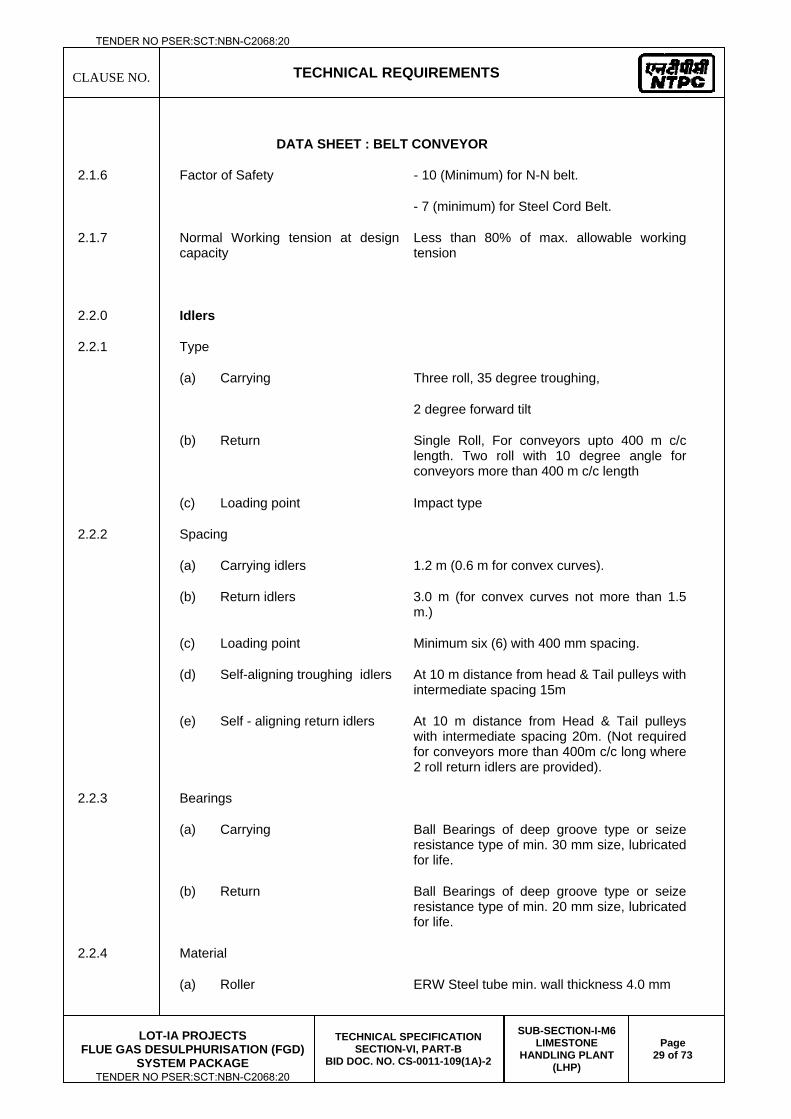
CLAUSE NO.
TECHNICAL REQUIREMENTS
LOT-IA PROJECTS
FLUE GAS DESULPHURISATION (FGD) SYSTEM PACKAGE
TECHNICAL SPECIFICATION SECTION-VI, PART-B
BID DOC. NO. CS-0011-109(1A)-2
SUB-SECTION-I-M6 LIMESTONE
HANDLING PLANT (LHP)
Page 29 of 73
DATA SHEET : BELT CONVEYOR
2.1.6 Factor of Safety - 10 (Minimum) for N-N belt.
- 7 (minimum) for Steel Cord Belt.
2.1.7 Normal Working tension at design capacity
Less than 80% of max. allowable working tension
2.2.0 Idlers
2.2.1 Type
(a) Carrying Three roll, 35 degree troughing,
2 degree forward tilt
(b) Return
Single Roll, For conveyors upto 400 m c/c length. Two roll with 10 degree angle for conveyors more than 400 m c/c length
(c) Loading point Impact type
2.2.2 Spacing
(a) Carrying idlers 1.2 m (0.6 m for convex curves).
(b) Return idlers 3.0 m (for convex curves not more than 1.5 m.)
(c) Loading point Minimum six (6) with 400 mm spacing.
(d) Self-aligning troughing idlers At 10 m distance from head & Tail pulleys with intermediate spacing 15m
(e) Self - aligning return idlers At 10 m distance from Head & Tail pulleys with intermediate spacing 20m. (Not required for conveyors more than 400m c/c long where 2 roll return idlers are provided).
2.2.3 Bearings
(a) Carrying Ball Bearings of deep groove type or seize resistance type of min. 30 mm size, lubricated for life.
(b) Return Ball Bearings of deep groove type or seize resistance type of min. 20 mm size, lubricated for life.
2.2.4 Material
(a) Roller ERW Steel tube min. wall thickness 4.0 mm
TENDER NO PSER:SCT:NBN-C2068:20
TENDER NO PSER:SCT:NBN-C2068:20
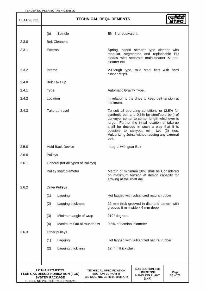
CLAUSE NO.
TECHNICAL REQUIREMENTS
LOT-IA PROJECTS
FLUE GAS DESULPHURISATION (FGD) SYSTEM PACKAGE
TECHNICAL SPECIFICATION SECTION-VI, PART-B
BID DOC. NO. CS-0011-109(1A)-2
SUB-SECTION-I-M6 LIMESTONE
HANDLING PLANT (LHP)
Page 30 of 73
(b) Spindle EN- 8 or equivalent.
2.3.0 Belt Cleaners
2.3.1 External Spring loaded scraper type cleaner with modular, segmented and replaceable PU blades with separate main-cleaner & pre-cleaner etc.
2.3.2 Internal V-Plough type, mild steel flats with hard rubber strips.
2.4.0 Belt Take up
2.4.1 Type Automatic Gravity Type.
2.4.2 Location In relation to the drive to keep belt tension at minimum.
2.4.3 Take-up travel To suit all operating conditions or (2.5% for synthetic belt and 0.5% for steel/cord belt) of conveyor center to center length whichever is larger. Further the initial location of take-up shall be decided in such a way that it is possible to carryout min. two (2) nos. Vulcanizing Joints without adding any external belt.
2.5.0 Hold Back Device Integral with gear Box
2.6.0 Pulleys
2.6.1 General (for all types of Pulleys)
Pulley shaft diameter Margin of minimum 20% shall be Considered on maximum tension at design capacity for arriving at the shaft dia.
2.6.2 Drive Pulleys
(1) Lagging Hot lagged with vulcanized natural rubber
(2) Lagging thickness 12 mm thick grooved in diamond pattern with grooves 6 mm wide x 6 mm deep
(3) Minimum angle of wrap 210° degrees
(4) Maximum Out of roundness 0.5% of nominal diameter
2.6.3 Other pulleys
(1) Lagging Hot lagged with vulcanized natural rubber
(2) Lagging thickness 12 mm thick plain
TENDER NO PSER:SCT:NBN-C2068:20
TENDER NO PSER:SCT:NBN-C2068:20
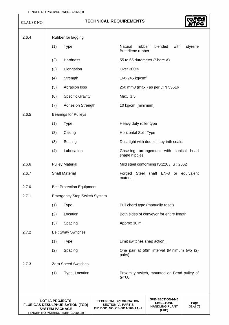
CLAUSE NO.
TECHNICAL REQUIREMENTS
LOT-IA PROJECTS
FLUE GAS DESULPHURISATION (FGD) SYSTEM PACKAGE
TECHNICAL SPECIFICATION SECTION-VI, PART-B
BID DOC. NO. CS-0011-109(1A)-2
SUB-SECTION-I-M6 LIMESTONE
HANDLING PLANT (LHP)
Page 31 of 73
2.6.4 Rubber for lagging
(1) Type Natural rubber blended with styrene Butadiene rubber.
(2) Hardness 55 to 65 durometer (Shore A)
(3) Elongation Over 300%
(4) Strength 160-245 kg/cm2
(5) Abrasion loss 250 mm3 (max.) as per DIN 53516
(6) Specific Gravity Max. 1.5
(7) Adhesion Strength 10 kg/cm (minimum)
2.6.5 Bearings for Pulleys
(1) Type Heavy duty roller type
(2) Casing Horizontal Split Type
(3) Sealing Dust tight with double labyrinth seals.
(4) Lubrication Greasing arrangement with conical head shape nipples.
2.6.6 Pulley Material Mild steel conforming IS:226 / IS : 2062
2.6.7 Shaft Material Forged Steel shaft EN-8 or equivalent material.
2.7.0 Belt Protection Equipment
2.7.1 Emergency Stop Switch System
(1) Type Pull chord type (manually reset)
(2) Location Both sides of conveyor for entire length
(3) Spacing Approx 30 m
2.7.2 Belt Sway Switches
(1) Type Limit switches snap action.
(2) Spacing One pair at 50m interval (Minimum two (2) pairs)
2.7.3 Zero Speed Switches
(1) Type, Location Proximity switch, mounted on Bend pulley of GTU.
TENDER NO PSER:SCT:NBN-C2068:20
TENDER NO PSER:SCT:NBN-C2068:20
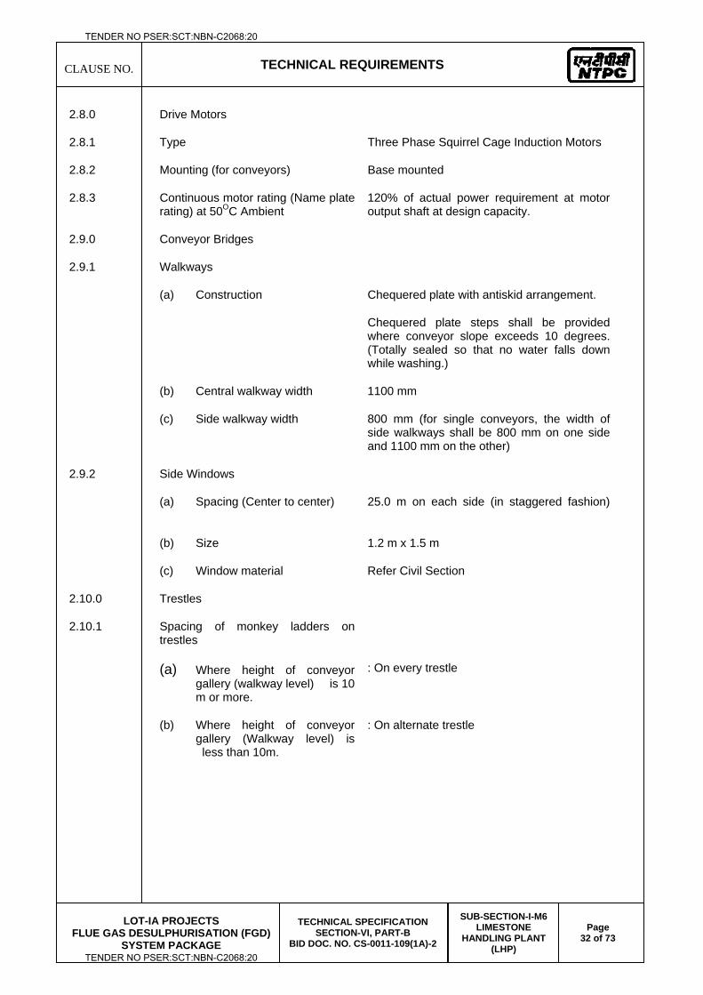
CLAUSE NO.
TECHNICAL REQUIREMENTS
LOT-IA PROJECTS
FLUE GAS DESULPHURISATION (FGD) SYSTEM PACKAGE
TECHNICAL SPECIFICATION SECTION-VI, PART-B
BID DOC. NO. CS-0011-109(1A)-2
SUB-SECTION-I-M6 LIMESTONE
HANDLING PLANT (LHP)
Page 32 of 73
2.8.0 Drive Motors
2.8.1 Type Three Phase Squirrel Cage Induction Motors
2.8.2 Mounting (for conveyors) Base mounted
2.8.3 Continuous motor rating (Name plate rating) at 50OC Ambient
120% of actual power requirement at motor output shaft at design capacity.
2.9.0 Conveyor Bridges
2.9.1 Walkways
(a) Construction Chequered plate with antiskid arrangement.
Chequered plate steps shall be provided where conveyor slope exceeds 10 degrees. (Totally sealed so that no water falls down while washing.)
(b) Central walkway width 1100 mm
(c) Side walkway width 800 mm (for single conveyors, the width of side walkways shall be 800 mm on one side and 1100 mm on the other)
2.9.2 Side Windows
(a) Spacing (Center to center) 25.0 m on each side (in staggered fashion)
(b) Size 1.2 m x 1.5 m
(c) Window material Refer Civil Section
2.10.0 Trestles
2.10.1 Spacing of monkey ladders on trestles
(a) Where height of conveyor gallery (walkway level) is 10 m or more.
: On every trestle
(b) Where height of conveyor gallery (Walkway level) is less than 10m.
: On alternate trestle
TENDER NO PSER:SCT:NBN-C2068:20
TENDER NO PSER:SCT:NBN-C2068:20
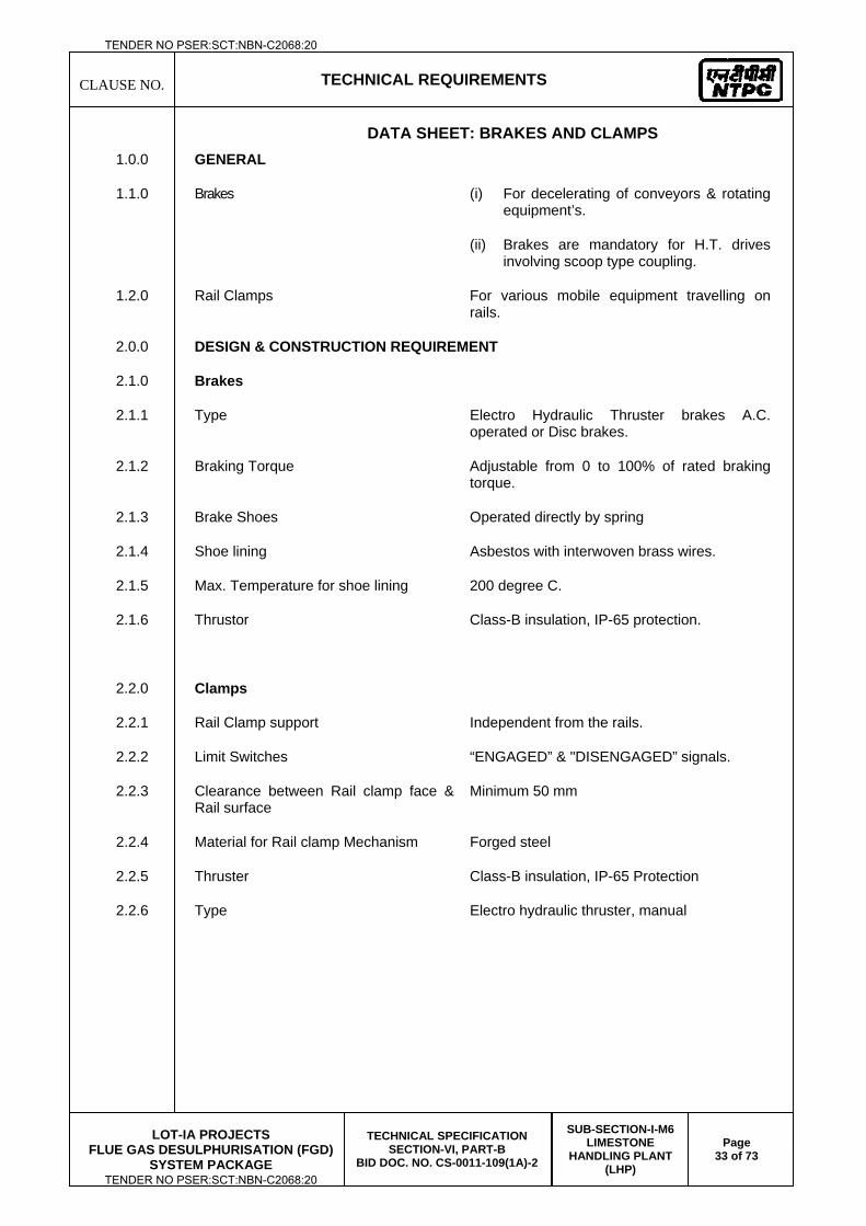
CLAUSE NO.
TECHNICAL REQUIREMENTS
LOT-IA PROJECTS
FLUE GAS DESULPHURISATION (FGD) SYSTEM PACKAGE
TECHNICAL SPECIFICATION SECTION-VI, PART-B
BID DOC. NO. CS-0011-109(1A)-2
SUB-SECTION-I-M6 LIMESTONE
HANDLING PLANT (LHP)
Page 33 of 73
DATA SHEET: BRAKES AND CLAMPS 1.0.0 GENERAL
1.1.0 Brakes (i) For decelerating of conveyors & rotating equipment’s.
(ii) Brakes are mandatory for H.T. drives involving scoop type coupling.
1.2.0 Rail Clamps For various mobile equipment travelling on rails.
2.0.0 DESIGN & CONSTRUCTION REQUIREMENT
2.1.0 Brakes
2.1.1 Type Electro Hydraulic Thruster brakes A.C. operated or Disc brakes.
2.1.2 Braking Torque Adjustable from 0 to 100% of rated braking torque.
2.1.3 Brake Shoes Operated directly by spring
2.1.4 Shoe lining Asbestos with interwoven brass wires.
2.1.5 Max. Temperature for shoe lining 200 degree C.
2.1.6 Thrustor Class-B insulation, IP-65 protection.
2.2.0 Clamps
2.2.1 Rail Clamp support Independent from the rails.
2.2.2 Limit Switches “ENGAGED” & "DISENGAGED” signals.
2.2.3 Clearance between Rail clamp face & Rail surface
Minimum 50 mm
2.2.4 Material for Rail clamp Mechanism Forged steel
2.2.5 Thruster Class-B insulation, IP-65 Protection
2.2.6 Type Electro hydraulic thruster, manual
TENDER NO PSER:SCT:NBN-C2068:20
TENDER NO PSER:SCT:NBN-C2068:20
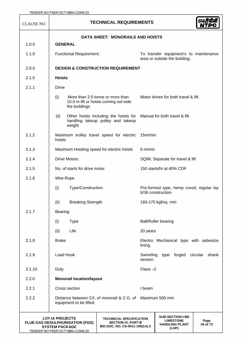
CLAUSE NO.
TECHNICAL REQUIREMENTS
LOT-IA PROJECTS
FLUE GAS DESULPHURISATION (FGD) SYSTEM PACKAGE
TECHNICAL SPECIFICATION SECTION-VI, PART-B
BID DOC. NO. CS-0011-109(1A)-2
SUB-SECTION-I-M6 LIMESTONE
HANDLING PLANT (LHP)
Page 34 of 73
DATA SHEET: MONORAILS AND HOISTS
1.0.0 GENERAL
1.1.0 Functional Requirement : To transfer equipment’s to maintenance area or outside the building.
2.0.0 DESIGN & CONSTRUCTION REQUIREMENT
2.1.0 Hoists
2.1.1 Drive
(i) More than 2.0 tonne or more than 10.0 m lift or hoists coming out-side the buildings
Motor driven for both travel & lift.
(ii) Other hoists including the hoists for handling takeup pulley and takeup weight
Manual for both travel & lift.
2.1.2 Maximum trolley travel speed for electric hoists
15m/min
2.1.3 Maximum Hoisting speed for electric hoists 6 m/min
2.1.4 Drive Motors SQIM, Separate for travel & lift
2.1.5 No. of starts for drive motor 150 starts/hr at 40% CDF
2.1.6 Wire Rope
(i) Type/Construction Pre-formed type, hemp cored, regular lay 6/36 construction
(ii) Breaking Strength 160-175 kgf/sq. mm
2.1.7 Bearing
(i) Type Ball/Roller bearing
(ii) Life 20 years
2.1.8 Brake Electro Mechanical type with asbestos lining.
2.1.9 Load Hook Swiveling type forged circular shank section.
2.1.10 Duty Class –2
2.2.0 Monorail location/layout
2.2.1 Cross section I beam
2.2.2 Distance between C/L of monorail & C.G. of equipment to be lifted
Maximum 500 mm
TENDER NO PSER:SCT:NBN-C2068:20
TENDER NO PSER:SCT:NBN-C2068:20
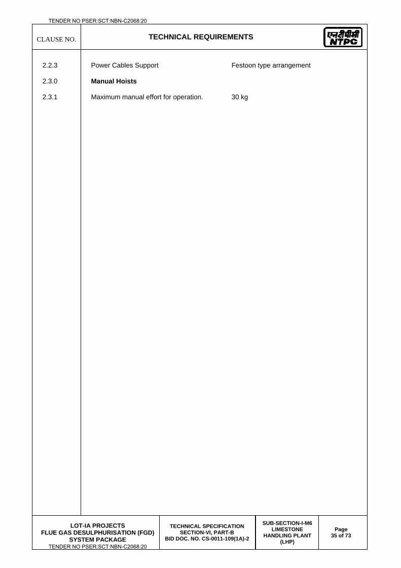
CLAUSE NO.
TECHNICAL REQUIREMENTS
LOT-IA PROJECTS
FLUE GAS DESULPHURISATION (FGD) SYSTEM PACKAGE
TECHNICAL SPECIFICATION SECTION-VI, PART-B
BID DOC. NO. CS-0011-109(1A)-2
SUB-SECTION-I-M6 LIMESTONE
HANDLING PLANT (LHP)
Page 35 of 73
2.2.3 Power Cables Support Festoon type arrangement
2.3.0 Manual Hoists
2.3.1 Maximum manual effort for operation. 30 kg
TENDER NO PSER:SCT:NBN-C2068:20
TENDER NO PSER:SCT:NBN-C2068:20
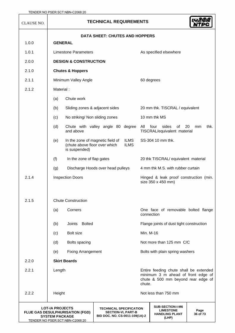
CLAUSE NO.
TECHNICAL REQUIREMENTS
LOT-IA PROJECTS
FLUE GAS DESULPHURISATION (FGD) SYSTEM PACKAGE
TECHNICAL SPECIFICATION SECTION-VI, PART-B
BID DOC. NO. CS-0011-109(1A)-2
SUB-SECTION-I-M6 LIMESTONE
HANDLING PLANT (LHP)
Page 36 of 73
DATA SHEET: CHUTES AND HOPPERS
1.0.0 GENERAL
1.0.1 Limestone Parameters As specified elsewhere
2.0.0 DESIGN & CONSTRUCTION
2.1.0 Chutes & Hoppers
2.1.1 Minimum Valley Angle 60 degrees
2.1.2 Material :
(a) Chute work
(b) Sliding zones & adjacent sides 20 mm thk. TISCRAL / equivalent
(c) No striking/ Non sliding zones 10 mm thk MS
(d) Chute with valley angle 80 degree and above
All four sides of 20 mm thk. TISCRAL/equivalent material
(e) In the zone of magnetic field of ILMS (chute above floor over which ILMS is suspended)
SS-304 10 mm thk.
(f) In the zone of flap gates 20 thk TISCRAL/ equivalent material
(g) Discharge Hoods over head pulleys 4 mm thk M.S. with rubber curtain
2.1.4 Inspection Doors Hinged & leak proof construction (min. size 350 x 450 mm)
2.1.5 Chute Construction
(a) Corners One face of removable bolted flange connection
(b) Joints Bolted Flange joints of dust tight construction
(c) Bolt size Min. M-16
(d) Bolts spacing Not more than 125 mm C/C
(e) Fixing Arrangement Bolts with plain spring washers
2.2.0 Skirt Boards
2.2.1 Length Entire feeding chute shall be extended minimum 3 m ahead of front edge of chute & 500 mm beyond rear edge of chute.
2.2.2 Height Not less than 750 mm
TENDER NO PSER:SCT:NBN-C2068:20
TENDER NO PSER:SCT:NBN-C2068:20
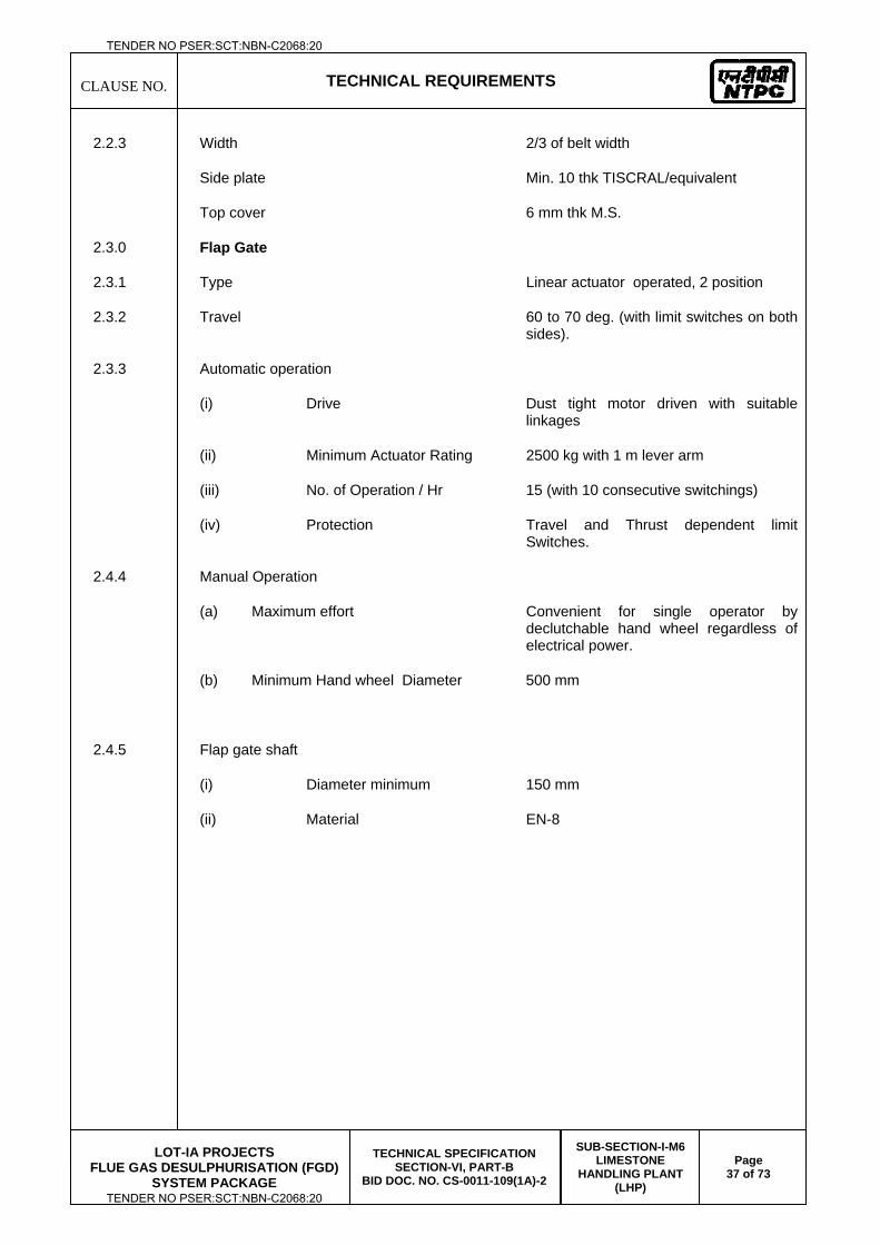
CLAUSE NO.
TECHNICAL REQUIREMENTS
LOT-IA PROJECTS
FLUE GAS DESULPHURISATION (FGD) SYSTEM PACKAGE
TECHNICAL SPECIFICATION SECTION-VI, PART-B
BID DOC. NO. CS-0011-109(1A)-2
SUB-SECTION-I-M6 LIMESTONE
HANDLING PLANT (LHP)
Page 37 of 73
2.2.3 Width 2/3 of belt width
Side plate Min. 10 thk TISCRAL/equivalent
Top cover 6 mm thk M.S.
2.3.0 Flap Gate
2.3.1 Type Linear actuator operated, 2 position
2.3.2 Travel 60 to 70 deg. (with limit switches on both sides).
2.3.3 Automatic operation
(i) Drive Dust tight motor driven with suitable linkages
(ii) Minimum Actuator Rating 2500 kg with 1 m lever arm
(iii) No. of Operation / Hr 15 (with 10 consecutive switchings)
(iv) Protection Travel and Thrust dependent limit Switches.
2.4.4 Manual Operation
(a) Maximum effort Convenient for single operator by declutchable hand wheel regardless of electrical power.
(b) Minimum Hand wheel Diameter 500 mm
2.4.5 Flap gate shaft
(i) Diameter minimum 150 mm
(ii) Material EN-8
TENDER NO PSER:SCT:NBN-C2068:20
TENDER NO PSER:SCT:NBN-C2068:20
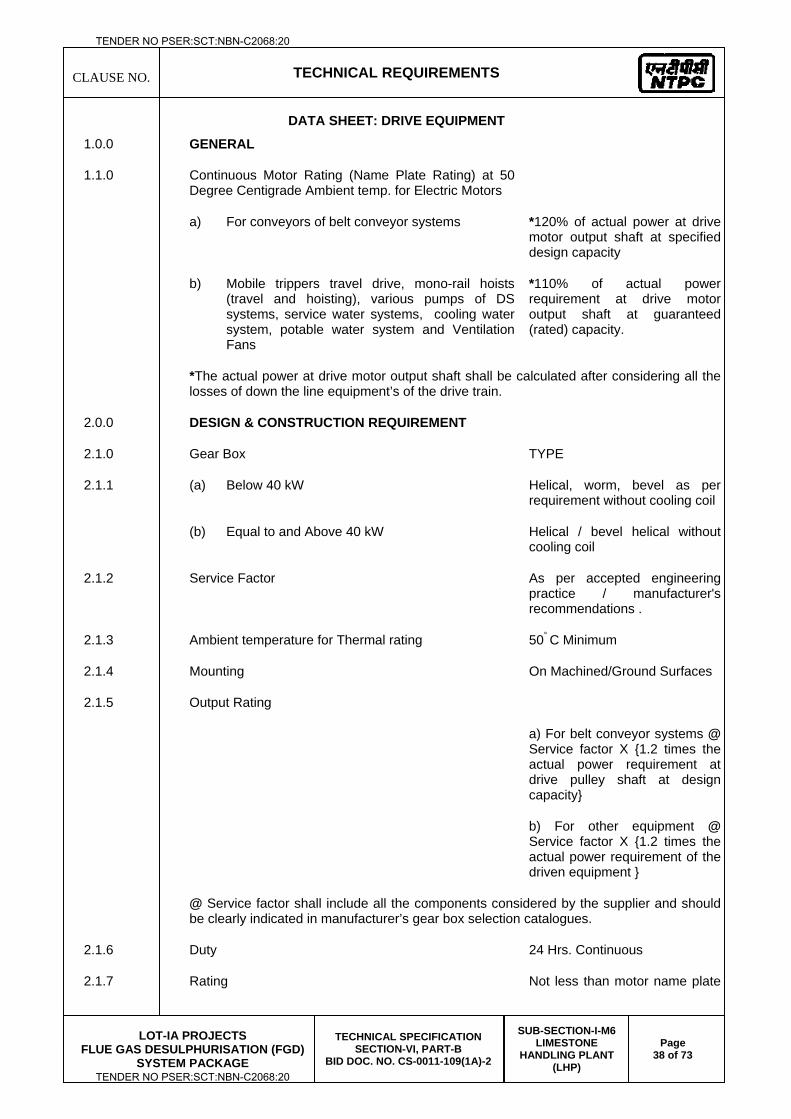
CLAUSE NO.
TECHNICAL REQUIREMENTS
LOT-IA PROJECTS
FLUE GAS DESULPHURISATION (FGD) SYSTEM PACKAGE
TECHNICAL SPECIFICATION SECTION-VI, PART-B
BID DOC. NO. CS-0011-109(1A)-2
SUB-SECTION-I-M6 LIMESTONE
HANDLING PLANT (LHP)
Page 38 of 73
DATA SHEET: DRIVE EQUIPMENT
1.0.0 GENERAL
1.1.0 Continuous Motor Rating (Name Plate Rating) at 50 Degree Centigrade Ambient temp. for Electric Motors
a) For conveyors of belt conveyor systems *120% of actual power at drive motor output shaft at specified design capacity
b) Mobile trippers travel drive, mono-rail hoists (travel and hoisting), various pumps of DS systems, service water systems, cooling water system, potable water system and Ventilation Fans
*110% of actual power requirement at drive motor output shaft at guaranteed (rated) capacity.
*The actual power at drive motor output shaft shall be calculated after considering all the losses of down the line equipment’s of the drive train.
2.0.0 DESIGN & CONSTRUCTION REQUIREMENT
2.1.0 Gear Box TYPE
2.1.1 (a) Below 40 kW Helical, worm, bevel as per requirement without cooling coil
(b) Equal to and Above 40 kW Helical / bevel helical without cooling coil
2.1.2 Service Factor As per accepted engineering practice / manufacturer's recommendations .
2.1.3 Ambient temperature for Thermal rating 50° C Minimum
2.1.4 Mounting On Machined/Ground Surfaces
2.1.5 Output Rating
a) For belt conveyor systems @ Service factor X {1.2 times the actual power requirement at drive pulley shaft at design capacity}
b) For other equipment @ Service factor X {1.2 times the actual power requirement of the driven equipment }
@ Service factor shall include all the components considered by the supplier and should be clearly indicated in manufacturer’s gear box selection catalogues.
2.1.6 Duty 24 Hrs. Continuous
2.1.7 Rating Not less than motor name plate
TENDER NO PSER:SCT:NBN-C2068:20
TENDER NO PSER:SCT:NBN-C2068:20
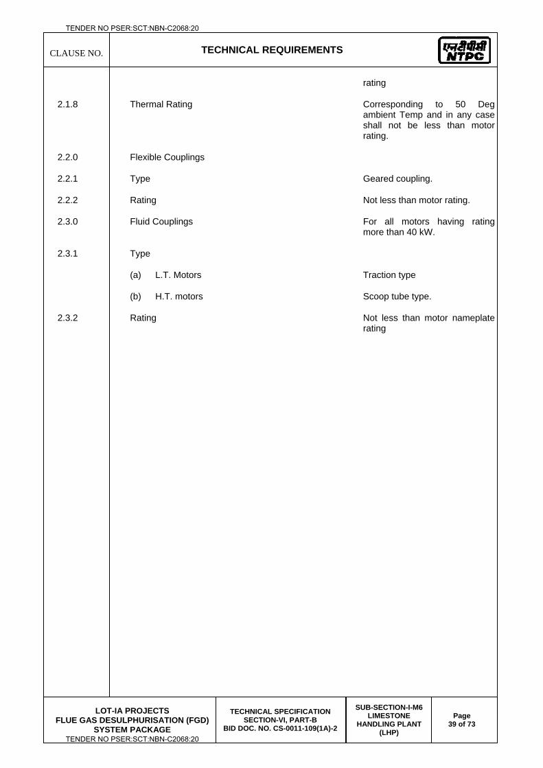
CLAUSE NO.
TECHNICAL REQUIREMENTS
LOT-IA PROJECTS
FLUE GAS DESULPHURISATION (FGD) SYSTEM PACKAGE
TECHNICAL SPECIFICATION SECTION-VI, PART-B
BID DOC. NO. CS-0011-109(1A)-2
SUB-SECTION-I-M6 LIMESTONE
HANDLING PLANT (LHP)
Page 39 of 73
rating
2.1.8 Thermal Rating Corresponding to 50 Deg ambient Temp and in any case shall not be less than motor rating.
2.2.0 Flexible Couplings
2.2.1 Type Geared coupling.
2.2.2 Rating Not less than motor rating.
2.3.0 Fluid Couplings For all motors having rating more than 40 kW.
2.3.1 Type
(a) L.T. Motors Traction type
(b) H.T. motors Scoop tube type.
2.3.2 Rating Not less than motor nameplate rating
TENDER NO PSER:SCT:NBN-C2068:20
TENDER NO PSER:SCT:NBN-C2068:20
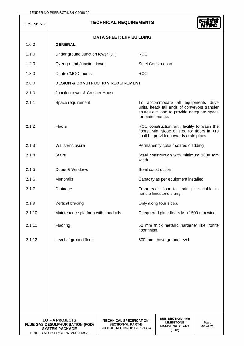
CLAUSE NO.
TECHNICAL REQUIREMENTS
LOT-IA PROJECTS
FLUE GAS DESULPHURISATION (FGD) SYSTEM PACKAGE
TECHNICAL SPECIFICATION SECTION-VI, PART-B
BID DOC. NO. CS-0011-109(1A)-2
SUB-SECTION-I-M6 LIMESTONE
HANDLING PLANT (LHP)
Page 40 of 73
DATA SHEET: LHP BUILDING
1.0.0 GENERAL
1.1.0 Under ground Junction tower (JT) RCC
1.2.0 Over ground Junction tower Steel Construction
1.3.0 Control/MCC rooms RCC
2.0.0 DESIGN & CONSTRUCTION REQUIREMENT
2.1.0 Junction tower & Crusher House
2.1.1 Space requirement To accommodate all equipments drive units, head/ tail ends of conveyors transfer chutes etc. and to provide adequate space for maintenance.
2.1.2 Floors RCC construction with facility to wash the floors. Min. slope of 1:80 for floors in JTs shall be provided towards drain pipes.
2.1.3 Walls/Enclosure Permanently colour coated cladding
2.1.4 Stairs Steel construction with minimum 1000 mm width.
2.1.5 Doors & Windows Steel construction
2.1.6 Monorails Capacity as per equipment installed
2.1.7 Drainage From each floor to drain pit suitable to handle limestone slurry.
2.1.9 Vertical bracing Only along four sides.
2.1.10 Maintenance platform with handrails. Chequered plate floors Min.1500 mm wide
2.1.11 Flooring 50 mm thick metallic hardener like ironite floor finish.
2.1.12 Level of ground floor 500 mm above ground level.
TENDER NO PSER:SCT:NBN-C2068:20
TENDER NO PSER:SCT:NBN-C2068:20
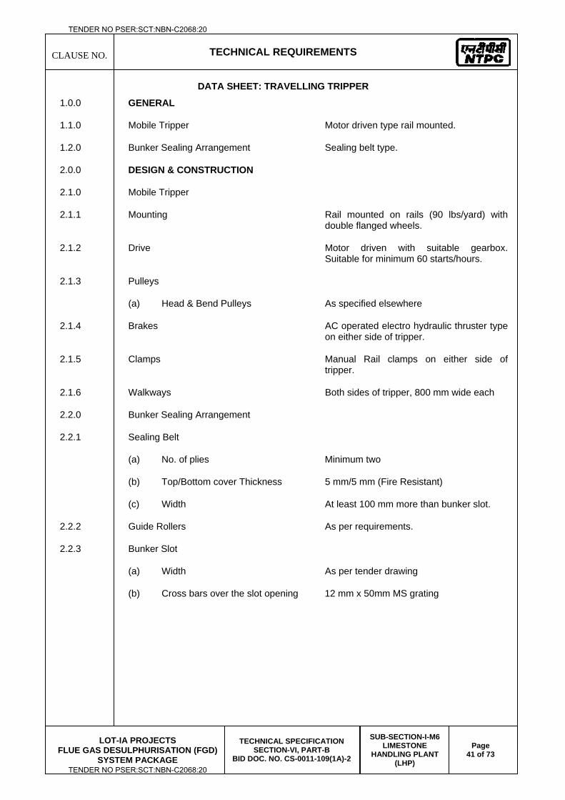
CLAUSE NO.
TECHNICAL REQUIREMENTS
LOT-IA PROJECTS
FLUE GAS DESULPHURISATION (FGD) SYSTEM PACKAGE
TECHNICAL SPECIFICATION SECTION-VI, PART-B
BID DOC. NO. CS-0011-109(1A)-2
SUB-SECTION-I-M6 LIMESTONE
HANDLING PLANT (LHP)
Page 41 of 73
DATA SHEET: TRAVELLING TRIPPER
1.0.0 GENERAL
1.1.0 Mobile Tripper Motor driven type rail mounted.
1.2.0 Bunker Sealing Arrangement Sealing belt type.
2.0.0 DESIGN & CONSTRUCTION
2.1.0 Mobile Tripper
2.1.1 Mounting Rail mounted on rails (90 lbs/yard) with double flanged wheels.
2.1.2 Drive Motor driven with suitable gearbox. Suitable for minimum 60 starts/hours.
2.1.3 Pulleys
(a) Head & Bend Pulleys As specified elsewhere
2.1.4 Brakes AC operated electro hydraulic thruster type on either side of tripper.
2.1.5 Clamps Manual Rail clamps on either side of tripper.
2.1.6 Walkways Both sides of tripper, 800 mm wide each
2.2.0 Bunker Sealing Arrangement
2.2.1 Sealing Belt
(a) No. of plies Minimum two
(b) Top/Bottom cover Thickness 5 mm/5 mm (Fire Resistant)
(c) Width At least 100 mm more than bunker slot.
2.2.2 Guide Rollers As per requirements.
2.2.3 Bunker Slot
(a) Width As per tender drawing
(b) Cross bars over the slot opening 12 mm x 50mm MS grating
TENDER NO PSER:SCT:NBN-C2068:20
TENDER NO PSER:SCT:NBN-C2068:20
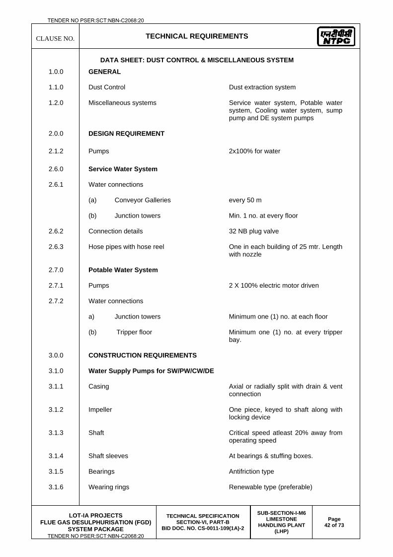
CLAUSE NO.
TECHNICAL REQUIREMENTS
LOT-IA PROJECTS
FLUE GAS DESULPHURISATION (FGD) SYSTEM PACKAGE
TECHNICAL SPECIFICATION SECTION-VI, PART-B
BID DOC. NO. CS-0011-109(1A)-2
SUB-SECTION-I-M6 LIMESTONE
HANDLING PLANT (LHP)
Page 42 of 73
DATA SHEET: DUST CONTROL & MISCELLANEOUS SYSTEM
1.0.0 GENERAL
1.1.0 Dust Control Dust extraction system
1.2.0 Miscellaneous systems Service water system, Potable water system, Cooling water system, sump pump and DE system pumps
2.0.0 DESIGN REQUIREMENT
2.1.2 Pumps 2x100% for water
2.6.0 Service Water System
2.6.1 Water connections
(a) Conveyor Galleries every 50 m
(b) Junction towers Min. 1 no. at every floor
2.6.2 Connection details 32 NB plug valve
2.6.3 Hose pipes with hose reel One in each building of 25 mtr. Length with nozzle
2.7.0 Potable Water System
2.7.1 Pumps 2 X 100% electric motor driven
2.7.2 Water connections
a) Junction towers Minimum one (1) no. at each floor
(b) Tripper floor Minimum one (1) no. at every tripper bay.
3.0.0 CONSTRUCTION REQUIREMENTS
3.1.0 Water Supply Pumps for SW/PW/CW/DE
3.1.1 Casing Axial or radially split with drain & vent connection
3.1.2 Impeller One piece, keyed to shaft along with locking device
3.1.3 Shaft Critical speed atleast 20% away from operating speed
3.1.4 Shaft sleeves At bearings & stuffing boxes.
3.1.5 Bearings Antifriction type
3.1.6 Wearing rings Renewable type (preferable)
TENDER NO PSER:SCT:NBN-C2068:20
TENDER NO PSER:SCT:NBN-C2068:20
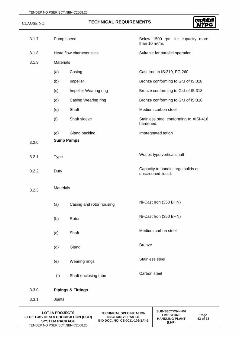
CLAUSE NO.
TECHNICAL REQUIREMENTS
LOT-IA PROJECTS
FLUE GAS DESULPHURISATION (FGD) SYSTEM PACKAGE
TECHNICAL SPECIFICATION SECTION-VI, PART-B
BID DOC. NO. CS-0011-109(1A)-2
SUB-SECTION-I-M6 LIMESTONE
HANDLING PLANT (LHP)
Page 43 of 73
3.1.7 Pump speed Below 1500 rpm for capacity more than 10 m³/hr.
3.1.8 Head flow characteristics Suitable for parallel operation.
3.1.9 Materials
(a) Casing Cast Iron to IS:210, FG 260
(b) Impeller Bronze conforming to Gr.I of IS:318
(c) Impeller Wearing ring Bronze conforming to Gr.I of IS:318
(d) Casing Wearing ring Bronze conforming to Gr.I of IS:318
(e) Shaft Medium carbon steel
(f) Shaft sleeve Stainless steel conforming to AISI-416 hardened.
(g) Gland packing Impregnated teflon
3.2.0 Sump Pumps
3.2.1 Type Wet pit type vertical shaft
3.2.2 Duty Capacity to handle large solids or unscreened liquid.
3.2.3 Materials
(a) Casing and rotor housing Ni-Cast Iron (350 BHN)
(b) Rotor Ni-Cast Iron (350 BHN)
(c) Shaft Medium carbon steel
(d) Gland Bronze
(e) Wearing rings Stainless steel
(f) Shaft enclosing tube Carbon steel
3.3.0 Pipings & Fittings
3.3.1 Joints
TENDER NO PSER:SCT:NBN-C2068:20
TENDER NO PSER:SCT:NBN-C2068:20
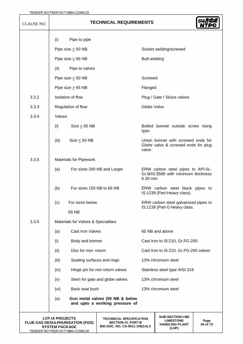
CLAUSE NO.
TECHNICAL REQUIREMENTS
LOT-IA PROJECTS
FLUE GAS DESULPHURISATION (FGD) SYSTEM PACKAGE
TECHNICAL SPECIFICATION SECTION-VI, PART-B
BID DOC. NO. CS-0011-109(1A)-2
SUB-SECTION-I-M6 LIMESTONE
HANDLING PLANT (LHP)
Page 44 of 73
(i) Pipe to pipe
Pipe size < 50 NB
Pipe size > 65 NB
Socket welding/screwed
Butt welding
(ii) Pipe to valves
Pipe size < 50 NB
Pipe size > 65 NB
Screwed
Flanged
3.3.2 Isolation of flow Plug / Gate / Sluice valves
3.3.3 Regulation of flow Globe Valve
3.3.4 Valves
(i) Size > 65 NB Bolted bonnet outside screw rising type.
(iii) Size < 50 NB
Union bonnet with screwed ends for Globe valve & screwed ends for plug valve
3.3.5 Materials for Pipework
(a) For sizes 200 NB and Larger ERW carbon steel pipes to API-5L-Gr.B/IS:3589 with minimum thickness 6.35 mm
(b) For sizes 150 NB to 65 NB ERW carbon steel black pipes to IS:1239 (Part-Heavy class).
(c) For sizes below
65 NB
ERW carbon steel galvanized pipes to IS:1239 (Part-I) Heavy class.
3.3.6 Materials for Valves & Specialities
(a) Cast Iron Valves 65 NB and above
(i) Body and bonnet Cast Iron to IS:210, Gr.FG-200
(ii) Disc for non- return Cast Iron to IS:210, Gr.FG-200 valves
(iii) Seating surfaces and rings 13% chromium steel
(iv) Hinge pin for non return valves Stainless steel type AISI-316
(v) Stem for gate and globe valves 13% chromium steel
(vi) Back seat bush 13% chromium steel
(a) Gun metal valves (50 NB & below and upto a working pressure of
TENDER NO PSER:SCT:NBN-C2068:20
TENDER NO PSER:SCT:NBN-C2068:20
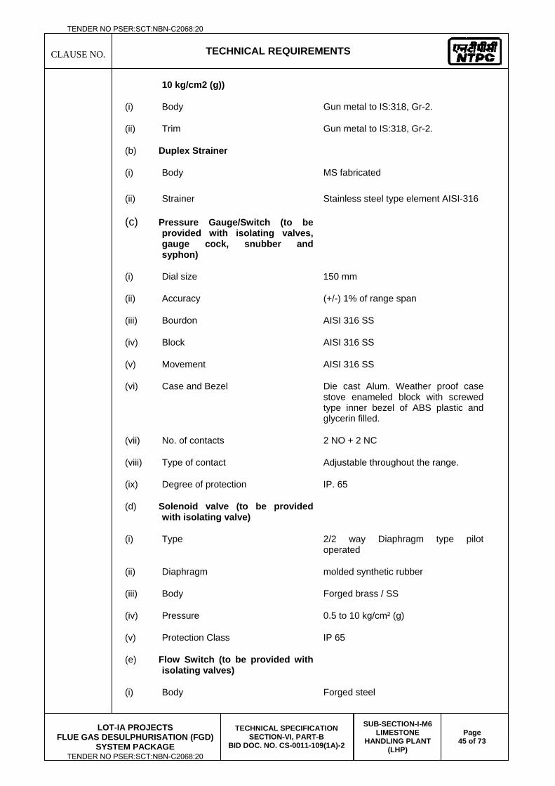
CLAUSE NO.
TECHNICAL REQUIREMENTS
LOT-IA PROJECTS
FLUE GAS DESULPHURISATION (FGD) SYSTEM PACKAGE
TECHNICAL SPECIFICATION SECTION-VI, PART-B
BID DOC. NO. CS-0011-109(1A)-2
SUB-SECTION-I-M6 LIMESTONE
HANDLING PLANT (LHP)
Page 45 of 73
10 kg/cm2 (g))
(i) Body Gun metal to IS:318, Gr-2.
(ii) Trim Gun metal to IS:318, Gr-2.
(b) Duplex Strainer
(i) Body MS fabricated
(ii) Strainer Stainless steel type element AISI-316
(c) Pressure Gauge/Switch (to be provided with isolating valves, gauge cock, snubber and syphon)
(i) Dial size 150 mm
(ii) Accuracy (+/-) 1% of range span
(iii) Bourdon AISI 316 SS
(iv) Block AISI 316 SS
(v) Movement AISI 316 SS
(vi) Case and Bezel Die cast Alum. Weather proof case stove enameled block with screwed type inner bezel of ABS plastic and glycerin filled.
(vii) No. of contacts 2 NO + 2 NC
(viii) Type of contact Adjustable throughout the range.
(ix) Degree of protection IP. 65
(d) Solenoid valve (to be provided with isolating valve)
(i) Type 2/2 way Diaphragm type pilot operated
(ii) Diaphragm molded synthetic rubber
(iii) Body Forged brass / SS
(iv) Pressure 0.5 to 10 kg/cm² (g)
(v) Protection Class IP 65
(e) Flow Switch (to be provided with isolating valves)
(i) Body Forged steel
TENDER NO PSER:SCT:NBN-C2068:20
TENDER NO PSER:SCT:NBN-C2068:20
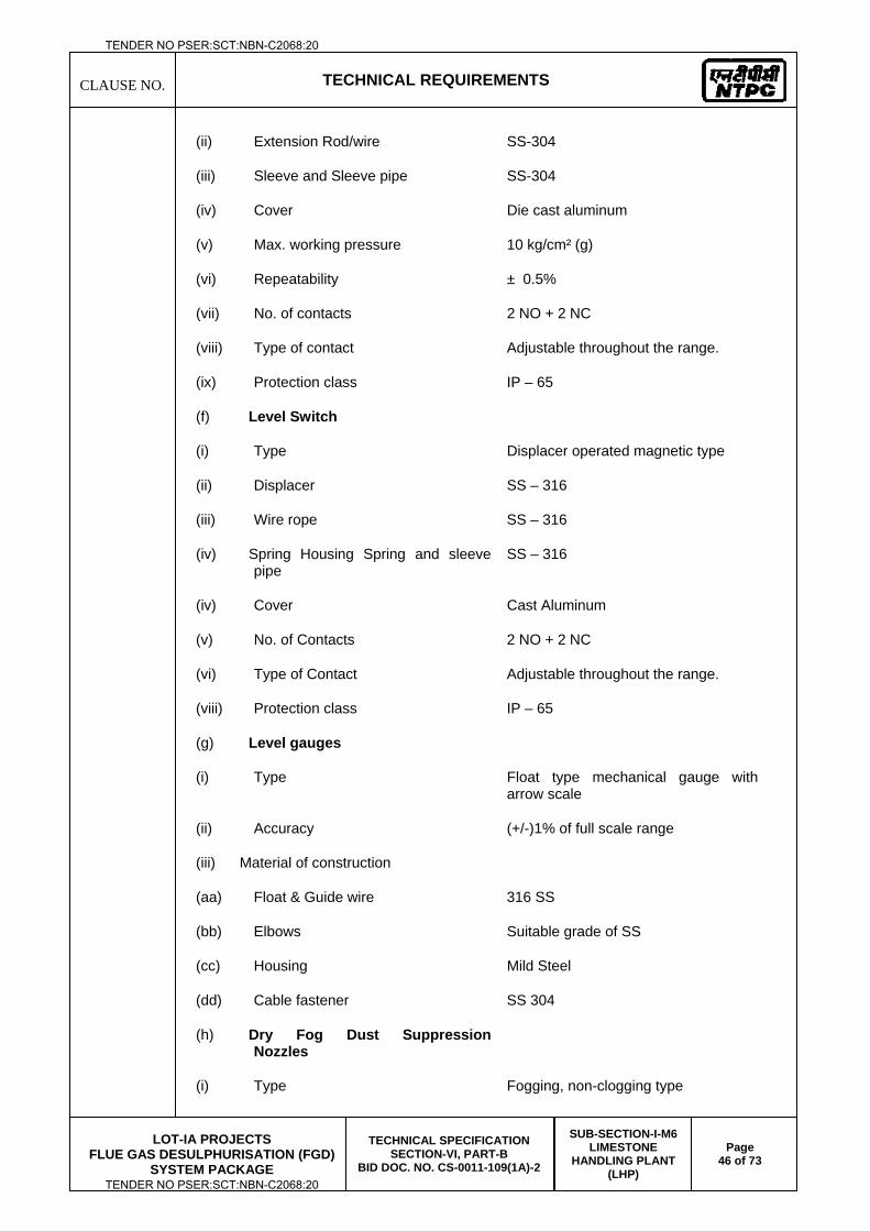
CLAUSE NO.
TECHNICAL REQUIREMENTS
LOT-IA PROJECTS
FLUE GAS DESULPHURISATION (FGD) SYSTEM PACKAGE
TECHNICAL SPECIFICATION SECTION-VI, PART-B
BID DOC. NO. CS-0011-109(1A)-2
SUB-SECTION-I-M6 LIMESTONE
HANDLING PLANT (LHP)
Page 46 of 73
(ii) Extension Rod/wire SS-304
(iii) Sleeve and Sleeve pipe SS-304
(iv) Cover Die cast aluminum
(v) Max. working pressure 10 kg/cm² (g)
(vi) Repeatability ± 0.5%
(vii) No. of contacts 2 NO + 2 NC
(viii) Type of contact Adjustable throughout the range.
(ix) Protection class IP – 65
(f) Level Switch
(i) Type Displacer operated magnetic type
(ii) Displacer SS – 316
(iii) Wire rope SS – 316
(iv) Spring Housing Spring and sleeve pipe
SS – 316
(iv) Cover Cast Aluminum
(v) No. of Contacts 2 NO + 2 NC
(vi) Type of Contact Adjustable throughout the range.
(viii) Protection class IP – 65
(g) Level gauges
(i) Type Float type mechanical gauge with arrow scale
(ii) Accuracy (+/-)1% of full scale range
(iii) Material of construction
(aa) Float & Guide wire 316 SS
(bb) Elbows Suitable grade of SS
(cc) Housing Mild Steel
(dd) Cable fastener SS 304
(h) Dry Fog Dust Suppression Nozzles
(i) Type Fogging, non-clogging type
TENDER NO PSER:SCT:NBN-C2068:20
TENDER NO PSER:SCT:NBN-C2068:20
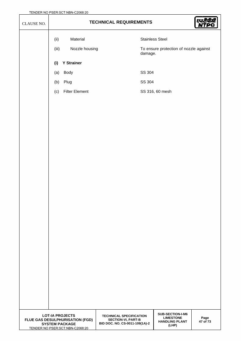
CLAUSE NO.
TECHNICAL REQUIREMENTS
LOT-IA PROJECTS
FLUE GAS DESULPHURISATION (FGD) SYSTEM PACKAGE
TECHNICAL SPECIFICATION SECTION-VI, PART-B
BID DOC. NO. CS-0011-109(1A)-2
SUB-SECTION-I-M6 LIMESTONE
HANDLING PLANT (LHP)
Page 47 of 73
(ii) Material Stainless Steel
(iii) Nozzle housing To ensure protection of nozzle against damage.
(i) Y Strainer
(a) Body SS 304
(b) Plug SS 304
(c) Filter Element SS 316, 60 mesh
TENDER NO PSER:SCT:NBN-C2068:20
TENDER NO PSER:SCT:NBN-C2068:20
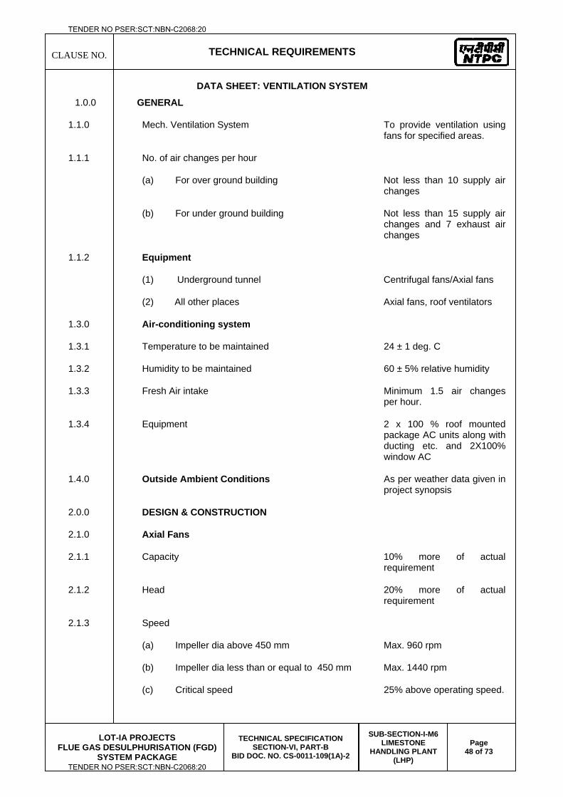
CLAUSE NO.
TECHNICAL REQUIREMENTS
LOT-IA PROJECTS
FLUE GAS DESULPHURISATION (FGD) SYSTEM PACKAGE
TECHNICAL SPECIFICATION SECTION-VI, PART-B
BID DOC. NO. CS-0011-109(1A)-2
SUB-SECTION-I-M6 LIMESTONE
HANDLING PLANT (LHP)
Page 48 of 73
DATA SHEET: VENTILATION SYSTEM
1.0.0 GENERAL
1.1.0 Mech. Ventilation System To provide ventilation using fans for specified areas.
1.1.1 No. of air changes per hour
(a) For over ground building Not less than 10 supply air changes
(b) For under ground building Not less than 15 supply air changes and 7 exhaust air changes
1.1.2 Equipment
(1) Underground tunnel Centrifugal fans/Axial fans
(2) All other places Axial fans, roof ventilators
1.3.0 Air-conditioning system
1.3.1 Temperature to be maintained 24 ± 1 deg. C
1.3.2 Humidity to be maintained 60 ± 5% relative humidity
1.3.3 Fresh Air intake Minimum 1.5 air changes per hour.
1.3.4 Equipment 2 x 100 % roof mounted package AC units along with ducting etc. and 2X100% window AC
1.4.0 Outside Ambient Conditions As per weather data given in project synopsis
2.0.0 DESIGN & CONSTRUCTION
2.1.0 Axial Fans
2.1.1 Capacity 10% more of actual requirement
2.1.2 Head 20% more of actual requirement
2.1.3 Speed
(a) Impeller dia above 450 mm Max. 960 rpm
(b) Impeller dia less than or equal to 450 mm Max. 1440 rpm
(c) Critical speed 25% above operating speed.
TENDER NO PSER:SCT:NBN-C2068:20
TENDER NO PSER:SCT:NBN-C2068:20
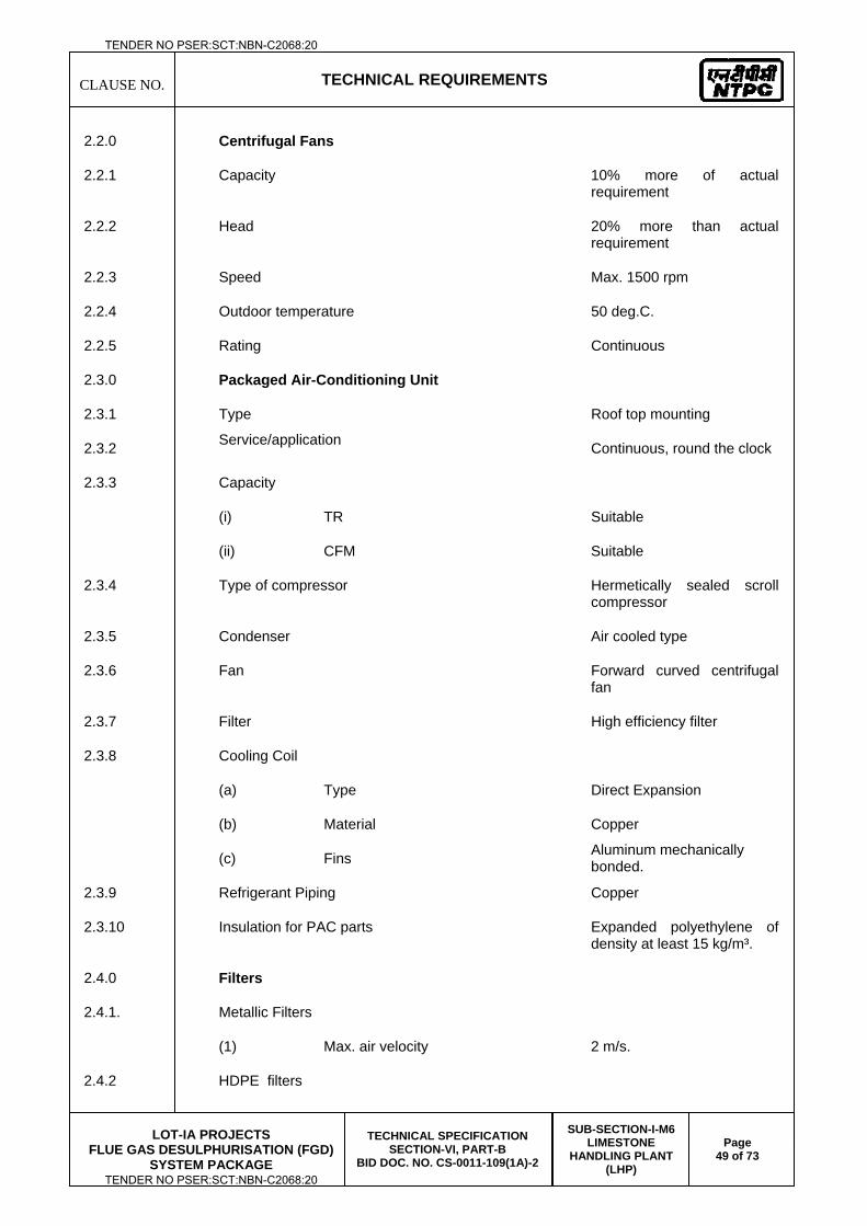
CLAUSE NO.
TECHNICAL REQUIREMENTS
LOT-IA PROJECTS
FLUE GAS DESULPHURISATION (FGD) SYSTEM PACKAGE
TECHNICAL SPECIFICATION SECTION-VI, PART-B
BID DOC. NO. CS-0011-109(1A)-2
SUB-SECTION-I-M6 LIMESTONE
HANDLING PLANT (LHP)
Page 49 of 73
2.2.0 Centrifugal Fans
2.2.1 Capacity 10% more of actual requirement
2.2.2 Head 20% more than actual requirement
2.2.3 Speed Max. 1500 rpm
2.2.4 Outdoor temperature 50 deg.C.
2.2.5 Rating Continuous
2.3.0 Packaged Air-Conditioning Unit
2.3.1 Type Roof top mounting
2.3.2 Service/application Continuous, round the clock
2.3.3 Capacity
(i) TR Suitable
(ii) CFM Suitable
2.3.4 Type of compressor Hermetically sealed scroll compressor
2.3.5 Condenser Air cooled type
2.3.6 Fan Forward curved centrifugal fan
2.3.7 Filter High efficiency filter
2.3.8 Cooling Coil
(a) Type Direct Expansion
(b) Material Copper
(c) Fins Aluminum mechanically bonded.
2.3.9 Refrigerant Piping Copper
2.3.10 Insulation for PAC parts Expanded polyethylene of density at least 15 kg/m³.
2.4.0 Filters
2.4.1. Metallic Filters
(1) Max. air velocity 2 m/s.
2.4.2 HDPE filters
TENDER NO PSER:SCT:NBN-C2068:20
TENDER NO PSER:SCT:NBN-C2068:20
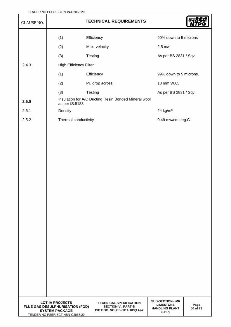
CLAUSE NO.
TECHNICAL REQUIREMENTS
LOT-IA PROJECTS
FLUE GAS DESULPHURISATION (FGD) SYSTEM PACKAGE
TECHNICAL SPECIFICATION SECTION-VI, PART-B
BID DOC. NO. CS-0011-109(1A)-2
SUB-SECTION-I-M6 LIMESTONE
HANDLING PLANT (LHP)
Page 50 of 73
(1) Efficiency 90% down to 5 microns
(2) Max. velocity 2.5 m/s
(3) Testing As per BS 2831 / Sqv.
2.4.3 High Efficiency Filter
(1) Efficiency 99% down to 5 microns.
(2) Pr. drop across 10 mm W.C.
(3) Testing As per BS 2831 / Sqv.
2.5.0 Insulation for A/C Ducting Resin Bonded Mineral wool as per IS:8183
2.5.1 Density 24 kg/m³
2.5.2 Thermal conductivity 0.49 mw/cm deg.C
TENDER NO PSER:SCT:NBN-C2068:20
TENDER NO PSER:SCT:NBN-C2068:20
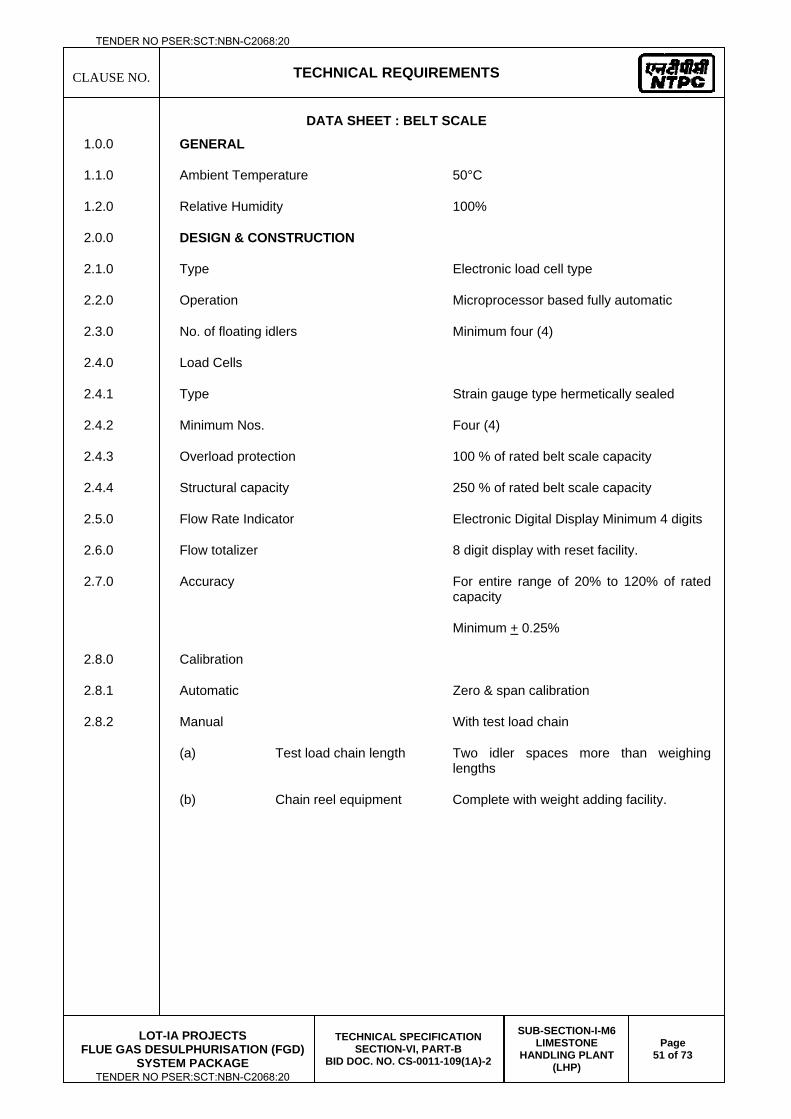
CLAUSE NO.
TECHNICAL REQUIREMENTS
LOT-IA PROJECTS
FLUE GAS DESULPHURISATION (FGD) SYSTEM PACKAGE
TECHNICAL SPECIFICATION SECTION-VI, PART-B
BID DOC. NO. CS-0011-109(1A)-2
SUB-SECTION-I-M6 LIMESTONE
HANDLING PLANT (LHP)
Page 51 of 73
DATA SHEET : BELT SCALE
1.0.0 GENERAL
1.1.0 Ambient Temperature 50°C
1.2.0 Relative Humidity 100%
2.0.0 DESIGN & CONSTRUCTION
2.1.0 Type Electronic load cell type
2.2.0 Operation Microprocessor based fully automatic
2.3.0 No. of floating idlers Minimum four (4)
2.4.0 Load Cells
2.4.1 Type Strain gauge type hermetically sealed
2.4.2 Minimum Nos. Four (4)
2.4.3 Overload protection 100 % of rated belt scale capacity
2.4.4 Structural capacity 250 % of rated belt scale capacity
2.5.0 Flow Rate Indicator Electronic Digital Display Minimum 4 digits
2.6.0 Flow totalizer 8 digit display with reset facility.
2.7.0 Accuracy For entire range of 20% to 120% of rated capacity
Minimum + 0.25%
2.8.0 Calibration
2.8.1 Automatic Zero & span calibration
2.8.2 Manual With test load chain
(a) Test load chain length Two idler spaces more than weighing lengths
(b) Chain reel equipment Complete with weight adding facility.
TENDER NO PSER:SCT:NBN-C2068:20
TENDER NO PSER:SCT:NBN-C2068:20
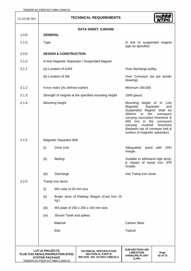
CLAUSE NO.
TECHNICAL REQUIREMENTS
LOT-IA PROJECTS
FLUE GAS DESULPHURISATION (FGD) SYSTEM PACKAGE
TECHNICAL SPECIFICATION SECTION-VI, PART-B
BID DOC. NO. CS-0011-109(1A)-2
SUB-SECTION-I-M6 LIMESTONE
HANDLING PLANT (LHP)
Page 52 of 73
DATA SHEET: ILMS/SM
1.0.0 GENERAL
1.1.0 Type In line or suspended magnet type as specified.
2.0.0 DESIGN & CONSTRUCTION
2.1.0 In-line Magnetic Separator / Suspended Magnet
2.1.1 (a) Location of ILMS Over discharge pulley.
(b) Location of SM Over Conveyor (as per tender drawing)
2.1.2 Force index (As defined earlier) Minimum 100,000
2.1.3 Strength of magnet at the specified mounting height 1000 gauss.
2.1.4 Mounting height Mounting height of In Line Magnetic Separator and Suspended Magnet shall be 450mm in the conveyors carrying uncrushed limestone & 400 mm in the conveyors carrying crushed limestone (between top of conveyor belt & surface of magnetic separator)
2.1.5 Magnetic Separator Belt
(i) Drive Unit Adequately sized with 20% margin.
(ii) Belting Suitable to withstand high temp. & impact of tramp iron. (FR Grade)
(iii) Discharge Into Tramp iron chute.
2.2.0 Tramp Iron Items
(i) MS cube of 20 mm size
(ii) Brake shoe of Railway Wagon (Cast Iron 15 kg.)
(iii) MS plate of 250 x 250 x 100 mm size.
(iv) Shovel Teeth and spikes.
Material Carbon Steel
Size Typical
TENDER NO PSER:SCT:NBN-C2068:20
TENDER NO PSER:SCT:NBN-C2068:20
CLAUSE NO.
TECHNICAL REQUIREMENTS
LOT-IA PROJECTS
FLUE GAS DESULPHURISATION (FGD) SYSTEM PACKAGE
TECHNICAL SPECIFICATION SECTION-VI, PART-B
BID DOC. NO. CS-0011-109(1A)-2
SUB-SECTION-I-M6 LIMESTONE
HANDLING PLANT (LHP)
Page 53 of 73
(v) MS round bar of 50 kg with L/D ratio not exceeding 5.
2.3.0 Control
Inline Magnetic Separator / Suspended Magnet Local and remote
2.4.0 Electric Supply 415V, 3 phase, 50 Hz input Silicon Rectifier units
2.5.0 Location of silicon rectifier unit Nearby control/MCC room
2.6.0 Handling Arrangement for inline Magnetic separator/Suspended magnet
(a) Height adjustment With turn buckle arrangement
(b) Cross-travel Electric Hoist operated cross travel facility.
TENDER NO PSER:SCT:NBN-C2068:20
TENDER NO PSER:SCT:NBN-C2068:20
CLAUSE NO.
TECHNICAL REQUIREMENTS
LOT-IA PROJECTS
FLUE GAS DESULPHURISATION (FGD) SYSTEM PACKAGE
TECHNICAL SPECIFICATION SECTION-VI, PART-B
BID DOC. NO. CS-0011-109(1A)-2
SUB-SECTION-I-M6 LIMESTONE
HANDLING PLANT (LHP)
Page 54 of 73
DATA SHEET: METAL DETECTOR
1.0.0 GENERAL
1.1.0 Type Coil type
2.0.0 DESIGN & CONSTRUCTION
2.1.0 Sensitivity - 35 mm Aluminum sphere below limestone for steel cord belting.
- 25 mm aluminum sphere below limestone for synthetic belting
2.2.0 Enclosure Fiber glass
2.3.0 Control Through local control panel.
2.4.0 Calibration Provision for automatic static calibration with adjustable sensitivity.
TENDER NO PSER:SCT:NBN-C2068:20
TENDER NO PSER:SCT:NBN-C2068:20
CLAUSE NO.
TECHNICAL REQUIREMENTS
LOT-IA PROJECTS
FLUE GAS DESULPHURISATION (FGD) SYSTEM PACKAGE
TECHNICAL SPECIFICATION SECTION-VI, PART-B
BID DOC. NO. CS-0011-109(1A)-2
SUB-SECTION-I-M6 LIMESTONE
HANDLING PLANT (LHP)
Page 55 of 73
DATA SHEET: LIMESTONE SAMPLING UNIT
1.0.0 GENERAL
1.1.0 Type Automatic
2.0.0 DESIGN & CONSTRUCTION
2.1.0 Codes & Standard ASTM C-50
2.2.0 Uncrushed feed limestone size (-) 250 mm
2.3.0 Crushed feed limestone size (-) 20 mm
3.0.0 CHUTES
3.3.1 Min. angle 60 deg
3.3.2 Cross section Square/rectangular with rounded corners.
3.3.3 Joints Bolted flanges with 6 mm thick standard grade neoprene gasket.
4.0.0 CRUSHER
4.4.1 Uncrushed (as received) feed limestone size (-)250 mm
4.4.2 Crushed (as fired) feed limestone size (-) 20 mm
4.4.3 Output size ASTM C-50
4.4.3 Stages of size reduction Single stage crushing
5.0.0 BELT FEEDER
5.5.1 Belt Flanged type, FR grade
5.5.2 Pulleys Rubber lagged head pulley
5.5.3 Drive Electric Motor
TENDER NO PSER:SCT:NBN-C2068:20
TENDER NO PSER:SCT:NBN-C2068:20
CLAUSE NO.
TECHNICAL REQUIREMENTS
LOT-IA PROJECTS
FLUE GAS DESULPHURISATION (FGD) SYSTEM PACKAGE
TECHNICAL SPECIFICATION SECTION-VI, PART-B
BID DOC. NO. CS-0011-109(1A)-2
SUB-SECTION-I-M6 LIMESTONE
HANDLING PLANT (LHP)
Page 56 of 73
DATA SHEET – PADDLE FEEDER 1.00.00 GENERAL
1.01.00 Type of paddle feeder Mobile, Rotary plough
1.02.00 Input limestone parameters As described elsewhere in the specification
1.03.00 Location Underground below ground hopper (Limestone storage shed)
2.00.00 DESIGN & CONSTRUCTION
2.01.00 Paddle Wheel
2.01.01 No. of paddle wheel vanes Suitable
2.01.02 Material for Vane liners TISCRAL / SAILHARD / LSLAS07 (Replaceable)
2.02.00 Drive Arrangement
2.02.01 Paddle Wheel Step less Hydraulic drive
2.02.02 Feeder Carriage & flexible coupling Electric Motor with gear box OR Hydraulic Drive
OR Electric geared Motor
2.02.03 Minimum No. of starts per hour for drive chain equipment
15 Starts/hour (with minimum 10 consecutive starts)
2.02.04 Paddle wheel speeds Step less variable
2.03.00 Paddle Feeder Rails
2.03.01 Size 90 lb/yard
2.03.02 Support Arrangement To be mounted on supporting structure of conveyors with continuous support below rail.
2.04.00 Feeder Carriage wheels
(i) Nos. Suitable
(ii) Type Double Flange
(iii) Bearings Sealed type
2.05.00 Anti Collision Device Mechanical and Infra red type
2.06.00 Cable Tray Height & width Min. 300 mm above floor & 300 mm wide all along the length of storage shed hopper on both sides.
TENDER NO PSER:SCT:NBN-C2068:20
TENDER NO PSER:SCT:NBN-C2068:20
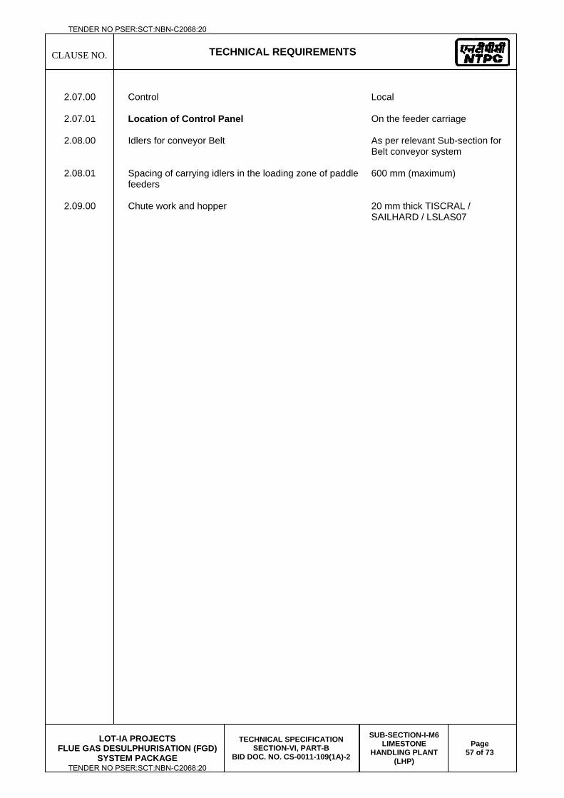
CLAUSE NO.
TECHNICAL REQUIREMENTS
LOT-IA PROJECTS
FLUE GAS DESULPHURISATION (FGD) SYSTEM PACKAGE
TECHNICAL SPECIFICATION SECTION-VI, PART-B
BID DOC. NO. CS-0011-109(1A)-2
SUB-SECTION-I-M6 LIMESTONE
HANDLING PLANT (LHP)
Page 57 of 73
2.07.00 Control Local
2.07.01 Location of Control Panel On the feeder carriage
2.08.00 Idlers for conveyor Belt As per relevant Sub-section for
Belt conveyor system
2.08.01 Spacing of carrying idlers in the loading zone of paddle feeders
600 mm (maximum)
2.09.00 Chute work and hopper 20 mm thick TISCRAL / SAILHARD / LSLAS07
TENDER NO PSER:SCT:NBN-C2068:20
TENDER NO PSER:SCT:NBN-C2068:20
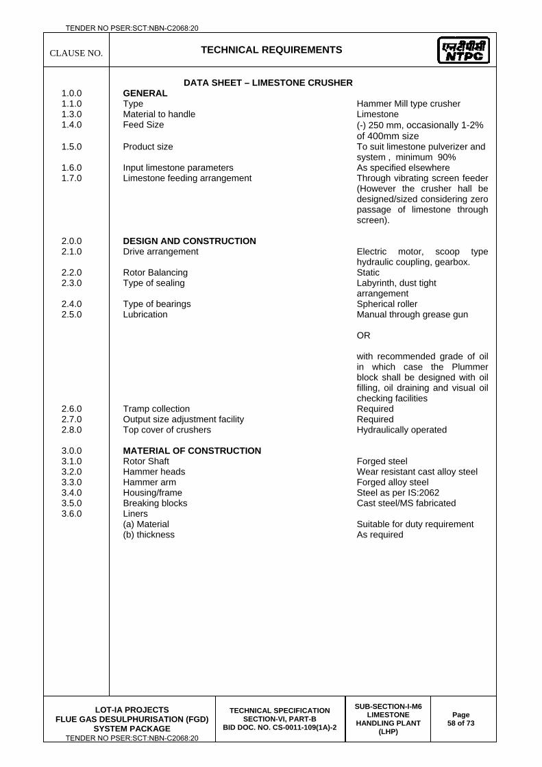
CLAUSE NO.
TECHNICAL REQUIREMENTS
LOT-IA PROJECTS
FLUE GAS DESULPHURISATION (FGD) SYSTEM PACKAGE
TECHNICAL SPECIFICATION SECTION-VI, PART-B
BID DOC. NO. CS-0011-109(1A)-2
SUB-SECTION-I-M6 LIMESTONE
HANDLING PLANT (LHP)
Page 58 of 73
DATA SHEET – LIMESTONE CRUSHER 1.0.0 GENERAL 1.1.0 Type Hammer Mill type crusher 1.3.0 Material to handle Limestone 1.4.0 Feed Size (-) 250 mm, occasionally 1-2%
of 400mm size 1.5.0 Product size To suit limestone pulverizer and
system , minimum 90% 1.6.0 Input limestone parameters As specified elsewhere 1.7.0 Limestone feeding arrangement Through vibrating screen feeder
(However the crusher hall be designed/sized considering zero passage of limestone through screen).
2.0.0 DESIGN AND CONSTRUCTION 2.1.0 Drive arrangement Electric motor, scoop type
hydraulic coupling, gearbox. 2.2.0 Rotor Balancing Static 2.3.0 Type of sealing Labyrinth, dust tight
arrangement 2.4.0 Type of bearings Spherical roller 2.5.0 Lubrication Manual through grease gun
OR with recommended grade of oil in which case the Plummer block shall be designed with oil filling, oil draining and visual oil checking facilities
2.6.0 Tramp collection Required 2.7.0 Output size adjustment facility Required 2.8.0 Top cover of crushers Hydraulically operated
3.0.0 MATERIAL OF CONSTRUCTION 3.1.0 Rotor Shaft Forged steel 3.2.0 Hammer heads Wear resistant cast alloy steel 3.3.0 Hammer arm Forged alloy steel 3.4.0 Housing/frame Steel as per IS:2062 3.5.0 Breaking blocks Cast steel/MS fabricated 3.6.0 Liners (a) Material Suitable for duty requirement (b) thickness As required
TENDER NO PSER:SCT:NBN-C2068:20
TENDER NO PSER:SCT:NBN-C2068:20
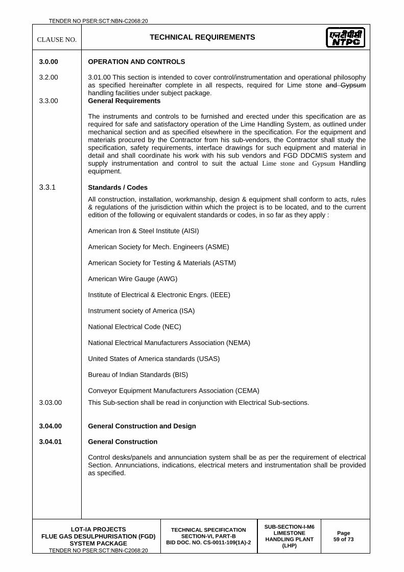
CLAUSE NO.
TECHNICAL REQUIREMENTS
LOT-IA PROJECTS
FLUE GAS DESULPHURISATION (FGD) SYSTEM PACKAGE
TECHNICAL SPECIFICATION SECTION-VI, PART-B
BID DOC. NO. CS-0011-109(1A)-2
SUB-SECTION-I-M6 LIMESTONE
HANDLING PLANT (LHP)
Page 59 of 73
3.0.00 OPERATION AND CONTROLS 3.2.00 3.01.00 This section is intended to cover control/instrumentation and operational philosophy
as specified hereinafter complete in all respects, required for Lime stone and Gypsum handling facilities under subject package.
3.3.00 General Requirements
The instruments and controls to be furnished and erected under this specification are as required for safe and satisfactory operation of the Lime Handling System, as outlined under mechanical section and as specified elsewhere in the specification. For the equipment and materials procured by the Contractor from his sub-vendors, the Contractor shall study the specification, safety requirements, interface drawings for such equipment and material in detail and shall coordinate his work with his sub vendors and FGD DDCMIS system and supply instrumentation and control to suit the actual Lime stone and Gypsum Handling equipment.
3.3.1 Standards / Codes All construction, installation, workmanship, design & equipment shall conform to acts, rules & regulations of the jurisdiction within which the project is to be located, and to the current edition of the following or equivalent standards or codes, in so far as they apply :
American Iron & Steel Institute (AISI)
American Society for Mech. Engineers (ASME)
American Society for Testing & Materials (ASTM)
American Wire Gauge (AWG)
Institute of Electrical & Electronic Engrs. (IEEE)
Instrument society of America (ISA)
National Electrical Code (NEC)
National Electrical Manufacturers Association (NEMA)
United States of America standards (USAS)
Bureau of Indian Standards (BIS)
Conveyor Equipment Manufacturers Association (CEMA)
3.03.00 This Sub-section shall be read in conjunction with Electrical Sub-sections. 3.04.00 General Construction and Design 3.04.01 General Construction
Control desks/panels and annunciation system shall be as per the requirement of electrical Section. Annunciations, indications, electrical meters and instrumentation shall be provided as specified.
TENDER NO PSER:SCT:NBN-C2068:20
TENDER NO PSER:SCT:NBN-C2068:20
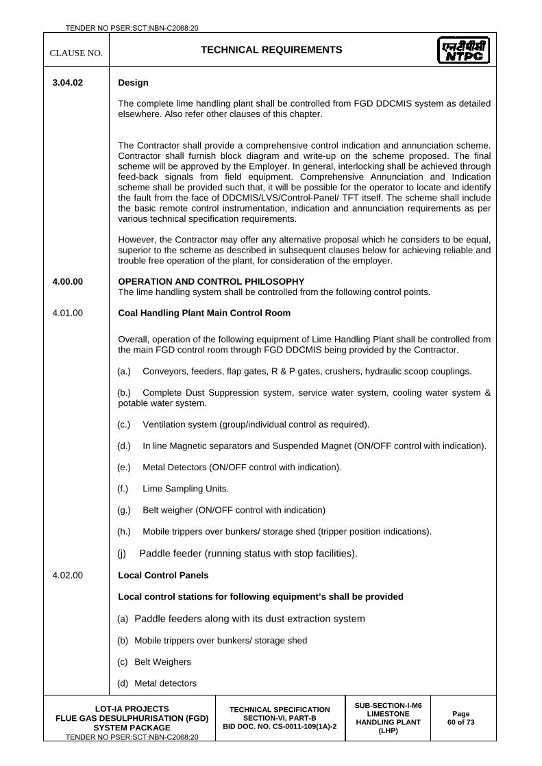
CLAUSE NO.
TECHNICAL REQUIREMENTS
LOT-IA PROJECTS
FLUE GAS DESULPHURISATION (FGD) SYSTEM PACKAGE
TECHNICAL SPECIFICATION SECTION-VI, PART-B
BID DOC. NO. CS-0011-109(1A)-2
SUB-SECTION-I-M6 LIMESTONE
HANDLING PLANT (LHP)
Page 60 of 73
3.04.02 Design
The complete lime handling plant shall be controlled from FGD DDCMIS system as detailed elsewhere. Also refer other clauses of this chapter. The Contractor shall provide a comprehensive control indication and annunciation scheme. Contractor shall furnish block diagram and write-up on the scheme proposed. The final scheme will be approved by the Employer. In general, interlocking shall be achieved through feed-back signals from field equipment. Comprehensive Annunciation and Indication scheme shall be provided such that, it will be possible for the operator to locate and identify the fault from the face of DDCMIS/LVS/Control-Panel/ TFT itself. The scheme shall include the basic remote control instrumentation, indication and annunciation requirements as per various technical specification requirements.
However, the Contractor may offer any alternative proposal which he considers to be equal, superior to the scheme as described in subsequent clauses below for achieving reliable and trouble free operation of the plant, for consideration of the employer.
4.00.00 OPERATION AND CONTROL PHILOSOPHY The lime handling system shall be controlled from the following control points. 4.01.00 Coal Handling Plant Main Control Room
Overall, operation of the following equipment of Lime Handling Plant shall be controlled from the main FGD control room through FGD DDCMIS being provided by the Contractor.
(a.) Conveyors, feeders, flap gates, R & P gates, crushers, hydraulic scoop couplings.
(b.) Complete Dust Suppression system, service water system, cooling water system & potable water system.
(c.) Ventilation system (group/individual control as required).
(d.) In line Magnetic separators and Suspended Magnet (ON/OFF control with indication).
(e.) Metal Detectors (ON/OFF control with indication).
(f.) Lime Sampling Units.
(g.) Belt weigher (ON/OFF control with indication)
(h.) Mobile trippers over bunkers/ storage shed (tripper position indications).
(j) Paddle feeder (running status with stop facilities).
4.02.00 Local Control Panels
Local control stations for following equipment’s shall be provided
(a) Paddle feeders along with its dust extraction system
(b) Mobile trippers over bunkers/ storage shed
(c) Belt Weighers
(d) Metal detectors
TENDER NO PSER:SCT:NBN-C2068:20
TENDER NO PSER:SCT:NBN-C2068:20
CLAUSE NO.
TECHNICAL REQUIREMENTS
LOT-IA PROJECTS
FLUE GAS DESULPHURISATION (FGD) SYSTEM PACKAGE
TECHNICAL SPECIFICATION SECTION-VI, PART-B
BID DOC. NO. CS-0011-109(1A)-2
SUB-SECTION-I-M6 LIMESTONE
HANDLING PLANT (LHP)
Page 61 of 73
(e) Electric hoist - wall mounted control box with pendent push button controls.
(f) In line magnetic separators
(g) Suspended Magnet
(h) Sump Pump
(i) Hydraulic scoop coupling.
(j) Lime Sampling Sytem:- Complete PLC along with interface with FGD DDCMIS
All the above local control panels shall be accessible and located near their respective equipment and shall be complete with all the required controls, interlocks, annunciation’s etc. However, for items (j.), above, controls shall be through contractor’s PLC. Further, necessary controls, indications and annunciations for all the above equipment shall also be provided at main FGD Control Room as described under relevant clause.
4.03.01 System Operation 4.03.01 Lime conveying facilities under subject package shall be operated in association with a coal
handling plant being provided by contractor separately. The lime handling plant being provided by bidder envisages control of complete lime
handling system including facilities under subject package by DDCMIS.
Envisaged Operation philosophy of the plant, in general, shall be as elaborated below:
(a.) Lime flow path selection shall be done from CRT/Keyboard to select any one of the following conveying paths.
a. Track hopper to Limestone storage shed
b. Wagon Tippler to Limestone storage shed
c. Limestone storage shed to Limestone bunker
d. Combination of above
The lime handling system operator will select any one of the above paths from OWS located on the main control desk. The flow stream path is then selected by positioning different flap gates/ movable discharge pulley at desired positions by means of keyboard available at the central control desk. Once the system is in the operation, the gates/ movable discharge pulley can not be moved from their positions and path. Flap gates which do not come in the stream in which coal flow is taking place, can be operated at any time. However, for the flap gates in Limestone bunker area conveyors, it shall be possible to change flap gate position while the conveyor is in operation and feeding coal using interlock bypass facility, provided that sequential permissive are available.
The Control system will be designed for “Auto” & “Manual” operation of the conveyors in the selected path. Auto/Manual Selection shall be done from keyboard.
TENDER NO PSER:SCT:NBN-C2068:20
TENDER NO PSER:SCT:NBN-C2068:20
CLAUSE NO.
TECHNICAL REQUIREMENTS
LOT-IA PROJECTS
FLUE GAS DESULPHURISATION (FGD) SYSTEM PACKAGE
TECHNICAL SPECIFICATION SECTION-VI, PART-B
BID DOC. NO. CS-0011-109(1A)-2
SUB-SECTION-I-M6 LIMESTONE
HANDLING PLANT (LHP)
Page 62 of 73
Auto Mode : In the “Auto” mode, the conveyors and related equipment will start sequentially when the “System Start” is activated. During stopping, when the “System Stop” is activated, all conveyors will also stop sequentially (in the reverse sequence) allowing time delays for clearing the belts.
Manual Mode : In Manual Mode, the operator will start the conveyor system, in the same sequence as in Auto mode from keyboard. The operator will also stop the conveyor system, by pressing "System stop" or individual “Stop” push buttons/command from keyboard in the reverse sequence.
During “Sequence Start” in both Auto and Manual modes, first the required number of hooters (3 phase induction motor type) will be energized simultaneously for a preset time of 1 minute or so (adjustable at site) as per the program. After the preset time, the hooters will stop and a preset time of two minutes (adjustable at site) as per program will be allowed for the movement of the personnel and for the permissive of the conveyor system operation. This condition will be indicated on the panel by glowing of lamp “Lime Handling Sequence Start”. The starting permissive will be available for a period of 5 minutes (Pre-programmed and adjustable in the field). In the event the last conveyor / equipment is not started within this preset time of 5 minutes, the start command for equipment not started will be withdrawn. The system cannot be started again unless the “Sequence Start” push button is again pressed and the hooters sound again, as described before. Those conveyors and equipment, which have already started, will continue to run.
The status indication in the graphic display against all conveyors and equipment in the selected path/stream will start slow flickering. However, all status indications against all flap gates / movable discharge pulley in the selected path will glow steadily. Therefore, from the selected flow stream path of the flap gates / movable discharge pulley, the operator will come to know the conveyors and equipment to be started for the selected path/stream. After a conveyor/equipment is started, the status indications against that conveyor / equipment will change to steady glow indicating that it is running. Separate color scheme shall be provided to all common conveyors and equipment, to distinguish handling of Lime and Coal while conveying
Graphic display status indicators associated with a particular motor/equipment shall flicker fast in case of fault / trip.
In addition, emergency stop push button on the control desk for immediate shut down of complete plant shall be provided.
For changeover of feed from one row of Bunkers to another row of Bunkers without stopping of the LHP, provision shall be made for interlock bypass on the control desk for flap gates of all conveyors in Boiler area for a preset period. If the changeover, in above specified time, is not completed then the entire LHP shall stop.
(i) Lamp test facility will be provided for the annunciation and mimic lamps.
4.06.00 Conveyor System
(a) Normally the movement of the paddle feeders feeding Lime from the Limestone shed to the conveyor shall be controlled from the paddle feeder itself based on instructions from main control room.
(b) The paddle feeder carriages shall move continuously to and fro along their tracks. Suitable limit switches and anti-collision devices (both mechanical limit switch operated and infra- red type) shall be provided to enable them to change direction of movement as soon as they come within a specified distance at the end of travel in one direction.
TENDER NO PSER:SCT:NBN-C2068:20
TENDER NO PSER:SCT:NBN-C2068:20
CLAUSE NO.
TECHNICAL REQUIREMENTS
LOT-IA PROJECTS
FLUE GAS DESULPHURISATION (FGD) SYSTEM PACKAGE
TECHNICAL SPECIFICATION SECTION-VI, PART-B
BID DOC. NO. CS-0011-109(1A)-2
SUB-SECTION-I-M6 LIMESTONE
HANDLING PLANT (LHP)
Page 63 of 73
(c) The operation and stoppage of the paddle feeders shall be signaled in the main control room of the Lime handling plant. It shall be possible to stop the paddle feeder from main control room. It shall be possible to stop the conveyor taking feed from paddle feeder from respective paddle feeder.
(d) Each conveyor shall be protected against damage to the edge of the belt due to excessive sideways movement by providing an adequate number of belt sway switches. In addition, each conveyor shall be provided with one (1) No. speed detection device (zero speed switch). The zero speed switches shall be designed to sense belt speed. In case of speed of belt goes below 85% of rated speed, it shall trip the conveyor.
(e) All the conveyors shall be protected from reverse running due to power failure by providing mechanical or electrical locking system.
(f) The starting sequence of the conveyors shall follow a direction opposite to that of flow of material i.e. :
(1.) In case of direct conveying of lime to limestone bunkers, start from lime bunker conveyor and end up with reclaim conveyors below track hopper/Wagon Tippler .
(2.) In case of stacking of lime in stock yard, start from yard conveyor and end up with reclaim conveyors below track hopper/Wagon Tippler.
(3.) In case of reclamation of lime from stock yard, start from bunker conveyors and end up with yard conveyor alongwith Travelling tripper.
(4) The starting of mobile trippers shall be interlocked with operation of the bunker bay conveyors.
(g) Any individual equipment (belt conveyor etc.) should not be allowed to start unless the equipment immediately following the same in the direction of flow of material is already in operation.
(h) Stop/tripping of any equipment from running condition shall trip all preceding equipment in the system, except crushers but shall not effect succeeding ones which shall continue to operate.
(i) Adequate number of pull-cord switches shall be provided at suitable intervals along the length of each belt conveyor, which shall enable the respective conveyor to be stopped immediately. Each pull chord switch shall be identified by a specific number on HMI in the main control room. Each belt sway switch shall also be identified by a specific number on HMI in control room.
(j) Means shall be provided to pre-warn personnel working nearby when starting any conveyor and mobile tripper.
(k) Interlocking of various conveyors shall be achieved with Flap Gate, discharge pulleys, limit switches and zero speed switches.
(l) Suitable indication for paddle wheel rpm shall be provided on the local panels. Manual facility to control the cutting rate of paddle feeder shall also be provided.
(m) Motors shall start only when the brake/rail clamp if-provided, is in “not applied’ ‘condition. This signal shall be obtained from limit switch provided for that purpose.
TENDER NO PSER:SCT:NBN-C2068:20
TENDER NO PSER:SCT:NBN-C2068:20
CLAUSE NO.
TECHNICAL REQUIREMENTS
LOT-IA PROJECTS
FLUE GAS DESULPHURISATION (FGD) SYSTEM PACKAGE
TECHNICAL SPECIFICATION SECTION-VI, PART-B
BID DOC. NO. CS-0011-109(1A)-2
SUB-SECTION-I-M6 LIMESTONE
HANDLING PLANT (LHP)
Page 64 of 73
(n) Lime stone crusher shall be provided with speed and vibration monitoring instruments. crusher shall trip in case speed/ vibration is going beyond tolerable limits of design. Temperature sensing devices shall be installed on all bearings of each of the ring granulator to trip the ring granulator in case of temperature goes beyond limit. Audio-visual annunciation shall be provided in main control room and locally also.
(o) Once a conveyor trips, flap gate directing coal from this conveyor shall change over its position with a time delay and shall come back to the original position again. This is to prevent jamming of gate.
(p) Tripping of the respective conveyor shall be provided in case any of paddle feeders and mobile trippers starts running along with conveyor belt at speed higher than their rated speed by providing an over speed sensing device on the equipment.
(q) It shall be possible to trip bunker conveyor from mobile tripper Where ever scoop type coupling provided for HT motors, the coasting time of respective conveyor, thruster brake, actuator selection and the chute size shall be so selected such that there is no spillage of coal from any down stream conveyors during next start.
(r) Wherever the conveyor is provided with the movable discharge pulleys in place of flap gates, the starting of the conveyor will be interlocked with the position of the movable discharge pulley.
4.07.00 Interlocking
(a.) The following conveyors / equipment will come under interlock scheme :-
(1) All conveyors
(2) All flap gates
(3) Mobile Trippers
(4) Rack & Pinion Gates
(5) Metal detectors
(6) Magnetic Separators and suspended Magnet
(7) Crushers
(8) Paddle Feeders
(9) Belt scale
(b.) The following equipment will not come under interlock of the conveyor scheme.
(1.) All dust extraction systems & service water system.
(2.) Ventilation systems
(c.) All conveyors and equipment will have local push button stations each consisting of :
(1.) Pos - I, Pos - II & stop button for flap gate.
TENDER NO PSER:SCT:NBN-C2068:20
TENDER NO PSER:SCT:NBN-C2068:20
CLAUSE NO.
TECHNICAL REQUIREMENTS
LOT-IA PROJECTS
FLUE GAS DESULPHURISATION (FGD) SYSTEM PACKAGE
TECHNICAL SPECIFICATION SECTION-VI, PART-B
BID DOC. NO. CS-0011-109(1A)-2
SUB-SECTION-I-M6 LIMESTONE
HANDLING PLANT (LHP)
Page 65 of 73
(2.) Emergency stop push button (Red) for other equipment
(d.) Belt scale shall be started when relevant conveyors are started
(e.) The dust extraction systems will be energized as soon as the conveyors are energized.
(f.) Lime handling plant shall be tripped in case of detection of fire.
(g.) Interlock for H.T. Motor :
H.T. motors used will continue to run on no load by disengaging the fluid coupling in case of failure of any process interlock. The H.T. motors will however be tripped in case of any motor fault like O/L, high motor winding temperature etc. In addition, in case of normal stop command, after running of the system, motors will stop.
(h.) The following are the various safety interlocks for the conveyors and other equipment. This list is indicative only and the Contractor shall develop a comprehensive interlocking scheme.
Conveyors
a) Pull - Chord switch - not operated
b) Belt sway switch - not operated
c) Under speed switch - closed at 90% speed of the conveyor within designed accelerating time.
d) Motor protection - not tripped
e) Local stop PB – reset
f) Chute Block switch - not operated.
g) Brakes for conveyor – not operated.
h) Trip circuits healthy.
i) Temp. of fluid coupling oil - not high
Paddle Feeders
a). Motor O/L - not tripped
b). Local E-Stop PB - reset
c). Stop PB in main FGD control room - reset
d). All Limit Switches – reset
e). Overspeed limit switch – not tripped
Travelling Tripper :
a) Stop PB in Local control station - reset
b) Motor O/L not tripped.
c) Over Travel Limit switches - not tripped.
TENDER NO PSER:SCT:NBN-C2068:20
TENDER NO PSER:SCT:NBN-C2068:20
CLAUSE NO.
TECHNICAL REQUIREMENTS
LOT-IA PROJECTS
FLUE GAS DESULPHURISATION (FGD) SYSTEM PACKAGE
TECHNICAL SPECIFICATION SECTION-VI, PART-B
BID DOC. NO. CS-0011-109(1A)-2
SUB-SECTION-I-M6 LIMESTONE
HANDLING PLANT (LHP)
Page 66 of 73
Magnetic Separators / Metal Detectors / Suspended Magnets
a) O/L / fault relay - not tripped.
b) Stop PB (Local & Remote) reset.
c) Metal detector reset
d) Oil temperature - not high
Flap Gates/ R & P Gates
a) End of travel limit switches - reset.
b) Torque limit switches - reset.
c) Local stop - reset.
Crusher
a) Zero speed - not operated
b) Temp. of fluid coupling oil - not high.
c) Local stop push button reset.
d) Temperature of bearings – not high.
e) Cooling water flow switch – reset
Motor O/L – not tripped
Local E-Stop PB-reset
Stop PB in main FGD Control Room reset.
All limit switches - reset
All limit Switches – not tripped.
Apron feeder
Motor O/L – not tripped.
Local stop PB – reset
4.07.01 The lists of indications and audio-visual annunciation given in subsequent clauses are indicative only and the same shall be finalised during detail engineering.
4.07.02 Status indications in Large Video Screen
Following individual status indications shall be provided in LVS with individual ON/OFF/TRIP indications on CRT.
(a.) Conveyor 'ON'
(b.) Flap Gate Rack and Pinion.
TENDER NO PSER:SCT:NBN-C2068:20
TENDER NO PSER:SCT:NBN-C2068:20
CLAUSE NO.
TECHNICAL REQUIREMENTS
LOT-IA PROJECTS
FLUE GAS DESULPHURISATION (FGD) SYSTEM PACKAGE
TECHNICAL SPECIFICATION SECTION-VI, PART-B
BID DOC. NO. CS-0011-109(1A)-2
SUB-SECTION-I-M6 LIMESTONE
HANDLING PLANT (LHP)
Page 67 of 73
(c.) Belt scale flow rate indication and totalizer.
(d.) Belt sway switch operated for each conveyor (individual switch indication on CRT).
(e.) Pull cord switch operated for each conveyor (Individual switches indication on CRT).
(f.) Zero speed switch operated for each conveyor
(g.) Paddle Feeder ‘’ON
(h.) Travelling tripper position.”
(i.) Crusher ON
(j.) MD/ ILMS/ SM/ LSU ON
(k.) DE/ SW/PW/CW/Vent ON (System wise)
(l.) Unit wise MW indication, total lime flow & Bunker level.
(m.) Further Mimic lamps for HT and LT SLDs shall be provided on the control desk.
4.08.00 Annunciation System:
DDCMIS/Control desk shall be provided with adequate number of facia type annunciation windows operating through DDCMIS for the following audio-visual fault annunciation purposes. Wherever group annunciation is provided, alarm status of individual equipment shall be provided on OWS.
(a) 3.3 kV Breaker Trip (Group wise for each board)
(b) 415 V MCC Breaker Trip (MCC wise)
(c) Bus under voltage for each LT MCC & HT switchgear buses.
(d) Following group wise annunciation shall be provided for transformers :
(1.) Buchholz alarm
(2.) Winding/oil temperature high alarm
(3.) Oil level low alarm
(4.) Buchholz trip
(5.) Winding/oil temperature high trip
(e) A.C Control Supply failure.
(f) D.C. Control Supply failure.
(g) Annunciation supply failure.
(h) Both CPU fail
(i) Stand by CPU in service
(j) H.T. motor overload alarm (individual)
TENDER NO PSER:SCT:NBN-C2068:20
TENDER NO PSER:SCT:NBN-C2068:20
CLAUSE NO.
TECHNICAL REQUIREMENTS
LOT-IA PROJECTS
FLUE GAS DESULPHURISATION (FGD) SYSTEM PACKAGE
TECHNICAL SPECIFICATION SECTION-VI, PART-B
BID DOC. NO. CS-0011-109(1A)-2
SUB-SECTION-I-M6 LIMESTONE
HANDLING PLANT (LHP)
Page 68 of 73
(k) HT motor bearing/ winding temp. high alarm (for each) and trip (for each)
(l) HT motor trip on electrical fault (for each)
(m) LT motor overload tripped (for each).
(n) Belt sway switch operated (for each)
(o) Pull cord switch operated (for each)
(p) Zero speed switch operated. (for each)
(q) Chute plugged (for each)
(r) Paddle feeder over speed tripped (group)
(s) Tripper over speed tripped (for each)
(t) Magnetic separator fault and cleaning belt trip.
(u) (i) Metal Detector fault (for each)
(ii) Metal detected / MD not reset (for each)
(v) Belt Scale fault (for each)
(w) Sampling system faults and trips (for each)
(x) Crusher low speed & crusher bearing temperature – high.
(y) Water level low in tanks (for each)
(z) Oil temperature of fluid coupling high
(aa) Dust Extraction/service water system faults and trips (system wise)
(bb) 20% spare window
For identification of the fault for a particular conveyor or equipment, status indication against that conveyor / equipment in the mimic will start fast flickering and the annunciation window will be blinking against that particular fault. In addition, a buzzer (alarm) will start sounding. After acknowledgement of the fault, the buzzer will stop, but the fast flickering on the mimic and the steady glow on the annunciation window will continue until the fault is cleared and the Reset push button is pressed. When the fault is cleared and the Reset push button is pressed, the status indication of that conveyor / equipment on the mimic will start slow blinking if it is on selected path otherwise it will go off and the steady glow in the annunciation window will go off. However, pressing of the Reset push button before clearance of the fault, will have no effect on the lamps.
At the time of a fault, the faulty conveyor / equipment, as well as the preceding conveyors / equipment in the interlock sequence, will stop except H.T. motors for which only scoop coupling will be disengaged and motor will continue to run for process fault. In case of motor fault, H.T. motor will trip but the succeeding conveyors / equipment will continue to run. The status indication against the preceding conveyors / equipment will start slow blinking while the faulty conveyor / equipment will be fast blinking.
Start command shall not be initiated unless reset button in pressed after clearance of fault.
TENDER NO PSER:SCT:NBN-C2068:20
TENDER NO PSER:SCT:NBN-C2068:20
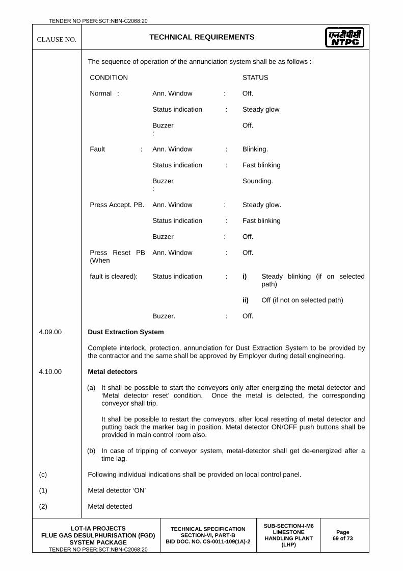
CLAUSE NO.
TECHNICAL REQUIREMENTS
LOT-IA PROJECTS
FLUE GAS DESULPHURISATION (FGD) SYSTEM PACKAGE
TECHNICAL SPECIFICATION SECTION-VI, PART-B
BID DOC. NO. CS-0011-109(1A)-2
SUB-SECTION-I-M6 LIMESTONE
HANDLING PLANT (LHP)
Page 69 of 73
The sequence of operation of the annunciation system shall be as follows :-
CONDITION STATUS
Normal : Ann. Window : Off.
Status indication : Steady glow
Buzzer :
Off.
Fault : Ann. Window : Blinking.
Status indication : Fast blinking
Buzzer :
Sounding.
Press Accept. PB. Ann. Window : Steady glow.
Status indication : Fast blinking
Buzzer : Off.
Press Reset PB (When
Ann. Window : Off.
fault is cleared): Status indication : i) Steady blinking (if on selected path)
ii) Off (if not on selected path)
Buzzer. : Off.
4.09.00 Dust Extraction System
Complete interlock, protection, annunciation for Dust Extraction System to be provided by the contractor and the same shall be approved by Employer during detail engineering.
4.10.00 Metal detectors
(a) It shall be possible to start the conveyors only after energizing the metal detector and ‘Metal detector reset’ condition. Once the metal is detected, the corresponding conveyor shall trip.
It shall be possible to restart the conveyors, after local resetting of metal detector and putting back the marker bag in position. Metal detector ON/OFF push buttons shall be provided in main control room also.
(b) In case of tripping of conveyor system, metal-detector shall get de-energized after a time lag.
(c) Following individual indications shall be provided on local control panel.
(1) Metal detector ‘ON’
(2) Metal detected
TENDER NO PSER:SCT:NBN-C2068:20
TENDER NO PSER:SCT:NBN-C2068:20
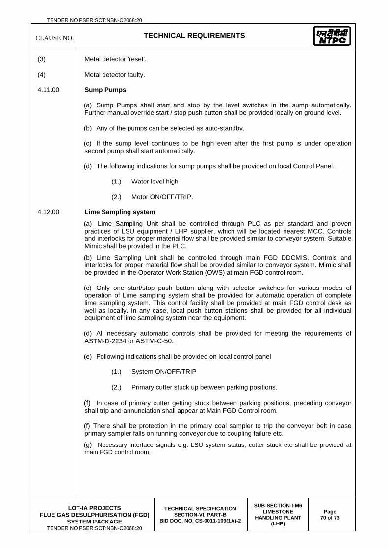
CLAUSE NO.
TECHNICAL REQUIREMENTS
LOT-IA PROJECTS
FLUE GAS DESULPHURISATION (FGD) SYSTEM PACKAGE
TECHNICAL SPECIFICATION SECTION-VI, PART-B
BID DOC. NO. CS-0011-109(1A)-2
SUB-SECTION-I-M6 LIMESTONE
HANDLING PLANT (LHP)
Page 70 of 73
(3) Metal detector 'reset'.
(4) Metal detector faulty.
4.11.00 Sump Pumps
(a) Sump Pumps shall start and stop by the level switches in the sump automatically. Further manual override start / stop push button shall be provided locally on ground level.
(b) Any of the pumps can be selected as auto-standby.
(c) If the sump level continues to be high even after the first pump is under operation second pump shall start automatically.
(d) The following indications for sump pumps shall be provided on local Control Panel.
(1.) Water level high
(2.) Motor ON/OFF/TRIP.
4.12.00 Lime Sampling system
(a) Lime Sampling Unit shall be controlled through PLC as per standard and proven practices of LSU equipment / LHP supplier, which will be located nearest MCC. Controls and interlocks for proper material flow shall be provided similar to conveyor system. Suitable Mimic shall be provided in the PLC.
(b) Lime Sampling Unit shall be controlled through main FGD DDCMIS. Controls and interlocks for proper material flow shall be provided similar to conveyor system. Mimic shall be provided in the Operator Work Station (OWS) at main FGD control room.
(c) Only one start/stop push button along with selector switches for various modes of operation of Lime sampling system shall be provided for automatic operation of complete lime sampling system. This control facility shall be provided at main FGD control desk as well as locally. In any case, local push button stations shall be provided for all individual equipment of lime sampling system near the equipment.
(d) All necessary automatic controls shall be provided for meeting the requirements of ASTM-D-2234 or ASTM-C-50.
(e) Following indications shall be provided on local control panel
(1.) System ON/OFF/TRIP
(2.) Primary cutter stuck up between parking positions.
(f) In case of primary cutter getting stuck between parking positions, preceding conveyor shall trip and annunciation shall appear at Main FGD Control room.
(f) There shall be protection in the primary coal sampler to trip the conveyor belt in case primary sampler falls on running conveyor due to coupling failure etc.
(g) Necessary interface signals e.g. LSU system status, cutter stuck etc shall be provided at main FGD control room.
TENDER NO PSER:SCT:NBN-C2068:20
TENDER NO PSER:SCT:NBN-C2068:20
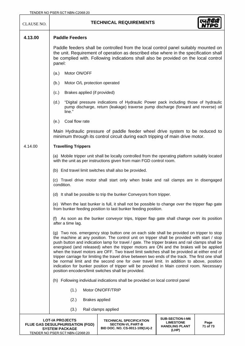
CLAUSE NO.
TECHNICAL REQUIREMENTS
LOT-IA PROJECTS
FLUE GAS DESULPHURISATION (FGD) SYSTEM PACKAGE
TECHNICAL SPECIFICATION SECTION-VI, PART-B
BID DOC. NO. CS-0011-109(1A)-2
SUB-SECTION-I-M6 LIMESTONE
HANDLING PLANT (LHP)
Page 71 of 73
4.13.00 Paddle Feeders
Paddle feeders shall be controlled from the local control panel suitably mounted on the unit. Requirement of operation as described else where in the specification shall be complied with. Following indications shall also be provided on the local control panel:
(a.) Motor ON/OFF
(b.) Motor O/L protection operated
(c.) Brakes applied (if provided)
(d.) “Digital pressure indications of Hydraulic Power pack including those of hydraulic pump discharge, return (leakage) traverse pump discharge (forward and reverse) oil line.”
(e.) Coal flow rate
Main Hydraulic pressure of paddle feeder wheel drive system to be reduced to minimum through its control circuit during each tripping of main drive motor.
4.14.00 Travelling Trippers
(a) Mobile tripper unit shall be locally controlled from the operating platform suitably located with the unit as per instructions given from main FGD control room.
(b) End travel limit switches shall also be provided.
(c) Travel drive motor shall start only when brake and rail clamps are in disengaged condition.
(d) It shall be possible to trip the bunker Conveyors from tripper.
(e) When the last bunker is full, it shall not be possible to change over the tripper flap gate from bunker feeding position to last bunker feeding position.
(f) As soon as the bunker conveyor trips, tripper flap gate shall change over its position after a time lag.
(g) Two nos. emergency stop button one on each side shall be provided on tripper to stop the machine at any position. The control unit on tripper shall be provided with start / stop push button and indication lamp for travel / gate. The tripper brakes and rail clamps shall be energised (and released) when the tripper motors are ON and the brakes will be applied when the travel motors are OFF. Two travel limit switches shall be provided at either end of tripper carriage for limiting the travel drive between two ends of the track. The first one shall be normal limit and the second one for over travel limit. In addition to above, position indication for bunker position of tripper will be provided in Main control room. Necessary position encoders/limit switches shall be provided.
(h) Following individual indications shall be provided on local control panel
(1.) Motor ON/OFF/TRIP
(2.) Brakes applied
(3.) Rail clamps applied
TENDER NO PSER:SCT:NBN-C2068:20
TENDER NO PSER:SCT:NBN-C2068:20
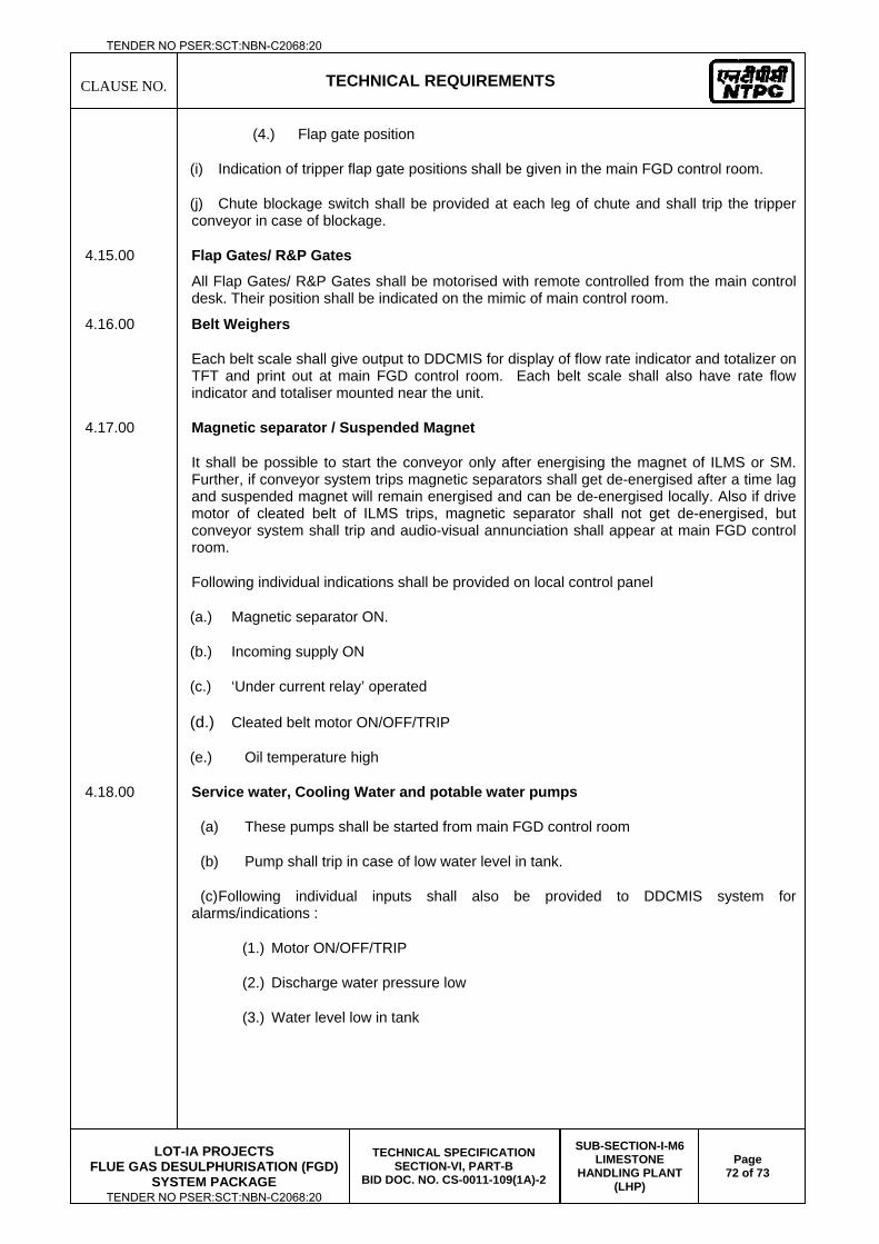
CLAUSE NO.
TECHNICAL REQUIREMENTS
LOT-IA PROJECTS
FLUE GAS DESULPHURISATION (FGD) SYSTEM PACKAGE
TECHNICAL SPECIFICATION SECTION-VI, PART-B
BID DOC. NO. CS-0011-109(1A)-2
SUB-SECTION-I-M6 LIMESTONE
HANDLING PLANT (LHP)
Page 72 of 73
(4.) Flap gate position
(i) Indication of tripper flap gate positions shall be given in the main FGD control room.
(j) Chute blockage switch shall be provided at each leg of chute and shall trip the tripper conveyor in case of blockage.
4.15.00 Flap Gates/ R&P Gates All Flap Gates/ R&P Gates shall be motorised with remote controlled from the main control desk. Their position shall be indicated on the mimic of main control room.
4.16.00 Belt Weighers
Each belt scale shall give output to DDCMIS for display of flow rate indicator and totalizer on TFT and print out at main FGD control room. Each belt scale shall also have rate flow indicator and totaliser mounted near the unit.
4.17.00 Magnetic separator / Suspended Magnet
It shall be possible to start the conveyor only after energising the magnet of ILMS or SM. Further, if conveyor system trips magnetic separators shall get de-energised after a time lag and suspended magnet will remain energised and can be de-energised locally. Also if drive motor of cleated belt of ILMS trips, magnetic separator shall not get de-energised, but conveyor system shall trip and audio-visual annunciation shall appear at main FGD control room.
Following individual indications shall be provided on local control panel
(a.) Magnetic separator ON.
(b.) Incoming supply ON
(c.) ‘Under current relay’ operated
(d.) Cleated belt motor ON/OFF/TRIP
(e.) Oil temperature high
4.18.00 Service water, Cooling Water and potable water pumps
(a) These pumps shall be started from main FGD control room
(b) Pump shall trip in case of low water level in tank.
(c) Following individual inputs shall also be provided to DDCMIS system for alarms/indications :
(1.) Motor ON/OFF/TRIP
(2.) Discharge water pressure low
(3.) Water level low in tank
TENDER NO PSER:SCT:NBN-C2068:20
TENDER NO PSER:SCT:NBN-C2068:20
CLAUSE NO.
TECHNICAL REQUIREMENTS
LOT-IA PROJECTS
FLUE GAS DESULPHURISATION (FGD) SYSTEM PACKAGE
TECHNICAL SPECIFICATION SECTION-VI, PART-B
BID DOC. NO. CS-0011-109(1A)-2
SUB-SECTION-I-M6 LIMESTONE
HANDLING PLANT (LHP)
Page 73 of 73
(4) Water level high in tank
Contractor shall provide a comprehensive interlock and protection scheme and include a block logic diagram and write up on the scheme proposed. The final scheme shall be subject to approval of Employer. Sequential interlocking as applicable shall be provided. This shall be a part of main interlock scheme /writeup for the entire Lime Handling Plant.
4.21.00 Summary of control philosophy
Contractor shall furnish summary of control philosophy indicating permissive, trip and interlock conditions for each drive/equipment. It shall clearly list all permissive conditions (conditions required to start the drive), all the trip/protection conditions and each auto start/open and auto stop/close condition for each drive/equipment.
The sequential start-up and shut-down steps for a group of drive/equipments shall also be described clearly.
The above summary conditions shall be comprehensive to include all process conditions and shall be elaborated in clear and unambiguous way, and shall include tag numbers of devices and equipments.
A centralized main FGD control room (DDCIMS based) shall be provided to control and monitor the operations of the Lime handling system and Gypsum handling plant.
4.22.00 Logic Diagram
The contractor shall furnish comprehensive logic diagram showing all interlock, protection, sequence and alarm requirements of complete system to the employer during detail engineering stage. In this logic diagram, tag number corresponding to I/O list and drive list shall be clearly indicated. The format of this logic diagram shall be informed by employer during detail engineering. The recommended logic and write-up shall match fully.
TENDER NO PSER:SCT:NBN-C2068:20
TENDER NO PSER:SCT:NBN-C2068:20

LOT-IA PROJECTS FLUE GAS DESULPHURISATION (FGD) SYSTEM PACKAGE
TECHNICAL SPECIFICATION
SECTION-VI
BID DOCUMENT NO.: CS-0011-109(1A)-2
SUB-SECTION-I-M7
ZERO LIQUID DISCHARGE SYSTEM
TENDER NO PSER:SCT:NBN-C2068:20
TENDER NO PSER:SCT:NBN-C2068:20
CLAUSE NO.
TECHNICAL REQUIREMENTS
LOT-IA PROJECTS
FLUE GAS DESULPHURISATION SYSTEM PACKAGE
TECHNICAL SPECIFICATION
SECTION-VI, PART-B
BID DOC. NO.:CS-0011-109(1A)-2
SUB-SECTION-I-M7 ZERO LIQUID DISCHARGE
SYSTEM
PAGE
1 OF 32
1.00.00 CODES AND STANDARDS
1.01.00 In addition to the codes and standards specifically mentioned in the relevant
technical specifications for the equipment/plant/system, all equipment parts, systems
and works covered under this specification shall comply with all currently applicable
statutory regulations and safety codes of the Republic of India as well as of the
locality where they will be installed, including the following:
(a.) Bureau of Indian Standards (BIS)
(b.) Indian Boiler Regulations (IBR)
(c.) Regulations of the Ministry of Environment & Forest (MoEF),
(d.) State Pollution Control Board.
(e.) Explosive Rules, 1983
(f.) Static and Mobile Pressure Vessels (Unified) Rules, 1981
(g.) Owner’s Safety Policy
(h.) Any other statutory codes/standards/regulations, as may be applicable.
1.02.00 Unless covered otherwise by Indian codes & standards and in case nothing to the
contrary is specifically mentioned elsewhere in the specifications, the latest editions,
of the codes and standards given below shall also apply:
(a.) British Standards (BS)
(b.) Japanese Industrial Standards (JIS)
(c.) American National Standards Institute (ANSI)
(d.) American Society of Testing and Materials (ASTM)
(e.) American Society of Mechanical Engineers (ASME)
(f.) American Petroleum Institute (API)
(g.) Standards of the Hydraulic Institute, U.S.A.
(h.) International Organization for Standardization (ISO)
(i.) Tubular Exchanger Manufacturer's Association (TEMA)
(j.) American Welding Society (AWS)
(k.) Cooling Tower Institute (CTI)
(l.) National Electrical Manufacturers Association (NEMA)
(m.) National Fire Protection Association (NFPA)
(n.) International Electro-Technical Commission (IEC)
(o.) Expansion Joint Manufacturers Association (EJMA)
(p.) Heat Exchange Institute (HEI)
(q.) IEEE standard
TENDER NO PSER:SCT:NBN-C2068:20
TENDER NO PSER:SCT:NBN-C2068:20
CLAUSE NO.
TECHNICAL REQUIREMENTS
LOT-IA PROJECTS
FLUE GAS DESULPHURISATION SYSTEM PACKAGE
TECHNICAL SPECIFICATION
SECTION-VI, PART-B
BID DOC. NO.:CS-0011-109(1A)-2
SUB-SECTION-I-M7 ZERO LIQUID DISCHARGE
SYSTEM
PAGE
2 OF 32
(r.) JEC standard
(s.) American Gear Manufacturers Association (AGMA).
(t.) American Institute of Steel Construction (AISC).
(u.) American Iron and Steel Institute (AISI).
(v.) American National Standards Institute (ANSI).
(w.) American Society for Testing and Materials (ASTM).
(x.) American Society of Mechanical Engineers (ASME).
(y.) B31.1. Power Piping Code.
(z.) American Water Works Association (AWWA).
(aa.) D1.1 Structural Welding Code.
(bb.) Anti-Friction Bearing Manufacturers' Association (AFBMA).
(cc.) Hydraulic Institute Standards (HIS).
(dd.) Institute of Electrical and Electronic Engineers (IEEE).
(ee.) Instrument Systems and Automation Society (ISA).
(ff.) Insulated Cable Engineering Association (IPCEA).
(gg.) Manufacturers Standardization Society of the Valve and Fittings Industry
(MSS):
a. SP58 - Pipe Hangers and Supports - Materials Design and Manufacture.
b. SP69 - Pipe Hangers and Supports - Selection and Application.
c.SP89 – Pipe Hangers and Supports – Fabrication and Installation Practices
d. SP90 – Guidelines on Terminology for Pipe Hangers and Supports
(hh.) National Electrical Code (NEC).
(ii.) National Electrical Safety Code (NESC).
(jj.) National Institute of Safety and Health (NIOSH).
(kk.) Occupation Safety and Health Administration (OSHA).
(ll.) Pipe Fabricators Institute (PFI).
(mm.) Rubber Manufacturers Association (RMA).
(nn.) Steel Structures Painting Council (SSPC).
(oo.) Tubular Exchanger Manufacturer's Association (TEMA).
1.03.00 Other International/ National standards such as DIN, VDI, BS, etc. shall also be
accepted for only material codes and manufacturing standards, subject to the
Owner's approval, for which the Bidder shall furnish, along with the offer, adequate
information to justify that these standards are equivalent or superior to the standards
mentioned above. In all such cases the Bidder shall furnish specifically the variations
TENDER NO PSER:SCT:NBN-C2068:20
TENDER NO PSER:SCT:NBN-C2068:20
CLAUSE NO.
TECHNICAL REQUIREMENTS
LOT-IA PROJECTS
FLUE GAS DESULPHURISATION SYSTEM PACKAGE
TECHNICAL SPECIFICATION
SECTION-VI, PART-B
BID DOC. NO.:CS-0011-109(1A)-2
SUB-SECTION-I-M7 ZERO LIQUID DISCHARGE
SYSTEM
PAGE
3 OF 32
and deviations from the standards mentioned elsewhere in the specification together
with the complete word to word translation of the standard that is normally not
published in English.
1.04.00 National /International standards such as JIS, DIN, VDI, ISO, SEL, SEW, VDE, IEC
& VGB shall also be considered as far as applicable for Design, Manufacturing and
Testing of the respective equipment. In addition, these standards shall be referred
for the design of machine foundations, wherever specifically mentioned in the
specifications. However, for those of the above equipment not covered by these
National/International standards, established and proven standards of manufacturers
shall also be considered.
1.05.00 In the event of any conflict between the codes and standards referred to in the
above clauses and the requirement of this specification, the requirement of
Technical Specification shall govern.
2.00.00 CONDITIONS OF SERVICE
A). Design pressure of all device, piping and auxiliary facilities for waste water
treatment (evaporation process) is specified as below.
a) Device and tank maximum allowance : operating pressure x 1.5
b) Piping and auxiliary facilities : 150 lbs class flange, STD wall pipe
B). All equipment shall be safely accessible for monitoring, operation and
maintenance from grade or platforms.
C). All equipment, ducts, tanks, valves and piping shall be designed and installed
not to cause the vibration and hammering problems during the start-up,
operation and shut-down.
D). Auxiliary steam if required shall be provided by owner for start-up condition only.
For continuous duty, Bidder to design the various systems considering power
driven equipment and the same shall be considered in power guarantee.
3.00.00 DESIGN REQUIRMENTS
3.01.00 FGD Wastewater Treatment System
A. General System Description
The wastewater stream will be made up of reject water from FGD, GGH washing
etc. Pre-treatment shall be provided with two stage clarification i.e. primary clarifier
(1x100%) & secondary lime soda softening clarifier (1x100%) to reduce the
hardness and suspended solids. The Clarifier outlet will be fed to the mechanical
vapor recompression (MVR), Brine Concentrator and Crystallizer system. The
TENDER NO PSER:SCT:NBN-C2068:20
TENDER NO PSER:SCT:NBN-C2068:20
CLAUSE NO.
TECHNICAL REQUIREMENTS
LOT-IA PROJECTS
FLUE GAS DESULPHURISATION SYSTEM PACKAGE
TECHNICAL SPECIFICATION
SECTION-VI, PART-B
BID DOC. NO.:CS-0011-109(1A)-2
SUB-SECTION-I-M7 ZERO LIQUID DISCHARGE
SYSTEM
PAGE
4 OF 32
Evaporative concentration system consisting of 1x100% or 2x50% Evaporator/Brine
concentrator train(s) to be provided to accept feed from Pre-treatment. The brine
concentrator blowdown shall be fed to the crystallizer(1x100%). The Crystallizer will
concentrate the brine to a solid sludge suitable for solid disposal. An indicative
system process flow diagram is provided in the tender.
Brine Concentrator The design of the Brine Concentrators/Crystallizers (ZLD
system) will be based on the FGD blowdown design feed chemistry. To avoid scale
buildup in the Brine Concentrator, calcium sulfate (seed) will be continuously
circulated over the wetted surfaces in the Brine Concentrator. The wastewater
enters a feed tank to deaeration and decarbonation. The wastewater is pumped
through a heat exchanger that raises its temperature close to the boiling point. The
vapor, created inside the tubes, passes through mist eliminators and enters the
Mechanical Vapor Compressor. Compressed vapor flows to the outside of the heat
transfer tubes. Wastewater passes through a deaerator counter-current to low-
pressure steam, which removes non-condensable gases such as oxygen and
carbon dioxide. Heat from the vapor (steam) is transferred to the cooler brine falling
inside the tubes, causing some of the brine to evaporate. As the vapor (steam) gives
up heat, it condenses as distillate (condensate). Hot feed combines with the
concentrated brine in the sump. The concentrated brine is constantly circulated from
the sump to a floodbox at the top of a bundle of heat transfer tubes. The distillate is
pumped back through the heat exchanger, where it gives up heat to the incoming
wastewater. Some of the brine evaporates as it flows in a falling film down the
inside of the heat transfer tubes and back into the sump. A small amount of waste
brine is blown down from the sump to control the brine concentration and for further
treatment in the crystallizer to produce solids.
Crystallizer System
Wastewater is pumped to the crystallizer and joins the re-circulating brine. The brine
slurry is pumped through a shell and tube heat exchanger (heater) to heat the brine
a few degrees. Because the tubes are flooded, the brine is under pressure and will
not boil. This prevents scaling in the tubes. The process vapor is directed to a
knockout pot to prevent foam from being discharge to the atmosphere. The re-
circulating brine enters the Crystallizer vapor body at an angle, where it swirls in a
vortex. A small amount of the brine evaporates. Condensate of steam used initially
shall be collected and returned for reuse. The vapor from evaporation passes
TENDER NO PSER:SCT:NBN-C2068:20
TENDER NO PSER:SCT:NBN-C2068:20
CLAUSE NO.
TECHNICAL REQUIREMENTS
LOT-IA PROJECTS
FLUE GAS DESULPHURISATION SYSTEM PACKAGE
TECHNICAL SPECIFICATION
SECTION-VI, PART-B
BID DOC. NO.:CS-0011-109(1A)-2
SUB-SECTION-I-M7 ZERO LIQUID DISCHARGE
SYSTEM
PAGE
5 OF 32
through a mist eliminator to remove entrained particles. As water is evaporated from
the brine, crystals form. Most of the brine is re-circulated back to the heater. A small
stream from the re-circulating loop is sent to a centrifuge or pressure filter to
separate remaining water from the crystals. The solids go to disposal and the liquid
is returned to the Crystallizer. A small purge may be required. Crystallizer shall be
driven by the way of mechanical vapor compressor.
B. General Design Criteria
1) The FGD wastewater treatment system shall be designed to treat the FGD
waste water of all units of Plant for 24 hours continuous operation per day and
seven (7) days per week except during annual cleaning period.
2) The capacity of FGD WWT plant for ZLD for Barh-I (3x660 MW) and Nabinagar
JV (4x250 MW) shall not be less than 30 m3/hr and 20 m3/hr respectively.
3) FGD Wastewater such as GGH washing water and filtrated water which is bled
to control chloride concentration in FGD system shall be routed to Pre-
clarifier(s). It shall be precipitated and overflow shall be transferred to FGD
wastewater Tank.
4) FGD Wastewater tank shall be aerated by the aeration devices. The Contractor
shall provide the aeration devices.
5) The FGD wastewater treatment system shall be composed of the following
system to meet the specified discharge water quality as defined in the
specification
i) FGD wastewater storage system
ii) Suspended Solid removal system
iii) Pre-treatment system(including decalcification system)
iv) Evaporative concentration system
v) Chemical storage & dosing system
vi) Sludge dewatering system
6) The FGD wastewater which is stored in wastewater tank shall be transferred to
Pre-treatment by wastewater pump.
7) To prevent scaling of the system and gypsum super saturation, the sludge
recirculation shall be provided to required system. Wastewater from overflow
tank shall be treated through the evaporative concentration process.
8) The removed impurities from the waste water will be bound in the form of solid
cake, hence allowing the station to be complete ZLD.
TENDER NO PSER:SCT:NBN-C2068:20
TENDER NO PSER:SCT:NBN-C2068:20
CLAUSE NO.
TECHNICAL REQUIREMENTS
LOT-IA PROJECTS
FLUE GAS DESULPHURISATION SYSTEM PACKAGE
TECHNICAL SPECIFICATION
SECTION-VI, PART-B
BID DOC. NO.:CS-0011-109(1A)-2
SUB-SECTION-I-M7 ZERO LIQUID DISCHARGE
SYSTEM
PAGE
6 OF 32
9) Evaporated steam in evaporator shall be transferred to condenser and then
stored in treated water tank. This stored water shall be reused for FGD make up
water.
10) The Contractor shall provide wastewater treatment system to remove heavy
metals such as mercury, selenium and T-N as well as sulfate, fluoride and
chloride. The Contractor shall submit the technical documents with regard to
treatment method for major pollutants in wastewater.
11) Flow meter with totalizer at the inlet and outlet of FGD wastewater treatment
system shall be provided by the Contractor.
12) The Contractor shall design the FGD wastewater treatment system to minimize
the sludge quantity. The sludge from clarifiers shall be transferred to thickeners
and reuse gypsum storage tank. The overflow of thickeners shall be transferred
to the FGD wastewater tank/pond, and the thickened sludge shall be transferred
to the filter press for sludge dewatering and reuse.
13) The system design treatment rate shall be as specified.
14) The system shall be designed for influent water quality. Due to the fluctuating
nature of the effluent wastewater chemistry, consideration must be given to
ensure an operable system throughout a wide operating condition of flow and
feed quality.
15) The Softening Reactor Tanks and Softening Clarifiers shall be designed for
outdoor installation.
16) All Equipment shall be noted within proposal as indoor/outdoor equipment.
17) All wastewater treatment processes shall be designed to maintain treatability for
design flow using only duty equipment. Operation of standby equipment shall
not be acceptable for system functionality under normal working conditions.
18) Equipment shall be furnished as pre-assembled skids whenever possible.
19) Supplier must provide flow ranges and maximum design pressures at
Equipment inlets and outlets.
20) The Contractor shall provide the safety shower and eye washer at the chemical
feed equipment area.
21) All the design procedures, systems, and components proposed shall have
already been adequately developed and have demonstrated good reliability
under similar or more arduous conditions elsewhere.
TENDER NO PSER:SCT:NBN-C2068:20
TENDER NO PSER:SCT:NBN-C2068:20
CLAUSE NO.
TECHNICAL REQUIREMENTS
LOT-IA PROJECTS
FLUE GAS DESULPHURISATION SYSTEM PACKAGE
TECHNICAL SPECIFICATION
SECTION-VI, PART-B
BID DOC. NO.:CS-0011-109(1A)-2
SUB-SECTION-I-M7 ZERO LIQUID DISCHARGE
SYSTEM
PAGE
7 OF 32
C. FGD Wastewater Storage System
1) Wastewater from Pre-Clarifier shall be transferred to FGD wastewater
tank/pond. FGD wastewater tanks(2x50%) shall designed to store FGD
wastewater from all units of FGD system operated continuously for 24 hours
and GGH washing water which is produced temporarily.
2) FGD waste water tank will be constructed of the concrete coated/lined with vinyl
esteric resin mortar.
3) The aeration devices shall be provided and installed in FGD wastewater tank by
the Contractor. The aeration devices shall be constructed of suitable corrosion
resistant material. The material selection of the aeration devices shall be
approved by owner.
D. Pre-treatment System
1) pH adjustment, reaction and coagulation tank
a) pH adjustment, reaction and coagulation tank shall be square or
rectangular type and installed on the concrete foundation. Tanks shall be
equipped partition for smooth mixing of chemicals. Tanks shall be lined with
min. 4.8 mm of rubber or equivalent material.
b) The agitator for pH adjustment, reaction and coagulation tank shall be
mounted on the top of those tanks and consists of shaft, propeller or
paddles, lubricated bearings, constant speed and gear reducer. Inverter
type of agitator shall be provided for reaction and coagulation tank in order
to control rpm.
c) The capacity of pH adjustment and reaction tank shall have a minimum 10
minute retention time in order to react with chemical. Coagulation tank shall
have a minimum 20 minute retention time.
d) All tanks and agitators shall meet the requirement as per specification.
2) Pre-clarifier/Thickeners
a) Clarifiers/thickeners shall be reinforced concrete coated/lined with vinyl
esteric resin mortar.
b) Clarifiers and internals designed and supplied by Contractor shall include the
following as a minimum:-
i) Reaction cone.
ii) Stilling chamber.
iii) Launders.
TENDER NO PSER:SCT:NBN-C2068:20
TENDER NO PSER:SCT:NBN-C2068:20
CLAUSE NO.
TECHNICAL REQUIREMENTS
LOT-IA PROJECTS
FLUE GAS DESULPHURISATION SYSTEM PACKAGE
TECHNICAL SPECIFICATION
SECTION-VI, PART-B
BID DOC. NO.:CS-0011-109(1A)-2
SUB-SECTION-I-M7 ZERO LIQUID DISCHARGE
SYSTEM
PAGE
8 OF 32
iv) Tank anchor channel.
v) Drive mechanisms for sludge scraper rake and mixer.
vi) Sludge collecting arms.
vii) Access stairs.
viii) Walkway and drive platform.
ix) High/Low torque shutoff controls.
x) Overflow pipe.
c) FGD Softening Clarifier Sludge Pumps: Sludge pumps shall be located
adjacent to the clarifiers, Sludge pumps shall transfer sludge from Clarifier to
Sludge Storage sump/tank.
d) Interconnecting platforms, including stairs between softening reactors and
softening clarifiers shall be provided.
e) The two-rake arm will move the settled solids to a central discharge point.
The blade shall be bolted to the bottom chord of truss structure of rake arm.
The rake and rake support parts submerged below the liquid level shall be
carbon steel with rubber lining for protection against abrasion and corrosion.
f) The bleeding of clarifier sludge collector shall be consisting of manual and
automatically system in accordance with time and flow rate. In addition, the
facility shall be consisting of equipment for auto flushing and internal cleaning
of settled sludge and sludge feed piping to prevent clogging.
g) The bottom shall have sufficient slope for solids collection. The settled sludge
will form a blanket on the bottom of the clarifier/thickener and be pushed
gently toward the central discharge outlet. The center scraper will clear the
discharge trench and move the solid deposits toward the underflow
discharge point.
h) The feed well in the clarifier/thickener center will quiet the incoming flow as it
enters the sump. The feed well shall settle solids rapidly with minimum
influence from turbulence.
i) The center-driving device shall have a sufficient torque to rotate the rake
arm. The channel with handrail shall be installed in the top of the
clarifier/thickener across the center-driving device.
j) The Contractor shall design the clarifier as followings:
- Retention time: 3 - 5 hours
- Surface loading: 15 - 20 m3/m2-day
TENDER NO PSER:SCT:NBN-C2068:20
TENDER NO PSER:SCT:NBN-C2068:20
CLAUSE NO.
TECHNICAL REQUIREMENTS
LOT-IA PROJECTS
FLUE GAS DESULPHURISATION SYSTEM PACKAGE
TECHNICAL SPECIFICATION
SECTION-VI, PART-B
BID DOC. NO.:CS-0011-109(1A)-2
SUB-SECTION-I-M7 ZERO LIQUID DISCHARGE
SYSTEM
PAGE
9 OF 32
- Efficient depth: 2 - 4 m
- Linear velocity of driver: 1 - 2 m/min
k) The Contractor shall design the thickener as followings:
- Retention time of solid: 1 - 2 days
- Surface loading: 16 - 30 m3/ m2-day
- Efficient depth: 3.0 - 3.7 m
- Solid content of thickened sludge: 4% or more
E. Evaporative Concentration
1) The Contractor shall be responsible for detailed system design, material
selection, equipment fabrication and supply. Contractor is to provide a complete
description of all items to be included within proposal and shall clearly identify
all items required to be supplied by contractor to complete the system within
their proposal. The softened wastewater shall flow to the evaporation phase of
the plant. Contractor shall provide two independent trains (2x50%) to maintain
for redundancy of critical operations; however both trains shall be capable of
being run simultaneously.
2) Evaporative concentration shall be designed to start/stop every day.
3) Evaporative concentration, Brine concentrator consisting of Falling film type in
first and Crystallizer in second, shall be designed. The compressors shall be
MVR (Mechanical Vapour Re-compressor).
4) The capacity of condenser shall be 110% to process wastewater
5) Evaporator, sludge centrate tank, agitator, centrifuge and pumps to meet
wastewater shall consist of materials for resistance corrosion.
6) Pressure vessel in evaporative concentration shall be designed as per ASME
Sec.VIII or equivalent code listed above.
7) If required, the Contractor shall provide chemical storage and injection system
to maintain quality of cooling water which will be used in evaporative
concentration process.
8) Evaporative concentration shall be designed to reduce and avoid a scale while
it is operating, and it shall be consist of accessories to wash each part. Also,
brush for washing condenser shall be provided by Contractor.
9) Evaporative concentration process shall have related equipment to drain and
flush the wastewater and condensate when the process is stopped or in
TENDER NO PSER:SCT:NBN-C2068:20
TENDER NO PSER:SCT:NBN-C2068:20
CLAUSE NO.
TECHNICAL REQUIREMENTS
LOT-IA PROJECTS
FLUE GAS DESULPHURISATION SYSTEM PACKAGE
TECHNICAL SPECIFICATION
SECTION-VI, PART-B
BID DOC. NO.:CS-0011-109(1A)-2
SUB-SECTION-I-M7 ZERO LIQUID DISCHARGE
SYSTEM
PAGE
10 OF 32
emergency. Also chemical storing and injection equipment are required to
remove scales in evaporative concentration process equipment.
10) Drain water and washing water from Evaporative concentration shall be
transferred to FGD waste water storage by sump pump.
11) Evaporative concentration washing water shall be the treated water from treated
water tank of FGD WWT system.
12) All evaporative concentration pumps shall be provided with installed stand-by
pump in case of 1x100% Evaporative concentration system & with a
store(warehouse) spare pump in case of 2x50% Evaporative concentration
system.
13) All vessel connection in evaporative concentration shall be as per the
Manufacturer’s proven practice.
14) Hoists shall be provided for all vessels in evaporative concentration system as
per the Manufacturer’s proven practice.
15) Vessel support shall be designed same as materials for vessel. Different
material cannot be welded to vessel.
16) The Contractor shall provide pressure transmitter and level transmitter with root
valve for each sealed vessel. Drain pipe of vessels shall be equipped with float
trap, Y strainer, bypass valve & shut-off valve and connected to drainage point.
17) The hoists for O&M in the FGD wastewater treatment system shall be provided
by Contractor.
18) All support platforms and access stair required for any contractor provided
piping/equipment shall be provided by contractor.
F. Centrifuge
1) Centrifuge shall be designed to minimize the sludge moisture content, and its
type shall be approved by owner.
2) Centrifuge to dehydrate solids form evaporative concentration shall be consist
of Centrifuge 2x50%
3) Sludge filter press shall be manually and automatically operated.
4) All accessories of centrifuge, filter press shall be provided by the Contractor.
G. Chemical Feed Equipment
1) The Contractor shall provide the all required chemical feed equipment for FGD
waste water treatment system. Chemical Feed Equipment shall include the
TENDER NO PSER:SCT:NBN-C2068:20
TENDER NO PSER:SCT:NBN-C2068:20
CLAUSE NO.
TECHNICAL REQUIREMENTS
LOT-IA PROJECTS
FLUE GAS DESULPHURISATION SYSTEM PACKAGE
TECHNICAL SPECIFICATION
SECTION-VI, PART-B
BID DOC. NO.:CS-0011-109(1A)-2
SUB-SECTION-I-M7 ZERO LIQUID DISCHARGE
SYSTEM
PAGE
11 OF 32
chemical storage tank, chemical dissolving tank, chemical injection tank &
pumps etc. It shall be equipped with agitator, heater, fume scrubber, if required.
2) The Contractor shall design chemical tanks as followings:
a) Chemical storage tanks : 15 days
b) Chemical dissolving tank : 3 days
c) Chemical dosing/injection tank : 24 hours
3) Necessary chemical shall be provided by unloading pump, depending on the
water level of the chemical tank and injection tank. Also, Contractor shall
provide the piping associated with Unloading pump, injection tank and
connection flange to connect the chemical transport vehicles to supply the
chemicals easily and quickly.
4) If chemical shall be necessary to dissolve, the chemical tanks shall be consist of
dissolving and injection tank. The chemical dissolving and injection tanks shall
be provided with agitator. The chemical dissolving tank will be filled with
demineralized water and chemical.
5) If polymer shall be used, the Contractor shall provide the necessary tank,
pumps, piping along with auto dissolving equipment.
6) Coagulant shall use the liquefied PAC.
7) All chemical tanks shall be provided with level gauge.
8) Chemical dosing/injection system equipment shall provide and maintain
constant concentration, capacity and shall meet the following.
a) The equipment and auxiliaries shall be capable on condition of constant
operation and intermittent operation of WWT system.
b) Local control panel shall be equipped with all control circuit and device to
start and stop. It shall control equipment related chemical injection at
local control panel. Also, operation and monitoring of FGD waste water
treatment system injection equipment should be possible at main control
room.
9) Chemical storage tank shall be constructed of suitable corrosion resistance
material.
a) The caustic storage tank shall be made STS304 or equivalent, and the
other chemical tanks shall be made of PE/FRP or equivalent.
b) Acid storage/injection tank shall be provided with fume scrubber. Acid
storage/injection tank shall be constructed of FRP or equivalent.
TENDER NO PSER:SCT:NBN-C2068:20
TENDER NO PSER:SCT:NBN-C2068:20
CLAUSE NO.
TECHNICAL REQUIREMENTS
LOT-IA PROJECTS
FLUE GAS DESULPHURISATION SYSTEM PACKAGE
TECHNICAL SPECIFICATION
SECTION-VI, PART-B
BID DOC. NO.:CS-0011-109(1A)-2
SUB-SECTION-I-M7 ZERO LIQUID DISCHARGE
SYSTEM
PAGE
12 OF 32
10) Caustic tank shall be provided with electric heater. Caustic piping shall be
provided with electric heat tracing.
11) Each tank shall be equipped with auxiliary equipment including manhole,
drainage system and overflow drainage system stairs, access way, handrails
and hoists etc, for operation, monitoring and maintenance.
12) Two (2x100%) chemical feed pumps per each tank shall be provided by the
Contractor. The flooded suction positive displacement, diaphragm type pumps
with accumulator or equivalent shall be provided for each chemical tank. The
chemical feed pumps shall be made of suitable materials for feeding chemicals.
13) Chemical injection pump shall be provided as skid mounted including motor,
reducer, injection rate control device, protection devices, etc on the common
base plate.
14) Material of chemical unloading and injection pump shall be constructed of
suitable corrosion resistance material. The material of the chemical transport
and injection pump shall be approved by owner.
15) Chemical injection pump outlet shall be equipped with equipment to prevent
siphon.
16) If the chemical is hazardous material, Contractor shall provide all necessary
equipment and accessories.
17) Each pump shall have the following features:
a) Pumps shall be mounted and attached to a stainless steel, coated
carbon steel or fiberglass fabricated base plates with surfaces
machined flat and parallel to receive feet of mounted equipment. Rolled
or bent plate base plates and pump/motor support pedestals are not
acceptable. Base plates shall be designed rigid and suitable for field
grouting under the entire plate
b) Pumps and entire skid shall be capable of wash-down.
c) The design flow rate of each chemical shall be approximately 70
percent of the maximum capacity (at the maximum specified pressure)
of each metering and spare pump supplied under this Purchase Order.
d) All pumps shall be capable of fully automatic or manual control.
e) Provide pressure gauges at the discharge of all pumps.
f) Pumps shall have inlet and outlet isolation ball valves, suction strainers,
unions, and calibration columns.
TENDER NO PSER:SCT:NBN-C2068:20
TENDER NO PSER:SCT:NBN-C2068:20
CLAUSE NO.
TECHNICAL REQUIREMENTS
LOT-IA PROJECTS
FLUE GAS DESULPHURISATION SYSTEM PACKAGE
TECHNICAL SPECIFICATION
SECTION-VI, PART-B
BID DOC. NO.:CS-0011-109(1A)-2
SUB-SECTION-I-M7 ZERO LIQUID DISCHARGE
SYSTEM
PAGE
13 OF 32
g) Provide capability to water flush the system beginning at the pump
suction strainer/skid inlet manifold.
18) Diaphragm style pumps shall have the following features:
a) Controlled volume, automatic electronic variable stroke adjustment,
diaphragm metering pump.
b) 2Micrometer stroke adjustment designed to permit variance from zero
to full capacity during pump operation. Pumps shall be capable of
manual micro meter stroke adjustment if the electronic stroke controller
fails.
c) Design target flow rate must be achieved within a range of 70-90
strokes per minute.
d) Each pump shall be designed for a minimum turndown ration of 10:1.
e) For high viscosity fluids or fluids with high vapour pressures, strokes
per minute shall not exceed 70.
f) Pump shall have integral suction and discharge ball check valves and
oil-lubricated drive.
g) Pump relief valve shall have one of the following options: integral to
pump, relief to pump suction, return to on-skid solution tank, return to
bulk storage tank, return to chemical tote.
h) A pulse dampener shall be furnished on the discharge of the pumps. If
pulse dampener is not required due to design of pump and allowed by
Purchaser approval, Supplier shall so indicate on Bid.
i) Materials shall be suitable for the intended service and approved by
Purchaser (Sulfuric acid pumps shall be Alloy 20 wetted materials with
Teflon diaphragm, Antifoam and Anti-scalant shall be 316 SS wetted
materials).
19) Chemical feed strainers
a) Flanged 150-lb strainers shall be furnished in each pump suction line
and shall be the same size as suction piping. If strainers are Y-type,
socket weld is acceptable in place of flange.
b) Sulfuric acid pumps shall have no strainers.
c) Strainers shall be of the same materials of construction as associated
pump wetted materials.
d) Strainers shall be provided with blowdown valves.
TENDER NO PSER:SCT:NBN-C2068:20
TENDER NO PSER:SCT:NBN-C2068:20
CLAUSE NO.
TECHNICAL REQUIREMENTS
LOT-IA PROJECTS
FLUE GAS DESULPHURISATION SYSTEM PACKAGE
TECHNICAL SPECIFICATION
SECTION-VI, PART-B
BID DOC. NO.:CS-0011-109(1A)-2
SUB-SECTION-I-M7 ZERO LIQUID DISCHARGE
SYSTEM
PAGE
14 OF 32
20) Calibration columns
a) Furnish one transparent, plastic graduated calibration column in the
suction line for each set of pumps. Columns shall be of butyrate or
other chemical resistant, rigid, transparent plastic tubing rated for
intended service.
b) Columns shall have threaded bottom fitting and top shall be vented
back to tank or tote.
c) Each column shall be sized so that a 2 minute pump flow at the pump
design flow rate shall be performed within the graduated part of the
column.
d) Columns shall be provided with isolation valves.
21) Chemical feed valves
a) Materials of construction shall be the same as piping materials of
construction for transfer fluid.
b) Isolation ball valves shall be provided in suction and discharge line
from each pump.
c) Check valves shall be provided in each pump discharge.
d) If required, field adjustable backpressure regulating valves shall be
provided on each pump discharge.
e) Relief valves shall be provided as required. The relief valve set point
shall be manually adjustable.
22) Chemical feed pump suction piping, tubing and fittings
a) Materials and pressure ratings, as required.
b) Tubing shall be fully annealed and suitable for bending.
c) All connections shall terminate in a true horizontal or vertical plane.
d) Size: ½-inch OD minimum.
e) Provide ability to flush piping through the pump.
f) Each skid shall have as a minimum one quick connect suction line.
Quick connect shall be same size as the suction piping. Fittings shall
be of the same materials as the suction piping.
g) Unions and isolation valves shall be provided on each pump to allow
easy removal of the pump.
h) Provide dual set point pressure switch (pressure switch diaphragm for
sulfuric acid shall be Viton only).
TENDER NO PSER:SCT:NBN-C2068:20
TENDER NO PSER:SCT:NBN-C2068:20
CLAUSE NO.
TECHNICAL REQUIREMENTS
LOT-IA PROJECTS
FLUE GAS DESULPHURISATION SYSTEM PACKAGE
TECHNICAL SPECIFICATION
SECTION-VI, PART-B
BID DOC. NO.:CS-0011-109(1A)-2
SUB-SECTION-I-M7 ZERO LIQUID DISCHARGE
SYSTEM
PAGE
15 OF 32
i) When specified as fed from a permanent storage tote, Supplier shall
supply 6 feet of chemically compatible hose with camlock type fittings
to connect tote to pump inlet manifold for each skid supplied.
H. Waste water tank
1) Unless otherwise specified, all waste water tank shall be constructed of the
concrete or steel. Inner surface of the pond (side and bottom) shall be lined with
vinyl esteric resin mortar minimum 6 mm thickness, tank shall be lined with
minimum 4.8mm of rubber or equivalent.
2) Contractor shall install the treatment tank which can store the condensation
water generated from the evaporative concentration.
3) After final treatment water condensation water of evaporative concentration
shall be collected in treatment tank, to be pumped back to the FGD service
storage tank.
4) Contractor shall install the access ladder and handrail for maintenance of
wastewater pond/tank.
3.02.00 Process Equipment and Accessories
3.02.01 Pumps and Piping
A. General
1). The Contractor shall provide all necessary pumps required for the operation of
the FGD system. Equipment supplied shall comply with currently approved
applicable industry standards including those requirements of ANSI, ASME,
ASTM, AFBMA, HI (Hydraulics Institute), and RMA (Rubber Manufacturers
Association). Suction and discharge pressure instruments shall be supplied on
all pumps.
2). The Contractor shall provide a complete, fully coordinated, pumping unit
including pump, and as applicable, base plate, slide rails (with actuator), or
other pump mounting provision, drive motor and mounting provision, gear
reducers, couplings, sheaves/belts, seals and safety guards. The suction and
discharge piping shall be equipped with erosion resistant piece, drain, vent, seal
water, flush water and instrument connections.
3). Pumps shall be designed to receive and support all forces and moments
associated with start-up, normal operation and temperature changes.
4). Unless otherwise specified, the Contractor shall provide the duplicate pumps
(2x100%) or multiple standby pumps for the same service. Duplicate pumps for
TENDER NO PSER:SCT:NBN-C2068:20
TENDER NO PSER:SCT:NBN-C2068:20
CLAUSE NO.
TECHNICAL REQUIREMENTS
LOT-IA PROJECTS
FLUE GAS DESULPHURISATION SYSTEM PACKAGE
TECHNICAL SPECIFICATION
SECTION-VI, PART-B
BID DOC. NO.:CS-0011-109(1A)-2
SUB-SECTION-I-M7 ZERO LIQUID DISCHARGE
SYSTEM
PAGE
16 OF 32
the same service shall be designed to operate in parallel without undue noise
and vibration or shaft breakage.
5). Contractor shall provide identical pumps for the same services preferably.
6). lmpellers shall be individually statically balanced. In addition impellers shall be
dynamically balanced, if the pump impeller is greater than 250 mm in diameter,
or the speed is over 1800 rpm for any diameter. But, open impeller type pumps
for slurry service are not dynamically balanced. If the Contractor wants to use
pumps with speed greater than 1,800 rpm, then the Contractor's document must
contain a detailed justification that will be subject to Owner’s approval.
7). Impellers shall not be either the maximum or minimum diameter for the pump
casing size.
8). All pump casings shall be of such wall thickness as to be suitable for the
maximum operating and hydro test pressures.
9). Pumps shall be provided with either packing, mechanical seals, or special
arrangements designed to eliminate seal water consumption. Material selection
for sealing components, sleeves and shafts shall be consistent with the
corrosive and erosive nature of the service. Mechanical seal cover shall be
duplex stainless steel or equivalent.
10). Bearings shall be designed to minimize deflection of the shaft and impeller.
Bearings shall be provided with oil/dust tight seals.
11). Flange connections shall be dimensioned in accordance with ASME B16.5
except modifications as required for linings.
12). A method to quickly release the impeller from the shaft, without the use of
come-along, shall be incorporated into the design.
13). The axial thrust of the pumps shall be so compensated that there will be no
axial movement or float of the shaft at any flow from minimum capacity to
maximum capacity under the specified conditions of operation.
14). Pumps with special construction features which facilitate service and
maintenance will be given special consideration.
15). The final performance curve for all pumps shall rise steadily from the design
point to pump shutoff.
16). The Contractor shall indicate the minimum flow at which each pump can
operate continuously without suffering damage. The Contractor shall also
indicate the continuous maximum allowable run out flow for each pump.
TENDER NO PSER:SCT:NBN-C2068:20
TENDER NO PSER:SCT:NBN-C2068:20
CLAUSE NO.
TECHNICAL REQUIREMENTS
LOT-IA PROJECTS
FLUE GAS DESULPHURISATION SYSTEM PACKAGE
TECHNICAL SPECIFICATION
SECTION-VI, PART-B
BID DOC. NO.:CS-0011-109(1A)-2
SUB-SECTION-I-M7 ZERO LIQUID DISCHARGE
SYSTEM
PAGE
17 OF 32
17). Wetted pump components such as casing internals, impeller and shaft sleeve
shall be suitable for the fluid pumped, including its erosive and corrosive
characteristics. The material chosen for pump shall be proven type in similar
application. Reference list of previous installation for similar application shall
also be furnished to the employer.
18). The large horizontal pumps with vertically split casings shall be designed to
permit removal of the impellers, shafts, bearings, etc, without disassembling the
suction or discharge piping other than for pump maintenance spool pieces.
19). The coupling and mechanical seal or stuffing box for packing shall be arranged
so it is not necessary to remove the motor to service these items.
20). Couplings shall be spacer-type (stainless steel flexible double disk type or
flexible gear type), where required, to allow dismantling of the pumps without
disturbing the motors or the pump pedestals. Metal coupling guards shall be
provided to cover couplings and exposed key ways.
21). The total number of different sized pumps and pump manufacturers shall be
minimized.
22). When pumps of same capacities and same services are furnished, all
components including spares and spare assemblies shall be completely
interchangeable.
23). All Piping shall be suitable for the fluid therein, including its erosive and
corrosive characteristics. The material chosen for piping shall be proven type in
similar application. Reference list of previous installation for similar application
shall also be furnished to the employer.
B. Wastewater Pumps
1) All components of the FGD wastewater pumps which come into contact with the
wastewater shall be made of corrosive and abrasive resistant material with
excellent durability for the intended service.
2) Parts subject to wear or requiring adjustment and inspection shall be accessible
and capable of reasonably convenient removal.
3) The material of centrifugal pump included in Evaporative concentration system
shall be complied with below requirement.
- Casing: ASTM A890 Gr. 5A or better
- Impeller: ASTM A890 Gr. 5A or better
- Shaft: SM45C or better (STS 316L and STS 304 will not be acceptable.)
TENDER NO PSER:SCT:NBN-C2068:20
TENDER NO PSER:SCT:NBN-C2068:20
CLAUSE NO.
TECHNICAL REQUIREMENTS
LOT-IA PROJECTS
FLUE GAS DESULPHURISATION SYSTEM PACKAGE
TECHNICAL SPECIFICATION
SECTION-VI, PART-B
BID DOC. NO.:CS-0011-109(1A)-2
SUB-SECTION-I-M7 ZERO LIQUID DISCHARGE
SYSTEM
PAGE
18 OF 32
C. Chemical Feed/injection Pumps
1) Chemical injection pumps shall be the metering, positive displacement
diaphragm type and shall be furnished complete with drive motors, gear
reducers, stroke control devices, and guards, all mounted on a common base
plate.
2) The pumps for acid shall be constructed of PE/PP/FRP or equal and the pumps
for caustic shall be constructed of 316 stainless steel wetted parts or equal. The
other pumps shall be made of suitable materials for handling chemicals.
3) All Chemical feed rates shall be automatically controlled based on process
variables and/or other appropriate measurements in the ZLD controls system.
4) For each chemical feed system identified above, the Equipment shall include,
but not be limited to, the following:
a) Metering pumps, valves, calibration columns and suction strainers.
b) Low level shutoff controls for each tote or storage tank and associated pumps.
c) Associated instrumentation and controls specified below and required for a
complete operational system.
3.02.02 Agitators
1) Agitators shall be provided for all sumps and tanks where slurry collects and
for chemical tanks, or where mixing is required by the FGD system process. A
sufficient number of agitators shall be deployed at each location.
2) Design of agitators shall be proven type.
3) Agitators shall ensure that all the suspended solid particles in the slurry shall
be adequately dispersed throughout the tank. Each agitator shall be complete
including, but not be limited to, shaft, shaft seals, impellers, mounting
provision, speed reducer and motor.
4) Materials of construction of the agitator components shall withstand normal
operating and upset conditions including slurry concentration, volume and pH
variation. Shaft shall be of solid construction.
5) Agitator shaft bearings shall be designed and spaced properly for minimum
deflection of the shaft.
6) The operating speed shall not be within 20 percent of any of the agitator's
critical speeds.
7) Agitators shall be shipped either fully assembled or in the largest shippable
subassemblies. The Contractor shall design and furnish hoisting provision at
TENDER NO PSER:SCT:NBN-C2068:20
TENDER NO PSER:SCT:NBN-C2068:20
CLAUSE NO.
TECHNICAL REQUIREMENTS
LOT-IA PROJECTS
FLUE GAS DESULPHURISATION SYSTEM PACKAGE
TECHNICAL SPECIFICATION
SECTION-VI, PART-B
BID DOC. NO.:CS-0011-109(1A)-2
SUB-SECTION-I-M7 ZERO LIQUID DISCHARGE
SYSTEM
PAGE
19 OF 32
each tank for replacing completely assembled agitator and/or its largest
subassembly. Agitators shall be designed to enable servicing and replacement
of packing without draining the tank contents.
8) Agitators shall be oil-lubricated with provision for filling and draining.
9) Side entering agitator gearing shall be of helical bevel type design. Worm
gearing shall not be used. Agitator speed shall be adjustable by means of
changing gears. Changing gears shall be accomplished without disassembling
the agitator.
10) Agitators may be either constructed of the appropriate metallurgy or rubber
lined for the service chemistry.
11) Side entering agitators shall come complete with support legs by the steel
structure on foundation.
12) Also, the strength by the agitating motion and weight shall not have effect on
the absorber shell.
13) Side entering agitators shall be of the non-leakage type. Seal water, if required,
shall be fed continuously, whenever the tank is in service. Hoist and monorail
shall be provided for maintenance.
14) All agitators shall be driven by electric motors. Belt drive shall not be employed
for speed reduction.
15) The number of different agitators shall be minimized in order to minimize spare
parts requirements.
16) The degree of agitation achieved shall be that required by the process.
Agitators shall be sized that, in the event of agitator failure, upon restoration of
the agitator. All material which has settled as a result of the agitator failure
shall be completely resuspended within 8 hrs after the agitators were
inoperable for up to 24 hrs.
17) Flow patterns from the impeller shall be capable of maintaining solids in
suspension with and without recirculating flow from the tank. The flow pattern
shall also be capable of resuspension solids within two hours after a short (two
hours) shutdown, such as a power failure.
18) The impeller and shaft shall be easily removable from inside the tanks without
disturbing the speed reducers or the motor.
19) lmpellers shall not be integrally welded to the shaft.
20) The agitators shall be designed and installed to minimize the vibration.
TENDER NO PSER:SCT:NBN-C2068:20
TENDER NO PSER:SCT:NBN-C2068:20
CLAUSE NO.
TECHNICAL REQUIREMENTS
LOT-IA PROJECTS
FLUE GAS DESULPHURISATION SYSTEM PACKAGE
TECHNICAL SPECIFICATION
SECTION-VI, PART-B
BID DOC. NO.:CS-0011-109(1A)-2
SUB-SECTION-I-M7 ZERO LIQUID DISCHARGE
SYSTEM
PAGE
20 OF 32
3.02.03 Tanks
1) The Contractor shall design and install the tanks complete with all the
necessary connections and appurtenance, including manholes, hand holes and
roof drain, as required for the tank service.
2) Tanks shall be provided with drain connections and associated valves to allow
the tank to be easily drained to sump. Slurry tank bases shall be designed to
minimize accumulation of solids and for ease of cleaning. All slurry tanks
including filtrate tanks shall have agitators to provide adequate agitation of the
slurry. Slurry tanks shall be provided with screen at the inlet nozzles.
3) Connections for lined pipe and plastic pipe shall be flanged.
4) Tanks in contact with slurry or reacted slurry shall be used appropriate
corrosion resistant metal or linings such as flake glass or rubber, as specified
herein. Mill slurry tanks must be constructed of rubber lined carbon steel. Each
lining/coating procedures shall be submitted and subject to owner' approval.
5) All tank storage capacities except emergency storage tank shall be based on
the minimum available storage capacity. The minimum available storage
capacity is defined as volume from low level to high level (minimum 150 mm
below the tank overflow level). When low level, the pump operation and/or solid
suspension shall be good condition.
6) The Contractor shall furnish all necessary tanks, which shall have storage and
surge capacity required for operation of the FGD system throughout the entire
load range and present this information.
7) All tanks shall be designed to withstand the loads imposed by filling with the
liquid to the maximum extent possible as well as the forces caused by wind
and seismic loads.
8) Tanks and access hatches shall be designed in accordance with APl Code
650. Remote level indicators or alarm shall be provided for all tanks. Tanks
shall be provided with all necessary walkways and stairs with handrail required
to provide access to areas requiring periodic maintenance or inspections. The
Contractor shall provide rail guards at the periphery of the tank roof, and the
spiral stair with handrail for the tank height of 3 m or more.
9) The Contractor shall ensure that the agitator support structure is arranged to
enable agitator removal without destruction (field cutting or touching) of any
support steel.
TENDER NO PSER:SCT:NBN-C2068:20
TENDER NO PSER:SCT:NBN-C2068:20
CLAUSE NO.
TECHNICAL REQUIREMENTS
LOT-IA PROJECTS
FLUE GAS DESULPHURISATION SYSTEM PACKAGE
TECHNICAL SPECIFICATION
SECTION-VI, PART-B
BID DOC. NO.:CS-0011-109(1A)-2
SUB-SECTION-I-M7 ZERO LIQUID DISCHARGE
SYSTEM
PAGE
21 OF 32
10) For pressure vessels, the Contractor shall provide material specification,
design parameters (ASME Section Vlll), manufacturing drawings and
inspection reports.
11) Tanks shall have at least one, side hinged, bolted, circular shell manhole.
12) The drain size of slurry tanks shall be minimum 200 mm.
3.02.04 Lifting Devices
1) The Contractor shall furnish hoists with trolleys and other lifting appliances with
associated support, crane rails, runways and lifting eyes required for the
adequate maintenance of the equipment to be removed for routine
maintenance and weighing in excess of 50 kg for Tanks,Equipment at FGD
wastewater treatment system.
2) Trolley-hoists shall be electric type and shall be manufacturers' standard
design in so far as practicable in meeting the requirements of this specification.
The Contractor shall supply monorail beams as required to provide access to
all equipment to be served by the hoists.
3) The trolley-hoists in their entirety shall comply with all current applicable local
and government statutes, regulations, and safety codes relative to the design,
construction, and operation of hoists in the locality where the hoists will be
installed.
4) As a minimum two (2) trolley-hoists of each size shall be furnished for
installation and use.
(Example: Seven(7) hoists are to be furnished. The sizing criteria call for six(6)
100 kg hoists and one(1) 150 kg hoist. To meet the above requirement, the
Contractor will supply five(5) 100 kg hoists and two(2) 150 kg hoists. That is to
say, one(1) hoist will be oversized to meet the requirement).
5) Monorails shall be arranged to permit movement of lifted equipment from the
installation area directly to a truck, without transfer of hoists or re-rigging.
6) Trolley-hoist shall be floor controlled from a pushbutton station, suspended
from a fixed point on the trolley. One button shall be provided for each direction
of motion of the hoist-trolley, plus stop and start buttons. Where necessary, the
Contractor shall provide a torque reel for vertical movement of the pushbutton
station. Trolley-hoists shall receive a finish coat of epoxy yellow paint applied in
accordance with the manufacturer's instructions. A capacity plate showing
TENDER NO PSER:SCT:NBN-C2068:20
TENDER NO PSER:SCT:NBN-C2068:20
CLAUSE NO.
TECHNICAL REQUIREMENTS
LOT-IA PROJECTS
FLUE GAS DESULPHURISATION SYSTEM PACKAGE
TECHNICAL SPECIFICATION
SECTION-VI, PART-B
BID DOC. NO.:CS-0011-109(1A)-2
SUB-SECTION-I-M7 ZERO LIQUID DISCHARGE
SYSTEM
PAGE
22 OF 32
rated capacity of the hoist shall be placed on hoists in such a manner as to be
easily legible. Pushbuttons shall be protected with neoprene hoods.
7) Control panel enclosures and pushbutton station shall be suitable for operation
in a corrosive environment, preferably NEW 4X or high impact fiberglass
construction.
8) The Contractor may find that the layout and size of equipment lends itself to
the use of a bridge crane in lieu of trolley-hoists. If bridge cranes are furnished
they shall meet the requirements of this Paragraph. The Contractor shall
provide detailed information in the proposal on any bridge cranes for owner’s
acceptance.
9) A hoist shall be provided at the mist eliminator level to assist in removal and
replacement of mist eliminators. The hoist shall be positioned to minimize the
distance the mist eliminators will have to be hand carried.
3.02.05 Falling film evaporator(FEE) and accessory equipment design:
1. FFE trains shall include following as a minimum:
a) Feed pump
b) Feed tank
c) Feed heat exchanger
d) Deaerator
e) Falling film evaporator
f) Vapour compressor
g) Evaporator recirculation pump
h) Hydro cyclone and associated pump
i) Hot distillate tank
j) Distillate pump
2. Seeding system
3. All valves and instrumentation.
A). Falling film evaporator(FEE)
1. One (1) per evaporator train.
2. The FFE shall be constructed of:
i). Brine wetted parts, material with a PREN of greater than 40.
ii). Tubes, Titanium Gr. 2.
iii). Upper tube sheet, Titanium Gr. 1 clad on 316 SST.
iv). Shell, duplex SST.
TENDER NO PSER:SCT:NBN-C2068:20
TENDER NO PSER:SCT:NBN-C2068:20
CLAUSE NO.
TECHNICAL REQUIREMENTS
LOT-IA PROJECTS
FLUE GAS DESULPHURISATION SYSTEM PACKAGE
TECHNICAL SPECIFICATION
SECTION-VI, PART-B
BID DOC. NO.:CS-0011-109(1A)-2
SUB-SECTION-I-M7 ZERO LIQUID DISCHARGE
SYSTEM
PAGE
23 OF 32
v). The plate thickness shall be a minimum of 6.35 mm (0.25 in). Tube
wall thickness shall be a minimum of 22 BWG (0.028 in).
3. The FFE shall be designed for outdoor service with the accessory equipment
located indoors. All outdoor equipment including piping shall be supported on
foundations.
4. All wetted materials of construction shall be selected for severe corrosion
service and are to be as specified. Any changes in proposed equipment,
materials selection or manufacturer/Contractor during design shall be
approved by Purchaser prior to incorporation into the design.
5. The design of equipment, arrangement of components, and routing of piping
shall consider operational and maintenance accessibility of components.
Equipment, piping, valves, and instruments shall be arranged so that when
installed, components requiring manipulation, observation, or maintenance
will be readily accessible and safe to operating and maintenance personnel.
6. Contractor shall include provisions for automatic flushing of piping upon
shutdown and as operationally required.
7. Chemical feeds shall be injected tangentially into tanks or using retractable
injection quills into piping.
8. Contractor shall include provisions for automatic washing of mist eliminators
and Vapour Compressor blades. Wash water shall be hot distillate.
9. Any vents from the evaporator shall be supplied with bird screens.
10. The FFE shall contain a vertical shell-and-tube heat exchanger (condenser)
with brine cascading into an internal reservoir or sump. The Bidder’s proposal
shall fully describe the evaporator design features including the following
components:
a) Description of tube attachment to the tube sheet (both upper and lower
tube sheet) and evaporator volume and design.
b) Manways shall be located above tubesheet and at sump level. Minimum
manway diameter is 30”. Access via stairs shall be supplied to the
evaporator sump manways. Access via ladder shall be supplied to the
tubesheet manways.
c) Mist eliminators may either be integral to the evaporator or located in
ductwork adjacent to the evaporator. Mist eliminator design and material
TENDER NO PSER:SCT:NBN-C2068:20
TENDER NO PSER:SCT:NBN-C2068:20
CLAUSE NO.
TECHNICAL REQUIREMENTS
LOT-IA PROJECTS
FLUE GAS DESULPHURISATION SYSTEM PACKAGE
TECHNICAL SPECIFICATION
SECTION-VI, PART-B
BID DOC. NO.:CS-0011-109(1A)-2
SUB-SECTION-I-M7 ZERO LIQUID DISCHARGE
SYSTEM
PAGE
24 OF 32
including online provisions for cleaning and method of control. Access to
mist eliminators shall be via stairs.
d) Location of all site ports.
B). Evaporator Feed Tank
1) The Evaporator Feed Tank volume shall residence time, at 100% level, of no
less than 30 minutes.
2) Feed tank shall be constructed of fiberglass material (FRP) fabricated per the
requirements of ASTM D3299 and D4097. Tank design shall incorporate a
double surface veil comprised of 10 mil of nexus and 20 mil of c-glass.
3) Tank mixers shall be furnished to provide continuous agitation.
4) Support for the agitator shall be integral to the tank structure. All wetted
materials for the mixer shall be suitable for the service. Access to the agitator
shall be provided with platforms at top of tank. Minimum access of 3’6” shall
be provided on 2 of 4 sides around the agitator for maintenance personnel.
5) All chemicals injected into the system shall be provided with retractable
injection quills of suitable materials and injected into the tank below all
ranges of operating liquid level.
C). Evaporator Feed Pumps
1) Contractor shall provide Evaporator Feed Pumps for FFE. Two (2) x 100%
Evaporator Feed Pump shall be installed; one operating and one spare in
case of 1x100% Evaporative concentration system. One (1) x 100%
Evaporator Feed Pump shall be installed per FFE train with a store stand-by
Evaporator Feed Pump in case of 2x50% Evaporative concentration system.
2) Feed Pump materials shall be ASTM A890 Gr. 5A or better impeller and
casing.
3) Pump shall use a double mechanical seal.
D). Feed/Distillate Heat Exchangers:
1) One (1) per evaporator train.
2) The heat exchanger’s purpose is to recover sensible heat from the distillate
to preheat the feed water. Heat exchanger shall be plate-and-frame type
sized to include 20 percent additional plates with no modifications. Gaskets
shall be clip-in type.
3) Heat exchanger shall be constructed of Titanium Gr. 1 plates with Carbon
Steel end plates and support bars.
TENDER NO PSER:SCT:NBN-C2068:20
TENDER NO PSER:SCT:NBN-C2068:20
CLAUSE NO.
TECHNICAL REQUIREMENTS
LOT-IA PROJECTS
FLUE GAS DESULPHURISATION SYSTEM PACKAGE
TECHNICAL SPECIFICATION
SECTION-VI, PART-B
BID DOC. NO.:CS-0011-109(1A)-2
SUB-SECTION-I-M7 ZERO LIQUID DISCHARGE
SYSTEM
PAGE
25 OF 32
4) Contractor shall furnish the following instrumentation:
a. Differential pressure across the cold (feed) side of each heat
exchanger.
b. RTD’s with thermowells on each stream in and out of the heat
exchanger
5) The heat exchanger shall be provided with a permanently installed local
cleaning system with quick connect hoses for periodic cleaning of the heat
exchangers. Cleaning system shall, at a minimum, include an on-skid pump,
heater, 500 lt. tank and agitator.
6) The heat exchanger shall be provided with suitable high point vents and low
point drains.
E). Deaerator:
1) One (1) per evaporator.
2) The deaerator shall be constructed of 2507 duplex SST material with glass
reinforced polyethylene random packing.
3) The deaerator shall be provided to remove non-condensable gasses from the
heated feed water. Stripping steam from the distillate tank shall be used as
the carrier for removal of non-condensable gasses.
4) The deaerator shall use a disc and donut configuration and shall be provided
with an inlet nozzle designed to evenly distribute feed water over the
packing. The deaerator vent or vent piping shall be supplied with bird
screens.
5) A pressure transmitter shall be installed above the packing for vapour
pressure monitoring and feed rate control of stripping steam from the
distillate tank to the deaerator.
F). Vapour Compressor:
1) One (1) per evaporator.
2) The compressor casing shall be 316 SST and the impeller duplex SST.
3) Compressor, sealing methods, lubrication, and instrumentation shall be
designed to be suitable for steam applications. The compressor bearing
lubrication system shall be designed to provide continuous bearing
lubrication during all modes of operation. Compressor shall be air cooled. If
water cooled, the system shall be designed for a closed loop system with
integral cooling.
TENDER NO PSER:SCT:NBN-C2068:20
TENDER NO PSER:SCT:NBN-C2068:20
CLAUSE NO.
TECHNICAL REQUIREMENTS
LOT-IA PROJECTS
FLUE GAS DESULPHURISATION SYSTEM PACKAGE
TECHNICAL SPECIFICATION
SECTION-VI, PART-B
BID DOC. NO.:CS-0011-109(1A)-2
SUB-SECTION-I-M7 ZERO LIQUID DISCHARGE
SYSTEM
PAGE
26 OF 32
4) The compressor and ancillary system shall be provided preferably on a
common baseplate to facilitate installation and alignment. Vibration
transmitters and monitoring equipment are required. To the maximum extent
practical the vibration monitoring equipment and lubrication systems shall be
mounted on the common baseplate. Motor shall be shipped loose for site
assembly.
5) A compressor enclosure shall be supplied to meet contract noise limits.
6) Additional required equipment
i). Shaft driven lube oil pump
ii). Electrically driven Lube oil pump.
iii). Lube Oil cooler
iv). Electric Lube Oil heater
7) After the manufacture, following tests for Vapour Compressors shall be
demonstrated at membrane manufacturer’s works in the presence of
Employer's representative and contractor:
i) Performance Test with job motor
ii) For detailed Quality Assurance tests, QA chapter shall be referred to.
iii) One Compressor shall be tested at shop with job motor and
guaranteed power consumption shall be determined based on shop
test results of tested compressor multiplied by number of working
compressors.
iv) The responsibility for conducting the test will be with the Contractor
and Contractor shall make all the arrangements for carrying out tests
at compressor manufacturer’s works. In case such test facilities are
not available at manufacturer's works, the test may be carried out at
any other test facility with the approval of Employer. All cost
associated with testing at contractor's works or at any other test facility
shall be borne by the contractor & shall be included in the contract
price. Bidder shall submit the test procedure for Employer's approval.
G). Evaporator Recirculation Pumps:
1) Evaporator recirculation pump shall be furnished for evaporator train and
designed for continuous service with minimal maintenance requirements.
Two (2)x100% Evaporator recirculation Pump shall be installed; one
operating and one spare in case of 1x100% Evaporative concentration
TENDER NO PSER:SCT:NBN-C2068:20
TENDER NO PSER:SCT:NBN-C2068:20
CLAUSE NO.
TECHNICAL REQUIREMENTS
LOT-IA PROJECTS
FLUE GAS DESULPHURISATION SYSTEM PACKAGE
TECHNICAL SPECIFICATION
SECTION-VI, PART-B
BID DOC. NO.:CS-0011-109(1A)-2
SUB-SECTION-I-M7 ZERO LIQUID DISCHARGE
SYSTEM
PAGE
27 OF 32
system. One (1) x 100% Evaporator recirculation Pump shall be installed per
FFE train with a store stand-by Evaporator recirculation Pump in case of
2x50% Evaporative concentration system.
2) The pump casing and impeller shall be ASTM 890 Gr. 5A.
3) Recirculation pump mechanical seal shall be continuously purged to cool the
seal and to minimize the amount of solids at the seal faces. Seal water shall
be of service quality.
H). Distillate Tank:
One (1) distillate tank which shall be provided per evaporator train sized to
provide not less than 10 minutes retention at the maximum treatment rate.
Any vents from the distillate tank shall be supplied with bird screens.
The tank shall be fabricated from 316L SST.
I). Distillate Pumps:
1) Two (2) x 100% Distillate Pump shall be installed; one operating and one
spare in case of 1x100% Evaporative concentration system. One (1) x 100%
Distillate Pump shall be installed per FFE train with a store stand-by Distillate
Pump in case of 2x50% Evaporative concentration system..
2) The distillate pump casing and impeller shall be 316L SST
3) One (1) x 100% centrifugal distillate pump.
4) Distillate pump shall transfer distillate from the distillate tank to the heat
exchanger for sensible heat recovery.
J). Seeding System:
1) One (1) seeding system.
2) The seeding system shall be of proven type and the contractor shall submit
the detail scheme for employer’s approval. Reference list of previous
installations for similar application shall also be furnished to the employer.
3) Seed tank (which is also the evaporator blowdown tank) and pump shall be
supplied to provide calcium sulfate feed slurry to the evaporator recirculation
pump suctions of the FFE.
4) Tank shall be of 316L SST construction.
5) Tank shall be furnished with an agitator to blend dry calcium sulphate with
feed water at time of seeding.
i) Agitator shall be propeller type.
TENDER NO PSER:SCT:NBN-C2068:20
TENDER NO PSER:SCT:NBN-C2068:20
CLAUSE NO.
TECHNICAL REQUIREMENTS
LOT-IA PROJECTS
FLUE GAS DESULPHURISATION SYSTEM PACKAGE
TECHNICAL SPECIFICATION
SECTION-VI, PART-B
BID DOC. NO.:CS-0011-109(1A)-2
SUB-SECTION-I-M7 ZERO LIQUID DISCHARGE
SYSTEM
PAGE
28 OF 32
ii) Materials of construction shall be suitable for intended purpose,
identified by Contractor within the Proposal and approved by
Purchaser.
6) Tank volume shall be at 10m3 minimum.
7) Access via stairs shall be provided to the top of the seed tank to facilitate
maintenance of tank agitator and filling of tank with dry calcium sulfate.
K). Evaporator Blowdown Pump:
1) Two (2)x100% Evaporator Blowdown Pump shall be installed; one operating
and one spare in case of 1x100% Evaporative concentration system. One (1)
x 100% Evaporator Blowdown Pump shall be installed per FFE train with a
store stand-by Evaporator Blowdown Pump in case of 2x50% Evaporative
concentration system. Blowdown pump shall be provided to transfer brine
blowdown
2) Casing and impeller shall be fabricated of A890 Gr 5A
L). Hydrocyclone Pump:
1) One (1) per evaporator train.
2) The pump casing and impeller shall be ASTM A890 Gr. 5A or equal.
3) Evaporator train shall have a centrifugal hydrocyclone feed pump.
M). Hydrocyclone:
1) One (1) per evaporator train.
2) Materials shall be 6% Mo SST/Ceramic/Equivalent.
3) Evaporator shall have a hydrocyclone for automatic control of dissolved and
suspended solids in the evaporator sump.
3.02.06 Crystallizer, Crystallizer Feed Tank, Crystallizer Brine Tank & Crystallizer heat
exchanger equipment:
1) Crystallizer Feed Tank and Pump-
One (1) Crystallizer Feed Tank, shall be provided for storage of evaporator
effluent brine. The tank will be utilized for interim storage of brine both during
normal operation and for short periods when maintenance is being performed
on the crystallizer/centrifuge system. Materials of construction shall be Super
Duplex 2507. The tank shall be furnished complete with Alloy C-276 agitator,
level and temperature controls, and other required accessories. Feed pump
shall be ASTM A 890 Gr. 5A.
2) Crystallizer Heater
TENDER NO PSER:SCT:NBN-C2068:20
TENDER NO PSER:SCT:NBN-C2068:20
CLAUSE NO.
TECHNICAL REQUIREMENTS
LOT-IA PROJECTS
FLUE GAS DESULPHURISATION SYSTEM PACKAGE
TECHNICAL SPECIFICATION
SECTION-VI, PART-B
BID DOC. NO.:CS-0011-109(1A)-2
SUB-SECTION-I-M7 ZERO LIQUID DISCHARGE
SYSTEM
PAGE
29 OF 32
One (1) forced circulation (1x120%), horizontally mounted, TEMA "C" design
heat exchanger shall be furnished. Tubes to be made of Ti Gr 16, Tube
sheets: Ti Gr 16, cladding on 316 SS, Shell to be made of 2205 Or 316 LSS.
Head to be made of C 276.
3) Crystallizer Vapor Body
One (1) body of Alloy C 276 construction or higher grade, including de-
entraining device. A cone bottom to be included. All other necessary
accessories, controls, etc. shall be included. Crystallizer main circulating
piping Inconel 625 or better.
4) Crystallizer Recirculation Pump
One (1), 100% duty pump constructed of ASTM A890 Gr. 5A or better shall
be furnished for circulating slurry through the process. Pump type may be
centrifugal or axial flow. Pump shall be furnished complete with double
mechanical seals and a discharge pressure gauge.
5) Surface Condenser
One (1) surface condenser to condense crystallizer distillate shall be
provided. Material of construction shall be 316L SS.
6) Anti-Foam Feed Tank and Pump
Complete feed system for injection of anti-foam to appropriate points in the
process shall be included. The feed system shall include feed tank, agitator,
and positive displacement metering pumps. Tank shall include a low-level
alarm.
7) Caustic Feed Tank and Pump
Complete feed system for injection of caustic to appropriate points in the
process shall be included. The feed system shall include feed tank, agitator,
and two positive displacement metering pumps. Tank shall include low level
alarm.
8) Crystallizer Distillate Tank
One (1) distillate tank shall be included, to provide positive suction head to
the distillate pump. The tank shall collect both crystallizer distillate and return
condensate from the crystallizer heater. Tank shall be of 316L stainless steel
construction or other compatible material.
TENDER NO PSER:SCT:NBN-C2068:20
TENDER NO PSER:SCT:NBN-C2068:20
CLAUSE NO.
TECHNICAL REQUIREMENTS
LOT-IA PROJECTS
FLUE GAS DESULPHURISATION SYSTEM PACKAGE
TECHNICAL SPECIFICATION
SECTION-VI, PART-B
BID DOC. NO.:CS-0011-109(1A)-2
SUB-SECTION-I-M7 ZERO LIQUID DISCHARGE
SYSTEM
PAGE
30 OF 32
9) Crystallizer Distillate Pump
One (1) 100% duty, centrifugal pumps shall be furnished to transfer distillate
from the distillate tank to be combined with the Evaporator distillate. Should
the crystallizer distillate be contaminated, it shall be discharged back to the
Wastewater Storage Tank. The distillate pump casing and impeller shall be
316L SST or better.
10) Recirculation piping and Vapor duct
Recirculation Piping shall be provided in C 276 material, Vapor duct to be
made of 2205.
11) Mechanical Vapour Compressor
One (1), 100% duty, centrifugal compressor shall be provided. Compressor
shall have 2507 casing, 2507 impeller . Inlet guide vanes or an outlet damper
valve shall be provided for flow control. Oil cooler, filter and vibration
monitoring shall be included as required.
12) Dewatring System: Solids generated in the crystallizer process are
dewatered in the dewatering system. Centrifuge or Belt Filter Press can be
offered for dewatering salts. Material of construction for wetted part should
be Hastelloy C or equal. Filter cloth can be vendor’s standard material based
on application.
13) Centrate Tank and Centrate Pump
Centrate generated from dewatering system is collected in the Centrate tank.
Brine is recycled back to crystallizer process. A small amount of purge can
be separated from centrate pump discharge of necessary. Material of
constriction for brine wetted material shall be Hastelloy C or equal.
3.02.07 General
a) All equipment and material furnished by the contractor shall have an acceptable
history of satisfactory reliable operation and the Contractor shall offer only
proven design in successful operation in similar application at previous
installations.
b) Type of equipment and material of construction for various applications in the
plant shall be selected by the Contractor as per its proven practice unless
specified elsewhere.
TENDER NO PSER:SCT:NBN-C2068:20
TENDER NO PSER:SCT:NBN-C2068:20
CLAUSE NO.
TECHNICAL REQUIREMENTS
LOT-IA PROJECTS
FLUE GAS DESULPHURISATION SYSTEM PACKAGE
TECHNICAL SPECIFICATION
SECTION-VI, PART-B
BID DOC. NO.:CS-0011-109(1A)-2
SUB-SECTION-I-M7 ZERO LIQUID DISCHARGE
SYSTEM
PAGE
31 OF 32
c) Contractor shall take full responsibility that all materials and components of
valves, pumps, piping and other equipment and appurtenances shall be
compatible with the respective fluids herein.
d) All fasteners such as nuts, bolts etc. shall be of stainless steel.
e) Equipment shall be fabricated, assembled, installed and placed in proper
operating condition in full conformity with detail drawings, specifications,
engineering data, instructions and recommendations of the equipment
manufacturer as approved by the Employer.
f) All pressure vessels shall be tested and code-stamped conforming to ASME
Section VIII, Boiler and Pressure Vessel Code. ASME Section IX certified
welders shall perform welding of fabricated equipment per ASME procedures.
g) The design of equipment, arrangement of components, and routing of piping
shall consider operational and maintenance accessibility of components.
Equipment, piping, valves, and instruments shall be arranged so that when
installed, components requiring manipulation, observation, or maintenance will
be readily accessible and safe to operating and maintenance personnel.
h) The owner shall:
i). Have full access to the equipment during manufacturing.
ii). Be notified when manufacturing schedule is arranged, and be kept
informed during manufacture of any major problems or rework that may
affect delivery of the equipment as scheduled.
iii). Be notified, should any work, fabrication, or material be supplied by a
subcontractor or outside bidder, prior to release to the bidder. Engineer
reserves the right of approval of any subcontractor and also the right to
inspect work, fabrication or material being subcontracted at the
subcontractor’s location.
iv). Each Bidder furnished equipment skid shall be assembled and shop
tested as completely as possible (both mechanically and electrically)
including stroking of valves. All rotating parts and shaft couplings shall be
statically and dynamically balanced in the shop.
v). Each pressure vessel shall be subjected to testing specified within
ASME. Skid piping and other piping assemblies shall also be
hydrostatically shop tested per ASME B31.1.
TENDER NO PSER:SCT:NBN-C2068:20
TENDER NO PSER:SCT:NBN-C2068:20
CLAUSE NO.
TECHNICAL REQUIREMENTS
LOT-IA PROJECTS
FLUE GAS DESULPHURISATION SYSTEM PACKAGE
TECHNICAL SPECIFICATION
SECTION-VI, PART-B
BID DOC. NO.:CS-0011-109(1A)-2
SUB-SECTION-I-M7 ZERO LIQUID DISCHARGE
SYSTEM
PAGE
32 OF 32
vi). The Bidder shall notify the owner fifteen (15) working days prior to
performing the following for potential owner witness or inspection:
a) Hydrostatic testing.
b) Functional testing.
vii). Coatings & Galvanizing:
a) Unless otherwise required, the Bidder’s standard finish coating
systems shall be applied in the shop to ferrous metal surfaces of
equipment and materials. The coating system shall provide resistance
to corrosion caused by weather and industrial environments. Surfaces
to be primed only shall use a zinc rich primer. Surfaces shall be
cleaned, prepared and coated in accordance with the coating
manufacturer’s instructions. Each shop fabricated vessel and tank
shall be complete.
b) Stainless steel and FRP surfaces shall not be painted.
c) All exterior coating shall be epoxy black powder, no galvanized
outdoors.
d) Bidder shall fully describe the proposed coating system for all Bidder
supplied equipment. Equivalent coating systems by other
manufacturers must be submitted for approval to the Engineer/Owner
prior to fabrication of the equipment.
TENDER NO PSER:SCT:NBN-C2068:20
TENDER NO PSER:SCT:NBN-C2068:20
LOT-IA PROJECTS FLUE GAS DESULPHURISATION (FGD) SYSTEM PACKAGE
TECHNICAL SPECIFICATION
SECTION-VI
BID DOCUMENT NO.: CS-0011-109(1A)-2
SUB-SECTION-I-M8
PIPING
TENDER NO PSER:SCT:NBN-C2068:20
TENDER NO PSER:SCT:NBN-C2068:20
CLAUSE NO.
TECHNICAL REQUIREMENTS
LOT-IA PROJECTS
FLUE GAS DESULPHURISATION (FGD) SYSTEM PACKAGE
TECHNICAL SPECIFICATION SECTION-VI, PART-B
BID DOC. NO.:CS-0011-109(1A)-2
SUB-SECTION-I-M8 (LOW PRESSURE
PIPING) PAGE 1 OF 16
LOW PRESSURE PIPING 1.00.00 EQUIPMENT SIZING CRITERIA
1.01.00 All the piping systems and equipment supplied under this package shall be designed to operate without replacement and with normal maintenance for a plant service life of 30 years, and shall withstand the operating parameter fluctuations and cycling which can be normally expected during this period.
1.02.00 For all Low Pressure piping systems covered under this specification, sizing and system
design shall be to the requirements of relevant codes and standard indicated. In addition to this, requirements of any statutory code as applicable shall also be taken into consideration.
1.03.00 Inside diameters of piping shall be calculated for the flow requirements of various systems.
The velocities for calculating the inside diameters shall be limited to the following:
a) Water Application Water Velocity in m/sec Pipe Size Below 50-150 200 mm 50 mm mm & above (a) Pump suction ------ 1.2-1.5 1.2-1.8 (b) Pump discharge and recirculation 1.2-1.8 1.8-2.4 2.1-2.5 (c) Header ------ 1.5-2.4 2.1-2.4
Pipe line under gravity flow shall be restricted to a flow velocity of 1 m/sec generally. Channels under gravity flow shall be sized for a maximum flow velocity of 0.6 m/sec.
WILLIAM & HAZEN formula shall be used for calculating the friction loss in piping systems with the following "C" value:
(i) Carbon steel pipe 100 (ii) Ductile Iron. 140 (iii) Rubber lined steel pipe 120
(iv) Stainless steel pipe 100
For calculating the required pump head for pump selection, at least 10% margin
shall be taken over the pipe friction losses and static head shall be calculated from
the minimum water level of the tank/ sump/ reservoir from which the pumps draw
water.
(b) Compressed Air Application
Compressed air 15.0 m/sec.(under Average Pressure & Temp. conditions)
TENDER NO PSER:SCT:NBN-C2068:20
TENDER NO PSER:SCT:NBN-C2068:20
CLAUSE NO.
TECHNICAL REQUIREMENTS
LOT-IA PROJECTS
FLUE GAS DESULPHURISATION (FGD) SYSTEM PACKAGE
TECHNICAL SPECIFICATION SECTION-VI, PART-B
BID DOC. NO.:CS-0011-109(1A)-2
SUB-SECTION-I-M8 (LOW PRESSURE
PIPING) PAGE 2 OF 16
1.04.00 The pipes shall be sized for the worst (i.e. maximum flow, temp. and pressure values)
operating conditions.
1.05.00 Based on the inside dia. so established, thickness calculation shall be made as per ANSI B 31.1 OD and thickness of pipes shall than be selected as per ANSI B 36.10/IS-1239 Heavy grade/IS-3589/ASTM-A-53/API-5L/ANSI B 36.19 as the case may be.
1.06.00 Corrosion allowance of 1.6 mm will be added to the calculated thickness being considered (except stainless steel piping). 1.07.00 Bend thinning allowance/manufacturing allowance etc. shall be as per the requirement of the
design code provision. 1.08.00 High points in piping system shall be provided with vents along with valves as per the system
requirement. Low points shall be provided with drains along with drain valves as per the system requirement. Drain lines shall be adequately sized so as to clear condensate in the lines. Material for drain and vent lines shall be compatible with that of the parent pipe material.
1.09.00 Material of construction for pipes carrying various fluids shall be as specified elsewhere. 1.10.00 Compressed air pipe work shall be adequately drained to prevent internal moisture
accumulation and moisture traps shall be provided at strategic locations in the piping systems.
1.11.00 Depending upon the size and system pressure, joints in compressed air pipe work shall be
screwed or flanged. The flange shall be welded with the parent pipe at shop and shall be hot dip galvanized before dispatch to site. Alternatively, the flanges on GI pipes may be screwed-on flanges also.
1.12.00 Threaded joints shall be provided with Teflon sealant tapes.
1.13.00 Following types of valves shall be used for the system/service indicated.
SYSTEM TYPES OF VALVES Butterfly Gate Globe Check Ball Plug Water x x x x x Air x x x x Drains & vents x x x
1.14.0 Recirculation pipes along with valves, breakdown orifices etc. shall be provided for
important pumping systems as indicated in respective process and instrumentation diagrams
(P&IDs). The recirculation pipe shall be sized for minimum 30%design flow of single pump
operation or the recommended flow of the pump manufacturer whichever is higher.
TENDER NO PSER:SCT:NBN-C2068:20
TENDER NO PSER:SCT:NBN-C2068:20
CLAUSE NO.
TECHNICAL REQUIREMENTS
LOT-IA PROJECTS
FLUE GAS DESULPHURISATION (FGD) SYSTEM PACKAGE
TECHNICAL SPECIFICATION SECTION-VI, PART-B
BID DOC. NO.:CS-0011-109(1A)-2
SUB-SECTION-I-M8 (LOW PRESSURE
PIPING) PAGE 3 OF 16
2.00.00 TECHNICAL SPECIFICATION 2.01.00 GENERAL
Specific technical requirements of low-pressure piping, fittings, supports, valves, specialties and tanks etc. have been covered under this Sub-section. It includes details pertaining to design and material of construction for piping, fittings, valves, equipment, etc. cleaning/surface preparation application of primer and painting on over ground piping. It also includes detailed technical requirement of laying underground/buried piping including water proofing/anti corrosive protection. It also covers design, engineering, manufacturing, fabrication, technical details of piping, valves, specialties, piping hangers / supports, tanks etc.
2.02.00 Pipes and fittings 2.02.01 All low pressure piping systems shall be capable of withstanding the maximum pressure in
the corresponding lines at the relevant temperatures. However, the minimum thickness as specified in the following clauses and or respective codes for pipes and fittings shall be adhered to. The bidder shall furnish the pipe sizing/ thickness calculation as per the criteria mentioned above under LP piping equipment sizing criteria of this Technical Specification.
2.02.02 Piping and fittings coming under the purview of IBR shall be designed satisfying the
requirements of IBR as a minimum. 2.02.03 Supporting arrangement of piping systems shall be properly designed for systems where
hydraulic shocks and pressure surges may arise in the system during operation. Bidder should provide necessary protective arrangement like anchor blocks/anchor bolt etc. for the safeguard of the piping systems under above mentioned conditions. The requirement will be, however, worked out by the contractor and he will submit the detailed drawings for thrust/anchor block to the Employer. External, and internal, attachments to piping shall be designed so as not to cause flattening of pipes and excessive localized bending stresses.
2.02.04 Bends, loops, off sets, expansion or flexible joints shall be used as required in order to
prevent overstressing the piping system and to provide adequate flexibility. Flexibility analysis (using software packages such as Caesar-II etc.) shall be carried out for sufficiently long piping (straight run more than 300M).
2.02.05 Wherever Bidder's piping coming under this specification, terminates at an equipments or
terminal point not included in this specification, the reaction and the thermal movement imposed by bidder's piping on equipment terminal point shall be within limits to be approved by the Employer.
2.02.06 The hot lines shall be supported with flexible connections to permit axial and lateral
movements. Flexibility analysis shall be carried out for pipelines which have considerable
straight run as indicated above and necessary loops/ expansion joint etc. shall be provided
as may be necessary depending on layout.
2.02.07 Piping and fittings shall be manufactured by an approved manufacturer of repute. They should be truly cylindrical of clear internal diameter, of uniform thickness, smooth and strong, free from dents, cracks and holes and other defects.
2.02.08 For rubber lined ERW pipes, beads shall be removed. 2.02.09 Inspection holes shall be provided at suitable locations for pipes 800 Nb and above as
required for periodic observations and inspection purposes.
TENDER NO PSER:SCT:NBN-C2068:20
TENDER NO PSER:SCT:NBN-C2068:20
CLAUSE NO.
TECHNICAL REQUIREMENTS
LOT-IA PROJECTS
FLUE GAS DESULPHURISATION (FGD) SYSTEM PACKAGE
TECHNICAL SPECIFICATION SECTION-VI, PART-B
BID DOC. NO.:CS-0011-109(1A)-2
SUB-SECTION-I-M8 (LOW PRESSURE
PIPING) PAGE 4 OF 16
2.02.10 At all intersection joints, it is Contractor's responsibility to design and provide suitable reinforcements as per the applicable codes and standards.
2.02.11 For large size pipes/ducts, at high point and bends/change of direction of flow, air release
valves shall be provided as dictated by the system requirement and operation philosophy & tripping conditions of pumping system. Sizing criteria for air release valves shall be generally on the basis of valve size to pipe diameter ratio of 1:8. Requirement shall be decided as per relevant code.
Transient analysis /surge analysis where ever specified and required shall be conducted in order to determine the location , number and size of the Air-Release valve on certain long distance/high volume piping systems, if applicable within the scope of work of the package.
2.03.00 Material 2.03.01 Alternate materials offered by Bidder against those specified. shall either be equal to or
superior to those specified, The responsibility for establishing equality or superiority of the alternate materials offered rests entirely with the Bidder and any standard code required for establishing the same shall be in English language.
2.03.02 No extra credit would be given to offers containing materials superior to those specified.
Likewise no extra credit would be given to offers containing pipe thickness more than specified.
2.03.03 All materials shall be new and procured directly from the manufacturers. Materials procured
from traders or stockists are not acceptable. 2.03.04 All materials shall be certified by proper material test certificates. All material test certificates
shall carry proper heat number or other acceptable references to enable identification of the certificate that certifies the material.
2.03.05 Material of construction for pipes carrying various fluids shall be as follows:
Sl No Type of Fluid Material 1. i) Ordinary Water (Raw Water,
Clarified Water, etc.) ii) Equipment cooling water including Both primary & secondary circuit (DMCW pH-corrected & ACW drain water)
IS-2062 Gr.-E-250B/ASTM A-36/ASTM A-53 type 'E'Gr.B/IS-3589 Gr. 410 /IS-1239 Heavy.
2. i) Demineralised water, ii)Alkaline solution (ECW system chemical dosing)
Stainless Steel to ASTM A312, Gr. 304 welded for sizes 65 mm NB and above. Stainless steel to ASTM A312, Gr. 304 sch.40s seamless for sizes 50mm and below
3. i) Drinking (potable) water ii)Compressed air (Instrument & service air)
ASTM A-53 type E Gr. B galvanized/ IS 1239 Gr heavy galvanized/IS 3589 Gr 410 galvanized. Galvanized shall be to IS- 4736 or equivalent.
2.03.06 In water lines, pipes upto 150mm Nb shall conform to ANSI B36.10/ASTM-A-53, Type-E Gr.B
/IS:1239 Gr. Heavy and minimum selected thickness shall not be less than IS:1239 Grade Heavy except for demineralised water, drinking water and condensate spill lines.
TENDER NO PSER:SCT:NBN-C2068:20
TENDER NO PSER:SCT:NBN-C2068:20
CLAUSE NO.
TECHNICAL REQUIREMENTS
LOT-IA PROJECTS
FLUE GAS DESULPHURISATION (FGD) SYSTEM PACKAGE
TECHNICAL SPECIFICATION SECTION-VI, PART-B
BID DOC. NO.:CS-0011-109(1A)-2
SUB-SECTION-I-M8 (LOW PRESSURE
PIPING) PAGE 5 OF 16
2.03.07 Pipes of above 150mm Nb shall be to AWWA-C200/ANSI B 36.10/ASTM A-53/IS 3589 Gr.410. Pipe to be fabricated by the bidder shall be rolled and butt welded from plates conforming to ASTM A-53 type 'E' Gr. B/IS 2062 Gr.E-250B/ASTM-A-36. However, larger pipes, i.e. 1000mm Nb and above shall be made from plates conforming to ASTM A 36/IS 2062 Gr.E-250B and shall meet the requirements of AWWA-M-11 (for deflection & buckling criteria considering water filled pipe as well as vacuum condition that may prevail during transient/surge conditions, truck-load, rail-load and weight density for compacted soil or any other load as the case may be).
2.03.08 In demineralised water service, the pipes upto 50 Nb shall be of stainless steel ASTM A 312,
Gr. 304 sch. 40 Seamless. The size for these pipes shall be to ANSI B 36.19. These shall be socket welded. The material for pipe from 65mm NB upto and including 400 NB shall be to ASTM A 312, Gr. 304 (welded). In no case the thickness of fittings shall be less than parent pipe thickness.
Bidder/Contractor shall note that pipes offered as per a particular code shall conform to that code in all respects i.e. Dimension, tolerances, manufacturing methods, material, heat treatment, testing requirements, etc. unless otherwise mentioned elsewhere in the specification.
2.03.09 Instrument air, Plant (service) air lines and Drinking water lines shall be to ASTM A 53 type E
grade B/ANSI B 36. 10/IS 3589, Gr. 410 / IS: 1239 Heavy (in case thickness calculated is more than gr. Heavy, ANSI B 36.10 Schedule numbers shall be followed) and galvanized to IS 4736 or any equivalent internationally reputed standard. The material of the pipes shall be to ASTM A 53 type 'E' Gr. B / IS: 3589, Gr. 410 / IS: 1239 Gr. Heavy. The fittings shall be of either same as parent material or malleable iron to IS-1879 (galvanized).
2.03.10 Spiral welded pipes as per API-5L/IS-3589 are also acceptable for pipe of size above 150
NB. However minimum thickness of the pipes shall be as elaborated in above clauses. 2.03.11 Condensate lines shall be to ASTM A 106 Gr. B and dimension to ANSI B 36.10 schedule
"standard" as minimum to be maintained. 2.03.12 If carbon steel plates of thickness more than 12 mm are used for manufacture of pipes,
fittings and other appurtenances, then the same shall be control-cooled or normalized as the case may be following the guidelines of the governing code.
2.04.00 Field routed pipes: 2.04.01 Pipe lines of NB 50 size and below are regarded as field run piping. It is Bidder's
responsibility to plan suitable layouts for these system insitu. Bidder shall prepare drawings indicating the layout of field run pipe work. These drawings shall be approved by Project Manager to the installation of the field run pipe work. Based on these approved layouts the Bidder shall prepare the BOQ of field run-pipes and submit to Employer for approval.
2.05.00 Slope/Drains and Vents 2.05.01 Suitable slope shall be provided for all pipelines towards drain points. It is Bidder
responsibility to identify the requirements of drains and vents, and supply the necessary pipe work, valves, fittings, hangers and supports etc. As per the system requirement low points in the pipelines shall be provided with suitable draining arrangement and high points shall be provided with vent connections where air or gas pockets may occur. Vent for use during hydrostatic test shall be plugged after the completion of the test. Vent shall not be less than 15mm size. Drains shall be provided at low points and at pockets in piping such that complete drainage of all systems is possible. Drain shall not be less than 15mm for line size up to 150mm, not less than 20mm up to 300mm and not less than 25mm for 350mm to 600mm pipes and not less than 50mm for 600mm and above pipes.
TENDER NO PSER:SCT:NBN-C2068:20
TENDER NO PSER:SCT:NBN-C2068:20
CLAUSE NO.
TECHNICAL REQUIREMENTS
LOT-IA PROJECTS
FLUE GAS DESULPHURISATION (FGD) SYSTEM PACKAGE
TECHNICAL SPECIFICATION SECTION-VI, PART-B
BID DOC. NO.:CS-0011-109(1A)-2
SUB-SECTION-I-M8 (LOW PRESSURE
PIPING) PAGE 6 OF 16
2.05.02 Air piping shall be sloped so that any part of the system can be drained through the shut-off drain valve or drain plugs.
2.06.00 Pipe Joints
In general all water lines 65mm NB and above, are to be joined generally by butt welding except the locations where valves/fittings are to be installed with flanged connections and 50mm and below by socket welding unless mentioned otherwise specifically. All air lines shall be of screwed connection and rubber lined pipes of flanged connections.
2.06.01 Screwed Joints (a) Threading of pipes shall be carried out after bending, heat treatment etc. If not
possible, threading may be done prior to these operations but proper care should be taken to protect them from damage. Threads shall be to ANSI B 2.1 (taper) NPT/IS: 554 unless specified otherwise.
(b) Galvanized pipe shall generally be joined by screwing into sockets. The exposed
threaded portion on the outside of the pipes shall be given a zinc silicate coating. Galvanized pipes shall not be field joined by welding for protection of Galvanising Zinc layer. Screwed ends of GI pipes shall be thoroughly cleaned and painted with a mixture of red and white lead before jointing. For galvanized pipe sizes above 150 mm NB, screw & socket jointing as per ASTM-A-865 shall be employed for both pipe-to-pipe and pipe-to-fitting jointing. For pipe to fitting connection since no direct threading can be done on the fittings (supplied as per ASTM-A-234 Gr. WPB and ANSI B-16.9) necessary straight pipe lengths acting as match pieces shall be welded to the fitting at both ends and subsequently the free ends of the straight lengths shall be threaded as per ASTM A-865 for jointing with main pipe. Once welding of fittings with match pieces and threading of free ends of match pieces are over, the entire fabricated piece shall be galvanized, or in case match pipes and fittings are already galvanized before the above mentioned fabrication then suitable application of Zinc-Silicate paste adequately at the welded surface (both in side & out side) after welding with zinc rich electrode, along with the nascent threaded metal portions at both free ends given the same application of Zinc Silicate paste. Alternatively flanged jointing may be employed for pipe sizes 100 NB and above. However, the bidder shall ensure the galvanized pipe joints do not fail during hydro test.
(c) Teflon tapes shall be used to seal out screwed joints and shall be applied to the male
threads only. Threaded parts shall be wiped clean of oil or grease with appropriate solvent if necessary and allowing proper time for drying before applying the sealant. Pipe ends shall be reamed and all chips shall be removed. Screwed flanges shall be attached by screwing the pipe through the flange and the pipe and flange shall be refaced accurately.
(d) For pipe sizes from 350 mm NB to 550 mm NB (including 350 NB & 550 NB) the GI
pipes shall be of flanged connection. However, the pipes after welding of flanges shall be completely galvanized. Any site welding done on galvanized pipes shall be done with zinc-rich special electrodes and the welded surfaces whether inside or outside shall be coated with zinc-silicate paste. Seal welding of flanges with zinc-rich electrode will be permitted only when any flange is leak-prone during hydro testing.
(e) For pipe sizes 600 mm NB and above, the GI pipes shall be of welded connection
(with zinc-rich special electrodes) followed by application of zinc silicate coating at welded surfaces both inside and outside the pipe, except for the last blank/blind flange, or, equipment connection where application of zinc-silicate paste after welding cannot be done due to inaccessibility of the inside welded surface and where galvanic protection has been impaired due to welding of pipe-to-pipe joint. Thus the last erection joint shall be flanged joint.
TENDER NO PSER:SCT:NBN-C2068:20
TENDER NO PSER:SCT:NBN-C2068:20
CLAUSE NO.
TECHNICAL REQUIREMENTS
LOT-IA PROJECTS
FLUE GAS DESULPHURISATION (FGD) SYSTEM PACKAGE
TECHNICAL SPECIFICATION SECTION-VI, PART-B
BID DOC. NO.:CS-0011-109(1A)-2
SUB-SECTION-I-M8 (LOW PRESSURE
PIPING) PAGE 7 OF 16
2.06.02 Welded Joints (a) For making up welded joints (butt weld or socket weld) the welding shall be
performed by manual shielded metal arc process in accordance with the requirements specified elsewhere in the spec. Any welder employed for carrying butt welding shall be qualified as per ASME section IX for the type of joints he is going to weld. Jointing by butt weld, or socket weld shall depend upon the respective piping material specifications.
2.06.03 Flanged Joints (a) Flanged connections for pipes are to be kept to the minimum and used only for
connections to vessel, equipments, flanged valves and other fittings like strainer/traps/orifices etc. for ease of connection and maintenance etc. Rubber lined pipes shall be flange joined only.
(b) All flanged valves intended for installation on steel piping system, shall have their
flanges drilled to ANSI B 16.5 (or equivalent) and according to the pressure class stated in their respective piping material specification.
(c) Drilling on flanges of flanged valves must correspond to the drilling of flanges on the
piping system on which the valves are installed. 2.07.00 Bends/elbows/mitre bends/ Tees/ Reducers & other fittings 2.07.01 For pipe fittings such as elbows (long radius), reducers, tees, etc. the material shall be to
ASTM-A-234 Gr. WPB/ASTM-105 up to 300 NB. For pipe fittings above 300 NB, the fittings may be fabricated conforming to parent pipe material. Provision of compensation pads shall be kept as per ANSI B 31.1. The fitting shall conform to the dimensional standard of ANSI B-16.9/ 16.11.Further branching in pipes for sizes 65nb and above is also acceptable (ANSI B 31.1).
However, for pipes up to 150 NB, pipe fittings may be supplied with material and dimension
conforming to IS 1239 in case parent pipes also conform to IS 1239. 2.07.02 For pipe size 350Nb and above mitre bends may be used for all pipes except rubber lined
pipes. The bend radius shall be 1½ times the nominal pipe diameter. 90 deg. bends (mitre) shall be in 4 pieces (3 cuts) and 45 deg. mitre bends shall be in 3 pieces 22½ deg. Fabrication of mitre bends shall be as detailed in BS 2633/BS534.
2.07.03 For pipes, above 1200 NB, reducer and tees shall be to dimensional standard of AWWA-C-
208. 2.07.04 Stainless steel fittings shall conform to either ASTM-A-182 Gr. 304 or ASTM-A-403 Grade
WP. 304 Class-S, for sizes upto and including 50 mm NB, i.e. the fittings shall be of seamless construction. However, for stainless fittings above 50 mm NB, the same shall conform to ASTM-A-403 Gr. WP 304 Class W i.e. the fittings shall be of welded construction strictly in accordance with ASTM-A-403.
2.07.07 In no case, the thickness of fittings shall be less than the thickness of parent pipe, irrespective of material of construction.
2.08.00 Flanges 2.08.01 Flanges shall be slip on type. Welding of flanges in tension is not permitted., 2.08.02 All flanges and-flanged drilling shall be to ANSI B 16.5/BS EN-1092 of relevant
pressure/temperature class. Flanges shall be fabricated from steel plates conforming to ASTM A 105/IS 2062 Gr. E-250B. However stainless steel flanges shall be fabricated from SS plates to ASTM-A-240, Gr. 304 or equivalent.
TENDER NO PSER:SCT:NBN-C2068:20
TENDER NO PSER:SCT:NBN-C2068:20
CLAUSE NO.
TECHNICAL REQUIREMENTS
LOT-IA PROJECTS
FLUE GAS DESULPHURISATION (FGD) SYSTEM PACKAGE
TECHNICAL SPECIFICATION SECTION-VI, PART-B
BID DOC. NO.:CS-0011-109(1A)-2
SUB-SECTION-I-M8 (LOW PRESSURE
PIPING) PAGE 8 OF 16
2.09.00 Specific technical requirement of laying buried pipe with anti corrosive treatment
The pipe in general shall be laid with the top of the pipe minimum 1.0 (one) meter below finished general ground level.
2.09.01 Trenching (a) The trench shall be cut true to the line and level and shall follow the gradient of the
pipeline. The width of the trench shall be sufficient to give free working space on each side of the pipe. Trenches shall conform to IS 5822 or any international standard.
2.09.02 Preparation and cleaning of piping (a) The pipeline shall be thoroughly cleaned of all rust, grease, dirt, weld scales and
weld burrs etc. moisture or other foreign matter by power cleaning method such as sand or grit blasting, power tool cleaning, etc. Grease or heavy oil shall be removed by washing with a volatile solvent such as gasoline. Certain inaccessible portions of the pipeline (which otherwise not possible to be cleaned by power cleaning methods) may be scrubbed manually with a stiff wire brush and scrapped where necessary with specific permission of the Project Manager.
(b) On the internal surface for pipes 1000 Nb and above, a coat of primer followed by a
hot coal-tar enamel or coal tar epoxy painting (cold) shall be applied. 2.09.03 Coating and wrapping/ Anti corrosive Protection Coal tar tape a. Buried piping shall be coated and wrapped, as per specification, after completion of
welded and/or flanged connections, and after completion and approval of Hydro testing. Materials to be used for coating and wrapping of underground pipelines are:
(1) Coating primer (coal tar primer) (2) Coating enamel (coal tar enamel) (3) Wrapping materials. All primer/coating/wrapping materials and methods of application shall conform to IS:
10221 except asphalt/bitumen material. Materials (primer/coating/wrapping) as per AWWA-C-203 are also acceptable.
Protective coating shall consist of coal tar primer, coal tar enamel coating, glass
fiber, tissue inner wrap followed by glass fiber or coal tar impregnated Kraft outer wrap or finish coat.
Number of coats and wraps, minimum thickness for each layer of application shall be as per IS-10221. Number of. Coats and wraps shall be decided based on soil corrosivity/resistivity as indicated in IS-10221. Soil data-for this purpose shall be made available.
Total thickness of completed coating and wrapping shall not be less than 4.0 mm. b. Alternatively, the anti-corrosive protection for buried pipes can consist of anti-
corrosive protection Coal-tar tapes. Material and application of tapes shall conform to IS 15337 or equivalent. These-tapes shall be applied hot over the cold coal tar primer in steps of 2mm thickness so as to cover the spiral edges of the first tape by the application of second tape. The total nominal thickness of the finished protective coating shall be 4.0 mm.
TENDER NO PSER:SCT:NBN-C2068:20
TENDER NO PSER:SCT:NBN-C2068:20
CLAUSE NO.
TECHNICAL REQUIREMENTS
LOT-IA PROJECTS
FLUE GAS DESULPHURISATION (FGD) SYSTEM PACKAGE
TECHNICAL SPECIFICATION SECTION-VI, PART-B
BID DOC. NO.:CS-0011-109(1A)-2
SUB-SECTION-I-M8 (LOW PRESSURE
PIPING) PAGE 9 OF 16
2.09.04 Trench bed preparation and back filling
Prior to lowering and laying pipe in any excavated trench, the bottom of the trench may require to be back filled and compacted (or as the case may be) to provide an acceptable bed for placing the pipe. Bed preparation in general shall be as per IS: 5822.
2.09.05 laying of galvanized steel (GI) pipes
All the joints shall be screwed with socket or flanged. Screwed ends of GI pipes shall be thoroughly cleaned and painted with a mixture of red and white lead before jointing Threaded portion on either side of the socket joint shall be applied with Zinc silicate paste. All the provisions for trenching' bed preparation' laying the pipe application of primer' coating' wrapping with tapes and back filling etc. as indicated for "laying of buried piping" and " anti corrosive protection for buried piping" are applicable for buried galvanized steel (GI) pipes also.
2.10.00 Cleaning and flushing 2.10.01 All piping shall be cleaned by the Bidder before and after erection to remove grease, dirt,
dust, scale and welding slag. 2.10.02 Before erection all pipe work, assemblies, sub-assemblies, fittings, and components, etc.
shall be thoroughly cleaned internally and externally by blast cleaning or by power driven wire brushes and followed by air-blowing . However for pipe sizes below 100nb the pipes may be cleaned internally by compressed air blowing as an alternative to internal blast cleaning. The brushes shall be of the same or similar material as the metal being cleaned. Cleaning of Galvanized pipes shall be done by air blowing only.
2.10.03 After erection, all water lines shall be mass flushed with water. The cleaning velocities in
water lines shall be 1.2-1.5 times the operating velocities in the pipelines. 2.10.04 All compressed air pipe work shall be cleaned by blowing compressed air. 2.11.00 Specification for hangers and supports 2.11.01 All supports and parts shall conform to the requirement of power piping code ANSI B 31.1 or
approved equivalent. 2.11.02 The maximum spans of the supports of straight length shall not exceed the recommended
values indicated in ANSI B 31.1.
2.11.03 At all sliding surfaces of supports suitable arrangement is to be provided to minimize sliding
friction.
2.12.00 Design/Construction/Material Particulars of Gate/ Globe /Check /Butterfly / Ball / Air
release /Float valves / Moisture Traps.
2.12.01 GENERAL (a) All valves shall have indicators or direction clearly marked on the hand-wheel so that
the valves opening/closing can be readily determined. (b) Special attention shall be given to operating mechanism for large size valves with a
view to obtaining quick and easy operation ensuring that a minimum of maintenance is required.
TENDER NO PSER:SCT:NBN-C2068:20
TENDER NO PSER:SCT:NBN-C2068:20
CLAUSE NO.
TECHNICAL REQUIREMENTS
LOT-IA PROJECTS
FLUE GAS DESULPHURISATION (FGD) SYSTEM PACKAGE
TECHNICAL SPECIFICATION SECTION-VI, PART-B
BID DOC. NO.:CS-0011-109(1A)-2
SUB-SECTION-I-M8 (LOW PRESSURE
PIPING) PAGE 10 OF 16
(c) The valves coming in vacuum lines shall be of extended gland type and/or water
sealed.
(d) The actuator-operated valves shall be designed on the basis of the following:
(1) The internal parts shall be suitable to support the pressure caused by the actuators;
(2) The valve-actuator unit shall be suitably stiff so as not to cause vibrations,
misalignments, etc. (3) All actuator-operated valves shall be provided with hand operated gearing
mechanism also. (4) All actuators operated valves shall open/ close fully within time required
by the process. (e) Valves coming under the purview of IBR shall meet IBR requirements. (f) All valves shall be provided with embossed name plate giving details such as tag
number, type, size etc. (g) Wherever required valves shall be provided with chain operator, extension spindles
and floor stands or any other arrangement approved by employer so that they can be operated with ease from the nearest operating floor. Wherever necessary for safety purpose locking device shall be provided. Further, necessary small platforms for facilitating easy valve operation shall be provided by the contractor wherever necessary in consultation with project manager within the bid price at no extra cost to employer
2.12.02 VALVE BODY MATERIAL Valve body material for various services shall be as follows:
Valve body material for water application like Secondary circuit auxiliary cooling water of ECW system, Raw water, Ash water make-up, service water, clarified water, DM cooling water (pH corrected) , drinking water etc. shall be cast iron for sizes 65NB and above; gun-metal for sizes 50 Nb and below.
For compressed air application, valve body material shall be cast carbon steel or forged carbon steel for sizes 65 mm NB & above and Gun metal for sizes 50 NB and below.
DM water: SS body and disc along with SS internals. However for butterfly valves, Cast Iron /Ductile Iron/SG iron/carbon steel body and disc with elastomer lining are also acceptable.
Condensate: Cast Carbon Steel / Forged Carbon Steel. 2.12.03 The design, material, construction, manufacture, inspection, testing and performance of
valves shall comply with all currently applicable statutes, regulations and safety codes in the locality where the valves will be installed. The valves shall conform to the latest editions of applicable codes and standards as mentioned elsewhere. Nothing in this specification shall be construed to relieve the Bidder of his responsibility. Valves in general shall conform to the requirements of the following standards.
Standards and Codes AWWA-C-504 Rubber seated butterfly valves.
TENDER NO PSER:SCT:NBN-C2068:20
TENDER NO PSER:SCT:NBN-C2068:20
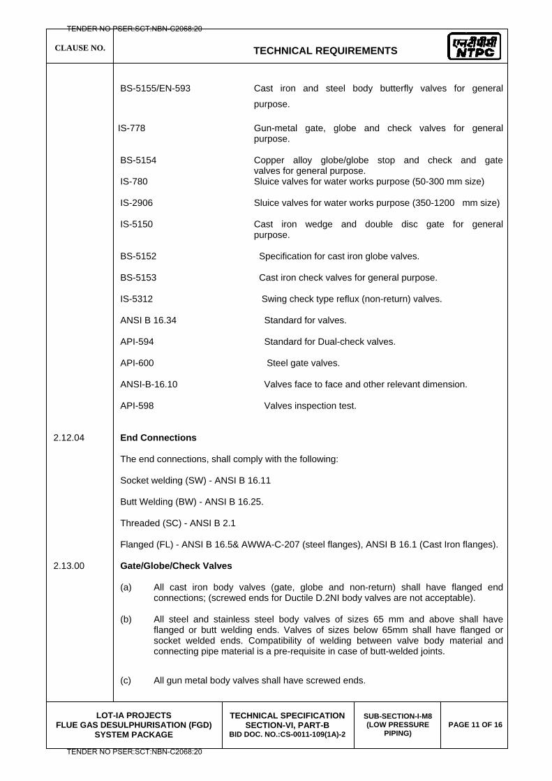
CLAUSE NO.
TECHNICAL REQUIREMENTS
LOT-IA PROJECTS
FLUE GAS DESULPHURISATION (FGD) SYSTEM PACKAGE
TECHNICAL SPECIFICATION SECTION-VI, PART-B
BID DOC. NO.:CS-0011-109(1A)-2
SUB-SECTION-I-M8 (LOW PRESSURE
PIPING) PAGE 11 OF 16
BS-5155/EN-593 Cast iron and steel body butterfly valves for general
purpose.
IS-778 Gun-metal gate, globe and check valves for general purpose.
BS-5154 Copper alloy globe/globe stop and check and gate
valves for general purpose. IS-780 Sluice valves for water works purpose (50-300 mm size) IS-2906 Sluice valves for water works purpose (350-1200 mm size)
IS-5150 Cast iron wedge and double disc gate for general purpose.
BS-5152 Specification for cast iron globe valves. BS-5153 Cast iron check valves for general purpose. IS-5312 Swing check type reflux (non-return) valves. ANSI B 16.34 Standard for valves. API-594 Standard for Dual-check valves. API-600 Steel gate valves. ANSI-B-16.10 Valves face to face and other relevant dimension. API-598 Valves inspection test. 2.12.04 End Connections The end connections, shall comply with the following: Socket welding (SW) - ANSI B 16.11 Butt Welding (BW) - ANSI B 16.25. Threaded (SC) - ANSI B 2.1 Flanged (FL) - ANSI B 16.5& AWWA-C-207 (steel flanges), ANSI B 16.1 (Cast Iron flanges). 2.13.00 Gate/Globe/Check Valves (a) All cast iron body valves (gate, globe and non-return) shall have flanged end
connections; (screwed ends for Ductile D.2NI body valves are not acceptable).
(b) All steel and stainless steel body valves of sizes 65 mm and above shall have flanged or butt welding ends. Valves of sizes below 65mm shall have flanged or socket welded ends. Compatibility of welding between valve body material and connecting pipe material is a pre-requisite in case of butt-welded joints.
(c) All gun metal body valves shall have screwed ends.
TENDER NO PSER:SCT:NBN-C2068:20
TENDER NO PSER:SCT:NBN-C2068:20
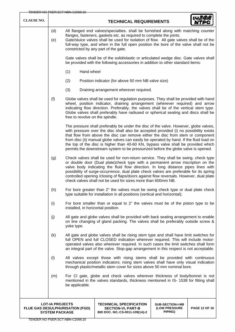
CLAUSE NO.
TECHNICAL REQUIREMENTS
LOT-IA PROJECTS
FLUE GAS DESULPHURISATION (FGD) SYSTEM PACKAGE
TECHNICAL SPECIFICATION SECTION-VI, PART-B
BID DOC. NO.:CS-0011-109(1A)-2
SUB-SECTION-I-M8 (LOW PRESSURE
PIPING) PAGE 12 OF 16
(d) All flanged end valves/specialties. shall be furnished along with matching counter flanges, fasteners, gaskets etc. as required to complete the joints.
(e) Gate/sluice valves shall be used for isolation of flow. All gate valves shall be of the full-way type, and when in the full open position the bore of the valve shall not be constricted by any part of the gate.
Gate valves shall be of the solid/elastic or articulated wedge disc. Gate valves shall
be provided with the following accessories in addition to other standard items: (1) Hand wheel (2) Position indicator (for above 50 mm NB valve size) (3) Draining arrangement wherever required. (f) Globe valves shall be used for regulation purposes. They shall be provided with hand
wheel, position indicator, draining arrangement (wherever required) and arrow indicating flow direction. Preferably, the valves shall be of the vertical stem type. Globe valves shall preferably have radiused or spherical seating and discs shall be free to revolve on the spindle.
The pressure shall preferably be under the disc of the valve. However, globe valves,
with pressure over the disc shall also be accepted provided (i) no possibility exists that flow from above the disc can remove either the disc from stem or component from disc (ii) manual globe valves can easily be operated by hand. If the fluid load on the top of the disc is higher than 40-60 KN, bypass valve shall be provided which permits the downstream system to be pressurized before the globe valve is opened.
(g) Check valves shall be used for non-return service. They shall be swing. check type
or double door (Dual plate)check type with a permanent arrow inscription on the valve body indicating the fluid flow direction. In long distance pipes lines with possibility of surge-occurrence, dual plate check valves are preferable for its spring controlled opening /closing of flaps/doors against flow reversals. However, dual plate check valves shall not be used for sizes more than 600mm NB.
(h) For bore greater than 2" the valves must be swing check type or dual plate check
type suitable for installation in all positions (vertical and horizontal); (i) For bore smaller than or equal to 2" the valves must be of the piston type to be
installed, in horizontal position. (j) All gate and globe valves shall be provided with back seating arrangement to enable
on line changing of gland packing. The valves shall be preferably outside screw & yoke type.
(k) All gate and globe valves shall be rising stem type and shall have limit switches for
full OPEN and full CLOSED indication wherever required. This will include motor-operated valves also wherever required. In such cases the limit switches shall form an integral part of the valve. Stop-gap arrangement in this respect is not acceptable.
(l) All valves except those with rising stems shall be provided with continuous mechanical position indicators; rising stem valves shall have only visual indication through plastic/metallic stem cover for sizes above 50 mm nominal bore.
(m) For Cl gate, globe and check valves wherever thickness of body/bonnet is not
mentioned in the valves standards, thickness mentioned in IS- 1538 for fitting shall be applicable.
TENDER NO PSER:SCT:NBN-C2068:20
TENDER NO PSER:SCT:NBN-C2068:20
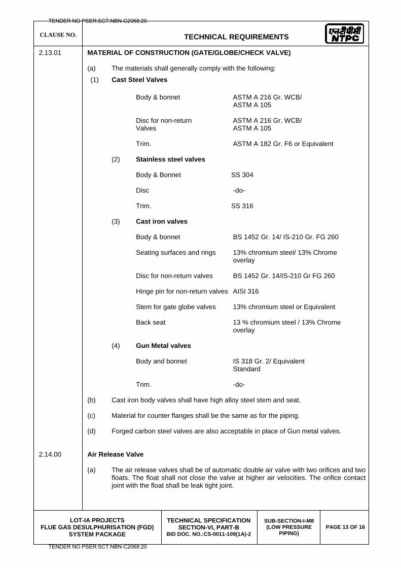
CLAUSE NO.
TECHNICAL REQUIREMENTS
LOT-IA PROJECTS
FLUE GAS DESULPHURISATION (FGD) SYSTEM PACKAGE
TECHNICAL SPECIFICATION SECTION-VI, PART-B
BID DOC. NO.:CS-0011-109(1A)-2
SUB-SECTION-I-M8 (LOW PRESSURE
PIPING) PAGE 13 OF 16
2.13.01 MATERIAL OF CONSTRUCTION (GATE/GLOBE/CHECK VALVE) (a) The materials shall generally comply with the following:
(1) Cast Steel Valves
Body & bonnet ASTM A 216 Gr. WCB/ ASTM A 105 Disc for non-return ASTM A 216 Gr. WCB/ Valves ASTM A 105 Trim. ASTM A 182 Gr. F6 or Equivalent (2) Stainless steel valves Body & Bonnet SS 304 Disc -do- Trim. SS 316
(3) Cast iron valves Body & bonnet BS 1452 Gr. 14/ IS-210 Gr. FG 260 Seating surfaces and rings 13% chromium steel/ 13% Chrome overlay Disc for non-return valves BS 1452 Gr. 14/IS-210 Gr FG 260 Hinge pin for non-return valves AISI 316 Stem for gate globe valves 13% chromium steel or Equivalent Back seat 13 % chromium steel / 13% Chrome overlay (4) Gun Metal valves Body and bonnet IS 318 Gr. 2/ Equivalent Standard Trim. -do- (b) Cast iron body valves shall have high alloy steel stem and seat.
(c) Material for counter flanges shall be the same as for the piping.
(d) Forged carbon steel valves are also acceptable in place of Gun metal valves.
2.14.00 Air Release Valve (a) The air release valves shall be of automatic double air valve with two orifices and two
floats. The float shall not close the valve at higher air velocities. The orifice contact joint with the float shall be leak tight joint.
TENDER NO PSER:SCT:NBN-C2068:20
TENDER NO PSER:SCT:NBN-C2068:20
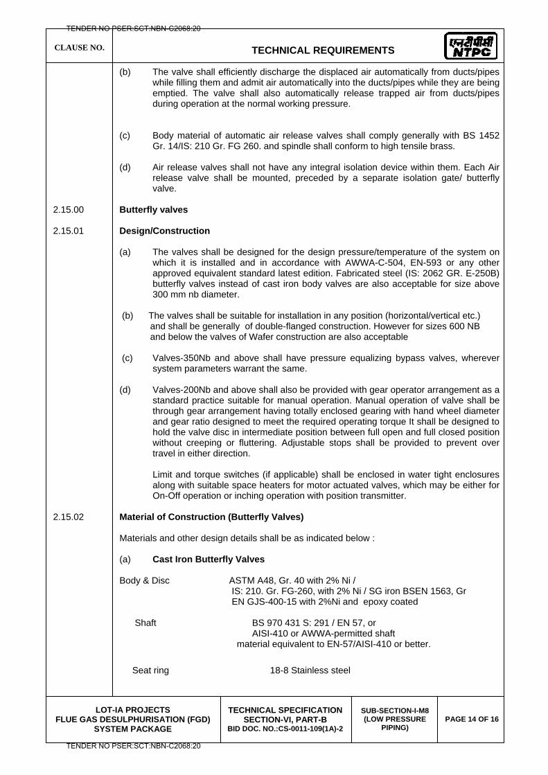
CLAUSE NO.
TECHNICAL REQUIREMENTS
LOT-IA PROJECTS
FLUE GAS DESULPHURISATION (FGD) SYSTEM PACKAGE
TECHNICAL SPECIFICATION SECTION-VI, PART-B
BID DOC. NO.:CS-0011-109(1A)-2
SUB-SECTION-I-M8 (LOW PRESSURE
PIPING) PAGE 14 OF 16
(b) The valve shall efficiently discharge the displaced air automatically from ducts/pipes while filling them and admit air automatically into the ducts/pipes while they are being emptied. The valve shall also automatically release trapped air from ducts/pipes during operation at the normal working pressure.
(c) Body material of automatic air release valves shall comply generally with BS 1452 Gr. 14/IS: 210 Gr. FG 260. and spindle shall conform to high tensile brass.
(d) Air release valves shall not have any integral isolation device within them. Each Air
release valve shall be mounted, preceded by a separate isolation gate/ butterfly valve.
2.15.00 Butterfly valves 2.15.01 Design/Construction
(a) The valves shall be designed for the design pressure/temperature of the system on which it is installed and in accordance with AWWA-C-504, EN-593 or any other approved equivalent standard latest edition. Fabricated steel (IS: 2062 GR. E-250B) butterfly valves instead of cast iron body valves are also acceptable for size above 300 mm nb diameter.
(b) The valves shall be suitable for installation in any position (horizontal/vertical etc.) and shall be generally of double-flanged construction. However for sizes 600 NB and below the valves of Wafer construction are also acceptable (c) Valves-350Nb and above shall have pressure equalizing bypass valves, wherever
system parameters warrant the same. (d) Valves-200Nb and above shall also be provided with gear operator arrangement as a
standard practice suitable for manual operation. Manual operation of valve shall be through gear arrangement having totally enclosed gearing with hand wheel diameter and gear ratio designed to meet the required operating torque It shall be designed to hold the valve disc in intermediate position between full open and full closed position without creeping or fluttering. Adjustable stops shall be provided to prevent over travel in either direction.
Limit and torque switches (if applicable) shall be enclosed in water tight enclosures along with suitable space heaters for motor actuated valves, which may be either for On-Off operation or inching operation with position transmitter.
2.15.02 Material of Construction (Butterfly Valves) Materials and other design details shall be as indicated below : (a) Cast Iron Butterfly Valves Body & Disc ASTM A48, Gr. 40 with 2% Ni / IS: 210. Gr. FG-260, with 2% Ni / SG iron BSEN 1563, Gr EN GJS-400-15 with 2%Ni and epoxy coated Shaft BS 970 431 S: 291 / EN 57, or AISI-410 or AWWA-permitted shaft material equivalent to EN-57/AISI-410 or better.
Seat ring 18-8 Stainless steel
TENDER NO PSER:SCT:NBN-C2068:20
TENDER NO PSER:SCT:NBN-C2068:20
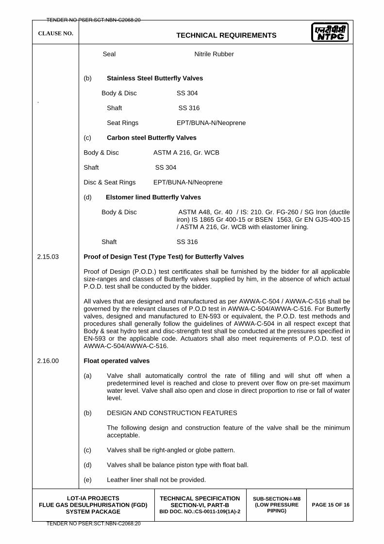
CLAUSE NO.
TECHNICAL REQUIREMENTS
LOT-IA PROJECTS
FLUE GAS DESULPHURISATION (FGD) SYSTEM PACKAGE
TECHNICAL SPECIFICATION SECTION-VI, PART-B
BID DOC. NO.:CS-0011-109(1A)-2
SUB-SECTION-I-M8 (LOW PRESSURE
PIPING) PAGE 15 OF 16
Seal Nitrile Rubber
(b) Stainless Steel Butterfly Valves Body & Disc SS 304 . Shaft SS 316 Seat Rings EPT/BUNA-N/Neoprene (c) Carbon steel Butterfly Valves Body & Disc ASTM A 216, Gr. WCB Shaft SS 304 Disc & Seat Rings EPT/BUNA-N/Neoprene (d) Elstomer lined Butterfly Valves Body & Disc ASTM A48, Gr. 40 / IS: 210. Gr. FG-260 / SG Iron (ductile
iron) IS 1865 Gr 400-15 or BSEN 1563, Gr EN GJS-400-15 / ASTM A 216, Gr. WCB with elastomer lining.
Shaft SS 316 2.15.03 Proof of Design Test (Type Test) for Butterfly Valves
Proof of Design (P.O.D.) test certificates shall be furnished by the bidder for all applicable size-ranges and classes of Butterfly valves supplied by him, in the absence of which actual P.O.D. test shall be conducted by the bidder. All valves that are designed and manufactured as per AWWA-C-504 / AWWA-C-516 shall be governed by the relevant clauses of P.O.D test in AWWA-C-504/AWWA-C-516. For Butterfly valves, designed and manufactured to EN-593 or equivalent, the P.O.D. test methods and procedures shall generally follow the guidelines of AWWA-C-504 in all respect except that Body & seat hydro test and disc-strength test shall be conducted at the pressures specified in EN-593 or the applicable code. Actuators shall also meet requirements of P.O.D. test of AWWA-C-504/AWWA-C-516.
2.16.00 Float operated valves (a) Valve shall automatically control the rate of filling and will shut off when a
predetermined level is reached and close to prevent over flow on pre-set maximum water level. Valve shall also open and close in direct proportion to rise or fall of water level.
(b) DESIGN AND CONSTRUCTION FEATURES
The following design and construction feature of the valve shall be the minimum acceptable.
(c) Valves shall be right-angled or globe pattern. (d) Valves shall be balance piston type with float ball. (e) Leather liner shall not be provided.
TENDER NO PSER:SCT:NBN-C2068:20
TENDER NO PSER:SCT:NBN-C2068:20
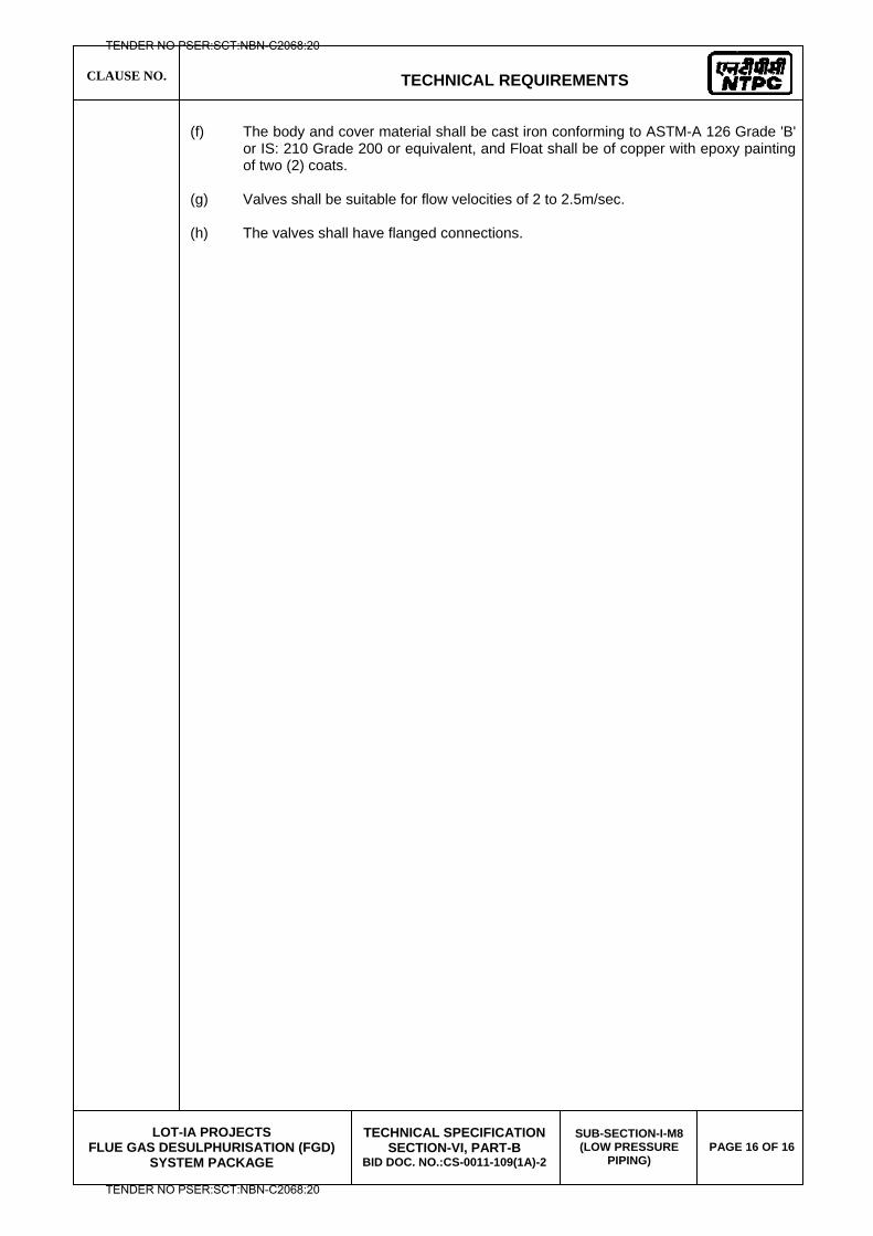
CLAUSE NO.
TECHNICAL REQUIREMENTS
LOT-IA PROJECTS
FLUE GAS DESULPHURISATION (FGD) SYSTEM PACKAGE
TECHNICAL SPECIFICATION SECTION-VI, PART-B
BID DOC. NO.:CS-0011-109(1A)-2
SUB-SECTION-I-M8 (LOW PRESSURE
PIPING) PAGE 16 OF 16
(f) The body and cover material shall be cast iron conforming to ASTM-A 126 Grade 'B'
or IS: 210 Grade 200 or equivalent, and Float shall be of copper with epoxy painting of two (2) coats.
(g) Valves shall be suitable for flow velocities of 2 to 2.5m/sec. (h) The valves shall have flanged connections.
TENDER NO PSER:SCT:NBN-C2068:20
TENDER NO PSER:SCT:NBN-C2068:20

LOT-IA PROJECTS FLUE GAS DESULPHURISATION (FGD) SYSTEM PACKAGE
TECHNICAL SPECIFICATION
SECTION-VI
BID DOCUMENT NO.: CS-0011-109(1A)-2
SUB-SECTION-I-M9
MDL
TENDER NO PSER:SCT:NBN-C2068:20
TENDER NO PSER:SCT:NBN-C2068:20
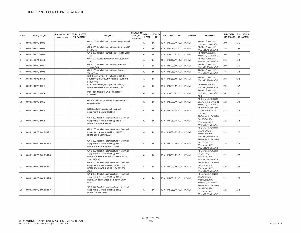
S. No. NTPC_DRG_NORev_drg_no_for_
inouhse_drgTO_BE_SHIFTED_TO_PACKAGE
DRG_TITLEPROJECT_SPECIFC_INFORMATION
DRG_PURPOSE
DRG_TYPE
AREA MILESTONE CUSTODIAN REVIEWERSSUB_FROM_MP_AWARD
SUB_FROM_FGD_AWARD
1 0000‐109‐PVC‐B‐001GA & RCC Detail of Foundation of Reagent Feed Tank
A D FGD MISCELLANEOUS PE‐CivilPE‐Mech/Layout,PE‐Mech/SG,PE‐Mech/SG,
290 140
2 0000‐109‐PVC‐B‐002GA & RCC Detail of Foundation of Secondary HC Feed Tank
A D FGD MISCELLANEOUS PE‐CivilPE‐Mech/Layout,PE‐Mech/SG,PE‐Mech/SG,
255 105
3 0000‐109‐PVC‐B‐003GA & RCC Detail of Foundation of Filtrate water Tank
A D FGD MISCELLANEOUS PE‐CivilPE‐Mech/Layout,PE‐Mech/SG,PE‐Mech/SG,
283 133
4 0000‐109‐PVC‐B‐004GA & RCC Detailof Foundation of Waste water Tank
A D FGD MISCELLANEOUS PE‐CivilPE‐Mech/Layout,PE‐Mech/SG,PE‐Mech/SG,
290 140
5 0000‐109‐PVC‐B‐005GA & RCC Detail of Foundation of Auxilliary Storage Tank
A D FGD MISCELLANEOUS PE‐CivilPE‐Mech/Layout,PE‐Mech/SG,PE‐Mech/SG,
290 140
6 0000‐109‐PVC‐B‐006GA & RCC Detail of Foundation of Process Water Tank
A D FGD MISCELLANEOUS PE‐CivilPE‐Mech/Layout,PE‐Mech/SG,PE‐Mech/SG,
283 133
7 0000‐109‐PVC‐B‐010GGH‐Layout of Piles (If applicable) ‐ GA OF FOUNDATION & COLUMN FOR GGH SUPPORT STRUCTURE
A D FGD MISCELLANEOUS PE‐CivilPE‐Mech/Layout,PE‐Mech/SG,PE‐Mech/SG,
292 142
8 0000‐109‐PVC‐B‐011GGH ‐ Foundation/Pilecap & Pedestal ‐ R/F DETAILS FOR GGH SUPPORT STRUCTURE
A D FGD MISCELLANEOUS PE‐CivilPE‐Mech/Layout,PE‐Mech/SG,PE‐Mech/SG,
292 142
9 0000‐109‐PVC‐B‐014Pipe Rack structure‐ GA & RCC detail of Foundation
A D FGD MISCELLANEOUS PE‐CivilPE‐Mech/Layout,PE‐Mech/SG,PE‐Mech/SG,PE‐Civil,
302 152
10 0000‐109‐PVC‐B‐016GA of Foundation of Electrical equipments & control Building
A D FGD MISCELLANEOUS PE‐CivilPE‐Electrical,PE‐C&I,PE‐C&I,PE‐Mech/Layout,PE‐Mech/SG,PE‐Mech/SG,
322 172
11 0000‐109‐PVC‐B‐017RCC Detail of Foundation of Electrical equipments & control Building
A D FGD MISCELLANEOUS PE‐CivilPE‐Electrical,PE‐C&I,PE‐C&I,PE‐Mech/SG,PE‐Mech/SG,
322 172
12 0000‐109‐PVC‐B‐018GA & RCC Detail of Superstructure of Electrical equipments & control Building ‐ SHEET‐1 ‐ DETAILS OF GRADE BEAMS
A D FGD MISCELLANEOUS PE‐Civil
PE‐Electrical,PE‐C&I,PE‐C&I,PE‐Civil,PE‐Mech/Layout,PE‐Mech/SG,PE‐Mech/SG,
322 172
13 0000‐109‐PVC‐B‐018‐SHT‐2GA & RCC Detail of Superstructure of Electrical equipments & control Building ‐ SHEET‐2 ‐ DETAILS OF LINTEN BEAMS
A D FGD MISCELLANEOUS PE‐Civil
PE‐Electrical,PE‐C&I,PE‐C&I,PE‐Civil,PE‐Mech/Layout,PE‐Mech/SG,PE‐Mech/SG,
322 172
14 0000‐109‐PVC‐B‐018‐SHT‐3GA & RCC Detail of Superstructure of Electrical equipments & control Building ‐ SHEET‐3 ‐ DETAILS OF FLOOR BEAMS & SLABS
A D FGD MISCELLANEOUS PE‐Civil
PE‐Electrical,PE‐C&I,PE‐C&I,PE‐Civil,PE‐Mech/Layout,PE‐Mech/SG,PE‐Mech/SG,
322 172
15 0000‐109‐PVC‐B‐018‐SHT‐4
GA & RCC Detail of Superstructure of Electrical equipments & control Building ‐ SHEET‐4 ‐ DETAILS OF FROOF BEAMS & SLABS AT RL (+) 295.250 (TOC)
A D FGD MISCELLANEOUS PE‐Civil
PE‐Electrical,PE‐C&I,PE‐C&I,PE‐Civil,PE‐Mech/Layout,PE‐Mech/SG,PE‐Mech/SG,
322 172
16 0000‐109‐PVC‐B‐018‐SHT‐5
GA & RCC Detail of Superstructure of Electrical equipments & control Building ‐ SHEET‐5 ‐ DETAILS OF GRADE SLAB AT RL (+) 285.800 (TOC)
A D FGD MISCELLANEOUS PE‐Civil
PE‐Electrical,PE‐C&I,PE‐C&I,PE‐Civil,PE‐Mech/Layout,PE‐Mech/SG,PE‐Mech/SG,
322 172
17 0000‐109‐PVC‐B‐018‐SHT‐6
GA & RCC Detail of Superstructure of Electrical equipments & control Building ‐ SHEET‐6 ‐ DETAILS OF STAIR CASES & ITS BEAM UPTO ROOF
A D FGD MISCELLANEOUS PE‐Civil
PE‐Electrical,PE‐C&I,PE‐C&I,PE‐Civil,PE‐Mech/Layout,PE‐Mech/SG,PE‐Mech/SG,
322 172
18 0000‐109‐PVC‐B‐018‐SHT‐7GA & RCC Detail of Superstructure of Electrical equipments & control Building ‐ SHEET‐7 ‐ DETAILS OF COLUMNS
A D FGD MISCELLANEOUS PE‐Civil
PE‐Electrical,PE‐C&I,PE‐C&I,PE‐Civil,PE‐Mech/Layout,PE‐Mech/SG,PE‐Mech/SG,
322 172
LOT‐IA PROJECTSFLUE GAS DESULPHURISATION (FGD) SYSTEM PACKAGE
SUB‐SECTION‐I‐M9MDL
PAGE 1 OF 24
TENDER NO PSER:SCT:NBN-C2068:20
TENDER NO PSER:SCT:NBN-C2068:20
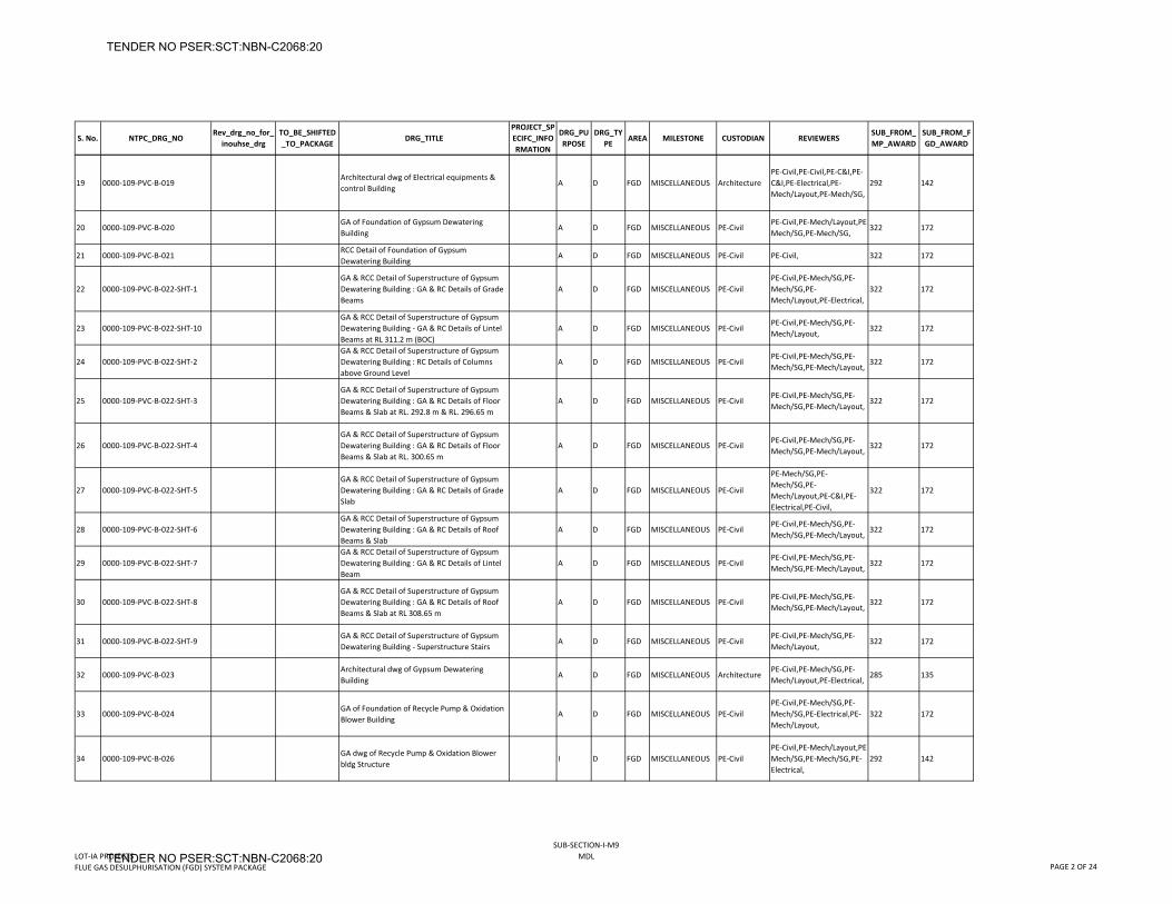
S. No. NTPC_DRG_NORev_drg_no_for_
inouhse_drgTO_BE_SHIFTED_TO_PACKAGE
DRG_TITLEPROJECT_SPECIFC_INFORMATION
DRG_PURPOSE
DRG_TYPE
AREA MILESTONE CUSTODIAN REVIEWERSSUB_FROM_MP_AWARD
SUB_FROM_FGD_AWARD
19 0000‐109‐PVC‐B‐019Architectural dwg of Electrical equipments & control Building
A D FGD MISCELLANEOUS ArchitecturePE‐Civil,PE‐Civil,PE‐C&I,PE‐C&I,PE‐Electrical,PE‐Mech/Layout,PE‐Mech/SG,
292 142
20 0000‐109‐PVC‐B‐020GA of Foundation of Gypsum Dewatering Building
A D FGD MISCELLANEOUS PE‐CivilPE‐Civil,PE‐Mech/Layout,PE‐Mech/SG,PE‐Mech/SG,
322 172
21 0000‐109‐PVC‐B‐021RCC Detail of Foundation of Gypsum Dewatering Building
A D FGD MISCELLANEOUS PE‐Civil PE‐Civil, 322 172
22 0000‐109‐PVC‐B‐022‐SHT‐1GA & RCC Detail of Superstructure of Gypsum Dewatering Building : GA & RC Details of Grade Beams
A D FGD MISCELLANEOUS PE‐CivilPE‐Civil,PE‐Mech/SG,PE‐Mech/SG,PE‐Mech/Layout,PE‐Electrical,
322 172
23 0000‐109‐PVC‐B‐022‐SHT‐10GA & RCC Detail of Superstructure of Gypsum Dewatering Building ‐ GA & RC Details of Lintel Beams at RL 311.2 m (BOC)
A D FGD MISCELLANEOUS PE‐CivilPE‐Civil,PE‐Mech/SG,PE‐Mech/Layout,
322 172
24 0000‐109‐PVC‐B‐022‐SHT‐2GA & RCC Detail of Superstructure of Gypsum Dewatering Building : RC Details of Columns above Ground Level
A D FGD MISCELLANEOUS PE‐CivilPE‐Civil,PE‐Mech/SG,PE‐Mech/SG,PE‐Mech/Layout,
322 172
25 0000‐109‐PVC‐B‐022‐SHT‐3GA & RCC Detail of Superstructure of Gypsum Dewatering Building : GA & RC Details of Floor Beams & Slab at RL. 292.8 m & RL. 296.65 m
A D FGD MISCELLANEOUS PE‐CivilPE‐Civil,PE‐Mech/SG,PE‐Mech/SG,PE‐Mech/Layout,
322 172
26 0000‐109‐PVC‐B‐022‐SHT‐4GA & RCC Detail of Superstructure of Gypsum Dewatering Building : GA & RC Details of Floor Beams & Slab at RL. 300.65 m
A D FGD MISCELLANEOUS PE‐CivilPE‐Civil,PE‐Mech/SG,PE‐Mech/SG,PE‐Mech/Layout,
322 172
27 0000‐109‐PVC‐B‐022‐SHT‐5GA & RCC Detail of Superstructure of Gypsum Dewatering Building : GA & RC Details of Grade Slab
A D FGD MISCELLANEOUS PE‐Civil
PE‐Mech/SG,PE‐Mech/SG,PE‐Mech/Layout,PE‐C&I,PE‐Electrical,PE‐Civil,
322 172
28 0000‐109‐PVC‐B‐022‐SHT‐6GA & RCC Detail of Superstructure of Gypsum Dewatering Building : GA & RC Details of Roof Beams & Slab
A D FGD MISCELLANEOUS PE‐CivilPE‐Civil,PE‐Mech/SG,PE‐Mech/SG,PE‐Mech/Layout,
322 172
29 0000‐109‐PVC‐B‐022‐SHT‐7GA & RCC Detail of Superstructure of Gypsum Dewatering Building : GA & RC Details of Lintel Beam
A D FGD MISCELLANEOUS PE‐CivilPE‐Civil,PE‐Mech/SG,PE‐Mech/SG,PE‐Mech/Layout,
322 172
30 0000‐109‐PVC‐B‐022‐SHT‐8GA & RCC Detail of Superstructure of Gypsum Dewatering Building : GA & RC Details of Roof Beams & Slab at RL 308.65 m
A D FGD MISCELLANEOUS PE‐CivilPE‐Civil,PE‐Mech/SG,PE‐Mech/SG,PE‐Mech/Layout,
322 172
31 0000‐109‐PVC‐B‐022‐SHT‐9GA & RCC Detail of Superstructure of Gypsum Dewatering Building ‐ Superstructure Stairs
A D FGD MISCELLANEOUS PE‐CivilPE‐Civil,PE‐Mech/SG,PE‐Mech/Layout,
322 172
32 0000‐109‐PVC‐B‐023Architectural dwg of Gypsum Dewatering Building
A D FGD MISCELLANEOUS ArchitecturePE‐Civil,PE‐Mech/SG,PE‐Mech/Layout,PE‐Electrical,
285 135
33 0000‐109‐PVC‐B‐024GA of Foundation of Recycle Pump & Oxidation Blower Building
A D FGD MISCELLANEOUS PE‐CivilPE‐Civil,PE‐Mech/SG,PE‐Mech/SG,PE‐Electrical,PE‐Mech/Layout,
322 172
34 0000‐109‐PVC‐B‐026GA dwg of Recycle Pump & Oxidation Blower bldg Structure
I D FGD MISCELLANEOUS PE‐CivilPE‐Civil,PE‐Mech/Layout,PE‐Mech/SG,PE‐Mech/SG,PE‐Electrical,
292 142
LOT‐IA PROJECTSFLUE GAS DESULPHURISATION (FGD) SYSTEM PACKAGE
SUB‐SECTION‐I‐M9MDL
PAGE 2 OF 24
TENDER NO PSER:SCT:NBN-C2068:20
TENDER NO PSER:SCT:NBN-C2068:20
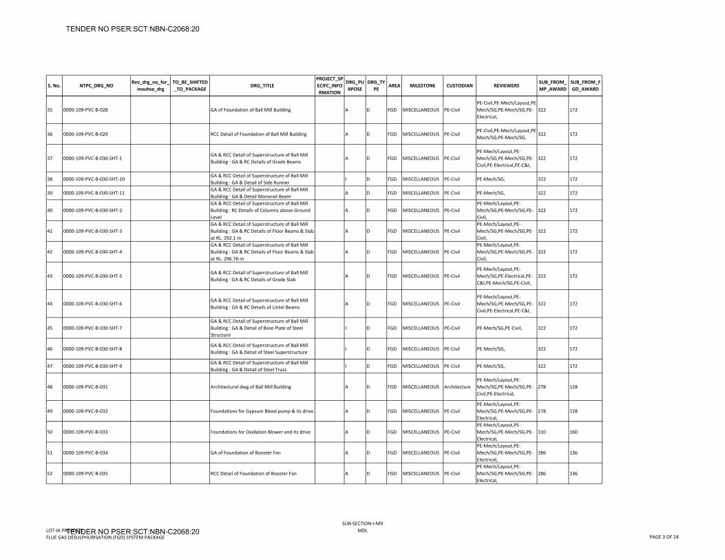
S. No. NTPC_DRG_NORev_drg_no_for_
inouhse_drgTO_BE_SHIFTED_TO_PACKAGE
DRG_TITLEPROJECT_SPECIFC_INFORMATION
DRG_PURPOSE
DRG_TYPE
AREA MILESTONE CUSTODIAN REVIEWERSSUB_FROM_MP_AWARD
SUB_FROM_FGD_AWARD
35 0000‐109‐PVC‐B‐028 GA of Foundation of Ball Mill Building A D FGD MISCELLANEOUS PE‐CivilPE‐Civil,PE‐Mech/Layout,PE‐Mech/SG,PE‐Mech/SG,PE‐Electrical,
322 172
36 0000‐109‐PVC‐B‐029 RCC Detail of Foundation of Ball Mill Building A D FGD MISCELLANEOUS PE‐CivilPE‐Civil,PE‐Mech/Layout,PE‐Mech/SG,PE‐Mech/SG,
322 172
37 0000‐109‐PVC‐B‐030‐SHT‐1GA & RCC Detail of Superstructure of Ball Mill Building : GA & RC Details of Grade Beams
A D FGD MISCELLANEOUS PE‐CivilPE‐Mech/Layout,PE‐Mech/SG,PE‐Mech/SG,PE‐Civil,PE‐Electrical,PE‐C&I,
322 172
38 0000‐109‐PVC‐B‐030‐SHT‐10GA & RCC Detail of Superstructure of Ball Mill Building : GA & Detail of Side Runner
I D FGD MISCELLANEOUS PE‐Civil PE‐Mech/SG, 322 172
39 0000‐109‐PVC‐B‐030‐SHT‐11GA & RCC Detail of Superstructure of Ball Mill Building : GA & Detail Monorail Beam
A D FGD MISCELLANEOUS PE‐Civil PE‐Mech/SG, 322 172
40 0000‐109‐PVC‐B‐030‐SHT‐2GA & RCC Detail of Superstructure of Ball Mill Building : RC Details of Columns above Ground Level
A D FGD MISCELLANEOUS PE‐CivilPE‐Mech/Layout,PE‐Mech/SG,PE‐Mech/SG,PE‐Civil,
322 172
41 0000‐109‐PVC‐B‐030‐SHT‐3GA & RCC Detail of Superstructure of Ball Mill Building : GA & RC Details of Floor Beams & Slab at RL. 292.1 m
A D FGD MISCELLANEOUS PE‐CivilPE‐Mech/Layout,PE‐Mech/SG,PE‐Mech/SG,PE‐Civil,
322 172
42 0000‐109‐PVC‐B‐030‐SHT‐4GA & RCC Detail of Superstructure of Ball Mill Building : GA & RC Details of Floor Beams & Slab at RL. 296.76 m
A D FGD MISCELLANEOUS PE‐CivilPE‐Mech/Layout,PE‐Mech/SG,PE‐Mech/SG,PE‐Civil,
322 172
43 0000‐109‐PVC‐B‐030‐SHT‐5GA & RCC Detail of Superstructure of Ball Mill Building : GA & RC Details of Grade Slab
A D FGD MISCELLANEOUS PE‐CivilPE‐Mech/Layout,PE‐Mech/SG,PE‐Electrical,PE‐C&I,PE‐Mech/SG,PE‐Civil,
322 172
44 0000‐109‐PVC‐B‐030‐SHT‐6GA & RCC Detail of Superstructure of Ball Mill Building : GA & RC Details of Lintel Beams
A D FGD MISCELLANEOUS PE‐CivilPE‐Mech/Layout,PE‐Mech/SG,PE‐Mech/SG,PE‐Civil,PE‐Electrical,PE‐C&I,
322 172
45 0000‐109‐PVC‐B‐030‐SHT‐7GA & RCC Detail of Superstructure of Ball Mill Building : GA & Detail of Base Plate of Steel Structure
I D FGD MISCELLANEOUS PE‐Civil PE‐Mech/SG,PE‐Civil, 322 172
46 0000‐109‐PVC‐B‐030‐SHT‐8GA & RCC Detail of Superstructure of Ball Mill Building : GA & Detail of Steel Superstructure
I D FGD MISCELLANEOUS PE‐Civil PE‐Mech/SG, 322 172
47 0000‐109‐PVC‐B‐030‐SHT‐9GA & RCC Detail of Superstructure of Ball Mill Building : GA & Detail of Steel Truss
I D FGD MISCELLANEOUS PE‐Civil PE‐Mech/SG, 322 172
48 0000‐109‐PVC‐B‐031 Architectural dwg of Ball Mill Building A D FGD MISCELLANEOUS ArchitecturePE‐Mech/Layout,PE‐Mech/SG,PE‐Mech/SG,PE‐Civil,PE‐Electrical,
278 128
49 0000‐109‐PVC‐B‐032 Foundations for Gypsum Bleed pump & its drive A D FGD MISCELLANEOUS PE‐CivilPE‐Mech/Layout,PE‐Mech/SG,PE‐Mech/SG,PE‐Electrical,
278 128
50 0000‐109‐PVC‐B‐033 Foundations for Oxidation Blower and its drive A D FGD MISCELLANEOUS PE‐CivilPE‐Mech/Layout,PE‐Mech/SG,PE‐Mech/SG,PE‐Electrical,
310 160
51 0000‐109‐PVC‐B‐034 GA of Foundation of Booster Fan A D FGD MISCELLANEOUS PE‐CivilPE‐Mech/Layout,PE‐Mech/SG,PE‐Mech/SG,PE‐Electrical,
286 136
52 0000‐109‐PVC‐B‐035 RCC Detail of Foundation of Booster Fan A D FGD MISCELLANEOUS PE‐CivilPE‐Mech/Layout,PE‐Mech/SG,PE‐Mech/SG,PE‐Electrical,
286 136
LOT‐IA PROJECTSFLUE GAS DESULPHURISATION (FGD) SYSTEM PACKAGE
SUB‐SECTION‐I‐M9MDL
PAGE 3 OF 24
TENDER NO PSER:SCT:NBN-C2068:20
TENDER NO PSER:SCT:NBN-C2068:20
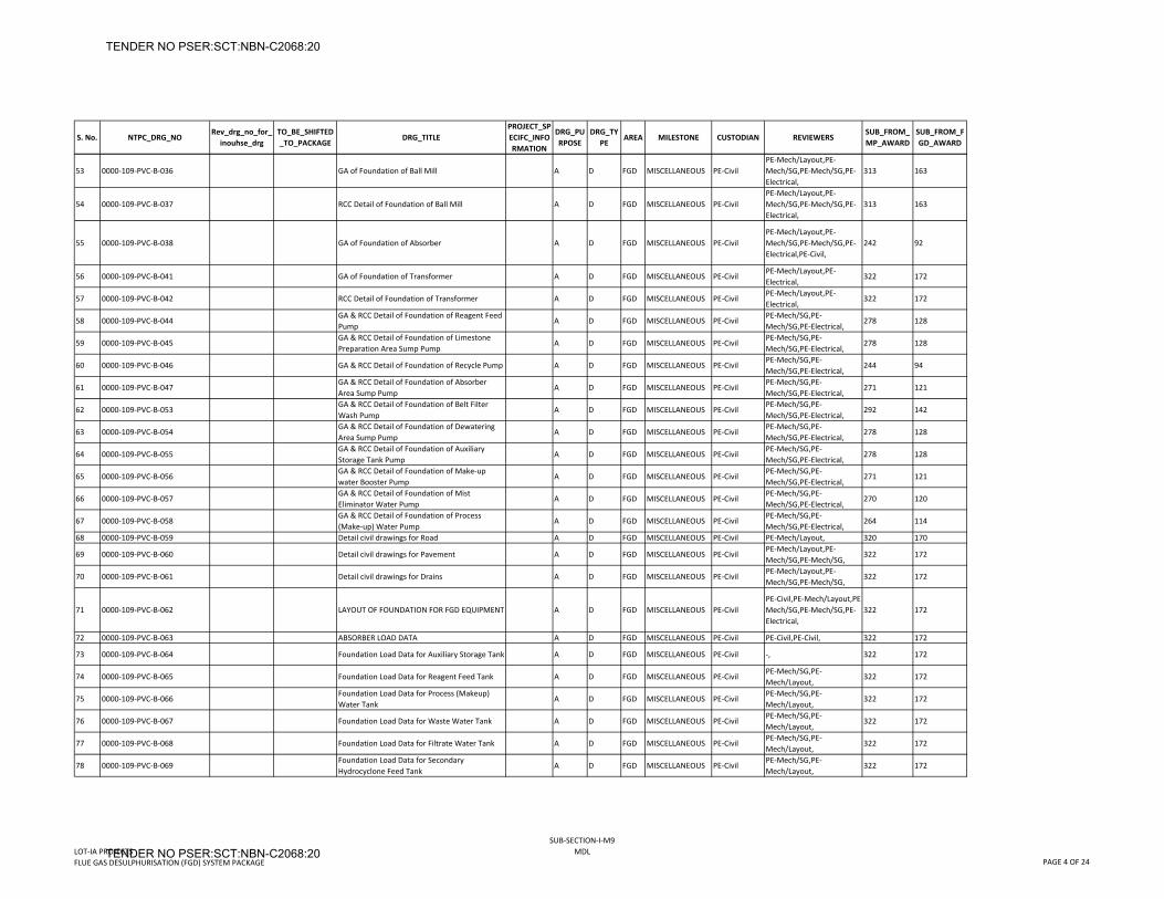
S. No. NTPC_DRG_NORev_drg_no_for_
inouhse_drgTO_BE_SHIFTED_TO_PACKAGE
DRG_TITLEPROJECT_SPECIFC_INFORMATION
DRG_PURPOSE
DRG_TYPE
AREA MILESTONE CUSTODIAN REVIEWERSSUB_FROM_MP_AWARD
SUB_FROM_FGD_AWARD
53 0000‐109‐PVC‐B‐036 GA of Foundation of Ball Mill A D FGD MISCELLANEOUS PE‐CivilPE‐Mech/Layout,PE‐Mech/SG,PE‐Mech/SG,PE‐Electrical,
313 163
54 0000‐109‐PVC‐B‐037 RCC Detail of Foundation of Ball Mill A D FGD MISCELLANEOUS PE‐CivilPE‐Mech/Layout,PE‐Mech/SG,PE‐Mech/SG,PE‐Electrical,
313 163
55 0000‐109‐PVC‐B‐038 GA of Foundation of Absorber A D FGD MISCELLANEOUS PE‐CivilPE‐Mech/Layout,PE‐Mech/SG,PE‐Mech/SG,PE‐Electrical,PE‐Civil,
242 92
56 0000‐109‐PVC‐B‐041 GA of Foundation of Transformer A D FGD MISCELLANEOUS PE‐CivilPE‐Mech/Layout,PE‐Electrical,
322 172
57 0000‐109‐PVC‐B‐042 RCC Detail of Foundation of Transformer A D FGD MISCELLANEOUS PE‐CivilPE‐Mech/Layout,PE‐Electrical,
322 172
58 0000‐109‐PVC‐B‐044GA & RCC Detail of Foundation of Reagent Feed Pump
A D FGD MISCELLANEOUS PE‐CivilPE‐Mech/SG,PE‐Mech/SG,PE‐Electrical,
278 128
59 0000‐109‐PVC‐B‐045GA & RCC Detail of Foundation of Limestone Preparation Area Sump Pump
A D FGD MISCELLANEOUS PE‐CivilPE‐Mech/SG,PE‐Mech/SG,PE‐Electrical,
278 128
60 0000‐109‐PVC‐B‐046 GA & RCC Detail of Foundation of Recycle Pump A D FGD MISCELLANEOUS PE‐CivilPE‐Mech/SG,PE‐Mech/SG,PE‐Electrical,
244 94
61 0000‐109‐PVC‐B‐047GA & RCC Detail of Foundation of Absorber Area Sump Pump
A D FGD MISCELLANEOUS PE‐CivilPE‐Mech/SG,PE‐Mech/SG,PE‐Electrical,
271 121
62 0000‐109‐PVC‐B‐053GA & RCC Detail of Foundation of Belt Filter Wash Pump
A D FGD MISCELLANEOUS PE‐CivilPE‐Mech/SG,PE‐Mech/SG,PE‐Electrical,
292 142
63 0000‐109‐PVC‐B‐054GA & RCC Detail of Foundation of Dewatering Area Sump Pump
A D FGD MISCELLANEOUS PE‐CivilPE‐Mech/SG,PE‐Mech/SG,PE‐Electrical,
278 128
64 0000‐109‐PVC‐B‐055GA & RCC Detail of Foundation of Auxiliary Storage Tank Pump
A D FGD MISCELLANEOUS PE‐CivilPE‐Mech/SG,PE‐Mech/SG,PE‐Electrical,
278 128
65 0000‐109‐PVC‐B‐056GA & RCC Detail of Foundation of Make‐up water Booster Pump
A D FGD MISCELLANEOUS PE‐CivilPE‐Mech/SG,PE‐Mech/SG,PE‐Electrical,
271 121
66 0000‐109‐PVC‐B‐057GA & RCC Detail of Foundation of Mist Eliminator Water Pump
A D FGD MISCELLANEOUS PE‐CivilPE‐Mech/SG,PE‐Mech/SG,PE‐Electrical,
270 120
67 0000‐109‐PVC‐B‐058GA & RCC Detail of Foundation of Process (Make‐up) Water Pump
A D FGD MISCELLANEOUS PE‐CivilPE‐Mech/SG,PE‐Mech/SG,PE‐Electrical,
264 114
68 0000‐109‐PVC‐B‐059 Detail civil drawings for Road A D FGD MISCELLANEOUS PE‐Civil PE‐Mech/Layout, 320 170
69 0000‐109‐PVC‐B‐060 Detail civil drawings for Pavement A D FGD MISCELLANEOUS PE‐CivilPE‐Mech/Layout,PE‐Mech/SG,PE‐Mech/SG,
322 172
70 0000‐109‐PVC‐B‐061 Detail civil drawings for Drains A D FGD MISCELLANEOUS PE‐CivilPE‐Mech/Layout,PE‐Mech/SG,PE‐Mech/SG,
322 172
71 0000‐109‐PVC‐B‐062 LAYOUT OF FOUNDATION FOR FGD EQUIPMENT A D FGD MISCELLANEOUS PE‐CivilPE‐Civil,PE‐Mech/Layout,PE‐Mech/SG,PE‐Mech/SG,PE‐Electrical,
322 172
72 0000‐109‐PVC‐B‐063 ABSORBER LOAD DATA A D FGD MISCELLANEOUS PE‐Civil PE‐Civil,PE‐Civil, 322 172
73 0000‐109‐PVC‐B‐064 Foundation Load Data for Auxiliary Storage Tank A D FGD MISCELLANEOUS PE‐Civil ‐, 322 172
74 0000‐109‐PVC‐B‐065 Foundation Load Data for Reagent Feed Tank A D FGD MISCELLANEOUS PE‐CivilPE‐Mech/SG,PE‐Mech/Layout,
322 172
75 0000‐109‐PVC‐B‐066Foundation Load Data for Process (Makeup) Water Tank
A D FGD MISCELLANEOUS PE‐CivilPE‐Mech/SG,PE‐Mech/Layout,
322 172
76 0000‐109‐PVC‐B‐067 Foundation Load Data for Waste Water Tank A D FGD MISCELLANEOUS PE‐CivilPE‐Mech/SG,PE‐Mech/Layout,
322 172
77 0000‐109‐PVC‐B‐068 Foundation Load Data for Filtrate Water Tank A D FGD MISCELLANEOUS PE‐CivilPE‐Mech/SG,PE‐Mech/Layout,
322 172
78 0000‐109‐PVC‐B‐069Foundation Load Data for Secondary Hydrocyclone Feed Tank
A D FGD MISCELLANEOUS PE‐CivilPE‐Mech/SG,PE‐Mech/Layout,
322 172
LOT‐IA PROJECTSFLUE GAS DESULPHURISATION (FGD) SYSTEM PACKAGE
SUB‐SECTION‐I‐M9MDL
PAGE 4 OF 24
TENDER NO PSER:SCT:NBN-C2068:20
TENDER NO PSER:SCT:NBN-C2068:20
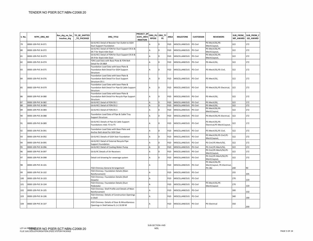
S. No. NTPC_DRG_NORev_drg_no_for_
inouhse_drgTO_BE_SHIFTED_TO_PACKAGE
DRG_TITLEPROJECT_SPECIFC_INFORMATION
DRG_PURPOSE
DRG_TYPE
AREA MILESTONE CUSTODIAN REVIEWERSSUB_FROM_MP_AWARD
SUB_FROM_FGD_AWARD
79 0000‐109‐PVC‐B‐071GA & RCC Detail of Booster Fan Outlet to GGH Duct Support Foundation
A D FGD MISCELLANEOUS PE‐CivilPE‐Mech/SG,PE‐Mech/Layout,
322 172
80 0000‐109‐PVC‐B‐072GA & RCC Detail of FDN for Duct Support DS 6 & DS 7 for Stack Inlet Duct
A D FGD MISCELLANEOUS PE‐CivilPE‐Mech/SG,PE‐Mech/Layout,
322 172
81 0000‐109‐PVC‐B‐073GA & RCC Detail of FDN for Duct Support DS 8 & DS 9 for Stack Inlet Duct
A D FGD MISCELLANEOUS PE‐CivilPE‐Mech/SG,PE‐Mech/Layout,
322 172
82 0000‐109‐PVC‐B‐074FDN Load Data with Base Plate & FDN Bolt Detail for DS 8&9
A D FGD MISCELLANEOUS PE‐Civil PE‐Mech/SG, 322 172
83 0000‐109‐PVC‐B‐075Foundation Load Data with base Plate & Foundation Bolt Detail For GGH Support Structure
A D FGD MISCELLANEOUS PE‐Civil PE‐Mech/SG,PE‐Civil, 322 172
84 0000‐109‐PVC‐B‐076Foundation Load Data with base Plate & Foundation Bolt Detail For Duct Support Structure DS‐1
A D FGD MISCELLANEOUS PE‐Civil PE‐Mech/SG, 322 172
85 0000‐109‐PVC‐B‐079Foundation Load Data with base Plate & Foundation Bolt Detail For Pipe & Cable Support Structure
A D FGD MISCELLANEOUS PE‐Civil PE‐Mech/SG,PE‐Electrical, 322 172
86 0000‐109‐PVC‐B‐080Foundation Load Data with base Plate & Foundation Bolt Detail For Recycle Pipe Support Structure
A D FGD MISCELLANEOUS PE‐Civil PE‐Mech/SG, 322 172
87 0000‐109‐PVC‐B‐082 GA & RCC Detail of FDN DS 1 A D FGD MISCELLANEOUS PE‐Civil PE‐Mech/SG, 322 17288 0000‐109‐PVC‐B‐083 GA & RCC Detail of FDN DS 2 A D FGD MISCELLANEOUS PE‐Civil PE‐Mech/SG, 322 172
89 0000‐109‐PVC‐B‐084 GA & RCC Detail of FDN DS 3 A D FGD MISCELLANEOUS PE‐CivilPE‐Mech/SG,PE‐Mech/Layout,
322 172
90 0000‐109‐PVC‐B‐088Foundation Load Data of Pipe & Cable Tray Support Structure
A D FGD MISCELLANEOUS PE‐Civil PE‐Mech/SG,PE‐Electrical, 322 172
91 0000‐109‐PVC‐B‐089GA & RCC Details of Pipe & Cable Support Foundations mkd. F3 to F5
A D FGD MISCELLANEOUS PE‐CivilPE‐Mech/SG,PE‐Electrical,PE‐Mech/Layout,
322 172
92 0000‐109‐PVC‐B‐091Foundation Load Data with Base Plate and Anchor Bolt detail for GGH Stair
A D FGD MISCELLANEOUS PE‐Civil PE‐Mech/SG,PE‐Civil, 322 172
93 0000‐109‐PVC‐B‐092 GA & RCC Details of GGH Stair Foundation A D FGD MISCELLANEOUS PE‐CivilPE‐Mech/SG,PE‐Civil,PE‐Mech/Layout,
322 172
94 0000‐109‐PVC‐B‐095GA & RCC Detail of External Recycle Pipe Support Foundation
A D FGD MISCELLANEOUS PE‐Civil PE‐Civil,PE‐Mech/SG, 322 172
95 0000‐109‐PVC‐B‐096 GA & RCC Detail of Cooling Water Pump A D FGD MISCELLANEOUS PE‐Civil PE‐Civil,PE‐Mech/SG, 322 172
96 0000‐109‐PVC‐B‐097 GA & RC Details of Air Receivers A D FGD MISCELLANEOUS PE‐CivilPE‐Civil,PE‐Mech/SG,PE‐Mech/Layout,
322 172
97 0000‐109‐PVC‐B‐098 Detail civil drawing for sewerage system A D FGD MISCELLANEOUS PE‐CivilPE‐Civil,PE‐Mech/SG,PE‐Mech/Layout,
322 172
98 0000‐109‐PVC‐B‐101FGD Chimney‐General Arrangement
A FGD MISCELLANEOUS PE‐CivilPE‐Mech/SG,PE‐Mech/Layout, PE‐Electrical, PE‐C&I 240 90
99 0000‐109‐PVC‐B‐102FGD Chimney‐ Foundation Details (Main Reinforcement)
A FGD MISCELLANEOUS PE‐Civil 255105
100 0000‐109‐PVC‐B‐103FGD Chimney‐ Foundation Details (Shell Dowels)
A FGD MISCELLANEOUS PE‐Civil 270120
101 0000‐109‐PVC‐B‐104FGD Chimney‐ Foundation Details (Duct Pedestals)
A FGD MISCELLANEOUS PE‐CivilPE‐Mech/SG,PE‐Mech/Layout
270120
102 0000‐109‐PVC‐B‐105FGD Chimney‐ Shell Profile and Details of Main Reinforcement
A FGD MISCELLANEOUS PE‐Civil 300150
103 0000‐109‐PVC‐B‐106FGD Chimney‐ Details of Construction Openings in Shell
A FGD MISCELLANEOUS PE‐Civil 340190
104 0000‐109‐PVC‐B‐107FGD Chimney‐ Details of Door & Miscellaneous Openings in Shell below EL (+) 10.00 M
A FGD MISCELLANEOUS PE‐Civil PE‐Electrical 350200
LOT‐IA PROJECTSFLUE GAS DESULPHURISATION (FGD) SYSTEM PACKAGE
SUB‐SECTION‐I‐M9MDL
PAGE 5 OF 24
TENDER NO PSER:SCT:NBN-C2068:20
TENDER NO PSER:SCT:NBN-C2068:20
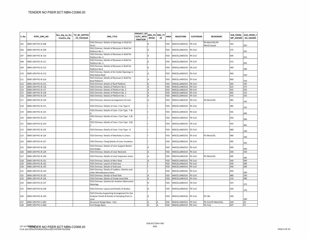
S. No. NTPC_DRG_NORev_drg_no_for_
inouhse_drgTO_BE_SHIFTED_TO_PACKAGE
DRG_TITLEPROJECT_SPECIFC_INFORMATION
DRG_PURPOSE
DRG_TYPE
AREA MILESTONE CUSTODIAN REVIEWERSSUB_FROM_MP_AWARD
SUB_FROM_FGD_AWARD
105 0000‐109‐PVC‐B‐108FGD Chimney‐ Details of Openings in Shell for Ducts
A FGD MISCELLANEOUS PE‐CivilPE‐Mech/SG,PE‐Mech/Layout
355205
106 0000‐109‐PVC‐B‐109FGD Chimney‐ Details of Recesses in Shell for Platform No. 1
A FGD MISCELLANEOUS PE‐Civil 375225
107 0000‐109‐PVC‐B‐110FGD Chimney‐ Details of Recesses in Shell for Platform No. 2
A FGD MISCELLANEOUS PE‐Civil 405255
108 0000‐109‐PVC‐B‐111FGD Chimney‐ Details of Recesses in Shell for Platform No. 3
A FGD MISCELLANEOUS PE‐Civil 415265
109 0000‐109‐PVC‐B‐112FGD Chimney‐ Details of Recesses in Shell for Platform No.4
A FGD MISCELLANEOUS PE‐Civil 440290
110 0000‐109‐PVC‐B‐113FGD Chimney‐ Details of Air Outlet Openings in Shell below Roof
A FGD MISCELLANEOUS PE‐Civil 460310
111 0000‐109‐PVC‐B‐114FGD Chimney‐ Details of Recesses in Shell for Roof Platform
A FGD MISCELLANEOUS PE‐Civil 460310
112 0000‐109‐PVC‐B‐115 FGD Chimney‐ Details of Roof Platform A FGD MISCELLANEOUS PE‐Civil 395 245113 0000‐109‐PVC‐B‐116 FGD Chimney‐ Details of Platform No.4 A FGD MISCELLANEOUS PE‐Civil 425 275114 0000‐109‐PVC‐B‐117 FGD Chimney‐ Details of Platform No. 3 A FGD MISCELLANEOUS PE‐Civil 445 295115 0000‐109‐PVC‐B‐118 FGD Chimney‐ Details of Platform No. 2 A FGD MISCELLANEOUS PE‐Civil 465 315116 0000‐109‐PVC‐B‐119 FGD Chimney‐ Details of Platform No. 1 A FGD MISCELLANEOUS PE‐Civil 475 325
117 0000‐109‐PVC‐B‐120 FGD Chimney‐ General Arrangement of Liner A FGD MISCELLANEOUS PE‐Civil PE‐Mech/SG 385235
118 0000‐109‐PVC‐B‐121 FGD Chimney‐ Details of Liner / Can Type‐A I FGD MISCELLANEOUS PE‐Civil 385235
119 0000‐109‐PVC‐B‐122FGD Chimney‐ Details of Liner / Can Type ‐ F & G
I FGD MISCELLANEOUS PE‐Civil 435285
120 0000‐109‐PVC‐B‐123FGD Chimney‐ Details of Liner / Can Type ‐ E & H
I FGD MISCELLANEOUS PE‐Civil 450300
121 0000‐109‐PVC‐B‐124FGD Chimney‐ Details of Liner / Can Type ‐ B & C
I FGD MISCELLANEOUS PE‐Civil 455305
122 0000‐109‐PVC‐B‐125 FGD Chimney‐ Details of Liner / Can Type ‐ D I FGD MISCELLANEOUS PE‐Civil 480330
123 0000‐109‐PVC‐B‐126 FGD Chimney‐ Details of Manholes in Liners I FGD MISCELLANEOUS PE‐Civil PE‐Mech/SG 480330
124 0000‐109‐PVC‐B‐127 FGD Chimney‐ Fixing Details of Liner Insulation I FGD MISCELLANEOUS PE‐Civil 495345
125 0000‐109‐PVC‐B‐128FGD Chimney‐ Details of Liner Support Beams and Hanger
A FGD MISCELLANEOUS PE‐Civil 490340
126 0000‐109‐PVC‐B‐129 FGD Chimney‐ Details of Liner Restraint A FGD MISCELLANEOUS PE‐Civil 500 350
127 0000‐109‐PVC‐B‐130 FGD Chimney‐ Details of Liner Expansion Joints A FGD MISCELLANEOUS PE‐Civil PE‐Mech/SG 495345
128 0000‐109‐PVC‐B‐131 FGD Chimney‐ Details of Mini‐Shell A FGD MISCELLANEOUS PE‐Civil 540 390129 0000‐109‐PVC‐B‐132 FGD Chimney‐ Layout of Staircase I FGD MISCELLANEOUS PE‐Civil 430 280130 0000‐109‐PVC‐B‐133 FGD Chimney‐ Details of Staircase I FGD MISCELLANEOUS PE‐Civil 430 280
131 0000‐109‐PVC‐B‐134FGD Chimney‐ Details of Ladders, Hatches and other Miscellaneous Items
I FGD MISCELLANEOUS PE‐Civil 440290
132 0000‐109‐PVC‐B‐135 FGD Chimney‐ Details of Roof Slab A FGD MISCELLANEOUS PE‐Civil 480 330133 0000‐109‐PVC‐B‐136 FGD Chimney‐ Details of Grade Level Slab A FGD MISCELLANEOUS PE‐Civil 510 360
134 0000‐109‐PVC‐B‐137FGD Chimney‐ Scheme for Aviation Obstruction Markings
A FGD MISCELLANEOUS PE‐Civil 525375
135 0000‐109‐PVC‐B‐138 FGD Chimney‐ Layout and Details of Strakes A FGD MISCELLANEOUS PE‐Civil 420270
136 0000‐109‐PVC‐B‐139FGD Chimney‐Supporting Arrangement for Gas Analyzer Panels & Details of Sampling Ports in Liner
A FGD MISCELLANEOUS PE‐Civil PE‐C&I 540390
137 0000‐109‐PVC‐U‐001 Structural Design Basis ‐ Civil A A FGD MISCELLANEOUS PE‐Civil PE‐Civil,PE‐Mech/SG, 160 10138 0000‐109‐PVC‐U‐002 Civil Design Basis A A FGD MISCELLANEOUS PE‐Civil PE‐Civil, 207 57
LOT‐IA PROJECTSFLUE GAS DESULPHURISATION (FGD) SYSTEM PACKAGE
SUB‐SECTION‐I‐M9MDL
PAGE 6 OF 24
TENDER NO PSER:SCT:NBN-C2068:20
TENDER NO PSER:SCT:NBN-C2068:20
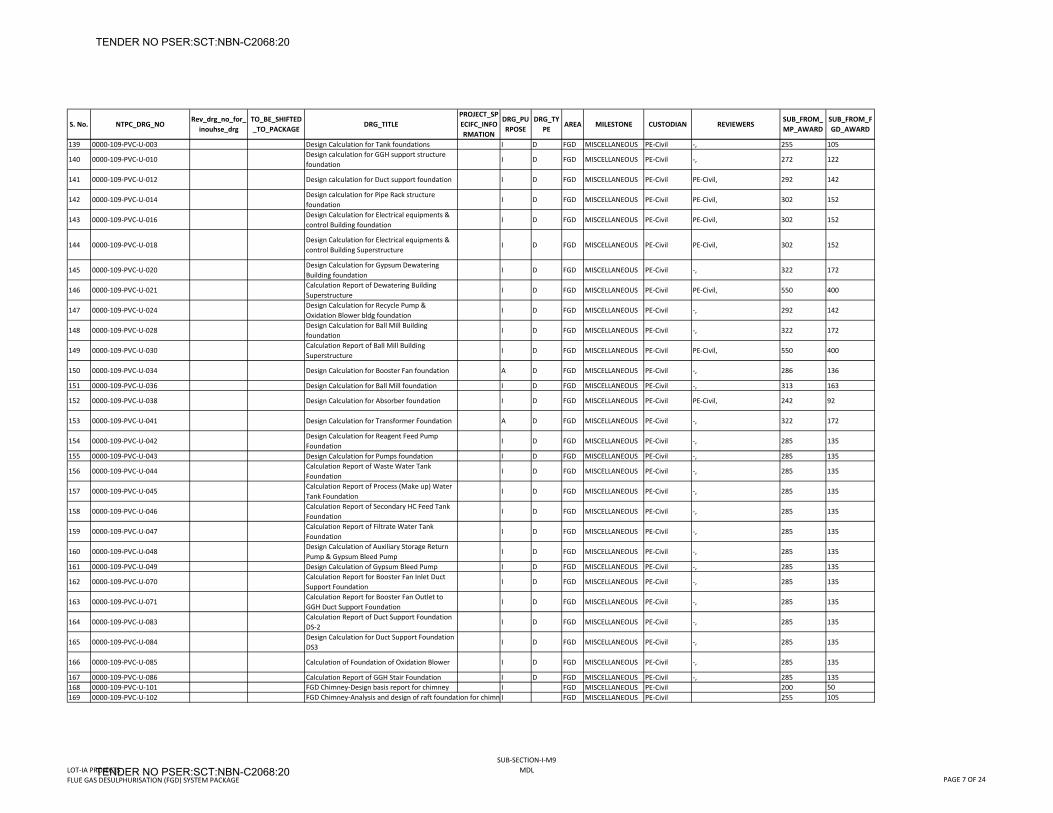
S. No. NTPC_DRG_NORev_drg_no_for_
inouhse_drgTO_BE_SHIFTED_TO_PACKAGE
DRG_TITLEPROJECT_SPECIFC_INFORMATION
DRG_PURPOSE
DRG_TYPE
AREA MILESTONE CUSTODIAN REVIEWERSSUB_FROM_MP_AWARD
SUB_FROM_FGD_AWARD
139 0000‐109‐PVC‐U‐003 Design Calculation for Tank foundations I D FGD MISCELLANEOUS PE‐Civil ‐, 255 105
140 0000‐109‐PVC‐U‐010Design calculation for GGH support structure foundation
I D FGD MISCELLANEOUS PE‐Civil ‐, 272 122
141 0000‐109‐PVC‐U‐012 Design calculation for Duct support foundation I D FGD MISCELLANEOUS PE‐Civil PE‐Civil, 292 142
142 0000‐109‐PVC‐U‐014Design calculation for Pipe Rack structure foundation
I D FGD MISCELLANEOUS PE‐Civil PE‐Civil, 302 152
143 0000‐109‐PVC‐U‐016Design Calculation for Electrical equipments & control Building foundation
I D FGD MISCELLANEOUS PE‐Civil PE‐Civil, 302 152
144 0000‐109‐PVC‐U‐018Design Calculation for Electrical equipments & control Building Superstructure
I D FGD MISCELLANEOUS PE‐Civil PE‐Civil, 302 152
145 0000‐109‐PVC‐U‐020Design Calculation for Gypsum Dewatering Building foundation
I D FGD MISCELLANEOUS PE‐Civil ‐, 322 172
146 0000‐109‐PVC‐U‐021Calculation Report of Dewatering Building Superstructure
I D FGD MISCELLANEOUS PE‐Civil PE‐Civil, 550 400
147 0000‐109‐PVC‐U‐024Design Calculation for Recycle Pump & Oxidation Blower bldg foundation
I D FGD MISCELLANEOUS PE‐Civil ‐, 292 142
148 0000‐109‐PVC‐U‐028Design Calculation for Ball Mill Building foundation
I D FGD MISCELLANEOUS PE‐Civil ‐, 322 172
149 0000‐109‐PVC‐U‐030Calculation Report of Ball Mill Building Superstructure
I D FGD MISCELLANEOUS PE‐Civil PE‐Civil, 550 400
150 0000‐109‐PVC‐U‐034 Design Calculation for Booster Fan foundation A D FGD MISCELLANEOUS PE‐Civil ‐, 286 136
151 0000‐109‐PVC‐U‐036 Design Calculation for Ball Mill foundation I D FGD MISCELLANEOUS PE‐Civil ‐, 313 163
152 0000‐109‐PVC‐U‐038 Design Calculation for Absorber foundation I D FGD MISCELLANEOUS PE‐Civil PE‐Civil, 242 92
153 0000‐109‐PVC‐U‐041 Design Calculation for Transformer Foundation A D FGD MISCELLANEOUS PE‐Civil ‐, 322 172
154 0000‐109‐PVC‐U‐042Design Calculation for Reagent Feed Pump Foundation
I D FGD MISCELLANEOUS PE‐Civil ‐, 285 135
155 0000‐109‐PVC‐U‐043 Design Calculation for Pumps foundation I D FGD MISCELLANEOUS PE‐Civil ‐, 285 135
156 0000‐109‐PVC‐U‐044Calculation Report of Waste Water Tank Foundation
I D FGD MISCELLANEOUS PE‐Civil ‐, 285 135
157 0000‐109‐PVC‐U‐045Calculation Report of Process (Make up) Water Tank Foundation
I D FGD MISCELLANEOUS PE‐Civil ‐, 285 135
158 0000‐109‐PVC‐U‐046Calculation Report of Secondary HC Feed Tank Foundation
I D FGD MISCELLANEOUS PE‐Civil ‐, 285 135
159 0000‐109‐PVC‐U‐047Calculation Report of Filtrate Water Tank Foundation
I D FGD MISCELLANEOUS PE‐Civil ‐, 285 135
160 0000‐109‐PVC‐U‐048Design Calculation of Auxiliary Storage Return Pump & Gypsum Bleed Pump
I D FGD MISCELLANEOUS PE‐Civil ‐, 285 135
161 0000‐109‐PVC‐U‐049 Design Calculation of Gypsum Bleed Pump I D FGD MISCELLANEOUS PE‐Civil ‐, 285 135
162 0000‐109‐PVC‐U‐070Calculation Report for Booster Fan Inlet Duct Support Foundation
I D FGD MISCELLANEOUS PE‐Civil ‐, 285 135
163 0000‐109‐PVC‐U‐071Calculation Report for Booster Fan Outlet to GGH Duct Support Foundation
I D FGD MISCELLANEOUS PE‐Civil ‐, 285 135
164 0000‐109‐PVC‐U‐083Calculation Report of Duct Support Foundation DS‐2
I D FGD MISCELLANEOUS PE‐Civil ‐, 285 135
165 0000‐109‐PVC‐U‐084Design Calculation for Duct Support Foundation DS3
I D FGD MISCELLANEOUS PE‐Civil ‐, 285 135
166 0000‐109‐PVC‐U‐085 Calculation of Foundation of Oxidation Blower I D FGD MISCELLANEOUS PE‐Civil ‐, 285 135
167 0000‐109‐PVC‐U‐086 Calculation Report of GGH Stair Foundation I D FGD MISCELLANEOUS PE‐Civil ‐, 285 135168 0000‐109‐PVC‐U‐101 FGD Chimney‐Design basis report for chimney I FGD MISCELLANEOUS PE‐Civil 200 50169 0000‐109‐PVC‐U‐102 FGD Chimney‐Analysis and design of raft foundation for chimn I FGD MISCELLANEOUS PE‐Civil 255 105
LOT‐IA PROJECTSFLUE GAS DESULPHURISATION (FGD) SYSTEM PACKAGE
SUB‐SECTION‐I‐M9MDL
PAGE 7 OF 24
TENDER NO PSER:SCT:NBN-C2068:20
TENDER NO PSER:SCT:NBN-C2068:20
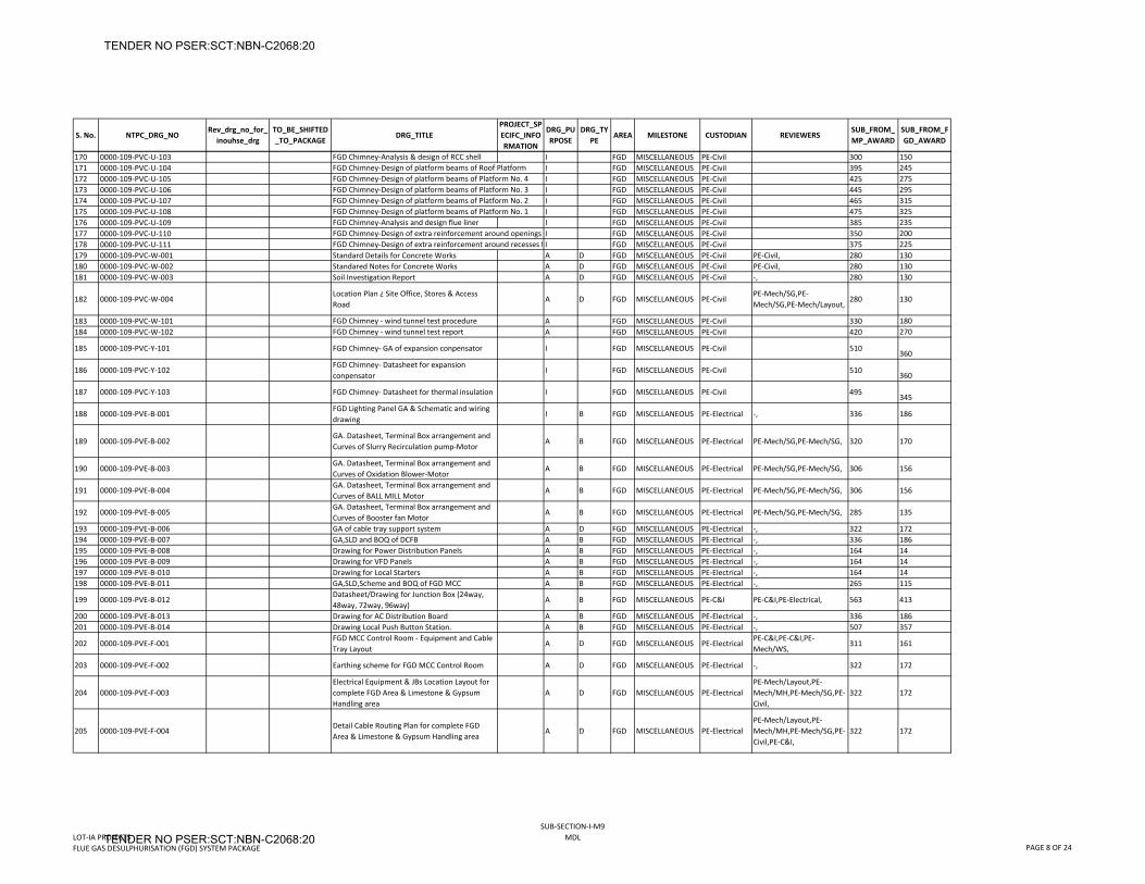
S. No. NTPC_DRG_NORev_drg_no_for_
inouhse_drgTO_BE_SHIFTED_TO_PACKAGE
DRG_TITLEPROJECT_SPECIFC_INFORMATION
DRG_PURPOSE
DRG_TYPE
AREA MILESTONE CUSTODIAN REVIEWERSSUB_FROM_MP_AWARD
SUB_FROM_FGD_AWARD
170 0000‐109‐PVC‐U‐103 FGD Chimney‐Analysis & design of RCC shell I FGD MISCELLANEOUS PE‐Civil 300 150171 0000‐109‐PVC‐U‐104 FGD Chimney‐Design of platform beams of Roof Platform I FGD MISCELLANEOUS PE‐Civil 395 245172 0000‐109‐PVC‐U‐105 FGD Chimney‐Design of platform beams of Platform No. 4 I FGD MISCELLANEOUS PE‐Civil 425 275173 0000‐109‐PVC‐U‐106 FGD Chimney‐Design of platform beams of Platform No. 3 I FGD MISCELLANEOUS PE‐Civil 445 295174 0000‐109‐PVC‐U‐107 FGD Chimney‐Design of platform beams of Platform No. 2 I FGD MISCELLANEOUS PE‐Civil 465 315175 0000‐109‐PVC‐U‐108 FGD Chimney‐Design of platform beams of Platform No. 1 I FGD MISCELLANEOUS PE‐Civil 475 325176 0000‐109‐PVC‐U‐109 FGD Chimney‐Analysis and design flue liner I FGD MISCELLANEOUS PE‐Civil 385 235177 0000‐109‐PVC‐U‐110 FGD Chimney‐Design of extra reinforcement around openings I FGD MISCELLANEOUS PE‐Civil 350 200178 0000‐109‐PVC‐U‐111 FGD Chimney‐Design of extra reinforcement around recesses f I FGD MISCELLANEOUS PE‐Civil 375 225179 0000‐109‐PVC‐W‐001 Standard Details for Concrete Works A D FGD MISCELLANEOUS PE‐Civil PE‐Civil, 280 130180 0000‐109‐PVC‐W‐002 Standared Notes for Concrete Works A D FGD MISCELLANEOUS PE‐Civil PE‐Civil, 280 130181 0000‐109‐PVC‐W‐003 Soil Investigation Report A D FGD MISCELLANEOUS PE‐Civil ‐, 280 130
182 0000‐109‐PVC‐W‐004Location Plan ¿ Site Office, Stores & Access Road
A D FGD MISCELLANEOUS PE‐CivilPE‐Mech/SG,PE‐Mech/SG,PE‐Mech/Layout,
280 130
183 0000‐109‐PVC‐W‐101 FGD Chimney ‐ wind tunnel test procedure A FGD MISCELLANEOUS PE‐Civil 330 180184 0000‐109‐PVC‐W‐102 FGD Chimney ‐ wind tunnel test report A FGD MISCELLANEOUS PE‐Civil 420 270
185 0000‐109‐PVC‐Y‐101 FGD Chimney‐ GA of expansion conpensator I FGD MISCELLANEOUS PE‐Civil 510360
186 0000‐109‐PVC‐Y‐102FGD Chimney‐ Datasheet for expansion conpensator
I FGD MISCELLANEOUS PE‐Civil 510360
187 0000‐109‐PVC‐Y‐103 FGD Chimney‐ Datasheet for thermal insulation I FGD MISCELLANEOUS PE‐Civil 495345
188 0000‐109‐PVE‐B‐001FGD Lighting Panel GA & Schematic and wiring drawing
I B FGD MISCELLANEOUS PE‐Electrical ‐, 336 186
189 0000‐109‐PVE‐B‐002GA. Datasheet, Terminal Box arrangement and Curves of Slurry Recirculation pump‐Motor
A B FGD MISCELLANEOUS PE‐Electrical PE‐Mech/SG,PE‐Mech/SG, 320 170
190 0000‐109‐PVE‐B‐003GA. Datasheet, Terminal Box arrangement and Curves of Oxidation Blower‐Motor
A B FGD MISCELLANEOUS PE‐Electrical PE‐Mech/SG,PE‐Mech/SG, 306 156
191 0000‐109‐PVE‐B‐004GA. Datasheet, Terminal Box arrangement and Curves of BALL MILL Motor
A B FGD MISCELLANEOUS PE‐Electrical PE‐Mech/SG,PE‐Mech/SG, 306 156
192 0000‐109‐PVE‐B‐005GA. Datasheet, Terminal Box arrangement and Curves of Booster fan Motor
A B FGD MISCELLANEOUS PE‐Electrical PE‐Mech/SG,PE‐Mech/SG, 285 135
193 0000‐109‐PVE‐B‐006 GA of cable tray support system A D FGD MISCELLANEOUS PE‐Electrical ‐, 322 172194 0000‐109‐PVE‐B‐007 GA,SLD and BOQ of DCFB A B FGD MISCELLANEOUS PE‐Electrical ‐, 336 186195 0000‐109‐PVE‐B‐008 Drawing for Power Distribution Panels A B FGD MISCELLANEOUS PE‐Electrical ‐, 164 14196 0000‐109‐PVE‐B‐009 Drawing for VFD Panels A B FGD MISCELLANEOUS PE‐Electrical ‐, 164 14197 0000‐109‐PVE‐B‐010 Drawing for Local Starters A B FGD MISCELLANEOUS PE‐Electrical ‐, 164 14198 0000‐109‐PVE‐B‐011 GA,SLD,Scheme and BOQ of FGD MCC A B FGD MISCELLANEOUS PE‐Electrical ‐, 265 115
199 0000‐109‐PVE‐B‐012Datasheet/Drawing for Junction Box (24way, 48way, 72way, 96way)
A B FGD MISCELLANEOUS PE‐C&I PE‐C&I,PE‐Electrical, 563 413
200 0000‐109‐PVE‐B‐013 Drawing for AC Distribution Board A B FGD MISCELLANEOUS PE‐Electrical ‐, 336 186201 0000‐109‐PVE‐B‐014 Drawing Local Push Button Station. A B FGD MISCELLANEOUS PE‐Electrical ‐, 507 357
202 0000‐109‐PVE‐F‐001FGD MCC Control Room ‐ Equipment and Cable Tray Layout
A D FGD MISCELLANEOUS PE‐ElectricalPE‐C&I,PE‐C&I,PE‐Mech/WS,
311 161
203 0000‐109‐PVE‐F‐002 Earthing scheme for FGD MCC Control Room A D FGD MISCELLANEOUS PE‐Electrical ‐, 322 172
204 0000‐109‐PVE‐F‐003Electrical Equipment & JBs Location Layout for complete FGD Area & Limestone & Gypsum Handling area
A D FGD MISCELLANEOUS PE‐ElectricalPE‐Mech/Layout,PE‐Mech/MH,PE‐Mech/SG,PE‐Civil,
322 172
205 0000‐109‐PVE‐F‐004Detail Cable Routing Plan for complete FGD Area & Limestone & Gypsum Handling area
A D FGD MISCELLANEOUS PE‐ElectricalPE‐Mech/Layout,PE‐Mech/MH,PE‐Mech/SG,PE‐Civil,PE‐C&I,
322 172
LOT‐IA PROJECTSFLUE GAS DESULPHURISATION (FGD) SYSTEM PACKAGE
SUB‐SECTION‐I‐M9MDL
PAGE 8 OF 24
TENDER NO PSER:SCT:NBN-C2068:20
TENDER NO PSER:SCT:NBN-C2068:20
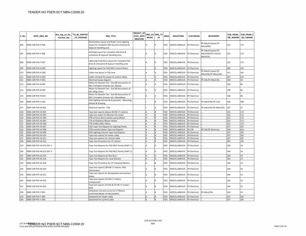
S. No. NTPC_DRG_NORev_drg_no_for_
inouhse_drgTO_BE_SHIFTED_TO_PACKAGE
DRG_TITLEPROJECT_SPECIFC_INFORMATION
DRG_PURPOSE
DRG_TYPE
AREA MILESTONE CUSTODIAN REVIEWERSSUB_FROM_MP_AWARD
SUB_FROM_FGD_AWARD
206 0000‐109‐PVE‐F‐005Illumination Layout and Road / area Lighting layout for complete FGD Area & Limestone & Gypsum Handling area
A D FGD MISCELLANEOUS PE‐ElectricalPE‐Mech/Layout,PE‐Mech/MH,
322 172
207 0000‐109‐PVE‐F‐006Earthing Layout for complete FGD Area & Limestone & Gypsum Handling area
A D FGD MISCELLANEOUS PE‐ElectricalPE‐Mech/Layout,PE‐Mech/MH,PE‐Civil,PE‐Mech/SG,
322 172
208 0000‐109‐PVE‐F‐007Lightning Protection Layout for complete FGD Area & Limestone & Gypsum Handling area
A D FGD MISCELLANEOUS PE‐Electrical ‐, 322 172
209 0000‐109‐PVE‐G‐001 Lighting Layout for FGD MCC Control Room I D FGD MISCELLANEOUS PE‐Electrical ‐, 285 135
210 0000‐109‐PVE‐G‐002 Cable tray layout in FGD area A D FGD MISCELLANEOUS PE‐ElectricalPE‐Mech/Layout,PE‐Mech/SG,PE‐Mech/SG,
311 161
211 0000‐109‐PVE‐H‐001 Cable schedule for power & control cables I D FGD MISCELLANEOUS PE‐Electrical ‐, 297 147212 0000‐109‐PVE‐P‐001 Electrical Scope diagram A A FGD MISCELLANEOUS PE‐Electrical PE‐C&I,PE‐Mech/SG, 160 10
213 0000‐109‐PVE‐R‐001Motor for Booster Fan ‐ Sub QR documents of M/s Crompton Greaves Ltd., Bhopal
A A FGD MISCELLANEOUS PE‐Electrical ‐, 196 46
214 0000‐109‐PVE‐R‐002Motor for Booster Fan ‐ Sub QR documents of M/s Weg, Hosur
A A FGD MISCELLANEOUS PE‐Electrical ‐, 196 46
215 0000‐109‐PVE‐R‐003Motor for Booster Fan ‐ Sub QR documents of M/s Crompton Greaves Ltd., Mandideep
A A FGD MISCELLANEOUS PE‐Electrical ‐, 196 46
216 0000‐109‐PVE‐V‐001FGD Lighting Fixtures & Accessories ‐ Mounting Details & Drawing
I B FGD MISCELLANEOUS PE‐Electrical PE‐Mech/SG,PE‐Civil, 336 186
217 0000‐109‐PVE‐W‐001 Electrical load list ‐ FGD I A FGD MISCELLANEOUS PE‐Electrical PE‐Mech/SG,PE‐Mech/SG, 187 37
218 0000‐109‐PVE‐W‐002 Type test reports (above 50 KW LT motors) A B FGD MISCELLANEOUS PE‐Electrical ‐, 322 172219 0000‐109‐PVE‐W‐003 Type test report for Booster fan motor A B FGD MISCELLANEOUS PE‐Electrical ‐, 322 172220 0000‐109‐PVE‐W‐004 TTR of Slurry Recirculation pump‐Motor A B FGD MISCELLANEOUS PE‐Electrical ‐, 322 172221 0000‐109‐PVE‐W‐005 TTR of Oxidation Blower‐Motor A B FGD MISCELLANEOUS PE‐Electrical ‐, 322 172222 0000‐109‐PVE‐W‐006 TTR of BALL MILL Motor A B FGD MISCELLANEOUS PE‐Electrical ‐, 322 172223 0000‐109‐PVE‐W‐007 FGD‐Type Test Reports for Lighting Panels A B FGD MISCELLANEOUS PE‐Electrical ‐, 337 187224 0000‐109‐PVE‐W‐008 FGD‐Junction Boxes Type test Reports A B FGD MISCELLANEOUS PE‐C&I PE‐C&I,PE‐Electrical, 564 414225 0000‐109‐PVE‐W‐009 FGD‐Lighting Fixtures Type Test Reports A B FGD MISCELLANEOUS PE‐Electrical ‐, 337 187226 0000‐109‐PVE‐W‐010 Type test reports for Power cable A B FGD MISCELLANEOUS PE‐Electrical ‐, 337 187227 0000‐109‐PVE‐W‐011 Type test reports for Control cable A B FGD MISCELLANEOUS PE‐Electrical ‐, 337 187228 0000‐109‐PVE‐W‐012 Type Test Procedure for HT motors A B FGD MISCELLANEOUS PE‐Electrical ‐, 285 135
229 0000‐109‐PVE‐W‐013‐SHT‐1 Type Test Reports for FGD MCC Panels (PART 1) A D FGD MISCELLANEOUS PE‐Electrical ‐, 164 14
230 0000‐109‐PVE‐W‐013‐SHT‐2 Type Test Reports for FGD MCC Panels (PART 2) A D FGD MISCELLANEOUS PE‐Electrical ‐, 164 14
231 0000‐109‐PVE‐W‐014 Type Test Reports for Bus Duct A D FGD MISCELLANEOUS PE‐Electrical ‐, 164 14232 0000‐109‐PVE‐W‐016 Type Test Reports for Local Starters A D FGD MISCELLANEOUS PE‐Electrical ‐, 164 14
233 0000‐109‐PVE‐W‐018 Type Test Procedure for HT Imported Motors. A B FGD MISCELLANEOUS PE‐Electrical ‐, 164 14
234 0000‐109‐PVE‐W‐020Type test reports (90 kW LT motors‐ Mist Eleiminator)
A B FGD MISCELLANEOUS PE‐Electrical ‐, 164 14
235 0000‐109‐PVE‐W‐021Type test reports for Receptacles and Junction boxes
A B FGD MISCELLANEOUS PE‐Electrical ‐, 164 14
236 0000‐109‐PVE‐W‐022Type test reports (55 kW LT motors‐ Compressor)
A B FGD MISCELLANEOUS PE‐Electrical ‐, 164 14
237 0000‐109‐PVE‐W‐023Type test reports (75 kW & 55 kW LT motors‐ MH)
A B FGD MISCELLANEOUS PE‐Electrical ‐, 164 14
238 0000‐109‐PVE‐Y‐001Datasheet, GA and curves for LT Motors (FURTHER BREAK UP NECESSARY)
A B FGD MISCELLANEOUS PE‐Electrical PE‐Mech/SG, 164 14
239 0000‐109‐PVE‐Y‐002 Datasheet for Power cable A B FGD MISCELLANEOUS PE‐Electrical ‐, 337 187240 0000‐109‐PVE‐Y‐003 Datasheet for Control cable A B FGD MISCELLANEOUS PE‐Electrical ‐, 337 187
LOT‐IA PROJECTSFLUE GAS DESULPHURISATION (FGD) SYSTEM PACKAGE
SUB‐SECTION‐I‐M9MDL
PAGE 9 OF 24
TENDER NO PSER:SCT:NBN-C2068:20
TENDER NO PSER:SCT:NBN-C2068:20
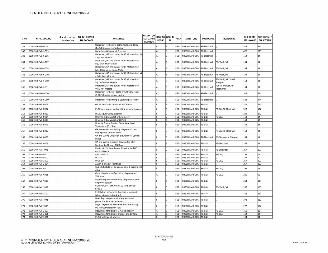
S. No. NTPC_DRG_NORev_drg_no_for_
inouhse_drgTO_BE_SHIFTED_TO_PACKAGE
DRG_TITLEPROJECT_SPECIFC_INFORMATION
DRG_PURPOSE
DRG_TYPE
AREA MILESTONE CUSTODIAN REVIEWERSSUB_FROM_MP_AWARD
SUB_FROM_FGD_AWARD
241 0000‐109‐PVE‐Y‐004Datasheet for Control cable Additional Sizes (24Cx1.5 sqmm control cables)
A B FGD MISCELLANEOUS PE‐Electrical ‐, 524 374
242 0000‐109‐PVE‐Y‐005 Data sheet & layout of Bus‐duct A B FGD MISCELLANEOUS PE‐Electrical ‐, 475 325
243 0000‐109‐PVE‐Y‐006Datasheet, GA and curves for LT Motors (Part II) ‐ Agitator Motors
A B FGD MISCELLANEOUS PE‐Electrical ‐, 164 14
244 0000‐109‐PVE‐Y‐007Datasheet, GA and curves for LT Motors (Part III) ¿ GGH Main Motor
A B FGD MISCELLANEOUS PE‐Electrical PE‐Mech/SG, 164 14
245 0000‐109‐PVE‐Y‐008Datasheet, GA and curves for LT Motors (Part IV) ¿ Clear water Pump Motor
A B FGD MISCELLANEOUS PE‐Electrical PE‐Mech/SG, 164 14
246 0000‐109‐PVE‐Y‐009Datasheet, GA and curves for LT Motors (Part V) ¿ GGH Aux. Motors
A B FGD MISCELLANEOUS PE‐Electrical PE‐Mech/SG, 164 14
247 0000‐109‐PVE‐Y‐010Datasheet, GA and curves for LT Motors (Part VI) ¿ GGH Aux. Motors.
A B FGD MISCELLANEOUS PE‐ElectricalPE‐Mech/SG,Kuntal Bhuiyan,
164 14
248 0000‐109‐PVE‐Y‐011Datasheet, GA and curves for LT Motors (Part VII) ¿ MH Motors
A B FGD MISCELLANEOUS PE‐ElectricalKuntal Bhuiyan,PE‐Mech/MH,
164 14
249 0000‐109‐PVE‐Y‐020Datasheet for Power cable of Additional Sizes (3.5Cx50 sqmm power cables)
A B FGD MISCELLANEOUS PE‐Electrical ‐, 524 374
250 0000‐109‐PVE‐Y‐050 Datasheet for Earthing & Lightning Materials A B FGD MISCELLANEOUS PE‐Electrical ‐, 524 374
251 0000‐109‐PVI‐B‐001 GA, BOQ & Data sheets for PLC Panels I B FGD MISCELLANEOUS PE‐C&I ‐, 322 172
252 0000‐109‐PVI‐B‐002 PLC Power supply and earthing scheme drawing I B FGD MISCELLANEOUS PE‐C&I PE‐C&I,PE‐Electrical, 322 172
253 0000‐109‐PVI‐B‐003 PLC Module wiring diagram I B FGD MISCELLANEOUS PE‐C&I ‐, 322 172254 0000‐109‐PVI‐B‐004 Drawing & Datasheet of Rotameter I B FGD MISCELLANEOUS PE‐C&I PE‐C&I, 164 14255 0000‐109‐PVI‐B‐005 Drawing & Datasheet of LIE/LIR I B FGD MISCELLANEOUS PE‐C&I ‐, 164 14
256 0000‐109‐PVI‐B‐006Drawing & datasheet of Radar type Level Transmitter (for Silo)
I B FGD MISCELLANEOUS PE‐C&I ‐, 164 14
257 0000‐109‐PVI‐B‐007GA, Datasheet and Wiring diagram of Lime Dosing Local Control Panel
I B FGD MISCELLANEOUS PE‐C&I PE‐C&I,PE‐Electrical, 164 14
258 0000‐109‐PVI‐B‐008GA and Wiring Oxidation Blower Local Control Panel
I B FGD MISCELLANEOUS PE‐Electrical PE‐C&I,Kuntal Bhuiyan, 164 14
259 0000‐109‐PVI‐B‐009GA and Wiring Diagram Drawing for GGH‐Multimedia Cleaner PLC Panel
I B FGD MISCELLANEOUS PE‐C&I PE‐Electrical, 164 14
260 0000‐109‐PVI‐F‐001Electronic Earthing Layout Drawing for FGD Control Room
I D FGD MISCELLANEOUS PE‐C&I PE‐Electrical, 257 107
261 0000‐109‐PVI‐G‐001 Instrument list I A FGD MISCELLANEOUS PE‐C&I PE‐C&I, 194 44262 0000‐109‐PVI‐G‐002 I/O List I D FGD MISCELLANEOUS PE‐C&I ‐, 257 107263 0000‐109‐PVI‐G‐003 Drive List I D FGD MISCELLANEOUS PE‐C&I PE‐C&I, 257 107264 0000‐109‐PVI‐G‐004 Alarm & Trip Set Point List I D FGD MISCELLANEOUS PE‐C&I ‐, 257 107
265 0000‐109‐PVI‐H‐001Cable Schedule for power, control & instrument cables.
I D FGD MISCELLANEOUS PE‐C&I PE‐C&I, 297 147
266 0000‐109‐PVI‐P‐001Control system configuration diagrams and Write up
A D FGD MISCELLANEOUS PE‐C&I PE‐C&I, 235 85
267 0000‐109‐PVI‐P‐002Interfacing and connectivity diagram with the Employer system
I D FGD MISCELLANEOUS PE‐C&I ‐, 264 114
268 0000‐109‐PVI‐P‐009CONTROL SYSTEM ARCHITECTURE of FGD System
I D FGD MISCELLANEOUS PE‐C&I PE‐Mech/SG, 265 115
269 0000‐109‐PVI‐Q‐001Installation Scheme, Instrument wiring and tubing diagrams (hook up)
I D FGD MISCELLANEOUS PE‐C&I ‐, 322 172
270 0000‐109‐PVI‐T‐001Block logic diagrams with Sequence and protection interlock schemes
I D FGD MISCELLANEOUS PE‐C&I ‐, 272 122
271 0000‐109‐PVI‐T‐002Logic Diagram for Sequence and Interlocking (AS IMPLEMENTED IN PLC)
I D FGD MISCELLANEOUS PE‐C&I ‐, 272 122
272 0000‐109‐PVI‐U‐007 Document for Sizing of UPS and Battery A D FGD MISCELLANEOUS PE‐C&I PE‐C&I, 166 16273 0000‐109‐PVI‐U‐008 Document for Sizing of charger and Battery A D FGD MISCELLANEOUS PE‐C&I PE‐C&I, 164 14274 0000‐109‐PVI‐V‐001 PLC Graphics and Mimics I D FGD MISCELLANEOUS PE‐C&I ‐, 164 14
LOT‐IA PROJECTSFLUE GAS DESULPHURISATION (FGD) SYSTEM PACKAGE
SUB‐SECTION‐I‐M9MDL
PAGE 10 OF 24
TENDER NO PSER:SCT:NBN-C2068:20
TENDER NO PSER:SCT:NBN-C2068:20
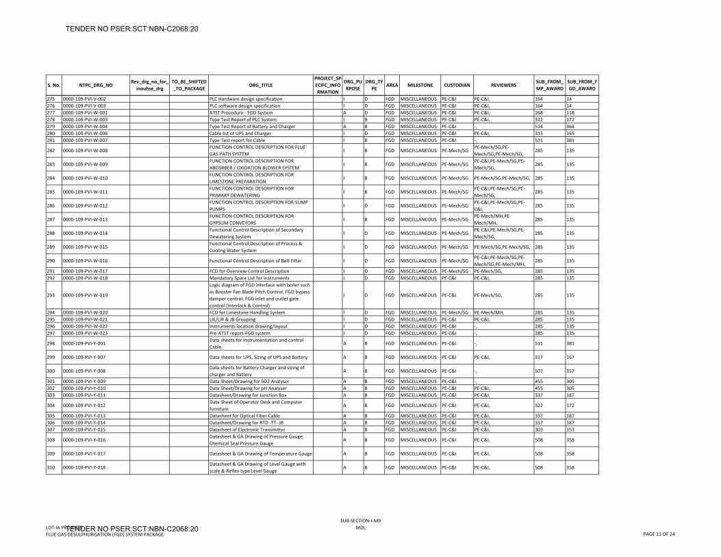
S. No. NTPC_DRG_NORev_drg_no_for_
inouhse_drgTO_BE_SHIFTED_TO_PACKAGE
DRG_TITLEPROJECT_SPECIFC_INFORMATION
DRG_PURPOSE
DRG_TYPE
AREA MILESTONE CUSTODIAN REVIEWERSSUB_FROM_MP_AWARD
SUB_FROM_FGD_AWARD
275 0000‐109‐PVI‐V‐002 PLC Hardware design specification I D FGD MISCELLANEOUS PE‐C&I PE‐C&I, 164 14276 0000‐109‐PVI‐V‐003 PLC software design specification I D FGD MISCELLANEOUS PE‐C&I PE‐C&I, 164 14277 0000‐109‐PVI‐W‐001 ATST Procedure ‐ FGD System A D FGD MISCELLANEOUS PE‐C&I PE‐C&I, 268 118278 0000‐109‐PVI‐W‐003 Type Test Report of PLC System I B FGD MISCELLANEOUS PE‐C&I PE‐C&I, 322 172279 0000‐109‐PVI‐W‐004 Type Test Report of Battery and Charger A B FGD MISCELLANEOUS PE‐C&I ‐, 514 364280 0000‐109‐PVI‐W‐006 Cable list of UPS and Charger I D FGD MISCELLANEOUS PE‐C&I PE‐C&I, 315 165281 0000‐109‐PVI‐W‐007 Type Test report for Cable I B FGD MISCELLANEOUS PE‐C&I ‐, 531 381
282 0000‐109‐PVI‐W‐008FUNCTION CONTROL DESCRIPTION FOR FLUE GAS PATH SYSTEM
I B FGD MISCELLANEOUS PE‐Mech/SGPE‐Mech/SG,PE‐Mech/SG,PE‐Mech/SG,
285 135
283 0000‐109‐PVI‐W‐009FUNCTION CONTROL DESCRIPTION FOR ABOSRBER / OXIDATION BLOWER SYSTEM
I B FGD MISCELLANEOUS PE‐Mech/SGPE‐C&I,PE‐Mech/SG,PE‐Mech/SG,
285 135
284 0000‐109‐PVI‐W‐010FUNCTION CONTROL DESCRIPTION FOR LIMESTONE PREPARATION
I B FGD MISCELLANEOUS PE‐Mech/SG PE‐Mech/SG,PE‐Mech/SG, 285 135
285 0000‐109‐PVI‐W‐011FUNCTION CONTROL DESCRIPTION FOR PRIMARY DEWATERING
I B FGD MISCELLANEOUS PE‐Mech/SGPE‐C&I,PE‐Mech/SG,PE‐Mech/SG,
285 135
286 0000‐109‐PVI‐W‐012FUNCTION CONTROL DESCRIPTION FOR SUMP PUMPS
I D FGD MISCELLANEOUS PE‐Mech/SGPE‐C&I,PE‐Mech/SG,PE‐C&I,
285 135
287 0000‐109‐PVI‐W‐013FUNCTION CONTROL DESCRIPTION FOR GYPSUM CONVEYORS
I B FGD MISCELLANEOUS PE‐Mech/SGPE‐Mech/MH,PE‐Mech/MH,
285 135
288 0000‐109‐PVI‐W‐014Functional Control Description of Secondary Dewatering System
I D FGD MISCELLANEOUS PE‐Mech/SGPE‐C&I,PE‐Mech/SG,PE‐Mech/SG,
285 135
289 0000‐109‐PVI‐W‐015Functional Control Description of Process & Cooling Water System
I D FGD MISCELLANEOUS PE‐Mech/SG PE‐Mech/SG,PE‐Mech/SG, 285 135
290 0000‐109‐PVI‐W‐016 Functional Control Description of Belt Filter I D FGD MISCELLANEOUS PE‐Mech/SGPE‐C&I,PE‐Mech/SG,PE‐Mech/SG,PE‐Mech/MH,
285 135
291 0000‐109‐PVI‐W‐017 FCD for Overview Control Description I D FGD MISCELLANEOUS PE‐Mech/SG PE‐Mech/SG, 285 135292 0000‐109‐PVI‐W‐018 Mandatory Spare List for Instruments I D FGD MISCELLANEOUS PE‐C&I PE‐C&I, 285 135
293 0000‐109‐PVI‐W‐019
Logic diagram of FGD interface with boiler such as Booster Fan Blade Pitch Control, FGD bypass damper control, FGD Inlet and outlet gate control (Interlock & Control)
I D FGD MISCELLANEOUS PE‐C&I PE‐Mech/SG, 285 135
294 0000‐109‐PVI‐W‐020 FCD for Limestone Handling System I D FGD MISCELLANEOUS PE‐Mech/SG PE‐Mech/MH, 285 135295 0000‐109‐PVI‐W‐021 LIE/LIR & JB Grouping I D FGD MISCELLANEOUS PE‐C&I PE‐C&I, 285 135296 0000‐109‐PVI‐W‐022 Instruments location drawing/layout I D FGD MISCELLANEOUS PE‐C&I ‐, 285 135297 0000‐109‐PVI‐W‐023 Pre‐ATST report‐FGD system I D FGD MISCELLANEOUS PE‐C&I ‐, 285 135
298 0000‐109‐PVI‐Y‐001Data sheets for Instrumentation and control Cable.
A B FGD MISCELLANEOUS PE‐C&I ‐, 531 381
299 0000‐109‐PVI‐Y‐007 Data sheets for UPS, Sizing of UPS and Battery A B FGD MISCELLANEOUS PE‐C&I PE‐C&I, 317 167
300 0000‐109‐PVI‐Y‐008Data sheets for Battery Charger and sizing of charger and Battery
A B FGD MISCELLANEOUS PE‐C&I ‐, 507 357
301 0000‐109‐PVI‐Y‐009 Data Sheet/Drawing for SO2 Analyser A B FGD MISCELLANEOUS PE‐C&I ‐, 455 305302 0000‐109‐PVI‐Y‐010 Data Sheet/Drawing for pH Analyser A B FGD MISCELLANEOUS PE‐C&I PE‐C&I, 455 305303 0000‐109‐PVI‐Y‐011 Datasheet/Drawing for Junction Box A B FGD MISCELLANEOUS PE‐C&I PE‐C&I, 337 187
304 0000‐109‐PVI‐Y‐012Data Sheet of Operator Desk and Computer furniture
A B FGD MISCELLANEOUS PE‐C&I PE‐C&I, 322 172
305 0000‐109‐PVI‐Y‐013 Datasheet for Optical Fiber Cable A B FGD MISCELLANEOUS PE‐C&I PE‐C&I, 337 187306 0000‐109‐PVI‐Y‐014 Datasheet/Drawing for RTD ‐TT‐ JB A B FGD MISCELLANEOUS PE‐C&I PE‐C&I, 337 187307 0000‐109‐PVI‐Y‐015 Datasheet of Electronic Transmitter A B FGD MISCELLANEOUS PE‐C&I PE‐C&I, 303 153
308 0000‐109‐PVI‐Y‐016Datasheet & GA Drawing of Pressure Gauge, Chemical Seal Pressure Gauge
A B FGD MISCELLANEOUS PE‐C&I PE‐C&I, 508 358
309 0000‐109‐PVI‐Y‐017 Datasheet & GA Drawing of Temperature Gauge A B FGD MISCELLANEOUS PE‐C&I PE‐C&I, 508 358
310 0000‐109‐PVI‐Y‐018Datasheet & GA Drawing of Level Gauge with scale & Reflex type Level Gauge
A B FGD MISCELLANEOUS PE‐C&I PE‐C&I, 508 358
LOT‐IA PROJECTSFLUE GAS DESULPHURISATION (FGD) SYSTEM PACKAGE
SUB‐SECTION‐I‐M9MDL
PAGE 11 OF 24
TENDER NO PSER:SCT:NBN-C2068:20
TENDER NO PSER:SCT:NBN-C2068:20
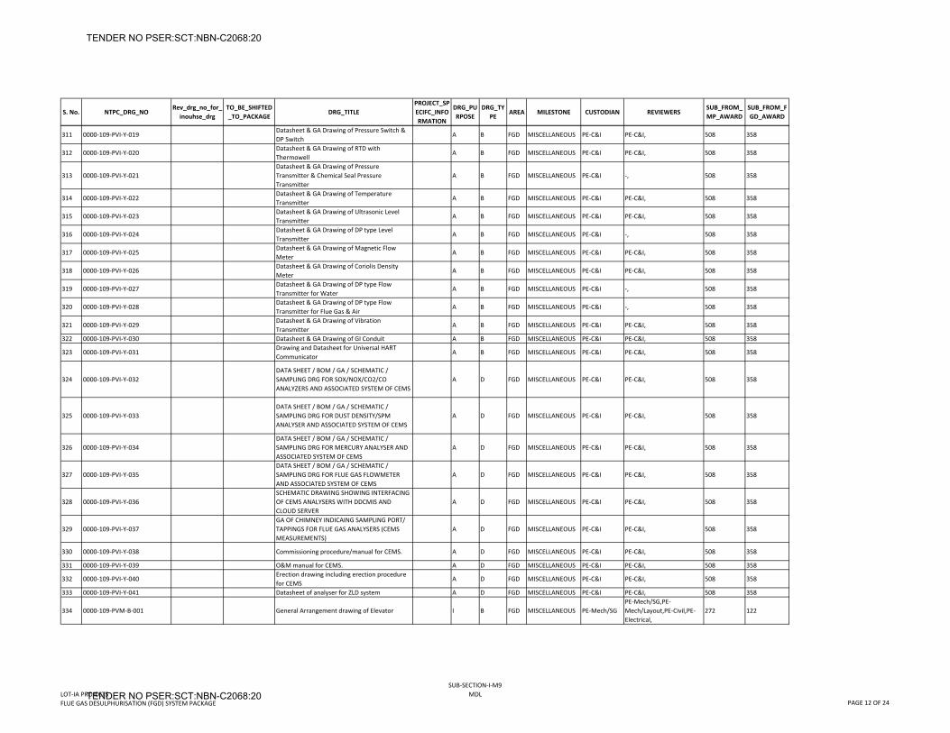
S. No. NTPC_DRG_NORev_drg_no_for_
inouhse_drgTO_BE_SHIFTED_TO_PACKAGE
DRG_TITLEPROJECT_SPECIFC_INFORMATION
DRG_PURPOSE
DRG_TYPE
AREA MILESTONE CUSTODIAN REVIEWERSSUB_FROM_MP_AWARD
SUB_FROM_FGD_AWARD
311 0000‐109‐PVI‐Y‐019Datasheet & GA Drawing of Pressure Switch & DP Switch
A B FGD MISCELLANEOUS PE‐C&I PE‐C&I, 508 358
312 0000‐109‐PVI‐Y‐020Datasheet & GA Drawing of RTD with Thermowell
A B FGD MISCELLANEOUS PE‐C&I PE‐C&I, 508 358
313 0000‐109‐PVI‐Y‐021Datasheet & GA Drawing of Pressure Transmitter & Chemical Seal Pressure Transmitter
A B FGD MISCELLANEOUS PE‐C&I ‐, 508 358
314 0000‐109‐PVI‐Y‐022Datasheet & GA Drawing of Temperature Transmitter
A B FGD MISCELLANEOUS PE‐C&I PE‐C&I, 508 358
315 0000‐109‐PVI‐Y‐023Datasheet & GA Drawing of Ultrasonic Level Transmitter
A B FGD MISCELLANEOUS PE‐C&I PE‐C&I, 508 358
316 0000‐109‐PVI‐Y‐024Datasheet & GA Drawing of DP type Level Transmitter
A B FGD MISCELLANEOUS PE‐C&I ‐, 508 358
317 0000‐109‐PVI‐Y‐025Datasheet & GA Drawing of Magnetic Flow Meter
A B FGD MISCELLANEOUS PE‐C&I PE‐C&I, 508 358
318 0000‐109‐PVI‐Y‐026Datasheet & GA Drawing of Coriolis Density Meter
A B FGD MISCELLANEOUS PE‐C&I PE‐C&I, 508 358
319 0000‐109‐PVI‐Y‐027Datasheet & GA Drawing of DP type Flow Transmitter for Water
A B FGD MISCELLANEOUS PE‐C&I ‐, 508 358
320 0000‐109‐PVI‐Y‐028Datasheet & GA Drawing of DP type Flow Transmitter for Flue Gas & Air
A B FGD MISCELLANEOUS PE‐C&I ‐, 508 358
321 0000‐109‐PVI‐Y‐029Datasheet & GA Drawing of Vibration Transmitter
A B FGD MISCELLANEOUS PE‐C&I PE‐C&I, 508 358
322 0000‐109‐PVI‐Y‐030 Datasheet & GA Drawing of GI Conduit A B FGD MISCELLANEOUS PE‐C&I PE‐C&I, 508 358
323 0000‐109‐PVI‐Y‐031Drawing and Datasheet for Universal HART Communicator
A B FGD MISCELLANEOUS PE‐C&I PE‐C&I, 508 358
324 0000‐109‐PVI‐Y‐032DATA SHEET / BOM / GA / SCHEMATIC / SAMPLING DRG FOR SOX/NOX/CO2/CO ANALYZERS AND ASSOCIATED SYSTEM OF CEMS
A D FGD MISCELLANEOUS PE‐C&I PE‐C&I, 508 358
325 0000‐109‐PVI‐Y‐033DATA SHEET / BOM / GA / SCHEMATIC / SAMPLING DRG FOR DUST DENSITY/SPM ANALYSER AND ASSOCIATED SYSTEM OF CEMS
A D FGD MISCELLANEOUS PE‐C&I PE‐C&I, 508 358
326 0000‐109‐PVI‐Y‐034DATA SHEET / BOM / GA / SCHEMATIC / SAMPLING DRG FOR MERCURY ANALYSER AND ASSOCIATED SYSTEM OF CEMS
A D FGD MISCELLANEOUS PE‐C&I PE‐C&I, 508 358
327 0000‐109‐PVI‐Y‐035DATA SHEET / BOM / GA / SCHEMATIC / SAMPLING DRG FOR FLUE GAS FLOWMETER AND ASSOCIATED SYSTEM OF CEMS
A D FGD MISCELLANEOUS PE‐C&I PE‐C&I, 508 358
328 0000‐109‐PVI‐Y‐036SCHEMATIC DRAWING SHOWING INTERFACING OF CEMS ANALYSERS WITH DDCMIS AND CLOUD SERVER
A D FGD MISCELLANEOUS PE‐C&I PE‐C&I, 508 358
329 0000‐109‐PVI‐Y‐037GA OF CHIMNEY INDICAING SAMPLING PORT/ TAPPINGS FOR FLUE GAS ANALYSERS (CEMS MEASUREMENTS)
A D FGD MISCELLANEOUS PE‐C&I PE‐C&I, 508 358
330 0000‐109‐PVI‐Y‐038 Commissioning procedure/manual for CEMS. A D FGD MISCELLANEOUS PE‐C&I PE‐C&I, 508 358
331 0000‐109‐PVI‐Y‐039 O&M manual for CEMS. A D FGD MISCELLANEOUS PE‐C&I PE‐C&I, 508 358
332 0000‐109‐PVI‐Y‐040Erection drawing including erection procedure for CEMS
A D FGD MISCELLANEOUS PE‐C&I PE‐C&I, 508 358
333 0000‐109‐PVI‐Y‐041 Datasheet of analyser for ZLD system A D FGD MISCELLANEOUS PE‐C&I PE‐C&I, 508 358
334 0000‐109‐PVM‐B‐001 General Arrangement drawing of Elevator I B FGD MISCELLANEOUS PE‐Mech/SGPE‐Mech/SG,PE‐Mech/Layout,PE‐Civil,PE‐Electrical,
272 122
LOT‐IA PROJECTSFLUE GAS DESULPHURISATION (FGD) SYSTEM PACKAGE
SUB‐SECTION‐I‐M9MDL
PAGE 12 OF 24
TENDER NO PSER:SCT:NBN-C2068:20
TENDER NO PSER:SCT:NBN-C2068:20
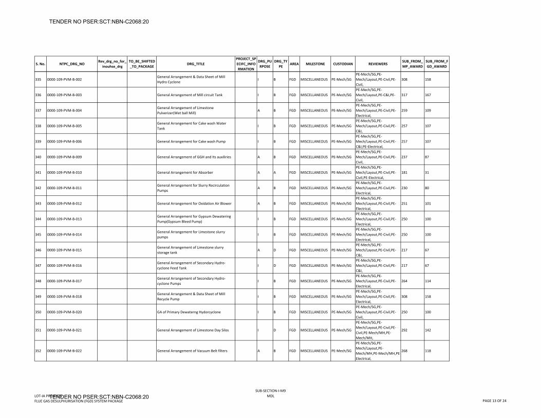
S. No. NTPC_DRG_NORev_drg_no_for_
inouhse_drgTO_BE_SHIFTED_TO_PACKAGE
DRG_TITLEPROJECT_SPECIFC_INFORMATION
DRG_PURPOSE
DRG_TYPE
AREA MILESTONE CUSTODIAN REVIEWERSSUB_FROM_MP_AWARD
SUB_FROM_FGD_AWARD
335 0000‐109‐PVM‐B‐002General Arrangement & Data Sheet of Mill Hydro Cyclone
I B FGD MISCELLANEOUS PE‐Mech/SGPE‐Mech/SG,PE‐Mech/Layout,PE‐Civil,PE‐Civil,
308 158
336 0000‐109‐PVM‐B‐003 General Arrangement of Mill circuit Tank I B FGD MISCELLANEOUS PE‐Mech/SGPE‐Mech/SG,PE‐Mech/Layout,PE‐C&I,PE‐Civil,
317 167
337 0000‐109‐PVM‐B‐004General Arrangement of Limestone Pulverizer(Wet ball Mill)
A B FGD MISCELLANEOUS PE‐Mech/SGPE‐Mech/SG,PE‐Mech/Layout,PE‐Civil,PE‐Electrical,
259 109
338 0000‐109‐PVM‐B‐005General Arrangement for Cake wash Water Tank
I B FGD MISCELLANEOUS PE‐Mech/SGPE‐Mech/SG,PE‐Mech/Layout,PE‐Civil,PE‐C&I,
257 107
339 0000‐109‐PVM‐B‐006 General Arrangement for Cake wash Pump I B FGD MISCELLANEOUS PE‐Mech/SGPE‐Mech/SG,PE‐Mech/Layout,PE‐Civil,PE‐C&I,PE‐Electrical,
257 107
340 0000‐109‐PVM‐B‐009 General Arrangement of GGH and Its auxiliries A B FGD MISCELLANEOUS PE‐Mech/SGPE‐Mech/SG,PE‐Mech/Layout,PE‐Civil,PE‐Civil,
237 87
341 0000‐109‐PVM‐B‐010 General Arrangement for Absorber A A FGD MISCELLANEOUS PE‐Mech/SGPE‐Mech/SG,PE‐Mech/Layout,PE‐Civil,PE‐Civil,PE‐Electrical,
181 31
342 0000‐109‐PVM‐B‐011General Arrangement for Slurry Recirculation Pumps
A B FGD MISCELLANEOUS PE‐Mech/SGPE‐Mech/SG,PE‐Mech/Layout,PE‐Civil,PE‐Electrical,
230 80
343 0000‐109‐PVM‐B‐012 General Arrangement for Oxidation Air Blower A B FGD MISCELLANEOUS PE‐Mech/SGPE‐Mech/SG,PE‐Mech/Layout,PE‐Civil,PE‐Electrical,
251 101
344 0000‐109‐PVM‐B‐013General Arrangement for Gypsum Dewatering Pump(Gypsum Bleed Pump)
I B FGD MISCELLANEOUS PE‐Mech/SGPE‐Mech/SG,PE‐Mech/Layout,PE‐Civil,PE‐Electrical,
250 100
345 0000‐109‐PVM‐B‐014General Arrangement for Limestone slurry pumps
I B FGD MISCELLANEOUS PE‐Mech/SGPE‐Mech/SG,PE‐Mech/Layout,PE‐Civil,PE‐Electrical,
250 100
346 0000‐109‐PVM‐B‐015General Arrangement of Limestone slurry storage tank
A D FGD MISCELLANEOUS PE‐Mech/SGPE‐Mech/SG,PE‐Mech/Layout,PE‐Civil,PE‐C&I,
217 67
347 0000‐109‐PVM‐B‐016General Arrangement of Secondary Hydro‐cyclone Feed Tank
I D FGD MISCELLANEOUS PE‐Mech/SGPE‐Mech/SG,PE‐Mech/Layout,PE‐Civil,PE‐C&I,
217 67
348 0000‐109‐PVM‐B‐017General Arrangement of Secondary Hydro‐cyclone Pumps
I B FGD MISCELLANEOUS PE‐Mech/SGPE‐Mech/SG,PE‐Mech/Layout,PE‐Civil,PE‐Electrical,
264 114
349 0000‐109‐PVM‐B‐018General Arrangement & Data Sheet of Mill Recycle Pump
I B FGD MISCELLANEOUS PE‐Mech/SGPE‐Mech/SG,PE‐Mech/Layout,PE‐Civil,PE‐Electrical,
308 158
350 0000‐109‐PVM‐B‐020 GA of Primary Dewaterng Hydorcyclone I B FGD MISCELLANEOUS PE‐Mech/SGPE‐Mech/SG,PE‐Mech/Layout,PE‐Civil,PE‐Civil,
250 100
351 0000‐109‐PVM‐B‐021 General Arrangement of Limestone Day Silos I D FGD MISCELLANEOUS PE‐Mech/SG
PE‐Mech/SG,PE‐Mech/Layout,PE‐Civil,PE‐Civil,PE‐Mech/MH,PE‐Mech/MH,
292 142
352 0000‐109‐PVM‐B‐022 General Arrangement of Vacuum Belt filters A B FGD MISCELLANEOUS PE‐Mech/SG
PE‐Mech/SG,PE‐Mech/Layout,PE‐Mech/MH,PE‐Mech/MH,PE‐Electrical,
268 118
LOT‐IA PROJECTSFLUE GAS DESULPHURISATION (FGD) SYSTEM PACKAGE
SUB‐SECTION‐I‐M9MDL
PAGE 13 OF 24
TENDER NO PSER:SCT:NBN-C2068:20
TENDER NO PSER:SCT:NBN-C2068:20
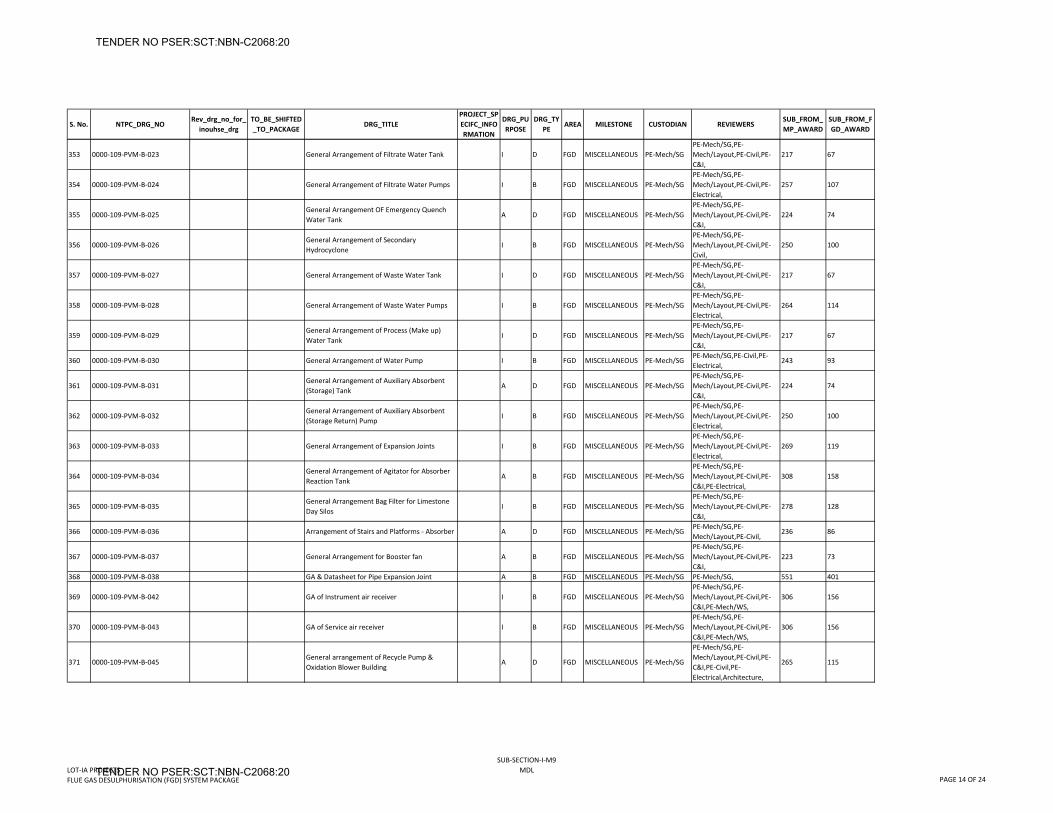
S. No. NTPC_DRG_NORev_drg_no_for_
inouhse_drgTO_BE_SHIFTED_TO_PACKAGE
DRG_TITLEPROJECT_SPECIFC_INFORMATION
DRG_PURPOSE
DRG_TYPE
AREA MILESTONE CUSTODIAN REVIEWERSSUB_FROM_MP_AWARD
SUB_FROM_FGD_AWARD
353 0000‐109‐PVM‐B‐023 General Arrangement of Filtrate Water Tank I D FGD MISCELLANEOUS PE‐Mech/SGPE‐Mech/SG,PE‐Mech/Layout,PE‐Civil,PE‐C&I,
217 67
354 0000‐109‐PVM‐B‐024 General Arrangement of Filtrate Water Pumps I B FGD MISCELLANEOUS PE‐Mech/SGPE‐Mech/SG,PE‐Mech/Layout,PE‐Civil,PE‐Electrical,
257 107
355 0000‐109‐PVM‐B‐025General Arrangement OF Emergency Quench Water Tank
A D FGD MISCELLANEOUS PE‐Mech/SGPE‐Mech/SG,PE‐Mech/Layout,PE‐Civil,PE‐C&I,
224 74
356 0000‐109‐PVM‐B‐026General Arrangement of Secondary Hydrocyclone
I B FGD MISCELLANEOUS PE‐Mech/SGPE‐Mech/SG,PE‐Mech/Layout,PE‐Civil,PE‐Civil,
250 100
357 0000‐109‐PVM‐B‐027 General Arrangement of Waste Water Tank I D FGD MISCELLANEOUS PE‐Mech/SGPE‐Mech/SG,PE‐Mech/Layout,PE‐Civil,PE‐C&I,
217 67
358 0000‐109‐PVM‐B‐028 General Arrangement of Waste Water Pumps I B FGD MISCELLANEOUS PE‐Mech/SGPE‐Mech/SG,PE‐Mech/Layout,PE‐Civil,PE‐Electrical,
264 114
359 0000‐109‐PVM‐B‐029General Arrangement of Process (Make up) Water Tank
I D FGD MISCELLANEOUS PE‐Mech/SGPE‐Mech/SG,PE‐Mech/Layout,PE‐Civil,PE‐C&I,
217 67
360 0000‐109‐PVM‐B‐030 General Arrangement of Water Pump I B FGD MISCELLANEOUS PE‐Mech/SGPE‐Mech/SG,PE‐Civil,PE‐Electrical,
243 93
361 0000‐109‐PVM‐B‐031General Arrangement of Auxiliary Absorbent (Storage) Tank
A D FGD MISCELLANEOUS PE‐Mech/SGPE‐Mech/SG,PE‐Mech/Layout,PE‐Civil,PE‐C&I,
224 74
362 0000‐109‐PVM‐B‐032General Arrangement of Auxiliary Absorbent (Storage Return) Pump
I B FGD MISCELLANEOUS PE‐Mech/SGPE‐Mech/SG,PE‐Mech/Layout,PE‐Civil,PE‐Electrical,
250 100
363 0000‐109‐PVM‐B‐033 General Arrangement of Expansion Joints I B FGD MISCELLANEOUS PE‐Mech/SGPE‐Mech/SG,PE‐Mech/Layout,PE‐Civil,PE‐Electrical,
269 119
364 0000‐109‐PVM‐B‐034General Arrangement of Agitator for Absorber Reaction Tank
A B FGD MISCELLANEOUS PE‐Mech/SGPE‐Mech/SG,PE‐Mech/Layout,PE‐Civil,PE‐C&I,PE‐Electrical,
308 158
365 0000‐109‐PVM‐B‐035General Arrangement Bag Filter for Limestone Day Silos
I B FGD MISCELLANEOUS PE‐Mech/SGPE‐Mech/SG,PE‐Mech/Layout,PE‐Civil,PE‐C&I,
278 128
366 0000‐109‐PVM‐B‐036 Arrangement of Stairs and Platforms ‐ Absorber A D FGD MISCELLANEOUS PE‐Mech/SGPE‐Mech/SG,PE‐Mech/Layout,PE‐Civil,
236 86
367 0000‐109‐PVM‐B‐037 General Arrangement for Booster fan A B FGD MISCELLANEOUS PE‐Mech/SGPE‐Mech/SG,PE‐Mech/Layout,PE‐Civil,PE‐C&I,
223 73
368 0000‐109‐PVM‐B‐038 GA & Datasheet for Pipe Expansion Joint A B FGD MISCELLANEOUS PE‐Mech/SG PE‐Mech/SG, 551 401
369 0000‐109‐PVM‐B‐042 GA of Instrument air receiver I B FGD MISCELLANEOUS PE‐Mech/SGPE‐Mech/SG,PE‐Mech/Layout,PE‐Civil,PE‐C&I,PE‐Mech/WS,
306 156
370 0000‐109‐PVM‐B‐043 GA of Service air receiver I B FGD MISCELLANEOUS PE‐Mech/SGPE‐Mech/SG,PE‐Mech/Layout,PE‐Civil,PE‐C&I,PE‐Mech/WS,
306 156
371 0000‐109‐PVM‐B‐045General arrangement of Recycle Pump & Oxidation Blower Building
A D FGD MISCELLANEOUS PE‐Mech/SG
PE‐Mech/SG,PE‐Mech/Layout,PE‐Civil,PE‐C&I,PE‐Civil,PE‐Electrical,Architecture,
265 115
LOT‐IA PROJECTSFLUE GAS DESULPHURISATION (FGD) SYSTEM PACKAGE
SUB‐SECTION‐I‐M9MDL
PAGE 14 OF 24
TENDER NO PSER:SCT:NBN-C2068:20
TENDER NO PSER:SCT:NBN-C2068:20
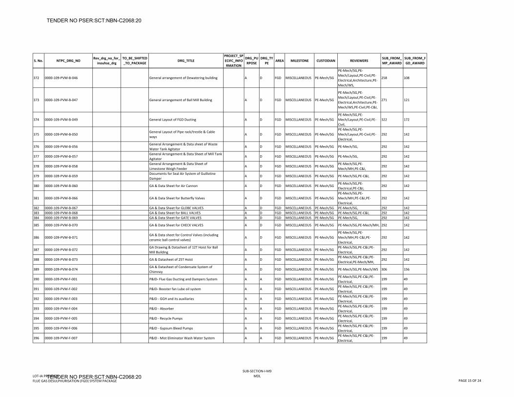
S. No. NTPC_DRG_NORev_drg_no_for_
inouhse_drgTO_BE_SHIFTED_TO_PACKAGE
DRG_TITLEPROJECT_SPECIFC_INFORMATION
DRG_PURPOSE
DRG_TYPE
AREA MILESTONE CUSTODIAN REVIEWERSSUB_FROM_MP_AWARD
SUB_FROM_FGD_AWARD
372 0000‐109‐PVM‐B‐046 General arrangement of Dewatering building A D FGD MISCELLANEOUS PE‐Mech/SG
PE‐Mech/SG,PE‐Mech/Layout,PE‐Civil,PE‐Electrical,Architecture,PE‐Mech/WS,
258 108
373 0000‐109‐PVM‐B‐047 General arrangement of Ball Mill Building A D FGD MISCELLANEOUS PE‐Mech/SG
PE‐Mech/SG,PE‐Mech/Layout,PE‐Civil,PE‐Electrical,Architecture,PE‐Mech/WS,PE‐Civil,PE‐C&I,
271 121
374 0000‐109‐PVM‐B‐049 General Layout of FGD Ducting A D FGD MISCELLANEOUS PE‐Mech/SGPE‐Mech/SG,PE‐Mech/Layout,PE‐Civil,PE‐Civil,
322 172
375 0000‐109‐PVM‐B‐050General Layout of Pipe rack/trestle & Cable ways
A D FGD MISCELLANEOUS PE‐Mech/SGPE‐Mech/SG,PE‐Mech/Layout,PE‐Civil,PE‐Electrical,
292 142
376 0000‐109‐PVM‐B‐056General Arrangement & Data sheet of Waste Water Tank Agitator
A D FGD MISCELLANEOUS PE‐Mech/SG PE‐Mech/SG, 292 142
377 0000‐109‐PVM‐B‐057General Arrangement & Data Sheet of Mill Tank Agitator
A D FGD MISCELLANEOUS PE‐Mech/SG PE‐Mech/SG, 292 142
378 0000‐109‐PVM‐B‐058General Arrangement & Data Sheet of Limestone Weigh Feeder
A D FGD MISCELLANEOUS PE‐Mech/SGPE‐Mech/SG,PE‐Mech/MH,PE‐C&I,
292 142
379 0000‐109‐PVM‐B‐059Documents for Seal Air System of Guillotine Damper
A D FGD MISCELLANEOUS PE‐Mech/SG PE‐Mech/SG,PE‐C&I, 292 142
380 0000‐109‐PVM‐B‐060 GA & Data Sheet for Air Cannon A D FGD MISCELLANEOUS PE‐Mech/SGPE‐Mech/SG,PE‐Electrical,PE‐C&I,
292 142
381 0000‐109‐PVM‐B‐066 GA & Data Sheet for Butterfly Valves A D FGD MISCELLANEOUS PE‐Mech/SGPE‐Mech/SG,PE‐Mech/MH,PE‐C&I,PE‐Electrical,
292 142
382 0000‐109‐PVM‐B‐067 GA & Data Sheet for GLOBE VALVES A D FGD MISCELLANEOUS PE‐Mech/SG PE‐Mech/SG, 292 142383 0000‐109‐PVM‐B‐068 GA & Data Sheet for BALL VALVES A D FGD MISCELLANEOUS PE‐Mech/SG PE‐Mech/SG,PE‐C&I, 292 142384 0000‐109‐PVM‐B‐069 GA & Data Sheet for GATE VALVES A D FGD MISCELLANEOUS PE‐Mech/SG PE‐Mech/SG, 292 142
385 0000‐109‐PVM‐B‐070 GA & Data Sheet for CHECK VALVES A D FGD MISCELLANEOUS PE‐Mech/SG PE‐Mech/SG,PE‐Mech/MH, 292 142
386 0000‐109‐PVM‐B‐071GA & Data sheet for Control Valves (including ceramic ball control valves)
A D FGD MISCELLANEOUS PE‐Mech/SGPE‐Mech/SG,PE‐Mech/MH,PE‐C&I,PE‐Electrical,
292 142
387 0000‐109‐PVM‐B‐072GA Drawing & Datasheet of 12T Hoist for Ball Mill Building
A D FGD MISCELLANEOUS PE‐Mech/SGPE‐Mech/SG,PE‐C&I,PE‐Electrical,
292 142
388 0000‐109‐PVM‐B‐073 GA & Datasheet of 25T Hoist A D FGD MISCELLANEOUS PE‐Mech/SGPE‐Mech/SG,PE‐C&I,PE‐Electrical,PE‐Mech/MH,
292 142
389 0000‐109‐PVM‐B‐074GA & Datasheet of Condensate System of Chimney
A D FGD MISCELLANEOUS PE‐Mech/SG PE‐Mech/SG,PE‐Mech/WS 306 156
390 0000‐109‐PVM‐F‐001 P&ID‐ Flue Gas Ducting and Dampers System A A FGD MISCELLANEOUS PE‐Mech/SGPE‐Mech/SG,PE‐C&I,PE‐Electrical,
199 49
391 0000‐109‐PVM‐F‐002 P&ID‐ Booster fan Lube oil system A A FGD MISCELLANEOUS PE‐Mech/SGPE‐Mech/SG,PE‐C&I,PE‐Electrical,
199 49
392 0000‐109‐PVM‐F‐003 P&ID ‐ GGH and its auxiliaries A A FGD MISCELLANEOUS PE‐Mech/SGPE‐Mech/SG,PE‐C&I,PE‐Electrical,
199 49
393 0000‐109‐PVM‐F‐004 P&ID ‐ Absorber A A FGD MISCELLANEOUS PE‐Mech/SGPE‐Mech/SG,PE‐C&I,PE‐Electrical,
199 49
394 0000‐109‐PVM‐F‐005 P&ID ‐ Recycle Pumps A A FGD MISCELLANEOUS PE‐Mech/SGPE‐Mech/SG,PE‐C&I,PE‐Electrical,
199 49
395 0000‐109‐PVM‐F‐006 P&ID ‐ Gypsum Bleed Pumps A A FGD MISCELLANEOUS PE‐Mech/SGPE‐Mech/SG,PE‐C&I,PE‐Electrical,
199 49
396 0000‐109‐PVM‐F‐007 P&ID ‐ Mist Eliminator Wash Water System A A FGD MISCELLANEOUS PE‐Mech/SGPE‐Mech/SG,PE‐C&I,PE‐Electrical,
199 49
LOT‐IA PROJECTSFLUE GAS DESULPHURISATION (FGD) SYSTEM PACKAGE
SUB‐SECTION‐I‐M9MDL
PAGE 15 OF 24
TENDER NO PSER:SCT:NBN-C2068:20
TENDER NO PSER:SCT:NBN-C2068:20
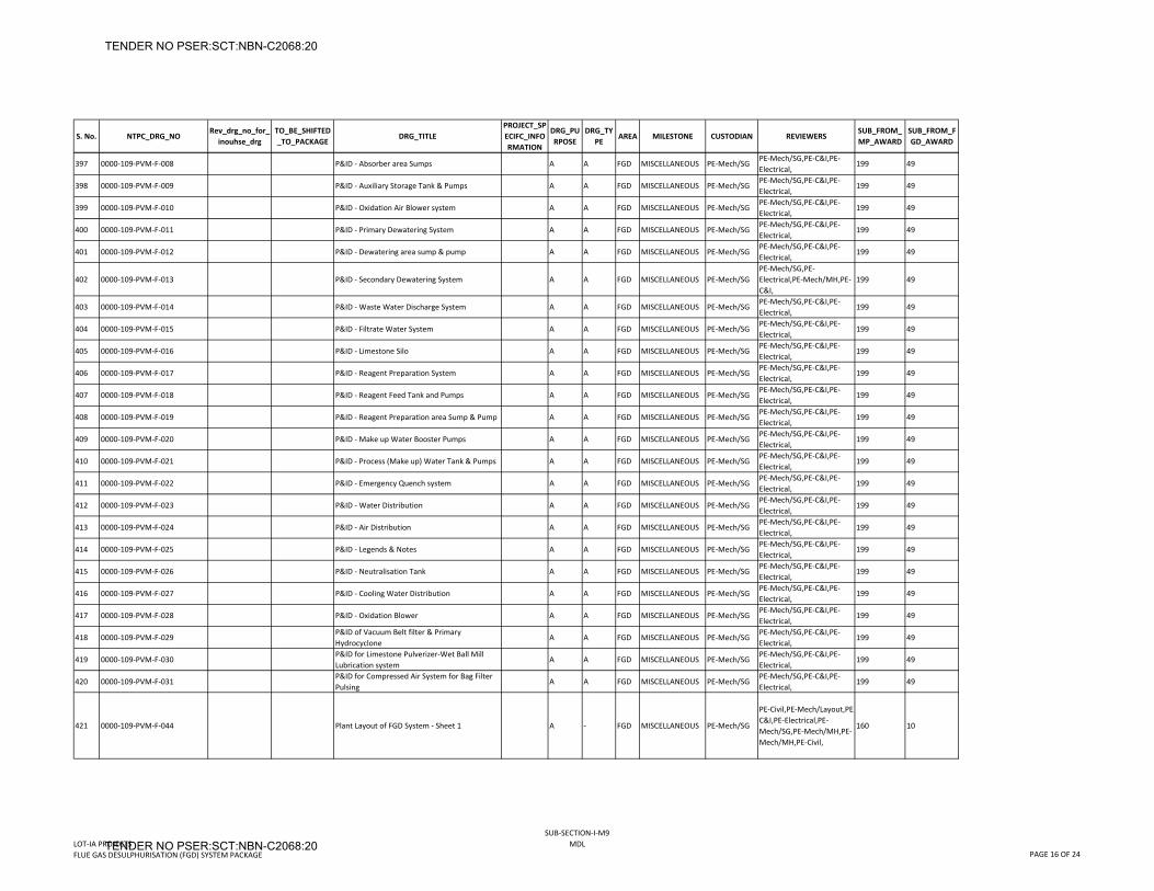
S. No. NTPC_DRG_NORev_drg_no_for_
inouhse_drgTO_BE_SHIFTED_TO_PACKAGE
DRG_TITLEPROJECT_SPECIFC_INFORMATION
DRG_PURPOSE
DRG_TYPE
AREA MILESTONE CUSTODIAN REVIEWERSSUB_FROM_MP_AWARD
SUB_FROM_FGD_AWARD
397 0000‐109‐PVM‐F‐008 P&ID ‐ Absorber area Sumps A A FGD MISCELLANEOUS PE‐Mech/SGPE‐Mech/SG,PE‐C&I,PE‐Electrical,
199 49
398 0000‐109‐PVM‐F‐009 P&ID ‐ Auxiliary Storage Tank & Pumps A A FGD MISCELLANEOUS PE‐Mech/SGPE‐Mech/SG,PE‐C&I,PE‐Electrical,
199 49
399 0000‐109‐PVM‐F‐010 P&ID ‐ Oxidation Air Blower system A A FGD MISCELLANEOUS PE‐Mech/SGPE‐Mech/SG,PE‐C&I,PE‐Electrical,
199 49
400 0000‐109‐PVM‐F‐011 P&ID ‐ Primary Dewatering System A A FGD MISCELLANEOUS PE‐Mech/SGPE‐Mech/SG,PE‐C&I,PE‐Electrical,
199 49
401 0000‐109‐PVM‐F‐012 P&ID ‐ Dewatering area sump & pump A A FGD MISCELLANEOUS PE‐Mech/SGPE‐Mech/SG,PE‐C&I,PE‐Electrical,
199 49
402 0000‐109‐PVM‐F‐013 P&ID ‐ Secondary Dewatering System A A FGD MISCELLANEOUS PE‐Mech/SGPE‐Mech/SG,PE‐Electrical,PE‐Mech/MH,PE‐C&I,
199 49
403 0000‐109‐PVM‐F‐014 P&ID ‐ Waste Water Discharge System A A FGD MISCELLANEOUS PE‐Mech/SGPE‐Mech/SG,PE‐C&I,PE‐Electrical,
199 49
404 0000‐109‐PVM‐F‐015 P&ID ‐ Filtrate Water System A A FGD MISCELLANEOUS PE‐Mech/SGPE‐Mech/SG,PE‐C&I,PE‐Electrical,
199 49
405 0000‐109‐PVM‐F‐016 P&ID ‐ Limestone Silo A A FGD MISCELLANEOUS PE‐Mech/SGPE‐Mech/SG,PE‐C&I,PE‐Electrical,
199 49
406 0000‐109‐PVM‐F‐017 P&ID ‐ Reagent Preparation System A A FGD MISCELLANEOUS PE‐Mech/SGPE‐Mech/SG,PE‐C&I,PE‐Electrical,
199 49
407 0000‐109‐PVM‐F‐018 P&ID ‐ Reagent Feed Tank and Pumps A A FGD MISCELLANEOUS PE‐Mech/SGPE‐Mech/SG,PE‐C&I,PE‐Electrical,
199 49
408 0000‐109‐PVM‐F‐019 P&ID ‐ Reagent Preparation area Sump & Pump A A FGD MISCELLANEOUS PE‐Mech/SGPE‐Mech/SG,PE‐C&I,PE‐Electrical,
199 49
409 0000‐109‐PVM‐F‐020 P&ID ‐ Make up Water Booster Pumps A A FGD MISCELLANEOUS PE‐Mech/SGPE‐Mech/SG,PE‐C&I,PE‐Electrical,
199 49
410 0000‐109‐PVM‐F‐021 P&ID ‐ Process (Make up) Water Tank & Pumps A A FGD MISCELLANEOUS PE‐Mech/SGPE‐Mech/SG,PE‐C&I,PE‐Electrical,
199 49
411 0000‐109‐PVM‐F‐022 P&ID ‐ Emergency Quench system A A FGD MISCELLANEOUS PE‐Mech/SGPE‐Mech/SG,PE‐C&I,PE‐Electrical,
199 49
412 0000‐109‐PVM‐F‐023 P&ID ‐ Water Distribution A A FGD MISCELLANEOUS PE‐Mech/SGPE‐Mech/SG,PE‐C&I,PE‐Electrical,
199 49
413 0000‐109‐PVM‐F‐024 P&ID ‐ Air Distribution A A FGD MISCELLANEOUS PE‐Mech/SGPE‐Mech/SG,PE‐C&I,PE‐Electrical,
199 49
414 0000‐109‐PVM‐F‐025 P&ID ‐ Legends & Notes A A FGD MISCELLANEOUS PE‐Mech/SGPE‐Mech/SG,PE‐C&I,PE‐Electrical,
199 49
415 0000‐109‐PVM‐F‐026 P&ID ‐ Neutralisation Tank A A FGD MISCELLANEOUS PE‐Mech/SGPE‐Mech/SG,PE‐C&I,PE‐Electrical,
199 49
416 0000‐109‐PVM‐F‐027 P&ID ‐ Cooling Water Distribution A A FGD MISCELLANEOUS PE‐Mech/SGPE‐Mech/SG,PE‐C&I,PE‐Electrical,
199 49
417 0000‐109‐PVM‐F‐028 P&ID ‐ Oxidation Blower A A FGD MISCELLANEOUS PE‐Mech/SGPE‐Mech/SG,PE‐C&I,PE‐Electrical,
199 49
418 0000‐109‐PVM‐F‐029P&ID of Vacuum Belt filter & Primary Hydrocyclone
A A FGD MISCELLANEOUS PE‐Mech/SGPE‐Mech/SG,PE‐C&I,PE‐Electrical,
199 49
419 0000‐109‐PVM‐F‐030P&ID for Limestone Pulverizer‐Wet Ball Mill Lubrication system
A A FGD MISCELLANEOUS PE‐Mech/SGPE‐Mech/SG,PE‐C&I,PE‐Electrical,
199 49
420 0000‐109‐PVM‐F‐031P&ID for Compressed Air System for Bag Filter Pulsing
A A FGD MISCELLANEOUS PE‐Mech/SGPE‐Mech/SG,PE‐C&I,PE‐Electrical,
199 49
421 0000‐109‐PVM‐F‐044 Plant Layout of FGD System ‐ Sheet 1 A ‐ FGD MISCELLANEOUS PE‐Mech/SG
PE‐Civil,PE‐Mech/Layout,PE‐C&I,PE‐Electrical,PE‐Mech/SG,PE‐Mech/MH,PE‐Mech/MH,PE‐Civil,
160 10
LOT‐IA PROJECTSFLUE GAS DESULPHURISATION (FGD) SYSTEM PACKAGE
SUB‐SECTION‐I‐M9MDL
PAGE 16 OF 24
TENDER NO PSER:SCT:NBN-C2068:20
TENDER NO PSER:SCT:NBN-C2068:20
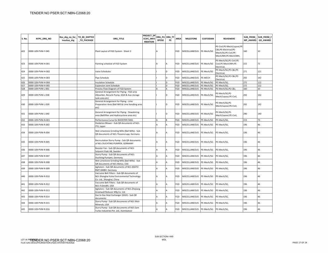
S. No. NTPC_DRG_NORev_drg_no_for_
inouhse_drgTO_BE_SHIFTED_TO_PACKAGE
DRG_TITLEPROJECT_SPECIFC_INFORMATION
DRG_PURPOSE
DRG_TYPE
AREA MILESTONE CUSTODIAN REVIEWERSSUB_FROM_MP_AWARD
SUB_FROM_FGD_AWARD
422 0000‐109‐PVM‐F‐045 Plant Layout of FGD System ‐ Sheet 2 A ‐ FGD MISCELLANEOUS PE‐Mech/SG
PE‐Civil,PE‐Mech/Layout,PE‐C&I,PE‐Electrical,PE‐Mech/SG,PE‐Civil,PE‐Mech/MH,PE‐Mech/MH,
160 10
423 0000‐109‐PVM‐H‐001 Painting schedule of FGD System A A FGD MISCELLANEOUS PE‐Mech/SGPE‐Mech/SG,PE‐Civil,PE‐Civil,PE‐Mech/MH,PE‐Electrical,
222 72
424 0000‐109‐PVM‐H‐002 Valve Schedules I D FGD MISCELLANEOUS PE‐Mech/SGPE‐Mech/SG,PE‐C&I,PE‐Electrical,
271 121
425 0000‐109‐PVM‐H‐003 Pipe Schedule I D FGD MISCELLANEOUS PE‐MECHPE‐Mech/SG,PE‐C&I,PE‐Electrical,
292 142
426 0000‐109‐PVM‐H‐004 Insulation Schedule I D FGD MISCELLANEOUS PE‐Mech/SG PE‐Mech/SG, 272 122427 0000‐109‐PVM‐H‐005 Expansion Joint Schedule I D FGD MISCELLANEOUS PE‐Mech/SG PE‐Mech/SG, 272 122428 0000‐109‐PVM‐L‐001 Process Flow Diagram of FGD System A A FGD MISCELLANEOUS PE‐Mech/SG PE‐Mech/SG,PE‐C&I, 160 10
429 0000‐109‐PVM‐L‐038General Arrangement for Piping ‐ FGD area (Absorber, Recycle Pump, GGH & Aux storage tank area etc)
I D FGD MISCELLANEOUS PE‐Mech/SGPE‐Mech/SG,PE‐Mech/Layout,PE‐Civil,
292 142
430 0000‐109‐PVM‐L‐039General Arrangement for Piping ‐ Lime Preparation Area (Ball Mill & Lime handling area etc)
I D FGD MISCELLANEOUS PE‐Mech/SGPE‐Mech/SG,PE‐Mech/Layout,PE‐Civil,
292 142
431 0000‐109‐PVM‐L‐040General Arrangement for Piping ‐ Dewatering area (Beltfilter and Hydrocyclone area etc)
I D FGD MISCELLANEOUS PE‐Mech/SGPE‐Mech/SG,PE‐Mech/Layout,PE‐Civil,
290 140
432 0000‐109‐PVM‐N‐001 Performance Curve for BOOSTER FANS A B FGD MISCELLANEOUS PE‐Mech/SG PE‐Mech/SG, 223 73
433 0000‐109‐PVM‐R‐002Oxidation Blower ‐ Sub QR documents of M/s ITO, Japan
A A FGD MISCELLANEOUS PE‐Mech/SG PE‐Mech/SG, 196 46
434 0000‐109‐PVM‐R‐004Wet Limestone Grinding Mills (Ball Mills) ‐ Sub QR documents of M/s Thysencrupp, Germany
A A FGD MISCELLANEOUS PE‐Mech/SG PE‐Mech/SG, 196 46
435 0000‐109‐PVM‐R‐005Recirculation Slurry Pump ‐ Sub QR documents of M/s DUCHTING PUMPEN, GERMANY
A A FGD MISCELLANEOUS PE‐Mech/SG PE‐Mech/SG, 196 46
436 0000‐109‐PVM‐R‐006Booster Fan ‐ Sub QR documents of M/s Solyvent Flakt AB, Sweden
A A FGD MISCELLANEOUS PE‐Mech/SG PE‐Mech/SG, 196 46
437 0000‐109‐PVM‐R‐007Slurry Pump ‐ Sub QR documents of M/s Duchting Pumpen, Germany
A A FGD MISCELLANEOUS PE‐Mech/SG PE‐Mech/SG, 196 46
438 0000‐109‐PVM‐R‐008Wet Limestone Grinding Mills (Ball Mills) ‐ Sub QR documents of M/s Metso, USA
A A FGD MISCELLANEOUS PE‐Mech/SG PE‐Mech/SG, 196 46
439 0000‐109‐PVM‐R‐009Agitators ‐ Sub QR documents of M/s EKATO RMT GMBH. Germany
A A FGD MISCELLANEOUS PE‐Mech/SG PE‐Mech/SG, 196 46
440 0000‐109‐PVM‐R‐010Vaccume Belt Filters ‐ Sub QR documents of M/s Shanghai Xuhe Environmental Technology Co. Ltd., Shanghai, China
A A FGD MISCELLANEOUS PE‐Mech/SG PE‐Mech/SG, 196 46
441 0000‐109‐PVM‐R‐012Vaccume Belt Filters ‐ Sub QR documents of M/s FLSmidth, USA
A A FGD MISCELLANEOUS PE‐Mech/SG PE‐Mech/SG, 196 46
442 0000‐109‐PVM‐R‐013Agitators ‐ Sub QR documents of M/s Zhejiang Greatwall Reducer Mfg Co. Ltd.
A A FGD MISCELLANEOUS PE‐Mech/SG PE‐Mech/SG, 196 46
443 0000‐109‐PVM‐R‐014Gas to Gas Heat Exchanger (GGH) ‐ Sub QR documents
A A FGD MISCELLANEOUS PE‐Mech/SG PE‐Mech/SG, 196 46
444 0000‐109‐PVM‐R‐015Slurry Pump ‐ Sub QR documents of M/s Weir Minerals, USA
A A FGD MISCELLANEOUS PE‐Mech/SG PE‐Mech/SG, 196 46
445 0000‐109‐PVM‐R‐016Slurry Pump ‐ Sub QR documents of M/s Sam Turbo Industries Pvt. Ltd., Koimbatoor
A A FGD MISCELLANEOUS PE‐Mech/SG PE‐Mech/SG, 196 46
LOT‐IA PROJECTSFLUE GAS DESULPHURISATION (FGD) SYSTEM PACKAGE
SUB‐SECTION‐I‐M9MDL
PAGE 17 OF 24
TENDER NO PSER:SCT:NBN-C2068:20
TENDER NO PSER:SCT:NBN-C2068:20
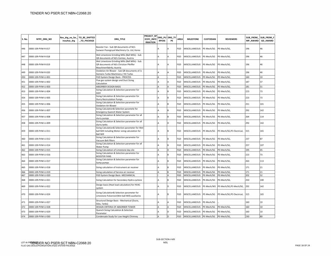
S. No. NTPC_DRG_NORev_drg_no_for_
inouhse_drgTO_BE_SHIFTED_TO_PACKAGE
DRG_TITLEPROJECT_SPECIFC_INFORMATION
DRG_PURPOSE
DRG_TYPE
AREA MILESTONE CUSTODIAN REVIEWERSSUB_FROM_MP_AWARD
SUB_FROM_FGD_AWARD
446 0000‐109‐PVM‐R‐017Booster Fan ‐ Sub QR documents of M/s Suewon Poongryuk Machinery Co. Ltd, Korea
A A FGD MISCELLANEOUS PE‐Mech/SG PE‐Mech/SG, 196 46
447 0000‐109‐PVM‐R‐018Wet Limestone Grinding Mills (Ball Mills) ‐ Sub QR documents of M/s Cemtec, Austria
A A FGD MISCELLANEOUS PE‐Mech/SG PE‐Mech/SG, 196 46
448 0000‐109‐PVM‐R‐019Wet Limestone Grinding Mills (Ball Mills) ‐ Sub QR documents of M/s Christian Pfeiffer Maschinenfabrik¿ Austria
A A FGD MISCELLANEOUS PE‐Mech/SG PE‐Mech/SG, 196 46
449 0000‐109‐PVM‐R‐020Oxidation Air Blower ‐ Sub QR documents of /s Siemens Turbo Machinery / HV Turbo
A A FGD MISCELLANEOUS PE‐Mech/SG PE‐Mech/SG, 196 46
450 0000‐109‐PVM‐U‐001 FGD System Design Basis ‐ PROCESS A ‐ FGD MISCELLANEOUS PE‐Mech/SG PE‐Mech/SG, 160 10
451 0000‐109‐PVM‐U‐002Flue gas system design and Duct Sizing Calculation
A A FGD MISCELLANEOUS PE‐Mech/SG PE‐Mech/SG, 187 37
452 0000‐109‐PVM‐U‐003 ABSORBER DESIGN BASIS A A FGD MISCELLANEOUS PE‐Mech/SG PE‐Mech/SG, 181 31
453 0000‐109‐PVM‐U‐004Sizing Calculation & Selection parameter for GGH
A B FGD MISCELLANEOUS PE‐Mech/SG PE‐Mech/SG, 223 73
454 0000‐109‐PVM‐U‐005Sizing Calculation & Selection parameter for Slurry Recirculation Pumps
A B FGD MISCELLANEOUS PE‐Mech/SG PE‐Mech/SG, 223 73
455 0000‐109‐PVM‐U‐006Sizing Calculation & Selection parameter for Oxidation Air Blower
A B FGD MISCELLANEOUS PE‐Mech/SG PE‐Mech/SG, 251 101
456 0000‐109‐PVM‐U‐007Sizing Calculation& Selection paramete for Emergency Quench Water System
A B FGD MISCELLANEOUS PE‐Mech/SG PE‐Mech/SG, 292 142
457 0000‐109‐PVM‐U‐008Sizing Calculation & Selection parameter for all slurry pumps
A B FGD MISCELLANEOUS PE‐Mech/SG PE‐Mech/SG, 264 114
458 0000‐109‐PVM‐U‐009Sizing Calculation & Selection parameter for all slurry tanks
A D FGD MISCELLANEOUS PE‐Mech/SG PE‐Mech/SG, 292 142
459 0000‐109‐PVM‐U‐011Sizing Calculation& Selection parameter for Wet ball Mill including Motor sizing calculation for Ball Mill
A B FGD MISCELLANEOUS PE‐Mech/SG PE‐Mech/SG,PE‐Electrical, 315 165
460 0000‐109‐PVM‐U‐012Sizing Calculation & Selection parameter for Vacuum Belt filters
A B FGD MISCELLANEOUS PE‐Mech/SG PE‐Mech/SG, 237 87
461 0000‐109‐PVM‐U‐014Sizing Calculation & Selection parameter for all Water Pump
A B FGD MISCELLANEOUS PE‐Mech/SG PE‐Mech/SG, 257 107
462 0000‐109‐PVM‐U‐015 Sizing Calculation of Limestone day silo A D FGD MISCELLANEOUS PE‐Mech/SG PE‐Mech/SG, 195 45
463 0000‐109‐PVM‐U‐016Sizing Calculation & Selection parameter for BOOSTER FANS
A B FGD MISCELLANEOUS PE‐Mech/SG PE‐Mech/SG, 223 73
464 0000‐109‐PVM‐U‐017Sizing Calculation & Selection parameter for Sump pumps
A B FGD MISCELLANEOUS PE‐Mech/SG PE‐Mech/SG, 263 113
465 0000‐109‐PVM‐U‐018 Sizing calculation of Instrument air receiver A B FGD MISCELLANEOUS PE‐Mech/SG PE‐Mech/SG, 171 21
466 0000‐109‐PVM‐U‐019 Sizing calculation of Service air receiver A B FGD MISCELLANEOUS PE‐Mech/SG PE‐Mech/SG, 171 21467 0000‐109‐PVM‐U‐020 FGD System Design Basis ‐MECHANICAL I A FGD MISCELLANEOUS PE‐Mech/SG PE‐Mech/SG, 202 52
468 0000‐109‐PVM‐U‐021 Sizing Calculation for Secondary Hydro‐cyclone A B FGD MISCELLANEOUS PE‐Mech/SG PE‐Mech/SG, 250 100
469 0000‐109‐PVM‐U‐022Design basis (Heat load calculation) for HVAC system
A D FGD MISCELLANEOUS PE‐Mech/WS PE‐Mech/SG,PE‐Mech/SG, 292 142
470 0000‐109‐PVM‐U‐024Sizing Calculation& Selection parameter for Limestone Pulverizer(Wet ball Mill) auxiliaries
A B FGD MISCELLANEOUS PE‐Mech/SG PE‐Mech/SG,PE‐Electrical, 315 165
471 0000‐109‐PVM‐U‐027Structural Design Basis ‐ Mechanical (Ducts, Silos, Tanks)
A A FGD MISCELLANEOUS PE‐Mech/SG ‐, 160 10
472 0000‐109‐PVM‐U‐028 DESIGN CRITERIA OF ABSORBER TOWER A A FGD MISCELLANEOUS PE‐Mech/SG PE‐Mech/SG, 160 10
473 0000‐109‐PVM‐U‐029Quench Sizing Calculation & Selection Parameter
A D FGD MISCELLANEOUS PE‐Mech/SG PE‐Mech/SG, 160 10
474 0000‐109‐PVM‐U‐030 Condensate Study for Low Height Chimney A D FGD MISCELLANEOUS PE‐Mech/SG PE‐Mech/SG, 230 80
LOT‐IA PROJECTSFLUE GAS DESULPHURISATION (FGD) SYSTEM PACKAGE
SUB‐SECTION‐I‐M9MDL
PAGE 18 OF 24
TENDER NO PSER:SCT:NBN-C2068:20
TENDER NO PSER:SCT:NBN-C2068:20
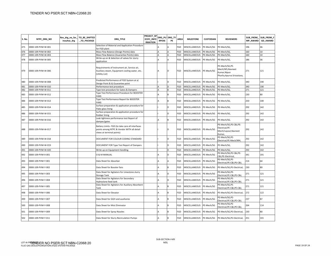
S. No. NTPC_DRG_NORev_drg_no_for_
inouhse_drgTO_BE_SHIFTED_TO_PACKAGE
DRG_TITLEPROJECT_SPECIFC_INFORMATION
DRG_PURPOSE
DRG_TYPE
AREA MILESTONE CUSTODIAN REVIEWERSSUB_FROM_MP_AWARD
SUB_FROM_FGD_AWARD
475 0000‐109‐PVM‐W‐001Selection of Material and Application Procedure for FGD plant
A A FGD MISCELLANEOUS PE‐Mech/SG PE‐Mech/SG, 196 46
476 0000‐109‐PVM‐W‐002 Mass Flow Balance (Design Points) data A A FGD MISCELLANEOUS PE‐Mech/SG PE‐Mech/SG, 160 10477 0000‐109‐PVM‐W‐003 Mass Flow Balance (Guarantee Points) data A A FGD MISCELLANEOUS PE‐Mech/SG PE‐Mech/SG, 160 10
478 0000‐109‐PVM‐W‐005Write‐up on & Selection of valves for slurry application
A A FGD MISCELLANEOUS PE‐Mech/SG PE‐Mech/SG, 186 36
479 0000‐109‐PVM‐W‐006Requirements of Instrument air, Service air, Auxiliary steam, Equipment cooling water, etc.. (Utility List)
A D FGD MISCELLANEOUS PE‐Mech/SG
PE‐Mech/SG,PE‐Mech/WS,Navneet Kumar,Nipun Pharlia,Apurva Srivastava,
271 121
480 0000‐109‐PVM‐W‐008Predicted Performance of FGD System at a) Design Point & b) Guarantee point
I D FGD MISCELLANEOUS PE‐Mech/SG PE‐Mech/SG, 340 190
481 0000‐109‐PVM‐W‐010 Performance test procedure A D FGD MISCELLANEOUS PE‐Mech/SG PE‐Mech/SG, 340 190482 0000‐109‐PVM‐W‐011 Type test procedure for Gates & Dampers A B FGD MISCELLANEOUS PE‐Mech/SG PE‐Mech/SG, 271 121
483 0000‐109‐PVM‐W‐012Type Test Performance Procedure for BOOSTER FANS
A B FGD MISCELLANEOUS PE‐Mech/SG PE‐Mech/SG, 230 80
484 0000‐109‐PVM‐W‐013Type Test Performance Report for BOOSTER FANS
A B FGD MISCELLANEOUS PE‐Mech/SG PE‐Mech/SG, 250 100
485 0000‐109‐PVM‐W‐014Surface preparation & application procedure for Flake glass lining
I D FGD MISCELLANEOUS PE‐Mech/SG PE‐Mech/SG, 292 142
486 0000‐109‐PVM‐W‐015Surface preparation & application procedure for Rubber lining
I D FGD MISCELLANEOUS PE‐Mech/SG PE‐Mech/SG, 292 142
487 0000‐109‐PVM‐W‐016Leak tightness performance test Report of damper/gates
A B FGD MISCELLANEOUS PE‐Mech/SG PE‐Mech/SG, 292 142
488 0000‐109‐PVM‐W‐017Battery Limits‐ FGD (to take care all interfaces points among NTPC & Vendor WITH all detail views at terminal points)
I D FGD MISCELLANEOUS PE‐Mech/SG
PE‐Mech/SG,PE‐C&I,PE‐Electrical,PE‐Mech/Layout,Navneet Kumar,
292 142
489 0000‐109‐PVM‐W‐018 DOCUMENT FOR COLOUR CODING STANDARD I D FGD MISCELLANEOUS PE‐Mech/SGPE‐Mech/SG,PE‐Electrical,PE‐Mech/MH,
292 142
490 0000‐109‐PVM‐W‐019 DOCUMENT FOR Type Test Report of Dampers I D FGD MISCELLANEOUS PE‐Mech/SG PE‐Mech/SG, 292 142
491 0000‐109‐PVM‐W‐020 Write up on Equipment Handling I D FGD MISCELLANEOUS PE‐Mech/SG PE‐Mech/SG, 292 142
492 0000‐109‐PVM‐X‐001 O & M MANUAL A D FGD MISCELLANEOUS PE‐Mech/SGPE‐Mech/SG,PE‐C&I,PE‐C&I,PE‐Electrical,
341 191
493 0000‐109‐PVM‐Y‐001 Data Sheet for Absorber A A FGD MISCELLANEOUS PE‐Mech/SGPE‐Mech/SG,PE‐Electrical,PE‐C&I,PE‐C&I,
214 64
494 0000‐109‐PVM‐Y‐002 Data Sheet for Booster fans A B FGD MISCELLANEOUS PE‐Mech/SG PE‐Mech/SG,PE‐Electrical, 230 80
495 0000‐109‐PVM‐Y‐003Data Sheet for Agitators for Limestone slurry Storage Tank
A D FGD MISCELLANEOUS PE‐Mech/SGPE‐Mech/SG,PE‐Electrical,PE‐C&I,PE‐C&I,
271 121
496 0000‐109‐PVM‐Y‐004Data Sheet for Agitators for Secondary Hydroclone feed tank
A D FGD MISCELLANEOUS PE‐Mech/SGPE‐Mech/SG,PE‐Electrical,PE‐C&I,PE‐C&I,
271 121
497 0000‐109‐PVM‐Y‐005Data Sheet for Agitators for Auxiliary Absorbent Tank
A B FGD MISCELLANEOUS PE‐Mech/SGPE‐Mech/SG,PE‐Electrical,PE‐C&I,PE‐C&I,
271 121
498 0000‐109‐PVM‐Y‐006 Data Sheet for Elevator A B FGD MISCELLANEOUS PE‐Mech/SG PE‐Mech/SG,PE‐Electrical, 272 122
499 0000‐109‐PVM‐Y‐007 Data Sheet for GGH and auxiliaries A B FGD MISCELLANEOUS PE‐Mech/SGPE‐Mech/SG,PE‐Electrical,PE‐C&I,PE‐C&I,
237 87
500 0000‐109‐PVM‐Y‐008 Data Sheet for Mist Eliminator A B FGD MISCELLANEOUS PE‐Mech/SGPE‐Mech/SG,PE‐Electrical,PE‐C&I,PE‐C&I,
264 114
501 0000‐109‐PVM‐Y‐009 Data Sheet for Spray Nozzles A B FGD MISCELLANEOUS PE‐Mech/SG PE‐Mech/SG,PE‐Electrical, 230 80
502 0000‐109‐PVM‐Y‐011 Data Sheet for Slurry Recirculation Pumps A B FGD MISCELLANEOUS PE‐Mech/SG PE‐Mech/SG,PE‐Electrical, 251 101
LOT‐IA PROJECTSFLUE GAS DESULPHURISATION (FGD) SYSTEM PACKAGE
SUB‐SECTION‐I‐M9MDL
PAGE 19 OF 24
TENDER NO PSER:SCT:NBN-C2068:20
TENDER NO PSER:SCT:NBN-C2068:20
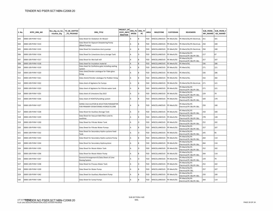
S. No. NTPC_DRG_NORev_drg_no_for_
inouhse_drgTO_BE_SHIFTED_TO_PACKAGE
DRG_TITLEPROJECT_SPECIFC_INFORMATION
DRG_PURPOSE
DRG_TYPE
AREA MILESTONE CUSTODIAN REVIEWERSSUB_FROM_MP_AWARD
SUB_FROM_FGD_AWARD
503 0000‐109‐PVM‐Y‐012 Data Sheet for Oxidation Air Blower A B FGD MISCELLANEOUS PE‐Mech/SG PE‐Mech/SG,PE‐Electrical, 251 101
504 0000‐109‐PVM‐Y‐014Data Sheet for Gypsum Dewatering Pump (Bleed Pumps)
A B FGD MISCELLANEOUS PE‐Mech/SG PE‐Mech/SG,PE‐Electrical, 250 100
505 0000‐109‐PVM‐Y‐015 Data Sheet for Limestone slurry pumps A B FGD MISCELLANEOUS PE‐Mech/SG PE‐Mech/SG,PE‐Electrical, 250 100
506 0000‐109‐PVM‐Y‐016 Data Sheet for Limestone slurry storage Tank A D FGD MISCELLANEOUS PE‐Mech/SGPE‐Mech/SG,PE‐Electrical,PE‐C&I,PE‐C&I,
217 67
507 0000‐109‐PVM‐Y‐017 Data Sheet for Wet ball mill A B FGD MISCELLANEOUS PE‐Mech/SGPE‐Mech/SG,PE‐Electrical,PE‐C&I,PE‐C&I,
257 107
508 0000‐109‐PVM‐Y‐018 Data sheet for Insulation material A B FGD MISCELLANEOUS PE‐Mech/SG PE‐Mech/SG, 336 186
509 0000‐109‐PVM‐Y‐019Data sheet for Guillotine gate including sealing system
A B FGD MISCELLANEOUS PE‐Mech/SG PE‐Mech/SG, 271 121
510 0000‐109‐PVM‐Y‐020Data sheet/Vendor catalogue for Flake glass lining
A B FGD MISCELLANEOUS PE‐Mech/SG PE‐Mech/SG, 336 186
511 0000‐109‐PVM‐Y‐021 Data sheet//Vendor catalogue for Rubber lining A B FGD MISCELLANEOUS PE‐Mech/SG PE‐Mech/SG, 332 182
512 0000‐109‐PVM‐Y‐022 Data sheet of Agitators for Sumps A B FGD MISCELLANEOUS PE‐Mech/SG PE‐Mech/SG,PE‐Electrical, 271 121
513 0000‐109‐PVM‐Y‐023 Data sheet of Agitators for Filtrate water tank A B FGD MISCELLANEOUS PE‐Mech/SGPE‐Mech/SG,PE‐Electrical,PE‐C&I,PE‐C&I,
271 121
514 0000‐109‐PVM‐Y‐025 Data sheet of Limestone Day SILO A D FGD MISCELLANEOUS PE‐Mech/SGPE‐Mech/SG,PE‐Electrical,PE‐C&I,PE‐C&I,
229 79
515 0000‐109‐PVM‐Y‐026 Data sheet of HOISTS/handling system A B FGD MISCELLANEOUS PE‐Mech/SGPE‐Mech/SG,PE‐Electrical,PE‐C&I,PE‐C&I,
320 170
516 0000‐109‐PVM‐Y‐027SIZING CALCULATION & SELECTION PARAMETER FOR PRIMARY DEWATERING HYDROCYCLONE
A B FGD MISCELLANEOUS PE‐Mech/SGPE‐Mech/SG,PE‐Electrical,PE‐C&I,PE‐C&I,
250 100
517 0000‐109‐PVM‐Y‐028 Data Sheet for Auxiliary Storage Tank A D FGD MISCELLANEOUS PE‐Mech/SGPE‐Mech/SG,PE‐Electrical,PE‐C&I,PE‐C&I,
250 100
518 0000‐109‐PVM‐Y‐029Data Sheet for Vacuum Belt filters and its auxiliries
A B FGD MISCELLANEOUS PE‐Mech/SGPE‐Mech/SG,PE‐Electrical,PE‐C&I,PE‐C&I,
278 128
519 0000‐109‐PVM‐Y‐030 Data Sheet for Filtrate Water Tank A D FGD MISCELLANEOUS PE‐Mech/SGPE‐Mech/SG,PE‐Electrical,PE‐C&I,PE‐C&I,
252 102
520 0000‐109‐PVM‐Y‐031 Data Sheet for Filtrate Water Pumps A B FGD MISCELLANEOUS PE‐Mech/SGPE‐Mech/SG,PE‐Electrical,PE‐C&I,PE‐C&I,
257 107
521 0000‐109‐PVM‐Y‐032Data Sheet for Secondary Hydro‐cyclone Feed Tank
A D FGD MISCELLANEOUS PE‐Mech/SGPE‐Mech/SG,PE‐Electrical,PE‐C&I,PE‐C&I,
245 95
522 0000‐109‐PVM‐Y‐033 Data Sheet for Secondary Hydro‐cyclone Pump A B FGD MISCELLANEOUS PE‐Mech/SGPE‐Mech/SG,PE‐Electrical,PE‐C&I,PE‐C&I,
264 114
523 0000‐109‐PVM‐Y‐034 Data Sheet for Secondary Hydrocyclone A B FGD MISCELLANEOUS PE‐Mech/SGPE‐Mech/SG,PE‐Electrical,PE‐C&I,PE‐C&I,
264 114
524 0000‐109‐PVM‐Y‐035 Data Sheet for Waste Water Tank A D FGD MISCELLANEOUS PE‐Mech/SGPE‐Mech/SG,PE‐Electrical,PE‐C&I,PE‐C&I,
252 102
525 0000‐109‐PVM‐Y‐036 Data Sheet for Waste Water Pump A B FGD MISCELLANEOUS PE‐Mech/SGPE‐Mech/SG,PE‐Electrical,PE‐C&I,PE‐C&I,
264 114
526 0000‐109‐PVM‐Y‐037General Arrangement & Data Sheet of Lime Dosing System
A D FGD MISCELLANEOUS PE‐Mech/SGPE‐Mech/SG,PE‐Electrical,PE‐C&I,PE‐C&I,
229 79
527 0000‐109‐PVM‐Y‐038 Data Sheet for Process Water Tank A D FGD MISCELLANEOUS PE‐Mech/SGPE‐Mech/SG,PE‐Electrical,PE‐C&I,PE‐C&I,
252 102
528 0000‐109‐PVM‐Y‐039 Data Sheet for Water Pump A B FGD MISCELLANEOUS PE‐Mech/SGPE‐Mech/SG,PE‐Electrical,PE‐C&I,
257 107
529 0000‐109‐PVM‐Y‐042 Data Sheet for Auxiliary Absorbent Pump A B FGD MISCELLANEOUS PE‐Mech/SGPE‐Mech/SG,PE‐Electrical,PE‐C&I,PE‐C&I,
250 100
530 0000‐109‐PVM‐Y‐044 Data Sheet for Sump Pumps A B FGD MISCELLANEOUS PE‐Mech/SGPE‐Mech/SG,PE‐Electrical,PE‐C&I,PE‐C&I,
264 114
LOT‐IA PROJECTSFLUE GAS DESULPHURISATION (FGD) SYSTEM PACKAGE
SUB‐SECTION‐I‐M9MDL
PAGE 20 OF 24
TENDER NO PSER:SCT:NBN-C2068:20
TENDER NO PSER:SCT:NBN-C2068:20
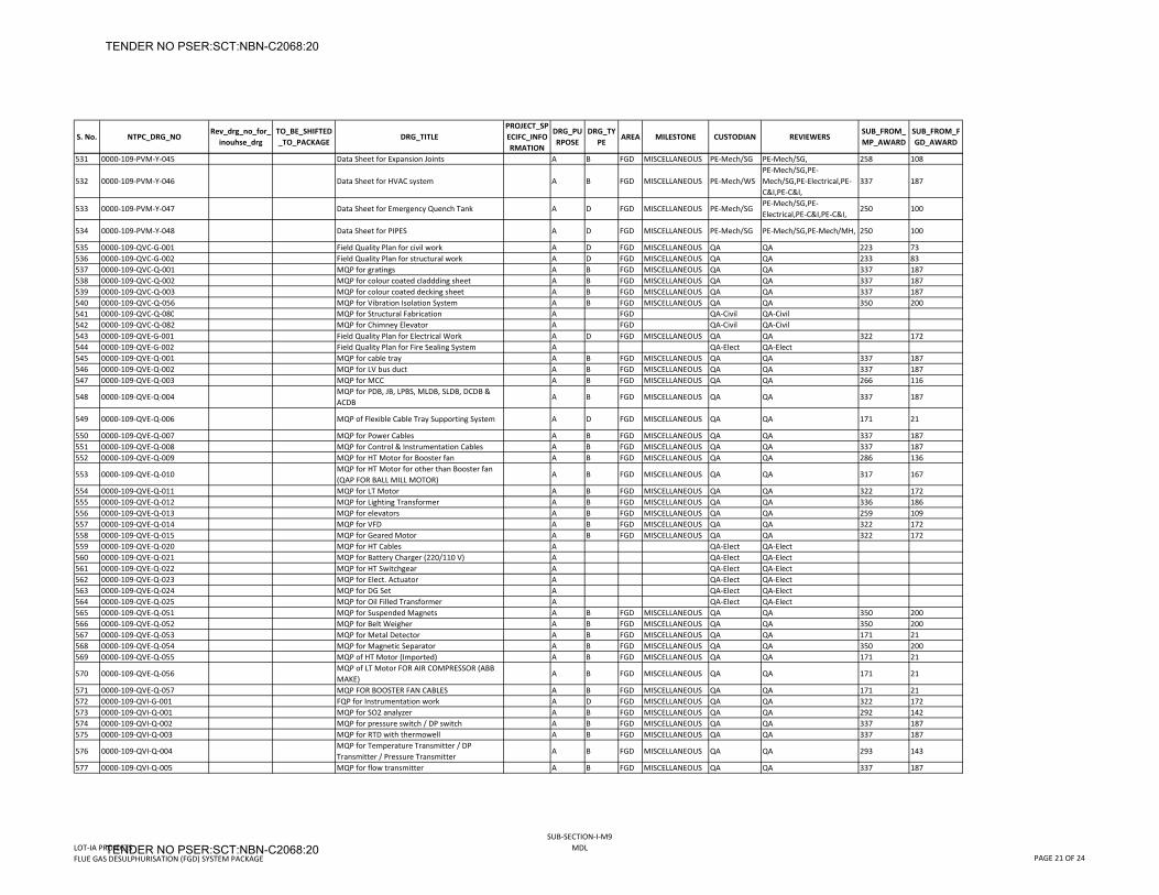
S. No. NTPC_DRG_NORev_drg_no_for_
inouhse_drgTO_BE_SHIFTED_TO_PACKAGE
DRG_TITLEPROJECT_SPECIFC_INFORMATION
DRG_PURPOSE
DRG_TYPE
AREA MILESTONE CUSTODIAN REVIEWERSSUB_FROM_MP_AWARD
SUB_FROM_FGD_AWARD
531 0000‐109‐PVM‐Y‐045 Data Sheet for Expansion Joints A B FGD MISCELLANEOUS PE‐Mech/SG PE‐Mech/SG, 258 108
532 0000‐109‐PVM‐Y‐046 Data Sheet for HVAC system A B FGD MISCELLANEOUS PE‐Mech/WSPE‐Mech/SG,PE‐Mech/SG,PE‐Electrical,PE‐C&I,PE‐C&I,
337 187
533 0000‐109‐PVM‐Y‐047 Data Sheet for Emergency Quench Tank A D FGD MISCELLANEOUS PE‐Mech/SGPE‐Mech/SG,PE‐Electrical,PE‐C&I,PE‐C&I,
250 100
534 0000‐109‐PVM‐Y‐048 Data Sheet for PIPES A D FGD MISCELLANEOUS PE‐Mech/SG PE‐Mech/SG,PE‐Mech/MH, 250 100
535 0000‐109‐QVC‐G‐001 Field Quality Plan for civil work A D FGD MISCELLANEOUS QA QA 223 73536 0000‐109‐QVC‐G‐002 Field Quality Plan for structural work A D FGD MISCELLANEOUS QA QA 233 83537 0000‐109‐QVC‐Q‐001 MQP for gratings A B FGD MISCELLANEOUS QA QA 337 187538 0000‐109‐QVC‐Q‐002 MQP for colour coated claddding sheet A B FGD MISCELLANEOUS QA QA 337 187539 0000‐109‐QVC‐Q‐003 MQP for colour coated decking sheet A B FGD MISCELLANEOUS QA QA 337 187540 0000‐109‐QVC‐Q‐056 MQP for Vibration Isolation System A B FGD MISCELLANEOUS QA QA 350 200541 0000‐109‐QVC‐Q‐080 MQP for Structural Fabrication A FGD QA‐Civil QA‐Civil542 0000‐109‐QVC‐Q‐082 MQP for Chimney Elevator A FGD QA‐Civil QA‐Civil543 0000‐109‐QVE‐G‐001 Field Quality Plan for Electrical Work A D FGD MISCELLANEOUS QA QA 322 172544 0000‐109‐QVE‐G‐002 Field Quality Plan for Fire Sealing System A QA‐Elect QA‐Elect545 0000‐109‐QVE‐Q‐001 MQP for cable tray A B FGD MISCELLANEOUS QA QA 337 187546 0000‐109‐QVE‐Q‐002 MQP for LV bus duct A B FGD MISCELLANEOUS QA QA 337 187547 0000‐109‐QVE‐Q‐003 MQP for MCC A B FGD MISCELLANEOUS QA QA 266 116
548 0000‐109‐QVE‐Q‐004MQP for PDB, JB, LPBS, MLDB, SLDB, DCDB & ACDB
A B FGD MISCELLANEOUS QA QA 337 187
549 0000‐109‐QVE‐Q‐006 MQP of Flexible Cable Tray Supporting System A D FGD MISCELLANEOUS QA QA 171 21
550 0000‐109‐QVE‐Q‐007 MQP for Power Cables A B FGD MISCELLANEOUS QA QA 337 187551 0000‐109‐QVE‐Q‐008 MQP for Control & Instrumentation Cables A B FGD MISCELLANEOUS QA QA 337 187552 0000‐109‐QVE‐Q‐009 MQP for HT Motor for Booster fan A B FGD MISCELLANEOUS QA QA 286 136
553 0000‐109‐QVE‐Q‐010MQP for HT Motor for other than Booster fan (QAP FOR BALL MILL MOTOR)
A B FGD MISCELLANEOUS QA QA 317 167
554 0000‐109‐QVE‐Q‐011 MQP for LT Motor A B FGD MISCELLANEOUS QA QA 322 172555 0000‐109‐QVE‐Q‐012 MQP for Lighting Transformer A B FGD MISCELLANEOUS QA QA 336 186556 0000‐109‐QVE‐Q‐013 MQP for elevators A B FGD MISCELLANEOUS QA QA 259 109557 0000‐109‐QVE‐Q‐014 MQP for VFD A B FGD MISCELLANEOUS QA QA 322 172558 0000‐109‐QVE‐Q‐015 MQP for Geared Motor A B FGD MISCELLANEOUS QA QA 322 172559 0000‐109‐QVE‐Q‐020 MQP for HT Cables A QA‐Elect QA‐Elect560 0000‐109‐QVE‐Q‐021 MQP for Battery Charger (220/110 V) A QA‐Elect QA‐Elect561 0000‐109‐QVE‐Q‐022 MQP for HT Switchgear A QA‐Elect QA‐Elect562 0000‐109‐QVE‐Q‐023 MQP for Elect. Actuator A QA‐Elect QA‐Elect563 0000‐109‐QVE‐Q‐024 MQP for DG Set A QA‐Elect QA‐Elect564 0000‐109‐QVE‐Q‐025 MQP for Oil Filled Transformer A QA‐Elect QA‐Elect565 0000‐109‐QVE‐Q‐051 MQP for Suspended Magnets A B FGD MISCELLANEOUS QA QA 350 200566 0000‐109‐QVE‐Q‐052 MQP for Belt Weigher A B FGD MISCELLANEOUS QA QA 350 200567 0000‐109‐QVE‐Q‐053 MQP for Metal Detector A B FGD MISCELLANEOUS QA QA 171 21568 0000‐109‐QVE‐Q‐054 MQP for Magnetic Separator A B FGD MISCELLANEOUS QA QA 350 200569 0000‐109‐QVE‐Q‐055 MQP of HT Motor (Imported) A B FGD MISCELLANEOUS QA QA 171 21
570 0000‐109‐QVE‐Q‐056MQP of LT Motor FOR AIR COMPRESSOR (ABB MAKE)
A B FGD MISCELLANEOUS QA QA 171 21
571 0000‐109‐QVE‐Q‐057 MQP FOR BOOSTER FAN CABLES A B FGD MISCELLANEOUS QA QA 171 21572 0000‐109‐QVI‐G‐001 FQP for Instrumentation work A D FGD MISCELLANEOUS QA QA 322 172573 0000‐109‐QVI‐Q‐001 MQP for SO2 analyzer A B FGD MISCELLANEOUS QA QA 292 142574 0000‐109‐QVI‐Q‐002 MQP for pressure switch / DP switch A B FGD MISCELLANEOUS QA QA 337 187575 0000‐109‐QVI‐Q‐003 MQP for RTD with thermowell A B FGD MISCELLANEOUS QA QA 337 187
576 0000‐109‐QVI‐Q‐004MQP for Temperature Transmitter / DP Transmitter / Pressure Transmitter
A B FGD MISCELLANEOUS QA QA 293 143
577 0000‐109‐QVI‐Q‐005 MQP for flow transmitter A B FGD MISCELLANEOUS QA QA 337 187
LOT‐IA PROJECTSFLUE GAS DESULPHURISATION (FGD) SYSTEM PACKAGE
SUB‐SECTION‐I‐M9MDL
PAGE 21 OF 24
TENDER NO PSER:SCT:NBN-C2068:20
TENDER NO PSER:SCT:NBN-C2068:20
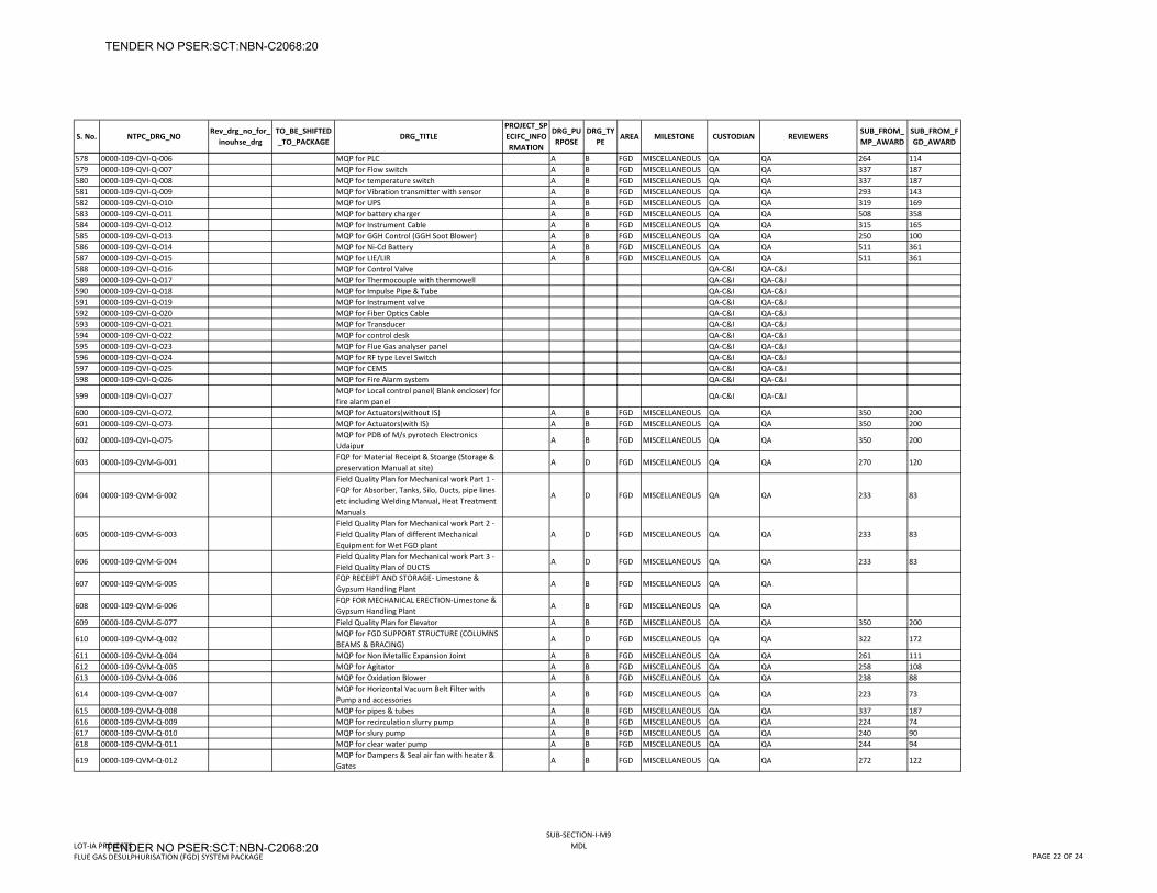
S. No. NTPC_DRG_NORev_drg_no_for_
inouhse_drgTO_BE_SHIFTED_TO_PACKAGE
DRG_TITLEPROJECT_SPECIFC_INFORMATION
DRG_PURPOSE
DRG_TYPE
AREA MILESTONE CUSTODIAN REVIEWERSSUB_FROM_MP_AWARD
SUB_FROM_FGD_AWARD
578 0000‐109‐QVI‐Q‐006 MQP for PLC A B FGD MISCELLANEOUS QA QA 264 114579 0000‐109‐QVI‐Q‐007 MQP for Flow switch A B FGD MISCELLANEOUS QA QA 337 187580 0000‐109‐QVI‐Q‐008 MQP for temperature switch A B FGD MISCELLANEOUS QA QA 337 187581 0000‐109‐QVI‐Q‐009 MQP for Vibration transmitter with sensor A B FGD MISCELLANEOUS QA QA 293 143582 0000‐109‐QVI‐Q‐010 MQP for UPS A B FGD MISCELLANEOUS QA QA 319 169583 0000‐109‐QVI‐Q‐011 MQP for battery charger A B FGD MISCELLANEOUS QA QA 508 358584 0000‐109‐QVI‐Q‐012 MQP for Instrument Cable A B FGD MISCELLANEOUS QA QA 315 165585 0000‐109‐QVI‐Q‐013 MQP for GGH Control (GGH Soot Blower) A B FGD MISCELLANEOUS QA QA 250 100586 0000‐109‐QVI‐Q‐014 MQP for Ni‐Cd Battery A B FGD MISCELLANEOUS QA QA 511 361587 0000‐109‐QVI‐Q‐015 MQP for LIE/LIR A B FGD MISCELLANEOUS QA QA 511 361588 0000‐109‐QVI‐Q‐016 MQP for Control Valve QA‐C&I QA‐C&I589 0000‐109‐QVI‐Q‐017 MQP for Thermocouple with thermowell QA‐C&I QA‐C&I590 0000‐109‐QVI‐Q‐018 MQP for Impulse Pipe & Tube QA‐C&I QA‐C&I591 0000‐109‐QVI‐Q‐019 MQP for Instrument valve QA‐C&I QA‐C&I592 0000‐109‐QVI‐Q‐020 MQP for Fiber Optics Cable QA‐C&I QA‐C&I593 0000‐109‐QVI‐Q‐021 MQP for Transducer QA‐C&I QA‐C&I594 0000‐109‐QVI‐Q‐022 MQP for control desk QA‐C&I QA‐C&I595 0000‐109‐QVI‐Q‐023 MQP for Flue Gas analyser panel QA‐C&I QA‐C&I596 0000‐109‐QVI‐Q‐024 MQP for RF type Level Switch QA‐C&I QA‐C&I597 0000‐109‐QVI‐Q‐025 MQP for CEMS QA‐C&I QA‐C&I598 0000‐109‐QVI‐Q‐026 MQP for Fire Alarm system QA‐C&I QA‐C&I
599 0000‐109‐QVI‐Q‐027MQP for Local control panel( Blank encloser) for fire alarm panel
QA‐C&I QA‐C&I
600 0000‐109‐QVI‐Q‐072 MQP for Actuators(without IS) A B FGD MISCELLANEOUS QA QA 350 200601 0000‐109‐QVI‐Q‐073 MQP for Actuators(with IS) A B FGD MISCELLANEOUS QA QA 350 200
602 0000‐109‐QVI‐Q‐075MQP for PDB of M/s pyrotech Electronics Udaipur
A B FGD MISCELLANEOUS QA QA 350 200
603 0000‐109‐QVM‐G‐001FQP for Material Receipt & Stoarge (Storage & preservation Manual at site)
A D FGD MISCELLANEOUS QA QA 270 120
604 0000‐109‐QVM‐G‐002
Field Quality Plan for Mechanical work Part 1 ‐ FQP for Absorber, Tanks, Silo, Ducts, pipe lines etc including Welding Manual, Heat Treatment Manuals
A D FGD MISCELLANEOUS QA QA 233 83
605 0000‐109‐QVM‐G‐003Field Quality Plan for Mechanical work Part 2 ‐ Field Quality Plan of different Mechanical Equipment for Wet FGD plant
A D FGD MISCELLANEOUS QA QA 233 83
606 0000‐109‐QVM‐G‐004Field Quality Plan for Mechanical work Part 3 ‐ Field Quality Plan of DUCTS
A D FGD MISCELLANEOUS QA QA 233 83
607 0000‐109‐QVM‐G‐005FQP RECEIPT AND STORAGE‐ Limestone & Gypsum Handling Plant
A B FGD MISCELLANEOUS QA QA
608 0000‐109‐QVM‐G‐006FQP FOR MECHANICAL ERECTION‐Limestone & Gypsum Handling Plant
A B FGD MISCELLANEOUS QA QA
609 0000‐109‐QVM‐G‐077 Field Quality Plan for Elevator A B FGD MISCELLANEOUS QA QA 350 200
610 0000‐109‐QVM‐Q‐002MQP for FGD SUPPORT STRUCTURE (COLUMNS BEAMS & BRACING)
A D FGD MISCELLANEOUS QA QA 322 172
611 0000‐109‐QVM‐Q‐004 MQP for Non Metallic Expansion Joint A B FGD MISCELLANEOUS QA QA 261 111612 0000‐109‐QVM‐Q‐005 MQP for Agitator A B FGD MISCELLANEOUS QA QA 258 108613 0000‐109‐QVM‐Q‐006 MQP for Oxidation Blower A B FGD MISCELLANEOUS QA QA 238 88
614 0000‐109‐QVM‐Q‐007MQP for Horizontal Vacuum Belt Filter with Pump and accessories
A B FGD MISCELLANEOUS QA QA 223 73
615 0000‐109‐QVM‐Q‐008 MQP for pipes & tubes A B FGD MISCELLANEOUS QA QA 337 187616 0000‐109‐QVM‐Q‐009 MQP for recirculation slurry pump A B FGD MISCELLANEOUS QA QA 224 74617 0000‐109‐QVM‐Q‐010 MQP for slury pump A B FGD MISCELLANEOUS QA QA 240 90618 0000‐109‐QVM‐Q‐011 MQP for clear water pump A B FGD MISCELLANEOUS QA QA 244 94
619 0000‐109‐QVM‐Q‐012MQP for Dampers & Seal air fan with heater & Gates
A B FGD MISCELLANEOUS QA QA 272 122
LOT‐IA PROJECTSFLUE GAS DESULPHURISATION (FGD) SYSTEM PACKAGE
SUB‐SECTION‐I‐M9MDL
PAGE 22 OF 24
TENDER NO PSER:SCT:NBN-C2068:20
TENDER NO PSER:SCT:NBN-C2068:20
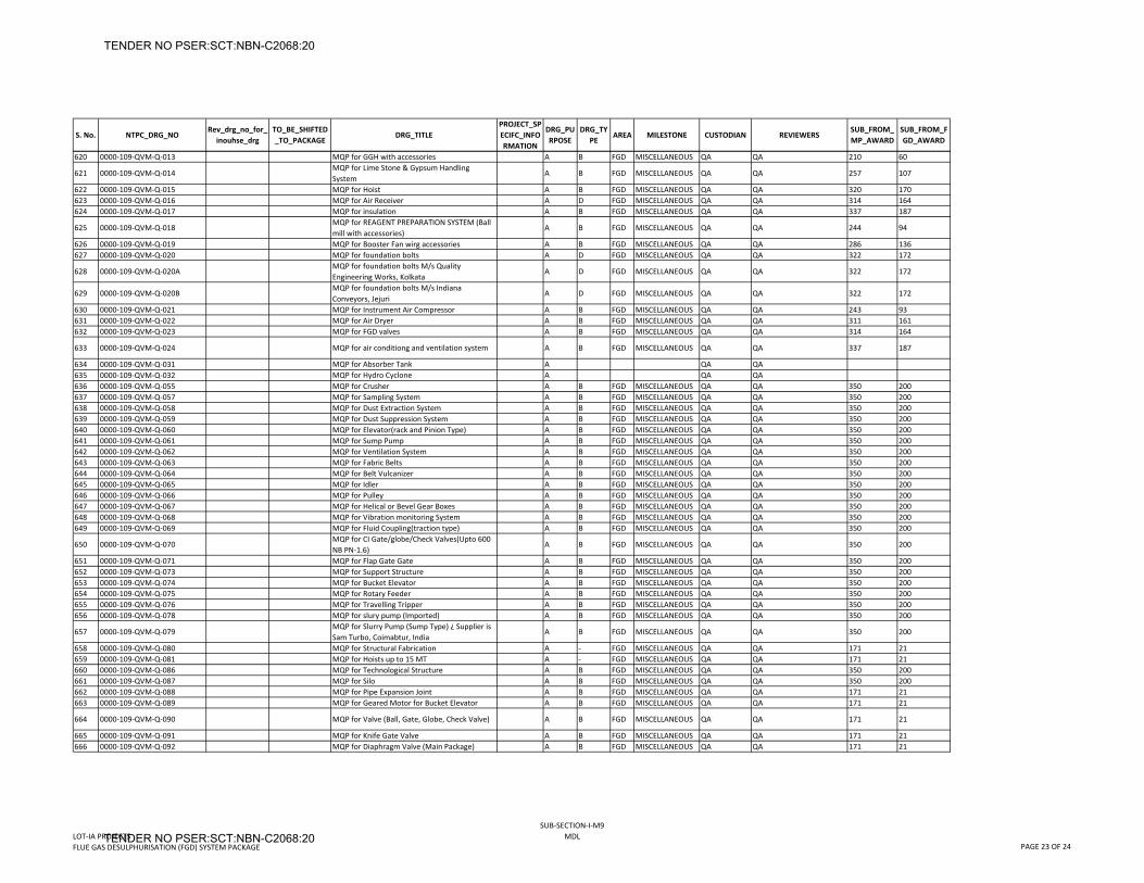
S. No. NTPC_DRG_NORev_drg_no_for_
inouhse_drgTO_BE_SHIFTED_TO_PACKAGE
DRG_TITLEPROJECT_SPECIFC_INFORMATION
DRG_PURPOSE
DRG_TYPE
AREA MILESTONE CUSTODIAN REVIEWERSSUB_FROM_MP_AWARD
SUB_FROM_FGD_AWARD
620 0000‐109‐QVM‐Q‐013 MQP for GGH with accessories A B FGD MISCELLANEOUS QA QA 210 60
621 0000‐109‐QVM‐Q‐014MQP for Lime Stone & Gypsum Handling System
A B FGD MISCELLANEOUS QA QA 257 107
622 0000‐109‐QVM‐Q‐015 MQP for Hoist A B FGD MISCELLANEOUS QA QA 320 170623 0000‐109‐QVM‐Q‐016 MQP for Air Receiver A D FGD MISCELLANEOUS QA QA 314 164624 0000‐109‐QVM‐Q‐017 MQP for insulation A B FGD MISCELLANEOUS QA QA 337 187
625 0000‐109‐QVM‐Q‐018MQP for REAGENT PREPARATION SYSTEM (Ball mill with accessories)
A B FGD MISCELLANEOUS QA QA 244 94
626 0000‐109‐QVM‐Q‐019 MQP for Booster Fan wirg accessories A B FGD MISCELLANEOUS QA QA 286 136627 0000‐109‐QVM‐Q‐020 MQP for foundation bolts A D FGD MISCELLANEOUS QA QA 322 172
628 0000‐109‐QVM‐Q‐020AMQP for foundation bolts M/s Quality Engineering Works, Kolkata
A D FGD MISCELLANEOUS QA QA 322 172
629 0000‐109‐QVM‐Q‐020BMQP for foundation bolts M/s Indiana Conveyors, Jejuri
A D FGD MISCELLANEOUS QA QA 322 172
630 0000‐109‐QVM‐Q‐021 MQP for Instrument Air Compressor A B FGD MISCELLANEOUS QA QA 243 93631 0000‐109‐QVM‐Q‐022 MQP for Air Dryer A B FGD MISCELLANEOUS QA QA 311 161632 0000‐109‐QVM‐Q‐023 MQP for FGD valves A B FGD MISCELLANEOUS QA QA 314 164
633 0000‐109‐QVM‐Q‐024 MQP for air conditiong and ventilation system A B FGD MISCELLANEOUS QA QA 337 187
634 0000‐109‐QVM‐Q‐031 MQP for Absorber Tank A QA QA635 0000‐109‐QVM‐Q‐032 MQP for Hydro Cyclone A QA QA636 0000‐109‐QVM‐Q‐055 MQP for Crusher A B FGD MISCELLANEOUS QA QA 350 200637 0000‐109‐QVM‐Q‐057 MQP for Sampling System A B FGD MISCELLANEOUS QA QA 350 200638 0000‐109‐QVM‐Q‐058 MQP for Dust Extraction System A B FGD MISCELLANEOUS QA QA 350 200639 0000‐109‐QVM‐Q‐059 MQP for Dust Suppression System A B FGD MISCELLANEOUS QA QA 350 200640 0000‐109‐QVM‐Q‐060 MQP for Elevator(rack and Pinion Type) A B FGD MISCELLANEOUS QA QA 350 200641 0000‐109‐QVM‐Q‐061 MQP for Sump Pump A B FGD MISCELLANEOUS QA QA 350 200642 0000‐109‐QVM‐Q‐062 MQP for Ventilation System A B FGD MISCELLANEOUS QA QA 350 200643 0000‐109‐QVM‐Q‐063 MQP for Fabric Belts A B FGD MISCELLANEOUS QA QA 350 200644 0000‐109‐QVM‐Q‐064 MQP for Belt Vulcanizer A B FGD MISCELLANEOUS QA QA 350 200645 0000‐109‐QVM‐Q‐065 MQP for Idler A B FGD MISCELLANEOUS QA QA 350 200646 0000‐109‐QVM‐Q‐066 MQP for Pulley A B FGD MISCELLANEOUS QA QA 350 200647 0000‐109‐QVM‐Q‐067 MQP for Helical or Bevel Gear Boxes A B FGD MISCELLANEOUS QA QA 350 200648 0000‐109‐QVM‐Q‐068 MQP for Vibration monitoring System A B FGD MISCELLANEOUS QA QA 350 200649 0000‐109‐QVM‐Q‐069 MQP for Fluid Coupling(traction type) A B FGD MISCELLANEOUS QA QA 350 200
650 0000‐109‐QVM‐Q‐070MQP for CI Gate/globe/Check Valves(Upto 600 NB PN‐1.6)
A B FGD MISCELLANEOUS QA QA 350 200
651 0000‐109‐QVM‐Q‐071 MQP for Flap Gate Gate A B FGD MISCELLANEOUS QA QA 350 200652 0000‐109‐QVM‐Q‐073 MQP for Support Structure A B FGD MISCELLANEOUS QA QA 350 200653 0000‐109‐QVM‐Q‐074 MQP for Bucket Elevator A B FGD MISCELLANEOUS QA QA 350 200654 0000‐109‐QVM‐Q‐075 MQP for Rotary Feeder A B FGD MISCELLANEOUS QA QA 350 200655 0000‐109‐QVM‐Q‐076 MQP for Travelling Tripper A B FGD MISCELLANEOUS QA QA 350 200656 0000‐109‐QVM‐Q‐078 MQP for slury pump (Imported) A B FGD MISCELLANEOUS QA QA 350 200
657 0000‐109‐QVM‐Q‐079MQP for Slurry Pump (Sump Type) ¿ Supplier is Sam Turbo, Coimabtur, India
A B FGD MISCELLANEOUS QA QA 350 200
658 0000‐109‐QVM‐Q‐080 MQP for Structural Fabrication A ‐ FGD MISCELLANEOUS QA QA 171 21659 0000‐109‐QVM‐Q‐081 MQP for Hoists up to 15 MT A ‐ FGD MISCELLANEOUS QA QA 171 21660 0000‐109‐QVM‐Q‐086 MQP for Technological Structure A B FGD MISCELLANEOUS QA QA 350 200661 0000‐109‐QVM‐Q‐087 MQP for Silo A B FGD MISCELLANEOUS QA QA 350 200662 0000‐109‐QVM‐Q‐088 MQP for Pipe Expansion Joint A B FGD MISCELLANEOUS QA QA 171 21663 0000‐109‐QVM‐Q‐089 MQP for Geared Motor for Bucket Elevator A B FGD MISCELLANEOUS QA QA 171 21
664 0000‐109‐QVM‐Q‐090 MQP for Valve (Ball, Gate, Globe, Check Valve) A B FGD MISCELLANEOUS QA QA 171 21
665 0000‐109‐QVM‐Q‐091 MQP for Knife Gate Valve A B FGD MISCELLANEOUS QA QA 171 21666 0000‐109‐QVM‐Q‐092 MQP for Diaphragm Valve (Main Package) A B FGD MISCELLANEOUS QA QA 171 21
LOT‐IA PROJECTSFLUE GAS DESULPHURISATION (FGD) SYSTEM PACKAGE
SUB‐SECTION‐I‐M9MDL
PAGE 23 OF 24
TENDER NO PSER:SCT:NBN-C2068:20
TENDER NO PSER:SCT:NBN-C2068:20
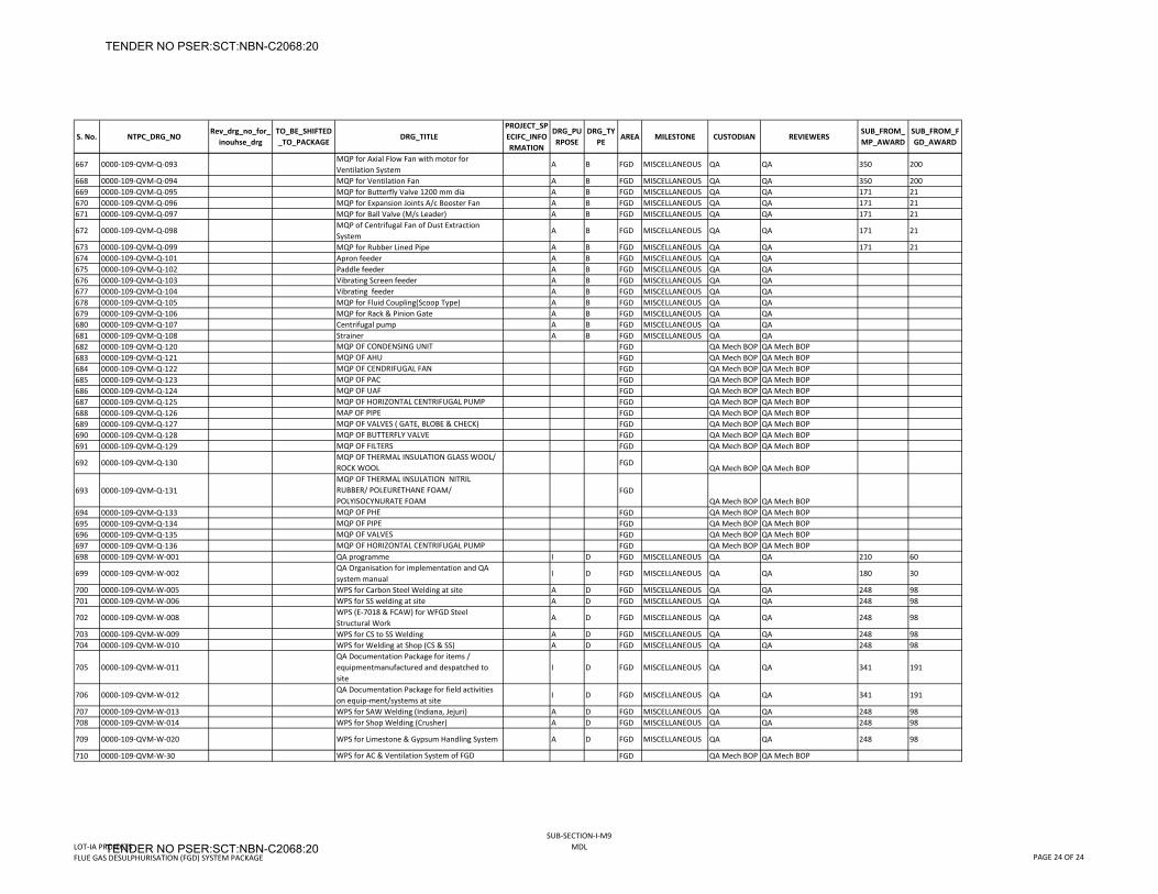
S. No. NTPC_DRG_NORev_drg_no_for_
inouhse_drgTO_BE_SHIFTED_TO_PACKAGE
DRG_TITLEPROJECT_SPECIFC_INFORMATION
DRG_PURPOSE
DRG_TYPE
AREA MILESTONE CUSTODIAN REVIEWERSSUB_FROM_MP_AWARD
SUB_FROM_FGD_AWARD
667 0000‐109‐QVM‐Q‐093MQP for Axial Flow Fan with motor for Ventilation System
A B FGD MISCELLANEOUS QA QA 350 200
668 0000‐109‐QVM‐Q‐094 MQP for Ventilation Fan A B FGD MISCELLANEOUS QA QA 350 200669 0000‐109‐QVM‐Q‐095 MQP for Butterfly Valve 1200 mm dia A B FGD MISCELLANEOUS QA QA 171 21670 0000‐109‐QVM‐Q‐096 MQP for Expansion Joints A/c Booster Fan A B FGD MISCELLANEOUS QA QA 171 21671 0000‐109‐QVM‐Q‐097 MQP for Ball Valve (M/s Leader) A B FGD MISCELLANEOUS QA QA 171 21
672 0000‐109‐QVM‐Q‐098MQP of Centrifugal Fan of Dust Extraction System
A B FGD MISCELLANEOUS QA QA 171 21
673 0000‐109‐QVM‐Q‐099 MQP for Rubber Lined Pipe A B FGD MISCELLANEOUS QA QA 171 21674 0000‐109‐QVM‐Q‐101 Apron feeder A B FGD MISCELLANEOUS QA QA675 0000‐109‐QVM‐Q‐102 Paddle feeder A B FGD MISCELLANEOUS QA QA676 0000‐109‐QVM‐Q‐103 Vibrating Screen feeder A B FGD MISCELLANEOUS QA QA677 0000‐109‐QVM‐Q‐104 Vibrating feeder A B FGD MISCELLANEOUS QA QA678 0000‐109‐QVM‐Q‐105 MQP for Fluid Coupling(Scoop Type) A B FGD MISCELLANEOUS QA QA679 0000‐109‐QVM‐Q‐106 MQP for Rack & Pinion Gate A B FGD MISCELLANEOUS QA QA680 0000‐109‐QVM‐Q‐107 Centrifugal pump A B FGD MISCELLANEOUS QA QA681 0000‐109‐QVM‐Q‐108 Strainer A B FGD MISCELLANEOUS QA QA682 0000‐109‐QVM‐Q‐120 MQP OF CONDENSING UNIT FGD QA Mech BOP QA Mech BOP683 0000‐109‐QVM‐Q‐121 MQP OF AHU FGD QA Mech BOP QA Mech BOP684 0000‐109‐QVM‐Q‐122 MQP OF CENDRIFUGAL FAN FGD QA Mech BOP QA Mech BOP685 0000‐109‐QVM‐Q‐123 MQP OF PAC FGD QA Mech BOP QA Mech BOP686 0000‐109‐QVM‐Q‐124 MQP OF UAF FGD QA Mech BOP QA Mech BOP687 0000‐109‐QVM‐Q‐125 MQP OF HORIZONTAL CENTRIFUGAL PUMP FGD QA Mech BOP QA Mech BOP688 0000‐109‐QVM‐Q‐126 MAP OF PIPE FGD QA Mech BOP QA Mech BOP689 0000‐109‐QVM‐Q‐127 MQP OF VALVES ( GATE, BLOBE & CHECK) FGD QA Mech BOP QA Mech BOP690 0000‐109‐QVM‐Q‐128 MQP OF BUTTERFLY VALVE FGD QA Mech BOP QA Mech BOP691 0000‐109‐QVM‐Q‐129 MQP OF FILTERS FGD QA Mech BOP QA Mech BOP
692 0000‐109‐QVM‐Q‐130MQP OF THERMAL INSULATION GLASS WOOL/ ROCK WOOL
FGD QA Mech BOP QA Mech BOP
693 0000‐109‐QVM‐Q‐131MQP OF THERMAL INSULATION NITRIL RUBBER/ POLEURETHANE FOAM/ POLYISOCYNURATE FOAM
FGD QA Mech BOP QA Mech BOP
694 0000‐109‐QVM‐Q‐133 MQP OF PHE FGD QA Mech BOP QA Mech BOP695 0000‐109‐QVM‐Q‐134 MQP OF PIPE FGD QA Mech BOP QA Mech BOP696 0000‐109‐QVM‐Q‐135 MQP OF VALVES FGD QA Mech BOP QA Mech BOP697 0000‐109‐QVM‐Q‐136 MQP OF HORIZONTAL CENTRIFUGAL PUMP FGD QA Mech BOP QA Mech BOP698 0000‐109‐QVM‐W‐001 QA programme I D FGD MISCELLANEOUS QA QA 210 60
699 0000‐109‐QVM‐W‐002QA Organisation for implementation and QA system manual
I D FGD MISCELLANEOUS QA QA 180 30
700 0000‐109‐QVM‐W‐005 WPS for Carbon Steel Welding at site A D FGD MISCELLANEOUS QA QA 248 98701 0000‐109‐QVM‐W‐006 WPS for SS welding at site A D FGD MISCELLANEOUS QA QA 248 98
702 0000‐109‐QVM‐W‐008WPS (E‐7018 & FCAW) for WFGD Steel Structural Work
A D FGD MISCELLANEOUS QA QA 248 98
703 0000‐109‐QVM‐W‐009 WPS for CS to SS Welding A D FGD MISCELLANEOUS QA QA 248 98704 0000‐109‐QVM‐W‐010 WPS for Welding at Shop (CS & SS) A D FGD MISCELLANEOUS QA QA 248 98
705 0000‐109‐QVM‐W‐011QA Documentation Package for items / equipmentmanufactured and despatched to site
I D FGD MISCELLANEOUS QA QA 341 191
706 0000‐109‐QVM‐W‐012QA Documentation Package for field activities on equip‐ment/systems at site
I D FGD MISCELLANEOUS QA QA 341 191
707 0000‐109‐QVM‐W‐013 WPS for SAW Welding (Indiana, Jejuri) A D FGD MISCELLANEOUS QA QA 248 98708 0000‐109‐QVM‐W‐014 WPS for Shop Welding (Crusher) A D FGD MISCELLANEOUS QA QA 248 98
709 0000‐109‐QVM‐W‐020 WPS for Limestone & Gypsum Handling System A D FGD MISCELLANEOUS QA QA 248 98
710 0000‐109‐QVM‐W‐30 WPS for AC & Ventilation System of FGD FGD QA Mech BOP QA Mech BOP
LOT‐IA PROJECTSFLUE GAS DESULPHURISATION (FGD) SYSTEM PACKAGE
SUB‐SECTION‐I‐M9MDL
PAGE 24 OF 24
TENDER NO PSER:SCT:NBN-C2068:20
TENDER NO PSER:SCT:NBN-C2068:20
NTPC Limited (A Government of India Enterprise)
LOT 1A PROJECTS
PART – B (DETAILED TECHNICAL SPECIFICATION)
SUB-SECTION-III-C
(CONTROL & INSTRUMENTATION SYSTEM)
SECTON – VI
TECHNICAL SPECIFICATION
FOR
FLUE GAS DESULPHURISATION (FGD)
SYSTEM PACKAGE
BIDDING DOCUMENT NO. : CS-0011-109(1A)-2
TENDER NO PSER:SCT:NBN-C2068:20
TENDER NO PSER:SCT:NBN-C2068:20
LOT-IA PROJECTS FLUE GAS DESULPHURISATION (FGD) SYSTEM PACKAGE
TECHNICAL SPECIFICATION
SECTION-VI
BID DOCUMENT NO.: CS-0011-109(1A)-2
PART – B (DETAILED TECHNICAL SPECIFICATION)
SUB-SECTION-III-C (CONTROL & INSTRUMENTATION SYSTEM)
TENDER NO PSER:SCT:NBN-C2068:20
TENDER NO PSER:SCT:NBN-C2068:20
LOT-IA PROJECTS FLUE GAS DESULPHURISATION (FGD) SYSTEM PACKAGE
TECHNICAL SPECIFICATION
SECTION-VI
BID DOCUMENT NO.: CS-0011-109(1A)-2
SUB-SECTION-III-C1
BASIC DESIGN CRITERIA
TENDER NO PSER:SCT:NBN-C2068:20
TENDER NO PSER:SCT:NBN-C2068:20
CLAUSE NO. TECHNICAL REQUIREMENTS
LOT-IA PROJECTS
FLUE GAS DESULPHURISATION (FGD)
SYSTEM PACKAGE
TECHNICAL SPECIFICATION
SECTION-VI, PART-B
BID DOCUMENT NO.: CS-0011-109(1A)-2
SUB-SECTION-III-C1
BASIC DESIGN CRITERIA PAGE 1 OF 4
BASIC DESIGN CRITERIA
1.00.00 GENERAL REQUIREMENTS
1.01.00 The Contractor shall provide Independent Control & Instrumentation system for control, monitoring and operation of associated drives in all regimes of operation in safe and most efficient manner including Primary and Secondary Instruments, Panels/ Desks, Process Connection and Piping, charges & batteries, associated Instrumentation Cables etc. as identified in the specification.
1.02.00 The Contractor shall provide all material, equipment and services so as to make a totally integrated Instrumentation and Control System together with all accessories, auxiliaries and associated equipments ensuring operability, maintainability and reliability. This work shall be consistent with modern power plant practices and shall be in compliance with all applicable codes, standards, guides, statutory regulations and safety requirements in force.
1.03.00 Further Bidder shall also include in his proposal and shall furnish all equipment, devices and services which may not be specifically stated in the specification but are needed for completeness of the equipment/systems furnished by the Bidder and for meeting the intent and requirements of the specification.
1.04.00 Bidder shall include in his bid a detailed Bill of Material (BOM) for each of the systems.
1.05.00 In addition to requirements specified under this Section-VI, Part-B, all C&I systems/ sub-systems/ equipment/ devices shall also meet other requirements stipulated under other Sub-sections/ parts/ sections of specification.
2.00.00 RELIABILITY AND AVAILABILITY
2.01.00 Each component and system offered by the Bidder shall be of established reliability. The minimum target reliability of each piece of equipment like each electronic module/card, Power supply, Peripheral etc. shall be established by the Bidder, considering its failure rate/mean time between failures (MTBF), meantime to repair (MTTR), such that the availability of the complete C&I system is assured .
2.02.00 When more than one device uses the same measurement or control signal, the transmitter and other components/ module shall be fully equipped to provide all signal requirements. All the 4-20 mA output signals from transmitters/other control system shall be able to drive minimum 500 Ohms load resistance. The system shall be arranged so that the failure of any monitoring device or control components or spurious intermediate grounding in the signal path shall not open the signal loop nor cause the loss or malfunction of signal to other devices using the same signal.
TENDER NO PSER:SCT:NBN-C2068:20
TENDER NO PSER:SCT:NBN-C2068:20
CLAUSE NO. TECHNICAL REQUIREMENTS
LOT-IA PROJECTS
FLUE GAS DESULPHURISATION (FGD)
SYSTEM PACKAGE
TECHNICAL SPECIFICATION
SECTION-VI, PART-B
BID DOCUMENT NO.: CS-0011-109(1A)-2
SUB-SECTION-III-C1
BASIC DESIGN CRITERIA PAGE 2 OF 4
2.03.00 To ensure availability, adequate redundancy in system design shall be provided at hardware, software and sensor level to satisfy the availability criteria mentioned above. For the protection system, independent sensing device shall be provided to ensure adequate safety of plant equipment.
3.00.00 OPERABILITY & MAINTAINABILITY
3.01.00 The design of the control systems and related equipments shall adhere to the principle of ‘Fail Safe’ Operation wherever safety of personnel / plant equipment is involved. ‘Fail Safe’ operation signifies that the loss of signal, loss of excitation or failure of any component shall not cause a hazardous condition. However, it shall also be ensured that occurrence of false trips are avoided / minimised .
3.02.00 The types of failure that shall be taken into account for ensuring operability of the plant shall include but not be limited to:
— Failure of sensor or transmitter.
— Failure of main and/or redundant controller/other modules.
— Loss of motive power to final control element.
— Loss of control power.
— Loss of instrument air.
3.03.00 The choice of hardware shall also take into account sound maintainability principles and techniques. The same shall include but shall not be limited to the following:
— Standardization of parts.
— Minimum use of special tools.
— Grouping of functions.
— Interchangeability.
— Malfunction identification facility/self surveillance facility.
— Easy modular replacement.
— Fool proof design providing proper identification and other features to preclude improper mounting and installation.
— Appropriate de-rating of electronic components and parts.
TENDER NO PSER:SCT:NBN-C2068:20
TENDER NO PSER:SCT:NBN-C2068:20
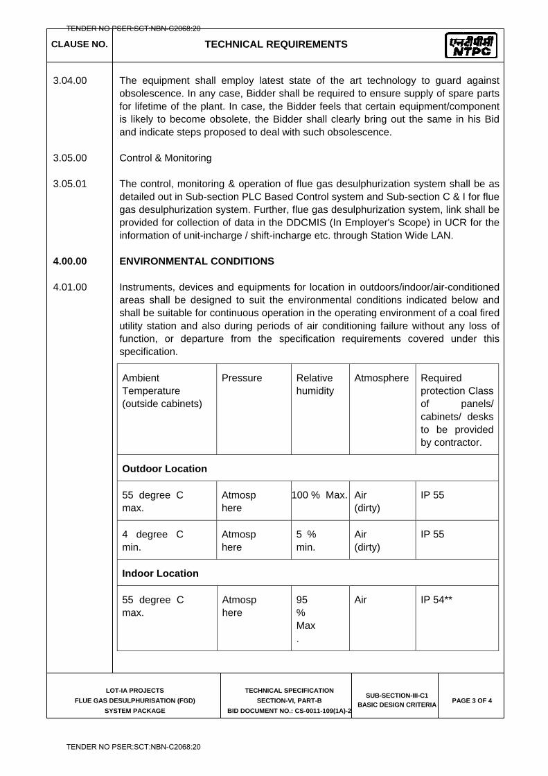
CLAUSE NO. TECHNICAL REQUIREMENTS
LOT-IA PROJECTS
FLUE GAS DESULPHURISATION (FGD)
SYSTEM PACKAGE
TECHNICAL SPECIFICATION
SECTION-VI, PART-B
BID DOCUMENT NO.: CS-0011-109(1A)-2
SUB-SECTION-III-C1
BASIC DESIGN CRITERIA PAGE 3 OF 4
3.04.00 The equipment shall employ latest state of the art technology to guard against obsolescence. In any case, Bidder shall be required to ensure supply of spare parts for lifetime of the plant. In case, the Bidder feels that certain equipment/component is likely to become obsolete, the Bidder shall clearly bring out the same in his Bid and indicate steps proposed to deal with such obsolescence.
3.05.00 Control & Monitoring
3.05.01 The control, monitoring & operation of flue gas desulphurization system shall be as detailed out in Sub-section PLC Based Control system and Sub-section C & I for flue gas desulphurization system. Further, flue gas desulphurization system, link shall be provided for collection of data in the DDCMIS (In Employer's Scope) in UCR for the information of unit-incharge / shift-incharge etc. through Station Wide LAN.
4.00.00 ENVIRONMENTAL CONDITIONS
4.01.00 Instruments, devices and equipments for location in outdoors/indoor/air-conditioned areas shall be designed to suit the environmental conditions indicated below and shall be suitable for continuous operation in the operating environment of a coal fired utility station and also during periods of air conditioning failure without any loss of function, or departure from the specification requirements covered under this specification.
Ambient Temperature (outside cabinets)
Pressure Relative humidity
Atmosphere Required protection Class of panels/ cabinets/ desks to be provided by contractor.
Outdoor Location
55 degree C max.
Atmosphere
100 % Max. Air (dirty)
IP 55
4 degree C min.
Atmosphere
5 % min.
Air (dirty)
IP 55
Indoor Location
55 degree C max.
Atmosphere
95 % Max.
Air IP 54**
TENDER NO PSER:SCT:NBN-C2068:20
TENDER NO PSER:SCT:NBN-C2068:20
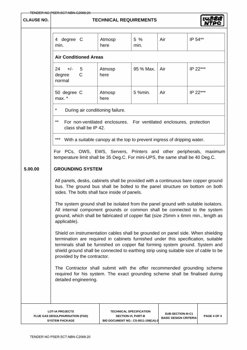
CLAUSE NO. TECHNICAL REQUIREMENTS
LOT-IA PROJECTS
FLUE GAS DESULPHURISATION (FGD)
SYSTEM PACKAGE
TECHNICAL SPECIFICATION
SECTION-VI, PART-B
BID DOCUMENT NO.: CS-0011-109(1A)-2
SUB-SECTION-III-C1
BASIC DESIGN CRITERIA PAGE 4 OF 4
4 degree C min.
Atmosphere
5 % min.
Air IP 54**
Air Conditioned Areas
24 +/- 5 degree C normal
Atmosphere
95 % Max. Air IP 22***
50 degree C max. *
Atmosphere
5 %min. Air IP 22***
* During air conditioning failure.
** For non-ventilated enclosures. For ventilated enclosures, protection class shall be IP 42.
*** With a suitable canopy at the top to prevent ingress of dripping water.
For PCs, OWS, EWS, Servers, Printers and other peripherals, maximum temperature limit shall be 35 Deg.C. For mini-UPS, the same shall be 40 Deg.C.
5.00.00 GROUNDING SYSTEM
All panels, desks, cabinets shall be provided with a continuous bare copper ground bus. The ground bus shall be bolted to the panel structure on bottom on both sides. The bolts shall face inside of panels.
The system ground shall be isolated from the panel ground with suitable isolators. All internal component grounds or common shall be connected to the system ground, which shall be fabricated of copper flat (size 25mm x 6mm min., length as applicable).
Shield on instrumentation cables shall be grounded on panel side. When shielding termination are required in cabinets furnished under this specification, suitable terminals shall be furnished on copper flat forming system ground. System and shield ground shall be connected to earthing strip using suitable size of cable to be provided by the contractor.
The Contractor shall submit with the offer recommended grounding scheme required for his system. The exact grounding scheme shall be finalised during detailed engineering.
TENDER NO PSER:SCT:NBN-C2068:20
TENDER NO PSER:SCT:NBN-C2068:20
LOT-IA PROJECTS FLUE GAS DESULPHURISATION (FGD) SYSTEM PACKAGE
TECHNICAL SPECIFICATION
SECTION-VI
BID DOCUMENT NO.: CS-0011-109(1A)-2
SUB-SECTION-III-C2
MEASURING INSTRUMENTS (PRIMARY AND SECONDARY)
TENDER NO PSER:SCT:NBN-C2068:20
TENDER NO PSER:SCT:NBN-C2068:20
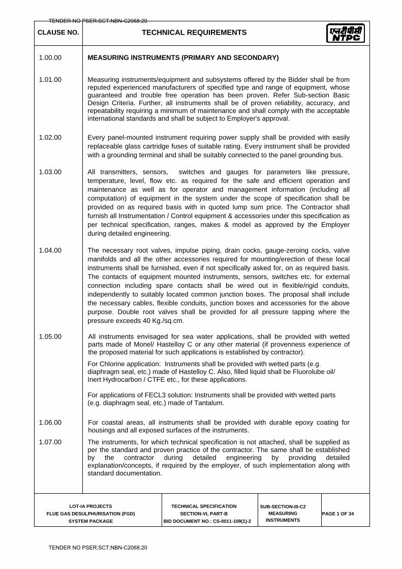
CLAUSE NO. TECHNICAL REQUIREMENTS
LOT-IA PROJECTS
FLUE GAS DESULPHURISATION (FGD)
SYSTEM PACKAGE
TECHNICAL SPECIFICATION
SECTION-VI, PART-B
BID DOCUMENT NO.: CS-0011-109(1)-2
SUB-SECTION-III-C2
MEASURING
INSTRUMENTS PAGE 1 OF 34
1.00.00 MEASURING INSTRUMENTS (PRIMARY AND SECONDARY)
1.01.00 Measuring instruments/equipment and subsystems offered by the Bidder shall be from reputed experienced manufacturers of specified type and range of equipment, whose guaranteed and trouble free operation has been proven. Refer Sub-section Basic Design Criteria. Further, all instruments shall be of proven reliability, accuracy, and repeatability requiring a minimum of maintenance and shall comply with the acceptable international standards and shall be subject to Employer's approval.
1.02.00 Every panel-mounted instrument requiring power supply shall be provided with easily replaceable glass cartridge fuses of suitable rating. Every instrument shall be provided with a grounding terminal and shall be suitably connected to the panel grounding bus.
1.03.00 All transmitters, sensors, switches and gauges for parameters like pressure, temperature, level, flow etc. as required for the safe and efficient operation and maintenance as well as for operator and management information (including all computation) of equipment in the system under the scope of specification shall be provided on as required basis with in quoted lump sum price. The Contractor shall furnish all Instrumentation / Control equipment & accessories under this specification as per technical specification, ranges, makes & model as approved by the Employer during detailed engineering.
1.04.00 The necessary root valves, impulse piping, drain cocks, gauge-zeroing cocks, valve manifolds and all the other accessories required for mounting/erection of these local instruments shall be furnished, even if not specifically asked for, on as required basis. The contacts of equipment mounted instruments, sensors, switches etc. for external connection including spare contacts shall be wired out in flexible/rigid conduits, independently to suitably located common junction boxes. The proposal shall include the necessary cables, flexible conduits, junction boxes and accessories for the above purpose. Double root valves shall be provided for all pressure tapping where the pressure exceeds 40 Kg./sq.cm.
1.05.00 All instruments envisaged for sea water applications, shall be provided with wetted parts made of Monel/ Hastelloy C or any other material (if provenness experience of the proposed material for such applications is established by contractor).
For Chlorine application: Instruments shall be provided with wetted parts (e.g. diaphragm seal, etc.) made of Hastelloy C. Also, filled liquid shall be Fluorolube oil/ Inert Hydrocarbon / CTFE etc., for these applications. For applications of FECL3 solution: Instruments shall be provided with wetted parts (e.g. diaphragm seal, etc.) made of Tantalum.
1.06.00 For coastal areas, all instruments shall be provided with durable epoxy coating for housings and all exposed surfaces of the instruments.
1.07.00 The instruments, for which technical specification is not attached, shall be supplied as per the standard and proven practice of the contractor. The same shall be established by the contractor during detailed engineering by providing detailed explanation/concepts, if required by the employer, of such implementation along with standard documentation.
TENDER NO PSER:SCT:NBN-C2068:20
TENDER NO PSER:SCT:NBN-C2068:20
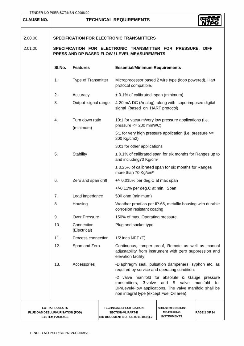
CLAUSE NO. TECHNICAL REQUIREMENTS
LOT-IA PROJECTS
FLUE GAS DESULPHURISATION (FGD)
SYSTEM PACKAGE
TECHNICAL SPECIFICATION
SECTION-VI, PART-B
BID DOCUMENT NO.: CS-0011-109(1)-2
SUB-SECTION-III-C2
MEASURING
INSTRUMENTS PAGE 2 OF 34
2.00.00 SPECIFICATION FOR ELECTRONIC TRANSMITTERS
2.01.00 SPECIFICATION FOR ELECTRONIC TRANSMITTER FOR PRESSURE, DIFF PRESS AND DP BASED FLOW / LEVEL MEASUREMENTS
Sl.No.
Features Essential/Minimum Requirements
1.
Type of Transmitter Microprocessor based 2 wire type (loop powered), Hart protocol compatible.
2. Accuracy ± 0.1% of calibrated span (minimum)
3.
Output signal range 4-20 mA DC (Analog) along with superimposed digital signal (based on HART protocol)
4. Turn down ratio
(minimum)
10:1 for vacuum/very low pressure applications (i.e. pressure <= 200 mmWC)
5:1 for very high pressure application (i.e. pressure >= 200 Kg/cm2)
30:1 for other applications
5. Stability ± 0.1% of calibrated span for six months for Ranges up to and including70 Kg/cm²
± 0.25% of calibrated span for six months for Ranges more than 70 Kg/cm²
6. Zero and span drift +/- 0.015% per deg.C at max span
+/-0.11% per deg.C at min. Span
7. Load impedance 500 ohm (minimum)
8. Housing Weather proof as per IP-65, metallic housing with durable corrosion resistant coating
9. Over Pressure 150% of max. Operating pressure
10. Connection (Electrical)
Plug and socket type
11. Process connection 1/2 inch NPT (F)
12. Span and Zero Continuous, tamper proof, Remote as well as manual adjustability from instrument with zero suppression and elevation facility.
13. Accessories -Diaphragm seal, pulsation dampeners, syphon etc. as required by service and operating condition.
-2 valve manifold for absolute & Gauge pressure transmitters, 3-valve and 5 valve manifold for DP/Level/Flow applications. The valve manifold shall be non integral type (except Fuel Oil area).
TENDER NO PSER:SCT:NBN-C2068:20
TENDER NO PSER:SCT:NBN-C2068:20
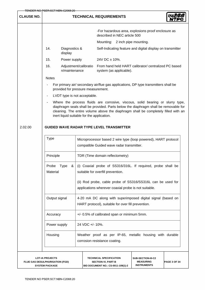
CLAUSE NO. TECHNICAL REQUIREMENTS
LOT-IA PROJECTS
FLUE GAS DESULPHURISATION (FGD)
SYSTEM PACKAGE
TECHNICAL SPECIFICATION
SECTION-VI, PART-B
BID DOCUMENT NO.: CS-0011-109(1)-2
SUB-SECTION-III-C2
MEASURING
INSTRUMENTS PAGE 3 OF 34
-For hazardous area, explosions proof enclosure as described in NEC article 500
Mounting: 2 inch pipe mounting.
14. Diagnostics & display
Self-Indicating feature and digital display on transmitter
15. Power supply 24V DC ± 10%.
16. Adjustment/calibration/maintenance
From hand held HART calibrator/ centralized PC based system (as applicable).
Notes
- For primary air/ secondary air/flue gas applications, DP type transmitters shall be provided for pressure measurement.
- LVDT type is not acceptable.
- Where the process fluids are corrosive, viscous, solid bearing or slurry type, diaphragm seals shall be provided. Parts below the diaphragm shall be removable for cleaning. The entire volume above the diaphragm shall be completely filled with an inert liquid suitable for the application.
2.02.00 GUIDED WAVE RADAR TYPE LEVEL TRANSMITTER
Type Microprocessor based 2 wire type (loop powered), HART protocol
compatible Guided wave radar transmitter.
Principle TDR (Time domain reflectometry)
Probe Type &
Material
(i) Coaxial probe of SS316/316L. If required, probe shall be
suitable for overfill prevention.
(ii) Rod probe, cable probe of SS316/SS316L can be used for
applications wherever coaxial probe is not suitable.
Output signal 4-20 mA DC along with superimposed digital signal (based on
HART protocol), suitable for over fill prevention.
Accuracy +/- 0.5% of calibrated span or minimum 5mm.
Power supply 24 VDC +/- 10%.
Housing Weather proof as per IP-65, metallic housing with durable
corrosion resistance coating.
TENDER NO PSER:SCT:NBN-C2068:20
TENDER NO PSER:SCT:NBN-C2068:20
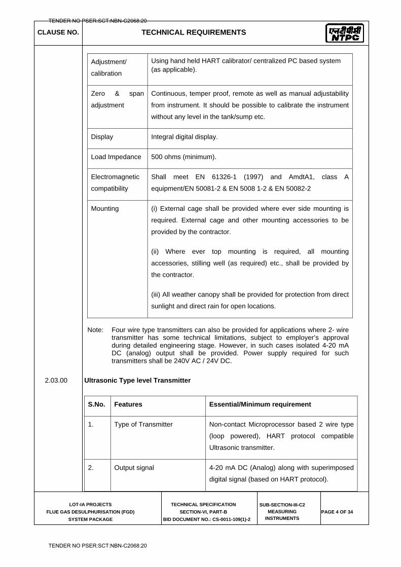
CLAUSE NO. TECHNICAL REQUIREMENTS
LOT-IA PROJECTS
FLUE GAS DESULPHURISATION (FGD)
SYSTEM PACKAGE
TECHNICAL SPECIFICATION
SECTION-VI, PART-B
BID DOCUMENT NO.: CS-0011-109(1)-2
SUB-SECTION-III-C2
MEASURING
INSTRUMENTS PAGE 4 OF 34
Adjustment/
calibration
Using hand held HART calibrator/ centralized PC based system (as applicable).
Zero & span
adjustment
Continuous, temper proof, remote as well as manual adjustability
from instrument. It should be possible to calibrate the instrument
without any level in the tank/sump etc.
Display Integral digital display.
Load Impedance 500 ohms (minimum).
Electromagnetic
compatibility
Shall meet EN 61326-1 (1997) and AmdtA1, class A
equipment/EN 50081-2 & EN 5008 1-2 & EN 50082-2
Mounting (i) External cage shall be provided where ever side mounting is
required. External cage and other mounting accessories to be
provided by the contractor.
(ii) Where ever top mounting is required, all mounting
accessories, stilling well (as required) etc., shall be provided by
the contractor.
(iii) All weather canopy shall be provided for protection from direct
sunlight and direct rain for open locations.
Note: Four wire type transmitters can also be provided for applications where 2- wire
transmitter has some technical limitations, subject to employer’s approval during detailed engineering stage. However, in such cases isolated 4-20 mA DC (analog) output shall be provided. Power supply required for such transmitters shall be 240V AC / 24V DC.
2.03.00 Ultrasonic Type level Transmitter
S.No. Features Essential/Minimum requirement
1. Type of Transmitter Non-contact Microprocessor based 2 wire type
(loop powered), HART protocol compatible
Ultrasonic transmitter.
2. Output signal 4-20 mA DC (Analog) along with superimposed
digital signal (based on HART protocol).
TENDER NO PSER:SCT:NBN-C2068:20
TENDER NO PSER:SCT:NBN-C2068:20
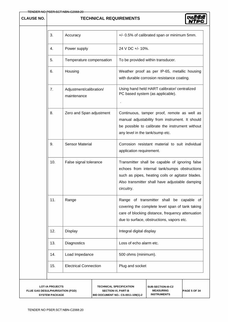
CLAUSE NO. TECHNICAL REQUIREMENTS
LOT-IA PROJECTS
FLUE GAS DESULPHURISATION (FGD)
SYSTEM PACKAGE
TECHNICAL SPECIFICATION
SECTION-VI, PART-B
BID DOCUMENT NO.: CS-0011-109(1)-2
SUB-SECTION-III-C2
MEASURING
INSTRUMENTS PAGE 5 OF 34
3. Accuracy +/- 0.5% of calibrated span or minimum 5mm.
4. Power supply 24 V DC +/- 10%.
5. Temperature compensation To be provided within transducer.
6. Housing Weather proof as per IP-65, metallic housing
with durable corrosion resistance coating.
7. Adjustment/calibration/
maintenance
Using hand held HART calibrator/ centralized PC based system (as applicable).
.
8. Zero and Span adjustment Continuous, tamper proof, remote as well as
manual adjustability from instrument. It should
be possible to calibrate the instrument without
any level in the tank/sump etc.
9. Sensor Material Corrosion resistant material to suit individual
application requirement.
10. False signal tolerance Transmitter shall be capable of ignoring false
echoes from internal tank/sumps obstructions
such as pipes, heating coils or agitator blades.
Also transmitter shall have adjustable damping
circuitry.
11. Range Range of transmitter shall be capable of
covering the complete level span of tank taking
care of blocking distance, frequency attenuation
due to surface, obstructions, vapors etc.
12. Display Integral digital display
13. Diagnostics Loss of echo alarm etc.
14. Load Impedance 500 ohms (minimum).
15. Electrical Connection Plug and socket
TENDER NO PSER:SCT:NBN-C2068:20
TENDER NO PSER:SCT:NBN-C2068:20
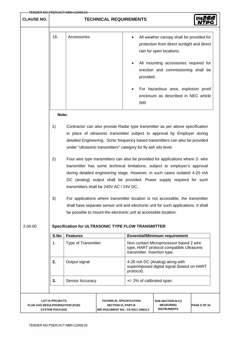
CLAUSE NO. TECHNICAL REQUIREMENTS
LOT-IA PROJECTS
FLUE GAS DESULPHURISATION (FGD)
SYSTEM PACKAGE
TECHNICAL SPECIFICATION
SECTION-VI, PART-B
BID DOCUMENT NO.: CS-0011-109(1)-2
SUB-SECTION-III-C2
MEASURING
INSTRUMENTS PAGE 6 OF 34
16. Accessories All weather canopy shall be provided for
protection from direct sunlight and direct
rain for open locations.
All mounting accessories required for
erection and commissioning shall be
provided.
For hazardous area, explosion proof
enclosure as described in NEC article
500
Note:
1) Contractor can also provide Radar type transmitter as per above specification
in place of ultrasonic transmitter subject to approval by Employer during
detailed Engineering. Sonic frequency based transmitters can also be provided
under “ultrasonic transmitters” category for fly ash silo level.
2) Four wire type transmitters can also be provided for applications where 2- wire
transmitter has some technical limitations, subject to employer’s approval
during detailed engineering stage. However, in such cases isolated 4-20 mA
DC (analog) output shall be provided. Power supply required for such
transmitters shall be 240V AC / 24V DC.
3) For applications where transmitter location is not accessible, the transmitter
shall have separate sensor unit and electronic unit for such applications. It shall
be possible to mount the electronic unit at accessible location.
2.04.00 Specification for ULTRASONIC TYPE FLOW TRANSMITTER
S.No Features Essential/Minimum requirement
1. Type of Transmitter Non contact Microprocessor based 2 wire type, HART protocol compatible Ultrasonic transmitter. Insertion type.
2. Output signal 4-20 mA DC (Analog) along with superimposed digital signal (based on HART protocol).
3. Sensor Accuracy +/- 2% of calibrated span.
TENDER NO PSER:SCT:NBN-C2068:20
TENDER NO PSER:SCT:NBN-C2068:20
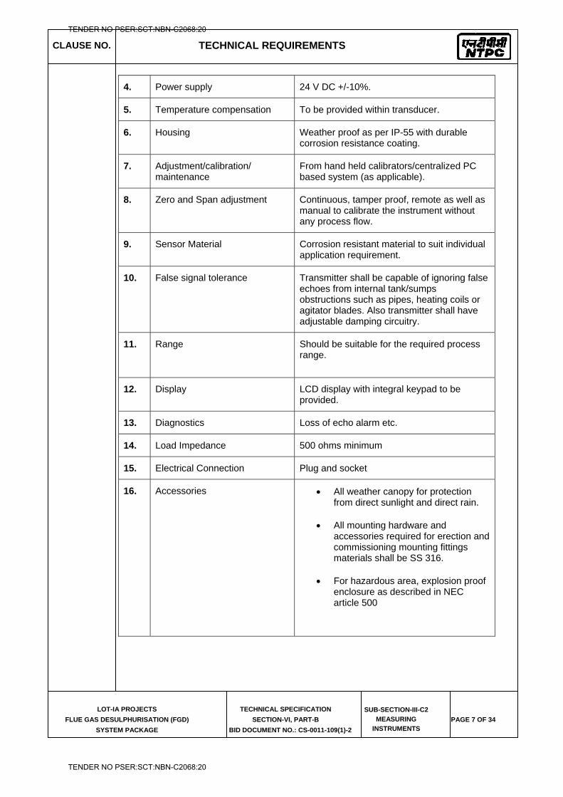
CLAUSE NO. TECHNICAL REQUIREMENTS
LOT-IA PROJECTS
FLUE GAS DESULPHURISATION (FGD)
SYSTEM PACKAGE
TECHNICAL SPECIFICATION
SECTION-VI, PART-B
BID DOCUMENT NO.: CS-0011-109(1)-2
SUB-SECTION-III-C2
MEASURING
INSTRUMENTS PAGE 7 OF 34
4. Power supply 24 V DC +/-10%.
5. Temperature compensation To be provided within transducer.
6. Housing Weather proof as per IP-55 with durable corrosion resistance coating.
7. Adjustment/calibration/ maintenance
From hand held calibrators/centralized PC based system (as applicable).
8. Zero and Span adjustment Continuous, tamper proof, remote as well as manual to calibrate the instrument without any process flow.
9. Sensor Material Corrosion resistant material to suit individual application requirement.
10. False signal tolerance Transmitter shall be capable of ignoring false echoes from internal tank/sumps obstructions such as pipes, heating coils or agitator blades. Also transmitter shall have adjustable damping circuitry.
11. Range
Should be suitable for the required process range.
12. Display LCD display with integral keypad to be provided.
13. Diagnostics Loss of echo alarm etc.
14. Load Impedance 500 ohms minimum
15. Electrical Connection Plug and socket
16. Accessories All weather canopy for protection from direct sunlight and direct rain.
All mounting hardware and accessories required for erection and commissioning mounting fittings materials shall be SS 316.
For hazardous area, explosion proof enclosure as described in NEC article 500
TENDER NO PSER:SCT:NBN-C2068:20
TENDER NO PSER:SCT:NBN-C2068:20
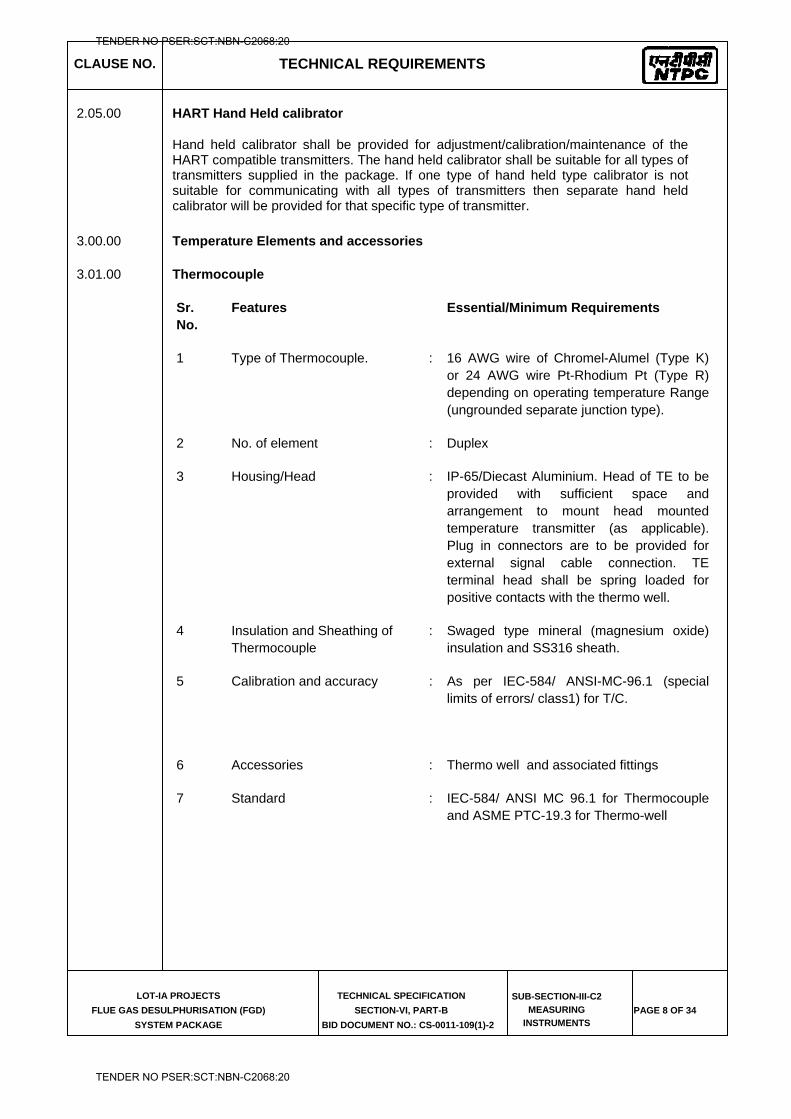
CLAUSE NO. TECHNICAL REQUIREMENTS
LOT-IA PROJECTS
FLUE GAS DESULPHURISATION (FGD)
SYSTEM PACKAGE
TECHNICAL SPECIFICATION
SECTION-VI, PART-B
BID DOCUMENT NO.: CS-0011-109(1)-2
SUB-SECTION-III-C2
MEASURING
INSTRUMENTS PAGE 8 OF 34
2.05.00 HART Hand Held calibrator
Hand held calibrator shall be provided for adjustment/calibration/maintenance of the HART compatible transmitters. The hand held calibrator shall be suitable for all types of transmitters supplied in the package. If one type of hand held type calibrator is not suitable for communicating with all types of transmitters then separate hand held calibrator will be provided for that specific type of transmitter.
3.00.00 Temperature Elements and accessories
3.01.00 Thermocouple
Sr. No.
Features Essential/Minimum Requirements
1 Type of Thermocouple. : 16 AWG wire of Chromel-Alumel (Type K) or 24 AWG wire Pt-Rhodium Pt (Type R) depending on operating temperature Range (ungrounded separate junction type).
2 No. of element : Duplex
3 Housing/Head : IP-65/Diecast Aluminium. Head of TE to be provided with sufficient space and arrangement to mount head mounted temperature transmitter (as applicable). Plug in connectors are to be provided for external signal cable connection. TE terminal head shall be spring loaded for positive contacts with the thermo well.
4 Insulation and Sheathing of Thermocouple
: Swaged type mineral (magnesium oxide) insulation and SS316 sheath.
5 Calibration and accuracy : As per IEC-584/ ANSI-MC-96.1 (special limits of errors/ class1) for T/C.
6 Accessories : Thermo well and associated fittings
7 Standard : IEC-584/ ANSI MC 96.1 for Thermocouple and ASME PTC-19.3 for Thermo-well
TENDER NO PSER:SCT:NBN-C2068:20
TENDER NO PSER:SCT:NBN-C2068:20
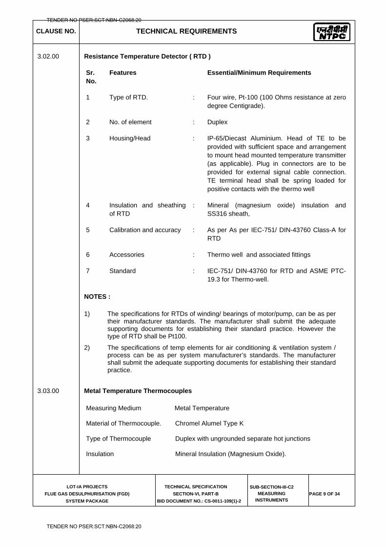
CLAUSE NO. TECHNICAL REQUIREMENTS
LOT-IA PROJECTS
FLUE GAS DESULPHURISATION (FGD)
SYSTEM PACKAGE
TECHNICAL SPECIFICATION
SECTION-VI, PART-B
BID DOCUMENT NO.: CS-0011-109(1)-2
SUB-SECTION-III-C2
MEASURING
INSTRUMENTS PAGE 9 OF 34
3.02.00 Resistance Temperature Detector ( RTD )
Sr. No.
Features Essential/Minimum Requirements
1 Type of RTD. : Four wire, Pt-100 (100 Ohms resistance at zero degree Centigrade).
2 No. of element : Duplex
3 Housing/Head : IP-65/Diecast Aluminium. Head of TE to be provided with sufficient space and arrangement to mount head mounted temperature transmitter (as applicable). Plug in connectors are to be provided for external signal cable connection. TE terminal head shall be spring loaded for positive contacts with the thermo well
4 Insulation and sheathing of RTD
: Mineral (magnesium oxide) insulation and SS316 sheath,
5 Calibration and accuracy : As per As per IEC-751/ DIN-43760 Class-A for RTD
6 Accessories : Thermo well and associated fittings
7 Standard : IEC-751/ DIN-43760 for RTD and ASME PTC-19.3 for Thermo-well.
NOTES :
1) The specifications for RTDs of winding/ bearings of motor/pump, can be as per their manufacturer standards. The manufacturer shall submit the adequate supporting documents for establishing their standard practice. However the type of RTD shall be Pt100.
2) The specifications of temp elements for air conditioning & ventilation system / process can be as per system manufacturer’s standards. The manufacturer shall submit the adequate supporting documents for establishing their standard practice.
3.03.00 Metal Temperature Thermocouples
Measuring Medium Metal Temperature
Material of Thermocouple. Chromel Alumel Type K
Type of Thermocouple Duplex with ungrounded separate hot junctions
Insulation Mineral Insulation (Magnesium Oxide).
TENDER NO PSER:SCT:NBN-C2068:20
TENDER NO PSER:SCT:NBN-C2068:20
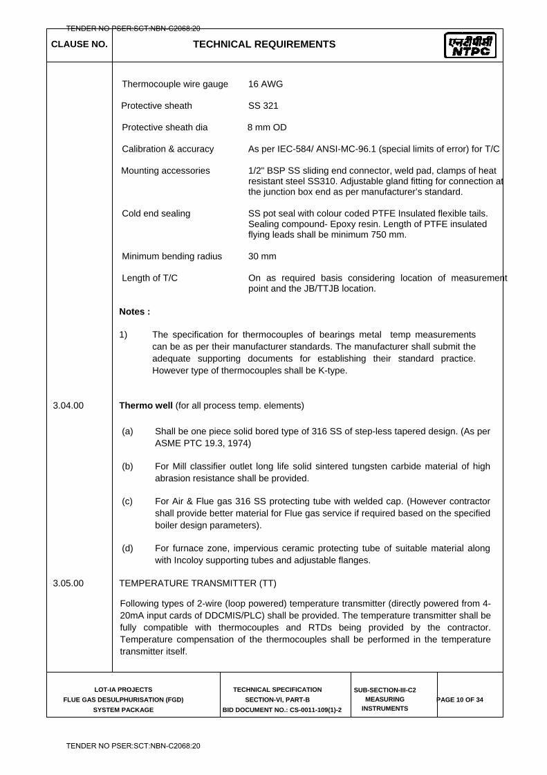
CLAUSE NO. TECHNICAL REQUIREMENTS
LOT-IA PROJECTS
FLUE GAS DESULPHURISATION (FGD)
SYSTEM PACKAGE
TECHNICAL SPECIFICATION
SECTION-VI, PART-B
BID DOCUMENT NO.: CS-0011-109(1)-2
SUB-SECTION-III-C2
MEASURING
INSTRUMENTS PAGE 10 OF 34
Thermocouple wire gauge 16 AWG
Protective sheath SS 321
Protective sheath dia 8 mm OD
Calibration & accuracy As per IEC-584/ ANSI-MC-96.1 (special limits of error) for T/C
Mounting accessories 1/2" BSP SS sliding end connector, weld pad, clamps of heat resistant steel SS310. Adjustable gland fitting for connection at the junction box end as per manufacturer’s standard.
Cold end sealing SS pot seal with colour coded PTFE Insulated flexible tails. Sealing compound- Epoxy resin. Length of PTFE insulated flying leads shall be minimum 750 mm.
Minimum bending radius 30 mm
Length of T/C On as required basis considering location of measurement point and the JB/TTJB location.
Notes :
1) The specification for thermocouples of bearings metal temp measurements can be as per their manufacturer standards. The manufacturer shall submit the adequate supporting documents for establishing their standard practice. However type of thermocouples shall be K-type.
3.04.00 Thermo well (for all process temp. elements)
(a) Shall be one piece solid bored type of 316 SS of step-less tapered design. (As per ASME PTC 19.3, 1974)
(b) For Mill classifier outlet long life solid sintered tungsten carbide material of high abrasion resistance shall be provided.
(c) For Air & Flue gas 316 SS protecting tube with welded cap. (However contractor shall provide better material for Flue gas service if required based on the specified boiler design parameters).
(d) For furnace zone, impervious ceramic protecting tube of suitable material along with Incoloy supporting tubes and adjustable flanges.
3.05.00 TEMPERATURE TRANSMITTER (TT)
Following types of 2-wire (loop powered) temperature transmitter (directly powered from 4-20mA input cards of DDCMIS/PLC) shall be provided. The temperature transmitter shall be fully compatible with thermocouples and RTDs being provided by the contractor. Temperature compensation of the thermocouples shall be performed in the temperature transmitter itself.
TENDER NO PSER:SCT:NBN-C2068:20
TENDER NO PSER:SCT:NBN-C2068:20
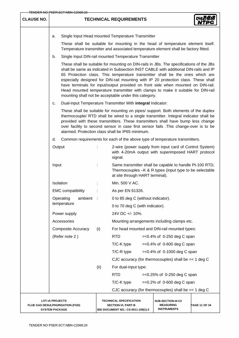
CLAUSE NO. TECHNICAL REQUIREMENTS
LOT-IA PROJECTS
FLUE GAS DESULPHURISATION (FGD)
SYSTEM PACKAGE
TECHNICAL SPECIFICATION
SECTION-VI, PART-B
BID DOCUMENT NO.: CS-0011-109(1)-2
SUB-SECTION-III-C2
MEASURING
INSTRUMENTS PAGE 11 OF 34
a. Single Input Head mounted Temperature Transmitter
These shall be suitable for mounting in the head of temperature element itself. Temperature transmitter and associated temperature element shall be factory fitted.
b. Single Input DIN-rail mounted Temperature Transmitter
These shall be suitable for mounting on DIN-rails in JBs. The specifications of the JBs shall be same as indicated in Subsection INST CABLE with additional DIN-rails and IP 65 Protection class. This temperature transmitter shall be the ones which are especially designed for DIN-rail mounting with IP 20 protection class. These shall have terminals for input/output provided on front side when mounted on DIN-rail. Head mounted temperature transmitter with clamps to make it suitable for DIN-rail mounting shall not be acceptable under this category.
c. Dual-input Temperature Transmitter With integral Indicator:
These shall be suitable for mounting on pipes/ support. Both elements of the duplex thermocouple/ RTD shall be wired to a single transmitter. Integral indicator shall be provided with these transmitters. These transmitters shall have bump less change over facility to second sensor in case first sensor fails .This change-over is to be alarmed. Protection class shall be IP65 minimum.
d. Common requirements for each of the above type of temperature transmitters.
Output : 2-wire (power supply from input card of Control System) with 4-20mA output with superimposed HART protocol signal.
Input : Same transmitter shall be capable to handle Pt-100 RTD, Thermocouples –K & R types (input type to be selectable at site through HART terminal).
Isolation : Min. 500 V AC.
EMC compatibility : As per EN 61326.
Operating ambient temperature
: 0 to 85 deg C (without indicator).
0 to 70 deg C (with indicator).
Power supply 24V DC +/- 10%.
Accessories Mounting arrangements including clamps etc.
Composite Accuracy (i) For head mounted and DIN-rail mounted types:
(Refer note 2 ) RTD =<0.4% of 0-250 deg C span
T/C-K type =<0.4% of 0-600 deg C span
T/C-R type =<0.4% of 0-1000 deg C span
CJC accuracy (for thermocouples) shall be =< 1 deg C
(ii) For dual-input type:
RTD =<0.25% of 0-250 deg C span
T/C-K type =<0.2% of 0-600 deg C span
CJC accuracy (for thermocouples) shall be =< 1 deg C
TENDER NO PSER:SCT:NBN-C2068:20
TENDER NO PSER:SCT:NBN-C2068:20
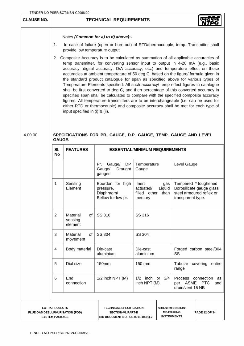
CLAUSE NO. TECHNICAL REQUIREMENTS
LOT-IA PROJECTS
FLUE GAS DESULPHURISATION (FGD)
SYSTEM PACKAGE
TECHNICAL SPECIFICATION
SECTION-VI, PART-B
BID DOCUMENT NO.: CS-0011-109(1)-2
SUB-SECTION-III-C2
MEASURING
INSTRUMENTS PAGE 12 OF 34
Notes (Common for a) to d) above):-
1. In case of failure (open or burn-out) of RTD/thermocouple, temp. Transmitter shall provide low temperature output.
2. Composite Accuracy is to be calculated as summation of all applicable accuracies of temp transmitter, for converting sensor input to output in 4-20 mA (e.g., basic accuracy, digital accuracy, D/A accuracy, etc.) and temperature effect on these accuracies at ambient temperature of 50 deg C, based on the figure/ formula given in the standard product catalogue for span as specified above for various types of Temperature Elements specified. All such accuracy/ temp effect figures in catalogue shall be first converted to deg C, and then percentage of this converted accuracy in specified span shall be calculated to compare with the specified composite accuracy figures. All temperature transmitters are to be interchangeable (i.e. can be used for either RTD or thermocouple) and composite accuracy shall be met for each type of input specified in (i) & (ii).
4.00.00 SPECIFICATIONS FOR PR. GAUGE, D.P. GAUGE, TEMP. GAUGE AND LEVEL GAUGE.
Sl.No
FEATURES ESSENTIAL/MINIMUM REQUIREMENTS
Pr. Gauge/ DP Gauge/ Draught gauges
Temperature Gauge
Level Gauge
1 Sensing Element
Bourdon for high pressure, Diaphragm/ Bellow for low pr.
Inert gas actuated/ Liquid filled other than mercury
Tempered * toughened Borosilicate gauge glass steel armoured reflex or transparent type.
2 Material of sensing element
SS 316 SS 316
3 Material of movement
SS 304 SS 304
4 Body material Die-cast aluminium
Die-cast aluminium
Forged carbon steel/304 SS
5 Dial size 150mm 150 mm Tubular covering entire range
6 End connection
1/2 inch NPT (M) 1/2 inch or 3/4 inch NPT (M).
Process connection as per ASME PTC and drain/vent 15 NB
TENDER NO PSER:SCT:NBN-C2068:20
TENDER NO PSER:SCT:NBN-C2068:20
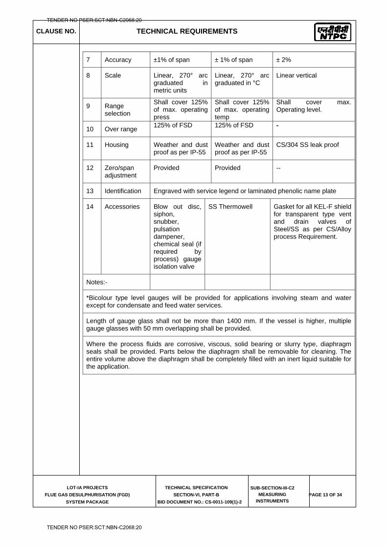
CLAUSE NO. TECHNICAL REQUIREMENTS
LOT-IA PROJECTS
FLUE GAS DESULPHURISATION (FGD)
SYSTEM PACKAGE
TECHNICAL SPECIFICATION
SECTION-VI, PART-B
BID DOCUMENT NO.: CS-0011-109(1)-2
SUB-SECTION-III-C2
MEASURING
INSTRUMENTS PAGE 13 OF 34
7 Accuracy ±1% of span ± 1% of span ± 2%
8 Scale Linear, 270° arc graduated in metric units
Linear, 270° arc graduated in °C
Linear vertical
9 Range selection
Shall cover 125% of max. operating press
Shall cover 125% of max. operating temp
Shall cover max. Operating level.
10 Over range 125% of FSD 125% of FSD -
11 Housing Weather and dust proof as per IP-55
Weather and dust proof as per IP-55
CS/304 SS leak proof
12 Zero/span adjustment
Provided Provided --
13 Identification Engraved with service legend or laminated phenolic name plate
14 Accessories Blow out disc, siphon, snubber, pulsation dampener, chemical seal (if required by process) gauge isolation valve
SS Thermowell Gasket for all KEL-F shield for transparent type vent and drain valves of Steel/SS as per CS/Alloy process Requirement.
Notes:-
*Bicolour type level gauges will be provided for applications involving steam and water except for condensate and feed water services.
Length of gauge glass shall not be more than 1400 mm. If the vessel is higher, multiple gauge glasses with 50 mm overlapping shall be provided.
Where the process fluids are corrosive, viscous, solid bearing or slurry type, diaphragm seals shall be provided. Parts below the diaphragm shall be removable for cleaning. The entire volume above the diaphragm shall be completely filled with an inert liquid suitable for the application.
TENDER NO PSER:SCT:NBN-C2068:20
TENDER NO PSER:SCT:NBN-C2068:20
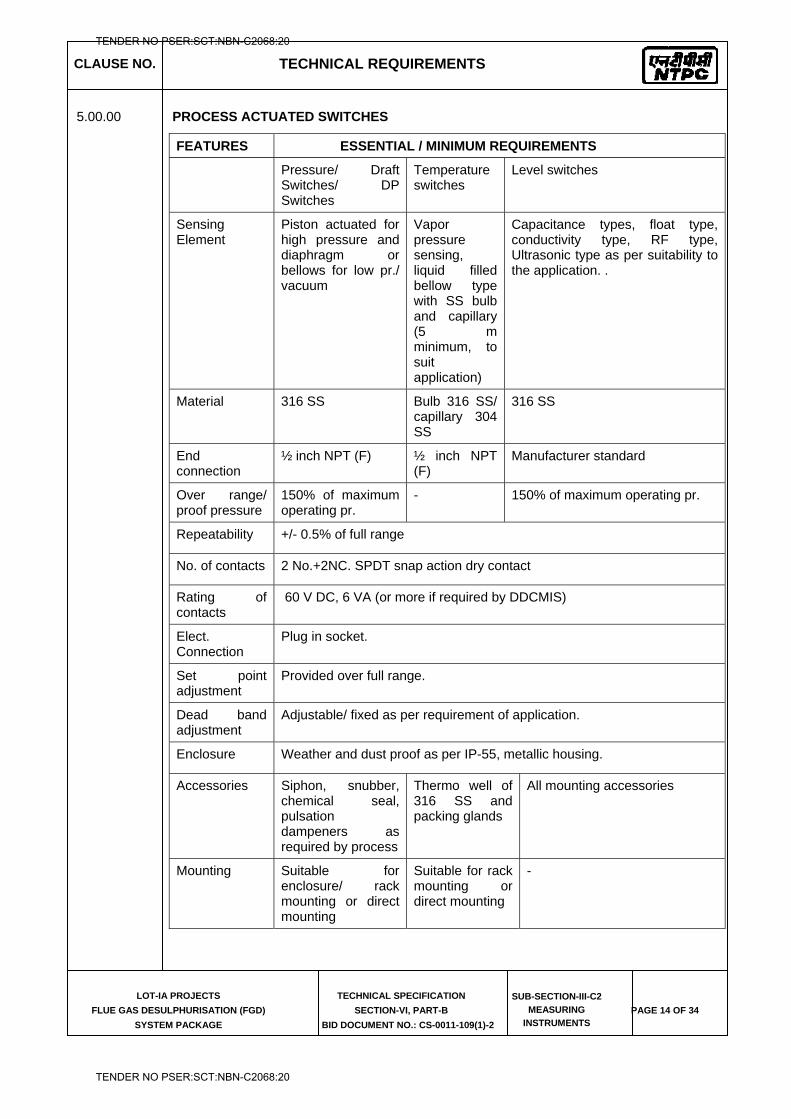
CLAUSE NO. TECHNICAL REQUIREMENTS
LOT-IA PROJECTS
FLUE GAS DESULPHURISATION (FGD)
SYSTEM PACKAGE
TECHNICAL SPECIFICATION
SECTION-VI, PART-B
BID DOCUMENT NO.: CS-0011-109(1)-2
SUB-SECTION-III-C2
MEASURING
INSTRUMENTS PAGE 14 OF 34
5.00.00 PROCESS ACTUATED SWITCHES
FEATURES ESSENTIAL / MINIMUM REQUIREMENTS
Pressure/ Draft Switches/ DP Switches
Temperature switches
Level switches
Sensing Element
Piston actuated for high pressure and diaphragm or bellows for low pr./ vacuum
Vapor pressure sensing, liquid filled bellow type with SS bulb and capillary (5 m minimum, to suit application)
Capacitance types, float type, conductivity type, RF type, Ultrasonic type as per suitability to the application. .
Material 316 SS Bulb 316 SS/ capillary 304 SS
316 SS
End connection
½ inch NPT (F) ½ inch NPT (F)
Manufacturer standard
Over range/ proof pressure
150% of maximum operating pr.
- 150% of maximum operating pr.
Repeatability +/- 0.5% of full range
No. of contacts 2 No.+2NC. SPDT snap action dry contact
Rating of contacts
60 V DC, 6 VA (or more if required by DDCMIS)
Elect. Connection
Plug in socket.
Set point adjustment
Provided over full range.
Dead band adjustment
Adjustable/ fixed as per requirement of application.
Enclosure Weather and dust proof as per IP-55, metallic housing.
Accessories Siphon, snubber, chemical seal, pulsation dampeners as required by process
Thermo well of 316 SS and packing glands
All mounting accessories
Mounting Suitable for enclosure/ rack mounting or direct mounting
Suitable for rack mounting or direct mounting
-
TENDER NO PSER:SCT:NBN-C2068:20
TENDER NO PSER:SCT:NBN-C2068:20
CLAUSE NO. TECHNICAL REQUIREMENTS
LOT-IA PROJECTS
FLUE GAS DESULPHURISATION (FGD)
SYSTEM PACKAGE
TECHNICAL SPECIFICATION
SECTION-VI, PART-B
BID DOCUMENT NO.: CS-0011-109(1)-2
SUB-SECTION-III-C2
MEASURING
INSTRUMENTS PAGE 15 OF 34
Power Supply
(wherever required)
As per Contractor’s Standard practice.
Notes :-
1) Where the process fluids are corrosive, viscous, solid bearing or slurry type, diaphragm seals shall be provided. Parts below the diaphragm shall be removable for cleaning. The entire volume above the diaphragm shall be completely filled with an inert liquid suitable for the application.
2) Pressure/ Diff pressure switches for very low press/ DP measurements can have sensor material other than SS316 in case of any technical limitation and the offered product is standard product of the manufacture for very low pressure applications.
3) Repeatability can be upto +/-1% of full range in case of switches with diaphragm seals or very low pressure/DP range.
4) The specifications of switches for air conditioning & ventilation system / process can be as per system manufacturer’s standards. The manufacturer shall submit the adequate supporting documents for establishing their standard practice.
6.00.00 SOLENOID VALVES
Solenoid valves shall fulfill the following requirements: -
a) Type 2/3/4 way SS 316/ forged brass (depending on the application subject to Employer’s approval during detailed engg.)
b) Power supply 24V DC.
c) Plug in connector connection.
d) Insulation : Class “H”
7.00.00 Limit switches
e) Limit switches shall be silver plated with high conductivity and non-corrosive type. Contact rating shall be sufficient to meet the requirement of Fire alarm Control System subject to a minimum of 60V, 6VA rating. Protection class shall be IP-55.
8.00.00 SPECIFICATION FOR CORIOLIS FLOW TRANSMITTER
Type Coriolis
Material of Wetted Parts 316 SS
Material of Housing 304L SS
Accuracy ± 0.2% of Rate
Repeatability ± 0.1% of Rate
TENDER NO PSER:SCT:NBN-C2068:20
TENDER NO PSER:SCT:NBN-C2068:20
CLAUSE NO. TECHNICAL REQUIREMENTS
LOT-IA PROJECTS
FLUE GAS DESULPHURISATION (FGD)
SYSTEM PACKAGE
TECHNICAL SPECIFICATION
SECTION-VI, PART-B
BID DOCUMENT NO.: CS-0011-109(1)-2
SUB-SECTION-III-C2
MEASURING
INSTRUMENTS PAGE 16 OF 34
Output 4-20 mA DC, HART Compatible
Power Supply 230 VAC or 24VDC operated
Process Temperature range 0-200 degree Celsius
Others Drain / purging arrangement shall be provided as per standard practice.
Viscosity range of Fluid 0-500cst for HFO
The offered Coriolis type flow transmitter shall be suitable for intended application. Contractor shall submit flow and sizing calculation for Employer’s approval. For each type of Coriolis type flow transmitter general arrangement and assembly drawing and cable wiring diagram shall be submitted for Employer’s approval.
9.00.00 SPECIFICATION FOR FLOW ELEMENTS
9.01.00 Orifice Plate
Features Essential/Minimum Requirements
Type Concentric as per ASME PTC-19.5 (Part-II), ISA RP-3.2, 1960 or BS-1042, ISO 5167
Material 316 SS
Thickness 3 mm for main pipe diameter up to 300 mm and6 mm for main pipe dia above300 mm.
Material of branch pipe Same as main pipe
Root valve type Globe
Root valve material Same as pipe material
Root valve size 1 / 2 inch or 1 inch (as applicable)
Impulse pipe of same material up to root valve
Required
Tappings Flanged weld neck or D & D/2 with 3 pairs of tapping ( as applicable ). Root valves to be provided in all the tappings. However for flow elements in CPU, DM & PT plant- 2 Pairs of Tappings shall be provided as minimum.
Beta Ratio 0.34 to 0.7
Beta Ratio calculation to be submitted
Yes
Assembly drg. and flow Vs DP Curves
Yes
Accessories Root valves, flanges, Vent/drain hole(As required)
TENDER NO PSER:SCT:NBN-C2068:20
TENDER NO PSER:SCT:NBN-C2068:20
CLAUSE NO. TECHNICAL REQUIREMENTS
LOT-IA PROJECTS
FLUE GAS DESULPHURISATION (FGD)
SYSTEM PACKAGE
TECHNICAL SPECIFICATION
SECTION-VI, PART-B
BID DOCUMENT NO.: CS-0011-109(1)-2
SUB-SECTION-III-C2
MEASURING
INSTRUMENTS PAGE 17 OF 34
Contractor shall submit certified flow calculation and differential pressure vs. flow curves for each element for Employer's approval. Sizing calculation, precise flow calculation for all the flow elements, fabrication and assembly drawings and installation drawings shall be submitted for Employer's approval.
9.02.00 Flow Nozzle
Features Essential/Minimum Requirements
Type Long radius, welded type as per ASME PTC-19.5 (Part-III) or BS-1042
Material 316 SS
Thickness Suitable for intended application.
Material of branch pipe Same as main pipe
Root valve type Globe
Root valve material Same as pipe material
Root valve size 1 inch
Impulse pipe of same material up to root valve
Required
Tapping Flanged weld neck or D & D/2 with 3 pairs of tapping ( as applicable ). Root valves to be provided in all the tappings. However for flow elements in CPU, DM & PT plant- 2 Pairs of Tappings shall be provided as minimum.
Beta Ratio Around 0.7
Beta Ratio calculation to be submitted Yes
Assembly drg. and flow Vs DP Curves Yes
Accessories Root valves, vent and drain hole.
Contractor shall submit certified flow calculation and differential pressure vs. flow curves for each element for Employer's approval. Sizing calculation, precise flow calculation for all the flow elements, fabrication and assembly drawings and installation drawings shall be submitted for Employer's approval.
TENDER NO PSER:SCT:NBN-C2068:20
TENDER NO PSER:SCT:NBN-C2068:20
CLAUSE NO. TECHNICAL REQUIREMENTS
LOT-IA PROJECTS
FLUE GAS DESULPHURISATION (FGD)
SYSTEM PACKAGE
TECHNICAL SPECIFICATION
SECTION-VI, PART-B
BID DOCUMENT NO.: CS-0011-109(1)-2
SUB-SECTION-III-C2
MEASURING
INSTRUMENTS PAGE 18 OF 34
9.03.00 Venturi (For Liquid applications) --------------------------------------------------------------------------------------------------------------------
------- Features Essential/Minimum Requirements --------------------------------------------------------------------------------------------------------------------
------- Type Rough Welded (for Pipe dia between
200mm to 1200mm) or Machined (for Pipe dia 50mm to 250mm) as per ISO 5167-4:2003,
Material Same as Main Pipe Thickness Same as Main Pipe. Root valve type Globe Type Root valve material Same as Pipe material Root valve size 1 inch Impulse pipe of same material Required up to root valve Tapping 3 pairs of tappings for each Venturi as per
ISO 5167-4:2003, However for some areas like CPU, DM & PT plant- 2 Pairs of Tappings shall be provided as minimum.
Beta Ratio 0.4 to 0.7 Beta Ratio calculation to be Yes Submitted Assembly drg. and flow Yes Vs DP Curves Accessories Root valves, vent and drain hole. --------------------------------------------------------------------------------------------------------------------
Contractor shall submit certified flow calculation and differential pressure vs. Flow curves for each element for employer's approval. Sizing calculation, precise flow calculation for all the flow elements, fabrication and assembly drawings and installation drawings shall be submitted for employer's approval.
9.04.00 ROTAMETERS
Sr. No. Features Essential / minimum requirements
1. Type Variable Area Metal Tube
2. Fluid media Water/oil
3. Tube body SS316
4. Material of float 316 SS
5. Indicator Linear scale
TENDER NO PSER:SCT:NBN-C2068:20
TENDER NO PSER:SCT:NBN-C2068:20
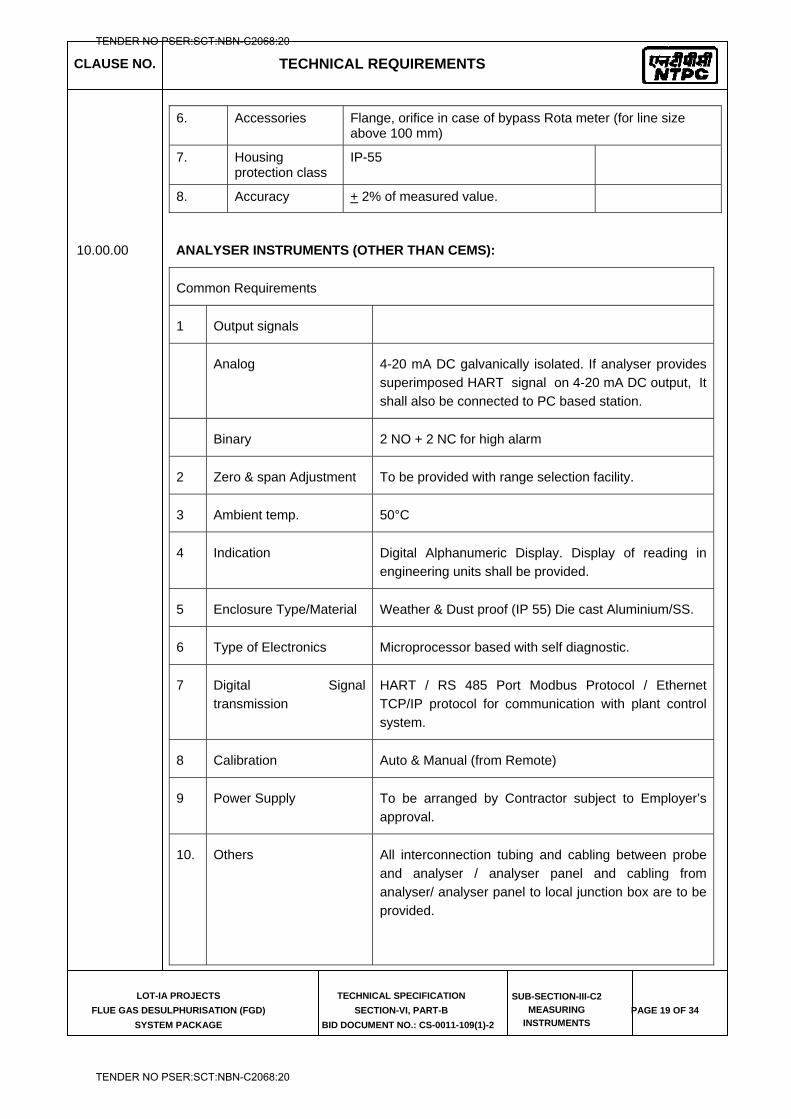
CLAUSE NO. TECHNICAL REQUIREMENTS
LOT-IA PROJECTS
FLUE GAS DESULPHURISATION (FGD)
SYSTEM PACKAGE
TECHNICAL SPECIFICATION
SECTION-VI, PART-B
BID DOCUMENT NO.: CS-0011-109(1)-2
SUB-SECTION-III-C2
MEASURING
INSTRUMENTS PAGE 19 OF 34
6. Accessories Flange, orifice in case of bypass Rota meter (for line size above 100 mm)
7. Housing protection class
IP-55
8. Accuracy + 2% of measured value.
10.00.00 ANALYSER INSTRUMENTS (OTHER THAN CEMS):
Common Requirements
1 Output signals
Analog 4-20 mA DC galvanically isolated. If analyser provides superimposed HART signal on 4-20 mA DC output, It shall also be connected to PC based station.
Binary 2 NO + 2 NC for high alarm
2 Zero & span Adjustment To be provided with range selection facility.
3 Ambient temp. 50°C
4 Indication Digital Alphanumeric Display. Display of reading in engineering units shall be provided.
5 Enclosure Type/Material Weather & Dust proof (IP 55) Die cast Aluminium/SS.
6 Type of Electronics Microprocessor based with self diagnostic.
7 Digital Signal transmission
HART / RS 485 Port Modbus Protocol / Ethernet TCP/IP protocol for communication with plant control system.
8 Calibration Auto & Manual (from Remote)
9 Power Supply To be arranged by Contractor subject to Employer’s approval.
10. Others All interconnection tubing and cabling between probe and analyser / analyser panel and cabling from analyser/ analyser panel to local junction box are to be provided.
TENDER NO PSER:SCT:NBN-C2068:20
TENDER NO PSER:SCT:NBN-C2068:20
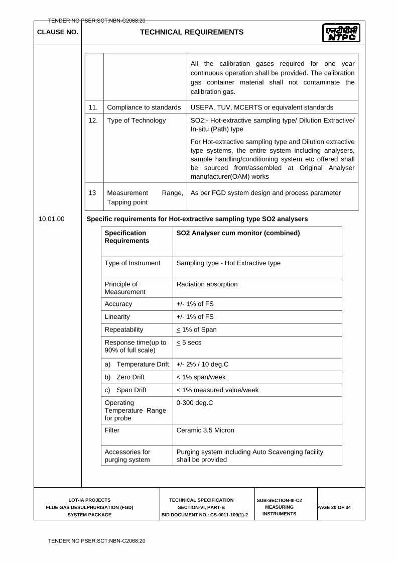
CLAUSE NO. TECHNICAL REQUIREMENTS
LOT-IA PROJECTS
FLUE GAS DESULPHURISATION (FGD)
SYSTEM PACKAGE
TECHNICAL SPECIFICATION
SECTION-VI, PART-B
BID DOCUMENT NO.: CS-0011-109(1)-2
SUB-SECTION-III-C2
MEASURING
INSTRUMENTS PAGE 20 OF 34
All the calibration gases required for one year continuous operation shall be provided. The calibration gas container material shall not contaminate the calibration gas.
11. Compliance to standards USEPA, TUV, MCERTS or equivalent standards
12. Type of Technology
SO2:- Hot-extractive sampling type/ Dilution Extractive/ In-situ (Path) type
For Hot-extractive sampling type and Dilution extractive type systems, the entire system including analysers, sample handling/conditioning system etc offered shall be sourced from/assembled at Original Analyser manufacturer(OAM) works
13 Measurement Range, Tapping point
As per FGD system design and process parameter
10.01.00 Specific requirements for Hot-extractive sampling type SO2 analysers
Specification Requirements
SO2 Analyser cum monitor (combined)
Type of Instrument Sampling type - Hot Extractive type
Principle of Measurement
Radiation absorption
Accuracy +/- 1% of FS
Linearity +/- 1% of FS
Repeatability < 1% of Span
Response time(up to 90% of full scale)
< 5 secs
a) Temperature Drift +/- 2% / 10 deg.C
b) Zero Drift < 1% span/week
c) Span Drift < 1% measured value/week
Operating Temperature Range for probe
0-300 deg.C
Filter Ceramic 3.5 Micron
Accessories for purging system
Purging system including Auto Scavenging facility shall be provided
TENDER NO PSER:SCT:NBN-C2068:20
TENDER NO PSER:SCT:NBN-C2068:20
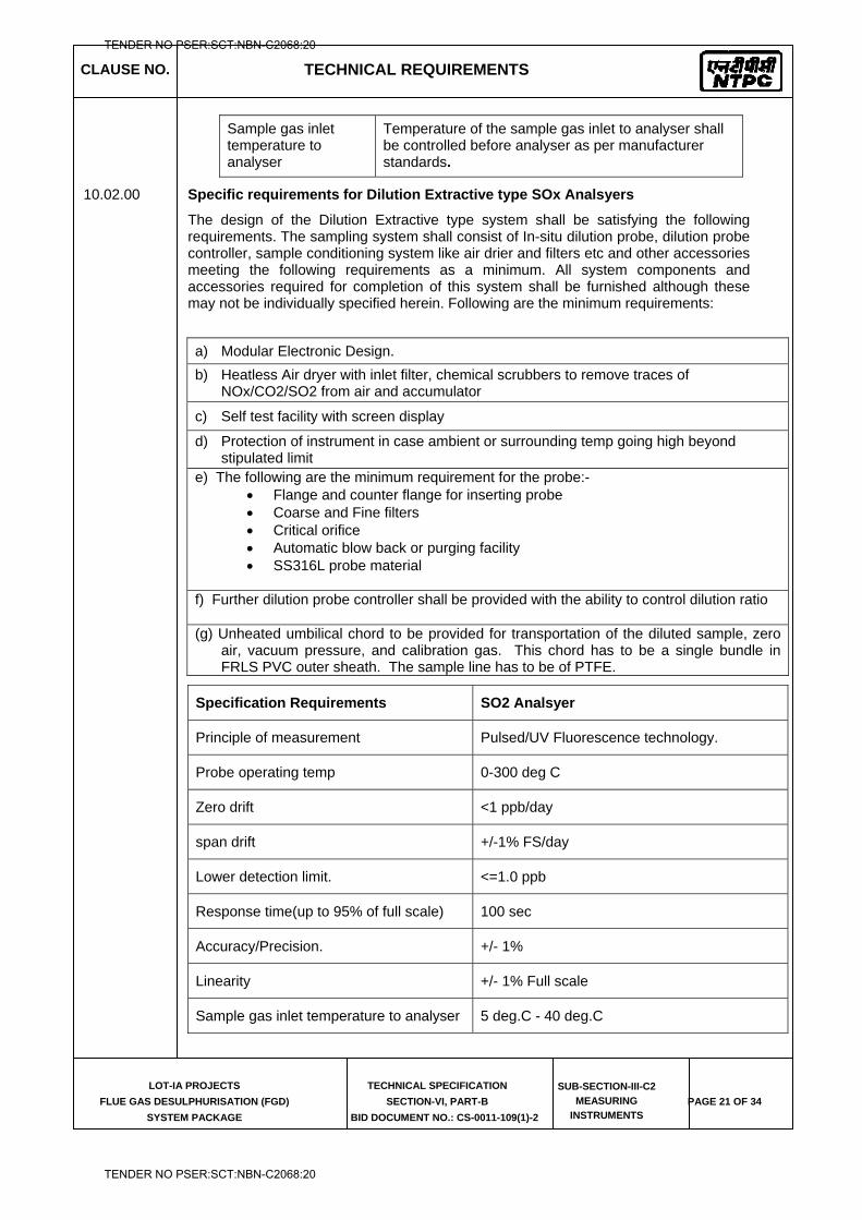
CLAUSE NO. TECHNICAL REQUIREMENTS
LOT-IA PROJECTS
FLUE GAS DESULPHURISATION (FGD)
SYSTEM PACKAGE
TECHNICAL SPECIFICATION
SECTION-VI, PART-B
BID DOCUMENT NO.: CS-0011-109(1)-2
SUB-SECTION-III-C2
MEASURING
INSTRUMENTS PAGE 21 OF 34
Sample gas inlet temperature to analyser
Temperature of the sample gas inlet to analyser shall be controlled before analyser as per manufacturer standards.
10.02.00 Specific requirements for Dilution Extractive type SOx Analsyers
The design of the Dilution Extractive type system shall be satisfying the following requirements. The sampling system shall consist of In-situ dilution probe, dilution probe controller, sample conditioning system like air drier and filters etc and other accessories meeting the following requirements as a minimum. All system components and accessories required for completion of this system shall be furnished although these may not be individually specified herein. Following are the minimum requirements:
Specification Requirements SO2 Analsyer
Principle of measurement Pulsed/UV Fluorescence technology.
Probe operating temp 0-300 deg C
Zero drift <1 ppb/day
span drift +/-1% FS/day
Lower detection limit. <=1.0 ppb
Response time(up to 95% of full scale) 100 sec
Accuracy/Precision. +/- 1%
Linearity +/- 1% Full scale
Sample gas inlet temperature to analyser 5 deg.C - 40 deg.C
a) Modular Electronic Design. b) Heatless Air dryer with inlet filter, chemical scrubbers to remove traces of
NOx/CO2/SO2 from air and accumulator
c) Self test facility with screen display
d) Protection of instrument in case ambient or surrounding temp going high beyond stipulated limit
e) The following are the minimum requirement for the probe:- Flange and counter flange for inserting probe Coarse and Fine filters Critical orifice Automatic blow back or purging facility SS316L probe material
f) Further dilution probe controller shall be provided with the ability to control dilution ratio (g) Unheated umbilical chord to be provided for transportation of the diluted sample, zero
air, vacuum pressure, and calibration gas. This chord has to be a single bundle in FRLS PVC outer sheath. The sample line has to be of PTFE.
TENDER NO PSER:SCT:NBN-C2068:20
TENDER NO PSER:SCT:NBN-C2068:20
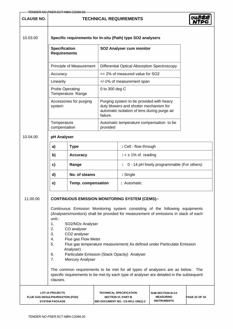
CLAUSE NO. TECHNICAL REQUIREMENTS
LOT-IA PROJECTS
FLUE GAS DESULPHURISATION (FGD)
SYSTEM PACKAGE
TECHNICAL SPECIFICATION
SECTION-VI, PART-B
BID DOCUMENT NO.: CS-0011-109(1)-2
SUB-SECTION-III-C2
MEASURING
INSTRUMENTS PAGE 22 OF 34
10.03.00 Specific requirements for In-situ (Path) type SO2 analysers
Specification Requirements
SO2 Analyser cum monitor
Principle of Measurement Differential Optical Absorption Spectroscopy
Accuracy <= 2% of measured value for SO2
Linearity +/-1% of measurement span
Probe Operating Temperature Range
0 to 300 deg C
Accessories for purging system
Purging system to be provided with heavy duty blowers and shutter mechanism for automatic isolation of lens during purge air failure.
Temperature compensation
Automatic temperature compensation to be provided
10.04.00 pH Analyser
11.00.00 CONTINUOUS EMISSION MONITORING SYSTEM (CEMS):-
Continuous Emission Monitoring system consisting of the following equipments (Analysers/monitors) shall be provided for measurement of emissions in stack of each unit:- 1. SO2/NOx Analyser 2. CO analyser 3. CO2 analyser 4. Flue gas Flow Meter 5. Flue gas temperature measurement( As defined under Particulate Emission
Analyser) 6. Particulate Emission (Stack Opacity) Analyser 7. Mercury Analyser The common requirements to be met for all types of analysers are as below. The specific requirements to be met by each type of analyser are detailed in the subsequent clauses.
a) Type : Cell - flow through
b) Accuracy : < ± 1% of reading
c) Range : 0 - 14 pH freely programmable (For others)
d) No. of steams : Single
e) Temp. compensation : Automatic
TENDER NO PSER:SCT:NBN-C2068:20
TENDER NO PSER:SCT:NBN-C2068:20
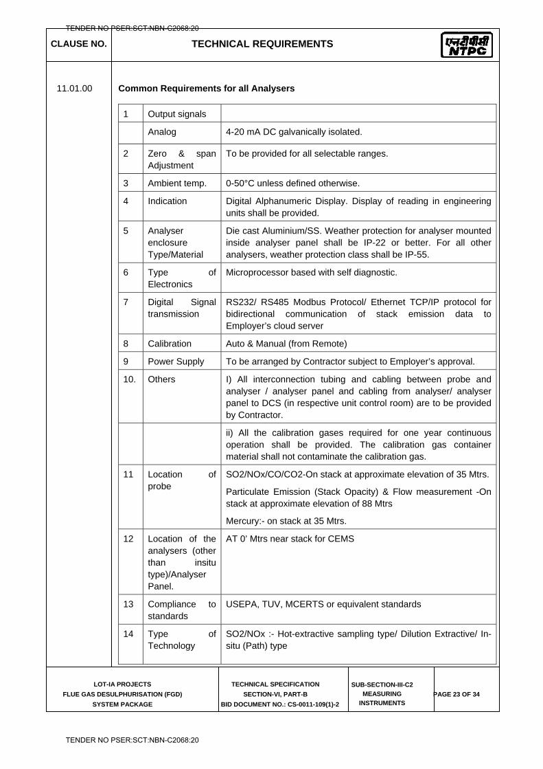
CLAUSE NO. TECHNICAL REQUIREMENTS
LOT-IA PROJECTS
FLUE GAS DESULPHURISATION (FGD)
SYSTEM PACKAGE
TECHNICAL SPECIFICATION
SECTION-VI, PART-B
BID DOCUMENT NO.: CS-0011-109(1)-2
SUB-SECTION-III-C2
MEASURING
INSTRUMENTS PAGE 23 OF 34
11.01.00 Common Requirements for all Analysers
1 Output signals
Analog 4-20 mA DC galvanically isolated.
2 Zero & span Adjustment
To be provided for all selectable ranges.
3 Ambient temp. 0-50°C unless defined otherwise.
4 Indication Digital Alphanumeric Display. Display of reading in engineering units shall be provided.
5 Analyser enclosure Type/Material
Die cast Aluminium/SS. Weather protection for analyser mounted inside analyser panel shall be IP-22 or better. For all other analysers, weather protection class shall be IP-55.
6 Type of Electronics
Microprocessor based with self diagnostic.
7 Digital Signal transmission
RS232/ RS485 Modbus Protocol/ Ethernet TCP/IP protocol for bidirectional communication of stack emission data to Employer’s cloud server
8 Calibration Auto & Manual (from Remote)
9 Power Supply To be arranged by Contractor subject to Employer’s approval.
10. Others I) All interconnection tubing and cabling between probe and analyser / analyser panel and cabling from analyser/ analyser panel to DCS (in respective unit control room) are to be provided by Contractor.
ii) All the calibration gases required for one year continuous operation shall be provided. The calibration gas container material shall not contaminate the calibration gas.
11 Location of probe
SO2/NOx/CO/CO2-On stack at approximate elevation of 35 Mtrs.
Particulate Emission (Stack Opacity) & Flow measurement -On stack at approximate elevation of 88 Mtrs
Mercury:- on stack at 35 Mtrs.
12 Location of the analysers (other than insitu type)/Analyser Panel.
AT 0’ Mtrs near stack for CEMS
13 Compliance to standards
USEPA, TUV, MCERTS or equivalent standards
14 Type of Technology
SO2/NOx :- Hot-extractive sampling type/ Dilution Extractive/ In-situ (Path) type
TENDER NO PSER:SCT:NBN-C2068:20
TENDER NO PSER:SCT:NBN-C2068:20
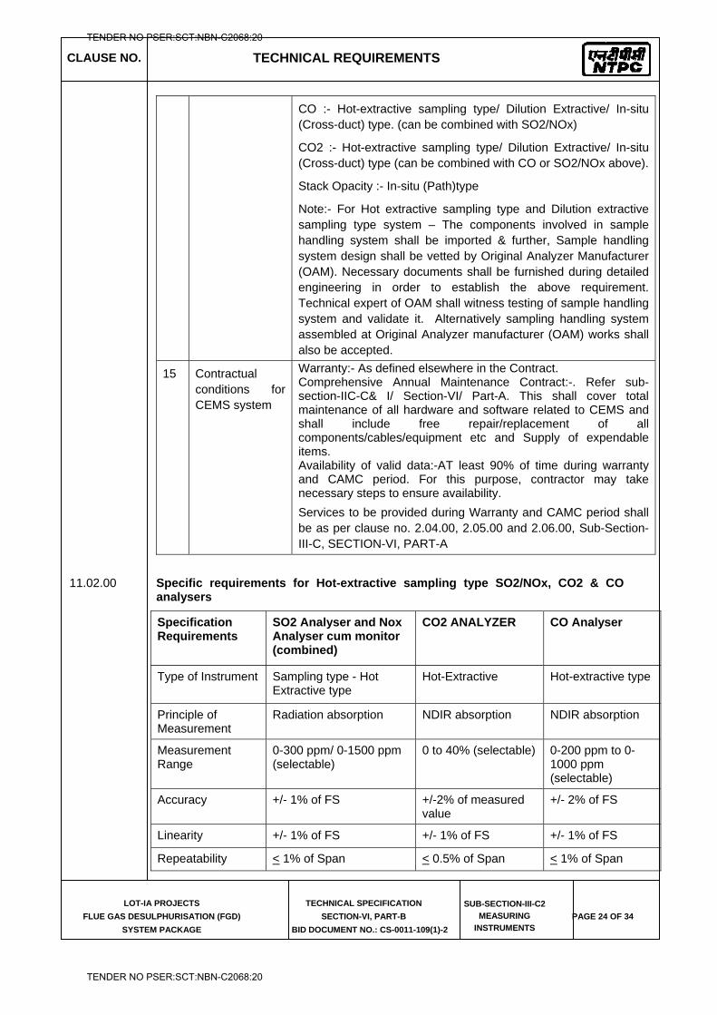
CLAUSE NO. TECHNICAL REQUIREMENTS
LOT-IA PROJECTS
FLUE GAS DESULPHURISATION (FGD)
SYSTEM PACKAGE
TECHNICAL SPECIFICATION
SECTION-VI, PART-B
BID DOCUMENT NO.: CS-0011-109(1)-2
SUB-SECTION-III-C2
MEASURING
INSTRUMENTS PAGE 24 OF 34
CO :- Hot-extractive sampling type/ Dilution Extractive/ In-situ (Cross-duct) type. (can be combined with SO2/NOx)
CO2 :- Hot-extractive sampling type/ Dilution Extractive/ In-situ (Cross-duct) type (can be combined with CO or SO2/NOx above).
Stack Opacity :- In-situ (Path)type
Note:- For Hot extractive sampling type and Dilution extractive sampling type system – The components involved in sample handling system shall be imported & further, Sample handling system design shall be vetted by Original Analyzer Manufacturer (OAM). Necessary documents shall be furnished during detailed engineering in order to establish the above requirement. Technical expert of OAM shall witness testing of sample handling system and validate it. Alternatively sampling handling system assembled at Original Analyzer manufacturer (OAM) works shall also be accepted.
15 Contractual conditions for CEMS system
Warranty:- As defined elsewhere in the Contract. Comprehensive Annual Maintenance Contract:-. Refer sub-section-IIC-C& I/ Section-VI/ Part-A. This shall cover total maintenance of all hardware and software related to CEMS and shall include free repair/replacement of all components/cables/equipment etc and Supply of expendable items. Availability of valid data:-AT least 90% of time during warranty and CAMC period. For this purpose, contractor may take necessary steps to ensure availability. Services to be provided during Warranty and CAMC period shall be as per clause no. 2.04.00, 2.05.00 and 2.06.00, Sub-Section-III-C, SECTION-VI, PART-A
11.02.00 Specific requirements for Hot-extractive sampling type SO2/NOx, CO2 & CO analysers
Specification Requirements
SO2 Analyser and Nox Analyser cum monitor (combined)
CO2 ANALYZER CO Analyser
Type of Instrument Sampling type - Hot Extractive type
Hot-Extractive Hot-extractive type
Principle of Measurement
Radiation absorption NDIR absorption NDIR absorption
Measurement Range
0-300 ppm/ 0-1500 ppm (selectable)
0 to 40% (selectable) 0-200 ppm to 0-1000 ppm (selectable)
Accuracy +/- 1% of FS +/-2% of measured value
+/- 2% of FS
Linearity +/- 1% of FS +/- 1% of FS +/- 1% of FS
Repeatability < 1% of Span < 0.5% of Span < 1% of Span
TENDER NO PSER:SCT:NBN-C2068:20
TENDER NO PSER:SCT:NBN-C2068:20
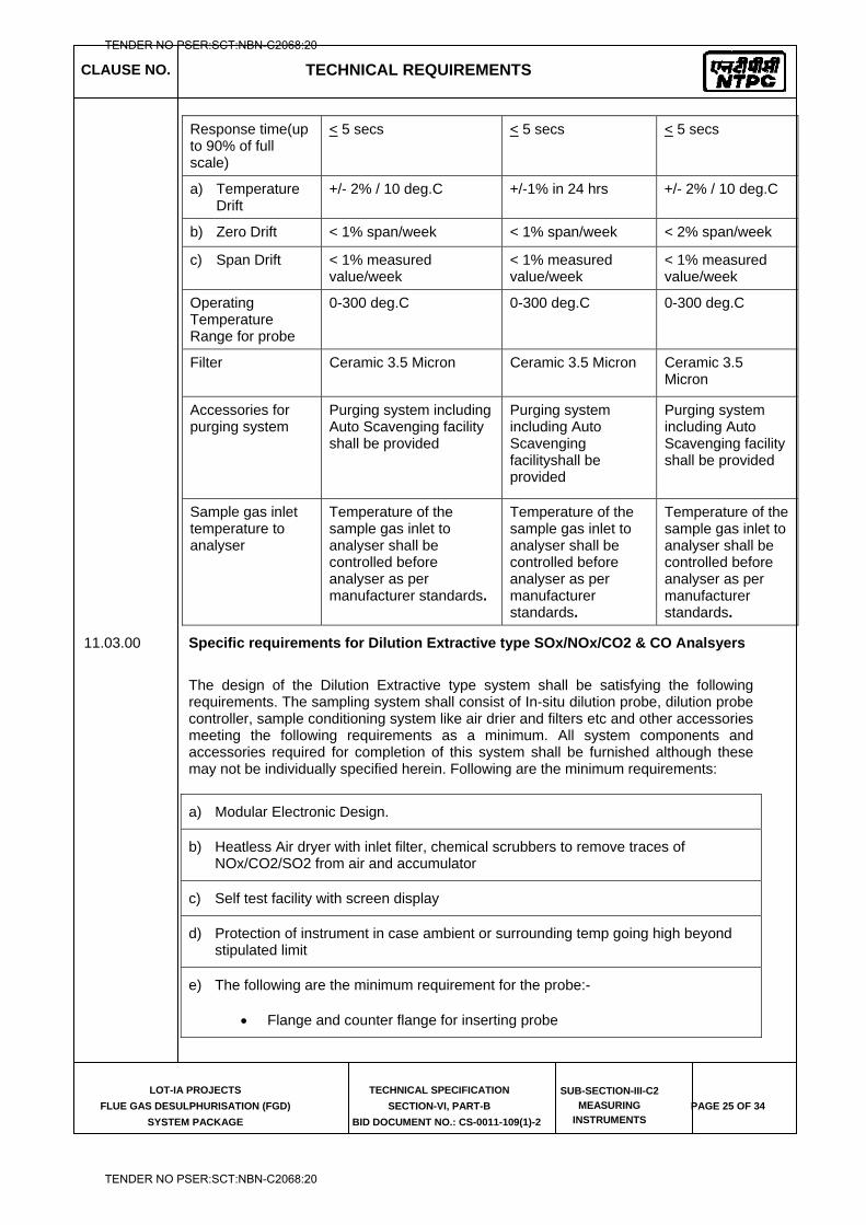
CLAUSE NO. TECHNICAL REQUIREMENTS
LOT-IA PROJECTS
FLUE GAS DESULPHURISATION (FGD)
SYSTEM PACKAGE
TECHNICAL SPECIFICATION
SECTION-VI, PART-B
BID DOCUMENT NO.: CS-0011-109(1)-2
SUB-SECTION-III-C2
MEASURING
INSTRUMENTS PAGE 25 OF 34
Response time(up to 90% of full scale)
< 5 secs < 5 secs < 5 secs
a) Temperature Drift
+/- 2% / 10 deg.C +/-1% in 24 hrs +/- 2% / 10 deg.C
b) Zero Drift < 1% span/week < 1% span/week < 2% span/week
c) Span Drift < 1% measured value/week
< 1% measured value/week
< 1% measured value/week
Operating Temperature Range for probe
0-300 deg.C 0-300 deg.C 0-300 deg.C
Filter Ceramic 3.5 Micron Ceramic 3.5 Micron Ceramic 3.5 Micron
Accessories for purging system
Purging system including Auto Scavenging facility shall be provided
Purging system including Auto Scavenging facilityshall be provided
Purging system including Auto Scavenging facility shall be provided
Sample gas inlet temperature to analyser
Temperature of the sample gas inlet to analyser shall be controlled before analyser as per manufacturer standards.
Temperature of the sample gas inlet to analyser shall be controlled before analyser as per manufacturer standards.
Temperature of the sample gas inlet to analyser shall be controlled before analyser as per manufacturer standards.
11.03.00 Specific requirements for Dilution Extractive type SOx/NOx/CO2 & CO Analsyers
The design of the Dilution Extractive type system shall be satisfying the following requirements. The sampling system shall consist of In-situ dilution probe, dilution probe controller, sample conditioning system like air drier and filters etc and other accessories meeting the following requirements as a minimum. All system components and accessories required for completion of this system shall be furnished although these may not be individually specified herein. Following are the minimum requirements:
a) Modular Electronic Design.
b) Heatless Air dryer with inlet filter, chemical scrubbers to remove traces of NOx/CO2/SO2 from air and accumulator
c) Self test facility with screen display
d) Protection of instrument in case ambient or surrounding temp going high beyond stipulated limit
e) The following are the minimum requirement for the probe:-
Flange and counter flange for inserting probe
TENDER NO PSER:SCT:NBN-C2068:20
TENDER NO PSER:SCT:NBN-C2068:20
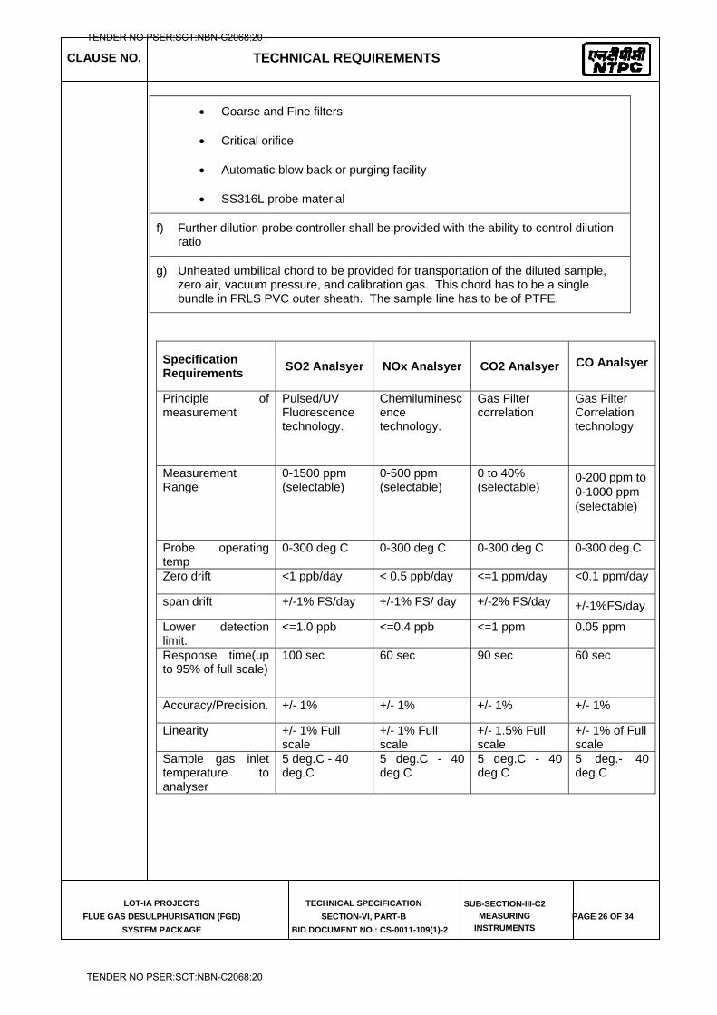
CLAUSE NO. TECHNICAL REQUIREMENTS
LOT-IA PROJECTS
FLUE GAS DESULPHURISATION (FGD)
SYSTEM PACKAGE
TECHNICAL SPECIFICATION
SECTION-VI, PART-B
BID DOCUMENT NO.: CS-0011-109(1)-2
SUB-SECTION-III-C2
MEASURING
INSTRUMENTS PAGE 26 OF 34
Coarse and Fine filters
Critical orifice
Automatic blow back or purging facility
SS316L probe material
f) Further dilution probe controller shall be provided with the ability to control dilution ratio
g) Unheated umbilical chord to be provided for transportation of the diluted sample, zero air, vacuum pressure, and calibration gas. This chord has to be a single bundle in FRLS PVC outer sheath. The sample line has to be of PTFE.
Specification Requirements
SO2 Analsyer NOx Analsyer CO2 Analsyer
CO Analsyer
Principle of measurement
Pulsed/UV Fluorescence technology.
Chemiluminescence technology.
Gas Filter correlation
Gas Filter Correlation technology
Measurement Range
0-1500 ppm (selectable)
0-500 ppm (selectable)
0 to 40% (selectable)
0-200 ppm to 0-1000 ppm (selectable)
Probe operating temp
0-300 deg C 0-300 deg C 0-300 deg C 0-300 deg.C
Zero drift <1 ppb/day < 0.5 ppb/day <=1 ppm/day <0.1 ppm/day
span drift +/-1% FS/day +/-1% FS/ day +/-2% FS/day +/-1%FS/day
Lower detection limit.
<=1.0 ppb <=0.4 ppb <=1 ppm 0.05 ppm
Response time(up to 95% of full scale)
100 sec 60 sec 90 sec 60 sec
Accuracy/Precision. +/- 1% +/- 1% +/- 1% +/- 1%
Linearity +/- 1% Full scale
+/- 1% Full scale
+/- 1.5% Full scale
+/- 1% of Full scale
Sample gas inlet temperature to analyser
5 deg.C - 40 deg.C
5 deg.C - 40 deg.C
5 deg.C - 40 deg.C
5 deg.- 40 deg.C
TENDER NO PSER:SCT:NBN-C2068:20
TENDER NO PSER:SCT:NBN-C2068:20
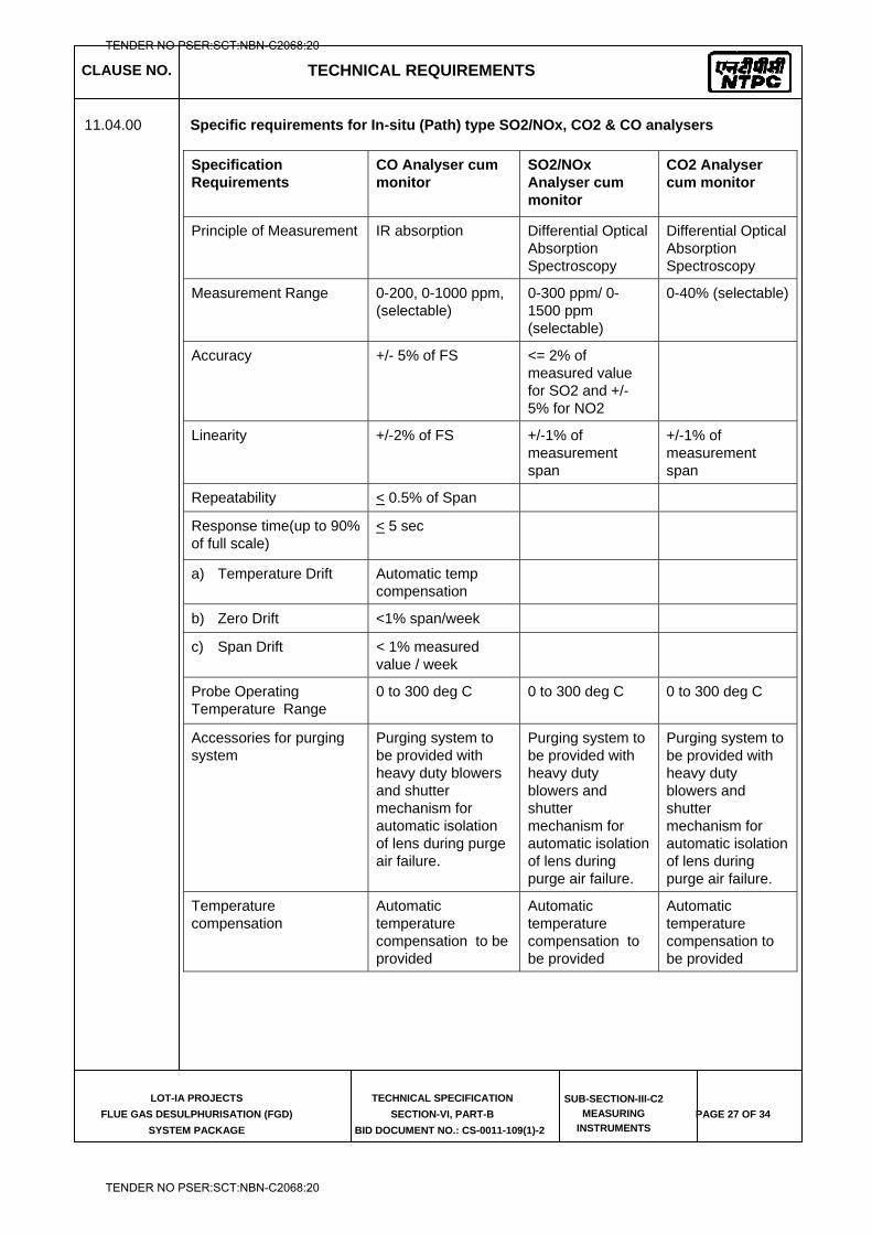
CLAUSE NO. TECHNICAL REQUIREMENTS
LOT-IA PROJECTS
FLUE GAS DESULPHURISATION (FGD)
SYSTEM PACKAGE
TECHNICAL SPECIFICATION
SECTION-VI, PART-B
BID DOCUMENT NO.: CS-0011-109(1)-2
SUB-SECTION-III-C2
MEASURING
INSTRUMENTS PAGE 27 OF 34
11.04.00 Specific requirements for In-situ (Path) type SO2/NOx, CO2 & CO analysers
Specification Requirements
CO Analyser cum monitor
SO2/NOx Analyser cum monitor
CO2 Analyser cum monitor
Principle of Measurement IR absorption Differential Optical Absorption Spectroscopy
Differential Optical Absorption Spectroscopy
Measurement Range 0-200, 0-1000 ppm, (selectable)
0-300 ppm/ 0-1500 ppm (selectable)
0-40% (selectable)
Accuracy +/- 5% of FS <= 2% of measured value for SO2 and +/- 5% for NO2
Linearity +/-2% of FS +/-1% of measurement span
+/-1% of measurement span
Repeatability < 0.5% of Span
Response time(up to 90% of full scale)
< 5 sec
a) Temperature Drift Automatic temp compensation
b) Zero Drift <1% span/week
c) Span Drift < 1% measured value / week
Probe Operating Temperature Range
0 to 300 deg C 0 to 300 deg C 0 to 300 deg C
Accessories for purging system
Purging system to be provided with heavy duty blowers and shutter mechanism for automatic isolation of lens during purge air failure.
Purging system to be provided with heavy duty blowers and shutter mechanism for automatic isolation of lens during purge air failure.
Purging system to be provided with heavy duty blowers and shutter mechanism for automatic isolation of lens during purge air failure.
Temperature compensation
Automatic temperature compensation to be provided
Automatic temperature compensation to be provided
Automatic temperature compensation to be provided
TENDER NO PSER:SCT:NBN-C2068:20
TENDER NO PSER:SCT:NBN-C2068:20
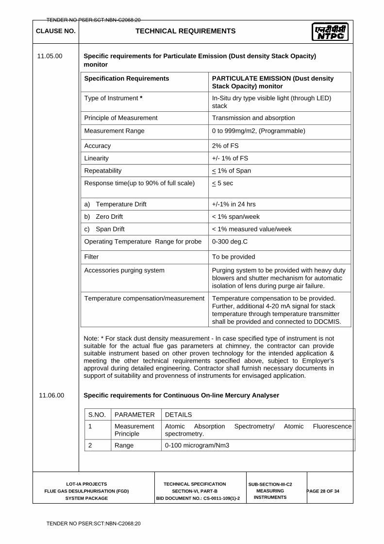
CLAUSE NO. TECHNICAL REQUIREMENTS
LOT-IA PROJECTS
FLUE GAS DESULPHURISATION (FGD)
SYSTEM PACKAGE
TECHNICAL SPECIFICATION
SECTION-VI, PART-B
BID DOCUMENT NO.: CS-0011-109(1)-2
SUB-SECTION-III-C2
MEASURING
INSTRUMENTS PAGE 28 OF 34
11.05.00 Specific requirements for Particulate Emission (Dust density Stack Opacity) monitor
Specification Requirements PARTICULATE EMISSION (Dust density Stack Opacity) monitor
Type of Instrument * In-Situ dry type visible light (through LED) stack
Principle of Measurement Transmission and absorption
Measurement Range 0 to 999mg/m2, (Programmable)
Accuracy 2% of FS
Linearity +/- 1% of FS
Repeatability < 1% of Span
Response time(up to 90% of full scale) < 5 sec
a) Temperature Drift +/-1% in 24 hrs
b) Zero Drift < 1% span/week
c) Span Drift < 1% measured value/week
Operating Temperature Range for probe 0-300 deg.C
Filter To be provided
Accessories purging system Purging system to be provided with heavy duty blowers and shutter mechanism for automatic isolation of lens during purge air failure.
Temperature compensation/measurement Temperature compensation to be provided. Further, additional 4-20 mA signal for stack temperature through temperature transmitter shall be provided and connected to DDCMIS.
Note: * For stack dust density measurement - In case specified type of instrument is not suitable for the actual flue gas parameters at chimney, the contractor can provide suitable instrument based on other proven technology for the intended application & meeting the other technical requirements specified above, subject to Employer’s approval during detailed engineering. Contractor shall furnish necessary documents in support of suitability and provenness of instruments for envisaged application.
11.06.00 Specific requirements for Continuous On-line Mercury Analyser
S.NO. PARAMETER DETAILS
1 Measurement Principle
Atomic Absorption Spectrometry/ Atomic Fluorescence spectrometry.
2 Range 0-100 microgram/Nm3
TENDER NO PSER:SCT:NBN-C2068:20
TENDER NO PSER:SCT:NBN-C2068:20
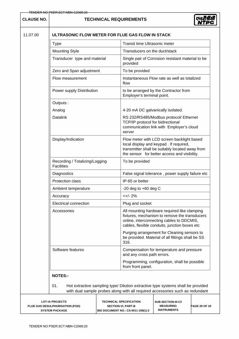
CLAUSE NO. TECHNICAL REQUIREMENTS
LOT-IA PROJECTS
FLUE GAS DESULPHURISATION (FGD)
SYSTEM PACKAGE
TECHNICAL SPECIFICATION
SECTION-VI, PART-B
BID DOCUMENT NO.: CS-0011-109(1)-2
SUB-SECTION-III-C2
MEASURING
INSTRUMENTS PAGE 29 OF 34
11.07.00 ULTRASONIC FLOW METER FOR FLUE GAS FLOW IN STACK
Type Transit time Ultrasonic meter
Mounting Style Transducers on the duct/stack
Transducer type and material Single pair of Corrosion resistant material to be provided
Zero and Span adjustment To be provided
Flow measurement Instantaneous Flow rate as well as totalized flow
Power supply Distribution to be arranged by the Contractor from Employer’s terminal point.
Outputs :
Analog
Datalink
4-20 mA DC galvanically isolated.
RS 232/RS485/Modbus protocol/ Ethernet TCP/IP protocol for bidirectional communication link with Employer’s cloud server
Display/Indication Flow meter with LCD screen backlight based local display and keypad . If required, transmitter shall be suitably located away from the sensor for better access and visibility.
Recording / Totalizing/Logging Facilities
To be provided
Diagnostics False signal tolerance , power supply failure etc
Protection class IP-65 or better
Ambient temperature -20 deg to +60 deg C
Accuracy <+/- 2%
Electrical connection Plug and socket
Accessories All mounting hardware required like clamping fixtures, mechanism to remove the transducers online, interconnecting cables to DDCMIS, cables, flexible conduits, junction boxes etc
Purging arrangement for Cleaning sensors to be provided. Material of all fittings shall be SS 316.
Software features Compensation for temperature and pressure and any cross path errors.
Programming, configuration, shall be possible from front panel.
NOTES:-
01. Hot extractive sampling type/ Dilution extractive type systems shall be provided with dual sample probes along with all required accessories such as redundant
TENDER NO PSER:SCT:NBN-C2068:20
TENDER NO PSER:SCT:NBN-C2068:20
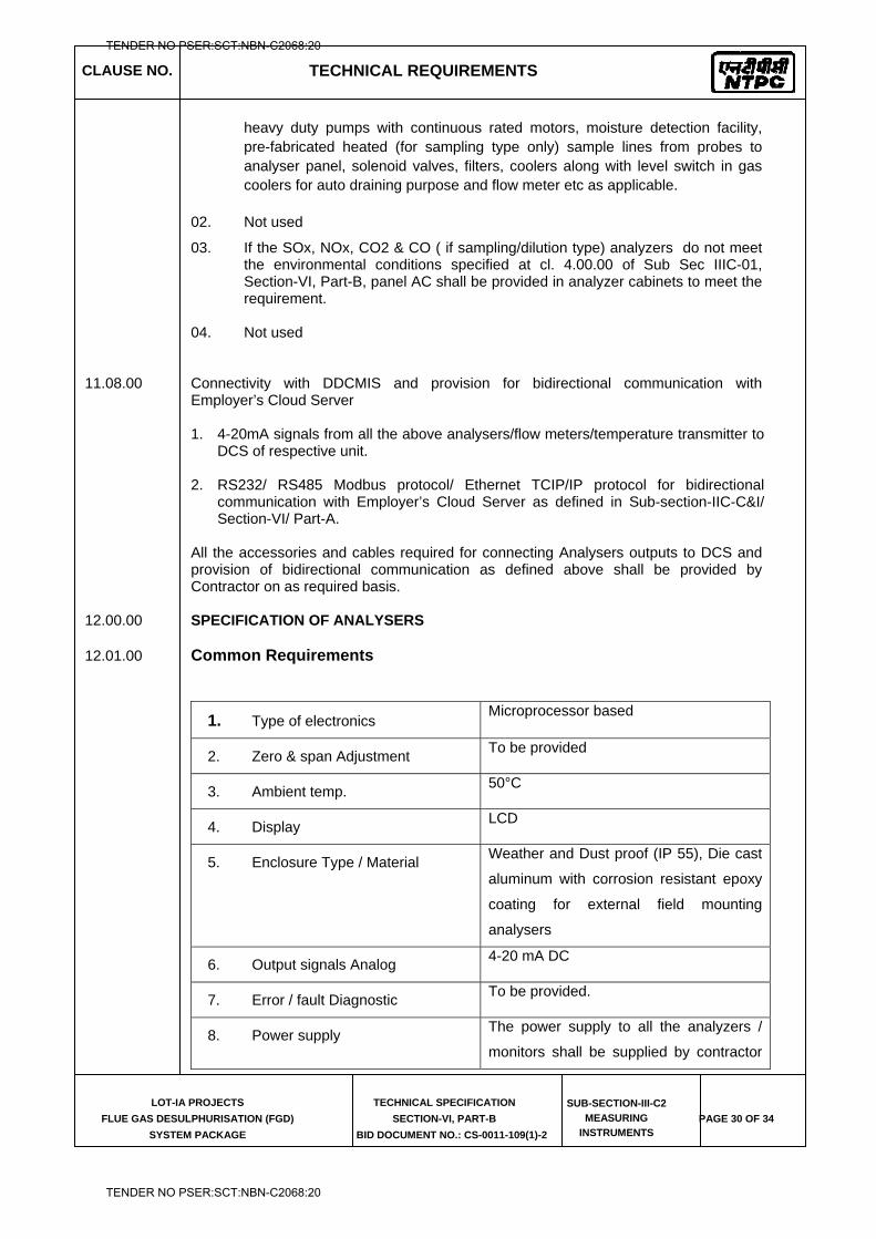
CLAUSE NO. TECHNICAL REQUIREMENTS
LOT-IA PROJECTS
FLUE GAS DESULPHURISATION (FGD)
SYSTEM PACKAGE
TECHNICAL SPECIFICATION
SECTION-VI, PART-B
BID DOCUMENT NO.: CS-0011-109(1)-2
SUB-SECTION-III-C2
MEASURING
INSTRUMENTS PAGE 30 OF 34
heavy duty pumps with continuous rated motors, moisture detection facility, pre-fabricated heated (for sampling type only) sample lines from probes to analyser panel, solenoid valves, filters, coolers along with level switch in gas coolers for auto draining purpose and flow meter etc as applicable.
02. Not used
03. If the SOx, NOx, CO2 & CO ( if sampling/dilution type) analyzers do not meet the environmental conditions specified at cl. 4.00.00 of Sub Sec IIIC-01, Section-VI, Part-B, panel AC shall be provided in analyzer cabinets to meet the requirement.
04. Not used
11.08.00 Connectivity with DDCMIS and provision for bidirectional communication with Employer’s Cloud Server 1. 4-20mA signals from all the above analysers/flow meters/temperature transmitter to
DCS of respective unit. 2. RS232/ RS485 Modbus protocol/ Ethernet TCIP/IP protocol for bidirectional
communication with Employer’s Cloud Server as defined in Sub-section-IIC-C&I/ Section-VI/ Part-A.
All the accessories and cables required for connecting Analysers outputs to DCS and provision of bidirectional communication as defined above shall be provided by Contractor on as required basis.
12.00.00 SPECIFICATION OF ANALYSERS 12.01.00 Common Requirements
1. Type of electronics Microprocessor based
2. Zero & span Adjustment To be provided
3. Ambient temp. 50°C
4. Display LCD
5. Enclosure Type / Material Weather and Dust proof (IP 55), Die cast
aluminum with corrosion resistant epoxy
coating for external field mounting
analysers
6. Output signals Analog 4-20 mA DC
7. Error / fault Diagnostic To be provided.
8. Power supply The power supply to all the analyzers /
monitors shall be supplied by contractor
TENDER NO PSER:SCT:NBN-C2068:20
TENDER NO PSER:SCT:NBN-C2068:20
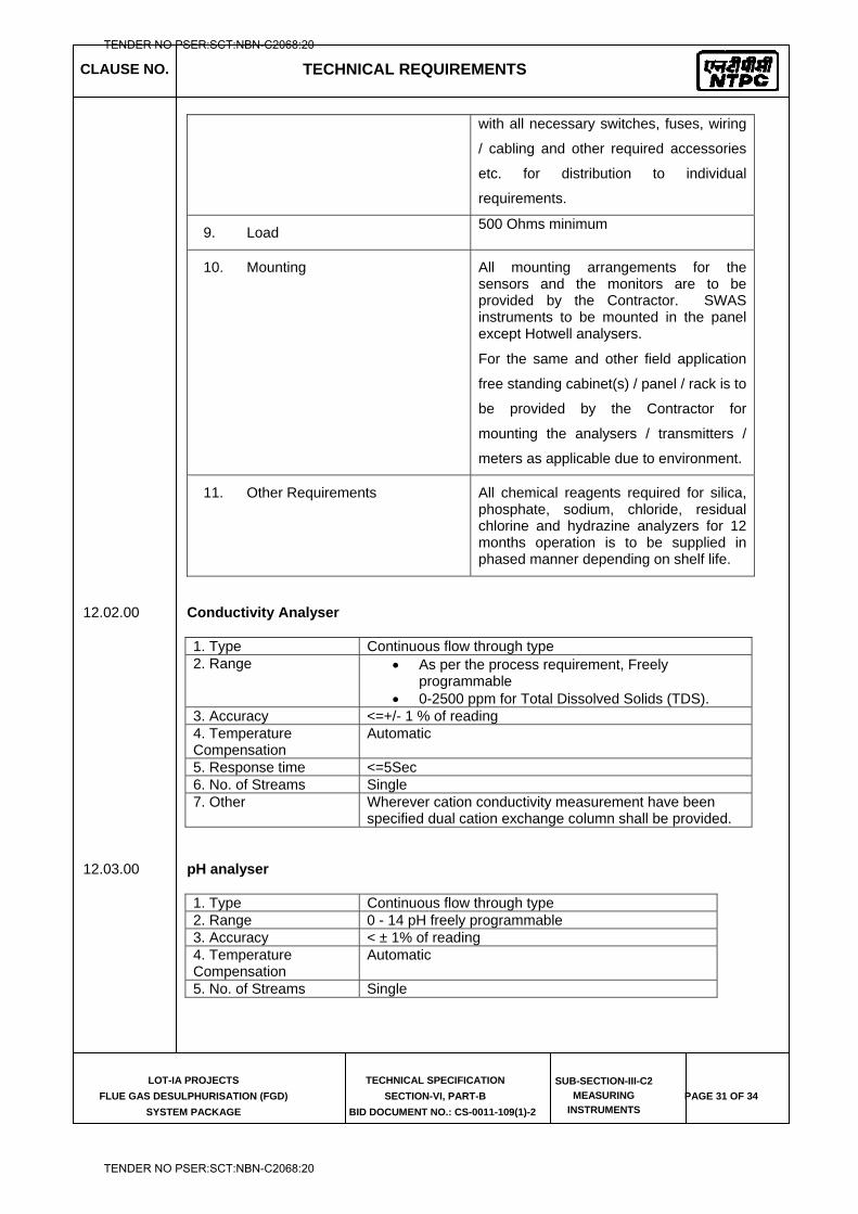
CLAUSE NO. TECHNICAL REQUIREMENTS
LOT-IA PROJECTS
FLUE GAS DESULPHURISATION (FGD)
SYSTEM PACKAGE
TECHNICAL SPECIFICATION
SECTION-VI, PART-B
BID DOCUMENT NO.: CS-0011-109(1)-2
SUB-SECTION-III-C2
MEASURING
INSTRUMENTS PAGE 31 OF 34
with all necessary switches, fuses, wiring
/ cabling and other required accessories
etc. for distribution to individual
requirements.
9. Load 500 Ohms minimum
10. Mounting All mounting arrangements for the sensors and the monitors are to be provided by the Contractor. SWAS instruments to be mounted in the panel except Hotwell analysers.
For the same and other field application
free standing cabinet(s) / panel / rack is to
be provided by the Contractor for
mounting the analysers / transmitters /
meters as applicable due to environment.
11. Other Requirements All chemical reagents required for silica, phosphate, sodium, chloride, residual chlorine and hydrazine analyzers for 12 months operation is to be supplied in phased manner depending on shelf life.
12.02.00 Conductivity Analyser 1. Type Continuous flow through type 2. Range
As per the process requirement, Freely programmable
0-2500 ppm for Total Dissolved Solids (TDS). 3. Accuracy <=+/- 1 % of reading 4. Temperature Compensation
Automatic
5. Response time <=5Sec 6. No. of Streams Single 7. Other Wherever cation conductivity measurement have been
specified dual cation exchange column shall be provided.
12.03.00 pH analyser
1. Type Continuous flow through type 2. Range 0 - 14 pH freely programmable 3. Accuracy < ± 1% of reading 4. Temperature Compensation
Automatic
5. No. of Streams Single
TENDER NO PSER:SCT:NBN-C2068:20
TENDER NO PSER:SCT:NBN-C2068:20
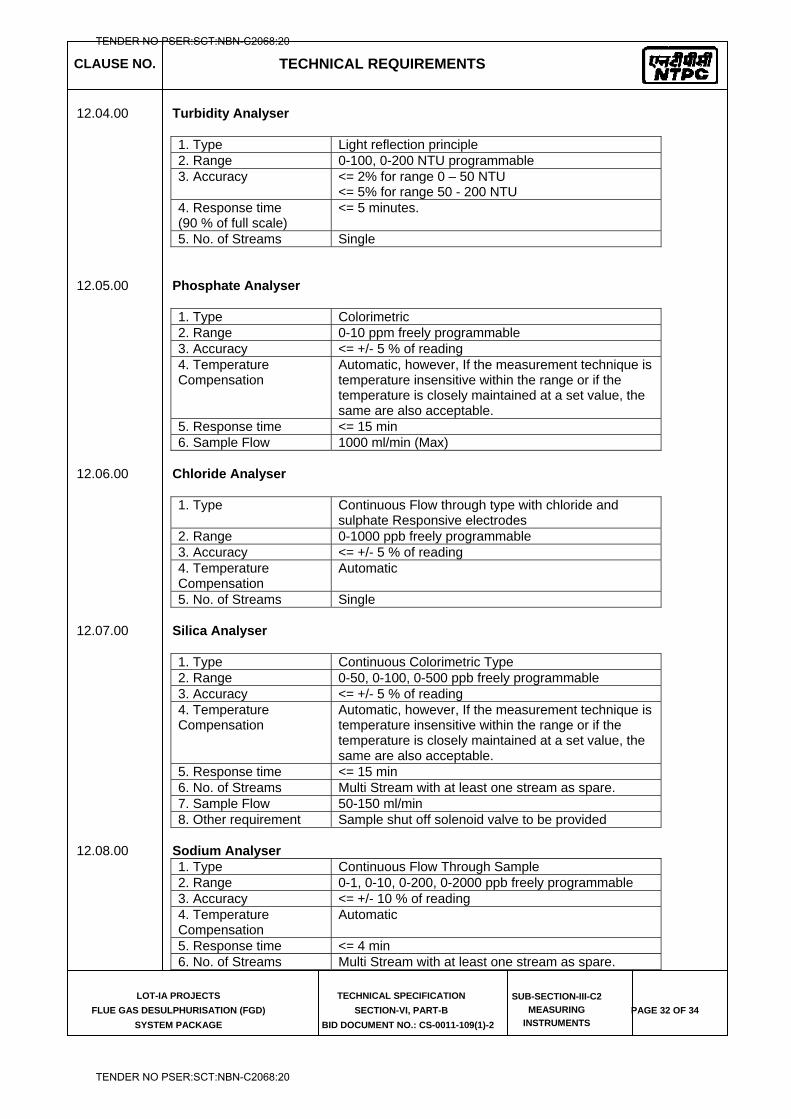
CLAUSE NO. TECHNICAL REQUIREMENTS
LOT-IA PROJECTS
FLUE GAS DESULPHURISATION (FGD)
SYSTEM PACKAGE
TECHNICAL SPECIFICATION
SECTION-VI, PART-B
BID DOCUMENT NO.: CS-0011-109(1)-2
SUB-SECTION-III-C2
MEASURING
INSTRUMENTS PAGE 32 OF 34
12.04.00 Turbidity Analyser
1. Type Light reflection principle 2. Range 0-100, 0-200 NTU programmable 3. Accuracy <= 2% for range 0 – 50 NTU
<= 5% for range 50 - 200 NTU 4. Response time (90 % of full scale)
<= 5 minutes.
5. No. of Streams Single 12.05.00 Phosphate Analyser
1. Type Colorimetric 2. Range 0-10 ppm freely programmable 3. Accuracy <= +/- 5 % of reading 4. Temperature Compensation
Automatic, however, If the measurement technique is temperature insensitive within the range or if the temperature is closely maintained at a set value, the same are also acceptable.
5. Response time <= 15 min 6. Sample Flow 1000 ml/min (Max)
12.06.00 Chloride Analyser
1. Type Continuous Flow through type with chloride and
sulphate Responsive electrodes 2. Range 0-1000 ppb freely programmable 3. Accuracy <= +/- 5 % of reading 4. Temperature Compensation
Automatic
5. No. of Streams Single
12.07.00 Silica Analyser 1. Type Continuous Colorimetric Type 2. Range 0-50, 0-100, 0-500 ppb freely programmable 3. Accuracy <= +/- 5 % of reading 4. Temperature Compensation
Automatic, however, If the measurement technique is temperature insensitive within the range or if the temperature is closely maintained at a set value, the same are also acceptable.
5. Response time <= 15 min 6. No. of Streams Multi Stream with at least one stream as spare. 7. Sample Flow 50-150 ml/min 8. Other requirement Sample shut off solenoid valve to be provided
12.08.00 Sodium Analyser
1. Type Continuous Flow Through Sample 2. Range 0-1, 0-10, 0-200, 0-2000 ppb freely programmable 3. Accuracy <= +/- 10 % of reading 4. Temperature Compensation
Automatic
5. Response time <= 4 min 6. No. of Streams Multi Stream with at least one stream as spare.
TENDER NO PSER:SCT:NBN-C2068:20
TENDER NO PSER:SCT:NBN-C2068:20
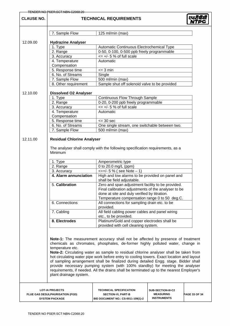
CLAUSE NO. TECHNICAL REQUIREMENTS
LOT-IA PROJECTS
FLUE GAS DESULPHURISATION (FGD)
SYSTEM PACKAGE
TECHNICAL SPECIFICATION
SECTION-VI, PART-B
BID DOCUMENT NO.: CS-0011-109(1)-2
SUB-SECTION-III-C2
MEASURING
INSTRUMENTS PAGE 33 OF 34
7. Sample Flow 125 ml/min (max)
12.09.00 Hydrazine Analyser 1. Type Automatic Continuous Electrochemical Type 2. Range 0-50, 0-100, 0-500 ppb freely programmable 3. Accuracy <= +/- 5 % of full scale 4. Temperature Compensation
Automatic
5. Response time <= 3 min 6. No. of Streams Single 7. Sample Flow 500 ml/min (max) 8. Other requirement Sample shut off solenoid valve to be provided
12.10.00 Dissolved O2 Analyser
1. Type Continuous Flow Through Sample 2. Range 0-20, 0-200 ppb freely programmable 3. Accuracy <= +/- 5 % of full scale 4. Temperature Compensation
Automatic
5. Response time <= 30 sec 6. No. of Streams One single stream, one switchable between two. 7. Sample Flow 500 ml/min (max)
12.11.00 Residual Chlorine Analyser
The analyser shall comply with the following specification requirements, as a Minimum 1. Type Amperometric type 2. Range 0 to 20.0 mg/L (ppm) 3. Accuracy <=+/- 5 % ( see Note – 1) 4. Alarm annunciation High and low alarms to be provided on panel and
shall be field adjustable. 5. Calibration Zero and span adjustment facility to be provided.
Final calibration adjustments of the analyser to be done at site and duly verified by titration. Temperature compensation range 0 to 50 deg.C.
6. Connections All connections for sampling drain etc. to be provided.
7. Cabling All field cabling power cables and panel wiring etc., to be provided.
8. Electrodes Platinum/Gold and copper electrodes shall be provided with cell cleaning system.
Note-1: The measurement accuracy shall not be affected by presence of treatment chemicals as chromates, phosphates, de-former highly polluted water, change in temperature etc. Note-2: Circulating water as sample to residual chlorine analyser shall be taken from hot circulating water pipe work before entry to cooling towers. Exact location and layout of sampling arrangement shall be finalized during detailed Engg. stage. Bidder shall provide necessary pumping system (with 100% standby) for meeting the analyser requirements, if needed. All the drains shall be terminated up to the nearest Employer's plant drainage system.
TENDER NO PSER:SCT:NBN-C2068:20
TENDER NO PSER:SCT:NBN-C2068:20
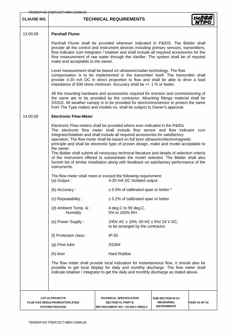
CLAUSE NO. TECHNICAL REQUIREMENTS
LOT-IA PROJECTS
FLUE GAS DESULPHURISATION (FGD)
SYSTEM PACKAGE
TECHNICAL SPECIFICATION
SECTION-VI, PART-B
BID DOCUMENT NO.: CS-0011-109(1)-2
SUB-SECTION-III-C2
MEASURING
INSTRUMENTS PAGE 34 OF 34
13.00.00 Parshall Flume
Parshall Flume shall be provided wherever indicated in P&IDS. The Bidder shall provide all the control and Instrument devices including primary sensors, transmitters, flow indicator cum integrator / totaliser and shall include all required accessories for the flow measurement of raw water through the clarifier. The system shall be of reputed make and acceptable to the owner. Level measurement shall be based on ultrasonic/radan technology. The flow compensation is to be implemented in the transmitter itself. The transmitter shall provide 4-20 mA DC in direct proportion to flow and shall be able to drive a load impedance of 500 ohms minimum. Accuracy shall be +/- 1 % or better.
All the mounting hardware and accessories required for erection and commissioning of the same are to be provided by the contractor. Mounting fittings material shall be SS316. All weather canopy is to be provided for electronics/sensor to protect the same from The Type makes and models no. shall be subject to Owner’s approval.
14.00.00 Electronic Flow-Meter
Electronic Flow-meters shall be provided where ever indicated in the P&IDs. The electronic flow meter shall include flow sensor and flow indicator cum integrator/totaliser and shall include all required accessories for satisfactory operation. The flow meter shall be based on full bore ultrasonic/electromagnetic principle and shall be electronic type of proven design, make and model acceptable to the owner. The Bidder shall submit all necessary technical literature and details of selection criteria of the instrument offered to substantiate the model selected. The Bidder shall also furnish list of similar installation along with feedback on satisfactory performance of the instruments. The flow meter shall meet or exceed the following requirement: (a) Output : 4-20 mA DC Isolated output (b) Accuracy : ± 0.5% of calibrated span or better * (c) Repeatability : ± 0.2% of calibrated span or better (d) Ambient Temp. & : 4 deg.C to 55 deg.C.
Humidity 5% to 100% RH (e) Power Supply : 240V AC ± 10%, 50 HZ ± 5%/ 24 V DC,
to be arranged by the contractor. (f) Protection class : IP-55 (g) Flow tube SS304 (h) liner Hard Rubber The flow meter shall provide local indication for instantaneous flow. It should also be possible to get local display for daily and monthly discharge. The flow meter shall indicate totaliser / integrator to get the daily and monthly discharge as stated above.
TENDER NO PSER:SCT:NBN-C2068:20
TENDER NO PSER:SCT:NBN-C2068:20

LOT-IA PROJECTS FLUE GAS DESULPHURISATION (FGD) SYSTEM PACKAGE
TECHNICAL SPECIFICATION
SECTION-VI
BID DOCUMENT NO.: CS-0011-109(1A)-2
SUB-SECTION-III-C3
PROCESS CONNECTION AND PIPING
TENDER NO PSER:SCT:NBN-C2068:20
TENDER NO PSER:SCT:NBN-C2068:20
CLAUSE NO.
TECHNICAL REQUIREMENTS
LOT-IA PROJECTS
FLUE GAS DESULPHURISATION (FGD) SYSTEM PACKAGE
TECHNICAL SPECIFICATION
SECTION-VI, PART-B
BID DOCUMENT NO.: CS-0011-109(1A)-2
SUB-SECTION-III-C3 PCP
PAGE
1 OF 4
PROCESS CONNECTION AND PIPING
1.00.00 PROCESS CONNECTION PIPING
1.01.00 The Contractor shall provide, install and test all required material for completeness of Impulse Piping System and Air Piping System as per the requirements of this Sub-Section on as required basis for the connection of all instruments and control equipments of entire plant.
1.01.01 IMPULSE PIPING, TUBING, FITTINGS, VALVES AND VALVE MANIFOLDS
1.01.02 All impulse pipes shall be of seamless type conforming to ANSI B36.10 for schedule numbers. The size of impulse pipe shall be ½” for Steam & Water Application and ¾” for Air & Flue Gas applications. The rating of material of impulse pipes, tubes, fittings, valves and their installation thereof shall conform to the latest edition of standards as per following table:
Impulse Pipes, Tubes (Material, Rating) ANSI B31.1, ANSI B31.1a, ANSI/ISA 77.70 Valves (Material, Pr. Class, Size) ASTM A182/ASTM A105 as per ASME 16.34 Fittings (Size, Rating, Material) ANSI B31.1, ANSI B31.1a, ASME B16.11-2009 Installation Schemes BS 6739-2009, ANSI/ISA 77.70
Stainless steel tube shall be provided inside enclosures & racks from tee connection to valve manifold and then to instrument. The source shut-off (primary process root valve) and blow down valve shall be of 1/2 inch size globe valve type for all applications except for air and flue gas service wherein no source shut-off valves are to be provided. Two root valves are to be used wherever pressure is more than 40 Kg/cm2 or Temp>280 oC. The end connections of valves shall be of socket welded type. Typical installation scheme of DP Transmitter (inside LIE/LIR) mounted below instrument source point is indicated in Drg. No. 0000-999-POI-A-036. Same scheme with necessary changes shall be applied for other instruments.
1.01.03 The valve manifolds of 316 SS with pressure rating suitable for intended application shall be provided as given below:
Manifold Application/Measurement 2 Valve Pressure measurements using pressure transmitters/pressure switches 3 Valve Pressure measurements using differential pressure transmitter/ switches 5 Valve Differential Pressure, Flow and Level Measurements
For Pr./D.P gauges, two-way globe/gate valve shall be provided on each impulse line to the instrument in Fluid/Air & Flue Gas applications respectively .
2.00.00 AIR SUPPLY PIPING
2.01.01 All pneumatic piping, fittings, valves, air filter cum regulator, purge rotameter and other accessories required for instrument air for the various pneumatic devices/ instruments shall be provided. This will include as a minimum air supply to pneumatically operated control valves, actuators, instruments, continuous and intermittent purging requirements etc.
2.02.00 Instrument air and Service air supply shall be provided for continuous and intermittent purging respectively for all transmitters of mill, dirty air and flue gas applications. Purging Scheme shall be as per Drg. No. 0000-999-POI-A-036.
2.03.00 The Contractor shall also provide SS Tubing and associated fittings (screwed type) of suitable sizes for all pneumatic equipments/actuators (including supply air, signal air and output to actuators) conforming to ANSI 31.1 and 31.3 standard. All other air supply lines shall be of mild steel hot dipped galvanized inside and outside as per IS-1239, heavy duty
TENDER NO PSER:SCT:NBN-C2068:20
TENDER NO PSER:SCT:NBN-C2068:20
CLAUSE NO.
TECHNICAL REQUIREMENTS
LOT-IA PROJECTS
FLUE GAS DESULPHURISATION (FGD) SYSTEM PACKAGE
TECHNICAL SPECIFICATION
SECTION-VI, PART-B
BID DOCUMENT NO.: CS-0011-109(1A)-2
SUB-SECTION-III-C3 PCP
PAGE
2 OF 4
with threaded ends. Fittings for air supply line shall be of forged carbon steel A234 Gr. WPB galvanized inside and outside, screwed as per ASA B2.1. Dimensions of fittings shall be as per ASA B16.11 of rating 3000 lbs. Air supply piping shall be adequately sloped to prevent accumulation of condensed water within the pipe. The air supply headers, sub-headers and branch pipes shall be supported properly by clamps or supports.
2.04.00 The instrument/service air supply to each equipment/devices requiring air supply shall be provided by a well designed air distribution scheme comprising of 2” GI Pipe Header feeding 1” GI Pipe sub-header feeding ½” pipe at each equipment/device. Instrument air filters cum regulator set with mounting accessories shall be provided for each pneumatic device requiring air supply except for Ash Handling System wherein it shall be provided on instrument air header at each location.
2.05.00 All the isolation valves in the air supply line shall be gate valves as per ASTM B62 inside screw rising stem, screwed female ends as per ASA B2.1. Valve bonnet shall be union type & trim material shall be stainless steel, body rating 150 pounds ASA. The valve sizes shall be ½ inch to 2 inch.
2.06.00 Instrument air filters cum regulator set with mounting accessories shall be provided for pneumatic device requiring air supply. The filter regulators shall be suitable for 10-kg/ sq.cm max. Inlet pressure. The filter shall be of size 5 microns and of material sintered bronze. The air set shall have 2-inch size pressure gauge and built in filter housing blowdown valve. The end connection shall be as per the requirement to be finalized during detailed engineering.
3.00.00 INSTALLATION AND ROUTING 3.01.01 All instrument piping, tubing and its accessories shall be supported in a safe manner to
prevent excessive vibrations and anchored sufficiently to prevent undue strain on connected equipment. Impulse piping shall be supported at an interval not exceeding 1.5 meters. The slope of the impulse pipe form the process connection to the instrument shall be as per ANSI/ISA 77.70 latest edition and BS 6739-2009. All impulse piping shall be installed to permit free movement due to thermal expansion. Wherever required expansion loops shall be provided.
Condensate pots shall be provided for all level measurements in steam and water services, all flow measurement in steam services and for flow measurements in water services above 120 Deg. C. Colour coding of all impulse pipes shall be done by the Contractor in line with the colour coding being followed for the parent pipes.
4.00.00 SHOP AND SITE TESTS
4.01.01 The equipment and work performed as per this Sub-section shall be subject to shop and site test as per requirements of Sub-section-IIIE-04 (Quality Assurance & Inspection) other applicable clauses of this Sub-section and Employer approved quality assurance plan.
4.01.02 Hydrostatic and Pneumatic leakage tests shall be performed on all pipes, tubing and systems and shall conform to ANSI B31.1.
5.00.00 LOCAL INSTRUMENT ENCLOSURE AND RACKS
All transmitters, switches etc. for FGD system and other system being provided under the contract shall be suitably grouped together and mounted inside (i) local instruments enclosures in case of open areas of the plant and (ii) In local instrument racks in case of covered areas. The GA of LIE with purging indicated in the Drg. No. 0000-999-POI-A-036 is to be followed by contractor. The GA of LIR shall be similar to LIE except for front/rear doors and side panels.
TENDER NO PSER:SCT:NBN-C2068:20
TENDER NO PSER:SCT:NBN-C2068:20
CLAUSE NO.
TECHNICAL REQUIREMENTS
LOT-IA PROJECTS
FLUE GAS DESULPHURISATION (FGD) SYSTEM PACKAGE
TECHNICAL SPECIFICATION
SECTION-VI, PART-B
BID DOCUMENT NO.: CS-0011-109(1A)-2
SUB-SECTION-III-C3 PCP
PAGE
3 OF 4
The internal layout shall be such that the impulse piping/ blow down lines are accessible from back side of the enclosure / rack and the transmitters etc. are accessible from front side for easy maintenance. Bulkheads, especially designed to provide isolation from process line vibration shall be installed on instrument enclosures/racks to meet the process sensing line connection requirement. Vibration dampeners shall be installed for each enclosure / rack. The Degree of Protection of LIE and JB of LIE/LIR shall be IP-55.
The enclosures shall be constructed of 3 mm sheet plate and shall be of modular construction with one or more modules and two end assemblies bolted together to form an enclosure. Double inter locking doors shall be provided. The doors shall be the three-point locking type constructed of not less than 1.6 mm thick steel. Doors shall have concealed quick removal type pinned hinges and locking handles. Door locks shall accept the same key.
The instrument racks shall be free standing type constructed of suitable 5 mm thick channel frame of steel and shall be provided with a canopy to protect the equipment mounted in racks from falling objects, water etc. The canopy shall not be less than 3 mm thick steel, and extended beyond the ends of the rack. Enclosures/Racks shall be reinforced as required to ensure true surface and to provide adequate support for instruments and equipment mounted therein. Centre posts or any member which would reduce access shall not be provided. Contractor shall provide not more than three variants for LIE/LIR with respect to max. no. transmitters mounted in each LIE/LIR.
5.01.00 ENCLOSURE / RACKS FOR DUAL I/P TEMPERATURE TRANSMITTERS
All Dual Input temperature transmitters for FGD system and other system being provided under the contract shall be suitably grouped together and mounted inside (i) Enclosures in case of open areas of the plant and (ii) Racks in case of covered areas. Integral JB shall be provided with each Enclosure and Rack. The internal layout shall be such that the transmitters are accessible from both front and back side of the enclosure / rack for easy maintenance. Enclosure/ Racks shall be of robust and rugged design. Vibration dampeners shall be installed for each enclosure / rack. The Degree of Protection of Enclosure and JB shall be IP-55. Enclosure and Racks shall be free standing type. Enclosures/Racks shall be reinforced as required to ensure true surface and to provide adequate support for instruments and equipment mounted therein. Contractor shall provide not more than five variants for Enclosure/ Rack with respect to max. no. transmitters mounted in each Enclosure/ Rack. However, the maximum number of Transmitters that can be grouped in one Enclosure/ Rack shall be decided during detail Engineering.
TENDER NO PSER:SCT:NBN-C2068:20
TENDER NO PSER:SCT:NBN-C2068:20
CLAUSE NO.
TECHNICAL REQUIREMENTS
LOT-IA PROJECTS
FLUE GAS DESULPHURISATION (FGD) SYSTEM PACKAGE
TECHNICAL SPECIFICATION
SECTION-VI, PART-B
BID DOCUMENT NO.: CS-0011-109(1A)-2
SUB-SECTION-III-C3 PCP
PAGE
4 OF 4
6.00.00 INSTALLATION OF OTHER INSTRUMENTS:
For installation and routing of other field mounted instruments which are not covered in Cl. No. 5.00.00, please refer Cl. No 52.04.00(J) of Section-VI, Part-D, Erection Conditions of Contract (ECC) of Technical Specifications.
TENDER NO PSER:SCT:NBN-C2068:20
TENDER NO PSER:SCT:NBN-C2068:20

LOT-IA PROJECTS FLUE GAS DESULPHURISATION (FGD) SYSTEM PACKAGE
TECHNICAL SPECIFICATION
SECTION-VI
BID DOCUMENT NO.: CS-0011-109(1A)-2
SUB-SECTION-III-C4
INSTRUMENTATION CABLES
TENDER NO PSER:SCT:NBN-C2068:20
TENDER NO PSER:SCT:NBN-C2068:20
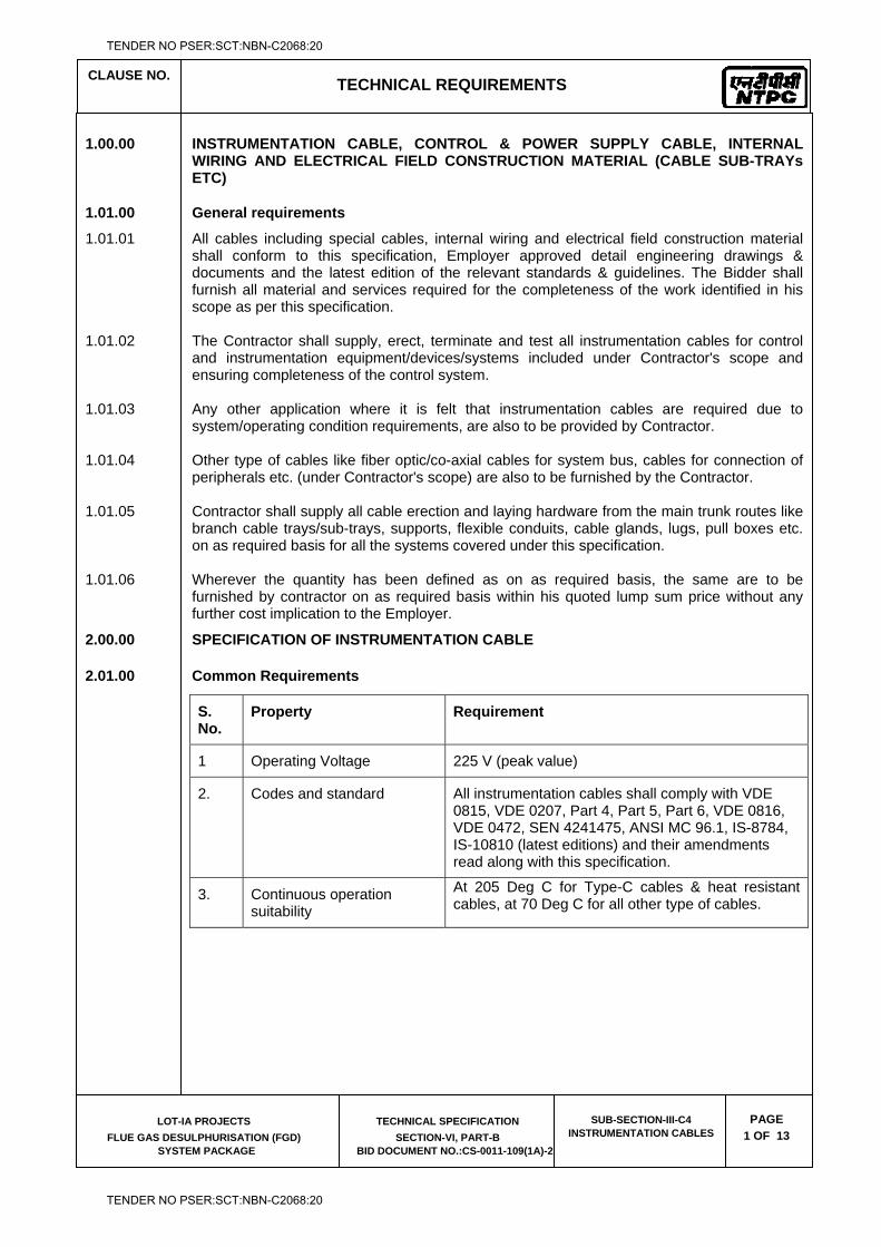
CLAUSE NO.
TECHNICAL REQUIREMENTS
LOT-IA PROJECTS
FLUE GAS DESULPHURISATION (FGD) SYSTEM PACKAGE
TECHNICAL SPECIFICATION
SECTION-VI, PART-B BID DOCUMENT NO.:CS-0011-109(1A)-2
SUB-SECTION-III-C4 INSTRUMENTATION CABLES
PAGE
1 OF 13
1.00.00 INSTRUMENTATION CABLE, CONTROL & POWER SUPPLY CABLE, INTERNAL WIRING AND ELECTRICAL FIELD CONSTRUCTION MATERIAL (CABLE SUB-TRAYs ETC)
1.01.00 General requirements
1.01.01 All cables including special cables, internal wiring and electrical field construction material shall conform to this specification, Employer approved detail engineering drawings & documents and the latest edition of the relevant standards & guidelines. The Bidder shall furnish all material and services required for the completeness of the work identified in his scope as per this specification.
1.01.02 The Contractor shall supply, erect, terminate and test all instrumentation cables for control and instrumentation equipment/devices/systems included under Contractor's scope and ensuring completeness of the control system.
1.01.03 Any other application where it is felt that instrumentation cables are required due to system/operating condition requirements, are also to be provided by Contractor.
1.01.04 Other type of cables like fiber optic/co-axial cables for system bus, cables for connection of peripherals etc. (under Contractor's scope) are also to be furnished by the Contractor.
1.01.05 Contractor shall supply all cable erection and laying hardware from the main trunk routes like branch cable trays/sub-trays, supports, flexible conduits, cable glands, lugs, pull boxes etc. on as required basis for all the systems covered under this specification.
1.01.06 Wherever the quantity has been defined as on as required basis, the same are to be furnished by contractor on as required basis within his quoted lump sum price without any further cost implication to the Employer.
2.00.00 SPECIFICATION OF INSTRUMENTATION CABLE
2.01.00 Common Requirements
S. No.
Property Requirement
1 Operating Voltage 225 V (peak value)
2. Codes and standard All instrumentation cables shall comply with VDE 0815, VDE 0207, Part 4, Part 5, Part 6, VDE 0816, VDE 0472, SEN 4241475, ANSI MC 96.1, IS-8784, IS-10810 (latest editions) and their amendments read along with this specification.
3. Continuous operation suitability
At 205 Deg C for Type-C cables & heat resistant cables, at 70 Deg C for all other type of cables.
TENDER NO PSER:SCT:NBN-C2068:20
TENDER NO PSER:SCT:NBN-C2068:20
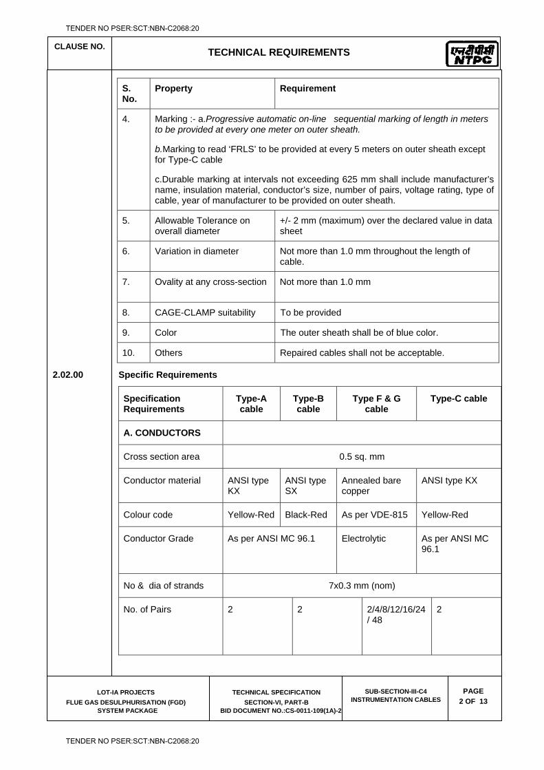
CLAUSE NO.
TECHNICAL REQUIREMENTS
LOT-IA PROJECTS
FLUE GAS DESULPHURISATION (FGD) SYSTEM PACKAGE
TECHNICAL SPECIFICATION
SECTION-VI, PART-B BID DOCUMENT NO.:CS-0011-109(1A)-2
SUB-SECTION-III-C4 INSTRUMENTATION CABLES
PAGE
2 OF 13
S. No.
Property Requirement
4. Marking :- a.Progressive automatic on-line sequential marking of length in meters to be provided at every one meter on outer sheath.
b.Marking to read ‘FRLS’ to be provided at every 5 meters on outer sheath except for Type-C cable
c.Durable marking at intervals not exceeding 625 mm shall include manufacturer’s name, insulation material, conductor’s size, number of pairs, voltage rating, type of cable, year of manufacturer to be provided on outer sheath.
5. Allowable Tolerance on overall diameter
+/- 2 mm (maximum) over the declared value in data sheet
6. Variation in diameter Not more than 1.0 mm throughout the length of cable.
7. Ovality at any cross-section Not more than 1.0 mm
8. CAGE-CLAMP suitability To be provided
9. Color The outer sheath shall be of blue color.
10. Others Repaired cables shall not be acceptable.
2.02.00 Specific Requirements
Specification Requirements
Type-A cable
Type-B cable
Type F & G cable
Type-C cable
A. CONDUCTORS
Cross section area 0.5 sq. mm
Conductor material ANSI type KX
ANSI type SX
Annealed bare copper
ANSI type KX
Colour code Yellow-Red Black-Red As per VDE-815 Yellow-Red
Conductor Grade As per ANSI MC 96.1
Electrolytic As per ANSI MC 96.1
No & dia of strands 7x0.3 mm (nom)
No. of Pairs 2 2 2/4/8/12/16/24/ 48
2
TENDER NO PSER:SCT:NBN-C2068:20
TENDER NO PSER:SCT:NBN-C2068:20
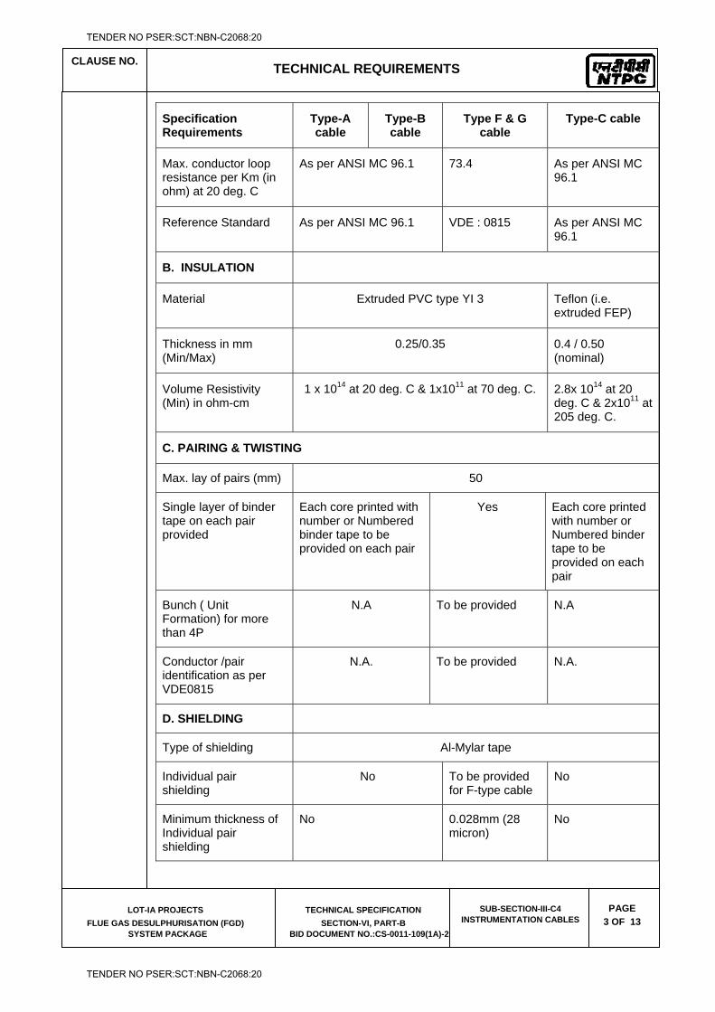
CLAUSE NO.
TECHNICAL REQUIREMENTS
LOT-IA PROJECTS
FLUE GAS DESULPHURISATION (FGD) SYSTEM PACKAGE
TECHNICAL SPECIFICATION
SECTION-VI, PART-B BID DOCUMENT NO.:CS-0011-109(1A)-2
SUB-SECTION-III-C4 INSTRUMENTATION CABLES
PAGE
3 OF 13
Specification Requirements
Type-A cable
Type-B cable
Type F & G cable
Type-C cable
Max. conductor loop resistance per Km (in ohm) at 20 deg. C
As per ANSI MC 96.1 73.4 As per ANSI MC 96.1
Reference Standard As per ANSI MC 96.1 VDE : 0815 As per ANSI MC 96.1
B. INSULATION
Material Extruded PVC type YI 3 Teflon (i.e. extruded FEP)
Thickness in mm (Min/Max)
0.25/0.35 0.4 / 0.50 (nominal)
Volume Resistivity (Min) in ohm-cm
1 x 10¹⁴ at 20 deg. C & 1x10¹¹ at 70 deg. C. 2.8x 10¹⁴ at 20 deg. C & 2x10¹¹ at 205 deg. C.
C. PAIRING & TWISTING
Max. lay of pairs (mm) 50
Single layer of binder tape on each pair provided
Each core printed with number or Numbered binder tape to be provided on each pair
Yes Each core printed with number or Numbered binder tape to be provided on each pair
Bunch ( Unit Formation) for more than 4P
N.A To be provided N.A
Conductor /pair identification as per VDE0815
N.A.
To be provided N.A.
D. SHIELDING
Type of shielding Al-Mylar tape
Individual pair shielding
No To be provided for F-type cable
No
Minimum thickness of Individual pair shielding
No 0.028mm (28 micron)
No
TENDER NO PSER:SCT:NBN-C2068:20
TENDER NO PSER:SCT:NBN-C2068:20
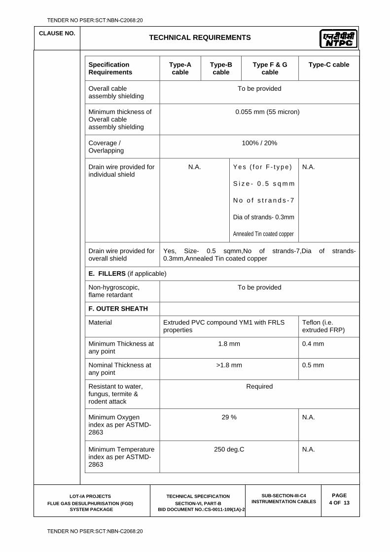
CLAUSE NO.
TECHNICAL REQUIREMENTS
LOT-IA PROJECTS
FLUE GAS DESULPHURISATION (FGD) SYSTEM PACKAGE
TECHNICAL SPECIFICATION
SECTION-VI, PART-B BID DOCUMENT NO.:CS-0011-109(1A)-2
SUB-SECTION-III-C4 INSTRUMENTATION CABLES
PAGE
4 OF 13
Specification Requirements
Type-A cable
Type-B cable
Type F & G cable
Type-C cable
Overall cable assembly shielding
To be provided
Minimum thickness of Overall cable assembly shielding
0.055 mm (55 micron)
Coverage / Overlapping
100% / 20%
Drain wire provided for individual shield
N.A.
Y e s ( f o r F - t y p e )
S i z e - 0 . 5 s q m m
N o o f s t r a n d s - 7
Dia of strands- 0.3mm
Annealed Tin coated copper
N.A.
Drain wire provided for overall shield
Yes, Size- 0.5 sqmm,No of strands-7,Dia of strands- 0.3mm,Annealed Tin coated copper
E. FILLERS (if applicable)
Non-hygroscopic, flame retardant
To be provided
F. OUTER SHEATH
Material Extruded PVC compound YM1 with FRLS properties
Teflon (i.e. extruded FRP)
Minimum Thickness at any point
1.8 mm 0.4 mm
Nominal Thickness at any point
>1.8 mm 0.5 mm
Resistant to water, fungus, termite & rodent attack
Required
Minimum Oxygen index as per ASTMD-2863
29 % N.A.
Minimum Temperature index as per ASTMD-2863
250 deg.C N.A.
TENDER NO PSER:SCT:NBN-C2068:20
TENDER NO PSER:SCT:NBN-C2068:20
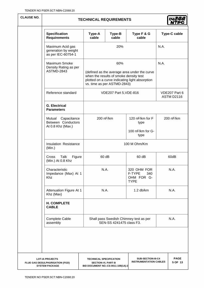
CLAUSE NO.
TECHNICAL REQUIREMENTS
LOT-IA PROJECTS
FLUE GAS DESULPHURISATION (FGD) SYSTEM PACKAGE
TECHNICAL SPECIFICATION
SECTION-VI, PART-B BID DOCUMENT NO.:CS-0011-109(1A)-2
SUB-SECTION-III-C4 INSTRUMENTATION CABLES
PAGE
5 OF 13
Specification Requirements
Type-A cable
Type-B cable
Type F & G cable
Type-C cable
Maximum Acid gas generation by weight as per IEC-60754-1
20% N.A.
Maximum Smoke Density Rating as per ASTMD-2843
60%
(defined as the average area under the curve when the results of smoke density test plotted on a curve indicating light absorption vs. time as per ASTMD-2843)
N.A.
Reference standard VDE207 Part 5,VDE-816 VDE207 Part 6 ASTM D2116
G. Electrical Parameters
Mutual Capacitance Between Conductors At 0.8 Khz (Max.)
200 nF/km 120 nF/km for F type
100 nF/km for G-type
200 nF/km
Insulation Resistance (Min.)
100 M Ohm/Km
Cross Talk Figure (Min.) At 0.8 Khz
60 dB 60 dB 60dB
Characteristic Impedance (Max) At 1 Khz
N.A. 320 OHM FOR F-TYPE 340 OHM FOR G-TYPE
N.A.
Attenuation Figure At 1 Khz (Max)
N.A. 1.2 db/km N.A.
H. COMPLETE CABLE
Complete Cable assembly
Shall pass Swedish Chimney test as per SEN-SS 4241475 class F3.
N.A.
TENDER NO PSER:SCT:NBN-C2068:20
TENDER NO PSER:SCT:NBN-C2068:20
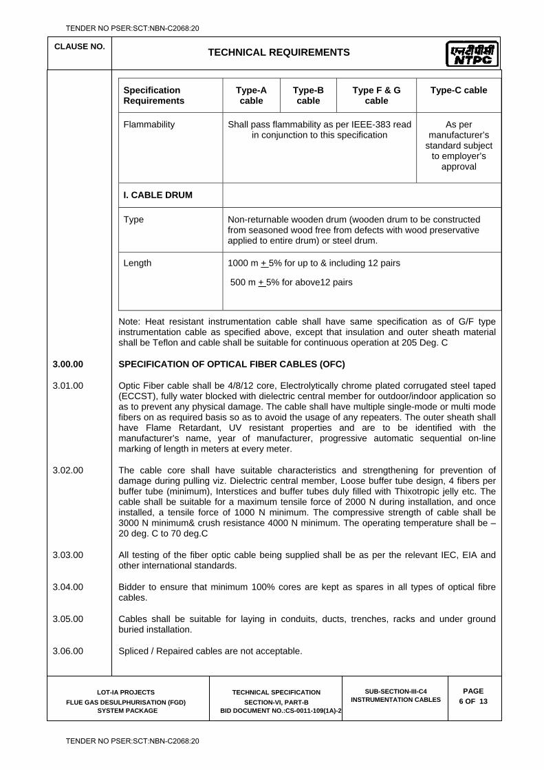
CLAUSE NO.
TECHNICAL REQUIREMENTS
LOT-IA PROJECTS
FLUE GAS DESULPHURISATION (FGD) SYSTEM PACKAGE
TECHNICAL SPECIFICATION
SECTION-VI, PART-B BID DOCUMENT NO.:CS-0011-109(1A)-2
SUB-SECTION-III-C4 INSTRUMENTATION CABLES
PAGE
6 OF 13
Specification Requirements
Type-A cable
Type-B cable
Type F & G cable
Type-C cable
Flammability Shall pass flammability as per IEEE-383 read in conjunction to this specification
As per manufacturer’s
standard subject to employer’s
approval
I. CABLE DRUM
Type Non-returnable wooden drum (wooden drum to be constructed from seasoned wood free from defects with wood preservative applied to entire drum) or steel drum.
Length 1000 m + 5% for up to & including 12 pairs
500 m + 5% for above12 pairs
Note: Heat resistant instrumentation cable shall have same specification as of G/F type instrumentation cable as specified above, except that insulation and outer sheath material shall be Teflon and cable shall be suitable for continuous operation at 205 Deg. C
3.00.00 SPECIFICATION OF OPTICAL FIBER CABLES (OFC)
3.01.00 Optic Fiber cable shall be 4/8/12 core, Electrolytically chrome plated corrugated steel taped (ECCST), fully water blocked with dielectric central member for outdoor/indoor application so as to prevent any physical damage. The cable shall have multiple single-mode or multi mode fibers on as required basis so as to avoid the usage of any repeaters. The outer sheath shall have Flame Retardant, UV resistant properties and are to be identified with the manufacturer’s name, year of manufacturer, progressive automatic sequential on-line marking of length in meters at every meter.
3.02.00 The cable core shall have suitable characteristics and strengthening for prevention of damage during pulling viz. Dielectric central member, Loose buffer tube design, 4 fibers per buffer tube (minimum), Interstices and buffer tubes duly filled with Thixotropic jelly etc. The cable shall be suitable for a maximum tensile force of 2000 N during installation, and once installed, a tensile force of 1000 N minimum. The compressive strength of cable shall be 3000 N minimum& crush resistance 4000 N minimum. The operating temperature shall be –20 deg. C to 70 deg.C
3.03.00 All testing of the fiber optic cable being supplied shall be as per the relevant IEC, EIA and other international standards.
3.04.00 Bidder to ensure that minimum 100% cores are kept as spares in all types of optical fibre cables.
3.05.00 Cables shall be suitable for laying in conduits, ducts, trenches, racks and under ground buried installation.
3.06.00 Spliced / Repaired cables are not acceptable.
TENDER NO PSER:SCT:NBN-C2068:20
TENDER NO PSER:SCT:NBN-C2068:20
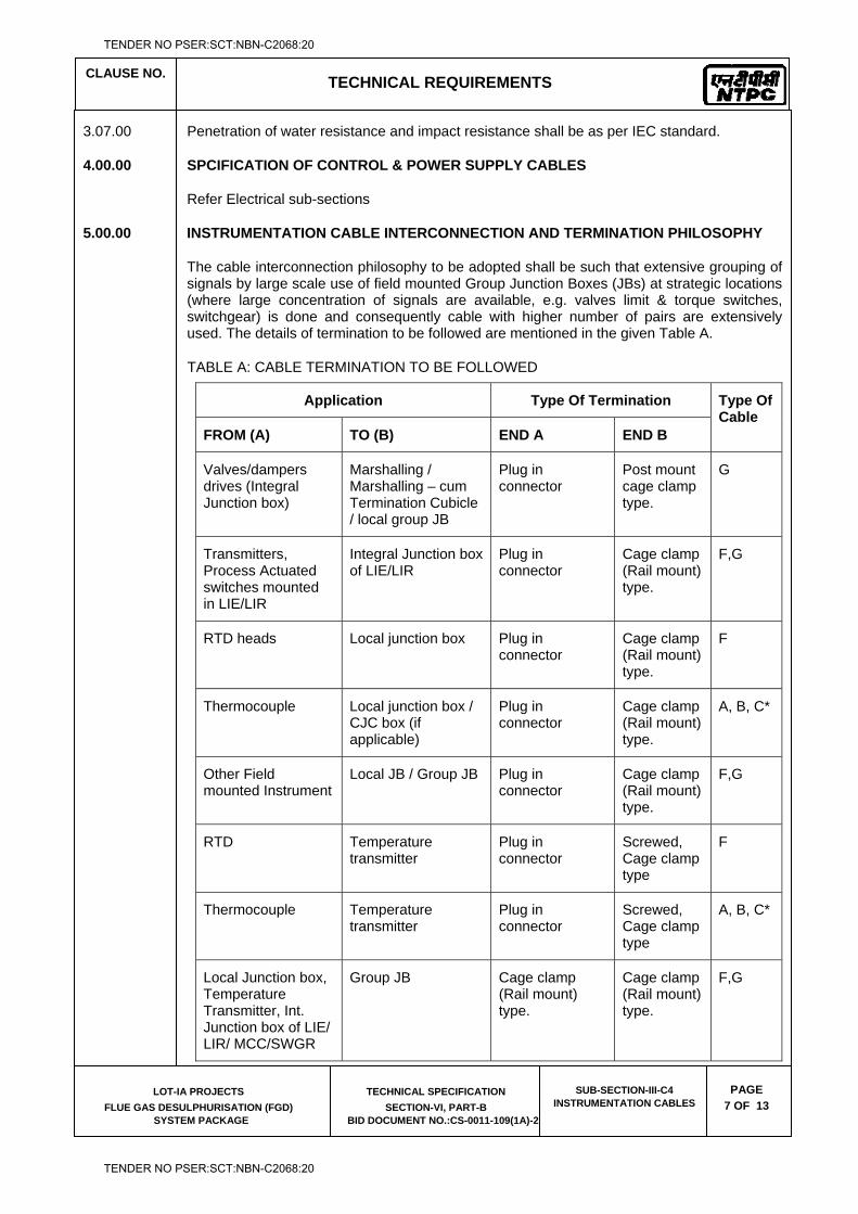
CLAUSE NO.
TECHNICAL REQUIREMENTS
LOT-IA PROJECTS
FLUE GAS DESULPHURISATION (FGD) SYSTEM PACKAGE
TECHNICAL SPECIFICATION
SECTION-VI, PART-B BID DOCUMENT NO.:CS-0011-109(1A)-2
SUB-SECTION-III-C4 INSTRUMENTATION CABLES
PAGE
7 OF 13
3.07.00 Penetration of water resistance and impact resistance shall be as per IEC standard.
4.00.00 SPCIFICATION OF CONTROL & POWER SUPPLY CABLES
Refer Electrical sub-sections
5.00.00 INSTRUMENTATION CABLE INTERCONNECTION AND TERMINATION PHILOSOPHY
The cable interconnection philosophy to be adopted shall be such that extensive grouping of signals by large scale use of field mounted Group Junction Boxes (JBs) at strategic locations (where large concentration of signals are available, e.g. valves limit & torque switches, switchgear) is done and consequently cable with higher number of pairs are extensively used. The details of termination to be followed are mentioned in the given Table A.
TABLE A: CABLE TERMINATION TO BE FOLLOWED
Application Type Of Termination Type Of Cable
FROM (A) TO (B) END A END B
Valves/dampers drives (Integral Junction box)
Marshalling / Marshalling – cum Termination Cubicle / local group JB
Plug in connector
Post mount cage clamp type.
G
Transmitters, Process Actuated switches mounted in LIE/LIR
Integral Junction box of LIE/LIR
Plug in connector
Cage clamp (Rail mount) type.
F,G
RTD heads Local junction box Plug in connector
Cage clamp (Rail mount) type.
F
Thermocouple Local junction box / CJC box (if applicable)
Plug in connector
Cage clamp (Rail mount) type.
A, B, C*
Other Field mounted Instrument
Local JB / Group JB Plug in connector
Cage clamp (Rail mount) type.
F,G
RTD Temperature transmitter
Plug in connector
Screwed, Cage clamp type
F
Thermocouple Temperature transmitter
Plug in connector
Screwed, Cage clamp type
A, B, C*
Local Junction box, Temperature Transmitter, Int. Junction box of LIE/ LIR/ MCC/SWGR
Group JB Cage clamp (Rail mount) type.
Cage clamp (Rail mount) type.
F,G
TENDER NO PSER:SCT:NBN-C2068:20
TENDER NO PSER:SCT:NBN-C2068:20
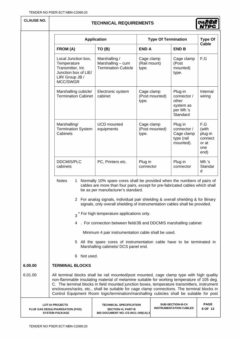
CLAUSE NO.
TECHNICAL REQUIREMENTS
LOT-IA PROJECTS
FLUE GAS DESULPHURISATION (FGD) SYSTEM PACKAGE
TECHNICAL SPECIFICATION
SECTION-VI, PART-B BID DOCUMENT NO.:CS-0011-109(1A)-2
SUB-SECTION-III-C4 INSTRUMENTATION CABLES
PAGE
8 OF 13
Application Type Of Termination Type Of Cable
FROM (A) TO (B) END A END B
Local Junction box, Temperature Transmitter, Int. Junction box of LIE/ LIR/ Group JB / MCC/SWGR
Marshalling / Marshalling – cum Termination Cubicle
Cage clamp (Rail mount) type.
Cage clamp (Post mounted) type.
F,G
Marshalling cubicle/ Termination Cabinet
Electronic system cabinet
Cage clamp (Post mounted) type.
Plug-in connector / other system as per Mfr.’s Standard
Internal wiring
Marshalling/ Termination System Cabinets
UCD mounted equipments
Cage clamp (Post mounted) type.
Plug in connector / Cage clamp type (rail mounted).
F,G (with plug-in connector at one end)
DDCMIS/PLC cabinets
PC, Printers etc. Plug in connector
Plug in connector
Mfr.’s Standard
Notes 1 Normally 10% spare cores shall be provided when the numbers of pairs of cables are more than four pairs, except for pre-fabricated cables which shall be as per manufacturer’s standard.
2
3
For analog signals, individual pair shielding & overall shielding & for Binary signals, only overall shielding of instrumentation cables shall be provided.
* For high temperature applications only.
4 . For connection between field/JB and DDCMIS marshalling cabinet
Minimum 4 pair instrumentation cable shall be used.
5 All the spare cores of instrumentation cable have to be terminated in Marshalling cabinets/ DCS panel end.
6 Not used.
6.00.00 TERMINAL BLOCKS
6.01.00 All terminal blocks shall be rail mounted/post mounted, cage clamp type with high quality non-flammable insulating material of melamine suitable for working temperature of 105 deg. C. The terminal blocks in field mounted junction boxes, temperature transmitters, instrument enclosures/racks, etc., shall be suitable for cage clamp connections. The terminal blocks in Control Equipment Room logic/termination/marshalling cubicles shall be suitable for post
TENDER NO PSER:SCT:NBN-C2068:20
TENDER NO PSER:SCT:NBN-C2068:20
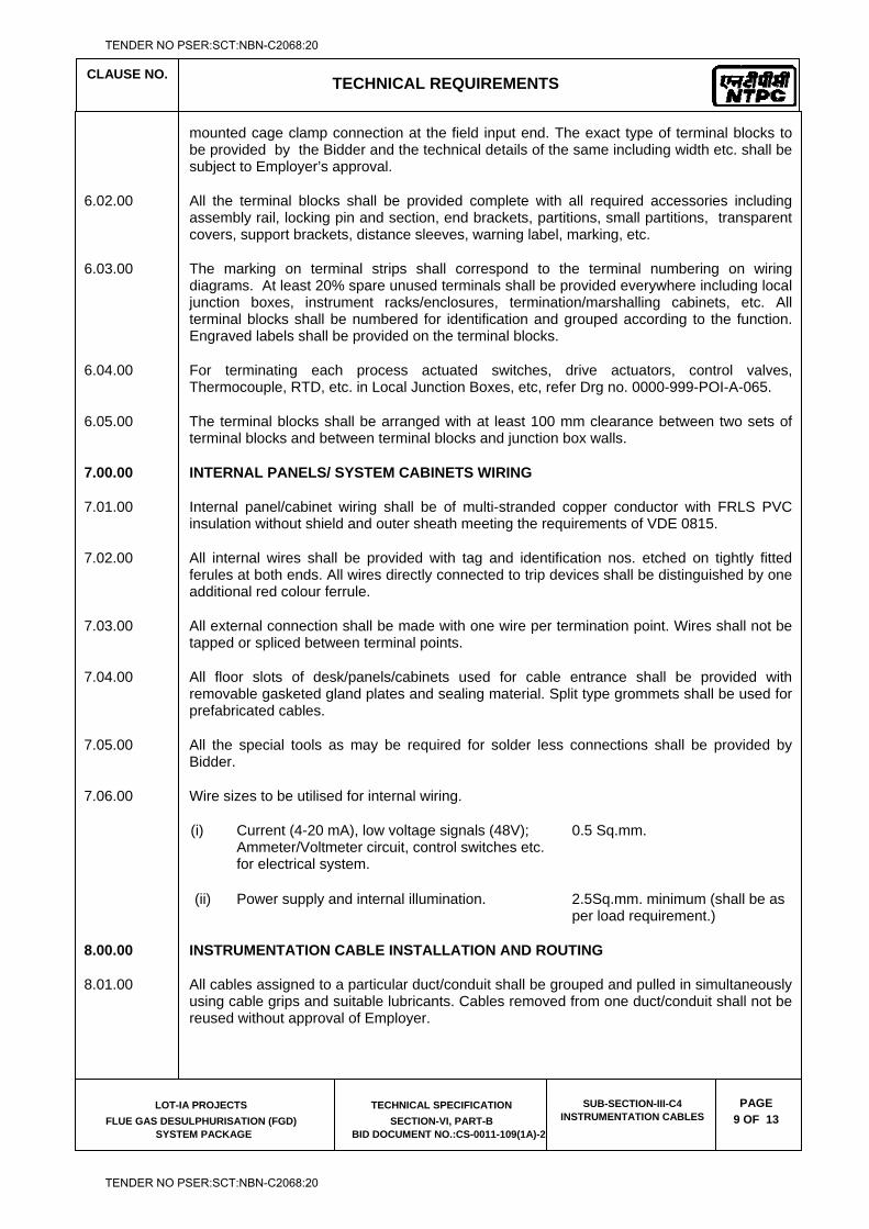
CLAUSE NO.
TECHNICAL REQUIREMENTS
LOT-IA PROJECTS
FLUE GAS DESULPHURISATION (FGD) SYSTEM PACKAGE
TECHNICAL SPECIFICATION
SECTION-VI, PART-B BID DOCUMENT NO.:CS-0011-109(1A)-2
SUB-SECTION-III-C4 INSTRUMENTATION CABLES
PAGE
9 OF 13
mounted cage clamp connection at the field input end. The exact type of terminal blocks to be provided by the Bidder and the technical details of the same including width etc. shall be subject to Employer’s approval.
6.02.00 All the terminal blocks shall be provided complete with all required accessories including assembly rail, locking pin and section, end brackets, partitions, small partitions, transparent covers, support brackets, distance sleeves, warning label, marking, etc.
6.03.00 The marking on terminal strips shall correspond to the terminal numbering on wiring diagrams. At least 20% spare unused terminals shall be provided everywhere including local junction boxes, instrument racks/enclosures, termination/marshalling cabinets, etc. All terminal blocks shall be numbered for identification and grouped according to the function. Engraved labels shall be provided on the terminal blocks.
6.04.00 For terminating each process actuated switches, drive actuators, control valves, Thermocouple, RTD, etc. in Local Junction Boxes, etc, refer Drg no. 0000-999-POI-A-065.
6.05.00 The terminal blocks shall be arranged with at least 100 mm clearance between two sets of terminal blocks and between terminal blocks and junction box walls.
7.00.00 INTERNAL PANELS/ SYSTEM CABINETS WIRING
7.01.00 Internal panel/cabinet wiring shall be of multi-stranded copper conductor with FRLS PVC insulation without shield and outer sheath meeting the requirements of VDE 0815.
7.02.00 All internal wires shall be provided with tag and identification nos. etched on tightly fitted ferules at both ends. All wires directly connected to trip devices shall be distinguished by one additional red colour ferrule.
7.03.00 All external connection shall be made with one wire per termination point. Wires shall not be tapped or spliced between terminal points.
7.04.00 All floor slots of desk/panels/cabinets used for cable entrance shall be provided with removable gasketed gland plates and sealing material. Split type grommets shall be used for prefabricated cables.
7.05.00 All the special tools as may be required for solder less connections shall be provided by Bidder.
7.06.00 Wire sizes to be utilised for internal wiring.
(i) Current (4-20 mA), low voltage signals (48V); Ammeter/Voltmeter circuit, control switches etc. for electrical system.
0.5 Sq.mm.
(ii) Power supply and internal illumination. 2.5Sq.mm. minimum (shall be as per load requirement.)
8.00.00 INSTRUMENTATION CABLE INSTALLATION AND ROUTING
8.01.00 All cables assigned to a particular duct/conduit shall be grouped and pulled in simultaneously using cable grips and suitable lubricants. Cables removed from one duct/conduit shall not be reused without approval of Employer.
TENDER NO PSER:SCT:NBN-C2068:20
TENDER NO PSER:SCT:NBN-C2068:20
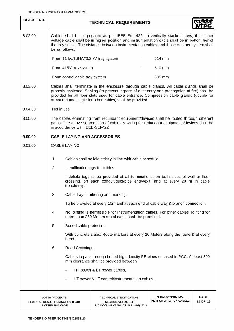
CLAUSE NO.
TECHNICAL REQUIREMENTS
LOT-IA PROJECTS
FLUE GAS DESULPHURISATION (FGD) SYSTEM PACKAGE
TECHNICAL SPECIFICATION
SECTION-VI, PART-B BID DOCUMENT NO.:CS-0011-109(1A)-2
SUB-SECTION-III-C4 INSTRUMENTATION CABLES
PAGE
10 OF 13
8.02.00 Cables shall be segregated as per IEEE Std.-422. In vertically stacked trays, the higher voltage cable shall be in higher position and instrumentation cable shall be in bottom tier of the tray stack. The distance between instrumentation cables and those of other system shall be as follows:
From 11 kV/6.6 kV/3.3 kV tray system - 914 mm
From 415V tray system - 610 mm
From control cable tray system - 305 mm
8.03.00 Cables shall terminate in the enclosure through cable glands. All cable glands shall be properly gasketed. Sealing (to prevent ingress of dust entry and propagation of fire) shall be provided for all floor slots used for cable entrance. Compression cable glands (double for armoured and single for other cables) shall be provided.
8.04.00 Not in use
8.05.00 The cables emanating from redundant equipment/devices shall be routed through different paths. The above segregation of cables & wiring for redundant equipments/devices shall be in accordance with IEEE-Std-422.
9.00.00 CABLE LAYING AND ACCESSORIES
9.01.00 CABLE LAYING
1 Cables shall be laid strictly in line with cable schedule.
2 Identification tags for cables.
Indelible tags to be provided at all terminations, on both sides of wall or floor crossing, on each conduit/duct/pipe entry/exit, and at every 20 m in cable trench/tray.
3 Cable tray numbering and marking.
To be provided at every 10m and at each end of cable way & branch connection.
4 No jointing is permissible for Instrumentation cables. For other cables Jointing for more than 250 Meters run of cable shall be permitted.
5 Buried cable protection
With concrete slabs; Route markers at every 20 Meters along the route & at every bend.
6 Road Crossings
Cables to pass through buried high density PE pipes encased in PCC. At least 300 mm clearance shall be provided between
- HT power & LT power cables,
- LT power & LT control/instrumentation cables,
TENDER NO PSER:SCT:NBN-C2068:20
TENDER NO PSER:SCT:NBN-C2068:20
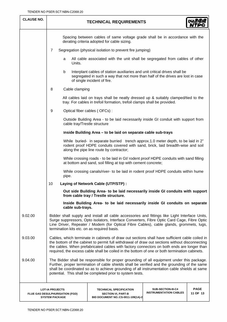
CLAUSE NO.
TECHNICAL REQUIREMENTS
LOT-IA PROJECTS
FLUE GAS DESULPHURISATION (FGD) SYSTEM PACKAGE
TECHNICAL SPECIFICATION
SECTION-VI, PART-B BID DOCUMENT NO.:CS-0011-109(1A)-2
SUB-SECTION-III-C4 INSTRUMENTATION CABLES
PAGE
11 OF 13
Spacing between cables of same voltage grade shall be in accordance with the derating criteria adopted for cable sizing.
7 Segregation (physical isolation to prevent fire jumping)
a All cable associated with the unit shall be segregated from cables of other Units.
b Interplant cables of station auxiliaries and unit critical drives shall be segregated in such a way that not more than half of the drives are lost in case of single incident of fire.
8 Cable clamping
All cables laid on trays shall be neatly dressed up & suitably clamped/tied to the tray. For cables in trefoil formation, trefoil clamps shall be provided.
9 Optical fiber cables ( OFCs) :
Outside Building Area - to be laid necessarily inside GI conduit with support from cable tray/Trestle structure
Inside Building Area – to be laid on separate cable sub-trays
While buried- in separate burried trench approx.1.0 meter depth, to be laid in 2” rodent proof HDPE conduits covered with sand, brick, laid breadth-wise and soil along the pipe line route by contractor;
While crossing roads - to be laid in GI/ rodent proof HDPE conduits with sand filling at bottom and sand, soil filling at top with cement concrete;
While crossing canals/river- to be laid in rodent proof HDPE conduits within hume pipe.
10 Laying of Network Cable (UTP/STP) :
Out side Building Area- to be laid necessarily inside GI conduits with support from cable tray / Trestle structure.
Inside Building Area- to be laid necessarily inside GI conduits on separate cable sub-trays.
9.02.00 Bidder shall supply and install all cable accessories and fittings like Light Interface Units, Surge suppressors, Opto isolators, Interface Converters, Fibre Optic Card Cage, Fibre Optic Line Driver, Repeater / Modem (for Optical Fibre Cables), cable glands, grommets, lugs, termination kits etc. on as required basis.
9.03.00 Cables, which terminate in cabinets of draw out sections shall have sufficient cable coiled in the bottom of the cabinet to permit full withdrawal of draw out sections without disconnecting the cables. When prefabricated cables with factory connectors on both ends are longer than required, the excess cable shall be coiled in the bottom of one or both termination cabinets.
9.04.00 The Bidder shall be responsible for proper grounding of all equipment under this package. Further, proper termination of cable shields shall be verified and the grounding of the same shall be coordinated so as to achieve grounding of all instrumentation cable shields at same potential. This shall be completed prior to system tests.
TENDER NO PSER:SCT:NBN-C2068:20
TENDER NO PSER:SCT:NBN-C2068:20
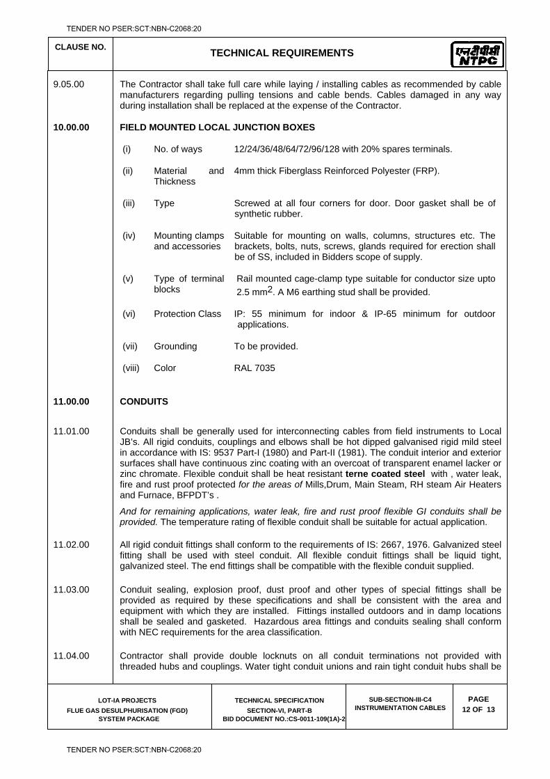
CLAUSE NO.
TECHNICAL REQUIREMENTS
LOT-IA PROJECTS
FLUE GAS DESULPHURISATION (FGD) SYSTEM PACKAGE
TECHNICAL SPECIFICATION
SECTION-VI, PART-B BID DOCUMENT NO.:CS-0011-109(1A)-2
SUB-SECTION-III-C4 INSTRUMENTATION CABLES
PAGE
12 OF 13
9.05.00 The Contractor shall take full care while laying / installing cables as recommended by cable manufacturers regarding pulling tensions and cable bends. Cables damaged in any way during installation shall be replaced at the expense of the Contractor.
10.00.00 FIELD MOUNTED LOCAL JUNCTION BOXES
(i) No. of ways 12/24/36/48/64/72/96/128 with 20% spares terminals.
(ii) Material and Thickness
4mm thick Fiberglass Reinforced Polyester (FRP).
(iii) Type Screwed at all four corners for door. Door gasket shall be of synthetic rubber.
(iv) Mounting clamps and accessories
Suitable for mounting on walls, columns, structures etc. The brackets, bolts, nuts, screws, glands required for erection shall be of SS, included in Bidders scope of supply.
(v) Type of terminal blocks
Rail mounted cage-clamp type suitable for conductor size upto 2.5 mm2. A M6 earthing stud shall be provided.
(vi) Protection Class IP: 55 minimum for indoor & IP-65 minimum for outdoor applications.
(vii) Grounding To be provided.
(viii) Color RAL 7035
11.00.00 CONDUITS
11.01.00 Conduits shall be generally used for interconnecting cables from field instruments to Local
JB’s. All rigid conduits, couplings and elbows shall be hot dipped galvanised rigid mild steel in accordance with IS: 9537 Part-I (1980) and Part-II (1981). The conduit interior and exterior surfaces shall have continuous zinc coating with an overcoat of transparent enamel lacker or zinc chromate. Flexible conduit shall be heat resistant terne coated steel with , water leak, fire and rust proof protected for the areas of Mills,Drum, Main Steam, RH steam Air Heaters and Furnace, BFPDT’s .
And for remaining applications, water leak, fire and rust proof flexible GI conduits shall be provided. The temperature rating of flexible conduit shall be suitable for actual application.
11.02.00 All rigid conduit fittings shall conform to the requirements of IS: 2667, 1976. Galvanized steel fitting shall be used with steel conduit. All flexible conduit fittings shall be liquid tight, galvanized steel. The end fittings shall be compatible with the flexible conduit supplied.
11.03.00 Conduit sealing, explosion proof, dust proof and other types of special fittings shall be provided as required by these specifications and shall be consistent with the area and equipment with which they are installed. Fittings installed outdoors and in damp locations shall be sealed and gasketed. Hazardous area fittings and conduits sealing shall conform with NEC requirements for the area classification.
11.04.00 Contractor shall provide double locknuts on all conduit terminations not provided with threaded hubs and couplings. Water tight conduit unions and rain tight conduit hubs shall be
TENDER NO PSER:SCT:NBN-C2068:20
TENDER NO PSER:SCT:NBN-C2068:20
CLAUSE NO.
TECHNICAL REQUIREMENTS
LOT-IA PROJECTS
FLUE GAS DESULPHURISATION (FGD) SYSTEM PACKAGE
TECHNICAL SPECIFICATION
SECTION-VI, PART-B BID DOCUMENT NO.:CS-0011-109(1A)-2
SUB-SECTION-III-C4 INSTRUMENTATION CABLES
PAGE
13 OF 13
utilised for all the application which shall be exposed to weather. Moisture pockets shall be eliminated from conduits.
11.05.00 Conduits shall be securely fastened to all boxes and cabinets.
12.00.00 CABLE SUB-TRAY & SUPPORT
12.01.00 The cable sub-trays and the supporting system, to be generally used between Local/Group JBs and the main cable trays and the same shall be furnished and installed by the Contractor. It is the assembly of sections and associated fittings forming a rigid structural system used to support the cable from the equipment or instrument enclosure upto the main cable trays (trunk route).
12.02.00 The covers on the cable sub-trays shall be used for protection of cables in areas where damage may occur from falling objects, welding spark, corrosive environment, etc. & shall be electrically continuous and solidly grounded.
TENDER NO PSER:SCT:NBN-C2068:20
TENDER NO PSER:SCT:NBN-C2068:20

LOT-IA PROJECTS FLUE GAS DESULPHURISATION (FGD) SYSTEM PACKAGE
TECHNICAL SPECIFICATION
SECTION-VI
BID DOCUMENT NO.: CS-0011-109(1A)-2
SUB-SECTION-III-C5
PLC BASED CONTROL SYSTEM
TENDER NO PSER:SCT:NBN-C2068:20
TENDER NO PSER:SCT:NBN-C2068:20
CLAUSE NO. TECHNICAL REQUIREMENTS
LOT-IA PROJECTS
FLUE GAS DESULPHURISATION (FGD)
SYSTEM PACKAGE
TECHNICAL SPECIFICATION
SECTION-VI, PART-B
BID DOCUMENT NO.: CS-0011-109(1A)-2
SUB-SECTION-III-C5
PLC BASED CONTROL
SYSTEM PAGE 1 OF 27
PLC BASED CONTROL SYSTEM
1.00.00 CONTROL AND INSTRUMENTATION FOR PLANT AUXILIARY PACKAGES
1.01.00 Contractor shall provide complete Control and Instrumentation system with all accessories, auxiliaries and associated equipments and cables for the safe, efficient and reliable operation of the plant auxiliary systems as indicated under scope part at III C, Part-A, Section VI.
1.02.00 The quantity of instruments for each plant auxiliary system shall be as per tender P&ID wherever provided of the respective system as a minimum, for bidding purpose. However, Bidder shall also include in his proposal all instruments and devices, which are needed for the completeness of the plant auxiliary system/equipment, supplied by the Contractor, even if the same is not specifically appearing in the P&ID.
1.03.00 All instruments and control equipments like primary and secondary instruments etc. shall meet the requirements specified in Sub-Section - MEAS INST, Part-B, Section VI. In addition, all electrical instrument devices like switches/ transmitters/ controllers/analyzers/solenoid valves which are located in the field/hazardous locations shall be provided with explosion proof enclosure suitable for hazardous areas described in National Electric Code (USA), Article 500, Class-I, Division-I. All fittings, cable glands etc. shall be strictly as per NEC recommendation article, 500 to 503.
1.04.00 Contractor shall provide independent control systems for safe, efficient and reliable operation of each of the plant auxiliary systems. The type of control system shall be as indicated under scope part at III C, Part-A, Section VI.
1.05.00 ON/OFF control, indication, annunciation of incomers and bus-coupler (even if they are not in the scope of the contractor) are also to be performed from Contractor's Control System for each of the plant auxiliary system as applicable.
1.06.00 It shall be possible to remove/replace online various modules (like any I/O module, interface module, etc.) from its slot for maintenance purpose without switching off power supply to the corresponding rack. System design shall ensure that while doing so, undefined signaling and releases do not occur and controller operation in any way is not affected (including controller trip to manual, etc) except that information related to removed module is not available to controller. Further, it shall also be possible to remove/replace any of the redundant controller module without switching off the power to the corresponding rack and this will not result in system disturbance or loss of any controller functions for the other controller. The on-line
TENDER NO PSER:SCT:NBN-C2068:20
TENDER NO PSER:SCT:NBN-C2068:20
CLAUSE NO. TECHNICAL REQUIREMENTS
LOT-IA PROJECTS
FLUE GAS DESULPHURISATION (FGD)
SYSTEM PACKAGE
TECHNICAL SPECIFICATION
SECTION-VI, PART-B
BID DOCUMENT NO.: CS-0011-109(1A)-2
SUB-SECTION-III-C5
PLC BASED CONTROL
SYSTEM PAGE 2 OF 27
removal/insertion of controller, I/O modules shall in no way jeopardize safety of plant and personnel.
1.07.00 The control system shall provide safe operation under all plant disturbances and on component failure so that under no condition the safety of plant, personnel or equipment is jeopardized. Control system shall be designed to prevent abnormal swings due to loss of Control System power supply, failure of any Control System component, open circuit/short circuit, instrument air supply failure etc. On any of these failures the controlled equipment/parameter shall either remain in last position before failure or shall come to fully open/close or on/off state as required for the safety of plant/personnel/equipment and as finalised during detailed engineering. System shall be designed such that there will be no upset when Power is restored.
1.08.00 The Control system shall include on-line self-surveillance, monitoring and diagnostic facility giving the details of the fault on the Human Machine Interface System (HMIS). The faults to be reported shall include fault in main & standby power supplies, sensor fault, Input/ Output card failure, Memory Status, Controller fault, failure of Communication/ Network links to PLCs, LAN etc. These faults shall be reported as color change on system status display and as messages on HMIS as well as through local indication on the faulty module and on respective rack/ cubicle. The diagnostic system shall ensure that the faults are detected before any significant change in any controller output has taken place.
1.09.00 The Control system shall be located in Air conditioned area. However the referred control system shall be designed to operate in non-air conditioned area also and shall meet the minimum requirements as specified below.
1.10.00 Also refer configuration diagram for PLC based off-site control system, drawing no. 0000-151-POI-A-013.
2.00.00 PROGRAMMABLE LOGIC BASED CONTROL SYSTEM
2.01.00 PLC PROCESSOR
The processor unit shall be capable of executing the following functions:-
a Receiving binary and analog signals from the field and providing command output to MCC/SWGR/Drive etc. through Input / Output modules and operator initiated commands from HMIS / control panel.
b Implementing all logic functions for control, protection and annunciation of the equipment and systems.
TENDER NO PSER:SCT:NBN-C2068:20
TENDER NO PSER:SCT:NBN-C2068:20
CLAUSE NO. TECHNICAL REQUIREMENTS
LOT-IA PROJECTS
FLUE GAS DESULPHURISATION (FGD)
SYSTEM PACKAGE
TECHNICAL SPECIFICATION
SECTION-VI, PART-B
BID DOCUMENT NO.: CS-0011-109(1A)-2
SUB-SECTION-III-C5
PLC BASED CONTROL
SYSTEM PAGE 3 OF 27
c Implementing modulating control function for certain application as specified elsewhere in the specification.
d Providing supervisory information for alarm, various types of displays, status information, trending, historical storage of data etc.
e Performing self-monitoring and diagnostic functions.
2.02.00 Wherever Dual processor based PLC system has been specified, each PLC unit shall be provided with two processors (Main processing unit and memories) one for normal operation and one as hot standby. In case of failure of working processor, there shall be an appropriate alarm and simultaneously the hot standby processor shall take over the complete plant operation automatically. The transfer from main processor to standby processor shall be totally bump less and shall not cause any plant disturbance whatsoever. In the event of both processors failing, the system shall revert to fail safe mode. It shall be possible to keep any of the processors as master and other as standby. The standby processor shall be updated in line with the changes made in working processor.
Wherever multiple functional groups have been specified/ required, the above requirements are applicable for each functional group.
2.03.00 The memory shall be field expandable. The memory capacity shall be sufficient for the complete system operation and have a capability for at least 20% expansion in future. Programmed operating sequences and criteria shall be stored in non volatile semi conductor memories like EPROM. All dynamic memories shall be provided with buffer battery back up which shall be for at least 360 hours. The batteries shall be lithium or Ni-Cd type.
2.04.00 Priority of different commands shall be as follows:
2.04.01 Manual intervention shall be possible at any stage of operation. Protection commands shall have priority over manual commands and manual commands shall prevail over auto commands.
2.04.02 A forcing facility shall be provided for changing the states of inputs and outputs, timers and flags to facilitate fault finding and other testing requirements. It shall be possible to display the signal flow during operation of the program.
2.05.00 HUMAN MACHINE INTERFACE SYSTEM (HMIS)
2.05.01 Operator work station (OWS) shall perform control, monitoring and operation of all auxiliaries/ drives interacting with PLC based control system. It shall be possible to use the same as programming station of the PLC and the Human Machine Interface
TENDER NO PSER:SCT:NBN-C2068:20
TENDER NO PSER:SCT:NBN-C2068:20
CLAUSE NO. TECHNICAL REQUIREMENTS
LOT-IA PROJECTS
FLUE GAS DESULPHURISATION (FGD)
SYSTEM PACKAGE
TECHNICAL SPECIFICATION
SECTION-VI, PART-B
BID DOCUMENT NO.: CS-0011-109(1A)-2
SUB-SECTION-III-C5
PLC BASED CONTROL
SYSTEM PAGE 4 OF 27
System. It shall basically perform the following functions. In case the PC based OWS can not be used as programming station of the PLC and the Human Machine Interface System, then separate PC based programming station shall be provided.
2.05.02 Operator shall be able to access all control/information related data under all operating conditions including a single processor/computer failure in the HMIS.
2.05.03 All frequently called important functions including major displays shall be assigned to dedicated function keys on a soft keyboard for the convenience of the operator for quick access to displays & other operator functions.
2.05.04 The operator functions for each OWS shall as a minimum include Control System operation (A/M selection, raise/lower, set point/bias change, on/off, open/close operation, mode/device selection, bypassing criteria, sequence auto, start/stop selection, drive auto selection, local-remote/other multi-position selection etc.); alarm acknowledge; call all kind of displays, logs, summaries, calculation results, etc.; printing of logs & reports; retrieval of historical data; and any other functions required for smooth operation, control & management of information as finalized during detailed engineering.
2.05.05 The display selection process shall be optimized so that the desired display can be selected with the minimum no. of operations. Navigation from one display to any other should be possible efficiently through paging soft keys as well as through targets defined on the displays. There should be no limitation on number of such targets.
2.05.06 The system shall have built-in safety features that will allow/disallow certain functions and entry fields within a function to be under password control to protect against inadvertent and unauthorized use of these functions. Assignment of allowable functions and entry fields shall be on the basis of user profile. The system security shall contain various user levels with specific rights as finalised by the Employer during detailed engineering. However, no. of user levels, no. of users in a level and rights for each level shall be changeable by the programmer (Administrator).
When any drive or sequence is being controlled from one OWS, the system shall inhibit control access of the same drive or sequence from other OWS or Local Control Panel.
TENDER NO PSER:SCT:NBN-C2068:20
TENDER NO PSER:SCT:NBN-C2068:20
CLAUSE NO. TECHNICAL REQUIREMENTS
LOT-IA PROJECTS
FLUE GAS DESULPHURISATION (FGD)
SYSTEM PACKAGE
TECHNICAL SPECIFICATION
SECTION-VI, PART-B
BID DOCUMENT NO.: CS-0011-109(1A)-2
SUB-SECTION-III-C5
PLC BASED CONTROL
SYSTEM PAGE 5 OF 27
2.06.00 PROGRAMMING FUNCTIONALITIES
Programming of the PLC Processor / controller as well as programming of HMIS shall be user friendly with graphical user interface and shall not require knowledge of any specialized language. For example, the programming of PLC shall use either of the following:-
- Flow-chart or block logic representing the instructions graphically.
- Ladder diagrams.
The programming of HMIS (like development and modification of data base, mimics, logs / reports, HSR functionalities etc.) shall also be possible through user-friendly menus etc
All programming functionalities shall be password protected to avoid unauthorised modification.
2.07.00 SOFTWARE REQUIREMENT
2.07.01 All necessary software required for implementation of control logic, operator station displays / logs, storage & retrieval and other functional requirement shall be provided. The programs shall include high level languages as far as possible. The contractor shall provide sufficient documentation and program listing so that it is possible for the Employer to carry out modification at a later date.
2.07.02 The Contractor shall provide all software required by the system for meeting the intent and functional/parametric requirements of the specification.
2.07.03 Industry standard operating system like UNIX/WINDOWS (latest version) etc. to ensure openness and connectivity with other system in industry standard protocols (TCP-IP/ OPC etc.) shall be provided. The system shall have user friendly programming language & graphic user interface.
2.07.04 All system related software including Real Time Operating System, File management software, screen editor, database management software. On line diagnostics/debug software, peripheral drivers software and latest versions of standard PC-based software and latest WINDOWS based packages etc. and any other standard language offered shall be furnished as a minimum.
2.07.05 All application software for PLC system functioning like input scanning, acquisition, conditioning processing, control and communication and software for operator
TENDER NO PSER:SCT:NBN-C2068:20
TENDER NO PSER:SCT:NBN-C2068:20
CLAUSE NO. TECHNICAL REQUIREMENTS
LOT-IA PROJECTS
FLUE GAS DESULPHURISATION (FGD)
SYSTEM PACKAGE
TECHNICAL SPECIFICATION
SECTION-VI, PART-B
BID DOCUMENT NO.: CS-0011-109(1A)-2
SUB-SECTION-III-C5
PLC BASED CONTROL
SYSTEM PAGE 6 OF 27
interface of monitors, displays, trends, curves, bar charts etc. Historical storage and retrieval utility, and alarm functions shall be provided.
2.07.06 The Contractor shall provide software locks and passwords to Employer’s engineers at site for all operating & application software so that Employer’s engineers can take backup of these software and are able to do modifications at site.
2.08.00 PARAMETRIC REQUIREMENTS
The control system shall be designed such that under worst case loading conditions the response time shall not be worst than the following:-
On/Off Command - The response time for screen update after the execution of the control command from the time the command is issued (for example command to start a motor to the time the screen is updated) shall be two seconds (excluding the drive actuation time).
Adjustment Command - 0.5 to 1 second.
On screen Updating - 1 second.
All Control related displays - 1 second.
Bar Chart displays - 2 to 3 seconds.
Plant Mimic displays - 2 to 3 seconds.
Group review displays - 2 to 3 seconds.
X-T Plot Displays - 1 to 2 seconds.
Plant Summary Displays - 1 to 2 seconds.
Even under worst case loading condition of HMIS and system Bus, each HMIS processor shall have 50 % spare time when measured over any one minute period and the system bus shall have at least 50 % spare duty cycle.
TENDER NO PSER:SCT:NBN-C2068:20
TENDER NO PSER:SCT:NBN-C2068:20
CLAUSE NO. TECHNICAL REQUIREMENTS
LOT-IA PROJECTS
FLUE GAS DESULPHURISATION (FGD)
SYSTEM PACKAGE
TECHNICAL SPECIFICATION
SECTION-VI, PART-B
BID DOCUMENT NO.: CS-0011-109(1A)-2
SUB-SECTION-III-C5
PLC BASED CONTROL
SYSTEM PAGE 7 OF 27
3.00.00 INPUT/OUTPUT MODULES
3.00.01 The PLC system should be designed according to the location of the input/output cabinets as specified.
3.00.02 Input Output modules, as required in the Control System for all type of field input signals ( 4-20 mA, non change over/change over type of contact inputs etc.) and outputs from the control system (non change over/change over type of contact, 24/48 VDC output signals for energising interface relays,4-20 mA output etc.) are to be provided by the Contractor. Contractor to refer drawing no. 0000-999-POI-A-065 for interface/termination requirements of Field Instruments/ Drives.
3.00.03 Electrical isolation of 1.5KV with optical couplers between the plant input/output and controller shall be provided on the I/O cards. The isolation shall ensure that any inadvertent voltage or voltage spikes (as may be encountered in a plant of this nature) shall not damage or mal-operate the internal processing equipment.
3.00.04 The Input/output system shall facilitate modular expansion in fixed stages. The individual input/output cards shall incorporate indications on the module front panels for displaying individual signal status.
3.00.05 Individually fused output circuits with the blower fuse indicator shall be provided. All input/output points shall be provided with status indicator. Input circuits shall be provided with fuses preferably for each input, alternatively suitable combination of inputs shall be done and provided with fuses such that for any fault, fuse failure shall affect the particular drive system only without affecting other systems.
3.00.06 All input/output cards shall have quick disconnect terminations allowing for card replacement without disconnection of external wiring and without switching of power supply.
3.00.07 The Contractor shall provide the following monitoring features:
a Power supply monitoring.
b Contact bounce filtering.
c Optical isolation between input and output signals with the internal circuits
d In case of power supply failure or hardware fault, the critical outputs shall be automatically switched to the fail-safe mode. The fail-safe mode shall be intimated to the successful Contractor during detailed engineering.
TENDER NO PSER:SCT:NBN-C2068:20
TENDER NO PSER:SCT:NBN-C2068:20
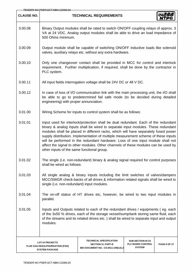
CLAUSE NO. TECHNICAL REQUIREMENTS
LOT-IA PROJECTS
FLUE GAS DESULPHURISATION (FGD)
SYSTEM PACKAGE
TECHNICAL SPECIFICATION
SECTION-VI, PART-B
BID DOCUMENT NO.: CS-0011-109(1A)-2
SUB-SECTION-III-C5
PLC BASED CONTROL
SYSTEM PAGE 8 OF 27
3.00.08 Binary Output modules shall be rated to switch ON/OFF coupling relays of approx. 3 VA at 24 VDC. Analog output modules shall be able to drive an load impedance of 500 Ohms minimum.
3.00.09 Output module shall be capable of switching ON/OFF inductive loads like solenoid valves, auxiliary relays etc. without any extra hardware.
3.00.10 Only one changeover contact shall be provided in MCC for control and interlock requirement. Further multiplication, if required, shall be done by the contractor in PLC system.
3.00.11 All input fields interrogation voltage shall be 24V DC or 48 V DC.
3.00.12 In case of loss of I/O communication link with the main processing unit, the I/O shall be able to go to predetermined fail safe mode (to be decided during detailed engineering) with proper annunciation.
3.01.00 Wiring Scheme for inputs to control system shall be as follows:
3.01.01 Input used for interlock/protection shall be dual redundant. Each of the redundant binary & analog inputs shall be wired to separate input modules. These redundant modules shall be placed in different racks, which will have separately fused power supply distribution. Implementation of multiple measurement scheme of these inputs will be performed in the redundant hardware. Loss of one input module shall not affect the signal to other modules. Other channels of these modules can be used by other inputs of the same functional group.
3.01.02 The single (i.e. non-redundant) binary & analog signal required for control purposes shall be wired as follows:
3.01.03 All single analog & binary inputs including the limit switches of valves/dampers MCC/SWGR check-backs of all drives & information related signals shall be wired to single (i.e. non-redundant) input modules.
3.01.04 The on-off status of HT drives etc, however, be wired to two input modules in parallel.
3.01.05 Inputs and Outputs related to each of the redundant drives / equipments ( eg. each of the 3x50 % drives, each of the storage vessel/sump/tank storing same fluid, each of the streams and its related drives etc. ) shall be wired to separate input and output modules.
TENDER NO PSER:SCT:NBN-C2068:20
TENDER NO PSER:SCT:NBN-C2068:20
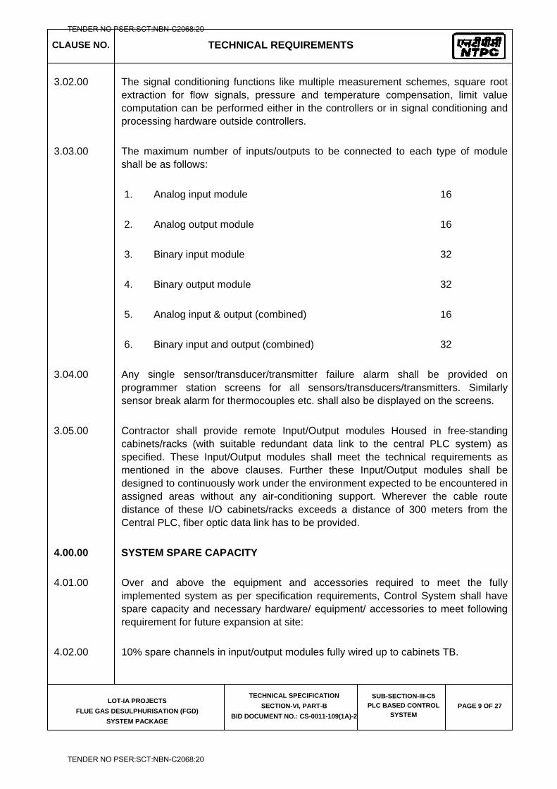
CLAUSE NO. TECHNICAL REQUIREMENTS
LOT-IA PROJECTS
FLUE GAS DESULPHURISATION (FGD)
SYSTEM PACKAGE
TECHNICAL SPECIFICATION
SECTION-VI, PART-B
BID DOCUMENT NO.: CS-0011-109(1A)-2
SUB-SECTION-III-C5
PLC BASED CONTROL
SYSTEM PAGE 9 OF 27
3.02.00 The signal conditioning functions like multiple measurement schemes, square root extraction for flow signals, pressure and temperature compensation, limit value computation can be performed either in the controllers or in signal conditioning and processing hardware outside controllers.
3.03.00 The maximum number of inputs/outputs to be connected to each type of module shall be as follows:
1. Analog input module 16
2. Analog output module 16
3. Binary input module 32
4. Binary output module 32
5. Analog input & output (combined) 16
6. Binary input and output (combined) 32
3.04.00 Any single sensor/transducer/transmitter failure alarm shall be provided on programmer station screens for all sensors/transducers/transmitters. Similarly sensor break alarm for thermocouples etc. shall also be displayed on the screens.
3.05.00 Contractor shall provide remote Input/Output modules Housed in free-standing cabinets/racks (with suitable redundant data link to the central PLC system) as specified. These Input/Output modules shall meet the technical requirements as mentioned in the above clauses. Further these Input/Output modules shall be designed to continuously work under the environment expected to be encountered in assigned areas without any air-conditioning support. Wherever the cable route distance of these I/O cabinets/racks exceeds a distance of 300 meters from the Central PLC, fiber optic data link has to be provided.
4.00.00 SYSTEM SPARE CAPACITY
4.01.00 Over and above the equipment and accessories required to meet the fully implemented system as per specification requirements, Control System shall have spare capacity and necessary hardware/ equipment/ accessories to meet following requirement for future expansion at site:
4.02.00 10% spare channels in input/output modules fully wired up to cabinets TB.
TENDER NO PSER:SCT:NBN-C2068:20
TENDER NO PSER:SCT:NBN-C2068:20
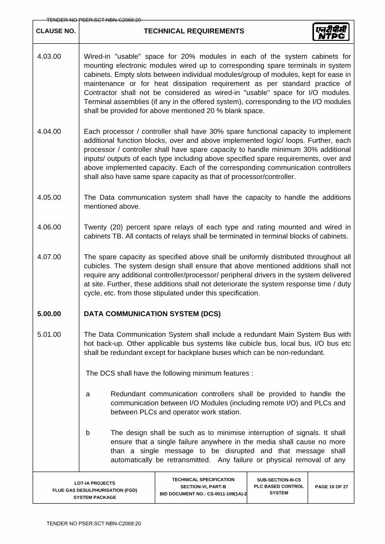
CLAUSE NO. TECHNICAL REQUIREMENTS
LOT-IA PROJECTS
FLUE GAS DESULPHURISATION (FGD)
SYSTEM PACKAGE
TECHNICAL SPECIFICATION
SECTION-VI, PART-B
BID DOCUMENT NO.: CS-0011-109(1A)-2
SUB-SECTION-III-C5
PLC BASED CONTROL
SYSTEM PAGE 10 OF 27
4.03.00 Wired-in "usable" space for 20% modules in each of the system cabinets for mounting electronic modules wired up to corresponding spare terminals in system cabinets. Empty slots between individual modules/group of modules, kept for ease in maintenance or for heat dissipation requirement as per standard practice of Contractor shall not be considered as wired-in "usable" space for I/O modules. Terminal assemblies (if any in the offered system), corresponding to the I/O modules shall be provided for above mentioned 20 % blank space.
4.04.00 Each processor / controller shall have 30% spare functional capacity to implement additional function blocks, over and above implemented logic/ loops. Further, each processor / controller shall have spare capacity to handle minimum 30% additional inputs/ outputs of each type including above specified spare requirements, over and above implemented capacity. Each of the corresponding communication controllers shall also have same spare capacity as that of processor/controller.
4.05.00 The Data communication system shall have the capacity to handle the additions mentioned above.
4.06.00 Twenty (20) percent spare relays of each type and rating mounted and wired in cabinets TB. All contacts of relays shall be terminated in terminal blocks of cabinets.
4.07.00 The spare capacity as specified above shall be uniformly distributed throughout all cubicles. The system design shall ensure that above mentioned additions shall not require any additional controller/processor/ peripheral drivers in the system delivered at site. Further, these additions shall not deteriorate the system response time / duty cycle, etc. from those stipulated under this specification.
5.00.00 DATA COMMUNICATION SYSTEM (DCS)
5.01.00 The Data Communication System shall include a redundant Main System Bus with hot back-up. Other applicable bus systems like cubicle bus, local bus, I/O bus etc shall be redundant except for backplane buses which can be non-redundant.
The DCS shall have the following minimum features :
a Redundant communication controllers shall be provided to handle the communication between I/O Modules (including remote I/O) and PLCs and between PLCs and operator work station.
b The design shall be such as to minimise interruption of signals. It shall ensure that a single failure anywhere in the media shall cause no more than a single message to be disrupted and that message shall automatically be retransmitted. Any failure or physical removal of any
TENDER NO PSER:SCT:NBN-C2068:20
TENDER NO PSER:SCT:NBN-C2068:20
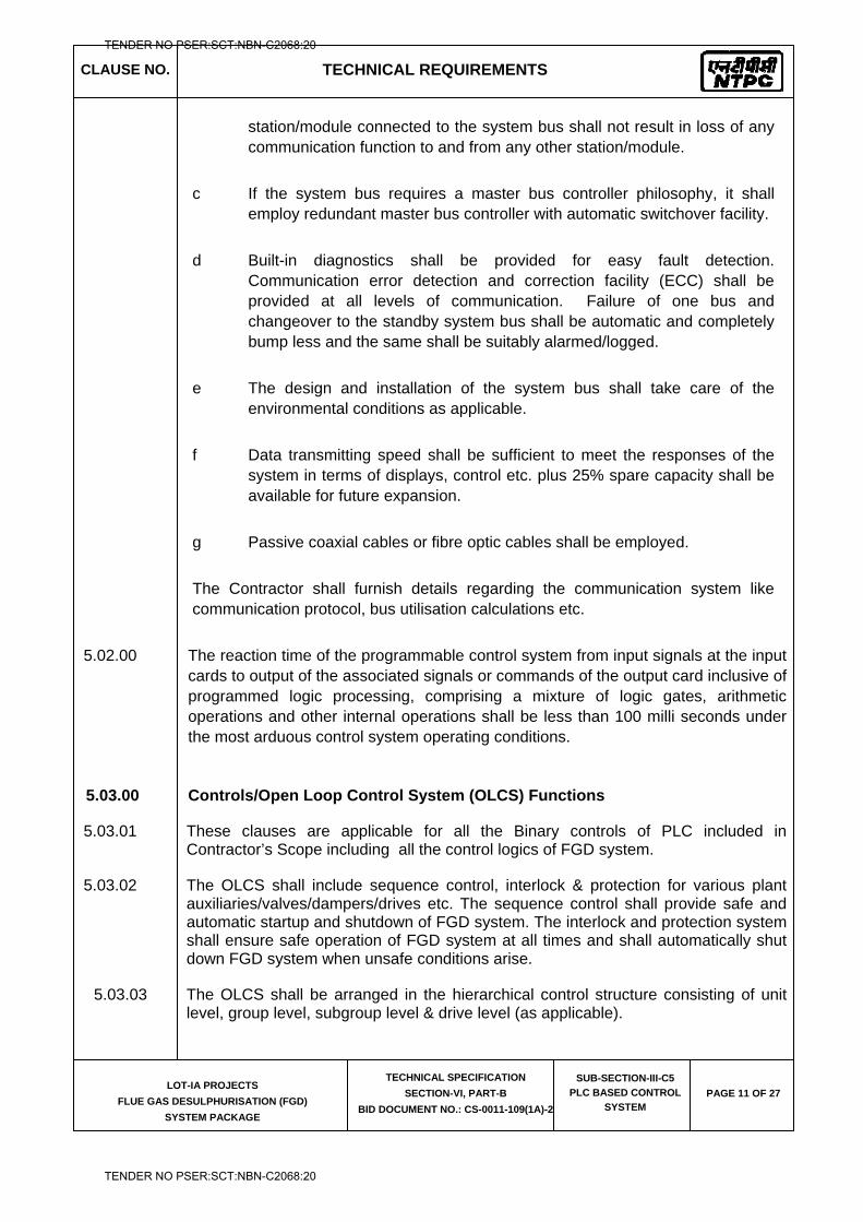
CLAUSE NO. TECHNICAL REQUIREMENTS
LOT-IA PROJECTS
FLUE GAS DESULPHURISATION (FGD)
SYSTEM PACKAGE
TECHNICAL SPECIFICATION
SECTION-VI, PART-B
BID DOCUMENT NO.: CS-0011-109(1A)-2
SUB-SECTION-III-C5
PLC BASED CONTROL
SYSTEM PAGE 11 OF 27
station/module connected to the system bus shall not result in loss of any communication function to and from any other station/module.
c If the system bus requires a master bus controller philosophy, it shall employ redundant master bus controller with automatic switchover facility.
d Built-in diagnostics shall be provided for easy fault detection. Communication error detection and correction facility (ECC) shall be provided at all levels of communication. Failure of one bus and changeover to the standby system bus shall be automatic and completely bump less and the same shall be suitably alarmed/logged.
e The design and installation of the system bus shall take care of the environmental conditions as applicable.
f Data transmitting speed shall be sufficient to meet the responses of the system in terms of displays, control etc. plus 25% spare capacity shall be available for future expansion.
g Passive coaxial cables or fibre optic cables shall be employed.
The Contractor shall furnish details regarding the communication system like communication protocol, bus utilisation calculations etc.
5.02.00 The reaction time of the programmable control system from input signals at the input cards to output of the associated signals or commands of the output card inclusive of programmed logic processing, comprising a mixture of logic gates, arithmetic operations and other internal operations shall be less than 100 milli seconds under the most arduous control system operating conditions.
5.03.00 Controls/Open Loop Control System (OLCS) Functions
5.03.01 These clauses are applicable for all the Binary controls of PLC included in Contractor’s Scope including all the control logics of FGD system.
5.03.02 The OLCS shall include sequence control, interlock & protection for various plant auxiliaries/valves/dampers/drives etc. The sequence control shall provide safe and automatic startup and shutdown of FGD system. The interlock and protection system shall ensure safe operation of FGD system at all times and shall automatically shut down FGD system when unsafe conditions arise.
5.03.03 The OLCS shall be arranged in the hierarchical control structure consisting of unit level, group level, subgroup level & drive level (as applicable).
TENDER NO PSER:SCT:NBN-C2068:20
TENDER NO PSER:SCT:NBN-C2068:20
CLAUSE NO. TECHNICAL REQUIREMENTS
LOT-IA PROJECTS
FLUE GAS DESULPHURISATION (FGD)
SYSTEM PACKAGE
TECHNICAL SPECIFICATION
SECTION-VI, PART-B
BID DOCUMENT NO.: CS-0011-109(1A)-2
SUB-SECTION-III-C5
PLC BASED CONTROL
SYSTEM PAGE 12 OF 27
5.03.04 It shall be possible to perform automatic FGD startup & shutdown by issuing minimum number of command from OWS. Thus, the unit level shall control all the Control System Blocks and issue appropriate startup & shutdown commands to various blocks of this Control System and receive corresponding commands/check backs/feedbacks.
5.03.05 The group level shall control a set of functional sub-groups of drives. Appropriate start-up and shut down commands shall be issued to the sub-group control and various check-backs shall be received from sub-groups or drives. Each sub-group shall execute the sequential start-up and shut down programs of a set of inter-related drives along with system interlocks and protections associated with that sub-group as well as basic interlocks and protections related to individual drive falling under that sub-group. The drive level shall accept commands from the sub-groups, push buttons (wherever provided), etc., and transmit them to the respective drive, after taking into account various interlocks and protections and the safety of that particular drive. For HT drive, first-up logic shall be incorporated to indicate the cause of protection/trip.
5.03.06 Sequence Control
1 A sequence shall be used to move a set of groups, sub-groups from an initial steady state (for instance 'OFF') to a final steady state (for instance 'ON'). The sequence initiating command for the unit & group level shall be issued from OWS.
2 A sequence shall be made of steps. The steps shall be executed in predetermined order according to logic criteria and monitoring time consisting of the interlock & protection requirements and check back of previous step which shall act as preconditions before the sequence control can execute the command for that step.
3 Each step shall have a "waiting time" implying that the subsequent step would not be executed unless the specified time elapses. A monitoring time shall also be defined as the maximum time required in executing the commands of any step and the time required for appearance of check back signals. In case, this is not completed within the specified time, a message shall be displayed and programme will not proceed further.
4 Manual intervention shall be possible at any stage of operation and the sequence control shall be able to continue at the correct point in the programme on return to automatic control. Protection commands shall have priority over manual commands, and manual commands shall prevail over auto commands.
5 Open or close priority shall be selectable for each drive.
6 The sequence startup mode shall be of the following types.
A
B
Automatic Mode
Semi-Automatic Mode
TENDER NO PSER:SCT:NBN-C2068:20
TENDER NO PSER:SCT:NBN-C2068:20
CLAUSE NO. TECHNICAL REQUIREMENTS
LOT-IA PROJECTS
FLUE GAS DESULPHURISATION (FGD)
SYSTEM PACKAGE
TECHNICAL SPECIFICATION
SECTION-VI, PART-B
BID DOCUMENT NO.: CS-0011-109(1A)-2
SUB-SECTION-III-C5
PLC BASED CONTROL
SYSTEM PAGE 13 OF 27
C Operator Guide Mode / Test Mode
5.03.07 For the drives, the command shall be provided through redundant O/P module to MCC/SWGR/Actuator as applicable and inputs (status, SWGR & process) shall be acquired through input modules. The failure of one of the redundant output module shall in no way affect the function of the other output module.
5.03.08 The output modules control module shall have the feature that ensures that in case of failure, all the outputs are driven to zero. The 24V DC command outputs to drives for ON/OPEN, OFF/CLOSE shall be separate and independent and inverted outputs shall not be employed. Keeping +24 V DC extended to the relays for these outputs continuously and extending ground/ negative when command is to be issued is not acceptable except some of the auxiliary plants as to be decided during detailed engineering.
5.03.09 For inching type of drives, position transmitter power supply and monitoring of position transmitter signal shall be provided.
5.03.10 The termination for OPEN (ON)/CLOSE (OFF) command for the drive actuator shall be performed in the actuators specified elsewhere in the specification. However, OPEN (ON)/CLOSE (OFF) and disturbance status as a minimum shall be monitored in OLCS.
5.03.11 The sequence interlock & protection requirements shall be finalized during detailed engineering and the same shall be subject to Employer's approval.
5.03.12 The drive function i.e. basic interlock & protection logic of the drive shall be implemented in redundant controllers. The drive function shall ensure that protection signals for the safety of the drive shall be effective under all conditions and under all modes of operation. The different commands shall be performed according to the priority of protection 'Off', Protection 'On', manual and automatic. The standard functions like running time monitoring, status signaling, alarm/drive annunciation, etc. shall be performed in drive function. The drive function shall prevent hunting of the actuator in the presence of both open & close commands for actuators of the valves & dampers. The drive function shall be implemented in dedicated standard software functional block.
5.03.13 The reversible drives to be controlled under OLCS shall be actuators with integral starters. These actuators will have coupling/interposing relays for accepting commands from OLCS and shall provide check back signals to OLCS. As such, all drive related inputs/outputs for reversible drives shall be available from actuators in field. The 'Open' and 'Closed' limit switches of each actuator shall be monitored with selectable delay time to check & alarm the contradictory condition of both contacts indicating 'Open' or 'Closed' status of actuators. The actuators for valves & dampers shall be interfaced as follows :
5.03.14 The open/close commands and check back signals from limit switches and disturbance signals shall be hardwired to respective OLCS group through I/O modules from actuators in the field.
TENDER NO PSER:SCT:NBN-C2068:20
TENDER NO PSER:SCT:NBN-C2068:20
CLAUSE NO. TECHNICAL REQUIREMENTS
LOT-IA PROJECTS
FLUE GAS DESULPHURISATION (FGD)
SYSTEM PACKAGE
TECHNICAL SPECIFICATION
SECTION-VI, PART-B
BID DOCUMENT NO.: CS-0011-109(1A)-2
SUB-SECTION-III-C5
PLC BASED CONTROL
SYSTEM PAGE 14 OF 27
5.04.00 Modulating Controls/Closed Loop Control System (CLCS) Functions
5.04.01 This Clause is applicable for all analog controls of PLC.
5.04.02 The controller capability shall, as a minimum, include (i) P, PI, PD and PID control functions and their variations (ii) cascade control (iii) feed forward control (iv) On-Off control, (v) Ratio and bias control, (vi) Logical operation .
5.04.03 The loop reaction time (from change of output of the transmitter/temperature element to the corresponding control command output) shall be within 500 milli seconds. For binary control the response time shall be within 100 milli seconds only.
5.04.04 The control loop shall have enough flexibility and various features to perform feed forwards, balancing of controller, increasing the response to achieve the desired process parameter within prescribed time frame.
5.04.05 The control system shall be bumplessly transferred to manual on the conditions of Control power supply failure, Failure of redundant controllers, Field input signal not available, Analog input exceeding preset value, etc. as a minimum and as finalized during detailed engineering.
5.04.06 Any switch over from auto to manual, manual to auto and switchover from OWS operation to H/A station operation and vice versa shall be bump less and without resulting in any change in the plant regulations and the same shall be reported to the operator and recorded automatically.
5.04.07 The System being supplied shall be such that when permissible limits are exceeded, an automatic switchover from an operation governed by maximum efficiency, to an operation governed by safety and availability is affected.
5.04.08 For safety reasons, switchover logics associated with the modulating control loops shall be performed within the closed loop control equipment. Modulating control loops shall be provided with standard features to interface overriding commands from OLCS/Protection System like open, protection open etc.
5.04.09 All controllers shall be freely configurable with respect to requisite control algorithms.
6.00.00 SYSTEM REACTION TIME
6.01.00 The reaction time of the programmable control system from input signals at the input cards to output of the associated signals or commands of the output card inclusive of programmed logic processing, comprising a mixture of logic gates, arithmetic operations and other internal operations shall be less than 100 milli seconds under the most arduous control system operating conditions.
7.00.00 OPERATOR INTERFACE DISPLAYS/LOGS/REPORTS
7.01.00 Suitable Operator Interface Displays/Logs/Reports for control operation & monitoring shall be provided. The details shall be finalised during detailed Engg. stage.
TENDER NO PSER:SCT:NBN-C2068:20
TENDER NO PSER:SCT:NBN-C2068:20
CLAUSE NO. TECHNICAL REQUIREMENTS
LOT-IA PROJECTS
FLUE GAS DESULPHURISATION (FGD)
SYSTEM PACKAGE
TECHNICAL SPECIFICATION
SECTION-VI, PART-B
BID DOCUMENT NO.: CS-0011-109(1A)-2
SUB-SECTION-III-C5
PLC BASED CONTROL
SYSTEM PAGE 15 OF 27
7.02.00 Minimum quantities shall be as follows:-
1 Various displays on the OWS shall as a minimum include P&ID displays or mimic, bar chart displays, x-y & x-t plot (trend) displays, operator guidance message displays, group displays, plant start-up/shutdown message displays, system status displays etc. Number of displays and the exact functionality shall be on as required basis and as finalised during detailed engineering subject to the minimum quantities as given in subsequent clauses. For x-t & x-y plots, the facility of providing a background grid on operator request shall be variable with adequate no. Of divisions in both co-ordinates.
2 The Minimum Quantity of Major Types of Displays per unit shall be as follows:
a) Control displays (group/sub-group/ sequence/loop)
(On as reqd. basis subject to 100 minimum)
b) P&ID/ mimic display 20
C) X-Y Plot (with superimposed operating curves + using user selectable stored data)
25 + 25
D) Group displays 20
E) Operator guidance message 10
F) System status & other diagnostic display on as required basis
The assignment for the above will be done by the contractor as per the requirement of operation of contractor's system as well as for maintenance. The balance displays shall be left as spare for future modification/addition.
8.00.00 HISTORICAL STORAGE AND RETRIEVAL SYSTEM (HSRS)
8.00.01 The HSRS shall collect, store and process system data from MMIPIS data base. The data shall be saved online on hard disk and automatically transferred to erasable long term storage media once in every 24 hours periodically for long term storage. Provision shall be made to notify the operator when hard disk is certain percentage full. The disk capacity shall be sufficient to store at least seven days data .
TENDER NO PSER:SCT:NBN-C2068:20
TENDER NO PSER:SCT:NBN-C2068:20
CLAUSE NO. TECHNICAL REQUIREMENTS
LOT-IA PROJECTS
FLUE GAS DESULPHURISATION (FGD)
SYSTEM PACKAGE
TECHNICAL SPECIFICATION
SECTION-VI, PART-B
BID DOCUMENT NO.: CS-0011-109(1A)-2
SUB-SECTION-III-C5
PLC BASED CONTROL
SYSTEM PAGE 16 OF 27
8.00.02 The data to be stored in the above system shall include alarm and event list, periodic plant data, selected logs/reports . The data/information to be stored & frequency of storage and retrieval shall be as finalised during detailed engineering. The system shall provide user-friendly operator functions to retrieve the data from historical storage. It shall be possible to retrieve the selected data on OWS or printer in form of trend/report by specifying date, time & period. Further, suitable index files/directories shall also be provided to facilitate the same. The logs/reports for at least last seven (7) days shall be available on the disk.
8.00.03 In addition to above, the system shall also have facility to store & retrieve important plant data for a very long duration (plant life) on portable long term storage media). These data will include any data from the database as well as processed/computed data based an various calculations/transformation. The retrieved data from long term storage media should be possible to be presented in form of alarms, logs, reports, etc.
9.00.00 CONTROL & POWER SUPPLY SCHEME
9.00.01 General Requirements
The requirements of Electrical Power Supply system are specified herein on system basis. The Contractor shall be responsible for engineering and furnishing a complete and operational system fully meeting the intent and requirements of this specification including tender drawings and Employer approved drawings during detailed engineering. All equipment and accessories required for completeness of this system shall be furnished by the Contractor whether these are specifically mentioned herein or not. All the equipments and sub systems offered shall be from reputed experienced manufacturers. All system cabinets, enclosures, & distribution boards shall be manufactured, assembled, wired and fully tested as a complete assembly as per the requirements of this specification at the manufacturer’s works.
The Contractor shall furnish all required equipment cubicles and wiring required for conversion and/or stabilization of the power sources provided by the Employer to all other levels which may be necessary for meeting the individual requirement of equipment/system furnished by him including the panel/desk mounted equipment.
24 V DC power supply system shall be provided as below:-
i) 24V DC power supply system for PLC based control system shall comprise of two sets, each set shall consist of 1 x 100% microprocessor controlled, intelligent, modular rectifier banks, Controller – one for each rectifier bank, 1 x 100% Nickel - Cadmium batteries for one (1) hour duty, 1 X 100% DC distribution board. 1x100% Microprocessor controlled Battery Health Monitoring System (BHMS)–common for both the sets.
TENDER NO PSER:SCT:NBN-C2068:20
TENDER NO PSER:SCT:NBN-C2068:20
CLAUSE NO. TECHNICAL REQUIREMENTS
LOT-IA PROJECTS
FLUE GAS DESULPHURISATION (FGD)
SYSTEM PACKAGE
TECHNICAL SPECIFICATION
SECTION-VI, PART-B
BID DOCUMENT NO.: CS-0011-109(1A)-2
SUB-SECTION-III-C5
PLC BASED CONTROL
SYSTEM PAGE 17 OF 27
Necessary redundant transformers shall be provided by the contractor to derive the power supply from 415V, 3 phase, 3 wire incomers for above.
9.01.00 POWER SUPPLY SYSTEM FOR PLC BASED CONTROL PANELS
9.01.01 Microprocessor based, Intelligent, Modular Power Supply.
9.01.02 Microprocessor based, intelligent, modular power supply shall be sized to meet connected load requirements and keep the connected battery full charged in Float/ Boost mode. A provision of 10% design margin shall be kept over and above the load requirement. Either of the bank of rectifier modules shall be able to recharge fully discharged battery within 8 hours. It shall also be possible to discharge batteries periodically manually. Each rectifier bank shall have N+1 rectifier modules for all applications. The exact sizing of the rectifiers in one bank shall be as approved by Employer during detailed engineering. While selecting the components and finalizing the cooling arrangements, Bidder to note that these rectifier modules are required to operate at 30-40 % of the rated load for most of the time. While sizing, the temperature derating factor as applicable, is to be considered for arriving at the rating of the modules as per Bidder’s manufacturing standard if the modules are rated for lower than the 50 deg. C ambient. For the rectifier bank, matching controller along with applicable software shall be provided to meet system requirements under all modes of operation.”
9.01.03 The rectifier module shall be microprocessor controlled, IGBT/Power MOSFET based, high frequency with active load sharing, designed for single and parallel operation with battery and shall have automatic voltage regulators for a close voltage stability even when AC supply voltage and DC load fluctuates, effective current limiting features, front access design, programmable temperature compensation feature for battery charging and filters on both input and output to minimize harmonics. The rectifier module output regulation shall be +/- 1% or better from no load to full load with an input power supply variation of +/- 10% in voltage and +/- 5% in frequency. In addition to indications / display on rectifier panel, alarms along with relevant analog measurements shall also be provided by employing RS 485 Port Modbus Protocol / Ethernet TCP/IP protocol for use in PLC system. Further isolated 4-20 mA signals shall be provided for important parameters like rectifier bank voltage, rectifier bank current, battery voltage, battery current, DCDB Voltage, DCDB current etc. The list of alarm output & 4-20 mA signals shall be as approved by Employer during detailed engineering. Necessary provision shall be done in PLC end also.
9.01.04 “Float / Boost” charge functions shall be provided with alarm / indications.
9.01.05 Each rectifier bank shall be rated for 100% load requirement and keep the connected battery full charged and one spare rectifier module.
TENDER NO PSER:SCT:NBN-C2068:20
TENDER NO PSER:SCT:NBN-C2068:20
CLAUSE NO. TECHNICAL REQUIREMENTS
LOT-IA PROJECTS
FLUE GAS DESULPHURISATION (FGD)
SYSTEM PACKAGE
TECHNICAL SPECIFICATION
SECTION-VI, PART-B
BID DOCUMENT NO.: CS-0011-109(1A)-2
SUB-SECTION-III-C5
PLC BASED CONTROL
SYSTEM PAGE 18 OF 27
9.01.06 The rectifier module circuitry shall be of fail-safe design and failure of any component should not result in any rectifier bank output voltage to increase beyond acceptable limits of the C&I system being fed from it.
9.01.07 The rectifier module shall be current limited for circuit protection and protection of battery from overcharge. The current limit shall be continuously programmable.
9.01.08 The rectifier module shall have a slow walk-in circuit which shall prevent application of full load DC current in less than 10 seconds after AC power is energized.
9.01.09 The rectifier module shall be fed from 415 V AC, 50 HZ, 3 phase, 3 wire system. Bidder shall provide all required power cables & other accessories etc. from 415 V AC power supply system to his electrical power supply system.
9.01.10 The full load efficiency of rectifier module at nominal input and output shall be 90%. The ripple content shall be limited to +/- 0.5% of output voltage.
9.01.11 Bidder shall furnish the equipment complete in all respect along with rectifier module rating & voltage drop calculations, supporting curves / data etc.
9.01.12 The Controller shall be intelligent, microprocessor controlled for monitoring & control of rectifier modules with features viz. auto / manual battery discharge test, battery reserve time prediction, energy management, float / boost mode control etc.
9.01.13 All software as required for smooth operation and monitoring of rectifier modules in conjunction with controller & BHMS shall be provided by the Contractor.
9.02.00 Batteries for PLC system
9.02.01 The batteries shall be heavy duty Nickel-cadmium type and shall be sized for one hour of full load operation during non-availability of AC supply / chargers. The Ni-Cd batteries shall conform to IS: 10918. The batteries shall be sized as per relevant IEEE Standards. For sizing calculation, an aging factor of 0.8 and a temperature correction factor as per manufacturer’s standard at 4 deg. C electrolyte temperature (Based on temperature characteristics curve to be submitted by the Contractor at a temperature of 4 deg. C). Capacity factor, Float Correction Factor, as per Battery Supplier Standard, shall be taken into consideration, if applicable and ambient temperature shall be considered as the electrolytic temperature. The sizing of the battery shall be as approved by Employer during detailed engineering. However, Contractor shall consider a suitable voltage drop of 2V from battery room to DCDB and DCDB to load, while sizing the battery.
TENDER NO PSER:SCT:NBN-C2068:20
TENDER NO PSER:SCT:NBN-C2068:20
CLAUSE NO. TECHNICAL REQUIREMENTS
LOT-IA PROJECTS
FLUE GAS DESULPHURISATION (FGD)
SYSTEM PACKAGE
TECHNICAL SPECIFICATION
SECTION-VI, PART-B
BID DOCUMENT NO.: CS-0011-109(1A)-2
SUB-SECTION-III-C5
PLC BASED CONTROL
SYSTEM PAGE 19 OF 27
9.03.00 DC DISTRIBUTION BOARD (DCDB)
Redundant DC feeders (one from each DCDB) shall supply each of the connected panels. From DCDB / panel to driver/load feeder shall be in scope of Bidder. The exact design, rating & number of feeders of the each redundant DCDB shall be as finalized during detailed engineering and as approved by Employer. However, 25% spare feeder (min. 1 no.) with fuses for each rating shall be provided in each DCDB.
9.04.00 Battery Health Monitoring System (BHMS)
BHMS, wherever applicable, shall include microprocessor based hardware and software to monitor the condition of each battery cell of 24 V DC systems on-line. With BHMS it shall be possible to measure & analyze the minimum and maximum voltage values of each battery-cell so that any damage to battery shall be prevented by pro-active maintenance. BHMS shall communicate with the charger/PLC and provide alarms as finalized by Employer during detailed engineering.
9.05.00 The UPS Power Supply for various systems shall consist of one or more of the following configurations.
Bidder shall clearly bring out in the proposal the redundancy feature along with configuration diagram, single line diagram and data sheets etc. & this shall be finalized subject to employer’s approval during detailed engineering.
Configuration B : UPS system shall consist of 1 x 100% charger and inverter, 1 x 100% Ni Cd Battery Bank for 1 hour, Bypass Line Transformers and Voltage Stabilizer, static switch, manual bypass switch, 2 x 100% ACDB, 1x100% Microprocessor controlled Battery Health Monitoring System (BHMS) and other necessary protective devices and accessories.
The specifications for this UPS configuration shall be as per Cl.No. 9.06.00 to 9.06.05 and specifications for Battery shall be as per Cl. No 9.06.06 for Ni-Cd type Batteries.
Configuration C : On line UPS with remote monitoring having a battery backup of 30 min. The batteries for UPS System shall be Sealed Maintenance Free type and shall be as per Control System Vendor’s standards.
9.06.00 UNINTERRUPTIBLE POWER SUPPLY (UPS) SYSTEM
The minimum capacity of the UPS at load factor of 0.8 lagging inclusive of 10% design margin at 50 deg c.
TENDER NO PSER:SCT:NBN-C2068:20
TENDER NO PSER:SCT:NBN-C2068:20
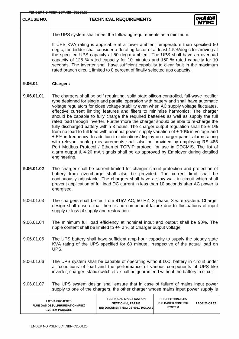
CLAUSE NO. TECHNICAL REQUIREMENTS
LOT-IA PROJECTS
FLUE GAS DESULPHURISATION (FGD)
SYSTEM PACKAGE
TECHNICAL SPECIFICATION
SECTION-VI, PART-B
BID DOCUMENT NO.: CS-0011-109(1A)-2
SUB-SECTION-III-C5
PLC BASED CONTROL
SYSTEM PAGE 20 OF 27
The UPS system shall meet the following requirements as a minimum.
If UPS KVA rating is applicable at a lower ambient temperature than specified 50 deg.c, the bidder shall consider a derating factor of at least 1.5%/deg.c for arriving at the specified UPS capacity at 50 deg.c ambient. The UPS shall have an overload capacity of 125 % rated capacity for 10 minutes and 150 % rated capacity for 10 seconds. The inverter shall have sufficient capability to clear fault in the maximum rated branch circuit, limited to 8 percent of finally selected ups capacity.
9.06.01 Chargers
9.06.01.01 The chargers shall be self regulating, solid state silicon controlled, full-wave rectifier type designed for single and parallel operation with battery and shall have automatic voltage regulators for close voltage stability even when AC supply voltage fluctuates, effective current limiting features and filters to minimise harmonics. The charger should be capable to fully charge the required batteries as well as supply the full rated load through inverter. Furthermore the charger should be able to re-charge the fully discharged battery within 8 hours. The charger output regulation shall be ± 1% from no load to full load with an input power supply variation of ± 10% in voltage and ± 5% in frequency. In addition to indications/display on charger panel, alarms along with relevant analog measurements shall also be provided by employing RS 485 Port Modbus Protocol / Ethernet TCP/IP protocol for use in DDCMIS. The list of alarm output & 4-20 mA signals shall be as approved by Employer during detailed engineering.
9.06.01.02 The charger shall be current limited for charger circuit protection and protection of battery from overcharge shall also be provided. The current limit shall be continuously adjustable. The chargers shall have a slow walk-in circuit which shall prevent application of full load DC current in less than 10 seconds after AC power is energised.
9.06.01.03 The chargers shall be fed from 415V AC, 50 HZ, 3 phase, 3 wire system. Charger design shall ensure that there is no component failure due to fluctuations of input supply or loss of supply and restoration.
9.06.01.04 The minimum full load efficiency at nominal input and output shall be 90%. The ripple content shall be limited to +/- 2 % of Charger output voltage.
9.06.01.05 The UPS battery shall have sufficient amp-hour capacity to supply the steady state KVA rating of the UPS specified for 60 minute, irrespective of the actual load on UPS.
9.06.01.06 The UPS system shall be capable of operating without D.C. battery in circuit under all conditions of load and the performance of various components of UPS like inverter, charger, static switch etc. shall be guaranteed without the battery in circuit.
9.06.01.07 The UPS system design shall ensure that in case of failure of mains input power supply to one of the chargers, the other charger whose mains input power supply is
TENDER NO PSER:SCT:NBN-C2068:20
TENDER NO PSER:SCT:NBN-C2068:20
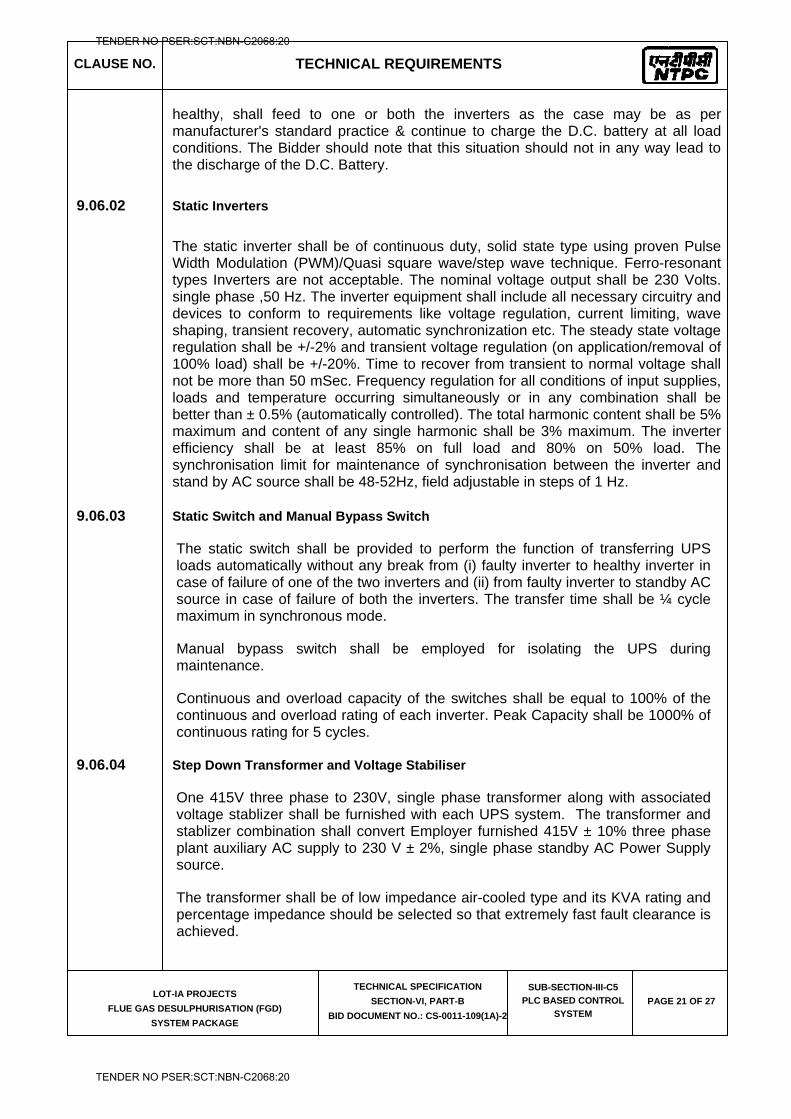
CLAUSE NO. TECHNICAL REQUIREMENTS
LOT-IA PROJECTS
FLUE GAS DESULPHURISATION (FGD)
SYSTEM PACKAGE
TECHNICAL SPECIFICATION
SECTION-VI, PART-B
BID DOCUMENT NO.: CS-0011-109(1A)-2
SUB-SECTION-III-C5
PLC BASED CONTROL
SYSTEM PAGE 21 OF 27
healthy, shall feed to one or both the inverters as the case may be as per manufacturer's standard practice & continue to charge the D.C. battery at all load conditions. The Bidder should note that this situation should not in any way lead to the discharge of the D.C. Battery.
9.06.02 Static Inverters
The static inverter shall be of continuous duty, solid state type using proven Pulse Width Modulation (PWM)/Quasi square wave/step wave technique. Ferro-resonant types Inverters are not acceptable. The nominal voltage output shall be 230 Volts. single phase ,50 Hz. The inverter equipment shall include all necessary circuitry and devices to conform to requirements like voltage regulation, current limiting, wave shaping, transient recovery, automatic synchronization etc. The steady state voltage regulation shall be +/-2% and transient voltage regulation (on application/removal of 100% load) shall be +/-20%. Time to recover from transient to normal voltage shall not be more than 50 mSec. Frequency regulation for all conditions of input supplies, loads and temperature occurring simultaneously or in any combination shall be better than ± 0.5% (automatically controlled). The total harmonic content shall be 5% maximum and content of any single harmonic shall be 3% maximum. The inverter efficiency shall be at least 85% on full load and 80% on 50% load. The synchronisation limit for maintenance of synchronisation between the inverter and stand by AC source shall be 48-52Hz, field adjustable in steps of 1 Hz.
9.06.03 Static Switch and Manual Bypass Switch
The static switch shall be provided to perform the function of transferring UPS loads automatically without any break from (i) faulty inverter to healthy inverter in case of failure of one of the two inverters and (ii) from faulty inverter to standby AC source in case of failure of both the inverters. The transfer time shall be ¼ cycle maximum in synchronous mode.
Manual bypass switch shall be employed for isolating the UPS during maintenance.
Continuous and overload capacity of the switches shall be equal to 100% of the continuous and overload rating of each inverter. Peak Capacity shall be 1000% of continuous rating for 5 cycles.
9.06.04 Step Down Transformer and Voltage Stabiliser
One 415V three phase to 230V, single phase transformer along with associated voltage stablizer shall be furnished with each UPS system. The transformer and stablizer combination shall convert Employer furnished 415V ± 10% three phase plant auxiliary AC supply to 230 V ± 2%, single phase standby AC Power Supply source.
The transformer shall be of low impedance air-cooled type and its KVA rating and percentage impedance should be selected so that extremely fast fault clearance is achieved.
TENDER NO PSER:SCT:NBN-C2068:20
TENDER NO PSER:SCT:NBN-C2068:20
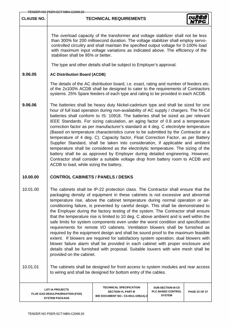
CLAUSE NO. TECHNICAL REQUIREMENTS
LOT-IA PROJECTS
FLUE GAS DESULPHURISATION (FGD)
SYSTEM PACKAGE
TECHNICAL SPECIFICATION
SECTION-VI, PART-B
BID DOCUMENT NO.: CS-0011-109(1A)-2
SUB-SECTION-III-C5
PLC BASED CONTROL
SYSTEM PAGE 22 OF 27
The overload capacity of the transformer and voltage stabilizer shall not be less than 300% for 200 millisecond duration. The voltage stabilizer shall employ servo-controlled circuitry and shall maintain the specified output voltage for 0-100% load with maximum input voltage variations as indicated above. The efficiency of the stabiliser shall be 95% or better.
The type and other details shall be subject to Employer’s approval.
9.06.05 AC Distribution Board (ACDB)
The details of the AC distribution board, i.e. exact, rating and number of feeders etc. of the 2x100% ACDB shall be designed to cater to the requirements of Contractors systems. 25% Spare feeders of each type and rating to be provided in each ACDB.
9.06.06 The batteries shall be heavy duty Nickel-cadmium type and shall be sized for one hour of full load operation during non-availability of AC supply / chargers. The Ni-Cd batteries shall conform to IS: 10918. The batteries shall be sized as per relevant IEEE Standards. For sizing calculation, an aging factor of 0.8 and a temperature correction factor as per manufacturer’s standard at 4 deg. C electrolyte temperature (Based on temperature characteristics curve to be submitted by the Contractor at a temperature of 4 deg. C). Capacity factor, Float Correction Factor, as per Battery Supplier Standard, shall be taken into consideration, if applicable and ambient temperature shall be considered as the electrolytic temperature. The sizing of the battery shall be as approved by Employer during detailed engineering. However, Contractor shall consider a suitable voltage drop from battery room to ACDB and ACDB to load, while sizing the battery.
10.00.00 CONTROL CABINETS / PANELS / DESKS
10.01.00 The cabinets shall be IP-22 protection class. The Contractor shall ensure that the packaging density of equipment in these cabinets is not excessive and abnormal temperature rise, above the cabinet temperature during normal operation or air-conditioning failure, is prevented by careful design. This shall be demonstrated to the Employer during the factory testing of the system. The Contractor shall ensure that the temperature rise is limited to 10 deg. C above ambient and is well within the safe limits for system components even under the worst condition and specification requirements for remote I/O cabinets. Ventilation blowers shall be furnished as required by the equipment design and shall be sound proof to the maximum feasible extent. If blowers are required for satisfactory system operation, dual blowers with blower failure alarm shall be provided in each cabinet with proper enclosure and details shall be furnished with proposal. Suitable louvers with wire mesh shall be provided on the cabinet.
10.01.01 The cabinets shall be designed for front access to system modules and rear access to wiring and shall be designed for bottom entry of the cables.
TENDER NO PSER:SCT:NBN-C2068:20
TENDER NO PSER:SCT:NBN-C2068:20
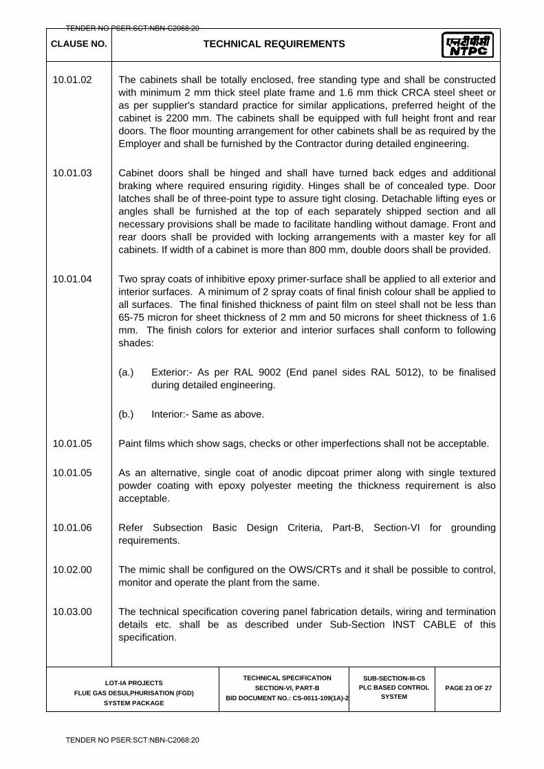
CLAUSE NO. TECHNICAL REQUIREMENTS
LOT-IA PROJECTS
FLUE GAS DESULPHURISATION (FGD)
SYSTEM PACKAGE
TECHNICAL SPECIFICATION
SECTION-VI, PART-B
BID DOCUMENT NO.: CS-0011-109(1A)-2
SUB-SECTION-III-C5
PLC BASED CONTROL
SYSTEM PAGE 23 OF 27
10.01.02 The cabinets shall be totally enclosed, free standing type and shall be constructed with minimum 2 mm thick steel plate frame and 1.6 mm thick CRCA steel sheet or as per supplier's standard practice for similar applications, preferred height of the cabinet is 2200 mm. The cabinets shall be equipped with full height front and rear doors. The floor mounting arrangement for other cabinets shall be as required by the Employer and shall be furnished by the Contractor during detailed engineering.
10.01.03 Cabinet doors shall be hinged and shall have turned back edges and additional braking where required ensuring rigidity. Hinges shall be of concealed type. Door latches shall be of three-point type to assure tight closing. Detachable lifting eyes or angles shall be furnished at the top of each separately shipped section and all necessary provisions shall be made to facilitate handling without damage. Front and rear doors shall be provided with locking arrangements with a master key for all cabinets. If width of a cabinet is more than 800 mm, double doors shall be provided.
10.01.04 Two spray coats of inhibitive epoxy primer-surface shall be applied to all exterior and interior surfaces. A minimum of 2 spray coats of final finish colour shall be applied to all surfaces. The final finished thickness of paint film on steel shall not be less than 65-75 micron for sheet thickness of 2 mm and 50 microns for sheet thickness of 1.6 mm. The finish colors for exterior and interior surfaces shall conform to following shades:
(a.) Exterior:- As per RAL 9002 (End panel sides RAL 5012), to be finalised during detailed engineering.
(b.) Interior:- Same as above.
10.01.05 Paint films which show sags, checks or other imperfections shall not be acceptable.
10.01.05 As an alternative, single coat of anodic dipcoat primer along with single textured powder coating with epoxy polyester meeting the thickness requirement is also acceptable.
10.01.06 Refer Subsection Basic Design Criteria, Part-B, Section-VI for grounding requirements.
10.02.00 The mimic shall be configured on the OWS/CRTs and it shall be possible to control, monitor and operate the plant from the same.
10.03.00 The technical specification covering panel fabrication details, wiring and termination details etc. shall be as described under Sub-Section INST CABLE of this specification.
TENDER NO PSER:SCT:NBN-C2068:20
TENDER NO PSER:SCT:NBN-C2068:20
CLAUSE NO. TECHNICAL REQUIREMENTS
LOT-IA PROJECTS
FLUE GAS DESULPHURISATION (FGD)
SYSTEM PACKAGE
TECHNICAL SPECIFICATION
SECTION-VI, PART-B
BID DOCUMENT NO.: CS-0011-109(1A)-2
SUB-SECTION-III-C5
PLC BASED CONTROL
SYSTEM PAGE 24 OF 27
10.04.00 CONTROL DESK
10.04.01 Control desk shall be free standing table top type with doors at the back and shall be constructed of 3 mm thick CRCA steel plates. A 19 mm thick wooden top shall be provided on the desk to keep the TFT monitors at top and computers inside. Control desk shall consist of vertical, horizontal and base supports with their coverings for work surface, keyboard trays, mouse pads, monitor shelf and concealed cable and wire way management, perforated trays with covers in both horizontal and vertical directions. PA system hand sets, telephone sets, very few PB stations and lamps shall be mounted on the control desk on mosaic grid structure and same shall be decided during detailed engineering. ASCII Keyboard shall be capable of being pulled out through a tray.
10.04.02 The cabling / wiring between OWS & CPU’S, power supply cables etc. shall be aesthetically routed and concealed from view.
10.05.00 FURNITURE
Chairs – Industry standard revolving chairs with wheels and with provision for adjustment of height (hydraulically/gas lift) shall be provided for the operators, unit-in-charge & other personnel in control room area. These shall be designed for sitting for long duration such that these are comfortable for the back. Chair pedestal shall be made of 5mm thick MS plate covered with poly-propylene cladding. Arm-rests in one piece shall be of poly-urethane and twin wheel castor of glass filled nylon. The exact details shall be finalized & approved by Employer during detailed engineering.
11.00.00 ANNUNCIATION SYSTEM
11.01.00 Only OWS based alarm system shall be provided with audio alarm facility ( beep/tone generator). No facia annunciation is envisaged in the control room. Hooters are to be provided.
11.02.00 The system shall display history of alarms in chronological order on any of the OWS. The HMIS shall have the capability to store a minimum of 500 alarms each with paging features allowing the operator to view any page. The system shall have all alarm functions and related function keys like alarm acknowledge, reset, paging, summaries etc. Other design features like set point/dead band adjustments, provision of alarm priority, manual inhibition & automatic inhibition based on predefined logic etc., shall be provided and shall be as finalised during detailed engineering. The alarm display/report format shall be as approved by the Employer.
TENDER NO PSER:SCT:NBN-C2068:20
TENDER NO PSER:SCT:NBN-C2068:20
CLAUSE NO. TECHNICAL REQUIREMENTS
LOT-IA PROJECTS
FLUE GAS DESULPHURISATION (FGD)
SYSTEM PACKAGE
TECHNICAL SPECIFICATION
SECTION-VI, PART-B
BID DOCUMENT NO.: CS-0011-109(1A)-2
SUB-SECTION-III-C5
PLC BASED CONTROL
SYSTEM PAGE 25 OF 27
11.03.00 Facility of audio annunciation shall be provided in OWS upon the occurrence OWS alarms irrespective of whether alarms are displayed or not. Facility to disable the audio annunciation shall be provided.
11.04.00 At least three levels of alarm priority shall be available which will be displayed in different colour. It shall be possible to display & print alarms of any of the three levels.
11.05.00 Alarm boxes shall be provided in each display to alert the operator about an alarm when he is viewing some other picture. No of alarm boxes shall be finalised during detailed engineering for each process area & each priority therein.
11.06.00 The annunciator sequence shall conform to ISA sequence ISA-2A.
12.00.00 SOFTWARE DOCUMENTATION AND SOFTWARE LISTINGS
12.01.00 All technical manuals, reference manuals, user’s guide etc., in English required for modification/editing/addition/deletion of features in the software of the PLC System shall be furnished. The Contractor shall furnish a comprehensive list of all system/application software documentation after system finalization for Employer’s review and approval.
12.02.00 All The software listings including Source code for application software, All special -to-project data files etc. shall be submitted by the Contractor.
13.00.00 SOFTWARE LICENCES
The Contractor shall provide software license for all software being used in Contractor’s System. The software licenses shall be provided for the project (e.g. organisation or site license) and shall not be hardware/machine-specific. That is, if any hardware/machine is upgraded or changed, the same license shall hold good and it shall not be necessary for Employer to seek a new license/renew license due to upgradation/change of hardware/machine in Contractor’s System at site. All licenses shall be valid for the continuous service life of the plant.
As a customer support, the Contractor shall periodically inform the designated officer of the Employer about the software upgrades/new releases that would be taking place after the system is commissioned so that if required, same can be procured & implemented at site.
TENDER NO PSER:SCT:NBN-C2068:20
TENDER NO PSER:SCT:NBN-C2068:20
CLAUSE NO. TECHNICAL REQUIREMENTS
LOT-IA PROJECTS
FLUE GAS DESULPHURISATION (FGD)
SYSTEM PACKAGE
TECHNICAL SPECIFICATION
SECTION-VI, PART-B
BID DOCUMENT NO.: CS-0011-109(1A)-2
SUB-SECTION-III-C5
PLC BASED CONTROL
SYSTEM PAGE 26 OF 27
14.00.00 SPECIFICATIONS OF PC BASED OWS
15.00.00 PRINTER
15.01.00 A4 size color laser printer shall be provided as a part of the HMIS system as per Part-A. It shall print out all alarm/trip conditions and event changes in plant status along with date and time of occurrence.
16.00.00 ANNUAL MAINTENANCE CONTRACT (AMC)
16.01.00 The Bidder shall provide maintenance services of complete control System under a comprehensive Annual Maintenance Contract (AMC) for period of one year after Warranty period and thereafter AMC for only hardware support for next two years.
16.02.00 The AMC shall cover total maintenance of all hardware & software coming under the scope of control system and shall include free repair/replacement of all cards/ modules/ peripherals/ cables/ components etc., correction of software problems and supply of expendable items. The Bidder shall ensure 99.7% availability of the system with the AMC. Bidder to ensure that system expert is available at site within 48 hours
CPU Latest generation CPU
Main memory 2 GB expandable to 4 GB
DVD R/W 16 x Or higher
Hard disk 160 GB SAS Removable bulk storage drive
500 GB (minimum)
Monitor 20" Full Flat TFT Resolution with non interfaced refresh rate min 75 Hz.
Graphic Memory 128 MB
Communication port 2 serial plus, one parallel, 1 USB port, Dual 100 Mbps Ethernet.
Expansion slots 3
Other Features 101 Keys Keyboard and Optical Mouse
Software
a) General MS Windows latest version, MSOffice, Microsoft Visual Studio, Adobe Acrobat, anti-virus McAfee or equivalent, etc.
b) Application software - to suit project specific requirement
TENDER NO PSER:SCT:NBN-C2068:20
TENDER NO PSER:SCT:NBN-C2068:20
CLAUSE NO. TECHNICAL REQUIREMENTS
LOT-IA PROJECTS
FLUE GAS DESULPHURISATION (FGD)
SYSTEM PACKAGE
TECHNICAL SPECIFICATION
SECTION-VI, PART-B
BID DOCUMENT NO.: CS-0011-109(1A)-2
SUB-SECTION-III-C5
PLC BASED CONTROL
SYSTEM PAGE 27 OF 27
of problem reporting by NTPC, in case the solution to the problem is not provided within 24 hours of problem reporting.
16.03.00 Further, bidder may note that during the AMC he will be allowed to use Employer's mandatory spares and has to replenish the same within three months’ time or before completion of AMC period whichever is earlier. However, if in the opinion of the Bidder, more spares than those included in the mandatory spare list are required to meet the availability requirement, then Bidder shall stock the same.
16.04.00 The Bidder shall prepare detailed list of faults corrected and parts, expendables utilised during AMC period and shall furnish the same to Employer, properly documented at the end of AMC period. Further, during AMC period the details as required by Employer/ Project Manager shall be made available by Bidder's personnel.
TENDER NO PSER:SCT:NBN-C2068:20
TENDER NO PSER:SCT:NBN-C2068:20

LOT-IA PROJECTS FLUE GAS DESULPHURISATION (FGD) SYSTEM PACKAGE
TECHNICAL SPECIFICATION
SECTION-VI
BID DOCUMENT NO.: CS-0011-109(1A)-2
SUB-SECTION-III-C6
TYPE TEST REQUIREMENTS
TENDER NO PSER:SCT:NBN-C2068:20
TENDER NO PSER:SCT:NBN-C2068:20
CLAUSE NO. TECHNICAL REQUIREMENTS
LOT-IA PROJECTS
FLUE GAS DESULPHURISATION (FGD)
SYSTEM PACKAGE
TECHNICAL SPECIFICATION
SECTION-VI, PART-B
BID DOCUMENT NO.: CS-0011-109(1A)-2
SUB-SECTION-III-C6
TYPE TEST
REQUIREMENTS PAGE 1 OF 7
TYPE TEST REQUIREMENTS
1.00.00 TYPE TEST REQUIREMENTS
1.01.00 General Requirements
1.01.01 The Contractor shall furnish the type test reports of all type tests as per relevant standards and codes as well as other specific tests indicated in this specification. A list of such tests are given for various equipment in table titled 'TYPE TEST REQUIREMENT FOR C&I SYSTEMS' at the end of this chapter and under the item Special Requirement for Solid State Equipments/Systems. For the balance equipment instrument, type tests may be conducted as per manufactures standard or if required by relevant standard.
(a) Out of the tests listed, the Bidder/ sub-vendor/ manufacturer is required to conduct certain type tests specifically for this contract (and witnessed by Employer or his authorized representative) even if the same had been conducted earlier, as clearly indicated subsequently against such tests.
(b) For the rest, submission of type test results and certificate shall be acceptable provided.
i. The same has been carried out by the Bidder/ sub-vendor on exactly the same model /rating of equipment.
ii. There has been no change in the components from the offered equipment & tested equipment.
iii. The test has been carried out as per the latest standards alongwith amendments as on the date of Bid opening but not more than five (5) year back.
(c) In case the approved equipment is different from the one on which the type test had been conducted earlier or any of the above grounds, then the tests have to be repeated and the cost of such tests shall be borne by the Bidder/ sub-vendor within the quoted price and no extra cost will be payable by the Employer on this account.
1.01.02 As mentioned against certain items, the test certificates for some of the items shall be reviewed and approved by the main Bidder or his authorized representative and the balance have to be approved by the Employer.
1.01.03 The schedule of conduction of type tests/ submission of reports shall be submitted and finalized during pre-award discussion.
TENDER NO PSER:SCT:NBN-C2068:20
TENDER NO PSER:SCT:NBN-C2068:20
CLAUSE NO. TECHNICAL REQUIREMENTS
LOT-IA PROJECTS
FLUE GAS DESULPHURISATION (FGD)
SYSTEM PACKAGE
TECHNICAL SPECIFICATION
SECTION-VI, PART-B
BID DOCUMENT NO.: CS-0011-109(1A)-2
SUB-SECTION-III-C6
TYPE TEST
REQUIREMENTS PAGE 2 OF 7
1.01.04 For the type tests to be conducted, Contractor shall submit detailed test procedure for approval by Employer. This shall clearly specify test setup, instruments to be used, procedure, acceptance norms (wherever applicable), recording of different parameters, interval of recording precautions to be taken etc. for the tests to be carried out.
1.01.05 The Bidder shall indicate in the relevant BPS schedule, the cost of the type test for each item only for which type tests are to be conducted specifically for this project. The cost shall only be payable after conduction of the respective test in presence of authorize representative of Employer. If a test is waived off, then the cost shall not be payable.
2.00.00 SPECIAL REQUIREMENT FOR SOLID STATE EQUIPMENTS/ SYSTEMS
2.01.00 The minimum type test reports, over and above the requirements of above clause, which are to be submitted for each of the major C&I systems Analyzer instruments, various PLCs etc. shall be as indicated below:
i) Surge Protections for Solid State Equipments/ Systems
All solid state systems/ equipments shall be able to withstand the electrical noise and surges as encountered in actual service conditions and inherent in a power plant. All the solid state systems/ equipments shall be provided with all required protections that needs the surge withstand capability as defined in ANSI 37.90a/ IEEE-472. Hence, all front end cards which receive external signals like Analog input & output modules, Binary input & output modules etc. including power supply, data highway, data links shall be provided with protections that meets the surge withstand capability as defined in ANSI 37.90a/ IEEE-472. Complete details of the features incorporated in electronics systems to meet this requirement, the relevant tests carried out, the test certificates etc. shall be submitted alongwith the proposal. As an alternative to above, suitable class of IEC-60255-4 which is equivalent to ANSI 37.90a/ IEEE-472 may also be adopted for SWC test.
ii) Dry Heat test as per IEC-68-2-2 or equivalent.
iii) Damp Heat test as per IEC-68-2-3 or equivalent.
iv) Vibration test as per IEC-68-2-6 or equivalent.
v) Electrostatic discharge tests as per IEC 61000-4-2 or equivalent.
vi) Radio frequency immunity test as per EN 50082-2 or equivalent.
TENDER NO PSER:SCT:NBN-C2068:20
TENDER NO PSER:SCT:NBN-C2068:20
CLAUSE NO. TECHNICAL REQUIREMENTS
LOT-IA PROJECTS
FLUE GAS DESULPHURISATION (FGD)
SYSTEM PACKAGE
TECHNICAL SPECIFICATION
SECTION-VI, PART-B
BID DOCUMENT NO.: CS-0011-109(1A)-2
SUB-SECTION-III-C6
TYPE TEST
REQUIREMENTS PAGE 3 OF 7
vii) Electromagnetic immunity as per EN 61131-2 or equivalent.
Test listed at item no. v, vi, vii, above are applicable for front end cards only as defined under item (i) above.
TENDER NO PSER:SCT:NBN-C2068:20
TENDER NO PSER:SCT:NBN-C2068:20
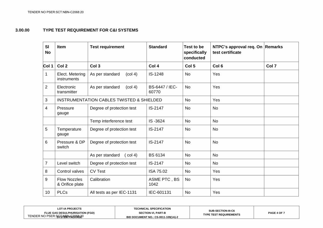
LOT-IA PROJECTS
FLUE GAS DESULPHURISATION (FGD)
SYSTEM PACKAGE
TECHNICAL SPECIFICATION
SECTION-VI, PART-B
BID DOCUMENT NO.: CS-0011-109(1A)-2
SUB-SECTION-III-C6
TYPE TEST REQUIREMENTS PAGE 4 OF 7
3.00.00 TYPE TEST REQUIREMENT FOR C&I SYSTEMS
Sl No
Item Test requirement Standard Test to be specifically conducted
NTPC’s approval req. On test certificate
Remarks
Col 1 Col 2 Col 3 Col 4 Col 5 Col 6 Col 7
1 Elect. Metering instruments
As per standard (col 4) IS-1248 No Yes
2 Electronic transmitter
As per standard (col 4) BS-6447 / IEC-60770
No Yes
3 INSTRUMENTATION CABLES TWISTED & SHIELDED No Yes
4 Pressure gauge
Degree of protection test IS-2147 No No
Temp interference test IS -3624 No No
5 Temperature gauge
Degree of protection test IS-2147 No No
6 Pressure & DP switch
Degree of protection test IS-2147 No No
As per standard ( col 4) BS 6134 No No
7 Level switch Degree of protection test IS-2147 No No
8 Control valves CV Test ISA 75.02 No Yes
9 Flow Nozzles & Orifice plate
Calibration ASME PTC , BS 1042
No Yes
10 PLCs All tests as per IEC-1131 IEC-601131 No Yes
TENDER NO PSER:SCT:NBN-C2068:20
TENDER NO PSER:SCT:NBN-C2068:20
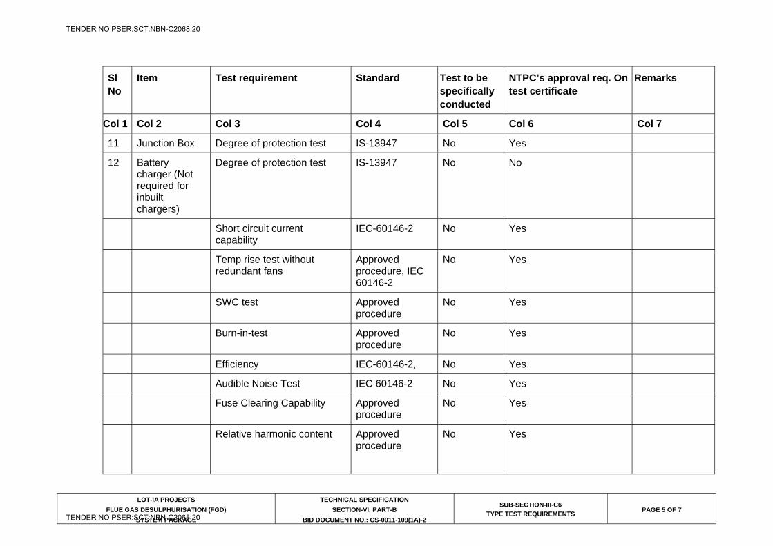
LOT-IA PROJECTS
FLUE GAS DESULPHURISATION (FGD)
SYSTEM PACKAGE
TECHNICAL SPECIFICATION
SECTION-VI, PART-B
BID DOCUMENT NO.: CS-0011-109(1A)-2
SUB-SECTION-III-C6
TYPE TEST REQUIREMENTS PAGE 5 OF 7
Sl No
Item Test requirement Standard Test to be specifically conducted
NTPC’s approval req. On test certificate
Remarks
Col 1 Col 2 Col 3 Col 4 Col 5 Col 6 Col 7
11 Junction Box Degree of protection test IS-13947 No Yes
12 Battery charger (Not required for inbuilt chargers)
Degree of protection test IS-13947 No No
Short circuit current capability
IEC-60146-2 No Yes
Temp rise test without redundant fans
Approved procedure, IEC 60146-2
No Yes
SWC test Approved procedure
No Yes
Burn-in-test Approved procedure
No Yes
Efficiency IEC-60146-2, No Yes
Audible Noise Test IEC 60146-2 No Yes
Fuse Clearing Capability Approved procedure
No Yes
Relative harmonic content Approved procedure
No Yes
TENDER NO PSER:SCT:NBN-C2068:20
TENDER NO PSER:SCT:NBN-C2068:20
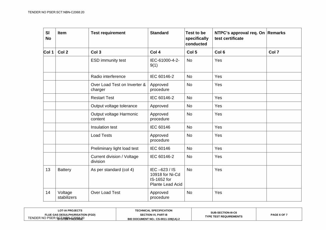
LOT-IA PROJECTS
FLUE GAS DESULPHURISATION (FGD)
SYSTEM PACKAGE
TECHNICAL SPECIFICATION
SECTION-VI, PART-B
BID DOCUMENT NO.: CS-0011-109(1A)-2
SUB-SECTION-III-C6
TYPE TEST REQUIREMENTS PAGE 6 OF 7
Sl No
Item Test requirement Standard Test to be specifically conducted
NTPC’s approval req. On test certificate
Remarks
Col 1 Col 2 Col 3 Col 4 Col 5 Col 6 Col 7
ESD immunity test IEC-61000-4-2-9(1)
No Yes
Radio interference IEC 60146-2 No Yes
Over Load Test on Inverter & charger
Approved procedure
No Yes
Restart Test IEC 60146-2 No Yes
Output voltage tolerance Approved No Yes
Output voltage Harmonic content
Approved procedure
No Yes
Insulation test IEC 60146 No Yes
Load Tests Approved procedure
No Yes
Preliminary light load test IEC 60146 No Yes
Current division / Voltage division
IEC 60146-2 No Yes
13 Battery As per standard (col 4) IEC –623 / IS 10918 for Ni-Cd IS-1652 for Plante Lead Acid
No Yes
14 Voltage stabilizers
Over Load Test Approved procedure
No Yes
TENDER NO PSER:SCT:NBN-C2068:20
TENDER NO PSER:SCT:NBN-C2068:20
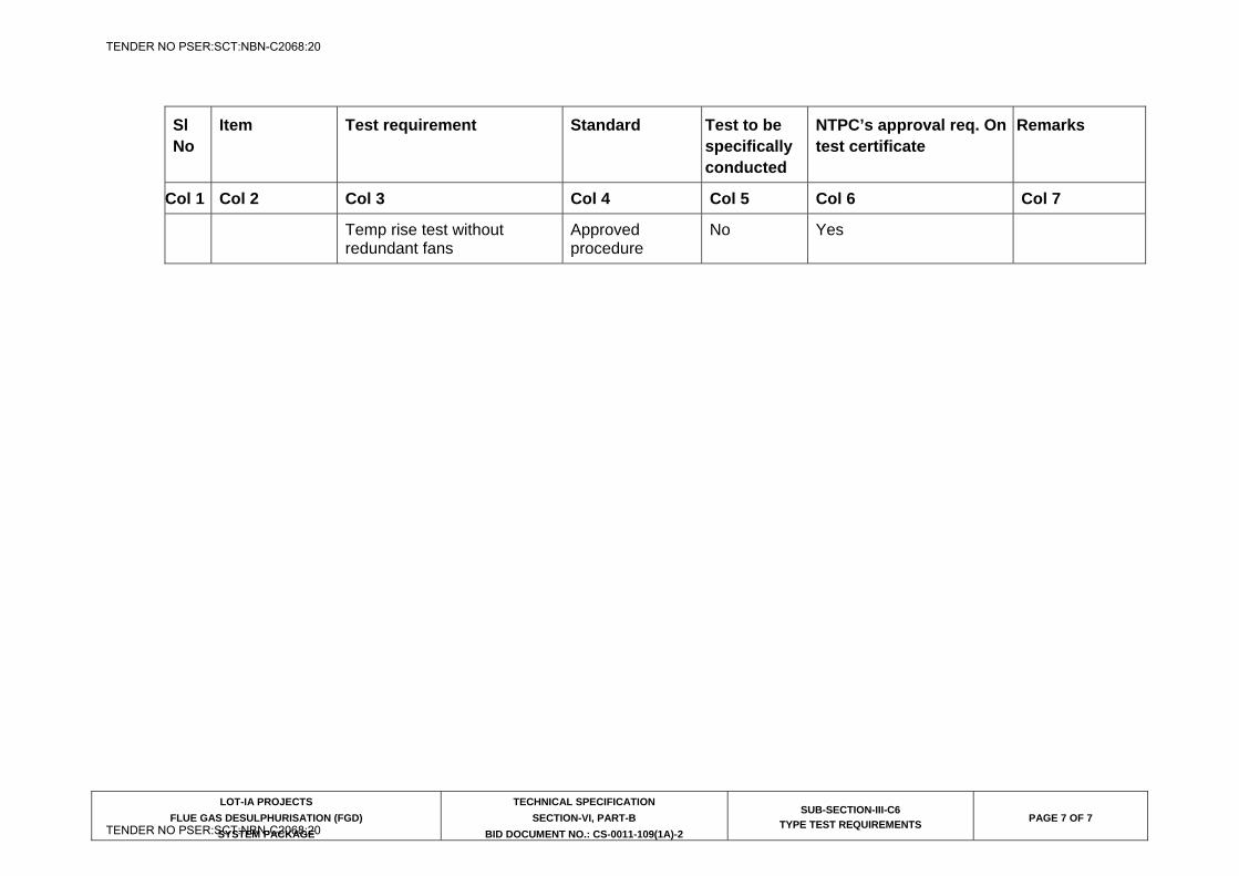
LOT-IA PROJECTS
FLUE GAS DESULPHURISATION (FGD)
SYSTEM PACKAGE
TECHNICAL SPECIFICATION
SECTION-VI, PART-B
BID DOCUMENT NO.: CS-0011-109(1A)-2
SUB-SECTION-III-C6
TYPE TEST REQUIREMENTS PAGE 7 OF 7
Sl No
Item Test requirement Standard Test to be specifically conducted
NTPC’s approval req. On test certificate
Remarks
Col 1 Col 2 Col 3 Col 4 Col 5 Col 6 Col 7
Temp rise test without redundant fans
Approved procedure
No Yes
TENDER NO PSER:SCT:NBN-C2068:20
TENDER NO PSER:SCT:NBN-C2068:20

LOT-IA PROJECTS FLUE GAS DESULPHURISATION (FGD) SYSTEM PACKAGE
TECHNICAL SPECIFICATION
SECTION-VI
BID DOCUMENT NO.: CS-0011-109(1A)-2
SUB-SECTION-III-C7
CONTROL VALVES, ACTUATORS & ACCESSORIES
TENDER NO PSER:SCT:NBN-C2068:20
TENDER NO PSER:SCT:NBN-C2068:20
CLAUSE NO. TECHNICAL REQUIREMENTS
LOT-IA PROJECTS
FLUE GAS DESULPHURISATION (FGD)
SYSTEM PACKAGE
TECHNICAL SPECIFICATION SECTION-VI, PART-B
BID DOCUMENT NO.: CS-0011-109(1A)-2
SUB-SECTION-III-C7 CONTROL VALVES,
ACTUATORS & ACCESSORIES
PAGE 1 OF 5
CONTROL VALVES, ACTUATORS & ACCESSORIES
1.00.00 CONTROL VALVES & ACCESSORIES
1.01.00 General Requirements
1.01.01 The control valves and accessories equipment furnished by the Bidder shall be designed, constructed and tested in accordance with the latest applicable requirements of code for pressure piping ANSI B 31.1, the ASME Boiler & pressure vessel code, Indian Boiler Regulation (IBR), ISA, and other standards specified elsewhere as well as in accordance with all applicable requirements of the “Federal Occupational Safety and Health Standards, USA” or acceptable equal standards. All the Control Valves, their actuators and accessories to be furnished under this Sub-section will be fully suitable and compatible with the modulating loops covered under the Specification.
1.01.02 All the control valves and accessories offered by the Bidder, shall be from reputed, experienced manufacturers of specified type and range of valves.
1.02.00 CONTROL VALVE SIZING & CONSTRUCTION
1.02.01 The design of all valve bodies shall meet the specification requirements and shall conform to the requirements of ANSI (USA) for dimensions, material thickness and material specification for their respective pressure classes.
1.02.02 The valve sizing shall be suitable for obtaining maximum flow conditions with valve opening at approximately 80% of total valve stem travel and minimum flow conditions with valve stem travel not less than 10% of total valve stem travel. All the valves shall be capable of handling at least 120% of the required maximum flow. Further, the valve stem travel range from minimum flow condition to maximum flow condition shall not be less than 50% of the total valve stem travel. The sizing shall be in accordance with the latest edition of ISA handbook on control valves. While deciding the size of valves, Bidder shall ensure that valves trim exit outlet velocity as defined in ISA handbook does not exceed 8 m/sec for liquid services, 150 m/sec. for steam services and 50% of sonic velocity for flashing services. Bidder shall furnish the sizing calculations clearly indicating the outlet velocity achieved with the valve size selected by him as well as noise calculations, which will be subject to Employer’s approval during detailed engineering.
1.02.03 Control valves for steam and water applications shall be designed to prevent cavitation, wire drawing, flashing on the downstream side of valve and down stream piping. Thus for cavitation/flashing service, only valve with anti cavitation trim shall be provided. Detailed calculations to establish whether cavitation will occur or not for any given application shall be furnished.
1.02.04 Control valves shall have leakage rate as per leakage Class-IV.
TENDER NO PSER:SCT:NBN-C2068:20
TENDER NO PSER:SCT:NBN-C2068:20
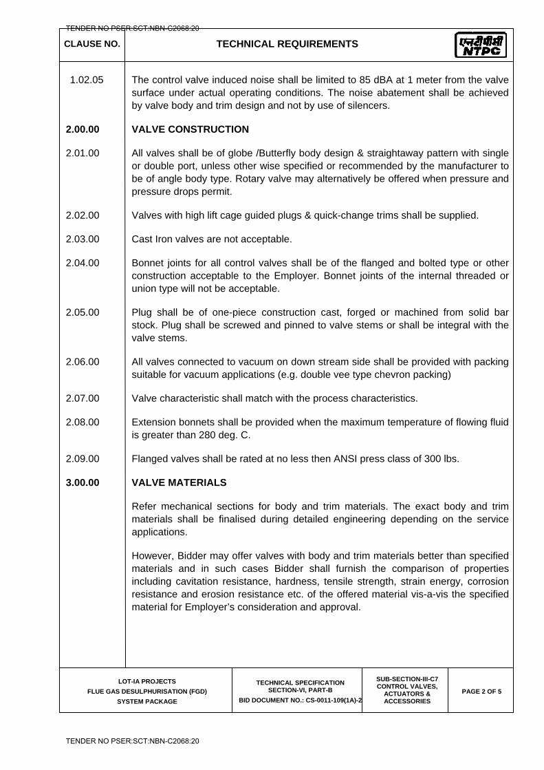
CLAUSE NO. TECHNICAL REQUIREMENTS
LOT-IA PROJECTS
FLUE GAS DESULPHURISATION (FGD)
SYSTEM PACKAGE
TECHNICAL SPECIFICATION SECTION-VI, PART-B
BID DOCUMENT NO.: CS-0011-109(1A)-2
SUB-SECTION-III-C7 CONTROL VALVES,
ACTUATORS & ACCESSORIES
PAGE 2 OF 5
1.02.05 The control valve induced noise shall be limited to 85 dBA at 1 meter from the valve surface under actual operating conditions. The noise abatement shall be achieved by valve body and trim design and not by use of silencers.
2.00.00 VALVE CONSTRUCTION
2.01.00 All valves shall be of globe /Butterfly body design & straightaway pattern with single or double port, unless other wise specified or recommended by the manufacturer to be of angle body type. Rotary valve may alternatively be offered when pressure and pressure drops permit.
2.02.00 Valves with high lift cage guided plugs & quick-change trims shall be supplied.
2.03.00 Cast Iron valves are not acceptable.
2.04.00 Bonnet joints for all control valves shall be of the flanged and bolted type or other construction acceptable to the Employer. Bonnet joints of the internal threaded or union type will not be acceptable.
2.05.00 Plug shall be of one-piece construction cast, forged or machined from solid bar stock. Plug shall be screwed and pinned to valve stems or shall be integral with the valve stems.
2.06.00 All valves connected to vacuum on down stream side shall be provided with packing suitable for vacuum applications (e.g. double vee type chevron packing)
2.07.00 Valve characteristic shall match with the process characteristics.
2.08.00 Extension bonnets shall be provided when the maximum temperature of flowing fluid is greater than 280 deg. C.
2.09.00 Flanged valves shall be rated at no less then ANSI press class of 300 lbs.
3.00.00 VALVE MATERIALS
Refer mechanical sections for body and trim materials. The exact body and trim materials shall be finalised during detailed engineering depending on the service applications.
However, Bidder may offer valves with body and trim materials better than specified materials and in such cases Bidder shall furnish the comparison of properties including cavitation resistance, hardness, tensile strength, strain energy, corrosion resistance and erosion resistance etc. of the offered material vis-a-vis the specified material for Employer’s consideration and approval.
TENDER NO PSER:SCT:NBN-C2068:20
TENDER NO PSER:SCT:NBN-C2068:20
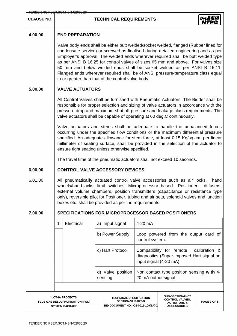
CLAUSE NO. TECHNICAL REQUIREMENTS
LOT-IA PROJECTS
FLUE GAS DESULPHURISATION (FGD)
SYSTEM PACKAGE
TECHNICAL SPECIFICATION SECTION-VI, PART-B
BID DOCUMENT NO.: CS-0011-109(1A)-2
SUB-SECTION-III-C7 CONTROL VALVES,
ACTUATORS & ACCESSORIES
PAGE 3 OF 5
4.00.00 END PREPARATION
Valve body ends shall be either butt welded/socket welded, flanged (Rubber lined for condensate service) or screwed as finalised during detailed engineering and as per Employer’s approval. The welded ends wherever required shall be butt welded type as per ANSI B 16.25 for control valves of sizes 65 mm and above. For valves size 50 mm and below welded ends shall be socket welded as per ANSI B 16.11. Flanged ends wherever required shall be of ANSI pressure-temperature class equal to or greater than that of the control valve body.
5.00.00 VALVE ACTUATORS
All Control Valves shall be furnished with Pneumatic Actuators. The Bidder shall be responsible for proper selection and sizing of valve actuators in accordance with the pressure drop and maximum shut off pressure and leakage class requirements. The valve actuators shall be capable of operating at 60 deg.C continuously.
Valve actuators and stems shall be adequate to handle the unbalanced forces occurring under the specified flow conditions or the maximum differential pressure specified. An adequate allowance for stem force, at least 0.15 Kg/sq.cm. per linear millimeter of seating surface, shall be provided in the selection of the actuator to ensure tight seating unless otherwise specified.
The travel time of the pneumatic actuators shall not exceed 10 seconds.
6.00.00 CONTROL VALVE ACCESSORY DEVICES
6.01.00 All pneumatically actuated control valve accessories such as air locks, hand wheels/hand-jacks, limit switches, Microprocessor based Positioner, diffusers, external volume chambers, position transmitters (capacitance or resistance type only), reversible pilot for Positioner, tubing and air sets, solenoid valves and junction boxes etc. shall be provided as per the requirements.
7.00.00 SPECIFICATIONS FOR MICROPROCESSOR BASED POSITIONERS
1 Electrical
a) Input signal 4-20 mA
b) Power Supply Loop powered from the output card of control system.
c) Hart Protocol Compatibility for remote calibration & diagnostics (Super-imposed Hart signal on input signal (4-20 mA)
d) Valve position sensing
Non contact type position sensing with 4-20 mA output signal
TENDER NO PSER:SCT:NBN-C2068:20
TENDER NO PSER:SCT:NBN-C2068:20
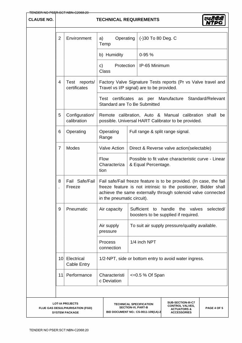
CLAUSE NO. TECHNICAL REQUIREMENTS
LOT-IA PROJECTS
FLUE GAS DESULPHURISATION (FGD)
SYSTEM PACKAGE
TECHNICAL SPECIFICATION SECTION-VI, PART-B
BID DOCUMENT NO.: CS-0011-109(1A)-2
SUB-SECTION-III-C7 CONTROL VALVES,
ACTUATORS & ACCESSORIES
PAGE 4 OF 5
2 Environment
a) Operating Temp
(-)30 To 80 Deg. C
b) Humidity 0-95 %
c) Protection Class
IP-65 Minimum
4 Test reports/ certificates
Factory Valve Signature Tests reports (Pr vs Valve travel and Travel vs I/P signal) are to be provided.
Test certificates as per Manufacture Standard/Relevant Standard are To Be Submitted
5 Configuration/ calibration
Remote calibration, Auto & Manual calibration shall be possible. Universal HART Calibrator to be provided.
6 Operating Operating Range
Full range & split range signal.
7 Modes
Valve Action Direct & Reverse valve action(selectable)
Flow Characterization
Possible to fit valve characteristic curve - Linear & Equal Percentage.
8.
Fail Safe/Fail Freeze
Fail safe/Fail freeze feature is to be provided. (In case, the fail freeze feature is not intrinsic to the positioner, Bidder shall achieve the same externally through solenoid valve connected in the pneumatic circuit).
9 Pneumatic
Air capacity Sufficient to handle the valves selected/ boosters to be supplied if required.
Air supply pressure
To suit air supply pressure/quality available.
Process connection
1/4 inch NPT
10 Electrical Cable Entry
1/2-NPT, side or bottom entry to avoid water ingress.
11 Performance Characteristic Deviation
<=0.5 % Of Span
TENDER NO PSER:SCT:NBN-C2068:20
TENDER NO PSER:SCT:NBN-C2068:20
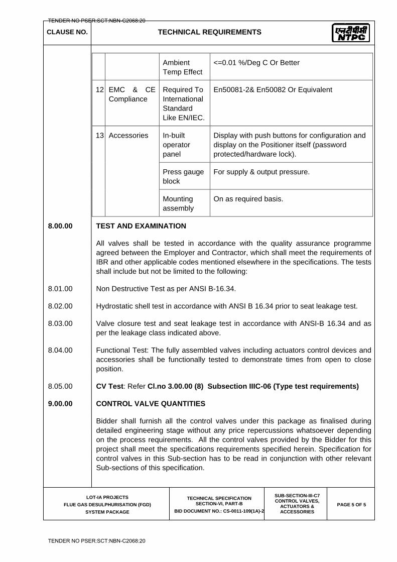
CLAUSE NO. TECHNICAL REQUIREMENTS
LOT-IA PROJECTS
FLUE GAS DESULPHURISATION (FGD)
SYSTEM PACKAGE
TECHNICAL SPECIFICATION SECTION-VI, PART-B
BID DOCUMENT NO.: CS-0011-109(1A)-2
SUB-SECTION-III-C7 CONTROL VALVES,
ACTUATORS & ACCESSORIES
PAGE 5 OF 5
Ambient Temp Effect
<=0.01 %/Deg C Or Better
12 EMC & CE Compliance
Required To International Standard Like EN/IEC.
En50081-2& En50082 Or Equivalent
13 Accessories
In-built operator panel
Display with push buttons for configuration and display on the Positioner itself (password protected/hardware lock).
Press gauge block
For supply & output pressure.
Mounting assembly
On as required basis.
8.00.00 TEST AND EXAMINATION
All valves shall be tested in accordance with the quality assurance programme agreed between the Employer and Contractor, which shall meet the requirements of IBR and other applicable codes mentioned elsewhere in the specifications. The tests shall include but not be limited to the following:
8.01.00 Non Destructive Test as per ANSI B-16.34.
8.02.00 Hydrostatic shell test in accordance with ANSI B 16.34 prior to seat leakage test.
8.03.00 Valve closure test and seat leakage test in accordance with ANSI-B 16.34 and as per the leakage class indicated above.
8.04.00 Functional Test: The fully assembled valves including actuators control devices and accessories shall be functionally tested to demonstrate times from open to close position.
8.05.00 CV Test: Refer Cl.no 3.00.00 (8) Subsection IIIC-06 (Type test requirements)
9.00.00 CONTROL VALVE QUANTITIES
Bidder shall furnish all the control valves under this package as finalised during detailed engineering stage without any price repercussions whatsoever depending on the process requirements. All the control valves provided by the Bidder for this project shall meet the specifications requirements specified herein. Specification for control valves in this Sub-section has to be read in conjunction with other relevant Sub-sections of this specification.
TENDER NO PSER:SCT:NBN-C2068:20
TENDER NO PSER:SCT:NBN-C2068:20

NTPC Limited (A Government of India Enterprise)
LOT 1A PROJECTS
PART – B (DETAILED TECHNICAL SPECIFICATION)
SUB-SECTION-V-Q
(QUALITY ASSURANCE)
SECTON – VI
TECHNICAL SPECIFICATION
FOR
FLUE GAS DESULPHURISATION (FGD)
SYSTEM PACKAGE
BIDDING DOCUMENT NO. : CS-0011-109(1A)-2
TENDER NO PSER:SCT:NBN-C2068:20
TENDER NO PSER:SCT:NBN-C2068:20
LOT-IA PROJECTS FLUE GAS DESULPHURISATION (FGD) SYSTEM PACKAGE
TECHNICAL SPECIFICATION
SECTION-VI
BID DOCUMENT NO.: CS-0011-109(1A)-2
PART – B (DETAILED TECHNICAL SPECIFICATION)
SUB-SECTION- V-Q (QUALITY ASSURANCE)
TENDER NO PSER:SCT:NBN-C2068:20
TENDER NO PSER:SCT:NBN-C2068:20
LOT-IA PROJECTS FLUE GAS DESULPHURISATION (FGD) SYSTEM PACKAGE
TECHNICAL SPECIFICATION
SECTION-VI
BID DOCUMENT NO.: CS-0011-109(1A)-2
(MECHANICAL)
TENDER NO PSER:SCT:NBN-C2068:20
TENDER NO PSER:SCT:NBN-C2068:20

LOT-IA PROJECTS FLUE GAS DESULPHURISATION (FGD) SYSTEM PACKAGE
TECHNICAL SPECIFICATION
SECTION-VI
BID DOCUMENT NO.: CS-0011-109(1A)-2
SUB-SECTION-V-QM1
FLUE GAS DESULPHURISATION SYSTEM
TENDER NO PSER:SCT:NBN-C2068:20
TENDER NO PSER:SCT:NBN-C2068:20
CLAUSE NO. QUALITY ASSURANCE
LOT-IA PROJECTS
FLUE GAS DESULPHURISATION (FGD) SYSTEM PACKAGE
TECHNICAL SPECIFICATION SECTION-VI, PART-B
BID DOC NO.:CS-0011-109(1A)-2
SUB-SECTION – V-QM1
FGD System
Page
1 of 4
FLUE GAS DESULPHURISATION SYSTEM 1.00.0 FLUE GAS DESULPHURISATION SYSTEM 1.01.0 Mills: 1.01.01 Raw material for shaft, coupling, gears and pinions, top and bottom races and
other rotating components shall be subjected to UT. MPI/LPI shall be carried out to check surface soundness.
1.01.02 Wear-resistant parts shall be UT/RT tested to check soundness after suitable
heat treatment. Check for chemical composition, hardness and microstructure shall be carried out.
1.01.03 Butt welds in the tube/separator/body casing of the mill shall be tested by RT
and MPI. All other welds in main tube/separator shall be tested by MPI/LPI for acceptance. The tube shall be statically balanced.
1.01.04 All gearboxes shall be run tested for adequate duration to check rise in oil
temperature, noise level and vibration. Check for leak tightness of gear case also shall be performed.
1.02.0 Feeders: 1.02.01 Any welds in the casing/pulley fabrication shall be checked with MPI. 1.02.02 Routine tests shall be done as per relevant Indian Standards or equivalent
International Standards. 1.02.03 All major items like plates for casing, head pulley, tail pulley, pulley shaft and
major castings shall be procured with respective material test certificates. 1.02.04 Calibration check shall be carried out on all feeders. 1.03.0 Dampers: 1.03.01 All the dampers shall be subjected to operational test/checks. 1.03.02 Gas tight Dampers shall be subjected to shop leakage test to demonstrate the
guaranteed tightness as per NTPC Tech Specification. 1.04.0 PIPING, VALVE AND SPECIALITIES: 1.04.01 All pipes and fittings shall be tested as per applicable code. 1.04.02 All valves shall be hydraulically/Air tested for body, seat and back-seat (if
applicable) as per relevant standard. 1.04.03 NDT on valves shall be as per relevant standard. 1.04.04 Valves shall be offered for hydro test in unpainted conditions.
TENDER NO PSER:SCT:NBN-C2068:20
TENDER NO PSER:SCT:NBN-C2068:20
CLAUSE NO. QUALITY ASSURANCE
LOT-IA PROJECTS
FLUE GAS DESULPHURISATION (FGD) SYSTEM PACKAGE
TECHNICAL SPECIFICATION SECTION-VI, PART-B
BID DOC NO.:CS-0011-109(1A)-2
SUB-SECTION – V-QM1
FGD System
Page
2 of 4
1.04.05 Functional checks of the valves for smooth opening and closing shall also be
done. 1.05.00 TANKS / VESSELS: 1.05.01 Atmospheric tanks:
i) All welds joints shall be DP tested and complete tanks shall be water fill
tested. ii) All atmospheric storage tanks fabricated and erected at site shall be
subjected to tests (Hydro, NDT and Vacuum) according to design code as applicable.
iii) Rubber lining shall be tested for hardness and spark test, as applicable.
1.05.02 Pressure vessels:
1) NDT on weld joint shall be as per respective code requirements or the minimum as specified as below:
i) 100% DPT on root run of butt weld, nozzle welds and finished
fillet welds. ii) 10% DPT on all finished butt welds. iii) 10% RT (covering all ‘T’/cross joints) of butt welds.
2) Butt welds of dished ends shall be stress relieved and subjected to 100% RT.
3) Each finished vessels shall be hydraulically tested to 150% of the design pressure for a duration of 30 minutes.
1.06.0 HEAT EXCHANGER/HEATER: 1.06.01 All material shall be tested for chemical and mechanical properties and NDT as
per relevant standard. 1.06.02 NDT on welds and other checks shall be as per relevant code. 1.06.03 Air heaters shall be subjected to dimensional and clearance checks as per
standard practice 1.06.04 Lub. oil system, drive system, soot blowing system etc. of Air heaters shall be
checked suitably as per standard practice 1.07.0 PUMPS: 1.07.01 UT on shaft forgings (greater or equal to 40mm) and MPI/DPT shall be done on
shafts and impeller to ensure freedom from defects. 1.07.02 The pump casing shall be hydraulically tested at 200% of pump rated head or
at 150% of shut off head, whichever is higher. The test pressure shall be maintained for at least half an hour.
TENDER NO PSER:SCT:NBN-C2068:20
TENDER NO PSER:SCT:NBN-C2068:20
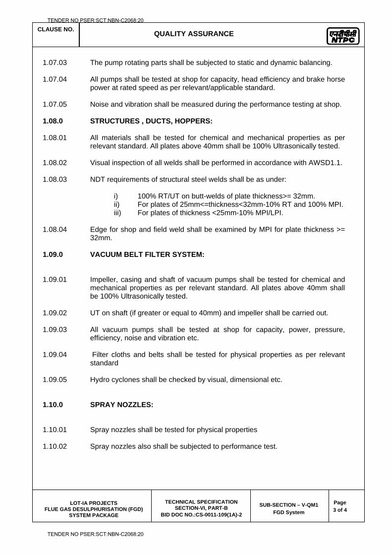
CLAUSE NO. QUALITY ASSURANCE
LOT-IA PROJECTS
FLUE GAS DESULPHURISATION (FGD) SYSTEM PACKAGE
TECHNICAL SPECIFICATION SECTION-VI, PART-B
BID DOC NO.:CS-0011-109(1A)-2
SUB-SECTION – V-QM1
FGD System
Page
3 of 4
1.07.03 The pump rotating parts shall be subjected to static and dynamic balancing. 1.07.04 All pumps shall be tested at shop for capacity, head efficiency and brake horse
power at rated speed as per relevant/applicable standard. 1.07.05 Noise and vibration shall be measured during the performance testing at shop. 1.08.0 STRUCTURES , DUCTS, HOPPERS: 1.08.01 All materials shall be tested for chemical and mechanical properties as per
relevant standard. All plates above 40mm shall be 100% Ultrasonically tested. 1.08.02 Visual inspection of all welds shall be performed in accordance with AWSD1.1. 1.08.03 NDT requirements of structural steel welds shall be as under:
i) 100% RT/UT on butt-welds of plate thickness>= 32mm. ii) For plates of 25mm<=thickness<32mm-10% RT and 100% MPI. iii) For plates of thickness <25mm-10% MPI/LPI.
1.08.04 Edge for shop and field weld shall be examined by MPI for plate thickness >=
32mm. 1.09.0 VACUUM BELT FILTER SYSTEM: 1.09.01 Impeller, casing and shaft of vacuum pumps shall be tested for chemical and
mechanical properties as per relevant standard. All plates above 40mm shall be 100% Ultrasonically tested.
1.09.02 UT on shaft (if greater or equal to 40mm) and impeller shall be carried out. 1.09.03 All vacuum pumps shall be tested at shop for capacity, power, pressure,
efficiency, noise and vibration etc. 1.09.04 Filter cloths and belts shall be tested for physical properties as per relevant
standard 1.09.05 Hydro cyclones shall be checked by visual, dimensional etc. 1.10.0 SPRAY NOZZLES: 1.10.01 Spray nozzles shall be tested for physical properties 1.10.02 Spray nozzles also shall be subjected to performance test.
TENDER NO PSER:SCT:NBN-C2068:20
TENDER NO PSER:SCT:NBN-C2068:20
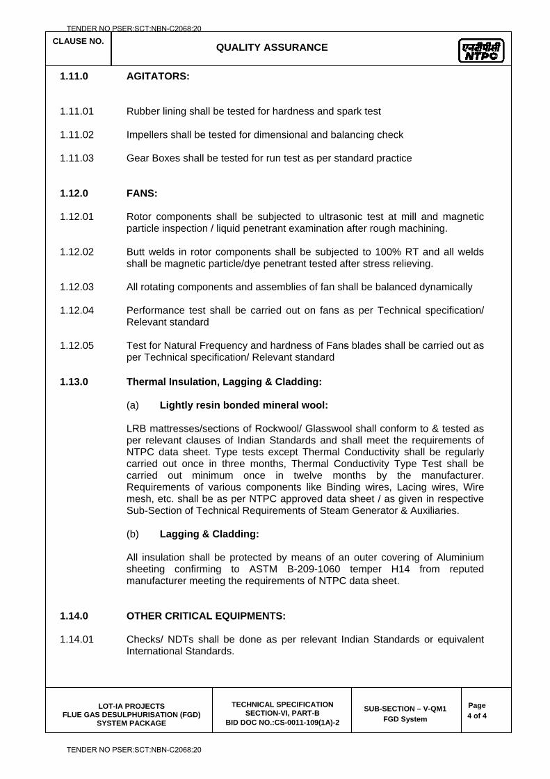
CLAUSE NO. QUALITY ASSURANCE
LOT-IA PROJECTS
FLUE GAS DESULPHURISATION (FGD) SYSTEM PACKAGE
TECHNICAL SPECIFICATION SECTION-VI, PART-B
BID DOC NO.:CS-0011-109(1A)-2
SUB-SECTION – V-QM1
FGD System
Page
4 of 4
1.11.0 AGITATORS: 1.11.01 Rubber lining shall be tested for hardness and spark test 1.11.02 Impellers shall be tested for dimensional and balancing check 1.11.03 Gear Boxes shall be tested for run test as per standard practice 1.12.0 FANS: 1.12.01 Rotor components shall be subjected to ultrasonic test at mill and magnetic
particle inspection / liquid penetrant examination after rough machining. 1.12.02 Butt welds in rotor components shall be subjected to 100% RT and all welds
shall be magnetic particle/dye penetrant tested after stress relieving. 1.12.03 All rotating components and assemblies of fan shall be balanced dynamically 1.12.04 Performance test shall be carried out on fans as per Technical specification/
Relevant standard 1.12.05 Test for Natural Frequency and hardness of Fans blades shall be carried out as
per Technical specification/ Relevant standard
1.13.0 Thermal Insulation, Lagging & Cladding: (a) Lightly resin bonded mineral wool: LRB mattresses/sections of Rockwool/ Glasswool shall conform to & tested as per relevant clauses of Indian Standards and shall meet the requirements of NTPC data sheet. Type tests except Thermal Conductivity shall be regularly carried out once in three months, Thermal Conductivity Type Test shall be carried out minimum once in twelve months by the manufacturer. Requirements of various components like Binding wires, Lacing wires, Wire mesh, etc. shall be as per NTPC approved data sheet / as given in respective Sub-Section of Technical Requirements of Steam Generator & Auxiliaries. (b) Lagging & Cladding: All insulation shall be protected by means of an outer covering of Aluminium sheeting confirming to ASTM B-209-1060 temper H14 from reputed manufacturer meeting the requirements of NTPC data sheet.
1.14.0 OTHER CRITICAL EQUIPMENTS: 1.14.01 Checks/ NDTs shall be done as per relevant Indian Standards or equivalent
International Standards.
TENDER NO PSER:SCT:NBN-C2068:20
TENDER NO PSER:SCT:NBN-C2068:20

LOT-IA PROJECTS FLUE GAS DESULPHURISATION (FGD) SYSTEM PACKAGE
TECHNICAL SPECIFICATION
SECTION-VI
BID DOCUMENT NO.: CS-0011-109(1A)-2
SUB-SECTION-V-QM2
LIME & GYPSUM HANDLING
TENDER NO PSER:SCT:NBN-C2068:20
TENDER NO PSER:SCT:NBN-C2068:20
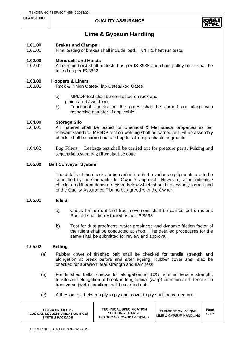
CLAUSE NO. QUALITY ASSURANCE
LOT-IA PROJECTS
FLUE GAS DESULPHURISATION (FGD) SYSTEM PACKAGE
TECHNICAL SPECIFICATION SECTION-VI, PART-B
BID DOC NO.:CS-0011-109(1A)-2
SUB-SECTION –V- QM2
LIME & GYPSUM HANDLING
Page
1 of 9
Lime & Gypsum Handling 1.01.00 Brakes and Clamps : 1.01.01 Final testing of brakes shall include load, HV/IR & heat run tests. 1.02.00 Monorails and Hoists 1.02.01 All electric hoist shall be tested as per IS 3938 and chain pulley block shall be
tested as per IS 3832. 1.03.00 Hoppers & Liners 1.03.01 Rack & Pinion Gates/Flap Gates/Rod Gates a) MPI/DP test shall be conducted on rack and pinion / rod / weld joint
b) Functional checks on the gates shall be carried out along with respective actuator, if applicable.
1.04.00 Storage Silo 1.04.01 All material shall be tested for Chemical & Mechanical properties as per
relevant standard. MPI/DP test on welding shall be carried out. Fit up assembly checks shall be carried out at shop for all despatchable segments
1.04.02 Bag Filters : Leakage test shall be carried out for pressure parts. Pulsing and
sequential test on bag filter shall be done. 1.05.00 Belt Conveyor System
The details of the checks to be carried out in the various equipments are to be submitted by the Contractor for Owner’s approval. However, some indicative checks on different items are given below which should necessarily form a part of the Quality Assurance Plan to be agreed with the Owner.
1.05.01 Idlers
a) Check for run out and free movement shall be carried out on idlers. Run out shall be restricted as per IS:8598
b) Test for dust proofness, water proofness and dynamic friction factor of the Idlers shall be conducted at shop. The detailed procedures for the same shall be submitted for review and approval.
1.05.02 Belting
(a) Rubber cover of finished belt shall be checked for tensile strength and elongation at break before and after ageing. Rubber cover shall also be checked for abrasion, tear strength and hardness.
(b) For finished belts, checks for elongation at 10% nominal tensile strength, tensile and elongation at break in longitudinal (warp) direction and tensile in transverse (weft) direction shall be carried out.
(c) Adhesion test between ply to ply and cover to ply shall be carried out.
TENDER NO PSER:SCT:NBN-C2068:20
TENDER NO PSER:SCT:NBN-C2068:20
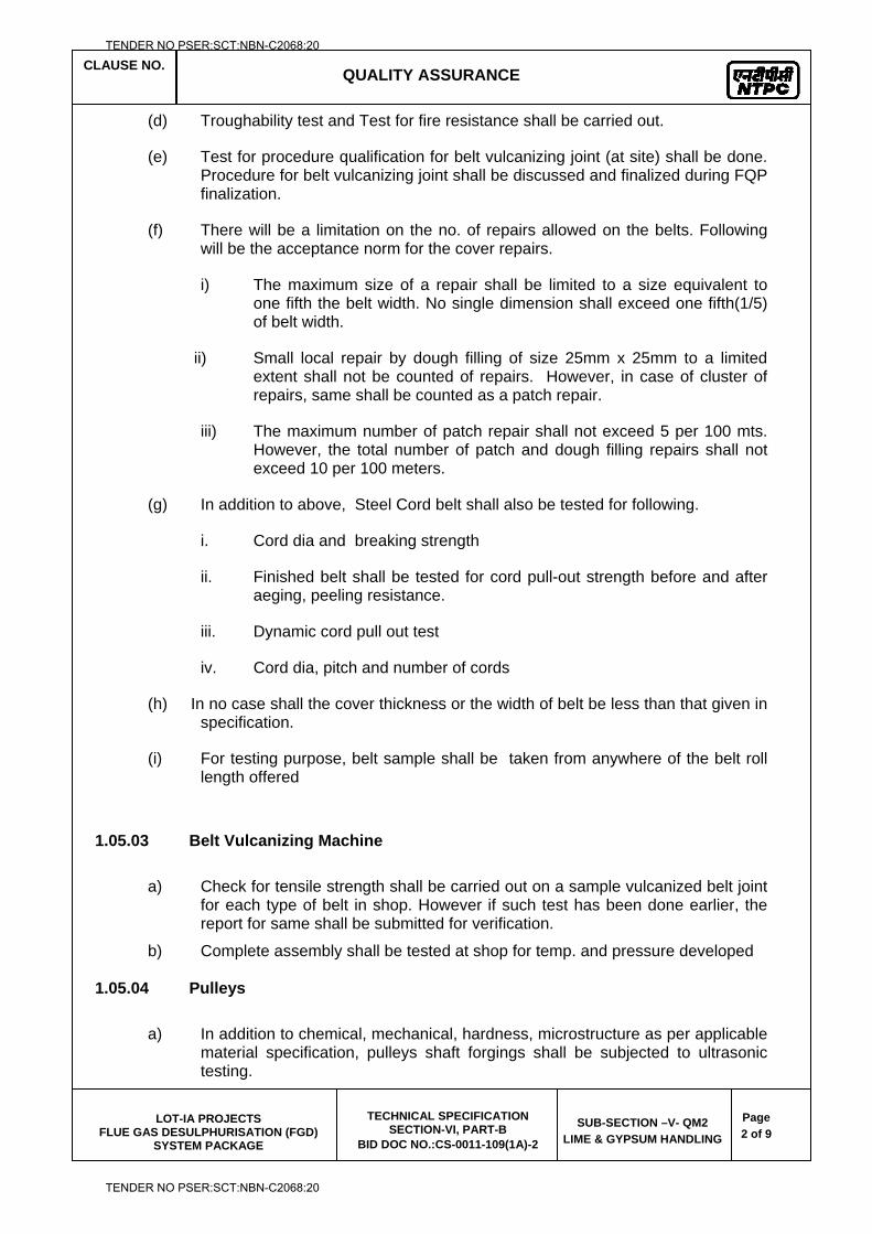
CLAUSE NO. QUALITY ASSURANCE
LOT-IA PROJECTS
FLUE GAS DESULPHURISATION (FGD) SYSTEM PACKAGE
TECHNICAL SPECIFICATION SECTION-VI, PART-B
BID DOC NO.:CS-0011-109(1A)-2
SUB-SECTION –V- QM2
LIME & GYPSUM HANDLING
Page
2 of 9
(d) Troughability test and Test for fire resistance shall be carried out.
(e) Test for procedure qualification for belt vulcanizing joint (at site) shall be done. Procedure for belt vulcanizing joint shall be discussed and finalized during FQP finalization.
(f) There will be a limitation on the no. of repairs allowed on the belts. Following will be the acceptance norm for the cover repairs.
i) The maximum size of a repair shall be limited to a size equivalent to one fifth the belt width. No single dimension shall exceed one fifth(1/5) of belt width.
ii) Small local repair by dough filling of size 25mm x 25mm to a limited extent shall not be counted of repairs. However, in case of cluster of repairs, same shall be counted as a patch repair.
iii) The maximum number of patch repair shall not exceed 5 per 100 mts. However, the total number of patch and dough filling repairs shall not exceed 10 per 100 meters.
(g) In addition to above, Steel Cord belt shall also be tested for following.
i. Cord dia and breaking strength
ii. Finished belt shall be tested for cord pull-out strength before and after aeging, peeling resistance.
iii. Dynamic cord pull out test
iv. Cord dia, pitch and number of cords
(h) In no case shall the cover thickness or the width of belt be less than that given in specification.
(i) For testing purpose, belt sample shall be taken from anywhere of the belt roll length offered
1.05.03 Belt Vulcanizing Machine
a) Check for tensile strength shall be carried out on a sample vulcanized belt joint for each type of belt in shop. However if such test has been done earlier, the report for same shall be submitted for verification.
b) Complete assembly shall be tested at shop for temp. and pressure developed 1.05.04 Pulleys
a) In addition to chemical, mechanical, hardness, microstructure as per applicable material specification, pulleys shaft forgings shall be subjected to ultrasonic testing.
TENDER NO PSER:SCT:NBN-C2068:20
TENDER NO PSER:SCT:NBN-C2068:20
CLAUSE NO. QUALITY ASSURANCE
LOT-IA PROJECTS
FLUE GAS DESULPHURISATION (FGD) SYSTEM PACKAGE
TECHNICAL SPECIFICATION SECTION-VI, PART-B
BID DOC NO.:CS-0011-109(1A)-2
SUB-SECTION –V- QM2
LIME & GYPSUM HANDLING
Page
3 of 9
b) 100% MPI/DPT on all welds shall be conducted and 10% RT/UT on butt welds shall be conducted.
c) Static balancing of pulleys shall be carried out after rubber lagging.
d) Checks on rubber lagging to include abrasion loss, shore hardness test, peel-off strength test and physical properties. Peel-off strength shall be 10 Kg/Cm, Abrasion loss shall be less than 250 cubic mm when tested as per DIN 53516.
1.05.05 Pull Chord & Belt Sway Switches
a. Acceptance tests
i) Over all dimension and functional test.
ii) HV & IR test
iii) Degree of protection test report.
1.05.06 Zero Speed Switch, Under Belt Switch and Chute Blockage Switch
a Acceptance test
i) Burn in test at 50 degree C for 48 hours shall be done for electronic switches.
ii) Over all dimension and functional test shall be carried out.
iii) HV & IR
iv) Degree of protection test
1.06.00 Drive Equipments 1.06.01 Gear Boxes :
(a) In addition to checks for physical, chemical, hardness,microstructure as per relevant standard, the shaft and gear/pinion forgings shall be subjected to ultrasonic testing .
(b) MPI to be carried out on Gears/Pinions after machining. Case depth, hardness and MPI after hardfacing shall be checked to ensure freedom from defects.
(c) Gear reducer shall be checked for reduction ratio, backlash and contact pattern. No load shop trial run to be conducted on gear boxes to check for oil leakage, temperature rise, noise level and vibration .
1.06.02 Flexible Coupling
(a) Ultrasonic testing shall be conducted on forgings for gear sleeve and gear hub, if gear coupling is provided.
(b) MPI shall be carried out after machining to ensure freedom from cracks.
TENDER NO PSER:SCT:NBN-C2068:20
TENDER NO PSER:SCT:NBN-C2068:20
CLAUSE NO. QUALITY ASSURANCE
LOT-IA PROJECTS
FLUE GAS DESULPHURISATION (FGD) SYSTEM PACKAGE
TECHNICAL SPECIFICATION SECTION-VI, PART-B
BID DOC NO.:CS-0011-109(1A)-2
SUB-SECTION –V- QM2
LIME & GYPSUM HANDLING
Page
4 of 9
1.06.03 Fluid Coupling
(a) Dynamic balancing shall be carried out for the rotating parts.
(b) Check for leak tightness of the coupling shall be carried out.
(c) Functional test on fusible plug for each type of coupling shall be conducted at shop.
(d) All couplings to be run tested at shop on no load
(e) Check for temperature rise, torque-speed, torque-slip characteristics and over speed test shall be included during performance test of one coupling of each type preferably at full load.
1.07.00 Belt Scales
The details of the checks to be carried out in the various equipments are to be submitted by the Contractor for Employer’s approval. However, some indicative checks are given below which should necessarily form a part of the quality assurance plan to be agreed with the Employer.
1.07.01 Mounting arrangement/Overall dimensional check shall be carried out on the Belt Scales.
1.07.02 Belt scale shall be calibrated with test weight/test chain in static at works and with test weight for dynamic condition at site.
1.07.03 All electronic modules shall be subjected to burn in test at 50 Degree C for 48 hours.
1.07.04 General check for load cell shall be carried out.
1.07.05 Test report for degree of protection on enclosure shall be furnished.
1.07.06 Accuracy/performance check shall be demonstrated at site.
1.08.00 Dust Control & Miscellaneous Systems(Dust Suppression & Dry Fog Dust Suppression System)
The details of the checks to be carried out on the various equipments are to be submitted by the Contractor for Owners approval. However some indicative checks on different items are given below which should necessarily form a part of the Quality Assurance Plan to be agreed with by the Owner.
1.08.01 Pumps
(a) All materials should be of tested quality and test certificates to be provided.
(b) DPT of machined shaft and impeller shall be done.
(c) Shaft forgings to be also subjected to ultrasonic testing.
(d) Impellers to be dynamically balanced to ISO 1940 Gr.6.3
TENDER NO PSER:SCT:NBN-C2068:20
TENDER NO PSER:SCT:NBN-C2068:20
CLAUSE NO. QUALITY ASSURANCE
LOT-IA PROJECTS
FLUE GAS DESULPHURISATION (FGD) SYSTEM PACKAGE
TECHNICAL SPECIFICATION SECTION-VI, PART-B
BID DOC NO.:CS-0011-109(1A)-2
SUB-SECTION –V- QM2
LIME & GYPSUM HANDLING
Page
5 of 9
(e) All pressure parts shall be hydraulically tested at 150% of the shut-off head or 200% of rated head, whichever is higher for 30 minutes. No leakage is allowed.
(f) All pumps to be performance tested as per Hydraulic Institute Standard/Indian Standard. Performance test to include check for noise, vibration level and temperature rise.
1.08.02 Valves & Specialities
(a) Valves and Specialities shall be tested as per relevant standards / codes.
(b) Seat Leakage and hydraulic test to be carried out as per relevant standards / codes.
1.08.03 Pipes and Fittings
Pipes and fittings shall be tested as per relevant standards/ codes
1.08.04 Air Compressor
a) All pressure parts shall be hydraulically tested at not less than 150% of design pressure for a duration of 30 minutes prior to painting.
b) All other parts including inter-connecting piping shall be hydraulically tested wherever possible, as per relevant codes.
c) Ultrasonic testing shall be carried out on all forgings and rotor for dia 50mm and above. MPI/DPT shall be done on machined area of the components.
d) During assembly all clearances and alignments shall also be checked and recorded
e) Rotor shall be statically and dynamically balanced
f) Performance Test(Shop Test)
i. Performance test on the compressor shall be carried out in accordance with ISO:1217/Eq. The test shall also include demonstration of loading and unloading mechanism(Capacity control) and operation of safety valve
ii. Vibration and Noise level measurement shall be done during shop performance test.
1.08.05 Air Receiver
a) Each finished vessel shall be hydraulically tested at 150% of the design pressure for a duration of 30 minutes
b) NDT on weld joints shall be as per respective code requirements or the minimum as specified below
i. 100% DPT on root run of butt welds
TENDER NO PSER:SCT:NBN-C2068:20
TENDER NO PSER:SCT:NBN-C2068:20
CLAUSE NO. QUALITY ASSURANCE
LOT-IA PROJECTS
FLUE GAS DESULPHURISATION (FGD) SYSTEM PACKAGE
TECHNICAL SPECIFICATION SECTION-VI, PART-B
BID DOC NO.:CS-0011-109(1A)-2
SUB-SECTION –V- QM2
LIME & GYPSUM HANDLING
Page
6 of 9
ii. 100% DPT on all finished butt welds and fillet welds
iii. 10% RT on butt welds which shall include all T-Joints
1.09.00 Dust Extraction and Ventilation System
1.09.01 Fan
(a) All materials should be of tested quality and test certificates should be provided.
(b) Dynamic balancing of the fan impellers to be carried out.
(c) Shop run test shall be conducted on all centrifugal fans including check for noise and vibration level.
(d) Performance test shall be conducted on one fan of each type at shop for capacity, pressure, efficiency and power consumption.
1.09.02 Valves and Specialties
Refer 1.08.02 above
1.09.03 Pipes and Fittings
Refer 1.08.03 above
1.09.04 Package Air-Conditioner
Each Unit shall be subjected to production routine Test excluding performance test carried out as per relevant standard. Performance test of PAC shall be carried out as per relevant standard on one unit of each type and rating at site.
1.10.00 Crushers
The details of the checks to be carried out for various components are to be submitted by the Contractor for Owner’s approval. However, some indicative checks on different items are given below which should necessarily form part of the Quality Assurance Plan to be agreed with the Owner.
(a) All plates equal to or above 25mm thickness shall be ultrasonically tested.
(b) Shaft forgings and suspension bars to be checked for ultrasonic testing in addition to check for chemical, mechanical, hardness, microstructure etc. as per applicable material specification.
(c) Following minimum NDT requirements to be ensured for welds:
i) Butt welds - 10% UT/RT and 100% MPI/DPT.
ii) Fillet Welds - 10% MPI/DPT.
TENDER NO PSER:SCT:NBN-C2068:20
TENDER NO PSER:SCT:NBN-C2068:20
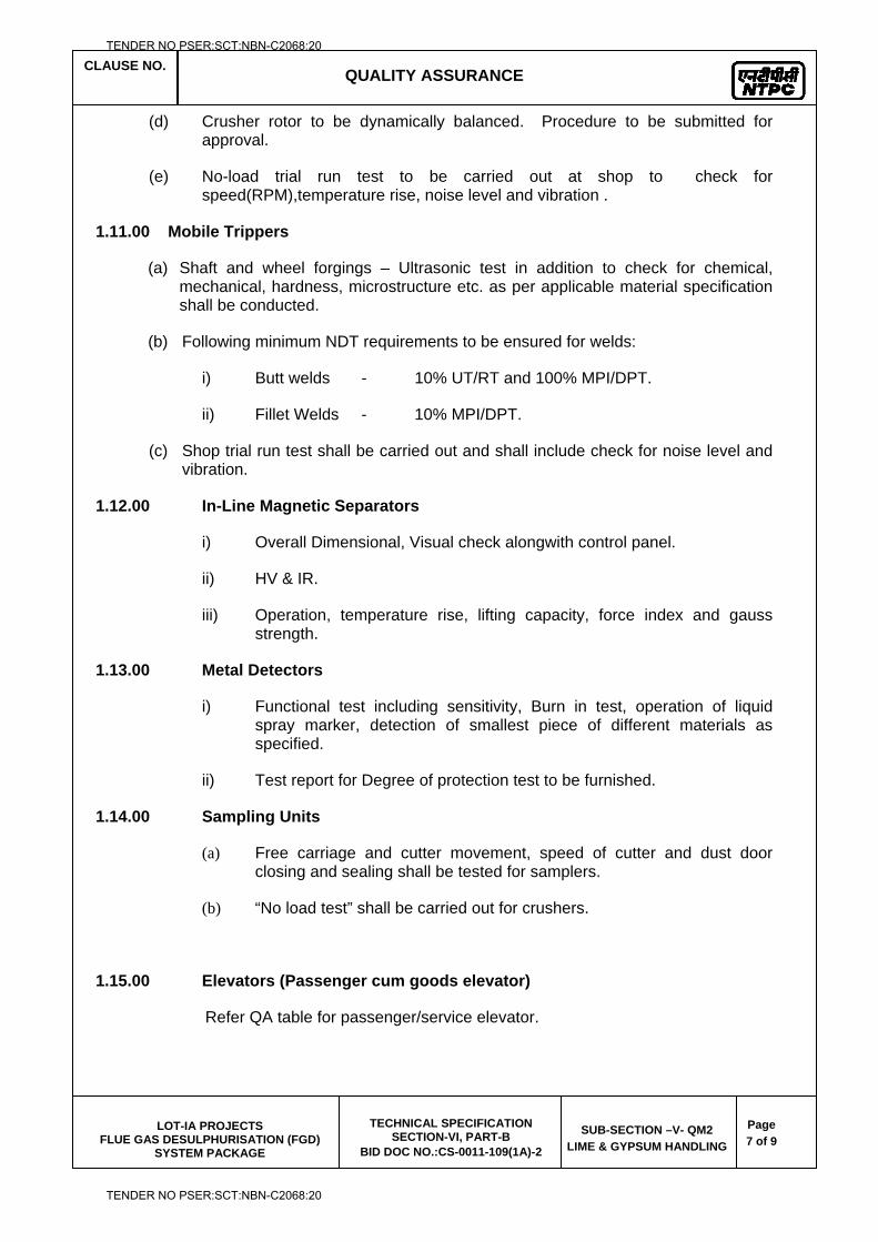
CLAUSE NO. QUALITY ASSURANCE
LOT-IA PROJECTS
FLUE GAS DESULPHURISATION (FGD) SYSTEM PACKAGE
TECHNICAL SPECIFICATION SECTION-VI, PART-B
BID DOC NO.:CS-0011-109(1A)-2
SUB-SECTION –V- QM2
LIME & GYPSUM HANDLING
Page
7 of 9
(d) Crusher rotor to be dynamically balanced. Procedure to be submitted for approval.
(e) No-load trial run test to be carried out at shop to check for speed(RPM),temperature rise, noise level and vibration .
1.11.00 Mobile Trippers
(a) Shaft and wheel forgings – Ultrasonic test in addition to check for chemical, mechanical, hardness, microstructure etc. as per applicable material specification shall be conducted.
(b) Following minimum NDT requirements to be ensured for welds:
i) Butt welds - 10% UT/RT and 100% MPI/DPT.
ii) Fillet Welds - 10% MPI/DPT.
(c) Shop trial run test shall be carried out and shall include check for noise level and vibration.
1.12.00 In-Line Magnetic Separators
i) Overall Dimensional, Visual check alongwith control panel.
ii) HV & IR.
iii) Operation, temperature rise, lifting capacity, force index and gauss strength.
1.13.00 Metal Detectors
i) Functional test including sensitivity, Burn in test, operation of liquid spray marker, detection of smallest piece of different materials as specified.
ii) Test report for Degree of protection test to be furnished.
1.14.00 Sampling Units
(a) Free carriage and cutter movement, speed of cutter and dust door closing and sealing shall be tested for samplers.
(b) “No load test” shall be carried out for crushers.
1.15.00 Elevators (Passenger cum goods elevator)
Refer QA table for passenger/service elevator.
TENDER NO PSER:SCT:NBN-C2068:20
TENDER NO PSER:SCT:NBN-C2068:20
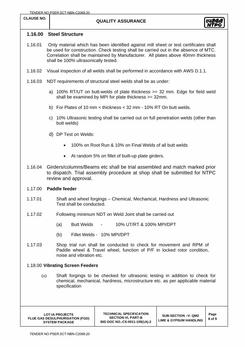
CLAUSE NO. QUALITY ASSURANCE
LOT-IA PROJECTS
FLUE GAS DESULPHURISATION (FGD) SYSTEM PACKAGE
TECHNICAL SPECIFICATION SECTION-VI, PART-B
BID DOC NO.:CS-0011-109(1A)-2
SUB-SECTION –V- QM2
LIME & GYPSUM HANDLING
Page
8 of 9
1.16.00 Steel Structure
1.16.01 Only material which has been identified against mill sheet or test certificates shall be used for construction. Check testing shall be carried out in the absence of MTC. Correlation shall be maintained by Manufacturer. All plates above 40mm thickness shall be 100% ultrasonically tested.
1.16.02 Visual inspection of all welds shall be performed in accordance with AWS D.1.1.
1.16.03 NDT requirements of structural steel welds shall be as under:
a) 100% RT/UT on butt-welds of plate thickness >= 32 mm. Edge for field weld shall be examined by MPI for plate thickness >= 32mm.
b) For Plates of 10 mm < thickness < 32 mm - 10% RT On butt welds.
c) 10% Ultrasonic testing shall be carried out on full penetration welds (other than butt welds)
d) DP Test on Welds:
100% on Root Run & 10% on Final Welds of all butt welds
At random 5% on fillet of built-up plate girders.
1.16.04 Girders/columns/Beams etc shall be trial assembled and match marked prior to dispatch. Trial assembly procedure at shop shall be submitted for NTPC review and approval.
1.17.00 Paddle feeder
1.17.01 Shaft and wheel forgings – Chemical, Mechanical, Hardness and Ultrasonic Test shall be conducted.
1.17.02 Following minimum NDT on Weld Joint shall be carried out
(a) Butt Welds - 10% UT/RT & 100% MPI/DPT
(b) Fillet Welds - 10% MPI/DPT
1.17.03 Shop trial run shall be conducted to check for movement and RPM of Paddle wheel & Travel wheel, function of P/F in locked rotor condition, noise and vibration etc.
1.18.00 Vibrating Screen Feeders
(a) Shaft forgings to be checked for ultrasonic testing in addition to check for chemical, mechanical, hardness, microstructure etc. as per applicable material specification
TENDER NO PSER:SCT:NBN-C2068:20
TENDER NO PSER:SCT:NBN-C2068:20
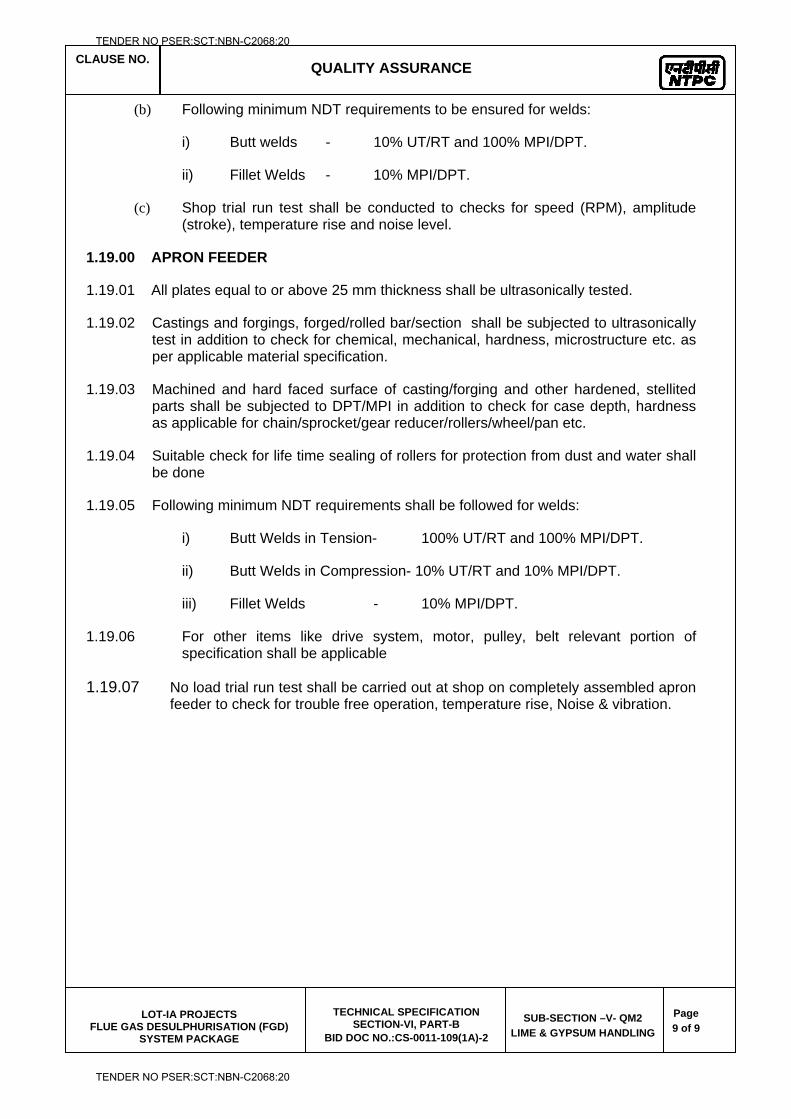
CLAUSE NO. QUALITY ASSURANCE
LOT-IA PROJECTS
FLUE GAS DESULPHURISATION (FGD) SYSTEM PACKAGE
TECHNICAL SPECIFICATION SECTION-VI, PART-B
BID DOC NO.:CS-0011-109(1A)-2
SUB-SECTION –V- QM2
LIME & GYPSUM HANDLING
Page
9 of 9
(b) Following minimum NDT requirements to be ensured for welds:
i) Butt welds - 10% UT/RT and 100% MPI/DPT.
ii) Fillet Welds - 10% MPI/DPT.
(c) Shop trial run test shall be conducted to checks for speed (RPM), amplitude (stroke), temperature rise and noise level.
1.19.00 APRON FEEDER
1.19.01 All plates equal to or above 25 mm thickness shall be ultrasonically tested.
1.19.02 Castings and forgings, forged/rolled bar/section shall be subjected to ultrasonically test in addition to check for chemical, mechanical, hardness, microstructure etc. as per applicable material specification.
1.19.03 Machined and hard faced surface of casting/forging and other hardened, stellited parts shall be subjected to DPT/MPI in addition to check for case depth, hardness as applicable for chain/sprocket/gear reducer/rollers/wheel/pan etc.
1.19.04 Suitable check for life time sealing of rollers for protection from dust and water shall be done
1.19.05 Following minimum NDT requirements shall be followed for welds:
i) Butt Welds in Tension- 100% UT/RT and 100% MPI/DPT.
ii) Butt Welds in Compression- 10% UT/RT and 10% MPI/DPT.
iii) Fillet Welds - 10% MPI/DPT.
1.19.06 For other items like drive system, motor, pulley, belt relevant portion of specification shall be applicable
1.19.07 No load trial run test shall be carried out at shop on completely assembled apron feeder to check for trouble free operation, temperature rise, Noise & vibration.
TENDER NO PSER:SCT:NBN-C2068:20
TENDER NO PSER:SCT:NBN-C2068:20

LOT-IA PROJECTS FLUE GAS DESULPHURISATION (FGD) SYSTEM PACKAGE
TECHNICAL SPECIFICATION
SECTION-VI
BID DOCUMENT NO.: CS-0011-109(1A)-2
SUB-SECTION-V-QM3
EQUIPMENT COOLING WATER SYSTEM
TENDER NO PSER:SCT:NBN-C2068:20
TENDER NO PSER:SCT:NBN-C2068:20
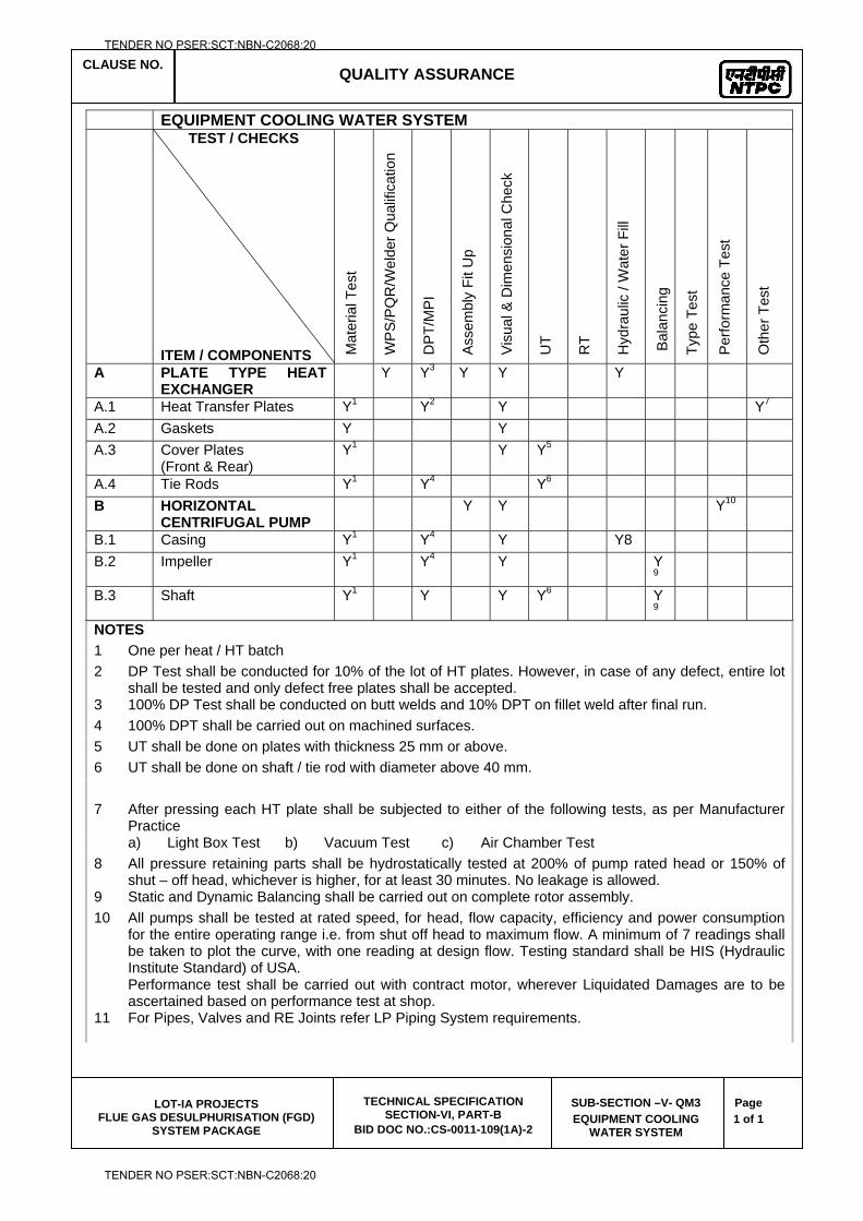
CLAUSE NO. QUALITY ASSURANCE
LOT-IA PROJECTS
FLUE GAS DESULPHURISATION (FGD) SYSTEM PACKAGE
TECHNICAL SPECIFICATION SECTION-VI, PART-B
BID DOC NO.:CS-0011-109(1A)-2
SUB-SECTION –V- QM3
EQUIPMENT COOLING WATER SYSTEM
Page
1 of 1
EQUIPMENT COOLING WATER SYSTEM TEST / CHECKS
ITEM / COMPONENTS Mat
eria
l Tes
t
WP
S/P
QR
/Wel
der Q
ualif
icat
ion
DP
T/M
PI
Asse
mbl
y Fi
t Up
Vis
ual &
Dim
ensi
onal
Che
ck
UT
RT
Hyd
raul
ic /
Wat
er F
ill
Bal
anci
ng
Type
Tes
t
Per
form
ance
Tes
t
Oth
er T
est
A PLATE TYPE HEAT EXCHANGER
Y Y3 Y Y Y
A.1 Heat Transfer Plates Y1 Y2 Y Y7 A.2 Gaskets Y Y A.3 Cover Plates
(Front & Rear) Y1 Y Y5
A.4 Tie Rods Y1 Y4 Y6 B HORIZONTAL
CENTRIFUGAL PUMP Y Y Y10
B.1 Casing Y1 Y4 Y Y8 B.2 Impeller Y1 Y4 Y Y
9
B.3 Shaft Y1 Y Y Y6 Y9
NOTES
1 One per heat / HT batch 2 DP Test shall be conducted for 10% of the lot of HT plates. However, in case of any defect, entire lot
shall be tested and only defect free plates shall be accepted. 3 100% DP Test shall be conducted on butt welds and 10% DPT on fillet weld after final run. 4 100% DPT shall be carried out on machined surfaces. 5 UT shall be done on plates with thickness 25 mm or above. 6 UT shall be done on shaft / tie rod with diameter above 40 mm. 7 After pressing each HT plate shall be subjected to either of the following tests, as per Manufacturer
Practice a) Light Box Test b) Vacuum Test c) Air Chamber Test 8 All pressure retaining parts shall be hydrostatically tested at 200% of pump rated head or 150% of
shut – off head, whichever is higher, for at least 30 minutes. No leakage is allowed. 9 Static and Dynamic Balancing shall be carried out on complete rotor assembly. 10 All pumps shall be tested at rated speed, for head, flow capacity, efficiency and power consumption
for the entire operating range i.e. from shut off head to maximum flow. A minimum of 7 readings shall be taken to plot the curve, with one reading at design flow. Testing standard shall be HIS (Hydraulic Institute Standard) of USA. Performance test shall be carried out with contract motor, wherever Liquidated Damages are to be ascertained based on performance test at shop.
11 For Pipes, Valves and RE Joints refer LP Piping System requirements.
TENDER NO PSER:SCT:NBN-C2068:20
TENDER NO PSER:SCT:NBN-C2068:20

LOT-IA PROJECTS FLUE GAS DESULPHURISATION (FGD) SYSTEM PACKAGE
TECHNICAL SPECIFICATION
SECTION-VI
BID DOCUMENT NO.: CS-0011-109(1A)-2
SUB-SECTION-V-QM4
AIR CONDITIONING & VENTILATION SYSTEM
TENDER NO PSER:SCT:NBN-C2068:20
TENDER NO PSER:SCT:NBN-C2068:20
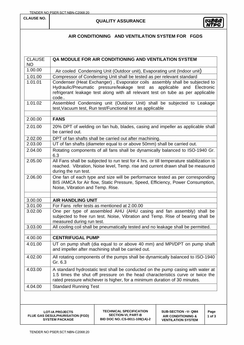
CLAUSE NO. QUALITY ASSURANCE
LOT-IA PROJECTS
FLUE GAS DESULPHURISATION (FGD) SYSTEM PACKAGE
TECHNICAL SPECIFICATION SECTION-VI, PART-B
BID DOC NO.:CS-0011-109(1A)-2
SUB-SECTION –V- QM4
AIR CONDITIONING & VENTILATION SYSTEM
Page
1 of 3
AIR CONDITIONING AND VENTILATION SYSTEM FOR FGDS
CLAUSE NO
QA MODULE FOR AIR CONDITIONING AND VENTILATION SYSTEM
1.00.00 Air cooled Condensing Unit (Outdoor unit), Evaporating unit (Indoor unit) 1.01.00 Compressor of Condensing Unit shall be tested as per relevant standard 1.01.01 Condenser (Heat Exchanger) , Evaporator coils assembly shall be subjected to
Hydraulic/Pneumatic pressure/leakage test as applicable and Electronic refrigerant leakage test along with all relevant test on tube as per applicable code..
1.01.02 Assembled Condensing unit (Outdoor Unit) shall be subjected to Leakage test,Vacuum test, Run test/Functional test as applicable
2.00.00 FANS
2.01.00 20% DPT of welding on fan hub, blades, casing and impeller as applicable shall be carried out.
2.02.00 DPT of fan shafts shall be carried out after machining. 2.03.00 UT of fan shafts (diameter equal to or above 50mm) shall be carried out. 2.04.00 Rotating components of all fans shall be dynamically balanced to ISO-1940 Gr.
6.3 2.05.00 All Fans shall be subjected to run test for 4 hrs. or till temperature stabilization is
reached. Vibration, Noise level, Temp. rise and current drawn shall be measured during the run test.
2.06.00 One fan of each type and size will be performance tested as per corresponding BIS /AMCA for Air flow, Static Pressure, Speed, Efficiency, Power Consumption, Noise, Vibration and Temp. Rise.
3.00.00 AIR HANDLING UNIT 3.01.00 For Fans refer tests as mentioned at 2.00.00 3.02.00 One per type of assembled AHU (AHU casing and fan assembly) shall be
subjected to free run test. Noise, Vibration and Temp. Rise of bearing shall be measured during run test.
3.03.00 All cooling coil shall be pneumatically tested and no leakage shall be permitted. 4.00.00 CENTRIFUGAL PUMP
4.01.00 UT on pump shaft (dia equal to or above 40 mm) and MPI/DPT on pump shaft and impeller after machining shall be carried out.
4.02.00 All rotating components of the pumps shall be dynamically balanced to ISO-1940 Gr. 6.3
4.03.00 A standard hydrostatic test shall be conducted on the pump casing with water at 1.5 times the shut off pressure on the head characteristics curve or twice the rated pressure whichever is higher, for a minimum duration of 30 minutes.
4.04.00 Standard Running Test
TENDER NO PSER:SCT:NBN-C2068:20
TENDER NO PSER:SCT:NBN-C2068:20
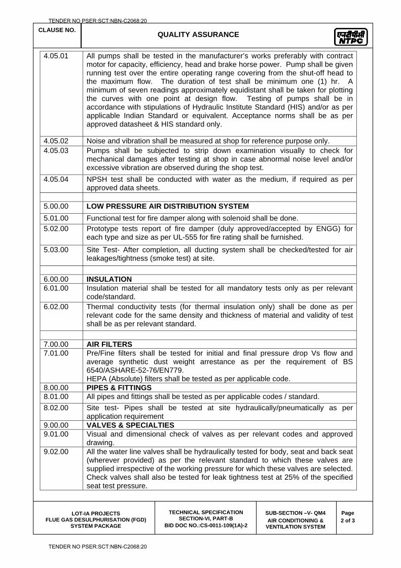
CLAUSE NO. QUALITY ASSURANCE
LOT-IA PROJECTS
FLUE GAS DESULPHURISATION (FGD) SYSTEM PACKAGE
TECHNICAL SPECIFICATION SECTION-VI, PART-B
BID DOC NO.:CS-0011-109(1A)-2
SUB-SECTION –V- QM4
AIR CONDITIONING & VENTILATION SYSTEM
Page
2 of 3
4.05.01 All pumps shall be tested in the manufacturer’s works preferably with contract motor for capacity, efficiency, head and brake horse power. Pump shall be given running test over the entire operating range covering from the shut-off head to the maximum flow. The duration of test shall be minimum one (1) hr. A minimum of seven readings approximately equidistant shall be taken for plotting the curves with one point at design flow. Testing of pumps shall be in accordance with stipulations of Hydraulic Institute Standard (HIS) and/or as per applicable Indian Standard or equivalent. Acceptance norms shall be as per approved datasheet & HIS standard only.
4.05.02 Noise and vibration shall be measured at shop for reference purpose only. 4.05.03 Pumps shall be subjected to strip down examination visually to check for
mechanical damages after testing at shop in case abnormal noise level and/or excessive vibration are observed during the shop test.
4.05.04 NPSH test shall be conducted with water as the medium, if required as per approved data sheets.
5.00.00 LOW PRESSURE AIR DISTRIBUTION SYSTEM
5.01.00 Functional test for fire damper along with solenoid shall be done. 5.02.00 Prototype tests report of fire damper (duly approved/accepted by ENGG) for
each type and size as per UL-555 for fire rating shall be furnished.
5.03.00 Site Test- After completion, all ducting system shall be checked/tested for air leakages/tightness (smoke test) at site.
6.00.00 INSULATION 6.01.00 Insulation material shall be tested for all mandatory tests only as per relevant
code/standard. 6.02.00 Thermal conductivity tests (for thermal insulation only) shall be done as per
relevant code for the same density and thickness of material and validity of test shall be as per relevant standard.
7.00.00 AIR FILTERS 7.01.00 Pre/Fine filters shall be tested for initial and final pressure drop Vs flow and
average synthetic dust weight arrestance as per the requirement of BS 6540/ASHARE-52-76/EN779. HEPA (Absolute) filters shall be tested as per applicable code.
8.00.00 PIPES & FITTINGS 8.01.00 All pipes and fittings shall be tested as per applicable codes / standard. 8.02.00 Site test- Pipes shall be tested at site hydraulically/pneumatically as per
application requirement 9.00.00 VALVES & SPECIALTIES 9.01.00 Visual and dimensional check of valves as per relevant codes and approved
drawing. 9.02.00 All the water line valves shall be hydraulically tested for body, seat and back seat
(wherever provided) as per the relevant standard to which these valves are supplied irrespective of the working pressure for which these valves are selected. Check valves shall also be tested for leak tightness test at 25% of the specified seat test pressure.
TENDER NO PSER:SCT:NBN-C2068:20
TENDER NO PSER:SCT:NBN-C2068:20
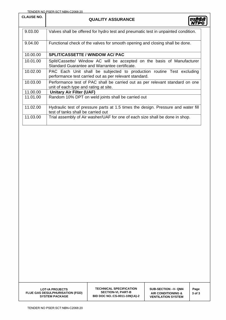
CLAUSE NO. QUALITY ASSURANCE
LOT-IA PROJECTS
FLUE GAS DESULPHURISATION (FGD) SYSTEM PACKAGE
TECHNICAL SPECIFICATION SECTION-VI, PART-B
BID DOC NO.:CS-0011-109(1A)-2
SUB-SECTION –V- QM4
AIR CONDITIONING & VENTILATION SYSTEM
Page
3 of 3
9.03.00 Valves shall be offered for hydro test and pneumatic test in unpainted condition.
9.04.00 Functional check of the valves for smooth opening and closing shall be done.
10.00.00 SPLIT/CASSETTE / WINDOW AC/ PAC
10.01.00 Split/Cassette/ Window AC will be accepted on the basis of Manufacturer Standard Guarantee and Warrantee certificate.
10.02.00 PAC Each Unit shall be subjected to production routine Test excluding performance test carried out as per relevant standard.
10.03.00 Performance test of PAC shall be carried out as per relevant standard on one unit of each type and rating at site.
11.00.00 Unitary Air Filter (UAF) 11.01.00 Random 10% DPT on weld joints shall be carried out
11.02.00 Hydraulic test of pressure parts at 1.5 times the design. Pressure and water fill test of tanks shall be carried out
11.03.00 Trial assembly of Air washer/UAF for one of each size shall be done in shop.
TENDER NO PSER:SCT:NBN-C2068:20
TENDER NO PSER:SCT:NBN-C2068:20

LOT-IA PROJECTS FLUE GAS DESULPHURISATION (FGD) SYSTEM PACKAGE
TECHNICAL SPECIFICATION
SECTION-VI
BID DOCUMENT NO.: CS-0011-109(1A)-2
SUB-SECTION-V-QM5
ZERO LIQUID DISCHARGE SYSTEM
TENDER NO PSER:SCT:NBN-C2068:20
TENDER NO PSER:SCT:NBN-C2068:20
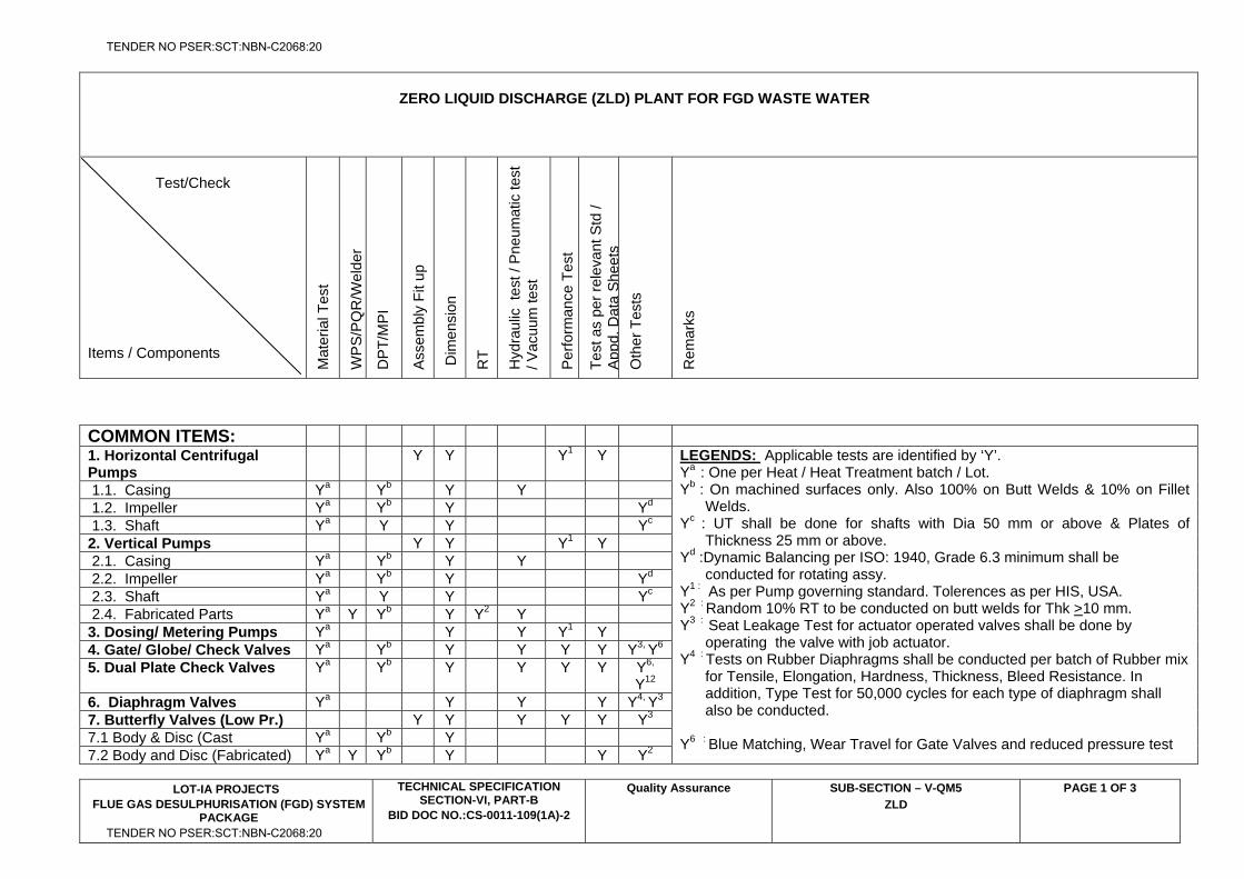
ZERO LIQUID DISCHARGE (ZLD) PLANT FOR FGD WASTE WATER
Test/Check
Items / Components M
ater
ial T
est
WP
S/P
QR
/Wel
der
DP
T/M
PI
Asse
mbl
y Fi
t up
Dim
ensi
on
RT
Hyd
raul
ic t
est /
Pne
umat
ic te
st
/ Vac
uum
test
Per
form
ance
Tes
t
Test
as
per r
elev
ant S
td /
Appd
. Dat
a Sh
eets
O
ther
Tes
ts
Rem
arks
LOT-IA PROJECTS FLUE GAS DESULPHURISATION (FGD) SYSTEM
PACKAGE
TECHNICAL SPECIFICATION SECTION-VI, PART-B
BID DOC NO.:CS-0011-109(1A)-2
Quality Assurance SUB-SECTION – V-QM5
ZLD
PAGE 1 OF 3
COMMON ITEMS:
1. Horizontal Centrifugal Pumps
Y Y Y1 Y LEGENDS: Applicable tests are identified by ‘Y’. Ya : One per Heat / Heat Treatment batch / Lot. Yb : On machined surfaces only. Also 100% on Butt Welds & 10% on Fillet
Welds. Yc : UT shall be done for shafts with Dia 50 mm or above & Plates of
Thickness 25 mm or above. Yd :Dynamic Balancing per ISO: 1940, Grade 6.3 minimum shall be
conducted for rotating assy. Y1 : As per Pump governing standard. Tolerences as per HIS, USA. Y2 : Random 10% RT to be conducted on butt welds for Thk >10 mm. Y3 : Seat Leakage Test for actuator operated valves shall be done by
operating the valve with job actuator. Y4 : Tests on Rubber Diaphragms shall be conducted per batch of Rubber mix
for Tensile, Elongation, Hardness, Thickness, Bleed Resistance. In addition, Type Test for 50,000 cycles for each type of diaphragm shall also be conducted.
Y6 : Blue Matching, Wear Travel for Gate Valves and reduced pressure test
1.1. Casing Ya Yb Y Y 1.2. Impeller Ya Yb Y Yd 1.3. Shaft Ya Y Y Yc 2. Vertical Pumps Y Y Y1 Y 2.1. Casing Ya Yb Y Y 2.2. Impeller Ya Yb Y Yd 2.3. Shaft Ya Y Y Yc 2.4. Fabricated Parts Ya Y Yb Y Y2 Y 3. Dosing/ Metering Pumps Ya Y Y Y1 Y 4. Gate/ Globe/ Check Valves Ya Yb Y Y Y Y Y3, Y6 5. Dual Plate Check Valves Ya Yb Y Y Y Y Y6,
Y12 6. Diaphragm Valves Ya Y Y Y Y4, Y3 7. Butterfly Valves (Low Pr.) Y Y Y Y Y Y3 7.1 Body & Disc (Cast Ya Yb Y 7.2 Body and Disc (Fabricated) Ya Y Yb Y Y Y2
TENDER NO PSER:SCT:NBN-C2068:20
TENDER NO PSER:SCT:NBN-C2068:20
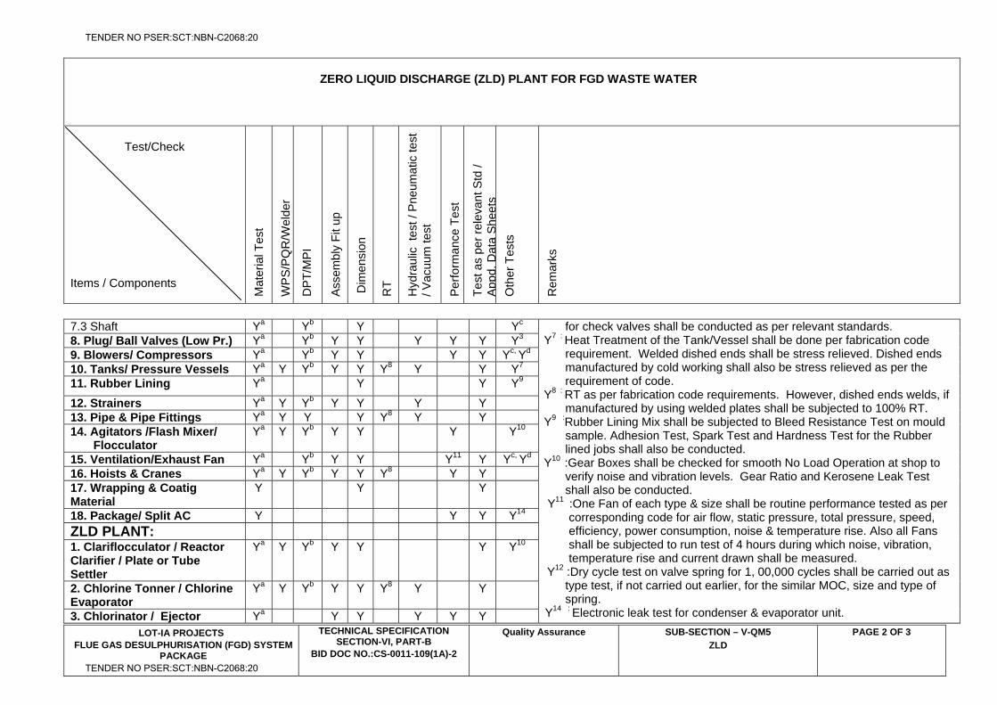
ZERO LIQUID DISCHARGE (ZLD) PLANT FOR FGD WASTE WATER
Test/Check
Items / Components M
ater
ial T
est
WP
S/P
QR
/Wel
der
DP
T/M
PI
Asse
mbl
y Fi
t up
Dim
ensi
on
RT
Hyd
raul
ic t
est /
Pne
umat
ic te
st
/ Vac
uum
test
Per
form
ance
Tes
t
Test
as
per r
elev
ant S
td /
Appd
. Dat
a Sh
eets
O
ther
Tes
ts
Rem
arks
LOT-IA PROJECTS FLUE GAS DESULPHURISATION (FGD) SYSTEM
PACKAGE
TECHNICAL SPECIFICATION SECTION-VI, PART-B
BID DOC NO.:CS-0011-109(1A)-2
Quality Assurance SUB-SECTION – V-QM5
ZLD
PAGE 2 OF 3
7.3 Shaft Ya Yb Y Yc for check valves shall be conducted as per relevant standards. Y7 : Heat Treatment of the Tank/Vessel shall be done per fabrication code
requirement. Welded dished ends shall be stress relieved. Dished ends manufactured by cold working shall also be stress relieved as per the requirement of code.
Y8 : RT as per fabrication code requirements. However, dished ends welds, if manufactured by using welded plates shall be subjected to 100% RT.
Y9 :Rubber Lining Mix shall be subjected to Bleed Resistance Test on mould sample. Adhesion Test, Spark Test and Hardness Test for the Rubber lined jobs shall also be conducted.
Y10 :Gear Boxes shall be checked for smooth No Load Operation at shop to verify noise and vibration levels. Gear Ratio and Kerosene Leak Test shall also be conducted.
Y11 :One Fan of each type & size shall be routine performance tested as per corresponding code for air flow, static pressure, total pressure, speed, efficiency, power consumption, noise & temperature rise. Also all Fans shall be subjected to run test of 4 hours during which noise, vibration, temperature rise and current drawn shall be measured.
Y12 :Dry cycle test on valve spring for 1, 00,000 cycles shall be carried out as type test, if not carried out earlier, for the similar MOC, size and type of spring.
Y14 : Electronic leak test for condenser & evaporator unit.
8. Plug/ Ball Valves (Low Pr.) Ya Yb Y Y Y Y Y Y3 9. Blowers/ Compressors Ya Yb Y Y Y Y Yc, Yd
10. Tanks/ Pressure Vessels Ya Y Yb Y Y Y8 Y Y Y7 11. Rubber Lining Ya Y Y Y9
12. Strainers Ya Y Yb Y Y Y Y 13. Pipe & Pipe Fittings Ya Y Y Y Y8 Y Y 14. Agitators /Flash Mixer/ Flocculator
Ya Y Yb Y Y Y Y10
15. Ventilation/Exhaust Fan Ya Yb Y Y Y11 Y Yc, Yd 16. Hoists & Cranes Ya Y Yb Y Y Y8 Y Y 17. Wrapping & Coatig Material
Y Y Y
18. Package/ Split AC Y Y Y Y14 ZLD PLANT: 1. Clariflocculator / Reactor Clarifier / Plate or Tube Settler
Ya Y Yb Y Y Y Y10
2. Chlorine Tonner / Chlorine Evaporator
Ya Y Yb Y Y Y8 Y Y
3. Chlorinator / Ejector Ya Y Y Y Y Y
TENDER NO PSER:SCT:NBN-C2068:20
TENDER NO PSER:SCT:NBN-C2068:20
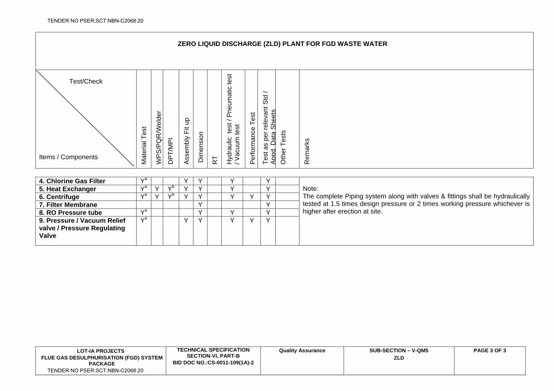
ZERO LIQUID DISCHARGE (ZLD) PLANT FOR FGD WASTE WATER
Test/Check
Items / Components M
ater
ial T
est
WP
S/P
QR
/Wel
der
DP
T/M
PI
Asse
mbl
y Fi
t up
Dim
ensi
on
RT
Hyd
raul
ic t
est /
Pne
umat
ic te
st
/ Vac
uum
test
Per
form
ance
Tes
t
Test
as
per r
elev
ant S
td /
Appd
. Dat
a Sh
eets
O
ther
Tes
ts
Rem
arks
LOT-IA PROJECTS FLUE GAS DESULPHURISATION (FGD) SYSTEM
PACKAGE
TECHNICAL SPECIFICATION SECTION-VI, PART-B
BID DOC NO.:CS-0011-109(1A)-2
Quality Assurance SUB-SECTION – V-QM5
ZLD
PAGE 3 OF 3
4. Chlorine Gas Filter Ya Y Y Y Y Note: The complete Piping system along with valves & fittings shall be hydraulically tested at 1.5 times design pressure or 2 times working pressure whichever is higher after erection at site.
5. Heat Exchanger Ya Y Yb Y Y Y Y 6. Centrifuge Ya Y Yb Y Y Y Y Y 7. Filter Membrane Y Y 8. RO Pressure tube Ya Y Y Y 9. Pressure / Vacuum Relief valve / Pressure Regulating Valve
Ya Y Y Y Y Y
TENDER NO PSER:SCT:NBN-C2068:20
TENDER NO PSER:SCT:NBN-C2068:20
LOT-IA PROJECTS FLUE GAS DESULPHURISATION (FGD) SYSTEM PACKAGE
TECHNICAL SPECIFICATION
SECTION-VI
BID DOCUMENT NO.: CS-0011-109(1A)-2
SUB-SECTION-V-QM6
COMPRESSOR AIR SYSTEM
TENDER NO PSER:SCT:NBN-C2068:20
TENDER NO PSER:SCT:NBN-C2068:20
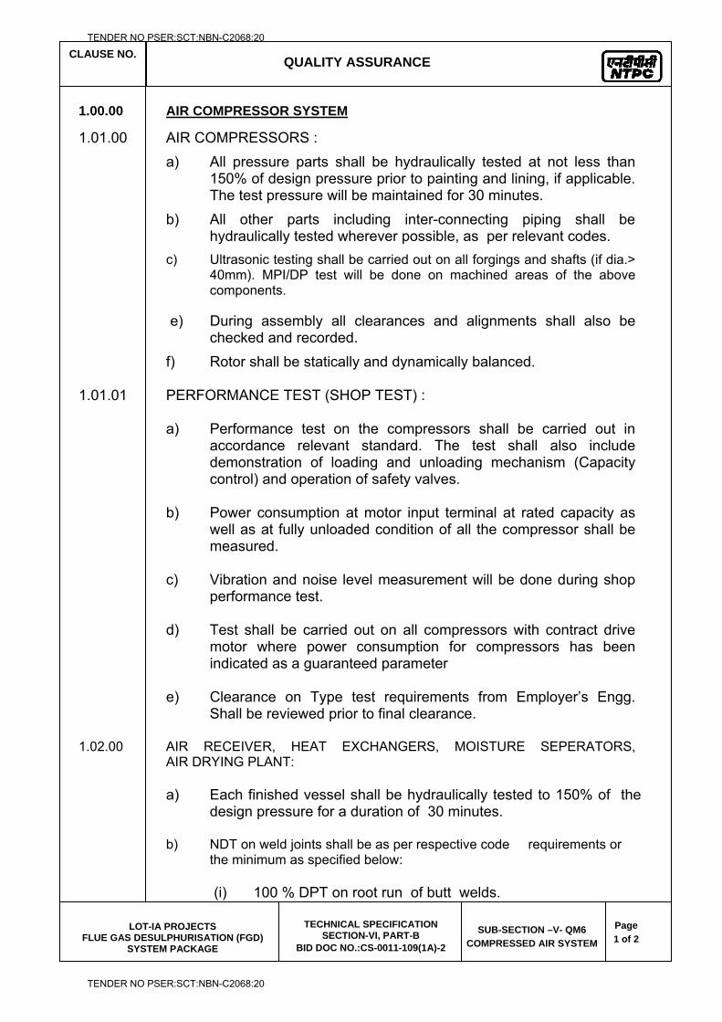
CLAUSE NO.
QUALITY ASSURANCE
LOT-IA PROJECTS
FLUE GAS DESULPHURISATION (FGD) SYSTEM PACKAGE
TECHNICAL SPECIFICATION SECTION-VI, PART-B
BID DOC NO.:CS-0011-109(1A)-2
SUB-SECTION –V- QM6
COMPRESSED AIR SYSTEM
Page
1 of 2
1.00.00 AIR COMPRESSOR SYSTEM
1.01.00 AIR COMPRESSORS :
a) All pressure parts shall be hydraulically tested at not less than 150% of design pressure prior to painting and lining, if applicable. The test pressure will be maintained for 30 minutes.
b) All other parts including inter-connecting piping shall be hydraulically tested wherever possible, as per relevant codes.
c) Ultrasonic testing shall be carried out on all forgings and shafts (if dia.> 40mm). MPI/DP test will be done on machined areas of the above components.
e) During assembly all clearances and alignments shall also be checked and recorded.
f) Rotor shall be statically and dynamically balanced. 1.01.01 PERFORMANCE TEST (SHOP TEST) : a) Performance test on the compressors shall be carried out in
accordance relevant standard. The test shall also include demonstration of loading and unloading mechanism (Capacity control) and operation of safety valves.
b) Power consumption at motor input terminal at rated capacity as
well as at fully unloaded condition of all the compressor shall be measured.
c) Vibration and noise level measurement will be done during shop
performance test. d) Test shall be carried out on all compressors with contract drive
motor where power consumption for compressors has been indicated as a guaranteed parameter
e) Clearance on Type test requirements from Employer’s Engg.
Shall be reviewed prior to final clearance. 1.02.00 AIR RECEIVER, HEAT EXCHANGERS, MOISTURE SEPERATORS,
AIR DRYING PLANT:
a) Each finished vessel shall be hydraulically tested to 150% of the design pressure for a duration of 30 minutes.
b) NDT on weld joints shall be as per respective code requirements or
the minimum as specified below:
(i) 100 % DPT on root run of butt welds.
TENDER NO PSER:SCT:NBN-C2068:20
TENDER NO PSER:SCT:NBN-C2068:20
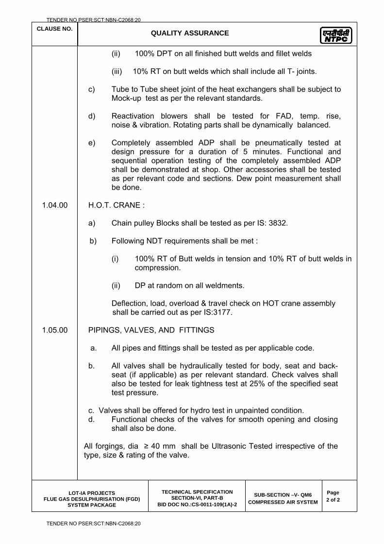
CLAUSE NO.
QUALITY ASSURANCE
LOT-IA PROJECTS
FLUE GAS DESULPHURISATION (FGD) SYSTEM PACKAGE
TECHNICAL SPECIFICATION SECTION-VI, PART-B
BID DOC NO.:CS-0011-109(1A)-2
SUB-SECTION –V- QM6
COMPRESSED AIR SYSTEM
Page
2 of 2
(ii) 100% DPT on all finished butt welds and fillet welds (iii) 10% RT on butt welds which shall include all T- joints.
c) Tube to Tube sheet joint of the heat exchangers shall be subject to
Mock-up test as per the relevant standards. d) Reactivation blowers shall be tested for FAD, temp. rise,
noise & vibration. Rotating parts shall be dynamically balanced. e) Completely assembled ADP shall be pneumatically tested at
design pressure for a duration of 5 minutes. Functional and sequential operation testing of the completely assembled ADP shall be demonstrated at shop. Other accessories shall be tested as per relevant code and sections. Dew point measurement shall be done.
1.04.00 H.O.T. CRANE : a) Chain pulley Blocks shall be tested as per IS: 3832. b) Following NDT requirements shall be met :
(i) 100% RT of Butt welds in tension and 10% RT of butt welds in
compression. (ii) DP at random on all weldments.
Deflection, load, overload & travel check on HOT crane assembly shall be carried out as per IS:3177.
1.05.00 PIPINGS, VALVES, AND FITTINGS
a. All pipes and fittings shall be tested as per applicable code. b. All valves shall be hydraulically tested for body, seat and back-
seat (if applicable) as per relevant standard. Check valves shall also be tested for leak tightness test at 25% of the specified seat test pressure.
c. Valves shall be offered for hydro test in unpainted condition. d. Functional checks of the valves for smooth opening and closing
shall also be done. All forgings, dia ≥ 40 mm shall be Ultrasonic Tested irrespective of the type, size & rating of the valve.
TENDER NO PSER:SCT:NBN-C2068:20
TENDER NO PSER:SCT:NBN-C2068:20
LOT-IA PROJECTS FLUE GAS DESULPHURISATION (FGD) SYSTEM PACKAGE
TECHNICAL SPECIFICATION
SECTION-VI
BID DOCUMENT NO.: CS-0011-109(1A)-2
SUB-SECTION-V-QM7
FIRE DETECTION & PROTECTION SYSTEM
TENDER NO PSER:SCT:NBN-C2068:20
TENDER NO PSER:SCT:NBN-C2068:20
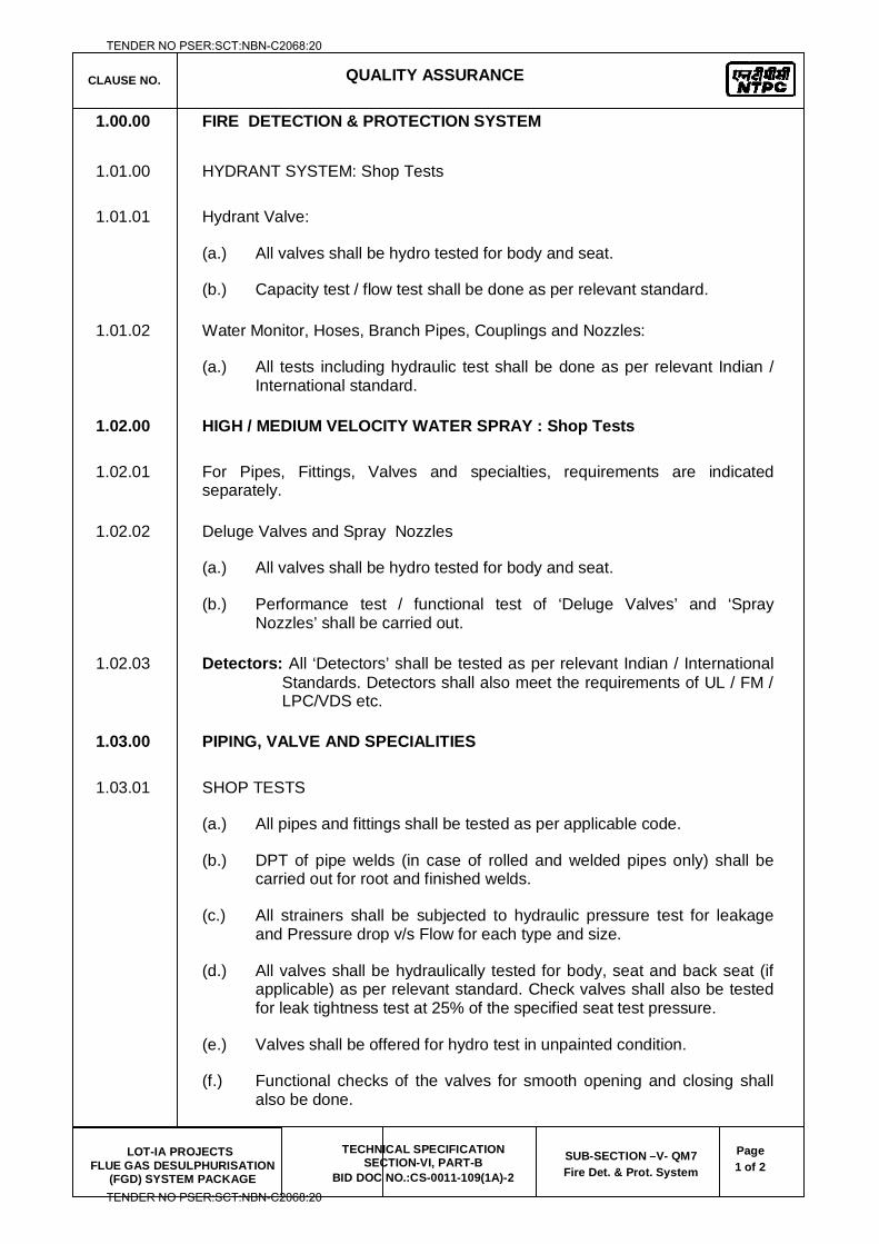
CLAUSE NO.
QUALITY ASSURANCE
LOT-IA PROJECTS FLUE GAS DESULPHURISATION
(FGD) SYSTEM PACKAGE
TECHNICAL SPECIFICATION SECTION-VI, PART-B
BID DOC NO.:CS-0011-109(1A)-2
SUB-SECTION –V- QM7 Fire Det. & Prot. System
Page 1 of 2
1.00.00 FIRE DETECTION & PROTECTION SYSTEM
1.01.00 HYDRANT SYSTEM: Shop Tests
1.01.01 Hydrant Valve:
(a.) All valves shall be hydro tested for body and seat.
(b.) Capacity test / flow test shall be done as per relevant standard.
1.01.02 Water Monitor, Hoses, Branch Pipes, Couplings and Nozzles:
(a.) All tests including hydraulic test shall be done as per relevant Indian / International standard.
1.02.00 HIGH / MEDIUM VELOCITY WATER SPRAY : Shop Tests
1.02.01 For Pipes, Fittings, Valves and specialties, requirements are indicated separately.
1.02.02 Deluge Valves and Spray Nozzles
(a.) All valves shall be hydro tested for body and seat.
(b.) Performance test / functional test of ‘Deluge Valves’ and ‘Spray Nozzles’ shall be carried out.
1.02.03 Detectors: All ‘Detectors’ shall be tested as per relevant Indian / International Standards. Detectors shall also meet the requirements of UL / FM / LPC/VDS etc.
1.03.00 PIPING, VALVE AND SPECIALITIES
1.03.01 SHOP TESTS
(a.) All pipes and fittings shall be tested as per applicable code.
(b.) DPT of pipe welds (in case of rolled and welded pipes only) shall be carried out for root and finished welds.
(c.) All strainers shall be subjected to hydraulic pressure test for leakage and Pressure drop v/s Flow for each type and size.
(d.) All valves shall be hydraulically tested for body, seat and back seat (if applicable) as per relevant standard. Check valves shall also be tested for leak tightness test at 25% of the specified seat test pressure.
(e.) Valves shall be offered for hydro test in unpainted condition.
(f.) Functional checks of the valves for smooth opening and closing shall also be done.
TENDER NO PSER:SCT:NBN-C2068:20
TENDER NO PSER:SCT:NBN-C2068:20
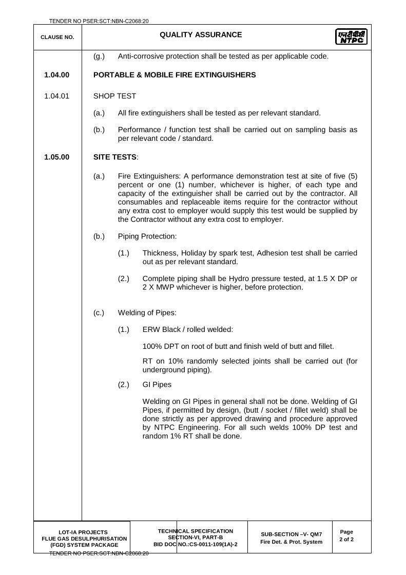
CLAUSE NO.
QUALITY ASSURANCE
LOT-IA PROJECTS FLUE GAS DESULPHURISATION
(FGD) SYSTEM PACKAGE
TECHNICAL SPECIFICATION SECTION-VI, PART-B
BID DOC NO.:CS-0011-109(1A)-2
SUB-SECTION –V- QM7 Fire Det. & Prot. System
Page 2 of 2
(g.) Anti-corrosive protection shall be tested as per applicable code.
1.04.00 PORTABLE & MOBILE FIRE EXTINGUISHERS
1.04.01 SHOP TEST
(a.) All fire extinguishers shall be tested as per relevant standard.
(b.) Performance / function test shall be carried out on sampling basis as per relevant code / standard.
1.05.00 SITE TESTS:
(a.) Fire Extinguishers: A performance demonstration test at site of five (5) percent or one (1) number, whichever is higher, of each type and capacity of the extinguisher shall be carried out by the contractor. All consumables and replaceable items require for the contractor without any extra cost to employer would supply this test would be supplied by the Contractor without any extra cost to employer.
(b.) Piping Protection:
(1.) Thickness, Holiday by spark test, Adhesion test shall be carried out as per relevant standard.
(2.) Complete piping shall be Hydro pressure tested, at 1.5 X DP or 2 X MWP whichever is higher, before protection.
(c.) Welding of Pipes:
(1.) ERW Black / rolled welded:
100% DPT on root of butt and finish weld of butt and fillet.
RT on 10% randomly selected joints shall be carried out (for underground piping).
(2.) GI Pipes
Welding on GI Pipes in general shall not be done. Welding of GI Pipes, if permitted by design, (butt / socket / fillet weld) shall be done strictly as per approved drawing and procedure approved by NTPC Engineering. For all such welds 100% DP test and random 1% RT shall be done.
TENDER NO PSER:SCT:NBN-C2068:20
TENDER NO PSER:SCT:NBN-C2068:20
LOT-IA PROJECTS FLUE GAS DESULPHURISATION (FGD) SYSTEM PACKAGE
TECHNICAL SPECIFICATION
SECTION-VI
BID DOCUMENT NO.: CS-0011-109(1A)-2
(ELECTRICAL)
TENDER NO PSER:SCT:NBN-C2068:20
TENDER NO PSER:SCT:NBN-C2068:20
LOT-IA PROJECTS FLUE GAS DESULPHURISATION (FGD) SYSTEM PACKAGE
TECHNICAL SPECIFICATION
SECTION-VI
BID DOCUMENT NO.: CS-0011-109(1A)-2
SUB-SECTION-V-QE1
MOTORS
TENDER NO PSER:SCT:NBN-C2068:20
TENDER NO PSER:SCT:NBN-C2068:20
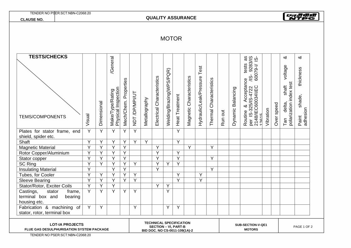
CLAUSE NO. QUALITY ASSURANCE
LOT-IA PROJECTS FLUE GAS DESULPHURISATION SYSTEM PACKAGE
TECHNICAL SPECIFICATION SECTION – VI, PART-B
BID DOC. NO CS-0011-109(1A)-2
SUB-SECTION-V-QE1
MOTORS PAGE 1 OF 2
MOTOR
TESTS/CHECKS
TEMS/COMPONENTS
Vis
ual
Dim
ensi
onal
Mak
e/Ty
pe/R
atin
g /G
ener
al
Phy
sica
l Ins
pect
ion
Mec
h/C
hem
. Pro
perti
es
ND
T /D
P/M
PI/U
T
Met
allo
grap
hy
Ele
ctric
al C
hara
cter
istic
s
Wel
ding
/Bra
zing
(WP
S/P
QR
)
Hea
t Tre
atm
ent
Mag
netic
Cha
ract
eris
tics
Hyd
raul
ic/L
eak/
Pre
ssur
e Te
st
Ther
mal
Cha
ract
eris
tics
Run
out
Dyn
amic
Bal
anci
ng
Rou
tine
& A
ccep
tanc
e t
ests
as
per
IS-3
25/IS
-472
2 /
IS-
9283
/IS
2148
/IEC
6003
4\IE
C
6007
9-I/
IS-
1261
5V
ibra
tion
Ove
r spe
ed
Tan
delta
, sh
aft
volta
ge
&
pola
rizat
ion
inde
x te
st
Pai
nt
shad
e,
thic
knes
s &
ad
hesi
on
Plates for stator frame, end shield, spider etc.
Y Y Y Y Y Y
Shaft Y Y Y Y Y Y Y Magnetic Material Y Y Y Y Y Y Y Rotor Copper/Aluminium Y Y Y Y Y Y Stator copper Y Y Y Y Y Y Y SC Ring Y Y Y Y Y Y Y Y Insulating Material Y Y Y Y Y Tubes, for Cooler Y Y Y Y Y Y Y Sleeve Bearing Y Y Y Y Y Y Y Stator/Rotor, Exciter Coils Y Y Y Y Y Castings, stator frame, terminal box and bearing housing etc.
Y Y Y Y Y Y
Fabrication & machining of stator, rotor, terminal box
Y Y Y Y Y
TENDER NO PSER:SCT:NBN-C2068:20
TENDER NO PSER:SCT:NBN-C2068:20
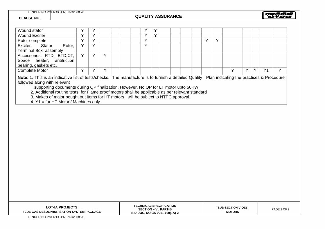
CLAUSE NO. QUALITY ASSURANCE
LOT-IA PROJECTS FLUE GAS DESULPHURISATION SYSTEM PACKAGE
TECHNICAL SPECIFICATION SECTION – VI, PART-B
BID DOC. NO CS-0011-109(1A)-2
SUB-SECTION-V-QE1
MOTORS PAGE 2 OF 2
Wound stator Y Y Y Y Wound Exciter Y Y Y Y Rotor complete Y Y Y Y Y Exciter, Stator, Rotor, Terminal Box assembly
Y Y Y
Accessories, RTD, BTD,CT, Space heater, antifriction bearing, gaskets etc.
Y Y Y
Complete Motor Y Y Y Y Y Y Y1 Y
Note: 1. This is an indicative list of tests/checks. The manufacture is to furnish a detailed Quality Plan indicating the practices & Procedure followed along with relevant supporting documents during QP finalization. However, No QP for LT motor upto 50KW. 2. Additional routine tests for Flame proof motors shall be applicable as per relevant standard 3. Makes of major bought out items for HT motors will be subject to NTPC approval. 4. Y1 = for HT Motor / Machines only.
TENDER NO PSER:SCT:NBN-C2068:20
TENDER NO PSER:SCT:NBN-C2068:20

LOT-IA PROJECTS FLUE GAS DESULPHURISATION (FGD) SYSTEM PACKAGE
TECHNICAL SPECIFICATION
SECTION-VI
BID DOCUMENT NO.: CS-0011-109(1A)-2
SUB-SECTION-V-QE2
MEDIUM VOLTAGE BUS DUCTS
TENDER NO PSER:SCT:NBN-C2068:20
TENDER NO PSER:SCT:NBN-C2068:20
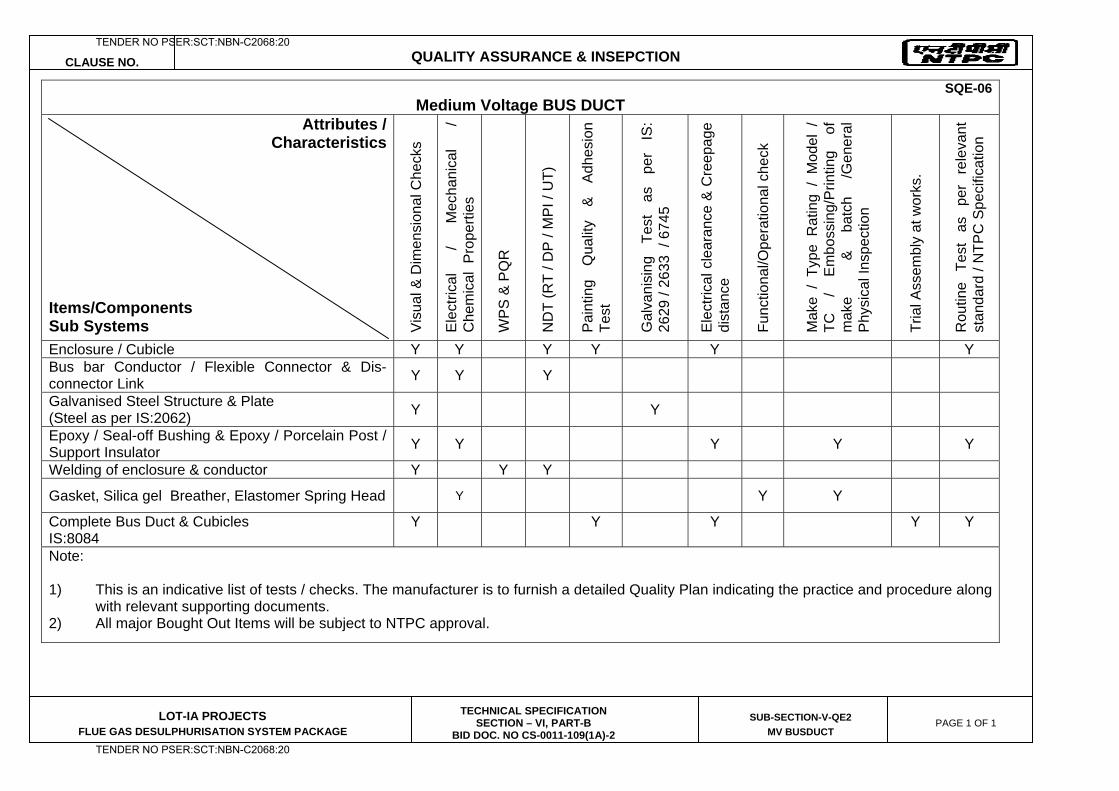
CLAUSE NO. QUALITY ASSURANCE & INSEPCTION
LOT-IA PROJECTS FLUE GAS DESULPHURISATION SYSTEM PACKAGE
TECHNICAL SPECIFICATION SECTION – VI, PART-B
BID DOC. NO CS-0011-109(1A)-2
SUB-SECTION-V-QE2
MV BUSDUCT PAGE 1 OF 1
SQE-06 Medium Voltage BUS DUCT
Attributes / Characteristics
Items/Components Sub Systems V
isua
l & D
imen
sion
al C
heck
s
Ele
ctric
al
/ M
echa
nica
l /
Che
mic
al P
rope
rties
WP
S &
PQ
R
ND
T (R
T / D
P /
MP
I / U
T)
Pai
ntin
g Q
ualit
y &
Ad
hesi
on
Test
Gal
vani
sing
Te
st
as
per
IS:
2629
/ 26
33 /
674
5
Ele
ctric
al c
lear
ance
& C
reep
age
dist
ance
Func
tiona
l/Ope
ratio
nal c
heck
Mak
e /
Type
Rat
ing
/ M
odel
/
TC
/ E
mbo
ssin
g/P
rintin
g of
m
ake
&
ba
tch
/Gen
eral
P
hysi
cal I
nspe
ctio
n
Tria
l Ass
embl
y at
wor
ks.
Rou
tine
Test
as
pe
r re
leva
nt
stan
dard
/ N
TPC
Spe
cific
atio
n
Enclosure / Cubicle Y Y Y Y Y Y Bus bar Conductor / Flexible Connector & Dis-connector Link Y Y Y
Galvanised Steel Structure & Plate (Steel as per IS:2062) Y Y
Epoxy / Seal-off Bushing & Epoxy / Porcelain Post / Support Insulator Y Y Y Y Y
Welding of enclosure & conductor Y Y Y
Gasket, Silica gel Breather, Elastomer Spring Head Y Y Y
Complete Bus Duct & Cubicles IS:8084
Y Y Y Y Y
Note: 1) This is an indicative list of tests / checks. The manufacturer is to furnish a detailed Quality Plan indicating the practice and procedure along
with relevant supporting documents. 2) All major Bought Out Items will be subject to NTPC approval.
TENDER NO PSER:SCT:NBN-C2068:20
TENDER NO PSER:SCT:NBN-C2068:20

LOT-IA PROJECTS FLUE GAS DESULPHURISATION (FGD) SYSTEM PACKAGE
TECHNICAL SPECIFICATION
SECTION-VI
BID DOCUMENT NO.: CS-0011-109(1A)-2
SUB-SECTION-V-QE3
LT POWER CABLES
TENDER NO PSER:SCT:NBN-C2068:20
TENDER NO PSER:SCT:NBN-C2068:20
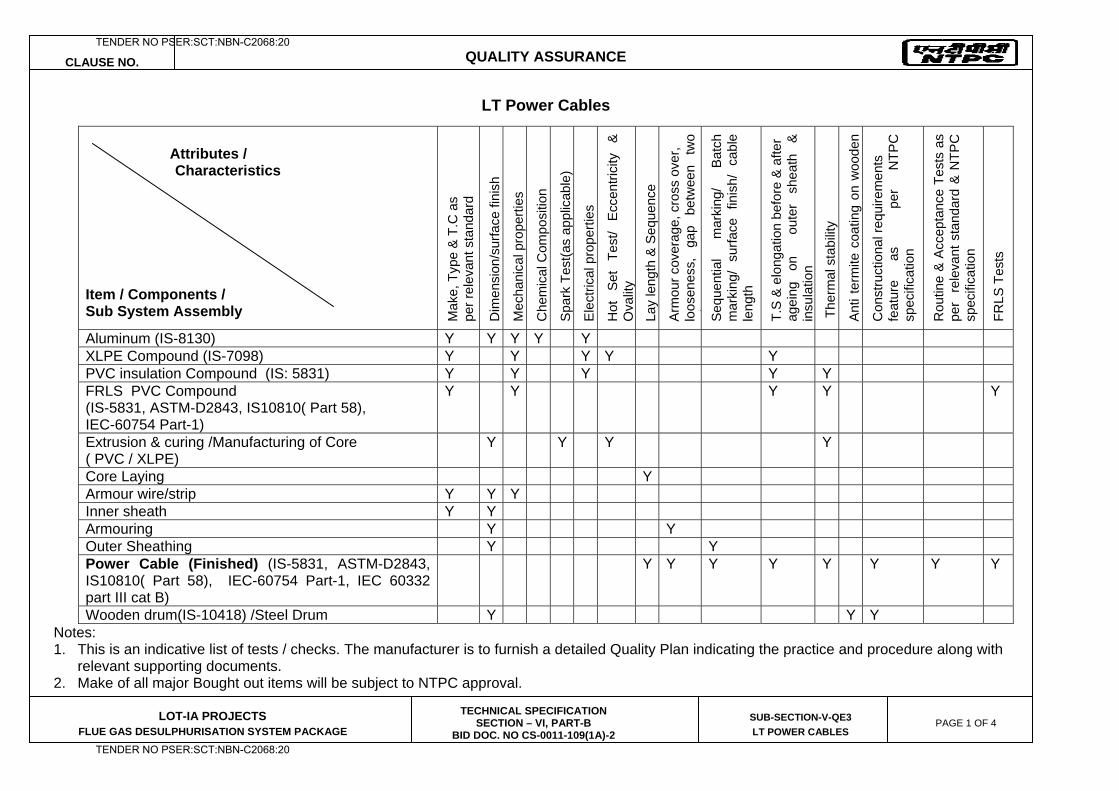
CLAUSE NO. QUALITY ASSURANCE
LOT-IA PROJECTS FLUE GAS DESULPHURISATION SYSTEM PACKAGE
TECHNICAL SPECIFICATION SECTION – VI, PART-B
BID DOC. NO CS-0011-109(1A)-2
SUB-SECTION-V-QE3
LT POWER CABLES PAGE 1 OF 4
LT Power Cables
Notes: 1. This is an indicative list of tests / checks. The manufacturer is to furnish a detailed Quality Plan indicating the practice and procedure along with
relevant supporting documents. 2. Make of all major Bought out items will be subject to NTPC approval.
Attributes / Characteristics Item / Components / Sub System Assembly M
ake,
Typ
e &
T.C
as
pe
r rel
evan
t sta
ndar
d
Dim
ensi
on/s
urfa
ce fi
nish
Mec
hani
cal p
rope
rties
Che
mic
al C
ompo
sitio
n
Spa
rk T
est(a
s ap
plic
able
)
Ele
ctric
al p
rope
rties
Hot
Se
t Te
st/
Ecce
ntric
ity
& O
valit
y
Lay
leng
th &
Seq
uenc
e
Arm
our c
over
age,
cro
ss o
ver,
lo
osen
ess,
ga
p be
twee
n tw
o i
Seq
uent
ial
mar
king
/ B
atch
m
arki
ng/
surfa
ce f
inis
h/ c
able
le
ngth
T.S
& e
long
atio
n be
fore
& a
fter
agei
ng
on
ou
ter
shea
th
&
insu
latio
n
The
rmal
sta
bilit
y
Ant
i ter
mite
coa
ting
on w
oode
n
Con
stru
ctio
nal r
equi
rem
ents
fe
atur
e as
per
NTP
C
spec
ifica
tion
Rou
tine
& A
ccep
tanc
e Te
sts
as
per
rel
evan
t sta
ndar
d &
NTP
C
spec
ifica
tion
FRLS
Tes
ts
Aluminum (IS-8130) Y Y Y Y Y XLPE Compound (IS-7098) Y Y Y Y Y PVC insulation Compound (IS: 5831) Y Y Y Y Y FRLS PVC Compound (IS-5831, ASTM-D2843, IS10810( Part 58), IEC-60754 Part-1)
Y Y Y Y Y
Extrusion & curing /Manufacturing of Core ( PVC / XLPE)
Y Y Y Y
Core Laying Y Armour wire/strip Y Y Y Inner sheath Y Y Armouring Y Y Outer Sheathing Y Y Power Cable (Finished) (IS-5831, ASTM-D2843, IS10810( Part 58), IEC-60754 Part-1, IEC 60332 part III cat B)
Y Y Y Y Y Y Y Y
Wooden drum(IS-10418) /Steel Drum Y Y Y
TENDER NO PSER:SCT:NBN-C2068:20
TENDER NO PSER:SCT:NBN-C2068:20
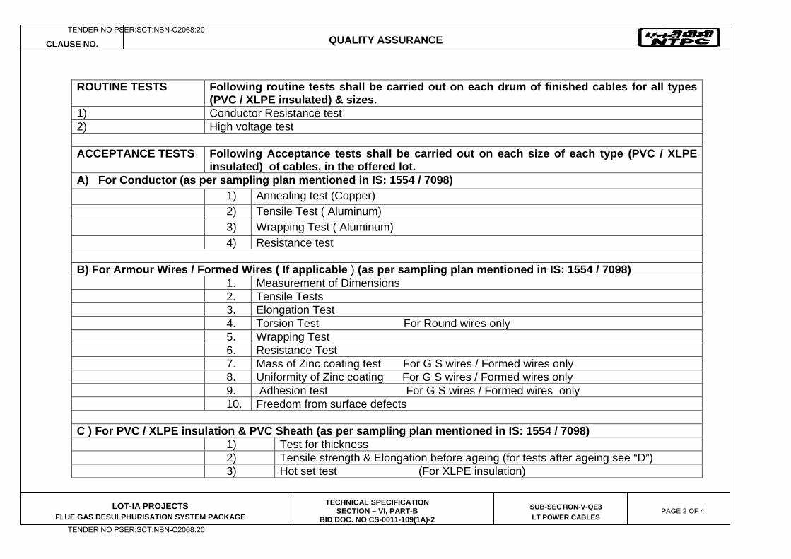
CLAUSE NO. QUALITY ASSURANCE
LOT-IA PROJECTS FLUE GAS DESULPHURISATION SYSTEM PACKAGE
TECHNICAL SPECIFICATION SECTION – VI, PART-B
BID DOC. NO CS-0011-109(1A)-2
SUB-SECTION-V-QE3
LT POWER CABLES PAGE 2 OF 4
ROUTINE TESTS Following routine tests shall be carried out on each drum of finished cables for all types
(PVC / XLPE insulated) & sizes. 1) Conductor Resistance test 2) High voltage test ACCEPTANCE TESTS
Following Acceptance tests shall be carried out on each size of each type (PVC / XLPE insulated) of cables, in the offered lot.
A) For Conductor (as per sampling plan mentioned in IS: 1554 / 7098) 1) Annealing test (Copper) 2) Tensile Test ( Aluminum) 3) Wrapping Test ( Aluminum) 4) Resistance test
B) For Armour Wires / Formed Wires ( If applicable ) (as per sampling plan mentioned in IS: 1554 / 7098) 1. Measurement of Dimensions 2. Tensile Tests 3. Elongation Test 4. Torsion Test For Round wires only 5. Wrapping Test 6. Resistance Test 7. Mass of Zinc coating test For G S wires / Formed wires only 8. Uniformity of Zinc coating For G S wires / Formed wires only 9. Adhesion test For G S wires / Formed wires only 10. Freedom from surface defects C ) For PVC / XLPE insulation & PVC Sheath (as per sampling plan mentioned in IS: 1554 / 7098) 1) Test for thickness 2) Tensile strength & Elongation before ageing (for tests after ageing see “D”) 3) Hot set test (For XLPE insulation)
TENDER NO PSER:SCT:NBN-C2068:20
TENDER NO PSER:SCT:NBN-C2068:20
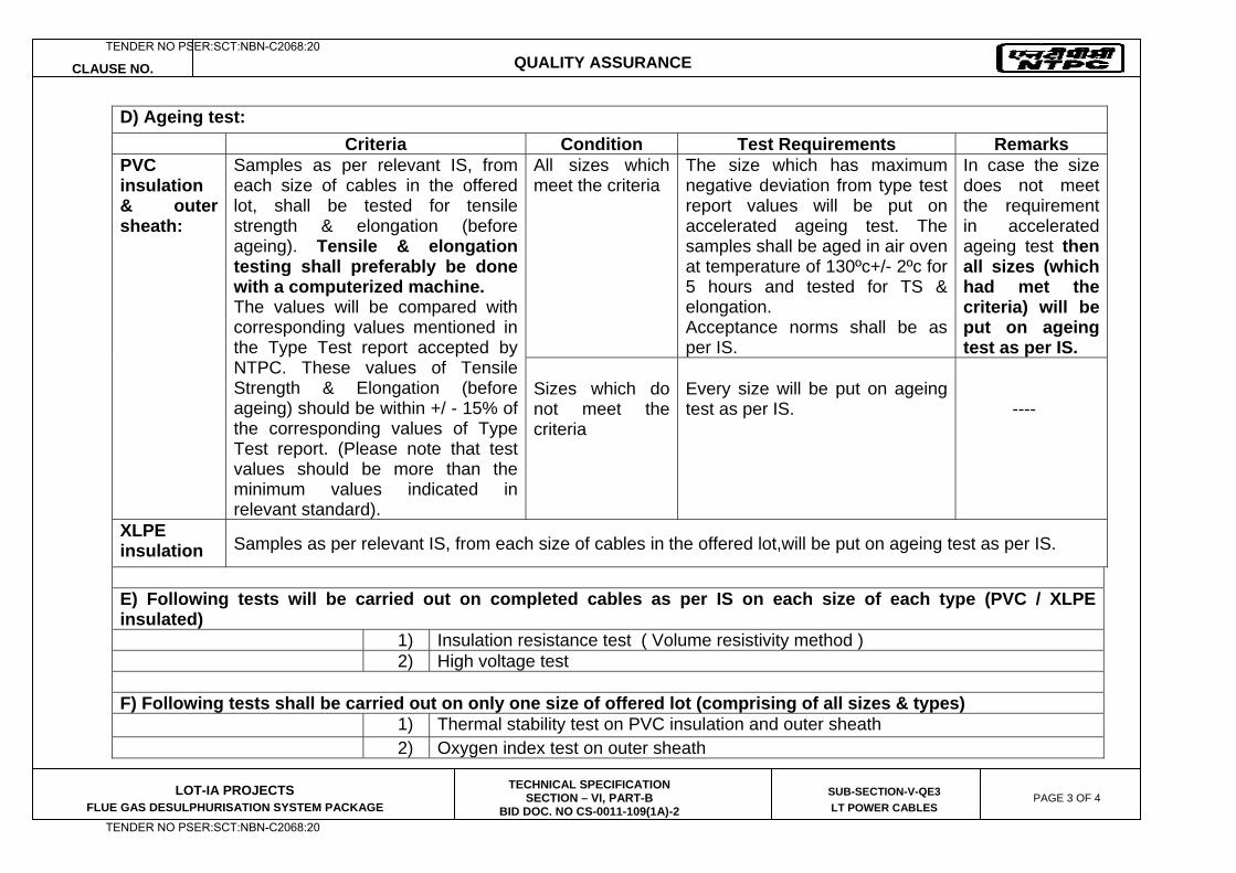
CLAUSE NO. QUALITY ASSURANCE
LOT-IA PROJECTS FLUE GAS DESULPHURISATION SYSTEM PACKAGE
TECHNICAL SPECIFICATION SECTION – VI, PART-B
BID DOC. NO CS-0011-109(1A)-2
SUB-SECTION-V-QE3
LT POWER CABLES PAGE 3 OF 4
D) Ageing test: Criteria Condition Test Requirements Remarks
PVC insulation & outer sheath:
Samples as per relevant IS, from each size of cables in the offered lot, shall be tested for tensile strength & elongation (before ageing). Tensile & elongation testing shall preferably be done with a computerized machine. The values will be compared with corresponding values mentioned in the Type Test report accepted by NTPC. These values of Tensile Strength & Elongation (before ageing) should be within +/ - 15% of the corresponding values of Type Test report. (Please note that test values should be more than the minimum values indicated in relevant standard).
All sizes which meet the criteria
The size which has maximum negative deviation from type test report values will be put on accelerated ageing test. The samples shall be aged in air oven at temperature of 130ºc+/- 2ºc for 5 hours and tested for TS & elongation. Acceptance norms shall be as per IS.
In case the size does not meet the requirement in accelerated ageing test then all sizes (which had met the criteria) will be put on ageing test as per IS.
Sizes which do not meet the criteria
Every size will be put on ageing test as per IS.
----
XLPE insulation Samples as per relevant IS, from each size of cables in the offered lot,will be put on ageing test as per IS.
E) Following tests will be carried out on completed cables as per IS on each size of each type (PVC / XLPE insulated) 1) Insulation resistance test ( Volume resistivity method ) 2) High voltage test F) Following tests shall be carried out on only one size of offered lot (comprising of all sizes & types) 1) Thermal stability test on PVC insulation and outer sheath 2) Oxygen index test on outer sheath
TENDER NO PSER:SCT:NBN-C2068:20
TENDER NO PSER:SCT:NBN-C2068:20
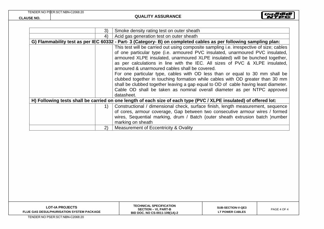
CLAUSE NO. QUALITY ASSURANCE
LOT-IA PROJECTS FLUE GAS DESULPHURISATION SYSTEM PACKAGE
TECHNICAL SPECIFICATION SECTION – VI, PART-B
BID DOC. NO CS-0011-109(1A)-2
SUB-SECTION-V-QE3
LT POWER CABLES PAGE 4 OF 4
3) Smoke density rating test on outer sheath 4) Acid gas generation test on outer sheath G) Flammability test as per IEC 60332 - Part- 3 (Category- B) on completed cables as per following sampling plan: This test will be carried out using composite sampling i.e. irrespective of size; cables
of one particular type (i.e. armoured PVC insulated, unarmoured PVC insulated, armoured XLPE insulated, unarmoured XLPE insulated) will be bunched together, as per calculations in line with the IEC. All sizes of PVC & XLPE insulated, armoured & unarmoured cables shall be covered. For one particular type, cables with OD less than or equal to 30 mm shall be clubbed together in touching formation while cables with OD greater than 30 mm shall be clubbed together leaving a gap equal to OD of cable having least diameter. Cable OD shall be taken as nominal overall diameter as per NTPC approved datasheet.
H) Following tests shall be carried on one length of each size of each type (PVC / XLPE insulated) of offered lot: 1) Constructional / dimensional check, surface finish, length measurement, sequence
of cores, armour coverage, Gap between two consecutive armour wires / formed wires, Sequential marking, drum / Batch (outer sheath extrusion batch )number marking on sheath
2) Measurement of Eccentricity & Ovality
TENDER NO PSER:SCT:NBN-C2068:20
TENDER NO PSER:SCT:NBN-C2068:20
LOT-IA PROJECTS FLUE GAS DESULPHURISATION (FGD) SYSTEM PACKAGE
TECHNICAL SPECIFICATION
SECTION-VI
BID DOCUMENT NO.: CS-0011-109(1A)-2
SUB-SECTION-V-QE4
CONTROL CABLES
TENDER NO PSER:SCT:NBN-C2068:20
TENDER NO PSER:SCT:NBN-C2068:20
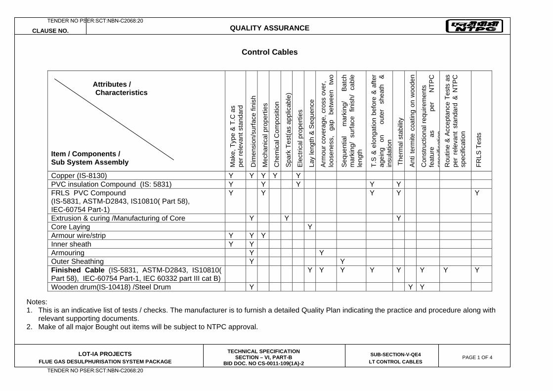
CLAUSE NO. QUALITY ASSURANCE
LOT-IA PROJECTS FLUE GAS DESULPHURISATION SYSTEM PACKAGE
TECHNICAL SPECIFICATION SECTION – VI, PART-B
BID DOC. NO CS-0011-109(1A)-2
SUB-SECTION-V-QE4
LT CONTROL CABLES PAGE 1 OF 4
Control Cables Notes: 1. This is an indicative list of tests / checks. The manufacturer is to furnish a detailed Quality Plan indicating the practice and procedure along with
relevant supporting documents. 2. Make of all major Bought out items will be subject to NTPC approval.
Attributes / Characteristics Item / Components / Sub System Assembly M
ake,
Typ
e &
T.C
as
pe
r rel
evan
t sta
ndar
d
Dim
ensi
on/s
urfa
ce fi
nish
Mec
hani
cal p
rope
rties
Che
mic
al C
ompo
sitio
n
Spa
rk T
est(a
s ap
plic
able
)
Ele
ctric
al p
rope
rties
Lay
leng
th &
Seq
uenc
e
Arm
our c
over
age,
cro
ss o
ver,
lo
osen
ess,
ga
p be
twee
n tw
o i
Seq
uent
ial
mar
king
/ B
atch
m
arki
ng/
surfa
ce f
inis
h/ c
able
le
ngth
T.S
& e
long
atio
n be
fore
& a
fter
agei
ng
on
ou
ter
shea
th
&
insu
latio
n
The
rmal
sta
bilit
y
Ant
i ter
mite
coa
ting
on w
oode
n
Con
stru
ctio
nal r
equi
rem
ents
fe
atur
e as
per
NTP
C
spec
ifica
tion
Rou
tine
& A
ccep
tanc
e Te
sts
as
per
rele
vant
sta
ndar
d &
NTP
C
spec
ifica
tion
FRLS
Tes
ts
Copper (IS-8130) Y Y Y Y Y PVC insulation Compound (IS: 5831) Y Y Y Y Y FRLS PVC Compound (IS-5831, ASTM-D2843, IS10810( Part 58), IEC-60754 Part-1)
Y Y Y Y Y
Extrusion & curing /Manufacturing of Core Y Y Y Core Laying Y Armour wire/strip Y Y Y Inner sheath Y Y Armouring Y Y Outer Sheathing Y Y Finished Cable (IS-5831, ASTM-D2843, IS10810( Part 58), IEC-60754 Part-1, IEC 60332 part III cat B)
Y Y Y Y Y Y Y Y
Wooden drum(IS-10418) /Steel Drum Y Y Y
TENDER NO PSER:SCT:NBN-C2068:20
TENDER NO PSER:SCT:NBN-C2068:20
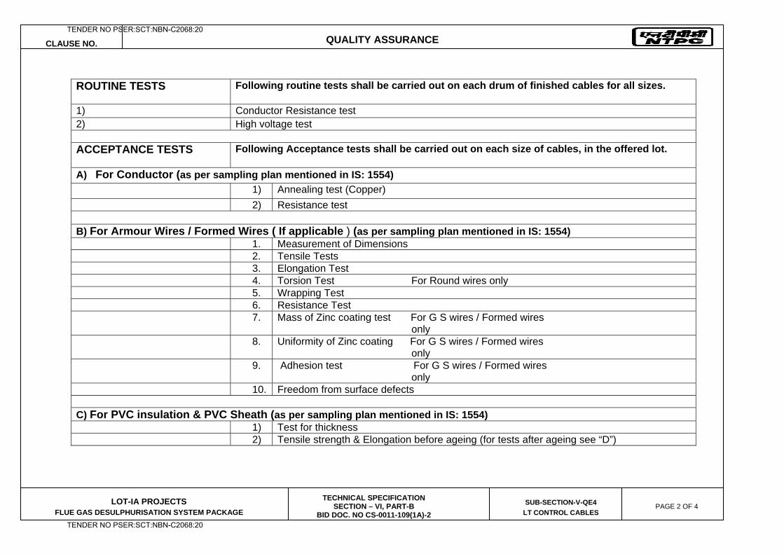
CLAUSE NO. QUALITY ASSURANCE
LOT-IA PROJECTS FLUE GAS DESULPHURISATION SYSTEM PACKAGE
TECHNICAL SPECIFICATION SECTION – VI, PART-B
BID DOC. NO CS-0011-109(1A)-2
SUB-SECTION-V-QE4
LT CONTROL CABLES PAGE 2 OF 4
ROUTINE TESTS
Following routine tests shall be carried out on each drum of finished cables for all sizes.
1) Conductor Resistance test 2) High voltage test ACCEPTANCE TESTS
Following Acceptance tests shall be carried out on each size of cables, in the offered lot.
A) For Conductor (as per sampling plan mentioned in IS: 1554) 1) Annealing test (Copper) 2) Resistance test
B) For Armour Wires / Formed Wires ( If applicable ) (as per sampling plan mentioned in IS: 1554) 1. Measurement of Dimensions 2. Tensile Tests 3. Elongation Test 4. Torsion Test For Round wires only 5. Wrapping Test 6. Resistance Test 7. Mass of Zinc coating test For G S wires / Formed wires
only 8. Uniformity of Zinc coating For G S wires / Formed wires
only 9. Adhesion test For G S wires / Formed wires
only 10. Freedom from surface defects C) For PVC insulation & PVC Sheath (as per sampling plan mentioned in IS: 1554) 1) Test for thickness 2) Tensile strength & Elongation before ageing (for tests after ageing see “D”)
TENDER NO PSER:SCT:NBN-C2068:20
TENDER NO PSER:SCT:NBN-C2068:20
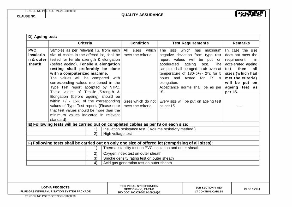
CLAUSE NO. QUALITY ASSURANCE
LOT-IA PROJECTS FLUE GAS DESULPHURISATION SYSTEM PACKAGE
TECHNICAL SPECIFICATION SECTION – VI, PART-B
BID DOC. NO CS-0011-109(1A)-2
SUB-SECTION-V-QE4
LT CONTROL CABLES PAGE 3 OF 4
D) Ageing test:
Criteria Condition Test Requirements Remarks
PVC insulation & outer sheath:
Samples as per relevant IS, from each size of cables in the offered lot, shall be tested for tensile strength & elongation (before ageing). Tensile & elongation testing shall preferably be done with a computerized machine. The values will be compared with corresponding values mentioned in the Type Test report accepted by NTPC. These values of Tensile Strength & Elongation (before ageing) should be within +/ - 15% of the corresponding values of Type Test report. (Please note that test values should be more than the minimum values indicated in relevant standard).
All sizes which meet the criteria
The size which has maximum negative deviation from type test report values will be put on accelerated ageing test. The samples shall be aged in air oven at temperature of 130ºc+/- 2ºc for 5 hours and tested for TS & elongation. Acceptance norms shall be as per IS.
In case the size does not meet the requirement in accelerated ageing test then all sizes (which had met the criteria) will be put on ageing test as per IS.
Sizes which do not meet the criteria
Every size will be put on ageing test as per IS.
----
E) Following tests will be carried out on completed cables as per IS on each size: 1) Insulation resistance test ( Volume resistivity method ) 2) High voltage test F) Following tests shall be carried out on only one size of offered lot (comprising of all sizes): 1) Thermal stability test on PVC insulation and outer sheath 2) Oxygen index test on outer sheath 3) Smoke density rating test on outer sheath 4) Acid gas generation test on outer sheath
TENDER NO PSER:SCT:NBN-C2068:20
TENDER NO PSER:SCT:NBN-C2068:20
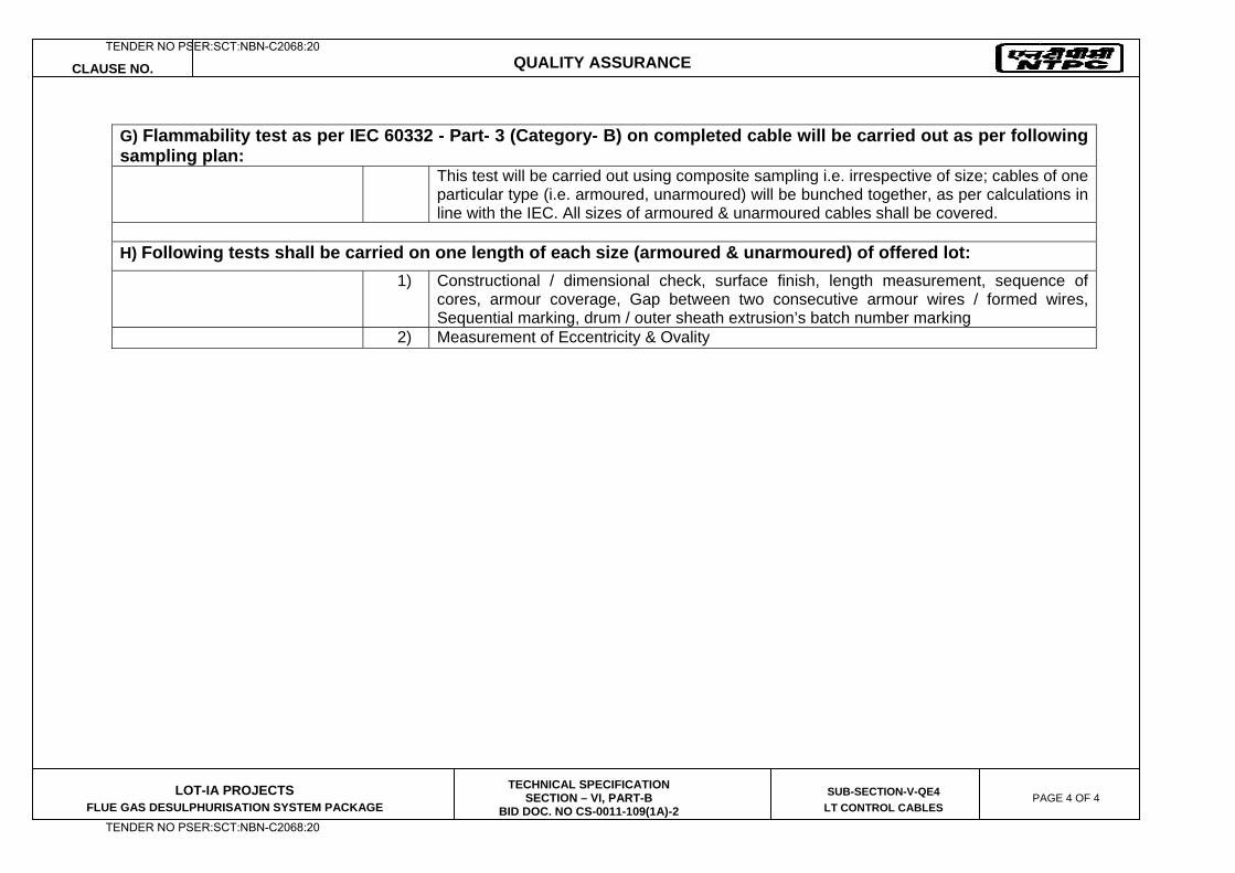
CLAUSE NO. QUALITY ASSURANCE
LOT-IA PROJECTS FLUE GAS DESULPHURISATION SYSTEM PACKAGE
TECHNICAL SPECIFICATION SECTION – VI, PART-B
BID DOC. NO CS-0011-109(1A)-2
SUB-SECTION-V-QE4
LT CONTROL CABLES PAGE 4 OF 4
G) Flammability test as per IEC 60332 - Part- 3 (Category- B) on completed cable will be carried out as per following sampling plan: This test will be carried out using composite sampling i.e. irrespective of size; cables of one
particular type (i.e. armoured, unarmoured) will be bunched together, as per calculations in line with the IEC. All sizes of armoured & unarmoured cables shall be covered.
H) Following tests shall be carried on one length of each size (armoured & unarmoured) of offered lot:
1) Constructional / dimensional check, surface finish, length measurement, sequence of cores, armour coverage, Gap between two consecutive armour wires / formed wires, Sequential marking, drum / outer sheath extrusion’s batch number marking
2) Measurement of Eccentricity & Ovality
TENDER NO PSER:SCT:NBN-C2068:20
TENDER NO PSER:SCT:NBN-C2068:20

LOT-IA PROJECTS FLUE GAS DESULPHURISATION (FGD) SYSTEM PACKAGE
TECHNICAL SPECIFICATION
SECTION-VI
BID DOCUMENT NO.: CS-0011-109(1A)-2
SUB-SECTION-V-QE5
CABLING EARTHING & LIGHTNING PROTECTION
TENDER NO PSER:SCT:NBN-C2068:20
TENDER NO PSER:SCT:NBN-C2068:20
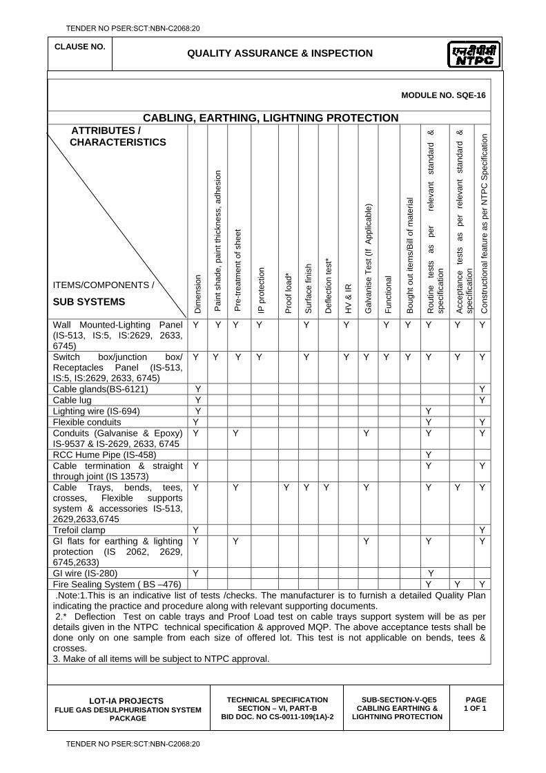
CLAUSE NO.
QUALITY ASSURANCE & INSPECTION
LOT-IA PROJECTS
FLUE GAS DESULPHURISATION SYSTEM PACKAGE
TECHNICAL SPECIFICATION SECTION – VI, PART-B
BID DOC. NO CS-0011-109(1A)-2
SUB-SECTION-V-QE5 CABLING EARTHING &
LIGHTNING PROTECTION
PAGE 1 OF 1
MODULE NO. SQE-16
CABLING, EARTHING, LIGHTNING PROTECTION ATTRIBUTES / CHARACTERISTICS
ITEMS/COMPONENTS /
SUB SYSTEMS D
imen
sion
Pai
nt s
hade
, pai
nt th
ickn
ess,
adh
esio
n
Pre
-trea
tmen
t of s
heet
IP p
rote
ctio
n
Pro
of lo
ad*
Sur
face
fini
sh
Def
lect
ion
test
*
HV
& IR
Gal
vani
se T
est (
If A
pplic
able
)
Func
tiona
l
Bou
ght o
ut it
ems/
Bill
of m
ater
ial
Rou
tine
test
s as
pe
r
rele
vant
st
anda
rd
&
spec
ifica
tion
Acc
epta
nce
test
s as
pe
r re
leva
nt
stan
dard
&
sp
ecifi
catio
n
Con
stru
ctio
nal f
eatu
re a
s pe
r NTP
C S
peci
ficat
ion
Wall Mounted-Lighting Panel (IS-513, IS:5, IS:2629, 2633, 6745)
Y Y Y Y Y Y Y Y Y Y Y
Switch box/junction box/ Receptacles Panel (IS-513, IS:5, IS:2629, 2633, 6745)
Y Y Y Y Y Y Y Y Y Y Y Y
Cable glands(BS-6121) Y Y Cable lug Y Y Lighting wire (IS-694) Y Y Flexible conduits Y Y Y Conduits (Galvanise & Epoxy) IS-9537 & IS-2629, 2633, 6745
Y Y Y Y Y
RCC Hume Pipe (IS-458) Y Cable termination & straight through joint (IS 13573)
Y Y Y
Cable Trays, bends, tees, crosses, Flexible supports system & accessories IS-513, 2629,2633,6745
Y Y Y Y Y Y Y Y Y
Trefoil clamp Y Y GI flats for earthing & lighting protection (IS 2062, 2629, 6745,2633)
Y Y Y Y Y
GI wire (IS-280) Y Y Fire Sealing System ( BS –476) Y Y Y .Note:1.This is an indicative list of tests /checks. The manufacturer is to furnish a detailed Quality Plan indicating the practice and procedure along with relevant supporting documents. 2.* Deflection Test on cable trays and Proof Load test on cable trays support system will be as per details given in the NTPC technical specification & approved MQP. The above acceptance tests shall be done only on one sample from each size of offered lot. This test is not applicable on bends, tees & crosses. 3. Make of all items will be subject to NTPC approval.
TENDER NO PSER:SCT:NBN-C2068:20
TENDER NO PSER:SCT:NBN-C2068:20

LOT-IA PROJECTS FLUE GAS DESULPHURISATION (FGD) SYSTEM PACKAGE
TECHNICAL SPECIFICATION
SECTION-VI
BID DOCUMENT NO.: CS-0011-109(1A)-2
SUB-SECTION-V-QE6
HT CABLES
TENDER NO PSER:SCT:NBN-C2068:20
TENDER NO PSER:SCT:NBN-C2068:20
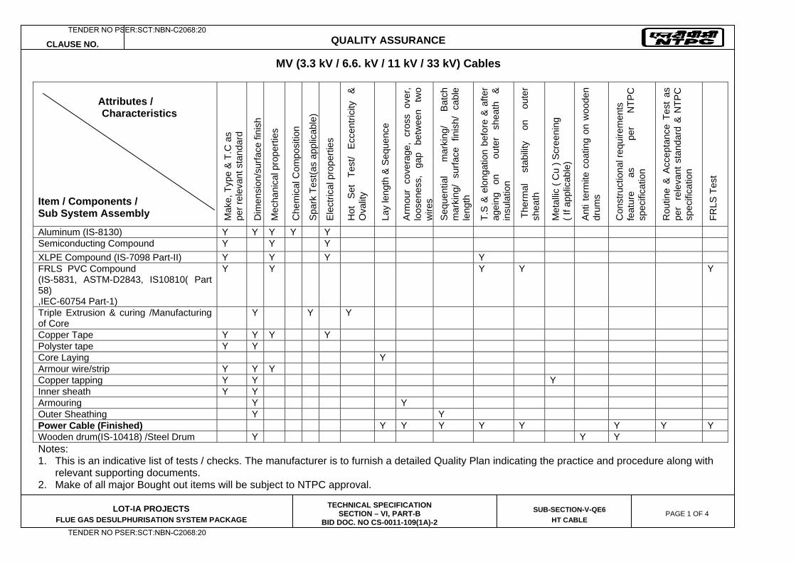
CLAUSE NO. QUALITY ASSURANCE
LOT-IA PROJECTS FLUE GAS DESULPHURISATION SYSTEM PACKAGE
TECHNICAL SPECIFICATION SECTION – VI, PART-B
BID DOC. NO CS-0011-109(1A)-2
SUB-SECTION-V-QE6
HT CABLE PAGE 1 OF 4
MV (3.3 kV / 6.6. kV / 11 kV / 33 kV) Cables Attributes / Characteristics Item / Components / Sub System Assembly M
ake,
Typ
e &
T.C
as
pe
r rel
evan
t sta
ndar
d
Dim
ensi
on/s
urfa
ce fi
nish
Mec
hani
cal p
rope
rties
Che
mic
al C
ompo
sitio
n
Spa
rk T
est(a
s ap
plic
able
)
Ele
ctric
al p
rope
rties
Hot
Se
t Te
st/
Ecce
ntric
ity
& O
valit
y
Lay
leng
th &
Seq
uenc
e
Arm
our
cove
rage
, cr
oss
over
, lo
osen
ess,
ga
p be
twee
n tw
o w
ires
Seq
uent
ial
mar
king
/ B
atch
m
arki
ng/
surfa
ce f
inis
h/ c
able
le
ngth
T.S
& e
long
atio
n be
fore
& a
fter
agei
ng
on
ou
ter
shea
th
&
insu
latio
n
The
rmal
st
abili
ty
on
oute
r sh
eath
Met
allic
( C
u ) S
cree
ning
( I
f app
licab
le)
Ant
i ter
mite
coa
ting
on w
oode
n dr
ums
Con
stru
ctio
nal r
equi
rem
ents
fe
atur
e as
per
NTP
C
spec
ifica
tion
Rou
tine
& A
ccep
tanc
e Te
st a
s pe
r r
elev
ant s
tand
ard
& N
TPC
sp
ecifi
catio
n
FRLS
Tes
t
Aluminum (IS-8130) Y Y Y Y Y Semiconducting Compound Y Y Y XLPE Compound (IS-7098 Part-II) Y Y Y Y FRLS PVC Compound (IS-5831, ASTM-D2843, IS10810( Part 58) ,IEC-60754 Part-1)
Y Y Y Y Y
Triple Extrusion & curing /Manufacturing of Core
Y Y Y
Copper Tape Y Y Y Y Polyster tape Y Y Core Laying Y Armour wire/strip Y Y Y Copper tapping Y Y Y Inner sheath Y Y Armouring Y Y Outer Sheathing Y Y Power Cable (Finished) Y Y Y Y Y Y Y Y Wooden drum(IS-10418) /Steel Drum Y Y Y Notes: 1. This is an indicative list of tests / checks. The manufacturer is to furnish a detailed Quality Plan indicating the practice and procedure along with
relevant supporting documents. 2. Make of all major Bought out items will be subject to NTPC approval.
TENDER NO PSER:SCT:NBN-C2068:20
TENDER NO PSER:SCT:NBN-C2068:20
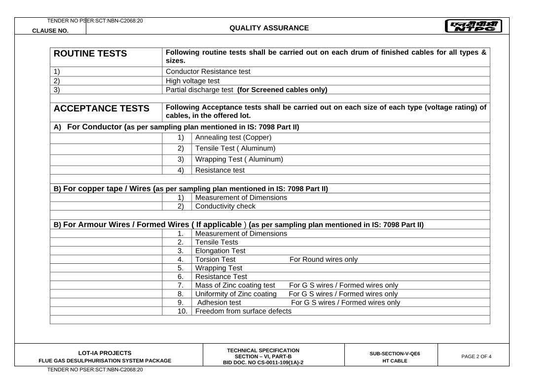
CLAUSE NO. QUALITY ASSURANCE
LOT-IA PROJECTS FLUE GAS DESULPHURISATION SYSTEM PACKAGE
TECHNICAL SPECIFICATION SECTION – VI, PART-B
BID DOC. NO CS-0011-109(1A)-2
SUB-SECTION-V-QE6
HT CABLE PAGE 2 OF 4
ROUTINE TESTS
Following routine tests shall be carried out on each drum of finished cables for all types & sizes.
1) Conductor Resistance test 2) High voltage test 3) Partial discharge test (for Screened cables only)
ACCEPTANCE TESTS
Following Acceptance tests shall be carried out on each size of each type (voltage rating) of cables, in the offered lot.
A) For Conductor (as per sampling plan mentioned in IS: 7098 Part II) 1) Annealing test (Copper) 2) Tensile Test ( Aluminum) 3) Wrapping Test ( Aluminum) 4) Resistance test
B) For copper tape / Wires (as per sampling plan mentioned in IS: 7098 Part II) 1) Measurement of Dimensions 2) Conductivity check B) For Armour Wires / Formed Wires ( If applicable ) (as per sampling plan mentioned in IS: 7098 Part II) 1. Measurement of Dimensions 2. Tensile Tests 3. Elongation Test 4. Torsion Test For Round wires only 5. Wrapping Test 6. Resistance Test 7. Mass of Zinc coating test For G S wires / Formed wires only 8. Uniformity of Zinc coating For G S wires / Formed wires only 9. Adhesion test For G S wires / Formed wires only 10. Freedom from surface defects
TENDER NO PSER:SCT:NBN-C2068:20
TENDER NO PSER:SCT:NBN-C2068:20
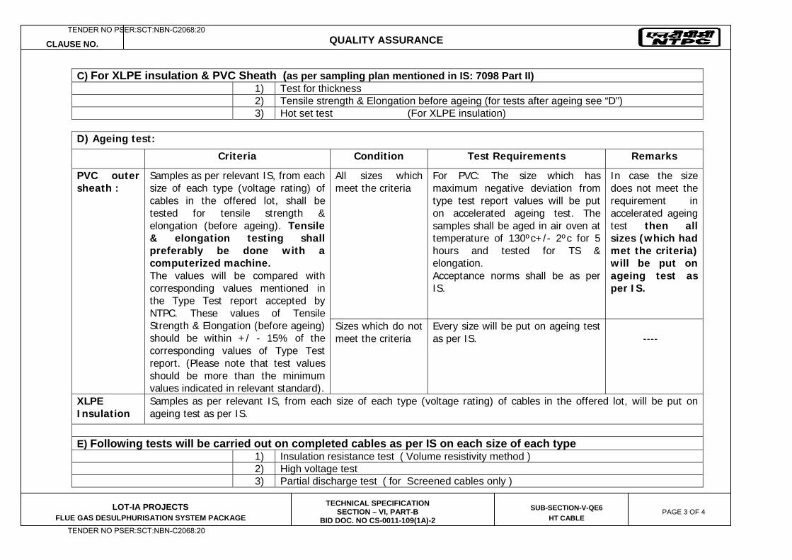
CLAUSE NO. QUALITY ASSURANCE
LOT-IA PROJECTS FLUE GAS DESULPHURISATION SYSTEM PACKAGE
TECHNICAL SPECIFICATION SECTION – VI, PART-B
BID DOC. NO CS-0011-109(1A)-2
SUB-SECTION-V-QE6
HT CABLE PAGE 3 OF 4
C) For XLPE insulation & PVC Sheath (as per sampling plan mentioned in IS: 7098 Part II) 1) Test for thickness 2) Tensile strength & Elongation before ageing (for tests after ageing see “D”) 3) Hot set test (For XLPE insulation)
D) Ageing test:
Criteria Condition Test Requirements Remarks
PVC outer sheath :
Samples as per relevant IS, from each size of each type (voltage rating) of cables in the offered lot, shall be tested for tensile strength & elongation (before ageing). Tensile & elongation testing shall preferably be done with a computerized machine. The values will be compared with corresponding values mentioned in the Type Test report accepted by NTPC. These values of Tensile Strength & Elongation (before ageing) should be within +/ - 15% of the corresponding values of Type Test report. (Please note that test values should be more than the minimum values indicated in relevant standard).
All sizes which meet the criteria
For PVC: The size which has maximum negative deviation from type test report values will be put on accelerated ageing test. The samples shall be aged in air oven at temperature of 130ºc+/- 2ºc for 5 hours and tested for TS & elongation. Acceptance norms shall be as per IS.
In case the size does not meet the requirement in accelerated ageing test then all sizes (which had met the criteria) will be put on ageing test as per IS.
Sizes which do not meet the criteria
Every size will be put on ageing test as per IS.
----
XLPE Insulation
Samples as per relevant IS, from each size of each type (voltage rating) of cables in the offered lot, will be put on ageing test as per IS.
E) Following tests will be carried out on completed cables as per IS on each size of each type 1) Insulation resistance test ( Volume resistivity method ) 2) High voltage test 3) Partial discharge test ( for Screened cables only )
TENDER NO PSER:SCT:NBN-C2068:20
TENDER NO PSER:SCT:NBN-C2068:20
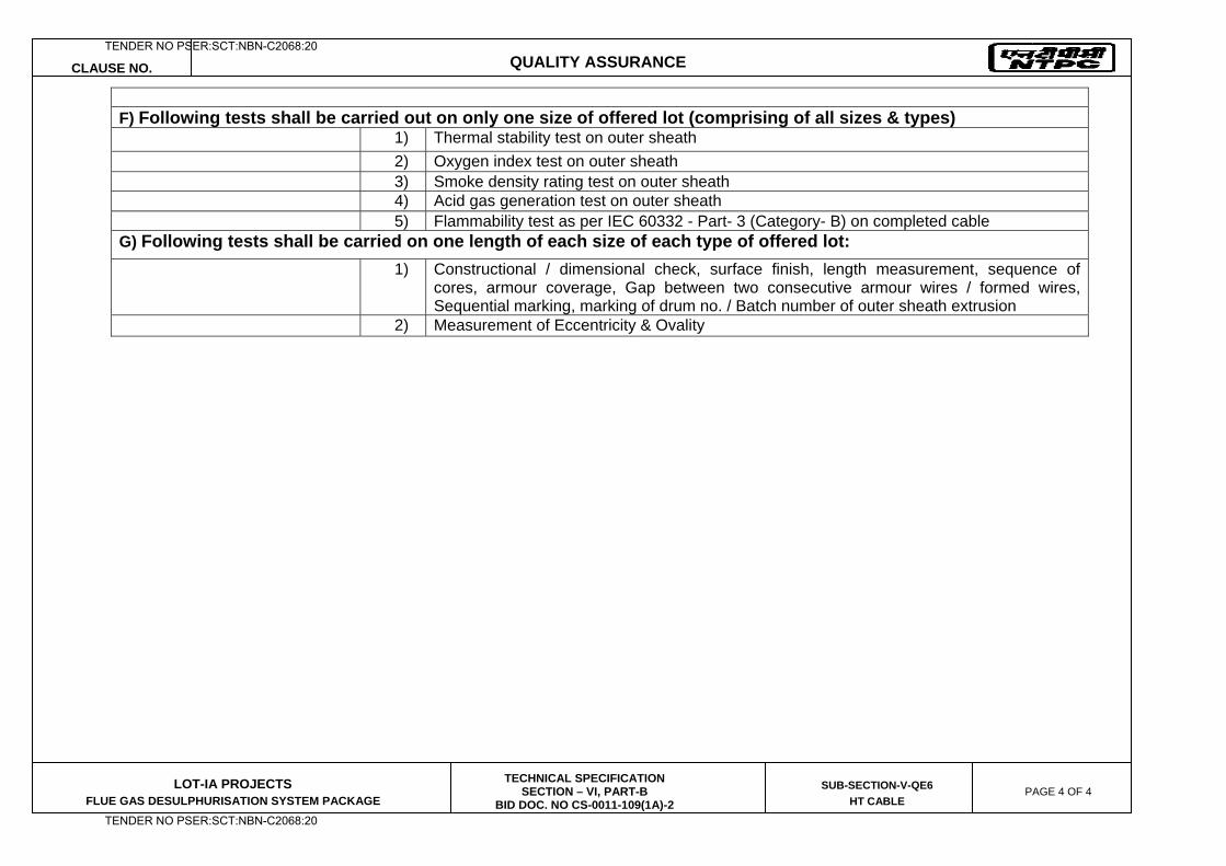
CLAUSE NO. QUALITY ASSURANCE
LOT-IA PROJECTS FLUE GAS DESULPHURISATION SYSTEM PACKAGE
TECHNICAL SPECIFICATION SECTION – VI, PART-B
BID DOC. NO CS-0011-109(1A)-2
SUB-SECTION-V-QE6
HT CABLE PAGE 4 OF 4
F) Following tests shall be carried out on only one size of offered lot (comprising of all sizes & types) 1) Thermal stability test on outer sheath 2) Oxygen index test on outer sheath 3) Smoke density rating test on outer sheath 4) Acid gas generation test on outer sheath 5) Flammability test as per IEC 60332 - Part- 3 (Category- B) on completed cable G) Following tests shall be carried on one length of each size of each type of offered lot:
1) Constructional / dimensional check, surface finish, length measurement, sequence of cores, armour coverage, Gap between two consecutive armour wires / formed wires, Sequential marking, marking of drum no. / Batch number of outer sheath extrusion
2) Measurement of Eccentricity & Ovality
TENDER NO PSER:SCT:NBN-C2068:20
TENDER NO PSER:SCT:NBN-C2068:20

LOT-IA PROJECTS FLUE GAS DESULPHURISATION (FGD) SYSTEM PACKAGE
TECHNICAL SPECIFICATION
SECTION-VI
BID DOCUMENT NO.: CS-0011-109(1A)-2
SUB-SECTION-V-QE7
ELECTRIC ACTUATORS WITH INTEGRAL STARTERS
TENDER NO PSER:SCT:NBN-C2068:20
TENDER NO PSER:SCT:NBN-C2068:20
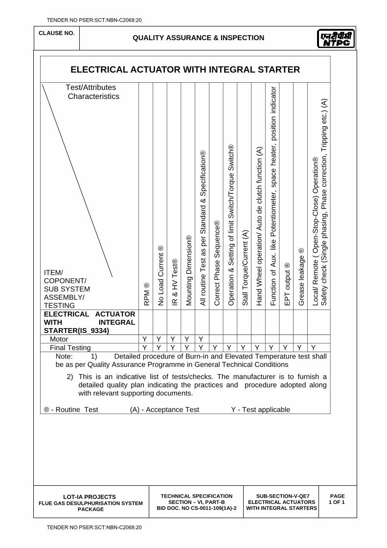
CLAUSE NO.
QUALITY ASSURANCE & INSPECTION
LOT-IA PROJECTS
FLUE GAS DESULPHURISATION SYSTEM PACKAGE
TECHNICAL SPECIFICATION SECTION – VI, PART-B
BID DOC. NO CS-0011-109(1A)-2
SUB-SECTION-V-QE7 ELECTRICAL ACTUATORS
WITH INTEGRAL STARTERS
PAGE 1 OF 1
ELECTRICAL ACTUATOR WITH INTEGRAL STARTER
Test/Attributes Characteristics
ITEM/ COPONENT/ SUB SYSTEM ASSEMBLY/ TESTING R
PM ®
No
Load
Cur
rent
®
IR &
HV
Tes
t®
Mou
ntin
g D
imen
sion
®
All
rout
ine
Test
as
per S
tand
ard
& S
peci
ficat
ion®
Cor
rect
Pha
se S
eque
nce®
Ope
ratio
n &
Set
ting
of li
mit
Sw
itch/
Torq
ue S
witc
h®
Sta
ll To
rque
/Cur
rent
(A)
Han
d W
heel
ope
ratio
n/ A
uto
de c
lutc
h fu
nctio
n (A
)
Func
tion
of A
ux. l
ike
Pot
entio
met
er, s
pace
hea
ter,
posi
tion
indi
cato
r ® E
PT
outp
ut ®
Gre
ase
leak
age
®
Loca
l/ R
emot
e ( O
pen-
Sto
p-C
lose
) Ope
ratio
n®
Saf
ety
chec
k (S
ingl
e ph
asin
g, P
hase
cor
rect
ion,
Trip
ping
etc
.) (A
) ELECTRICAL ACTUATOR WITH INTEGRAL STARTER(IS_9334)
Motor Y Y Y Y Y Final Testing Y Y Y Y Y Y Y Y Y Y Y Y Y
Note: 1) Detailed procedure of Burn-in and Elevated Temperature test shall be as per Quality Assurance Programme in General Technical Conditions
2) This is an indicative list of tests/checks. The manufacturer is to furnish a detailed quality plan indicating the practices and procedure adopted along with relevant supporting documents.
® - Routine Test (A) - Acceptance Test Y - Test applicable
TENDER NO PSER:SCT:NBN-C2068:20
TENDER NO PSER:SCT:NBN-C2068:20

LOT-IA PROJECTS FLUE GAS DESULPHURISATION (FGD) SYSTEM PACKAGE
TECHNICAL SPECIFICATION
SECTION-VI
BID DOCUMENT NO.: CS-0011-109(1A)-2
SUB-SECTION-V-QE8
HT SWTIGCHGEAR
TENDER NO PSER:SCT:NBN-C2068:20
TENDER NO PSER:SCT:NBN-C2068:20
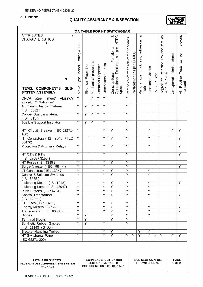
CLAUSE NO.
QUALITY ASSURANCE & INSPECTION
LOT-IA PROJECTS
FLUE GAS DESULPHURISATION SYSTEM PACKAGE
TECHNICAL SPECIFICATION SECTION – VI, PART-B
BID DOC. NO CS-0011-109(1A)-2
SUB-SECTION-V-QE8 HT SWITCHGEAR
PAGE 1 OF 2
QA TABLE FOR HT SWITCHGEAR ATTRIBUTES / CHARACTERISTICS
ITEMS, COMPONENTS, SUB-SYSTEM ASSEMBLY M
ake,
Typ
e, M
odel
, R
atin
g &
TC
Ele
ctric
al P
rope
rties
Mec
hani
cal p
rope
rties
Che
mic
al P
rope
rties
Dim
ensi
ons
& F
inis
h
Con
stru
ctio
nal,
Func
tiona
l &
O
pera
tiona
l Fe
atur
es
as
per
NTP
C
Spe
c.
Item
to c
onfo
rm to
rele
vant
Sta
ndar
ds
Pre
treat
men
t as
per I
S 6
005
Pai
nt
shad
e,
thic
knes
s,
adhe
sion
&
fin
ish
Func
tiona
l Che
cks
HV
& IR
Tes
t
Deg
ree
of P
rote
ctio
n R
outin
e te
st a
s pe
r NTP
C s
pec.
CB
Ope
ratio
n tim
ing
che
ck
All
Rou
tine
Test
s as
pe
r
rele
vant
st
anda
rd
CRCA steel sheet/ Aluzinc*/ Zincalum*/ Galvalum*
Y Y Y Y Y
Aluminum Bus bar material ( IS : 5082 )
Y Y Y Y Y Y
Copper Bus bar material ( IS : 613 )
Y Y Y Y Y Y
Bus bar Support Insulator
Y Y Y Y Y Y
HT Circuit Breaker (IEC-62271-100)
Y Y Y Y Y Y Y
HT Contactors ( IS : 9046 / IEC 60470)
Y Y Y Y Y Y
Protection & Auxilliary Relays
Y Y Y Y Y Y
HT CT’s & PT’s ( IS : 2705 / 3156 )
Y Y Y Y
HT Fuses ( IS : 9385 ) Y Y Y Y Surge Arrester ( IEC : 99 –4 ) Y Y Y Y LT Contactors ( IS : 13947) Y Y Y Y Y Control & Selector Switches ( IS : 6875 )
Y Y Y Y Y
Indicating Meters ( IS : 1248) Y Y Y Y Y Y Indicating Lamps ( IS : 13947) Y Y Y Y Y Push Buttons ( IS : 4794) Y Y Y Y Y Control Transformer ( IS : 12021 )
Y Y Y Y Y Y
LT Fuses ( IS : 13703) Y Y Y Y Energy Meters ( IS : 722 ) Y Y Y Y Y Y Transducers ( IEC : 60688) Y Y Y Y Y Y Diodes Y Y Y Y Y Terminal Blocks Y Y Y Y Synthetic Rubber Gasket ( IS : 11149 / 3400 )
Y Y Y Y
Breaker Handling Trolley Y Y Y Y Y HT Switchgear Panel IEC-62271-200)
Y Y Y Y Y Y Y Y Y Y Y
TENDER NO PSER:SCT:NBN-C2068:20
TENDER NO PSER:SCT:NBN-C2068:20
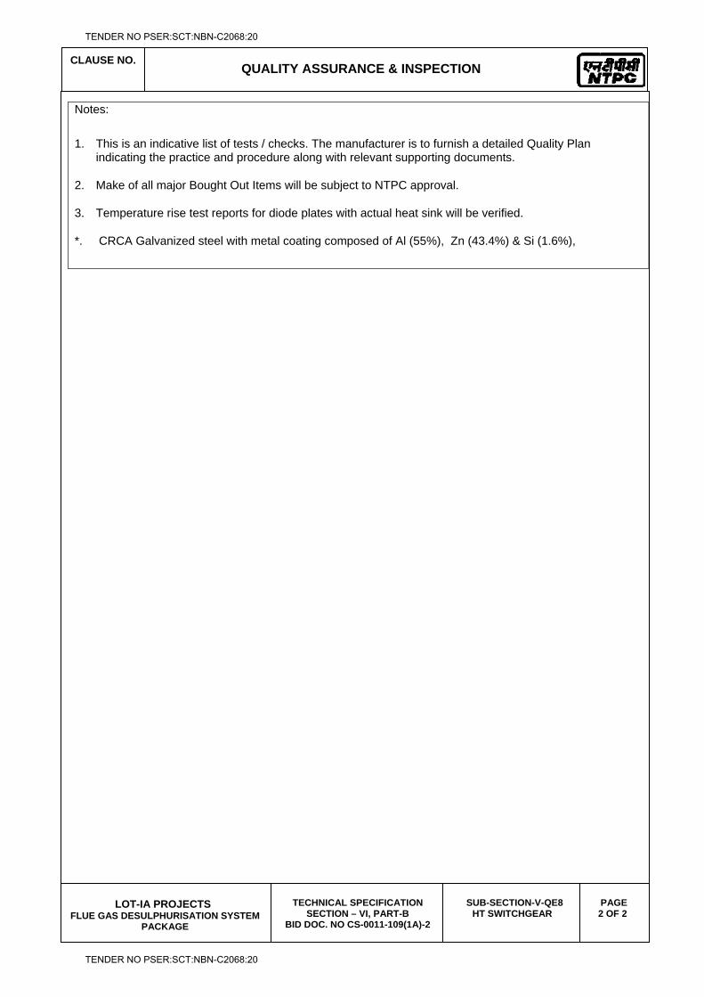
CLAUSE NO.
QUALITY ASSURANCE & INSPECTION
LOT-IA PROJECTS
FLUE GAS DESULPHURISATION SYSTEM PACKAGE
TECHNICAL SPECIFICATION SECTION – VI, PART-B
BID DOC. NO CS-0011-109(1A)-2
SUB-SECTION-V-QE8 HT SWITCHGEAR
PAGE 2 OF 2
Notes:
1. This is an indicative list of tests / checks. The manufacturer is to furnish a detailed Quality Plan indicating the practice and procedure along with relevant supporting documents.
2. Make of all major Bought Out Items will be subject to NTPC approval.
3. Temperature rise test reports for diode plates with actual heat sink will be verified.
*. CRCA Galvanized steel with metal coating composed of Al (55%), Zn (43.4%) & Si (1.6%),
TENDER NO PSER:SCT:NBN-C2068:20
TENDER NO PSER:SCT:NBN-C2068:20

LOT-IA PROJECTS FLUE GAS DESULPHURISATION (FGD) SYSTEM PACKAGE
TECHNICAL SPECIFICATION
SECTION-VI
BID DOCUMENT NO.: CS-0011-109(1A)-2
SUB-SECTION-V-QE9
LT SWTIGCHGEAR
TENDER NO PSER:SCT:NBN-C2068:20
TENDER NO PSER:SCT:NBN-C2068:20
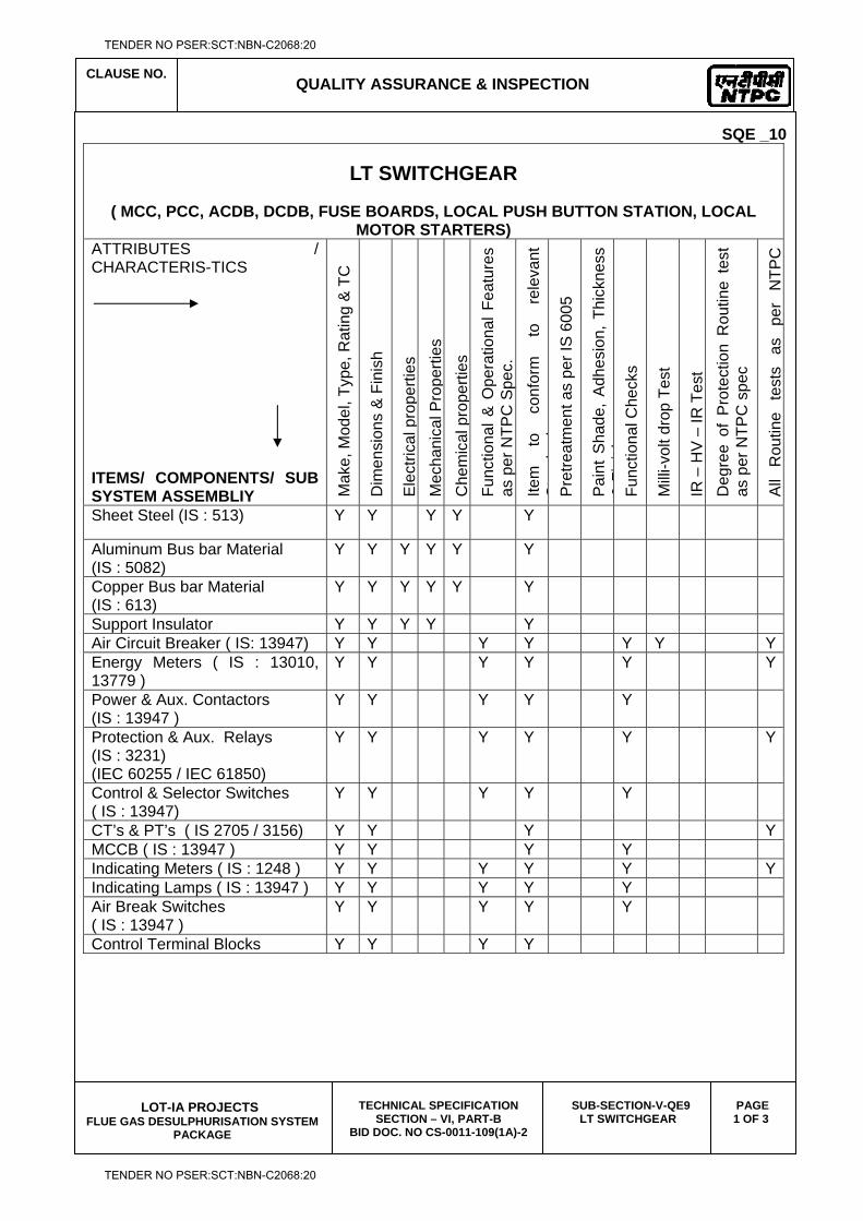
CLAUSE NO.
QUALITY ASSURANCE & INSPECTION
LOT-IA PROJECTS
FLUE GAS DESULPHURISATION SYSTEM PACKAGE
TECHNICAL SPECIFICATION SECTION – VI, PART-B
BID DOC. NO CS-0011-109(1A)-2
SUB-SECTION-V-QE9 LT SWITCHGEAR
PAGE 1 OF 3
SQE _10
LT SWITCHGEAR
( MCC, PCC, ACDB, DCDB, FUSE BOARDS, LOCAL PUSH BUTTON STATION, LOCAL MOTOR STARTERS)
ATTRIBUTES / CHARACTERIS-TICS
ITEMS/ COMPONENTS/ SUB SYSTEM ASSEMBLIY M
ake,
Mod
el, T
ype,
Rat
ing
& T
C
Dim
ensi
ons
& F
inis
h
Ele
ctric
al p
rope
rties
M
echa
nica
l Pro
perti
es
Che
mic
al p
rope
rties
Fu
nctio
nal &
Ope
ratio
nal F
eatu
res
as p
er N
TPC
Spe
c.
Item
to
co
nfor
m
to
rele
vant
S
td
dP
retre
atm
ent a
s pe
r IS
600
5
Pai
nt S
hade
, A
dhes
ion,
Thi
ckne
ss
&Fi
ih
Func
tiona
l Che
cks
Mill
i-vol
t dro
p Te
st
IR –
HV
– IR
Tes
t D
egre
e of
Pro
tect
ion
Rou
tine
test
as
per
NTP
C s
pec
All
Rou
tine
test
s as
pe
r N
TPC
Sheet Steel (IS : 513) Y Y Y Y Y
Aluminum Bus bar Material (IS : 5082)
Y Y Y Y Y Y
Copper Bus bar Material (IS : 613)
Y Y Y Y Y Y
Support Insulator Y Y Y Y Y Air Circuit Breaker ( IS: 13947) Y Y Y Y Y Y YEnergy Meters ( IS : 13010, 13779 )
Y Y Y Y Y Y
Power & Aux. Contactors (IS : 13947 )
Y Y Y Y Y
Protection & Aux. Relays (IS : 3231) (IEC 60255 / IEC 61850)
Y Y Y Y Y Y
Control & Selector Switches ( IS : 13947)
Y Y Y Y Y
CT’s & PT’s ( IS 2705 / 3156) Y Y Y YMCCB ( IS : 13947 ) Y Y Y Y Indicating Meters ( IS : 1248 ) Y Y Y Y Y YIndicating Lamps ( IS : 13947 ) Y Y Y Y Y Air Break Switches ( IS : 13947 )
Y Y Y Y Y
Control Terminal Blocks Y Y Y Y
TENDER NO PSER:SCT:NBN-C2068:20
TENDER NO PSER:SCT:NBN-C2068:20
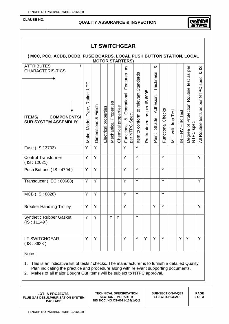
CLAUSE NO.
QUALITY ASSURANCE & INSPECTION
LOT-IA PROJECTS
FLUE GAS DESULPHURISATION SYSTEM PACKAGE
TECHNICAL SPECIFICATION SECTION – VI, PART-B
BID DOC. NO CS-0011-109(1A)-2
SUB-SECTION-V-QE9 LT SWITCHGEAR
PAGE 2 OF 3
LT SWITCHGEAR
( MCC, PCC, ACDB, DCDB, FUSE BOARDS, LOCAL PUSH BUTTON STATION, LOCAL MOTOR STARTERS)
ATTRIBUTES / CHARACTERIS-TICS
ITEMS/ COMPONENTS/ SUB SYSTEM ASSEMBLIY
Mak
e, M
odel
, Typ
e, R
atin
g &
TC
Dim
ensi
ons
& F
inis
h
Ele
ctric
al p
rope
rties
M
echa
nica
l Pro
perti
es
Che
mic
al p
rope
rties
Fu
nctio
nal
&
Ope
ratio
nal
Feat
ures
as
pe
r NTP
C S
pec.
Item
to c
onfo
rm to
rele
vant
Sta
ndar
ds
Pre
treat
men
t as
per I
S 6
005
Pai
nt
Sha
de,
Adh
esio
n,
Thic
knes
s &
Fi
ih
Func
tiona
l Che
cks
Mill
i-vol
t dro
p Te
st
IR –
HV
– IR
Tes
t D
egre
e of
Pro
tect
ion
Rou
tine
test
as
per
NTP
C s
pec
All
Rou
tine
test
s as
per
NTP
C s
pec.
& IS
Fuse ( IS 13703) Y Y Y Y
Control Transformer ( IS : 12021)
Y Y Y Y Y Y
Push Buttons ( IS : 4794 ) Y Y Y Y Y
Transducer ( IEC : 60688) Y Y Y Y Y Y
MCB ( IS : 8828) Y Y Y Y Y
Breaker Handling Trolley Y Y Y Y Y Y
Synthetic Rubber Gasket (IS : 11149 )
Y Y Y Y Y
LT SWITCHGEAR ( IS : 8623 )
Y Y Y Y Y Y Y Y Y Y
Notes: 1. This is an indicative list of tests / checks. The manufacturer is to furnish a detailed Quality
Plan indicating the practice and procedure along with relevant supporting documents. 2. Makes of all major Bought Out Items will be subject to NTPC approval.
TENDER NO PSER:SCT:NBN-C2068:20
TENDER NO PSER:SCT:NBN-C2068:20
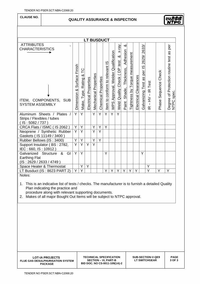
CLAUSE NO.
QUALITY ASSURANCE & INSPECTION
LOT-IA PROJECTS
FLUE GAS DESULPHURISATION SYSTEM PACKAGE
TECHNICAL SPECIFICATION SECTION – VI, PART-B
BID DOC. NO CS-0011-109(1A)-2
SUB-SECTION-V-QE9 LT SWITCHGEAR
PAGE 3 OF 3
LT BUSDUCT ATTRIBUTES ,
CHARACTERISTICS ITEM, COMPONENTS, SUB SYSTEM ASSEMBLY D
imen
sion
& S
urfa
ce F
inis
h M
ake,
Typ
e, R
atin
g &
TC
E
lect
rical
Pro
perti
es
Mec
hani
cal P
rope
rties
C
hem
ical
Pro
perti
es
Item
to c
onfo
rm to
rele
vant
IS
WP
S A
ppro
val,
Wel
der Q
ualif
icat
ion
Wel
d Q
ualit
y C
heck
( D
P te
st
&
x-ra
y P
aint
Sha
de,
Thic
knes
s, A
dhes
ion
&
Tigh
tnes
s by
Tor
que
mea
sure
men
t E
lect
rical
Cle
aran
ces
G
alva
nizi
n g T
est a
s pe
r IS
262
9/ 2
633/
IR
– H
V –
IR T
est
Pha
se S
eque
nce
Che
ck
Deg
ree
of P
rote
ctio
n ro
utin
e te
st a
s pe
r N
TPC
spe
c.
Aluminum Sheets / Plates / Strips / Flexibles / tubes ( IS : 5082 / 737 )
Y Y Y Y Y Y Y
CRCA Flats / ISMC ( IS 2062 ) Y Y Y Y Y Neoprene / Synthetic Rubber Gaskets ( IS 11149 / 3400 )
Y Y Y Y
Rubber Bellows (IS : 3400) Y Y Y Y Support Insulator ( BS : 2782, IEC : 660, IS : 10912 )
Y Y Y Y
Galvanized Structure & GI Earthing Flat (IS : 2629 / 2633 / 4749 )
Y Y Y Y
Space Heater & Thermostat Y Y Y LT Busduct (IS : 8623 PART 2) Y Y Y Y Y Y Y Y Y Y Y Notes: 1. This is an indicative list of tests / checks. The manufacturer is to furnish a detailed Quality
Plan indicating the practice and procedure along with relevant supporting documents.
2. Makes of all major Bought Out Items will be subject to NTPC approval.
TENDER NO PSER:SCT:NBN-C2068:20
TENDER NO PSER:SCT:NBN-C2068:20

LOT-IA PROJECTS FLUE GAS DESULPHURISATION (FGD) SYSTEM PACKAGE
TECHNICAL SPECIFICATION
SECTION-VI
BID DOCUMENT NO.: CS-0011-109(1A)-2
SUB-SECTION-V-QE10
DIESEL GENERATORS
TENDER NO PSER:SCT:NBN-C2068:20
TENDER NO PSER:SCT:NBN-C2068:20
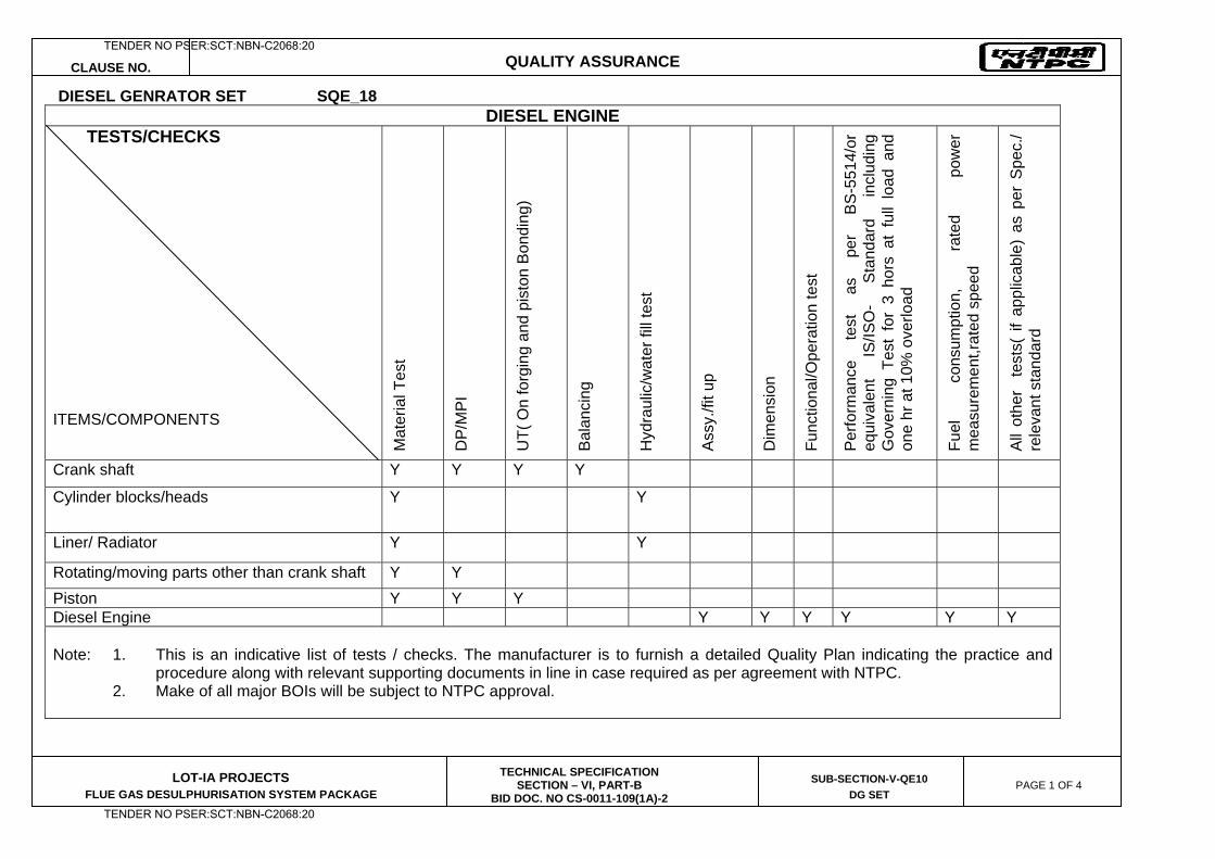
CLAUSE NO. QUALITY ASSURANCE
LOT-IA PROJECTS FLUE GAS DESULPHURISATION SYSTEM PACKAGE
TECHNICAL SPECIFICATION SECTION – VI, PART-B
BID DOC. NO CS-0011-109(1A)-2
SUB-SECTION-V-QE10
DG SET PAGE 1 OF 4
DIESEL GENRATOR SET SQE_18 DIESEL ENGINE
TESTS/CHECKS
ITEMS/COMPONENTS
Mat
eria
l Tes
t
DP
/MP
I U
T( O
n fo
rgin
g an
d pi
ston
Bon
ding
)
Bal
anci
ng
Hyd
raul
ic/w
ater
fill
test
Ass
y./fi
t up
Dim
ensi
on
Func
tiona
l/Ope
ratio
n te
st
Per
form
ance
te
st
as
per
BS
-551
4/or
eq
uiva
lent
IS
/ISO
- S
tand
ard
incl
udin
g G
over
ning
Tes
t fo
r 3
hors
at
full
load
and
on
e hr
at 1
0% o
verlo
ad
Fuel
co
nsum
ptio
n,
rate
d po
wer
m
easu
rem
ent,r
ated
spe
ed
All
othe
r t
ests
( if
appl
icab
le)
as p
er S
pec.
/ re
leva
nt s
tand
ard
Crank shaft Y Y Y Y
Cylinder blocks/heads Y Y
Liner/ Radiator Y Y
Rotating/moving parts other than crank shaft Y Y Piston Y Y Y Diesel Engine Y Y Y Y Y Y Note: 1. This is an indicative list of tests / checks. The manufacturer is to furnish a detailed Quality Plan indicating the practice and
procedure along with relevant supporting documents in line in case required as per agreement with NTPC. 2. Make of all major BOIs will be subject to NTPC approval.
TENDER NO PSER:SCT:NBN-C2068:20
TENDER NO PSER:SCT:NBN-C2068:20
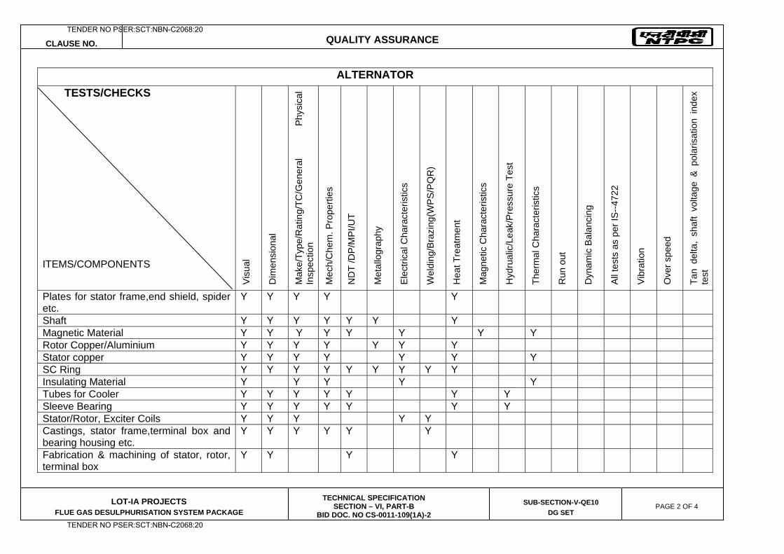
CLAUSE NO. QUALITY ASSURANCE
LOT-IA PROJECTS FLUE GAS DESULPHURISATION SYSTEM PACKAGE
TECHNICAL SPECIFICATION SECTION – VI, PART-B
BID DOC. NO CS-0011-109(1A)-2
SUB-SECTION-V-QE10
DG SET PAGE 2 OF 4
ALTERNATOR
TESTS/CHECKS
ITEMS/COMPONENTS
Vis
ual
Dim
ensi
onal
M
ake/
Type
/Rat
ing/
TC/G
ener
al
Phys
ical
In
spec
tion
Mec
h/C
hem
. Pro
perti
es
ND
T /D
P/M
PI/U
T
Met
allo
grap
hy
Ele
ctric
al C
hara
cter
istic
s
Wel
ding
/Bra
zing
(WP
S/P
QR
)
Hea
t Tre
atm
ent
Mag
netic
Cha
ract
eris
tics
Hyd
rual
ic/L
eak/
Pre
ssur
e Te
st
Ther
mal
Cha
ract
eris
tics
Run
out
Dyn
amic
Bal
anci
ng
All
test
s as
per
IS--4
722
Vib
ratio
n
Ove
r spe
ed
Tan
delta
, sh
aft
volta
ge &
pol
aris
atio
n in
dex
test
Plates for stator frame,end shield, spider etc.
Y Y Y Y Y
Shaft Y Y Y Y Y Y Y Magnetic Material Y Y Y Y Y Y Y Y Rotor Copper/Aluminium Y Y Y Y Y Y Y Stator copper Y Y Y Y Y Y Y SC Ring Y Y Y Y Y Y Y Y Y Insulating Material Y Y Y Y Y Tubes for Cooler Y Y Y Y Y Y Y Sleeve Bearing Y Y Y Y Y Y Y Stator/Rotor, Exciter Coils Y Y Y Y Y Castings, stator frame,terminal box and bearing housing etc.
Y Y Y Y Y Y
Fabrication & machining of stator, rotor, terminal box
Y Y Y Y
TENDER NO PSER:SCT:NBN-C2068:20
TENDER NO PSER:SCT:NBN-C2068:20
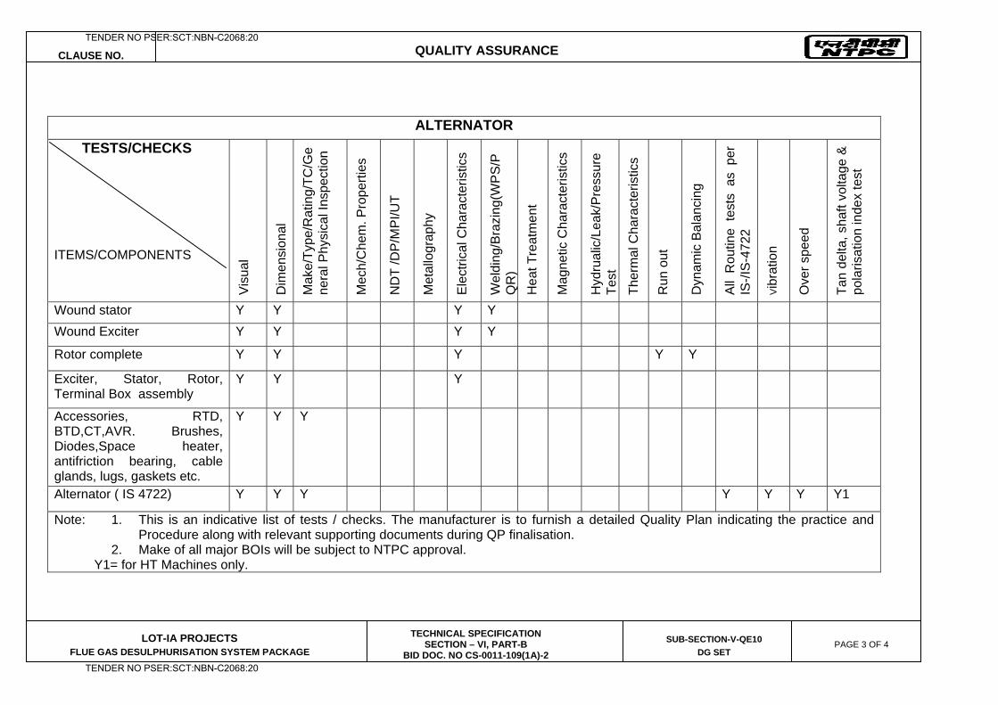
CLAUSE NO. QUALITY ASSURANCE
LOT-IA PROJECTS FLUE GAS DESULPHURISATION SYSTEM PACKAGE
TECHNICAL SPECIFICATION SECTION – VI, PART-B
BID DOC. NO CS-0011-109(1A)-2
SUB-SECTION-V-QE10
DG SET PAGE 3 OF 4
ALTERNATOR
TESTS/CHECKS
ITEMS/COMPONENTS
Vis
ual
Dim
ensi
onal
Mak
e/Ty
pe/R
atin
g/TC
/Ge
nera
l Phy
sica
l Ins
pect
ion
Mec
h/C
hem
. Pro
perti
es
ND
T /D
P/M
PI/U
T
Met
allo
grap
hy
Ele
ctric
al C
hara
cter
istic
s
Wel
ding
/Bra
zing
(WP
S/P
QR
) H
eat T
reat
men
t
Mag
netic
Cha
ract
eris
tics
Hyd
rual
ic/L
eak/
Pre
ssur
e Te
st
Ther
mal
Cha
ract
eris
tics
Run
out
Dyn
amic
Bal
anci
ng
All
Rou
tine
test
s as
per
IS
-/IS
-472
2
Vib
ratio
n
Ove
r spe
ed
Tan
delta
, sha
ft vo
ltage
&
pola
risat
ion
inde
x te
st
Wound stator Y Y Y Y Wound Exciter Y Y Y Y
Rotor complete Y Y Y Y Y
Exciter, Stator, Rotor, Terminal Box assembly
Y Y Y
Accessories, RTD, BTD,CT,AVR. Brushes, Diodes,Space heater, antifriction bearing, cable glands, lugs, gaskets etc.
Y Y Y
Alternator ( IS 4722) Y Y Y Y Y Y Y1
Note: 1. This is an indicative list of tests / checks. The manufacturer is to furnish a detailed Quality Plan indicating the practice and Procedure along with relevant supporting documents during QP finalisation.
2. Make of all major BOIs will be subject to NTPC approval. Y1= for HT Machines only.
TENDER NO PSER:SCT:NBN-C2068:20
TENDER NO PSER:SCT:NBN-C2068:20
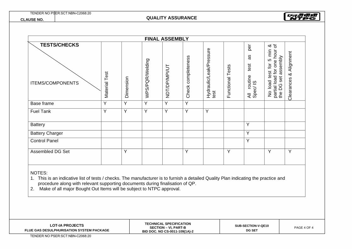
CLAUSE NO. QUALITY ASSURANCE
LOT-IA PROJECTS FLUE GAS DESULPHURISATION SYSTEM PACKAGE
TECHNICAL SPECIFICATION SECTION – VI, PART-B
BID DOC. NO CS-0011-109(1A)-2
SUB-SECTION-V-QE10
DG SET PAGE 4 OF 4
FINAL ASSEMBLY TESTS/CHECKS
ITEMS/COMPONENTS
Mat
eria
l Tes
t
Dim
ensi
on
WP
S/P
QR
/Wel
ding
ND
T/D
P/M
PI/U
T
Che
ck c
ompl
eten
ess
Hyd
raul
ic/L
eak/
Pre
ssur
e te
st
Func
tiona
l Tes
ts
All
rout
ine
test
as
pe
r S
pec/
IS
No
load
tes
t fo
r 5
min
&
parti
al lo
ad fo
r one
hou
r of
the
DG
set
ass
embl
y
Cle
aran
ces
& A
lignm
ent
Base frame Y Y Y Y Y
Fuel Tank Y Y Y Y Y Y
Battery Y
Battery Charger Y Control Panel Y
Assembled DG Set
Y Y Y
Y Y
NOTES: 1. This is an indicative list of tests / checks. The manufacturer is to furnish a detailed Quality Plan indicating the practice and
procedure along with relevant supporting documents during finalisation of QP. 2. Make of all major Bought Out Items will be subject to NTPC approval.
TENDER NO PSER:SCT:NBN-C2068:20
TENDER NO PSER:SCT:NBN-C2068:20

LOT-IA PROJECTS FLUE GAS DESULPHURISATION (FGD) SYSTEM PACKAGE
TECHNICAL SPECIFICATION
SECTION-VI
BID DOCUMENT NO.: CS-0011-109(1A)-2
SUB-SECTION-V-QE11
AUXILIARY TRANSFORMERS
TENDER NO PSER:SCT:NBN-C2068:20
TENDER NO PSER:SCT:NBN-C2068:20
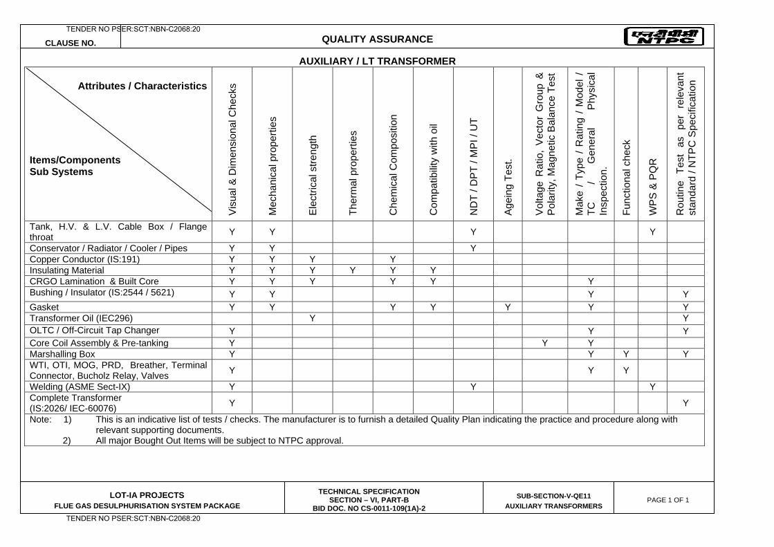
CLAUSE NO. QUALITY ASSURANCE
LOT-IA PROJECTS FLUE GAS DESULPHURISATION SYSTEM PACKAGE
TECHNICAL SPECIFICATION SECTION – VI, PART-B
BID DOC. NO CS-0011-109(1A)-2
SUB-SECTION-V-QE11
AUXILIARY TRANSFORMERS PAGE 1 OF 1
AUXILIARY / LT TRANSFORMER Attributes / Characteristics
Items/Components Sub Systems
Vis
ual &
Dim
ensi
onal
Che
cks
Mec
hani
cal p
rope
rties
Ele
ctric
al s
treng
th
Ther
mal
pro
perti
es
Che
mic
al C
ompo
sitio
n
Com
patib
ility
with
oil
ND
T / D
PT
/ MP
I / U
T
Age
ing
Test
.
Vol
tage
Rat
io,
Vec
tor
Gro
up &
P
olar
ity, M
agne
tic B
alan
ce T
est
Mak
e /
Type
/ R
atin
g /
Mod
el /
TC
/
Gen
eral
P
hysi
cal
Insp
ectio
n.
Func
tiona
l che
ck
WP
S &
PQ
R
Rou
tine
Test
as
pe
r re
leva
nt
stan
dard
/ N
TPC
Spe
cific
atio
n
Tank, H.V. & L.V. Cable Box / Flange throat Y Y Y Y
Conservator / Radiator / Cooler / Pipes Y Y Y Copper Conductor (IS:191) Y Y Y Y Insulating Material Y Y Y Y Y Y CRGO Lamination & Built Core Y Y Y Y Y Y Bushing / Insulator (IS:2544 / 5621) Y Y Y Y Gasket Y Y Y Y Y Y Y Transformer Oil (IEC296) Y Y OLTC / Off-Circuit Tap Changer Y Y Y Core Coil Assembly & Pre-tanking Y Y Y Marshalling Box Y Y Y Y WTI, OTI, MOG, PRD, Breather, Terminal Connector, Bucholz Relay, Valves Y Y Y
Welding (ASME Sect-IX) Y Y Y Complete Transformer (IS:2026/ IEC-60076) Y Y
Note: 1) This is an indicative list of tests / checks. The manufacturer is to furnish a detailed Quality Plan indicating the practice and procedure along with relevant supporting documents.
2) All major Bought Out Items will be subject to NTPC approval.
TENDER NO PSER:SCT:NBN-C2068:20
TENDER NO PSER:SCT:NBN-C2068:20

LOT-IA PROJECTS FLUE GAS DESULPHURISATION (FGD) SYSTEM PACKAGE
TECHNICAL SPECIFICATION
SECTION-VI
BID DOCUMENT NO.: CS-0011-109(1A)-2
SUB-SECTION-V-QE12
ELEVATOR
TENDER NO PSER:SCT:NBN-C2068:20
TENDER NO PSER:SCT:NBN-C2068:20
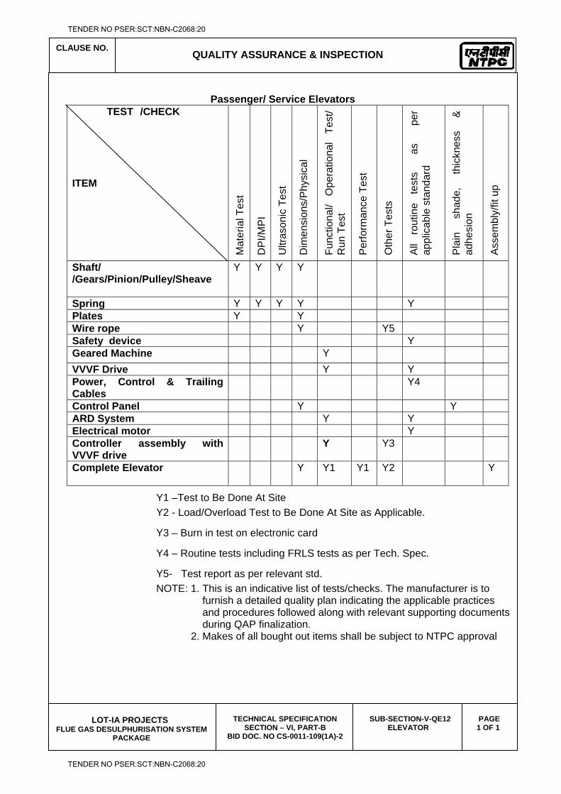
CLAUSE NO.
QUALITY ASSURANCE & INSPECTION
LOT-IA PROJECTS
FLUE GAS DESULPHURISATION SYSTEM PACKAGE
TECHNICAL SPECIFICATION SECTION – VI, PART-B
BID DOC. NO CS-0011-109(1A)-2
SUB-SECTION-V-QE12 ELEVATOR
PAGE 1 OF 1
Passenger/ Service Elevators
TEST /CHECK ITEM M
ater
ial T
est
DP
I/MP
I
Ultr
ason
ic T
est
Dim
ensi
ons/
Phy
sica
l
Func
tiona
l/ O
pera
tiona
l Te
st/
Run
Tes
t
Per
form
ance
Tes
t
Oth
er T
ests
All
rout
ine
test
s
as
pe
r ap
plic
able
sta
ndar
d
Pla
in
shad
e,
thic
knes
s &
ad
hesi
on
Ass
embl
y/fit
up
Shaft/ /Gears/Pinion/Pulley/Sheave
Y Y Y Y
Spring Y Y Y Y Y Plates Y Y Wire rope Y Y5 Safety device Y Geared Machine Y VVVF Drive Y Y Power, Control & Trailing Cables
Y4
Control Panel Y Y ARD System Y Y Electrical motor Y Controller assembly with VVVF drive
Y Y3
Complete Elevator
Y Y1 Y1 Y2 Y
Y1 –Test to Be Done At Site Y2 - Load/Overload Test to Be Done At Site as Applicable.
Y3 – Burn in test on electronic card
Y4 – Routine tests including FRLS tests as per Tech. Spec.
Y5- Test report as per relevant std. NOTE: 1. This is an indicative list of tests/checks. The manufacturer is to furnish a detailed quality plan indicating the applicable practices and procedures followed along with relevant supporting documents during QAP finalization. 2. Makes of all bought out items shall be subject to NTPC approval
TENDER NO PSER:SCT:NBN-C2068:20
TENDER NO PSER:SCT:NBN-C2068:20

LOT-IA PROJECTS FLUE GAS DESULPHURISATION (FGD) SYSTEM PACKAGE
TECHNICAL SPECIFICATION
SECTION-VI
BID DOCUMENT NO.: CS-0011-109(1A)-2
SUB-SECTION-V-QE13
VFD MODULE
TENDER NO PSER:SCT:NBN-C2068:20
TENDER NO PSER:SCT:NBN-C2068:20
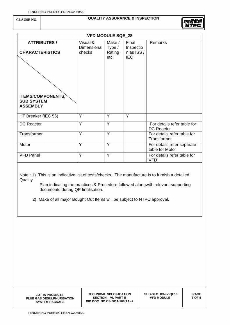
CLAUSE NO. QUALITY ASSURANCE & INSPECTION
LOT-IA PROJECTS
FLUE GAS DESULPHURISATION SYSTEM PACKAGE
TECHNICAL SPECIFICATION SECTION – VI, PART-B
BID DOC. NO CS-0011-109(1A)-2
SUB-SECTION-V-QE13 VFD MODULE
PAGE 1 OF 5
VFD MODULE SQE_28
ATTRIBUTES / CHARACTERISTICS ITEMS/COMPONENTS, SUB SYSTEM ASSEMBLY
Visual & Dimensional checks
Make / Type / Rating etc.
Final Inspection as ISS / IEC
Remarks
HT Breaker (IEC 56) Y Y Y
DC Reactor Y Y For details refer table for DC Reactor
Transformer Y Y For details refer table for Transformer
Motor Y Y For details refer separate table for Motor
VFD Panel Y Y For details refer table for VFD
Note : 1) This is an indicative list of tests/checks. The manufacture is to furnish a detailed Quality Plan indicating the practices & Procedure followed alongwith relevant supporting documents during QP finalisation. 2) Make of all major Bought Out Items will be subject to NTPC approval.
TENDER NO PSER:SCT:NBN-C2068:20
TENDER NO PSER:SCT:NBN-C2068:20
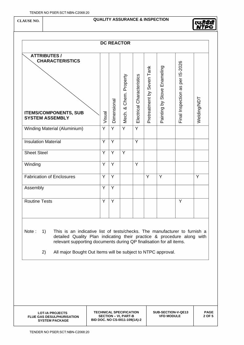
CLAUSE NO. QUALITY ASSURANCE & INSPECTION
LOT-IA PROJECTS
FLUE GAS DESULPHURISATION SYSTEM PACKAGE
TECHNICAL SPECIFICATION SECTION – VI, PART-B
BID DOC. NO CS-0011-109(1A)-2
SUB-SECTION-V-QE13 VFD MODULE
PAGE 2 OF 5
DC REACTOR
ATTRIBUTES / CHARACTERISTICS ITEMS/COMPONENTS, SUB SYSTEM ASSEMBLY V
isua
l
Dim
ensi
onal
Mec
h. &
Che
m. P
rope
rty
Ele
ctric
al C
hara
cter
istic
s
Pre
treat
men
t by
Sev
en T
ank
Pai
ntin
g by
Sto
ve E
nam
elin
g
Fina
l Ins
pect
ion
as p
er IS
-202
6
Wel
ding
/ND
T
Winding Material (Aluminium) Y Y Y Y
Insulation Material Y Y Y
Sheet Steel Y Y Y
Winding Y Y Y
Fabrication of Enclosures Y Y Y Y Y
Assembly Y Y
Routine Tests Y Y Y
Note : 1) This is an indicative list of tests/checks. The manufacturer to furnish a
detailed Quality Plan indicating their practice & procedure along with relevant supporting documents during QP finalisation for all items.
2) All major Bought Out Items will be subject to NTPC approval.
TENDER NO PSER:SCT:NBN-C2068:20
TENDER NO PSER:SCT:NBN-C2068:20
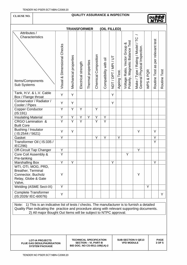
CLAUSE NO. QUALITY ASSURANCE & INSPECTION
LOT-IA PROJECTS
FLUE GAS DESULPHURISATION SYSTEM PACKAGE
TECHNICAL SPECIFICATION SECTION – VI, PART-B
BID DOC. NO CS-0011-109(1A)-2
SUB-SECTION-V-QE13 VFD MODULE
PAGE 3 OF 5
TRANSFORMER (OIL FILLED) Attributes / Characteristics Items/Components Sub Systems V
isua
l & D
imen
sion
al C
heck
s
Mec
hani
cal p
rope
rties
Ele
ctric
al s
treng
th
Ther
mal
pro
perti
es
Che
mic
al C
ompo
sitio
n
Com
patib
ility
with
oil
ND
T / D
PT
/ MP
I / U
T
Age
ing
Test
.
Vol
tage
Rat
io, V
ecto
r Gro
up &
P
olar
ity, M
agne
tic B
alan
ce T
est
Mak
e / T
ype
/ Rat
ing
/ Mod
el /
TC /
G
ener
al P
hysi
cal I
nspe
ctio
n.
WP
S &
PQ
R
Rou
tine
Test
as
per r
elev
ant t
est
Rou
tine
Test
Tank, H.V. & L.V. Cable Box / Flange throat Y Y Y
Conservator / Radiator / Cooler / Pipes Y Y Y
Copper Conductor (IS:191)
Y Y Y Y
Insulating Material Y Y Y Y Y Y CRGO Lamination & Built Core
Y Y Y Y Y
Bushing / Insulator ( IS:2544 / 5621) Y Y Y Y
Gasket Y Y Y Y Y Transformer Oil ( IS:335 / IEC296)
Y
Off-Circuit Tap Changer Y Y Core Coil Assembly & Pre-tanking
Y Y
Marshalling Box Y Y Y Y WTI, OTI, MOG, PRD, Breather, Terminal Connector, Bucholz Relay, Globe & Gate Valve,
Y Y
Welding (ASME Sect-IX) Y Y Complete Transformer (IS:2026/ IEC-60076) Y Y
Note: 1) This is an indicative list of tests / checks. The manufacturer is to furnish a detailed Quality Plan indicating the practice and procedure along with relevant supporting documents. 2) All major Bought Out Items will be subject to NTPC approval.
TENDER NO PSER:SCT:NBN-C2068:20
TENDER NO PSER:SCT:NBN-C2068:20
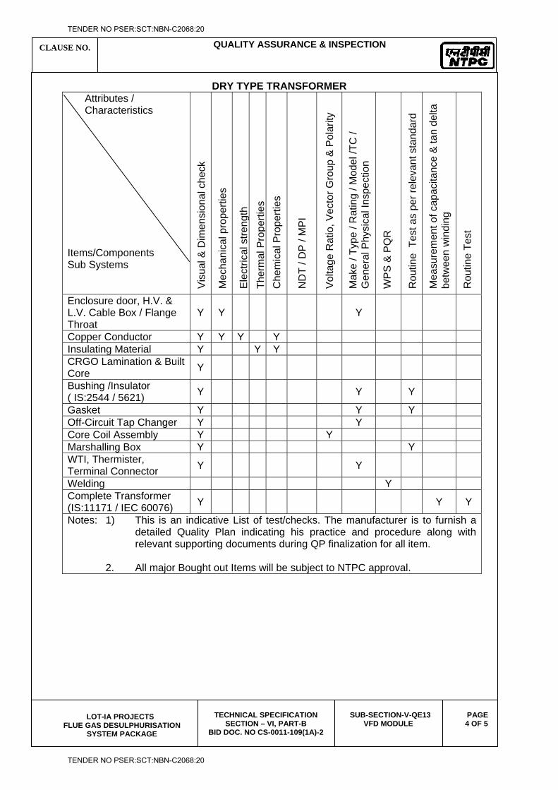
CLAUSE NO. QUALITY ASSURANCE & INSPECTION
LOT-IA PROJECTS
FLUE GAS DESULPHURISATION SYSTEM PACKAGE
TECHNICAL SPECIFICATION SECTION – VI, PART-B
BID DOC. NO CS-0011-109(1A)-2
SUB-SECTION-V-QE13 VFD MODULE
PAGE 4 OF 5
DRY TYPE TRANSFORMER Attributes / Characteristics Items/Components Sub Systems V
isua
l & D
imen
sion
al c
heck
Mec
hani
cal p
rope
rties
Ele
ctric
al s
tren g
th
Ther
mal
Pro
perti
es
Che
mic
al P
rope
rties
ND
T / D
P /
MP
I
Vol
tage
Rat
io, V
ecto
r Gro
up &
Pol
arity
Mak
e / T
ype
/ Rat
ing
/ Mod
el /T
C /
Gen
eral
Phy
sica
l Ins
pect
ion
WP
S &
PQ
R
Rou
tine
Tes
t as
per r
elev
ant s
tand
ard
Mea
sure
men
t of c
apac
itanc
e &
tan
delta
be
twee
n w
indi
ng
Rou
tine
Test
Enclosure door, H.V. & L.V. Cable Box / Flange Throat
Y Y Y
Copper Conductor Y Y Y Y Insulating Material Y Y Y CRGO Lamination & Built Core Y
Bushing /Insulator ( IS:2544 / 5621) Y Y Y
Gasket Y Y Y Off-Circuit Tap Changer Y Y Core Coil Assembly Y Y Marshalling Box Y Y WTI, Thermister, Terminal Connector Y Y
Welding Y Complete Transformer (IS:11171 / IEC 60076) Y Y Y
Notes: 1) This is an indicative List of test/checks. The manufacturer is to furnish a detailed Quality Plan indicating his practice and procedure along with relevant supporting documents during QP finalization for all item.
2. All major Bought out Items will be subject to NTPC approval.
TENDER NO PSER:SCT:NBN-C2068:20
TENDER NO PSER:SCT:NBN-C2068:20
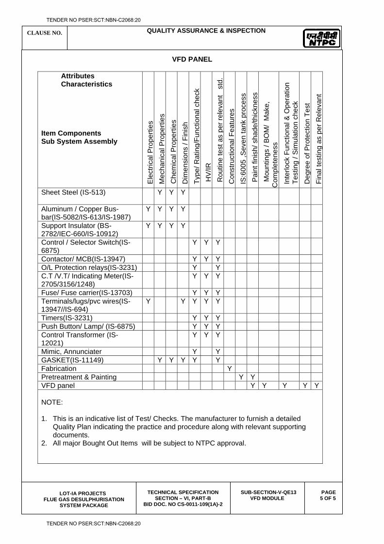
CLAUSE NO. QUALITY ASSURANCE & INSPECTION
LOT-IA PROJECTS
FLUE GAS DESULPHURISATION SYSTEM PACKAGE
TECHNICAL SPECIFICATION SECTION – VI, PART-B
BID DOC. NO CS-0011-109(1A)-2
SUB-SECTION-V-QE13 VFD MODULE
PAGE 5 OF 5
VFD PANEL
Attributes Characteristics Item Components Sub System Assembly
Ele
ctric
al P
rope
rties
M
echa
nica
l Pro
perti
es
Che
mic
al P
rope
rties
D
imen
sion
s / F
inis
h T y
pe/ R
atin
g/Fu
nctio
nal c
heck
HV
/IR
Rou
tine
test
as
per r
elev
ant
std
. C
onst
ruct
iona
l Fea
ture
s IS
:600
5 ,S
even
tank
pro
cess
P
aint
fini
sh/ s
hade
/thic
knes
s
Mou
ntin
gs /
BO
M/
Mak
e,
Com
plet
enes
s
Inte
rlock
Fun
ctio
nal &
Ope
ratio
n Te
stin
g / S
imul
atio
n ch
eck
De g
ree
of P
rote
ctio
n Te
st
Fina
l tes
ting
as p
er R
elev
ant
Sheet Steel (IS-513) Y Y
Y
Aluminum / Copper Bus-bar(IS-5082/IS-613/IS-1987)
Y Y Y Y
Support Insulator (BS-2782/IEC-660/IS-10912)
Y Y Y Y
Control / Selector Switch(IS-6875)
Y Y Y
Contactor/ MCB(IS-13947) Y Y Y O/L Protection relays(IS-3231) Y Y C.T /V.T/ Indicating Meter(IS-2705/3156/1248)
Y Y Y
Fuse/ Fuse carrier(IS-13703) Y Y Y Terminals/lugs/pvc wires(IS-13947//IS-694)
Y Y Y Y Y
Timers(IS-3231) Y Y Y Push Button/ Lamp/ (IS-6875) Y Y Y Control Transformer (IS-12021)
Y Y Y
Mimic, Annunciater Y Y GASKET(IS-11149) Y Y Y Y Y Fabrication Y Pretreatment & Painting Y Y VFD panel Y Y Y Y Y NOTE: 1. This is an indicative list of Test/ Checks. The manufacturer to furnish a detailed
Quality Plan indicating the practice and procedure along with relevant supporting documents.
2. All major Bought Out Items will be subject to NTPC approval.
TENDER NO PSER:SCT:NBN-C2068:20
TENDER NO PSER:SCT:NBN-C2068:20

LOT-IA PROJECTS FLUE GAS DESULPHURISATION (FGD) SYSTEM PACKAGE
TECHNICAL SPECIFICATION
SECTION-VI
BID DOCUMENT NO.: CS-0011-109(1A)-2
SUB-SECTION-V-QE14
STATION LIGHTING
TENDER NO PSER:SCT:NBN-C2068:20
TENDER NO PSER:SCT:NBN-C2068:20
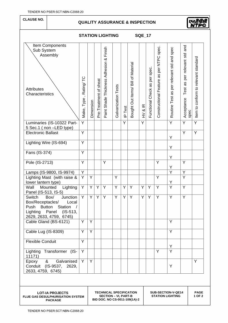
CLAUSE NO.
QUALITY ASSURANCE & INSPECTION
LOT-IA PROJECTS
FLUE GAS DESULPHURISATION SYSTEM PACKAGE
TECHNICAL SPECIFICATION SECTION – VI, PART-B
BID DOC. NO CS-0011-109(1A)-2
SUB-SECTION-V-QE14 STATION LIGHTING
PAGE 1 OF 2
STATION LIGHTING SQE_17
Item Components Sub System Assembly Attributes Characteristics M
ake,
Typ
e , R
atin
g/ T
C
Dim
ensi
on
Pre
-Tre
atm
ent o
f she
at
Pai
nt S
hade
Thi
ckne
ss A
dhes
ion
& F
inis
h
Gal
vani
zatio
n Te
sts
IP T
est
Bou
ght O
ut It
ems/
Bill
of M
ater
ial
HV
& IR
Func
tiona
l Che
ck a
s pe
r spe
c.
Con
stru
ctio
nal F
eatu
re a
s pe
r NTP
C s
pec.
Rou
tine
Test
as
per r
elev
ant s
td a
nd s
pec
Acc
epta
nce
Tes
t as
per
rel
evan
t st
d an
d sp
ec
Item
to c
onfo
rm to
rele
vant
sta
ndar
d
Luminaries (IS-10322 Part-5 Sec.1 ( non –LED type)
Y Y Y Y
Y Y
Electronic Ballast Y Y
Y Y
Lighting Wire (IS-694) Y Y
Fans (IS-374) Y Y
Pole (IS-2713) Y Y Y Y
Y
Lamps (IS-9800, IS-9974) Y Y Y Lighting Mast (with raise & lower lantern type)
Y Y Y Y Y
Y
Wall Mounted Lighting Panel (IS-513, IS-5)
Y Y Y Y Y Y Y Y Y Y Y Y
Switch Box/ Junction Box/Receptacles/ Local Push Button Station / Lighting Panel (IS-513, 2629, 2633, 4759, 6745)
Y Y Y Y Y Y Y Y Y Y Y Y
Cable Gland (BS-6121) Y Y Y
Cable Lug (IS-8309) Y Y Y
Flexible Conduit Y Y
Lighting Transformer (IS-11171)
Y Y Y
Epoxy & Galvanised Conduit (IS-9537, 2629, 2633, 4759, 6745)
Y Y Y
Y
TENDER NO PSER:SCT:NBN-C2068:20
TENDER NO PSER:SCT:NBN-C2068:20
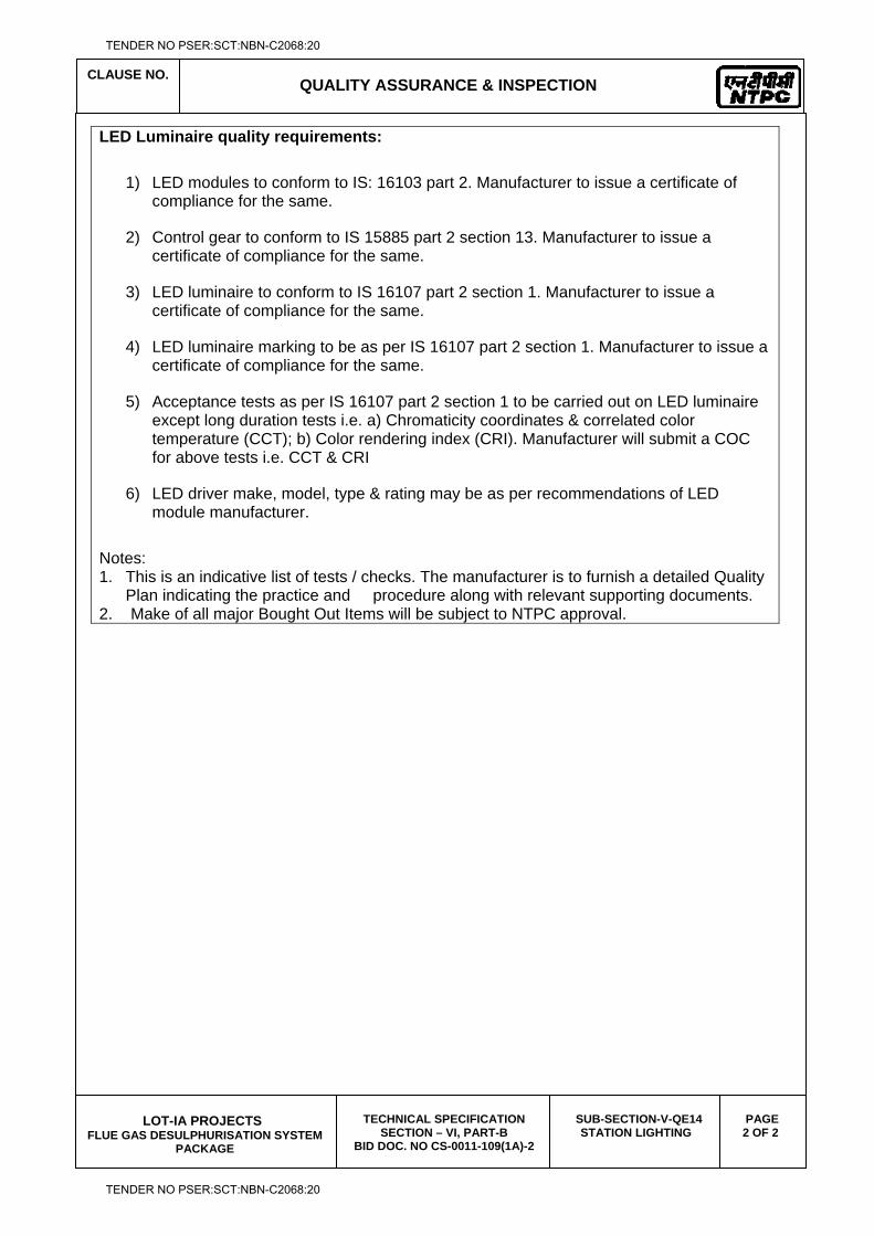
CLAUSE NO.
QUALITY ASSURANCE & INSPECTION
LOT-IA PROJECTS
FLUE GAS DESULPHURISATION SYSTEM PACKAGE
TECHNICAL SPECIFICATION SECTION – VI, PART-B
BID DOC. NO CS-0011-109(1A)-2
SUB-SECTION-V-QE14 STATION LIGHTING
PAGE 2 OF 2
LED Luminaire quality requirements:
1) LED modules to conform to IS: 16103 part 2. Manufacturer to issue a certificate of compliance for the same.
2) Control gear to conform to IS 15885 part 2 section 13. Manufacturer to issue a certificate of compliance for the same.
3) LED luminaire to conform to IS 16107 part 2 section 1. Manufacturer to issue a certificate of compliance for the same.
4) LED luminaire marking to be as per IS 16107 part 2 section 1. Manufacturer to issue a certificate of compliance for the same.
5) Acceptance tests as per IS 16107 part 2 section 1 to be carried out on LED luminaire except long duration tests i.e. a) Chromaticity coordinates & correlated color temperature (CCT); b) Color rendering index (CRI). Manufacturer will submit a COC for above tests i.e. CCT & CRI
6) LED driver make, model, type & rating may be as per recommendations of LED module manufacturer.
Notes: 1. This is an indicative list of tests / checks. The manufacturer is to furnish a detailed Quality
Plan indicating the practice and procedure along with relevant supporting documents. 2. Make of all major Bought Out Items will be subject to NTPC approval.
TENDER NO PSER:SCT:NBN-C2068:20
TENDER NO PSER:SCT:NBN-C2068:20
LOT-IA PROJECTS FLUE GAS DESULPHURISATION (FGD) SYSTEM PACKAGE
TECHNICAL SPECIFICATION
SECTION-VI
BID DOCUMENT NO.: CS-0011-109(1A)-2
(CONTROL & INSTRUMENTATION SYSTEM)
TENDER NO PSER:SCT:NBN-C2068:20
TENDER NO PSER:SCT:NBN-C2068:20
LOT-IA PROJECTS FLUE GAS DESULPHURISATION (FGD) SYSTEM PACKAGE
TECHNICAL SPECIFICATION
SECTION-VI
BID DOCUMENT NO.: CS-0011-109(1A)-2
SUB-SECTION-V-QC1
MEASURING INSTRUMENTS (PRIMARY & SECONDARY
TENDER NO PSER:SCT:NBN-C2068:20
TENDER NO PSER:SCT:NBN-C2068:20
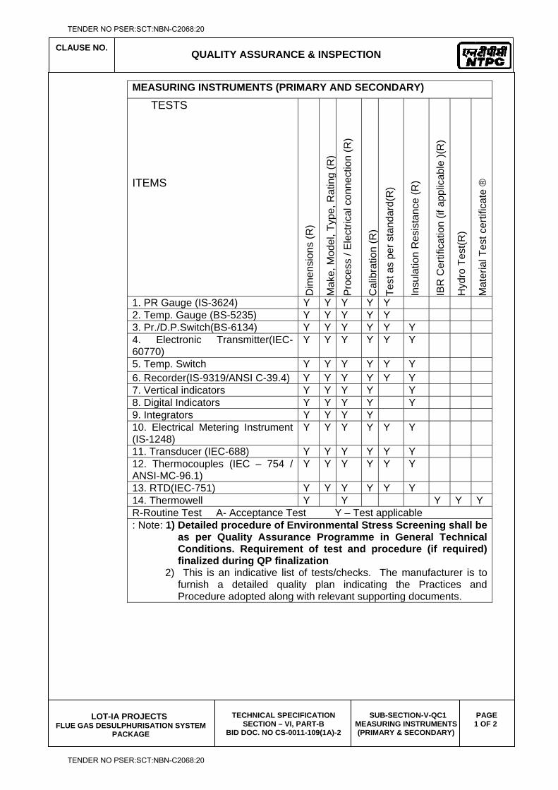
CLAUSE NO.
QUALITY ASSURANCE & INSPECTION
LOT-IA PROJECTS
FLUE GAS DESULPHURISATION SYSTEM PACKAGE
TECHNICAL SPECIFICATION SECTION – VI, PART-B
BID DOC. NO CS-0011-109(1A)-2
SUB-SECTION-V-QC1 MEASURING INSTRUMENTS (PRIMARY & SECONDARY)
PAGE 1 OF 2
MEASURING INSTRUMENTS (PRIMARY AND SECONDARY)
TESTS ITEMS D
imen
sion
s (R
)
Mak
e, M
odel
, Typ
e, R
atin
g (R
) P
roce
ss /
Ele
ctric
al c
onne
ctio
n (R
)
Cal
ibra
tion
(R)
Test
as
per s
tand
ard(
R)
Insu
latio
n R
esis
tanc
e (R
)
IBR
Cer
tific
atio
n (if
app
licab
le )(
R)
Hyd
ro T
est(R
)
Mat
eria
l Tes
t cer
tific
ate
®
1. PR Gauge (IS-3624) Y Y Y Y Y 2. Temp. Gauge (BS-5235) Y Y Y Y Y 3. Pr./D.P.Switch(BS-6134) Y Y Y Y Y Y 4. Electronic Transmitter(IEC-60770)
Y Y Y Y Y Y
5. Temp. Switch Y Y Y Y Y Y 6. Recorder(IS-9319/ANSI C-39.4) Y Y Y Y Y Y 7. Vertical indicators Y Y Y Y Y 8. Digital Indicators Y Y Y Y Y 9. Integrators Y Y Y Y 10. Electrical Metering Instrument (IS-1248)
Y Y Y Y Y Y
11. Transducer (IEC-688) Y Y Y Y Y Y 12. Thermocouples (IEC – 754 / ANSI-MC-96.1)
Y Y Y Y Y Y
13. RTD(IEC-751) Y Y Y Y Y Y 14. Thermowell Y Y Y Y Y R-Routine Test A- Acceptance Test Y – Test applicable : Note: 1) Detailed procedure of Environmental Stress Screening shall be
as per Quality Assurance Programme in General Technical Conditions. Requirement of test and procedure (if required) finalized during QP finalization
2) This is an indicative list of tests/checks. The manufacturer is to furnish a detailed quality plan indicating the Practices and Procedure adopted along with relevant supporting documents.
TENDER NO PSER:SCT:NBN-C2068:20
TENDER NO PSER:SCT:NBN-C2068:20
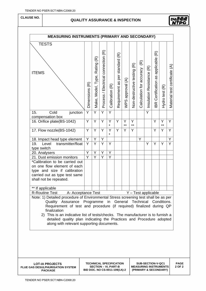
CLAUSE NO.
QUALITY ASSURANCE & INSPECTION
LOT-IA PROJECTS
FLUE GAS DESULPHURISATION SYSTEM PACKAGE
TECHNICAL SPECIFICATION SECTION – VI, PART-B
BID DOC. NO CS-0011-109(1A)-2
SUB-SECTION-V-QC1 MEASURING INSTRUMENTS (PRIMARY & SECONDARY)
PAGE 2 OF 2
MEASURING INSTRUMENTS (PRIMARY AND SECONDARY)
TESTS ITEMS D
imen
sion
s (R
)
Mak
e, M
odel
, Typ
e, R
atin
g (R
)
Pro
cess
/ E
lect
rical
con
nect
ion
(R)
Cal
ibra
tion
(R)
Req
uire
men
t as
per s
tand
ard
(R)
WP
S a
ppro
val (
A)
Non
-des
truct
ive
test
ing
(R)
Cal
cula
tion
for a
ccur
acy
(R)
Insu
latio
n R
esis
tanc
e (R
)
IBR
Cer
tific
atio
n as
app
licab
le (R
)
Hyd
ro te
st (R
)
Mat
eria
l tes
t cer
tific
ate
(A)
15. Cold junction compensation box
Y Y Y Y Y
16. Orifice plate(BS-1042) Y Y Y Y*
Y Y**
Y**
Y Y**
Y
17. Flow nozzle(BS-1042) Y Y Y Y*
Y Y Y Y Y Y
18. Impact head type element Y Y Y Y Y19. Level transmitter/float type switch
Y Y Y Y Y Y Y Y
20. Analysers Y Y Y Y 21. Dust emission monitors Y Y Y Y *Calibration to be carried out on one flow element of each type and size if calibration carried out as type test same shall not be repeated.
** If applicable R-Routine Test A- Acceptance Test Y – Test applicable Note: 1) Detailed procedure of Environmental Stress screening test shall be as per
Quality Assurance Programme in General Technical Conditions. Requirement of test and procedure (if required) finalized during QP finalization
2) This is an indicative list of tests/checks. The manufacturer is to furnish a detailed quality plan indicating the Practices and Procedure adopted along with relevant supporting documents.
TENDER NO PSER:SCT:NBN-C2068:20
TENDER NO PSER:SCT:NBN-C2068:20
LOT-IA PROJECTS FLUE GAS DESULPHURISATION (FGD) SYSTEM PACKAGE
TECHNICAL SPECIFICATION
SECTION-VI
BID DOCUMENT NO.: CS-0011-109(1A)-2
SUB-SECTION-V-QC2
PROCESS CONNECTION & PIPING
TENDER NO PSER:SCT:NBN-C2068:20
TENDER NO PSER:SCT:NBN-C2068:20
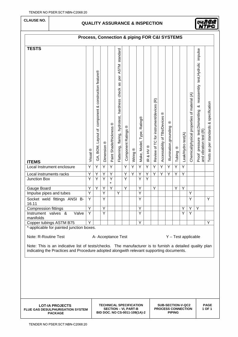
CLAUSE NO.
QUALITY ASSURANCE & INSPECTION
LOT-IA PROJECTS
FLUE GAS DESULPHURISATION SYSTEM PACKAGE
TECHNICAL SPECIFICATION SECTION – VI, PART-B
BID DOC. NO CS-0011-109(1A)-2
SUB-SECTION-V-QC2 PROCESS CONNECTION
PIPING
PAGE 1 OF 1
Process, Connection & piping FOR C&I SYSTEMS
TESTS ITEMS V
isua
l ®
GA
, BO
M, L
ayou
t of
com
pone
nt &
con
stru
ctio
n fe
atur
e®
Dim
ensi
on ®
Pai
nt S
hade
/thic
knes
s ®
Flat
teni
ng,
flarin
g, h
ydro
test
, ha
rdne
ss c
heck
as
per
AS
TM s
tand
ard
Com
pone
nt R
atin
gs ®
Wiri
ng ®
Mak
e, M
odel
, Typ
e, R
atin
g®
IR &
HV
®
Rev
iew
of T
C fo
r ins
trum
ent/d
evic
es (R
)
Acc
essa
bilit
y of
TB
s/D
evic
es ®
Illu
min
atio
n,gr
ound
ing
®
Tubi
ng ®
Leak
/Hyd
ro te
st(A
)
Che
mic
al/p
hysi
cal p
rope
rties
of m
ater
ial (
A)
Pro
of p
ress
ure
test
,Dis
man
tling
& r
eass
embl
y te
st,H
ydru
lic i
mpu
lse
and
vibr
atio
n te
st (R
)
Test
s as
per
sta
ndar
ds &
spe
cific
atio
n
Local Instrument enclosure Y Y Y Y Y Y Y Y Y Y Y Y Y
Local instruments racks Y Y Y Y Y Y Y Y Y Y Y Y Y Junction Box Y Y Y Y
* Y Y Y
Gauge Board Y Y Y Y Y Y Y Y Y Impulse pipes and tubes Y Y Y Y Y Socket weld fittings ANSI B-16.11
Y Y Y Y Y
Compression fittings Y Y Y Y Y Y Instrument valves & Valve manifolds
Y Y Y Y Y
Copper tubings ASTM B75 Y Y Y *-applicable for painted junction boxes. Note: R-Routine Test A- Acceptance Test Y – Test applicable Note: This is an indicative list of tests/checks. The manufacturer is to furnish a detailed quality plan indicating the Practices and Procedure adopted alongwith relevant supporting documents.
TENDER NO PSER:SCT:NBN-C2068:20
TENDER NO PSER:SCT:NBN-C2068:20

LOT-IA PROJECTS FLUE GAS DESULPHURISATION (FGD) SYSTEM PACKAGE
TECHNICAL SPECIFICATION
SECTION-VI
BID DOCUMENT NO.: CS-0011-109(1A)-2
SUB-SECTION-V-QC3
INSTRUMENTATION CABLES
TENDER NO PSER:SCT:NBN-C2068:20
TENDER NO PSER:SCT:NBN-C2068:20

CLAUSE NO.
QUALITY ASSURANCE & INSPECTION
LOT-IA PROJECTS
FLUE GAS DESULPHURISATION SYSTEM PACKAGE
TECHNICAL SPECIFICATION SECTION – VI, PART-B
BID DOC. NO CS-0011-109(1A)-2
SUB-SECTION-V-QC3 INSTRUMENTATION
CABLES
PAGE 1 OF 1
INSTRUMENTATION CABLE
TESTS ITEMS
Con
duct
or R
esis
tanc
e ®
& (A
) H
igh
Vol
tage
® &
(A)
Insu
latio
n R
esis
tanc
e ®
& (
A)
Con
stru
ctio
nal d
etai
l, di
men
sion
s (A
)
Out
er-S
heat
he/c
ore
mar
king
, end
sea
ling
(A)
Ther
mal
Sta
bilit
y (A
) +
Vis
ual,
Sur
face
fini
sh (A
) +
Ele
ctric
al P
aram
eter
s *
* (A
) +
Per
sulp
hate
Tes
t (A
) +
Ove
rall/
Cov
erag
e/C
ontin
uity
(A)
Sw
ides
h ch
imne
y T
est (
SS
-424
1475
) (A
) ++
FRLS
Tes
t * (A
) ++
Tens
ile &
Elo
ngat
ion
befo
re &
afte
r agi
ng (A
) ++
Vol
. Res
istiv
ity. a
t roo
m &
Ele
vate
d Te
mp.
(A) +
+
Spa
rk te
st re
port
revi
ew ®
1. Instrument cable twisted and shielded
Conductor(IS-8130) Y Y Y Insulation(VDE-207) Y Y Y Y Y Y Pairing/Twisting Y Y Y Shielding Y Y Y Drain wire Y Y Y Y Y Inner Sheath Y Y Y Y Y Y Outer Sheath Y Y Y Y Y Y Over all cable Y Y Y Y Y Y Y Y Y Cable Drums(IS-10418) Y Y
Note : High Temp. cables shall be subjected to tests as per VDE-207(Part-6) Compensating cables shall be checked for Thermal EMF/Endurance test as per IS 8784. Note : This is an indicative list of tests/checks. The manufacture is to furnish a detailed Quality Plan indicating his practice & Procedure along with relevant supporting documents during QP finalization for all items. Note : ® - Routine Test A - Acceptance Test Y - Test Applicable Note : Sampling Plan for Acceptance test shall be as per IS 8784 (As applicable) * FRLS Tests: Oxygen / Temp Index ( ASTM D-2863), Smoke Density Rating ( ASTM
– D 2843), HCL Emission ( IEC-754-1) ** Characteristic Impedance, Attenuation, Mutual Capacitance, Cross Talk ( As
applicable) + Sample size will be One No. of each size/type per lot. ++ Sample size will be One No. sample for complete lot offered irrespective of size/type.
TENDER NO PSER:SCT:NBN-C2068:20
TENDER NO PSER:SCT:NBN-C2068:20

LOT-IA PROJECTS FLUE GAS DESULPHURISATION (FGD) SYSTEM PACKAGE
TECHNICAL SPECIFICATION
SECTION-VI
BID DOCUMENT NO.: CS-0011-109(1A)-2
SUB-SECTION-V-QC4
CONTROL DESK PLC PANEL SMOKE DETECTOR FIRE ALARM & CONTROL SYSTEM
TENDER NO PSER:SCT:NBN-C2068:20
TENDER NO PSER:SCT:NBN-C2068:20
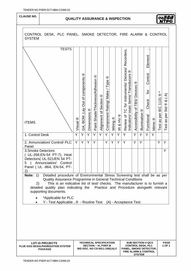
CLAUSE NO.
QUALITY ASSURANCE & INSPECTION
LOT-IA PROJECTS
FLUE GAS DESULPHURISATION SYSTEM PACKAGE
TECHNICAL SPECIFICATION SECTION – VI, PART-B
BID DOC. NO CS-0011-109(1A)-2
SUB-SECTION-V-QC4 CONTROL DESK, PLC
PANEL, SMOKE DETECTOR, FIRE ALARM & CONTROL
SYSTEM
PAGE 1 OF 1
CONTROL DESK, PLC PANEL, SMOKE DETECTOR, FIRE ALARM & CONTROL SYSTEM
TESTS
ITEMS V
isua
l ®
GA
, BO
M ,L
ay O
ut o
f com
pone
nts
®
Dim
ensi
ons
®
Pai
nt S
hade
/Thi
ckne
ss/A
dhes
ion
®
Alig
nmen
t of S
ectio
n ®
Com
pone
nt R
atin
g/ M
ake
/ Typ
e ®
Wiri
ng ®
IR &
HV
®
Rev
iew
of
TC f
or in
stru
men
ts/
Dev
ices
/ R
ecor
ders
, In
dica
tors
/ osa
ic It
ems/
Tra
nsdu
cers
®
Acc
essi
bilit
y of
TB
S/ D
evic
es ®
Illum
inat
ion
®
Func
tiona
l C
heck
fo
r C
ontro
l E
lem
ent
,
Mim
ic ®
Test
as
per I
EC
113
1 ®
*
Test
as
per S
td ®
& (
A)
1. Control Desk Y Y Y Y Y Y Y Y Y Y Y Y Y
2. Annunciation/ Control/ PLC Panel
Y Y Y Y Y Y Y Y Y Y Y Y
3.Smoke Detectors ( UL-268,EN-54 PT-7), Heat Detectors( UL-521/EN 54 PT-5 ) Annunciation/ Control Panel ( UL -864, EN-54, PT-2)
Y
Note: 1) Detailed procedure of Environmental Stress Screening test shall be as per Quality Assurance Programme in General Technical Conditions
2) This is an indicative list of test/ checks. The manufacturer is to furnish a detailed quality plan indicating the Practice and Procedure alongwith relevant supporting documents.
*Applicable for PLC Y - Test Applicable , ® - Routine Test (A) - Acceptance Test
TENDER NO PSER:SCT:NBN-C2068:20
TENDER NO PSER:SCT:NBN-C2068:20

LOT-IA PROJECTS FLUE GAS DESULPHURISATION (FGD) SYSTEM PACKAGE
TECHNICAL SPECIFICATION
SECTION-VI
BID DOCUMENT NO.: CS-0011-109(1A)-2
SUB-SECTION-V-QC5
POWER SUPPLY SYSTEM
TENDER NO PSER:SCT:NBN-C2068:20
TENDER NO PSER:SCT:NBN-C2068:20
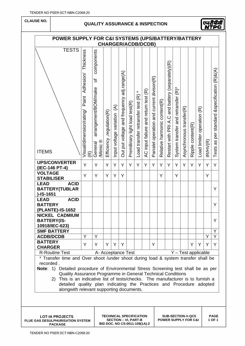
CLAUSE NO.
QUALITY ASSURANCE & INSPECTION
LOT-IA PROJECTS
FLUE GAS DESULPHURISATION SYSTEM PACKAGE
TECHNICAL SPECIFICATION SECTION – VI, PART-B
BID DOC. NO CS-0011-109(1A)-2
SUB-SECTION-V-QC5 POWER SUPPLY FOR C&I
PAGE 1 OF 1
POWER SUPPLY FOR C&I SYSTEMS (UPS/BATTERY/BATTERY CHARGER/ACDB/DCDB)
TESTS ITEMS V
isua
l/dim
ensi
on/ra
ting/
P
aint
A
dhes
ion/
Th
ickn
ess
(R)
Gen
eral
ar
rang
emen
t/BO
M/m
ake
of
com
pone
nts
/Mim
ic ®
E
ffici
ency
,reg
ulat
ion(
R)
Inpu
t vol
tage
var
iatio
n (A
)
Out
put
vol
tage
and
freq
uenc
y ad
j.ran
ge(A
)
Pre
mili
nary
ligh
t loa
d te
st(R
)
Load
tran
sfer
retra
nsfe
r tes
t (R
) *
AC
inpu
t fal
iure
and
retu
rn te
st (R
)
Par
rale
l ope
ratio
n an
d cu
rren
t div
ison
(R)
Rel
ativ
e ha
rmon
ic c
onte
nt(R
)
Res
tart
with
PR
I A.C
and
bat
tery
(sep
arat
ely)
(R)
Sys
tem
tran
sfer
and
retra
nsfe
r (R
)*
Asy
nchr
onou
s tra
nsfe
r(R)
Rip
ple
cont
ent(R
)
Load
lim
iter o
pera
tion
(R)
IR/H
V(R
)
Test
s as
per
sta
ndar
d &
spec
ifica
tion
(R)&
(A)
UPS/CONVERTER (IEC-146 PT-4)
Y Y Y Y Y Y Y Y Y Y Y Y Y Y Y Y Y
VOLTAGE STABILISER
Y Y Y Y Y Y Y Y
LEAD ACID BATTERY(TUBLAR)-IS-1651
Y
LEAD ACID BATTERY (PLANTE)-IS-1652
Y
NICKEL CADMIUM BATTERY(IS-10918/IEC-623)
Y
SMF BATTERY YACDB/DCDB Y Y Y YBATTERY CHARGER
Y Y Y Y Y Y Y Y Y Y
R-Routine Test A- Acceptance Test Y – Test applicable * Transfer time and Over shoot /under shoot during load & system transfer shall be recorded .
Note: 1) Detailed procedure of Environmental Stress Screening test shall be as per Quality Assurance Programme in General Technical Conditions
2) This is an indicative list of tests/checks. The manufacturer is to furnish a detailed quality plan indicating the Practices and Procedure adopted alongwith relevant supporting documents.
TENDER NO PSER:SCT:NBN-C2068:20
TENDER NO PSER:SCT:NBN-C2068:20
LOT-IA PROJECTS FLUE GAS DESULPHURISATION (FGD) SYSTEM PACKAGE
TECHNICAL SPECIFICATION
SECTION-VI
BID DOCUMENT NO.: CS-0011-109(1A)-2
SUB-SECTION-V-QC6
CONTROL VALVE ACTUATORS AND ACCESSORIES
TENDER NO PSER:SCT:NBN-C2068:20
TENDER NO PSER:SCT:NBN-C2068:20
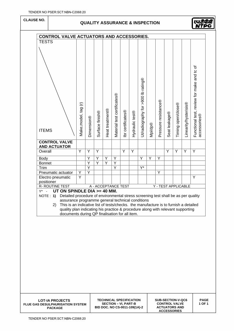
CLAUSE NO.
QUALITY ASSURANCE & INSPECTION
LOT-IA PROJECTS
FLUE GAS DESULPHURISATION SYSTEM PACKAGE
TECHNICAL SPECIFICATION SECTION – VI, PART-B
BID DOC. NO CS-0011-109(1A)-2
SUB-SECTION-V-QC6 CONTROL VALVE ACTUATORS AND
ACCESSORIES
PAGE 1 OF 1
CONTROL VALVE ACTUATORS AND ACCESSORIES. TESTS ITEMS
M
ake,
mod
el, t
ag (r
)
Dim
ensi
on®
Sur
face
fini
sh®
Hea
t tre
atm
ent®
Mat
eria
l tes
t cer
tific
ates
®
Ibr c
ertif
icat
es®
Hyd
raul
ic te
st®
Ut/r
adio
grap
hy fo
r >90
0 lb
ratin
g®
Mpi
/dp®
Pres
sure
resi
stan
ce®
Sea
t lea
kage
®
Tim
ing
open
/clo
se®
Line
arity
/hys
teris
is®
Func
tiona
l tes
t, re
view
for m
ake
and
tc o
f ac
cess
orie
s®
CONTROL VALVE AND ACTUATOR
Overall Y Y Y Y Y Y Y Y Y
Body Y Y Y Y Y Y Y Bonnet Y Y Y Y Trim Y Y Y* Pneumatic actuator Y Y Y Electro pneumatic positioner
Y Y
R- ROUTINE TEST A - ACCEPTANCE TEST Y - TEST APPLICABLE Y* - UT ON SPINDLE DIA >= 40 MM. NOTE : 1) Detailed procedure of environmental stress screening test shall be as per quality
assurance programme general technical conditions 2) This is an indicative list of tests/checks. the manufacture is to furnish a detailed
quality plan indicating his practice & procedure along with relevant supporting documents during QP finalisation for all item.
TENDER NO PSER:SCT:NBN-C2068:20
TENDER NO PSER:SCT:NBN-C2068:20

LOT-IA PROJECTS FLUE GAS DESULPHURISATION (FGD) SYSTEM PACKAGE
TECHNICAL SPECIFICATION
SECTION-VI
BID DOCUMENT NO.: CS-0011-109(1A)-2
SUB-SECTION-V-QC7
ELECTRICAL ACTUATOR WITH INTEGRAL STARTERS
TENDER NO PSER:SCT:NBN-C2068:20
TENDER NO PSER:SCT:NBN-C2068:20
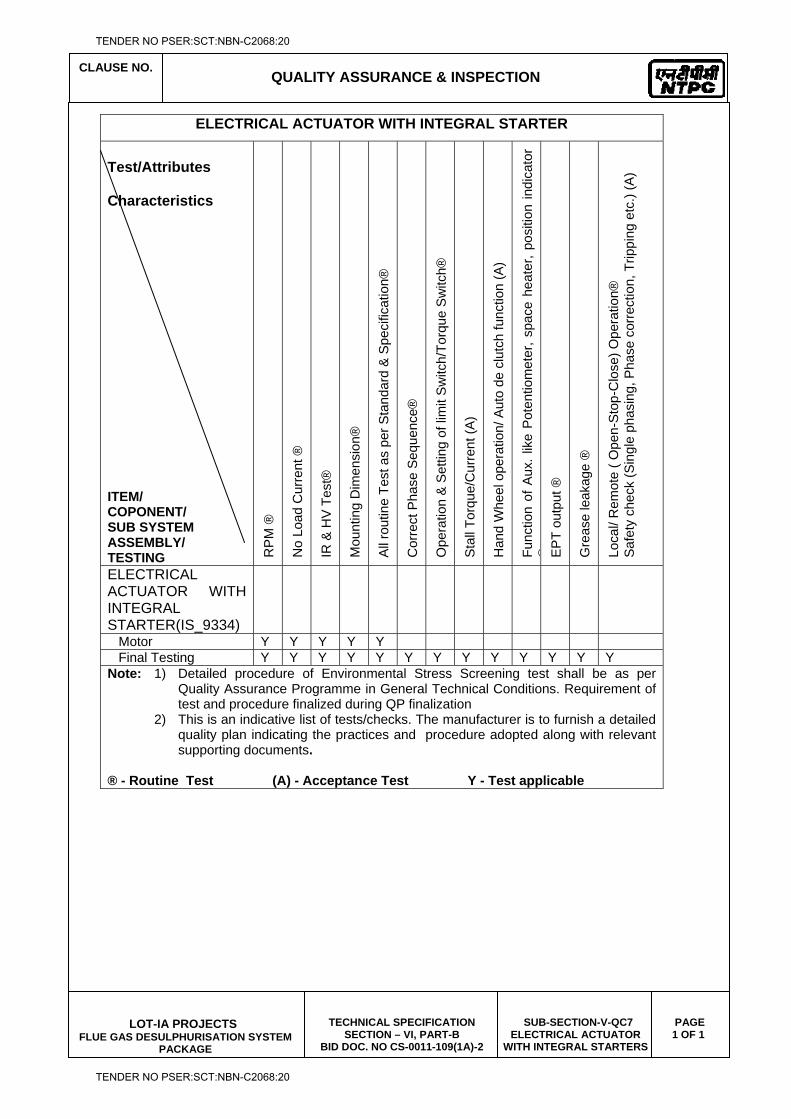
CLAUSE NO.
QUALITY ASSURANCE & INSPECTION
LOT-IA PROJECTS
FLUE GAS DESULPHURISATION SYSTEM PACKAGE
TECHNICAL SPECIFICATION SECTION – VI, PART-B
BID DOC. NO CS-0011-109(1A)-2
SUB-SECTION-V-QC7 ELECTRICAL ACTUATOR
WITH INTEGRAL STARTERS
PAGE 1 OF 1
ELECTRICAL ACTUATOR WITH INTEGRAL STARTER
Test/Attributes Characteristics ITEM/ COPONENT/ SUB SYSTEM ASSEMBLY/ TESTING R
PM
®
No
Load
Cur
rent
®
IR &
HV
Tes
t®
Mou
ntin
g D
imen
sion
®
All
rout
ine
Test
as
per S
tand
ard
& S
peci
ficat
ion®
Cor
rect
Pha
se S
eque
nce®
Ope
ratio
n &
Set
ting
of li
mit
Sw
itch/
Torq
ue S
witc
h®
Sta
ll To
rque
/Cur
rent
(A)
Han
d W
heel
ope
ratio
n/ A
uto
de c
lutc
h fu
nctio
n (A
)
Func
tion
of A
ux. l
ike
Pot
entio
met
er, s
pace
hea
ter,
posi
tion
indi
cato
r ® E
PT
outp
ut ®
Gre
ase
leak
age
®
Loca
l/ R
emot
e ( O
pen-
Sto
p-C
lose
) Ope
ratio
n®
Saf
ety
chec
k (S
ingl
e ph
asin
g, P
hase
cor
rect
ion,
Trip
ping
etc
.) (A
)
ELECTRICAL ACTUATOR WITH INTEGRAL STARTER(IS_9334)
Motor Y Y Y Y Y Final Testing Y Y Y Y Y Y Y Y Y Y Y Y Y Note: 1) Detailed procedure of Environmental Stress Screening test shall be as per
Quality Assurance Programme in General Technical Conditions. Requirement of test and procedure finalized during QP finalization
2) This is an indicative list of tests/checks. The manufacturer is to furnish a detailed quality plan indicating the practices and procedure adopted along with relevant supporting documents.
® - Routine Test (A) - Acceptance Test Y - Test applicable
TENDER NO PSER:SCT:NBN-C2068:20
TENDER NO PSER:SCT:NBN-C2068:20
LOT-IA PROJECTS FLUE GAS DESULPHURISATION (FGD) SYSTEM PACKAGE
TECHNICAL SPECIFICATION
SECTION-VI
BID DOCUMENT NO.: CS-0011-109(1A)-2
(CIVIL WORKS)
SUB-SECTION-V-QD1
TENDER NO PSER:SCT:NBN-C2068:20
TENDER NO PSER:SCT:NBN-C2068:20
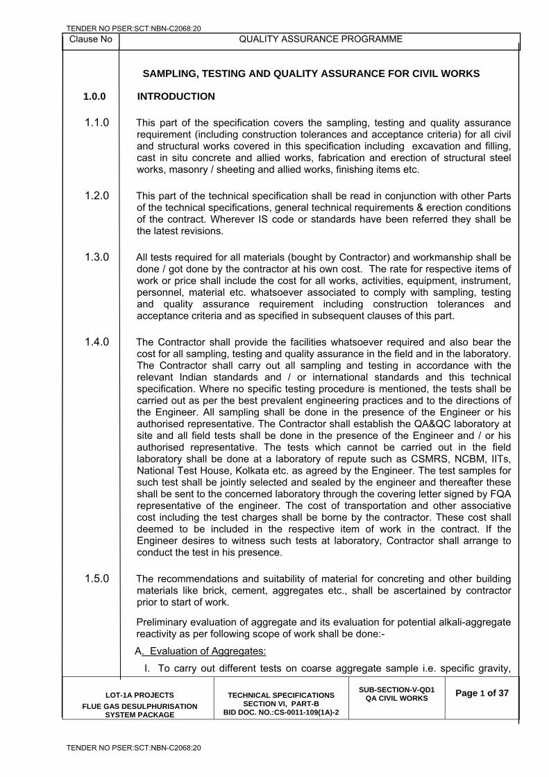
Clause No QUALITY ASSURANCE PROGRAMME
LOT-1A PROJECTS
FLUE GAS DESULPHURISATION SYSTEM PACKAGE
TECHNICAL SPECIFICATIONS SECTION VI, PART-B
BID DOC. NO.:CS-0011-109(1A)-2
SUB-SECTION-V-QD1
QA CIVIL WORKS
Page 1 of 37
SAMPLING, TESTING AND QUALITY ASSURANCE FOR CIVIL WORKS
1.0.0 INTRODUCTION
1.1.0 This part of the specification covers the sampling, testing and quality assurance requirement (including construction tolerances and acceptance criteria) for all civil and structural works covered in this specification including excavation and filling, cast in situ concrete and allied works, fabrication and erection of structural steel works, masonry / sheeting and allied works, finishing items etc.
1.2.0 This part of the technical specification shall be read in conjunction with other Parts of the technical specifications, general technical requirements & erection conditions of the contract. Wherever IS code or standards have been referred they shall be the latest revisions.
1.3.0 All tests required for all materials (bought by Contractor) and workmanship shall be done / got done by the contractor at his own cost. The rate for respective items of work or price shall include the cost for all works, activities, equipment, instrument, personnel, material etc. whatsoever associated to comply with sampling, testing and quality assurance requirement including construction tolerances and acceptance criteria and as specified in subsequent clauses of this part.
1.4.0 The Contractor shall provide the facilities whatsoever required and also bear the cost for all sampling, testing and quality assurance in the field and in the laboratory. The Contractor shall carry out all sampling and testing in accordance with the relevant Indian standards and / or international standards and this technical specification. Where no specific testing procedure is mentioned, the tests shall be carried out as per the best prevalent engineering practices and to the directions of the Engineer. All sampling shall be done in the presence of the Engineer or his authorised representative. The Contractor shall establish the QA&QC laboratory at site and all field tests shall be done in the presence of the Engineer and / or his authorised representative. The tests which cannot be carried out in the field laboratory shall be done at a laboratory of repute such as CSMRS, NCBM, IITs, National Test House, Kolkata etc. as agreed by the Engineer. The test samples for such test shall be jointly selected and sealed by the engineer and thereafter these shall be sent to the concerned laboratory through the covering letter signed by FQA representative of the engineer. The cost of transportation and other associative cost including the test charges shall be borne by the contractor. These cost shall deemed to be included in the respective item of work in the contract. If the Engineer desires to witness such tests at laboratory, Contractor shall arrange to conduct the test in his presence.
1.5.0 The recommendations and suitability of material for concreting and other building materials like brick, cement, aggregates etc., shall be ascertained by contractor prior to start of work.
Preliminary evaluation of aggregate and its evaluation for potential alkali-aggregate reactivity as per following scope of work shall be done:-
A. Evaluation of Aggregates:
I. To carry out different tests on coarse aggregate sample i.e. specific gravity,
TENDER NO PSER:SCT:NBN-C2068:20
TENDER NO PSER:SCT:NBN-C2068:20
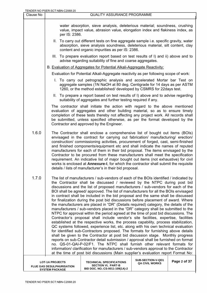
Clause No QUALITY ASSURANCE PROGRAMME
LOT-1A PROJECTS
FLUE GAS DESULPHURISATION SYSTEM PACKAGE
TECHNICAL SPECIFICATIONS SECTION VI, PART-B
BID DOC. NO.:CS-0011-109(1A)-2
SUB-SECTION-V-QD1
QA CIVIL WORKS
Page 2 of 37
water absorption, sieve analysis, deleterious material; soundness, crushing value, impact value, abrasion value, elongation index and flakiness index, as per IS: 2386.
II. To carry out different tests on fine aggregate sample i.e. specific gravity, water absorption, sieve analysis soundness, deleterious material, silt content, clay content and organic impurities as per IS: 2386.
III. To prepare evaluation report based on test results of I) and ii) above and to advise regarding suitability of fine and coarse aggregates.
B. Evaluation of Aggregates for Potential Alkali-Aggregate Reactivity:
Evaluation for Potential Alkali-Aggregate reactivity as per following scope of work:
I. To carry out petrographic analysis and accelerated Mortar bar Test on aggregate samples (1N NaOH at 80 deg. Centigrade for 14 days as per ASTM 1260, or the method established/ developed by CSMRS for 22days test.
II. To prepare a report based on test results of I) above and to advise regarding suitability of aggregates and further testing required if any.
The contractor shall initiate the action with regard to the above mentioned evaluation of aggregates and other building material, so as to ensure timely completion of these tests thereby not affecting any project work. All records shall be submitted, unless specified otherwise, as per the format developed by the Contractor and approved by the Engineer.
1.6.0 The Contractor shall enclose a comprehensive list of bought out items (BOIs) envisaged in the contract for carrying out fabrication/ manufacturing/ erection/ construction/ commissioning activities, procurement of forged, cast, semi-finished and finished components/equipment etc and shall indicate the names of reputed manufacturers for each of them in their bid proposal. The items envisaged by the Contractor to be procured from these manufacturers shall meet the specification requirement. An indicative list of major bought out items (not exhaustive) for civil works is enclosed at Annexure-I, for which the contractor shall submit the requisite details / lists of manufacturer’s in their bid proposal.
1.7.0 The list of manufacturers / sub-vendors of each of the BOIs identified / indicated by the Contractor shall be discussed / reviewed by the NTPC during post bid discussions and the list of proposed manufacturers / sub-vendors for each of the BOI shall be agreed/ approved. The list of manufacturers for all the BOIs envisaged in contract shall be included in the bid proposal and the same shall be discussed for finalization during the post bid discussions before placement of award. Where the manufacturers are placed in “DR” (Details required) category, the details of the manufacturers / sub-vendors placed in the “DR” category shall be submitted to the NTPC for approval within the period agreed at the time of post bid discussions. The Contractor’s proposal shall include vendor’s site facilities, expertise, facilities established at the respective works, the process capability, process stabilization, QC systems followed, experience list, etc. along with his own technical evaluation for identified sub-Contractors proposed. The formats for furnishing above details shall be given to the Contractor at post bid discussion stage. Monthly progress reports on sub-Contractor detail submission / approval shall be furnished on format no. QS-01-QAI-P-02/F1. The NTPC shall furnish other relevant formats for information/ clarification for manufacturers / sub-vendors approval to the Contractor at the time of post bid discussions (Main supplier’s evaluation report Format No:
TENDER NO PSER:SCT:NBN-C2068:20
TENDER NO PSER:SCT:NBN-C2068:20
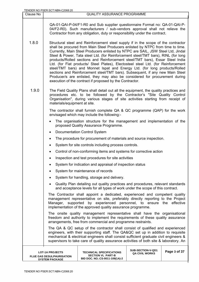
Clause No QUALITY ASSURANCE PROGRAMME
LOT-1A PROJECTS
FLUE GAS DESULPHURISATION SYSTEM PACKAGE
TECHNICAL SPECIFICATIONS SECTION VI, PART-B
BID DOC. NO.:CS-0011-109(1A)-2
SUB-SECTION-V-QD1
QA CIVIL WORKS
Page 3 of 37
QA-01-QAI-P-04/F1-R0 and Sub supplier questionnaire Format no: QA-01-QAI-P-04/F2-R0). Such manufacturers / sub-vendors approval shall not relieve the Contractor from any obligation, duty or responsibility under the contract.
1.8.0 Structural steel and Reinforcement steel supply if in the scope of the contractor shall be procured from Main Steel Producers enlisted by NTPC from time to time. Currently, Main Steel Producers enlisted by NTPC are SAIL, JSW Steel Ltd, Jindal Steel & Power, Tata steel Ltd. (for Reinforcement steel/TMT bars), RINL (for long products/Rolled sections and Reinforcement steel/TMT bars), Essar Steel India Ltd. (for Flat products/ Steel Plates), Electosteel steel Ltd. (for Reinforcement steel/TMT bars) and Monnet Ispat and Energy Ltd. (for long products/Rolled sections and Reinforcement steel/TMT bars). Subsequent, if any new Main Steel Producer/s are enlisted, they may also be considered for procurement during execution of the contract if proposed by the Contractor.
1.9.0 The Field Quality Plans shall detail out all the equipment, the quality practices and procedures etc. to be followed by the Contractor’s "Site Quality Control Organisation", during various stages of site activities starting from receipt of materials/equipment at site.
The contractor shall furnish complete QA & QC programme (QAP) for the work envisaged which may include the following:-
The organisation structure for the management and implementation of the proposed Quality Assurance Programme.
Documentation Control System
The procedure for procurement of materials and source inspection.
System for site controls including process controls.
Control of non-conforming items and systems for corrective action
Inspection and test procedures for site activities
System for indication and appraisal of inspection status
System for maintenance of records
System for handling, storage and delivery.
Quality Plan detailing out quality practices and procedures, relevant standards and acceptance levels for all types of work under the scope of this contract.
The Contractor shall appoint a dedicated, experienced and competent quality management representative on site, preferably directly reporting to the Project Manager, supported by experienced personnel, to ensure the effective implementation of the approved quality assurance programme.
The onsite quality management representative shall have the organisational freedom and authority to implement the requirements of these quality assurance arrangements, free from commercial and programme restraints.
The QA & QC setup of the contractor shall consist of qualified and experienced engineers, with their supporting staff. The QA&QC set up in addition to requisite mechanical & electrical engineers shall consist sufficient graduate civil engineers & supervisors to take care of quality assurance activities of both site & laboratory. An
TENDER NO PSER:SCT:NBN-C2068:20
TENDER NO PSER:SCT:NBN-C2068:20
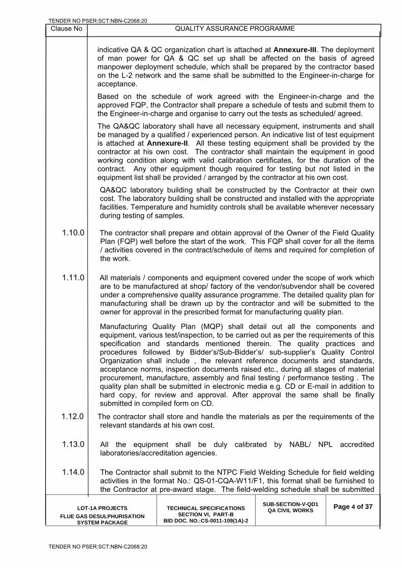
Clause No QUALITY ASSURANCE PROGRAMME
LOT-1A PROJECTS
FLUE GAS DESULPHURISATION SYSTEM PACKAGE
TECHNICAL SPECIFICATIONS SECTION VI, PART-B
BID DOC. NO.:CS-0011-109(1A)-2
SUB-SECTION-V-QD1
QA CIVIL WORKS
Page 4 of 37
indicative QA & QC organization chart is attached at Annexure-III. The deployment of man power for QA & QC set up shall be affected on the basis of agreed manpower deployment schedule, which shall be prepared by the contractor based on the L-2 network and the same shall be submitted to the Engineer-in-charge for acceptance.
Based on the schedule of work agreed with the Engineer-in-charge and the approved FQP, the Contractor shall prepare a schedule of tests and submit them to the Engineer-in-charge and organise to carry out the tests as scheduled/ agreed.
The QA&QC laboratory shall have all necessary equipment, instruments and shall be managed by a qualified / experienced person. An indicative list of test equipment is attached at Annexure-II. All these testing equipment shall be provided by the contractor at his own cost. The contractor shall maintain the equipment in good working condition along with valid calibration certificates, for the duration of the contract. Any other equipment though required for testing but not listed in the equipment list shall be provided / arranged by the contractor at his own cost.
QA&QC laboratory building shall be constructed by the Contractor at their own cost. The laboratory building shall be constructed and installed with the appropriate facilities. Temperature and humidity controls shall be available wherever necessary during testing of samples.
1.10.0 The contractor shall prepare and obtain approval of the Owner of the Field Quality Plan (FQP) well before the start of the work. This FQP shall cover for all the items / activities covered in the contract/schedule of items and required for completion of the work.
1.11.0 All materials / components and equipment covered under the scope of work which are to be manufactured at shop/ factory of the vendor/subvendor shall be covered under a comprehensive quality assurance programme. The detailed quality plan for manufacturing shall be drawn up by the contractor and will be submitted to the owner for approval in the prescribed format for manufacturing quality plan.
Manufacturing Quality Plan (MQP) shall detail out all the components and equipment, various test/inspection, to be carried out as per the requirements of this specification and standards mentioned therein. The quality practices and procedures followed by Bidder’s/Sub-Bidder’s/ sub-supplier’s Quality Control Organization shall include , the relevant reference documents and standards, acceptance norms, inspection documents raised etc., during all stages of material procurement, manufacture, assembly and final testing / performance testing . The quality plan shall be submitted in electronic media e.g. CD or E-mail in addition to hard copy, for review and approval. After approval the same shall be finally submitted in compiled form on CD.
1.12.0 The contractor shall store and handle the materials as per the requirements of the relevant standards at his own cost.
1.13.0 All the equipment shall be duly calibrated by NABL/ NPL accredited laboratories/accreditation agencies.
1.14.0 The Contractor shall submit to the NTPC Field Welding Schedule for field welding activities in the format No.: QS-01-CQA-W11/F1, this format shall be furnished to the Contractor at pre-award stage. The field-welding schedule shall be submitted
TENDER NO PSER:SCT:NBN-C2068:20
TENDER NO PSER:SCT:NBN-C2068:20
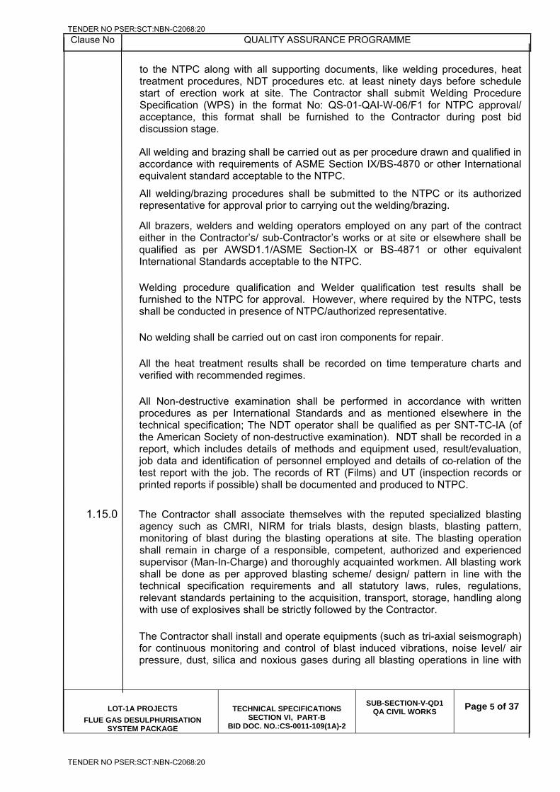
Clause No QUALITY ASSURANCE PROGRAMME
LOT-1A PROJECTS
FLUE GAS DESULPHURISATION SYSTEM PACKAGE
TECHNICAL SPECIFICATIONS SECTION VI, PART-B
BID DOC. NO.:CS-0011-109(1A)-2
SUB-SECTION-V-QD1
QA CIVIL WORKS
Page 5 of 37
to the NTPC along with all supporting documents, like welding procedures, heat treatment procedures, NDT procedures etc. at least ninety days before schedule start of erection work at site. The Contractor shall submit Welding Procedure Specification (WPS) in the format No: QS-01-QAI-W-06/F1 for NTPC approval/ acceptance, this format shall be furnished to the Contractor during post bid discussion stage.
All welding and brazing shall be carried out as per procedure drawn and qualified in accordance with requirements of ASME Section IX/BS-4870 or other International equivalent standard acceptable to the NTPC.
All welding/brazing procedures shall be submitted to the NTPC or its authorized representative for approval prior to carrying out the welding/brazing.
All brazers, welders and welding operators employed on any part of the contract either in the Contractor’s/ sub-Contractor’s works or at site or elsewhere shall be qualified as per AWSD1.1/ASME Section-IX or BS-4871 or other equivalent International Standards acceptable to the NTPC.
Welding procedure qualification and Welder qualification test results shall be furnished to the NTPC for approval. However, where required by the NTPC, tests shall be conducted in presence of NTPC/authorized representative.
No welding shall be carried out on cast iron components for repair.
All the heat treatment results shall be recorded on time temperature charts and verified with recommended regimes.
All Non-destructive examination shall be performed in accordance with written procedures as per International Standards and as mentioned elsewhere in the technical specification; The NDT operator shall be qualified as per SNT-TC-IA (of the American Society of non-destructive examination). NDT shall be recorded in a report, which includes details of methods and equipment used, result/evaluation, job data and identification of personnel employed and details of co-relation of the test report with the job. The records of RT (Films) and UT (inspection records or printed reports if possible) shall be documented and produced to NTPC.
1.15.0 The Contractor shall associate themselves with the reputed specialized blasting agency such as CMRI, NIRM for trials blasts, design blasts, blasting pattern, monitoring of blast during the blasting operations at site. The blasting operation shall remain in charge of a responsible, competent, authorized and experienced supervisor (Man-In-Charge) and thoroughly acquainted workmen. All blasting work shall be done as per approved blasting scheme/ design/ pattern in line with the technical specification requirements and all statutory laws, rules, regulations, relevant standards pertaining to the acquisition, transport, storage, handling along with use of explosives shall be strictly followed by the Contractor.
The Contractor shall install and operate equipments (such as tri-axial seismograph) for continuous monitoring and control of blast induced vibrations, noise level/ air pressure, dust, silica and noxious gases during all blasting operations in line with
TENDER NO PSER:SCT:NBN-C2068:20
TENDER NO PSER:SCT:NBN-C2068:20
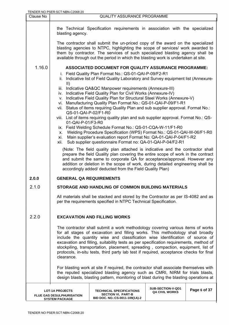
Clause No QUALITY ASSURANCE PROGRAMME
LOT-1A PROJECTS
FLUE GAS DESULPHURISATION SYSTEM PACKAGE
TECHNICAL SPECIFICATIONS SECTION VI, PART-B
BID DOC. NO.:CS-0011-109(1A)-2
SUB-SECTION-V-QD1
QA CIVIL WORKS
Page 6 of 37
the Technical Specification requirements in association with the specialized blasting agency. The contractor shall submit the un-priced copy of the award on the specialized blasting agencies to NTPC, highlighting the scope of services/ work awarded to them by contractor. The services of such specialized blasting agency shall be available through out the period in which the blasting work is undertaken at site.
1.16.0 ASSOCIATED DOCUMENT FOR QUALITY ASSURANCE PROGRAMME:
i. Field Quality Plan Format No.: QS-01-QAI-P-09/F2-R1 ii. Indicative list of Field Quality Laboratory and Survey equipment list (Annexure-
II) iii. Indicative QA&QC Manpower requirements (Annexure-III) iv. Indicative Field Quality Plan for Civil Works (Annexure-IV) v. Indicative Field Quality Plan for Structural Steel Works (Annexure-V) vi. Manufacturing Quality Plan Format No.: QS-01-QAI-P-09/F1-R1 vii. Status of items requiring Quality Plan and sub supplier approval. Format No.:
QS-01-QAI-P-02/F1-R0 viii. List of items requiring quality plan and sub supplier approval. Format No.: QS-
01-QAI-P-01/F3-R0 ix. Field Welding Schedule Format No.: QS-01-CQA-W-11/F1-R0 x. Welding Procedure Specification (WPS) Format No.: QS-01-QAI-W-06/F1-R0 xi. Main supplier’s evaluation report Format No: QA-01-QAI-P-04/F1-R2 xii. Sub supplier questionnaire Format no: QA-01-QAI-P-04/F2-R1
(Note: The field quality plan attached is indicative and the contractor shall prepare the field Quality plan covering the entire scope of work in the contract and submit the same to corporate QA for acceptance/approval. However any addition or deletion in the scope of work, during detailed engineering shall be accordingly added/ deducted from the Field Quality Plan)
2.0.0 GENERAL QA REQUIREMENTS
2.1.0 STORAGE AND HANDLING OF COMMON BUILDING MATERIALS
All materials shall be stacked and stored by the Contractor as per IS-4082 and as per the requirements specified in NTPC Technical Specification.
2.2.0 EXCAVATION AND FILLING WORKS
The contractor shall submit a work methodology covering various items of works for all stages of excavation and filling works. This methodology shall broadly include the quantity wise and classification wise identification of source of excavation and filling, suitability tests as per specification requirements, method of stockpiling, transportation, placement, spreading , compaction, equipment, list of protocols, in-situ tests, third party lab test if required, acceptance checks for final clearance.
For blasting work at site if required, the contractor shall associate themselves with the reputed specialized blasting agency such as CMRI, NIRM for trials blasts, design blasts, blasting pattern, monitoring of blast during the blasting operations at
TENDER NO PSER:SCT:NBN-C2068:20
TENDER NO PSER:SCT:NBN-C2068:20
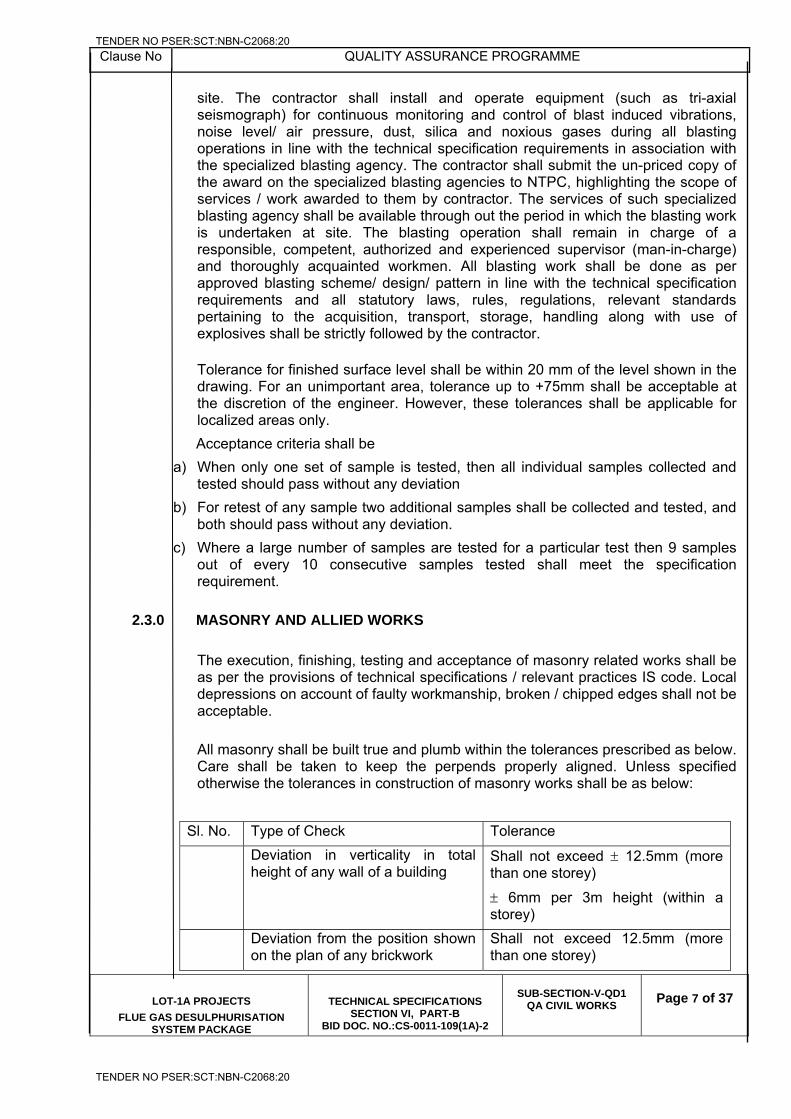
Clause No QUALITY ASSURANCE PROGRAMME
LOT-1A PROJECTS
FLUE GAS DESULPHURISATION SYSTEM PACKAGE
TECHNICAL SPECIFICATIONS SECTION VI, PART-B
BID DOC. NO.:CS-0011-109(1A)-2
SUB-SECTION-V-QD1
QA CIVIL WORKS
Page 7 of 37
site. The contractor shall install and operate equipment (such as tri-axial seismograph) for continuous monitoring and control of blast induced vibrations, noise level/ air pressure, dust, silica and noxious gases during all blasting operations in line with the technical specification requirements in association with the specialized blasting agency. The contractor shall submit the un-priced copy of the award on the specialized blasting agencies to NTPC, highlighting the scope of services / work awarded to them by contractor. The services of such specialized blasting agency shall be available through out the period in which the blasting work is undertaken at site. The blasting operation shall remain in charge of a responsible, competent, authorized and experienced supervisor (man-in-charge) and thoroughly acquainted workmen. All blasting work shall be done as per approved blasting scheme/ design/ pattern in line with the technical specification requirements and all statutory laws, rules, regulations, relevant standards pertaining to the acquisition, transport, storage, handling along with use of explosives shall be strictly followed by the contractor.
Tolerance for finished surface level shall be within 20 mm of the level shown in the drawing. For an unimportant area, tolerance up to +75mm shall be acceptable at the discretion of the engineer. However, these tolerances shall be applicable for localized areas only.
Acceptance criteria shall be
a) When only one set of sample is tested, then all individual samples collected and tested should pass without any deviation
b) For retest of any sample two additional samples shall be collected and tested, and both should pass without any deviation.
c) Where a large number of samples are tested for a particular test then 9 samples out of every 10 consecutive samples tested shall meet the specification requirement.
2.3.0 MASONRY AND ALLIED WORKS
The execution, finishing, testing and acceptance of masonry related works shall be as per the provisions of technical specifications / relevant practices IS code. Local depressions on account of faulty workmanship, broken / chipped edges shall not be acceptable.
All masonry shall be built true and plumb within the tolerances prescribed as below. Care shall be taken to keep the perpends properly aligned. Unless specified otherwise the tolerances in construction of masonry works shall be as below:
Sl. No. Type of Check Tolerance
Deviation in verticality in total height of any wall of a building
Shall not exceed 12.5mm (more than one storey)
6mm per 3m height (within a storey)
Deviation from the position shown on the plan of any brickwork
Shall not exceed 12.5mm (more than one storey)
TENDER NO PSER:SCT:NBN-C2068:20
TENDER NO PSER:SCT:NBN-C2068:20
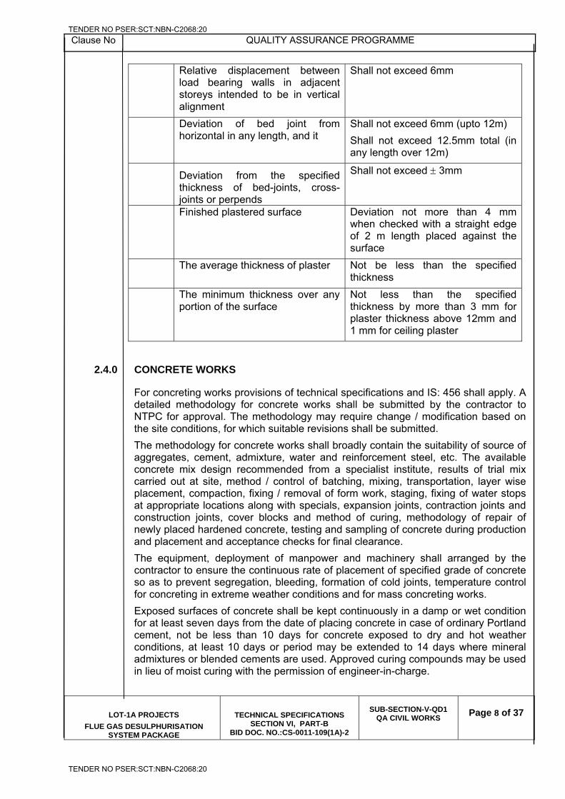
Clause No QUALITY ASSURANCE PROGRAMME
LOT-1A PROJECTS
FLUE GAS DESULPHURISATION SYSTEM PACKAGE
TECHNICAL SPECIFICATIONS SECTION VI, PART-B
BID DOC. NO.:CS-0011-109(1A)-2
SUB-SECTION-V-QD1
QA CIVIL WORKS
Page 8 of 37
Relative displacement between load bearing walls in adjacent storeys intended to be in vertical alignment
Shall not exceed 6mm
Deviation of bed joint from horizontal in any length, and it
Shall not exceed 6mm (upto 12m)
Shall not exceed 12.5mm total (in any length over 12m)
Deviation from the specified thickness of bed-joints, cross-joints or perpends
Shall not exceed 3mm
Finished plastered surface Deviation not more than 4 mm when checked with a straight edge of 2 m length placed against the surface
The average thickness of plaster Not be less than the specified thickness
The minimum thickness over any portion of the surface
Not less than the specified thickness by more than 3 mm for plaster thickness above 12mm and 1 mm for ceiling plaster
2.4.0 CONCRETE WORKS
For concreting works provisions of technical specifications and IS: 456 shall apply. A detailed methodology for concrete works shall be submitted by the contractor to NTPC for approval. The methodology may require change / modification based on the site conditions, for which suitable revisions shall be submitted.
The methodology for concrete works shall broadly contain the suitability of source of aggregates, cement, admixture, water and reinforcement steel, etc. The available concrete mix design recommended from a specialist institute, results of trial mix carried out at site, method / control of batching, mixing, transportation, layer wise placement, compaction, fixing / removal of form work, staging, fixing of water stops at appropriate locations along with specials, expansion joints, contraction joints and construction joints, cover blocks and method of curing, methodology of repair of newly placed hardened concrete, testing and sampling of concrete during production and placement and acceptance checks for final clearance.
The equipment, deployment of manpower and machinery shall arranged by the contractor to ensure the continuous rate of placement of specified grade of concrete so as to prevent segregation, bleeding, formation of cold joints, temperature control for concreting in extreme weather conditions and for mass concreting works.
Exposed surfaces of concrete shall be kept continuously in a damp or wet condition for at least seven days from the date of placing concrete in case of ordinary Portland cement, not be less than 10 days for concrete exposed to dry and hot weather conditions, at least 10 days or period may be extended to 14 days where mineral admixtures or blended cements are used. Approved curing compounds may be used in lieu of moist curing with the permission of engineer-in-charge.
TENDER NO PSER:SCT:NBN-C2068:20
TENDER NO PSER:SCT:NBN-C2068:20
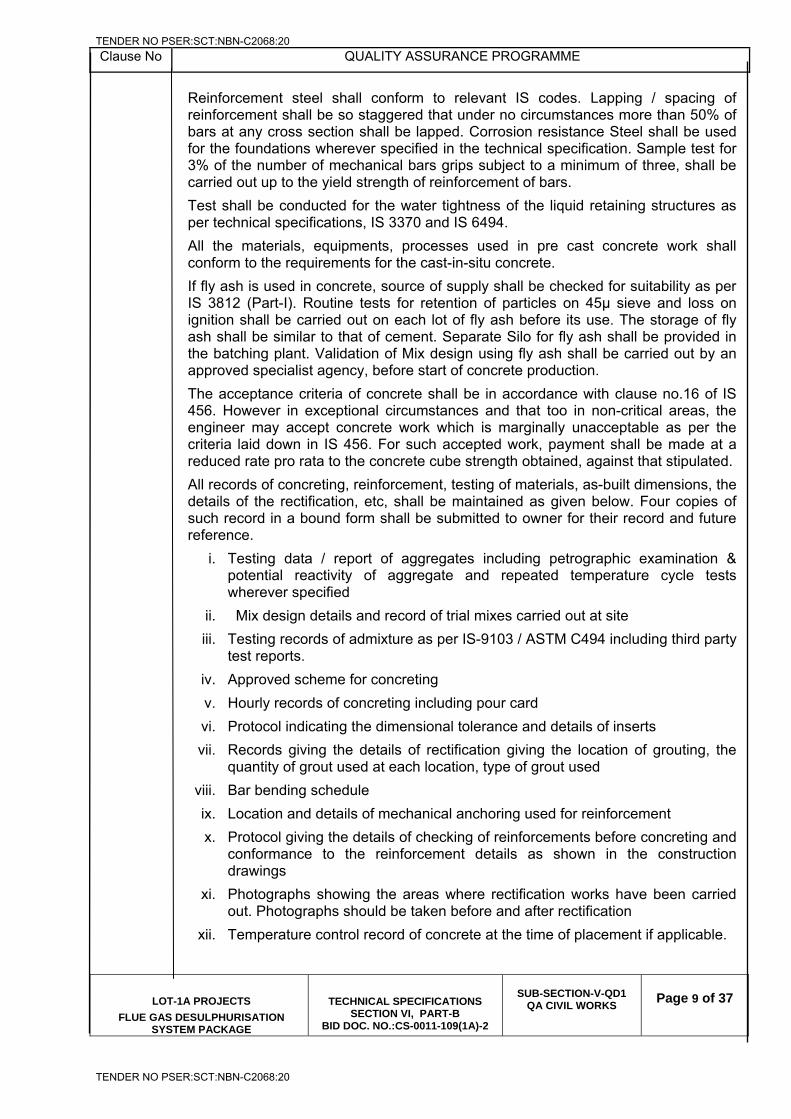
Clause No QUALITY ASSURANCE PROGRAMME
LOT-1A PROJECTS
FLUE GAS DESULPHURISATION SYSTEM PACKAGE
TECHNICAL SPECIFICATIONS SECTION VI, PART-B
BID DOC. NO.:CS-0011-109(1A)-2
SUB-SECTION-V-QD1
QA CIVIL WORKS
Page 9 of 37
Reinforcement steel shall conform to relevant IS codes. Lapping / spacing of reinforcement shall be so staggered that under no circumstances more than 50% of bars at any cross section shall be lapped. Corrosion resistance Steel shall be used for the foundations wherever specified in the technical specification. Sample test for 3% of the number of mechanical bars grips subject to a minimum of three, shall be carried out up to the yield strength of reinforcement of bars.
Test shall be conducted for the water tightness of the liquid retaining structures as per technical specifications, IS 3370 and IS 6494.
All the materials, equipments, processes used in pre cast concrete work shall conform to the requirements for the cast-in-situ concrete.
If fly ash is used in concrete, source of supply shall be checked for suitability as per IS 3812 (Part-I). Routine tests for retention of particles on 45μ sieve and loss on ignition shall be carried out on each lot of fly ash before its use. The storage of fly ash shall be similar to that of cement. Separate Silo for fly ash shall be provided in the batching plant. Validation of Mix design using fly ash shall be carried out by an approved specialist agency, before start of concrete production.
The acceptance criteria of concrete shall be in accordance with clause no.16 of IS 456. However in exceptional circumstances and that too in non-critical areas, the engineer may accept concrete work which is marginally unacceptable as per the criteria laid down in IS 456. For such accepted work, payment shall be made at a reduced rate pro rata to the concrete cube strength obtained, against that stipulated.
All records of concreting, reinforcement, testing of materials, as-built dimensions, the details of the rectification, etc, shall be maintained as given below. Four copies of such record in a bound form shall be submitted to owner for their record and future reference.
i. Testing data / report of aggregates including petrographic examination & potential reactivity of aggregate and repeated temperature cycle tests wherever specified
ii. Mix design details and record of trial mixes carried out at site
iii. Testing records of admixture as per IS-9103 / ASTM C494 including third party test reports.
iv. Approved scheme for concreting
v. Hourly records of concreting including pour card
vi. Protocol indicating the dimensional tolerance and details of inserts
vii. Records giving the details of rectification giving the location of grouting, the quantity of grout used at each location, type of grout used
viii. Bar bending schedule
ix. Location and details of mechanical anchoring used for reinforcement
x. Protocol giving the details of checking of reinforcements before concreting and conformance to the reinforcement details as shown in the construction drawings
xi. Photographs showing the areas where rectification works have been carried out. Photographs should be taken before and after rectification
xii. Temperature control record of concrete at the time of placement if applicable.
TENDER NO PSER:SCT:NBN-C2068:20
TENDER NO PSER:SCT:NBN-C2068:20
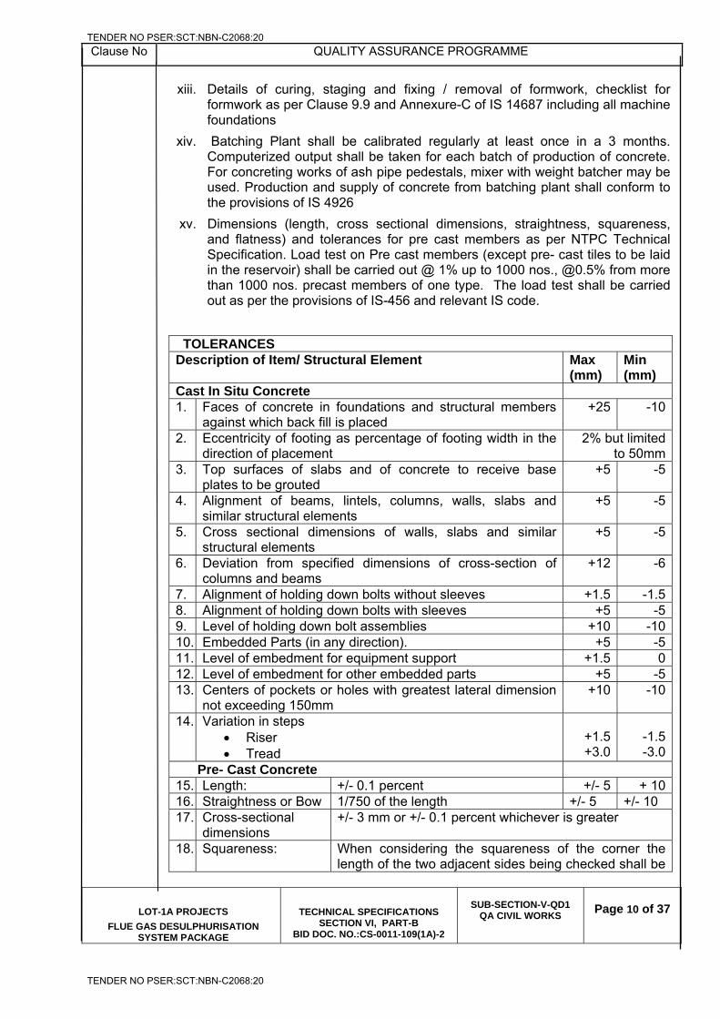
Clause No QUALITY ASSURANCE PROGRAMME
LOT-1A PROJECTS
FLUE GAS DESULPHURISATION SYSTEM PACKAGE
TECHNICAL SPECIFICATIONS SECTION VI, PART-B
BID DOC. NO.:CS-0011-109(1A)-2
SUB-SECTION-V-QD1
QA CIVIL WORKS
Page 10 of 37
xiii. Details of curing, staging and fixing / removal of formwork, checklist for formwork as per Clause 9.9 and Annexure-C of IS 14687 including all machine foundations
xiv. Batching Plant shall be calibrated regularly at least once in a 3 months. Computerized output shall be taken for each batch of production of concrete. For concreting works of ash pipe pedestals, mixer with weight batcher may be used. Production and supply of concrete from batching plant shall conform to the provisions of IS 4926
xv. Dimensions (length, cross sectional dimensions, straightness, squareness, and flatness) and tolerances for pre cast members as per NTPC Technical Specification. Load test on Pre cast members (except pre- cast tiles to be laid in the reservoir) shall be carried out @ 1% up to 1000 nos., @0.5% from more than 1000 nos. precast members of one type. The load test shall be carried out as per the provisions of IS-456 and relevant IS code.
TOLERANCES Description of Item/ Structural Element Max
(mm) Min (mm)
Cast In Situ Concrete 1. Faces of concrete in foundations and structural members
against which back fill is placed +25 -10
2. Eccentricity of footing as percentage of footing width in the direction of placement
2% but limited to 50mm
3. Top surfaces of slabs and of concrete to receive base plates to be grouted
+5 -5
4. Alignment of beams, lintels, columns, walls, slabs and similar structural elements
+5 -5
5. Cross sectional dimensions of walls, slabs and similar structural elements
+5 -5
6. Deviation from specified dimensions of cross-section of columns and beams
+12 -6
7. Alignment of holding down bolts without sleeves +1.5 -1.58. Alignment of holding down bolts with sleeves +5 -59. Level of holding down bolt assemblies +10 -1010. Embedded Parts (in any direction). +5 -511. Level of embedment for equipment support +1.5 012. Level of embedment for other embedded parts +5 -513. Centers of pockets or holes with greatest lateral dimension
not exceeding 150mm +10 -10
14. Variation in steps Riser Tread
+1.5+3.0
-1.5-3.0
Pre- Cast Concrete 15. Length: +/- 0.1 percent +/- 5 + 10 16. Straightness or Bow 1/750 of the length +/- 5 +/- 10 17. Cross-sectional
dimensions +/- 3 mm or +/- 0.1 percent whichever is greater
18. Squareness: When considering the squareness of the corner the length of the two adjacent sides being checked shall be
TENDER NO PSER:SCT:NBN-C2068:20
TENDER NO PSER:SCT:NBN-C2068:20
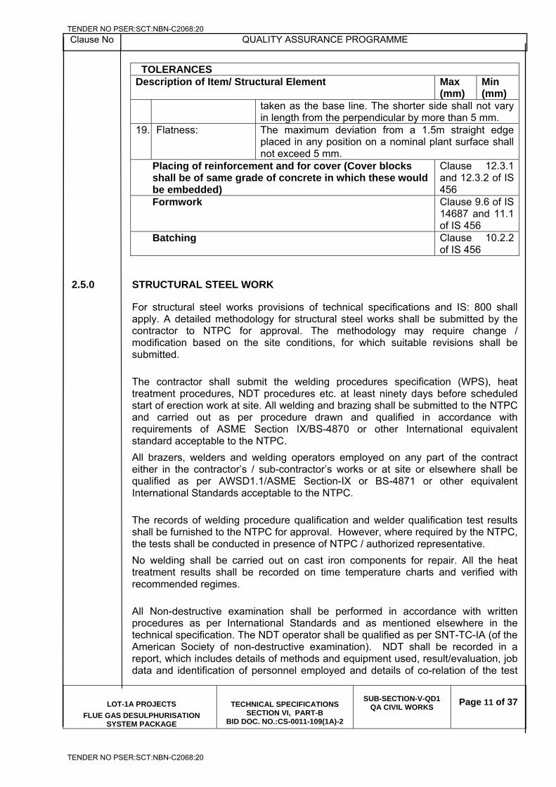
Clause No QUALITY ASSURANCE PROGRAMME
LOT-1A PROJECTS
FLUE GAS DESULPHURISATION SYSTEM PACKAGE
TECHNICAL SPECIFICATIONS SECTION VI, PART-B
BID DOC. NO.:CS-0011-109(1A)-2
SUB-SECTION-V-QD1
QA CIVIL WORKS
Page 11 of 37
TOLERANCES Description of Item/ Structural Element Max
(mm) Min (mm)
taken as the base line. The shorter side shall not vary in length from the perpendicular by more than 5 mm.
19. Flatness: The maximum deviation from a 1.5m straight edge placed in any position on a nominal plant surface shall not exceed 5 mm.
Placing of reinforcement and for cover (Cover blocks shall be of same grade of concrete in which these would be embedded)
Clause 12.3.1 and 12.3.2 of IS 456
Formwork Clause 9.6 of IS 14687 and 11.1 of IS 456
Batching Clause 10.2.2 of IS 456
2.5.0 STRUCTURAL STEEL WORK For structural steel works provisions of technical specifications and IS: 800 shall apply. A detailed methodology for structural steel works shall be submitted by the contractor to NTPC for approval. The methodology may require change / modification based on the site conditions, for which suitable revisions shall be submitted.
The contractor shall submit the welding procedures specification (WPS), heat treatment procedures, NDT procedures etc. at least ninety days before scheduled start of erection work at site. All welding and brazing shall be submitted to the NTPC and carried out as per procedure drawn and qualified in accordance with requirements of ASME Section IX/BS-4870 or other International equivalent standard acceptable to the NTPC.
All brazers, welders and welding operators employed on any part of the contract either in the contractor’s / sub-contractor’s works or at site or elsewhere shall be qualified as per AWSD1.1/ASME Section-IX or BS-4871 or other equivalent International Standards acceptable to the NTPC.
The records of welding procedure qualification and welder qualification test results shall be furnished to the NTPC for approval. However, where required by the NTPC, the tests shall be conducted in presence of NTPC / authorized representative.
No welding shall be carried out on cast iron components for repair. All the heat treatment results shall be recorded on time temperature charts and verified with recommended regimes.
All Non-destructive examination shall be performed in accordance with written procedures as per International Standards and as mentioned elsewhere in the technical specification. The NDT operator shall be qualified as per SNT-TC-IA (of the American Society of non-destructive examination). NDT shall be recorded in a report, which includes details of methods and equipment used, result/evaluation, job data and identification of personnel employed and details of co-relation of the test
TENDER NO PSER:SCT:NBN-C2068:20
TENDER NO PSER:SCT:NBN-C2068:20
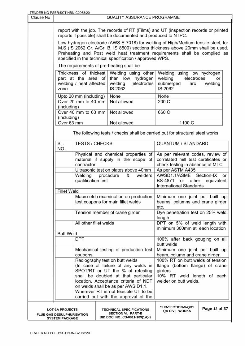
Clause No QUALITY ASSURANCE PROGRAMME
LOT-1A PROJECTS
FLUE GAS DESULPHURISATION SYSTEM PACKAGE
TECHNICAL SPECIFICATIONS SECTION VI, PART-B
BID DOC. NO.:CS-0011-109(1A)-2
SUB-SECTION-V-QD1
QA CIVIL WORKS
Page 12 of 37
report with the job. The records of RT (Films) and UT (inspection records or printed reports if possible) shall be documented and produced to NTPC.
Low hydrogen electrode (AWS E-7018) for welding of High/Medium tensile steel, for M.S (IS 2062 Gr. A/Gr. B, IS 8500) sections thickness above 20mm shall be used. Preheating and Post weld heat treatment requirements shall be complied as specified in the technical specification / approved WPS.
The requirements of pre-heating shall be
Thickness of thickest part at the area of welding / heat affected zone
Welding using other than low hydrogen welding electrodes IS 2062
Welding using low hydrogen welding electrodes or submerged arc welding IS 2062
Upto 20 mm (including) None None Over 20 mm to 40 mm (including)
Not allowed 200 C
Over 40 mm to 63 mm (including)
Not allowed 660 C
Over 63 mm Not allowed 1100 C
The following tests / checks shall be carried out for structural steel works SL. NO.
TESTS / CHECKS QUANTUM / STANDARD
Physical and chemical properties of material if supply in the scope of contractor
As per relevant codes, review of correlated mill test certificates or check testing in absence of MTC
Ultrasonic test on plates above 40mm As per ASTM A435 Welding procedure & welders
qualification test
AWSD1.1/ASME Section-IX or BS-4871 or other equivalent International Standards
Fillet Weld Macro-etch examination on production
test coupons for main fillet welds Minimum one joint per built up beams, columns and crane girder etc.
Tension member of crane girder Dye penetration test on 25% weld length
All other fillet welds DPT on 5% of weld length with minimum 300mm at each location
Butt Weld DPT 100% after back gouging on all
butt welds Mechanical testing of production test
coupons Minimum one joint per built up beam, column and crane girder.
Radiography test on butt welds (In case of failure of any welds in SPOT/RT or UT the % of retesting shall be doubled at that particular location. Acceptance criteria of NDT on welds shall be as per AWS D1.1. Wherever RT is not feasible UT to be carried out with the approval of the
100% RT on butt welds of tension flange (bottom flange) of crane girders 10% RT weld length of each welder on butt welds,
TENDER NO PSER:SCT:NBN-C2068:20
TENDER NO PSER:SCT:NBN-C2068:20
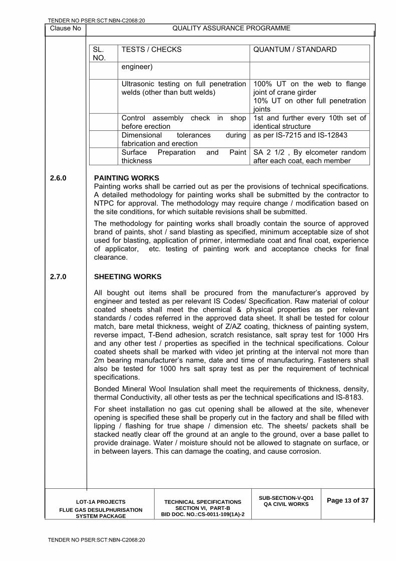
Clause No QUALITY ASSURANCE PROGRAMME
LOT-1A PROJECTS
FLUE GAS DESULPHURISATION SYSTEM PACKAGE
TECHNICAL SPECIFICATIONS SECTION VI, PART-B
BID DOC. NO.:CS-0011-109(1A)-2
SUB-SECTION-V-QD1
QA CIVIL WORKS
Page 13 of 37
SL. NO.
TESTS / CHECKS QUANTUM / STANDARD
engineer)
Ultrasonic testing on full penetration welds (other than butt welds)
100% UT on the web to flange joint of crane girder 10% UT on other full penetration joints
Control assembly check in shop before erection
1st and further every 10th set of identical structure
Dimensional tolerances during fabrication and erection
as per IS-7215 and IS-12843
Surface Preparation and Paint thickness
SA 2 1/2 , By elcometer random after each coat, each member
2.6.0 PAINTING WORKS
Painting works shall be carried out as per the provisions of technical specifications. A detailed methodology for painting works shall be submitted by the contractor to NTPC for approval. The methodology may require change / modification based on the site conditions, for which suitable revisions shall be submitted.
The methodology for painting works shall broadly contain the source of approved brand of paints, shot / sand blasting as specified, minimum acceptable size of shot used for blasting, application of primer, intermediate coat and final coat, experience of applicator, etc. testing of painting work and acceptance checks for final clearance.
2.7.0 SHEETING WORKS
All bought out items shall be procured from the manufacturer’s approved by engineer and tested as per relevant IS Codes/ Specification. Raw material of colour coated sheets shall meet the chemical & physical properties as per relevant standards / codes referred in the approved data sheet. It shall be tested for colour match, bare metal thickness, weight of Z/AZ coating, thickness of painting system, reverse impact, T-Bend adhesion, scratch resistance, salt spray test for 1000 Hrs and any other test / properties as specified in the technical specifications. Colour coated sheets shall be marked with video jet printing at the interval not more than 2m bearing manufacturer’s name, date and time of manufacturing. Fasteners shall also be tested for 1000 hrs salt spray test as per the requirement of technical specifications.
Bonded Mineral Wool Insulation shall meet the requirements of thickness, density, thermal Conductivity, all other tests as per the technical specifications and IS-8183.
For sheet installation no gas cut opening shall be allowed at the site, whenever opening is specified these shall be properly cut in the factory and shall be filled with lipping / flashing for true shape / dimension etc. The sheets/ packets shall be stacked neatly clear off the ground at an angle to the ground, over a base pallet to provide drainage. Water / moisture should not be allowed to stagnate on surface, or in between layers. This can damage the coating, and cause corrosion.
TENDER NO PSER:SCT:NBN-C2068:20
TENDER NO PSER:SCT:NBN-C2068:20
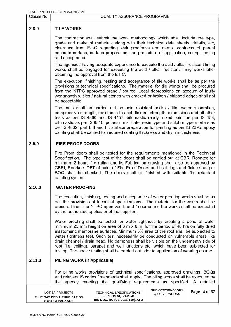
Clause No QUALITY ASSURANCE PROGRAMME
LOT-1A PROJECTS
FLUE GAS DESULPHURISATION SYSTEM PACKAGE
TECHNICAL SPECIFICATIONS SECTION VI, PART-B
BID DOC. NO.:CS-0011-109(1A)-2
SUB-SECTION-V-QD1
QA CIVIL WORKS
Page 14 of 37
2.8.0 TILE WORKS The contractor shall submit the work methodology which shall include the type, grade and make of materials along with their technical data sheets, details, etc, clearance from E-I-C regarding leak proofness and damp proofness of parent concrete surface, surface preparation, the procedure of application, curing, testing and acceptance.
The agencies having adequate experience to execute the acid / alkali resistant lining works shall be engaged for executing the acid / alkali resistant lining works after obtaining the approval from the E-I-C.
The execution, finishing, testing and acceptance of tile works shall be as per the provisions of technical specifications. The material for tile works shall be procured from the NTPC approved brand / source. Local depressions on account of faulty workmanship, tiles / natural stones with cracked or broken / chipped edges shall not be acceptable.
The tests shall be carried out on acid resistant bricks / tile- water absorption, compressive strength, resistance to acid, flexural strength, dimensions and all other tests as per IS 4860 and IS 4457, bitumastic ready mixed paint as per IS 158, bitumastic as per IS 9510, potassium silicate, resin type and sulphur type mortars as per IS 4832, part I, II and III, surface preparation for painting as per IS 2395, epoxy painting shall be carried for required coating thickness and dry film thickness.
2.9.0 FIRE PROOF DOORS
Fire Proof doors shall be tested for the requirements mentioned in the Technical Specification. The type test of the doors shall be carried out at CBRI Roorkee for minimum 2 hours fire rating and its Fabrication drawing shall also be approved by CBRI, Roorkee. DFT of paint of Fire Proof Doors and its fittings and fixtures as per BOQ shall be checked. The doors shall be finished with suitable fire retardant painting system
2.10.0 WATER PROOFING The execution, finishing, testing and acceptance of water proofing works shall be as per the provisions of technical specifications. The material for the works shall be procured from the NTPC approved brand / source and the works shall be executed by the authorized applicator of the supplier. Water proofing shall be tested for water tightness by creating a pond of water minimum 25 mm height on area of 6 m x 6 m, for the period of 48 hrs on fully dried elastomeric membrane surfaces. Minimum 5% area of the roof shall be subjected to water tightness test. Such test necessarily be conducted on vulnerable areas like drain channel / drain head. No dampness shall be visible on the underneath side of roof (i.e. ceiling), parapet and well junctions etc. which have been subjected for testing. The above testing shall be carried out prior to application of wearing course.
2.11.0 PILING WORK (If Applicable)
For piling works provisions of technical specifications, approved drawings, BOQs and relevant IS codes / standards shall apply. The piling works shall be executed by the agency meeting the qualifying requirements as specified. A detailed
TENDER NO PSER:SCT:NBN-C2068:20
TENDER NO PSER:SCT:NBN-C2068:20
Clause No QUALITY ASSURANCE PROGRAMME
LOT-1A PROJECTS
FLUE GAS DESULPHURISATION SYSTEM PACKAGE
TECHNICAL SPECIFICATIONS SECTION VI, PART-B
BID DOC. NO.:CS-0011-109(1A)-2
SUB-SECTION-V-QD1
QA CIVIL WORKS
Page 15 of 37
methodology for piling works shall be submitted by the contractor to NTPC for approval. The methodology may require change / modification based on the site conditions, for which suitable revisions shall be submitted.
The methodology for piling works shall broadly contain the method of boring, stability of bore hole, termination criteria, tests / checks for termination level, fabrication of cage, cage lowering, concrete batching / mixing, transportation, placing, recording of the time of construction operations, method of conducting initial and routine load tests, testing and sampling of concrete during production and placement and acceptance checks on piles for final clearance.
The equipment, deployment of manpower and machinery shall be arranged by the contractor to prevent the collapse of bore hole and to ensure continuous rate of placement of specified grade of concrete.
The piling works shall be executed as per the technical specifications, approved drawings, relevant codes / standards, FQP and BOQ. In addition to the requirements of technical specifications, the following shall also be ensured while execution of piling works:
a) Time gap between completion of pile boring and start of concreting should be kept to the minimum. However the maximum time gap shall not be more than 6 hours.
b) Muck Debris should be removed from the pile bore by air lift technique(by keeping the tremie & air pipe as close as to bottom of pile bore) i.e. after completion of boring, after completion of SPT(wherever applicable), after lowering reinforcement cage, but before start of concreting.
c) Density of bentonite slurry shall be checked from the sample taken from the bottom of pile bore( not at 1.0 m above the bottom of the pile bore)
d) Minimum two welding sets shall be kept ready to join the two cages of reinforcement by engaging 3 or more welders. This will ensure the lowering of R/F cage in minimum time.
e) While lowering the R/F cage into the pile bore, two hooks shall always be used to ensure balanced/symmetrical insertion of cage into the pile bore.
f) Concrete cover blocks at the junction of two R/F cage shall be ensured before lowering the second segment.
g) Surge concreting of about 1.0 cum shall be ensured at the start of concreting (i.e. in the first pour), by suddenly allowing to fall through the tremie pipe from the funnel. This will help in displacing left out muck/debris in the pile bore (by the impact).
h) Continuous feeding of concrete shall be ensured by deploying at least two transit concrete mixers (if required to be deployed) and mixing done through concrete batching plant (if deployed). Cold joints in the pile shall be avoided.
i) In a pile group, SPT shall be carried out at termination level in the pile, taken up first.
j) Bentonite slurry circulation to be ensured from start of boring to start of concreting. Flushing of bentonite slurry will only ensure maintaining of density of bentonite slurry uniformly and will not allow bentonite jelly to settle at the bottom, whereas air lift technique with bentonite circulation will ensure removal of muck debris from the bottom of pile bore.
TENDER NO PSER:SCT:NBN-C2068:20
TENDER NO PSER:SCT:NBN-C2068:20
Clause No QUALITY ASSURANCE PROGRAMME
LOT-1A PROJECTS
FLUE GAS DESULPHURISATION SYSTEM PACKAGE
TECHNICAL SPECIFICATIONS SECTION VI, PART-B
BID DOC. NO.:CS-0011-109(1A)-2
SUB-SECTION-V-QD1
QA CIVIL WORKS
Page 16 of 37
k) Properties of drilling mud shall be checked prior to commencement of the piling work and thereafter, minimum once per week or as found necessary by the engineer. One sample consisting of 3 specimens shall be tested for the above.
l) Low strain pile integrity test on all job piles and test piles shall be conducted as specified in the Technical Specification. This test shall be suitably used to identify the piles for routine tests. High Strain dynamic test shall be done as per the technical specification. The frequency of the test shall be as per the BOQ
m) For Working Piles: Minimum one sample consisting of 6 test cubes shall be made for first ten piles. Out of these 3 shall be tested for 7 days cube strength and 3 for 28 days cube strength. Minimum one sample of 6 test cubes for every 25 nos. of piles shall be tested, out of these 3 shall be tested for 7 days cube strength and 3 for 28 days cube strength
PILE LOAD TEST
Pile load testing shall conform to the requirements of IS-2911 (Part IV) and the technical specification. Initial load tests as specified in the contract documents shall be conducted to assess the safe load carrying capacity of pile before start of work. To verify the load carrying capacity of the working piles, routine load test shall be conducted.
Pile load-testing procedure and the test setup / scheme shall be submitted for approval of NTPC. The contractor shall use the test setup having arrangement for anchor piles / rock anchors alone or combination of anchor piles / rock anchors and kentledge for both vertical compression and uplift (tension) Load test (initial) on piles. The cost of reaction system / piles shall deem to be included in the cost of test piles
All the gauges and instruments shall be calibrated before the start of the tests on test piles and working piles and the calibration record shall be verified before start of execution of the test.
2.12.0 WATER SUPPLY, DRAINAGE & SANITATION
Material used for sanitary and plumbing fittings and fixtures shall conform to and be tested as per the requirements of relevant IS Codes specified in NTPC technical specification.
The obstructions in sewer lines shall be checked by inserting a smooth ball, of diameter 13 mm less than the pipe bore at the high end of the sewer or drain. If absence of any obstructions, such as yarn or mortar projecting through the joints, ball shall roll down the invert of the pipe and emerge at the lower end. The straightness shall be checked by means of a mirror at one end of the line and lamp at the other. If the pipeline is straight, the full circle of the light may be observed. The mirror will also indicate obstruction in the barrel, if the pipeline is not straight.
The service pipes shall be slowly and carefully charged with water, allowing all air to escape avoiding all shock or water hammer. The service pipe shall then be inspected under test / working condition of pressure and flow, when all draw-off taps
TENDER NO PSER:SCT:NBN-C2068:20
TENDER NO PSER:SCT:NBN-C2068:20
Clause No QUALITY ASSURANCE PROGRAMME
LOT-1A PROJECTS
FLUE GAS DESULPHURISATION SYSTEM PACKAGE
TECHNICAL SPECIFICATIONS SECTION VI, PART-B
BID DOC. NO.:CS-0011-109(1A)-2
SUB-SECTION-V-QD1
QA CIVIL WORKS
Page 17 of 37
are closed. The service pipes shall be checked for satisfactory support and protection from damage, corrosion and frost.
2.13.0 ARCHITECTURAL & MISC. WORKS
Material used for sanitary and plumbing fittings and fixtures, floor finishes and allied work shall conform and tested as per the requirements of relevant IS Codes specified in NTPC technical specification.
Fabricated item like metal doors, windows, ventilators, louvers, rolling shutters and grills etc. shall be checked for correctness of locations and smoothness of operation and fixtures. All controls and locking devices shall give fault free performance. Door and window shutters shall operate without jamming. The clearance at head and jamb for door shutters shall not exceed 1.5 mm. For double leaf doors, the gap at the meeting stiles shall not be more than 2.5 mm.
Materials used in glass and glazing shall be procured from source approved by NTPC and shall conform to the requirements of the Technical Specification and IS Codes.
False ceiling panels shall be best quality material in thickness and properties called for in the specification / schedule of items. Material Test Certificate to be submitted before bulk supply.
All bought items covered in the scope of contract shall be procured from sources approved by NTPC and shall conform to the requirements of the technical specifications and referred standards /codes.
2.14.0 PRE CAST CONCRETE WORKS
1. All the materials used in Pre cast Concrete work shall be tested and conform to
the requirements of IS codes and NTPC Tech. Specification. 2. Concrete mix for Pre cast members shall conform to IS-456-2000. 3. All relevant QA requirements pertaining to cast insitu concrete shall be applicable. 4. Pre Cast Concrete member shall be checked for dimensions (length, cross
sectional dimensions, straightness, squareness, and flatness) and tolerances shall be as per NTPC Technical Specification.
2.15.0 FABRIC EXPANSION COMPENSATOR:
Each layer of fabric Compensator shall be checked for thickness, unit weight, tensile strength & elongation, composite layer of the expansion joint shall be tested for temperature withstandability test.
Thermal Insulation shall be checked for thickness, density, thermal conductivity test and all other tests as per IS:8183.
Tests and checks on all other items shall be carried out as per relevant codes.
TENDER NO PSER:SCT:NBN-C2068:20
TENDER NO PSER:SCT:NBN-C2068:20
Clause No QUALITY ASSURANCE PROGRAMME
LOT-1A PROJECTS
FLUE GAS DESULPHURISATION SYSTEM PACKAGE
TECHNICAL SPECIFICATIONS SECTION VI, PART-B
BID DOC. NO.:CS-0011-109(1A)-2
SUB-SECTION-V-QD1
QA CIVIL WORKS
Page 18 of 37
2.16.0 SLIPFORM SHUTTERING
1. The monitoring of the leveling of the yoke and the platform of the slip form
shuttering to be done in each shift to avoid tilt during the casting of the chimney shell.
2. Manning of each shift shall be done by at least two experienced operators and a
foreman particularly in night shift. 3. Suitable removal/ reduction of overhung / excess yoke beam length shall be
affected with the decrease in the diameter of Chimney shell, as per the approved plan.
4. The laser centering method to be deployed for chimney alignment and Monitoring
of chimney centre should be done by laser instruments at least two points. Monitoring/Recording of the same shall be done in each shift of 8 hours
5. Shuttering plates to be used for slip form shall be new and the grade of steel shall
conform to the specification requirements. 6. The outage of the alignment of chimney centre shall be prevented by creating a
counterbalance for alignment purpose to avoid differential loading, arising out of placement of reinforcement bars at one side or unloading of concrete in a hopper at one side of the platform for slip form shuttering.
TENDER NO PSER:SCT:NBN-C2068:20
TENDER NO PSER:SCT:NBN-C2068:20
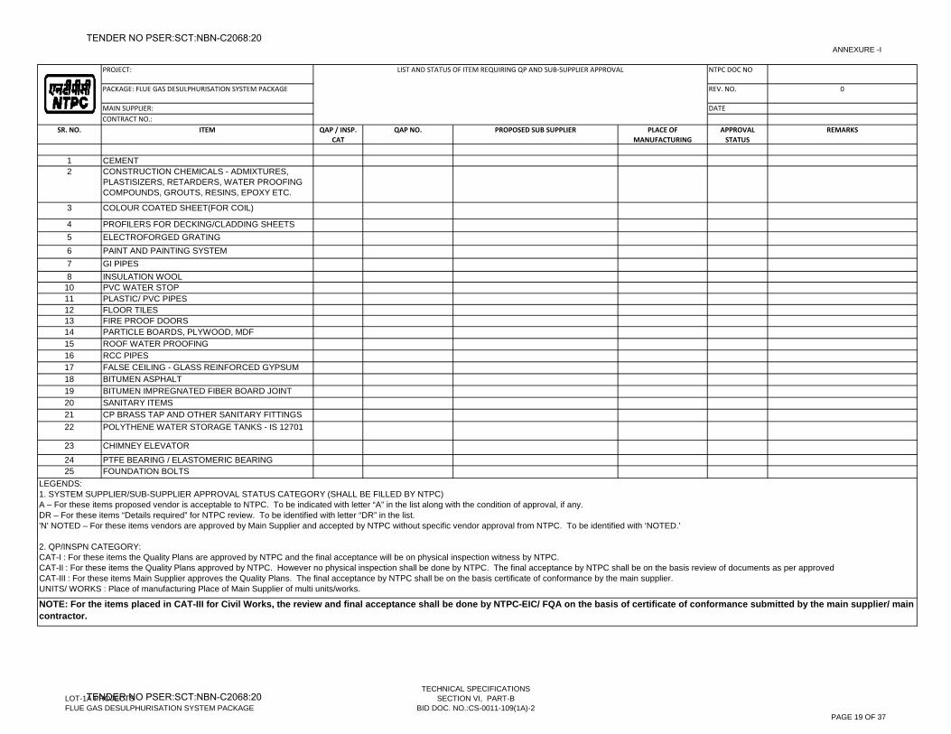
ANNEXURE -I
PROJECT: NTPC DOC NO
PACKAGE: FLUE GAS DESULPHURISATION SYSTEM PACKAGE REV. NO. 0
MAIN SUPPLIER: DATECONTRACT NO.:
SR. NO. ITEM QAP / INSP. CAT
QAP NO. PROPOSED SUB SUPPLIER PLACE OF MANUFACTURING
APPROVAL STATUS
REMARKS
1 CEMENT2 CONSTRUCTION CHEMICALS - ADMIXTURES,
PLASTISIZERS, RETARDERS, WATER PROOFING COMPOUNDS, GROUTS, RESINS, EPOXY ETC.
3 COLOUR COATED SHEET(FOR COIL)
4 PROFILERS FOR DECKING/CLADDING SHEETS5 ELECTROFORGED GRATING6 PAINT AND PAINTING SYSTEM7 GI PIPES 8 INSULATION WOOL
10 PVC WATER STOP11 PLASTIC/ PVC PIPES12 FLOOR TILES13 FIRE PROOF DOORS14 PARTICLE BOARDS, PLYWOOD, MDF15 ROOF WATER PROOFING
LIST AND STATUS OF ITEM REQUIRING QP AND SUB‐SUPPLIER APPROVAL
15 ROOF WATER PROOFING16 RCC PIPES17 FALSE CEILING - GLASS REINFORCED GYPSUM 18 BITUMEN ASPHALT19 BITUMEN IMPREGNATED FIBER BOARD JOINT 20 SANITARY ITEMS21 CP BRASS TAP AND OTHER SANITARY FITTINGS22 POLYTHENE WATER STORAGE TANKS - IS 12701
23 CHIMNEY ELEVATOR
24 PTFE BEARING / ELASTOMERIC BEARING25 FOUNDATION BOLTS
NOTE: For the items placed in CAT-III for Civil Works, the review and final acceptance shall be done by NTPC-EIC/ FQA on the basis of certificate of conformance submitted by the main supplier/ main contractor.
LEGENDS:1. SYSTEM SUPPLIER/SUB-SUPPLIER APPROVAL STATUS CATEGORY (SHALL BE FILLED BY NTPC)A – For these items proposed vendor is acceptable to NTPC. To be indicated with letter “A” in the list along with the condition of approval, if any.DR – For these items “Details required” for NTPC review. To be identified with letter “DR” in the list.'N' NOTED – For these items vendors are approved by Main Supplier and accepted by NTPC without specific vendor approval from NTPC. To be identified with ‘NOTED.’
2. QP/INSPN CATEGORY:CAT-I : For these items the Quality Plans are approved by NTPC and the final acceptance will be on physical inspection witness by NTPC.CAT-II : For these items the Quality Plans approved by NTPC. However no physical inspection shall be done by NTPC. The final acceptance by NTPC shall be on the basis review of documents as per approvedCAT-III : For these items Main Supplier approves the Quality Plans. The final acceptance by NTPC shall be on the basis certificate of conformance by the main supplier.UNITS/ WORKS : Place of manufacturing Place of Main Supplier of multi units/works.
LOT-1A PROJECTSFLUE GAS DESULPHURISATION SYSTEM PACKAGE
TECHNICAL SPECIFICATIONSSECTION VI, PART-B
BID DOC. NO.:CS-0011-109(1A)-2PAGE 19 OF 37
TENDER NO PSER:SCT:NBN-C2068:20
TENDER NO PSER:SCT:NBN-C2068:20
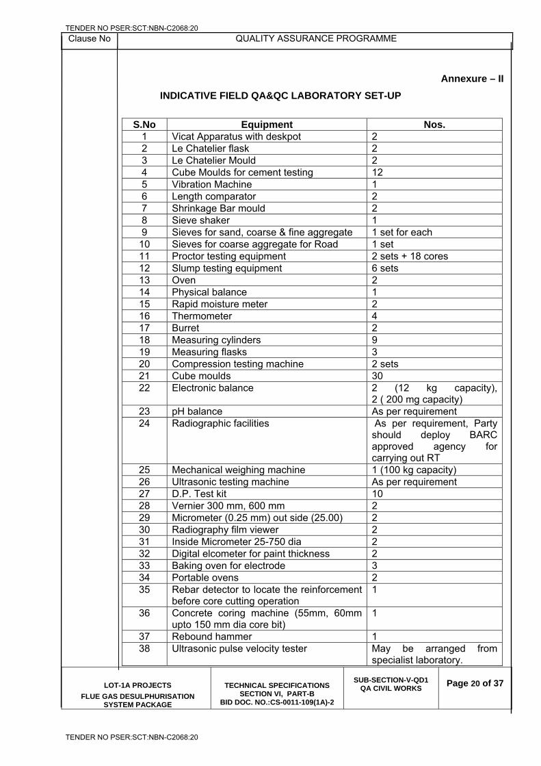
Clause No QUALITY ASSURANCE PROGRAMME
LOT-1A PROJECTS
FLUE GAS DESULPHURISATION SYSTEM PACKAGE
TECHNICAL SPECIFICATIONS SECTION VI, PART-B
BID DOC. NO.:CS-0011-109(1A)-2
SUB-SECTION-V-QD1
QA CIVIL WORKS
Page 20 of 37
Annexure – II
INDICATIVE FIELD QA&QC LABORATORY SET-UP
S.No Equipment Nos.
1 Vicat Apparatus with deskpot 2 2 Le Chatelier flask 2 3 Le Chatelier Mould 2 4 Cube Moulds for cement testing 12 5 Vibration Machine 1 6 Length comparator 2 7 Shrinkage Bar mould 2 8 Sieve shaker 1 9 Sieves for sand, coarse & fine aggregate 1 set for each
10 Sieves for coarse aggregate for Road 1 set 11 Proctor testing equipment 2 sets + 18 cores 12 Slump testing equipment 6 sets 13 Oven 2 14 Physical balance 1 15 Rapid moisture meter 2 16 Thermometer 4 17 Burret 2 18 Measuring cylinders 9 19 Measuring flasks 3 20 Compression testing machine 2 sets 21 Cube moulds 30 22 Electronic balance 2 (12 kg capacity),
2 ( 200 mg capacity) 23 pH balance As per requirement 24 Radiographic facilities As per requirement, Party
should deploy BARC approved agency for carrying out RT
25 Mechanical weighing machine 1 (100 kg capacity) 26 Ultrasonic testing machine As per requirement 27 D.P. Test kit 10 28 Vernier 300 mm, 600 mm 2 29 Micrometer (0.25 mm) out side (25.00) 2 30 Radiography film viewer 2 31 Inside Micrometer 25-750 dia 2 32 Digital elcometer for paint thickness 2 33 Baking oven for electrode 3 34 Portable ovens 2 35 Rebar detector to locate the reinforcement
before core cutting operation 1
36 Concrete coring machine (55mm, 60mm upto 150 mm dia core bit)
1
37 Rebound hammer 1 38 Ultrasonic pulse velocity tester May be arranged from
specialist laboratory.
TENDER NO PSER:SCT:NBN-C2068:20
TENDER NO PSER:SCT:NBN-C2068:20
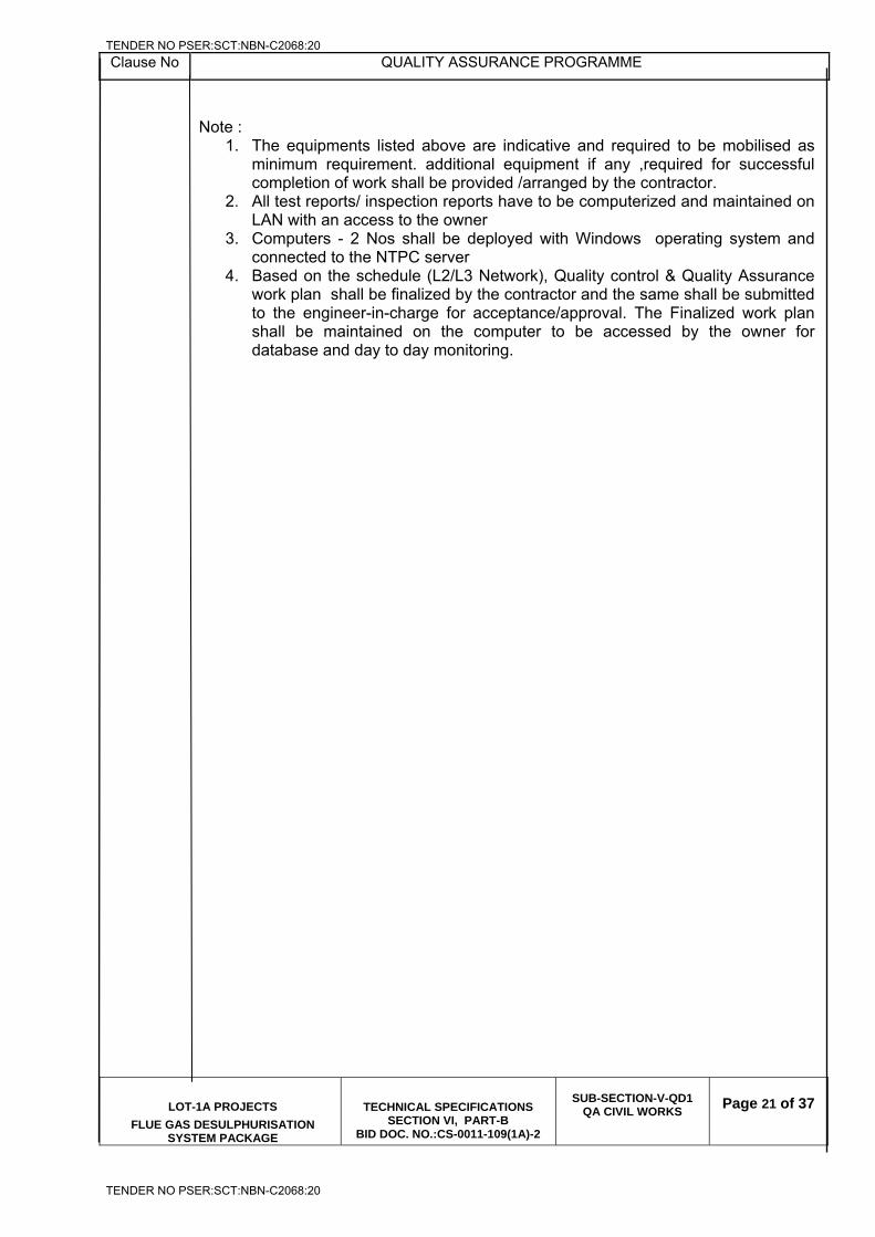
Clause No QUALITY ASSURANCE PROGRAMME
LOT-1A PROJECTS
FLUE GAS DESULPHURISATION SYSTEM PACKAGE
TECHNICAL SPECIFICATIONS SECTION VI, PART-B
BID DOC. NO.:CS-0011-109(1A)-2
SUB-SECTION-V-QD1
QA CIVIL WORKS
Page 21 of 37
Note :
1. The equipments listed above are indicative and required to be mobilised as minimum requirement. additional equipment if any ,required for successful completion of work shall be provided /arranged by the contractor.
2. All test reports/ inspection reports have to be computerized and maintained on LAN with an access to the owner
3. Computers - 2 Nos shall be deployed with Windows operating system and connected to the NTPC server
4. Based on the schedule (L2/L3 Network), Quality control & Quality Assurance work plan shall be finalized by the contractor and the same shall be submitted to the engineer-in-charge for acceptance/approval. The Finalized work plan shall be maintained on the computer to be accessed by the owner for database and day to day monitoring.
TENDER NO PSER:SCT:NBN-C2068:20
TENDER NO PSER:SCT:NBN-C2068:20
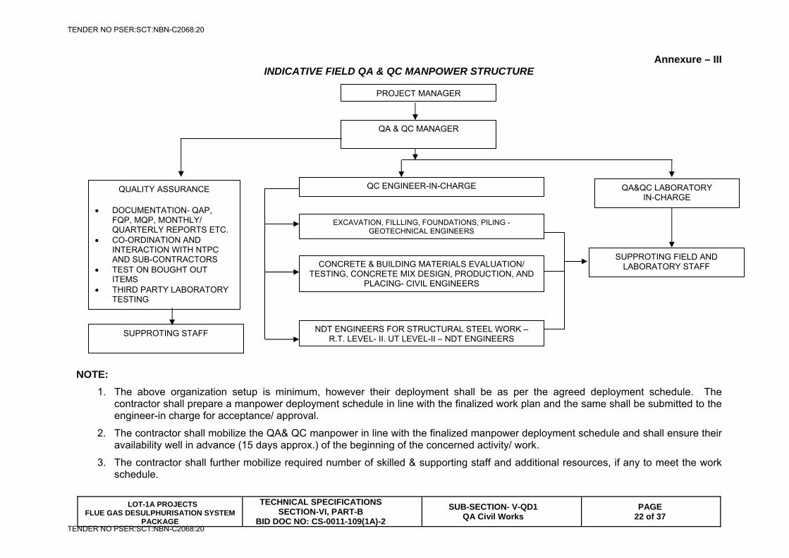
LOT-1A PROJECTS FLUE GAS DESULPHURISATION SYSTEM
PACKAGE
TECHNICAL SPECIFICATIONSSECTION-VI, PART-B
BID DOC NO: CS-0011-109(1A)-2
SUB-SECTION- V-QD1 QA Civil Works
PAGE 22 of 37
Annexure – III INDICATIVE FIELD QA & QC MANPOWER STRUCTURE
NOTE:
1. The above organization setup is minimum, however their deployment shall be as per the agreed deployment schedule. The contractor shall prepare a manpower deployment schedule in line with the finalized work plan and the same shall be submitted to the engineer-in charge for acceptance/ approval.
2. The contractor shall mobilize the QA& QC manpower in line with the finalized manpower deployment schedule and shall ensure their availability well in advance (15 days approx.) of the beginning of the concerned activity/ work.
3. The contractor shall further mobilize required number of skilled & supporting staff and additional resources, if any to meet the work schedule.
PROJECT MANAGER
QA & QC MANAGER
QC ENGINEER-IN-CHARGE QA&QC LABORATORY IN-CHARGE
CONCRETE & BUILDING MATERIALS EVALUATION/ TESTING, CONCRETE MIX DESIGN, PRODUCTION, AND
PLACING- CIVIL ENGINEERS
NDT ENGINEERS FOR STRUCTURAL STEEL WORK – R.T. LEVEL- II, UT LEVEL-II – NDT ENGINEERS
QUALITY ASSURANCE DOCUMENTATION- QAP,
FQP, MQP, MONTHLY/ QUARTERLY REPORTS ETC.
CO-ORDINATION AND INTERACTION WITH NTPC AND SUB-CONTRACTORS
TEST ON BOUGHT OUT ITEMS
THIRD PARTY LABORATORY TESTING
SUPPROTING FIELD AND LABORATORY STAFF
SUPPROTING STAFF
EXCAVATION, FILLLING, FOUNDATIONS, PILING - GEOTECHNICAL ENGINEERS
TENDER NO PSER:SCT:NBN-C2068:20
TENDER NO PSER:SCT:NBN-C2068:20
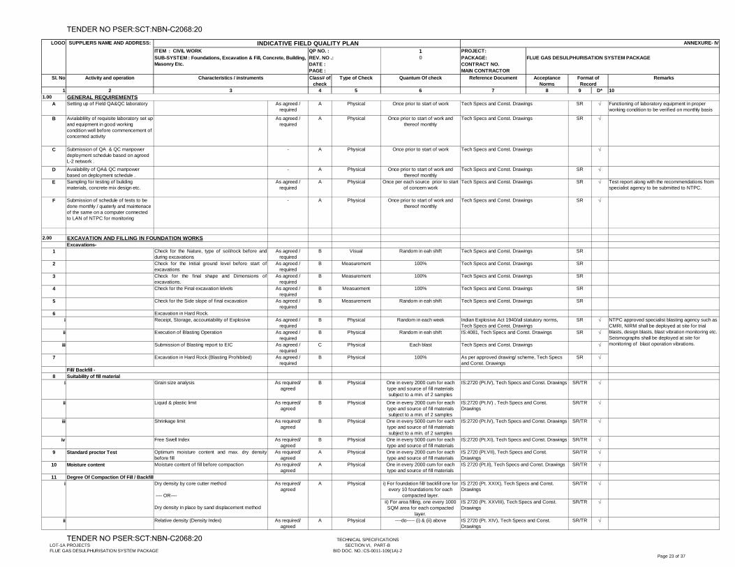
1 PROJECT:0 PACKAGE:
CONTRACT NO.MAIN CONTRACTOR
1 2 4 5 6 7 8 9 D* 101.00
A Setting up of Field QA&QC laboratory As agreed / required
A Physical Once prior to start of work SR Functioning of laboratory equipment in proper working condition to be verified on monthly basis
B Avialablility of requisite laboratory set up and equipment in good working condition well before commencement of concerned activity
As agreed / required
A Physical Once prior to start of work and thereof monthly
SR
C Submission of QA & QC manpower deployment schedule based on agreed L-2 network .
- A Physical Once prior to start of work
D Availability of QA& QC manpower based on deployment schedule .
- A Physical Once prior to start of work and thereof monthly
SR
E Sampling for testing of buliding materials, concrete mix design etc.
As agreed / required
A Physical Once per each source prior to start of concern work
SR Test report along with the recommendations from specialist agency to be submitted to NTPC.
F Submission of schedule of tests to be done monthly / quaterly and maintenace of the same on a computer connected to LAN of NTPC for monitoring
- A Physical Once prior to start of work and thereof monthly
SR
2.00
1 Check for the Nature, type of soil/rock before andduring excavations
As agreed / required
B Visual Random in eah shift SR
2 Check for the Initial ground level before start ofexcavations
As agreed / required
B Measurement 100% SR
3 Check for the final shape and Dimensions ofexcavations.
As agreed / required
B Measurement 100% SR
4 Check for the Final excavation lelvels As agreed / required
B Measuement 100% SR
5 Check for the Side slope of final excavation As agreed / required
B Measurement Random in eah shift SR
6 Excavation in Hard Rock.i Receipt, Storage, accountability of Explosive As agreed /
requiredB Physical Random in each week SR
ii Execution of Blasting Operation As agreed / required
B Physical Random in eah shift SR
iii Submission of Blasting report to EIC As agreed / required
C Physical Each blast
7 Excavation in Hard Rock (Blasting Prohibited) As agreed / required
B Physical 100% SR
8i Grain size analysis As required/
agreedB Physical One in every 2000 cum for each
type and source of fill materials subject to a min. of 2 samples
SR/TR
ii Liquid & plastic limit As required/ agreed
B Physical One in every 2000 cum for each type and source of fill materials subject to a min. of 2 samples
SR/TR
iii Shrinkage limit As required/ agreed
B Physical One in every 5000 cum for each type and source of fill materials subject to a min. of 2 samples
SR/TR
iv Free Swell Index As required/ agreed
B Physical One in every 5000 cum for each type and source of fill materials
SR/TR
9 Standard proctor Test Optimum moisture content and max. dry densitybefore fill
As required/ agreed
A Physical One in every 2000 cum for each type and source of fill materials
SR/TR
10 Moisture content Moisture content of fill before compaction As required/ agreed
A Physical One in every 2000 cum for each type and source of fill materials
SR/TR
11i) For foundation fill/ backfill one for
every 10 foundations for each compacted layer.
SR/TR
ii) For area filling, one every 1000 SQM area for each compacted
layer.
SR/TR
ii Relative density (Density Index) As required/ agreed
A Physical ----do----- (i) & (ii) above SR/TR
EXCAVATION AND FILLING IN FOUNDATION WORKS
Degree Of Compaction Of Fill / Backfill
Excavations-
Fill/ Backfill -
As required/ agreed
IS 2720 (Pt. XXIX), Tech Specs and Const. Drawings
Indian Explosive Act 1940/all statutory norms, Tech Specs and Const. Drawings IS:4081, Tech Specs and Const. Drawings
Tech Specs and Const. Drawings
IS:2720 (Pt.IV), Tech Specs and Const. Drawings
IS:2720 (Pt.XI), Tech Specs and Const. Drawings
Tech Specs and Const. Drawings
Tech Specs and Const. Drawings
Tech Specs and Const. Drawings
Tech Specs and Const. Drawings
Tech Specs and Const. Drawings
Tech Specs and Const. Drawings
Tech Specs and Const. Drawings
Tech Specs and Const. Drawings
Activity and operation Type of Check Quantum Of check Reference Document RemarksAcceptance Norms
Format of Record
3
GENERAL REQUIREMENTS
i Dry density by core cutter method
---- OR----
Dry density in place by sand displacement method
Tech Specs and Const. Drawings
Tech Specs and Const. Drawings
Tech Specs and Const. Drawings
Sl. No Characteristics / instruments Class# of check
A Physical
As per approved drawing/ scheme, Tech Specs and Const. Drawings
IS:2720 (Pt.IV), Tech Specs and Const. Drawings
IS 2720 (Pt. XIV), Tech Specs and Const. Drawings
NTPC approved specialist blasting agency such as CMRI, NIRM shall be deployed at site for trial blasts, design blasts, blast vibration monitoring etc. Seismographs shall be deployed at site for monitoring of blast operation vibrations.
IS 2720 (Pt.II), Tech Specs and Const. Drawings
SUPPLIERS NAME AND ADDRESS: ANNEXURE- IV
IS:2720 (Pt.IV) , Tech Specs and Const. Drawings
IS 2720 (Pt.VII), Tech Specs and Const. Drawings
IS 2720 (Pt. XXVIII), Tech Specs and Const. Drawings
SUB-SYSTEM : Foundations, Excavation & Fill, Concrete, Building, Masonry Etc.
LOGO
QP NO. :
REV. NO .: DATE :PAGE :
INDICATIVE FIELD QUALITY PLANITEM : CIVIL WORK
FLUE GAS DESULPHURISATION SYSTEM PACKAGE
Suitability of fill material
LOT-1A PROJECTSFLUE GAS DESULPHURISATION SYSTEM PACKAGE
TECHNICAL SPECIFICATIONSSECTION VI, PART-B
BID DOC. NO.:CS-0011-109(1A)-2Page 23 of 37
TENDER NO PSER:SCT:NBN-C2068:20
TENDER NO PSER:SCT:NBN-C2068:20
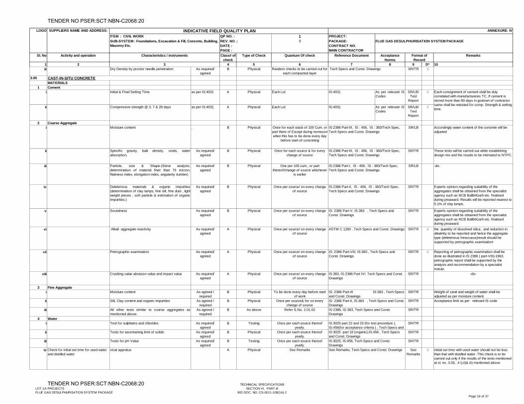
1 PROJECT:0 PACKAGE:
CONTRACT NO.MAIN CONTRACTOR
1 2 4 5 6 7 8 9 D* 10
Activity and operation Type of Check Quantum Of check Reference Document RemarksAcceptance Norms
Format of Record
3
Sl. No Characteristics / instruments Class# of check
SUPPLIERS NAME AND ADDRESS: ANNEXURE- IV
SUB-SYSTEM : Foundations, Excavation & Fill, Concrete, Building, Masonry Etc.
LOGO
QP NO. :
REV. NO .: DATE :PAGE :
INDICATIVE FIELD QUALITY PLANITEM : CIVIL WORK
FLUE GAS DESULPHURISATION SYSTEM PACKAGE
iii Dry Density by proctor needle penetration As required/ agreed
B Physical Random checks to be carried out for each compacted layer
SR/TR
3.00
MATERIALS1 Cement
i Initial & Final Setting Time as per IS:4031 A Physical Each Lot IS:4031 As per relevant ISCodes
SR/LB/ Test
Report
ii Compressive strength @ 3, 7 & 28 days as per IS:4031 A Physical Each Lot IS:4031 As per relevant ISCodes
SR/LB/ Test
Report
2 Coarse Aggregatei Moisture content . B Physical Once for each stack of 100 Cum. or
part there of Except during monsoon when this has to be done every day
before start of concreting
SR/LB Accordingly water content of the concrete will be adjusted
ii Specific gravity, bulk density, voids, waterabsorption,
As required/ agreed
B Physical Once for each source & for every change of source
SR/TR These tests will be carried out white establishing design mix and the results to be intimated to NTPC.
iii Particle, size & Shape-(Sieve analysis,determination of material finer than 75 micron,flakiness index, elongation index, angularity number)
As required/ agreed
B Physical One per 100 cum., or part thereof/change of source whichever
is earlier
SR/LB -do-
iv Deleterious materials & organic impurities(determination of clay lumps, fine silt, fine dust , lightweight pieces , soft particle & estimation of organicimpurities.)
As required/ agreed
B Physical Once per source/ on every change of source
SR/TR Experts opinion regarding suitability of the aggregates shall be obtained from the specialist agency such as NCB BallbhGarh etc. finalised during preaward. Results will be reported nearest to 0.1% of clay lumps.
v Soundness As required/ agreed
B Physical Once per source/ on every change of source
SR/TR Experts opinion regarding suitability of the aggregates shall be obtained from the specialist agency such as NCB BallbhGarh etc. finalised during preaward.
vi Alkali aggregate reactivity As required/ agreed
A Physical Once per source/ on every change of source
SR/TR the quantity of dissolved silica , and reduction in alkalinity to be reported and hence the aggregate type (deleterious /innocuous)result should be supported by petrographic examination
vii Petrographic examination As required/ agreed
A Physical Once per source/ on every change of source
SR/TR Reporting of petrographic examination shall be done as illustrated in IS 2386 ( part-VIII)-1963. petrographic report shall be supported by the analysis and recommendation by a specialist instute.
viii Crushing value abrasion value and impact value As required/ agreed
A Physical Once per source/ on every change of source
SR/TR -do-
3 Fine Aggregatei Moisture content As agreed /
requiredB Physical To be done every day before start
of workSR/TR Weight of sand and weight of water shall be
adjusted as per moisture content.ii Silt, Clay content and organic impurities As agreed /
requiredB Physical Once per source& for on every
change of sourceSR/TR Acceptance limit as per relevant IS code
iii All other tests similar to coarse aggregates asmentioned above.
As agreed / required
B As above Refer S.No. 2.01.02 SR/TR
4 Wateri Test for sulphates and chlorides As required/
agreedB Testing Once per each source thereof
yearly.SR/TR
ii Tests for ascertaining limit of solids As required/ agreed
B Physical Once per each source thereof yearly.
SR/TR
iii Tests for pH Value As required/ agreed
B Testing Once per each source thereof yearly.
SR/TR
iv Check for initial set time for used water and distilled water
vicat appratus A Physical See Remarks See Remarks
Initial set time with used water should not be less than that with distilled water. This check is to be carried out only if the results of the tests mentioned at sl. no. 3.00, .4 i),ii)& iii) mentioned above
IS: 2386 Part-II, IS:383 , Tech Specs and Const. Drawings
IS:3025 part 22 and 23 (for test procedure ), IS:456(for acceptance criteria ) , Tech Specs and
CAST-IN-SITU CONCRETE
IS-2386, IS-383, Tech Specs and Const. Drawings
IS:3025, IS:456, Tech Specs and Const. Drawings
Each consignment of cement shall be duly correlated with manufactureres TC, If cement is stored more than 90 days in godown of contractor same shall be retested for comp. Strength & setting time.
IS: 2386 Part-V, IS:383 , Tech Specs and Const. Drawings
IS: 2386 Part-III IS:383 , Tech Specs and Const. Drawings
IS: 2386 Part-VIII, IS:383 , Tech Specs and Const. Drawings
IS:383, IS-2386 Part IV/, Tech Specs and Const. Drawings
IS:2386 Part-III, IS : 456, IS : 383/Tech Spec, Tech Specs and Const. Drawings
IS:2386 Part-III, IS : 456, IS : 383/Tech Spec, Tech Specs and Const. Drawings
IS:2386 Part-I, IS : 456, IS : 383/Tech Spec, Tech Specs and Const. Drawings
IS:3025 part 18 (organic),IS:456 , Tech Specs and Const. Drawings
IS:2386 Part-II, IS : 456, IS : 383/Tech Spec, Tech Specs and Const. Drawings
ASTM C 1260 , Tech Specs and Const. Drawings
See Remarks, Tech Specs and Const. Drawings
Tech Specs and Const. Drawings
LOT-1A PROJECTSFLUE GAS DESULPHURISATION SYSTEM PACKAGE
TECHNICAL SPECIFICATIONSSECTION VI, PART-B
BID DOC. NO.:CS-0011-109(1A)-2Page 24 of 37
TENDER NO PSER:SCT:NBN-C2068:20
TENDER NO PSER:SCT:NBN-C2068:20
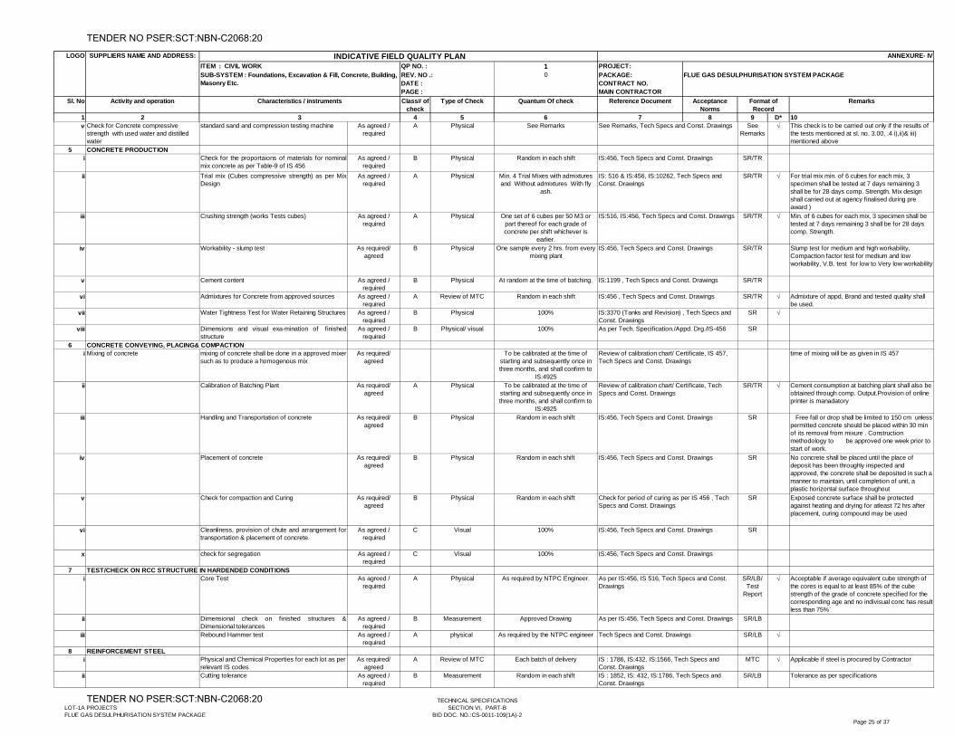
1 PROJECT:0 PACKAGE:
CONTRACT NO.MAIN CONTRACTOR
1 2 4 5 6 7 8 9 D* 10
Activity and operation Type of Check Quantum Of check Reference Document RemarksAcceptance Norms
Format of Record
3
Sl. No Characteristics / instruments Class# of check
SUPPLIERS NAME AND ADDRESS: ANNEXURE- IV
SUB-SYSTEM : Foundations, Excavation & Fill, Concrete, Building, Masonry Etc.
LOGO
QP NO. :
REV. NO .: DATE :PAGE :
INDICATIVE FIELD QUALITY PLANITEM : CIVIL WORK
FLUE GAS DESULPHURISATION SYSTEM PACKAGE
v Check for Concrete compressive strength with used water and distilled water
standard sand and compression testing machine As agreed / required
A Physical See Remarks See Remarks
This check is to be carried out only if the results of the tests mentioned at sl. no. 3.00, .4 i),ii)& iii) mentioned above
5 CONCRETE PRODUCTIONi Check for the proportaions of materials for nominal
mix concrete as per Table-9 of IS 456As agreed /
requiredB Physical Random in each shift SR/TR
ii Trial mix (Cubes compressive strength) as per MixDesign
As agreed / required
A Physical Min. 4 Trial Mixes with admixtures and Without admixtures With fly
ash.
SR/TR For trial mix min. of 6 cubes for each mix, 3 specimen shall be tested at 7 days remaining 3 shall be for 28 days comp. Strength. Mix design shall carried out at agency finalised during pre award )
iii Crushing strength (works Tests cubes) As agreed / required
A Physical One set of 6 cubes per 50 M3 or part thereof for each grade of concrete per shift whichever is
earlier.
SR/TR Min. of 6 cubes for each mix, 3 specimen shall be tested at 7 days remaining 3 shall be for 28 days comp. Strength.
iv Workability - slump test As required/ agreed
B Physical One sample every 2 hrs. from every mixing plant
SR/TR Slump test for medium and high workability, Compaction factor test for medium and low workability, V.B. test for low to Very low workability
v Cement content As agreed / required
B Physical At random at the time of batching. SR/TR
vi Admixtures for Concrete from approved sources As agreed / required
A Review of MTC Random in each shift SR/TR Admixture of appd. Brand and tested quality shall be used.
vii Water Tightness Test for Water Retaining Structures As agreed / required
B Physical 100% SR
viii Dimensions and visual exa-mination of finishedstructure
As agreed / required
B Physical/ visual 100% SR
6 CONCRETE CONVEYING, PLACING& COMPACTIONi Mixing of concrete mixing of concrete shall be done in a approved mixer
such as to produce a homogenous mixAs required/
agreedTo be calibrated at the time of
starting and subsequently once in three months, and shall confirm to
IS:4925
time of mixing will be as given in IS 457
ii Calibration of Batching Plant As required/ agreed
A Physical To be calibrated at the time of starting and subsequently once in three months, and shall confirm to
IS:4925
SR/TR Cement consumption at batching plant shall also be obtained through comp. Output.Provision of online printer is manadatory
iii Handling and Transportation of concrete As required/ agreed
B Physical Random in each shift SR Free fall or drop shall be limited to 150 cm unless permitted concrete should be placed within 30 min of its removal from mixure . Construction methodology to be approved one week prior to start of work.
iv Placement of concrete As required/ agreed
B Physical Random in each shift SR No concrete shall be placed until the place of deposit has been throughly inspected and approved, the concrete shall be deposited in such a manner to maintain, until completion of unit, a plastic horizontal surface throughout
v Check for compaction and Curing As required/ agreed
B Physical Random in each shift SR Exposed concrete surface shall be protected against heating and drying for atleast 72 hrs after placement, curing compound may be used
vi Cleanliness, provision of chute and arrangement fortransportation & placement of concrete.
As agreed / required
C Visual 100% SR
x check for segregation As agreed / required
C Visual 100%
7 TEST/CHECK ON RCC STRUCTURE IN HARDENDED CONDITIONSi Core Test As agreed /
requiredA Physical As required by NTPC Engineer. SR/LB/
Test Report
Acceptable if average equivalent cube strength of the cores is equal to at least 85% of the cube strength of the grade of concrete specified for the corresponding age and no indivisual conc has result less than 75%`
ii Dimensional check on finished structures &Dimensional tolerances
As agreed / required
B Measurement Approved Drawing SR/LB
iii Rebound Hammer test As agreed / required
A physical As required by the NTPC engineer SR/LB
8 REINFORCEMENT STEELi Physical and Chemical Properties for each lot as per
relevant IS codesAs required/
agreedA Review of MTC Each batch of delivery MTC Applicable if steel is procured by Contractor
ii Cutting tolerance As agreed / required
B Measurement Random in each shift SR/LB Tolerance as per specifications
IS:456, Tech Specs and Const. Drawings
See Remarks, Tech Specs and Const. Drawings
IS:516, IS:456, Tech Specs and Const. Drawings
IS:456, Tech Specs and Const. Drawings
As per IS:456, IS 516, Tech Specs and Const. Drawings
Review of calibration chart/ Certificate, IS 457, Tech Specs and Const. Drawings
As per Tech. Specification./Appd. Drg./IS-456
IS:1199 , Tech Specs and Const. Drawings
IS:456, Tech Specs and Const. Drawings
IS:456, Tech Specs and Const. Drawings
IS:3370 (Tanks and Revision) , Tech Specs and Const. Drawings
IS: 516 & IS:456, IS:10262, Tech Specs and Const. Drawings
IS:456, Tech Specs and Const. Drawings
Review of calibration chart/ Certificate, Tech Specs and Const. Drawings
IS:456, Tech Specs and Const. Drawings
Check for period of curing as per IS 456 , Tech Specs and Const. Drawings
As per IS:456, Tech Specs and Const. Drawings
IS : 1786, IS:432, IS:1566, Tech Specs and Const. Drawings
Tech Specs and Const. Drawings
IS : 1852, IS: 432, IS:1786, Tech Specs and Const. Drawings
IS:456 , Tech Specs and Const. Drawings
LOT-1A PROJECTSFLUE GAS DESULPHURISATION SYSTEM PACKAGE
TECHNICAL SPECIFICATIONSSECTION VI, PART-B
BID DOC. NO.:CS-0011-109(1A)-2Page 25 of 37
TENDER NO PSER:SCT:NBN-C2068:20
TENDER NO PSER:SCT:NBN-C2068:20
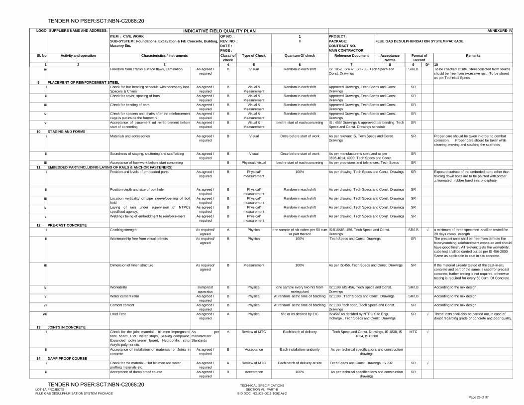
1 PROJECT:0 PACKAGE:
CONTRACT NO.MAIN CONTRACTOR
1 2 4 5 6 7 8 9 D* 10
Activity and operation Type of Check Quantum Of check Reference Document RemarksAcceptance Norms
Format of Record
3
Sl. No Characteristics / instruments Class# of check
SUPPLIERS NAME AND ADDRESS: ANNEXURE- IV
SUB-SYSTEM : Foundations, Excavation & Fill, Concrete, Building, Masonry Etc.
LOGO
QP NO. :
REV. NO .: DATE :PAGE :
INDICATIVE FIELD QUALITY PLANITEM : CIVIL WORK
FLUE GAS DESULPHURISATION SYSTEM PACKAGE
iii Freedom form cracks surface flaws, Lamination. As agreed / required
B Visual Random in each shift SR/LB To be checked at site. Steel collected from source should be free from excessive rust. To be stored as per Technical Specs.
9I Check for bar bending schedule with necessary laps.
Spacers & ChairsAs agreed /
requiredB Visual &
MeasurementRandom in each shift SR
ii Check for cover, spacing of bars As agreed / required
B Visual & Measurement
Random in each shift SR
iii Check for bending of bars As agreed / required
B Visual & Measurement
Random in each shift SR
iv Check for spacers and chairs after the reinforcementcage is put inside the formwork
As agreed / required
B Visual & Measurement
Random in each shift SR
v Acceptance of placement od reinforcement beforestart of concreting
As agreed / required
B Visual & Measurement
beofre start of each concreting SR
10 STAGING AND FORMSi Materials and accessories As agreed /
requiredB Visual Once before start of work SR Proper care should be taken in order to combat
corrosion. Proper care should be taken while cleaning, moving and stacking the scaffolds
ii Soundness of staging, shuttering and scaffolding As agreed / required
B Visual Once before start of work SR
iii Acceptance of formwork before start concreting B Physical / visual beofre start of each concreting SR11
i Position and levels of embedded parts As agreed / required
B Physical/ measurement
100% SR Exposed surfsce of the embeded parts other than holding down bolts are to be painted with primer ,chlorinated , rubber baed zinc phosphate
ii Position depth and size of bolt hole As agreed / required
B Physical/ measurement
Random in each shift SR
iii Location verticality of pipe sleeve/opening of bolthold
As agreed / required
B Physical/ measurement
Random in each shift SR
iv Laying of rails under supervision of NTPCsspecilised agency.
As agreed / required
B Physical/ measurement
Random in each shift SR
v Welding / tieing of embeddment to reinforce-ment As agreed / required
B Physical/ measurement
Random in each shift SR
12 PRE-CAST CONCRETEi Crushing strength As required/
agreedA Physical one sample of six cubes per 50 cum
or part thereof SR/LB a minimum of three specimen shall be tested for
28 days comp. strengthii Workmanship free from visual defects As required/
agreedB Physical 100% SR The precast units shall be free from defects like
honeycombing, reinforcement exposure and should have good finish. All relevant tests like workability, cube test shall be carried out as per IS 456-2000 Same as applicable to cast in situ concrete.
iii Dimension of finish structure As required/ agreed
B Measurement 100% SR If the material already tested of the cast-in-situ concrete and part of the same is used for precast concrete, further testing is not required, otherwise testing is required for every 50 Cum. Of Concrete.
iv Workability slump test apparatus
B Physical one sample every two hrs from mixing plant
SR/LB According to the mix design
v Water cement ratio As agreed / required
B Physical At random at the time of batching SR/LB According to the mix design
vi Cement content As agreed / required
B Physical At random at the time of batching SR According to the mix design
vii Load Test As agreed / required
A Physical 5% or as desired by EIC SR These tests shall also be carried out, in case of doubt regarding grade of concrete and poor quality.
13 JOINTS IN CONCRETEi Check for the joint material - bitumen impregnated
fibre board, PVC water stops, Sealing compound,Expanded polystyrene board, Hydrophillic strip,Acrylic polymer etc.
As permanufacturer Standards
A Review of MTC Each batch of delivery MTC
ii Acceptance of installation of materials for Joints inconcrete
As agreed / required
B Acceptance Each installation randomly
14 DAMP PROOF COURSEi Check for the material - Hot bitumen and water
proffing materials etcAs agreed /
requiredA Review of MTC Each batch of delivery at site SR
ii Acceptance of damp proof course As agreed / required
B Acceptance 100% SR
As per drawing, Tech Specs and Const. Drawings
Approved Drawings, Tech Specs and Const. Drawings
As per provisions and tolerances, Tech Specs
Tech Specs and Const. Drawings
As per drawing, Tech Specs and Const. Drawings
IS : 456/ Drawings & approved bar bending, Tech Specs and Const. Drawings schedule
As per manufacturer's spec.and as per 3696,4014, 4990, Tech Specs and Const.
As per drawing, Tech Specs and Const. Drawings
As per relevant IS, Tech Specs and Const. Drawings
Approved Drawings, Tech Specs and Const. Drawings
As per drawing, Tech Specs and Const. Drawings
PLACEMENT OF REINFORCEMENT STEEL
EMBEDDED PART(INCLUDING LAYING OF RAILS & ANCHOR FASTENERS)
As per technical specifications and construction drawings
As per technical specifications and construction drawings
Tech Specs and Const. Drawings, IS 1838, IS 1834, IS12200
As per IS:456, Tech Specs and Const. Drawings
As per drawing, Tech Specs and Const. Drawings
IS:456/ As decided by NTPC Site Engr. Incharge., Tech Specs and Const. Drawings
IS:1199 , Tech Specs and Const. Drawings
IS:1199 /tech spec, Tech Specs and Const. Drawings
IS: 1852, IS:432, IS:1786, Tech Specs and Const. Drawings
Tech Specs and Const. Drawings, IS 702
IS:1199 &IS:456, Tech Specs and Const. Drawings
Approved Drawings, Tech Specs and Const. DrawingsApproved Drawings, Tech Specs and Const. Drawings
IS:516&IS; 456, Tech Specs and Const. Drawings
LOT-1A PROJECTSFLUE GAS DESULPHURISATION SYSTEM PACKAGE
TECHNICAL SPECIFICATIONSSECTION VI, PART-B
BID DOC. NO.:CS-0011-109(1A)-2Page 26 of 37
TENDER NO PSER:SCT:NBN-C2068:20
TENDER NO PSER:SCT:NBN-C2068:20
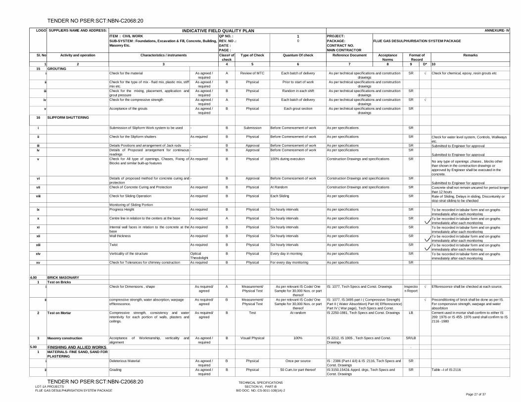
1 PROJECT:0 PACKAGE:
CONTRACT NO.MAIN CONTRACTOR
1 2 4 5 6 7 8 9 D* 10
Activity and operation Type of Check Quantum Of check Reference Document RemarksAcceptance Norms
Format of Record
3
Sl. No Characteristics / instruments Class# of check
SUPPLIERS NAME AND ADDRESS: ANNEXURE- IV
SUB-SYSTEM : Foundations, Excavation & Fill, Concrete, Building, Masonry Etc.
LOGO
QP NO. :
REV. NO .: DATE :PAGE :
INDICATIVE FIELD QUALITY PLANITEM : CIVIL WORK
FLUE GAS DESULPHURISATION SYSTEM PACKAGE
15 GROUTINGi Check for the material As agreed /
requiredA Review of MTC Each batch of delivery SR Check for chemical, epoxy, resin grouts etc
ii Check for the type of mix - fluid mix, plastic mix, stiffmix etc.
As agreed / required
B Physical Prior to start of work
iii Check for the mixing, placement, application andgrout pressure
As agreed / required
B Physical Random in each shift SR
iv Check for the compressive strength As agreed / required
A Physical Each batch of delivery SR
v Acceptance of the grouts As agreed / required
B Physical Each grout section SR
16 SLIPFORM SHUTTERING
i Submission of Slipform Work system to be used - B Submission Before Comencement of work SR
ii Check for the Slipform shutters As required B Physical Before Comencement of work SR Check for water level system, Controls, Walkways etc.
iii Details Positions and arrangement of Jack rods - B Approval Before Comencement of work SR Submitted to Engineer for approvaliv Details of Proposed arrangement for continuous
readings- B Approval Before Comencement of work SR
Submitted to Engineer for approvalv Check for All type of openings, Chases, Fixing of
Blocks and similar built-up featuresAs required B Physical 100% during execution SR
No any type of openings ,chases , blocks other than shown in the construction drawings or approved by Engineer shall be executed in the concrete.
vi Details of proposed method for concrete curing andprotection
- B Approval Before Comencement of work SRSubmitted to Engineer for approval
vii Check of Concrete Curing and Protection As required B Physical At Random SR Concrete shall not remain uncured for period longer than 12 hours
viii Check for Sliding Operation As required B Physical Each Sliding SR Rate of Sliding, Delays in sliding, Discontunity or stop strat sliding to be checked
Monitoring of Sliding Portionix Progress Height As required B Physical Six hourly intervals SR To be recorded in tabular form and on graphs
immediately after each monitoringx Centre line in relation to the centers at the base As required A Physical Six hourly intervals SR To be recorded in tabular form and on graphs
immediately after each monitoringxi Internal wall faces in relation to the concrete at the
baseAs required B Physical Six hourly intervals SR To be recorded in tabular form and on graphs
immediately after each monitoringxii Wall thickness As required B Physical Six hourly intervals SR To be recorded in tabular form and on graphs
immediately after each monitoringxiii Twist As required B Physical Six hourly intervals SR To be recorded in tabular form and on graphs
immediately after each monitoringxiv Verticality of the structure Optical
TheodolightB Physical Every day in morning SR To be recorded in tabular form and on graphs
immediately after each monitoringxv Check for Tolerances for chimney construction As required B Physical For every day monitoring SR
4.00 BRICK MASONARY1 Test on Bricks
i Check for Dimensions , shape As required/ agreed
A Measurement/ Physical Test
As per relevant IS Code/ One Sample for 30,000 Nos. or part
thereof
Inspection Report
Efflorescence shall be checked at each source.
ii compressive strength, water absorption, warpage efflorescence.
As required/ agreed
B Measurement/ Physical Test
As per relevant IS Code/ One Sample for 30,000 Nos. or part
thereof
Preconditioning of brick shall be done as per IS. For comperssive strength, warpage and water absorbtion
2 Test on Mortar Compressive strength, consistency and waterretentivity for each portion of walls, plasters andceilings.
As required/ agreed
B Test At random LB Cement used in mortar shall confirm to either IS 269: 1976 or IS 455- 1976 sand shall confirm to IS 2116 -1980
3 Masonry construction Acceptance of Workmanship, verticality andalignment
As agreed / required
B Visual/ Physical 100% SR/LB
5.00 .1 MATERIALS- FINE SAND, SAND FOR
PLASTERINGi Deleterious Material As agreed /
requiredB Physical Once per source SR
ii Grading As agreed / required
B Physical 50 Cum./or part thereof SR Table –I of IS:2116
FINISHING AND ALLIED WORKS
As per technical specifications and construction drawings
IS: 1077, Tech Specs and Const. Drawings
IS : 2386 (Part-I &II) & IS :2116, Tech Specs and Const. DrawingsIS:3150,1542& Apprd. drgs, Tech Specs and Const. Drawings
IS 2250-1981, Tech Specs and Const. Drawings
IS 2212, IS 1905 , Tech Specs and Const. Drawings
As per technical specifications and construction drawings
As per technical specifications and construction drawings
As per technical specifications and construction drawings
As per technical specifications and construction drawings
Construction Drawings and specifications
As per specifications
As per specifications
As per specificationsAs per specifications
Construction Drawings and specifications
Construction Drawings and specifications
As per specifications
As per specifications
As per specifications
As per specifications
As per specifications
As per specifications
As per specifications
As per specifications
IS: 1077, IS:3495 part I ( Compressive Strength) Part II ( Water Absorbtion) Part III( Efflorescence) Part IV ( War page), Tech Specs and Const.
LOT-1A PROJECTSFLUE GAS DESULPHURISATION SYSTEM PACKAGE
TECHNICAL SPECIFICATIONSSECTION VI, PART-B
BID DOC. NO.:CS-0011-109(1A)-2Page 27 of 37
TENDER NO PSER:SCT:NBN-C2068:20
TENDER NO PSER:SCT:NBN-C2068:20
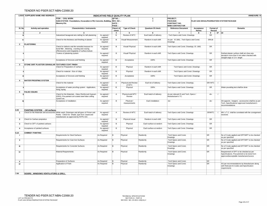
1 PROJECT:0 PACKAGE:
CONTRACT NO.MAIN CONTRACTOR
1 2 4 5 6 7 8 9 D* 10
Activity and operation Type of Check Quantum Of check Reference Document RemarksAcceptance Norms
Format of Record
3
Sl. No Characteristics / instruments Class# of check
SUPPLIERS NAME AND ADDRESS: ANNEXURE- IV
SUB-SYSTEM : Foundations, Excavation & Fill, Concrete, Building, Masonry Etc.
LOGO
QP NO. :
REV. NO .: DATE :PAGE :
INDICATIVE FIELD QUALITY PLANITEM : CIVIL WORK
FLUE GAS DESULPHURISATION SYSTEM PACKAGE
iii Galvanized hexagonal wire netting for lath plastering As agreed / required
B Review of MTC Each batch of delivery SR
iv Check for the thickness and finishing of plaster As agreed / required
B Visual/ Measurement Random in each shift SR/LB
2 PLASTERINGi Check for defects and the remedial measure for
bond filler , blistering , cracking and crazing , efflorescence and irregularity of surface texture
As agreed / required
B Visual/ Physical Random in each shift SR
ii Truness of plastering system As agreed / required
B Visual/ Physical Random in each shift SR finished plaster surface shall not show any deviation more than 4 mm when checked with straight edge of 2 m length
iii Acceptance of Grooves and finishing As agreed / required
B Acceptance 100% SR
3i Check for Preparation of surface As agreed /
requiredB Physical Random in each shift SR
ii Check for material - Size of chips As agreed / required
B Physical Random in each shift SR
iii Acceptance of Grooves and finishing As agreed / required
B Acceptance 100% SR
4 WATER PROOFING SYSTEMi Check for the material As agreed /
requiredA Physical and Review
of MTC Each lot of delivery SR/ MTC
ii Acceptance of water proofing system - Application, fixing, laying
As agreed / required
B Physical 100% SR Water pounding test shall be done
5 FALSE CEILINGi) Check for the Materials - Glass Reinforced Gypsum
(GRG), Pre-painted coil coated steel false ceiling system etc.
As agreed / required
A Physical and MTC Review
Each batch of delivery -do-
ii) Acceptance of installation As agreed / required
B Physical / measurements
Each installation -do- All supports , hangers , accessories shall be as per Tech. Specifications/ approved manufacturer's recommendations
6.00
1 Check for the Materials and accessories White wash, Distemper and all types of Primer and Paints - Check for Shade, type from brand and manufacturer as approved by NTPC EIC
As agreed / required
A Review of MTC Each batch of delivery SR/MTC Mfr.’s T.C. shall be correlated with the consignment received.
2 Check for Surface prepration As agreed / required
B Physical /visual Random in each shift SR
3 Check for DFT of painted surfaces As agreed / required
B Physical Each surface at random SR
4 Acceptance of painted surfaces As agreed / required
B Physical Each surface at random SR
6.10i Requirements for Steel Surfaces As Required B Physical Randomly Tech Specs and Const.
DrawingsSR No of Coats applied and DFT/WFT to be checked
as per specifiedii Requirements for Cast Iron Surfaces As Required B Physical Randomly Tech Specs and Const.
DrawingsSR No of Coats applied and DFT/WFT to be checked
as per specified
iii Requirements for Concrete Surfaces As Required B Physical Randomly Tech Specs and Const. Drawings
SR No of Coats applied and DFT/WFT to be checked as per specified
iv Material Requirements As Required B Physical Randomly Tech Specs and Const. Drawings
SR Requirement of DFT to be checked as per Specifications. Procurement to be done from approved/acceptable manufacturer/source
v Preparation of Surfaces As Required B Physical Randomly Tech Specs and Const. SRvi Application of Paint As Required B Physical Randomly Tech Specs and Const.
DrawingsSR AS per recommendations by Manufacturer along
with Relevant IS Codes and Specification requirements
7.00
PAINTING SYSTEM - All surfaces
STONE GRIT PLASTER/ GRANULAR TEXTURED COAT FINISH
DOORS , WINDOWS VENTILATORS & GRILL
Tech Specs and Const. Drawings,
, Tech Specs and Const. Drawings
Tech Specs and Const. Drawings
Tech Specs and Const. Drawings
As per relevant IS and Tech. Specs / Manufacturer's TC
Tech Specs and Const. Drawings
Tech Specs and Const. Drawings
Tech Specs and Const. Drawings, IS: 1661
Tech Specs and Const. Drawings
Tech Specs and Const. Drawings
-do-
Tech Specs and Const. Drawings
As per IS 1661 , Tech Specs and Const. Drawings
CHIMNEY PAINTING
Tech Specs and Const. Drawings
Tech Specs and Const. Drawings
Tech Specs and Const. Drawings
LOT-1A PROJECTSFLUE GAS DESULPHURISATION SYSTEM PACKAGE
TECHNICAL SPECIFICATIONSSECTION VI, PART-B
BID DOC. NO.:CS-0011-109(1A)-2Page 28 of 37
TENDER NO PSER:SCT:NBN-C2068:20
TENDER NO PSER:SCT:NBN-C2068:20
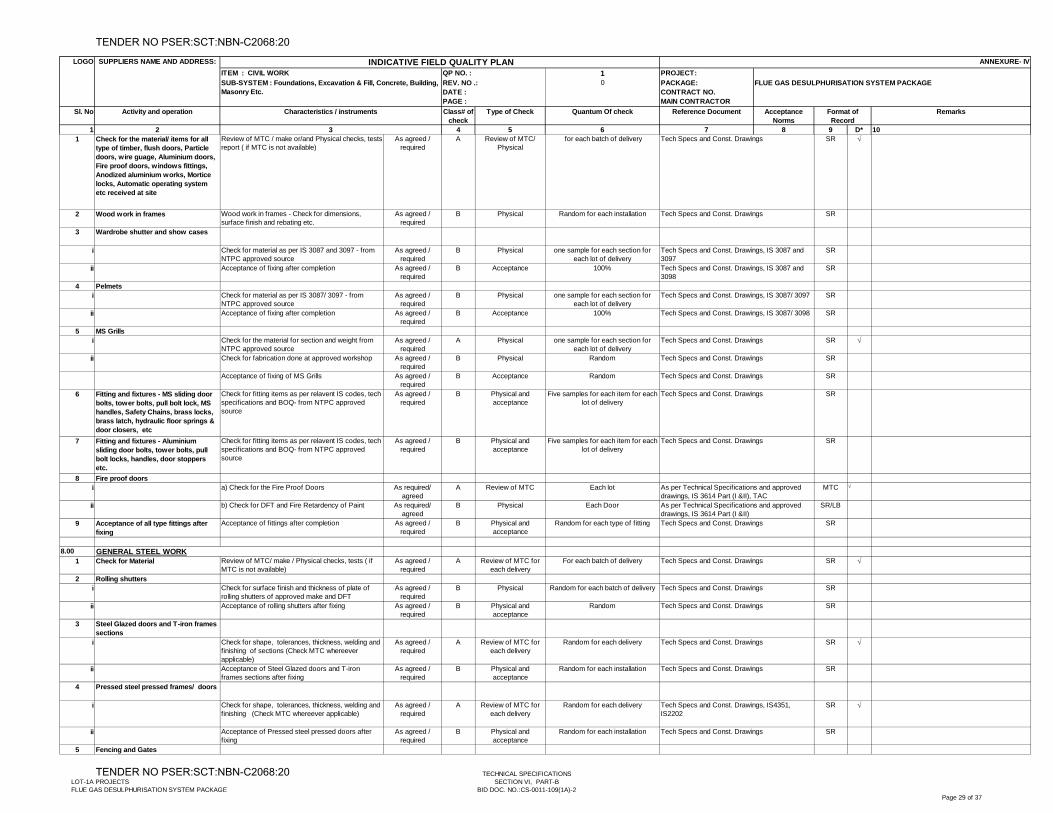
1 PROJECT:0 PACKAGE:
CONTRACT NO.MAIN CONTRACTOR
1 2 4 5 6 7 8 9 D* 10
Activity and operation Type of Check Quantum Of check Reference Document RemarksAcceptance Norms
Format of Record
3
Sl. No Characteristics / instruments Class# of check
SUPPLIERS NAME AND ADDRESS: ANNEXURE- IV
SUB-SYSTEM : Foundations, Excavation & Fill, Concrete, Building, Masonry Etc.
LOGO
QP NO. :
REV. NO .: DATE :PAGE :
INDICATIVE FIELD QUALITY PLANITEM : CIVIL WORK
FLUE GAS DESULPHURISATION SYSTEM PACKAGE
1 Check for the material/ items for all type of timber, flush doors, Particle doors, wire guage, Aluminium doors, Fire proof doors, windows fittings, Anodized aluminium works, Mortice locks, Automatic operating system etc received at site
Review of MTC / make or/and Physical checks, tests report ( if MTC is not available)
As agreed / required
A Review of MTC/ Physical
for each batch of delivery SR
2 Wood work in frames Wood work in frames - Check for dimensions, surface finish and rebating etc.
As agreed / required
B Physical Random for each installation SR
3 Wardrobe shutter and show cases
i Check for material as per IS 3087 and 3097 - from NTPC approved source
As agreed / required
B Physical one sample for each section for each lot of delivery
SR
ii Acceptance of fixing after completion As agreed / required
B Acceptance 100% SR
4 Pelmetsi Check for material as per IS 3087/ 3097 - from
NTPC approved sourceAs agreed /
requiredB Physical one sample for each section for
each lot of deliverySR
ii Acceptance of fixing after completion As agreed / required
B Acceptance 100% SR
5 MS Grillsi Check for the material for section and weight from
NTPC approved sourceAs agreed /
requiredA Physical one sample for each section for
each lot of deliverySR
ii Check for fabrication done at approved workshop As agreed / required
B Physical Random SR
Acceptance of fixing of MS Grills As agreed / required
B Acceptance Random SR
6 Fitting and fixtures - MS sliding door bolts, tower bolts, pull bolt lock, MS handles, Safety Chains, brass locks, brass latch, hydraulic floor springs & door closers, etc
Check for fitting items as per relavent IS codes, tech specifications and BOQ- from NTPC approved source
As agreed / required
B Physical and acceptance
Five samples for each item for each lot of delivery
SR
7 Fitting and fixtures - Aluminium sliding door bolts, tower bolts, pull bolt locks, handles, door stoppers etc.
Check for fitting items as per relavent IS codes, tech specifications and BOQ- from NTPC approved source
As agreed / required
B Physical and acceptance
Five samples for each item for each lot of delivery
SR
8 Fire proof doorsi a) Check for the Fire Proof Doors As required/
agreedA Review of MTC Each lot MTC
ii b) Check for DFT and Fire Retardency of Paint As required/ agreed
B Physical Each Door SR/LB
9 Acceptance of all type fittings after fixing
Acceptance of fittings after completion As agreed / required
B Physical and acceptance
Random for each type of fitting SR
8.00
1 Check for Material Review of MTC/ make / Physical checks, tests ( if MTC is not available)
As agreed / required
A Review of MTC for each delivery
For each batch of delivery SR
2 Rolling shuttersi Check for surface finish and thickness of plate of
rolling shutters of approved make and DFTAs agreed /
requiredB Physical Random for each batch of delivery SR
ii Acceptance of rolling shutters after fixing As agreed / required
B Physical and acceptance
Random SR
3 Steel Glazed doors and T-iron frames sections
i Check for shape, tolerances, thickness, welding and finishing of sections (Check MTC whereever applicable)
As agreed / required
A Review of MTC for each delivery
Random for each delivery SR
ii Acceptance of Steel Glazed doors and T-iron frames sections after fixing
As agreed / required
B Physical and acceptance
Random for each installation SR
4 Pressed steel pressed frames/ doors
i Check for shape, tolerances, thickness, welding and finishing (Check MTC whereever applicable)
As agreed / required
A Review of MTC for each delivery
Random for each delivery SR
ii Acceptance of Pressed steel pressed doors after fixing
As agreed / required
B Physical and acceptance
Random for each installation SR
5 Fencing and Gates
Tech Specs and Const. Drawings
Tech Specs and Const. Drawings, IS 3087 and 3098
Tech Specs and Const. Drawings, IS 3087/ 3097
GENERAL STEEL WORK
Tech Specs and Const. Drawings
Tech Specs and Const. Drawings
Tech Specs and Const. Drawings
Tech Specs and Const. Drawings, IS 3087 and 3097
Tech Specs and Const. Drawings, IS 3087/ 3098
Tech Specs and Const. Drawings
Tech Specs and Const. Drawings
Tech Specs and Const. Drawings
Tech Specs and Const. Drawings
Tech Specs and Const. Drawings
Tech Specs and Const. Drawings
Tech Specs and Const. Drawings
Tech Specs and Const. Drawings
As per Technical Specifications and approved drawings, IS 3614 Part (I &II)
Tech Specs and Const. Drawings
As per Technical Specifications and approved drawings, IS 3614 Part (I &II), TAC
Tech Specs and Const. Drawings
Tech Specs and Const. Drawings, IS4351, IS2202
LOT-1A PROJECTSFLUE GAS DESULPHURISATION SYSTEM PACKAGE
TECHNICAL SPECIFICATIONSSECTION VI, PART-B
BID DOC. NO.:CS-0011-109(1A)-2Page 29 of 37
TENDER NO PSER:SCT:NBN-C2068:20
TENDER NO PSER:SCT:NBN-C2068:20
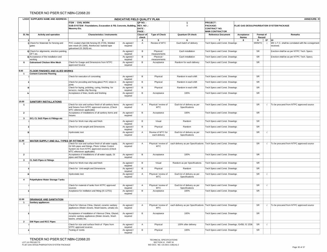
1 PROJECT:0 PACKAGE:
CONTRACT NO.MAIN CONTRACTOR
1 2 4 5 6 7 8 9 D* 10
Activity and operation Type of Check Quantum Of check Reference Document RemarksAcceptance Norms
Format of Record
3
Sl. No Characteristics / instruments Class# of check
SUPPLIERS NAME AND ADDRESS: ANNEXURE- IV
SUB-SYSTEM : Foundations, Excavation & Fill, Concrete, Building, Masonry Etc.
LOGO
QP NO. :
REV. NO .: DATE :PAGE :
INDICATIVE FIELD QUALITY PLANITEM : CIVIL WORK
FLUE GAS DESULPHURISATION SYSTEM PACKAGE
i) Check for Materials for fencing and gates
PVC coated chain link fencing (IS 2720), Welded wire mesh (IS 1566), Reinforced barbed tape galvanised (IS 2629) etc.
As agreed / required
A Review of MTC Each batch of delivery SR/MTC Mfr.’s T.C. shall be correlated with the consignment received.
ii) Check for alignments, erection painting, DFT etc.
As agreed / required
B Physical / measurements
Each installation SR Erection shall be as per NTPC Tech. Specs.
ii) Acceptance of the installation and working
As agreed / required
B Physical / measurements
Each installation SR Erection shall be as per NTPC Tech. Specs.
6 Galvanised Chicken Wire Mesh Check for Guage and Dimensions from NTPC approved Source
As agreed / required
B Acceptance Random for each delivery SR
9.001 Cement Concrete Flooring
i Check for execution of concreting As agreed / required
B Physical Random in each shift SR
ii Check for providing and fixing glass/ PVC strips in joints
As agreed / required
B Physical Random in each shift SR
iii Check for laying, polishing, curing, finishing for terrazzo, marble chip flooring
As agreed / required
B Physical Random in each shift SR
iv Acceptance of lines, levels and finishing As agreed / required
B Acceptance 100% SR
10.00
1 Check for size and surface finish of all sanitory items and fixtures from NTPC approved sources, (Check MTC whereever applicable)
As agreed / required
A Physical / review of MTC
Each lot of delivery as per Specifications
SR To be procured from NTPC approved source
2 Acceptance of installations of all sanitory items and fixtures
As agreed / required
B Acceptance 100% SR
3 SCI, CI, S&S Pipes & Fittings etci Check for Work man ship and finish As agreed /
requiredB Visual Random SR
ii Check for Unit weight and Dimensions As agreed / required
B Physical Random SR
iii Hydrostatic test As agreed / required
A Review of MTC for each delivery
Each lot of delivery as per Specifications
SR
11.001 Check for size and surface finish of all water supply,
GI/ MS pipes and fittings, Photo Voltaic Control System etc from NTPC approved sources (Check MTC whereever applicable)
As agreed / required
A Physical / review of MTC
each delivery as per Specifications SR To be procured from NTPC approved source
2 Acceptance of installations of all water supply, GI pipes and fittings
As agreed / required
B Acceptance 100% SR
3 CI, S&S Pipes & Fittingsi Check for Work man ship and finish As agreed /
requiredB Visual Random as per Specifications SR
ii Check for Unit weight and Dimensions As agreed / required
B Physical Random SR
iii Hydrostatic test As agreed / required
A Physical / review of MTC
Each lot of delivery as per Specifications
SR
4 Polyethylene Water Storage Tanks
i Check for material of tanks from NTPC approved sources
As agreed / required
A Physical / review of MTC
Each lot of delivery as per Specifications
SR
ii Aceptance for instllation and fitting (IS 12701) As agreed / required
B Acceptance 100% SR
12.00
1 Sanitary appliancesi Check for Viterous China, Glazed, ceramic sanitary
appliances (Water closets, Wash basins, urinals) etc.As agreed /
requiredA Physical / review of
MTCeach delivery as per Specifications SR To be procured from NTPC approved source
ii Acceptance of installation of Viterous China, Glazed, ceramic sanitary appliances (Water closets, Wash basins, urinals) etc.
As agreed / required
B Acceptance 100% SR
2 SW Pipes and RCC Pipesi Check for size and surface finish of Pipes from
NTPC approved sourcesAs agreed /
requiredA Physical 100% after delivery SR
ii Testing of Joints As agreed / required
B Physical 100% SR
DRAINAGE AND SANITATION
FLOOR FINISHES AND ALIED WORKS
Tech Specs and Const. Drawings
Tech Specs and Const. Drawings
Tech Specs and Const. Drawings
Tech Specs and Const. Drawings
Tech Specs and Const. Drawings
Tech Specs and Const. Drawings
Tech Specs and Const. Drawings
WATER SUPPLY AND ALL TYPES OF FITTINGS
SANITORY INSTALLATIONS
Tech Specs and Const. Drawings
Tech Specs and Const. Drawings
Tech Specs and Const. Drawings
Tech Specs and Const. Drawings, IS458, IS 1536
Tech Specs and Const. Drawings
Tech Specs and Const. Drawings
Tech Specs and Const. Drawings
Tech Specs and Const. Drawings
Tech Specs and Const. Drawings
Tech Specs and Const. Drawings
Tech Specs and Const. Drawings
Tech Specs and Const. Drawings
Tech Specs and Const. Drawings
Tech Specs and Const. Drawings
Tech Specs and Const. Drawings
Tech Specs and Const. Drawings
Tech Specs and Const. Drawings
LOT-1A PROJECTSFLUE GAS DESULPHURISATION SYSTEM PACKAGE
TECHNICAL SPECIFICATIONSSECTION VI, PART-B
BID DOC. NO.:CS-0011-109(1A)-2Page 30 of 37
TENDER NO PSER:SCT:NBN-C2068:20
TENDER NO PSER:SCT:NBN-C2068:20
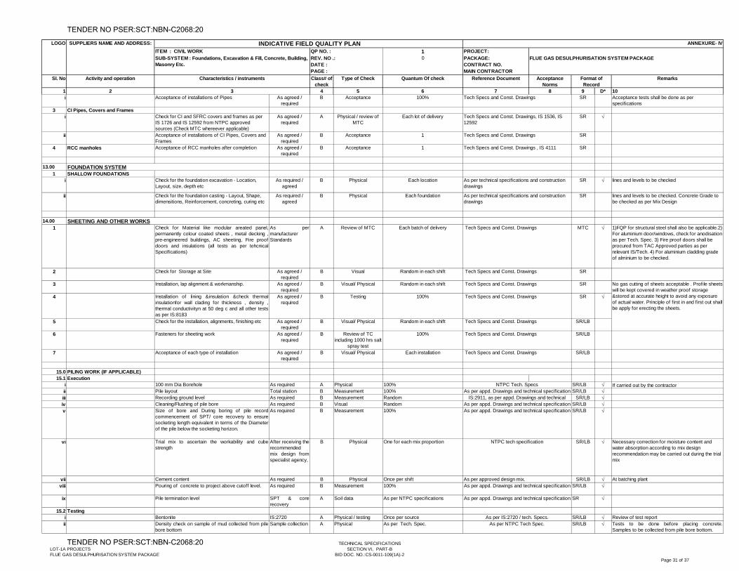
1 PROJECT:0 PACKAGE:
CONTRACT NO.MAIN CONTRACTOR
1 2 4 5 6 7 8 9 D* 10
Activity and operation Type of Check Quantum Of check Reference Document RemarksAcceptance Norms
Format of Record
3
Sl. No Characteristics / instruments Class# of check
SUPPLIERS NAME AND ADDRESS: ANNEXURE- IV
SUB-SYSTEM : Foundations, Excavation & Fill, Concrete, Building, Masonry Etc.
LOGO
QP NO. :
REV. NO .: DATE :PAGE :
INDICATIVE FIELD QUALITY PLANITEM : CIVIL WORK
FLUE GAS DESULPHURISATION SYSTEM PACKAGE
i Acceptance of installations of Pipes As agreed / required
B Acceptance 100% SR Acceptance tests shall be done as per specifications
3 CI Pipes, Covers and Framesi Check for CI and SFRC covers and frames as per
IS 1726 and IS 12592 from NTPC approved sources (Check MTC whereever applicable)
As agreed / required
A Physical / review of MTC
Each lot of delivery SR
ii Acceptance of installations of CI Pipes, Covers and Frames
As agreed / required
B Acceptance 1 SR
4 RCC manholes Acceptance of RCC manholes after completion As agreed / required
B Acceptance 1 SR
13.00
1 SHALLOW FOUNDATIONSi Check for the foundation excavation - Location,
Layout, size, depth etcAs required /
agreedB Physical Each location SR lines and levels to be checked
ii Check for the foundation casting - Layout, Shape, dimensitions, Reinforcement, concreting, curing etc
As required / agreed
B Physical Each foundation SR lines and levels to be checked. Concrete Grade to be checked as per Mix Design
14.00
1 Check for Material like modular areated panel,permanently colour coated sheets , metal decking ,pre-engineered buildings, AC sheeting, Fire proofdoors and insulations (all tests as per tehcnicalSpecifications)
As permanufacturer Standards
A Review of MTC Each batch of delivery MTC 1)FQP for structural steel shall also be applicable.2) For aluminium door/windows, check for anodisation as per Tech. Spec. 3) Fire proof doors shall be procured from TAC Approved parties as per relevant IS/Tech. 4) For aluminium cladding grade of alminium to be checked.
2 Check for Storage at Site As agreed / required
B Visual Random in each shift SR
3 Installation, lap alignment & workmanship. As agreed / required
B Visual/ Physical Random in each shift SR
4 Installation of lining &insulation &check thermalinsulationfor wall clading for thickness , density ,thermal conductivityn at 50 deg c and all other testsas per IS:8183
As agreed / required
B Testing 100% SR
5 Check for the installation, alignments, finishing etc As agreed / required
B Visual/ Physical Random in each shift SR/LB
6 Fasteners for sheeting work As agreed / required
B Review of TC including 1000 hrs salt
spray test
100% SR/LB
7 Acceptance of each type of installation As agreed / required
B Visual/ Physical Each installation SR/LB
15.0 PILING WORK (IF APPLICABLE)15.1 Execution
i 100 mm Dia Borehole As required A Physical 100% SR/LB If carried out by the contractorii Pile layout Total station B Measurement 100% SR/LB iii Recording ground level As required B Measurement Random SR/LB iv Cleaning/Flushing of pile bore As required B Visual Random SR/LB v Size of bore and During boring of pile record
commencement of SPT/ core recovery to ensuresocketing length equivalent in terms of the Diameterof the pile below the socketing horizon.
As required B Measurement 100% SR/LB
vi Trial mix to ascertain the workability and cubestrength
After receiving therecommended mix design fromspecialist agency,
B Physical One for each mix proportion SR/LB Necessary correction for moisture content and water absorption according to mix design recommendation may be carried out during the trial mix
vii Cement content As required B Physical Once per shift SR/LB At batching plantviii Pouring of concrete to project above cutoff level. As required B Measurement 100% SR/LB
ix Pile termination level SPT & corerecovery
A Soil data As per NTPC specifications SR
15.2 Testingi Bentonite IS:2720 A Physical / testing Once per source SR/LB Review of test reportii Density check on sample of mud collected from pile
bore bottomSample collection A Physical As per Tech. Spec. SR/LB Tests to be done before placing concrete.
Samples to be collected from pile bore bottom.
As per IS:2720 / tech. Specs.As per NTPC Tech Spec.
As per appd. Drawings and technical specification
NTPC tech specification
As per approved design mix.As per appd. Drawings and technical specification
As per appd. Drawings and technical specification
NTPC Tech. SpecsAs per appd. Drawings and technical specification
IS:2911, as per appd. Drawings and technical As per appd. Drawings and technical specification
FOUNDATION SYSTEM
Tech Specs and Const. Drawings
Tech Specs and Const. Drawings , IS 4111
Tech Specs and Const. Drawings, IS 1536, IS 12592
Tech Specs and Const. Drawings
No gas cutting of sheets acceptable . Profile sheets will be kept covered in weather proof storage &stored at accurate height to avoid any exposure of actual water. Principle of first in and first out shall be apply for erecting the sheets.
Tech Specs and Const. Drawings
Tech Specs and Const. Drawings
Tech Specs and Const. Drawings
Tech Specs and Const. Drawings
SHEETING AND OTHER WORKS
As per technical specifications and construction drawings
As per technical specifications and construction drawings
Tech Specs and Const. Drawings
Tech Specs and Const. Drawings
Tech Specs and Const. Drawings
LOT-1A PROJECTSFLUE GAS DESULPHURISATION SYSTEM PACKAGE
TECHNICAL SPECIFICATIONSSECTION VI, PART-B
BID DOC. NO.:CS-0011-109(1A)-2Page 31 of 37
TENDER NO PSER:SCT:NBN-C2068:20
TENDER NO PSER:SCT:NBN-C2068:20
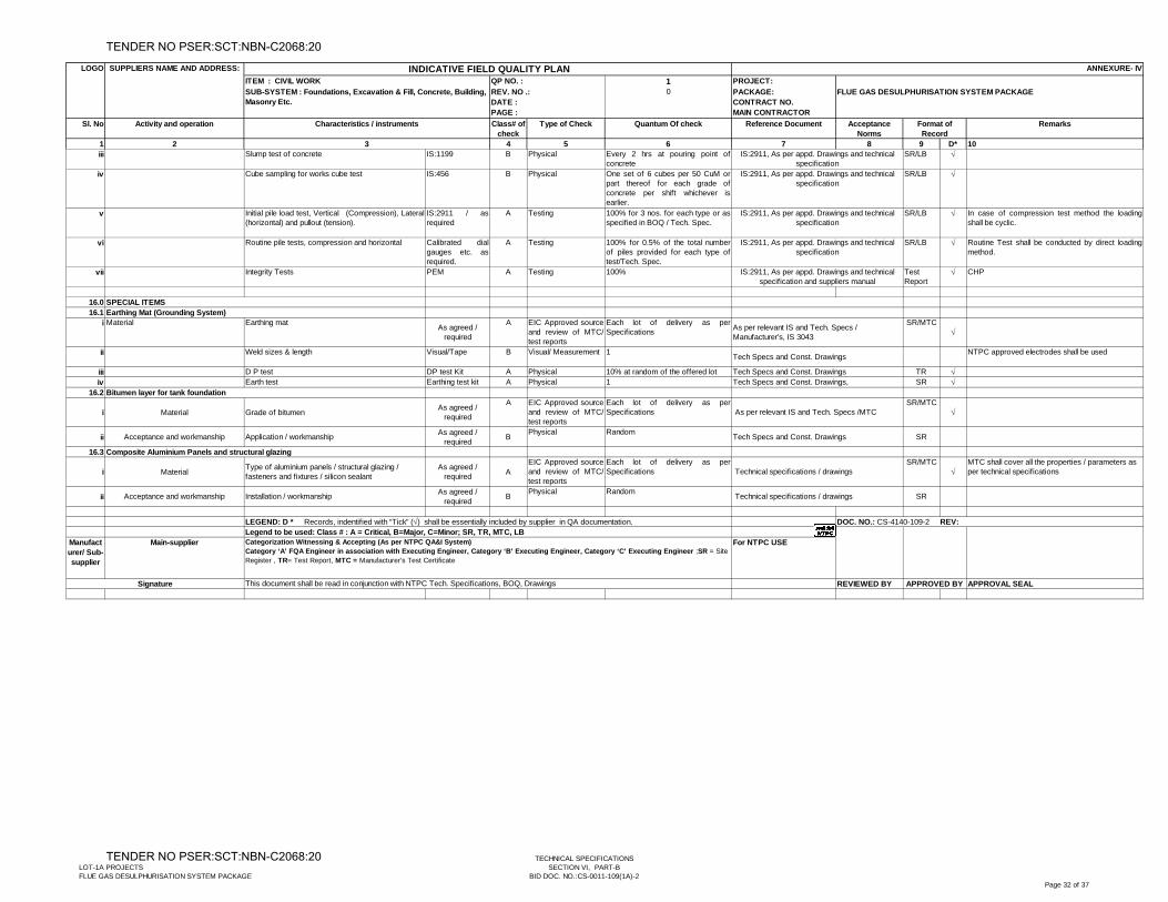
1 PROJECT:0 PACKAGE:
CONTRACT NO.MAIN CONTRACTOR
1 2 4 5 6 7 8 9 D* 10
Activity and operation Type of Check Quantum Of check Reference Document RemarksAcceptance Norms
Format of Record
3
Sl. No Characteristics / instruments Class# of check
SUPPLIERS NAME AND ADDRESS: ANNEXURE- IV
SUB-SYSTEM : Foundations, Excavation & Fill, Concrete, Building, Masonry Etc.
LOGO
QP NO. :
REV. NO .: DATE :PAGE :
INDICATIVE FIELD QUALITY PLANITEM : CIVIL WORK
FLUE GAS DESULPHURISATION SYSTEM PACKAGE
iii Slump test of concrete IS:1199 B Physical Every 2 hrs at pouring point ofconcrete
SR/LB
iv Cube sampling for works cube test IS:456 B Physical One set of 6 cubes per 50 CuM orpart thereof for each grade ofconcrete per shift whichever isearlier.
SR/LB
v Initial pile load test, Vertical (Compression), Lateral(horizontal) and pullout (tension).
IS:2911 / asrequired
A Testing 100% for 3 nos. for each type or asspecified in BOQ / Tech. Spec.
SR/LB In case of compression test method the loadingshall be cyclic.
vi Routine pile tests, compression and horizontal Calibrated dialgauges etc. asrequired.
A Testing 100% for 0.5% of the total numberof piles provided for each type oftest/Tech. Spec.
SR/LB Routine Test shall be conducted by direct loadingmethod.
vii Integrity Tests PEM A Testing 100% Test Report
CHP
16.016.1
i Material Earthing mat As agreed / required
A EIC Approved sourceand review of MTC/test reports
Each lot of delivery as perSpecifications
SR/MTC
ii Weld sizes & length Visual/Tape B Visual/ Measurement 1 NTPC approved electrodes shall be used
iii D P test DP test Kit A Physical 10% at random of the offered lot TR iv Earth test Earthing test kit A Physical 1 SR
16.2
i Material Grade of bitumen As agreed / required
A EIC Approved sourceand review of MTC/test reports
Each lot of delivery as perSpecifications
SR/MTC
ii Acceptance and workmanship Application / workmanship As agreed / required B Physical Random SR
16.3
i Material Type of aluminium panels / structural glazing / fasteners and fixtures / silicon sealant
As agreed / required A
EIC Approved sourceand review of MTC/test reports
Each lot of delivery as perSpecifications
SR/MTC
MTC shall cover all the properties / parameters as per technical specifications
ii Acceptance and workmanship Installation / workmanship As agreed / required B Physical Random SR
Manufacturer/ Sub-supplier
Main-supplier For NTPC USE
REVIEWED BY APPROVAL SEAL
Technical specifications / drawings
Technical specifications / drawings
As per relevant IS and Tech. Specs /MTC
Tech Specs and Const. Drawings
Tech Specs and Const. Drawings
Composite Aluminium Panels and structural glazing
Tech Specs and Const. Drawings Tech Specs and Const. Drawings,
Bitumen layer for tank foundation
IS:2911, As per appd. Drawings and technical specification and suppliers manual
SPECIAL ITEMSEarthing Mat (Grounding System)
As per relevant IS and Tech. Specs / Manufacturer's, IS 3043
IS:2911, As per appd. Drawings and technical specification
IS:2911, As per appd. Drawings and technical specification
IS:2911, As per appd. Drawings and technical specification
IS:2911, As per appd. Drawings and technical specification
LEGEND: D * Records, indentified with “Tick” () shall be essentially included by supplier in QA documentation.
Signature This document shall be read in conjunction with NTPC Tech. Specifications, BOQ, Drawings
Legend to be used: Class # : A = Critical, B=Major, C=Minor; SR, TR, MTC, LB Categorization Witnessing & Accepting (As per NTPC QA&I System)Category ‘A’ FQA Engineer in association with Executing Engineer, Category ‘B’ Executing Engineer, Category ‘C’ Executing Engineer ;SR = Site Register , TR= Test Report, MTC = Manufacturer's Test Certificate
DOC. NO.: CS-4140-109-2 REV:
APPROVED BY
LOT-1A PROJECTSFLUE GAS DESULPHURISATION SYSTEM PACKAGE
TECHNICAL SPECIFICATIONSSECTION VI, PART-B
BID DOC. NO.:CS-0011-109(1A)-2Page 32 of 37
TENDER NO PSER:SCT:NBN-C2068:20
TENDER NO PSER:SCT:NBN-C2068:20
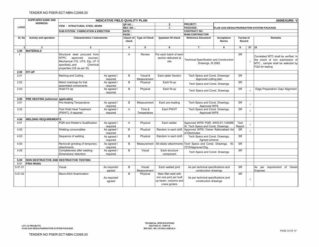
2 PROJECT:
0 PACKAGE:CONTRACT NO.MAIN CONTRACTOR
1 2 4 5 6 7 8 9 D* 10
1.00 MATERIALSi Structural steel procured from
NTPC approved sources-Mechanical (YS, UTS, Elg, UT ifspecified),,and Chemicalproperties (CE as per IS)
A Review For each batch of each section delivered at
site
SR
Correlated MTC shall be verified. Inthe event of non submission ofMTC , sample shall be selected byFQA for testing
2.00 FIT-UP2.01 Marking and Cutting As agreed /
requiredB Visual &
MeasurementEach plate/ Section SR
2.02 Match markings for trial assembled components
As agreed / required
B Physical Each fit-up SR
2.03 Weld Fit Up As agreed / required
B Physical Each fit-up SR
Edge Preparation/ Gap/ Alignment
3.00 PRE HEATING (wherever applicable)3.01 Pre-Heating Temperature As agreed /
requiredB Measurement Each pre-heating SR
3.02 Post Weld Heat Treatment (PWHT), if required
As agreed / required
A Time & Temperature
Each PWHT SR
Sl. No Characteristics / instruments Class# of check
LOGO
SUPPLIERS NAME AND ADDRESS:
ITEM : STRUCTURAL STEEL WORK
DATE :
3
Technical Specification and Construction Drawings, IS 2062
Tech Specs and Const. Drawings, Approved WPS
Tech Specs and Const. Drawings, Approved WPS
INDICATIVE FIELD QUALITY PLAN ANNEXURE- VQP NO. : REV. NO .: FLUE GAS DESULPHURISATION SYSTEM PACKAGE
SUB-SYSTEM : FABRICATION & ERECTIONPAGE :
Activity and operation Type of Check Quantum Of check Reference Document Acceptance Norms
Format of Record
Remarks
Tech Specs and Const. Drawings/ Approved cutting plan
Tech Specs and Const. Drawings
Tech Specs and Const. Drawings
4.00 WELDING REQUIREMENTS4.01 PQR and Welder's Qualification As agreed /
requiredA Physical Each welder Test
Report
4.02 Welding consumables As agreed / required
B Physical Random in each shift SR
4.03 Sequence of welding As agreed / required
B Physical Random in each shift SR
4.04 Removal/ grinding of temporary attachments
As agreed / required
B Measurement All cleats/ attachments SR
4.05 Completeness after welding- Dimensions/ distortion
As agreed / required
B Visual Each structure component
SR
5.00 NON DESTRUCTIVE AND DESTRUCTIVE TESTING 5.01 Fillet Welds
5.01.01 Visual As required/ agreed
B Visual/ Measurement
Each welded joint SR As per requirement of OwnerEngineer
5.01.02 Macro-Etch Examination
As required/ agreed
B Physical Main fillet weld with min one joint per built
up beam, columns and crane girders
SR
Tech Specs and Const. Drawings
Tech Specs and Const. Drawings, Agreed scheme
As per technical specifications and construction drawings
As per technical specifications and construction drawings
Tech Specs and Const. Drawings, IS-7215/Approved Drg.
Approved WPS/ PQR, AWS-D1.1/ASME-IX, Tech Specs and Const. DrawingsApproved WPS/ Owner Rationalized listof Electrodes.
LOT-1A PROJECTSFLUE GAS DESULPHURISATION SYSTEM PACKAGE
TECHNICAL SPECIFICATIONSSECTION VI, PART-B
BID DOC. NO.:CS-0011-109(1A)-2PAGE 33 OF 37
TENDER NO PSER:SCT:NBN-C2068:20
TENDER NO PSER:SCT:NBN-C2068:20
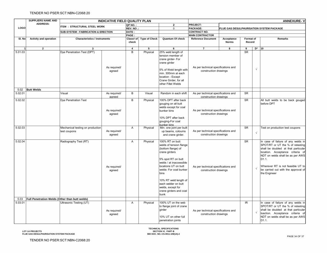
2 PROJECT:
0 PACKAGE:CONTRACT NO.MAIN CONTRACTOR
1 2 4 5 6 7 8 9 D* 10
Sl. No Characteristics / instruments Class# of check
LOGO
SUPPLIERS NAME AND ADDRESS:
ITEM : STRUCTURAL STEEL WORK
DATE :
3
INDICATIVE FIELD QUALITY PLAN ANNEXURE- VQP NO. : REV. NO .: FLUE GAS DESULPHURISATION SYSTEM PACKAGE
SUB-SYSTEM : FABRICATION & ERECTIONPAGE :
Activity and operation Type of Check Quantum Of check Reference Document Acceptance Norms
Format of Record
Remarks
5.01.03 Dye Penetration Test (DPT)
As required/ agreed
B Physical 25% weld length of tension member of crane girder- For crane girder
5% of Weld length with min. 300mm at each location - Except Crane Girder, for all other Fillet Welds
SR
5.02 Butt Welds5.02.01 Visual As required/
agreedB Visual Random in each shift SR
5.02.02 Dye Penetration Test
As required/ agreed
B Physical 100% DPT after back gouging on all butt welds except for coal bunker bins
10% DPT after back
SR All butt welds to be back gougedbefore DPT
As per technical specifications and construction drawings
As per technical specifications and construction drawings
As per technical specifications and construction drawings
10% DPT after back gouging-For coal bunker bins
5.02.03 Mechanical testing on production test coupons As required/
agreed
A Physical Min. one joint per built up beams, coloums and crane girder.
SR
Test on production test coupons
5.02.04 Radiography Test (RT)
As required/ agreed
A Physical 100% RT on butt welds of tension flange (bottom flange) of crane girders
5% spot RT on butt welds / at inaccessible locations UT on butt welds- For coal bunker bins
10% RT weld length of each welder on butt welds, except for crane girders and coal bunk
SR
In case of failure of any welds inSPOT/RT or UT the % of retestingshall be doubled at that particularlocation. Acceptance criteria ofNDT on welds shall be as per AWSD1.1.
Wherever RT is not feasible UT tobe carried out with the approval ofthe Engineer
5.03 Full Penetration Welds (Other than butt welds)5.03.01 Ultrasonic Testing (UT)
As required/ agreed
A Physical 100% UT on the web to flange joint of crane girder
10% UT on other full penetration joints
IR
In case of failure of any welds inSPOT/RT or UT the % of retestingshall be doubled at that particularloaction. Acceptance criteria ofNDT on welds shall be as per AWSD1.1.
As per technical specifications and construction drawings
As per technical specifications and construction drawings
As per technical specifications and construction drawings
LOT-1A PROJECTSFLUE GAS DESULPHURISATION SYSTEM PACKAGE
TECHNICAL SPECIFICATIONSSECTION VI, PART-B
BID DOC. NO.:CS-0011-109(1A)-2PAGE 34 OF 37
TENDER NO PSER:SCT:NBN-C2068:20
TENDER NO PSER:SCT:NBN-C2068:20
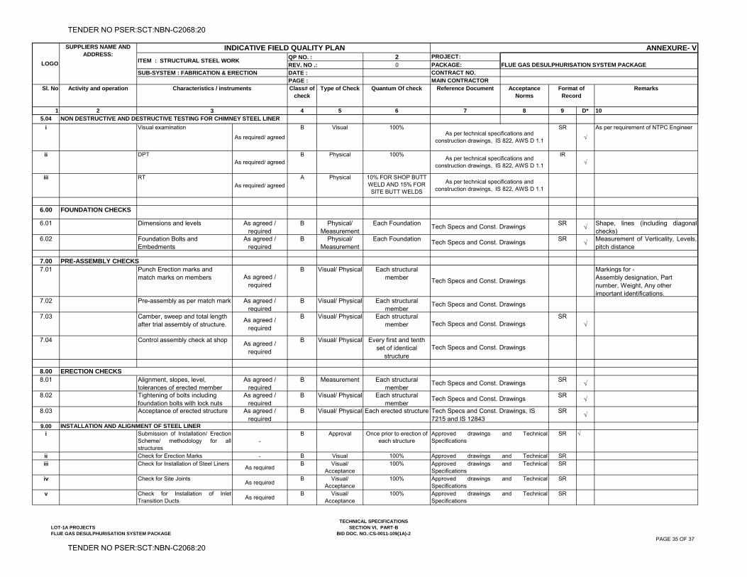
2 PROJECT:
0 PACKAGE:CONTRACT NO.MAIN CONTRACTOR
1 2 4 5 6 7 8 9 D* 10
Sl. No Characteristics / instruments Class# of check
LOGO
SUPPLIERS NAME AND ADDRESS:
ITEM : STRUCTURAL STEEL WORK
DATE :
3
INDICATIVE FIELD QUALITY PLAN ANNEXURE- VQP NO. : REV. NO .: FLUE GAS DESULPHURISATION SYSTEM PACKAGE
SUB-SYSTEM : FABRICATION & ERECTIONPAGE :
Activity and operation Type of Check Quantum Of check Reference Document Acceptance Norms
Format of Record
Remarks
5.04 NON DESTRUCTIVE AND DESTRUCTIVE TESTING FOR CHIMNEY STEEL LINER
i Visual examination
As required/ agreed
B Visual 100% SR
As per requirement of NTPC Engineer
ii DPTAs required/ agreed
B Physical 100% IR
iii RT
As required/ agreed
A Physical 10% FOR SHOP BUTT WELD AND 15% FOR SITE BUTT WELDS
6.00 FOUNDATION CHECKS
6.01 Dimensions and levels As agreed / required
B Physical/ Measurement
Each Foundation SR
Shape, lines (including diagonalchecks)
6.02 Foundation Bolts and Embedments
As agreed / required
B Physical/ Measurement
Each Foundation SR
Measurement of Verticality, Levels,pitch distance
7.00 PRE-ASSEMBLY CHECKS7 01 Punch Erection marks and B Visual/ Physical Each structural Markings for -
Tech Specs and Const. Drawings
Tech Specs and Const. Drawings
As per technical specifications and construction drawings, IS 822, AWS D 1.1
As per technical specifications and construction drawings, IS 822, AWS D 1.1
As per technical specifications and construction drawings, IS 822, AWS D 1.1
7.01 Punch Erection marks and match marks on members As agreed /
required
B Visual/ Physical Each structural member
Markings for -Assembly designation, Part number, Weight, Any other important identifications.
7.02 Pre-assembly as per match mark As agreed / required
B Visual/ Physical Each structural member
7.03 Camber, sweep and total length after trial assembly of structure.
As agreed / required
B Visual/ Physical Each structural member
SR
7.04 Control assembly check at shopAs agreed /
required
B Visual/ Physical Every first and tenth set of identical
structure
8.008.01 Alignment, slopes, level,
tolerances of erected memberAs agreed /
requiredB Measurement Each structural
memberSR
8.02 Tightening of bolts including foundation bolts with lock nuts
As agreed / required
B Visual/ Physical Each structural member
SR
8.03 Acceptance of erected structure As agreed / required
B Visual/ Physical Each erected structure SR
9.00 INSTALLATION AND ALIGNMENT OF STEEL LINERi Submission of Installation/ Erection
Scheme/ methodology for allstructures
-B Approval Once prior to erection of
each structureSR √
ii Check for Erection Marks - B Visual 100% SRiii Check for Installation of Steel Liners
As requiredB Visual/
Acceptance100% SR
iv Check for Site JointsAs required
B Visual/ Acceptance
100% SR
v Check for Installation of InletTransition Ducts
As requiredB Visual/
Acceptance100% SR
Approved drawings and TechnicalSpecifications
Approved drawings and TechnicalApproved drawings and TechnicalSpecifications Approved drawings and TechnicalSpecifications Approved drawings and TechnicalSpecifications
Tech Specs and Const. Drawings
Tech Specs and Const. Drawings
Tech Specs and Const. Drawings, IS 7215 and IS 12843
Tech Specs and Const. Drawings
Tech Specs and Const. Drawings
Tech Specs and Const. Drawings
Tech Specs and Const. Drawings
ERECTION CHECKS
LOT-1A PROJECTSFLUE GAS DESULPHURISATION SYSTEM PACKAGE
TECHNICAL SPECIFICATIONSSECTION VI, PART-B
BID DOC. NO.:CS-0011-109(1A)-2PAGE 35 OF 37
TENDER NO PSER:SCT:NBN-C2068:20
TENDER NO PSER:SCT:NBN-C2068:20
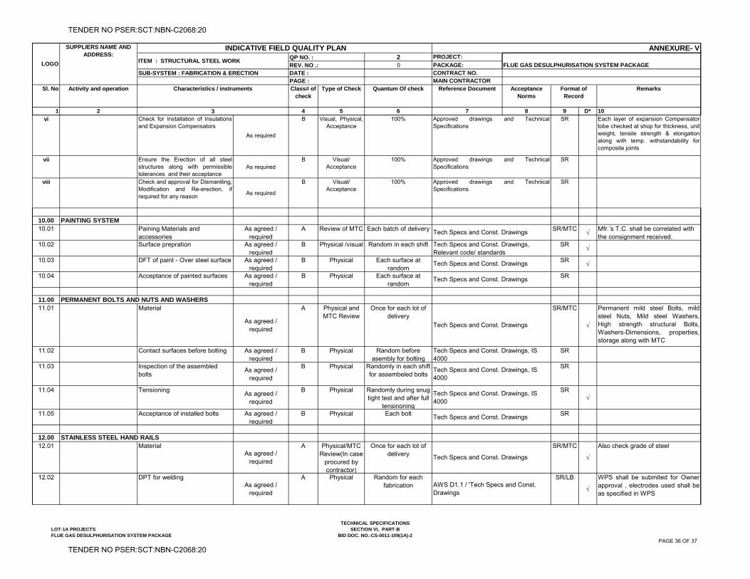
2 PROJECT:
0 PACKAGE:CONTRACT NO.MAIN CONTRACTOR
1 2 4 5 6 7 8 9 D* 10
Sl. No Characteristics / instruments Class# of check
LOGO
SUPPLIERS NAME AND ADDRESS:
ITEM : STRUCTURAL STEEL WORK
DATE :
3
INDICATIVE FIELD QUALITY PLAN ANNEXURE- VQP NO. : REV. NO .: FLUE GAS DESULPHURISATION SYSTEM PACKAGE
SUB-SYSTEM : FABRICATION & ERECTIONPAGE :
Activity and operation Type of Check Quantum Of check Reference Document Acceptance Norms
Format of Record
Remarks
vi Check for Installation of Insulationsand Expansion Compensators
As required
B Visual, Physical, Acceptance
100% SR Each layer of expansion Compensatortobe checked at shop for thickness, unitweight, tensile strength & elongationalong with temp. withstandability forcomposite joints
vii Ensure the Erection of all steelstructures along with permissibletolerances and their acceptance
As requiredB Visual/
Acceptance100% SR
viii Check and approval for Dismantling,Modification and Re-erection, ifrequired for any reason
As required
B Visual/ Acceptance
100% SR
10.00 PAINTING SYSTEM10.01 Paining Materials and
accessoriesAs agreed /
requiredA Review of MTC Each batch of delivery SR/MTC
Mfr.’s T.C. shall be correlated with the consignment received.
10.02 Surface prepration As agreed / required
B Physical /visual Random in each shift SR
10.03 DFT of paint - Over steel surface As agreed / required
B Physical Each surface at random
SR
Approved drawings and TechnicalSpecifications
Approved drawings and TechnicalSpecifications
Approved drawings and TechnicalSpecifications
Tech Specs and Const. Drawings
Tech Specs and Const. Drawings, Relevant code/ standards
Tech Specs and Const. Drawings q
10.04 Acceptance of painted surfaces As agreed / required
B Physical Each surface at random
SR
11.0011.01 Material
As agreed / required
A Physical and MTC Review
Once for each lot of delivery
SR/MTC
Permanent mild steel Bolts, mildsteel Nuts, Mild steel Washers,High strength structural Bolts,Washers-Dimensions, properties,storage along with MTC
11.02 Contact surfaces before bolting As agreed / required
B Physical Random before asembly for bolting
SR
11.03 Inspection of the assembled bolts
As agreed / required
B Physical Randomly in each shift for assembeled bolts
SR
11.04 Tensioning As agreed /
required
B Physical Randomly during snug tight test and after full
tensinoning
SR
11.05 Acceptance of installed bolts As agreed / required
B Physical Each bolt SR
12.0012.01 Material
As agreed / required
A Physical/MTC Review(In case
procured by contractor)
Once for each lot of delivery
SR/MTC
Also check grade of steel
12.02 DPT for weldingAs agreed /
required
A Physical Random for each fabrication
SR/LB
WPS shall be submited for Ownerapproval , electrodes used shall beas specified in WPS
Tech Specs and Const. Drawings
Tech Specs and Const. Drawings, IS 4000
Tech Specs and Const. Drawings
Tech Specs and Const. Drawings, IS 4000
Tech Specs and Const. Drawings, IS 4000
Tech Specs and Const. Drawings
PERMANENT BOLTS AND NUTS AND WASHERS
STAINLESS STEEL HAND RAILS
Tech Specs and Const. Drawings
AWS D1.1 / 'Tech Specs and Const. Drawings
LOT-1A PROJECTSFLUE GAS DESULPHURISATION SYSTEM PACKAGE
TECHNICAL SPECIFICATIONSSECTION VI, PART-B
BID DOC. NO.:CS-0011-109(1A)-2PAGE 36 OF 37
TENDER NO PSER:SCT:NBN-C2068:20
TENDER NO PSER:SCT:NBN-C2068:20
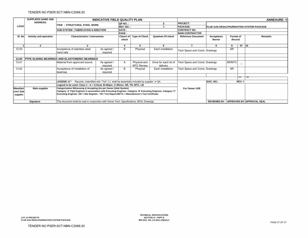
2 PROJECT:
0 PACKAGE:CONTRACT NO.MAIN CONTRACTOR
1 2 4 5 6 7 8 9 D* 10
Sl. No Characteristics / instruments Class# of check
LOGO
SUPPLIERS NAME AND ADDRESS:
ITEM : STRUCTURAL STEEL WORK
DATE :
3
INDICATIVE FIELD QUALITY PLAN ANNEXURE- VQP NO. : REV. NO .: FLUE GAS DESULPHURISATION SYSTEM PACKAGE
SUB-SYSTEM : FABRICATION & ERECTIONPAGE :
Activity and operation Type of Check Quantum Of check Reference Document Acceptance Norms
Format of Record
Remarks
12.03 Acceptance of stainless steel hand rails
As agreed / required
B Physical Each installation SR
13.00 PTFE SLIDING BEARINGS AND ELASTOMERIC BEARINGS13.01 Material from approved source As agreed /
requiredA Physical and
MTC ReviewOnce for each lot of
deliverySR/MTC
13.02 Acceptance of installation of bearings
As agreed / required
B Physical Each installation SR
Manufacturer/ Sub-supplier
Main-supplier For Owner USE
REVIEWED BY APPROVAL SEALAPPROVED BY
Categorization Witnessing & Accepting (As per Owner QA&I System)Category ‘A’ FQA Engineer in association with Executing Engineer, Category ‘B’ Executing Engineer, Category ‘C’ Executing Engineer ;SR = Site Register , TR= Test Report,MfrTC = Manufacturer's Test Certificate
LEGEND: D * Records, indentified with “Tick” () shall be essentially included by supplier in QA DOC. NO.: REV: 0
Signature This document shall be read in conjunction with Owner Tech. Specifications, BOQ, Drawings
Legend to be used: Class # : A = Critical, B=Major, C=Minor; SR, TR, MTC, LB
Tech Specs and Const. Drawings
Tech Specs and Const. Drawings
Tech Specs and Const. Drawings
LOT-1A PROJECTSFLUE GAS DESULPHURISATION SYSTEM PACKAGE
TECHNICAL SPECIFICATIONSSECTION VI, PART-B
BID DOC. NO.:CS-0011-109(1A)-2PAGE 37 OF 37
TENDER NO PSER:SCT:NBN-C2068:20
TENDER NO PSER:SCT:NBN-C2068:20

TITLE: - 3X660 MW NPGCL NABINAGAR FGD SPECIFICATIONS FOR RCC CHIMNEY
SPECIFICATION NO. PE-TS-457-620-C002
VOLUME : IIB
SECTION : C
REV.NO. 00
SHEET
3X660 MW NPGCL NABINAGAR STPP
FGD SYSTEM PACKAGE
VOLUME II-B
CIVIL, STRUCTURAL AND ARCHITECTURAL WORKS
SECTION – C
SPECIFIC TECHNICAL REQUIREMENTS
(RCC CHIMNEY)
SPECIFICATION NO. PE-TS-457-620-C002 REV-00
Bharat Heavy Electricals Limited Project Engineering Management
Power Sector, PPEI BUILDING, Plot No-25 SECTOR 16A, NOIDA-201301, UP
TENDER NO PSER:SCT:NBN-C2068:20
TENDER NO PSER:SCT:NBN-C2068:20

TITLE: - 3X660 MW NPGCL NABINAGAR FGD SPECIFICATIONS FOR RCC CHIMNEY
SPECIFICATION NO. PE-TS-457-620-C002
VOLUME : IIB
SECTION : C
REV.NO. 00
SHEET
PREAMBLE
Standard technical details as indicated in specification shall be agreed upon between
BHEL & Bidder.
Technical requirements are stipulated in this Volume which comprises of
Section C : This section indicates the technical requirements
specific to the contract not covered in Section D
Section D : This section comprises of technical specification(s)
The requirements mentioned in the Section C shall prevail and govern in case of
conflict between the same and the corresponding requirements mentioned in the
Section D in the specification. In case on any conflict between technical specification
and BOQ, BOQ shall prevail.
TENDER NO PSER:SCT:NBN-C2068:20
TENDER NO PSER:SCT:NBN-C2068:20
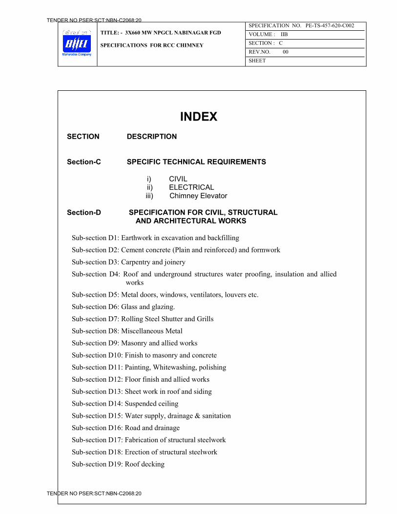
TITLE: - 3X660 MW NPGCL NABINAGAR FGD SPECIFICATIONS FOR RCC CHIMNEY
SPECIFICATION NO. PE-TS-457-620-C002
VOLUME : IIB
SECTION : C
REV.NO. 00
SHEET
INDEX SECTION DESCRIPTION
3 Section-C SPECIFIC TECHNICAL REQUIREMENTS 12
i) CIVIL ii) ELECTRICAL
iii) Chimney Elevator
Section-D SPECIFICATION FOR CIVIL, STRUCTURAL 22 AND ARCHITECTURAL WORKS
Sub-section D1: Earthwork in excavation and backfilling
Sub-section D2: Cement concrete (Plain and reinforced) and formwork
Sub-section D3: Carpentry and joinery
Sub-section D4: Roof and underground structures water proofing, insulation and allied works
Sub-section D5: Metal doors, windows, ventilators, louvers etc.
Sub-section D6: Glass and glazing.
Sub-section D7: Rolling Steel Shutter and Grills
Sub-section D8: Miscellaneous Metal
Sub-section D9: Masonry and allied works
Sub-section D10: Finish to masonry and concrete
Sub-section D11: Painting, Whitewashing, polishing
Sub-section D12: Floor finish and allied works
Sub-section D13: Sheet work in roof and siding
Sub-section D14: Suspended ceiling
Sub-section D15: Water supply, drainage & sanitation
Sub-section D16: Road and drainage
Sub-section D17: Fabrication of structural steelwork
Sub-section D18: Erection of structural steelwork
Sub-section D19: Roof decking
TENDER NO PSER:SCT:NBN-C2068:20
TENDER NO PSER:SCT:NBN-C2068:20
TITLE: - 3X660 MW NPGCL NABINAGAR FGD SPECIFICATIONS FOR RCC CHIMNEY
SPECIFICATION NO. PE-TS-457-620-C002
VOLUME : IIB
SECTION : C
REV.NO. 00
SHEET
Sub-section D20: False flooring
Sub-section D21: Bored cast in situ RCC pile
Sub-section D22: Levelling and grading
Sub-section D23: Anti termite
Sub-section D24: Quality Assurance & Inspection
Sub-section D25: RCC stack
Sub-section D26: Borosilicate glass block lining system
Sub-section D27: Specification for electrical works.
Sub-section D28: specification for chimney elevator
TENDER NO PSER:SCT:NBN-C2068:20
TENDER NO PSER:SCT:NBN-C2068:20
TITLE: - 3X660 MW NPGCL NABINAGAR FGD SPECIFICATIONS FOR RCC CHIMNEY
SPECIFICATION NO. PE-TS-457-620-C002
VOLUME : IIB
SECTION : C
REV.NO. 00
SHEET
SECTION-C
SPECIFIC TECHNICAL REQUIREMENTS FOR CIVIL WORKS
SPECIFICATION NO. PE-TS-457-620-C002
TENDER NO PSER:SCT:NBN-C2068:20
TENDER NO PSER:SCT:NBN-C2068:20
TECHNICAL SPECIFICATION FOR CHIMNEY(ELECTRICAL ROURKELA PP-II EXPANSION
(1x250 MW) SECTION-C
VOLUME – II
SECTION-C
SPECIFIC TECHNICAL REQUIREMENTS FOR ELECTRICAL WORKS
Note : In case of any conflict between section-C & section-D of electrical portion, section-C of electrical portion shall prevail.
1 OF 24
TENDER NO PSER:SCT:NBN-C2068:20
TENDER NO PSER:SCT:NBN-C2068:20
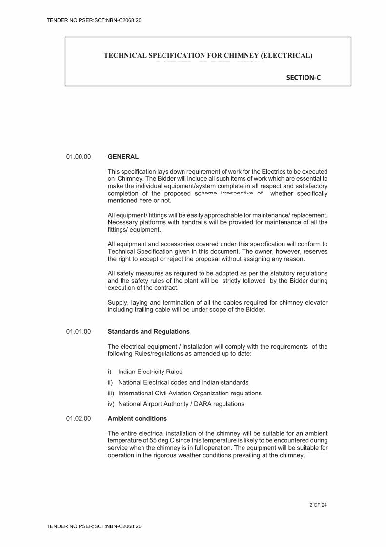
NTPC SAIL POWER COMPANY (P) LIMITED ROURKELA POWER PROJECT
(PP – III : 1X250 MW)
TECHNICAL SPECIFICATION FOREPC PACKAGE
Rourkela Power Project (PP – III : 1 x 250 MW) EPC Package
Technical Specification Section – VI, Vol – II-E Bid Doc. No. : CC&M-C-347-211
Chapter – 20.0 Chimney Electrics
Page 1 of 20
CHAPTER-20.0
TECHNICAL SPECIFICATION FOR CHIMNEY ELECTRICS
01.00.00 GENERAL
This specification lays down requirement of work for the Electrics to be executed on Chimney. The Bidder will include all such items of work which are essential to make the individual equipment/system complete in all respect and satisfactory completion of the proposed scheme irrespective of whether specifically mentioned here or not.
All equipment/ fittings will be easily approachable for maintenance/ replacement. Necessary platforms with handrails will be provided for maintenance of all the fittings/ equipment.
All equipment and accessories covered under this specification will conform to Technical Specification given in this document. The owner, however, reserves the right to accept or reject the proposal without assigning any reason.
All safety measures as required to be adopted as per the statutory regulations and the safety rules of the plant will be strictly followed by the Bidder during execution of the contract.
Supply, laying and termination of all the cables required for chimney elevator including trailing cable will be under scope of the Bidder.
01.01.00 Standards and Regulations
The electrical equipment / installation will comply with the requirements of the following Rules/regulations as amended up to date:
i) Indian Electricity Rules
ii) National Electrical codes and Indian standards
iii) International Civil Aviation Organization regulations
iv) National Airport Authority / DARA regulations
01.02.00 Ambient conditions
The entire electrical installation of the chimney will be suitable for an ambient temperature of 55 deg C since this temperature is likely to be encountered during service when the chimney is in full operation. The equipment will be suitable for operation in the rigorous weather conditions prevailing at the chimney. Special
TECHNICAL SPECIFICATION FOR CHIMNEY (ELECTRICAL)
ROURKELA PP-II EXPANSION (1x250 MW)
2 OF 24
SECTION-C
TENDER NO PSER:SCT:NBN-C2068:20
TENDER NO PSER:SCT:NBN-C2068:20
NTPC SAIL POWER COMPANY (P) LIMITED ROURKELA POWER PROJECT
(PP – III : 1X250 MW)
TECHNICAL SPECIFICATION FOREPC PACKAGE
Rourkela Power Project (PP – III : 1 x 250 MW) EPC Package
Technical Specification Section – VI, Vol – II-E Bid Doc. No. : CC&M-C-347-211
Chapter – 20.0 Chimney Electrics
Page 2 of 20
attention may be given to the fact that the project site is very near the sea shore.
02.00.00 SCOPE AND BRIEF DESCRIPTION OF WORK
The scope of work includes design, detailed engineering, procurement of items, shop testing, packaging, delivery to site, unloading at site, storage, handling, comprehensive insurance, erection, testing and commissioning of all necessary items for the chimney as indicated below.
1) Lightning protection system consisting of air termination, down rods/ GI strips, test points etc.
2) Main Power Distribution boards(PDB), Emergency distribution board, Elevator board, Lighting Panels, Power Panels etc. for power supply to various electrical items
3) Earthing system for equipment and structures of the chimney.
4) Aviation warning system.
5) Illumination of various platforms & landings of RCC Biflue chimney
6) Welding sockets, Power receptacles, switches and other hardware
7) Power and control Cables
8) Cabling system including trays, supporting structure, conduits etc.
9) Electrics for the freight cum passenger elevator and roll up door.
10) Accessories like clamps, nuts, bolts etc.
11) Under ground earthing for the earthing system as well as lightning protection
The Bidder will provide auto change over facility in the DB
The successful Bidder will have to carry out the detailed engineering for the entire work.For installation of fixtures etc., the Bidder will have to arrange tools, tackles, welding sets, pipe bending machine, cable crimping tools, IR megger, earth megger, tester etc.
The Bidder will be responsible for supply and fixing of all accessories required for installation of lightning protection equipment, aviation lighting system equipment, light fittings, distribution panel, electrics for the freight cum passenger elevator, elevator control panel, etc. at required places even though every individual item necessarily may not have been detailed out explicitly in the specification.
The main items in the scope will be as follows:� AC distribution board
TECHNICAL SPECIFICATION FOR CHIMNEY (ELECTRICAL)
ROURKELA PP-II EXPANSION (1x250 MW)
3 OF 24
SECTION-C
12) Communication system
• Telephone handset
TENDER NO PSER:SCT:NBN-C2068:20
TENDER NO PSER:SCT:NBN-C2068:20
NTPC SAIL POWER COMPANY (P) LIMITED ROURKELA POWER PROJECT
(PP – III : 1X250 MW)
TECHNICAL SPECIFICATION FOREPC PACKAGE
Rourkela Power Project (PP – III : 1 x 250 MW) EPC Package
Technical Specification Section – VI, Vol – II-E Bid Doc. No. : CC&M-C-347-211
Chapter – 20.0 Chimney Electrics
Page 3 of 20
� Power & control Cables including incoming cables to the board � Cable accessories like glands, lugs, clamps, brackets, JBs, ferrules and
other fixing accessories � Conduits of required sizes for protection of cables � Air termination rods � GI strips for lightning protection. � GI strips for earthing of equipment & structures � Earthing electrodes & Treated earth pits. � Aviation warning lights � 24 Hrs timer, Photoelectric light detector etc. for controlling the lights � Outdoor type fittings and lamps � Indoor type fittings for illumination of premises inside � 20A and 63 A Power receptacles, 24V sockets etc. � O & M spares and commissioning spares � Special tools and tackles for the equipment/system supplied � Complete electrics for the freight cum passenger elevator and for
electrically operated door. � Danger boards, safety items etc. � Various fixing accessories such as nut bolts, check nuts, bushes, clips,
nails, clamps, screws, hoppers, conduits, etc.
For lightning protection, Bidder scope of work will include supply, installation testing and commissioning of the complete system consisting of air terminations, down rods, earth, testing points, earthing pits, etc.
Bidder will furnish a detailed drawing of the lightning protection and earthing system and execution of work will be commenced only after obtaining approval to this from the owner.
For aviation warning system Bidder scope of work will include supply and installation & commissioning of the complete aviation warning system including supply & laying of cables, termination etc.
Aviation lighting system will be test operated by the Bidder for not less than 60 days. Equipment and work, which fails during the test period, will be repaired or replaced at the option of the owner.
The scope will also include the civil works associated with aviation lighting.
The Bidder will furnish a detailed drawing of aviation warning system and associated power distribution scheme and execution of work will be commenced only after obtaining approval to this from the owner.
For general illumination of chimney , scope of work includes installation of complete illumination system including distribution board, illumination fittings,
TECHNICAL SPECIFICATION FOR CHIMNEY (ELECTRICAL)
ROURKELA PP-II EXPANSION (1x250 MW) 4
4 OF 24
SECTION-C
TENDER NO PSER:SCT:NBN-C2068:20
TENDER NO PSER:SCT:NBN-C2068:20
NTPC SAIL POWER COMPANY (P) LIMITED ROURKELA POWER PROJECT
(PP – III : 1X250 MW)
TECHNICAL SPECIFICATION FOREPC PACKAGE
Rourkela Power Project (PP – III : 1 x 250 MW) EPC Package
Technical Specification Section – VI, Vol – II-E Bid Doc. No. : CC&M-C-347-211
Chapter – 20.0 Chimney Electrics
Page 4 of 20
cabling, power receptacles, maintenance sockets, earthing etc.
The Bidder will also furnish a detailed drawing of illumination system and associated power distribution network.
02.01.00 Power Supply System The details of power supply system are outlined below.
a) 415 Volt system (Normal)
i) System voltage 415 V +/-10%, three phase, 4 wire, neutral solidly earthed
ii) System frequency 50 Hz +/- 5%
iii) Combined Voltage and frequency variation
10%
iv) Fault level 50 KA
b) 415 Volt system (Emergency)
i) System voltage 415 V +/-10%, three phase, 3 wire syatem
ii) System frequency 50 Hz +/- 5%
iii) Combined Voltage and frequency variation
10%
iv) Fault level 50 KA
c) In case any power supply other than 415 V, 3 phase indicated above is required, same will be generated by the Bidder through suitable step down transformer, rectifier etc.
03.00.00 TECHNICAL SPECIFICATION/DETAILS OF EQUIPMENT AND INSTALLATION
03.01.00 LIGHTNING PROTECTION
The chimney will be protected against damage by the lightning protection system complying with IS-2309 (1989), and will be subject to approval of the owner.
TECHNICAL SPECIFICATION FOR CHIMNEY (ELECTRICAL)
ROURKELA PP-II EXPANSION (1x250 MW) 5
5 OF 24
SECTION-C
IEC-62305 & latest IS standard,and will be subject to approval of the owner.
TENDER NO PSER:SCT:NBN-C2068:20
TENDER NO PSER:SCT:NBN-C2068:20
NTPC SAIL POWER COMPANY (P) LIMITED ROURKELA POWER PROJECT
(PP – III : 1X250 MW)
TECHNICAL SPECIFICATION FOREPC PACKAGE
Rourkela Power Project (PP – III : 1 x 250 MW) EPC Package
Technical Specification Section – VI, Vol – II-E Bid Doc. No. : CC&M-C-347-211
Chapter – 20.0 Chimney Electrics
Page 5 of 20
Around the top of each of the flue ducts, a coronal band of lead coated copper strip of size 50x6 mm or equivalent approved section will be provided. The circumferential conductor will be connected to the down conductors of minimum 50x6 mm size galvanized steel strips. The other end of each down conductor will be connected to an earth termination. Vertical down conductors will be spaced as per IS:2309 (1989).
Vertical air termination will be of 3 m height and will be projecting 0.75 m above the highest part of the chimney. Lightning protection system shall comprise minimum 3 veritcal air teminations for each flue liner.
The vertical air terminations will be made of minimum 20 mm dia solid copper rod &top with lead coating, will have spikes on solid sphere on top. The termination rod will be secured to the top of the chimney with adequate number of fasteners to withstand high wind pressure at the height involved.
The vertical air terminations will be electrically connected together with the lead coated copper strip coronal band which will be fixed 600 mm below top of the chimney . The coronal band will be clamped along the surface at intervals of 600 mm by 25x6 mm GI clamps. The connection between copper and GI will be done by brazing.
The down conductor will be clamped along the surface at intervals of 1500 mm by GI clamps. The connection between the GI Flats and GI clamps will be done by arc welding.
The down conductors will be minimum FOUR numbers per flue ducts and will be evenly spaced along the periphery. These materials provided at top 12 m shall
At each chimney platform level, a circulating band will be provided which will be made of 50 x 6 mm GI flat and electrically connected to each down conductor.
Earthing system for lightning protection will be electrically separate from the earthing of ladders, platforms, equipment and structures. Separate earthing systems will be provided accordingly.
Earth termination will consist of earth electrodes made of 3 Metre long MS rods driven into ground. The earth electrode will conform to IS: 3043. Test joint will be provided at a height of 2.7 m from grade level for each down conductor before termination on earth electrode. The test point will be covered in 150 X 150 X 100 mm GI box. The testing point of the down conductors will be convenient for testing but inaccessible for interference. Testing point will be of phosphor-bronze gunmetal or copper. The down conductors will come via these test points to the earth pits. Sufficient earth electrodes will be provided to limit the earth resistance as per standards. No sharp bends will be formed in the down conductors and will be kept as straight as possible.
TECHNICAL SPECIFICATION FOR CHIMNEY (ELECTRICAL)
ROURKELA PP-II EXPANSION (1x250 MW) 6
6 OF 24
SECTION-C
IEC-62305 & latest IS standard.
TENDER NO PSER:SCT:NBN-C2068:20
TENDER NO PSER:SCT:NBN-C2068:20
NTPC SAIL POWER COMPANY (P) LIMITED ROURKELA POWER PROJECT
(PP – III : 1X250 MW)
TECHNICAL SPECIFICATION FOREPC PACKAGE
Rourkela Power Project (PP – III : 1 x 250 MW) EPC Package
Technical Specification Section – VI, Vol – II-E Bid Doc. No. : CC&M-C-347-211
Chapter – 20.0 Chimney Electrics
Page 6 of 20
A suitable chamber having a water tight manhole cover of approved pattern and size will be constructed around each earth termination and will also house the joint between the earth termination and the down conductor.
Earth pit will consist of 40 mm dia 3000 mm long MS rod electrode in accordance with IS: 3043. These earth pits will be interconnected by providing a peripheral band of 40 mm dia MS rods to be laid at depth of minimum 600 mm below grade level. At least two pig tails each of 2 nos. 40 mm MS rod will be brought out one meter above ground to interconnect the Earth grid of RCC Biflue chimney with the main grounding grid. Interconnection will be done by the Bidder.
All connections clamps, anchors, etc. of the lightning protection system will be made of stainless steel to avoid corrosion. All joints will be clamped or bolted by high-pressure contact or by phosphorus copper brazing of the metal to form a connection of adequate current carrying capacity and mechanical strength. Soldered connections will not be permitted.
All reinforcing bars will be properly bonded and connected to down conductors if the latter is taken along the wall of the structure.
The ohmic resistance of the lightning conductor system when isolated from earth electrode will be less than 1.0 ohm. The earth electrode resistance will also be less than 1 ohm when measured after disconnecting from plant grid.
The minimum number of earth pits will be eight, however, to achieve earth resistance value as described above, more pits will be provided.
The exposed conductors, connections, clamps, base plates, etc., will be protected by hot dip galvanizing. All site-welded joints in down conductors will be coated with anticorrosive paints over a coat of primer.
All metallic structures like ladders, handrails, light fixtures along with reinforcement bars will be bonded to the down conductors/circumferential conductor by GI strip of size not less than 50x6 mm either by welding or by bolting.
The down conductors on the base diagonal columns will be protected from mechanical damage for a height of 2.5 metres from the grade by taking them through cement pipe fixed on the face of the column, the pipe in turn filled with concrete of 1:5:10 nominal mix.
During the construction of the chimney, temporary lightning protection will be maintained by connecting the reinforcement bars to two earth electrodes by means of two 50x6 mm GI conductors. Temporary protection will be provided even after the completion of the tower till such time that the permanent air
TECHNICAL SPECIFICATION FOR CHIMNEY (ELECTRICAL)
ROURKELA PP-II EXPANSION (1x250 MW)
7 OF 24
SECTION-C
TENDER NO PSER:SCT:NBN-C2068:20
TENDER NO PSER:SCT:NBN-C2068:20
NTPC SAIL POWER COMPANY (P) LIMITED ROURKELA POWER PROJECT
(PP – III : 1X250 MW)
TECHNICAL SPECIFICATION FOREPC PACKAGE
Rourkela Power Project (PP – III : 1 x 250 MW) EPC Package
Technical Specification Section – VI, Vol – II-E Bid Doc. No. : CC&M-C-347-211
Chapter – 20.0 Chimney Electrics
Page 7 of 20
termination rods are installed. Interconnection of earth pits will be done by bolting so that earth resistance of individual earth pits can be measured.
Separate earthing systems will be considered for lightning protection and for equipment/structure earthing.
03.02.00 AVIATION WARNING SYSTEM
The aviation warning system lights will meet the regulations of ICAO, National Airport Authority.
The aviation warning lights will be clustered type LED.
The aviation warning system will be of high intensity type.
Aviation warning light will have Integral flasher & intensity control andlatched lid for easy flashtube replacement. It will have three auto switched intensities - day / twilight and night.
The aviation warning lights will be controlled through photo electric control unit. Photo electric controller will be housed in a rugged, weather tight, IP 65, enclosure. LEDs will be provided to indicate the operation status of the unit. A bypass manual switch will be provided to bypass the photoelectric device, whenever required. Aviation warning light will have a day time effective intensity of minimum 200000 cd. The intensity of light will reduce automatically to 20000 cd +/-25% at twilight and 4000 +/-25% during night time through the use of photo cell.
The system will also provide automatic sensing and display of system status and aviation lamp failure detection.
The system will be suitable for operation on 240V +/- 10%, single phase, 50 Hz, AC supply.
Four nos. of aviation warning lights will be installed at each elevation. The distance between lighting elevations will not be more than 105 metres and lowest lighting elevatiot be less than 70 metres.
The light unit will have adjustable bracket with level indicator to ensure accurate vertical placement of the light flash.
The arrangement of lights will be made such that the object is indicated from every angle in azimuth.
For each row of High Intensity Obstacle Lights, walkway platforms ladders, hand-
TECHNICAL SPECIFICATION FOR CHIMNEY (ELECTRICAL)
ROURKELA PP-II EXPANSION (1x250 MW) 8
8 OF 24
SECTION-C
Medium intensity type.
Aviation Warning Lights (AWL) shall be mounted on door panel of required size (open able from interior of chimney shell) fixed to openings in the chimney shell at 3 levels. There will be four light units per level.. Suitable provision for approach to the AWL shall be provided at the platform level. AWL shall be located at about 1-1.5 metre above the top of platform to enable easy handling for maintenance. The size of roll-up door shall be determined based on minimum requirement for ventilation and transportation & erection of flue segments.
Emergency supply shall feed aviation obstruction lighting.
High intensity type.
TENDER NO PSER:SCT:NBN-C2068:20
TENDER NO PSER:SCT:NBN-C2068:20
NTPC SAIL POWER COMPANY (P) LIMITED ROURKELA POWER PROJECT
(PP – III : 1X250 MW)
TECHNICAL SPECIFICATION FOREPC PACKAGE
Rourkela Power Project (PP – III : 1 x 250 MW) EPC Package
Technical Specification Section – VI, Vol – II-E Bid Doc. No. : CC&M-C-347-211
Chapter – 20.0 Chimney Electrics
Page 8 of 20
railing all round the chimney will be provided, to attend to maintenance work of the light fittings. Landings of staircases will be suitably adjusted to facilitate maintenance /replacement of light fittings. Entire electrical system will have easy access for maintenance.
Aviation lighting fixtures securely mounted at the top of the flue ducts and the chimney will be within the zone of protection of vertical air terminations.
The body of the aviation light will be made of corrosion resistant aluminium casting finished in stove-enameled aviation yellow. The fittings will be complete with double compression type cable glands.
Aviation lights supports etc. will be fitted to the chimney by GI nuts on to GI inserts projecting from concrete surface. All bolts clamps etc used will be hot dip galvanized.
All the aviation light fixtures will be weatherproof and outdoor type suitable for highly humid and flue laden atmosphere.
The aviation light circuits will be distributed among R,Y and B phases of 3 phase, 4 wire supply.
1100 V grade, 4 core, 16 sq mm stranded copper conductor, PVC insulated, heat resistant, steel wire armoured cable conforming to IS-1554 (Part-I) will be used for wiring the aviation warning system. The cable will be clamped by the side of the ladder at 750 mm centers by means of GI clamps.
Weather proof terminal boxes with cable glands made of brass, tin plate will be provided at the location of each of the aviation warning lights for termination of cables.
Temporary warning lights will be installed during construction suitably located above the top most point of obstruction and will be shifted up as the construction progresses. These lights shall be installed free of cost to BHEL.
Temporary warning lights will be four fixtures each with not less than 10 candelas of red light. As construction progresses, each completed level will be provided with temporary aviation warning lights. Temporary obstruction lights will have four fixtures located in a horizontal plane on the chimney structure to ensure unobstructed visibility of at least one obstruction light from aircraft at any normal angle of approach. Power for operation of the temporary lights will be obtained from the construction Power system. Supply circuits for these lights will be furnished, installed and maintained by the Bidder. These lights will be operated right from sunset to sunrise on each day of the contract period until the normal aviation warning system is commissioned and put to operation.
TECHNICAL SPECIFICATION FOR CHIMNEY (ELECTRICAL)
ROURKELA PP-II EXPANSION (1x250 MW)
09 OF 24
SECTION-C
cable as per Electrical BOQ
TENDER NO PSER:SCT:NBN-C2068:20
TENDER NO PSER:SCT:NBN-C2068:20
NTPC SAIL POWER COMPANY (P) LIMITED ROURKELA POWER PROJECT
(PP – III : 1X250 MW)
TECHNICAL SPECIFICATION FOREPC PACKAGE
Rourkela Power Project (PP – III : 1 x 250 MW) EPC Package
Technical Specification Section – VI, Vol – II-E Bid Doc. No. : CC&M-C-347-211
Chapter – 20.0 Chimney Electrics
Page 9 of 20
The Bidder will provide sufficient hand railing, ladders, and platforms to attend any maintenance work.
03.03.00 POWER DISTRIBUTION BOARD (PDB) / ACDB Distribution board will be of metal enclosed , single front, Indoor, floor mounted, free standing , fixed type conforming to IS: 13947 Part-1. The elevator board / power panels/Lighting panel will be of floor/wall mounted type. The equipment will be fully assembled and wired, complete with base frame, anchoring arrangement, gland plates, internal wiring, terminal blocks etc. Operating height of switches will be limited to 1800 mm.
Boards will have IP 52 enclosure.
PDB/AC Distribution Board (DB) will house switch fuse modules / MCCB modules only.
Will have base channel of size ISMC 75.
Will have isolated busbar chamber for main busbar at the top, running through out the length of the board. Chamber will have removable cover.
Cable alley will have sufficient space for aluminium power cables and bottom cable chamber will be left free completely isolated from the vertical busbar.
Busbars will have same cross section through out the length. Rating of the neutral busbar will be 50% of the main busbar. Earth bus bar will run in bottom chamber throughout the length of the panel.
Bus bars and jumper connections will be of high conductivity aluminium alloy/copper.
Temperature rise of busbar and contacts when carrying rated current will not exceed 45 deg C with silver plated joints and 35 deg C with other type of joints over an ambient of 55 deg C.. All busbars will be adequately supported by non-hygroscopic, non-combustible track resistant and high strength sheet moulded compound or polyester fibre glass moulded insulators.
20% of the total feeders will be kept as spare.
The front of the feeder compartments will have hinged door with locking facility.
TECHNICAL SPECIFICATION FOR CHIMNEY (ELECTRICAL)
ROURKELA PP-II EXPANSION (1x250 MW)
10 OF 24
SECTION-C
SFU
TENDER NO PSER:SCT:NBN-C2068:20
TENDER NO PSER:SCT:NBN-C2068:20
NTPC SAIL POWER COMPANY (P) LIMITED ROURKELA POWER PROJECT
(PP – III : 1X250 MW)
TECHNICAL SPECIFICATION FOREPC PACKAGE
Rourkela Power Project (PP – III : 1 x 250 MW) EPC Package
Technical Specification Section – VI, Vol – II-E Bid Doc. No. : CC&M-C-347-211
Chapter – 20.0 Chimney Electrics
Page 10 of 20
The incoming switch fuse unit of the Emergency board will be changeover switch type and will have provision for two incoming supplies. Auto changeover scheme shall be provided to enable changeover to healthy source on failure of the supply the incoming switch ..
The board will be painted with one coat of zinc chromate primer (yellow) and two coats of synthetic enamel paint of approved shade.
The switches will be of heavy duty type conforming to the requirement of IS :13947(1993). The fuses will be HRC link type.
All fuses will be HRC cartridge fuse link type and will be of suitable rating conforming to IS IS 9224. They will be mounted on fuse carriers. Fuses will be fited with a device to indicate operation of the fuse.
DB will have indicating meters in the incoming feeders. Ammeter and voltmeter selector switches will be of rotary type with four stay put positions with adequate number of contacts for 3 phase 4 wire system.
All indicating meters will be flush mounted on panel front. They will be of at least 96 mm square size with 90 deg scales and will have an accuracy class of 2.0 or better.
Current transformers will be completely encapsulated epoxy resin insulated type having accuracy class of 1.0 conforming to IS 2705.
DB will have indicating lamps. Indicating lamps will be of the panel mounting, low wattage type. Lamps and lamp covers will be easily replaceable from the front of the panels.
Wiring for power circuits will be through 1100 V grade, copper wires of 2.5 sq mm size.
All internal control wiring will be through 660V grade, single core, 1.5 sq mm or larger stranded copper wires.
All panels will have continuous earth bus of minimum 50 x 6 mm size.
Lighting Circuits
Lighting panels will receive power from the power DB through lighting transformer for reducing the fault level. Lighting transformers will be dry type, natural air cooled with class F insulation or better. +/- 5% taps will be provided in steps of 2.5%. In case the transformer is not mounted inside the DB, same will be mounted in a separate enclosure with IP 42 degree of protection. However transformer terminal box will have IP-52 degree of protection.
TECHNICAL SPECIFICATION FOR CHIMNEY (ELECTRICAL)
ROURKELA PP-II EXPANSION (1x250 MW)
11 OF 24
SECTION-C
MCCB
source
SFU
TENDER NO PSER:SCT:NBN-C2068:20
TENDER NO PSER:SCT:NBN-C2068:20
NTPC SAIL POWER COMPANY (P) LIMITED ROURKELA POWER PROJECT
(PP – III : 1X250 MW)
TECHNICAL SPECIFICATION FOREPC PACKAGE
Rourkela Power Project (PP – III : 1 x 250 MW) EPC Package
Technical Specification Section – VI, Vol – II-E Bid Doc. No. : CC&M-C-347-211
Chapter – 20.0 Chimney Electrics
Page 11 of 20
Miniature Circuit Breakers (MCB) will be used for the lighting circuits. They will conform to IS 8828.They will be current limiting type with magnetic and thermal release suitable for manual closing and automatic tripping under fault condition. MCBs will have interrupting capacity of 9 KA rms. MCB terminal will be shrouded to avoid accidental contact. Different circuits will be used for aviation warning lights and general lighting. Various lights will be grouped in to different circuits and will be controlled through Miniature Circuit Breakers (MCBs) of adequate rating. MCB feeders will be provided for power receptacles and instrument supplies also. 20% of the MCBs will be kept as spare. Distribution board will be installed at a convenient operating height of 1.5 mtr from floor level. Supporting structure of the DB will be grouted properly. The distribution board will be supplied with tinned brass glands and tinned crimping type copper cable lugs for termination of cables. The DB and the entire installation will be earthed as per IS 3043 and electricity rules.
03.04.00 GENERAL ILLUMINATION
Adequate illumination will be provided at various platforms, stairways, landings etc.
The following average illumination levels will be maintained at different locations:
a) On equipment : 150 Lux
b) General platform area : 50 Lux
c) Stairways and landings : 50 Lux
Minimum one fitting will be provided on each landing.
80% of lighting at various platforms and 50% lighting in staircases will be fed from normal AC source and balance from Emergency AC source. Emergency AC supply will be obtained from Emergency Distribution board.
Following type of fixtures will be used: (Min 1 Fixture at each landing)
a) H /HPSV well glass fixture dust tight(for platforms) b) Energy efficient lamp fixture (for staircase) c) Dust tight well glass fixture for internal light at each floor. d) Street light type fixture ( for area illumination, illumination at 0.0 level etc.)
General illumination will be controlled by 24 hrs timer.
General illumination of the RCC chimney will be done for platform lighting with industrial weather proof dust tight with reflector integral mounted control gear
TECHNICAL SPECIFICATION FOR CHIMNEY (ELECTRICAL)
ROURKELA PP-II EXPANSION (1x250 MW)
12 OF 24
SECTION-C
100 70
LED
TENDER NO PSER:SCT:NBN-C2068:20
TENDER NO PSER:SCT:NBN-C2068:20
NTPC SAIL POWER COMPANY (P) LIMITED ROURKELA POWER PROJECT
(PP – III : 1X250 MW)
TECHNICAL SPECIFICATION FOREPC PACKAGE
Rourkela Power Project (PP – III : 1 x 250 MW) EPC Package
Technical Specification Section – VI, Vol – II-E Bid Doc. No. : CC&M-C-347-211
Chapter – 20.0 Chimney Electrics
Page 12 of 20
with1x250 watt HPSV lamps mounted on brackets on the platform hand rails on fabricated MS angle support
Number of light fittings for platform lighting provided on each platform level will be four. These fittings will be equally spaced on the platform outside the chimney at each level. Two fittings will be fixed to the ladder near access doors at each level. Lights will be operated through switches, outdoor duty type, located on the platform.
Light fixtures will have IP-55 enclosure.
The fittings will be fixed on hand railing of the platform such that they can be capable of withstanding high wind pressure.
General lighting system of chimney will be fed from a separate feeder of distribution board.
Considering voltage drop, 1100V,4 core, 25 sq. mm stranded copper conductor, armoured, PVC insulated, heat resistance cable conforming to IS:1554(part-I) will be used for wiring all lighting fixtures and power receptacles. The cable will be clamped by the side of the ladder at 750 mm centers by means of GI clamps.
Lighting fixtures, conduits, junction boxes etc. will be properly earthed using galvanized iron wire of 8 SWG. Earth wire will run inside along the entire length of conduit between the fixtures and distribution panel where it will be connected to the earth.
Heavy duty metal clad, welding receptacles rated for 415 V, 63 A will be provided at each internal platform level. Welding receptacles will have IP 55 degree of protection. The receptacle unit will be compete with 63A, AC 23 category switch, plug top and safety lid.
The welding receptacle will be wall mounted type. It will be interlocked such that
a) Switch can be put ON only when the plug is fully engaged
b) Plug can be taken out only when the switch is in OFF position.
c) Cover can be opened only when the switch is in OFF position.
One nos. 20A, 240V, AC 3 pin industrial type power receptacles with controlling switches and loose matching plugs mounted in a weather proof and dust tight boxes will be supplied and installed at each of the platforms near access doors. The box will be fabricated of galvanized sheet steel having suitable hinged door properly gasketted to make it dust proof.
The lighting fixtures and receptacles will be fed such that loading of all the three
TECHNICAL SPECIFICATION FOR CHIMNEY (ELECTRICAL)
ROURKELA PP-II EXPANSION (1x250 MW)
13 OF 24
SECTION-C
LED
cable as per Electrical BOQ
TENDER NO PSER:SCT:NBN-C2068:20
TENDER NO PSER:SCT:NBN-C2068:20
NTPC SAIL POWER COMPANY (P) LIMITED ROURKELA POWER PROJECT
(PP – III : 1X250 MW)
TECHNICAL SPECIFICATION FOREPC PACKAGE
Rourkela Power Project (PP – III : 1 x 250 MW) EPC Package
Technical Specification Section – VI, Vol – II-E Bid Doc. No. : CC&M-C-347-211
Chapter – 20.0 Chimney Electrics
Page 13 of 20
phases is balanced. The lamps on the same vertical line will be fed from different phases, so that failure of any one phase will not cause total blackout on one side.
WIRING ARRANGEMENT AND INSTALLATION FOR ILLUMINATION WORK
For aviation warning system two independent and separate circuits will be laid along the ladder inside the chimney and will come out through the access door to the outside platform . 4x16 sq. mm. Heat resistant Copper cable will be laid for this purpose. At each platform a junction box will be provided for taking connection through MCB. Junction box at a platform will be looped with the junction box at next higher platform. The two circuits will be diametrically opposite of the chimney. At ground level in aviation lighting circuit contacts of the contactor will be provided to monitor the aviation lights. The contactor will be operating through a suitable timer/ photoelectric device which is mounted at the bottom on the distribution board. In case of malfunction of timer/ photoelectric device, manual bypass arrangement through bypass switch will be provided.
Similarly for platform lighting two independent circuits will be laid along the stairs at each platform junction boxes will be provided for taking connection through MCB to light fittings. From the junction box, cable will be connected to another junction box located at higher elevation. 4x25 sq. mm heat resistant copper cables will be laid for this purpose. From each circuit at each platform two separate sub circuits will be provided, one for platform level lighting and one for sockets.
Wiring installation covers supply and wiring of all the conduits, junction boxes, wires, accessories, cable identification tags/ferrules, hardware and consumables required to complete the installation.
All the cables and conduits will be clamped in steel supports fixed to the wall. Necessary dash fasteners will be provided by the Bidder for this purpose. The conduits will be supported at 750 mm intervals. The wiring will be continuous without any loose joints. Whenever looping or connection is to be made on wires, it will be done within the junction box through suitable fixed terminal strips. For longer run of conduits, pullout boxes will be provided at an interval of 4 m. Separate conduit will be used for individual phases.
All conduits will be electrically continuous and thoroughly grounded by drawing 8 SWG GI wire along the conduit.
The Bidder will install weather proof terminal boxes with MCBs and cable glands on each platform of the chimney at location close to the aviation warning beacons. The maximum conduit fill will not exceed 60%. Suitable pull boxes will be provided at convenient locations. All aviation light fixture, conduits and junction boxes etc. will be properly earthed. Earth wire will run inside along the entire length of conduit between the fixtures and distribution board where it will
TECHNICAL SPECIFICATION FOR CHIMNEY (ELECTRICAL)
ROURKELA PP-II EXPANSION (1x250 MW)
14 OF 24
SECTION-C
AL
as per Electrical BOQ
Cable as per Electrical BOQ
TENDER NO PSER:SCT:NBN-C2068:20
TENDER NO PSER:SCT:NBN-C2068:20
NTPC SAIL POWER COMPANY (P) LIMITED ROURKELA POWER PROJECT
(PP – III : 1X250 MW)
TECHNICAL SPECIFICATION FOREPC PACKAGE
Rourkela Power Project (PP – III : 1 x 250 MW) EPC Package
Technical Specification Section – VI, Vol – II-E Bid Doc. No. : CC&M-C-347-211
Chapter – 20.0 Chimney Electrics
Page 14 of 20
be connected to earth.
Cables will be protected with GI pipes wherever there is a chance of mechanical damage.
03.05.00 Cables
Power cables will be 1100V grade, multi core, FRLS HR PVC or XLPE insulated, PVC sheathed, steel wire or steel strip armoured, stranded copper or aluminium conductor conforming to IS-1554.
Control cables will be 1100V grade, multi core, FRLS HR PVC insulated, PVC inner sheathed, steel wire armoured, PVC outer sheathed, stranded copper conductor conforming to IS-1554.
Following factors will be considered in sizing of cables:
a) Continuous current carrying capacity
b) Short circuit capacity
c) Voltage drop
d) Ambient temperature (55 deg C)
e) Cable grouping factors
Maximum voltage drop between main DB and the final equipment will be imited to 3 % when carrying full load current.
All cable sizing calculation will be submitted for approval.
Minimum size of cable will be 2.5 sq mm for copper and 6 sq mm for Aluminium.
03.06 Installation Equipments/items will be installed in a neat manner so that it is leveled, plumbed, squared and properly aligned and oriented.
The Bidder will furnish all supervision, labour, tools, equipment, rigging materials, incidental items such as bolts, wedges, anchors/angles, frames, studs, rawl plugs, concrete inserts etc. required to completely install, test, adjust and fix the equipment.
Manufacturer’s drawings, instructions and recommendations will be correctly followed in handling, erecting, testing and commissioning of all items/equipments and care will be exercised in handling to avoid distortion to stationary structures, the marring of finish, or damaging of delicate instruments or other electrical parts. All care should be taken to avoid damage of galvanised/painted surfaces during installation. All damaged surfaces of galvanised or ungalvanised faces of steel structures, conduits, junction boxes,
TECHNICAL SPECIFICATION FOR CHIMNEY (ELECTRICAL)
ROURKELA PP-II EXPANSION (1x250 MW)
15 OF 24
SECTION-C
TENDER NO PSER:SCT:NBN-C2068:20
TENDER NO PSER:SCT:NBN-C2068:20
NTPC SAIL POWER COMPANY (P) LIMITED ROURKELA POWER PROJECT
(PP – III : 1X250 MW)
TECHNICAL SPECIFICATION FOREPC PACKAGE
Rourkela Power Project (PP – III : 1 x 250 MW) EPC Package
Technical Specification Section – VI, Vol – II-E Bid Doc. No. : CC&M-C-347-211
Chapter – 20.0 Chimney Electrics
Page 15 of 20
trays etc. will be brushed up and will be painted with red primer paint followed by two coats of aluminium paint/enamel paint to the satisfaction of Engineer.
Connections between distribution boards, between distribution board and Elevator board/lighting & power panels and between distribution board/power panels & receptacles will be carried out with FRLS-HRPVC or XLPE insulated armoured copper / aluminium cables. Connections between lighting panel and lighting fixture/ receptacles and for aviation lighting system will be carried out with PVC insulated copper / aluminium wires laid in galvanised steel conduit.
After installation of lighting fixtures/ receptacles/switch boxes, the panel number and circuit number will be painted on them at a suitable place.
Wherever non-galvanised steel members/structures are erected, they will be brushed before giving one coat of lead primer followed by two coats of epoxy paint. All nuts, bolts and washers required for complete installation will be hot dipped galvanised.
Wooden plugs in walls and ceilings for fixing of lighting fixtures and accessories are not acceptable. A suitable fool-proof method (preferably using dash fasteners) for fixing these will be offered and this will be subject to Owner’s approval.
To distinguish emergency AC fixtures from normal AC fixtures, red painted circular mark of 1 cm. dia. will be provided on emergency fixtures
Exposed conduits will run in straight lines. Conduits will be fixed by using metallic saddles/clamp secured to suitable nylon rawl plugs with screws or secured to the wall/structure at an interval of not more than 1 metre. Notwithstanding the above in case of couplers or similar fittings, saddles/clamps will be fixed at a distance of 30 cm from the center of such fittings.
All openings in the floor/wall/ceiling etc, made for conduit installation will be sealed and made water proof.
For long conduit runs pull out boxes will be provided at suitable intervals (not exceeding 4 m to facilitate wiring. However pull out boxes need not be provided wherever junction boxes exists in circuit.
The entire metallic conduit system whether embedded or exposed will be electrically continuous and thoroughly grounded. Where slip joints are used, suitable bonding will be provided among the joint to ensure a continuous ground circuit. G.I. Pull wire of adequate size will be laid in all conduits before installation.
Each conduit run will be marked with its designation as indicated on the drawings. Identifications will be marked by means of painting so that each run of conduit is readily identified at each end. Where conduits terminate at panels, switch boxes, junction boxes, or other enclosures, the designations will also be
TECHNICAL SPECIFICATION FOR CHIMNEY (ELECTRICAL)
ROURKELA PP-II EXPANSION (1x250 MW)
16 OF 24
SECTION-C
TENDER NO PSER:SCT:NBN-C2068:20
TENDER NO PSER:SCT:NBN-C2068:20
NTPC SAIL POWER COMPANY (P) LIMITED ROURKELA POWER PROJECT
(PP – III : 1X250 MW)
TECHNICAL SPECIFICATION FOREPC PACKAGE
Rourkela Power Project (PP – III : 1 x 250 MW) EPC Package
Technical Specification Section – VI, Vol – II-E Bid Doc. No. : CC&M-C-347-211
Chapter – 20.0 Chimney Electrics
Page 16 of 20
painted on the inside of the enclosure adjacent to the conduits.
Wires will not be pulled through more than two equivalent 90 deg bends in a single circuit run. Wherever required, suitable conduit junction boxes/pull boxes will be provided. All types of wiring, concealed or unconcealed will be capable of easy inspection
Receptacles and lighting circuits will be fed from different circuits. The switch controlling these circuits will be on the live side (phase wire) of the circuits
A.C. normal & AC emergency wiring will run throughout, in separate conduits. Wires of different phases will run in different conduits
Wiring will be spliced only at junction boxes. Maximum two wires will be connected at each terminal. In vertical run of wires, in conduit the wires will be suitably supported by means of hard rubber plugs, at each pull/junction box
Cables will be installed on trays/troughs or cleated to steel work. Cable trays/ troughs and supports will be prefabricated and hot dip galvanised. Cable trays/ troughs will be of ladder/ perforated type constructed of minimum 2mm thick mild steel
Cable tray/trough supports will be fixed by bolting in case of concrete structures and by welding in case of steel structures. Cable trays will be adequately fastened to supports. Cables will be cleated/clamped with cable tray/ trough on vertical runs at every 1 metre interval. Cables laid on horizontal runs will be secured to trays with nylon cable ties at every 5 metre interval.
Wherever cable passes through floor/wall, pipe sleeves will be provided and will be properly sealed after laying cable. No joints will be allowed in any cable run. Power and control cables will not be laid together. Cable tags will be provided on all cables at each end, on both sides of floor/wall crossings and at every 20 metre interval in cable tray runs.
Electrics for Roll up Door The Bidder will include all necessary Electrics including electric drive, starter panel consisting of isolator , contactor , overload relay, On/Off push button , wiring etc.
Starter panel will be of IP54 enclosure and all components will be approved make only.
Types of cables and glands will be used as per details given in earlier clauses.
Incoming power supply will be taken from distribution board.
04.00 LIST OF MAJOR APPLICABLE CODES FOR ELECTRICAL EQUIPMENT
TECHNICAL SPECIFICATION FOR CHIMNEY (ELECTRICAL)
ROURKELA PP-II EXPANSION (1x250 MW)
17 OF 24
SECTION-C
TENDER NO PSER:SCT:NBN-C2068:20
TENDER NO PSER:SCT:NBN-C2068:20
NTPC SAIL POWER COMPANY (P) LIMITED ROURKELA POWER PROJECT
(PP – III : 1X250 MW)
TECHNICAL SPECIFICATION FOREPC PACKAGE
Rourkela Power Project (PP – III : 1 x 250 MW) EPC Package
Technical Specification Section – VI, Vol – II-E Bid Doc. No. : CC&M-C-347-211
Chapter – 20.0 Chimney Electrics
Page 17 of 20
Protection against lightning : IS-2309 (1989)
Earthing : IS-3043 (1991)
Aviation warning lighting : IS-4998 (1992)
Dust proof electric lighting fittings : IS-4012 (1990)
Switches : IS-13947 (1993)
Elevator motor/main control panel : IS-325 / IS-4722
TECHNICAL SPECIFICATION FOR CHIMNEY (ELECTRICAL)
ROURKELA PP-II EXPANSION (1x250 MW)
18 OF 24
SECTION-C
IEC-62305 & latest IS standard.
Communication systemCommunication system comprising of telephone socket at every internal platform leveland at grade level,necessary wiring installation ,a telephone handset,junction boxes etcshall also be provided.Telephone cables shall be of mimimum 0.6mm diameter annealedhigh conductivity elecro copper conductor,PVC insulated,twisted,PVC tapewrapped,screened,rip corded,PVC sheathed,conforming to relevant ITD(Indiantelephones department)specifications.All equipment to be supplied shall be of type tested quality.The contractor shall submit forowner's approval the reports of all type tests as listed below:(A) Distribution boards/panels-degree of protection tests(B)aviation lights:1)Intensity test2)degree of protection testRack & Pinion ElevatorDrive motor shall be of S3 duty class with CDF of 25% and maximum number of 120starts per hour in 55 degree celsius ambient temperature. The motor shall be providedwith internal 220V AC single phase space heaters or an alternate heatingsystem.Emergency supply shall feed the elevator load
TENDER NO PSER:SCT:NBN-C2068:20
TENDER NO PSER:SCT:NBN-C2068:20
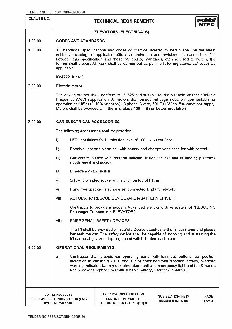
TENDER NO PSER:SCT:NBN-C2068:20
TENDER NO PSER:SCT:NBN-C2068:20
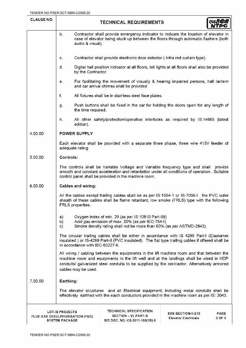
TENDER NO PSER:SCT:NBN-C2068:20
TENDER NO PSER:SCT:NBN-C2068:20
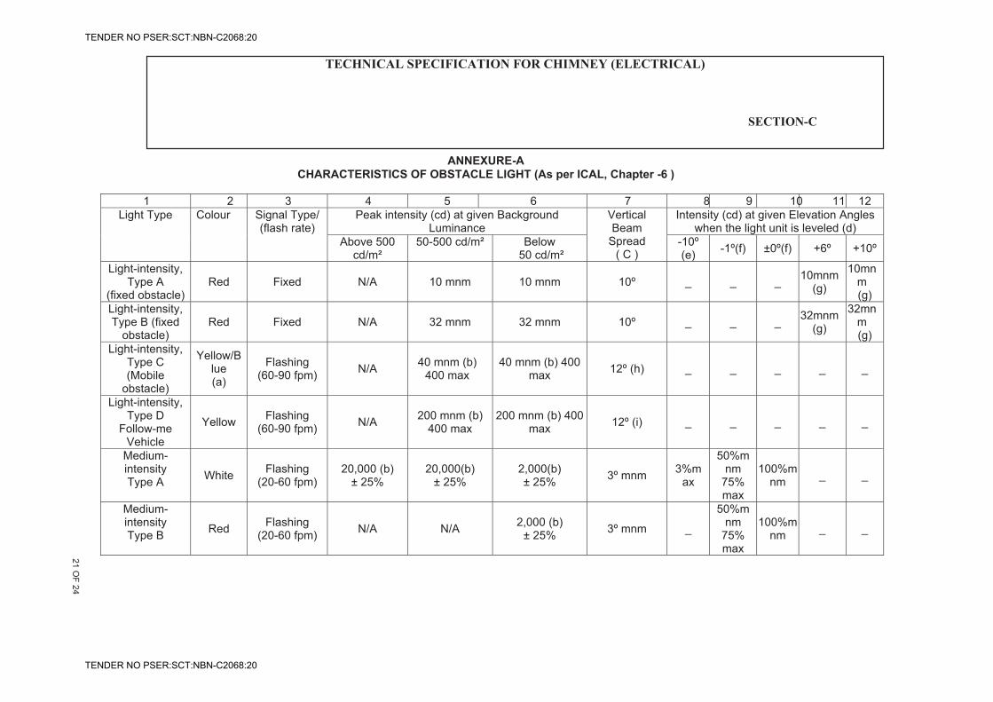
NTPC SAIL POWER COMPANY (P) LIMITED ROURKELA POWER PROJECT
(PP – III : 1X250 MW)
TECHNICAL SPECIFICATION FOREPC PACKAGE
Rourkela Power Project (PP – III : 1 x 250 MW) EPC Package
Technical Specification Section – VI, Vol – II-E Bid Doc. No. : CC&M-C-347-211
Chapter – 20.0 Chimney Electrics
Page 1 of 20
ANNEXURE-ACHARACTERISTICS OF OBSTACLE LIGHT (As per ICAL, Chapter -6 )
1 2 3 4 5 6 7 8 9 10 11 12 Light Type Colour Signal Type/
(flash rate)Peak intensity (cd) at given Background
LuminanceVerticalBeam
Spread( C )
Intensity (cd) at given Elevation Angles when the light unit is leveled (d)
Above 500 cd/m²
50-500 cd/m² Below 50 cd/m²
-10º(e) -1º(f) ±0º(f) +6º +10º
Light-intensity,Type A
(fixed obstacle) Red Fixed N/A 10 mnm 10 mnm 10º _ _ _ 10mnm
(g)
10mnm(g)
Light-intensity,Type B (fixed
obstacle)Red Fixed N/A 32 mnm 32 mnm 10º _ _ _ 32mnm
(g)
32mnm(g)
Light-intensity,Type C (Mobile
obstacle)
Yellow/Blue(a)
Flashing(60-90 fpm) N/A 40 mnm (b)
400 max 40 mnm (b) 400
max 12º (h) _ _ _ _ _
Light-intensity,Type D
Follow-meVehicle
Yellow Flashing(60-90 fpm) N/A 200 mnm (b)
400 max 200 mnm (b) 400
max 12º (i) _ _ _ _ _
Medium-intensityType A White Flashing
(20-60 fpm) 20,000 (b)
± 25% 20,000(b)
± 25% 2,000(b)± 25% 3º mnm 3%m
ax
50%mnm
75%max
100%mnm _ _
Medium-intensityType B Red Flashing
(20-60 fpm) N/A N/A 2,000 (b) ± 25% 3º mnm _
50%mnm
75%max
100%mnm _ _
TECHNICAL SPECIFICATION FOR CHIMNEY (ELECTRICAL) ROURKELA PP-II EXPANSION
(1x250 MW)
21 OF 24
SECTION-C
TENDER NO PSER:SCT:NBN-C2068:20
TENDER NO PSER:SCT:NBN-C2068:20
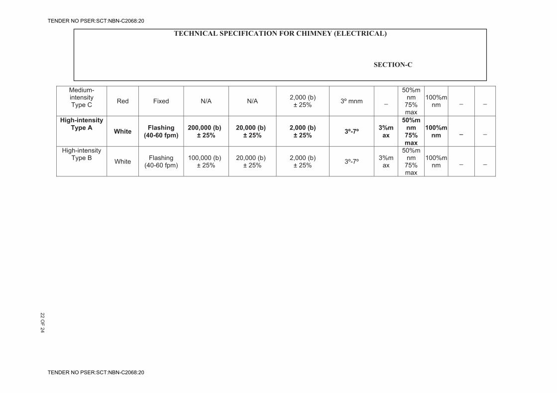
NTPC SAIL POWER COMPANY (P) LIMITED ROURKELA POWER PROJECT
(PP – III : 1X250 MW)
TECHNICAL SPECIFICATION FOREPC PACKAGE
Rourkela Power Project (PP – III : 1 x 250 MW) EPC Package
Technical Specification Section – VI, Vol – II-E Bid Doc. No. : CC&M-C-347-211
Chapter – 20.0 Chimney Electrics
Page 2 of 20
Medium-intensityType C Red Fixed N/A N/A 2,000 (b)
± 25% 3º mnm _
50%mnm
75%max
100%mnm _ _
High-intensity Type A White Flashing
(40-60 fpm) 200,000 (b)
± 25% 20,000 (b)
± 25% 2,000 (b)
± 25% 3º-7º 3%max
50%mnm75% max
100%mnm _ _
High-intensityType B White Flashing
(40-60 fpm) 100,000 (b)
± 25% 20,000 (b)
± 25% 2,000 (b)
± 25% 3º-7º 3%max
50%mnm
75%max
100%mnm _ _
TECHNICAL SPECIFICATION FOR CHIMNEY (ELECTRICAL) ROURKELA PP-II EXPANSION
(1x250 MW)
22 OF 24
SECTION-C
TENDER NO PSER:SCT:NBN-C2068:20
TENDER NO PSER:SCT:NBN-C2068:20
NTPC SAIL POWER COMPANY (P) LIMITED ROURKELA POWER PROJECT
(PP – III : 1X250 MW)
TECHNICAL SPECIFICATION FOREPC PACKAGE
Rourkela Power Project (PP – III : 1 x 250 MW) EPC Package
Technical Specification Section – VI, Vol – II-E Bid Doc. No. : CC&M-C-347-211
Chapter – 20.0 Chimney Electrics
Page 1 of 20
Table 6.3. Characteristics of obstacle light
Note: - This table does not include recommended horizontal beam spreads. 6.3.22 requires 360º coverage around an obstacle. Therefore, the number of light needed to meet this requirement will depend on the horizontal beam spreads of each light as well as the obstacle. Thus, with narrower beam spreads, more lights will be required.
a) See 6.3.25 b) Effective intensity, as determined in accordance with the Aerodrome
Design Manual, Part4. c) Beam spread is defined as the angle between two directions in a plane
for which the intensity is equal to 50% of the lower tolerance value of the intensity shown in columns 4.,5and 6. The beam pattern is not necessarily symmetrical about the elevation angle at which the peak intensity occurs.
d) Elevation (vertical) angle are referenced to the horizontal. e) Intensity at any specified horizontal radial as a percentage of the actual
peak intensity at he same radial when operated at each of the intensities shown in columns 4, 5and 6.
f) Intensity at any specified horizontal radial as a percentage of the lower tolerance value of the intensity shown in columns 4, 5 and 6.
g) In addition to specified values, light will have sufficient intensity to ensure conspicuity at elevation angle ±0º and 50º.
h) Peak intensity should be located at approximately 2.5º vertical. i) Peak intensity should be located at approximately 17º vertical.
TECHNICAL SPECIFICATION FOR CHIMNEY (ELECTRICAL)
ROURKELA PP-II EXPANSION (1x250 MW)
23 OF 24
SECTION-C
TENDER NO PSER:SCT:NBN-C2068:20
TENDER NO PSER:SCT:NBN-C2068:20
TECHNICAL SPECIFICATION FOR CHIMNEY(ELECTRICAL ROURKELA PP-II EXPANSION
(1x250 MW) SECTION-C
DRAWINGS, DATA AND MANUALS
1. To be submitted with the Bid
1.01.01 Typical general arrangement drawing of Chimney showing location of lighting fixtures, lightning protection system, grounding system etc.
1.01.02 Typical general arrangement drawing of A.C. distribution board, lightning board.
1.01.03 Catalogue cuts of various types of lightning fixtures, major components, cables, conduits etc
1.01.04 Type Test Certificate of various equipment
2. To be submitted for Approval (A) / Reference (R) and subsequent Distribution
2.02.01 Dimensional general arrangement drawing of chimney showing disposition of aviation warning lights, interior lights on platforms and stairs, receptacles, A.C. distribution boards, lighting boards including their fixing arrangements (A).
2.02.02 Arrangement drawings for lightning protection and grounding system (A)
2.02.03 Single line drawing of A.C. distribution boards and lighting boards (A)
2.02.04 Cable and Conduit layout (A)
2.02.05 Technical data sheet of all equipment / components (A).
2.02.06 Instruction Manuals and Catalogue cuts of all equipment (R)
The manuals shall clearly indicate the method of installation, check-up and tests to be carried out before commissioning of the equipment.
2.02.07 Any other relevant drawing or data necessary for satisfactory installation, operation and maintenance.
2.03.00 The Contractor may note that the drawings, data and manuals listed are minimum requirement only. The Contractor shall ensure that all other necessary information required to fully describe the equipment / system offered are submitted with his Bid.
24 OF 24
TENDER NO PSER:SCT:NBN-C2068:20
TENDER NO PSER:SCT:NBN-C2068:20
TITLE: - 3X660 MW NPGCL NABINAGAR FGD SPECIFICATIONS FOR SINGLE FLUE RCC CHIMNEY
SPECIFICATION NO: PE-TS-457-620-C002
VOLUME :
SECTION :
REV.NO : 00
SHEET :
SECTION-C
SPECIFIC TECHNICAL REQUIREMENTS FOR CHIMNEY ELEVATOR
SPECIFICATION NO. PE-TS-457-620-C002
TENDER NO PSER:SCT:NBN-C2068:20
TENDER NO PSER:SCT:NBN-C2068:20
SPECIFIC TECHNICAL REQUIREMENT
STACK ELEVATORS
SPECIFICATION NO. PE-TS-457-503-A-001
VOLUME II B
SECTION C SUB-SECTION A6
REV. 0
SHEET 1 of 5
1.1
P E M - 6 6 6 6 - 0
SECTION - C SUB SECTION – A6
STACK ELEVATORS
TENDER NO PSER:SCT:NBN-C2068:20
TENDER NO PSER:SCT:NBN-C2068:20
SPECIFIC TECHNICAL REQUIREMENT
STACK ELEVATORS
SPECIFICATION NO. PE-TS-457-503-A-001
VOLUME II B
SECTION C SUB-SECTION A6
REV. 0
SHEET 2 of 5
1.1
P E M - 6 6 6 6 - 0
1. SYSTEM DESCRIPTION
1.1 The Rack and pinion type stack elevator is required for installation inside multi-flue or outside single flue chimney. The stack Elevator is normally used for the movement of the maintenance personnel and for materials such as refractory bricks, etc. for maintenance of chimney.
2. SCOPE OF SUPPLY AND SERVICES
2.1 The scope of supply and services covered under the specification are broadly described below:
2.1.1 Three (03) Nos. Rack and Pinion type stack elevator complete with all other accessories and associated steel work.
2.1.2 Drive motor and control panel for Stack elevator 2.1.3 Control Panel 2.1.4 Equipment earthing 2.1.5 All power and control cables, trailing cables 2.1.6 Limit switches 2.1.7 Over speed governor 2.1.8 Alarm push button in the cage connected to battery operated alarm at
elevator base. 2.1.9 Reverse phase relay connected to prevent operation of the cab with improper
phase rotation or failure in any phase of power supply. 2.1.10 Continuous duty electrical torque motor recoil cable reels or cable trolley or
any equivalent arrangement to maintain electrical power service to all electrical components of the elevator for complete travel of stack elevator.
2.1.11 One auxiliary panel shall be provided and mounted on the graded level enclosure equipped with a main ON-OFF selector switch, main contractor, breaker, relays, control transformer and fuses, tone frequency transmitter or equivalent arrangement, terminal blocks and all other accessories required for normal operation of the elevator.
2.1.12 One main control panel shall be furnished and mounted on top of the cab. Panel shall be in enclosure equipped with necessary equipment like rectifier, battery charger charger, tone frequency receiver, contactors, breakers, control transformer and fuses, thermal overload relays, and all other equipment and accessories required for normal operation of the elevator.
2.1.13 Cab shall be controlled by semi-automatic floor selection control system. Cab shall be furnished with 240 V grounding receptacle, emergency alarm push button with normally open contact, indicating light, limit switches, and all other necessary control devices required to ensure safe and continuous cab operation. One trailing cable shall connect the main control panel to aux. Panel at ground level. Cable shall supply the cab necessary power supply requirements. Cable guides shall be installed at every 6 m intervals to avoid entanglement of this cable. Control signal between the aux. Panel at ground level, the main control panel on the cab and the landings shall be provided with tone frequency receiver or any other equivalent arrangement by trailing control cable.
TENDER NO PSER:SCT:NBN-C2068:20
TENDER NO PSER:SCT:NBN-C2068:20
SPECIFIC TECHNICAL REQUIREMENT
STACK ELEVATORS
SPECIFICATION NO. PE-TS-457-503-A-001
VOLUME II B
SECTION C SUB-SECTION A6
REV. 0
SHEET 3 of 5
1.1
P E M - 6 6 6 6 - 0
2.1.14 Each landing assembly shall include a limit switch and push button control station installed and wired to a landing junction box.
2.1.15 All power cable and race way shall be provided and installed by the bidder for interconnection of the main control panel, auxiliary panel and landing junction boxes. Trailing cables shall be as per relevant IS/IEC standard.
2.1.16 Bidder shall provide, install and connect a system equipment ground to owner’s chimney grounding system. Equipment grounding system shall electrically connect panels and junction boxes which contain electrical devices, motors and elevator platform and structures. Raceway system shall not be considered as an equipment ground.
2.1.17 All enclosures containing electrical devices shall be provided with 240 V, single phase heaters with adjustable thermostat control.
2.1.18 Cab shall be equipped with a 240 V AC interior light and duplex outlet. 2.1.19 Cable accessories as required to install the cables in bidder’s scope shall be
provided by the bidders. 2.1.20 Complete erection, testing and commissioning including all erection materials,
consumables and other tools and tackles required for erection along with commissioning spares.
2.1.21 All inserts, anchor bolts, sleeves, anchoring steel and any other items required to complete the job satisfactorily shall be in bidder’s scope.
2.1.22 First fill of lubricant and consumables shall be in bidder’s scope. 2.1.23 Satisfactory running and maintenance of elevator for a continuous period of
30 days including training of owner’s operators. 2.1.24 Supply of One complete set of special maintenance tools and tackles shall be
in bidder’s scope. 2.1.25 Any other equipment or accessories not specified, but required for the
satisfactory operation of chimney elevator shall be in bidder’s scope. 2.1.26 Recommended spares including instrumentation for 3 years of normal
operation of stack elevator. (List to be furnished by the bidder and for which order shall be placed separately by owner as per their requirements)
TENDER NO PSER:SCT:NBN-C2068:20
TENDER NO PSER:SCT:NBN-C2068:20
SPECIFIC TECHNICAL REQUIREMENT
STACK ELEVATORS
SPECIFICATION NO. PE-TS-457-503-A-001
VOLUME II B
SECTION C SUB-SECTION A6
REV. 0
SHEET 4 of 5
1.1
P E M - 6 6 6 6 - 0
3. SPECIFIC REQUIREMENTS
3.1 The equipment supplied, erected and commissioned shall meet the technical requirements of respective Section –D and Data Sheet-A.
3.2 Bidder shall note that all QP and Field quality plans shall be subject to purchaser’s approval.
3.3 All equipment offered shall have suitable provision of termination and connection of power and control cables inclusive of cable boxes, lugs and glands, etc.
3.4 All the equipment shall be suitable for the power supply fault level and other climatic conditions as indicated in project information.
3.5 The bidder shall guarantee the rating and performance parameters of the system/equipment offered in accordance with specification requirements.
3.6 It is the responsibility of bidder to arrange license for operation of chimney elevator from statutory body of that area before handing over.
3.7 Bidder shall furnish deviation (clause wise) in the deviation schedule. In absence of dully filled deviation list, it will be presumed that offer is exactly in line with the technical specification.
3.8 Bidder shall furnish duly filled data sheet –B along with the offer. In absence of same, offer shall be treated as incomplete.
3.9 Bidder shall offer the stack elevator considering prevailing statutory and regulatory requirements of project location.
3.10 Bidder shall indicate degree of protection of various electrical equipment in the offer.
3.11 Makes of all bought out items shall subject to purchaser’s approval after award of contract.
3.12 All drawings/documents shall subject to purchaser’s approval after award of contract.
3.13 Please refer / comply customer- NTPC specification (rack & pinion type elevator)
TENDER NO PSER:SCT:NBN-C2068:20
TENDER NO PSER:SCT:NBN-C2068:20
SPECIFIC TECHNICAL REQUIREMENT
STACK ELEVATORS
SPECIFICATION NO. PE-TS-457-503-A-001
VOLUME II B
SECTION C SUB-SECTION A6
REV. 0
SHEET 5 of 5
1.1
P E M - 6 6 6 6 - 0
DATA SHEET
1 Designation : Rack and Pinion Type Stack Elevator
2 Type of loading : Passenger cum goods
3 Quantity : 3 nos. for 150 M high Chimney. project requirement.
4 Carrying Capacity : 400 Kg (approximately)
5 Pay load : 400 Kg min.
6 Operating Speed : 40 m/min.
7 Dimension of lift and lift well/cut out : As per IS: 3534
8 No. of landings : For 150 M High Chimney=
Four (04) nos. including ground (0.0m, 47m, 92m, & last landing at 137m).
9 Total vertical travel : 137 m.
10 Electrical power supply system : 415 V, 3 ph, 50 Hz
11 Other accessories : As required
TENDER NO PSER:SCT:NBN-C2068:20
TENDER NO PSER:SCT:NBN-C2068:20
TENDER NO PSER:SCT:NBN-C2068:20
TENDER NO PSER:SCT:NBN-C2068:20
TENDER NO PSER:SCT:NBN-C2068:20
TENDER NO PSER:SCT:NBN-C2068:20