Embed Size (px)
Citation preview

400 V: MALSR and ALSFMedium Intensity Approach Lighting System and ApproachLighting System with Sequenced Flashers (Elevated and In-pavement Flashers)
User Manual96A0400, Rev. M, 2020/09/03


A.0 Disclaimer / Standard Warranty
CE certification
The equipment listed as CE certified means that the product complies with the essential requirements concerning safety andhygiene. The European directives that have been taken into consideration in the design are available on written request toADB SAFEGATE.
ETL certification
The equipment listed as ETL certified means that the product complies with the essential requirements concerning safety andFAA Airfield regulations. The FAA directives that have been taken into consideration in the design are available on writtenrequest to ADB SAFEGATE.
All Products Guarantee
ADB SAFEGATE will correct by repair or replacement per the applicable guarantee above, at its option, equipment or partswhich fail because of mechanical, electrical or physical defects, provided that the goods have been properly handled andstored prior to installation, properly installed and properly operated after installation, and provided further that Buyer givesADB SAFEGATE written notice of such defects after delivery of the goods to Buyer. Refer to the Safety section for moreinformation on Material Handling Precautions and Storage precautions that must be followed.
ADB SAFEGATE reserves the right to examine goods upon which a claim is made. Said goods must be presented in the samecondition as when the defect therein was discovered. ADB SAFEGATE furthers reserves the right to require the return of suchgoods to establish any claim.
ADB SAFEGATE's obligation under this guarantee is limited to making repair or replacement within a reasonable time afterreceipt of such written notice and does not include any other costs such as the cost of removal of defective part, installationof repaired product, labor or consequential damages of any kind, the exclusive remedy being to require such new parts to befurnished.
ADB SAFEGATE's liability under no circumstances will exceed the contract price of goods claimed to be defective. Any returnsunder this guarantee are to be on a transportation charges prepaid basis. For products not manufactured by, but sold by ADBSAFEGATE, warranty is limited to that extended by the original manufacturer. This is ADB SAFEGATE's sole guarantee andwarranty with respect to the goods; there are no express warranties or warranties of fitness for any particular purpose or anyimplied warranties of fitness for any particular purpose or any implied warranties other than those made expressly herein. Allsuch warranties being expressly disclaimed.
Standard Products Guarantee
Products of ADB SAFEGATE manufacture are guaranteed against mechanical, electrical, and physical defects (excluding lamps)which may occur during proper and normal use for a period of two years from the date of ex-works delivery, and areguaranteed to be merchantable and fit for the ordinary purposes for which such products are made.
NoteSee your sales order contract for a complete warranty description.
FAA Certified product installed in the United States and purchased or funded with monies through theAirport Improvement Program (AIP) installations guarantee
ADB SAFEGATE L858 Airfield Guidance Signs are warranted against mechanical and physical defects in design or manufacturefor a period of 2 years from date of installation, per FAA AC 150/5345-44 (applicable edition).
ADB SAFEGATE L858(L) Airfield Guidance Signs are warranted against electrical defects in design or manufacture of the LED orLED specific circuitry for a period of 4 years from date of installation, per FAA EB67 (applicable edition).
ADB SAFEGATE LED light fixtures (with the exception of obstruction lighting) are warranted against electrical defects in designor manufacture of the LED or LED specific circuitry for a period of 4 years from date of installation, per FAA EB67 (applicableedition). .
96A0400, Rev. M, 2020/09/03 iiiCopyright © ADB Safegate, All Rights Reserved

NoteSee your sales order contract for a complete warranty description.
Liability
WARNINGUse of the equipment in ways other than described in the catalog leaflet and the manual may result in personal injury,death, or property and equipment damage. Use this equipment only as described in the manual.
ADB SAFEGATE cannot be held responsible for injuries or damages resulting from non-standard, unintended uses of itsequipment. The equipment is designed and intended only for the purpose described in the manual. Uses not described in themanual are considered unintended uses and may result in serious personal injury, death or property damage.
Unintended uses, includes the following actions:
• Making changes to equipment that have not been recommended or described in this manual or using parts that are notgenuine ADB SAFEGATE replacement parts or accessories.
• Failing to make sure that auxiliary equipment complies with approval agency requirements, local codes, and all applicablesafety standards if not in contradiction with the general rules.
• Using materials or auxiliary equipment that are inappropriate or incompatible with your ADB SAFEGATE equipment.
• Allowing unskilled personnel to perform any task on or with the equipment.
© ADB SAFEGATE BV
This manual or parts thereof may not be reproduced, stored in a retrieval system, or transmitted, in any form or by any means,electronic, mechanical, photocopying, recording, nor otherwise, without ADB SAFEGATE BV's prior written consent.
This manual could contain technical inaccuracies or typographical errors. ADB SAFEGATE BV reserves the right to revise thismanual from time to time in the contents thereof without obligation of ADB SAFEGATE BV to notify any person of suchrevision or change. Details and values given in this manual are average values and have been compiled with care. They are notbinding, however, and ADB SAFEGATE BV disclaims any liability for damages or detriments suffered as a result of reliance onthe information given herein or the use of products, processes or equipment to which this manual refers. No warranty is madethat the use of the information or of the products, processes or equipment to which this manual refers will not infringe anythird party's patents or rights. The information given does not release the buyer from making their own experiments andtests.
400 V: MALSR and ALSF
ivCopyright © ADB Safegate, All Rights Reserved

TABLE OF CONTENTS
1.0 Safety ....................................................................................................................................................................................... 11.1 Safety Messages ........................................................................................................................................................................................................ 1
1.1.1 Introduction to Safety ................................................................................................................................................................................. 21.1.2 Intended Use .................................................................................................................................................................................................. 21.1.3 Material Handling Precautions: Storage .............................................................................................................................................. 31.1.4 Material Handling: Heavy Equipment .................................................................................................................................................. 31.1.5 Material Handling Precautions: Fasteners .......................................................................................................................................... 31.1.6 Operation Safety ........................................................................................................................................................................................... 41.1.7 Maintenance Safety ..................................................................................................................................................................................... 41.1.8 Maintenance ................................................................................................................................................................................................... 41.1.9 Material Handling Precautions, ESD ..................................................................................................................................................... 51.1.10 Arc Flash and Electric Shock Hazard ................................................................................................................................................... 6
2.0 Introduction ............................................................................................................................................................................ 72.1 Low-Voltage ALSF/MALSR Approach Lighting System .............................................................................................................................. 72.2 LV ALSF/MALSR ......................................................................................................................................................................................................... 82.3 About this manual .................................................................................................................................................................................................... 8
2.3.1 How to work with the manual ................................................................................................................................................................. 82.4 Product Introduction ............................................................................................................................................................................................... 8
2.4.1 Theory of Operation .................................................................................................................................................................................... 82.4.2 ALSF System ................................................................................................................................................................................................... 92.4.3 MALSR System ............................................................................................................................................................................................ 112.4.4 MALSR/ALSF Required Equipment: .................................................................................................................................................... 132.4.5 Additional equipment may be required, and must be ordered separately ......................................................................... 132.4.6 Some Useful Terms and Definitions .................................................................................................................................................... 142.4.7 Master Control Cabinet ........................................................................................................................................................................... 142.4.8 Equipment Data (Master Control Cabinet) ...................................................................................................................................... 152.4.9 Master Input Power Requirement ....................................................................................................................................................... 152.4.10 Flasher .......................................................................................................................................................................................................... 152.4.11 Individual Control Cabinet (ICC) ........................................................................................................................................................ 162.4.12 Aiming Devices ......................................................................................................................................................................................... 162.4.13 Flasher Tester ............................................................................................................................................................................................ 172.4.14 Junction Box .............................................................................................................................................................................................. 172.4.15 FAA Spare Parts Trunk ............................................................................................................................................................................ 172.4.16 MALSR Steady-Burning Light Components .................................................................................................................................. 172.4.17 MALSR Ordering Information ............................................................................................................................................................. 182.4.18 ALSF Ordering Information ................................................................................................................................................................. 182.4.19 Specifications ............................................................................................................................................................................................ 192.4.20 Technical Data ........................................................................................................................................................................................... 222.4.21 ICC Mechanical Data .............................................................................................................................................................................. 242.4.22 ADB SAFEGATE ALSF / MALSR System Specifications .............................................................................................................. 24
3.0 Installation of the System ................................................................................................................................................... 273.1 Overview .................................................................................................................................................................................................................... 28
3.1.1 Preparation of the Flashing Equipment ............................................................................................................................................ 283.2 Preparation for Installation ................................................................................................................................................................................. 30
3.2.1 Concrete slabs ............................................................................................................................................................................................. 303.3 Contractor ................................................................................................................................................................................................................. 323.4 Physical Installation ............................................................................................................................................................................................... 32
3.4.1 Mechanical Mounting and Electrical Connections ....................................................................................................................... 323.4.2 Unpacking the Equipment ...................................................................................................................................................................... 323.4.3 Installing Master Control Cabinet ....................................................................................................................................................... 333.4.4 Installing the Individual Control Cabinets ........................................................................................................................................ 333.4.5 Mounting Junction Box ........................................................................................................................................................................... 333.4.6 Installation of ICC 1 or ICC 3 .................................................................................................................................................................. 34
3.5 Electrical Connections ........................................................................................................................................................................................... 35
96A0400, Rev. M, 2020/09/03 vCopyright © ADB Safegate, All Rights Reserved

3.5.1 Power Supply Cable .................................................................................................................................................................................. 353.5.2 Local Bus Data Line Interlinking Cables ............................................................................................................................................ 363.5.3 Connection ................................................................................................................................................................................................... 363.5.4 Cable ............................................................................................................................................................................................................... 363.5.5 Remote control connections ................................................................................................................................................................. 373.5.6 External temperature sensor cable ..................................................................................................................................................... 373.5.7 Earth to ground connection .................................................................................................................................................................. 373.5.8 Cabling Preconditions .............................................................................................................................................................................. 373.5.9 Mounting Power Transformer (MALSR Only) .................................................................................................................................. 40
3.6 Installing Lightning Rod ....................................................................................................................................................................................... 413.7 Installing In-pavement Flasher on the Base and ICC Cable Connections ......................................................................................... 423.8 Connecting the In-pavement Flashing Light ............................................................................................................................................... 423.9 Mounting the Flashing Lights ............................................................................................................................................................................ 45
3.9.1 Overview of Sequence of Work ............................................................................................................................................................ 453.9.2 Installation on L-868 Base ...................................................................................................................................................................... 453.9.3 Torquing and Installation Guidance for In-pavement Fixtures ................................................................................................. 46
3.10 Wiring the Master Control Cabinet ............................................................................................................................................................... 473.11 To Wire the Individual Control Cabinet ....................................................................................................................................................... 473.12 Wiring 15 kVA Power Transformer (MALSR Only) ................................................................................................................................... 473.13 Aiming the UEL Lamp holders ........................................................................................................................................................................ 48
3.13.1 Bubble Level Aiming Device ................................................................................................................................................................ 483.13.2 Adjusting Horizontal .............................................................................................................................................................................. 493.13.3 Electronic Aiming Device ...................................................................................................................................................................... 493.13.4 Commissioning ........................................................................................................................................................................................ 50
3.14 Aiming the PAR-56 Lamp holders ................................................................................................................................................................. 513.14.1 Assembling the Aiming Device .......................................................................................................................................................... 513.14.2 Aiming Lamp holders (Conduit or Pipe Mounted) ..................................................................................................................... 523.14.3 Aiming the Lamp holders (Tower Mounted) ................................................................................................................................. 54
3.15 Aiming PAR-38 Lamp holders (MALSR Only) ............................................................................................................................................ 563.15.1 Adjusting Horizontal .............................................................................................................................................................................. 563.15.2 Adjusting Vertical .................................................................................................................................................................................... 56
4.0 Operation .............................................................................................................................................................................. 594.1 Interlock Switches ................................................................................................................................................................................................... 594.2 Local and Remote Control .................................................................................................................................................................................. 594.3 Master Control Cabinet Controls and Indicators ....................................................................................................................................... 594.4 Ground Fault Interpreter ...................................................................................................................................................................................... 594.5 MCC Controls and Indicators ............................................................................................................................................................................. 604.6 System Configuration ........................................................................................................................................................................................... 61
4.6.1 Manual configuration ............................................................................................................................................................................... 624.6.2 Configuration via the Dongle ................................................................................................................................................................ 654.6.3 Configuration of the REIL/RTIL system .............................................................................................................................................. 70
4.7 Technical Description of the Control Cabinets, System Components and Available Options .................................................. 724.7.1 Individual Control Cabinets (ICC) ......................................................................................................................................................... 724.7.2 Master Control Cabinet (MCC) ............................................................................................................................................................. 724.7.3 Configuration .............................................................................................................................................................................................. 724.7.4 Installation options ................................................................................................................................................................................... 734.7.5 Operating Principle ................................................................................................................................................................................... 73
4.8 Lightning Protection .............................................................................................................................................................................................. 734.8.1 Flasher system ............................................................................................................................................................................................. 734.8.2 External wiring ............................................................................................................................................................................................. 744.8.3 Local bus input ........................................................................................................................................................................................... 74
4.9 ICC (Individual Control Cabinet) FCU PCB 1487 ......................................................................................................................................... 744.9.1 FCU PCB Fuse .............................................................................................................................................................................................. 744.9.2 FCU PCB 1487 Jumpers ........................................................................................................................................................................... 754.9.3 FCU PCB Dip-switches .............................................................................................................................................................................. 764.9.4 ICC LEDs ......................................................................................................................................................................................................... 79
4.10 Local Bus Interface PCB 1498 .......................................................................................................................................................................... 794.11 MCC (Local Master) PCB 1485 ......................................................................................................................................................................... 79
4.11.1 Protections ................................................................................................................................................................................................. 804.11.2 Start-up and scanning ........................................................................................................................................................................... 80
400 V: MALSR and ALSFTABLE OF CONTENTS
viCopyright © ADB Safegate, All Rights Reserved

4.11.3 Synchronization ........................................................................................................................................................................................ 804.11.4 Real-time measurements ..................................................................................................................................................................... 81
4.12 PCB 1485 Jumpers ............................................................................................................................................................................................... 824.12.1 Rotary and Dip-switches ...................................................................................................................................................................... 824.12.2 MCC LEDs ................................................................................................................................................................................................... 85
4.13 Multi-wire Remote Control and Monitoring Interface PCB 1486 ...................................................................................................... 854.13.1 Control signals and back-indication ................................................................................................................................................. 864.13.2 FCU Multi-wire I/O Configuration for the FAA Market ............................................................................................................. 874.13.3 Functions .................................................................................................................................................................................................... 874.13.4 Input connector P2: remote control command signals ............................................................................................................ 884.13.5 Mode selection: ALSF1 / SSALR / MALSR / ALSF2 ..................................................................................................................... 894.13.6 Back-indication Output Functions .................................................................................................................................................... 904.13.7 Back-indication Modes of operation ............................................................................................................................................... 924.13.8 Manual configurations Overview ...................................................................................................................................................... 934.13.9 Configuring the 400V MALSR 5-Light Sequenced Flasher System ...................................................................................... 934.13.10 Configuring the Jumpers of the Multi-Wire Board .................................................................................................................. 964.13.11 Multiwire .................................................................................................................................................................................................. 964.13.12 Flasher Controller Unit (FCU) Board .............................................................................................................................................. 974.13.13 Configuring the Jumpers ................................................................................................................................................................... 984.13.14 Flasher Control Unit (FCU) Board LEDs ......................................................................................................................................... 99
4.14 External Temperature Probe ............................................................................................................................................................................. 994.15 Dongle ................................................................................................................................................................................................................... 100
4.15.1 Dongle LED Indicatorss ...................................................................................................................................................................... 1014.15.2 Cable layout ............................................................................................................................................................................................ 1014.15.3 Dip-switch bank ..................................................................................................................................................................................... 102
4.16 Initial Software Installation and Software Use ........................................................................................................................................ 1024.16.1 Configuration tool ................................................................................................................................................................................ 1024.16.2 Install the configuration tool ............................................................................................................................................................ 1024.16.3 System requirements: .......................................................................................................................................................................... 1024.16.4 Configuration tool package: ............................................................................................................................................................. 1034.16.5 Install software ....................................................................................................................................................................................... 1034.16.6 Connect cables ....................................................................................................................................................................................... 1034.16.7 Start software ......................................................................................................................................................................................... 103
4.17 Upload New Software ...................................................................................................................................................................................... 1044.17.1 Control menu ......................................................................................................................................................................................... 1074.17.2 Mode menu ............................................................................................................................................................................................. 1074.17.3 Flasher data menu ................................................................................................................................................................................ 107
4.18 Start Up the System .......................................................................................................................................................................................... 1104.19 Shutdown Procedures ...................................................................................................................................................................................... 111
4.19.1 Emergency Shutdown ......................................................................................................................................................................... 1114.19.2 Equipment Shutdown .......................................................................................................................................................................... 1114.19.3 Master Control Cabinet Switches Shutdown .............................................................................................................................. 1114.19.4 Individual Control Cabinet Shutdown ........................................................................................................................................... 112
5.0 Maintenance ....................................................................................................................................................................... 1135.1 Replacement of the ICC Board ........................................................................................................................................................................ 113
5.1.1 Replacement of the Electrolytic Capacitor ..................................................................................................................................... 1135.1.2 Replacement of the DC power Supply ............................................................................................................................................ 113
5.2 Replacement Optional Over-voltage Protection ...................................................................................................................................... 1145.3 Local Master Controller (LMC) and remote control PCBs .................................................................................................................... 114
5.3.1 LMC ............................................................................................................................................................................................................... 1145.3.2 Multiwire ..................................................................................................................................................................................................... 1155.3.3 Multi-wire cable ....................................................................................................................................................................................... 116
5.4 ALSF/MALSR Maintenance ............................................................................................................................................................................... 1175.4.1 ALSF/MALSR Maintenance Schedule .............................................................................................................................................. 1175.4.2 Maintenance Procedures ...................................................................................................................................................................... 1195.4.3 Checking System Performance .......................................................................................................................................................... 1195.4.4 Checking System Voltage ..................................................................................................................................................................... 1195.4.5 Checking the Equipment Visually ..................................................................................................................................................... 1205.4.6 In-pavement Flashing Light ................................................................................................................................................................. 1205.4.7 How to replace a lamp .......................................................................................................................................................................... 121
96A0400, Rev. M, 2020/09/03 viiCopyright © ADB Safegate, All Rights Reserved

5.4.8 How to replace the trigger and lamp holder PCBs .................................................................................................................... 1215.4.9 How to close and test the light fixture ............................................................................................................................................ 1225.4.10 Bolt Torque Preventive Maintenance Schedule ......................................................................................................................... 1235.4.11 Testing for Leaks .................................................................................................................................................................................... 1245.4.12 Individual Control Cabinets (ICCs) .................................................................................................................................................. 1255.4.13 Flashing Sequence ................................................................................................................................................................................ 1265.4.14 3-in-1 ICC AC Current Check ............................................................................................................................................................ 126
5.5 UEL Light Maintenance ...................................................................................................................................................................................... 1265.5.1 Preventive Maintenance ....................................................................................................................................................................... 1265.5.2 How to Replace the UEL Lamp ........................................................................................................................................................... 1265.5.3 How to Dismantle the Optical Assembly ....................................................................................................................................... 127
5.6 Troubleshooting and Fault Correction ......................................................................................................................................................... 1305.6.1 General Troubleshooting Tips ............................................................................................................................................................ 1305.6.2 Gather information about the problem .......................................................................................................................................... 1315.6.3 Do the easy checks first ........................................................................................................................................................................ 1315.6.4 Troubleshooting: System fails to flash ............................................................................................................................................. 1315.6.5 Verify that communication is present on the local bus ............................................................................................................ 1325.6.6 At each ICC cabinet, verify that: ......................................................................................................................................................... 1325.6.7 If the optional Modbus control is present: .................................................................................................................................... 1325.6.8 Troubleshooting: Several units fail to flash ................................................................................................................................... 1325.6.9 Verify that communication is present on the local bus ............................................................................................................ 1325.6.10 Troubleshooting: One unit fails to flash ....................................................................................................................................... 1325.6.11 Verify that communication is present on the local bus ......................................................................................................... 1335.6.12 Troubleshooting: One unit flashes incorrectly (intensity or timing) .................................................................................. 1335.6.13 Verify that communication is present on the local bus ......................................................................................................... 1335.6.14 UEL Light Assemblies .......................................................................................................................................................................... 133
5.7 Wiring Diagrams ................................................................................................................................................................................................... 134
6.0 Parts .................................................................................................................................................................................... 1496.1 MALSR Parts List ................................................................................................................................................................................................... 150
6.1.1 MALSR Master Control Cabinet Specific Parts List ..................................................................................................................... 1546.1.2 Steady Burning Elevated Light Assembly Parts List .................................................................................................................... 1546.1.3 MALSR/ALSF In-pavement Flasher Parts List ................................................................................................................................ 156
6.2 Spare Parts .............................................................................................................................................................................................................. 158
A.0 SUPPORT ............................................................................................................................................................................ 159A.1 ADB SAFEGATE Website .................................................................................................................................................................................... 159A.2 Recycling ................................................................................................................................................................................................................. 160
A.2.1 Local Authority Recycling .................................................................................................................................................................... 160A.2.2 ADB SAFEGATE Recycling .................................................................................................................................................................... 160
400 V: MALSR and ALSFTABLE OF CONTENTS
viiiCopyright © ADB Safegate, All Rights Reserved

List of Figures
Figure 1: In-pavement Fixture and Female Mating Connector ........................................................................................................................... 0
Figure 2: In-pavement Fixture with Snow Plow Ring .............................................................................................................................................. 0
Figure 3: ALSF System ........................................................................................................................................................................................................... 10
Figure 4: MALSR System ....................................................................................................................................................................................................... 11
Figure 5: TB2 Connector ....................................................................................................................................................................................................... 29
Figure 6: FCU PCB 1487: Switch Banks and Jumpers ................................................................................................................................................ 30
Figure 7: ICC Dimensions concrete slab ......................................................................................................................................................................... 31
Figure 8: Master Control Cabinet Installation and Dimensions ............................................................................................................................ 33
Figure 9: Dimensions and sequence of mounting on a slab using anchor bolts (dimensions in mm) ................................................. 34
Figure 10: ICC-1: Example of a Pole Mounted ICC ..................................................................................................................................................... 35
Figure 11: Typical Cable Entry Detail ............................................................................................................................................................................... 35
Figure 12: Cable clamp ......................................................................................................................................................................................................... 37
Figure 13: Example for an ALSF-2, 21-fixture configuration: ................................................................................................................................. 39
Figure 14: 15 kVA Transformer Installation (MALSR Only) ...................................................................................................................................... 40
Figure 15: Flasher Installation ............................................................................................................................................................................................. 42
Figure 16: Connections to the Male In-pavement Fixture Connector (field splice kit not shown) .......................................................... 43
Figure 17: In-pavement connections ............................................................................................................................................................................... 44
Figure 18: Bubble Level Aiming Device (1570.05.410) .............................................................................................................................................. 49
Figure 19: Electronic Aiming Device (1570.05.400) .................................................................................................................................................... 50
Figure 20: The PAR-56 Aiming Device ............................................................................................................................................................................ 51
Figure 21: Mounting the PAR-56 Aiming Device ........................................................................................................................................................ 51
Figure 22: Aiming Device Leg Clamp Locations (Top View) ................................................................................................................................... 52
Figure 23: Lamp Holder (Top View) .................................................................................................................................................................................. 53
Figure 24: Slip Fitter Dial Face and Adjusting Screws ............................................................................................................................................... 54
Figure 25: MALSR PAR-38 Aiming Device ..................................................................................................................................................................... 56
Figure 26: Master Control Cabinet Parts and Diagram (MALSR Shown) ........................................................................................................... 61
Figure 27: Flasher Configuration Software .................................................................................................................................................................... 71
Figure 28: Flasher control .................................................................................................................................................................................................... 73
Figure 29: FCU PCB 1487 Jumpers ................................................................................................................................................................................... 76
Figure 30: FCU PCB 1487: Switchbanks and Jumpers ............................................................................................................................................... 78
Figure 31: Local Bus interface, PCB 1498 ....................................................................................................................................................................... 79
Figure 32: MCC, PCB1485: Switches ................................................................................................................................................................................. 82
Figure 33: ALSF I/O settings: Click on I/O TAB ............................................................................................................................................................. 86
Figure 34: Click on Mode tab and click on Mode 2 SSALR ..................................................................................................................................... 87
Figure 35: External supply 24 Vdc or 48 Vdc: Polarity=either. ............................................................................................................................... 89
Figure 36: Internal power supply 48 Vdc or 24 Vdc Polarity=positive ................................................................................................................ 89
96A0400, Rev. M, 2020/09/03 ixCopyright © ADB Safegate, All Rights Reserved

Figure 37: ernal power supply 48 Vdc or 24 Vdc Polarity=negative ................................................................................................................... 90
Figure 38: Dry contacts: ........................................................................................................................................................................................................ 92
Figure 39: Polarized contact negative ............................................................................................................................................................................. 92
Figure 40: Polarized contact positive ............................................................................................................................................................................... 93
Figure 41: Manual Configuration Jumpers and Switches ........................................................................................................................................ 94
Figure 42: LMC LED Indications ......................................................................................................................................................................................... 95
Figure 43: Multi-Wire Board ............................................................................................................................................................................................... 96
Figure 44: Flasher Control Unit (FCU) Board Jumpers and Switches ................................................................................................................... 98
Figure 45: Flasher Control Unit (FCU) Board LED Indicators .................................................................................................................................. 99
Figure 46: External Temperature Probe (1440.21.000) ........................................................................................................................................... 100
Figure 47: Connection: ICC , Dongle and Laptop ..................................................................................................................................................... 102
Figure 48: Configuration tool ........................................................................................................................................................................................... 104
Figure 49: Configuration tool screen ............................................................................................................................................................................ 106
Figure 50: Over-voltage protection cartridges .......................................................................................................................................................... 114
Figure 51: Lamp Position ................................................................................................................................................................................................... 122
Figure 52: Anti-vibration washer example .................................................................................................................................................................. 123
Figure 53: Pressure Relief Screw ..................................................................................................................................................................................... 125
Figure 54: Pressure Test Fitting Assembly ................................................................................................................................................................... 125
Figure 55: UEL Lamp Assembly ....................................................................................................................................................................................... 127
Figure 56: UEL Lamp Assembly ....................................................................................................................................................................................... 127
Figure 57: UEL Exploded View ......................................................................................................................................................................................... 128
Figure 58: Local Bus Control ............................................................................................................................................................................................. 134
Figure 59: External Wiring Diagram, 400V Sequenced Flasher System- FAA MALSR diagram 1of2 .................................................... 135
Figure 60: External Wiring Diagram, 400V Sequenced Flasher System- FAA MALSR diagram 2of2 .................................................... 136
Figure 61: ALSF External Wiring Diagram, 400V Sequenced Flasher System- ALSF/SSALR diagrams 1of2 ...................................... 137
Figure 62: ALSF External Wiring Diagram, 400V Sequenced Flasher System- ALSF/SSALR diagrams 2of2 ...................................... 138
Figure 63: ALSF/MALSR External: FFL wiring .............................................................................................................................................................. 138
Figure 64: ALSF/MALSR External: UEL Wiring ............................................................................................................................................................ 139
Figure 65: ALSF/MALSR External: Junction Box Wiring .......................................................................................................................................... 139
Figure 66: Internal MALSR Wiring Diagram 400 V MCC 1of3 ............................................................................................................................. 140
Figure 67: Internal MALSR Wiring Diagram 400 V MCC 2of3 ............................................................................................................................. 141
Figure 68: Internal MALSR Wiring Diagram 400 V MCC 3of3 ............................................................................................................................. 142
Figure 69: 400V, ALSF/SSALR, 48 VDC CONTROL 1of2 .......................................................................................................................................... 143
Figure 70: 400V, ALSF/SSALR, 120 VAC CONTROL 2of2 ........................................................................................................................................ 144
Figure 71: Internal Wiring Diagram 400 V ICC (43A3512) .................................................................................................................................... 145
Figure 72: Elevated Flash Head Assembly ................................................................................................................................................................... 146
Figure 73: Mounting the Master Control Cabinet ................................................................................................................................................... 147
Figure 74: ICC-1 ..................................................................................................................................................................................................................... 148
Figure 75: Master Control Cabinet Parts and Diagram .......................................................................................................................................... 150
Figure 76: MCC Assembly 44A6839 Diagram ............................................................................................................................................................ 151
400 V: MALSR and ALSFList of Figures
xCopyright © ADB Safegate, All Rights Reserved

Figure 77: MCC ALSF/MALSR Assembly 44A6842 Diagram (MALSR Light Panel Label Shown) ........................................................... 152
Figure 78: MCC Assembly 44A6841 ALSF/MALSR 120V Diagrams ................................................................................................................... 153
Figure 79: MCC Assembly 44A6841 ALSF 48V Diagram ........................................................................................................................................ 154
Figure 80: PAR-38 Lampholder ....................................................................................................................................................................................... 155
Figure 81: Exploded Inset Light ....................................................................................................................................................................................... 157
96A0400, Rev. M, 2020/09/03 xiCopyright © ADB Safegate, All Rights Reserved

400 V: MALSR and ALSFList of Figures
xiiCopyright © ADB Safegate, All Rights Reserved

List of Tables
Table 1: ALSF Configurations ................................................................................................................................................................................................ 9
Table 2: MALSR/ALSF Required Equipment Supplied ............................................................................................................................................... 13
Table 3: Terms and Definitions ........................................................................................................................................................................................... 14
Table 4: Master Input Power Requirement .................................................................................................................................................................... 15
Table 5: MALSR Power Transformer Nominal Output Voltage .............................................................................................................................. 17
Table 6: MALSR Component Ordering by Configuration ........................................................................................................................................ 18
Table 7: ALSF Component Ordering by Configuration ............................................................................................................................................. 18
Table 8: Commissioning Record ........................................................................................................................................................................................ 19
Table 9: Back-indication signals Multi-wire ................................................................................................................................................................... 21
Table 10: Remote control signals Multi-wire ................................................................................................................................................................ 21
Table 11: Back-indication signals ...................................................................................................................................................................................... 22
Table 12: Remote control signals ...................................................................................................................................................................................... 22
Table 13: Remote control and monitoring .................................................................................................................................................................... 23
Table 14: Multi-wire Control Signal Specifications ..................................................................................................................................................... 23
Table 15: Time from Trigger Pulse to Trigger Pulse ................................................................................................................................................... 24
Table 16: Connections, cable terminals .......................................................................................................................................................................... 29
Table 17: MALSR/ALSF Master Control Cabinet Dimensions ................................................................................................................................. 33
Table 18: Recommended types of cable ........................................................................................................................................................................ 38
Table 19: Results given by the “power cable work sheet file” are: ....................................................................................................................... 39
Table 20: Required Tools ....................................................................................................................................................................................................... 45
Table 21: Elevated Flasher Aiming Devices ................................................................................................................................................................... 48
Table 22: Local Control Switch S5 Functions ................................................................................................................................................................ 59
Table 23: Master Control Cabinet Controls and Indicators ..................................................................................................................................... 60
Table 24: Set Cycle Timing SW2/4 .................................................................................................................................................................................... 63
Table 25: Dip-switch Settings SW2 ................................................................................................................................................................................... 63
Table 26: Dip Switches SW1-SW5 for Manual Configuration ................................................................................................................................ 64
Table 27: Dip-switch SW4 settings of the LMC PCB .................................................................................................................................................. 67
Table 28: Flashing modes ..................................................................................................................................................................................................... 69
Table 29: FCU PCB 1487 Connectors ............................................................................................................................................................................... 74
Table 30: FCU PCB 1487 Jumpers ..................................................................................................................................................................................... 76
Table 31: FCU PCB Dip-switches ........................................................................................................................................................................................ 77
Table 32: ICC LED Indicators ............................................................................................................................................................................................... 79
Table 33: PCB 1485 Connectors ......................................................................................................................................................................................... 81
Table 34: PCB 1485 Jumpers ............................................................................................................................................................................................... 82
Table 35: PCB 1485 Rotary and dip-switches ............................................................................................................................................................... 83
Table 36: SW5 dip switch ...................................................................................................................................................................................................... 84
96A0400, Rev. M, 2020/09/03 xiiiCopyright © ADB Safegate, All Rights Reserved

Table 37: MCC LED Indicators ............................................................................................................................................................................................. 85
Table 38: Multi-wire Signals ................................................................................................................................................................................................ 87
Table 39: PCB 1486 Input functions ................................................................................................................................................................................. 88
Table 40: Back-indication Signals ...................................................................................................................................................................................... 90
Table 41: Multiwire Configurations .................................................................................................................................................................................. 97
Table 42: Dongle Status LED Indicators ....................................................................................................................................................................... 101
Table 43: SW4 Settings ....................................................................................................................................................................................................... 104
Table 44: SW4 Settings ....................................................................................................................................................................................................... 105
Table 45: Menu Information ............................................................................................................................................................................................. 107
Table 46: Control menu ...................................................................................................................................................................................................... 107
Table 47: Mode menu ......................................................................................................................................................................................................... 107
Table 48: Status menu ......................................................................................................................................................................................................... 107
Table 49: Active state menu .............................................................................................................................................................................................. 108
Table 50: Misfire state and counter menu ................................................................................................................................................................... 108
Table 51: Flasher counter menu ...................................................................................................................................................................................... 108
Table 52: Flasher temperature menu ............................................................................................................................................................................ 108
Table 53: Flasher security menu ...................................................................................................................................................................................... 109
Table 54: Flasher steps menu ........................................................................................................................................................................................... 109
Table 55: Software version menu ................................................................................................................................................................................... 109
Table 56: Read communication counters menu ....................................................................................................................................................... 109
Table 57: Read flasher counters menu ......................................................................................................................................................................... 109
Table 58: MCC LED Indications ........................................................................................................................................................................................ 110
Table 59: ICC LED Indications ........................................................................................................................................................................................... 111
Table 60: Master Control Cabinet Switches Shutdown .......................................................................................................................................... 111
Table 61: DC supply voltages ........................................................................................................................................................................................... 114
Table 62: MALSR/ALSF Maintenance ............................................................................................................................................................................ 117
Table 63: Master Control/Individual Control Cabinet Input Voltages .............................................................................................................. 120
Table 64: ICC LED Indications ........................................................................................................................................................................................... 126
Table 65: 400 Vdc Flashing Light and MALSR Steady Burning Lights Performance Checks .................................................................... 128
Table 66: Troubleshooting the UEL Lights ................................................................................................................................................................... 133
Table 67: MCC Assembly 44A6539 Parts ..................................................................................................................................................................... 150
Table 68: MCC Assembly MALSR 44A6842 / ALSF 44A6842/1 Parts ................................................................................................................ 152
Table 69: MCC Assembly 44A6841 Parts ..................................................................................................................................................................... 152
Table 70: MALSR MCC Specific Parts List .................................................................................................................................................................... 154
Table 71: MALSR PAR-38 Lamp-holder Assembly Parts List ................................................................................................................................ 154
Table 72: MALSR/ALSF In-pavement Flasher Parts Requirements ..................................................................................................................... 156
Table 73: MALSR/ALSF In-pavement Flasher Parts List .......................................................................................................................................... 156
Table 74: Parts: In-pavement Flasher ............................................................................................................................................................................ 158
Table 75: Parts: PAR-56 or PAR-38 elevated lights ................................................................................................................................................... 158
Table 76: Parts: Optional .................................................................................................................................................................................................... 158
400 V: MALSR and ALSFList of Tables
xivCopyright © ADB Safegate, All Rights Reserved
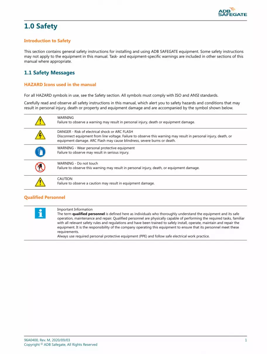
1.0 Safety
Introduction to Safety
This section contains general safety instructions for installing and using ADB SAFEGATE equipment. Some safety instructionsmay not apply to the equipment in this manual. Task- and equipment-specific warnings are included in other sections of thismanual where appropriate.
1.1 Safety Messages
HAZARD Icons used in the manual
For all HAZARD symbols in use, see the Safety section. All symbols must comply with ISO and ANSI standards.
Carefully read and observe all safety instructions in this manual, which alert you to safety hazards and conditions that mayresult in personal injury, death or property and equipment damage and are accompanied by the symbol shown below.
WARNINGFailure to observe a warning may result in personal injury, death or equipment damage.
DANGER - Risk of electrical shock or ARC FLASHDisconnect equipment from line voltage. Failure to observe this warning may result in personal injury, death, orequipment damage. ARC Flash may cause blindness, severe burns or death.
WARNING - Wear personal protective equipmentFailure to observe may result in serious injury.
WARNING - Do not touchFailure to observe this warning may result in personal injury, death, or equipment damage.
CAUTIONFailure to observe a caution may result in equipment damage.
Qualified Personnel
Important InformationThe term qualified personnel is defined here as individuals who thoroughly understand the equipment and its safeoperation, maintenance and repair. Qualified personnel are physically capable of performing the required tasks, familiarwith all relevant safety rules and regulations and have been trained to safely install, operate, maintain and repair theequipment. It is the responsibility of the company operating this equipment to ensure that its personnel meet theserequirements.Always use required personal protective equipment (PPE) and follow safe electrical work practice.
96A0400, Rev. M, 2020/09/03 1Copyright © ADB Safegate, All Rights Reserved

1.1.1 Introduction to Safety
CAUTIONUnsafe Equipment UseThis equipment may contain electrostatic devices, hazardous voltages and sharp edges on components
• Read installation instructions in their entirety before starting installation.• Become familiar with the general safety instructions in this section of the manual before installing,
operating, maintaining or repairing this equipment.• Read and carefully follow the instructions throughout this manual for performing specific tasks and
working with specific equipment.• Make this manual available to personnel installing, operating, maintaining or repairing this
equipment.• Follow all applicable safety procedures required by your company, industry standards and
government or other regulatory agencies.• Install all electrical connections to local code.• Use only electrical wire of sufficient gauge and insulation to handle the rated current demand. All
wiring must meet local codes.• Route electrical wiring along a protected path. Make sure they will not be damaged by moving
equipment.• Protect components from damage, wear, and harsh environment conditions.• Allow ample room for maintenance, panel accessibility, and cover removal.• Protect equipment with safety devices as specified by applicable safety regulations• If safety devices must be removed for installation, install them immediately after the work is
completed and check them for proper functioning prior to returning power to the circuit.
Failure to follow this instruction can result in serious injury or equipment damage
Additional Reference Materials
Important Information
• IEC - International Standards and Conformity Assessment for all electrical, electronic and related technologies.
• IEC 60364 - Electrical Installations in Buildings.
• FAA Advisory: AC 150/5340-26 (current edition), Maintenance of Airport Visual Aid Facilities.
• Maintenance personnel must refer to the maintenance procedure described in the ICAO Airport Services Manual,Part 9.
• ANSI/NFPA 79, Electrical Standards for Metalworking Machine Tools.
• National and local electrical codes and standards.
1.1.2 Intended Use
CAUTIONUse this equipment as intended by the manufacturerThis equipment is designed to perform a specific function, do not use this equipment for other purposes
• Using this equipment in ways other than described in this manual may result in personal injury, deathor property and equipment damage. Use this equipment only as described in this manual.
Failure to follow this instruction can result in serious injury or equipment damage
400 V: MALSR and ALSFSafety
2Copyright © ADB Safegate, All Rights Reserved

1.1.3 Material Handling Precautions: Storage
CAUTIONImproper StorageStore this equipment properly
• If equipment is to be stored prior to installation, it must be protected from the weather and kept freeof condensation and dust.
Failure to follow this instruction can result in equipment damage
1.1.4 Material Handling: Heavy Equipment
DANGERUnstable loadUse caution when moving heavy equipment
• Use extreme care when moving heavy equipment.• Verify that the moving equipment is rated to handle the weight.• When removing equipment from a shipping pallet, carefully balance and secure it using a safety
strap.
Failure to follow this instruction can result in death, serious injury, or equipment damage
1.1.5 Material Handling Precautions: Fasteners
DANGERForeign Object Damage - FODThis equipment may contain fasteners that may come loose - torque properly.
• Only use fasteners of the same type as the one originally supplied with the equipment.• Use of incorrect combination of gaskets, bolts and nuts can create severe damages to the product
installation and create safety risk .• You need to know what base the light fixture will be installed in, in order to chose the correct gasket,
bolts and nuts.• Bolt type, length, and torque value are determined by type of base, height of spacers used, and clamp
force required in FAA Engineering Brief No 83 (latest revision).• Due to the risk of bolts vibrating loose, do not use any type of washer with the fixing bolts (such as
split lock washers) other than an anti-vibration washer. Anti-vibration washers as defined in FAA EB83 (latest edition) must be used. For installations other than FAA, use the base can manufacturer'srecommendations.
• Always tighten the fasteners to the recommended torque. Use a calibrated torque wrench and applythe recommended adhesive type.
• Obey the instructions of the adhesives necessary for the fasteners.
Failure to follow these warnings may cause the fasteners to loosen, damage the equipment,potentially to loosen the equipment. This can lead to a highly dangerous situation of FOD, withpotential lethal consequences.
NoteTo minimize the risk of errors, the ADB SAFEGATE Sales Representative will have information on which gasket goeswith which base. This information is also provided in the product Data sheets, the User Manuals and the Spare PartLists.
96A0400, Rev. M, 2020/09/03 3Copyright © ADB Safegate, All Rights Reserved
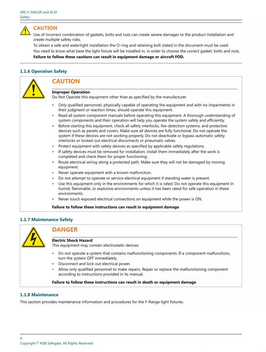
CAUTIONUse of incorrect combination of gaskets, bolts and nuts can create severe damages to the product installation andcreate multiple safety risks.To obtain a safe and watertight installation the O-ring and retaining bolt stated in the document must be used.You need to know what base the light fixture will be installed in, in order to choose the correct gasket, bolts and nuts.Failure to follow these cautions can result in equipment damage or aircraft FOD.
1.1.6 Operation Safety
CAUTIONImproper OperationDo Not Operate this equipment other than as specified by the manufacturer
• Only qualified personnel, physically capable of operating the equipment and with no impairments intheir judgment or reaction times, should operate this equipment.
• Read all system component manuals before operating this equipment. A thorough understanding ofsystem components and their operation will help you operate the system safely and efficiently.
• Before starting this equipment, check all safety interlocks, fire-detection systems, and protectivedevices such as panels and covers. Make sure all devices are fully functional. Do not operate thesystem if these devices are not working properly. Do not deactivate or bypass automatic safetyinterlocks or locked-out electrical disconnects or pneumatic valves.
• Protect equipment with safety devices as specified by applicable safety regulations.• If safety devices must be removed for installation, install them immediately after the work is
completed and check them for proper functioning.• Route electrical wiring along a protected path. Make sure they will not be damaged by moving
equipment.• Never operate equipment with a known malfunction.• Do not attempt to operate or service electrical equipment if standing water is present.• Use this equipment only in the environments for which it is rated. Do not operate this equipment in
humid, flammable, or explosive environments unless it has been rated for safe operation in theseenvironments.
• Never touch exposed electrical connections on equipment while the power is ON.
Failure to follow these instructions can result in equipment damage
1.1.7 Maintenance Safety
DANGERElectric Shock HazardThis equipment may contain electrostatic devices
• Do not operate a system that contains malfunctioning components. If a component malfunctions,turn the system OFF immediately.
• Disconnect and lock out electrical power.• Allow only qualified personnel to make repairs. Repair or replace the malfunctioning component
according to instructions provided in its manual.
Failure to follow these instructions can result in death or equipment damage
1.1.8 MaintenanceThis section provides maintenance information and procedures for the F-Range light fixtures.
400 V: MALSR and ALSFSafety
4Copyright © ADB Safegate, All Rights Reserved

Preventive Maintenance - Inset Lights
Maintenance personnel must refer to the maintenance procedure described in the ICAO Airport Services Manual, Part 9,Airport maintenance practices and in FAA Advisory Circular N° AC150/ 5340-26.
DANGERElectric Shock HazardThis equipment may contain electrostatic devices
• Do not carry out any action on the fixture unless you have read and understood all the information inthe Safety Section.
• Do not operate a system that contains malfunctioning components.• If a component malfunctions, turn the system OFF immediately.• Disconnect and lock out electrical power.• Allow only qualified personnel to make repairs. Repair or replace the malfunctioning component
according to instructions provided in its manual.• Make sure that the power to the series circuit is OFF when you carry out maintenance.
Failure to follow these instructions can result in death or equipment damage
CAUTIONUse of incorrect combination of gaskets, bolts and nuts can create severe damages to the product installation andcreate multiple safety risks.To obtain a safe and watertight installation the O-ring and retaining bolt stated in the document must be used.You need to know what base the light fixture will be installed in, in order to choose the correct gasket, bolts and nuts.Failure to follow these cautions can result in equipment damage or aircraft FOD.
1.1.9 Material Handling Precautions, ESD
CAUTIONElectrostatic Sensitive DevicesThis equipment may contain electrostatic devices
• Protect from electrostatic discharge.• Electronic modules and components should be touched only when this is unavoidable e.g. soldering,
replacement.• Before touching any component of the cabinet you shall bring your body to the same potential as the
cabinet by touching a conductive earthed part of the cabinet.• Electronic modules or components must not be brought in contact with highly insulating materials
such as plastic sheets, synthetic fiber clothing. They must be laid down on conductive surfaces.• The tip of the soldering iron must be grounded.• Electronic modules and components must be stored and transported in conductive packing.
Failure to follow this instruction can result in equipment damage
96A0400, Rev. M, 2020/09/03 5Copyright © ADB Safegate, All Rights Reserved

1.1.10 Arc Flash and Electric Shock Hazard
DANGERSeries Circuits have Hazardous VoltagesThis equipment produces high voltages to maintain the specified current - Do NOT Disconnect whileenergized.
• Allow only qualified personnel to perform maintenance, troubleshooting, and repair tasks.• Only persons who are properly trained and familiar with ADB SAFEGATE equipment are permitted to
service this equipment.• An open airfield current circuit is capable of generating >5000 Vac and may appear OFF to a meter.• Never unplug a device from a constant current circuit while it is operating; Arc flash may result.• Disconnect and lock out electrical power.• Always use safety devices when working on this equipment.• Follow the recommended maintenance procedures in the product manuals.• Do not service or adjust any equipment unless another person trained in first aid and CPR is present.• Connect all disconnected equipment ground cables and wires after servicing equipment. Ground all
conductive equipment.• Use only approved ADB SAFEGATE replacement parts. Using unapproved parts or making
unapproved modifications to equipment may void agency approvals and create safety hazards.• Check the interlock systems periodically to ensure their effectiveness.• Do not attempt to service electrical equipment if standing water is present. Use caution when
servicing electrical equipment in a high-humidity environment.• Use tools with insulated handles when working with airfield electrical equipment.
Failure to follow these instructions can result in death or equipment damage
400 V: MALSR and ALSFSafety
6Copyright © ADB Safegate, All Rights Reserved

2.0 Introduction
Provides the purpose, scope, and applicability of the technical manual.
The manual shows the information necessary to:
• Install and maintain the ALSF/MALSR system and associated equipment.
2.1 Low-Voltage ALSF/MALSR Approach Lighting System
Compliance with Standards
FAA: Designed according to ALSF-1, ALSF-2, ALSF-2/SSALR: FAA-E-2628; MALSR: FAA-E-2325
ICAO: Annex 14 Vol. 1, para. 5.3.4, 5.3.4.17, 5.3.7, and 5.3.8
Military: UFC 3-535-01 – Chapter 3 for Approach Applications using sequenced flashing lights
ALSF Uses
ALSF-1, ALSF-2, and ALSF-2/SSALR approach lighting systems with sequenced flashing lights are used at airports and militaryair bases to provide landing approach guidance, such as runway alignment, height perception, horizontal reference, and rollguidance extending from the landing threshold outward (2,400-3,000 feet) into the approach zone. Note that FAA-E-2628specifies only the sequenced flasher portion of the ALSF approach lighting system. The steady-burning portion of an ALSFsystem is implemented using either a 6.6 A or 20 A series circuit.
ALSF-1 • The ALSF-1 approach lighting system is used on Category I Instrument Landing Systems (ILS) and includes up to 24 lightstations (100-foot spacing) with up to 22 centerline bars of steady-burning lights (five lights to a bar) and up to 15flashers.
ALSF-2 • The ALSF-2 approach lighting system is used on Category II runways and includes up to 30 light stations (100-footspacing) with 30 centerline bars of steady-burning lights (five lights to a bar) and up to 21 flashers.
ALSF-2/SSALR • The SSALR approach lighting system has up to eight sequenced flashing lights and is used as part of a dual-mode
approach lighting system (ALSF-2/SSALR) when Category I conditions exist on Category II designated runways.
NoteFor ICAO applications, the system can also be used with up to 30 flashers.
MALSR Uses
The MALSR approach lighting system with sequenced flashing lights are used at airports and military air bases to providelanding approach guidance, such as runway alignment, height perception, horizontal reference, and roll guidance extendingfrom the landing threshold outward (2,400-3,000 feet) into the approach zone. Note that FAA-E-2325 specifies both thesequenced flasher and steady-burning portions of a MALSR approach lighting system.
Operating Conditions
Temperature Range: -67 °F to +137 °F (-55 °C to +55 °C)
Humidity: 0 to 100%
Altitude: 0 to 10,000 ft (3048 m) maximum
96A0400, Rev. M, 2020/09/03 7Copyright © ADB Safegate, All Rights Reserved

2.2 LV ALSF/MALSR
Low-Voltage ALSF High-Intensity and MALSR Medium-Intensity Approach Lighting Equipment with Elevated and In-pavementSequenced Flashers are used at airports and military air bases to provide landing approach guidance, such as runwayalignment, height perception, horizontal reference, and roll guidance extending from the landing threshold outward(2,400-3,000 feet) into the approach zone. Flasher operating voltage is +400V DC instead of +2000V DC used in traditionalsystems, improving safety. This also allows standard 600V cable to be used between the flasher and Individual Control Cabinet(ICC).
This eliminates the need for high voltage interconnecting cable. MALSR sequenced flashers can be easily expanded to ALSF ata later date.
2.3 About this manual
2.3.1 How to work with the manual
1. Become familiar with the structure and content.
2. Carry out the actions completely and in the given sequence.
2.4 Product Introduction
Sequenced flashing lights are used predominantly during reduced visibility as a landing aid in the approach area or therunway threshold area.
The units flash in sequence at 3 selectable brightness levels (3 steps).
This section describes the ADB SAFGATE Medium intensity Approach Lighting System with Runway alignment indicator lights(MALSR) and Approach Lighting System with sequenced Flashers (ALSF).
2.4.1 Theory of OperationThe ADB Safegate sequenced-flasher lighting systems includes a master control cabinet, junction boxes, individual controlcabinets (ICC), either elevated or in-pavement flasher units and, maintenance software that can be loaded on a PC running aWindows™ operating system. For MALSR systems, a 15kVA transformer is also provided to power the steady-burning lights.
In the ALSF configuration, an array of light bars are installed symmetrically around the centerline of the approach lightingsystem, starting at the approach threshold and extending a total distance of 2,400 feet (731.5 m) outward into the approachzone up to 3,000 feet (914 m) at facilities where high-speed military aircraft share runway usage. Up to 21 flashing lampassemblies (30 for ICAO applications) are installed in the outer portion of the approach lighting system at regular intervals.
In the MALSR configuration, an array of light bars are installed symmetrically around the centerline of the approach lightingsystem, starting at the approach threshold and extending a total distance of 2,400 feet (731.5 m) into the approach zone andup to 3,000 feet (914.4 m) at facilities where high-speed military aircraft share runway usage. Typically, up to 8 flashing lampassemblies are installed in the outer portion of the approach lighting system at regular intervals.
The MALSR system uses white 120V AC PAR-38 fixtures for the steady burning light bar arrays. Also, the MALSR system usesgreen elevated 120V AC PAR-56 fixtures for the threshold bar. The ALSF system uses white or red elevated PAR-56 6.6A or 20Afixtures for light bar arrays and green PAR-56 6.6A or 20A fixtures for the threshold bar.
Flashing lights are arranged and connected in such a way as to produce a sequenced flashing light signal that has theappearance of a ball of light traveling down the system from the outer end (flasher farthest from the runway threshold) to theflasher assembly closest to the runway threshold twice per second.
400 V: MALSR and ALSFIntroduction
8Copyright © ADB Safegate, All Rights Reserved

2.4.2 ALSF SystemSee Figure 3. The ALSF system comes in two configurations: ALSF-1 and ALSF-2. Refer to Table 1 for an overview of ALSFconfigurations.
Table 1: ALSF ConfigurationsALSF-1 ALSF-2 SSALR
Directs aircraft to runway centerlineunder CAT I and CAT II conditions withwaiver.
Directs aircraft to runway centerlineunder CAT I, II, III conditions.
Directs aircraft to runway centerline when visibilityconditions are better than CAT I.
Up to 15 flashers Up to 21 flashers5 flashers. Every other flasher up to #9 is active; the restare inactive. Operator can reconfigure the number ofactive flashers.
3-Step intensity 3-Step intensity 3-Step intensity
The ALSF consists of an array of light bars installed symmetrically about the approach lighting system centerline, starting atthe approach threshold and extending a total distance of 2400 feet (731.52 m) outward into the approach zone and, up to3000 feet (914.4 m) at facilities where high speed military aircraft share runway usage.
NoteFor steady burning PAR 56 (FAP) used with the ALSF system, refer to instruction manual 96A0119, Type FAP PAR-56Approach Light.
2.4.2.1 ALSF UsesALSF-1, ALSF-2, and ALSF-2/SSALR approach lighting systems with sequenced flashing lights are used at airports and militaryair bases to provide landing approach guidance, such as runway alignment, height perception, horizontal reference, and rollguidance extending from the landing threshold outward (2,400-3,000 feet) into the approach zone. Note that FAAE-2628specifies only the sequenced flasher portion of the ALSF approach lighting system. The steady-burning portion of an ALSFsystem is implemented using either a 6.6A or 20A series circuit.
2.4.2.2 ALSF-1The ALSF-1 approach lighting system is used on Category I Instrument Landing Systems (ILS) and includes up to 24 lightstations (100-foot spacing) with up to 22 centerline bars of steady-burning lights (five lights to a bar) and up to 15 flashers.
96A0400, Rev. M, 2020/09/03 9Copyright © ADB Safegate, All Rights Reserved

2.4.2.3 ALSF-2The ALSF-2 approach lighting system is used on Category II runways and includes up to 30 light stations (100-foot spacing)with 30 centerline bars of steady-burning lights (five lights to a bar) and up to 21 flashers.
Figure 3: ALSF System
2.4.2.4 ALSF-2/SSALRThe SSALR approach lighting system has up to eight sequenced flashing lights and is used as part of a dual-mode approachlighting system (ALSF-2/SSALR) when Category I conditions exist on Category II designated runways.
400 V: MALSR and ALSFIntroduction
10Copyright © ADB Safegate, All Rights Reserved

NoteFor ICAO applications, the system can also be used with up to 30 flashers with an additional 2 optional REIL flashers.
2.4.2.5 SSALR ModeSee Figure 3. Refer to Table 1. Both ALSF-1 and ALSF-2 can be operated in the SSALR mode.
2.4.3 MALSR System
2.4.3.1 MALSR UsesSee Figure 4. The MALSR system is used at airports to provide landing approach guidance under Category I conditions.
The MALSR approach lighting system with sequenced flashing lights are used at airports and military air bases to providelanding approach guidance, such as runway alignment, height perception, horizontal reference, and roll guidance extendingfrom the landing threshold outward (2,400-3,000 feet) into the approach zone. Note that FAA-E-2325 specifies both thesequenced flasher and steady-burning portions of a MALSR approach lighting system.
Figure 4: MALSR System
96A0400, Rev. M, 2020/09/03 11Copyright © ADB Safegate, All Rights Reserved

MALSR system includes:
• A master control cabinet.
• 3-8 sequenced flashers. Five flashers are standard.
• 15 kVA power transformer.
• 9 five-light bars installed symmetrically about the approach lighting centerline. Each light bar has five PAR-38 lampholders for a total of 45 lamp holders.
• 18 PAR-56 lamp holders used for a threshold marker. Refer to instruction manual 96A0119, Type FAP PAR-56 ApproachLight for more information on this fixture
NoteThe optional FAA-E-2968 in-pavement approach light can be used as a threshold marker, depending on siterequirements.
The ADB SAFEGATE MALSR sequenced flasher can be modified to a 21-flasher ALSF system at a later time.
2.4.3.2 Environmental Operating Conditions
• Temperature Range: -67°F to +137°F (-55°C to +55°C)
• Humidity: 0 to 100%.
• Altitude: 0 to 10,000 ft. (3048 m) maximum.
2.4.3.3 Features
• MALSR sequenced flashers can be easily expanded to ALSF at a later date.
• Flasher operating voltage is +400V DC instead of +2000V DC used in traditional systems, improving safety. This alsoallows standard 600V cable to be used between the flasher and Individual Control Cabinet (ICC). This eliminates the needfor high voltage interconnecting cable.
• Lamp subassembly in elevated flash head can be quickly and easily replaced without the use of tools.
• In-pavement flasher uses an aluminum top cover, reducing maintenance requirements. This also results in a very lowweight.
• In-pavement flasher height above ground (without snow plow ring) is only 0.75” high.
• In-pavement flasher height above ground (with snow plow ring) is only 0.5” high.
• Flashers can be up to 393 ft. (120 m) from the ICC, allowing placement outside the obstacle free zone.
• ICC can be optionally supplied with one cabinet that can connect to 3 flashers, minimizing acquisition and installationcost.
• ICC uses a highly efficient power supply. This yields lower power consumption, elimination of peak inrush currents, andallows use of smaller gauge supply power wires compared to traditional capacitive discharge systems.
• Numerous remote control/monitoring options maximize system flexibility. Remote control/monitoring can beaccomplished via:
• Single or dual field bus.
• Individual 24V DC, 48V DC or 120V AC hard-wired copper connections.
400 V: MALSR and ALSFIntroduction
12Copyright © ADB Safegate, All Rights Reserved

2.4.4 MALSR/ALSF Required Equipment:Refer to Table 2 for the MALSR/ALSF required equipment that is supplied. Refer to Additional equipment may be required,and must be ordered separately for the MALSR and ALSF required equipment that is not supplied. Refer to “Parts” on page121 for ordering information.
Table 2: MALSR/ALSF Required Equipment SuppliedDescription MALSR ALSF
Master Control Cabinet 1 1
Sequence Flasher Heads 3 to 8 Up to 21
Individual Control Cabinets 3 to 8 Up to 21
Junction Boxes 3 to 8 Up to 21
15 kVA Power Transformer 1 None
PAR-38 Lamp Holders 45 None
PAR-56 Lamp Holders 18 None
Flasher Test Equipment (Laptop and Software) 1 1
Mating Connectors for ICC and the flasher tester laptop 2 None
Steady-Burning Aiming Device (PAR-38/-56) 1 None
Elevated Flasher Aiming Device 1 1
Spare Parts Trunk 1 None
Instruction Manuals 1 set 1 set
NoteSee ADB Safegate catalog sheet 1042 for more details on ALSF or MALSR PAR-56 fixtures.
2.4.5 Additional equipment may be required, and must be ordered separately• 45-PAR-38, 120W or 150W, 120V AC lamps.
• 18-PAR-56, 300W, 120V AC lamps.
• Frangible couplings.
• Low impact-resistant structures.
• 2-inch (50.8 mm) EMT conduit.
NoteNew MALSR systems will use the 150 W PAR-38 Lamps.
• For in-pavement FAA-E-2968 MALSR medium-intensity system, Style I, unidirectional white applications, use part number44A6439-1000. This fixture uses one 105W lamp and is photometrically equivalent to the older style 200W L-850B fixturesthat were used in this application. See catalog sheet 2000 for more details.
• For in-pavement FAA-E-2968 MALSR medium-intensity system, Style II, unidirectional green applications, use part number44A6440-1000. This fixture uses three 62W lamps and is photometrically equivalent to the older style 200W L-850Efixtures that were used in this application. See catalog sheet 2029 for more details.
• Encapsulated (FAA Style) isolation transformers are available for voltage-driven, medium-intensity approach lightingapplications. For 105W, 240V AC to 15.9V AC applications, use part number 35C0095. For three 62W lamp applications, a186W, 240V AC to 28.2V AC transformer is used (Part No. 35C0096). See catalog sheet 2000 for white approach MALSRapplication.
96A0400, Rev. M, 2020/09/03 13Copyright © ADB Safegate, All Rights Reserved

2.4.6 Some Useful Terms and Definitions
Table 3: Terms and DefinitionsTerm Description
Binary notation All data in the digital circuits is treated using “1” and “0”. Thus, all decimal notations are transcribed into binarynotations.
FCU Flasher Control Unit (ICC)
Hexadecimal notation This is a way to write numbers in a base of 16, instead of the standard 10. In the manual, it is used for bits andaddresses, because it better identifies the active data address or data lines.
ICC Individual Control Cabinet
LMC Local Master Controller
Local bus The communication bus, which exchanges data and control signals between the FCUs and the LMC.
MW Multi-wire
PCB Printed Circuit Board
PE Protective Earth
UI User Interface
2.4.7 Master Control CabinetThe master control cabinet contains a control / monitoring board, called the Local Master Controller (LMC), that provides thepower, timing signals, misfire monitoring circuitry, and three-step intensity control signals to the sequenced flasherassemblies in remote and local mode.
400 V: MALSR and ALSFIntroduction
14Copyright © ADB Safegate, All Rights Reserved

2.4.8 Equipment Data (Master Control Cabinet)Input Voltage 120/240 Vac, +10%/-15%, 50/60Hz, three-wire, single-phase (neutral center-tapped).
• Time from:
• In ALSF mode, corresponds to one cycle, Trigger Pulse corresponds to one cycle of the 60Hz line, or 16.67 ms.
• In SSALR mode, Trigger Pulse corresponds to every other cycle of the 60Hz line or 33.3 ms.
• For MALSR, corresponds to every other cycle of the 60Hz line or 33.3 ms.
• Enclosure NEMA 4, outdoor and ventilated (to prevent condensation).
• Maintenance:
• Rotary control switch for manual operation.
• Flasher ON/OFF switch to de-energize flashers (if desired) when the approach lights are energized.
• LED indicators for system monitoring.
• Service entrance switch disconnects incoming power.
• 100W maintenance light.
• Door can be locked in a 120° open position.
• Lightning Protection on all input and output electrical connections.
2.4.8.1 Gross Weight and Dimensions
• 137 lb. (62 kg)
• 37.25 x 30 x 11.38 in (94.6 x 76.2 x 28.9 cm) (H x W x L)
2.4.9 Master Input Power Requirement
Table 4: Master Input Power RequirementVoltage Max. No. of Flashers Max. Power Requirements ALSF Max. Power Requirements MALSR
120/240 Vac
3 4kVA 18kVA
55kVA 19kVA
6
86kVA
20kVA
9
12 7kVA
15 8kVA
18 9kVA
21 10kVA
2.4.10 Flasher
2.4.10.1 Elevated Flash Head (UEL)Each elevated flash head assembly consists of a flashing light head, which houses a low voltage (400 Vdc) flashtube and atrigger transformer. A safety interlock switch disconnects the individual control cabinet (ICC) power when the flash head isopened. The elevated flash head is rated IP45.
2.4.10.2 Type FFL In-pavement Flasher (MALSR and ALSF)For both MALSR and ALSF, each in-pavement flasher consists of a aluminum fixture, which houses the low voltage (400 Vdc)linear xenon flashtube, trigger transformer, and optical assembly. The unique optical assembly ensures that the fixture meetsFAA/ICAO photometric requirements. A safety interlock switch discharges the voltage across the flash lamp when the fixture isopened for service. A 6-core (5-conductor and shield) cable is used between the ICC and the in-pavement flasher.
96A0400, Rev. M, 2020/09/03 15Copyright © ADB Safegate, All Rights Reserved

A 6-core cable pigtail is provided with the fixture. Two methods may be used to connect the 6-core cable to the light fixture.The 6-core pigtail can be spliced to the matching 6-core interconnecting cable using a conventional waterproof splice. Also, amating connector is available to allow the entire fixture to be quickly disconnected from the circuit.
In-pavement flasher height is 0.75 inch without the snow plow ring and fits on a standard FAA 12-inch base can. Fixtureheight is 0.5 inch with the snow plow ring.
2.4.10.3 In-pavement and Elevated Flasher Fixture Equipment Data
Input Voltage +400 Vdc
Lamp Xenon flashtube
Lamp Life Average 1,000 hours on high-intensity step
Intensity Decrease 30% or less over minimum rated lamp life
Flash Skipping Less than 1% with no consecutive skipping
Elevated Light Beam Axis Adjustable vertically from the horizontal to 25° above the horizontal
Vibration Withstands vibration in frequency range of 10 to 2,000Hz in accordance with NEMA Standard FA1-3.01
Elevated MountingOn a 2-inch (5.08 cm) frangible coupling or 2-inch EMT conduit, or 1.5-inch (3.81 cm) OD tube or 1.5-inchschedule 40 pipe. Mounting can be on a 1- inch (2.54 cm) pipe (used on an aluminum tower) using adaptersleeve.
Installation Distance A maximum of 393 ft. (120 m) from the ICC
Elevated Dimensions 10.6 x 5.75 x 6.7 in - H x W x D (27 x 14.6 x 17 cm)
In-pavement Fits on standard 12-inch base can.
Elevated Wt. 4 lb (1.8 kg).
In-pavement Weight 16.5 lb. (7.5 kg).
2.4.11 Individual Control Cabinet (ICC)Each flasher fixture is controlled by an individual control cabinet, which houses triggering circuits, terminal blocks, andlightning arrestors. A safety interlock switch is incorporated into the enclosure to discharge the flash lamp power circuitrywhen the cabinet door is opened. The ICC can connect to one flasher or optionally, 3 flashers. The ICC includes an anti-condensation heater. As soon as power is applied the anti-condensation heater(s) can activate, even if the flashing lightsystem is switched off.
2.4.12 Aiming Devices
2.4.12.1 Elevated PAR-38/56 Steady-Burning LampsAiming devices can be used on either ground mounted lights or when the lights are mounted on low impact resistantstructures conforming to FAA-E-2604 or FAA-E-2702. The aiming device is used to adjust the vertical elevation angle ofPAR-38 and PAR-56 steady-burning lamp holders. The aiming device permits aiming of the lamp axis perpendicular to theplane of the cover glass at any angle from 0° to +25° above the horizontal. The aiming angle can be calibrated in 1° intervals,and the actual aiming angle of the lamp holder with the aiming device attached is accurate to within ±0.5°.
2.4.12.2 Elevated Type UEL Flashing LampsThis aiming device is used to adjust the vertical elevation of the elevated flash head. It is available either as an electronic or asa simple mechanical (bubble level) based unit. Both aiming devices have a scale calibrated in 1 degree increments and areaccurate to within ±0.5°.
The electronic aiming device permits adjustment and measurement of the vertical elevation angle of the UEL lamp holder forfixtures mounted over 6 ft. (1829 mm) high and, the bubble level aiming device can be used on fixtures mounted 6 ft. (1829mm) high or less‘. It is a single unit consisting of a housing, support, trip cord (on electronic level only) and attaching parts.The aiming device permits aiming of the lamp axis perpendicular to the plane of the cover glass to any angle from 0.0 to +25degrees above the horizontal.
The electronic aiming device can be used to remotely aim the UEL lamp holder on low impact resistance structuresconforming to FAA-E-2604 or FAA-E-2702.
400 V: MALSR and ALSFIntroduction
16Copyright © ADB Safegate, All Rights Reserved

2.4.13 Flasher TesterFlasher Tester functionality is accomplished using software (supplied on a CD with the system) that provides advancedmonitoring and on-site configuration capabilities. The software may be loaded either on a customer supplied laptop or(optionally) on a laptop provided with the system. The laptop is connected to either the Master or any ICC using acommunication dongle. The software provides user-adjustable parameter setting and configuration functions and detailedindividual status monitoring screens.
2.4.14 Junction BoxJunction boxes are used to distribute power and communications signals to the ICCs. One junction box is required for eachsequenced flasher in the system. Each junction box has two terminal strips to accommodate all wires used for the flasher unit.
2.4.15 FAA Spare Parts TrunkThe optional FAA Spare Parts Trunk includes Master, ICC and flashing-fixture PCBs.
2.4.16 MALSR Steady-Burning Light Components
2.4.16.1 MALSR Lamp Holders
PAR-38 Lamp Holder
There are 45 clear PAR-38 lamp holders mounted five to a light bar in the runway approach. Each lamp holder is designed toaccommodate 120W or 150W, 120V AC PAR-38 lamps. An adjustable base on the lamp holder permits vertical adjustmentfrom the horizontal to 25° above the horizontal. Also, the mounting hardware permits horizontal alignment of the light beamaxis to any horizontal angle within ±1°. The lamp holder has a mounting base that mounts on the open top of a frangiblecoupling, on a light bar with an adapter sleeve, or to a 2-inch (EMT) conduit.
PAR-56 Lamp Holder
Eighteen PAR-56 lamp holders are installed on the runway threshold. The lamp holder has mounting clips to hold the greenfilter and is designed to accommodate a 300W, 120V AC PAR-56 lamp. Each lamp holder has an adjustable base for verticaladjustment and mounts to a 2-inch EMT conduit or on top of a frangible coupling. PAR-56 lamp holders are orderedseparately. See Catalog Sheet 1042 for ordering information.
2.4.16.2 MALSR 15kVA Power TransformerThe 15kVA, 60Hz power transformer powers the steady-burning PAR-56 and PAR-38 lights. Taps on the transformer areswitched electronically by the master control cabinet to provide power at any one of three voltage levels to the steady-burning lights. Additional taps provided on the primary of the transformer permit manual secondary voltage adjustment towithin 2.5% of the required secondary output assuming the primary voltage is between 210V and 252V AC. The transformer ishoused in an outdoor, rain-tight enclosure with lugs provided on the back of the enclosure for mounting the cabinet in avertical position. Two internal MOV lightning arrestors are provided for input and output lightning protection.
Table 5: MALSR Power Transformer Nominal Output VoltageIntensity Step Secondary Output
Low 50/100 Vac ±0.5%
Medium 75/150 Vac ±0.5%
High 120/240 Vac ±0.5
96A0400, Rev. M, 2020/09/03 17Copyright © ADB Safegate, All Rights Reserved

2.4.17 MALSR Ordering InformationThe following equipment is supplied for the MALSR approach lighting systems per FAA-E-2325:
Table 6: MALSR Component Ordering by ConfigurationQuantity Description
1 Master Control Cabinet
3 to 8 Sequence Flasher Heads
3 to 8 Individual Control Cabinets
3 to 8 Junction Boxes
1 15 kVA Power Transformer
45 PAR-38 Lamp Holders
18 PAR-56 Lamp Holders
1 Flasher Tester Equipment
1 Steady-Burning Aiming Device (PAR-38/-56)
1 Elevated Flasher Aiming Device
1 Spare Parts Trunk
1 Instruction Manual
Additional equipment may be required, but must be ordered separately:
• PAR-38, 120W or 150W, 120V AC lamps
• PAR-56, 300W, 120V AC lamps
• Frangible couplings
• Low impact-resistant structures
• For in-pavement FAA-E-2968 MALSR medium-intensity system, Style I, unidirectional white applications, use part number44A6439-1000.
• This fixture uses one 105W lamp and is photometrically equivalent to the older style 200W L-850B fixtures that were usedin this application. See catalog sheet 2000 for more details.
• Encapsulated (FAA Style) isolation transformers are available for voltage-driven, medium- intensity approach lightingapplications. For 105W, 240V AC to 15.9V AC applications, use part number 35C0095.
• For in-pavement FAA-E-2968 MALSR medium-intensity system, Style II, unidirectional green applications, use part number44A6440-1000. This fixture uses three 62W lamps and is photometrically equivalent to the older style 200W L-850Efixtures that were used in this application. See catalog sheet 2029 for more details.
• Encapsulated (FAA Style) isolation transformers are available for voltage-driven, medium- intensity approach lightingapplications. For three 62W lamp applications, a 186W, 240V AC to 28.2V AC transformer is used (Part No. 35C0096). Seecatalog sheet 2000 for white approach MALSR application
2.4.18 ALSF Ordering InformationThe following equipment is supplied for the ALSF-1, ALSF-2, and ALSF-2/SSALR approach lighting systems per FAA-E-2628:
Table 7: ALSF Component Ordering by ConfigurationQuantity Description
1 Master Control Cabinet (up to 32 for ICAO applications)
Up to 21 Flashing Light Heads (up to 32 for ICAO applications)
Up to 21 Individual Control Cabinets (up to 32 for ICAO applications)
Up to 21 Junction Boxes
400 V: MALSR and ALSFIntroduction
18Copyright © ADB Safegate, All Rights Reserved

Table 7: ALSF Component Ordering by Configuration (continued)1 Steady-Burning Aiming Device
1 Elevated Flasher Aiming Device
1 Flasher Tester Equipment
1 Instruction Manual
Additional equipment may be required, but must be ordered separately:
• PAR-56 Lamp Holder Assemblies
• PAR-56 Lamps
• Frangible Couplings
• Low Impact-Resistant Structures
• Spare Parts Trunk
• L-830 Isolation Transformer or (1) 1,500W, 20A/20A, Isolation Transformer
NoteFor in-pavement FAA-E-2952 (Replacement for 2491) ALSF high-intensity system applications, see Catalog Sheet2029 for details.
2.4.19 Specifications
2.4.19.1 Commissioning RecordsThis table may be used to record the configuration of the system.
APPROACH Mode name Notes
Cycle time in seconds
Table 8: Commissioning RecordControl unit ID Flasher ID SW2 Timing in ms REIL Group
Control unit 1 Flasher A
Flasher B
Flasher C
Control unit 2 Flasher A
Flasher B
Flasher C
Control unit 3 Flasher A
Flasher B
Flasher C
Control unit 4 Flasher A
Flasher B
Flasher C
Control unit 5 Flasher A
Flasher B
Flasher C
Control unit 6 Flasher A
96A0400, Rev. M, 2020/09/03 19Copyright © ADB Safegate, All Rights Reserved

Table 8: Commissioning Record (continued)Control unit ID Flasher ID SW2 Timing in ms REIL Group
Flasher B
Flasher C
Control unit 7 Flasher A
Flasher B
Flasher C
Control unit 8 Flasher A
Flasher B
Flasher C
Control unit 9 Flasher A
Flasher B
Flasher C
Control unit 10 Flasher A
Flasher B
Flasher C
Control unit 11
Control unit 12
Control unit 13
Control unit 14
Control unit 15
Control unit 16
Control unit 17
Control unit 18
Control unit 19
Control unit 20
Control unit 21
Control unit 22
Control unit 23
Control unit 24
Control unit 25
Control unit 26
Control unit 27
Control unit 28
Control unit 29
Control unit 30
Control unit 31
Control unit 32
400 V: MALSR and ALSFIntroduction
20Copyright © ADB Safegate, All Rights Reserved

2.4.19.2 Default Settings Multiwire
Table 9: Back-indication signals Multi-wireP1 Function
1 SFL running - contact closed when running
2 RTILS/REILS running - contact closed when running
3 REILS DOWN - contact closed in case of alarm
4 Misfire on 1 ICC (latched) - contact closed in case of alarm
5 Misfire on 2 consecutive ICCs (latched) - contact closed in case of alarm
6 Communication error on local bus + Security (Door + MOV) - contact open in case of alarm
7 Over temperature - contact closed in case of alarm
8 Alarms 3 + 5 + 6 combined in OR mode - contact closed in case of alarm
9 Common
10 GNDext
11 Vext+
12 PE
The above settings can be modified at any time, by using the Flasher Tester Software. It is the customer's responsibility tomodify the configuration. Modification of the Multi-wire configuration is only possible using the Flasher Tester Software.
Table 10: Remote control signals Multi-wireP2 Function
1 SFL ON Step 1
2 SFL ON Step 2
3 SFL ON Step 3
4 REILS/RTILS ON step 1
5 REILS/RTILS ON step 2
6 REILS/RTILS ON step 3
7 Reset alarms
8 Reserved for future use
9 Common
10 Vext+
11 GNDext
12 PE
The above settings can be modified at any time, by using the Flasher Tester Software. It is the customer's responsibility tomodify the configuration. Modification of the Multi-wire configuration is only possible using the Flasher Tester Software.
96A0400, Rev. M, 2020/09/03 21Copyright © ADB Safegate, All Rights Reserved

2.4.19.3 Customized Settings Multi-wireThe following table can be used to record the Back-indication signals
Table 11: Back-indication signalsP1 Function
1
2
3
4
5
6
7
8
9 Common
10 GNDext
11 Vext+
12 PE
The following table can be used to record the Remote control signals
Table 12: Remote control signalsP21
Function
2
3
4
5
6
7
8
9 Common
10 Vext+
11 GNDext
12 PE
2.4.20 Technical DataThe flashing light system meets ICAO (International Civil Aviation Organization) and FAA (Federal Aviation Administration)requirements, as well as those of the IEC 61824 and IEC 61000-6-4 and 61000-6-2 standards of the International Electro-technical Commission.
2.4.20.1 Operational LimitsThe flashing light units are designed for outdoor use in the airport approach area.
They are designed to meet the requirements of the various specifications mentioned above. Operation outside the designlimitations of these specifications may result in degradation of performance, damage or failure of components or hazardousconditions.
400 V: MALSR and ALSFIntroduction
22Copyright © ADB Safegate, All Rights Reserved
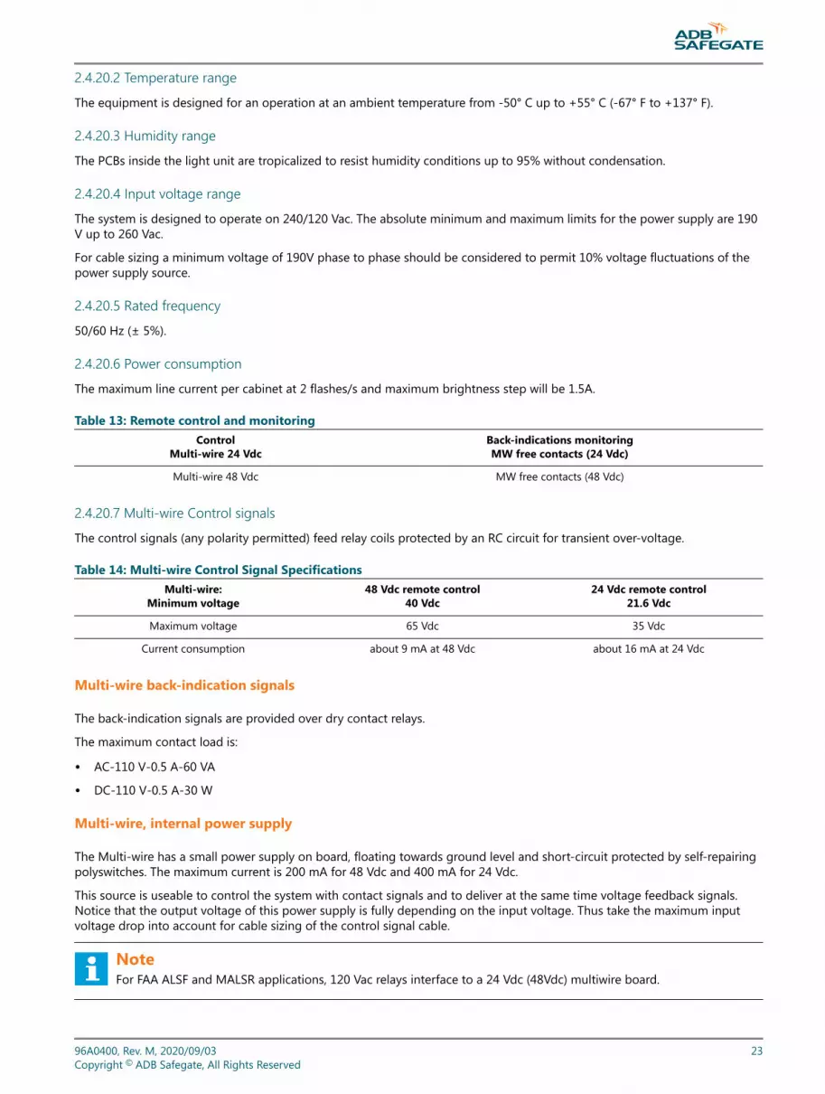
2.4.20.2 Temperature rangeThe equipment is designed for an operation at an ambient temperature from -50° C up to +55° C (-67° F to +137° F).
2.4.20.3 Humidity rangeThe PCBs inside the light unit are tropicalized to resist humidity conditions up to 95% without condensation.
2.4.20.4 Input voltage rangeThe system is designed to operate on 240/120 Vac. The absolute minimum and maximum limits for the power supply are 190V up to 260 Vac.
For cable sizing a minimum voltage of 190V phase to phase should be considered to permit 10% voltage fluctuations of thepower supply source.
2.4.20.5 Rated frequency50/60 Hz (± 5%).
2.4.20.6 Power consumptionThe maximum line current per cabinet at 2 flashes/s and maximum brightness step will be 1.5A.
Table 13: Remote control and monitoringControl
Multi-wire 24 VdcBack-indications monitoringMW free contacts (24 Vdc)
Multi-wire 48 Vdc MW free contacts (48 Vdc)
2.4.20.7 Multi-wire Control signalsThe control signals (any polarity permitted) feed relay coils protected by an RC circuit for transient over-voltage.
Table 14: Multi-wire Control Signal SpecificationsMulti-wire:
Minimum voltage48 Vdc remote control
40 Vdc24 Vdc remote control
21.6 Vdc
Maximum voltage 65 Vdc 35 Vdc
Current consumption about 9 mA at 48 Vdc about 16 mA at 24 Vdc
Multi-wire back-indication signals
The back-indication signals are provided over dry contact relays.
The maximum contact load is:
• AC-110 V-0.5 A-60 VA
• DC-110 V-0.5 A-30 W
Multi-wire, internal power supply
The Multi-wire has a small power supply on board, floating towards ground level and short-circuit protected by self-repairingpolyswitches. The maximum current is 200 mA for 48 Vdc and 400 mA for 24 Vdc.
This source is useable to control the system with contact signals and to deliver at the same time voltage feedback signals.Notice that the output voltage of this power supply is fully depending on the input voltage. Thus take the maximum inputvoltage drop into account for cable sizing of the control signal cable.
NoteFor FAA ALSF and MALSR applications, 120 Vac relays interface to a 24 Vdc (48Vdc) multiwire board.
96A0400, Rev. M, 2020/09/03 23Copyright © ADB Safegate, All Rights Reserved

2.4.20.8 EMC conformityAccording to EN61000-6-4 (Generic standard, Industrial environment, Emission), para. 7.1, the flashing light system will not beused in residential, commercial and light-industrial environment
2.4.21 ICC Mechanical Data
ICC-1: Dimensions and Weight
Outer dimensions(WxDxH):
16.5 x 9.25 x 20.5-inches(420 x 235 x 520 mm)(without mounting kit)
Total weight: 42.7 lbs. (19.4 kg)
ICC-3: Dimensions and Weight
Outer dimensions(WxDxH):
31 x 13.3 x 25.6-inches(790 x 340 x 650 mm)(sun roof & base included)
Total weight: 103.6 lbs. (47 kg)
2.4.22 ADB SAFEGATE ALSF / MALSR System SpecificationsThis subsection describes the specifications for the MALSR and ALSF. Refer to the Parts section for part numbers.
2.4.22.1 Master Control CabinetThis subsection describes the specifications for the master control cabinet.
Table 15: Time from Trigger Pulse to Trigger PulseMALSR ALSF SSALR
Corresponds to every other cycle of the 60 Hzline (33.33 ms)
Corresponds to one cycle of 60 Hz line(16.67 ms)
Corresponds to every other cycle of the 60 Hzline (33.33 ms)
2.4.22.2 Maintenance Features on Control CabinetRefer to the list below for the MALSR/ALSF approach lighting systems control cabinet maintenance features.
• Rotary control switch for manual control of brightness level of system.
• Flasher on/off switch to de-energize flashers, if desired, when the approach lights are energized.
• Service entrance switch disconnects incoming power to the control unit.
• Maintenance light (100 W, 120 Vac); 120 Vac, single phase, 15 A, grounding-type receptacle with built-in fault interrupter.
• Door can be locked in a 120 degree position.
Enclosure NEMA-4, Enclosure is outdoor and ventilated to prevent condensation.
Mounting Mounting lugs provided on the back of the cabinet for mounting the cabinet vertically.
Dimensions 37-1/4 x 30 x 13-3/8 inches (94.6 x 76.2 x 34 cm)
Total Weight 137 lb (62.14 kg)
400 V: MALSR and ALSFIntroduction
24Copyright © ADB Safegate, All Rights Reserved

2.4.22.3 Aiming DeviceThis subsection describes the specifications for the PAR38 / PAR56 aiming device.
Quantity One
Aiming Flash lamp axis can be aimed from 0 to 25 degrees above the horizontal.
Scale Calibrated in 1-degree increments
Accuracy ±1/2 degree
Dimensions 7 in. x 10 in. (17.8 cm x 25.4 cm) diameter
Weight 10 lb (4.5 kg)
2.4.22.4 Junction BoxThis subsection describes the specifications for the junction box.
Quantity
One junction box for each flasher.Junction boxes are made to FAA drawing D-5140-2 except for thefollowing:1-in. conduit hub is replaced by two 2-in. conduit hubs at the bottom of the box.Terminal blocks are of the enclosed-base type for use with pressure-type terminals meeting the requirements ofFAA-G-2100c, paragraph 3.5.34.Boxes provide control- and monitor-wire interconnection between master control cabinet and individual controlcabinets.
Conduit Hubs Two 2-in. hubs on the bottom of the box
Dimensions 14 x 14 x 6 in. (35.6 x 35.6 x 15.2 cm)
Weight 15 lb (6.8 kg)
2.4.22.5 PAR-38 Lampholders (MALSR Only)This subsection describes the specifications for the MALSR PAR-38 lampholders.
DesignThe PAR-38 lampholders are designed to accommodate 120W or150W,120 Vac, PAR-38 spot lamps.
Quantity Total of 45 lampholders
Installation 5 PAR-38 lampholders are installed on a light bar. Nine light bars are in a system.
Mounting Mounts on a 2-inch EMT conduit, to the top of a frangible coupling or with adapter sleeve, on analuminum or fiberglass tower.
Dimensions 9 x 3 x 3 in. (22.9 x 7.6 x 7.6 cm)
2.4.22.6 PAR-56 Lampholders (MALSR and ALSF)This subsection describes the specifications for the MALSR PAR-56 lampholders.
Design The PAR-56 lampholders are designed to accommodate 200 W, 300W, 500 W 6.6 A, 20 A, or 120 Vac depending upon application.
Quantity Total of 18 lampholders
Mounting Mounts on a 2-inch EMT conduit, to the top of a frangible coupling or with adapter sleeve on analuminum or fiberglass tower.
Dimensions 13-1/3 x 6-1/4 x 8-5/16 in. (33.86 x 15.88 x 21.11 cm)
96A0400, Rev. M, 2020/09/03 25Copyright © ADB Safegate, All Rights Reserved

2.4.22.7 15 kVA Power Transformer (MALSR Only)This subsection describes the specifications for the MALSR 15 kVA power transformer. This transformer provides power andintensity control to the steady burning PAR-38 and PAR-56 lamps.
Rating 15kVA
Input 210-252 Vac, 60 Hz
Output 120/240 Vac
Taps Taps are provided on the primary to permit adjustment of secondary voltages.
Output Voltage Refer to Table 5 for output voltage. Table 5 applies only when output voltage is connected to 240 Vacprimary input.
Lightning Protection Two internal lightning arrestors are provided on the transformer's input and output power lines.
Dimensions 18 x 13.25 x 12 in. (45.7 x 33.7 x 30.48 cm) (L x H x W)
Weight 262 lb (119 kg)
400 V: MALSR and ALSFIntroduction
26Copyright © ADB Safegate, All Rights Reserved

3.0 Installation of the System
Safety Instructions
WARNING• Read installation instructions in their entirety before starting installation.
DANGER• Only qualified personnel may install or repair electrical equipment in accordance with NFPA 70B, Electrical
Equipment Maintenance and NFPA 70E, Electrical Safety Requirements for Employee Workplaces.
• Disconnect and tag out the sources supplying electrical power to this device before making or repairingconnections to this device in accordance with airport lockout and tagout procedures.
• Use approved testing equipment to test that the circuit is de-energized.
• All applicable regulations in accordance with local codes and FAA standards must be followed.
When working on or carrying out measurements on the device, the following basic rules must be followed:
CAUTION• The device must be disconnected from the main power supply (isolated)
• The device must be secured against being accidentally switched on.
• Disconnection must be measured or checked.
• The ICC housing must not be opened until all electrical supply cables have been disconnected for at least 1minute.
• Only potential-free instruments may be used for measurements on components.
WARNING• Components may carry hazardous or deadly voltages even after being switched off.
96A0400, Rev. M, 2020/09/03 27Copyright © ADB Safegate, All Rights Reserved

WARNINGESD susceptible devices (ESDS): Components susceptible to damage by electrostatic discharges.The component assemblies contain components that are susceptible to electrostatic discharges.These components can be very easily destroyed if not handled properly. However, if it is necessary to work onelectronic assemblies, follow the instructions below:
• Electronic assemblies should only be touched if working on them is absolutely necessary.
• If assemblies have to be touched, use a static discharge strap.
• Connection pins and printed circuit conductors must not be touched.
• Assemblies must only be held by the edge.
• Assemblies may not be brought into contact with highly insulating materials e.g. plastic parts, insulating tabletops, or clothing made of artificial fibers.
• Assemblies may only be placed on conductive surfaces.
• Assemblies and components must only be stored or dispatched in conductive packaging (such as metallic ormetallized plastic containers).
• If the packaging itself is not conductive, assemblies must be wrapped in a conductive material before packing
3.1 Overview
This section provides instructions for the installation of the flashing system.
Refer to the project drawings and specifications for specific installation details.
All references in this chapter refer to the drawings at the end of this manual, see “Schematics” on page 131.
3.1.1 Preparation of the Flashing Equipment
Action 1: Unpacking
Unpack the crates upon receipt and examine the units to insure that no damage has occurred during shipping.
NoteInspect crates visually upon receipt to detect any possible damage to the equipment prior to unpacking.
If damage is detected to packaging or equipment, probably caused by transport, please immediately make a claim to theshipper. If required, prepare necessary evidence and fill out a claim form from the shipper.
Action 2: Identification of the ICC cabinets
Identify clearly the cabinets according to their physical location. Flasher #1 is always the
flasher farthest from the runway.
You can keep a record of the data by filling in the table in “Commissioning Records” on
page 15 of this manual.
Action 3: Identification of the MCC
• The MCC may be installed anywhere along the line of the flashing lights.
• Only one MCC is required for one sequenced flashing system and includes RTILS/REILS, if present.
400 V: MALSR and ALSFInstallation of the System
28Copyright © ADB Safegate, All Rights Reserved

• The Local Master Control PCB in the MCC will need to be configured on site for the required configuration. See“Operation” on page 53, for more information.
• The Master Control Cabinet (part number: “Parts” on page 121) contains the necessary hardware to connect to:
• The Individual Control Cabinets, ICC-1 or ICC-3.
• All the required remote control interfacing circuitry (the Multi-wire connection board).
• The external temperature probe.
Action 4: Prepare circuit boards
Although holes are present in the EMC covers, it will not always be possible to access all the Dip-switches and/or jumpers ifthe covers are installed.
(This is the case for the side mounted PCBs in the ICC -3).
Remove the EMC protection plate from the ICC PCB, if necessary. Be sure to replace EMC covers after configuration.
For safety reasons, turn power OFF at the Master and open the ICC incoming AC power
supply fuse link(s) (on the DIN rail next to the power supply terminals).
Table 16: Connections, cable terminalsName Type Purpose External wiring Remarks
TB2 6-pinPHOENIX (10.16 mm) Lamp connection to ICC x Connect the shielding of the cable to the
chassis of the cabinet
• Apart from the cabling between UEL or FFL (lamp units) and ICC (flasher control units), the power supply cabling and LocalBus interconnection, the ICC cabinets are pre-wired in the factory.
Figure 5: TB2 Connector
• Removal of the jumpers
For installations where the MCC is physically installed at the end of the flashers, jumpers W11, W25 and W28 must beremoved on all the ICC units EXCEPT on the last ICC on the local bus communication line that is farthest from the MCC.Make sure that the external “local bus” data line, in the first and last cabinet are respectively connected to P3 & P1 on PCB1498. The drawing in “Schematics” on page 131 can make this clear.
96A0400, Rev. M, 2020/09/03 29Copyright © ADB Safegate, All Rights Reserved

This is necessary to properly terminate the local bus communication line to insure proper communication between all ICCsand the MCC.
Figure 6: FCU PCB 1487: Switch Banks and Jumpers
3.2 Preparation for Installation
3.2.1 Concrete slabs• Location
The ICC Cabinets may be installed either close to the flashing lights they control or at a remote location up to 393 Feet(120 m) away, provided the cross-section of the cable from ICC to lighting fixture allows for the total distance between thetwo, including mast height if any. Mount ICC's on frangible couplings (separately supplied) if within the safety area. Referto the site drawings for cable sections and distances.
• The Concrete Slabs
The preferred method of installation for the ICC cabinets is on concrete foundations protruding slightly above thesurrounding ground level. Protrusion should be limited to the minimum compatible with a possible flooding of thesurrounding terrain.
400 V: MALSR and ALSFInstallation of the System
30Copyright © ADB Safegate, All Rights Reserved

The concrete is cast so that the foundation rests on firm soil, below the frost line.
Figure 7: ICC Dimensions concrete slab
96A0400, Rev. M, 2020/09/03 31Copyright © ADB Safegate, All Rights Reserved
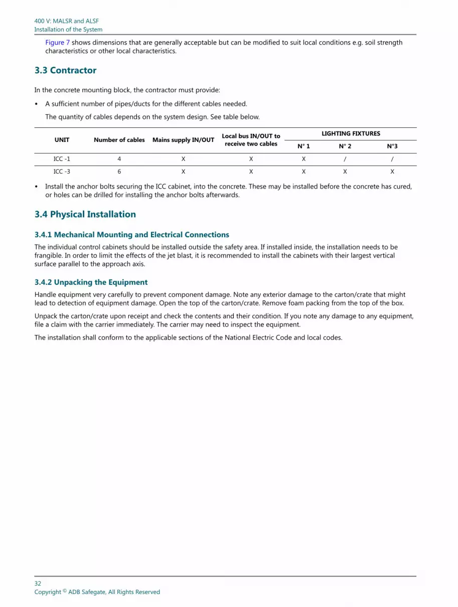
Figure 7 shows dimensions that are generally acceptable but can be modified to suit local conditions e.g. soil strengthcharacteristics or other local characteristics.
3.3 Contractor
In the concrete mounting block, the contractor must provide:
• A sufficient number of pipes/ducts for the different cables needed.
The quantity of cables depends on the system design. See table below.
UNIT Number of cables Mains supply IN/OUT Local bus IN/OUT toreceive two cables
LIGHTING FIXTURES
N° 1 N° 2 N°3
ICC -1 4 X X X / /
ICC -3 6 X X X X X
• Install the anchor bolts securing the ICC cabinet, into the concrete. These may be installed before the concrete has cured,or holes can be drilled for installing the anchor bolts afterwards.
3.4 Physical Installation
3.4.1 Mechanical Mounting and Electrical ConnectionsThe individual control cabinets should be installed outside the safety area. If installed inside, the installation needs to befrangible. In order to limit the effects of the jet blast, it is recommended to install the cabinets with their largest verticalsurface parallel to the approach axis.
3.4.2 Unpacking the EquipmentHandle equipment very carefully to prevent component damage. Note any exterior damage to the carton/crate that mightlead to detection of equipment damage. Open the top of the carton/crate. Remove foam packing from the top of the box.
Unpack the carton/crate upon receipt and check the contents and their condition. If you note any damage to any equipment,file a claim with the carrier immediately. The carrier may need to inspect the equipment.
The installation shall conform to the applicable sections of the National Electric Code and local codes.
400 V: MALSR and ALSFInstallation of the System
32Copyright © ADB Safegate, All Rights Reserved

3.4.3 Installing Master Control CabinetTo install the master control cabinet, follow the guidelines below. See Figure 8. Refer to Table 17. Refer to the site drawings forspecific installation details.
Figure 8: Master Control Cabinet Installation and Dimensions
Table 17: MALSR/ALSF Master Control Cabinet DimensionsSystem A in. (mm) B in. (mm) C in. (mm) D in. (mm)
MALSR/ALSF 36 (91) 30 (76) 24 (61) 37 (95)
• Mount the master control cabinet vertically through the external mounting lugs provided on the back of the cabinet.
• Drill conduit holes in the cabinet as required at the time of installation.
• When the master cabinet is mounted inside a vault, secure the cabinet to the wall by using bolts and bolt anchors or asspecified by site installation drawings.
• When the master cabinet is mounted out on the field, provide a concrete pad and fabricate and secure a steel frameworkin the concrete pad to mount the master control cabinet and other equipment as specified in site drawings. Concrete padsize and structure size is to be determined by the contractor and applicable local specifications.
3.4.4 Installing the Individual Control CabinetsTo install the individual control cabinet, follow the guidelines below.
3.4.5 Mounting Junction BoxTo mount the junction box, follow the guidelines below.
• Refer to site drawings for location and mounting provisions.
• Locate the junction box next to the individual control cabinet. This is the preferred method of installation.
• Mount the junction box on frangible couplings (separately supplied).
NoteThe junction box is supplied with two 2-in. (50.8-mm) conduit hubs for mounting and wiring.
• See Figure 7 for recommended installation and dimensions.
96A0400, Rev. M, 2020/09/03 33Copyright © ADB Safegate, All Rights Reserved

3.4.6 Installation of ICC 1 or ICC 3Install the ICC as in the drawings below:
After the concrete slabs are cured, the control units may be installed and secured with anchor bolts (see the drawings).
NoteBEWARE: Make sure you have the correct physical numbering of the control units (see your physical layout).
After installation, apply a watertight silicone seal between the control unit base and the concrete and fill the duct openingswith insulating expansion foam.
The ICC may be installed as shown in the pictures below or, on a mounting pole using an optional mounting kit (1440.20.200).The pole must be installed on a concrete slab. Use the junction box to connect the power supply cables and distribute thephases over the different ICCs, especially in the case of using a three-phase power supply. The control, supply and lamp (UELor FFL) cables can enter into the cabinet through a bottom plate that can be fitted in the bottom of the cabinet. The orderingcode for the replacement bottom plate is 4072.01.530. The cables must enter the cabinet through watertight connectors inorder to limit the ingress of vermin, insects and water.
Figure 9: Dimensions and sequence of mounting on a slab using anchor bolts (dimensions in mm)
400 V: MALSR and ALSFInstallation of the System
34Copyright © ADB Safegate, All Rights Reserved

More details on cabling for the ICC can be found in the drawings at the end of this manual.
Figure 10: ICC-1: Example of a Pole Mounted ICC
Figure 11: Typical Cable Entry Detail
3.5 Electrical Connections
Make sure that the cable selection and cable entry details are correct.
3.5.1 Power Supply CableKeep in mind that the system is designed so that power is permanently connected to the ICC Cabinet.
Terminals:
• The terminals (screw type) accept wire cross-sections ranging from 1.5 up to 16 mm2 (16 - 6 AWG).
• Insulation stripping length: 1/2-inch (12mm). Clamping screw: M4. Screwdriver blade: 5.5 x 1.0. Tightening torque range:0.9 to 1.8 ft-lb (1.2 to 2.4 N-m).
In the ICC-3: double terminals are present for the three phases, the neutral and Earth ground connection.
96A0400, Rev. M, 2020/09/03 35Copyright © ADB Safegate, All Rights Reserved

In the ICC-1: single terminals are present for each of the single-phase 240 Vac wires. Double terminals are present for theEarth ground connection.
• An external junction box is required for each ICC.
3.5.2 Local Bus Data Line Interlinking Cables
Remember:
• To use 18 AWG, Triad, Shielded, 600 V cable. Manhattan Wire M8628010 or equivalent.
• To connect the bus cable to P3 terminal on the local bus interface PCB of the first cabinet and to P1 on the last cabinet inthe LOCAL Bus communication line.
Terminals:
P1 and P3: WAGO 231-303/026-000 cage-clamp connectors type for wires of 0.08 to 2.5 mm2 (28-12 AWG). Connector springactivation is possible with screwdriver blade 3.5 x 0.5mm or with operating lever WAGO 231-131.
Recommended stripping length: 6 mm (1/4 in).
3.5.3 Connection• The use of a proper cable for Bus+ and Bus- and a zero volt connection wire is imperative.
During installation, care must be taken that the bus polarity remains the same in all the ICC cabinets.
NoteIf the polarity is inverted on a control unit this will not cause damage, but the flashers in the control unit will notrespond to the commands of the MCC.
3.5.4 CableCable between the flashing light and the ICC PCB (5-core cable with armor (shield) - up to 393 feet (120 m) max). Therecommended cable is Alpha 65405CY-SL or an equivalent, ADB SAFEGATE part number 89A0290-5.
Terminals:
• The lamp cable is connected to each ICC PCB and to its respective flashing light by means of the green TB2 connector (forconductors 0.5 up to 6 mm2; 20 - 7 AWG).
• Insulation stripping length: 9 mm (1/3-in). Clamping screw: M4. Screwdriver blade: 4.0 x 1.0. Tightening torque range: 0.9to 1.8 ft-lb (1.2 to 2.4 N«m).
Trigger: Lamp cathode
+400V: Lamp anode
PE: Protective earth
Cab +: Flash lamp interlock switch
Cab -: Flash lamp interlock switch
The shield is connected only at the ICC.
400 V: MALSR and ALSFInstallation of the System
36Copyright © ADB Safegate, All Rights Reserved

NoteThe terminals for both elevated and inset flashing lights are different. Check the details in the wiring diagrams in“Schematics”.
3.5.5 Remote control connectionsIndividual wires are always used for remote control commands and back-indications.
These are connected to the multi-wire board via the terminal blocks in the bottom of the MCC.
Terminals:
• The terminal blocks in the bottom of the MCC are cage-clamp connectors for wires from 0.08 to 2.5 mm2 (28 - 12 AWG).Recommended stripping length: 6 mm (1/4-in).
Connection:
The function of each input terminal is determined in the software. Configuration of this terminal block has to be known tomake the right connections.
3.5.6 External temperature sensor cableThis can be connected to any ICC. One sensor only is required per complete flashing system. Sensor is mounted using a17mm (11/16”) inside diameter gland, such that it can measure the outside air temperature.
3.5.7 Earth to ground connectionEarth to ground connection should be executed in accordance with applicable local regulations:
Recommendations and accessories:
• For strain relief and grounding of the cable armor (shield) there is a cable clamp usable for different cable diametersmountable on the grounded rail at the bottom of the ICC (Use one cable clamp per cable).
Figure 12: Cable clamp
• Earth connection of the unit has to be done with an individual grounding rod (by preference interconnected with theother cabinets) or with a grounding wire (Check local legislation for installation requirements and required cross-section).
3.5.8 Cabling PreconditionsInstallation of the cables shall be in ducts, in pipes or directly buried in the ground.
96A0400, Rev. M, 2020/09/03 37Copyright © ADB Safegate, All Rights Reserved

All cables enter the ICC cabinets through the bottom.
• ICC -1 via glands through the gland plate,
• ICC -3 via ducts in the concrete
Please check compliance with local requirements and regulations.
In any case, please ensure you have provided:
• Sufficient mechanical protection of the cables
• An adequate Earth to ground connection of the ICC cabinets
• An adequate Earth to ground connection of the cable armor
Table 18: Recommended types of cable
Function Type Number ofconductors
Required section/diameter Comments
Power supply cable
120/240 Vac, 3/C
3 conductors,neutral centertappedconnection
Depends on the lengthand the system layout(see Figure 13 )
Cable should be rated for 600V.To ease disconnection, we recommend the use of aflexible cable.We recommend a PVC covered, flexible metallicconduit (cable with armor or shield).
Three-phasePower distributioncable
5 (3 Ph+N+ Earthto groundconnection
Cable between thecabinet and fixture
Alpha cable part #65405CY-SL LAPPCable OllflexClassic 100CY
5 + shield Depends on length(see remarks)
WIRE CROSS-SECTION / MAXIMUM CABLE LENGTH
• # 16, (1.5 mm2) / 98'- 5” (30 m)
• # 12, (2.5 mm2) / 164' - 5” (50 m)
• # 10, (4 mm2) / 262' - 5” (80 m)
• # 8, (6 mm2) / 393' - 8” (120 m)
Multi-wire controlcable betweenmaster andsubstation or tower
Individual wiresrated 600V
(number ofsignals + 1common wire)
# 18 (0.8mm 2 )
The factor (number of signals + return(s)) dependson the remote control system design:
• Combining the remote control and back-indication signals in 1 cable is only possibleif there is no (or only low level) crosstalkrisk between these signals (as is the casewith one common DC energy source forremote control and back-indication signals).
Proper power cable sizing, to fit the actual field particulars, is possible using the ADB Safegate calculation tool “power cablework file selection sheet.xls” as shown below:
400 V: MALSR and ALSFInstallation of the System
38Copyright © ADB Safegate, All Rights Reserved

This “cable calculation program” is available from ADB Safegate upon request.
Figure 13: Example for an ALSF-2, 21-fixture configuration:
Home run cable length
Minimum section required for home run cable mm²
Type of power sypply
Nr of flashers #N/A flashers Nr of flashers #N/A flashersCable length #N/A m Cable length #N/A mMinimum section required #N/A mm² Minimum section required #N/A mm²Price for cable #N/A Price for cable #N/A
Power supply on box N° #N/ATotal num ber of flashers in system flashers Home run cable length MTotal cable length flasher #N/A m Price for home run cableTotal cost of cable #N/ A
Nr of flashers With / Without RTILS2.5 mm² 16 mm²4 mm² 25 mm²
Cable length between flashers M 6 mm² 35 mm²Cable length between flashers and RTILS M 10 mm² CurrencyRunway width M
Standard configuration
System overview
Nominal voltage on Power supply between L & N
Choosen section of home run cabl eType of approach Runway width
Additional information
Common information
Cable cost information
Power supply on Box N° ?
Custom approach
230V
Custom system
Lead-in sid eRunway sid e
25
07
32
31
30 1
Home run cabl e
The input power supply point is at the 21st fixture (nearest to the threshold) with a distance to the substation of 2953 ft. (900m) (home run) and a nominal source voltage between L and N of 240 Vac from a 3 phases +N network.
Table 19: Results given by the “power cable work sheet file” are:
Supply Cross-section of cablehome run
Cross-section of cable betweenthe units Comments
Three-phase 6 mm2 6mm2
Single-phase 10 mm2 10mm2
Lamp cable:
This should be a shielded cable with five conductors. There is no need for a high voltage cable.
See “Schematics” for color coding.
96A0400, Rev. M, 2020/09/03 39Copyright © ADB Safegate, All Rights Reserved

3.5.9 Mounting Power Transformer (MALSR Only)To mount the MALSR power transformer, follow the guidelines below. Refer to site drawings for location and mountingprovisions
Figure 14: 15 kVA Transformer Installation (MALSR Only)
Terminal Blocks TB1 through TB8 H1 (MEDIUM
H3 (LOW) Earth Ground Lug
H2 (HIGH)
400 V: MALSR and ALSFInstallation of the System
40Copyright © ADB Safegate, All Rights Reserved

NoteThe preferred method of installation is to locate the power transformer near the master control cabinet.
• The transformer weighs 262 lb. (118.8 kg). External mounting lugs are provided on the back of the transformer for verticalmounting. Secure the cabinet to a wall using bolts and bolt anchors or as specified by the site installation drawings.
• When the power transformer is mounted out in the field, a concrete pad should be provided and a steel frameworkshould be fabricated and secured in the concrete pad to mount the transformer and other equipment as specified in sitedrawings. Concrete pad size and structure size are to be determined by contractor and applicable local specifications.
3.6 Installing Lightning Rod
Install the lightning rod as close as possible to the cabinet.
NoteLightning protection is provided by metal oxide varistors in the master control cabinet at the input supply terminals ofTB1 and the supply power to the individual control cabinet. The fast-acting metal oxide varistors are most effective if alow resistance ground cable in compliance with the NEC and local codes, is connected to the lightning rod.
A large amount of charring on the surface of a metal oxide varistor is an indication that the system has taken a lightningstrike. If this has occurred, the varistor has done its job and must be replaced before placing the system back in operation.After replacing the varistor, test that the system is operating properly.
96A0400, Rev. M, 2020/09/03 41Copyright © ADB Safegate, All Rights Reserved

3.7 Installing In-pavement Flasher on the Base and ICC Cable Connections
The drawings on this page are for reference only and are not intended for design purposes.
Figure 15: Flasher Installation
3.8 Connecting the In-pavement Flashing Light
This subsection provides installation information for the MALSR and ALSF in-pavement flashing light. It discusses how toconnect the Individual Control Cabinet (ICC) wiring to the light fixture and how to install the light fixture on the base.
400 V: MALSR and ALSFInstallation of the System
42Copyright © ADB Safegate, All Rights Reserved

Pull the interconnection cable between the ICC and the fixture through the conduit. Terminate the cable at TB2 inside the ICC.See the wiring diagram at the end of this manual for details. Using a waterproof field splice kit (contractor supplied), splicethe interconnection cable to the mating female connector, part no. 4072.02.960. Set the in-pavement fixture upside downbeside the base can. Plug the fixture male plug into the female plug. Wrap electrical tape around the male-female plugconnection.
Figure 16: Connections to the Male In-pavement Fixture Connector (field splice kit not shown)
To assemble the in-pavement flasher connector assembly, perform the following procedure:
1. Install the Individual Control Cabinet (ICC), watertight conduit connectors and pull the cable as per the ALSF / MALSRinstruction manual and the airfield drawings.
2. Prepare the cable wire by stripping wire ends off each end to specified lengths as shown in Figure 16. Be careful not to cutthrough the outer jacket into the individual wire insulation. Repeat for all five wires. Cut the shield wire off at the fieldsplice.
3. Connect the connection cable, max 393 Ft. (120 m) to the FEMALE connector (shown in Figure 14) using a waterproof fieldsplice kit. If the female cordset is not labeled, you will need to make a resistance measurement (tone) and label each wireto make the correct connections. Cut the cable rubber filler off, so it doesn't interfere with the installation.
4. The in-pavement light fixture is already assembled. The detail between A and B on Figure 16 is to indicate the fixturesinternal wire connections.
5. Connect the 5/C female cordset (4) to the MALE connector.
96A0400, Rev. M, 2020/09/03 43Copyright © ADB Safegate, All Rights Reserved

6. Wrap the connection between the in-pavement light cord and the female cordset with electrical tape.
7. Connect the remaining end of the connection cable, max 393 Ft. (120 m) to the DIN Plug (TB2) supplied in the ADBSafegate ICC.
Figure 17: In-pavement connections
400 V: MALSR and ALSFInstallation of the System
44Copyright © ADB Safegate, All Rights Reserved

3.9 Mounting the Flashing Lights
To mount and connect the light assembly, proceed as follows:
Table 20: Required ToolsDescription Description
Torque wrench Screwdriver, flat blade AG. 8x150
Socket hex, 3/8”, vis 3/8”, J.9/16LA Screwdriver, pozi-drive AD.2x125
Socket hex, 3/8”, vis M10, J.17LA Loctite 270
Socket, 1/4”, 1.6x8 Flat, RS.8E Loctite 222
Socket, 1/4”, Pozidriv2, RD.2 Molycote BG87 INERTA grease
Extension, 1/4”, R.210 Natural hydraulic vacuum silicone grease
Adaptation, 1/4”-3/8”, R.232 Attack driver
Hinged handle - short Hammer 212A50
Plier Bit holder
Opening tool Bits END202, Pozidriv2
3.9.1 Overview of Sequence of Work• Electrical contractor locates new light bases and interconnecting conduit trench, and excavates for light base bottom
section by saw cutting or core drilling. Electrical contractor prepares subgrade and stone subbase, sets bottom sectionwith rebar, rigid steel conduit stubs, drain, and pours high early strength concrete-encasement excavation. Electricalcontractor shall record can locations and elevations of mud plate after concrete-encasement.
• Electrical contractor excavates conduit trench, installs rigid steel and fittings, backfills conduit trench with high earlystrength concrete.
• General contractor prepares and installs concrete pavement. Electrical contractor makes a pilot core to find mud platecenter point indent before final core-drilling.
• Electrical contractor core-drills concrete pavement. Electrical contractor installs top section, y-flange ring, space andlighting fixture, and pours epoxy joint sealer. Provide space for adjustment with spacers, maximum number of spacersshall be 3.
• See specific details as shown in FAA AC 150/5340-30 (current edition).
3.9.2 Installation on L-868 BaseThe light assembly is shipped complete, and is ready for installation.
To install the fixture on an L-868 base, see FAA AC 150/5345-30 and the project site-specific plans and specifications fordetails on L-868 base installation.
NoteMounting bolts are not supplied with the fixture. Mounting bolts and anti-rotation lock washers are normally suppliedwith the base can spacer or flange ring. If a flange ring is used, the bolt length is 1‑1/4 inch (32mm) plus the thicknessof the flange ring.
96A0400, Rev. M, 2020/09/03 45Copyright © ADB Safegate, All Rights Reserved

Also read the following guidelines:
1. Clean the base receptacle. Make sure the base receptacle is completely clean and dry. The mating surfaces must be cleanand free of foreign particles.
2. If, present, fit an appropriate lifting tool into the two threaded holes, which are located 180° apart in the cover.
The lifting tool can be made from two 1/2 x 13 eyebolts (1-inch ID) and a 1/2-inch diameter, 16-inch (406mm) long rod orpipe inserted through the eyebolts.
CAUTIONNever hold the light fixture by the wires. Doing so may damage the insulation, break the waterproof seal andcause insulation faults and water leakage.
3. Carry the light assembly to the base.
4. Place the light assembly next to the opening in the L-868 base so that the L-823 connector can be connected with themating receptacle from the L-830 or L-831 isolation transformer in the base. Make sure that the connection is solid andsecure. Refer to the Electrical Supply section of the User manual for required isolation transformers.
5. Make sure items such as spacers, shims and gaskets are installed on the light base as indicated on site plans, specificationsand drawings.
6. Position the light assembly over the L-868 base and set it onto the base. Align the light according to FAA AC 150/5345-30and project plans and specifications. Remove the eyebolts and lifting rod.
CAUTIONEnsure that the cord set wires are NOT pinched between the base can and the fixture. Pinched wires can causewater to be drawn inside the fixture.
7. If present, lubricate the labyrinth gasket with water. soap may be added to the water (8" only).
CAUTIONDo not use silcon or any other type of grease. Avoid the use of soap that contains silicon or glycerin.
8. Attach the six fixing bolts and anti-vibration washers. [See FAA EB-83 (latest revision)]
CAUTIONDue to the risk of bolts vibrating loose, do not use any type of washer with the fixing bolts (such as split lockwashers) other than an anti-vibration washer. Anti-vibration washers as defined in FAA EB-83 (latest revision).
9. Turn on the power to determine whether the LED fixture will illuminate. Operate for a minimum of five minutes.
3.9.3 Torquing and Installation Guidance for In-pavement FixturesIn-pavement fixtures must be installed according to the plans and specifications; the applicable regulatory guidance; and thefollowing guidance. The importance of using the proper fixture clamping components and bolt torque to minimize the risk forfixture failure or loosening of clamping components cannot be overemphasized. Refer to “Bolt Torqueing Maintenance” fortorque and installation guidelines for this fixture.
400 V: MALSR and ALSFInstallation of the System
46Copyright © ADB Safegate, All Rights Reserved
WARNINGForiegn Object DamageRead installation instructions in their entirety before starting installation.
• Failure to follow the installation guidance could result in bolt loosening or bolts breaking off,resulting in catastrophic failure of the fixture and/or the mounting system components.
Failure to follow these warnings may result in serious injury or equipment damage.
3.10 Wiring the Master Control Cabinet
See “Schematics”. All wiring and connections shall be made in accordance with the National Electrical Code and LocalRegulatory Authority and as specified on the installation drawings.
To wire the master control cabinet, perform the following procedure:
1. Connect 120/240 Vac, single phase, input power (AWG 8, 600 V) to terminal block TB1 terminals TB1-1 (120 V), TB1-2 (N),and TB1-3 (120 V) in the master control cabinet.
2. Connect an earth ground (AWG 4, minimum) wire to the earth ground lug on the master control cabinet.
3. Connect the flasher power wiring (2 single-conductor, AWG 10, 600 V) from the master cabinet terminal block TB1terminals 10 and 12 to terminal block TB1 terminals 1 and 2 in the junction box closest to the master.
4. Connect all junction boxes in parallel.
5. See Figure 71 or Figure 72 in “Schematics”. Make remote control connections (either 120 Vac or +48 Vdc) to terminal blockTB2.
6. Make the communications cable connections from the master control cabinet PCB-4 terminal P1 through the junction boxto PCB-1498 P1 in the individual control cabinet using Manhatten Wire M8628010, 18 AWG, Triad, Shielded, 600 V cableor ADB SAFEGATE-approved equivalent cable.Then connect PCB-1498 P3 through the junction box to PCB- 1498 P1 of thenext individual control cabinet.
7. Make the remote control/monitoring wiring connections as shown on the external wiring diagram shown in Figure 71 or Figure 72 for the MALSR and ALSF in “Schematics”.
3.11 To Wire the Individual Control Cabinet
Perform the following procedure:
1. Ground cabinet using AWG 10 (minimum) ground wire connected to the ground in the individual control cabinet and thejunction box. Connect ground wire to a grounding rod or counterpoise installed a short distance from the junction box.
2. Make connections from terminal block TB2 in the junction box to terminal block TB1 in the individual control cabinet asshown on the wiring diagram.
3.12 Wiring 15 kVA Power Transformer (MALSR Only)
The power transformer supplies power to the PAR-38 approach lights and the PAR-56 steady burning threshold lights.
To wire the MALSR 15 kVA power transformer, perform the following procedure:
1. See Figure 71 in the Wiring Schematics section. Connect the master cabinet terminal strip TB1 terminals 5, 6, and 7 toterminal block TB1 terminals H1 (MEDIUM), H2 (HIGH), and H3 (LOW) in the power transformer, respectively.
2. Initially connect the MCC terminal TB1-4 (xfmr common) to 15 kVA transformer TB1-3 through TB1-7 (120 Vac). Note thatthis tap may require adjustment later on to obtain the correct output voltage.
Note15 kVA transformer taps TB1-1 through TB1-8 are provided to adjust the output voltage of the power transformer.Use 3 single-conductor (AWG 4, 600 V) wires for the connections.
96A0400, Rev. M, 2020/09/03 47Copyright © ADB Safegate, All Rights Reserved

3. Connect an AWG 2 (minimum) ground wire to the earth ground lug on the power transformer.
4. See Figure 71 . Connect terminals X1 (120V/75V/50 Vac), X2 (NEUTRAL), and X3 (120V/75V/50 Vac) on terminal block TB1in the power transformer to the PAR-38/PAR- 56 lamp holders. Use 3 single-conductor (AWG 2, 600 V) wires for theconnections for each terminal.
3.13 Aiming the UEL Lamp holders
An aiming device is used to set the vertical angular position of the lamps. The lamp holders are mounted on either conduit,pipe, or towers as outlined in the site installation drawings.
For elevated flashing fixtures, the aiming device is available either as an electronic or as a simple mechanical (bubble level)based unit. Both aiming devices are accurate to within ±0.5°.
Table 21: Elevated Flasher Aiming DevicesDevice Part No.
Electronic Aiming Device 11570.05.400
Bubble Level Aiming Device 21570.05.410
Notes1 For fixture mounting heights from 6 ft. (1.82 m) to 33 ft. (10 m)2 For fixture mounting heights below 6 ft. (1.82 m)
3.13.1 Bubble Level Aiming DeviceThe bubble level aiming device consists of a support, which is secured on the light unit, in the place of the optical cartridge,and which is equipped with a elevation angle setting device, a sighting device (both with a graduated scale) and a bubblelevel.
The elevation angle setting device is graduated from 0 to 25°. For the azimuth setting, the system can be rotated around avertical axis, and has 4 set positions that allow aiming at reference points (generally other lights) in a direction parallel orperpendicular to the center line. The sighting device is graduated from -4 to +4° to allow for toe-in angles. Two additional setpositions at -15 and +15° permit the setting of elevated REIL/RTIL flashing lights.
1. Assemble the system by removing the optical cartridge and installing the leveling device in its place.
2. Tighten the securing screw.
3. Set the elevation angle on the setting device and the azimuth (toe-in) angle on the sighting device. For the correctelevation and toe-in angles refer to the project plans and specifications.
NoteFAA MALSR fixtures are usually set at +6°.
4. Approximately level the light to allow the azimuth orientation of the light.
5. Set the light in the correct direction using the sighting device, aiming at the next or former light in the same alignment.For lights in a barrette, a side row or a wing bar, aiming laterally at another light is possible. For this purpose release thetwo locking levers, turn the system 90° until a distinct click can be felt, and tighten the locking levers. If there is no light inthe same alignment, use a reference pole.
6. Secure the bracing clamp. Loosen the lock-nuts.
400 V: MALSR and ALSFInstallation of the System
48Copyright © ADB Safegate, All Rights Reserved

7. Use the bubble level to set the light at the correct elevation by unscrewing/ tightening slightly the two elevation angleadjustment screws. Tighten the screws sufficiently to avoid any play, but do not over-tighten them. Once this is done,secure the two lock-nuts.
8. Remove the device. Put the optical cartridge back in place, connect the lamp and latch the lamp.
Figure 18: Bubble Level Aiming Device (1570.05.410)
NoteUse the mirror to look down through the sighting device for horizontal alignment. You may optionally look directlythrough the sighting device by loosening the mirror securing screw and rotating it out of the way.
3.13.2 Adjusting HorizontalTo adjust the horizontal, perform the following procedure:
1. Loosen the 3 screws in slip collar and/or the 8-32 set screw in the slip collar.
2. Rotate the assembly to the correct horizontal position with the center of the light beam parallel to the runway centerline.
3. Retighten screws.
3.13.3 Electronic Aiming DeviceThis system is suited for elevated fixtures mounted on safety approach masts or fiberglass Device towers, when it is notpossible to get access to the top of the mast/tower in its standing position.
Composition : The system consists of a support similar to the one used with the bubble level device (see Bubble Level AimingDevice ). However, the support is equipped with a sensor activated with a switch, with a 33 ft. (10 m) long cable. The operatorcan then operate the sensor from the ground, and read the elevation angle measurement when the mast/tower is tilted onthe ground.
96A0400, Rev. M, 2020/09/03 49Copyright © ADB Safegate, All Rights Reserved

NoteDuring the installation of the approach line, a quicker method is to use a platform at the light level for an easy initialadjustment.
Figure 19: Electronic Aiming Device (1570.05.400)
1. Lower the mast. See instruction manual of the supplied masts.
2. If the mast has been correctly installed, i.e. its tilting axis is perpendicular to the centre line, a light with 0° toe-in will haveits front surface fully horizontal when the mast is tilted over 90° (down to the horizontal). With the mast in this position,adjust the light by turning it around the tube, and then tighten the bracing clamp. For lights with a toe-in, first adjust thelight for 0° toe-in. Make a reference mark on the tube just below the zero mark at the bottom of the slip fitter. Using thegraduated scale, turn the light around the tube to the desired toe-in, and tighten the bracing clamp.
3. Remove the optical cartridge and install the leveling device in its place. Tighten the securing screw.
4. Raise the mast. Operate the switch to take a measurement.
5. Lower the mast and read the angle indicated on the digital display. Calculate the difference between the real angle andthe required one.
6. If necessary, adjust the elevation angle by unscrewing/tightening slightly the two opposite screws. Tighten the screwssufficiently to avoid any play, but do not overtighten them. Once this is done, secure the two counter-nuts. While doingthe correction, two measurements means are useable: - The elevation scale on the side of the light body (coarsemeasurement); - The
3.13.4 CommissioningFinal check: A flight check must be performed to insure there is no major misalignment of the fixtures.
400 V: MALSR and ALSFInstallation of the System
50Copyright © ADB Safegate, All Rights Reserved

NoteThe system must not be put in operation until all errors have been corrected and the flight check is passedsuccessfully.
3.14 Aiming the PAR-56 Lamp holders
A separate aiming device (for PAR-56 only, order 44D1654-1 or for PAR-56 and PAR-38, order 44D1654-2) is used to set thevertical angular position of the steady burning elevated lamps. The lamp holders are mounted on either conduit, pipe, ortowers as outlined in the site installation drawings.
3.14.1 Assembling the Aiming DeviceTo assemble the aiming device, perform the following procedure:
1. Remove the aiming device components from the instrument case.
2. See Figure 20 . Remove two #10-32 x % screws (1) from the aiming device mounting pad (2).
Figure 20: The PAR-56 Aiming Device
3. See Figure 21 . Take the base plate (6) (round disc with three standoffs) and rotate so that the standoff (3), located at 15degrees above the horizontal, is positioned to the right of the assembler.
Figure 21: Mounting the PAR-56 Aiming Device
96A0400, Rev. M, 2020/09/03 51Copyright © ADB Safegate, All Rights Reserved

4. Take the aiming device and turn it so that when mounted on the base plate (6) the dial (1) is facing toward the singlestandoff (3) located at 15 degrees. Position the two tapped holes in the bottom of the mounting pad over the matingholes in the base plate. Insert mounting pad screws (2) and lock washers and tighten hardware.
5. See Figure 22 . Rotate the three-leg clamps (3) so that the tapered tang on the clamp is at a right angle to the back edgeof the standoff by pushing down on the spring-loaded shoulder screw (5).
Figure 22: Aiming Device Leg Clamp Locations (Top View)
6. Attach the snap-swivel and cord to the aiming dial locking lever (1) if the lever cannot be reached during the aimingprocedure. The aiming device is now ready to be mounted on the lamp holder.
3.14.2 Aiming Lamp holders (Conduit or Pipe Mounted)This section outlines the procedure to aim steady burning that are mounted at ground level to approximately a six-foot (1.83m) elevation (or easily reached by a ladder).
To aim lamp holders, perform the following procedure:
1. After the lamp holder has been wired and secured to conduit or pipe and aligned with the runway centerline per sitespecifications, secure the aiming device to the lamp holder.
2. Take the assembled aiming device and position it over the face of the lamp and align the three indexing pins (see Figure 22, Item 5), protruding from each of the standoffs, with the three mating index pin holes (see Figure 23, Item 2)found in the flanged lip of the lamp holder.
400 V: MALSR and ALSFInstallation of the System
52Copyright © ADB Safegate, All Rights Reserved
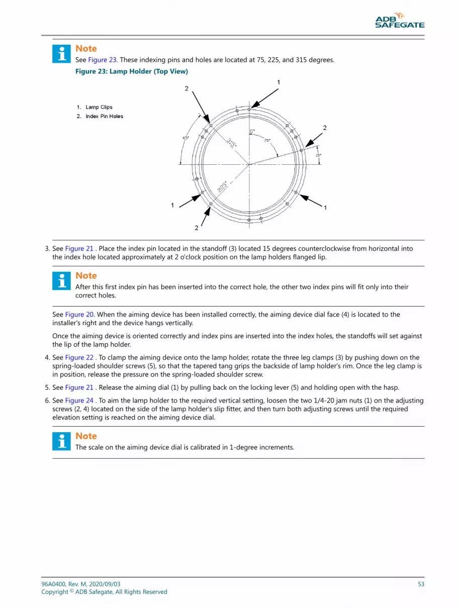
NoteSee Figure 23. These indexing pins and holes are located at 75, 225, and 315 degrees.
Figure 23: Lamp Holder (Top View)
3. See Figure 21 . Place the index pin located in the standoff (3) located 15 degrees counterclockwise from horizontal intothe index hole located approximately at 2 o'clock position on the lamp holders flanged lip.
NoteAfter this first index pin has been inserted into the correct hole, the other two index pins will fit only into theircorrect holes.
See Figure 20. When the aiming device has been installed correctly, the aiming device dial face (4) is located to theinstaller's right and the device hangs vertically.
Once the aiming device is oriented correctly and index pins are inserted into the index holes, the standoffs will set againstthe lip of the lamp holder.
4. See Figure 22 . To clamp the aiming device onto the lamp holder, rotate the three leg clamps (3) by pushing down on thespring-loaded shoulder screws (5), so that the tapered tang grips the backside of lamp holder's rim. Once the leg clamp isin position, release the pressure on the spring-loaded shoulder screw.
5. See Figure 21 . Release the aiming dial (1) by pulling back on the locking lever (5) and holding open with the hasp.
6. See Figure 24 . To aim the lamp holder to the required vertical setting, loosen the two 1/4-20 jam nuts (1) on the adjustingscrews (2, 4) located on the side of the lamp holder's slip fitter, and then turn both adjusting screws until the requiredelevation setting is reached on the aiming device dial.
NoteThe scale on the aiming device dial is calibrated in 1-degree increments.
96A0400, Rev. M, 2020/09/03 53Copyright © ADB Safegate, All Rights Reserved

The adjusting screws are designed to work against each other. If one screw is turned clockwise, as viewed from the head ofthe screw, then the other screw is turned counterclockwise to effect a change in elevation setting.
Figure 24: Slip Fitter Dial Face and Adjusting Screws
7. Once the desired setting is achieved, make sure that both adjusting screws are seated against screw stops, then retightenall jam nuts to lock adjusting screws in place.
NoteRecheck to make sure the angle setting has not changed when screws/nuts were tightened. If the setting haschanged, loosen nuts and adjust accordingly.
8. Remove the aiming device fixture by rotating the leg clamps away from the lamp holder's flanged lip.
9. Repeat above steps for each lamp holder in the system.
3.14.3 Aiming the Lamp holders (Tower Mounted)This subsection outlines the procedure to aim steady burning or flashing PAR-56 lamp units holders (Tower Mounted) that aremounted on aluminum or fiberglass towers (masts).
To aim the tower-mounted lamp holders, perform the following procedure:
1. Place the tower in the down position. Rest the tower on a sawhorse or other adequate support structure. Mount and wirethe lamp unit and align with the runway centerline per site specifications.
2. See Figure 23 . Loosen 1/4-20 jam nuts (1) on the adjusting screws (2, 4) that are located on the sides of the lamp holder'sslip fitter.
3. Turn the adjusting screws so that the bottom edge of the lamp holder is aligned with the zero angle setting as marked onthe dial (5) on the side of the slip fitter. Retighten the jam nuts to lock the lamp holder in the zero position.
4. See Figure 21 . Take the assembled aiming device, remove the aiming dial, and then install the dial on the slip section,supplied by tower manufacturer (For example: the VEGA F.A.M. by Jaquith Industries) using the dial strap clamp. Releasethe aiming dial by pulling back on the locking lever (5), and hold the lever open with the hasp.
5. See Figure 24 . Read and record the angle of the tower as it rests on the sawhorse, then aim the lamp holder to therequired vertical setting by loosening the two 1/4-20 jam nuts (1) on the adjusting screws again and turning the screwsuntil the required elevation setting is reached.
NoteTo make an accurate determination of the required elevation setting while the tower is resting on the sawhorse,compensation must be made for both the angle of the tower and the natural droop at the top of the tower due toits weight. Refer below for an example of how to compensate for these two factors.
Example: Elevation desired is 14 degrees. The aiming dial in free mode reads 84 degrees.
400 V: MALSR and ALSFInstallation of the System
54Copyright © ADB Safegate, All Rights Reserved

The angle of the tower on the sawhorse (recorded previously) is 10 degrees.
To determine the elevation setting, perform the following:
First, turn the adjusting screws until the aiming dial reads 90 degrees minus 10 degrees = 80 degrees.Second, subtract the desired elevation angle (14 degrees) from 80 degrees. The result is 66 degrees (90-10-14 = 66). Thisis the new angle required. Continue turning adjusting screws until this setting is reached.
6. Now remove the aiming dial from the tower's slip section, reassemble on the base plate, and install the aiming assemblyon the lamp holder.
7. After the setting has been reached, tighten both jam nuts on the adjusting screws to lock the lamp holder into position.
8. Now lock the aiming dial in place by releasing the hasp. The locking lever will now prevent the dial from turning.
9. Attach the snap-swivel and nylon cord to the locking lever before raising the tower.
10. Raise and lock the tower into vertical position. Pull on the cord and hold to allow the aiming dial to rotate so that it canmeasure the elevation angle of the lamp holder.
11. After the aiming dial has come to rest, release the cord and lock the dial in place. Lower the tower and read the elevationsetting of the lamp holder. If the desired setting has not been obtained, release the dial and loosen the jam nuts on theadjusting screws. Turn the screws accordingly to correct the elevation setting.
12. Repeat steps 6 through 11.
13. After the correct elevation has been achieved, secure the tower and repeat the process for all remaining towers.
96A0400, Rev. M, 2020/09/03 55Copyright © ADB Safegate, All Rights Reserved

3.15 Aiming PAR-38 Lamp holders (MALSR Only)
To aim the MALSR PAR-38 lamp holders, perform the following procedure:
1. See Figure 25 . Install PAR-38 lamp holder assembly (5), less PAR-38 lamp, onto the appropriate mount such as a frangiblecoupling or an EMT.
2. Secure by tightening the three screws (4) in the slip fitter.
Figure 25: MALSR PAR-38 Aiming Device
1. PAR-38 Socket Adapter
2. PAR-38 Support Plug
3. Socket Elbow Screw
4. Slip Fitter Screw
5. Slip Fitter Set Screw
6. PAR-38 Lamp holder Assembly
7. Screw
8. Mounting Adapter Screw
9. Aiming Device Mounting Adapter
10. Aiming Device
1
2
310
9
8
7
6
5
4
3.15.1 Adjusting HorizontalTo adjust the horizontal, perform the following procedure:
1. See Figure 25 . Loosen the 3 screws (4) in slip fitter and/or the 8-32 set screw (5) in the slip fitter's collar.
2. Rotate the assembly to the correct horizontal position with the center of the light beam parallel to the runway centerline.
3. Retighten the screws.
3.15.2 Adjusting VerticalTo adjust the vertical, perform the following procedure:
1. See Figure 25 . Attach the PAR-38 support plug (2) onto the socket adapter (1).
400 V: MALSR and ALSFInstallation of the System
56Copyright © ADB Safegate, All Rights Reserved

NoteThe tapered end of the support plug should be on the same end as the threads on the socket adapter. Locate thesupport plug 2.124 inches (5.4 cm) from the threaded end of the socket adapter (1) and tighten the set screw (5) tohold in place.
2. Attach aiming device mounting adapter (9) to aiming device (10) using two screws (8).
3. Loosen the screw in the socket elbow (3) of the lamp holder and rotate the lamp holder (6) to convenient working angle(approximately 45 degrees) and retighten screw.
4. Make sure that the power to the lamps has been turned off.
5. Screw the socket adapter (1) with support plug (2) attached into the lamp socket in the lamp holder.
6. Place the aiming device (10) with mounting adapter (9) attached onto the end of the socket adapter (1).
7. Position the dial face of the aiming device vertically so that the dial can be read and is level so that the dial can rotatefreely. Tighten the two set screws (7) in the mounting adapter's sleeve to hold in position.
8. Loosen the screw (8) in the elbow of the lamp holder (3) and move the lamp holder to correct the vertical angle(according to site specifications). Tighten screw and recheck setting.
NoteRefer to manual 96A0119 for mounting and aiming the 44D1661-XXXX Steady-Burning Approach Light.
96A0400, Rev. M, 2020/09/03 57Copyright © ADB Safegate, All Rights Reserved

400 V: MALSR and ALSFInstallation of the System
58Copyright © ADB Safegate, All Rights Reserved
4.0 Operation
This section provides information for operating the medium intensity approach lighting system with runway alignmentindicator lights (MALSR) and approach lighting system with sequenced flashers (ALSF).
4.1 Interlock Switches
Interlock switches are provided on all the flashers and control cabinets to disconnect power when a cabinet door or flasher isopened. The interlock switch is closed on the master and individual control cabinets when the cabinet door is closed and thescrews on the door are tightened. The interlock switch on the master and individual control cabinets can be bypassed forservicing by simply pulling out the shaft of the interlock switch. However, the interlock switch on the flasher can be defeatedonly by carefully shorting terminals CAB+ and CAB- on terminal block TB2 in the ICC.
Operating the MALSR/ALSF involves local and remote control; interlock switches; ground fault interpreter; controls andindicators on Local Master PCB, and the Flasher Control PCBs; start-up and emergency, equipment, and individual cabinetshutdown procedures; and radio controller operations (MALSR only).
4.2 Local and Remote Control
The MALSR/ALSF system can be operated by local control by manually setting switches on the control panel in the mastercontrol cabinet. The MALSR/ALSF can also be operated by remote control using +24 Vdc, +48 Vdc or 120 Vac signals to turnthe system on or off and to set the system to one of three brightness levels: low, medium, or high.
Refer to Table 22. Local control uses five-position rotary switch S5 on the control panel in the master control cabinet. Refer to Table 23 for more information about local and remote control.
Table 22: Local Control Switch S5 FunctionsSwitch Position Function
REMOTE System operates by 120 Vac, +24 Vdc or, +48 Vdc signals only. Turns on system to one of three intensity levels oroff from an interface panel or air- ground receiver.
OFF Turns system off
LOW Turns system on to low intensity
MEDIUM Turns system on to medium intensity
HIGH Turns system on to high intensity
4.3 Master Control Cabinet Controls and Indicators
See Manual configuration for configuration details. Refer to Table 23 for master control cabinet controls and indicators.
4.4 Ground Fault Interpreter
The ground fault interpreter (GFI) outlet (3) on the master control cabinet supplies 120 Vac power for operation of externalequipment. This outlet is designed to prevent accidental electrocution of the operator using the outlet. The Test button isused to test the operation of the GFI outlet. The Reset button is used to reset the GFI outlet when it is tripped.
96A0400, Rev. M, 2020/09/03 59Copyright © ADB Safegate, All Rights Reserved

4.5 MCC Controls and Indicators
This subsection describes controls and indicators for the master control cabinet, the Local Master PCB, and the FlasherControl PCB.
Table 23: Master Control Cabinet Controls and IndicatorsItem Controls/Indicators Function Note
1 Interlock switch Allows the master control cabinet to be energized when the door is closed. Refer toInterlock Switches in this section.
2 Switch S2 Turns maintenance light on or off. B
4 Fuse F1 (5 A) Protects maintenance light circuit.
5 Fuse F2 (15 A) Protects 120 Vac receptacle.
6 Hour Meter Records number of hours of lamp operation at the high intensity level.
7 Fuse F3 Spare
8 Fuse F4 (10 A) Protects power to contactors, remote control and PC boards.
9 Circuit breaker CB2 (15 A) Protects interlock switch (120 Vac) and equipment connected to fuse F4.
10 Fuse F5 Spare
11 Circuit breaker CB3 (30 A) Protects 240 Vac power supply to contactor K4 and power to the individual controlcabinets.
12 Circuit breaker CB1 (100 A) Provides 120/240 Vac power for disconnect switch to turn system on or off.
13
Switch S3 (ALSF/SSALR only) Selects ALSF and SSALR modes as long as rotary switch S5 has not been set toREMOTE.
Switch S4 (MALSR only) Allows the sequenced flashers to be turned on or off when the approach lights areenergized.
14 NEON indicator HI When lit, indicates system on high intensity.
15 NEON indicator MED When lit, indicates system on medium intensity.
16 NEON indicator LOW When lit, indicates system on low intensity. A
17 Switch S5Selects operational mode. Under remote operation, allows the system to be turnedon to one of three intensity levels or turned off from an interface panel or air-groundreceiver. Refer to Table 22.
32 Circuit breaker CB4 (70 A)(MALSR only) Protects 120/240 Vac steady burning approach light power.
33ON/OFF indicator(MALSR only) When lit, indicates system is turned on.
NoteA: The LOW NEON Light is lit when
• S5 is set to LOW.
• S5 is set to REMOTE and remote control switch is set to LOW.
• S5 is set to OFF and voltage is present.
• REMOTE is set to OFF and voltage is present. (This indicates that the master is in hot standby mode.)
NoteB: The maintenance light will operate even if the power disconnect switch has been opened.
Unscrew wire cage to replace lamp.
400 V: MALSR and ALSFOperation
60Copyright © ADB Safegate, All Rights Reserved

Figure 26: Master Control Cabinet Parts and Diagram (MALSR Shown)
#1
#9 CB2 Circuit breaker, 15 A (AIRPAX #219-2-1-63F-3-15)#11 or 32 CB3/4 Circuit breaker, 30 A (AIRPAX #219-2-1-62-3-1-30)
#12 CB1Switch, MALSR, 120/240 Vac, 100A
(AIRPAX #219-2-1-63F-3-1-100)
#12 CB1Switch, ALSF, 120/240 Vac, 100A
(AIRPAX #219-2-0-SW-3-1-100)
#17
K2, K3, (MALSR) K4Cont 2P, 60 A, 120 Vac, Coil53A0412-60
Varistor (VR1 - VR4)
Maintenance Lamp
K1 (MALSR)Cont 2P, 30 A, 120 Vac, Coil53A0412-30
PCB 1498
PCB 1486
PCB1485
Ground fault outlet
Assembly Figure 58
#13
#2
#4, 5, 7, 8 and 10
#6
#14 #15
#16
#33
4.6 System Configuration
The configuration can be done either manually or by means of a laptop & software interfacing with the ICC via the Dongle.
NoteThe ALSF can only be configured by means of a laptop and software.
CAUTIONMake sure that if a Dip-switch setting has been changed in any cabinet, the main power supply is switched off for afew seconds in order to confirm the change of the dip-witch in the cabinet where the change took place. If this is notdone, the system will not recognize the hardware (dip-switch) change.
96A0400, Rev. M, 2020/09/03 61Copyright © ADB Safegate, All Rights Reserved

4.6.1 Manual configuration
4.6.1.1 Action 1: Configuration of the ICCs
• For the dip-switch settings of each ICC , refer to Table 35.
NoteThe factory setting for the local bus communication is:38400 baud (SW 1-5 is OFF & SW 1-6 is ON);even parity (SW 1-7 is ON & SW 1-8 is ON).Dip-switches SW 1-1 to SW 1-4 are not used.
This configuration must be the same for all the units connected to this bus. This is the factory & recommended setting.These values should not be changed, except if severe problems occur in the communication between the different flasherunits.
• If the MCC is physically installed at either end of the flashers check if all the jumpers (W11, W25, W28) are removed on theFlasher Control PCBs, except for the ICC farthest from the MCC. See the drawings at the end of this manual.
• If the MCC is physically located somewhere in the middle of the flashers, both the physical routing of the CAT5ecommunication cable wire and the jumpers (W11, W25, W28) are different for this type of installation. See Manualconfigurations Overview
1. Set the dip-switch bank SW2 on each ICC so that the slave number of the first ICC corresponds to 1, and that the numberfor each following ICC is incremented by one, up to the last ICC. The slave number is set using binary code. (i.e. 00011binary = 3 decimal).
2. Check if all the jumpers (W11, W25, W28) are set properly.
4.6.1.2 Action 2: Configuration of the MCC (PCB)
For the Dip-switch settings of the MCC refer to Table 25.
NoteThe local bus communication setting (baud rate, parity) should be the same for each ICC.
400 V: MALSR and ALSFOperation
62Copyright © ADB Safegate, All Rights Reserved

Parameters that must be defined by setting the dip-switches on the MCC are:
• The number of ICCs in the system is defined by SW5-1 to SW5-6 (Note that the value that is set is in binary code).
For 1 to 31 ICCs the number must be converted to a binary value and for each bit 1, the corresponding switch must be set toON.
1. Set the MCC dip switches as required by Table 25 in binary format.
2. Set SW5-1 to SW5-6 in the MCC to the correct number of ICCs.
4.6.1.3 For 32 ICCs, all switches must be set to OFF.
• If SW2-3 is set, the last 2 ICCs are declared as REIL1 and REIL 2 respectively. Their misfire limit is set to 1.
• The cycle value of mode 1 is set according to SW2/4:
Table 24: Set Cycle Timing SW2/4
SW2-4ON 1 cycle per second
OFF 2 cycles per second
• The sequence times of mode 1 are set using SW2/1 and SW2/2
Table 25: Dip-switch Settings SW2Dip-switch bank SW2
Sequence timeMode
SW2-1 SW2-2 Number NAME
OFF OFF 16 msec1 ALSF-2
3 ALSF-1
ON OFF 33 msec
2 SSALR
4 SSALS/F
5 MALS/F
6 MALSR
OFF ON 66 msec 7 (ODALS)
ON ON Invalid!
The sequence time of the first ICC is set to 0, the next ICCs will have a sequence time equal to the interval time defined bythe switches, multiplied by their slave number in the system. If a REIL system is included in the configuration, the 2 lastICCs receive the same flash timing.
If the manual configuration option is selected, the dongle and software will not be useable.
96A0400, Rev. M, 2020/09/03 63Copyright © ADB Safegate, All Rights Reserved

Also when the system is configured via the manual configuration (not via the dongle & software) the physical connectionneeds to be logically in accordance with the sequence of the ICCs, i.e. ICC with address 1 needs to be physically the first inthe communication line, ICC 2 the 2nd, etc... The MCC and last ICC are used to terminate the local bus communication line.
Table 26: Dip Switches SW1-SW5 for Manual ConfigurationSwitch-bank Type Setting Use Remarks
SW1 Dip xxxxxxxx Not used, assuming a multi-wire remote control isimplemented.
SW2 Dip
1 + 2
OFF OFF 16 msec interval time
ON OFF 33 msec interval time
OFF ON 66 msec interval time
ON ON Invalid
3 ON Declaration of REILS
4
ON 1 cycle per second
OFF 2 cycles per second
SW3 Rotary
0 Flasher system OFF
1 Step 1
2 Step 2
3 Step 3
9 Remote Control
SW4 Dip
1
OFF Enabling of the control by the LMCPCB rotary switch SW3
ON Hardware local kill ON No control bySW3
2 OFF See note 1
3 OFF See note 2
4OFF Configuration via dongle & software
ON Manual config by SW2 and SW5
5 + 6
OFF OFF Baud rate local bus 9600 baud
ON OFF Baud rate local bus19200 baud
OFF ON Baud rate local bus 38400 baud DEFAULTSETTING
ON ON invalid
7 + 8
OFF OFF No parity
ON OFF Invalid (no parity)
OFF ON Local bus Odd parity
ON ON Local bus Even parity DEFAULTSETTING
400 V: MALSR and ALSFOperation
64Copyright © ADB Safegate, All Rights Reserved

Table 26: Dip Switches SW1-SW5 for Manual Configuration (continued)Switch-bank Type Setting Use Remarks
SW5 Dip
1 >6 Number of ICCs in the system Binary coding
7 Not used
8
OFF Disabling the use of the dongle
ON Enabling the use of the dongle
NoteSW4-2 - Initialize the data of E2PROM
The MCC stores the system parameters in an E2PROM. At first power-up or when the system must be completelyreconfigured, it is possible to clear the E2PROM and return to the default factory settings. To do this, put the switch to ON,power down the MCC and turn it ON again after 5 seconds. Do not forget to set the switch back to OFF or the E2PROMwill once again be cleared at the next power cycle!!
WARNINGThis will clear all the parameters, the system layout included. They must then all be restored via the software, or byusing the dip-switches.
NoteSW4-3 - Lock to bootThis switch is always OFF in a functioning system. It is only used if there is a major problem during upload of a newapplication code
4.6.2 Configuration via the Dongle
4.6.2.1 Action 1: Configuration of the ICCs
• For the dip-switch settings of each ICC, refer to Table 35.
The factory setting for the local bus communication is:
• 38400 baud
(SW1-5 is OFF and SW1-6 is ON).
• Even parity
(SW1-7 is ON and SW1-8 is ON).
• Dip-switches
96A0400, Rev. M, 2020/09/03 65Copyright © ADB Safegate, All Rights Reserved

SW1-1 to SW1-4 are not used.
These settings must be the same for all the units connected to this bus. This is the factory and recommended setting.These values should not be changed, except if severe problems occur in the communication between the different flasherunits.
• Check if all the jumpers (W11, W25, W28) are removed on the Flasher Control PCBs, except for the ICC farthest from theMCC on the local bus. Install jumpers (W15, W16 & W18) on the Local Master PCB.
1. Set the slave number on SW2 for each ICC so that every slave has a unique address. The slave number is set using binarycode. (i.e. 00011 binary = decimal 3).
2. For the ease of defining the layout through the software, choose a logical numeric sequence addressing of the ICCs.
4.6.2.2 Action 2: Configuration of the MCC (Local Master PCB)
The settings for the local bus communication should be:
• 38400 baud
(SW4-5 is OFF and SW4-6 is ON)
• Even parity
(SW4-7 is ON and SW4-8 is ON)
NoteThe local bus communication settings (baud rate, parity) should be the same as for the ICCs.
1. Set the dip-switch SW4-4 on the MCC in position “Off” and SW5-8 to “ON” to enable the dongle use.
2. Set the local bus communication baud rate and parity.
4.6.2.3 Action 3: Connect the dongle & define the layout through the software
To connect the “dongle” to any ICC or to the (MCC) LMC PCB follow the steps below.
1. Connect the “dongle” to any ICC or to the LMC PCB via the serial DB-9 connector.
2. Connect your laptop loaded with the software, latest version, to the dongle.
3. Launch the Flasher.exe program.
4. Verify in the configuration menu that the COM port and the communication parameters have been selected in accordancewith your laptop configuration.
4.6.2.4 Action 4: Software based configuration
NoteYou need the configuration tool to perform this procedure.See Configuration tool.
To configure the equipment with the configuration tool, set the switches of the Local Master Controller (LMC) PCB asdescribed in this section:
• Enable local control;
• Enable software configuration;
• Set the number of FCUs in the system;
• Restart the LMC;
• Define the system layout with the configuration tool;
• Define the flashing mode with the configuration tool.
Enable local control
400 V: MALSR and ALSFOperation
66Copyright © ADB Safegate, All Rights Reserved

The MCC rotary switch should be set to LOW intensity in LOCAL during this procedures. Also, set the LMC rotary switch to 0.When finished, return the LMC rotary switch to position 9.
Enable software configuration
To enable software configuration, set switch SW4 of the LMC PCB as follows:
Table 27: Dip-switch SW4 settings of the LMC PCBSetting Dip-switch 1-6 of switch SW
1 2 3 4 5 6 7 8
ON X X X
OFF X X X X X
Set number of FCUs in system
Set switch SW5 of the LMC PCB as follows. In SW5, dip-switches 1-6 represent the total number of FCUs in the system. Fordip-switches 1-6, set the same binary address as you set for the last FCU in the entire system (FCU PCB, SW2). Set SW5-7 toOFF and SW5-8 to ON.
Restart the LMC
To activate the dip-switch settings in the whole system, you must switch OFF the power in the MCC, which contains the LMC.
1. Make sure that the other cabinets in the system are switched ON.
2. Switch OFF power to the MCC. Leave the power off for approximately 10 seconds.
3. Switch ON power to the MCC.Define the system layout
Define the number of FCUs and boxes in the system and set a layout for the units. The FCU layout determines the order inwhich the lamps flash during a flashing sequence.
CAUTIONMake sure that all flash units are connected to the FCUs in a logical order. For example, the first flash unit is theone that is farthest away from the runway. If the system has REILs, they must be closest to the runway and havethe highest logical address.
4. Open the configuration tool.
5. Go to menu Layout.
96A0400, Rev. M, 2020/09/03 67Copyright © ADB Safegate, All Rights Reserved

6. Set the number of flashers, including REIL flashers. See the graphic.
7. Set the number of boxes in your system. See the graphic.
8. Set a sequence and a slave number for each flasher.
9. Set some of the flashers to be REILs or RTILs, if applicable to your system. Clickthe field after the sequence number. Seethe graphic.
10. Press Program. See the graphic.The changes are now sent to the LMC.
11. Check the message windows that appears on screen. “Layout OK” means that the new layout was sent successfully. “LayoutNot OK” means that you must check the layout and the dip-switch settings again.
12. Go to section Flasher data.
13. Press Status.
14. Make sure that the status of LMC and all flashers is Online. If they are not on-line,check the power supply to all cabinets,the position of the door switch, the binary addresses on the FCU PCBs, and the local bus communication cable.Define the flashing mode
400 V: MALSR and ALSFOperation
68Copyright © ADB Safegate, All Rights Reserved

The following flashing modes are available:
Table 28: Flashing modesMode Description
ALSF-1 Approach Light System with Sequenced Flashing Lights (ILS Cat-I Configuration)
ALSF-2 Approach Light System with Sequenced Flashing Lights (ILS Cat-II Configuration)
SSALR Simplified Short Approach Lighting System with Runway Alignment Indicator
SSALS Simplified Short Approach Lighting System with Sequenced Flasher
MALSR Medium-Intensity Approach Lighting System with Runway Alignment Indicator
MALSF Medium-Intensity Approach Lighting System with Sequenced Flashers
ODALS Omni Directional Approach Lighting System
Custom To be defined by the customer.
15. Open the configuration tool.
16. Switch the equipment ON.
17. Select the menu Modes.
18. Go to section Operational modes.
19. Select the active mode. Click the field nextto the mode description to make it active (see the graphic).
20. Modify the available modes, if necessary. Click a mode field to show the mode details in section Details of mode.
21. Define the Cycle time for each mode. Thisis the time it takes for all units to flash once in the predefined sequence.
22. Define which flashers are included in the selected mode. To include a flasher, clickon the flasher name so that thebackground color changes.
23. Set the correct sequence time in milliseconds.
4.6.2.5 Action 5: Definition of the Inputs and Outputs
Depending on what type of control & back-indication signals will be used, you must change parameters in the ‘IO' menu. Theparameters for the MW control & back-indication can be changed in this menu.
96A0400, Rev. M, 2020/09/03 69Copyright © ADB Safegate, All Rights Reserved
NoteThe system can only be completely configured if the power supply is present in all cabinets.
Via the control menu you can switch on the system at the chosen brilliancy. OFF - STEP1 - STEP2 - STEP3. The REILS or RTILSmust be switched on separately from the SFL.
If, after the startup and a visual inspection of the system, some lamps remain off, details on ICCs & communication can beobtained through the ‘Status' and ‘Flasher Data' menus. This will help to identify the cause of the problem.
ADB Safegate part number 1444.00.010 includes both the dongle, dongle cables and, software on a CD. This dongle comescomplete with its cables and a CD that contains the software.
See Initial Software Installation and Software Use for additional details on use of the software.
1. Switch on the system.
2. Check the configuration from the software application via the Dongle.
3. Test the configuration.
4.6.3 Configuration of the REIL/RTIL system
4.6.3.1 SFL including a RTIL (Runway Threshold Identification) system:To include 2 REIL/RTIL flashing lamps in the Sequenced Flashing System, the two ICC boards that will control the RTIL lampsmust be defined.
• Manual configuration
400 V: MALSR and ALSFOperation
70Copyright © ADB Safegate, All Rights Reserved
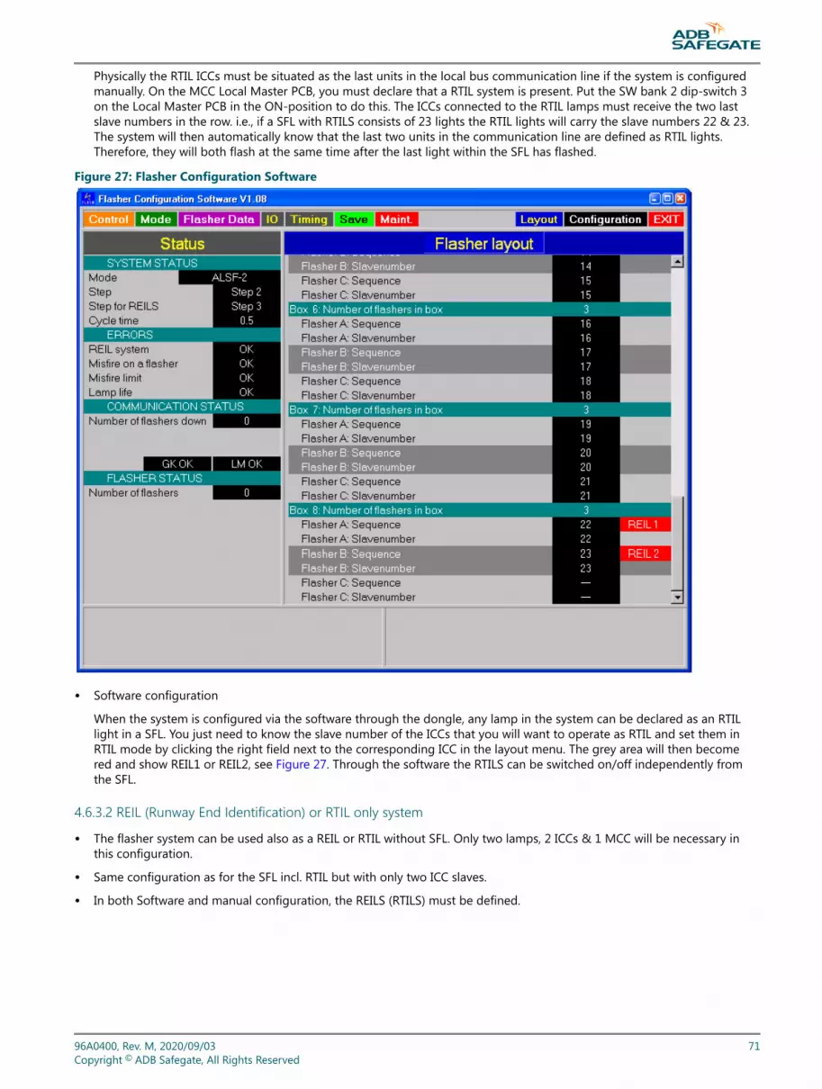
Physically the RTIL ICCs must be situated as the last units in the local bus communication line if the system is configuredmanually. On the MCC Local Master PCB, you must declare that a RTIL system is present. Put the SW bank 2 dip-switch 3on the Local Master PCB in the ON-position to do this. The ICCs connected to the RTIL lamps must receive the two lastslave numbers in the row. i.e., if a SFL with RTILS consists of 23 lights the RTIL lights will carry the slave numbers 22 & 23.The system will then automatically know that the last two units in the communication line are defined as RTIL lights.Therefore, they will both flash at the same time after the last light within the SFL has flashed.
Figure 27: Flasher Configuration Software
• Software configuration
When the system is configured via the software through the dongle, any lamp in the system can be declared as an RTILlight in a SFL. You just need to know the slave number of the ICCs that you will want to operate as RTIL and set them inRTIL mode by clicking the right field next to the corresponding ICC in the layout menu. The grey area will then becomered and show REIL1 or REIL2, see Figure 27. Through the software the RTILS can be switched on/off independently fromthe SFL.
4.6.3.2 REIL (Runway End Identification) or RTIL only system
• The flasher system can be used also as a REIL or RTIL without SFL. Only two lamps, 2 ICCs & 1 MCC will be necessary inthis configuration.
• Same configuration as for the SFL incl. RTIL but with only two ICC slaves.
• In both Software and manual configuration, the REILS (RTILS) must be defined.
96A0400, Rev. M, 2020/09/03 71Copyright © ADB Safegate, All Rights Reserved

NoteThe RTILS can only be activated separately (without activation of the SFL) from the Software or a J-Bus control if aSFL line is included in the system. (Not via a Multi-wire control.)
4.7 Technical Description of the Control Cabinets, System Components and AvailableOptions
4.7.1 Individual Control Cabinets (ICC)Each flasher requires one ICC (Individual Control Cabinet). There are 2 cabinet sizes:
• A single ICC (ICC-1) controlling one lamp unit.
• A multiple ICC with 3 units in one control unit (ICC-3) controlling three lamp units.
Any combination of these ICC cabinets is possible to obtain the required field configuration.
Note that the “ICC-3” has doubled terminals for a three-phase with neutral connection while the “ICC -1” has only single-phase connection terminals.
The “ICC-1” requires a junction box to connect it to the power supply cable. See Figure 61.
4.7.2 Master Control Cabinet (MCC)Each system requires one MCC (Master Control Cabinet). Each MCC contains a PCB that generates the control signals to allthe Individual Control Cabinets and connects the system to the remote control system.
Remote control and back-indication signals are possible through +24 Vdc, +48 Vdc or 120 Vac Multi-wire cable.
4.7.3 ConfigurationConfiguration of the system can be done using Dip-switches or through a PC. The remote control interface is factory set,depending on what has been ordered.
400 V: MALSR and ALSFOperation
72Copyright © ADB Safegate, All Rights Reserved
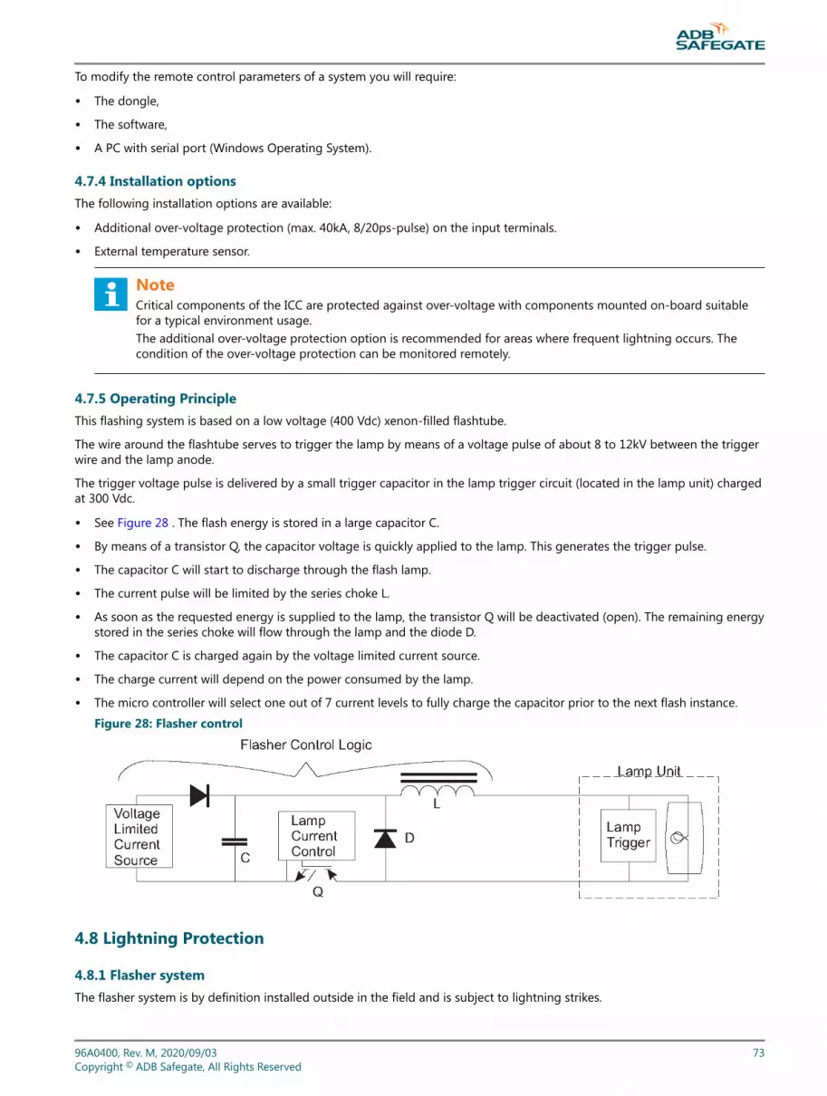
To modify the remote control parameters of a system you will require:
• The dongle,
• The software,
• A PC with serial port (Windows Operating System).
4.7.4 Installation optionsThe following installation options are available:
• Additional over-voltage protection (max. 40kA, 8/20ps-pulse) on the input terminals.
• External temperature sensor.
NoteCritical components of the ICC are protected against over-voltage with components mounted on-board suitablefor a typical environment usage.The additional over-voltage protection option is recommended for areas where frequent lightning occurs. Thecondition of the over-voltage protection can be monitored remotely.
4.7.5 Operating PrincipleThis flashing system is based on a low voltage (400 Vdc) xenon-filled flashtube.
The wire around the flashtube serves to trigger the lamp by means of a voltage pulse of about 8 to 12kV between the triggerwire and the lamp anode.
The trigger voltage pulse is delivered by a small trigger capacitor in the lamp trigger circuit (located in the lamp unit) chargedat 300 Vdc.
• See Figure 28 . The flash energy is stored in a large capacitor C.
• By means of a transistor Q, the capacitor voltage is quickly applied to the lamp. This generates the trigger pulse.
• The capacitor C will start to discharge through the flash lamp.
• The current pulse will be limited by the series choke L.
• As soon as the requested energy is supplied to the lamp, the transistor Q will be deactivated (open). The remaining energystored in the series choke will flow through the lamp and the diode D.
• The capacitor C is charged again by the voltage limited current source.
• The charge current will depend on the power consumed by the lamp.
• The micro controller will select one out of 7 current levels to fully charge the capacitor prior to the next flash instance.
Figure 28: Flasher control
4.8 Lightning Protection
4.8.1 Flasher systemThe flasher system is by definition installed outside in the field and is subject to lightning strikes.
96A0400, Rev. M, 2020/09/03 73Copyright © ADB Safegate, All Rights Reserved

For this reason, the ICC cabinets come with built-in lightning protection.
All metal parts are interconnected and there are earth ground lugs for the customer's use.
4.8.2 External wiringIn the external cabinet wiring, all cable shields must be connected to the cabinet earth ground. This must be done for thecable to the lamp, the main supply and the local bus connections.
Nevertheless, a major part of the efficiency of the protection is in the external wiring. All necessary steps must be taken toinsure a direct connection between the earth lug of the cabinet and a solid local earth ground (counterpoise or at the veryleast a large section grounding wire).
As an option, each ICC -cabinet can be equipped with MOV (Metal Oxide Varistors) over-voltage protection on the maininput. This will protect the cabinet if the lightning strikes nearby. It is possible to check remotely (Modbus or Multi-wire) if theMOVs are still intact or have to be replaced.
We recommend that the optional over-voltage protection be installed in any area where lightning occurs frequently.
4.8.3 Local bus inputThe local bus input is, at the input and the output level, protected by gas arresters (see Local bus interface). Here too, thecable armor (shield) must be connected to a low-resistance earth ground. On the flasher control unit (FCU) PCBs there issupplementary solid-state protection that can absorb substantial amounts of energy injected as a result of a nearby strike.
It must be stressed that although there can be no guarantee that there will be no damage after a lightning strike, if thenecessary precautions are taken, the damage will remain limited.
4.9 ICC (Individual Control Cabinet) FCU PCB 1487
The flasher control unit is a CPU-controlled PCB that receives its input messages from the MCC (or the dongle) via the localbus interface. There is no direct connection to the remote control system.
The board contains a Switched Mode Power Supply (SMPS) to charge the flash energy capacitor and has the necessaryhardware to drive and monitor the lamp.
The PCB within the ICC counts the number of misfires and sends error messages back to the MCC.
If the number of flashes exceeds the lamp lifetime, a message is sent to the system.
4.9.1 FCU PCB FuseF1 - Fuse rated 2 AT, 5x20 mm.
Table 29: FCU PCB 1487 Connectors
Name Type Purpose Factorywiring
Externalwiring Remarks
P1 5-pin Stocko Monitoring of the temperaturesensor x
P2 3-pin Stocko Monitoring of the door contact x
P3 3-pin Stocko Monitoring of the MOVS x
P4 10-pin flat-cable Local bus connector x
P5 3-pin Wago Heating resistor x
P6 3-pin Wago Mains supply x
P7 3-pin Molex Mains supply for the SMPS x
CAUTIONif the SMPS is not connected tothis board, there is a dummy plugon P7 to avoid accidental contactwith the mains supply.
400 V: MALSR and ALSFOperation
74Copyright © ADB Safegate, All Rights Reserved

Table 29: FCU PCB 1487 Connectors (continued)
Name Type Purpose Factorywiring
Externalwiring Remarks
J1 SUBD9 Connector for the dongle x Parameterization of the SFL
TB1 6-pin Phoenix DC supply connection x Return from the SMPS
TB2 6-pin Phoenix 0.4-in(10.16 mm) Lamp connection x
TB3 Fast-on Capacitor xWARNINGInsure the polarity blue or white,and red wires are correct!
TB4 Fast-on Coil xCAUTIONthe terminal PE (Potential toEarth) is never connected
4.9.2 FCU PCB 1487 JumpersJumpers are included on the PCBs to terminate the local bus, when necessary. During installation and setup, they may have tobe removed. See System Configuration .
96A0400, Rev. M, 2020/09/03 75Copyright © ADB Safegate, All Rights Reserved

Jumpers are used in the following diagram to short out / or leave in, the 680 Ω and 150 Ω resistors. Their function isdescribed as follows.
Figure 29: FCU PCB 1487 Jumpers
• The 150 Ω resistor is used to terminate the bus. It may only be installed at the physical ends of the bus i.e., at the first andthe last device physically found on the local bus communication cable.
• The 680 Ω resistors always come in pairs. There is a pull-up resistor on the positive bus wire and an identical pull-downresistor on the negative wire. Their purpose is to polarize the bus when no device is talking. After a message is sent by theMCC, but before an ICC starts responding, the bus is polarized to a safe position by the internal high-value pull- up/downresistors. Under extreme conditions of interference, additional 680 Ω resistors can be installed to decrease the sensitivityof the bus. Note that the 680 Ω resistors may only be connected at the LMC PCB and the last Individual Control Units (ICC)farthest from the MCC in the system, otherwise the bus drivers will become overloaded.
Table 30: FCU PCB 1487 Jumpers
Jumper Bus use Resistor Pull up 680 ohms Pulldown
Terminating resistor 150ohms Notes
W11 x
W28 Local bus x
W25 x
NoteJumpers W11, W28 and W25 must be placed on both ends if the MCC is in the middle of the ICCs.
4.9.3 FCU PCB Dip-switchesThere are two Dip-switch banks on the FCU PCB that are used to configure the ICC and thus pre-install some parameters.
400 V: MALSR and ALSFOperation
76Copyright © ADB Safegate, All Rights Reserved

CAUTION• If a switch setting is changed, it will only be taken into account after the next power down cycle, i.e. power down
the system in order to make a change in the hardware setting effective.
Table 31: FCU PCB Dip-switchesSwitch-bank Type Setting Use Remarks
Flasher SW2-
SW2-
SW2-
SW2-
SW2-
SW2-
SW2- SW2-
1 2 3 4 5 6 7 8
#1 • o o o o o o o
#2 o • o o o o o o
#3 • • o o o o o o
#4 o o • o o o o o
#5 • o • o o o o o
#6 o • • o o o o o
#7 • • • o o o o o
Slave number of the MCC (local #8 o o o o o o o
bus)MUST BE UNIQUE for each ICC
#9 • o o o o o o
#10 o • o o o o o
#11 • • o o o o o
Valid value from 1 to 32 (binary #12 o o • o o o o
SW2 Dip xxxxxxxxcode)
#13 • o • o o o o
#14 o • • o o o o
SW2 has eight dip switches. #15 • • • o o o o
Set as per chart to the right.#16 o o o o o o o
#17 • o o o o o o
0=off and 1=on #18 o • o o o o o
#19 • • o o o o o
#20 o o • o o o o
#21 • o • o o o o
#22 o • • o o o o
#23 • • • o o o o
#24 o o o o o o
#25 • o o o o o
#26 o • o o o o
#27 • • o o o o
#28 o o • o o o
#29 • o • o o o
1 OFF Internal use
2 OFF
3 OFF
96A0400, Rev. M, 2020/09/03 77Copyright © ADB Safegate, All Rights Reserved

Table 31: FCU PCB Dip-switches (continued)Switch-bank Type Setting Use Remarks
Flasher SW2-
SW2-
SW2-
SW2-
SW2-
SW2-
SW2- SW2-
4 OFF
5 + 6
OFF OFF Baud rate local bus 9600 baud
SW1 DipON OFF Baud rate local bus 19200 baud
OFF ON Baud rate local bus 38400 baud Factory Setting
ON ON Invalid
7 + 8
OFF OFF No parity
ON OFF Invalid (no parity)
OFF ON Local bus Odd parity
ON ON Local bus Even parity Factory Setting
NoteThe baud rate and parity of the local bus should only be changed if you experience severe problems incommunication between the units. In this case ALL the units should be set to the same baud rate and parity!
Figure 30: FCU PCB 1487: Switchbanks and Jumpers
400 V: MALSR and ALSFOperation
78Copyright © ADB Safegate, All Rights Reserved

4.9.4 ICC LEDsThe ICC is equipped with a number of LEDs. Their function is shown below.
Table 32: ICC LED IndicatorsName Indication Status Remarks
DS1 FLASH command Duration is proportional to theselected step.
DS2 RUN 1 Flash per second Higher rate during software upload
DS3 Rx local bus Normally OFFLights up momentarily duringtransmission or reception.
If one of these LEDs is OFF, there is no traffic on thecorresponding bus.
DS4 Tx local bus If one of these LEDs is ON, there is may be, apolarity inversion on the bus.
DS5 Isolated supply local bus ON
DS6 FLASH ON during flash request Hardware flash command to IGBT Driver
4.10 Local Bus Interface PCB 1498
This is a small PCB mounted on the DIN rail that provides the interconnection of the local bus between the ICC cabinets.
The PCB is equipped with gas arrestors for over-voltage protection.
For ease of wiring, there are 2 connectors for the local bus P1 and P3.
• One is for the connection to the next cabinet's PCB 1498 P1 (input),
• The other for the connection to the preceding ICC cabinet's PCB 1498 P3 (output).
• The external local bus connection from the MCC P3 is connected to P1 in the first ICC, and then P3 of that cabinet isconnected to P1 in the next ICC, and so on. See the external connection diagram in section 9.
• The flat-cable connectors P2 and P4 are for internal distribution of the bus signal, and are factory wired.
Figure 31: Local Bus interface, PCB 1498
4.11 MCC (Local Master) PCB 1485
The MCC Local Master PCB provides the control for the complete system.
96A0400, Rev. M, 2020/09/03 79Copyright © ADB Safegate, All Rights Reserved
Three modes of control exist:
• Remote control
• Local control
• Control via the Dongle
The Local Master PCB is a CPU-controlled printed circuit board. It interfaces with the remote control system that provides thecommand and back-indication signal functions. The MCC is not only the unique connection point for the customer's remotecontrol system, it is also the device that maintains a continuous communication with all the ICCs under its command. All thedata received is collected into a single database that gives the user a quick overview of the system without having to scan allseparate ICC PCBs. Full information on the individual ICCs can also be found in the data-base.
Data on the system can only be obtained using a PC and a Dongle.
The data exchange between the MCC and the individual ICCs is achieved over a twisted pair RS-485, 3 wire connection. Thiscommunication link is called the “local bus” connection. See also Chapter 4 “local bus Interface, PCB1498”. The protocol isproprietary.
The rotary switch in the MCC connects to the Local Master PCB to provide Local and Remote control functions.
On the Local Master PCB, there is a rotary selector switch SW3. It is normally not used and is set to position 9. If the MCCcabinet rotary switch is not present, it can optionally be used to select either remote control (position 9) or local control(position 1, 2 and 3 according to the brightness setting required).
The dongle is connected to the system using either the MCC or any ICC. When configuring the system using a PC, the MCCloses the master command over the local bus and the software is used to define the control and configuration of the system.At that moment the Multi-wire and the busses also lose control over the system. All settings and control parameters are setvia the software.
NoteFor FAA MALSR applications, all settings and control parameters can be set using only the DIP switches.
4.11.1 ProtectionsAll the bus signals (local bus and the optional Modbus) are protected with solid-state devices against over-voltages (lightningstrike). They are galvanically isolated from the LMC and FCU PCB signals to better absorb sudden surges on the bus.
4.11.2 Start-up and scanningAt power-up the MCC reads its local E2 PROM memory to find the system configuration. Then it will contact all the system'sICC PCBs via the local bus. System configuration data is sent to each ICC to program it for normal operation.
Depending on how the system was configured it will read the configuration from the dip- switches or the E2PROM.
After the start-up sequence, the MCC continues to scan all the ICCs sequentially to ensure correct operation. If REIL flashersare used, they are scanned at a higher rate for applications where it is required to switch one OFF if the other fails (misfires).
Supplementary messages are interleaved with this scan cycle when commands are received from Local or Remote control.
4.11.3 SynchronizationThe main purpose of a flasher system is that each unit flashes in a predefined sequence, interval and repetition rate.
Each ICC is an autonomous device that decides for itself when it is to flash. This is based on 2 parameters: the cycle time andthe sequence time.
The cycle time defines the repetition rate. It can be programmed to:
• 2 flashes per second (FAA and ICAO standard),
• 1 flash per second,
• 1 flash every 2, 5 or 10 seconds.
The sequence time is the delay counted from the beginning of a cycle that defines the moment a lamp must flash.
400 V: MALSR and ALSFOperation
80Copyright © ADB Safegate, All Rights Reserved

One of the functions of the MCC is to keep all the ICCs synchronized so that they will flash in sequence. This is accomplishedby sending a unique message to all the ICCs at regular intervals. This guarantees the system will keep the flashing sequencewithin a few milliseconds.
The CPU on each FCU PCB generates an internal clock with a precision that depends directly on the internal quartz crystal(100 ppm, i.e. 0.001%). This clock is the reference time base for all the internal timers. In order to achieve a continuous 1 msecprecision on the flashing timing, a re-synchronizing message is sent by the MCC once every 10 seconds. This corrects for anydrift in the clock frequency.
4.11.4 Real-time measurementsThe MCC is also the controller for the real-time measurement. This allows the user to check if each ICC flashes at the expectedmoment.
The real-time measurement only runs on request by the user and for a limited time that the user can select (min 5 sec to max60 sec). During this time, the MCC captures and stores the exact moment when each lamp flashes.
During real-time measurement, the synchronizing messages are suspended. This allows the user to check for possible timingdrift of each ICC.
After the measurement terminates, the captured data is available in the data base.
Table 33: PCB 1485 Connectors
Name Type Purpose To be connected bycustomer
Factoryconnections Remarks
P1 20-pin flat cable External Modbus x
P2 10-pin flat cable Local bus (coming from theclosest ICC)
x
P3 10-pin flat cable Alternative to P2
P4 6-pin Phoenix Mains supply Not used
P5 26-pin flat cable Supply for multi-wire control x
P6 3-pin Stocko Monitoring for the MOVs x
P7 3-pin Stocko Monitoring for the doorcontact x
P8 5-pin Stocko Monitoring for thetemperature sensor probe x
P9 5-pin Stocko Monitoring for the doorcontact
J1 3-pin Wago Mains supply of the Multi-wire Not used
J2 SUBD9 Connection of the dongleSets the Parameters of thesequenced flashing lights(SFL)
J3 3-pin Wago Synchronization betweenMCCs Not used
J4 3-pin Wago Mains supply Not used
J5 3-pin Wago Heating resistor Not used
TB1 6-pin Phoenix DC supply x
96A0400, Rev. M, 2020/09/03 81Copyright © ADB Safegate, All Rights Reserved

4.12 PCB 1485 Jumpers
Table 34: PCB 1485 Jumpers
Jumper Bus use Rx : TxResistor 680 ohms Terminating resistor
150 ohms RemarksPull up Pull down
W1Remote Bus A
Tx - x not used
W2 Tx + x not used
W3 Tx x not used
W4 Rx + x not used
W5 Rx - x not used
W6 Rx x not used
W7 Rx - x not used
W8 Tx x not used
W9Remote Bus B
Tx + x not used
W10 Tx - x not used
W11 R x+ x not used
W12 Rx x not used
W13Reserved
- xfor future use
W14 + x
W15Local bus jumpers
- x
W16 + x
W17 Synchronization line x for future use
W18 Local bus jumper x
W19 Bus A not used
W20 Bus B not used
4.12.1 Rotary and Dip-switchesThere are a number of dip-switches on this PCB that are used to configure it, to set some parameters or to reset completelythe MCC.
Figure 32: MCC, PCB1485: Switches
400 V: MALSR and ALSFOperation
82Copyright © ADB Safegate, All Rights Reserved

Table 35: PCB 1485 Rotary and dip-switchesSwitch-
bank Type Setting Use Remarks
SW1 Dip xxxxxxxx not used
Manual config SW4 /4SW2 Dip
1 + 2
OFF OFF 16 msec interval time
ON OFF 33 msec interval time
OFF ON 66 msec interval time
ON ON invalid
3 ON Declaration of REILS
4ON 1 cycle per second
OFF 2 cycles per second
SW3 Rotary
0 Flasher system OFF Set to position 9 for both FAA MALSR and ALSFapplications using a master control cabinet (MCC).
1 Step 1
2 Step 2
3 Step 3
9 Remote control
SW4 Dip
1OFF Enabling of the control by the
rotary SW3
ON Hardware local kill ON No control by SW3
2 OFF See note 1
3 OFF See note 2
4
OFF Configuration by use of thedongle
ON Manual config by SW2 and SW5NoteManual Configuration not available on ALSF/SSALR applications
5 + 6
OFF OFF Baud rate local bus 9600 baud
ON OFF Baud rate local bus 19200 baud
OFF ON Baud rate local bus 38400 baud Factory settings
SW4 Dip
ON ON invalid
7 + 8
OFF OFF No parity
ON OFF Invalid (no parity)
OFF ON Local bus Odd parity
ON ON Local bus Even parity Factory settings
96A0400, Rev. M, 2020/09/03 83Copyright © ADB Safegate, All Rights Reserved

Table 35: PCB 1485 Rotary and dip-switches (continued)Switch-
bank Type Setting Use Remarks
SW5 Dip
1 >6 Number of ICCs in the system See Table 36
7 Not used
8
OFF Disabling of the use of theDongle
ON Enabling of the use of theDongle
NoteExcept where specifically noted, all the switches are read at power-up. If a switch setting is changed, it will only betaken into account after the next power-down/power-up cycle.
CAUTIONSW4-2 - Initiation of the data E2PROMThe MCC stores the system parameters in an E2PROM. When first powered-up or when the system must becompletely reconfigured, it is possible to clear the E2PROM and return to the default factory settings. To do this, putthe switch in the ON position, power down the MCC and turn it ON again after 5 seconds. Do not forget to set theswitch back to OFF or the E2PROM will once again be cleared at the next power cycle.This will clear all the parameters, including the system layout data. The system parameters must be restored via thesoftware, or by using the dip-switches.
NoteSW4-3 - Lock to boot
This switch is always OFF in a functioning system. It is only used if there is a major problem during upload of new applicationcode.
Table 36: SW5 dip switchFlasher SW2-1 SW2-2 SW2-3 SW2-4 SW2-5 SW2-6 SW2-7 SW2-8
#1 • 0 0 0 0 0 0 0
#2 0 • 0 0 0 0 0 0
#3 • • 0 0 0 0 0 0
#4 0 0 • 0 0 0 0 0
#5 • 0 • 0 0 0 0 0
#6 0 • • 0 0 0 0 0
#7 • • • 0 0 0 0 0
#8 0 0 0 • 0 0 0 0
#9 • 0 0 • 0 0 0 0
#10 0 • 0 • 0 0 0 0
#11 • • 0 • 0 0 0 0
#12 0 0 • • 0 0 0 0
#13 • 0 • • 0 0 0 0
#14 0 • • • 0 0 0 0
#15 • • • • 0 0 0 0
400 V: MALSR and ALSFOperation
84Copyright © ADB Safegate, All Rights Reserved

Table 36: SW5 dip switch (continued)Flasher SW2-1 SW2-2 SW2-3 SW2-4 SW2-5 SW2-6 SW2-7 SW2-8
#16 0 0 0 0 • 0 0 0
#17 • 0 0 0 • 0 0 0
#18 0 • 0 0 • 0 0 0
#19 • • 0 0 • 0 0 0
#20 0 0 • 0 • 0 0 0
#21 • 0 • 0 • 0 0 0
#22 0 • • 0 • 0 0 0
#23 • • • 0 • 0 0 0
#24 0 0 0 • • 0 0 0
#25 • 0 0 • • 0 0 0
#26 0 • 0 • • 0 0 0
#27 • • 0 • • 0 0 0
#28 0 0 • • • 0 0 0
#29 • 0 • • • 0 0 0
#30 0 • • • • 0 0 0
#31 • • • • • 0 0 0
#32 0 0 0 0 0 • 0 0
4.12.2 MCC LEDsThe MCC is equipped with a number of LEDs. Their function is described in the table below.
Table 37: MCC LED IndicatorsName Indication Status Remarks
DS1 Isolated supply Bus A ON
DS2 Isolated supply Bus B
DS3 Isolated supply local bus
DS4 Reserved For future use
DS5 RUN 1 flash per second Higher rate during software upload
DS6 Rx local busIf one of these LEDs is OFF, there is no traffic on thecorresponding bus.DS7 Tx local bus Normally OFF.
DS8 Rx Bus A
Lights up momentarily duringtransmission or reception.
DS9 Tx Bus AIf one of these LEDs stays ON, there may be apolarity inversion on the bus.DS10 Rx Bus B
DS11 Tx Bus B
4.13 Multi-wire Remote Control and Monitoring Interface PCB 1486
The Multi-wire interface (in the MCC) is a simple device with 8 command (input) terminals (connectors P2) and up to 8 back-indication (output) terminals (connector P1). For 120 Vac remote control applications, there are multiple back indicatorsavailable. Separate relays are used for the back indication.
96A0400, Rev. M, 2020/09/03 85Copyright © ADB Safegate, All Rights Reserved

It provides a simple remote control system via relays and also provides galvanic isolation between the remote control systemand the flashing system. The Multi-wire is connected to the MCC by a flat cable on connector P3. Its presence is detectedautomatically.
In case the internal power supply is not used (external remote control power supply is available) there is no need to connectthis PCB to the mains supply (plug J1).
The user can also use the internal power supply to interface to the remote control system. This power supply is short-circuitprotected by self-repairing poly-switches. The maximum current is 200 mA for 48 V and 400 mA for 24 V. If the remote controlis 120 Vac, separately mounted 120 Vac relays feed the input of the multi-wire PCB.
4.13.1 Control signals and back-indicationThe Multi-wire interface exists in 2 versions: 24 Vdc (part number 1593.13.510) and 48 Vdc (1593.13.520).
The relays are DC, but are not polarized, i.e. the control can be inverted.
The back-indications signals are provided over dry contact relays.
Figure 33: ALSF I/O settings: Click on I/O TAB
400 V: MALSR and ALSFOperation
86Copyright © ADB Safegate, All Rights Reserved

Figure 34: Click on Mode tab and click on Mode 2 SSALR
4.13.2 FCU Multi-wire I/O Configuration for the FAA Market
Table 38: Multi-wire SignalsName Type Function
Mode Select Bit 0 Output This signal shows the value of mode select bit 0. This signal allows the upper system to know whatmode the FCU was commanded to.
Mode Select Bit 1 Output This signal shows the value of mode select bit 1. This signal allows the upper system to know whatmode the FCU was commanded to.
Step 1 Output This signal is made HIGH if the system was COMMANDED to step 1.
Step 2 Output This signal is made HIGH if the system was COMMANDED to step 2.
Step 3 Output This signal is made HIGH if the system was COMMANDED to step 3.
Local OutputThis signal is made HIGH when the local control selector switch is NOT in the remote position.Combined with the step signals above and the running signal, this allows the upper system toknow what the locally commanded conditions are.
CAUTION Output This signal is made HIGH when CAUTION condition exists for the FCU in the currentlyCOMMANDED mode.
FAULT Output This signal is made HIGH when FAULT condition exists for the FCU in the currently COMMANDEDmode.
Explicit ON InputThis signal is made HIGH by the upper system to command the FCU to switch on. Normally, theFCU will switch on as soon as an intensity is given. If the explicit on signal is present, both an“intensity” and the “explicit on” signal must be HIGH for the FCU to switch on.
4.13.3 FunctionsThe function of each input terminal is determined in the software.
96A0400, Rev. M, 2020/09/03 87Copyright © ADB Safegate, All Rights Reserved

There are two possibilities:
• Manual Configuration
For systems that utilize remote control without use of the Modbus, there is an alternative way to configure the systemwithout the use of the dongle and the software.
First the switch SW4/4 of the Local Master PCB must be set to ON to select manual configuration.
The system is configured using the dip-switches. Only the Multi-wire remote control and back-indication are available. See Table 35.
• Configuration by use of the dongle and the software (Windows I/O).
I/Os can be defined by means of the flasher software and dongle.
4.13.4 Input connector P2: remote control command signalsThis connector is only directly used via interface relays mounted in the MCC for 24 Vdc, 48 Vdc or 120 Vac remote controlsignals.
The connector type is WAGO 231-312/026-000 cage-clamp connector (part number 6112.33.112). See “Schematics” on page131.
Command signals on connector P2 are:
Table 39: PCB 1486 Input functionsFunction Description Manual config assignation
Step 1 If one of the contacts is activated, the ICCs switch ON at the selected step. Ifnothing is activated, the ICC goes OFF.Note that if more than 1 terminal is activated simultaneously, the flasherhighest step takes precedence.
Terminal IN 1
Step 2 Terminal IN 2
Step 3 Terminal IN 3
REILS ON When activated, this switches the REILS ON at the step defined above. Terminal IN 4
Reset misfire If there was a latched misfire condition, activating this terminal clears it. Terminal IN 8
Free These terminals are not used. Terminals IN 5, IN 6, IN 7
Mode Select Bit 0It is possible to select one of the first 4 modes via the Multi-wire.By default mode 1 is used.If only the mode select bit 0 is attributed to a
Not used
Mode Select Bit 1
terminal, it selects mode0 (OFF) or 1 (ON).If both functions are attributed to 2 terminals, then modes 2 and 3 can also beselected.Bit 0 - Bit 1
• OFF - OFF - Use mode 1
• ON - OFF - Use mode 2
• OFF - ON - Use mode 3
• ON - ON - Use mode 4
Not used
NoteThe control commands may use an external DC supply (polarity: any) or an internal DC supply (positive or negative:see wiring drawings.)
400 V: MALSR and ALSFOperation
88Copyright © ADB Safegate, All Rights Reserved

4.13.5 Mode selection: ALSF1 / SSALR / MALSR / ALSF2Modes of Operation: The control commands may use an external DC supply (polarity: any) or an internal DC supply (positiveor negative: see drawings).
Figure 35: External supply 24 Vdc or 48 Vdc: Polarity=either.
Figure 36: Internal power supply 48 Vdc or 24 Vdc Polarity=positive
96A0400, Rev. M, 2020/09/03 89Copyright © ADB Safegate, All Rights Reserved
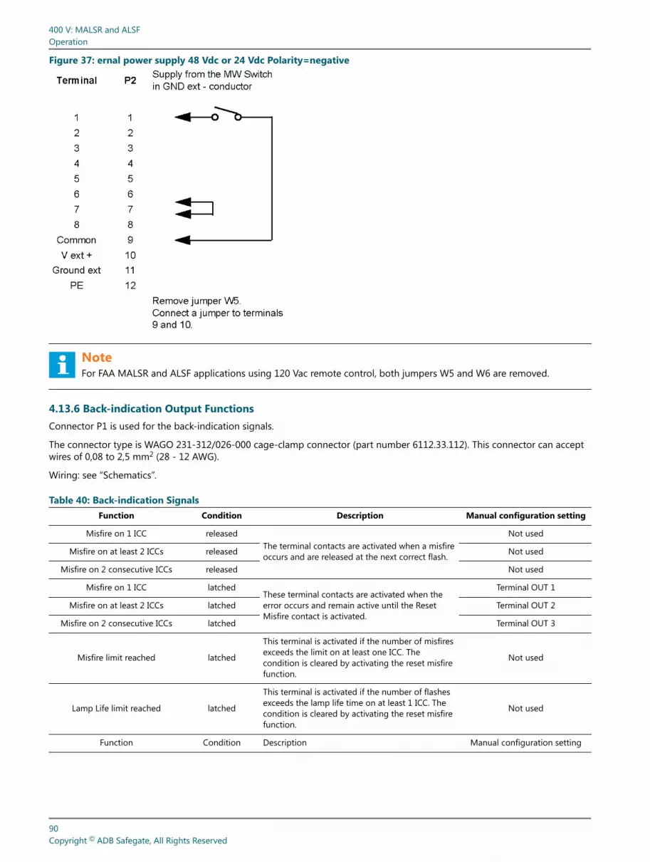
Figure 37: ernal power supply 48 Vdc or 24 Vdc Polarity=negative
NoteFor FAA MALSR and ALSF applications using 120 Vac remote control, both jumpers W5 and W6 are removed.
4.13.6 Back-indication Output FunctionsConnector P1 is used for the back-indication signals.
The connector type is WAGO 231-312/026-000 cage-clamp connector (part number 6112.33.112). This connector can acceptwires of 0,08 to 2,5 mm2 (28 - 12 AWG).
Wiring: see “Schematics”.
Table 40: Back-indication SignalsFunction Condition Description Manual configuration setting
Misfire on 1 ICC releasedThe terminal contacts are activated when a misfireoccurs and are released at the next correct flash.
Not used
Misfire on at least 2 ICCs released Not used
Misfire on 2 consecutive ICCs released Not used
Misfire on 1 ICC latchedThese terminal contacts are activated when theerror occurs and remain active until the ResetMisfire contact is activated.
Terminal OUT 1
Misfire on at least 2 ICCs latched Terminal OUT 2
Misfire on 2 consecutive ICCs latched Terminal OUT 3
Misfire limit reached latched
This terminal is activated if the number of misfiresexceeds the limit on at least one ICC. Thecondition is cleared by activating the reset misfirefunction.
Not used
Lamp Life limit reached latched
This terminal is activated if the number of flashesexceeds the lamp life time on at least 1 ICC. Thecondition is cleared by activating the reset misfirefunction.
Not used
Function Condition Description Manual configuration setting
400 V: MALSR and ALSFOperation
90Copyright © ADB Safegate, All Rights Reserved

Table 40: Back-indication Signals (continued)Function Condition Description Manual configuration setting
REILS DOWNIf there is a misfire on 1 of the REIL ICCs and theother one is switched OFF automatically, then thisterminal is activated.
Terminal OUT 4
Overtemperature
When the inside temperature of an ICC or theMCC exceeds the programmed maximumtemperature, this terminal is activated. As soon asthe temperature drops under the limit on all thedevices, the terminal resets.
Terminal OUT 5
Communication problems onlocal bus
If the MCC cannot contact one of the ICCs thisterminal is activated. As soon as the condition isrepaired and the ICC is back on line, the terminalresets.
Terminal OUT 6
Security (DOOR open + MOVblown)
The security parameters check for defects in theprotection of the Control units (MOV) or intrusion(DOOR open or flasher fixture open). As soon asthe condition is repaired or the door/fixture isclosed, the terminal resets. MOV monitoring isavailable only with the higher rated ICC lightningprotection option.
Terminal OUT 7
Security (DOOR open) Not used
Security (MOV blown) Not used
Free This terminal is not used. Terminal OUT 8
Flasher RUNNING Contact is closed when the flasher system receiveda valid step + mode command. Not used
96A0400, Rev. M, 2020/09/03 91Copyright © ADB Safegate, All Rights Reserved

4.13.7 Back-indication Modes of operationThe back-indication signals may be provided:
• Over dry contact relays
• Over polarized contacts (positive or negative)
See drawings below for 24 Vdc or 48 Vdc applications:
Figure 38: Dry contacts:
Figure 39: Polarized contact negative
400 V: MALSR and ALSFOperation
92Copyright © ADB Safegate, All Rights Reserved

Figure 40: Polarized contact positive
4.13.8 Manual configurations OverviewThe following is an overview on how to set the jumpers and switches.
NoteManual configuration is not available on ALSF systems.
4.13.9 Configuring the 400V MALSR 5-Light Sequenced Flasher SystemLocal Master Control (LMC) Board
• SW1: Not used
• SW2: 1=ON; 2=OFF; 3=OFF; 4=OFF
• Rotary switch SW3: Always set to position 9
• SW4:1=OFF; 2=OFF; 3=OFF; 4=OFF; 5=OFF; 6=ON; 7=ON; 8=ON
Note1 to 6 represents the total number of flashers in the system. (This means the binary value is the same as SW2 fromthe last FCU PCB in the system).
S4-4 is normally set to ON to enable automatic configuration by the dipswitch settings. It is set to OFF when connectingthe laptop.
• SW5: 1=ON/OFF; 2=ON/OFF; 3=ON/OFF; 4=ON/OFF; 5=ON/OFF; 6=ON/OFF; 7=OFF; 8=ON
Configuring the Jumpers
96A0400, Rev. M, 2020/09/03 93Copyright © ADB Safegate, All Rights Reserved

• Jumpers W15, W16 and W18: Insure that these jumpers are present.
• All other jumpers (W1-W14, W17, W19, W20, W32): Not used. If a jumper is present it can remain in place.
Figure 41: Manual Configuration Jumpers and Switches
400 V: MALSR and ALSFOperation
94Copyright © ADB Safegate, All Rights Reserved

Figure 42: LMC LED Indications
96A0400, Rev. M, 2020/09/03 95Copyright © ADB Safegate, All Rights Reserved
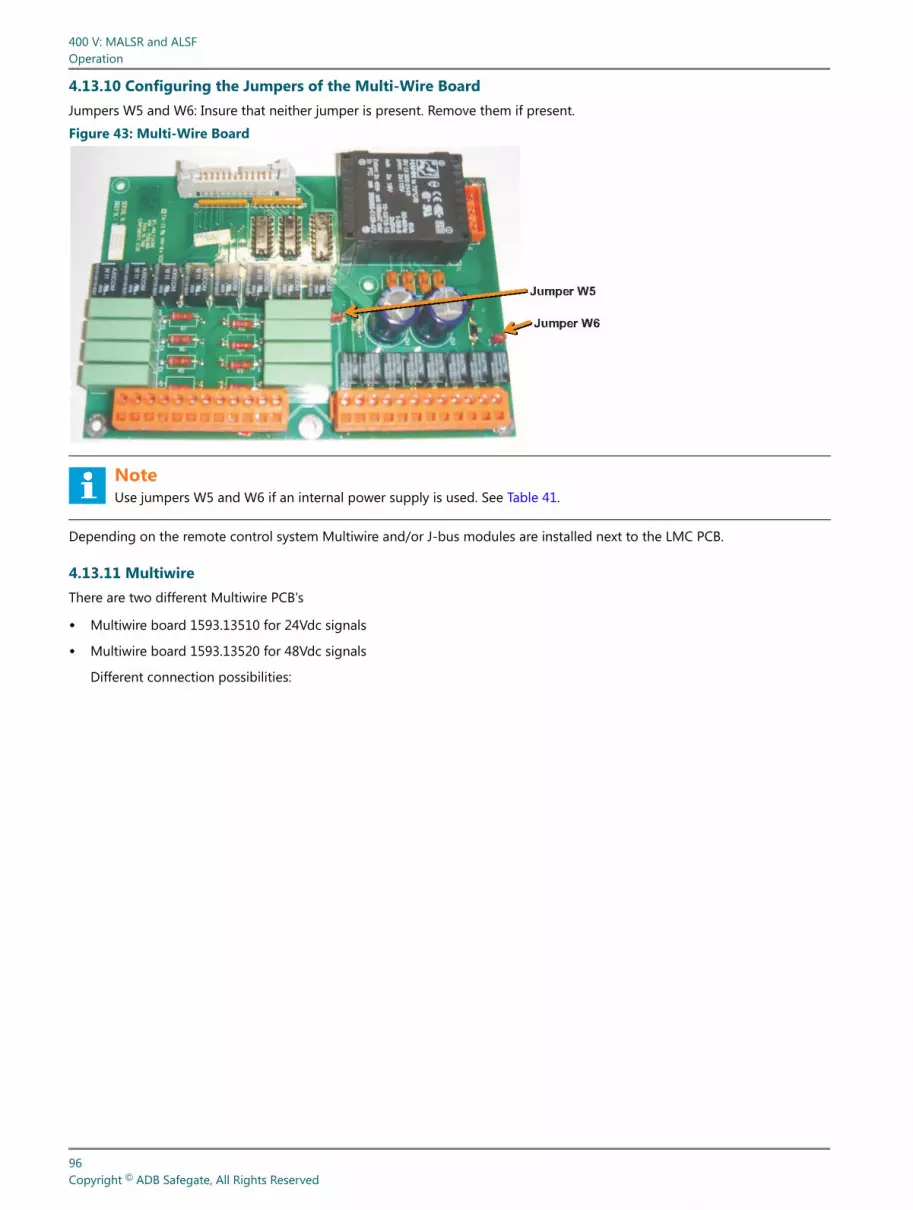
4.13.10 Configuring the Jumpers of the Multi-Wire BoardJumpers W5 and W6: Insure that neither jumper is present. Remove them if present.
Figure 43: Multi-Wire Board
NoteUse jumpers W5 and W6 if an internal power supply is used. See Table 41.
Depending on the remote control system Multiwire and/or J-bus modules are installed next to the LMC PCB.
4.13.11 MultiwireThere are two different Multiwire PCB's
• Multiwire board 1593.13510 for 24Vdc signals
• Multiwire board 1593.13520 for 48Vdc signals
Different connection possibilities:
400 V: MALSR and ALSFOperation
96Copyright © ADB Safegate, All Rights Reserved

• External power supply
• Internal power supply
Table 41: Multiwire Configurations
Back indication External power supply (polarity isnot important) Max. 110Vdc
Internal power supply (polarizedcontacts positive)
Internal power supply (polarizedcontacts negative)
Remarks Remove strap W6 Remove strap W6 Install strap W6
Control signal External power supply 24Vdc/48Vdc
Internal power supply (switch in +conductor)
Internal power supply (switch in –conductor)
Remarks Remove strap W5 Install strap W5 Remove strap W5
4.13.12 Flasher Controller Unit (FCU) BoardConfiguring the Dip-switches (example of 5-light MALSR)
96A0400, Rev. M, 2020/09/03 97Copyright © ADB Safegate, All Rights Reserved

SW1: 1=OFF; 2=OFF; 3=OFF; 4=OFF; 5=OFF; 6=ON; 7=ON; 8=ON.
SW2 Flasher #1: 1=ON; 2=OFF; 3=OFF; 4=OFF; 5=OFF; 6=OFF; 7=OFF; 8=OFF
SW2 Flasher #2: 1=OFF; 2=ON; 3=OFF; 4=OFF; 5=OFF; 6=OFF; 7=OFF; 8=OFF
SW2 Flasher #3: 1=ON; 2=ON; 3=OFF; 4=OFF; 5=OFF; 6=OFF; 7=OFF; 8=OFF
SW2 Flasher #4: 1=OFF; 2=OFF; 3=ON; 4=OFF; 5=OFF; 6=OFF; 7=OFF; 8=OFF.
SW2 Flasher #5: 1=ON; 2=OFF; 3=ON; 4=OFF; 5=OFF; 6=OFF; 7=OFF; 8=OFF.
NoteFlasher Number 1 is the flasher farthest from the runway.
4.13.13 Configuring the JumpersRemove jumpers W11, W25 & W28 on all FCUs but the FCU farthest from the Master Control Cabinet (MCC). As an exampleof 5-light MALSR with the MCC closest to Flasher #5, the jumper settings would be:
• W11, W25 & W28 Flasher #1: All 3 jumpers present. Note: Flasher Number 1 is the flasher farthest from the runway.
• W11, W25 & W28 Flasher #2: All 3 jumpers removed.
• W11, W25 & W28 Flasher #3: All 3 jumpers removed.
• W11, W25 & W28 Flasher #4: All 3 jumpers removed.
• W11, W25 & W28 Flasher #5: All 3 jumpers removed.
NoteFlasher Number 5 is the flasher closest to the runway.
Figure 44: Flasher Control Unit (FCU) Board Jumpers and Switches
NoteJumpers W11, W25 and W28 must be placed on both ICC ends if the Master is in the middle
400 V: MALSR and ALSFOperation
98Copyright © ADB Safegate, All Rights Reserved

4.13.14 Flasher Control Unit (FCU) Board LEDsFigure 45: Flasher Control Unit (FCU) Board LED Indicators
4.14 External Temperature Probe
The external temperature probe should be attached to one of the ICC cabinets.
The local master control (LMC) PCB interprets the data received from the external temperature probe connected to P8.
96A0400, Rev. M, 2020/09/03 99Copyright © ADB Safegate, All Rights Reserved
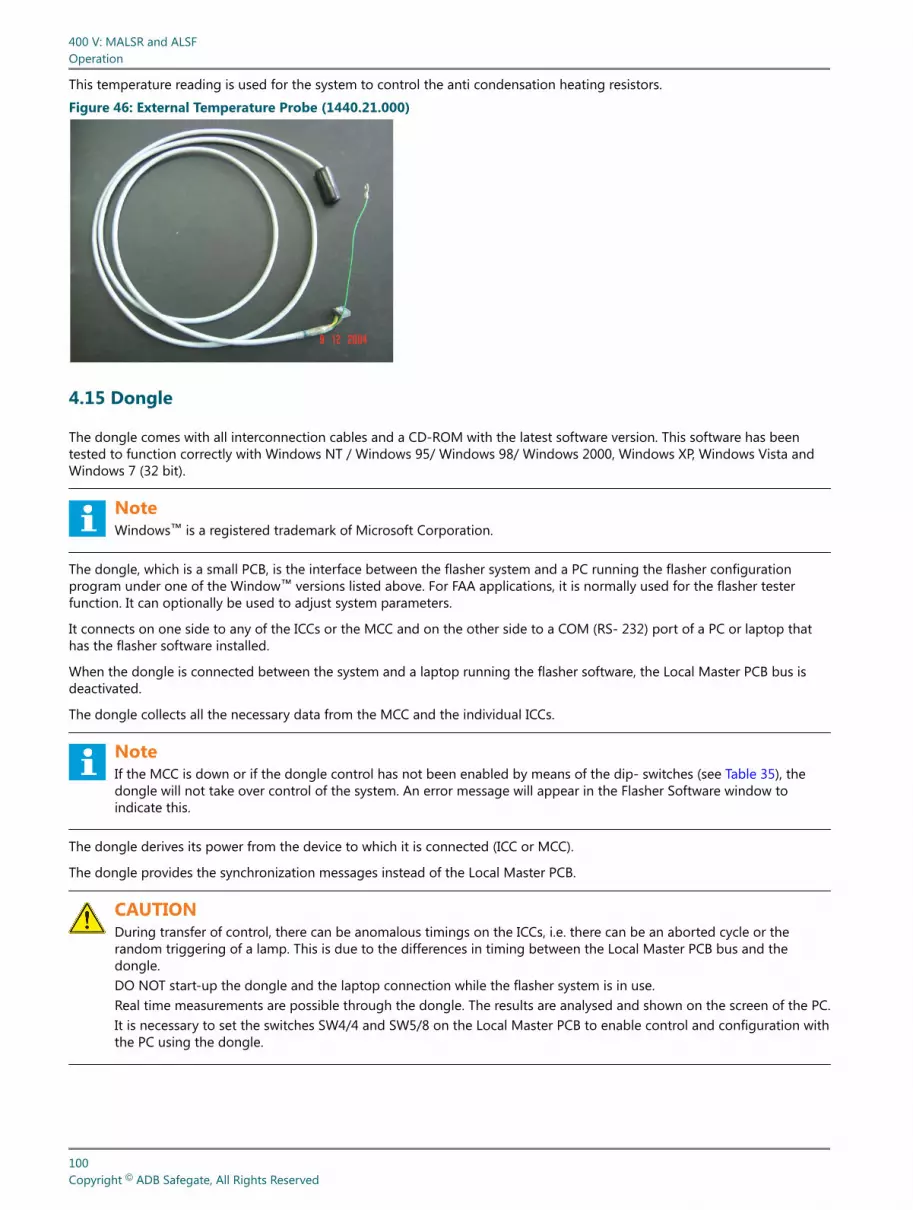
This temperature reading is used for the system to control the anti condensation heating resistors.
Figure 46: External Temperature Probe (1440.21.000)
4.15 Dongle
The dongle comes with all interconnection cables and a CD-ROM with the latest software version. This software has beentested to function correctly with Windows NT / Windows 95/ Windows 98/ Windows 2000, Windows XP, Windows Vista andWindows 7 (32 bit).
NoteWindows™ is a registered trademark of Microsoft Corporation.
The dongle, which is a small PCB, is the interface between the flasher system and a PC running the flasher configurationprogram under one of the Window™ versions listed above. For FAA applications, it is normally used for the flasher testerfunction. It can optionally be used to adjust system parameters.
It connects on one side to any of the ICCs or the MCC and on the other side to a COM (RS- 232) port of a PC or laptop thathas the flasher software installed.
When the dongle is connected between the system and a laptop running the flasher software, the Local Master PCB bus isdeactivated.
The dongle collects all the necessary data from the MCC and the individual ICCs.
NoteIf the MCC is down or if the dongle control has not been enabled by means of the dip- switches (see Table 35), thedongle will not take over control of the system. An error message will appear in the Flasher Software window toindicate this.
The dongle derives its power from the device to which it is connected (ICC or MCC).
The dongle provides the synchronization messages instead of the Local Master PCB.
CAUTIONDuring transfer of control, there can be anomalous timings on the ICCs, i.e. there can be an aborted cycle or therandom triggering of a lamp. This is due to the differences in timing between the Local Master PCB bus and thedongle.DO NOT start-up the dongle and the laptop connection while the flasher system is in use.Real time measurements are possible through the dongle. The results are analysed and shown on the screen of the PC.It is necessary to set the switches SW4/4 and SW5/8 on the Local Master PCB to enable control and configuration withthe PC using the dongle.
400 V: MALSR and ALSFOperation
100Copyright © ADB Safegate, All Rights Reserved

4.15.1 Dongle LED IndicatorssThe Dongle is equipped with a number of LED Indicators to help during system installation and repair.
Table 42: Dongle Status LED IndicatorsName Indication Status Remarks
DS1 TxD to laptopNormally OFF.Lights up momentarily duringtransmission or reception.
If one of these LEDs is OFF, there is no traffic on thecorresponding bus.If one of these LEDs stays ON, there may be a polarityinversion on the bus.DS2 RxD from laptop
DS5 Isolated supply forcommunication
DS7 RUN 1 flash per second
DS8 TxD to flasher system Normally OFF.Lights up momentarily duringtransmission or reception.
If one of these LEDs is OFF, there is no traffic on thecorresponding bus.If one of these LEDs stays ON, there may be a polarityinversion on the bus.
DS9 RxD fromflasher system
4.15.2 Cable layout• The cable between the laptop and the Dongle:
Both are interconnected with a null-modem cable (DB9 female -- DB9 female) with the following minimum configuration:
COM-PC Dongle J3
Pin 2 (RxD) Pin 3 (TxD)
Pin 3 (TxD) Pin 2 (RxD)
Pin 5 (GND) Pin 5 (GND)
Pin 7 (RTS) Pin 8 (CTS)
Pin 8 (CTS) Pin 7 (RTS)
• Cable between dongle and ICC or MCC:
96A0400, Rev. M, 2020/09/03 101Copyright © ADB Safegate, All Rights Reserved

This should be a pin-to-pin (DB9 male -- DB9 male) cable with the following layout:
Dongle MCC or ICC
Pin 2 RxD
Pin 3 TxD
Pin 5 GND
Pin 7 RTS
Pin 9 + 15 Vdc
4.15.3 Dip-switch bankThe dip-switch bank that is mounted on the Dongle is used to set the communication speed parameters. Set the switches to10101010 if not already set like this by default. In the configuration menu of the software, choose the used COM port on yourlaptop, ‘38400’ bd & ‘EVEN’ parity. This will allow proper communication between the ICCs, MCC and the Dongle.
Figure 47: Connection: ICC , Dongle and Laptop
4.16 Initial Software Installation and Software Use
This section provides additional details on use of the software.
4.16.1 Configuration toolYou can operate the equipment directly from your PC with the configuration tool.
WARNINGDo not use the configuration tool unless you have permission to do so. If you activate the configuration tool, youtransfer all control of the equipment to the tool. In this situation, remote or local control of the equipment is notpossible.
4.16.2 Install the configuration toolThe configuration tool is software that gives you full control of the entire equipment from your PC. You can use the tool toconfigure the equipment after installation or maintenance work.
4.16.3 System requirements:• PC with Microsoft Windows operating system;
• At least 50 Mbytes free disk space;
• 1 free serial communication (COM) port, or a virtual serial communication port over a USB bridge or a PCMCIA card;
• PC user account with either administrator or power user rights.
400 V: MALSR and ALSFOperation
102Copyright © ADB Safegate, All Rights Reserved

4.16.4 Configuration tool package:• 1 dongle with embedded software;
• 1 installation CD-Rom with a flasher program;
• 2 cables:
• Extension cable (DB9M/DB9M-1,5 m);
• Cable null modem (DB9F/DB9F-1,8 m).
4.16.5 Install software
1. Open Windows Explorer.
2. In Windows Explorer, open the main folder of the installation CD-ROM.
3. Run the setup application file. Follow the instructions of the installation program. The software is now installed.
4. Copy the system upgrade files (.upl) from the installation CD to the directory where you installed the software.
4.16.6 Connect cables
1. Make sure the equipment is switched OFF.
2. Open the cabinet.
3. Connect the extension cable to the dongle (B) and to the PC connector of the cabinet (A).You can connect directly to any ICC cabinet or to the LMC PCB in the MCC.
4. Connect the cable null modem to the dongle (B) and to the serial communication port of your PC (C).
4.16.7 Start software
1. Switch the equipment ON. The equipment also supplies power to the dongle.
2. Start the configuration tool. Go to Start > All programs > MCR_WIN > MCR_WIN. Alternatively click the MCR_WIN.exe filein the directory where you installed the software. The configuration tool opens.
3. Select the menu Configuration.
4. Select the applicable serial communication port (COM) to which you connected the dongle.
NoteThe baud rate and parity settings for the communication between the PC, dongle and the equipment must be thesame. For the dongle, the default baud rate is 38400 and the default parity setting is EVEN.
5. The dongle makes the connection to the equipment automatically.
96A0400, Rev. M, 2020/09/03 103Copyright © ADB Safegate, All Rights Reserved

4.17 Upload New Software
Figure 48: Configuration tool
1. Save the installation files of the new software to your PC.
2. Open the configuration tool.
3. Go to menu Configuration > Upload software.
4. Select Click here to upload. You can now see the available software versions on your PC.
5. Select and confirm GKFL (dongle).The software is now uploading.
CAUTIONYou must configure the system layout again after you do this procedure. When you reset the LMC, the systemstarts to use the default parameters.
6. Save the installation files of the new software to your PC.
7. Open the configuration tool.
8. Go to menu Configuration > Upload software.
9. Select Click here to upload. You can now see the available software versions on your PC.
10. Select and confirm LM (LMC). The software is now uploading.
11. If the uploading is successful, reset the LMC. Set the dip-switch SW4 as follows:
Table 43: SW4 SettingsDip 1 2 3 4 5 6 7 8
ON X X X X
OFF X X X X
12. Switch OFF the cabinet, where the LMC is installed. Leave the cabinet OFF for approximately 10 seconds.
13. Switch ON the cabinet, where the LMC is installed.
400 V: MALSR and ALSFOperation
104Copyright © ADB Safegate, All Rights Reserved

14. Set the dip-switch SW4 of the LMC PCB as follows:
Table 44: SW4 SettingsDip 1 2 3 4 5 6 7 8
ON X X X
OFF X X X X X
• SW 2 should be moved to ON and then back to OFF in order to reset.
15. Configure the system layout. See Action 4: Software based configuration.
CAUTIONYou must configure the system layout before you can do this procedure. See Action 4: Software basedconfiguration
16. Save the installation files of the new software to your PC.
17. Open the configuration tool.
18. Go to menu Configuration > Upload software.
19. Select Click here to upload.You can now see the available software versions on your PC.
20. Select and confirm FCU.
21. Select the specific FCU PSBs, the software of which you want to upgrade.
The software is now uploading.
96A0400, Rev. M, 2020/09/03 105Copyright © ADB Safegate, All Rights Reserved

Figure 49: Configuration tool screen
A Menu bar
B Status view
C Communication connection status view
400 V: MALSR and ALSFOperation
106Copyright © ADB Safegate, All Rights Reserved

D Active menu view
Table 45: Menu InformationScreen item Description
Menu bar The menu bar shows the available menu items and the Exit button.
Status viewThis view is always visible. The view shows the present status of the input and output current. It allows youto change the selected brightness step and select the active circuits. The view also shows error messagesand status of burnt lamps.
Communicationconnection status view This view shows possible communication errors between the dongle and the equipment.
Active menu view The active menu changes when you select a menu item from the menu bar. You can scroll this view up ordown.
4.17.1 Control menuThe menu allows you to change the active flasher mode and step. You can also reset counters.
Table 46: Control menuItem Description
Mode name Change the active flasher mode.
Step number Change the active brightness step for the sequence flashers.
Step number for REILS Change the active brightness step for the REILS units.
Reset bus counters Reset the error counters for bus communication.
Reset counters in all flashers Reset the misfire counters for all flashers. You can do this, for example, after youreplace a broken lamp.
Reset counters in a single flasher Reset the misfire counters for a specific flasher. You can do this, for example, after youreplace a broken lamp.
4.17.2 Mode menuThe menu allows you to check and adjust the predefined mode settings.
CAUTIONBe careful when you change the settings. If you change the settings of an active mode, the changes will take effectimmediately.
Table 47: Mode menuItem Description
Operational modes Check or adjust the predefined mode settings. Note that if you change the cycle time,the number of flashes per second also changes.Details of mode
4.17.3 Flasher data menu
Status menu
The menu shows the on-line status of all flashers in the system.
Table 48: Status menuItem Description
Individual flasher state The menu shows the on-line status of all flashers in the system. You can view thestatuses, but you cannot change anything.
96A0400, Rev. M, 2020/09/03 107Copyright © ADB Safegate, All Rights Reserved

Active state menu
The menu allows you to check the actual state of each flasher. You can also compare the actual state to the requestedcommands.
Table 49: Active state menuItem Description
Individual active stateThe menu shows the actual state of each flasher. It also shows the latest requestedstep and mode. If there is a difference between the actual state and a requested state,the difference is shown in seconds.
Misfire state and counter menu system
The menu allows you to set limits for the allowed number of misfires for each flasher in the counter menu system.
Table 50: Misfire state and counter menuItem Description
Individual misfire stateSet a misfire limit for each flasher in the system. The limit is based on the numbermisfires a lamp is allowed to produce before an alarm is sent. Note that in this menu,you can only change the limit field.
Flasher counter limit menu
The menu allows you to set limits for the lamp life of each flasher in the system.
Table 51: Flasher counter menuItem Description
Individual flash limitSet a lamp life limit for each flasher in the system. The limit is based on the number offlashes a lamp is allowed to produce before it must be replaced. Note that in thismenu, you can only change the limit field.
Flasher temperature data menu
The menu show the internal and external temperatures of the cabinets. The external temperature is shown only if the externaltemperature probe (option) is installed.
Table 52: Flasher temperature menuItem Description
Individual temperature parameters
The menu shows the internal temperature of the cabinets. If the external temperatureprobe (option) is installed, the menu also shows the external temperature of thecabinets and the possible difference between the two temperatures. You can also seta minimum and maximum allowed temperatures. You can view the statuses, but youcannot change anything.
400 V: MALSR and ALSFOperation
108Copyright © ADB Safegate, All Rights Reserved

Flasher security menu
The menu allows you to check and adjust the predefined mode settings.
Table 53: Flasher security menuItem Description
Security parameters The menu shows the status of all MOV modules and door switches in the system. Youcan view the statuses, but you cannot change anything. Example: FCU-3 cabinets:
• If the door switch status is open for only one flasher, the lamp cover may be open.
• If the door switch status is open for all three flashers, the cabinet door is open.
Flasher steps menu
The menu allows you to configure the intensity levels of each step.
CAUTIONDo not change the settings, unless it is absolutely necessary. If you change the settings of an active step, the changeswill take effect immediately.
Table 54: Flasher steps menuItem Description
Steps Configure the intensity level steps (1-3) separately for each flasher in the system.
Software version menu
The menu shows you the firmware and boot versions present in the system.
Table 55: Software version menuItem Description
Master and flasher software version The menu shows the firmware and boot versions present in the system. For example, Local MasterController (LMC), dongle, and flashers.
Read communication counters menu
The menu allows you to check the status of communication counters for individual flashers.
Table 56: Read communication counters menuItem Description
Read communication counters The menus shows the status of communication counters for individual flashers. To request thestatus for a specific flasher, enter the flasher number in the field "Request read from flasher".
Read flasher counters menu
The menu allows you to check the status of flasher counters for individual flashers.
Table 57: Read flasher counters menuItem Description
Read flash counters The menus shows the status of flash counters for individual flashers. To request the status for aspecific flasher, enter the flasher number in the field "Request read from flasher".
96A0400, Rev. M, 2020/09/03 109Copyright © ADB Safegate, All Rights Reserved
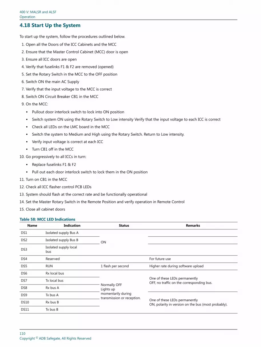
4.18 Start Up the System
To start up the system, follow the procedures outlined below.
1. Open all the Doors of the ICC Cabinets and the MCC
2. Ensure that the Master Control Cabinet (MCC) door is open
3. Ensure all ICC doors are open
4. Verify that fuselinks F1 & F2 are removed (opened)
5. Set the Rotary Switch in the MCC to the OFF position
6. Switch ON the main AC Supply
7. Verify that the input voltage to the MCC is correct
8. Switch ON Circuit Breaker CB1 in the MCC
9. On the MCC:
• Pullout door interlock switch to lock into ON position
• Switch system ON using the Rotary Switch to Low intensity Verify that the input voltage to each ICC is correct
• Check all LEDs on the LMC board in the MCC
• Switch the system to Medium and High using the Rotary Switch. Return to Low intensity.
• Verify input voltage is correct at each ICC
• Turn CB1 off in the MCC
10. Go progressively to all ICCs in turn:
• Replace fuselinks F1 & F2
• Pull out each door interlock switch to lock them in the ON position
11. Turn on CB1 in the MCC
12. Check all ICC flasher control PCB LEDs
13. System should flash at the correct rate and be functionally operational
14. Set the Master Rotary Switch in the Remote Position and verify operation in Remote Control
15. Close all cabinet doors
Table 58: MCC LED IndicationsName Indication Status Remarks
DS1 Isolated supply Bus A
ONDS2 Isolated supply Bus B
DS3 Isolated supply localbus
DS4 Reserved For future use
DS5 RUN 1 flash per second Higher rate during software upload
DS6 Rx local bus
Normally OFFLights upmomentarily duringtransmission or reception.
One of these LEDs permanentlyOFF, no traffic on the corresponding bus.DS7 Tx local bus
DS8 Rx bus A
DS9 Tx bus AOne of these LEDs permanentlyON, polarity in version on the bus (most probably).DS10 Rx bus B
DS11 Tx bus B
400 V: MALSR and ALSFOperation
110Copyright © ADB Safegate, All Rights Reserved

Table 59: ICC LED IndicationsName Indication Status Remarks
DS1 FLASH commandDuration isproportional to the selectedstep
DS2 RUN 1 Flash per second Higher rate during software upload
DS3 Rx local bus Normally OFFLights upmomentarily duringtransmission or reception.
One of these LEDs permanentlyOFF, no traffic on the corresponding bus.
DS4 Tx local bus One of these LEDs permanentlyON, polarity in version on the bus (most probably).
DS5 Isolated supply local bus ON
DS6 FLASHDuration isproportional to the selectedstep.
Hardware flash command to IGBT Driver
NoteThe flash lamp(s) must flash at a rate of 1 or 2 flashes/sec, as applicable.
16. Check the brightness steps by switching the rotary switch in the MCC cabinet to low, medium and high.
4.19 Shutdown Procedures
This subsection describes emergency and equipment shutdown procedures.
4.19.1 Emergency ShutdownSet the master control cabinet disconnect switch CB1 to OFF. This removes all power to the system, except power to themaintenance light and outlet in the master control cabinet.
4.19.2 Equipment ShutdownEquipment shutdown involves shutting down the master control cabinet switches and the individual control cabinets.
Table 60: Master Control Cabinet Switches ShutdownSystem Set to this position... To remove.
MALSR/ALSF Disconnect switch CB1 to OFF Power from all circuits
MALSR Only Circuit breaker CB4 to OFF Power from approach lights
MALSR/ALSF Circuit breaker CB3 to OFF 240 Vac power to sequenced flashers
MALSR/ALSF Circuit breaker CB2 to OFF 120 Vac power from master control cabinet circuits
4.19.3 Master Control Cabinet Switches ShutdownTo remove power from the master control cabinet switches, refer to Table 60
1. If operated in Remote Control, command the system to OFF.
2. Open the Master Control Cabinet (MCC) door.
3. Set the Rotary Switch in the MCC to the OFF position.
4. Switch OFF Circuit Breaker CB1 in the MCC.
96A0400, Rev. M, 2020/09/03 111Copyright © ADB Safegate, All Rights Reserved

4.19.4 Individual Control Cabinet ShutdownTo shut down the individual control cabinet, perform the following procedure:
1. Open the door of the individual control cabinet. The interlock switch disconnects the input 240 Vac power to the cabinet.
2. Open up both fuse links in the ICC.
3. Wait a minimum of one minute before working inside the ICC.
400 V: MALSR and ALSFOperation
112Copyright © ADB Safegate, All Rights Reserved

5.0 Maintenance
WARNING• Read installation instructions in their entirety before starting installation.
DANGER• Only qualified personnel may install or repair electrical equipment in accordance with NFPA 70B, Electrical
Equipment Maintenance and NFPA 70E, Electrical Safety Requirements for Employee Workplaces.
• Disconnect and tag out the sources supplying electrical power to this device before making or repairingconnections to this device in accordance with airport lockout and tagout procedures.
• Use approved testing equipment to test that the circuit is de-energized.
• All applicable regulations in accordance with local codes and FAA standards must be followed.
5.1 Replacement of the ICC Board
• The cover plate (EMC protection plate) over the ICC board is fixed with 4 fast locking screws (quarter turn to unlock).Remove the ribbon cable attached to the cover. Remove the cover.
• Take note of the position of the connectors before disconnecting the board.
• Take note of the dip-switch settings on the ICC board. (also jumper-setting of the local bus)
• The board is fixed with 9 screws M3; in every corner and in the middle of each axis, and with 2 screws M4; next to the twotransistors 2SK1120: Q7 and Q9. To improve the heat transfer of the two transistors (Q7 and Q9) to the mounting plate,there is a heat conductive paste between the mounting plate and the aluminum heat sink. Apply heat sink paste on thereplacement board. All screws should always be put back in place!
• In the “ICC-3” there are 2 ICC boards mounted on the left- and right-hand side of the cabinet.
• These boards are mounted on a special mounting plate that is fixed to the rear plate by means of 4 screws M4 and to thecabinet with 2 screws M5.
• Before mounting the ICC board to the special mounting plate, check on which side the plate should be mounted.
• Mount the board. Reconnect the board.
• Check the switch settings and the jumper settings before reinstalling the cover.
• Check the operation of the board.
5.1.1 Replacement of the Electrolytic CapacitorTake care to connect this capacitor with the correct polarity. Reversing the polarity will not only damage the capacitor, but alsothe control electronics. Inverting the polarity may result in serious injury.
5.1.2 Replacement of the DC power SupplyThis power supply is equipped with two connectors plugs at the top (AC) and six connectors at the bottom (DC).
The input AC voltage for the DC power supply is derived from connector P7 on an ICC board (the left one in case of an ICC -3)in the cabinet. The supply is mounted by means of 2 screws M4 on the rear plate and can be removed for troubleshootingpurposes.
96A0400, Rev. M, 2020/09/03 113Copyright © ADB Safegate, All Rights Reserved

The output DC voltage(s) are distributed inside the cabinet (from one to the other ICC boards in the case of an ICC-3, bymeans of six wires).
Table 61: DC supply voltagesBrown wire Red wires Black wires White wire
Voltage +15V +5V GND -15V
5.2 Replacement Optional Over-voltage Protection
There is no special equipment required to replace the cartridge but replacement cartridges must be of the same type andhave to be plugged in correctly to be effective.
Figure 50: Over-voltage protection cartridges
5.3 Local Master Controller (LMC) and remote control PCBs
If you replace some of the PCBs described in this section, you must also configure the system, as instructed by theprocedures. Before you can configure the system, you must change some dip-switch settings to enable configuration. Formore information on configuration, see Configuring the System.
5.3.1 LMC
1. Switch ON the equipment.
2. Open the configuration tool.
3. Go to menu SAVE.
4. Save the used IO profile.Select Save and save the profile on your PC
5. Switch OFF all power to the equipment.
6. Open the Master Control Cabinet (MCC) door.
7. Note the locations of all cables connected to the LMC PCB.
8. Disconnect the cables to the LMC PCB.
9. Take out the eight nuts (A).
10. Replace the LMC PCB (B).Copy the dipswitch and jumper settings from the old PCB.
11. Put in the eight nuts (A)
12. Connect the cables to the connectors:
a) Power distribution from the DC unit to TB1;
b) MOV connection to P6;
c) Door switch to P7;
400 V: MALSR and ALSFMaintenance
114Copyright © ADB Safegate, All Rights Reserved

d) Optional modules to P8;
e) Multiwire connection to P5;
f) Local bus to P2 or P3;
g) J-Bus connection to P1 (optional).
13. Close the cabinet door.
14. Switch ON the equipment.
15. Open the configuration tool.
16. Go to menu SAVE.
17. Restore the IO profile.Select Restore and browse to the saved profile on your PC.
18. Switch OFF all power to the equipment.
5.3.2 MultiwireThis procedure applies to both 24 V DC and 48 V DC type of multiwire PCBs.
1. Make sure that all power to the equipment is OFF.
2. Open the cabinet door.
3. Disconnect the cables from the PCB (B).
4. Take out the six nuts (A).
5. Replace the PCB (B). Make sure you use the same type of PCB. Copy the jumper settings from the old PCB.
6. Put back the six nuts (A). Use a number 5.5mm socket wrench.
7. Connect the cables to the connectors:
a) Power supply to J1;
b) LMC to P3;
c) Input and output signal connectors to P1 and P2.
96A0400, Rev. M, 2020/09/03 115Copyright © ADB Safegate, All Rights Reserved

8. Switch ON the equipment.
9. Open the configuration tool.
10. Go to menu IO.
11. Check all multi-wire settings.If necessary, click the fields next to the terminal names to open a selection window (see the graphic).
12. Close the cabinet door.
5.3.3 Multi-wire cable
1. Make sure that all power to the equipment is OFF.
2. Open the cabinet door.
3. Disconnect the flat multi-wire cable from the connector P5 of the LMC PCB and P3 of the multi-wire PCB.
4. Put in the new multi-wire cable.
5. Connect the flat multi-wire cable to the connector P5 of the LMC PCB and P3 of the multi-wire PCB.
6. Close the cabinet door.
NoteThe replacement LMC board will not have pre-existing jumpers at W15, W16 or W18. Substitute the jumpers fromthe replaced board or substitute the unused jumpers on W1-W6.
400 V: MALSR and ALSFMaintenance
116Copyright © ADB Safegate, All Rights Reserved

5.4 ALSF/MALSR Maintenance
5.4.1 ALSF/MALSR Maintenance ScheduleTo keep the MALSR and ALSF operating efficiently, follow a preventive maintenance schedule. Refer to Table 62. Refer to FAAAC 150/5340-26 for more detailed information.
Table 62: MALSR/ALSF MaintenanceInterval Maintenance Task Action
Monthly
Visually check all lights, including flashers, onall brightness steps. Replace lamps, if necessary.
Visually check for dim lamp.Clean optical surface if dirty.Check for presence of moisture.Check for lamp aging or physical displacement.
Every Three Months
Check sequenced flasher flash rate.
Verify flash rate (120 flashes perminute) either visually or, usingFlasher Tester laptop.Tolerances:
• Initial: ±2 flashes per minute
• Operating: ±2 flashes per minute
Check remote control function. Operate system in all remote control steps to verify operation.
Visually check for damaged(such as broken elevated or inpavement lens)or misaligned lights.
Repair or replace lights.
Visually check the approach line- of-sightclearance for vegetation or otherobstructions.
1. Remove vegetation.
2. Use weed killer.
According to localpractice (or annually)
If consistent with airportrequirements, check for water in excess of sixinches in base can.
Pump water from base.Remove and inspect light for water damage.
According to localpractice(manufacturerrecommendation isonce every 60 days)
Check for improper torque on inpavementhold-down bolts.
Torque six fixture bolts, see Bolt Torque Preventive MaintenanceSchedule.
Annually
Check elevated flashing fixture vertical andhorizontal angles.Vertical angle for elevated flasher is normally6°.
Readjust using aiming device.Tolerances:Initial: ±1°Operating: ±2°
Record meter readingsTake system out of service according to localpractice.When finished, return the system to serviceaccording to local practice.See Operating the System section forprocedure.
Measure the input voltage at the MCC, each FCU and the 15KVAtransformer in the High intensity step.Line-Line voltage must be:240Vac ±3% (Initial) and ±5%(Operating)
96A0400, Rev. M, 2020/09/03 117Copyright © ADB Safegate, All Rights Reserved

Table 62: MALSR/ALSF Maintenance (continued)Interval Maintenance Task Action
Annually
Record meter readingsTake system out of service according to localpractice.When finished, return the system to serviceaccording to local practice.See Operating the System section forprocedure.
Measure the input current at the MCC and the 15KVA transformer inall three steps.Record as reference data for use in future preventive maintenanceand troubleshooting efforts.
Record meter readingsTake system out of service according to localpractice.When finished, return the system to serviceaccording to local practice.See Operating the System section forProcedure.
Remove the cover on thetransformer. Measure the 15KVA transformer output voltage.Each side of the Line-Neutralvoltage must be-
• High: 120Vac
• Medium: 75Vac
• Low: 50Vac
• The Line-Line voltage must be-
• High: 240Vac
• Medium: 150Vac
• Low: 100Vac
• Tolerances on all measurements:
• ±3% (Initial)
• ±5% (Operating)
Annually (Optional) Record meter readings
Verify +400 Vdc output voltage from each FCU is “OK” using FlasherTester laptop.Record as reference data for use in future preventive maintenanceand troubleshooting efforts.
Annually
Check all structures for rot or corrosion.Check all light supports for rigidity, guytensions, and obvious misalignment.
Re-paint, repair or replace.
Check equipment electrical connections.
Remove power at input of MCC.Wait 1 minute before working on FCU cabinets.Visually inspect lighting arrestors.Check that all terminal connections and cable connections are tightand clean.Replace or tighten all connections that show signs of heating.
Check for obstruction in inpavement outputchannel. Clean channel and prism surface.
(Elevated) Check for dirty lens. Clean with glass cleaner.
Check fuse holders, circuit breakers, doorswitches and relays. Repair or replace.
Every 3 Years Check conductor and insulation resistance ofall power and control cables. Record all measurements and compare with previous readings.
During LampChanges
Check for interior cleanliness or presence ofmoisture inside light fixture.
Open the light assembly. Clean fixtures, if necessary, to maintain fulllight output.If Moisture present-
• In-pavement: Replace O-rings and other parts founddefective. Use pressure test plug to verify no leakage ispresent. Perform meg check.
• Elevated: Check drain holes. Replace gasket if defective
400 V: MALSR and ALSFMaintenance
118Copyright © ADB Safegate, All Rights Reserved

Table 62: MALSR/ALSF Maintenance (continued)Interval Maintenance Task Action
After 900 hours ofoperation in Highintensity
It is recommended to replace all xenon flashlamps systematically when, at full intensity,90% of the useful life has been reached
Replace the lamps.
If heavy snowfallpredicted
During winter months, permanently mark location of low mountedelevated fixtures on either side of the runway using red flags or sticksto facilitate snow removal and lessen the risk of damage to thefixtures by snow removal equipment.
After snow removal Check for damaged in-pavement lightfixtures.
Replace damaged fixtures. Use broom for snow removal. Followrecommended snow removal techniques described in AC150/5200-30.
5.4.2 Maintenance Procedures
WARNINGRead installation instructions in their entirety before starting maintenance.+400 Vdc is present in the individual control cabinet and the flasher light unit. Interlock switches are provided in thecabinets and flasher head to remove power when the cabinet door is opened or the lamp is removed. Allow oneminute for the flash capacitors to discharge before touching any electrical parts in the cabinet. Verify that they aredischarged by touching a wire connecting the 400 V TB2 terminal to earth ground.
This subsection describes maintenance procedures listed below for the MALSR and ALSF systems.
• checking performance
• checking electrical connections
• inspecting and replacing flash lamp
• inspecting and replacing lamp gaskets
• replacing lamps
5.4.3 Checking System PerformanceChecking performance involves the following:
• checking flash rate
• checking skipped flashes
• checking system voltage
• checking equipment visually
5.4.4 Checking System VoltageChecking system voltage involves checking master control cabinet and individual control cabinet voltages.
Checking the Master Control Cabinet Voltages
To check the master control cabinet voltages, perform the following procedure:
1. While operating the system at the high intensity level, measure the input voltage between terminal block TB1 terminals 1and 3.
2. Refer to Table 63 to verify the input voltages on the master control cabinet.
96A0400, Rev. M, 2020/09/03 119Copyright © ADB Safegate, All Rights Reserved

NoteUse a true RMS multimeter to measure the voltages in Table 63.
Table 63: Master Control/Individual Control Cabinet Input VoltagesAcross Terminal Block TB1 AC Voltages
Terminals 1 to 2 120 Vac ±2.5%
Terminals 2 to 3 120 Vac ±2.5%
Terminals 1 to 3 240 Vac ±5%
Checking the Individual Control Cabinet Voltages
To check individual control cabinet voltages, perform the following procedure:
3. While operating the system at the high intensity level, open the individual cabinet door and pull out the plunger on theinterlock switch.
4. Measure voltage between 1 and 2 on the input terminal block.
5. Verify the voltage at the input terminals of all the individual control cabinets is 240 Vac ±5%.
NoteUse a true RMS voltmeter to measure the voltages in Table 63.
5.4.5 Checking the Equipment VisuallyTo check the equipment visually, perform the following procedure:
1. Operate the system on all three brightness steps and visually verify that lamps switch to the brightness level selected.
2. Record any lamp failures and broken filters.
3. Replace lamps and filters when the system is turned off.
4. Inspect all lamps and filters for damage or misalignment.
5. Check for cracks, pits, and any evidence of leaks around the lamp and filter gaskets.
6. Replace any damaged glassware or gaskets.
7. Clean dirty glassware using a liquid glass cleaner and wipe dry with a soft clean cotton cloth.
8. Check light supports and guys for rigidity, misalignment, and rust or corrosion.
9. Check for dirt or water in the interior of all cabinets.Check gaskets in cabinet interiors for cracks or any sign of deterioration.
10. Remove dirt from the interior of the cabinets and replace gaskets showing signs of deterioration.Checking the Electrical Connections
To check electrical connections, perform the following procedure:
11. Check operation of interlock switches in the master and the individual control cabinets.
12. Check terminal blocks, PC boards, and connectors for any signs of dirt, corrosion, or moisture.Clean if necessary. Check all terminal connections for tightness.
13. Check lightning arrestor connections for tightness and any evidence of damage.Replace any damaged arrestors.
5.4.6 In-pavement Flashing LightThe assembly's service life depends to a large extent on being waterproof. All metal mating surfaces and seals must be clean,smooth, dry and free of all foreign particles if the light fixture is to operate for extended periods without requiringmaintenance.
400 V: MALSR and ALSFMaintenance
120Copyright © ADB Safegate, All Rights Reserved

Greasing of O-ring seals may be required as indicated in this manual.
Preventive maintenance of the light fixtures should be performed as listed in Table 65.
Maintenance frequency depends on the conditions under which the runway is used (i.e. climate, traffic, etc.). Therecommended practices for maintenance are described in the FAA advisory circular no. AC 150/5340-26.
For components mentioned in this chapter, refer to the Exploded View, Figure 70.
Always turn the fixture upside down next to the base when lifting it out of the base.
How to open the light assembly
To open the light assembly, proceed as follows (for tools to use, refer to Table 63:)
Step Action
1. Turn the light unit upside down.
2. Remove the pressure release screw.
3. Remove the 6 lamp enclosure screws.
4. Insert a flathead tip in the dedicated slot between cover and inner cover and rotate it to separate the inner cover from thecover.
5.4.7 How to replace a lamp
1. Disconnect the fast-on connectors of the lamp from the printed circuit board.
2. Using soft cotton gloves, remove the lamp from the printed circuit board part, holding the reflector.
3. Install a new lamp:
a) The lamp is supplied ready for installation.
b) Make sure that the lamp is positioned so that the trigger wire is in the position shown in Figure 51.
c) Gently position the lamp with its grommets on the lamp holder clamps and push down.
d) The lamp is very brittle so handle with care.
e) Never touch the quartz bulb of the lamp with your bare fingers. It will reduce the lifetime of the lamp considerably.Should this happen, clean the bulb with isopropyl alcohol. Make sure there is good contact between the fast-onconnectors and the terminals.
4. Reassemble the light fixture in reverse order.
5.4.8 How to replace the trigger and lamp holder PCBs
1. Disconnect the wires from the terminal block, by inserting a small screwdriver in the upper contact hole and pushing onthe spring contact of each particular terminal. See How to replace a lamp above.
2. Remove the faulty or defective PCB(s) by removing the screws.
3. Position the new PCB(s) with new dampers.
96A0400, Rev. M, 2020/09/03 121Copyright © ADB Safegate, All Rights Reserved

4. Torque down the fixing screws.
5. Connect the wires to the terminal block and reinstall the lamp(s).
Figure 51: Lamp Position
5.4.9 How to close and test the light fixtureTo close an optical unit, proceed as follows:
1. Turn the cover upside down.
2. Make sure that the contact surfaces with the O-ring are clean.
3. Put a new O-ring gasket greased with Novagard G322L (p/n 67A0009) silicone grease over the cover in the appropriategroove.
4. Remove the pressure release screw.
5. Gently put the inner cover on the cover, taking into account the keying pin between both parts.
6. Press the inner cover on the cover and secure with the screws.
7. Dielectric test:
Check the electrical insulation from the 5-pole plug male wires to the light fixture body
Interconnect wire terminals 1, 2, 3 and 4 together
• This can be accomplished by attaching a mating receptacle (p/n 4072.03.960) and connecting to the conductors onthe end of the cable assembly
Using a meg-ohmmeter, measure the insulation resistance between these wires and the fixture body. Insure the resistance,after 1 minute is:
• >1G ohms at 1000VDC, or alternately
• >1G ohms at 500VDC
400 V: MALSR and ALSFMaintenance
122Copyright © ADB Safegate, All Rights Reserved

NoteMake sure that the earth ground terminal is not included in the measurement
8. Closing and Testing the Fixture
• Remove the Pressure Release Screw.
• A Pressure Testing Device is used to pressure test the fixture. It screws into the pressure release port on the bottomcover and accepts a typical air hose fitting.
• Put entire fixture in bucket of water.
• Pressure test at 20 psi (137.9 kPa) for one minute in water and look carefully for any air bubbles emanating from thelight fixture.
NoteThe Pressure Testing Device has a 40 psi (275.8 kPa) relief valve so the fixture cannot be over pressurized.
• Remove the Pressure Testing Device.
• Make sure the O-ring seal of the pressure release screw is in good condition and resecure the Pressure Release Screw.
5.4.10 Bolt Torque Preventive Maintenance ScheduleAn established schedule for checking light fixture bolt torque and bolt condition is mandatory. This is particularly true forareas that are subject to high impact loads from aircraft such as runway status lights, runway touchdown zone lights, runwaycenterline lights, and taxiway lead-off lights. Although AC 150/5340-26 offers a recommended schedule for periodic checks,these checks should be tailored to the facility based on local conditions such as environmental issues and runway traffic load.
1. Torque according to: FAA Engineering Brief No 83 (latest revision).
Figure 52: Anti-vibration washer example
Cams (or steps) of the lock-washermust face each other
CAUTIONPer FAA AC 150/5340-30, Chapter 10, and FAA Engineering Brief No 83 (latest revision), it is extremely important thatother types of washers, such as split washers, must not be used. Failure to use properly installed anti-vibration lockwashers will cause mounting bolts to become loose. The cams (or steps) of each half of the lock washer must faceeach other.
FAA Cert Alert No. 14-03 refers to AC 150/5340-26 for the frequency of checking bolt torque. AC 150/5340-26 (latest revision)paragraph 5.3.4.1.4, Bi-Monthly Checks states: “The torque of the bolts attaching the light fixture to its base should be checkedwith a calibrated torque wrench – never use an impact wrench.”
Regular inspection as outlined in FAA Engineering Brief 83 (latest edition), Canada Civil Aviation Safety Alert Document CASA2014-05, and any other applicable regulatory guidelines is critical in insuring torque on all bolts is restored to optimumvalues. Bolts that loosen more often should be inspected and re-torqued on a more frequent basis.
It is especially important to maintain a regular inspection schedule for LED fixtures. Since LED fixtures operate more reliablyand are not subject to removal/replacement/re-torque as frequently as would be seen with incandescent fixtures, it is evenmore important to implement regular torque inspections.
96A0400, Rev. M, 2020/09/03 123Copyright © ADB Safegate, All Rights Reserved

It is critical that remedial action be taken if bolts are found to be loose or missing during inspection. If this occurs, it isimportant to carefully inspect all structural elements of the mounting system as defined in Installation. Also inspect the basecan for general structural conditions such as:
• Is the base can solidly mounted in the pavement, and not moving or rocking during rollovers?
• If a base can extension is present, are all extension attachment bolts tight?
If poor base can structure or mounting system components are not in accordance with regulatory requirements or are in poorcondition, it is the airport’s responsibility to:
• Increase the frequency of bolt torque inspection to insure that no bolts become loose or missing.
• Quickly replace/repair the mounting system components, which may include replacing the entire base can.
Airport operators must also ensure these maintenance activities are properly documented.
Digital Asset Tracking and Service Application Information
ALIS is ADB SAFEGATE’s new digital asset tracking, inspection and service solution, helps airports easily register airside assets,electronically schedule and track maintenance, and record maintenance and inspection tasks in compliance with ICAO andFAA standards.
Easy to implement and use, cloud-based software enables a more reliable and fail-safe approach to asset tracking andmaintenance by always using live field data and eliminating inefficiencies caused by human error. Every asset is registeredusing GPS data and its status recorded, so airport maintenance teams get a clearer view of maintenance schedules andhistory, allowing them to manage resources more effectively as well as improve the safety and longevity of airside assets. Thisincreased visibility helps airports plan and schedule preventive maintenance, or undertake corrective maintenance morequickly, to reduce downtime and significantly improve operational availability.
https://adbsafegate.com/product-center/airfield/airside-services/ALIS-airside-maintenance
• Easily integrates electronic torque measurements and photometric measurement reports to provide a complete view ofthe asset’s status.
• ALIS can be integrated with the AirTorque or Ingersoll Rand® QX series wrenches, which are used for accurate, ergonomictorque inspections of AGL fixtures. The applied torque can seamlessly be registered in the ALIS system as a part of themaintenance record.
• The iPhone application of ALIS – ALIS Personal – makes it easier than ever to register maintenance actions while working.It will proactively show you which assets you still need to work on and select the closest one to you automatically. ALISPersonal acts as a feedback and information device for the associated torque wrench.
5.4.11 Testing for LeaksTo test for leaks, perform the following procedure:
1. See Figure 53.Remove pressure relief screw.
2. See Figure 54.
Screw pressure test fitting into the pressure relief port (the opening created when the pressure relief screw is removed).Screw fitting hand-tight.
400 V: MALSR and ALSFMaintenance
124Copyright © ADB Safegate, All Rights Reserved

Figure 53: Pressure Relief Screw
Figure 54: Pressure Test Fitting Assembly
3. Attach the shop airline to the lock hose plug sleeve (2).
4. Pressurize to 20 psi.
5. Submerge the pressure test fitting in a water tank.Check for air bubbles. Air bubbles indicate a leak.
6. Locate the leak source, depressurize, replace the seal that is leaking, reassemble, and retest by following steps 4 and 5.If leak is fixed, depressurize and reinstall the pressure release screw (1).
Go to Overview of Sequence of Work to finish.
5.4.12 Individual Control Cabinets (ICCs)Preventive maintenance tasks
96A0400, Rev. M, 2020/09/03 125Copyright © ADB Safegate, All Rights Reserved

On each of the ICCs in the system:
• Reconnect fuses F1 and F2.
• Pull the door lock towards you and lock it in the ON position.
Check the following LEDs of the ICCs through the holes of the EMC plate.
Table 64: ICC LED IndicationsName Indication Status Remarks
DS1 FLASH commandDuration is proportional to the selectedstep. ON time longer for High, shorter forMed and shortest for LOW
none
DS2 RUN 1 FLASH per second Higher rate during software upload
DS3 Rx local bus Normally OFFLights up momentarily duringtransmission or reception
One of these LEDs OFF, no traffic is on thecorresponding bus
DS4 Tx local bus One of these LEDs stays ON, there may be apolarity inversion on the bus.
DS5 Isolated supply local bus ON none
DS6 FLASH ON during flash request Hardware flash command toIGBT Driver
The flash lamps must flash at the correct rate and selected brilliancy.
5.4.13 Flashing SequenceCheck the flashing sequence of the whole system. If it is not correct, change the dip-switch addresses in the ICCs wherenecessary or adapt the sequence number via the flasher tester software.
5.4.14 3-in-1 ICC AC Current CheckCheck the power distribution between the phases.
(If applicable, check the neutral current. For an equal number of units distributed over the 3 phases it should be less than 1ARMS. If there is a loading difference of 1 or 2 units between all the phases it should be less than 2.5 A RMS.)
5.5 UEL Light Maintenance
In this chapter, maintenance of the UEL light is described as well as the procedures of how to replace the lamp and the opticalcartridge. Preventive maintenance of the light fixtures should be performed as listed in Table 65.
Maintenance frequency depends on the conditions under which the runway is used (i.e. climate, traffic, etc.). Therecommended practices for maintenance are described in the FAA Advisory Circular no. AC 150/5340-26.
For the numbering of the components mentioned in this chapter, refer to the exploded Figure 57.
5.5.1 Preventive MaintenanceIn the table below you will find a checklist of preventive maintenance tasks.
Before attempting service, de-energize and lockout the master control cabinet input power to insure that the fixture cannotbe energized by remote means.
5.5.2 How to Replace the UEL LampLamp replacement is preferably performed in the maintenance shop but, it can also be done in the field. The following tableinstructs you on how to replace a lamp in the maintenance shop: See Figure 57
1. Open the fitting by pulling down the optical cartridge (1).
2. Disconnect the cable from the lamp (2).
3. Remove the optical cartridge and replace it with a new one.
400 V: MALSR and ALSFMaintenance
126Copyright © ADB Safegate, All Rights Reserved
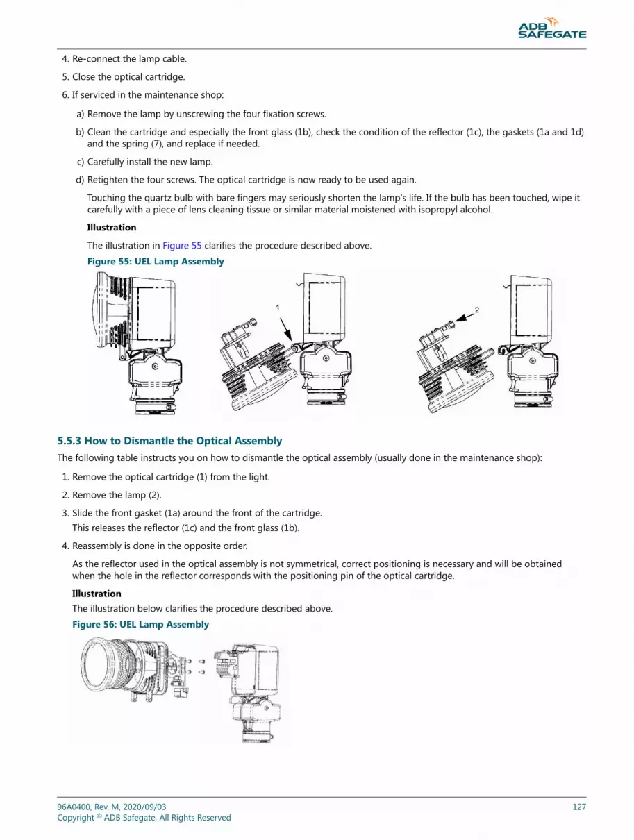
4. Re-connect the lamp cable.
5. Close the optical cartridge.
6. If serviced in the maintenance shop:
a) Remove the lamp by unscrewing the four fixation screws.
b) Clean the cartridge and especially the front glass (1b), check the condition of the reflector (1c), the gaskets (1a and 1d)and the spring (7), and replace if needed.
c) Carefully install the new lamp.
d) Retighten the four screws. The optical cartridge is now ready to be used again.
Touching the quartz bulb with bare fingers may seriously shorten the lamp's life. If the bulb has been touched, wipe itcarefully with a piece of lens cleaning tissue or similar material moistened with isopropyl alcohol.
Illustration
The illustration in Figure 55 clarifies the procedure described above.
Figure 55: UEL Lamp Assembly
5.5.3 How to Dismantle the Optical AssemblyThe following table instructs you on how to dismantle the optical assembly (usually done in the maintenance shop):
1. Remove the optical cartridge (1) from the light.
2. Remove the lamp (2).
3. Slide the front gasket (1a) around the front of the cartridge.This releases the reflector (1c) and the front glass (1b).
4. Reassembly is done in the opposite order.
As the reflector used in the optical assembly is not symmetrical, correct positioning is necessary and will be obtainedwhen the hole in the reflector corresponds with the positioning pin of the optical cartridge.
IllustrationThe illustration below clarifies the procedure described above.
Figure 56: UEL Lamp Assembly
96A0400, Rev. M, 2020/09/03 127Copyright © ADB Safegate, All Rights Reserved
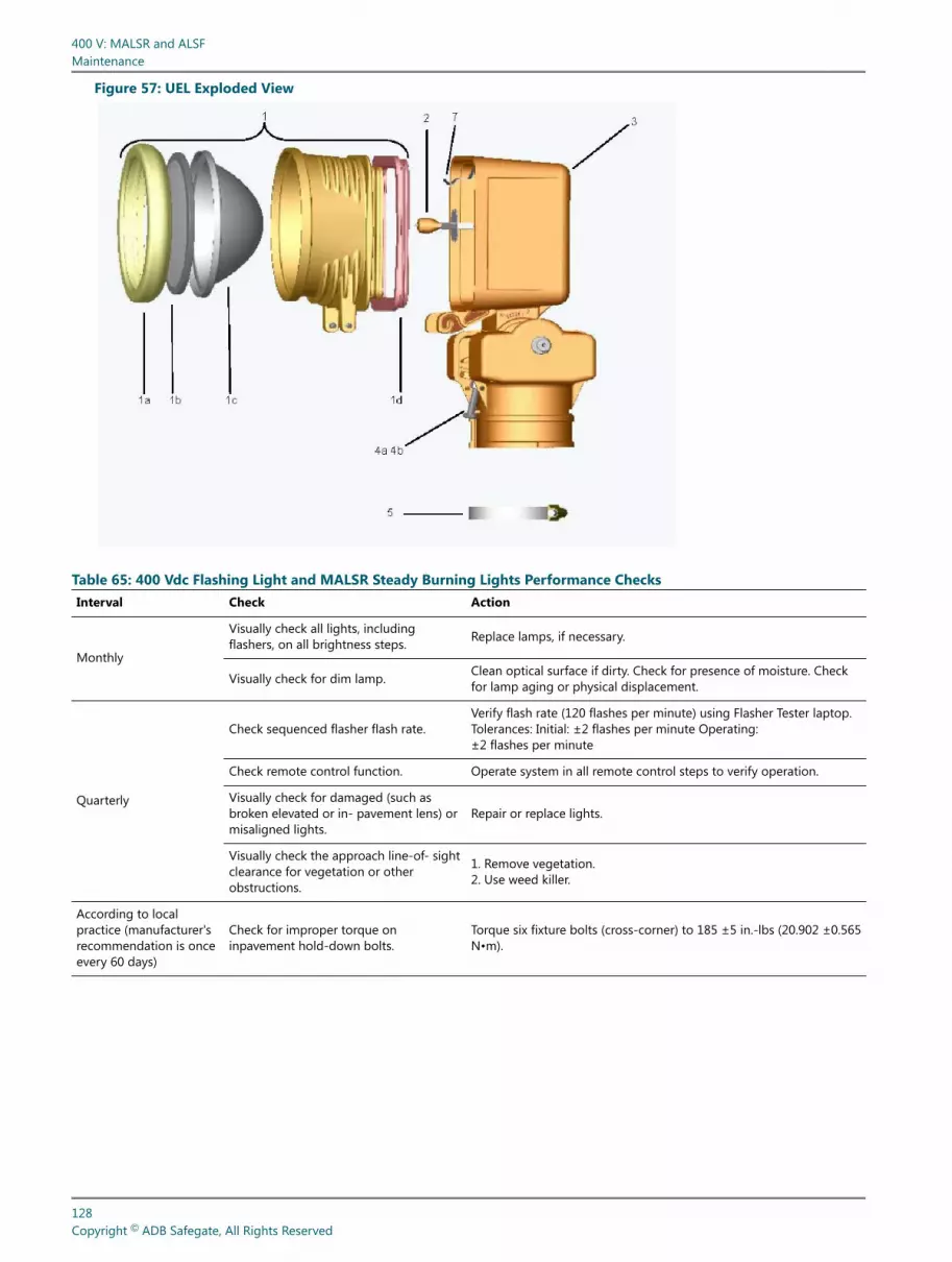
Figure 57: UEL Exploded View
Table 65: 400 Vdc Flashing Light and MALSR Steady Burning Lights Performance ChecksInterval Check Action
Monthly
Visually check all lights, includingflashers, on all brightness steps. Replace lamps, if necessary.
Visually check for dim lamp. Clean optical surface if dirty. Check for presence of moisture. Checkfor lamp aging or physical displacement.
Quarterly
Check sequenced flasher flash rate.Verify flash rate (120 flashes per minute) using Flasher Tester laptop.Tolerances: Initial: ±2 flashes per minute Operating:±2 flashes per minute
Check remote control function. Operate system in all remote control steps to verify operation.
Visually check for damaged (such asbroken elevated or in- pavement lens) ormisaligned lights.
Repair or replace lights.
Visually check the approach line-of- sightclearance for vegetation or otherobstructions.
1. Remove vegetation.2. Use weed killer.
According to localpractice (manufacturer'srecommendation is onceevery 60 days)
Check for improper torque oninpavement hold-down bolts.
Torque six fixture bolts (cross-corner) to 185 ±5 in.-lbs (20.902 ±0.565N•m).
400 V: MALSR and ALSFMaintenance
128Copyright © ADB Safegate, All Rights Reserved

Table 65: 400 Vdc Flashing Light and MALSR Steady Burning Lights Performance Checks (continued)Interval Check Action
Annually
Check elevated flashing fixture verticaland horizontal angles.Vertical angle for elevated flasher isnormally 6°.
Readjust using aiming device.Tolerances:Initial: ±1°Operating: ±2°
Record meter readingsTake system out of service according tolocal practice.When finished, return the system toservice according to local practice.See Operating the System section forprocedure.
Measure the input voltage at the MCC, each ICC and the 15KVAtransformer in the High intensity step.Line-Line voltage must be:240Vac ±3% (Initial) and ±5% (Operating)
Record meter readingsTake system out of service according tolocal practice.When finished, return the system toservice according to local practice.See Operating the System section forprocedure.
Measure the input current at the MCC and the 15KVA transformer inall three steps.Record as reference data for use in future preventive maintenanceand troubleshooting efforts.
Annually
Record meter readingsTake system out of service according tolocal practice.When finished, return the system toservice according to local practice.See Operating the System section forProcedure.
Remove the cover on the 15KVA transformer.Measure the 15KVA transformer output voltage.Each side of the Line-Neutral voltage must be:High: 120VacMedium: 75VacLow: 50VacThe Line-Line voltage must be:High: 240VacMedium: 150VacLow: 100VacTolerances on all measurements: ±3% (Initial) ±5%(Operating)
Annually (Optional) Record meter readings
On Flasher: Active State screen, verify “Capacitor voltage” and “Lampcurrent” on each Flasher is OK using Flasher Tester laptop.Record as reference data for use in future preventivemaintenance and troubleshooting efforts.
Annually
Check all structures for rot or corrosion.Check all light supports for rigidity, guytensions, and obvious misalignment.
Re-paint, repair or replace.
Check equipment electrical connections.
Remove power at input of MCC.Wait 1 minute before working on ICC cabinets.Visually inspect lighting arrestors.Check that all terminal connections and cable connections are tightand clean.Replace or tighten all connections that show signs of heating.
Check for obstruction in in-pavementoutput channel. Clean channel and prism surface.
(Elevated) Check for dirty lens. Clean with glass cleaner.
Check fuse holders, circuit breakers, doorswitches and relays. Repair or replace.
Every 3 YearsCheck conductor and insulationresistance of all power and controlcables.
Record all measurements and compare with previous readings.
96A0400, Rev. M, 2020/09/03 129Copyright © ADB Safegate, All Rights Reserved
Table 65: 400 Vdc Flashing Light and MALSR Steady Burning Lights Performance Checks (continued)Interval Check Action
During Lamp Changes Check for interior cleanliness or presenceof moisture inside light fixture.
Open the light assembly. Clean fixtures, if necessary, to maintain fulllight output.If Moisture present-In-pavement:Replace O-rings and other parts found defective.Use pressure test plug to verify no leakage is present. Perform megcheck.Elevated:Replace either gasket if defective
After 900 hours ofoperation in Highintensity
It is recommended to replace all xenonflash lamps systematically when, at fullintensity, 90% of the useful life has beenreached.
Replace the lamps.
If heavy snowfallpredicted
During winter months, permanently mark location of lowmounted elevated fixtures on either side of the runway using redflags or sticks to facilitate snow removal and lessen the risk ofdamage to the fixtures by snow removal equipment.
After snow removal Check for damaged in- pavement lightfixtures.
Replace damaged fixtures. Use broom for snow removal.Follow recommended snow removal techniques described in AC150/5200-30.
5.6 Troubleshooting and Fault Correction
DANGEROnly qualified personnel may install or repair electrical equipment in accordance with NFPA 70B,Electrical Equipment Maintenance and NFPA 70E, Electrical Safety Requirements for EmployeeWorkplaces.Disconnect and tag out the sources supplying electrical power to this device before making or repairingconnections to this device in accordance with airport lockout and tagout procedures.Use approved testing equipment to test that the circuit is deenergized.All applicable regulations in accordance with local codes and FAA standards must be followed.Review the “Safety” on page 1 prior to performing any maintenance steps.
Please read the following paragraphs for a description of the system:
• General description
• Technical description, selection and range of applications
• Technical data, operation limits
• Please read the safety notices and handling precautions at the beginning of this manual
• Refer to the wiring diagrams at the end of this manual
5.6.1 General Troubleshooting TipsPreparation
1. Read technical documentation provided with the system
2. Have 2 copies of ADB SAFEGATE equipment manual number 96A0400, “400 V Medium Intensity Approach LightingSystem (MALSR) and Approach Lighting System with Sequenced Flashers (ALSF)”
• One master copy stored in a permanent location
• One copy in work area
• Additional copies of manuals can be downloaded from the ADB SAFEGATE web site at http://www.adbsafegate.com
400 V: MALSR and ALSFMaintenance
130Copyright © ADB Safegate, All Rights Reserved

3. Attend manufacturer training classes
4. Insure adequate supply of spare parts are available
5. Make sure you have proper tools
• True RMS multi-meter
• Current Clamp
• Full set of hand tools
5.6.2 Gather information about the problem
1. What are symptoms?
2. When did failure occur?
3. Is the failure intermittent?
4. Is the failure in remote control only?
5.6.3 Do the easy checks first
1. Visual examination
2. Turn off, then back on
3. Operate in local remote (if applicable)
4. Check fuses
5. Check inputs and outputs
6. Cut problem in half
7. Use manufacturer's troubleshooting guidelines for assistance
8. Call equipment manufacturer for assistance
5.6.4 Troubleshooting: System fails to flashAt the Master Control Cabinet, verify that:
The input power supply is within tolerance (190Vac - 260Vac)
NoteStandard FAA tolerances are 240 ±12 volts (228Vac - 252Vac)
• No circuit breaker has tripped
• No fuses are blown
• The LMC board is operational (RUN LED DS5 blinks at a 1 Hz rate)
• Remote control signals are present and correct
96A0400, Rev. M, 2020/09/03 131Copyright © ADB Safegate, All Rights Reserved

5.6.5 Verify that communication is present on the local bus• On the LMC board, verify that Rx LED DS6 and Tx LED DS7 are blinking (which verifies that communication is occurring)
• At each failing ICC cabinet verify that Rx LED DS3 and Tx LED DS4 are blinking (which verifies that communication isoccurring)
5.6.6 At each ICC cabinet, verify that:• The FCU board is operational (RUN LED DS2 blinks at a 1 Hz rate)
• The lamp trigger command is being generated (FLASH LED DS1 flashes twice per second)
5.6.7 If the optional Modbus control is present:• Verify that the remote control bus communication is operational (LMC, Bus A/LEDs DS8 and DS10 are blinking) (LMC, Bus
B/LED DS9 and DS11 are blinking)
5.6.8 Troubleshooting: Several units fail to flashVerify at the first failing ICC cabinet that:
• The input power supply is within tolerance (190Vac - 260Vac)
NoteStandard FAA tolerances are 240 ±12 volts (228Vac - 252Vac)
• No fuses are blown
• The FCU board is operational (RUN LED DS2 blinks at a 1 Hz rate)
• The lamp trigger command is being generated (FLASH LED DS1 flashes twice per second)
• The FCU PCB coding on dipswitch SW1 and SW2 is correct
5.6.9 Verify that communication is present on the local bus• At each failing ICC cabinet verify that Rx LED DS3 and Tx LED DS4 are blinking (which verifies that communication is
occurring)
5.6.10 Troubleshooting: One unit fails to flashVerify on the failing ICC cabinet that:
• The input power supply is within tolerance (190Vac - 260Vac)
NoteStandard FAA tolerances are 240 ±12 volts (228Vac - 252Vac)
• No fuses are blown
• The FCU board is operational (RUN LED DS2 blinks at a 1 Hz rate)
• The lamp trigger command is being generated (FLASH LED DS1 flashes twice per second)
• The FCU board coding on dipswitch SW1 and SW2 is correct
• The door switch is properly closed and that the safety switch in the flashing lamp fixture is properly closed
• The flash energy capacitor charges at about 400V DC (Use laptop to measure voltage)
• The choke is correctly connected to the FCU board
400 V: MALSR and ALSFMaintenance
132Copyright © ADB Safegate, All Rights Reserved

5.6.11 Verify that communication is present on the local bus• At the failing ICC cabinet, verify that Rx LED DS3 and Tx LED DS4 are blinking (which verifies that communication is
occurring)
Then:
• Replace the lamp or
Replace the entire fixture (which replaces the trigger circuitry)
• Replace the FCU board
5.6.12 Troubleshooting: One unit flashes incorrectly (intensity or timing)Verify on the failing ICC cabinet that:
• The input power supply is within tolerance (190Vac - 260Vac)
NoteStandard FAA tolerances are 240 ±12 volts (228Vac - 252Vac)
• The FCU board is operational (RUN LED DS2 blinks at a 1 Hz rate)
• The lamp trigger command is being generated at same rate that flashing should occur (FCU board/FLASH LED DS1 blinkstwice per second for systems that flash twice per second)
• The FCU board coding on dipswitch SW1 and SW2 is correct
• The flash energy capacitor charges at about 400V DC (Use laptop to measure voltage)
• The choke is correctly connected to the FCU board
5.6.13 Verify that communication is present on the local bus• At the failing ICC cabinet, verify that Rx LED DS3 and Tx LED DS4 are blinking (which verifies that communication is
occurring)
Then:
• Replace the FCU board
• Replace the flashing fixture
5.6.14 UEL Light Assemblies
Table 66: Troubleshooting the UEL LightsProblem Possible cause Solution
Lamp does not energize.
Lamp defective Replace lamp.
Loose or broken contact or connector Tighten or replace the contacts or connector.
Moisture present in fixture Open up and dry, inspect lens forcracks. Check the gaskets.
Deteriorated wire insulation Replace wires.
Short lamp life Moisture in assembly Open up and dry out the assembly. Inspect the lens forcracks. Check the gaskets.
96A0400, Rev. M, 2020/09/03 133Copyright © ADB Safegate, All Rights Reserved

5.7 Wiring Diagrams
Figure 58: Local Bus Control
FIRST CABINET- ICC 3
Leave straps W11, W25 & W28 in these FCU’s (first and last FCU in LOCAL BUS communication line).
(Remove W11, W25 & W28 on all other FCU’S & W15, W16 & W18 on the LMC)
LAST CABINET- ICC 3
FCU-middle PCB1487
P4SLAVE 5
SLAVE 6
FCU-right PCB1487
P4
FCU-left PCB1487
P1
P2 P4
P3
SLAVE 4 P4
MIDDLE CABINET- ICC 3
LMC PCB1485 P2
FCU-left PCB1487
P4
FCU-middle PCB1487
P4
FCU-right PCB1487
P1
P4P2
P3
P4SLAVE 1
SLAVE 2 SLAVE 3
FCU-left PCB1487
P4
FCU-middle PCB1487
P4
FCU-right PCB1487
P1
P4P2
P3
P4SLAVE 7
SLAVE 8 SLAVE 9
MCC
400 V: MALSR and ALSFMaintenance
134Copyright © ADB Safegate, All Rights Reserved

Figure 59: External Wiring Diagram, 400V Sequenced Flasher System- FAA MALSR diagram 1of2
LAM
PUN
IT
FIEL
D SP
LICE
INDI
VIDU
AL C
ONTR
OL
CABI
NET
2+
+-0
V-0
V1
PEPE
P3P1
TB 2
+-
+-0
V0V
P1P3
1 2 3 4 8765
MASTER CONTROLCABINET
9 10 11 12 13 14 4 5 6 7 8 9 10 11 12
FLAS
HING
LI
GHTS
LAPT
OP
12
3TB
1
JUNC
TION
BO
X
(LM
C PC
B)
J1
MAINTENANCE CONNECTION
DONG
LE
18 PAR 56 LAMPS OR UP TO 45 PAR 38 LAMPS- MAY ALSO INCLUDE IN-PAVEMENT MALSR FIXTURES ACCORDING TO FAA-E-2952 (ALSF) OR FAA-E-2968 (MALSR).
INPU
T
PCB2
PCB4
SEE
NOTE
3
TB2
TB1
BURN
ING
LIGH
TS
STEA
DY
(IN P
AVEM
ENT
ONLY
)
HIGH
= S
1+S4
CLO
SED
MED
= S
2+S4
CLO
SED
LOW
= S
3+S4
CLO
SED
CAUT
ION!
ONL
Y S1
, OR
S2, O
R S3
CAN
BE C
LOSE
D AT
ONE
TIM
E:
4 AW
G, 6
00V
4 AW
G
10 A
WG
(MIN
), 60
0V
8 AW
G
8 AW
G
REM
OTE
POW
ER
NOT
USED
LOW
MED
HIGH
ON FLAS
HER
ON/O
FFCO
MM
ON
FEED
BACK
#1
FEED
BACK
#2
FEED
BACK
#3
NEUT
RAL
XFM
R CO
MM
EDHI
GHLO
WSP
ARE
SPAR
E12
0VAC
(L1A
SW
ITCH
ED)
NEUT
RAL
120
VAC
(L1B
SW
ITCH
ED)
120
VAC
(L1A
)NE
UTRA
L12
0 VA
C (L
1B)
246
VAC
252
VAC
LOW
HIGH
MED
210
VAC
216
VAC
222
VAC
228
VAC
234
VAC
240
VAC
GND
FEED
BACK
#4
THIS
TAP
NEED
S TO
BE
MOV
ED
TO T
HE C
LOSE
ST TA
P VA
LUE
AS M
EASU
RED
BETW
EEN
L1A
AND
L1B
ON T
B1
TB2-
1 RE
MOT
E PO
WER
TB2-
3 LO
WS1
TB2-
4 M
EDS2
TB2-
5 HI
GH
TB2-
7 FL
ASHE
R ON
/OFF
120/
75/5
0VAC
NEUT
RAL
120/
75/5
0VAC
2 AW
G, 6
00V
4 AW
G, 6
00V
(NOT
E 1)
MAL
SR R
EMOT
E CO
NTRO
L US
ING
THE
MCC
120
VAC
REM
OTE
POW
ER
INPU
T 12
0/24
0 VA
C, 5
0/60
HZF
H3 37 5 46H1 8H2X2 X3X1 2 1 TB1
15KV
A XF S3
S44 AW
G
- THESE FIXTURES ARE CONNECTED VIA A MATCHING VOLTAGE-VOLTAGE TX. 43A3511 F
96A0400, Rev. M, 2020/09/03 135Copyright © ADB Safegate, All Rights Reserved

Figure 60: External Wiring Diagram, 400V Sequenced Flasher System- FAA MALSR diagram 2of2
LAM
PUN
IT
FIEL
D SP
LICE
INDI
VIDU
AL C
ONTR
OL
CABI
NET
2+
+-0
V-0
V1
PEPE
P3P1
TB 2
FIEL
D SP
LICE
INDI
VIDU
AL C
ONTR
OL
CABI
NET
TB 2
UNIT
LAM
P
FIEL
D SP
LICE
INDI
VIDU
AL C
ONTR
OL
CABI
NET
TB 2
UNIT
LAM
P
JUNC
TION
BO
XBO
XJU
NCTI
ON
JUNC
TION
BO
X
PEPE
21
0V -+
0V
P3-
+P1PE
PE2
10V -
+0V
P3-
+P1IN
PUT
INPU
TIN
PUT
(IN P
AVEM
ENT
ONLY
)
8 AW
G8
AWG
8 AW
G
8 AW
G8
AWG
8 AW
G
(IN P
AVEM
ENT
ONLY
)(IN
PAV
EMEN
T ON
LY)
FIEL
D SP
LICE
INDI
VIDU
AL C
ONTR
OL
CABI
NET
TB 2
UNIT
LAM
P
FIEL
D SP
LICE
INDI
VIDU
AL C
ONTR
OL
CABI
NET
TB 2
UNIT
LAM
P
JUNC
TION
BO
XJU
NCTI
ON
BOX
PEPE
21
0V -+
0V
P3-
+P1PE
PE2
10V -
+0V
P3-
+P1
TO NEXTFLASHER
INPU
TIN
PUT
8 AW
G8
AWG
8 AW
G8
AWG
(IN P
AVEM
ENT
ONLY
)(IN
PAV
EMEN
T ON
LY)
SEE
NOTE
4
NOTES:1. REMOTE POWER SOURCE IS EITHER 120 VAC, +48VDC, OR +24VDC DEPENDING ON OPTION ORDERED WITH MASTER CONTROL CABINET. REMOTE POWER MAY ALSO BE EXTERNALLY SOURCED.2. FIRST COLOR IS FOR CABLE 89A0290/5 (ALPHA WIRE # 65405CY). SECOND COLOR, IN PARENTHESIS, IS FOR CABLE 6104.22.820, 5C+SHIELD, 14AWG, 600V. FOR FIXTURE TO FCU LINE LENGTH UP TO 131 FT (40m), USE 14 AWG WIRE. - FOR FIXTURE TO FCU LINE LENGTH UP TO 213 FT (65m), USE 12 AWG WIRE. - FOR FIXTURE TO FCU LINE LENGTH UP TO 328 FT (100m), USE 10 AWG WIRE. - FOR FIXTURE TO FCU LINE LENGTH UP TO 393 FT (120m), USE 8 AWG WIRE.3. SERIAL COMMUNICATION WIRING BETWEEN MASTER AND EACH ICC MUST BE MANHATTAN WIRE M8628010, 18AWG, TRIAD, SHIELDED, 600V CABLE or ADB-APPROVED EQUAL. 4. LAST INDIVIDUAL CONTROL CABINET (FARTHEST FROM MASTER) WILL NOT HAVE ANY WIRES CONNECTED TO P3. 43A3511 F
400 V: MALSR and ALSFMaintenance
136Copyright © ADB Safegate, All Rights Reserved

Figure 61: ALSF External Wiring Diagram, 400V Sequenced Flasher System- ALSF/SSALR diagrams 1of2
NOTES:1. REMOTE POWER SOURCE IS EITHER 120 VAC, +48VDC, OR +24VDC DEPENDING ON OPTION
ORDERED WITH MASTER CONTROL CABINET. REMOTE POWER MAY ALSO BE EXTERNALLY SOURCED.
2. FIRST COLOR IS FOR CABLE 89A0290/5 (ALPHA WIRE # 65405CY,). SECOND COLOR, IN PARENTHESIS, IS FOR CABLE 6104.22.820 5C+SHIELD, 14AWG, 600V.
- FOR FIXTURE TO FCU LINE LENGTH UP TO 131 FT (40m), USE 14 AWG WIRE. - FOR FIXTURE TO FCU LINE LENGTH UP TO 213 FT (65m), USE 12 AWG WIRE. - FOR FIXTURE TO FCU LINE LENGTH UP TO 328 FT (100m), USE 10 AWG WIRE. - FOR FIXTURE TO FCU LINE LENGTH UP TO 393 FT (120m), USE 8 AWG WIRE.3. SERIAL COMMUNICATION WIRING BETWEEN MASTER AND EACH ICC MUST BE MANHATTAN WIRE
M8628010, 18AWG, TRIAD, SHIELDED, 600V CABLE or ADB-APPROVED EQUAL. 4. CONNECTIONS SHOWN ON THIS PRINT ASSUME THAT THE MASTER IS PHYSICALLY LOCATED AT
EITHER END OF THE ROW OF ICC'S. IF THE MASTER IS PHYSICALLY LOCATED IN THE MIDDLE AREA OF THE ICC'S, CONNECT P1 TO ONE SECTION OF ICC's (AS SHOWN) AND THEN CONNECT P3 TO THE OTHER SECTION OF ICC's.
5. LAST INDIVIDUAL CONTROL CABINET (FARTHEST FROM MASTER) WILL NOT HAVE ANY WIRES CONNECTED TO P3.
TB2-3
TB2-4
S1
TB2-5
S2
TB2-7
S3
TB2-8
S4
CAUTION! ONLY S2, OR S3, OR S4,CAN BE CLOSED AT ONE TIME: CLOSE S1 FOR ALSF MODE OPEN S1 FOR SSALR MODE
S5
TB2-2ALSF/SSALR
LOW
MED
HIGH
FLASHERS ON
COMMON
LOW = S2+S5 CLOSEDMED = S3+S5 CLOSEDHIGH = S4+S5 CLOSED
+48VDCPOWERSUPPLY
+
-
ALSF REMOTE CONTROL USING ANEXTERNAL 48VDC SOURCE
NOTE: FOR ALSF MODE ONLY, DELETE EXTERNAL SWITCH S1 AND CONNECT A JUMPER FROM TB2-2 TO TB2-7.
To: M
CC
DRAWING NUMBER:
SCALE:
DRAWING TITLE:
SHEET NUMBER:
REV.
F
SYSTEM- FAA ALSF/SSALR
43A3546
400V SEQUENCED FLASHEREXTERNAL WIRING DIAGRAM,
N/A 1 OF 1
96A0400, Rev. M, 2020/09/03 137Copyright © ADB Safegate, All Rights Reserved

Figure 62: ALSF External Wiring Diagram, 400V Sequenced Flasher System- ALSF/SSALR diagrams 2of2
LAMPUNIT
FIELD SPLICE
INDIVIDUAL CONTROL CABINET
2+ +- 0V - 0V 1 PEPE
P3P1
TB 2
+ - + - 0V0V
P1 P3
1234
8765
MASTER CONTROLCABINET
91011121314
456789101112
(NOTE 1)ALSF/SSALR LOWMEDHIGHONFLASHER ON/OFFCOMMON
FEEDBACK #1FEEDBACK #2FEEDBACK #3
NEUTRAL
SPARESPARE120VAC (L1A SWITCHED)NEUTRAL120 VAC (L1B SWITCHED)
FLASHING LIGHTS
LAPTOP
1 2 3 TB1
120 VAC (L1A)NEUTRAL120 VAC (L1B)IN
PUT
120/
240
VAC,
50/
60HZ
JUNCTION BOX
GND
FEEDBACK #4(LMC PCB)
J1
MA
INTE
NA
NC
E C
ON
NE
CTI
ON
DONGLE
INPUT
PCB2
PCB4
SEE NOTE 3
TB2
TB1
(IN-PAVEMENT ONLY)
8 AWG, 600V
6 AWG
10AWG (MIN), 600V
8 AWG
REMOTE POWER
8 AWG
SEE NOTE 4
F
DRAWING NUMBER:
SCALE:
DRAWING TITLE:
SHEET NUMBER:
REV.
F
SYSTEM- FAA ALSF/SSALR
43A3546
400V SEQUENCED FLASHEREXTERNAL WIRING DIAGRAM,
N/A 1 OF 1
TO NEXTFLASHER
Figure 63: ALSF/MALSR External: FFL wiring
FFL IN-PAVEMENT FLASHING FIXTURE INTERCONNECTING WIRING
PECAB
CAB
PE400V
TRIG
_
+
TB2
FCUINDIVIDUALCONTROLCABINET
INTERLOCK - BLK-4 (BLK)
INTERLOCK - BLK-3 (BLK)
POTENTIAL EARTH GRN/YEL (GRN/YEL)
LAMP ANODE BLK-2 (BRN)
TRIG BLK-1 (BLU)
389.5 FT. (118m) MAX.30 IN.12 IN.
FIELD WATERPROOF SPLICE
393 FT. (120 m) MAX.
PLUG/RECEPTACLE SHIELD
SEE NOTE 2
SHIELD IS CUT OFF AT SPLICE
400 V: MALSR and ALSFMaintenance
138Copyright © ADB Safegate, All Rights Reserved
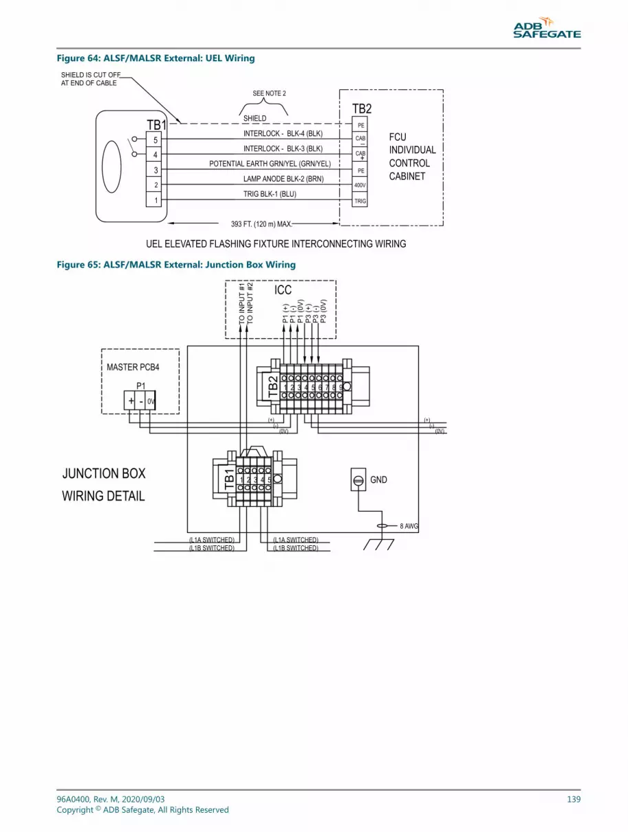
Figure 64: ALSF/MALSR External: UEL Wiring
SHIELD IS CUT OFF AT END OF CABLE
UEL ELEVATED FLASHING FIXTURE INTERCONNECTING WIRING
CABINETCONTROLINDIVIDUAL
SHIELD
INTERLOCK - BLK-4 (BLK)
INTERLOCK - BLK-3 (BLK)
POTENTIAL EARTH GRN/YEL (GRN/YEL)
LAMP ANODE BLK-2 (BRN)
393 FT. (120 m) MAX.
TRIG BLK-1 (BLU)
PE
TRIG
400V
TB2
CAB
+CAB
_
PE
FCU5
4
3
1
2
TB1
SEE NOTE 2
Figure 65: ALSF/MALSR External: Junction Box Wiring
987654321
1 2 3 4 5 GND
(L1A SWITCHED) (L1B SWITCHED)
TO IN
PU
T #1
TO IN
PU
T #2
0V-+P1
MASTER PCB4
P1
(-)
P1
(+)
P1
(0V
)
P3
(0V
)P
3 (-
)P
3 (+
)
(+)(-)
(0V)(-)
(+)
(0V)
ICC
JUNCTION BOXWIRING DETAIL
8 AWG
(L1A SWITCHED) (L1B SWITCHED)
TB2
TB1
96A0400, Rev. M, 2020/09/03 139Copyright © ADB Safegate, All Rights Reserved

Figure 66: Internal MALSR Wiring Diagram 400 V MCC 1of3
5
51324
PS1(24V PWR SUPPLY)
OUT+5+ 5- OUT-
TB2
TB3
PS2
"K" RELAY NO.S(8 PLC.S)
WHT
WHT
WHT
WHT
BRN
BRN
BRN
BRNW
HT
WHT
WHT
PUR
ORG
BLU
YEL
PURORG
BLU
P1P2
TB1
P6
GRNBLK GRY
BLU WHT
BRNYEL
RED
BLU
PUR
YEL
ORG
PUR
ORG
BLU
YEL
804
GRYBLU
ORGPUR
GRYBRN
WHT
BRNPUR
BRNPUR
PUR
PUR
WHTBLKBLKREDREDBRN
BLUPURYEL
ORG
WHTBRN
WHTBLKBLKREDREDBRN
YEL
YELORG
BLU
BLU
YEL
YEL
ORG
ORG
BLU
BLU
GRY
GRY
GRY
GRY
GRY
GRY
REDYELBRNWHTBLUGRYBLKGRN
BLU802
BLUYEL
GRY
GRNGRN
GRNGRN
L
N
BLU
GRY
BLU
GRY
YEL
BLU
GRY
123456
0
PCB1
PCB2
PCB3
(1593.13.412)
(1593.13.510)
(1590.03.490)
(1590.03.480)
PCB4P2
P3
(WIRING SIDE OF PANELS HOWN)
PUR
YEL
ORG
BLU
WHTGRN
601
60050
150
250
350
4
"ON/OFF"
("ON/OFF" SWITCH)
"HI"
"MED"
"LOW"
SELSW
BRN
P2 TO PCB4-P2
BRN
P1
TO PCB1-P6
BRN
TO PCB2-P5
P9
BRNTO PCB2-P2
P5BRN
TO PCB3-P3
CONN1
TO PCB2-P1
BRN
RIBBON CABLEASSY'S (3)
800
805
ORG
PUR
BLU
802
803
803
804
501
502
503
504
801
800
801
20AWG BUS WIRE JUMPERS(3 PLC.S)
805
TB7
J5
TOPPANEL
2
FEEDBACK #1
FEEDBACK #2
FEEDBACK #3
NEUTRALGND0NHI
MEDLOW
120V
AC
NEUTRAL
BLU
SEE DETAIL "A" FORJ5 CONNECTIONS
132-TRANSF LO
134-TRANSF HI4
12
1
8
133-TRANSF MED3
131-NEUTRAL
136-FLSH 120V (L1)137-FLSH 120V (L2)
135-TRANSF (L1)
7
56
12
34567
SEE DETAIL "B"
1
8
YEL
YEL
FEEDBACK #4
6
7
8 12
11
10
9
2 THRU 7K1-4
FLASHER O
N/OFF
K4
1234
5 6 78
910
1112
COM600
(TO J5-6)
("HI" LED)
(TB7-3)3(TB7-2)2
(J5-3)
COM
(SS-11)
117
505
505
506
507
507 (SS-9)506 (SS-10)
S5
S4
123
4 5 6 7 8
91011
K13
ORG
508
508
PUR
YEL
ORG
PUR
YEL
ORGPUR
YEL
ORG
GRY
GRY
PURYEL
ORG
75 Ω, 25W RESISTORADB# 15A0206(HS SOLDER JOINTS)
REDBLK
BRN
BLK
10 Ω, 25W RESISTORADB# 15A0205(HS SOLDER JOINTS)
INTERNAL WIRING DIAGRAM,
43A3513N/A1 OF 1
E
400V, SEQ. FLASHER MASTER,MALSR
DRAWING TITLE:
SCALE:
DRAWING NUMBER:
SHEET NUMBER:
REV.
400 V: MALSR and ALSFMaintenance
140Copyright © ADB Safegate, All Rights Reserved

Figure 67: Internal MALSR Wiring Diagram 400 V MCC 2of3
WIRE SIZES:100 & 400 WIRE NO.S USE 16 AWG.200's: USE 10 AWG.300's: USE 6A WG.500's: 22AWG, WHT, 200° C (SAS # 89A0002/9 or equal);600: 22AWG, BLK, 200° C (SAS # 89A0002/10 or equal);800's: 16AWG, GRN/YEL, UL1015, 600V, 105° C (SAS # 89A0163/6 or equal);
COLORED WIRES: 18AWG, UL1007, 300V, 80° C (SAS # 89A0207/X: "/1" = BRN,"/2" = RED, "/3" = ORG, "/4" = YEL, "/5" = GRN, "/6 = BLU, "/7" = PUR, "/8" = GRY,"/9" = WHT, "/10" = BLK or equal).
ASSEMBLY NOTES:IMPORTANT ! ON EXISTING ASSEMBLYW IRING,MOVE "K1" AND "K2" WIRES 132 & 134 FROMTHEIR CONTACTORS TO THEIR RESPECTIVE COILSAT "A1".-RELAYS K1, K2, K3, & K4 SHOWN DE-ENERGIZED.
8
HIGH RELAYMED RELAYLOW RELAY
120VACGND
12345678
FLSHR ON RELAY
DETAIL "A" - J5 CONNECTIONS:
9
146141
140 10
GRN -T O "ON/OFF" SW-6
114 11WHT- TO "ON/OFF" SW-4
119 0
804802BLU
DETAIL" B" - TB3 CONNECTIONS:
K5-TO-K8SCHEMATIC :
136
7
2120VAC
431
8 65
NOTE: RELAYS SHOWN DE-ENERGIZED
K1-3 COILS8 THRU 10
601 -T O "SEL. SW." COM
YEL -T O "HI" LED
11 F4
K9-TO-K12SCHEMATIC :
24VDC7
2
1A 1
2
3
4
5
6
11
12
7A
9
10
8
7
SELECTOR SWITCH SCHEMATIC
COM COMX
X
LOW
MED
HIGH
X
OFF
LOW
MED
HIGH
X
REMOTE
NEUTRALNOT USED
INTERNAL WIRING DIAGRAM,
43A3513N/A1 OF 1
E
400V, SEQ. FLASHER MASTER,MALSR
DRAWING TITLE:
SCALE:
DRAWING NUMBER:
SHEET NUMBER:
REV.
GR
N
BLK
GR
Y
BLU
WH
T
BR
N
YE
L
RE
D
PU
R
OR
G
YE
L
BLU
BR
N
GR
Y
96A0400, Rev. M, 2020/09/03 141Copyright © ADB Safegate, All Rights Reserved

Figure 68: Internal MALSR Wiring Diagram 400 V MCC 3of3
S2
146
A2
145
A1
211
NEUT
RAL
GROU
NDEA
RTH
302
201
BUSS
GND
210
213
VR1
212
VR2
211
303
302210
301
NEUT
RAL
120V
AC (L
1B)
120V
AC (L
1A)
INPU
T2 31
TB1
126
MAIN
TENA
NCE
LAMP
127
GFI
124
123
F2 15
A12
8
F1 5A
125
100A
POW
ERDI
SCON
NECT
303
301
LINE
304
305
LOAD
CB1
141
144
A2A1
A2A1
INPU
T13
0W
HT
140
14311
5
114
HOUR
MET
ER
SPAR
E 1151
16M
214
VR3
111
110 109
INTE
RLOC
K SW
ITCH
(ON-
OFF-
ON)
INPU
T 129
GRN
BLK
126
LINE
131
F4 10
A
F3
114
F5
112
15A
CB2
131
LINE
305
207
204
207
CB3
30A
LOAD
206
70A
307
306
315
65
DC S
UPPL
Y
SPAR
E
118
A2
117
A1
217
CONT
ROLP
ANEL
314
315
207
12
206
2K4
720
9137
613
620
8
31130
9
62
APPR
OACH
LIGH
TS
304
CB4
LOAD
1 5
307
K3
134
317
4
316
1 5
312
K2
2 6
133
3
313
130
8
5
K1
5
FLAS
HER
POW
ER21
6
VR4
SPAR
ESP
ARE
120V
AC (L
1B S
WIT
CHED
)
NEUT
RAL
120V
AC (L
1ASW
ITCH
ED)
8
215
218
214
209
208
1211109
HIGH
XFMR
COM
316
310
22 6
13513
2
7LO
W
6
317
313
54ME
D
TB1
POW
ER
APPR
OACH
LIGHT
K1K2
K3
89
140
10
1211
7
11J5
J5
J5J5
TB2-
7
27
TB7
THRU
240V
AC12
0 /
HIGH
MED
LOW
INTERNAL WIRING DIAGRAM,
43A3513N/A1 OF 1
E
400V, SEQ. FLASHER MASTER,MALSR
DRAWING TITLE:
SCALE:
DRAWING NUMBER:
SHEET NUMBER:
REV.
400 V: MALSR and ALSFMaintenance
142Copyright © ADB Safegate, All Rights Reserved
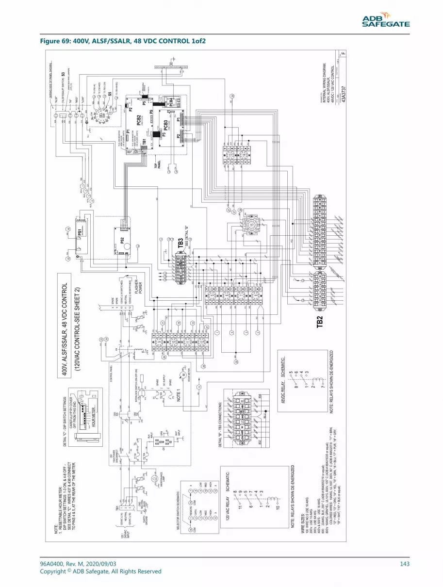
Figure 69: 400V, ALSF/SSALR, 48 VDC CONTROL 1of2
8765
13
9 10 11 12
14
15
120V
AC (L
1ASW
ITCH
ED)
NEUT
RAL
120V
AC (L
1B S
WIT
CHED
)
1143
5
WIR
E SI
ZES:
100
WIR
E NO
.S U
SE 16
AWG.
200's
: USE
10AW
G.30
0's: U
SE 6A
WG.
400's
& 50
0'S :
USE
18AW
G.60
0: 2
2AW
G, B
LK, 2
00° C
(ADB
# 89
A000
2/10 o
r equ
al);
800's
: 16A
WG,
GRN
/YEL
, UL1
015,
600V
, 105
° C (A
DB #
89A0
163/6
or eq
ual);
COLO
RED
WIR
ES: 1
8AW
G, U
L100
7, 30
0V, 8
0° C
(ADB
# 89
A020
7/X: "
/1" =
BRN
,"/2
" = R
ED, "
/3" =
ORG
, "/4"
=YE
L, "/5
" = G
RN, "
/6 =
BLU,
"/7"
= P
UR, "
/8" =
GRY
,"/9
" = W
HT, "
/10" =
BLK
or eq
ual).
SELE
CTOR
SW
ITCH
SCH
EMAT
IC:
COM
1A
OFFX
COM
82 65
XHIGH
3 4
LOW
MED
12119 10
XHIGH
LOW
MED
REMO
TE1
7A7
X
68
NOTE
: REL
AYS
SHOW
N DE
-ENE
RGIZ
ED
34
71 2
48VDCLO
W40
2
48VD
C RE
LAY
DETA
IL"B
" -TB
3 CON
NECT
IONS
:
506
406
802
405
507
437
5
BLU
407
408
804
412
431
416
507
804
455
409
435
430
415
413
414
LOAD
305
304
DISC
ONNE
CT10
0APO
WER 12
5 128
GFI
INPU
T
120 /
240V
AC
LAMP
MAIN
TENA
NCE
127
126
NEUT
RAL
EART
HGR
OUND
302
120V
AC (L
1B)
3
GND
BUSS 201
213
303 211
VR1
TB1
120V
AC (L
1A)
NEUT
RAL
1 2
301
302210
303
212
211
VR2
210
F2 15
A12
4
123
F1 5A
301
LINE
CB1
CONT
ROLP
ANEL
INTE
RLOC
K SW
ITCH
(ON-
OFF-
ON)
HOUR
MET
ER
INPU
T
WHT
INPU
T13
0
129
GRN
437
M
F4 10
A43
5
F3F5
DC S
UPPL
Y
SPAR
E
SPAR
E
BLK
126
S2
131
LINE
CB2
15A
CB3
LINE 131
30A
112
207
206
LOAD
438
A15
43620
7
118
A2
620
9
120
6
K4
2
220
8
209
215
21721
4VR
3VR
4
216
12
208
214
218
10 119SP
ARE
8SP
ARE
K11
TB2
FLASHER O
N/OFF
MED
420
NEUTRAL
MEDHI
LOW
ALSF
412
404
403
434
412
12
HI
421
804
407
412
406
405
412
412
412
412
BLU
TB1
804
430
431
802
405
406
407
431
408
412
431
507
506
455
505
804
409
435
SEE
DETA
IL"B
"TB
3
POW
ERFL
ASHE
R
644
544
6L
PS2
412
N803
1 543244
044
144
244
344
4
TOP
PANE
L
P1
440
441
442
443
444
445
803
802
OUT-
OUT+
PS1
1
(48V
PW
R SU
PPLY
)
423543
1
511
510
412
32
BLU
507
TO (T
B3-L
OW)
94
SW
P9
P2 PCB4
(159
0.03.4
80)
423
412
P2
805
422
421
420
428
P1
(159
3.13.5
20)
PCB3
P3BR
N
800
801
TO P
CB2-
P2BR
N80
5
TO (T
B3-4
8VDC
)
P5TO P
CB4-
P2
(159
3.13.4
12)
TO P
CB2-
P5
PCB2
P2601
BRN
65
750
8CO
M
8
RIBB
ON C
ABLE
ASSY
'S (3
)
BRN
TO P
CB3-
P3
S5
(WIR
ING
SIDE
OF
PANE
LSHO
WN)
"ALS
F"50
9
506
505"L
OW"
"MED
"
"HI"
("ALS
F/SS
ALR"
SW
ITCH
)
801
512
COM 11
121 SE
L32
10800
455
454
511
TO (T
B3-M
ED)
20AW
G BU
S W
IRE
JUMP
ERS
(3 P
LC.S
)
S3
ALSF
305
304
15
15
48 VDC
ALSF
16
16
48 VDC
ALSF
/SS
ALR
400
450
508
400
509
1
TO (T
B3-H
I)
510
451
2
1 4 351
1
509
2
437
510
512
K5-6
K8-6
K7-6
K6-6
431
431
431
431
12
436
412
431
412
412
450
412
450
450
450
423
422
421
420
138
GND
NEUTRAL
CAUTION
LOCAL
FLASHER O
NFAUL
T
412
SCHE
MATI
C:
454
1117
439
1742
5
K1040
1
18
1840
1
427
426
424
408
433
1920
21
21 20 19
22
2260
1 422
423
424
426
424
426
427
427
PE
434
455
455
439
J1
23 24
23 24
513
514
513
514
513
514
2525
26
26
446
446
27
27
SPARE
COMMON
412
508
412
412
450
447
447
447
448
448
12
3 45
67
8910
11
431
28
28
439
448
448
425
449
449
412
402
403
404
450 40
7
431
407
407
405
405
406
406
448
448
428
428
429
429
412
450
76
34
101 2
59811
120 V
AC R
ELAY
SCHE
MATI
C:
NOTE
: REL
AYS
SHOW
N DE
-ENE
RGIZ
ED
414
413
415 416
414
413
415 416
415
414
416
413
415 41
541
6
414
414
415
416
414
415
416
414
413
413
413
450
450
45043
040
9
NOTE
1
NOTE
:1.
RESE
TTAB
LE H
OUR
METE
R:DI
PSW
ITCH
SET
TING
S: 1-
3 ON,
& 4-
8 OFF
-SE
E DE
TAIL
"C".
WIR
ES 43
7 & 43
8 CON
NECT
TO P
INS
4 & 5,
ATTH
E RE
AR O
FTH
E ME
TER.
DETA
IL"C
" - D
IPSW
ITCH
SET
TING
S:
CARE
FULL
YPRY
COVE
ROF
F FR
OMTH
IS E
ND.
1 2 3 4 5 6 7 8
HOUR
MET
ER
ON
xxxx
x
OFF
75Ω
, 25W
RES
ISTO
RAD
B# 15
A020
6(H
S SO
LDER
JOIN
TS)
441A
444A
440A
443A
10Ω
, 25W
RES
ISTO
RAD
B# 15
A020
5(H
S SO
LDER
JOIN
TS)
COM
COM
N.O.
N.O.
412
1 OF
2N/
A
F43
A373
7
400V
,ALS
F/SS
ALR,
48 V
DC C
ONTR
OL
400V
,ALS
F/SS
ALR,
INTE
RNAL
WIR
ING
DIAG
RAM,
48VD
C / 1
20 V
AC C
ONTR
OL
(120
VAC
CONT
ROL-
SEE
SHEE
T2)
DRAW
ING
NUMB
ER:
DRAW
INGT
ITLE
:
SCAL
E:SH
EET
NUMB
ER:
REV.
111 110 109
96A0400, Rev. M, 2020/09/03 143Copyright © ADB Safegate, All Rights Reserved

Figure 70: 400V, ALSF/SSALR, 120 VAC CONTROL 2of2
8765
13
9 10 11 12
14
15
120V
AC (L
1ASW
ITCH
ED)
NEUT
RAL
120V
AC (L
1B S
WIT
CHED
)
1143
5
WIR
E SI
ZES:
100
WIR
E NO
.S U
SE 16
AWG.
200's
: USE
10AW
G.30
0's: U
SE 6A
WG.
400's
& 50
0'S :
USE
18AW
G.60
0: 2
2AW
G, B
LK, 2
00° C
(ADB
# 89
A000
2/10 o
r equ
al);
800's
: 16A
WG,
GRN
/YEL
, UL1
015,
600V
, 105
° C (A
DB #
89A0
163/6
or eq
ual);
COLO
RED
WIR
ES: 1
8AW
G, U
L100
7, 30
0V, 8
0° C
(ADB
# 89
A020
7/X: "
/1" =
BRN
,"/2
" = R
ED, "
/3" =
ORG
, "/4"
=YE
L, "/5
" = G
RN, "
/6 =
BLU,
"/7"
= P
UR, "
/8" =
GRY
,"/9
" = W
HT, "
/10" =
BLK
or eq
ual).
SELE
CTOR
SW
ITCH
SCH
EMAT
IC:
COM
1A
OFFX
COM
82 65
XHIGH
3 4
LOW
MED
12119 10
XHIGH
LOW
MED
REMO
TE1
7A7
X
68
NOTE
: REL
AYS
SHOW
N DE
-ENE
RGIZ
ED
34
71 212
0 VAC
LOW
402
120 V
AC R
ELAY
DETA
IL"B
" -TB
3 CON
NECT
IONS
:
506
406
802
405
507
437
5
BLU
407
408
804
412
431
416
507
804
455
409
435
415
413
414
LOAD
305
304
DISC
ONNE
CT10
0APO
WER 12
5 128
GFI
INPU
T
120 /
240V
AC
LAMP
MAIN
TENA
NCE
127
126
NEUT
RAL
EART
HGR
OUND
302
120V
AC (L
1B)
3
GND
BUSS 201
213
303 211
VR1
TB1
120V
AC (L
1A)
NEUT
RAL
1 2
301
302210
303
212
211
VR2
210
F2 15
A12
4
123
F1 5A
301
LINE
CB1
CONT
ROLP
ANEL
INTE
RLOC
K SW
ITCH
(ON-
OFF-
ON)
HOUR
MET
ER
INPU
T
WHT
INPU
T13
0
129
GRN
437
M
F4 10
A43
5
F3F5
DC S
UPPL
Y
SPAR
E
109
SPAR
E
110111
BLK
126
S2
131
LINE
CB2
15A
CB3
LINE 131
30A
112
207
206
LOAD
438
A15
43620
7
118
A2
620
9
120
6
K4
2
220
8
209
215
21721
4VR
3VR
4
216
12
208
214
218
10 119SP
ARE
8SP
ARE
K11
TB2
FLASHER O
N/OFF
MED
420
NEUTRAL
MEDHI
LOW
ALSF
412
404
403
434
412
12
HI
421
804
407
412
406
405
412
412
412
412
BLU
804
431
802
405
406
407
431
408
412
431
507
506
455
505
804
409
435
SEE
DETA
IL"B
"TB
3
POW
ERFL
ASHE
R
644
544
6L
PS2
412
N803
1 543244
044
144
244
344
4
803
802
511
510
32
BLU
512
94
SW
800
801
805
TO (T
B3-1
20VA
C)60
1
65
750
8CO
M
8
S5
(WIR
ING
SIDE
OF
PANE
LSHO
WN)
"ALS
F"50
9
506
505"LOW
"
"MED
"
"HI"
("ALS
F/SS
ALR"
SW
ITCH
)
801
512
COM 11
121 SE
L32
10800
455
454
511
20AW
G BU
S W
IRE
JUMP
ERS
(3 P
LC.S
)
S3
ALSF
305
304
ALSF
ALSF
/SS
ALR
400
431
508
400
510
451
2
437
510
431
431
431
431
12
436
412
431
412
412
431
412
431
450
430
430
423
422
421
420
433
GND
NEUTRAL
CAUTION
LOCAL
FLASHER O
NFAUL
T
412
SCHE
MATI
C:
454
1117
439
17
425
K1040
1
18
1840
1
408
433
1920
21
21 20 19
22
2260
1 422
423
424
426
424
426
427
427
434
455
455
439
23 24
513
514
25
25
26
26
446
446
27
27
SPARE
COMMON
412
508
412
412
431
447
447
447
448
448
12
3 45
67
8910
11
431
28
28
439
448
448
425
449
449
412
402
403
404
407
431
407
407
405
405
406
406
448
428
428
429
429
412
76
34
101 2
59811
120 V
AC R
ELAY
SCHE
MATI
C:
NOTE
: REL
AYS
SHOW
N DE
-ENE
RGIZ
ED
417
417
417
417
417
417
415
414
416
413
2 3 4
448
510
511
507
601
509
NOTE
1
NOTE
:1.
RESE
TTAB
LE H
OUR
METE
R:DI
PSW
ITCH
SET
TING
S: 1-
3 ON,
& 4-
8 OFF
-SE
E DE
TAIL
"C".
WIR
ES 43
7 & 43
8 CON
NECT
TO P
INS
4 & 5,
ATTH
E RE
AR O
FTH
E ME
TER.
DETA
IL"C
" - D
IPSW
ITCH
SET
TING
S:
CARE
FULL
YPRY
COVE
ROF
F FR
OMTH
IS E
ND.
1 2 3 4 5 6 7 8
HOUR
MET
ER
ON
xxxx
x
OFF
TB1
TOP
PANE
L
P1
440
441
442
443
444
445
P9
P2 PCB4
(159
0.03.4
80)
423
417
P2
805
422
421
420
428
P1
(159
3.13.5
10)
PCB3
P3BR
NTO
PCB
2-P2
BRN
P5TO P
CB4-
P2
(159
3.13.4
12)
TO P
CB2-
P5
PCB2
P2
BRN
RIBB
ON C
ABLE
ASSY
'S (3
)
BRN
TO P
CB3-
P3
427
426
424
PE
J123 24
513
514
513
514
414
413
415 416
414
413
415 416
441A
444A
440A
443A
75Ω
, 25W
RES
ISTO
RAD
B# 15
A020
6(H
S SO
LDER
JOIN
TS)
10Ω
, 25W
RES
ISTO
RAD
B# 15
A020
5(H
S SO
LDER
JOIN
TS)
400V
,ALS
F/SS
ALR,
2 OF
2
INTE
RNAL
WIR
ING
DIAG
RAM,
N/A
F43
A373
7
400V
,ALS
F/SS
ALR,
120 V
AC C
ONTR
OL
48VD
C / 1
20 V
AC C
ONTR
OL
(48V
DC C
ONTR
OL-S
EE S
HEET
1)
DRAW
ING
NUMB
ER:
DRAW
ING
TITL
E:
SCAL
E:SH
EET
NUMB
ER:
REV.
400 V: MALSR and ALSFMaintenance
144Copyright © ADB Safegate, All Rights Reserved

Figure 71: Internal Wiring Diagram 400 V ICC (43A3512)
21
PE
PCB1498
10 mm²
H05V-K0,75 mm²
Input Max.264VAC
H05V-K0,75 mm2
RECEPTACLE
LOAD
N'
P' SCHAFFNER
N
ELINE
PH05V-K0,75 mm2
Flatc.conn. 10 F6116.69.025
P3
FCC10P
LOCAL BUSINTERFACE
P1
FCC10P
4A T
4A TH05V-K0,75 mm2
1
770ITT22117 0,22 mm2
11
12 14
MOVP3
POWER SUPPLYASTEC LPT4 5
P6N
L1P7
PHPE N
P5HEATING
BLUE OR WHITE
RED
C1
-PE
N HEATPE +
N
H05V-K 0,75 mm2
PH
TB4 TB2
PHPE
P4FCC10P
J1DB9
FCU PCB
P2TB1H07V-K 1,5 mm2
+ TB3
DOOR
-- -+
P15- 13 24
Flatcable 10 WFlatcable 10 W
H05V-K 0,75 mm2
770ITT22117 0,22 mm2
CONN.MOLEX NC 6118.25.003PIN MOLEX NC 6118.25.000
+5V
6 x 0.75 mm2
-15VGNDGND
H05V -K
+15V+5V
321GND VDDDQ
DS18S20
1500 ohm
HSC100
H07V-K4 mm2
2
4 mm2
11
12 14
J1 (NOT USED)
P2 (NOT USED)
TB1 (NOT USED)
P7 (NOT USED)
P6; NOTUSED
OPTIONAL
-+ 0V +- 0V
OPTIONAL MONITORED MOV'S
TO DONGLE (WHEN USED)
INTERLOCK SWITCH (ON-OFF-ON)
TEMPERATURE SENSOR
PECAB-CAB+PE400VTRIG
TO ELEVATED OR IN-PAVEMANTFLASHING FIXTURE
DRAWING NUMBER:
SCALE: SHEETN UMBER:
REV.
1 OF 1N/A
43A3512 D/E
TRIG
RE
T
-15v
gnd
+5v
+15v
gnd
+5v
NL
2 AT
96A0400, Rev. M, 2020/09/03 145Copyright © ADB Safegate, All Rights Reserved

Figure 72: Elevated Flash Head Assembly
400 V: MALSR and ALSFMaintenance
146Copyright © ADB Safegate, All Rights Reserved

Figure 73: Mounting the Master Control Cabinet
96A0400, Rev. M, 2020/09/03 147Copyright © ADB Safegate, All Rights Reserved
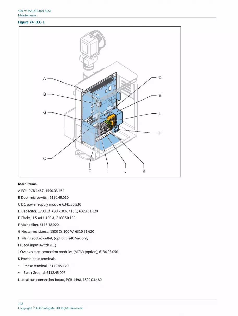
Figure 74: ICC-1
Main items
A FCU PCB 1487, 1590.03.464
B Door microswitch 6150.49.010
C DC power supply module 6341.80.230
D Capacitor, 1200 μf, +30 -10%, 415 V, 6323.61.120
E Choke, 1.5 mH, 150 A, 6166.50.150
F Mains filter, 6115.18.020
G Heater resistance, 1500 Ω, 100 W, 6310.51.620
H Mains socket outlet, (option), 240 Vac only
I Fused input switch (F1)
J Over-voltage protection modules (MOV) (option), 6134.03.050
K Power input terminals,
• Phase terminal , 6112.45.170
• Earth Ground, 6112.45.007
L Local bus connection board, PCB 1498, 1590.03.480
400 V: MALSR and ALSFMaintenance
148Copyright © ADB Safegate, All Rights Reserved
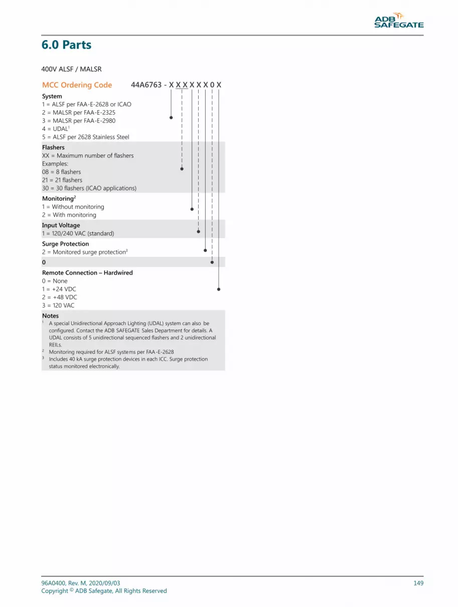
6.0 Parts
400V ALSF / MALSR
MCC Ordering Code System 1 = ALSF per FAA-E-2628 or ICAO 2 = MALSR per FAA-E-2325 3 = MALSR per FAA-E-2980 4 = UDAL1 5 = ALSF per 2628 Stainless Steel Flashers XX = Maximum number of flashers Examples: 08 = 8 flashers 21 = 21 flashers 30 = 30 flashers (ICAO applications) Monitoring2 1 = Without monitoring 2 = With monitoring
Input Voltage 1 = 120/240 VAC (standard) Surge Protection 2 = Monitored surge protection3 0
Remote Connection – Hardwired 0 = None 1 = +24 VDC 2 = +48 VDC 3 = 120 VAC
Notes 1 A special Unidirectional Approach Lighting (UDAL) system can also be
configured. Contact the ADB SAFEGATE Sales Department for details. A UDAL consists of 5 unidirectional sequenced flashers and 2 unidirectional REILs.
2 Monitoring required for ALSF systems per FAA-E-2628 3 Includes 40 kA surge protection devices in each ICC. Surge protection
status monitored electronically.
44A6763 - X X X X X X 0 X
96A0400, Rev. M, 2020/09/03 149Copyright © ADB Safegate, All Rights Reserved

6.1 MALSR Parts List
The MALSR/ALSF MCC part number is 44A6850/XXXXXXXX.
Figure 75: Master Control Cabinet Parts and Diagram
Interlock switch DPDT 10A45A0303
F1 Fuse, 5 A (BUSS AGC-5) 47A0015F2 Fuse, 15 A (BUSS AGC-15) 47A0016F3 Fuse, 1 A, S.B. A (BUSS MDL-5) 47A0017F4 & F5 Fuse 10 A (BUSS MDL-1) 47A0018
CB2 Circuit breaker, 15 A (AIRPAX #219-2-1-63F-3-15) 57A0047CB3/4 Circuit breaker, 30 A (AIRPAX #219-2-1-62-3-1-30) 57A0048
CB1 Switch, MALSR, 120/240 Vac, 100A (AIRPAX #219-2-1-63F-3-1-100) 57A0050
CB1 Switch, ALSF, 120/240 Vac, 100A (AIRPAX #219-2-0-SW-3-1-100) 57A0046
Rotary switchMALSR44B1698-1ALSF44B1698-2
K2, K3, K4Cont 2P 60 FLA 120 Vac Coil53A0412-60
Varistor (VR1 - VR4)32A0011
Lamp, 100 W (SYLVANIA #100A125)48A0065Lamp socket, snap-in49A0116 K1
Cont 2P 30 FLA 120 Vac Coil53A0412-30
PCB Assembly 44A6839See Figure
PCB 14981590.03.480
PCB 14861593.13.510
PCB14851593.13.412F
Ground fault outlet47A0041
Assembly 44A6841Figure
Assembly 44A6842See Figure
Table 67: MCC Assembly 44A6539 PartsItem Part Number Description Qty
1 1590.03.490 Master J-Bus Board, PCB 1502 1
2 60A4008 Mounting Plate Power Supply MALSR 1
3 60A4009 XFMR Mounting Plate MALSR 1
4 64A0199-4 6-32 X 1/4 Pan Head Phillips 8
400 V: MALSR and ALSFParts
150Copyright © ADB Safegate, All Rights Reserved
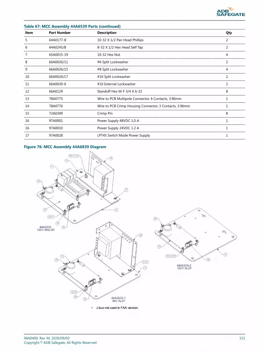
Table 67: MCC Assembly 44A6539 Parts (continued)Item Part Number Description Qty
5 64A0177-8 10-32 X 1/2 Pan Head Phillips 2
6 64A0245/8 8-32 X 1/2 Hex Head Self Tap 2
7 65A0015-19 10-32 Hex Nut 4
8 66A0026/11 #6 Split Lockwasher 2
9 66A0026/15 #8 Split Lockwasher 4
10 66A0026/17 #10 Split Lockwasher 2
11 66A0039-6 #10 External Lockwasher 2
12 66A0129 Standoff Hex M-F 3/4 X 6-32 8
13 78A0775 Wire to PCB Multipole Connector, 6 Contacts, 3.96mm 1
14 78A0776 Wire to PCB Crimp Housing Connector, 3 Contacts, 3.96mm 1
15 72A0399 Crimp Pin 8
16 97A0001 Power Supply 48VDC 1.0 A 1
16 97A0010 Power Supply 24VDC 1.2 A 1
17 97A0028 LPT45 Switch Mode Power Supply 1
Figure 76: MCC Assembly 44A6839 Diagram
96A0400, Rev. M, 2020/09/03 151Copyright © ADB Safegate, All Rights Reserved

Table 68: MCC Assembly MALSR 44A6842 / ALSF 44A6842/1 PartsITEM PART NUMBER DESCRIPTION QTY.
1 42A0587 MALSR Switch / Light Panel Label 1
1 42A0609 ALSF Switch / Light Panel Label 1
2 45A0468 Switch Toggle SPDT SLDR LUG 5PCS 1
3 46A0092-6 Rotary SW 30DEG SP 6POS. 1
3 61A0454 Knob, Phenolic, 1/4" Shaft, Pointer 1
4 48A0406 Neon Lamp, Neon IND 110V AMB 4
5 60A4010 Switch / Light Panel BRKT MALSR 1
6 63A0255 Cable Tie Mount Metal 1
6 64A0198-6 6-32 X 3/8 Pan Head Phillips 1
6 66A0026-11 #6 Split Lockwasher 1
6 65A0015-11 #6-32 HX NUT 1
Figure 77: MCC ALSF/MALSR Assembly 44A6842 Diagram (MALSR Light Panel Label Shown)
Table 69: MCC Assembly 44A6841 PartsITEM PART NUMBER DESCRIPTION QTY.
1 49A0361 Socket Relay 8 Pins 10
2 49A0363 Socket Relay 11 Pins 1
3 53A0436 120 Vac 50/60HZ 12 AMP SPDT 1
4 53A0437 24 Vdc 10 AMP DPDT 4
5 53A0442 Relay, 11 Pin, 3DPDT, 12A 1
6 53A0443 Relay Time Delay 3
400 V: MALSR and ALSFParts
152Copyright © ADB Safegate, All Rights Reserved

Table 69: MCC Assembly 44A6841 Parts (continued)ITEM PART NUMBER DESCRIPTION QTY.
7 53A0447 Relay DPDT, 48VDC Coil, 8 Pins 10
8 53A0450 Relay DPDT 120VAC 50/60HZ 12AMP 10
9 60A4007 Relay Mounting Plate MALSR 1
10 64A0169-16 4-40 X 1" Pan Head Phillips 22
11 64A0169-6 #4-40 X 3/8 Pan Head Phillips 6
12 66A0015-7 #4 Flatwasher SS 6
13 66A0026-7 #4 Split Lockwasher 24
14 72A0066 Term BLK 22-10AWG 600V 50A,Use W/72A0067 33
15 72A0067 Term BLK End, Flat Base, Mates W/72A0066 3
Figure 78: MCC Assembly 44A6841 ALSF/MALSR 120V Diagrams
96A0400, Rev. M, 2020/09/03 153Copyright © ADB Safegate, All Rights Reserved

Figure 79: MCC Assembly 44A6841 ALSF 48V Diagram
6.1.1 MALSR Master Control Cabinet Specific Parts ListSee Table 70 . This subsection provides master control cabinet parts applicable only to the MALSR system.
The MALSR master control cabinet part number is 44A6850/XXXXXXXX.
Table 70: MALSR MCC Specific Parts ListItem Description Part Number Quantity Note
20 Circuit breaker, 70 A (AIRPAX #219-2-1-62F-3-1-70), MALSR 57A0049 1
21 Contactor, 70 A, 120 Vac (TELEMECANIQUE #LC1-050BK), MALSR 53A0252 3
6.1.2 Steady Burning Elevated Light Assembly Parts List
MALSR PAR-56 Lampholder Assembly Parts List
Refer to instruction manual 96A0119, Type FAP PAR-56 Approach Light for parts list and diagrams for the steady burning lightassembly.
MALSR PAR-38 Lamp-holder Assembly Parts List
PAR-38 parts apply only to the MALSR system.
Table 71: MALSR PAR-38 Lamp-holder Assembly Parts ListItem Description Part Number Quantity Note
1 Lamp (150W PAR-38) 48A0447 1
2 PAR-38 lamp-holder, PAR/SP 44A0094 1
3 Slip-fitter 62B0528-2 1
400 V: MALSR and ALSFParts
154Copyright © ADB Safegate, All Rights Reserved

Table 71: MALSR PAR-38 Lamp-holder Assembly Parts List (continued)Item Description Part Number Quantity Note
4 PAR-38 tower mounting adapter (FAC) 62B0537 1 B
5 Lamp-holder assembly 44C1683 1 A
1. NOTE A: The lamp-holder assembly includes the PAR-38 lamp-holder (Item 2) and the slip fitter (Item 3). The lamp (item 1) is a separateline item and is not supplied with the lamp-holder assembly (item 5).
2. NOTE B: The mounting adapter (FAC) (item 4) is used in conjunction with the slip-fitter (item 3), when mounting the PAR-38 holder to afiber glass or aluminum tower cross arms hub.
Figure 80: PAR-38 Lampholder
Aluminum Tower Mount Fiberglass Tower Mount
1
2
3
4
5
96A0400, Rev. M, 2020/09/03 155Copyright © ADB Safegate, All Rights Reserved

6.1.3 MALSR/ALSF In-pavement Flasher Parts ListIt is recommended to create a sufficiently large stock of spare parts to maintain the fittings. It will mainly consist ofconsumables like lamps, O-ring gaskets, etc. Other components that may need replacement, such as prisms, prism gaskets,terminal blocks and hardware even as sub-assemblies should be stocked in smaller quantities. It is recommended to store atleast one complete fitting, FFL9C0000000.
The table below gives for each screw used in the FFL 12", the reference to the type of screw, the tool to use, and the type of"Loctite" when needed:
Table 72: MALSR/ALSF In-pavement Flasher Parts RequirementsScrew Tool Loctite Torque
A1/A2 Socket hex, 3/8”, J.9/16LA Loctite 2707870.05.110 190 in-lb (21 Nm)
B5 - screw TFC M5X10 DIN 965-Z INOX A2 Pozidriv2, RD.2 Loctite 2707870.05.110 31 in-lb (3.5 Nm)
C2 - Screw TFC M5X10 DIN 965-Z INOX A2 Pozidriv2, RD.2 No 31 in-lb (3.5 Nm)
C4 - Screw TFC M4X10 DIN 965-Z INOX A2 Pozidriv2, RD.2 No 30 in-lb (3.3 Nm)
D7 - screw TFC M5X10 DIN 965-Z INOX A2 Pozidriv2, RD.2 No 31 in-lb (3.5 Nm)
Screws delivered for installation of adapter ring on deep base Socket hex, 3/8”, J.9/16LA No 190 in-lb (21 Nm)
In the table below you will find the commercially available spare parts and main assemblies of the FFL light fitting (the partnumbers refer to Figure 81)
Table 73: MALSR/ALSF In-pavement Flasher Parts List
Ref. ADB part number Description Qty used infitting
Orderquantity (Per
xx)
B 1440.02.300 FFL Cover assy, including: 1 1
B1 4072.02.010 FFL machined cover 1 1
B2 MS00001-376-01 F-range 12 O-ring gasket 1 1
B3 4072.06.720 FFL prism kit consisting of 1 1
B3a 4072.02.030 - FFL sleeve gasket for prism 1 1
B3b 4072.01.520 - FFL prism 1 1
B3c 4072.02.060 - FFL flat seal for Prism 1 1
B4 4072.02.070 - FFL prism keeper plate 1 1
B5 64A0936-13 - Pan head screw M5 x 13 - Stainless Steel -DIN 7985-Z 10 100
C1 2990.82.673 FFL flashing lamp 60J - 400V (see note 1.) 1 1
C2 64A0936-13 Pan head screw M5 x 13 - Stainless Steel - DIN 7985-Z 5 100
C3 4072.20.810 Trigger PCB (see Note 2.) 1 1
C4 4072.02.181 Lamp PCB (see Note 2.) - does not include the lamp 1 1
C5 64A0964-10 Screw THRD M4X10 Stainless Steel 5 100
D 1440.02.310 FFL inner inner cover assembly including : 1 1
D1 4072.02.010 Machined FFL inner cover 1 1
D2 7080.90.650 O-ring seal between top cover and shallow base, for F- Range 12" 1 10
D3 6126.01.330 PG16 cable entry IP54 cable diameter 10.5 to 16 mm 1 10
D4 4072.03.980 5-pole plug assembly 1 1
400 V: MALSR and ALSFParts
156Copyright © ADB Safegate, All Rights Reserved

Table 73: MALSR/ALSF In-pavement Flasher Parts List (continued)
Ref. ADB part number Description Qty used infitting
Orderquantity (Per
xx)
D5 4072.20.981 Pressure release screw 1 10
D6 63B0267-011 O-ring for the pressure release screw 1 100
D7 64A0925-10 Screw TFC M5 X 10 Stainless Steel - DIN 965-Z 10 100
NoteFormer version of the lamp, with fast-on connector on the trigger wire: 2990.82.671.Order one Trigger PCB and one Lamp PCB to replace former FFL PCB ref. 4072.16.690.
Figure 81: Exploded Inset Light
96A0400, Rev. M, 2020/09/03 157Copyright © ADB Safegate, All Rights Reserved

6.2 Spare Parts
Refer below for optional parts.
Table 74: Parts: In-pavement FlasherItem Description Part Number Quantity Note
NS 6-core cable1 6104.90.206 AR
NS Connector kit, in-pavement flasher, male plug 70A0618 1
NS Connector kit, in-pavement flasher, female receptacle 70A0619 1
Notes1 One 6-core cable is needed with each in-pavement flasher. Please specify total length of cable required (in feet) when ordering.
NoteA:
NS: Not shown
AR: As required
Table 75: Parts: PAR-56 or PAR-38 elevated lightsItem Description Part Number Quantity Note
NS Adapter sleeve 1 62B0537 1
NS Flasher tester 44D1686-1 1
NS EMT Frangible coupling 44B0180 AR
NS Frangible coupling (Type F2) 62B0064 AR
NS Lightning arrestor 47A0019 2
NS Power transformer, 15 kVA for MALSR only 44D1685-1 1
Notes1 Used only on aluminum-tower cross arms to mount PAR-56 or PAR-38 lights, or on fiberglass tower for PAR-38 lampholders.
NS: Not Shown
AR: As required
Table 76: Parts: OptionalReference Description Code number Order qty
Over-voltage protection cartridge for supply phase VAL-MS230ST 6134.03.050 1
Over-voltage protection cartridge for supplyneutral F-MS 12T 6134.03.060 1
Temperature Sensor 1440.21.000 1
400 V: MALSR and ALSFParts
158Copyright © ADB Safegate, All Rights Reserved

Appendix A: SUPPORT
Our experienced engineers are available for support and service at all times, 24 hour/7 days a week. They are part of adynamic organization making sure the entire ADB SAFEGATE is committed to minimal disturbance for airport operations.
ADB SAFEGATE Support
Live Technical Support - AmericasIf at any time you have a question or concern about your product, just contact ADB SAFEGATE’stechnical service department. Trained in all areas of system issues, troubleshooting, quality controland technical assistance, our highly experienced Technical support specialists are available 24 hoursa day, seven days a week to provide assistance over the phone.ADB SAFEGATE Americas Technical Service & Support (US & Canada): +1-800-545-4157ADB SAFEGATE Americas Technical Service & Support (International): +1-614-861-1304During regular business hours, you can also Chat with a Service Technician. We look forward toworking with you!Before You CallWhen you have an airfield lighting or system control system problem it is our goal to supportairfield maintenance staff as quickly as possible. To support this effort we ask that you have thefollowing information ready before calling.
• The airport code
• If not with an airport, then company name (prefer customer id number)
• Contact phone number and email address
• Product with part number preferable or product number
• Have you reviewed the product’s manual and troubleshooting guide
• Do you have a True RMS meter available (and any other necessary tools)
• Be located with the product ready to troubleshoot
NoteFor more information, see www.adbsafegate.com, or contact ADB SAFEGATE Support via email [email protected] orBrussels: +32 2 722 17 11Rest of Europe: +46 (0) 40 699 17 40Americas: +1 614 861 1304. Press 3 for technical service or press 4 for sales support.China: +86 (10) 8476 0106
A.1 ADB SAFEGATE Website
The ADB SAFEGATE website, www.adbsafegate.com, offers information regarding our airport solutions, products, company,news, links, downloads, references, contacts and more.
96A0400, Rev. M, 2020/09/03 159Copyright © ADB Safegate, All Rights Reserved

A.2 Recycling
A.2.1 Local Authority RecyclingThe disposal of ADB SAFEGATE products is to be made at an applicable collection point for the recycling of electrical andelectronic equipment. The correct disposal of equipment prevents any potential negative consequences for the environmentand human health, which could otherwise be caused by inappropriate waste handling. The recycling of materials helps toconserve natural resources. For more detailed information about recycling of products, contact your local authority city office.
A.2.2 ADB SAFEGATE RecyclingADB SAFEGATE is fully committed to environmentally-conscious manufacturing with strict monitoring of our own processes aswell as supplier components and sub-contractor operations. ADB SAFEGATE offers a recycling program for our products to allcustomers worldwide, whether or not the products were sold within the EU.
ADB SAFEGATE products and/or specific electrical and electronic component parts which are fully removed/separated fromany customer equipment and returned will be accepted for our recycling program.
All items returned must be clearly labeled as follows:
• For ROHS/WEEE Recycling
• Sender contact information (Name, Business Address, Phone number).
• Main Unit Serial Number.
ADB SAFEGATE will continue to monitor and update according for any future requirements for EU directives as and when EUmember states implement new regulations and or amendments. It is our aim to maintain our compliance plan and assist ourcustomers.
400 V: MALSR and ALSFSUPPORT
160Copyright © ADB Safegate, All Rights Reserved

Company Addresses
ADB SAFEGATE ADB SAFEGATE, Belgium:Leuvensesteenweg 585,B-1930 ZaventemBelgium
Contact:Tel.: +32 2 722 17 11,Fax: +32 2 722 17 64
Email: [email protected]: www.adbsafegate.com
Americas LLC ADB SAFEGATE, Americas:977 Gahanna Parkway,Columbus, OH 43230USA
Contact:Tel.: +1 (614) 861 1304,Fax: +1 (614) 864 2069
Email: [email protected]: www.adbsafegate.com
ADB SAFEGATE Sweden AB ADB SAFEGATE, Sweden:Djurhagegatan 19SE-213 76 MalmöSweden
Contact:Tel.: +46 (0)40 699 17 00,Fax: +46 (0)40 699 17 30
Email: [email protected]: www.adbsafegate.com
ADB SAFEGATE Airfield Technologies Ltd. China ADB SAFEGATE, China:Unit 603, D Block,CAMIC International Convention Center,No 3, Hua Jia Di East road, ChaoYang district,Beijing 100102P.R. China
Contact:Tel.: +86 (10) 8476 0106,Fax: +86 (10) 8476 0090
Email: [email protected]: www.adbsafegate.com
ADB SAFEGATE Germany GmbH ADB SAFEGATE Germany GmbH, Mannheim:Konrad-Zuse-Ring 6,D-68163 MannheimGermany
Contact:Tel.: +49 (621) 87 55 76-0,Fax: +49 (621) 87 55 76-55
Email: [email protected]: www.adbsafegate.com
96A0400, Rev. M, 2020/09/03 161Copyright © ADB Safegate, All Rights Reserved


