Embed Size (px)
Citation preview

5. WRITTEN EXPLANATION
Introduction
Extraction Oil & Gas, Inc. (Extraction) submits this application for an Administrative Use by Special Review Permit (AUSR) concerning the Warbler oil and gas location, or “pad.” The application seeks to permit the drilling, completing, and installation of related surface production equipment for one (1) well pad, (1) one access road and up to twenty-two (22) horizontal wells on property located in Adams County, Colorado. The drilling schedule is subject to change due to economic conditions, business development priorities, and contract availability.
These wells and associated production facilities have been proposed on a single pad in the southeast quarter of Section 13-1S-66W on parcel number 0156900000161. The horizontal drilling technique eliminates the need to develop additional well pads, thus reducing the overall footprint needed on the surface if otherwise developed with vertical and or directional wells. This well pad and the subsequent 22 wells will produce a 3360-acre drilling unit in the Niobrara and Codell formations of the Denver-Julesburg (DJ) Basin.
The AUSR, pursuant to Section 4-10-02-04-02 of the Adams County Development Standards and Regulations, includes a full description of the site preparation, drilling, completion, production, maintenance and final abandonment processes.
Operating plan
The Operating Plan is divided into the site preparation, drilling phase, protection of fresh water, completion phase, production phase, and the abandonment and reclamation of wells and the site. All operations will be consistent with Adams County code and Colorado Oil and Gas Conservation Commission (“COGCC”) rules and regulations, specifically those set forth in the following series:
• 300 Series: Drilling, Development, Producing, and Abandonment• 600 Series: Safety Regulations• 800 Series: Aesthetic and Noise Control Regulations• 1000 Series: Reclamation Regulations• 1100 Series: Flowline Regulations
Site Preparation (21-34 days)
The proposed pad will be approximately 15.6 acres in size during construction and drilling and completions operations. Site preparation will include removal of current grass vegetation and stockpiling of topsoil, earthwork operations to grade the pad level for drilling operations, platting the pad with road base material, and improvements to the access road where necessary. Additionally, storm water controls and mitigation BMPs will be installed during construction of the pad.

Drilling Phase
A drilling prognosis will be prepared prior to drilling which details the landing points, formation tops, total depths, mud design, and wellbore logging and casing programs for each well.
The drilling phase typically proceeds as follows:
• A conductor rig is moved onto the location to set conductor casing for each well; typically, conductor casing takes one day for every two wells to set. Conductor casing is set at depths of 75-200’ and hold back the loose gravels and soil types from falling into the hole. The conductor casing is then cemented to the surface.
• After the conductor casing is set, a surface, or “spudder,” rig is moved onto location to set surface casing. It typically takes one day per well to set surface casing.
• The surface rig drills to approximate depths of 1500’ feet. For this site, surface casing will be set at least 50 feet below the deepest known fresh water Fox Hills water well in the area or the base of the mapped Fox Hills aquifer formation; whichever is deeper. Surface casing is then run and cemented from this depth to the surface. Typical surface casing designs in the basin are a minimum of 1500’ deep.
• Next, the drilling rig is moved onsite and rigged up. Mobilization of the drilling rig typically takes 2 to 4 days and a 24-hour drilling schedule is utilized. Under normal conditions, drilling is anticipated to take approximately 6 to 8 days per well.
• On multi-well pads, the wellheads are planned at 28 feet on center. The rig is set up on
the first well to be drilled, then skids or walks to each subsequent well.
• Once the total depth is reached for a well, the drill string is removed from the hole.
• Prior to running production casing, one well per pad has open-hole logs run to meet COGCC requirements if an offset well’s logs are not available or are insufficient. Logs are run to determine sufficient cement coverage and the stratigraphy of the formation. The objective target formations for this project are mapped and estimated to be between 7000-7600’ deep.
• Production casing is then run, set in the hole, and cemented in place to provide integrity and isolate the deeper hydrocarbon bearing formations.
• Next, the blow out preventer is removed, the well is properly capped and secured and then the rig skids to the next well on the pad.
• Once all wells on site are drilled, cased, cemented and the well heads capped and secured, the drilling rig is demobilized and moved offsite.

Protection of Fresh Water The COGCC sets forth specific requirements for casing setting depths necessary to protect ground water sources, and all drilling permits insure that those setting depths have been approved. The Fox Hills sands of the late Cretaceous age are important fresh water aquifers in the western portion of the DJ Basin. In addition, there are numerous discontinuous sands of secondary importance that lie directly below the Fox Hills formation. These ground water sands are found from the surface to a depth of approximately five hundred (500) feet in the north and eastern portions of the basin and from the surface to a depth of approximately one thousand (1,000) feet or more in the south and western parts of the basin. In order to ensure the protection of all fresh water resources, 9-5/8” steel surface casing is set to a depth at least fifty (50) feet below the base of the deepest known Fox Hills sands or water well, whichever is deeper, as required by the COGCC and is cemented from the bottom of the pipe up to the surface. The COGCC reviews all drilling permit applications for adequate surface casing setting depths and cementing programs based on subsurface ground water maps prepared by the State Water Engineer, offset well data and all available water well data.
Completion Phase
Completion operations commence once the production casing cement has had sufficient time to cure. Typically, cement will cure to maximum strength within 72 hours. The quality is verified by a cement bond log (“CBL”).
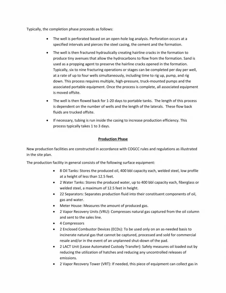
Typically, the completion phase proceeds as follows:
• The well is perforated based on an open-hole log analysis. Perforation occurs at a specified intervals and pierces the steel casing, the cement and the formation.
• The well is then fractured hydraulically creating hairline cracks in the formation to produce tiny avenues that allow the hydrocarbons to flow from the formation. Sand is used as a propping agent to preserve the hairline cracks opened in the formation. Typically, six to nine fracturing operations or stages can be completed per day per well, at a rate of up to four wells simultaneously, including time to rig up, pump, and rig down. This process requires multiple, high-pressure, truck-mounted pumps and the associated portable equipment. Once the process is complete, all associated equipment is moved offsite.
• The well is then flowed back for 1-20 days to portable tanks. The length of this process is dependent on the number of wells and the length of the laterals. These flow back fluids are trucked offsite.
• If necessary, tubing is run inside the casing to increase production efficiency. This process typically takes 1 to 3 days.
Production Phase
New production facilities are constructed in accordance with COGCC rules and regulations as illustrated in the site plan.
The production facility in general consists of the following surface equipment:
• 8 Oil Tanks: Stores the produced oil, 400 bbl capacity each, welded steel, low profile at a height of less than 12.5 feet.
• 2 Water Tanks: Stores the produced water, up to 400 bbl capacity each, fiberglass or welded steel, a maximum of 12.5 feet in height.
• 22 Separators: Separates production fluid into their constituent components of oil, gas and water.
• Meter House: Measures the amount of produced gas. • 2 Vapor Recovery Units (VRU): Compresses natural gas captured from the oil column
and sent to the sales line. • 4 Compressors • 2 Enclosed Combustor Devices (ECDs): To be used only on an as-needed basis to
incinerate natural gas that cannot be captured, processed and sold for commercial resale and/or in the event of an unplanned shut-down of the pad.
• 2 LACT Unit (Lease Automated Custody Transfer): Safely measures oil loaded out by reducing the utilization of hatches and reducing any uncontrolled releases of emissions.
• 2 Vapor Recovery Tower (VRT): If needed, this piece of equipment can collect gas in

a vertical separation format before oil goes to the tanks.
• 2 Modular Large Volume Tanks (MLVTs): temporary fresh water tanks for well completion operations will be used in lieu of historic in-ground pits or multiple mobile 500 bbl steel tanks. The use of MLVTs significantly reduces the number of truck trips and decrease time required for set-up of completion operations.
Per COGCC regulations, secondary containment will be constructed around all tanks, including an engineered containment system built to surround the tank battery. The walls will be 26 to 36 inches tall. Containment facilities will be painted in accordance with COGCC Rule 804.
The wellheads will be connected to the separators via flow lines that will be buried 3 to 4 feet deep. The flow lines are typically 2-inch diameter schedule 160 welded steel, coated.
Once the production phase of the wells commences, daily monitoring of the wells begins. Daily reports consist of tank measurements, gas production estimates, pressure readings, and general facility care and maintenance. This information is compiled and recorded in the COGCC monthly report. The production phase continues until a well is no longer productive, or it is no longer financially viable to continue production. It is estimated that the average life of each well at this location will be 20 to 30 years.
Plugging and Abandonment of Wells & Facilities
Extraction will plug the wells, remove production equipment, and reclaim the pad when it becomes uneconomical to continue operating the wells. This will include installation of a series of required cement plugs in the wells to eliminate future flow from the well, in accordance with Section 1000 of COGCC rules and regulations. After the well has been plugged, flow lines will be flushed of all hydrocarbons and capped or removed in accordance with Rule 1103 of COGCC rules and regulations. If the separator and tanks on the property surface are no longer needed for other wells, they will be removed. Surface restoration will include removal of any above-ground casing and installation of regulation markers that will not interfere with future surface use.
Site Reclamation The Warbler pad will have an interim reclamation period which includes re-contouring and reseeding around the edges of the pad but such as to allow for daily operations of the oil and gas facility, access to the wells, maintenance of the facility and wells, work-overs, and normal production activity. The pad size will be reduced to 8.9 acres. All tanks and equipment, lines and roads will be removed from the entire multi well pad location upon permanent cessation of the operator’s production and operations at the site. All reseeding shall be done with grasses consistent with the Rocky Mountain native mix or other grasses reasonably requested by the surface owner. All surface restoration shall be accomplished and completed to the reasonable

satisfaction of the surface owner or as soon as practical (weather permitting), and in accordance with regulatory agencies’ standards. All site reclamation will be in conformance with Adams County regulations as well as the COGCC regulations. However, this requirement may be waived with the permission of the surface owner at the time of final restoration.
Water Source
Extraction acquires water rights from various sources in surrounding counties, which can be used during drilling and completion operations. Extraction typically contracts with third parties to transport and store the water in temporary modular large volume tanks (MLVTs) in a central location for use during completion at the pad. Transportation of water to the MLVTs and the pad will be completed using temporary “lay flat” water lines on the surface topography and removed after use. This technology eliminates the need to truck water to the pad during completion operations.
Weed Control
All areas, including well heads and production facilities, will be kept free of weeds, rubbish, and other waste material. As much as possible, all areas will be kept free of noxious weeds. If noxious weeds are identified on-site, the area will be treated as soon as possible in an effort to prevent the weed from flowering and spreading. To the greatest extent possible, machinery and equipment will not be parked or staged in weed infested areas.
Drainage & Erosion Control
Proper storm-water controls will be installed around the tank battery and drilling pad during construction. The wellhead access road will be crowned, ditched and graveled, and culverts for cross drainage will be installed. Storm-water controls will also be installed around the spoil piles to prevent sediment migration. No changes in the current drainage patterns are anticipated. A Storm Water/Erosion Control BMP will also been filed with the COGCC as part of the Oil and Gas Location Assessment (COGCC Form 2A).
Sanitary Facilities
Extraction personnel and contractors will utilize portable sanitary toilets and wash stations. No personnel are on the location for a permanent period of time. No city services or permanent sanitary services of any kind are required. All personnel and contractors who visit the site are responsible for picking up and disposing of any debris.

Mitigation Measures and Best Management Practices
Wildlife & Environmental
The Warbler pad and its respective production facility are not located within USFWS (United States Fish and Wildlife Service) and CPW (Colorado Parks and Wildlife) mapped layers for sensitive species. The pad, wells and facilities outside of the FEMA mapped flood plain area. A full environmental site assessment was completed on November 15, 2018. A Natural Resource Conservation Overlay Review report is underway.
Noise Control
Any operations involving the use of a drilling rig, workover rig, or fracturing and any equipment used in the drilling, completion or production of a well are subject to and will comply with the noise regulations set forth by COGCC Rule 802.
Visual Impacts/Screening
The production facilities are painted in accordance with the COGCC Rule 804 regarding Visual Mitigation. The site was chosen in cooperation with the surface owner as there are no houses within 1000’. Screening choices will be negotiated between Extraction and the surface owner to match the surrounding scenery and provide visual barriers to production equipment.
Odor
All applicable COGCC regulations related to odor will be adhered to by Extraction. No noxious, prolonged or unusually high amounts of odor are expected from the proposed drilling of the wells.
Air Pollution
All drilling, well completion and production activities will be in compliance with the permit and control provision of the Colorado Air Quality Control Program, Title 25, Article 7, C.R.S.
Signage
Extraction maintains all signage pursuant to Adams County and COGCC Rules and Regulations.

Access Roads & Maintenance Extraction maintains all access roads in compliance with Adams County Code. Extraction will obtain the appropriate engineering documentation to establish access. Please see attached Site Plan. Access road will be bladed to minimize wet weather damage. Fugitive dust will be kept to a minimum. All lease roads leading to the drilling site, tank battery and surface equipment will be designated and maintained to support fire vehicles, equipment and apparatus. Extraction will work with Adams County road department to ensure any damage caused by Extraction activity is property repaired. A full baseline road study, traffic impact, and trip generation analysis be will done by a professional engineer prior to operations commencing. Extraction will enter into a Road Maintenance Agreement for the portion of East 144th Avenue that will be used for oil and gas operations.
Waste Disposal Extraction will dispose of all wastes in accordance with COGCC and/or the Colorado Department of Public Health and Environment rules and regulations. Extraction will provide the County copies of all waste management reports upon request.
Light Mitigation Temporary lighting will be on site for the drilling, completions and flow-back phases of the project. Wells generally do not have permanent lights but the facilities do for safety reasons. These are used for general maintenance, tanker truck loading, emergencies and other pertinent operations that require light for safety at times when additional light is needed. All permanent lighting of oil and gas well sites shall be directed downward and internally. Temporary lighting shall conform to the Commission’s Rules and Regulations.
Fencing
All equipment will be fenced as required by defined the COGCC 600 Series Rules.
Airport Height Overlay
The property lies approximately 35,000 feet (6.6 miles) northwest from the north end of existing Runway 16R at DEN. Extraction Oil & Gas has no plans to utilize permanent or temporary equipment that will meet or exceed the 200 ft. height requirement. In the event this changes Extraction will obtain necessary permit from FAA prior to constructing and utilize such equipment. Extraction has filed an FAA determination.

Background Ambient
Sound Level Survey Report Warbler Pad
Adams County, Colorado
Prepared for:
Extraction Oil & Gas, Inc. 370 17th Street, Suite 5300
Denver, CO 80202
Prepared by:
Principle Environmental, LLC 201 West Ranch Ct.
Weatherford, TX 76088
March 4, 2019

Principle Environmental, LLC | 201 West Ranch Ct. Weatherford, TX | 817.599.5332 |
www.truhorizon.com
Table of Contents
Executive Summary .......................................................................................................................1
Ordinance Summary .....................................................................................................................1
Site Information .............................................................................................................................2
Sound Level Meter Specifications ................................................................................................4
Acoustics Overview ........................................................................................................................4
Ambient Monitoring Data and Results ........................................................................................6
Attachments ......................................................................................................................................
Photo Log ........................................................................................................... Attachment 1
Manufacturer’s Specifications ............................................................................ Attachment 2
Data and Charts .................................................................................................. Attachment 3
1
Principle Environmental, LLC | 201 West Ranch Ct. Weatherford, TX | 817.599.5332 |
www.truhorizon.com
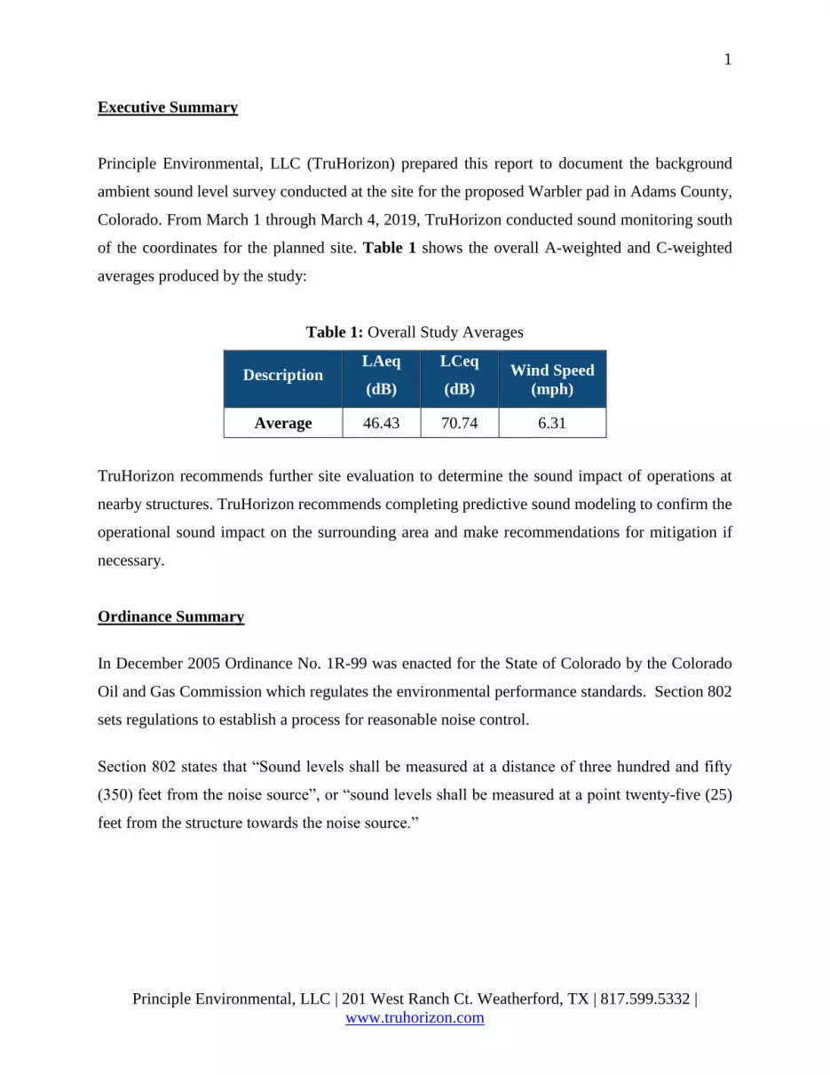
Executive Summary
Principle Environmental, LLC (TruHorizon) prepared this report to document the background
ambient sound level survey conducted at the site for the proposed Warbler pad in Adams County,
Colorado. From March 1 through March 4, 2019, TruHorizon conducted sound monitoring south
of the coordinates for the planned site. Table 1 shows the overall A-weighted and C-weighted
averages produced by the study:
Table 1: Overall Study Averages
Description LAeq
(dB)
LCeq
(dB)
Wind Speed
(mph)
Average 46.43 70.74 6.31
TruHorizon recommends further site evaluation to determine the sound impact of operations at
nearby structures. TruHorizon recommends completing predictive sound modeling to confirm the
operational sound impact on the surrounding area and make recommendations for mitigation if
necessary.
Ordinance Summary
In December 2005 Ordinance No. 1R-99 was enacted for the State of Colorado by the Colorado
Oil and Gas Commission which regulates the environmental performance standards. Section 802
sets regulations to establish a process for reasonable noise control.
Section 802 states that “Sound levels shall be measured at a distance of three hundred and fifty
(350) feet from the noise source”, or “sound levels shall be measured at a point twenty-five (25)
feet from the structure towards the noise source.”

2
Principle Environmental, LLC | 201 West Ranch Ct. Weatherford, TX | 817.599.5332 |
www.truhorizon.com
In situations where measurement of noise levels at three hundred and fifty (350) feet is impractical
or unrepresentative due to topography, the measurement may be taken at a lesser distance and
extrapolated to a 350-foot equivalent using the following formula:
Noise levels not to exceed designated limits in Table 2 during the stated time frames:
Table 2: COGCC Zones and Designated Limits for Oil and Gas Operations
ZONE 7:00 a.m. – 7:00 p.m. 7:00 p.m. – 7:00 a.m.
Residential 55 dB(A) 50 dB(A)
Commercial 60 dB(A) 55 dB(A)
Light industrial 70 dB(A) 65 dB(A)
Industrial 80 dB(A) 75 dB(A)
• Sound level measurements shall be taken four (4) feet above ground level.
• Sound levels shall be determined by averaging minute-by-minute measurements made
over a minimum fifteen (15) minute sample duration.
• Sound levels that are C-weighted for low frequency shall not exceed 65 dB(C) when
measured twenty-five (25) feet from the exterior wall of the residence or occupied
structure nearest to the noise source, in the event of a complaint.
Site Information
The Warbler pad is to be located east of Picadilly Rd and south of 152nd Ave. From Friday, March
01, 2019 through Monday, March 04, 2019, TruHorizon conducted approximately 72 hours of
monitoring at the location. The approximate coordinates for the monitoring point are
39°57'31.21"N, 104°43'11.79"W. The approximate coordinates for the site are 39°57'40.80"N,
104°43'12.36"W. The monitoring point is approximately 900 feet south or the provided pad
coordinates. The closest roads are small local dirt roads. The next closest road is Picadilly Rd
which is approximately 3,700 feet west of the monitor. There were railroad tracks about 1.6 miles
northwest of the monitor. Also, Denver International Airport was about 4.5 miles southeast of the

3
Principle Environmental, LLC | 201 West Ranch Ct. Weatherford, TX | 817.599.5332 |
www.truhorizon.com
monitor. Air traffic and train horns could be heard at the monitoring point while on location.
Figure 1 below shows the monitoring location marked by a green pin; photographs of the location
are provided in Attachment 1.
Figure 1: Aerial View of Warbler Location
With respect to the monitoring point, the closest residential structure was approximately 2,600 feet
west of the monitor. The monitor was placed in an open area with no significant changes in
elevation and no major obstructions. There was a creek that ran along the southeast side of the
monitor. While on location, there was noticeable noise from air traffic and birds. The closest town
(Lochbuie) was approximately 3.4 miles to the north. Wind data was measured for the area at the
KCOBRIGH76 weather station located about 2.1 miles northeast of the monitor. The coordinates
for the weather station are approximately 39°59'6.00"N, 104°41'56.40"W.

4
Principle Environmental, LLC | 201 West Ranch Ct. Weatherford, TX | 817.599.5332 |
www.truhorizon.com
Sound Level Meter Specifications
A Brüel & Kjær Type 2250, 4th generation, hand-held analyzer (S/N: 3010878) with transducer
(S/N: 3080399) measured sound levels at the monitoring location. Attachment 2 lists the
manufacturer’s specification for this meter. The software modules in the Type 2250 allows for
real-time frequency analysis, analysis of time histories for broadband parameters and spectra, and
documentation of measurements through recording of measured sound. The 2250 sound level
meter continuously sampled sound levels logging the specified data every minute; therefore, each
one hour period provided 60 readings.
Prior to beginning the monitoring, TruHorizon calibrated the 2250 meter using a Brüel & Kjær
Type 4231 Acoustical Calibrator (S/N: 3006473). The calibrator emits a reference sound pressure
level of 94 dB. The calibrator attaches to the transducer to verify the meter accurately measures
the reference sound level. Full manufacturer calibration documentation is available upon request.
After monitoring, the data collected by the 2250 sound level meter was downloaded to a computer
using Brüel & Kjær BZ-5503 Utility Software for Hand-held Analyzers Version 3.11.0.389.
TruHorizon used the manufacturer’s software, coupled with Excel spreadsheets, to summarize the
data.
Acoustics Overview
Sound pressure level measurements are commonly weighted in relation to their frequency
components in order to provide a consistent basis for comparison to other measurements of the
same type. Figure 2 depicts three common weighting curves plotted together for reference.

5
Principle Environmental, LLC | 201 West Ranch Ct. Weatherford, TX | 817.599.5332 |
www.truhorizon.com
Figure 2: Common Sound Weighting Curves
The study utilized A-weighted and C-weighted filters. An A-weighted filter corresponds to the
human ear’s response at low to medium sound levels. Time weighting defines how the exponential
averaging in root-mean-square measurement is done. The A-weighted filter with fast time
weighting is common for environmental noise measurement. The C-weighted filter is used for very
high sound level measurements and does not filter out low or high frequency sounds. It
approximates the human ear at very high sound levels and is typically used for measuring traffic,
machinery and other loud sound sources. B-weighting is no longer commonly used and was
developed to filter the mid-range frequencies between A and C weighting.
The sound level meter recorded the following weighted averages:
• LAeq – The equivalent continuous sound level over a specified period of time that
represents the same energy as the actual time varying sound signal; The ‘A’ in the above
variables denotes that the A-weighting has been included.
• LCeq – The equivalent continuous sound level over a specified period of time with C
weighting applied.
Decibels (dB) are a measure of sound energy based on a logarithmic scale. A sound level of 60
dB contains 10 times more sound energy relative to a sound level of 50 dB, and a sound level of
70 dB contains 100 times more sound energy relative to a sound level of 50 dB.
For comparison, Table 3 presents a summary of typical decibel levels for multiple types of sounds.

6
Principle Environmental, LLC | 201 West Ranch Ct. Weatherford, TX | 817.599.5332 |
www.truhorizon.com
Table 3: Typical Sound Levels (dBA)
Description of Sound Sound Level
(dBA)
Human Perception
of Loudness*
Threshold of Hearing 0
Rustling Leaves 20 Just Audible
Quiet Whisper (3 feet away) 30 Very Quiet
Quiet Home 40 Quiet
(1/8 as loud)
Quiet Street 50 (1/4 as loud)
Normal Conversation 60 (1/2 as loud)
Inside Car 70 Moderately Loud
(Reference Loudness)
Automobile (25 feet away) 80
Train Whistle (500 feet away) 90
Level at which sustained exposure may result
in hearing loss 90 – 95
Diesel Truck (30 feet away) 95
Pile Driver (50 ft.) 100 Very Loud
(8 times as loud)
Power Mower (3 feet away) 107
Amplified Rock and Roll (6 feet away) 110 (16 times as loud)
Jet Airplane (100 feet away) 120 Threshold of pain
(32 times as loud)
Civil defense siren (100 ft.) 130
Firearm shots near ear 140 Painfully Loud
Even short term exposure can cause permanent
damage – Loudest recommended exposure
WITH hearing protection
140
*Relative to a Reference Loudness of 70 Decibels – Various Sources: Barnek, 1998, Barnes et al., USEPA, 1971
Ambient Monitoring Data and Results
TruHorizon conducted the background ambient sound level survey from approximately 12:00 a.m.
on Friday, March 01, 2019 to 12:00 a.m. on Monday, March 04, 2019. Table 4 summarizes the
logarithmic averages of the study.

7
Principle Environmental, LLC | 201 West Ranch Ct. Weatherford, TX | 817.599.5332 |
www.truhorizon.com
Table 4: Daily and Overall Study Sound Level Averages (dBA, dBC)
Description LAeq
(dB)
LCeq
(dB)
Wind
Speed
(mph)
Friday, March 1, 2019 48.74 73.52 7.35
Saturday, March 2, 2019 45.57 70.88 9.13
Sunday, March 3, 2019 43.22 59.28 2.46
Average 46.43 70.74 6.31
Attachment 3 contains the hourly average summary table and charts obtained from the
background ambient evaluation.
Common sounds for the Warbler site primarily included noise from aircraft, trains, ducks and
birds. The sounds are characteristic of a residential area. The overall study averages are comparable
to sound levels on a quiet street. The overages that did occur were due to the noise from train
horns, air traffic and wind. The A-Weighted data charts, attached, illustrate the overages and their
causes.
The maximum study LAeq at the monitoring location was 63.7 dBA which occurred on Friday,
March 01, 2019 at approximately 10:05 a.m. The sound level meter recorded all LAeq signals
greater than or equal to 55 dB. From the recordings, the source of the maximum LAeq value was
an aircraft flying near the monitor. All sound clips are identified to the best of TruHorizon
personnel’s ability.
The services provided for this project were performed with the care and skill ordinarily exercised
by reputable members of the profession practicing under similar conditions. No warranty,
expressed or implied, is made or intended by rendition of these consulting services or by furnishing
oral or written reports of the findings made. This report has been prepared by Principle
Environmental, LLC for the exclusive use by Extraction Oil & Gas, Inc.

Principle Environmental, LLC | 201 West Ranch Ct. Weatherford, TX | 817.599.5332 |
www.truhorizon.com
____________________________________________________________
ATTACHMENT 1
PHOTO LOG
____________________________________________________________

Photo 1: View of Monitoring Location looking north Photo 2: View of Monitoring Location looking east
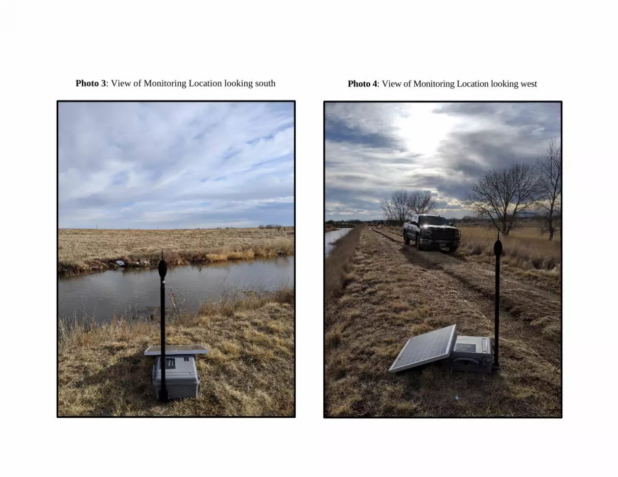
Photo 3: View of Monitoring Location looking south Photo 4: View of Monitoring Location looking west

_____________________________________________________________
ATTACHMENT 2
MANUFACTURER’S SPECIFICATIONS
_____________________________________________________________


_____________________________________________________________
ATTACHMENT 3
MONITORING LOCATION
STUDY SUMMARY DATA AND CHARTS
_____________________________________________________________

Ambient Sound Level Survey and Report
Warbler Pad
Timestamp LAeq
(dBA)
LCeq
(dBC) Timestamp
LAeq
(dBA)
LCeq
(dBC)
3/1/19 12:00 AM 42.71 58.51 3/2/19 12:00 PM 40.85 67.70
3/1/19 1:00 AM 43.45 59.48 3/2/19 1:00 PM 46.54 75.55
3/1/19 2:00 AM 46.43 61.42 3/2/19 2:00 PM 43.84 73.51
3/1/19 3:00 AM 48.79 64.26 3/2/19 3:00 PM 42.19 72.78
3/1/19 4:00 AM 47.15 63.25 3/2/19 4:00 PM 46.86 70.61
3/1/19 5:00 AM 47.09 62.54 3/2/19 5:00 PM 43.91 70.93
3/1/19 6:00 AM 47.99 61.09 3/2/19 6:00 PM 45.66 71.66
3/1/19 7:00 AM 51.38 64.24 3/2/19 7:00 PM 43.75 68.35
3/1/19 8:00 AM 51.97 66.86 3/2/19 8:00 PM 49.82 70.08
3/1/19 9:00 AM 51.99 64.73 3/2/19 9:00 PM 43.95 68.02
3/1/19 10:00 AM 49.66 65.34 3/2/19 10:00 PM 45.34 66.54
3/1/19 11:00 AM 50.16 76.96 3/2/19 11:00 PM 43.45 63.38
3/1/19 12:00 PM 51.55 79.57 3/3/19 12:00 AM 40.20 61.89
3/1/19 1:00 PM 50.78 78.41 3/3/19 1:00 AM 42.93 61.61
3/1/19 2:00 PM 49.40 75.76 3/3/19 2:00 AM 35.63 59.84
3/1/19 3:00 PM 46.22 70.17 3/3/19 3:00 AM 33.24 61.28
3/1/19 4:00 PM 46.20 72.04 3/3/19 4:00 AM 39.51 57.87
3/1/19 5:00 PM 44.95 65.47 3/3/19 5:00 AM 35.01 55.25
3/1/19 6:00 PM 43.79 62.08 3/3/19 6:00 AM 39.97 55.53
3/1/19 7:00 PM 44.51 64.78 3/3/19 7:00 AM 40.60 55.70
3/1/19 8:00 PM 45.13 67.07 3/3/19 8:00 AM 40.05 57.78
3/1/19 9:00 PM 49.03 77.71 3/3/19 9:00 AM 47.28 60.51
3/1/19 10:00 PM 50.82 80.08 3/3/19 10:00 AM 46.64 60.33
3/1/19 11:00 PM 48.44 78.27 3/3/19 11:00 AM 43.62 59.51
3/2/19 12:00 AM 47.42 77.72 3/3/19 12:00 PM 43.85 58.82
3/2/19 1:00 AM 36.57 60.78 3/3/19 1:00 PM 41.84 56.99
3/2/19 2:00 AM 34.96 53.75 3/3/19 2:00 PM 45.42 59.78
3/2/19 3:00 AM 40.99 65.54 3/3/19 3:00 PM 38.22 57.64
3/2/19 4:00 AM 42.24 67.58 3/3/19 4:00 PM 39.64 58.13
3/2/19 5:00 AM 43.96 62.56 3/3/19 5:00 PM 42.81 58.18
3/2/19 6:00 AM 46.21 61.61 3/3/19 6:00 PM 38.67 57.24
3/2/19 7:00 AM 44.96 69.69 3/3/19 7:00 PM 49.73 62.71
3/2/19 8:00 AM 51.29 73.83 3/3/19 8:00 PM 43.42 58.85
3/2/19 9:00 AM 46.31 72.93 3/3/19 9:00 PM 44.85 59.73
3/2/19 10:00 AM 47.17 70.17 3/3/19 10:00 PM 44.91 59.40
3/2/19 11:00 AM 45.60 67.18 3/3/19 11:00 PM 38.98 57.57

7
Principle Environmental, LLC | 201 West Ranch Ct. Weatherford, TX | 817.599.5332 | www.truhorizon.com
Model 2: Patterson 284 Traditional Drilling Operations (A-Weighted Levels)

Chart 1: A-Weighted sound levels with minute resolution
20
30
40
50
60
70
80
90
100
Sou
nd
Le
vel (
dB
)
Time
A-Weighted Minute Data Extraction Warbler
03/01/19 12:00 AM Through 03/02/19 12:00 AM
LAeq
Recording Level
Air TrafficTrain Horns
Birds & Air Traffic
Wind

Chart 2: A-Weighted sound levels with minute resolution
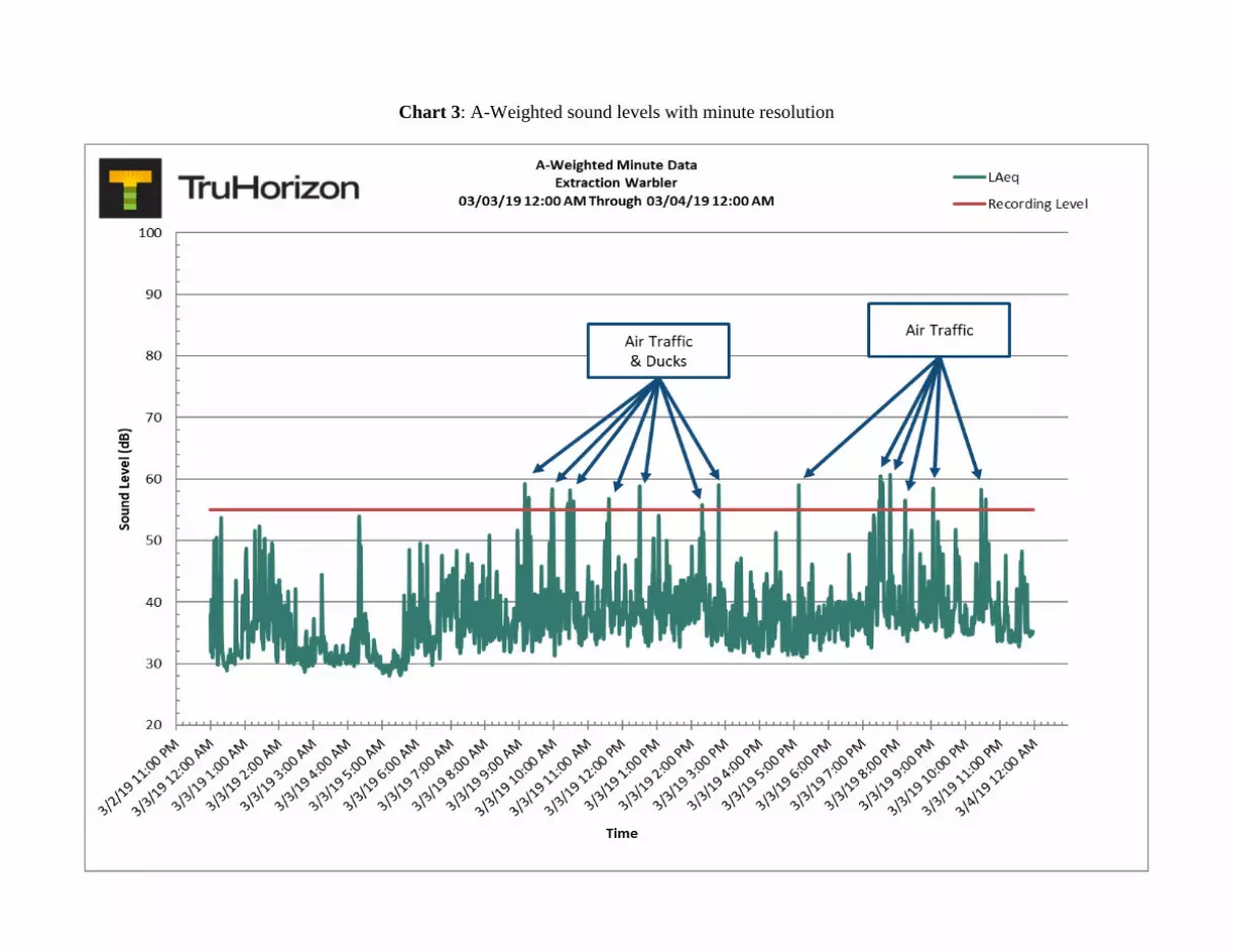
Chart 3: A-Weighted sound levels with minute resolution

Chart 4: C-Weighted sound levels with minute resolution
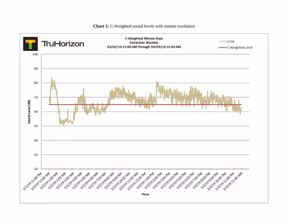
Chart 5: C-Weighted sound levels with minute resolution

Chart 6: C-Weighted sound levels with minute resolution

Chart 7: A & C-Weighted sound levels with hour resolution

NATRUAL RESOURCES CONVERVATION OVERLAY REVIEW
WARBLER OIL AND GAS LOCATION
ADAMS COUNTY, COLORADO
Prepared for:
370 17th Street #5300 Denver, CO 80202
Prepared by:
55 E. 4th Avenue Denver, CO 80203

55 E. 4th Avenue. Denver, CO 80203 www.quandaryconsultants.com
1
Background Quandary Consultants, LLC (Quandary) conducted a site-specific Natural Resources Conservation Overlay (NRCO) review for Extraction Oil and Gas (Extraction) to meet NRCO requirements for the Adams County Community and Economic Development Department. This review was prepared for the Warbler Oil and Gas (Location) in accordance with Adams County Zoning Code Sections 3-38 and 4-11-02-03. The Location includes the proposed Oil and Gas Operation Area (OGOA), Facilities, and Oil and Gas Wells. The proposed access road was also included in the Location survey. The proposed OGOA during drilling and hydraulic fracturing activities is 15.6 acres. As best practice following drilling and hydraulic fracturing, the OGOA will be reclaimed within six months to the minimum area needed to produce and maintain oil and gas wells. The Location is in Adams County (Approximately 1.3-miles east of the intersection of Picadilly Road and E 144th Avenue.) in the southeast quarter of Section 13, Township 1 south, Range 66 west of the 6th Principal Meridian. The proposed access road approaches the Location from the southwest, from Picadilly Road. A site-specific review was conducted for the Location since it is within in the general NRCO District Map. To confirm findings, Quandary also conducted an onsite field survey on November 1, 2018 for the proposed Location. This NRCO includes a review of natural resources, including; waterbodies, 100-year floodplains, wetlands, hydric soils, and wildlife habitat areas. In addition, this review discusses potential cultural and agriculture resources. Purpose The purpose of this NRCO is to identify natural, scenic, cultural, and agricultural resources associated with oil and gas development at the Location to meet Adams County Development Standards and Regulations Parts 3-38 and 4-11-02-03. This NRCO was completed as an analysis, utilizing the best available data from various County, State, and Federal resources. To confirm data, an onsite field survey was conducted November 1, 2018.

55 E 4th Ave
Denver, CO 80203 www.quandaryconsultants.com
2
Resource Review Three maps were created to complete this review, and can be found in Attachment I. These include a Site Location Map (Figure 1), Water Resource Findings Map (Figure 2) and, Wildlife and Vegetation Findings Map (Figure 3). Site photos were taken during the onsite field survey and can be found in Attachment II. Quandary reviewed Colorado Oil and Gas Conservation Commission (COGCC), Colorado Division of Water Resources (CDWR), United States Army Corp of Engineers (USACE), National Wetland Inventory (NWI), Federal Emergency Management Agency (FEMA), United States Fish and Wildlife Service (USFWS) and Colorado Parks and Wildlife (CPW) data.
100-Year Floodplains: The proposed Location will not be constructed within a mapped 100-year floodplain (Figure 2).
Riparian Areas: The proposed Location will not be constructed within a riparian area. Riparian areas are associated with irrigation canals to the southeast and northwest of the proposed Location, but the proposed Location would be constructed outside of these areas (Figure 2). Wetlands: The Location will not be constructed within an NWI mapped wetland. Field surveys verified the location consists of previously planted dryland agriculture fields. No wetland characteristics such as vegetation, hydrology, or hydric soils were observed during field surveys. No surface water resources were observed at the proposed Location during field surveys. Buffalograss (Bouteloua dactyloides), which is considered an upland species by the United States Department of Agriculture, Natural Resource Conservation Service, was the dominant vegetation species at the Location. Scattered Lambsquarters (Chenopodium album L), Field bindweed (Convolvulus arvensis), and Common sunflower (Helianthus

55 E 4th AveDenver, CO 80203
www.quandaryconsultants.com
3
anuus L.) were identified during the onsite field surveys of the Location. Field Bindweed is considered a CO noxious weed List C.
Lakes/Reservoirs:
The proposed Location would not directly impact any lakes, reservoirs, or other surface waters. The Location lies between an irrigation canal on the southeast and an irrigation canal on the northwest. At the time of the field survey these canals were dry, indicating water flow is seasonal. An access road currently exists adjacent to an irrigation canal east of the proposed Location. This existing gravel road will be utilized to access the proposed Location. Irrigation canals will not be disturbed during the construction of the proposed Location. Due to the proximity of seasonal water flows adjacent to the access road and proposed Location, Extraction will implement sediment controls to reduce the potential for sediment/pollutant discharge.
Hydric Soils:
Natural Resource Conservation Service (NRCS) data indicates the soil type for the Location and surrounding areas are dominated by Vona sandy loam, 3 to 5 percent slopes and Ascalon sandy loam, 1 to 3 percent slopes, which are not indicative of hydric soils. Soils at the Location are considered well drained and a runoff class that ranges from low to very low. FEMA’s Flood Map Service indicates the Location is in an area of minimal flood hazard.
Wildlife Habitat:
USFWS and CPW mapped layers indicate the Location is within Black- tailed prairie dog (Cynomys ludovicianus, BTPD) and Preble’s meadow jumping mouse overall range (Zapus hudsonius preblei, PMJM).
No prairie dogs or prairie dog burrows were identified during the onsite field survey conducted in November 2018.

55 E 4th Ave
Denver, CO 80203 www.quandaryconsultants.com
4
The PMJM is listed as threatened by the U.S. Fish and Wildlife Service (USFWS 1998). In Colorado, they are listed as a threatened, Tier 1, Species of Greatest Conservation Need (CPW 2015). During summer months, the most important wetland types occupied by PMJM include riparian areas and adjacent wet meadows. During the summer, they prefer dense shrub, grass and forb ground cover along creeks, rivers, and associated waterbodies. From early fall through the spring, they hibernate underground in burrows that are typically at the base of vegetation and have a northerly aspect.
The Location has been disturbed/modified for agricultural purposes and cropland with an existing gravel road that has been established. Additional disturbance is planned to the west of the irrigation canal. No riparian vegetation or wetlands are located within the planned disturbance area. Based on lack of vegetation, quality of vegetation and an existing gravel road separating the planned disturbed area from a water source, Quandary does not believe PMJM habitat is present at the Location.
One unknown raptor species (non-eagle) nest was observed in a mature cottonwood tree, approximately 2,000 feet southwest of the Location (Figure 3). The non-eagle nest determination is based on field survey observations, such as nest size and appearance. At the time of the onsite field survey, the nest was observed to be inactive and no raptor species were observed in areas surrounding the Location. Raptors are protected species where tolerance limits to disturbance can vary. As a result, CPW has established recommended buffer zones and seasonal restrictions to prevent disturbance of Colorado Raptors. Although the nest is inactive, it falls within the buffer zone of the most predominant Colorado Raptor species. Since seasonal conditions could change, raptor surveys will be conducted prior to construction at the Location to determine if the nest is still inactive during egg laying and incubation periods for Raptors or whether development activities are within a half-mile radius of the nest. If an active raptor nest is observed within the recommended buffer zone outlined in CPWs guidance for a particular species, stress monitoring or CPW consultation may be necessary prior to construction.

55 E 4th Ave
Denver, CO 80203 www.quandaryconsultants.com
5
Cultural: An onsite field survey and Class I cultural resource file search were conducted to assess cultural resources at the Location. Based on a file search on the Office of Archeology and Historic Preservation’s online COMPASS Database, the Location lies between the Denver Hudson Canal on the southeast and the Neres Canal on the northwest. Both of these resources have been officially determined eligible for inclusion in the National Register of Historic Places. Irrigation canals will not be disturbed during the construction of the proposed Location. The location consists of previously planted dryland agriculture fields dominated by smooth brome. The area has been cultivated Attachment II includes photographs showing the existing dryland agriculture nature of the Location. The proposed project would be constructed entirely on previously disturbed and planted dryland agriculture fields. Agricultural: The proposed project is located within agriculture lands identified by Adams County Zoning as A-1 Agriculture. As discussed above, the location is dominated by existing dryland agriculture pasture consisting of short and tall perennial grasses.
Extraction’s proposed OGOA is compatible with Adams County’s goal under its comprehensive development to preserve and maintain agricultural lands to the greatest extent possible. The development plan for the Location to drill multiple wells from one centralized OGOA, reduces Extraction’s footprint and leaves more land available for agriculture, wildlife and habitat. Restoring the surface to a minimum area is compatible with current and future land use and helps preserve historic agricultural lands in the rapidly urbanizing county.
55 E 4th Ave
Denver, CO 80203 www.quandaryconsultants.com
6
Conclusions
Although the Location is within a NRCO District, no significant risks to natural, scenic, cultural, and agricultural resources are associated with oil and gas development at the Location. The OGOA has been designed in a way that reduces impacts to 100-year floodplains, riparian areas, wetlands and surface water resources. Drilling multiple wells from one centralized Location reduces Extraction’s footprint on lands within the NRCO District. Based on field surveys, the Location may overlap with protected species habit. In accordance with CPW recommendations and guidance, additional wildlife surveys will be conducted to determine whether protected species are present prior to construction of the Location. If species are identified, appropriate mitigation measures will be implemented and or consultation with CPW will occur. Attachment I
Figure 1. Site Location Map Figure 2. Water Resource Findings Map Figure 3. Wildlife and Vegetation Findings Map Attachment II
Site Photographs

Attachment I
Maps


Attachment II
Site Photographs

Photo 1. Unknown raptor species nest located 2,000 ft.southwest of the Location.
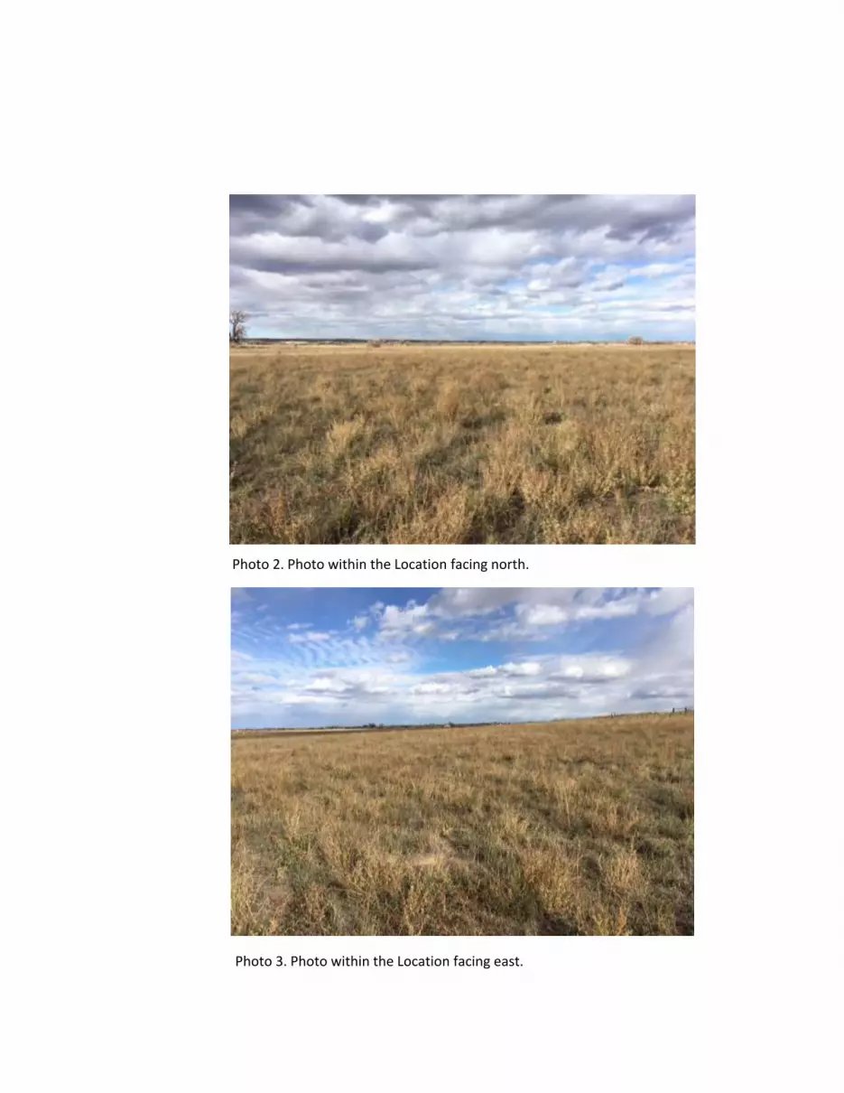
Photo 2. Photo within the Location facing north.
Photo 3. Photo within the Location facing east.

Photo 4. Photo within the Location facing South.
Photo 5. Photo within the Location facing West.

Photo 6. Irrigation canal southeast of the Location.

Warbler Pad Facility
Adams County - Independent Traffic Impact Fee Study
Bill Zahniser, P.E.
March 12, 2019


Objectives
• Prepare an independent fee calculation for Extraction’s Warbler Pad using project specific inputs and geotechnical engineering assumptions
• Develop and apply impact methodologies consistent with the broader county-wide study
• Determine if preliminary independent study findings, and resulting fee adjustments, will satisfy the County
2
Introduction
Methodology
● Defining the Study Parameters Location of Access Haul Route Specifics Extraction’s Traffic Assumptions
● Adapt FHU’s applicable impact methodologies
● Compare findings and fee determinations for two potential pipeline scenarios

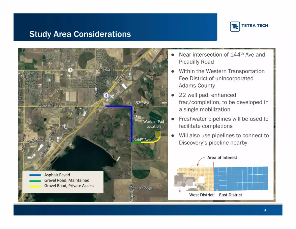
Study Considerations
4
Study Area Considerations
● Near intersection of 144th Ave and Picadilly Road
● Within the Western Transportation Fee District of unincorporated Adams County
● 22 well pad, enhanced frac/completion, to be developed in a single mobilization
● Freshwater pipelines will be used to facilitate completions
● Will also use pipelines to connect to Discovery’s pipeline nearby
144th Ave
152nd Ave
Asphalt PavedGravel Road, MaintainedGravel Road, Private Access
Warbler Pad Location
Area of Interest
East DistrictWest District

5
Regional Study Considerations
● Adopted fee structure for the West District would apply
● Warbler is being permitted as a 22 well pad development
● XOG is considering 2 of the pipeline scenarios Permit will assume both
freshwater and product pipelines will be used Standard Fee would be
$412,989
● Contingent on tie in to Discovery Pipeline Without product pipeline,
fee would be $771,501
Pipeline Scenario
Adopted Fee Structure (West District)
Fres
h W
ater
Pi
pelin
e
Prod
uced
Wat
er
Pipe
line
Prod
uct P
ipel
ine
Pad
Fee
Wel
l Fee
22 W
ell
Faci
lity
$753 $36,523 $804,259
X $753 $35,034 $771,501
X $753 $21,112 $465,217
X X $753 $20,227 $445,747
X $753 $19,623 $432,459
X X $753 $18,738 $412,989
X X $753 $4,816 $106,705
X X X $753 $3,327 $73,947

• Determine which FHU Methodologies are Applicable
Review of Location
Identify Methods to be used for Each Road Segment
• Determine Model Inputs
Haul Route Access Specifics
Trip Generation and Loading Estimates
• Determination of Traffic Based Impacts
HMA Overlay Requirements
Evaluate impact of different Resilient Modulus assumption
• Determination of Event Based Impacts
Shoulder Improvements
Development of Trip-Based Proportionality Factor
Summary of Study Approach

Shoulder Sufficiency (FHU, Fig 8)
Existing Pavement Conditions (FHU, Fig 7)County Maintained Roads (FHU, Fig 5)
Location Specific Considerations
Surface Types (FHU, Fig 6)

Regional Study Methodologies
How is the Impact Estimated? Warbler Access Route
Pave
d R
oad
Imp
acts HMA Pavement
Methodology
• Use traffic ESALs and design considerations for road classification to determine structural capacity necessary to support anticipated oilfield traffic (i.e., SN Deficiency).
• Determine required HMA overlay dimensions needed to satisfy the SN deficiency.
• Use FHU unit pricing, $85/ton, to calculate mitigation costs.
Applicable to 156th Ave and PicadillyRoad
Poor Condition Asphalt Methodology
• Assume reconstruction of road segments currently rated as "poor" pavement condition.
• Use FHU unit pricing, $30,000/mile, to calculate mitigation costs.Not Applicable
Concrete Pavement Methodology
• Use proportional ESALs to determine reduction in service life (i.e., % of use), multiply that percentage by the cost to reconstruct ($580,000/lane/mile, 12-inch depth).
Not Applicable
Safety Mitigation Methodology
• Improve/widen shoulders, as necessary to provide bike lanes on road segments with designated bike routes.
• Use FHU unit pricing ($23,000/mile, per foot of width added, plus $3,000/mile, per foot of pavement removed to construct) to estimate mitigation cost.
Applicable to the segment of the route using 156th Ave
Unpaved Road Impact Methodology
• Pave roads if VPD threshold is exceeded, account for added maintenance and rehabilitation costs.
• Use FHU unit pricing ($23,000/mile, per foot of width paved; increased gravel maintenance costs) to estimate mitigation cost.
Assume Not Applicable
While 144th Ave is Gravel road maintained by the County, it is not a throughway at this time, and as such the VPD threshold is very unlikely to
be met
Determine which Regional Study Elements are applicable to each road segment
1
2

9
Haul Route Specifics
● 152nd Ave Rural Arterial 0.73 miles, 24ft wide Asphalt Paved, 2 lane road PCI Rating = Good Designated bike route, but current
shoulder width is insufficient
● Picadilly Road Rural Arterial 1.0 miles, 24ft wide Asphalt Paved, 2 lane road PCI Rating = Good Not a bike route
● 144th Ave Section Line Arterial 0.25 miles, 24ft wide Gravel maintained, 2 lane road
144th Ave
152nd AveP
icad
illy
Ro
ad
Asphalt PavedGravel Road, MaintainedGravel Road, Private AccessInsufficient Shoulder

Development Stage Activity
Trip Generation Flexible Pavement Loading Summary
Total Trips Duration Average/Day ESAL Factors Combined ESALsHeavy Light Days Heavy Light Heavy Light Heavy Light Total
Pad Construction Pad and Road Construction 220 200 20 11.0 10.0 1.087 0.003 239 0.6 240Facility Construction Facility Construction 170 600 60 2.8 10.0 1.087 0.003 185 1.8 187
Drilling
Surface Rig 484
9,396 261
1.9
36.0
1.087
0.003
526
28.2
2,385
Drilling Rig 100 0.4 1.087 109Drilling Fluid & MaterialsDrilling Equipment (casing, drill pipe, etc)
1,584 6.1 1.0871,722
Completion Operations
Completion Equipment(pump truck, tanks, etc) 86
1,760 198
0.4
8.9
1.087
0.00393
5.3
9,825
Completion Fluids & Materials 550 2.8 1.087 598Sand 7,848 39.6 1.087 8,531Gel & Fuel Loads 550 2.8 1.087 598Flowback water disposal 2,640
1,760 8431.3
20.91.087
0.003 2,870 5.33,529Mill Out/Tubing Equipment 602 7.1 1.087 654
Flowback Flowback (on production) 33 205 26 1.3 8.0 1.087 0.003 36 0.6 36Development Phase Totals 14,867 13,921 649 22.9 21.5 16,161 42 16,202
Per Well Totals 676 633 30 735 2 736
Trip Generation Flexible Pavement Loading Summary
Total Trips Duration Average/Day ESAL Factors Combined ESALs10 Year Production Phase Totals Heavy Light Days Heavy Light Heavy Light Heavy Light Total
Without Product Pipeline 16,060 3,650 3,650 4.4 1 1.087 0.003 17,457 11 17,468
With Product Pipeline 11,484 3,650 3,650 3.1 1 12,483 11 12,494
Combined Development and Production Phase Totals
Freshwater Pipelines, without Product Pipeline: 33,670
Freshwater Pipelines, with Product Pipeline: 28,696
Traffic Considerations – Warbler Pad(Using Extraction’s Trip and CDOT LEF Assumptions)
10
• 28,696 ESALs will be used for study/calculation
• Notably this is approx. 5,600 ESAL less than what FHU’s trip numbers would be (34,285 ESAL)
• Scenario without Product Pipeline is provided for comparison purposes
Extra
ctio
n’s
Trip
Ass
umpt
ions
FHU’s Production Phase Trip Assumptions

Determination of Overlay Thickness
11
Determination of Overlay Thickness
Where:
����� ��� = �� ∗ �� + 9.36 ∗ ����� �� + 1 − 0.2 +�����
∆���4.2 − 1.5
0.40 +1094
�� + 1 �.��
+ 2.32 ∗ ����� �� − 8.07
Eqn 1. AASHTO Design Equation
W18 = Predicted Number of 80kN ESALs
Zr = The Standard Normal Deviate
S0 = Standard Deviation
SN = Structural Number
ΔPSI = Serviceable Life
Mr = Subgrade Resilient Modulus
Adams County Road Classification
Design ESAL ReliabilityStandard Normal
Deviate (Zr)Resilient Modulus
(Mr), psiInitial
ServiceabilityTerminal
Serviceability
Standard Deviation, Asphalt, S0
Standard Deviation,
Concrete, S0
Principal Arterial 1,825,000 0.95 -1.645 3,500 4.5 2.5 0.44 0.35
Minor Arterial 1,460,000 0.9 -1.282 3,500 4.5 2.5 0.44 0.35
Rural Arterial 1,460,000 0.9 -1.282 3,500 4.5 2.5 0.44 0.35
Collector 730,000 0.85 -1.037 3,500 4.5 2.5 0.44 0.35
Section Line Arterial 730,000 0.85 -1.037 3,500 4.5 2.5 0.44 0.35
Local 73,000 0.8 -0.841 3,500 4.5 2 0.44 0.35
Eqn2. Required Overlay Thickness =SNDeficiency
S0
Assumed ESALs 33,670 28,696
Assumed MR 3,500 20,000 3,500 20,000
Calculated SNDeficiency 2.604 1.303 2.538 1.141
Required Overlay Thickness (in) 5.92 2.96 5.77 2.59
Overlay thickness will vary depending on applied ESALs, and MR assumption used
Scenario 1(FW Pipelines Only)
Scenario 2(FW+Product Pipelines)
12
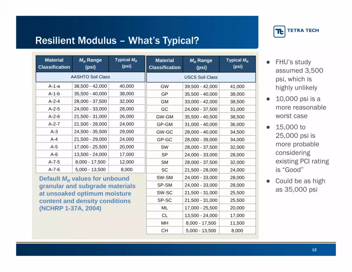
Resilient Modulus – What’s Typical?
Material
Classification
MR Range
(psi)
Typical MR
(psi)
AASHTO Soil Class
A-1-a 38,500 - 42,000 40,000A-1-b 35,500 - 40,000 38,000A-2-4 28,000 - 37,500 32,000A-2-5 24,000 - 33,000 28,000A-2-6 21,500 - 31,000 26,000A-2-7 21,500 - 28,000 24,000A-3 24,500 - 35,500 29,000A-4 21,500 - 29,000 24,000A-5 17,000 - 25,500 20,000A-6 13,500 - 24,000 17,000
A-7-5 8,000 - 17,500 12,000A-7-6 5,000 - 13,500 8,000
Default MR values for unbound granular and subgrade materials at unsoaked optimum moisture content and density conditions (NCHRP 1-37A, 2004)
Material
Classification
MR Range
(psi)
Typical MR
(psi)
USCS Soil Class
GW 39,500 - 42,000 41,000GP 35,500 - 40,000 38,000GM 33,000 - 42,000 38,500GC 24,000 - 37,500 31,000
GW-GM 35,500 - 40,500 38,500GP-GM 31,000 - 40,000 36,000GW-GC 28,000 - 40,000 34,500GP-GC 28,000 - 39,000 34,000
SW 28,000 - 37,500 32,000SP 24,000 - 33,000 28,000SM 28,000 - 37,500 32,000SC 21,500 - 28,000 24,000
SW-SM 24,000 - 33,000 28,000SP-SM 24,000 - 33,000 28,000SW-SC 21,500 - 31,000 25,500SP-SC 21,500 - 31,000 25,500
ML 17,000 - 25,500 20,000CL 13,500 - 24,000 17,000MH 8,000 - 17,500 11,500CH 5,000 - 13,500 8,000
● FHU’s study assumed 3,500 psi, which is highly unlikely
● 10,000 psi is a more reasonable worst case
● 15,000 to 25,000 psi is more probable considering existing PCI rating is “Good”
● Could be as high as 35,000 psi

13
Developing a Trip-Based Proportional Factor Multi-Modal Safety Considerations
● Per the County 2012 Transportation Plan, the segment of 152nd Ave between I-76 and Picadilly Road had average daily traffic volume of 5,000 VPD Applying a 3% compounded growth rate to
the 5,000 VPD Estimate the current baseline traffic
volume is approximately 6,150 VPD in 2019
● Over the next 10 years… 10 years is the timeline basis used in
FHU’s study Ongoing growth rate of 3% to the 6,150
VPD 72,610 total non O&G vehicle trips on this
segment of 152nd Ave between 2019 and 2029
Trip Factor =Production Phase Trips
Combined Trips× 100%
At most, Extraction should only be responsible for a portion of any shoulder improvement costs
20
19
to
20
29 Scenario 1 (No Product Pipeline)
Baseline Traffic Volume, 10yr period: 72,610
XOG Production Phase Trips: 19,710
Combined Traffic: 92,320
Trip Proportionality Factor: 21.3%
20
19
to
20
29 Scenario 2 (With Product Pipeline)
Baseline Traffic Volume, 10yr period: 72,610
XOG Production Phase Trips: 15,134
Combined Traffic: 87,744
Trip Proportionality Factor 17.2%
● Arguably, these factors could be 3-5% lower, considering: Shoulders will last up to 20 years Baseline traffic will continue to grow in years 10-20, whereas XOG’s traffic will
decline Other O&G development may access same portion of 152nd Ave

Two Development Scenarios were evaluated
● Scenario 1 (For Comparison) XOG Trip Estimates for 22 well,
enhanced frac/completion Freshwater Pipelines during
Development No Product Pipeline
● Scenario 2 (Likely) XOG Trip Estimates for 22 well,
enhanced frac/completion Freshwater Pipelines during
Development Product Pipeline during Production
14
Scenario Cost Modeling
Key Assumptions
● Scenario 1 33,670 Total ESALs 19,710 Production Phase Trips Mr = 20,000 psi
● Scenario 2 28,696 Total ESALs 15,134 Production Phase Trips Mr = 20,000 psi

Scenario Fee Calculations
15
Scenario 1 (Freshwater Pipelines Only)
Scenario 2(Freshwater & Product Pipelines)
As
ph
alt
Ove
rla
y C
os
t M
eth
od Dim
ensi
ons Road Segment: 152nd Ave Picadilly Road 152nd Ave Picadilly Road
Length (feet): 3,854 5,280 3,854 5,280Width (feet): 24 24 24 24
Area (sqft) 92,506 126,720 92,506 126,720Road Classification: Rural Arterial Rural Arterial Rural Arterial Rural Arterial
AASH
TO E
qn
Det
erm
inat
ions ESALs (W18): 33,670 33,670 28,696 28,696
Zr: -1.28 0.00 -1.28 0.00S0: 0.44 0.44 0.44 0.44
DPSI: 2.0 2.0 2.0 2.0Mr: 20,000 20,000 20,000 20,000
Required SN: 1.30 1.30 1.14 1.14
Equi
vale
nt O
verla
y In
stal
latio
n R
equi
rem
ents
HMA Thickness (inches): 2.96 2.96 2.59 2.59Overlay Volume (ft3): 22,818 31,258 19,966 27,350
Overlay Density (lb/ft3): 145 146 145 146Overlay Quantity (tons): 1,654 2,282 1448 1997
Unit Price ($/ton): $85 $85 $85 $85Overlay Cost (by segment): $140,616 $193,953 $123,039 $169,709Total Cost (all segments): $334,570 $292,748
Sh
ou
lde
r
Me
tho
d
Baseline Traffic Trips (2019-2029): 72,610
Not Applicable
72,610
Not ApplicableProduction Phase Trips (2019-2029): 19,710 15,134
Total Vehicle Trips (2019-2029): 92,320 87,744Trip Proportionality Factor: 21.3% 17.2%
Shoulder Improvement Costs (6ft added): $119,720 $119,720Extraction's Proportional Shoulder Cost: $25,560 $20,649
Independent Study, Combined Impact Cost: $360,129 $313,397
Cost per Well: $16,370/well $14,245/well

● Independent Study Fee determination for the proposed Warbler development, assuming both Freshwater and Product Pipelines is $313,397
● If no product pipeline is used, the fee would be $360,129
● Both options result in a calculated fee that is lower than the existing fee structure
16
Summary
Questions/Discussion

Tactical Response Plan Version Number: 0.1
Effective Date: 6/26/2018 Page Number: 2
Note: This site specific EAP is intended for use only from the drilling to completion phases. Once turned over to production, please refer to Extraction's Master Emergency Response Plan for reference.
Notice: Any printed copy of this Emergency Action Plan is considered an unofficial version at the time of printing. The official version of this document may be found on the Extraction Oil & Gas internal website. For information on how to obtain an official copy, please contact the appropriate Extraction Oil & Gas official.
Version: 0.3Effective Date: 3/19/2019
a
Emergency Action Plan
Warbler Pad Location: 0.87 mi NE of 144th and Picadilly Rd
Lease Road Entrance: N 39.958061, W 104.721676
Extraction Emergency Hotline: 720-370-5540

Emergency Action Plan Version Number: 0.3
Effective Date: 3/19/2019 Page
Number: 2
1.0 MAPS ....................................................................................................................................................... 3
1.1 TACTICAL OVERVIEW MAP ............................................................................................................ 3
1.2 RECEPTORS MAP ........................................................................................................................... 4
2.0 INCIDENT TACTICS ............................................................................................................................. 5
2.1 SHELTER IN PLACE ......................................................................................................................... 6
2.2 SPILLS ........................................................................................................................................... 7
2.3 FIRES ............................................................................................................................................. 8
2.4 NATURAL DISASTERS ..................................................................................................................... 9
Tornado ..................................................................................................................................................... 9
Winter Storm ............................................................................................................................................ 9
Earthquake .............................................................................................................................................. 10
Flooding................................................................................................................................................... 10
3.0 PLAN OVERVIEW ............................................................................................................................. 11
3.1 Emergency Preparedness Plan ……………………………………………………………………………………………………. 11
3.2 General Information …………………………………………………………………………………………………………………… 11
Plan Approved By
Organization Name Signature Date


Emergency Action Plan Version Number: 0.3
Effective Date: 3/19/2019 Page Number: 5
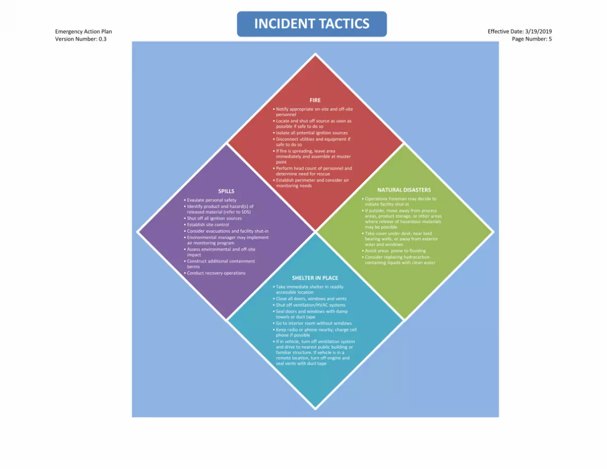
INCIDENT TACTICS
INCIDENT TACTICS
FIRE • Notify appropriate on-site and off-site
personnel • Locate and shut off source as soon as
possible if safe to do so • Isolate all potential ignition sources• Disconnect utilities and equipment if
safe to do so • If fire is spreading, leave area
immediately and assemble at musterpoint
• Perform head count of personnel and determine need for rescue
• Establish perimeter and consider airmonitoring needs
NATURAL DISASTERS • Operations Foreman may decide to
initiate facility shut-in • If outside, move away from process
areas, product storage, or other areas where release of hazardous materials may be possible
• Take cover under desk, near load bearing walls, or away from exterior ways and windows
• Avoid areas prone to flooding • Consider replacing hydrocarbon-
containing liquids with clean water
SPILLS • Evaulate personal safety • Identify product and hazard(s) of
released material (refer to SDS) • Shut off all ignition sources• Establish site control • Consider evacuations and facility shut-in • Environmental manager may implement
air monitoring program • Assess environmental and off-site
impact • Construct additional containment
berms • Conduct recovery operations
SHELTER IN PLACE • Take immediate shelter in readily
accessible location • Close all doors, windows and vents• Shut off ventilation/HVAC systems• Seal doors and windows with damp
towels or duct tape • Go to interior room without windows• Keep radio or phone nearby; charge cell
phone if possible • If in vehicle, turn off ventilation system
and drive to nearest public building or familiar structure. If vehicle is in a remote location, turn off engine and seal vents with duct tape

Emergency Action Plan Version Number: 0.3
Effective Date: 3/19/2019 Page Number: 6
2.1 SHELTER IN PLACE When hazardous materials are released into the atmosphere, a “Shelter in Place” order is issued. This is a short-term safety procedure that reduces potential exposure to airborne chemical hazards during a release or fire.
Listen for “All-Call” telephone calls,Emergency Alert System (EAS)broadcasts on the radio or television,outdoor warning sirens or horns,news media announcements, or NOAAWeather Radio alerts
Take immediate shelter in a readilyaccessible location
Close all doors, windows, and vents Shut off all ventilation/HVAC systems Close fireplace damper if present Seal doors and windows with damp
towels or plastic sheeting andadhesive/duct tape
Gather emergency supplies such asfood, bottled water, first aid supplies,and flashlights
Go to interior room without windowsthat is above ground level
Keep radio or phone nearby to callemergency contact in case of life-threatening condition
Charge cellphone if possible If you are in your vehicle, go to your
residence, place of work, or a nearbypublic building
If you are in a vehicle in a remotelocation, stop under a bridge or in ashaded area and turn off the engine
Seal the heating/air conditioning ventswith duct tape
Listen to radio regularly for updates Stay where you are until “Shelter in
Place” order is lifted

Emergency Aciton Plan Version Number: 0.3
Effective Date: 3/19/2019 Page Number: 7
2.2 SPILLS Designated Extraction field personnel are to conduct routine inspections of facilities and equipment to ensure proper operation and reduce the potential for a spill incident. In the event of a spill or release at a facility, immediate response and reporting is required. Failure to do so may increase the environmental impact and/or property damage, and subject Extraction to fines and enforcement actions. Depending on the size of the spill, on-site personnel can take certain actions to reduce the potential impact of a spill. The response strategy should be to confine spills to tanks or vessels, locate the leading edge of the spilled material, contain the spill to the ground and to drainage ways, recover spilled materials, and dispose of recovered materials properly.
Identify the incident level. Refer to thenotification flow chart in section 4.1 ofthe Extraction ERP for notificationprocedures based on incident level
Evaluate personal safety Identify product and hazard(s) of
spilled/released material Shut off all ignition sources – no open
flames, no smoking, no unapproved hotwork
Establish site control (safe perimeterand security)
If deemed necessary,foreman/supervisor will ensure safeevacuation of all personnel and willperform accountability check
Establish transportation restrictions Environmental supervisor will
implement initial air monitoringprogram
The operations foreman must considera facility shut-in
Initiate temporary repairs to stop theleak
Assess environmental and off-site impact Contact qualified response contractors Construct additional containment berms
around the facility. Take additional measures to protect the
community ditch to the northwest and southeast with sorbent berms downstream
Conduct recovery operations Retrieve detailed information regarding
spill/release Survey spill/release site for dimensions
and impacts Develop waste disposal plan and provide
SDS to appropriate organizations and contractors

Emergency Action Plan Version Number: 0.3
Effective Date: 3/19/2019 Page Number: 8
2.3 FIRESOil well fires can result from human actions, such as accidents or arson, or natural events such as lightning. Good workplace housekeeping practices, regular machinery maintenance, proper chemical storage, and designating smoking areas are effective strategies to reduce the chance of a fire-related incident. Although infrequent, wells have been known to lose pressure balance during drilling operations, which could result in a well control incident and the potential for a fire. Well fires can be extinguished in several ways, though large fires must be approached only by firefighters and designated well control personnel. If deemed safe by managers, on-site personnel may attempt to extinguish small fires to prevent the spread of flames to chemical storage containers, assets, or well structures using appropriate fire-extinguishers or other dry-chemical fire suppression agents such as Purple K.
Activate the fire alarm Foreman/supervisor will notify local fire
department if necessary Upon arrival of Fire Department, a
Foreman/Supervisor will serve as liaison
for the duration of the incident
Locate and shut off/remove the sourceas soon as possible if safe to do so
Isolate all potential ignition sources If it can be done safely and the source
has been shut off, attempt to extinguishthe fire
Fight the fire with wind at your back Use appropriate fire extinguisher
If fire is beyond the site's ability to
extinguish or control, leave the area
immediately and assemble at the
designated muster point (see Tactical
Overview Map 1.1
Disconnect utilities and equipment ifsafe to do so
Perform head count of personnel anddetermine need for rescue of missingpersonnel
Contain any potential runoff resultingfrom firefighting efforts
Environmental supervisor mayimplement initial air monitoringprogram and establish site control

Effective Date: 3/19/2019 Page Number: 9
Emergency Aciton Plan Version Number: 0.3
2.4 NATURAL DISASTERS
Tornado Tornado season is generally from March
to August Be aware of pre-designated shelters Operations Foreman will decide
whether or not to initiate facility shut-in Secure outside equipment that can be
blown away If indoors, move to the interior away
from windows at the lowest level Shelter in closet, bathroom, safe room,
basement, or storm shelter
If outside, move away from processareas, product storage, or other areaswhere release of hazardous materialsmay be possible. Move to low-lying areaand lie face down while covering head
If driving, move away from the tornadoat right angles. If not possible, abandonvehicle and lie flat in ditch or deeprecession
Winter Storm Prior to a storm, ensure that vehicles
are equipped with emergency kits (tire changing tools, fuses, tow chain, sand, flares, booster cables, etc.), store food (energy bars, preserved fruit, etc.) and store blankets/cold weather gear
During the winter storm season, themanager, with the help of theforemen/supervisors will monitorweather forecasts and notify fieldpersonnel via 2-way radio or cell phoneof a winter storm watch or warning
If a winter storm strikes and stormseverity warrants field evacuation, allpersonnel will report to the Field Officefor a head count. The Superintendentwill ensure that all persons areaccounted for prior to closing down
operations. Individuals traveling to their residence will telephone and notify the on-duty foreman/supervisor of their safe arrival home
In the event an individual becomesstranded in the field or on the road,he/she is urged to stay with theirvehicle and follow winter survival rulesuntil the storm abates or help arrives
After the storm abates, facilities will bechecked with the aid of four-wheeldrive vehicles. All personnel shallmaintain 2-way radio or cell phonecommunication with the office when inthe field during or immediately after astorm

Effective Date: 3/19/2019 Page Number: 10
Emergency Action Plan Version Number: 0.3
NATURAL DISASTERS (CONTINUED)
Earthquake Colorado is considered a region of
minor earthquake activity. Most seismic activity on record occurred west of the Rocky Mountain Front Range
Stay in general work area if safe If you smell gas or chemical fumes,
notify foreman who will consider facilityshut-in/down
Isolate ignition sources If outdoors, do not take shelter in a
building Take cover under desk or other heavy
furniture, in doorways (watch forclosing doors), or against load-bearingwalls
Move away from exterior walls andwindows
If evacuation order is issued byforeman/supervisor, personnel will
assemble at the designated muster point (see Tactical Overview Map 1.1)
Evacuate only after shaking has stopped Do not use elevators If in an elevator, use the emergency
phone in the elevator to alert someoneof your situation
Move away from buildings, trees, utilitywires, and posts
Go to an open area and stay alert If in a vehicle, stop safely as soon as
possible and remain in the vehicle Avoid stopping near buildings, trees,
overpasses, or utility wires Avoid bridges, ramps, or roads that may
have sustained damage Be prepared for aftershocks Watch for overhead and falling hazards
Flooding Per Federal Emergency Management
Agency (FEMA) data, the Facility doesnot fall in 100 year flood plain
Operations Foreman will utilize FEMA,United States Geological Survey,National Oceanic and AtmosphericAdministration, and National WeatherService to monitor potential floodevents
Be prepared to activate ExtractionFlood Response Plan (Rule 603.hrequirement)
Know the difference between a floodadvisory, flood watch, flood warning,and flash flood warning
If Flood Response Plan is activated,facility will be shut-in/down
Hydrocarbon-containing liquids may beremoved from the facility or replacedwith clean water
Consider total storage capacity andproximity to water ways
Following a flood event, flood waterswill be removed, facility will beinspected, damage will be documented,then production will be resumed ifdeemed safe

Emergency Action Plan Version Number: 0.3
Effective Date: 3/19/2019 Page Number: 11
3.0 PLAN OVERVIEW
3.1 EMERGENCY PREPARDNESS PLAN Extraction creates and maintains an emergency response plan and an emergency
preparedness plan, known as an Emergency Action Plan (EAP), for all Adams County locations. The EAP specific to the Warbler Pad location will be provided to and reviewed with the Adams County Emergency Management (EM) and Brighton Fire Protection District. The EAP includes response objectives that span all phases of the operation which details efforts for potential situations for response efforts. The EAP is kept at Extraction’s office and a copy is provided to the local fire department. Extraction lease operators carry a copy of the EAP summary card with them and copies of the summary card is provided to the local fire department to be kept in the responding fire apparatus.
3.2 GENERAL INFORMATION
The Warbler Pad is a production facility that has eight 400 crude oil storage tanks and two 400 water storage tanks located within a lined secondary containment structure. The
Warbler Pad Emergency Action Plan (EAP) is designed to provide Extraction employees at the
Warbler Pad in Adams County, CO with the information necessary to prepare for and respond to incidents in a safe, rapid, effective, and efficient manner. For purposes of this EAP, incidents are defined as events that occur at or near the facility that create unacceptable impacts on people, the environment, or property, and require emergency response operations. The primary goal of this document is to help the company prevent from incurring, as far as practical, any injury or loss of life, damage to property, or damage to the environment. The health and safety of the public, first responders, Extraction employees, and contractors will always be the primary objective of this plan.
In the event of an incident, site managers will consider implementing emergency shutdown procedures depending on the scope of the incident and the capabilities of the on-sit e personnel. It is important to limit the scope of a release or a fire by shutting off the source and by isolating all potential ignition sources. The foreman/supervisor is responsible for ensuring the safe evacuation of all personnel and for performing an accountability check at one of the designated muster points and to initiate incident command. The incident command may decide to implement an initial air monitoring program depending on the type of incident; an evacuation of nearby residences and nearby businesses also should be considered. It is important that incident details and actions are documented following company procedures as well as NIMS protocols. These, in addition to the appropriate forms, can be found in the Extraction's Master Emergency Response Plan.
Changing conditions such as wind direction, road closures, and flooding may require deviations from this plan. It is the responsibility of emergency response personnel to be trained in tactical and emergency response procedures and to be able to make adjustments to the plan as needed.


Developed by Quandary Consultants, LLC
10/18/2018
TACTICAL RESPONSE
After assessing the incident level and contacting the appropriate parties, the following steps will need to be taken for the tactical response:
1. Implement National Incident Management System(NIMS) Incident Command System (ICS)
2. Assess hazards to site, workers, and public3. Safety Officer should complete form ICS 208 –
Safety Message/Plan 4. Conduct Job Safety Briefing 5. Assess property and environmental impacts 6. Develop ICS 201 Incident Briefing and ICS 202 –
Incident Objectives7. Implement response actions:
a) Confine spills to tanks/vesselsb) Locate leading edge of spilled material c) Contain spills on ground and any surrounding
drainage waysd) Recover spilled materialse) Dispose of recovered materials properly
8. Document site conditions and activities9. Document impacts to natural, economic, and
cultural resources10. Document site restoration/remediation activities
See the Extraction's Master Emergency Response Plan for the full list of NIMS ICS Forms.
PAD STATS
WELL PAD LIQUID STORAGE
RESPONSE RESOURCE CONTACT INFORMATION
EXTRACTION OIL & GAS CONTACT INFORMATION Name Main Phone
24-Hour Hotline 720-370-5540
NEAREST LEVEL II TRAUMA CENTERS Name Address 24-Hour Phone
STATE, FEDERAL, MUNICIPAL EMERGENCY RESPONDERS Name 24-Hour Phone
Adams County Communications 303-288-1535
Adams County OEM 720-523-6600
Adams County Sheriff’s Office 720-322-1313
Brighton Fire Protection Disctrict 911
National Response Center 800-424-8802
Colorado Oil and Gas Conservation Commission Field Supervisors 719-343-0130, 970-573-1277
EPA Region 8 303-312-6312
Department of Transportation 855-368-4200
RESPONSE CONTRACTORS Contractor Type Name 24-Hour Phone
OSRO Belfor Environmental 800-930-0011 303-425-7526
OSRO Custom Environmental 800-310-7445 303-423-9949
Well Control Boots & Coots 281-931-8884 800-BLOWOUT
Well Control Wild Well 281-784-4700 281-784-4700
Environmental CTEH, LLC 866-869-2834 501-801-8500
Environmental
Response Management CTEH, LLC 866-869-2834 866-869-2834
RESPONSE OBJECTIVES
Ensure safety of the public, first responders, Extraction employees, and contractors. Minimize the impact to the environment and local community. Contain and recover released product to the extent possible. The following response objective checklist shall be followed:
SAFETY – PROTECT LIFE Evaluate and account for all personnel Isolate all potential ignition sources Initiate emergency services immediately, as needed
(911, Fire, LEPC) Identify hazard(s) of emitted material (obtain SDS) Establish site control (safe perimeter and evacuation
routes) Monitor air in impacted areas Develop Site Safety Plan (ICS 208) and Medical Plan
Continually assess site hazards and risks
RESPONSE – INCIDENT STABILIZATION
Conduct notifications to external agencies andinternal personnel
Assign on site liaison to Fire Department incident commander
Identify and implement staging areas to supportresponse operations
Activate response company for equipment and manpower as needed
Activate response tactics to contain and recoverproduct/material
Establish command post and field communications Establish flight traffic restriction if required Implement waste handling and disposal procedures as
required Initiate decontamination and demobilization procedures
when appropriate
ENVIRONMENTAL – PROTECT THE ENVIRONMENT
Identify, prioritize, and protect environmentally sensitive areasEstablish wildlife rescue rehabilitation operations if required
Verify release if waters are impacted Conduct visual assessments (spill tracking and
surveillance)
Oil (BBL) Water (BBL)
n/a n/a
Medical Center of Aurora
Lafayette, CO 80026
303- 695-2600 1501 S Potomac St
Aurora, CO 80012
303-689-4000Good Samaritan Medical Center 200 Exempla Circle
APEX COMPANIES, LLC 720-215-4720 307-399-2870
Note: This Emergency Action Card is a reference tool and is intended to provide guidance during an actual event or exercise only during the drilling through completion phases, once pad turned over to production refer to Extraction's Master Emergency Response Plan. Placement of resources may need to be adjusted according to environmental variables. It is the responsibility of emergency
response personnel to be trained in response and to be able to make adjustments to the card as needed.

500 S. 4th Ave, 3rd Floor • Brighton, Colorado 80601 Telephone: (303) 659-4101 • Fax: (303) 659-4103 • Website: www.brightonfire.org.
Brighton Fire Rescue District
April 2, 2019
Cody Russell
Safety Representative
Extraction Oil and Gas
Subject: Will Serve Letter
Project: Warbler Well Pad
Location: Latitude/Longitude location 39.958061, -104.721676; .87 miles northeast on 144th and
Picadilly Road
To Whom It May Concern:
The above named project is within the boundaries of the Brighton Fire Rescue District and will be
served by the District. Fire protection and prevention services provided by the District will be according
to applicable laws and District rules, regulations, and policies.
Please contact this office if you need further information or have any questions.
Sincerely,
Whitney Even
Fire Marshal

Erosion and Sediment Control Plan
for:
Warbler Multi-Well Pad
Parcel # 0156900000161
NE 1/4, Sec 13, T1S, R66W
, Colorado,
Operator(s):
Extraction Oil and Gas, Inc.
Attn: Blake Ford
370 17th Street, Suite 5300
Denver, CO 80202
720-354-4596
ESC Plan Administrator:
Extraction Oil and Gas, Inc.
Attn: Blake Ford
370 17th Street, Suite 5300
Denver, CO 80202
720-354-4596
ESC Plan Preparation Date: 02/08/2019

Appendix A-1 of the Stormwater Regulation Guide
Modified EPA SWPPP Template, Version 1.1, September 17, 2007
Created 3/17/11; Rev 2/14/12; Rev 3/12/12 2
Plan Revision:
Docs. #3697430-v3

Appendix A-1 of the Stormwater Regulation Guide
Modified EPA SWPPP Template, Version 1.1, September 17, 2007
Created 3/17/11; Rev 2/14/12; Rev 3/12/12 3
Table of Contents
SECTION 1: SITE EVALUATION, ASSESSMENT, AND PLANNING ................................................... 5
1.1 Project/Site Information ..................................................................................................... 5
1.2 Contact Information/Responsible Parties ........................................................................... 6
1.3 Nature and Sequence of Construction Activity ................................................................... 8
1.4 Soils, Slopes, Vegetation, and Current Drainage Patterns .................................................. 9
1.5 Construction Site Estimates .............................................................................................. 11
1.6 Receiving Waters ............................................................................................................... 12
1.7 Protected Site Features and Sensitive Areas .................................................................... 13
1.8 Potential Sources of Pollution ........................................................................................... 14
1.9 Demolition ......................................................................................................................... 22
SECTION 2: EROSION AND SEDIMENT CONTROL BMPS ............................................................ 23
2.1 Minimize Disturbed Area and Protect Natural Features and Soil ..................................... 24
2.2 Control Stormwater Flowing onto and through the Project ............................................. 26
2.3 Stabilize Soils and Protect Slopes ...................................................................................... 30
2.4 Protect Storm Drain Inlets ................................................................................................. 38
2.5 Establish Perimeter Controls and Sediment Barriers ........................................................ 40
2.6 Retain Sediment On-Site ................................................................................................... 42
2.7 Establish Stabilized Construction Exits .............................................................................. 46
2.8 Additional BMPs ................................................................................................................ 49
SECTION 3: CONSTRUCTION SITE PHASING AND SITE MAPS ..................................................... 52
3.1 Phase BMP Construction Activity ...................................................................................... 53
3.2 General Notes .................................................................................................................... 54
SECTION 4: WASTE MANAGEMENT PLAN ................................................................................ 56
4.1 Covering Outdoor Storage and Handling Areas ................................................................ 57
4.2 Spill Prevention, Containment and Control ...................................................................... 59
4.3 Good Housekeeping .......................................................................................................... 64
4.4 Vehicle Maintenance, Fueling and Storage ....................................................................... 67
4.5 Street Sweeping and Cleaning ........................................................................................... 70
4.6 Storm Sewer System Cleaning ........................................................................................... 72
SECTION 5: STORMWATER INSPECTIONS ................................................................................. 74
5.1 Inspections......................................................................................................................... 74
5.2 Delegation of Authority ..................................................................................................... 77
5.3 Recommended Inspection Sequence ................................................................................ 78
5.4 Common Compliance Problems During Construction ...................................................... 80
SECTION 6: RECORDKEEPING .................................................................................................. 81
6.1 Recordkeeping ................................................................................................................... 81
SECTION 7: FINAL STABILIZATION ............................................................................................ 82
7.1 Final Construction Site Stabilization .................................................................................. 82
7.2 Stormwater Quality Permit Close-out ............................................................................... 83
7.3 Permit Closeout Notification ............................................................................................. 83
7.4 Removal of Temporary BMPs ............................................................................................ 83
7.5 Construction Site Stabilization Certification ..................................................................... 83

Appendix A-1 of the Stormwater Regulation Guide
Modified EPA SWPPP Template, Version 1.1, September 17, 2007
Created 3/17/11; Rev 2/14/12; Rev 3/12/12 4
7.6 Stabilization ....................................................................................................................... 85
SECTION 8: STORMWATER QUALITY PERMIT VIOLATIONS ....................................................... 86
8.1 Stormwater Quality Violations .......................................................................................... 86
SECTION 9: CERTIFICATION AND NOTIFICATION ...................................................................... 87
9.1 Stormwater Quality Regulation Certification .................................................................... 87
ESC PLAN APPENDICES ............................................................................................................ 88
Appendix 1 – Project Vicinity Map (Section 1.1)
Appendix 2 – State CDPS Stormwater Construction Permit Certification (Section 1.2)
Appendix 3 – Pre-disturbance Photos (Section 1.4)
Appendix 4 – Copy of Demolition Permit and State Asbestos Permit (Section 1.9)
Appendix 5 – Erosion and Sediment Control BMP Details (Section 1.10)
Appendix 6 – Erosion and Sediment Control Plan - Site Map (Section 2.10)
Appendix 7 – Standard Stormwater Quality Inspection Form (Section 5.1)
Appendix 8 – Delegation of Authority (optional) (Section 5.2)
Appendix 9 – Completed Stormwater Quality Inspections (Sections 5.3 & 5.5)
Appendix 10 – Subcontractor Certifications/Agreements (optional) (Section 9.1)
General Instructions:
To fill out the Erosion and Sediment Control Template, select (double right click) the blue text and
enter the applicable information.
When a blue box is present, check the applicable selection.
In general, if a section is not applicable to the project, select the blue text and enter not applicable
“N/A”.
In section 1.8 always answer “Yes” or “No”; no items shall be left blank!
Note that Appendix 13 – Subcontractor Certifications/Agreement is optional to the permittee.

Appendix A-1 of the Stormwater Regulation Guide
Modified EPA SWPPP Template, Version 1.1, September 17, 2007
Created 3/17/11; Rev 2/14/12; Rev 3/12/12 5
SECTION 1: SITE EVALUATION, ASSESSMENT, AND PLANNING
1.1 Project/Site Information
Project/Site Name: Warbler Multi-Well Plan
Project Street/Location: SE/4, Sec 13, T1S, R66W
City: Adams County State: CO ZIP Code:
Subdivision:
County SWQ Permit Number:
*Attach color project vicinity map in Appendix 1 – Project Vicinity Map.
Instructions:
- In this section, include basic site information identifying general project information, permit numbers and include a project vicinity map in Appendix 1 – Project Vicinity Map.

Appendix A-1 of the Stormwater Regulation Guide
Modified EPA SWPPP Template, Version 1.1, September 17, 2007
Created 3/17/11; Rev 2/14/12; Rev 3/12/12 6
1.2 Contact Information/Responsible Parties
Owner(s):
Extraction Oil and Gas
370 17th Street, Suite 5300 Denver, CO, 80202
Office #: 720-354-4596
Cell #: 720-354-4596
Site Supervisor(s):
Extraction Oil and Gas
Blake Ford
370 17th Street, Suite 5300
Denver, CO, 80202
Office #: 720-354-4596
Cell #: 970-576-3446 Email Address: [email protected]
ESC Plan Administrator(s):
Extraction Oil and Gas
Blake Ford
370 17th Street, Suite 5300
Denver, CO, 80202
Office #: 720-354-4596
Cell #: 970-576-3446 Email Address: [email protected]
Insert ESC Plan Administrator's area of control (if more than one operator at site)
Insert area of control (if more than one operator at site)
This ESC Plan was Prepared by:
Lamp Rynearson
Peter Carlson
4715 Innovation Drive, Ste. 100
Fort Collins, CO 80525
Office #: 970-226-0342 Fax #: 970-226-0879
Instructions:
- List the owners(s) operator(s), project managers, stormwater contact(s), and person or organization that prepared the ESC Plan. Indicate respective responsibilities, where appropriate. To do this, select the blue text by double right clicking then type in the applicable information.
- Place a copy of the State CDPS Stormwater Construction Permit Certification Page in Appendix 2 – State CDPS Stormwater Construction Permit Certification Page.

Appendix A-1 of the Stormwater Regulation Guide
Modified EPA SWPPP Template, Version 1.1, September 17, 2007
Created 3/17/11; Rev 2/14/12; Rev 3/12/12 7
Cell #: 970-305-0426 Email Address: [email protected]
Emergency 24-Hour Contact:
Extraction Oil and Gas
Blake Ford
Office #: 720-354-4596 Cell #: 970-576-3446
State CDPS Stormwater Construction Permit #: COR-03M-013
*Attach a copy of the State CDPS Stormwater Construction Permit
Certification Page in Appendix 2 – State CDPS Stormwater
Construction Permit Certification.

Appendix A-1 of the Stormwater Regulation Guide
Modified EPA SWPPP Template, Version 1.1, September 17, 2007
Created 3/17/11; Rev 2/14/12; Rev 3/12/12 8
1.3 Nature and Sequence of Construction Activity
Describe the project scope of work:
The project includes construction of a well pad and installation of linear infrastructure typical to
oil and gas exploration and production.
What is the function of the construction activity (select check box)?
Residential Commercial Industrial Road Construction Linear Utility
Other (please specify): Oil and gas development
Estimated Project Start Date: 10/01/2020
Estimated Project Completion Date: 05/01/2023
Estimated Project Final Stabilization: 05/01/2023
Describe the major phases of Construction:
Pre-construction Phase including: surveying, locate and mark utilities, mark construction
disturbance allowance and access, stormwater control measure identification.
Construction Phase including: access road installation, stormwater control measure installation,
top soil striping, stockpiling and land grading, drilling, well completions, production equipment
construction, sales/transfer lines installation.
Interim Reclamation Phase including: backfilling and grading, topsoil replacement, re-seeding,
monitoring.
Instructions:
- Describe the scope of the construction activity at the project site.
- Identify the purpose of the construction activity and include estimated dates construction will begin and commence.
- Describe the sequence for major construction activities at each phase of the construction project.

Appendix A-1 of the Stormwater Regulation Guide
Modified EPA SWPPP Template, Version 1.1, September 17, 2007
Created 3/17/11; Rev 2/14/12; Rev 3/12/12 9
1.4 Soils, Slopes, Vegetation, and Current Drainage Patterns
Soil type(s):
Ascalon sandy loam, 0 to 3 percent runoff, hydrologic soil group B (moderate runoff potential)
Ascalon sandy loam, 3 to 5 percent runoff, hydrologic soil group B (moderate runoff potential)
Vona sandy loam, 3 to 5 percent runoff, hydrologic soil group A (low runoff potential)
Slope(s) - describe current slope and its ratio i.e. 3:1, and note any changes to any of the slopes
due to grading or fill activities:
The property is currently undeveloped and consists of moderately dense weeds and grasses. In
general, the site has a drainage divide near the middle of the site, sloping westerly and
northerly at slopes of approximately 1.0% to 3.0%. The south and southeast corner of the
proposed pad will be in a cut utilizing 3:1 slopes from existing grade to the proposed pad grade.
The westerly and northerly portion of the proposed pad will be in a fill area utilizing 3:1 slopes
from the proposed pad grade to existing grade. Following interim grading (post-development)
the site will continue to utilize 3:1 slopes in the cut and fill areas. The pad working grade will be
at approximately 0.5%, draining to the north.,
Drainage Pattern(s) - describe current drainage patterns and note any changes due to the
proposed grading or fill activities:
All the existing drainage on the site sheet flows northerly and westerly, discharging into Neres
Canal. The offsite runoff from neighboring properties enter the project site along the southerly
and southeasterly boundary of the project site and sheet flows to Neres Canal. Post-
development, runoff from the project site flows to the proposed sediment basin/extended
detention basin in the northerly portion of the production and drilling pad, before discharging
offsite into historical flow patterns.
Vegetation - describe pre-disturbance vegetation and estimate of percent vegetative cover:
The property is currently undeveloped and consists of moderately dense weeds and grasses but
is historically irrigated cropland. NA - cropland. When vegetation is used to achieve final
stabilization, a uniform vegetative cover will be established with an individual plant density of at
least 70 percent the surrounding landscape. Areas developed as stabilized unpaved surfaces, as
shown in the interim grading plan, will not be revegetated.
Instructions:
- Describe the existing soil conditions at the construction site including soil type(s), drainage patterns, and other topographic features that might affect erosion and sediment control.
- Describe the pre-disturbance vegetation and include color pre-disturbance photos in Appendix 3 – Pre-Disturbance Photos.
- Note any soil or groundwater contamination evident from existing site features and known past usage of the site.

Appendix A-1 of the Stormwater Regulation Guide
Modified EPA SWPPP Template, Version 1.1, September 17, 2007
Created 3/17/11; Rev 2/14/12; Rev 3/12/12 10
*Attach color pre-disturbance photo in Appendix 3 – Pre-Disturbance Photos.

Appendix A-1 of the Stormwater Regulation Guide
Modified EPA SWPPP Template, Version 1.1, September 17, 2007
Created 3/17/11; Rev 2/14/12; Rev 3/12/12 11
1.5 Construction Site Estimates
The following are estimates of the construction site.
Total project area: 15.4+/- acres
Construction site area to be disturbed: 12.0+/- acres
Area of site that is impervious: 0%
Instructions:
- Estimate the area to be disturbed by excavation, grading, or other construction activities, including dedicated off-site borrow and fill areas, equipment and material storage areas, and staging areas.
- Calculate the percentage of impervious surface area before construction.

Appendix A-1 of the Stormwater Regulation Guide
Modified EPA SWPPP Template, Version 1.1, September 17, 2007
Created 3/17/11; Rev 2/14/12; Rev 3/12/12 12
1.6 Receiving Waters
Description and name of receiving waters:
Neres Canal, approximately 7,500 ft. downstream of Barr Lake
Description and owner’s name of storm sewer system:
N/A
Other:
Instructions:
- List the waterbody(s) that would receive stormwater from your site, including streams, rivers, lakes and wetlands. Describe each as clearly as possible, such as: Clear Creek, a tributary to the South Platte River, and so on.
- List the jurisdictional storm sewer system or drainage system that stormwater from your site discharges to, such as Storm sewer system at inlets, culverts and pipes – Adams County MS4.

Appendix A-1 of the Stormwater Regulation Guide
Modified EPA SWPPP Template, Version 1.1, September 17, 2007
Created 3/17/11; Rev 2/14/12; Rev 3/12/12 13
1.7 Protected Site Features and Sensitive Areas
Historic Site Contamination (describe any known site contamination i.e. soil, ground water).
Refer to http://www.cdphe.state.co.us/hm/HMSiteCover.htm and access the Hazardous
Materials and Waste Management Division Site Locator Mapping Application:
All sensitive areas are shown on the site-specific drawings, as well as the stormwater control
measures to protect / preserve these areas.
Instructions:
- Describe unique site features including streams, stream buffers, wetlands, specimen trees, natural vegetation, steep slopes, or highly erodible soils that are to be preserved. Describe the measures that will be used to protect these features. Include unique features and sensitive areas on your ESC Plan site drawings.
- Identify and describe any historic structures and the methods to be used for demolition or protection.
- Describe any known soil or groundwater contamination; note that additional permitting will be required from the State Water Quality Control Division.

Appendix A-1 of the Stormwater Regulation Guide
Modified EPA SWPPP Template, Version 1.1, September 17, 2007
Created 3/17/11; Rev 2/14/12; Rev 3/12/12 14
1.8 Potential Sources of Pollution
Potential
Pollution Source
Potential
on This
Site?
Control Measures BMP Implementation
All Disturbed and
Stored Soils
- grading
- spoils
- stockpiles
Yes
1. Sediment and Erosion Control
Measures (IP1, IP2, SF, SSA,
TRM, RECP, TOP, SCL, SBB, RS,
SB, ST)
2. Preservation of Existing
Vegetation (PV, VB, CF, CP)
3. Materials Management
4. Solid Waste Management (SP,
GH)
5. Stockpile Management (SP)
6. Vehicle Tracking Controls
(VTC)
1. Install BMPs prior to major
construction.
2. Delineate protected areas prior to
major construction.
3. Material management effective
once material arrives on site.
4. Place trash receptacles on site prior
to major construction.
5. Implement spill response
procedures as needed.
6. Implement stockpile management
controls as needed.
7. Delineate vehicle travel areas prior
to major construction, adjust as
needed.
Vehicle Tracking of
Sediments
- all permitted
area vehicle
traffic
Yes
1. Sediment and Erosion Control
Measures (IP1, IP2, SF, SSA,
TRM, RECP, TOP, SCL, SBB, RS,
SB, ST)
2. Vehicle Traffic Controls
3. Vehicle Tracking Controls
(VTC)
4. Street Sweeping (SS)
1. Install BMPs prior to major
construction.
2. Delineate vehicle travel areas prior
to major construction, adjust as
needed.
3. Install VTC BMP prior to
construction.
4. Implement street sweeping in
conjunction with start of major
construction and as needed.
Management of
Contaminated
Soils
- fluid spills
Yes
1. Hazardous Materials
Management (GH, CT)
2. Spill Response and Notification
(GH)
3. Stockpile Management (SP)
1. Implement hazardous materials
management as needed.
2. Implement spill response
procedures as needed.
3. Implement stockpile management
controls as needed.
* See the Stormwater Regulation Guide for acronyms used to identify BMP details.
Instructions:
- Below is a comprehensive source list of potential sediment and pollutants associated with construction, which may reasonably be expected to affect the quality of stormwater discharges from the construction site. Add rows if additional potential sources of pollution are not included.
- Identify and list all potential sources of pollution, other than sediment, which may reasonably be expected to affect the quality of stormwater discharges from the construction site.
- Below, identify if a potential pollutant source that is applicable to the construction site by selecting the blue Yes/No then type “yes” or “no” in the applicable information.

Appendix A-1 of the Stormwater Regulation Guide
Modified EPA SWPPP Template, Version 1.1, September 17, 2007
Created 3/17/11; Rev 2/14/12; Rev 3/12/12 15

Appendix A-1 of the Stormwater Regulation Guide
Modified EPA SWPPP Template, Version 1.1, September 17, 2007
Created 3/17/11; Rev 2/14/12; Rev 3/12/12 16
Potential
Pollution Source
Potential
on This
Site?
Control Measures BMP Implementation
Loading and
Unloading
Activities
- construction
materials
Yes 1. Material Management (GH)
2. Vehicle Traffic Controls (VTC)
1. Materials management effective
once materials arrive on site and
effective throughout the project.
2. Delineate vehicle travel areas prior
to major construction, adjust as
needed.
Outdoor storage
activities
- building
materials
- fertilizers
- chemicals
Yes
1. Material Storage Procedures
(GH)
1. Designate materials storage areas
prior to the delivery of materials.
2. Materials left outdoors must be
covered if they can become a
pollutant when mixed with water.
3. Secondary containment must be
used for hazardous materials.
Vehicle equipment
maintenance and
fueling
- gas
- diesel
- oil
- lubricants
- hydraulic fluids
Yes
1. Spill prevention controls (GH)
2. Designated Fuel Storage Area
(GH)
3. Spill Response and Notification
(GH)
1. Implement spill prevention controls
as needed.
2. Designate fuel storage area as
needed.
3. Implement spill response and
notification procedures as needed.
Dust Control
- Wind Transport
- Saw Cutting
Activities
Yes
1. Dust Control (DC)
2. Temporary Soil Stabilization
(SF, SD, GB, SSA, TRM, RECP,
TOP)
3. Street Sweeping (SS)
4. Preservation of Existing (PV, VB,
CF) Vegetation (VB, CF)
1. Implement dust control in
conjunction with soil disturbing
activities and as needed.
2. Implement temporary soil
stabilization measures as soon as
practical.
3. Implement street sweeping at the
start of major construction and
maintain as needed.
4. Delineate protected areas prior to
major construction.
Routine
maintenance
activities
- fertilizers
- pesticides
- detergents
- fuels
- solvents
- oils, etc.
Yes
1. Material Storage (GH)
2. Hazardous Waste Management
(GH, CT)
3. Erosion and Sediment Controls
(IP1, IP2, SF, SSA, TRM, RECP,
TOP, SCL, SBB, RS, SB, ST)
1. Designate materials storage areas
prior to their arrival on site.
2. Practice hazardous waste
management procedures during the
storage of such materials.
3. Install sediment and erosion control
BMPs prior to conducting landscape
activities.
* See the Stormwater Regulation Guide for acronyms used to identify BMP details.

Appendix A-1 of the Stormwater Regulation Guide
Modified EPA SWPPP Template, Version 1.1, September 17, 2007
Created 3/17/11; Rev 2/14/12; Rev 3/12/12 17
Potential
Pollution Source
Potential
on This
Site?
Control Measures BMP Implementation
On-site waste
management
practices
Yes
1. Waste Management (GH)
2. Liquid Waste Management
(GH)
3. Hazardous Waste Management
(GH, CT)
1. Place trash receptacles on site prior
to major construction.
2. Place designated watertight
receptacles or washout area(s) prior
to proceeding with an activity that is
known to produce liquid waste.
3. Implement hazardous waste
management procedures as needed.
Concrete
truck/equipment
washing
Yes 1. Concrete Washout area (CWA)
1. Install designated concrete
washout(s) prior to commencement
of concrete activities.
Dedicated asphalt
and concrete
batch plants
No
1. Secondary Containment
2. Concrete Washout Area (CWA)
3. Solid Waste Management (GH)
4. Materials Management (GH)
1. Install secondary containment BMPs
prior to using dedicated batch plants.
2. Dedicated washout area must be
established before construction
begins.
3. Trash receptacles on site prior to
major construction activities.
4. Material management effective once
material arrives on site.
Non-industrial
waste sources –
worker trash and
portable toilets
Yes 1. Sanitary Waste (GH)
2. Solid Waste Management (GH)
1. Place temporary sanitary facilities on
site as needed and protect from off-
site discharge.
2. Trash receptacles on site prior to
major construction activities.
Waste from geo-
technical testing,
potholing, saw
cutting, and utility
borings for locates
No
1. Dust Control (DC)
2. Material Storage (GH)
3. Solid Waste Management (GH)
1. Implement dust control in
conjunction with soil disturbing
activities and as needed.
2. Designate materials storage areas
prior to their arrival on site.
3. Trash receptacles on site prior to
major construction activities.
Fly Ash
- concrete
- flow fill
No
1. Concrete Washout area (CWA)
2. Hazardous Waste Management
(GH)
1. Install designated concrete
washout(s) prior to commencement
of concrete activities.
2. Implement hazardous waste
management procedures as needed.
* See the Stormwater Regulation Guide for acronyms used to identify BMP details.

Appendix A-1 of the Stormwater Regulation Guide
Modified EPA SWPPP Template, Version 1.1, September 17, 2007
Created 3/17/11; Rev 2/14/12; Rev 3/12/12 18
Potential
Pollution Source
Potential
on This
Site?
Control Measures BMP Implementation
Demolition of
infrastructure, i.e.
- concrete curb
- asphalt road
- steel/rebar
No
1. Dust Control (DC)
2. Solid Waste Management
(GH)
1. Implement dust control in
conjunction with soil disturbing
activities and as needed.
2. Trash receptacles on site prior to
major construction activities.
Drywall Mud and
Paint No
1. Liquid Waste Management
(GH)
1. Place designated watertight
receptacles or washout area(s)
prior to proceeding with an
activity that is known to produce
liquid waste.
Electric Generator,
i.e. pump Yes
1. Secondary Containment
2. Spill Response and
Notification (GH)
3. Hazardous Waste
Management (GH, CT)
1. Install secondary containment
BMPs prior to using generators.
2. Implement hazardous waste
management procedures as
needed.
Other areas or
procedures where
potential spills can
occur
No
1. Hazardous Waste
Management (GH)
2. Spill Response and
Notification (GH)
1. Implement hazardous waste
management as needed.
2. Implement spill response and
notification procedures as
necessary.
Flushing New
Waterlines No
1. Sediment and Erosion
Control Measures
2. Low Risk Guidance for
Potable Water**
1. Install sediment and erosion control
measures prior to discharge.
2. Follow BMPs required by this low
risk guidance.
Dewatering and
Ponded Water
Management
Yes
1. Pumping out inundated area
to areas that are utilizing
BMPs
N/A
Utility Excavations,
Hydro-Vac
Operations
No
* See the Stormwater Regulation Guide for acronyms used to identify BMP details.

Appendix A-1 of the Stormwater Regulation Guide
Modified EPA SWPPP Template, Version 1.1, September 17, 2007
Created 3/17/11; Rev 2/14/12; Rev 3/12/12 19
Potential hazardous material/chemical pollutants, to stormwater runoff:
Potential On
This Site
Material/
Chemical
Physical
Description Stormwater Pollutants Location
Yes Fertilizer Liquid or solid
grains Nitrogen, phosphorous Newly seeded areas
No Cleaning solvents
Colorless, blue, or
yellow-green
liquid
Perchloroethylene,
methylene chloride,
trichloroethylene,
petroleum distillates
Staging areas
No Asphalt Black solid Oil, petroleum
distillates Streets
Yes Concrete and
Grout
White solid/grey
liquid
Limestone, sand, pH,
chromium
Curb and gutter,
sidewalk, building
construction
No Curing compounds Creamy white
liquid Naphtha
Curb and gutter,
sidewalk, driveways,
concrete slabs
Yes Hydraulic oil/
fluids
Brown, oily
petroleum
hydrocarbon
Mineral oil Leaks or broken hoses
from equipment
Yes Gasoline
Colorless, pale
brown or pink
petroleum
hydrocarbon
Benzene, ethyl
benzene, toluene,
xylene, MTBE
Secondary
containment/staging
area
Yes Antifreeze/
coolant
Clear
green/yellow
liquid
Ethylene glycol,
propylene glycol, heavy
metals (copper, lead,
zinc)
Leaks or broken hoses
from equipment or
vehicles
Yes Sanitary toilets Various colored
liquid
Bacteria, parasites, and
viruses Staging areas
Insert any additional hazardous material/chemical pollutants that are not listed above here.
Sediment, slurry, fuel, lubricants, grease, oils, debris, litter, trash, oil and gas exploration and
production fluids, well completion fluids, produced water, produced crude oil / condensate,
paint, primers, stains, glue, fire retardant, acid wash, graffiti prevention liquid, processed water,
chemical additives, and ground water and ponded water containing various other pollutants.
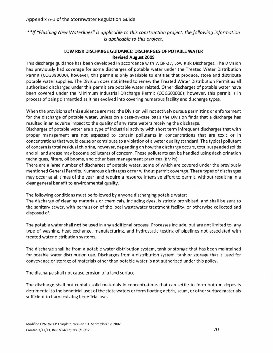
Appendix A-1 of the Stormwater Regulation Guide
Modified EPA SWPPP Template, Version 1.1, September 17, 2007
Created 3/17/11; Rev 2/14/12; Rev 3/12/12 20
**If “Flushing New Waterlines” is applicable to this construction project, the following information
is applicable to this project.
LOW RISK DISCHARGE GUIDANCE: DISCHARGES OF POTABLE WATER
Revised August 2009
This discharge guidance has been developed in accordance with WQP-27, Low Risk Discharges. The Division
has previously had coverage for some discharges of potable water under the Treated Water Distribution
Permit (COG380000), however, this permit is only available to entities that produce, store and distribute
potable water supplies. The Division does not intend to renew the Treated Water Distribution Permit as all
authorized discharges under this permit are potable water related. Other discharges of potable water have
been covered under the Minimum Industrial Discharge Permit (COG600000); however, this permit is in
process of being dismantled as it has evolved into covering numerous facility and discharge types.
When the provisions of this guidance are met, the Division will not actively pursue permitting or enforcement
for the discharge of potable water, unless on a case-by-case basis the Division finds that a discharge has
resulted in an adverse impact to the quality of any state waters receiving the discharge.
Discharges of potable water are a type of industrial activity with short term infrequent discharges that with
proper management are not expected to contain pollutants in concentrations that are toxic or in
concentrations that would cause or contribute to a violation of a water quality standard. The typical pollutant
of concern is total residual chlorine, however, depending on how the discharge occurs, total suspended solids
and oil and grease may become pollutants of concern. These pollutants can be handled using dechlorination
techniques, filters, oil booms, and other best management practices (BMPs).
There are a large number of discharges of potable water, some of which are covered under the previously
mentioned General Permits. Numerous discharges occur without permit coverage. These types of discharges
may occur at all times of the year, and require a resource intensive effort to permit, without resulting in a
clear general benefit to environmental quality.
The following conditions must be followed by anyone discharging potable water:
The discharge of cleaning materials or chemicals, including dyes, is strictly prohibited, and shall be sent to
the sanitary sewer, with permission of the local wastewater treatment facility, or otherwise collected and
disposed of.
The potable water shall not be used in any additional process. Processes include, but are not limited to, any
type of washing, heat exchange, manufacturing, and hydrostatic testing of pipelines not associated with
treated water distribution systems.
The discharge shall be from a potable water distribution system, tank or storage that has been maintained
for potable water distribution use. Discharges from a distribution system, tank or storage that is used for
conveyance or storage of materials other than potable water is not authorized under this policy.
The discharge shall not cause erosion of a land surface.
The discharge shall not contain solid materials in concentrations that can settle to form bottom deposits
detrimental to the beneficial uses of the state waters or form floating debris, scum, or other surface materials
sufficient to harm existing beneficial uses.

Appendix A-1 of the Stormwater Regulation Guide
Modified EPA SWPPP Template, Version 1.1, September 17, 2007
Created 3/17/11; Rev 2/14/12; Rev 3/12/12 21
All discharges must comply with the lawful requirements of federal agencies, municipalities, counties,
drainage districts, ditch owners, and other local agencies regarding any discharges to storm drain systems,
conveyances, ditches or other water courses under their jurisdiction.
The guidance included in this document in no way reduces the existing authority of the owner of a storm
sewer, ditch owner, or other local agency, from prohibiting or placing additional conditions on the discharge.
If the discharge is directly to a State surface water (any stream, creek, Gulch, whether dry or flowing), it must
not contain any residual chlorine. The operator is responsible for determining what is necessary for removing
chlorine from the discharge. If the discharge is to a ditch, chlorine content may be limited by the owner of
the ditch. However, if the ditch returns flow to classified state waters, it must not contain any residual
chlorine at the point where it discharges to the classified state water.
BMPs shall be implemented as necessary to meet the conditions above, by anyone discharging potable water.
These BMPs have been developed by the Division to help ensure that the discharge will not negatively affect
water quality.
For discharge to the ground, the water shall not cause any toxicity to vegetation. When discharging, allow
the water to drain slowly so that it soaks into the ground as much as possible.
If discharge is to the sanitary sewer, contact the local wastewater treatment facility prior to discharge.
System owners may grant blanket authorization to discharge to their systems. This must be done to ensure
that the facility is able to accept the discharge. Not all facilities are able to accept such discharges. Note that
additional restrictions or local guidelines may apply.
Removal of any residual chlorine must be done for any direct discharge to state surface waters or for any
discharge to a storm sewer or conveyance where the chlorine will not dissipate prior to reaching state surface
water. Dechlorination, if necessary, may be achieved by allowing water to stand uncovered until no chlorine
is detected, or by dechlorination using a portable dechlorinator. Pay particular attention when handling
super-chlorinated waters. A longer time is needed to dissipate chlorine from super-chlorinated waters.
The discharge shall be conducted to minimize the potential to pick up additional suspended solids. When
possible, a best management practice, or combination of practices, for filtering or settling suspended solids
and other debris, or a combination of practices, shall be used to remove suspended solids or other debris.
Examples of suspended solid removal practices include, but are not limited to check dams, filter bags, and
inlet protection. These devices shall be used and maintained in accordance with the manufacturers
specifications.
The discharge shall be conducted to minimize the potential that it will not pick up any oil and grease. When
possible, an absorbent oil pad, boom or similar device shall be used to eliminate oil from the discharge.
Contact Information:
Questions regarding this action shall be forwarded to Nicole Rolfe at: [email protected]

Appendix A-1 of the Stormwater Regulation Guide
Modified EPA SWPPP Template, Version 1.1, September 17, 2007
Created 3/17/11; Rev 2/14/12; Rev 3/12/12 22
1.9 Demolition
Are there any structures to be demolished as part of construction related to this site?
Yes No
If yes, describe or refer to documentation that determines the likelihood of an impact for
erosion and the steps taken to address that impact. Place a copy of the state asbestos
certification in Appendix 4, as applicable.
Instructions:
- Before demolition of a structure begins, a copy of the asbestos certification from the State certifying the structure is free of asbestos and other pollutants must be obtained. Attach a copy of the County Demolition Permit including the state issued asbestos abatement permit in Appendix 4 – Copy of Demolition Permit and State Asbestos Permit Certification.

Appendix A-1 of the Stormwater Regulation Guide
Modified EPA SWPPP Template, Version 1.1, September 17, 2007
Created 3/17/11; Rev 2/14/12; Rev 3/12/12 23
SECTION 2: EROSION AND SEDIMENT CONTROL BMPS
Below are standard structural and non-structural practices that are often used for erosion and
sediment control throughout a construction project. BMPs include but are not limited to the
following list. Following each BMP is a placeholder for additional site specific comments or
information the designer may want to include. If a BMP is not included, space has been provided
at the end of each BMP table. Any additional BMPs shall include all four “Expected Level of BMP
Information” (i.e. What, When, Where, How). All BMPs shall be installed as a phased operation
when construction progresses.
Expected Level of BMP Information = What, When, Where and How
Instructions:
- Multiple structural and non-structural BMPs are used during each phase of construction to minimize erosion and the transport of sediment. Included is the Expected Level of BMP Information for structural and non-structural BMPs that are expected to minimize sediment transport and erosion control.
- Describe the BMPs that will be implemented to control pollutants in stormwater discharges. For each major activity identified below, complete the following:
Clearly select and describe appropriate control measures.
Describe the maintenance and inspection procedures that will be used for that specific BMP.
Include protocols, thresholds, and schedules for cleaning, repairing or replacing damaged or failing BMPs.
- If a construction project uses a BMP that is not included below, add BMPs in the place provided after each listed BMP and ensure that the Expected Level of BMP Information is included.
- Below are the listed BMP descriptions Expected Level of BMP Information items that address the following:
What BMPs will be installed?
When will the BMPs be implemented and removed?
Where will the BMPs be implemented?
How will the BMPs be maintained?
- Place all BMP details and associated procedures in Appendix 5 – Erosion and Sediment Control BMP Details.
- Categorize and describe each BMP under one of the following 8 activities:
2.1 Minimize Disturbed Area and Protect Natural Features and Soil
2.2 Control Stormwater Flowing onto and through the Project
2.3 Stabilize Soils and Protect Slopes
2.4 Protect Storm Drain Inlets
2.5 Establish Perimeter Controls and Sediment Barriers
2.6 Retain Sediment On-Site and Control Dewatering Practices
2.7 Establish Stabilized Construction Exits
2.8 Any Additional BMPs
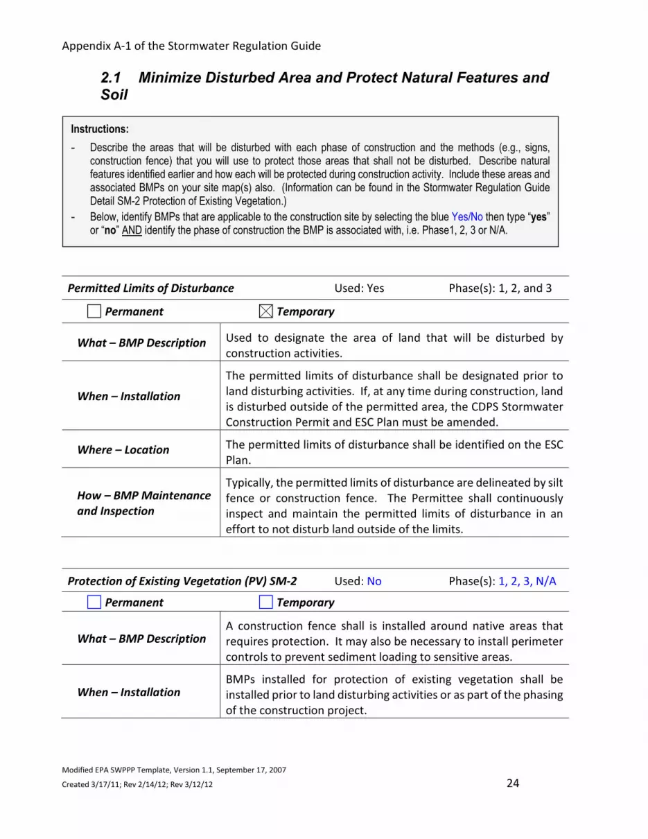
Appendix A-1 of the Stormwater Regulation Guide
Modified EPA SWPPP Template, Version 1.1, September 17, 2007
Created 3/17/11; Rev 2/14/12; Rev 3/12/12 24
2.1 Minimize Disturbed Area and Protect Natural Features and Soil
Permitted Limits of Disturbance Used: Yes Phase(s): 1, 2, and 3
Permanent Temporary
What – BMP Description Used to designate the area of land that will be disturbed by
construction activities.
When – Installation
The permitted limits of disturbance shall be designated prior to
land disturbing activities. If, at any time during construction, land
is disturbed outside of the permitted area, the CDPS Stormwater
Construction Permit and ESC Plan must be amended.
Where – Location The permitted limits of disturbance shall be identified on the ESC
Plan.
How – BMP Maintenance
and Inspection
Typically, the permitted limits of disturbance are delineated by silt
fence or construction fence. The Permittee shall continuously
inspect and maintain the permitted limits of disturbance in an
effort to not disturb land outside of the limits.
Protection of Existing Vegetation (PV) SM-2 Used: No Phase(s): 1, 2, 3, N/A
Permanent Temporary
What – BMP Description A construction fence shall is installed around native areas that
requires protection. It may also be necessary to install perimeter
controls to prevent sediment loading to sensitive areas.
When – Installation BMPs installed for protection of existing vegetation shall be
installed prior to land disturbing activities or as part of the phasing
of the construction project.
Instructions:
- Describe the areas that will be disturbed with each phase of construction and the methods (e.g., signs, construction fence) that you will use to protect those areas that shall not be disturbed. Describe natural features identified earlier and how each will be protected during construction activity. Include these areas and associated BMPs on your site map(s) also. (Information can be found in the Stormwater Regulation Guide Detail SM-2 Protection of Existing Vegetation.)
- Below, identify BMPs that are applicable to the construction site by selecting the blue Yes/No then type “yes” or “no” AND identify the phase of construction the BMP is associated with, i.e. Phase1, 2, 3 or N/A.

Appendix A-1 of the Stormwater Regulation Guide
Modified EPA SWPPP Template, Version 1.1, September 17, 2007
Created 3/17/11; Rev 2/14/12; Rev 3/12/12 25
Where – Location Protection of existing vegetation BMPs shall be installed at
locations identified on the ESC Plan. These locations will be any
area that has been designated as a preservation area.
How – BMP Maintenance
and Inspection
Protection of existing vegetation BMPs shall be installed per the
protection of existing vegetation detail (Appendix 5 – Erosion and
Sediment Control BMP Details and Procedural Plans).
Clearly mark the area on the site plan to be preserved. No
stockpiles, equipment, trailers or parking shall be allowed within
the area. Repair or replace damaged or displaced protective
barriers around the vegetated area. The Permittee shall
continuously inspect and maintain all areas that are designated to
be protected. If damage to the vegetation occurs in a protected
area, reseed the area with the same or similar species.
Construction equipment must not enter a wetland area, except as
permitted by the U.S. Army Corps of Engineers (USACE). In
advertent placement of fill in a wetland is a 404 permit violation
and will require notification of the USACE.

Appendix A-1 of the Stormwater Regulation Guide
Modified EPA SWPPP Template, Version 1.1, September 17, 2007
Created 3/17/11; Rev 2/14/12; Rev 3/12/12 26
2.2 Control Stormwater Flowing onto and through the Project
Temporary Slope Drains (TSD) BMP Detail EC-7 Used: No Phase(s):
Permanent Temporary
What – BMP Description
A pipe or culvert used to convey water down a slope where there
is high potential for erosion. A collection system at the top of the
slope directs runoff to the conveyance. The pipe outlet must be
equipped with outlet protection.
When - Installation Temporary slope drains shall be installed prior to up gradient land
disturbing activities and are to remain in place until no longer
needed, but shall be removed prior to the end of construction.
Where – Location Temporary slope drains shall be installed at the locations
identified on the ESC Plan. They are for use on long, steep slopes
where there is a high potential for flow concentration.
How – BMP Maintenance
and Inspection
Temporary slope drains shall be installed and maintained per the
temporary slope drain detail EC-7 (Appendix 5 - Erosion and
Sediment Control BMP Details).
The Permittee shall continuously inspect and maintain all
temporary slope drains throughout construction. Inspect the
entrance for sediment accumulation and remove, as needed.
Inspect the downstream outlet for signs of erosion and stabilize,
as needed. Remove accumulated sediment at the entrance and
outfall, and inspect pipe anchors to ensure they are secure.
Instructions:
- Describe structural practices (e.g., swales, diversions, berms, ditches, storage basins) used to divert flows from exposed soils, retain or detain flows, or otherwise limit runoff and the discharge of pollutants from exposed areas of the site. . (Information can be found in the Stormwater Regulation Guide Details EC-7 Temporary Slope Drains, EC-10 Earth Dikes and Drainage Swales & SC-8 Sediment Trap.)
- Below, identify BMPs that are applicable to the construction site by selecting the blue Yes/No then type “yes” or “no” AND identify the phase of construction the BMP is associated with, i.e. Phase1, 2, 3 or N/A.

Appendix A-1 of the Stormwater Regulation Guide
Modified EPA SWPPP Template, Version 1.1, September 17, 2007
Created 3/17/11; Rev 2/14/12; Rev 3/12/12 27
Earth Dikes/Drainage Swales (ED/DS) BMP Detail EC-10 Used: Yes Phase(s): 1, 2, 3
Permanent Temporary
What – BMP Description Temporary storm conveyance channels used to divert runoff
around slopes or to convey runoff to additional sediment control
BMPs prior to discharge from the site.
When –
Installation/Removal
Earth dikes and drainage swales will be installed immediately
upon completion of channel grading and will remain in place until
the end of construction.
Where – Location
Earth dikes and drainage swales shall be installed at the locations
identified on the ESC Plan. They are typically installed around
steep slopes or as a temporary conveyance feature leading to a
sediment basin or trap.
How – BMP Maintenance
and Inspection
Earth dikes and drainage swales shall be installed per the earth
dikes and drainage swales detail EC-10 (Appendix 5 – Erosion and
Sediment Control BMP Details and Procedural Plans).
The Permittee shall continuously inspect and maintain all earth
dikes and drainage swales for stability, compaction and signs of
erosion and repair. Inspect side slopes for erosion and damage to
erosion control fabric. Stabilize slopes and repair fabric as
necessary. Accumulated sediment shall be removed when the
sediment has accumulated to one-half of the depth of the earth
dike or drainage swales.
Sediment Trap (ST) BMP Detail SC-8 Used: Yes Phase(s): 1, 2
Permanent Temporary
What – BMP Description An excavated or bermed area designed to capture drainage,
allowing settling of sediment from a disturbed area less than one
acre.
When –
Installation/Removal
A sediment trap shall be installed prior to land disturbing
activities; the sediment trap shall not be removed until the
upstream area is sufficiently stabilized.
Where – Location Sediment traps shall be installed at the locations identified on the
ESC Plan. It shall be installed across a low area or drainage swale.
How – BMP Maintenance
and Inspection
Sediment trap shall be installed per the sediment trap detail SC-8
(Appendix 5 – Erosion and Sediment Control BMP Details). The
Permittee shall continuously inspect and maintain the sediment
trap embankments for stability and seepage.

Appendix A-1 of the Stormwater Regulation Guide
Modified EPA SWPPP Template, Version 1.1, September 17, 2007
Created 3/17/11; Rev 2/14/12; Rev 3/12/12 28
Inspect the sediment trap embankments for stability and seepage,
and the outlet for debris and damage. Repair damage to the
outlet, and remove all obstructions. Accumulated sediment shall
be removed when it reaches ½ the height of the outflow
embankment.
Temporary Diversion Channel (TDC) SM-8 Used: No Phase(s):
Permanent Temporary
What – BMP Description Diverts water from a stream to allow for construction activities to
take place underneath or in the stream.
When –
Installation/Removal
All BMPs associated with a temporary diversion channel shall be
installed prior to the start of any construction activities within a
stream; removed when the work at the down gradient or natural
channel is no longer required, the diversion channel shall be
backfilled and stabilized.
Where – Location
Temporary diversion channels shall be installed at the location
identified on the ESC Plan.
Temporary diversion channel BMPs can be used in the following
locations: construction of detention ponds, dams, in-stream
grade control structures, utility installations or any activity that
requires work in a waterway.
How – BMP Maintenance
and Inspection
Temporary diversion channel shall be installed per the temporary
diversion channel detail SM-8 (Appendix 5 - Erosion and Sediment
Control BMP Details).
The Permittee shall frequently and continuously inspect and
maintain all temporary diversion channel BMPs throughout
construction. Flow barriers shall be inspected at the start and end
of each workday. The diversion channel shall be inspected for
signs of erosion and the lining repaired or replaced if necessary.
Dewatering Operations (DW) SM-9 Used: Yes Phase(s): 1, 2
Permanent Temporary
What – BMP Description
Pumping water from an inundated area to a BMP, then
downstream to a receiving waterway, sediment basin or well-
vegetated area. When pumping water outside of the permitted
boundary a separate State Dewatering Permit is required.

Appendix A-1 of the Stormwater Regulation Guide
Modified EPA SWPPP Template, Version 1.1, September 17, 2007
Created 3/17/11; Rev 2/14/12; Rev 3/12/12 29
When –
Installation/Removal Dewatering operations are used when an area of the construction
site that is inundated with water which needs to be dewatered as
a result of a large storm event, groundwater or existing ponding
conditions; and be removed once the work in the down gradient
area or natural channel is no longer required.
Where – Location Dewatering BMPs shall be installed at the locations identified on
the ESC Plan. Dewatering operations may occur in any area of the
construction site where accumulated water needs to be removed.
How – BMP Maintenance
and Inspection Dewatering operations shall be conducted per dewatering
operations detail SM-9 (Appendix 5 – Erosion and Sediment
Control BMP Details).
All dewatering discharges must be treated to remove sediment
(and other pollutants as needed) before discharging from the
construction site. The Permittee shall continuously inspect and
maintain all dewatering operations throughout construction.
Temporary Stream Crossing (TSC) SM-10 Used: No Phase(s):
Permanent Temporary
What – BMP Description
A temporary crossing where an actively flowing watercourse must
be crossed. Three methods are available: culvert crossing, stream
ford and temporary bridge. A permit is required for placement of
fill in a waterway under Section 404 of the Clean Water Act.
Contact the local office of the U.S. Army Corps of Engineers
regarding the requirements for obtaining a 404 permit.
When –
Installation/Removal
A temporary stream crossing shall be installed only when it is
necessary to cross a stream; and removed when the crossing is no
longer needed for construction.
Where – Location Temporary stream crossings shall be installed at the locations
identified on the ESC Plan.
How – BMP Maintenance
and Inspection
Temporary stream crossings shall be installed per the temporary
stream crossing detail SM-10 (Appendix 5 - Erosion and Sediment
Control BMP Details).
The Permittee shall continuously inspect and maintain the
temporary stream crossing throughout construction. Specifically,
inspect for bank erosion and in-stream degradation.

Appendix A-1 of the Stormwater Regulation Guide
Modified EPA SWPPP Template, Version 1.1, September 17, 2007
Created 3/17/11; Rev 2/14/12; Rev 3/12/12 30
2.3 Stabilize Soils and Protect Slopes
Surface Roughening (SR) BMP Detail EC-1 Used: Yes Phase(s): 1, 2, 3
Permanent Temporary
What – BMP Description Tracking, scarifying, imprinting or tilling a disturbed area to
provide temporary stabilization. Variations in the soil are created
to help minimize wind and water erosion.
When – Installation Surface roughening shall be performed either after final grading
or to temporarily stabilize an area during active construction.
Where – Location Surface roughening shall be used in the locations identified on the
ESC Plan. It can be used on mild and steep slopes.
How – BMP Maintenance
and Inspection
Surface roughening shall be installed per the surface roughening
detail EC-1 (Appendix 5 – Erosion and Sediment Control BMP
Details).
Surface roughening shall always be perpendicular to the slope.
The Permittee shall continuously inspect and maintain all surfaces
that are roughened throughout construction. Surface roughening
shall be inspected for erosion as it is only a temporary control.
Vehicles and equipment shall not be driven over areas that have
been surface roughening. Additional activities may be needed to
maintain the roughening on the soil surface.
Instructions:
- Stabilize Soils - Describe controls (e.g., interim temporary mulching, seeding with native vegetation, hydro-seeding and soil binders) to stabilize exposed soils where construction activities have temporarily or permanently ceased. Also describe measures to control dust generation. (Information can be found in the Stormwater Regulation Guide Details EC-1 through EC-14 Erosion Control BMPs minus EC-5 & EC-9.)
- Protect Slopes - Describe controls (e.g., erosion control blankets, soil binders) including design specifications and details that will be implemented to protect all slopes from eroding. (Information can be found in the Stormwater Regulation Guide Details EC-1 through EC-14 Erosion Control BMPs minus EC-5 & EC-9.)
- Below, identify BMPs that are applicable to the construction site by selecting the blue Yes/No then type “yes” or “no” AND identify the phase of construction the BMP is associated with, i.e. Phase1, 2, 3 or N/A.

Appendix A-1 of the Stormwater Regulation Guide
Modified EPA SWPPP Template, Version 1.1, September 17, 2007
Created 3/17/11; Rev 2/14/12; Rev 3/12/12 31
Temporary and Permanent Seeding (P) EC-2 Used: Yes Phase(s): 2, 3, 5
Permanent Temporary
What – BMP Description
Amendment and Seed Specifications Must be Provided by ESC Plan
Designer.
Seed is applied to disturbed areas in an effort to establish
vegetation. Temporary seeding is used to stabilize disturbed
areas that will be inactive for an extended period.
Permanent seeding is used to stabilize areas at final grade that will
not be otherwise stabilized. Effective seeding includes
preparation of a seedbed, selection of an appropriate seed
mixture, proper planting techniques, and protection of the seeded
area with mulch, geotextile, or other appropriate measures.
Mulching helps to protect the bare soil and must be secured by
crimping, tackifiers, netting or other measures.
When – Installation Temporary and permanent seeding shall be performed on
temporary inactive surfaces and following the completion of final
grading.
Where – Location Temporary and permanent seeding shall be completed in the
locations identified on the ESC Plan. They are used to stabilize
areas at final grade that will not otherwise be stabilized.
How – BMP Maintenance
and Inspection
Permanent seeding and secured mulching shall be installed per
the temporary and permanent seeding specifications and detail.
The Permittee shall continuously inspect and maintain all
temporary and permanent seeding and secured mulch
throughout construction. Prepare the seedbed, select an
appropriate seed mixture, use proper planting techniques and
protect the seeded area with secured mulch.
Soil Binders (SB) EC-3 Used: No Phase(s):
Permanent Temporary
What – BMP Description A broad range of treatments that can be applied to exposed soils
for temporary stabilization to reduce wind and water erosion.
When – Installation Use soil binders for short term temporary stabilization. Soil
binders can break down fast due to natural weathering.
Where – Location Soil binders can be used on mild and steep slopes including
stockpiles. They are often used in areas where work has

Appendix A-1 of the Stormwater Regulation Guide
Modified EPA SWPPP Template, Version 1.1, September 17, 2007
Created 3/17/11; Rev 2/14/12; Rev 3/12/12 32
temporarily stopped, but is expected to resume before
revegetation can is established.
How – BMP Maintenance
and Inspection
Soil binders shall be used per the soil binder detail/specifications.
The Permittee shall continuously inspect and maintain all areas
where soil binders have been applied throughout construction.
Soil binders can fail after heavy rainfall events and may require
reapplication. In particular, soil binders will general experience
spot failures during heavy rainfall events.
Mulching (MU) EC-4 Used: Yes Phase(s): 3
Permanent Temporary
What – BMP Description Mulching consists of evenly applying straw, hay, shredded wood
mulch, bark or compost to disturbed soils and securing the mulch
be crimping, tackifiers or netting.
When – Installation
Mulching is used in conjunction with seeding to help protect the
seed bed and stabilize the soil. Mulch can also be used as a
temporary cover on low to mild slopes to help temporarily
stabilize disturbed area where there are growing season
constraints.
After mulching, the bare ground surface shall not be exposed.
Reapply mulch, as needed, to cover bare areas.
Where – Location Temporary and permanent mulching shall be completed in the
locations identified on the ESC Plan.
How – BMP Maintenance
and Inspection
Mulching shall be installed per the mulching detail EC-4 (Appendix
5 – Erosion and Sediment Control BMP Details).
After mulching, the bare ground surface shall not be more than
10% exposed. Reapply mulch, as needed, to cover bare areas.
Rolled Erosion Control Product (RECP) EC-6 Used: Yes Phase(s): 1, 2, 3, N/A
Permanent Temporary
What – BMP Description
A variety of temporary or permanently installed manufactured
products designed to control erosion and enhance vegetation
establishment and survivability, especially on slopes and in
channels. There are four categories of products; mulch control
netting, open weave textile, erosion control blanket and turf
reinforcement mat.

Appendix A-1 of the Stormwater Regulation Guide
Modified EPA SWPPP Template, Version 1.1, September 17, 2007
Created 3/17/11; Rev 2/14/12; Rev 3/12/12 33
When – Installation
Rolled erosion control products shall be installed upon completion
of slope grading and when revegetation measures are completed;
rolled erosion control products are biodegradable typically and do
not need to be removed after construction.
Where – Location Rolled erosion control products shall be installed at the locations
identified on the ESC Plan. They shall be installed according to
manufacturer’s specifications and guidelines.
How – BMP Maintenance
and Inspection
Rolled erosion control products shall be installed per the rolled
erosion control products detail EC-6 (Appendix 5 - Erosion and
Sediment Control BMP Details).
The Permittee shall continuously inspect and maintain all rolled
erosion control products throughout construction. Check for
signs of erosion, including voids under the mat. Also check for
damaged or loose stakes and secure loose sections of the blanket.
Temporary Slope Drain (TSD) EC-7 Used: No Phase(s):
Permanent Temporary
What – BMP Description
A temporary slope drain is a pipe or culvert used to convey water
down a slope where there is a high potential for erosion. A
drainage channel or swale at the top of the slope typically directs
up gradient runoff to the pipe entrance for conveyance down the
slope. The pipe outlet must be equipped with outlet protection.
When –
Installation/Removal
A temporary slope drain shall be installed when it is necessary to
convey water on long, steep slopes when there is a high potential
of flow concentration or rill development. Temporary slope drains
shall be removed when no longer needed or just prior to
installation of permanent slope stabilization measures that
cannot be installed with the slope drain in place.
Where – Location Temporary slope drain shall be installed at the locations
indentified on the ESC Plan. It shall be installed where it is
necessary to convey water down an erodible surface.
How – BMP Maintenance
and Inspection
Temporary slope drain shall be installed per the temporary slope
drain detail EC-7 (Appendix 5 - Erosion and Sediment Control BMP
Details). The Permittee shall continuously inspect and maintain
all temporary slope drains as the conveyance system may be
dislodged or displaced. Accumulated sediment shall be removed
before the outlet protection becomes buried and ineffective.

Appendix A-1 of the Stormwater Regulation Guide
Modified EPA SWPPP Template, Version 1.1, September 17, 2007
Created 3/17/11; Rev 2/14/12; Rev 3/12/12 34
Temporary Outlet Protection (TOP) EC-8 Used: Yes Phase(s): 1, 2
Permanent Temporary
What – BMP Description
Riprap rock placed at the outlet to help reduce erosion
immediately downstream of a pipe, culvert, slope drain rundown
or other conveyance with concentrated flow. Temporary outlet
protection is intended to be used for less than two years.
When –
Installation/Removal
Temporary outlet protection shall be installed immediately upon
the completion of grading; temporary outlet protection shall be
removed once the pipe is no longer draining and upstream area
or once the downstream area has been sufficiently stabilized.
Where – Location
Temporary outlet protection shall be installed at the locations
identified on the ESC Plan. It shall be installed where a
conveyance discharges onto a disturbed area where there is a
potential for accelerated erosion due to concentrated flow.
How – BMP Maintenance
and Inspection
Temporary outlet protection shall be installed per the temporary
outlet protection detail with topside protection1 EC-8 (Appendix 5
- Erosion and Sediment Control BMP Details). The Permittee shall
continuously inspect and maintain all temporary outlet protection
as the rocks may be damaged or displaced. Accumulated
sediment shall be removed before the outlet protection becomes
buried and ineffective. 1 8/5/11 LR Comment
Earth Dikes/Drainage Swales (ED/DS) BMP Detail EC-10 Used: Yes Phase(s): 1, 2, 3, N/A
Permanent Temporary
What – BMP Description Temporary storm conveyance channels are used to divert runoff
around slopes or to convey runoff to additional sediment control
BMPs prior to discharge from the site.
When –
Installation/Removal
Earth dikes and drainage swales will be installed immediately
upon completion of channel grading and will remain in place until
the end of construction.
Where – Location
Earth dikes and drainage swales shall be installed at the locations
identified on the ESC Plan. They are typically installed around
steep slopes or as a temporary conveyance feature leading to a
sediment basin or trap.
How – BMP Maintenance
and Inspection
Earth dikes and drainage swales shall be installed per the earth
dikes and drainage swales detail EC-10 (Appendix 5 - Erosion and
Sediment Control BMP Details).

Appendix A-1 of the Stormwater Regulation Guide
Modified EPA SWPPP Template, Version 1.1, September 17, 2007
Created 3/17/11; Rev 2/14/12; Rev 3/12/12 35
The Permittee shall continuously inspect and maintain all earth
dikes and drainage swales for stability, compaction and signs of
erosion and repair. Inspect side slopes for erosion and damage to
erosion control fabric. Stabilize slopes and repair fabric as
necessary. Accumulated sediment shall be removed when the
sediment has accumulated to one-half of the depth of the earth
dike or drainage swales.
Terracing (TER) EC-11 Used: No Phase(s):
Permanent Temporary
What – BMP Description
Grading steep slopes into a series of relatively flat sections
separated at intervals by steep slope segments. They shorten the
uninterrupted flow lengths on steep slopes, reducing the
development of rills and gullies.
When –
Installation/Removal Terracing shall be completed during grading activities; when slope
is at final grade vegetation shall be established as soon as possible.
Where – Location Terracing shall be installed at the locations identified on the ESC
Plan. It is usually used to control erosion on slopes that are
steeper than 4:1.
How – BMP Maintenance
and Inspection
Terracing shall be installed per the terracing detail EC-11
(Appendix 5 - Erosion and Sediment Control BMP Details).
Terracing shall be used in combination with other stabilization
measures that provide cover for exposed soils. The Permittee
shall continuously inspect and maintain all terracing throughout
construction. Remove accumulated sediment and repair rill
erosion as necessary.

Appendix A-1 of the Stormwater Regulation Guide
Modified EPA SWPPP Template, Version 1.1, September 17, 2007
Created 3/17/11; Rev 2/14/12; Rev 3/12/12 36
Check Dams (CD) EC-12 Used: No Phase(s):
Permanent Temporary
What – BMP Description
Temporary grade control structures are used in drainage channels
to reduce the velocity of runoff and concentrated flows. They can
be constructed from rock, gravel bags, sand bags or proprietary
devices.
When –
Installation/Removal
Check dams shall be installed prior to earth disturbing activities or
immediately upon completion of channel grading.
Temporary check dams shall be removed and stabilized.
Permanent check dams shall be cleaned and remain in place.
Where – Location Check dams shall be installed at the locations identified on the ESC
Plan. Typically they are placed in drainage channels, swales or on
mild to moderately steep slopes.
How – BMP Maintenance
and Inspection
Check dams shall be installed per the check dam detail EC-12
(Appendix 5 - Erosion and Sediment Control BMP Details). They
shall be placed at regularly spaced intervals along the drainage
swale or ditch. The height of the dams shall allow for pooling of
the runoff.
The Permittee shall continuously inspect and maintain check
dams as rocks can be displaced and gravel bags or sandbags can
be torn. Accumulated sediment shall be removed before it
reaches one-half the height of the check dam.
Streambank Stabilization (SS) EC-13 Used: No Phase(s):
Permanent Temporary
What – BMP Description
A combination of erosion and sediment control BMPs are used to
protect streams, banks, and in-stream habitat from accelerated
erosion. Some of the BMPs that may be used include protection
of existing vegetation, check dams, temporary and permanent
seeding and rolled erosion control products.
When –
Installation/Removal
BMPs used for streambank stabilization shall be installed prior to
earth disturbing activities to protect existing vegetation or to
preserve an exposed streambank to mitigate erosion rates from
the disturbed area; for BMPs that are not to remain in place as a
part of final stabilization, such as silt fence and other temporary
measures, BMPs shall be removed when all land disturbing
activities have ceased and area have been permanently stabilized.

Appendix A-1 of the Stormwater Regulation Guide
Modified EPA SWPPP Template, Version 1.1, September 17, 2007
Created 3/17/11; Rev 2/14/12; Rev 3/12/12 37
Where – Location BMPs used for stream bank stabilization shall be installed at the
locations identified on the ESC Plan. They shall be installed along
the banks of streams or waterways.
How – BMP Maintenance
and Inspection
See individual details and notes for the various BMPs used in
streambank stabilization EC-13 (Appendix 5 - Erosion and
Sediment Control BMP Details). The Permittee shall continuously
inspect and maintain BMPs used in streambank stabilization.
Wind Erosion/Dust Control (DC) EC-14 Used: Yes Phase(s): 1,2,3
Permanent Temporary
What – BMP Description
Wind erosion and dust control BMPs help sediment from
disturbed soils and soil stockpiles from entering the air as a result
of land disturbing construction activities. A variety of practices
that focus on either graded disturbed areas or construction
roadways may be used.
When – Installation During conditions which result in the formation of dust from
either construction activities or from naturally occurring winds.
Do not overwater.
Where – Location Dust abatement shall be completed throughout the project area
where any material exists that has the potential to become
airborne.
How – BMP Maintenance
and Inspection
Wind erosion/dust control measures shall be performed per the
wind erosion/dust control detail EC-14 (Appendix 5 - Erosion and
Sediment Control BMP Details). The Permittee may apply water
or magnesium chloride, seed and mulch or use spray-on soil
binders on disturbed areas.
Water and magnesium chloride shall be applied such that
concentrated flows do not form.

Appendix A-1 of the Stormwater Regulation Guide
Modified EPA SWPPP Template, Version 1.1, September 17, 2007
Created 3/17/11; Rev 2/14/12; Rev 3/12/12 38
2.4 Protect Storm Drain Inlets
Rock Sock (RS) SC-5 Used: No Phase(s): 1, 2, 3, N/A
Permanent Temporary
What – BMP Description An elongated cylindrical filter constructed of gravel wrapped by
wire mesh or woven geotextile. Also called curb socks when
placed at angles in the curb line.
When –
Installation/Removal
Rock socks shall be installed prior to land disturbing activities;
once upstream stabilization is complete, rock socks and
accumulated sediment shall be removed and properly disposed.
Where – Location Rock socks shall be installed at the locations identified on the ECS
Plan. They are typically used for perimeter control of a disturbed
area, part of inlet protection.
How – BMP Maintenance
and Inspection
Rock socks shall be installed per the rock sock detail SC-5
(Appendix 5 - Erosion and Sediment Control BMP Details). The
Permittee shall continuously inspect and maintain all rock socks
as they are susceptible to displacement and breakage due to
vehicle traffic. Accumulated sediment shall be removed by
sweeping, as needed, to maintain functionality.
Inlet Protection (IP) SC-6 Used: No Phase(s):
Permanent Temporary
What – BMP Description
A permeable barrier that is installed around an inlet to filter runoff
and remove sediment before it enters the storm drain inlet. Inlet
protection can be constructed of the following: rocks socks,
sediment control logs, silt fence, blocks and rock socks, or other
materials.
When –
Installation/Removal
Inlet protection for existing inlets shall be installed prior to land
disturbing activities upslope from the inlet. Inlet protection for
proposed inlets shall be installed immediately after the inlet is
Instructions:
- Describe controls (e.g., inserts, rock-filled bags, or block and gravel) including design specifications and details that will be implemented to protect all inlets receiving stormwater from the project during the entire project. (Information can be found in the Stormwater Regulation Guide Details SC-5 Rock Sock and SC-6 Inlet Protection.)
- Below, identify BMPs that are applicable to the construction site by selecting the blue Yes/No then type “yes” or “no” AND identify the phase of construction the BMP is associated with, i.e. Phase1, 2, 3 or N/A.

Appendix A-1 of the Stormwater Regulation Guide
Modified EPA SWPPP Template, Version 1.1, September 17, 2007
Created 3/17/11; Rev 2/14/12; Rev 3/12/12 39
completed and backfilled; inlet protection and any associated
sediment must be removed and properly disposed of when the
drainage area for the inlet is stabilized.
Where – Location
Inlet protection shall be installed at the locations identified on the
ESC Plan. Inlet protection shall not be a stand-alone BMP. It shall
be used in conjunction with other up gradient BMPs.
How – BMP Maintenance
and Inspection
Inlet protection shall be installed per the inlet protection detail
SC-6 (Appendix 5 - Erosion and Sediment Control BMP Details).
Inlet protection shall enable the inlet to function without
completely blocking the flow. The Permittee shall continuously
inspect and maintain all inlet protection BMPs throughout
construction as it is the final BMP before runoff enters the storm
drain.
Accumulated sediment shall be removed when it has reached
one-half the height of the inlet protection or looses functionality,
whichever comes first.
Inlet protection shall not be used as standalone BMP and shall be
part of redundant BMPs.1
1(8/5/11 LR Comment)

Appendix A-1 of the Stormwater Regulation Guide
Modified EPA SWPPP Template, Version 1.1, September 17, 2007
Created 3/17/11; Rev 2/14/12; Rev 3/12/12 40
2.5 Establish Perimeter Controls and Sediment Barriers
Construction Fence (CF) BMP Detail SM-3 Used: No Phase(s):
Permanent Temporary
What – BMP Description
Restricts site access to designated entrances and exits, delineates
construction site boundaries, and keeps construction out of
sensitive locations such as natural areas to be preserved as open
space, wetlands and riparian areas.
When –
Installation/Removal Construction fence shall be installed prior to earth disturbing
activities; and removed once construction is complete.
Where – Location Along the site perimeter or any area within the site where access
shall be restricted.
How – BMP Maintenance
and Inspection
Construction fencing shall be installed, maintained and removed
per the construction fence detail SM-3 (Appendix 5 – Erosion and
Sediment Control BMP Details).
The Permittee shall continuously inspect fences for damages and
slumping. The fence shall be tight and any areas with slumping or
fallen posts shall be reinstalled and/or replace the fencing.
Vehicle Tracking Control (VTC) SM-4 Used: Yes Phase(s): 1, 2, 3
Permanent Temporary
What – BMP Description A stabilized site access point that helps remove sediment from
vehicle tires and reduces tracking of the sediment onto paved
surfaces.
When –
Installation/Removal
Vehicle tracking control shall be installed prior to any land
disturbing activities; and removed when there is no longer the
potential for vehicle tracking to occur.
Instructions:
- Describe structural practices (e.g., silt fences or fiber rolls) including design specifications and details to filter and trap sediment before it leaves the construction site. (Information can be found in the Stormwater Regulation Guide Details SM-3 Construction Fence, SM-4 Vehicle Tracking Control and SC-9 Vegetated Buffer.)
- Below, identify BMPs that are applicable to the construction site by selecting the blue Yes/No then type “yes” or “no” AND identify the phase of construction the BMP is associated with, i.e. Phase1, 2, 3 or N/A.
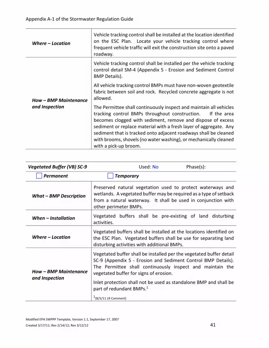
Appendix A-1 of the Stormwater Regulation Guide
Modified EPA SWPPP Template, Version 1.1, September 17, 2007
Created 3/17/11; Rev 2/14/12; Rev 3/12/12 41
Where – Location
Vehicle tracking control shall be installed at the location identified
on the ESC Plan. Locate your vehicle tracking control where
frequent vehicle traffic will exit the construction site onto a paved
roadway.
How – BMP Maintenance
and Inspection
Vehicle tracking control shall be installed per the vehicle tracking
control detail SM-4 (Appendix 5 - Erosion and Sediment Control
BMP Details).
All vehicle tracking control BMPs must have non-woven geotextile
fabric between soil and rock. Recycled concrete aggregate is not
allowed.
The Permittee shall continuously inspect and maintain all vehicles
tracking control BMPs throughout construction. If the area
becomes clogged with sediment, remove and dispose of excess
sediment or replace material with a fresh layer of aggregate. Any
sediment that is tracked onto adjacent roadways shall be cleaned
with brooms, shovels (no water washing), or mechanically cleaned
with a pick-up broom.
Vegetated Buffer (VB) SC-9 Used: No Phase(s):
Permanent Temporary
What – BMP Description
Preserved natural vegetation used to protect waterways and
wetlands. A vegetated buffer may be required as a type of setback
from a natural waterway. It shall be used in conjunction with
other perimeter BMPs.
When – Installation Vegetated buffers shall be pre-existing of land disturbing
activities.
Where – Location Vegetated buffers shall be installed at the locations identified on
the ESC Plan. Vegetated buffers shall be use for separating land
disturbing activities with additional BMPs.
How – BMP Maintenance
and Inspection
Vegetated buffer shall be installed per the vegetated buffer detail
SC-9 (Appendix 5 - Erosion and Sediment Control BMP Details).
The Permittee shall continuously inspect and maintain the
vegetated buffer for signs of erosion.
Inlet protection shall not be used as standalone BMP and shall be
part of redundant BMPs.1
1(8/5/11 LR Comment)

Appendix A-1 of the Stormwater Regulation Guide
Modified EPA SWPPP Template, Version 1.1, September 17, 2007
Created 3/17/11; Rev 2/14/12; Rev 3/12/12 42
2.6 Retain Sediment On-Site
Silt Fence (SF) SC-1 Used: Yes Phase(s): 1, 2
Permanent Temporary
What – BMP Description A woven geotextile fabric attached to wooden posts and trenched
into the ground. It is used to intercept sheet flow runoff from
disturbed areas.
When –
Installation/Removal Silt fence shall be installed prior to all land disturbing activities.
Silt fence shall be removed when the upstream area is stabilized.
Where – Location
Silt fence shall be installed at the locations identified on the ESC
Plan. It is typically installed along the contour of slopes, which is
down slope of a disturbed area to accept sheet flow, and placed
along the perimeter of a construction site.
Silt fence is not designed to receive concentrated flow or to be
used a filter fabric.
How – BMP Maintenance
and Inspection
Silt fence shall be installed per the silt fence detail SC-1 (Appendix
5 - Erosion and Sediment Control BMP Details). The Permittee
shall continuously inspect and maintain all silt fence throughout
construction.
Any section of silt fence that has a tear, hole, slumping,
undercutting or has been bypassed shall be replaced with a new
section. Accumulated sediment shall be removed before it
reaches a depth of 6 inches.
Sediment Control Log (SCL) SC-2 Used: No Phase(s):
Permanent Temporary
What – BMP Description Aka “Straw Wattle” - a linear roll made of natural materials such
as straw, coconut fiber or other fibrous material that is trenched
Instructions:
- Describe sediment control practices (e.g., sediment trap or sediment basin), including design specifications and details (volume, dimensions, outlet structure) that will be implemented at the construction site to retain sediments on-site. (Information can be found in the Stormwater Regulation Guide Details SC-1 through SC-3 Straw Bale Barrier and SC-7 Sediment Basin and SC-8 Sediment Trap.)
- Below, identify BMPs that are applicable to the construction site by selecting the blue Yes/No then type “yes” or “no” AND identify the phase of construction the BMP is associated with, i.e. Phase1, 2, 3 or N/A.

Appendix A-1 of the Stormwater Regulation Guide
Modified EPA SWPPP Template, Version 1.1, September 17, 2007
Created 3/17/11; Rev 2/14/12; Rev 3/12/12 43
into the ground and held with wooden stakes. It is used to
intercept sheet flow runoff from disturbed areas.
When -
Installation/Removal
Sediment control logs shall be installed during land disturbing
activities and after formation of a stockpile; once the upstream
area is stabilized, remove and properly dispose of the logs. If
disturbed areas exist after removal, the area shall be covered with
top soil, seeded and mulched.
Where – Location
Sediment control logs shall be installed at the locations identified
on the ECS Plan. They are typically used for stockpile control, inlet
protection, and check dams in small drainage ditches, on
disturbed slopes to shorten flow lengths and/or as part of multi-
layered perimeter control along receiving water such as a stream,
pond or wetland.
Sediment control logs work well in combination with other layers
of erosion and sediment controls.
Stockpiles stored on impervious surfaces shall not be placed in a
flowline and shall have weighted sediment control logs; stockpiles
stored on pervious surfaces may be protected by pervious
sediment control logs, silt fence or adequate vegetative cover as
allowed.
How – BMP Maintenance
and Inspection
Sediment control log shall be installed per the sediment control
log detail SC-2 (Appendix 5 - Erosion and Sediment Control BMP
Details). Sediment control logs shall be installed along (parallel)
the slope contour to avoid concentrating flows.
The Permittee shall continuously inspect and maintain all
sediment control logs throughout construction as they will
eventually degrade. Accumulated sediment shall be removed
before the depth is one-half the height of the sediment control
log.
Straw Bale Barrier (SBB) SC-3 Used: No Phase(s):
Permanent Temporary
What – BMP Description
A linear barrier of straw bales used to intercept and capture sheet
flow and to trap sediment before runoff exits a disturbed area. It
is typically used for perimeter control of a site or stockpile
management, at the toe of a slope, along the edge of a drainage
pathway, or as part of inlet protection.
When –
Installation/Removal Straw bale barriers shall be installed prior to land disturbing
activities and after formation of a stockpile; remove and properly

Appendix A-1 of the Stormwater Regulation Guide
Modified EPA SWPPP Template, Version 1.1, September 17, 2007
Created 3/17/11; Rev 2/14/12; Rev 3/12/12 44
dispose of the straw bale once the upstream area has been
stabilized. Areas of disturbance beneath the ball shall be seeded
and mulched when the bale is removed.
Where – Location Straw bale barriers shall be installed at the locations identified on
the ECS Plan.
How – BMP Maintenance
and Inspection
Straw bale barrier shall be installed per the straw bale barrier
detail SC-3 (Appendix 5 - Erosion and Sediment Control BMP
Details).
The Permittee shall continuously inspect and maintain all straw
bale barriers as they may be bypassed or undercut by flows and
will degrade and rot. Accumulated sediment shall be removed
when the depth reaches one-quarter the height of the bale.
Sediment Basin (SB) SC-7 Used: Yes Phase(s): 1,2
Permanent Temporary
What – BMP Description
A temporary basin built on a construction site to capture sediment
transported in runoff prior to discharge from the site. A sediment
basin is designed to capture runoff and slowly release it to allow
time for settling of the sediment prior to discharge.
When –
Installation/Removal
A sediment basin shall be installed prior to land disturbing
activities; for a basin being converted to permanent detention
basins. For basins to be converted to a detention facility, remove
accumulated sediment and reconfigure the basin and outlet to
meet the requirements of the final design for the detention
facility.
For basins that are temporary and not to be used as a permanent
detention facility, fill the excavated area with soil and stabilize
accordingly.
Where – Location
Sediment basins shall be installed at the locations identified on
the ESC Plan. Where feasible, the sediment basin shall be installed
in the same location where a permanent post-construction
detention pond will be located.
How – BMP Maintenance
and Inspection
The sediment basin shall be installed per the sediment basin detail
SC-7 (Appendix 5 - Erosion and Sediment Control BMP Details).
The Permittee shall continuously inspect and maintain the
sediment basin to ensure its effectiveness.
Accumulated sediment shall be dredged from the basin when it
reaches no more than one-third of the design storage volume.

Appendix A-1 of the Stormwater Regulation Guide
Modified EPA SWPPP Template, Version 1.1, September 17, 2007
Created 3/17/11; Rev 2/14/12; Rev 3/12/12 45
Sediment Trap (ST) BMP Detail SC-8 Used: No Phase(s):
Permanent Temporary
What – BMP Description An excavated or bermed area designed to capture drainage,
allowing settling of sediment from a disturbed area less than one
acre.
When –
Installation/Removal
A sediment trap shall be installed prior to land disturbing
activities; the sediment trap shall not be removed until the
upstream area is sufficiently stabilized.
Where – Location Sediment traps shall be installed at the locations identified on the
ESC Plan. It shall be installed across a low area or drainage swale.
How – BMP Maintenance
and Inspection
Sediment traps shall be installed per the sediment trap detail SC-
8 (Appendix 5 - Erosion and Sediment Control BMP Details). The
Permittee shall continuously inspect and maintain the sediment
trap embankments for stability and seepage.
Inspect the sediment trap embankments for stability and seepage,
and the outlet for sediment, debris and damage. Repair damage
to the outlet, and remove all obstructions. Accumulated sediment
shall be removed when it reaches ½ the height of the outflow
embankment.

Appendix A-1 of the Stormwater Regulation Guide
Modified EPA SWPPP Template, Version 1.1, September 17, 2007
Created 3/17/11; Rev 2/14/12; Rev 3/12/12 46
2.7 Establish Stabilized Construction Exits
Vehicle Tracking Control (VTC) SM-4 Used: Yes Phase(s): 1, 2, 3, 4
Permanent Temporary
What – BMP Description A stabilized site access point that helps remove sediment from
vehicle tires and reduces tracking of the sediment onto paved
surfaces.
When –
Installation/Removal Vehicle tracking control shall be installed prior to any land
disturbing activities; and removed when there is no longer the
potential for vehicle tracking to occur. This is typically after the
site has been stabilized.
Where – Location Vehicle tracking control shall be installed at the location identified
on the ESC Plan. Locate your vehicle tracking control where
frequent vehicle traffic will exit the construction site onto a paved
roadway.
How – BMP Maintenance
and Inspection Vehicle tracking control shall be installed per the vehicle tracking
control detail SM-4 (Appendix 5 - Erosion and Sediment Control
BMP Details).
All vehicle tracking control BMPs must have non-woven geotextile
fabric between soil and rock. Recycled concrete aggregate is not
allowed.
The Permittee shall continuously inspect and maintain all vehicles
tracking control BMPs throughout construction. If the area
becomes clogged with sediment, remove and dispose of excess
sediment or replace material with a fresh layer of aggregate. Any
sediment that is tracked onto adjacent roadways shall be cleaned
with brooms, shovels (no water washing), or mechanically cleaned
with a pick-up broom.
Instructions:
- Describe location(s) of vehicle entrance(s) and exit(s), procedures to remove accumulated sediment off-site (e.g., vehicle tracking), and stabilization practices (e.g., stone pads or wash racks or both) to minimize off-site vehicle tracking of sediments and discharges to stormwater. (Information can be found in the Stormwater Regulation Guide Detail SM-4 Vehicle Tracking Control and SM-6 Stabilized Staging Area.)
- Below, identify BMPs that are applicable to the construction site by selecting the blue Yes/No then type “yes” or “no” in the applicable information AND identify the phase of construction the BMP is associated with, i.e. Phase1, 2, 3 or N/A.

Appendix A-1 of the Stormwater Regulation Guide
Modified EPA SWPPP Template, Version 1.1, September 17, 2007
Created 3/17/11; Rev 2/14/12; Rev 3/12/12 47
Stabilized Construction Roadway (SCR) SM-5 Used: No Phase(s):
Permanent Temporary
What – BMP Description
A temporary method to control sediment runoff, vehicle tracking,
and dust from roads during construction activities consisting of
aggregate base course of 3-inch diameter granular material (no
recycled concrete allowed).
When –
Installation/Removal
Use on high traffic construction roads to minimize dust and
erosion, and use in place of rough cut street controls on roadways
with frequent construction and vehicle traffic; gravel shall be
removed once the road is ready to be paved. Prior to paving, the
road should be inspected for grade changes and damage. Regrade
and repair as necessary.
Where – Location Stabilized construction roadways shall be installed at the locations
identified on the ESC Plan. Apply gravel to disturbed areas that
are used as a route for vehicles.
How – BMP Maintenance
and Inspection
A stable surface cover of rigid gravel shall be maintained as well
as repairing any perimeter controls. Inspect drainage ditches
along the roadway for erosion and stabilize, as needed, through
the use of check dams or rolled erosion control products.
Stabilized Staging Area (SSA) SM-6 Used: Yes Phase(s): 1
Permanent Temporary
What – BMP Description
A stabilized staging area is a clearly designated area where
construction equipment and vehicles, stockpiles, waste bins and
other construction-related materials are stored. If the
construction site is big, more than one staging area may be
necessary.
When –
Installation/Removal Stabilized staging areas shall be installed prior to any land
disturbing activities.
Where – Location Stabilized staging areas shall be installed at the location identified
on the ESC Plan.
How – BMP Maintenance
and Inspection
Stabilized staging areas shall be installed per the stabilized staging
area detail SM-6 (Appendix 5 - Erosion and Sediment Control BMP
Details). The Permittee shall continuously inspect and maintain
all stabilized staging areas throughout construction.

Appendix A-1 of the Stormwater Regulation Guide
Modified EPA SWPPP Template, Version 1.1, September 17, 2007
Created 3/17/11; Rev 2/14/12; Rev 3/12/12 48
A stable surface cover of rigid gravel shall be maintained as well
as repairing any perimeter controls and following good
housekeeping practices.
Street Sweeping and Vacuuming (SS) SM-7 Used: No Phase(s):
Permanent Temporary
What – BMP Description Used where vehicles track sediment onto paved roadways to
reduce the transport of it into storm drain systems or surface
waterways.
When – Applicable
Street sweeping or vacuuming shall be conducted when there is
noticeable sediment accumulation on roadways adjacent to the
construction site. Street sweeping and vacuuming shall be
completed prior to any precipitation events, at the end of the
workday as needed, and at the end of construction.
Where – Location Street sweeping and vacuuming shall be utilized throughout and
adjacent to construction.
How – BMP Maintenance
and Inspection
Street sweeping and vacuuming shall be performed per the street
seeping and vacuuming detail SM-7 (Appendix 5 - Erosion and
Sediment Control BMP Details).
Use standard street sweeping and vacuuming equipment to
adequately remove sediment from roadways adjacent to the
construction site.

Appendix A-1 of the Stormwater Regulation Guide
Modified EPA SWPPP Template, Version 1.1, September 17, 2007
Created 3/17/11; Rev 2/14/12; Rev 3/12/12 49
2.8 Additional BMPs
Concrete Washout Areas (CWA) MM-1 Used: Yes Phase(s): 1, 2
Permanent Temporary
What – BMP Description
A specific area of the construction site must be designated and
managed as a concrete washout area. Three basic options are
available: excavation of a pit in the ground, use of an above
ground storage area or use of prefabricated haul-away concrete
washout containers.
When –
Installation/Removal
Concrete washout areas shall be installed prior to any concrete
delivery to the construction site; upon termination of use of the
washout, accumulated solid waste, including concrete waste and
any contamination soils, must be removed from the site to a
designated disposal location.
Where – Location
Concrete washout areas shall be installed at the locations
identified on the ESC Plan. Washout areas within 400 feet of any
natural drainage pathway or waterbody or within 1,000 feet of
any wells or drinking water sources must be lined.
How – BMP Maintenance
and Inspection
Concrete washout areas shall be installed per the concrete
washout area detail MM-1 (Appendix 5 - Erosion and Sediment
Control BMP Details). The Permittee shall continuously inspect
and maintain all concrete washout area BMPs throughout
construction.
Ensure adequate signage is in place identifying the location of the
washout area. Remove concrete waste in the washout area when
filled to about two-thirds of its capacity to maintain functionality.
Stockpile Management (SP) MM-2 Used: Yes Phase(s): 1, 2
Permanent Temporary
What – BMP Description Includes measures to minimize erosion and sediment transport
from stockpiles. Stockpile management shall be used when soils
or other erodible materials are stored at a construction site.
Instructions:
- Describe additional BMPs that are not listed in Sections 2.1 – 2.7.
- Below, identify BMPs that are applicable to the construction site by selecting the blue Yes/No then type “yes” or “no” AND identify the phase of construction the BMP is associated with, i.e. Phase1, 2, 3 or N/A.

Appendix A-1 of the Stormwater Regulation Guide
Modified EPA SWPPP Template, Version 1.1, September 17, 2007
Created 3/17/11; Rev 2/14/12; Rev 3/12/12 50
When –
Installation/Removal
Stockpile locations shall be determined during construction; and
when temporary removal of a BMP is necessary to access the
stockpile, ensure BMPs area reinstalled in accordance with their
respective design detail section.
When the stockpile is no longer needed, properly dispose of
excess materials and re-vegetate or otherwise stabilize the
ground surface where the stockpile was located.
Where – Location
Stockpile locations shall be placed away from areas where
concentrated stormwater flow is anticipated, major
drainageways, gutters, and storm sewer inlets. Stockpile
locations shall be noted on the ESC Plan.
How – BMP Maintenance
and Inspection
Stockpile management shall be performed per the stockpile
management detail MM-2 (Appendix 5 – Erosion and Sediment
Control BMP Details). The Permittee shall continuously inspect
and maintain all stockpiles throughout construction.
Pervious Surface - It is recommended that stockpiles are stored
on a pervious surface and are protected from any sediment
transport. BMPs that can be used on pervious surfaces include,
but are not limited to sediment control logs, vegetated buffer
and silt fence.
Impervious Surface - Stockpile locations are only allowed on
impervious surfaces if no other practical alternative exists.
Temporary sediment control shall be placed around the
perimeter of the stockpile, such as but not limited to rock socks,
straw bales and sand bags.
Paving and Grinding Operations (PGO) SM-12 Used: No Phase(s):
Permanent Temporary
What – BMP Description
Runoff management practices shall be used during all paving and
grinding operations. A variety of management practices can be
used including, but not limited to: inlet protection, perimeter
controls, store materials away from the storm sewer system,
drainages and waterways and keep a spill kit onsite.

Appendix A-1 of the Stormwater Regulation Guide
Modified EPA SWPPP Template, Version 1.1, September 17, 2007
Created 3/17/11; Rev 2/14/12; Rev 3/12/12 51
When –
Installation/Removal Paving and grinding operations shall be scheduled when dry
weather is forecasted; recycle asphalt and pavement material
when feasible. Material that cannot be recycled must be disposed
of in accordance with applicable regulations.
Where – Location Use runoff management practices during all paving and grinding
operations such as surfacing, resurfacing, and saw cuts.
How – BMP Maintenance
and Inspection The Permittee shall continuously inspect and maintain BMPs
associated with paving and grinding operations throughout
construction. Perform maintenance on associated BMPs in
accordance with their applicable detail maintenance notes.

Appendix A-1 of the Stormwater Regulation Guide
Modified EPA SWPPP Template, Version 1.1, September 17, 2007
Created 3/17/11; Rev 2/14/12; Rev 3/12/12 52
SECTION 3: CONSTRUCTION SITE PHASING AND SITE MAPS
Instructions: - Phased BMP Implementation – The ESC Plan Site Maps shall clearly delineate the construction sequencing
between the separate phases of construction, and the BMP implementation and maintenance of both structural and non-structural BMPs with each phase of construction.
- The ESC Plan must identify the BMPs to be implemented during the following three project phases. Develop
a separate phased detailed site maps (i.e. one page representing one phase; not combined) by delineating each BMP for each phase of construction AND provide BMP details with Installation and Maintenance Notes.
- Phases of Construction – Using Section 1.3 Nature and Sequence of Construction Activity section, delineate
which BMPs will be used for each of the following phases of construction: Initial Construction
Phase I – Locations of all initial BMPs Examples of activities include: protect specified vegetation, construction staging/parking/storage, clearing, grubbing, tree and scrub removal, top soil stripping and stock piling temporary roads, and site access points.
Interim Construction
Phase II – Locations of all interim BMPs Examples of activities include: removal of existing pipe, earthwork (excavation/embankment), dewatering, construction of utilities & structures, rip rap, and placement of top soil.
Final Construction
Phase III – Locations of all final BMPs Examples of activities include: final topsoil placement, sod, seeding, mulching, permanent landscaping, pavement, sod, seed and mulching.
- Place the site map pages for each phase in Appendix 6 – Erosion and Sediment Control Plan – Site Map.
Note the location of each BMP on your site map(s). All BMP details (with installation, maintenance and removal notes) shall be placed in Appendix 5 – Erosion and Sediment Control BMP Details.

Appendix A-1 of the Stormwater Regulation Guide
Modified EPA SWPPP Template, Version 1.1, September 17, 2007
Created 3/17/11; Rev 2/14/12; Rev 3/12/12 53
3.1 Phase BMP Construction Activity
Pre-Construction - Phase I
- Describe construction phase: 10/1/20 to 11/1/20
- List BMPs associated with this phase: Berm, Earth Dikes and Drainage Swales, Silt Fence,
Vehicle Tracking Controls
- Describe stabiliztion methods for this phase: N/A
Construction - Phase II
- Describe construction phase: 10/15/20 to 11/1/20
- List BMPs associated with this phase: Berm, Diversion Ditch and Berm, Drainage Swales,
Good Housekeeping, Mulching, Sediment Basin, Silt Fence, Surface Roughening, Temporary
Seeding, Vehicle Tracking Controls, Land grading, tackifiers, Erosion Control Blankets.
- Describe stabiliztion methods for this phase: N/A
Interim Reclamation - Phase III
- Describe construction phase: 5/1/22 to 5/1/23
- List BMPs associated with this phase: Drainage Swales, Good Housekeeping, Mulching,
Surface Roughening, Temporary and Permanent Seeding, Vehicle Tracking Controls
- Describe stabiliztion methods for this phase: Vegetation establishment and monitoring
Well Plugging & Abandonment - Phase IV
- Describe construction phase: 5/18/50 to 5/1/51
- List BMPs associated with this phase: Secondary Containment, Surface Roughening, Vehicle
Tracking Controls
- Describe stabiliztion methods for this phase: N/A
Final Reclamation - Phase V
- Describe construction phase: 5/18/50 to 5/1/51
- List BMPs associated with this phase: Mulching, Surface Roughening, Temporary and
Permanent Seeding
- Describe stabiliztion methods for this phase: Vegetation establishment and revegetation
monitoring
Instructions:
- Using the information provided in Section 1.3 Nature and Sequence of Construction Activity, specifically the major phases of construction describe the construction phase.
- Describe the BMPs associated with each phase, and the temporary & permanent stabilization methods to be used for each phase.

Appendix A-1 of the Stormwater Regulation Guide
Modified EPA SWPPP Template, Version 1.1, September 17, 2007
Created 3/17/11; Rev 2/14/12; Rev 3/12/12 54
3.2 General Notes
1. Owner/Contractor is responsible for obtaining a State of Colorado, Colorado Department of
Public Health and Environment (CDPHE) General Permit for Stormwater Discharges Associated
with Construction Activity COR-030000 prior to construction (CDPS Stormwater Construction
Permit).
2. The Owner/Contractor shall provide Adams County with a copy of the CDPS Stormwater
Construction Permit Inactivation Notice Application. There will be no fee charged to Adams
County for the Inactivation Notice or if the Contractor neglects to file this Notice.
3. It is anticipated that the BMPs implemented at the site will have to be maintained and modified
to adapt to changing conditions or to ensure that potential pollutants are being properly
managed at the site. Responsive ESC Plan changes addressing BMP installation, maintenance
and/or implementation or when BMPs are determined to be ineffective; shall be made prior to
changes in site conditions. Prior to BMP modification, a notation shall be made in the ESC Plan
that includes date and time of changes in the field, an identification of the BMPs removed or
added, and the locations of those BMPs.
4. Construction Safety Barrier Fencing (orange construction fence) shall be used to protect
wetlands and other sensitive areas, to prevent access, and to delineate the Limits of
Construction. The Construction Safety Barrier Fencing shall be installed prior to any work or
earth disturbing activities. It shall be specified in the ESC Plan and the locations shown on the
site map.
5. The Owner/Contractor is responsible for implementing and maintaining erosion and sediment
control measures at all times during construction. The ESC Plan shall be modified in
compliance to the Adams County Stormwater Regulations.
6. Stormwater Inspections – always use the Stormwater construction Inspection Report form
provided in Appendix 7 - Inspection Report Instructions and Form.
7. Minimum Stormwater Inspection Schedule - A thorough inspection of the Best Management
Practices (BMPs) shall be performed every fourteen (14) calendar days and within twenty-four
(24) hours after any precipitation or snowmelt event that causes surface erosion.
a. Post-Storm Event Stormwater Inspections at Temporarily Idle Sites – If no construction
activities will occur following a storm event, post-storm event inspections shall be
conducted prior to re-commencing construction activities, but no later than seventy
Instructions:
Below are the required general notes applicable to this Erosion and Sediment Control Plan.

Appendix A-1 of the Stormwater Regulation Guide
Modified EPA SWPPP Template, Version 1.1, September 17, 2007
Created 3/17/11; Rev 2/14/12; Rev 3/12/12 55
two (72) hours following the storm event. The occurrence of any such delayed
inspections must be documented in the inspection record. Routine inspections still
must be conducted at least every fourteen (14) calendar days.
b. Stormwater Inspections at Completed Sites/Areas – For sites or portions of sites that
meeting the following criteria, the permittee shall make a thorough inspection of their
construction site BMPs at least once every month, and post-storm event stormwater
inspection are not required.
i. all construction activities that will result in surface ground disturbed are
completed;
ii. all activities required for final stabilization, in accordance with the ESC Plan,
have been completed;
iii. the ESC Plan has been amended to indicate those areas that will be inspected in
accordance with the reduced schedule allowed.
8. Always use biodegradable erosion control blankets on slopes 3:1 or steeper and in swales, long
channels and roadside ditches.
9. All soil imported to or exported from the site shall be properly covered to prevent the loss of
material during transport. Haul routes must be permitted by the County. No material shall be
transported to another site without first obtaining a Hauling Permit from Adams County
Planning.
10. Sediment caused by accelerated soil erosion shall be removed from runoff water before it leaves
the site of the earth disturbance.
11. Any construction areas, not graded to final grade, require temporary BMPs for site stabilization.
12. Construction debris shall be stockpiled within the designated staging area and properly disposed
of.
13. Excavated material shall not be stockpiled within the roadway section unless it is temporary and
has appropriate sediment control measures in place.
14. Permanent erosion and sediment control measures for all slopes, channels, ditches, or any
disturbed land area shall be stabilized immediately after final grading.
15. All spills shall be cleaned up immediately after discovery, or contained until appropriate cleanup
methods can be employed. Section 4.2 Spill Prevention, Containment and Control shall be
followed along with proper disposal methods.

Appendix A-1 of the Stormwater Regulation Guide
Modified EPA SWPPP Template, Version 1.1, September 17, 2007
Created 3/17/11; Rev 2/14/12; Rev 3/12/12 56
SECTION 4: WASTE MANAGEMENT PLAN
Instructions:
- The construction site wastes identified in Section 1.8 Potential Sources of Pollutants include the following categories of waste:
Solid Waste (e.g. sediment, gravel, compost, building materials, vehicle tracking, construction spoils, trash, etc.)
Liquid Waste (e.g. oil, gas, tar, hydraulic fluid, etc.)
Concrete and Paint Washout (e.g. truck chute and associated fixtures and equipment, paint, etc.)
Sanitary Waste (e.g. worker trash, portable toilets, waste piles and dumpsters, etc.)
Chemical Waste (e.g. fertilizers, pesticides, detergents, fuels, solvents, oils, etc.)
Contaminated Groundwater Management, if applicable
Permitted Construction Dewatering, if applicable
- Use the Stormwater Regulation Guide to write a waste management plan by describing structural and non-structural pollution prevention BMPs that will be implemented to control pollutants in stormwater from construction site waste from leaving the construction site permitted area.
- The following BMP categories shall be addressed to control construction site waste, as applicable. Use the Stormwater Regulation Guide for information on the following BMPs:
Covering Outdoor Storage and Handling Areas Spill Prevention, Containment and Control Good Housekeeping Vehicle Maintenance, Fueling and Storage Street Sweeping and Cleaning Storm Sewer System Cleaning

Appendix A-1 of the Stormwater Regulation Guide
Modified EPA SWPPP Template, Version 1.1, September 17, 2007
Created 3/17/11; Rev 2/14/12; Rev 3/12/12 57
4.1 Covering Outdoor Storage and Handling Areas
Covering Outdoor Storage and Handling Areas Used: Yes Phase(s): 1, 2, 3
Permanent Temporary Procedure
Description
When raw materials, byproducts, finished products, storage tanks, and other materials are
stored or handled outdoors, stormwater runoff that comes in contact with the materials can
become contaminated. Proactively covering storage and handling areas can be an effective
source control for such areas. Coverings can be permanent or temporary and consist of tarp,
plastic sheeting, roofing, enclosed structures, or other approaches that reduce exposure of
materials to precipitation and wind.
Appropriate Uses
Covering is appropriate for areas where solids (e.g., gravel, compost, building materials) or
liquids (e.g., oil, gas, tar) are stored, prepared, or transferred. Cover the follow areas that are
applicable to this construction site:
Loading and Unloading: Loading and unloading operations usually take place at outside
storage or staging area on the construction site. Materials may be spilled during
transfer between storage facilities and trucks during pumping of liquids, pneumatic
transfer of dry chemicals, and mechanical transfer of bags, boxes, drums, or other
containers by material handling equipment.
Aboveground Tanks/Liquid Storage: Accidental releases of chemicals from above-
ground liquid storage can contaminate stormwater with a variety of pollutants. Several
common causes of accidental releases from above-ground storage include: external
corrosion and structural failure, problems due to improper installation, spills and
overfills due to operator error, failure of piping systems, and leads or spills during
pumping of liquids or gases between trucks to a storage facility.
Outside Manufacturing: Common outside manufacturing activities may include parts
assembly, rock grinding or crushing, metals paining or coating, grinding or sanding,
degreasing, concrete manufacturing, parts cleaning or operations that use hazardous
materials. These activities can result in dry deposition of dust, metal and wood shavings
and liquid discharges of dripping or leaking fluids from equipment or process and other
residuals being washed away in storm runoff. In addition to the manufacturing process,
Instructions:
- Below, identify BMP procedures that are applicable to the construction site by selecting the blue Yes/No then type “yes” or “no”.
- The following procedures shall be implemented for covering outdoor storage and handling areas.

Appendix A-1 of the Stormwater Regulation Guide
Modified EPA SWPPP Template, Version 1.1, September 17, 2007
Created 3/17/11; Rev 2/14/12; Rev 3/12/12 58
outside storage of materials and waste products may occur in conjunction with outside
manufacturing.
Waste Management: Wastes spilled, leached, or lost from outdoor waste management
areas or outside manufacturing activities may accumulate in soils or on other surfaces
and be carried away by storm runoff. There is also the potential for liquid wastes from
surface impoundments to overflow to surface waters or soak the soil where they can be
picked up by runoff. Possible stormwater contaminants include toxic compounds, oil
and grease, oxygen-demanding organics, paints and solvents, heavy metals and high
levels of suspended solids. Lack of coverage of waste receptacles can result in
precipitation seeping through the material and collecting contaminants or the material
being blown around the site and into the storm sewer system. Typical containment
sources include waste piles, wastewater and solid waste treatment and disposal, land
application sites, dumpsters, or unlabeled drums.
Outside Storage of Materials: Raw materials, intermediate products, byproducts,
process residuals, finished products, containers, and materials storage areas can be
sources of pollutants such as metals, oils and grease, sediment and other contaminants.
Pollutant transport can occur when solid materials wash off or dissolve into water, or
when spills or leaks occur.
Practice Procedures
Where practical, conduct operations indoors. Where impractical, select an appropriate
temporary of permanent covering to reduce exposure of materials to precipitation and
runoff.
The type of covering selected depends on a variety of factors such as the type and size
of activity being conducted and materials involved. Types of cover range from relatively
inexpensive tarps and plastic sheeting to overhead structures or fully enclosed buildings
equipped with ventilation, lighting, etc.
Covering practices should be combined with Good Housekeeping BMPs to be most
effective.
Measures such as tarps and plastic sheets typical require more frequent inspection and
maintenance than construction facilitates.
*During construction Adams County Inspects for Construction Site Waste.
Place additional information here:

Appendix A-1 of the Stormwater Regulation Guide
Modified EPA SWPPP Template, Version 1.1, September 17, 2007
Created 3/17/11; Rev 2/14/12; Rev 3/12/12 59
4.2 Spill Prevention, Containment and Control
Spill Prevention, Containment and Control Used: Yes Phase(s): 1, 2, 3
Permanent Temporary Procedure
Description
Spills and leaks of solid and liquid materials processed, handled or stored outdoors can be
significant source of stormwater pollutants. Spilled substances can reach receiving waters
when runoff washes these materials from impervious surfaces or when spills directly enter the
storm sewer system during dry weather conditions.
Effective spill control includes both spill prevent and spill response measures and depends on
proper training for spill response measures and may also include structural spill containment.
Structural spill containment measures typically include temporary or permanent curbs or berms
that surround a potential spill site. Berms may be construction of concrete, earthen material,
metal, synthetic liners, or other material that will safely contain the spill. Spill control devises
may also include valves, slide gates, or other devices that can control and contain spilled
material before it reaches the storm sewer system or receiving waters.
Appropriate Uses
Implement spill prevention, containment and control measures at construction sites in areas
where materials may be spilled in quantities that can adversely impact receiving waters when
discharged directly or through the storm sewer system.
Practice Procedures – Spill Prevention Measures
Train employees on potential sources of pollution on-site and provide clear, common-
sense spill prevention practices be strictly followed.
Identify equipment that is exposed to precipitation, pollutants that may be generated
and possible sources of leaks or discharges.
Perform regular inspection and preventative maintenance of equipment to ensure
proper operation and to check for leaks or evidence of discharge (stains). Provide clear
procedures to ensure that needed repairs are completed and provide temporary leak
containment until such repairs can be made.
Instructions:
- Below, identify BMP procedures that are applicable to the construction site by selecting the blue Yes/No then type “yes” or “no”.
- The following procedures shall be implemented for spill prevention, containment and control.

Appendix A-1 of the Stormwater Regulation Guide
Modified EPA SWPPP Template, Version 1.1, September 17, 2007
Created 3/17/11; Rev 2/14/12; Rev 3/12/12 60
Drain or replace motor oil and other automotive fluids in a designated area away from
storm sewer inlets. Collect spent fluids and recycle or dispose of properly. Never
dispose of these fluids in the storm sewer or sanitary sewer.
In fueling areas, clean up spills with dry methods (absorbents) and use damp cloths on
gas pumps and damp mops on paved surfaces. Never use a hose to “wash down” a fuel
spill.
Where practical, reduce stormwater contact with equipment and materials by
implementing covered storage, reduce stormwater run-on and follow good
housekeeping practices.
Identification of Spill Areas
Identify potential spill areas, potential spill volumes, material types, frequency of material used,
and drainage paths from spill areas with relation to storm sewer inlets, adjacent water bodies,
structural BMPs, and containment structures. Use this information to determine the types of
spill prevention and control measures needed specific to the site conditions. Examples of
potential spill locations include:
Loading and unloading areas
Outdoor storage areas
Outdoor manufacturing or processing activities
Waste disposal
Areas that generate significant dust or particulates (that may be subsequently deposited
on the ground)
Areas prone to spills based on past experience at the site
Locations where other routine maintenance activities occur such as equipment
maintenance and cleaning, pesticide/fertilizer application, etc.
Additionally, areas where smaller leaks may occur such as parking should also have basic spill
cleanup procedures.
Material Handling Procedures
From a water quality perspective, the primary principle behind effective material handling
practices is to minimize exposure to precipitation. This can be accomplished by storing the
material indoors under weather-resistant covering, elevating the material off the ground by
using pallets, and diverting stormwater around materials storage areas. Representative outdoor
materials handling procedures include:

Appendix A-1 of the Stormwater Regulation Guide
Modified EPA SWPPP Template, Version 1.1, September 17, 2007
Created 3/17/11; Rev 2/14/12; Rev 3/12/12 61
Keep bulk solid materials such as raw materials, sand, gravel, topsoil, compost,
concrete, packing materials, metal products and other materials covered and protected
from stormwater.
When practical, store materials on impermeable surfaces.
Store hazardous materials according to federal, state, and local hazardous materials
requirements.
Adopt procedures that reduce the chance of spills or leaks during filling or transfer of
materials.
Substitute less toxic or nontoxic materials for toxic materials.
Store containers that are easily punctured or damaged away from high traffic areas.
Add waste-capture containers such as collection pans for lubricating fluids.
Store drums and containers with liquid materials on impermeable surfaces and provide
secondary containment where appropriate. Drums stored outdoors should be located
on pallets to minimize contact with runoff.
Spill Response Procedures and Equipment
Spill response procedures should be tailored to site-specific conditions and industry-specific
regulatory requirements. General spill response procedures include:
Containment and cleanup of spills should begin promptly after the spill is observed.
Sweep up small quantities of dry chemical or solids to reduce exposure to runoff.
Shoveling may be used for larger quantities of materials.
Absorbents should be readily accessible in fueling areas or other areas susceptible to
spills.
Wipe up small spills with a shop rag, store shop rags in appropriate containers, dispose
of rags properly or use a professional industrial cleaning service.
Contain medium-sized spills with absorbents (e.g., kitty litter, sawdust) and use
inflatable berms or absorbent "snakes" as temporary booms for the spill. Store and
dispose of absorbents properly. Wet/dry vacuums may also be used, but not for volatile
fluids.
Develop procedures and locations for containing and storing leaking containers.
Install drip pans below minor equipment leaks and properly dispose of collected
material until a repair can be made.
For large spills, first contain the spill and plug storm sewer inlets where the liquid may
migrate off-site, then clean up the spill.
Excavation of spill areas to removed contaminated material may be required where
large liquid spills occur on unpaved surfaces.

Appendix A-1 of the Stormwater Regulation Guide
Modified EPA SWPPP Template, Version 1.1, September 17, 2007
Created 3/17/11; Rev 2/14/12; Rev 3/12/12 62
An inventory of cleanup materials should be maintained onsite and strategically located
based on the types and quantities of chemicals present.
Structural Spill Containment Measures
Two general approaches are often used when implementing spill containment measures. The
first approach is designed to contain the entire spill. The second approach uses curbing to
route spilled material to a collection basin. Both containment berming and curbing should be
sized to safely contain or convey to a collection basin a spill from the largest storage tank,
tanker truck, or other containment device in the possible spill area. The spill containment area
must have an impermeable surface (e.g., impermeable liner, asphalt or concrete) to prevent
groundwater contamination. The containment system must be designed to enable collection
and removal of spilled material through a pump or vacuum trucks, use of sorbent or gelling
material, or other measures. Material removed from the spill area must be disposed of or
recycled according to local, state, and federal standards.
If the capacity of the containment berming or the collection basin is exceeded, supplemental
spill control measures should be available such as a portable containment device, sorbent
materials, or gelling agents that eventually solidify the material. Water that collects within
containment areas due to rainfall or snowmelt must be appropriately treated before release
from the spill area.
Spill Plan Development
Many industries are required by federal law to have a Spill Prevention, Control and
countermeasures Plan (SPCC) that meets specific regulatory criteria when certain types and
quantities of materials are used or processed at a site. These plans can be instrumental in
developing a spill control plan for stormwater management purposes. Even if an SPCC plan is
not legally required at a site, a spill control plan for stormwater management purposes may be
necessary. Representative information appropriate for a spill control plan, building on concepts
previously introduced in this Fact Sheet, includes:
Site plan showing where materials are stored and handled, and where associated
activities occur.
Notification procedures to be used in the event of an accident.
Instructions for clean-up procedures.
A designated person with spill response and clean-up authority.
Training of key personnel in plan and clean-up procedures.
Signs posted at critical locations providing a summary of SPCC plan information, phone
numbers, contacts, equipment locations, etc.

Appendix A-1 of the Stormwater Regulation Guide
Modified EPA SWPPP Template, Version 1.1, September 17, 2007
Created 3/17/11; Rev 2/14/12; Rev 3/12/12 63
Provisions requiring spills to be cleaned up, corrective actions taken, or
countermeasures implemented immediately.
Provisions for absorbents to be made available for use in fuel areas, and for containers
to be available for used absorbents.
Prohibition on washing absorbents into the storm sewer system or into the sanitary
sewer system via floor drains.
Provision for emergency spill containment and clean-up kits in accessible and
convenient locations. Kits should contain the appropriate clean-up materials applicable
to the materials stored at the site.
*During construction Adams County Inspects for Construction Site Waste.
Place additional information here:

Appendix A-1 of the Stormwater Regulation Guide
Modified EPA SWPPP Template, Version 1.1, September 17, 2007
Created 3/17/11; Rev 2/14/12; Rev 3/12/12 64
4.3 Good Housekeeping
Good Housekeeping Practices Used: Yes Phase(s): 1, 2, 3
Permanent Temporary
Description
Good housekeeping practices are designed to maintain a clean and orderly work environment.
The most effective first steps towards preventing pollution in stormwater from construction
sites simply involve using common sense to improve the facility's basic housekeeping methods.
Poor housekeeping practices result in increased waste and potential for stormwater
contamination.
A clean and orderly work site reduces the possibility of accidental spills caused by mishandling
of chemicals and equipment and should reduce safety hazards to personnel. A well-maintained
material and chemical storage area will reduce the possibility of stormwater mixing with
pollutants.
Some simple procedures a facility can use to promote good housekeeping include improved
operation and maintenance of machinery and processes, material storage practices, material
inventory controls, routine and regular clean-up schedules, maintaining well organized work
areas, signage, and educational programs for employees and the general public about all of
these practices.
Practice Procedures
Good housekeeping practices include these general areas:
Operation and Maintenance
Material Storage
Material Inventory
Training and Participation.
Operation and Maintenance
Consider implementing the following practices:
Maintain dry and clean floors and ground surfaces by using brooms, shovels, vacuums or
cleaning machines, rather than wet clean-up methods.
Regularly collect and dispose of garbage and waste material.
Instructions:
- Below, identify BMP procedures that are applicable to the construction site by selecting the blue Yes/No then type “yes” or “no”.
- The following procedures shall be implemented for good housekeeping.
-

Appendix A-1 of the Stormwater Regulation Guide
Modified EPA SWPPP Template, Version 1.1, September 17, 2007
Created 3/17/11; Rev 2/14/12; Rev 3/12/12 65
Routinely inspect equipment to ensure that it is functioning properly without leaking
and conduct preventative maintenance and needed repairs.
Train employees on proper clean up and spill response procedures.
Designate separate areas of the site for auto parking, vehicle refueling and routine
maintenance.
Promptly clean up leaks, drips and other spills.
Cover and maintain dumpsters and waste receptacles. Add additional dumpsters or
increase frequency of waste collection if overflowing conditions reoccur.
Where outdoor painting and sanding occur, implement these practices:
- Conduct these activities in designated areas that provide adequate protection to
prevent overspray and uncontrolled emissions. All operations should be
conducted on paved surfaces to facilitate cleanup.
- Use portable containment as necessary for outside operations.
- Clean up and properly dispose of excess paint, paint chips, protective coatings,
grit waste, etc.
Maintain vegetation on facility grounds in a manner that minimizes erosion. Follow the
Landscape Maintenance and Pesticide, Herbicide and Fertilizer Usage BMPs to ensure
that minimum amounts of chemicals needed for healthy vegetation are applied in a
manner that minimizes transport of these materials in runoff.
Material Storage Practices
Proper storage techniques include the following:
Provide adequate aisle space to facilitate material transfer and ease of access for
inspection.
Store containers, drums, and bags away from direct traffic routes to reduce container
damage resulting in accidental spills.
Stack containers according to manufacturer's instructions to avoid damaging the
containers from improper weight distribution. Also store materials in accordance with
directions in Material Safety Data Sheets (MSDSs).
Store containers on pallets or similar devices to prevent corrosion of containers that
results from containers coming in contact with moisture on the ground.
Store toxic or hazardous liquids within curbed areas or secondary containers.
Material Inventory Practices
An up-to-date materials inventory can keep material costs down by preventing overstocking,
track how materials are stored and handled onsite, and identify which materials and activities
pose the most risk to the environment. Assign responsibility of hazardous material inventory to
individuals trained to handle such materials. A material inventory should include these steps:

Appendix A-1 of the Stormwater Regulation Guide
Modified EPA SWPPP Template, Version 1.1, September 17, 2007
Created 3/17/11; Rev 2/14/12; Rev 3/12/12 66
Identify all chemical substances present at work site. Perform a walk-through of the site,
review purchase orders, list all chemical substances used and obtain Material Safety
Data Sheets (MSDS) for all chemicals.
Label all containers. Labels should provide name and type of substance, stock number,
expiration date, health hazards, handling suggestions, and first aid information. Much
of, this information can be found on an MSDS.
Clearly identify special handling, storage, use and disposal considerations for hazardous
materials on the material inventory.
Institute a shelf-life program to improve material tracking and inventory that can reduce
the amount of materials that are overstocked and ensure proper disposal of expired
materials. Careful tracking of materials ordered can result in more efficient materials
use. Decisions on the amounts of hazardous materials that are stored on site should
include an evaluation-of any emergency control systems that are in place. All storage
areas for hazardous materials should be designed to contain spills.
Training and Participation
It is recommended that frequent and proper training in good housekeeping techniques reduces
the likelihood that chemicals or equipment will be mishandled. To promote good
housekeeping, consider implementing these practices:
Discuss good housekeeping practices in training programs and meetings.
Publicize pollution prevention concepts through posters or signs.
Post bulletin boards with updated good housekeeping procedures, tips and reminders.
*During construction Adams County Inspects for Construction Site Waste.
Place additional information here:

Appendix A-1 of the Stormwater Regulation Guide
Modified EPA SWPPP Template, Version 1.1, September 17, 2007
Created 3/17/11; Rev 2/14/12; Rev 3/12/12 67
4.4 Vehicle Maintenance, Fueling and Storage
Vehicle Maintenance, Fueling and Storage Used: Yes Phase(s): 1, 2, 3
Permanent Temporary
Description
Areas where vehicles are fueled, maintained, and stored/parked can be pollutant "hot spots"
that can result in hydrocarbons, trace metals, and other pollutants being transported in
precipitation runoff. Proper fueling operations, storage of automotive fluids and effective spill
cleanup procedures can help reduce contamination of stormwater runoff from vehicle
maintenance and fueling facilities.
Fuel-related spills can occur due to inattention during fueling or "topping off" fuel tanks.
Common activities at construction sites include vehicle fluid replacement and equipment
replacement and repair. Some of the wastes generated maintaining automobiles include
solvents (degreasers, paint thinners, etc.), antifreeze, brake fluid and brake pad dust, battery
acid, motor oil, fuel, and lubricating grease.
Appropriate Uses
These BMP procedures are applicable to vehicle maintenance and fueling. Be aware that
vehicle wash water is considered process wastewater that will not be discharged to the storm
sewer system.
Practice Procedures
Vehicle Maintenance
The most effective way to minimize wastes generated by automotive maintenance activities is
to prevent their production in the first place. Consider adopting these practices:
Perform maintenance activities inside or under cover. When repairs cannot be
performed indoors, be sure to use drip pans or absorbents.
Keep equipment clean and free of excessive oil and grease buildup.
Promptly cleanup spills using dry methods and properly dispose of waste. When water
is required, use as little as possible to clean spills, leaks, and drips.
Instructions:
- Below, identify BMP procedures that are applicable to the construction site by selecting the blue Yes/No then type “yes” or “no”.
- The following procedures shall be implemented for vehicle maintenance, fueling and storage.

Appendix A-1 of the Stormwater Regulation Guide
Modified EPA SWPPP Template, Version 1.1, September 17, 2007
Created 3/17/11; Rev 2/14/12; Rev 3/12/12 68
Use a solvent collection service to collect spent solvent used for parts cleaning.
When using liquids for cleaning, use a centralized station to ensure that solvents and
residues stay in one area. Locate drip pans and draining boards to direct solvents back
into a solvent sink or holding tank for reuse.
Store used oil for recycling in labeled tanks. Locate used oil tanks and drums away from
storm sewer, flowing streams, and preferably indoors.
Use non-hazardous or less hazardous alternatives when practical. For example, replace
chlorinated organic solvents with non-chlorinated ones like kerosene or mineral spirits.
Properly recycle or dispose of grease, oil, antifreeze, brake fluid, cleaning solutions,
hydraulic fluid, batteries, transmission fluid, worn parts, filters, and rags.
Drain and crush oil filters before recycling or disposal.
Drain all fluids and remove batteries from salvage vehicles and equipment.
Closely monitor parked vehicles for leaks and place pans under any leaks to collect the
fluids for proper disposal or recycling.
Install berms or other measures to contain spills and prevent work surface runoff from
entering storm sewer system.
Develop and follow a spill prevention plan. This includes a variety of measures such as
spill kits and knowing where storm sewers are located and how to protect them (e.g.,
drain mat, berm) when larger spills occur. (See the Spill Prevention, Containment and
Control BMP Procedure for more information.)
Conduct periodic employee training to reinforce proper disposal practices.
Promptly transfer used fluids to recycling drums or hazardous waste containers.
Store cracked batteries in leak-proof secondary containers.
Inspect outdoor storage areas regularly for drips, spills and improperly stored materials
(unlabeled containers, auto parts that might contain grease or fluids, etc.). This is
particularly important for parking areas for vehicles awaiting repair.
Structural stormwater BMPs in vehicle hotspot areas require routine cleanout of oil and
grease, sometimes monthly or more frequently. During periods of heavy rainfall,
cleanout is required more often to ensure that pollutants are not washed through the
trap. Sediment removal is also required on a regular basis to keep the BMP working
efficiently.
Vehicle Fueling
Designated fueling areas should be designed to prevent stormwater runoff and spills.
For example, fuel-dispensing areas should be paved with concrete or an equivalent
impervious surface, with an adequate slope to prevent ponding, and separated from the
rest of the site by a grade break or berm that prevents run-on of precipitation.

Appendix A-1 of the Stormwater Regulation Guide
Modified EPA SWPPP Template, Version 1.1, September 17, 2007
Created 3/17/11; Rev 2/14/12; Rev 3/12/12 69
For facilities where equipment is being fueled with a mobile fuel truck, establish a
designated fueling area. Place temporary "caps" over nearby catch basins or manhole
covers so that if a spill occurs, it is prevented from entering the storm sewer system. A
form of secondary containment should be used when transferring fuel from the tank
truck to the fuel tank. Storm drains in the vicinity should also be covered. Install vapor
recovery nozzles to help control drips, as well as reduce air pollution.
Keep spill response information and spill cleanup materials onsite and readily available.
Dry cleanup methods should be employed when cleaning up fuel spills. Such methods
include sweeping to remove litter and debris and using rags and absorbents for leaks
and spills.
Water should not be used to wash these areas. During routine cleaning, use a damp
cloth on the pumps and a damp mop on the pavement, rather than spraying with a
hose. Fuel dispensing nozzles should be fitted with "hold-open latches" (automatic
shutoff) except where prohibited by local fire departments. Signs can be posted at the
fuel dispenser or island warning vehicle owners/operators against "topping off' vehicle
fuel tanks.
Written procedures that describe these BMPs should be provided to employees who will
be using fueling systems.
*During construction Adams County Inspects for Construction Site Waste.
Place additional information here:

Appendix A-1 of the Stormwater Regulation Guide
Modified EPA SWPPP Template, Version 1.1, September 17, 2007
Created 3/17/11; Rev 2/14/12; Rev 3/12/12 70
4.5 Street Sweeping and Cleaning
Street Sweeping and Cleaning Used: No Phase(s):
Permanent Temporary
Description
Street sweeping uses mechanical pavement cleaning practices to reduce sediment, litter and
other debris washed into storm sewers by runoff. This can reduce pollutant loading to
receiving waters and in some cases reduce clogging of storm sewers and prolong the life of
infiltration oriented BMPs and reduce clogging of outlet structures in detention BMPs. Different
designs are available with typical sweepers categorized as a broom and conveyor belt sweeper,
wet or dry vacuum-assisted sweepers, and regenerative-air sweepers. The effectiveness of
street sweeping is dependent upon particle loadings in the area being swept, street texture,
moisture conditions, parked car management, equipment operating conditions and frequency
of cleaning (Pitt et aI. 2004).
Appropriate Uses
Street sweeping is an appropriate technique in urban areas where sediment and litter
accumulation on streets is of concern for aesthetic, sanitary, water quality, and air quality
reasons. From a pollutant loading perspective, street cleaning equipment can be most effective
in areas where the surface to be cleaned is the major source of contaminants. In areas where
construction activity is occurring, street sweeping shall occur as part of construction site
erosion and sediment control plans.
Practice Procedures
1. Street sweeping shall be completed when there is sediment or tracking from the
construction site exits present that has come from the construction site into the public
right-of-way.
2. The frequency of street sweeping is dependent on presence of sediment or tracking that
has occurred. If tracking is occurring, either a VTC shall be installed, the VTC needs
maintenance or the VTC present is inadequate; all require that the Erosion and
Sediment Control Plan be updated.
Instructions:
- Below, identify BMPs that are applicable to the construction site by selecting the blue Yes/No then type “yes” or “no”.
- The following procedures shall be implemented for street sweeping and cleaning.

Appendix A-1 of the Stormwater Regulation Guide
Modified EPA SWPPP Template, Version 1.1, September 17, 2007
Created 3/17/11; Rev 2/14/12; Rev 3/12/12 71
3. All instances of off-site (outside permitted area) sediment or tracking from the
construction site shall be swept immediately.
4. Conduct street sweeping prior to precipitation events.
5. Operate sweepers at manufacturer recommended optimal speed levels to increase
effectiveness.
6. Regularly inspect vehicles and equipment for leaks and repair promptly.
7. Keep accurate logs of the number of curb-miles swept and the amount of waste
collected.
8. Dispose of street sweeping debris and dirt at a landfill.
9. Do not store swept material along the side of the street or near a storm drain inlet.
Place additional information here:

Appendix A-1 of the Stormwater Regulation Guide
Modified EPA SWPPP Template, Version 1.1, September 17, 2007
Created 3/17/11; Rev 2/14/12; Rev 3/12/12 72
4.6 Storm Sewer System Cleaning
Storm Sewer System Cleaning Used: No Phase(s):
Permanent Temporary
Description
Periodic storm sewer system cleaning can help to remove accumulated sediment, trash, and
other substances from various components of the storm sewer system including inlets, pipes
and stormwater BMPs.
Routine cleaning reduces the amount of pollutants, trash, and debris both in the storm drain
system and in receiving waters. Clogged drains and storm drain inlets can cause the drains to
overflow, leading to increased erosion (Livingston et al. 1997). Cleaning increases dissolved
oxygen, reduces levels of bacteria, and supports in-stream habitat. Areas with relatively flat
grades or low flows should be given special attention because they rarely achieve high enough
flows to flush themselves (Ferguson et al. 1997).
Water used in storm drain cleaning must be collected and properly disposed of, typically at a
sanitary wastewater treatment facility. Simpler methods in localized areas can also include
manual trash collection and shoveling sediment and debris from inlets and outlets.
Frequency and prioritization of storm sewer cleaning is affected by multiple factors such as the
activity and intensity of construction and the proper installation and maintenance for
construction BMPs.
Appropriate Uses
The contractor is responsible for properly cleaning out the storm sewer system. It is
recommended that prior to construction, the contractor inspect existing storm sewer inlets to
document if they are clean or need maintenance.
The storm sewer system shall be cleaned, at minimum, following completion of construction
but prior to stabilization.
Practice Guidelines
Instructions:
- Describe structural and non-structural BMPs that are used to remove accumulated sediment, trash, and other pollutants of the storm sewer system including inlets, pipes and stormwater BMPs for the applicable construction site wastes identified in Section 1.8 Potential Sources of Pollution to maintain a clean and orderly construction site.
- Below, identify BMPs that are applicable to the construction site by selecting the blue Yes/No then type “yes” or “no”.

Appendix A-1 of the Stormwater Regulation Guide
Modified EPA SWPPP Template, Version 1.1, September 17, 2007
Created 3/17/11; Rev 2/14/12; Rev 3/12/12 73
To be most effective, the storm sewer system shall be inspected as part of the mandated 14
day stormwater quality inspections.
Technology: A variety of methods of cleaning catch basins are available, including
manual cleaning (shovel), vacuum cleaning and vacuum combination jet cleaning.
Choose the approach that is most effective for site conditions.
Staff training: Operators should be properly trained in catch basin maintenance
including waste collection and disposal methods.
Material disposal: Most catch basin waste is of acceptable quality for landfills. If it is
suspected that catch basin waste contains hazardous material, it should be tested and
disposed of accordingly.
Place additional information here:

Appendix A-1 of the Stormwater Regulation Guide
Modified EPA SWPPP Template, Version 1.1, September 17, 2007
Created 3/17/11; Rev 2/14/12; Rev 3/12/12 74
SECTION 5: STORMWATER INSPECTIONS
5.1 Inspections
1. Inspection Personnel:
Identify the person(s) who will be responsible for conducting inspections and describe their
qualifications:
Blake Ford – Certified SWMP Administrator and has completed CETC 145 and 150
continuing education classes
2. Inspection Frequency:
Stormwater Quality Regulations Section 9-05-05-02
“…shall perform and document complete inspections, at minimum, once every fourteen (14)
days during active construction in addition to post-precipitation events that may cause
surface erosion.” And “The Permittee shall make a thorough inspection of their construction
site at least once every month once all construction activities have been completed.”
Stormwater Inspections – always use the Stormwater construction Inspection Report form
provided in Appendix 7 - Inspection Report Instructions and Form.
a. Minimum Stormwater Inspection Schedule - A thorough inspection of the Best
Management Practices (BMPs) shall be performed every fourteen (14) calendar days
and within twenty-four (24) hours after any precipitation or snowmelt event that
causes surface erosion.
b. Post-Storm Event Stormwater Inspections at Temporarily Idle Sites – If no
construction activities will occur following a storm event, post-storm event
inspections shall be conducted prior to re-commencing construction activities, but
no later than seventy two (72) hours following the storm event. The occurrence of
any such delayed inspections must be documented in the inspection record.
Instructions:
- Identify the individual(s) responsible for conducting 14 day and stormwater quality inspections and describe their qualifications. It is recommended that the individual responsible for conducting stormwater quality inspection is Certified Inspector of Sediment and Erosion Control (CISEC) certification is preferred.
- Describe the frequency of inspections and procedures to inspect BMPs that will occur at your site.
- Identify procedures that will be taken to document the repairs and maintenance of BMPs that you undertake as a result of your inspections.
- For standard required stormwater quality inspections, use the Standard Stormwater Quality Inspection Form in Appendix 7 – Standard Stormwater Quality Inspection Form. Place completed stormwater quality inspections in Appendix 9 – Completed Stormwater Quality Inspections.

Appendix A-1 of the Stormwater Regulation Guide
Modified EPA SWPPP Template, Version 1.1, September 17, 2007
Created 3/17/11; Rev 2/14/12; Rev 3/12/12 75
Routine inspections still must be conducted at least every fourteen (14) calendar
days.
c. Stormwater Inspections at Completed Sites/Areas – For sites or portions of sites that
meeting the following criteria, the permittee shall make a thorough inspection of
their construction site BMPs at least once every month, and post-storm event
stormwater inspection are not required.
i. all construction activities that will result in surface ground disturbed are
completed;
ii. all activities required for final stabilization, in accordance with the ESC Plan,
have been completed;
iii. the ESC Plan has been amended to indicate those areas that will be inspected
in accordance with the reduced schedule allowed.
Minimum Stormwater Quality Inspection Schedule
The permittee will inspect at least once every 14 calendar days. Also, post-storm event
inspections must be conducted within 24 hours after the end of any precipitation event that
causes surface erosion.
Stormwater Quality Inspections at Completed Sites
The permittee is allowed to make a thorough stormwater quality inspection of their project
site at least once every month contingent upon:
a. All construction activities that will result in surface ground disturbance are
completed but final stabilization has not been achieved due to the vegetative
cover that has not become established;
b. All activities required for final stabilization, in accordance with the ESC Plan, have
been completed;
c. The ESC Plan has been amended to indicate those areas that will be inspected in
accordance with the reduced inspection schedule.
3. Inspection Procedures:
At minimum, inspect the construction site perimeter, all disturbed area, material and/or
waste storage areas that are exposed to precipitation, discharge location, and locations
where vehicles access the site shall be inspected for evidence of, or the potential for,
pollutants leaving the Permitted boundaries, entering the storm sewer system, or discharging

Appendix A-1 of the Stormwater Regulation Guide
Modified EPA SWPPP Template, Version 1.1, September 17, 2007
Created 3/17/11; Rev 2/14/12; Rev 3/12/12 76
to the County’s MS4 Permitted Area. Refer to Section 5.5 Recommended inspection
sequence.
4. Correcting Problems:
Describe the general procedures for correcting problems when they are identified and the
responsible staff that is responsible for making corrections.
Inspection forms will be completed by the designated contractor after each inspection
frequency and included in the Project records. Inspectors shall be knowledgeable in erosion,
sediment, and stormwater control principles as well as the installation, function, and
maintenance of such practices. All non-functioning control measures shall be documented upon
discovery in a corrective action maintenance log, then scheduled for completion, review, and /
or repaired immediately (during the inspection). Each inspection report shall to be signed, and a
copy of all inspection records will be maintained by Extraction Oil and Gas, Inc.
Where earthwork and construction activities have been completed, but final stabilization is not
achieved due to vegetative cover, the frequency of inspections may be reduced to once every 30
days. Inspections will continue until all reclaimed areas have achieved a plant cover of 70% of the
pre-construction reference vegetation (i.e. final stabilization).
5. Inspection Form:
Always use the inspection form provided under Appendix 7 – Standard Stormwater
Inspection Form and place all completed inspections under Appendix 9 – Completed
Stormwater Quality Inspections.

Appendix A-1 of the Stormwater Regulation Guide
Modified EPA SWPPP Template, Version 1.1, September 17, 2007
Created 3/17/11; Rev 2/14/12; Rev 3/12/12 77
5.2 Delegation of Authority
Duly Authorized Representative(s) or Position(s):
Extraction Oil and Gas, Inc.
Blake Ford
Site Supervisor
370 17th Street, Suite 5300
Denver, CO 80202
970-576-3446
Optional - Attach a copy of the signed delegation of authority form in Appendix 8.
Instructions:
- Delegation of Authority is optional.
- Identify the individual(s) or specifically describe the position where the construction site operator has delegated authority for the purposes of signing inspection reports, certifications, or other information.

Appendix A-1 of the Stormwater Regulation Guide
Modified EPA SWPPP Template, Version 1.1, September 17, 2007
Created 3/17/11; Rev 2/14/12; Rev 3/12/12 78
5.3 Recommended Inspection Sequence
1. Plan your stormwater inspection
Always use the inspection form provided in Appendix 7 – Stormwater Quality Inspection
Form.
Obtain a copy of the site drawings with BMP locations marked.
Plan to walk the entire site, including discharge points from the site and any off-site
support activities.
Follow a consistent pattern each time to ensure you inspect all areas.
2. Inspection frequency
Site inspections must be conducted at least once every 14 calendar day.
Post-storm inspections must be conducted within 24 hours after the end of any
precipitation or snowmelt event that causes surface erosion.
Stabilization inspections are inspections conducted at upon completion of construction,
but final stabilization has not been achieved due to a vegetative cover that has not
become established. Stabilization inspections are conducted at least once every month.
3. Inspect discharge points and downstream, off-site areas
Inspect discharge locations to determine whether erosion and sediment control measures
are effective.
Inspect nearby downstream locations, if feasible.
Walk down the street to inspect off-site areas for signs of discharges. This is important in
areas with existing curbs and gutters.
Inspect down slope existing catch basin inlets to ensure they are free of sediment and
other pollutants and to ensure that they are adequately protected.
4. Inspect perimeter controls and slopes
Inspect perimeter controls such as silt fences to determine if sediment shall be removed.
Check the structural integrity of the BMP to determine if portions of the BMP need to be
replaced.
Inspect slopes and temporary stockpiles to determine if erosion controls are effective.
5. Compare BMPs in the site plan with the construction site conditions.
Instructions:
- When conducting stormwater inspections of your construction site it is recommended that one always follows this recommended inspection sequence to ensure that all procedures and measures are being followed. Place all completed inspections in Appendix 9 – Completed Stormwater Quality Inspections.

Appendix A-1 of the Stormwater Regulation Guide
Modified EPA SWPPP Template, Version 1.1, September 17, 2007
Created 3/17/11; Rev 2/14/12; Rev 3/12/12 79
Determine whether BMPs are in place as required by the site plan.
Evaluate whether BMPs have been adequately installed and maintained.
Look for areas where BMPs are needed but are missing and are not in the Erosion and
Sediment Control Plan.
6. Inspect construction site entrances
Inspect the construction exits to determine if there is tracking of sediment from the site
onto the street.
Refresh or replace the rock in designated entrances and concrete washout areas.
Look for evidence of additional construction exits being used that are not in the ESC Plan
or are not stabilized.
Sweep or vacuum the street if there is evidence of sediment accumulation.
7. Inspect sediment controls
Inspect any sediment basins for sediment accumulation.
Remove sediment when it reduces the capacity of the basin by the specified amount for
maintenance.
8. Inspect pollution prevention and good housekeeping practices
Inspect trash areas to ensure that waste is properly contained.
Inspect material storage and staging areas to verify that potential pollutant sources are
not exposed to stormwater runoff.
Verify that concrete, paint, and stucco washouts are being used properly and are correctly
sized for the volume of wash water.
Inspect vehicle/equipment fueling and maintenance areas for signs of stormwater
pollutant exposure.
9. Inspect for final stabilization
Inspect all temporary and permanent BMPs for correct application and installation with
the BMP details.
Remove sediment that is in the private storm sewer system pipes – do not jet pollutants
into the County’s storm sewer system.

Appendix A-1 of the Stormwater Regulation Guide
Modified EPA SWPPP Template, Version 1.1, September 17, 2007
Created 3/17/11; Rev 2/14/12; Rev 3/12/12 80
5.4 Common Compliance Problems During Construction
The following reasons are problems commonly found at construction sites.
Problem #1 – Not using phased grading or providing temporary or permanent soil stabilization
Problem #2 – No sediment controls on-site
Problem #3 – No sediment control for temporary stockpiles
Problem #4 – No inlet protection
Problem #5 – No BMPs or inadequate BMPs to minimize vehicle tracking onto the road
Problem #6 – Inadequate or improper solid waste or hazardous waste management
Problem #7 – Unpermitted dewatering and other pollutant discharge at the construction site
Problem #8 – Poorly managed washouts (concrete, paint, stucco)
Problem #9 – Inadequate BMP maintenance
Problem #10 – Inadequate documentation

Appendix A-1 of the Stormwater Regulation Guide
Modified EPA SWPPP Template, Version 1.1, September 17, 2007
Created 3/17/11; Rev 2/14/12; Rev 3/12/12 81
SECTION 6: RECORDKEEPING
6.1 Recordkeeping
Records will be retained for a minimum period of at least 3 years after the permit is terminated.
This ESC Plan narrative, the design drawings, and the Permitte’s inspection and maintenance
records are all components of required record keeping and shall be kept on site at all times and
updated as required. These and any other pertinent records shall be provided to the county
when requested.
Instructions:
- The following is a list of records you shall keep available at your construction site for County Stormwater Program Inspectors to review:
An updated ESC Plan showing all changes to site conditions and BMPs on site.
Inspection reports, these shall be placed in Appendix 9 – Completed Stormwater Quality Inspections.

Appendix A-1 of the Stormwater Regulation Guide
Modified EPA SWPPP Template, Version 1.1, September 17, 2007
Created 3/17/11; Rev 2/14/12; Rev 3/12/12 82
SECTION 7: FINAL STABILIZATION
7.1 Final Construction Site Stabilization
In accordance with Adams County Stormwater Quality Regulations 9-07-04:
“Final Construction Site Stabilization means that all ground disturbing activities are
complete, and all disturbed areas have either been built on, paved over or are awaiting
uniform vegetative cover per County accepted plans.
Prior to closing out the Adams County Stormwater Quality Permit, all the items listed
below must be completed in order for the construction site to be considered to have final
stabilization.
1. The site has a uniform vegetative cover with a density of at least seventy percent
(70%) compared to the original undisturbed site. Such cover is capable of adequately
controlling soil erosion, as determined by the Stormwater Regulatory Compliance
Unit.
2. Proper installation of all approved, permanent, post-construction stormwater quality
BMPs.
3. Removal of all stockpiles of soil, construction material/debris, construction
equipment, etc. from the construction site.
4. Streets, parking lots and other surrounding paved surfaces are clean and free of any
sediment or debris.
5. Removal of sediment and debris within the County’s MS4 and surrounding property,
caused by the construction activity; this includes all pollutants. The Permittee shall
restore any damaged public infrastructure caused by the Permittee’s construction
activities.
6. Provide documentation as required by Section 9-05-08 Permit Closeout and Section
9-05-09 Permit Closeout Notification.”
Instructions:
- The final stabilization of construction sites occurs when there is 70% uniform vegetated cover. The vegetation MUST be uniform so that there are no open patches of soil. Vegetated cover for final stabilization is not what the vegetation was just prior to construction; it is from a fully vegetated site.

Appendix A-1 of the Stormwater Regulation Guide
Modified EPA SWPPP Template, Version 1.1, September 17, 2007
Created 3/17/11; Rev 2/14/12; Rev 3/12/12 83
7.2 Stormwater Quality Permit Close-out
In accordance with Adams County Stormwater Quality Regulations 9-05-08:
“In order to close out an Adams County Stormwater Quality permit, all of the following
measures must be met:
a. Notify the Stormwater Regulatory Compliance Unit as required in Section 9-05-
09 Permit Closeout Notification.
b. When a construction site is considered to be final stabilized, but prior to BMP
removal; submit an electronic (.pdf) color copy of the ESC Plan final marked up
copy to Adams County Public Works – SRC Unit with all revisions and markups
that update the plan during construction for stabilization.
c. Provide Construction Site Stabilization Certification and color photo
documentation in compliance with Section 9-05-10-02 Construction Site
Stabilization Certification.
d. BMPs will be removed only after a Release of Financial Surety Request has been
approved by the SRC Unit.”
7.3 Permit Closeout Notification
In accordance with Adams County Stormwater Quality Regulations 9-05-09:
“Permittee must contact Adams County Public Works - SRC Unit to set up a Closeout
Stormwater Quality Inspection. This notification shall be sent to the Public Works - SRC
Unit via e-mail as indicated on the County SWQ Permit. The Public Works – SRC Unit must
be contacted by the Permittee at least three (3) business days prior to scheduling the final
inspection.
The purpose of the Closeout Inspection is to verify the site is adequately stabilized
and/or covered with pavement or structures, per the County accepted plans.
If the Adams County Public Works - SRC Unit needs to conduct more than one Closeout
Inspection, an inspection fee will be assessed for each additional closeout inspection, as
approved by resolution, by the Board of County Commissioners.”
7.4 Removal of Temporary BMPs
In accordance with Adams County Stormwater Quality Regulations 9-05-09-01:
Once the site has met the final stabilization conditions, as specified in Section 9-07-04
Final Construction Site Stabilization, the remaining temporary BMPs such as perimeter
controls, inlet protection, silt fence, etc. shall be removed and disposed of properly.
7.5 Construction Site Stabilization Certification
In accordance with Adams County Stormwater Quality Regulations 09-05-10-02:

Appendix A-1 of the Stormwater Regulation Guide
Modified EPA SWPPP Template, Version 1.1, September 17, 2007
Created 3/17/11; Rev 2/14/12; Rev 3/12/12 84
“The responsible Adams County Stormwater Quality Permit holder (permittee) shall
provide formal notarized certification in accordance with the stabilization certification page
found in the supplemental stormwater guide.
The signed, sealed and notarized Stabilization Certification shall be submitted, in
electronic form, to Adams County Public Works - SRC Unit along with documented proof in
the form of electronic color photographs, depicting the stabilized site. The photographs
must show the materials used for stabilization and that growth of the vegetation is adequate.
It must be proved that the vegetation is 70% of pre-disturbance levels and no sediment will
erode outside the permitted area. Refer to the supplemental stormwater guide for a copy
of the Stabilization Certification Form.
Remove all temporary BMPs in compliance with Section 9-05-09-01 Removal of
Temporary BMPs.”

Appendix A-1 of the Stormwater Regulation Guide
Modified EPA SWPPP Template, Version 1.1, September 17, 2007
Created 3/17/11; Rev 2/14/12; Rev 3/12/12 85
7.6 Stabilization
Mulching and Seeding Used: Yes Phase(s): 5
Permanent Temporary
What – BMP Description Stabilize disturbed soils and achieve 70% vegetation
When - Installation Final Reclamation Phase
Where - Location Mulching and seeding areas shall be installed at the locations
identified on the ESC Plan.
How – BMP Maintenance
and Inspection
Mulching shall be installed per the mulching detail EC-4
(Appendix 5 – Erosion and Sediment Control BMP Details).
After mulching, the bare ground surface shall not be more than
10% exposed. Reapply mulch, as needed, to cover bare areas.
Permanent seeding and secured mulching shall be installed per
the temporary and permanent seeding specifications and detail.
The Permittee shall continuously inspect and maintain all
temporary and permanent seeding and secured mulch
throughout construction. Prepare the seedbed, select an
appropriate seed mixture, use proper planting techniques and
protect the seeded area with secured mulch.
Instructions:
Describe procedures for final stabilization. Following construction remember to update your site plans to indicate areas that have achieved final stabilization.

Appendix A-1 of the Stormwater Regulation Guide
Modified EPA SWPPP Template, Version 1.1, September 17, 2007
Created 3/17/11; Rev 2/14/12; Rev 3/12/12 86
SECTION 8: STORMWATER QUALITY PERMIT VIOLATIONS
8.1 Stormwater Quality Violations
In accordance with Adams County Stormwater Quality Regulations:
“Adams County complies with Colorado Revised Statute, Title 30 Government – County to enforce
the Stormwater Quality Regulations specifically, 30-15-401.11, CRS et. seq. These regulations allow
the County to enforce upon a Permittee or violator of these regulations to compel the abatement
of any condition that caused or contributes to a violation of the Adams County Stormwater Quality
Regulations.
ALL VIOLATIONS ARE SUBJECT TO ENFORCMENT FROM THE
TIME EVIDENCE IS DOCUMENTED OF VIOLATIONS.
The following items are considered a violation of the Adams County Regulations or Adams County
Ordinance No. 11 Concerning Illicit Discharges to the Waters of the State within Unincorporated
Adams County.
A. Conducting Permit Covered Activity without a County SWQ Permit.
B. Failure to prepare an Erosion and Sediment Control Plan.
C. Deficient Erosion and Sediment Control Plan.
D. Failure to install, maintain or properly select Best Management Practices.
E. Failure to perform required inspections of the permitted construction site.
F. Failure to submit requested documentation.
G. Failure to adequately respond to the SRC Unit’s findings as designated by a Compliance
Inspection Notification.
H. Failure to maintain the Erosion and Sediment Control Plan to reflect current site
conditions.
I. Pollution, contamination or degradation of stormwater quality caused by work outside
of the Adams County Stormwater Quality Permit boundary.
J. An illicit discharge into the County’s Municipal Separate Storm Sewer System.”

Appendix A-1 of the Stormwater Regulation Guide
Modified EPA SWPPP Template, Version 1.1, September 17, 2007
Created 3/17/11; Rev 2/14/12; Rev 3/12/12 87
SECTION 9: CERTIFICATION AND NOTIFICATION
9.1 Stormwater Quality Regulation Certification
I certify under penalty of law that this document and all attachments were prepared under my
direction or supervision in accordance with a system designed to assure that qualified personnel
properly gathered and evaluated the information submitted. Based on my inquiry of the person or
persons who manage the system, or those persons directly responsible for gathering the
information, the information submitted is, to the best of my knowledge and belief, true, accurate,
and complete. I am aware that there are significant penalties for submitting false information,
including the possibility of fine and imprisonment for knowing violations.
Name: Title:
Signature: Date:
Instructions:
The Permittee shall certify the ESC Plan by signing the ESC Plan Certification and Notification statement below. It is recommended that all subcontractors sign the Subcontractor Certifications/Agreements in Appendix 10 – Subcontractor Certifications/Agreements.

Appendix A-1 of the Stormwater Regulation Guide
Modified EPA SWPPP Template, Version 1.1, September 17, 2007
Created 3/17/11; Rev 2/14/12; Rev 3/12/12 88
ESC PLAN APPENDICES
Attach the following documentation to the ESC PLAN:
Appendix 1 – Project Vicinity Map (Section 1.1)
Appendix 2 – State CDPS Stormwater Construction Permit Certification Page (Section 1.2)
Appendix 3 – Pre-disturbance Photos (Section 1.4)
Appendix 4 – Copy of Demolition Permit and State Asbestos Permit (Section 1.9)
Appendix 5 – Erosion and Sediment Control BMP Details (Section 1.10)
Appendix 6 – Erosion and Sediment Control Plan - Site Map (Section 2.10)
Appendix 7 – Standard Stormwater Quality Inspection Form (Section 5.1)
Appendix 8 – Delegation of Authority (optional) (Section 5.2)
Appendix 9 – Completed Stormwater Quality Inspections (Sections 5.3 & 5.5)
Appendix 10 – Subcontractor Certifications/Agreements (optional) (Section 9.1)
*The format is “Appendices #– Name (Section Number)”.

Appendix A-1 of the Stormwater Regulation Guide
Modified EPA SWPPP Template, Version 1.1, September 17, 2007
Created 3/17/11; Rev 2/14/12; Rev 3/12/12 88
Appendix 1 – Project Vicinity Map

4715 Innovation Drive 970.226.0342 | PFort Collins, CO 80525 970.226.0879 | Fwww.LRA-Inc.com
LAMP RYNEARSON& ASSOCIATES

Appendix A-1 of the Stormwater Regulation Guide
Modified EPA SWPPP Template, Version 1.1, September 17, 2007
Created 3/17/11; Rev 2/14/12; Rev 3/12/12 89
Appendix 2 – State CDPS Stormwater Construction Permit Certification Page

Appendix A-1 of the Stormwater Regulation Guide
Modified EPA SWPPP Template, Version 1.1, September 17, 2007
Created 3/17/11; Rev 2/14/12; Rev 3/12/12 90
Appendix 3 – Pre-Disturbance Photos

4715 Innovation Drive 970.226.0342 | PFort Collins, CO 80525 970.226.0879 | Fwww.LRA-Inc.com
LAMP RYNEARSON& ASSOCIATES

Appendix A-1 of the Stormwater Regulation Guide
Modified EPA SWPPP Template, Version 1.1, September 17, 2007
Created 3/17/11; Rev 2/14/12; Rev 3/12/12 91
Appendix 4 – Copy of Demolition Permit and State Asbestos Permit

Appendix A-1 of the Stormwater Regulation Guide
Modified EPA SWPPP Template, Version 1.1, September 17, 2007
Created 3/17/11; Rev 2/14/12; Rev 3/12/12 92
Appendix 5 – Erosion and Sediment Control BMP Details

Check Dams (CD) EC-12
November 2010 Urban Drainage and Flood Control District CD-3Urban Storm Drainage Criteria Manual Volume 3

EC-12 Check Dams (CD)
CD-4 Urban Drainage and Flood Control District November 2010Urban Storm Drainage Criteria Manual Volume 3

Concrete Washout Area (CWA) MM-1
November 2010 Urban Drainage and Flood Control District CWA-3Urban Storm Drainage Criteria Manual Volume 3

MM-1 Concrete Washout Area (CWA)
CWA-4 Urban Drainage and Flood Control District November 2010Urban Storm Drainage Criteria Manual Volume 3
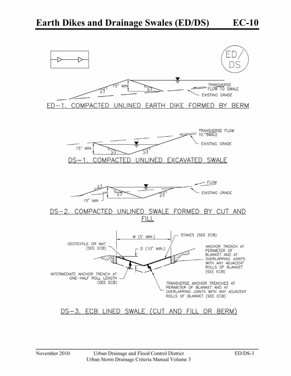
Earth Dikes and Drainage Swales (ED/DS) EC-10
November 2010 Urban Drainage and Flood Control District ED/DS-3Urban Storm Drainage Criteria Manual Volume 3

EC-10 Earth Dikes and Drainage Swales (ED/DS)
ED/DS-4 Urban Drainage and Flood Control District November 2010Urban Storm Drainage Criteria Manual Volume 3

Earth Dikes and Drainage Swales (ED/DS) EC-10
November 2010 Urban Drainage and Flood Control District ED/DS-5Urban Storm Drainage Criteria Manual Volume 3


Silt Fence (SF) SC-1
November 2010 Urban Drainage and Flood Control District SF-3Urban Storm Drainage Criteria Manual Volume 3

SC-1 Silt Fence (SF)
SF-4 Urban Drainage and Flood Control District November 2010Urban Storm Drainage Criteria Manual Volume 3

Stockpile Management (SP) MM-2
November 2010 Urban Drainage and Flood Control District SP-3Urban Storm Drainage Criteria Manual Volume 3

MM-2 Stockpile Management (SM)
SP-4 Urban Drainage and Flood Control District November 2010Urban Storm Drainage Criteria Manual Volume 3
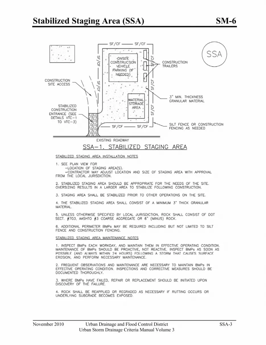
Stabilized Staging Area (SSA) SM-6
November 2010 Urban Drainage and Flood Control District SSA-3Urban Storm Drainage Criteria Manual Volume 3

SM-6 Stabilized Staging Area (SSA)
SSA-4 Urban Drainage and Flood Control District November 2010Urban Storm Drainage Criteria Manual Volume 3

Vehicle Tracking Control (VTC) SM-4
November 2010 Urban Drainage and Flood Control District VTC-3 Urban Storm Drainage Criteria Manual Volume 3

SM-4 Vehicle Tracking Control (VTC)
VTC-6 Urban Drainage and Flood Control District November 2010
Urban Storm Drainage Criteria Manual Volume 3

Temporary and Permanent Seeding (TS/PS) EC-2
June 2012 Urban Drainage and Flood Control District TS/PS-1 Urban Storm Drainage Criteria Manual Volume 3
Photograph TS/PS -1. Equipment used to drill seed. Photo courtesy of Douglas County.
Description Temporary seeding can be used to stabilize disturbed areas that will be inactive for an extended period. Permanent seeding should be used to stabilize areas at final grade that will not be otherwise stabilized. Effective seeding includes preparation of a seedbed, selection of an appropriate seed mixture, proper planting techniques, and protection of the seeded area with mulch, geotextiles, or other appropriate measures.
Appropriate Uses When the soil surface is disturbed and will remain inactive for an extended period (typically 30 days or longer), proactive stabilization measures should be implemented. If the inactive period is short-lived (on the order of two weeks), techniques such as surface roughening may be appropriate. For longer periods of inactivity, temporary seeding and mulching can provide effective erosion control. Permanent seeding should be used on finished areas that have not been otherwise stabilized.
Typically, local governments have their own seed mixes and timelines for seeding. Check jurisdictional requirements for seeding and temporary stabilization.
Design and Installation Effective seeding requires proper seedbed preparation, selection of an appropriate seed mixture, use of appropriate seeding equipment to ensure proper coverage and density, and protection with mulch or fabric until plants are established.
The USDCM Volume 2 Revegetation Chapter contains detailed seed mix, soil preparations, and seeding and mulching recommendations that may be referenced to supplement this Fact Sheet.
Drill seeding is the preferred seeding method. Hydroseeding is not recommended except in areas where steep slopes prevent use of drill seeding equipment, and even in these instances it is preferable to hand seed and mulch. Some jurisdictions do not allow hydroseeding or hydromulching.
Seedbed Preparation
Prior to seeding, ensure that areas to be revegetated have soil conditions capable of supporting vegetation. Overlot grading can result in loss of topsoil, resulting in poor quality subsoils at the ground surface that have low nutrient value, little organic matter content, few soil microorganisms, rooting restrictions, and conditions less conducive to infiltration of precipitation. As a result, it is typically necessary to provide stockpiled topsoil, compost, or other
Temporary and Permanent Seeding
Functions Erosion Control Yes Sediment Control No Site/Material Management No
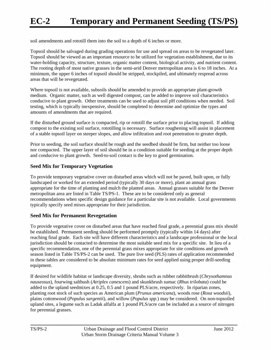
EC-2 Temporary and Permanent Seeding (TS/PS)
TS/PS-2 Urban Drainage and Flood Control District June 2012
Urban Storm Drainage Criteria Manual Volume 3
soil amendments and rototill them into the soil to a depth of 6 inches or more.
Topsoil should be salvaged during grading operations for use and spread on areas to be revegetated later. Topsoil should be viewed as an important resource to be utilized for vegetation establishment, due to its water-holding capacity, structure, texture, organic matter content, biological activity, and nutrient content. The rooting depth of most native grasses in the semi-arid Denver metropolitan area is 6 to 18 inches. At a minimum, the upper 6 inches of topsoil should be stripped, stockpiled, and ultimately respread across areas that will be revegetated.
Where topsoil is not available, subsoils should be amended to provide an appropriate plant-growth medium. Organic matter, such as well digested compost, can be added to improve soil characteristics conducive to plant growth. Other treatments can be used to adjust soil pH conditions when needed. Soil testing, which is typically inexpensive, should be completed to determine and optimize the types and amounts of amendments that are required.
If the disturbed ground surface is compacted, rip or rototill the surface prior to placing topsoil. If adding compost to the existing soil surface, rototilling is necessary. Surface roughening will assist in placement of a stable topsoil layer on steeper slopes, and allow infiltration and root penetration to greater depth.
Prior to seeding, the soil surface should be rough and the seedbed should be firm, but neither too loose nor compacted. The upper layer of soil should be in a condition suitable for seeding at the proper depth and conducive to plant growth. Seed-to-soil contact is the key to good germination.
Seed Mix for Temporary Vegetation
To provide temporary vegetative cover on disturbed areas which will not be paved, built upon, or fully landscaped or worked for an extended period (typically 30 days or more), plant an annual grass appropriate for the time of planting and mulch the planted areas. Annual grasses suitable for the Denver metropolitan area are listed in Table TS/PS-1. These are to be considered only as general recommendations when specific design guidance for a particular site is not available. Local governments typically specify seed mixes appropriate for their jurisdiction.
Seed Mix for Permanent Revegetation
To provide vegetative cover on disturbed areas that have reached final grade, a perennial grass mix should be established. Permanent seeding should be performed promptly (typically within 14 days) after reaching final grade. Each site will have different characteristics and a landscape professional or the local jurisdiction should be contacted to determine the most suitable seed mix for a specific site. In lieu of a specific recommendation, one of the perennial grass mixes appropriate for site conditions and growth season listed in Table TS/PS-2 can be used. The pure live seed (PLS) rates of application recommended in these tables are considered to be absolute minimum rates for seed applied using proper drill-seeding equipment.
If desired for wildlife habitat or landscape diversity, shrubs such as rubber rabbitbrush (Chrysothamnus nauseosus), fourwing saltbush (Atriplex canescens) and skunkbrush sumac (Rhus trilobata) could be added to the upland seedmixes at 0.25, 0.5 and 1 pound PLS/acre, respectively. In riparian zones, planting root stock of such species as American plum (Prunus americana), woods rose (Rosa woodsii), plains cottonwood (Populus sargentii), and willow (Populus spp.) may be considered. On non-topsoiled upland sites, a legume such as Ladak alfalfa at 1 pound PLS/acre can be included as a source of nitrogen for perennial grasses.
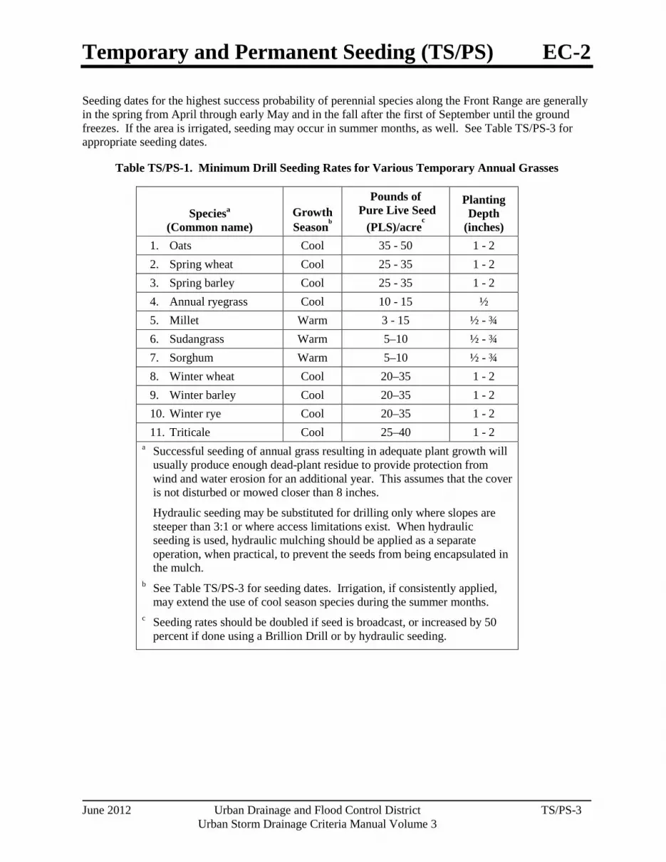
Temporary and Permanent Seeding (TS/PS) EC-2
June 2012 Urban Drainage and Flood Control District TS/PS-3 Urban Storm Drainage Criteria Manual Volume 3
Seeding dates for the highest success probability of perennial species along the Front Range are generally in the spring from April through early May and in the fall after the first of September until the ground freezes. If the area is irrigated, seeding may occur in summer months, as well. See Table TS/PS-3 for appropriate seeding dates.
Table TS/PS-1. Minimum Drill Seeding Rates for Various Temporary Annual Grasses
Speciesa (Common name)
Growth Seasonb
Pounds of Pure Live Seed
(PLS)/acrec
Planting Depth
(inches) 1. Oats Cool 35 - 50 1 - 2 2. Spring wheat Cool 25 - 35 1 - 2 3. Spring barley Cool 25 - 35 1 - 2 4. Annual ryegrass Cool 10 - 15 ½ 5. Millet Warm 3 - 15 ½ - ¾ 6. Sudangrass Warm 5–10 ½ - ¾ 7. Sorghum Warm 5–10 ½ - ¾ 8. Winter wheat Cool 20–35 1 - 2 9. Winter barley Cool 20–35 1 - 2 10. Winter rye Cool 20–35 1 - 2 11. Triticale Cool 25–40 1 - 2
a Successful seeding of annual grass resulting in adequate plant growth will usually produce enough dead-plant residue to provide protection from wind and water erosion for an additional year. This assumes that the cover is not disturbed or mowed closer than 8 inches.
Hydraulic seeding may be substituted for drilling only where slopes are steeper than 3:1 or where access limitations exist. When hydraulic seeding is used, hydraulic mulching should be applied as a separate operation, when practical, to prevent the seeds from being encapsulated in the mulch.
b See Table TS/PS-3 for seeding dates. Irrigation, if consistently applied, may extend the use of cool season species during the summer months.
c Seeding rates should be doubled if seed is broadcast, or increased by 50 percent if done using a Brillion Drill or by hydraulic seeding.

EC-2 Temporary and Permanent Seeding (TS/PS)
TS/PS-4 Urban Drainage and Flood Control District June 2012
Urban Storm Drainage Criteria Manual Volume 3
Table TS/PS-2. Minimum Drill Seeding Rates for Perennial Grasses
Commona Name
Botanical Name
Growth Seasonb
Growth Form
Seeds/ Pound
Pounds of PLS/acre
Alakali Soil Seed Mix
Alkali sacaton Sporobolus airoides Cool Bunch 1,750,000 0.25
Basin wildrye Elymus cinereus Cool Bunch 165,000 2.5
Sodar streambank wheatgrass Agropyron riparium 'Sodar' Cool Sod 170,000 2.5 Jose tall wheatgrass Agropyron elongatum 'Jose' Cool Bunch 79,000 7.0
Arriba western wheatgrass Agropyron smithii 'Arriba' Cool Sod 110,000 5.5
Total 17.75 Fertile Loamy Soil Seed Mix
Ephriam crested wheatgrass Agropyron cristatum 'Ephriam' Cool Sod 175,000 2.0
Dural hard fescue Festuca ovina 'duriuscula' Cool Bunch 565,000 1.0
Lincoln smooth brome Bromus inermis leyss 'Lincoln' Cool Sod 130,000 3.0
Sodar streambank wheatgrass Agropyron riparium 'Sodar' Cool Sod 170,000 2.5
Arriba western wheatgrass Agropyron smithii 'Arriba' Cool Sod 110,000 7.0
Total 15.5 High Water Table Soil Seed Mix Meadow foxtail Alopecurus pratensis Cool Sod 900,000 0.5
Redtop Agrostis alba Warm Open sod 5,000,000 0.25
Reed canarygrass Phalaris arundinacea Cool Sod 68,000 0.5
Lincoln smooth brome Bromus inermis leyss 'Lincoln' Cool Sod 130,000 3.0
Pathfinder switchgrass Panicum virgatum 'Pathfinder' Warm Sod 389,000 1.0
Alkar tall wheatgrass Agropyron elongatum 'Alkar' Cool Bunch 79,000 5.5
Total 10.75 Transition Turf Seed Mixc Ruebens Canadian bluegrass Poa compressa 'Ruebens' Cool Sod 2,500,000 0.5
Dural hard fescue Festuca ovina 'duriuscula' Cool Bunch 565,000 1.0 Citation perennial ryegrass Lolium perenne 'Citation' Cool Sod 247,000 3.0
Lincoln smooth brome Bromus inermis leyss 'Lincoln' Cool Sod 130,000 3.0
Total 7.5
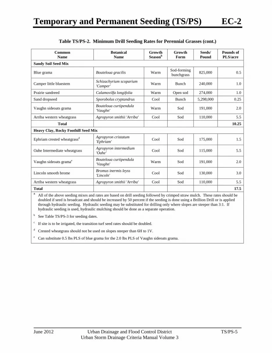
Temporary and Permanent Seeding (TS/PS) EC-2
June 2012 Urban Drainage and Flood Control District TS/PS-5 Urban Storm Drainage Criteria Manual Volume 3
Table TS/PS-2. Minimum Drill Seeding Rates for Perennial Grasses (cont.)
Common Name
Botanical Name
Growth Seasonb
Growth Form
Seeds/ Pound
Pounds of PLS/acre
Sandy Soil Seed Mix
Blue grama Bouteloua gracilis Warm Sod-forming bunchgrass 825,000 0.5
Camper little bluestem Schizachyrium scoparium 'Camper' Warm Bunch 240,000 1.0
Prairie sandreed Calamovilfa longifolia Warm Open sod 274,000 1.0
Sand dropseed Sporobolus cryptandrus Cool Bunch 5,298,000 0.25
Vaughn sideoats grama Bouteloua curtipendula 'Vaughn' Warm Sod 191,000 2.0
Arriba western wheatgrass Agropyron smithii 'Arriba' Cool Sod 110,000 5.5
Total 10.25 Heavy Clay, Rocky Foothill Seed Mix
Ephriam crested wheatgrassd Agropyron cristatum 'Ephriam' Cool Sod 175,000 1.5
Oahe Intermediate wheatgrass Agropyron intermedium 'Oahe' Cool Sod 115,000 5.5
Vaughn sideoats gramae Bouteloua curtipendula 'Vaughn' Warm Sod 191,000 2.0
Lincoln smooth brome Bromus inermis leyss 'Lincoln' Cool Sod 130,000 3.0
Arriba western wheatgrass Agropyron smithii 'Arriba' Cool Sod 110,000 5.5
Total 17.5 a All of the above seeding mixes and rates are based on drill seeding followed by crimped straw mulch. These rates should be
doubled if seed is broadcast and should be increased by 50 percent if the seeding is done using a Brillion Drill or is applied through hydraulic seeding. Hydraulic seeding may be substituted for drilling only where slopes are steeper than 3:1. If hydraulic seeding is used, hydraulic mulching should be done as a separate operation.
b See Table TS/PS-3 for seeding dates. c If site is to be irrigated, the transition turf seed rates should be doubled. d Crested wheatgrass should not be used on slopes steeper than 6H to 1V. e Can substitute 0.5 lbs PLS of blue grama for the 2.0 lbs PLS of Vaughn sideoats grama.

EC-2 Temporary and Permanent Seeding (TS/PS)
TS/PS-6 Urban Drainage and Flood Control District June 2012
Urban Storm Drainage Criteria Manual Volume 3
Table TS/PS-3. Seeding Dates for Annual and Perennial Grasses
Annual Grasses (Numbers in table reference
species in Table TS/PS-1)
Perennial Grasses
Seeding Dates Warm Cool Warm Cool January 1–March 15 March 16–April 30 4 1,2,3 May 1–May 15 4 May 16–June 30 4,5,6,7 July 1–July 15 5,6,7 July 16–August 31 September 1–September 30 8,9,10,11 October 1–December 31
Mulch
Cover seeded areas with mulch or an appropriate rolled erosion control product to promote establishment of vegetation. Anchor mulch by crimping, netting or use of a non-toxic tackifier. See the Mulching BMP Fact Sheet for additional guidance.
Maintenance and Removal Monitor and observe seeded areas to identify areas of poor growth or areas that fail to germinate. Reseed and mulch these areas, as needed.
An area that has been permanently seeded should have a good stand of vegetation within one growing season if irrigated and within three growing seasons without irrigation in Colorado. Reseed portions of the site that fail to germinate or remain bare after the first growing season.
Seeded areas may require irrigation, particularly during extended dry periods. Targeted weed control may also be necessary.
Protect seeded areas from construction equipment and vehicle access.

Mulching (MU) EC-4
June 2012 Urban Drainage and Flood Control District MU-1 Urban Storm Drainage Criteria Manual Volume 3
Photograph MU-1. An area that was recently seeded, mulched, and crimped.
Description Mulching consists of evenly applying straw, hay, shredded wood mulch, rock, bark or compost to disturbed soils and securing the mulch by crimping, tackifiers, netting or other measures. Mulching helps reduce erosion by protecting bare soil from rainfall impact, increasing infiltration, and reducing runoff. Although often applied in conjunction with temporary or permanent seeding, it can also be used for temporary stabilization of areas that cannot be reseeded due to seasonal constraints.
Mulch can be applied either using standard mechanical dry application methods or using hydromulching equipment that hydraulically applies a slurry of water, wood fiber mulch, and often a tackifier.
Appropriate Uses Use mulch in conjunction with seeding to help protect the seedbed and stabilize the soil. Mulch can also be used as a temporary cover on low to mild slopes to help temporarily stabilize disturbed areas where growing season constraints prevent effective reseeding. Disturbed areas should be properly mulched and tacked, or seeded, mulched and tacked promptly after final grade is reached (typically within no longer than 14 days) on portions of the site not otherwise permanently stabilized.
Standard dry mulching is encouraged in most jurisdictions; however, hydromulching may not be allowed in certain jurisdictions or may not be allowed near waterways.
Do not apply mulch during windy conditions.
Design and Installation Prior to mulching, surface-roughen areas by rolling with a crimping or punching type roller or by track walking. Track walking should only be used where other methods are impractical because track walking with heavy equipment typically compacts the soil.
A variety of mulches can be used effectively at construction sites. Consider the following:
Mulch
Functions Erosion Control Yes
Sediment Control Moderate Site/Material Management No

EC-4 Mulching (MU)
MU-2 Urban Drainage and Flood Control District June 2012
Urban Storm Drainage Criteria Manual Volume 3
Clean, weed-free and seed-free cereal grain straw should be applied evenly at a rate of 2 tons per acre and must be tacked or fastened by a method suitable for the condition of the site. Straw mulch must be anchored (and not merely placed) on the surface. This can be accomplished mechanically by crimping or with the aid of tackifiers or nets. Anchoring with a crimping implement is preferred, and is the recommended method for areas flatter than 3:1. Mechanical crimpers must be capable of tucking the long mulch fibers into the soil to a depth of 3 inches without cutting them. An agricultural disk, while not an ideal substitute, may work if the disk blades are dull or blunted and set vertically; however, the frame may have to be weighted to afford proper soil penetration.
Grass hay may be used in place of straw; however, because hay is comprised of the entire plant including seed, mulching with hay may seed the site with non-native grass species which might in turn out-compete the native seed. Alternatively, native species of grass hay may be purchased, but can be difficult to find and are more expensive than straw. Purchasing and utilizing a certified weed-free straw is an easier and less costly mulching method. When using grass hay, follow the same guidelines as for straw (provided above).
On small areas sheltered from the wind and heavy runoff, spraying a tackifier on the mulch is satisfactory for holding it in place. For steep slopes and special situations where greater control is needed, erosion control blankets anchored with stakes should be used instead of mulch.
Hydraulic mulching consists of wood cellulose fibers mixed with water and a tackifying agent and should be applied at a rate of no less than 1,500 pounds per acre (1,425 lbs of fibers mixed with at least 75 lbs of tackifier) with a hydraulic mulcher. For steeper slopes, up to 2000 pounds per acre may be required for effective hydroseeding. Hydromulch typically requires up to 24 hours to dry; therefore, it should not be applied immediately prior to inclement weather. Application to roads, waterways and existing vegetation should be avoided.
Erosion control mats, blankets, or nets are recommended to help stabilize steep slopes (generally 3:1 and steeper) and waterways. Depending on the product, these may be used alone or in conjunction with grass or straw mulch. Normally, use of these products will be restricted to relatively small areas. Biodegradable mats made of straw and jute, straw-coconut, coconut fiber, or excelsior can be used instead of mulch. (See the ECM/TRM BMP for more information.)
Some tackifiers or binders may be used to anchor mulch. Check with the local jurisdiction for allowed tackifiers. Manufacturer's recommendations should be followed at all times. (See the Soil Binder BMP for more information on general types of tackifiers.)
Rock can also be used as mulch. It provides protection of exposed soils to wind and water erosion and allows infiltration of precipitation. An aggregate base course can be spread on disturbed areas for temporary or permanent stabilization. The rock mulch layer should be thick enough to provide full coverage of exposed soil on the area it is applied.
Maintenance and Removal After mulching, the bare ground surface should not be more than 10 percent exposed. Reapply mulch, as needed, to cover bare areas.

Appendix B of the Stormwater Regulation Guide
Modified EPA SWPPP Template, Version 1.1, September 17, 2007
Created 3/17/11; Rev 2/14/12; Rev 3/12/12 93
Appendix 6 – Erosion and Sediment Control Plan - Site Map

Appendix B of the Stormwater Regulation Guide
Modified EPA SWPPP Template, Version 1.1, September 17, 2007
Created 3/17/11; Rev 2/14/12; Rev 3/12/12 94
Appendix 7 – Inspection Report Instructions and Form
Instructions
This inspection report has been developed for you use in completing your 14 day and storm event
site inspections and inspections at completed sites. This inspection report was created consistent
with County’s Stormwater Quality Regulations.
For an electronic copy of just the ESC Plan Contractor Stormwater Quality Inspection Form please
go to http://co-adamscounty.civicplus.com/index.aspx?nid=327.
Using the Inspection Report
You can complete the items in the upper section that will remain constant, such as the date,
project name, contractor, and inspector (if you only use one inspector). You will either need to
print out multiple copies of this inspection report or save an electronic version as a master form
to use during your inspections.
Ensure that all items in the “Weather/Off-Site Discharge Assessment” AND the “Overall Site
Assessment” are completed by checking “Yes” or “No” and document any “Corrective Action
Needed/Notes”. Under “Site Specific BMP Assessment”, document the BMPs that are required
and/or used, if maintenance is needed and document any “Corrective Action Needed/Notes” as
necessary.
When “findings” are present at a construction site due to a 14 day inspection, storm event site
inspections and inspections at completed sites, ensure that when the “finding” has been
addressed, on the same inspection form. Always document when the “finding” was addressed
by filling in the “Date Action Complete”.

Appendix B of the Stormwater Regulation Guide
Modified EPA SWPPP Template, Version 1.1, September 17, 2007
Created 3/17/11; Rev 2/14/12; Rev 3/12/12 95

Appendix B of the Stormwater Regulation Guide
Modified EPA SWPPP Template, Version 1.1, September 17, 2007
Created 3/17/11; Rev 2/14/12; Rev 3/12/12 96
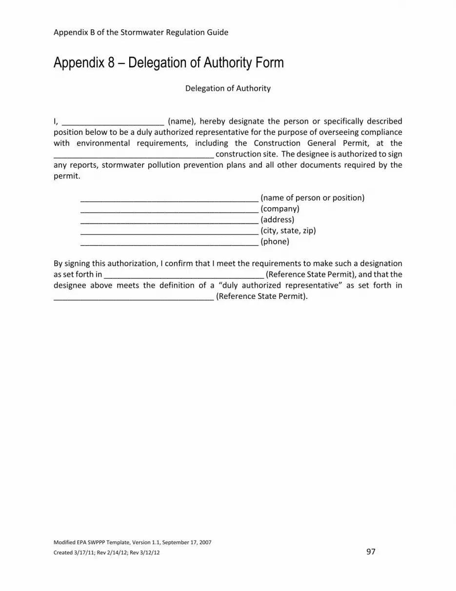
Appendix B of the Stormwater Regulation Guide
Modified EPA SWPPP Template, Version 1.1, September 17, 2007
Created 3/17/11; Rev 2/14/12; Rev 3/12/12 97
Appendix 8 – Delegation of Authority Form
Delegation of Authority
I, _______________________ (name), hereby designate the person or specifically described
position below to be a duly authorized representative for the purpose of overseeing compliance
with environmental requirements, including the Construction General Permit, at the
____________________________________ construction site. The designee is authorized to sign
any reports, stormwater pollution prevention plans and all other documents required by the
permit.
________________________________________ (name of person or position)
________________________________________ (company)
________________________________________ (address)
________________________________________ (city, state, zip)
________________________________________ (phone)
By signing this authorization, I confirm that I meet the requirements to make such a designation
as set forth in ____________________________________ (Reference State Permit), and that the
designee above meets the definition of a “duly authorized representative” as set forth in
____________________________________ (Reference State Permit).

Appendix B of the Stormwater Regulation Guide
Modified EPA SWPPP Template, Version 1.1, September 17, 2007
Created 3/17/11; Rev 2/14/12; Rev 3/12/12 98
Appendix 9 – Completed Stormwater Inspections
Insert completed 14-day, storm event and stabilization inspections here.

Appendix B of the Stormwater Regulation Guide
Modified EPA SWPPP Template, Version 1.1, September 17, 2007
Created 3/17/11; Rev 10/11/11 99
99
Appendix 10 – Subcontractor Certifications/Agreements
SUBCONTRACTOR CERTIFICATION
STORMWATER POLLUTION PREVENTION PLAN
Project Number:
Project Title:
Operator(s):
As a subcontractor, you are required to comply with the Erosion and Sediment Control Plan (ESC Plan) for
any work that you perform on-site. Any person or group who violates any condition of the ESC Plan may
be subject to substantial penalties or loss of contract. You are encouraged to advise each of your
employees working on this project of the requirements of the ESC Plan. A copy of the ESC Plan is available
for your review at the office trailer.
Each subcontractor engaged in activities at the construction site that could impact stormwater must be
identified and sign the following certification statement:
I certify under the penalty of law that I have read and understand the terms and conditions of the ESC
PLAN for the above designated project and agree to follow the BMPs and practices described in the ESC
Plan.
This certification is hereby signed in reference to the above named project:
Company:
Address:
Telephone Number:
Type of construction service to be provided:
Signature:
Title:
Date:

4715 Innovation Drive 970.226.0342 | PFort Collins, CO 80525 970.226.0879 | Fwww.LRA-Inc.com
LAMP RYNEARSON& ASSOCIATES
–
”
’
⅔
’ ’ “ ”
’
”
–

4715
Inno
vatio
n D
rive
970.
226.
0342
| P
For
t Col
lins,
CO
805
2597
0.22
6.08
79 |
Fw
ww
.LRA
-Inc
.com
LAMP
RYN
EARS
ON&
A
SS
OC
IAT
ES
LAMP RYNEARSON - ENGINEERS
PETE CARLSON

4715
Inno
vatio
n D
rive
970.
226.
0342
| P
For
t Col
lins,
CO
805
2597
0.22
6.08
79 |
Fw
ww
.LRA
-Inc
.com
LAMP
RYN
EARS
ON&
A
SS
OC
IAT
ES
LAMP RYNEARSON - ENGINEERS
PETE CARLSON

4715
Inno
vatio
n D
rive
970.
226.
0342
| P
For
t Col
lins,
CO
805
2597
0.22
6.08
79 |
Fw
ww
.LRA
-Inc
.com
LAMP
RYN
EARS
ON&
A
SS
OC
IAT
ES
LAMP RYNEARSON - ENGINEERS
PETE CARLSON

4715
Inno
vatio
n D
rive
970.
226.
0342
| P
For
t Col
lins,
CO
805
2597
0.22
6.08
79 |
Fw
ww
.LRA
-Inc
.com
LAMP
RYN
EARS
ON&
A
SS
OC
IAT
ES
LAMP RYNEARSON - ENGINEERS
PETE CARLSON

4715
Inno
vatio
n D
rive
970.
226.
0342
| P
For
t Col
lins,
CO
805
2597
0.22
6.08
79 |
Fw
ww
.LRA
-Inc
.com
LAMP
RYN
EARS
ON&
A
SS
OC
IAT
ES
LAMP RYNEARSON - ENGINEERS
PETE CARLSON

4715
Inno
vatio
n D
rive
970.
226.
0342
| P
For
t Col
lins,
CO
805
2597
0.22
6.08
79 |
Fw
ww
.LRA
-Inc
.com
LAMP
RYN
EARS
ON&
A
SS
OC
IAT
ES
LAMP RYNEARSON - ENGINEERS
PETE CARLSON

4715
Inno
vatio
n D
rive
970.
226.
0342
| P
For
t Col
lins,
CO
805
2597
0.22
6.08
79 |
Fw
ww
.LRA
-Inc
.com
LAMP
RYN
EARS
ON&
A
SS
OC
IAT
ES
LAMP RYNEARSON - ENGINEERS
PETE CARLSON

4715
Inno
vatio
n D
rive
970.
226.
0342
| P
For
t Col
lins,
CO
805
2597
0.22
6.08
79 |
Fw
ww
.LRA
-Inc
.com
LAMP
RYN
EARS
ON&
A
SS
OC
IAT
ES
LAMP RYNEARSON - ENGINEERS
PETE CARLSON

4715
Inno
vatio
n D
rive
970.
226.
0342
| P
For
t Col
lins,
CO
805
2597
0.22
6.08
79 |
Fw
ww
.LRA
-Inc
.com
LAMP
RYN
EARS
ON&
A
SS
OC
IAT
ES
LAMP RYNEARSON - ENGINEERS
PETE CARLSON

4715
Inno
vatio
n D
rive
970.
226.
0342
| P
For
t Col
lins,
CO
805
2597
0.22
6.08
79 |
Fw
ww
.LRA
-Inc
.com
LAMP
RYN
EARS
ON&
A
SS
OC
IAT
ES
LAMP RYNEARSON - ENGINEERS
PETE CARLSON
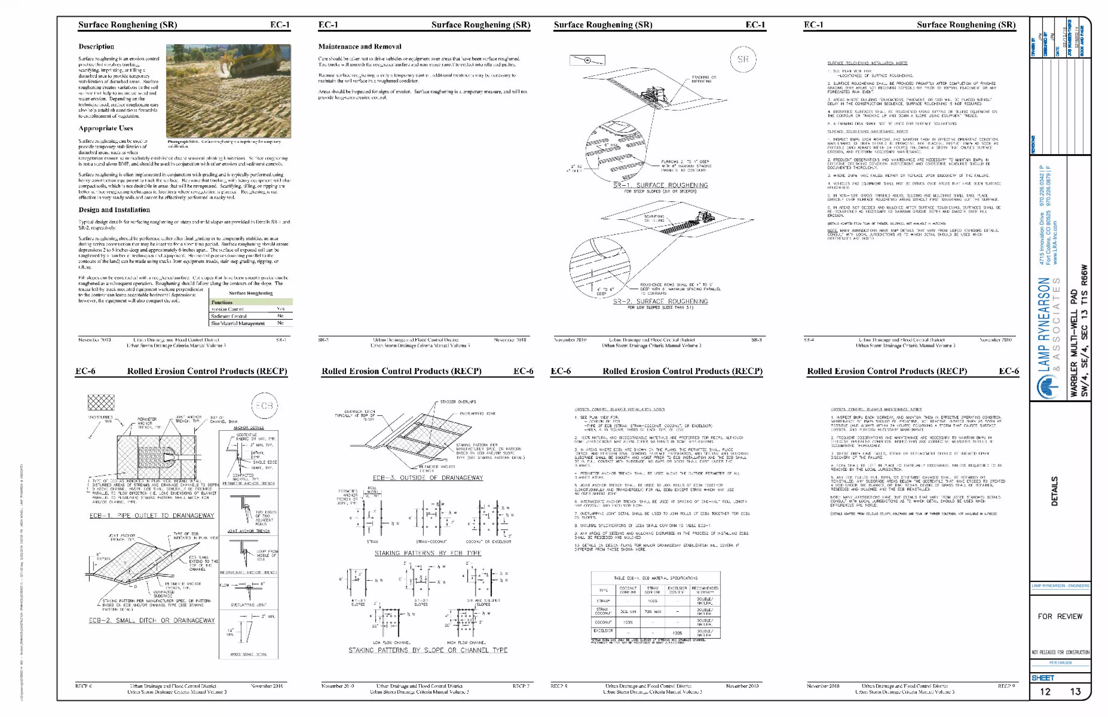
4715
Inno
vatio
n D
rive
970.
226.
0342
| P
For
t Col
lins,
CO
805
2597
0.22
6.08
79 |
Fw
ww
.LRA
-Inc
.com
LAMP
RYN
EARS
ON&
A
SS
OC
IAT
ES
LAMP RYNEARSON - ENGINEERS
PETE CARLSON

4715
Inno
vatio
n D
rive
970.
226.
0342
| P
For
t Col
lins,
CO
805
2597
0.22
6.08
79 |
Fw
ww
.LRA
-Inc
.com
LAMP
RYN
EARS
ON&
A
SS
OC
IAT
ES
LAMP RYNEARSON - ENGINEERS
PETE CARLSON

4715
Inno
vatio
n D
rive
970.
226.
0342
| P
For
t Col
lins,
CO
805
2597
0.22
6.08
79 |
Fw
ww
.LRA
-Inc
.com
LAMP
RYN
EARS
ON&
A
SS
OC
IAT
ES
LAMP RYNEARSON - ENGINEERS
PETE CARLSON
·
·


4715
Inno
vatio
n D
rive
970.
226.
0342
| P
For
t Col
lins,
CO
805
2597
0.22
6.08
79 |
Fw
ww
.LRA
-Inc
.com
LAMP
RYN
EARS
ON&
A
SS
OC
IAT
ES
LAMP RYNEARSON - ENGINEERS
PETE CARLSON

1
4715
Inno
vatio
n D
rive
970.
226.
0342
| P
For
t Col
lins,
CO
805
2597
0.22
6.08
79 |
Fw
ww
.LRA
-Inc
.com
LAMP
RYN
EARS
ON&
A
SS
OC
IAT
ES
LAMP RYNEARSON - ENGINEERS
PETE CARLSON

1 2
4715
Inno
vatio
n D
rive
970.
226.
0342
| P
For
t Col
lins,
CO
805
2597
0.22
6.08
79 |
Fw
ww
.LRA
-Inc
.com
LAMP
RYN
EARS
ON&
A
SS
OC
IAT
ES
LAMP RYNEARSON - ENGINEERS
PETE CARLSON

4715 Innovation Drive 970.226.0342 | PFort Collins, CO 80525 970.226.0879 | Fwww.LRA-Inc.com
LAMP RYNEARSON& ASSOCIATES


![Adams v Cape Industries [1990].pdf](https://img.pdfslide.net/doc/110x75/63287f09cedd78c2b50e14fb/adams-v-cape-industries-1990pdf.jpg)