Embed Size (px)
Citation preview
5.3 Refrigerant Piping
1. APPLICATION CONSIDERATIONSA refrigerant piping system requires the same general designconsiderations as any fluid flow system. However, there areadditional factors that critically influence system design:1.1 The system must be designed for minimum pressure drop since
pressure losses decrease the thermal capacity and increase thepower requirement in a refrigeration system.
1.2 The fluid being piped changes in state as it circulates.1.3 Since lubricating oil is miscible with Refrigerants 12, 22,
500 and 502, some provision must be made to:1.3.1 Minimize the accumulation of liquid refrigerant in thecompressor crankcase.1.3.2 Return oil to the compressor at the same rate at which itleaves.
2. CODE REGULATIONSSystem design should conform to all codes, laws and regulations
applying at the site of an installation.In addition the Safety Code for Mechanical Refrigeration (USAA-
B9.1) and the Code for Refrigeration Piping (USAS-B31.5) areprimarily drawn up as guides to safe practice and should also beadhered to. These two codes, as they apply to refrigeration, arealmost identical, and are the basis of most municipal and statecodes.
3. DESIGN PRINCIPLES3.1 Objectives
Refrigerant piping systems must be designed to accomplish thefollowing:3.1.1 Insure proper feed to evaporators.3.1.2 Provide practical line sizes without excessive pressure
drop.3.1.3 Protect compressors by –
3.1.3.1 Preventing excessive lubricating oil from beingtrapped in the system.3.1.3.2 Minimizing the loss of lubricating oil from thecompressor at all times.3.1.3.3 Preventing liquid refrigerant from entering thecompressor during operation and shutdown.
3.2 Friction Loss and Oil Return
1
In sizing refrigerant lines it is necessary to consider theoptimum size with respect to economics, friction loss and oilreturn. From a cost standpoint it is desirable to select the linesize as small as possible. Care must be taken, however, to selecta line size that does not cause excessive suction and dischargeline pressure drop since this may result in loss of compressorcapacity and excessive hp/ton. Too small a line size may alsocause excessive liquid line pressure drop. This can result inflashing of liquid refrigerant which causes faulty expansionvalve operation.
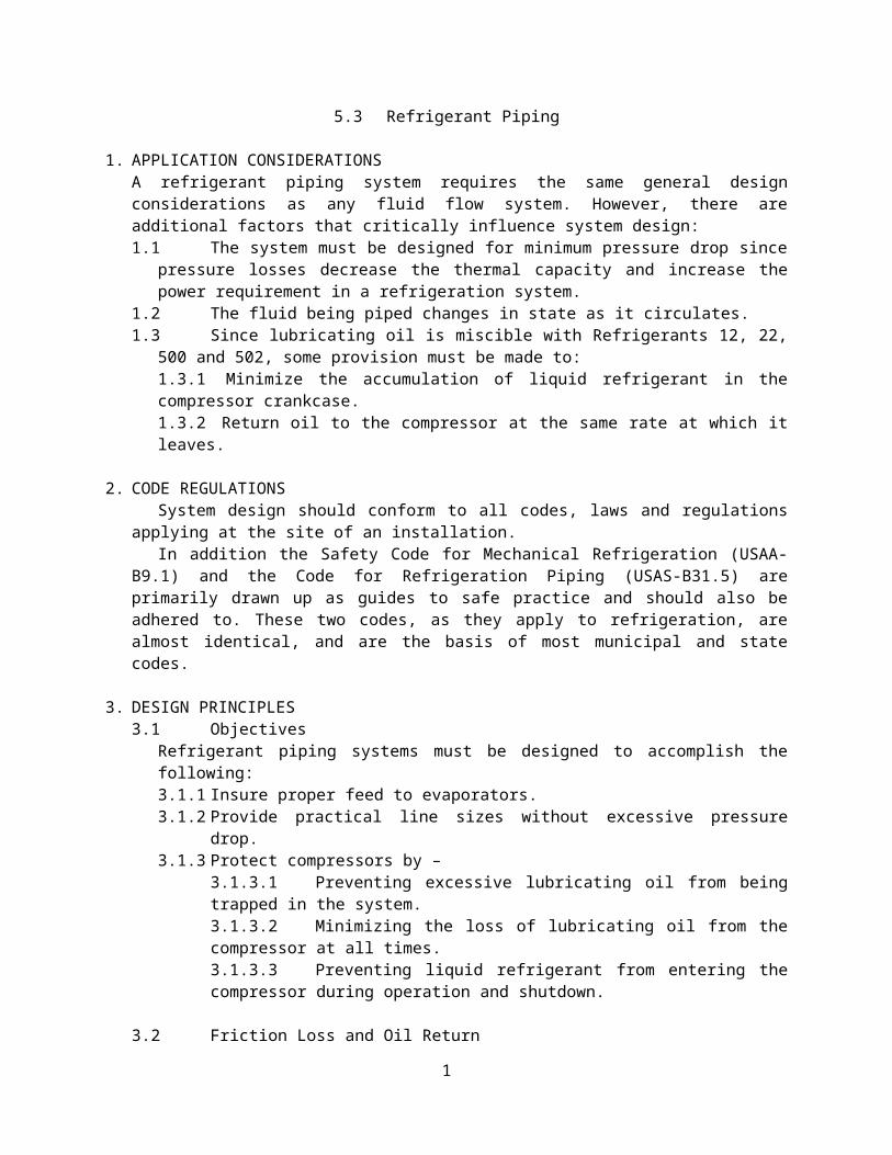
The effect of excessive suction and Hot gas line pressure dropon compressor capacity and horse power is illustrated in Table16.
Pressure drop is kept to a minimum by optimum sizing of thelines with respect to economics, making sure that refrigerantline velocities are sufficient to entrain and carry oil along atall loading conditions. For Refrigerants 12, 22, 500 and 502,consider the requirements for oil return up vertical risers.
Pressure drop in liquid lines is not as critical as in suctionand discharge lines. However, the pressure drop should not be soexcessive as to cause gas formation in the liquid line orinsufficient liquid pressure at the liquid feed device. A systemshould normally be designed so that the pressure drop in theliquid line is not greater than one to two degrees change insaturation temperature. In terms of pressure drop, thiscorresponds to about 1.8 to 3.8 psi for R-12, 2.9 to 6 psi for R-22, 2.2 to 4.6 psi for R-500 and 3.1 to 6.3 psi for R-502.
Friction pressure drop in the liquid line includes accessoriessuch as solenoid valve, strainer, drier and hand valves, as wellas the actual pipe and fittings from the receiver outlet to therefrigerant feed device at the evaporator.
Pressure drop in the suction line means a loss in systemcapacity because it forces the compressor to operate at a lower
2
suction pressure to maintain the desired evaporator temperature.Standard practice is to size the suction line for a pressure dropof approximately two degrees charge in saturation temperature. Interms of pressure loss at 40 F suction temperature, thiscorresponds to about 1.8 psi for R-12, 2.9 psi for R-22, 2.2 psifor R-500, and 3.1 psi for R-502.
Where a reduction in pipe size is necessary to providesufficient gas velocity to entrain oil upward in vertical risersat partial loads, a greater pressure drop is imposed at fullload. To keep the total pressure drop within the desired limit,excessive riser loss can be offset by properly sizing thehorizontal and “down” lines.
It is important to minimize the pressure loss in hot gas linesbecause these losses can increase the required compressorhorsepower and decrease the compressor capacity. It is usualpractice not to exceed a pressure drop corresponding to one totwo degrees change in saturation temperature. This is equal toabout 1.8 to 3.8 psi for R - 12 , 2.9 to 6 psi for R – 22 , 2.2to 4.6 psi for R – 500, and 3.1 to 6.3 psi for R – 502.
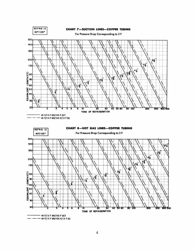
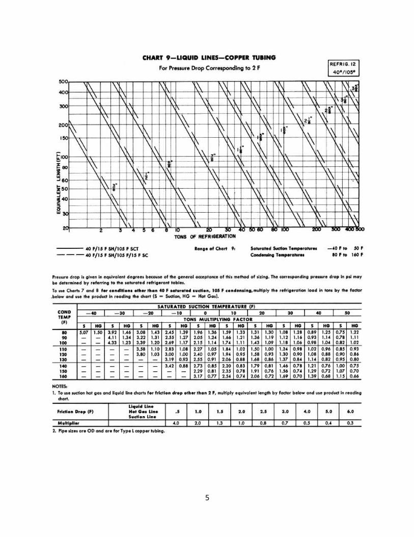
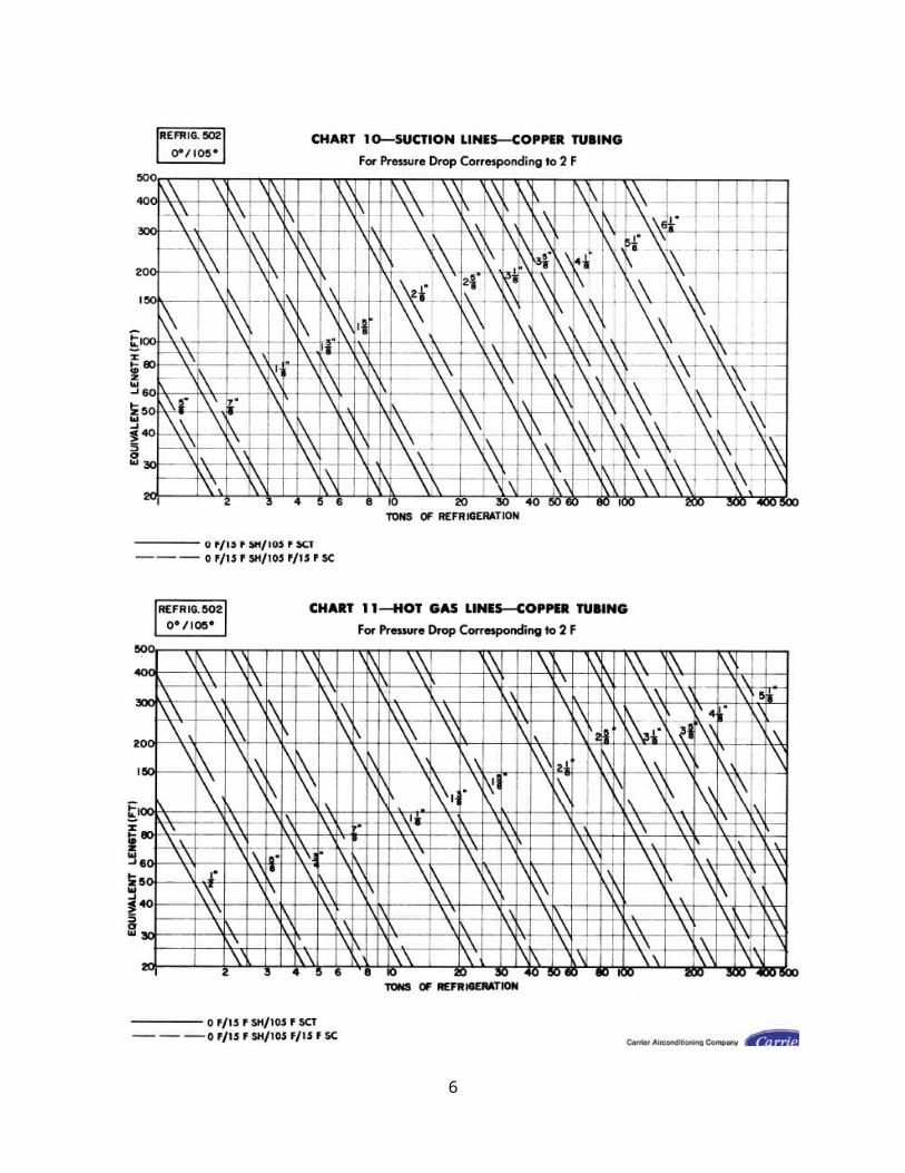
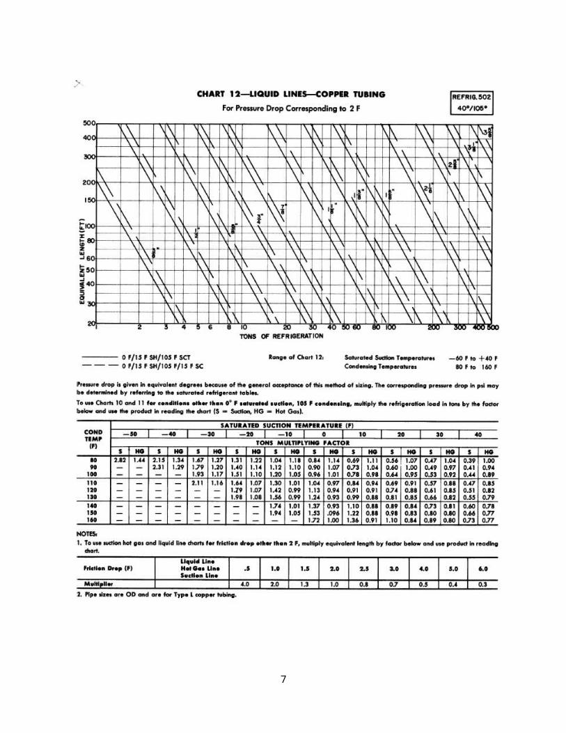
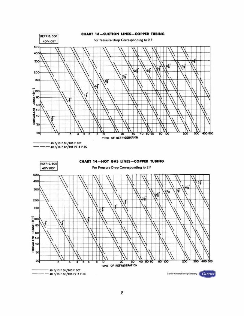
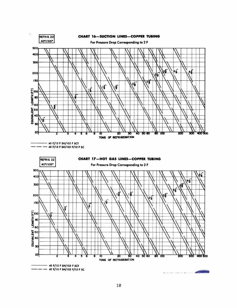
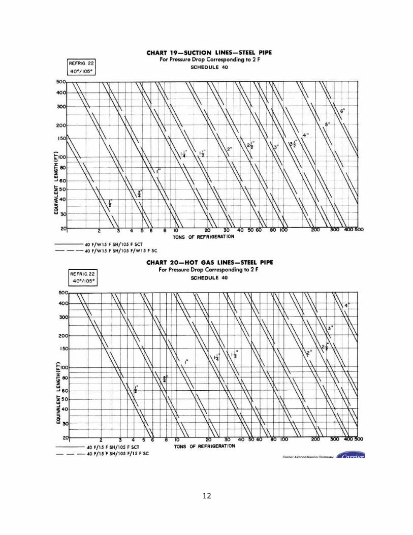
4. REFRIGERANT PIPE SIZINGCharts 7 thru 21 are used to select the proper steel pipe and
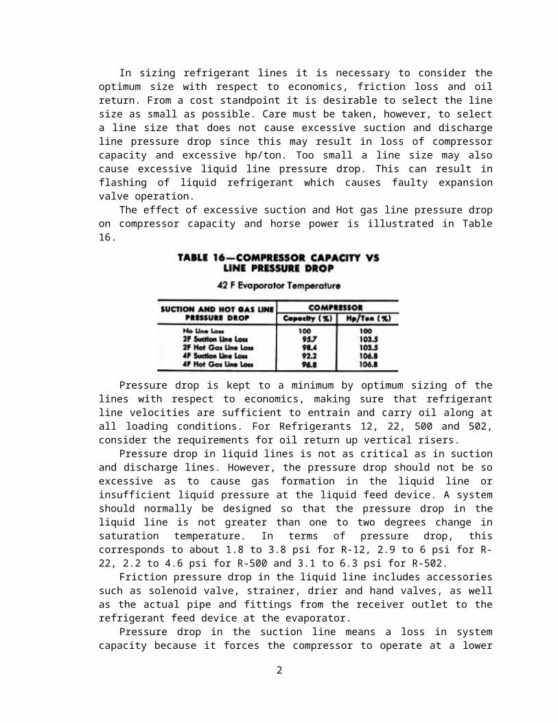
copper tubing size for the refrigeration lines. They are based onthe Darcy – Weisbach formula :
h=f LDV22g
where h = loss of head in feet of fluidf = friction factorL = length of pipe in feetD = diameter of pipe in feetV = velocity in fpsg = acceleration of gravity = 32.17 ft /sec/sec
The friction factor depends on the roughness of pipe surface andthe Reynolds number of the fluid. In this case the Reynolds numberand the Moody chart are used to determine the friction factor.
3
4
5
6
7
8
9
10
11
12
5. Use of Pipe Sizing ChartsThe following procedure for sizing refrigerant piping is recommended:a. Measure the length in feet ) of straight pipe.
13
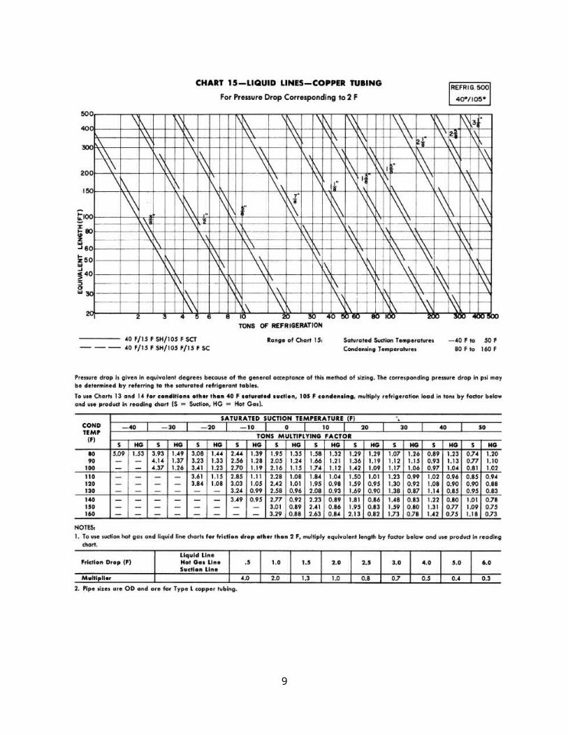
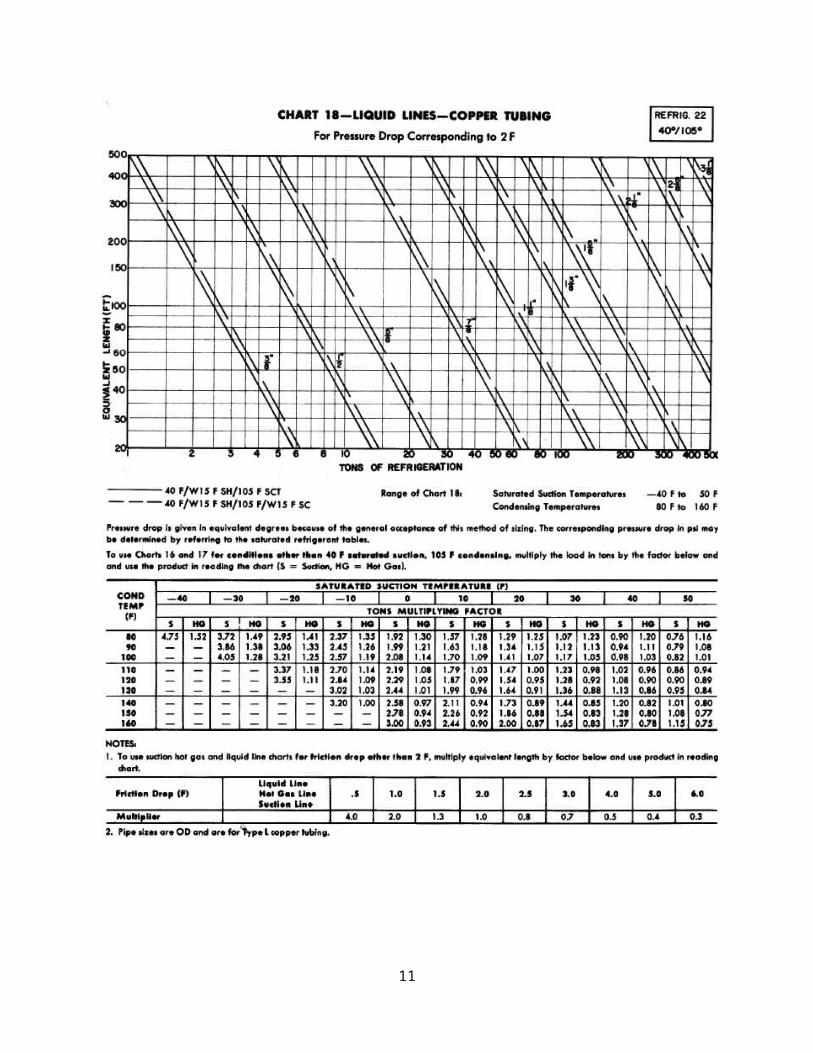
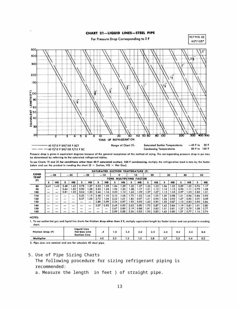
b. Add 50 % to obtain a trail total equivalent length.c. If other than a rated friction loss is desired, multiply the
total equivalent length by the correction factor from the tablefollowing the appropriate pipe or tubing size chart.
d. If necessary, correct for suction and condensing temperatures.e. Read pipe size from Charts 7 thru 21 to determine size of
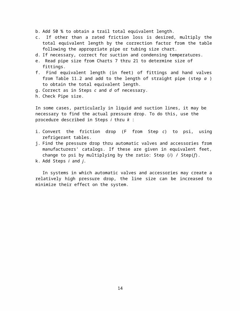
fittings.f. Find equivalent length (in feet) of fittings and hand valves
from Table 11.2 and add to the length of straight pipe (step a )to obtain the total equivalent length.
g. Correct as in Steps c and d of necessary.h. Check Pipe size.
In some cases, particularly in liquid and suction lines, it may be necessary to find the actual pressure drop. To do this, use the procedure described in Steps i thru k :
i. Convert the friction drop (F from Step c) to psi, usingrefrigerant tables.
j. Find the pressure drop thru automatic valves and accessories frommanufacturers’ catalogs. If these are given in equivalent feet,change to psi by multiplying by the ratio: Step (i) / Step(f).
k. Add Steps i and j.
In systems in which automatic valves and accessories may create arelatively high pressure drop, the line size can be increased tominimize their effect on the system.
14
Example No. 1 – Use of Pipe Sizing ChartsGiven:Refrigerant 12 systemLoad – 46 tonsEquivalent length of piping – 65 ftSaturated suction – 30 FCondensing temperature – 100 F , no subcoolingType L copper tubingFind:Suction line size for pressure drop corresponding to 2 F.Actual pressure drop in terms of degrees F for sizeselected.Solution:See Chart 7.
a. Line size for 40 F saturated suction and 105 F condensingtemperature are shown on Chart 7. Determine the correction factorfor a 30 F suction temperature of 1.18 from table in notefollowing Chart 9.
15
b. Determine adjusted tons to be used in Chart 7 by multiplying correction factor in Step 1 by load in tons: 1.18 x 46 = 55 tons
c. Enter Chart 7 and project upward from 55 tons, to the 0oFsubcooling line of a 2 5/8 in OD pipe size, then to a 31/8 in. ODpipe size. At 25/8 in. OD, a 2 F drop is obtained with 34 ft ofpipe; at 3 1/8 in. OD a 2 F drop is obtained with 80 ft of pipe.Select a 31/8 in. OD pipe to obtain less than a 2 F drop.
d. Use the following equation to determine actual pressure drop in terms of degrees F in the 3 1/8 in. OD pipe with a 46 ton load:Actual pressure drop=
equivalent ft of pipepiping allowed for 2 F drop
×2 F
=6571
×2 F=1.8 F
6. LIQUID LINE DESIGNRefrigeration oil is sufficiently miscible with these
refrigerants in the liquid phase to insure adequate mixing and oilreturn. Therefore low liquid velocities and traps in liquid lines donot pose oil return problems.
The amount of liquid line pressure drop which can be tolerated isdependent on the number of degrees subcooling of the liquid. Usuallythis amounts to 5 F to 15 F as the liquid leaves the condenser.Liquid lines should not be sized for more than a F drop under normalcircumstances. In addition, liquid lines passing thru extremely warmspaces should be insulated.
7. Friction Drop and Static Head (Liquid Line)With an appreciable friction drop and / or a static head due to
elevation of the liquid metering device above the condenser, It maybe necessary to resort to some additional means of liquid subcoolingto prevent flashing in the liquid line. Increasing the liquid linepipe size minimizes pipe friction and flashing due to friction drop.
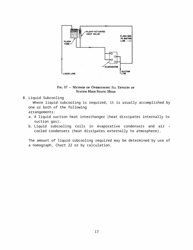
In large systems where the cost is warranted, a liquid pump maybe used to overcome static head. An arrangement shown in Fig. 57illustrate a method which may be used to overcome the effect ofexcessive flash gas caused by a high static head in the system. Thisarrangement does not prevent the forming of flash gas, but doesoffset the effect it might have on the operation of the evaporatorand valves.
16
8. Liquid SubcoolingWhere liquid subcooling is required, it is usually accomplished by
one or both of the followingarrangements: a. A liquid suction heat interchanger (heat dissipates internally to
suction gas).b. Liquid subcooling coils in evaporative condensers and air –
cooled condensers (heat dissipates externally to atmosphere).
The amount of liquid subcooling required may be determined by use ofa nomograph, Chart 22 or by calculation.
17
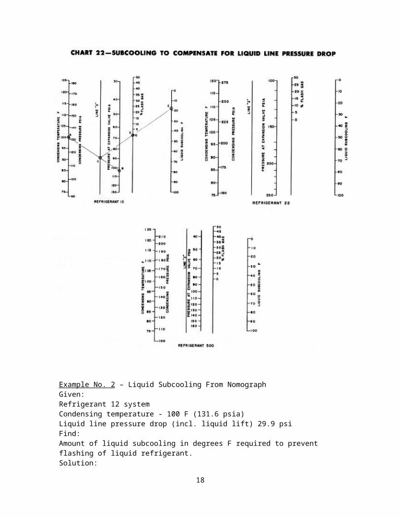
Example No. 2 – Liquid Subcooling From NomographGiven:Refrigerant 12 system Condensing temperature - 100 F (131.6 psia)Liquid line pressure drop (incl. liquid lift) 29.9 psiFind:Amount of liquid subcooling in degrees F required to prevent flashing of liquid refrigerant.Solution:
18
Use Chart 22.1. Determine pressure at expansion valve: 131.6 – 29.9 = 101.7 psia2. Draw line from point A (100 F cond temp) to point B (101.7 psia
at expansion valve).3. Draw line from point C (intersection of AB with line Z) thru
point D (0% flash gas) to point E (intersection of CD with liquidsubcooling line).
4. Liquid subcooling at point E = 18 F. Liquid subcooling required to prevent liquid flashing = 18 F.
Example No. 3 – Liquid Subcooling by CalculationGiven:Refrigerant 12 systemCondensing temperature – 100 FLiquid lift – 35 ftPiping friction loss – 3 psiLosses thru valves and accessories – 7.4 psiFind:Amount of liquid subcooling required to prevent flashing ofliquid refrigerant.Solution:1. Pressure loss due to pipe friction = 3.0 psi
Pressure loss due to valves and accessories = 7.4 psiPressure loss due to 35 ft liquid lift = 35/1.8* = 19.5 psiTotal pressure loss in liquid line = 29.9 psi
2. Condensing pressure at 100 F = 116.9 psigPressure loss in liquid line = 29.9 psiNet pressure at liquid feed valve = 87 psig
3. Saturation temperature at 87 psig = 82 F (from refrigerant property tables)
4. Subcooling required = condensing temp – saturation temp at 87 psig
= 100 – 82 = 18FLiquid subcooling required to prevent liquid flashing = 18 F.
* At no.rmal liquid temperatures the static pressure loss due toelevation at the top of a liquid lift is one psi for every 1.8 ft ofRefrigerant 12, 2.0 ft of Refrigerant 22, and 2.1 ft of Refrigerant500.
9. Sizing of Condenser to Receiver Lines(Condensate Lines)Liquid line piping from a condenser to a receiver is run out
horizontally (same size as the condenser outlet connection) to allow
19
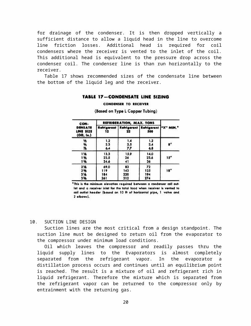
for drainage of the condenser. It is then dropped vertically asufficient distance to allow a liquid head in the line to overcomeline friction losses. Additional head is required for coilcondensers where the receiver is vented to the inlet of the coil.This additional head is equivalent to the pressure drop across thecondenser coil. The condenser line is than run horizontally to thereceiver.
Table 17 shows recommended sizes of the condensate line betweenthe bottom of the liquid leg and the receiver.
10. SUCTION LINE DESIGNSuction lines are the most critical from a design standpoint. The
suction line must be designed to return oil from the evaporator tothe compressor under minimum load conditions.
Oil which leaves the compressor and readily passes thru theliquid supply lines to the Evaporators is almost completelyseparated from the refrigerant vapor. In the evaporator adistillation process occurs and continues until an equilibrium pointis reached. The result is a mixture of oil and refrigerant rich inliquid refrigerant. Therefore the mixture which is separated fromthe refrigerant vapor can be returned to the compressor only byentrainment with the returning gas.
20
Oil entrainment with the return gas in a horizontal line isreadily accomplished with normal design velocities. Thereforehorizontal lines can and should be run “dead “ level.
11. Suction risersMost refrigeration piping systems contain a suction riser. Oil
circulating in the system can be returned up the riser only byentrainment with the returning gas. Oil returning up a riser creepsup the inner surface of the pipe. Whether the oil moves up the innersurface is dependent upon the mass velocity of the gas at the wallsurface. The larger the pipe diameter, the greater the velocityrequired at the center of the pipe to maintain a given velocity atthe wall surface.
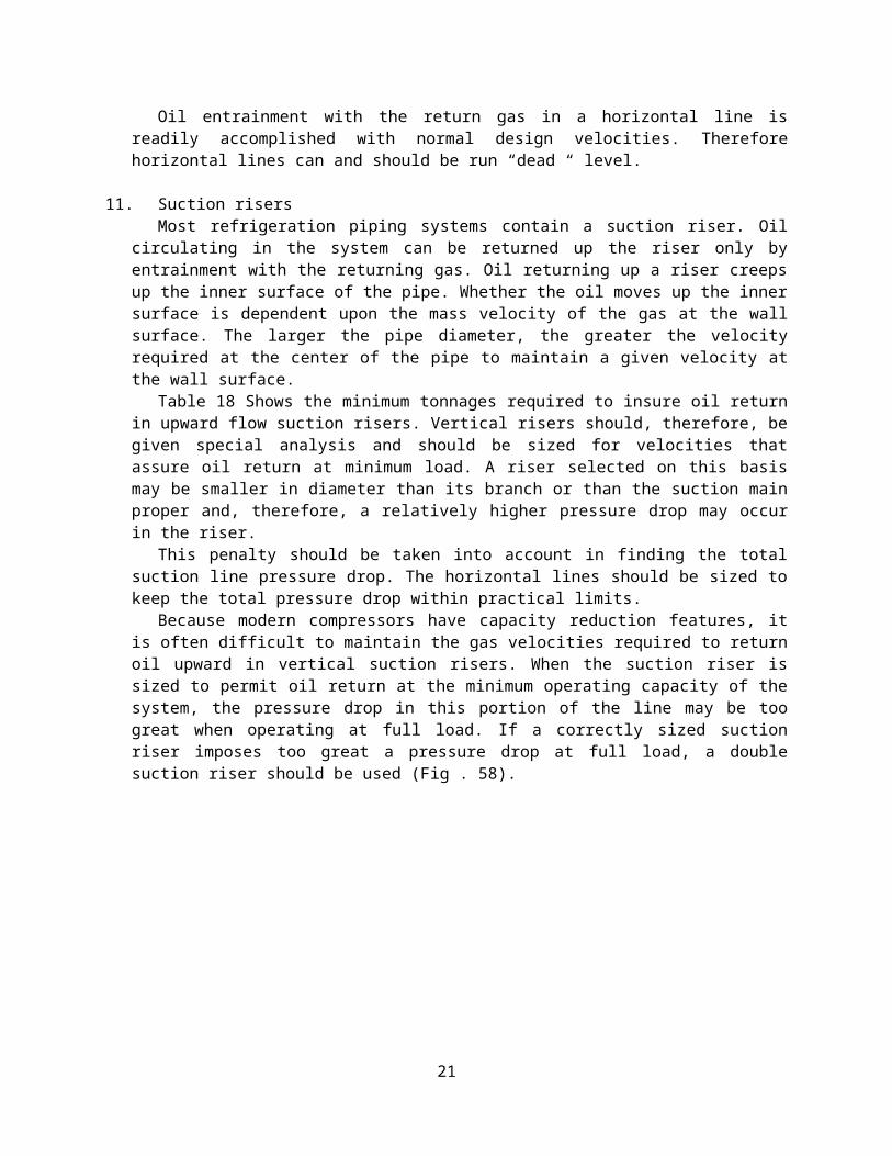
Table 18 Shows the minimum tonnages required to insure oil returnin upward flow suction risers. Vertical risers should, therefore, begiven special analysis and should be sized for velocities thatassure oil return at minimum load. A riser selected on this basismay be smaller in diameter than its branch or than the suction mainproper and, therefore, a relatively higher pressure drop may occurin the riser.
This penalty should be taken into account in finding the totalsuction line pressure drop. The horizontal lines should be sized tokeep the total pressure drop within practical limits.
Because modern compressors have capacity reduction features, itis often difficult to maintain the gas velocities required to returnoil upward in vertical suction risers. When the suction riser issized to permit oil return at the minimum operating capacity of thesystem, the pressure drop in this portion of the line may be toogreat when operating at full load. If a correctly sized suctionriser imposes too great a pressure drop at full load, a doublesuction riser should be used (Fig . 58).
21
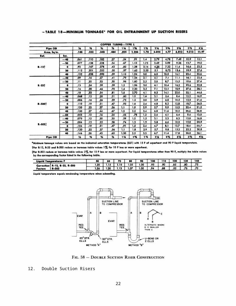
12. Double Suction Risers
22
There are applications in which single suction risers may besized for oil return at minimum load without serious penalty atdesign load. Where single compressors with capacity control areused, minimum capacity corresponds to the compressor capacity at itsminimum displacement. The maximum to minimum displacement ratio isusually three or four one, depending on compressor size.
The compressor capacity at minimum displacement should be taken at an arbitrary figure of approximately 20 F below the design suction temperature and 90 F liquid temperature and not the design suction temperature for air conditioning applications.
Where multiple compressors are interconnected and controlled sothat one or more may shut down while another continues to operate,the ratio of maximum to minimum displacement becomes much greater.In this case a double suction riser may be necessary for goodoperating economy at design load. The sizing and operation of adouble suction riser is described as follows:a. In Fig. 58 the minimum load riser indicated by A is sized so that
it returns oil at the minimum possible load.b. The second riser B which is usually larger than riser A is sized
so that the parallel pressure drop thru both risers at full loadis satisfactory, providing this assures oil return at full load.
c. A trap is introduced between the two risers as shown in Fig. 58.During partial load operation when the gas velocity is notsufficient to return oil through both risers, the trap graduallyfills with oil until the second riser B is sealed off. When thisoccurs, the gas travels up riser A only and has enough velocityto carry oil along with it back into the horizontal suction main.
The fittings at the bottom of the riser must be close coupled sothat the oil holding capacity of the trap is limited to a minimum.If this is not done, the trap can accumulate enough oil on partialload operation to seriously lower the compressor crankcase oillevel. Also, larger slug – backs of oil to the compressor occur whenthe trap clears out on increased load operation. Fig. 58 shows thatthe larger riser B forms an inverted loop and enters the horizontalsuction line form the top. The purpose of this loop is to preventoil drainage into this riser which may be “ idle “ during partialload operation.
Example 4 – Determination of Riser Size – (Single Riser )Given:
23
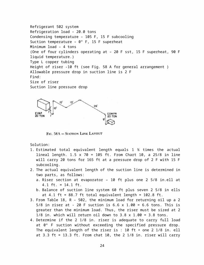
Refrigerant 502 systemRefrigeration load – 20.0 tonsCondensing temperature – 105 F, 15 F subcoolingSuction temperature – 0° F, 15 F superheatMinimum load – 4 tons(One of four cylinders operating at – 20 F sst, 15 F superheat, 90 Fliquid temperature.)Type L copper tubingHeight of riser -10 ft (see Fig. 58 A for general arrangement )Allowable pressure drop in suction line is 2 FFind:Size of riserSuction line pressure drop
Solution:1. Estimated total equivalent length equals 1 ½ times the actual
lineal length. 1.5 x 70 = 105 ft. From Chart 10, a 25/8 in linewill carry 20 tons for 165 ft at a pressure drop of 2 F with 15 Fsubcooling.
2. The actual equivalent length of the suction line is determined intwo parts, as follows:a. Riser section at evaporator – 10 ft plus one 2 5/8 in.ell at
4.1 ft. = 14.1 ft.b. Balance of suction line system 60 ft plus seven 2 5/8 in ells
at 4.1 ft = 88.7 ft total equivalent length = 102.8 ft.3. From Table 18, R – 502, the minimum load for returning oil up a 2
5/8 in riser at - 20 F suction is 6.6 x 1.00 = 6.6 tons. This isgreater than the minimum load. Thus, the riser must be sized at 21/8 in. which will return oil down to 3.8 x 1.00 = 3.8 tons.
4. Determine if the 2 1/8 in. riser is adequate to carry full loadat 0º F suction without exceeding the specified pressure drop.The equivalent length of the riser is : 10 ft + one 2 1/8 in. ellat 3.3 ft = 13.3 ft. From chat 10, the 2 1/8 in. riser will carry
24
20 tons for 58 ft at a pressure drop of 2 F. The loss in theriser for 13.3 ft:
13.3 ft58.0 ft
×2 F=0.46 F
The loss in the balance of the suction line:88.7 ft165 ft
×2 F=1.07 F
The total loss = .46 + 1.07 = 1.53 F which is within the 2 Fspecified.
Example 4 A – Determination of Riser Size – (Double Riser )Given:Refrigerant 12 systemRefrigeration load – 98.5 tonsCondensing temperature – 105 F, no subcoolingSuction temperature – 40 F, 15 F superheatMinimum load – 7.0 tons(Two of 16 cylinders operating at 20 F SST,15 F superheat, 105 F liquid temperature.)Type L Copper tubingHeight of riser – 10 ft (See Fig. 58 A for general arrangement)Allowable pressure drop in suction line is 2 FFind:Size of RiserSuction line pressure dropSolution:1. Estimated total equivalent length equals 1 ½ times the actual
lineal length 1.5 x 70 = 105 ft. From Chart 7, a 4 1/8 in. linewill carry 98.5 tons for 110 ft at a pressure drop of 2 F with nosubcooling.
2. The actual equivalent length of the suction line equals 70 ftplus eight 4 1/8 in. ells at 6.7 ft = 123.6 ft. This is greaterthan 110 ft which gives a 2 F loss for the 41/8 in. size.Therefore, select a a pressure drop 2 F.
3. The actual equivalent length of the suction line is determined intwo parts, as follows:a. Riser section at evaporator – 10 ft + one 5 1/8 in. ell at 8.2
ft = 18.2 ft.b. Balance of suction line system – 60 ft + seven 5 1/8 in. ell
at 8.2 ft = 117.4 ft. Total equivalent length = 135.6 ft.4. From Table 18, R –12, a 2 1/8 in. riser will return oil when
carrying 5.1 x .925 = 4.7 tons at 20 F suction temperature.
25
5. Determine if the 2 1/8 in. riser is adequate to carry full loadat 40 F suction without exceeding the specified pressure drop.The equivalent length of the riser is 10 ft + one 21/8 in. ell at3.3 ft = 13.3 ft. The pressure drop in the balance of the suctionline is :
117.4 ft340 ft
×2 F=0.69 F
The pressure drop allowed for the riser is then 2 F - .69 F or1.31 F. The chart equivalent length of a 2 1/8 in. line having apressure drop or 1.31 F is:
2 F1.31 F
×13.3 ft=20 ft
Chart 7 at 20 ft shows the a 2 1/8 in. line is only capable ofcarrying 42 tons. Thus a Second riser
is necessary.
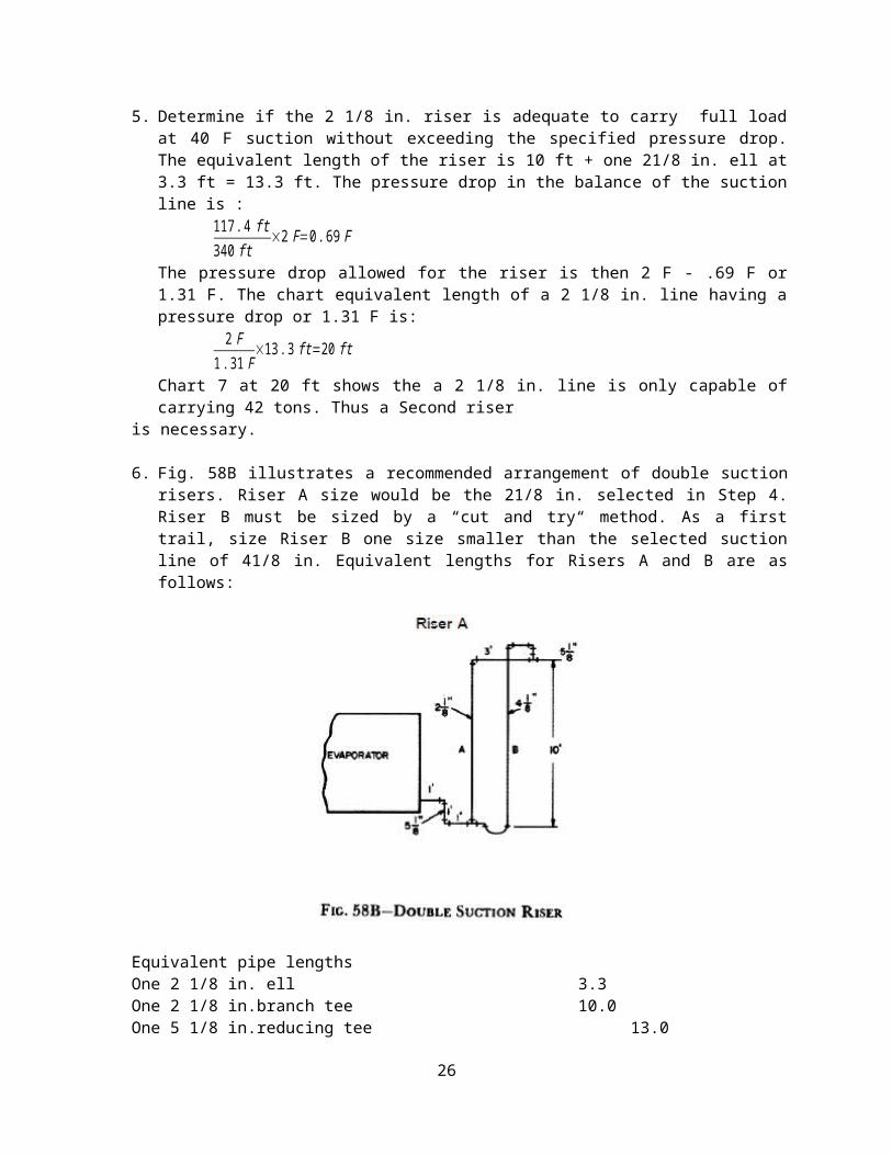
6. Fig. 58B illustrates a recommended arrangement of double suctionrisers. Riser A size would be the 21/8 in. selected in Step 4.Riser B must be sized by a “cut and try“ method. As a firsttrail, size Riser B one size smaller than the selected suctionline of 41/8 in. Equivalent lengths for Risers A and B are asfollows:
Equivalent pipe lengthsOne 2 1/8 in. ell 3.3One 2 1/8 in.branch tee 10.0One 5 1/8 in.reducing tee 13.0
26
Actual pipe length 13.0Total eguivalent length 39.3 ftRiser BEquivalent pipe lengthsThree 4 1/8 in. ells 20.1One 5 1/8 in. reducing tee 12.0One 4 1/8 in. branch tee 21.0One 4 1/8 in. “U” 17.0Actual pipe length 13.0Total equivalent length 83.1 ftPressure drop available for the riser is 1.31 F from Step 5.
For Riser A, the chart equivalent length of a 21/8 in. line is:2 F
1.31 F×39.3 ft=60.0 ft
For Riser B, the chart equivalent length of a 41/8 in. line is:2 F
1.31 F×83.1 ft=127.0 ft
From Chart 7, the 2 1/8 in. line is capable of carrying 23 tons andthe 41/8 in. line is capable of carrying 92 tons. The combinedcapacity is 115 tons , which is acceptable. Riser pressure drop isequal to:
98.5 tons115 tons
×1.31 F=1.12 F
Total pressure drop = 1.12 F + .69 F = 1.81 F
13. DISCHARGE ( HOT GAS ) LINE DESIGNThe hot gas line should be sized for a practical pressure drop. The effect of pressure drop is shown in Table 16.
14. Discharge RisersEven though a low loss is desired in the hot gas line, the line
should be sized so that refrigerant gas velocities are able to carryalong entrained oil. In the usual application this is not a problem,However, where multiple compressors are used with capacity control,hot gas risers must be sized to carry oil at minimum loading;
Table 19 shows the minimum tonnages required to insure oil returnin upward flow discharge risers. Friction drop in the risers in degrees F per 100 ft equivalent length is also included.
27
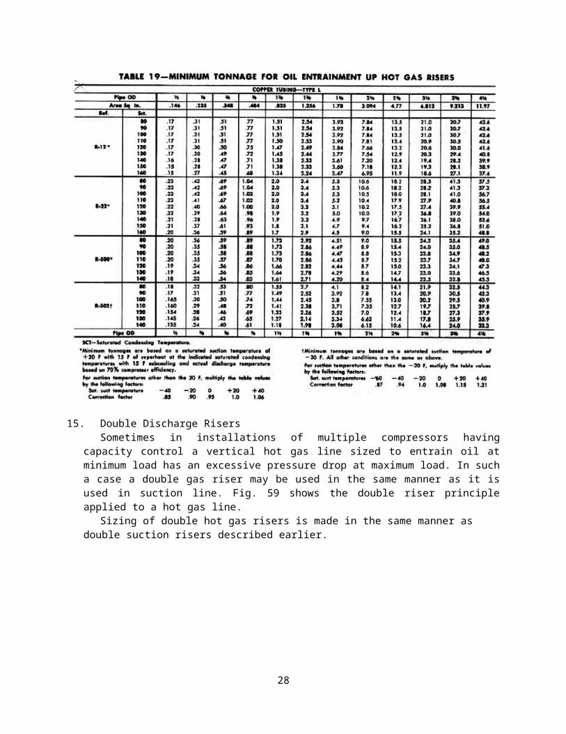
15. Double Discharge RisersSometimes in installations of multiple compressors having
capacity control a vertical hot gas line sized to entrain oil atminimum load has an excessive pressure drop at maximum load. In sucha case a double gas riser may be used in the same manner as it isused in suction line. Fig. 59 shows the double riser principleapplied to a hot gas line.
Sizing of double hot gas risers is made in the same manner as double suction risers described earlier.
28
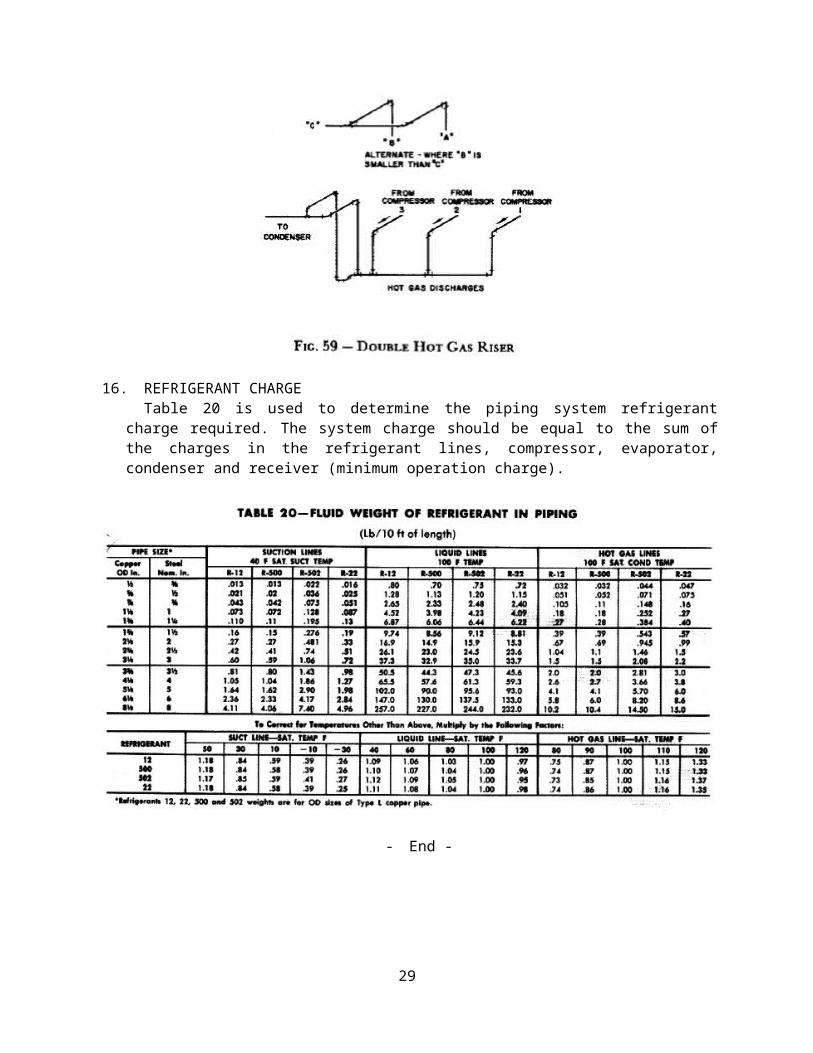
16. REFRIGERANT CHARGETable 20 is used to determine the piping system refrigerant
charge required. The system charge should be equal to the sum ofthe charges in the refrigerant lines, compressor, evaporator,condenser and receiver (minimum operation charge).
- End -
29