Embed Size (px)
Citation preview
International Journal of Advances in Engineering & Technology, May, 2014.
©IJAET ISSN: 22311963
341 Vol. 7, Issue 2, pp. 341-351
BEARINGS FAULT DIAGNOSIS IN DIRECT TORQUE CONTROL
PERMANENT MAGNET SYNCHRONOUS MOTOR BASED ON
DISCRETE WAVELET TRANSFORM AND ARTIFICIAL
NEURAL NETWORK
Abbas H. Abbas, Alaa A. AL-Saffar, and Dhiaa K. Shary
Department of Electrical Engineering, Basrah University, Basrah City, Iraq
Foundation of Technical Education, Basrah Technical College, Basrah City, Iraq
ABSTRACT The paper proposes a novel method, based on wavelet decomposition, for detection and diagnosis of bearings
fault in Direct Torque Control (DTC) Permanent Magnet Synchronous Motor (PMSM). In this technique the
root mean square (RMS) values of the Discrete Wavelet Transform (DWT) coefficients of the quadrature stator
current component are fed to Artificial Neural Network (ANN) to identify the machine state(healthy or faulty).
The dynamic model for PMSM with the bearings fault is derived in dq-variables. This model and the fault
detection algorithms are simulated using Matlab/Simulink environment. The results prove that the effectiveness
of the proposed method for bearing fault detection.
INDEX TERMS: Artificial Neural Network (ANN), Direct Torque Control (DTC), Discrete Wavelet
Transform (DWT), Permanent Synchronous Motor (PMSM), PI-like fuzzy controller.
I. INTRODUCTION
Direct Torque Control (DTC) is a popular control technique widely applied in motor drive
applications since it was proposed by Depenbrock and Takahashi [1], [2]. By directly controlling the
flux and torque, both techniques yield fast dynamic response and high performance [3]. The basic
principle of DTC is to directly select stator voltage vectors according to differences between the
references and actual torque and stator flux linkage [4].
The DTC has many favorable features, such as no need of complicated coordinate transformation and
pulse width modulation (PWM). Also, it is insensitive to motor parameters, which is inevitable in the
vector control scheme. A major problem associated with the popular DTC is the big torque and flux
ripples because of the use of two simple two-value hysteresis controllers for the stator flux linkage
and the torque. In addition, the use of a 600 angular region based signal for choosing the space voltage
vector applied to the stator windings, which is so crude that none of these space voltage vectors
generated by the voltage source inverter (VSI) could offer a precise control of the torque and the
stator flux linkage at the same time. These ripples can be reduced if the errors of the torque and the
flux linkage, and the angular position signal of the flux linkage are subdivided into several smaller
subsections. By choosing a more accurate space voltage vector , more accurate control of torque and
flux linkage can be obtained [5]. In this paper, the DTC of PMSM is proposed and the choice of null-
vectors and vector sequence are properly selected to improve the performance of motor drive system.
In this paper, we focus on the detection of an bearing fault in PMSM. The majority of the electrical
machines use ball or rolling element bearings. Each of these bearings consists of two rings, inner and
outer respectively. A set of balls or rolling elements placed in raceway rotate inside these rings. Even
under normal operating continues with balanced load and a good alignment, fatigue failure may take
place. Flaking or sapling of bearings might occur when fatigue causes small pieces to break loose
from the bearing. A part from normal internal operating stresses, other causes of bearing damages due
to vibration, inherent eccentricity, and bearing currents due to solid state drives appear as well.
Sometimes the ball bearing related defects can be categorized as outer bearing race defect, inner
International Journal of Advances in Engineering & Technology, May, 2014.
©IJAET ISSN: 22311963
342 Vol. 7, Issue 2, pp. 341-351
bearing race defect, ball defect, and train defect. All these mechanical defects cause distortions in flux
distribution inside the machine , which in turns leads to new current harmonics in stator windings [6].
In [7], it is proposed to use a dynamic neural network to fault detection and diagnosis (FDD) of
PMSM stator winding short circuit under load fluctuation. In [8], it presented the study of PMSM
running with eccentricity and bearing damage based on wavelet transform decomposition of the stator
current.
In this paper the bearings fault method for DTC PMSM has been presented. The structure of DTC
PMSM is analyzed to improve the motor performance. The paper is organized as follows. In Section
II mathematical model of PMSM. Section III and section IV describe the design and operational
principle of direct torque control of PMSM. Section V describes the construction of Fuzzy logic
controller used in DTC PMSM. Section VI discuss the application of DWT and ANN to detect the
bearings fault . Section VII discusses simulation results and discussion. Section VIII discusses
conclusion and suggests a roadmap for future works.
II. PMSM MODEL
The model of the PMSM is derived using direct (d) and quadrature (q) variables in a rotor reference
frame, the voltage equations are:
Vd = Rsid + d(Фd) dt⁄ − wФq (1)
Vq = Rsiq + d(Фq) dt⁄ + wФd + wФf (2)
It is noted that the stator flux linkage components are:
Фd = Ldid + Фf (3)
Фq = Lqiq (4)
where Rs is the stator winding resistance, Ld and Lq are d-q axis inductances, Фf is the rotor flux
linkage generated by the permanent magnets, Vd and Vq are the d-q axis voltages, Фd and Фq are d-q
axis fluxes, id and iq are d-q axis currents and w is the angular speed of the rotor [9], [10].
The mechanical torque equation referred to motor-load system is given by:
Te = (J p)⁄ dw dt + (D P)⁄ w +⁄ TL (5)
with
Te =3
2p(Фdid + ( Ld − Lq)idiq) (6)
where D is the damping torque coefficient, J is the moment of inertia of rotor, TL is the load torque
and P is the number of pole pairs [11], [12].
III. DIRECT TORQUE CONTROL STRATEGY
A- Stator flux linkages sectors
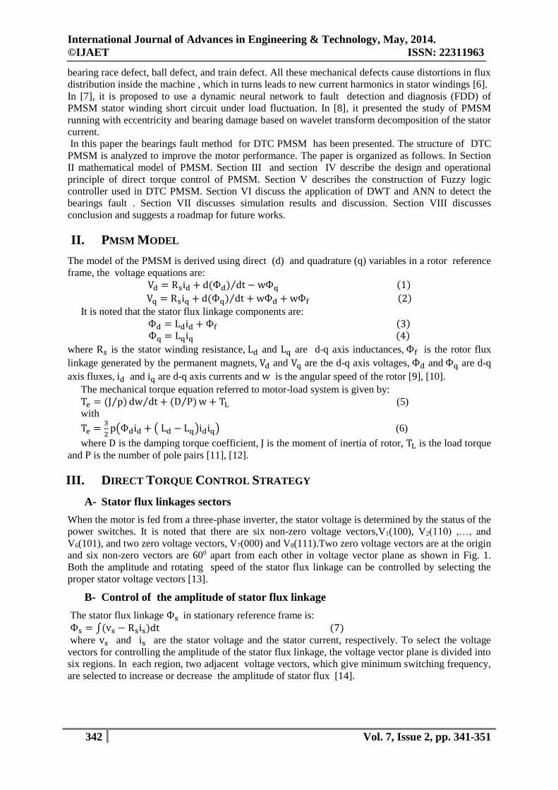
When the motor is fed from a three-phase inverter, the stator voltage is determined by the status of the
power switches. It is noted that there are six non-zero voltage vectors,V1(100), V2(110) ,…, and
V6(101), and two zero voltage vectors, V7(000) and V8(111).Two zero voltage vectors are at the origin
and six non-zero vectors are 600 apart from each other in voltage vector plane as shown in Fig. 1.
Both the amplitude and rotating speed of the stator flux linkage can be controlled by selecting the
proper stator voltage vectors [13].
B- Control of the amplitude of stator flux linkage
The stator flux linkage Фs in stationary reference frame is:
Фs = ∫(vs − Rsis)dt (7)
where vs and is are the stator voltage and the stator current, respectively. To select the voltage
vectors for controlling the amplitude of the stator flux linkage, the voltage vector plane is divided into
six regions. In each region, two adjacent voltage vectors, which give minimum switching frequency,
are selected to increase or decrease the amplitude of stator flux [14].
International Journal of Advances in Engineering & Technology, May, 2014.
©IJAET ISSN: 22311963
343 Vol. 7, Issue 2, pp. 341-351
Figure 1. Sectors of stator flux linkage.
C- Control of the rotation of stator flux linkage
In case of PMSM , Фs is changed even when zero voltage vectors are applied since the magnets rotate
with the rotor. Therefore, zero voltage vectors are not used for controlling Фs in PMSM. The
electromagnetic torque can be controlled by controlling the amplitude and rotational speed of Фs.
For counter clockwise operation, if the actual torque is smaller than the reference then the voltage
vectors that keep Фs rotating in the same direction are selected. If the actual torque is greater than the
reference, the voltage vectors that keep Фs in the reverse direction are selected instead of zero
voltage vectors. By selecting the voltage vectors in this way , Фs is rotated all the time and its
rotational direction is determined by the output of the hysteresis controller for torque. The switching
table for controlling both the amplitude and rotating direction of Фs is as follows:
In Table 1, EФ and ET are the outputs of the hysteresis controllers for flux linkage and torque,
respectively. If EФ=1 then the actual flux linkage is smaller than the reference value. The same is true
for the torque. N(1,2,,….6) represents the sector numbers for stator flux linkage [15].
Table 1. Outputs of hysteresis controllers for flux linkage and torque.
ET
EФ
N
1 2 3 4 5 6
1
1
0
V2
V6
V3
V1
V4
V2
V5
V3
V6
V4
V1
V5
0
1
0
V3
V5
V4
V6
V5
V1
V6
V2
V1
V3
V2
V4
IV. DTC IMPLEMENTATION OF PMSM
A- Flux linkage estimator
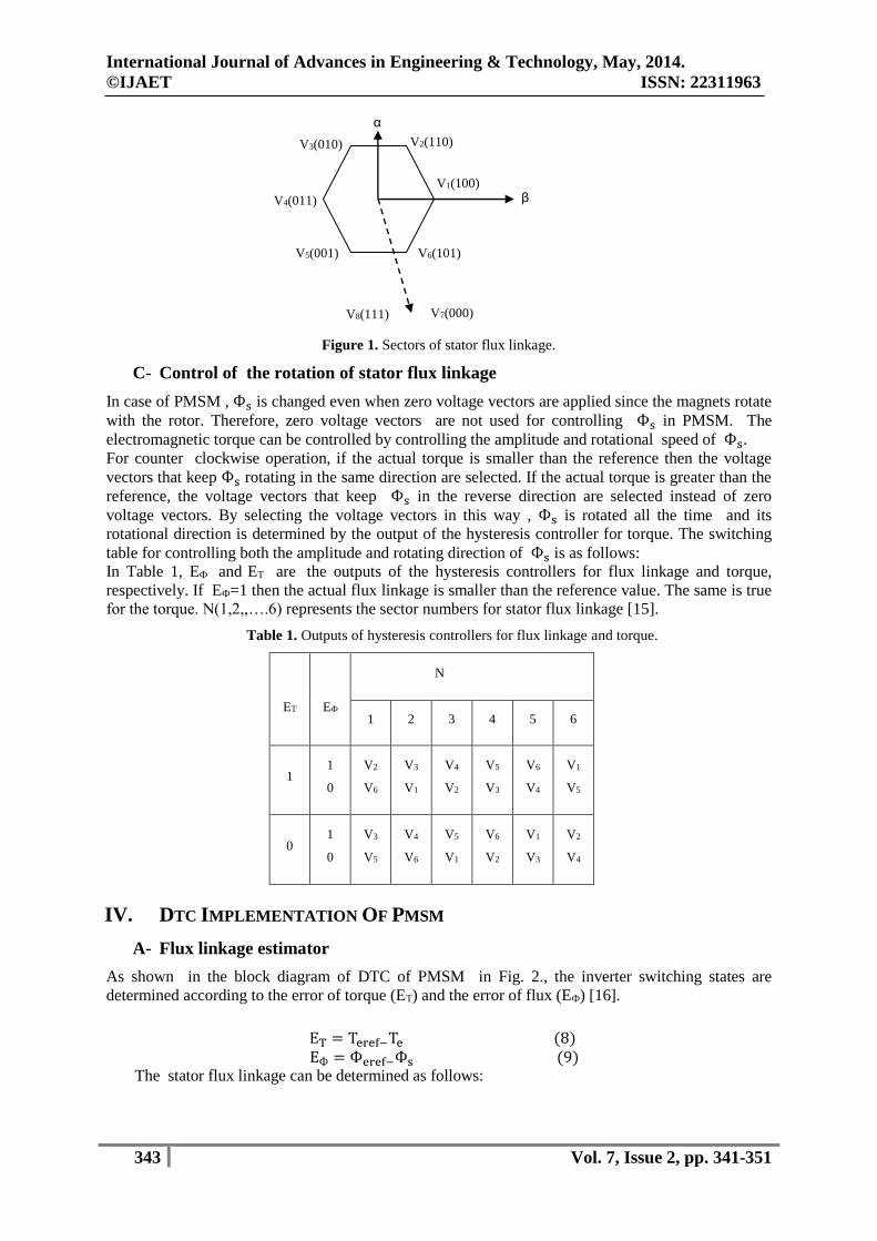
As shown in the block diagram of DTC of PMSM in Fig. 2., the inverter switching states are
determined according to the error of torque (ET) and the error of flux (EФ) [16].
ET = Teref−Te (8)
EФ = Фeref−Фs (9)
The stator flux linkage can be determined as follows:
)011(4V
α
(100)1V
0)1(12V 0)01(3V
)001(5V )1(106V
00)0(7V )11(18V
β
International Journal of Advances in Engineering & Technology, May, 2014.
©IJAET ISSN: 22311963
344 Vol. 7, Issue 2, pp. 341-351
Figure 2. Block diagram of DTC.
Фs = √Фα2 + Фβ
2 (10)
Фα = ∫(uα − Rsiα)dt (11)
Фβ = ∫(uβ − Rsiβ)dt (12)
where Фα and Фβ are α-β axis fluxes, iα and iβ are α-β axis currents.
The α-β axis voltages (uα and uβ ) are calculated from the dc-link voltage Vdc and switching
signal Sa, Sb and Sc as follows:
uα = √2
3 Vdc (Sa −
1
2( Sb + Sc ) (13)
uβ = √1
2 Vdc ( Sb − Sc ) (14)
Also
iα = √3
2 ia (15)
iβ = √1
2 (ib − ic ) (16)
B- Torque estimator
The torque can be calculated from the α-β axis voltages and currents as in [17]:
Te =3
2p(Фαiβ − Фβiα) (17)
V. FUZZY LOGIC CONTROL (FLC)
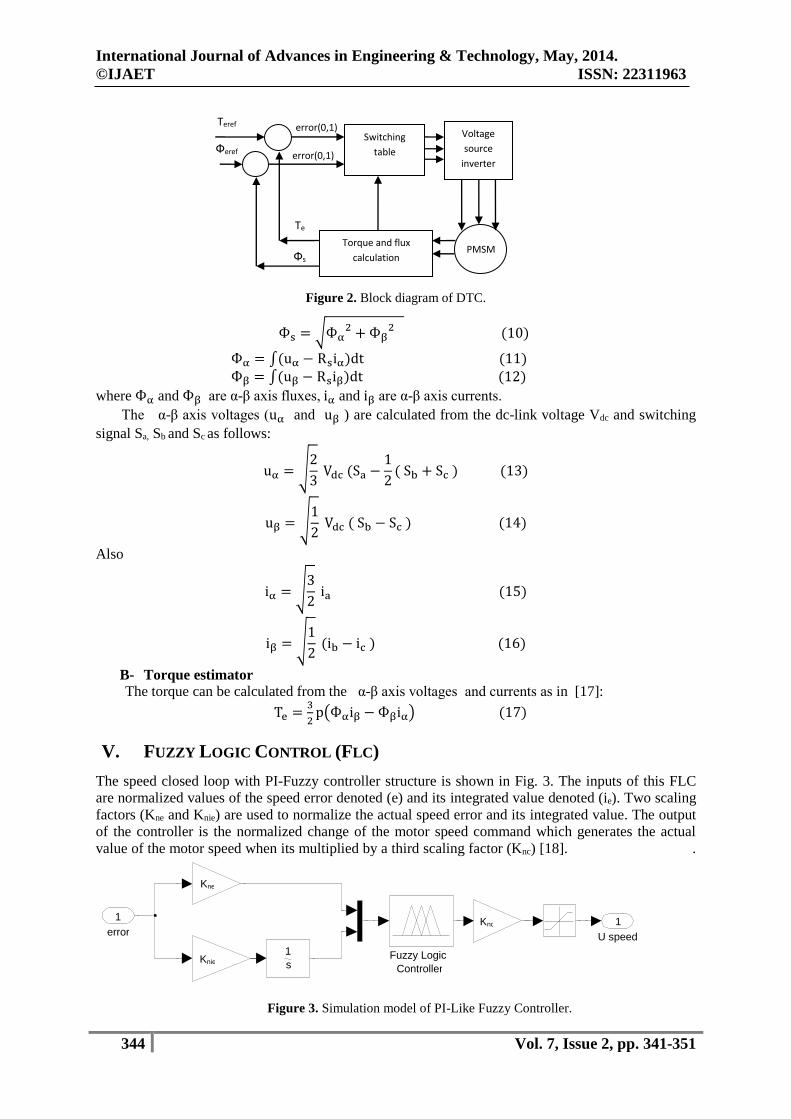
The speed closed loop with PI-Fuzzy controller structure is shown in Fig. 3. The inputs of this FLC
are normalized values of the speed error denoted (e) and its integrated value denoted (ie). Two scaling
factors (Kne and Knie) are used to normalize the actual speed error and its integrated value. The output
of the controller is the normalized change of the motor speed command which generates the actual
value of the motor speed when its multiplied by a third scaling factor (Knc) [18]. .
Figure 3. Simulation model of PI-Like Fuzzy Controller.
U speed 1
neK
nieK
ncK
1 s
Fuzzy Logic Controller
error 1
sФ
Switching
table
Torque and flux
calculation
Voltage
source
inverter
PMSM
erefT
erefФ
eT
error(0,1)
error(0,1)
International Journal of Advances in Engineering & Technology, May, 2014.
©IJAET ISSN: 22311963
345 Vol. 7, Issue 2, pp. 341-351
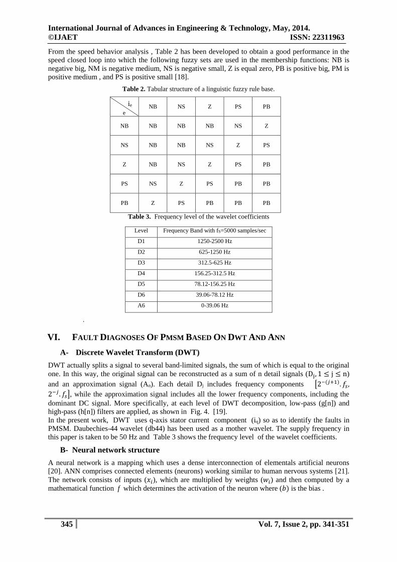
From the speed behavior analysis , Table 2 has been developed to obtain a good performance in the
speed closed loop into which the following fuzzy sets are used in the membership functions: NB is
negative big, NM is negative medium, NS is negative small, Z is equal zero, PB is positive big, PM is
positive medium , and PS is positive small [18].
Table 2. Tabular structure of a linguistic fuzzy rule base.
NB NS Z PS PB
NB NB NB NB NS Z
NS NB NB NS Z PS
Z NB NS Z PS PB
PS NS Z PS PB PB
PB Z PS PB PB PB
Table 3. Frequency level of the wavelet coefficients
.
VI. FAULT DIAGNOSES OF PMSM BASED ON DWT AND ANN
A- Discrete Wavelet Transform (DWT)
DWT actually splits a signal to several band-limited signals, the sum of which is equal to the original
one. In this way, the original signal can be reconstructed as a sum of n detail signals (Dj, 1 ≤ j ≤ n)
and an approximation signal (An). Each detail Dj includes frequency components [2−(𝑗+1). 𝑓𝑠,
2−𝑗. 𝑓𝑠], while the approximation signal includes all the lower frequency components, including the
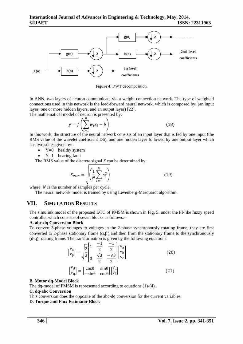
dominant DC signal. More specifically, at each level of DWT decomposition, low-pass (g[n]) and
high-pass (h[n]) filters are applied, as shown in Fig. 4. [19].
In the present work, DWT uses q-axis stator current component (iq) so as to identify the faults in
PMSM. Daubechies-44 wavelet (db44) has been used as a mother wavelet. The supply frequency in
this paper is taken to be 50 Hz and Table 3 shows the frequency level of the wavelet coefficients.
B- Neural network structure
A neural network is a mapping which uses a dense interconnection of elementals artificial neurons
[20]. ANN comprises connected elements (neurons) working similar to human nervous systems [21].
The network consists of inputs (𝑥𝑖), which are multiplied by weights (𝑤𝑖) and then computed by a
mathematical function f which determines the activation of the neuron where (𝑏) is the bias .
Level Frequency Band with fS=5000 samples/sec
D1 1250-2500 Hz
D2 625-1250 Hz
D3 312.5-625 Hz
D4 156.25-312.5 Hz
D5 78.12-156.25 Hz
D6 39.06-78.12 Hz
A6 0-39.06 Hz
ei
e
International Journal of Advances in Engineering & Technology, May, 2014.
©IJAET ISSN: 22311963
346 Vol. 7, Issue 2, pp. 341-351
Figure 4. DWT decomposition.
In ANN, two layers of neuron communicate via a weight connection network. The type of weighted
connections used in this network is the feed-forward neural network, which is composed by: (an input
layer, one or more hidden layers, and an output layer) [22].
The mathematical model of neuron is presented by:
𝑦 = 𝑓 (∑𝑤𝑖𝑥𝑖 − 𝑏
𝑛
𝑖=1
) (18)
In this work, the structure of the neural network consists of an input layer that is fed by one input (the
RMS value of the wavelet coefficient D6), and one hidden layer followed by one output layer which
has two states given by:
Y=0 healthy system
Y=1 bearing fault
The RMS value of the discrete signal 𝑆 can be determined by:
𝑆𝑅𝑀𝑆 = √(1
𝑁∑𝑠𝑖
2
𝑁
𝑖=1
) (19)
where 𝑁 is the number of samples per cycle.
The neural network model is trained by using Levenberg-Marquardt algorithm.
VII. SIMULATION RESULTS
The simulink model of the proposed DTC of PMSM is shown in Fig. 5. under the PI-like fuzzy speed
controller which consists of seven blocks as follows:-
A. abc-dq Conversion Block
To convert 3-phase voltages to voltages in the 2-phase synchronously rotating frame, they are first
converted to 2-phase stationary frame (,) and then from the stationary frame to the synchronously
(d-q) rotating frame. The transformation is given by the following equations:
[vα
vβ] = √
2
3[ 1
−1
2
−1
2
0√3
2
−√3
2 ]
[
va
vb
vc
] (20)
[vd
vq] = [
cosθ sinθ
−sinθ cosθ] [
vα
vβ] (21)
B. Motor dq-Model Block
The dq-model of PMSM is represented according to equations (1)-(4).
C. dq-abc Conversion
This conversion does the opposite of the abc-dq conversion for the current variables.
D. Torque and Flux Estimator Block
h(n)
g(n)
2
2 h(n)
g(n)
2
2
X(n) 1st level
coefficients
2nd level
coefficients
International Journal of Advances in Engineering & Technology, May, 2014.
©IJAET ISSN: 22311963
347 Vol. 7, Issue 2, pp. 341-351
This block is used to estimate the stator flux which is given in (7). This block is also used to obtain
the developed electromagnetic torque produced by simulated machine using (17).
E. Sector Detector Block
This block is used to detect the sector of the stator flux.
F. State Selector Block
After the sector of stator flux, error of stator flux and error of torque are obtained. These values are
fed to direct torque control block which contains the lookup table which is used to obtain the desired
voltage state vector according to the desired sectors mentioned in Table I.
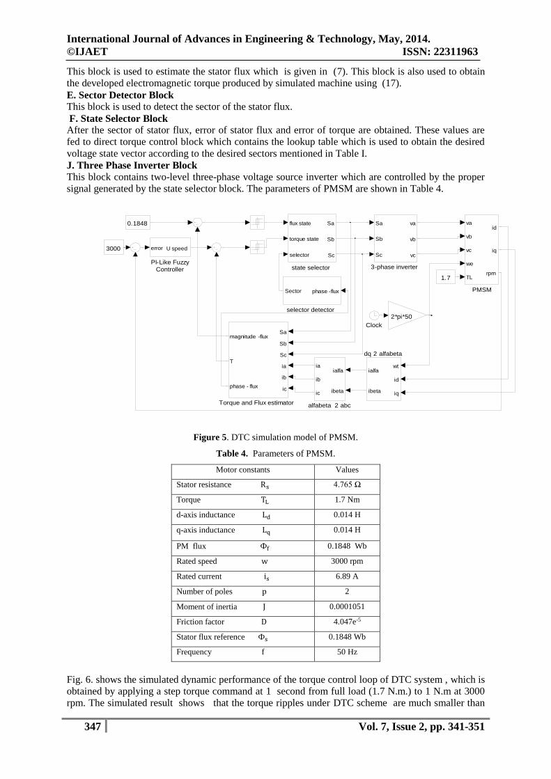
J. Three Phase Inverter Block
This block contains two-level three-phase voltage source inverter which are controlled by the proper
signal generated by the state selector block. The parameters of PMSM are shown in Table 4.
Figure 5. DTC simulation model of PMSM.
Table 4. Parameters of PMSM.
Motor constants Values
Stator resistance Rs 4.765 Ω
Torque TL 1.7 Nm
d-axis inductance Ld 0.014 H
q-axis inductance Lq 0.014 H
PM flux Фf 0.1848 Wb
Rated speed w 3000 rpm
Rated current is 6.89 A
Number of poles p 2
Moment of inertia J 0.0001051
Friction factor D 4.047e-5
Stator flux reference Фs 0.1848 Wb
Frequency f 50 Hz
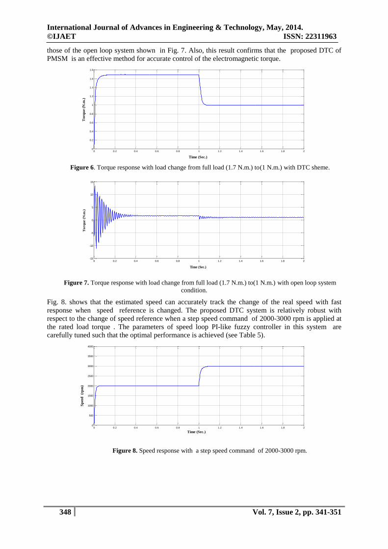
Fig. 6. shows the simulated dynamic performance of the torque control loop of DTC system , which is
obtained by applying a step torque command at 1 second from full load (1.7 N.m.) to 1 N.m at 3000
rpm. The simulated result shows that the torque ripples under DTC scheme are much smaller than
state selector
flux state
torque state
selector
Sa
Sb
Sc
selector detector
phase -fluxSector
dq 2 alfabeta
wt
id
iq
ialfa
ibeta
alfabeta 2 abc
ialfa
ibeta
ia
ib
ic
Torque and Flux estimator
Sa
Sb
Sc
ia
ib
ic
magnitude -flux
T
phase - flux
PMSM
va
vb
vc
we
TL
id
iq
rpm
2*pi*50
3000
1.7
0.1848
Clock
3-phase inverter
Sa
Sb
Sc
va
vb
vc
PI-Like Fuzzy Controller
error U speed
International Journal of Advances in Engineering & Technology, May, 2014.
©IJAET ISSN: 22311963
348 Vol. 7, Issue 2, pp. 341-351
those of the open loop system shown in Fig. 7. Also, this result confirms that the proposed DTC of
PMSM is an effective method for accurate control of the electromagnetic torque.
Figure 6. Torque response with load change from full load (1.7 N.m.) to(1 N.m.) with DTC sheme.
Figure 7. Torque response with load change from full load (1.7 N.m.) to(1 N.m.) with open loop system
condition.
Fig. 8. shows that the estimated speed can accurately track the change of the real speed with fast
response when speed reference is changed. The proposed DTC system is relatively robust with
respect to the change of speed reference when a step speed command of 2000-3000 rpm is applied at
the rated load torque . The parameters of speed loop PI-like fuzzy controller in this system are
carefully tuned such that the optimal performance is achieved (see Table 5).
Figure 8. Speed response with a step speed command of 2000-3000 rpm.
0 0.2 0.4 0.6 0.8 1 1.2 1.4 1.6 1.8 20
0.2
0.4
0.6
0.8
1
1.2
1.4
1.6
1.8
Time (Sec.)
To
rqu
e (N
.m.)
0 0.2 0.4 0.6 0.8 1 1.2 1.4 1.6 1.8 2-15
-10
-5
0
5
10
15
Time (Sec.)
To
rq
ue (
N.m
.)
0 0.2 0.4 0.6 0.8 1 1.2 1.4 1.6 1.8 20
500
1000
1500
2000
2500
3000
3500
4000
Time (Sec.)
Sp
eed
(r
pm
)
International Journal of Advances in Engineering & Technology, May, 2014.
©IJAET ISSN: 22311963
349 Vol. 7, Issue 2, pp. 341-351
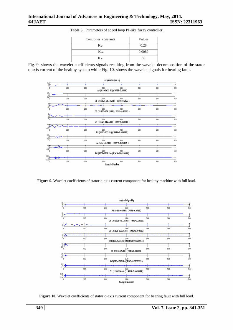
Table 5. Parameters of speed loop PI-like fuzzy controller.
Controller constants Values
Kne 0.28
Knie 0.0089
Knc 50
Fig. 9. shows the wavelet coefficients signals resulting from the wavelet decomposition of the stator
q-axis current of the healthy system while Fig. 10. shows the wavelet signals for bearing fault.
Figure 9. Wavelet coefficients of stator q-axis current component for healthy machine with full load.
Figure 10. Wavelet coefficients of stator q-axis current component for bearing fault with full load.
0 100 200 300 400 500 600 70005
10
original signal iq
0 100 200 300 400 500 600 700-10
010
A6 (0-39.0625 Hz) ( RMS=5.8599 )
0 100 200 300 400 500 600 700-101
D6 (39.0625-78.125 Hz) ( RMS=0.2122 )
0 100 200 300 400 500 600 700-101
D5 (78.125-156.25 Hz) ( RMS=0.12995 )
0 100 200 300 400 500 600 700-0.5
00.5
D4 (156.25-312.5 Hz) ( RMS=0.068988 )
0 100 200 300 400 500 600 700-0.5
00.5
D3 (312.5-625 Hz) ( RMS=0.030889 )
0 100 200 300 400 500 600 700-0.1
00.1
D2 (625-1250 Hz) ( RMS=0.0090889 )
0 100 200 300 400 500 600 700-0.05
00.05
D1 (1250-2500 Hz) ( RMS=0.0039649 )
Sample Number
0 500 1000 1500 2000 2500 300005
10
original signal iq
0 500 1000 1500 2000 2500 3000-10
010
A6 (0-39.0625 Hz) ( RMS=6.0422 )
0 500 1000 1500 2000 2500 3000-101
D6 (39.0625-78.125 Hz) ( RMS=0.10602 )
0 500 1000 1500 2000 2500 3000-101
D5 (78.125-156.25 Hz) ( RMS=0.072095 )
0 500 1000 1500 2000 2500 3000-0.5
00.5
D4 (156.25-312.5 Hz) ( RMS=0.035054 )
0 500 1000 1500 2000 2500 3000-0.5
00.5
D3 (312.5-625 Hz) ( RMS=0.012638 )
0 500 1000 1500 2000 2500 3000-0.1
00.1
D2 (625-1250 Hz) ( RMS=0.0057335 )
0 500 1000 1500 2000 2500 3000-0.05
00.05
D1 (1250-2500 Hz) ( RMS=0.0020181 )
Sample Number
International Journal of Advances in Engineering & Technology, May, 2014.
©IJAET ISSN: 22311963
350 Vol. 7, Issue 2, pp. 341-351
The comparison between Fig. 9. and Fig. 10. shows clearly that the bearing fault can be identified by
means of the RMS values of the wavelet coefficient (D6) between the different studied cases (0.2122
V for healthy machine and 0.10602 V for bearing fault case).
The RMS values of the wavelet coefficients for level 6 are used as the input of the neural network to
give an output which identifies the machine case.
VIII. CONCLUSION AND FUTURE WORK
In this paper bearings fault detection was simulated by means of Matlab/Simulink environment for
DTC PMSM drive system. The simulation results proved that the torque response of the proposed
DTC scheme is faster much than open loop system with low ripple. Also, the results showed the
feasibility and validity of the proposed Fuzzy speed controller for wide range of motor speed. It
also, presented the detection of the bearings fault for a PMSM in which the quadrature component of
the stator current has been analyzed using DWT and application of ANN to identify the machine
state. For the future work the proposed design for the artificial neural network can be easily and
successfully extended to get a compact design using fuzzy logic system to identify the machine
condition in short time. The scheme can also be improved using Neuro-Fuzzy system to control the
motor speed taking into account uncertainties.
REFERENCES
[1] M. Depenbrock," Direct Self-Control of Inverter-Fed Machine", IEEE Trans. Power Electron., pp. 420-429,
Oct. 1988.
[2] N. Takahashi," A New Quick-Response and High-Efficiency Control Strategy of an Induction Motor",
IEEE Trans. on Industry Applications , pp. 821-827, Nov. 1986.
[3] Z. Lu, H. Sheng, H. L. Hess, and K. M. Buck," The Modeling and Simulation of a Permanent Magnet
Synchronous Motor with Direct Torque Control Based on Matlab/Simulink", 2005 IEEE International
Conference on Electric Machines and Drives , pp. 1150-1156, 5-15 May 2005.
[4] L. Zhong, M. F. Rahman, W. Y. Hu, and K. W. Lim," Analysis of Direct Torque Control in Permanent
Magnet Synchronous Motor Drives", IEEE Transaction on Power Electronics, vol. 12, no. 3, pp. 528-536, May
1997.
[5] D. Sun, Y. He, and J. Guo Zho," Fuzzy Logic Direct Torque Control for Permanent Magnet Synchronous
Motors", proceedings of the 5th World Congress on Intelligent Control and Automatic, June 15-19, 2004,
Hangzhou, P.R.China.
[6] J. Rosero, and L. Romeral," Fault Detection in Dynamic Conditions by Means of Discrete Wavelet
Decomposition for PMSM Running Under Bearing Damage", Twenty-Fourth Annual IEEE Conference and
Exposition on Applied Power Electronics, pp. 951-956, 15-19 Feb. 2009.
[7] J. Quiroga, and D. Cartes," Neural Network based Fault Detection of PMSM Stator Winding Short under
Load Fluctuation", 13th IEEE International Power Electronics and Motion Control Conference, pp. 793-798,
2008.
[8] J. Rosero, and L. Romeral," Fault Detection of Eccentricity and Bearing Damage in a PMSM by means of
Wavelet Transforms Decomposition of the Stator Current", Twenty-Third Annual IEEE Applied Power
Electronics Conference and Exposition, pp. 111-116, 2008.
[9] S. Kar, and S. Kumar Mishra," Direct Torque Control of Permanent Magnet Synchronous Motor Drive with
a sensorless Initial Rotor Position Estimation Scheme", 2012 IEEE International Conference on Advances in
power Conversion and Energy Technologies , 2-4 Aug. 2012.
[10] G. Almandoz, J. Poza, M. Angel Rodriguez, and A. Gonzalez,"Modeling of Cross-Magnetization Effect in
Interior Permanent Magnet Machines", Proceedings of the 2008 International Conference on Electrical
Machines.
[11] A. Gebregergis, M. Islam, T. Sebastian, and R. Ramakrihnan,"Evaluation of Inductance in a Permanent
Magnet Synchronous Motor", 2011 IEEE International Electric Machines & Drive Conference (IEMDC), pp.
1171-1176, 15-18 May 2011.
[12] J. Singh, B. Singh, and S. P. Singh," Performance Evaluation of Direct Torque Control with Permanent
Magnet Synchronous Motor", SAMRIDDHI-A Journal of Physical Sciences, Engineering and Technology (S-
JPSET:ISSN:2229-7111, vol. 2, pp. 25-35-, 2011.
[13] J. Liu, P. Sheng Wu, H. Yu Bai, and X. Huang," Application of Fuzzy Control in Direct Torque Control of
Permanent Magnet Synchronous Motor", proceedings of the 5th World Congress on Intelligent Control and
Automatic, June 15-19, 2004, Hangzhou, P.R.China.
International Journal of Advances in Engineering & Technology, May, 2014.
©IJAET ISSN: 22311963
351 Vol. 7, Issue 2, pp. 341-351
[14] J. Sinivas Rao, S. Chandra Sekhar, and T. Raghu," Speed Control of PMSM by Using DSVM-DTC
Technique", International Journal of Engineering Trends and Technology ,vol. 3,2012.
[15] M. F. Rahmam, L. Zhong, W. Y. Hu, and K. W. Lim," A Direct Torque Controller for Permanent Magnet
Synchronous Motor Drives",1997 IEEE , TD1-(2.1-2.3).
[16] W. Jun, P. Hong, and J. Yu," A Simple Direct –Torque Fuzzy Control of Permanent Magnet Synchronous
Motor Drive", proceedings of the 5th World Congress on Intelligent Control and Automatic, June 15-19, 2004,
Hangzhou, P.R.China.
[17] R. R. Menon, S. Jebarani Evangeline, and A. Gopinath," Modified Direct Torque Control of permanent
Magnet Synchronous Motor by Using Voltage Vectors of Variable Amplitude and Angle", International Journal
of Engineering and Advanced Technology (IJEAT), vol. 2, pp. 285-289, December 2012.
[18] K. Chikh, M. Khfallah, and A. Saad," Improved DTC Algorithms for Reducing Torque and Flux Ripples of
PMSM Based on Fuzzy Logic and PWM Techniques", Matlab- A Fundamental Tool for Scientific Computing
and Engineering Applications-Volume 1, Chapter 8, 2012.
[19] I. Georgakopoulos, E. Mitronikas, A. Safacas, " Broken Bar Detection Using Inverter Currents in Induction
Motor Drives ", 2010 International Symposium on Power Electronics Electrical Drive and Motion (
SPEEDAM), pp. 1030-1035, 14-16 June 2010.
[20] S. V. Kartalopoulas, " Understanding Neural Networks and Fuzzy Logic-Basic Concepts and Applications
", Book, Wiley- IEEE press, ISBN:0780311280, 1997.
[21] S. Sornmuang, J. Suwatthikul, " Detection of a Motor Bearing Shield Fault Using Neural Networks ",
proceedings of SICE Annual Conference, pp. 1260-1264, 13-18 Sept. 2011.
[22] A. Drira, N. Derbel, " Classification of Rotor Fault in Induction Machine Using Artificial Neural Networks
", 8th International Multi-Conference on Systems, Signals and Devices, pp. 1-6, 22-25 March 2011.
AUTHORS
Abbas H. Abbas was born in Basrah, Iraq, in 1958. He received the B.Sc from the
University of Technology/Baghdad in 1980. He received the PHD from Technical
University/Sofia/Bulgaria in 1991. His current research interests include electrical
engineering power systems and electrical machines.
Alaa A. Al-Saffar was born in Basrah, Iraq, in 1957. He received the B.Sc, M.Sc and
PHD from the University of Basarh, College of Engineering, Electrical Engineering
Department in 1979, 1982 and 2001, respectively. His current research interests include
optical computing and robotic control.
Dhiaa K. Shary was born in Basrah, Iraq, in 1976. He received the B.Sc, and M.Sc
from the University of Basrah, College of Engineering, Electrical Engineering
Department in 1999, 2002, respectively . Currently He is PHD student in University of
Basrah, College of Engineering, Electrical Engineering Department.


![Blood Crossmatch\277\351\322\302 [Compatibility Mode]](https://img.pdfslide.net/doc/110x75/631ad8c20255356abc08d9ab/blood-crossmatch277351322302-compatibility-mode.jpg)


![Vol 03 - [The II-V7-I Progression] - Supplement](https://img.pdfslide.net/doc/110x75/6346ede260c04fc79b06f13c/vol-03-the-ii-v7-i-progression-supplement.jpg)


![ULg-Presentation-1.ppt [Mode de compatibilit\351] - Emship](https://img.pdfslide.net/doc/110x75/631b57f50255356abc090c80/ulg-presentation-1ppt-mode-de-compatibilit351-emship.jpg)