Embed Size (px)
Citation preview

IEEE JOURNAL OF OCEANIC ENGINEERING, VOL. 30, NO. 1, JANUARY 2005 47
A Case Study of a Modified Gravity Type Cageand Mooring System Using Numerical and
Physical ModelsJudson DeCew, David W. Fredriksson, Leonid Bugrov, M. Robinson Swift, Oleg Eroshkin, and Barbaros Celikkol
Abstract—A modified gravity-type cage, developed by SADCOShelf Ltd., was examined using numerical and physical models todetermine if the cage and mooring system is suitable for an exposedsite south of the Isles of Shoals, NH. The 3000-m3 SADCO ShelfSubmersible Fish Cage has angled stays between the upper frame-work and the ballasted bottom rim (in addition to net) to resistthe horizontal shear deformation. The mooring system consists ofthree legs—each made up of a taut vertical chain and an angledrope, both leading to deadweight anchors. Normalized responseamplitudes (response amplitude operators) were found for motionresponse in heave, surge and pitch, and load response in the anchorand bridle lines, in regular (single frequency) waves. In addition,a stochastic approach was taken to determine the motion and loadtransfer functions in random waves using a spectrum representa-tive of seas at the selected site. In general, the system motion had ahighly damped response, with no resonant peaks within the waveexcitation range of 0.05 to 0.45 Hz. The anchor line force responsewas at all frequencies below 5 kN per meter of wave amplitude.The physical model tests showed consistently more conservative(larger) results compared to those for the numerical model.
Index Terms—Finite-element modeling, open ocean aquacul-ture, physical modeling.
I. INTRODUCTION
I N the United States, inshore aquaculture, mainly located onprotected coastlines, has grown considerably in the past 20
years to meet the increased demand for seafood products. Ex-pansion of the aquaculture industries, however, is often metwith stiff resistance from recreational users, local fishermen,lobstermen, and environmentalists. The competition for spaceon the waterfront may drive the aquaculture industry offshore.Growing fish offshore in exposed waters, however, brings a newchallenge to the industry. The cages, mooring systems and aux-iliary equipment need to withstand a high energy environmentwith a full range of loading conditions such as strong winds,currents and storms.
Manuscript received on August 1, 2003; revised March 17, 2004. This workwas supported by the NOAA-UNH Cooperative Institute for the New EnglandMariculture and Fisheries (CINEMAR) Open Ocean Demonstration Project,NOAA Grant NA16RP1718. Paper approved by the Guest Editors.
J. DeCew, D. W. Fredriksson, and O. Eroshkin are with the Center for OceanEngineering, University of New Hampshire, Durham, NH 03824 USA (e-mail:[email protected]; [email protected]; [email protected]).
L. Bugrov is with SADCO Shelf LTD, St. Petersburg, Russia 192007 (e-mail:[email protected]).
M. R. Swift and B. Celikkol are with the Mechanical Engineering Depart-ment, University of New Hampshire, Durham, NH 03824 USA (e-mail: [email protected]; [email protected]).
Digital Object Identifier 10.1109/JOE.2004.841400
To investigate the feasibility of open ocean aquaculture, nu-merous studies have been conducted involving numerical mod-eling, scaled physical modeling and field measurements to betterunderstand the loading and dynamics of cages in waves and cur-rents [1]–[4]. At the University of New Hampshire, initial nu-merical and physical modeling activities included the investi-gation of gravity type, tension leg and central spar fish cages[5]–[8]. Together these modeling efforts resulted in the decisionto deploy two 600 central spar cages at the fully exposedUNH Open Ocean Aquaculture (OOA) demonstration site, lo-cated approximately 11 km off the coast of New Hampshire inthe Gulf of Maine [9], [10]. The gear deployed at the exposedsite (Fig. 1) has served as an open ocean laboratory, where loadcells were used to measure mooring tensions and accelerome-ters used to measure fish cage motions, all in response to waveand current forcing measured using instruments deployed on anoceanographic buoy [11]. The field data collected has helpedresearchers to understand numerical and physical modeling ap-proaches and to make improvements [12], [13].
A typical candidate for an open ocean cage system opti-mizes biomass capability to the seafloor footprint while beingstructurally sound. Options such as remote feeding and sub-mergence capability can help simplify operations and decreasewear on the system. The cages deployed at the demonstrationsite are ideal as a scientific platform but may by too small formany commercial level aquaculture activities due to the rela-tively small volume (600 ) and the large mooring footprint(60 700 or 15 acres). Depending upon local regulatorypractice, the footprint of the mooring system needs to be con-sidered because ocean bottom leasing costs can be substantial($750/acre in NH). Therefore a need exists to investigate largerfish cages and mooring systems for potential deployment at theUNH OOA site. One candidate for deployment is the SADCOShelf submersible fish cage and mooring system, of SADCOShelf LTD, St. Petersburg, Russia, due to the system’s largeinternal volume, reduced footprint area, and innovative cagedesign. The purpose of this paper is to evaluate the dynamic re-sponse of the SADCO system to waves by means of numericaland physical models.
The dynamic response of the system was investigated bymeans of numerical and scaled physical models using proce-dures similar to those employed in [12]. The primary forcingmechanisms acting on the cage and mooring system at theOOA site are due to currents and waves. Ocean currents inducesteady state forces onto the system and corresponding drag
0364-9059/$20.00 © 2005 IEEE

48 IEEE JOURNAL OF OCEANIC ENGINEERING, VOL. 30, NO. 1, JANUARY 2005
Fig. 1. The location of the UNH OOA demonstration site, 11 km off the coast of NH USA (site not drawn to scale for viewing purposes).
forces on nets have been the focus of research using theoreticaland model test methods [13]–[15]. Ocean waves, on the otherhand, are the primary dynamic forcing mechanism and induceoscillatory motion. Gravity type cage response to this motionis of interest due to the “shearing” movement of the buoyantand ballast rims, observed during testing in [16]. Therefore,SADCO’s gravity cage system was modeled using both regularand random waves. For regular wave tests, response amplitudeoperators (RAOs), were used to characterize cage dynamicsin heave (vertical translation), surge (horizontal translation)pitch (rotation about a transverse axis), and mooring line loadresponse, in the anchor and bridle lines. For the random seatests, statistical data analysis, specifically auto and cross-spec-tral methods, were used to evaluate the motion response andmooring line loads. Although this study investigates the cageand mooring system response solely to waves, the effect ofcurrent and waves on a moored cage system has been examined[17]. It was shown that the currents do not severely influence theoscillatory motion response but cause the cage to tilt, laybackand sink as well as increase mooring line loads.
A description of the cage system is given in the next sectionfollowed by a summary of the data processing techniques. Themodeling input parameters, such as wave heights, periods andirregular wave spectra are next before an in-depth examinationof the laboratory and modeling techniques. Finally, the results ofthe numerical and physical models are presented and compared.
II. SADCO SHELF SUBMERSIBLE FISH CAGE
The SADCO Shelf submersible fish cage, shown in Fig. 2(a),has a commercial “sized” 3000 net chamber with volu-metric stability under various environmental conditions suchas currents and waves. A three point taut mooring system (seeFigs. 3 and 4) with a 28 150 (7 acre) footprint is uti-lized which represents a 54% reduction of the current mooringsystem footprint at the site. The SADCO cage has features sim-ilar to a traditional gravity type cage, compared in Fig. 2(b),
in which a buoyant superstructure supports the net and bal-last. The tension provided by the buoyant superstructure andballast help resist deformation, but large currents and wavescan still have a tendency to deform the net chamber. Unlikethe traditional gravity cage, however, the SADCO system hasinclined tension lines along the length of the net chamber (butnot attached to the net themselves) connecting the buoyantsuperstructure to the ballast rim. Additional ballast is locatedbeneath the bottom rim to increase the tension in the system.These lines, in a triagonal sling orientation, help resist netchamber deformation and support the ballast system of thecage. The result is a net which is tightly strung between the su-perstructure and the ballast system. Transverse loads resultingin horizontal shear on the main body of the cage are sustainedby the angled stays rather than the net.
The cage superstructure is constructed in a floodable threetiered steel hexagon framework, having an overall diameter of18 m, and can support a 3000-kg capacity submersible feeder.The bottom rim (15 m below and ballasted), has a chain bridlewhich runs to a ballast tank and heavy or “steamer” chain (seeFig. 3). The ballast tank is floodable and is controlled to providevariable vertical force. When submerged, part of the chain is onthe bottom, and ballast tank force adjustment allows the cage tobe placed at a variety of water depths. The ballast tank partiallycompensates the weight of the chain when the cage is in thesurface mode.
The cage is secured in a three point mooring system config-uration by six dead weight anchors (see Fig. 4). The kapronmooring lines (kapron is a type of nylon) are wear resistantand have good elastic properties which allow it to absorb snaploading. Upper bridle lines connect the cage to spring floats(which add buoyancy to the system when in a submerged state).Lower bridle lines connect the spring floats to submerged buoys,which rest 10 m below the surface, held in place by vertical chainand deadweight anchors. Anchor lines with a 3:1 scope securethe buoys to the outside deadweight anchors.

DECEW et al.: A MODIFIED GRAVITY-TYPE CAGE 49
Fig. 2. (a) The SADCO cage system uses line in a triagonal sling orientation and ballast to resist deformation of the net where (b) a traditional gravity type cagerelies on tension between the buoyant and ballast rim to resist deformation.
Fig. 3. A side view of the SADCO system at the water surface. A chain bridle runs to a ballast tank and chain to help resist deformation.

50 IEEE JOURNAL OF OCEANIC ENGINEERING, VOL. 30, NO. 1, JANUARY 2005
Fig. 4. A top view of the 3-point SADCO mooring system. The cage is held in place by six deadweight anchors, 3 at the submerged buoys and 3 securing theanchor lines.
III. DATA PROCESSING TECHNIQUES
Regular (monochromatic) and random wave tests were per-formed using the numerical and physical models. Ten differentwave frequencies, assuming linear, small amplitude wave theory[18] as the excitation were applied to the regular wave tests. Theresponse amplitude operators were found for the heave, surge,pitch and mooring line response similar to [10], [12].
In the random wave experiments, the time series input wasgenerated using the random phase approach [19]. The surfaceelevation as a function of time was calculated as the superpo-sition of single frequency contributions. Linear transfer func-tions were calculated as a function of frequency using auto andcross-spectral techniques [20] for the cage motion (in heave,surge and pitch) and mooring line tensions, respectively. Usingthe cross-spectral technique, uncorrelated noise associated withline tension measurements is cancelled in the calculation, usu-ally providing a better estimate. This attribute was importantbecause the load cells used in physical model experiments werea known source of noise. The cross spectral method, however,can only be used when the measurements are made at the samelocation, with the same time base, due to phase considerations.This condition could not be easily met in the motion tests dueto the optical measurements system setup, so the autospectrumapproach was used for heave, surge, and pitch.
IV. MODEL INPUT PARAMETERS
Ten regular wave tests were conducted using numerical andphysical models subjected to a range of wave frequencies typ-ically found at the OOA site (Table I). The individual wave-
TABLE IREGULAR WAVE INPUT PARAMETERS FOR THE NUMERICAL AND PHYSICAL
MODELS (FULL SCALE)
* 7 m in the physical model test.
lengths used in the tests were chosen to be a fraction or multipleof the overall cage diameter, such as one-half times the cage di-ameter, one cage diameter, or four times the cage diameter. Aconstant wave slope of 1/15 ( ), where is the wave heightand is the wave length, was also chosen to define the waveheight. Additional regular waves were used in the tests to repre-sent typical wind generated waves and sea swell that occur at thesite. Wave set #11 was incorporated into the test program sinceit has been used in previous UNH studies as a “design wave”

DECEW et al.: A MODIFIED GRAVITY-TYPE CAGE 51
Fig. 5. The input spectrum, with H of 2.5 m and T of 10 s, applied to the cage in the numerical and physical models.
condition. With a height of 9 m and period of 8 s, it has servedas a basis for comparing all systems considered for the OOAsite. In the physical model tests, however, wave set #11 actuallyhad a wave height of 7 m due to wave tank limitations.
The random wave input parameters were based on a typicalwave spectrum, as developed by Fredriksson, in [10], for coastalNew Hampshire described by
(1)
where is the significant wave height of 2.5 m, is 4.35, isdominant period of 10 s, and is the second dominant periodof 5.34 s. The shaping parameter is 0.142, is 6.75, is0.456, and is 0.50. This spectrum takes into account the oceanswell with a period of 10 s, and the local wind driven waves witha period of 5.34 s. A plot of the wave spectrum used as input forthe modeling tests is shown in Fig. 5.
The random wave time series used in the numerical simula-tions had frequencies ranging between 0.05 and 0.45 Hz. Thetime series duration of 225 s was selected to be longer than thetime scales of initial transients yet less than the overall periodfor which the time series repeats itself.
V. PHYSICAL MODELING
Physical model tests were conducted in the 37.5 m long by3.66 m wide by 2.44 m deep wave tank facility at UNH. Sincethe forcing mechanism was through the action of surface waves,the experiments were Froude scaled. For the SADCO cage itwas important to have similarity in the vertical distribution ofwave motion, so the scale ratio was taken to be the ratio of tankdepth to depth at the OOA site yielding a scale ratio of 1:21.25.One of the more complicated components of the cage to modelis the net. Since it is likely that it represents a dominating drag
component of the system, selecting net properties is important.This is particularly true for the solidity—the ratio of thread pro-jected area to net outline area. In this paper, the model net wasselected to have the same solidity, 15%, as the full scale net.One implication of not scaling the net solidity is that for theseFroude scaled experiments, the Reynolds number is reduced atmodel scale. Flow around the net threads would consequentlybe more viscous contributing to possible greater net drag as dis-cussed by [10] and [14]. Thus, with respect to wave forcing onthe net, the performed tests are expected to be somewhat conser-vative. The components of the physical model cage and mooringsystem are provided in Tables II and III. A more complete de-scription is presented in [21].
VI. LABORATORY EXPERIMENTAL SETUP
To investigate “worst case” conditions, the cage and mooringsystem was set up in the wave tank such that one anchor leg wasparallel to the wave direction, with two anchor legs aft. Duringinitial tank tests, it was noticed that the cage had a significant“set-back” against the one anchor line, eliminating the effect ofthe aft anchor lines. Therefore, only one anchor line was usedin the physical model testing (as shown in Fig. 6).
Two types of data acquisition systems were utilized for mea-suring the cage dynamics and mooring system loads. A non-intrusive optical measurement system [22] was used to recordthe cage motion and surface elevation by means of the wavefollower ball. A capacitance wave staff and a proof ring loadcell, placed first in line with the anchor and then with the lowerbridle line, were used to record the wave heights and loads ofthe mooring system. The load cells had a 15-mm diameter andload capacity of 89 N (20 lbf). A small diameter wire ran fromthe load cells to a data acquisition system, avoiding contact withthe mooring system. The recorded data on the cage heave, surge,and pitch had an estimated error (full scale) of ,
, and , respectively. The wave

52 IEEE JOURNAL OF OCEANIC ENGINEERING, VOL. 30, NO. 1, JANUARY 2005
TABLE IIPROPERTIES OF THE FULL AND MODEL SCALE SADCO CAGE
TABLE IIIPROPERTIES OF THE FULL AND MODEL SCALE SADCO CAGE MOORING SYSTEM

DECEW et al.: A MODIFIED GRAVITY-TYPE CAGE 53
Fig. 6. Experimental setup of the scaled physical model in the UNH wave/tow tank. Though offset for clarity, the wave staff was actually positioned to measuresurface elevation at the cage.
follower ball, measured by the same means, had a full scale errorof . The wavestaff and load cell had an estimatederror (full scale) of and , respectively.
VII. NUMERICAL MODELING
Numerical modeling was done using the Aqua-FE finite-element analysis program described in [23] and [24]. Wave andcurrent loading on truss elements were incorporated into themodel using a Morison equation formulation [25] modified toinclude relative motion between the structural element and thesurrounding fluid. This computer model was successfully usedin support of the OOA demonstration project for the design andevaluation of fish cage and mooring systems currently deployedat the site, [5], [6]. Aqua-FE incorporates truss, buoy and mass-less elements to model the various parts of a net pen and mooringsystem. The model uses a nonlinear Lagrangian formulation toaccommodate for large displacements of structural elements.
The SADCO cage and mooring system model was con-structed in Aqua-FE, in the same orientation as the physicalmodel with one anchor leg parallel to the wave and currentdirection, using 725 elements with the properties described inTables II and III. The system was built using 63 elements in themooring, 503 elements in the cage and net, and supported with159 massless elements. As with the physical model, the net isimportant to model accurately, therefore the net was divided into348 elements to insure fluid, natural movement of the systemin the simulations. A net with a solidity of approximately 15%was modeled in the Aqua-FE using the consistent net elementapproach as described in Tsukrov et al., [9]. The consistentnet element approach enables the net structure to be modeledusing fewer elements than straight geometric modeling, whilemaintaining the same inertial, drag, elastic, and buoyancycharacteristics. This technique is necessary to accurately modelthe net while sustaining computational efficiency. A time stepof 0.01 s was used in the simulations.
VIII. RESULTS AND DISCUSSIONS
The numerical and physical models were subjected to reg-ular and random waves having frequencies that occur at the ex-posed site. The motion response (in heave, surge, and pitch) and
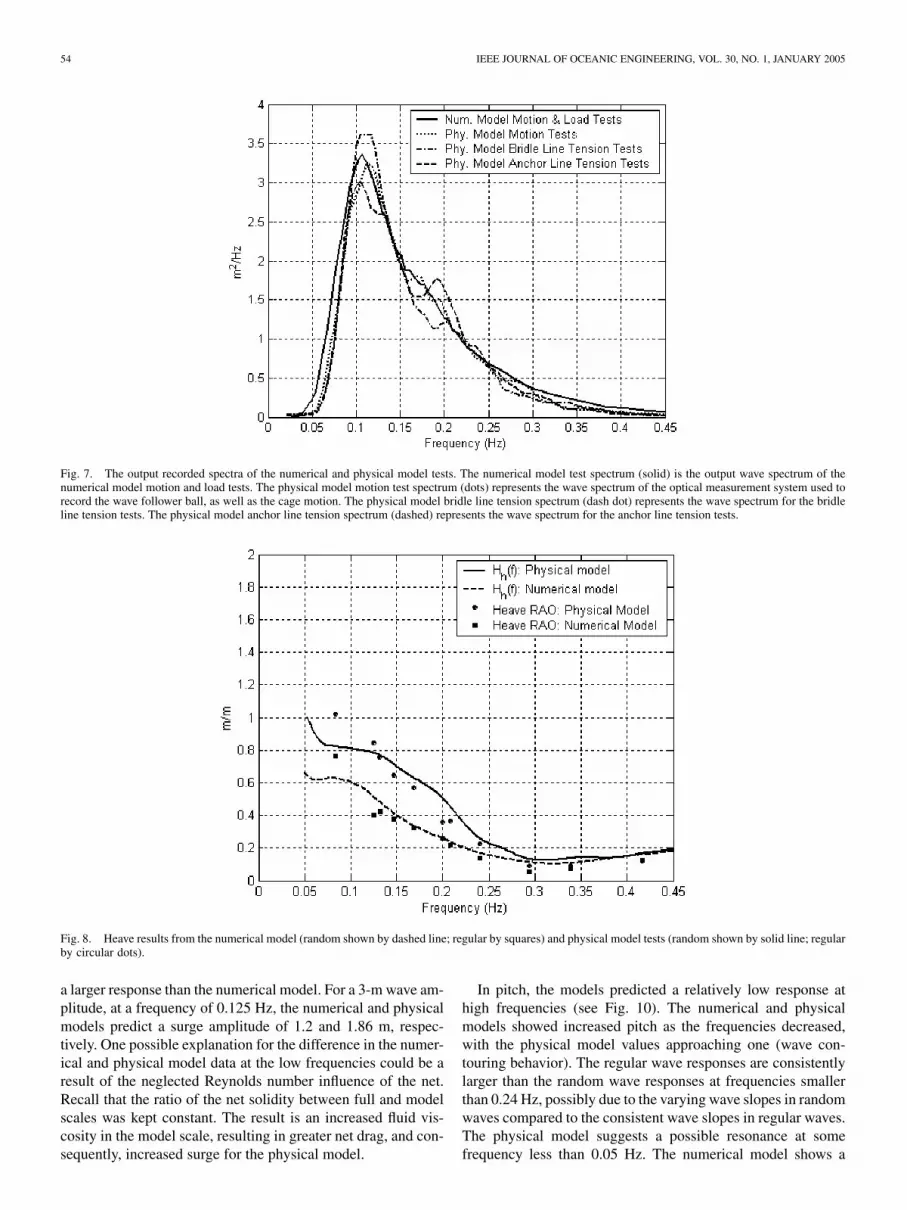
the load response (of the anchor and bridle lines) were investi-gated using these load cases. The random motion transfer func-tions were then calculated using autospectral density functionsand compared to the regular wave response amplitude opera-tors. The anchor and bridle line tension transfer functions weredetermined using cross-spectral density functions. It is impor-tant to note that the RAOs and transfer functions for the motionresponse of the cage represent the dynamics of the top super-structure due to the flexible construction of the cage, specificallythe tension lines attaching to the bottom rim. The numericaland physical model wave spectra recorded in each of the testsare shown in Fig. 7. The numerical model motion and load testspectra was generated by Aqua-FE. Three separate wave spectrafor the physical model tests are presented. For motion tests,surface elevation was recorded using the optical measurementsystem to follow float ball as well as the cage. The wave staffwas used during the separate anchor and bridle line tests sinceboth load cell signals could not be recorded using a commondata acquisition system.
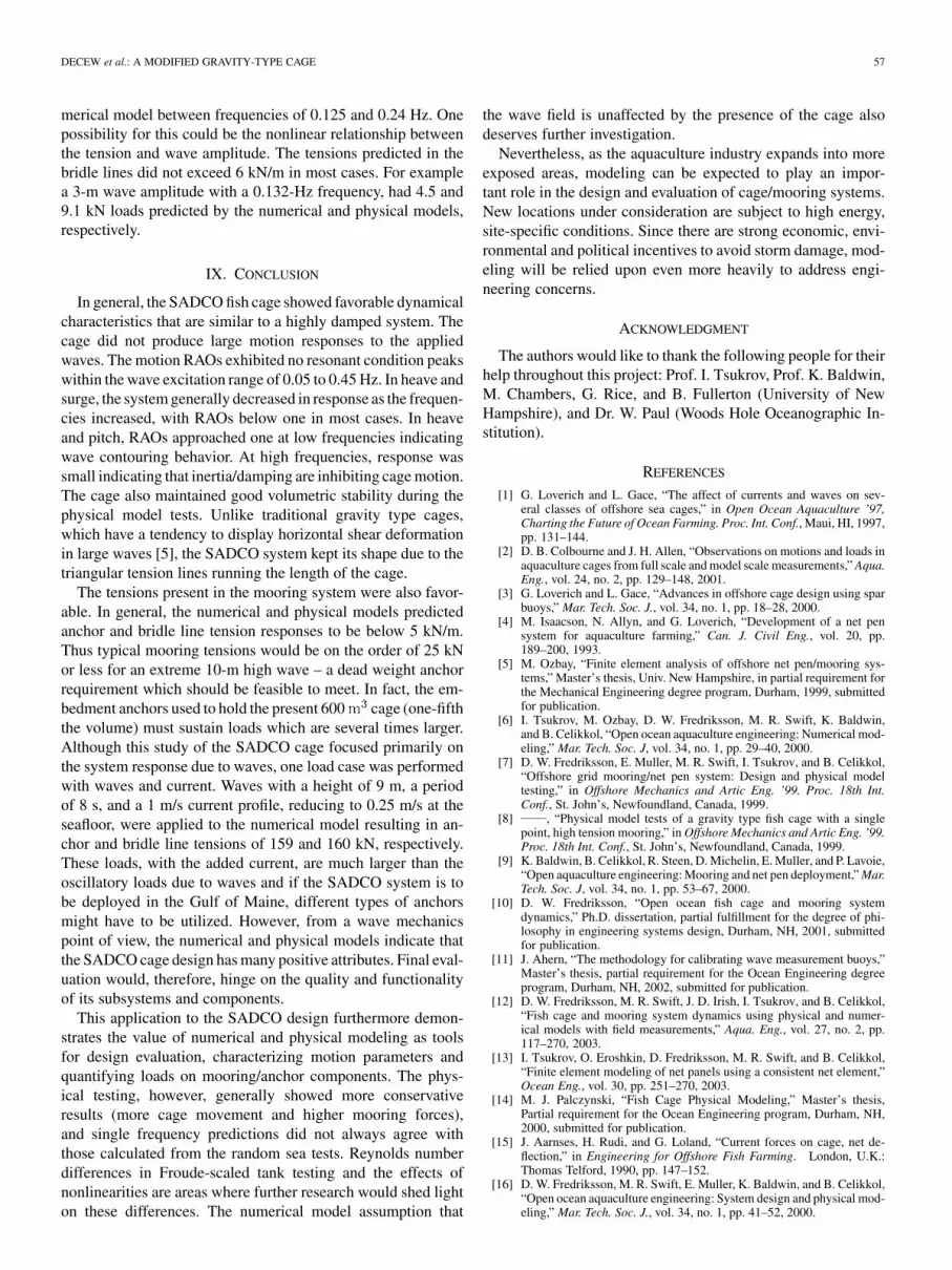
The heave results (Fig. 8) for both the numerical and phys-ical models were characteristic of a highly damped system withlittle response to high frequency waves. As the frequency de-creased, the response of the system increased approaching one,indicating wave contouring behavior. If a resonant condition ex-ists, on the other hand, it would most likely occur at waves with afrequency below 0.05 Hz, which are rare at the OOA site. Theseresults were consistent with those obtained by [26], where freerelease tests were performed with another type of fish cage andboth damped and undamped natural frequencies were obtained.In that study, the resonant frequencies were mainly influencedby the net system, and less by the structural parameters of thecage, which is generally the case. In general, the physical modelhad a higher response compared to the numerical model, with apeak heave amplitude of 1.02 m in response to a 1-m amplitude,0.083-Hz frequency, regular wave.
The response of the cage in surge, using both the numericaland physical models, was similar with negligible movement atthe high frequencies (Fig. 9). Both the numerical and physicalmodels showed an increase in surge response between frequen-cies of 0.1 to 0.12 Hz, with the physical model generally having
54 IEEE JOURNAL OF OCEANIC ENGINEERING, VOL. 30, NO. 1, JANUARY 2005
Fig. 7. The output recorded spectra of the numerical and physical model tests. The numerical model test spectrum (solid) is the output wave spectrum of thenumerical model motion and load tests. The physical model motion test spectrum (dots) represents the wave spectrum of the optical measurement system used torecord the wave follower ball, as well as the cage motion. The physical model bridle line tension spectrum (dash dot) represents the wave spectrum for the bridleline tension tests. The physical model anchor line tension spectrum (dashed) represents the wave spectrum for the anchor line tension tests.
Fig. 8. Heave results from the numerical model (random shown by dashed line; regular by squares) and physical model tests (random shown by solid line; regularby circular dots).
a larger response than the numerical model. For a 3-m wave am-plitude, at a frequency of 0.125 Hz, the numerical and physicalmodels predict a surge amplitude of 1.2 and 1.86 m, respec-tively. One possible explanation for the difference in the numer-ical and physical model data at the low frequencies could be aresult of the neglected Reynolds number influence of the net.Recall that the ratio of the net solidity between full and modelscales was kept constant. The result is an increased fluid vis-cosity in the model scale, resulting in greater net drag, and con-sequently, increased surge for the physical model.
In pitch, the models predicted a relatively low response athigh frequencies (see Fig. 10). The numerical and physicalmodels showed increased pitch as the frequencies decreased,with the physical model values approaching one (wave con-touring behavior). The regular wave responses are consistentlylarger than the random wave responses at frequencies smallerthan 0.24 Hz, possibly due to the varying wave slopes in randomwaves compared to the consistent wave slopes in regular waves.The physical model suggests a possible resonance at somefrequency less than 0.05 Hz. The numerical model shows a

DECEW et al.: A MODIFIED GRAVITY-TYPE CAGE 55
Fig. 9. Surge results from the numerical model (random shown by dashed line; regular by squares) and physical model tests (random shown by solid line; regularby circular dots).
Fig. 10. Pitch results from the numerical model (random shown by dashed line; regular by squares) and physical model tests (random shown by solid line; regularby circular dots).
similar trend, but to a lesser extent. Once again, since wavefrequencies less than 0.05 Hz are unlikely at the OOA site,excessive movements due to resonating components are alsounlikely. It is possible that the use of the triangular tension linesconnecting the buoyant superstructure to the bottom rim helpsprevent pitch motion.
The significant response, or the top one third motion responseof the cage, was also investigated for the numerical and phys-ical models in random waves with results given in Table IV. Thesignificant response was determined using the same approach
as the significant wave height in the frequency domain, exceptthat the cage motion response and not wave height was used.These values represent the cage motion response to a numericaland physical model significant wave height of 2.55 and 2.45 m,respectively. It is important to note that “coupling” motion, orinteractions of various component motions, can affect the dy-namics of the cage system. This was investigated, using spectralanalysis techniques, and determined that negligible coupling oc-curred between different degrees of freedom in the regular wavetests.

56 IEEE JOURNAL OF OCEANIC ENGINEERING, VOL. 30, NO. 1, JANUARY 2005
TABLE IVSIGNIFICANT MOTION RESPONSE OF THE NUMERICAL AND PHYSICAL MODELS IN RANDOM WAVES WITH A SIGNIFICANT WAVE
HEIGHT OF 2.55 AND 2.45 m, RESPECTIVELY
Fig. 11. Anchor line force results from the numerical model (random shown by dashed line; regular by squares) and physical model tests (random shown by solidline; regular by circular dots).
Fig. 12. Bridle line force results from the numerical model (random shown by dashed line; regular by squares) and physical model tests (random shown by solidline; regular by circular dots).
Linear transfer functions, using cross-spectral techniques,were also found for tensions in the anchor and lower bridlelines, Figs. 11 and 12, respectively. In the anchor line, boththe numerical and physical model data agreed well throughoutthe frequencies. The models predicted a tension response lessthan 5 kN/m throughout the wave frequencies. For example,the numerical and physical models both predicted a tensionof 1.8 kN to a 3-m wave with a frequency of 0.083 Hz. It is
important to note that the tension response of the anchor andbridle line represent the tension associated with the oscillatorymotion of the cage and mooring system, not any set-back orcurrent loads.
The random wave response of the numerical and physicalmodel bridle line tensions matched up well throughout the fre-quencies. However, the physical model regular wave tensionresponses in the bridle line where much higher than the nu-
DECEW et al.: A MODIFIED GRAVITY-TYPE CAGE 57
merical model between frequencies of 0.125 and 0.24 Hz. Onepossibility for this could be the nonlinear relationship betweenthe tension and wave amplitude. The tensions predicted in thebridle lines did not exceed 6 kN/m in most cases. For examplea 3-m wave amplitude with a 0.132-Hz frequency, had 4.5 and9.1 kN loads predicted by the numerical and physical models,respectively.
IX. CONCLUSION
In general, the SADCO fish cage showed favorable dynamicalcharacteristics that are similar to a highly damped system. Thecage did not produce large motion responses to the appliedwaves. The motion RAOs exhibited no resonant condition peakswithin the wave excitation range of 0.05 to 0.45 Hz. In heave andsurge, the system generally decreased in response as the frequen-cies increased, with RAOs below one in most cases. In heaveand pitch, RAOs approached one at low frequencies indicatingwave contouring behavior. At high frequencies, response wassmall indicating that inertia/damping are inhibiting cage motion.The cage also maintained good volumetric stability during thephysical model tests. Unlike traditional gravity type cages,which have a tendency to display horizontal shear deformationin large waves [5], the SADCO system kept its shape due to thetriangular tension lines running the length of the cage.
The tensions present in the mooring system were also favor-able. In general, the numerical and physical models predictedanchor and bridle line tension responses to be below 5 kN/m.Thus typical mooring tensions would be on the order of 25 kNor less for an extreme 10-m high wave – a dead weight anchorrequirement which should be feasible to meet. In fact, the em-bedment anchors used to hold the present 600 cage (one-fifththe volume) must sustain loads which are several times larger.Although this study of the SADCO cage focused primarily onthe system response due to waves, one load case was performedwith waves and current. Waves with a height of 9 m, a periodof 8 s, and a 1 m/s current profile, reducing to 0.25 m/s at theseafloor, were applied to the numerical model resulting in an-chor and bridle line tensions of 159 and 160 kN, respectively.These loads, with the added current, are much larger than theoscillatory loads due to waves and if the SADCO system is tobe deployed in the Gulf of Maine, different types of anchorsmight have to be utilized. However, from a wave mechanicspoint of view, the numerical and physical models indicate thatthe SADCO cage design has many positive attributes. Final eval-uation would, therefore, hinge on the quality and functionalityof its subsystems and components.
This application to the SADCO design furthermore demon-strates the value of numerical and physical modeling as toolsfor design evaluation, characterizing motion parameters andquantifying loads on mooring/anchor components. The phys-ical testing, however, generally showed more conservativeresults (more cage movement and higher mooring forces),and single frequency predictions did not always agree withthose calculated from the random sea tests. Reynolds numberdifferences in Froude-scaled tank testing and the effects ofnonlinearities are areas where further research would shed lighton these differences. The numerical model assumption that
the wave field is unaffected by the presence of the cage alsodeserves further investigation.
Nevertheless, as the aquaculture industry expands into moreexposed areas, modeling can be expected to play an impor-tant role in the design and evaluation of cage/mooring systems.New locations under consideration are subject to high energy,site-specific conditions. Since there are strong economic, envi-ronmental and political incentives to avoid storm damage, mod-eling will be relied upon even more heavily to address engi-neering concerns.
ACKNOWLEDGMENT
The authors would like to thank the following people for theirhelp throughout this project: Prof. I. Tsukrov, Prof. K. Baldwin,M. Chambers, G. Rice, and B. Fullerton (University of NewHampshire), and Dr. W. Paul (Woods Hole Oceanographic In-stitution).
REFERENCES
[1] G. Loverich and L. Gace, “The affect of currents and waves on sev-eral classes of offshore sea cages,” in Open Ocean Aquaculture ’97,Charting the Future of Ocean Farming. Proc. Int. Conf., Maui, HI, 1997,pp. 131–144.
[2] D. B. Colbourne and J. H. Allen, “Observations on motions and loads inaquaculture cages from full scale and model scale measurements,” Aqua.Eng., vol. 24, no. 2, pp. 129–148, 2001.
[3] G. Loverich and L. Gace, “Advances in offshore cage design using sparbuoys,” Mar. Tech. Soc. J., vol. 34, no. 1, pp. 18–28, 2000.
[4] M. Isaacson, N. Allyn, and G. Loverich, “Development of a net pensystem for aquaculture farming,” Can. J. Civil Eng., vol. 20, pp.189–200, 1993.
[5] M. Ozbay, “Finite element analysis of offshore net pen/mooring sys-tems,” Master’s thesis, Univ. New Hampshire, in partial requirement forthe Mechanical Engineering degree program, Durham, 1999, submittedfor publication.
[6] I. Tsukrov, M. Ozbay, D. W. Fredriksson, M. R. Swift, K. Baldwin,and B. Celikkol, “Open ocean aquaculture engineering: Numerical mod-eling,” Mar. Tech. Soc. J, vol. 34, no. 1, pp. 29–40, 2000.
[7] D. W. Fredriksson, E. Muller, M. R. Swift, I. Tsukrov, and B. Celikkol,“Offshore grid mooring/net pen system: Design and physical modeltesting,” in Offshore Mechanics and Artic Eng. ’99. Proc. 18th Int.Conf., St. John’s, Newfoundland, Canada, 1999.
[8] , “Physical model tests of a gravity type fish cage with a singlepoint, high tension mooring,” in Offshore Mechanics and Artic Eng. ’99.Proc. 18th Int. Conf., St. John’s, Newfoundland, Canada, 1999.
[9] K. Baldwin, B. Celikkol, R. Steen, D. Michelin, E. Muller, and P. Lavoie,“Open aquaculture engineering: Mooring and net pen deployment,” Mar.Tech. Soc. J, vol. 34, no. 1, pp. 53–67, 2000.
[10] D. W. Fredriksson, “Open ocean fish cage and mooring systemdynamics,” Ph.D. dissertation, partial fulfillment for the degree of phi-losophy in engineering systems design, Durham, NH, 2001, submittedfor publication.
[11] J. Ahern, “The methodology for calibrating wave measurement buoys,”Master’s thesis, partial requirement for the Ocean Engineering degreeprogram, Durham, NH, 2002, submitted for publication.
[12] D. W. Fredriksson, M. R. Swift, J. D. Irish, I. Tsukrov, and B. Celikkol,“Fish cage and mooring system dynamics using physical and numer-ical models with field measurements,” Aqua. Eng., vol. 27, no. 2, pp.117–270, 2003.
[13] I. Tsukrov, O. Eroshkin, D. Fredriksson, M. R. Swift, and B. Celikkol,“Finite element modeling of net panels using a consistent net element,”Ocean Eng., vol. 30, pp. 251–270, 2003.
[14] M. J. Palczynski, “Fish Cage Physical Modeling,” Master’s thesis,Partial requirement for the Ocean Engineering program, Durham, NH,2000, submitted for publication.
[15] J. Aarnses, H. Rudi, and G. Loland, “Current forces on cage, net de-flection,” in Engineering for Offshore Fish Farming. London, U.K.:Thomas Telford, 1990, pp. 147–152.
[16] D. W. Fredriksson, M. R. Swift, E. Muller, K. Baldwin, and B. Celikkol,“Open ocean aquaculture engineering: System design and physical mod-eling,” Mar. Tech. Soc. J., vol. 34, no. 1, pp. 41–52, 2000.
58 IEEE JOURNAL OF OCEANIC ENGINEERING, VOL. 30, NO. 1, JANUARY 2005
[17] D. W. Fredriksson, M. R. Swift, O. Eroshkin, I. Tsukrov, J. Irish, and B.Celikkol, “Moored fish cage dynamics in waves and currents,” IEEE J.Ocean. Eng., to be published.
[18] R. G. Dean and R. A. Dalrymple, Water Wave Mechanics for Engineersand Scientists, 2nd ed, Singapore: World Scientific, 1991, p. 353.
[19] S. K. Chakrabarti, Offshore Structure Modeling, Singapore: World Sci-entific, 1994, vol. 9.
[20] J. S. Bendat and A. G. Pearsal, Random Data: Analysis and Measure-ment Procedures, 2nd ed. New York: Wiley , 1986.
[21] J. DeCew, “Numerical and physical modeling of a SADCO© shelf sub-mersible fish cage,” Master’s thesis, partial requirement for the OceanEngineering degree program, Durham, NH, 2002, submitted for publi-cation.
[22] M. R. Swift, M. Palczynski, K. Kestler, D. Michelin, B. Celikkol,and M. Gosz, “Fish cage physical modeling for software developmentand design applications,” in Nutrition and Tech. Dev. Aquaculture.Proc. 26th US-Japan Aquaculture Symp., Durham, NH, 1996, Rep.UNHMP-CP-SG-98-19, pp. 199–206.
[23] M. Gosz, K. Kestler, M. R. Swift, and B. Celikkol, “Finite elementmodeling of submerged aquaculture net-pen systems,” in Open OceanAquaculture. Proc. Int. Conf., M. Polk, Ed., Portland, ME, May8–10, 1996, New Hampshire/Maine Sea Grant College Program Rep.#UNHMP-CP-SG-96-9, pp. 523–554.
[24] I. Tsukrov, M. Ozbay, D. W. Fredriksson, E. Muller, M. R. Swift, and B.Celikkol, “Offshore grid mooring/net pen system: Finite element anal-ysis,” in Proc. 18th Int. Conf. Offshore Mechan. and Arctic Eng., 1999,ASME/OMAE99-3065.
[25] J. R. Morison, J. W. Johnson, M. P. O’Brien, and S. A. Schaaf, “Theforces exerted by surface waves on piles,” in Petroleum Trans.: Amer.Inst. Mining Eng., 1950, pp. 149–157.
[26] D. W. Fredriksson, J. D. Irish, M. R. Swift, and B. Celikkol, “The heaveresponse of a central spar fish cage,” Trans. ASME, J. Off. Mechan. Arct.Eng., vol. 125, pp. 242–248, 2003.
Judson DeCew received the B.S. degree in me-chanical engineering and the M.S. degree in oceanengineering from the University of New Hampshire,Durham.
After working at the Portsmouth Naval Shipyard,he joined the Ocean Engineering Department asa Research Project Engineer working on cage andmooring system design and analysis.
David W. Fredriksson received the B.S. degree inmarine engineering from the Massachusetts MaritimeAcademy, and the M.S. and Ph.D. degrees in oceanengineering and system design engineering, respec-tively, both from the University of New Hampshire,Durham.
He is a Research Assistant Professor with theCenter for Ocean Engineering, University of NewHampshire. His research focus includes open oceanaquaculture engineering, ocean and coastal mea-surements, and oil-spill response and remediation
technologies.
Leonid Bugrov received the M.S. degree in biology and ichthyology from theState University of Leningrad, St. Petersburg, Russia, and the Ph.D. degree (can-didatum scientarium) in fish biology from the State Research Institute of Lakeand River Fisheries, St. Petersburg, Russia.
He has more than 30 years experience in fish biology and aquaculture. Heis the author of approximately 60 papers and articles in this field. His researchinterest in aquaculture engineering, fish ecology, and physiology have led to thedevelopment of new cage systems based on underwater fish-farming concept.His past experience involves conversion of oilrigs to offshore aquaculture withMinistry of Oil and Gas Industry of the former USSR and with Russian FederalInstitute of Fishery for cage farming of salmon and sturgeon. He is currentlywith SADCO Shelf LTD, St. Petersburg, Russia. He was responsible for projectmanagement and installation of submersible cage farms at the MediterraneanRegion for seabream and seabass production.
M. Robinson Swift received the B.S. degree and thePh.D. degree in mechanical engineering, both fromthe University of New Hampshire, Durham.
He is a Professor of Mechanical and OceanEngineering with the University of New Hampshire.His research focuses on oil-spill response, compliantocean structures, tidal dynamics, and nonpointsource pollution.
Oleg Eroshkin received the B.S. and M.S. degrees inmathematics from Dnipropetrovsk State University,Dnepropetrovsk, Ukraine.
He is currently with the University of NewHampshire, Durham, pursuing the Ph.D. degree inmathematics. He is working on numerical modelingof fluid-structure interaction in open ocean environ-ment with the Open Ocean Demonstration Project atthe University of New Hampshire, which he joinedin 2000.
Barbaros Celikkol received the B.S. degree inphysics-math from Elon College, the M.S. degreein physics from the Stevens Institute of Technology,Hoboken, NJ, and the Ph.D. degree in physics fromthe University of New Hampshire, Durham.
He is a Professor and the Chair of the MechanicalEngineering Department, University of New Hamp-shire. His research interests are in the areas of openocean aquaculture engineering, environmental mod-eling, and oil-spill response technology.