Embed Size (px)
Citation preview
This article was originally published in a journal published byElsevier, and the attached copy is provided by Elsevier for the
author’s benefit and for the benefit of the author’s institution, fornon-commercial research and educational use including without
limitation use in instruction at your institution, sending it to specificcolleagues that you know, and providing a copy to your institution’s
administrator.
All other uses, reproduction and distribution, including withoutlimitation commercial reprints, selling or licensing copies or access,
or posting on open internet sites, your personal or institution’swebsite or repository, are prohibited. For exceptions, permission
may be sought for such use through Elsevier’s permissions site at:
http://www.elsevier.com/locate/permissionusematerial
Autho
r's
pers
onal
co
py
Building and Environment 42 (2007) 3298–3308
A combined system of chilled ceiling, displacement ventilation anddesiccant dehumidification
Xiaoli Haoa,b, Guoqiang Zhanga,�, Youming Chena, Shenghua Zoub,Demetrios. J. Moschandreasa,c
aCollege of Civil Engineering, Hunan University, Changsha, Hunan 410082, PR ChinabDepartment of Building Environment and Services Engineering, College of Energy and Safety Engineering, Hunan University of Science and Technology,
Xiangtan, Hunan 411201, PR ChinacIllinois Institute of Technology, Chicago, IL USA
Received 8 April 2005; received in revised form 9 May 2006; accepted 29 August 2006
Abstract
Different types of heating, ventilation, and air-conditioning (HVAC) systems consume different amounts of energy yet they deliver
similar levels of acceptable indoor air quality (IAQ) and thermal comfort. It is desirable to provide buildings with an optimal HVAC
system to create the best IAQ and thermal comfort with minimum energy consumption. In this paper, a combined system of chilled
ceiling, displacement ventilation and desiccant dehumidification is designed and applied for space conditioning in a hot and humid
climate. IAQ, thermal comfort, and energy saving potential of the combined system are estimated using a mathematical model of the
system described in this paper. To confirm the feasibility of the combined system in a hot and humid climate, like China, and to evaluate
the system performance, the mathematical model simulates an office building in Beijing and estimates IAQ, thermal comfort and energy
consumption. We conclude that in comparison with a conventional all-air system the combined system saves 8.2% of total primary
energy consumption in addition to achieving better IAQ and thermal comfort. Chilled ceiling, displacement ventilation and desiccant
dehumidification respond consistently to cooling source demand and complement each other on indoor comfort and air quality. It is
feasible to combine the three technologies for space conditioning of office building in a hot and humid climate.
r 2006 Published by Elsevier Ltd.
Keywords: Chilled ceiling; Displacement ventilation; Desiccant dehumidification; Thermal comfort; Indoor air quality; Energy conservation
1. Introduction
Today, as people spend more and more time in buildingsthan before, indoor air quality (IAQ) and thermal comfortattract increasing attention. Although a definitive quanti-tative relation between environment and productivity hasnot yet been established, individuals perform better, moreeffectively, in conditioned than in untreated indoor airenvironments [1]. Therefore, a comfortable and healthyindoor environment should improve the occupants’ work-ing efficiency. The operation of a heating, ventilation andair-conditioning (HVAC) system is usually required toachieve comfortable indoor conditions by providing
sufficient amount of fresh air to the occupied zone toremove indoor generated contaminants and maintainsuitable indoor air temperature and humidity by supplyingor removing heat and/or moisture to or from the occupiedzone. However, HVAC systems often consume largeamounts of energy. In other words, comfortable indoorenvironment is paid by energy consumption because theamount of energy consumed for conditioning indoorenvironments affects IAQ and thermal comfort. Therefore,it is important to investigate the possibility of attainingimproved indoor environmental quality efficiently withoutincreasing energy consumption or indeed decreasing energyconsumption.Different types of HVAC systems have different energy
consumption for the same IAQ and thermal comfort. It isdesirable to provide each building with an optimal HVAC
ARTICLE IN PRESS
www.elsevier.com/locate/buildenv
0360-1323/$ - see front matter r 2006 Published by Elsevier Ltd.
doi:10.1016/j.buildenv.2006.08.020
�Corresponding author. Tel.: +86731 8825398; fax: +86 731 8821005.
E-mail address: [email protected] (G. Zhang).
Autho
r's
pers
onal
co
pysystem, which would provide the best IAQ and thermalcomfort for occupants with minimum energy consumption.Many investigators have focused on this topic and a fewnovel HVAC systems have been proposed and studied[2–8]. Among these systems, the chilled ceiling (CC) systemis viewed as a good alternative for conventional air-conditioning system. CC offers several advantages over aconventional air-conditioning system. It is better in thermalcomfort, energy consumption, space saving and noiseelimination than conventional system due to its energytransfer mainly by radiation and by decoupling heattransfer mechanisms from ventilation. In addition, therelatively high chilled water temperature used by the CCsystem enables it to use natural cooling or free cooling,thus reducing energy consumption and pollutant emissions.[9,10]. Owing to these advantages the CC system hasattracted much attention in recent years [11,12]. However,CC does not control humidity levels. IAQ becomes aproblem for CC system due to its decoupling fromventilation. Therefore, an additional ventilation system isnecessary when CC is used for space conditioning.Although natural ventilation may be utilized to supplyfresh air for air-conditioning the indoor space, mechanicalventilation is usually used to guarantee an energy efficientair exchange rate. Both mixing ventilation and displace-ment ventilation can be used to supply fresh air. But,displacement ventilation system supplies conditioned freshair with low air velocity directly to the occupied zone andtherefore it provides improved IAQ [3]. Hence, combined
with displacement ventilation, a well designed CC systemcan achieve better thermal comfort and IAQ.To avoid moisture condensation on the surface of CC
the air dew-point temperature should be controlled belowthe surface temperature of the chilled panel. In order toattain this requirement, a displacement ventilation systemmust dehumidify the supply air before it is distributed.Conventional air handling units (AHU) are used fordehumidifying supply air. In such conventional AHU thesupply air is dehumidified because moisture contained inthe incoming air condenses on the cooling coil surface if thesurface temperature of the cooling coil is lower than the airdew-point temperature. In the process of dehumidification,air is also overcooled to rather low temperatures. To avoiddiscomfort caused by cold draft, supply air is oftenreheated before it is distributed into air-conditioning spaceand consequently the system consumes excessive energy.An alternative dehumidification approach is the use ofdesiccant dehumidification, which uses desiccant, absor-bent or adsorbent, to remove moisture in air. The rotarydehumidifier, known as the desiccant wheel, is a commontype of sorption dehumidifier. With a rotating desiccantwheel air dehumidification is achieved continuously. Sincethe supply air is not overcooled in the process ofdehumidification, reheating the air is not needed. In recentyears, desiccant technology is increasingly gaining accep-tance from HVAC engineers [13–16]. Moreover results ofnumerical simulations show large energy savings when CCis combined with desiccant cooling [17].
ARTICLE IN PRESS
Nomenclature
q cooling load (W/m2)T temperature (K)f rate of chilled ceiling area to floor areaQ volumetric flow rate of air or chilled water
(m3/s)C specific heat of air (kJ/(kg 1C))W moisture load of unit floor area (g/s)d humidity ratio (g/kg)E cooling or heating capacity (W)A, B, C experimental coefficientsc contaminant concentrationN power consumption of primary equipment (W)COP coefficient of performance of chillerdp total pressure rise of pump or fan (Pa)R portion of cooling load removed by chilled
ceiling in total sensible cooling loadP/Q Ratio between the total sensible cooling load
and supply air flow rate
Greek letters
r density of air (kg/m3)
Z effectiveness coefficientm contaminant removal efficiencyo portion of cooling load removed by DV system
in total sensible cooling load of room
Subscripts
IA indoor airCC chilled ceilingDV displacement ventilationSA supply airFN fanSHR sensible heat recoveryMR moisture recoverySHE sensible heat exchangerEC evaporative coolerCCL cooling coilHR heaterEA exhaust airi any position of roomCH chillerBR boilerPP pumpA–O air state points
X. Hao et al. / Building and Environment 42 (2007) 3298–3308 3299
Autho
r's
pers
onal
co
py
The objective of this paper is to investigate the feasibilityof combining CC, displacement ventilation and desiccantdehumidification and determine if this integrated systemconfiguration can realize desirable levels of IAQ, thermalcomfort, and energy savings in the hot and humid climateof China. This paper describes the combined system and itsjustification, and formulates a mathematical model of thecombined system. The model is employed to analyze a casestudy of the proposed system and compare it with aconventional all-air system. Conclusions of this researchare reported in the last section of the paper.
2. System analyses
2.1. System description
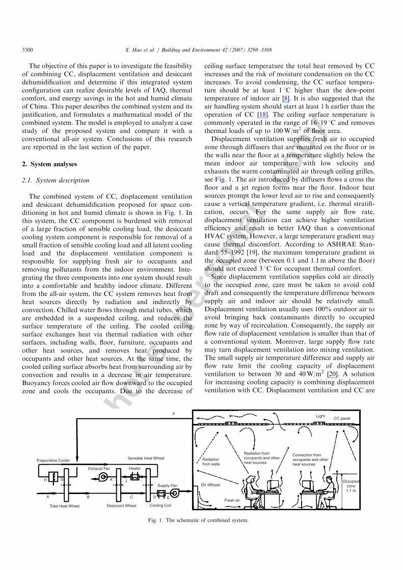
The combined system of CC, displacement ventilationand desiccant dehumidification proposed for space con-ditioning in hot and humid climate is shown in Fig. 1. Inthis system, the CC component is burdened with removalof a large fraction of sensible cooling load, the desiccantcooling system component is responsible for removal of asmall fraction of sensible cooling load and all latent coolingload and the displacement ventilation component isresponsible for supplying fresh air to occupants andremoving pollutants from the indoor environment. Inte-grating the three components into one system should resultinto a comfortable and healthy indoor climate. Differentfrom the all-air system, the CC system removes heat fromheat sources directly by radiation and indirectly byconvection. Chilled water flows through metal tubes, whichare embedded in a suspended ceiling, and reduces thesurface temperature of the ceiling. The cooled ceilingsurface exchanges heat via thermal radiation with othersurfaces, including walls, floor, furniture, occupants andother heat sources, and removes heat produced byoccupants and other heat sources. At the same time, thecooled ceiling surface absorbs heat from surrounding air byconvection and results in a decrease in air temperature.Buoyancy forces cooled air flow downward to the occupiedzone and cools the occupants. Due to the decrease of
ceiling surface temperature the total heat removed by CCincreases and the risk of moisture condensation on the CCincreases. To avoid condensing, the CC surface tempera-ture should be at least 1 1C higher than the dew-pointtemperature of indoor air [8]. It is also suggested that theair handling system should start at least 1 h earlier than theoperation of CC [18]. The ceiling surface temperature iscommonly operated in the range of 16–19 1C and removesthermal loads of up to 100W/m2 of floor area.Displacement ventilation supplies fresh air to occupied
zone through diffusers that are mounted on the floor or inthe walls near the floor at a temperature slightly below themean indoor air temperature with low velocity andexhausts the warm contaminated air through ceiling grilles,see Fig. 1. The air introduced by diffusers flows a cross thefloor and a jet region forms near the floor. Indoor heatsources prompt the lower level air to rise and consequentlycause a vertical temperature gradient, i.e. thermal stratifi-cation, occurs. For the same supply air flow rate,displacement ventilation can achieve higher ventilationefficiency and result in better IAQ than a conventionalHVAC system. However, a large temperature gradient maycause thermal discomfort. According to ASHRAE Stan-dard 55–1992 [19], the maximum temperature gradient inthe occupied zone (between 0.1 and 1.1m above the floor)should not exceed 3 1C for occupant thermal comfort.Since displacement ventilation supplies cold air directly
to the occupied zone, care must be taken to avoid colddraft and consequently the temperature difference betweensupply air and indoor air should be relatively small.Displacement ventilation usually uses 100% outdoor air toavoid bringing back contaminants directly to occupiedzone by way of recirculation. Consequently, the supply airflow rate of displacement ventilation is smaller than that ofa conventional system. Moreover, large supply flow ratemay turn displacement ventilation into mixing ventilation.The small supply air temperature difference and supply airflow rate limit the cooling capacity of displacementventilation to between 30 and 40W/m2 [20]. A solutionfor increasing cooling capacity is combining displacementventilation with CC. Displacement ventilation and CC are
ARTICLE IN PRESS
Evaporative Cooler
H G
A B
Total Heat Wheel Desiccant Wheel
C D E
K J I
Exhaust Fan
Sensible Heat Wheel
Heater
Supply Fan
Cooling Coil
DV diffuser
Fresh air
Radiationfrom walls
Radiation fromoccupants and otherheat sources
Convection fromoccupants and otherheat sources
LightCC panel
Occupiedzone1.1 m
F
Fig. 1. The schematic of combined system.
X. Hao et al. / Building and Environment 42 (2007) 3298–33083300
Autho
r's
pers
onal
co
py
complementary with respect to indoor environmentalquality. Displacement ventilation leads to good IAQ whileCC results in good thermal comfort.
The combined system dehumidifies the supply air using adesiccant wheel, which transfers moisture from the supplyair to the dried desiccant surface as a result of lower watervapor partial pressure on it. By absorbing or adsorbingmore moisture from supply air, water vapor partialpressure on the desiccant surface increases and pressureequilibrium is reached. To continuously remove moisturefrom supply air, the desiccant should be regeneratedcontinuously. Desiccant recovery is accomplished byexposing the wetted desiccant to another heated air streamwhich has a lower water vapor partial pressure than that onwetted desiccant surface. So the moisture on the surface ofdesiccant transfers into regeneration air and the ability todehumidify of desiccant is recovered.
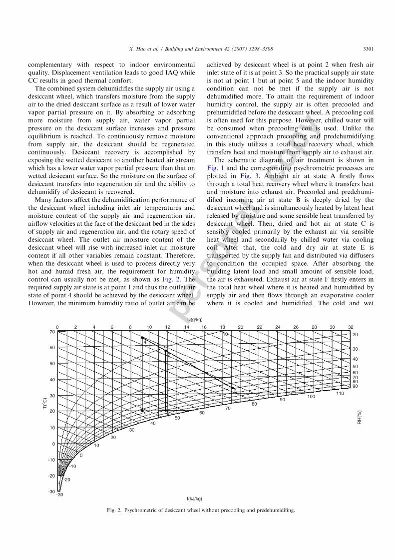
Many factors affect the dehumidification performance ofthe desiccant wheel including inlet air temperatures andmoisture content of the supply air and regeneration air,airflow velocities at the face of the desiccant bed in the sidesof supply air and regeneration air, and the rotary speed ofdesiccant wheel. The outlet air moisture content of thedesiccant wheel will rise with increased inlet air moisturecontent if all other variables remain constant. Therefore,when the desiccant wheel is used to process directly veryhot and humid fresh air, the requirement for humiditycontrol can usually not be met, as shown as Fig. 2. Therequired supply air state is at point 1 and thus the outlet airstate of point 4 should be achieved by the desiccant wheel.However, the minimum humidity ratio of outlet air can be
achieved by desiccant wheel is at point 2 when fresh airinlet state of it is at point 3. So the practical supply air stateis not at point 1 but at point 5 and the indoor humiditycondition can not be met if the supply air is notdehumidified more. To attain the requirement of indoorhumidity control, the supply air is often precooled andprehumidified before the desiccant wheel. A precooling coilis often used for this purpose. However, chilled water willbe consumed when precooling coil is used. Unlike theconventional approach precooling and predehumidifyingin this study utilizes a total heat recovery wheel, whichtransfers heat and moisture from supply air to exhaust air.The schematic diagram of air treatment is shown in
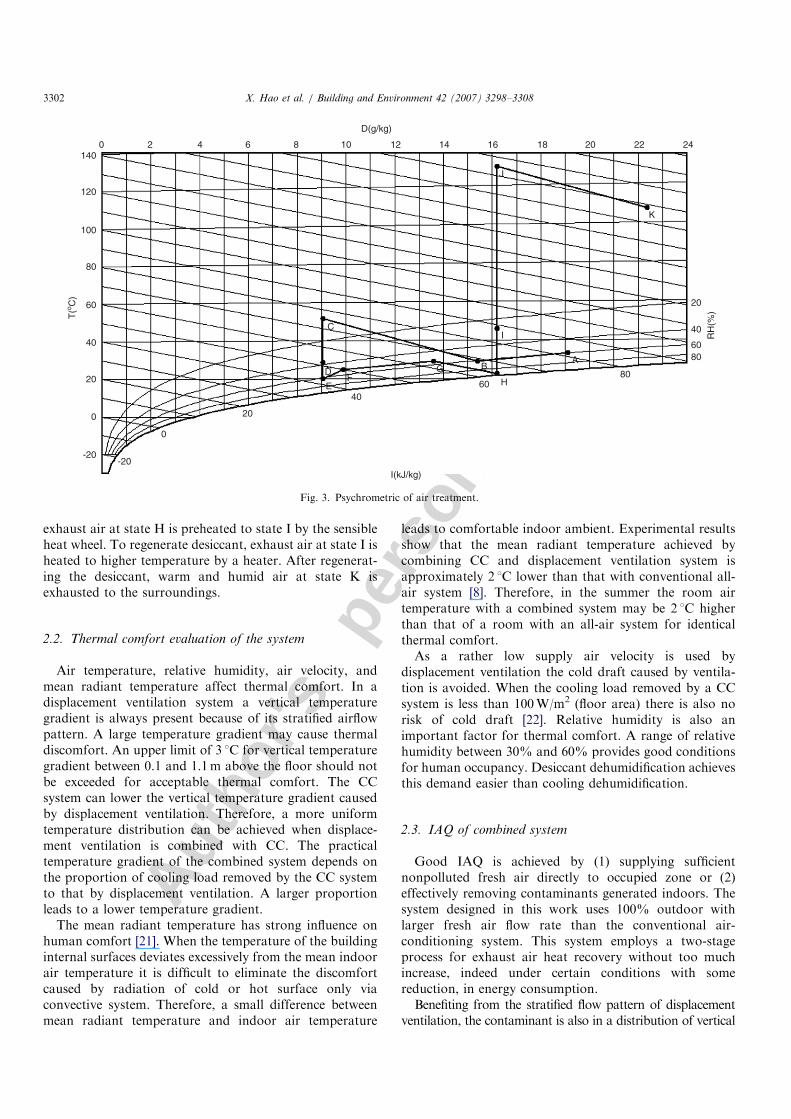
Fig. 1 and the corresponding psychrometric processes areplotted in Fig. 3. Ambient air at state A firstly flowsthrough a total heat recovery wheel where it transfers heatand moisture into exhaust air. Precooled and predehumi-dified incoming air at state B is deeply dried by thedesiccant wheel and is simultaneously heated by latent heatreleased by moisture and some sensible heat transferred bydesiccant wheel. Then, dried and hot air at state C issensibly cooled primarily by the exhaust air via sensibleheat wheel and secondarily by chilled water via coolingcoil. After that, the cold and dry air at state E istransported by the supply fan and distributed via diffusersto condition the occupied space. After absorbing thebuilding latent load and small amount of sensible load,the air is exhausted. Exhaust air at state F firstly enters inthe total heat wheel where it is heated and humidified bysupply air and then flows through an evaporative coolerwhere it is cooled and humidified. The cold and wet
ARTICLE IN PRESS
I(kJ/kg)-30
-30
-10-10
-20-20
0
0
10
10
20
3040
5060
7080
90100
110
RH
(%)
9080706050
40
30
20
323028262422201816
D(g/kg)
1412108642070
60
50
40
30
20
T(o C
)
4
2
1 5
3
10
Fig. 2. Psychrometric of desiccant wheel without precooling and predehumidifing.
X. Hao et al. / Building and Environment 42 (2007) 3298–3308 3301
Autho
r's
pers
onal
co
pyexhaust air at state H is preheated to state I by the sensibleheat wheel. To regenerate desiccant, exhaust air at state I isheated to higher temperature by a heater. After regenerat-ing the desiccant, warm and humid air at state K isexhausted to the surroundings.
2.2. Thermal comfort evaluation of the system
Air temperature, relative humidity, air velocity, andmean radiant temperature affect thermal comfort. In adisplacement ventilation system a vertical temperaturegradient is always present because of its stratified airflowpattern. A large temperature gradient may cause thermaldiscomfort. An upper limit of 3 1C for vertical temperaturegradient between 0.1 and 1.1m above the floor should notbe exceeded for acceptable thermal comfort. The CCsystem can lower the vertical temperature gradient causedby displacement ventilation. Therefore, a more uniformtemperature distribution can be achieved when displace-ment ventilation is combined with CC. The practicaltemperature gradient of the combined system depends onthe proportion of cooling load removed by the CC systemto that by displacement ventilation. A larger proportionleads to a lower temperature gradient.
The mean radiant temperature has strong influence onhuman comfort [21]. When the temperature of the buildinginternal surfaces deviates excessively from the mean indoorair temperature it is difficult to eliminate the discomfortcaused by radiation of cold or hot surface only viaconvective system. Therefore, a small difference betweenmean radiant temperature and indoor air temperature
leads to comfortable indoor ambient. Experimental resultsshow that the mean radiant temperature achieved bycombining CC and displacement ventilation system isapproximately 2 1C lower than that with conventional all-air system [8]. Therefore, in the summer the room airtemperature with a combined system may be 2 1C higherthan that of a room with an all-air system for identicalthermal comfort.As a rather low supply air velocity is used by
displacement ventilation the cold draft caused by ventila-tion is avoided. When the cooling load removed by a CCsystem is less than 100W/m2 (floor area) there is also norisk of cold draft [22]. Relative humidity is also animportant factor for thermal comfort. A range of relativehumidity between 30% and 60% provides good conditionsfor human occupancy. Desiccant dehumidification achievesthis demand easier than cooling dehumidification.
2.3. IAQ of combined system
Good IAQ is achieved by (1) supplying sufficientnonpolluted fresh air directly to occupied zone or (2)effectively removing contaminants generated indoors. Thesystem designed in this work uses 100% outdoor withlarger fresh air flow rate than the conventional air-conditioning system. This system employs a two-stageprocess for exhaust air heat recovery without too muchincrease, indeed under certain conditions with somereduction, in energy consumption.Benefiting from the stratified flow pattern of displacement
ventilation, the contaminant is also in a distribution of vertical
ARTICLE IN PRESS
140
120
100
80
60
40
20
T(o C
)
0
-20-20
0
20
4060 H
80
8060
40
20
RH
(%)
242220181614121086420
D(g/kg)
C
D
EF
A
I
G B
K
J
I(kJ/kg)
Fig. 3. Psychrometric of air treatment.
X. Hao et al. / Building and Environment 42 (2007) 3298–33083302
Autho
r's
pers
onal
co
py
stratification. The concentration of contaminants in occupiedzone is obviously lower than that of upper zone, where theexhaust air outlet is located. Consequently, the contaminantconcentration in the exhaust air is larger than the averagecontaminant concentration of indoor air. Hence, due to itshigher ventilation effectiveness the combined system canprovide better contaminant removal than the conventionalmixing ventilation system for the same supply flow rate. Highrelative humidity increases occupant thermal discomfort andresults in poor IAQ by promoting growth of moulds, bacteria,and viruses, which are harmful to the health of occupants. Thedesiccant wheel maintains a relatively lower indoor humiditylevel, which results in a more healthful indoor environment.Moreover, the design of the combined system avoidscondensation of water vapor on coil surface, which reducesthe probability of microbe’s breeding on it and potentiallyimproves IAQ. In summary, a well-designed combined systemof CC, displacement ventilation and desiccant dehumidifica-tion results in better IAQ and thermal comfort than theconventional air-conditioning system.
2.4. Energy savings potential of the system
Energy consumption is one of the most importantfactors considered in the selection of an HVAC system.Different HVAC systems have different energy consump-tions for the same requirement of thermal comfort andIAQ. Clearly, a system that achieves good thermal comfortand IAQ with minimal energy consumption is preferred.
The potential for energy savings of the combined systeminclude:
(a) The temperature of chilled water required by thecombined system is higher than that required by theconventional system due to the decoupling of dehumi-dification from cooling. Higher supply water tempera-ture means higher chiller coefficient of performance(COP). Moreover, higher chilled water temperaturemakes possible the use of low energy or free cooling asalternatives to mechanical refrigeration.
(b) The supply air flow rate decreases and reduces fanenergy consumption due to the decoupling of the heattransfer mechanisms from ventilation.
(c) A two-stage exhaust air heat recovery is used and savescooling capacity.
(d) Reheating supply air is not needed because air over-cooling is avoided.
(e) Since the room mean radiant temperature with the CCsystem is lower than that with the conventional air-conditioning system the indoor air temperature may behigher than that of conventional system for the samethermal comfort and thus energy conservation can beachieved.
(f) If waste heat is available it can be used to regeneratethe desiccant wheel and enable the combined system toreduce additional energy consumption.
3. Model of the combined system
The combined system of CC system, displacementventilation and desiccant dehumidification for goodthermal comfort and IAQ and energy consumptionreduction involves complex interactions among its compo-nents. A modeling framework for this design is described inthis section.
3.1. CC
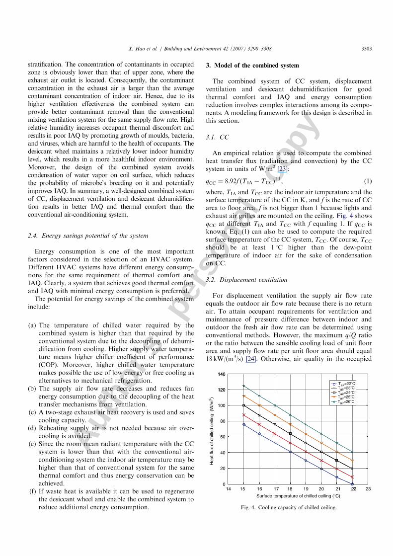
An empirical relation is used to compute the combinedheat transfer flux (radiation and convection) by the CCsystem in units of W/m2 [23]:
qCC ¼ 8:92f ðT IA � TCCÞ1:1, (1)
where, TIA and TCC are the indoor air temperature and thesurface temperature of the CC in K, and f is the rate of CCarea to floor area. f is not bigger than 1 because lights andexhaust air grilles are mounted on the ceiling. Fig. 4 showsqCC at different TIA and TCC with f equaling 1. If qCC isknown, Eq. (1) can also be used to compute the requiredsurface temperature of the CC system, TCC. Of course, TCC
should be at least 1 1C higher than the dew-pointtemperature of indoor air for the sake of condensationon CC.
3.2. Displacement ventilation
For displacement ventilation the supply air flow rateequals the outdoor air flow rate because there is no returnair. To attain occupant requirements for ventilation andmaintenance of pressure difference between indoor andoutdoor the fresh air flow rate can be determined usingconventional methods. However, the maximum q/Q ratioor the ratio between the sensible cooling load of unit floorarea and supply flow rate per unit floor area should equal18 kW/(m3/s) [24]. Otherwise, air quality in the occupied
ARTICLE IN PRESS
14 17 18 19 20 21 22 230
20
40
60
80
100
120
140
15 16 22
120
140
Tair=22°CTair=23°CTair=24°CTair=25°CTair=26°C
Surface temperature of chilled ceiling (°C)
Hea
t flu
x of
chi
lled
ceili
ng (
W/m
2 )
Fig. 4. Cooling capacity of chilled ceiling.
X. Hao et al. / Building and Environment 42 (2007) 3298–3308 3303
Autho
r's
pers
onal
co
py
zone will be lower due to the mixture of the downwardairflow caused by the CC system. The sensible cooling loadof a unit floor area removed by displacement ventilation inunits of kW is
qDV ¼ rQCðT IA � TSAÞ, (2)
where r is the density of air in kg/m3; Q the supply air flowrate per unit floor area in m3/s; C the specific heat of air inkJ/(kg 1C) and TSA the supply air temperature in K.
The moisture load of a unit floor area removed bydisplacement ventilation in units of g/s is
WDV ¼ rQðdIA � dSAÞ, (3)
where, dIA and dSA are the humidity ratios of indoor airand supply air in units of g/kg, respectively. In view of thefact that the total sensible cooling load is removed by theCC system and displacement ventilation, the total sensiblecooling load of a unit floor area, q, is
q ¼ qCC þ qDV. (4)
3.3. Desiccant dehumidification
Performance of the total heat wheel is modeled usingsensible heat recovery effectiveness, ZSHR, and moisturerecovery effectiveness, ZMR, which are defined as
ZSHR ¼TA � TB
TA � TF
, (5)
ZMR ¼dA � dB
dA � dF
. (6)
Therefore, the temperature and humidity ratio of thesupply air stream leavening the total heat wheel can bedetermined as
TB ¼ TA � ZSHRðTA � TF Þ, (7)
dB ¼ dA � ZMRðdA � dF Þ. (8)
According to the laws of mass conservation and energyconservation, the temperature and humidity ratios ofexhaust air stream leaving the total heat wheel areestimated by Eqs. (9) and (10) respectively.
TG ¼ TF þ ZSHRðTA � TF Þ, (9)
dG ¼ dF þ ZMRðdA � dF Þ. (10)
A sensible heat exchange effectiveness, ZSHE, is used tomodel the thermal performance of the sensible heat wheel:
ZSHE ¼TC � TD
TC � TH
. (11)
Thus, the temperature of the supply air stream leaving thesensible heat wheel is determined as
TD ¼ TC � ZSHEðTC � TH Þ. (12)
Similarly, the temperature of exhaust air stream leaving thesensible heat wheel is estimated as
TI ¼ TH þ ZSHEðTC � TH Þ. (13)
The temperature of exhaust air leaving the evaporativecooler is determined as
TH ¼ TG � ZECðTG � TWBGÞ, (14)
where, ZEC is the saturation effectiveness of evaporativecooler and TWBG is the wet bulb temperature of airentering the evaporative cooler.The cool capacity consumed by cooling coil, ECCL, and
the heat capacity consumed by heater, EHR, are computedas
ECCL ¼ rQCðTD � TEÞ, (15)
EHR ¼ rQCðTI � TJÞ. (16)
The performance of the desiccant wheel cannot beexpressed exactly in the form of effectiveness because themodel based on fundamentals of heat and moisturetransfer is rather complicated. The component modeldiscussed in this section is based on performance datafrom one manufacturer [25].
3.4. IAQ and thermal comfort
IAQ denotes the extent to which objective guidelines aremet. Contaminant concentrations in the occupied zone areused to investigate IAQ. The contamination degree, whichis also called dimensionless concentration or contaminantremoval efficiency, is estimated as [8]
m ¼ci � cSA
cEA � cSA, (17)
where, ci is the local contaminant concentration; cSA thecontaminant concentration in supply air and cEA thecontaminant concentration in exhaust air. For perfectmixing ventilation the contaminant concentration in theexhaust air tends to equal the local contaminant concen-tration and m is 1.0. However, for displacement ventilationthe value of m is usually less than 1.0 because thecontaminant concentration in the exhaust air is usuallyhigher than that in the occupied zone. Consequently, forthe same supply air flow rate, the displacement ventilationcan achieve better IAQ than mixing ventilation. Lowervalues of m denote better IAQ if all other conditions areidentical.The portion of cooling load removed by the CC system
in total sensible cooling affects the mean contaminantremoval efficiency in the occupied zone, m̄0:1=1:1m [26].A regression equation was used to compute the upper andlower limits of the mean contaminant removal efficiency inoccupied zones [26]:
m̄0:1=1:1m ¼ AeðBðoþCÞÞ, (18)
where, o is the portion of cooling load removed bydisplacement ventilation system in total sensible cooling
ARTICLE IN PRESSX. Hao et al. / Building and Environment 42 (2007) 3298–33083304
Autho
r's
pers
onal
co
py
load of room. That is,
o ¼qDV
q. (19)
In Eq. (18), A–C are experimental coefficients, which aregiven in Table 1 [26].
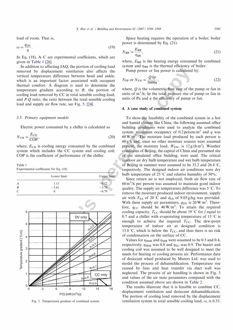
In addition to affecting IAQ, the portion of cooling loadremoved by displacement ventilation also affects thevertical temperature difference between head and ankle,which is an important factor associated with occupantthermal comfort. A diagram is used to determine thetemperature gradient according to R, the portion ofcooling load removed by CC in total sensible cooling load,and P/Q ratio, the ratio between the total sensible coolingload and supply air flow rate, see Fig. 5. [24].
3.5. Primary equipment models
Electric power consumed by a chiller is calculated as
NCH ¼ECH
COP, (20)
where, ECH is cooling energy consumed by the combinedsystem which includes the CC system and cooling coil;COP is the coefficient of performance of the chiller.
Space heating requires the operation of a boiler; boilerpower is determined by Eq. (21).
NBR ¼EBR
ZBR, (21)
where, EBR is the heating energy consumed by combinedsystem and ZBR is the thermal efficiency of boiler.Pump power or fan power is calculated by:
NPP or NFN ¼Q dp
3600Z, (22)
where, Q is the volumetric flow rate of the pump or fan inunits of m3/h; dp the total pressure rise of pump or fan inunits of Pa and Z the efficiency of pump or fan.
4. A case study of combined system
To show the feasibility of the combined system in a hotand humid climate like China, the following assumed officebuilding conditions were used to analyze the combinedsystem: maximum occupancy of 0.2 person/m2 and q was60W/m2. The moisture load produced by each person is60 g/h and, since no other moisture sources were assumedpresent, the moisture load, WDV, is 12 g/(hm2). Weatherconditions of Beijing, the capital of China and presumed siteof the simulated office building, were used. The criticaloutdoor air dry bulb temperature and wet bulb temperatureof Beijing in summer were assumed to be 33.2 and 26.4 1C,respectively. The designed indoor air conditions were drybulb temperature of 25 1C and relative humidity of 50%.Since return air is not employed, fresh air flow rate of
60m3/h per person was assumed to maintain good indoorquality. The supply air temperature difference was 5 1C. Toremove the moisture produced indoor environment, supplyair with TSA of 20 1C and dSA of 9.05 g/kg was provided.With these supply air parameters, qDV is 20W/m2. There-fore, qCC should be 40W/m2. To attain the requiredcooling capacity, TCC should be about 19 1C for f equal to0.7 and a chiller with evaporating temperature of 15 1C isenough to achieve the required TCC. The dew-pointtemperature of indoor air at designed condition is13.8 1C, which is below the TCC, and thus there is no riskof condensation on the surface of CC.Values for ZSHR and ZMR were assumed to be 0.5 and 0.4,
respectively; ZSHE was 0.8 and ZEC was 0.9. The heater andcooling coil was assumed to be well designed to meet theneeds for heating or cooling process air. Performance dataof desiccant wheel produced by Muters Ltd. was used tomodel the process of dehumidification. Temperature risecaused by fans and heat transfer via duct wall wasneglected. The process of air handling is shown in Fig. 3and values of the air state parameters computed with thecondition assumed above are shown in Table 2.The results illustrate that it is feasible to combine CC,
displacement ventilation and desiccant dehumidification.The portion of cooling load removed by the displacementventilation system in total sensible cooling load, o, is 0.33.
ARTICLE IN PRESS
Table 1
Experimental coefficients for Eq. (18)
Lower limit Upper limit
A 1.13 0.12
B �3.61 �3.70
C 0 �0.79
00
1
2
3
4
6
5
3 6 9 12 15 18
P/Q [kW/(m3/s)]
Tem
pera
ture
gra
dien
t [° C
/m]
DV only
R=0.0
R=0.4
R=0.5
R=0.6
R=0.7
CC onlyR=0.8
R=0.9
Fig. 5. Temperature gradient of combined system.
X. Hao et al. / Building and Environment 42 (2007) 3298–3308 3305
Autho
r's
pers
onal
co
py
The upper and lower limits of contaminant removalefficiency computed by using Eq. (18) are 0.66 and 0.34,respectively. The mean contaminant removal efficiencym̄0:1=1:1m is less than 1.0 and thus good IAQ was achieved.
According to computed results, P/Q rate is 18kW/(m3/s),and R is 0.67. It can be found from Fig. 5 that thetemperature gradient in occupied zone is about 2 1C/m.This temperature gradient is less than the upper limit ofvertical temperature gradient for thermal comfort, which is3 1C/m. Therefore, good thermal comfort was achieved.
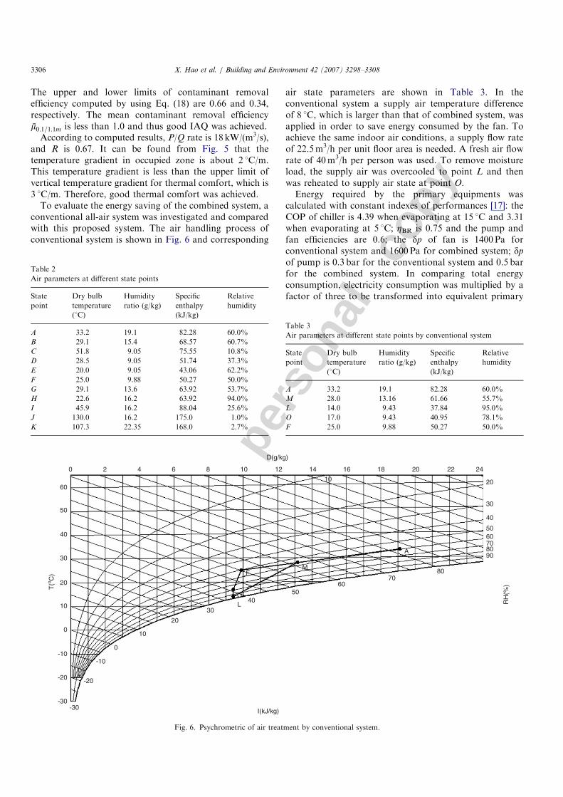
To evaluate the energy saving of the combined system, aconventional all-air system was investigated and comparedwith this proposed system. The air handling process ofconventional system is shown in Fig. 6 and corresponding
air state parameters are shown in Table 3. In theconventional system a supply air temperature differenceof 8 1C, which is larger than that of combined system, wasapplied in order to save energy consumed by the fan. Toachieve the same indoor air conditions, a supply flow rateof 22.5m3/h per unit floor area is needed. A fresh air flowrate of 40m3/h per person was used. To remove moistureload, the supply air was overcooled to point L and thenwas reheated to supply air state at point O.Energy required by the primary equipments was
calculated with constant indexes of performances [17]: theCOP of chiller is 4.39 when evaporating at 15 1C and 3.31when evaporating at 5 1C; ZBR is 0.75 and the pump andfan efficiencies are 0.6; the dp of fan is 1400 Pa forconventional system and 1600 Pa for combined system; dp
of pump is 0.3 bar for the conventional system and 0.5 barfor the combined system. In comparing total energyconsumption, electricity consumption was multiplied by afactor of three to be transformed into equivalent primary
ARTICLE IN PRESS
Table 2
Air parameters at different state points
State
point
Dry bulb
temperature
(1C)
Humidity
ratio (g/kg)
Specific
enthalpy
(kJ/kg)
Relative
humidity
A 33.2 19.1 82.28 60.0%
B 29.1 15.4 68.57 60.7%
C 51.8 9.05 75.55 10.8%
D 28.5 9.05 51.74 37.3%
E 20.0 9.05 43.06 62.2%
F 25.0 9.88 50.27 50.0%
G 29.1 13.6 63.92 53.7%
H 22.6 16.2 63.92 94.0%
I 45.9 16.2 88.04 25.6%
J 130.0 16.2 175.0 1.0%
K 107.3 22.35 168.0 2.7%
Table 3
Air parameters at different state points by conventional system
State
point
Dry bulb
temperature
(1C)
Humidity
ratio (g/kg)
Specific
enthalpy
(kJ/kg)
Relative
humidity
A 33.2 19.1 82.28 60.0%
M 28.0 13.16 61.66 55.7%
L 14.0 9.43 37.84 95.0%
O 17.0 9.43 40.95 78.1%
F 25.0 9.88 50.27 50.0%
60
50
40
30
20
10
0
-10-10
-20 -20
-30-30
0
10
20
30
4050
6070
80
L
9080706050
30
20
242220181614121086420
40
A
M
10
F
O
T(o C
)
RH
(%)
D(g/kg)
I(kJ/kg)
Fig. 6. Psychrometric of air treatment by conventional system.
X. Hao et al. / Building and Environment 42 (2007) 3298–33083306
Autho
r's
pers
onal
co
py
energy. The energy used by motor driving rotary wheelswas neglected.
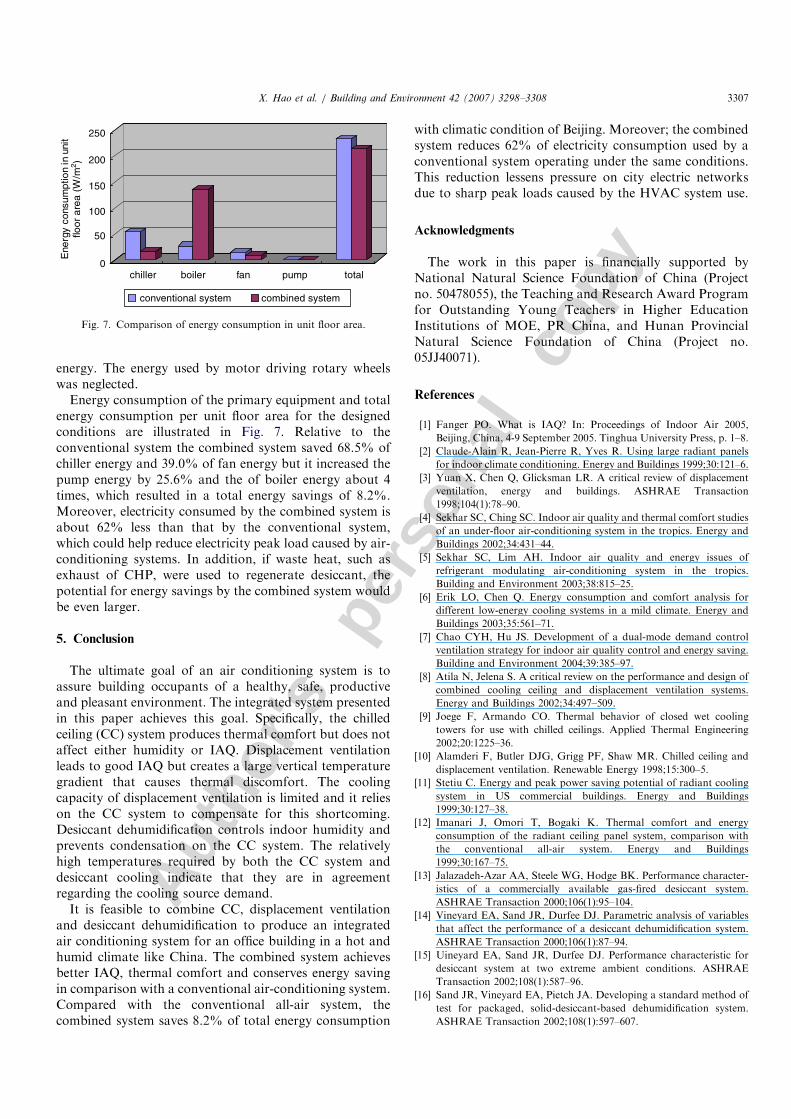
Energy consumption of the primary equipment and totalenergy consumption per unit floor area for the designedconditions are illustrated in Fig. 7. Relative to theconventional system the combined system saved 68.5% ofchiller energy and 39.0% of fan energy but it increased thepump energy by 25.6% and the of boiler energy about 4times, which resulted in a total energy savings of 8.2%.Moreover, electricity consumed by the combined system isabout 62% less than that by the conventional system,which could help reduce electricity peak load caused by air-conditioning systems. In addition, if waste heat, such asexhaust of CHP, were used to regenerate desiccant, thepotential for energy savings by the combined system wouldbe even larger.
5. Conclusion
The ultimate goal of an air conditioning system is toassure building occupants of a healthy, safe, productiveand pleasant environment. The integrated system presentedin this paper achieves this goal. Specifically, the chilledceiling (CC) system produces thermal comfort but does notaffect either humidity or IAQ. Displacement ventilationleads to good IAQ but creates a large vertical temperaturegradient that causes thermal discomfort. The coolingcapacity of displacement ventilation is limited and it relieson the CC system to compensate for this shortcoming.Desiccant dehumidification controls indoor humidity andprevents condensation on the CC system. The relativelyhigh temperatures required by both the CC system anddesiccant cooling indicate that they are in agreementregarding the cooling source demand.
It is feasible to combine CC, displacement ventilationand desiccant dehumidification to produce an integratedair conditioning system for an office building in a hot andhumid climate like China. The combined system achievesbetter IAQ, thermal comfort and conserves energy savingin comparison with a conventional air-conditioning system.Compared with the conventional all-air system, thecombined system saves 8.2% of total energy consumption
with climatic condition of Beijing. Moreover; the combinedsystem reduces 62% of electricity consumption used by aconventional system operating under the same conditions.This reduction lessens pressure on city electric networksdue to sharp peak loads caused by the HVAC system use.
Acknowledgments
The work in this paper is financially supported byNational Natural Science Foundation of China (Projectno. 50478055), the Teaching and Research Award Programfor Outstanding Young Teachers in Higher EducationInstitutions of MOE, PR China, and Hunan ProvincialNatural Science Foundation of China (Project no.05JJ40071).
References
[1] Fanger PO. What is IAQ? In: Proceedings of Indoor Air 2005,
Beijing, China, 4-9 September 2005. Tinghua University Press, p. 1–8.
[2] Claude-Alain R, Jean-Pierre R, Yves R. Using large radiant panels
for indoor climate conditioning. Energy and Buildings 1999;30:121–6.
[3] Yuan X, Chen Q, Glicksman LR. A critical review of displacement
ventilation, energy and buildings. ASHRAE Transaction
1998;104(1):78–90.
[4] Sekhar SC, Ching SC. Indoor air quality and thermal comfort studies
of an under-floor air-conditioning system in the tropics. Energy and
Buildings 2002;34:431–44.
[5] Sekhar SC, Lim AH. Indoor air quality and energy issues of
refrigerant modulating air-conditioning system in the tropics.
Building and Environment 2003;38:815–25.
[6] Erik LO, Chen Q. Energy consumption and comfort analysis for
different low-energy cooling systems in a mild climate. Energy and
Buildings 2003;35:561–71.
[7] Chao CYH, Hu JS. Development of a dual-mode demand control
ventilation strategy for indoor air quality control and energy saving.
Building and Environment 2004;39:385–97.
[8] Atila N, Jelena S. A critical review on the performance and design of
combined cooling ceiling and displacement ventilation systems.
Energy and Buildings 2002;34:497–509.
[9] Joege F, Armando CO. Thermal behavior of closed wet cooling
towers for use with chilled ceilings. Applied Thermal Engineering
2002;20:1225–36.
[10] Alamderi F, Butler DJG, Grigg PF, Shaw MR. Chilled ceiling and
displacement ventilation. Renewable Energy 1998;15:300–5.
[11] Stetiu C. Energy and peak power saving potential of radiant cooling
system in US commercial buildings. Energy and Buildings
1999;30:127–38.
[12] Imanari J, Omori T, Bogaki K. Thermal comfort and energy
consumption of the radiant ceiling panel system, comparison with
the conventional all-air system. Energy and Buildings
1999;30:167–75.
[13] Jalazadeh-Azar AA, Steele WG, Hodge BK. Performance character-
istics of a commercially available gas-fired desiccant system.
ASHRAE Transaction 2000;106(1):95–104.
[14] Vineyard EA, Sand JR, Durfee DJ. Parametric analysis of variables
that affect the performance of a desiccant dehumidification system.
ASHRAE Transaction 2000;106(1):87–94.
[15] Uineyard EA, Sand JR, Durfee DJ. Performance characteristic for
desiccant system at two extreme ambient conditions. ASHRAE
Transaction 2002;108(1):587–96.
[16] Sand JR, Vineyard EA, Pietch JA. Developing a standard method of
test for packaged, solid-desiccant-based dehumidification system.
ASHRAE Transaction 2002;108(1):597–607.
ARTICLE IN PRESSE
nerg
y co
nsum
ptio
n in
uni
tflo
or a
rea
(W/m
2 )
0
50
100
150
200
250
chiller boiler fan pump total
conventional system combined system
Fig. 7. Comparison of energy consumption in unit floor area.
X. Hao et al. / Building and Environment 42 (2007) 3298–3308 3307
Autho
r's
pers
onal
co
py
[17] Niu JL, Zhang LZ, Zuo HG. Energy savings potential of chilled
ceiling combined with desiccant cooling in hot and humid climates.
Energy and Buildings 2002;34:487–95.
[18] Zhang LG, Niu JL. Indoor humidity behaviors associated with
decoupled cooling in hot and humid climates. Building and
Environment 2003;38:99–107.
[19] ASHRAE. ANSI/ASHRAE Standard 55-1992. Thermal environ-
mental conditions for human occupancy. Atlanta: American Society
of Heating, Refrigerating and Air-conditioning Engineers Inc.; 1996.
[20] Rees SJ, Haves P. A nodal model for displacement ventilation and
chilled ceiling systems in office spaces. Building and Environment
2001;36:753–62.
[21] ASHRAE. ASHRAE Handbook. Atlanta: American Society of
Heating, Refrigerating and Air-conditioning Engineers Inc.; 2000.
[22] Fitzner. K. Displacement ventilation and cooled ceiling, results of
laboratory tests and practical installations, In: Proceedings of Indoor
Air’96, 1996. p. 41–50.
[23] Ardehali MM, Panah NG, Smith TF. Proof of concept modeling of
energy transfer mechanisms for radiant conditioning panels. Energy
conversion and Management 2004;45:2005–17.
[24] Tan H, Murata T, Aoki K, Kurabuchi T. Cooled ceiling/displace-
ment ventilation hybrid air conditioning system—design criteria. In:
Proceedings of Roomvent’98, 1998. p. 77–84.
[25] Munter Ltd. MA-series desiccant dehumidifier cassette, Company
brochure.
[26] Behne M. Indoor air quality in rooms with cooled ceilings. Mixing
ventilation on rather displacement ventilation? Energy and Buildings
1999;30:155–66.
ARTICLE IN PRESSX. Hao et al. / Building and Environment 42 (2007) 3298–33083308


