Embed Size (px)
Citation preview

Surface & Coatings Technology 202 (2008) 4793–4809
Contents lists available at ScienceDirect
Surface & Coatings Technology
j ourna l homepage: www.e lsev ie r.com/ locate /sur fcoat
A comparison between the corrosion resistances of some HVOF-sprayed metalalloy coatings
Giovanni Bolelli ⁎, Luca Lusvarghi, Roberto GiovanardiDepartment of Materials and Environmental Engineering, Università di Modena e Reggio Emilia, Via Vignolese, 905 - 41100 Modena (MO), Italy
⁎ Corresponding author. Tel.: +39 059 2056281; fax: +E-mail addresses: [email protected] (G. Bo
(L. Lusvarghi), [email protected] (R. Giovan
0257-8972/$ – see front matter © 2008 Elsevier B.V. Aldoi:10.1016/j.surfcoat.2008.04.056
A B S T R A C T
A R T I C L E I N F OArticle history:
This study compares the c Received 21 September 2007Accepted in revised form 9 April 2008Available online 18 April 2008PACS:81.15.Rs81.65.Kn
Keywords:High velocity oxyfuel (HVOF)Nickel alloyFree corrosion testCorrodkote testElectrochemical polarization test
orrosion resistance of one Co–based alloy coating, namely Co–28Mo–17Cr–3Si(similar to Tribaloy-800), four Ni-based alloy coatings, namely Ni–17Cr–4Fe–4Si–3.5B–1C (Diamalloy-2001),Ni–20Cr–10W–9Mo–4Cu–1C–1B–1Fe (Diamalloy-4006), Ni–22Cr–9Mo–4Nb–5Fe (similar to Inconel-625),Ni–32Mo–16Cr–3Si–2Co (similar to Tribaloy-700), and a (WC-12Co)–33Ni–9Cr–3.5Fe–2Si–2B–0.5C cermet–Ni alloy blend coating. They were produced by liquid-fuelled HVOF spraying onto AISI1040 steel plates.Electrolytic hard chrome (EHC) plating was characterised as a reference material, to verify whether someHVOF coatings are suitable as an EHC replacement. The microstructure of the coatings was examined by SEMand XRD. Electrochemical polarization tests and free corrosion tests were performed in 0.1 M HCl aqueoussolution; the corrodkote test (ASTM B380-97R02) was also performed, to rank coatings qualitatively.The lowest corrosion current densities (Icorr) were recorded for EHC and Tribaloy-700. The latter coatingcontained few secondary phases and little porosity; the damage was mainly due to corrosion activation alonglamellae boundaries. Diamalloy-2001 exhibited the highest Icorr and was significantly damaged after thepolarization test, as its multi-phase microstructure had triggered severe galvanic corrosion. During freecorrosion in 0.1 M HCl, Tribaloy-700 and Diamalloy-4006 retained rather stable polarization resistance (Rp),whereas the Rp of EHC decreased significantly. Tribaloy-700 survived 40 h of corrodkote test with noapparent damage and EHC underwent limited pitting corrosion. All other coatings had visible corrosion. TheInconel-625 coating failed to protect the substrate after 20 h of testing, due to inadequate processingconditions.
© 2008 Elsevier B.V. All rights reserved.
1. Introduction
Thermally-sprayed protective coatings find numerous industrialapplications in chemical and petrochemical plants, paper processingrolls, flexographic equipment, components for packaging machines,pump parts (impellers, seals, body, journal bearings), hydraulicmachinery (pistons, rods), coastal and off-shore installations, etc…[1]. In many of these applications, the coatings are required to protectthe substrate from corrosive environments. They must not thereforehave any interconnected porosity, otherwise, galvanic corrosion of thesubstrate would occur, since the coating materials suitable foroperation in severe conditions (Ni- and Co-based alloys and cermets)are electrochemically more noble than ordinary steel substrates [2].Fulfilment of this requirement has recently been enabled by thedevelopment of the high-velocity oxygen-fuel (HVOF) flame sprayprocess. The supersonic gas velocity and limited flame temperature(compared to other thermal spray techniques, like plasma-spraying)
39 059 2056243.lelli), [email protected]).
l rights reserved.
result in dense coatings with a limited oxide content [3]. HVOFspraying has therefore also been considered as a replacement forelectrolytic hard chrome (EHC) plating [4–12]: this latter coatingtechnology still enjoys significant industrial diffusion in some of theabove-mentioned applications, thanks to its interesting wear andcorrosion resistance and low processing cost, however it poses severesafety and environmental problems [4,12] and in some cases, itsperformance can be unsatisfactory [4–7,10].
Specifically, many recent papers have focused on HVOF-sprayedcermets, which have already been proven to possess excellenttribological properties [13–16] as well as good corrosion resistance,if a suitable carbide and metal matrix are chosen [17–19]. Cermets areknown to be a technically viable alternative to hard chrome plating[4–12].
Other studies deal with HVOF-sprayedmetal alloy coatings, which,despite being less wear resistant than cermets [10,14], can be veryuseful in industrial applications, thanks to their higher depositionefficiency, far lower machining (grinding/polishing) costs, and(usually) lower powder cost [20]. They may also possess certainpeculiar properties, such as great hardness at high temperatures andoxidation resistance. Of these, self-fluxing Ni–Cr–Fe–B–Si–C alloys

Table 1Characteristics of the commercial spray powders used in this study, and abbreviated designation hereinafter used in the paper
Commercial name Manufacturer Designation Nominal chemical composition (in weight%) Nominal particle size range Manufacturing method
Ni 700 Sandvik-Osprey Ni700 Ni–32Mo–15Cr–3Si–2Co (Similar to Tribaloy-700®) −53+10 μm Gas atomizedDiamalloy 4006 Sulzer-Metco D4006 Ni–20Cr–10W–9Mo–4Cu–1C–1B–1Fe −53+11 μm Water atomizedCo-111 Praxair Co800 Co–28Mo–17Cr–3Si (Similar to Tribaloy-800®) −45+10 μm Gas atomizedNi 625 Sandvik-Osprey Ni625 Ni–22Cr–9Mo–4Nb–5Fe (Similar to Inconel®-625) −53+20 μm Gas atomizedDiamalloy 2001 Sulzer–Metco D2001 Ni–17Cr–4Fe–4Si–3.5B–1C −45+15 μm Gas atomizedDiamalloy 2002 Sulzer-Metco D2002 (WC–12Co)–33Ni–9Cr–3.5Fe–2Si–2B–0.5C −45+11 μm Blend: agglomerated and sintered
WC–Co+gas atomized Ni alloy
4794 G. Bolelli et al. / Surface & Coatings Technology 202 (2008) 4793–4809
have been most thoroughly examined. Although they possessinteresting characteristics [21,22–28], they can be prone to localizedcorrosion, especially in acid environments, where they do notpassivate properly [21,23]. HVOF-sprayed Inconel and Hastelloycoatings have also been considered [29–34]. To date, fewer studieshave examined other HVOF-sprayed alloys, such as Tribaloys or Ni–Cr–Mo–W–B alloys. Tribaloys, with composition M–Mo–Cr–Si (M=Co,Ni), possess high wear, corrosion and oxidation resistance: they aremainly employed as coatings, since they are too brittle to be used inbulk form [35]. However, they have mainly been studied as welded orclad overlays [36–38] rather than in thermally sprayed form[4,10,11,39–44]. Data on the corrosion resistance of HVOF-sprayedTribaloys is particularly scarce [11,44]. Similarly, to the authors'knowledge, despite their very promising features, only one literaturepaper deals with the corrosion resistance of Ni–Cr–Mo–W–B alloys[45].
This literature background highlights two needs. First of all, furtherresearch is needed on the above mentioned alloy compositions.Moreover, most of the studies currently available deal with one or fewcompositions only, whereas comparative overviews of the anti-corrosion performance of different coatings are less numerous[46,47], although those available are of relevant practical importance,because they provide industrial designers with a basis for coatingmaterial choice.
This research therefore aims to characterise and compare thecorrosion resistance of six different HVOF-sprayed alloy coatings: aCo–28Mo–17Cr–3Si coating, similar to Tribaloy®1-800, a Ni–32Mo–16Cr–3Si–2Co alloy (similar to Tribaloy®-700), a Ni–Cr–Mo–W–Balloy with composition Ni–20Cr–10W–9Mo–4Cu–1C–1B–1Fe (Dia-malloy-4006), a Ni-based self-fluxing alloy with composition Ni–17Cr–4Fe–4Si–3.5B–1C (Diamalloy-2001), a Ni–22Cr–9Mo–4Nb–5Fecoating (similar to Inconel®2-625), and also a cermet-Ni alloy blendcoating, namely (WC–12Co)–33Ni–9Cr–3.5Fe–2Si–2B–0.5C. Theseblends are frequently used as thermal spray coating, to combine thehardness of WC–Co cermets with the toughness and corrosionresistance of self-fluxing Ni-based alloys [14,48,49].
Besides, information concerning the employability of HVOF-sprayed alloy coatings as an EHC replacement is less readily availablethan for HVOF-sprayed cermets. Wear data from former researchindicates that some of these coatings can be an EHC alternative from atribological point of view [43]. Hence, industrially manufactured EHCplating was also considered in this research on corrosion resistance, asa term of comparison.
2. Experimental
2.1. Powder and coating characterisation
Six commercially available thermal spray powders were employed.Their characteristics, including nominal chemical composition, man-ufacturing method and designation used hereinafter, are listed inTable 1. Their particle size distribution was measured by laser
1 Tribaloy is a trademark of Deloro-Stellite.2 Inconel is a trademark of Inco.
diffraction, using the wet dispersion system (Mastersizer 2000 laserparticle sizer fitted with Hydro 2000S wet dispersion unit, MalvernInstruments, Worcestershire, UK). Scanning electron microscopy(SEM, XL30, FEI, Eindhoven, The Netherlands), energy-dispersive X-ray microanalysis (EDX, INCA, Oxford Instruments) and X-raydiffractometry (XRD, X'Pert Pro, PANalytical, Eindhoven, The Nether-lands, using Cu Kα1 radiation) were also employed to characterise thespray powders.
The powders were HVOF-sprayed using a Praxair-Tafa JP5000kerosene-fuelled torch3. The substrates were AISI 1040 steel plates(100×100×5)mm3, grit-blasted immediately before coating deposi-tion using a manual vacuum-operated Norblast blasting machine,with 500 μm angular alumina grits (Metcolite-C, Sulzer Metco).Substrate temperature was monitored by thermocouples placed onthe rear of the plates. The spray parameters are listed in Table 2. Theseparameters are routinely used by the coating manufacturer and wereoriginally selected for high deposition efficiency.
Some AISI 1040 steel plates were also coated by industrially-manufactured electrolytic hard chrome (EHC) plating.
Coatings were characterised by SEM observations of polished topsurfaces and cross-sections (hot-mounted in phenolic resin) and byXRD analysis on polished top surfaces. Polishing was performed usingSiC papers (up to 2000 mesh), diamond slurry (up to 0.5 μm particlesize) and alumina slurry (0.2 μm particle size). Diamond papers wereused instead of SiC papers for D2002 coating and EHC plating.
2.2. Corrosion testing
To prevent the influence of coating thickness and roughness oncorrosion test outcomes (as deposited coatings have different thick-ness due to the different deposition efficiency of the various powders),all coatings were ground to a thickness of about 300 μm (evaluatedusing non-destructive electromagnetic induction thickness measure-ment, C-Gage, Sonatest, Old Wolverton, UK), polished to Ra≈0.5 μmand ultrasonically degreased with acetone before each corrosion test.
Anodic and cathodic electrochemical polarization tests wereperformed in contact with 0.1 M HCl aqueous solution in equilibriumwith the environment at room temperature, using a three-electrodecell (K0235 flat cell, Princeton Applied Research) where the sample isthe working electrode, the counter-electrode is a Pt grid and thereference electrode is an Ag/AgCl electrode. The sample is pressedagainst a Teflon gasket leaving a 1 cm2 exposed surface. A PC-programmed EG&G 270 potentiostat/galvanostat (Princeton AppliedResearch, UK)was employed. The scanned potential range is −300mV/+1400 mV from rest potential, at 0.5 mV/s scan rate. The testscommenced after 30 min of free corrosion (to allow full wetting of thecoating surface and open circuit potential stabilization). The corrosioncurrent density Icorr (A/cm2) and corrosion potential Ecorr (mV) weredetermined by Tafel analysis, according to the same procedureoutlined by the authors in [11]. At least two samples were tested foreach coating; the average values of Ecorr, Icorr and their standarddeviations are computed and reported. The top surface and polishedcross-section of corroded samples were also observed by SEM.
3 Owned by Centro Sviluppo Materiali S.p.A., Roma, Italy.

Table 2HVOF spray parameters
O2 flux [Sl/min] D4006: 755All other coatings: 944
Kerosene flux [l/min] 0.379Carrier gas (N2) flux [Sl/min] 5Feeding disk revolutionspeed (rpm)
D4006, D2001, D2002, Co800: 330Ni625, Ni700: 270
Barrel length [mm] 102Spray distance [mm] 380Gun traverse speed [mm/s] 500Gun pass distance [mm] 5Substrate temperature b220 °C
Note: spray parameters were chosen on the basis of prior experience and onpreliminary optimization tests. Differences between spray parameters for variouspowders are needed to optimize the deposition, on account of different in-flight particlebehaviour.
Table 3Main features of particle size distributions of all spray powders
Powder D10 [µm] D50 [µm] D90 [µm]
Ni700 11.6 23.1 44.6D4006 11.4 30.6 61.7Co800 20.4 29.4 42.3Ni625 34.0 48.8 70.1D2001 22.2 35.4 55.5D2002 9.0 22.2 40.7
Note: D10, D50, D90: 10%, 50%, 90% (respectively) of the overall number of particleshaving equivalent diameters smaller than the reported value.
Fig. 1. SEM micrograph of Co800 (A) and Ni700 (B) spray powders.
4795G. Bolelli et al. / Surface & Coatings Technology 202 (2008) 4793–4809
Free corrosion tests were conducted for 2 days, in contact with0.1 M HCl aqueous solution in equilibrium with the environment atroom temperature, using the K0235 flat cell with the same experi-mental arrangement described above. The polarization resistance Rpwas periodically measured by electrochemical polarization tests(EG&G 270 potentiostat/galvanostat) according to the Stern–Gearymethod [50]: a ±20 mV overpotential range (from rest potential) wasscanned (0.5 mV/s scan rate) and the slope of the linearly fitted E vs. Idata was assumed as Rp.
For each coating, the inverse of the polarization resistance 1/Rp isproportional to the corrosion current density according to Eq. (1) [50]:
Icorr ¼ ba � bc2:3: ba þ bcð Þ :
1Rp
: ð1Þ
However, a direct comparison between the corrosion currentdensity values of the various coatings cannot be obtained bycomparing 1/Rp values (i.e.: the coating displaying the lowest 1/Rpvalue may not be the one with the lowest Icorr), since theproportionality coefficient between 1/Rp and Icorr depends on theanodic and cathodic Tafel slopes (as shown in Eq. (1)), which arespecific to the system being tested, as also noted in [29]. Again, tworeplicate tests were performed on each coating.
Qualitative evaluation and ranking of the corrosion resistance ofthe coatings was also performed by the corrodkote test (ASTM B380-97/R02), specifically developed for Ni- and Cr-based coatings. A thickcorrosive suspension must be uniformly spread on to the coatedsample surface with a paintbrush. The suspension consists of 60 g ofkaolin+100 ml of a solution containing NH4Cl (20 g/l), FeCl3∙6H2O(3.3 g/l), Cu(NO3)2∙3H2O (0.7 g/l). The sample is then kept for 20 h at40 °C, 90% relative humidity. Afterwards, the suspension is removedusing water and a cloth, and the sample is visually inspected for aqualitative evaluation of corrosion. A new, fresh suspension is thenreapplied for a new 20 h-test cycle. This test is considered as being 100times more accelerated than the salt spray test (ASTM B368-97/R03)[51].
In this study, two 20 h-test cycles were performed. For eachcoating, two 25 mm×25 mm samples, cut from the larger plates, weretested. The sides of the samples were protected with silicone resin toprevent the infiltration of corrosive agents. Digital photographs of thecoatings were taken after each cycle. A better inspection of thecorrosion morphology was also obtained by optical microscopy.
3. Results and discussion
3.1. Microstructural characterisation of powders
3.1.1. SEM examination of spray powdersAll spray powders have a rather narrow particle size distribution,
which would seem suitable for thermal spraying. Particle size
distribution data is listed in Table 3: experimental values normallymatch well with the suppliers' nominal ranges (Table 1), althoughdeviations exist both above and below the nominal distributionlimits. SEM micrographs (Fig. 1A, B) also show that the powdershave a spherical morphology, typical of gas or water atomizationprocesses.
More detailed micrographs indicate that most of these powderspossess crystalline microstructure. The Ni700 powder in particularcontains bright phases (see arrow in Fig. 2A), richer in Mo than thesurroundingmatrix (EDXmicroanalysis in Fig. 2F). The D4006 powder,by contrast, does not show any perceivable secondary phase (Fig. 2B).The Co800 powder is very similar to the Ni700 powder, with brightMo-rich phases in a Co-based surrounding matrix. In the Ni625powder, thin bright areas appear along darker areas (Fig. 2C). Thedifference between the chemical composition of these two phasescould not be reliably evaluated by the EDX microanalysis employed inthis study. However, in a detailed research on HVOF-sprayed Inconel-625, Zhang et al. [32] presented an identical microstructure anddescribed it as consisting of dark Cr-rich dendrites surrounded by thinbright Mo,Nb-rich interdendritic regions. The D2001 powder containsa large number of small dark secondary phases, some of which are

Fig. 2. Cross-section of Ni700 (A), D4006 (B), Ni625 (C), D2001 (D) and D2002 (E) spray powders. Note: in panel E, 1=WC–Co particle, 2=NiCrBSi particle.
4796 G. Bolelli et al. / Surface & Coatings Technology 202 (2008) 4793–4809
richer in Cr than the surrounding metal matrix (Fig. 2D). The D2002powder differs from the others, because it consists of a blend ofspherical NiCrBSi particles and more irregular WC–Co particles(agglomerated and sintered), which can be clearly distinguished inSEM micrographs (Fig. 2E, labels 2 and 1 respectively).
3.1.2. XRD characterisation of powders and coatingsAll spray powders showed much sharper X-ray diffraction peaks
than the corresponding HVOF-sprayed coatings (Fig. 3A-F). In the Ni-based metallic powders, the main phase is either Ni (JCPDS 4-850) oran fcc Ni-based solid solution, whose diffraction peaks are shifted tolower 2θ-values than that of pure Ni (as listed in JCPDS 4-850),probably because the γ-Ni lattice is enlarged by relevant amounts ofsolute elements.
In particular, the latter solid solution (with a larger latticeparameter than pure fcc Ni) is the main phase in the Ni700 powder;moreover, secondary phases exist (Ni- and Mo-silicides, Fig. 3A). TheD4006 powder also consists of an identical fcc Ni-based solid
solution with modified lattice parameter; however, very fewsecondary phase peaks appear (mainly some Cr23C6, Fig. 3B). TheCo800 powder consists in various Co–Mo and Co–Mo–Si phases (Fig.3C). The diffraction pattern of the Ni625 powder is similar to that ofD4006: it has a Ni-based solid solution, with few secondary peaksbelonging to Ni and Nb (Fig. 3D). These probably appear on accountof segregation during powder manufacturing. By contrast, in theD2001 powder, Ni (not a solid solution with enlarged latticeparameter) appears as a main phase (Fig. 3E), together with severalCr- and Ni-based carbides (such as Cr7C3 and (Cr,Ni)23C6) and borides(such as CrB, M6B, Ni4B3), consistently with former SEM observa-tions: probably, most of the alloying elements are not retained in theNi matrix but rather form secondary compounds. In the D2002powder diffraction pattern, the main peaks are those of the WC-phase, whereas those of the NiCrBSi powder have a lower intensity(Fig. 3F).
Diffraction peaks of HVOF-sprayed coatings are broader than thoseof the corresponding spray powders. Broader peaks are the result of a

Fig. 3. X-ray diffraction patterns of spray powders and HVOF–sprayed coatings. (black line: powder; grey line: coating): (A) Ni700; (B) D4006; (C) Co800; (D) Ni625; (E) D2001; (F)D2002. Legend for figure E:1=M6B (M=Ni,Cr,Fe); 2=CrB; 3=Ni4B3; 4=M23C6; 5=Cr7C3; 6=Ni. Note: γ-s.s.=Ni-based solid solution with face centred cubic (fcc) structure.
4797G. Bolelli et al. / Surface & Coatings Technology 202 (2008) 4793–4809
smaller crystal size and/or microstrains inside crystals. Both phenom-ena are caused by the thermal and kinetic history experienced bypowder particles during HVOF spraying. Indeed, during spraying, theparticles are heated and accelerated, and may impinge on thesubstrate in unmelted, partially molten or fully molten conditions.Unmelted material may be plastically deformed upon impact,resulting in crystal size reduction and high microstrains insidecrystals. The molten material solidifies and cools down at a fast rate(usually ≥105 K/s [52]) upon impact. This cooling rate is much higherthan that occurring during the powder manufacturing process (gas orwater atomisation); indeed, previous research has estimated thedifference to be as much as three orders of magnitude [32]. Therefore,
during the solidification of the sprayed molten droplets, the nuclea-tion rate is higher than during gas/water atomisation and the crystalgrowth rate is lower. Thus, finer crystals are found in the sprayedcoating than in the original spray powder. Large humps in the40 °b2θb50 ° range also appear in XRD patterns of Ni700, Co800 and(to a somewhat minor extent) D2001 coatings: these indicate theformation of amorphous or nanocrystalline phases. The possibleappearance of amorphous phases in HVOF-sprayed metal alloys hasbeen reported in previous studies found in literature. It is clearly dueto the combination of the very high cooling rate of impinging moltendroplets and the slow crystallization kinetics of the sprayed alloy[41,43,52].

4798 G. Bolelli et al. / Surface & Coatings Technology 202 (2008) 4793–4809
3.1.3. SEM observation of coatingsThe crystalline microstructure of the Ni700 and Co800 spray
powders (Figs. 2A, 3A, C) is either altered (Fig. 4B, region 2) orcompletely lost (Fig. 4B, region 3) in the well-flattened lamellae of
Fig. 4. SEM micrographs of HVOF-sprayed coatings cross-section: Ni700, general view (A, cparticle retaining the secondary phases, area 2=altered microstructure; area 3=flattened lametching (D), showing two-phase microstructure (labels 1 and 2); Ni625 general view (E) and dtwo-phase microstructure (labels 1 and 2) in etched cross-section of D4006 (L).
Ni700 and Co800 coatings (Fig. 4A, B), i.e. in the lamellae produced byquenching fully molten material. This is consistent with the loss ofcrystallinity indicated by XRD patterns. The microstructure of thespray power only persists in some rounded particles (circle in Fig. 4A,
ircle indicates a rounded unmelted particle); Ni700, detail (B, area 1=partly unmeltedellae with few perceivable secondary phases); D4006, general view (C) and detail afteretail (F); D2001 general view (G) and detail (H); I: D2002 general view; EDX analyses of

Fig. 4 (continued).
Fig. 5. Coating overviews: Ni625: A=secondary electron micrograph, circle indicates sommicrograph, circle indicates some closed pores; B=backscattered electron micrograph (arro
4799G. Bolelli et al. / Surface & Coatings Technology 202 (2008) 4793–4809
region 1 in B), probably resulting from the impact and deformation ofunmelted (or partially unmelted) material.
The D4006 coating also contains some rounded, not completelyflattened particles. No relevant amounts of secondary grains areapparent in the as-polished cross-section (Fig. 4C). Accordingly, XRDpatterns indicate that very few carbides exist after spraying (Fig. 3B).However, etching with 75 g HCl+25 g HNO3+2 g CuCl2 for 30 s revealsa two-phase microstructure (Fig. 4D). Although it is quite difficult todifferentiate between the two compositions by EDX microanalysis(due to the size of the X-ray generation area on the sample), it seems(Fig. 4L) that brighter areas are richer in Ni, whereas darker ones arericher in solute elements (especially Cr). They are probably twodifferent solid solutionswith different solute contents, as reported in aprevious study on HVOF-sprayed NiCrWMoB alloy [45]; however,these phases are not discernible by X-ray diffraction.
The Ni625 coating still retains the dendritic microstructure of thespray powder (Fig. 4E, F) and flattening of sprayed particles is verylimited (Fig. 4F). These features suggest that the particles were notsignificantly melted during spraying, so that they impacted in thesolid state and the original dendrites were merely plasticallydeformed, with no melting or further alterations. Indeed, as explainedin [32], an Inconel-625-type powder having rather coarse particle sizedistribution (like the one currently employed, Table 3) tends to remainin an unmelted conditionwhen sprayedwith a kerosene-fuelled HVOFtorch. This phenomenon was assumed to be mainly due to the coarseparticle size distribution itself, rather than to the thermophysicalproperties of the sprayedmaterial [32]. For instance, themelting pointof Inconel-625 (1290 °C [53]) is not higher than that of Tribaloy-700(solid–liquid transition between 1230 °C and 1560 °C [35]), but severalwell-flattened lamellae (produced by fully-molten particles) areobserved in the Ni700 coating (Fig. 4B, region 3). These could beobtained because the Ni700 powder possesses a finer particle sizedistribution than the Ni625 one (Table 3). Accordingly, numerical
e closed pores; B=backscattered electron micrograph; Ni700: C=secondary electronws indicate some oxide inclusions).
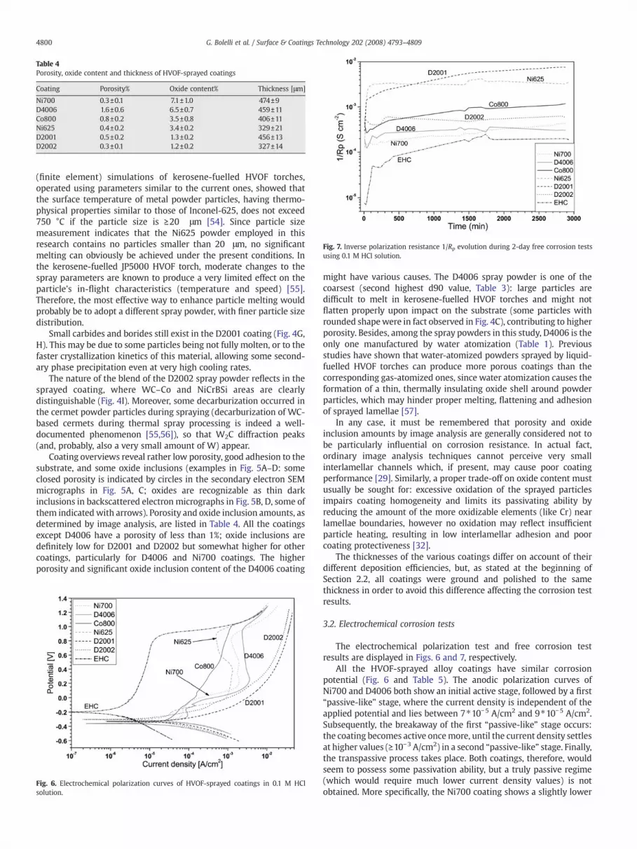
Fig. 7. Inverse polarization resistance 1/Rp evolution during 2-day free corrosion testsusing 0.1 M HCl solution.
Table 4Porosity, oxide content and thickness of HVOF-sprayed coatings
Coating Porosity% Oxide content% Thickness [μm]
Ni700 0.3±0.1 7.1±1.0 474±9D4006 1.6±0.6 6.5±0.7 459±11Co800 0.8±0.2 3.5±0.8 406±11Ni625 0.4±0.2 3.4±0.2 329±21D2001 0.5±0.2 1.3±0.2 456±13D2002 0.3±0.1 1.2±0.2 327±14
4800 G. Bolelli et al. / Surface & Coatings Technology 202 (2008) 4793–4809
(finite element) simulations of kerosene-fuelled HVOF torches,operated using parameters similar to the current ones, showed thatthe surface temperature of metal powder particles, having thermo-physical properties similar to those of Inconel-625, does not exceed750 °C if the particle size is ≥20 μm [54]. Since particle sizemeasurement indicates that the Ni625 powder employed in thisresearch contains no particles smaller than 20 μm, no significantmelting can obviously be achieved under the present conditions. Inthe kerosene-fuelled JP5000 HVOF torch, moderate changes to thespray parameters are known to produce a very limited effect on theparticle's in-flight characteristics (temperature and speed) [55].Therefore, the most effective way to enhance particle melting wouldprobably be to adopt a different spray powder, with finer particle sizedistribution.
Small carbides and borides still exist in the D2001 coating (Fig. 4G,H). This may be due to some particles being not fully molten, or to thefaster crystallization kinetics of this material, allowing some second-ary phase precipitation even at very high cooling rates.
The nature of the blend of the D2002 spray powder reflects in thesprayed coating, where WC–Co and NiCrBSi areas are clearlydistinguishable (Fig. 4I). Moreover, some decarburization occurred inthe cermet powder particles during spraying (decarburization of WC-based cermets during thermal spray processing is indeed a well-documented phenomenon [55,56]), so that W2C diffraction peaks(and, probably, also a very small amount of W) appear.
Coating overviews reveal rather low porosity, good adhesion to thesubstrate, and some oxide inclusions (examples in Fig. 5A–D: someclosed porosity is indicated by circles in the secondary electron SEMmicrographs in Fig. 5A, C; oxides are recognizable as thin darkinclusions in backscattered electron micrographs in Fig. 5B, D, some ofthem indicated with arrows). Porosity and oxide inclusion amounts, asdetermined by image analysis, are listed in Table 4. All the coatingsexcept D4006 have a porosity of less than 1%; oxide inclusions aredefinitely low for D2001 and D2002 but somewhat higher for othercoatings, particularly for D4006 and Ni700 coatings. The higherporosity and significant oxide inclusion content of the D4006 coating
Fig. 6. Electrochemical polarization curves of HVOF-sprayed coatings in 0.1 M HClsolution.
might have various causes. The D4006 spray powder is one of thecoarsest (second highest d90 value, Table 3): large particles aredifficult to melt in kerosene-fuelled HVOF torches and might notflatten properly upon impact on the substrate (some particles withrounded shapewere in fact observed in Fig. 4C), contributing to higherporosity. Besides, among the spray powders in this study, D4006 is theonly one manufactured by water atomization (Table 1). Previousstudies have shown that water-atomized powders sprayed by liquid-fuelled HVOF torches can produce more porous coatings than thecorresponding gas-atomized ones, since water atomization causes theformation of a thin, thermally insulating oxide shell around powderparticles, which may hinder proper melting, flattening and adhesionof sprayed lamellae [57].
In any case, it must be remembered that porosity and oxideinclusion amounts by image analysis are generally considered not tobe particularly influential on corrosion resistance. In actual fact,ordinary image analysis techniques cannot perceive very smallinterlamellar channels which, if present, may cause poor coatingperformance [29]. Similarly, a proper trade-off on oxide content mustusually be sought for: excessive oxidation of the sprayed particlesimpairs coating homogeneity and limits its passivating ability byreducing the amount of the more oxidizable elements (like Cr) nearlamellae boundaries, however no oxidation may reflect insufficientparticle heating, resulting in low interlamellar adhesion and poorcoating protectiveness [32].
The thicknesses of the various coatings differ on account of theirdifferent deposition efficiencies, but, as stated at the beginning ofSection 2.2, all coatings were ground and polished to the samethickness in order to avoid this difference affecting the corrosion testresults.
3.2. Electrochemical corrosion tests
The electrochemical polarization test and free corrosion testresults are displayed in Figs. 6 and 7, respectively.
All the HVOF-sprayed alloy coatings have similar corrosionpotential (Fig. 6 and Table 5). The anodic polarization curves ofNi700 and D4006 both show an initial active stage, followed by a first“passive-like” stage, where the current density is independent of theapplied potential and lies between 7⁎10−5 A/cm2 and 9⁎10−5 A/cm2.Subsequently, the breakaway of the first “passive-like” stage occurs:the coating becomes active oncemore, until the current density settlesat higher values (≥10−3 A/cm2) in a second “passive-like” stage. Finally,the transpassive process takes place. Both coatings, therefore, wouldseem to possess some passivation ability, but a truly passive regime(which would require much lower current density values) is notobtained. More specifically, the Ni700 coating shows a slightly lower

Table 5Electrochemical polarization test results: corrosion current density (Icorr) and corrosionpotential (Ecorr) calculated by Tafel analysis (average±standard deviation)
Coating Icorr [⁎10−5 A/cm2] Ecorr [mV]
Ni700 1.95±0.52 −307.9±27.1D4006 5.64±1.69 −312.0±28.2Co800 3.01±0.07 −315.8±8.2Ni625 2.48±0.01 −263.8±11.8D2001 21.87±0.20 −393.2±16.2D2002 2.79±0.04 −329.7±32.6EHC 0.149±0.093 −141.6±51.5
4801G. Bolelli et al. / Surface & Coatings Technology 202 (2008) 4793–4809
“passive-like” current density and its Icorr is the lowest of all theHVOF-sprayed coatings. These results would suggest that the Ni700coating has superior corrosion resistance.
Fig. 8. Ni700 coating before and after electrochemical polarization test: (A) Polished top surfaimpacting in the solid state) with crystalline structure; (B) Top surface after electrochemicawhich impacted in the solid state), surrounded by more corroded areas; (C) Cross-section(b40 μm), arrows indicate corrosionmainly propagating along interlamellar boundaries; (D) Ha corroded matrix; (E) EDX microanalyses of protruding phases (label 1) and corroded matr
SEM micrographs (Fig. 8B) indicate that, in the Ni700 coating, themost severe corrosion damage took place along the boundaries ofrounded, unmelted particles (recognizable on the polished uncor-roded surface in Fig. 8A, see circles) and, more generally, alonglamellae boundaries. Indeed, these areas are known to be particularlycritical to the corrosion resistance of thermally sprayed metal alloys,on account of several factors. First of all, when defects due to porosityand/or imperfect interlamellar cohesion exist, they can becomepreferential corrosion sites, as the diffusion of O2 into these defectsis much slower than that of small Cl− ions: thus, passivation isprevented and auto-catalytic processes, similar to those taking placein pitting corrosion, can be triggered [21–23,34]. Secondly, oxideinclusions along lamellae boundaries can be preferential sites forcorrosion processes. Finally, the oxidation of the lamellae boundaries(occurring either in the gas jet or immediately after particle impact)
ce before electrochemical polarization test. Circles indicate rounded particles (probablyl polarization test. Circle indicates a less-corroded rounded particle (probably a particleafter electrochemical polarization test. Circle indicates the corrosion-affected depthighmagnification detail showing selective corrosionwith protruding phases (label 1) inix in panel D.

Fig. 9. D4006 coating before and after electrochemical polarization test: (A) Top surface before electrochemical polarization test; (B) Top surface after electrochemical polarizationtest, covered by a layer of corrosion products. Circle indicates a rounded particle with selective corrosion; (C) Detail of rounded particle with selective corrosion (label 1: protrudingphase, label 2: corroded phase); (D) Cross-section. Arrows indicate corrosionmainly propagating along interlamellar boundaries; (E) EDXmicroanalysis of the corrosion product layershown in panel A, compared to the original alloy average composition; (F) EDX microanalyses of phases 1 (less corroded) and 2 (preferentially corroded) in panel C.
4802 G. Bolelli et al. / Surface & Coatings Technology 202 (2008) 4793–4809
deprives them of themost oxidizable elements (like Cr): this depletionmay further favour the onset of selective corrosion, similar to pittingcorrosion [31,32]. However, the overall depth of the corrosion-affectedarea in the Ni700 coating is low (b40 μm) (Fig. 8C). Presumably,interlamellar cohesion is quite good; so that the electrolyte cannotpenetrate easily along lamellae boundaries and does not find anydirect path to the substrate.
At higher magnification, selective corrosion is noted in someregions (Fig. 8D): less-corroded Mo-rich phases (region 1 in Fig. 8D,EDX microanalysis in Fig. 8E) protrude out of a damaged Mo-poormatrix. The presence of Mo-rich grains in a Mo-poor metal matrixresembles the original microstructure of the spray powder (Fig. 2A). Inthose regions of the coating where the original microstructure hadbeen preserved (Fig. 4B: type 1 regions, possibly also type 2 regions),galvanic microcells were probably established between the Mo-rich
grains and the Mo-poor matrix, resulting in galvanic corrosion of thelatter.
We can hypothesize that “passive-like” stages are produced dueto the formation of a thin passive oxide film; however, imperfectionsdue to interlamellar boundaries, pores and oxide inclusions preventperfect passivity, for the reasons listed above. The breakaway of thefirst “passive-like” stage might be connected to the onset of galvanicmicrocells, whereas the breakaway of the second “passive-like” stage(onset of the final transpassive stage) may be due to selectivecorrosion along lamellae boundaries, according to a mechanismsimilar to pitting corrosion, as explained above. Indeed, the formerprocess produces moderately low damage, so that it can beassociated to lower values of the anodic current density; instead,the latter inflicts greater damage, resulting in higher current densityvalues. Obviously, assessment of the exact mechanisms underlying

Fig. 10. Top surface of Ni700 (A) and D4006 (B) coatings after free corrosion test. Fig. 11. Co800 coating after electrochemical polarization test: (A) Polished top surfaceshowing pitting and interlamellar boundary corrosion; (B) Cross-section. Arrowsindicate corrosion starting from a pit and mainly propagating along interlamellarboundaries under the surface.
Fig. 12. Ni625 coating after electrochemical polarization test: (A) Cross-section. Arrowsindicate severely corroded interlamellar boundaries; (B) Substrate interface. Arrowsindicate interface corrosion.
4803G. Bolelli et al. / Surface & Coatings Technology 202 (2008) 4793–4809
the two “passive-like” stages and their breakaway requires furtherspecific investigation, as it is outside the aims of this comparativeresearch.
On the D4006 coating, a layer of corrosion products, rich in Cr andW, can be recognized after the polarization test (compare theuncorroded surface in Fig. 9A to the corroded one in Fig. 9B; EDXanalyses of non-corroded alloy and of corrosion products rich in Cr, W,O are provided in Fig. 9E). This layer would seem to be damaged(cracks are clearly visible in Fig. 9B): this damage may have beencaused by oxygen evolution during the final transpassive stage. Onceagain, more detailed investigation is needed to clarify this point, as itlies outside the scope of this study.
In some areas, whose rounded shape may suggest they areunmelted particles (circle in Fig. 9B), detailed micrographs (Fig. 9C)indicate that corrosion unfolded the two phases which werepreviously observed by etching (Fig. 4D). This is consistent with thefindings presented in literature [45]. Specifically, the protruding phase(label 1 in Fig. 9C) is the Cr,W-rich one (EDX analysis in Fig. 9F),whereas the Ni-rich phase was more severely corroded (label 2). Thebreakaway of the first “passive-like” stage may be due to the onset ofthis selective corrosion process, similarly to the hypothesis putforward for Ni700. Again, some corrosion seems to have occurredalong splat boundaries (Fig. 9D): as formerly noted, lamellaeboundaries are preferential sites for corrosion activation in ther-mally-sprayed metal coatings. In any case, penetration of thecorrosion damage along lamellae boundaries involved a very shallowcoating thickness (Fig. 9D), as for Ni700.
During free corrosion tests (Fig. 7), the 1/Rp value of D4006 is quitestable and that of Ni700 increases very slowly with time. Therefore,the corrosion current density of D4006 and Ni700 does not increasegreatly during the test period. This result testifies to the effectivenessof the Ni700 coating in preserving its very low corrosion currentdensity during long-term tests. Indeed, after the 2-day exposure to theelectrolyte (Fig. 10A), its surface shows no perceivable difference fromthe original polished surface (Fig. 8A). By contrast, on the D4006

Fig. 13. D2001 coating after electrochemical polarization test: (A) Top surface. Label 1=less-corroded metallic areas; label 2=severely corroded areas; (B) Detail of severely corrodedregion 2. Arrows indicate micron-sized phase standing out of the corrosion products; (C) Detail of a less-corroded metallic area, containing few secondary phases; (D) EDXmicroanalyses of less-corroded metallic area (label 1 in panel A), of corrosion products (dark regions in panel B) and of protruding phases (arrow in panel B); (E) Cross-section.
4804 G. Bolelli et al. / Surface & Coatings Technology 202 (2008) 4793–4809
coating surface, moderate selective corrosion of one phase is found(Fig. 10B), similarly to electrochemical polarization tests. Indeed, eventhough the corrosion resistance of this coating does not appear todeteriorate with time, its original corrosion resistance (from electro-chemical polarization) is lower than for Ni700 (higher Icorr, highercurrent density in “passive-like” stages). In any case, it would seemthat the “passive-like” behaviour capacity of these coatings allowsthem to withstand the long-term corrosive action of the electrolytewithout relevant damage.
The anodic polarization behaviour of the Co800 coating differsfrom that of the former coatings: it does not undergo a series of“passive-like” stages followed by active breakdowns, but rather showssignificant active corrosion retardation (Fig. 6: the current densityincreases very slowly over a large potential range). The differentanodic behaviours of the two Tribaloy-based coatings (Co800 andNi700) are probably due to their different chemical composition.Detailed investigations on the surface chemistry and on the composi-tion of surface filmsmay give more accurate information, but were not
included in the subject of the present research. In any case, certainsimilarities exist between the surface morphologies of Ni700 andCo800 after anodic polarization. Indeed, pitting and localized corro-sion along interlamellar boundaries, which affect the surface of Ni700(Fig. 8B), can also be seen on the Co800 coating (Fig.11A). Transpassivecorrosion is probably therefore connected to pitting and “pitting-like”interlamellar corrosion. However, the corrosion-affected depth is lessthan 40 μm (Fig. 11B). This coating therefore seems to have goodinterlamellar cohesion, similar to that of the previous coatings.
During free corrosion tests, Co800 undergoes continuous corrosionactivation (1/Rp increases, Fig. 7). This is probably connected to theabovementioned lack of a “passive-like” stage: this coating seemsunable to passivate (despite the active corrosion retardation duringanodic polarization tests); therefore, continuous activation over longperiods cannot be prevented.
Unlike the previous coatings, Ni625 demonstrates insufficientinterlamellar cohesion: lamellae boundaries were extensively dete-riorated (compare Figs. 12A to 4G, H), eventually resulting in the

Fig. 14. D2001 coating before and after free corrosion test: (A) Top surface after testing.Circles indicate corroded areas; (B) Detail of corroded areas showing many phasesstanding out of corrosion products (EDX microanalysis as in Fig. 13D); (C) Top surfacebefore testing. Circles indicate highly crystallized rounded particles, which probablycorrespond to the corroded areas in panel A.
4805G. Bolelli et al. / Surface & Coatings Technology 202 (2008) 4793–4809
corrosion of the substrate interface (Fig. 12B). Consistently with theexplanation provided in [32], the insufficient melting of particlesduring coating deposition (as described in Section 3.1.3) is the mostlikely reason for this unsatisfactory performance: since all particlesimpacted in a completely unmelted condition, many small defects andpores were left between the lamellae, however image analysis did notallow their recognition (as further explained in Section 3.1.3). Thecorrosive agents were therefore able to penetrate these defects,corrode the lamellae boundaries somewhat easily and reach thesubstrate in a short time. Consistently, during free corrosion, the 1/Rpvalue increased very quickly at the beginning of the test, indicatingrapid interlamellar infiltration of corrosive agents, and eventuallyobtained a stable value when infiltration was complete and galvaniccorrosion of the steel substrate was taking place. This poorperformance is therefore caused by inadequate coating depositionparameters, not by the intrinsic properties of the material. Optimisa-tion of the processing conditions (involving, first and foremost, the useof a finer powder, as explained in Section 3.1.3) is needed beforereasonable conclusions on the performance of this material can bemade.
The D2001 coating showed the highest corrosion current density(Table 5) and underwent active corrosion over the whole anodicpotential scan. This is consistent with ref.[23], where it is suggestedthat self-fluxing NiCrBSi alloys have poor passivation ability in acidicCl– containing solutions. The corroded surface is heavily damaged(Fig. 13A). Particularly, some metallic areas (labelled as 1, lookingbrighter in the backscattered electron micrograph, EDS microana-lysis in Fig. 13D, black solid line) emerge from a darker, heavilycorroded background, which is covered by a layer of Cr-richcorrosion products (labelled as 2, EDS microanalysis in Fig. 13D,solid grey line). Looking at these severely corroded regions withgreater magnification (Fig. 13B), very small Cr-rich bright phases(EDX microanalysis in Fig. 13D, dashed black line), whose morphol-ogy definitely resembles that of carbide and boride phases observedin the spray powder and in the as-deposited coating (Figs. 2D and4H, respectively), are clearly distinguishable from the severelycorroded metal matrix, covered by the dark corrosion products.Instead, in the less-corroded areas (label 1 in Fig. 13A), fewsecondary phases are noticeable (detail in Fig. 13C). Therefore, thecorrosion damage mainly concentrates on the metal matrix in theregions richer in secondary phases (Cr carbides and borides). Firstly,carbides and borides are electrochemically more noble than themetal matrix, so that microgalvanic couples are formed and thelatter is corroded. Moreover, where Cr-based precipitates are moreabundant, the metal matrix is poorer in Cr and has insufficientpassivation ability. This is the most likely reason for the completelack of passive stages during the anodic polarization of this coating.In any case, cross-sectional SEM micrographs indicate that almost nointerlamellar corrosion took place (Fig. 13E), which demonstrates thegood interlamellar cohesion of this coating.
The poor corrosion resistance of D2001 and its inability topassivate explain why its 1/Rp value increases very rapidly at thebeginning of free corrosion tests (Fig. 7). Unlike the Ni625 coating,where 1/Rp stabilizes once substrate corrosion starts, in the D2001coating 1/Rp does not stabilize: it increases continuously, suggestingthat complete coating failure never occurs, consistently with observa-tions on Fig. 13E. Once again, selective corrosion of the Ni-based metalmatrix between the more noble carbide and boride phases isencountered (Fig. 14A, B). Specifically, the corrosion process duringthe 2-day period mainly took place inside more rounded lamellae(compare Fig. 14A to C, non-corroded surface), probably caused bypowder particles impacting mainly in the solid state during spraying.If a particle did not melt during spraying, no dissolution of secondaryphases could occur; the matrix is therefore poorer in Cr, and thelargest number of noble carbide and boride phases, enhancingcorrosion due to galvanic microcells, exists.
The polarization curves of the D2002 coating are very similar tothose of D2001, but shifted to slightly higher potential (Fig. 6). Thecoating surface, however, seems less damaged (Fig. 15A). Corrosionwould appear to have taken place in the Ni-based metal matrix, in theareas where it is more closely intermixed with the WC–Co phase.Indeed, corroded areas are adjacent to WC–Co regions (see circle inFig. 15A), and EDX microanalysis indicates that Cr,Ni-based corrosionproducts are present (Fig. 15B). This is very likely due to galvanicmicrocells leading to corrosion of the NiCrBSi alloy. The samephenomenon is found at the end of the free corrosion tests (Fig.15C). However, unlike the D2001 coating, the 1/Rp value of the D2002coating did not display a monotonous decreasing trend, suggesting alower degree of corrosion activation.
Finally, electrolytic hard chrome showed by far the most noblecorrosion potential and the lowest corrosion current density afterpolarization tests (Fig. 6), and exhibited a passive behaviour over arather large anodic overpotential interval. Passivity is lost only at high

Fig. 16. EHC plating after electrochemical polarization test: (A) Top surface exhibitingpitting damage; (B) Cross-section. Circle indicates one of the pits.
Fig. 15. D2002 coating: (A) Top surface after electrochemical polarization test. Circleindicates a corroded NiCrBSi metal matrix area close to WC–Co areas; (B) EDXmicroanalyses of corrosion products inside the corroded area indicated in panel A; (C)Top surface after free corrosion test. Circle indicates a corroded area. EDX microanalysisas in panel B.
4806 G. Bolelli et al. / Surface & Coatings Technology 202 (2008) 4793–4809
anodic overpotentials, resulting in very limited pitting corrosion (Fig.16A, B). However, the EHC plating also underwent a remarkable 1/Rpincrease during free corrosion tests. This coating therefore seemsunable to retain its initially excellent corrosion resistant character-istics for longer times.
3.3. Corrodkote test
Most coatings seem affected by corrosion after the first 20 h-testcycle (Fig. 17A); further corrosion is obviously observed after thesecond cycle (Fig. 17B).
Of the coatings capable of “passive-like” behaviour (Ni700 andD4006), the former performed much better in this test. Indeed, it doesnot display any visible sign of corrosion even after the second test
cycle. Optical micrographs (Fig. 18A) can only detect the normalcoating porosity, without any further corrosion damage. Instead, theD4006 coating shows some damage after 20 h, with few red corrosionproducts on the surface, suggesting that corrosive agents could open apath to the substrate and corrode it. Substrate corrosion proceededfurther during the next cycle. Damage seems to start mainly fromlamellae boundaries (Fig. 18B). In actual fact, compared to Ni700, thiscoating demonstrated poorer performance in free corrosion tests(some selective corrosion was detected, Fig. 10B), slightly higher Icorrand higher “passive-like” current.
Pitting seems to affect the non-passivating coatings. Indeed, on theCo800 coating, pits appear after 20 h (Fig. 18C): some of them becameso deep that substrate corrosion could occur; indeed, some reddishcorrosion products emerge from them (circles in Fig. 17A). During thesecond cycle, corrosion continued to coating failure and moreextensive substrate corrosion (Fig. 17B). Very numerous pits appearedon the D2001 coating surface even after the first test cycle and grewlarger in the second (Figs. 17A, B and 18E). The D2002 coating'sbehaviour is quite peculiar. Not only did it undergo limited pittingcorrosion where the test slurry was applied, consistently with theformerly noted occurrence of selective NiCrBSi matrix corrosion closeto WC–Co regions, but also coloured corrosion products appeared ontop of the coating surface where the slurry was not present (Figs. 17A,18F). This coating seems to undergo some form of oxidation evenunder the bare 40 °C, 90% R.H. chamber environment, without theaddition of further corrosive agents. After the second cycle, morepitting corrosion was caused by the slurry, whereas the outercorrosion products remained visible (Fig. 17B). Some pits in the areasubject to the corrosive slurry (to the left) and several “leopard's spot”corrosion products on the outer area (to the right) were observedusing the optical microscope (Fig. 18F).
The Ni625 coating completely failed to protect the substrate evenafter 20 h, consistently with the formerly-discussed inadequacy ofdeposition conditions: a lot of reddish corrosion products emerged at

Fig. 17. Photographs of sample surfaces after corrodkote test: (A) 1 cycle=20 h; (B) 2 cycles=40 h. Area inside the dotted circles (label 1): area covered by the corrosive suspension.Area outside dotted circles (label 2): area not covered by the corrosive suspension. Silicone resin around sample edges.
4807G. Bolelli et al. / Surface & Coatings Technology 202 (2008) 4793–4809
the end of the first cycle on both samples (Figs. 17A, 18D). Due to thiscomplete failure, the Ni625 coated samples were not subjected tothe second cycle. As noted above, this coating should not beconsidered in the overall comparison, since deposition conditionsmust be optimised.
The EHC plating succeeded in protecting the substrate fromcorrosion, but, since its passivation capacity may deteriorate overlong periods, it undergoes some pitting corrosion. However, pits arevery small compared to the D2001 case (Fig. 18G). Similar behaviourhas already been reported by the authors for EHC platings undergoingthe corrodkote test [11].
Therefore, of all coatings, Ni700 offered the best performance inthe corrodkote test (Fig. 17A, B) and outperformed the EHC plating.Accordingly, polarization tests indicated that Ni700 has low Icorr, it isable to produce a “passive-like” stage (unlike Co800, D2001 andD2002) and is able to retain the “passive-like” condition over longperiods. The excellent behaviour of Ni700 in all corrosion testsperformed so far is probably explained by a combination of factors.First of all, adequate processing conditions resulted in goodinterlamellar cohesion, so that corrosion penetration through thecoating thickness is largely inhibited (as proven by Fig. 8C). Secondly,the alloy is intrinsically resistant to corrosion [35] and is probably ableto form a very thin, protective surface film (as it normally occurs onpassive alloys [58]), which is stable over long periods (despite theimpossibility of a complete passive state due to unavoidable poresand defects). For instance, Co800, D2001 and D2002 are not capableof forming or preserving stable “passive-like” stages; EHC itself doesnot retain its initial passive state. Thirdly, the alloy is quitehomogeneous (multi-phase microstructures appear only in few cir-
cumscribed regions, Fig. 4B) and galvanic microcells (which deeplyaffect the performance of D2001 and D2002) are not particularlydangerous (Fig. 8D).
4. Conclusions
The corrosion resistance of five HVOF-sprayed metal alloy coatings(four Ni-based and one Co-based) and of a cermet–Ni alloy blendcoating was characterised, correlated to microstructural features andcompared to electrolytic hard chrome (EHC) plating. Electrochemicalpolarization tests and free corrosion tests were performed using 0.1 MHCl aqueous solutions, and the corrodkote test (ASTM B380-97/R02)was performed as well.
The HVOF-sprayed alloy coatings do not achieve perfectly passivestates, due to pores, defects and oxide inclusions; however, some ofthem can achieve a “passive-like” state, which seems to play a relevantrole.
The Ni700 coating possesses good interlamellar cohesion and asignificantly homogeneous microstructure; thus, microgalvanic corro-sion is not particularly dangerous and corrosion penetration alonglamellae boundaries is limited. The “passive-like” behaviour cantherefore be held to impart long-term corrosion protection. TheD4006 coating also demonstrates “passive-like” stages and stablebehaviour during free corrosion tests, but, having higher corrosioncurrent density and slightly higher “passive-like” current density, itshows some damage after both free corrosion tests and the corrodkotetest.
The coatings with no “passive-like” behaviour generally presentcorrosion activation (1/Rp increase) during the free corrosion test and

Fig. 18. Optical micrographs of samples after 20 h Corrodkote test: (A) Ni700; (B) D4006; (C) Co800; (D) Ni625; (E) D2001; (F) D2002 (area 1: area under the corrosive slurry; area 2:area out of the corrosive slurry); (G) EHC.
4808 G. Bolelli et al. / Surface & Coatings Technology 202 (2008) 4793–4809
localized pitting corrosion during the corrodkote test. Indeed, thisoccurs both on the Co800 coating and (to an even greater extent) onthe D2001 coating. In the latter, corrosion is particularly severebecause of the multi-phase microstructure, which deprives the Ni-
based metal matrix of the oxidizable elements and triggers galvanicmicrocells. The D2002 coating, although somewhat similar to theD2001 one, exhibits some peculiarities: it does not suffer the samesevere corrosion activation during free corrosion tests and displays

4809G. Bolelli et al. / Surface & Coatings Technology 202 (2008) 4793–4809
unique corrosion morphology after the corrodkote test. Corrosion ofthe NiCrBSi metal matrix close toWC–Co areas due to the formation ofgalvanic microcells would appear to be its main degradationmechanism.
Similarly, the chrome plating itself, despite its extremely lowcorrosion current density, suffers some pitting corrosion in thecorrodkote test, due to degradation of its passivating capacity overlong periods. Therefore, the overall performance of the Ni700 coatingwas similar or even better than that of EHC. This coating could betechnically viable as a hard chrome replacement from the point ofview of corrosion resistance. Experiments are underway to study thewear resistance of these coatings, as well.
Finally, the Ni625 coating tested in this research had insufficientinterlamellar cohesion, on account of inadequate processing condi-tions, and failed to protect the substrate from the infiltration ofcorrosive agents. Perhaps, further optimization of the spray para-meters, including the choice of a spray powder having finer particlesize distribution, could improve its performance [32].
Acknowledgements
The authors are particularly grateful to Ing. Elisabetta Parsini andMs. Elena Ternelli for their precious contribution to the experimentalcharacterisation. Production of HVOF-sprayed coatings by CentroSviluppoMateriali S.p.A. (Roma, Italy), and in particular by Dr. FabrizioCasadei, Mr. Edoardo Severini, Mr. Francesco Barulli and Mr. CarloCosta, is gratefully acknowledged. Thanks to Mr. Moreno Ghiaroni(Galvanica Nobili S.r.l., Marano sul Panaro, Modena, Italy) for thedeposition of hard chrome platings. Partially supported by PRRIITT(Regione Emilia-Romagna), Net-Lab ‘‘Surface & Coatings for AdvancedMechanics and Nanomechanics’’ (SUP&RMAN).
References
[1] J.R. Davis, Handbook of Thermal Spray Technology', Materials Park, OH, USA, ASMInternational, 2004, p. 169.
[2] B. Xu, Z. Zhu, Y. Liu Yan, S. Ma, Y. Chen, in: E. Lughsheider (Ed.), Thermal Sprayconnects: Explore its surfacing potential – Proceedings of the InternationalThermal Spray Conference 2005, Materials Park, OH, USA, ASM International,2005, p. 700.
[3] H. Herman, S. Sampath, R. McCune, Mater. Res. Soc. Bull. 25 (2000) 17.[4] B. Sartwell, K. Legg, J. Sauer, Validation of WC/Co HVOF Thermal Spray Coatings as
a Replacement for Hard Chrome Plating On Aircraft Landing Gear, Joint Test Reportby U.S. Department of Defense, Environmental Security Technology CertificationProgram (ESTCP) and Joint Group on Pollution Prevention (JG-PP) (2002).
[5] J.M. Guilemany, N. Espallargas, P.H. Suegama, A.V. Benedetti, J. Fernández,J. Therm. Spray Technol. 14 (2005) 335.
[6] J.A. Picas, A. Forn, G. Matthäus, Wear 261 (2006) 477.[7] K.O. Legg, M. Graham, P. Chang, F. Rastagar, A. Gonzales, B. Sartwell, Surf. Coat.
Technol. 81 (1996) 99.[8] G. Montavon, A. Vardelle, N. Krishnan, P. Ulloa, S. Costil, H. Liao, Building on
100 years of success – Proceedings of the International Thermal Spray Conference2006', Materials Park, OH, USA, ASM International, 2006, Paper s17-10.
[9] B. Evans, R. Panza-Giosa, E. Cochien-Brikaras, S. Maitland, Building on 100 years ofsuccess – Proceedings of the International Thermal Spray Conference 2006,Materials Park, OH, USA, ASM International, 2006, Paper s7-2.
[10] G. Bolelli, V. Cannillo, L. Lusvarghi, S. Riccò, Surf. Coat. Technol. 200 (2006) 2995.
[11] G. Bolelli, R. Giovanardi, L. Lusvarghi, T. Manfredini, Corros. Sci. 48 (2006) 3375.[12] D.W. Wheeler, R.J.K. Wood, Wear 258 (2005) 526.[13] T. Pearson, Trans. Inst. Met. Finish. 83 (2005) 2.[14] H.M. Hawthorne, B. Arsenault, J.P. Immarigeon, J.G. Legoux, V.R. Parameswaran,
Wear 225–229 (1999) 825.[15] E. Celik, O. Culha, B. Uyulgan, N.F. Ak Azem, I. Ozdemir, A. Turk, Surf. Coat. Technol.
200 (2006) 4320.[16] A. Wank, B. Wielage, H. Pokhmurska, E. Friesen, G. Reisel, Surf. Coat. Technol. 201
(2006) 1975.[17] J.E. Cho, S.Y. Hwang, K.Y. Kim, Surf. Coat. Technol. 200 (2006) 2653.[18] V.A.D. Souza, A. Neville, Wear 259 (2005) 171.[19] V.A.D. Souza, A. Neville, J. Therm. Spray Technol. 15 (2006) 106.[20] D.E. Crawmer, in: J.R. Davis (Ed.), Thermal Spray Processes, in: ‘Handbook of
Thermal Spray Technology, Materials Park, OH, USA, ASM International, 2004,p. 58.
[21] W-M. Zhao, Y. Wang, L-X. Dong, K-Y. Wu, J. Xue, Surf. Coat. Technol. 190 (2005)293.
[22] L. Gil, M.A. Prato, M.H. Staia, J. Therm. Spray Technol. 11 (2002) 95.[23] W-M. Zhao, Y. Wang, T. Han, K-Y. Wu, J. Xue, Surf. Coat. Technol. 183 (2004) 118.[24] T.S. Sidhu, S. Prakash, R.D. Agrawal, Surf. Coat. Technol. 201 (2006) 1602.[25] T.S. Sidhu, S. Prakash, R.D. Agrawal, Acta Mater. 54 (2006) 773.[26] S. Shrestha, T. Hodgkiess, A. Neville, Wear 259 (2005) 208.[27] M.C. Lin, L.S. Chang, H.C. Lin, C.H. Yang, K.M. Lin, Surf. Coat. Technol. 201 (2006)
3193.[28] M.A. Uusitalo, P.M.J. Vuoristo, T.A. Mäntylä, Wear 252 (2002) 586.[29] J. Kawakita, S. Kuroda, T. Kodama, Surf. Coat. Technol. 166 (2003) 17.[30] B.S. Yilbas, M. Kalid, B.J. Abdul-Aleem, J. Therm. Spray Technol. 12 (2003) 572.[31] T.E. Lister, R.N. Wright, P.J. Pinhero, W.D. Swank, J. Therm. Spray Technol. 11 (2002)
530.[32] D. Zhang, S.J. Harris, D.G. McCartney, Mater. Sci. Eng., A Struct. Mater.: Prop.
Microstruct. Process. 344 (2003) 45.[33] M.P. Planche, B. Normand, H. Liao, G. Rannou, C. Coddet, Surf. Coat. Technol. 157
(2002) 247.[34] J. Kawakita, S. Kuroda, T. Fukushima, T. Kodama, Corros. Sci. 45 (2003) 2819.[35] R.D. Schmidt, D.P. Ferriss, Wear 32 (1975) 279.[36] C. Navas, M. Cadenas, J.M. Cuetos, J. de Damborenea, Wear 260 (2006) 838.[37] J. Przybylowicz, J. Kusinski, Surf. Coat. Technol. 125 (2000) 13.[38] Z.A. Foroulis, Wear 96 (1984) 203.[39] M.O. Price, T.A. Wolfla, R.C. Tucker, Thin Solid Films 45 (1977) 309.[40] T. Sahraoui, N-E. Fenineche, G. Montavon, C. Coddet, J. Mater. Process. Technol. 152
(2004) 43.[41] T. Sahraoui, H.I. Feraoun, N. Fenineche, G. Montavon, H. Aourag, C. Coddet, Mater.
Lett. 58 (2004) 2433.[42] G. Xiao-Xi, H. Zhang, in: C.C. Berndt (Ed.), Thermal Spray: International Advances
in Coatings Technology, Materials Park, OH, USA, ASM International, 1992, p. 729.[43] G. Bolelli, L. Lusvarghi, J. Therm. Spray Technol. 15 (2006) 802.[44] R.N. Johnson, D.G. Farwick, Thin Solid Films 53 (1978) 365.[45] C.H. Lee, K.O. Min, Surf. Coat. Technol. 132 (2000) 49.[46] D. Chidambaram, C.R. Clayton, M.R. Dorfman, Surf. Coat. Technol. 176 (2004) 307.[47] D. Chidambaram, C.R. Clayton, M.R. Dorfman, Surf. Coat. Technol. 192 (2005) 278.[48] S. Stewart, R. Ahmed, T. Itsukaichi, Wear 257 (2004) 962.[49] S. Stewart, R. Ahmed, T. Itsukaichi, Surf. Coat. Technol. 190 (2005) 171.[50] M. Stern, A.L. Geary, J. Electrochem. Soc. 104 (1957) 56.[51] G. Wranglén, An Introduction to Corrosion and Protection of Metals, Institut för
Metallskydd, Stockholm, Sweden, 1972, p. 239.[52] Y. Wu, P. Lin, G. Xie, J. Hu, M. Cao, Mater. Sci. Eng., A Struct. Mater.: Prop.
Microstruct. Process. 430 (2006) 34.[53] S. Gu, D.G. McCartney, C.N. Eastwick, K. Simmons, J. Therm. Spray Technol. 13
(2004) 200.[54] N. Zeoli, S. Gu, S. Kamnis, Comput. Chem. Eng. 32 (2008) 1661.[55] B.R. Marple, R.S. Lima, J. Therm. Spray Technol. 14 (2005) 67.[56] C. Verdon, A. Karimi, J.-L. Martin, Mater. Sci. Eng., A Struct. Mater.: Prop.
Microstruct. Process. 246 (1998) 11.[57] M.E. Aalamialeagha, S.J. Harris, M. Emamighomi, J. Mater. Sci. 38 (2003) 4587.[58] J. Kruger, Passivity, in: ‘Corrosion: Fundamentals, Testing, and Protection – ASM
Handbook, vol. 13A, Materials Park, OH, USA, ASM International, 2003, p. 61.


