Embed Size (px)
Citation preview

Part Two: Publications © 2002 Kluwer Academic Publishers. Reprinted, with permission, from the International Journal of Multimedia Tools and
Applications, 17(1): 121-141, May 2002.
ISSN: 1380-7501 © 2002 Kluwer Academic Publishers 59
A Digital Television Navigator
CHENGYUAN PENG [email protected] Telecommunications Software and Multimedia Laboratory, Helsinki University of Technology, P.O. Box 5400, FI-02015 HUT, Finland ARTUR LUGMAYR [email protected] Digital Media Institute, Tampere University of Technology, P.O. Box 553, FI-33101, Tampere, Finland PETRI VUORIMAA [email protected] Telecommunications Software and Multimedia Laboratory, Helsinki University of Technology, P.O. Box 5400, FI-02015 HUT, Finland
Abstract. Digital television is a new, interesting, and rich platform for developing next generation multimedia services. Navigator is the most important service of digital television. It acts as the main index of all services available in set-top box. In this paper, we describe the definition of a Navigator, its functionality, its information retrieval processes, and its information source based on DVB-SI (Service Information) which is multiplexed in MPEG2 Transport Streams (TS). The process of developing a Navigator in Java language is presented. A software model including navigation model, state model of a remote control, and data structures is introduced. Furthermore, a software reference model for DVB-SI demultiplexing is described. Its implementation was based on a client/server approach using the User Datagram Protocol (UDP). The development issues, performance evaluation, and future research topics are given as conclusions.
Keywords: Navigator, digital television, service information, demultiplexing, transport stream, video server, Java.
1. Introduction The Multimedia Home Platform (MHP) is specified by the Digital Video Broadcasting (DVB). It is a common platform for users to transparently access a range of multimedia services [7]. It includes software architecture and hardware devices. Its hardware devices consist of the home terminal (i.e., set-top box, TV, and PC), its peripherals, and the in-home digital network [7]. The DVB-MHP solution covers the whole set of technologies that are necessary to implement digital interactive multimedia services in the home. These technologies include protocols, Application Programming Interfaces (APIs), interfaces, and recommendations [7]. The multimedia services are categorized as enhanced broadcasting, interactive broadcasting, and Internet access services in the DVB-MHP specifications. Digital television platform fulfills the DVB-MHP requirements for implementation of multimedia services. Navigator is a resident application in set-top box for enhanced broadcasting (i.e., without a return channel). It is a part of the system software [12]. The Navigator is typically provided by the set-top box manufacturer. Its functionality and look & feel are also determined by the manufacturer. Digital television brings us the age of interaction. The viewers of tomorrow will receive a multitude of channels with their set-top box. These services range from interactive television, to Electronic Program Guide (EPG), and to specified programs. The Navigator is the guide of the viewer to select services and applications, initiate interoperable applications, boot loading, and store user profiles. The DVB-SI broadcast specifications provide the information structures necessary for the development of a basic Navigator [7]. The Navigator uses the DVB-SI data supplied by the network operator or the broadcaster. The DVB-SI data is multiplexed together with MPEG-2 compressed video, audio, and private data streams to form a transport stream. The multiplexed transport stream must be demultiplexed in the set-top box before the Navigator can use it. The DVB-SI adds information that enables set-top box to tune automatically to particular services and allows services to be grouped into categories with relevant schedule information. There is a button labeled “Navigator” in the remote control. The viewer can activate the Navigator at any time with a remote control. When the viewer presses the “Navigator” button, the main graphical user interface will be displayed, through which the viewer then can navigate the services provided by set-top box manufacturer, broadcaster, and service provider.
Part Two: Publications
ISSN: 1380-7501 © 2002 Kluwer Academic Publishers 60
2. Transport stream and DVB-SI
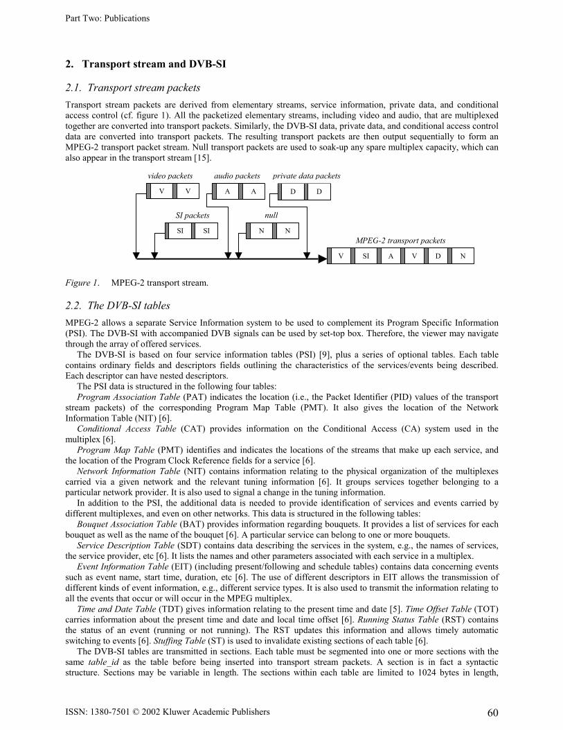
2.1. Transport stream packets Transport stream packets are derived from elementary streams, service information, private data, and conditional access control (cf. figure 1). All the packetized elementary streams, including video and audio, that are multiplexed together are converted into transport packets. Similarly, the DVB-SI data, private data, and conditional access control data are converted into transport packets. The resulting transport packets are then output sequentially to form an MPEG-2 transport packet stream. Null transport packets are used to soak-up any spare multiplex capacity, which can also appear in the transport stream [15]. Figure 1. MPEG-2 transport stream.
2.2. The DVB-SI tables MPEG-2 allows a separate Service Information system to be used to complement its Program Specific Information (PSI). The DVB-SI with accompanied DVB signals can be used by set-top box. Therefore, the viewer may navigate through the array of offered services. The DVB-SI is based on four service information tables (PSI) [9], plus a series of optional tables. Each table contains ordinary fields and descriptors fields outlining the characteristics of the services/events being described. Each descriptor can have nested descriptors. The PSI data is structured in the following four tables: Program Association Table (PAT) indicates the location (i.e., the Packet Identifier (PID) values of the transport stream packets) of the corresponding Program Map Table (PMT). It also gives the location of the Network Information Table (NIT) [6]. Conditional Access Table (CAT) provides information on the Conditional Access (CA) system used in the multiplex [6]. Program Map Table (PMT) identifies and indicates the locations of the streams that make up each service, and the location of the Program Clock Reference fields for a service [6]. Network Information Table (NIT) contains information relating to the physical organization of the multiplexes carried via a given network and the relevant tuning information [6]. It groups services together belonging to a particular network provider. It is also used to signal a change in the tuning information. In addition to the PSI, the additional data is needed to provide identification of services and events carried by different multiplexes, and even on other networks. This data is structured in the following tables: Bouquet Association Table (BAT) provides information regarding bouquets. It provides a list of services for each bouquet as well as the name of the bouquet [6]. A particular service can belong to one or more bouquets. Service Description Table (SDT) contains data describing the services in the system, e.g., the names of services, the service provider, etc [6]. It lists the names and other parameters associated with each service in a multiplex. Event Information Table (EIT) (including present/following and schedule tables) contains data concerning events such as event name, start time, duration, etc [6]. The use of different descriptors in EIT allows the transmission of different kinds of event information, e.g., different service types. It is also used to transmit the information relating to all the events that occur or will occur in the MPEG multiplex. Time and Date Table (TDT) gives information relating to the present time and date [5]. Time Offset Table (TOT) carries information about the present time and date and local time offset [6]. Running Status Table (RST) contains the status of an event (running or not running). The RST updates this information and allows timely automatic switching to events [6]. Stuffing Table (ST) is used to invalidate existing sections of each table [6]. The DVB-SI tables are transmitted in sections. Each table must be segmented into one or more sections with the same table_id as the table before being inserted into transport stream packets. A section is in fact a syntactic structure. Sections may be variable in length. The sections within each table are limited to 1024 bytes in length,
audio packets video packets
MPEG-2 transport packets
nullSI packets
V V A A D D
SI SI N N
V SI A V D N
private data packets
Part Two: Publications
ISSN: 1380-7501 © 2002 Kluwer Academic Publishers 61
except for sections within EIT, which are limited to 4096 bytes [6]. Each section is uniquely identified by the combination of the five fields in a section, such as table_id, section_number, etc. More detailed fields and descriptors of a section for different table can be found in [6].
2.3. Table sections The DVB-SI tables are transmitted in sections. Each table must be segmented into one or more sections with the same table_id as the table before being inserted into transport stream packets. A section is in fact a syntactic structure. Sections may be variable in length. The sections within each table are limited to 1024 bytes in length, except for sections within EIT, which are limited to 4096 bytes [6]. Sections should be mapped directly into transport stream packets. No gaps between sections within a transport stream packet are allowed. Stuffing may be completed by filling each remaining byte of transport stream packet with the value 0xFF. Stuffing may also be performed using the adaptation field in transport stream packet.
3. Demultiplexing DVB-SI
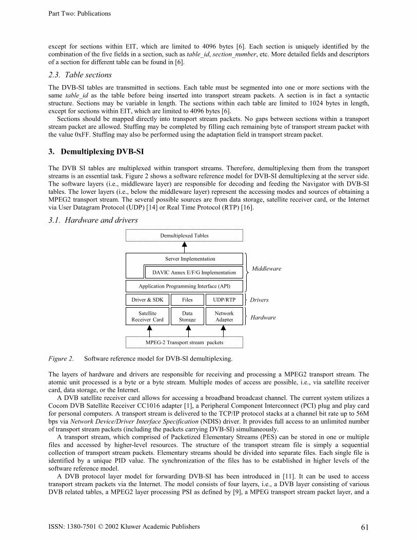
The DVB SI tables are multiplexed within transport streams. Therefore, demultiplexing them from the transport streams is an essential task. Figure 2 shows a software reference model for DVB-SI demultiplexing at the server side. The software layers (i.e., middleware layer) are responsible for decoding and feeding the Navigator with DVB-SI tables. The lower layers (i.e., below the middleware layer) represent the accessing modes and sources of obtaining a MPEG2 transport stream. The several possible sources are from data storage, satellite receiver card, or the Internet via User Datagram Protocol (UDP) [14] or Real Time Protocol (RTP) [16].
3.1. Hardware and drivers
Figure 2. Software reference model for DVB-SI demultiplexing. The layers of hardware and drivers are responsible for receiving and processing a MPEG2 transport stream. The atomic unit processed is a byte or a byte stream. Multiple modes of access are possible, i.e., via satellite receiver card, data storage, or the Internet. A DVB satellite receiver card allows for accessing a broadband broadcast channel. The current system utilizes a Cocom DVB Satellite Receiver CC1016 adapter [1], a Peripheral Component Interconnect (PCI) plug and play card for personal computers. A transport stream is delivered to the TCP/IP protocol stacks at a channel bit rate up to 56M bps via Network Device/Driver Interface Specification (NDIS) driver. It provides full access to an unlimited number of transport stream packets (including the packets carrying DVB-SI) simultaneously. A transport stream, which comprised of Packetized Elementary Streams (PES) can be stored in one or multiple files and accessed by higher-level resources. The structure of the transport stream file is simply a sequential collection of transport stream packets. Elementary streams should be divided into separate files. Each single file is identified by a unique PID value. The synchronization of the files has to be established in higher levels of the software reference model. A DVB protocol layer model for forwarding DVB-SI has been introduced in [11]. It can be used to access transport stream packets via the Internet. The model consists of four layers, i.e., a DVB layer consisting of various DVB related tables, a MPEG2 layer processing PSI as defined by [9], a MPEG transport stream packet layer, and a
Server Implementation
Middleware
Drivers
Hardware
Driver & SDK Files UDP/RTP
Satellite Receiver Card
Data Storage
Network Adapter
Application Programming Interface (API)
DAVIC Annex E/F/G Implementation
Demultiplexed Tables
MPEG-2 Transport stream packets
Part Two: Publications
ISSN: 1380-7501 © 2002 Kluwer Academic Publishers 62
broadcast layer responsible for broadcasting sections or transport stream packets encapsulated as payload of UDP [14] or RTP [8, 16] packets. A client can read a transport stream or sections from the Internet source.
3.2. Middleware The middleware layer is comprised of the Application Programming Interface (API), DAVIC Annex E/F/G implementation, and Server implementation. The API layer unifies data retrieved from lower levels and maintains resource interconnection. It allows for the management of different transport streams or section sources. Its main task is to unify the access of low-level resources that upper layers can interact independent of the underlying resources, implement transport stream packet buffer strategies, synchronize different elementary streams if they are not achieved by the lower layers, and implement native code. The atomic data unit of this layer is transport stream packets. The main part of the implementation of demultiplexing is made by the part of DAVIC Annex E/F/G implementation as defined by the Digital Audio-Visual Council (DAVIC). This annex standardizes the section filtering process from a transport stream and provides reference APIs in Java for performing this functionality. DAVIC Annex E [3] standardizes a platform neutral MPEG2-transport stream section access, control, and filtering mechanisms based on an abstract Java interface description to enable a satisfactory access to any data carried by MPEG sections independent of transmission scheme and transport stream source. The atomic unit processed by this layer are sections, which carry the signaling, thus portions of whole DVB SI tables and represent normative and private data that enable de-multiplexing of programs, additional program and bouquet information, conditional access, and pure non video- and audio- related data transmissions. Sections – as defined in [8] may be of variable length, are protected by Cyclic Redundancy Check (CRC) 32 bit coding, are not synchronized, and a version mechanism guarantees the implementation of accurate update mechanism on application level. Three different types of section filter with different life cycle and buffering characteristics are present in the current implementation. In comparison to simple section filter, which allows the filtering for single sections only, table and ring section filters allow for buffering of sections until an entire table is filtered or permanent buffering depended on the buffer size. Each section filter filters upon certain filter criterions, which can be defined at the beginning of the whole filtering process. Currently pure PID section filtering, PID and table id filtering, filtering with a positive filter mask, and filtering with a positive and negative filter is possible. The last two filter types provide the ability to define a filter mask for the first nine bytes, such the header, of a section. Interconnection to higher levels in the software reference model is realized by the implementation of an asynchronous event mechanism, that allows to respond to different processes, such as life cycle changes of objects, signal errors, state changes, available sections, incomplete filtering, timeouts, and version changes. Resource monitoring, including resource and transport stream status, is realized by the same event posting mechanism.
4. Transmission of TS packets via the Internet
We used the Internet (UDP protocol) access mode to transmit the DVB-SI as a system testing since a real broadcasting network was not available. At the server side (remote), the datagram packets carrying DVB-SI tables were sent recursively. These datagram packets were decoded at the client side where the Navigator was running. When the DVB-SI data is changed on the server, the client is signaled, and the changed part is renewed in the Navigator (i.e., it reads the tables again). For SI specified in ETS [6] the minimum time interval between the arrival of the last byte of a section and the first byte of the next transmitted section, which belongs to the same table should be 25 milliseconds. This limit applies for transport streams with a total data rate of up to 100Mbit/s. The method of sending UDP datagrams can serve the purpose.
4.1. UDP datagrams Applications, which communicate via UDP datagrams, send and receive completely independent packets of information [2]. These clients and servers do not have and do not need a dedicated point-to-point channel. A datagram is an independent, self-contained message sent over the network [2]. The delivery of datagrams to their destinations is not guaranteed. Nor is the order of their arrival. We used the classes included in java.net package when writing Java program that uses datagrams to send and receive packets over the network [2].
4.2. Structure of transport stream packet A transport stream packet is always 188 bytes long [15]. It comprises a 4-byte header followed by a payload (or an adaptation field, or both). The payload is 184 bytes in length (cf. figure 3).
Part Two: Publications
ISSN: 1380-7501 © 2002 Kluwer Academic Publishers 63
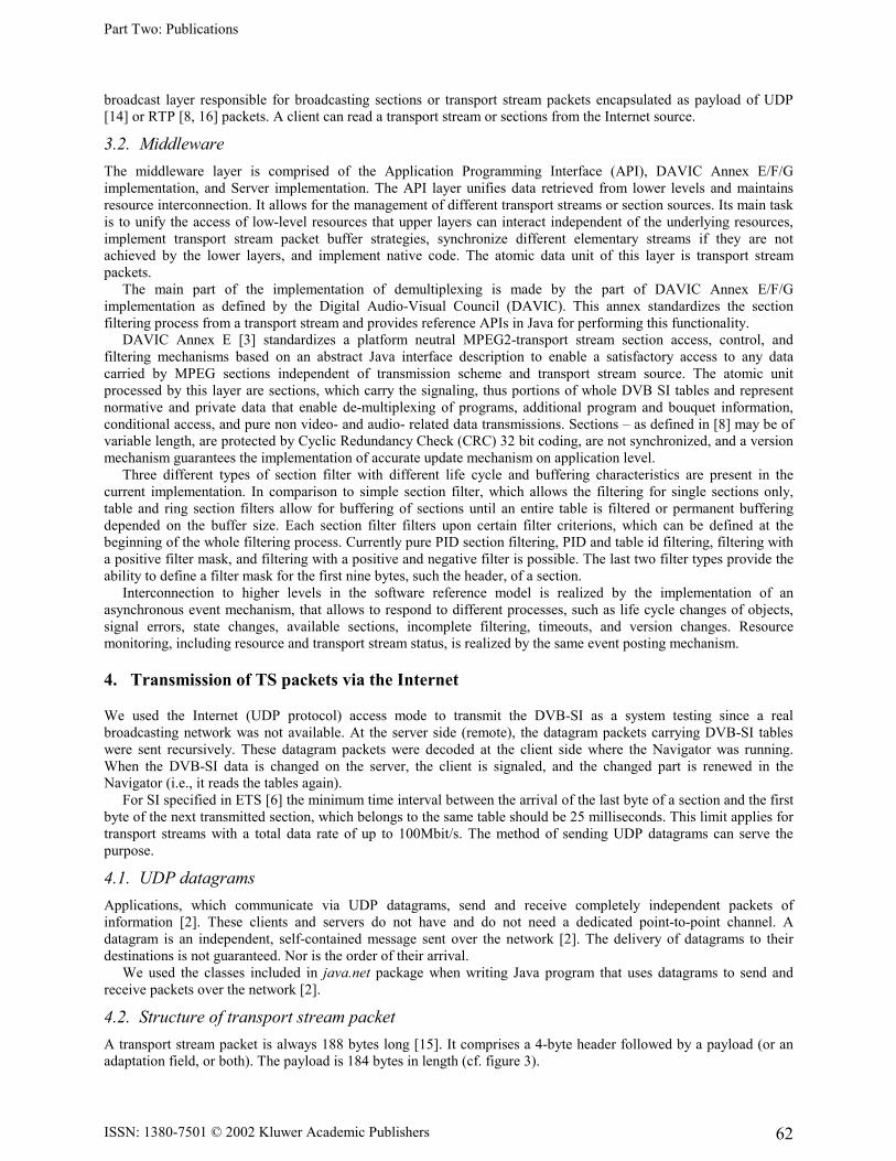
Figure 3. A UDP datagram packet.
A transport stream packet begins with 4-byte header [15]. The first byte is a sync-byte having the value 0x47 (hex), which is used for the decoder to identify the start of each new transport packet. In the following two bytes, the first bit is transport_error_indicator, the second bit is payload_unit_start_indicator, the third bit indicates transport_priority, and the last 13-bit is PID. The first two bits of the fourth byte are used for transport_scrambling_control. The second two bits are used for adaptation_control. The last 4-bit is continuity_count field.
4.3. Encapsulation of DVB-SI tables Figure 3 illustrates the method of inserting the DVB-SI tables into a datagram packet. From section 2 we know that each table must be separated in several sections with limited length before they are inserted into transport stream packets. The payload of each transport stream packet may contain one or more sections or a section can be put in several payloads depending on the size of the sections. The null data in the payload are stuffed with 0xFF. In our experiment system, the BAT table had 492 bytes. It was put in one DatagramPacket with three transport packets. The continuity_count field in the header indicated each BAT packet. The PID value is 0x0011. It cannot be identified uniquely because the other two tables (i.e., SDT and ST) have the same PID value. The BAT packets can be found by BAT PID value together with its table_id and continuity_count field. The EIT and SDT tables have the same encapsulation as the BAT table. The difference is that the later tables have different number of transport stream packets. The EPG data was encapsulated in text files since the EPG data was not carried in the transport stream. Each text file is the program information of one channel/service for one day. In order to simplify the data transmission, each DatagramPacket contained one text file.
5. Navigator functionality
This section gives a description of the main functions of the Navigator implemented in the Future TV project. Also, a detailed description of the fields of the tables, which contributed to the functionality of the Navigator, is presented.
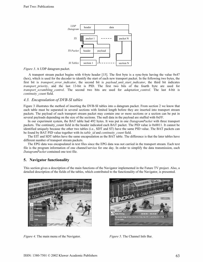
Figure 4. The main menu of the Navigator. Figure 5. The Channel Info Bar.
TS
SI Tables
UDP Datagram
header data
packet 1 packet N
TS Packet header payload
section 1 section N
Part Two: Publications
ISSN: 1380-7501 © 2002 Kluwer Academic Publishers 64
There are five main functions in the Navigator (cf. figure 4): Channel Info Bar, Channel Guide, Program Guide (i.e., EPG), Services, and Configuration. All these views can be accessed via the main user interface. Pushing the “Navigator” button on the remote control displays the main menu of the Navigator. Next, the viewer presses the “up” or “down” arrow and “OK” button to select a particular function of the Navigator (cf. figure 4). A conceptual panel of the PC remote control is shown in figure 10.
5.1. Channel Info Bar The purpose of the Channel Info Bar is to show the information of the current program/event immediately. Thus, the viewer does not need to browse the newspaper or Text TV. When the viewer presses a “TV” button, the Channel Info Bar is displayed on the screen (cf. figure 5). Pressing “TV” again hides the display. The Channel Info Bar displays current channel and program/event information (i.e., service/channel name, channel logo, event name, detailed information about the current event, and the date and time of the set-top box). The information comes from the EIT present/following table (table_id = 0x4E) and SDT table (table_id = 0x42). Two descriptors are used in the Channel Info Bar (i.e., Short Event descriptor and Extended Event Descriptor). The Short Event Descriptor transmits the name and a short text description for the event. The language code indicates in which language the text was written. The Extended Event Descriptor provides a detailed text description of the event. In the Channel Info Bar, the channel/service name is required. The EIT table does not include Service Descriptor field, but it can be uniquely identified by service_id field, event_id, and transport_stream_id field (cf. figure 8).
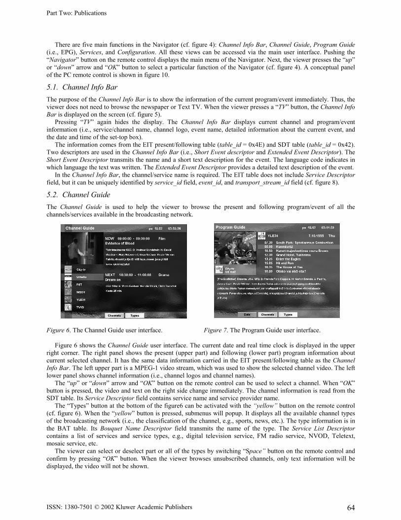
5.2. Channel Guide The Channel Guide is used to help the viewer to browse the present and following program/event of all the channels/services available in the broadcasting network.
Figure 6. The Channel Guide user interface. Figure 7. The Program Guide user interface. Figure 6 shows the Channel Guide user interface. The current date and real time clock is displayed in the upper right corner. The right panel shows the present (upper part) and following (lower part) program information about current selected channel. It has the same data information carried in the EIT present/following table as the Channel Info Bar. The left upper part is a MPEG-1 video stream, which was used to show the selected channel video. The left lower panel shows channel information (i.e., channel logos and channel names). The “up” or “down” arrow and “OK” button on the remote control can be used to select a channel. When “OK” button is pressed, the video and text on the right side change immediately. The channel information is read from the SDT table. Its Service Descriptor field contains service name and service provider name. The “Types” button at the bottom of the figure6 can be activated with the “yellow” button on the remote control (cf. figure 6). When the “yellow” button is pressed, submenus will popup. It displays all the available channel types of the broadcasting network (i.e., the classification of the channel, e.g., sports, news, etc.). The type information is in the BAT table. Its Bouquet Name Descriptor field transmits the name of the type. The Service List Descriptor contains a list of services and service types, e.g., digital television service, FM radio service, NVOD, Teletext, mosaic service, etc. The viewer can select or deselect part or all of the types by switching “Space” button on the remote control and confirm by pressing “OK” button. When the viewer browses unsubscribed channels, only text information will be displayed, the video will not be shown.
Part Two: Publications
ISSN: 1380-7501 © 2002 Kluwer Academic Publishers 65
The “Channels” button corresponds to “green” button on the remote control. This submenu lists all the channel names. When pressing “left” or “right” button, one of the two submenus can also be activated (cf. figure 11). The viewer can return to watch the current selected channel by pressing “TV” button.
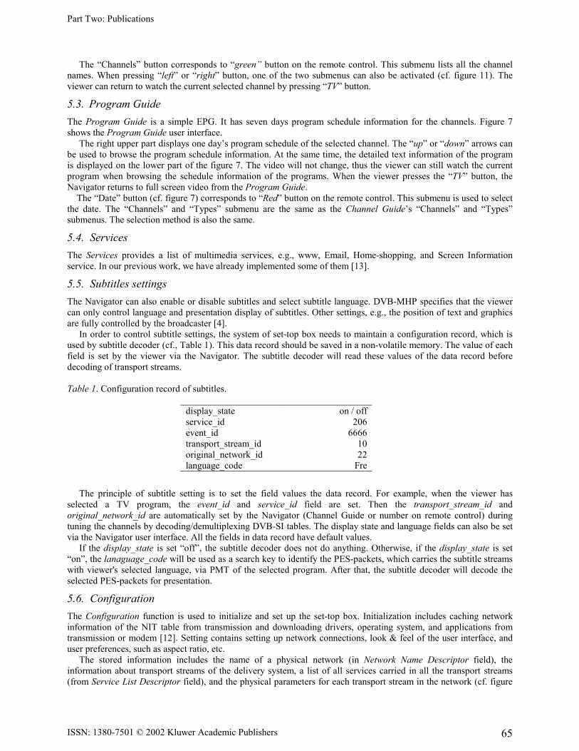
5.3. Program Guide The Program Guide is a simple EPG. It has seven days program schedule information for the channels. Figure 7 shows the Program Guide user interface. The right upper part displays one day’s program schedule of the selected channel. The “up” or “down” arrows can be used to browse the program schedule information. At the same time, the detailed text information of the program is displayed on the lower part of the figure 7. The video will not change, thus the viewer can still watch the current program when browsing the schedule information of the programs. When the viewer presses the “TV” button, the Navigator returns to full screen video from the Program Guide. The “Date” button (cf. figure 7) corresponds to “Red” button on the remote control. This submenu is used to select the date. The “Channels” and “Types” submenu are the same as the Channel Guide’s “Channels” and “Types” submenus. The selection method is also the same.
5.4. Services The Services provides a list of multimedia services, e.g., www, Email, Home-shopping, and Screen Information service. In our previous work, we have already implemented some of them [13].
5.5. Subtitles settings The Navigator can also enable or disable subtitles and select subtitle language. DVB-MHP specifies that the viewer can only control language and presentation display of subtitles. Other settings, e.g., the position of text and graphics are fully controlled by the broadcaster [4]. In order to control subtitle settings, the system of set-top box needs to maintain a configuration record, which is used by subtitle decoder (cf., Table 1). This data record should be saved in a non-volatile memory. The value of each field is set by the viewer via the Navigator. The subtitle decoder will read these values of the data record before decoding of transport streams. Table 1. Configuration record of subtitles.
display_state on / off service_id 206 event_id 6666 transport_stream_id 10 original_network_id 22 language_code Fre
The principle of subtitle setting is to set the field values the data record. For example, when the viewer has selected a TV program, the event_id and service_id field are set. Then the transport_stream_id and original_network_id are automatically set by the Navigator (Channel Guide or number on remote control) during tuning the channels by decoding/demultiplexing DVB-SI tables. The display state and language fields can also be set via the Navigator user interface. All the fields in data record have default values. If the display_state is set “off”, the subtitle decoder does not do anything. Otherwise, if the display_state is set “on”, the lanaguage_code will be used as a search key to identify the PES-packets, which carries the subtitle streams with viewer's selected language, via PMT of the selected program. After that, the subtitle decoder will decode the selected PES-packets for presentation.
5.6. Configuration The Configuration function is used to initialize and set up the set-top box. Initialization includes caching network information of the NIT table from transmission and downloading drivers, operating system, and applications from transmission or modem [12]. Setting contains setting up network connections, look & feel of the user interface, and user preferences, such as aspect ratio, etc. The stored information includes the name of a physical network (in Network Name Descriptor field), the information about transport streams of the delivery system, a list of all services carried in all the transport streams (from Service List Descriptor field), and the physical parameters for each transport stream in the network (cf. figure
Part Two: Publications
ISSN: 1380-7501 © 2002 Kluwer Academic Publishers 66
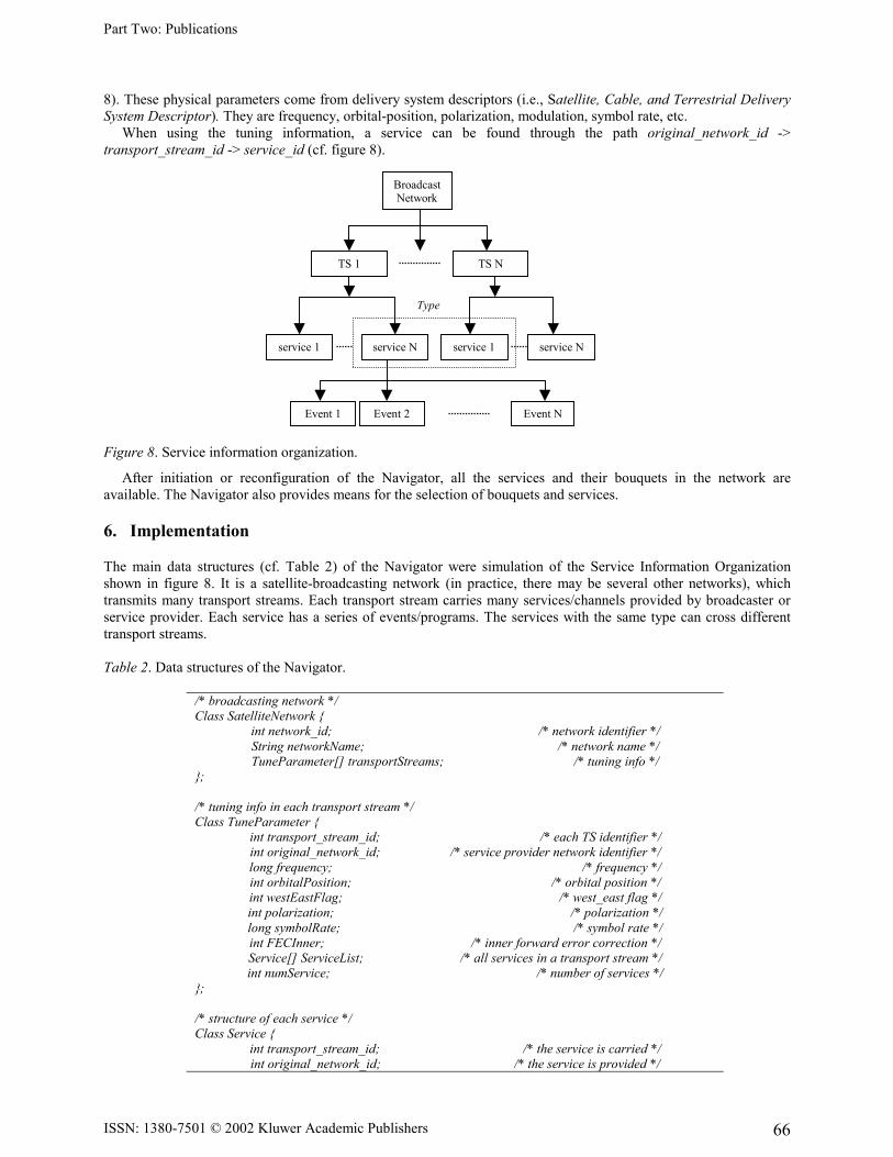
8). These physical parameters come from delivery system descriptors (i.e., Satellite, Cable, and Terrestrial Delivery System Descriptor). They are frequency, orbital-position, polarization, modulation, symbol rate, etc. When using the tuning information, a service can be found through the path original_network_id -> transport_stream_id -> service_id (cf. figure 8). Figure 8. Service information organization.
After initiation or reconfiguration of the Navigator, all the services and their bouquets in the network are available. The Navigator also provides means for the selection of bouquets and services.
6. Implementation
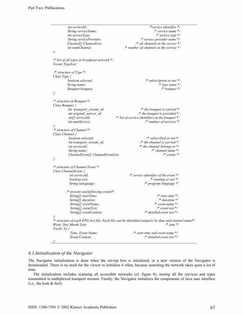
The main data structures (cf. Table 2) of the Navigator were simulation of the Service Information Organization shown in figure 8. It is a satellite-broadcasting network (in practice, there may be several other networks), which transmits many transport streams. Each transport stream carries many services/channels provided by broadcaster or service provider. Each service has a series of events/programs. The services with the same type can cross different transport streams. Table 2. Data structures of the Navigator.
/* broadcasting network */ Class SatelliteNetwork {
int network_id; /* network identifier */ String networkName; /* network name */ TuneParameter[] transportStreams; /* tuning info */
}; /* tuning info in each transport stream */ Class TuneParameter {
int transport_stream_id; /* each TS identifier */ int original_network_id; /* service provider network identifier */ long frequency; /* frequency */ int orbitalPosition; /* orbital position */ int westEastFlag; /* west_east flag */ int polarization; /* polarization */ long symbolRate; /* symbol rate */ int FECInner; /* inner forward error correction */ Service[] ServiceList; /* all services in a transport stream */ int numService; /* number of services */
}; /* structure of each service */ Class Service {
int transport_stream_id; /* the service is carried */ int original_network_id; /* the service is provided */
Type
BroadcastNetwork
TS N TS 1
service 1 service N service 1 service N
Event NEvent 2Event 1
Part Two: Publications
ISSN: 1380-7501 © 2002 Kluwer Academic Publishers 67
int serviceId; /*service identifier */ String serviceName; /* service name */ int serviceType; /* service type */ String serviceProvider; /* service provider name */ Channel[] ChannelList; /* all channels in the service */ int numChannel; /* number of channels in the service */
}; /* list of all types in broadcast network */ Vector TypeList; /* structure of Type */ Class Type {
boolean selected; /* subscription or not */ String name; /* type name */ Bouquet bouquet; /* bouquet */
}; /* structure of Bouquet */ Class Bouquet {
int transport_stream_id; /* the bouquet is carried */ int original_netwot_id; /* the bouquet is provided */ int[] serviceId; /* list of service identifiers in the bouquet */ int numService; /* number of services */
}; /* structure of Channel */ Class Channel {
boolean selected; /* subscribed or not */ int transport_stream_id; /* the channel is carried */ int serviceId; /* the channel belongs to */ String name; /* channel name */ ChannelEvent[] ChannelEventList; /* events */
}; /* structure of Channel Event */ Class ChannelEvent {
int serviceId; /* service identifier of the event */ boolean exit; /* running or not */ String lanaguage; /* program language */
/* present and following events*/
String[] startTime; /* start time */ String[] duration; /* duration */ String[] eventName; /* event name */ String[] eventText; /* event text */ String[] eventContent; /* detailed event text */
}; /* structure of each EPG text file. Each file can be identified uniquely by date and channel name*/ Week, Day Month Year /* time */ For(0; N) {
Time Event Name; /* start time and event name */ Event Content; /* detailed event text */
};
6.1.Initialization of the Navigator The Navigator initialization is done when the set-top box is initialized, or a new version of the Navigator is downloaded. There is no need for the viewer to initialize it often, because searching the network takes quite a lot of time. The initialization includes scanning all accessible networks (cf. figure 8), storing all the services and types transmitted in multiplexed transport streams. Finally, the Navigator initializes the components of Java user interface (i.e., the look & feel).
Part Two: Publications
ISSN: 1380-7501 © 2002 Kluwer Academic Publishers 68
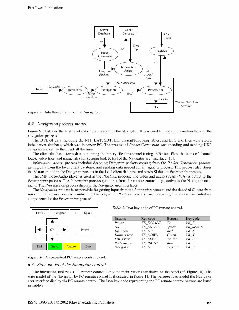
Figure 9. Data flow diagram of the Navigator.
6.2. Navigation process model Figure 9 illustrates the first level data flow diagram of the Navigator. It was used to model information flow of the navigation process. The DVB-SI data including the NIT, BAT, SDT, EIT present/following tables, and EPG text files were stored inthe server database, which was in server PC. The process of Packet Generation was encoding and sending UDP datagram packets to the client all the time. The client database stores data containing the binary file for channel tuning, EPG text files, the icons of channel logos, video files, and image files for keeping look & feel of the Navigator user interface [13]. Information Access process included decoding Datagram packets coming from the Packet Generation process, getting data from the local client database, and sending data needed for Navigation process. This process also stores the SI transmitted in the Datagram packets in the local client database and sends SI data to Presentation process. The JMF video/Audio player is used in the Playback process. The video and audio stream (V/A) is output to the Presentation process. The Interaction process gets input from the remote control, e.g., activates the Navigator main menu. The Presentation process displays the Navigator user interfaces. The Navigation process is responsible for getting input from the Interaction process and the decoded SI data from Information Access process, controlling the player in Playback process, and preparing the entire user interface components for the Presentation process. Table 3. Java key-code of PC remote control. Figure 10. A conceptual PC remote control panel.
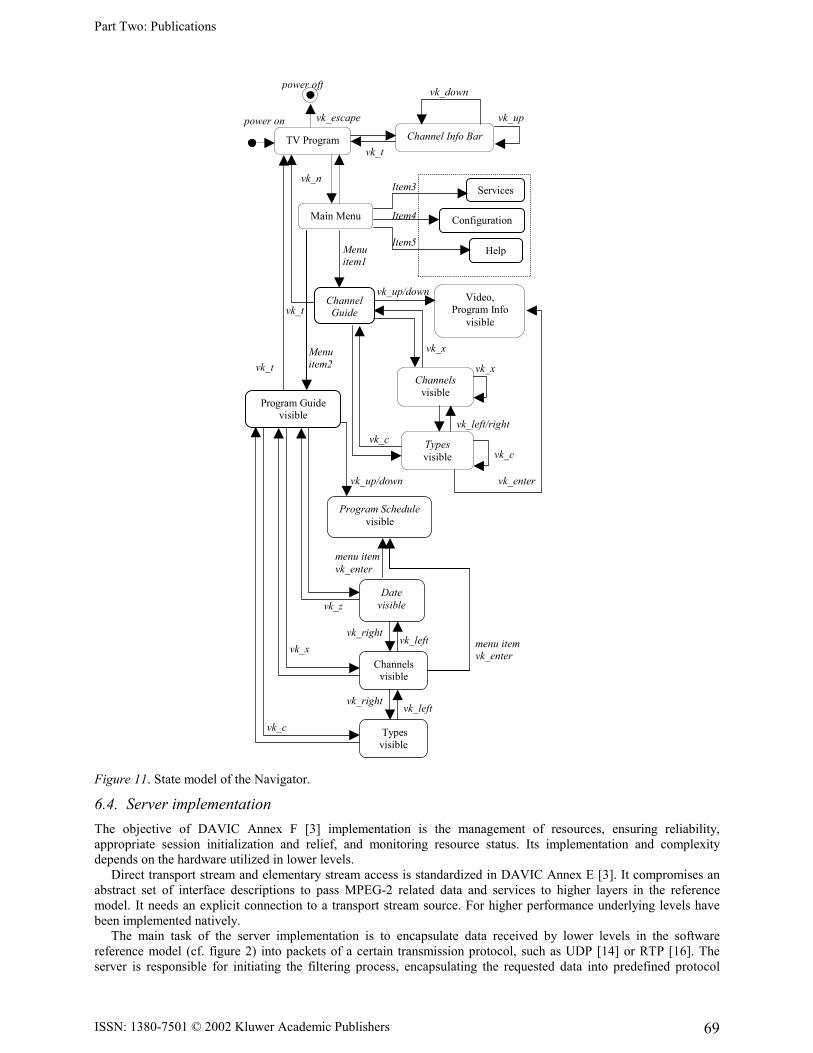
6.3. State model of the Navigator control The interaction tool was a PC remote control. Only the main buttons are drawn on the panel (cf. Figure 10). The state model of the Navigator by PC remote control is illustrated in figure 11. The purpose is to model the Navigator user interface display via PC remote control. The Java key-code representing the PC remote control buttons are listed in Table 3.
Buttons Key-code Buttons Key-code Power VK_ESCAPE TV VK_T OK VK_ENTER Space VK_SPACE Up arrow VK_UP Red VK_Z Down arrow VK_DOWN Green VK_X Left arrow VK_LEFT Yellow VK_C Right arrow VK_RIGHT Blue VK_V Navigator VK_N TextTV VK_P
TextTV Navigator T Space
OK Power
Red Green Yellow Blue
V/A
Datagram Packets
Menu selection
keycodes
Channel Switching Selection
Java UI
GUI
Stored Info
Video Files
SI, Stored Info
SI, Stored
Info
SI
SI
Server Database
Client Database
Packet Generation
Playback
Information Access
Navigation Presentation
TV
Interaction Input
Part Two: Publications
ISSN: 1380-7501 © 2002 Kluwer Academic Publishers 69
Figure 11. State model of the Navigator.
6.4. Server implementation The objective of DAVIC Annex F [3] implementation is the management of resources, ensuring reliability, appropriate session initialization and relief, and monitoring resource status. Its implementation and complexity depends on the hardware utilized in lower levels. Direct transport stream and elementary stream access is standardized in DAVIC Annex E [3]. It compromises an abstract set of interface descriptions to pass MPEG-2 related data and services to higher layers in the reference model. It needs an explicit connection to a transport stream source. For higher performance underlying levels have been implemented natively. The main task of the server implementation is to encapsulate data received by lower levels in the software reference model (cf. figure 2) into packets of a certain transmission protocol, such as UDP [14] or RTP [16]. The server is responsible for initiating the filtering process, encapsulating the requested data into predefined protocol
power off
vk_z
menu item vk_enter
vk_right vk_left
vk_x
vk_c
vk_right vk_left
menu item vk_enter
vk_up/down vk_enter
vk_left/right
vk_c
vk_x
vk_x
vk_c
vk_t
vk_t
vk_up/down
Item4
Item5
Item3
Menu item2
Menu item1
vk_n
vk_t
vk_escapepower on vk_up
vk_down
TV Program Channel Info Bar
Services
Configuration
Help
Main Menu
Channel Guide
Video, Program Info
visible
Program Guide visible
Channels visible
Types visible
Program Schedulevisible
Date visible
Channels visible
Types visible
Part Two: Publications
ISSN: 1380-7501 © 2002 Kluwer Academic Publishers 70
packets, lower layer data access, monitoring the whole process, establishing and maintaining the transmission session, and guaranteeing synchronization. The server is able to transmit transport stream packets, sections, or whole tables. The current integration work with the Navigator relies on UDP as transmission protocol, in whose datagram packets a whole table is transmitted in the form of consequent sections.
7. Conclusions
In this paper, we have implemented a basic set-top box Navigator in resident subset of Java classes. In particular, the Navigator’s features related to the DVB-SI tables were discussed, simulation of broadcasting transmission of transport streams via the Internet was designed and implemented. The work demonstrated that parsing transport streams and decoding the DVB_SI data in the set-top box are the key functions of the Navigator for retrieving and updating its data information. Furthermore, Java is a good platform for coding the Navigator and accessing data from files and network. It is especially suitable for coding remote control events, the graphical user interface, etc. Java was fast enough at the server side implementation without any performance enhancing tools. No packet losses or buffer overflows where registered. Forwarding and encapsulating them in transmission protocols did not cause delays or jitter. At the server side, a DVB compliant MPEG-2 downstream at 38M bps was decoded and filtered. The stream could be received at a signal strength of 49.2%, signal/noise ratio of 9.6 dB, and symbol frequency of 27500000 Hz. Each table had different transport stream packet rates: BAT 6 Kbps, CAT 5 Kbps, NIT 7 Kbps, SDT 6.6 Kbps, EIT 47.6 Kbps, TDT 2.9 Kbps, BAT 6.6 Kbps, RST and TOT were not multiplexed in the stream. The server-side implementation showed no buffer overflows and inconsistent filtering events. This relies on an appropriate buffer size of 400 transport stream packets and 250 sections, a discreet resource sharing, and the Java native interface to pure C++ source code. The current implementation buffers transport stream packets at driver level, where the C++ source code is the interface between a pure Java based, DAVIC compliant implementation and drivers. Therefore, section buffers have been realized in Java. Time boundaries for decoding SI from a transport stream are less restrictive than for video/audio, as SI tables are small and sent with high frequency. Therefore a pure Java based decoding was fast satisfying and each section could be compiled in appropriate manner and without any noticeable delays. At the client side, the rate of receiving UDP datagram packets was 19.53 Kbps. The rate corresponds to 11 transport stream packets per ten seconds. This rate fulfils the limit in ETR [4], i.e., the DVB-SI stream shall have at least 8 Transport Stream packets per 10 seconds carrying NIT data or null packets. We also gathered statistics about the consumption of memory. Java byte codes of the Navigator consume about 107 kB. The SI data files consisting of binary and text files need about 350 kB. The look & feel images of the user interface including channel logos need about 202 kB. This statistics indicate that memory space of caching the SI and the user interface initialization data is greater than embedding the Java bytecodes of the Navigator. Therefore, balancing accessing time and display performance with memory consumption will be one of the design issues in the set-top box with limited resources. Our work constitutes a basis for developing other multimedia services in the set-top box (e.g., Near Video-on-Demand, mosaic services, enhanced Teletext service, etc.), designing the user interface of these services, decoding, displaying and controlling subtitles in the set-top box, etc. We plan to embed the Navigator byte codes in our test system and make it work with other system functions and services in real broadcasting environment. Another goal is to develop other multimedia services as mentioned above in conjunction with DSM_CC (Digital Storage Media Command and Control) data carousels and object carousels.
Acknowledgments
We thank Mr. Juha Vierinen for helping with the graphical design of the Images in the Future TV project. The author Chengyuan Peng would also like to thank Nokia Oyj Foundation for providing the scholarship and support during the research work. The server side implementation has been done at the Digital Media Institute, Tampere University of Technology; therefore we would also like to thank our research colleagues at this institute, especially Seppo Kalli, Teemu Lukkarinen, Arttu Heinonen Florina Tico, Mikko Oksanen, and Perttu Rautavir.
References
Part Two: Publications
ISSN: 1380-7501 © 2002 Kluwer Academic Publishers 71
[1] COCOM, DVB Satellite Receiver CC1016. Product Data Sheet; DVB-S Evaluation Kit CC1016 (Manual); COCOM CC1016 DVB-Satelite Data Receiver Developers Toolkit (Manual).
[2] Justin Couch, Java™ 2 Networking, McGraw-Hill: New York, 1999. [3] DAVIC, “DAVIC 1.4 Specification Part 9, Information Representation (technical specification),” DAVIC
Digital Audio-Visual Council, 1998. [4] TS 101 812, “Digital Video Broadcasting (DVB); Multimedia Home Platform (MHP) Specification 1.0.1,”
European Telecommunications Standards Institute, October 2001. [5] ETR 211, “Digital broadcasting systems for television; Implementation guidelines for the use of MPEG-2
systems; Guidelines on implementation and usage of service information,” European Telecommunications Standards Institute, April 1996.
[6] ETS 300 468, “Digital Video Broadcasting (DVB) Specification for Service Information (SI) in DVB systems,” European Telecommunications Standards Institute, January 1997.
[7] J.-P. Evain, “The Multimedia Home Platform – an overview,” EBU Technical Review, Spring 1998, pp. 4-10. [8] D. Hoffman, G. Fernando, V. Goyal, and M. Civanlar, “RFC2250, RTP Payload Format for MPEG1/MPEG2
Video,” January 1998. [9] ISO/IEC 13818-1, “Generic Coding of Moving Pictures and Associated Audio Recommendation H.222.0
(systems),” International Organization for Standardization, November 1994. [10] ISO/IEC 13818-6, “Generic Coding of Moving Pictures and Associated Audio: Digital Storage Media
Command and Control,” International Organization for Standardization, July 1996. [11] A. Lugmayr and S. Kalli, “Transmission of DVB Service Information via Internet. Next Generation Networks:
Networks and Services for the Information Society,” in Proceedings of the 5th IFIP TC6 International Symposium, INTERWORKING 2000, Bergen, Norway.
[12] NorDig II and III, “Digital Integrated Receiver Decoder Draft Specification, for use in cable, satellite and terrestrial networks,” January 2000.
[13] C. Peng and P. Vuorimaa, “Developing Java User Interface for Digital Television,” in the 8th International Conference on Computer Graphics, Visualization and Interactive Digital Media' 2000, Czech Republic, February 7-10, 2000.
[14] J. Postel, RFC 768, UDP: User Datagram Protocol, August 1980. [15] P.A. Sarginson, “MPEG-2: Overview of the systems layer,” Research and Development Report, No. 1996/2. [16] Hjhjh H. Schulzrinne, S. Casner, R. Fredrick, and V. Jacobson, “RFC 1889, RTP: A Transport Protocol for
Real-Time Applications,” Audio-Video Transport Working Group, January 1996.


