Embed Size (px)
Citation preview

Pergamon Information Systems Vol. 20, No. 6, pp. 465-482, 1995
Copyright@ 1995 Elsevier Science Ltd Printed in Great Britain. All rights reserved
0306-4379(95)00025-9 030s4379/95&.50 + 0.00
A DISK-BASED STORAGE ARCHITECTURE FOR MOVIE ON DEMAND SERVERS
BANU ~ZDEN, ALEXANDROS BILIRIS, RAJEEV RASTOGI AND AVI SILBERSCHATZ
AT&T Bell Laboratories, 600 Mountain Avenue, Murray Hill, NJ 07974
(Received 30 July 1994; in final revised form 1 August 1995)
Abstract - Recent advances in storage technology provides an effective way to store video in digital and compressed form. This, coupled with the recent dramatic increase in the bandwidth of networks, make it possible now to provide to viewers “movies on demand”, thereby eliminating the inflexibility inherent in todays broadcast cable systems. A movie on demand (MOD) server is a computer system that stores movies in compressed digital form and provides support for different portions of compressed movie data to be accessed and transmitted concurrently. Such a server not only enables viewers to watch a movie at any time they desire, but also enables them to apply VCR operations like pause, resume, fast-forward and rewind to the movies they are currently watching. In this paper, we present a disk-based storage architecture for a MOD server. We present a clever strategy for striping movies that enables simultaneous access and transmission of different portions of a movie. We also present a wide range of schemes for implementing VCR-like functions including fast-forward, rewind and pause.
Key words: Movie on Demand, Stripping, Multimedia
1. INTRODUCTION
The movie on demand (MOD) concept has become exceedingly popular with telecommunica- tions, computer and cable companies. Viewers that subscribe to a MOD service have access to a much wider feature set in comparison to the broadcast based cable and TV networks. For example, a viewer can start watching a movie, from among a particular set of movies, at any time the viewer wishes to do so. When watching a movie, a viewer can apply VCR operations like pause, resume, fast-forward and rewind to the movie. Thus, MOD services differ substantially from today’s broad- cast, cable services in which, at any given time, all the viewers see the same portion of a movie and viewers of movies have no control over its transmission.
Until recently, low network bandwidths and video storage technologies made offering MOD ser- vices to viewers a difficult task. However, today, networks built using optic fibers have bandwidths of several gigabits per second. Furthermore, not only is it now possible to store video data in digital form, but it is also possible to obtain high compression ratios. For example, display of video at 30 frames/set that is compressed using the MPEG [2] compression algorithm requires a bandwidth of merely 1.5 Mb/s. Thus, it is possible now to concurrently transmit independent video streams to thousands of viewers.
Even though the problem of transmitting video data is considerably simplified due to the availability of high bandwidth networks, the design and implementation of MOD storage servers that are responsible for the storage and retrieval of different portions of movies simultaneously remains a non-trivial problem. A storage architecture for a MOD server must address the following issues: low-cost, continuous retrieval of movies, ability to support VCR operations, and servicing multiple viewers concurrently.
In general, a MOD server will contain a cache to temporarily store the currently viewed movies. The popular movies will be loaded onto the cache from a library which stores movies permanently (e.g., a jukebox of tapes). The cache can be designed with random access memory (RAM) as a flat architecture. However, this approach will increase the cost of the MOD server substantially due to the high cost of RAM and the high storage requirements of movies. For example, an MPEG compressed 100 minute movie with an average bandwidth of 1.5 Mb/s require8 approximately 1.125 GB of storage. Assuming the cost of RAM is $50.00 per MB, the cost of a RAM-based cache to store 100 popular movie8 will exceed $5.5 million.
465

466 BANU &DEN et al.
In this paper, we propose a storage hierarchy to design a low-cost cache for a MOD server. The hierarchy consists of disks which store the popular movies, and a small amount of RAM buffers which store only portions of the movies. Due to the low cost of disks (approximately $1 per MB), the cost of a MOD server based on our architecture is substantially less than one in which the entire movie is loaded into RAM. However, unlike a RAM-based architecture, access times to random locations on disks are relatively high. Therefore, clever storage allocation schemes must be devised to continuously retrieve different portions of a movie for a large number of users and at the same time to minimize the buffering requirements. For the same reasons, the implementation of VCR operations like fast-forward, rewind, pause and resume is a difficult task. We present the “phase-constrained” storage allocation scheme which enables a large number of different parts of a movie to be viewed simultaneously, and a variety of schemes for implementing the VCR operations. The schemes illustrate the trade-off between the size of the RAM buffers required and the quality of the VCR-type service, in particular, abruptness in display perceived by viewers during fast-forward/rewind operations as well as the response time for switching back to normal display mode from pause, fast forward and rewind modes. The lower costs of schemes that provide limited functionality for fast-forward, rewind and pause make them attractive for a wide range of environments.
The remainder of the paper is organized as follows. In Section 2, we present an overview of the system architecture that provides MOD services. We present our scheme for storing movies on disks in Section 3. In Section 4, we describe how VCR operations can be implemented in our architecture. Schemes for implementing fine granularity fast-forward and rewind are presented in Section 5. In Section 6, we present buffering schemes that provide the same functionality of movies stored in RAM, but do not require entire movies to be stored in RAM. A comparison of our work with related work in the area can be found in Section 7. Finally, in Section 8, we offer concluding remarks.
2. OVERALL SYSTEM ARCHITECTURE
In this section, we present an overview of the system architecture for supporting MOD services. The main system component, the MOD server, is a computer with one or more processors, and a cache to hold a set of popular movies in compressed form. The cache is updated from a library of movies at the same site or from a library or a cache at another site. Figure 1 illustrates the overall architecture for MOD services.
The compressed movie data is transmitted at a rate of rd over a high bandwidth network individually to every viewer that subscribes to a MOD service. The number of viewers serviced by a single MOD server would vary depending on the geographical location. However, we expect this number to be between 5,000 and 10,000. Every viewer has a decoder, which consumes the compressed movie data from a local buffer at a rate of about rd and outputs frames to a display at the playback rate (which is typically 30 frames/set).
Viewers can issue commands to control the display of a movie that is stored in the MOD server. These commands include begin, fast-forward, rewind, pause and resume. The commands are transmitted to the MOD server, which maintains information relating to the status of every viewer (e.g., the last command executed by the viewer, the position in the movie of the last bit transmitted to the viewer). While a movie is being displayed, viewers can apply any of the above commands to control the display of the movie.
We refer to the transmission of a movie starting at a given time as a stream. Two streams may correspond to the same or different movies. The maximum number of streams that a storage server can support is limited by its bandwidth. This number is not, in general, sufficient to provide each viewer with an independent stream, since the number of viewers will be typically larger than the maximum number of streams. The challenge is to devise clever algorithms and buffering techniques to assign viewers to the right streams at the right times in order to provide on-demand movie service with VCR functionalities.
The cache that stores the popular movies can be designed as a flat architecture consisting only of RAM. Due to the high cost of RAM, however, this approach makes the cost of a MOD

A Disk-based Storage Architecture for Movie on Demand Servers 467
Movie Library MOD Sewer
,_I.. c ‘1 NeWork
Fig. 1: System architecture for MOD services.
server prohibitively expensive. Therefore, we propose a two-level cache architecture consisting primarily of secondary storage devices and a limited amount of RAM. The second level of the cache consists of disks, which store the popular movies, while the first level consists of the RAM buffer to temporarily hold portions of movies currently being displayed. Due to the lower cost of disks, our approach yields cheaper MOD services.
However, given that our primary storage device is a disk, it is difficult to obtain the maximum number of concurrent streams, since disks have high access time to random locations (approxi- mately 15 ms in the worst case). A major portion of this paper is devoted to the design of a basic storage architecture which is capable of transmitting the maximum number of streams by employing only little amount of RAM buffers.
To simplify our discussion, we will present our results assuming that only one movie is being handled by the MOD server. Our results can, however, be generalized to providing streams for multiple movies by simply expanding the system (bandwidth, disk storage and buffers) by the number of movies.
3. THE BASIC STORAGE ARCHITECTURE
A MOD server must provide support for the transmission of a movie on demand which can be initiated at any time. We refer to the transmission of movie data initiated at a certain time as a phase. Two phases are said to be concurrent if their transmission overlaps in time. We refer to the difference in the initiation times for two phases as their phase difference.
Our basic storage architecture consists of disks that store the movie, and RAM buffers, referred to as movie buffers, that store portions of the movie temporarily. Due to the relatively high access time to a random location on a disk, clever storage allocation schemes must be used to concurrently support the maximum number of phases. Furthermore, in order to keep the cost of the system low, the storage allocation scheme must not require large amounts of movie data to be buffered in RAM. In this section, we propose a novel storage allocation scheme for movies on disk, which enables a MOD server to support the maximum number of concurrent phases with fixed phase differences, and requires only a small amount of buffer space to be maintained per phase.

468 BANU &EN et al.
3.1. Storage Allocation
Suppose a movie is stored on a disk with bandwidth Q. A disk can be either a single disk or a disk array. In the latter case, the bandwidth rt is defined aa the number of bits retrieved in parallel in a second. Since each phase requires movie data to be retrieved from disk at a rate Td,
the number of concurrent phases that can be supported is clearly limited by the bandwidth it.
The maximum number of concurrent phases, denoted by p, that can be supported by retrieving movie data from disk is given by:
0)
Before we present our storage allocation scheme in Section 3.1.2, in the following subsection, we show that adopting a naive approach like storing movie data contiguously on disk requires large amounts of movie data to be buffered in RAM in order to compensate for the high latency time associated with disks.
3.1.1. Contiguozls Allocation
For every phase, movie data from disk is retrieved into a RAM buffer of size d bits at a rate Td. We show that with contiguous allocation, the amount of buffer required for a phase increases with the number of phases and the latency of disk. Suppose that there are m concurrent phases of the movie. In order to ensure that data for the m phases can be continually retrieved from disk at a rate Td, in the time that the d bits from m buffers are consumed at a rate Td, the d bits of the movie following the d bits consumed must be retrieved into the buffers. Since each retrieval involves positioning the disk head at the desired location and then transferring the d bits from the disk to the buffer, we have the following equation.
where tlat is the worst case latency of the disk. Hence, the size d of the buffer per phase can be calculated as
d > &at . Td * Tt
- (2 -Td) * (2)
Thus, the buffer size per phase increases both with latency of the disk and the number of concur- rent phases. In the following example, we compute for a commercially available disk, the sizes of portions of movies that need to be buffered in order to support the maximum number of concurrent phases.
Example 1 Consider a commercially available disk costing $3000 with a capacity of 9 GB, a transfer rate of 80 Mb/s and a worst case latency time of 15 ms. Since Td is 1.5 Mb/s (for MPEG), the maximum number of concurrent phases that can be supported at a rate of 1.5 Mb/s using the device is [EJ = 53. Using Equation 2, we compute the buffer size requirements d to support 53 concurrent phases to be d 2 190 Mb. Since we require 53 different buffers, the total storage requirements are 53 . 190 x 10 Gb, which is larger than the size of a movie. 0
3.1-Z Phase-Constrained Allocation
In order to keep the amount of buffer per phase low, we propose a new storage allocation scheme for a movie on disk, which we call the phase-constrained allocation scheme. The phase-constrained allocation scheme eliminates seeks to random locations, and thereby enables the concurrent re- trieval of maximum number of phases p, while maintaining the buffer size per phase as a constant independent of the number of phases and disk latencies. Since movie data is retrieved sequentially from disk, only ‘&certain” concurrent phases with fixed phase differences are supported.
Let 1 be the length of a movie in seconds. Thus, the storage occupied by the movie is 1. Td bits. Suppose movie data is read from disks in portions of size d. We shall assume that 1 .Td is a multiple

A Disk-based Storage Architecture for Movie on Demand Servers 469
1 2 3 n
Fig. 2: The movie viewed as a matrix.
of p. d. (The length of the movie can be modified by appending advertisements, etc. to the end of the movie.) Our goal is to be able to support p concurrent phases of the movie. In order to do this, we chop the movie into p contiguous partitions. Thus, the movie data can be visualized as a (p x 1) vector, the concatenation of whose rows is the movie itself and each row contains t, . Td
bits of movie data, where
t,= 4. P
We refer to t, as the smallest phase difference since the first bit in any two adjacent rows are t, seconds apart in the movie. Since movie data in each row is retrieved in portions of size d, a row can be further viewed as consisting of n portions of size d, where
tc . Td n=-
d
Thus, a movie can be represented as a (p x n) matrix of portions as shown in Figure 2. Each portion in the matrix can be uniquely identified by the row and column to which it belongs. Suppose we now store the movie matrix on disk sequentially in column-major form. Thus, as shown in Figure 3, Column 1 is stored first, followed by Column 2, and finally Column n.
We show that by sequentially reading from disk, movie data in each row can be retrieved concurrently at a rate Td. From Equation 1, it follows that:
Therefore, in the time required to consume d bits of the movie at a rate Td, an entire column can be retrieved from disk. As a result, while a portion is being consumed at a rate rd, the next portion can be retrieved. The scheme we describe guarantees a transfer rate of rd. It can be easily modified to guarantee the transfer of a certain number of frames in a given time in a given time span. This can be accomplished by chopping the movie into logically related units instead of fixing the sizes of portions to d. For example, each portion may contain compressed data of Ic frames.
If we assume that once the nth column has been retrieved, the disk head can be repositioned to the start of the device almost instantaneously, then we can show that p concurrent phases can be supported, the phase difference between any two phases being a multiple of t,. The reason for this is that every t, seconds the disk head can be repositioned to the start. Thus, a new phase can be initiated every t, seconds. Furthermore, for every other concurrent phase, the last portion retrieved just before the disk head is repositioned, belongs to Column n. Since we assume that repositioning time is negligible, Column 1 can be retrieved immediately after Column n. Thus, since the portion following portion (i, n) in Column n, is portion (i + 1,1) in Column 1, data for concurrent phases can be retrieved from disk at a rate rd. In Section 3.3, we present schemes that take into account repositioning time when retrieving data for p concurrent phases.

470 BANU 6ZDEN et d.
.v- ‘a- -_ / rndcc+Jml . . __ fmcc+Jml _._---__+
(1.1) (2.1) (P#V (12) (2.2)
r-T-1 . . . [,I . . . f-j (’ “) (2’“)
(PdJ)
,.. l__i__l *a* LX c -. d+- Fig. 3: Placement of n columns of movie matrix.
3.2. Buflering
We now compute the buffering requirements for our storage scheme. With every row of the movie matrix, we associate a movie buffer, into which consecutive portions in the row are retrieved. Each of the movie buffers is implemented as a circular buffer; that is, while writing into the buffer, if the end is reached, then further bits are written at the beginning of the movie buffer (similarly, while reading, if the end is reached, then subsequent bits are read from the beginning of the buffer).
With the above circular storage scheme, every 2 seconds, consecutive columns of movie data are retrieved from disk into movie buffers. The size of each buffer is 24 one half of which is used to read in a portion of the movie from disk, while d bits of the movie are transmitted to viewers from the other half. Also, the number of movie buffers is p to store the p different portions of the movie contained in a single column - the first portion in a column is read into the first movie buffer, the second portion into the second movie buffer and so on. Thus, in the scheme, initially, the p portions of the movie in the first column are read into the first d bits of each of the corresponding movie buffers. Following this, the next p portions in the second column are read into the latter d bits of each of the corresponding movie buffers. Concurrently, the first d bits from each of the movie buffers can be transmitted to viewers. Once the portions from the second column have been retrieved, the portions from the third column are retrieved into the first d bits of the movie buffers and so on. Since consecutive portions of a movie are retrieved every % seconds, consecutive portions of the movie are retrieved into the buffer at a rate of rd. Thus, in the first movie buffer, the first n portions of the movie (from the first row) are output at a rate of ?‘d, while in the second, the next n portions (from the second row) are output and so on. Thus, data for p concurrent phases of the movie can be retrieved by sequentially accessing the contents of consecutive movie buffers.
3.3. Repositioning
The storage technique we have presented thus far enables data to be retrieved continuously at a rate of rd under the assumption that once the nth column of the movie is retrieved from disk, the disk head can be repositioned at the start almost instantaneously. However, in reality, this assumption does not hold. Below, we present techniques for retrieving data for p concurrent phases of the movie if we were to relax this assumption. The basic problem is to retrieve data from the device at a rate of rd in light of the fact that no data can be transferred while the head is being repositioned at the start. A simple solution to this problem is to maintain another disk which stores the movie exactly as stored by the first disk and which takes over the function of the disk while its head is being repositioned.
An alternate scheme that does not require the entire movie to be duplicated on both disks can be employed if the minimum phase difference t, is at least twice the repositioning time. The movie data matrix is divided into two submatrices so that one submatrix contains the first [41 columns and the other submatrix, the remaining L;J columns of the original matrix, and each submatrix is stored in column-major form on two disks with bandwidth rt. The first submatrix is retrieved from the first disk, and then the second submatrix is read from the other disk while the first disk is repositioned. When the end of the data on the second disk is reached, the data is read from the first disk and the second disk is repositioned.
If the time it takes to reposition the disk to the start is low, in comparison to the time taken to read the entire movie, as is the case for disks, then almost at any given instant one of the
A Disk-based Storage Architecture for Movie on Demand Servers 471
disks would be idle. To remedy this deficiency, in the following, we present a scheme that is more suitable for disks. In the scheme, we eliminate the additional disk by storing, for some m, the last p.m portions of the column-major form representation of the movie in RAM so that after the first 1. rd - p. m . d portions have been retrieved from the disk into the movie buffers, repositioning of the head to the start is initiated. Furthermore, while the device is being repositioned, the last p.m portions of the movie are retrieved into the movie buffers from RAM instead of the device. Once the head is repositioned and the last m portions have been retrieved into the movie buffers, the columns are once again loaded into the movie buffers from disk beginning with the first column as described earlier in the section. For the above scheme to retrieve data for phases of the movie continuously at a rate of Td, we need the time to reposition the head to be less than or equal to the time to consume m portions of the movie at a rate of Td, that is,
m.d - L h
rd
Thus, the total RAM required is mdp + 2dp. The cost of retrieving data for p concurrent phases of the movie into the movie buffers using the disk in Example 1 and our storage allocation scheme can be computed as follows. We choose the portion size d to be 50 Kb. Since the maximum number of concurrent phases for the disk is 53, the RAM required for the movie buffers is 50.53.2 = 5.3 Mb. Since the cost of the disk is $3000, if we use the additional disk to make up for repositioning time, the total storage cost for the system per movie would be approximately $6033. On the other hand, if we use the latter scheme that uses RAM, due to the low value of tlat, the cost of RAM is negligible. Thus, the storage cost of the system per movie would be $3033 as opposed to $62,500 if the entire movie were stored in RAM.
4. IMPLEMENTATION OF VCR OPERATIONS
We now turn our attention to how VCR operations can be implemented in our basic architec- ture. We assume that movies are digitized and compressed using the widely used MPEG video compression algorithm [2]. However, our scheme for the implementation of VCR operations is general and can be used even if different compression algorithms, transfer and playback rates are employed.
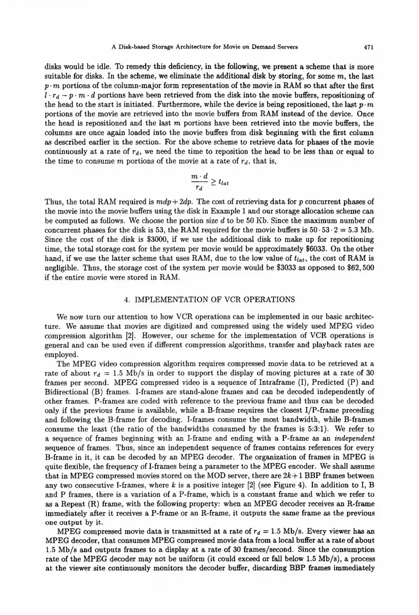
The MPEG video compression algorithm requires compressed movie data to be retrieved at a rate of about Td = 1.5 Mb/s in order to support the display of moving pictures at a rate of 30 frames per second. MPEG compressed video is a sequence of Intraframe (I), Predicted (P) and Bidirectional (B) frames. I-frames are stand-alone frames and can be decoded independently of other frames. P-frames are coded with reference to the previous frame and thus can be decoded only if the previous frame is available, while a B-frame requires the closest I/P-frame preceding and following the B-frame for decoding. I-frames consume the most bandwidth, while B-frames consume the least (the ratio of the bandwidths consumed by the frames is 5:3:1). We refer to a sequence of frames beginning with an I-frame and ending with a P-frame as an independent sequence of frames. Thus, since an independent sequence of frames contains references for every B-frame in it, it can be decoded by an MPEG decoder. The organization of frames in MPEG is quite flexible, the frequency of I-frames being a parameter to the MPEG encoder. We shall assume that in MPEG compressed movies stored on the MOD server, there are 21c+ 1 BBP frames between any two consecutive I-frames, where k is a positive integer [2] (see Figure 4). In addition to I, B and P frames, there is a variation of a P-frame, which is a constant frame and which we refer to as a Repeat (R) frame, with the following property: when an MPEG decoder receives an R-frame immediately after it receives a P-frame or an R-frame, it outputs the same frame as the previous one output by it.
MPEG compressed movie data is transmitted at a rate of Td = 1.5 Mb/s. Every viewer has an MPEG decoder, that consumes MPEG compressed movie data from a local buffer at a rate of about 1.5 Mb/s and outputs frames to a display at a rate of 30 frames/second. Since the consumption rate of the MPEG decoder may not be uniform (it could exceed or fall below 1.5 Mb/s), a process at the viewer site continuously monitors the decoder buffer, discarding BBP frames immediately

472
I 00P BBP BBP I
Fig. 4: A possible sequence of MPEG frames.
preceding an I-frame if the buffer overflows and inserting additional R-frames between P and I- frames in case the buffer underflows. We do not expect deletion and insertion of a few additional
frames to seriously effect the quality of the movie since each frame is displayed for only hth of a second.
We now describe how the control operations like begin, pause, fast-forward, rewind and resume for a movie are executed with our basic storage architecture. As we described earlier, contiguous portions of the movie are retrieved into p movie buffers at a rate rd. The first n portions are retrieved into the first movie buffer, the next n into the second movie buffer, and so on.
begin: The transmission of compressed movie data to the viewer starts once the first movie buffer contains the first frame of the movie. Portions of size d are transmitted to the user at a rate rd from the movie buffer (wrapping around if necessary). After the i * nth portion is transmitted, transmission of movie data is resumed from the i + lth movie buffer. We refer to the movie buffer that outputs the movie data currently being transmitted to the viewer as the current movie buffer. Since in the worst case, n. d bits may need to be transmitted before the first movie buffer contains the first frame of the movie, the delay involved in the transmission of a movie when a viewer issues a begin command, in the worst case, is the minimum phase difference t,.
pause: Once a P-frame immediately preceding an I-frame is transmitted, subsequent frames trans- mitted to the viewer are R-frames.
fast-forward: Beginning with the current movie buffer, the following steps are executed.
1. Continue transmitting compressed movie data normally until a P-frame is transmitted from the current movie buffer and the next movie buffer contains an I-frame.
2. Transmit movie data beginning with the I-frame in the next movie buffer.
3. Go to Step 1.
Thus, during fast-forward, independent sequences of frames are transmitted, the number of bits skipped between any two successive sequences being approximately n . d.
rewind: This operation is implemented in a similar fashion to the fast-forward operation except that instead of jumping ahead to the following movie buffer, jumps during transmission are made to the preceding movie buffer. Thus, beginning with the current movie buffer, the following steps are executed.
1. Continue transmitting compressed movie data normally until a P-frame is transmitted from the current movie buffer and the previous movie buffer contains an I-frame.
2. Transmit movie data beginning with the I-frame in the previous movie buffer.
3. Go to Step 1.
resume: In case the previously issued command was either fast forward or rewind, bits are continued to be transmitted normally from the current movie buffer. If, however, the previous command was pause, then once the current movie buffer contains the I-frame following the last P- frame transmitted, normal transmission of movie data from the movie buffer is resumed beginning with the I-frame. Thus, in the worst case, similar to the case of the begin operation, a viewer may experience a delay of t, seconds before transmission can be resumed after a pause operation.
Furthermore, the basic architecture enables the viewer to jump to any location in the movie in t, seconds. During fast-forward and rewind, since independent sequences of frames are transmitted,

A Disk-based Storage Architecture for Movie on Demand Servers 473
the MPEG decoder has no problems decoding transmitted data. Also, when switching from one movie buffer to another, one of the movie buffers must contain an I-frame, while the other must contain a P-frame. However, this is not really a problem, since due to the high frequency of P- frames in the compressed movie, it is very likely that every time a movie buffer contains an I-frame, adjacent movie buffers would contain P-frames. Finally, in the extreme case, 30t, frames may be skipped for every IBBP sequence transmitted. Thus, fast-forward and rewind could give the effect that the frames are displayed at approximately 7.5t, times their normal rate. We shall refer to the number of frames skipped during fast-forward and rewind as their granularity.
For the disk in Example 1, t, for a 100 minute movie is approximately 113 s. Thus, the worst case delay is 113 s when beginning or resuming the display of a movie. Furthermore, the number of frames skipped when fast-forwarding and rewinding is 3390 (113 s of the movie). By reducing the minimum phase difference t,, we could provide better quality MOD service to viewers. We now show how multiple disks can be employed to reduce t,. Returning to Example 1, suppose that instead of using a single disk, we were to use an array of 5 disks. In this case, the bandwidth of the disk array increases from 80 Mb/s to 265 Mb/s. The number of phases, p, increases from 53 to 266, and, therefore, the minimum phase difference t, reduces from 113 s to approximately 22 s. In this system, the worst case delay is 22 s and the number of frames skipped is 660 (22 s of the movie). The storage cost of the system would increase five-fold, from $3033 to $15165, which is still less than the cost of storing the entire movie in RAM (i.e., $62500).
Although the basic service may be sufficient for many viewers, there may be viewers who are willing to pay more for higher quality MOD service. Ideally, during fast-forward and rewind, we would like the 2k BBP frames between consecutive IBBP frames to be skipped (typically, the value of k ranges between 2 and 5). In the following sections, we individually address the following two issues.
1. Reduction of the granularity of fast-forward and rewind.
2. Elimination of the delay in resuming normal display after a pause operation.
5. IMPROVING GRANULARITY OF FAST-FORWARD AND REWIND
The granularity of fast-forward and rewind operations presented in Section 4 is dependent on the phase difference t,. There are two possible approaches to reducing the number of bits skipped between two successive independent sequences of frames during fast-forward and rewind. We elaborate on both approaches in the following subsections.
5.1. Storing a Fast-Forward Version of the Movie
A separate version of the movie that is used to perform fast-forward and rewind operations is stored. Since we assume that there are 2k BBP sequences between any two consecutive IBBP sequences in the movie, the fast-forward (FF) version is obtained from the compressed MPEG movie by omitting the 2k BBP sequences in between two consecutive IBBP sequences. Thus, the FF-version of the movie contains only consecutive IBBP sequences of frames and thus, transmitting it to viewers at a rate of rd would result in an effect that is similar to one of playing the movie in fast-forward mode. Note that since only IBBP sequences are transmitted, it is possible that the rate at which the decoder consumes bits would increase beyond rd. However, the process at the viewer site can insert R-frames to ensure that the buffer never underflows.
The storage required for the FF-version of the movie can be shown to be & times the storage required for the movie. Since the bandwidth requirements for I, P and B are in the ratio 5:3:1,
assuming that a B-frame consumes a unit of storage, it follows that P and I frames consume 3 and 5 units of storage, respectively. Thus, since there are 2k + 1 BBP frames between any two consecutive I-frames, and each BBP sequence consumes 5 units of storage, it can be shown that for every 10 + 1Ok units of the movie, the FF-version of it contains only 10 frames. Thus, it follows that the FF-version of the movie consumes & times the storage consumed by the movie.

474 BANU &DEN et al.
5.1.1. Storing the Fast-Forward Version in RAM
One simple option is to store the entire FF-version of the movie in RAM. This is more cost-
effective than the RAM-based architecture in which the entire movie is stored in RAM since the FF-version of the movie occupies only & times the storage occupied by the movie. The
operations fast-forward, rewind, and resume require the transmission of bits to switch between the movie buffers and the FF-version of the movie. The various operations are implemented as follows
(pause and resumption from pause mode is implemented as described in the previous section).
fast-forward: Frames are continued to be transmitted from the current movie buffer until a P- frame is transmitted. Once a P-frame is transmitted, the first I-frame that follows the P-frame in
the movie is located in the FF-version of the movie. Frames are continued to be transmitted at a rate of Td from the FF-version beginning with the I-frame. rewind: In this case, frames are transmitted from the current movie buffer until a P-frame is
transmitted. Once a P-frame is transmitted, the first I-frame that precedes the P-frame in the movie is located in the FF-version of the movie. The following steps are executed.
1. Transmit frames from the FF-version of the movie beginning with the I-frame until a P-frame
is transmitted.
2. Once the P-frame is transmitted, locate the I-frame in the FF-version that belongs to the IBBP sequence that immediately precedes the IBBP sequence just transmitted.
3. Go to Step 1.
resume: Resumption of normal display from fast-forward and rewind is handled in a similar fashion to resumption from pause. Once a P-frame is transmitted from the FF-version, until one of the movie buffers contains the first I-frame in the movie following the P-frame, R-frames are
transmitted to the viewer. Normal transmission is resumed from the movie buffer beginning with the I-frame.
5.1.2. Storing the Fast-Forward Version on Disk
An alternative to storing the FF-version of the movie in RAM is to store it on disk using the
phase-constrained allocation scheme described in Section 3 as we did for the movie itself. Thus, in
addition to movie buffers in which consecutive portions of a movie are retrieved, an additional set of buffers into which consecutive portions of the FF-version of the movie are retrieved is maintained. We refer to these as FF-buffers. The minimum phase difference for the stored FF-version of the
movie is tff, which is approximately & times smaller than the minimum phase difference t, for
the movie. The number of portions, nff of size d in a row of the FF-version is tff.Ta. There are three possible ways in which the fast-forward operation can be imilemented. The
simplest way of implementing the fast forward operation is to first determine the FF-buffer con- taining frames closest to and following the frame being currently transmitted from the current
movie buffer. After a P-frame is transmitted from the current movie buffer, frames are transmit- ted from the FF-buffer beginning with an I-frame. The number of bits between portions contained concurrently in any two consecutive FF-buffers is nff ad bits in the FF-version of the movie. Thus, in the worst case, switching from a movie buffer to a FF-buffer could result in approximately n. d bits (tc seconds) of the movie being skipped. However, once transmission is switched from the movie buffer to the FF-buffer, 21c BBP sequences are skipped between any two consecutive IBBP sequences.
Another approach is to continue transmitting from the current movie buffer until a P-frame immediately preceding an I-frame is transmitted and then simply transmit R-frames until an FF- buffer contains the I-frame that follows the P-frame in the movie. In the worst case, this could result in the viewer’s display being frozen for about tff seconds since the required I-frame may have just been transmitted from the FF-buffer and waiting for it to be retrieved into the FF-buffer again may result in a delay of tff seconds.
It would be desirable if we can avoid freezing the viewer’s display as well as skipping n . d bits of the movie when switching from the movie buffer to an FF-buffer. A solution that achieves

A Disk-based Storage Architecture for Movie on Demand Servers 475
both is to simply continue transmitting frames normally from the movie buffer until one of the FF-buffers contains the first I-frame in the movie that follows the last P-frame transmitted. At this time, transmission of subsequent frames is carried out from the FF-buffers beginning with the I-frame. In this case, however, in the worst case, the delay involved in switching from the movie buffer to the FF-buffer could be greater than tfj seconds since the first I-frame following the last transmitted P-frame may have just been transmitted out of the FF-buffer. The I-frame is retrieved into the FF-buffer again after tjf seconds. However, in that time, few more frames may have been transmitted to the viewer from the movie buffer. Thus, in order to compute the delay, td, in the worst case, we use the following equation.
nff . d + (;+t;) - = Tdtd
The above equation basically states that the number of bits output from the FF-buffer in time td, in the worst case, is the sum of njf .d and & times the bits transmitted from the movie buffer
to the viewer (since the FF-version of the movie is & times the size of the movie). Thus, in the worst case, the delay would be
td M njj . d. (k + 1) k'Td ’
Thus, unlike the case in which the FF-version of the movie is loaded into RAM in which a smooth transition to the fast-forward mode is possible without delay, in the disk based solution, the transition to fast-forward mode is either abrupt or could, in the worst case, result in a delay of at least tjf seconds.
The problem with storing an FF-version of the movie on a disk is that the implementation of the rewind command is not possible using the FF-buffers. The reason for this is that successive IBBP sequences of frames are retrieved into the FF-buffers, while for rewind, once an IBBP sequence of frames is transmitted, the previous IBBP sequence of frames needs to be transmitted. Thus, for the purpose of supporting rewind, we store a different version of the movie, which we refer to as the REW-version of the movie, on the disk. The REW-version, like the FF-version, contains only IBBP sequences of frames except that the order of appearance of the IBBP sequences in the FF-version and the REW-version are reversed. Also, a separate set of buffers is maintained into which consecutive portions of the REW-version of the movie are retrieved, which we refer to as REW-buffers. The minimum phase difference for the RJZW-version of the movie is also tjf seconds.
The alternatives described for the implementation of fast forward can also be used to imple- ment rewind by switching to the RECW-buffer instead of the FF-buffer. In addition, in the first alternative, the REW-buffer containing frames closest to and preceding the frame being currently transmitted from the current movie buffer is determined. In the second and third alternatives, instead of transmitting the first I-frame in the movie that follows the last P-frame transmitted from the FF-buffer, the first I-frame in the movie that precedes the P-frame is transmitted from the RJZW-buffer. The number of bits skipped by the first alternative and the worst case delay in the second alternative are as described for fast-forward. However, for the third alternative, the worst case time delay, td, can be shown to be
td M nff . d * (k + 1) (k+2).Td ’
The reason for this is that since frames are continually transmitted to the viewer, in the worst case, only the difference between njf . d and & times the number of bits transmitted from the movie buffer in time td are output from the REW-buffer in time td. Thus,
The resume operation is implemented similar to the case in which the entire FF-version was stored in RAM and may require the display to be frozen for t, seconds.

476
buffer
... I- Movie Buffers
. . . El (fhn) Cdumn n
Viewer Buffer
(k+2) Viewer Buffer
Fig. 5: Viewer Buffers for Fast-forward and Rewind
5.2. Bu#er Based Solution
The schemes for implementing fine granularity fast-forward and rewind described in the previous subsection either require the entire FF-version of the movie to be stored in RAM or resulted in an abruptness or delay in switching to fast-forward/rewind mode. In this subsection, we present a scheme for supporting fine-granularity fast-forward and rewind that does not require the entire FF-version of the movie to be stored (in RAM or on disk) and results in a smooth transition to fast-forward and rewind mode. The scheme is especially suitable in case a few number of viewers are watching the movie.
Informally, the basic idea underlying the scheme is that, at all times, if we were to buffer nd bits following, and nd bits of the FF-version of the movie preceding the current bit being transmitted, then it is possible to support both fine-granularity fast forward and rewind without any delays. It is necessary to buffer bits since movie buffers output the movie at a rate of rd, and during fast-forward/rewind, the FF-version of the movie, and not the movie itself needs to be transmitted at rd. The reason that it suffices to buffer nd bits of FF-version of the movie following the current bit being transmitted is that when a viewer issues the fast-forward command, in the time that the buffered nd bits of the FF-version of the movie are transmitted, nd bits are output by each movie buffer. Thus, the nd + lth bit of FF-version of the movie would be output by a movie buffer and by buffering it, its availability for transmission once nd bits are transmitted can be ensured.
Using a similar argument, it can be shown that buffering nd bits preceding the current bit being transmitted suffices to support continuous rewind. Note that buffering z < nd bits of the FF-version of the movie preceding or following the current bit being transmitted, could result in hiccups due to the unavailability of bits during fast-forward/rewind. The reason for this is that once z bits of FF-version of the movie have been transmitted, the z + lth bit may not be available since x < nd and thus, none of the movie buffers may have output it while the x bits were being transmitted.
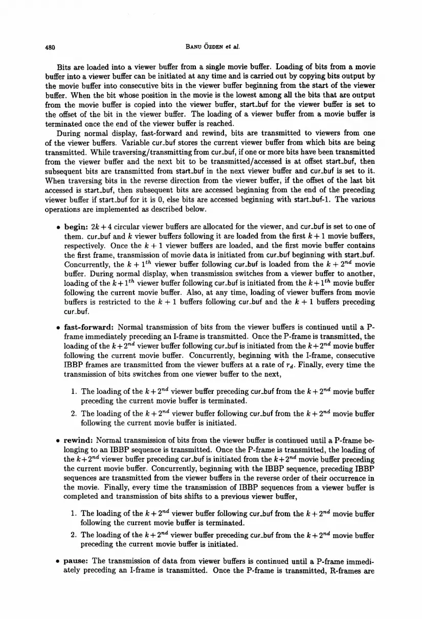
In order to buffer the required bits of the FF-version of the movie, 2k+4 viewer buffers are maintained per viewer watching the movie (see Figure 5). A viewer buffer is used to store the
FF-version of the movie output by a movie buffer and has a size nd-/+:BPl + (IBBPJ which is the maximum number of bits of FF-version, that a movie buffer can output ([IBBP( is the storage required for an IBBP sequence). The buffers are arranged in a circular fashion and each buffer is a circular buffer. One viewer buffer stores the FF-version of the movie output from the current movie buffer. k + 1 viewer buffers following the buffer are used to store nd bits of the FF-version of the movie output from the k+ 1 movie buffers following the current movie buffer, while k+ 1 viewer

A Disk-baaed Storage Architecture for Movie on Demand Servers 477
buffers preceding the buffer are used to store nd bits of the FF-version of the movie output from the k + 1 movie buffers preceding the current movie buffer. The remaining viewer buffer is used
to load the FF-version of the movie in case the viewer issues a fast-forward or rewind command.
With every viewer buffer are associated variables start_buf and end_buf. start_buf stores the
offset from the start of the buffer of the bit in the viewer buffer with the lowest position in the
movie. Variable end_buf stores the offset from the start of the buffer, of the last bit contained
in the buffer. An additional variable cur-buf is used to store the current viewer buffer. During
normal display and during pause, cur_buf is the viewer buffer containing the FF-version of the movie output by the current movie buffer, and during fast forward and rewind mode, cur_buf is
the viewer buffer from which bits are transmitted.
The FF-version of a movie is loaded into a viewer buffer from a single movie buffer. Consecutive
bits output from the movie buffer and belonging to only IBBP sequences are simply copied into the viewer buffer beginning from the start of the buffer. When a bit whose position in the movie
is the smallest among all the bits (belonging to IBBP sequences and) output by the movie buffer is copied into the viewer buffer, start_buf for the buffer is set equal to the offset of the bit from
the beginning of the viewer buffer. Bits are continued to be copied into the viewer buffer until it contains all the bits output by the movie buffer that belong to IBBP sequences. end_buf for the buffer is set to the offset of the last bit from the start of the buffer.
During fast-forward and rewind, the FF-version of the movie is transmitted from the viewer
buffers at a rate of rd. While transmitting data from a viewer buffer, if end_buf is reached and start-buf for the buffer is 0, then subsequent bits are transmitted beginning with start_buf in the
next viewer buffer. If, on the other hand, start_buf for the buffer is not 0, then subsequent bits are retrieved from the start of the buffer. Once one or more bits have been retrieved from a buffer, if
the next bit to be retrieved from the buffer is at offset start_buf from the beginning of the buffer,
then subsequent bits are retrieved from start_buf in the next buffer. Traversing the viewer buffers in the reverse direction (during rewind) is carried out as follows.
If the beginning of the buffer is reached and start_buf is not 0, then subsequent bits are traversed
beginning with end_buf. On the other hand, if the offset of the current bit from the start of the buffer is start-buf, then subsequent bits are accessed from the previous viewer buffer, beginning
with
l end_buf, if start_buf for the buffer is 0, and
l start_buf-1, otherwise.
The various operations are implemented as follows. begin: 2k + 4 viewer buffers are allocated for the viewer and cur_buf is set to one of them (that is
arbitrarily chosen). cur_buf and the k viewer buffers following it are loaded with the FF-version of the movie from the first k + 1 movie buffers. Once the k + 1 viewer buffers are loaded, and the first
movie buffer contains the first frame of the movie, movie data is transmitted to the viewer from the first movie buffer and concurrently the k + lth viewer buffer following cur_buf is loaded from
the k + 2nd movie buffer. During normal transmission of bits to the viewer, when transmission switches from the current movie buffer to the next, cur-buf is set to the next viewer buffer and the k + lth viewer buffer following cur_buf is begun to be loaded from the k + lth movie buffer following the current movie buffer. Furthermore, during normal display, loading of viewer buffers is restricted to only cur_buf, the k + 1 viewer buffers following cur-buf and the k + 1 viewer buffers preceding cur_buf. The maximum latency to start viewing the movie is less than 2 . t,. fast-forward: Once a P-frame immediately preceding an I-frame is transmitted from the movie buffer, loading of the k+2”d viewer buffer following cur_buf is initiated from the k+2nd movie buffer
following the current movie buffer. Concurrently, the I-frame following the P-frame is located in cur_buf and subsequent bits are transmitted from cur_buf beginning with the I-frame. During fast- forward, every time transmission of bits switches from a viewer buffer to the next buffer (cur_buf
is set to the next buffer), the following steps are performed.
1. The loading of the k + 2nd viewer buffer preceding cur_buf from the k + 2nd movie buffer preceding the current movie buffer is terminated.
IS 20/6-D

2. The k + Pd viewer buffer following cur_buf is loaded from the k + 2nd movie buffer following the current movie buffer.
rewind: Once a P-frame belonging to an IBBP sequence is transmitted from the movie buffer, loading of the k + 2”d viewer buffer preceding cur_buf is initiated from the k + 2nd movie buffer preceding the current movie buffer. Concurrently, the I-frame belonging to the sequence is located in cur_buf and sequences of IBBP frames are transmitted at a rate of rd in the reverse order of their occurrence in the viewer buffers. During rewind, once every bit from a viewer buffer has been transmitted and transmission switches to the previous viewer buffer (cur-buf is set to the previous buffer), the following steps are performed.
1. The loading of the k + 2nd viewer buffer following cur_buf from the k + Znd movie buffer following the current movie buffer is terminated.
2. The k + 2nd viewer buffer preceding cur_buf is loaded from the k + 2”d movie buffer preceding the current movie buffer.
pause: In this case, bits are transmitted normally from the movie buffers until a P-frame preceding an I-frame is transmitted. Once the P-frame is transmitted, subsequent frames transmitted to the viewer are R-frames (loading of viewer buffers is continued as before the transmission of R-frames). resume: In case the previous command was a pause, once the movie buffer contains the I-frame following the last P-frame transmitted, transmission of movie data to viewers is resumed at a rate of Td.. Also, all viewer buffers that were being loaded during the pause operation, are continued to be loaded.
In case the previous command was rewind or fast-forward, bits are transmitted from the viewer buffers until a P-frame is transmitted. Once the P-frame is transmitted, until a movie buffer contains the I-frame following the P-frame, subsequent frames transmitted to the viewer are R- frames. During the transmission of R-frames, loading of viewer buffers is restricted to the k + 1 buffers following and the k + 1 buffers preceding cur_buf. Once a movie buffer contains the I-frame, normal transmission is resumed from the movie buffer beginning with the I-frame.
6. REDUCING RESPONSE TIME
The schemes presented for pause in sections 4 and 5, and those for fine-granularity fast-forward and rewind in the previous section all require a movie buffer to contain the first I-frame in the movie following the last P-frame transmitted before normal transmission of bits to the viewer can be resumed. In the worst case, this could result in a delay of t, seconds which, to some viewers, may be unacceptable. In the following subsections, we first present a scheme that can be used in conjunction with all the schemes presented in sections 4 and 5 in order to eliminate the delay associated with only the pause operation. We then present a scheme that eliminates the delay associated with all of the operations - pause, fast-forward and rewind, and that also provides smooth fine granularity fast-forward and rewind operations. The schemes are built on the scheme presented in Section 4 that ensures movie buffers output continuous portions of the movie at a rate of Td. Both schemes can be used to provide, at an additional cost, enhanced MOD services to few viewers since they require RAM buffers to be allocated on a per viewer basis.
6.1. Pause
Regarding the pause operation, our scheme requires a circular viewer buffer to be maintained per user. The idea is to store in the viewer buffer, bits following the last bit transmitted before pause so that subsequent bits can be transmitted from the viewer buffer (instead of the movie buffer) without delay when the viewer issues the resume command. If immediate resumption of normal transmission of bits from pause mode is to be supported, then the size of the viewer buffer required must be at least n . d. The reason for this is that if the size of the buffer is 2, where x < n. d, then if the viewer issues a pause command, only x bits following the last bit transmitted can be buffered. Thus, if the viewer were to issue the resume command when the x + lJt bit was

A Disk-based Storage Architecture for Movie on Demand Servers 479
output by the movie buffer, it would not be possible to buffer the z+ ldt bit. Thus, it would not be possible to transmit the x + lSt bit to the viewer, since x < nd and the bit needs to be transmitted after x bits have been transmitted, but is not output in the movie buffer again until nd bits have been transmitted. On the other hand, if the size of the viewer buffer is n-d, then when the viewer resumes after a pause, some movie buffer must output bits contained in the buffer and it can be used to replenish the bits consumed from the viewer buffer.
We now describe how the viewer buffer can be used to implement pause and resume. With every viewer buffer are associated variables start-buf, num_bits and next-pos. start_buf stores the offset from the start of the viewer buffer, of the next bit to be transmitted to the viewer. Also, num_bits stores the number of untransmitted bits contained in the buffer, while next-pos stores the position in the movie of the next bit to be retrieved into the viewer buffer. Furthermore, at any time, x bits output by a movie buffer are retrieved into the viewer buffer at offset ((start_buf+num_bits) mod nd) if the following two conditions hold.
1. 2 5 nd - num_bits.
2. The position in the movie of the first among the x consecutive bits is next_pos.
num_bits and next_pos are incremented by x. Also, x bits are transmitted from the viewer buffer beginning with start_buf, if x 5 num_bits. numbits is decremented by x and stat-t_buf is set to ((start_buf + X) mod nd).
l pause: Once a P-frame that is immediately followed by an I-frame is transmitted, subsequent frames transmitted to the viewer are R-frames. In addition, if bits were being transmitted from a movie buffer, then start-buf and num_bits are both set to 0 and next_pos is set to the position in the movie of the next I-frame to be transmitted.
l resume: Bits are transmitted to viewers from the viewer buffer beginning with start_buf.
The above described scheme for pause and resume can be used in conjunction with the schemes for fast-forward and rewind described in the previous two sections. In the schemes, implementations of fast-forward and rewind stay the same except that in case bits were being transmitted from the viewer buffer when the commands were issued, transmission of bits switches from the viewer buffer to a movie buffer (in Section 4), RAM, an FF or a REW buffer (in Section 5.1), or a viewer buffer storing FF-version of the movie (Section 5.2). Furthermore, while bits are being transmitted from the viewer buffer, in the scheme presented in Section 5.2, cur_buf is the viewer buffer containing the FF-version of the movie from the movie buffer that output the bits being transmitted.
6.2. Fast-Forward and Rewind
In this subsection, we propose a comprehensive scheme that in addition to eliminating the response time for pause, fast forward and rewind, also provides fine granularity fast-forward and rewind. The scheme requires (k + 1)nd bits of the movie preceding as well as following the current bit being transmitted to be buffered in order to support continuous fast-forward and rewind. The basic idea is similar to that presented in Section 5.2. In the time that FF-version of movie contained in the buffered (k + 1)nd bits can be transmitted, during fast-forward/rewind, the (k + 1)nd + lth bit is output by a movie buffer (since typically, (k + 1)nd bits of the movie contain nd bits of the FF-version of the movie, nd bits are output by a movie buffer).
Our scheme requires 2k + 4 circular viewer buffers, each of size nd and arranged in a circular fashion, to be maintained per viewer. Bits are always transmitted to viewers from viewer buffers, and a viewer buffer is used to store bits output by a movie buffer. k+l buffers each are used to store the (k+ 1)nd bits following as well aa preceding the current bit being transmitted. One buffer stores the bits output by the current movie buffer, while another is used to store bits following/preceding the buffered (k + 1)nd bits in case the viewer issues a fast-forward/rewind command. With every viewer buffer is associated a variable stat-t_buf that stores the offset, from the start of the buffer, of the bit, in the buffer with the lowest position in the movie.
480 BANU &DEN et aI.
Bits are loaded into a viewer buffer from a single movie buffer. Loading of bits from a movie buffer into a viewer buffer can be initiated at any time and is carried out by copying bits output by the movie buffer into consecutive bits in the viewer buffer beginning from the start of the viewer buffer. When the bit whose position in the movie is the lowest among all the bits that are output from the movie buffer is copied into the viewer buffer, start_buf for the viewer buffer is set to the offset of the bit in the viewer buffer. The loading of a viewer buffer from a movie buffer is terminated once the end of the viewer buffer is reached.
During normal display, fast-forward and rewind, bits are transmitted to viewers from one of the viewer buffers. Variable cur-buf stores the current viewer buffer from which bits are being transmitted. While traversing/transmitting from cur_buf, if one or more bits have been transmitted from the viewer buffer and the next bit to be transmitted/accessed is at offset start-buf, then subsequent bits are transmitted from stat-t_buf in the next viewer buffer and cur_buf is set to it. When traversing bits in the reverse direction from the viewer buffer, if the offset of the last bit accessed is start_buf, then subsequent bits are accessed beginning from the end of the preceding viewer buffer if start_buf for it is 0, else bits are accessed beginning with start_buf-1. The various operations are implemented as described below.
l begin: 2k + 4 circular viewer buffers are allocated for the viewer, and cur_buf is set to one of them. cur_buf and k viewer buffers following it are loaded from the first k + 1 movie buffers, respectively. Once the k + 1 viewer buffers are loaded, and the first movie buffer contains the first frame, transmission of movie data is initiated from cur_buf beginning with start_buf. Concurrently, the k + lth viewer buffer following cur_buf is loaded from the k + 2nd movie buffer. During normal display, when transmission switches from a viewer buffer to another, loading of the k + lth viewer buffer following cur_buf is initiated from the k + lth movie buffer following the current movie buffer. Also, at any time, loading of viewer buffers from movie buffers is restricted to the k + 1 buffers following cur_buf and the k + 1 buffers preceding cur_buf.
l fast-forward: Normal transmission of bits from the viewer buffers is continued until a P- frame immediately preceding an I-frame is transmitted. Once the P-frame is transmitted, the loading of the k + 2nd viewer buffer following cur_buf is initiated from the k + 2nd movie buffer following the current movie buffer. Concurrently, beginning with the I-frame, consecutive IBBP frames are transmitted from the viewer buffers at a rate of rd. Finally, every time the transmission of bits switches from one viewer buffer to the next,
1. The loading of the lc + 2”d viewer buffer preceding cur_buf from the k + 2nd movie buffer preceding the current movie buffer is terminated.
2. The loading of the k + 2nd viewer buffer following cur_buf from the k + 2nd movie buffer following the current movie buffer is initiated.
l rewind: Normal transmission of bits from the viewer buffer is continued until a P-frame be- longing to an IBBP sequence is transmitted. Once the P-frame is transmitted, the loading of the k+2nd viewer buffer preceding cur-buf is initiated from the k+2”d movie buffer preceding the current movie buffer. Concurrently, beginning with the IBBP sequence, preceding IBBP sequences are transmitted from the viewer buffers in the reverse order of their occurrence in the movie. Finally, every time the transmission of IBBP sequences from a viewer buffer is completed and transmission of bits shifts to a previous viewer buffer,
1. The loading of the k + 2nd viewer buffer following cur_buf from the k + 2”d movie buffer following the current movie buffer is terminated.
2. The loading of the k + 2nd viewer buffer preceding cur_buf from the k + Znd movie buffer preceding the current movie buffer is initiated.
l pause: The transmission of data from viewer buffers is continued until a P-frame immedi- ately preceding an I-frame is transmitted. Once the P-frame is transmitted, R-frames are

A Disk-based Storage Architecture for Movie on Demand Servers 481
transmitted to the viewer and transmission of bits from viewer buffers is stopped. Loading of data during pause is continued only in the k + 1 viewer buffers following and the k + 1 viewer buffers preceding cur_buf.
l resume: If the last command was a pause, then transmission of R-frames is stopped and normal transmission of bits to the viewer is resumed with the I-frame following the last P- frame transmitted from the viewer buffer. On the other hand, if the last command was a fast-forward or rewind, then normal transmission of bits from viewer buffers is resumed.
7. RELATED WORK
A number of storage schemes for continuous retrieval of video and audio data have been pro- posed in the literature [l, 6, 5, 3, 7, 41. Among these, however, only [l, 6, 31 address the problem of satisfying multiple concurrent requests for the retrieval of multimedia objects residing on a disk, These schemes are similar in spirit to the contiguous allocation scheme that we presented in Sec- tion 3.1.1. In each of the schemes, concurrent requests are serviced in rounds retrieving successive portions of multimedia objects and performing multiple seeks in each round. Thus, the schemes are unsuitable for handling large number of requests concurrently. In fact, admission control tests based on computed buffer requirements for multiple requests are employed in order to determine the feasibility of additional requests with available resources. However, unlike our scheme, which is specifically tailored for MOD environments, the schemes in [l, 6, 31 can be used to concurrently retrieve arbitrary multimedia objects residing on disk.
In order to reduce buffer requirements, an audio record is stored on optical disk as a sequence of data blocks separated by gaps in [7]. Furthermore, in order to save disk space, the authors derive conditions for merging different audio records. In (51, similar to [7], the authors define an interleaved storage organization for multimedia data that permits the merging of time-dependent multimedia objects for efficient disk space utilization. However, they adopt a weaker condition for merging different media strands, a consequence of which is an increase in the read-ahead and buffering requirements.
In [4], the authors use parallelism in order to support the display of high resolution of video data that have high bandwidth requirements. In order to make up for the low I/O bandwidths of current disk technology, a multimedia object is declustered across several disk drives, and the aggregate bandwidth of multiple disks is utilized.
8. CONCLUDING REMARKS
We have proposed a low cost architecture for a movie on demand (MOD) server. In our architecture, the popular movies are stored on inexpensive disks. We proposed a novel storage allocation scheme that enables multiple different portions of a movie to be concurrently retrieved from disk. Since the scheme eliminates random disk head seeks, it requires only small portions of the movie currently being viewed to be buffered in RAM.
We showed how VCR operations could be implemented in our basic architecture. We also showed how the quality of MOD services could be improved by allocating additional RAM buffers per viewer. Thus, basic MOD services can be provided to all viewers at low cost by the basic architecture, and superior quality services can be provided on a per viewer basis at an extra cost by allocating additional buffers.
Acknowledgements - We would like to thank Kim Matthews and Eric Petajan for discussions that helped us understand details about MPEG.

462 BANU &DEN et al.
REFERENCES
[l] D. P. Anderson, Y. Osawa, and R. Govindan. A file system for continius media. ACM ‘hansactions on Computer Systems, 10(4):311-337 (1992).
[2] D. Gall. MPEG: A video compression standard for multimedia applications. Communications of the ACM, 34(4):46-58 (1991).
[3] J. Gemmell and S. Christodoulakis. Principles of delay-sensitive multimedia data storage and retreival. ACM 7kansactions on Information Systems, 10(1):51-90 (1992).
[4] S. Ghandeharizadeh and L. Ramos. Continuous retrieval of multimedia data using parallelism. IEEE Z+ansac- tions on Knowledge and Data Engineeting, 6(4):658-669 (1993).
[5] P. V. Rangan and H. M. Vin. Efficient storage techniques for digital continuous multimedia. IEEE Zkan~actions eta Knowledge and Data Engineering, 5(4):564-573 (1993).
[6] P. V. Rangan, H. M. Vin, and S. Ramanathan. Designing an on-demand multimedia service. IEEE Communi- cations Magazine, l( 1):56-64 (1992).
[7] C. Yu, W. Sun, D. Bitton, Q. Yang, R. Bruno, and J. Tullis. Efficient placement of audio datat on optical disks for real-time applications. Communications of the ACM, 32(7):862-871 (1989).


